PIM Configuration Guide, Cisco IOS XE Bengaluru 17.x
334
IP Multicast: PIM Configuration Guide, Cisco IOS XE Bengaluru 17.x | Cisco Catalyst 8000 Edge Platforms Americas Headquarters Cisco Systems, Inc. 170 West Tasman Drive San Jose, CA 95134-1706 USA http://www.cisco.com Tel: 408 526-4000 800 553-NETS (6387) Fax: 408 527-0883
-
Upload
khangminh22 -
Category
Documents
-
view
0 -
download
0
Transcript of PIM Configuration Guide, Cisco IOS XE Bengaluru 17.x

IP Multicast: PIM Configuration Guide, Cisco IOS XE Bengaluru 17.x |Cisco Catalyst 8000 Edge PlatformsAmericas HeadquartersCisco Systems, Inc.170 West Tasman DriveSan Jose, CA 95134-1706USAhttp://www.cisco.comTel: 408 526-4000
800 553-NETS (6387)Fax: 408 527-0883

THE SPECIFICATIONS AND INFORMATION REGARDING THE PRODUCTS IN THIS MANUAL ARE SUBJECT TO CHANGE WITHOUT NOTICE. ALL STATEMENTS,INFORMATION, AND RECOMMENDATIONS IN THIS MANUAL ARE BELIEVED TO BE ACCURATE BUT ARE PRESENTED WITHOUT WARRANTY OF ANY KIND,EXPRESS OR IMPLIED. USERS MUST TAKE FULL RESPONSIBILITY FOR THEIR APPLICATION OF ANY PRODUCTS.
THE SOFTWARE LICENSE AND LIMITED WARRANTY FOR THE ACCOMPANYING PRODUCT ARE SET FORTH IN THE INFORMATION PACKET THAT SHIPPED WITHTHE PRODUCT AND ARE INCORPORATED HEREIN BY THIS REFERENCE. IF YOU ARE UNABLE TO LOCATE THE SOFTWARE LICENSE OR LIMITED WARRANTY,CONTACT YOUR CISCO REPRESENTATIVE FOR A COPY.
The Cisco implementation of TCP header compression is an adaptation of a program developed by the University of California, Berkeley (UCB) as part of UCB's public domain version ofthe UNIX operating system. All rights reserved. Copyright © 1981, Regents of the University of California.
NOTWITHSTANDING ANY OTHERWARRANTY HEREIN, ALL DOCUMENT FILES AND SOFTWARE OF THESE SUPPLIERS ARE PROVIDED “AS IS" WITH ALL FAULTS.CISCO AND THE ABOVE-NAMED SUPPLIERS DISCLAIM ALL WARRANTIES, EXPRESSED OR IMPLIED, INCLUDING, WITHOUT LIMITATION, THOSE OFMERCHANTABILITY, FITNESS FOR A PARTICULAR PURPOSE AND NONINFRINGEMENT OR ARISING FROM A COURSE OF DEALING, USAGE, OR TRADE PRACTICE.
IN NO EVENT SHALL CISCO OR ITS SUPPLIERS BE LIABLE FOR ANY INDIRECT, SPECIAL, CONSEQUENTIAL, OR INCIDENTAL DAMAGES, INCLUDING, WITHOUTLIMITATION, LOST PROFITS OR LOSS OR DAMAGE TO DATA ARISING OUT OF THE USE OR INABILITY TO USE THIS MANUAL, EVEN IF CISCO OR ITS SUPPLIERSHAVE BEEN ADVISED OF THE POSSIBILITY OF SUCH DAMAGES.
Any Internet Protocol (IP) addresses and phone numbers used in this document are not intended to be actual addresses and phone numbers. Any examples, command display output, networktopology diagrams, and other figures included in the document are shown for illustrative purposes only. Any use of actual IP addresses or phone numbers in illustrative content is unintentionaland coincidental.
All printed copies and duplicate soft copies of this document are considered uncontrolled. See the current online version for the latest version.
Cisco has more than 200 offices worldwide. Addresses and phone numbers are listed on the Cisco website at www.cisco.com/go/offices.
Cisco and the Cisco logo are trademarks or registered trademarks of Cisco and/or its affiliates in the U.S. and other countries. To view a list of Cisco trademarks, go to this URL:https://www.cisco.com/c/en/us/about/legal/trademarks.html. Third-party trademarks mentioned are the property of their respective owners. The use of the word partner does not imply apartnership relationship between Cisco and any other company. (1721R)
© 2021 Cisco Systems, Inc. All rights reserved.

C O N T E N T S
Read Me First 1C H A P T E R 1
Short Description 2
IP Multicast Technology Overview 3C H A P T E R 2
Information About IP Multicast Technology 3
Role of IP Multicast in Information Delivery 3
Multicast Group Transmission Scheme 3
IP Multicast Routing Protocols 4
IP Multicast Group Addressing 4
IP Class D Addresses 4
IP Multicast Address Scoping 5
Layer 2 Multicast Addresses 6
IP Multicast Delivery Modes 6
Any Source Multicast 7
Source Specific Multicast 7
Protocol Independent Multicast 7
PIM Dense Mode 7
PIM Sparse Mode 8
Sparse-Dense Mode 9
Bidirectional PIM 9
Multicast Group Modes 10
Bidirectional Mode 10
Sparse Mode 10
Dense Mode 10
Rendezvous Points 11
Auto-RP 11
IP Multicast: PIM Configuration Guide, Cisco IOS XE Bengaluru 17.x | Cisco Catalyst 8000 Edge Platformsiii

Sparse-Dense Mode for Auto-RP 12
Bootstrap Router 12
Multicast Source Discovery Protocol 12
Anycast RP 13
Multicast Forwarding 14
Multicast Distribution Source Tree 14
Multicast Distribution Shared Tree 15
Source Tree Advantage 15
Shared Tree Advantage 16
Reverse Path Forwarding 16
RPF Check 16
PIM Dense Mode Fallback 17
Guidelines for Choosing a PIM Mode 19
Where to Go Next 19
Additional References 19
Feature Information for IP Multicast Technology Overview 20
Glossary 20
Configuring Basic IP Multicast 23C H A P T E R 3
Prerequisites for Configuring Basic IP Multicast 23
Information About Configuring Basic IP Multicast 23
Auto-RP Overview 23
The Role of Auto-RP in a PIM Network 23
IP Multicast Boundary 24
Benefits of Auto-RP in a PIM Network 24
Anycast RP Overview 25
BSR Overview 25
BSR Election and Functionality 25
BSR Border Interface 25
Static RP Overview 26
SSM Overview 26
SSM Components 26
How SSM Differs from Internet Standard Multicast 27
SSM Operations 27
IP Multicast: PIM Configuration Guide, Cisco IOS XE Bengaluru 17.x | Cisco Catalyst 8000 Edge Platformsiv
Contents

IGMPv3 Host Signaling 28
Benefits of Source Specific Multicast 28
Bidir-PIM Overview 29
Multicast Group Modes 29
Bidirectional Shared Tree 29
DF Election 31
Bidirectional Group Tree Building 31
Packet Forwarding 31
Benefits of Bidirectional PIM 31
How to Configure Basic IP Multicast 32
Configuring Sparse Mode with Auto-RP 32
What to Do Next 36
Configuring Sparse Mode with Anycast RP 36
What to Do Next 39
Configuring Sparse Mode with a Bootstrap Router 39
What to Do Next 43
Configuring Sparse Mode with a Single Static RP(CLI) 43
What to Do Next 45
Configuring Source Specific Multicast 46
What to Do Next 47
Configuring Bidirectional PIM 47
Configuration Examples for Basic IP Multicast 49
Example: Sparse Mode with Auto-RP 49
Sparse Mode with Anycast RP Example 50
Sparse Mode with Bootstrap Router Example 51
BSR and RFC 2362 Interoperable Candidate RP Example 51
Example: Sparse Mode with a Single Static RP 52
SSM with IGMPv3 Example 53
SSM Filtering Example 53
Bidir-PIM Example 54
Additional References 54
Feature Information for Configuring Basic IP Multicast in IPv4 Networks 55
Configuring Basic IP Multicast in IPv6 Networks 57C H A P T E R 4
IP Multicast: PIM Configuration Guide, Cisco IOS XE Bengaluru 17.x | Cisco Catalyst 8000 Edge Platformsv
Contents

Prerequisites for Configuring Basic IP Multicast 57
Information About Configuring Basic IP Multicast in IPv6 Networks 57
IPv6 Multicast 57
IPv6 Multicast Overview 57
IPv6 Multicast Addressing 58
IPv6 Multicast Groups 59
Scoped Address Architecture 60
MRIB 60
IPv6 Multicast Process Switching and Fast Switching 61
IPv6 Anycast RP Solution 61
PIMv6 Anycast RP Solution Overview 61
PIMv6 Anycast RP Normal Operation 62
PIMv6 Anycast RP Failover 62
IPv6 BSR 63
IPv6 BSR 63
IPv6 BSR: Configure RP Mapping 64
IPv6 BSR: Scoped Zone Support 64
IPv6 Multicast: RPF Flooding of BSR Packets 64
IPv6 Multicast Groups 64
IPv6 Multicast Address Group Range Support 65
Multicast Admission Control Features 65
Global and Per MVRF Mroute State Limit 66
Global and Per MVRF Mroute State Limit Feature Design 66
Mechanics of Global and Per MVRF Mroute State Limiters 67
How to Configure Basic IP Multicast in IPv6 Networks 68
Configuring IPv6 Addressing and Enabling IPv6 Routing 68
Enabling IPv6 Multicast Routing 69
Disabling the Device from Receiving Unauthenticated Multicast Traffic 70
Troubleshooting IPv6 Multicast 71
Troubleshooting IPv6 Multicast Route Limit 73
Configuring PIMv6 Anycast RP 74
Configuring a BSR and Verifying BSR Information 77
Sending PIM RP Advertisements to the BSR 78
Configuring BSR for Use Within Scoped Zones 79
IP Multicast: PIM Configuration Guide, Cisco IOS XE Bengaluru 17.x | Cisco Catalyst 8000 Edge Platformsvi
Contents
Configuring BSR Devices to Announce Scope-to-RP Mappings 80
Configuring Global and Per MVRF Multicast Route Limit for IPv6 81
Configuration Examples for Configuring IP Multicast Basic in IPv6 Networks 82
Example: Enabling IPv6 Multicast Routing 82
Examples: Disabling IPv6 Multicast Address Group Range Support 82
Example: Verifying IPv6 MRIB Information 83
Example: Configuring PIMv6 Anycast RP 83
Example: Configuring a BSR 84
Example: Enabling IPv6 Multicast Routing Limit Per VRF 84
Example: Disabling IPv6 Multicast Routing Limit Per VRF 84
Additional References 85
Feature Information for Configuring Basic IP Multicast in IPv6 Networks 86
Using MSDP to Interconnect Multiple PIM-SM Domains 87C H A P T E R 5
87
Information About Using MSDP to Interconnect Multiple PIM-SM Domains 87
Benefits of Using MSDP to Interconnect Multiple PIM-SM Domains 87
Use of MSDP to Interconnect Multiple PIM-SM Domains 87
MSDP Message Types 90
SA Messages 90
SA Request Messages 91
SA Response Messages 91
Keepalive Messages 91
SA Message Origination Receipt and Processing 91
SA Message Origination 91
SA Message Receipt 91
SA Message Processing 94
MSDP Peers 94
MSDP MD5 Password Authentication 94
How MSDP MD5 Password Authentication Works 95
Benefits of MSDP MD5 Password Authentication 95
SA Message Limits 95
MSDP Keepalive and Hold-Time Intervals 95
MSDP Connection-Retry Interval 96
IP Multicast: PIM Configuration Guide, Cisco IOS XE Bengaluru 17.x | Cisco Catalyst 8000 Edge Platformsvii
Contents

MSDP Compliance with IETF RFC 3618 96
Benefits of MSDP Compliance with RFC 3618 96
Default MSDP Peers 97
MSDP Mesh Groups 98
Benefits of MSDP Mesh Groups 98
SA Origination Filters 99
Use of Outgoing Filter Lists in MSDP 99
Use of Incoming Filter Lists in MSDP 100
TTL Thresholds in MSDP 101
SA Request Messages 101
SA Request Filters 101
MSDP MIB 102
How to Use MSDP to Interconnect Multiple PIM-SM Domains 102
Configuring an MSDP Peer 102
Shutting Down an MSDP Peer 103
Configuring MSDP MD5 Password Authentication Between MSDP Peers 104
Troubleshooting Tips 105
Preventing DoS Attacks by Limiting the Number of SA Messages Allowed in the SA Cache fromSpecified MSDP Peers 106
Adjusting the MSDP Keepalive and Hold-Time Intervals 107
Adjusting the MSDP Connection-Retry Interval 108
Configuring MSDP Compliance with IETF RFC 3618 109
Configuring a Default MSDP Peer 110
Configuring an MSDP Mesh Group 111
Controlling SA Messages Originated by an RP for Local Sources 112
Controlling the Forwarding of SA Messages to MSDP Peers Using Outgoing Filter Lists 113
Controlling the Receipt of SA Messages from MSDP Peers Using Incoming Filter Lists 114
Using TTL Thresholds to Limit the Multicast Data Sent in SA Messages 115
Requesting Source Information from MSDP Peers 116
Controlling the Response to Outgoing SA Request Messages from MSDP Peers Using SA RequestFilters 117
Including a Bordering PIM Dense Mode Region in MSDP 118
Configuring an Originating Address Other Than the RP Address 119
Monitoring MSDP 120
IP Multicast: PIM Configuration Guide, Cisco IOS XE Bengaluru 17.x | Cisco Catalyst 8000 Edge Platformsviii
Contents

Clearing MSDP Connections Statistics and SA Cache Entries 122
Enabling SNMP Monitoring of MSDP 123
Troubleshooting Tips 124
Configuration Examples for Using MSDP to Interconnect Multiple PIM-SM Domains 124
Example: Configuring an MSDP Peer 124
Example: Configuring MSDP MD5 Password Authentication 125
Configuring MSDP Compliance with IETF RFC 3618 Example 125
Configuring a Default MSDP Peer Example 126
Example: Configuring MSDP Mesh Groups 127
Additional References 127
Feature Information for Using MSDP to Interconnect Multiple PIM-SM Domains 128
PIM Allow RP 129C H A P T E R 6
Restrictions for PIM Allow RP 129
Information About PIM Allow RP 129
Rendezvous Points 129
PIM Allow RP 130
How to Configure PIM Allow RP 130
Configuring RPs for PIM-SM 130
Enabling PIM Allow RP 133
Displaying Information About PIM-SM and RPs 134
Configuration Examples for PIM Allow RP 134
Example: IPv4 PIM Allow RP 134
Example: IPv6 PIM Allow RP 136
Additional References for PIM Allow RP 138
Feature Information for PIM Allow RP 138
Configuring Source Specific Multicast 139C H A P T E R 7
Restrictions for Source Specific Multicast 139
Information About Source Specific Multicast 141
SSM Overview 141
SSM Components 141
How SSM Differs from Internet Standard Multicast 141
SSM Operations 142
IP Multicast: PIM Configuration Guide, Cisco IOS XE Bengaluru 17.x | Cisco Catalyst 8000 Edge Platformsix
Contents

IGMPv3 Host Signaling 142
Benefits of 143
IGMP v3lite Host Signalling 144
URD Host Signalling 144
How to Configure Source Specific Multicast 146
Configuring SSM 146
Configuration Examples of Source Specific Multicast 147
SSM with IGMPv3 Example 147
SSM with IGMP v3lite and URD Example 148
SSM Filtering Example 148
Additional References 149
Feature Information for Source Specific Multicast 150
Tunneling to Connect Non-IP Multicast Areas 151C H A P T E R 8
Prerequisites for Tunneling to Connect Non-IP Multicast Areas 151
Information About Tunneling to Connect Non-IP Multicast Areas 151
Benefits of Tunneling to Connect Non-IP Multicast Areas 151
IP Multicast Static Route 151
How to Connect Non-IP Multicast Areas 152
Configuring a Tunnel to Connect Non-IP Multicast Areas 152
Configuration Examples for Tunneling to Connect Non-IP Multicast Areas 155
Tunneling to Connect Non-IP Multicast Areas Example 155
Additional References 157
Feature Information for Tunneling to Connect Non-IP Multicast Areas 158
Automatic Multicast Tunneling 159C H A P T E R 9
Finding Feature Information 159
Restrictions for Automatic Multicast Tunneling 159
Information About Automatic Multicast Tunneling 160
Overview 160
Automatic Multicast Tunneling Message Exchanges 160
AMT Tunnel and Traffic Types 161
Advantages of Automatic Multicast Tunneling 161
Prerequisites for AMT 161
IP Multicast: PIM Configuration Guide, Cisco IOS XE Bengaluru 17.x | Cisco Catalyst 8000 Edge Platformsx
Contents

Configuration Recommendations for AMT 162
How to Configure Automatic Multicast Tunneling 162
Enabling and Configuring Automatic Multicast Tunneling on a Relay 162
Enabling and Configuring Automatic Multicast Tunneling on Gateway 164
Displaying and Verifying AMT Configuration 167
Displaying and Verifying AMT Relay Configuration 169
Displaying and Verifying AMT Gateway Configuration 172
Configuration Examples for Automatic Multicast Tunneling 174
Example: AMT Relay Configuration 174
Example: AMT Gateway Configuration 174
Additional References for Automatic Multicast Tunneling 175
Feature Information for Automatic Multicast Tunneling 175
BFD Support for Multicast (PIM) 177C H A P T E R 1 0
Restrictions for BFD Support for Multicast (PIM) 177
Information About BFD Support for Multicast (PIM) 177
PIM BFD 177
How to Configure BFD Support for Multicast (PIM) 178
Enabling BFD PIM on an Interface 178
Configuration Examples for BFD Support for Multicast (PIM) 179
Additional References for BFD Support for Multicast (PIM) 179
Feature Information for BFD Support for Multicast (PIM) 180
HSRP Aware PIM 181C H A P T E R 1 1
Restrictions for HSRP Aware PIM 181
Information About HSRP Aware PIM 182
HSRP 182
HSRP Aware PIM 182
How to Configure HSRP Aware PIM 183
Configuring an HSRP Group on an Interface 183
Configuring PIM Redundancy 185
Configuration Examples for HSRP Aware PIM 186
Example: Configuring an HSRP Group on an Interface 186
Example: Configuring PIM Redundancy 186
IP Multicast: PIM Configuration Guide, Cisco IOS XE Bengaluru 17.x | Cisco Catalyst 8000 Edge Platformsxi
Contents

Additional References for HSRP Aware PIM 187
Feature Information for HSRP Aware PIM 187
VRRP Aware PIM 189C H A P T E R 1 2
Restrictions for VRRP Aware PIM 189
Information About VRRP Aware PIM 190
Overview of VRRP Aware PIM 190
How to Configure VRRP Aware PIM 190
Configuring VRRP Aware PIM 190
Configuration Examples for VRRP Aware PIM 192
Example: VRRP Aware PIM 192
Additional References for VRRP Aware PIM 193
Feature Information for VRRP Aware PIM 193
Verifying IP Multicast Operation 195C H A P T E R 1 3
Prerequisites for Verifying IP Multicast Operation 195
Restrictions for Verifying IP Multicast Operation 195
Information About Verifying IP Multicast Operation 196
Guidelines for Verifying IPMulticast Operation in a PIM-SM and PIM-SSMNetwork Environment196
Common Commands Used to Verify IP Multicast Operation on the Last Hop Router for PIM-SMand PIM-SSM 196
CommonCommands Used to Verify IPMulticast Operation on Routers Along the SPT for PIM-SMand PIM-SSM 197
Common Commands Used to Verify IP Multicast Operation on the First Hop Router for PIM-SMand PIM-SSM 197
How to Verify IP Multicast Operation 198
Using PIM-Enabled Routers to Test IP Multicast Reachability 198
Configuring Routers to Respond to Multicast Pings 198
Pinging Routers Configured to Respond to Multicast Pings 199
Verifying IP Multicast Operation in a PIM-SM or a PIM-SSM Network 199
Verifying IP Multicast Operation on the Last Hop Router 200
Verifying IP Multicast on Routers Along the SPT 203
Verifying IP Multicast on the First Hop Router 204
IP Multicast: PIM Configuration Guide, Cisco IOS XE Bengaluru 17.x | Cisco Catalyst 8000 Edge Platformsxii
Contents

Configuration Examples for Verifying IP Multicast Operation 206
Verifying IP Multicast Operation in a PIM-SM or PIM-SSM Network Example 206
Verifying IP Multicast on the Last Hop Router Example 206
Verifying IP Multicast on Routers Along the SPT Example 209
Verifying IP Multicast on the First Hop Router Example 209
Additional References 210
Feature Information for Verifying IP Multicast Operation 211
Monitoring and Maintaining IP Multicast 213C H A P T E R 1 4
Prerequisites for Monitoring and Maintaining IP Multicast 213
Information About Monitoring and Maintaining IP Multicast 214
IP Multicast Heartbeat 214
Session Announcement Protocol (SAP) 214
PIM MIB Extensions for SNMP Traps for IP Multicast 215
Benefits of PIM MIB Extensions 215
How to Monitor and Maintain IP Multicast 216
Displaying Multicast Peers Packet Rates and Loss Information and Tracing a Path 216
Displaying IP Multicast System and Network Statistics 217
Clearing IP Multicast Routing Table or Caches 218
Monitoring IP Multicast Delivery Using IP Multicast Heartbeat 219
Advertising Multicast Multimedia Sessions Using SAP Listener 220
Disabling Fast Switching of IP Multicast 221
Enabling PIM MIB Extensions for IP Multicast 222
Configuration Examples for Monitoring and Maintaining IP Multicast 224
Displaying IP Multicast System and Network Statistics Example 224
Monitoring IP Multicast Delivery Using IP Multicast Heartbeat Example 225
Advertising Multicast Multimedia Sessions Using SAP Listener Example 225
Displaying IP Multicast System and Network Statistics Example 226
Enabling PIM MIB Extensions for IP Multicast Example 227
Additional References 228
Feature Information for Monitoring and Maintaining IP Multicast 228
Multicast User Authentication and Profile Support 229C H A P T E R 1 5
Restrictions for Multicast User Authentication and Profile Support 229
IP Multicast: PIM Configuration Guide, Cisco IOS XE Bengaluru 17.x | Cisco Catalyst 8000 Edge Platformsxiii
Contents

Information About Multicast User Authentication and Profile Support 229
IPv6 Multicast User Authentication and Profile Support 229
How to Configure Multicast User Authentication and Profile Support 230
Enabling AAA Access Control for IPv6 Multicast 230
Specifying Method Lists and Enabling Multicast Accounting 230
Disabling the Device from Receiving Unauthenticated Multicast Traffic 231
Configuration Examples for Multicast User Authentication and Profile Support 232
Example: EnablingAAAAccess Control, SpecifyingMethod Lists, and EnablingMulticast Accountingfor IPv6 232
Additional References for IPv6 Services: AAAA DNS Lookups 232
Feature Information for Multicast User Authentication and Profile Support 233
IPv6 Multicast: Bootstrap Router 235C H A P T E R 1 6
Information About IPv6 Multicast: Bootstrap Router 235
IPv6 BSR 235
IPv6 BSR: Configure RP Mapping 236
IPv6 BSR: Scoped Zone Support 236
IPv6 Multicast: RPF Flooding of BSR Packets 236
How to Configure IPv6 Multicast: Bootstrap Router 237
Configuring a BSR and Verifying BSR Information 237
Sending PIM RP Advertisements to the BSR 238
Configuring BSR for Use Within Scoped Zones 239
Configuring BSR Devices to Announce Scope-to-RP Mappings 240
Configuration Examples for IPv6 Multicast: Bootstrap Router 241
Example: Configuring a BSR 241
Additional References 241
Feature Information for IPv6 Multicast: Bootstrap Router 242
IPv6 Multicast: PIM Sparse Mode 243C H A P T E R 1 7
Information About IPv6 Multicast PIM Sparse Mode 243
Protocol Independent Multicast 243
PIM-Sparse Mode 243
How to Configure IPv6 Multicast PIM Sparse Mode 247
Enabling IPv6 Multicast Routing 247
IP Multicast: PIM Configuration Guide, Cisco IOS XE Bengaluru 17.x | Cisco Catalyst 8000 Edge Platformsxiv
Contents

Configuring PIM-SM and Displaying PIM-SM Information for a Group Range 248
Configuring PIM Options 250
Resetting the PIM Traffic Counters 251
Turning Off IPv6 PIM on a Specified Interface 252
Configuration Examples for IPv6 Multicast PIM Sparse Mode 253
Example: Enabling IPv6 Multicast Routing 253
Example: Configuring PIM 253
Example: Displaying IPv6 PIM Topology Information 253
Example: Displaying PIM-SM Information for a Group Range 254
Example: Configuring PIM Options 255
Example: Displaying Information About PIM Traffic 255
Additional References 255
Feature Information for IPv6 Multicast PIM Sparse Mode 256
IPv6 Multicast: Static Multicast Routing for IPv6 257C H A P T E R 1 8
Information About IPv6 Static Mroutes 257
How to Configure IPv6 Static Multicast Routes 257
Configuring Static Mroutes 257
Configuration Examples for IPv6 Static Multicast Routes 259
Example: Configuring Static Mroutes 259
Additional References 260
Feature Information for IPv6 Multicast: Static Multicast Routing for IPv6 261
IPv6 Multicast: PIM Source-Specific Multicast 263C H A P T E R 1 9
Prerequisites for IPv6 Multicast: PIM Source-Specific Multicast 263
Information About IPv6 Multicast: PIM Source-Specific Multicast 263
IPv6 Multicast Routing Implementation 263
Protocol Independent Multicast 264
PIM-Source Specific Multicast 264
How to Configure IPv6 Multicast: PIM Source-Specific Multicast 266
Configuring PIM Options 266
Resetting the PIM Traffic Counters 268
Clearing the PIM Topology Table to Reset the MRIB Connection 269
Configuration Examples for IPv6 Multicast: PIM Source-Specific Multicast 270
IP Multicast: PIM Configuration Guide, Cisco IOS XE Bengaluru 17.x | Cisco Catalyst 8000 Edge Platformsxv
Contents

Example: Displaying IPv6 PIM Topology Information 270
Example: Configuring Join/Prune Aggregation 271
Example: Displaying Information About PIM Traffic 271
Additional References 272
Feature Information for IPv6 Multicast: PIM Source-Specific Multicast 273
IPv6 Source Specific Multicast Mapping 275C H A P T E R 2 0
Information About IPv6 Source Specific Multicast Mapping 275
How to Configure IPv6 Source Specific Multicast Mapping 275
Configuring IPv6 SSM 275
Configuration Examples for IPv6 Source Specific Multicast Mapping 277
Example: IPv6 SSM Mapping 277
Additional References 277
Feature Information for IPv6 Source Specific Multicast Mapping 278
IPv6 Multicast: Explicit Tracking of Receivers 279C H A P T E R 2 1
Information About IPv6 Multicast Explicit Tracking of Receivers 279
Explicit Tracking of Receivers 279
How to Configure IPv6 Multicast Explicit Tracking of Receivers 279
Configuring Explicit Tracking of Receivers to Track Host Behavior 279
Configuration Examples for IPv6 Multicast Explicit Tracking of Receivers 280
Example: Configuring Explicit Tracking of Receivers 280
Additional References 280
Feature Information for IPv6 Multicast: Explicit Tracking of Receivers 281
IPv6 Bidirectional PIM 283C H A P T E R 2 2
Restrictions for IPv6 Bidirectional PIM 283
Information About IPv6 Bidirectional PIM 283
Bidirectional PIM 283
How to Configure IPv6 Bidirectional PIM 284
Configuring Bidirectional PIM and Displaying Bidirectional PIM Information 284
Configuration Examples for IPv6 Bidirectional PIM 285
Example: Configuring Bidirectional PIM and Displaying Bidirectional PIM Information 285
Additional References 285
IP Multicast: PIM Configuration Guide, Cisco IOS XE Bengaluru 17.x | Cisco Catalyst 8000 Edge Platformsxvi
Contents

Feature Information for IPv6 Bidirectional PIM 286
IPv6 PIM Passive Mode 287C H A P T E R 2 3
Information About IPv6 PIM Passive Mode 287
How to Configure IPv6 PIM Passive Mode 287
Additional References 288
Feature Information for IPv6 PIM Passive 289
IPv6 Multicast: Routable Address Hello Option 291C H A P T E R 2 4
Information About the Routable Address Hello Option 291
How to Configure IPv6 Multicast: Routable Address Hello Option 292
Configuring the Routable Address Hello Option 292
Configuration Example for the Routable Address Hello Option 293
Additional References 293
Feature Information for IPv6 Multicast: Routable Address Hello Option 294
PIMv6 Anycast RP Solution 295C H A P T E R 2 5
Information About the PIMv6 Anycast RP Solution 295
PIMv6 Anycast RP Solution Overview 295
PIMv6 Anycast RP Normal Operation 295
PIMv6 Anycast RP Failover 296
How to Configure the PIMv6 Anycast RP Solution 297
Configuring PIMv6 Anycast RP 297
Configuration Examples for the PIMv6 Anycast RP Solution 300
Example: Configuring PIMv6 Anycast RP 300
Additional References 300
Feature Information for PIMv6 Anycast RP Solution 301
MTR in VRF 303C H A P T E R 2 6
Information About MTR in VRF 303
MTR in VRF Overview 303
How to Configure VRF in MTR 303
Configuring MTR in VRF 303
Configuring Examples for MTR in VRF 306
IP Multicast: PIM Configuration Guide, Cisco IOS XE Bengaluru 17.x | Cisco Catalyst 8000 Edge Platformsxvii
Contents

Example for MTR in VRF 306
Additional References for MTR in VRF 306
Feature Information for MTR in VRF 307
Configuring IP Multicast Over Unidirectional Links 309C H A P T E R 2 7
Information About IP Multicast over UDL 309
Prerquisites for Multicast Over UDL 311
Restrictions for Multicast Over UDL 311
How to Configure Multicast Over UDL 311
Verifying Multicast Over UDL Configuration 312
Verifying Multicast Over UDL Configuration 314
IP Multicast: PIM Configuration Guide, Cisco IOS XE Bengaluru 17.x | Cisco Catalyst 8000 Edge Platformsxviii
Contents

C H A P T E R 1Read Me First
Important Information
For CUBE feature support information in Cisco IOS XE Bengaluru 17.6.1a and later releases, see CiscoUnified Border Element IOS-XE Configuration Guide.
Note
The documentation set for this product strives to use bias-free language. For purposes of this documentationset, bias-free is defined as language that does not imply discrimination based on age, disability, gender, racialidentity, ethnic identity, sexual orientation, socioeconomic status, and intersectionality. Exceptions may bepresent in the documentation due to language that is hardcoded in the user interfaces of the product software,language used based on standards documentation, or language that is used by a referenced third-party product.
Note
Feature Information
Use Cisco Feature Navigator to find information about feature support, platform support, and Cisco softwareimage support. An account on Cisco.com is not required.
Related References
• Cisco IOS Command References, All Releases
Obtaining Documentation and Submitting a Service Request
• To receive timely, relevant information from Cisco, sign up at Cisco Profile Manager.
• To get the business impact you’re looking for with the technologies that matter, visit Cisco Services.
• To submit a service request, visit Cisco Support.
• To discover and browse secure, validated enterprise-class apps, products, solutions and services, visitCisco Marketplace.
• To obtain general networking, training, and certification titles, visit Cisco Press.
• To find warranty information for a specific product or product family, access Cisco Warranty Finder.
IP Multicast: PIM Configuration Guide, Cisco IOS XE Bengaluru 17.x | Cisco Catalyst 8000 Edge Platforms1

• Short Description, on page 2
Short DescriptionCisco and the Cisco logo are trademarks or registered trademarks of Cisco and/or its affiliates in the U.S. andother countries. To view a list of Cisco trademarks, go to this URL: https://www.cisco.com/c/en/us/about/legal/trademarks.html. Third-party trademarks mentioned are the property of their respective owners. The useof the word partner does not imply a partnership relationship between Cisco and any other company. (1721R)
IP Multicast: PIM Configuration Guide, Cisco IOS XE Bengaluru 17.x | Cisco Catalyst 8000 Edge Platforms2
Read Me FirstShort Description
C H A P T E R 2IP Multicast Technology Overview
IP multicast is a bandwidth-conserving technology that reduces traffic by delivering a single stream ofinformation simultaneously to potentially thousands of businesses and homes. Applications that take advantageof multicast include video conferencing, corporate communications, distance learning, and distribution ofsoftware, stock quotes, and news.
This module contains a technical overview of IP multicast. IP multicast is an efficient way to use networkresources, especially for bandwidth-intensive services such as audio and video. Before beginning to configureIP multicast, it is important that you understand the information presented in this module.
• Information About IP Multicast Technology, on page 3• Where to Go Next, on page 19• Additional References, on page 19• Feature Information for IP Multicast Technology Overview, on page 20• Glossary, on page 20
Information About IP Multicast Technology
Role of IP Multicast in Information DeliveryIP multicast is a bandwidth-conserving technology that reduces traffic by delivering a single stream ofinformation simultaneously to potentially thousands of businesses and homes. Applications that take advantageof multicast include video conferencing, corporate communications, distance learning, and distribution ofsoftware, stock quotes, and news.
IP multicast routing enables a host (source) to send packets to a group of hosts (receivers) anywhere withinthe IP network by using a special form of IP address called the IP multicast group address. The sending hostinserts the multicast group address into the IP destination address field of the packet and IP multicast routersand multilayer switches forward incoming IP multicast packets out all interfaces that lead to the members ofthe multicast group. Any host, regardless of whether it is a member of a group, can send to a group. However,only the members of a group receive the message.
Multicast Group Transmission SchemeIP communication consists of hosts that act as senders and receivers of traffic as shown in the first figure.Senders are called sources. Traditional IP communication is accomplished by a single host source sendingpackets to another single host (unicast transmission) or to all hosts (broadcast transmission). IP multicast
IP Multicast: PIM Configuration Guide, Cisco IOS XE Bengaluru 17.x | Cisco Catalyst 8000 Edge Platforms3
provides a third scheme, allowing a host to send packets to a subset of all hosts (multicast transmission). Thissubset of receiving hosts is called a multicast group. The hosts that belong to a multicast group are calledgroup members.
Multicast is based on this group concept. A multicast group is an arbitrary number of receivers that join agroup in order to receive a particular data stream. This multicast group has no physical or geographicalboundaries--the hosts can be located anywhere on the Internet or on any private internetwork. Hosts that areinterested in receiving data from a source to a particular group must join that group. Joining a group isaccomplished by a host receiver by way of the Internet Group Management Protocol (IGMP).
In a multicast environment, any host, regardless of whether it is a member of a group, can send to a group.However, only the members of a group can receive packets sent to that group. Multicast packets are deliveredto a group using best-effort reliability, just like IP unicast packets.
In the next figure, the receivers (the designated multicast group) are interested in receiving the video datastream from the source. The receivers indicate their interest by sending an IGMP host report to the routers inthe network. The routers are then responsible for delivering the data from the source to the receivers. Therouters use Protocol Independent Multicast (PIM) to dynamically create a multicast distribution tree. Thevideo data stream will then be delivered only to the network segments that are in the path between the sourceand the receivers.
IP Multicast Routing ProtocolsThe software supports the following protocols to implement IP multicast routing:
• IGMP is used between hosts on a LAN and the routers on that LAN to track the multicast groups ofwhich hosts are members.
• Protocol Independent Multicast (PIM) is used between routers so that they can track which multicastpackets to forward to each other and to their directly connected LANs.
This figure shows where these protocols operate within the IP multicast environment.
IP Multicast Group AddressingAmulticast group is identified by its multicast group address. Multicast packets are delivered to that multicastgroup address. Unlike unicast addresses that uniquely identify a single host, multicast IP addresses do notidentify a particular host. To receive the data sent to a multicast address, a host must join the group that addressidentifies. The data is sent to the multicast address and received by all the hosts that have joined the groupindicating that they wish to receive traffic sent to that group. The multicast group address is assigned to agroup at the source. Network administrators who assignmulticast group addresses must make sure the addressesconform to the multicast address range assignments reserved by the Internet Assigned Numbers Authority(IANA).
IP Class D AddressesIP multicast addresses have been assigned to the IPv4 Class D address space by IANA. The high-order fourbits of a Class D address are 1110. Therefore, host group addresses can be in the range 224.0.0.0 to239.255.255.255. A multicast address is chosen at the source (sender) for the receivers in a multicast group.
IP Multicast: PIM Configuration Guide, Cisco IOS XE Bengaluru 17.x | Cisco Catalyst 8000 Edge Platforms4
IP Multicast Technology OverviewIP Multicast Routing Protocols
The Class D address range is used only for the group address or destination address of IP multicast traffic.The source address for multicast datagrams is always the unicast source address.
Note
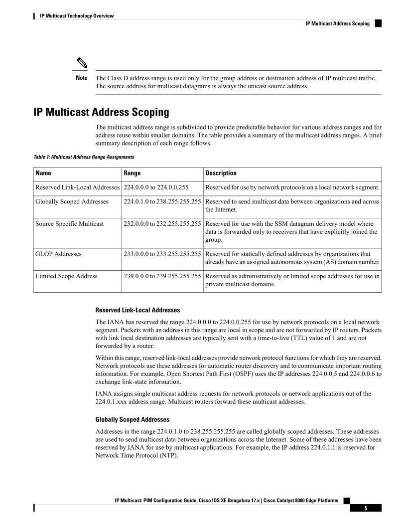
IP Multicast Address ScopingThe multicast address range is subdivided to provide predictable behavior for various address ranges and foraddress reuse within smaller domains. The table provides a summary of the multicast address ranges. A briefsummary description of each range follows.
Table 1: Multicast Address Range Assignments
DescriptionRangeName
Reserved for use by network protocols on a local network segment.224.0.0.0 to 224.0.0.255Reserved Link-Local Addresses
Reserved to send multicast data between organizations and acrossthe Internet.
224.0.1.0 to 238.255.255.255Globally Scoped Addresses
Reserved for use with the SSM datagram delivery model wheredata is forwarded only to receivers that have explicitly joined thegroup.
232.0.0.0 to 232.255.255.255Source Specific Multicast
Reserved for statically defined addresses by organizations thatalready have an assigned autonomous system (AS) domain number.
233.0.0.0 to 233.255.255.255GLOP Addresses
Reserved as administratively or limited scope addresses for use inprivate multicast domains.
239.0.0.0 to 239.255.255.255Limited Scope Address
Reserved Link-Local Addresses
The IANA has reserved the range 224.0.0.0 to 224.0.0.255 for use by network protocols on a local networksegment. Packets with an address in this range are local in scope and are not forwarded by IP routers. Packetswith link local destination addresses are typically sent with a time-to-live (TTL) value of 1 and are notforwarded by a router.
Within this range, reserved link-local addresses provide network protocol functions for which they are reserved.Network protocols use these addresses for automatic router discovery and to communicate important routinginformation. For example, Open Shortest Path First (OSPF) uses the IP addresses 224.0.0.5 and 224.0.0.6 toexchange link-state information.
IANA assigns single multicast address requests for network protocols or network applications out of the224.0.1.xxx address range. Multicast routers forward these multicast addresses.
Globally Scoped Addresses
Addresses in the range 224.0.1.0 to 238.255.255.255 are called globally scoped addresses. These addressesare used to send multicast data between organizations across the Internet. Some of these addresses have beenreserved by IANA for use by multicast applications. For example, the IP address 224.0.1.1 is reserved forNetwork Time Protocol (NTP).
IP Multicast: PIM Configuration Guide, Cisco IOS XE Bengaluru 17.x | Cisco Catalyst 8000 Edge Platforms5
IP Multicast Technology OverviewIP Multicast Address Scoping
Source Specific Multicast Addresses
Addresses in the range 232.0.0.0/8 are reserved for Source Specific Multicast (SSM) by IANA. In Cisco IOSsoftware, you can use the ip pim ssmcommand to configure SSM for arbitrary IP multicast addresses also.SSM is an extension of Protocol Independent Multicast (PIM) that allows for an efficient data deliverymechanism in one-to-many communications. SSM is described in the IP Multicast Delivery Modes, on page6 section.
GLOP Addresses
GLOP addressing (as proposed by RFC 2770, GLOPAddressing in 233/8) proposes that the 233.0.0.0/8 rangebe reserved for statically defined addresses by organizations that already have an AS number reserved. Thispractice is called GLOP addressing. The AS number of the domain is embedded into the second and thirdoctets of the 233.0.0.0/8 address range. For example, AS 62010 is written in hexadecimal format as F23A.Separating the two octets F2 and 3A results in 242 and 58 in decimal format. These values result in a subnetof 233.242.58.0/24 that would be globally reserved for AS 62010 to use.
Limited Scope Addresses
The range 239.0.0.0 to 239.255.255.255 is reserved as administratively or limited scoped addresses for usein private multicast domains. These addresses are constrained to a local group or organization. Companies,universities, and other organizations can use limited scope addresses to have local multicast applications thatwill not be forwarded outside their domain. Routers typically are configured with filters to prevent multicasttraffic in this address range from flowing outside an autonomous system (AS) or any user-defined domain.Within an AS or domain, the limited scope address range can be further subdivided so that local multicastboundaries can be defined.
Network administrators may use multicast addresses in this range, inside a domain, without conflicting withothers elsewhere in the Internet.
Note
Layer 2 Multicast AddressesHistorically, network interface cards (NICs) on a LAN segment could receive only packets destined for theirburned-inMAC address or the broadcast MAC address. In IP multicast, several hosts need to be able to receivea single data stream with a common destinationMAC address. Some means had to be devised so that multiplehosts could receive the same packet and still be able to differentiate between several multicast groups. Onemethod to accomplish this is to map IP multicast Class D addresses directly to a MAC address. Using thismethod, NICs can receive packets destined to many different MAC address.
Cisco Group Management Protocol ( CGMP) is used on routers connected to Catalyst switches to performtasks similar to those performed by IGMP. CGMP is necessary for those Catalyst switches that cannotdistinguish between IP multicast data packets and IGMP report messages, both of which are addressed to thesame group address at the MAC level.
IP Multicast Delivery ModesIP multicast delivery modes differ only for the receiver hosts, not for the source hosts. A source host sendsIP multicast packets with its own IP address as the IP source address of the packet and a group address as theIP destination address of the packet.
IP Multicast: PIM Configuration Guide, Cisco IOS XE Bengaluru 17.x | Cisco Catalyst 8000 Edge Platforms6
IP Multicast Technology OverviewLayer 2 Multicast Addresses
Any Source MulticastFor the Any Source Multicast (ASM) delivery mode, an IP multicast receiver host can use any version ofIGMP to join a multicast group. This group is notated as G in the routing table state notation. By joining thisgroup, the receiver host is indicating that it wants to receive IP multicast traffic sent by any source to groupG. The network will deliver IP multicast packets from any source host with the destination address G to allreceiver hosts in the network that have joined group G.
ASM requires group address allocation within the network. At any given time, an ASM group should onlybe used by a single application. When two applications use the same ASM group simultaneously, receiverhosts of both applications will receive traffic from both application sources. This may result in unexpectedexcess traffic in the network. This situation may cause congestion of network links and malfunction of theapplication receiver hosts.
Source Specific MulticastSource Specific Multicast (SSM) is a datagram delivery model that best supports one-to-many applications,also known as broadcast applications. SSM is a core network technology for the Cisco implementation of IPmulticast targeted for audio and video broadcast application environments.
For the SSM delivery mode, an IP multicast receiver host must use IGMP Version 3 (IGMPv3) to subscribeto channel (S,G). By subscribing to this channel, the receiver host is indicating that it wants to receive IPmulticast traffic sent by source host S to group G. The network will deliver IP multicast packets from sourcehost S to group G to all hosts in the network that have subscribed to the channel (S, G).
SSM does not require group address allocation within the network, only within each source host. Differentapplications running on the same source host must use different SSM groups. Different applications runningon different source hosts can arbitrarily reuse SSM group addresses without causing any excess traffic on thenetwork.
Protocol Independent MulticastThe Protocol Independent Multicast (PIM) protocol maintains the current IP multicast service mode ofreceiver-initiated membership. PIM is not dependent on a specific unicast routing protocol; it is IP routingprotocol independent and can leverage whichever unicast routing protocols are used to populate the unicastrouting table, including Enhanced Interior Gateway Routing Protocol (EIGRP), Open Shortest Path First(OSPF), Border Gateway Protocol (BGP), and static routes. PIM uses unicast routing information to performthe multicast forwarding function.
Although PIM is called a multicast routing protocol, it actually uses the unicast routing table to perform thereverse path forwarding (RPF) check function instead of building up a completely independent multicastrouting table. Unlike other routing protocols, PIM does not send and receive routing updates between routers.
PIM can operate in dense mode or sparse mode. The router can also handle both sparse groups and densegroups at the same time. The mode determines how the router populates its multicast routing table and howthe router forwards multicast packets it receives from its directly connected LANs.
For information about PIM forwarding (interface) modes, see the following sections:
PIM Dense ModePIM dense mode (PIM-DM) uses a push model to flood multicast traffic to every corner of the network. Thispush model is a method for delivering data to the receivers without the receivers requesting the data. Thismethod is efficient in certain deployments in which there are active receivers on every subnet in the network.
IP Multicast: PIM Configuration Guide, Cisco IOS XE Bengaluru 17.x | Cisco Catalyst 8000 Edge Platforms7
IP Multicast Technology OverviewAny Source Multicast
In dense mode, a router assumes that all other routers want to forward multicast packets for a group. If a routerreceives a multicast packet and has no directly connected members or PIM neighbors present, a prune messageis sent back to the source. Subsequent multicast packets are not flooded to this router on this pruned branch.PIM builds source-based multicast distribution trees.
PIM-DM initially floods multicast traffic throughout the network. Routers that have no downstream neighborsprune back the unwanted traffic. This process repeats every 3 minutes.
Routers accumulate state information by receiving data streams through the flood and prune mechanism.These data streams contain the source and group information so that downstream routers can build up theirmulticast forwarding table. PIM-DM supports only source trees--that is, (S,G) entries--and cannot be used tobuild a shared distribution tree.
Dense mode is not often used and its use is not recommended. For this reason it is not specified in theconfiguration tasks in related modules.
Note
PIM Sparse ModePIM sparse mode (PIM-SM) uses a pull model to deliver multicast traffic. Only network segments with activereceivers that have explicitly requested the data will receive the traffic.
Unlike dense mode interfaces, sparse mode interfaces are added to the multicast routing table only whenperiodic Join messages are received from downstream routers, or when a directly connected member is onthe interface. When forwarding from a LAN, sparse mode operation occurs if an RP is known for the group.If so, the packets are encapsulated and sent toward the RP. When no RP is known, the packet is flooded in adense mode fashion. If the multicast traffic from a specific source is sufficient, the first hop router of thereceiver may send Join messages toward the source to build a source-based distribution tree.
PIM-SM distributes information about active sources by forwarding data packets on the shared tree. BecausePIM-SM uses shared trees (at least, initially), it requires the use of a rendezvous point (RP). The RP must beadministratively configured in the network. See the Rendezvous Points, on page 11 section for moreinformation.
In sparse mode, a router assumes that other routers do not want to forward multicast packets for a group,unless there is an explicit request for the traffic. When hosts join a multicast group, the directly connectedrouters send PIM Join messages toward the RP. The RP keeps track of multicast groups. Hosts that sendmulticast packets are registered with the RP by the first hop router of that host. The RP then sends Joinmessages toward the source. At this point, packets are forwarded on a shared distribution tree. If the multicasttraffic from a specific source is sufficient, the first hop router of the host may send Join messages toward thesource to build a source-based distribution tree.
Sources register with the RP and then data is forwarded down the shared tree to the receivers. The edge routerslearn about a particular source when they receive data packets on the shared tree from that source through theRP. The edge router then sends PIM (S,G) Join messages toward that source. Each router along the reversepath compares the unicast routing metric of the RP address to the metric of the source address. If the metricfor the source address is better, it will forward a PIM (S,G) Join message toward the source. If the metric forthe RP is the same or better, then the PIM (S,G) Join message will be sent in the same direction as the RP. Inthis case, the shared tree and the source tree would be considered congruent.
If the shared tree is not an optimal path between the source and the receiver, the routers dynamically createa source tree and stop traffic from flowing down the shared tree. This behavior is the default behavior insoftware. Network administrators can force traffic to stay on the shared tree by using the ip pim spt-thresholdinfinity command.
IP Multicast: PIM Configuration Guide, Cisco IOS XE Bengaluru 17.x | Cisco Catalyst 8000 Edge Platforms8
IP Multicast Technology OverviewPIM Sparse Mode
PIM-SM scales well to a network of any size, including those with WAN links. The explicit join mechanismprevents unwanted traffic from flooding the WAN links.
Sparse-Dense ModeIf you configure either sparse mode or dense mode on an interface, then sparseness or denseness is appliedto the interface as a whole. However, some environments might require PIM to run in a single region in sparsemode for some groups and in dense mode for other groups.
An alternative to enabling only dense mode or only sparse mode is to enable sparse-dense mode. In this case,the interface is treated as dense mode if the group is in dense mode; the interface is treated in sparse mode ifthe group is in sparse mode. You must have an RP if the interface is in sparse-dense mode and you want totreat the group as a sparse group.
If you configure sparse-dense mode, the idea of sparseness or denseness is applied to the groups for whichthe router is a member.
Another benefit of sparse-dense mode is that Auto-RP information can be distributed in a dense mode; yet,multicast groups for user groups can be used in a sparse mode manner. Therefore there is no need to configurea default RP at the leaf routers.
When an interface is treated in dense mode, it is populated in the outgoing interface list of a multicast routingtable when either of the following conditions is true:
• Members or DVMRP neighbors are on the interface.
• There are PIM neighbors and the group has not been pruned.
When an interface is treated in sparse mode, it is populated in the outgoing interface list of a multicast routingtable when either of the following conditions is true:
• Members or DVMRP neighbors are on the interface.
• An explicit Join message has been received by a PIM neighbor on the interface.
Bidirectional PIMBidirectional PIM (bidir-PIM) is an enhancement of the PIM protocol that was designed for efficientmany-to-many communications within an individual PIM domain. Multicast groups in bidirectional modecan scale to an arbitrary number of sources with only a minimal amount of additional overhead.
The shared trees that are created in PIM sparse mode are unidirectional. This means that a source tree mustbe created to bring the data stream to the RP (the root of the shared tree) and then it can be forwarded downthe branches to the receivers. Source data cannot flow up the shared tree toward the RP--this would beconsidered a bidirectional shared tree.
In bidirectional mode, traffic is routed only along a bidirectional shared tree that is rooted at the RP for thegroup. In bidir-PIM, the IP address of the RP acts as the key to having all routers establish a loop-free spanningtree topology rooted in that IP address. This IP address need not be a router address, but can be any unassignedIP address on a network that is reachable throughout the PIM domain.
Bidir-PIM is derived from the mechanisms of PIM sparse mode (PIM-SM) and shares many of the sharedtree operations. Bidir-PIM also has unconditional forwarding of source traffic toward the RP upstream on theshared tree, but no registering process for sources as in PIM-SM. These modifications are necessary andsufficient to allow forwarding of traffic in all routers solely based on the (*, G) multicast routing entries. Thisfeature eliminates any source-specific state and allows scaling capability to an arbitrary number of sources.
IP Multicast: PIM Configuration Guide, Cisco IOS XE Bengaluru 17.x | Cisco Catalyst 8000 Edge Platforms9
IP Multicast Technology OverviewSparse-Dense Mode
Multicast Group ModesIn PIM, packet traffic for a multicast group is routed according to the rules of the mode configured for thatmulticast group. The Cisco implementation of PIM supports four modes for a multicast group:
• PIM Bidirectional mode
• PIM Sparse mode
• PIM Dense mode
• PIM Source Specific Multicast (SSM) mode
A router can simultaneously support all four modes or any combination of them for different multicast groups.
Bidirectional ModeIn bidirectional mode, traffic is routed only along a bidirectional shared tree that is rooted at the rendezvouspoint (RP) for the group. In bidir-PIM, the IP address of the RP acts as the key to having all routers establisha loop-free spanning tree topology rooted in that IP address. This IP address need not be a router, but can beany unassigned IP address on a network that is reachable throughout the PIM domain. This technique is thepreferred configuration method for establishing a redundant RP configuration for bidir-PIM.
Membership to a bidirectional group is signalled via explicit Join messages. Traffic from sources isunconditionally sent up the shared tree toward the RP and passed down the tree toward the receivers on eachbranch of the tree.
Sparse ModeSparse mode operation centers around a single unidirectional shared tree whose root node is called therendezvous point (RP). Sources must register with the RP to get their multicast traffic to flow down the sharedtree by way of the RP. This registration process actually triggers a shortest path tree (SPT) Join by the RPtoward the source when there are active receivers for the group in the network.
A sparse mode group uses the explicit join model of interaction. Receiver hosts join a group at a rendezvouspoint (RP). Different groups can have different RPs.
Multicast traffic packets flow down the shared tree to only those receivers that have explicitly asked to receivethe traffic.
Dense ModeDense mode operates using the broadcast (flood) and prune model.
In populating the multicast routing table, dense mode interfaces are always added to the table. Multicast trafficis forwarded out all interfaces in the outgoing interface list to all receivers. Interfaces are removed from theoutgoing interface list in a process called pruning. In dense mode, interfaces are pruned for various reasonsincluding that there are no directly connected receivers.
A pruned interface can be reestablished, that is, grafted back so that restarting the flow of multicast trafficcan be accomplished with minimal delay.
IP Multicast: PIM Configuration Guide, Cisco IOS XE Bengaluru 17.x | Cisco Catalyst 8000 Edge Platforms10
IP Multicast Technology OverviewMulticast Group Modes
Rendezvous PointsA rendezvous point (RP) is a role that a device performs when operating in Protocol Independent Multicast(PIM) Sparse Mode (SM). An RP is required only in networks running PIM SM. In the PIM-SM model, onlynetwork segments with active receivers that have explicitly requested multicast data will be forwarded thetraffic.
This method of delivering multicast data is in contrast to PIM Dense Mode (PIM DM). In PIM DM, multicasttraffic is initially flooded to all segments of the network. Routers that have no downstream neighbors ordirectly connected receivers prune back the unwanted traffic.
An RP acts as the meeting place for sources and receivers of multicast data. In a PIM-SM network, sourcesmust send their traffic to the RP. This traffic is then forwarded to receivers down a shared distribution tree.By default, when the first hop device of the receiver learns about the source, it will send a Join message directlyto the source, creating a source-based distribution tree from the source to the receiver. This source tree doesnot include the RP unless the RP is located within the shortest path between the source and receiver.
In most cases, the placement of the RP in the network is not a complex decision. By default, the RP is neededonly to start new sessions with sources and receivers. Consequently, the RP experiences little overhead fromtraffic flow or processing. In PIM version 2, the RP performs less processing than in PIM version 1 becausesources must only periodically register with the RP to create state.
Auto-RPIn the first version of PIM-SM, all leaf routers (routers directly connected to sources or receivers) were requiredto be manually configured with the IP address of the RP. This type of configuration is also known as staticRP configuration. Configuring static RPs is relatively easy in a small network, but it can be laborious in alarge, complex network.
Following the introduction of PIM-SM version 1, Cisco implemented a version of PIM-SMwith the Auto-RPfeature. Auto-RP automates the distribution of group-to-RP mappings in a PIM network. Auto-RP has thefollowing benefits:
• Configuring the use of multiple RPs within a network to serve different groups is easy.
• Auto-RP allows load splitting among different RPs and arrangement of RPs according to the location ofgroup participants.
• Auto-RP avoids inconsistent, manual RP configurations that can cause connectivity problems.
Multiple RPs can be used to serve different group ranges or serve as backups to each other. For Auto-RP towork, a router must be designated as an RP-mapping agent, which receives the RP-announcement messagesfrom the RPs and arbitrates conflicts. The RP-mapping agent then sends the consistent group-to-RPmappingsto all other routers. Thus, all routers automatically discover which RP to use for the groups they support.
If you configure PIM in sparse mode or sparse-dense mode and do not configure Auto-RP, you must staticallyconfigure an RP.
Note
If router interfaces are configured in sparse mode, Auto-RP can still be used if all routers are configured witha static RP address for the Auto-RP groups.
Note
IP Multicast: PIM Configuration Guide, Cisco IOS XE Bengaluru 17.x | Cisco Catalyst 8000 Edge Platforms11
IP Multicast Technology OverviewRendezvous Points
To make Auto-RP work, a router must be designated as an RP mapping agent, which receives the RPannouncement messages from the RPs and arbitrates conflicts. The RPmapping agent then sends the consistentgroup-to-RP mappings to all other routers by dense mode flooding. Thus, all routers automatically discoverwhich RP to use for the groups they support. The Internet Assigned Numbers Authority (IANA) has assignedtwo group addresses, 224.0.1.39 and 224.0.1.40, for Auto-RP. One advantage of Auto-RP is that any changeto the RP designation must be configured only on the routers that are RPs and not on the leaf routers. Anotheradvantage of Auto-RP is that it offers the ability to scope the RP address within a domain. Scoping can beachieved by defining the time-to-live (TTL) value allowed for the Auto-RP advertisements.
Eachmethod for configuring an RP has its own strengths, weaknesses, and level of complexity. In conventionalIP multicast network scenarios, we recommend using Auto-RP to configure RPs because it is easy to configure,well-tested, and stable. The alternative ways to configure an RP are static RP, Auto-RP, and bootstrap router.
Sparse-Dense Mode for Auto-RPA prerequisite of Auto-RP is that all interfaces must be configured in sparse-dense mode using the ip pimsparse-dense-mode interface configuration command. An interface configured in sparse-densemode is treatedin either sparse mode or dense mode of operation, depending on which mode the multicast group operates. Ifa multicast group has a known RP, the interface is treated in sparse mode. If a group has no known RP, bydefault the interface is treated in dense mode and data will be flooded over this interface. (You can preventdense-mode fallback; see the module “Configuring Basic IP Multicast.”)
To successfully implement Auto-RP and prevent any groups other than 224.0.1.39 and 224.0.1.40 fromoperating in dense mode, we recommend configuring a “sink RP” (also known as “RP of last resort”). A sinkRP is a statically configured RP that may or may not actually exist in the network. Configuring a sink RPdoes not interfere with Auto-RP operation because, by default, Auto-RP messages supersede static RPconfigurations. We recommend configuring a sink RP for all possible multicast groups in your network,because it is possible for an unknown or unexpected source to become active. If no RP is configured to limitsource registration, the group may revert to dense mode operation and be flooded with data.
Bootstrap RouterAnother RP selection model called bootstrap router (BSR) was introduced after Auto-RP in PIM-SM version2. BSR performs similarly to Auto-RP in that it uses candidate routers for the RP function and for relayingthe RP information for a group. RP information is distributed through BSRmessages, which are carried withinPIM messages. PIM messages are link-local multicast messages that travel from PIM router to PIM router.Because of this single hop method of disseminating RP information, TTL scoping cannot be used with BSR.A BSR performs similarly as an RP, except that it does not run the risk of reverting to dense mode operation,and it does not offer the ability to scope within a domain.
Multicast Source Discovery ProtocolIn the PIM sparse mode model, multicast sources and receivers must register with their local rendezvous point(RP). Actually, the router closest to a source or a receiver registers with the RP, but the key point to note isthat the RP “knows” about all the sources and receivers for any particular group. RPs in other domains haveno way of knowing about sources that are located in other domains. Multicast Source Discovery Protocol(MSDP) is an elegant way to solve this problem.
MSDP is a mechanism that allows RPs to share information about active sources. RPs know about the receiversin their local domain. When RPs in remote domains hear about the active sources, they can pass on thatinformation to their local receivers. Multicast data can then be forwarded between the domains. A usefulfeature of MSDP is that it allows each domain to maintain an independent RP that does not rely on other
IP Multicast: PIM Configuration Guide, Cisco IOS XE Bengaluru 17.x | Cisco Catalyst 8000 Edge Platforms12
IP Multicast Technology OverviewSparse-Dense Mode for Auto-RP
domains, but it does enable RPs to forward traffic between domains. PIM-SM is used to forward the trafficbetween the multicast domains.
The RP in each domain establishes an MSDP peering session using a TCP connection with the RPs in otherdomains or with border routers leading to the other domains.When the RP learns about a newmulticast sourcewithin its own domain (through the normal PIM register mechanism), the RP encapsulates the first data packetin a Source-Active (SA) message and sends the SA to all MSDP peers. Each receiving peer uses a modifiedReverse Path Forwarding (RPF) check to forward the SA, until the SA reaches every MSDP router in theinterconnected networks--theoretically the entire multicast internet. If the receiving MSDP peer is an RP, andthe RP has a (*, G) entry for the group in the SA (there is an interested receiver), the RP creates (S,G) statefor the source and joins to the shortest path tree for the source. The encapsulated data is decapsulated andforwarded down the shared tree of that RP.When the last hop router (the router closest to the receiver) receivesthe multicast packet, it may join the shortest path tree to the source. The MSDP speaker periodically sendsSAs that include all sources within the domain of the RP.
MSDP was developed for peering between Internet service providers (ISPs). ISPs did not want to rely on anRP maintained by a competing ISP to provide service to their customers. MSDP allows each ISP to have itsown local RP and still forward and receive multicast traffic to the Internet.
Anycast RPAnycast RP is a useful application of MSDP. Originally developed for interdomain multicast applications,MSDP used for Anycast RP is an intradomain feature that provides redundancy and load-sharing capabilities.Enterprise customers typically use Anycast RP for configuring a Protocol Independent Multicast sparse mode(PIM-SM) network to meet fault tolerance requirements within a single multicast domain.
In Anycast RP, two or more RPs are configured with the same IP address on loopback interfaces. The AnycastRP loopback address should be configured with a 32-bit mask, making it a host address. All the downstreamrouters should be configured to “know” that the Anycast RP loopback address is the IP address of their localRP. IP routing automatically will select the topologically closest RP for each source and receiver. Assumingthat the sources are evenly spaced around the network, an equal number of sources will register with eachRP. That is, the process of registering the sources will be shared equally by all the RPs in the network.
Because a source may register with one RP and receivers may join to a different RP, a method is needed forthe RPs to exchange information about active sources. This information exchange is done with MSDP.
In Anycast RP, all the RPs are configured to be MSDP peers of each other. When a source registers with oneRP, an SA message will be sent to the other RPs informing them that there is an active source for a particularmulticast group. The result is that each RP will know about the active sources in the area of the other RPs. Ifany of the RPs were to fail, IP routing would converge and one of the RPs would become the active RP inmore than one area. New sources would register with the backup RP. Receivers would join toward the newRP and connectivity would be maintained.
The RP is normally needed only to start new sessions with sources and receivers. The RP facilitates the sharedtree so that sources and receivers can directly establish a multicast data flow. If a multicast data flow is alreadydirectly established between a source and the receiver, then an RP failure will not affect that session. AnycastRP ensures that new sessions with sources and receivers can begin at any time.
Note
IP Multicast: PIM Configuration Guide, Cisco IOS XE Bengaluru 17.x | Cisco Catalyst 8000 Edge Platforms13
IP Multicast Technology OverviewAnycast RP
Multicast ForwardingForwarding of multicast traffic is accomplished bymulticast-capable routers. These routers create distributiontrees that control the path that IP multicast traffic takes through the network in order to deliver traffic to allreceivers.
Multicast traffic flows from the source to the multicast group over a distribution tree that connects all of thesources to all of the receivers in the group. This tree may be shared by all sources (a shared tree) or a separatedistribution tree can be built for each source (a source tree). The shared tree may be one-way or bidirectional.
Before describing the structure of source and shared trees, it is helpful to explain the notations that are usedin multicast routing tables. These notations include the following:
• (S,G) = (unicast source for the multicast group G, multicast group G)
• (*,G) = (any source for the multicast group G, multicast group G)
The notation of (S,G), pronounced “S comma G,” enumerates a shortest path tree where S is the IP addressof the source and G is the multicast group address.
Shared trees are (*,G) and the source trees are (S,G) and always routed at the sources.
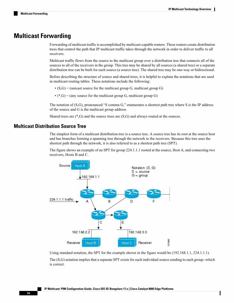
Multicast Distribution Source TreeThe simplest form of a multicast distribution tree is a source tree. A source tree has its root at the source hostand has branches forming a spanning tree through the network to the receivers. Because this tree uses theshortest path through the network, it is also referred to as a shortest path tree (SPT).
The figure shows an example of an SPT for group 224.1.1.1 rooted at the source, Host A, and connecting tworeceivers, Hosts B and C.
Using standard notation, the SPT for the example shown in the figure would be (192.168.1.1, 224.1.1.1).
The (S,G) notation implies that a separate SPT exists for each individual source sending to each group--whichis correct.
IP Multicast: PIM Configuration Guide, Cisco IOS XE Bengaluru 17.x | Cisco Catalyst 8000 Edge Platforms14
IP Multicast Technology OverviewMulticast Forwarding
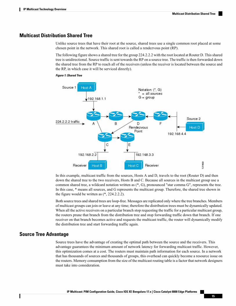
Multicast Distribution Shared TreeUnlike source trees that have their root at the source, shared trees use a single common root placed at somechosen point in the network. This shared root is called a rendezvous point (RP).
The following figure shows a shared tree for the group 224.2.2.2 with the root located at Router D. This sharedtree is unidirectional. Source traffic is sent towards the RP on a source tree. The traffic is then forwarded downthe shared tree from the RP to reach all of the receivers (unless the receiver is located between the source andthe RP, in which case it will be serviced directly).
Figure 1: Shared Tree
In this example, multicast traffic from the sources, Hosts A and D, travels to the root (Router D) and thendown the shared tree to the two receivers, Hosts B and C. Because all sources in the multicast group use acommon shared tree, a wildcard notation written as (*, G), pronounced "star comma G", represents the tree.In this case, * means all sources, and G represents the multicast group. Therefore, the shared tree shown inthe figure would be written as (*, 224.2.2.2).
Both source trees and shared trees are loop-free.Messages are replicated only where the tree branches.Membersof multicast groups can join or leave at any time; therefore the distribution trees must be dynamically updated.When all the active receivers on a particular branch stop requesting the traffic for a particular multicast group,the routers prune that branch from the distribution tree and stop forwarding traffic down that branch. If onereceiver on that branch becomes active and requests the multicast traffic, the router will dynamically modifythe distribution tree and start forwarding traffic again.
Source Tree AdvantageSource trees have the advantage of creating the optimal path between the source and the receivers. Thisadvantage guarantees the minimum amount of network latency for forwarding multicast traffic. However,this optimization comes at a cost. The routers must maintain path information for each source. In a networkthat has thousands of sources and thousands of groups, this overhead can quickly become a resource issue onthe routers. Memory consumption from the size of the multicast routing table is a factor that network designersmust take into consideration.
IP Multicast: PIM Configuration Guide, Cisco IOS XE Bengaluru 17.x | Cisco Catalyst 8000 Edge Platforms15
IP Multicast Technology OverviewMulticast Distribution Shared Tree
Shared Tree AdvantageShared trees have the advantage of requiring the minimum amount of state in each router. This advantagelowers the overall memory requirements for a network that only allows shared trees. The disadvantage ofshared trees is that under certain circumstances the paths between the source and receivers might not be theoptimal paths, which might introduce some latency in packet delivery. For example, in the figure above theshortest path between Host A (source 1) and Host B (a receiver) would be Router A and Router C. Becausewe are using Router D as the root for a shared tree, the traffic must traverse Routers A, B, D and then C.Network designers must carefully consider the placement of the rendezvous point (RP) when implementinga shared tree-only environment.
In unicast routing, traffic is routed through the network along a single path from the source to the destinationhost. A unicast router does not consider the source address; it considers only the destination address and howto forward the traffic toward that destination. The router scans through its routing table for the destinationaddress and then forwards a single copy of the unicast packet out the correct interface in the direction of thedestination.
In multicast forwarding, the source is sending traffic to an arbitrary group of hosts that are represented by amulticast group address. The multicast router must determine which direction is the upstream direction (towardthe source) and which one is the downstream direction (or directions) toward the receivers. If there are multipledownstream paths, the router replicates the packet and forwards it down the appropriate downstream paths(best unicast route metric)--which is not necessarily all paths. Forwarding multicast traffic away from thesource, rather than to the receiver, is called Reverse Path Forwarding (RPF). RPF is described in the followingsection.
Reverse Path ForwardingIn unicast routing, traffic is routed through the network along a single path from the source to the destinationhost. A unicast router does not consider the source address; it considers only the destination address and howto forward the traffic toward that destination. The router scans through its routing table for the destinationnetwork and then forwards a single copy of the unicast packet out the correct interface in the direction of thedestination.
In multicast forwarding, the source is sending traffic to an arbitrary group of hosts that are represented by amulticast group address. The multicast router must determine which direction is the upstream direction (towardthe source) and which one is the downstream direction (or directions) toward the receivers. If there are multipledownstream paths, the router replicates the packet and forwards it down the appropriate downstream paths(best unicast route metric)--which is not necessarily all paths. Forwarding multicast traffic away from thesource, rather than to the receiver, is called Reverse Path Forwarding (RPF). RPF is an algorithm used forforwarding multicast datagrams.
Protocol Independent Multicast (PIM) uses the unicast routing information to create a distribution tree alongthe reverse path from the receivers towards the source. The multicast routers then forward packets along thedistribution tree from the source to the receivers. RPF is a key concept in multicast forwarding. It enablesrouters to correctly forward multicast traffic down the distribution tree. RPF makes use of the existing unicastrouting table to determine the upstream and downstream neighbors. A router will forward a multicast packetonly if it is received on the upstream interface. This RPF check helps to guarantee that the distribution treewill be loop-free.
RPF CheckWhen a multicast packet arrives at a router, the router performs an RPF check on the packet. If the RPF checksucceeds, the packet is forwarded. Otherwise, it is dropped.
IP Multicast: PIM Configuration Guide, Cisco IOS XE Bengaluru 17.x | Cisco Catalyst 8000 Edge Platforms16
IP Multicast Technology OverviewShared Tree Advantage

For traffic flowing down a source tree, the RPF check procedure works as follows:
1. The router looks up the source address in the unicast routing table to determine if the packet has arrivedon the interface that is on the reverse path back to the source.
2. If the packet has arrived on the interface leading back to the source, the RPF check succeeds and thepacket is forwarded out the interfaces present in the outgoing interface list of a multicast routing tableentry.
3. If the RPF check in Step 2 fails, the packet is dropped.
The figure shows an example of an unsuccessful RPF check.
Figure 2: RPF Check Fails
As the figure illustrates, a multicast packet from source 151.10.3.21 is received on serial interface 0 (S0). Acheck of the unicast route table shows that S1 is the interface this router would use to forward unicast data to151.10.3.21. Because the packet has arrived on interface S0, the packet is discarded.
The figure shows an example of a successful RPF check.
Figure 3: RPF Check Succeeds
In this example, the multicast packet has arrived on interface S1. The router refers to the unicast routing tableand finds that S1 is the correct interface. The RPF check passes, and the packet is forwarded.
PIM Dense Mode FallbackIf you use IP multicast in mission-critical networks, you should avoid the use of PIM-DM (dense mode).
Dense mode fallback describes the event of the PIM mode changing (falling back) from sparse mode (whichrequires an RP) to dense mode (which does not use an RP). Dense mode fallback occurs when RP informationis lost.
IP Multicast: PIM Configuration Guide, Cisco IOS XE Bengaluru 17.x | Cisco Catalyst 8000 Edge Platforms17
IP Multicast Technology OverviewPIM Dense Mode Fallback
If all interfaces are configured with the ip pim sparse-mode command, there is no dense mode fallbackbecause dense mode groups cannot be created over interfaces configured for sparse mode.
To configure multicast over DMVPN (dynamic multipoint virtual private network), ensure that you configurePIM sparse mode using ip pim sparse-modecommand. Configuring PIM dense mode over a DMVPN tunnelinterface is not supported on IOS-XE.
Note
Cause and Effect of Dense Mode Fallback
PIM determines whether a multicast group operates in PIM-DMor PIM-SMmode based solely on the existenceof RP information in the group-to-RP mapping cache. If Auto-RP is configured or a bootstrap router (BSR)is used to distribute RP information, there is a risk that RP information can be lost if all RPs, Auto-RP, or theBSR for a group fails due to network congestion. This failure can lead to the network either partially or fullyfalling back into PIM-DM.
If a network falls back into PIM-DM and AutoRP or BSR is being used, dense mode flooding will occur.Routers that lose RP information will fallback into dense mode and any new states that must be created forthe failed group will be created in dense mode.
Effects of Preventing Dense Mode Fallback
Prior to the introduction of PIM-DM fallback prevention, all multicast groups without a group-to-RPmappingwould be treated as dense mode.
With the introduction of PIM-DM fallback prevention, the PIM-DM fallback behavior has been changed toprevent dense mode flooding. By default, if all of the interfaces are configured to operate in PIM sparse mode(using the ip pim sparse-mode command), there is no need to configure the no ip pim dm-fallback command(that is, the PIM-DM fallback behavior is enabled by default). If any interfaces are not configured using theip pim sparse-modecommand (for example, using the ip pim sparse-dense-mode command), then thePIM-DM fallback behavior can be explicit disabled using the no ip pim dm-fallbackcommand.
When the no ip pim dm-fallback command is configured or when ip pim sparse-mode is configured on allinterfaces, any existing groups running in sparse mode will continue to operate in sparse mode but will usean RP address set to 0.0.0.0. Multicast entries with an RP address set to 0.0.0.0 will exhibit the followingbehavior:
• Existing (S, G) states will be maintained.
• No PIM Join or Prune messages for (*, G) or (S, G, RPbit) are sent.
• Received (*, G) or (S, G, RPbit) Joins or Prune messages are ignored.
• No registers are sent and traffic at the first hop is dropped.
• Received registers are answered with register stop.
• Asserts are unchanged.
• The (*, G) outgoing interface list (olist) is maintained only for the Internet Group Management Protocol(IGMP) state.
• Multicast Source Discovery Protocol (MSDP) source active (SA) messages for RP 0.0.0.0 groups arestill accepted and forwarded.
IP Multicast: PIM Configuration Guide, Cisco IOS XE Bengaluru 17.x | Cisco Catalyst 8000 Edge Platforms18
IP Multicast Technology OverviewPIM Dense Mode Fallback
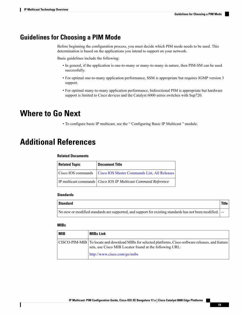
Guidelines for Choosing a PIM ModeBefore beginning the configuration process, you must decide which PIM mode needs to be used. Thisdetermination is based on the applications you intend to support on your network.
Basic guidelines include the following:
• In general, if the application is one-to-many or many-to-many in nature, then PIM-SM can be usedsuccessfully.
• For optimal one-to-many application performance, SSM is appropriate but requires IGMP version 3support.
• For optimal many-to-many application performance, bidirectional PIM is appropriate but hardwaresupport is limited to Cisco devices and the Catalyst 6000 series switches with Sup720.
Where to Go Next• To configure basic IP multicast, see the “ Configuring Basic IP Multicast ” module.
Additional ReferencesRelated Documents
Document TitleRelated Topic
Cisco IOS Master Commands List, All ReleasesCisco IOS commands
Cisco IOS IP Multicast Command ReferenceIP multicast commands
Standards
TitleStandard
--No new or modified standards are supported, and support for existing standards has not been modified.
MIBs
MIBs LinkMIB
To locate and downloadMIBs for selected platforms, Cisco software releases, and featuresets, use Cisco MIB Locator found at the following URL:
http://www.cisco.com/go/mibs
CISCO-PIM-MIB
IP Multicast: PIM Configuration Guide, Cisco IOS XE Bengaluru 17.x | Cisco Catalyst 8000 Edge Platforms19
IP Multicast Technology OverviewGuidelines for Choosing a PIM Mode
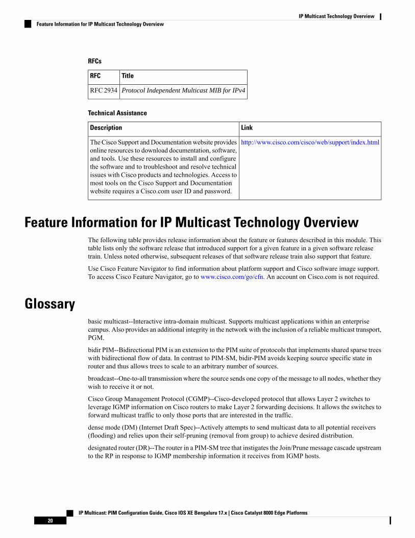
RFCs
TitleRFC
Protocol Independent Multicast MIB for IPv4RFC2934
Technical Assistance
LinkDescription
http://www.cisco.com/cisco/web/support/index.htmlTheCisco Support andDocumentationwebsite providesonline resources to download documentation, software,and tools. Use these resources to install and configurethe software and to troubleshoot and resolve technicalissues with Cisco products and technologies. Access tomost tools on the Cisco Support and Documentationwebsite requires a Cisco.com user ID and password.
Feature Information for IP Multicast Technology OverviewThe following table provides release information about the feature or features described in this module. Thistable lists only the software release that introduced support for a given feature in a given software releasetrain. Unless noted otherwise, subsequent releases of that software release train also support that feature.
Use Cisco Feature Navigator to find information about platform support and Cisco software image support.To access Cisco Feature Navigator, go to www.cisco.com/go/cfn. An account on Cisco.com is not required.
Glossarybasic multicast--Interactive intra-domain multicast. Supports multicast applications within an enterprisecampus. Also provides an additional integrity in the network with the inclusion of a reliable multicast transport,PGM.
bidir PIM--Bidirectional PIM is an extension to the PIM suite of protocols that implements shared sparse treeswith bidirectional flow of data. In contrast to PIM-SM, bidir-PIM avoids keeping source specific state inrouter and thus allows trees to scale to an arbitrary number of sources.
broadcast--One-to-all transmission where the source sends one copy of the message to all nodes, whether theywish to receive it or not.
Cisco Group Management Protocol (CGMP)--Cisco-developed protocol that allows Layer 2 switches toleverage IGMP information on Cisco routers to make Layer 2 forwarding decisions. It allows the switches toforward multicast traffic to only those ports that are interested in the traffic.
dense mode (DM) (Internet Draft Spec)--Actively attempts to send multicast data to all potential receivers(flooding) and relies upon their self-pruning (removal from group) to achieve desired distribution.
designated router (DR)--The router in a PIM-SM tree that instigates the Join/Prune message cascade upstreamto the RP in response to IGMP membership information it receives from IGMP hosts.
IP Multicast: PIM Configuration Guide, Cisco IOS XE Bengaluru 17.x | Cisco Catalyst 8000 Edge Platforms20
IP Multicast Technology OverviewFeature Information for IP Multicast Technology Overview
distribution tree--Multicast traffic flows from the source to the multicast group over a distribution tree thatconnects all of the sources to all of the receivers in the group. This tree may be shared by all sources (ashared-tree), or a separate distribution tree can be built for each source (a source-tree). The shared-tree maybe one-way or bidirectional.
IGMP messages--IGMP messages are encapsulated in standard IP datagrams with an IP protocol number of2 and the IP Router Alert option (RFC 2113).
IGMP snooping--IGMP snooping requires the LAN switch to examine, or “snoop,” some Layer 3 informationin the IGMP packet sent from the host to the router. When the switch hears an IGMP report from a host fora particular multicast group, the switch adds the host’s port number to the associated multicast table entry.When it hears an IGMP Leave Group message from a host, it removes the host’s port from the table entry.
IGMP unidirectional link routing--Cisco’s other UDLR solution is to use IP multicast routing with IGMP,which has been enhanced to accommodate UDLR. This solution scales very well for many satellite links.
Internet Group Management Protocol v2 (IGMP)--Used by IP routers and their immediately connected hoststo communicate multicast group membership states.
Internet Group Management Protocol v3 (IGMP)--IGMP is the protocol used by IPv4 systems to report theirIP multicast groupmemberships to neighboringmulticast routers. Version 3 of IGMP adds support for “sourcefiltering,” that is, the ability for a system to report interest in receiving packets only from specific sourceaddresses, or from all but specific source addresses, sent to a particular multicast address.
multicast--A routing technique that allows IP traffic to be sent from one source or multiple sources anddelivered to multiple destinations. Instead of sending individual packets to each destination, a single packetis sent to a group of destinations known as a multicast group, which is identified by a single IP destinationgroup address. Multicast addressing supports the transmission of a single IP datagram to multiple hosts.
multicast routing monitor (MRM)--A management diagnostic tool that provides network fault detection andisolation in a large multicast routing infrastructure. It is designed to notify a network administrator of multicastrouting problems in near real time.
Multicast Source Discovery Protocol (MSDP)--Amechanism to connect multiple PIM sparse mode (PIM-SM)domains. MSDP allows multicast sources for a group to be known to all rendezvous point(s) (RPs) in differentdomains. Each PIM-SM domain uses its own RPs and need not depend on RPs in other domains. An RP runsMSDP over TCP to discover multicast sources in other domains. MSDP is also used to announce sourcessending to a group. These announcements must originate at the domain’s RP. MSDP depends heavily onMBGP for interdomain operation.
Protocol Independent Multicast (PIM)--A multicast routing architecture defined by the IETF that enables IPmulticast routing on existing IP networks. Its key point is its independence from any underlying unicastprotocol such as OSPF or BGP.
prune--Multicast routing terminology indicating that the multicast-enabled router has sent the appropriatemulticast messages to remove itself from themulticast tree for a particular multicast group. It will stop receivingthe multicast data addressed to that group and, therefore, cannot deliver the data to any connected hosts untilit rejoins the group.
query--IGMP messages originating from the router(s) to elicit multicast group membership information fromits connected hosts.
rendezvous point (RP)--The multicast router that is the root of the PIM-SM shared multicast distribution tree.
report--IGMP messages originating from the hosts that are joining, maintaining, or leaving their membershipin a multicast group.
IP Multicast: PIM Configuration Guide, Cisco IOS XE Bengaluru 17.x | Cisco Catalyst 8000 Edge Platforms21
IP Multicast Technology OverviewGlossary
source tree--A multicast distribution path that directly connects the source’s and receivers’ designated router(or the rendezvous point) to obtain the shortest path through the network. Results in most efficient routing ofdata between source and receivers, but may result in unnecessary data duplication throughout the network ifbuilt by anything other than the RP.
sparse mode (SM) (RFC 2362)--Relies upon an explicitly joining method before attempting to send multicastdata to receivers of a multicast group.
UDLR tunnel--Uses a back channel (another link) so the routing protocols believe the one-way link isbidirectional. The back channel itself is a special, unidirectional, generic route encapsulation (GRE) tunnelthrough which control traffic flows in the opposite direction of the user data flow. This feature allows IP andits associated unicast and multicast routing protocols to believe the unidirectional link is logically bidirectional.This solution accommodates all IP unicast and multicast routing protocols without changing them. However,it does not scale and no more than 20 tunnels should feed into the upstream router. The purpose of theunidirectional GRE tunnel is to move control packets from a downstream node to an upstream node.
Unicast--Point-to-point transmission requiring the source to send an individual copy of a message to eachrequester.
unidirectional Link Routing Protocol (UDLR)--A routing protocol that provides a way to forward multicastpackets over a physical unidirectional interface (such as a satellite link of high bandwidth) to stub networksthat have a back channel.
URL rendezvous directory (URD)--URD is a multicast-lite solution that directly provides the network withinformation about the specific source of a content stream. It enables the network to quickly establish the mostdirect distribution path from the source to the receiver, thus significantly reducing the time and effort requiredin receiving the streaming media. URD allows an application to identify the source of the content streamthrough a web page link or web directly. When that information is sent back to the application it is thenconveyed back to the network using URD.
In this feature, a URD-capable web page provides information about the source, the group, and the application(via media-type) on a web page. An interested host will click on the web page pulling across the informationin an HTTP transaction. The last-hop router to receiver would intercept this transaction and send it to a specialport allocated by IANA. The last-hop router is also URD capable and uses the information to initiate the PIMsource, group (S,G) join on behalf of the host.
IP Multicast: PIM Configuration Guide, Cisco IOS XE Bengaluru 17.x | Cisco Catalyst 8000 Edge Platforms22
IP Multicast Technology OverviewGlossary
C H A P T E R 3Configuring Basic IP Multicast
IP multicast is a bandwidth-conserving technology that reduces traffic by delivering a single stream ofinformation simultaneously to potentially thousands of corporate businesses and homes. Applications thattake advantage of multicast include video conferencing, corporate communications, distance learning, anddistribution of software, stock quotes, and news. This module describes the tasks used to configure basic IPmulticast.
• Prerequisites for Configuring Basic IP Multicast, on page 23• Information About Configuring Basic IP Multicast, on page 23• How to Configure Basic IP Multicast, on page 32• Configuration Examples for Basic IP Multicast, on page 49• Additional References, on page 54• Feature Information for Configuring Basic IP Multicast in IPv4 Networks, on page 55
Prerequisites for Configuring Basic IP Multicast• To determine which of the tasks contained in this module you will have to perform, you must decidewhich Protocol Independent Multicast (PIM) mode will be used. This determination is based on theapplications you intend to support on your network.
• All access lists to be used with the tasks in this module should be configured prior to beginning theconfiguration task. For information about how to configure an access list, see the “Creating an IP AccessList and Applying It to an Interface” module of the Security Configuration Guide: Access Control Listsguide.
Information About Configuring Basic IP Multicast
Auto-RP Overview
The Role of Auto-RP in a PIM NetworkAuto-RP automates the distribution of group-to-rendezvous point (RP) mappings in a PIM network. To makeAuto-RP work, a device must be designated as an RP mapping agent, which receives the RP announcement
IP Multicast: PIM Configuration Guide, Cisco IOS XE Bengaluru 17.x | Cisco Catalyst 8000 Edge Platforms23
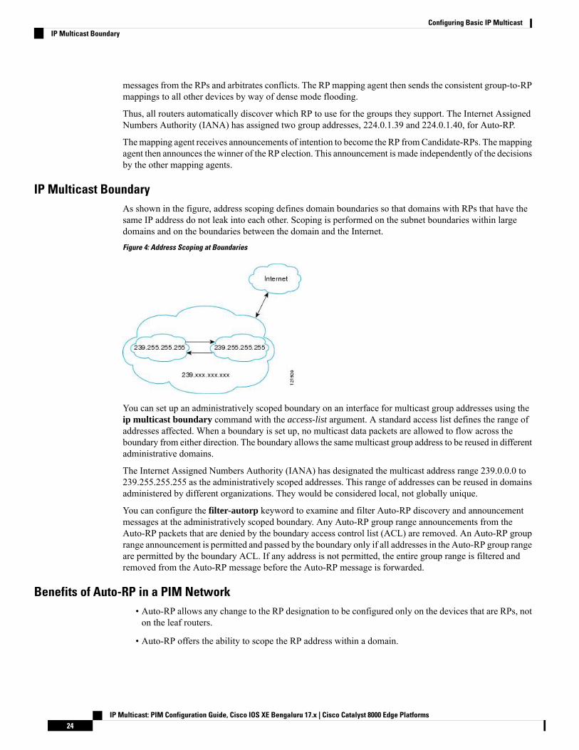
messages from the RPs and arbitrates conflicts. The RP mapping agent then sends the consistent group-to-RPmappings to all other devices by way of dense mode flooding.
Thus, all routers automatically discover which RP to use for the groups they support. The Internet AssignedNumbers Authority (IANA) has assigned two group addresses, 224.0.1.39 and 224.0.1.40, for Auto-RP.
Themapping agent receives announcements of intention to become the RP fromCandidate-RPs. Themappingagent then announces the winner of the RP election. This announcement is made independently of the decisionsby the other mapping agents.
IP Multicast BoundaryAs shown in the figure, address scoping defines domain boundaries so that domains with RPs that have thesame IP address do not leak into each other. Scoping is performed on the subnet boundaries within largedomains and on the boundaries between the domain and the Internet.
Figure 4: Address Scoping at Boundaries
You can set up an administratively scoped boundary on an interface for multicast group addresses using theip multicast boundary command with the access-list argument. A standard access list defines the range ofaddresses affected. When a boundary is set up, no multicast data packets are allowed to flow across theboundary from either direction. The boundary allows the samemulticast group address to be reused in differentadministrative domains.
The Internet Assigned Numbers Authority (IANA) has designated the multicast address range 239.0.0.0 to239.255.255.255 as the administratively scoped addresses. This range of addresses can be reused in domainsadministered by different organizations. They would be considered local, not globally unique.
You can configure the filter-autorp keyword to examine and filter Auto-RP discovery and announcementmessages at the administratively scoped boundary. Any Auto-RP group range announcements from theAuto-RP packets that are denied by the boundary access control list (ACL) are removed. An Auto-RP grouprange announcement is permitted and passed by the boundary only if all addresses in the Auto-RP group rangeare permitted by the boundary ACL. If any address is not permitted, the entire group range is filtered andremoved from the Auto-RP message before the Auto-RP message is forwarded.
Benefits of Auto-RP in a PIM Network• Auto-RP allows any change to the RP designation to be configured only on the devices that are RPs, noton the leaf routers.
• Auto-RP offers the ability to scope the RP address within a domain.
IP Multicast: PIM Configuration Guide, Cisco IOS XE Bengaluru 17.x | Cisco Catalyst 8000 Edge Platforms24
Configuring Basic IP MulticastIP Multicast Boundary
Anycast RP OverviewAnycast RP is a useful application of MSDP. Originally developed for interdomain multicast applications,MSDP used for Anycast RP is an intradomain feature that provides redundancy and load-sharing capabilities.Enterprise customers typically use Anycast RP for configuring a Protocol Independent Multicast sparse mode(PIM-SM) network to meet fault tolerance requirements within a single multicast domain.
In anycast RP, two or more RPs are configured with the same IP address on loopback interfaces. The anycastRP loopback address should be configured with a 32-bit mask, making it a host address. All the downstreamrouters should be configured so that the anycast RP loopback address is the IP address of their local RP. IProuting will automatically select the topologically closest RP for each source and receiver. Assuming that thesources are evenly spaced around the network, an equal number of sources will register with each RP. Thatis, the process of registering the sources will be shared equally by all the RPs in the network.
Because a source may register with one RP and receivers may join to a different RP, a method is needed forthe RPs to exchange information about active sources. This information exchange is done with MSDP.
In anycast RP, all the RPs are configured to be MSDP peers of each other. When a source registers with oneRP, an SA message will be sent to the other RPs informing them that there is an active source for a particularmulticast group. The result is that each RP will know about the active sources in the area of the other RPs. Ifany of the RPs were to fail, IP routing would converge, and one of the RPs would become the active RP inmore than one area. New sources would register with the backup RP. Receivers would join the new RP andconnectivity would be maintained.
The RP is normally needed only to start new sessions with sources and receivers. The RP facilitates the sharedtree so that sources and receivers can establish a direct multicast data flow. If a multicast data flow is alreadyestablished between a source and the receiver, an RP failure will not affect that session. Anycast RP ensuresthat new sessions with sources and receivers can begin at any time.
BSR Overview
BSR Election and FunctionalityPIM uses the BSR to discover and announce RP-set information for each group prefix to all the routers in aPIM domain. This is the same function performed by Auto-RP, but the BSR is part of the PIM Version 2specification. The BSR mechanism interoperates with Auto-RP on Cisco routers.
To avoid a single point of failure, you can configure several candidate BSRs in a PIM domain. A BSR iselected among the candidate BSRs automatically; they use bootstrap messages to discover which BSR hasthe highest priority. This router then announces to all PIM routers in the PIM domain that it is the BSR.
Following the election of the BSR, candidate RPs use unicast to announce to the BSR their willingness to bethe RP. The BSR advertises the entire group-to-RP mapping set to the router link local address 224.0.0.13.Unlike the RP mapping agent in Auto-RP, which is used by Auto-RP to select the RP, every router in the BSRnetwork is responsible for selecting the RP.
BSR lacks the ability to scope RP advertisements; however, BSR is used when vendor interoperability oropen standard adherence is a requirement.
BSR Border InterfaceA border interface in a PIM sparse mode domain requires precautions to prevent exchange of certain trafficwith a neighboring domain reachable through that interface, especially if that domain is also running PIMsparse mode. BSR and Auto-RP messages should not be exchanged between different domains, because
IP Multicast: PIM Configuration Guide, Cisco IOS XE Bengaluru 17.x | Cisco Catalyst 8000 Edge Platforms25
Configuring Basic IP MulticastAnycast RP Overview
routers in one domain may elect RPs in the other domain, resulting in protocol malfunction or loss of isolationbetween the domains. Configure a BSR border interface to prevent BSRmessages from being sent or receivedthrough an interface.
Static RP OverviewIf you are configuring PIM sparse mode, you must configure a PIM RP for a multicast group. An RP caneither be configured statically in each device, or learned through a dynamic mechanism. This task explainshow to statically configure an RP, as opposed to the router learning the RP through a dynamic mechanismsuch as Auto-RP.
PIM designated routers (DRs) forward data from directly connected multicast sources to the RP for distributiondown the shared tree. Data is forwarded to the RP in one of two ways. It is encapsulated in register packetsand unicast directly to the RP, or, if the RP has itself joined the source tree, it is multicast forwarded per theRPF forwarding algorithm. Last hop routers directly connected to receivers may, at their discretion, jointhemselves to the source tree and prune themselves from the shared tree.
A single RP can be configured for multiple groups that are defined by an access list. If no RP is configuredfor a group, the router treats the group as dense using the PIM dense mode techniques. (You can prevent thisoccurrence by configuring the no ip pim dm-fallbackcommand.)
If dynamic and static group-to-RP mappings are used together and there is an RP address conflict, the RPaddress configured for a static group-to-RP mapping (with the ip pim rp-address overridecommand) willtake precedence.
If the override keyword is not specified and there is RP address conflict, dynamic group-to-RP mappingswill take precedence over static group-to-RP mappings.
Note
SSM OverviewSource Specific Multicast (SSM). SSM is an extension of IP multicast where datagram traffic is forwardedto receivers from only those multicast sources that the receivers have explicitly joined. For multicast groupsconfigured for SSM, only source-specific multicast distribution trees (not shared trees) are created.
SSM ComponentsSource Specific Multicast (SSM) is a datagram delivery model that best supports one-to-many applications,also known as broadcast applications. SSM is a core networking technology for the Cisco implementation ofIP multicast solutions targeted for audio and video broadcast application environments and is described inRFC 3569. The following two components together support the implementation of SSM:
• Protocol Independent Multicast source-specific mode (PIM-SSM)
• Internet Group Management Protocol Version 3 (IGMPv3)
Protocol Independent Multicast (PIM) SSM, or PIM-SSM, is the routing protocol that supports theimplementation of SSM and is derived from PIM sparse mode (PIM-SM). IGMP is the Internet EngineeringTask Force (IETF) standards track protocol used for hosts to signal multicast group membership to routers.IGMP Version 3 supports source filtering, which is required for SSM. In order for SSM to run with IGMPv3,SSM must be supported in the device, the host where the application is running, and the application itself.
IP Multicast: PIM Configuration Guide, Cisco IOS XE Bengaluru 17.x | Cisco Catalyst 8000 Edge Platforms26
Configuring Basic IP MulticastStatic RP Overview
How SSM Differs from Internet Standard MulticastThe standard IP multicast infrastructure in the Internet and many enterprise intranets is based on the PIM-SMprotocol and Multicast Source Discovery Protocol (MSDP). These protocols have proved to be reliable,extensive, and efficient. However, they are bound to the complexity and functionality limitations of the InternetStandardMulticast (ISM) service model. For example, with ISM, the network must maintain knowledge aboutwhich hosts in the network are actively sending multicast traffic. With SSM, this information is provided byreceivers through the source addresses relayed to the last-hop devices by IGMPv3. SSM is an incrementalresponse to the issues associated with ISM and is intended to coexist in the network with the protocolsdeveloped for ISM. In general, SSM provides IP multicast service for applications that utilize SSM.
ISM service is described in RFC 1112. This service consists of the delivery of IP datagrams from any sourceto a group of receivers called the multicast host group. The datagram traffic for the multicast host groupconsists of datagrams with an arbitrary IP unicast source address S and the multicast group address G as theIP destination address. Systems will receive this traffic by becoming members of the host group. Membershipin a host group simply requires signaling the host group through IGMP Version 1, 2, or 3.
In SSM, delivery of datagrams is based on (S, G) channels. Traffic for one (S, G) channel consists of datagramswith an IP unicast source address S and the multicast group address G as the IP destination address. Systemswill receive this traffic by becoming members of the (S, G) channel. In both SSM and ISM, no signaling isrequired to become a source. However, in SSM, receivers must subscribe or unsubscribe to (S, G) channelsto receive or not receive traffic from specific sources. In other words, receivers can receive traffic only from(S, G) channels to which they are subscribed, whereas in ISM, receivers need not know the IP addresses ofsources from which they receive their traffic. The proposed standard approach for channel subscriptionsignaling utilizes IGMP INCLUDE mode membership reports, which are supported only in IGMP Version3.
SSM OperationsAn established network in which IP multicast service is based on PIM-SM can support SSM services. SSMcan also be deployed alone in a network without the full range of protocols that are required for interdomainPIM-SM. That is, SSM does not require an RP, so there is no need for an RP mechanism such as Auto-RP,MSDP, or bootstrap router (BSR).
If SSM is deployed in a network that is already configured for PIM-SM, then only the last-hop devices mustbe upgraded to a software image that supports SSM. Routers that are not directly connected to receivers donot have to upgrade to a software image that supports SSM. In general, these non-last-hop devices must onlyrun PIM-SM in the SSM range. They may need additional access control configuration to suppress MSDPsignaling, registering, or PIM-SM shared-tree operations from occurring within the SSM range.
The SSMmode of operation is enabled by configuring the SSM range using the ip pim ssm global configurationcommand. This configuration has the following effects:
• For groups within the SSM range, (S, G) channel subscriptions are accepted through IGMPv3 INCLUDEmode membership reports.
• PIM operations within the SSM range of addresses change to PIM-SSM, a mode derived from PIM-SM.In this mode, only PIM (S, G) Join and Prune messages are generated by the device. Incoming messagesrelated to rendezvous point tree (RPT) operations are ignored or rejected, and incoming PIM registermessages are immediately answered with Register-Stop messages. PIM-SSM is backward-compatiblewith PIM-SM unless a device is a last-hop device. Therefore, devices that are not last-hop devices canrun PIM-SM for SSM groups (for example, if they do not yet support SSM).
• For groups within the SSM range, no MSDP Source-Active (SA) messages within the SSM range willbe accepted, generated, or forwarded.
IP Multicast: PIM Configuration Guide, Cisco IOS XE Bengaluru 17.x | Cisco Catalyst 8000 Edge Platforms27
Configuring Basic IP MulticastHow SSM Differs from Internet Standard Multicast
IGMPv3 Host SignalingIGMPv3 is the third version of the IETF standards track protocol in which hosts signal membership to last-hopdevices of multicast groups. IGMPv3 introduces the ability for hosts to signal group membership that allowsfiltering capabilities with respect to sources. A host can signal either that it wants to receive traffic from allsources sending to a group except for some specific sources (a mode called EXCLUDE) or that it wants toreceive traffic only from some specific sources sending to the group (a mode called INCLUDE).
IGMPv3 can operate with both ISM and SSM. In ISM, both EXCLUDE and INCLUDE mode reports areaccepted by the last-hop router. In SSM, only INCLUDE mode reports are accepted by the last-hop router.
Benefits of Source Specific Multicast
IP Multicast Address Management Not Required
In the ISM service, applications must acquire a unique IP multicast group address because traffic distributionis based only on the IP multicast group address used. If two applications with different sources and receiversuse the same IP multicast group address, then receivers of both applications will receive traffic from thesenders of both applications. Even though the receivers, if programmed appropriately, can filter out theunwanted traffic, this situation would cause generally unacceptable levels of unwanted traffic.
Allocating a unique IPmulticast group address for an application is still a problem.Most short-lived applicationsuse mechanisms like Session Description Protocol (SDP) and Session Announcement Protocol (SAP) to geta random address, a solution that does not work well with a rising number of applications in the Internet. Thebest current solution for long-lived applications is described in RFC 2770, but this solution suffers from therestriction that each autonomous system is limited to only 255 usable IP multicast addresses.
In SSM, traffic from each source is forwarded between devices in the network independent of traffic fromother sources. Thus different sources can reuse multicast group addresses in the SSM range.
Denial of Service Attacks from Unwanted Sources Inhibited
In SSM, multicast traffic from each individual source will be transported across the network only if it wasrequested (through IGMPv3, IGMP v3lite, or URD memberships) from a receiver. In contrast, ISM forwardstraffic from any active source sending to a multicast group to all receivers requesting that multicast group. InInternet broadcast applications, this ISM behavior is highly undesirable because it allows unwanted sourcesto easily disturb the actual Internet broadcast source by simply sending traffic to the same multicast group.This situation depletes bandwidth at the receiver side with unwanted traffic and thus disrupts the undisturbedreception of the Internet broadcast. In SSM, this type of denial of service (DoS) attack cannot be made bysimply sending traffic to a multicast group.
Easy to Install and Manage
SSM is easy to install and provision in a network because it does not require the network to maintain whichactive sources are sending to multicast groups. This requirement exists in ISM (with IGMPv1, IGMPv2, orIGMPv3).
The current standard solutions for ISM service are PIM-SM and MSDP. Rendezvous point (RP) managementin PIM-SM (including the necessity for Auto-RP or BSR) andMSDP is required only for the network to learnabout active sources. This management is not necessary in SSM, which makes SSM easier than ISM to installandmanage, and therefore easier than ISM to operationally scale in deployment. Another factor that contributesto the ease of installation of SSM is the fact that it can leverage preexisting PIM-SM networks and requiresonly the upgrade of last hop devices to support IGMPv3, IGMP v3lite, or URD.
IP Multicast: PIM Configuration Guide, Cisco IOS XE Bengaluru 17.x | Cisco Catalyst 8000 Edge Platforms28
Configuring Basic IP MulticastIGMPv3 Host Signaling
Ideal for Internet Broadcast Applications
The three benefits previously described make SSM ideal for Internet broadcast-style applications for thefollowing reasons:
• The ability to provide Internet broadcast services through SSM without the need for unique IP multicastaddresses allows content providers to easily offer their service (IP multicast address allocation has beena serious problem for content providers in the past).
• The prevention against DoS attacks is an important factor for Internet broadcast services because, withtheir exposure to a large number of receivers, they are the most common targets for such attacks.
• The ease of installation and operation of SSM makes it ideal for network operators, especially in thosecases where content needs to be forwarded between multiple independent PIM domains (because thereis no need to manage MSDP for SSM between PIM domains).
Bidir-PIM OverviewBidir-PIM shares many of its shortest path tree (SPT) operations with PIM-SM. Bidir-PIM also hasunconditional forwarding of source traffic toward the RP upstream on the shared tree, but has no registeringprocess for sources as in PIM-SM. These modifications allow forwarding of traffic in all routers based solelyon the (*, G) multicast routing entries. This form of forwarding eliminates any source-specific state and allowsscaling capability to an arbitrary number of sources.
Multicast Group ModesIn PIM, packet traffic for a multicast group is routed according to the rules of the mode configured for thatmulticast group. The Cisco implementation of PIM supports four modes for a multicast group:
• PIM bidirectional mode
• PIM dense mode
• PIM sparse mode
• PIM Source Specific Mode (SSM)
A router can simultaneously support all four modes or any combination of them for different multicast groups.
Bidirectional Shared TreeIn bidirectional mode, traffic is routed only along a bidirectional shared tree that is rooted at the rendezvouspoint (RP) for the group. In bidir-PIM, the IP address of the RP acts as the key to having all routers establisha loop-free spanning tree topology rooted in that IP address. This IP address need not be a router, but can beany unassigned IP address on a network that is reachable throughout the PIM domain. This technique is thepreferred configuration method for establishing a redundant RP configuration for bidir-PIM.
Membership in a bidirectional group is signaled by way of explicit Join messages. Traffic from sources isunconditionally sent up the shared tree toward the RP and passed down the tree toward the receivers on eachbranch of the tree.
The figures below show the difference in state created per router for a unidirectional shared tree and sourcetree versus a bidirectional shared tree.
IP Multicast: PIM Configuration Guide, Cisco IOS XE Bengaluru 17.x | Cisco Catalyst 8000 Edge Platforms29
Configuring Basic IP MulticastBidir-PIM Overview
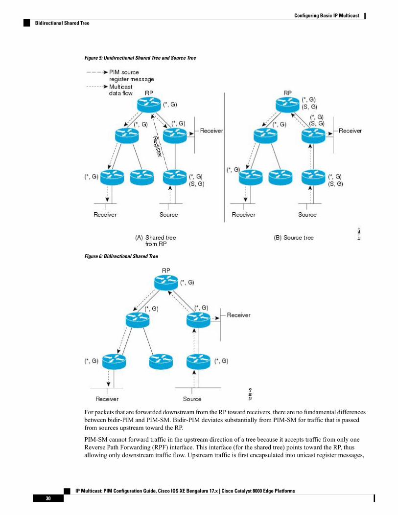
Figure 5: Unidirectional Shared Tree and Source Tree
Figure 6: Bidirectional Shared Tree
For packets that are forwarded downstream from the RP toward receivers, there are no fundamental differencesbetween bidir-PIM and PIM-SM. Bidir-PIM deviates substantially from PIM-SM for traffic that is passedfrom sources upstream toward the RP.
PIM-SM cannot forward traffic in the upstream direction of a tree because it accepts traffic from only oneReverse Path Forwarding (RPF) interface. This interface (for the shared tree) points toward the RP, thusallowing only downstream traffic flow. Upstream traffic is first encapsulated into unicast register messages,
IP Multicast: PIM Configuration Guide, Cisco IOS XE Bengaluru 17.x | Cisco Catalyst 8000 Edge Platforms30
Configuring Basic IP MulticastBidirectional Shared Tree
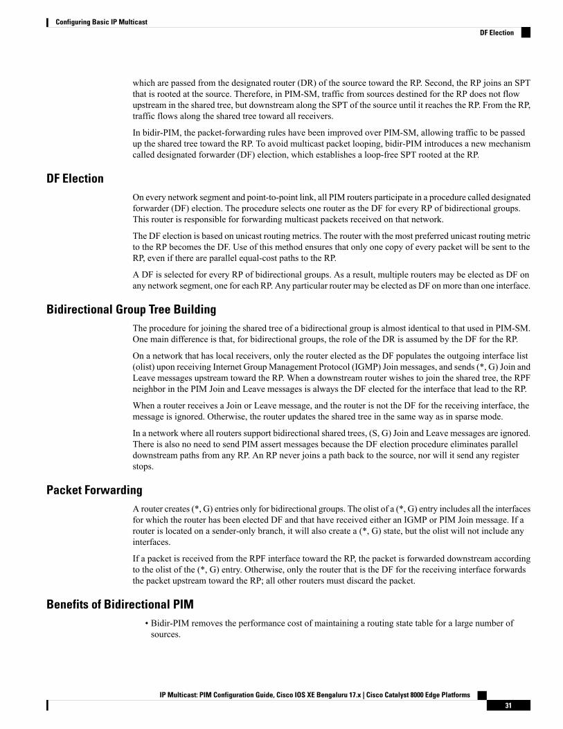
which are passed from the designated router (DR) of the source toward the RP. Second, the RP joins an SPTthat is rooted at the source. Therefore, in PIM-SM, traffic from sources destined for the RP does not flowupstream in the shared tree, but downstream along the SPT of the source until it reaches the RP. From the RP,traffic flows along the shared tree toward all receivers.
In bidir-PIM, the packet-forwarding rules have been improved over PIM-SM, allowing traffic to be passedup the shared tree toward the RP. To avoid multicast packet looping, bidir-PIM introduces a new mechanismcalled designated forwarder (DF) election, which establishes a loop-free SPT rooted at the RP.
DF ElectionOn every network segment and point-to-point link, all PIM routers participate in a procedure called designatedforwarder (DF) election. The procedure selects one router as the DF for every RP of bidirectional groups.This router is responsible for forwarding multicast packets received on that network.
The DF election is based on unicast routing metrics. The router with the most preferred unicast routing metricto the RP becomes the DF. Use of this method ensures that only one copy of every packet will be sent to theRP, even if there are parallel equal-cost paths to the RP.
A DF is selected for every RP of bidirectional groups. As a result, multiple routers may be elected as DF onany network segment, one for each RP. Any particular router may be elected as DF onmore than one interface.
Bidirectional Group Tree BuildingThe procedure for joining the shared tree of a bidirectional group is almost identical to that used in PIM-SM.One main difference is that, for bidirectional groups, the role of the DR is assumed by the DF for the RP.
On a network that has local receivers, only the router elected as the DF populates the outgoing interface list(olist) upon receiving Internet GroupManagement Protocol (IGMP) Join messages, and sends (*, G) Join andLeave messages upstream toward the RP. When a downstream router wishes to join the shared tree, the RPFneighbor in the PIM Join and Leave messages is always the DF elected for the interface that lead to the RP.
When a router receives a Join or Leave message, and the router is not the DF for the receiving interface, themessage is ignored. Otherwise, the router updates the shared tree in the same way as in sparse mode.
In a network where all routers support bidirectional shared trees, (S, G) Join and Leave messages are ignored.There is also no need to send PIM assert messages because the DF election procedure eliminates paralleldownstream paths from any RP. An RP never joins a path back to the source, nor will it send any registerstops.
Packet ForwardingA router creates (*, G) entries only for bidirectional groups. The olist of a (*, G) entry includes all the interfacesfor which the router has been elected DF and that have received either an IGMP or PIM Join message. If arouter is located on a sender-only branch, it will also create a (*, G) state, but the olist will not include anyinterfaces.
If a packet is received from the RPF interface toward the RP, the packet is forwarded downstream accordingto the olist of the (*, G) entry. Otherwise, only the router that is the DF for the receiving interface forwardsthe packet upstream toward the RP; all other routers must discard the packet.
Benefits of Bidirectional PIM• Bidir-PIM removes the performance cost of maintaining a routing state table for a large number ofsources.
IP Multicast: PIM Configuration Guide, Cisco IOS XE Bengaluru 17.x | Cisco Catalyst 8000 Edge Platforms31
Configuring Basic IP MulticastDF Election
• Bidir-PIM is designed to be used for many-to-many applications within individual PIM domains.Multicastgroups in bidirectional PIMmode can scale to an arbitrary number of sources without incurring overheaddue to the number of sources.
How to Configure Basic IP MulticastThe tasks described in this section configure the basic IP multicast modes. No single task in this section isrequired; however, at least one of the tasks must be performed to configure IP multicast in a network. Morethan one of the tasks may be needed.
Configuring Sparse Mode with Auto-RP
Before you begin
• An interface configured in sparse-dense mode is treated in either sparse mode or dense mode of operation,depending on the mode in which the multicast group operates. You must decide how to configure yourinterfaces.
• All access lists that are needed when Auto-RP is configured should be configured prior to beginning theconfiguration task.
• If a group has no known RP and the interface is configured to be sparse-dense mode, the interface istreated as if it were in dense mode, and data is flooded over the interface. To avoid this data flooding,configure the Auto-RP listener and then configure the interface as sparse mode.
• When configuring Auto-RP, you must either configure the Auto-RP listener feature (Step 5) and specifysparse mode (Step 7) or specify sparse-dense mode (Step 8) .
• When you configure sparse-dense mode, dense mode failover may result in a network dense-mode flood.To avoid this condition, use PIM sparse mode with the Auto-RP listener feature.
Note
Follow this procedure to configure auto-rendezvous point (Auto-RP). Auto-RP can also be optionally usedwith anycast RP.
SUMMARY STEPS
1. enable2. configure terminal3. ip multicast-routing [distributed]4. Either perform Steps 5 through 7 or perform Steps 6 and 8.5. ip pim autorp listener6. interface type number
7. ip pim sparse-mode8. ip pim sparse-dense-mode9. exit10. Repeat Steps 1 through 9 on all PIM interfaces.
IP Multicast: PIM Configuration Guide, Cisco IOS XE Bengaluru 17.x | Cisco Catalyst 8000 Edge Platforms32
Configuring Basic IP MulticastHow to Configure Basic IP Multicast

11. ip pim send-rp-announce {interface-type interface-number | ip-address} scope ttl-value [group-listaccess-list] [interval seconds] [bidir]
12. ip pim send-rp-discovery [interface-type interface-number] scope ttl-value [interval seconds]13. ip pim rp-announce-filter rp-list access-list group-list access-list
14. no ip pim dm-fallback15. interface type number
16. ip multicast boundary access-list [filter-autorp]17. end18. show ip pim autorp19. show ip pim rp [mapping] [rp-address]20. show ip igmp groups [group-name | group-address| interface-type interface-number] [detail]21. show ip mroute [group-address | group-name] [source-address | source-name] [interface-type
interface-number] [summary] [count] [active kbps]
DETAILED STEPS
PurposeCommand or Action
Enables privileged EXEC mode.enableStep 1
• Enter your password if prompted.
Enters global configuration mode.configure terminalStep 2
Enables IP multicast routing.ip multicast-routing [distributed]Step 3
• Use the distributed keyword to enabled MulticastDistributed Switching.
--Either perform Steps 5 through 7 or perform Steps 6 and8.
Step 4
Causes IP multicast traffic for the two Auto-RP groups209.165.201.1 and 209.165.201.22 to be PIM dense modeflooded across interfaces operating in PIM sparse mode.
ip pim autorp listenerStep 5
• Skip this step if you are configuring sparse-densemode in Step 8.
Selects an interface that is connected to hosts on whichPIM can be enabled.
interface type number
Example:
Step 6
Enables PIM sparse mode on an interface. Whenconfiguring Auto-RP in sparse mode, you must alsoconfigure the Auto-RP listener in the next step.
ip pim sparse-mode
Example:
Step 7
• Skip this step if you are configuring sparse-densemode in Step 8.
Enables PIM sparse-dense mode on an interface.ip pim sparse-dense-modeStep 8
Example:
IP Multicast: PIM Configuration Guide, Cisco IOS XE Bengaluru 17.x | Cisco Catalyst 8000 Edge Platforms33
Configuring Basic IP MulticastConfiguring Sparse Mode with Auto-RP
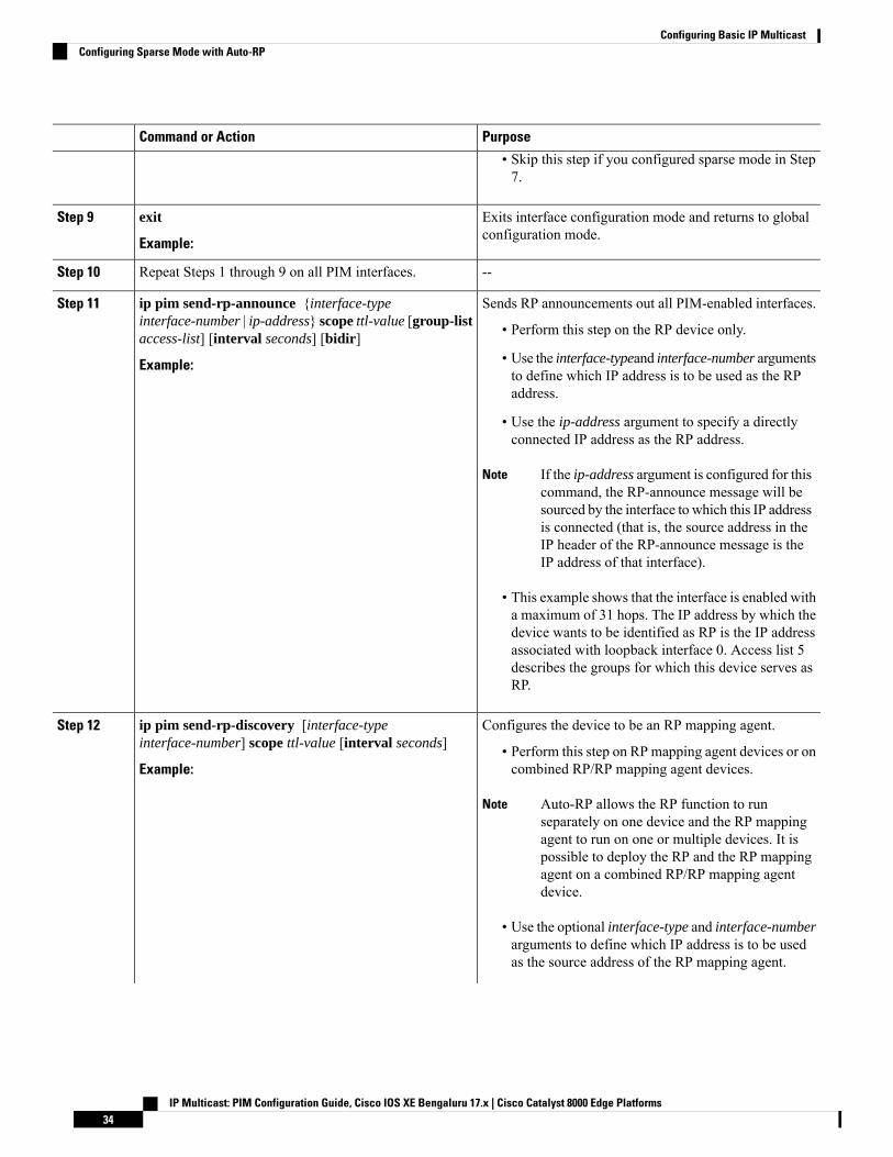
PurposeCommand or Action
• Skip this step if you configured sparse mode in Step7.
Exits interface configuration mode and returns to globalconfiguration mode.
exit
Example:
Step 9
--Repeat Steps 1 through 9 on all PIM interfaces.Step 10
Sends RP announcements out all PIM-enabled interfaces.ip pim send-rp-announce {interface-typeinterface-number | ip-address} scope ttl-value [group-listaccess-list] [interval seconds] [bidir]
Step 11
• Perform this step on the RP device only.
Example: • Use the interface-typeand interface-number argumentsto define which IP address is to be used as the RPaddress.
• Use the ip-address argument to specify a directlyconnected IP address as the RP address.
If the ip-address argument is configured for thiscommand, the RP-announce message will besourced by the interface to which this IP addressis connected (that is, the source address in theIP header of the RP-announce message is theIP address of that interface).
Note
• This example shows that the interface is enabled witha maximum of 31 hops. The IP address by which thedevice wants to be identified as RP is the IP addressassociated with loopback interface 0. Access list 5describes the groups for which this device serves asRP.
Configures the device to be an RP mapping agent.ip pim send-rp-discovery [interface-typeinterface-number] scope ttl-value [interval seconds]
Step 12
• Perform this step on RP mapping agent devices or oncombined RP/RP mapping agent devices.Example:
Auto-RP allows the RP function to runseparately on one device and the RP mappingagent to run on one or multiple devices. It ispossible to deploy the RP and the RP mappingagent on a combined RP/RP mapping agentdevice.
Note
• Use the optional interface-type and interface-numberarguments to define which IP address is to be usedas the source address of the RP mapping agent.
IP Multicast: PIM Configuration Guide, Cisco IOS XE Bengaluru 17.x | Cisco Catalyst 8000 Edge Platforms34
Configuring Basic IP MulticastConfiguring Sparse Mode with Auto-RP

PurposeCommand or Action
• Use the scope keyword and ttl-value argument tospecify the Time-to-Live (TTL) value in the IP headerof Auto-RP discovery messages.
• Use the optional interval keyword and secondsargument to specify the interval at which Auto-RPdiscovery messages are sent.
Lowering the interval at which Auto-RPdiscovery messages are sent from the defaultvalue of 60 seconds results in more frequentfloodings of the group-to-RPmappings. In somenetwork environments, the disadvantages oflowering the interval (more control packetoverhead) may outweigh the advantages (morefrequent group-to-RP mapping updates).
Note
• The example shows limiting the Auto-RP discoverymessages to 31 hops on loopback interface 1.
Filters incoming RP announcement messages sent fromcandidate RPs (C-RPs) to the RP mapping agent.
ip pim rp-announce-filter rp-list access-list group-listaccess-list
Step 13
Example: • Perform this step on the RP mapping agent only.
(Optional) Prevents PIM dense mode fallback.no ip pim dm-fallbackStep 14
Example: • Skip this step if all interfaces have been configuredto operate in PIM sparse mode.
The no ip pim dm-fallback command behavioris enabled by default if all the interfaces areconfigured to operate in PIM sparse mode(using the ip pim sparse-mode command).
Note
Selects an interface that is connected to hosts on whichPIM can be enabled.
interface type numberStep 15
Configures an administratively scoped boundary.ip multicast boundary access-list [filter-autorp]Step 16
Example: • Perform this step on the interfaces that are boundariesto other devices.
• The access list is not shown in this task.
• An access list entry that uses the deny keywordcreates a multicast boundary for packets that matchthat entry.
Returns to global configuration mode.endStep 17
(Optional) Displays the Auto-RP information.show ip pim autorpStep 18
IP Multicast: PIM Configuration Guide, Cisco IOS XE Bengaluru 17.x | Cisco Catalyst 8000 Edge Platforms35
Configuring Basic IP MulticastConfiguring Sparse Mode with Auto-RP
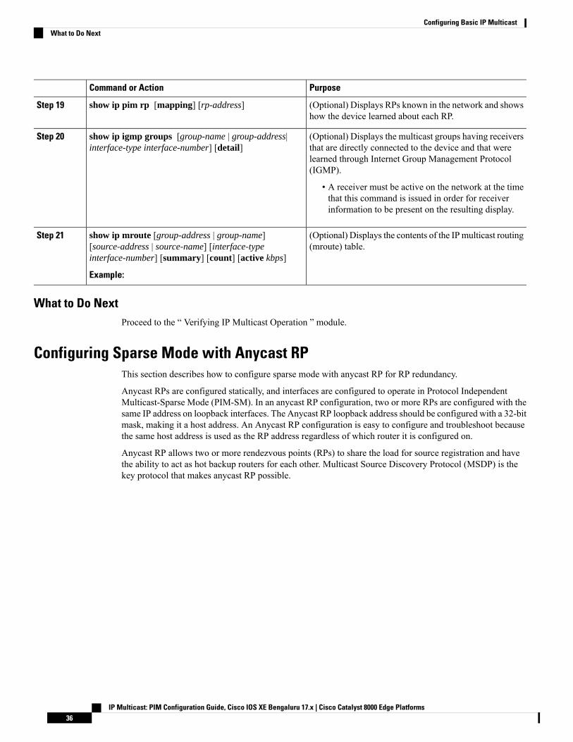
PurposeCommand or Action
(Optional) Displays RPs known in the network and showshow the device learned about each RP.
show ip pim rp [mapping] [rp-address]Step 19
(Optional) Displays the multicast groups having receiversthat are directly connected to the device and that were
show ip igmp groups [group-name | group-address|interface-type interface-number] [detail]
Step 20
learned through Internet Group Management Protocol(IGMP).
• A receiver must be active on the network at the timethat this command is issued in order for receiverinformation to be present on the resulting display.
(Optional) Displays the contents of the IPmulticast routing(mroute) table.
show ip mroute [group-address | group-name][source-address | source-name] [interface-typeinterface-number] [summary] [count] [active kbps]
Step 21
Example:
What to Do NextProceed to the “ Verifying IP Multicast Operation ” module.
Configuring Sparse Mode with Anycast RPThis section describes how to configure sparse mode with anycast RP for RP redundancy.
Anycast RPs are configured statically, and interfaces are configured to operate in Protocol IndependentMulticast-Sparse Mode (PIM-SM). In an anycast RP configuration, two or more RPs are configured with thesame IP address on loopback interfaces. The Anycast RP loopback address should be configured with a 32-bitmask, making it a host address. An Anycast RP configuration is easy to configure and troubleshoot becausethe same host address is used as the RP address regardless of which router it is configured on.
Anycast RP allows two or more rendezvous points (RPs) to share the load for source registration and havethe ability to act as hot backup routers for each other. Multicast Source Discovery Protocol (MSDP) is thekey protocol that makes anycast RP possible.
IP Multicast: PIM Configuration Guide, Cisco IOS XE Bengaluru 17.x | Cisco Catalyst 8000 Edge Platforms36
Configuring Basic IP MulticastWhat to Do Next
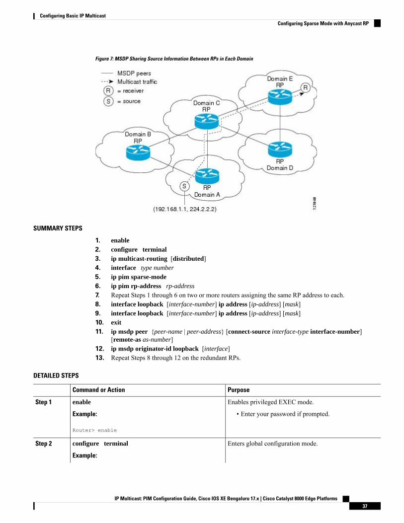
Figure 7: MSDP Sharing Source Information Between RPs in Each Domain
SUMMARY STEPS
1. enable2. configure terminal3. ip multicast-routing [distributed]4. interface type number
5. ip pim sparse-mode6. ip pim rp-address rp-address
7. Repeat Steps 1 through 6 on two or more routers assigning the same RP address to each.8. interface loopback [interface-number] ip address [ip-address] [mask]9. interface loopback [interface-number] ip address [ip-address] [mask]10. exit11. ip msdp peer {peer-name | peer-address} [connect-source interface-type interface-number]
[remote-as as-number]12. ip msdp originator-id loopback [interface]13. Repeat Steps 8 through 12 on the redundant RPs.
DETAILED STEPS
PurposeCommand or Action
Enables privileged EXEC mode.enableStep 1
Example: • Enter your password if prompted.
Router> enable
Enters global configuration mode.configure terminal
Example:
Step 2
IP Multicast: PIM Configuration Guide, Cisco IOS XE Bengaluru 17.x | Cisco Catalyst 8000 Edge Platforms37
Configuring Basic IP MulticastConfiguring Sparse Mode with Anycast RP
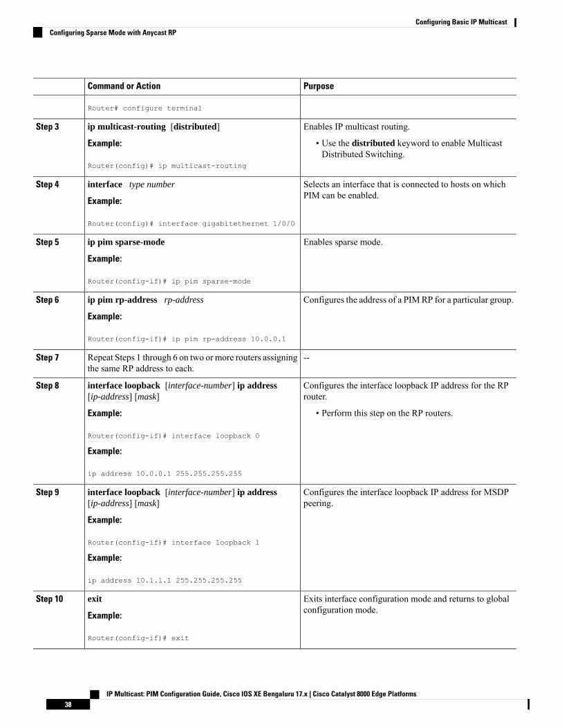
PurposeCommand or Action
Router# configure terminal
Enables IP multicast routing.ip multicast-routing [distributed]Step 3
Example: • Use the distributed keyword to enable MulticastDistributed Switching.
Router(config)# ip multicast-routing
Selects an interface that is connected to hosts on whichPIM can be enabled.
interface type number
Example:
Step 4
Router(config)# interface gigabitethernet 1/0/0
Enables sparse mode.ip pim sparse-mode
Example:
Step 5
Router(config-if)# ip pim sparse-mode
Configures the address of a PIMRP for a particular group.ip pim rp-address rp-address
Example:
Step 6
Router(config-if)# ip pim rp-address 10.0.0.1
--Repeat Steps 1 through 6 on two or more routers assigningthe same RP address to each.
Step 7
Configures the interface loopback IP address for the RProuter.
interface loopback [interface-number] ip address[ip-address] [mask]
Step 8
Example: • Perform this step on the RP routers.
Router(config-if)# interface loopback 0
Example:
ip address 10.0.0.1 255.255.255.255
Configures the interface loopback IP address for MSDPpeering.
interface loopback [interface-number] ip address[ip-address] [mask]
Example:
Step 9
Router(config-if)# interface loopback 1
Example:
ip address 10.1.1.1 255.255.255.255
Exits interface configuration mode and returns to globalconfiguration mode.
exit
Example:
Step 10
Router(config-if)# exit
IP Multicast: PIM Configuration Guide, Cisco IOS XE Bengaluru 17.x | Cisco Catalyst 8000 Edge Platforms38
Configuring Basic IP MulticastConfiguring Sparse Mode with Anycast RP
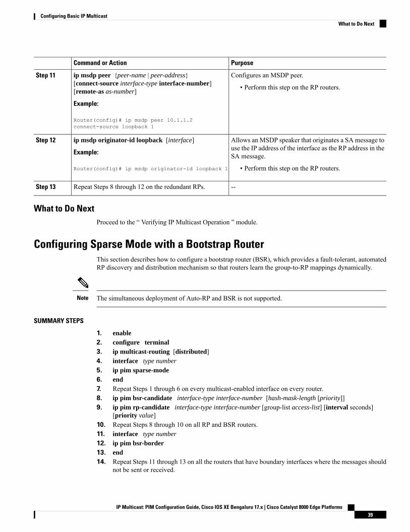
PurposeCommand or Action
Configures an MSDP peer.ip msdp peer {peer-name | peer-address}[connect-source interface-type interface-number][remote-as as-number]
Step 11
• Perform this step on the RP routers.
Example:
Router(config)# ip msdp peer 10.1.1.2connect-source loopback 1
Allows an MSDP speaker that originates a SA message touse the IP address of the interface as the RP address in theSA message.
ip msdp originator-id loopback [interface]
Example:
Router(config)# ip msdp originator-id loopback 1
Step 12
• Perform this step on the RP routers.
--Repeat Steps 8 through 12 on the redundant RPs.Step 13
What to Do NextProceed to the “ Verifying IP Multicast Operation ” module.
Configuring Sparse Mode with a Bootstrap RouterThis section describes how to configure a bootstrap router (BSR), which provides a fault-tolerant, automatedRP discovery and distribution mechanism so that routers learn the group-to-RP mappings dynamically.
The simultaneous deployment of Auto-RP and BSR is not supported.Note
SUMMARY STEPS
1. enable2. configure terminal3. ip multicast-routing [distributed]4. interface type number
5. ip pim sparse-mode6. end7. Repeat Steps 1 through 6 on every multicast-enabled interface on every router.8. ip pim bsr-candidate interface-type interface-number [hash-mask-length [priority]]9. ip pim rp-candidate interface-type interface-number [group-list access-list] [interval seconds]
[priority value]10. Repeat Steps 8 through 10 on all RP and BSR routers.11. interface type number
12. ip pim bsr-border13. end14. Repeat Steps 11 through 13 on all the routers that have boundary interfaces where the messages should
not be sent or received.
IP Multicast: PIM Configuration Guide, Cisco IOS XE Bengaluru 17.x | Cisco Catalyst 8000 Edge Platforms39
Configuring Basic IP MulticastWhat to Do Next

15. show ip pim rp [mapping] [rp-address]16. show ip pim rp-hash [group-address] [group-name]17. show ip pim bsr-router18. show ip igmp groups [group-name | group-address| interface-type interface-number] [detail]19. show ip mroute
DETAILED STEPS
PurposeCommand or Action
Enables privileged EXEC mode.enableStep 1
Example: • Enter your password if prompted.
Router> enable
Enters global configuration mode.configure terminal
Example:
Step 2
Router# configure terminal
Enables IP multicast routing.ip multicast-routing [distributed]Step 3
Example: • Use the distributed keyword to enable MulticastDistributed Switching.
Router(config)# ip multicast-routing
Selects an interface that is connected to hosts on whichPIM can be enabled.
interface type number
Example:
Step 4
Router(config)# interface gigabitethernet 1/0/0
Enables sparse mode.ip pim sparse-mode
Example:
Step 5
Router(config-if)# ip pim sparse-mode
Returns to global configuration mode.end
Example:
Step 6
Router(config-if)# end
--Repeat Steps 1 through 6 on every multicast-enabledinterface on every router.
Step 7
Configures the router to announce its candidacy as abootstrap router (BSR).
ip pim bsr-candidate interface-type interface-number[hash-mask-length [priority]]
Step 8
Example: • Perform this step on the RP or on combined RP/BSRrouters.
Router(config)# ip pim bsr-candidategigibitethernet 0/0/0 0 192
IP Multicast: PIM Configuration Guide, Cisco IOS XE Bengaluru 17.x | Cisco Catalyst 8000 Edge Platforms40
Configuring Basic IP MulticastConfiguring Sparse Mode with a Bootstrap Router
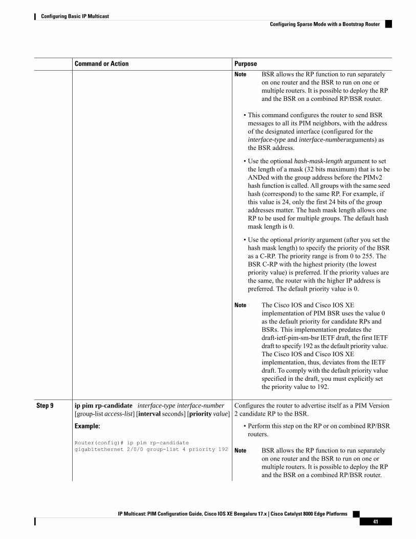
PurposeCommand or Action
BSR allows the RP function to run separatelyon one router and the BSR to run on one ormultiple routers. It is possible to deploy the RPand the BSR on a combined RP/BSR router.
Note
• This command configures the router to send BSRmessages to all its PIM neighbors, with the addressof the designated interface (configured for theinterface-type and interface-numberarguments) asthe BSR address.
• Use the optional hash-mask-length argument to setthe length of a mask (32 bits maximum) that is to beANDed with the group address before the PIMv2hash function is called. All groups with the same seedhash (correspond) to the same RP. For example, ifthis value is 24, only the first 24 bits of the groupaddresses matter. The hash mask length allows oneRP to be used for multiple groups. The default hashmask length is 0.
• Use the optional priority argument (after you set thehash mask length) to specify the priority of the BSRas a C-RP. The priority range is from 0 to 255. TheBSR C-RP with the highest priority (the lowestpriority value) is preferred. If the priority values arethe same, the router with the higher IP address ispreferred. The default priority value is 0.
The Cisco IOS and Cisco IOS XEimplementation of PIM BSR uses the value 0as the default priority for candidate RPs andBSRs. This implementation predates thedraft-ietf-pim-sm-bsr IETF draft, the first IETFdraft to specify 192 as the default priority value.The Cisco IOS and Cisco IOS XEimplementation, thus, deviates from the IETFdraft. To comply with the default priority valuespecified in the draft, you must explicitly setthe priority value to 192.
Note
Configures the router to advertise itself as a PIM Version2 candidate RP to the BSR.
ip pim rp-candidate interface-type interface-number[group-list access-list] [interval seconds] [priority value]
Step 9
Example: • Perform this step on the RP or on combined RP/BSRrouters.
Router(config)# ip pim rp-candidategigabitethernet 2/0/0 group-list 4 priority 192 BSR allows the RP function to run separately
on one router and the BSR to run on one ormultiple routers. It is possible to deploy the RPand the BSR on a combined RP/BSR router.
Note
IP Multicast: PIM Configuration Guide, Cisco IOS XE Bengaluru 17.x | Cisco Catalyst 8000 Edge Platforms41
Configuring Basic IP MulticastConfiguring Sparse Mode with a Bootstrap Router
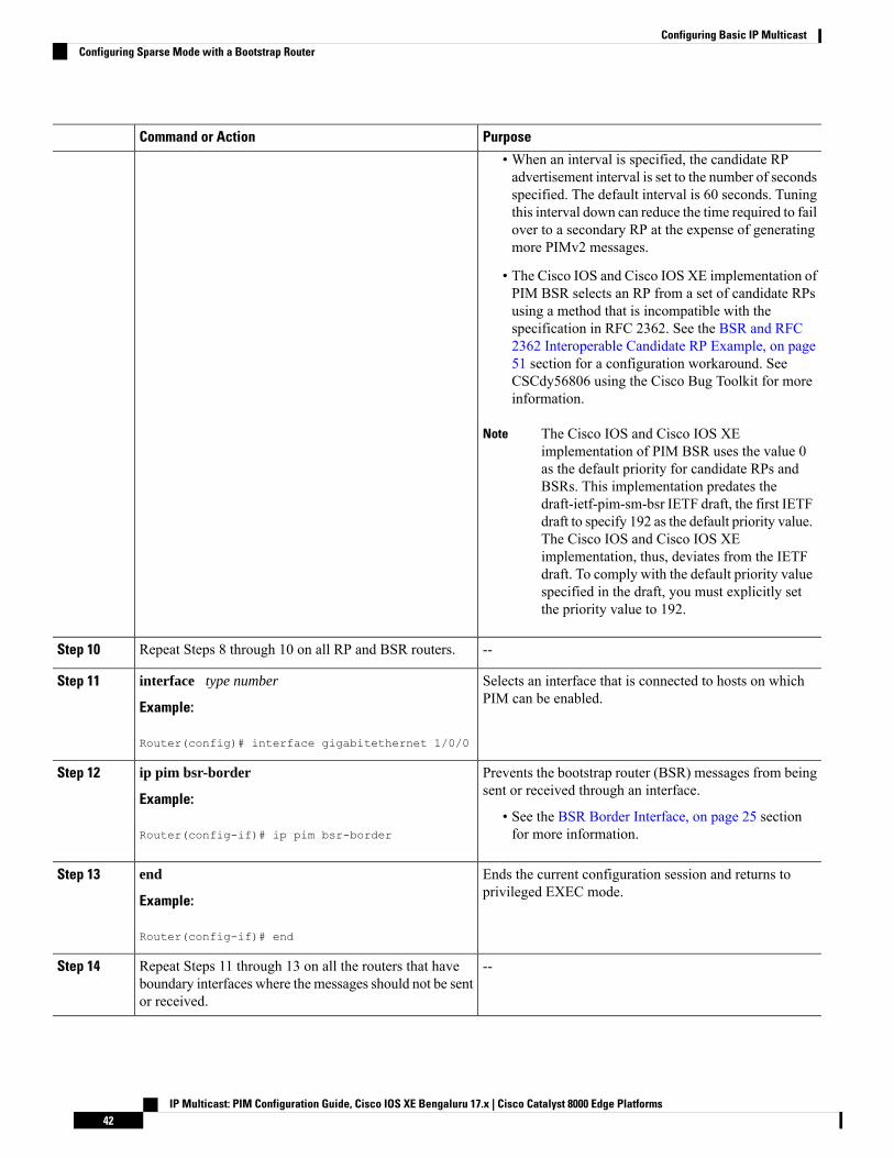
PurposeCommand or Action
• When an interval is specified, the candidate RPadvertisement interval is set to the number of secondsspecified. The default interval is 60 seconds. Tuningthis interval down can reduce the time required to failover to a secondary RP at the expense of generatingmore PIMv2 messages.
• The Cisco IOS and Cisco IOS XE implementation ofPIM BSR selects an RP from a set of candidate RPsusing a method that is incompatible with thespecification in RFC 2362. See the BSR and RFC2362 Interoperable Candidate RP Example, on page51 section for a configuration workaround. SeeCSCdy56806 using the Cisco Bug Toolkit for moreinformation.
The Cisco IOS and Cisco IOS XEimplementation of PIM BSR uses the value 0as the default priority for candidate RPs andBSRs. This implementation predates thedraft-ietf-pim-sm-bsr IETF draft, the first IETFdraft to specify 192 as the default priority value.The Cisco IOS and Cisco IOS XEimplementation, thus, deviates from the IETFdraft. To comply with the default priority valuespecified in the draft, you must explicitly setthe priority value to 192.
Note
--Repeat Steps 8 through 10 on all RP and BSR routers.Step 10
Selects an interface that is connected to hosts on whichPIM can be enabled.
interface type number
Example:
Step 11
Router(config)# interface gigabitethernet 1/0/0
Prevents the bootstrap router (BSR) messages from beingsent or received through an interface.
ip pim bsr-border
Example:
Step 12
• See the BSR Border Interface, on page 25 sectionfor more information.Router(config-if)# ip pim bsr-border
Ends the current configuration session and returns toprivileged EXEC mode.
end
Example:
Step 13
Router(config-if)# end
--Repeat Steps 11 through 13 on all the routers that haveboundary interfaces where the messages should not be sentor received.
Step 14
IP Multicast: PIM Configuration Guide, Cisco IOS XE Bengaluru 17.x | Cisco Catalyst 8000 Edge Platforms42
Configuring Basic IP MulticastConfiguring Sparse Mode with a Bootstrap Router
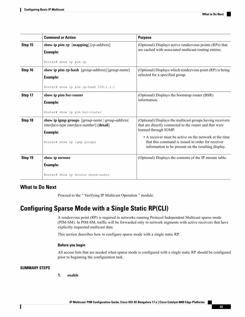
PurposeCommand or Action
(Optional) Displays active rendezvous points (RPs) thatare cached with associated multicast routing entries.
show ip pim rp [mapping] [rp-address]
Example:
Step 15
Router# show ip pim rp
(Optional) Displays which rendezvous point (RP) is beingselected for a specified group.
show ip pim rp-hash [group-address] [group-name]
Example:
Step 16
Router# show ip pim rp-hash 239.1.1.1
(Optional) Displays the bootstrap router (BSR)information.
show ip pim bsr-router
Example:
Step 17
Router# show ip pim bsr-router
(Optional) Displays the multicast groups having receiversthat are directly connected to the router and that werelearned through IGMP.
show ip igmp groups [group-name | group-address|interface-type interface-number] [detail]
Example:
Step 18
• A receiver must be active on the network at the timethat this command is issued in order for receiverinformation to be present on the resulting display.
Router# show ip igmp groups
(Optional) Displays the contents of the IP mroute table.show ip mroute
Example:
Step 19
Router# show ip mroute cbone-audio
What to Do NextProceed to the “ Verifying IP Multicast Operation ” module.
Configuring Sparse Mode with a Single Static RP(CLI)A rendezvous point (RP) is required in networks running Protocol Independent Multicast sparse mode(PIM-SM). In PIM-SM, traffic will be forwarded only to network segments with active receivers that haveexplicitly requested multicast data.
This section describes how to configure sparse mode with a single static RP.
Before you begin
All access lists that are needed when sparse mode is configured with a single static RP should be configuredprior to beginning the configuration task.
SUMMARY STEPS
1. enable
IP Multicast: PIM Configuration Guide, Cisco IOS XE Bengaluru 17.x | Cisco Catalyst 8000 Edge Platforms43
Configuring Basic IP MulticastWhat to Do Next

2. configure terminal3. ip multicast-routing [distributed]4. interface type number
5. ip pim sparse-mode6. Repeat Steps 1 through 5 on every interface that uses IP multicast.7. exit8. ip pim rp-address rp-address [access-list] [override]9. end10. show ip pim rp [mapping] [rp-address]11. show ip igmp groups [group-name | group-address| interface-type interface-number] [detail]12. show ip mroute
DETAILED STEPS
PurposeCommand or Action
Enables privileged EXEC mode.enableStep 1
Example: • Enter your password if prompted.
device> enable
Enters global configuration mode.configure terminal
Example:
Step 2
device# configure terminal
Enables IP multicast routing.ip multicast-routing [distributed]Step 3
Example: • Use the distributed keyword to enable MulticastDistributed Switching.
device(config)# ip multicast-routing
Selects an interface that is connected to hosts on whichPIM can be enabled.
interface type number
Example:
Step 4
device(config)# interface gigabitethernet 1/0/0
Enables PIM on an interface. You must use sparse mode.ip pim sparse-mode
Example:
Step 5
device(config-if)# ip pim sparse-mode
--Repeat Steps 1 through 5 on every interface that uses IPmulticast.
Step 6
Returns to global configuration mode.exit
Example:
Step 7
device(config-if)# exit
IP Multicast: PIM Configuration Guide, Cisco IOS XE Bengaluru 17.x | Cisco Catalyst 8000 Edge Platforms44
Configuring Basic IP MulticastConfiguring Sparse Mode with a Single Static RP(CLI)
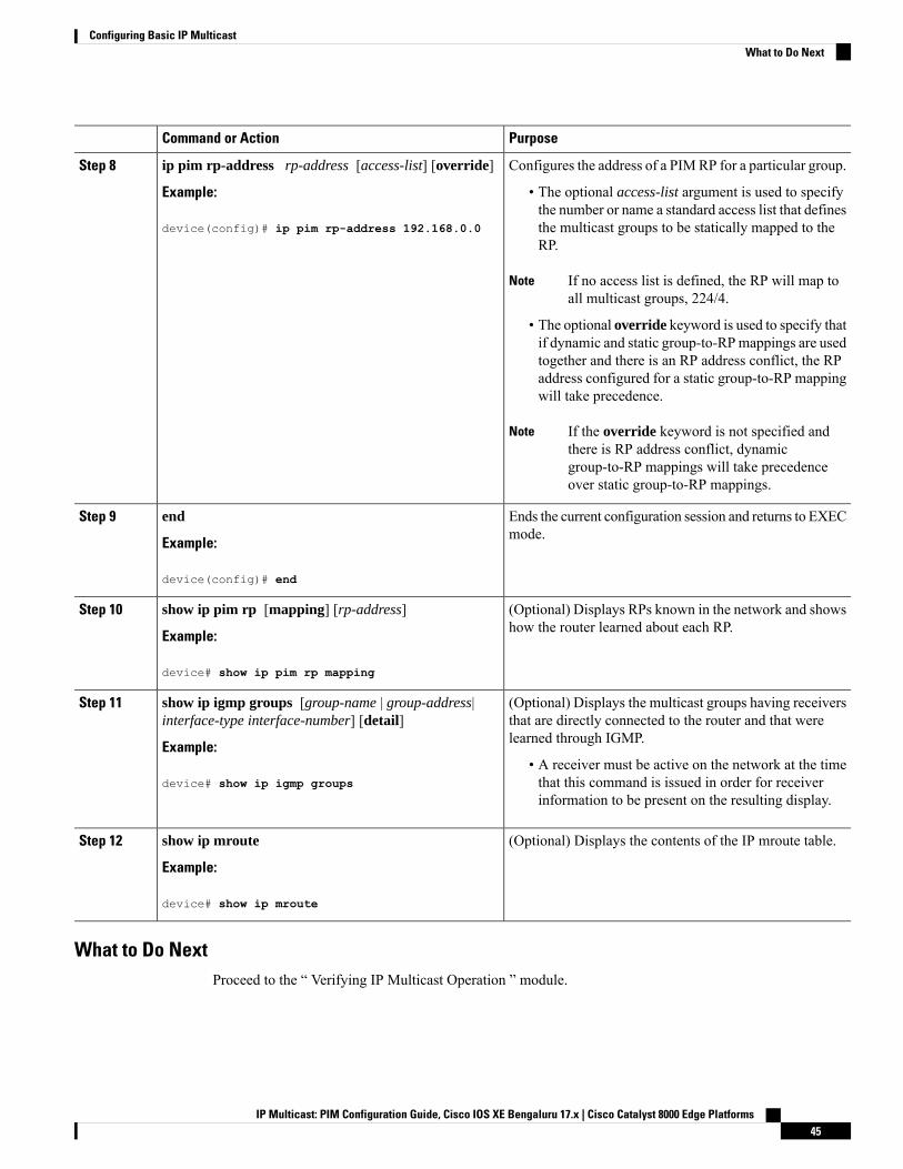
PurposeCommand or Action
Configures the address of a PIMRP for a particular group.ip pim rp-address rp-address [access-list] [override]Step 8
Example: • The optional access-list argument is used to specifythe number or name a standard access list that defines
device(config)# ip pim rp-address 192.168.0.0 the multicast groups to be statically mapped to theRP.
If no access list is defined, the RP will map toall multicast groups, 224/4.
Note
• The optional override keyword is used to specify thatif dynamic and static group-to-RPmappings are usedtogether and there is an RP address conflict, the RPaddress configured for a static group-to-RP mappingwill take precedence.
If the override keyword is not specified andthere is RP address conflict, dynamicgroup-to-RP mappings will take precedenceover static group-to-RP mappings.
Note
Ends the current configuration session and returns to EXECmode.
end
Example:
Step 9
device(config)# end
(Optional) Displays RPs known in the network and showshow the router learned about each RP.
show ip pim rp [mapping] [rp-address]
Example:
Step 10
device# show ip pim rp mapping
(Optional) Displays the multicast groups having receiversthat are directly connected to the router and that werelearned through IGMP.
show ip igmp groups [group-name | group-address|interface-type interface-number] [detail]
Example:
Step 11
• A receiver must be active on the network at the timethat this command is issued in order for receiverinformation to be present on the resulting display.
device# show ip igmp groups
(Optional) Displays the contents of the IP mroute table.show ip mroute
Example:
Step 12
device# show ip mroute
What to Do NextProceed to the “ Verifying IP Multicast Operation ” module.
IP Multicast: PIM Configuration Guide, Cisco IOS XE Bengaluru 17.x | Cisco Catalyst 8000 Edge Platforms45
Configuring Basic IP MulticastWhat to Do Next
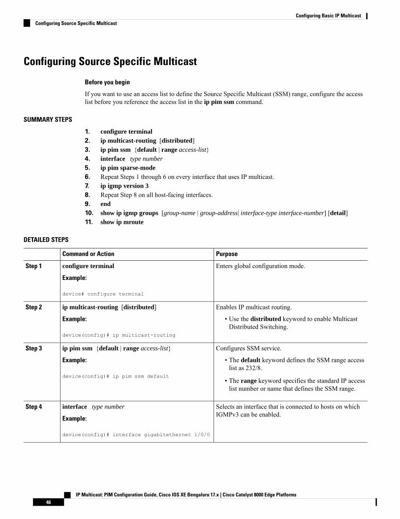
Configuring Source Specific Multicast
Before you begin
If you want to use an access list to define the Source Specific Multicast (SSM) range, configure the accesslist before you reference the access list in the ip pim ssm command.
SUMMARY STEPS
1. configure terminal2. ip multicast-routing [distributed]3. ip pim ssm {default | range access-list}4. interface type number
5. ip pim sparse-mode6. Repeat Steps 1 through 6 on every interface that uses IP multicast.7. ip igmp version 38. Repeat Step 8 on all host-facing interfaces.9. end10. show ip igmp groups [group-name | group-address| interface-type interface-number] [detail]11. show ip mroute
DETAILED STEPS
PurposeCommand or Action
Enters global configuration mode.configure terminal
Example:
Step 1
device# configure terminal
Enables IP multicast routing.ip multicast-routing [distributed]Step 2
Example: • Use the distributed keyword to enable MulticastDistributed Switching.
device(config)# ip multicast-routing
Configures SSM service.ip pim ssm {default | range access-list}Step 3
Example: • The default keyword defines the SSM range accesslist as 232/8.
device(config)# ip pim ssm default• The range keyword specifies the standard IP accesslist number or name that defines the SSM range.
Selects an interface that is connected to hosts on whichIGMPv3 can be enabled.
interface type number
Example:
Step 4
device(config)# interface gigabitethernet 1/0/0
IP Multicast: PIM Configuration Guide, Cisco IOS XE Bengaluru 17.x | Cisco Catalyst 8000 Edge Platforms46
Configuring Basic IP MulticastConfiguring Source Specific Multicast

PurposeCommand or Action
Enables PIM on an interface. You must use sparse mode.ip pim sparse-mode
Example:
Step 5
device(config-if)# ip pim sparse-mode
--Repeat Steps 1 through 6 on every interface that uses IPmulticast.
Step 6
Enables IGMPv3 on this interface. The default version ofIGMP is set to Version 2. Version 3 is required by SSM.
ip igmp version 3
Example:
Step 7
device(config-if)# ip igmp version 3
--Repeat Step 8 on all host-facing interfaces.Step 8
Ends the current configuration session and returns toprivileged EXEC mode.
end
Example:
Step 9
device(config-if)# end
(Optional) Displays the multicast groups having receiversthat are directly connected to the device and that werelearned through IGMP.
show ip igmp groups [group-name | group-address|interface-type interface-number] [detail]
Example:
Step 10
• A receiver must be active on the network at the timethat this command is issued in order for receiverinformation to be present on the resulting display.
device# show ip igmp groups
(Optional) Displays the contents of the IP mroute table.show ip mrouteStep 11
Example: • This command displays whether a multicast group isconfigured for SSM service or a source-specific hostreport has been received.device# show ip mroute
What to Do NextProceed to the “ Verifying IP Multicast Operation ” module.
Configuring Bidirectional PIM
Before you begin
All required access lists must be configured before configuring bidirectional PIM.
SUMMARY STEPS
1. enable2. configure terminal
IP Multicast: PIM Configuration Guide, Cisco IOS XE Bengaluru 17.x | Cisco Catalyst 8000 Edge Platforms47
Configuring Basic IP MulticastWhat to Do Next

3. ip multicast-routing [distributed]4. interface type number
5. ip pim sparse-mode6. exit7. ip pim bidir-enable8. ip pim rp-address rp-address [access-list] [override] bidir9. end10. Repeat Steps 2 through 9 on every multicast-enabled interface on every router.11. show ip pim rp [mapping] [rp-address]12. show ip mroute13. show ip pim interface [type number] [df | count] [rp-address]14. copy running-config startup-config
DETAILED STEPS
PurposeCommand or Action
Enables privileged EXEC mode.enableStep 1
Example: • Enter your password if prompted.Device# enable
Enters global configuration mode.configure terminalStep 2
Enables IP multicast routing.ip multicast-routing [distributed]Step 3
Example: • Use the distributed keyword to enable MulticastDistributed Switching.
Selects an interface that is connected to hosts on whichPIM can be enabled.
interface type numberStep 4
Enables sparse mode.ip pim sparse-modeStep 5
Returns to global configuration mode.exitStep 6
Enables bidir-PIM on a router.ip pim bidir-enableStep 7
• Perform this step on every router.
Configures the address of a PIMRP for a particular group.ip pim rp-address rp-address [access-list] [override]bidir
Step 8
• Perform this step on every router.
• This command defines the RP as bidirectional anddefines the bidirectional group by way of the accesslist.
• The optional override keyword is used to specify thatif dynamic and static group-to-RPmappings are usedtogether and there is an RP address conflict, the RPaddress configured for a static group-to-RP mappingwill take precedence.
IP Multicast: PIM Configuration Guide, Cisco IOS XE Bengaluru 17.x | Cisco Catalyst 8000 Edge Platforms48
Configuring Basic IP MulticastConfiguring Bidirectional PIM
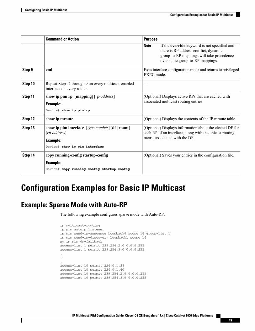
PurposeCommand or Action
If the override keyword is not specified andthere is RP address conflict, dynamicgroup-to-RP mappings will take precedenceover static group-to-RP mappings.
Note
Exits interface configurationmode and returns to privilegedEXEC mode.
endStep 9
--Repeat Steps 2 through 9 on every multicast-enabledinterface on every router.
Step 10
(Optional) Displays active RPs that are cached withassociated multicast routing entries.
show ip pim rp [mapping] [rp-address]
Example:
Step 11
Device# show ip pim rp
(Optional) Displays the contents of the IP mroute table.show ip mrouteStep 12
(Optional) Displays information about the elected DF foreach RP of an interface, along with the unicast routingmetric associated with the DF.
show ip pim interface [type number] [df | count][rp-address]
Example:
Step 13
Device# show ip pim interface
(Optional) Saves your entries in the configuration file.copy running-config startup-config
Example:
Step 14
Device# copy running-config startup-config
Configuration Examples for Basic IP Multicast
Example: Sparse Mode with Auto-RPThe following example configures sparse mode with Auto-RP:
ip multicast-routingip pim autorp listenerip pim send-rp-announce Loopback0 scope 16 group-list 1ip pim send-rp-discovery Loopback1 scope 16no ip pim dm-fallbackaccess-list 1 permit 239.254.2.0 0.0.0.255access-list 1 permit 239.254.3.0 0.0.0.255...access-list 10 permit 224.0.1.39access-list 10 permit 224.0.1.40access-list 10 permit 239.254.2.0 0.0.0.255access-list 10 permit 239.254.3.0 0.0.0.255
IP Multicast: PIM Configuration Guide, Cisco IOS XE Bengaluru 17.x | Cisco Catalyst 8000 Edge Platforms49
Configuring Basic IP MulticastConfiguration Examples for Basic IP Multicast

Sparse Mode with Anycast RP ExampleThe main purpose of an Anycast RP implementation is that the downstream multicast routers will have justone address for an RP. The example given in the figure below shows how loopback interface 0 of the RPs(RP1 and RP2) is configured with the 10.0.0.1 IP address. If this 10.0.0.1 address is configured on all RPs asthe address for loopback interface 0 and then configured as the RP address, IP routing will converge on theclosest RP. This address must be a host route; note the 255.255.255.255 subnet mask.
The downstream routers must be informed about the 10.0.0.1 RP address. In the figure below, the routers areconfigured statically with the ip pim rp-address 10.0.0.1global configuration command. This configurationcould also be accomplished using the Auto-RP or bootstrap router (BSR) features.
The RPs in the figure must also share source information using MSDP. In this example, loopback interface1 of the RPs (RP1 and RP2) is configured for MSDP peering. The MSDP peering address must be differentfrom the anycast RP address.
Figure 8: AnyCast RP Configuration
Many routing protocols choose the highest IP address on loopback interfaces for the router ID. A problemmay arise if the router selects the anycast RP address for the router ID. It is recommended that you avoid thisproblem by manually setting the router ID on the RPs to the same address as the MSDP peering address (forexample, the loopback 1 address in the figure above). In Open Shortest Path First (OSPF), the router ID isconfigured using the router-idrouter configuration command. In Border Gateway Protocol (BGP), the routerID is configured using the bgp router-id router configuration command. In many BGP topologies, the MSDPpeering address and the BGP peering address must be the same in order to pass the RPF check. The BGPpeering address can be set using the neighbor update-source router configuration command.
The anycast RP example above uses IP addresses taken from RFC 1918. These IP addresses are normallyblocked at interdomain borders and therefore are not accessible to other ISPs. You must use valid IP addressesif you want the RPs to be reachable from other domains.
The following example shows how to perform an Anycast RP configuration.
IP Multicast: PIM Configuration Guide, Cisco IOS XE Bengaluru 17.x | Cisco Catalyst 8000 Edge Platforms50
Configuring Basic IP MulticastSparse Mode with Anycast RP Example
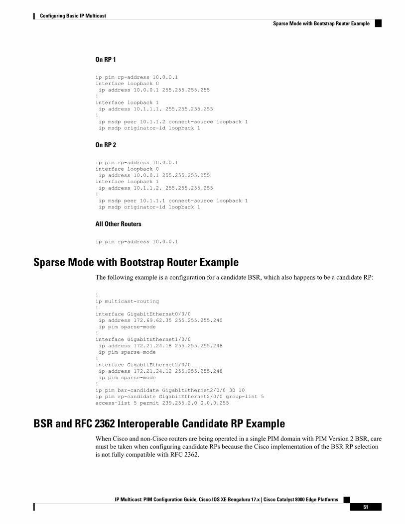
On RP 1
ip pim rp-address 10.0.0.1interface loopback 0ip address 10.0.0.1 255.255.255.255!interface loopback 1ip address 10.1.1.1. 255.255.255.255!ip msdp peer 10.1.1.2 connect-source loopback 1ip msdp originator-id loopback 1
On RP 2
ip pim rp-address 10.0.0.1interface loopback 0ip address 10.0.0.1 255.255.255.255interface loopback 1ip address 10.1.1.2. 255.255.255.255!ip msdp peer 10.1.1.1 connect-source loopback 1ip msdp originator-id loopback 1
All Other Routers
ip pim rp-address 10.0.0.1
Sparse Mode with Bootstrap Router ExampleThe following example is a configuration for a candidate BSR, which also happens to be a candidate RP:
!ip multicast-routing!interface GigabitEthernet0/0/0ip address 172.69.62.35 255.255.255.240ip pim sparse-mode!interface GigabitEthernet1/0/0ip address 172.21.24.18 255.255.255.248ip pim sparse-mode!interface GigabitEthernet2/0/0ip address 172.21.24.12 255.255.255.248ip pim sparse-mode!ip pim bsr-candidate GigabitEthernet2/0/0 30 10ip pim rp-candidate GigabitEthernet2/0/0 group-list 5access-list 5 permit 239.255.2.0 0.0.0.255
BSR and RFC 2362 Interoperable Candidate RP ExampleWhen Cisco and non-Cisco routers are being operated in a single PIM domain with PIM Version 2 BSR, caremust be taken when configuring candidate RPs because the Cisco implementation of the BSR RP selectionis not fully compatible with RFC 2362.
IP Multicast: PIM Configuration Guide, Cisco IOS XE Bengaluru 17.x | Cisco Catalyst 8000 Edge Platforms51
Configuring Basic IP MulticastSparse Mode with Bootstrap Router Example
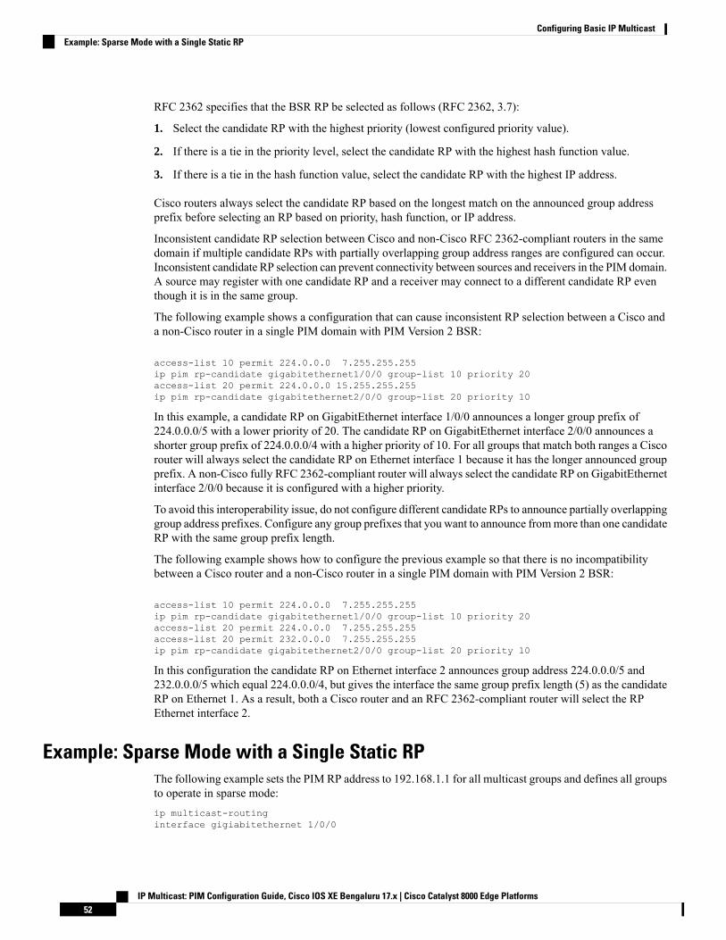
RFC 2362 specifies that the BSR RP be selected as follows (RFC 2362, 3.7):
1. Select the candidate RP with the highest priority (lowest configured priority value).
2. If there is a tie in the priority level, select the candidate RP with the highest hash function value.
3. If there is a tie in the hash function value, select the candidate RP with the highest IP address.
Cisco routers always select the candidate RP based on the longest match on the announced group addressprefix before selecting an RP based on priority, hash function, or IP address.
Inconsistent candidate RP selection between Cisco and non-Cisco RFC 2362-compliant routers in the samedomain if multiple candidate RPs with partially overlapping group address ranges are configured can occur.Inconsistent candidate RP selection can prevent connectivity between sources and receivers in the PIM domain.A source may register with one candidate RP and a receiver may connect to a different candidate RP eventhough it is in the same group.
The following example shows a configuration that can cause inconsistent RP selection between a Cisco anda non-Cisco router in a single PIM domain with PIM Version 2 BSR:
access-list 10 permit 224.0.0.0 7.255.255.255ip pim rp-candidate gigabitethernet1/0/0 group-list 10 priority 20access-list 20 permit 224.0.0.0 15.255.255.255ip pim rp-candidate gigabitethernet2/0/0 group-list 20 priority 10
In this example, a candidate RP on GigabitEthernet interface 1/0/0 announces a longer group prefix of224.0.0.0/5 with a lower priority of 20. The candidate RP on GigabitEthernet interface 2/0/0 announces ashorter group prefix of 224.0.0.0/4 with a higher priority of 10. For all groups that match both ranges a Ciscorouter will always select the candidate RP on Ethernet interface 1 because it has the longer announced groupprefix. A non-Cisco fully RFC 2362-compliant router will always select the candidate RP on GigabitEthernetinterface 2/0/0 because it is configured with a higher priority.
To avoid this interoperability issue, do not configure different candidate RPs to announce partially overlappinggroup address prefixes. Configure any group prefixes that you want to announce frommore than one candidateRP with the same group prefix length.
The following example shows how to configure the previous example so that there is no incompatibilitybetween a Cisco router and a non-Cisco router in a single PIM domain with PIM Version 2 BSR:
access-list 10 permit 224.0.0.0 7.255.255.255ip pim rp-candidate gigabitethernet1/0/0 group-list 10 priority 20access-list 20 permit 224.0.0.0 7.255.255.255access-list 20 permit 232.0.0.0 7.255.255.255ip pim rp-candidate gigabitethernet2/0/0 group-list 20 priority 10
In this configuration the candidate RP on Ethernet interface 2 announces group address 224.0.0.0/5 and232.0.0.0/5 which equal 224.0.0.0/4, but gives the interface the same group prefix length (5) as the candidateRP on Ethernet 1. As a result, both a Cisco router and an RFC 2362-compliant router will select the RPEthernet interface 2.
Example: Sparse Mode with a Single Static RPThe following example sets the PIM RP address to 192.168.1.1 for all multicast groups and defines all groupsto operate in sparse mode:ip multicast-routinginterface gigiabitethernet 1/0/0
IP Multicast: PIM Configuration Guide, Cisco IOS XE Bengaluru 17.x | Cisco Catalyst 8000 Edge Platforms52
Configuring Basic IP MulticastExample: Sparse Mode with a Single Static RP
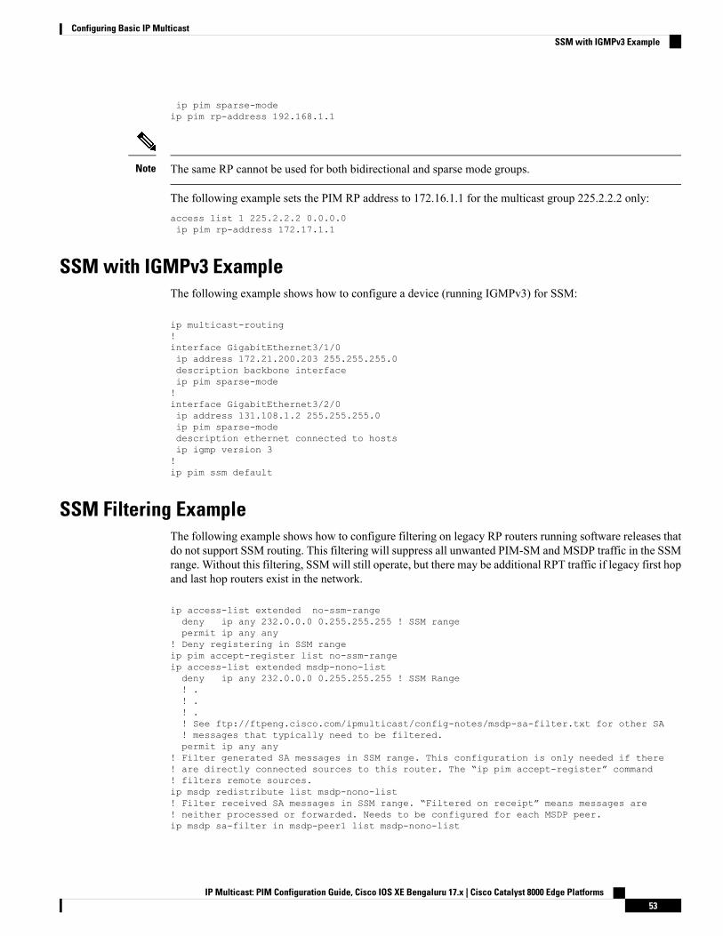
ip pim sparse-modeip pim rp-address 192.168.1.1
The same RP cannot be used for both bidirectional and sparse mode groups.Note
The following example sets the PIM RP address to 172.16.1.1 for the multicast group 225.2.2.2 only:access list 1 225.2.2.2 0.0.0.0ip pim rp-address 172.17.1.1
SSM with IGMPv3 ExampleThe following example shows how to configure a device (running IGMPv3) for SSM:
ip multicast-routing!interface GigabitEthernet3/1/0ip address 172.21.200.203 255.255.255.0description backbone interfaceip pim sparse-mode!interface GigabitEthernet3/2/0ip address 131.108.1.2 255.255.255.0ip pim sparse-modedescription ethernet connected to hostsip igmp version 3!ip pim ssm default
SSM Filtering ExampleThe following example shows how to configure filtering on legacy RP routers running software releases thatdo not support SSM routing. This filtering will suppress all unwanted PIM-SM and MSDP traffic in the SSMrange. Without this filtering, SSMwill still operate, but there may be additional RPT traffic if legacy first hopand last hop routers exist in the network.
ip access-list extended no-ssm-rangedeny ip any 232.0.0.0 0.255.255.255 ! SSM rangepermit ip any any
! Deny registering in SSM rangeip pim accept-register list no-ssm-rangeip access-list extended msdp-nono-listdeny ip any 232.0.0.0 0.255.255.255 ! SSM Range! .! .! .! See ftp://ftpeng.cisco.com/ipmulticast/config-notes/msdp-sa-filter.txt for other SA! messages that typically need to be filtered.permit ip any any
! Filter generated SA messages in SSM range. This configuration is only needed if there! are directly connected sources to this router. The “ip pim accept-register” command! filters remote sources.ip msdp redistribute list msdp-nono-list! Filter received SA messages in SSM range. “Filtered on receipt” means messages are! neither processed or forwarded. Needs to be configured for each MSDP peer.ip msdp sa-filter in msdp-peer1 list msdp-nono-list
IP Multicast: PIM Configuration Guide, Cisco IOS XE Bengaluru 17.x | Cisco Catalyst 8000 Edge Platforms53
Configuring Basic IP MulticastSSM with IGMPv3 Example
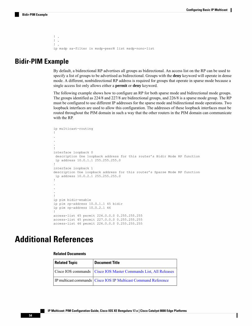
! .! .! .ip msdp sa-filter in msdp-peerN list msdp-nono-list
Bidir-PIM ExampleBy default, a bidirectional RP advertises all groups as bidirectional. An access list on the RP can be used tospecify a list of groups to be advertised as bidirectional. Groups with the deny keyword will operate in densemode. A different, nonbidirectional RP address is required for groups that operate in sparse mode because asingle access list only allows either a permit or deny keyword.
The following example shows how to configure an RP for both sparse mode and bidirectional mode groups.The groups identified as 224/8 and 227/8 are bidirectional groups, and 226/8 is a sparse mode group. The RPmust be configured to use different IP addresses for the sparse mode and bidirectional mode operations. Twoloopback interfaces are used to allow this configuration. The addresses of these loopback interfaces must berouted throughout the PIM domain in such a way that the other routers in the PIM domain can communicatewith the RP.
ip multicast-routing!...!interface loopback 0description One loopback address for this router’s Bidir Mode RP functionip address 10.0.1.1 255.255.255.0!interface loopback 1description One loopback address for this router’s Sparse Mode RP functionip address 10.0.2.1 255.255.255.0!...!ip pim bidir-enableip pim rp-address 10.0.1.1 45 bidirip pim rp-address 10.0.2.1 46!access-list 45 permit 224.0.0.0 0.255.255.255access-list 45 permit 227.0.0.0 0.255.255.255access-list 46 permit 226.0.0.0 0.255.255.255
Additional ReferencesRelated Documents
Document TitleRelated Topic
Cisco IOS Master Commands List, All ReleasesCisco IOS commands
Cisco IOS IP Multicast Command ReferenceIPmulticast commands
IP Multicast: PIM Configuration Guide, Cisco IOS XE Bengaluru 17.x | Cisco Catalyst 8000 Edge Platforms54
Configuring Basic IP MulticastBidir-PIM Example
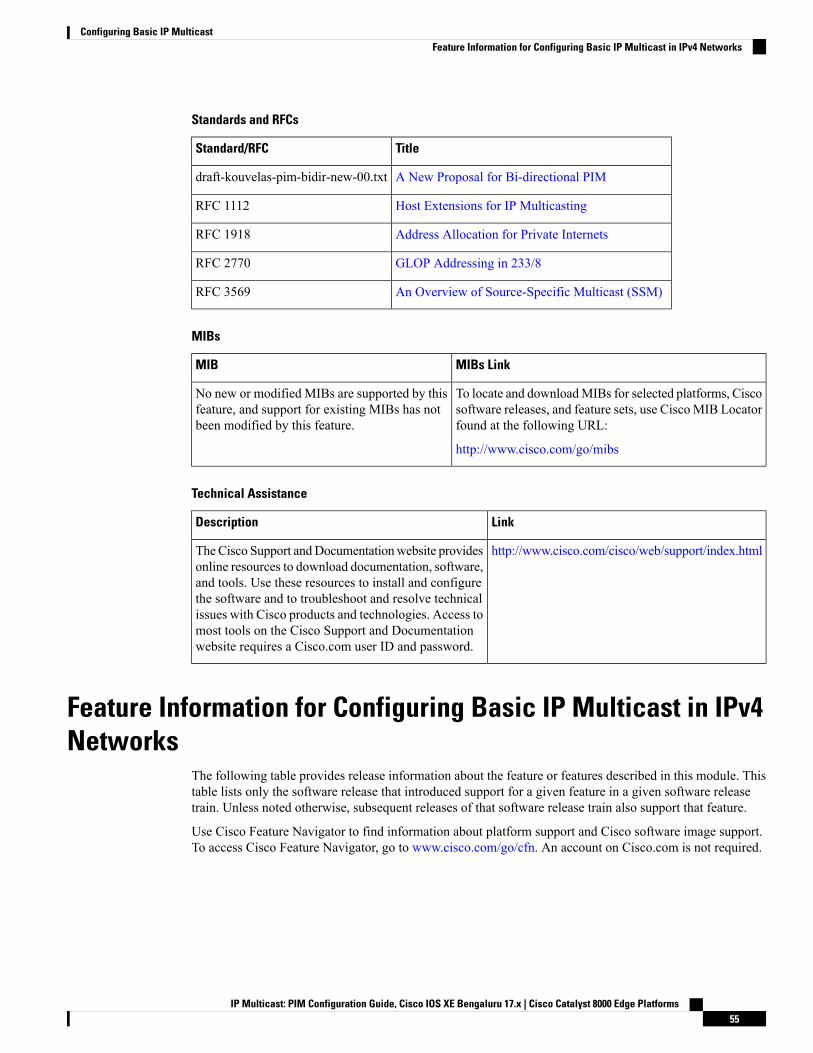
Standards and RFCs
TitleStandard/RFC
A New Proposal for Bi-directional PIMdraft-kouvelas-pim-bidir-new-00.txt
Host Extensions for IP MulticastingRFC 1112
Address Allocation for Private InternetsRFC 1918
GLOP Addressing in 233/8RFC 2770
An Overview of Source-Specific Multicast (SSM)RFC 3569
MIBs
MIBs LinkMIB
To locate and downloadMIBs for selected platforms, Ciscosoftware releases, and feature sets, use CiscoMIB Locatorfound at the following URL:
http://www.cisco.com/go/mibs
No new or modified MIBs are supported by thisfeature, and support for existing MIBs has notbeen modified by this feature.
Technical Assistance
LinkDescription
http://www.cisco.com/cisco/web/support/index.htmlTheCisco Support andDocumentationwebsite providesonline resources to download documentation, software,and tools. Use these resources to install and configurethe software and to troubleshoot and resolve technicalissues with Cisco products and technologies. Access tomost tools on the Cisco Support and Documentationwebsite requires a Cisco.com user ID and password.
Feature Information for Configuring Basic IP Multicast in IPv4Networks
The following table provides release information about the feature or features described in this module. Thistable lists only the software release that introduced support for a given feature in a given software releasetrain. Unless noted otherwise, subsequent releases of that software release train also support that feature.
Use Cisco Feature Navigator to find information about platform support and Cisco software image support.To access Cisco Feature Navigator, go to www.cisco.com/go/cfn. An account on Cisco.com is not required.
IP Multicast: PIM Configuration Guide, Cisco IOS XE Bengaluru 17.x | Cisco Catalyst 8000 Edge Platforms55
Configuring Basic IP MulticastFeature Information for Configuring Basic IP Multicast in IPv4 Networks

IP Multicast: PIM Configuration Guide, Cisco IOS XE Bengaluru 17.x | Cisco Catalyst 8000 Edge Platforms56
Configuring Basic IP MulticastFeature Information for Configuring Basic IP Multicast in IPv4 Networks
C H A P T E R 4Configuring Basic IP Multicast in IPv6 Networks
This module describes how to configure basic IP multicast in an IPv6 network.
• Prerequisites for Configuring Basic IP Multicast, on page 57• Information About Configuring Basic IP Multicast in IPv6 Networks, on page 57• Multicast Admission Control Features, on page 65• Global and Per MVRF Mroute State Limit, on page 66• How to Configure Basic IP Multicast in IPv6 Networks, on page 68• Configuration Examples for Configuring IP Multicast Basic in IPv6 Networks, on page 82• Additional References, on page 85• Feature Information for Configuring Basic IP Multicast in IPv6 Networks, on page 86
Prerequisites for Configuring Basic IP Multicast• To determine which of the tasks contained in this module you will have to perform, you must decidewhich Protocol Independent Multicast (PIM) mode will be used. This determination is based on theapplications you intend to support on your network.
• All access lists to be used with the tasks in this module should be configured prior to beginning theconfiguration task. For information about how to configure an access list, see the “Creating an IP AccessList and Applying It to an Interface” module of the Security Configuration Guide: Access Control Listsguide.
Information About Configuring Basic IP Multicast in IPv6Networks
IPv6 Multicast
IPv6 Multicast OverviewAn IPv6 multicast group is an arbitrary group of receivers that want to receive a particular data stream. Thisgroup has no physical or geographical boundaries--receivers can be located anywhere on the Internet or in
IP Multicast: PIM Configuration Guide, Cisco IOS XE Bengaluru 17.x | Cisco Catalyst 8000 Edge Platforms57

any private network. Receivers that are interested in receiving data flowing to a particular group must jointhe group by signaling their local device. This signaling is achieved with the MLD protocol.
Devices use the MLD protocol to learn whether members of a group are present on their directly attachedsubnets. Hosts join multicast groups by sending MLD report messages. The network then delivers data to apotentially unlimited number of receivers, using only one copy of the multicast data on each subnet. IPv6hosts that wish to receive the traffic are known as group members.
Packets delivered to group members are identified by a single multicast group address. Multicast packets aredelivered to a group using best-effort reliability, just like IPv6 unicast packets.
The multicast environment consists of senders and receivers. Any host, regardless of whether it is a memberof a group, can send to a group. However, only the members of a group receive the message.
Amulticast address is chosen for the receivers in a multicast group. Senders use that address as the destinationaddress of a datagram to reach all members of the group.
Membership in a multicast group is dynamic; hosts can join and leave at any time. There is no restriction onthe location or number of members in a multicast group. A host can be a member of more than one multicastgroup at a time.
How active a multicast group is, its duration, and its membership can vary from group to group and from timeto time. A group that has members may have no activity.
IPv6 Multicast AddressingAn IPv6 multicast address is an IPv6 address that has a prefix of FF00::/8 (1111 1111). An IPv6 multicastaddress is an identifier for a set of interfaces that typically belong to different nodes. A packet sent to a multicastaddress is delivered to all interfaces identified by the multicast address. The second octet following the prefixdefines the lifetime and scope of the multicast address. A permanent multicast address has a lifetime parameterequal to 0; a temporary multicast address has a lifetime parameter equal to 1. A multicast address that has thescope of a node, link, site, or organization, or a global scope has a scope parameter of 1, 2, 5, 8, or E,respectively. For example, a multicast address with the prefix FF02::/16 is a permanent multicast address witha link scope. The figure below shows the format of the IPv6 multicast address.
Figure 9: IPv6 Multicast Address Format
IPv6 nodes (hosts and routers) are required to join (receive packets destined for) the following multicastgroups:
• All-nodes multicast group FF02:0:0:0:0:0:0:1 (scope is link-local)
IP Multicast: PIM Configuration Guide, Cisco IOS XE Bengaluru 17.x | Cisco Catalyst 8000 Edge Platforms58
Configuring Basic IP Multicast in IPv6 NetworksIPv6 Multicast Addressing
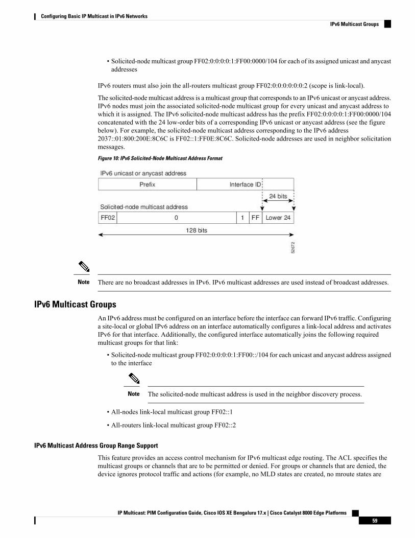
• Solicited-nodemulticast group FF02:0:0:0:0:1:FF00:0000/104 for each of its assigned unicast and anycastaddresses
IPv6 routers must also join the all-routers multicast group FF02:0:0:0:0:0:0:2 (scope is link-local).
The solicited-nodemulticast address is a multicast group that corresponds to an IPv6 unicast or anycast address.IPv6 nodes must join the associated solicited-node multicast group for every unicast and anycast address towhich it is assigned. The IPv6 solicited-node multicast address has the prefix FF02:0:0:0:0:1:FF00:0000/104concatenated with the 24 low-order bits of a corresponding IPv6 unicast or anycast address (see the figurebelow). For example, the solicited-node multicast address corresponding to the IPv6 address2037::01:800:200E:8C6C is FF02::1:FF0E:8C6C. Solicited-node addresses are used in neighbor solicitationmessages.
Figure 10: IPv6 Solicited-Node Multicast Address Format
There are no broadcast addresses in IPv6. IPv6 multicast addresses are used instead of broadcast addresses.Note
IPv6 Multicast GroupsAn IPv6 address must be configured on an interface before the interface can forward IPv6 traffic. Configuringa site-local or global IPv6 address on an interface automatically configures a link-local address and activatesIPv6 for that interface. Additionally, the configured interface automatically joins the following requiredmulticast groups for that link:
• Solicited-node multicast group FF02:0:0:0:0:1:FF00::/104 for each unicast and anycast address assignedto the interface
The solicited-node multicast address is used in the neighbor discovery process.Note
• All-nodes link-local multicast group FF02::1
• All-routers link-local multicast group FF02::2
IPv6 Multicast Address Group Range Support
This feature provides an access control mechanism for IPv6 multicast edge routing. The ACL specifies themulticast groups or channels that are to be permitted or denied. For groups or channels that are denied, thedevice ignores protocol traffic and actions (for example, no MLD states are created, no mroute states are
IP Multicast: PIM Configuration Guide, Cisco IOS XE Bengaluru 17.x | Cisco Catalyst 8000 Edge Platforms59
Configuring Basic IP Multicast in IPv6 NetworksIPv6 Multicast Groups
created, no PIM joins are forwarded), and drops data traffic on all interfaces in the system, disabling multicastfor groups or channels denied by the ACL.
Scoped Address ArchitectureIPv6 includes support for global and nonglobal addresses. This section describes the usage of IPv6 addressesof different scopes.
A scope zone, or a simply a zone, is a connected region of topology of a given scope. For example, the set oflinks connected by devices within a particular site, and the interfaces attached to those links, comprise a singlezone of site-local scope.
A zone is a particular instance of a topological region (for example, Zone1’s site or Zone2’s site), whereas ascope is the size of a topological region (for example, a site or a link). The zone to which a particular nonglobaladdress pertains is not encoded in the address itself, but rather is determined by context, such as the interfacefrom which it is sent or received. Therefore, addresses of a given nonglobal scope may be reused in differentzones of that scope. For example, Zone1’s site and Zone2’s site may each contain a node with site-localaddress FEC0::1.
Zones of the different scopes are instantiated as follows:
• Each link, and the interfaces attached to that link, comprises a single zone of link-local scope (for bothunicast and multicast).
• There is a single zone of global scope (for both unicast and multicast), comprising all the links andinterfaces in the Internet.
• The boundaries of zones of scope other than interface-local, link-local, and global must be defined andconfigured by network administrators. A site boundary serves as such for both unicast and multicast.
Zone boundaries are relatively static features and do not change in response to short-term changes in topology.Therefore, the requirement that the topology within a zone be "connected" is intended to include links andinterfaces that may be connected only occasionally. For example, a residential node or network that obtainsInternet access by dialup to an employer’s site may be treated as part of the employer’s site-local zone evenwhen the dialup link is disconnected. Similarly, a failure of a device, interface, or link that causes a zone tobecome partitioned does not split that zone into multiple zones; rather, the different partitions are still consideredto belong to the same zone.
Zones have the following additional properties:
• Zone boundaries cut through nodes, not links (the global zone has no boundary, and the boundary of aninterface-local zone encloses just a single interface.)
• Zones of the same scope cannot overlap; that is, they can have no links or interfaces in common.
• A zone of a given scope (less than global) falls completely within zones of larger scope; that is, a smallerscope zone cannot include more topology than any larger scope zone with which it shares any links orinterfaces.
• Each interface belongs to exactly one zone of each possible scope.
MRIBThe Multicast Routing Information Base (MRIB) is a protocol-independent repository of multicast routingentries instantiated bymulticast routing protocols (routing clients). Its main function is to provide independence
IP Multicast: PIM Configuration Guide, Cisco IOS XE Bengaluru 17.x | Cisco Catalyst 8000 Edge Platforms60
Configuring Basic IP Multicast in IPv6 NetworksScoped Address Architecture
between routing protocols and theMulticast Forwarding Information Base (MFIB). It also acts as a coordinationand communication point among its clients.
Routing clients use the services provided by theMRIB to instantiate routing entries and retrieve changes madeto routing entries by other clients. Besides routing clients, MRIB also has forwarding clients (MFIB instances)and special clients such as MLD. MFIB retrieves its forwarding entries from MRIB and notifies the MRIBof any events related to packet reception. These notifications can either be explicitly requested by routingclients or spontaneously generated by the MFIB.
Another important function of the MRIB is to allow for the coordination of multiple routing clients inestablishing multicast connectivity within the same multicast session. MRIB also allows for the coordinationbetween MLD and routing protocols.
IPv6 Multicast Process Switching and Fast SwitchingA unified MFIB is used to provide both fast switching and process switching support for PIM-SM andPIM-SSM in IPv6 multicast. In process switching, the Route Processor must examine, rewrite, and forwardeach packet. The packet is first received and copied into the system memory. The device then looks up theLayer 3 network address in the routing table. The Layer 2 frame is then rewritten with the next-hop destinationaddress and sent to the outgoing interface. The RP also computes the cyclic redundancy check (CRC). Thisswitching method is the least scalable method for switching IPv6 packets.
IPv6 multicast fast switching allows devices to provide better packet forwarding performance than processswitching. Information conventionally stored in a route cache is stored in several data structures for IPv6multicast switching. The data structures provide optimized lookup for efficient packet forwarding.
In IPv6 multicast forwarding, the first packet is fast-switched if the PIM protocol logic allows it. In IPv6multicast fast switching, the MAC encapsulation header is precomputed. IPv6 multicast fast switching usesthe MFIB to make IPv6 destination prefix-based switching decisions. In addition to the MFIB, IPv6 multicastfast switching uses adjacency tables to prepend Layer 2 addressing information. The adjacency table maintainsLayer 2 next-hop addresses for all MFIB entries.
The adjacency table is populated as adjacencies are discovered. Each time an adjacency entry is created (suchas through ARP), a link-layer header for that adjacent node is precomputed and stored in the adjacency table.Once a route is determined, it points to a next hop and corresponding adjacency entry. It is subsequently usedfor encapsulation during switching of packets.
A route might have several paths to a destination prefix, such as when a device is configured for simultaneousload balancing and redundancy. For each resolved path, a pointer is added for the adjacency correspondingto the next-hop interface for that path. This mechanism is used for load balancing across several paths.
IPv6 Anycast RP Solution
PIMv6 Anycast RP Solution OverviewThe anycast RP solution in IPv6 PIM allows an IPv6 network to support anycast services for the PIM-SMRP. It allows anycast RP to be used inside a domain that runs PIM only. Anycast RP can be used in IPv4 aswell as IPv6, but it does not depend on the Multicast Source Discovery Protocol (MSDP), which runs onlyon IPv4. This feature is useful when interdomain connection is not required.
Anycast RP is a mechanism that ISP-based backbones use to get fast convergence when a PIM RP devicefails. To allow receivers and sources to rendezvous to the closest RP, the packets from a source need to getto all RPs to find joined receivers.
IP Multicast: PIM Configuration Guide, Cisco IOS XE Bengaluru 17.x | Cisco Catalyst 8000 Edge Platforms61
Configuring Basic IP Multicast in IPv6 NetworksIPv6 Multicast Process Switching and Fast Switching
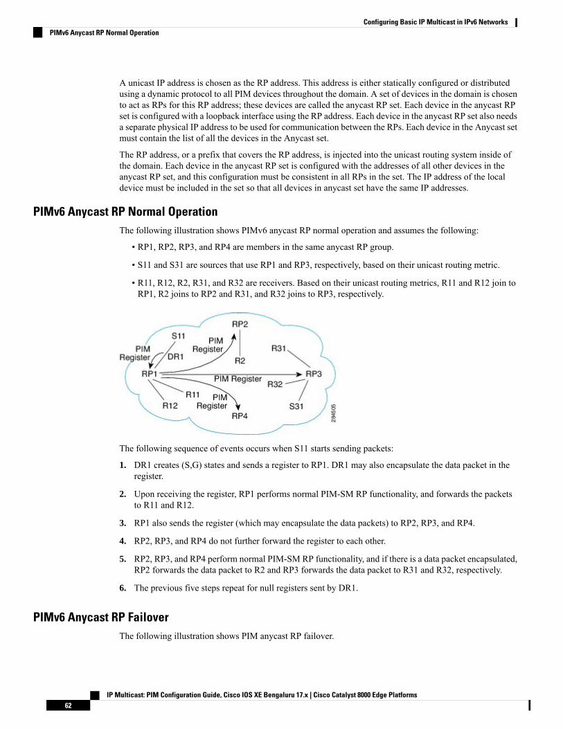
A unicast IP address is chosen as the RP address. This address is either statically configured or distributedusing a dynamic protocol to all PIM devices throughout the domain. A set of devices in the domain is chosento act as RPs for this RP address; these devices are called the anycast RP set. Each device in the anycast RPset is configured with a loopback interface using the RP address. Each device in the anycast RP set also needsa separate physical IP address to be used for communication between the RPs. Each device in the Anycast setmust contain the list of all the devices in the Anycast set.
The RP address, or a prefix that covers the RP address, is injected into the unicast routing system inside ofthe domain. Each device in the anycast RP set is configured with the addresses of all other devices in theanycast RP set, and this configuration must be consistent in all RPs in the set. The IP address of the localdevice must be included in the set so that all devices in anycast set have the same IP addresses.
PIMv6 Anycast RP Normal OperationThe following illustration shows PIMv6 anycast RP normal operation and assumes the following:
• RP1, RP2, RP3, and RP4 are members in the same anycast RP group.
• S11 and S31 are sources that use RP1 and RP3, respectively, based on their unicast routing metric.
• R11, R12, R2, R31, and R32 are receivers. Based on their unicast routing metrics, R11 and R12 join toRP1, R2 joins to RP2 and R31, and R32 joins to RP3, respectively.
The following sequence of events occurs when S11 starts sending packets:
1. DR1 creates (S,G) states and sends a register to RP1. DR1 may also encapsulate the data packet in theregister.
2. Upon receiving the register, RP1 performs normal PIM-SM RP functionality, and forwards the packetsto R11 and R12.
3. RP1 also sends the register (which may encapsulate the data packets) to RP2, RP3, and RP4.
4. RP2, RP3, and RP4 do not further forward the register to each other.
5. RP2, RP3, and RP4 perform normal PIM-SM RP functionality, and if there is a data packet encapsulated,RP2 forwards the data packet to R2 and RP3 forwards the data packet to R31 and R32, respectively.
6. The previous five steps repeat for null registers sent by DR1.
PIMv6 Anycast RP FailoverThe following illustration shows PIM anycast RP failover.
IP Multicast: PIM Configuration Guide, Cisco IOS XE Bengaluru 17.x | Cisco Catalyst 8000 Edge Platforms62
Configuring Basic IP Multicast in IPv6 NetworksPIMv6 Anycast RP Normal Operation
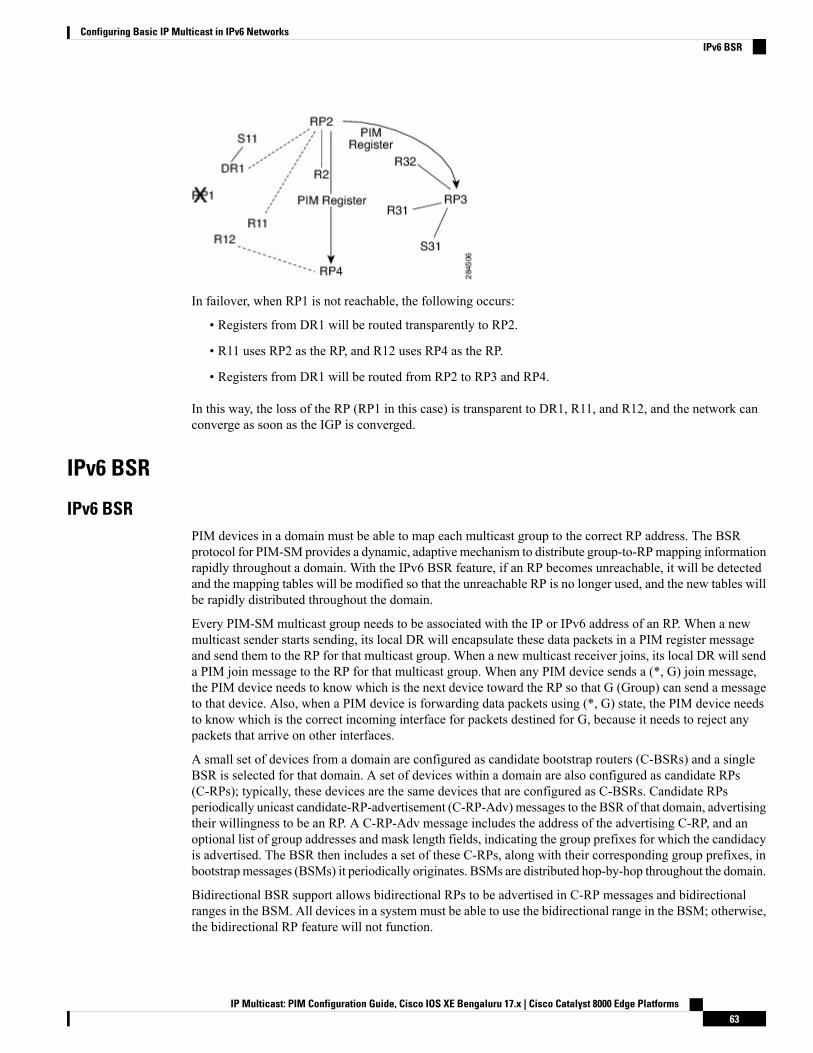
In failover, when RP1 is not reachable, the following occurs:
• Registers from DR1 will be routed transparently to RP2.
• R11 uses RP2 as the RP, and R12 uses RP4 as the RP.
• Registers from DR1 will be routed from RP2 to RP3 and RP4.
In this way, the loss of the RP (RP1 in this case) is transparent to DR1, R11, and R12, and the network canconverge as soon as the IGP is converged.
IPv6 BSR
IPv6 BSRPIM devices in a domain must be able to map each multicast group to the correct RP address. The BSRprotocol for PIM-SM provides a dynamic, adaptive mechanism to distribute group-to-RPmapping informationrapidly throughout a domain. With the IPv6 BSR feature, if an RP becomes unreachable, it will be detectedand the mapping tables will be modified so that the unreachable RP is no longer used, and the new tables willbe rapidly distributed throughout the domain.
Every PIM-SM multicast group needs to be associated with the IP or IPv6 address of an RP. When a newmulticast sender starts sending, its local DR will encapsulate these data packets in a PIM register messageand send them to the RP for that multicast group. When a new multicast receiver joins, its local DR will senda PIM join message to the RP for that multicast group. When any PIM device sends a (*, G) join message,the PIM device needs to know which is the next device toward the RP so that G (Group) can send a messageto that device. Also, when a PIM device is forwarding data packets using (*, G) state, the PIM device needsto know which is the correct incoming interface for packets destined for G, because it needs to reject anypackets that arrive on other interfaces.
A small set of devices from a domain are configured as candidate bootstrap routers (C-BSRs) and a singleBSR is selected for that domain. A set of devices within a domain are also configured as candidate RPs(C-RPs); typically, these devices are the same devices that are configured as C-BSRs. Candidate RPsperiodically unicast candidate-RP-advertisement (C-RP-Adv) messages to the BSR of that domain, advertisingtheir willingness to be an RP. A C-RP-Adv message includes the address of the advertising C-RP, and anoptional list of group addresses and mask length fields, indicating the group prefixes for which the candidacyis advertised. The BSR then includes a set of these C-RPs, along with their corresponding group prefixes, inbootstrapmessages (BSMs) it periodically originates. BSMs are distributed hop-by-hop throughout the domain.
Bidirectional BSR support allows bidirectional RPs to be advertised in C-RP messages and bidirectionalranges in the BSM. All devices in a system must be able to use the bidirectional range in the BSM; otherwise,the bidirectional RP feature will not function.
IP Multicast: PIM Configuration Guide, Cisco IOS XE Bengaluru 17.x | Cisco Catalyst 8000 Edge Platforms63
Configuring Basic IP Multicast in IPv6 NetworksIPv6 BSR
IPv6 BSR: Configure RP MappingThe IPv6 BSR ability to configure RP mapping allows IPv6 multicast devices to be statically configured toannounce scope-to-RPmappings directly from the BSR instead of learning them from candidate-RPmessages.Announcing RP mappings from the BSR is useful in several situations:
• When an RP address never changes because there is only a single RP or the group range uses an anycastRP, it may be less complex to configure the RP address announcement statically on the candidate BSRs.
• When an RP address is a virtual RP address (such as when using bidirectional PIM), it cannot be learnedby the BSR from a candidate-RP. Instead, the virtual RP address must be configured as an announcedRP on the candidate BSRs.
IPv6 BSR: Scoped Zone SupportBSR provides scoped zone support by distributing group-to-RP mappings in networks using administrativelyscoped multicast. The user can configure candidate BSRs and a set of candidate RPs for each administrativelyscoped region in the user’s domain.
For BSR to function correctly with administrative scoping, a BSR and at least one C-RP must be within everyadministratively scoped region. Administratively scoped zone boundaries must be configured at the zoneborder devices, because they need to filter PIM join messages that might inadvertently cross the border dueto error conditions. In addition, at least one C-BSRwithin the administratively scoped zone must be configuredto be a C-BSR for the administratively scoped zone’s address range.
A separate BSR election will then take place (using BSMs) for every administratively scoped range, plus onefor the global range. Administratively scoped ranges are identified in the BSM because the group range ismarked to indicate that this is an administrative scope range, not just a range that a particular set of RPs isconfigured to handle.
Unless the C-RP is configured with a scope, it discovers the existence of the administratively scoped zoneand its group range through reception of a BSM from the scope zone’s elected BSR containing the scopezone’s group range. A C-RP stores each elected BSR's address and the administratively scoped range containedin its BSM. It separately unicasts C-RP-Adv messages to the appropriate BSR for every administrativelyscoped range within which it is willing to serve as an RP.
All PIM devices within a PIM bootstrap domain where administratively scoped ranges are in use must be ableto receive BSMs and store the winning BSR and RP set for all administratively scoped zones that apply.
IPv6 Multicast: RPF Flooding of BSR PacketsCisco IPv6 devices provide support for the RPF flooding of BSR packets so that the device will not disruptthe flow of BSMs. The device will recognize and parse enough of the BSM to identify the BSR address. Thedevice performs an RPF check for this BSR address and forwards the packet only if it is received on the RPFinterface. The device also creates a BSR entry containing RPF information to use for future BSMs from thesame BSR. When BSMs from a given BSR are no longer received, the BSR entry is timed out.
IPv6 Multicast GroupsAn IPv6 address must be configured on an interface before the interface can forward IPv6 traffic. Configuringa site-local or global IPv6 address on an interface automatically configures a link-local address and activatesIPv6 for that interface. Additionally, the configured interface automatically joins the following requiredmulticast groups for that link:
IP Multicast: PIM Configuration Guide, Cisco IOS XE Bengaluru 17.x | Cisco Catalyst 8000 Edge Platforms64
Configuring Basic IP Multicast in IPv6 NetworksIPv6 BSR: Configure RP Mapping
• Solicited-node multicast group FF02:0:0:0:0:1:FF00::/104 for each unicast and anycast address assignedto the interface
The solicited-node multicast address is used in the neighbor discovery process.Note
• All-nodes link-local multicast group FF02::1
• All-routers link-local multicast group FF02::2
IPv6 Multicast Address Group Range SupportThis feature provides an access control mechanism for IPv6 multicast edge routing. The ACL specifies themulticast groups or channels that are to be permitted or denied. For groups or channels that are denied, thedevice ignores protocol traffic and actions (for example, no MLD states are created, no mroute states arecreated, no PIM joins are forwarded), and drops data traffic on all interfaces in the system, disabling multicastfor groups or channels denied by the ACL.
Multicast Admission Control FeaturesThe Cisco IOS XE software supports the following multicast admission control features:
• Global and Per MVRF Mroute State Limit
The ipv6 multicast route-limit command allows for the configuration of global and per MVRF state limiters,which impose limits on the number of user configured multicast routes (mroutes) that can be added to theglobal table or to a particular Multicast Virtual Routing and Forwarding (MVRF) table.
• IGMP State Limit
This feature allows for the configuration of IGMP state limiters, which impose limits on mroute states resultingfrom Internet Group Management Protocol (IGMP) membership reports (IGMP joins).
• Per Interface Mroute State Limit
This feature allows for the configuration of per interface mroute state limiters, which impose mroute statelimits for different access control list (ACL)-classified sets of multicast traffic on an interface.
• Bandwidth-Based CAC for IP Multicast
This feature allows for the configuration of bandwidth-based multicast CAC policies, which allow forbandwidth-based CAC on a per interface basis.
These admission control features may be invoked by service providers and enterprise network administratorsbased on different criteria, including the service package an end user has purchased or the privileges anenterprise user is entitled to.
IP Multicast: PIM Configuration Guide, Cisco IOS XE Bengaluru 17.x | Cisco Catalyst 8000 Edge Platforms65
Configuring Basic IP Multicast in IPv6 NetworksIPv6 Multicast Address Group Range Support

Global and Per MVRF Mroute State LimitThe ipv6 multicast route-limit command allows for the configuration of global and per MVRF mroute statelimiters, which impose limits on the number of user configured number of mroutes that can be added to theglobal table or to a particular MVRF table, respectively.
Global mroute state limiters are used to limit the number of mroutes that can be added to the global table ona router. Configuring a global mroute state limiter can protect a router in the event of a multicast DoS attack(by preventing mroutes from overrunning the router).
Per VRF mroute state limiters are used to limit the number of mroutes that can be added to an MVRF tableon a Multicast VPN (MVPN) provider edge (PE) router. Configuring per MVRF mroute state limits can beused to ensure the fair sharing of mroutes between different MVRFs on an MVPN PE router.
Use the show ipv6 multicast [vrf vrf-name] command to get the count of the number of mroute entries, theconfigured mroute limit and configured mroute threshold values.
Note
Global and Per MVRF Mroute State Limit Feature DesignGlobal and per MVRF mroute state limiters are configured using the ipv6 multicast route-limit commandin global configuration mode. The syntax of the ipv6 multicast route-limit command is as follows:
ipv6 multicast [vrf vrf-name] route-limit limit [threshold]
Issuing the ipv6 multicast route-limit command without the optional vrf keyword and vrf-name argumentsconfigures a global mroute state limiter. The optional vrf keyword and vrf-name arguments are used with theipv6 multicast limit command to configure per MVRF mroute state limiters.
When configuring global and per VRF mroute state limiters, you can only configure one limit for the globaltable and one limit per MVRF table.
Note
The value specified for the required limit argument defines themaximum number of mroutes that can be addedto either the global table or a particular MVRF table, respectively.
Global and perMVRFmroute state limiters operate independently and can be used alone or together, dependingupon the admission control requirements of your network.
Note
In addition, for both global and per MVRF mroute state limiters, the optional threshold argument is availableto set mroute threshold limits.
IP Multicast: PIM Configuration Guide, Cisco IOS XE Bengaluru 17.x | Cisco Catalyst 8000 Edge Platforms66
Configuring Basic IP Multicast in IPv6 NetworksGlobal and Per MVRF Mroute State Limit

Mechanics of Global and Per MVRF Mroute State Limiters
When the user configures the mroute-limit (for example, at 1000) and has already consumed all the (1000)entries by “(S,G)s, user defined (*,G)s, fixed link-local (*,G)s”, and the user turns on any protocol that requiresa well-known ipv6 link-local multicast address to be programmed, the configuration will fail.
The following syslog message will be displayed to indicate no space for new mroute entries:
Failed to create route entry (*,FF02::1), attempt to exceed the multicast route-limit of 1000.
To address this limitation:
• The user can increase the route-limit.
• The user has to reconfigure the protocol, so that the well-known ipv6 link-local multicast address willget programmed.
If the route is not created due to the multicast route limit, then the IPv6 group is removed from MLD. The“show ipv6 mldp groups” command does not show the multicast group if the route created has failed. Thisdesign approach is in sync with mCAC feature (route limit on interface). To restore an mroute from this state,we rely on the next join as it is not immediate if we only change the route-limit. Till then, there will be trafficimpact.
Note
When IPv6 multicast routing is enabled, a number of the well-known multicast addresses and solicited-nodeaddresses get programmed in the multicast routing table based on the configuration.
The list of link-local scope addresses, fixed and variable scope multicast addresses are listed here:
https://www.iana.org/assignments/ipv6-multicast-addresses/ipv6-multicast-addresses.xhtml
Use the following CLIs to view the fixed addresses:
show ipv6 mroute vrf <vrf-name> link-local
The mroute count will include both user-configured and link-local addresses.
Note
The mechanics of global and per MVRF mroute state limiters are as follows:
• Each time the state for an mroute is created on a router, the Cisco IOS software checks to see if the limitfor the global mroute state limiter (if the mroute is associated with the global table) or the limit for theper MVRF mroute state limiter (if the mroute is associated with the MVRF table) has been reached.
• States for mroutes that exceed the configured limit for the global or the per MVRF mroute state limiterare not created on the router, and a error message in the following format is generated:
%PIM_PROT-4-MROUTELIMIT_ATTEMPT: Attempt to exceed multicast route-limit of "mroute limitvalue" -Process= "PIM IPv6", ipl= 0, pid= 203
• When an mroute threshold limit is also configured for the global or the per MVRF mroute state limiter,each time the state for an mroute is created on a router, the Cisco IOS software also checks to see if themroute threshold limit has been reached. If the mroute threshold limit is exceeded, a warning messagein the following format is generated:
IP Multicast: PIM Configuration Guide, Cisco IOS XE Bengaluru 17.x | Cisco Catalyst 8000 Edge Platforms67
Configuring Basic IP Multicast in IPv6 NetworksMechanics of Global and Per MVRF Mroute State Limiters
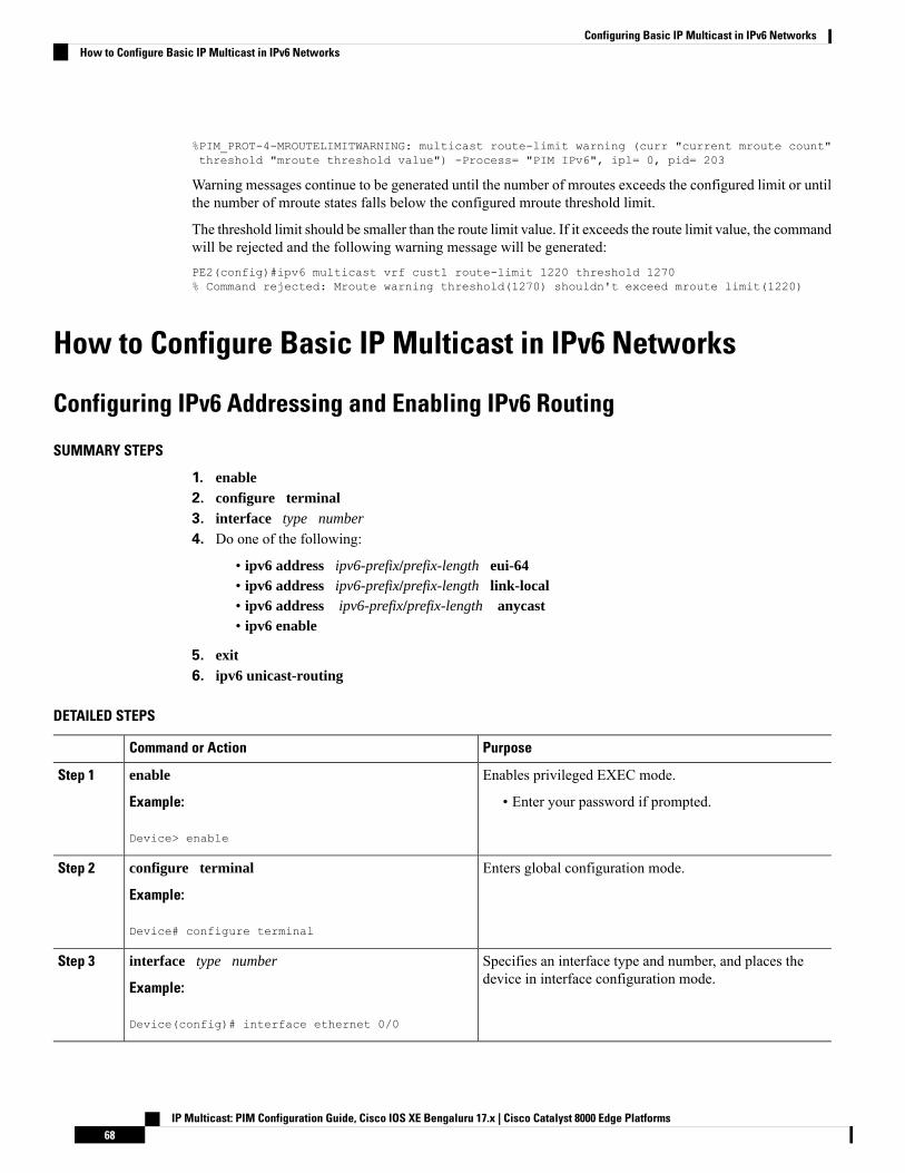
%PIM_PROT-4-MROUTELIMITWARNING: multicast route-limit warning (curr "current mroute count"threshold "mroute threshold value") -Process= "PIM IPv6", ipl= 0, pid= 203
Warning messages continue to be generated until the number of mroutes exceeds the configured limit or untilthe number of mroute states falls below the configured mroute threshold limit.
The threshold limit should be smaller than the route limit value. If it exceeds the route limit value, the commandwill be rejected and the following warning message will be generated:PE2(config)#ipv6 multicast vrf cust1 route-limit 1220 threshold 1270% Command rejected: Mroute warning threshold(1270) shouldn't exceed mroute limit(1220)
How to Configure Basic IP Multicast in IPv6 Networks
Configuring IPv6 Addressing and Enabling IPv6 Routing
SUMMARY STEPS
1. enable2. configure terminal3. interface type number
4. Do one of the following:
• ipv6 address ipv6-prefix/prefix-length eui-64• ipv6 address ipv6-prefix/prefix-length link-local• ipv6 address ipv6-prefix/prefix-length anycast• ipv6 enable
5. exit6. ipv6 unicast-routing
DETAILED STEPS
PurposeCommand or Action
Enables privileged EXEC mode.enableStep 1
Example: • Enter your password if prompted.
Device> enable
Enters global configuration mode.configure terminal
Example:
Step 2
Device# configure terminal
Specifies an interface type and number, and places thedevice in interface configuration mode.
interface type number
Example:
Step 3
Device(config)# interface ethernet 0/0
IP Multicast: PIM Configuration Guide, Cisco IOS XE Bengaluru 17.x | Cisco Catalyst 8000 Edge Platforms68
Configuring Basic IP Multicast in IPv6 NetworksHow to Configure Basic IP Multicast in IPv6 Networks
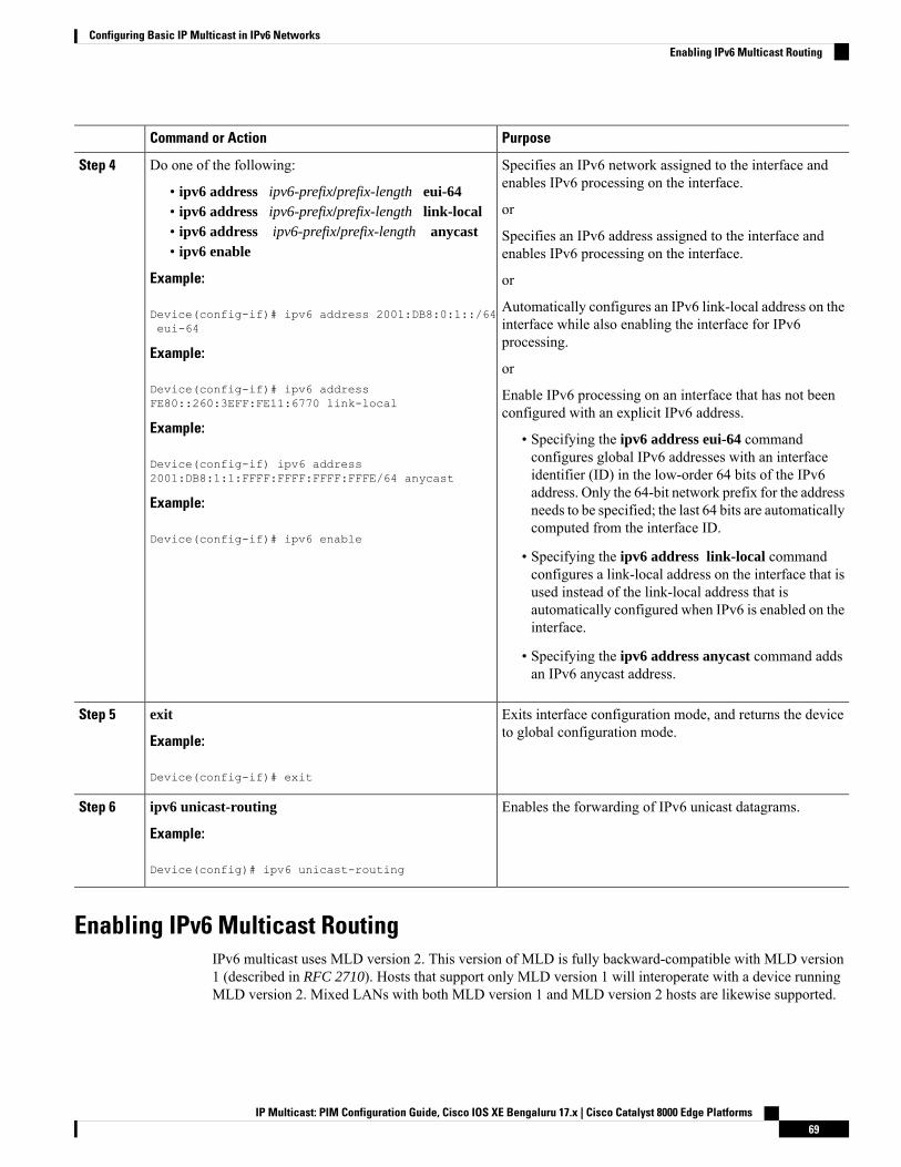
PurposeCommand or Action
Specifies an IPv6 network assigned to the interface andenables IPv6 processing on the interface.
Do one of the following:Step 4
• ipv6 address ipv6-prefix/prefix-length eui-64or• ipv6 address ipv6-prefix/prefix-length link-local
• ipv6 address ipv6-prefix/prefix-length anycast Specifies an IPv6 address assigned to the interface andenables IPv6 processing on the interface.• ipv6 enable
Example: or
Device(config-if)# ipv6 address 2001:DB8:0:1::/64eui-64
Automatically configures an IPv6 link-local address on theinterface while also enabling the interface for IPv6processing.
Example:or
Device(config-if)# ipv6 addressFE80::260:3EFF:FE11:6770 link-local
Enable IPv6 processing on an interface that has not beenconfigured with an explicit IPv6 address.
Example:• Specifying the ipv6 address eui-64 commandconfigures global IPv6 addresses with an interfaceDevice(config-if) ipv6 address
2001:DB8:1:1:FFFF:FFFF:FFFF:FFFE/64 anycast identifier (ID) in the low-order 64 bits of the IPv6address. Only the 64-bit network prefix for the address
Example: needs to be specified; the last 64 bits are automaticallycomputed from the interface ID.
Device(config-if)# ipv6 enable
• Specifying the ipv6 address link-local commandconfigures a link-local address on the interface that isused instead of the link-local address that isautomatically configured when IPv6 is enabled on theinterface.
• Specifying the ipv6 address anycast command addsan IPv6 anycast address.
Exits interface configuration mode, and returns the deviceto global configuration mode.
exit
Example:
Step 5
Device(config-if)# exit
Enables the forwarding of IPv6 unicast datagrams.ipv6 unicast-routing
Example:
Step 6
Device(config)# ipv6 unicast-routing
Enabling IPv6 Multicast RoutingIPv6 multicast uses MLD version 2. This version of MLD is fully backward-compatible with MLD version1 (described in RFC 2710). Hosts that support only MLD version 1 will interoperate with a device runningMLD version 2. Mixed LANs with both MLD version 1 and MLD version 2 hosts are likewise supported.
IP Multicast: PIM Configuration Guide, Cisco IOS XE Bengaluru 17.x | Cisco Catalyst 8000 Edge Platforms69
Configuring Basic IP Multicast in IPv6 NetworksEnabling IPv6 Multicast Routing
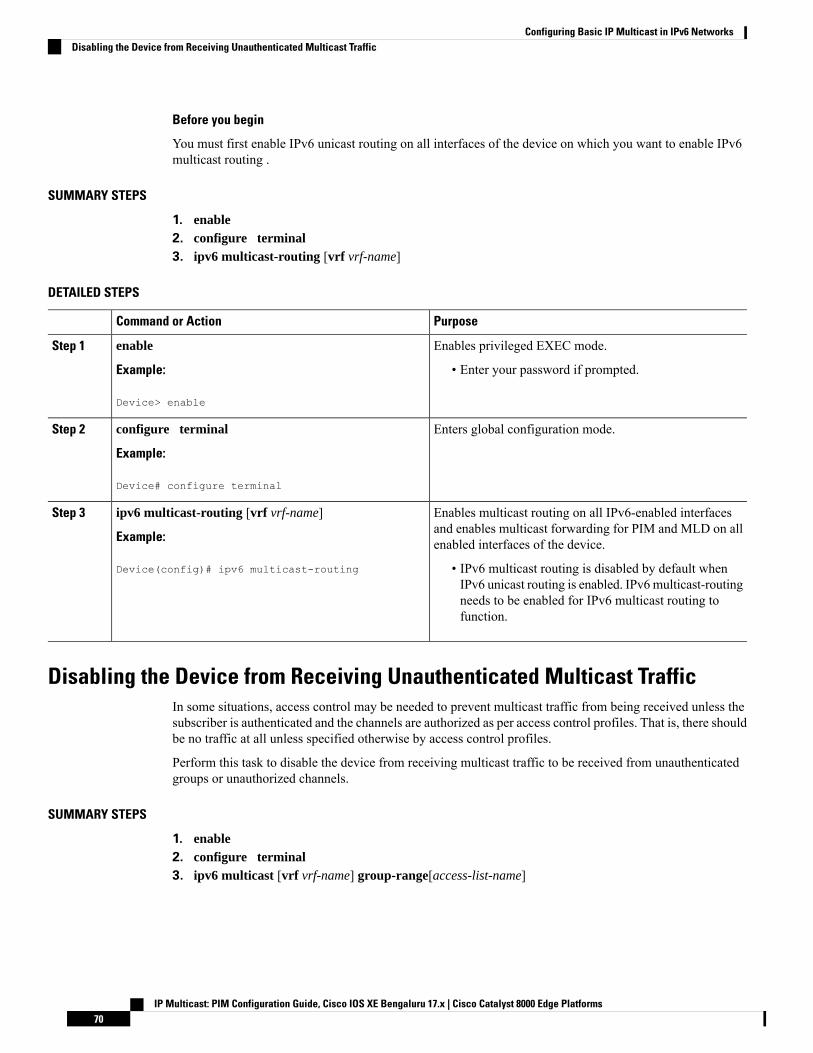
Before you begin
You must first enable IPv6 unicast routing on all interfaces of the device on which you want to enable IPv6multicast routing .
SUMMARY STEPS
1. enable2. configure terminal3. ipv6 multicast-routing [vrf vrf-name]
DETAILED STEPS
PurposeCommand or Action
Enables privileged EXEC mode.enableStep 1
Example: • Enter your password if prompted.
Device> enable
Enters global configuration mode.configure terminal
Example:
Step 2
Device# configure terminal
Enables multicast routing on all IPv6-enabled interfacesand enables multicast forwarding for PIM and MLD on allenabled interfaces of the device.
ipv6 multicast-routing [vrf vrf-name]
Example:
Device(config)# ipv6 multicast-routing
Step 3
• IPv6 multicast routing is disabled by default whenIPv6 unicast routing is enabled. IPv6multicast-routingneeds to be enabled for IPv6 multicast routing tofunction.
Disabling the Device from Receiving Unauthenticated Multicast TrafficIn some situations, access control may be needed to prevent multicast traffic from being received unless thesubscriber is authenticated and the channels are authorized as per access control profiles. That is, there shouldbe no traffic at all unless specified otherwise by access control profiles.
Perform this task to disable the device from receiving multicast traffic to be received from unauthenticatedgroups or unauthorized channels.
SUMMARY STEPS
1. enable2. configure terminal3. ipv6 multicast [vrf vrf-name] group-range[access-list-name]
IP Multicast: PIM Configuration Guide, Cisco IOS XE Bengaluru 17.x | Cisco Catalyst 8000 Edge Platforms70
Configuring Basic IP Multicast in IPv6 NetworksDisabling the Device from Receiving Unauthenticated Multicast Traffic
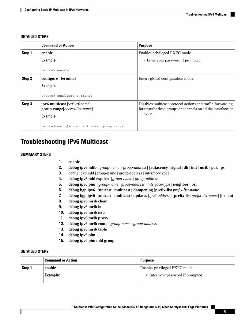
DETAILED STEPS
PurposeCommand or Action
Enables privileged EXEC mode.enableStep 1
Example: • Enter your password if prompted.
Device> enable
Enters global configuration mode.configure terminal
Example:
Step 2
Device# configure terminal
Disables multicast protocol actions and traffic forwardingfor unauthorized groups or channels on all the interfaces ina device.
ipv6 multicast [vrf vrf-name]group-range[access-list-name]
Example:
Step 3
Device(config)# ipv6 multicast group-range
Troubleshooting IPv6 Multicast
SUMMARY STEPS
1. enable2. debug ipv6 mfib group-name | group-address] [adjacency | signal | db | init | mrib | pak | ps3. debug ipv6 mld [group-name | group-address | interface-type]4. debug ipv6 mld explicit [group-name | group-address
5. debug ipv6 pim [group-name | group-address | interface-type | neighbor | bsr6. debug bgp ipv6 {unicast | multicast} dampening [prefix-list prefix-list-name
7. debug bgp ipv6 {unicast | multicast} updates [ipv6-address] [prefix-list prefix-list-name] [in | out8. debug ipv6 mrib client9. debug ipv6 mrib io10. debug ipv6 mrib issu11. debug ipv6 mrib proxy12. debug ipv6 mrib route [group-name | group-address
13. debug ipv6 mrib table14. debug ipv6 pim15. debug ipv6 pim mld group
DETAILED STEPS
PurposeCommand or Action
Enables privileged EXEC mode.enableStep 1
Example: • Enter your password if prompted.
IP Multicast: PIM Configuration Guide, Cisco IOS XE Bengaluru 17.x | Cisco Catalyst 8000 Edge Platforms71
Configuring Basic IP Multicast in IPv6 NetworksTroubleshooting IPv6 Multicast
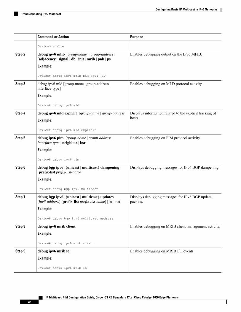
PurposeCommand or Action
Device> enable
Enables debugging output on the IPv6 MFIB.debug ipv6 mfib group-name | group-address][adjacency | signal | db | init | mrib | pak | ps
Step 2
Example:
Device# debug ipv6 mfib pak FF04::10
Enables debugging on MLD protocol activity.debug ipv6 mld [group-name | group-address |interface-type]
Step 3
Example:
Device# debug ipv6 mld
Displays information related to the explicit tracking ofhosts.
debug ipv6 mld explicit [group-name | group-address
Example:
Step 4
Device# debug ipv6 mld explicit
Enables debugging on PIM protocol activity.debug ipv6 pim [group-name | group-address |interface-type | neighbor | bsr
Step 5
Example:
Device# debug ipv6 pim
Displays debugging messages for IPv6 BGP dampening.debug bgp ipv6 {unicast | multicast} dampening[prefix-list prefix-list-name
Step 6
Example:
Device# debug bgp ipv6 multicast
Displays debugging messages for IPv6 BGP updatepackets.
debug bgp ipv6 {unicast | multicast} updates[ipv6-address] [prefix-list prefix-list-name] [in | out
Example:
Step 7
Device# debug bgp ipv6 multicast updates
Enables debugging on MRIB client management activity.debug ipv6 mrib client
Example:
Step 8
Device# debug ipv6 mrib client
Enables debugging on MRIB I/O events.debug ipv6 mrib io
Example:
Step 9
Device# debug ipv6 mrib io
IP Multicast: PIM Configuration Guide, Cisco IOS XE Bengaluru 17.x | Cisco Catalyst 8000 Edge Platforms72
Configuring Basic IP Multicast in IPv6 NetworksTroubleshooting IPv6 Multicast
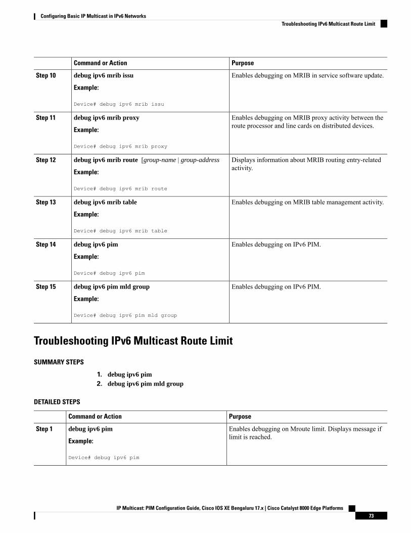
PurposeCommand or Action
Enables debugging on MRIB in service software update.debug ipv6 mrib issu
Example:
Step 10
Device# debug ipv6 mrib issu
Enables debugging on MRIB proxy activity between theroute processor and line cards on distributed devices.
debug ipv6 mrib proxy
Example:
Step 11
Device# debug ipv6 mrib proxy
Displays information about MRIB routing entry-relatedactivity.
debug ipv6 mrib route [group-name | group-address
Example:
Step 12
Device# debug ipv6 mrib route
Enables debugging on MRIB table management activity.debug ipv6 mrib table
Example:
Step 13
Device# debug ipv6 mrib table
Enables debugging on IPv6 PIM.debug ipv6 pim
Example:
Step 14
Device# debug ipv6 pim
Enables debugging on IPv6 PIM.debug ipv6 pim mld group
Example:
Step 15
Device# debug ipv6 pim mld group
Troubleshooting IPv6 Multicast Route Limit
SUMMARY STEPS
1. debug ipv6 pim2. debug ipv6 pim mld group
DETAILED STEPS
PurposeCommand or Action
Enables debugging on Mroute limit. Displays message iflimit is reached.
debug ipv6 pim
Example:
Step 1
Device# debug ipv6 pim
IP Multicast: PIM Configuration Guide, Cisco IOS XE Bengaluru 17.x | Cisco Catalyst 8000 Edge Platforms73
Configuring Basic IP Multicast in IPv6 NetworksTroubleshooting IPv6 Multicast Route Limit

PurposeCommand or Action
Enables debugging on Mroute limit. Displays message iflimit is reached.
debug ipv6 pim mld group
Example:
Step 2
Device# debug ipv6 pim mld group
Configuring PIMv6 Anycast RPThis task describes how to configure two PIMv6 anycast RP peers. Steps 3 through 11 show the configurationfor RP1, and Steps 12 through 19 show the configuration for RP2.
SUMMARY STEPS
1. enable2. configure terminal3. ipv6 address {ipv6-address/prefix-length | prefix-name sub-bits /prefix-length}4. interface type number
5. ipv6 address {ipv6-address/prefix-length | prefix-name sub-bits /prefix-length}6. no shut7. interface type number
8. ipv6 pim [vrf vrf-name] rp-address ipv6-address [group-address-list ] [bidir]9. no shut10. exit11. ipv6 pim anycast-RP rp-address peer-address
12. ipv6 address {ipv6-address/prefix-length | prefix-name sub-bits /prefix-length}13. interface type number
14. ipv6 address {ipv6-address/prefix-length | prefix-name sub-bits /prefix-length}15. no shut16. interface type number
17. ipv6 pim [vrf vrf-name] rp-address ipv6-address [group-address-list ] [bidir]18. no shut19. ipv6 pim anycast-RP rp-address peer-address
DETAILED STEPS
PurposeCommand or Action
Enables privileged EXEC mode.enableStep 1
Example: Enter your password if prompted.Device> enable
Enters global configuration mode.configure terminal
Example:
Step 2
Device# configure terminal
IP Multicast: PIM Configuration Guide, Cisco IOS XE Bengaluru 17.x | Cisco Catalyst 8000 Edge Platforms74
Configuring Basic IP Multicast in IPv6 NetworksConfiguring PIMv6 Anycast RP

PurposeCommand or Action
Configures an IPv6 address based on an IPv6 general prefixand enable IPv6 processing on an interface.
ipv6 address {ipv6-address/prefix-length |prefix-name sub-bits /prefix-length}
Example:
Step 3
Device(config-if)# ipv6 add 2001:DB8::1:1/128
Specifies an interface type and number, and places thedevice in interface configuration mode.
interface type number
Example:
Step 4
Device(config)# interface Loopback4
Configures an IPv6 address based on an IPv6 general prefixand enable IPv6 processing on an interface.
ipv6 address {ipv6-address/prefix-length |prefix-name sub-bits /prefix-length}
Example:
Step 5
Device(config-if)# ipv6 address 2001:DB8::4:4/64
Enables an interface.no shut
Example:
Step 6
Device(config-if)# no shut
Specifies an interface type and number, and places thedevice in interface configuration mode.
interface type number
Example:
Step 7
Device(config-if)# interface Loopback5
Configures the address of a PIM RP for a particular grouprange.
ipv6 pim [vrf vrf-name] rp-address ipv6-address[group-address-list ] [bidir]
Example:
Step 8
Device(config)# ipv6 pim rp-address 2001:DB8::1:1acl_sparse1
Enables an interface.no shut
Example:
Step 9
Device(config-if)# no shut
Enter this command to exit interface configuration modeand enter global configuration mode.
exit
Example:
Step 10
Device(config-if)# exit
Use this command to configure the address of the PIM RPfor an anycast group range.
ipv6 pim anycast-RP rp-address peer-address
Example:
Step 11
• The IP address of the local device must be includedin the set so that all devices in anycast set have thesame IP addresses.
The following example shows configuring PIM RP for ananycast group range for a remote and local router:Device(config)# ipv6 pim anycast-rp 2001:DB8::1:12001:DB8::3:3# ipv6 pim anycast-rp 2001:DB8::1:1 2001:DB8::4:4
IP Multicast: PIM Configuration Guide, Cisco IOS XE Bengaluru 17.x | Cisco Catalyst 8000 Edge Platforms75
Configuring Basic IP Multicast in IPv6 NetworksConfiguring PIMv6 Anycast RP

PurposeCommand or Action
Configures an IPv6 address based on an IPv6 general prefixand enables IPv6 processing on an interface.
ipv6 address {ipv6-address/prefix-length |prefix-name sub-bits /prefix-length}
Example:
Step 12
Device(config-if)# ipv6 add 2001:DB8::1:1/128
Specifies an interface type and number, and places thedevice in interface configuration mode.
interface type number
Example:
Step 13
Device(config)# interface Loopback4
Configures an IPv6 address based on an IPv6 general prefixand enables IPv6 processing on an interface.
ipv6 address {ipv6-address/prefix-length |prefix-name sub-bits /prefix-length}
Example:
Step 14
Device(config-if)# ipv6 address 2001:DB8::3:3/64
Enables an interface.no shut
Example:
Step 15
Device(config-if)# no shut
Specifies an interface type and number, and places thedevice in interface configuration mode.
interface type number
Example:
Step 16
Device(config-if)# interface Loopback5
Configures the address of a PIM RP for a particular grouprange.
ipv6 pim [vrf vrf-name] rp-address ipv6-address[group-address-list ] [bidir]
Example:
Step 17
Device(config)# ipv6 pim rp-address 2001:DB8::1:1acl_sparse1
Enables an interfaceno shut
Example:
Step 18
Device(config-if)# no shut
Use this command to configure the address of the PIM RPfor an anycast group range for a remote or local router.
ipv6 pim anycast-RP rp-address peer-address
Example:
Step 19
The following example shows configuring PIM RP for ananycast group range for a remote and local router:Device(config-if)# ipv6 pim anycast-rp2001:DB8::1:1 2001:DB8::3:3# ipv6 pim anycast-rp 2001:DB8::1:1 2001:DB8::4:4
IP Multicast: PIM Configuration Guide, Cisco IOS XE Bengaluru 17.x | Cisco Catalyst 8000 Edge Platforms76
Configuring Basic IP Multicast in IPv6 NetworksConfiguring PIMv6 Anycast RP
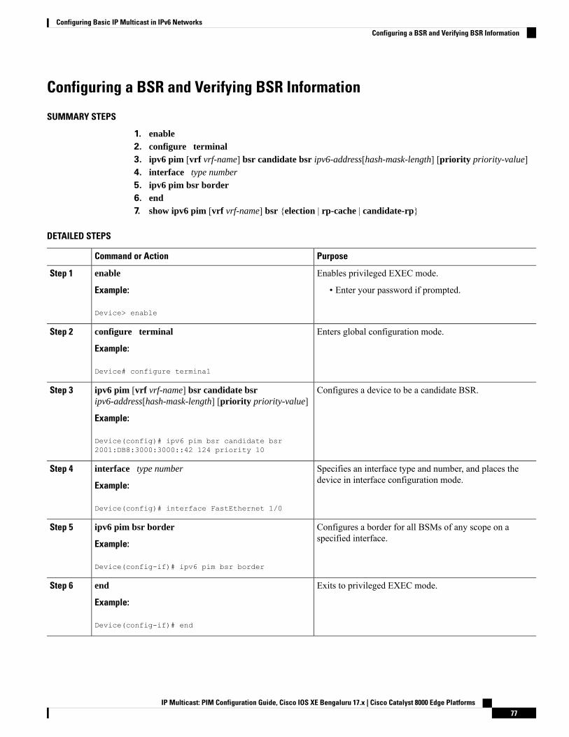
Configuring a BSR and Verifying BSR Information
SUMMARY STEPS
1. enable2. configure terminal3. ipv6 pim [vrf vrf-name] bsr candidate bsr ipv6-address[hash-mask-length] [priority priority-value]4. interface type number
5. ipv6 pim bsr border6. end7. show ipv6 pim [vrf vrf-name] bsr {election | rp-cache | candidate-rp}
DETAILED STEPS
PurposeCommand or Action
Enables privileged EXEC mode.enableStep 1
Example: • Enter your password if prompted.
Device> enable
Enters global configuration mode.configure terminal
Example:
Step 2
Device# configure terminal
Configures a device to be a candidate BSR.ipv6 pim [vrf vrf-name] bsr candidate bsripv6-address[hash-mask-length] [priority priority-value]
Step 3
Example:
Device(config)# ipv6 pim bsr candidate bsr2001:DB8:3000:3000::42 124 priority 10
Specifies an interface type and number, and places thedevice in interface configuration mode.
interface type number
Example:
Step 4
Device(config)# interface FastEthernet 1/0
Configures a border for all BSMs of any scope on aspecified interface.
ipv6 pim bsr border
Example:
Step 5
Device(config-if)# ipv6 pim bsr border
Exits to privileged EXEC mode.end
Example:
Step 6
Device(config-if)# end
IP Multicast: PIM Configuration Guide, Cisco IOS XE Bengaluru 17.x | Cisco Catalyst 8000 Edge Platforms77
Configuring Basic IP Multicast in IPv6 NetworksConfiguring a BSR and Verifying BSR Information

PurposeCommand or Action
Displays information related to PIM BSR protocolprocessing.
show ipv6 pim [vrf vrf-name] bsr {election | rp-cache |candidate-rp}
Example:
Step 7
Device# show ipv6 pim bsr election
Sending PIM RP Advertisements to the BSR
SUMMARY STEPS
1. enable2. configure terminal3. ipv6 pim [vrf vrf-name] bsr candidate rp ipv6-address [group-list access-list-name] [priority
priority-value] [interval seconds] [scope scope-value] [bidir]4. interface type number
5. ipv6 pim bsr border
DETAILED STEPS
PurposeCommand or Action
Enables privileged EXEC mode.enableStep 1
Example: • Enter your password if prompted.
Device> enable
Enters global configuration mode.configure terminal
Example:
Step 2
Device# configure terminal
Sends PIM RP advertisements to the BSR.ipv6 pim [vrf vrf-name] bsr candidate rp ipv6-address[group-list access-list-name] [priority priority-value][interval seconds] [scope scope-value] [bidir]
Step 3
Example:
Device(config)# ipv6 pim bsr candidate rp2001:DB8:3000:3000::42 priority 0
Specifies an interface type and number, and places thedevice in interface configuration mode.
interface type number
Example:
Step 4
Device(config)# interface FastEthernet 1/0
Configures a border for all BSMs of any scope on aspecified interface.
ipv6 pim bsr border
Example:
Step 5
IP Multicast: PIM Configuration Guide, Cisco IOS XE Bengaluru 17.x | Cisco Catalyst 8000 Edge Platforms78
Configuring Basic IP Multicast in IPv6 NetworksSending PIM RP Advertisements to the BSR
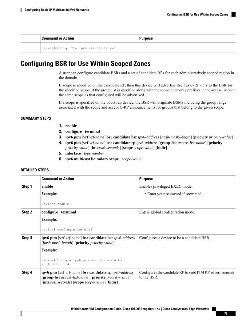
PurposeCommand or Action
Device(config-if)# ipv6 pim bsr border
Configuring BSR for Use Within Scoped ZonesA user can configure candidate BSRs and a set of candidate RPs for each administratively scoped region inthe domain.
If scope is specified on the candidate RP, then this device will advertise itself as C-RP only to the BSR forthe specified scope. If the group list is specified along with the scope, then only prefixes in the access list withthe same scope as that configured will be advertised.
If a scope is specified on the bootstrap device, the BSR will originate BSMs including the group rangeassociated with the scope and accept C-RP announcements for groups that belong to the given scope.
SUMMARY STEPS
1. enable2. configure terminal3. ipv6 pim [vrf vrf-name] bsr candidate bsr ipv6-address [hash-mask-length] [priority priority-value]4. ipv6 pim [vrf vrf-name] bsr candidate rp ipv6-address [group-list access-list-name] [priority
priority-value] [interval seconds] [scope scope-value] [bidir]5. interface type number
6. ipv6 multicast boundary scope scope-value
DETAILED STEPS
PurposeCommand or Action
Enables privileged EXEC mode.enableStep 1
Example: • Enter your password if prompted.
Device> enable
Enters global configuration mode.configure terminal
Example:
Step 2
Device# configure terminal
Configures a device to be a candidate BSR.ipv6 pim [vrf vrf-name] bsr candidate bsr ipv6-address[hash-mask-length] [priority priority-value]
Step 3
Example:
Device(config)# ipv6 pim bsr candidate bsr2001:DB8:1:1:4
Configures the candidate RP to send PIMRP advertisementsto the BSR.
ipv6 pim [vrf vrf-name] bsr candidate rp ipv6-address[group-list access-list-name] [priority priority-value][interval seconds] [scope scope-value] [bidir]
Step 4
IP Multicast: PIM Configuration Guide, Cisco IOS XE Bengaluru 17.x | Cisco Catalyst 8000 Edge Platforms79
Configuring Basic IP Multicast in IPv6 NetworksConfiguring BSR for Use Within Scoped Zones
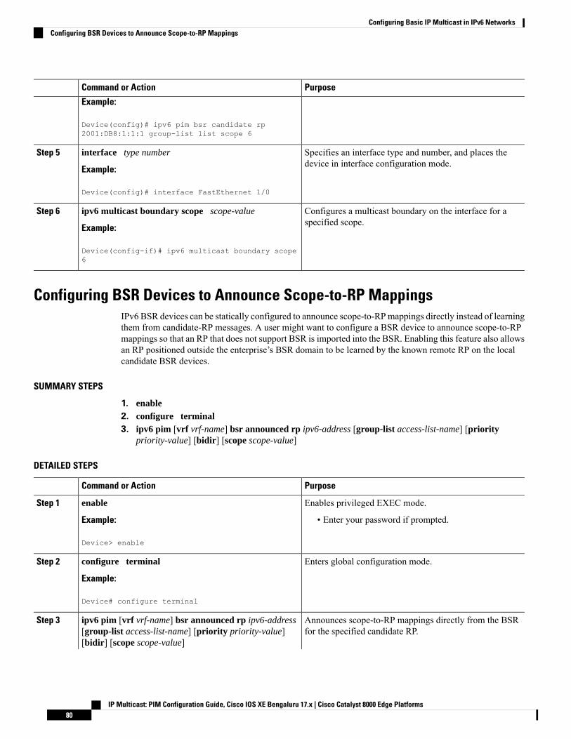
PurposeCommand or Action
Example:
Device(config)# ipv6 pim bsr candidate rp2001:DB8:1:1:1 group-list list scope 6
Specifies an interface type and number, and places thedevice in interface configuration mode.
interface type number
Example:
Step 5
Device(config)# interface FastEthernet 1/0
Configures a multicast boundary on the interface for aspecified scope.
ipv6 multicast boundary scope scope-value
Example:
Step 6
Device(config-if)# ipv6 multicast boundary scope6
Configuring BSR Devices to Announce Scope-to-RP MappingsIPv6 BSR devices can be statically configured to announce scope-to-RPmappings directly instead of learningthem from candidate-RP messages. A user might want to configure a BSR device to announce scope-to-RPmappings so that an RP that does not support BSR is imported into the BSR. Enabling this feature also allowsan RP positioned outside the enterprise’s BSR domain to be learned by the known remote RP on the localcandidate BSR devices.
SUMMARY STEPS
1. enable2. configure terminal3. ipv6 pim [vrf vrf-name] bsr announced rp ipv6-address [group-list access-list-name] [priority
priority-value] [bidir] [scope scope-value]
DETAILED STEPS
PurposeCommand or Action
Enables privileged EXEC mode.enableStep 1
Example: • Enter your password if prompted.
Device> enable
Enters global configuration mode.configure terminal
Example:
Step 2
Device# configure terminal
Announces scope-to-RP mappings directly from the BSRfor the specified candidate RP.
ipv6 pim [vrf vrf-name] bsr announced rp ipv6-address[group-list access-list-name] [priority priority-value][bidir] [scope scope-value]
Step 3
IP Multicast: PIM Configuration Guide, Cisco IOS XE Bengaluru 17.x | Cisco Catalyst 8000 Edge Platforms80
Configuring Basic IP Multicast in IPv6 NetworksConfiguring BSR Devices to Announce Scope-to-RP Mappings
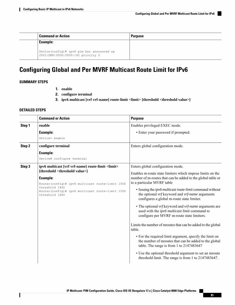
PurposeCommand or Action
Example:
Device(config)# ipv6 pim bsr announced rp2001:DB8:3000:3000::42 priority 0
Configuring Global and Per MVRF Multicast Route Limit for IPv6
SUMMARY STEPS
1. enable2. configure terminal3. ipv6 multicast [vrf vrf-name] route-limit <limit> [threshold <threshold value>]
DETAILED STEPS
PurposeCommand or Action
Enables privileged EXEC mode.enableStep 1
Example: • Enter your password if prompted.Device> enable
Enters global configuration mode.configure terminal
Example:
Step 2
Device# configure terminal
Enters global configuration mode.ipv6 multicast [vrf vrf-name] route-limit <limit>[threshold <threshold value>]
Step 3
Enables m-route state limiters which impose limits on thenumber of m-routes that can be added to the global table orto a particular MVRF table
Example:Router(config)# ipv6 multicast route-limit 1500threshold 1460 • Issuing the ipv6 multicast route-limit commandwithout
the optional vrf keyword and vrf-name argumentsconfigures a global m-route state limiter.
Router(config)# ipv6 multicast route-limit 1500threshold 1460
• The optional vrf keyword and vrf-name arguments areused with the ipv6 multicast limit command toconfigure per MVRF m-route state limiters.
Limits the number of mroutes that can be added to the globaltable.
• For the required limit argument, specify the limit onthe number of mroutes that can be added to the globaltable. The range is from 1 to 2147483647
• Use the optional threshold argument to set an mroutethreshold limit. The range is from 1 to 2147483647.
IP Multicast: PIM Configuration Guide, Cisco IOS XE Bengaluru 17.x | Cisco Catalyst 8000 Edge Platforms81
Configuring Basic IP Multicast in IPv6 NetworksConfiguring Global and Per MVRF Multicast Route Limit for IPv6
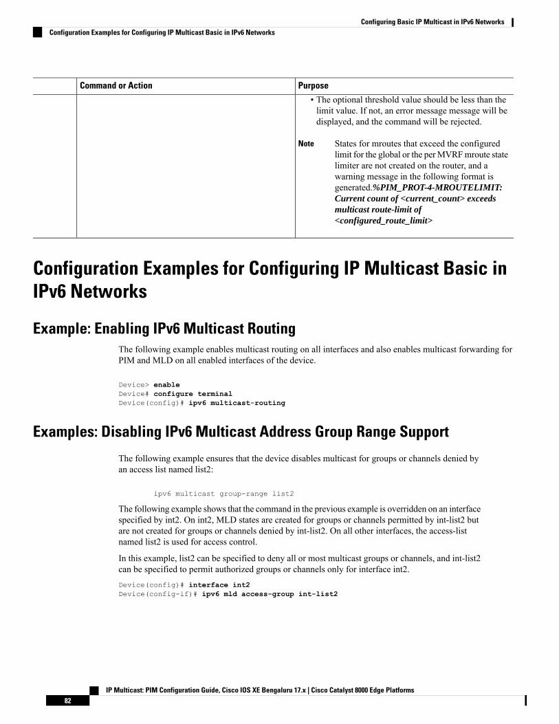
PurposeCommand or Action
• The optional threshold value should be less than thelimit value. If not, an error message message will bedisplayed, and the command will be rejected.
States for mroutes that exceed the configuredlimit for the global or the perMVRFmroute statelimiter are not created on the router, and awarning message in the following format isgenerated.%PIM_PROT-4-MROUTELIMIT:Current count of <current_count> exceedsmulticast route-limit of<configured_route_limit>
Note
Configuration Examples for Configuring IP Multicast Basic inIPv6 Networks
Example: Enabling IPv6 Multicast RoutingThe following example enables multicast routing on all interfaces and also enables multicast forwarding forPIM and MLD on all enabled interfaces of the device.
Device> enableDevice# configure terminalDevice(config)# ipv6 multicast-routing
Examples: Disabling IPv6 Multicast Address Group Range Support
The following example ensures that the device disables multicast for groups or channels denied byan access list named list2:
ipv6 multicast group-range list2
The following example shows that the command in the previous example is overridden on an interfacespecified by int2. On int2, MLD states are created for groups or channels permitted by int-list2 butare not created for groups or channels denied by int-list2. On all other interfaces, the access-listnamed list2 is used for access control.
In this example, list2 can be specified to deny all or most multicast groups or channels, and int-list2can be specified to permit authorized groups or channels only for interface int2.Device(config)# interface int2Device(config-if)# ipv6 mld access-group int-list2
IP Multicast: PIM Configuration Guide, Cisco IOS XE Bengaluru 17.x | Cisco Catalyst 8000 Edge Platforms82
Configuring Basic IP Multicast in IPv6 NetworksConfiguration Examples for Configuring IP Multicast Basic in IPv6 Networks
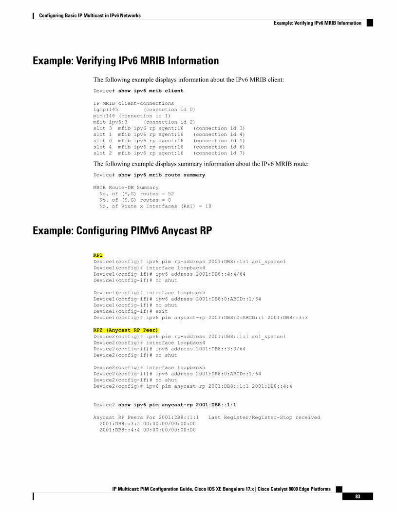
Example: Verifying IPv6 MRIB Information
The following example displays information about the IPv6 MRIB client:Device# show ipv6 mrib client
IP MRIB client-connectionsigmp:145 (connection id 0)pim:146 (connection id 1)mfib ipv6:3 (connection id 2)slot 3 mfib ipv6 rp agent:16 (connection id 3)slot 1 mfib ipv6 rp agent:16 (connection id 4)slot 0 mfib ipv6 rp agent:16 (connection id 5)slot 4 mfib ipv6 rp agent:16 (connection id 6)slot 2 mfib ipv6 rp agent:16 (connection id 7)
The following example displays summary information about the IPv6 MRIB route:Device# show ipv6 mrib route summary
MRIB Route-DB SummaryNo. of (*,G) routes = 52No. of (S,G) routes = 0No. of Route x Interfaces (RxI) = 10
Example: Configuring PIMv6 Anycast RP
RP1Device1(config)# ipv6 pim rp-address 2001:DB8::1:1 acl_sparse1Device1(config)# interface Loopback4Device1(config-if)# ipv6 address 2001:DB8::4:4/64Device1(config-if)# no shut
Device1(config)# interface Loopback5Device1(config-if)# ipv6 address 2001:DB8:0:ABCD::1/64Device1(config-if)# no shutDevice1(config-if)# exitDevice1(config)# ipv6 pim anycast-rp 2001:DB8:0:ABCD::1 2001:DB8::3:3
RP2 (Anycast RP Peer)Device2(config)# ipv6 pim rp-address 2001:DB8::1:1 acl_sparse1Device2(config)# interface Loopback4Device2(config-if)# ipv6 address 2001:DB8::3:3/64Device2(config-if)# no shut
Device2(config)# interface Loopback5Device2(config-if)# ipv6 address 2001:DB8:0:ABCD::1/64Device2(config-if)# no shutDevice2(config)# ipv6 pim anycast-rp 2001:DB8::1:1 2001:DB8::4:4
Device2 show ipv6 pim anycast-rp 2001:DB8::1:1
Anycast RP Peers For 2001:DB8::1:1 Last Register/Register-Stop received2001:DB8::3:3 00:00:00/00:00:002001:DB8::4:4 00:00:00/00:00:00
IP Multicast: PIM Configuration Guide, Cisco IOS XE Bengaluru 17.x | Cisco Catalyst 8000 Edge Platforms83
Configuring Basic IP Multicast in IPv6 NetworksExample: Verifying IPv6 MRIB Information
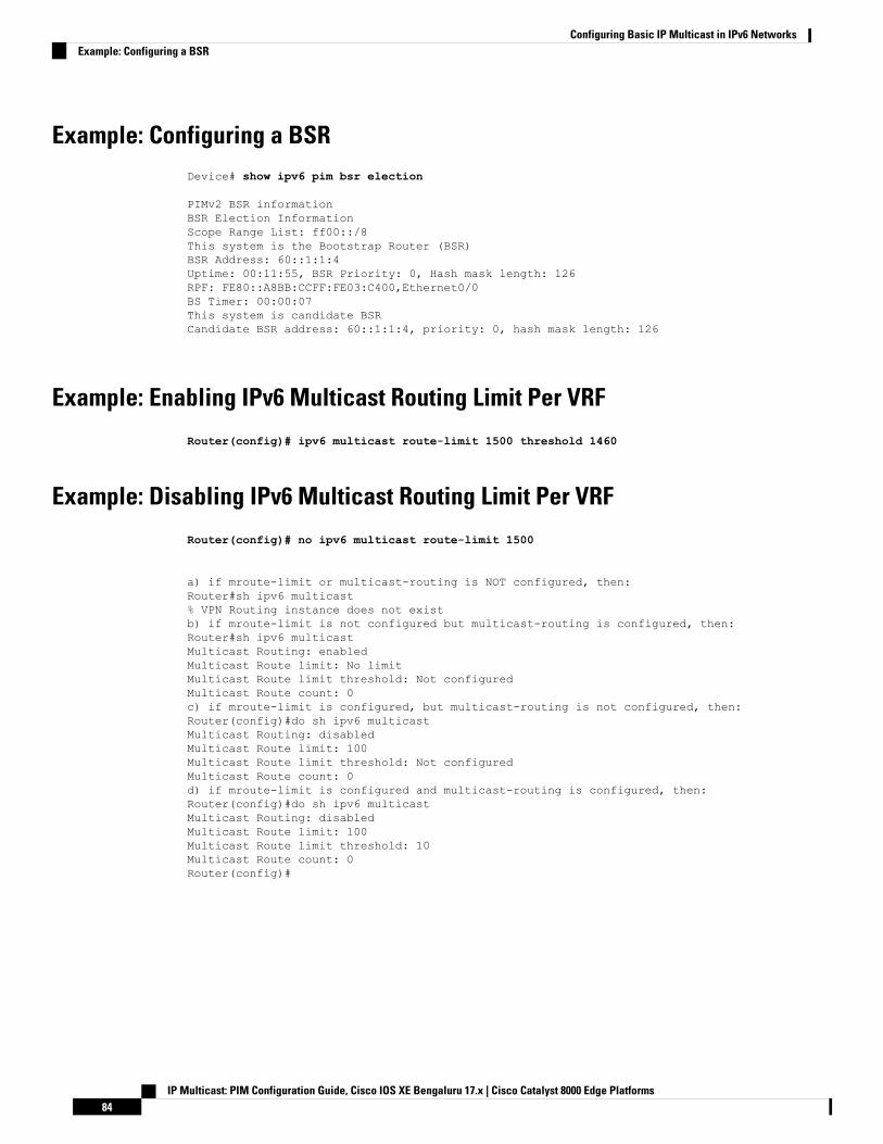
Example: Configuring a BSRDevice# show ipv6 pim bsr election
PIMv2 BSR informationBSR Election InformationScope Range List: ff00::/8This system is the Bootstrap Router (BSR)BSR Address: 60::1:1:4Uptime: 00:11:55, BSR Priority: 0, Hash mask length: 126RPF: FE80::A8BB:CCFF:FE03:C400,Ethernet0/0BS Timer: 00:00:07This system is candidate BSRCandidate BSR address: 60::1:1:4, priority: 0, hash mask length: 126
Example: Enabling IPv6 Multicast Routing Limit Per VRF
Router(config)# ipv6 multicast route-limit 1500 threshold 1460
Example: Disabling IPv6 Multicast Routing Limit Per VRF
Router(config)# no ipv6 multicast route-limit 1500
a) if mroute-limit or multicast-routing is NOT configured, then:Router#sh ipv6 multicast% VPN Routing instance does not existb) if mroute-limit is not configured but multicast-routing is configured, then:Router#sh ipv6 multicastMulticast Routing: enabledMulticast Route limit: No limitMulticast Route limit threshold: Not configuredMulticast Route count: 0c) if mroute-limit is configured, but multicast-routing is not configured, then:Router(config)#do sh ipv6 multicastMulticast Routing: disabledMulticast Route limit: 100Multicast Route limit threshold: Not configuredMulticast Route count: 0d) if mroute-limit is configured and multicast-routing is configured, then:Router(config)#do sh ipv6 multicastMulticast Routing: disabledMulticast Route limit: 100Multicast Route limit threshold: 10Multicast Route count: 0Router(config)#
IP Multicast: PIM Configuration Guide, Cisco IOS XE Bengaluru 17.x | Cisco Catalyst 8000 Edge Platforms84
Configuring Basic IP Multicast in IPv6 NetworksExample: Configuring a BSR
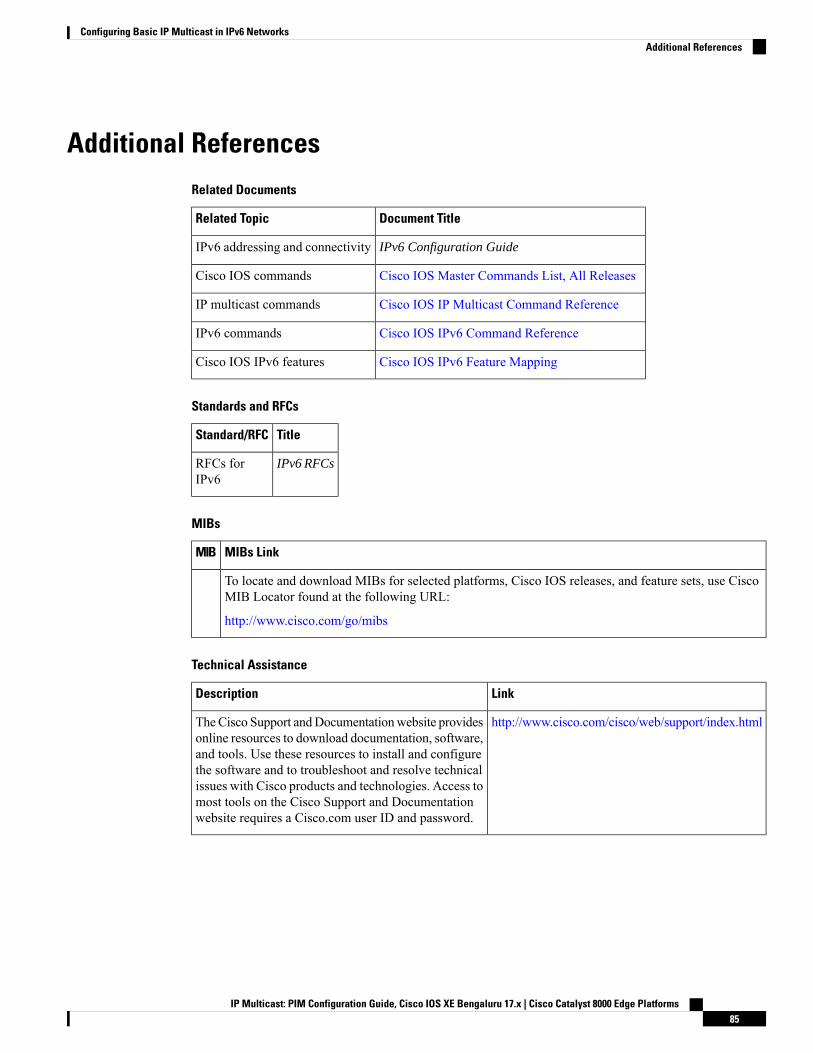
Additional ReferencesRelated Documents
Document TitleRelated Topic
IPv6 Configuration GuideIPv6 addressing and connectivity
Cisco IOS Master Commands List, All ReleasesCisco IOS commands
Cisco IOS IP Multicast Command ReferenceIP multicast commands
Cisco IOS IPv6 Command ReferenceIPv6 commands
Cisco IOS IPv6 Feature MappingCisco IOS IPv6 features
Standards and RFCs
TitleStandard/RFC
IPv6 RFCsRFCs forIPv6
MIBs
MIBs LinkMIB
To locate and download MIBs for selected platforms, Cisco IOS releases, and feature sets, use CiscoMIB Locator found at the following URL:
http://www.cisco.com/go/mibs
Technical Assistance
LinkDescription
http://www.cisco.com/cisco/web/support/index.htmlTheCisco Support andDocumentationwebsite providesonline resources to download documentation, software,and tools. Use these resources to install and configurethe software and to troubleshoot and resolve technicalissues with Cisco products and technologies. Access tomost tools on the Cisco Support and Documentationwebsite requires a Cisco.com user ID and password.
IP Multicast: PIM Configuration Guide, Cisco IOS XE Bengaluru 17.x | Cisco Catalyst 8000 Edge Platforms85
Configuring Basic IP Multicast in IPv6 NetworksAdditional References
Feature Information for Configuring Basic IP Multicast in IPv6Networks
The following table provides release information about the feature or features described in this module. Thistable lists only the software release that introduced support for a given feature in a given software releasetrain. Unless noted otherwise, subsequent releases of that software release train also support that feature.
Use Cisco Feature Navigator to find information about platform support and Cisco software image support.To access Cisco Feature Navigator, go to www.cisco.com/go/cfn. An account on Cisco.com is not required.
IP Multicast: PIM Configuration Guide, Cisco IOS XE Bengaluru 17.x | Cisco Catalyst 8000 Edge Platforms86
Configuring Basic IP Multicast in IPv6 NetworksFeature Information for Configuring Basic IP Multicast in IPv6 Networks
C H A P T E R 5Using MSDP to Interconnect Multiple PIM-SMDomains
This module describes the tasks associated with using Multicast Source Discovery Protocol (MSDP) tointerconnect multiple PIM-SM domains. The tasks explain how to configure MSDP peers, mesh groups, anddefault peers, how to use filters to control and scope MSDP activity, and how to monitor and maintain MSDP.Using MSDP with PIM-SM greatly reduces the complexity of connecting multiple PIM-SM domains.
• , on page 87• Information About Using MSDP to Interconnect Multiple PIM-SM Domains, on page 87• How to Use MSDP to Interconnect Multiple PIM-SM Domains, on page 102• Configuration Examples for Using MSDP to Interconnect Multiple PIM-SM Domains, on page 124• Additional References, on page 127• Feature Information for Using MSDP to Interconnect Multiple PIM-SM Domains, on page 128
Information About Using MSDP to Interconnect MultiplePIM-SM Domains
Benefits of Using MSDP to Interconnect Multiple PIM-SM Domains• Allows a rendezvous point (RP) to dynamically discover active sources outside of its domain.
• Introduces a more manageable approach for building multicast distribution trees between multipledomains.
Use of MSDP to Interconnect Multiple PIM-SM DomainsMSDP is a mechanism to connect multiple PIM-SM domains. The purpose of MSDP is to discover multicastsources in other PIM domains. Themain advantage ofMSDP is that it reduces the complexity of interconnectingmultiple PIM-SM domains by allowing PIM-SM domains to use an interdomain source tree (rather than acommon shared tree). When MSDP is configured in a network, RPs exchange source information with RPsin other domains. An RP can join the interdomain source tree for sources that are sending to groups for which
IP Multicast: PIM Configuration Guide, Cisco IOS XE Bengaluru 17.x | Cisco Catalyst 8000 Edge Platforms87
it has receivers. The RP can do that because it is the root of the shared tree within its domain, which hasbranches to all points in the domain where there are active receivers. When a last-hop router learns of a newsource outside the PIM-SM domain (through the arrival of a multicast packet from the source down the sharedtree), it then can send a join toward the source and join the interdomain source tree.
If the RP either has no shared tree for a particular group or a shared tree whose outgoing interface list is null,it does not send a join to the source in another domain.
Note
When MSDP is enabled, an RP in a PIM-SM domain maintains MSDP peering relationships withMSDP-enabled routers in other domains. This peering relationship occurs over a TCP connection, whereprimarily a list of sources sending to multicast groups is exchanged.MSDP uses TCP (port 639) for its peeringconnections. As with BGP, using point-to-point TCP peeringmeans that each peer must be explicitly configured.The TCP connections between RPs, moreover, are achieved by the underlying routing system. The receivingRP uses the source lists to establish a source path. If the multicast sources are of interest to a domain that hasreceivers, multicast data is delivered over the normal, source-tree building mechanism provided by PIM-SM.MSDP is also used to announce sources sending to a group. These announcements must originate at the RPof the domain.
MSDP depends on BGP or multiprotocol BGP (MBGP) for interdomain operation. We recommended thatyou run MSDP on RPs sending to global multicast groups.
Note
The figure illustratesMSDP operating between twoMSDP peers. PIM usesMSDP as the standardmechanismto register a source with the RP of a domain.
IP Multicast: PIM Configuration Guide, Cisco IOS XE Bengaluru 17.x | Cisco Catalyst 8000 Edge Platforms88
Using MSDP to Interconnect Multiple PIM-SM DomainsUse of MSDP to Interconnect Multiple PIM-SM Domains
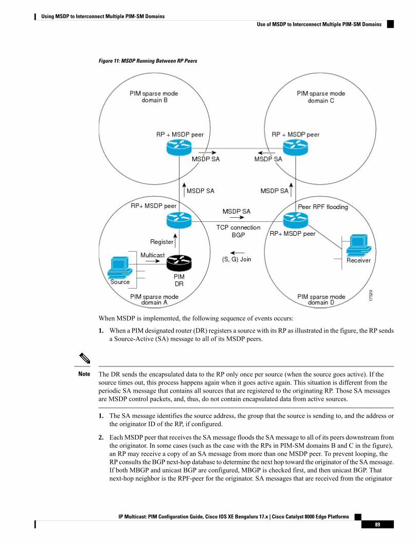
Figure 11: MSDP Running Between RP Peers
When MSDP is implemented, the following sequence of events occurs:
1. When a PIM designated router (DR) registers a source with its RP as illustrated in the figure, the RP sendsa Source-Active (SA) message to all of its MSDP peers.
The DR sends the encapsulated data to the RP only once per source (when the source goes active). If thesource times out, this process happens again when it goes active again. This situation is different from theperiodic SA message that contains all sources that are registered to the originating RP. Those SA messagesare MSDP control packets, and, thus, do not contain encapsulated data from active sources.
Note
1. The SA message identifies the source address, the group that the source is sending to, and the address orthe originator ID of the RP, if configured.
2. EachMSDP peer that receives the SAmessage floods the SAmessage to all of its peers downstream fromthe originator. In some cases (such as the case with the RPs in PIM-SM domains B and C in the figure),an RP may receive a copy of an SA message from more than one MSDP peer. To prevent looping, theRP consults the BGP next-hop database to determine the next hop toward the originator of the SAmessage.If both MBGP and unicast BGP are configured, MBGP is checked first, and then unicast BGP. Thatnext-hop neighbor is the RPF-peer for the originator. SA messages that are received from the originator
IP Multicast: PIM Configuration Guide, Cisco IOS XE Bengaluru 17.x | Cisco Catalyst 8000 Edge Platforms89
Using MSDP to Interconnect Multiple PIM-SM DomainsUse of MSDP to Interconnect Multiple PIM-SM Domains
on any interface other than the interface to the RPF peer are dropped. The SA message flooding process,therefore, is referred to as peer-RPF flooding. Because of the peer-RPF flooding mechanism, BGP orMBGP must be running in conjunction with MSDP.
(M)BGP is not required in MSDP mesh group scenarios. For more information about MSDP mesh groups,see the Configuring an MSDP Mesh Group, on page 111 section.
Note
(M)BGP is not required in default MSDP peer scenarios or in scenarios where only one MSDP peer isconfigured. For more information, see the Configuring a Default MSDP Peer, on page 110 section.
Note
1. When an RP receives an SA message, it checks to see whether there are any members of the advertisedgroups in its domain by checking to see whether there are interfaces on the group’s (*, G) outgoinginterface list. If there are no group members, the RP does nothing. If there are group members, the RPsends an (S, G) join toward the source. As a result, a branch of the interdomain source tree is constructedacross autonomous system boundaries to the RP. As multicast packets arrive at the RP, they are thenforwarded down its own shared tree to the group members in the RP’s domain. The members’ DRs thenhave the option of joining the rendezvous point tree (RPT) to the source using standard PIM-SMprocedures.
2. The originating RP continues to send periodic SA messages for the (S, G) state every 60 seconds for aslong as the source is sending packets to the group. When an RP receives an SA message, it caches the SAmessage. Suppose, for example, that an RP receives an SA message for (172.16.5.4, 228.1.2.3) fromoriginating RP 10.5.4.3. The RP consults its mroute table and finds that there are no active members forgroup 228.1.2.3, so it passes the SA message to its peers downstream of 10.5.4.3. If a host in the domainthen sends a join to the RP for group 228.1.2.3, the RP adds the interface toward the host to the outgoinginterface list of its (*, 224.1.2.3) entry. Because the RP caches SA messages, the router will have an entryfor (172.16.5.4, 228.1.2.3) and can join the source tree as soon as a host requests a join.
In all current and supported software releases, caching of MSDP SA messages is mandatory and cannot bemanually enabled or disabled. By default, when anMSDP peer is configured, the ip multicast cache-sa-statecommand will automatically be added to the running configuration.
Note
MSDP Message TypesThere are four basic MSDP message types, each encoded in their own Type, Length, and Value (TLV) dataformat.
SA MessagesSA messages are used to advertise active sources in a domain. In addition, these SA messages may containthe initial multicast data packet that was sent by the source.
SA messages contain the IP address of the originating RP and one or more (S, G) pairs being advertised. Inaddition, the SA message may contain an encapsulated data packet.
IP Multicast: PIM Configuration Guide, Cisco IOS XE Bengaluru 17.x | Cisco Catalyst 8000 Edge Platforms90
Using MSDP to Interconnect Multiple PIM-SM DomainsMSDP Message Types
For more information about SA messages, see the SA Message Origination Receipt and Processing, on page91 section.
Note
SA Request MessagesSA request messages are used to request a list of active sources for a specific group. These messages are sentto an MSDP SA cache that maintains a list of active (S, G) pairs in its SA cache. Join latency can be reducedby using SA request messages to request the list of active sources for a group instead of having to wait up to60 seconds for all active sources in the group to be readvertised by originating RPs.
SA Response MessagesSA responsemessages are sent by theMSDP peer in response to an SA request message. SA responsemessagescontain the IP address of the originating RP and one or more (S, G) pairs of the active sources in the originatingRP’s domain that are stored in the cache.
Keepalive MessagesKeepalive messages are sent every 60 seconds in order to keep the MSDP session active. If no keepalivemessages or SA messages are received for 75 seconds, the MSDP session is reset.
SA Message Origination Receipt and ProcessingThe section describes SA message origination, receipt, and processing in detail.
SA Message OriginationSAmessages are triggered by an RP (assumingMSDP is configured) when any new source goes active withina local PIM-SM domain. A local source is a source that is directly connected to the RP or is the first-hop DRthat has registered with it. An RP originates SA messages only for local sources in its PIM-SM domain; thatis, for local sources that register with it.
A local source is denoted by the A flag being set in the (S, G) mroute entry on the RP (which can be viewedin the output of the show ip mroute command). This flag indicates that the source is a candidate foradvertisement by the RP to other MSDP peers.
Note
When a source is in the local PIM-SM domain, it causes the creation of (S, G) state in the RP. New sourcesare detected by the RP either by the receipt of a register message or the arrival of the first (S, G) packet froma directly connected source. The initial multicast packet sent by the source (either encapsulated in the registermessage or received from a directly connected source) is encapsulated in the initial SA message.
SA Message ReceiptSA messages are only accepted from the MSDP RPF peer that is in the best path back toward the originator.The same SA message arriving from other MSDP peers must be ignored or SA loops can occur.Deterministically selecting theMSDP RPF peer for an arriving SAmessage requires knowledge of theMSDPtopology. However, MSDP does not distribute topology information in the form of routing updates. MSDP
IP Multicast: PIM Configuration Guide, Cisco IOS XE Bengaluru 17.x | Cisco Catalyst 8000 Edge Platforms91
Using MSDP to Interconnect Multiple PIM-SM DomainsSA Request Messages
infers this information by using (M)BGP routing data as the best approximation of the MSDP topology forthe SA RPF check mechanism. An MSDP topology, therefore, must follow the same general topology as theBGP peer topology. Besides a few exceptions (such as default MSDP peers and MSDP peers in MSDP meshgroups), MSDP peers, in general should also be (M)BGP peers.
How RPF Check Rules Are Applied to SA Messages
The rules that apply to RPF checks for SA messages are dependent on the BGP peerings between the MSDPpeers:
• Rule 1: Applied when the sending MSDP peer is also an interior (M)BGP peer.
• Rule 2: Applied when the sending MSDP peer is also an exterior (M)BGP peer.
• Rule 3: Applied when the sending MSDP peer is not an (M)BGP peer.
RPF checks are not performed in the following cases:
• If the sending MSDP peer is the only MSDP peer, which would be the case if only a single MSDP peeror a default MSDP peer is configured.
• If the sending MSDP peer is a member of a mesh group.
• If the sending MSDP peer address is the RP address contained in the SA message.
How the Software Determines the Rule to Apply to RPF Checks
The software uses the following logic to determine which RPF rule to apply to RPF checks:
• Find the (M)BGP neighbor that has the same IP address as the sending MSDP peer.
• If the matching (M)BGP neighbor is an internal BGP (iBGP) peer, apply Rule 1.• If the matching (M)BGP neighbor is an external BGP (eBGP) peer, apply Rule 2.• If no match is found, apply Rule 3.
The implication of the RPF check rule selection is as follows: The IP address used to configure an MSDPpeer on a device must match the IP address used to configure the (M)BGP peer on the same device.
Rule 1 of RPF Checking of SA Messages in MSDP
Rule 1 of RPF checking in MSDP is applied when the sending MSDP peer is also an i(M)BGP peer. WhenRule 1 is applied, the RPF check proceeds as follows:
1. The peer searches the BGP Multicast Routing Information Base (MRIB) for the best path to the RP thatoriginated the SA message. If a path is not found in the MRIB, the peer then searches the Unicast RoutingInformation Base (URIB). If a path is still not found, the RPF check fails.
2. If the previous search succeeds (that is, the best path is found), the peer then determines the address ofthe BGP neighbor for this best path, which will be the address of the BGP neighbor that sent the peer thepath in BGP update messages.
The BGP neighbor address is not the same as the next-hop address in the path. Because i(M)BGP peers donot update the next-hop attribute of a path, the next-hop address usually is not the same as the address of theBGP peer that sent us the path.
Note
IP Multicast: PIM Configuration Guide, Cisco IOS XE Bengaluru 17.x | Cisco Catalyst 8000 Edge Platforms92
Using MSDP to Interconnect Multiple PIM-SM DomainsHow RPF Check Rules Are Applied to SA Messages
The BGP neighbor address is not necessarily the same as the BGP ID of the peer that sent the peer the path.Note
1. If the IP address of the sending MSDP peer is the same as the BGP neighbor address (that is, the addressof the BGP peer that sent the peer the path), then the RPF check succeeds; otherwise it fails.
Implications of Rule 1 of RPF Checking on MSDP
The MSDP topology must mirror the (M)BGP topology. In general, wherever there is an i(M)BGP peerconnection between two devices, an MSDP peer connection should be configured. More specifically, the IPaddress of the far-end MSDP peer connection must be the same as the far-end i(M)BGP peer connection. Theaddresses must be the same because the BGP topology between i(M)BGP peers inside an autonomous systemis not described by the AS path. If it were always the case that i(M)BGP peers updated the next-hop addressin the path when sending an update to another i(M)BGP peer, then the peer could rely on the next-hop addressto describe the i(M)BGP topology (and hence the MSDP topology). However, because the default behaviorfor i(M)BGP peers is to not update the next-hop address, the peer cannot rely on the next-hop address todescribe the (M)BGP topology (MSDP topology). Instead, the i(M)BGP peer uses the address of the i(M)BGPpeer that sent the path to describe the i(M)BGP topology (MSDP topology) inside the autonomous system.
Care should be taken when configuring the MSDP peer addresses to make sure that the same address is usedfor both i(M)BGP and MSDP peer addresses.
Tip
Rule 2 of RPF Checking of SA Messages in MSDP
Rule 2 of RPF checking in MSDP is applied when the sending MSDP peer is also an e(M)BGP peer. WhenRule 2 is applied, the RPF check proceeds as follows:
1. The peer searches the BGP MRIB for the best path to the RP that originated the SA message. If a path isnot found in the MRIB, the peer then searches the URIB. If a path is still not found, the RPF check fails.
2. If the previous search succeeds (that is, the best path is found), the peer then examines the path. If thefirst autonomous system in the best path to the RP is the same as the autonomous system of the e(M)BGPpeer (which is also the sending MSDP peer), then the RPF check succeeds; otherwise it fails.
Implications of Rule 2 of RPF Checking on MSDP
The MSDP topology must mirror the (M)BGP topology. In general, wherever there is an e(M)BGP peerconnection between two devices, an MSDP peer connection should be configured. As opposed to Rule 1, theIP address of the far-end MSDP peer connection does not have to be the same as the far-end e(M)BGP peerconnection.The reason that the addresses do not have to be identical is that BGP topology between twoe(M)BGP peers is not described by the AS path.
Rule 3 of RPF Checking of SA Messages in MSDP
Rule 3 of RPF checking is applied when the sending MSDP peer is not a (M)BGP peer at all. When Rule 3is applied, the RPF check proceeds as follows:
1. The peer searches the BGP MRIB for the best path to the RP that originated the SA message. If a path isnot found in the MRIB, the peer then searches the URIB. If a path is still not found, the RPF check fails.
IP Multicast: PIM Configuration Guide, Cisco IOS XE Bengaluru 17.x | Cisco Catalyst 8000 Edge Platforms93
Using MSDP to Interconnect Multiple PIM-SM DomainsImplications of Rule 1 of RPF Checking on MSDP
2. If the previous search succeeds (that is, the best path to the RP that originated the SA message is found),the peer then searches the BGP MRIB for the best path to the MSDP peer that sent the SA message. If apath is not found in the MRIB, the peer then searches the URIB. If a path is still not found, the RPF checkfails.
The autonomous system of the MSDP peer that sent the SA is the origin autonomous system, which is thelast autonomous system in the AS path to the MSDP peer.
Note
1. If the first autonomous system in the best path to the RP is the same as the autonomous system of thesending MSDP peer, then the RPF check succeeds; otherwise it fails.
SA Message ProcessingThe following steps are taken by an MSDP peer whenever it processes an SA message:
1. Using the group address G of the (S, G) pair in the SA message, the peer locates the associated (*, G)entry in the mroute table. If the (*, G) entry is found and its outgoing interface list is not null, then thereare active receivers in the PIM-SM domain for the source advertised in the SA message.
2. The MSDP peer then creates an (S, G) entry for the advertised source.
3. If the (S, G) entry did not already exist, the MSDP peer immediately triggers an (S, G) join toward thesource in order to join the source tree.
4. The peer then floods the SA message to all other MSDP peers with the exception of:
• The MSDP peer from which the SA message was received.• Any MSDP peers that are in the same MSDP mesh group as this device (if the peer is a member ofa mesh group).
SA messages are stored locally in the device’s SA cache.Note
MSDP PeersLike BGP,MSDP establishes neighbor relationships with other MSDP peers. MSDP peers connect using TCPport 639. The lower IP address peer takes the active role of opening the TCP connection. The higher IP addresspeer waits in LISTEN state for the other to make the connection. MSDP peers send keepalive messages every60 seconds. The arrival of data performs the same function as the keepalive message and keeps the sessionfrom timing out. If no keepalive messages or data is received for 75 seconds, the TCP connection is reset.
MSDP MD5 Password AuthenticationThe MSDP MD5 password authentication feature is an enhancement to support Message Digest 5 (MD5)signature protection on a TCP connection between two MSDP peers. This feature provides added security byprotecting MSDP against the threat of spoofed TCP segments being introduced into the TCP connectionstream.
IP Multicast: PIM Configuration Guide, Cisco IOS XE Bengaluru 17.x | Cisco Catalyst 8000 Edge Platforms94
Using MSDP to Interconnect Multiple PIM-SM DomainsSA Message Processing
How MSDP MD5 Password Authentication WorksDeveloped in accordance with RFC 2385, the MSDP MD5 password authentication feature is used to verifyeach segment sent on the TCP connection between MSDP peers. The ip msdp password peer command isused to enableMD5 authentication for TCP connections between twoMSDP peers.WhenMD5 authenticationis enabled between two MSDP peers, each segment sent on the TCP connection between the peers is verified.MD5 authenticationmust be configuredwith the same password on bothMSDP peers; otherwise, the connectionbetween them will not be made. Configuring MD5 authentication causes the Cisco IOS software to generateand verify the MD5 digest of every segment sent on the TCP connection.
Benefits of MSDP MD5 Password Authentication• Protects MSDP against the threat of spoofed TCP segments being introduced into the TCP connectionstream.
• Uses the industry-standard MD5 algorithm for improved reliability and security.
SA Message LimitsThe ip msdp sa-limit command is used to limit the overall number of SA messages that a device can acceptfrom specified MSDP peers. When the ip msdp sa-limit command is configured, the device maintains aper-peer count of SA messages stored in the SA cache and will ignore new messages from a peer if theconfigured SA message limit for that peer has been reached.
The ip msdp sa-limit command was introduced as a means to protect an MSDP-enabled device from denialof service (DoS) attacks. We recommended that you configure SA message limits for all MSDP peerings onthe device. An appropriately low SA limit should be configured on peerings with a stub MSDP region (forexample, a peer that may have some further downstream peers but that will not act as a transit for SAmessagesacross the rest of the Internet). A high SA limit should be configured for all MSDP peerings that act as transitsfor SA messages across the Internet.
MSDP Keepalive and Hold-Time IntervalsThe ip msdp keepalive command is used to adjust the interval at which an MSDP peer will send keepalivemessages and the interval at which the MSDP peer will wait for keepalive messages from other peers beforedeclaring them down.
Once an MSDP peering session is established, each side of the connection sends a keepalive message andsets a keepalive timer. If the keepalive timer expires, the local MSDP peer sends a keepalive message andrestarts its keepalive timer; this interval is referred to as the keepalive interval. The keepalive-intervalargumentis used to adjust the interval for which keepalive messages will be sent. The keepalive timer is set to the valuespecified for the keepalive-intervalargument when the peer comes up. The keepalive timer is reset to the valueof the keepalive-interval argument whenever an MSDP keepalive message is sent to the peer and reset whenthe timer expires. The keepalive timer is deleted when an MSDP peering session is closed. By default, thekeepalive timer is set to 60 seconds.
The value specified for the keepalive-interval argument must be less than the value specified for theholdtime-intervalargument and must be at least one second.
Note
IP Multicast: PIM Configuration Guide, Cisco IOS XE Bengaluru 17.x | Cisco Catalyst 8000 Edge Platforms95
Using MSDP to Interconnect Multiple PIM-SM DomainsHow MSDP MD5 Password Authentication Works
The hold-time timer is initialized to the value of the hold-time-interval argument whenever an MSDP peeringconnection is established, and is reset to the value of the hold-time-intervalargument whenever an MSDPkeepalive message is received. The hold-time timer is deleted whenever an MSDP peering connection isclosed. By default, the hold-time interval is set to 75 seconds.
Use the hold-time-interval argument to adjust the interval at which the MSDP peer will wait for keepalivemessages from other peers before declaring them down.
MSDP Connection-Retry IntervalYou can adjust the interval at which all MSDP peers will wait after peering sessions are reset before attemptingto reestablish the peering sessions. This interval is referred to as the connection-retry interval. By default,MSDP peers will wait 30 seconds after the session is reset before attempting to reestablish sessions with otherpeers. The modified configured connection-retry interval applies to all MSDP peering sessions on the device.
MSDP Compliance with IETF RFC 3618When the MSDP Compliance with IETF RFC 3618 feature is configured, the peer-RPF forwarding rulesdefined in IETF RFC 3618 are applied to MSDP peers. IETF RFC 3618 provides peer-RPF forwarding rulesthat are used for forwarding SA messages throughout an MSDP-enabled internet. Unlike the RPF check usedwhen forwarding data packets, which compares a packet’s source address against the interface upon whichthe packet was received, the peer-RPF check compares the RP address carried in the SA message against theMSDP peer from which the message was received. Except when MSDP mesh groups are being used, SAmessages from an RP address are accepted from only one MSDP peer to avoid looping SA messages.
For more information about the MSDP peer-forwarding rules defined in RFC 3618, see RFC 3618, MulticastSource Discovery Protocol (MSDP) .
Note
Benefits of MSDP Compliance with RFC 3618• You can use BGP route reflectors (RRs) without running MSDP on them. This capability is useful toservice providers that need to reduce the load on RRs.
• You can use an Interior Gateway Protocol (IGP) for the Reverse Path Forwarding (RPF) checks andthereby run peerings without (M)BGP. This capability is useful to enterprise customers that do not run(M)BGP and require larger topologies than mesh groups can provide.
IGP peerings must always be between directly connected MSDP peers or else the RPF checks will fail.Note
• You can have peerings between routers in nondirectly connected autonomous systems (that is, with oneor more autonomous systems between them). This capability helps in confederation configurations andfor redundancy.
IP Multicast: PIM Configuration Guide, Cisco IOS XE Bengaluru 17.x | Cisco Catalyst 8000 Edge Platforms96
Using MSDP to Interconnect Multiple PIM-SM DomainsMSDP Connection-Retry Interval
Default MSDP PeersIn most scenarios, an MSDP peer is also a BGP peer. If an autonomous system is a stub or nontransitautonomous system, and particularly if the autonomous system is not multihomed, there is little or no reasonto run BGP to its transit autonomous system. A static default route at the stub autonomous system, and a staticroute pointing to the stub prefixes at the transit autonomous system, is generally sufficient. But if the stubautonomous system is also a multicast domain and its RP must peer with an RP in the neighboring domain,MSDP depends on the BGP next-hop database for its peer-RPF checks. You can disable this dependency onBGP by defining a default peer fromwhich to accept all SAmessages without performing the peer-RPF check,using the ip msdp default-peer command. A default MSDP peer must be a previously configured MSDPpeer.
A stub autonomous system also might want to have MSDP peerings with more than one RP for the sake ofredundancy. For example, SA messages cannot just be accepted from multiple default peers, because there isno RPF check mechanism. Instead, SA messages are accepted from only one peer. If that peer fails, SAmessages are then accepted from the other peer. The underlying assumption here, of course, is that both defaultpeers are sending the same SA messages.
The figure illustrates a scenario where default MSDP peers might be used. In the figure, a customer that ownsRouter B is connected to the Internet through two Internet service providers (ISPs), one that owns Router Aand the other that owns Router C. They are not running BGP orMBGP between them. In order for the customerto learn about sources in the ISP domain or in other domains, Router B identifies Router A as its default MSDPpeer. Router B advertises SA messages to both Router A and Router C, but accepts SA messages either fromRouter A only or Router C only. If Router A is the first default peer in the configuration, it will be used if itis up and running. Only if Router A is not running will Router B accept SA messages from Router C.
The ISP will also likely use a prefix list to define which prefixes it will accept from the customer router. Thecustomer will define multiple default peers, each having one or more prefixes associated with it.
The customer has two ISPs to use. The customer defines both ISPs as default peers. As long as the first defaultpeer identified in the configuration is up and running, it will be the default peer and the customer will acceptall SA messages it receives from that peer.
IP Multicast: PIM Configuration Guide, Cisco IOS XE Bengaluru 17.x | Cisco Catalyst 8000 Edge Platforms97
Using MSDP to Interconnect Multiple PIM-SM DomainsDefault MSDP Peers
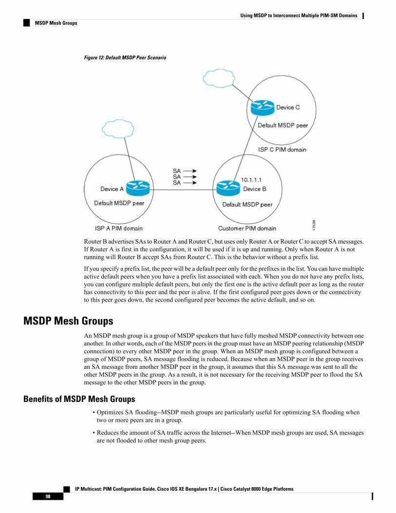
Figure 12: Default MSDP Peer Scenario
Router B advertises SAs to Router A and Router C, but uses only Router A or Router C to accept SAmessages.If Router A is first in the configuration, it will be used if it is up and running. Only when Router A is notrunning will Router B accept SAs from Router C. This is the behavior without a prefix list.
If you specify a prefix list, the peer will be a default peer only for the prefixes in the list. You can have multipleactive default peers when you have a prefix list associated with each. When you do not have any prefix lists,you can configure multiple default peers, but only the first one is the active default peer as long as the routerhas connectivity to this peer and the peer is alive. If the first configured peer goes down or the connectivityto this peer goes down, the second configured peer becomes the active default, and so on.
MSDP Mesh GroupsAnMSDP mesh group is a group of MSDP speakers that have fully meshed MSDP connectivity between oneanother. In other words, each of theMSDP peers in the groupmust have anMSDP peering relationship (MSDPconnection) to every other MSDP peer in the group. When an MSDP mesh group is configured between agroup of MSDP peers, SA message flooding is reduced. Because when an MSDP peer in the group receivesan SA message from another MSDP peer in the group, it assumes that this SA message was sent to all theother MSDP peers in the group. As a result, it is not necessary for the receiving MSDP peer to flood the SAmessage to the other MSDP peers in the group.
Benefits of MSDP Mesh Groups• Optimizes SA flooding--MSDP mesh groups are particularly useful for optimizing SA flooding whentwo or more peers are in a group.
• Reduces the amount of SA traffic across the Internet--When MSDP mesh groups are used, SA messagesare not flooded to other mesh group peers.
IP Multicast: PIM Configuration Guide, Cisco IOS XE Bengaluru 17.x | Cisco Catalyst 8000 Edge Platforms98
Using MSDP to Interconnect Multiple PIM-SM DomainsMSDP Mesh Groups
• Eliminates RPF checks on arriving SAmessages--When anMSDPmesh group is configured, SAmessagesare always accepted from mesh group peers.
SA Origination FiltersBy default, an RP that is configured to run MSDP will originate SA messages for all local sources for whichit is the RP. Local sources that register with an RP, therefore, will be advertised in SA messages, which insome cases is not desirable. For example, if sources inside a PIM-SM domain are using private addresses (forexample, network 10.0.0.0/8), you should configure an SA origination filter to restrict those addresses frombeing advertised to other MSDP peers across the Internet.
To control what sources are advertised in SA messages, you can configure SA origination filters on an RP.By creating SA origination filters, you can control the sources advertised in SA messages as follows:
• You can configure an RP to prevent the device from advertising local sources in SAmessages. The devicewill still forward SA messages from other MSDP peers in the normal fashion; it will just not originateany SA messages for local sources.
• You can configure the device to only originate SA messages for local sources sending to specific groupsthat match (S, G) pairs defined in the extended access list. All other local sources will not be advertisedin SA messages.
• You can configure the device to only originate SA messages for local sources sending to specific groupsthat the match AS paths defined in an AS-path access list. All other local sources will not be advertisedin SA messages.
• You can configure the device to only originate SA messages for local sources that match the criteriadefined in the route map. All other local sources will not be advertised in SA messages.
• You configure an SA origination filter that includes an extended access list, an AS-path access list, androute map, or a combination thereof. In this case, all conditions must be true before any local sourcesare advertised in SA messages.
Use of Outgoing Filter Lists in MSDPBy default, anMSDP-enabled device forwards all SAmessages it receives to all of its MSDP peers. However,you can prevent SAmessages from being forwarded toMSDP peers by creating outgoing filter lists. Outgoingfilter lists apply to all SA messages, whether locally originated or received from another MSDP peer, whereasSA origination filters apply only to locally originated SA messages. For more information about enabling afilter for MSDP SA messages originated by the local device, see the Controlling SA Messages Originated byan RP for Local Sources section.
By creating an outgoing filter list, you can control the SAmessages that a device forwards to a peer as follows:
• You can filter all outgoing SA messages forwarded to a specified MSDP peer by configuring the deviceto stop forwarding its SA messages to the MSDP peer.
• You can filter a subset of outgoing SA messages forwarded to a specified MSDP peer based on (S, G)pairs defined in an extended access list by configuring the device to only forward SA messages to theMSDP peer that match the (S, G) pairs permitted in an extended access list. The forwarding of all otherSA messages to the MSDP peer will be stopped.
IP Multicast: PIM Configuration Guide, Cisco IOS XE Bengaluru 17.x | Cisco Catalyst 8000 Edge Platforms99
Using MSDP to Interconnect Multiple PIM-SM DomainsSA Origination Filters
• You can filter a subset of outgoing SA messages forwarded to a specified MSDP peer based on matchcriteria defined in a route map by configuring the device to only forward SA messages that match thecriteria defined in the route map. The forwarding of all other SA messages to the MSDP peer will bestopped.
• You can filter a subset of outgoing SA messages from a specified peer based on the announcing RPaddress contained in the SA message by configuring the device to filter outgoing SA messages based ontheir origin, even after an SA message has been transmitted across one or more MSDP peers. Theforwarding of all other SA messages to the MSDP peer will be stopped.
• You can configure an outgoing filter list that includes an extended access list, a route map, and either anRP access list or an RP route map. In this case, all conditions must be true for the MSDP peer to forwardthe outgoing SA message.
Arbitrary filtering of SA messages can result in downstream MSDP peers being starved of SA messages forlegitimate active sources. Care, therefore, should be taken when using these sorts of filters. Normally, outgoingfilter lists are used only to reject undesirable sources, such as sources using private addresses.
Caution
Use of Incoming Filter Lists in MSDPBy default, an MSDP-enabled device receives all SA messages sent to it from its MSDP peers. However, youcan control the source information that a device receives from its MSDP peers by creating incoming filterlists.
By creating incoming filter lists, you can control the incoming SA messages that a device receives from itspeers as follows:
• You can filter all incoming SAmessages from a specifiedMSDP peer by configuring the device to ignoreall SA messages sent to it from the specified MSDP peer.
• You can filter a subset of incoming SA messages from a specified peer based on (S, G) pairs defined inan extended access list by configuring the device to only receive SA messages from the MSDP peer thatmatch the (S, G) pairs defined in the extended access list. All other incoming SA messages from theMSDP peer will be ignored.
• You can filter a subset of incoming SA request messages from a specified peer based on match criteriadefined in a route map by configuring the device to only receive SA messages that match the criteriadefined in the route map. All other incoming SA messages from the MSDP peer will be ignored.
• You can filter a subset of incoming SAmessages from a specified peer based on both (S, G) pairs definedin an extended access list and on match criteria defined in a route map by configuring the device to onlyreceive incoming SA messages that both match the (S, G) pairs defined in the extended access list andmatch the criteria defined in the route map. All other incoming SA messages from the MSDP peer willbe ignored.
• You can filter a subset of incoming SA messages from a specified peer based on the announcing RPaddress contained in the SA message by configuring the device to filter incoming SA messages basedon their origin, even after the SA message may have already been transmitted across one or more MSDPpeers.
IP Multicast: PIM Configuration Guide, Cisco IOS XE Bengaluru 17.x | Cisco Catalyst 8000 Edge Platforms100
Using MSDP to Interconnect Multiple PIM-SM DomainsUse of Incoming Filter Lists in MSDP
• You can configure an incoming filter list that includes an extended access list, a route map, and eitheran RP access list or an RP route map. In this case, all conditions must be true for the MSDP peer toreceive the incoming SA message.
Arbitrary filtering of SA messages can result in downstream MSDP peers being starved of SA messages forlegitimate active sources. Care, therefore, should be taken when using these sorts of filters. Normally, incomingfilter lists are used only to reject undesirable sources, such as sources using private addresses.
Caution
TTL Thresholds in MSDPThe time-to-live (TTL) value provides a means to limit the number of hops a packet can take before beingdropped. The ip multicast ttl-threshold command is used to specify a TTL for data-encapsulated SAmessagessent to specified MSDP peers. By default, multicast data packets in SA messages are sent to an MSDP peer,provided the TTL value of the packet is greater than 0, which is standard TTL behavior.
In general, a TTL-threshold problem can be introduced by the encapsulation of a source’s initial multicastpacket in an SA message. Because the multicast packet is encapsulated inside of the unicast SA message(whose TTL is 255), its TTL is not decremented as the SA message travels to the MSDP peer. Furthermore,the total number of hops that the SA message traverses can be drastically different than a normal multicastpacket because multicast and unicast traffic may follow completely different paths to the MSDP peer andhence the remote PIM-SM domain. As a result, encapsulated packets can end up violating TTL thresholds.The solution to this problem is to configure a TTL threshold that is associated with any multicast packet thatis encapsulated in an SAmessage sent to a particularMSDP peer using the ip multicast ttl-threshold command.The ip msdp ttl-threshold command prevents any multicast packet whose TTL in the IP header is less thanthe TTL value specified for the ttl-valueargument from being encapsulated in SA messages sent to that peer.
SA Request MessagesYou can configure a noncaching device to send SA request messages to one or more specified MSDP peers.
If an noncaching RP has an MSDP peer that is caching SAs, you can reduce the join latency for a noncachingpeer by enabling the noncaching peer to send SA request messages. When a host requests a join to a particulargroup, the noncaching RP sends an SA request message to its caching peers. If a peer has cached sourceinformation for the group in question, it sends the information to the requesting RP with an SA responsemessage. The requesting RP uses the information in the SA response but does not forward the message to anyother peers. If a noncaching RP receives an SA request, it sends an error message back to the requestor.
In all current and supported software releases, caching of MSDP SA messages is mandatory and cannot bemanually enabled or disabled. By default, when an MSDP peer is configured, the configured commands areautomatically added to the running configuration.
Note
SA Request FiltersBy default, a device honors all outgoing SA request messages from its MSDP peers; that is, it sends cachedsource information to requesting MSDP peers in SA response messages. You can control the outgoing SA
IP Multicast: PIM Configuration Guide, Cisco IOS XE Bengaluru 17.x | Cisco Catalyst 8000 Edge Platforms101
Using MSDP to Interconnect Multiple PIM-SM DomainsTTL Thresholds in MSDP
request messages that a device will honor from specified peers by creating an SA request filter. An SA requestfilter controls the outgoing SA requests that the device will honor from MSDP peers as follows:
• You can filter all SA request messages from a specified peer by configuring the device to ignore all SArequests from the specified MSDP peer.
• You can filter a subset of SA request messages from a specified peer based on groups defined in a standardaccess list by configuring the device to honor only SA request messages from the MSDP peer that matchthe groups defined in a standard access list. SA request messages from the specified peer for other groupswill be ignored.
MSDP MIBThe MSDP MIB describes managed objects that can be used to remotely monitor MSDP speakers usingSNMP. The MSDP MIB module contains four scalar objects and three tables. The tables are the Requeststable, the Peer table, and the Source-Active (SA) Cache table. The Cisco implementation supports the Peertable and SA Cache table only. The Requests table contains information used to determine which peer to sendSA requests to. However, the MSDP implementation used in Cisco IOS software does not associate sendingSA requests to peers with group addresses (or group address masks).
TheMSDP-MIB.my file can be downloaded from the CiscoMIBwebsite on Cisco.com at the followingURL:http://www.cisco.com/public/sw-center/netmgmt/cmtk/mibs.shtml .
Note
How to Use MSDP to Interconnect Multiple PIM-SM DomainsThe first task is required; all other tasks are optional.
Configuring an MSDP Peer
By enabling an MSDP peer, you implicitly enable MSDP.Note
Before you begin
• IP multicast routing must be enabled and PIM-SM must be configured.
• With the exception of a single MSDP peer, default MSDP peer, and MSDP mesh group scenarios, allMSDP peers must be configured to run BGP prior to being configured for MSDP.
SUMMARY STEPS
1. enable2. configure terminal3. ip msdp peer {peer-name| peer-address} [connect-source type number] [remote-as as-number]4. ip msdp description {peer-name| peer-address} text
IP Multicast: PIM Configuration Guide, Cisco IOS XE Bengaluru 17.x | Cisco Catalyst 8000 Edge Platforms102
Using MSDP to Interconnect Multiple PIM-SM DomainsMSDP MIB
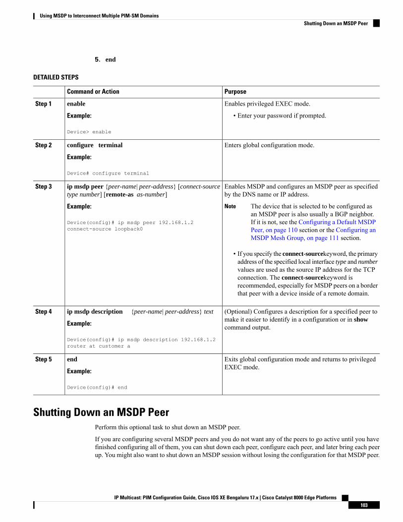
5. end
DETAILED STEPS
PurposeCommand or Action
Enables privileged EXEC mode.enableStep 1
Example: • Enter your password if prompted.
Device> enable
Enters global configuration mode.configure terminal
Example:
Step 2
Device# configure terminal
Enables MSDP and configures an MSDP peer as specifiedby the DNS name or IP address.
ip msdp peer {peer-name| peer-address} [connect-sourcetype number] [remote-as as-number]
Step 3
Example: The device that is selected to be configured asan MSDP peer is also usually a BGP neighbor.If it is not, see the Configuring a Default MSDPPeer, on page 110 section or the Configuring anMSDP Mesh Group, on page 111 section.
Note
Device(config)# ip msdp peer 192.168.1.2connect-source loopback0
• If you specify the connect-sourcekeyword, the primaryaddress of the specified local interface type and numbervalues are used as the source IP address for the TCPconnection. The connect-sourcekeyword isrecommended, especially forMSDP peers on a borderthat peer with a device inside of a remote domain.
(Optional) Configures a description for a specified peer tomake it easier to identify in a configuration or in showcommand output.
ip msdp description {peer-name| peer-address} text
Example:
Device(config)# ip msdp description 192.168.1.2router at customer a
Step 4
Exits global configuration mode and returns to privilegedEXEC mode.
end
Example:
Step 5
Device(config)# end
Shutting Down an MSDP PeerPerform this optional task to shut down an MSDP peer.
If you are configuring several MSDP peers and you do not want any of the peers to go active until you havefinished configuring all of them, you can shut down each peer, configure each peer, and later bring each peerup. You might also want to shut down an MSDP session without losing the configuration for that MSDP peer.
IP Multicast: PIM Configuration Guide, Cisco IOS XE Bengaluru 17.x | Cisco Catalyst 8000 Edge Platforms103
Using MSDP to Interconnect Multiple PIM-SM DomainsShutting Down an MSDP Peer
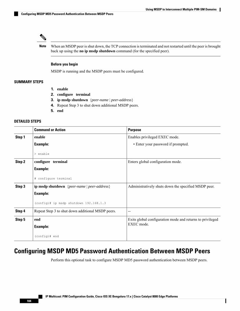
When anMSDP peer is shut down, the TCP connection is terminated and not restarted until the peer is broughtback up using the no ip msdp shutdown command (for the specified peer).
Note
Before you begin
MSDP is running and the MSDP peers must be configured.
SUMMARY STEPS
1. enable2. configure terminal3. ip msdp shutdown {peer-name | peer-address}4. Repeat Step 3 to shut down additional MSDP peers.5. end
DETAILED STEPS
PurposeCommand or Action
Enables privileged EXEC mode.enableStep 1
Example: • Enter your password if prompted.
> enable
Enters global configuration mode.configure terminal
Example:
Step 2
# configure terminal
Administratively shuts down the specified MSDP peer.ip msdp shutdown {peer-name | peer-address}
Example:
Step 3
(config)# ip msdp shutdown 192.168.1.3
--Repeat Step 3 to shut down additional MSDP peers.Step 4
Exits global configuration mode and returns to privilegedEXEC mode.
end
Example:
Step 5
(config)# end
Configuring MSDP MD5 Password Authentication Between MSDP PeersPerform this optional task to configure MSDP MD5 password authentication between MSDP peers.
IP Multicast: PIM Configuration Guide, Cisco IOS XE Bengaluru 17.x | Cisco Catalyst 8000 Edge Platforms104
Using MSDP to Interconnect Multiple PIM-SM DomainsConfiguring MSDP MD5 Password Authentication Between MSDP Peers
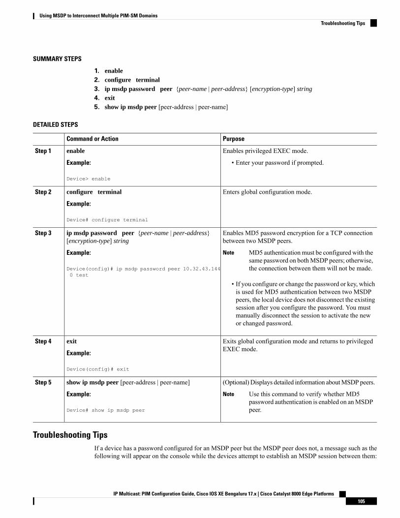
SUMMARY STEPS
1. enable2. configure terminal3. ip msdp password peer {peer-name | peer-address} [encryption-type] string
4. exit5. show ip msdp peer [peer-address | peer-name]
DETAILED STEPS
PurposeCommand or Action
Enables privileged EXEC mode.enableStep 1
Example: • Enter your password if prompted.
Device> enable
Enters global configuration mode.configure terminal
Example:
Step 2
Device# configure terminal
Enables MD5 password encryption for a TCP connectionbetween two MSDP peers.
ip msdp password peer {peer-name | peer-address}[encryption-type] string
Step 3
Example: MD5 authenticationmust be configured with thesame password on bothMSDP peers; otherwise,the connection between them will not be made.
Note
Device(config)# ip msdp password peer 10.32.43.1440 test
• If you configure or change the password or key, whichis used for MD5 authentication between two MSDPpeers, the local device does not disconnect the existingsession after you configure the password. You mustmanually disconnect the session to activate the newor changed password.
Exits global configuration mode and returns to privilegedEXEC mode.
exit
Example:
Step 4
Device(config)# exit
(Optional) Displays detailed information aboutMSDP peers.show ip msdp peer [peer-address | peer-name]Step 5
Example: Use this command to verify whether MD5password authentication is enabled on anMSDPpeer.
Note
Device# show ip msdp peer
Troubleshooting TipsIf a device has a password configured for an MSDP peer but the MSDP peer does not, a message such as thefollowing will appear on the console while the devices attempt to establish an MSDP session between them:
IP Multicast: PIM Configuration Guide, Cisco IOS XE Bengaluru 17.x | Cisco Catalyst 8000 Edge Platforms105
Using MSDP to Interconnect Multiple PIM-SM DomainsTroubleshooting Tips

%TCP-6-BADAUTH: No MD5 digest from [peer's IP address]:11003 to [local router'sIP address]:179
Similarly, if the two devices have different passwords configured, a message such as the following will appearon the console:
%TCP-6-BADAUTH: Invalid MD5 digest from [peer's IP address]:11004 to [local router'sIP address]:179
The debug ip tcp transactions command is used to display information on significant TCP transactions suchas state changes, retransmissions, and duplicate packets. In the context of monitoring or troubleshootingMSDPMD5 password authentication, use the debug ip tcp transactions command to verify that the MD5 passwordis enabled and that the keepalive message is received by the MSDP peer.
Preventing DoS Attacks by Limiting the Number of SA Messages Allowed inthe SA Cache from Specified MSDP Peers
Perform this optional (but highly recommended) task to limit the overall number of SA messages that thedevice can accept from specified MSDP peers. Performing this task protects an MSDP-enabled device fromdistributed denial-of-service (DoS) attacks.
We recommend that you perform this task for all MSDP peerings on the device.Note
SUMMARY STEPS
1. enable2. configure terminal3. ip msdp sa-limit {peer-address | peer-name} sa-limit
4. Repeat Step 3 to configure SA limits for additional MSDP peers.5. exit6. show ip msdp count [as-number]7. show ip msdp peer [peer-address | peer-name]8. show ip msdp summary
DETAILED STEPS
PurposeCommand or Action
Enables privileged EXEC mode.enableStep 1
Example: • Enter your password if prompted.
Device> enable
Enters global configuration mode.configure terminal
Example:
Step 2
Device# configure terminal
IP Multicast: PIM Configuration Guide, Cisco IOS XE Bengaluru 17.x | Cisco Catalyst 8000 Edge Platforms106
Using MSDP to Interconnect Multiple PIM-SM DomainsPreventing DoS Attacks by Limiting the Number of SA Messages Allowed in the SA Cache from Specified MSDP Peers
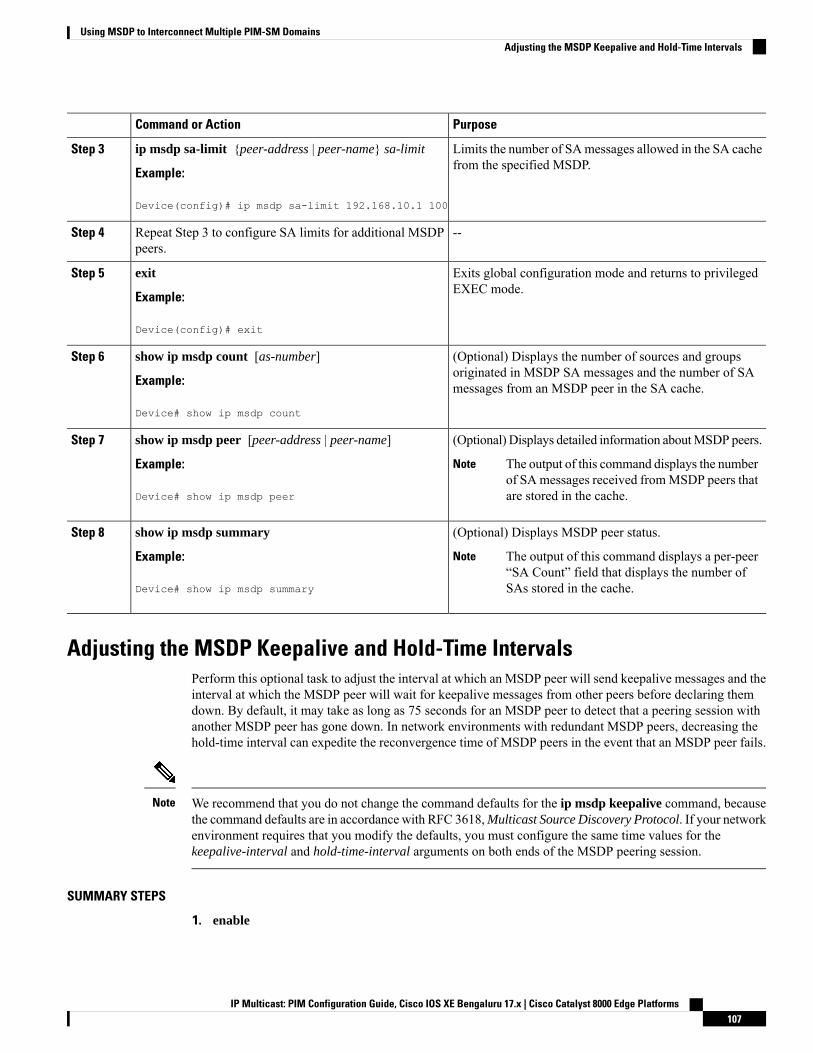
PurposeCommand or Action
Limits the number of SAmessages allowed in the SA cachefrom the specified MSDP.
ip msdp sa-limit {peer-address | peer-name} sa-limit
Example:
Step 3
Device(config)# ip msdp sa-limit 192.168.10.1 100
--Repeat Step 3 to configure SA limits for additional MSDPpeers.
Step 4
Exits global configuration mode and returns to privilegedEXEC mode.
exit
Example:
Step 5
Device(config)# exit
(Optional) Displays the number of sources and groupsoriginated in MSDP SA messages and the number of SAmessages from an MSDP peer in the SA cache.
show ip msdp count [as-number]
Example:
Device# show ip msdp count
Step 6
(Optional) Displays detailed information aboutMSDP peers.show ip msdp peer [peer-address | peer-name]Step 7
Example: The output of this command displays the numberof SAmessages received fromMSDP peers thatare stored in the cache.
Note
Device# show ip msdp peer
(Optional) Displays MSDP peer status.show ip msdp summaryStep 8
Example: The output of this command displays a per-peer“SA Count” field that displays the number ofSAs stored in the cache.
Note
Device# show ip msdp summary
Adjusting the MSDP Keepalive and Hold-Time IntervalsPerform this optional task to adjust the interval at which an MSDP peer will send keepalive messages and theinterval at which the MSDP peer will wait for keepalive messages from other peers before declaring themdown. By default, it may take as long as 75 seconds for an MSDP peer to detect that a peering session withanother MSDP peer has gone down. In network environments with redundant MSDP peers, decreasing thehold-time interval can expedite the reconvergence time of MSDP peers in the event that an MSDP peer fails.
We recommend that you do not change the command defaults for the ip msdp keepalive command, becausethe command defaults are in accordance with RFC 3618,Multicast Source Discovery Protocol. If your networkenvironment requires that you modify the defaults, you must configure the same time values for thekeepalive-interval and hold-time-interval arguments on both ends of the MSDP peering session.
Note
SUMMARY STEPS
1. enable
IP Multicast: PIM Configuration Guide, Cisco IOS XE Bengaluru 17.x | Cisco Catalyst 8000 Edge Platforms107
Using MSDP to Interconnect Multiple PIM-SM DomainsAdjusting the MSDP Keepalive and Hold-Time Intervals
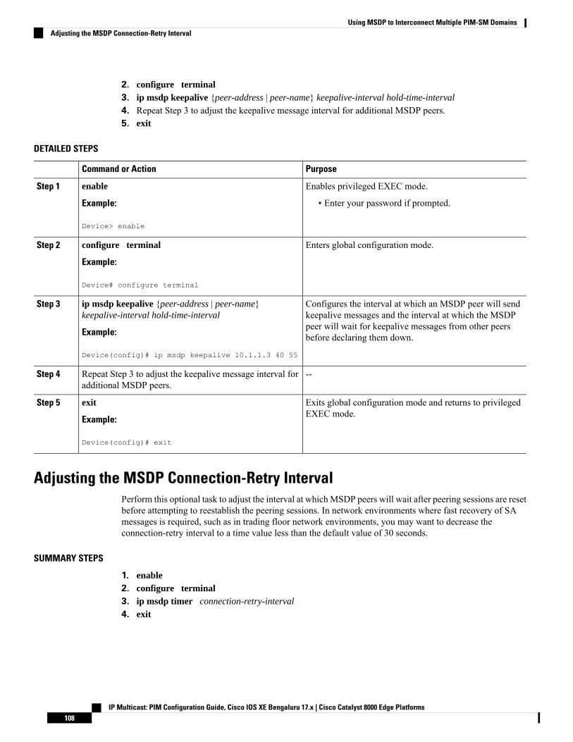
2. configure terminal3. ip msdp keepalive {peer-address | peer-name} keepalive-interval hold-time-interval
4. Repeat Step 3 to adjust the keepalive message interval for additional MSDP peers.5. exit
DETAILED STEPS
PurposeCommand or Action
Enables privileged EXEC mode.enableStep 1
Example: • Enter your password if prompted.
Device> enable
Enters global configuration mode.configure terminal
Example:
Step 2
Device# configure terminal
Configures the interval at which an MSDP peer will sendkeepalive messages and the interval at which the MSDP
ip msdp keepalive {peer-address | peer-name}keepalive-interval hold-time-interval
Step 3
peer will wait for keepalive messages from other peersbefore declaring them down.Example:
Device(config)# ip msdp keepalive 10.1.1.3 40 55
--Repeat Step 3 to adjust the keepalive message interval foradditional MSDP peers.
Step 4
Exits global configuration mode and returns to privilegedEXEC mode.
exit
Example:
Step 5
Device(config)# exit
Adjusting the MSDP Connection-Retry IntervalPerform this optional task to adjust the interval at which MSDP peers will wait after peering sessions are resetbefore attempting to reestablish the peering sessions. In network environments where fast recovery of SAmessages is required, such as in trading floor network environments, you may want to decrease theconnection-retry interval to a time value less than the default value of 30 seconds.
SUMMARY STEPS
1. enable2. configure terminal3. ip msdp timer connection-retry-interval
4. exit
IP Multicast: PIM Configuration Guide, Cisco IOS XE Bengaluru 17.x | Cisco Catalyst 8000 Edge Platforms108
Using MSDP to Interconnect Multiple PIM-SM DomainsAdjusting the MSDP Connection-Retry Interval
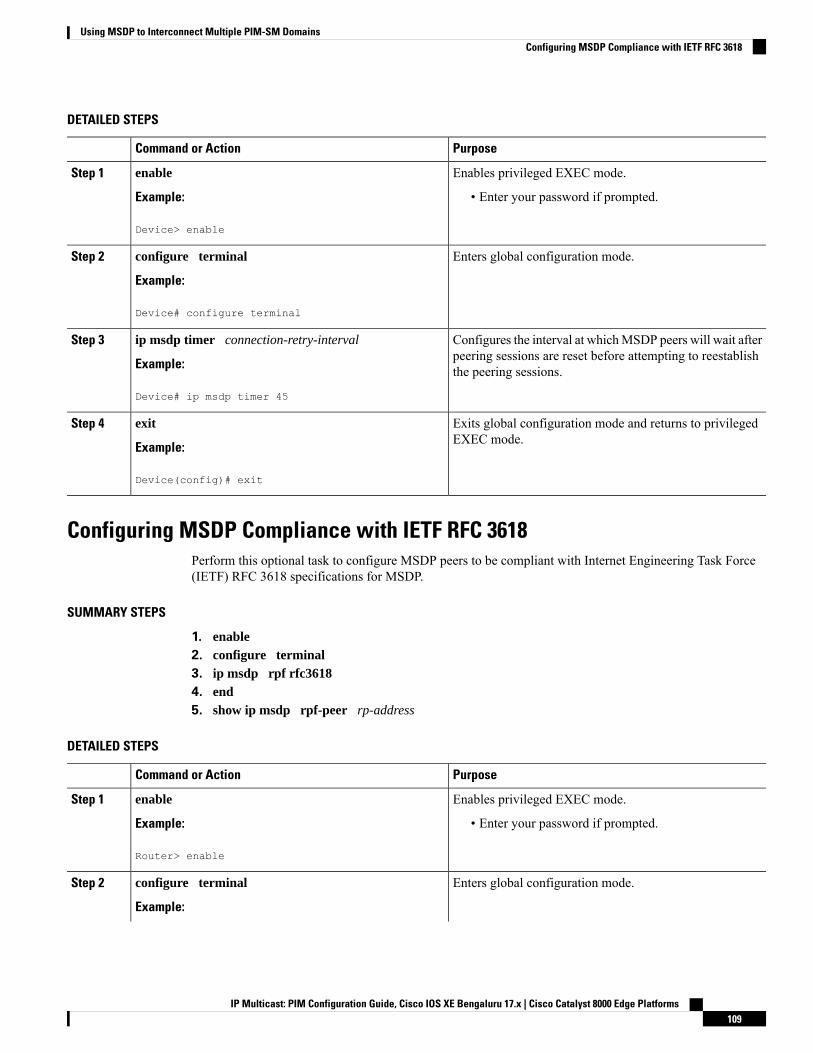
DETAILED STEPS
PurposeCommand or Action
Enables privileged EXEC mode.enableStep 1
Example: • Enter your password if prompted.
Device> enable
Enters global configuration mode.configure terminal
Example:
Step 2
Device# configure terminal
Configures the interval at whichMSDP peers will wait afterpeering sessions are reset before attempting to reestablishthe peering sessions.
ip msdp timer connection-retry-interval
Example:
Device# ip msdp timer 45
Step 3
Exits global configuration mode and returns to privilegedEXEC mode.
exit
Example:
Step 4
Device(config)# exit
Configuring MSDP Compliance with IETF RFC 3618Perform this optional task to configure MSDP peers to be compliant with Internet Engineering Task Force(IETF) RFC 3618 specifications for MSDP.
SUMMARY STEPS
1. enable2. configure terminal3. ip msdp rpf rfc36184. end5. show ip msdp rpf-peer rp-address
DETAILED STEPS
PurposeCommand or Action
Enables privileged EXEC mode.enableStep 1
Example: • Enter your password if prompted.
Router> enable
Enters global configuration mode.configure terminal
Example:
Step 2
IP Multicast: PIM Configuration Guide, Cisco IOS XE Bengaluru 17.x | Cisco Catalyst 8000 Edge Platforms109
Using MSDP to Interconnect Multiple PIM-SM DomainsConfiguring MSDP Compliance with IETF RFC 3618
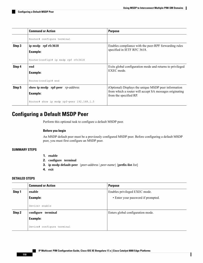
PurposeCommand or Action
Router# configure terminal
Enables compliance with the peer-RPF forwarding rulesspecified in IETF RFC 3618.
ip msdp rpf rfc3618
Example:
Step 3
Router(config)# ip msdp rpf rfc3618
Exits global configuration mode and returns to privilegedEXEC mode.
end
Example:
Step 4
Router(config)# end
(Optional) Displays the unique MSDP peer informationfrom which a router will accept SA messages originatingfrom the specified RP.
show ip msdp rpf-peer rp-address
Example:
Router# show ip msdp rpf-peer 192.168.1.5
Step 5
Configuring a Default MSDP PeerPerform this optional task to configure a default MSDP peer.
Before you begin
An MSDP default peer must be a previously configured MSDP peer. Before configuring a default MSDPpeer, you must first configure an MSDP peer.
SUMMARY STEPS
1. enable2. configure terminal3. ip msdp default-peer {peer-address | peer-name} [prefix-list list]4. exit
DETAILED STEPS
PurposeCommand or Action
Enables privileged EXEC mode.enableStep 1
Example: • Enter your password if prompted.
Device> enable
Enters global configuration mode.configure terminal
Example:
Step 2
Device# configure terminal
IP Multicast: PIM Configuration Guide, Cisco IOS XE Bengaluru 17.x | Cisco Catalyst 8000 Edge Platforms110
Using MSDP to Interconnect Multiple PIM-SM DomainsConfiguring a Default MSDP Peer
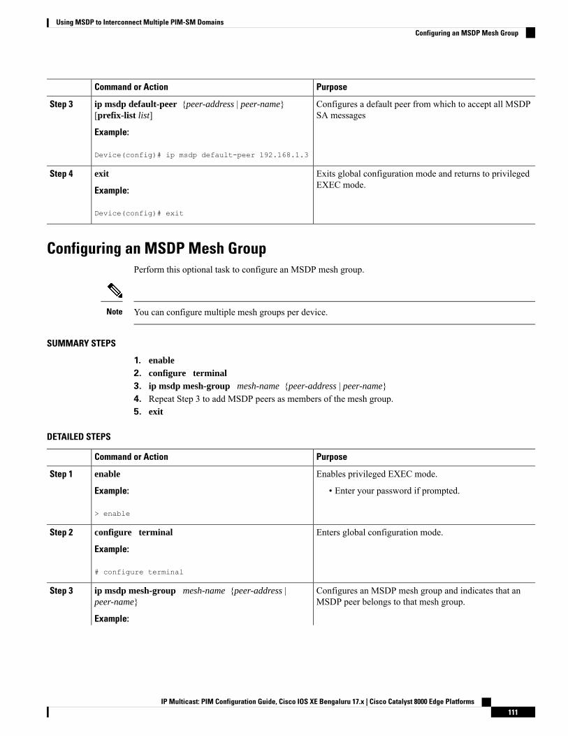
PurposeCommand or Action
Configures a default peer from which to accept all MSDPSA messages
ip msdp default-peer {peer-address | peer-name}[prefix-list list]
Example:
Step 3
Device(config)# ip msdp default-peer 192.168.1.3
Exits global configuration mode and returns to privilegedEXEC mode.
exit
Example:
Step 4
Device(config)# exit
Configuring an MSDP Mesh GroupPerform this optional task to configure an MSDP mesh group.
You can configure multiple mesh groups per device.Note
SUMMARY STEPS
1. enable2. configure terminal3. ip msdp mesh-group mesh-name {peer-address | peer-name}4. Repeat Step 3 to add MSDP peers as members of the mesh group.5. exit
DETAILED STEPS
PurposeCommand or Action
Enables privileged EXEC mode.enableStep 1
Example: • Enter your password if prompted.
> enable
Enters global configuration mode.configure terminal
Example:
Step 2
# configure terminal
Configures an MSDP mesh group and indicates that anMSDP peer belongs to that mesh group.
ip msdp mesh-group mesh-name {peer-address |peer-name}
Step 3
Example:
IP Multicast: PIM Configuration Guide, Cisco IOS XE Bengaluru 17.x | Cisco Catalyst 8000 Edge Platforms111
Using MSDP to Interconnect Multiple PIM-SM DomainsConfiguring an MSDP Mesh Group
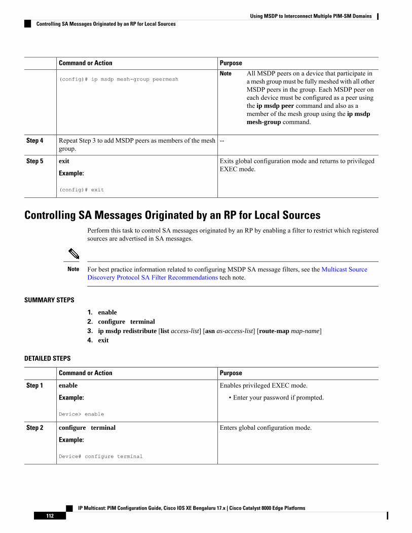
PurposeCommand or Action
(config)# ip msdp mesh-group peermeshAll MSDP peers on a device that participate ina mesh groupmust be fully meshed with all otherMSDP peers in the group. Each MSDP peer oneach device must be configured as a peer usingthe ip msdp peer command and also as amember of the mesh group using the ip msdpmesh-group command.
Note
--Repeat Step 3 to add MSDP peers as members of the meshgroup.
Step 4
Exits global configuration mode and returns to privilegedEXEC mode.
exit
Example:
Step 5
(config)# exit
Controlling SA Messages Originated by an RP for Local SourcesPerform this task to control SA messages originated by an RP by enabling a filter to restrict which registeredsources are advertised in SA messages.
For best practice information related to configuring MSDP SA message filters, see the Multicast SourceDiscovery Protocol SA Filter Recommendations tech note.
Note
SUMMARY STEPS
1. enable2. configure terminal3. ip msdp redistribute [list access-list] [asn as-access-list] [route-map map-name]4. exit
DETAILED STEPS
PurposeCommand or Action
Enables privileged EXEC mode.enableStep 1
Example: • Enter your password if prompted.
Device> enable
Enters global configuration mode.configure terminal
Example:
Step 2
Device# configure terminal
IP Multicast: PIM Configuration Guide, Cisco IOS XE Bengaluru 17.x | Cisco Catalyst 8000 Edge Platforms112
Using MSDP to Interconnect Multiple PIM-SM DomainsControlling SA Messages Originated by an RP for Local Sources
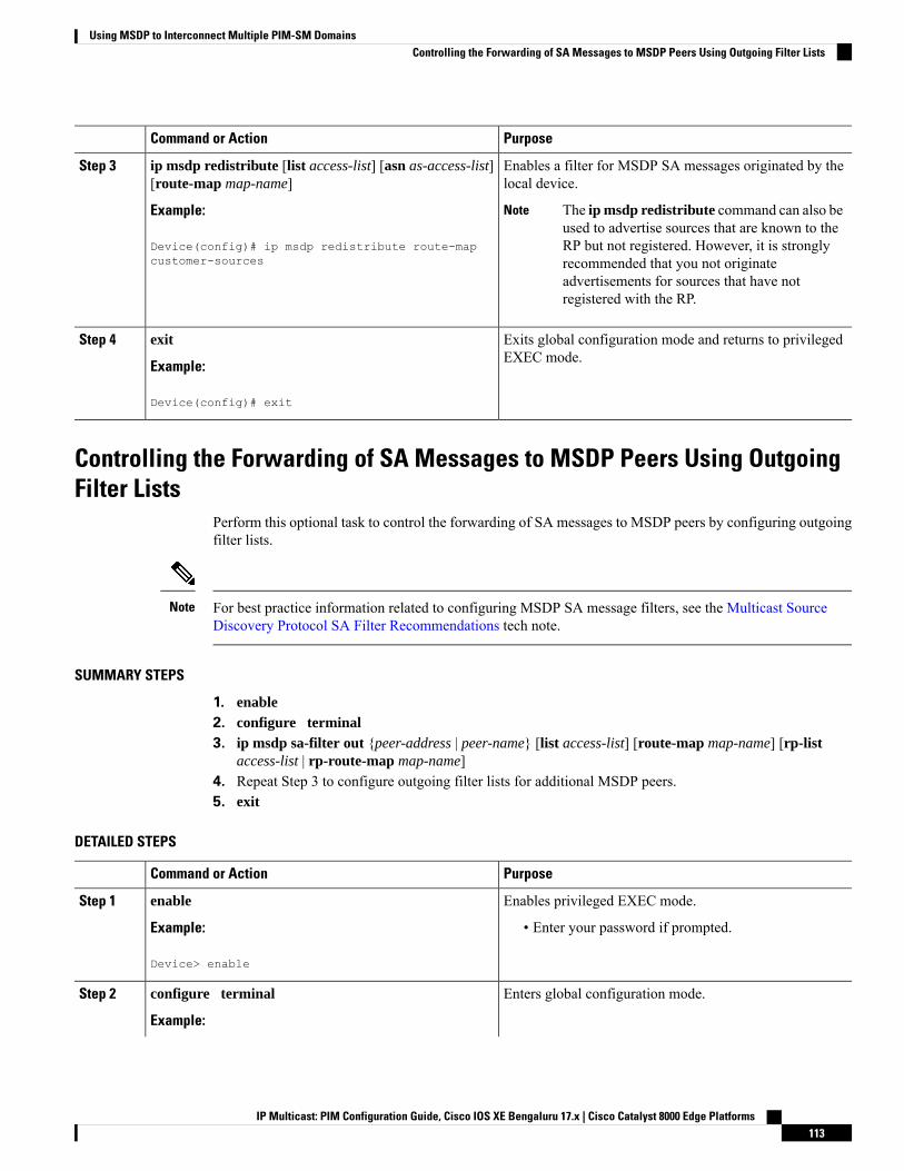
PurposeCommand or Action
Enables a filter for MSDP SA messages originated by thelocal device.
ip msdp redistribute [list access-list] [asn as-access-list][route-map map-name]
Step 3
Example: The ip msdp redistribute command can also beused to advertise sources that are known to theRP but not registered. However, it is stronglyrecommended that you not originateadvertisements for sources that have notregistered with the RP.
Note
Device(config)# ip msdp redistribute route-mapcustomer-sources
Exits global configuration mode and returns to privilegedEXEC mode.
exit
Example:
Step 4
Device(config)# exit
Controlling the Forwarding of SA Messages to MSDP Peers Using OutgoingFilter Lists
Perform this optional task to control the forwarding of SA messages to MSDP peers by configuring outgoingfilter lists.
For best practice information related to configuring MSDP SA message filters, see the Multicast SourceDiscovery Protocol SA Filter Recommendations tech note.
Note
SUMMARY STEPS
1. enable2. configure terminal3. ip msdp sa-filter out {peer-address | peer-name} [list access-list] [route-map map-name] [rp-list
access-list | rp-route-map map-name]4. Repeat Step 3 to configure outgoing filter lists for additional MSDP peers.5. exit
DETAILED STEPS
PurposeCommand or Action
Enables privileged EXEC mode.enableStep 1
Example: • Enter your password if prompted.
Device> enable
Enters global configuration mode.configure terminal
Example:
Step 2
IP Multicast: PIM Configuration Guide, Cisco IOS XE Bengaluru 17.x | Cisco Catalyst 8000 Edge Platforms113
Using MSDP to Interconnect Multiple PIM-SM DomainsControlling the Forwarding of SA Messages to MSDP Peers Using Outgoing Filter Lists
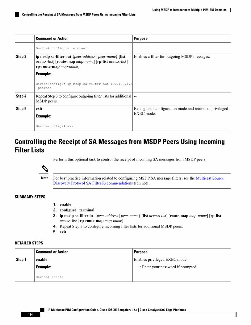
PurposeCommand or Action
Device# configure terminal
Enables a filter for outgoing MSDP messages.ip msdp sa-filter out {peer-address | peer-name} [listaccess-list] [route-map map-name] [rp-list access-list |rp-route-map map-name]
Step 3
Example:
Device(config)# ip msdp sa-filter out 192.168.1.5peerone
--Repeat Step 3 to configure outgoing filter lists for additionalMSDP peers.
Step 4
Exits global configuration mode and returns to privilegedEXEC mode.
exit
Example:
Step 5
Device(config)# exit
Controlling the Receipt of SA Messages from MSDP Peers Using IncomingFilter Lists
Perform this optional task to control the receipt of incoming SA messages from MSDP peers.
For best practice information related to configuring MSDP SA message filters, see the Multicast SourceDiscovery Protocol SA Filter Recommendations tech note.
Note
SUMMARY STEPS
1. enable2. configure terminal3. ip msdp sa-filter in {peer-address | peer-name} [list access-list] [route-map map-name] [rp-list
access-list | rp-route-map map-name]4. Repeat Step 3 to configure incoming filter lists for additional MSDP peers.5. exit
DETAILED STEPS
PurposeCommand or Action
Enables privileged EXEC mode.enableStep 1
Example: • Enter your password if prompted.
Device> enable
IP Multicast: PIM Configuration Guide, Cisco IOS XE Bengaluru 17.x | Cisco Catalyst 8000 Edge Platforms114
Using MSDP to Interconnect Multiple PIM-SM DomainsControlling the Receipt of SA Messages from MSDP Peers Using Incoming Filter Lists
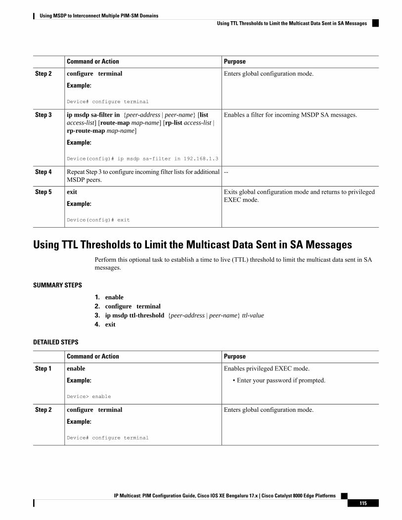
PurposeCommand or Action
Enters global configuration mode.configure terminal
Example:
Step 2
Device# configure terminal
Enables a filter for incoming MSDP SA messages.ip msdp sa-filter in {peer-address | peer-name} [listaccess-list] [route-map map-name] [rp-list access-list |rp-route-map map-name]
Step 3
Example:
Device(config)# ip msdp sa-filter in 192.168.1.3
--Repeat Step 3 to configure incoming filter lists for additionalMSDP peers.
Step 4
Exits global configuration mode and returns to privilegedEXEC mode.
exit
Example:
Step 5
Device(config)# exit
Using TTL Thresholds to Limit the Multicast Data Sent in SA MessagesPerform this optional task to establish a time to live (TTL) threshold to limit the multicast data sent in SAmessages.
SUMMARY STEPS
1. enable2. configure terminal3. ip msdp ttl-threshold {peer-address | peer-name} ttl-value
4. exit
DETAILED STEPS
PurposeCommand or Action
Enables privileged EXEC mode.enableStep 1
Example: • Enter your password if prompted.
Device> enable
Enters global configuration mode.configure terminal
Example:
Step 2
Device# configure terminal
IP Multicast: PIM Configuration Guide, Cisco IOS XE Bengaluru 17.x | Cisco Catalyst 8000 Edge Platforms115
Using MSDP to Interconnect Multiple PIM-SM DomainsUsing TTL Thresholds to Limit the Multicast Data Sent in SA Messages
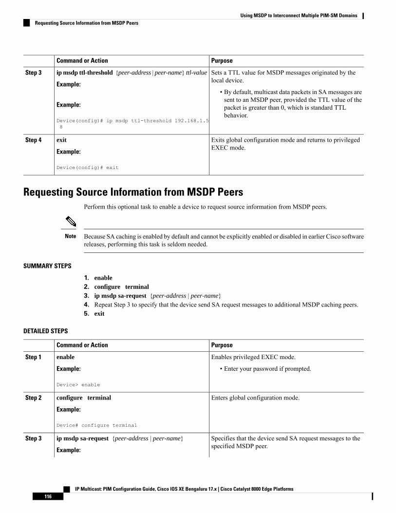
PurposeCommand or Action
Sets a TTL value for MSDP messages originated by thelocal device.
ip msdp ttl-threshold {peer-address | peer-name} ttl-value
Example:
Step 3
• By default, multicast data packets in SA messages aresent to an MSDP peer, provided the TTL value of the
Example: packet is greater than 0, which is standard TTLbehavior.
Device(config)# ip msdp ttl-threshold 192.168.1.58
Exits global configuration mode and returns to privilegedEXEC mode.
exit
Example:
Step 4
Device(config)# exit
Requesting Source Information from MSDP PeersPerform this optional task to enable a device to request source information from MSDP peers.
Because SA caching is enabled by default and cannot be explicitly enabled or disabled in earlier Cisco softwarereleases, performing this task is seldom needed.
Note
SUMMARY STEPS
1. enable2. configure terminal3. ip msdp sa-request {peer-address | peer-name}4. Repeat Step 3 to specify that the device send SA request messages to additional MSDP caching peers.5. exit
DETAILED STEPS
PurposeCommand or Action
Enables privileged EXEC mode.enableStep 1
Example: • Enter your password if prompted.
Device> enable
Enters global configuration mode.configure terminal
Example:
Step 2
Device# configure terminal
Specifies that the device send SA request messages to thespecified MSDP peer.
ip msdp sa-request {peer-address | peer-name}
Example:
Step 3
IP Multicast: PIM Configuration Guide, Cisco IOS XE Bengaluru 17.x | Cisco Catalyst 8000 Edge Platforms116
Using MSDP to Interconnect Multiple PIM-SM DomainsRequesting Source Information from MSDP Peers

PurposeCommand or Action
Device(config)# ip msdp sa-request 192.168.10.1
--Repeat Step 3 to specify that the device send SA requestmessages to additional MSDP caching peers.
Step 4
Exits global configuration mode and returns to privilegedEXEC mode.
exit
Example:
Step 5
Device(config)# exit
Controlling the Response to Outgoing SA Request Messages from MSDP PeersUsing SA Request Filters
Perform this optional task to control the outgoing SA request messages that the device will honor fromMSDPpeers.
SUMMARY STEPS
1. enable2. configure terminal3. ip msdp filter-sa-request {peer-address | peer-name} [list access-list]4. Repeat Step 3 to configure SA request filters for additional MSDP peers.5. exit
DETAILED STEPS
PurposeCommand or Action
Enables privileged EXEC mode.enableStep 1
Example: • Enter your password if prompted.
Device> enable
Enters global configuration mode.configure terminal
Example:
Step 2
Device# configure terminal
Enables a filter for outgoing SA request messages.ip msdp filter-sa-request {peer-address | peer-name} [listaccess-list]
Step 3
Only one SA request filter can be configured perMSDP peer.
NoteExample:
Device(config)# ip msdp filter sa-request172.31.2.2 list 1
--Repeat Step 3 to configure SA request filters for additionalMSDP peers.
Step 4
IP Multicast: PIM Configuration Guide, Cisco IOS XE Bengaluru 17.x | Cisco Catalyst 8000 Edge Platforms117
Using MSDP to Interconnect Multiple PIM-SM DomainsControlling the Response to Outgoing SA Request Messages from MSDP Peers Using SA Request Filters
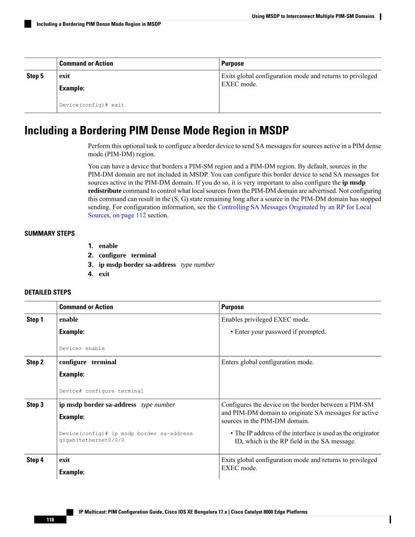
PurposeCommand or Action
Exits global configuration mode and returns to privilegedEXEC mode.
exit
Example:
Step 5
Device(config)# exit
Including a Bordering PIM Dense Mode Region in MSDPPerform this optional task to configure a border device to send SAmessages for sources active in a PIM densemode (PIM-DM) region.
You can have a device that borders a PIM-SM region and a PIM-DM region. By default, sources in thePIM-DM domain are not included in MSDP. You can configure this border device to send SA messages forsources active in the PIM-DM domain. If you do so, it is very important to also configure the ip msdpredistribute command to control what local sources from the PIM-DMdomain are advertised. Not configuringthis command can result in the (S, G) state remaining long after a source in the PIM-DM domain has stoppedsending. For configuration information, see the Controlling SA Messages Originated by an RP for LocalSources, on page 112 section.
SUMMARY STEPS
1. enable2. configure terminal3. ip msdp border sa-address type number
4. exit
DETAILED STEPS
PurposeCommand or Action
Enables privileged EXEC mode.enableStep 1
Example: • Enter your password if prompted.
Device> enable
Enters global configuration mode.configure terminal
Example:
Step 2
Device# configure terminal
Configures the device on the border between a PIM-SMand PIM-DM domain to originate SA messages for activesources in the PIM-DM domain.
ip msdp border sa-address type number
Example:
Device(config)# ip msdp border sa-addressgigabitethernet0/0/0
Step 3
• The IP address of the interface is used as the originatorID, which is the RP field in the SA message.
Exits global configuration mode and returns to privilegedEXEC mode.
exit
Example:
Step 4
IP Multicast: PIM Configuration Guide, Cisco IOS XE Bengaluru 17.x | Cisco Catalyst 8000 Edge Platforms118
Using MSDP to Interconnect Multiple PIM-SM DomainsIncluding a Bordering PIM Dense Mode Region in MSDP

PurposeCommand or Action
Device(config)# exit
Configuring an Originating Address Other Than the RP AddressPerform this optional task to allow an MSDP speaker that originates an SA message to use the IP address ofits interface as the RP address in the SA message.
You can also change the originator ID for any one of the following reasons:
• If you configure multiple devices in an MSDP mesh group for Anycast RP.
• If you have a device that borders a PIM-SM domain and a PIM-DMdomain. If a device borders a PIM-SMdomain and a PIM-DM domain and you want to advertise active sources within the PIM-DM domain,configure the RP address in SA messages to be the address of the originating device’s interface.
Before you begin
MSDP is enabled and the MSDP peers are configured. For more information about configuring MSDP peers,see the Configuring an MSDP Peer, on page 102 section.
SUMMARY STEPS
1. enable2. configure terminal3. ip msdp originator-id type number
4. exit
DETAILED STEPS
PurposeCommand or Action
Enables privileged EXEC mode.enableStep 1
Example: • Enter your password if prompted.
Device> enable
Enters global configuration mode.configure terminal
Example:
Step 2
Device# configure terminal
Configures the RP address in SAmessages to be the addressof the originating device’s interface.
ip msdp originator-id type number
Example:
Step 3
Device(config)# ip msdp originator-id ethernet 1
Exits global configuration mode and returns to privilegedEXEC mode.
exit
Example:
Step 4
IP Multicast: PIM Configuration Guide, Cisco IOS XE Bengaluru 17.x | Cisco Catalyst 8000 Edge Platforms119
Using MSDP to Interconnect Multiple PIM-SM DomainsConfiguring an Originating Address Other Than the RP Address

PurposeCommand or Action
Device(config)# exit
Monitoring MSDPPerform this optional task to monitor MSDP SA messages, peers, state, and peer status.
SUMMARY STEPS
1. enable2. debug ip msdp [peer-address | peer-name] [detail] [routes]3. debug ip msdp resets4. show ip msdp count [as-number]5. show ip msdp peer [peer-address | peer-name]6. show ip msdp sa-cache [group-address | source-address | group-name | source-name] [as-number]7. show ip msdp summary
DETAILED STEPS
Step 1 enable
Example:
Device# enable
Enables privileged EXEC mode.
• Enter your password if prompted.
Step 2 debug ip msdp [peer-address | peer-name] [detail] [routes]
Use this command to debug MSDP activity.
Use the optional peer-address or peer-name argument to specify for which peer debug events are logged.
The following is sample output from the debug ip msdp command:
Example:
Device# debug ip msdpMSDP debugging is onDevice#MSDP: 224.150.44.254: Received 1388-byte message from peerMSDP: 224.150.44.254: SA TLV, len: 1388, ec: 115, RP: 172.31.3.92MSDP: 224.150.44.254: Peer RPF check passed for 172.31.3.92, used EMBGP peerMSDP: 224.150.44.250: Forward 1388-byte SA to peerMSDP: 224.150.44.254: Received 1028-byte message from peerMSDP: 224.150.44.254: SA TLV, len: 1028, ec: 85, RP: 172.31.3.92MSDP: 224.150.44.254: Peer RPF check passed for 172.31.3.92, used EMBGP peerMSDP: 224.150.44.250: Forward 1028-byte SA to peerMSDP: 224.150.44.254: Received 1388-byte message from peerMSDP: 224.150.44.254: SA TLV, len: 1388, ec: 115, RP: 172.31.3.111MSDP: 224.150.44.254: Peer RPF check passed for 172.31.3.111, used EMBGP peer
IP Multicast: PIM Configuration Guide, Cisco IOS XE Bengaluru 17.x | Cisco Catalyst 8000 Edge Platforms120
Using MSDP to Interconnect Multiple PIM-SM DomainsMonitoring MSDP

MSDP: 224.150.44.250: Forward 1388-byte SA to peerMSDP: 224.150.44.250: Received 56-byte message from peerMSDP: 224.150.44.250: SA TLV, len: 56, ec: 4, RP: 192.168.76.241MSDP: 224.150.44.250: Peer RPF check passed for 192.168.76.241, used EMBGP peerMSDP: 224.150.44.254: Forward 56-byte SA to peerMSDP: 224.150.44.254: Received 116-byte message from peerMSDP: 224.150.44.254: SA TLV, len: 116, ec: 9, RP: 172.31.3.111MSDP: 224.150.44.254: Peer RPF check passed for 172.31.3.111, used EMBGP peerMSDP: 224.150.44.250: Forward 116-byte SA to peerMSDP: 224.150.44.254: Received 32-byte message from peerMSDP: 224.150.44.254: SA TLV, len: 32, ec: 2, RP: 172.31.3.78MSDP: 224.150.44.254: Peer RPF check passed for 172.31.3.78, used EMBGP peerMSDP: 224.150.44.250: Forward 32-byte SA to peer
Step 3 debug ip msdp resets
Use this command to debug MSDP peer reset reasons.
Example:
Device# debug ip msdp resets
Step 4 show ip msdp count [as-number]
Use this command to display the number of sources and groups originated in MSDP SA messages and the number of SAmessages from an MSDP peer in the SA cache. The ip msdp cache-sa-state command must be configured for thiscommand to produce any output.
The following is sample output from the show ip msdp countcommand:
Example:
Device# show ip msdp countSA State per Peer Counters, <Peer>: <# SA learned>
192.168.4.4: 8SA State per ASN Counters, <asn>: <# sources>/<# groups>
Total entries: 8?: 8/8
Step 5 show ip msdp peer [peer-address | peer-name]
Use this command to display detailed information about MSDP peers.
Use the optional peer-address or peer-name argument to display information about a particular peer.
The following is sample output from the show ip msdp peercommand:
Example:
Device# show ip msdp peer 192.168.4.4MSDP Peer 192.168.4.4 (?), AS 64512 (configured AS)Connection status:State: Up, Resets: 0, Connection source: Loopback0 (2.2.2.2)Uptime(Downtime): 00:07:55, Messages sent/received: 8/18Output messages discarded: 0Connection and counters cleared 00:08:55 ago
SA Filtering:Input (S,G) filter: none, route-map: noneInput RP filter: none, route-map: noneOutput (S,G) filter: none, route-map: noneOutput RP filter: none, route-map: none
SA-Requests:Input filter: none
IP Multicast: PIM Configuration Guide, Cisco IOS XE Bengaluru 17.x | Cisco Catalyst 8000 Edge Platforms121
Using MSDP to Interconnect Multiple PIM-SM DomainsMonitoring MSDP
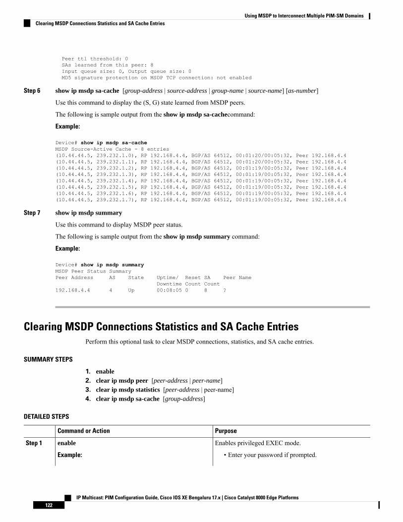
Peer ttl threshold: 0SAs learned from this peer: 8Input queue size: 0, Output queue size: 0MD5 signature protection on MSDP TCP connection: not enabled
Step 6 show ip msdp sa-cache [group-address | source-address | group-name | source-name] [as-number]
Use this command to display the (S, G) state learned from MSDP peers.
The following is sample output from the show ip msdp sa-cachecommand:
Example:
Device# show ip msdp sa-cacheMSDP Source-Active Cache - 8 entries(10.44.44.5, 239.232.1.0), RP 192.168.4.4, BGP/AS 64512, 00:01:20/00:05:32, Peer 192.168.4.4(10.44.44.5, 239.232.1.1), RP 192.168.4.4, BGP/AS 64512, 00:01:20/00:05:32, Peer 192.168.4.4(10.44.44.5, 239.232.1.2), RP 192.168.4.4, BGP/AS 64512, 00:01:19/00:05:32, Peer 192.168.4.4(10.44.44.5, 239.232.1.3), RP 192.168.4.4, BGP/AS 64512, 00:01:19/00:05:32, Peer 192.168.4.4(10.44.44.5, 239.232.1.4), RP 192.168.4.4, BGP/AS 64512, 00:01:19/00:05:32, Peer 192.168.4.4(10.44.44.5, 239.232.1.5), RP 192.168.4.4, BGP/AS 64512, 00:01:19/00:05:32, Peer 192.168.4.4(10.44.44.5, 239.232.1.6), RP 192.168.4.4, BGP/AS 64512, 00:01:19/00:05:32, Peer 192.168.4.4(10.44.44.5, 239.232.1.7), RP 192.168.4.4, BGP/AS 64512, 00:01:19/00:05:32, Peer 192.168.4.4
Step 7 show ip msdp summary
Use this command to display MSDP peer status.
The following is sample output from the show ip msdp summary command:
Example:
Device# show ip msdp summaryMSDP Peer Status SummaryPeer Address AS State Uptime/ Reset SA Peer Name
Downtime Count Count192.168.4.4 4 Up 00:08:05 0 8 ?
Clearing MSDP Connections Statistics and SA Cache EntriesPerform this optional task to clear MSDP connections, statistics, and SA cache entries.
SUMMARY STEPS
1. enable2. clear ip msdp peer [peer-address | peer-name]3. clear ip msdp statistics [peer-address | peer-name]4. clear ip msdp sa-cache [group-address]
DETAILED STEPS
PurposeCommand or Action
Enables privileged EXEC mode.enableStep 1
Example: • Enter your password if prompted.
IP Multicast: PIM Configuration Guide, Cisco IOS XE Bengaluru 17.x | Cisco Catalyst 8000 Edge Platforms122
Using MSDP to Interconnect Multiple PIM-SM DomainsClearing MSDP Connections Statistics and SA Cache Entries
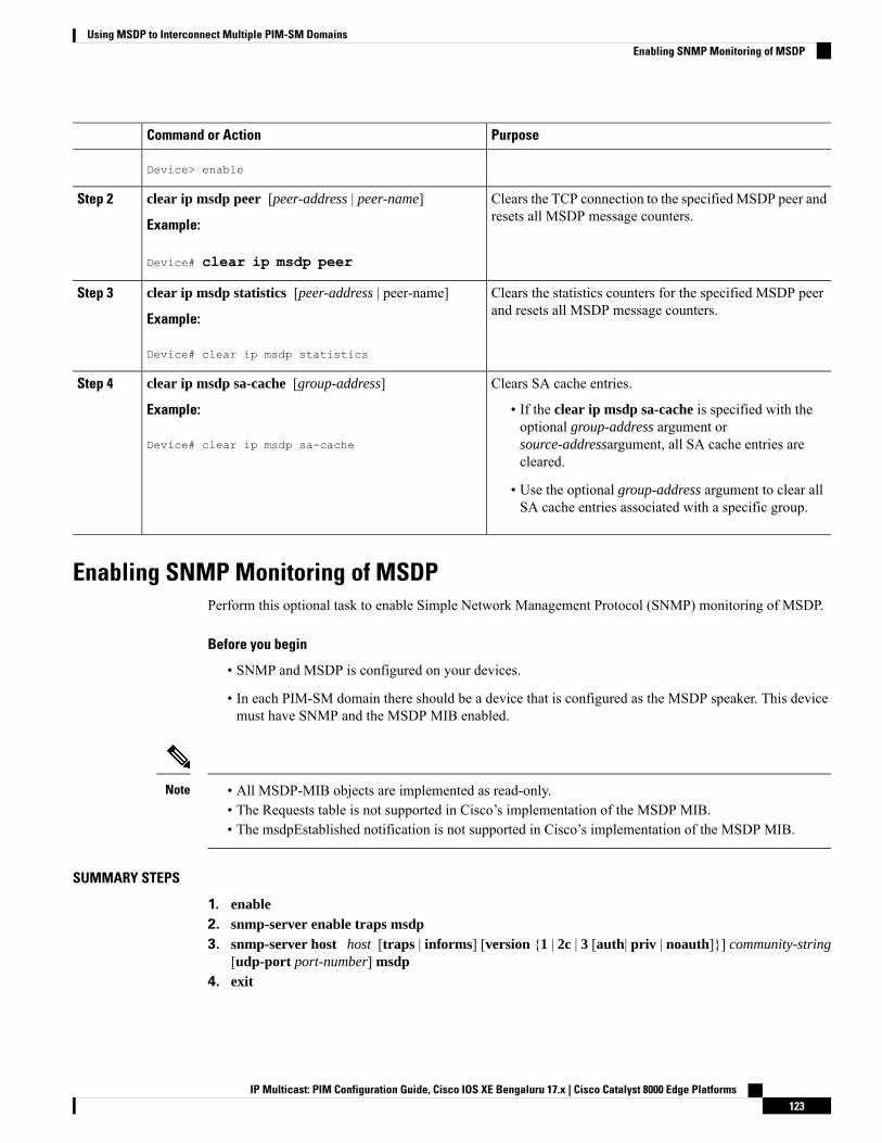
PurposeCommand or Action
Device> enable
Clears the TCP connection to the specifiedMSDP peer andresets all MSDP message counters.
clear ip msdp peer [peer-address | peer-name]
Example:
Step 2
Device# clear ip msdp peer
Clears the statistics counters for the specified MSDP peerand resets all MSDP message counters.
clear ip msdp statistics [peer-address | peer-name]
Example:
Step 3
Device# clear ip msdp statistics
Clears SA cache entries.clear ip msdp sa-cache [group-address]Step 4
Example: • If the clear ip msdp sa-cache is specified with theoptional group-address argument or
Device# clear ip msdp sa-cache source-addressargument, all SA cache entries arecleared.
• Use the optional group-address argument to clear allSA cache entries associated with a specific group.
Enabling SNMP Monitoring of MSDPPerform this optional task to enable Simple Network Management Protocol (SNMP) monitoring of MSDP.
Before you begin
• SNMP and MSDP is configured on your devices.
• In each PIM-SM domain there should be a device that is configured as the MSDP speaker. This devicemust have SNMP and the MSDP MIB enabled.
• All MSDP-MIB objects are implemented as read-only.• The Requests table is not supported in Cisco’s implementation of the MSDP MIB.• The msdpEstablished notification is not supported in Cisco’s implementation of the MSDP MIB.
Note
SUMMARY STEPS
1. enable2. snmp-server enable traps msdp3. snmp-server host host [traps | informs] [version {1 | 2c | 3 [auth| priv | noauth]}] community-string
[udp-port port-number] msdp4. exit
IP Multicast: PIM Configuration Guide, Cisco IOS XE Bengaluru 17.x | Cisco Catalyst 8000 Edge Platforms123
Using MSDP to Interconnect Multiple PIM-SM DomainsEnabling SNMP Monitoring of MSDP
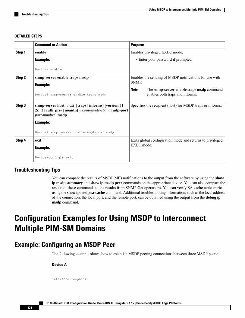
DETAILED STEPS
PurposeCommand or Action
Enables privileged EXEC mode.enableStep 1
Example: • Enter your password if prompted.
Device> enable
Enables the sending of MSDP notifications for use withSNMP.
snmp-server enable traps msdp
Example:
Step 2
The snmp-server enable traps msdp commandenables both traps and informs.
NoteDevice# snmp-server enable traps msdp
Specifies the recipient (host) for MSDP traps or informs.snmp-server host host [traps | informs] [version {1 |2c | 3 [auth| priv | noauth]}] community-string [udp-portport-number] msdp
Step 3
Example:
Device# snmp-server host examplehost msdp
Exits global configuration mode and returns to privilegedEXEC mode.
exit
Example:
Step 4
Device(config)# exit
Troubleshooting TipsYou can compare the results of MSDP MIB notifications to the output from the software by using the showip msdp summary and show ip msdp peer commands on the appropriate device. You can also compare theresults of these commands to the results from SNMP Get operations. You can verify SA cache table entriesusing the show ip msdp sa-cache command. Additional troubleshooting information, such as the local addressof the connection, the local port, and the remote port, can be obtained using the output from the debug ipmsdp command.
Configuration Examples for Using MSDP to InterconnectMultiple PIM-SM Domains
Example: Configuring an MSDP PeerThe following example shows how to establish MSDP peering connections between three MSDP peers:
Device A
!interface Loopback 0
IP Multicast: PIM Configuration Guide, Cisco IOS XE Bengaluru 17.x | Cisco Catalyst 8000 Edge Platforms124
Using MSDP to Interconnect Multiple PIM-SM DomainsTroubleshooting Tips
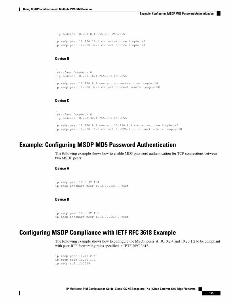
ip address 10.220.8.1 255.255.255.255!ip msdp peer 10.220.16.1 connect-source Loopback0ip msdp peer 10.220.32.1 connect-source Loopback0!
Device B
!interface Loopback 0ip address 10.220.16.1 255.255.255.255!ip msdp peer 10.220.8.1 connect connect-source Loopback0ip msdp peer 10.220.32.1 connect connect-source Loopback0!
Device C
!interface Loopback 0ip address 10.220.32.1 255.255.255.255!ip msdp peer 10.220.8.1 connect 10.220.8.1 connect-source Loopback0ip msdp peer 10.220.16.1 connect 10.220.16.1 connect-source Loopback0!
Example: Configuring MSDP MD5 Password AuthenticationThe following example shows how to enable MD5 password authentication for TCP connections betweentwo MSDP peers:
Device A
!ip msdp peer 10.3.32.154ip msdp password peer 10.3.32.154 0 test!
Device B
!ip msdp peer 10.3.32.153ip msdp password peer 10.3.32.153 0 test!
Configuring MSDP Compliance with IETF RFC 3618 ExampleThe following example shows how to configure the MSDP peers at 10.10.2.4 and 10.20.1.2 to be compliantwith peer-RPF forwarding rules specified in IETF RFC 3618:
ip msdp peer 10.10.2.4ip msdp peer 10.20.1.2ip msdp rpf rfc3618
IP Multicast: PIM Configuration Guide, Cisco IOS XE Bengaluru 17.x | Cisco Catalyst 8000 Edge Platforms125
Using MSDP to Interconnect Multiple PIM-SM DomainsExample: Configuring MSDP MD5 Password Authentication

Configuring a Default MSDP Peer ExampleThe figure illustrates a scenario where default MSDP peers might be used. In the figure, a customer that ownsRouter B is connected to the internet through two ISPs, one that owns Router A and the other that owns RouterC. They are not running (M)BGP between them. In order for the customer to learn about sources in the ISPdomain or in other domains, Router B identifies Router A as its default MSDP peer. Router B advertises SAmessages to both Router A and Router C, but accepts SA messages either from Router A only or Router Conly. If Router A is the first default peer in the configuration, it will be used if it is up and running. Only ifRouter A is not running will Router B accept SA messages from Router C.
The ISP will also likely use a prefix list to define which prefixes it will accept from the customer router. Thecustomer will define multiple default peers, each having one or more prefixes associated with it.
The customer has two ISPs to use. The customer defines both ISPs as default peers. As long as the first defaultpeer identified in the configuration is up and running, it will be the default peer and the customer will acceptall SA messages it receives from that peer.
Figure 13: Default MSDP Peer Scenario
Router B advertises SAs to Router A and Router C, but uses only Router A or Router C to accept SAmessages.If Router A is first in the configuration file, it will be used if it is up and running. Only when Router A is notrunning will Router B accept SAs from Router C. This is the behavior without a prefix list.
If you specify a prefix list, the peer will be a default peer only for the prefixes in the list. You can have multipleactive default peers when you have a prefix list associated with each. When you do not have any prefix lists,you can configure multiple default peers, but only the first one is the active default peer as long as the routerhas connectivity to this peer and the peer is alive. If the first configured peer goes down or the connectivityto this peer goes down, the second configured peer becomes the active default, and so on.
The following example shows a partial configuration of Router A and Router C in the figure. Each of theseISPs may have more than one customer using default peering, like the customer in the figure. In that case,
IP Multicast: PIM Configuration Guide, Cisco IOS XE Bengaluru 17.x | Cisco Catalyst 8000 Edge Platforms126
Using MSDP to Interconnect Multiple PIM-SM DomainsConfiguring a Default MSDP Peer Example
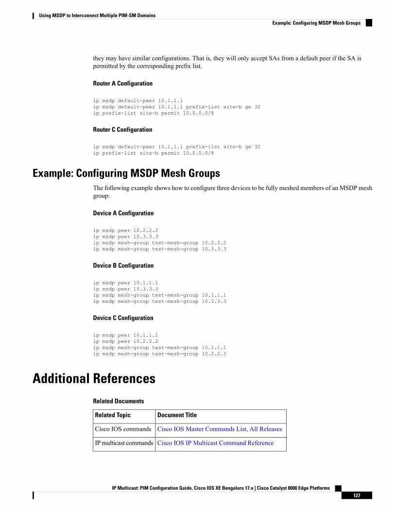
they may have similar configurations. That is, they will only accept SAs from a default peer if the SA ispermitted by the corresponding prefix list.
Router A Configuration
ip msdp default-peer 10.1.1.1ip msdp default-peer 10.1.1.1 prefix-list site-b ge 32ip prefix-list site-b permit 10.0.0.0/8
Router C Configuration
ip msdp default-peer 10.1.1.1 prefix-list site-b ge 32ip prefix-list site-b permit 10.0.0.0/8
Example: Configuring MSDP Mesh GroupsThe following example shows how to configure three devices to be fully meshed members of an MSDP meshgroup:
Device A Configuration
ip msdp peer 10.2.2.2ip msdp peer 10.3.3.3ip msdp mesh-group test-mesh-group 10.2.2.2ip msdp mesh-group test-mesh-group 10.3.3.3
Device B Configuration
ip msdp peer 10.1.1.1ip msdp peer 10.3.3.3ip msdp mesh-group test-mesh-group 10.1.1.1ip msdp mesh-group test-mesh-group 10.3.3.3
Device C Configuration
ip msdp peer 10.1.1.1ip msdp peer 10.2.2.2ip msdp mesh-group test-mesh-group 10.1.1.1ip msdp mesh-group test-mesh-group 10.2.2.2
Additional ReferencesRelated Documents
Document TitleRelated Topic
Cisco IOS Master Commands List, All ReleasesCisco IOS commands
Cisco IOS IP Multicast Command ReferenceIPmulticast commands
IP Multicast: PIM Configuration Guide, Cisco IOS XE Bengaluru 17.x | Cisco Catalyst 8000 Edge Platforms127
Using MSDP to Interconnect Multiple PIM-SM DomainsExample: Configuring MSDP Mesh Groups
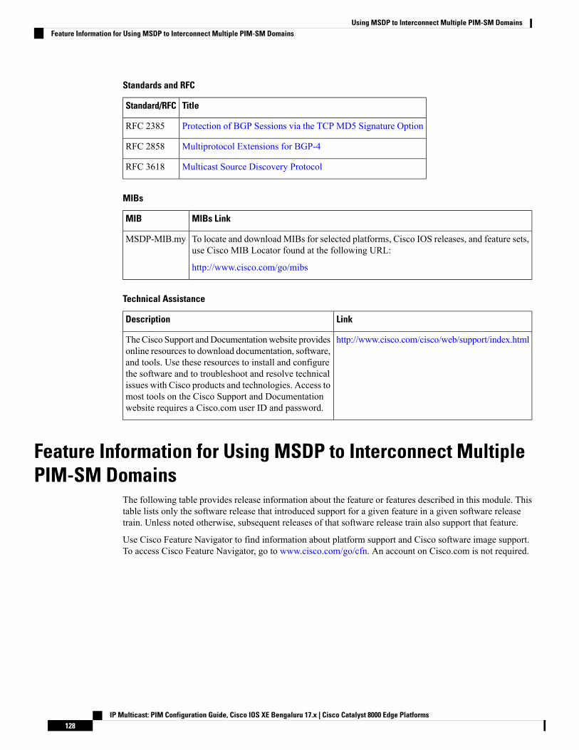
Standards and RFC
TitleStandard/RFC
Protection of BGP Sessions via the TCP MD5 Signature OptionRFC 2385
Multiprotocol Extensions for BGP-4RFC 2858
Multicast Source Discovery ProtocolRFC 3618
MIBs
MIBs LinkMIB
To locate and download MIBs for selected platforms, Cisco IOS releases, and feature sets,use Cisco MIB Locator found at the following URL:
http://www.cisco.com/go/mibs
MSDP-MIB.my
Technical Assistance
LinkDescription
http://www.cisco.com/cisco/web/support/index.htmlTheCisco Support andDocumentationwebsite providesonline resources to download documentation, software,and tools. Use these resources to install and configurethe software and to troubleshoot and resolve technicalissues with Cisco products and technologies. Access tomost tools on the Cisco Support and Documentationwebsite requires a Cisco.com user ID and password.
Feature Information for Using MSDP to Interconnect MultiplePIM-SM Domains
The following table provides release information about the feature or features described in this module. Thistable lists only the software release that introduced support for a given feature in a given software releasetrain. Unless noted otherwise, subsequent releases of that software release train also support that feature.
Use Cisco Feature Navigator to find information about platform support and Cisco software image support.To access Cisco Feature Navigator, go to www.cisco.com/go/cfn. An account on Cisco.com is not required.
IP Multicast: PIM Configuration Guide, Cisco IOS XE Bengaluru 17.x | Cisco Catalyst 8000 Edge Platforms128
Using MSDP to Interconnect Multiple PIM-SM DomainsFeature Information for Using MSDP to Interconnect Multiple PIM-SM Domains

C H A P T E R 6PIM Allow RP
Thismodule describes how to configure the PIMAllowRP feature in IPv4 or IPv6 networks for inter-connectingProtocol Independent Multicast (PIM) Sparse Mode (SM) domains with different rendezvous points (RPs).PIM Allow RP enables the receiving device to use its own RP to create state and build shared trees when anincoming (*, G) Join is processed and a different RP is identified. This allows the receiving device to acceptthe (*, G) Join from the different RP.
• Restrictions for PIM Allow RP, on page 129• Information About PIM Allow RP, on page 129• How to Configure PIM Allow RP, on page 130• Configuration Examples for PIM Allow RP, on page 134• Additional References for PIM Allow RP, on page 138• Feature Information for PIM Allow RP, on page 138
Restrictions for PIM Allow RP• PIM Allow RP only supports connecting PIM SM domains.
• PIM Allow RP is applicable for downstream traffic only, that is, it is only applicable for building theshared tree.
• PIM Allow RP does not work with Auto-RP or Boot Strap Router (BSR). Only static configuration issupported. However, it does allow the embedded RP in the consumer network to be different than theone configured statically in the service provider network.
Information About PIM Allow RP
Rendezvous PointsA rendezvous point (RP) is a role that a device performs when operating in Protocol Independent Multicast(PIM) Sparse Mode (SM). An RP is required only in networks running PIM SM. In the PIM-SM model, onlynetwork segments with active receivers that have explicitly requested multicast data will be forwarded thetraffic.
IP Multicast: PIM Configuration Guide, Cisco IOS XE Bengaluru 17.x | Cisco Catalyst 8000 Edge Platforms129
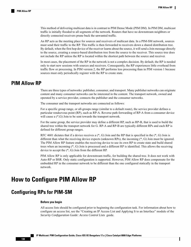
This method of delivering multicast data is in contrast to PIM Dense Mode (PIM DM). In PIM DM, multicasttraffic is initially flooded to all segments of the network. Routers that have no downstream neighbors ordirectly connected receivers prune back the unwanted traffic.
An RP acts as the meeting place for sources and receivers of multicast data. In a PIM-SM network, sourcesmust send their traffic to the RP. This traffic is then forwarded to receivers down a shared distribution tree.By default, when the first hop device of the receiver learns about the source, it will send a Join message directlyto the source, creating a source-based distribution tree from the source to the receiver. This source tree doesnot include the RP unless the RP is located within the shortest path between the source and receiver.
In most cases, the placement of the RP in the network is not a complex decision. By default, the RP is neededonly to start new sessions with sources and receivers. Consequently, the RP experiences little overhead fromtraffic flow or processing. In PIM version 2, the RP performs less processing than in PIM version 1 becausesources must only periodically register with the RP to create state.
PIM Allow RPThere are three types of networks: publisher, consumer, and transport. Many publisher networks can originatecontent and many consumer networks can be interested in the content. The transport network, owned andoperated by a service provider, connects the publisher and the consumer networks.
The consumer and the transport networks are connected as follows:
For a specific group range, or all-groups range (similar to a default route), the service provider defines aparticular rendezvous point (RP), such as RP-A. Reverse path forwarding of RP-A from a consumer devicewill cause a (*,G) Join to be sent towards the transport network.
For the same group, the service provider may define a different RP, such as RP-B, that is used to build theshared tree within the transport network for G. RP-A and RP-B are typically different RPs and each RP isdefined for different group ranges.
RFC 4601 dictates that if a device receives a (*, G) Join and the RP that is specified in the (*, G) Join isdifferent than what the receiving device expects (unknown RPs), the incoming (*, G) Join must be ignored.The PIM Allow RP feature enables the receiving device to use its own RP to create state and build sharedtrees when an incoming (*, G) Join is processed and a different RP is identified. This allows the receivingdevice to accept the (*, G) Join from the different RP.
PIM Allow RP is only applicable for downstream traffic, for building the shared tree. It does not work withAuto-RP or BSR. Only static configuration is supported. However, PIM Allow RP does compensate for theembedded RP in the consumer network to be different than the one configured statically in the transportnetwork.
How to Configure PIM Allow RP
Configuring RPs for PIM-SM
Before you begin
All access lists should be configured prior to beginning the configuration task. For information about how toconfigure an access list, see the “Creating an IP Access List and Applying It to an Interface” module of theSecurity Configuration Guide: Access Control Lists guide.
IP Multicast: PIM Configuration Guide, Cisco IOS XE Bengaluru 17.x | Cisco Catalyst 8000 Edge Platforms130
PIM Allow RPPIM Allow RP

For IPv6 network devices, you must first enable IPv6 unicast routing on all interfaces of the device on whichyou want to enable IPv6 multicast routing.
SUMMARY STEPS
1. enable2. configure terminal3. ip multicast-routing [vrf vrf-name] distributed•
• ipv6 multicast-routing [vrf vrf-name]
4. interface type number
5. ip pim sparse-mode•• ipv6 pim enable
6. ipv6 address {ipv6-address | prefix-length | prefix-name sub-bits | prefix-length}7. no shut8. exit9. Repeat Steps 4 through 8 on every interface that uses IP multicast.10. ip pim [vrf vrf-name] rp-address rp-address [access-list] [override]•
• ipv6 pim [vrf vrf-name] rp-address ipv6-address [group-address-list]
11. exit12. show ip pim rp [mapping] [rp-address]13. show ip mroute
DETAILED STEPS
PurposeCommand or Action
Enables privileged EXEC mode.enableStep 1
Example: • Enter your password if prompted.Device> enable
Enters global configuration mode.configure terminal
Example:
Step 2
Device# configure terminal
Step 3 • For IPv4: Enables multicast routing on all interfacesof the device. In Cisco IOS XE Release 3.2S andearlier releases, the distributed keyword is optional.
• ip multicast-routing [vrf vrf-name] distributed• ipv6 multicast-routing [vrf vrf-name]
Example:• For IPv6: Enables multicast routing on all interfacesof the device and also enables multicast forwarding
Device(config)# ip multicast-routing
Device(config)# ipv6 multicast-routing for PIM andMLD on all multicast-enabled interfacesof the device.
IPv6 multicast routing is disabled bydefault when IPv6 unicast routing isenabled. On certain devices, the IPv6multicast routing must also be enabled inorder to use IPv6 unicast routing.
Note
IP Multicast: PIM Configuration Guide, Cisco IOS XE Bengaluru 17.x | Cisco Catalyst 8000 Edge Platforms131
PIM Allow RPConfiguring RPs for PIM-SM
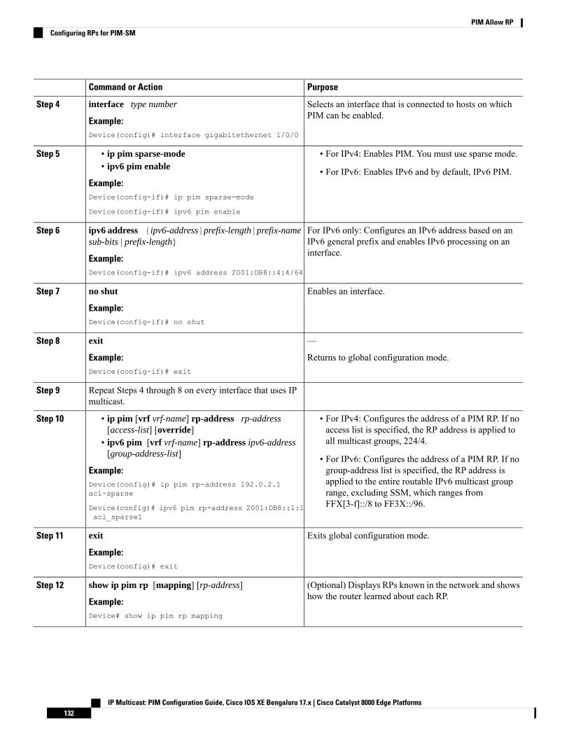
PurposeCommand or Action
Selects an interface that is connected to hosts on whichPIM can be enabled.
interface type number
Example:
Step 4
Device(config)# interface gigabitethernet 1/0/0
Step 5 • For IPv4: Enables PIM. You must use sparse mode.• ip pim sparse-mode• ipv6 pim enable • For IPv6: Enables IPv6 and by default, IPv6 PIM.
Example:Device(config-if)# ip pim sparse-mode
Device(config-if)# ipv6 pim enable
For IPv6 only: Configures an IPv6 address based on anIPv6 general prefix and enables IPv6 processing on aninterface.
ipv6 address {ipv6-address | prefix-length | prefix-namesub-bits | prefix-length}
Example:
Step 6
Device(config-if)# ipv6 address 2001:DB8::4:4/64
Enables an interface.no shut
Example:
Step 7
Device(config-if)# no shut
—exitStep 8
Example: Returns to global configuration mode.Device(config-if)# exit
Repeat Steps 4 through 8 on every interface that uses IPmulticast.
Step 9
Step 10 • For IPv4: Configures the address of a PIM RP. If noaccess list is specified, the RP address is applied toall multicast groups, 224/4.
• ip pim [vrf vrf-name] rp-address rp-address[access-list] [override]
• ipv6 pim [vrf vrf-name] rp-address ipv6-address[group-address-list] • For IPv6: Configures the address of a PIM RP. If no
group-address list is specified, the RP address isExample:applied to the entire routable IPv6 multicast groupDevice(config)# ip pim rp-address 192.0.2.1
acl-sparse range, excluding SSM, which ranges fromFFX[3-f]::/8 to FF3X::/96.Device(config)# ipv6 pim rp-address 2001:DB8::1:1
acl_sparse1
Exits global configuration mode.exit
Example:
Step 11
Device(config)# exit
(Optional) Displays RPs known in the network and showshow the router learned about each RP.
show ip pim rp [mapping] [rp-address]
Example:
Step 12
Device# show ip pim rp mapping
IP Multicast: PIM Configuration Guide, Cisco IOS XE Bengaluru 17.x | Cisco Catalyst 8000 Edge Platforms132
PIM Allow RPConfiguring RPs for PIM-SM
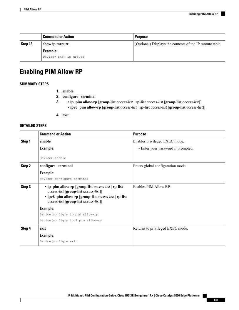
PurposeCommand or Action
(Optional) Displays the contents of the IP mroute table.show ip mroute
Example:
Step 13
Device# show ip mroute
Enabling PIM Allow RP
SUMMARY STEPS
1. enable2. configure terminal3. ip pim allow-rp [group-list access-list | rp-list access-list [group-list access-list]]•
• ipv6 pim allow-rp [group-list access-list | rp-list access-list [group-list access-list]]
4. exit
DETAILED STEPS
PurposeCommand or Action
Enables privileged EXEC mode.enableStep 1
Example: • Enter your password if prompted.
Device> enable
Enters global configuration mode.configure terminal
Example:
Step 2
Device# configure terminal
Enables PIM Allow RP.Step 3 • ip pim allow-rp [group-list access-list | rp-listaccess-list [group-list access-list]]
• ipv6 pim allow-rp [group-list access-list | rp-listaccess-list [group-list access-list]]
Example:Device(config)# ip pim allow-rp
Device(config)# ipv6 pim allow-rp
Returns to privileged EXEC mode.exit
Example:
Step 4
Device(config)# exit
IP Multicast: PIM Configuration Guide, Cisco IOS XE Bengaluru 17.x | Cisco Catalyst 8000 Edge Platforms133
PIM Allow RPEnabling PIM Allow RP
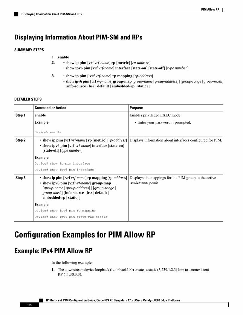
Displaying Information About PIM-SM and RPs
SUMMARY STEPS
1. enable2. show ip pim [vrf vrf-name] rp [metric] [rp-address]•
• show ipv6 pim [vrf vrf-name] interface [state-on] [state-off] [type number]
3. show ip pim [ vrf vrf-name] rp mapping [rp-address]•• show ipv6 pim [vrf vrf-name] group-map [group-name | group-address] | [group-range | group-mask][info-source {bsr | default | embedded-rp | static}]
DETAILED STEPS
PurposeCommand or Action
Enables privileged EXEC mode.enableStep 1
Example: • Enter your password if prompted.
Device> enable
Displays information about interfaces configured for PIM.Step 2 • show ip pim [vrf vrf-name] rp [metric] [rp-address]• show ipv6 pim [vrf vrf-name] interface [state-on][state-off] [type number]
Example:Device# show ip pim interface
Device# show ipv6 pim interface
Displays the mappings for the PIM group to the activerendezvous points.
Step 3 • show ip pim [ vrf vrf-name] rp mapping [rp-address]• show ipv6 pim [vrf vrf-name] group-map[group-name | group-address] | [group-range |group-mask] [info-source {bsr | default |embedded-rp | static}]
Example:Device# show ipv6 pim rp mapping
Device# show ipv6 pim group-map static
Configuration Examples for PIM Allow RP
Example: IPv4 PIM Allow RP
In the following example:
1. The downstream device loopback (Loopback100) creates a static (*,239.1.2.3) Join to a nonexistentRP (11.30.3.3).
IP Multicast: PIM Configuration Guide, Cisco IOS XE Bengaluru 17.x | Cisco Catalyst 8000 Edge Platforms134
PIM Allow RPDisplaying Information About PIM-SM and RPs

2. The static route makes the device think that this RP can be reached through the upstream devicevia 11.10.2.1, causing the downstream device to send a (*,239.1.2.3) PIM Join with an RP address(11.30.3.3) to the upstream router.
3. When the upstream device receives the (*,239.1.2.3) PIM Join, it realizes that the RP address inthe Join (11.30.3.3) is different from the known (configured) interface-to-RP address (11.10.3.3).
4. The PIM allow RP configuration on the upstream device permits the (*,239.1.2.3) to be processedand creates a (*,239.1.2.3) join to the RP (11.10.3.3).
If the pim allow-rp command is not configured on the upstream device, the upstream device mustignore Joins with different RPs.
Note
################### Downstream##################!hostname downstream-router!!ip multicast-routing distributed!!interface Loopback100ip address 101.10.1.2 255.255.255.0ip igmp static-group 239.1.2.3ip pim sparse-dense-modeno shut!interface Ethernet1/2ip address 11.10.2.2 255.255.255.0ip pim sparse-dense-modeno shut!router ospf 200network 11.0.0.0 0.255.255.255 area 1network 101.0.0.0 0.255.255.255 area 1!ip pim rp-address 11.30.3.3ip mroute 11.30.3.3 255.255.255.255 11.10.2.1!end
################### Upstream##################!hostname Upstream-router!!ip multicast-routing distributed!!interface FastEthernet0/0/2ip address 11.10.2.1 255.255.255.0ip pim sparse-dense-modeno shut!
IP Multicast: PIM Configuration Guide, Cisco IOS XE Bengaluru 17.x | Cisco Catalyst 8000 Edge Platforms135
PIM Allow RPExample: IPv4 PIM Allow RP

interface FastEthernet0/0/4! interface to RP (11.10.3.3)ip address 10.10.4.1 255.255.255.0ip pim sparse-dense-modeno shut!router ospf 200network 10.0.0.0 0.255.255.255 area 1network 11.0.0.0 0.255.255.255 area 1!ip pim rp-address 11.10.3.3ip pim allow-rp!end
Example: IPv6 PIM Allow RP
In the following example:
1. The downstream device loopback creates an static (*,FF03::1) Join to a non-existent RP(80::1:1:3).
2. The static route makes the device think that this RP can be reach via the upstream device via10::1:1:1 and causes the downstream device to send a (*,FF03::1) PIM Join with an RP address(80::1:1:3) to the upstream device.
3. When the upstream device receives the (*,FF03::1) PIM Join, it realizes that the RP address inthe Join (80::1:1:3) is different from the (known) configured address (20::1:1:3).
4. The PIM allow RP configuration on the upstream device permits the (*,FF03::1) to be processed,and creates a (*,FF03::1) Join to the RP (20::1:1:3).
If the pim allow-rp command is not configured on the upstream device, the upstream device mustignore Joins with different RPs .
Note
################### Downstream##################
!hostname downstream-router!!ipv6 unicast-routingipv6 multicast-routing!!interface Loopback100ipv6 address FE80::50:1:2 link-localipv6 address 50::1:1:2/64ipv6 enableipv6 ospf 1 area 0ipv6 mld join-group FF03::1!
IP Multicast: PIM Configuration Guide, Cisco IOS XE Bengaluru 17.x | Cisco Catalyst 8000 Edge Platforms136
PIM Allow RPExample: IPv6 PIM Allow RP

interface Ethernet1/2ipv6 address FE80::10:1:2 link-localipv6 address 10::1:1:2/64ipv6 enableipv6 ospf 1 area 0no keepalive!!ipv6 pim rp-address 80::1:1:3ipv6 route 80::1:1:3/128 10::1:1:1 multicast!ipv6 router ospf 1router-id 205.2.0.2!!end
#################### Upstream###################!hostname Upstream-router!!ipv6 unicast-routingipv6 multicast-routing!!interface FastEthernet0/0/2ipv6 address FE80::10:1:1 link-localipv6 address 10::1:1:1/64ipv6 enableipv6 ospf 1 area 0!interface FastEthernet0/0/3! interface to the RP (20::1:1:3)ipv6 address FE80::20:1:1 link-localipv6 address 20::1:1:1/64ipv6 enableipv6 ospf 1 area 0!!ipv6 pim rp-address 20::1:1:3ipv6 pim allow-rp!ipv6 router ospf 1router-id 205.1.0.1!!end
IP Multicast: PIM Configuration Guide, Cisco IOS XE Bengaluru 17.x | Cisco Catalyst 8000 Edge Platforms137
PIM Allow RPExample: IPv6 PIM Allow RP
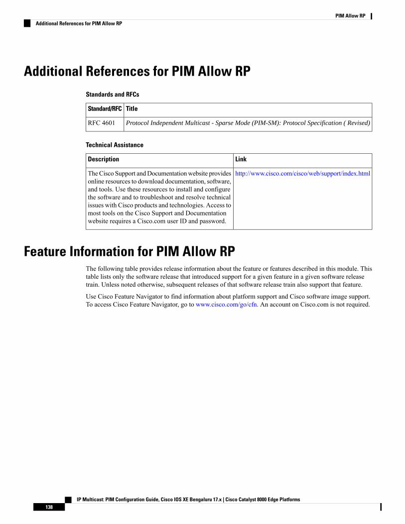
Additional References for PIM Allow RPStandards and RFCs
TitleStandard/RFC
Protocol Independent Multicast - Sparse Mode (PIM-SM): Protocol Specification ( Revised)RFC 4601
Technical Assistance
LinkDescription
http://www.cisco.com/cisco/web/support/index.htmlTheCisco Support andDocumentationwebsite providesonline resources to download documentation, software,and tools. Use these resources to install and configurethe software and to troubleshoot and resolve technicalissues with Cisco products and technologies. Access tomost tools on the Cisco Support and Documentationwebsite requires a Cisco.com user ID and password.
Feature Information for PIM Allow RPThe following table provides release information about the feature or features described in this module. Thistable lists only the software release that introduced support for a given feature in a given software releasetrain. Unless noted otherwise, subsequent releases of that software release train also support that feature.
Use Cisco Feature Navigator to find information about platform support and Cisco software image support.To access Cisco Feature Navigator, go to www.cisco.com/go/cfn. An account on Cisco.com is not required.
IP Multicast: PIM Configuration Guide, Cisco IOS XE Bengaluru 17.x | Cisco Catalyst 8000 Edge Platforms138
PIM Allow RPAdditional References for PIM Allow RP
C H A P T E R 7Configuring Source Specific Multicast
This module describes how to configure Source Specific Multicast (SSM). The Source Specific Multicastfeature is an extension of IP multicast where datagram traffic is forwarded to receivers from only thosemulticast sources to which the receivers have explicitly joined. For multicast groups configured for SSM,only source-specific multicast distribution trees (no shared trees) are created.
• Restrictions for Source Specific Multicast, on page 139• Information About Source Specific Multicast, on page 141• How to Configure Source Specific Multicast, on page 146• Configuration Examples of Source Specific Multicast, on page 147• Additional References, on page 149• Feature Information for Source Specific Multicast, on page 150
Restrictions for Source Specific MulticastLegacy Applications Within the SSM Range Restrictions
Existing applications in a network predating SSMwill not work within the SSM range unless they are modifiedto support (S, G) channel subscriptions or are enabled through URLRendezvous Directory (URD). Therefore,enabling SSM in a network may cause problems for existing applications if they use addresses within thedesignated SSM range.
IGMP v3lite and URD Require a Cisco Last Hop Router
SSM and IGMPv3 are solutions that are being standardized in the IETF. However, IGMP v3lite and URDare Cisco-developed solutions. For IGMP v3lite and URD to operate properly for a host, the last hop routertoward that host must be a Cisco router with IGMP v3lite or URD enabled.
This limitation does not apply to an application using the Host Side IGMP Library (HSIL) if the host haskernel support for IGMPv3, because then the HSIL will use the kernel IGMPv3 instead of IGMP v3lite.
Note
Address Management Restrictions
Address management is still necessary to some degree when SSM is used with Layer 2 switchingmechanisms.Cisco Group Management Protocol (CGMP), IGMP snooping, or Router-Port Group Management Protocol
IP Multicast: PIM Configuration Guide, Cisco IOS XE Bengaluru 17.x | Cisco Catalyst 8000 Edge Platforms139
(RGMP) currently support only group-specific filtering, not (S, G) channel-specific filtering. If differentreceivers in a switched network request different (S, G) channels sharing the same group, then they will notbenefit from these existing mechanisms. Instead, both receivers will receive all (S, G) channel traffic (andfilter out the unwanted traffic on input). Because of the ability of SSM to reuse the group addresses in theSSM range for many independent applications, this situation can lead to less than expected traffic filtering ina switched network. For this reason it is important to follow the recommendations set forth in the IETF draftsfor SSM to use random IP addresses out of the SSM range for an application to minimize the chance for reuseof a single address within the SSM range between different applications. For example, an application serviceproviding a set of television channels should, even with SSM, use a different group for each television (S, G)channel. This setup will guarantee that multiple receivers to different channels within the same applicationservice will never experience traffic aliasing in networks that include Layer 2 switches.
IGMP Snooping and CGMP Limitations
IGMPv3 uses newmembership report messages that may not be recognized correctly by older IGMP Snoopingswitches, in which case hosts will not properly receive traffic. This situation is not an issue if URD or IGMPv3lite is used with hosts where the operating system is not upgraded for IGMPv3, because IGMP v3lite andURD rely only on IGMPv1 or IGMPv2 membership reports.
URD Intercept URL Limitations
A URD intercept URL string must be fewer than 256 bytes in length, starting from the /path argument. In theHTTP/TCP connection, this string must also be contained within a single TCP/IP packet. For example, for a256-byte string, a link maximum transmission unit (MTU) of 128 bytes between the host and interceptingrouter would cause incorrect operation of URD.
State Maintenance Limitations
In PIM-SSM, the last hop router will continue to periodically send (S, G) join messages if appropriate (S, G)subscriptions are on the interfaces. Therefore, as long as receivers send (S, G) subscriptions, the shortest pathtree (SPT) state from the receivers to the source will be maintained, even if the source is not sending trafficfor longer periods of time (or even never).
This case is opposite to PIM-SM, where (S, G) state is maintained only if the source is sending traffic andreceivers are joining the group. If a source stops sending traffic for more than 3 minutes in PIM-SM, the (S,G) state will be deleted and only reestablished after packets from the source arrive again through the RPT.Because no mechanism in PIM-SSM notifies a receiver that a source is active, the network must maintain the(S, G) state in PIM-SSM as long as receivers are requesting receipt of that channel.
HSIL Limitations
As explained in the IGMP v3lite Host Signalling, on page 144 concept, the HSIL tries to determine if the hostoperating system supports IGMPv3. This check is made so that a single application can be used both on hostswhere the operating system has been upgraded to IGMPv3 and on hosts where the operating system onlysupports IGMPv1 or IGMPv2.
Checking for the availability of IGMPv3 in the host operating system can only be made by the HSIL if IGMPv3kernel support exists for at least one version of this operating system at the time when the HSIL was provided.If such an IGMPv3 kernel implementation has become available only recently, then users may need to alsoupgrade the HSIL on their hosts so that applications compiled with the HSIL will then dynamically bind tothe newest version of the HSIL, which should support the check for IGMPv3 in the operating system kernel.Upgrading the HSIL can be done independently of upgrading the application itself.
IP Multicast: PIM Configuration Guide, Cisco IOS XE Bengaluru 17.x | Cisco Catalyst 8000 Edge Platforms140
Configuring Source Specific MulticastRestrictions for Source Specific Multicast
Information About Source Specific Multicast
SSM OverviewSource Specific Multicast (SSM). SSM is an extension of IP multicast where datagram traffic is forwardedto receivers from only those multicast sources that the receivers have explicitly joined. For multicast groupsconfigured for SSM, only source-specific multicast distribution trees (not shared trees) are created.
SSM ComponentsSSM is a datagram delivery model that best supports one-to-many applications, also known as broadcastapplications.
SSM is a core networking technology for Cisco's implementation of IP multicast solutions targeted for audioand video broadcast application environments and is described in RFC 3569. The following componentstogether support the implementation of SSM:
• Protocol Independent Multicast source-specific mode (PIM-SSM)
• Internet Group Management Protocol Version 3 (IGMPv3)
Protocol Independent Multicast (PIM) SSM, or PIM-SSM, is the routing protocol that supports theimplementation of SSM and is derived from PIM sparse mode (PIM-SM). IGMP is the Internet EngineeringTask Force (IETF) standards track protocol used for hosts to signal multicast group membership to routers.IGMP Version 3 supports source filtering, which is required for SSM. IGMP For SSM to run with IGMPv3,SSM must be supported in the router, the host where the application is running, and the application itself.
How SSM Differs from Internet Standard MulticastThe standard IP multicast infrastructure in the Internet and many enterprise intranets is based on the PIM-SMprotocol and Multicast Source Discovery Protocol (MSDP). These protocols have proved to be reliable,extensive, and efficient. However, they are bound to the complexity and functionality limitations of the InternetStandardMulticast (ISM) service model. For example, with ISM, the network must maintain knowledge aboutwhich hosts in the network are actively sending multicast traffic. With SSM, this information is provided byreceivers through the source addresses relayed to the last-hop devices by IGMPv3. SSM is an incrementalresponse to the issues associated with ISM and is intended to coexist in the network with the protocolsdeveloped for ISM. In general, SSM provides IP multicast service for applications that utilize SSM.
ISM service is described in RFC 1112. This service consists of the delivery of IP datagrams from any sourceto a group of receivers called the multicast host group. The datagram traffic for the multicast host groupconsists of datagrams with an arbitrary IP unicast source address S and the multicast group address G as theIP destination address. Systems will receive this traffic by becoming members of the host group. Membershipin a host group simply requires signaling the host group through IGMP Version 1, 2, or 3.
In SSM, delivery of datagrams is based on (S, G) channels. Traffic for one (S, G) channel consists of datagramswith an IP unicast source address S and the multicast group address G as the IP destination address. Systemswill receive this traffic by becoming members of the (S, G) channel. In both SSM and ISM, no signaling isrequired to become a source. However, in SSM, receivers must subscribe or unsubscribe to (S, G) channelsto receive or not receive traffic from specific sources. In other words, receivers can receive traffic only from(S, G) channels to which they are subscribed, whereas in ISM, receivers need not know the IP addresses ofsources from which they receive their traffic. The proposed standard approach for channel subscription
IP Multicast: PIM Configuration Guide, Cisco IOS XE Bengaluru 17.x | Cisco Catalyst 8000 Edge Platforms141
Configuring Source Specific MulticastInformation About Source Specific Multicast
signaling utilizes IGMP INCLUDE mode membership reports, which are supported only in IGMP Version3.
SSM can coexist with the ISM service by applying the SSM delivery model to a configured subset of the IPmulticast group address range. The Internet Assigned Numbers Authority (IANA) has reserved the addressrange from 232.0.0.0 through 232.255.255.255 for SSM applications and protocols. The software allows SSMconfiguration for an arbitrary subset of the IP multicast address range from 224.0.0.0 through 239.255.255.255.When an SSM range is defined, an existing IP multicast receiver application will not receive any traffic whenit tries to use addresses in the SSM range unless the application is modified to use explicit (S, G) channelsubscription or is SSM-enabled through a URL Rendezvous Directory (URD).
SSM OperationsAn established network in which IP multicast service is based on PIM-SM can support SSM services. SSMcan also be deployed alone in a network without the full range of protocols that are required for interdomainPIM-SM. That is, SSM does not require an RP, so there is no need for an RP mechanism such as Auto-RP,MSDP, or bootstrap router (BSR).
If SSM is deployed in a network that is already configured for PIM-SM, then only the last-hop routers mustbe upgraded to a software image that supports SSM. Routers that are not directly connected to receivers donot have to upgrade to a software image that supports SSM. In general, these non-last-hop routers must onlyrun PIM-SM in the SSM range. They may need additional access control configuration to suppress MSDPsignaling, registering, or PIM-SM shared-tree operations from occurring within the SSM range.
The SSMmode of operation is enabled by configuring the SSM range using the ip pim ssm global configurationcommand. This configuration has the following effects:
• For groups within the SSM range, (S, G) channel subscriptions are accepted through IGMPv3 INCLUDEmode membership reports.
• PIM operations within the SSM range of addresses change to PIM-SSM, a mode derived from PIM-SM.In this mode, only PIM (S, G) Join and Prune messages are generated by the router. Incoming messagesrelated to rendezvous point tree (RPT) operations are ignored or rejected, and incoming PIM registermessages are immediately answered with Register-Stop messages. PIM-SSM is backward-compatiblewith PIM-SM unless a router is a last-hop router. Therefore, routers that are not last-hop routers can runPIM-SM for SSM groups (for example, if they do not yet support SSM).
• For groups within the SSM range, no MSDP Source-Active (SA) messages within the SSM range willbe accepted, generated, or forwarded.
IGMPv3 Host SignalingIGMPv3 is the third version of the IETF standards track protocol in which hosts signal membership to last-hoprouters of multicast groups. IGMPv3 introduces the ability for hosts to signal group membership that allowsfiltering capabilities with respect to sources. A host can signal either that it wants to receive traffic from allsources sending to a group except for some specific sources (a mode called EXCLUDE) or that it wants toreceive traffic only from some specific sources sending to the group (a mode called INCLUDE).
IGMPv3 can operate with both ISM and SSM. In ISM, both EXCLUDE and INCLUDE mode reports areaccepted by the last-hop router. In SSM, only INCLUDE mode reports are accepted by the last-hop router.
IP Multicast: PIM Configuration Guide, Cisco IOS XE Bengaluru 17.x | Cisco Catalyst 8000 Edge Platforms142
Configuring Source Specific MulticastSSM Operations
Benefits of
IP Multicast Address Management Not Required
In the ISM service, applications must acquire a unique IP multicast group address because traffic distributionis based only on the IP multicast group address used. If two applications with different sources and receiversuse the same IP multicast group address, then receivers of both applications will receive traffic from thesenders of both applications. Even though the receivers, if programmed appropriately, can filter out theunwanted traffic, this situation would cause generally unacceptable levels of unwanted traffic.
Allocating a unique IPmulticast group address for an application is still a problem.Most short-lived applicationsuse mechanisms like Session Description Protocol (SDP) and Session Announcement Protocol (SAP) to geta random address, a solution that does not work well with a rising number of applications in the Internet. Thebest current solution for long-lived applications is described in RFC 2770, but this solution suffers from therestriction that each autonomous system is limited to only 255 usable IP multicast addresses.
In SSM, traffic from each source is forwarded between routers in the network independent of traffic fromother sources. Thus different sources can reuse multicast group addresses in the SSM range.
Denial of Service Attacks from Unwanted Sources Inhibited
In SSM, multicast traffic from each individual source will be transported across the network only if it wasrequested (through IGMPv3, IGMP v3lite, or URD memberships) from a receiver. In contrast, ISM forwardstraffic from any active source sending to a multicast group to all receivers requesting that multicast group. InInternet broadcast applications, this ISM behavior is highly undesirable because it allows unwanted sourcesto easily disturb the actual Internet broadcast source by simply sending traffic to the same multicast group.This situation depletes bandwidth at the receiver side with unwanted traffic and thus disrupts the undisturbedreception of the Internet broadcast. In SSM, this type of denial of service (DoS) attack cannot be made bysimply sending traffic to a multicast group.
Easy to Install and Manage
SSM is easy to install and provision in a network because it does not require the network to maintain whichactive sources are sending to multicast groups. This requirement exists in ISM (with IGMPv1, IGMPv2, orIGMPv3).
The current standard solutions for ISM service are PIM-SM and MSDP. Rendezvous point (RP) managementin PIM-SM (including the necessity for Auto-RP or BSR) andMSDP is required only for the network to learnabout active sources. This management is not necessary in SSM, which makes SSM easier than ISM to installandmanage, and therefore easier than ISM to operationally scale in deployment. Another factor that contributesto the ease of installation of SSM is the fact that it can leverage preexisting PIM-SM networks and requiresonly the upgrade of last hop routers to support IGMPv3, IGMP v3lite, or URD.
Ideal for Internet Broadcast Applications
The three benefits previously described make SSM ideal for Internet broadcast-style applications for thefollowing reasons:
• The ability to provide Internet broadcast services through SSM without the need for unique IP multicastaddresses allows content providers to easily offer their service (IP multicast address allocation has beena serious problem for content providers in the past).
• The prevention against DoS attacks is an important factor for Internet broadcast services because, withtheir exposure to a large number of receivers, they are the most common targets for such attacks.
IP Multicast: PIM Configuration Guide, Cisco IOS XE Bengaluru 17.x | Cisco Catalyst 8000 Edge Platforms143
Configuring Source Specific MulticastBenefits of
• The ease of installation and operation of SSM makes it ideal for network operators, especially in thosecases where content needs to be forwarded between multiple independent PIM domains (because thereis no need to manage MSDP for SSM between PIM domains).
IGMP v3lite Host SignallingIGMP v3lite is a Cisco-developed transitional solution for application developers to immediately startprogramming SSM applications. It allows you to write and run SSM applications on hosts that do not yetsupport IGMPv3 in their operating system kernel.
Applications must be compiled with the Host Side IGMP Library (HSIL) for IGMP v3lite. This softwareprovides applications with a subset of the IGMPv3 applications programming interface (API) that is requiredto write SSM applications. HSIL was developed for Cisco by Talarian and is available from the followingweb page:
http://www.talarianmulticast.com/cgi-bin/igmpdownld
One part of the HSIL is a client library linked to the SSM application. It provides the SSM subset of theIGMPv3 API to the SSM application. If possible, the library checks whether the operating system kernelsupports IGMPv3. If it does, then the API calls simply are passed through to the kernel. If the kernel does notsupport IGMPv3, then the library uses the IGMP v3lite mechanism.
When using the IGMP v3lite mechanism, the library tells the operating system kernel to join to the wholemulticast group, because joining to the whole group is the only method for the application to receive trafficfor that multicast group (if the operating system kernel only supports IGMPv1 or IGMPv2). In addition, thelibrary signals the (S, G) channel subscriptions to an IGMP v3lite server process, which is also part of theHSIL. A server process is needed because multiple SSM applications may be on the same host. This serverprocess will then send IGMP v3lite-specific (S, G) channel subscriptions to the last hop Cisco IOS router,which needs to be enabled for IGMP v3lite. This router will then “see” both the IGMPv1 or IGMPv2 groupmembership report from the operating system kernel and the (S, G) channel subscription from the HSILdaemon. If the router sees both of these messages, it will interpret them as an SSM (S, G) channel subscriptionand join to the channel through PIM-SSM. We recommend referring to the documentation accompanying theHSIL software for further information on how to utilize IGMP v3lite with your application.
IGMP v3lite is supported by Cisco only through the API provided by the HSIL, not as a function of the routerindependent of the HSIL. By default, IGMP v3lite is disabled. When IGMP v3lite is configured through theip igmp v3lite interface configuration command on an interface, it will be active only for IP multicast addressesin the SSM range.
URD Host SignallingURD is a Cisco-developed transitional solution that allows existing IP multicast receiver applications to beused with SSM without the need to modify the application and change or add any software on the receiverhost running the application. URD is a content provider solution in which the receiver applications can bestarted or controlled through a web browser.
URD operates by passing a special URL from the web browser to the last hop router. This URL is called aURD intercept URL. A URD intercept URL is encoded with the (S, G) channel subscription and has a formatthat allows the last hop router to easily intercept it.
As soon as the last hop router intercepts both an (S, G) channel subscription encoded in a URD intercept URLand sees an IGMP group membership report for the same multicast group from the receiver application, thelast hop router will use PIM-SSM to join toward the (S, G) channel as long as the application maintains the
IP Multicast: PIM Configuration Guide, Cisco IOS XE Bengaluru 17.x | Cisco Catalyst 8000 Edge Platforms144
Configuring Source Specific MulticastIGMP v3lite Host Signalling
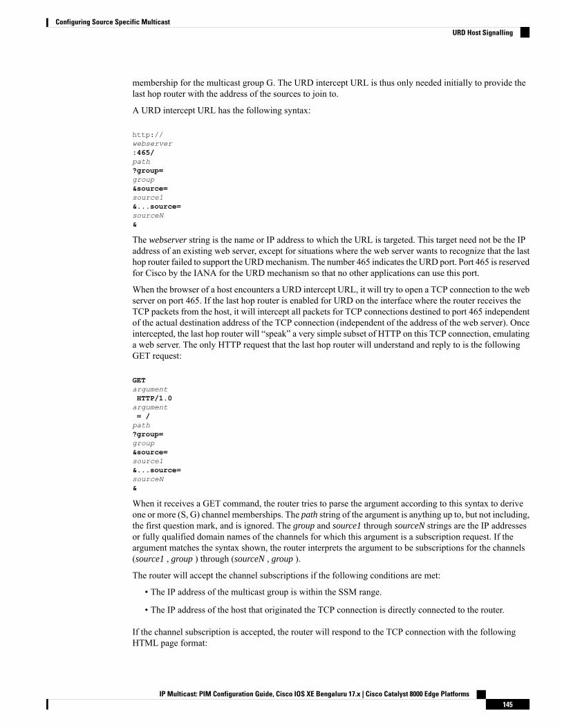
membership for the multicast group G. The URD intercept URL is thus only needed initially to provide thelast hop router with the address of the sources to join to.
A URD intercept URL has the following syntax:
http://webserver:465/path?group=group&source=source1&...source=sourceN&
The webserver string is the name or IP address to which the URL is targeted. This target need not be the IPaddress of an existing web server, except for situations where the web server wants to recognize that the lasthop router failed to support the URDmechanism. The number 465 indicates the URD port. Port 465 is reservedfor Cisco by the IANA for the URD mechanism so that no other applications can use this port.
When the browser of a host encounters a URD intercept URL, it will try to open a TCP connection to the webserver on port 465. If the last hop router is enabled for URD on the interface where the router receives theTCP packets from the host, it will intercept all packets for TCP connections destined to port 465 independentof the actual destination address of the TCP connection (independent of the address of the web server). Onceintercepted, the last hop router will “speak” a very simple subset of HTTP on this TCP connection, emulatinga web server. The only HTTP request that the last hop router will understand and reply to is the followingGET request:
GETargumentHTTP/1.0argument= /path?group=group&source=source1&...source=sourceN&
When it receives a GET command, the router tries to parse the argument according to this syntax to deriveone or more (S, G) channel memberships. The path string of the argument is anything up to, but not including,the first question mark, and is ignored. The group and source1 through sourceN strings are the IP addressesor fully qualified domain names of the channels for which this argument is a subscription request. If theargument matches the syntax shown, the router interprets the argument to be subscriptions for the channels(source1 , group ) through (sourceN , group ).
The router will accept the channel subscriptions if the following conditions are met:
• The IP address of the multicast group is within the SSM range.
• The IP address of the host that originated the TCP connection is directly connected to the router.
If the channel subscription is accepted, the router will respond to the TCP connection with the followingHTML page format:
IP Multicast: PIM Configuration Guide, Cisco IOS XE Bengaluru 17.x | Cisco Catalyst 8000 Edge Platforms145
Configuring Source Specific MulticastURD Host Signalling
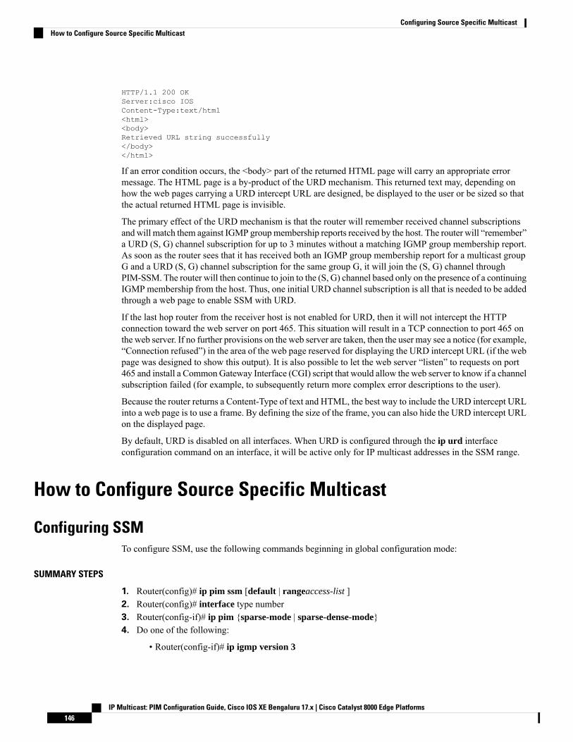
HTTP/1.1 200 OKServer:cisco IOSContent-Type:text/html<html><body>Retrieved URL string successfully</body></html>
If an error condition occurs, the <body> part of the returned HTML page will carry an appropriate errormessage. The HTML page is a by-product of the URD mechanism. This returned text may, depending onhow the web pages carrying a URD intercept URL are designed, be displayed to the user or be sized so thatthe actual returned HTML page is invisible.
The primary effect of the URD mechanism is that the router will remember received channel subscriptionsand will match them against IGMP groupmembership reports received by the host. The router will “remember”a URD (S, G) channel subscription for up to 3 minutes without a matching IGMP group membership report.As soon as the router sees that it has received both an IGMP group membership report for a multicast groupG and a URD (S, G) channel subscription for the same group G, it will join the (S, G) channel throughPIM-SSM. The router will then continue to join to the (S, G) channel based only on the presence of a continuingIGMPmembership from the host. Thus, one initial URD channel subscription is all that is needed to be addedthrough a web page to enable SSM with URD.
If the last hop router from the receiver host is not enabled for URD, then it will not intercept the HTTPconnection toward the web server on port 465. This situation will result in a TCP connection to port 465 onthe web server. If no further provisions on the web server are taken, then the user may see a notice (for example,“Connection refused”) in the area of the web page reserved for displaying the URD intercept URL (if the webpage was designed to show this output). It is also possible to let the web server “listen” to requests on port465 and install a CommonGateway Interface (CGI) script that would allow the web server to know if a channelsubscription failed (for example, to subsequently return more complex error descriptions to the user).
Because the router returns a Content-Type of text and HTML, the best way to include the URD intercept URLinto a web page is to use a frame. By defining the size of the frame, you can also hide the URD intercept URLon the displayed page.
By default, URD is disabled on all interfaces. When URD is configured through the ip urd interfaceconfiguration command on an interface, it will be active only for IP multicast addresses in the SSM range.
How to Configure Source Specific Multicast
Configuring SSMTo configure SSM, use the following commands beginning in global configuration mode:
SUMMARY STEPS
1. Router(config)# ip pim ssm [default | rangeaccess-list ]2. Router(config)# interface type number3. Router(config-if)# ip pim {sparse-mode | sparse-dense-mode}4. Do one of the following:
• Router(config-if)# ip igmp version 3
IP Multicast: PIM Configuration Guide, Cisco IOS XE Bengaluru 17.x | Cisco Catalyst 8000 Edge Platforms146
Configuring Source Specific MulticastHow to Configure Source Specific Multicast
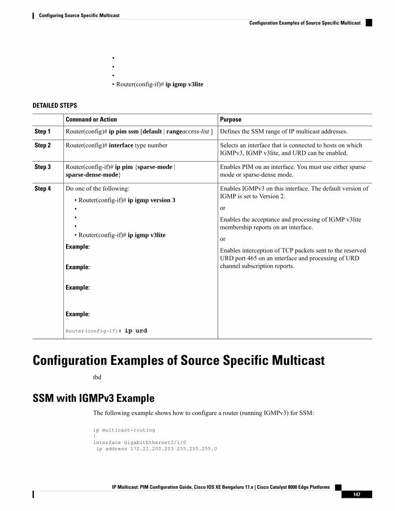
•••• Router(config-if)# ip igmp v3lite
DETAILED STEPS
PurposeCommand or Action
Defines the SSM range of IP multicast addresses.Router(config)# ip pim ssm [default | rangeaccess-list ]Step 1
Selects an interface that is connected to hosts on whichIGMPv3, IGMP v3lite, and URD can be enabled.
Router(config)# interface type numberStep 2
Enables PIM on an interface. You must use either sparsemode or sparse-dense mode.
Router(config-if)# ip pim {sparse-mode |sparse-dense-mode}
Step 3
Enables IGMPv3 on this interface. The default version ofIGMP is set to Version 2.
Do one of the following:Step 4
• Router(config-if)# ip igmp version 3or•
• Enables the acceptance and processing of IGMP v3litemembership reports on an interface.•
• Router(config-if)# ip igmp v3lite orExample: Enables interception of TCP packets sent to the reserved
URD port 465 on an interface and processing of URDchannel subscription reports.Example:
Example:
Example:
Router(config-if)# ip urd
Configuration Examples of Source Specific Multicasttbd
SSM with IGMPv3 ExampleThe following example shows how to configure a router (running IGMPv3) for SSM:
ip multicast-routing!interface GigabitEthernet3/1/0ip address 172.21.200.203 255.255.255.0
IP Multicast: PIM Configuration Guide, Cisco IOS XE Bengaluru 17.x | Cisco Catalyst 8000 Edge Platforms147
Configuring Source Specific MulticastConfiguration Examples of Source Specific Multicast
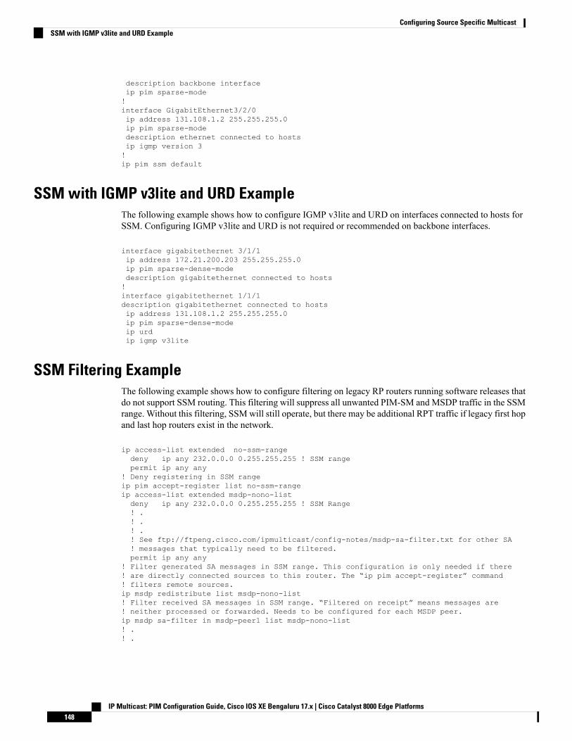
description backbone interfaceip pim sparse-mode!interface GigabitEthernet3/2/0ip address 131.108.1.2 255.255.255.0ip pim sparse-modedescription ethernet connected to hostsip igmp version 3!ip pim ssm default
SSM with IGMP v3lite and URD ExampleThe following example shows how to configure IGMP v3lite and URD on interfaces connected to hosts forSSM. Configuring IGMP v3lite and URD is not required or recommended on backbone interfaces.
interface gigabitethernet 3/1/1ip address 172.21.200.203 255.255.255.0ip pim sparse-dense-modedescription gigabitethernet connected to hosts!interface gigabitethernet 1/1/1description gigabitethernet connected to hostsip address 131.108.1.2 255.255.255.0ip pim sparse-dense-modeip urdip igmp v3lite
SSM Filtering ExampleThe following example shows how to configure filtering on legacy RP routers running software releases thatdo not support SSM routing. This filtering will suppress all unwanted PIM-SM and MSDP traffic in the SSMrange. Without this filtering, SSMwill still operate, but there may be additional RPT traffic if legacy first hopand last hop routers exist in the network.
ip access-list extended no-ssm-rangedeny ip any 232.0.0.0 0.255.255.255 ! SSM rangepermit ip any any
! Deny registering in SSM rangeip pim accept-register list no-ssm-rangeip access-list extended msdp-nono-listdeny ip any 232.0.0.0 0.255.255.255 ! SSM Range! .! .! .! See ftp://ftpeng.cisco.com/ipmulticast/config-notes/msdp-sa-filter.txt for other SA! messages that typically need to be filtered.permit ip any any
! Filter generated SA messages in SSM range. This configuration is only needed if there! are directly connected sources to this router. The “ip pim accept-register” command! filters remote sources.ip msdp redistribute list msdp-nono-list! Filter received SA messages in SSM range. “Filtered on receipt” means messages are! neither processed or forwarded. Needs to be configured for each MSDP peer.ip msdp sa-filter in msdp-peer1 list msdp-nono-list! .! .
IP Multicast: PIM Configuration Guide, Cisco IOS XE Bengaluru 17.x | Cisco Catalyst 8000 Edge Platforms148
Configuring Source Specific MulticastSSM with IGMP v3lite and URD Example
! .ip msdp sa-filter in msdp-peerN list msdp-nono-list
Additional ReferencesThe following sections provide references related to Source Specific Multicast.
Related Documents
Document TitleRelated Topic
“Configuring Basic IP Multicast ”module
PIM-SM and SSM concepts and configuration examples
IP multicast commands: complete command syntax, commandmode,defaults, command history, usage guidelines, and examples
Standards
TitleStandard
--No new or modified standards are supported by this feature, and support for existing standards has notbeen modified by this feature.
MIBs
MIBs LinkMIB
To locate and downloadMIBs for selected platforms, CiscoIOS XE releases, and feature sets, use Cisco MIB Locatorfound at the following URL:
http://www.cisco.com/go/mibs
No new or modified MIBs are supported by thisfeature, and support for existing standards hasnot been modified by this feature.
RFCs
TitleRFC
--No new or modified RFCs are supported by this feature, and support for existing standards has notbeen modified by this feature.
IP Multicast: PIM Configuration Guide, Cisco IOS XE Bengaluru 17.x | Cisco Catalyst 8000 Edge Platforms149
Configuring Source Specific MulticastAdditional References
Technical Assistance
LinkDescription
http://www.cisco.com/techsupportThe Cisco Support website provides extensive online resources, includingdocumentation and tools for troubleshooting and resolving technical issueswith Cisco products and technologies.
To receive security and technical information about your products, youcan subscribe to various services, such as the Product Alert Tool (accessedfrom Field Notices), the Cisco Technical Services Newsletter, and ReallySimple Syndication (RSS) Feeds.
Access to most tools on the Cisco Support website requires a Cisco.comuser ID and password.
Feature Information for Source Specific MulticastThe following table provides release information about the feature or features described in this module. Thistable lists only the software release that introduced support for a given feature in a given software releasetrain. Unless noted otherwise, subsequent releases of that software release train also support that feature.
Use Cisco Feature Navigator to find information about platform support and Cisco software image support.To access Cisco Feature Navigator, go to www.cisco.com/go/cfn. An account on Cisco.com is not required.
IP Multicast: PIM Configuration Guide, Cisco IOS XE Bengaluru 17.x | Cisco Catalyst 8000 Edge Platforms150
Configuring Source Specific MulticastFeature Information for Source Specific Multicast

C H A P T E R 8Tunneling to Connect Non-IP Multicast Areas
This module describes how to configure a Generic Route Encapsulation (GRE) tunnel to tunnel IP multicastpackets between non-IP multicast areas. The benefit is that IP multicast traffic can be sent from a source to amulticast group, over an area where IP multicast is not supported.
• Prerequisites for Tunneling to Connect Non-IP Multicast Areas, on page 151• Information About Tunneling to Connect Non-IP Multicast Areas, on page 151• How to Connect Non-IP Multicast Areas, on page 152• Configuration Examples for Tunneling to Connect Non-IP Multicast Areas, on page 155• Additional References, on page 157• Feature Information for Tunneling to Connect Non-IP Multicast Areas, on page 158
Prerequisites for Tunneling to Connect Non-IP Multicast AreasThis module assumes you understand the concepts in the “IP Multicast Technology Overview” module.
InformationAboutTunnelingtoConnectNon-IPMulticastAreas
Benefits of Tunneling to Connect Non-IP Multicast Areas• If the path between a source and a group member (destination) does not support IP multicast, a tunnelbetween them can transport IP multicast packets.
• Per packet load balancing can be used. Load balancing in IP multicast is normally per (S,G). Therefore,(S1, G) can go over Link X and (S2, G) can go over Link Y, where X and Y are parallel links. If youcreate a tunnel between the routers, you can get per packet load balancing because the load balancing isdone on the tunnel unicast packets.
IP Multicast Static RouteIP multicast static routes (mroutes) allow you to have multicast paths diverge from the unicast paths. Whenusing Protocol IndependentMulticast (PIM), the router expects to receive packets on the same interface whereit sends unicast packets back to the source. This expectation is beneficial if your multicast and unicast topologiesare congruent. However, you might want unicast packets to take one path and multicast packets to take another.
IP Multicast: PIM Configuration Guide, Cisco IOS XE Bengaluru 17.x | Cisco Catalyst 8000 Edge Platforms151
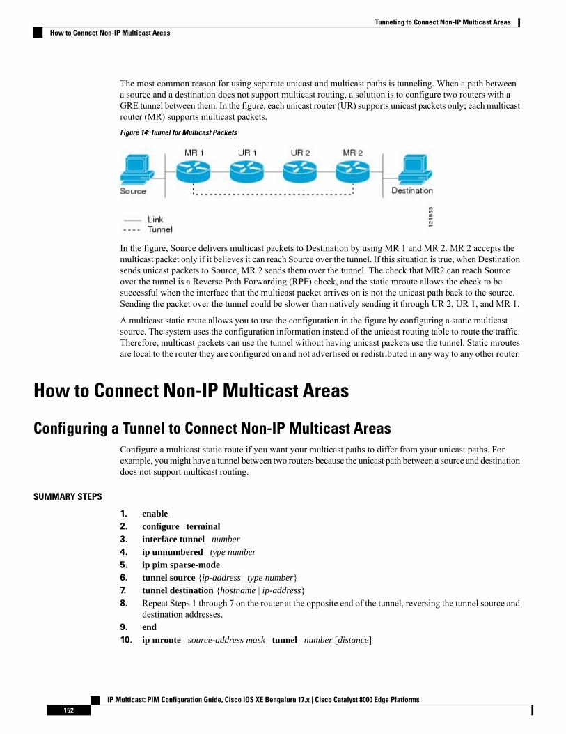
The most common reason for using separate unicast and multicast paths is tunneling. When a path betweena source and a destination does not support multicast routing, a solution is to configure two routers with aGRE tunnel between them. In the figure, each unicast router (UR) supports unicast packets only; each multicastrouter (MR) supports multicast packets.
Figure 14: Tunnel for Multicast Packets
In the figure, Source delivers multicast packets to Destination by using MR 1 and MR 2. MR 2 accepts themulticast packet only if it believes it can reach Source over the tunnel. If this situation is true, when Destinationsends unicast packets to Source, MR 2 sends them over the tunnel. The check that MR2 can reach Sourceover the tunnel is a Reverse Path Forwarding (RPF) check, and the static mroute allows the check to besuccessful when the interface that the multicast packet arrives on is not the unicast path back to the source.Sending the packet over the tunnel could be slower than natively sending it through UR 2, UR 1, and MR 1.
A multicast static route allows you to use the configuration in the figure by configuring a static multicastsource. The system uses the configuration information instead of the unicast routing table to route the traffic.Therefore, multicast packets can use the tunnel without having unicast packets use the tunnel. Static mroutesare local to the router they are configured on and not advertised or redistributed in any way to any other router.
How to Connect Non-IP Multicast Areas
Configuring a Tunnel to Connect Non-IP Multicast AreasConfigure a multicast static route if you want your multicast paths to differ from your unicast paths. Forexample, youmight have a tunnel between two routers because the unicast path between a source and destinationdoes not support multicast routing.
SUMMARY STEPS
1. enable2. configure terminal3. interface tunnel number
4. ip unnumbered type number
5. ip pim sparse-mode6. tunnel source {ip-address | type number}7. tunnel destination {hostname | ip-address}8. Repeat Steps 1 through 7 on the router at the opposite end of the tunnel, reversing the tunnel source and
destination addresses.9. end10. ip mroute source-address mask tunnel number [distance]
IP Multicast: PIM Configuration Guide, Cisco IOS XE Bengaluru 17.x | Cisco Catalyst 8000 Edge Platforms152
Tunneling to Connect Non-IP Multicast AreasHow to Connect Non-IP Multicast Areas

11. ip mroute source-address mask tunnel number [distance]12. end13. show ip mroute [group-address | group-name] [source-address | source-name] [interface-type
interface-number] [summary] [count] [active kbps]14. show ip rpf {source-address | source-name} [metric]
DETAILED STEPS
PurposeCommand or Action
Enables privileged EXEC mode.enableStep 1
Example: • Enter your password if prompted.
Router> enable
Enters global configuration mode.configure terminal
Example:
Step 2
Router# configure terminal
Configures a tunnel interface.interface tunnel number
Example:
Step 3
Router(config)# interface tunnel 0
Enables IP processing without assigning an IP address tothe interface.
ip unnumbered type number
Example:
Step 4
Router(config-if)# ip unnumbered gigabitethernet0/0/0
Enables PIM sparse mode on the tunnel interface.ip pim sparse-mode
Example:
Step 5
Router(config-if)# ip pim sparse-mode
Configures the tunnel source.tunnel source {ip-address | type number}
Example:
Step 6
Router(config-if)# tunnel source 100.1.1.1
Configures the tunnel destination.tunnel destination {hostname | ip-address}
Example:
Step 7
Router(config-if)# tunnel destination 100.1.5.3
Router A’s tunnel source address will match Router B’stunnel destination address. Router A’s tunnel destinationaddress will match Router B’s tunnel source address.
Repeat Steps 1 through 7 on the router at the opposite endof the tunnel, reversing the tunnel source and destinationaddresses.
Step 8
IP Multicast: PIM Configuration Guide, Cisco IOS XE Bengaluru 17.x | Cisco Catalyst 8000 Edge Platforms153
Tunneling to Connect Non-IP Multicast AreasConfiguring a Tunnel to Connect Non-IP Multicast Areas
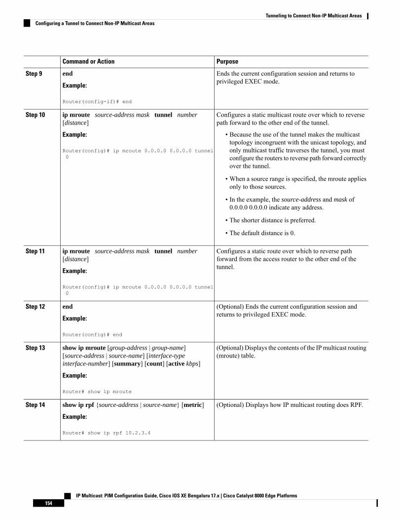
PurposeCommand or Action
Ends the current configuration session and returns toprivileged EXEC mode.
end
Example:
Step 9
Router(config-if)# end
Configures a static multicast route over which to reversepath forward to the other end of the tunnel.
ip mroute source-address mask tunnel number[distance]
Step 10
Example: • Because the use of the tunnel makes the multicasttopology incongruent with the unicast topology, and
Router(config)# ip mroute 0.0.0.0 0.0.0.0 tunnel0
only multicast traffic traverses the tunnel, you mustconfigure the routers to reverse path forward correctlyover the tunnel.
• When a source range is specified, the mroute appliesonly to those sources.
• In the example, the source-address and mask of0.0.0.0 0.0.0.0 indicate any address.
• The shorter distance is preferred.
• The default distance is 0.
Configures a static route over which to reverse pathforward from the access router to the other end of thetunnel.
ip mroute source-address mask tunnel number[distance]
Example:
Step 11
Router(config)# ip mroute 0.0.0.0 0.0.0.0 tunnel0
(Optional) Ends the current configuration session andreturns to privileged EXEC mode.
end
Example:
Step 12
Router(config)# end
(Optional) Displays the contents of the IPmulticast routing(mroute) table.
show ip mroute [group-address | group-name][source-address | source-name] [interface-typeinterface-number] [summary] [count] [active kbps]
Step 13
Example:
Router# show ip mroute
(Optional) Displays how IP multicast routing does RPF.show ip rpf {source-address | source-name} [metric]
Example:
Step 14
Router# show ip rpf 10.2.3.4
IP Multicast: PIM Configuration Guide, Cisco IOS XE Bengaluru 17.x | Cisco Catalyst 8000 Edge Platforms154
Tunneling to Connect Non-IP Multicast AreasConfiguring a Tunnel to Connect Non-IP Multicast Areas
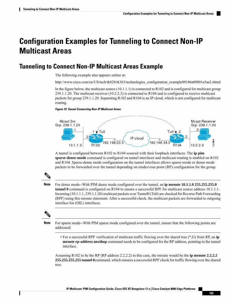
Configuration Examples for Tunneling to Connect Non-IPMulticast Areas
Tunneling to Connect Non-IP Multicast Areas ExampleThe following example also appears online at:
http://www.cisco.com/en/US/tech/tk828/tk363/technologies_configuration_example09186a00801a5aa2.shtml
In the figure below, the multicast source (10.1.1.1) is connected to R102 and is configured for multicast group239.1.1.20. The multicast receiver (10.2.2.3) is connected to R104 and is configured to receive multicastpackets for group 239.1.1.20. Separating R102 and R104 is an IP cloud, which is not configured for multicastrouting.
Figure 15: Tunnel Connecting Non-IP Multicast Areas
A tunnel is configured between R102 to R104 sourced with their loopback interfaces. The ip pimsparse-dense-mode command is configured on tunnel interfaces and multicast-routing is enabled on R102and R104. Sparse-dense mode configuration on the tunnel interfaces allows sparse-mode or dense-modepackets to be forwarded over the tunnel depending on rendezvous point (RP) configuration for the group.
For dense mode--With PIM dense mode configured over the tunnel, an ip mroute 10.1.1.0 255.255.255.0tunnel 0 command is configured on R104 to ensure a successful RPF for multicast source address 10.1.1.1.Incoming (10.1.1.1, 239.1.1.20) multicast packets over Tunnel0 (Tu0) are checked for Reverse Path Forwarding(RPF) using this mroute statement. After a successful check, the multicast packets are forwarded to outgoinginterface list (OIL) interfaces.
Note
For sparse mode--With PIM sparse mode configured over the tunnel, ensure that the following points areaddressed:
Note
• For a successful RPF verification of multicast traffic flowing over the shared tree (*,G) from RP, an ipmroute rp-address nexthop command needs to be configured for the RP address, pointing to the tunnelinterface.
Assuming R102 to be the RP (RP address 2.2.2.2) in this case, the mroute would be the ip mroute 2.2.2.2255.255.255.255 tunnel 0command, which ensures a successful RPF check for traffic flowing over the sharedtree.
IP Multicast: PIM Configuration Guide, Cisco IOS XE Bengaluru 17.x | Cisco Catalyst 8000 Edge Platforms155
Tunneling to Connect Non-IP Multicast AreasConfiguration Examples for Tunneling to Connect Non-IP Multicast Areas

• For a successful RPF verification of multicast (S,G) traffic flowing over the Shortest Path Tree (SPT),an ip mroute source-address nexthop command needs to be configured for the multicast source, pointingto the tunnel interface.
In this case, when SPT traffic is flowing over tunnel interface an ip mroute 10.1.1.0 255.255.255.0 tunnel0 command is configured on R104 to ensure a successful RPF verification for incoming (10.1.1.1, 239.1.1.20)multicast packets over the Tunnel 0 interface.
R102#
version 12.2hostname r102ip subnet-zerono ip domain-lookup!--- It stops IP domain lookup, which improves the show command response time.!ip multicast-routing!--- Enables IP multicast routing.!interface Loopback0ip address 2.2.2.2 255.255.255.255!--- Tunnel Source interface.!interface Tunnel0!--- Tunnel interface configured for PIM and carrying multicast packets to R104.ip address 192.168.24.1 255.255.255.252ip pim sparse-dense-modetunnel source Loopback0tunnel destination 4.4.4.4!interface Ethernet0/0!--- Interface connected to Source.ip address 10.1.1.2 255.255.255.0ip pim sparse-dense-mode!interface Serial8/0ip address 192.168.23.1 255.255.255.252!--- Note IP PIM sparse-dense mode is not configured on Serial interface.!router ospf 1log-adjacency-changesnetwork 2.2.2.2 0.0.0.0 area 0network 10.1.1.0 0.0.0.255 area 0network 192.168.23.0 0.0.0.255 area 0!ip classlessip pim bidir-enable!line con 0line aux 0line vty 0 4login!end
R104#
version 12.2!hostname r104
IP Multicast: PIM Configuration Guide, Cisco IOS XE Bengaluru 17.x | Cisco Catalyst 8000 Edge Platforms156
Tunneling to Connect Non-IP Multicast AreasTunneling to Connect Non-IP Multicast Areas Example
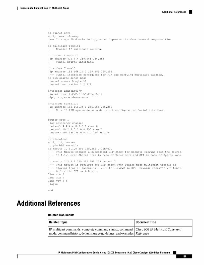
!ip subnet-zerono ip domain-lookup!--- It stops IP domain lookup, which improves the show command response time.!ip multicast-routing!--- Enables IP multicast routing.!interface Loopback0ip address 4.4.4.4 255.255.255.255!--- Tunnel Source interface.!interface Tunnel0ip address 192.168.24.2 255.255.255.252!--- Tunnel interface configured for PIM and carrying multicast packets.ip pim sparse-dense-modetunnel source Loopback0tunnel destination 2.2.2.2!interface Ethernet0/0ip address 10.2.2.2 255.255.255.0ip pim sparse-dense-mode!interface Serial9/0ip address 192.168.34.1 255.255.255.252!--- Note IP PIM sparse-dense mode is not configured on Serial interface.!!router ospf 1log-adjacency-changesnetwork 4.4.4.4 0.0.0.0 area 0network 10.2.2.0 0.0.0.255 area 0network 192.168.34.0 0.0.0.255 area 0!ip classlessno ip http serverip pim bidir-enableip mroute 10.1.1.0 255.255.255.0 Tunnel0!--- This Mroute ensures a successful RPF check for packets flowing from the source.!--- 10.1.1.1 over Shared tree in case of Dense more and SPT in case of Sparse mode.!ip mroute 2.2.2.2 255.255.255.255 tunnel 0!--- This Mroute is required for RPF check when Sparse mode multicast traffic is!--- flowing from RP (assuming R102 with 2.2.2.2 as RP) towards receiver via tunnel!--- before the SPT switchover.line con 0line aux 0line vty 0 4login!end
Additional ReferencesRelated Documents
Document TitleRelated Topic
Cisco IOS IP Multicast CommandReference
IP multicast commands: complete command syntax, commandmode, command history, defaults, usage guidelines, and examples
IP Multicast: PIM Configuration Guide, Cisco IOS XE Bengaluru 17.x | Cisco Catalyst 8000 Edge Platforms157
Tunneling to Connect Non-IP Multicast AreasAdditional References
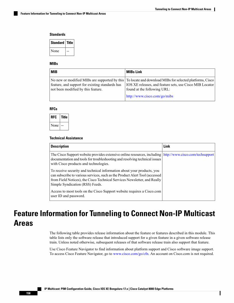
Standards
TitleStandard
--None
MIBs
MIBs LinkMIB
To locate and downloadMIBs for selected platforms, CiscoIOS XE releases, and feature sets, use Cisco MIB Locatorfound at the following URL:
http://www.cisco.com/go/mibs
No new or modified MIBs are supported by thisfeature, and support for existing standards hasnot been modified by this feature.
RFCs
TitleRFC
--None
Technical Assistance
LinkDescription
http://www.cisco.com/techsupportThe Cisco Support website provides extensive online resources, includingdocumentation and tools for troubleshooting and resolving technical issueswith Cisco products and technologies.
To receive security and technical information about your products, youcan subscribe to various services, such as the Product Alert Tool (accessedfrom Field Notices), the Cisco Technical Services Newsletter, and ReallySimple Syndication (RSS) Feeds.
Access to most tools on the Cisco Support website requires a Cisco.comuser ID and password.
Feature Information for Tunneling to Connect Non-IP MulticastAreas
The following table provides release information about the feature or features described in this module. Thistable lists only the software release that introduced support for a given feature in a given software releasetrain. Unless noted otherwise, subsequent releases of that software release train also support that feature.
Use Cisco Feature Navigator to find information about platform support and Cisco software image support.To access Cisco Feature Navigator, go to www.cisco.com/go/cfn. An account on Cisco.com is not required.
IP Multicast: PIM Configuration Guide, Cisco IOS XE Bengaluru 17.x | Cisco Catalyst 8000 Edge Platforms158
Tunneling to Connect Non-IP Multicast AreasFeature Information for Tunneling to Connect Non-IP Multicast Areas
C H A P T E R 9Automatic Multicast Tunneling
Automatic Multicast Tunneling (AMT) provides a method to tunnel multicast data over a unicast network.The tunneling is performed between AMT relays and AMT gateways, using User Datagram Protocol (UDP)encapsulation. AMT enables service providers and their customers to participate in deliveringmulticast trafficeven in the absence of end-to-end multicast connectivity.
• Finding Feature Information, on page 159• Restrictions for Automatic Multicast Tunneling, on page 159• Information About Automatic Multicast Tunneling, on page 160• How to Configure Automatic Multicast Tunneling, on page 162• Configuration Examples for Automatic Multicast Tunneling, on page 174• Additional References for Automatic Multicast Tunneling, on page 175• Feature Information for Automatic Multicast Tunneling, on page 175
Finding Feature InformationYour software release may not support all the features documented in this module. For the latest caveats andfeature information, see Bug Search Tool and the release notes for your platform and software release. Tofind information about the features documented in this module, and to see a list of the releases in which eachfeature is supported, see the feature information table.
Use Cisco Feature Navigator to find information about platform support and Cisco software image support.To access Cisco Feature Navigator, go to https://cfnng.cisco.com/. An account on Cisco.com is not required.
Restrictions for Automatic Multicast Tunneling• AMT tunnel only support PIM passive mode on AMT Gateway side.
• AMT only support SSM modes for PIM signaling.
• AMT only support ipv4 transport for tunnel.
• For AMT, auto-rp is invalid between relay and gateway.
IP Multicast: PIM Configuration Guide, Cisco IOS XE Bengaluru 17.x | Cisco Catalyst 8000 Edge Platforms159
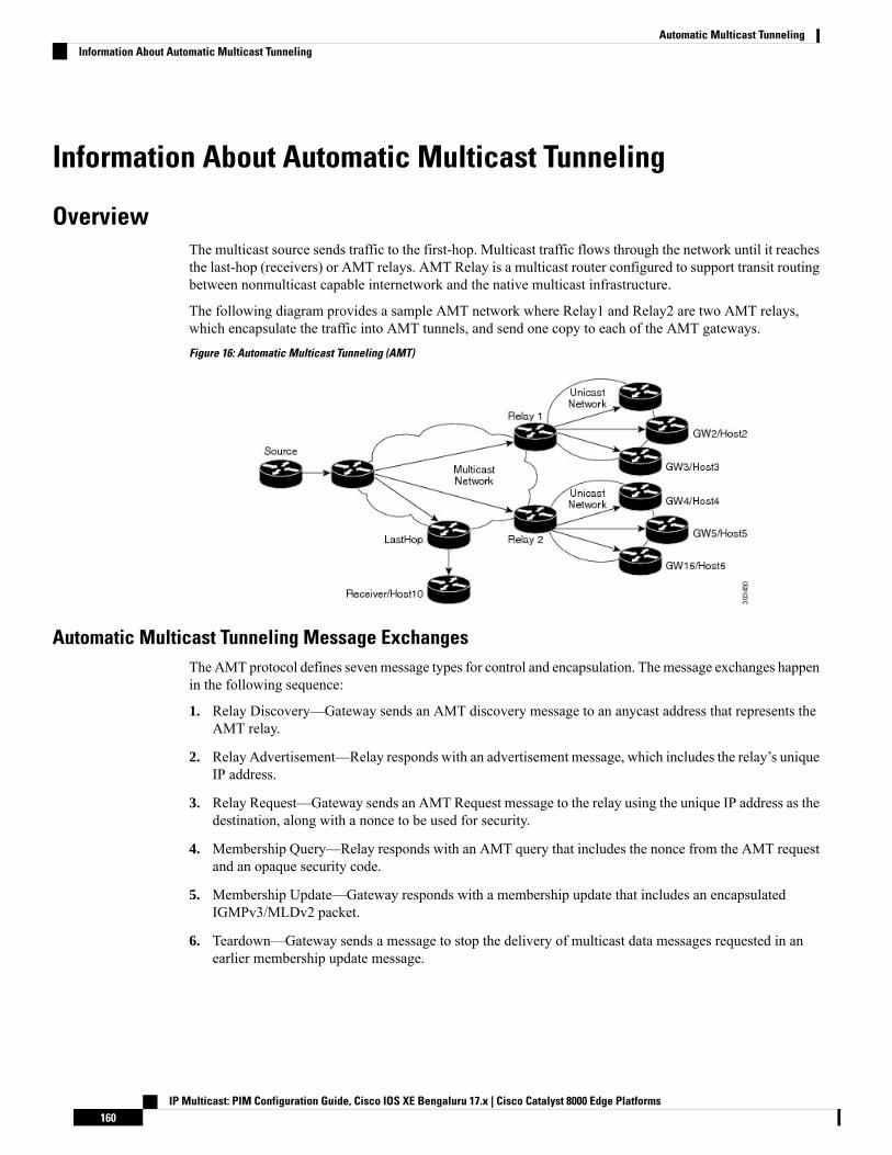
Information About Automatic Multicast Tunneling
OverviewThe multicast source sends traffic to the first-hop. Multicast traffic flows through the network until it reachesthe last-hop (receivers) or AMT relays. AMT Relay is a multicast router configured to support transit routingbetween nonmulticast capable internetwork and the native multicast infrastructure.
The following diagram provides a sample AMT network where Relay1 and Relay2 are two AMT relays,which encapsulate the traffic into AMT tunnels, and send one copy to each of the AMT gateways.
Figure 16: Automatic Multicast Tunneling (AMT)
Automatic Multicast Tunneling Message ExchangesThe AMT protocol defines sevenmessage types for control and encapsulation. Themessage exchanges happenin the following sequence:
1. Relay Discovery—Gateway sends an AMT discovery message to an anycast address that represents theAMT relay.
2. Relay Advertisement—Relay responds with an advertisement message, which includes the relay’s uniqueIP address.
3. Relay Request—Gateway sends an AMT Request message to the relay using the unique IP address as thedestination, along with a nonce to be used for security.
4. Membership Query—Relay responds with an AMT query that includes the nonce from the AMT requestand an opaque security code.
5. Membership Update—Gateway responds with a membership update that includes an encapsulatedIGMPv3/MLDv2 packet.
6. Teardown—Gateway sends a message to stop the delivery of multicast data messages requested in anearlier membership update message.
IP Multicast: PIM Configuration Guide, Cisco IOS XE Bengaluru 17.x | Cisco Catalyst 8000 Edge Platforms160
Automatic Multicast TunnelingInformation About Automatic Multicast Tunneling
7. After validation the Relay establishes the AMT Tunnel and starts sending multicast traffic [Type 6]. Anyfurther (S,G) uses the same Request/Query/Update - three-way handshake because the tunnel is alreadyestablished.
AMT Tunnel and Traffic TypesThe multicast traffic carried in the AMT tunnel may be IPv4 or IPv6. The AMT tunnel may be setup withIPv4 or IPv6 endpoints, thereby providing the following possibilities.
• IPv4-in-IPv4—IPv4 multicast traffic carried over an IPv4 tunnel
• IPv6-in-IPv4—IPv6 multicast traffic carried over an IPv4 tunnel
• IPv6-in-IPv6—IPv6 multicast traffic carried over an IPv6 tunnel
• IPv4-in-IPv6—IPv4 multicast traffic carried over an IPv6 tunnel
In Cisco IOS XE Release 3.15S, AMT supports IPv4-in-IPv4 and IPv6-in-IPv4 only.Note
Advantages of Automatic Multicast Tunneling• Simplicity—Instead of incurring the overhead of manually provisioning, establishing and maintainingGRE tunnels between two locations, the receiving network simply sends AMT advertisements to awell-known any-cast prefix. The rest of the tunnel establishment process is done automatically withoutthe need for additional configuration.
• Resiliency—Because the relay discovery uses an any-cast address, gateways automatically find theclosest relay. If that relay becomes unavailable or unreachable, the routing table reconverges on the nextclosest relay.
• Efficiency—AMT allows transit routers to perform flow-based load balancing for more efficient linkutilization.
Automatic Multicast Tunneling supports IPv4 transport for tunnel and also support for IPv4 multicast traffic& IPv6 multicast traffic. You can also configure AMT relay-only, gateway-only and relay-gateway coexistingmodes.
Prerequisites for AMT• AMT relay and gateway tunnel requires an interface IP address. However the interface IP addresses donot need to be unique. You can configure the same addresses for the tunnel source address using the ipunnumbered command.
• You must configure IGMP version 3 on the tunnel interfaces for the SSM to work across tunnels.
• The tunnel source port and tunnel destination port must be configured to achieve a valid AMTconfiguration.
IP Multicast: PIM Configuration Guide, Cisco IOS XE Bengaluru 17.x | Cisco Catalyst 8000 Edge Platforms161
Automatic Multicast TunnelingAMT Tunnel and Traffic Types
Configuration Recommendations for AMTThe tunnel source interface address should be an interface that is set up to be reachable from receivers underall instances. You can use a physical interface address, but it can cause the tunnel to go down if that physicalinterface is down. A loopback interface is recommended to sustain availability. You do not need a separateloopback address, you can reuse the loopback interface that you usually would have to carry router androuter-ID IP address (usually Loopback 0).
IP PIM passive is the recommended and supported mode on AMT interfaces to enable IP multicast routingfor AMT tunnel interfaces. This is recommended since no PIM messages (only AMT/IGMP messages) willbe sent or received via the AMT tunnel.
On an AMT relay, you need only one tunnel interface to which all gateways can connect. Therefore theinterface is a multipoint interface. Every gateway interface can only connect to one relay, but you can configuremultiple tunnel interfaces.
Even though AMT tunnels (relay and gateway) only support IPv4 tunnels, the IPv4 tunnels can carry bothIPv4 and IPv6 simultaneously. You can configure the AMT for the version(s) of IP that you need.
If you want to set up a redundant AMT relay, your AMT relay address configured on the gateway should beany IP address that you set up as an anycast address on your relays. If you do not plan to use redundant(Anycast) Relay, you can use the relays tunnel source address on the gateways.
If you shut down the anycast Loopback interface, the AMT relay would not accept new AMT gateway tunnelrequests. IP routing for the anycast address would only point to any other relays active with the same addressand new requests would therefore go to those relays. Any AMT gateways already connected to this relaywould stay on this relay, because they already are using the relays interface address.
How to Configure Automatic Multicast Tunneling
Enabling and Configuring Automatic Multicast Tunneling on a Relay
Switch-over from active relay to backup relay can take more than 5 minutes.Note
SUMMARY STEPS
1. enable2. configure terminal3. interface tunnel number
4. ip address ip-address mask
5. no ip redirects6. ip pim sparse-mode7. ip igmp version version number
8. ipv6 enable9. tunnel source interface-type interface-number
10. tunnel mode udp multipoint11. tunnel dst-port dynamic
IP Multicast: PIM Configuration Guide, Cisco IOS XE Bengaluru 17.x | Cisco Catalyst 8000 Edge Platforms162
Automatic Multicast TunnelingConfiguration Recommendations for AMT
12. tunnel src-port dynamic13. amt relay traffic {ip | ipv6}14. exit15. ip multicast-routing distributed16. ipv6 multicast-routing17. ip pim ssm {default | range access-list}
DETAILED STEPS
PurposeCommand or Action
Enables privileged EXEC mode.enableStep 1
Example: • Enter your password if prompted.Device> enable
Enters global configuration mode.configure terminal
Example:
Step 2
Device# configure terminal
Specifies the interface tunnel number and enters interfaceconfiguration mode.
interface tunnel number
Example:
Step 3
Device(config)# interface tunnel 11
Configures the IP address on the interface.ip address ip-address mask
Example:
Step 4
Device(config-if)# 11.1.1.1 255.255.255.0
Disables sending ICMP Redirect messages.no ip redirects
Example:
Step 5
Device(config-if)# no ip redirects
Enable PIM sparse-mode operation.ip pim sparse-mode
Example:
Step 6
Device(config-if)# ip pim sparse-mode
Specifies IGMP version.ip igmp version version number
Example:
Step 7
Device(config-if)# ip igmp version 3
Enables IPv6 on interface.ipv6 enable
Example:
Step 8
Device(config-if)# ipv6 enable
Configures tunnel source as a loopback interface.tunnel source interface-type interface-number
Example:
Step 9
Device(config-if)# tunnel source loopback 0
IP Multicast: PIM Configuration Guide, Cisco IOS XE Bengaluru 17.x | Cisco Catalyst 8000 Edge Platforms163
Automatic Multicast TunnelingEnabling and Configuring Automatic Multicast Tunneling on a Relay
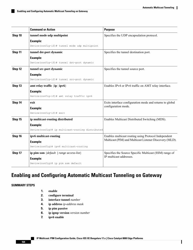
PurposeCommand or Action
Specifies the UDP encapsulation protocol.tunnel mode udp multipoint
Example:
Step 10
Device(config-if)# tunnel mode udp multipoint
Specifies the tunnel destination port.tunnel dst-port dynamic
Example:
Step 11
Device(config-if)# tunnel dst-port dynamic
Specifies the tunnel source port.tunnel src-port dynamic
Example:
Step 12
Device(config-if)# tunnel src-port dynamic
Enables IPv4 or IPv6 traffic on AMT relay interface.amt relay traffic {ip | ipv6}
Example:
Step 13
Device(config-if)# amt relay traffic ipv6
Exits interface configuration mode and returns to globalconfiguration mode.
exit
Example:
Step 14
Device(config-if)# exit
Enables Multicast Distributed Switching (MDS).ip multicast-routing distributed
Example:
Step 15
Device(config)# ip multicast-routing distributed
Enables multicast routing using Protocol IndependentMulticast (PIM) andMulticast Listener Discovery (MLD).
ipv6 multicast-routing
Example:
Step 16
Device(config)# ipv6 multicast-routing
Specifies the Source Specific Multicast (SSM) range ofIP multicast addresses.
ip pim ssm {default | range access-list}
Example:
Step 17
Device(config)# ip pim ssm default
Enabling and Configuring Automatic Multicast Tunneling on Gateway
SUMMARY STEPS
1. enable2. configure terminal3. interface tunnel number
4. ip address ip-address mask
5. ip pim passive6. ip igmp version version number
7. ipv6 enable
IP Multicast: PIM Configuration Guide, Cisco IOS XE Bengaluru 17.x | Cisco Catalyst 8000 Edge Platforms164
Automatic Multicast TunnelingEnabling and Configuring Automatic Multicast Tunneling on Gateway

8. ipv6 pim passive9. tunnel source interface-type interface-number
10. tunnel mode udp ip11. tunnel destination dynamic12. tunnel dst-port dynamic13. tunnel src-port dynamic14. amt gateway traffic {ip | ipv6}15. amt gateway relay-address IP address
16. exit17. ip multicast-routing distributed18. ipv6 multicast-routing19. ip pim ssm {default | range access-list}20. ipv6 multicast pim-passive-enable21. ip route ip-address interface-type interface-number [multicast]22. ipv6 route ipv6-prefix/prefix-length interface-type interface-number [multicast]
DETAILED STEPS
PurposeCommand or Action
Enables privileged EXEC mode.enableStep 1
Example: • Enter your password if prompted.Device> enable
Enters global configuration mode.configure terminal
Example:
Step 2
Device# configure terminal
Specifies the interface tunnel number and enters interfaceconfiguration mode.
interface tunnel number
Example:
Step 3
Device(config)# interface tunnel 11
Configures the IP address on the interface.ip address ip-address mask
Example:
Step 4
Device(config-if)# 11.1.1.1 255.255.255.0
Enables IP PIM passive mode operation.ip pim passive
Example:
Step 5
Device(config-if)# ip pim passive
Specifies IGMP version.ip igmp version version number
Example:
Step 6
Device(config-if)# ip igmp version 3
Enables IPv6 on interface.ipv6 enable
Example:
Step 7
IP Multicast: PIM Configuration Guide, Cisco IOS XE Bengaluru 17.x | Cisco Catalyst 8000 Edge Platforms165
Automatic Multicast TunnelingEnabling and Configuring Automatic Multicast Tunneling on Gateway

PurposeCommand or ActionDevice(config-if)# ipv6 enable
Enables IPv6 PIM passive mode operation.ipv6 pim passive
Example:
Step 8
Device(config-if)# ipv6 pim passive
Configures tunnel source as a loopback interface.tunnel source interface-type interface-number
Example:
Step 9
Device(config-if)# tunnel source loopback 0
Specifies the UDP encapsulation protocol.tunnel mode udp ip
Example:
Step 10
Device(config-if)# tunnel mode udp ip
Applies the tunnel destination address dynamically to thetunnel interface.
tunnel destination dynamic
Example:
Step 11
Device(config-if)# tunnel destination dynamic
Applies the tunnel destination port dynamically.tunnel dst-port dynamic
Example:
Step 12
Device(config-if)# tunnel dst-port dynamic
Applies the tunnel source port dynamically.tunnel src-port dynamic
Example:
Step 13
Device(config-if)# tunnel src-port dynamic
Enables IPv4 or IPv6 traffic on AMT gateway interface.amt gateway traffic {ip | ipv6}
Example:
Step 14
Device(config-if)# amt gateway traffic ipv6
Specifies the destination IP address of AMT discovery.amt gateway relay-address IP address
Example:
Step 15
Device(config-if)# amt gateway relay-address172.16.0.0
Exits interface configuration mode and returns to globalconfiguration mode.
exit
Example:
Step 16
Device(config-if)# exit
Enables Multicast Distributed Switching (MDS).ip multicast-routing distributed
Example:
Step 17
Device(config)# ip multicast-routing distributed
Enables multicast routing using Protocol IndependentMulticast (PIM) andMulticast Listener Discovery (MLD).
ipv6 multicast-routing
Example:
Step 18
IP Multicast: PIM Configuration Guide, Cisco IOS XE Bengaluru 17.x | Cisco Catalyst 8000 Edge Platforms166
Automatic Multicast TunnelingEnabling and Configuring Automatic Multicast Tunneling on Gateway
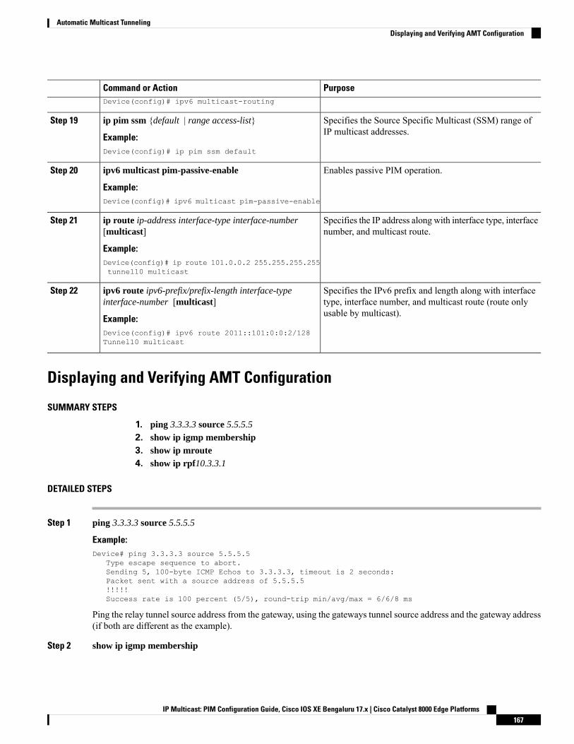
PurposeCommand or ActionDevice(config)# ipv6 multicast-routing
Specifies the Source Specific Multicast (SSM) range ofIP multicast addresses.
ip pim ssm {default | range access-list}
Example:
Step 19
Device(config)# ip pim ssm default
Enables passive PIM operation.ipv6 multicast pim-passive-enable
Example:
Step 20
Device(config)# ipv6 multicast pim-passive-enable
Specifies the IP address along with interface type, interfacenumber, and multicast route.
ip route ip-address interface-type interface-number[multicast]
Example:
Step 21
Device(config)# ip route 101.0.0.2 255.255.255.255tunnel10 multicast
Specifies the IPv6 prefix and length along with interfacetype, interface number, and multicast route (route onlyusable by multicast).
ipv6 route ipv6-prefix/prefix-length interface-typeinterface-number [multicast]
Example:
Step 22
Device(config)# ipv6 route 2011::101:0:0:2/128Tunnel10 multicast
Displaying and Verifying AMT Configuration
SUMMARY STEPS
1. ping 3.3.3.3 source 5.5.5.5
2. show ip igmp membership3. show ip mroute4. show ip rpf10.3.3.1
DETAILED STEPS
Step 1 ping 3.3.3.3 source 5.5.5.5
Example:Device# ping 3.3.3.3 source 5.5.5.5
Type escape sequence to abort.Sending 5, 100-byte ICMP Echos to 3.3.3.3, timeout is 2 seconds:Packet sent with a source address of 5.5.5.5!!!!!Success rate is 100 percent (5/5), round-trip min/avg/max = 6/6/8 ms
Ping the relay tunnel source address from the gateway, using the gateways tunnel source address and the gateway address(if both are different as the example).
Step 2 show ip igmp membership
IP Multicast: PIM Configuration Guide, Cisco IOS XE Bengaluru 17.x | Cisco Catalyst 8000 Edge Platforms167
Automatic Multicast TunnelingDisplaying and Verifying AMT Configuration
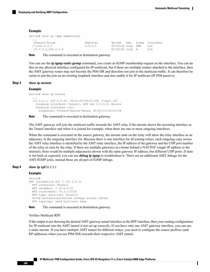
Example:Device# show ip igmp membership...Channel/Group Reporter Uptime Exp. Flags Interface/*,232.2.3.4 0.0.0.0 00:03:02 stop 2MA Lo010.3.3.1,232.2.3.4 00:03:02 stop A Lo0
The command is executed at destination gateway.Note
You can use the ip igmp static-group command, you create an IGMP membership request on the interface. You can dothis on any physical interface configured for IP multicast, but if there are multiple routers attached to the interface, thenthe AMT gateway router may not become the PIM-DR and therefore not join to the multicast traffic. It can therefore beeasier to put the join on an existing loopback interface and also enable it for IP multicast (IP PIM passive).
Step 3 show ip mroute
Example:Device# show ip mroute...(10.3.3.1, 232.2.3.4), 00:01:53/00:01:08, flags: sTIIncoming interface: Tunnel1, RPF nbr 0.0.0.0, MrouteOutgoing interface list:Loopback0, Forward/Sparse-Dense, 00:01:51/00:01:08
The command is executed at destination gateway.Note
The AMT gateway will join the multicast traffic towards the AMT relay if the mroute shows the incoming interface asthe Tunnel interface and when it is joined for example, when there are one or more outgoing interfaces.
When the command is executed on the source gateway, the mroute state on the relay will show the relay interface as anadjacency in the outgoing interface list. Because there is one interface for all joining relays, each outgoing copy acrossthe AMT relay interface is identified by the AMT relay interface, the IP address of the gateway and the UDP port numberof the relay as seen by the relay. If there are multiple gateways in a home behind a NAT/PAT (single IP address to theinternet), there would be multiple adjacencies shown with the same gateway IP address, but different UDP ports. If stateis not built as expected, you can use debug ip igmp to troubleshoot it. There are no additional AMT debugs for theAMT/IGMP joins, instead those are all part of IGMP debugs.
Step 4 show ip rpf10.3.3.1
Example:Device#RPF information for ? (10.3.3.1)RPF interface: Tunnel1RPF neighbor: ? (0.0.0.0)RPF route/mask: 10.3.3.0/24RPF type: multicast (static)Doing distance-preferred lookups across tablesRPF topology: ipv4 multicast base
The command is executed at destination gateway.Note
Verifies Multicast RPF.
If the output is not showing the desired AMT gateway tunnel interface as the RPF interface, then your routing configurationfor IP multicast into the AMT tunnel is not set up correctly. If you have only one AMT gateway interface, you can usea static mroute. If you have multiple AMT tunnel for different relays, you need to configure the source prefixes (andRP-addresses when you use PIM-SM) towards their respective AMT tunnel.
IP Multicast: PIM Configuration Guide, Cisco IOS XE Bengaluru 17.x | Cisco Catalyst 8000 Edge Platforms168
Automatic Multicast TunnelingDisplaying and Verifying AMT Configuration
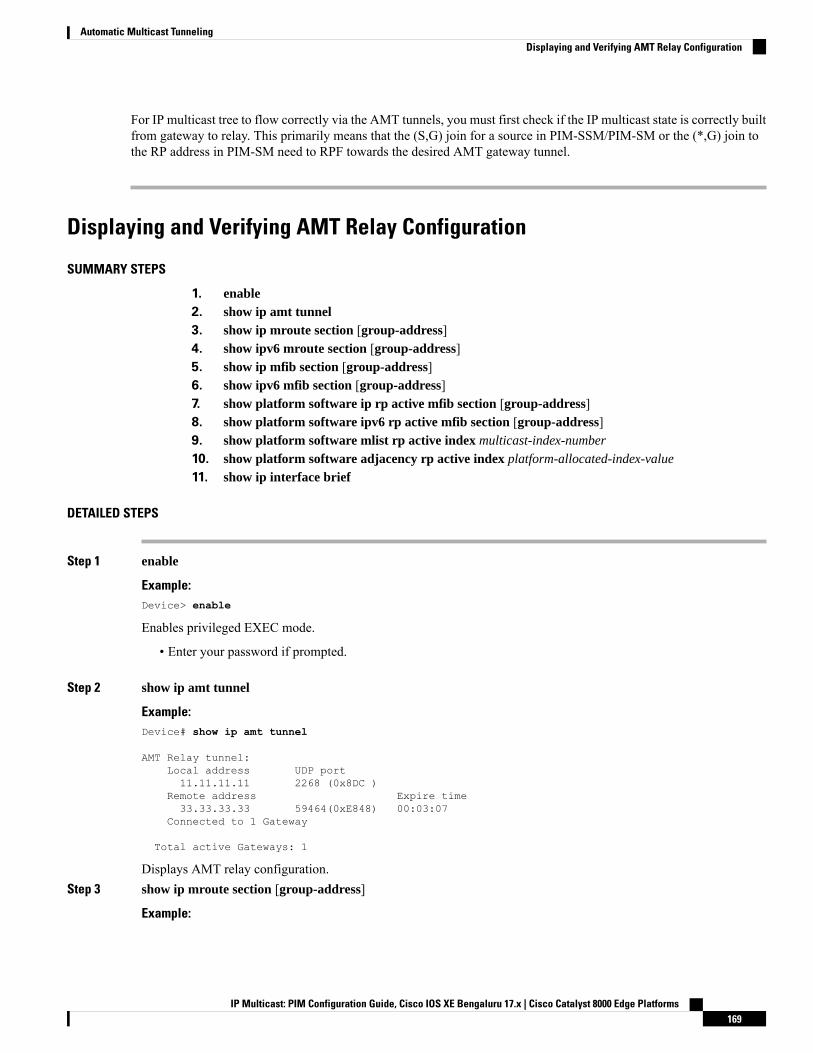
For IP multicast tree to flow correctly via the AMT tunnels, you must first check if the IP multicast state is correctly builtfrom gateway to relay. This primarily means that the (S,G) join for a source in PIM-SSM/PIM-SM or the (*,G) join tothe RP address in PIM-SM need to RPF towards the desired AMT gateway tunnel.
Displaying and Verifying AMT Relay Configuration
SUMMARY STEPS
1. enable2. show ip amt tunnel3. show ip mroute section [group-address]4. show ipv6 mroute section [group-address]5. show ip mfib section [group-address]6. show ipv6 mfib section [group-address]7. show platform software ip rp active mfib section [group-address]8. show platform software ipv6 rp active mfib section [group-address]9. show platform software mlist rp active index multicast-index-number
10. show platform software adjacency rp active index platform-allocated-index-value
11. show ip interface brief
DETAILED STEPS
Step 1 enable
Example:Device> enable
Enables privileged EXEC mode.
• Enter your password if prompted.
Step 2 show ip amt tunnel
Example:Device# show ip amt tunnel
AMT Relay tunnel:Local address UDP port11.11.11.11 2268 (0x8DC )
Remote address Expire time33.33.33.33 59464(0xE848) 00:03:07
Connected to 1 Gateway
Total active Gateways: 1
Displays AMT relay configuration.Step 3 show ip mroute section [group-address]
Example:
IP Multicast: PIM Configuration Guide, Cisco IOS XE Bengaluru 17.x | Cisco Catalyst 8000 Edge Platforms169
Automatic Multicast TunnelingDisplaying and Verifying AMT Relay Configuration

Device# show ip mroute section 232.1.1.1
(101.0.0.2, 232.1.1.1), 2d00h/00:02:18, flags: sTIIncoming interface: GigabitEthernet0/0/4, RPF nbr 0.0.0.0Outgoing interface list:Tunnel10, 33.33.33.33, UDP port 59464, Forward/Sparse, 2d00h/00:02:18
Displays information about sparse mode routes in the IP multicast routing (mroute) table for the specified multicastgroup.
Step 4 show ipv6 mroute section [group-address]
Example:Device# show ipv6 mroute section 232.1.1.1
(2011::101:0:0:2, FF3F::232:1:1:1), 2d00h/never, flags: sTIIncoming interface: GigabitEthernet0/0/4RPF nbr: 2011::101:0:0:2Immediate Outgoing interface list:Tunnel10, AMT NH 33.33.33.33, UDP Port 59464, Forward, 2d00h/never
Displays information about sparse mode routes in the IPv6 mroute table for the specified multicast group.Step 5 show ip mfib section [group-address]
Example:Device# show ip mfib section 232.1.1.1
(101.0.0.2,232.1.1.1) Flags: HWSW Forwarding: 0/0/0/0, Other: 0/0/0HW Forwarding: NA/NA/NA/NA, Other: NA/NA/NAGigabitEthernet0/0/4 Flags: ATunnel10, AMT Encap 33.33.33.33, UDP Port:59464 Flags: F NSPkts: 0/0
Displays the status of entries and interfaces in the IPv4Multicast Forwarding Information Base (MFIB) for the specifiedmulticast group.
Step 6 show ipv6 mfib section [group-address]
Example:Device# show ipv6 mfib section 232.1.1.1
(2011::101:0:0:2,FF3F::232:1:1:1) Flags: HWSW Forwarding: 0/0/0/0, Other: 0/0/0HW Forwarding: NA/NA/NA/NA, Other: NA/NA/NAGigabitEthernet0/0/4 Flags: ATunnel10, AMT Encap 33.33.33.33, UDP Port:59464 Flags: F NSPkts: 0/0
Displays the status of entries and interfaces in the IPv6Multicast Forwarding Information Base (MFIB) for the specifiedmulticast group.
Step 7 show platform software ip rp active mfib section [group-address]
Example:Device# show platform software ip rp active mfib section 232.1.1.1
232.1.1.1, 101.0.0.2/64 --> OBJ_INTF_LIST (0x5a)Obj id: 0x5a, Flags:OM handle: 0x421712c4
Displays platform software IPv4 MFIB route processor information for the specified multicast group.Step 8 show platform software ipv6 rp active mfib section [group-address]
IP Multicast: PIM Configuration Guide, Cisco IOS XE Bengaluru 17.x | Cisco Catalyst 8000 Edge Platforms170
Automatic Multicast TunnelingDisplaying and Verifying AMT Relay Configuration
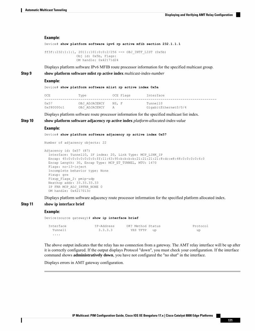
Example:Device# show platform software ipv6 rp active mfib section 232.1.1.1
ff3f::232:1:1:1, 2011::101:0:0:2/256 --> OBJ_INTF_LIST (0x5b)Obj id: 0x5b, Flags:OM handle: 0x42171d24
Displays platform software IPv6 MFIB route processor information for the specified multicast group.Step 9 show platform software mlist rp active index multicast-index-number
Example:Device# show platform software mlist rp active index 0x5a
OCE Type OCE Flags Interface--------------------------------------------------------------------------------------0x57 OBJ_ADJACENCY NS, F Tunnel100xf80000c1 OBJ_ADJACENCY A GigabitEthernet0/0/4
Displays platform software route processor information for the specified multicast list index.Step 10 show platform software adjacency rp active index platform-allocated-index-value
Example:Device# show platform software adjacency rp active index 0x57
Number of adjacency objects: 22
Adjacency id: 0x57 (87)Interface: Tunnel10, IF index: 20, Link Type: MCP_LINK_IPEncap: 45:0:0:0:0:0:0:0:ff:11:63:95:b:b:b:b:21:21:21:21:8:dc:e8:48:0:0:0:0:6:0Encap Length: 30, Encap Type: MCP_ET_TUNNEL, MTU: 1470Flags: no-l3-injectIncomplete behavior type: NoneFixup: greFixup_Flags_2: pmip-udpNexthop addr: 33.33.33.33IP FRR MCP_ADJ_IPFRR_NONE 0OM handle: 0x4217013c
Displays platform software adjacency route processor information for the specified platform allocated index.Step 11 show ip interface brief
Example:Device(source gateway)# show ip interface brief
Interface IP-Address OK? Method Status ProtocolTunnel1 3.3.3.3 YES TFTP up up....
The above output indicates that the relay has no connection from a gateway. The AMT relay interface will be up afterit is correctly configured. If the output displays Protocol "down", you must check your configuration. If the interfacecommand shows administratively down, you have not configured the "no shut" in the interface.
Displays errors in AMT gateway configuration.
IP Multicast: PIM Configuration Guide, Cisco IOS XE Bengaluru 17.x | Cisco Catalyst 8000 Edge Platforms171
Automatic Multicast TunnelingDisplaying and Verifying AMT Relay Configuration
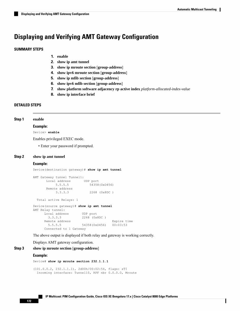
Displaying and Verifying AMT Gateway Configuration
SUMMARY STEPS
1. enable2. show ip amt tunnel3. show ip mroute section [group-address]4. show ipv6 mroute section [group-address]5. show ip mfib section [group-address]6. show ipv6 mfib section [group-address]7. show platform software adjacency rp active index platform-allocated-index-value
8. show ip interface brief
DETAILED STEPS
Step 1 enable
Example:Device> enable
Enables privileged EXEC mode.
• Enter your password if prompted.
Step 2 show ip amt tunnel
Example:Device(destination gateway)# show ip amt tunnel
AMT Gateway tunnel Tunnel1:Local address UDP port
5.5.5.5 54358(0xD456)Remote address
3.3.3.3 2268 (0x8DC )
Total active Relays: 1
Device(source gateway)# show ip amt tunnelAMT Relay tunnel:
Local address UDP port3.3.3.3 2268 (0x8DC )
Remote address Expire time5.5.5.5 54358(0xD456) 00:03:53
Connected to 1 Gateway
The above output is displayed if both relay and gateway is working correctly.
Displays AMT gateway configuration.Step 3 show ip mroute section [group-address]
Example:Device# show ip mroute section 232.1.1.1
(101.0.0.2, 232.1.1.1), 2d00h/00:02:54, flags: sTIIncoming interface: Tunnel10, RPF nbr 0.0.0.0, Mroute
IP Multicast: PIM Configuration Guide, Cisco IOS XE Bengaluru 17.x | Cisco Catalyst 8000 Edge Platforms172
Automatic Multicast TunnelingDisplaying and Verifying AMT Gateway Configuration

Outgoing interface list:GigabitEthernet0/0/4, Forward/Sparse, 2d00h/00:02:54
Displays information about the IP multicast routing (mroute) table for the specified multicast group.Step 4 show ipv6 mroute section [group-address]
Example:Device# show ipv6 mroute section 232.1.1.1
(2011::101:0:0:2, FF3F::232:1:1:1), 2d00h/never, flags: sTIIncoming interface: Tunnel10RPF nbr: ::Immediate Outgoing interface list:GigabitEthernet0/0/4, Forward, 2d00h/never
Displays information about the IPv6 mroute table for the specified multicast group.Step 5 show ip mfib section [group-address]
Example:Device# show ip mfib section 232.1.1.1
(101.0.0.2,232.1.1.1) Flags: HWSW Forwarding: 0/0/0/0, Other: 0/0/0HW Forwarding: NA/NA/NA/NA, Other: NA/NA/NATunnel10 Flags: AGigabitEthernet0/0/4 Flags: F NSPkts: 0/0
Displays the entries and interfaces in the IPv4Multicast Forwarding Information Base (MFIB) for the specified multicastgroup.
Step 6 show ipv6 mfib section [group-address]
Example:Device# show ipv6 mfib section 232.1.1.1
(2011::101:0:0:2,FF3F::232:1:1:1) Flags: HWSW Forwarding: 0/0/0/0, Other: 0/0/0HW Forwarding: NA/NA/NA/NA, Other: NA/NA/NATunnel10 Flags: AGigabitEthernet0/0/4 Flags: F NSPkts: 0/0
Displays the entries and interfaces in the IPv6Multicast Forwarding Information Base (MFIB) for the specified multicastgroup.
Step 7 show platform software adjacency rp active index platform-allocated-index-value
Example:Device# show platform software adjacency rp active index 0x57
Number of adjacency objects: 19Adjacency id: 0xf8000126 (4160749862)Interface: Tunnel10, IF index: 18, Link Type: MCP_LINK_IPEncap: 45:0:0:0:0:0:0:0:ff:11:63:95:21:21:21:21:b:b:b:b:e8:48:8:dc:0:0:0:0:6:0Encap Length: 30, Encap Type: MCP_ET_TUNNEL, MTU: 1470Incomplete behavior type: NoneFixup: greFixup_Flags_2: pmip-udpIP FRR MCP_ADJ_IPFRR_NONE 0OM handle: 0x4216aaf4
Displays platform software adjacency route processor information for the specified platform allocated index.
IP Multicast: PIM Configuration Guide, Cisco IOS XE Bengaluru 17.x | Cisco Catalyst 8000 Edge Platforms173
Automatic Multicast TunnelingDisplaying and Verifying AMT Gateway Configuration
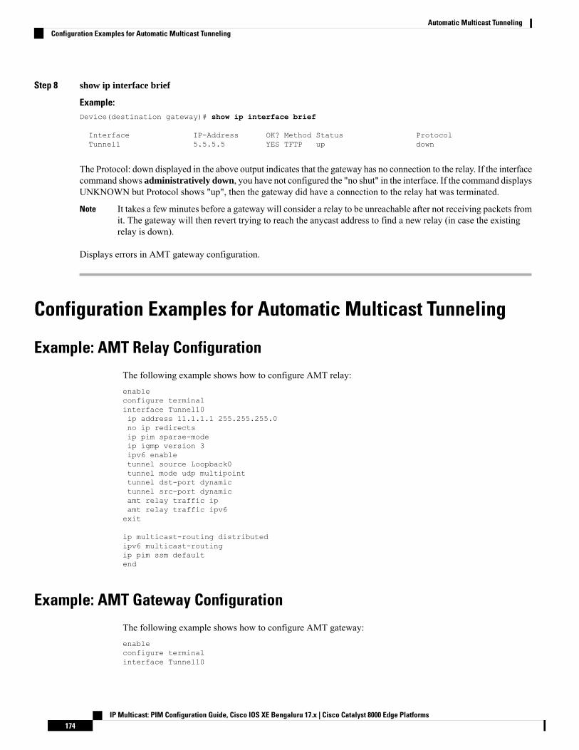
Step 8 show ip interface brief
Example:Device(destination gateway)# show ip interface brief
Interface IP-Address OK? Method Status ProtocolTunnel1 5.5.5.5 YES TFTP up down
The Protocol: down displayed in the above output indicates that the gateway has no connection to the relay. If the interfacecommand shows administratively down, you have not configured the "no shut" in the interface. If the command displaysUNKNOWN but Protocol shows "up", then the gateway did have a connection to the relay hat was terminated.
It takes a few minutes before a gateway will consider a relay to be unreachable after not receiving packets fromit. The gateway will then revert trying to reach the anycast address to find a new relay (in case the existingrelay is down).
Note
Displays errors in AMT gateway configuration.
Configuration Examples for Automatic Multicast Tunneling
Example: AMT Relay Configuration
The following example shows how to configure AMT relay:enableconfigure terminalinterface Tunnel10ip address 11.1.1.1 255.255.255.0no ip redirectsip pim sparse-modeip igmp version 3ipv6 enabletunnel source Loopback0tunnel mode udp multipointtunnel dst-port dynamictunnel src-port dynamicamt relay traffic ipamt relay traffic ipv6exit
ip multicast-routing distributedipv6 multicast-routingip pim ssm defaultend
Example: AMT Gateway Configuration
The following example shows how to configure AMT gateway:enableconfigure terminalinterface Tunnel10
IP Multicast: PIM Configuration Guide, Cisco IOS XE Bengaluru 17.x | Cisco Catalyst 8000 Edge Platforms174
Automatic Multicast TunnelingConfiguration Examples for Automatic Multicast Tunneling
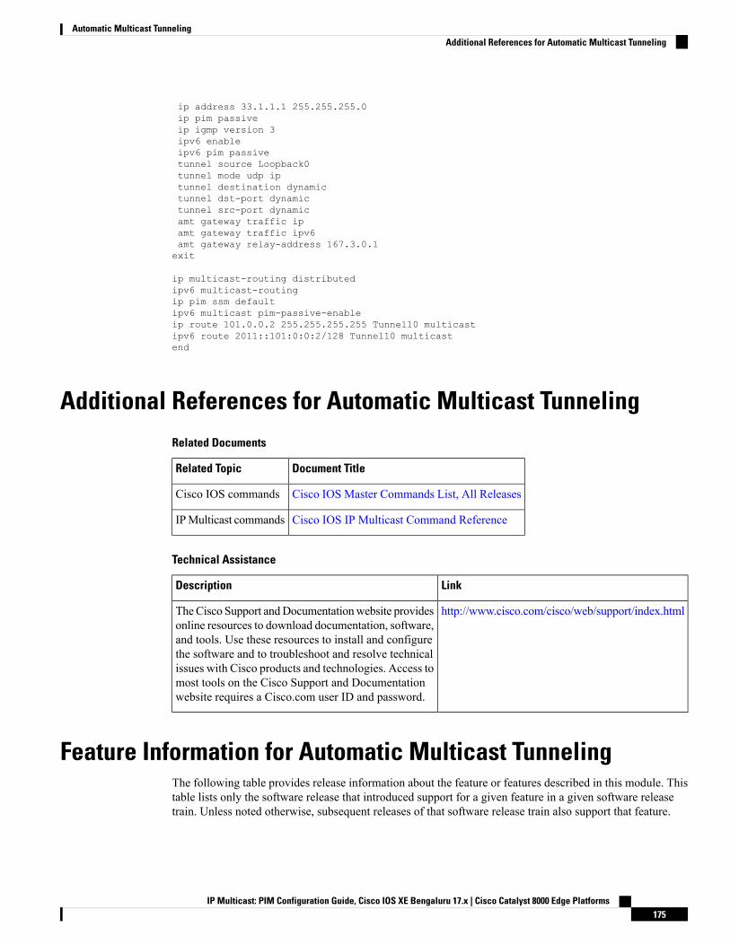
ip address 33.1.1.1 255.255.255.0ip pim passiveip igmp version 3ipv6 enableipv6 pim passivetunnel source Loopback0tunnel mode udp iptunnel destination dynamictunnel dst-port dynamictunnel src-port dynamicamt gateway traffic ipamt gateway traffic ipv6amt gateway relay-address 167.3.0.1exit
ip multicast-routing distributedipv6 multicast-routingip pim ssm defaultipv6 multicast pim-passive-enableip route 101.0.0.2 255.255.255.255 Tunnel10 multicastipv6 route 2011::101:0:0:2/128 Tunnel10 multicastend
Additional References for Automatic Multicast TunnelingRelated Documents
Document TitleRelated Topic
Cisco IOS Master Commands List, All ReleasesCisco IOS commands
Cisco IOS IP Multicast Command ReferenceIPMulticast commands
Technical Assistance
LinkDescription
http://www.cisco.com/cisco/web/support/index.htmlTheCisco Support andDocumentationwebsite providesonline resources to download documentation, software,and tools. Use these resources to install and configurethe software and to troubleshoot and resolve technicalissues with Cisco products and technologies. Access tomost tools on the Cisco Support and Documentationwebsite requires a Cisco.com user ID and password.
Feature Information for Automatic Multicast TunnelingThe following table provides release information about the feature or features described in this module. Thistable lists only the software release that introduced support for a given feature in a given software releasetrain. Unless noted otherwise, subsequent releases of that software release train also support that feature.
IP Multicast: PIM Configuration Guide, Cisco IOS XE Bengaluru 17.x | Cisco Catalyst 8000 Edge Platforms175
Automatic Multicast TunnelingAdditional References for Automatic Multicast Tunneling

Use Cisco Feature Navigator to find information about platform support and Cisco software image support.To access Cisco Feature Navigator, go to www.cisco.com/go/cfn. An account on Cisco.com is not required.
IP Multicast: PIM Configuration Guide, Cisco IOS XE Bengaluru 17.x | Cisco Catalyst 8000 Edge Platforms176
Automatic Multicast TunnelingFeature Information for Automatic Multicast Tunneling
C H A P T E R 10BFD Support for Multicast (PIM)
This module contains information for enabling the Bidirectional Forwarding Detection (BFD) detectionprotocol on Protocol Independent Multicast (PIM) interfaces in your IP v4 and IPv6 network. Enabling PIMBFD enables PIM to use BFD's quicker adjacent system failure detection and avoid the slower query-intervalin its own detection mechanisms.
• Restrictions for BFD Support for Multicast (PIM), on page 177• Information About BFD Support for Multicast (PIM), on page 177• How to Configure BFD Support for Multicast (PIM), on page 178• Configuration Examples for BFD Support for Multicast (PIM), on page 179• Additional References for BFD Support for Multicast (PIM), on page 179• Feature Information for BFD Support for Multicast (PIM), on page 180
Restrictions for BFD Support for Multicast (PIM)• This feature is not supported for Multicast VPN (MVPN).
• This feature is supported only on interfaces on which both PIM and BFD are supported.
Information About BFD Support for Multicast (PIM)
PIM BFDBidirectional Forwarding Detection (BFD) is a detection protocol designed to provide fast forwarding pathfailure detection times for all media types, encapsulations, topologies, and routing protocols and independentof the higher layer protocols. In addition to fast forwarding path failure detection, BFD provides a consistentfailure detectionmethod for network administrators. Because the network administrator can use BFD to detectforwarding path failures at a uniform rate, rather than the variable rates for different routing protocol hellomechanisms, network profiling and planning is easier and reconvergence time is consistent and predictable.
Protocol IndependentMulticast (PIM) uses a hello mechanism for discovering new neighbors and for detectingfailures between adjacent nodes. Theminimum failure detection time in PIM is 3 times the PIMQuery-Interval.To enable faster failure detection, the rate at which a PIM Hello message is transmitted on an interface isconfigurable. However, lower intervals increase the load on the protocol and can increase CPU and memoryutilization and cause a system-wide negative impact on performance. Lower intervals can also cause PIM
IP Multicast: PIM Configuration Guide, Cisco IOS XE Bengaluru 17.x | Cisco Catalyst 8000 Edge Platforms177
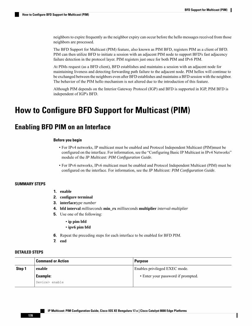
neighbors to expire frequently as the neighbor expiry can occur before the hello messages received from thoseneighbors are processed.
The BFD Support for Multicast (PIM) feature, also known as PIM BFD, registers PIM as a client of BFD.PIM can then utilize BFD to initiate a session with an adjacent PIM node to support BFD's fast adjacencyfailure detection in the protocol layer. PIM registers just once for both PIM and IPv6 PIM.
At PIMs request (as a BFD client), BFD establishes and maintains a session with an adjacent node formaintaining liveness and detecting forwarding path failure to the adjacent node. PIM hellos will continue tobe exchanged between the neighbors even after BFD establishes andmaintains a BFD session with the neighbor.The behavior of the PIM hello mechanism is not altered due to the introduction of this feature.
Although PIM depends on the Interior Gateway Protocol (IGP) and BFD is supported in IGP, PIM BFD isindependent of IGP's BFD.
How to Configure BFD Support for Multicast (PIM)
Enabling BFD PIM on an Interface
Before you begin
• For IPv4 networks, IP multicast must be enabled and Protocol Independent Multicast (PIM)must beconfigured on the interface. For information, see the “Configuring Basic IP Multicast in IPv4 Networks”module of the IP Multicast: PIM Configuration Guide.
• For IPv6 networks, IPv6 multicast must be enabled and Protocol Independent Multicast (PIM) must beconfigured on the interface. For information, see the IP Multicast: PIM Configuration Guide.
SUMMARY STEPS
1. enable2. configure terminal3. interfacetype number
4. bfd interval milliseconds min_rx milliseconds multiplier interval-multiplier
5. Use one of the following:
• ip pim bfd• ipv6 pim bfd
6. Repeat the preceding steps for each interface to be enabled for BFD PIM.7. end
DETAILED STEPS
PurposeCommand or Action
Enables privileged EXEC mode.enable
Example:
Step 1
• Enter your password if prompted.Device> enable
IP Multicast: PIM Configuration Guide, Cisco IOS XE Bengaluru 17.x | Cisco Catalyst 8000 Edge Platforms178
BFD Support for Multicast (PIM)How to Configure BFD Support for Multicast (PIM)
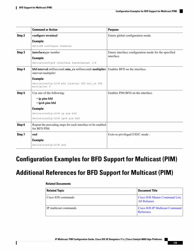
PurposeCommand or Action
Enters global configuration mode.configure terminal
Example:
Step 2
Device# configure terminal
Enters interface configuration mode for the specifiedinterface.
interfacetype number
Example:
Step 3
Device(config)# interface fastethernet 1/6
Enables BFD on the interface.bfd interval milliseconds min_rx milliseconds multiplierinterval-multiplier
Step 4
Example:Device(config-if)# bfd interval 500 min_rx 500multiplier 5
Enables PIM BFD on the interface.Use one of the following:Step 5
• ip pim bfd• ipv6 pim bfd
Example:Device(config-if)# ip pim bfd
Device(config-if)# ipv6 pim bfd
Repeat the preceding steps for each interface to be enabledfor BFD PIM.
Step 6
Exits to privileged EXEC mode .end
Example:
Step 7
Device(config-if)# end
Configuration Examples for BFD Support for Multicast (PIM)
Additional References for BFD Support for Multicast (PIM)Related Documents
Document TitleRelated Topic
Cisco IOS Master Command List,All Releases
Cisco IOS commands
Cisco IOS IP Multicast CommandReference
IP multicast commands
IP Multicast: PIM Configuration Guide, Cisco IOS XE Bengaluru 17.x | Cisco Catalyst 8000 Edge Platforms179
BFD Support for Multicast (PIM)Configuration Examples for BFD Support for Multicast (PIM)
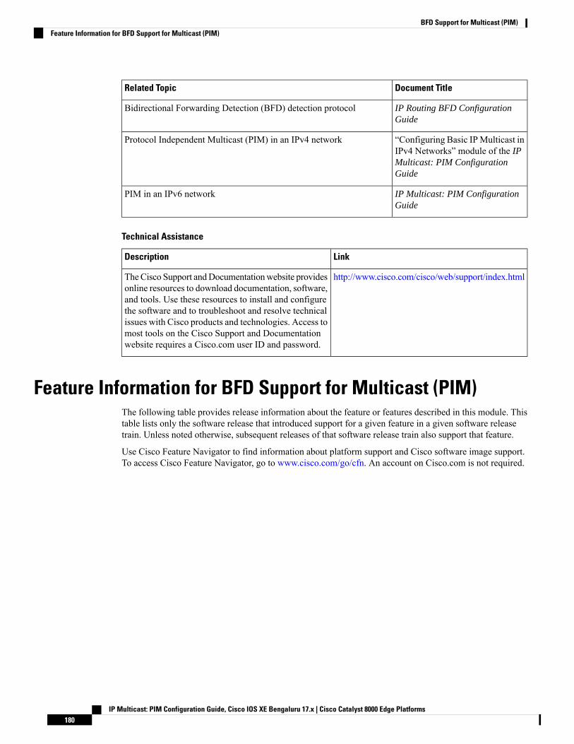
Document TitleRelated Topic
IP Routing BFD ConfigurationGuide
Bidirectional Forwarding Detection (BFD) detection protocol
“Configuring Basic IPMulticast inIPv4 Networks” module of the IPMulticast: PIM ConfigurationGuide
Protocol Independent Multicast (PIM) in an IPv4 network
IP Multicast: PIM ConfigurationGuide
PIM in an IPv6 network
Technical Assistance
LinkDescription
http://www.cisco.com/cisco/web/support/index.htmlTheCisco Support andDocumentationwebsite providesonline resources to download documentation, software,and tools. Use these resources to install and configurethe software and to troubleshoot and resolve technicalissues with Cisco products and technologies. Access tomost tools on the Cisco Support and Documentationwebsite requires a Cisco.com user ID and password.
Feature Information for BFD Support for Multicast (PIM)The following table provides release information about the feature or features described in this module. Thistable lists only the software release that introduced support for a given feature in a given software releasetrain. Unless noted otherwise, subsequent releases of that software release train also support that feature.
Use Cisco Feature Navigator to find information about platform support and Cisco software image support.To access Cisco Feature Navigator, go to www.cisco.com/go/cfn. An account on Cisco.com is not required.
IP Multicast: PIM Configuration Guide, Cisco IOS XE Bengaluru 17.x | Cisco Catalyst 8000 Edge Platforms180
BFD Support for Multicast (PIM)Feature Information for BFD Support for Multicast (PIM)

C H A P T E R 11HSRP Aware PIM
This module describes how to configure the HSRP Aware PIM feature for enabling multicast traffic to beforwarded through the Hot Standby Router Protocol (HSRP) active router (AR), allowing Protocol IndependentMulticast (PIM) to leverage HSRP redundancy, avoid potential duplicate traffic, and enable failover.
• Restrictions for HSRP Aware PIM, on page 181• Information About HSRP Aware PIM, on page 182• How to Configure HSRP Aware PIM, on page 183• Configuration Examples for HSRP Aware PIM, on page 186• Additional References for HSRP Aware PIM, on page 187• Feature Information for HSRP Aware PIM, on page 187
Restrictions for HSRP Aware PIM• HSRP IPv6 is not supported.
• Stateful failover is not supported. During PIM stateless failover, the HSRP group's virtual IP addresstransfers to the standby router but no mrouting sate information is transferred. PIM listens and respondsto state change events and creates mroute states upon failover.
• The maximum number of HSRP groups that can be tracked by PIM on each interface is 16.
• The redundancy priority for a PIM DR must be greater than the configured or default value (1) of thePIM DR priority on any device for which the same HSRP group is enabled or the HSRP Active will failto win the DR election.
• Dense mode is not supported.
• HSRP address as PIM RP is not supported. HSRP aware PIM is for coordinating PIM DR election andHSRP primary election.
IP Multicast: PIM Configuration Guide, Cisco IOS XE Bengaluru 17.x | Cisco Catalyst 8000 Edge Platforms181
Information About HSRP Aware PIM
HSRPHot Standby Router Protocol (HSRP) is a Cisco proprietary redundancy protocol for establishing a fault-tolerantdefault gateway.
The protocol establishes a framework between network devices in order to achieve default gateway failoverif the primary gateway becomes inaccessible. By sharing an IP address and a MAC (Layer 2) address, two ormore devices can act as a single virtual router. The members of a virtual router group continually exchangestatus messages and one device can assume the routing responsibility of another, should it go out of commissionfor either planned or unplanned reasons. Hosts continue to forward IP packets to a consistent IP and MACaddres,s and the changeover of devices doing the routing is transparent.
HSRP is useful for hosts that do not support a router discovery protocol and cannot switch to a new devicewhen their selected device reloads or loses power. Because existing TCP sessions can survive the failover,this protocol also provides a more transparent recovery for hosts that dynamically choose a next hop forrouting IP traffic.
When HSRP is configured on a network segment, it provides a virtual MAC address and an IP address thatis shared among a group of devices running HSRP. The address of this HSRP group is referred to as the virtualIP address. One of these devices is selected by the protocol to be the active router (AR). The AR receives androutes packets destined for the MAC address of the group.
HSRP uses a priority mechanism to determine which HSRP configured device is to be the default AR. Toconfigure a device as the AR, you assign it a priority that is higher than the priority of all the otherHSRP-configured devices. The default priority is 100, so if you configure just one device to have a higherpriority, that device will be the default AR.
Devices that are running HSRP send and receive multicast User Datagram Protocol (UDP)-based hellomessages to detect device failure and to designate active and standby devices. When the AR fails to send ahello message within a configurable period of time, the standby device with the highest priority becomes theAR. The transition of packet forwarding functions between devices is completely transparent to all hosts onthe network.
You can configure multiple Hot Standby groups on an interface, thereby making fuller use of redundantdevices and load sharing.
HSRP is not a routing protocol as it does not advertise IP routes or affect the routing table in any way.
HSRP has the ability to trigger a failover if one or more interfaces on the device fail. This can be useful fordual branch devices each with a single serial link back to the head end. If the serial link of the primary devicegoes down, the backup device takes over the primary functionality and thus retains connectivity to the headend.
HSRP Aware PIMProtocol Independent Multicast (PIM) has no inherent redundancy capabilities and its operation is completelyindependent of Hot Standby Router Protocol (HSRP) group states. As a result, IP multicast traffic is forwardednot necessarily by the same device as is elected by HSRP. The HSRP Aware PIM feature provides consistentIP multicast forwarding in a redundant network with virtual routing groups enabled.
IP Multicast: PIM Configuration Guide, Cisco IOS XE Bengaluru 17.x | Cisco Catalyst 8000 Edge Platforms182
HSRP Aware PIMInformation About HSRP Aware PIM
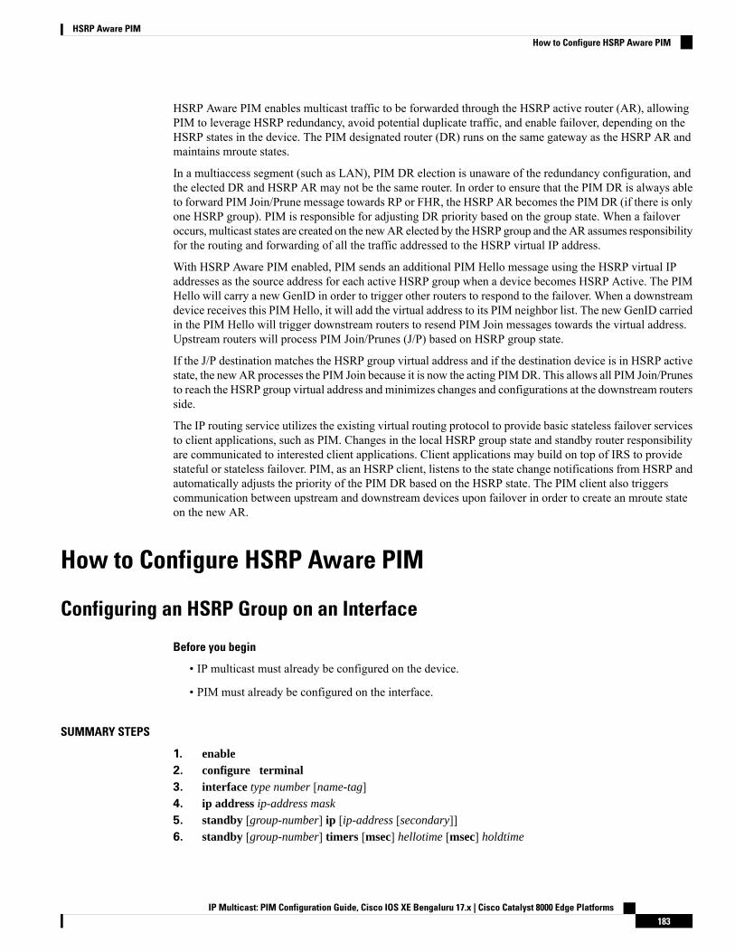
HSRP Aware PIM enables multicast traffic to be forwarded through the HSRP active router (AR), allowingPIM to leverage HSRP redundancy, avoid potential duplicate traffic, and enable failover, depending on theHSRP states in the device. The PIM designated router (DR) runs on the same gateway as the HSRP AR andmaintains mroute states.
In a multiaccess segment (such as LAN), PIM DR election is unaware of the redundancy configuration, andthe elected DR and HSRP AR may not be the same router. In order to ensure that the PIM DR is always ableto forward PIM Join/Prune message towards RP or FHR, the HSRP AR becomes the PIM DR (if there is onlyone HSRP group). PIM is responsible for adjusting DR priority based on the group state. When a failoveroccurs, multicast states are created on the newAR elected by the HSRP group and the AR assumes responsibilityfor the routing and forwarding of all the traffic addressed to the HSRP virtual IP address.
With HSRP Aware PIM enabled, PIM sends an additional PIM Hello message using the HSRP virtual IPaddresses as the source address for each active HSRP group when a device becomes HSRP Active. The PIMHello will carry a new GenID in order to trigger other routers to respond to the failover. When a downstreamdevice receives this PIM Hello, it will add the virtual address to its PIM neighbor list. The new GenID carriedin the PIM Hello will trigger downstream routers to resend PIM Join messages towards the virtual address.Upstream routers will process PIM Join/Prunes (J/P) based on HSRP group state.
If the J/P destination matches the HSRP group virtual address and if the destination device is in HSRP activestate, the newAR processes the PIM Join because it is now the acting PIMDR. This allows all PIM Join/Prunesto reach the HSRP group virtual address and minimizes changes and configurations at the downstream routersside.
The IP routing service utilizes the existing virtual routing protocol to provide basic stateless failover servicesto client applications, such as PIM. Changes in the local HSRP group state and standby router responsibilityare communicated to interested client applications. Client applications may build on top of IRS to providestateful or stateless failover. PIM, as an HSRP client, listens to the state change notifications from HSRP andautomatically adjusts the priority of the PIM DR based on the HSRP state. The PIM client also triggerscommunication between upstream and downstream devices upon failover in order to create an mroute stateon the new AR.
How to Configure HSRP Aware PIM
Configuring an HSRP Group on an Interface
Before you begin
• IP multicast must already be configured on the device.
• PIM must already be configured on the interface.
SUMMARY STEPS
1. enable2. configure terminal3. interface type number [name-tag]4. ip address ip-address mask
5. standby [group-number] ip [ip-address [secondary]]6. standby [group-number] timers [msec] hellotime [msec] holdtime
IP Multicast: PIM Configuration Guide, Cisco IOS XE Bengaluru 17.x | Cisco Catalyst 8000 Edge Platforms183
HSRP Aware PIMHow to Configure HSRP Aware PIM

7. standby [group-number] priority priority
8. standby [group-number] name group-name
9. end10. show standby [type number [group]] [all | brief]
DETAILED STEPS
PurposeCommand or Action
Enables privileged EXEC mode.enableStep 1
Example: • Enter your password if prompted.Device> enable
Enters global configuration mode.configure terminal
Example:
Step 2
Device# configure terminal
Specifies an interface to be configured and enters interfaceconfiguration mode.
interface type number [name-tag]
Example:
Step 3
Device(config)# interface ethernet 0/0
Sets a primary or secondary IP address for an interface.ip address ip-address mask
Example:
Step 4
Device(config-if)# ip address 10.0.0.2255.255.255.0
Activates HSRP and defines an HRSP group.standby [group-number] ip [ip-address [secondary]]
Example:
Step 5
Device(config-if)# standby 1 ip 192.0.2.99
(Optional) Configures the time between hello packets andthe time before other devices declare an HSRP active orstandby router to be down.
standby [group-number] timers [msec] hellotime [msec]holdtime
Example:
Step 6
Device(config-if)# standby 1 timers 5 15
(Optional) Assigns the HSRP priority to be used to helpselect the HSRP active and standby routers.
standby [group-number] priority priority
Example:
Step 7
Device(config-if)# standby 1 priority 120
(Optional) Defines a name for the HSRP group.standby [group-number] name group-name
Example:
Step 8
We recommend that you always configure thestandby ip name command when configuringan HSRP group to be used for HSRP AwarePIM.
Note
Device(config-if)# standby 1 name HSRP1
Returns to privileged EXEC mode.end
Example:
Step 9
IP Multicast: PIM Configuration Guide, Cisco IOS XE Bengaluru 17.x | Cisco Catalyst 8000 Edge Platforms184
HSRP Aware PIMConfiguring an HSRP Group on an Interface
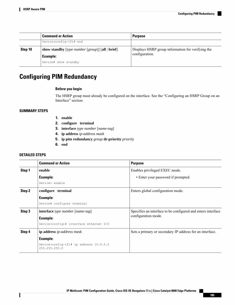
PurposeCommand or ActionDevice(config-if)# end
Displays HSRP group information for verifying theconfiguration.
show standby [type number [group]] [all | brief]
Example:
Step 10
Device# show standby
Configuring PIM Redundancy
Before you begin
The HSRP group must already be configured on the interface. See the “Configuring an HSRP Group on anInterface” section.
SUMMARY STEPS
1. enable2. configure terminal3. interface type number [name-tag]4. ip address ip-address mask
5. ip pim redundancy group dr-priority priority
6. end
DETAILED STEPS
PurposeCommand or Action
Enables privileged EXEC mode.enableStep 1
Example: • Enter your password if prompted.Device> enable
Enters global configuration mode.configure terminal
Example:
Step 2
Device# configure terminal
Specifies an interface to be configured and enters interfaceconfiguration mode.
interface type number [name-tag]
Example:
Step 3
Device(config)# interface ethernet 0/0
Sets a primary or secondary IP address for an interface.ip address ip-address mask
Example:
Step 4
Device(config-if)# ip address 10.0.0.2255.255.255.0
IP Multicast: PIM Configuration Guide, Cisco IOS XE Bengaluru 17.x | Cisco Catalyst 8000 Edge Platforms185
HSRP Aware PIMConfiguring PIM Redundancy
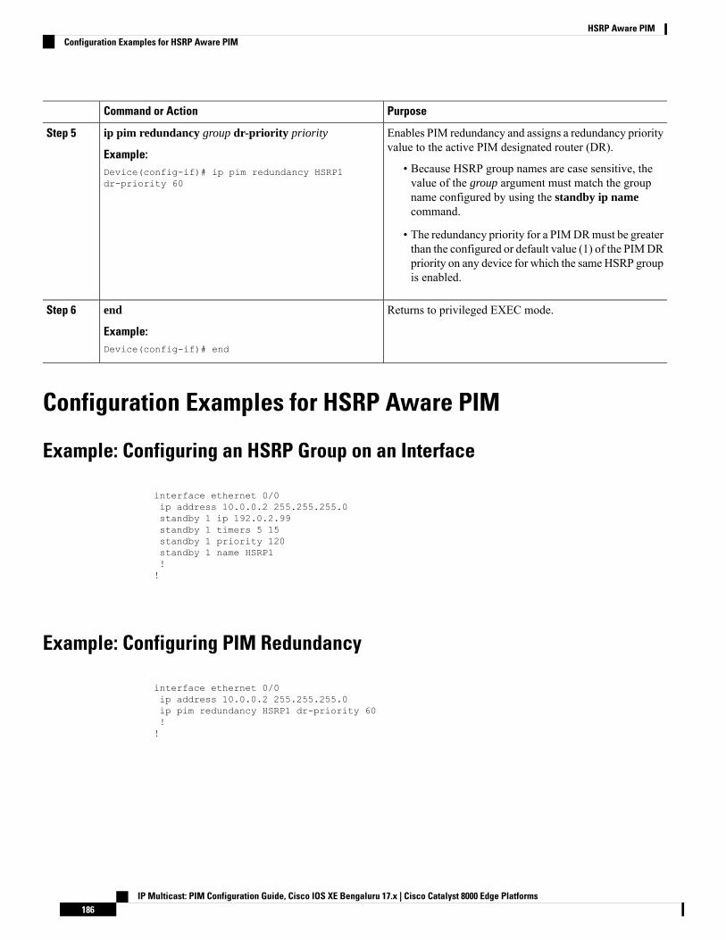
PurposeCommand or Action
Enables PIM redundancy and assigns a redundancy priorityvalue to the active PIM designated router (DR).
ip pim redundancy group dr-priority priority
Example:
Step 5
• Because HSRP group names are case sensitive, thevalue of the group argument must match the group
Device(config-if)# ip pim redundancy HSRP1dr-priority 60
name configured by using the standby ip namecommand.
• The redundancy priority for a PIMDRmust be greaterthan the configured or default value (1) of the PIMDRpriority on any device for which the sameHSRP groupis enabled.
Returns to privileged EXEC mode.end
Example:
Step 6
Device(config-if)# end
Configuration Examples for HSRP Aware PIM
Example: Configuring an HSRP Group on an Interface
interface ethernet 0/0ip address 10.0.0.2 255.255.255.0standby 1 ip 192.0.2.99standby 1 timers 5 15standby 1 priority 120standby 1 name HSRP1!!
Example: Configuring PIM Redundancy
interface ethernet 0/0ip address 10.0.0.2 255.255.255.0ip pim redundancy HSRP1 dr-priority 60!!
IP Multicast: PIM Configuration Guide, Cisco IOS XE Bengaluru 17.x | Cisco Catalyst 8000 Edge Platforms186
HSRP Aware PIMConfiguration Examples for HSRP Aware PIM
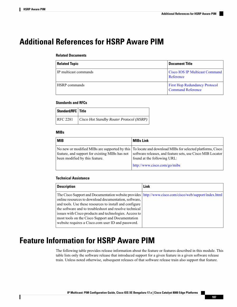
Additional References for HSRP Aware PIMRelated Documents
Document TitleRelated Topic
Cisco IOS IP Multicast CommandReference
IP multicast commands
First Hop Redundancy ProtocolCommand Reference
HSRP commands
Standards and RFCs
TitleStandard/RFC
Cisco Hot Standby Router Protocol (HSRP)RFC 2281
MIBs
MIBs LinkMIB
To locate and downloadMIBs for selected platforms, Ciscosoftware releases, and feature sets, use Cisco MIB Locatorfound at the following URL:
http://www.cisco.com/go/mibs
No new or modified MIBs are supported by thisfeature, and support for existing MIBs has notbeen modified by this feature.
Technical Assistance
LinkDescription
http://www.cisco.com/cisco/web/support/index.htmlTheCisco Support andDocumentationwebsite providesonline resources to download documentation, software,and tools. Use these resources to install and configurethe software and to troubleshoot and resolve technicalissues with Cisco products and technologies. Access tomost tools on the Cisco Support and Documentationwebsite requires a Cisco.com user ID and password.
Feature Information for HSRP Aware PIMThe following table provides release information about the feature or features described in this module. Thistable lists only the software release that introduced support for a given feature in a given software releasetrain. Unless noted otherwise, subsequent releases of that software release train also support that feature.
IP Multicast: PIM Configuration Guide, Cisco IOS XE Bengaluru 17.x | Cisco Catalyst 8000 Edge Platforms187
HSRP Aware PIMAdditional References for HSRP Aware PIM

Use Cisco Feature Navigator to find information about platform support and Cisco software image support.To access Cisco Feature Navigator, go to www.cisco.com/go/cfn. An account on Cisco.com is not required.
IP Multicast: PIM Configuration Guide, Cisco IOS XE Bengaluru 17.x | Cisco Catalyst 8000 Edge Platforms188
HSRP Aware PIMFeature Information for HSRP Aware PIM

C H A P T E R 12VRRP Aware PIM
The Virtual Router Redundancy Protocol (VRRP) eliminates the single point of failure inherent in the staticdefault routed environment. VRRP is an election protocol that dynamically assigns responsibility for one ormore virtual routers to the VRRP routers on a LAN, allowing several routers on a multi access link to utilizethe same virtual IP address.
VRRP Aware PIM is a redundancy mechanism for the Protocol Independent Multicast (PIM) to interoperatewith VRRP. It allows PIM to track VRRP state and to preserve multicast traffic upon fail over in a redundantnetwork with virtual routing groups enabled.
This module explains how to configure VRRP Aware PIM in a network.
• Restrictions for VRRP Aware PIM, on page 189• Information About VRRP Aware PIM, on page 190• How to Configure VRRP Aware PIM, on page 190• Configuration Examples for VRRP Aware PIM, on page 192• Additional References for VRRP Aware PIM, on page 193• Feature Information for VRRP Aware PIM, on page 193
Restrictions for VRRP Aware PIM• Only PIM sparse mode (SM) and source specific multicast (SSM) modes are supported. Bidirectional(BiDir) PIM is not supported.
• PIM interoperability with Hot Standby Router Protocol (HSRP) IPv6 is not supported.• PIM tracks only one virtual group, either Virtual Router Redundancy Protocol (VRRP) or HSRP, perinterface.
• VRRP Aware PIM is not supported on a Transit network. PIM redundancy enabled interface does notsupport the PIM joining the network from down stream.
IP Multicast: PIM Configuration Guide, Cisco IOS XE Bengaluru 17.x | Cisco Catalyst 8000 Edge Platforms189
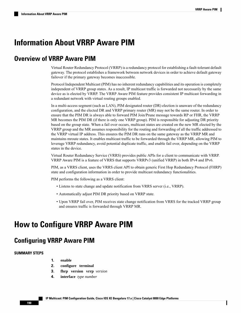
Information About VRRP Aware PIM
Overview of VRRP Aware PIMVirtual Router Redundancy Protocol (VRRP) is a redundancy protocol for establishing a fault-tolerant defaultgateway. The protocol establishes a framework between network devices in order to achieve default gatewayfailover if the primary gateway becomes inaccessible.
Protocol Independent Multicast (PIM) has no inherent redundancy capabilities and its operation is completelyindependent of VRRP group states. As a result, IP multicast traffic is forwarded not necessarily by the samedevice as is elected by VRRP. The VRRP Aware PIM feature provides consistent IP multicast forwarding ina redundant network with virtual routing groups enabled.
In a multi-access segment (such as LAN), PIM designated router (DR) election is unaware of the redundancyconfiguration, and the elected DR and VRRP primary router (MR) may not be the same router. In order toensure that the PIM DR is always able to forward PIM Join/Prune message towards RP or FHR, the VRRPMR becomes the PIM DR (if there is only one VRRP group). PIM is responsible for adjusting DR prioritybased on the group state. When a fail over occurs, multicast states are created on the new MR elected by theVRRP group and the MR assumes responsibility for the routing and forwarding of all the traffic addressed tothe VRRP virtual IP address. This ensures the PIM DR runs on the same gateway as the VRRP MR andmaintains mroute states. It enables multicast traffic to be forwarded through the VRRP MR, allowing PIM toleverage VRRP redundancy, avoid potential duplicate traffic, and enable fail over, depending on the VRRPstates in the device.
Virtual Router Redundancy Service (VRRS) provides public APIs for a client to communicate with VRRP.VRRP Aware PIM is a feature of VRRS that supports VRRPv3 (unified VRRP) in both IPv4 and IPv6.
PIM, as a VRRS client, uses the VRRS client API to obtain generic First Hop Redundancy Protocol (FHRP)state and configuration information in order to provide multicast redundancy functionalities.
PIM performs the following as a VRRS client:
• Listens to state change and update notification from VRRS server (i.e., VRRP).
• Automatically adjust PIM DR priority based on VRRP state.
• Upon VRRP fail over, PIM receives state change notification from VRRS for the tracked VRRP groupand ensures traffic is forwarded through VRRP MR.
How to Configure VRRP Aware PIM
Configuring VRRP Aware PIM
SUMMARY STEPS
1. enable2. configure terminal3. fhrp version vrrp version
4. interface type number
IP Multicast: PIM Configuration Guide, Cisco IOS XE Bengaluru 17.x | Cisco Catalyst 8000 Edge Platforms190
VRRP Aware PIMInformation About VRRP Aware PIM

5. ip address address {primary |secondary}6. vrrp group id address-family ipv47. vrrs leader group name
8. vrrp group id ip ip address{primary |secondary}9. exit10. interface type number
11. ip pim redundancy group name vrrp dr-priority priority-value
12. end
DETAILED STEPS
PurposeCommand or Action
Enables privileged EXEC mode.enableStep 1
Example: • Enter your password if prompted.
Device> enable
Enters global configuration mode.configure terminal
Example:
Step 2
Router# configure terminal
Enables the ability to configure VRRPv3 and VRRS.fhrp version vrrp version
Example:
Step 3
Device(config)# fhrp version vrrp v3
Specifies an interface to be configured and enters interfaceconfiguration mode.
interface type number
Example:
Step 4
Device(config)# interface Ethernet0/0
Specifies a primary or secondary address for the VRRPgroup.
ip address address {primary |secondary}
Example:
Step 5
Device(config-if)# ip address 192.0.2.2
Creates a VRRP group and enters VRRP configurationmode.
vrrp group id address-family ipv4
Example:
Step 6
Device(config-if)# vrrp 1 address-family ipv4
Enables community and (or) extended communityexchange with the specified neighbor.
vrrs leader group name
Example:
Step 7
Device(config-if-vrrp)# vrrs leader VRRP1
IP Multicast: PIM Configuration Guide, Cisco IOS XE Bengaluru 17.x | Cisco Catalyst 8000 Edge Platforms191
VRRP Aware PIMConfiguring VRRP Aware PIM
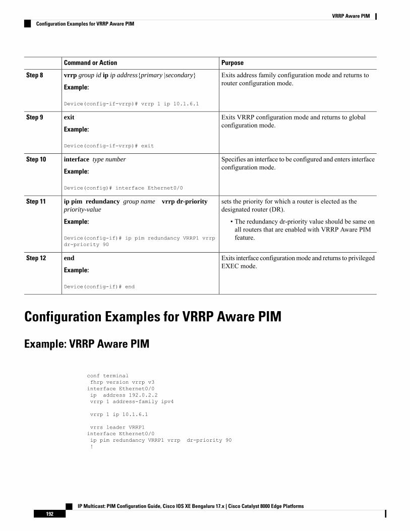
PurposeCommand or Action
Exits address family configuration mode and returns torouter configuration mode.
vrrp group id ip ip address{primary |secondary}
Example:
Step 8
Device(config-if-vrrp)# vrrp 1 ip 10.1.6.1
Exits VRRP configuration mode and returns to globalconfiguration mode.
exit
Example:
Step 9
Device(config-if-vrrp)# exit
Specifies an interface to be configured and enters interfaceconfiguration mode.
interface type number
Example:
Step 10
Device(config)# interface Ethernet0/0
sets the priority for which a router is elected as thedesignated router (DR).
ip pim redundancy group name vrrp dr-prioritypriority-value
Step 11
Example: • The redundancy dr-priority value should be same onall routers that are enabled with VRRP Aware PIMfeature.Device(config-if)# ip pim redundancy VRRP1 vrrp
dr-priority 90
Exits interface configurationmode and returns to privilegedEXEC mode.
end
Example:
Step 12
Device(config-if)# end
Configuration Examples for VRRP Aware PIM
Example: VRRP Aware PIM
conf terminalfhrp version vrrp v3interface Ethernet0/0ip address 192.0.2.2vrrp 1 address-family ipv4
vrrp 1 ip 10.1.6.1
vrrs leader VRRP1interface Ethernet0/0ip pim redundancy VRRP1 vrrp dr-priority 90!
IP Multicast: PIM Configuration Guide, Cisco IOS XE Bengaluru 17.x | Cisco Catalyst 8000 Edge Platforms192
VRRP Aware PIMConfiguration Examples for VRRP Aware PIM
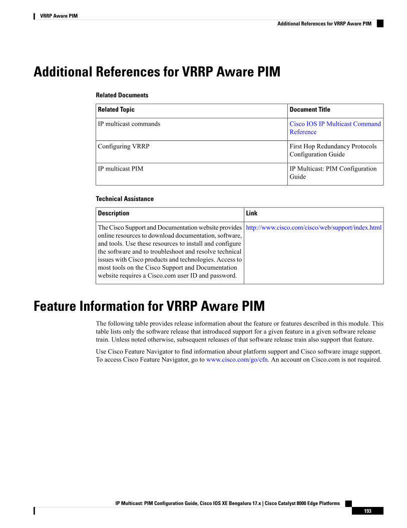
Additional References for VRRP Aware PIMRelated Documents
Document TitleRelated Topic
Cisco IOS IP Multicast CommandReference
IP multicast commands
First Hop Redundancy ProtocolsConfiguration Guide
Configuring VRRP
IP Multicast: PIM ConfigurationGuide
IP multicast PIM
Technical Assistance
LinkDescription
http://www.cisco.com/cisco/web/support/index.htmlTheCisco Support andDocumentationwebsite providesonline resources to download documentation, software,and tools. Use these resources to install and configurethe software and to troubleshoot and resolve technicalissues with Cisco products and technologies. Access tomost tools on the Cisco Support and Documentationwebsite requires a Cisco.com user ID and password.
Feature Information for VRRP Aware PIMThe following table provides release information about the feature or features described in this module. Thistable lists only the software release that introduced support for a given feature in a given software releasetrain. Unless noted otherwise, subsequent releases of that software release train also support that feature.
Use Cisco Feature Navigator to find information about platform support and Cisco software image support.To access Cisco Feature Navigator, go to www.cisco.com/go/cfn. An account on Cisco.com is not required.
IP Multicast: PIM Configuration Guide, Cisco IOS XE Bengaluru 17.x | Cisco Catalyst 8000 Edge Platforms193
VRRP Aware PIMAdditional References for VRRP Aware PIM

IP Multicast: PIM Configuration Guide, Cisco IOS XE Bengaluru 17.x | Cisco Catalyst 8000 Edge Platforms194
VRRP Aware PIMFeature Information for VRRP Aware PIM
C H A P T E R 13Verifying IP Multicast Operation
This module describes how to verify IP multicast operation in a network after Protocol Independent Multicast(PIM) sparse mode (PIM-SM) or Source Specific Multicast (PIM-SSM) has been implemented. The tasks inthis module can be used to test IP multicast reachability and to confirm that receivers and sources are operatingas expected in an IP multicast network.
• Prerequisites for Verifying IP Multicast Operation, on page 195• Restrictions for Verifying IP Multicast Operation, on page 195• Information About Verifying IP Multicast Operation, on page 196• How to Verify IP Multicast Operation, on page 198• Configuration Examples for Verifying IP Multicast Operation, on page 206• Additional References, on page 210• Feature Information for Verifying IP Multicast Operation, on page 211
Prerequisites for Verifying IP Multicast Operation• Before performing the tasks in this module, you should be familiar with the concepts described in the “IP Multicast Technology Overview ” module.
• The tasks in this module assume that IP multicast has been enabled and that PIM-SM or SSM has beenconfigured using the relevant tasks described in the “ Configuring Basic IP Multicast ” module.
Restrictions for Verifying IP Multicast Operation• For PIM-SM, this module assumes that the shortest path tree (SPT) threshold for PIM-enabled routersis set to the value of zero (the default) and not infinity. For more information about setting the SPTthreshold, see the ip pim spt-threshold command page in theCisco IOS IP Multicast Command Reference.
• Verifying IP multicast operation in a bidirectional PIM (bidir-PIM) network or a PIM-SM network witha finite or infinite SPT threshold is outside the scope of this module.
IP Multicast: PIM Configuration Guide, Cisco IOS XE Bengaluru 17.x | Cisco Catalyst 8000 Edge Platforms195
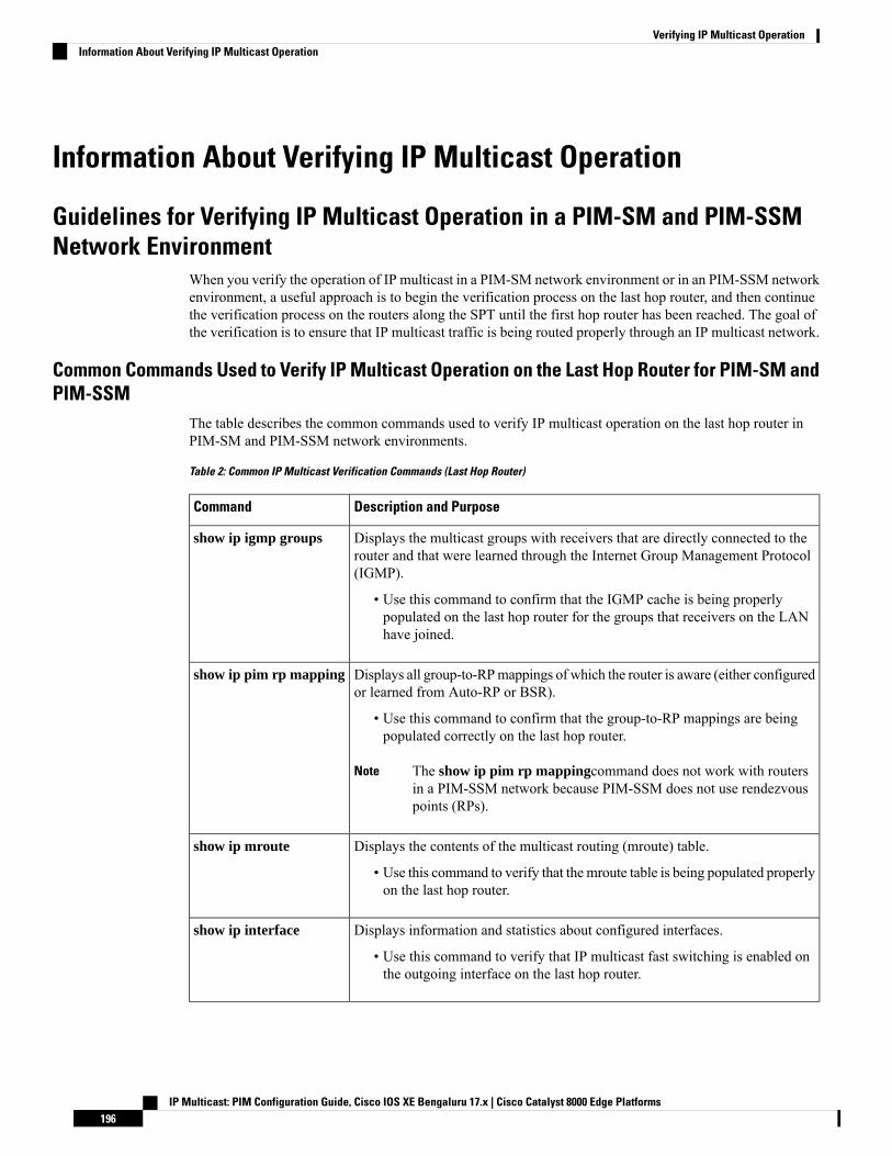
Information About Verifying IP Multicast Operation
Guidelines for Verifying IP Multicast Operation in a PIM-SM and PIM-SSMNetwork Environment
When you verify the operation of IP multicast in a PIM-SM network environment or in an PIM-SSM networkenvironment, a useful approach is to begin the verification process on the last hop router, and then continuethe verification process on the routers along the SPT until the first hop router has been reached. The goal ofthe verification is to ensure that IP multicast traffic is being routed properly through an IP multicast network.
Common Commands Used to Verify IP Multicast Operation on the Last Hop Router for PIM-SM andPIM-SSM
The table describes the common commands used to verify IP multicast operation on the last hop router inPIM-SM and PIM-SSM network environments.
Table 2: Common IP Multicast Verification Commands (Last Hop Router)
Description and PurposeCommand
Displays the multicast groups with receivers that are directly connected to therouter and that were learned through the Internet Group Management Protocol(IGMP).
• Use this command to confirm that the IGMP cache is being properlypopulated on the last hop router for the groups that receivers on the LANhave joined.
show ip igmp groups
Displays all group-to-RPmappings of which the router is aware (either configuredor learned from Auto-RP or BSR).
• Use this command to confirm that the group-to-RP mappings are beingpopulated correctly on the last hop router.
The show ip pim rp mappingcommand does not work with routersin a PIM-SSM network because PIM-SSM does not use rendezvouspoints (RPs).
Note
show ip pim rp mapping
Displays the contents of the multicast routing (mroute) table.
• Use this command to verify that the mroute table is being populated properlyon the last hop router.
show ip mroute
Displays information and statistics about configured interfaces.
• Use this command to verify that IP multicast fast switching is enabled onthe outgoing interface on the last hop router.
show ip interface
IP Multicast: PIM Configuration Guide, Cisco IOS XE Bengaluru 17.x | Cisco Catalyst 8000 Edge Platforms196
Verifying IP Multicast OperationInformation About Verifying IP Multicast Operation
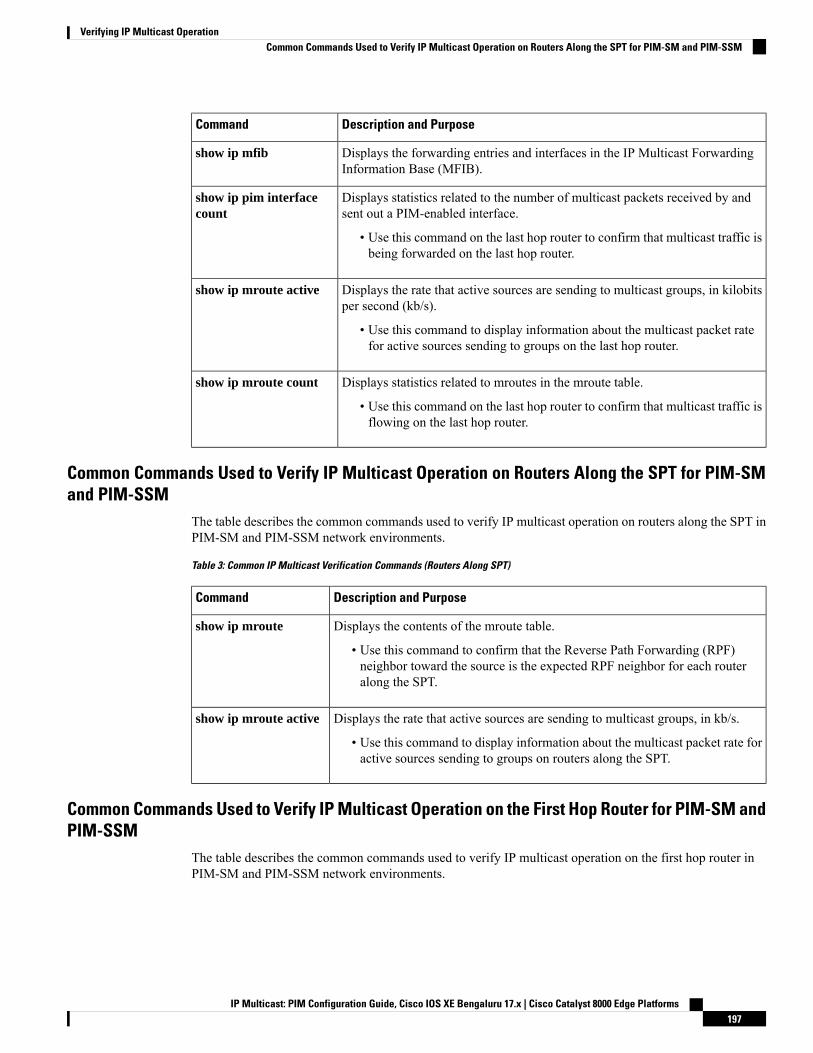
Description and PurposeCommand
Displays the forwarding entries and interfaces in the IP Multicast ForwardingInformation Base (MFIB).
show ip mfib
Displays statistics related to the number of multicast packets received by andsent out a PIM-enabled interface.
• Use this command on the last hop router to confirm that multicast traffic isbeing forwarded on the last hop router.
show ip pim interfacecount
Displays the rate that active sources are sending to multicast groups, in kilobitsper second (kb/s).
• Use this command to display information about the multicast packet ratefor active sources sending to groups on the last hop router.
show ip mroute active
Displays statistics related to mroutes in the mroute table.
• Use this command on the last hop router to confirm that multicast traffic isflowing on the last hop router.
show ip mroute count
Common Commands Used to Verify IP Multicast Operation on Routers Along the SPT for PIM-SMand PIM-SSM
The table describes the common commands used to verify IP multicast operation on routers along the SPT inPIM-SM and PIM-SSM network environments.
Table 3: Common IP Multicast Verification Commands (Routers Along SPT)
Description and PurposeCommand
Displays the contents of the mroute table.
• Use this command to confirm that the Reverse Path Forwarding (RPF)neighbor toward the source is the expected RPF neighbor for each routeralong the SPT.
show ip mroute
Displays the rate that active sources are sending to multicast groups, in kb/s.
• Use this command to display information about the multicast packet rate foractive sources sending to groups on routers along the SPT.
show ip mroute active
Common Commands Used to Verify IP Multicast Operation on the First Hop Router for PIM-SM andPIM-SSM
The table describes the common commands used to verify IP multicast operation on the first hop router inPIM-SM and PIM-SSM network environments.
IP Multicast: PIM Configuration Guide, Cisco IOS XE Bengaluru 17.x | Cisco Catalyst 8000 Edge Platforms197
Verifying IP Multicast OperationCommon Commands Used to Verify IP Multicast Operation on Routers Along the SPT for PIM-SM and PIM-SSM
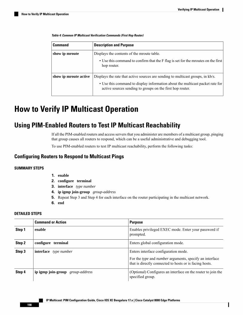
Table 4: Common IP Multicast Verification Commands (First Hop Router)
Description and PurposeCommand
Displays the contents of the mroute table.
• Use this command to confirm that the F flag is set for the mroutes on the firsthop router.
show ip mroute
Displays the rate that active sources are sending to multicast groups, in kb/s.
• Use this command to display information about the multicast packet rate foractive sources sending to groups on the first hop router.
show ip mroute active
How to Verify IP Multicast Operation
Using PIM-Enabled Routers to Test IP Multicast ReachabilityIf all the PIM-enabled routers and access servers that you administer are members of a multicast group, pingingthat group causes all routers to respond, which can be a useful administrative and debugging tool.
To use PIM-enabled routers to test IP multicast reachability, perform the following tasks:
Configuring Routers to Respond to Multicast Pings
SUMMARY STEPS
1. enable2. configure terminal3. interface type number
4. ip igmp join-group group-address
5. Repeat Step 3 and Step 4 for each interface on the router participating in the multicast network.6. end
DETAILED STEPS
PurposeCommand or Action
Enables privileged EXEC mode. Enter your password ifprompted.
enableStep 1
Enters global configuration mode.configure terminalStep 2
Enters interface configuration mode.interface type numberStep 3
For the type and number arguments, specify an interfacethat is directly connected to hosts or is facing hosts.
(Optional) Configures an interface on the router to join thespecified group.
ip igmp join-group group-addressStep 4
IP Multicast: PIM Configuration Guide, Cisco IOS XE Bengaluru 17.x | Cisco Catalyst 8000 Edge Platforms198
Verifying IP Multicast OperationHow to Verify IP Multicast Operation
PurposeCommand or Action
For the purpose of this task, configure the same groupaddress for the group-address argument on all interfaceson the router participating in the multicast network.
With this method, the router accepts themulticastpackets in addition to forwarding them.Accepting the multicast packets prevents therouter from fast switching.
Note
--Repeat Step 3 and Step 4 for each interface on the routerparticipating in the multicast network.
Step 5
Ends the current configuration session and returns toprivileged EXEC mode.
endStep 6
Pinging Routers Configured to Respond to Multicast Pingson a router to initiate a ping test to the routers configured to respond to multicast pings. This task is used totest IP multicast reachability in a network.
SUMMARY STEPS
1. enable2. ping group-address
DETAILED STEPS
PurposeCommand or Action
Enables privileged EXEC mode. Enter your password ifprompted.
enableStep 1
Pings an IP multicast group address.ping group-addressStep 2
A successful response indicates that the group address isfunctioning.
Verifying IP Multicast Operation in a PIM-SM or a PIM-SSM NetworkPerform the following optional tasks to verify IP multicast operation in a PIM-SM or a PIM-SSM network.The steps in these tasks help to locate a faulty hop when sources and receivers are not operating as expected.
If packets are not reaching their expected destinations, you might want consider disabling IP multicast fastswitching, which would place the router in process switching mode. If packets begin reaching their properdestinations after IP multicast fast switching has been disabled, then the issue most likely was related to IPmulticast fast switching.
Note
IP Multicast: PIM Configuration Guide, Cisco IOS XE Bengaluru 17.x | Cisco Catalyst 8000 Edge Platforms199
Verifying IP Multicast OperationPinging Routers Configured to Respond to Multicast Pings

Verifying IP Multicast Operation on the Last Hop RouterPerform the following task to verify the operation of IP multicast on the last hop router.
If you are verifying a last hop router in a PIM-SSM network, ignore Step 3.Note
SUMMARY STEPS
1. enable2. show ip igmp groups3. show ip pim rp mapping4. show ip mroute5. show ip interface [type number]6. show ip mfib7. show ip pim interface count8. show ip mroute count9. show ip mroute active [kb/s]
DETAILED STEPS
Step 1 enable
Enables privileged EXEC mode. Enter your password if prompted.
Step 2 show ip igmp groups
Use this command to verify IGMPmemberships on the last hop router. This information will confirm themulticast groupswith receivers that are directly connected to the last hop router and that are learned through IGMP.
The following is sample output from the show ip igmp groups command:
Example:
Router# show ip igmp groupsIGMP Connected Group MembershipGroup Address Interface Uptime Expires Last Reporter239.1.2.3 GigabitEthernet1/0/0 00:05:14 00:02:14 10.1.0.6224.0.1.39 GigabitEthernet0/0/0 00:09:11 00:02:08 172.31.100.1
Step 3 show ip pim rp mapping
Use this command to confirm that the group-to-RP mappings are being populated correctly on the last hop router.
Ignore this step if you are verifying a last hop router in a PIM-SSM network. The show ip pim rpmappingcommand does not work with routers in a PIM-SSM network because PIM-SSM does not use RPs.In addition, if configured correctly, PIM-SSM groups should not appear in the output of the show ip pim rpmappingcommand.
Note
The following is sample output from the show ip pim rp mappingcommand:
Example:
IP Multicast: PIM Configuration Guide, Cisco IOS XE Bengaluru 17.x | Cisco Catalyst 8000 Edge Platforms200
Verifying IP Multicast OperationVerifying IP Multicast Operation on the Last Hop Router

Router# show ip pim rp mappingPIM Group-to-RP Mappings
Group(s) 224.0.0.0/4RP 172.16.0.1 (?), v2v1Info source: 172.16.0.1 (?), elected via Auto-RP
Uptime: 00:09:11, expires: 00:02:47
Step 4 show ip mroute
Use this command to verify that the mroute table is being populated properly on the last hop router.
The following is sample output from the show ip mroute command:
Example:
Router# show ip mroute(*, 239.1.2.3), 00:05:14/00:03:04, RP 172.16.0.1, flags: SJCIncoming interface: GigabitEthernet0/0/0, RPF nbr 172.31.100.1Outgoing interface list:GigabitEthernet1/0, Forward/Sparse-Dense, 00:05:10/00:03:04
(10.0.0.1, 239.1.2.3), 00:02:49/00:03:29, flags: TIncoming interface: GigabitEthernet0/0/0, RPF nbr 172.31.100.1Outgoing interface list:GigabitEthernet1/0, Forward/Sparse-Dense, 00:02:49/00:03:04
(*, 224.0.1.39), 00:10:05/stopped, RP 0.0.0.0, flags: DCIncoming interface: Null, RPF nbr 0.0.0.0Outgoing interface list:GigabitEthernet1/0, Forward/Sparse-Dense, 00:05:15/00:00:00GigabitEthernet0/0, Forward/Sparse-Dense, 00:10:05/00:00:00
(172.16.0.1, 224.0.1.39), 00:02:00/00:01:33, flags: PTXIncoming interface: GigabitEthernet0/0/0, RPF nbr 172.31.100.1
Step 5 show ip interface [type number]
Use this command to verify that multicast fast switching is enabled for optimal performance on the outgoing interfaceon the last hop router.
Using the no ip mroute-cache interface command disables IP multicast fast-switching. When IP multicast fastswitching is disabled, packets are forwarded through the process-switched path.
Note
The following is sample output from the show ip interfacecommand for a particular interface:
Example:
Router# show ip interface GigabitEthernet 0/0/0GigabitEthernet0/0 is up, line protocol is upInternet address is 172.31.100.2/24Broadcast address is 255.255.255.255Address determined by setup commandMTU is 1500 bytesHelper address is not setDirected broadcast forwarding is disabledMulticast reserved groups joined: 224.0.0.1 224.0.0.22 224.0.0.13
224.0.0.5 224.0.0.6Outgoing access list is not setInbound access list is not setProxy ARP is enabledLocal Proxy ARP is disabled
IP Multicast: PIM Configuration Guide, Cisco IOS XE Bengaluru 17.x | Cisco Catalyst 8000 Edge Platforms201
Verifying IP Multicast OperationVerifying IP Multicast Operation on the Last Hop Router

Security level is defaultSplit horizon is enabledICMP redirects are always sentICMP unreachables are always sentICMP mask replies are never sentIP fast switching is enabledIP fast switching on the same interface is disabledIP Flow switching is disabledIP CEF switching is disabledIP Fast switching turbo vectorIP multicast fast switching is enabledIP multicast distributed fast switching is disabledIP route-cache flags are FastRouter Discovery is disabledIP output packet accounting is disabledIP access violation accounting is disabledTCP/IP header compression is disabledRTP/IP header compression is disabledPolicy routing is disabledNetwork address translation is disabledWCCP Redirect outbound is disabledWCCP Redirect inbound is disabledWCCP Redirect exclude is disabledBGP Policy Mapping is disabled
Step 6 show ip mfib
Use this command to display the forwarding entries and interfaces in the IP Multicast Forwarding Information Base(MFIB).
Example:
Step 7 show ip pim interface count
Use this command to confirm that multicast traffic is being forwarded on the last hop router.
The following is sample output from the show ip pim interface command with the count keyword:
Example:
Router# show ip pim interface count
State: * - Fast Switched, D - Distributed Fast SwitchedH - Hardware Switching Enabled
Address Interface FS Mpackets In/Out172.31.100.2 GigabitEthernet0/0/0 * 4122/010.1.0.1 GigabitEthernet1/0/0 * 0/3193
Step 8 show ip mroute count
Use this command to confirm that multicast traffic is being forwarded on the last hop router.
The following is sample output from the show ip mroutecommand with the count keyword:
Example:
Router# show ip mroute countIP Multicast Statistics6 routes using 4008 bytes of memory3 groups, 1.00 average sources per groupForwarding Counts: Pkt Count/Pkts per second/Avg Pkt Size/Kilobits per secondOther counts: Total/RPF failed/Other drops(OIF-null, rate-limit etc)
IP Multicast: PIM Configuration Guide, Cisco IOS XE Bengaluru 17.x | Cisco Catalyst 8000 Edge Platforms202
Verifying IP Multicast OperationVerifying IP Multicast Operation on the Last Hop Router
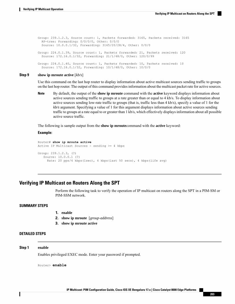
Group: 239.1.2.3, Source count: 1, Packets forwarded: 3165, Packets received: 3165RP-tree: Forwarding: 0/0/0/0, Other: 0/0/0Source: 10.0.0.1/32, Forwarding: 3165/20/28/4, Other: 0/0/0
Group: 224.0.1.39, Source count: 1, Packets forwarded: 21, Packets received: 120Source: 172.16.0.1/32, Forwarding: 21/1/48/0, Other: 120/0/99
Group: 224.0.1.40, Source count: 1, Packets forwarded: 10, Packets received: 10Source: 172.16.0.1/32, Forwarding: 10/1/48/0, Other: 10/0/0
Step 9 show ip mroute active [kb/s]
Use this command on the last hop router to display information about active multicast sources sending traffic to groupson the last hop router. The output of this command provides information about the multicast packet rate for active sources.
By default, the output of the show ip mroute command with the active keyword displays information aboutactive sources sending traffic to groups at a rate greater than or equal to 4 kb/s. To display information aboutactive sources sending low-rate traffic to groups (that is, traffic less than 4 kb/s), specify a value of 1 for thekb/s argument. Specifying a value of 1 for this argument displays information about active sources sendingtraffic to groups at a rate equal to or greater than 1 kb/s, which effectively displays information about all possibleactive source traffic.
Note
The following is sample output from the show ip mroutecommand with the active keyword:
Example:
Router# show ip mroute activeActive IP Multicast Sources - sending >= 4 kbps
Group: 239.1.2.3, (?)Source: 10.0.0.1 (?)Rate: 20 pps/4 kbps(1sec), 4 kbps(last 50 secs), 4 kbps(life avg)
Verifying IP Multicast on Routers Along the SPTPerform the following task to verify the operation of IP multicast on routers along the SPT in a PIM-SM orPIM-SSM network.
SUMMARY STEPS
1. enable2. show ip mroute [group-address]3. show ip mroute active
DETAILED STEPS
Step 1 enable
Enables privileged EXEC mode. Enter your password if prompted.
Router> enable
IP Multicast: PIM Configuration Guide, Cisco IOS XE Bengaluru 17.x | Cisco Catalyst 8000 Edge Platforms203
Verifying IP Multicast OperationVerifying IP Multicast on Routers Along the SPT
Step 2 show ip mroute [group-address]
Use this command on routers along the SPT to confirm the RPF neighbor toward the source for a particular group orgroups.
The following is sample output from the show ip mroutecommand for a particular group:
Example:
Router# show ip mroute 239.1.2.3(*, 239.1.2.3), 00:17:56/00:03:02, RP 172.16.0.1, flags: SIncoming interface: Null, RPF nbr 0.0.0.0Outgoing interface list:GigabitEthernet0/0/0, Forward/Sparse-Dense, 00:17:56/00:03:02
(10.0.0.1, 239.1.2.3), 00:15:34/00:03:28, flags: TIncoming interface: Serial1/0, RPF nbr 172.31.200.1Outgoing interface list:GigabitEthernet0/0/0, Forward/Sparse-Dense, 00:15:34/00:03:02
Step 3 show ip mroute active
Use this command on routers along the SPT to display information about active multicast sources sending to groups. Theoutput of this command provides information about the multicast packet rate for active sources.
By default, the output of the show ip mroute command with the active keyword displays information aboutactive sources sending traffic to groups at a rate greater than or equal to 4 kb/s. To display information aboutactive sources sending low-rate traffic to groups (that is, traffic less than 4 kb/s), specify a value of 1 for thekb/s argument. Specifying a value of 1 for this argument displays information about active sources sendingtraffic to groups at a rate equal to or greater than 1 kb/s, which effectively displays information about all possibleactive source traffic.
Note
The following is sample output from the show ip mroute command with the active keyword:
Example:
Router# show ip mroute activeActive IP Multicast Sources - sending >= 4 kbps
Group: 239.1.2.3, (?)Source: 10.0.0.1 (?)Rate: 20 pps/4 kbps(1sec), 4 kbps(last 30 secs), 4 kbps(life avg)
Verifying IP Multicast on the First Hop RouterPerform the following task to verify the operation of IP multicast on the first hop router.
SUMMARY STEPS
1. enable2. show ip mroute [group-address]3. show ip mroute active [kb/s]
IP Multicast: PIM Configuration Guide, Cisco IOS XE Bengaluru 17.x | Cisco Catalyst 8000 Edge Platforms204
Verifying IP Multicast OperationVerifying IP Multicast on the First Hop Router

DETAILED STEPS
Step 1 enable
Enables privileged EXEC mode.
• Enter your password if prompted.
Router> enable
Step 2 show ip mroute [group-address]
Use this command on the first hop router to confirm the F flag has been set for mroutes on the first hop router.
The following is sample output from the show ip mroutefor a particular group:
Example:
Router# show ip mroute 239.1.2.3(*, 239.1.2.3), 00:18:10/stopped, RP 172.16.0.1, flags: SPFIncoming interface: Serial1/0, RPF nbr 172.31.200.2Outgoing interface list: Null
(10.0.0.1, 239.1.2.3), 00:18:10/00:03:22, flags: FTIncoming interface: GigabitEthernet0/0/0, RPF nbr 0.0.0.0Outgoing interface list:Serial1/0, Forward/Sparse-Dense, 00:18:10/00:03:19
Step 3 show ip mroute active [kb/s]
Use this command on the first hop router to display information about active multicast sources sending to groups. Theoutput of this command provides information about the multicast packet rate for active sources.
By default, the output of the show ip mroute command with the active keyword displays information aboutactive sources sending traffic to groups at a rate greater than or equal to 4 kb/s. To display information aboutactive sources sending low-rate traffic to groups (that is, traffic less than 4 kb/s), specify a value of 1 for thekb/s argument. Specifying a value of 1 for this argument displays information about active sources sendingtraffic to groups at a rate equal to or greater than 1 kb/s, which effectively displays information about all possibleactive source traffic.
Note
The following is sample output from the show ip mroute command with the active keyword:
Example:
Router# show ip mroute activeActive IP Multicast Sources - sending >= 4 kbps
Group: 239.1.2.3, (?)Source: 10.0.0.1 (?)Rate: 20 pps/4 kbps(1sec), 4 kbps(last 30 secs), 4 kbps(life avg)
IP Multicast: PIM Configuration Guide, Cisco IOS XE Bengaluru 17.x | Cisco Catalyst 8000 Edge Platforms205
Verifying IP Multicast OperationVerifying IP Multicast on the First Hop Router
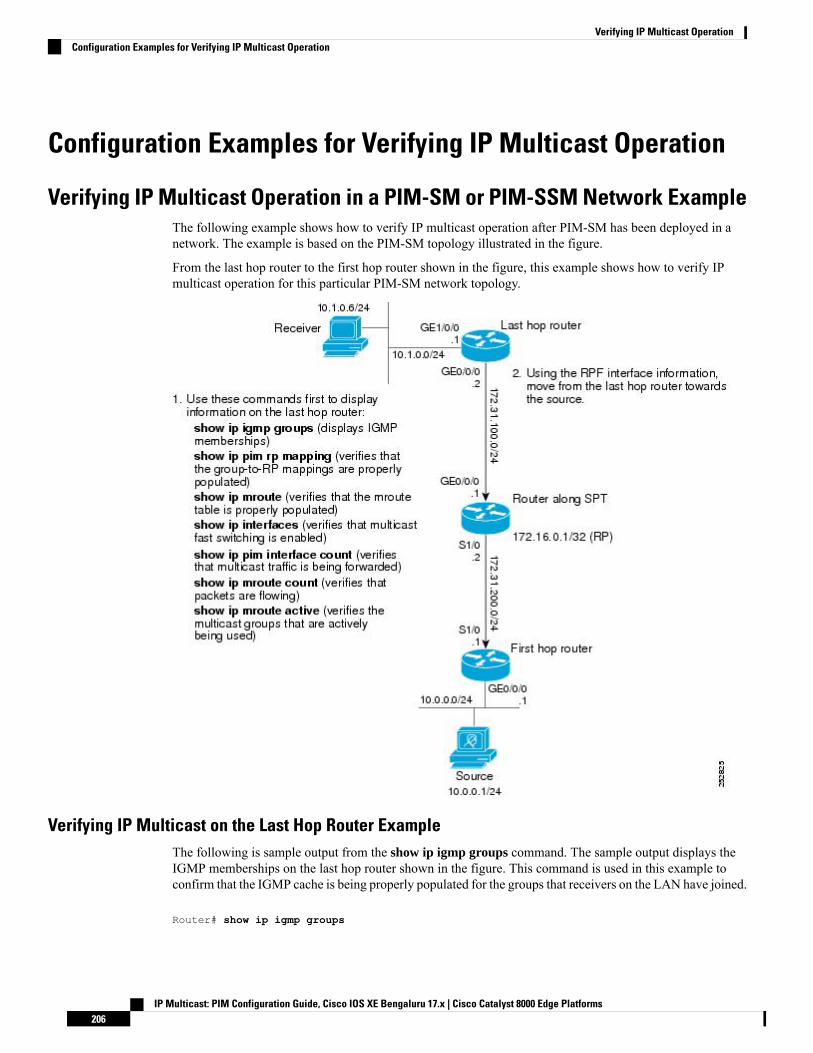
Configuration Examples for Verifying IP Multicast Operation
Verifying IP Multicast Operation in a PIM-SM or PIM-SSM Network ExampleThe following example shows how to verify IP multicast operation after PIM-SM has been deployed in anetwork. The example is based on the PIM-SM topology illustrated in the figure.
From the last hop router to the first hop router shown in the figure, this example shows how to verify IPmulticast operation for this particular PIM-SM network topology.
Verifying IP Multicast on the Last Hop Router ExampleThe following is sample output from the show ip igmp groups command. The sample output displays theIGMP memberships on the last hop router shown in the figure. This command is used in this example toconfirm that the IGMP cache is being properly populated for the groups that receivers on the LAN have joined.
Router# show ip igmp groups
IP Multicast: PIM Configuration Guide, Cisco IOS XE Bengaluru 17.x | Cisco Catalyst 8000 Edge Platforms206
Verifying IP Multicast OperationConfiguration Examples for Verifying IP Multicast Operation

IGMP Connected Group MembershipGroup Address Interface Uptime Expires Last Reporter239.1.2.3 GigabitEthernet1/0/0 00:05:14 00:02:14 10.1.0.6224.0.1.39 GigabitEthernet0/0/0 00:09:11 00:02:08 172.31.100.1
The following is sample output from the show ip pim rp mappingcommand. In the sample output, noticethe RP address displayed for the RP field. Use the RP address and group information to verify that thegroup-to-RP mappings have been properly populated on the last hop router shown in the figure.
In the output, the “(?)” indicates that the router is unable to resolve an IP address to a hostname.Note
Router# show ip pim rp mappingPIM Group-to-RP Mappings
Group(s) 224.0.0.0/4RP 172.16.0.1 (?), v2v1Info source: 172.16.0.1 (?), elected via Auto-RP
Uptime: 00:09:11, expires: 00:02:47
The following is sample output from the show ip mroute command. This command is used to verify that themroute table is being properly populated on the last hop router shown in the figure. In the sample output,notice the T flag for the (10.0.0.1, 239.1.2.3) mroute. The T flag indicates that the SPT-bit has been set, whichmeans a multicast packet was received on the SPT tree for this particular mroute. In addition, the RPF nbrfield should point toward the RPF neighbor with the highest IP address determined by unicast routing towardthe multicast source.
Router# show ip mroute(*, 239.1.2.3), 00:05:14/00:03:04, RP 172.16.0.1, flags: SJCIncoming interface: GigabitEthernet0/0/0, RPF nbr 172.31.100.1Outgoing interface list:Ethernet1/0, Forward/Sparse-Dense, 00:05:10/00:03:04
(10.0.0.1, 239.1.2.3), 00:02:49/00:03:29, flags: TIncoming interface: GigabitEthernet0/0/0, RPF nbr 172.31.100.1Outgoing interface list:Ethernet1/0, Forward/Sparse-Dense, 00:02:49/00:03:04
(*, 224.0.1.39), 00:10:05/stopped, RP 0.0.0.0, flags: DCIncoming interface: Null, RPF nbr 0.0.0.0Outgoing interface list:Ethernet1/0, Forward/Sparse-Dense, 00:05:15/00:00:00Ethernet0/0, Forward/Sparse-Dense, 00:10:05/00:00:00
The following is sample output from the show ip interface command for the incoming interface. This commandis used in this example to confirm that IP multicast fast switching is enabled on the last hop router shown inthe figure. When IP multicast fast switching is enabled, the line “IP multicast fast switching is enabled”displays in the output.
Router# show ip interface GigabitEthernet 0/0/0GigabitEthernet0/0/0 is up, line protocol is upInternet address is 172.31.100.2/24Broadcast address is 255.255.255.255Address determined by setup commandMTU is 1500 bytesHelper address is not setDirected broadcast forwarding is disabledMulticast reserved groups joined: 224.0.0.1 224.0.0.22 224.0.0.13
IP Multicast: PIM Configuration Guide, Cisco IOS XE Bengaluru 17.x | Cisco Catalyst 8000 Edge Platforms207
Verifying IP Multicast OperationVerifying IP Multicast on the Last Hop Router Example

224.0.0.5 224.0.0.6Outgoing access list is not setInbound access list is not setProxy ARP is enabledLocal Proxy ARP is disabledSecurity level is defaultSplit horizon is enabledICMP redirects are always sentICMP unreachables are always sentICMP mask replies are never sentIP fast switching is enabledIP fast switching on the same interface is disabledIP Flow switching is disabledIP CEF switching is disabledIP Fast switching turbo vectorIP multicast fast switching is enabledIP multicast distributed fast switching is disabledIP route-cache flags are FastRouter Discovery is disabledIP output packet accounting is disabledIP access violation accounting is disabledTCP/IP header compression is disabledRTP/IP header compression is disabledPolicy routing is disabledNetwork address translation is disabledWCCP Redirect outbound is disabledWCCP Redirect inbound is disabledWCCP Redirect exclude is disabledBGP Policy Mapping is disabled
The following is sample output from the show ip pim interface count command. This command is used inthis example to confirm that multicast traffic is being forwarded to the last hop router shown in the figure. Inthe sample output, notice the Mpackets In/Out field. This field displays the number of multicast packetsreceived by and sent on each interface listed in the output.
Router# show ip pim interface count
State: * - Fast Switched, D - Distributed Fast SwitchedH - Hardware Switching Enabled
Address Interface FS Mpackets In/Out172.31.100.2 GigabitEthernet0/0/0 * 4122/010.1.0.1 GigabitEthernet1/0/0 * 0/3193
The following is sample output from the show ip mroutecommand with the count keyword. This commandis used on the last hop router shown in the figure to verify the packets being sent to groups from active sources.In the sample output, notice the packet count displayed for the Forwarding field. This field displays the packetforwarding count for sources sending to groups.
Router# show ip mroute countIP Multicast Statistics6 routes using 4008 bytes of memory3 groups, 1.00 average sources per groupForwarding Counts: Pkt Count/Pkts per second/Avg Pkt Size/Kilobits per secondOther counts: Total/RPF failed/Other drops(OIF-null, rate-limit etc)
Group: 239.1.2.3, Source count: 1, Packets forwarded: 3165, Packets received: 3165RP-tree: Forwarding: 0/0/0/0, Other: 0/0/0Source: 10.0.0.1/32, Forwarding: 3165/20/28/4, Other: 0/0/0
Group: 224.0.1.39, Source count: 1, Packets forwarded: 21, Packets received: 120Source: 172.16.0.1/32, Forwarding: 21/1/48/0, Other: 120/0/99
IP Multicast: PIM Configuration Guide, Cisco IOS XE Bengaluru 17.x | Cisco Catalyst 8000 Edge Platforms208
Verifying IP Multicast OperationVerifying IP Multicast on the Last Hop Router Example

Group: 224.0.1.40, Source count: 1, Packets forwarded: 10, Packets received: 10Source: 172.16.0.1/32, Forwarding: 10/1/48/0, Other: 10/0/0
The following is sample output from the show ip mroutecommand with the active keyword. This commandis used on the last hop router shown in the figure to confirm the multicast groups with active sources on thelast hop router.
In the output, the “(?)” indicates that the router is unable to resolve an IP address to a hostname.Note
Router# show ip mroute activeActive IP Multicast Sources - sending >= 4 kbps
Group: 239.1.2.3, (?)Source: 10.0.0.1 (?)Rate: 20 pps/4 kbps(1sec), 4 kbps(last 50 secs), 4 kbps(life avg)
Verifying IP Multicast on Routers Along the SPT ExampleThe following is sample output from the show ip mroutefor a particular group. This command is used in thisexample to verify that the RPF neighbor toward the source is the expected RPF neighbor for the router alongthe SPT shown in the figure.
Router# show ip mroute 239.1.2.3(*, 239.1.2.3), 00:17:56/00:03:02, RP 172.16.0.1, flags: SIncoming interface: Null, RPF nbr 0.0.0.0Outgoing interface list:Ethernet0/0, Forward/Sparse-Dense, 00:17:56/00:03:02
(10.0.0.1, 239.1.2.3), 00:15:34/00:03:28, flags: TIncoming interface: Serial1/0, RPF nbr 172.31.200.1Outgoing interface list:
Ethernet0/0, Forward/Sparse-Dense, 00:15:34/00:03:02
The following is sample output from the show ip mroute command with the active keyword from the routeralong the SPT shown in the figure. This command is used to confirm the multicast groups with active sourceson this router.
In the output, the “(?)” indicates that the router is unable to resolve an IP address to a hostname.Note
Router# show ip mroute activeActive IP Multicast Sources - sending >= 4 kbps
Group: 239.1.2.3, (?)Source: 10.0.0.1 (?)Rate: 20 pps/4 kbps(1sec), 4 kbps(last 30 secs), 4 kbps(life avg)
Verifying IP Multicast on the First Hop Router ExampleThe following is sample output from the show ip mroutefor a particular group. This command is used in thisexample to verify the packets being sent to groups from active sources on the first hop router shown in the
IP Multicast: PIM Configuration Guide, Cisco IOS XE Bengaluru 17.x | Cisco Catalyst 8000 Edge Platforms209
Verifying IP Multicast OperationVerifying IP Multicast on Routers Along the SPT Example

figure. In the sample output, notice the packet count displayed for the Forwarding field. This field displaysthe packet forwarding count for sources sending to groups on the first hop router.
The RPF nbr 0.0.0.0 field indicates that the source of an mroute has been reached.Note
Router# show ip mroute 239.1.2.3(*, 239.1.2.3), 00:18:10/stopped, RP 172.16.0.1, flags: SPFIncoming interface: Serial1/0, RPF nbr 172.31.200.2Outgoing interface list: Null
(10.0.0.1, 239.1.2.3), 00:18:10/00:03:22, flags: FTIncoming interface: GigabitEthernet0/0/0, RPF nbr 0.0.0.0Outgoing interface list:Serial1/0/0, Forward/Sparse-Dense, 00:18:10/00:03:19
The following is sample output from the show ip mroute command with the active keyword from the firsthop router shown in the figure:
In the output, the “(?)” indicates that the router is unable to resolve an IP address to a host name.Note
Router# show ip mroute activeActive IP Multicast Sources - sending >= 4 kbps
Group: 239.1.2.3, (?)Source: 10.0.0.1 (?)Rate: 20 pps/4 kbps(1sec), 4 kbps(last 30 secs), 4 kbps(life avg)
Additional ReferencesRelated Documents
Document TitleRelated Topic
“ IP Multicast Technology Overview ” moduleOverview of the IP multicast technology area
“ Configuring Basic IP Multicast ” modulePIM-SM and SSM concepts and configuration examples
Cisco IOS IP Multicast Command ReferenceIP multicast commands: complete command syntax,command mode, command history, defaults, usageguidelines, and examples
Standards
TitleStandard
--No new or modified standards are supported, and support for existing standards has not been modified.
IP Multicast: PIM Configuration Guide, Cisco IOS XE Bengaluru 17.x | Cisco Catalyst 8000 Edge Platforms210
Verifying IP Multicast OperationAdditional References
MIBs
MIBs LinkMIB
To locate and download MIBs for selected platforms, CiscoIOS releases, and feature sets, use Cisco MIB Locator foundat the following URL:
http://www.cisco.com/go/mibs
No new ormodifiedMIBs are supported, andsupport for existing MIBs has not beenmodified.
RFCs
TitleRFC
--No new or modified RFCs are supported, and support for existing RFCs has not been modified.
Technical Assistance
LinkDescription
http://www.cisco.com/techsupportThe Cisco Support website provides extensive online resources, includingdocumentation and tools for troubleshooting and resolving technical issueswith Cisco products and technologies.
To receive security and technical information about your products, youcan subscribe to various services, such as the Product Alert Tool (accessedfrom Field Notices), the Cisco Technical Services Newsletter, and ReallySimple Syndication (RSS) Feeds.
Access to most tools on the Cisco Support website requires a Cisco.comuser ID and password.
Feature Information for Verifying IP Multicast OperationThe following table provides release information about the feature or features described in this module. Thistable lists only the software release that introduced support for a given feature in a given software releasetrain. Unless noted otherwise, subsequent releases of that software release train also support that feature.
Use Cisco Feature Navigator to find information about platform support and Cisco software image support.To access Cisco Feature Navigator, go to www.cisco.com/go/cfn. An account on Cisco.com is not required.
IP Multicast: PIM Configuration Guide, Cisco IOS XE Bengaluru 17.x | Cisco Catalyst 8000 Edge Platforms211
Verifying IP Multicast OperationFeature Information for Verifying IP Multicast Operation

IP Multicast: PIM Configuration Guide, Cisco IOS XE Bengaluru 17.x | Cisco Catalyst 8000 Edge Platforms212
Verifying IP Multicast OperationFeature Information for Verifying IP Multicast Operation
C H A P T E R 14Monitoring and Maintaining IP Multicast
This module describes many ways to monitor and maintain an IP multicast network, such as
• displaying which neighboring multicast routers are peering with the local router
• displaying multicast packet rates and loss information
• tracing the path from a source to a destination branch for a multicast distribution tree
• displaying the contents of the IP multicast routing table, information about interfaces configured forPIM, the PIM neighbors discovered by the router, and contents of the IP fast-switching cache
• clearing caches, tables, and databases
• monitoring the delivery of IP multicast packets and being alerted if the delivery fails to meet certainparameters (IP multicast heartbeat)
• using session description and announcement protocols and applications to assist the advertisement ofmulticast multimedia conferences and other multicast sessions and communicating the relevant sessionsetup information to prospective participants (SAP listener support)
• storing IP multicast packet headers in a cache and displaying them to find out information such as whois sending IP multicast packets to what groups and any multicast forwarding loops in your network
• using managed objects to remotely monitor and configure PIM using Simple Network ManagementProtocol (SNMP)
• disabling fast switching of IP multicast in order to log debug messages
• Prerequisites for Monitoring and Maintaining IP Multicast, on page 213• Information About Monitoring and Maintaining IP Multicast, on page 214• How to Monitor and Maintain IP Multicast, on page 216• Configuration Examples for Monitoring and Maintaining IP Multicast, on page 224• Additional References, on page 228• Feature Information for Monitoring and Maintaining IP Multicast, on page 228
Prerequisites for Monitoring and Maintaining IP Multicast• Before performing the tasks in this module, you should be familiar with the concepts described in the“IP Multicast Technology Overview” module.
IP Multicast: PIM Configuration Guide, Cisco IOS XE Bengaluru 17.x | Cisco Catalyst 8000 Edge Platforms213
• You must also have enabled IP multicast and have Protocol Independent Multicast (PIM) configuredand running on your network. Refer to the “Configuring Basic IP Multicast” module.
Information About Monitoring and Maintaining IP Multicast
IP Multicast HeartbeatThe IPMulticast Heartbeat feature enables you to monitor the delivery of IP multicast packets and to be alertedif the delivery fails to meet certain parameters.
Although you could alternatively use MRM to monitor IP multicast, you can perform the following tasks withIP multicast heartbeat that you cannot perform with MRM:
• Generate an SNMP trap
• Monitor a production multicast stream
When IP multicast heartbeat is enabled, the router monitors IP multicast packets destined for a particularmulticast group at a particular interval. If the number of packets observed is less than a configured minimumamount, the router sends an SNMP trap to a specified network management station to indicate a loss ofheartbeat exception.
The ip multicast heartbeat command does not create a heartbeat if there is no existing multicast forwardingstate for group in the router. This command will not create a multicast forwarding state in the router. Use theip igmp static-groupcommandon the router or on a downstream router to force forwarding of IP multicasttraffic. Use the snmp-server host ipmulticast command to enable the sending of IP multicast traps to specificreceiver hosts. Use the debug ip mhbeatcommand to debug the Multicast Heartbeat feature.
Session Announcement Protocol (SAP)Session Announcement Protocol (SAP) listener support is needed to use session description and announcementprotocols and applications to assist the advertisement of multicast multimedia conferences and other multicastsessions and to communicate the relevant session setup information to prospective participants.
Sessions are described by the Session Description Protocol (SDP), which is defined in RFC 2327. SDP providesa formatted, textual description of session properties (for example, contact information, session lifetime, andthe media) being used in the session (for example, audio, video, and whiteboard) with their specific attributessuch as time-to-live (TTL) scope, group address, and User Datagram Protocol (UDP) port number.
Many multimedia applications rely on SDP for session descriptions. However, they may use different methodsto disseminate these session descriptions. For example, IP/TV relies on the web to disseminate sessiondescriptions to participants. In this example, participants must know of a web server that provides the sessioninformation.
MBONE applications (for example, vic, vat, and wb) and other applications rely on multicast sessioninformation sent throughout the network. In these cases, SAP is used to transport the SDP sessionannouncements. SAP Version 2 uses the well-known session directory multicast group 224.2.127.254 todisseminate SDP session descriptions for global scope sessions and group 239.255.255.255 for administrativescope sessions.
IP Multicast: PIM Configuration Guide, Cisco IOS XE Bengaluru 17.x | Cisco Catalyst 8000 Edge Platforms214
Monitoring and Maintaining IP MulticastInformation About Monitoring and Maintaining IP Multicast
The Session Directory (SDR) application is commonly used to send and receive SDP/SAP sessionannouncements.
Note
PIM MIB Extensions for SNMP Traps for IP MulticastProtocol Independent Multicast (PIM) is an IP multicast routing protocol used for routing multicast datapackets to multicast groups. RFC 2934 defines the PIM MIB for IPv4, which describes managed objects thatenable users to remotely monitor and configure PIM using Simple Network Management Protocol (SNMP).
PIM MIB extensions introduce the following new classes of PIM notifications:
• neighbor-change--This notification results from the following conditions:
• A dDevice’s PIM interface is disabled or enabled (using the ip pim command in interfaceconfiguration mode)
• A dDevice's PIM neighbor adjacency expires (defined in RFC 2934)
• rp-mapping-change--This notification results from a change in the rendezvous point (RP) mappinginformation due to either Auto-RP messages or bootstrap router (BSR) messages.
• invalid-pim-message--This notification results from the following conditions:
• An invalid (*, G) Join or Prune message is received by the device (for example, when a dDevicereceives a Join or Prune message for which the RP specified in the packet is not the RP for themulticast group)
• An invalid PIM register message is received by the device (for example, when a dDevice receivesa register message from a multicast group for which it is not the RP)
Benefits of PIM MIB ExtensionsPIM MIB extensions:
• Allow users to identify changes in the multicast topology of their network by detecting changes in theRP mapping.
• Provide traps to monitor the PIM protocol on PIM-enabled interfaces.
• Help users identify routing issues when multicast neighbor adjacencies expire on a multicast interface.
• Enable users to monitor RP configuration errors (for example, errors due to flapping in dynamic RPallocation protocols like Auto-RP).
IP Multicast: PIM Configuration Guide, Cisco IOS XE Bengaluru 17.x | Cisco Catalyst 8000 Edge Platforms215
Monitoring and Maintaining IP MulticastPIM MIB Extensions for SNMP Traps for IP Multicast
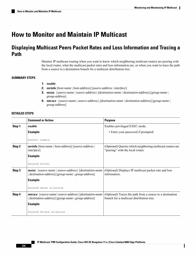
How to Monitor and Maintain IP Multicast
Displaying Multicast Peers Packet Rates and Loss Information and Tracing aPath
Monitor IP multicast routing when you want to know which neighboring multicast routers are peering withthe local router, what the multicast packet rates and loss information are, or when you want to trace the pathfrom a source to a destination branch for a multicast distribution tree.
SUMMARY STEPS
1. enable2. mrinfo [host-name | host-address] [source-address | interface]3. mstat {source-name | source-address} [destination-name | destination-address] [group-name |
group-address]4. mtrace {source-name | source-address} [destination-name | destination-address] [group-name |
group-address]
DETAILED STEPS
PurposeCommand or Action
Enables privileged EXEC mode.enableStep 1
Example: • Enter your password if prompted.
Router> enable
(Optional) Queries which neighboring multicast routers are“peering” with the local router.
mrinfo [host-name | host-address] [source-address |interface]
Example:
Step 2
Router# mrinfo
(Optional) Displays IP multicast packet rate and lossinformation.
mstat {source-name | source-address} [destination-name| destination-address] [group-name | group-address]
Example:
Step 3
Router# mstat allsource
(Optional) Traces the path from a source to a destinationbranch for a multicast distribution tree.
mtrace {source-name | source-address} [destination-name| destination-address] [group-name | group-address]
Example:
Step 4
Router# mtrace allsource
IP Multicast: PIM Configuration Guide, Cisco IOS XE Bengaluru 17.x | Cisco Catalyst 8000 Edge Platforms216
Monitoring and Maintaining IP MulticastHow to Monitor and Maintain IP Multicast
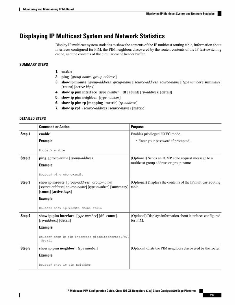
Displaying IP Multicast System and Network StatisticsDisplay IP multicast system statistics to show the contents of the IP multicast routing table, information aboutinterfaces configured for PIM, the PIM neighbors discovered by the router, contents of the IP fast-switchingcache, and the contents of the circular cache header buffer.
SUMMARY STEPS
1. enable2. ping [group-name | group-address]3. show ip mroute [group-address | group-name] [source-address | source-name] [type number] [summary]
[count] [active kbps]4. show ip pim interface [type number] [df | count] [rp-address] [detail]5. show ip pim neighbor [type number]6. show ip pim rp [mapping | metric] [rp-address]7. show ip rpf {source-address | source-name} [metric]
DETAILED STEPS
PurposeCommand or Action
Enables privileged EXEC mode.enableStep 1
Example: • Enter your password if prompted.
Router> enable
(Optional) Sends an ICMP echo request message to amulticast group address or group name.
ping [group-name | group-address]
Example:
Step 2
Router# ping cbone-audio
(Optional) Displays the contents of the IP multicast routingtable.
show ip mroute [group-address | group-name][source-address | source-name] [type number] [summary][count] [active kbps]
Step 3
Example:
Router# show ip mroute cbone-audio
(Optional) Displays information about interfaces configuredfor PIM.
show ip pim interface [type number] [df | count][rp-address] [detail]
Example:
Step 4
Router# show ip pim interface gigabitethernet1/0/0detail
(Optional) Lists the PIM neighbors discovered by the router.show ip pim neighbor [type number]
Example:
Step 5
Router# show ip pim neighbor
IP Multicast: PIM Configuration Guide, Cisco IOS XE Bengaluru 17.x | Cisco Catalyst 8000 Edge Platforms217
Monitoring and Maintaining IP MulticastDisplaying IP Multicast System and Network Statistics
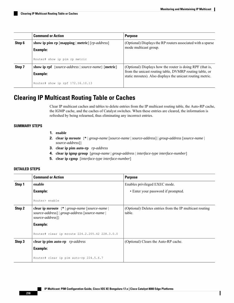
PurposeCommand or Action
(Optional) Displays the RP routers associated with a sparsemode multicast group.
show ip pim rp [mapping | metric] [rp-address]
Example:
Step 6
Router# show ip pim rp metric
(Optional) Displays how the router is doing RPF (that is,from the unicast routing table, DVMRP routing table, orstatic mroutes). Also displays the unicast routing metric.
show ip rpf {source-address | source-name} [metric]
Example:
Router# show ip rpf 172.16.10.13
Step 7
Clearing IP Multicast Routing Table or CachesClear IP multicast caches and tables to delete entries from the IP multicast routing table, the Auto-RP cache,the IGMP cache, and the caches of Catalyst switches. When these entries are cleared, the information isrefreshed by being relearned, thus eliminating any incorrect entries.
SUMMARY STEPS
1. enable2. clear ip mroute {* | group-name [source-name | source-address] | group-address [source-name |
source-address]}3. clear ip pim auto-rp rp-address
4. clear ip igmp group [group-name | group-address | interface-type interface-number]5. clear ip cgmp [interface-type interface-number]
DETAILED STEPS
PurposeCommand or Action
Enables privileged EXEC mode.enableStep 1
Example: • Enter your password if prompted.
Router> enable
(Optional) Deletes entries from the IP multicast routingtable.
clear ip mroute {* | group-name [source-name |source-address] | group-address [source-name |source-address]}
Step 2
Example:
Router# clear ip mroute 224.2.205.42 228.3.0.0
(Optional) Clears the Auto-RP cache.clear ip pim auto-rp rp-address
Example:
Step 3
Router# clear ip pim auto-rp 224.5.6.7
IP Multicast: PIM Configuration Guide, Cisco IOS XE Bengaluru 17.x | Cisco Catalyst 8000 Edge Platforms218
Monitoring and Maintaining IP MulticastClearing IP Multicast Routing Table or Caches

PurposeCommand or Action
(Optional) Deletes entries from the IGMP cache.clear ip igmp group [group-name | group-address |interface-type interface-number]
Step 4
Example:
Router# clear ip igmp group 224.0.255.1
(Optional) Clears all group entries from the caches ofCatalyst switches.
clear ip cgmp [interface-type interface-number]
Example:
Step 5
Router# clear ip cgmp
Monitoring IP Multicast Delivery Using IP Multicast Heartbeat
SUMMARY STEPS
1. enable2. configure terminal3. ip multicast-routing distributed4. snmp-server host {hostname | ip-address} [traps | informs] [version {1 | 2c | 3 [auth | noauth | priv]}]
community-string[udp-port port] [notification-type]5. snmp-server enable traps ipmulticast6. ip multicast heartbeat group-address minimum-number window-size interval
DETAILED STEPS
PurposeCommand or Action
Enables privileged EXEC mode.enableStep 1
Example: • Enter your password if prompted.
Router> enable
Enters global configuration mode.configure terminal
Example:
Step 2
Router# configure terminal
Enables IP multicast routing.ip multicast-routing distributed
Example:
Step 3
Router(config)# ip multicast-routing distributed
Specifies the recipient of an SNMP notification operation.snmp-server host {hostname | ip-address} [traps |informs] [version {1 | 2c | 3 [auth | noauth | priv]}]community-string[udp-port port] [notification-type]
Step 4
Example:
IP Multicast: PIM Configuration Guide, Cisco IOS XE Bengaluru 17.x | Cisco Catalyst 8000 Edge Platforms219
Monitoring and Maintaining IP MulticastMonitoring IP Multicast Delivery Using IP Multicast Heartbeat

PurposeCommand or Action
Router(config)# snmp-server host 224.1.0.1 trapspublic
Enables the router to send IP multicast traps.snmp-server enable traps ipmulticast
Example:
Step 5
Router(config)# snmp-server enable trapsipmulticast
Enables the monitoring of the IP multicast packet delivery.ip multicast heartbeat group-address minimum-numberwindow-size interval
Step 6
• The interval should be set to a multiple of 10 secondson platforms that use Multicast Distributed FastExample:Switching (MDFS) because on those platforms, the
Router(config)# ip multicast heartbeat 224.1.1.11 1 10
packet counters are only updated once every 10seconds. Other platforms may have other increments.
Advertising Multicast Multimedia Sessions Using SAP ListenerEnable SAP listener support when you want to use session description and announcement protocols andapplications to assist the advertisement of multicast multimedia conferences and other multicast sessions andto communicate the relevant session setup information to prospective participants.
SUMMARY STEPS
1. enable2. configure terminal3. ip sap cache-timeout minutes
4. interface type number
5. ip sap listen6. end7. clear ip sap [group-address | “ session-name ”]8. show ip sap [group-address | “ session-name ”| detail]
DETAILED STEPS
PurposeCommand or Action
Enables privileged EXEC mode.enableStep 1
Example: • Enter your password if prompted.
Router> enable
Enters global configuration mode.configure terminal
Example:
Step 2
Router# configure terminal
IP Multicast: PIM Configuration Guide, Cisco IOS XE Bengaluru 17.x | Cisco Catalyst 8000 Edge Platforms220
Monitoring and Maintaining IP MulticastAdvertising Multicast Multimedia Sessions Using SAP Listener
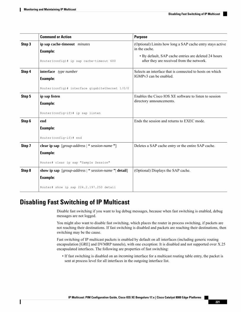
PurposeCommand or Action
(Optional) Limits how long a SAP cache entry stays activein the cache.
ip sap cache-timeout minutes
Example:
Step 3
• By default, SAP cache entries are deleted 24 hoursafter they are received from the network.Router(config)# ip sap cache-timeout 600
Selects an interface that is connected to hosts on whichIGMPv3 can be enabled.
interface type number
Example:
Step 4
Router(config)# interface gigabitethernet 1/0/0
Enables the Cisco IOS XE software to listen to sessiondirectory announcements.
ip sap listen
Example:
Step 5
Router(config-if)# ip sap listen
Ends the session and returns to EXEC mode.end
Example:
Step 6
Router(config-if)# end
Deletes a SAP cache entry or the entire SAP cache.clear ip sap [group-address | “ session-name ”]
Example:
Step 7
Router# clear ip sap "Sample Session"
(Optional) Displays the SAP cache.show ip sap [group-address | “ session-name ”| detail]
Example:
Step 8
Router# show ip sap 224.2.197.250 detail
Disabling Fast Switching of IP MulticastDisable fast switching if you want to log debug messages, because when fast switching is enabled, debugmessages are not logged.
You might also want to disable fast switching, which places the router in process switching, if packets arenot reaching their destinations. If fast switching is disabled and packets are reaching their destinations, thenswitching may be the cause.
Fast switching of IP multicast packets is enabled by default on all interfaces (including generic routingencapsulation [GRE] and DVMRP tunnels), with one exception: It is disabled and not supported over X.25encapsulated interfaces. The following are properties of fast switching:
• If fast switching is disabled on an incoming interface for a multicast routing table entry, the packet issent at process level for all interfaces in the outgoing interface list.
IP Multicast: PIM Configuration Guide, Cisco IOS XE Bengaluru 17.x | Cisco Catalyst 8000 Edge Platforms221
Monitoring and Maintaining IP MulticastDisabling Fast Switching of IP Multicast
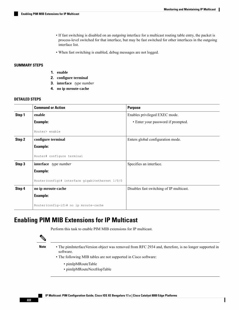
• If fast switching is disabled on an outgoing interface for a multicast routing table entry, the packet isprocess-level switched for that interface, but may be fast switched for other interfaces in the outgoinginterface list.
• When fast switching is enabled, debug messages are not logged.
SUMMARY STEPS
1. enable2. configure terminal3. interface type number
4. no ip mroute-cache
DETAILED STEPS
PurposeCommand or Action
Enables privileged EXEC mode.enableStep 1
Example: • Enter your password if prompted.
Router> enable
Enters global configuration mode.configure terminal
Example:
Step 2
Router# configure terminal
Specifies an interface.interface type number
Example:
Step 3
Router(config)# interface gigabitethernet 1/0/0
Disables fast switching of IP multicast.no ip mroute-cache
Example:
Step 4
Router(config-if)# no ip mroute-cache
Enabling PIM MIB Extensions for IP MulticastPerform this task to enable PIM MIB extensions for IP multicast.
• The pimInterfaceVersion object was removed from RFC 2934 and, therefore, is no longer supported insoftware.
• The following MIB tables are not supported in Cisco software:
• pimIpMRouteTable• pimIpMRouteNextHopTable
Note
IP Multicast: PIM Configuration Guide, Cisco IOS XE Bengaluru 17.x | Cisco Catalyst 8000 Edge Platforms222
Monitoring and Maintaining IP MulticastEnabling PIM MIB Extensions for IP Multicast
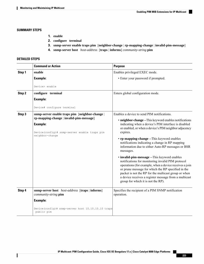
SUMMARY STEPS
1. enable2. configure terminal3. snmp-server enable traps pim [neighbor-change | rp-mapping-change | invalid-pim-message]4. snmp-server host host-address [traps | informs] community-string pim
DETAILED STEPS
PurposeCommand or Action
Enables privileged EXEC mode.enableStep 1
Example: • Enter your password if prompted.
Device> enable
Enters global configuration mode.configure terminal
Example:
Step 2
Device# configure terminal
Enables a device to send PIM notifications.snmp-server enable traps pim [neighbor-change |rp-mapping-change | invalid-pim-message]
Step 3
• neighbor-change --This keyword enables notificationsindicating when a device’s PIM interface is disabledExample:or enabled, or when a device’s PIM neighbor adjacencyexpires.Device(config)# snmp-server enable traps pim
neighbor-change• rp-mapping-change --This keyword enablesnotifications indicating a change in RP mappinginformation due to either Auto-RP messages or BSRmessages.
• invalid-pim-message --This keyword enablesnotifications for monitoring invalid PIM protocoloperations (for example, when a device receives a joinor prune message for which the RP specified in thepacket is not the RP for the multicast group or whena device receives a register message from a multicastgroup for which it is not the RP).
Specifies the recipient of a PIM SNMP notificationoperation.
snmp-server host host-address [traps | informs]community-string pim
Example:
Step 4
Device(config)# snmp-server host 10.10.10.10 trapspublic pim
IP Multicast: PIM Configuration Guide, Cisco IOS XE Bengaluru 17.x | Cisco Catalyst 8000 Edge Platforms223
Monitoring and Maintaining IP MulticastEnabling PIM MIB Extensions for IP Multicast
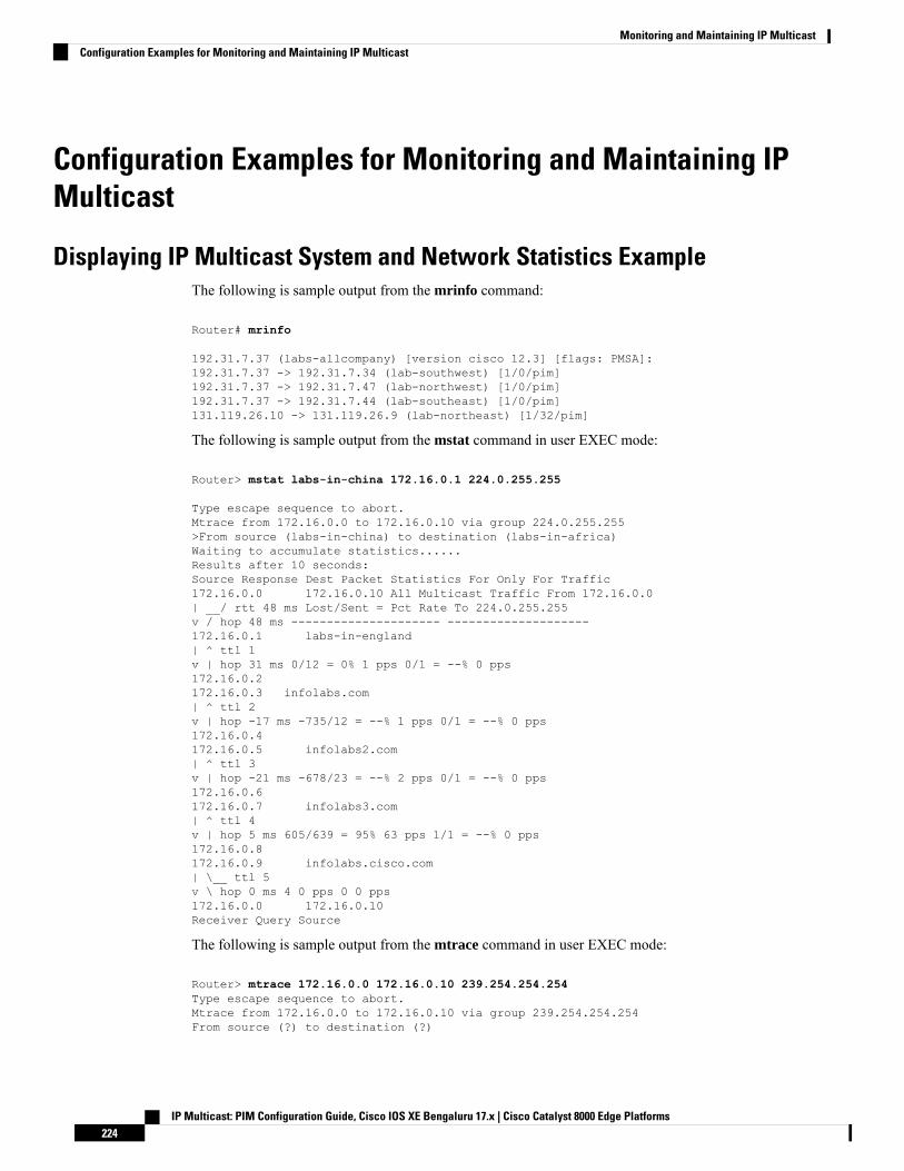
Configuration Examples for Monitoring and Maintaining IPMulticast
Displaying IP Multicast System and Network Statistics ExampleThe following is sample output from the mrinfo command:
Router# mrinfo
192.31.7.37 (labs-allcompany) [version cisco 12.3] [flags: PMSA]:192.31.7.37 -> 192.31.7.34 (lab-southwest) [1/0/pim]192.31.7.37 -> 192.31.7.47 (lab-northwest) [1/0/pim]192.31.7.37 -> 192.31.7.44 (lab-southeast) [1/0/pim]131.119.26.10 -> 131.119.26.9 (lab-northeast) [1/32/pim]
The following is sample output from the mstat command in user EXEC mode:
Router> mstat labs-in-china 172.16.0.1 224.0.255.255
Type escape sequence to abort.Mtrace from 172.16.0.0 to 172.16.0.10 via group 224.0.255.255>From source (labs-in-china) to destination (labs-in-africa)Waiting to accumulate statistics......Results after 10 seconds:Source Response Dest Packet Statistics For Only For Traffic172.16.0.0 172.16.0.10 All Multicast Traffic From 172.16.0.0| __/ rtt 48 ms Lost/Sent = Pct Rate To 224.0.255.255v / hop 48 ms --------------------- --------------------172.16.0.1 labs-in-england| ^ ttl 1v | hop 31 ms 0/12 = 0% 1 pps 0/1 = --% 0 pps172.16.0.2172.16.0.3 infolabs.com| ^ ttl 2v | hop -17 ms -735/12 = --% 1 pps 0/1 = --% 0 pps172.16.0.4172.16.0.5 infolabs2.com| ^ ttl 3v | hop -21 ms -678/23 = --% 2 pps 0/1 = --% 0 pps172.16.0.6172.16.0.7 infolabs3.com| ^ ttl 4v | hop 5 ms 605/639 = 95% 63 pps 1/1 = --% 0 pps172.16.0.8172.16.0.9 infolabs.cisco.com| \__ ttl 5v \ hop 0 ms 4 0 pps 0 0 pps172.16.0.0 172.16.0.10Receiver Query Source
The following is sample output from the mtrace command in user EXEC mode:
Router> mtrace 172.16.0.0 172.16.0.10 239.254.254.254Type escape sequence to abort.Mtrace from 172.16.0.0 to 172.16.0.10 via group 239.254.254.254From source (?) to destination (?)
IP Multicast: PIM Configuration Guide, Cisco IOS XE Bengaluru 17.x | Cisco Catalyst 8000 Edge Platforms224
Monitoring and Maintaining IP MulticastConfiguration Examples for Monitoring and Maintaining IP Multicast
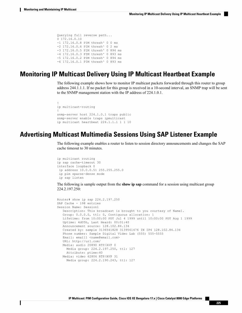
Querying full reverse path...0 172.16.0.10-1 172.16.0.8 PIM thresh^ 0 0 ms-2 172.16.0.6 PIM thresh^ 0 2 ms-3 172.16.0.5 PIM thresh^ 0 894 ms-4 172.16.0.3 PIM thresh^ 0 893 ms-5 172.16.0.2 PIM thresh^ 0 894 ms-6 172.16.0.1 PIM thresh^ 0 893 ms
Monitoring IP Multicast Delivery Using IP Multicast Heartbeat ExampleThe following example shows how to monitor IP multicast packets forwarded through this router to groupaddress 244.1.1.1. If no packet for this group is received in a 10-second interval, an SNMP trap will be sentto the SNMP management station with the IP address of 224.1.0.1.
!ip multicast-routing!snmp-server host 224.1.0.1 traps publicsnmp-server enable traps ipmulticastip multicast heartbeat 224.1.1.1 1 1 10
Advertising Multicast Multimedia Sessions Using SAP Listener ExampleThe following example enables a router to listen to session directory announcements and changes the SAPcache timeout to 30 minutes.
ip multicast routingip sap cache-timeout 30interface loopback 0ip address 10.0.0.51 255.255.255.0ip pim sparse-dense modeip sap listen
The following is sample output from the show ip sap command for a session using multicast group224.2.197.250:
Router# show ip sap 224.2.197.250SAP Cache - 198 entriesSession Name: Session1
Description: This broadcast is brought to you courtesy of Name1.Group: 0.0.0.0, ttl: 0, Contiguous allocation: 1Lifetime: from 10:00:00 PDT Jul 4 1999 until 10:00:00 PDT Aug 1 1999Uptime: 4d05h, Last Heard: 00:01:40Announcement source: 128.102.84.134Created by: sample 3136541828 3139561476 IN IP4 128.102.84.134Phone number: Sample Digital Video Lab (555) 555-5555Email: email1 <[email protected]>URL: http://url.com/Media: audio 20890 RTP/AVP 0Media group: 224.2.197.250, ttl: 127Attribute: ptime:40
Media: video 62806 RTP/AVP 31Media group: 224.2.190.243, ttl: 127
IP Multicast: PIM Configuration Guide, Cisco IOS XE Bengaluru 17.x | Cisco Catalyst 8000 Edge Platforms225
Monitoring and Maintaining IP MulticastMonitoring IP Multicast Delivery Using IP Multicast Heartbeat Example
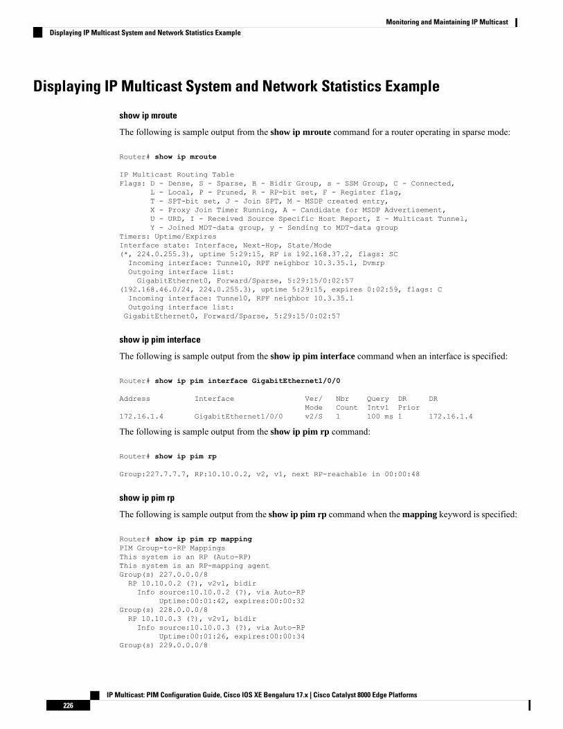
Displaying IP Multicast System and Network Statistics Example
show ip mroute
The following is sample output from the show ip mroute command for a router operating in sparse mode:
Router# show ip mroute
IP Multicast Routing TableFlags: D - Dense, S - Sparse, B - Bidir Group, s - SSM Group, C - Connected,
L - Local, P - Pruned, R - RP-bit set, F - Register flag,T - SPT-bit set, J - Join SPT, M - MSDP created entry,X - Proxy Join Timer Running, A - Candidate for MSDP Advertisement,U - URD, I - Received Source Specific Host Report, Z - Multicast Tunnel,Y - Joined MDT-data group, y - Sending to MDT-data group
Timers: Uptime/ExpiresInterface state: Interface, Next-Hop, State/Mode(*, 224.0.255.3), uptime 5:29:15, RP is 192.168.37.2, flags: SCIncoming interface: Tunnel0, RPF neighbor 10.3.35.1, DvmrpOutgoing interface list:GigabitEthernet0, Forward/Sparse, 5:29:15/0:02:57
(192.168.46.0/24, 224.0.255.3), uptime 5:29:15, expires 0:02:59, flags: CIncoming interface: Tunnel0, RPF neighbor 10.3.35.1Outgoing interface list:GigabitEthernet0, Forward/Sparse, 5:29:15/0:02:57
show ip pim interface
The following is sample output from the show ip pim interface command when an interface is specified:
Router# show ip pim interface GigabitEthernet1/0/0
Address Interface Ver/ Nbr Query DR DRMode Count Intvl Prior
172.16.1.4 GigabitEthernet1/0/0 v2/S 1 100 ms 1 172.16.1.4
The following is sample output from the show ip pim rp command:
Router# show ip pim rp
Group:227.7.7.7, RP:10.10.0.2, v2, v1, next RP-reachable in 00:00:48
show ip pim rp
The following is sample output from the show ip pim rp command when the mapping keyword is specified:
Router# show ip pim rp mappingPIM Group-to-RP MappingsThis system is an RP (Auto-RP)This system is an RP-mapping agentGroup(s) 227.0.0.0/8RP 10.10.0.2 (?), v2v1, bidirInfo source:10.10.0.2 (?), via Auto-RP
Uptime:00:01:42, expires:00:00:32Group(s) 228.0.0.0/8RP 10.10.0.3 (?), v2v1, bidirInfo source:10.10.0.3 (?), via Auto-RP
Uptime:00:01:26, expires:00:00:34Group(s) 229.0.0.0/8
IP Multicast: PIM Configuration Guide, Cisco IOS XE Bengaluru 17.x | Cisco Catalyst 8000 Edge Platforms226
Monitoring and Maintaining IP MulticastDisplaying IP Multicast System and Network Statistics Example
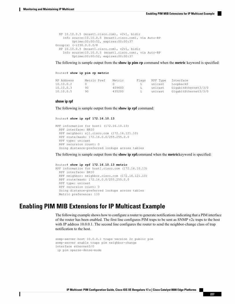
RP 10.10.0.5 (mcast1.cisco.com), v2v1, bidirInfo source:10.10.0.5 (mcast1.cisco.com), via Auto-RP
Uptime:00:00:52, expires:00:00:37Group(s) (-)230.0.0.0/8RP 10.10.0.5 (mcast1.cisco.com), v2v1, bidirInfo source:10.10.0.5 (mcast1.cisco.com), via Auto-RP
Uptime:00:00:52, expires:00:00:37
The following is sample output from the show ip pim rp command when the metric keyword is specified:
Router# show ip pim rp metric
RP Address Metric Pref Metric Flags RPF Type Interface10.10.0.2 0 0 L unicast Loopback010.10.0.3 90 409600 L unicast GigabitEthernet3/3/010.10.0.5 90 435200 L unicast GigabitEthernet3/3/0
show ip rpf
The following is sample output from the show ip rpf command:
Router# show ip rpf 172.16.10.13
RPF information for host1 (172.16.10.13)RPF interface: BRI0RPF neighbor: sj1.cisco.com (172.16.121.10)RPF route/mask: 172.16.0.0/255.255.0.0RPF type: unicastRPF recursion count: 0Doing distance-preferred lookups across tables
The following is sample output from the show ip rpfcommand when the metrickeyword is specified:
Router# show ip rpf 172.16.10.13 metricRPF information for host1.cisco.com (172.16.10.13)RPF interface: BRI0RPF neighbor: neighbor.cisco.com (172.16.121.10)RPF route/mask: 172.16.0.0/255.255.0.0RPF type: unicastRPF recursion count: 0Doing distance-preferred lookups across tablesMetric preference: 110
Enabling PIM MIB Extensions for IP Multicast ExampleThe following example shows how to configure a router to generate notifications indicating that a PIM interfaceof the router has been enabled. The first line configures PIM traps to be sent as SNMP v2c traps to the hostwith IP address 10.0.0.1. The second line configures the router to send the neighbor-change class of trapnotification to the host.
snmp-server host 10.0.0.1 traps version 2c public pimsnmp-server enable traps pim neighbor-changeinterface ethernet0/0ip pim sparse-dense-mode
IP Multicast: PIM Configuration Guide, Cisco IOS XE Bengaluru 17.x | Cisco Catalyst 8000 Edge Platforms227
Monitoring and Maintaining IP MulticastEnabling PIM MIB Extensions for IP Multicast Example
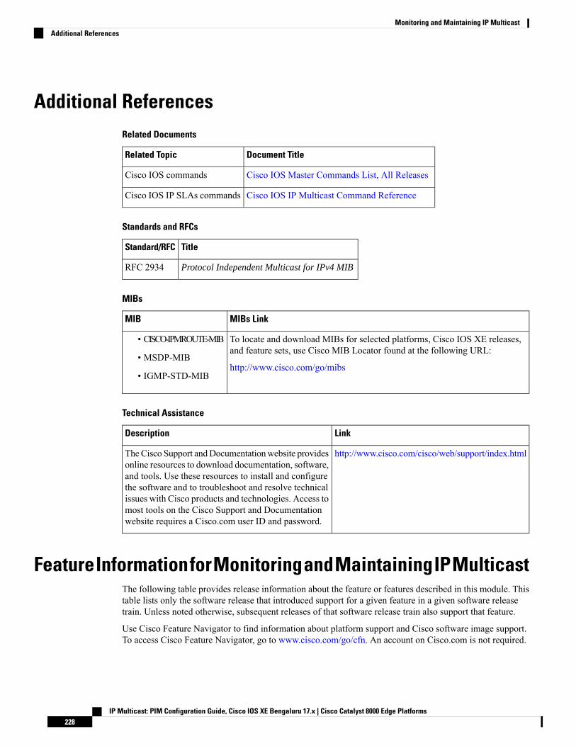
Additional ReferencesRelated Documents
Document TitleRelated Topic
Cisco IOS Master Commands List, All ReleasesCisco IOS commands
Cisco IOS IP Multicast Command ReferenceCisco IOS IP SLAs commands
Standards and RFCs
TitleStandard/RFC
Protocol Independent Multicast for IPv4 MIBRFC 2934
MIBs
MIBs LinkMIB
To locate and download MIBs for selected platforms, Cisco IOS XE releases,and feature sets, use Cisco MIB Locator found at the following URL:
http://www.cisco.com/go/mibs
• CISCO-IPMROUTE-MIB
• MSDP-MIB
• IGMP-STD-MIB
Technical Assistance
LinkDescription
http://www.cisco.com/cisco/web/support/index.htmlTheCisco Support andDocumentationwebsite providesonline resources to download documentation, software,and tools. Use these resources to install and configurethe software and to troubleshoot and resolve technicalissues with Cisco products and technologies. Access tomost tools on the Cisco Support and Documentationwebsite requires a Cisco.com user ID and password.
FeatureInformationforMonitoringandMaintainingIPMulticastThe following table provides release information about the feature or features described in this module. Thistable lists only the software release that introduced support for a given feature in a given software releasetrain. Unless noted otherwise, subsequent releases of that software release train also support that feature.
Use Cisco Feature Navigator to find information about platform support and Cisco software image support.To access Cisco Feature Navigator, go to www.cisco.com/go/cfn. An account on Cisco.com is not required.
IP Multicast: PIM Configuration Guide, Cisco IOS XE Bengaluru 17.x | Cisco Catalyst 8000 Edge Platforms228
Monitoring and Maintaining IP MulticastAdditional References
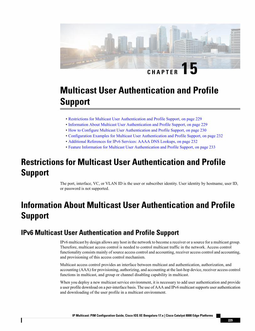
C H A P T E R 15Multicast User Authentication and ProfileSupport
• Restrictions for Multicast User Authentication and Profile Support, on page 229• Information About Multicast User Authentication and Profile Support, on page 229• How to Configure Multicast User Authentication and Profile Support, on page 230• Configuration Examples for Multicast User Authentication and Profile Support, on page 232• Additional References for IPv6 Services: AAAA DNS Lookups, on page 232• Feature Information for Multicast User Authentication and Profile Support, on page 233
Restrictions for Multicast User Authentication and ProfileSupport
The port, interface, VC, or VLAN ID is the user or subscriber identity. User identity by hostname, user ID,or password is not supported.
Information About Multicast User Authentication and ProfileSupport
IPv6 Multicast User Authentication and Profile SupportIPv6multicast by design allows any host in the network to become a receiver or a source for a multicast group.Therefore, multicast access control is needed to control multicast traffic in the network. Access controlfunctionality consists mainly of source access control and accounting, receiver access control and accounting,and provisioning of this access control mechanism.
Multicast access control provides an interface between multicast and authentication, authorization, andaccounting (AAA) for provisioning, authorizing, and accounting at the last-hop device, receiver access controlfunctions in multicast, and group or channel disabling capability in multicast.
When you deploy a new multicast service environment, it is necessary to add user authentication and providea user profile download on a per-interface basis. The use of AAA and IPv6multicast supports user authenticationand downloading of the user profile in a multicast environment.
IP Multicast: PIM Configuration Guide, Cisco IOS XE Bengaluru 17.x | Cisco Catalyst 8000 Edge Platforms229
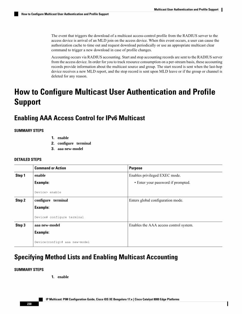
The event that triggers the download of a multicast access-control profile from the RADIUS server to theaccess device is arrival of an MLD join on the access device. When this event occurs, a user can cause theauthorization cache to time out and request download periodically or use an appropriate multicast clearcommand to trigger a new download in case of profile changes.
Accounting occurs via RADIUS accounting. Start and stop accounting records are sent to the RADIUS serverfrom the access device. In order for you to track resource consumption on a per-stream basis, these accountingrecords provide information about the multicast source and group. The start record is sent when the last-hopdevice receives a new MLD report, and the stop record is sent upon MLD leave or if the group or channel isdeleted for any reason.
How to Configure Multicast User Authentication and ProfileSupport
Enabling AAA Access Control for IPv6 Multicast
SUMMARY STEPS
1. enable2. configure terminal3. aaa new-model
DETAILED STEPS
PurposeCommand or Action
Enables privileged EXEC mode.enableStep 1
Example: • Enter your password if prompted.
Device> enable
Enters global configuration mode.configure terminal
Example:
Step 2
Device# configure terminal
Enables the AAA access control system.aaa new-model
Example:
Step 3
Device(config)# aaa new-model
Specifying Method Lists and Enabling Multicast Accounting
SUMMARY STEPS
1. enable
IP Multicast: PIM Configuration Guide, Cisco IOS XE Bengaluru 17.x | Cisco Catalyst 8000 Edge Platforms230
Multicast User Authentication and Profile SupportHow to Configure Multicast User Authentication and Profile Support
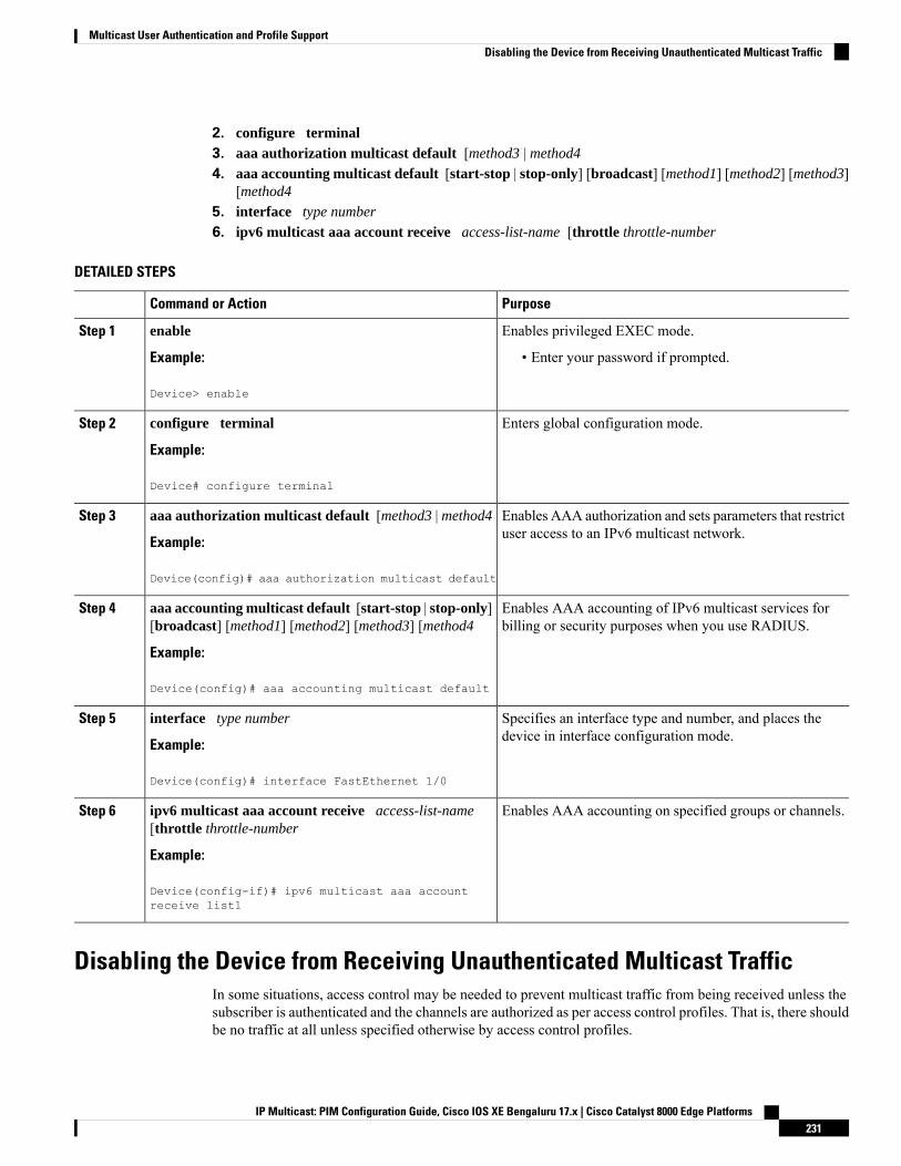
2. configure terminal3. aaa authorization multicast default [method3 | method4
4. aaa accounting multicast default [start-stop | stop-only] [broadcast] [method1] [method2] [method3][method4
5. interface type number
6. ipv6 multicast aaa account receive access-list-name [throttle throttle-number
DETAILED STEPS
PurposeCommand or Action
Enables privileged EXEC mode.enableStep 1
Example: • Enter your password if prompted.
Device> enable
Enters global configuration mode.configure terminal
Example:
Step 2
Device# configure terminal
Enables AAA authorization and sets parameters that restrictuser access to an IPv6 multicast network.
aaa authorization multicast default [method3 | method4
Example:
Step 3
Device(config)# aaa authorization multicast default
Enables AAA accounting of IPv6 multicast services forbilling or security purposes when you use RADIUS.
aaa accounting multicast default [start-stop | stop-only][broadcast] [method1] [method2] [method3] [method4
Example:
Step 4
Device(config)# aaa accounting multicast default
Specifies an interface type and number, and places thedevice in interface configuration mode.
interface type number
Example:
Step 5
Device(config)# interface FastEthernet 1/0
Enables AAA accounting on specified groups or channels.ipv6 multicast aaa account receive access-list-name[throttle throttle-number
Step 6
Example:
Device(config-if)# ipv6 multicast aaa accountreceive list1
Disabling the Device from Receiving Unauthenticated Multicast TrafficIn some situations, access control may be needed to prevent multicast traffic from being received unless thesubscriber is authenticated and the channels are authorized as per access control profiles. That is, there shouldbe no traffic at all unless specified otherwise by access control profiles.
IP Multicast: PIM Configuration Guide, Cisco IOS XE Bengaluru 17.x | Cisco Catalyst 8000 Edge Platforms231
Multicast User Authentication and Profile SupportDisabling the Device from Receiving Unauthenticated Multicast Traffic
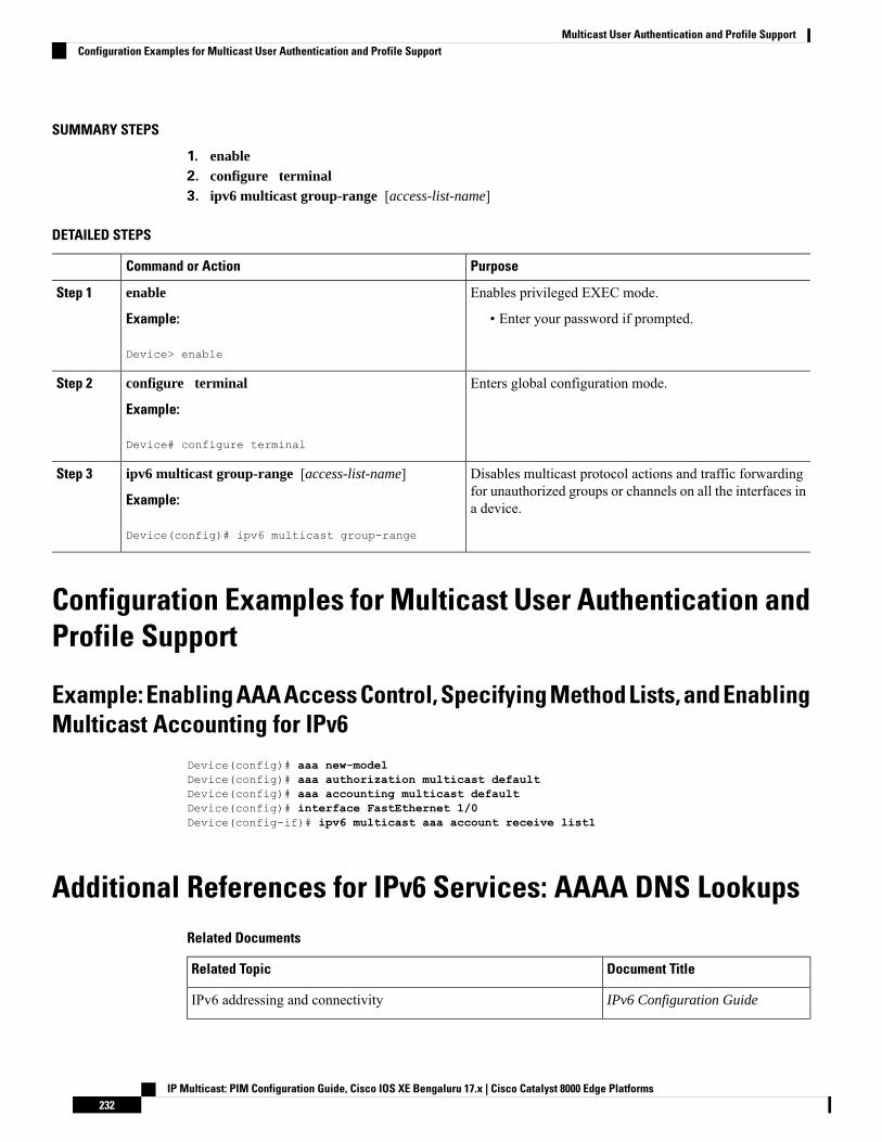
SUMMARY STEPS
1. enable2. configure terminal3. ipv6 multicast group-range [access-list-name]
DETAILED STEPS
PurposeCommand or Action
Enables privileged EXEC mode.enableStep 1
Example: • Enter your password if prompted.
Device> enable
Enters global configuration mode.configure terminal
Example:
Step 2
Device# configure terminal
Disables multicast protocol actions and traffic forwardingfor unauthorized groups or channels on all the interfaces ina device.
ipv6 multicast group-range [access-list-name]
Example:
Device(config)# ipv6 multicast group-range
Step 3
Configuration Examples for Multicast User Authentication andProfile Support
Example: Enabling AAA Access Control, Specifying Method Lists, and EnablingMulticast Accounting for IPv6
Device(config)# aaa new-modelDevice(config)# aaa authorization multicast defaultDevice(config)# aaa accounting multicast defaultDevice(config)# interface FastEthernet 1/0Device(config-if)# ipv6 multicast aaa account receive list1
Additional References for IPv6 Services: AAAA DNS LookupsRelated Documents
Document TitleRelated Topic
IPv6 Configuration GuideIPv6 addressing and connectivity
IP Multicast: PIM Configuration Guide, Cisco IOS XE Bengaluru 17.x | Cisco Catalyst 8000 Edge Platforms232
Multicast User Authentication and Profile SupportConfiguration Examples for Multicast User Authentication and Profile Support
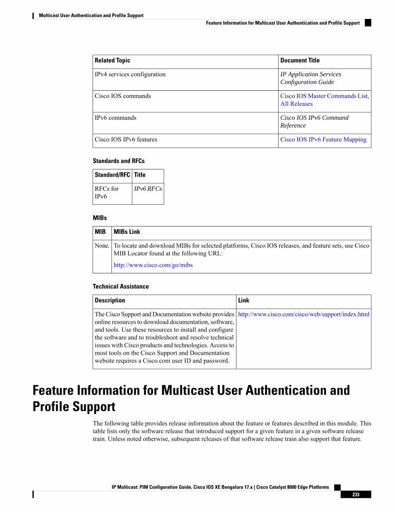
Document TitleRelated Topic
IP Application ServicesConfiguration Guide
IPv4 services configuration
Cisco IOSMaster Commands List,All Releases
Cisco IOS commands
Cisco IOS IPv6 CommandReference
IPv6 commands
Cisco IOS IPv6 Feature MappingCisco IOS IPv6 features
Standards and RFCs
TitleStandard/RFC
IPv6 RFCsRFCs forIPv6
MIBs
MIBs LinkMIB
To locate and download MIBs for selected platforms, Cisco IOS releases, and feature sets, use CiscoMIB Locator found at the following URL:
http://www.cisco.com/go/mibs
None.
Technical Assistance
LinkDescription
http://www.cisco.com/cisco/web/support/index.htmlTheCisco Support andDocumentationwebsite providesonline resources to download documentation, software,and tools. Use these resources to install and configurethe software and to troubleshoot and resolve technicalissues with Cisco products and technologies. Access tomost tools on the Cisco Support and Documentationwebsite requires a Cisco.com user ID and password.
Feature Information for Multicast User Authentication andProfile Support
The following table provides release information about the feature or features described in this module. Thistable lists only the software release that introduced support for a given feature in a given software releasetrain. Unless noted otherwise, subsequent releases of that software release train also support that feature.
IP Multicast: PIM Configuration Guide, Cisco IOS XE Bengaluru 17.x | Cisco Catalyst 8000 Edge Platforms233
Multicast User Authentication and Profile SupportFeature Information for Multicast User Authentication and Profile Support

Use Cisco Feature Navigator to find information about platform support and Cisco software image support.To access Cisco Feature Navigator, go to www.cisco.com/go/cfn. An account on Cisco.com is not required.
IP Multicast: PIM Configuration Guide, Cisco IOS XE Bengaluru 17.x | Cisco Catalyst 8000 Edge Platforms234
Multicast User Authentication and Profile SupportFeature Information for Multicast User Authentication and Profile Support
C H A P T E R 16IPv6 Multicast: Bootstrap Router
• Information About IPv6 Multicast: Bootstrap Router, on page 235• How to Configure IPv6 Multicast: Bootstrap Router, on page 237• Configuration Examples for IPv6 Multicast: Bootstrap Router, on page 241• Additional References, on page 241• Feature Information for IPv6 Multicast: Bootstrap Router, on page 242
Information About IPv6 Multicast: Bootstrap Router
IPv6 BSRPIM devices in a domain must be able to map each multicast group to the correct RP address. The BSRprotocol for PIM-SM provides a dynamic, adaptive mechanism to distribute group-to-RPmapping informationrapidly throughout a domain. With the IPv6 BSR feature, if an RP becomes unreachable, it will be detectedand the mapping tables will be modified so that the unreachable RP is no longer used, and the new tables willbe rapidly distributed throughout the domain.
Every PIM-SM multicast group needs to be associated with the IP or IPv6 address of an RP. When a newmulticast sender starts sending, its local DR will encapsulate these data packets in a PIM register messageand send them to the RP for that multicast group. When a new multicast receiver joins, its local DR will senda PIM join message to the RP for that multicast group. When any PIM device sends a (*, G) join message,the PIM device needs to know which is the next device toward the RP so that G (Group) can send a messageto that device. Also, when a PIM device is forwarding data packets using (*, G) state, the PIM device needsto know which is the correct incoming interface for packets destined for G, because it needs to reject anypackets that arrive on other interfaces.
A small set of devices from a domain are configured as candidate bootstrap routers (C-BSRs) and a singleBSR is selected for that domain. A set of devices within a domain are also configured as candidate RPs(C-RPs); typically, these devices are the same devices that are configured as C-BSRs. Candidate RPsperiodically unicast candidate-RP-advertisement (C-RP-Adv) messages to the BSR of that domain, advertisingtheir willingness to be an RP. A C-RP-Adv message includes the address of the advertising C-RP, and anoptional list of group addresses and mask length fields, indicating the group prefixes for which the candidacyis advertised. The BSR then includes a set of these C-RPs, along with their corresponding group prefixes, inbootstrapmessages (BSMs) it periodically originates. BSMs are distributed hop-by-hop throughout the domain.
IP Multicast: PIM Configuration Guide, Cisco IOS XE Bengaluru 17.x | Cisco Catalyst 8000 Edge Platforms235
Bidirectional BSR support allows bidirectional RPs to be advertised in C-RP messages and bidirectionalranges in the BSM. All devices in a system must be able to use the bidirectional range in the BSM; otherwise,the bidirectional RP feature will not function.
IPv6 BSR: Configure RP MappingThe IPv6 BSR ability to configure RP mapping allows IPv6 multicast devices to be statically configured toannounce scope-to-RPmappings directly from the BSR instead of learning them from candidate-RPmessages.Announcing RP mappings from the BSR is useful in several situations:
• When an RP address never changes because there is only a single RP or the group range uses an anycastRP, it may be less complex to configure the RP address announcement statically on the candidate BSRs.
• When an RP address is a virtual RP address (such as when using bidirectional PIM), it cannot be learnedby the BSR from a candidate-RP. Instead, the virtual RP address must be configured as an announcedRP on the candidate BSRs.
IPv6 BSR: Scoped Zone SupportBSR provides scoped zone support by distributing group-to-RP mappings in networks using administrativelyscoped multicast. The user can configure candidate BSRs and a set of candidate RPs for each administrativelyscoped region in the user’s domain.
For BSR to function correctly with administrative scoping, a BSR and at least one C-RP must be within everyadministratively scoped region. Administratively scoped zone boundaries must be configured at the zoneborder devices, because they need to filter PIM join messages that might inadvertently cross the border dueto error conditions. In addition, at least one C-BSRwithin the administratively scoped zone must be configuredto be a C-BSR for the administratively scoped zone’s address range.
A separate BSR election will then take place (using BSMs) for every administratively scoped range, plus onefor the global range. Administratively scoped ranges are identified in the BSM because the group range ismarked to indicate that this is an administrative scope range, not just a range that a particular set of RPs isconfigured to handle.
Unless the C-RP is configured with a scope, it discovers the existence of the administratively scoped zoneand its group range through reception of a BSM from the scope zone’s elected BSR containing the scopezone’s group range. A C-RP stores each elected BSR's address and the administratively scoped range containedin its BSM. It separately unicasts C-RP-Adv messages to the appropriate BSR for every administrativelyscoped range within which it is willing to serve as an RP.
All PIM devices within a PIM bootstrap domain where administratively scoped ranges are in use must be ableto receive BSMs and store the winning BSR and RP set for all administratively scoped zones that apply.
IPv6 Multicast: RPF Flooding of BSR PacketsCisco IPv6 devices provide support for the RPF flooding of BSR packets so that the device will not disruptthe flow of BSMs. The device will recognize and parse enough of the BSM to identify the BSR address. Thedevice performs an RPF check for this BSR address and forwards the packet only if it is received on the RPFinterface. The device also creates a BSR entry containing RPF information to use for future BSMs from thesame BSR. When BSMs from a given BSR are no longer received, the BSR entry is timed out.
IP Multicast: PIM Configuration Guide, Cisco IOS XE Bengaluru 17.x | Cisco Catalyst 8000 Edge Platforms236
IPv6 Multicast: Bootstrap RouterIPv6 BSR: Configure RP Mapping
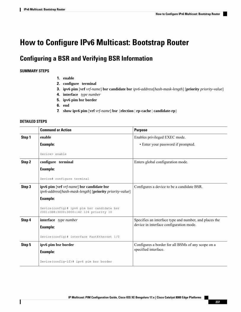
How to Configure IPv6 Multicast: Bootstrap Router
Configuring a BSR and Verifying BSR Information
SUMMARY STEPS
1. enable2. configure terminal3. ipv6 pim [vrf vrf-name] bsr candidate bsr ipv6-address[hash-mask-length] [priority priority-value]4. interface type number
5. ipv6 pim bsr border6. end7. show ipv6 pim [vrf vrf-name] bsr {election | rp-cache | candidate-rp}
DETAILED STEPS
PurposeCommand or Action
Enables privileged EXEC mode.enableStep 1
Example: • Enter your password if prompted.
Device> enable
Enters global configuration mode.configure terminal
Example:
Step 2
Device# configure terminal
Configures a device to be a candidate BSR.ipv6 pim [vrf vrf-name] bsr candidate bsripv6-address[hash-mask-length] [priority priority-value]
Step 3
Example:
Device(config)# ipv6 pim bsr candidate bsr2001:DB8:3000:3000::42 124 priority 10
Specifies an interface type and number, and places thedevice in interface configuration mode.
interface type number
Example:
Step 4
Device(config)# interface FastEthernet 1/0
Configures a border for all BSMs of any scope on aspecified interface.
ipv6 pim bsr border
Example:
Step 5
Device(config-if)# ipv6 pim bsr border
IP Multicast: PIM Configuration Guide, Cisco IOS XE Bengaluru 17.x | Cisco Catalyst 8000 Edge Platforms237
IPv6 Multicast: Bootstrap RouterHow to Configure IPv6 Multicast: Bootstrap Router

PurposeCommand or Action
Exits to privileged EXEC mode.end
Example:
Step 6
Device(config-if)# end
Displays information related to PIM BSR protocolprocessing.
show ipv6 pim [vrf vrf-name] bsr {election | rp-cache |candidate-rp}
Example:
Step 7
Device# show ipv6 pim bsr election
Sending PIM RP Advertisements to the BSR
SUMMARY STEPS
1. enable2. configure terminal3. ipv6 pim [vrf vrf-name] bsr candidate rp ipv6-address [group-list access-list-name] [priority
priority-value] [interval seconds] [scope scope-value] [bidir]4. interface type number
5. ipv6 pim bsr border
DETAILED STEPS
PurposeCommand or Action
Enables privileged EXEC mode.enableStep 1
Example: • Enter your password if prompted.
Device> enable
Enters global configuration mode.configure terminal
Example:
Step 2
Device# configure terminal
Sends PIM RP advertisements to the BSR.ipv6 pim [vrf vrf-name] bsr candidate rp ipv6-address[group-list access-list-name] [priority priority-value][interval seconds] [scope scope-value] [bidir]
Step 3
Example:
Device(config)# ipv6 pim bsr candidate rp2001:DB8:3000:3000::42 priority 0
Specifies an interface type and number, and places thedevice in interface configuration mode.
interface type number
Example:
Step 4
IP Multicast: PIM Configuration Guide, Cisco IOS XE Bengaluru 17.x | Cisco Catalyst 8000 Edge Platforms238
IPv6 Multicast: Bootstrap RouterSending PIM RP Advertisements to the BSR
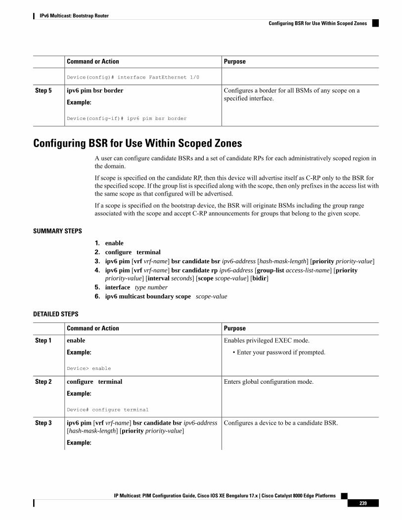
PurposeCommand or Action
Device(config)# interface FastEthernet 1/0
Configures a border for all BSMs of any scope on aspecified interface.
ipv6 pim bsr border
Example:
Step 5
Device(config-if)# ipv6 pim bsr border
Configuring BSR for Use Within Scoped ZonesA user can configure candidate BSRs and a set of candidate RPs for each administratively scoped region inthe domain.
If scope is specified on the candidate RP, then this device will advertise itself as C-RP only to the BSR forthe specified scope. If the group list is specified along with the scope, then only prefixes in the access list withthe same scope as that configured will be advertised.
If a scope is specified on the bootstrap device, the BSR will originate BSMs including the group rangeassociated with the scope and accept C-RP announcements for groups that belong to the given scope.
SUMMARY STEPS
1. enable2. configure terminal3. ipv6 pim [vrf vrf-name] bsr candidate bsr ipv6-address [hash-mask-length] [priority priority-value]4. ipv6 pim [vrf vrf-name] bsr candidate rp ipv6-address [group-list access-list-name] [priority
priority-value] [interval seconds] [scope scope-value] [bidir]5. interface type number
6. ipv6 multicast boundary scope scope-value
DETAILED STEPS
PurposeCommand or Action
Enables privileged EXEC mode.enableStep 1
Example: • Enter your password if prompted.
Device> enable
Enters global configuration mode.configure terminal
Example:
Step 2
Device# configure terminal
Configures a device to be a candidate BSR.ipv6 pim [vrf vrf-name] bsr candidate bsr ipv6-address[hash-mask-length] [priority priority-value]
Step 3
Example:
IP Multicast: PIM Configuration Guide, Cisco IOS XE Bengaluru 17.x | Cisco Catalyst 8000 Edge Platforms239
IPv6 Multicast: Bootstrap RouterConfiguring BSR for Use Within Scoped Zones
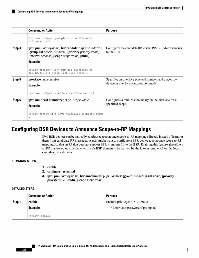
PurposeCommand or Action
Device(config)# ipv6 pim bsr candidate bsr2001:DB8:1:1:4
Configures the candidate RP to send PIMRP advertisementsto the BSR.
ipv6 pim [vrf vrf-name] bsr candidate rp ipv6-address[group-list access-list-name] [priority priority-value][interval seconds] [scope scope-value] [bidir]
Step 4
Example:
Device(config)# ipv6 pim bsr candidate rp2001:DB8:1:1:1 group-list list scope 6
Specifies an interface type and number, and places thedevice in interface configuration mode.
interface type number
Example:
Step 5
Device(config)# interface FastEthernet 1/0
Configures a multicast boundary on the interface for aspecified scope.
ipv6 multicast boundary scope scope-value
Example:
Step 6
Device(config-if)# ipv6 multicast boundary scope6
Configuring BSR Devices to Announce Scope-to-RP MappingsIPv6 BSR devices can be statically configured to announce scope-to-RPmappings directly instead of learningthem from candidate-RP messages. A user might want to configure a BSR device to announce scope-to-RPmappings so that an RP that does not support BSR is imported into the BSR. Enabling this feature also allowsan RP positioned outside the enterprise’s BSR domain to be learned by the known remote RP on the localcandidate BSR devices.
SUMMARY STEPS
1. enable2. configure terminal3. ipv6 pim [vrf vrf-name] bsr announced rp ipv6-address [group-list access-list-name] [priority
priority-value] [bidir] [scope scope-value]
DETAILED STEPS
PurposeCommand or Action
Enables privileged EXEC mode.enableStep 1
Example: • Enter your password if prompted.
Device> enable
IP Multicast: PIM Configuration Guide, Cisco IOS XE Bengaluru 17.x | Cisco Catalyst 8000 Edge Platforms240
IPv6 Multicast: Bootstrap RouterConfiguring BSR Devices to Announce Scope-to-RP Mappings
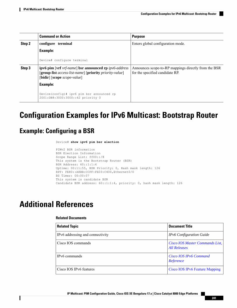
PurposeCommand or Action
Enters global configuration mode.configure terminal
Example:
Step 2
Device# configure terminal
Announces scope-to-RP mappings directly from the BSRfor the specified candidate RP.
ipv6 pim [vrf vrf-name] bsr announced rp ipv6-address[group-list access-list-name] [priority priority-value][bidir] [scope scope-value]
Step 3
Example:
Device(config)# ipv6 pim bsr announced rp2001:DB8:3000:3000::42 priority 0
Configuration Examples for IPv6 Multicast: Bootstrap Router
Example: Configuring a BSRDevice# show ipv6 pim bsr election
PIMv2 BSR informationBSR Election InformationScope Range List: ff00::/8This system is the Bootstrap Router (BSR)BSR Address: 60::1:1:4Uptime: 00:11:55, BSR Priority: 0, Hash mask length: 126RPF: FE80::A8BB:CCFF:FE03:C400,Ethernet0/0BS Timer: 00:00:07This system is candidate BSRCandidate BSR address: 60::1:1:4, priority: 0, hash mask length: 126
Additional ReferencesRelated Documents
Document TitleRelated Topic
IPv6 Configuration GuideIPv6 addressing and connectivity
Cisco IOS Master Commands List,All Releases
Cisco IOS commands
Cisco IOS IPv6 CommandReference
IPv6 commands
Cisco IOS IPv6 Feature MappingCisco IOS IPv6 features
IP Multicast: PIM Configuration Guide, Cisco IOS XE Bengaluru 17.x | Cisco Catalyst 8000 Edge Platforms241
IPv6 Multicast: Bootstrap RouterConfiguration Examples for IPv6 Multicast: Bootstrap Router
Standards and RFCs
TitleStandard/RFC
IPv6 RFCsRFCs forIPv6
MIBs
MIBs LinkMIB
To locate and download MIBs for selected platforms, Cisco IOS releases, and feature sets, use CiscoMIB Locator found at the following URL:
http://www.cisco.com/go/mibs
Technical Assistance
LinkDescription
http://www.cisco.com/cisco/web/support/index.htmlTheCisco Support andDocumentationwebsite providesonline resources to download documentation, software,and tools. Use these resources to install and configurethe software and to troubleshoot and resolve technicalissues with Cisco products and technologies. Access tomost tools on the Cisco Support and Documentationwebsite requires a Cisco.com user ID and password.
Feature Information for IPv6 Multicast: Bootstrap RouterThe following table provides release information about the feature or features described in this module. Thistable lists only the software release that introduced support for a given feature in a given software releasetrain. Unless noted otherwise, subsequent releases of that software release train also support that feature.
Use Cisco Feature Navigator to find information about platform support and Cisco software image support.To access Cisco Feature Navigator, go to www.cisco.com/go/cfn. An account on Cisco.com is not required.
IP Multicast: PIM Configuration Guide, Cisco IOS XE Bengaluru 17.x | Cisco Catalyst 8000 Edge Platforms242
IPv6 Multicast: Bootstrap RouterFeature Information for IPv6 Multicast: Bootstrap Router

C H A P T E R 17IPv6 Multicast: PIM Sparse Mode
IPv6multicast provides support for intradomainmulticast routing using PIM sparse mode (PIM-SM). PIM-SMuses unicast routing to provide reverse-path information for multicast tree building, but it is not dependenton any particular unicast routing protocol.
• Information About IPv6 Multicast PIM Sparse Mode, on page 243• How to Configure IPv6 Multicast PIM Sparse Mode, on page 247• Configuration Examples for IPv6 Multicast PIM Sparse Mode, on page 253• Additional References, on page 255• Feature Information for IPv6 Multicast PIM Sparse Mode, on page 256
Information About IPv6 Multicast PIM Sparse Mode
Protocol Independent MulticastProtocol Independent Multicast (PIM) is used between devices so that they can track which multicast packetsto forward to each other and to their directly connected LANs. PIMworks independently of the unicast routingprotocol to perform send or receive multicast route updates like other protocols. Regardless of which unicastrouting protocols are being used in the LAN to populate the unicast routing table, Cisco IOS PIM uses theexisting unicast table content to perform the Reverse Path Forwarding (RPF) check instead of building andmaintaining its own separate routing table.
You can configure IPv6 multicast to use either a PIM- Sparse Mode (SM) or PIM-Source Specific Multicast(SSM) operation, or you can use both PIM-SM and PIM-SSM together in your network.
PIM-Sparse ModeIPv6 multicast provides support for intradomain multicast routing using PIM-SM. PIM-SM uses unicastrouting to provide reverse-path information for multicast tree building, but it is not dependent on any particularunicast routing protocol.
PIM-SM is used in a multicast network when relatively few devices are involved in each multicast and thesedevices do not forward multicast packets for a group, unless there is an explicit request for the traffic. PIM-SMdistributes information about active sources by forwarding data packets on the shared tree. PIM-SM initiallyuses shared trees, which requires the use of an RP.
Requests are accomplished via PIM joins, which are sent hop by hop toward the root node of the tree. Theroot node of a tree in PIM-SM is the RP in the case of a shared tree or the first-hop device that is directly
IP Multicast: PIM Configuration Guide, Cisco IOS XE Bengaluru 17.x | Cisco Catalyst 8000 Edge Platforms243
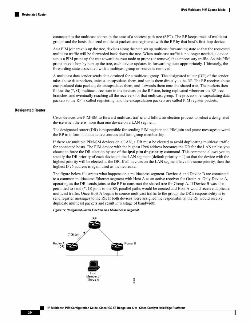
connected to the multicast source in the case of a shortest path tree (SPT). The RP keeps track of multicastgroups and the hosts that send multicast packets are registered with the RP by that host’s first-hop device.
As a PIM join travels up the tree, devices along the path set up multicast forwarding state so that the requestedmulticast traffic will be forwarded back down the tree. When multicast traffic is no longer needed, a devicesends a PIM prune up the tree toward the root node to prune (or remove) the unnecessary traffic. As this PIMprune travels hop by hop up the tree, each device updates its forwarding state appropriately. Ultimately, theforwarding state associated with a multicast group or source is removed.
A multicast data sender sends data destined for a multicast group. The designated router (DR) of the sendertakes those data packets, unicast-encapsulates them, and sends them directly to the RP. The RP receives theseencapsulated data packets, de-encapsulates them, and forwards them onto the shared tree. The packets thenfollow the (*, G) multicast tree state in the devices on the RP tree, being replicated wherever the RP treebranches, and eventually reaching all the receivers for that multicast group. The process of encapsulating datapackets to the RP is called registering, and the encapsulation packets are called PIM register packets.
Designated Router
Cisco devices use PIM-SM to forward multicast traffic and follow an election process to select a designateddevice when there is more than one device on a LAN segment.
The designated router (DR) is responsible for sending PIM register and PIM join and prune messages towardthe RP to inform it about active sources and host group membership.
If there are multiple PIM-SM devices on a LAN, a DR must be elected to avoid duplicating multicast trafficfor connected hosts. The PIM device with the highest IPv6 address becomes the DR for the LAN unless youchoose to force the DR election by use of the ipv6 pim dr-priority command. This command allows you tospecify the DR priority of each device on the LAN segment (default priority = 1) so that the device with thehighest priority will be elected as the DR. If all devices on the LAN segment have the same priority, then thehighest IPv6 address is again used as the tiebreaker.
The figure below illustrates what happens on a multiaccess segment. Device A and Device B are connectedto a common multiaccess Ethernet segment with Host A as an active receiver for Group A. Only Device A,operating as the DR, sends joins to the RP to construct the shared tree for Group A. If Device B was alsopermitted to send (*, G) joins to the RP, parallel paths would be created and Host A would receive duplicatemulticast traffic. Once Host A begins to source multicast traffic to the group, the DR’s responsibility is tosend register messages to the RP. If both devices were assigned the responsibility, the RP would receiveduplicate multicast packets and result in wastage of bandwidth.
Figure 17: Designated Router Election on a Multiaccess Segment
IP Multicast: PIM Configuration Guide, Cisco IOS XE Bengaluru 17.x | Cisco Catalyst 8000 Edge Platforms244
IPv6 Multicast: PIM Sparse ModeDesignated Router

If the DR should fail, the PIM-SM provides a way to detect the failure of Device A and elect a failover DR.If the DR (Device A) became inoperable, Device B would detect this situation when its neighbor adjacencywith Device A timed out. Because Device B has been hearing MLD membership reports from Host A, italready has MLD state for Group A on this interface and would immediately send a join to the RP when itbecame the new DR. This step reestablishes traffic flow down a new branch of the shared tree via Device B.Additionally, if Host A were sourcing traffic, Device B would initiate a new register process immediatelyafter receiving the next multicast packet from Host A. This action would trigger the RP to join the SPT toHost A via a new branch through Device B.
Two PIM devices are neighbors if there is a direct connection between them. To display your PIM neighbors,use the show ipv6 pim neighbor command in privileged EXEC mode.
Tip
The DR election process is required only on multiaccess LANs.Note
Rendezvous Point
IPv6 PIM provides embedded RP support. Embedded RP support allows the device to learn RP informationusing the multicast group destination address instead of the statically configured RP. For devices that are theRP, the device must be statically configured as the RP.
The device searches for embedded RP group addresses in MLD reports or PIM messages and data packets.On finding such an address, the device learns the RP for the group from the address itself. It then uses thislearned RP for all protocol activity for the group. For devices that are the RP, the device is advertised as anembedded RP must be configured as the RP.
To select a static RP over an embedded RP, the specific embedded RP group range or maskmust be configuredin the access list of the static RP. When PIM is configured in sparse mode, you must also choose one or moredevices to operate as an RP. An RP is a single common root placed at a chosen point of a shared distributiontree and is configured statically in each box.
PIM DRs forward data from directly connected multicast sources to the RP for distribution down the sharedtree. Data is forwarded to the RP in one of two ways:
• Data is encapsulated in register packets and unicast directly to the RP by the first-hop device operatingas the DR.
• If the RP has itself joined the source tree, it is multicast-forwarded per the RPF forwarding algorithmdescribed in the PIM-Sparse Mode section.
The RP address is used by first-hop devices to send PIM register messages on behalf of a host sending a packetto the group. The RP address is also used by last-hop devices to send PIM join and prune messages to the RPto inform it about group membership. You must configure the RP address on all devices (including the RPdevice).
A PIM device can be an RP for more than one group. Only one RP address can be used at a time within aPIM domain for a certain group. The conditions specified by the access list determine for which groups thedevice is an RP.
IPv6 multicast supports the PIM accept register feature, which is the ability to perform PIM-SM registermessage filtering at the RP. The user can match an access list or compare the AS path for the registered sourcewith the AS path specified in a route map.
IP Multicast: PIM Configuration Guide, Cisco IOS XE Bengaluru 17.x | Cisco Catalyst 8000 Edge Platforms245
IPv6 Multicast: PIM Sparse ModeRendezvous Point

PIM Shared Tree and Source Tree (Shortest-Path Tree)
By default, members of a group receive data from senders to the group across a single data distribution treerooted at the RP. This type of distribution tree is called shared tree or rendezvous point tree (RPT), as illustratedin the figure below. Data from senders is delivered to the RP for distribution to group members joined to theshared tree.
Figure 18: Shared Tree and Source Tree (Shortest Path Tree)
If the data threshold warrants, leaf devices on the shared tree may initiate a switch to the data distribution treerooted at the source. This type of distribution tree is called a shortest path tree or source tree. By default, thesoftware switches to a source tree upon receiving the first data packet from a source.
The following process details the move from shared tree to source tree:
1. Receiver joins a group; leaf Device C sends a join message toward the RP.
2. RP puts the link to Device C in its outgoing interface list.
3. Source sends the data; Device A encapsulates the data in the register and sends it to the RP.
4. RP forwards the data down the shared tree to Device C and sends a join message toward the source. Atthis point, data may arrive twice at Device C, once encapsulated and once natively.
5. When data arrives natively (unencapsulated) at the RP, the RP sends a register-stop message to DeviceA.
6. By default, receipt of the first data packet prompts Device C to send a join message toward the source.
7. When Device C receives data on (S, G), it sends a prune message for the source up the shared tree.
8. RP deletes the link to Device C from the outgoing interface of (S, G).
9. RP triggers a prune message toward the source.
IP Multicast: PIM Configuration Guide, Cisco IOS XE Bengaluru 17.x | Cisco Catalyst 8000 Edge Platforms246
IPv6 Multicast: PIM Sparse ModePIM Shared Tree and Source Tree (Shortest-Path Tree)
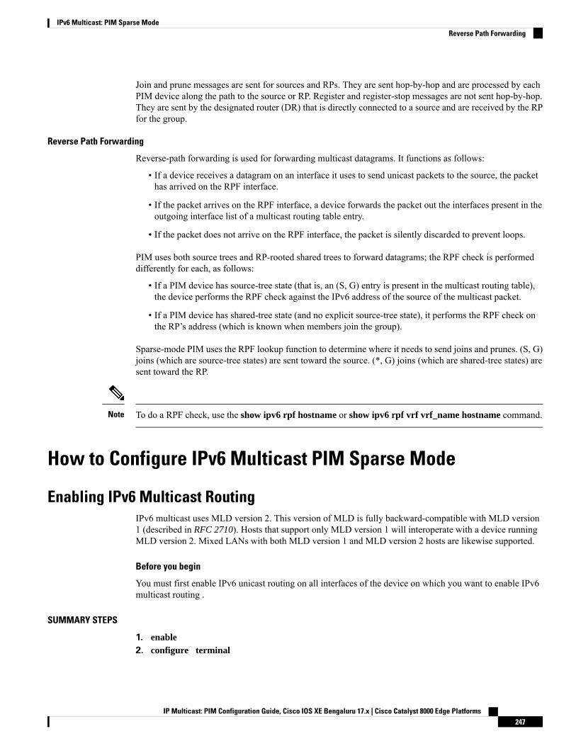
Join and prune messages are sent for sources and RPs. They are sent hop-by-hop and are processed by eachPIM device along the path to the source or RP. Register and register-stop messages are not sent hop-by-hop.They are sent by the designated router (DR) that is directly connected to a source and are received by the RPfor the group.
Reverse Path Forwarding
Reverse-path forwarding is used for forwarding multicast datagrams. It functions as follows:
• If a device receives a datagram on an interface it uses to send unicast packets to the source, the packethas arrived on the RPF interface.
• If the packet arrives on the RPF interface, a device forwards the packet out the interfaces present in theoutgoing interface list of a multicast routing table entry.
• If the packet does not arrive on the RPF interface, the packet is silently discarded to prevent loops.
PIM uses both source trees and RP-rooted shared trees to forward datagrams; the RPF check is performeddifferently for each, as follows:
• If a PIM device has source-tree state (that is, an (S, G) entry is present in the multicast routing table),the device performs the RPF check against the IPv6 address of the source of the multicast packet.
• If a PIM device has shared-tree state (and no explicit source-tree state), it performs the RPF check onthe RP’s address (which is known when members join the group).
Sparse-mode PIM uses the RPF lookup function to determine where it needs to send joins and prunes. (S, G)joins (which are source-tree states) are sent toward the source. (*, G) joins (which are shared-tree states) aresent toward the RP.
To do a RPF check, use the show ipv6 rpf hostname or show ipv6 rpf vrf vrf_name hostname command.Note
How to Configure IPv6 Multicast PIM Sparse Mode
Enabling IPv6 Multicast RoutingIPv6 multicast uses MLD version 2. This version of MLD is fully backward-compatible with MLD version1 (described in RFC 2710). Hosts that support only MLD version 1 will interoperate with a device runningMLD version 2. Mixed LANs with both MLD version 1 and MLD version 2 hosts are likewise supported.
Before you begin
You must first enable IPv6 unicast routing on all interfaces of the device on which you want to enable IPv6multicast routing .
SUMMARY STEPS
1. enable2. configure terminal
IP Multicast: PIM Configuration Guide, Cisco IOS XE Bengaluru 17.x | Cisco Catalyst 8000 Edge Platforms247
IPv6 Multicast: PIM Sparse ModeReverse Path Forwarding
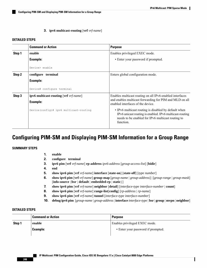
3. ipv6 multicast-routing [vrf vrf-name]
DETAILED STEPS
PurposeCommand or Action
Enables privileged EXEC mode.enableStep 1
Example: • Enter your password if prompted.
Device> enable
Enters global configuration mode.configure terminal
Example:
Step 2
Device# configure terminal
Enables multicast routing on all IPv6-enabled interfacesand enables multicast forwarding for PIM and MLD on allenabled interfaces of the device.
ipv6 multicast-routing [vrf vrf-name]
Example:
Device(config)# ipv6 multicast-routing
Step 3
• IPv6 multicast routing is disabled by default whenIPv6 unicast routing is enabled. IPv6multicast-routingneeds to be enabled for IPv6 multicast routing tofunction.
Configuring PIM-SM and Displaying PIM-SM Information for a Group Range
SUMMARY STEPS
1. enable2. configure terminal3. ipv6 pim [vrf vrf-name] rp-address ipv6-address [group-access-list] [bidir]4. end5. show ipv6 pim [vrf vrf-name] interface [state-on] [state-off] [type number]6. show ipv6 pim [vrf vrf-name] group-map [group-name | group-address] | [group-range | group-mask]
[info-source {bsr | default | embedded-rp | static}]7. show ipv6 pim [vrf vrf-name] neighbor [detail] [interface-type interface-number | count]8. show ipv6 pim [vrf vrf-name] range-list[config] [rp-address | rp-name]9. show ipv6 pim [vrf vrf-name] tunnel [interface-type interface-number]10. debug ipv6 pim [group-name | group-address | interface interface-type | bsr | group |mvpn | neighbor]
DETAILED STEPS
PurposeCommand or Action
Enables privileged EXEC mode.enableStep 1
Example: • Enter your password if prompted.
IP Multicast: PIM Configuration Guide, Cisco IOS XE Bengaluru 17.x | Cisco Catalyst 8000 Edge Platforms248
IPv6 Multicast: PIM Sparse ModeConfiguring PIM-SM and Displaying PIM-SM Information for a Group Range

PurposeCommand or Action
Device> enable
Enters global configuration mode.configure terminal
Example:
Step 2
Device# configure terminal
Configures the address of a PIM RP for a particular grouprange.
ipv6 pim [vrf vrf-name] rp-address ipv6-address[group-access-list] [bidir]
Example:
Step 3
Device(config)# ipv6 pim rp-address2001:DB8::01:800:200E:8C6C acc-grp-1
Returns to privileged EXEC mode.end
Example:
Step 4
Device(config-if)# end
Displays information about interfaces configured for PIM.show ipv6 pim [vrf vrf-name] interface [state-on][state-off] [type number]
Step 5
Example:
Device# show ipv6 pim interface
Displays an IPv6 multicast group mapping table.show ipv6 pim [vrf vrf-name] group-map [group-name| group-address] | [group-range | group-mask] [info-source{bsr | default | embedded-rp | static}]
Step 6
Example:
Device# show ipv6 pim group-map
Displays the PIM neighbors discovered by the Cisco IOSsoftware.
show ipv6 pim [vrf vrf-name] neighbor [detail][interface-type interface-number | count]
Example:
Step 7
Device# show ipv6 pim neighbor
Displays information about IPv6 multicast range lists.show ipv6 pim [vrf vrf-name] range-list[config][rp-address | rp-name]
Step 8
Example:
Device# show ipv6 pim range-list
Displays information about the PIM register encapsulationand de-encapsulation tunnels on an interface.
show ipv6 pim [vrf vrf-name] tunnel [interface-typeinterface-number]
Example:
Step 9
IP Multicast: PIM Configuration Guide, Cisco IOS XE Bengaluru 17.x | Cisco Catalyst 8000 Edge Platforms249
IPv6 Multicast: PIM Sparse ModeConfiguring PIM-SM and Displaying PIM-SM Information for a Group Range
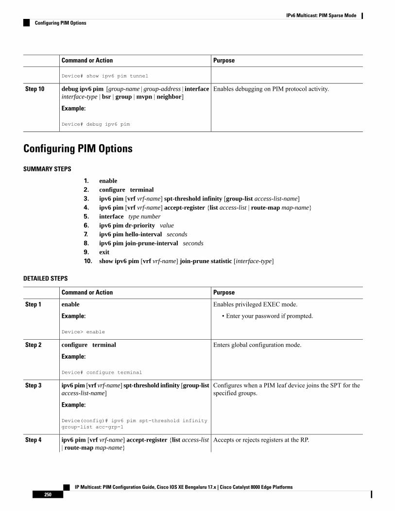
PurposeCommand or Action
Device# show ipv6 pim tunnel
Enables debugging on PIM protocol activity.debug ipv6 pim [group-name | group-address | interfaceinterface-type | bsr | group | mvpn | neighbor]
Step 10
Example:
Device# debug ipv6 pim
Configuring PIM Options
SUMMARY STEPS
1. enable2. configure terminal3. ipv6 pim [vrf vrf-name] spt-threshold infinity [group-list access-list-name]4. ipv6 pim [vrf vrf-name] accept-register {list access-list | route-map map-name}5. interface type number
6. ipv6 pim dr-priority value
7. ipv6 pim hello-interval seconds
8. ipv6 pim join-prune-interval seconds
9. exit10. show ipv6 pim [vrf vrf-name] join-prune statistic [interface-type]
DETAILED STEPS
PurposeCommand or Action
Enables privileged EXEC mode.enableStep 1
Example: • Enter your password if prompted.
Device> enable
Enters global configuration mode.configure terminal
Example:
Step 2
Device# configure terminal
Configures when a PIM leaf device joins the SPT for thespecified groups.
ipv6 pim [vrf vrf-name] spt-threshold infinity [group-listaccess-list-name]
Example:
Step 3
Device(config)# ipv6 pim spt-threshold infinitygroup-list acc-grp-1
Accepts or rejects registers at the RP.ipv6 pim [vrf vrf-name] accept-register {list access-list| route-map map-name}
Step 4
IP Multicast: PIM Configuration Guide, Cisco IOS XE Bengaluru 17.x | Cisco Catalyst 8000 Edge Platforms250
IPv6 Multicast: PIM Sparse ModeConfiguring PIM Options
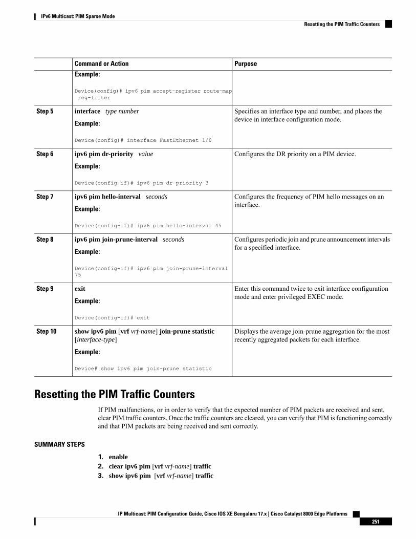
PurposeCommand or Action
Example:
Device(config)# ipv6 pim accept-register route-mapreg-filter
Specifies an interface type and number, and places thedevice in interface configuration mode.
interface type number
Example:
Step 5
Device(config)# interface FastEthernet 1/0
Configures the DR priority on a PIM device.ipv6 pim dr-priority value
Example:
Step 6
Device(config-if)# ipv6 pim dr-priority 3
Configures the frequency of PIM hello messages on aninterface.
ipv6 pim hello-interval seconds
Example:
Step 7
Device(config-if)# ipv6 pim hello-interval 45
Configures periodic join and prune announcement intervalsfor a specified interface.
ipv6 pim join-prune-interval seconds
Example:
Step 8
Device(config-if)# ipv6 pim join-prune-interval75
Enter this command twice to exit interface configurationmode and enter privileged EXEC mode.
exit
Example:
Step 9
Device(config-if)# exit
Displays the average join-prune aggregation for the mostrecently aggregated packets for each interface.
show ipv6 pim [vrf vrf-name] join-prune statistic[interface-type]
Example:
Step 10
Device# show ipv6 pim join-prune statistic
Resetting the PIM Traffic CountersIf PIM malfunctions, or in order to verify that the expected number of PIM packets are received and sent,clear PIM traffic counters. Once the traffic counters are cleared, you can verify that PIM is functioning correctlyand that PIM packets are being received and sent correctly.
SUMMARY STEPS
1. enable2. clear ipv6 pim [vrf vrf-name] traffic3. show ipv6 pim [vrf vrf-name] traffic
IP Multicast: PIM Configuration Guide, Cisco IOS XE Bengaluru 17.x | Cisco Catalyst 8000 Edge Platforms251
IPv6 Multicast: PIM Sparse ModeResetting the PIM Traffic Counters
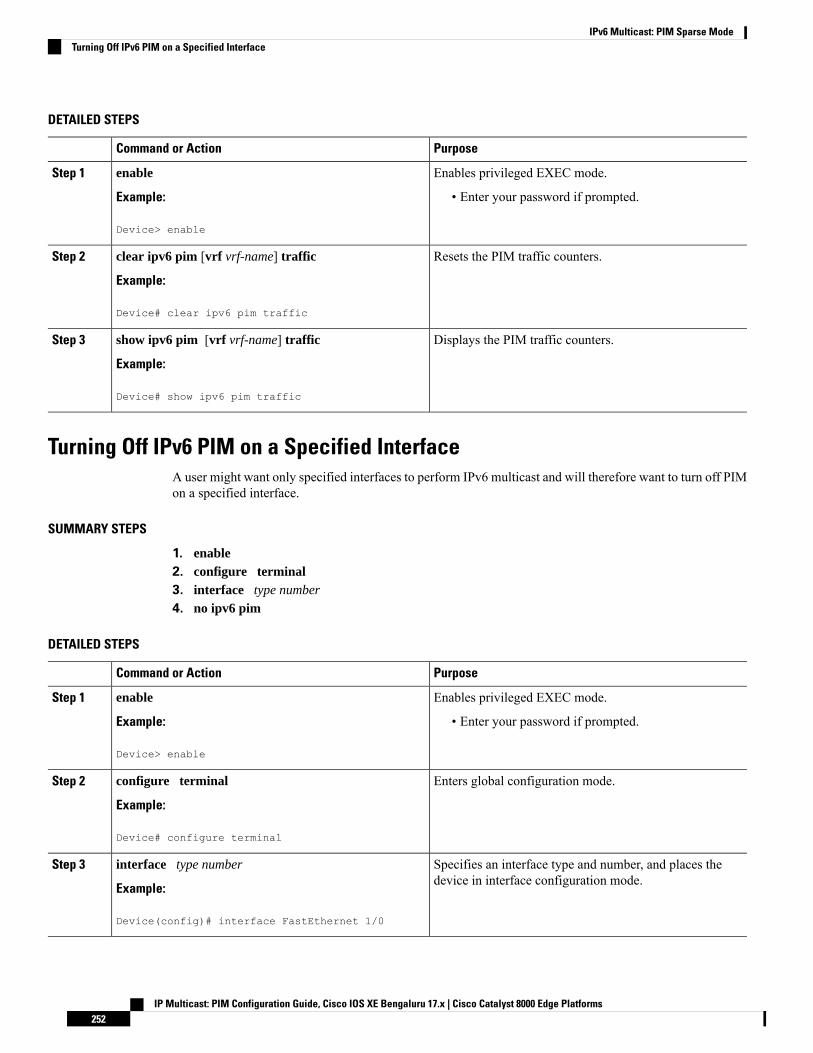
DETAILED STEPS
PurposeCommand or Action
Enables privileged EXEC mode.enableStep 1
Example: • Enter your password if prompted.
Device> enable
Resets the PIM traffic counters.clear ipv6 pim [vrf vrf-name] traffic
Example:
Step 2
Device# clear ipv6 pim traffic
Displays the PIM traffic counters.show ipv6 pim [vrf vrf-name] traffic
Example:
Step 3
Device# show ipv6 pim traffic
Turning Off IPv6 PIM on a Specified InterfaceA user might want only specified interfaces to perform IPv6 multicast and will therefore want to turn off PIMon a specified interface.
SUMMARY STEPS
1. enable2. configure terminal3. interface type number
4. no ipv6 pim
DETAILED STEPS
PurposeCommand or Action
Enables privileged EXEC mode.enableStep 1
Example: • Enter your password if prompted.
Device> enable
Enters global configuration mode.configure terminal
Example:
Step 2
Device# configure terminal
Specifies an interface type and number, and places thedevice in interface configuration mode.
interface type number
Example:
Step 3
Device(config)# interface FastEthernet 1/0
IP Multicast: PIM Configuration Guide, Cisco IOS XE Bengaluru 17.x | Cisco Catalyst 8000 Edge Platforms252
IPv6 Multicast: PIM Sparse ModeTurning Off IPv6 PIM on a Specified Interface
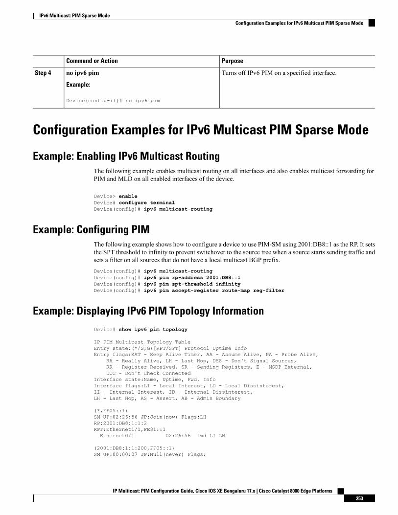
PurposeCommand or Action
Turns off IPv6 PIM on a specified interface.no ipv6 pim
Example:
Step 4
Device(config-if)# no ipv6 pim
Configuration Examples for IPv6 Multicast PIM Sparse Mode
Example: Enabling IPv6 Multicast RoutingThe following example enables multicast routing on all interfaces and also enables multicast forwarding forPIM and MLD on all enabled interfaces of the device.
Device> enableDevice# configure terminalDevice(config)# ipv6 multicast-routing
Example: Configuring PIMThe following example shows how to configure a device to use PIM-SM using 2001:DB8::1 as the RP. It setsthe SPT threshold to infinity to prevent switchover to the source tree when a source starts sending traffic andsets a filter on all sources that do not have a local multicast BGP prefix.Device(config)# ipv6 multicast-routingDevice(config)# ipv6 pim rp-address 2001:DB8::1Device(config)# ipv6 pim spt-threshold infinityDevice(config)# ipv6 pim accept-register route-map reg-filter
Example: Displaying IPv6 PIM Topology InformationDevice# show ipv6 pim topology
IP PIM Multicast Topology TableEntry state:(*/S,G)[RPT/SPT] Protocol Uptime InfoEntry flags:KAT - Keep Alive Timer, AA - Assume Alive, PA - Probe Alive,
RA - Really Alive, LH - Last Hop, DSS - Don't Signal Sources,RR - Register Received, SR - Sending Registers, E - MSDP External,DCC - Don't Check Connected
Interface state:Name, Uptime, Fwd, InfoInterface flags:LI - Local Interest, LD - Local Dissinterest,II - Internal Interest, ID - Internal Dissinterest,LH - Last Hop, AS - Assert, AB - Admin Boundary
(*,FF05::1)SM UP:02:26:56 JP:Join(now) Flags:LHRP:2001:DB8:1:1:2RPF:Ethernet1/1,FE81::1Ethernet0/1 02:26:56 fwd LI LH
(2001:DB8:1:1:200,FF05::1)SM UP:00:00:07 JP:Null(never) Flags:
IP Multicast: PIM Configuration Guide, Cisco IOS XE Bengaluru 17.x | Cisco Catalyst 8000 Edge Platforms253
IPv6 Multicast: PIM Sparse ModeConfiguration Examples for IPv6 Multicast PIM Sparse Mode
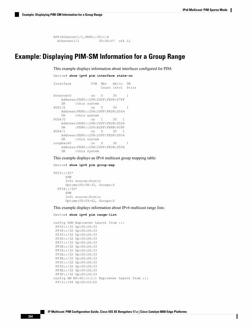
RPF:Ethernet1/1,FE80::30:1:4Ethernet1/1 00:00:07 off LI
Example: Displaying PIM-SM Information for a Group Range
This example displays information about interfaces configured for PIM:Device# show ipv6 pim interface state-on
Interface PIM Nbr Hello DRCount Intvl Prior
Ethernet0 on 0 30 1Address:FE80::208:20FF:FE08:D7FFDR :this system
POS1/0 on 0 30 1Address:FE80::208:20FF:FE08:D554DR :this system
POS4/0 on 1 30 1Address:FE80::208:20FF:FE08:D554DR :FE80::250:E2FF:FE8B:4C80
POS4/1 on 0 30 1Address:FE80::208:20FF:FE08:D554DR :this system
Loopback0 on 0 30 1Address:FE80::208:20FF:FE08:D554DR :this system
This example displays an IPv6 multicast group mapping table:Device# show ipv6 pim group-map
FF33::/32*SSMInfo source:StaticUptime:00:08:32, Groups:0
FF34::/32*SSMInfo source:StaticUptime:00:09:42, Groups:0
This example displays information about IPv6 multicast range lists:Device# show ipv6 pim range-list
config SSM Exp:never Learnt from :::FF33::/32 Up:00:26:33FF34::/32 Up:00:26:33FF35::/32 Up:00:26:33FF36::/32 Up:00:26:33FF37::/32 Up:00:26:33FF38::/32 Up:00:26:33FF39::/32 Up:00:26:33FF3A::/32 Up:00:26:33FF3B::/32 Up:00:26:33FF3C::/32 Up:00:26:33FF3D::/32 Up:00:26:33FF3E::/32 Up:00:26:33FF3F::/32 Up:00:26:33config SM RP:40::1:1:1 Exp:never Learnt from :::FF13::/64 Up:00:03:50
IP Multicast: PIM Configuration Guide, Cisco IOS XE Bengaluru 17.x | Cisco Catalyst 8000 Edge Platforms254
IPv6 Multicast: PIM Sparse ModeExample: Displaying PIM-SM Information for a Group Range
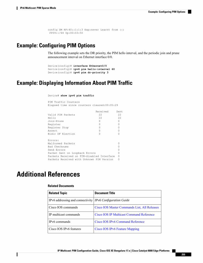
config SM RP:40::1:1:3 Exp:never Learnt from :::FF09::/64 Up:00:03:50
Example: Configuring PIM OptionsThe following example sets the DR priority, the PIM hello interval, and the periodic join and pruneannouncement interval on Ethernet interface 0/0.
Device(config)# interface Ethernet0/0Device(config)# ipv6 pim hello-interval 60Device(config)# ipv6 pim dr-priority 3
Example: Displaying Information About PIM Traffic
Device# show ipv6 pim traffic
PIM Traffic CountersElapsed time since counters cleared:00:05:29
Received SentValid PIM Packets 22 22Hello 22 22Join-Prune 0 0Register 0 0Register Stop 0 0Assert 0 0Bidir DF Election 0 0
Errors:Malformed Packets 0Bad Checksums 0Send Errors 0Packet Sent on Loopback Errors 0Packets Received on PIM-disabled Interface 0Packets Received with Unknown PIM Version 0
Additional ReferencesRelated Documents
Document TitleRelated Topic
IPv6 Configuration GuideIPv6 addressing and connectivity
Cisco IOS Master Commands List, All ReleasesCisco IOS commands
Cisco IOS IP Multicast Command ReferenceIP multicast commands
Cisco IOS IPv6 Command ReferenceIPv6 commands
Cisco IOS IPv6 Feature MappingCisco IOS IPv6 features
IP Multicast: PIM Configuration Guide, Cisco IOS XE Bengaluru 17.x | Cisco Catalyst 8000 Edge Platforms255
IPv6 Multicast: PIM Sparse ModeExample: Configuring PIM Options
Standards and RFCs
TitleStandard/RFC
IPv6 RFCsRFCs forIPv6
MIBs
MIBs LinkMIB
To locate and download MIBs for selected platforms, Cisco IOS releases, and feature sets, use CiscoMIB Locator found at the following URL:
http://www.cisco.com/go/mibs
Technical Assistance
LinkDescription
http://www.cisco.com/cisco/web/support/index.htmlTheCisco Support andDocumentationwebsite providesonline resources to download documentation, software,and tools. Use these resources to install and configurethe software and to troubleshoot and resolve technicalissues with Cisco products and technologies. Access tomost tools on the Cisco Support and Documentationwebsite requires a Cisco.com user ID and password.
Feature Information for IPv6 Multicast PIM Sparse Mode
IP Multicast: PIM Configuration Guide, Cisco IOS XE Bengaluru 17.x | Cisco Catalyst 8000 Edge Platforms256
IPv6 Multicast: PIM Sparse ModeFeature Information for IPv6 Multicast PIM Sparse Mode
C H A P T E R 18IPv6 Multicast: Static Multicast Routing for IPv6
IPv6 static multicast routes, or mroutes, share the same database as IPv6 static routes and are implementedby extending static route support for reverse path forwarding (RPF) checks.
• Information About IPv6 Static Mroutes, on page 257• How to Configure IPv6 Static Multicast Routes, on page 257• Configuration Examples for IPv6 Static Multicast Routes, on page 259• Additional References, on page 260• Feature Information for IPv6 Multicast: Static Multicast Routing for IPv6, on page 261
Information About IPv6 Static MroutesIPv6 static mroutes behave much in the same way as IPv4 static mroutes used to influence the RPF check.IPv6 static mroutes share the same database as IPv6 static routes and are implemented by extending staticroute support for RPF checks. Static mroutes support equal-cost multipath mroutes, and they also supportunicast-only static routes.
How to Configure IPv6 Static Multicast Routes
Configuring Static MroutesStatic multicast routes (mroutes) in IPv6 can be implemented as an extension of IPv6 static routes. You canconfigure your device to use a static route for unicast routing only, to use a static multicast route for multicastRPF selection only, or to use a static route for both unicast routing and multicast RPF selection.
SUMMARY STEPS
1. enable2. configure terminal3. ipv6 route ipv6-prefix / prefix-length ipv6-address | interface-type interface-number ipv6-address]}
[administrative-distance] [administrative-multicast-distance | unicast| multicast] [tag tag
4. end5. show ipv6 mroute [vrf vrf-name] [link-local | [group-name | group-address [source-address |
source-name]] [summary] [count]
IP Multicast: PIM Configuration Guide, Cisco IOS XE Bengaluru 17.x | Cisco Catalyst 8000 Edge Platforms257

6. show ipv6 mroute [vrf vrf-name] [link-local | group-name | group-address] active[kbps]7. show ipv6 rpf [vrf vrf-name] ipv6-prefix
DETAILED STEPS
PurposeCommand or Action
Enables privileged EXEC mode.enableStep 1
Example: • Enter your password if prompted.
Device> enable
Enters global configuration mode.configure terminal
Example:
Step 2
Device# configure terminal
Establishes static IPv6 routes. The example shows a staticroute used for both unicast routing and multicast RPFselection.
ipv6 route ipv6-prefix / prefix-length ipv6-address |interface-type interface-number ipv6-address]}[administrative-distance] [administrative-multicast-distance| unicast| multicast] [tag tag
Step 3
Example:
Device(config)# ipv6 route 2001:DB8::/64 6::6 100
Exits to privileged EXEC mode.end
Example:
Step 4
Device(config-if)# end
Displays the contents of the IPv6 multicast routing table.show ipv6 mroute [vrf vrf-name] [link-local | [group-name| group-address [source-address | source-name]][summary] [count]
Step 5
Example:
Device# show ipv6 mroute ff07::1
Displays the active multicast streams on the device.show ipv6 mroute [vrf vrf-name] [link-local | group-name| group-address] active[kbps]
Step 6
Example:
Device# show ipv6 mroute active
Checks RPF information for a given unicast host addressand prefix.
show ipv6 rpf [vrf vrf-name] ipv6-prefix
Example:
Step 7
Device# show ipv6 rpf 2001:DB8::1:1:2
IP Multicast: PIM Configuration Guide, Cisco IOS XE Bengaluru 17.x | Cisco Catalyst 8000 Edge Platforms258
IPv6 Multicast: Static Multicast Routing for IPv6Configuring Static Mroutes
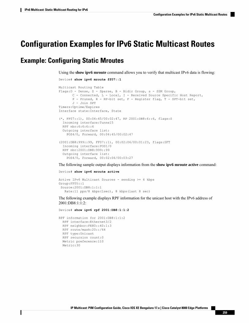
Configuration Examples for IPv6 Static Multicast Routes
Example: Configuring Static Mroutes
Using the show ipv6 mroute command allows you to verify that multicast IPv6 data is flowing:Device# show ipv6 mroute ff07::1
Multicast Routing TableFlags:D - Dense, S - Sparse, B - Bidir Group, s - SSM Group,
C - Connected, L - Local, I - Received Source Specific Host Report,P - Pruned, R - RP-bit set, F - Register flag, T - SPT-bit set,J - Join SPT
Timers:Uptime/ExpiresInterface state:Interface, State
(*, FF07::1), 00:04:45/00:02:47, RP 2001:DB8:6::6, flags:SIncoming interface:Tunnel5RPF nbr:6:6:6::6Outgoing interface list:POS4/0, Forward, 00:04:45/00:02:47
(2001:DB8:999::99, FF07::1), 00:02:06/00:01:23, flags:SFTIncoming interface:POS1/0RPF nbr:2001:DB8:999::99Outgoing interface list:POS4/0, Forward, 00:02:06/00:03:27
The following sample output displays information from the show ipv6 mroute active command:Device# show ipv6 mroute active
Active IPv6 Multicast Sources - sending >= 4 kbpsGroup:FF05::1Source:2001:DB8:1:1:1Rate:11 pps/8 kbps(1sec), 8 kbps(last 8 sec)
The following example displays RPF information for the unicast host with the IPv6 address of2001:DB8:1:1:2:Device# show ipv6 rpf 2001:DB8:1:1:2
RPF information for 2001:DB8:1:1:2RPF interface:Ethernet3/2RPF neighbor:FE80::40:1:3RPF route/mask:20::/64RPF type:UnicastRPF recursion count:0Metric preference:110Metric:30
IP Multicast: PIM Configuration Guide, Cisco IOS XE Bengaluru 17.x | Cisco Catalyst 8000 Edge Platforms259
IPv6 Multicast: Static Multicast Routing for IPv6Configuration Examples for IPv6 Static Multicast Routes
Additional ReferencesRelated Documents
Document TitleRelated Topic
IPv6 Configuration GuideIPv6 addressing and connectivity
Cisco IOS Master Commands List, All ReleasesCisco IOS commands
Cisco IOS IP Multicast Command ReferenceIP multicast commands
Cisco IOS IPv6 Command ReferenceIPv6 commands
Cisco IOS IPv6 Feature MappingCisco IOS IPv6 features
Standards and RFCs
TitleStandard/RFC
IPv6 RFCsRFCs forIPv6
MIBs
MIBs LinkMIB
To locate and download MIBs for selected platforms, Cisco IOS releases, and feature sets, use CiscoMIB Locator found at the following URL:
http://www.cisco.com/go/mibs
Technical Assistance
LinkDescription
http://www.cisco.com/cisco/web/support/index.htmlTheCisco Support andDocumentationwebsite providesonline resources to download documentation, software,and tools. Use these resources to install and configurethe software and to troubleshoot and resolve technicalissues with Cisco products and technologies. Access tomost tools on the Cisco Support and Documentationwebsite requires a Cisco.com user ID and password.
IP Multicast: PIM Configuration Guide, Cisco IOS XE Bengaluru 17.x | Cisco Catalyst 8000 Edge Platforms260
IPv6 Multicast: Static Multicast Routing for IPv6Additional References
Feature Information for IPv6 Multicast: Static Multicast Routingfor IPv6
The following table provides release information about the feature or features described in this module. Thistable lists only the software release that introduced support for a given feature in a given software releasetrain. Unless noted otherwise, subsequent releases of that software release train also support that feature.
Use Cisco Feature Navigator to find information about platform support and Cisco software image support.To access Cisco Feature Navigator, go to www.cisco.com/go/cfn. An account on Cisco.com is not required.
IP Multicast: PIM Configuration Guide, Cisco IOS XE Bengaluru 17.x | Cisco Catalyst 8000 Edge Platforms261
IPv6 Multicast: Static Multicast Routing for IPv6Feature Information for IPv6 Multicast: Static Multicast Routing for IPv6

IP Multicast: PIM Configuration Guide, Cisco IOS XE Bengaluru 17.x | Cisco Catalyst 8000 Edge Platforms262
IPv6 Multicast: Static Multicast Routing for IPv6Feature Information for IPv6 Multicast: Static Multicast Routing for IPv6
C H A P T E R 19IPv6 Multicast: PIM Source-Specific Multicast
The PIM source-specific multicast (SSM) routing protocol supports SSM implementation and is derived fromPIM-SM. However, unlike PIM-SM data from all multicast sources are sent when there is a PIM join, theSSM feature forwards datagram traffic to receivers from only those multicast sources that the receivers haveexplicitly joined, thus optimizing bandwidth utilization and denying unwanted Internet broadcast traffic.
• Prerequisites for IPv6 Multicast: PIM Source-Specific Multicast , on page 263• Information About IPv6 Multicast: PIM Source-Specific Multicast, on page 263• How to Configure IPv6 Multicast: PIM Source-Specific Multicast, on page 266• Configuration Examples for IPv6 Multicast: PIM Source-Specific Multicast, on page 270• Additional References, on page 272• Feature Information for IPv6 Multicast: PIM Source-Specific Multicast, on page 273
PrerequisitesforIPv6Multicast:PIMSource-SpecificMulticast• Multicast Listener Discovery (MLD) version 2 is required for source-specific multicast (SSM) to operate.
• Before SSM will run with MLD, SSM must be supported by the Cisco IPv6 device, the host where theapplication is running, and the application itself.
Information About IPv6 Multicast: PIM Source-SpecificMulticast
IPv6 Multicast Routing ImplementationCisco software supports the following protocols to implement IPv6 multicast routing:
• MLD is used by IPv6 devices to discover multicast listeners (nodes that want to receive multicast packetsdestined for specific multicast addresses) on directly attached links. There are two versions of MLD:
• MLD version 1 is based on version 2 of the Internet Group Management Protocol (IGMP) for IPv4.• MLD version 2 is based on version 3 of the IGMP for IPv4.
• IPv6 multicast for Cisco software uses both MLD version 2 and MLD version 1. MLD version 2 is fullybackward-compatible with MLD version 1 (described in RFC 2710). Hosts that support only MLD
IP Multicast: PIM Configuration Guide, Cisco IOS XE Bengaluru 17.x | Cisco Catalyst 8000 Edge Platforms263
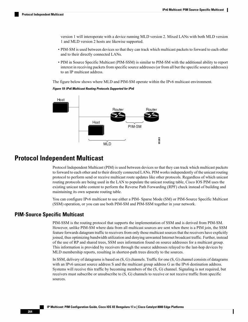
version 1 will interoperate with a device running MLD version 2. Mixed LANs with both MLD version1 and MLD version 2 hosts are likewise supported.
• PIM-SM is used between devices so that they can track which multicast packets to forward to each otherand to their directly connected LANs.
• PIM in Source Specific Multicast (PIM-SSM) is similar to PIM-SM with the additional ability to reportinterest in receiving packets from specific source addresses (or from all but the specific source addresses)to an IP multicast address.
The figure below shows where MLD and PIM-SM operate within the IPv6 multicast environment.
Figure 19: IPv6 Multicast Routing Protocols Supported for IPv6
Protocol Independent MulticastProtocol Independent Multicast (PIM) is used between devices so that they can track which multicast packetsto forward to each other and to their directly connected LANs. PIMworks independently of the unicast routingprotocol to perform send or receive multicast route updates like other protocols. Regardless of which unicastrouting protocols are being used in the LAN to populate the unicast routing table, Cisco IOS PIM uses theexisting unicast table content to perform the Reverse Path Forwarding (RPF) check instead of building andmaintaining its own separate routing table.
You can configure IPv6 multicast to use either a PIM- Sparse Mode (SM) or PIM-Source Specific Multicast(SSM) operation, or you can use both PIM-SM and PIM-SSM together in your network.
PIM-Source Specific MulticastPIM-SSM is the routing protocol that supports the implementation of SSM and is derived from PIM-SM.However, unlike PIM-SM where data from all multicast sources are sent when there is a PIM join, the SSMfeature forwards datagram traffic to receivers from only thosemulticast sources that the receivers have explicitlyjoined, thus optimizing bandwidth utilization and denying unwanted Internet broadcast traffic. Further, insteadof the use of RP and shared trees, SSM uses information found on source addresses for a multicast group.This information is provided by receivers through the source addresses relayed to the last-hop devices byMLD membership reports, resulting in shortest-path trees directly to the sources.
In SSM, delivery of datagrams is based on (S, G) channels. Traffic for one (S, G) channel consists of datagramswith an IPv6 unicast source address S and the multicast group address G as the IPv6 destination address.Systems will receive this traffic by becoming members of the (S, G) channel. Signaling is not required, butreceivers must subscribe or unsubscribe to (S, G) channels to receive or not receive traffic from specificsources.
IP Multicast: PIM Configuration Guide, Cisco IOS XE Bengaluru 17.x | Cisco Catalyst 8000 Edge Platforms264
IPv6 Multicast: PIM Source-Specific MulticastProtocol Independent Multicast
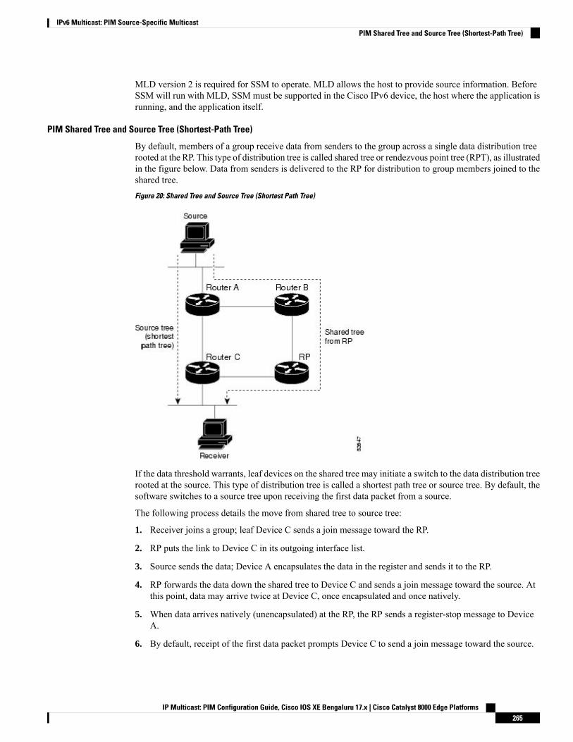
MLD version 2 is required for SSM to operate. MLD allows the host to provide source information. BeforeSSM will run with MLD, SSM must be supported in the Cisco IPv6 device, the host where the application isrunning, and the application itself.
PIM Shared Tree and Source Tree (Shortest-Path Tree)
By default, members of a group receive data from senders to the group across a single data distribution treerooted at the RP. This type of distribution tree is called shared tree or rendezvous point tree (RPT), as illustratedin the figure below. Data from senders is delivered to the RP for distribution to group members joined to theshared tree.
Figure 20: Shared Tree and Source Tree (Shortest Path Tree)
If the data threshold warrants, leaf devices on the shared tree may initiate a switch to the data distribution treerooted at the source. This type of distribution tree is called a shortest path tree or source tree. By default, thesoftware switches to a source tree upon receiving the first data packet from a source.
The following process details the move from shared tree to source tree:
1. Receiver joins a group; leaf Device C sends a join message toward the RP.
2. RP puts the link to Device C in its outgoing interface list.
3. Source sends the data; Device A encapsulates the data in the register and sends it to the RP.
4. RP forwards the data down the shared tree to Device C and sends a join message toward the source. Atthis point, data may arrive twice at Device C, once encapsulated and once natively.
5. When data arrives natively (unencapsulated) at the RP, the RP sends a register-stop message to DeviceA.
6. By default, receipt of the first data packet prompts Device C to send a join message toward the source.
IP Multicast: PIM Configuration Guide, Cisco IOS XE Bengaluru 17.x | Cisco Catalyst 8000 Edge Platforms265
IPv6 Multicast: PIM Source-Specific MulticastPIM Shared Tree and Source Tree (Shortest-Path Tree)
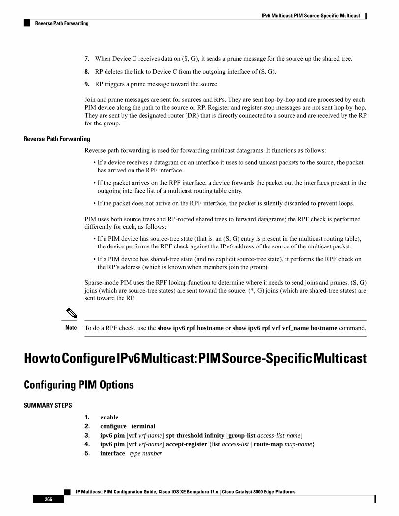
7. When Device C receives data on (S, G), it sends a prune message for the source up the shared tree.
8. RP deletes the link to Device C from the outgoing interface of (S, G).
9. RP triggers a prune message toward the source.
Join and prune messages are sent for sources and RPs. They are sent hop-by-hop and are processed by eachPIM device along the path to the source or RP. Register and register-stop messages are not sent hop-by-hop.They are sent by the designated router (DR) that is directly connected to a source and are received by the RPfor the group.
Reverse Path Forwarding
Reverse-path forwarding is used for forwarding multicast datagrams. It functions as follows:
• If a device receives a datagram on an interface it uses to send unicast packets to the source, the packethas arrived on the RPF interface.
• If the packet arrives on the RPF interface, a device forwards the packet out the interfaces present in theoutgoing interface list of a multicast routing table entry.
• If the packet does not arrive on the RPF interface, the packet is silently discarded to prevent loops.
PIM uses both source trees and RP-rooted shared trees to forward datagrams; the RPF check is performeddifferently for each, as follows:
• If a PIM device has source-tree state (that is, an (S, G) entry is present in the multicast routing table),the device performs the RPF check against the IPv6 address of the source of the multicast packet.
• If a PIM device has shared-tree state (and no explicit source-tree state), it performs the RPF check onthe RP’s address (which is known when members join the group).
Sparse-mode PIM uses the RPF lookup function to determine where it needs to send joins and prunes. (S, G)joins (which are source-tree states) are sent toward the source. (*, G) joins (which are shared-tree states) aresent toward the RP.
To do a RPF check, use the show ipv6 rpf hostname or show ipv6 rpf vrf vrf_name hostname command.Note
HowtoConfigureIPv6Multicast:PIMSource-SpecificMulticast
Configuring PIM Options
SUMMARY STEPS
1. enable2. configure terminal3. ipv6 pim [vrf vrf-name] spt-threshold infinity [group-list access-list-name]4. ipv6 pim [vrf vrf-name] accept-register {list access-list | route-map map-name}5. interface type number
IP Multicast: PIM Configuration Guide, Cisco IOS XE Bengaluru 17.x | Cisco Catalyst 8000 Edge Platforms266
IPv6 Multicast: PIM Source-Specific MulticastReverse Path Forwarding

6. ipv6 pim dr-priority value
7. ipv6 pim hello-interval seconds
8. ipv6 pim join-prune-interval seconds
9. exit10. show ipv6 pim [vrf vrf-name] join-prune statistic [interface-type]
DETAILED STEPS
PurposeCommand or Action
Enables privileged EXEC mode.enableStep 1
Example: • Enter your password if prompted.
Device> enable
Enters global configuration mode.configure terminal
Example:
Step 2
Device# configure terminal
Configures when a PIM leaf device joins the SPT for thespecified groups.
ipv6 pim [vrf vrf-name] spt-threshold infinity [group-listaccess-list-name]
Example:
Step 3
Device(config)# ipv6 pim spt-threshold infinitygroup-list acc-grp-1
Accepts or rejects registers at the RP.ipv6 pim [vrf vrf-name] accept-register {list access-list| route-map map-name}
Step 4
Example:
Device(config)# ipv6 pim accept-register route-mapreg-filter
Specifies an interface type and number, and places thedevice in interface configuration mode.
interface type number
Example:
Step 5
Device(config)# interface FastEthernet 1/0
Configures the DR priority on a PIM device.ipv6 pim dr-priority value
Example:
Step 6
Device(config-if)# ipv6 pim dr-priority 3
Configures the frequency of PIM hello messages on aninterface.
ipv6 pim hello-interval seconds
Example:
Step 7
Device(config-if)# ipv6 pim hello-interval 45
IP Multicast: PIM Configuration Guide, Cisco IOS XE Bengaluru 17.x | Cisco Catalyst 8000 Edge Platforms267
IPv6 Multicast: PIM Source-Specific MulticastConfiguring PIM Options
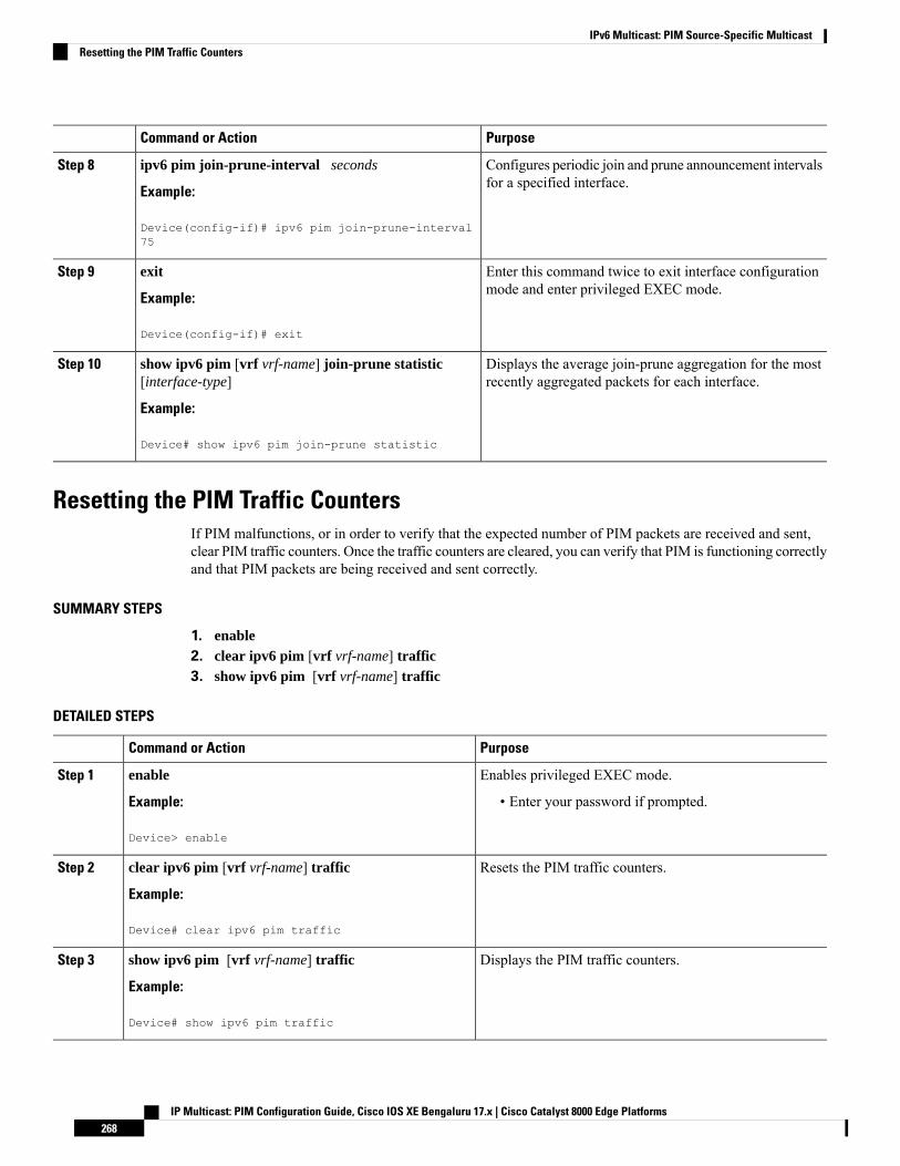
PurposeCommand or Action
Configures periodic join and prune announcement intervalsfor a specified interface.
ipv6 pim join-prune-interval seconds
Example:
Step 8
Device(config-if)# ipv6 pim join-prune-interval75
Enter this command twice to exit interface configurationmode and enter privileged EXEC mode.
exit
Example:
Step 9
Device(config-if)# exit
Displays the average join-prune aggregation for the mostrecently aggregated packets for each interface.
show ipv6 pim [vrf vrf-name] join-prune statistic[interface-type]
Example:
Step 10
Device# show ipv6 pim join-prune statistic
Resetting the PIM Traffic CountersIf PIM malfunctions, or in order to verify that the expected number of PIM packets are received and sent,clear PIM traffic counters. Once the traffic counters are cleared, you can verify that PIM is functioning correctlyand that PIM packets are being received and sent correctly.
SUMMARY STEPS
1. enable2. clear ipv6 pim [vrf vrf-name] traffic3. show ipv6 pim [vrf vrf-name] traffic
DETAILED STEPS
PurposeCommand or Action
Enables privileged EXEC mode.enableStep 1
Example: • Enter your password if prompted.
Device> enable
Resets the PIM traffic counters.clear ipv6 pim [vrf vrf-name] traffic
Example:
Step 2
Device# clear ipv6 pim traffic
Displays the PIM traffic counters.show ipv6 pim [vrf vrf-name] traffic
Example:
Step 3
Device# show ipv6 pim traffic
IP Multicast: PIM Configuration Guide, Cisco IOS XE Bengaluru 17.x | Cisco Catalyst 8000 Edge Platforms268
IPv6 Multicast: PIM Source-Specific MulticastResetting the PIM Traffic Counters
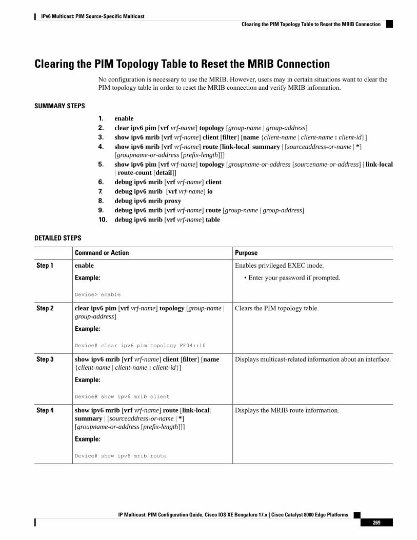
Clearing the PIM Topology Table to Reset the MRIB ConnectionNo configuration is necessary to use the MRIB. However, users may in certain situations want to clear thePIM topology table in order to reset the MRIB connection and verify MRIB information.
SUMMARY STEPS
1. enable2. clear ipv6 pim [vrf vrf-name] topology [group-name | group-address]3. show ipv6 mrib [vrf vrf-name] client [filter] [name {client-name | client-name : client-id}]4. show ipv6 mrib [vrf vrf-name] route [link-local| summary | [sourceaddress-or-name | *]
[groupname-or-address [prefix-length]]]5. show ipv6 pim [vrf vrf-name] topology [groupname-or-address [sourcename-or-address] | link-local
| route-count [detail]]6. debug ipv6 mrib [vrf vrf-name] client7. debug ipv6 mrib [vrf vrf-name] io8. debug ipv6 mrib proxy9. debug ipv6 mrib [vrf vrf-name] route [group-name | group-address]10. debug ipv6 mrib [vrf vrf-name] table
DETAILED STEPS
PurposeCommand or Action
Enables privileged EXEC mode.enableStep 1
Example: • Enter your password if prompted.
Device> enable
Clears the PIM topology table.clear ipv6 pim [vrf vrf-name] topology [group-name |group-address]
Step 2
Example:
Device# clear ipv6 pim topology FF04::10
Displays multicast-related information about an interface.show ipv6 mrib [vrf vrf-name] client [filter] [name{client-name | client-name : client-id}]
Step 3
Example:
Device# show ipv6 mrib client
Displays the MRIB route information.show ipv6 mrib [vrf vrf-name] route [link-local|summary | [sourceaddress-or-name | *][groupname-or-address [prefix-length]]]
Step 4
Example:
Device# show ipv6 mrib route
IP Multicast: PIM Configuration Guide, Cisco IOS XE Bengaluru 17.x | Cisco Catalyst 8000 Edge Platforms269
IPv6 Multicast: PIM Source-Specific MulticastClearing the PIM Topology Table to Reset the MRIB Connection
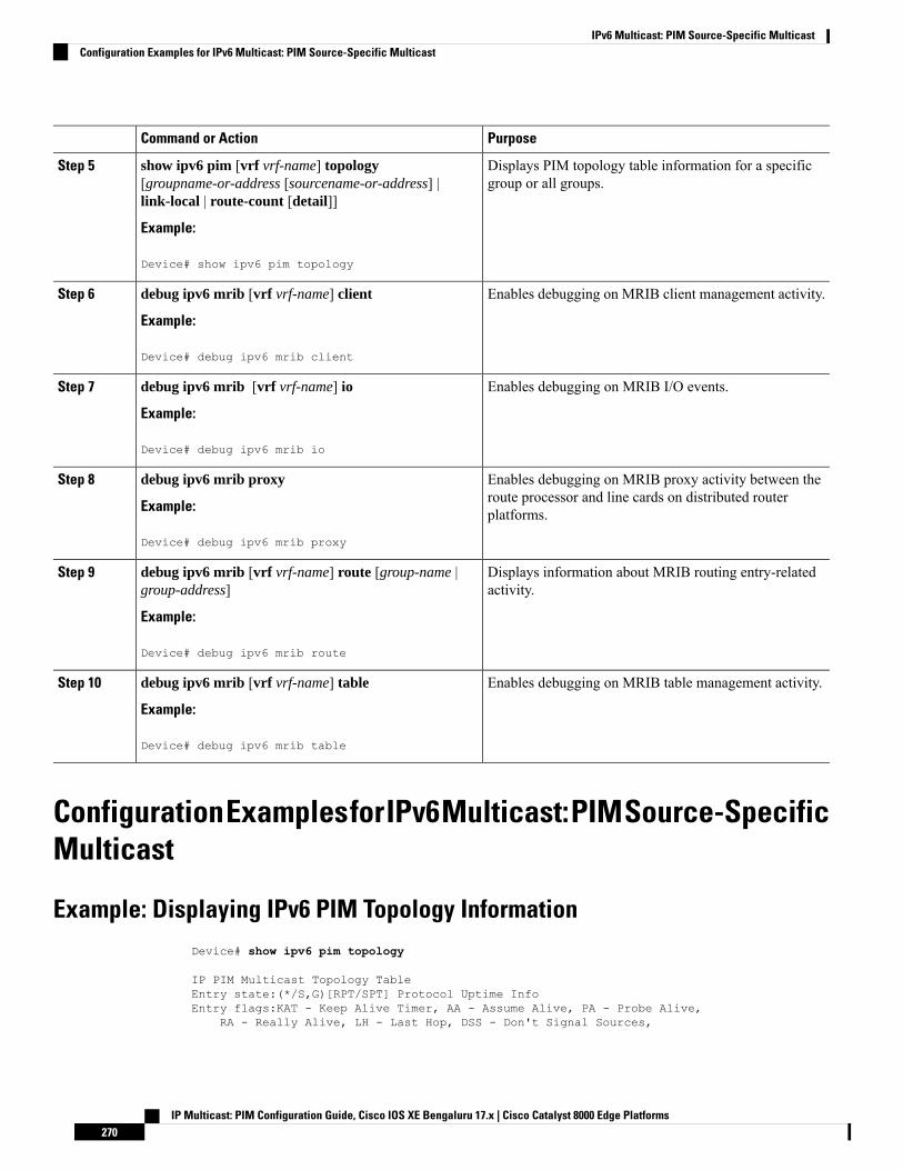
PurposeCommand or Action
Displays PIM topology table information for a specificgroup or all groups.
show ipv6 pim [vrf vrf-name] topology[groupname-or-address [sourcename-or-address] |link-local | route-count [detail]]
Step 5
Example:
Device# show ipv6 pim topology
Enables debugging on MRIB client management activity.debug ipv6 mrib [vrf vrf-name] client
Example:
Step 6
Device# debug ipv6 mrib client
Enables debugging on MRIB I/O events.debug ipv6 mrib [vrf vrf-name] io
Example:
Step 7
Device# debug ipv6 mrib io
Enables debugging on MRIB proxy activity between theroute processor and line cards on distributed routerplatforms.
debug ipv6 mrib proxy
Example:
Device# debug ipv6 mrib proxy
Step 8
Displays information about MRIB routing entry-relatedactivity.
debug ipv6 mrib [vrf vrf-name] route [group-name |group-address]
Example:
Step 9
Device# debug ipv6 mrib route
Enables debugging on MRIB table management activity.debug ipv6 mrib [vrf vrf-name] table
Example:
Step 10
Device# debug ipv6 mrib table
ConfigurationExamplesforIPv6Multicast:PIMSource-SpecificMulticast
Example: Displaying IPv6 PIM Topology InformationDevice# show ipv6 pim topology
IP PIM Multicast Topology TableEntry state:(*/S,G)[RPT/SPT] Protocol Uptime InfoEntry flags:KAT - Keep Alive Timer, AA - Assume Alive, PA - Probe Alive,
RA - Really Alive, LH - Last Hop, DSS - Don't Signal Sources,
IP Multicast: PIM Configuration Guide, Cisco IOS XE Bengaluru 17.x | Cisco Catalyst 8000 Edge Platforms270
IPv6 Multicast: PIM Source-Specific MulticastConfiguration Examples for IPv6 Multicast: PIM Source-Specific Multicast
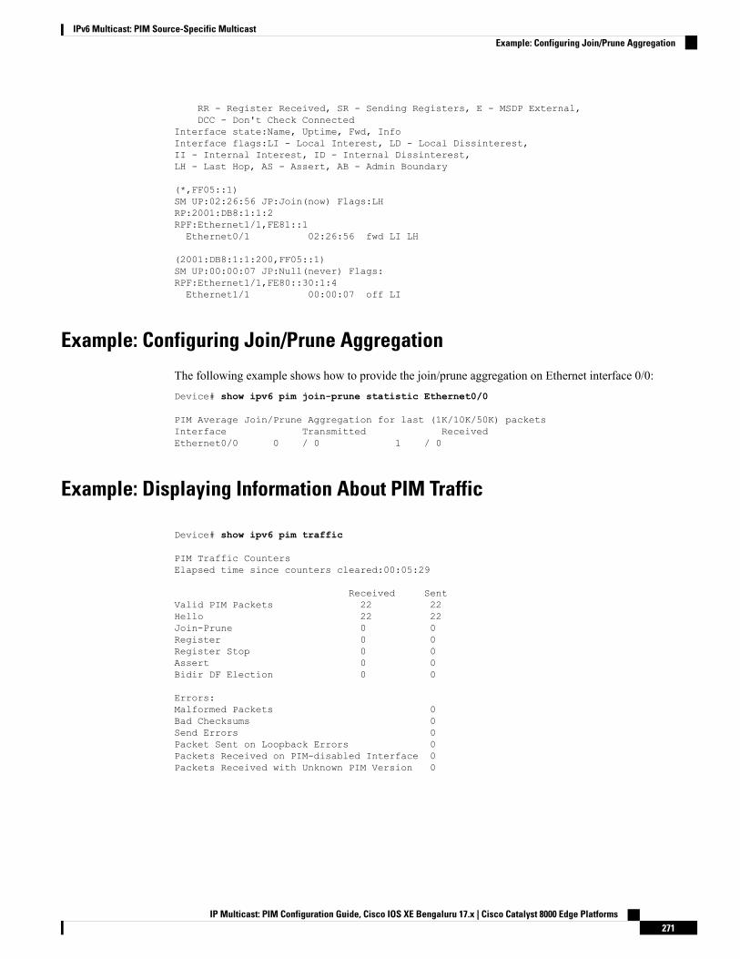
RR - Register Received, SR - Sending Registers, E - MSDP External,DCC - Don't Check Connected
Interface state:Name, Uptime, Fwd, InfoInterface flags:LI - Local Interest, LD - Local Dissinterest,II - Internal Interest, ID - Internal Dissinterest,LH - Last Hop, AS - Assert, AB - Admin Boundary
(*,FF05::1)SM UP:02:26:56 JP:Join(now) Flags:LHRP:2001:DB8:1:1:2RPF:Ethernet1/1,FE81::1Ethernet0/1 02:26:56 fwd LI LH
(2001:DB8:1:1:200,FF05::1)SM UP:00:00:07 JP:Null(never) Flags:RPF:Ethernet1/1,FE80::30:1:4Ethernet1/1 00:00:07 off LI
Example: Configuring Join/Prune Aggregation
The following example shows how to provide the join/prune aggregation on Ethernet interface 0/0:Device# show ipv6 pim join-prune statistic Ethernet0/0
PIM Average Join/Prune Aggregation for last (1K/10K/50K) packetsInterface Transmitted ReceivedEthernet0/0 0 / 0 1 / 0
Example: Displaying Information About PIM Traffic
Device# show ipv6 pim traffic
PIM Traffic CountersElapsed time since counters cleared:00:05:29
Received SentValid PIM Packets 22 22Hello 22 22Join-Prune 0 0Register 0 0Register Stop 0 0Assert 0 0Bidir DF Election 0 0
Errors:Malformed Packets 0Bad Checksums 0Send Errors 0Packet Sent on Loopback Errors 0Packets Received on PIM-disabled Interface 0Packets Received with Unknown PIM Version 0
IP Multicast: PIM Configuration Guide, Cisco IOS XE Bengaluru 17.x | Cisco Catalyst 8000 Edge Platforms271
IPv6 Multicast: PIM Source-Specific MulticastExample: Configuring Join/Prune Aggregation

Additional ReferencesRelated Documents
Document TitleRelated Topic
IPv6 Configuration GuideIPv6 addressing and connectivity
Cisco IOS Master Commands List, All ReleasesCisco IOS commands
Cisco IOS IP Multicast Command ReferenceIP multicast commands
Cisco IOS IPv6 Command ReferenceIPv6 commands
Cisco IOS IPv6 Feature MappingCisco IOS IPv6 features
Standards and RFCs
TitleStandard/RFC
IPv6 RFCsRFCs forIPv6
MIBs
MIBs LinkMIB
To locate and download MIBs for selected platforms, Cisco IOS releases, and feature sets, use CiscoMIB Locator found at the following URL:
http://www.cisco.com/go/mibs
Technical Assistance
LinkDescription
http://www.cisco.com/cisco/web/support/index.htmlTheCisco Support andDocumentationwebsite providesonline resources to download documentation, software,and tools. Use these resources to install and configurethe software and to troubleshoot and resolve technicalissues with Cisco products and technologies. Access tomost tools on the Cisco Support and Documentationwebsite requires a Cisco.com user ID and password.
IP Multicast: PIM Configuration Guide, Cisco IOS XE Bengaluru 17.x | Cisco Catalyst 8000 Edge Platforms272
IPv6 Multicast: PIM Source-Specific MulticastAdditional References

Feature Information for IPv6 Multicast: PIM Source-SpecificMulticast
The following table provides release information about the feature or features described in this module. Thistable lists only the software release that introduced support for a given feature in a given software releasetrain. Unless noted otherwise, subsequent releases of that software release train also support that feature.
Use Cisco Feature Navigator to find information about platform support and Cisco software image support.To access Cisco Feature Navigator, go to www.cisco.com/go/cfn. An account on Cisco.com is not required.
IP Multicast: PIM Configuration Guide, Cisco IOS XE Bengaluru 17.x | Cisco Catalyst 8000 Edge Platforms273
IPv6 Multicast: PIM Source-Specific MulticastFeature Information for IPv6 Multicast: PIM Source-Specific Multicast

IP Multicast: PIM Configuration Guide, Cisco IOS XE Bengaluru 17.x | Cisco Catalyst 8000 Edge Platforms274
IPv6 Multicast: PIM Source-Specific MulticastFeature Information for IPv6 Multicast: PIM Source-Specific Multicast
C H A P T E R 20IPv6 Source Specific Multicast Mapping
Source-specific multicast (SSM) SSM mapping for IPv6 supports both static and dynamic Domain NameSystem (DNS)mapping forMLD version 1 receivers. This feature allows deployment of IPv6 SSMwith hoststhat are incapable of providing MLD version 2 support in their TCP/IP host stack and their IP multicastreceiving application.
• Information About IPv6 Source Specific Multicast Mapping, on page 275• How to Configure IPv6 Source Specific Multicast Mapping, on page 275• Configuration Examples for IPv6 Source Specific Multicast Mapping, on page 277• Additional References, on page 277• Feature Information for IPv6 Source Specific Multicast Mapping, on page 278
Information About IPv6 Source Specific Multicast MappingSSM mapping for IPv6 supports both static and dynamic Domain Name System (DNS) mapping for MLDversion 1 receivers. This feature allows deployment of IPv6 SSM with hosts that are incapable of providingMLD version 2 support in their TCP/IP host stack and their IP multicast receiving application.
SSMmapping allows the device to look up the source of a multicast MLD version 1 report either in the runningconfiguration of the device or from aDNS server. The device can then initiate an (S, G) join toward the source.
How to Configure IPv6 Source Specific Multicast Mapping
Configuring IPv6 SSMWhen the SSMmapping feature is enabled, DNS-based SSMmapping is automatically enabled, which meansthat the device will look up the source of a multicast MLD version 1 report from a DNS server.
You can configure either DNS-based or static SSM mapping, depending on your device configuration. If youchoose to use static SSM mapping, you can configure multiple static SSM mappings. If multiple static SSMmappings are configured, the source addresses of all matching access lists will be used.
IP Multicast: PIM Configuration Guide, Cisco IOS XE Bengaluru 17.x | Cisco Catalyst 8000 Edge Platforms275

Before you begin
To use DNS-based SSM mapping, the device needs to find at least one correctly configured DNS server towhich the device can be directly attached.
Note
SUMMARY STEPS
1. enable2. configure terminal3. ipv6 mld [vrf vrf-name] ssm-map enable4. no ipv6 mld [vrf vrf-name] ssm-map query dns5. ipv6 mld [vrf vrf-name] ssm-map static access-list source-address
6. end7. show ipv6 mld [vrf vrf-name] ssm-map [source-address]
DETAILED STEPS
PurposeCommand or Action
Enables privileged EXEC mode.enableStep 1
Example: • Enter your password if prompted.
Device> enable
Enters global configuration mode.configure terminal
Example:
Step 2
Device# configure terminal
Enables the SSM mapping feature for groups in theconfigured SSM range.
ipv6 mld [vrf vrf-name] ssm-map enable
Example:
Step 3
Device(config)# ipv6 mld ssm-map enable
Disables DNS-based SSM mapping.no ipv6 mld [vrf vrf-name] ssm-map query dns
Example:
Step 4
Device(config)# no ipv6 mld ssm-map query dns
Configures static SSM mappings.ipv6 mld [vrf vrf-name] ssm-map static access-listsource-address
Step 5
Example:
Device(config)# ipv6 mld ssm-map staticSSM_MAP_ACL_2 2001:DB8:1::1
IP Multicast: PIM Configuration Guide, Cisco IOS XE Bengaluru 17.x | Cisco Catalyst 8000 Edge Platforms276
IPv6 Source Specific Multicast MappingConfiguring IPv6 SSM
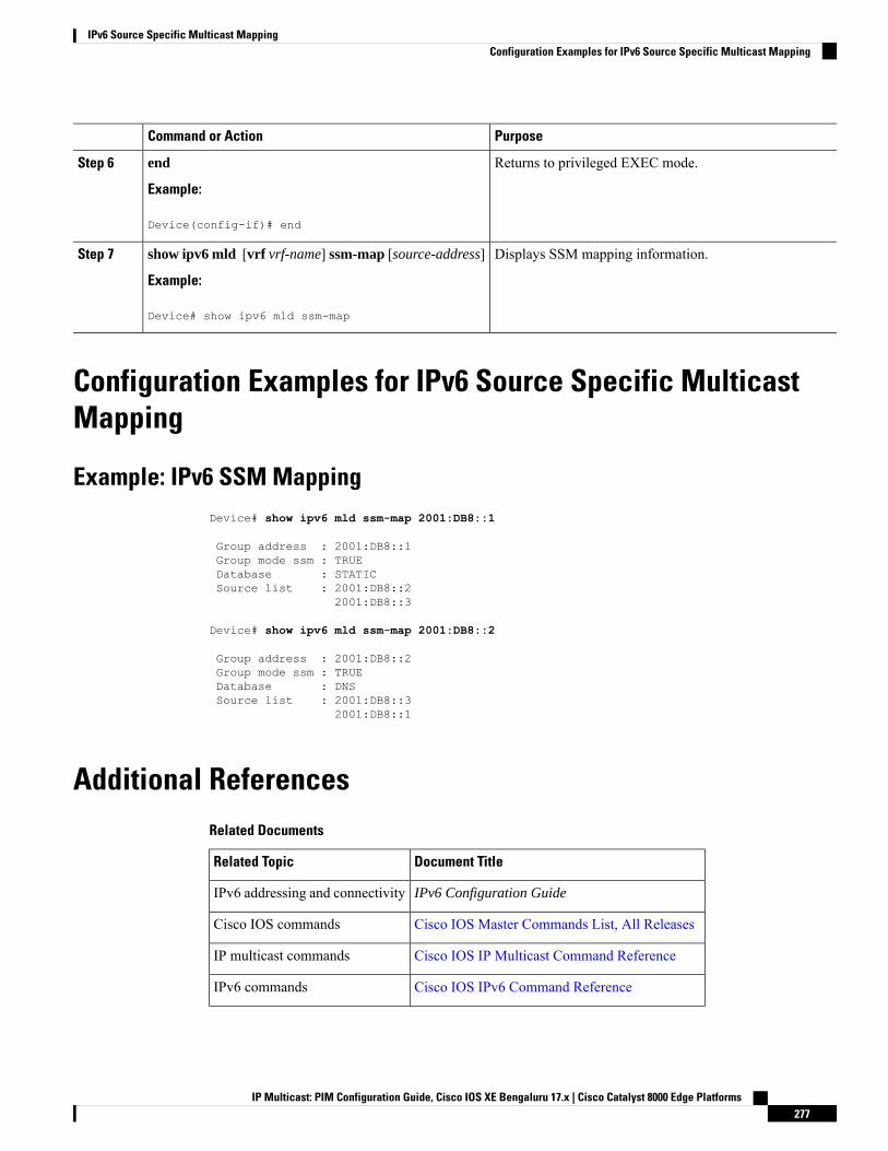
PurposeCommand or Action
Returns to privileged EXEC mode.end
Example:
Step 6
Device(config-if)# end
Displays SSM mapping information.show ipv6 mld [vrf vrf-name] ssm-map [source-address]
Example:
Step 7
Device# show ipv6 mld ssm-map
Configuration Examples for IPv6 Source Specific MulticastMapping
Example: IPv6 SSM MappingDevice# show ipv6 mld ssm-map 2001:DB8::1
Group address : 2001:DB8::1Group mode ssm : TRUEDatabase : STATICSource list : 2001:DB8::2
2001:DB8::3
Device# show ipv6 mld ssm-map 2001:DB8::2
Group address : 2001:DB8::2Group mode ssm : TRUEDatabase : DNSSource list : 2001:DB8::3
2001:DB8::1
Additional ReferencesRelated Documents
Document TitleRelated Topic
IPv6 Configuration GuideIPv6 addressing and connectivity
Cisco IOS Master Commands List, All ReleasesCisco IOS commands
Cisco IOS IP Multicast Command ReferenceIP multicast commands
Cisco IOS IPv6 Command ReferenceIPv6 commands
IP Multicast: PIM Configuration Guide, Cisco IOS XE Bengaluru 17.x | Cisco Catalyst 8000 Edge Platforms277
IPv6 Source Specific Multicast MappingConfiguration Examples for IPv6 Source Specific Multicast Mapping
Document TitleRelated Topic
Cisco IOS IPv6 Feature MappingCisco IOS IPv6 features
Standards and RFCs
TitleStandard/RFC
IPv6 RFCsRFCs forIPv6
MIBs
MIBs LinkMIB
To locate and download MIBs for selected platforms, Cisco IOS releases, and feature sets, use CiscoMIB Locator found at the following URL:
http://www.cisco.com/go/mibs
Technical Assistance
LinkDescription
http://www.cisco.com/cisco/web/support/index.htmlTheCisco Support andDocumentationwebsite providesonline resources to download documentation, software,and tools. Use these resources to install and configurethe software and to troubleshoot and resolve technicalissues with Cisco products and technologies. Access tomost tools on the Cisco Support and Documentationwebsite requires a Cisco.com user ID and password.
FeatureInformationforIPv6SourceSpecificMulticastMappingThe following table provides release information about the feature or features described in this module. Thistable lists only the software release that introduced support for a given feature in a given software releasetrain. Unless noted otherwise, subsequent releases of that software release train also support that feature.
Use Cisco Feature Navigator to find information about platform support and Cisco software image support.To access Cisco Feature Navigator, go to www.cisco.com/go/cfn. An account on Cisco.com is not required.
IP Multicast: PIM Configuration Guide, Cisco IOS XE Bengaluru 17.x | Cisco Catalyst 8000 Edge Platforms278
IPv6 Source Specific Multicast MappingFeature Information for IPv6 Source Specific Multicast Mapping
C H A P T E R 21IPv6 Multicast: Explicit Tracking of Receivers
• Information About IPv6 Multicast Explicit Tracking of Receivers, on page 279• How to Configure IPv6 Multicast Explicit Tracking of Receivers, on page 279• Configuration Examples for IPv6 Multicast Explicit Tracking of Receivers, on page 280• Additional References, on page 280• Feature Information for IPv6 Multicast: Explicit Tracking of Receivers, on page 281
Information About IPv6 Multicast Explicit Tracking of Receivers
Explicit Tracking of ReceiversThe explicit tracking feature allows a device to track the behavior of the hosts within its IPv6 network. Thisfeature also enables the fast leave mechanism to be used with MLD version 2 host reports.
How to Configure IPv6 Multicast Explicit Tracking of Receivers
Configuring Explicit Tracking of Receivers to Track Host Behavior
SUMMARY STEPS
1. enable2. configure terminal3. interface type number
4. ipv6 mld explicit-tracking access-list-name
DETAILED STEPS
PurposeCommand or Action
Enables privileged EXEC mode.enableStep 1
Example: • Enter your password if prompted.
IP Multicast: PIM Configuration Guide, Cisco IOS XE Bengaluru 17.x | Cisco Catalyst 8000 Edge Platforms279
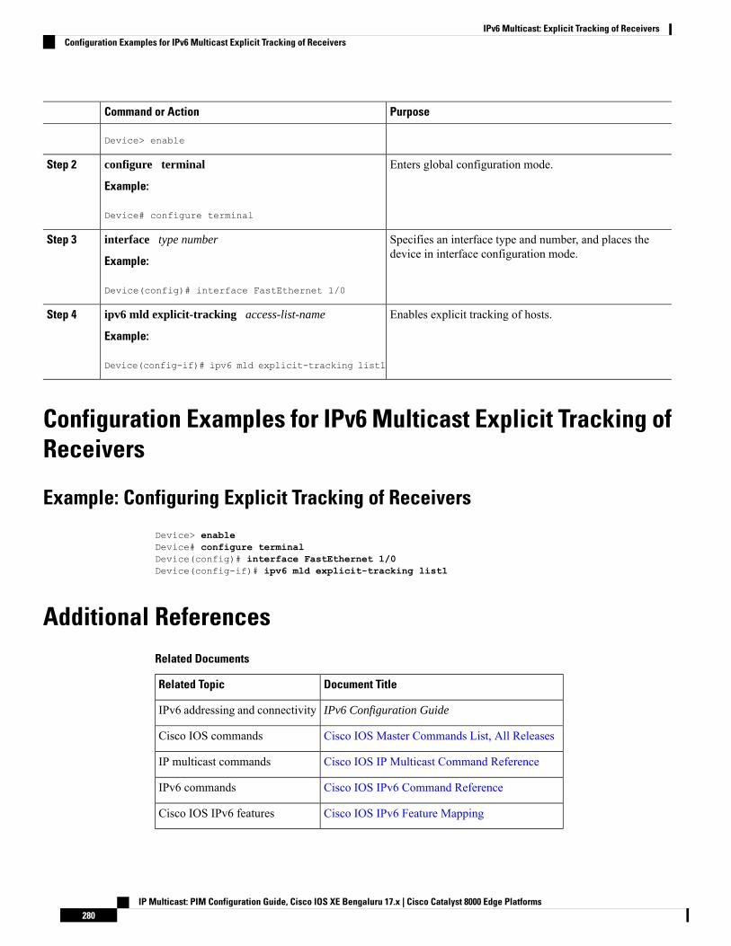
PurposeCommand or Action
Device> enable
Enters global configuration mode.configure terminal
Example:
Step 2
Device# configure terminal
Specifies an interface type and number, and places thedevice in interface configuration mode.
interface type number
Example:
Step 3
Device(config)# interface FastEthernet 1/0
Enables explicit tracking of hosts.ipv6 mld explicit-tracking access-list-name
Example:
Step 4
Device(config-if)# ipv6 mld explicit-tracking list1
Configuration Examples for IPv6 Multicast Explicit Tracking ofReceivers
Example: Configuring Explicit Tracking of Receivers
Device> enableDevice# configure terminalDevice(config)# interface FastEthernet 1/0Device(config-if)# ipv6 mld explicit-tracking list1
Additional ReferencesRelated Documents
Document TitleRelated Topic
IPv6 Configuration GuideIPv6 addressing and connectivity
Cisco IOS Master Commands List, All ReleasesCisco IOS commands
Cisco IOS IP Multicast Command ReferenceIP multicast commands
Cisco IOS IPv6 Command ReferenceIPv6 commands
Cisco IOS IPv6 Feature MappingCisco IOS IPv6 features
IP Multicast: PIM Configuration Guide, Cisco IOS XE Bengaluru 17.x | Cisco Catalyst 8000 Edge Platforms280
IPv6 Multicast: Explicit Tracking of ReceiversConfiguration Examples for IPv6 Multicast Explicit Tracking of Receivers
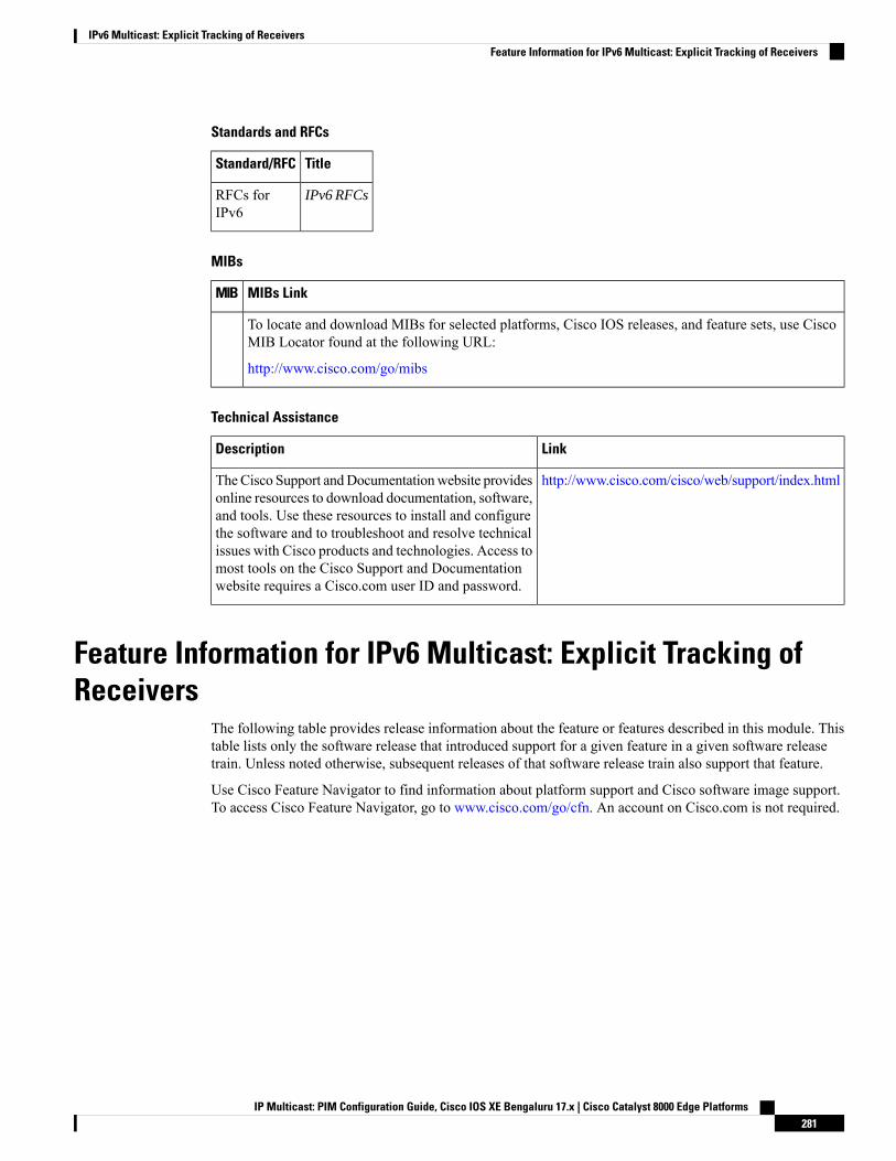
Standards and RFCs
TitleStandard/RFC
IPv6 RFCsRFCs forIPv6
MIBs
MIBs LinkMIB
To locate and download MIBs for selected platforms, Cisco IOS releases, and feature sets, use CiscoMIB Locator found at the following URL:
http://www.cisco.com/go/mibs
Technical Assistance
LinkDescription
http://www.cisco.com/cisco/web/support/index.htmlTheCisco Support andDocumentationwebsite providesonline resources to download documentation, software,and tools. Use these resources to install and configurethe software and to troubleshoot and resolve technicalissues with Cisco products and technologies. Access tomost tools on the Cisco Support and Documentationwebsite requires a Cisco.com user ID and password.
Feature Information for IPv6 Multicast: Explicit Tracking ofReceivers
The following table provides release information about the feature or features described in this module. Thistable lists only the software release that introduced support for a given feature in a given software releasetrain. Unless noted otherwise, subsequent releases of that software release train also support that feature.
Use Cisco Feature Navigator to find information about platform support and Cisco software image support.To access Cisco Feature Navigator, go to www.cisco.com/go/cfn. An account on Cisco.com is not required.
IP Multicast: PIM Configuration Guide, Cisco IOS XE Bengaluru 17.x | Cisco Catalyst 8000 Edge Platforms281
IPv6 Multicast: Explicit Tracking of ReceiversFeature Information for IPv6 Multicast: Explicit Tracking of Receivers

IP Multicast: PIM Configuration Guide, Cisco IOS XE Bengaluru 17.x | Cisco Catalyst 8000 Edge Platforms282
IPv6 Multicast: Explicit Tracking of ReceiversFeature Information for IPv6 Multicast: Explicit Tracking of Receivers
C H A P T E R 22IPv6 Bidirectional PIM
• Restrictions for IPv6 Bidirectional PIM, on page 283• Information About IPv6 Bidirectional PIM, on page 283• How to Configure IPv6 Bidirectional PIM, on page 284• Configuration Examples for IPv6 Bidirectional PIM, on page 285• Additional References, on page 285• Feature Information for IPv6 Bidirectional PIM, on page 286
Restrictions for IPv6 Bidirectional PIMWhen the bidirectional (bidir) range is used in a network, all devices in that network must be able to understandthe bidirectional range in the bootstrap message (BSM).
Information About IPv6 Bidirectional PIM
Bidirectional PIMBidirectional PIM allows multicast devices to keep reduced state information, as compared with unidirectionalshared trees in PIM-SM. Bidirectional shared trees convey data from sources to the RPA and distribute themfrom the RPA to the receivers. Unlike PIM-SM, bidirectional PIM does not switch over to the source tree,and there is no register encapsulation of data from the source to the RP.
A single designated forwarder (DF) exists for each RPA on every link within a bidirectional PIM domain(including multiaccess and point-to-point links). The only exception is the RPL on which no DF exists. TheDF is the device on the link with the best route to the RPA, which is determined by comparingMRIB-providedmetrics. A DF for a given RPA forwards downstream traffic onto its link and forwards upstream traffic fromits link toward the rendezvous point link (RPL). The DF performs this function for all bidirectional groupsthat map to the RPA. The DF on a link is also responsible for processing Join messages from downstreamdevices on the link as well as ensuring that packets are forwarded to local receivers discovered through a localmembership mechanism such as MLD.
Bidirectional PIM offers advantages when there are many moderate or low-rate sources. However, thebidirectional shared trees may have worse delay characteristics than do the source trees built in PIM-SM(depending on the topology).
Only static configuration of bidirectional RPs is supported in IPv6.
IP Multicast: PIM Configuration Guide, Cisco IOS XE Bengaluru 17.x | Cisco Catalyst 8000 Edge Platforms283
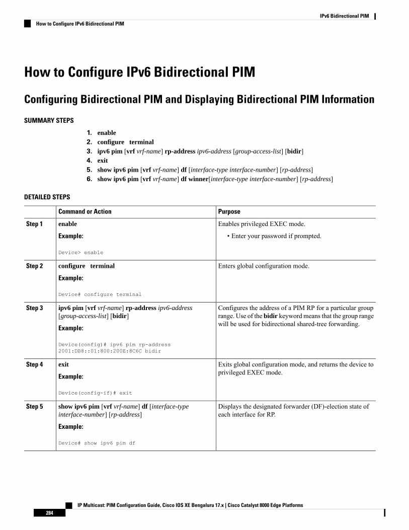
How to Configure IPv6 Bidirectional PIM
Configuring Bidirectional PIM and Displaying Bidirectional PIM Information
SUMMARY STEPS
1. enable2. configure terminal3. ipv6 pim [vrf vrf-name] rp-address ipv6-address [group-access-list] [bidir]4. exit5. show ipv6 pim [vrf vrf-name] df [interface-type interface-number] [rp-address]6. show ipv6 pim [vrf vrf-name] df winner[interface-type interface-number] [rp-address]
DETAILED STEPS
PurposeCommand or Action
Enables privileged EXEC mode.enableStep 1
Example: • Enter your password if prompted.
Device> enable
Enters global configuration mode.configure terminal
Example:
Step 2
Device# configure terminal
Configures the address of a PIM RP for a particular grouprange. Use of the bidir keyword means that the group rangewill be used for bidirectional shared-tree forwarding.
ipv6 pim [vrf vrf-name] rp-address ipv6-address[group-access-list] [bidir]
Example:
Step 3
Device(config)# ipv6 pim rp-address2001:DB8::01:800:200E:8C6C bidir
Exits global configuration mode, and returns the device toprivileged EXEC mode.
exit
Example:
Step 4
Device(config-if)# exit
Displays the designated forwarder (DF)-election state ofeach interface for RP.
show ipv6 pim [vrf vrf-name] df [interface-typeinterface-number] [rp-address]
Example:
Step 5
Device# show ipv6 pim df
IP Multicast: PIM Configuration Guide, Cisco IOS XE Bengaluru 17.x | Cisco Catalyst 8000 Edge Platforms284
IPv6 Bidirectional PIMHow to Configure IPv6 Bidirectional PIM

PurposeCommand or Action
Displays the DF-election winner on each interface for eachRP.
show ipv6 pim [vrf vrf-name] df winner[interface-typeinterface-number] [rp-address]
Example:
Step 6
Device# show ipv6 pim df winner ethernet 1/0 200::1
Configuration Examples for IPv6 Bidirectional PIM
Example: Configuring Bidirectional PIM and Displaying Bidirectional PIMInformation
The following example displays the DF-election states:Device# show ipv6 pim df
Interface DF State Timer MetricsEthernet0/0 Winner 4s 8ms [120/2]
RP :200::1Ethernet1/0 Lose 0s 0ms [inf/inf]
RP :200::1
The following example displays information on the RP:Device# show ipv6 pim df
Interface DF State Timer MetricsEthernet0/0 None:RP LAN 0s 0ms [inf/inf]
RP :200::1Ethernet1/0 Winner 7s 600ms [0/0]
RP :200::1Ethernet2/0 Winner 9s 8ms [0/0]
RP :200::1
Additional ReferencesRelated Documents
Document TitleRelated Topic
IPv6 Configuration GuideIPv6 addressing and connectivity
Cisco IOS Master Commands List, All ReleasesCisco IOS commands
Cisco IOS IP Multicast Command ReferenceIP multicast commands
Cisco IOS IPv6 Command ReferenceIPv6 commands
IP Multicast: PIM Configuration Guide, Cisco IOS XE Bengaluru 17.x | Cisco Catalyst 8000 Edge Platforms285
IPv6 Bidirectional PIMConfiguration Examples for IPv6 Bidirectional PIM
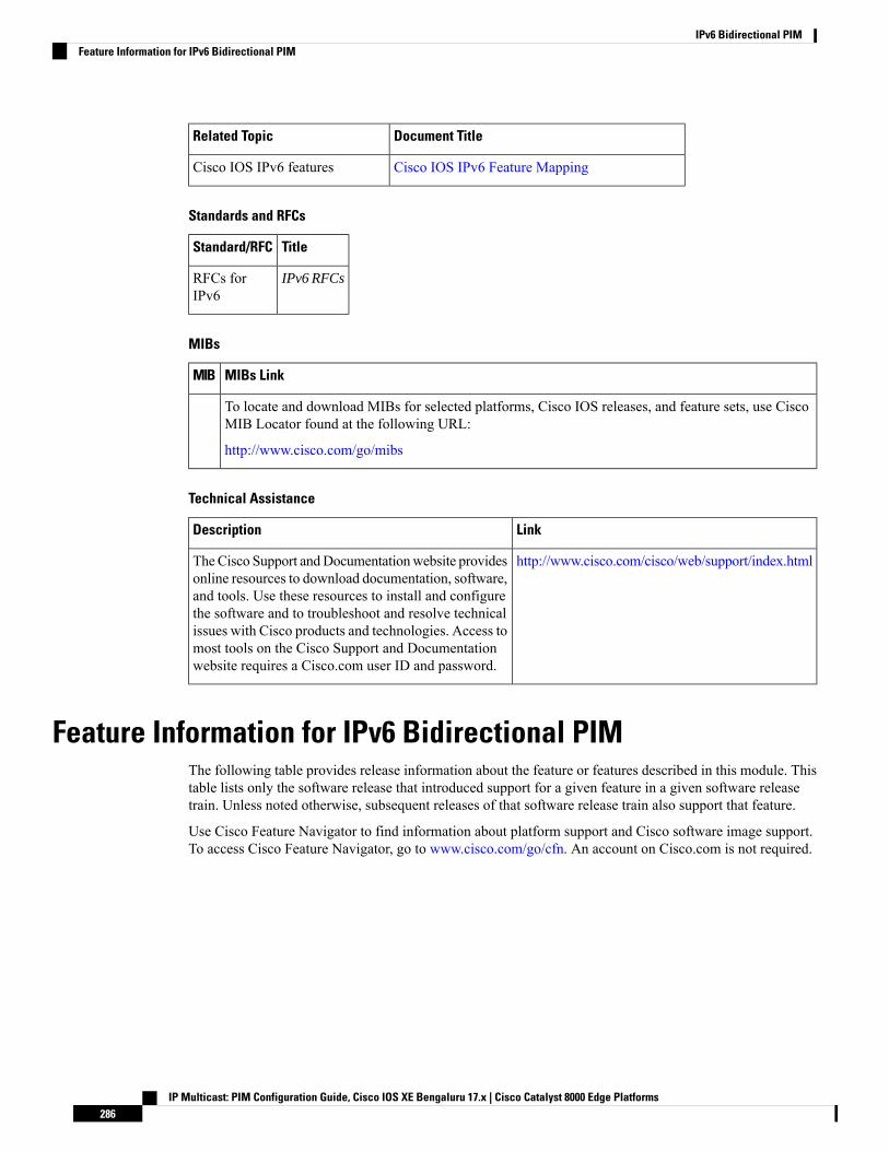
Document TitleRelated Topic
Cisco IOS IPv6 Feature MappingCisco IOS IPv6 features
Standards and RFCs
TitleStandard/RFC
IPv6 RFCsRFCs forIPv6
MIBs
MIBs LinkMIB
To locate and download MIBs for selected platforms, Cisco IOS releases, and feature sets, use CiscoMIB Locator found at the following URL:
http://www.cisco.com/go/mibs
Technical Assistance
LinkDescription
http://www.cisco.com/cisco/web/support/index.htmlTheCisco Support andDocumentationwebsite providesonline resources to download documentation, software,and tools. Use these resources to install and configurethe software and to troubleshoot and resolve technicalissues with Cisco products and technologies. Access tomost tools on the Cisco Support and Documentationwebsite requires a Cisco.com user ID and password.
Feature Information for IPv6 Bidirectional PIMThe following table provides release information about the feature or features described in this module. Thistable lists only the software release that introduced support for a given feature in a given software releasetrain. Unless noted otherwise, subsequent releases of that software release train also support that feature.
Use Cisco Feature Navigator to find information about platform support and Cisco software image support.To access Cisco Feature Navigator, go to www.cisco.com/go/cfn. An account on Cisco.com is not required.
IP Multicast: PIM Configuration Guide, Cisco IOS XE Bengaluru 17.x | Cisco Catalyst 8000 Edge Platforms286
IPv6 Bidirectional PIMFeature Information for IPv6 Bidirectional PIM

C H A P T E R 23IPv6 PIM Passive Mode
This feature allows PIM passive mode to be enabled on an interface so that a PIM passive interface cannotsend and receive PIM control messages, but it can act as a reverse path forwarding (RPF) interface for multicastroute entries, and it can accept and forward multicast data packets.
• Information About IPv6 PIM Passive Mode, on page 287• How to Configure IPv6 PIM Passive Mode, on page 287• Additional References, on page 288• Feature Information for IPv6 PIM Passive, on page 289
Information About IPv6 PIM Passive ModeA device configured with PIM will always send out PIM hello messages to all interfaces enabled for IPv6multicast routing, even if the device is configured not to accept PIMmessages from any neighbor on the LAN.The IPv6 PIM passive mode feature allows PIM passive mode to be enabled on an interface so that a PIMpassive interface cannot send and receive PIM control messages, but it can act as RPF interface for multicastroute entries, and it can accept and forward multicast data packets.
How to Configure IPv6 PIM Passive ModeSUMMARY STEPS
1. enable2. configure terminal3. ipv6 multicast pim-passive-enable4. interface type number
5. ipv6 pim passive
DETAILED STEPS
Step 1 enable
Example:
IP Multicast: PIM Configuration Guide, Cisco IOS XE Bengaluru 17.x | Cisco Catalyst 8000 Edge Platforms287
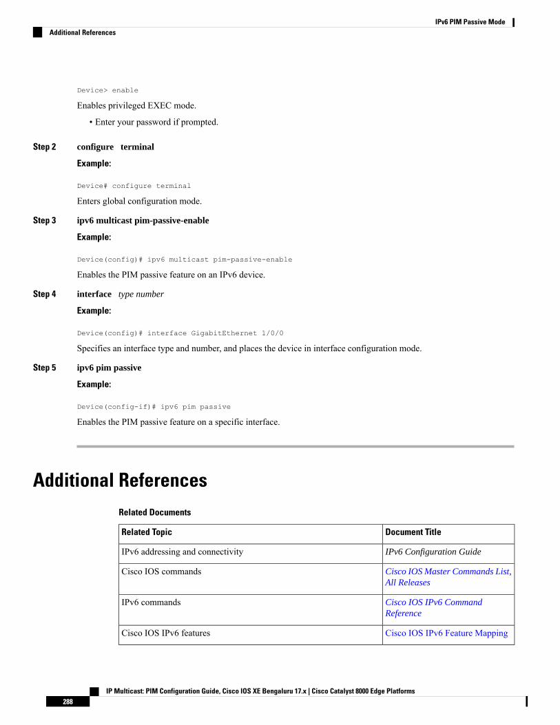
Device> enable
Enables privileged EXEC mode.
• Enter your password if prompted.
Step 2 configure terminal
Example:
Device# configure terminal
Enters global configuration mode.
Step 3 ipv6 multicast pim-passive-enable
Example:
Device(config)# ipv6 multicast pim-passive-enable
Enables the PIM passive feature on an IPv6 device.
Step 4 interface type number
Example:
Device(config)# interface GigabitEthernet 1/0/0
Specifies an interface type and number, and places the device in interface configuration mode.
Step 5 ipv6 pim passive
Example:
Device(config-if)# ipv6 pim passive
Enables the PIM passive feature on a specific interface.
Additional ReferencesRelated Documents
Document TitleRelated Topic
IPv6 Configuration GuideIPv6 addressing and connectivity
Cisco IOS Master Commands List,All Releases
Cisco IOS commands
Cisco IOS IPv6 CommandReference
IPv6 commands
Cisco IOS IPv6 Feature MappingCisco IOS IPv6 features
IP Multicast: PIM Configuration Guide, Cisco IOS XE Bengaluru 17.x | Cisco Catalyst 8000 Edge Platforms288
IPv6 PIM Passive ModeAdditional References
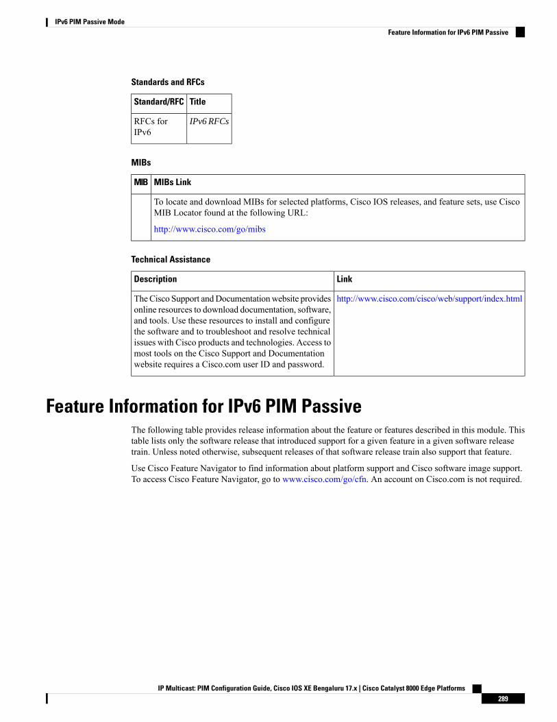
Standards and RFCs
TitleStandard/RFC
IPv6 RFCsRFCs forIPv6
MIBs
MIBs LinkMIB
To locate and download MIBs for selected platforms, Cisco IOS releases, and feature sets, use CiscoMIB Locator found at the following URL:
http://www.cisco.com/go/mibs
Technical Assistance
LinkDescription
http://www.cisco.com/cisco/web/support/index.htmlTheCisco Support andDocumentationwebsite providesonline resources to download documentation, software,and tools. Use these resources to install and configurethe software and to troubleshoot and resolve technicalissues with Cisco products and technologies. Access tomost tools on the Cisco Support and Documentationwebsite requires a Cisco.com user ID and password.
Feature Information for IPv6 PIM PassiveThe following table provides release information about the feature or features described in this module. Thistable lists only the software release that introduced support for a given feature in a given software releasetrain. Unless noted otherwise, subsequent releases of that software release train also support that feature.
Use Cisco Feature Navigator to find information about platform support and Cisco software image support.To access Cisco Feature Navigator, go to www.cisco.com/go/cfn. An account on Cisco.com is not required.
IP Multicast: PIM Configuration Guide, Cisco IOS XE Bengaluru 17.x | Cisco Catalyst 8000 Edge Platforms289
IPv6 PIM Passive ModeFeature Information for IPv6 PIM Passive

IP Multicast: PIM Configuration Guide, Cisco IOS XE Bengaluru 17.x | Cisco Catalyst 8000 Edge Platforms290
IPv6 PIM Passive ModeFeature Information for IPv6 PIM Passive
C H A P T E R 24IPv6 Multicast: Routable Address Hello Option
The routable address hello option adds a PIM hello message option that includes all the addresses on theinterface on which the PIM hello message is advertised.
• Information About the Routable Address Hello Option, on page 291• How to Configure IPv6 Multicast: Routable Address Hello Option, on page 292• Configuration Example for the Routable Address Hello Option, on page 293• Additional References, on page 293• Feature Information for IPv6 Multicast: Routable Address Hello Option, on page 294
Information About the Routable Address Hello OptionWhen an IPv6 interior gateway protocol is used to build the unicast routing table, the procedure to detect theupstream device address assumes the address of a PIM neighbor is always same as the address of the next-hopdevice, as long as they refer to the same device. However, it may not be the case when a device has multipleaddresses on a link.
Two typical situations can lead to this situation for IPv6. The first situation can occur when the unicast routingtable is not built by an IPv6 interior gateway protocol such as multicast BGP. The second situation occurswhen the address of an RP shares a subnet prefix with downstream devices (note that the RP address has tobe domain-wide and therefore cannot be a link-local address).
The routable address hello option allows the PIM protocol to avoid such situations by adding a PIM hellomessage option that includes all the addresses on the interface on which the PIM hello message is advertised.When a PIM device finds an upstream device for some address, the result of RPF calculation is comparedwith the addresses in this option, in addition to the PIM neighbor's address itself. Because this option includesall the possible addresses of a PIM device on that link, it always includes the RPF calculation result if it refersto the PIM device supporting this option.
Because of size restrictions on PIM messages and the requirement that a routable address hello option fitswithin a single PIM hello message, a limit of 16 addresses can be configured on the interface.
IP Multicast: PIM Configuration Guide, Cisco IOS XE Bengaluru 17.x | Cisco Catalyst 8000 Edge Platforms291
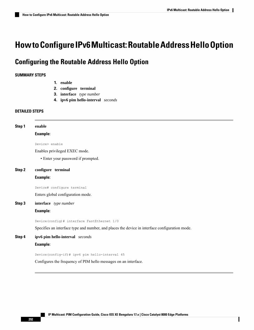
HowtoConfigureIPv6Multicast:RoutableAddressHelloOption
Configuring the Routable Address Hello Option
SUMMARY STEPS
1. enable2. configure terminal3. interface type number
4. ipv6 pim hello-interval seconds
DETAILED STEPS
Step 1 enable
Example:
Device> enable
Enables privileged EXEC mode.
• Enter your password if prompted.
Step 2 configure terminal
Example:
Device# configure terminal
Enters global configuration mode.
Step 3 interface type number
Example:
Device(config)# interface FastEthernet 1/0
Specifies an interface type and number, and places the device in interface configuration mode.
Step 4 ipv6 pim hello-interval seconds
Example:
Device(config-if)# ipv6 pim hello-interval 45
Configures the frequency of PIM hello messages on an interface.
IP Multicast: PIM Configuration Guide, Cisco IOS XE Bengaluru 17.x | Cisco Catalyst 8000 Edge Platforms292
IPv6 Multicast: Routable Address Hello OptionHow to Configure IPv6 Multicast: Routable Address Hello Option
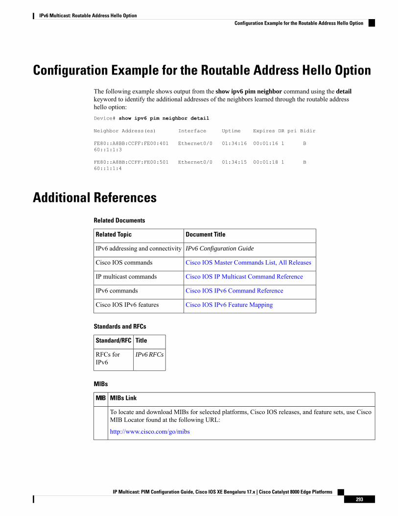
Configuration Example for the Routable Address Hello OptionThe following example shows output from the show ipv6 pim neighbor command using the detailkeyword to identify the additional addresses of the neighbors learned through the routable addresshello option:Device# show ipv6 pim neighbor detail
Neighbor Address(es) Interface Uptime Expires DR pri Bidir
FE80::A8BB:CCFF:FE00:401 Ethernet0/0 01:34:16 00:01:16 1 B60::1:1:3
FE80::A8BB:CCFF:FE00:501 Ethernet0/0 01:34:15 00:01:18 1 B60::1:1:4
Additional ReferencesRelated Documents
Document TitleRelated Topic
IPv6 Configuration GuideIPv6 addressing and connectivity
Cisco IOS Master Commands List, All ReleasesCisco IOS commands
Cisco IOS IP Multicast Command ReferenceIP multicast commands
Cisco IOS IPv6 Command ReferenceIPv6 commands
Cisco IOS IPv6 Feature MappingCisco IOS IPv6 features
Standards and RFCs
TitleStandard/RFC
IPv6 RFCsRFCs forIPv6
MIBs
MIBs LinkMIB
To locate and download MIBs for selected platforms, Cisco IOS releases, and feature sets, use CiscoMIB Locator found at the following URL:
http://www.cisco.com/go/mibs
IP Multicast: PIM Configuration Guide, Cisco IOS XE Bengaluru 17.x | Cisco Catalyst 8000 Edge Platforms293
IPv6 Multicast: Routable Address Hello OptionConfiguration Example for the Routable Address Hello Option
Technical Assistance
LinkDescription
http://www.cisco.com/cisco/web/support/index.htmlTheCisco Support andDocumentationwebsite providesonline resources to download documentation, software,and tools. Use these resources to install and configurethe software and to troubleshoot and resolve technicalissues with Cisco products and technologies. Access tomost tools on the Cisco Support and Documentationwebsite requires a Cisco.com user ID and password.
Feature Information for IPv6 Multicast: Routable Address HelloOption
The following table provides release information about the feature or features described in this module. Thistable lists only the software release that introduced support for a given feature in a given software releasetrain. Unless noted otherwise, subsequent releases of that software release train also support that feature.
Use Cisco Feature Navigator to find information about platform support and Cisco software image support.To access Cisco Feature Navigator, go to www.cisco.com/go/cfn. An account on Cisco.com is not required.
IP Multicast: PIM Configuration Guide, Cisco IOS XE Bengaluru 17.x | Cisco Catalyst 8000 Edge Platforms294
IPv6 Multicast: Routable Address Hello OptionFeature Information for IPv6 Multicast: Routable Address Hello Option

C H A P T E R 25PIMv6 Anycast RP Solution
• Information About the PIMv6 Anycast RP Solution, on page 295• How to Configure the PIMv6 Anycast RP Solution, on page 297• Configuration Examples for the PIMv6 Anycast RP Solution, on page 300• Additional References, on page 300• Feature Information for PIMv6 Anycast RP Solution, on page 301
Information About the PIMv6 Anycast RP Solution
PIMv6 Anycast RP Solution OverviewThe anycast RP solution in IPv6 PIM allows an IPv6 network to support anycast services for the PIM-SMRP. It allows anycast RP to be used inside a domain that runs PIM only. Anycast RP can be used in IPv4 aswell as IPv6, but it does not depend on the Multicast Source Discovery Protocol (MSDP), which runs onlyon IPv4. This feature is useful when interdomain connection is not required.
Anycast RP is a mechanism that ISP-based backbones use to get fast convergence when a PIM RP devicefails. To allow receivers and sources to rendezvous to the closest RP, the packets from a source need to getto all RPs to find joined receivers.
A unicast IP address is chosen as the RP address. This address is either statically configured or distributedusing a dynamic protocol to all PIM devices throughout the domain. A set of devices in the domain is chosento act as RPs for this RP address; these devices are called the anycast RP set. Each device in the anycast RPset is configured with a loopback interface using the RP address. Each device in the anycast RP set also needsa separate physical IP address to be used for communication between the RPs. Each device in the Anycast setmust contain the list of all the devices in the Anycast set.
The RP address, or a prefix that covers the RP address, is injected into the unicast routing system inside ofthe domain. Each device in the anycast RP set is configured with the addresses of all other devices in theanycast RP set, and this configuration must be consistent in all RPs in the set. The IP address of the localdevice must be included in the set so that all devices in anycast set have the same IP addresses.
PIMv6 Anycast RP Normal OperationThe following illustration shows PIMv6 anycast RP normal operation and assumes the following:
• RP1, RP2, RP3, and RP4 are members in the same anycast RP group.
IP Multicast: PIM Configuration Guide, Cisco IOS XE Bengaluru 17.x | Cisco Catalyst 8000 Edge Platforms295
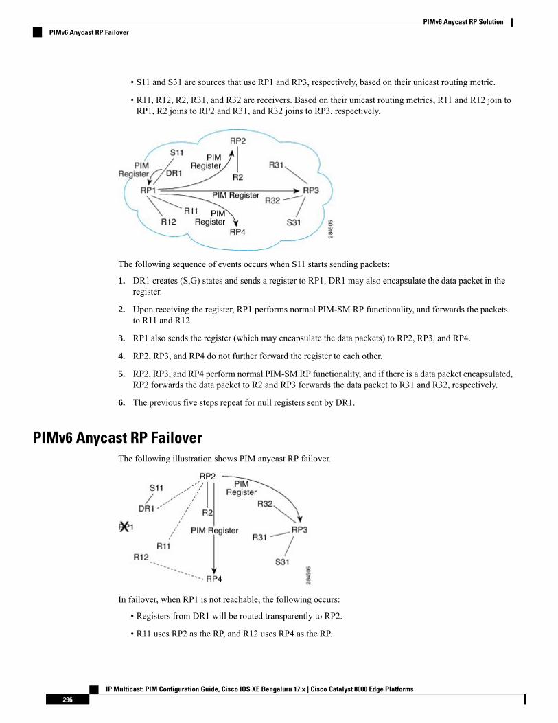
• S11 and S31 are sources that use RP1 and RP3, respectively, based on their unicast routing metric.
• R11, R12, R2, R31, and R32 are receivers. Based on their unicast routing metrics, R11 and R12 join toRP1, R2 joins to RP2 and R31, and R32 joins to RP3, respectively.
The following sequence of events occurs when S11 starts sending packets:
1. DR1 creates (S,G) states and sends a register to RP1. DR1 may also encapsulate the data packet in theregister.
2. Upon receiving the register, RP1 performs normal PIM-SM RP functionality, and forwards the packetsto R11 and R12.
3. RP1 also sends the register (which may encapsulate the data packets) to RP2, RP3, and RP4.
4. RP2, RP3, and RP4 do not further forward the register to each other.
5. RP2, RP3, and RP4 perform normal PIM-SM RP functionality, and if there is a data packet encapsulated,RP2 forwards the data packet to R2 and RP3 forwards the data packet to R31 and R32, respectively.
6. The previous five steps repeat for null registers sent by DR1.
PIMv6 Anycast RP FailoverThe following illustration shows PIM anycast RP failover.
In failover, when RP1 is not reachable, the following occurs:
• Registers from DR1 will be routed transparently to RP2.
• R11 uses RP2 as the RP, and R12 uses RP4 as the RP.
IP Multicast: PIM Configuration Guide, Cisco IOS XE Bengaluru 17.x | Cisco Catalyst 8000 Edge Platforms296
PIMv6 Anycast RP SolutionPIMv6 Anycast RP Failover

• Registers from DR1 will be routed from RP2 to RP3 and RP4.
In this way, the loss of the RP (RP1 in this case) is transparent to DR1, R11, and R12, and the network canconverge as soon as the IGP is converged.
How to Configure the PIMv6 Anycast RP Solution
Configuring PIMv6 Anycast RPThis task describes how to configure two PIMv6 anycast RP peers. Steps 3 through 11 show the configurationfor RP1, and Steps 12 through 19 show the configuration for RP2.
SUMMARY STEPS
1. enable2. configure terminal3. ipv6 address {ipv6-address/prefix-length | prefix-name sub-bits /prefix-length}4. interface type number
5. ipv6 address {ipv6-address/prefix-length | prefix-name sub-bits /prefix-length}6. no shut7. interface type number
8. ipv6 pim [vrf vrf-name] rp-address ipv6-address [group-address-list ] [bidir]9. no shut10. exit11. ipv6 pim anycast-RP rp-address peer-address
12. ipv6 address {ipv6-address/prefix-length | prefix-name sub-bits /prefix-length}13. interface type number
14. ipv6 address {ipv6-address/prefix-length | prefix-name sub-bits /prefix-length}15. no shut16. interface type number
17. ipv6 pim [vrf vrf-name] rp-address ipv6-address [group-address-list ] [bidir]18. no shut19. ipv6 pim anycast-RP rp-address peer-address
DETAILED STEPS
PurposeCommand or Action
Enables privileged EXEC mode.enableStep 1
Example: Enter your password if prompted.Device> enable
Enters global configuration mode.configure terminal
Example:
Step 2
Device# configure terminal
IP Multicast: PIM Configuration Guide, Cisco IOS XE Bengaluru 17.x | Cisco Catalyst 8000 Edge Platforms297
PIMv6 Anycast RP SolutionHow to Configure the PIMv6 Anycast RP Solution

PurposeCommand or Action
Configures an IPv6 address based on an IPv6 general prefixand enable IPv6 processing on an interface.
ipv6 address {ipv6-address/prefix-length |prefix-name sub-bits /prefix-length}
Example:
Step 3
Device(config-if)# ipv6 add 2001:DB8::1:1/128
Specifies an interface type and number, and places thedevice in interface configuration mode.
interface type number
Example:
Step 4
Device(config)# interface Loopback4
Configures an IPv6 address based on an IPv6 general prefixand enable IPv6 processing on an interface.
ipv6 address {ipv6-address/prefix-length |prefix-name sub-bits /prefix-length}
Example:
Step 5
Device(config-if)# ipv6 address 2001:DB8::4:4/64
Enables an interface.no shut
Example:
Step 6
Device(config-if)# no shut
Specifies an interface type and number, and places thedevice in interface configuration mode.
interface type number
Example:
Step 7
Device(config-if)# interface Loopback5
Configures the address of a PIM RP for a particular grouprange.
ipv6 pim [vrf vrf-name] rp-address ipv6-address[group-address-list ] [bidir]
Example:
Step 8
Device(config)# ipv6 pim rp-address 2001:DB8::1:1acl_sparse1
Enables an interface.no shut
Example:
Step 9
Device(config-if)# no shut
Enter this command to exit interface configuration modeand enter global configuration mode.
exit
Example:
Step 10
Device(config-if)# exit
Use this command to configure the address of the PIM RPfor an anycast group range.
ipv6 pim anycast-RP rp-address peer-address
Example:
Step 11
• The IP address of the local device must be includedin the set so that all devices in anycast set have thesame IP addresses.
The following example shows configuring PIM RP for ananycast group range for a remote and local router:Device(config)# ipv6 pim anycast-rp 2001:DB8::1:12001:DB8::3:3# ipv6 pim anycast-rp 2001:DB8::1:1 2001:DB8::4:4
IP Multicast: PIM Configuration Guide, Cisco IOS XE Bengaluru 17.x | Cisco Catalyst 8000 Edge Platforms298
PIMv6 Anycast RP SolutionConfiguring PIMv6 Anycast RP

PurposeCommand or Action
Configures an IPv6 address based on an IPv6 general prefixand enables IPv6 processing on an interface.
ipv6 address {ipv6-address/prefix-length |prefix-name sub-bits /prefix-length}
Example:
Step 12
Device(config-if)# ipv6 add 2001:DB8::1:1/128
Specifies an interface type and number, and places thedevice in interface configuration mode.
interface type number
Example:
Step 13
Device(config)# interface Loopback4
Configures an IPv6 address based on an IPv6 general prefixand enables IPv6 processing on an interface.
ipv6 address {ipv6-address/prefix-length |prefix-name sub-bits /prefix-length}
Example:
Step 14
Device(config-if)# ipv6 address 2001:DB8::3:3/64
Enables an interface.no shut
Example:
Step 15
Device(config-if)# no shut
Specifies an interface type and number, and places thedevice in interface configuration mode.
interface type number
Example:
Step 16
Device(config-if)# interface Loopback5
Configures the address of a PIM RP for a particular grouprange.
ipv6 pim [vrf vrf-name] rp-address ipv6-address[group-address-list ] [bidir]
Example:
Step 17
Device(config)# ipv6 pim rp-address 2001:DB8::1:1acl_sparse1
Enables an interfaceno shut
Example:
Step 18
Device(config-if)# no shut
Use this command to configure the address of the PIM RPfor an anycast group range for a remote or local router.
ipv6 pim anycast-RP rp-address peer-address
Example:
Step 19
The following example shows configuring PIM RP for ananycast group range for a remote and local router:Device(config-if)# ipv6 pim anycast-rp2001:DB8::1:1 2001:DB8::3:3# ipv6 pim anycast-rp 2001:DB8::1:1 2001:DB8::4:4
IP Multicast: PIM Configuration Guide, Cisco IOS XE Bengaluru 17.x | Cisco Catalyst 8000 Edge Platforms299
PIMv6 Anycast RP SolutionConfiguring PIMv6 Anycast RP
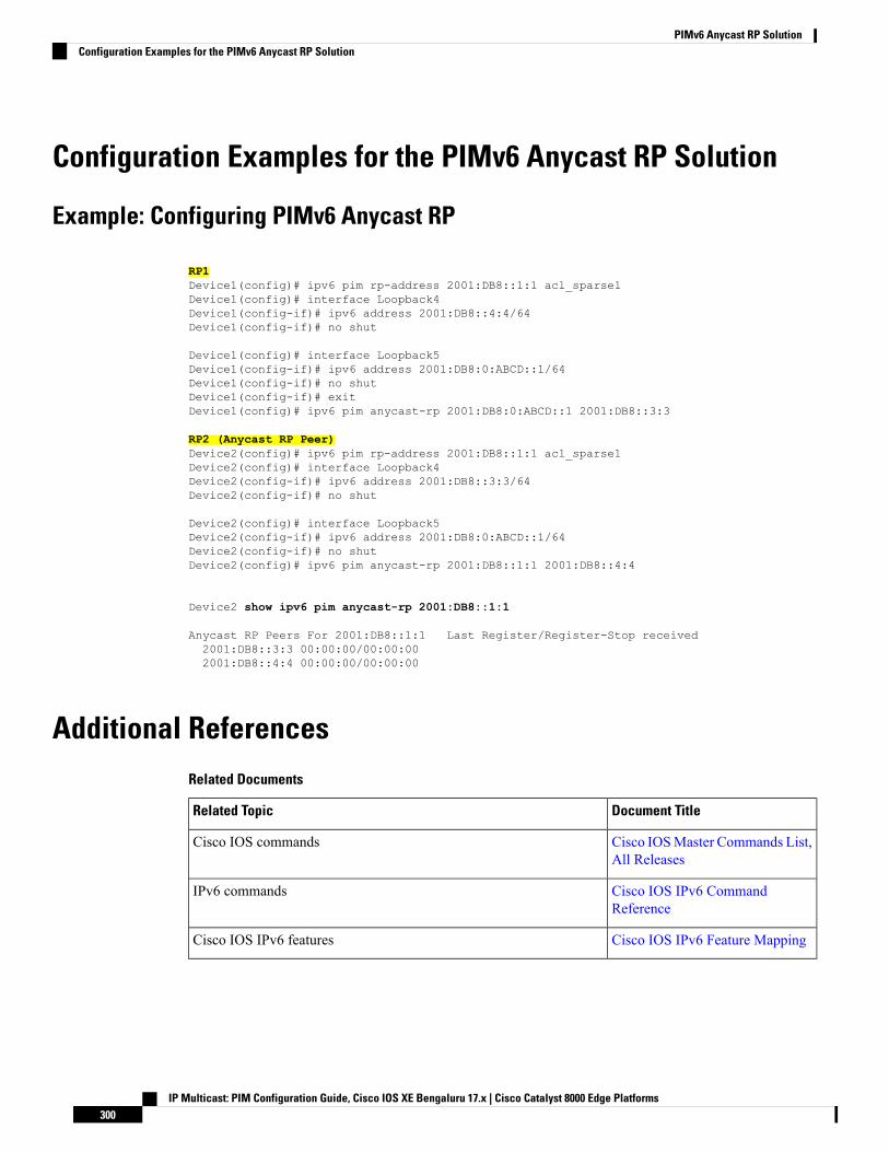
Configuration Examples for the PIMv6 Anycast RP Solution
Example: Configuring PIMv6 Anycast RP
RP1Device1(config)# ipv6 pim rp-address 2001:DB8::1:1 acl_sparse1Device1(config)# interface Loopback4Device1(config-if)# ipv6 address 2001:DB8::4:4/64Device1(config-if)# no shut
Device1(config)# interface Loopback5Device1(config-if)# ipv6 address 2001:DB8:0:ABCD::1/64Device1(config-if)# no shutDevice1(config-if)# exitDevice1(config)# ipv6 pim anycast-rp 2001:DB8:0:ABCD::1 2001:DB8::3:3
RP2 (Anycast RP Peer)Device2(config)# ipv6 pim rp-address 2001:DB8::1:1 acl_sparse1Device2(config)# interface Loopback4Device2(config-if)# ipv6 address 2001:DB8::3:3/64Device2(config-if)# no shut
Device2(config)# interface Loopback5Device2(config-if)# ipv6 address 2001:DB8:0:ABCD::1/64Device2(config-if)# no shutDevice2(config)# ipv6 pim anycast-rp 2001:DB8::1:1 2001:DB8::4:4
Device2 show ipv6 pim anycast-rp 2001:DB8::1:1
Anycast RP Peers For 2001:DB8::1:1 Last Register/Register-Stop received2001:DB8::3:3 00:00:00/00:00:002001:DB8::4:4 00:00:00/00:00:00
Additional ReferencesRelated Documents
Document TitleRelated Topic
Cisco IOSMaster Commands List,All Releases
Cisco IOS commands
Cisco IOS IPv6 CommandReference
IPv6 commands
Cisco IOS IPv6 Feature MappingCisco IOS IPv6 features
IP Multicast: PIM Configuration Guide, Cisco IOS XE Bengaluru 17.x | Cisco Catalyst 8000 Edge Platforms300
PIMv6 Anycast RP SolutionConfiguration Examples for the PIMv6 Anycast RP Solution
Standards and RFCs
TitleStandard/RFC
Anycast-RP Using Protocol Independent Multicast (PIM)RFC 4610
Technical Assistance
LinkDescription
http://www.cisco.com/cisco/web/support/index.htmlTheCisco Support andDocumentationwebsite providesonline resources to download documentation, software,and tools. Use these resources to install and configurethe software and to troubleshoot and resolve technicalissues with Cisco products and technologies. Access tomost tools on the Cisco Support and Documentationwebsite requires a Cisco.com user ID and password.
Feature Information for PIMv6 Anycast RP SolutionThe following table provides release information about the feature or features described in this module. Thistable lists only the software release that introduced support for a given feature in a given software releasetrain. Unless noted otherwise, subsequent releases of that software release train also support that feature.
Use Cisco Feature Navigator to find information about platform support and Cisco software image support.To access Cisco Feature Navigator, go to www.cisco.com/go/cfn. An account on Cisco.com is not required.
IP Multicast: PIM Configuration Guide, Cisco IOS XE Bengaluru 17.x | Cisco Catalyst 8000 Edge Platforms301
PIMv6 Anycast RP SolutionFeature Information for PIMv6 Anycast RP Solution

IP Multicast: PIM Configuration Guide, Cisco IOS XE Bengaluru 17.x | Cisco Catalyst 8000 Edge Platforms302
PIMv6 Anycast RP SolutionFeature Information for PIMv6 Anycast RP Solution
C H A P T E R 26MTR in VRF
The MTR in VRF feature extends to IPv4 VRF contexts the Cisco IOS software's capability that allows usersto configure one or more non-congruent multicast topologies in global IPv4 routing context. These contextscan be used to forward unicast and multicast traffic over different links in the network, or in the case ofnon-base topologies to provide a Live-Livemulticast service usingmultiple non-congruent multicast topologiesmapped to different (S,G) groups.
• Information About MTR in VRF, on page 303• How to Configure VRF in MTR, on page 303• Configuring Examples for MTR in VRF, on page 306• Additional References for MTR in VRF, on page 306• Feature Information for MTR in VRF, on page 307
Information About MTR in VRF
MTR in VRF OverviewThe MTR in VRF feature extends to IPv4 VRF contexts, Cisco IOS software's capability that allows users toconfigure one or more non-congruent multicast topologies in global IPv4 routing context. These contexts canbe used to forward unicast and multicast traffic over different links in the network, or in the case of non-basetopologies to provide a Live-Live multicast service using multiple non-congruent multicast topologies mappedto different (S,G) groups.
The Cisco IOS Software allows a set of attributes, primarily used by BGP/MPLS L3VPNs, to be configuredon a per-address family basis within a VRF. TheMTR inVRF feature allows these attributes to be independentlyconfigured for the multicast sub-address families within a VRF address family.
How to Configure VRF in MTR
Configuring MTR in VRF
SUMMARY STEPS
1. enable
IP Multicast: PIM Configuration Guide, Cisco IOS XE Bengaluru 17.x | Cisco Catalyst 8000 Edge Platforms303
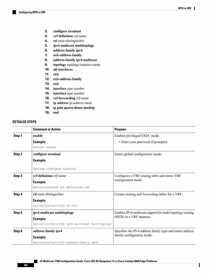
2. configure terminal3. vrf definition vrf-name
4. rd route-distinguisher
5. ipv4 multicast multitoplogy6. address-family ipv47. exit-address-family8. address-family ipv4 multicast9. topology topology-instance-name
10. all-interfaces11. exit12. exit-address-family13. exit14. interface type number
15. interface type number
16. vrf forwarding vrf-name
17. ip address ip-address mask
18. ip pim sparse-dense-modeip19. end
DETAILED STEPS
PurposeCommand or Action
Enables privileged EXEC mode.enableStep 1
Example: • Enter your password if prompted.Device> enable
Enters global configuration mode.configure terminal
Example:
Step 2
Device# configure terminal
Configures a VRF routing table and enters VRFconfiguration mode.
vrf definition vrf-name
Example:
Step 3
Device(config)# vrf definition vd1
Creates routing and forwarding tables for a VRF.rd route-distinguisher
Example:
Step 4
Device(config-vrf)# rd 10:1
Enables IPv4multicast support for multi-topology routing(MTR) in a VRF instance.
ipv4 multicast multitoplogy
Example:
Step 5
Device(config-vrf)# ipv4 multicast multitoplogy
Specifies the IPv4 address family type and enters addressfamily configuration mode.
address-family ipv4
Example:
Step 6
Device(config-vrf)# address-family ipv4
IP Multicast: PIM Configuration Guide, Cisco IOS XE Bengaluru 17.x | Cisco Catalyst 8000 Edge Platforms304
MTR in VRFConfiguring MTR in VRF

PurposeCommand or Action
Exits address family configuration mode and removes theIPv4 address family.
exit-address-family
Example:
Step 7
Device(config-vrf-af)# exit-address-family
Specifies the IPv4 address family multicast type and entersVRF address family configuration mode.
address-family ipv4 multicast
Example:
Step 8
Device(config-vrf)# address-family ipv4 multicast
Specifies a topology instance and a name to it and entersVRF address family topology configuration mode.
topology topology-instance-name
Example:
Step 9
Device(config-vrf-af)# topology red
Configure the topology instance to use all interfaces onthe device.
all-interfaces
Example:
Step 10
Device(config-vrf-af-topology)# all-interfaces
Exits VRF address-family topology configuration modeand enters VRF address-family configuration mode.
exit
Example:
Step 11
Device(config-vrf-af-topology)# exit
Exits address family configuration mode and removes theIPv4 address family.
exit-address-family
Example:
Step 12
Device(config-vrf-af)# exit-address-family
Exits VRF configuration mode and enters globalconfiguration mode.
exit
Example:
Step 13
Device(config-vrf)# exit
Selects the Ethernet interface and enters the interfaceconfiguration mode.
interface type number
Example:
Step 14
Device(config)# interface ethernet 0/1
Selects the Ethernet interface and enters the interfaceconfiguration mode.
interface type number
Example:
Step 15
Device(config)# interface ethernet 0/1
Associates a VRF instance with the interface.vrf forwarding vrf-name
Example:
Step 16
Device(config-if)# vrf forwwarding vrf1
Sets a primary or secondary IP address for an interface.ip address ip-address mask
Example:
Step 17
IP Multicast: PIM Configuration Guide, Cisco IOS XE Bengaluru 17.x | Cisco Catalyst 8000 Edge Platforms305
MTR in VRFConfiguring MTR in VRF
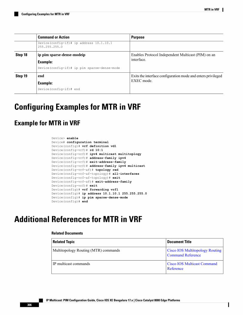
PurposeCommand or ActionDevice(config-if)# ip address 10.1.10.1255.255.255.0
Enables Protocol Independent Multicast (PIM) on aninterface.
ip pim sparse-dense-modeip
Example:
Step 18
Device(config-if)# ip pim sparse-dense-mode
Exits the interface configurationmode and enters privilegedEXEC mode.
end
Example:
Step 19
Device(config-if)# end
Configuring Examples for MTR in VRF
Example for MTR in VRF
Device> enableDevice# configuration terminalDevice(config)# vrf definition vd1Device(config-vrf)# rd 10:1Device(config-vrf)# ipv4 multicast multitoplogyDevice(config-vrf)# address-family ipv4Device(config-vrf)# exit-address-familyDevice(config-vrf)# address-family ipv4 multicastDevice(config-vrf-af)# topology redDevice(config-vrf-af-topology)# all-interfacesDevice(config-vrf-af-topology)# exitDevice(config-vrf-af)# exit-address-familyDevice(config-vrf)# exitDevice(config)# vrf forwarding vrf1Device(config)# ip address 10.1.10.1 255.255.255.0Device(config)# ip pim sparse-dense-modeDevice(config)# end
Additional References for MTR in VRFRelated Documents
Document TitleRelated Topic
Cisco IOS Multitopology RoutingCommand Reference
Multitopology Routing (MTR) commands
Cisco IOS Multicast CommandReference
IP multicast commands
IP Multicast: PIM Configuration Guide, Cisco IOS XE Bengaluru 17.x | Cisco Catalyst 8000 Edge Platforms306
MTR in VRFConfiguring Examples for MTR in VRF
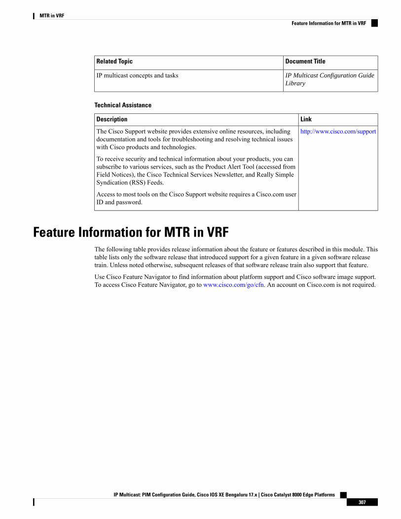
Document TitleRelated Topic
IP Multicast Configuration GuideLibrary
IP multicast concepts and tasks
Technical Assistance
LinkDescription
http://www.cisco.com/supportThe Cisco Support website provides extensive online resources, includingdocumentation and tools for troubleshooting and resolving technical issueswith Cisco products and technologies.
To receive security and technical information about your products, you cansubscribe to various services, such as the Product Alert Tool (accessed fromField Notices), the Cisco Technical Services Newsletter, and Really SimpleSyndication (RSS) Feeds.
Access to most tools on the Cisco Support website requires a Cisco.com userID and password.
Feature Information for MTR in VRFThe following table provides release information about the feature or features described in this module. Thistable lists only the software release that introduced support for a given feature in a given software releasetrain. Unless noted otherwise, subsequent releases of that software release train also support that feature.
Use Cisco Feature Navigator to find information about platform support and Cisco software image support.To access Cisco Feature Navigator, go to www.cisco.com/go/cfn. An account on Cisco.com is not required.
IP Multicast: PIM Configuration Guide, Cisco IOS XE Bengaluru 17.x | Cisco Catalyst 8000 Edge Platforms307
MTR in VRFFeature Information for MTR in VRF

IP Multicast: PIM Configuration Guide, Cisco IOS XE Bengaluru 17.x | Cisco Catalyst 8000 Edge Platforms308
MTR in VRFFeature Information for MTR in VRF
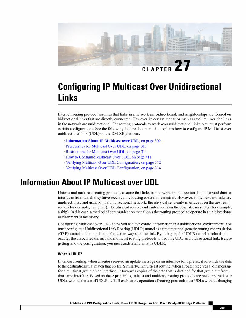
C H A P T E R 27Configuring IP Multicast Over UnidirectionalLinks
Internet routing protocol assumes that links in a network are bidirectional, and neighborships are formed onbidirectional links that are directly connected. However, in certain scenarios such as satellite links, the linksin the network are unidirectional. For routing protocols to work over unidirectional links, you must performcertain configurations. See the following feature document that explains how to configure IP Multicast overunidirectional link (UDL) on the IOS XE platform.
• Information About IP Multicast over UDL, on page 309• Prerquisites for Multicast Over UDL, on page 311• Restrictions for Multicast Over UDL, on page 311• How to Configure Multicast Over UDL, on page 311• Verifying Multicast Over UDL Configuration, on page 312• Verifying Multicast Over UDL Configuration, on page 314
Information About IP Multicast over UDLUnicast and multicast routing protocols assume that links in a network are bidirectional, and forward data oninterfaces from which they have received the routing control information. However, some network links areunidirectional, and usually, in a unidirectional network, the physical send-only interface is on the upstreamrouter (for example, a satellite). The physical receive-only interface is on the downstream router (for example,a ship). In this case, a method of communication that allows the routing protocol to operate in a unidirectionalenvironment is necessary.
Configuring Multicast over UDL helps you achieve control information in a unidirectional environment. Youmust configure a Unidirectional Link Routing (UDLR) tunnel as a unidirectional generic routing encapsulation(GRE) tunnel and map this tunnel to a one-way satellite link. By doing so, the UDLR tunnel mechanismenables the associated unicast and multicast routing protocols to treat the UDL as a bidirectional link. Beforegetting into the configuration, you must understand what is UDLR.
What is UDLR?
In unicast routing, when a router receives an update message on an interface for a prefix, it forwards the datato the destinations that match that prefix. Similarly, in multicast routing, when a router receives a join messagefor a multicast group on an interface, it forwards copies of the data that is destined for that group out fromthat same interface. Based on these principles, unicast and multicast routing protocols are not supported overUDLswithout the use of UDLR. UDLR enables the operation of routing protocols over UDLswithout changing
IP Multicast: PIM Configuration Guide, Cisco IOS XE Bengaluru 17.x | Cisco Catalyst 8000 Edge Platforms309
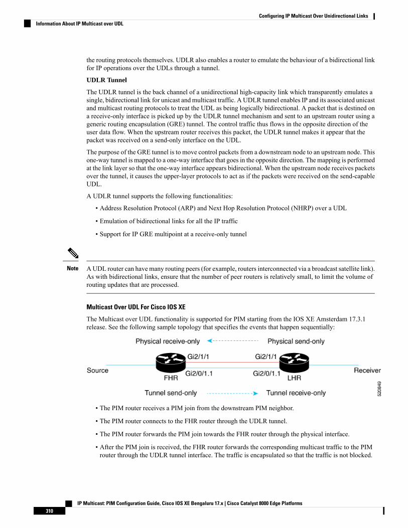
the routing protocols themselves. UDLR also enables a router to emulate the behaviour of a bidirectional linkfor IP operations over the UDLs through a tunnel.
UDLR Tunnel
The UDLR tunnel is the back channel of a unidirectional high-capacity link which transparently emulates asingle, bidirectional link for unicast and multicast traffic. A UDLR tunnel enables IP and its associated unicastand multicast routing protocols to treat the UDL as being logically bidirectional. A packet that is destined ona receive-only interface is picked up by the UDLR tunnel mechanism and sent to an upstream router using ageneric routing encapsulation (GRE) tunnel. The control traffic thus flows in the opposite direction of theuser data flow. When the upstream router receives this packet, the UDLR tunnel makes it appear that thepacket was received on a send-only interface on the UDL.
The purpose of the GRE tunnel is to move control packets from a downstream node to an upstream node. Thisone-way tunnel is mapped to a one-way interface that goes in the opposite direction. The mapping is performedat the link layer so that the one-way interface appears bidirectional. When the upstream node receives packetsover the tunnel, it causes the upper-layer protocols to act as if the packets were received on the send-capableUDL.
A UDLR tunnel supports the following functionalities:
• Address Resolution Protocol (ARP) and Next Hop Resolution Protocol (NHRP) over a UDL
• Emulation of bidirectional links for all the IP traffic
• Support for IP GRE multipoint at a receive-only tunnel
AUDL router can have many routing peers (for example, routers interconnected via a broadcast satellite link).As with bidirectional links, ensure that the number of peer routers is relatively small, to limit the volume ofrouting updates that are processed.
Note
Multicast Over UDL For Cisco IOS XE
The Multicast over UDL functionality is supported for PIM starting from the IOS XE Amsterdam 17.3.1release. See the following sample topology that specifies the events that happen sequentially:
• The PIM router receives a PIM join from the downstream PIM neighbor.
• The PIM router connects to the FHR router through the UDLR tunnel.
• The PIM router forwards the PIM join towards the FHR router through the physical interface.
• After the PIM join is received, the FHR router forwards the corresponding multicast traffic to the PIMrouter through the UDLR tunnel interface. The traffic is encapsulated so that the traffic is not blocked.
IP Multicast: PIM Configuration Guide, Cisco IOS XE Bengaluru 17.x | Cisco Catalyst 8000 Edge Platforms310
Configuring IP Multicast Over Unidirectional LinksInformation About IP Multicast over UDL
In an encap-helper (encapsulated) tunnel on a physical interface, all the (*/S, G) MROUTE entries having thephysical interface as the outgoing interface (OIF), use the tunnel interface as the OIF. All the multicast trafficdestined to the physical interface flows through the configured tunnel with the encapsulation.
A new flag is propagated and is first introduced to MROUTE. This flag is set against an entry, provided theentry has at least one physical interface as the OIF on which the encap-helper is configured. Consequently, anew flag is introduced to MRIB, which is set against the entry that corresponds to the MROUTE entry.Similarly, a new flag is introduced to MFIB that corresponds to the MRIB entry. The flag is then visible tothe platform which punts the multicast traffic only for those (*/S, G) entries based on the status of the flag.The IOS process then switches the packets and sends out these GRE-encapsulated packets.
When you remove or disable the encap-helper tunnel configuration on a physical interface, all the (*/S, G)MROUTE entries having the tunnel interface as the OIF use the physical interface as the OIF. The encap-helperfeature is removed on the interface and the default behavior is enabled.
Note
Prerquisites for Multicast Over UDL• Configure IP multicast in your network. For more information, see the Configuring Basic IP Multicastsection.
• Ensure that the physical interface and the tunnel interface are on the same mvrf.
Restrictions for Multicast Over UDL• This functionality is supported only for IPv4 addresses and not IPv6 addresses.
• Bidirectional PIM is not supported.
• The encap-helper command is visible only on the physical interfaces, in the supported platforms.
• If the tunnel interface is not up, or if the interface is on a different mvrf compared to the physical interface,the encap-helper configuration does not work.
• This functionality is supported only in the PIM sparse mode.
How to Configure Multicast Over UDLTo configure the IP multicast over UDL functionality, execute the Router(config-if)# [no] ip pim
sparse-mode encap-helper tunnel <tunnel-number> command.
You can configure the UDLR tunnel only in the pim sparse-mode.Note
Router (config)# interface Tunnel1001vrf forwarding VRF1no ip address
IP Multicast: PIM Configuration Guide, Cisco IOS XE Bengaluru 17.x | Cisco Catalyst 8000 Edge Platforms311
Configuring IP Multicast Over Unidirectional LinksPrerquisites for Multicast Over UDL
ip pim sparse-modetunnel source GigabitEthernet2/0/1.1tunnel destination 3.3.5.3tunnel key 7354tunnel udlr send-only GigabitEthernet2/1/1tunnel udlr address-resolutiontunnel vrf VRF1endLMA1#sh runn int GigabitEthernet2/1/1Building configuration...
Current configuration : 177 bytes!interface GigabitEthernet2/1/1vrf forwarding VRF1ip address 12.12.2.1 255.255.255.0ip pim sparse-mode encap-helper Tunnel1001ip ospf 101 area 0negotiation autoend
When you execute the udlr send-only command, it associates the tunnel send-only interface with thereceive-only port.
When you execute the encap-helper command, the encap-helper tunnel is configured on a physical interface.All the (*/S, G) MROUTE entries with the physical interface as the OIF use the tunnel interface as the OIF.All the multicast traffic destined to the physical interface flows through the configured tunnel interface withthe encapsulation.
When the tunnel interface goes down, the tunnel interfaces in the OIF list are removed.Note
Verifying Multicast Over UDL ConfigurationVerify whether the configuration is successful by executing the following show commands:Router# show ip mroute vrf VRF1IP Multicast Routing TableFlags: D - Dense, S - Sparse, B - Bidir Group, s - SSM Group, C - Connected,L - Local, P - Pruned, R - RP-bit set, F - Register flag,T - SPT-bit set, J - Join SPT, M - MSDP created entry, E - Extranet,X - Proxy Join Timer Running, A - Candidate for MSDP Advertisement,U - URD, I - Received Source Specific Host Report,Z - Multicast Tunnel, z - MDT-data group sender,Y - Joined MDT-data group, y - Sending to MDT-data group,G - Received BGP C-Mroute, g - Sent BGP C-Mroute,N - Received BGP Shared-Tree Prune, n - BGP C-Mroute suppressed,Q - Received BGP S-A Route, q - Sent BGP S-A Route,V - RD & Vector, v - Vector, p - PIM Joins on route,x - VxLAN group, c - PFP-SA cache created entry,* - determined by Assert, # - iif-starg configured on rpf intf,e - encap-helper tunnel flagOutgoing interface flags: H - Hardware switched, A - Assert winner, p - PIM JoinTimers: Uptime/ExpiresInterface state: Interface, Next-Hop or VCD, State/Mode(*, 239.1.1.1), 00:28:39/stopped, RP 4.4.3.4, flags: SPFIncoming interface: GigabitEthernet2/1/1, RPF nbr 12.12.2.2Outgoing interface list: Null
(100.100.3.2, 239.1.1.1), 00:28:39/00:02:58, flags: FTe, eh_tun_count :1
IP Multicast: PIM Configuration Guide, Cisco IOS XE Bengaluru 17.x | Cisco Catalyst 8000 Edge Platforms312
Configuring IP Multicast Over Unidirectional LinksVerifying Multicast Over UDL Configuration

Incoming interface: GigabitEthernet2/0/4.2, RPF nbr 0.0.0.0Outgoing interface list:Tunnel1001, Forward/Sparse, 00:24:59/00:03:21(*, 224.0.1.40), 02:10:54/00:02:08, RP 4.4.3.4, flags: SJCLIncoming interface: GigabitEthernet2/1/1, RPF nbr 12.12.2.2Outgoing interface list:Loopback1, Forward/Sparse, 02:10:52/00:02:08
Router(config-if)# show ip mrib vrf VRF1 routeIP Multicast Routing Information BaseEntry flags: L - Domain-Local Source, E - External Source to the Domain,C - Directly-Connected Check, S - Signal, IA - Inherit Accept, D - DropET - Data Rate Exceeds Threshold,K - Keepalive,DDE - Data Driven EventME - MoFRR ECMP Flow based, MNE - MoFRR Non-ECMP Flow based,MP - Primary MoFRR Non-ECMP Flow based entry,e - Encap helper tunnel flagInterface flags: F - Forward, A - Accept, IC - Internal Copy,NS - Negate Signal, DP - Don't Preserve, SP - Signal Present,II - Internal Interest, ID - Internal Disinterest, LI - Local Interest,LD - Local Disinterest, MD - mCAC Denied, MI - mLDP InterestA2 - MoFRR ECMP Backup Accept(*,224.0.0.0/4) Flags: C(*,224.0.1.40) RPF nbr: 12.12.2.2 Flags: CGigabitEthernet2/1/1 Flags: A NSLoopback1 Flags: F IC NS(*,239.1.1.1) RPF nbr: 12.12.2.2 Flags: CGigabitEthernet2/1/1 Flags: A(100.100.3.2,239.1.1.1) RPF nbr: 0.0.0.0 Flags: eGigabitEthernet2/0/4.2 Flags: ATunnel1001 Flags: F NS
Router# show ip mfib vrf VRF1Entry Flags: C - Directly Connected, S - Signal, IA - Inherit A flag,
ET - Data Rate Exceeds Threshold, K - KeepaliveDDE - Data Driven Event, HW - Hardware InstalledME - MoFRR ECMP entry, MNE - MoFRR Non-ECMP entry, MP - MFIBMoFRR Primary, RP - MRIB MoFRR Primary, P - MoFRR PrimaryMS - MoFRR Entry in Sync, MC - MoFRR entry in MoFRR Client,e - Encap helper tunnel flag.
I/O Item Flags: IC - Internal Copy, NP - Not platform switched,NS - Negate Signalling, SP - Signal Present,A - Accept, F - Forward, RA - MRIB Accept, RF - MRIB Forward,MA - MFIB Accept, A2 - Accept backup,RA2 - MRIB Accept backup, MA2 - MFIB Accept backup
Forwarding Counts: Pkt Count/Pkts per second/Avg Pkt Size/Kbits per secondOther counts: Total/RPF failed/Other dropsI/O Item Counts: HW Pkt Count/FS Pkt Count/PS Pkt Count Egress Rate in ppsVRF VRF1(*,224.0.0.0/4) Flags: C HW
SW Forwarding: 0/0/0/0, Other: 0/0/0HW Forwarding: 0/0/0/0, Other: 19/19/0
(*,224.0.1.40) Flags: C HWSW Forwarding: 0/0/0/0, Other: 0/0/0HW Forwarding: 0/0/0/0, Other: 0/0/0GigabitEthernet2/1/1 Flags: A NSLoopback1 Flags: F IC NSPkts: 0/0/0 Rate: 0 pps
(*,239.1.1.1) Flags: C HWSW Forwarding: 0/0/0/0, Other: 0/0/0HW Forwarding: 0/0/0/0, Other: 0/0/0GigabitEthernet2/1/1 Flags: A
(100.100.3.2,239.1.1.1) Flags: HW eSW Forwarding: 1623356/997/46/358, Other: 1/0/1HW Forwarding: 101680/0/63/0, Other: 33853/1/33852
IP Multicast: PIM Configuration Guide, Cisco IOS XE Bengaluru 17.x | Cisco Catalyst 8000 Edge Platforms313
Configuring IP Multicast Over Unidirectional LinksVerifying Multicast Over UDL Configuration
GigabitEthernet2/0/4.2 Flags: ATunnel1001 Flags: F NSPkts: 0/0/1539215 Rate: 0 pps
The encap tunnel prefixed with ‘e’ indicates the entry of the new flag for MROUTE, MFIB. The highlightedportions also indicate the successful configuration of the tunnel interface and the SW Forwarding counters.
Verifying Multicast Over UDL ConfigurationVerify whether the configuration is successful by executing the following show commands:Router# show ip mroute vrf VRF1IP Multicast Routing TableFlags: D - Dense, S - Sparse, B - Bidir Group, s - SSM Group, C - Connected,L - Local, P - Pruned, R - RP-bit set, F - Register flag,T - SPT-bit set, J - Join SPT, M - MSDP created entry, E - Extranet,X - Proxy Join Timer Running, A - Candidate for MSDP Advertisement,U - URD, I - Received Source Specific Host Report,Z - Multicast Tunnel, z - MDT-data group sender,Y - Joined MDT-data group, y - Sending to MDT-data group,G - Received BGP C-Mroute, g - Sent BGP C-Mroute,N - Received BGP Shared-Tree Prune, n - BGP C-Mroute suppressed,Q - Received BGP S-A Route, q - Sent BGP S-A Route,V - RD & Vector, v - Vector, p - PIM Joins on route,x - VxLAN group, c - PFP-SA cache created entry,* - determined by Assert, # - iif-starg configured on rpf intf,e - encap-helper tunnel flagOutgoing interface flags: H - Hardware switched, A - Assert winner, p - PIM JoinTimers: Uptime/ExpiresInterface state: Interface, Next-Hop or VCD, State/Mode(*, 239.1.1.1), 00:28:39/stopped, RP 4.4.3.4, flags: SPFIncoming interface: GigabitEthernet2/1/1, RPF nbr 12.12.2.2Outgoing interface list: Null
(100.100.3.2, 239.1.1.1), 00:28:39/00:02:58, flags: FTe, eh_tun_count :1Incoming interface: GigabitEthernet2/0/4.2, RPF nbr 0.0.0.0Outgoing interface list:Tunnel1001, Forward/Sparse, 00:24:59/00:03:21(*, 224.0.1.40), 02:10:54/00:02:08, RP 4.4.3.4, flags: SJCLIncoming interface: GigabitEthernet2/1/1, RPF nbr 12.12.2.2Outgoing interface list:Loopback1, Forward/Sparse, 02:10:52/00:02:08
Router(config-if)# show ip mrib vrf VRF1 routeIP Multicast Routing Information BaseEntry flags: L - Domain-Local Source, E - External Source to the Domain,C - Directly-Connected Check, S - Signal, IA - Inherit Accept, D - DropET - Data Rate Exceeds Threshold,K - Keepalive,DDE - Data Driven EventME - MoFRR ECMP Flow based, MNE - MoFRR Non-ECMP Flow based,MP - Primary MoFRR Non-ECMP Flow based entry,e - Encap helper tunnel flagInterface flags: F - Forward, A - Accept, IC - Internal Copy,NS - Negate Signal, DP - Don't Preserve, SP - Signal Present,II - Internal Interest, ID - Internal Disinterest, LI - Local Interest,LD - Local Disinterest, MD - mCAC Denied, MI - mLDP InterestA2 - MoFRR ECMP Backup Accept(*,224.0.0.0/4) Flags: C(*,224.0.1.40) RPF nbr: 12.12.2.2 Flags: CGigabitEthernet2/1/1 Flags: A NSLoopback1 Flags: F IC NS(*,239.1.1.1) RPF nbr: 12.12.2.2 Flags: CGigabitEthernet2/1/1 Flags: A(100.100.3.2,239.1.1.1) RPF nbr: 0.0.0.0 Flags: e
IP Multicast: PIM Configuration Guide, Cisco IOS XE Bengaluru 17.x | Cisco Catalyst 8000 Edge Platforms314
Configuring IP Multicast Over Unidirectional LinksVerifying Multicast Over UDL Configuration

GigabitEthernet2/0/4.2 Flags: ATunnel1001 Flags: F NS
Router# show ip mfib vrf VRF1Entry Flags: C - Directly Connected, S - Signal, IA - Inherit A flag,
ET - Data Rate Exceeds Threshold, K - KeepaliveDDE - Data Driven Event, HW - Hardware InstalledME - MoFRR ECMP entry, MNE - MoFRR Non-ECMP entry, MP - MFIBMoFRR Primary, RP - MRIB MoFRR Primary, P - MoFRR PrimaryMS - MoFRR Entry in Sync, MC - MoFRR entry in MoFRR Client,e - Encap helper tunnel flag.
I/O Item Flags: IC - Internal Copy, NP - Not platform switched,NS - Negate Signalling, SP - Signal Present,A - Accept, F - Forward, RA - MRIB Accept, RF - MRIB Forward,MA - MFIB Accept, A2 - Accept backup,RA2 - MRIB Accept backup, MA2 - MFIB Accept backup
Forwarding Counts: Pkt Count/Pkts per second/Avg Pkt Size/Kbits per secondOther counts: Total/RPF failed/Other dropsI/O Item Counts: HW Pkt Count/FS Pkt Count/PS Pkt Count Egress Rate in ppsVRF VRF1(*,224.0.0.0/4) Flags: C HW
SW Forwarding: 0/0/0/0, Other: 0/0/0HW Forwarding: 0/0/0/0, Other: 19/19/0
(*,224.0.1.40) Flags: C HWSW Forwarding: 0/0/0/0, Other: 0/0/0HW Forwarding: 0/0/0/0, Other: 0/0/0GigabitEthernet2/1/1 Flags: A NSLoopback1 Flags: F IC NSPkts: 0/0/0 Rate: 0 pps
(*,239.1.1.1) Flags: C HWSW Forwarding: 0/0/0/0, Other: 0/0/0HW Forwarding: 0/0/0/0, Other: 0/0/0GigabitEthernet2/1/1 Flags: A
(100.100.3.2,239.1.1.1) Flags: HW eSW Forwarding: 1623356/997/46/358, Other: 1/0/1HW Forwarding: 101680/0/63/0, Other: 33853/1/33852GigabitEthernet2/0/4.2 Flags: ATunnel1001 Flags: F NSPkts: 0/0/1539215 Rate: 0 pps
The encap tunnel prefixed with ‘e’ indicates the entry of the new flag for MROUTE, MFIB. The highlightedportions also indicate the successful configuration of the tunnel interface and the SW Forwarding counters.
IP Multicast: PIM Configuration Guide, Cisco IOS XE Bengaluru 17.x | Cisco Catalyst 8000 Edge Platforms315
Configuring IP Multicast Over Unidirectional LinksVerifying Multicast Over UDL Configuration

IP Multicast: PIM Configuration Guide, Cisco IOS XE Bengaluru 17.x | Cisco Catalyst 8000 Edge Platforms316
Configuring IP Multicast Over Unidirectional LinksVerifying Multicast Over UDL Configuration