QoS: Congestion Avoidance Configuration Guide, Cisco IOS XE Fuji ...
92
QoS: Congestion Avoidance Configuration Guide, Cisco IOS XE Fuji 16.9.x Americas Headquarters Cisco Systems, Inc. 170 West Tasman Drive San Jose, CA 95134-1706 USA http://www.cisco.com Tel: 408 526-4000 800 553-NETS (6387) Fax: 408 527-0883
-
Upload
khangminh22 -
Category
Documents
-
view
1 -
download
0
Transcript of QoS: Congestion Avoidance Configuration Guide, Cisco IOS XE Fuji ...

QoS: Congestion Avoidance Configuration Guide, Cisco IOS XE Fuji16.9.xAmericas HeadquartersCisco Systems, Inc.170 West Tasman DriveSan Jose, CA 95134-1706USAhttp://www.cisco.comTel: 408 526-4000
800 553-NETS (6387)Fax: 408 527-0883

THE SPECIFICATIONS AND INFORMATION REGARDING THE PRODUCTS IN THIS MANUAL ARE SUBJECT TO CHANGE WITHOUT NOTICE. ALL STATEMENTS,INFORMATION, AND RECOMMENDATIONS IN THIS MANUAL ARE BELIEVED TO BE ACCURATE BUT ARE PRESENTED WITHOUT WARRANTY OF ANY KIND,EXPRESS OR IMPLIED. USERS MUST TAKE FULL RESPONSIBILITY FOR THEIR APPLICATION OF ANY PRODUCTS.
THE SOFTWARE LICENSE AND LIMITED WARRANTY FOR THE ACCOMPANYING PRODUCT ARE SET FORTH IN THE INFORMATION PACKET THAT SHIPPED WITHTHE PRODUCT AND ARE INCORPORATED HEREIN BY THIS REFERENCE. IF YOU ARE UNABLE TO LOCATE THE SOFTWARE LICENSE OR LIMITED WARRANTY,CONTACT YOUR CISCO REPRESENTATIVE FOR A COPY.
The Cisco implementation of TCP header compression is an adaptation of a program developed by the University of California, Berkeley (UCB) as part of UCB's public domain version ofthe UNIX operating system. All rights reserved. Copyright © 1981, Regents of the University of California.
NOTWITHSTANDING ANY OTHERWARRANTY HEREIN, ALL DOCUMENT FILES AND SOFTWARE OF THESE SUPPLIERS ARE PROVIDED “AS IS" WITH ALL FAULTS.CISCO AND THE ABOVE-NAMED SUPPLIERS DISCLAIM ALL WARRANTIES, EXPRESSED OR IMPLIED, INCLUDING, WITHOUT LIMITATION, THOSE OFMERCHANTABILITY, FITNESS FOR A PARTICULAR PURPOSE AND NONINFRINGEMENT OR ARISING FROM A COURSE OF DEALING, USAGE, OR TRADE PRACTICE.
IN NO EVENT SHALL CISCO OR ITS SUPPLIERS BE LIABLE FOR ANY INDIRECT, SPECIAL, CONSEQUENTIAL, OR INCIDENTAL DAMAGES, INCLUDING, WITHOUTLIMITATION, LOST PROFITS OR LOSS OR DAMAGE TO DATA ARISING OUT OF THE USE OR INABILITY TO USE THIS MANUAL, EVEN IF CISCO OR ITS SUPPLIERSHAVE BEEN ADVISED OF THE POSSIBILITY OF SUCH DAMAGES.
Any Internet Protocol (IP) addresses and phone numbers used in this document are not intended to be actual addresses and phone numbers. Any examples, command display output, networktopology diagrams, and other figures included in the document are shown for illustrative purposes only. Any use of actual IP addresses or phone numbers in illustrative content is unintentionaland coincidental.
Cisco and the Cisco logo are trademarks or registered trademarks of Cisco and/or its affiliates in the U.S. and other countries. To view a list of Cisco trademarks, go to this URL: www.cisco.comgo trademarks. Third-party trademarks mentioned are the property of their respective owners. The use of the word partner does not imply a partnership relationship between Cisco and anyother company. (1721R)
© 2018 Cisco Systems, Inc. All rights reserved.

C O N T E N T S
Read Me First 1C H A P T E R 1
Read Me First 1
Congestion Avoidance Overview 3C H A P T E R 2
Congestion Avoidance Overview 3
Finding Feature Information 3
Weighted Random Early Detection 3
About Random Early Detection 3
About WRED 6
IPv6 QoS: MQCWRED-Based Drop 9C H A P T E R 3
IPv6 QoS: MQC WRED-Based Drop 9
Finding Feature Information 9
Information About IPv6 QoS: MQC WRED-Based Drop 9
Implementation Strategy for QoS for IPv6 9
Congestion Avoidance for IPv6 Traffic 10
Additional References 10
Feature Information for IPv6 QoS: MQC WRED-Based Drop 11
Configuring Weighted Random Early Detection 13C H A P T E R 4
Configuring Weighted Random Early Detection 13
Finding Feature Information 13
About Weighted Random Early Detection 13
How to Configure WRED 14
Enabling WRED 14
Changing WRED Parameters 14
QoS: Congestion Avoidance Configuration Guide, Cisco IOS XE Fuji 16.9.xiii

Monitoring WRED 15
WRED Configuration Examples 15
Example WRED Configuration 15
Example Parameter-Setting WRED 16
Feature Information for Configuring Weighted Random Early Detection 17
Byte-Based Weighted Random Early Detection 19C H A P T E R 5
Byte-Based Weighted Random Early Detection 19
Finding Feature Information 19
Restrictions for Byte-Based Weighted Random Early Detection 19
Information About Byte-Based Weighted Random Early Detection 19
Changes in functionality of WRED 19
Changes in Queue Limit and WRED Thresholds 20
How to Configure Byte-Based Weighted Random Early Detection 20
Configuring Byte-Based WRED 20
Configuring the Queue Depth and WRED Thresholds 21
Changing the Queue Depth and WRED Threshold Unit Modes 24
Verifying the Configuration for Byte-Based WRED 27
Configuration Examples for Byte-Based Weighted Random Early Detection 28
Example Configuring Byte-Based WRED 28
Additional References 29
Feature Information for Byte-Based Weighted Random Early Detection 30
WRED Explicit Congestion Notification 31C H A P T E R 6
WRED Explicit Congestion Notification 31
Finding Feature Information 31
Prerequisites for WRED-Explicit Congestion Notification 31
Information About WRED-Explicit Congestion Notification 31
WRED-Explicit Congestion Notification Feature Overview 31
How WRED Works 32
ECN Extends WRED Functionality 32
Benefits of WRED Explicit Congestion Notification 33
How to Configure WRED-Explicit Congestion Notification 33
Configuring Explicit Congestion Notification 33
QoS: Congestion Avoidance Configuration Guide, Cisco IOS XE Fuji 16.9.xiv
Contents

Verifying the Explicit Congestion Notification Configuration 35
Configuration Examples for WRED-Explicit Congestion Notification 36
Example Enabling ECN 36
Example Verifying the ECN Configuration 36
Additional References 37
Feature Information for WRED Explicit Congestion Notification 38
QoS Time-Based Thresholds for WRED and Queue Limit 41C H A P T E R 7
QoS Time-Based Thresholds for WRED and Queue Limit 41
Finding Feature Information 41
Prerequisites for QoS Time-Based Thresholds for WRED and Queue Limit 41
Restrictions for QoS Time-Based Thresholds for WRED and Queue Limit 41
Information About QoS Time-Based Thresholds for WRED and Queue Limit 42
Benefits of QoS Time-Based Thresholds for WRED and Queue Limit 42
Setting Thresholds by Using WRED 42
Setting Thresholds by Using the queue-limit Command 42
random-detect Commands with the Milliseconds Keyword 43
Mixing Threshold Units of Measure 43
How to Configure QoS Time-Based Thresholds for WRED and Queue Limit 43
Enabling WRED and Using WRED to Specify Thresholds 43
Using the queue-limit Command to Specify the Thresholds 45
Attaching the Policy Map to an Interface in a QoS Time-Based Threshold for WREDConfiguration 46
Verifying the QoS Time-Based Thresholds for WRED and Queue Limit Configuration 48
Configuration Examples for QoS Time-Based Thresholds for WRED and Queue Limit 49
Example Using WRED to Set Thresholds 49
Example Using the queue-limit Command to Set Thresholds 50
Example Verifying the Configuration 50
Example WRED Threshold Configuration Sample Output 50
Example queue-limit command Threshold Configuration Sample Output 51
Additional References 52
Feature Information for QoS Time-Based Thresholds for WRED and Queue Limit 53
DiffServ Compliant WRED 55C H A P T E R 8
QoS: Congestion Avoidance Configuration Guide, Cisco IOS XE Fuji 16.9.xv
Contents

DiffServ Compliant WRED 55
Finding Feature Information 55
Information About DiffServ Compliant WRED 55
Differentiated Services for WRED 55
Usage Guidelines for DiffServ Compliant WRED 56
How to Configure DiffServ Compliant WRED 56
Configuring DiffServ Compliant WRED 56
Configuration Examples for DiffServ Compliant WRED 59
Example: DiffServ compliant WRED 59
Additional References 59
Feature Information for DiffServ Compliant WRED 60
Shaping on Dialer Interfaces 63C H A P T E R 9
Shaping on Dialer Interfaces 63
Finding Feature Information 63
Restrictions for Shaping on Dialer Interfaces 63
Information About Shaping on Dialer Interfaces 63
QoS on PPP Session on Dialer Interfaces 63
QoS Dialer Interface Topology 64
How to Configure Shaping on Dialer Interfaces 64
Configuring an Output Queueing Policy for Dialer Interfaces 64
Configuring QoS for PPPoEoA for Dialer Interfaces 67
Configuring QoS for PPPoE for Dialer Interfaces 70
Configuring QoS for PPPoA for Dialer Interfaces 72
Configuring QoS for Multiple Sessions on Dialer Interfaces 75
Applying CoS Values to a Dialer Interface 78
Configuration Examples for Shaping on Dialer Interfaces 80
Example: Configuring Output Queuing Policy for a Dialer Interface 80
Example: Configuring QoS for PPPoEoA for a Dialer Interface 80
Example: Configuring QoS for a PPPoE on a Dialer Interface 81
Example: Configuring QoS for PPPoA on a Dialer Interface 81
Example: Configuring QoS for Multiple Sessions on a Dialer Interface 82
Example: Applying CoS Values to a Dialer Interface 82
Additional References for Shaping on Dialer Interfaces 82
QoS: Congestion Avoidance Configuration Guide, Cisco IOS XE Fuji 16.9.xvi
Contents

Feature Information for Shaping on Dialer Interfaces 83
QoS: Congestion Avoidance Configuration Guide, Cisco IOS XE Fuji 16.9.xvii
Contents

QoS: Congestion Avoidance Configuration Guide, Cisco IOS XE Fuji 16.9.xviii
Contents

C H A P T E R 1Read Me First
• Read Me First, on page 1
Read Me FirstImportant Information about Cisco IOS XE 16
Effective Cisco IOSXERelease 3.7.0E (for Catalyst Switching) and Cisco IOSXERelease 3.17S (for Accessand Edge Routing) the two releases evolve (merge) into a single version of converged release—the Cisco IOSXE 16—providing one release covering the extensive range of access and edge products in the Switching andRouting portfolio.
Feature Information
Use Cisco Feature Navigator to find information about feature support, platform support, and Cisco softwareimage support. An account on Cisco.com is not required.
Related References
• Cisco IOS Command References, All Releases
Obtaining Documentation and Submitting a Service Request
For information on obtaining documentation, using the Cisco Bug Search Tool (BST), submitting a servicerequest, and gathering additional information, see What's New in Cisco Product Documentation.
To receive new and revised Cisco technical content directly to your desktop, you can subscribe to the . RSSfeeds are a free service.
QoS: Congestion Avoidance Configuration Guide, Cisco IOS XE Fuji 16.9.x1

QoS: Congestion Avoidance Configuration Guide, Cisco IOS XE Fuji 16.9.x2
Read Me FirstRead Me First

C H A P T E R 2Congestion Avoidance Overview
• Congestion Avoidance Overview, on page 3
Congestion Avoidance OverviewCongestion avoidance techniques monitor network traffic loads in an effort to anticipate and avoid congestionat common network bottlenecks. Congestion avoidance is achieved through packet dropping. Among the morecommonly used congestion avoidance mechanisms is Random Early Detection (RED), which is optimum forhigh-speed transit networks. Cisco IOS XE Software includes an implementation of RED, called WeightedRED (WRED), that combines the capabilities of the RED algorithm with the IP Precedence feature. WRED,when configured, controls when the router drops packets.
Finding Feature InformationYour software release may not support all the features documented in this module. For the latest caveats andfeature information, see Bug Search Tool and the release notes for your platform and software release. Tofind information about the features documented in this module, and to see a list of the releases in which eachfeature is supported, see the feature information table at the end of this module.
Use Cisco Feature Navigator to find information about platform support and Cisco software image support.To access Cisco Feature Navigator, go to www.cisco.com/go/cfn. An account on Cisco.com is not required.
Weighted Random Early DetectionWRED helps avoid the globalization problems that can occur. Global synchronization occurs as waves ofcongestion crest only to be followed by troughs during which the transmission link is not fully utilized. Globalsynchronization of TCP hosts, for example, can occur because packets are dropped all at once. Globalsynchronization manifests when multiple TCP hosts reduce their transmission rates in response to packetdropping and then increase their transmission rates once again when the congestion is reduced.
About Random Early DetectionThe RED mechanism was proposed by Sally Floyd and Van Jacobson in the early 1990s to address networkcongestion in a responsive rather than reactive manner. Underlying the RED mechanism is the premise thatmost traffic runs on data transport implementations that are sensitive to loss and will temporarily slow downwhen some of their traffic is dropped. TCP, which responds appropriately--even robustly--to traffic drop by
QoS: Congestion Avoidance Configuration Guide, Cisco IOS XE Fuji 16.9.x3

slowing down its traffic transmission, effectively allows the traffic-drop behavior of RED to work as acongestion-avoidance signalling mechanism.
TCP constitutes the most heavily used network transport. Given the ubiquitous presence of TCP, RED offersa widespread, effective congestion-avoidance mechanism.
In considering the usefulness of RED when robust transports such as TCP are pervasive, it is important toconsider also the seriously negative implications of employing RED when a significant percentage of thetraffic is not robust in response to packet loss. Neither Novell NetWare nor AppleTalk is appropriately robustin response to packet loss, therefore you should not use RED for them.
How It Works
The DiffServ Compliant WRED feature enables WRED to use the DSCP value when it calculates the dropprobability for a packet. The DSCP value is the first six bits of the IP type of service (ToS) byte.
This feature adds two new commands, random-detect dscp and dscp. It also adds two new arguments,dscp-based and prec-based , to two existingWRED-related commands--the random-detect(interface) commandand the random-detect-group command.
The dscp-based argument enables WRED to use the DSCP value of a packet when it calculates the dropprobability for the packet. The prec-based argument enablesWRED to use the IP Precedence value of a packetwhen it calculates the drop probability for the packet.
These arguments are optional (you need not use any of them to use the commands) but they are also mutuallyexclusive. That is, if you use the dscp-based argument, you cannot use the prec-based argument with the samecommand.
After enabling WRED to use the DSCP value, you can then use the new random-detect dscp command tochange the minimum and maximum packet thresholds for that DSCP value.
Three scenarios for using these arguments are provided.
Packet Drop Probability
The packet drop probability is based on the minimum threshold, maximum threshold, and mark probabilitydenominator.
When the average queue depth is above the minimum threshold, RED starts dropping packets. The rate ofpacket drop increases linearly as the average queue size increases until the average queue size reaches themaximum threshold.
The mark probability denominator is the fraction of packets dropped when the average queue depth is at themaximum threshold. For example, if the denominator is 512, one out of every 512 packets is dropped whenthe average queue is at the maximum threshold.
When the average queue size is above the maximum threshold, all packets are dropped. The figure belowsummarizes the packet drop probability.
QoS: Congestion Avoidance Configuration Guide, Cisco IOS XE Fuji 16.9.x4
Congestion Avoidance OverviewHow It Works

Figure 1: RED Packet Drop Probability
The minimum threshold value should be set high enough to maximize the link utilization. If the minimumthreshold is too low, packets may be dropped unnecessarily, and the transmission link will not be fully used.
The difference between the maximum threshold and the minimum threshold should be large enough to avoidglobal synchronization of TCP hosts (global synchronization of TCP hosts can occur as multiple TCP hostsreduce their transmission rates). If the difference between the maximum andminimum thresholds is too small,many packets may be dropped at once, resulting in global synchronization.
How TCP Handles Traffic Loss
Both this section and How the Router Interacts with TCP, on page 6 contain detailed information that youneed not read in order to use WRED or to have a general sense of the capabilities of RED. If you want tounderstand why problems of global synchronization occur in response to congestion and how RED addressesthem, read these sections.
Note
When the recipient of TCP traffic--called the receiver--receives a data segment, it checks the four octet (32-bit)sequence number of that segment against the number the receiver expected, which would indicate that thedata segment was received in order. If the numbers match, the receiver delivers all of the data that it holds tothe target application, then it updates the sequence number to reflect the next number in order, and finally iteither immediately sends an acknowledgment (ACK) packet to the sender or it schedules an ACK to be sentto the sender after a short delay. The ACK notifies the sender that the receiver received all data segments upto but not including the one marked with the new sequence number.
Receivers usually try to send an ACK in response to alternating data segments they receive; they send theACK because for many applications, if the receiver waits out a small delay, it can efficiently include its replyacknowledgment on a normal response to the sender. However, when the receiver receives a data segmentout of order, it immediately responds with an ACK to direct the sender to resend the lost data segment.
When the sender receives an ACK, it makes this determination: It determines if any data is outstanding. If nodata is outstanding, the sender determines that the ACK is a keepalive, meant to keep the line active, and itdoes nothing. If data is outstanding, the sender determines whether the ACK indicates that the receiver hasreceived some or none of the data. If the ACK indicates receipt of some data sent, the sender determines ifnew credit has been granted to allow it to send more data. When the ACK indicates receipt of none of the datasent and there is outstanding data, the sender interprets the ACK to be a repeatedly sent ACK. This conditionindicates that some data was received out of order, forcing the receiver to remit the first ACK, and that a
QoS: Congestion Avoidance Configuration Guide, Cisco IOS XE Fuji 16.9.x5
Congestion Avoidance OverviewHow TCP Handles Traffic Loss

second data segment was received out of order, forcing the receiver to remit the second ACK. In most cases,the receiver would receive two segments out of order because one of the data segments had been dropped.
When a TCP sender detects a dropped data segment, it resends the segment. Then it adjusts its transmissionrate to half of what is was before the drop was detected. This is the TCP back-off or slow-down behavior.Although this behavior is appropriately responsive to congestion, problems can arise when multiple TCPsessions are carried on concurrently with the same router and all TCP senders slow down transmission ofpackets at the same time.
How the Router Interacts with TCP
The sections How TCP Handles Traffic Loss, on page 5 and How TCP Handles Traffic Loss, on page 5contain detailed information that you need not read in order to use WRED or to have a general sense of thecapabilities of RED. If you want to understand why problems of global synchronization occur in response tocongestion and how RED addresses them, read these sections.
Note
To see how the router interacts with TCP, we will look at an example. In this example, on average, the routerreceives traffic from one particular TCP stream every other, every 10th, and every 100th or 200th messagein the interface inMAE-EAST or FIX-WEST. A router can handle multiple concurrent TCP sessions. Becausenetwork flows are additive, there is a high probability that when traffic exceeds the Transmit Queue Limit(TQL) at all, it will vastly exceed the limit. However, there is also a high probability that the excessive trafficdepth is temporary and that traffic will not stay excessively deep except at points where traffic flows mergeor at edge routers.
If the router drops all traffic that exceeds the TQL, many TCP sessions will simultaneously go into slow start.Consequently, traffic temporarily slows down to the extreme and then all flows slow-start again; this activitycreates a condition of global synchronization.
However, if the router drops no traffic, as is the case when queueing features such as fair queueing or priorityqueueing (PQ) are used, then the data is likely to be stored in main memory, drastically degrading routerperformance.
By directing one TCP session at a time to slow down, RED solves the problems described, allowing for fullutilization of the bandwidth rather than utilization manifesting as crests and troughs of traffic.
About WREDWRED combines the capabilities of the RED algorithmwith the IP Precedence feature to provide for preferentialtraffic handling of higher priority packets. WRED can selectively discard lower priority traffic when theinterface begins to get congested and provide differentiated performance characteristics for different classesof service.
You can configure WRED to ignore IP precedence when making drop decisions so that nonweighted REDbehavior is achieved.
For interfaces configured to use the Resource Reservation Protocol (RSVP) feature, WRED chooses packetsfrom other flows to drop rather than the RSVP flows. Also, IP Precedence governs which packets aredropped--traffic that is at a lower precedence has a higher drop rate and therefore is more likely to be throttledback.
WRED differs from other congestion avoidance techniques such as queueing strategies because it attemptsto anticipate and avoid congestion rather than control congestion once it occurs.
QoS: Congestion Avoidance Configuration Guide, Cisco IOS XE Fuji 16.9.x6
Congestion Avoidance OverviewHow the Router Interacts with TCP

Why Use WRED
WREDmakes early detection of congestion possible and provides for multiple classes of traffic. It also protectsagainst global synchronization. For these reasons, WRED is useful on any output interface where you expectcongestion to occur.
However, WRED is usually used in the core routers of a network, rather than at the edge of the network. Edgerouters assign IP precedences to packets as they enter the network.WRED uses these precedences to determinehow to treat different types of traffic.
WRED provides separate thresholds and weights for different IP precedences, allowing you to provide differentqualities of service in regard to packet dropping for different traffic types. Standard traffic may be droppedmore frequently than premium traffic during periods of congestion.
WRED is also RSVP-aware, and it can provide the controlled-load QoS service of integrated service.
How It Works
By randomly dropping packets prior to periods of high congestion, WRED tells the packet source to decreaseits transmission rate. If the packet source is using TCP, it will decrease its transmission rate until all the packetsreach their destination, which indicates that the congestion is cleared.
WRED generally drops packets selectively based on IP precedence. Packets with a higher IP precedence areless likely to be dropped than packets with a lower precedence. Thus, the higher the priority of a packet, thehigher the probability that the packet will be delivered.
WRED selectively drops packets when the output interface begins to show signs of congestion. By droppingsome packets early rather than waiting until the queue is full, WRED avoids dropping large numbers of packetsat once and minimizes the chances of global synchronization. Thus, WRED allows the transmission line tobe used fully at all times.
In addition, WRED statistically drops more packets from large users than small. Therefore, traffic sourcesthat generate the most traffic are more likely to be slowed down than traffic sources that generate little traffic.
WRED helps to avoid the globalization problems. Global synchronizationmanifests whenmultiple TCP hostsreduce their transmission rates in response to packet dropping and then increase their transmission rates onceagain when the congestion is reduced.
WRED is only useful when the bulk of the traffic is TCP/IP traffic. With TCP, dropped packets indicatecongestion, so the packet source will reduce its transmission rate. With other protocols, packet sources maynot respond or may resend dropped packets at the same rate. Thus, dropping packets does not decreasecongestion.
WRED treats non-IP traffic as precedence 0, the lowest precedence. Therefore, non-IP traffic, in general, ismore likely to be dropped than IP traffic.
The figure below illustrates how WRED works.
QoS: Congestion Avoidance Configuration Guide, Cisco IOS XE Fuji 16.9.x7
Congestion Avoidance OverviewWhy Use WRED

Figure 2: Weighted Random Early Detection
Average Queue Size
The average queue size is based on the previous average and the current size of the queue. The formula is:
average = (old_average * (1-1/2^n)) + (current_queue_size * 1/2^n)
where n is the exponential weight factor, a user-configurable value.
For high values of n, the previous average queue size becomes more important. A large factor smooths outthe peaks and lows in queue length. The average queue size is unlikely to change very quickly, avoidingdrastic swings in size. TheWRED process will be slow to start dropping packets, but it may continue droppingpackets for a time after the actual queue size has fallen below the minimum threshold. The slow-movingaverage will accommodate temporary bursts in traffic.
If the value of n gets too high,WREDwill not react to congestion. Packets will be sent or dropped as ifWREDwere not in effect.
Note
For low values of n, the average queue size closely tracks the current queue size. The resulting average mayfluctuate with changes in the traffic levels. In this case, the WRED process responds quickly to long queues.Once the queue falls below the minimum threshold, the process stops dropping packets.
If the value of n gets too low, WRED will overreact to temporary traffic bursts and drop traffic unnecessarily.
QoS: Congestion Avoidance Configuration Guide, Cisco IOS XE Fuji 16.9.x8
Congestion Avoidance OverviewAverage Queue Size

C H A P T E R 3IPv6 QoS: MQC WRED-Based Drop
• IPv6 QoS: MQC WRED-Based Drop, on page 9
IPv6 QoS: MQC WRED-Based DropWRED implements the RED-based drop policy on the packets that are likely to overflow the limits of CBWFQ.
Finding Feature InformationYour software release may not support all the features documented in this module. For the latest caveats andfeature information, see Bug Search Tool and the release notes for your platform and software release. Tofind information about the features documented in this module, and to see a list of the releases in which eachfeature is supported, see the feature information table at the end of this module.
Use Cisco Feature Navigator to find information about platform support and Cisco software image support.To access Cisco Feature Navigator, go to www.cisco.com/go/cfn. An account on Cisco.com is not required.
Information About IPv6 QoS: MQC WRED-Based Drop
Implementation Strategy for QoS for IPv6IPv6 packets are forwarded by paths that are different from those for IPv4. QoS features supported for IPv6environments include packet classification, queuing, traffic shaping, weighted random early detection (WRED),class-based packet marking, and policing of IPv6 packets. These features are available at both the processswitching and Cisco Express Forwarding switching paths of IPv6.
All of the QoS features available for IPv6 environments are managed from the modular QoS command-lineinterface (MQC). The MQC allows you to define traffic classes, create and configure traffic policies (policymaps), and then attach those traffic policies to interfaces.
To implement QoS in networks that are running IPv6, follow the same steps that you would follow to implementQoS in networks running only IPv4. At a very high level, the basic steps for implementing QoS are as follows:
• Know which applications in your network need QoS.
• Understand the characteristics of the applications so that you can make decisions about which QoSfeatures would be appropriate.
QoS: Congestion Avoidance Configuration Guide, Cisco IOS XE Fuji 16.9.x9

• Know your network topology so that you know how link layer header sizes are affected by changes andforwarding.
• Create classes based on the criteria that you establish for your network. In particular, if the same networkis also carrying IPv4 traffic along with IPv6 traffic, decide if you want to treat both of them the sameway or treat them separately and specify match criteria accordingly. If you want to treat them the same,use match statements such asmatch precedence, match dscp, set precedence, and set dscp. If youwant to treat them separately, add match criteria such asmatch protocol ip andmatch protocol ipv6in a match-all class map.
• Create a policy to mark each class.
• Work from the edge toward the core in applying QoS features.
• Build the policy to treat the traffic.
• Apply the policy.
Congestion Avoidance for IPv6 TrafficWRED implements the RED-based drop policy on the packets that are likely to overflow the limits ofclass-based weighted fair queueing (CBWFQ). WRED supports class-based and flow-based queueing (usingDSCP or precedence values).
Additional References
Related Documents
Document TitleRelated Topic
Cisco IOS Master Command List,All Releases
Cisco IOS commands
IPv6 Configuration GuideIPv6 addressing and connectivity
Cisco IOS IPv6 CommandReference
IPv6 commands
Cisco IOS IPv6 Feature MappingCisco IOS IPv6 features
Technical Assistance
LinkDescription
http://www.cisco.com/cisco/web/support/index.htmlTheCisco Support andDocumentationwebsite providesonline resources to download documentation, software,and tools. Use these resources to install and configurethe software and to troubleshoot and resolve technicalissues with Cisco products and technologies. Access tomost tools on the Cisco Support and Documentationwebsite requires a Cisco.com user ID and password.
QoS: Congestion Avoidance Configuration Guide, Cisco IOS XE Fuji 16.9.x10
IPv6 QoS: MQC WRED-Based DropCongestion Avoidance for IPv6 Traffic

Feature Information for IPv6 QoS: MQC WRED-Based DropThe following table provides release information about the feature or features described in this module. Thistable lists only the software release that introduced support for a given feature in a given software releasetrain. Unless noted otherwise, subsequent releases of that software release train also support that feature.
Use Cisco Feature Navigator to find information about platform support and Cisco software image support.To access Cisco Feature Navigator, go to www.cisco.com/go/cfn. An account on Cisco.com is not required.
Table 1: Feature Information for IPv6 QoS: MQC WRED-Based Drop
Feature InformationReleasesFeature Name
WRED implements the RED-baseddrop policy on the packets that arelikely to overflow the limits ofCBWFQ.
Cisco IOS XE Release 2.1IPv6 QoS: MQC WRED-BasedDrop
QoS: Congestion Avoidance Configuration Guide, Cisco IOS XE Fuji 16.9.x11
IPv6 QoS: MQC WRED-Based DropFeature Information for IPv6 QoS: MQC WRED-Based Drop

QoS: Congestion Avoidance Configuration Guide, Cisco IOS XE Fuji 16.9.x12
IPv6 QoS: MQC WRED-Based DropFeature Information for IPv6 QoS: MQC WRED-Based Drop

C H A P T E R 4Configuring Weighted Random Early Detection
• Configuring Weighted Random Early Detection, on page 13
Configuring Weighted Random Early DetectionThis module describes the tasks for configuring Weighted Random Early Detection (WRED) on a router.
Finding Feature InformationYour software release may not support all the features documented in this module. For the latest caveats andfeature information, see Bug Search Tool and the release notes for your platform and software release. Tofind information about the features documented in this module, and to see a list of the releases in which eachfeature is supported, see the feature information table at the end of this module.
Use Cisco Feature Navigator to find information about platform support and Cisco software image support.To access Cisco Feature Navigator, go to www.cisco.com/go/cfn. An account on Cisco.com is not required.
About Weighted Random Early DetectionRandom Early Detection (RED) is a congestion avoidance mechanism that takes advantage of the congestioncontrol mechanism of TCP. By randomly dropping packets prior to periods of high congestion, RED tells thepacket source to decrease its transmission rate. WRED drops packets selectively based on IP precedence.Edge routers assign IP precedences to packets as they enter the network. (WRED is useful on any outputinterface where you expect to have congestion. However, WRED is usually used in the core routers of anetwork, rather than at the edge.) WRED uses these precedences to determine how it treats different types oftraffic.
When a packet arrives, the following events occur:
1. The average queue size is calculated.
2. If the average is less than the minimum queue threshold, the arriving packet is queued.
3. If the average is between the minimum queue threshold for that type of traffic and the maximum thresholdfor the interface, the packet is either dropped or queued, depending on the packet drop probability for thattype of traffic.
4. If the average queue size is greater than the maximum threshold, the packet is dropped.
QoS: Congestion Avoidance Configuration Guide, Cisco IOS XE Fuji 16.9.x13

WRED is useful with adaptive traffic such as TCP/IP. With TCP, dropped packets indicate congestion, so thepacket source will reduce its transmission rate. With other protocols, packet sources may not respond or mayresend dropped packets at the same rate. Thus, dropping packets does not decrease congestion. WRED treatsnon-IP traffic as precedence 0, the lowest precedence. Therefore, non-IP traffic is more likely to be droppedthan IP traffic.
Note
When you enable WRED with the random-detect interface configuration command, the parameters are setto their default values. The weight factor is 9. For all precedences, the mark probability denominator is 10,and maximum threshold is based on the output buffering capacity and the transmission speed for the interface.
The default minimum threshold depends on the precedence. The minimum threshold for IP Precedence 0corresponds to half of the maximum threshold. The values for the remaining precedences fall between halfthe maximum threshold and the maximum threshold at evenly spaced intervals.
The default WRED parameter values are based on the best available data. We recommend that you do notchange the parameters from their default values unless you have determined that your applications will benefitfrom the changed values.
Note
How to Configure WRED
Enabling WRED
PurposeCommand
EnablesWRED.Router(config-if)# random-detect
Changing WRED Parameters
PurposeCommand
Configures the weight factor used in calculating the averagequeue length.Router(config-if)# random-detect
exponential-weighting-constantexponent
Configures parameters for packets with a specific IPPrecedence. The minimum threshold for IP Precedence 0corresponds to half the maximum threshold for the interface.Repeat this command for each precedence. To configure RED,rather than WRED, use the same parameters for eachprecedence.
Router(config-if)# random-detectprecedence precedence min-thresholdmax-threshold mark-prob-denominator
QoS: Congestion Avoidance Configuration Guide, Cisco IOS XE Fuji 16.9.x14
Configuring Weighted Random Early DetectionHow to Configure WRED

Monitoring WRED
PurposeCommand
Displays the header information of the packets insidea queue.Router# show queue interface-type
interface-number
Displays the WRED statistics of a specific virtualcircuit (VC) on an interface.Router# show queueing interface
interface-number [vc [[vpi/] vci]]
Displays the queueing configuration for WRED.Router# show queueing random-detect
Displays WRED configuration on an interface.Router# show interfaces [type slot |port-adapter | port]
WRED Configuration Examples
Example WRED ConfigurationThe following example enables WRED with default parameter values:
interface Serial5/0description to qos1-75aip address 200.200.14.250 255.255.255.252random-detect
Use the show interfaces command output to verify the configuration. Notice that the "Queueing strategy"report lists "random early detection (RED)."
Router# show interfaces serial 5/0Serial5/0 is up, line protocol is upHardware is M4TDescription: to qos1-75aInternet address is 200.200.14.250/30MTU 1500 bytes, BW 128 Kbit, DLY 20000 usec,
reliability 255/255, txload 1/255, rxload 237/255Encapsulation HDLC, crc 16, loopback not setKeepalive not setLast input 00:00:15, output 00:00:00, output hang neverLast clearing of "show interface" counters 00:05:08Input queue: 0/75/0 (size/max/drops); Total output drops: 1036Queueing strategy: random early detection(RED)5 minutes input rate 0 bits/sec, 2 packets/sec5 minutes output rate 119000 bits/sec, 126 packets/sec
594 packets input, 37115 bytes, 0 no bufferReceived 5 broadcasts, 0 runts, 0 giants, 0 throttles0 input errors, 0 CRC, 0 frame, 0 overrun, 0 ignored, 0 abort37525 packets output, 4428684 bytes, 0 underruns0 output errors, 0 collisions, 0 interface resets0 output buffer failures, 0 output buffers swapped out0 carrier transitions DCD=up DSR=up DTR=up RTS=up CTS=up
QoS: Congestion Avoidance Configuration Guide, Cisco IOS XE Fuji 16.9.x15
Configuring Weighted Random Early DetectionMonitoring WRED

Use the show queue command output to view the current contents of the interface queue. Notice that thereis only a single queue into which packets from all IP precedences are placed after dropping has taken place.The output has been truncated to show only three of the five packets.
Router# show queue serial 5/0
Output queue for Serial5/0 is 5/0Packet 1, linktype: ip, length: 118, flags: 0x288source: 190.1.3.4, destination: 190.1.2.2, id: 0x0001, ttl: 254,TOS: 128 prot: 17, source port 11111, destination port 22222data: 0x2B67 0x56CE 0x005E 0xE89A 0xCBA9 0x8765 0x4321
0x0FED 0xCBA9 0x8765 0x4321 0x0FED 0xCBA9 0x8765Packet 2, linktype: ip, length: 118, flags: 0x288source: 190.1.3.5, destination: 190.1.2.2, id: 0x0001, ttl: 254,TOS: 160 prot: 17, source port 11111, destination port 22222data: 0x2B67 0x56CE 0x005E 0xE89A 0xCBA9 0x8765 0x4321
0x0FED 0xCBA9 0x8765 0x4321 0x0FED 0xCBA9 0x8765Packet 3, linktype: ip, length: 118, flags: 0x280source: 190.1.3.6, destination: 190.1.2.2, id: 0x0001, ttl: 254,TOS: 192 prot: 17, source port 11111, destination port 22222data: 0x2B67 0x56CE 0x005E 0xE89A 0xCBA9 0x8765 0x4321
0x0FED 0xCBA9 0x8765 0x4321 0x0FED 0xCBA9 0x8765
Use the show queueing command output to view the current settings for each of the precedences. Also noticethat the default minimum thresholds are spaced evenly between half and the entire maximum threshold.Thresholds are specified in terms of packet count.
Router# show queueingCurrent random-detect configuration:
Serial5/0Queueing strategy:random early detection (WRED)Exp-weight-constant:9 (1/512)Mean queue depth:28
Class Random Tail Minimum Maximum Markdrop drop threshold threshold probability
0 330 0 20 40 1/101 267 0 22 40 1/102 217 0 24 40 1/103 156 0 26 40 1/104 61 0 28 40 1/105 6 0 31 40 1/106 0 0 33 40 1/107 0 0 35 40 1/10rsvp 0 0 37 40 1/10
Example Parameter-Setting WREDThe following example enables WRED on the interface and specifies parameters for the different IPprecedences:
interface Hssi0/0/0description 45Mbps to R1ip address 10.200.14.250 255.255.255.252random-detectrandom-detect precedence 0 32 256 100random-detect precedence 1 64 256 100random-detect precedence 2 96 256 100random-detect precedence 3 120 256 100random-detect precedence 4 140 256 100
QoS: Congestion Avoidance Configuration Guide, Cisco IOS XE Fuji 16.9.x16
Configuring Weighted Random Early DetectionExample Parameter-Setting WRED

random-detect precedence 5 170 256 100random-detect precedence 6 290 256 100random-detect precedence 7 210 256 100random-detect precedence rsvp 230 256 100
Feature Information for Configuring Weighted Random Early DetectionThe following table provides release information about the feature or features described in this module. Thistable lists only the software release that introduced support for a given feature in a given software releasetrain. Unless noted otherwise, subsequent releases of that software release train also support that feature.
Use Cisco Feature Navigator to find information about platform support and Cisco software image support.To access Cisco Feature Navigator, go to www.cisco.com/go/cfn. An account on Cisco.com is not required.
Table 2: Feature Information for Configuring Weighted Random Early Detection
Feature InformationReleasesFeature Name
This feature was introduced on Cisco ASR1000 Series Routers.
For information about CBWFQ,see the "ConfiguringWeighted FairQueueing" module.
Note
Cisco IOSXERelease 2.1Class-Based Weighted FairQueueing (CBWFQ) andWeighted Random EarlyDetection (WRED)
This feature was introduced on Cisco ASR1000 Series Routers.
Cisco IOSXERelease 2.1Random Early Detection (RED)
This feature was introduced on Cisco ASR1000 Series Routers.
Cisco IOSXERelease 2.1Weighted Random EarlyDetection
This feature was introduced on Cisco ASR1000 Series Routers.
Cisco IOSXERelease 2.1Weighted RED (WRED)
QoS: Congestion Avoidance Configuration Guide, Cisco IOS XE Fuji 16.9.x17
Configuring Weighted Random Early DetectionFeature Information for Configuring Weighted Random Early Detection

QoS: Congestion Avoidance Configuration Guide, Cisco IOS XE Fuji 16.9.x18
Configuring Weighted Random Early DetectionFeature Information for Configuring Weighted Random Early Detection

C H A P T E R 5Byte-Based Weighted Random Early Detection
• Byte-Based Weighted Random Early Detection, on page 19
Byte-Based Weighted Random Early DetectionThismodule explains how to enable byte-basedWeighted RandomEarly Detection (WRED), and set byte-basedqueue limits and WRED thresholds.
Finding Feature InformationYour software release may not support all the features documented in this module. For the latest caveats andfeature information, see Bug Search Tool and the release notes for your platform and software release. Tofind information about the features documented in this module, and to see a list of the releases in which eachfeature is supported, see the feature information table at the end of this module.
Use Cisco Feature Navigator to find information about platform support and Cisco software image support.To access Cisco Feature Navigator, go to www.cisco.com/go/cfn. An account on Cisco.com is not required.
Restrictions for Byte-Based Weighted Random Early Detection• WRED is only useful when the bulk of the traffic is TCP/IP traffic. With TCP, dropped packets indicatecongestion, so the packet source will reduce its transmission rate. With other protocols, packet sourcesmay not respond or may resend dropped packets at the same rate. Thus, dropping packets does notdecrease congestion.
• You cannot configure byte-basedWRED on a class in which the queue-limit is configured in millisecondsor packets.
Information About Byte-Based Weighted Random Early Detection
Changes in functionality of WREDThis feature extends the functionality of WRED. In previous releases, you specified the WRED actions basedon the number of packets. With the byte-based WRED, you can specify WRED actions based on the numberof bytes.
QoS: Congestion Avoidance Configuration Guide, Cisco IOS XE Fuji 16.9.x19

Changes in Queue Limit and WRED ThresholdsIn Cisco IOS XE Release 2.4, the Cisco ASR 1000 Series Aggregation Services Routers support the additionof bytes as a unit of configuration for both queue limits and WRED thresholds. Therefore, as of this release,packet-based and byte-based limits are configurable, with some restrictions.
How to Configure Byte-Based Weighted Random Early Detection
Configuring Byte-Based WRED
SUMMARY STEPS
1. enable2. configure terminal3. class-map class-map-name4. match ip precedence ip-precedence-value5. exit6. policy-map policy-name7. class class-name8. random-detect9. random-detect precedence precedence min-threshold bytes max-threshold bytes
mark-prob-denominator
DETAILED STEPS
PurposeCommand or Action
Enables privileged EXEC mode.enableStep 1
Example: • Enter your password if prompted.
Router> enable
Enters global configuration mode.configure terminal
Example:
Step 2
Router# configure terminal
Specifies the user-defined name of the traffic class.class-map class-map-name
Example:
Step 3
Router(config)# class-map c1
Specifies up to eight IP Precedence values used as matchcriteria.
match ip precedence ip-precedence-value
Example:
Step 4
Router(config-cmap)# match ip precedence 1
QoS: Congestion Avoidance Configuration Guide, Cisco IOS XE Fuji 16.9.x20
Byte-Based Weighted Random Early DetectionChanges in Queue Limit and WRED Thresholds

PurposeCommand or Action
Exits from class-map configuration mode.exit
Example:
Step 5
Router(config-cmap)# exit
Specifies the name of the traffic policy to configure.policy-map policy-name
Example:
Step 6
Router(config)# policy-map p1
Specifies the name of a predefined traffic class, which wasconfigured with the class-map command, used to classifytraffic to the traffic policy.
class class-name
Example:
Router(config-pmap)# class c1
Step 7
Enables WRED.random-detect
Example:
Step 8
Router(config-pmap-c)# random-detect
Configures the parameters for bytes with a specific IPprecedence.
random-detect precedence precedence min-thresholdbytes max-threshold bytes mark-prob-denominator
Example:
Step 9
Example:
Router(config-pmap-c)# random-detect precedence 12000 bytes 3000 bytes 200
Configuring the Queue Depth and WRED Thresholds
Before you begin
Be sure that your configuration satisfies the following conditions when configuring the queue depth andWRED thresholds:
• When configuring byte-based mode, the queue limit must be configured prior to the WRED thresholdand before the service policy is applied.
• When setting the queue depth and WRED thresholds in an enhanced QoS policies aggregationconfiguration, the limits are supported only for the default class at a subinterface policy map and for anyclasses at the main interface policy map.
QoS: Congestion Avoidance Configuration Guide, Cisco IOS XE Fuji 16.9.x21
Byte-Based Weighted Random Early DetectionConfiguring the Queue Depth and WRED Thresholds

Consider the following restrictions when you configure the queue depth and WRED thresholds:
• Do not configure the queue limit unit before you configure a queueing feature for a traffic class.
• If you do not configure a queue limit, then the default mode is packets.
• When you configure WRED thresholds, the following restrictions apply:
• The WRED threshold must use the same unit as the queue limit. For example, if the queue limit isin packets, then the WRED thresholds also must be in packets.
• If you do not configure a queue limit in bytes, then the default mode is packets and you must alsoconfigure the WRED threshold in packets.
• The queue limit size must be greater than the WRED threshold.
• The unit modes for either the queue limit or WRED thresholds cannot be changed dynamically after aservice policy is applied.
>
Note
SUMMARY STEPS
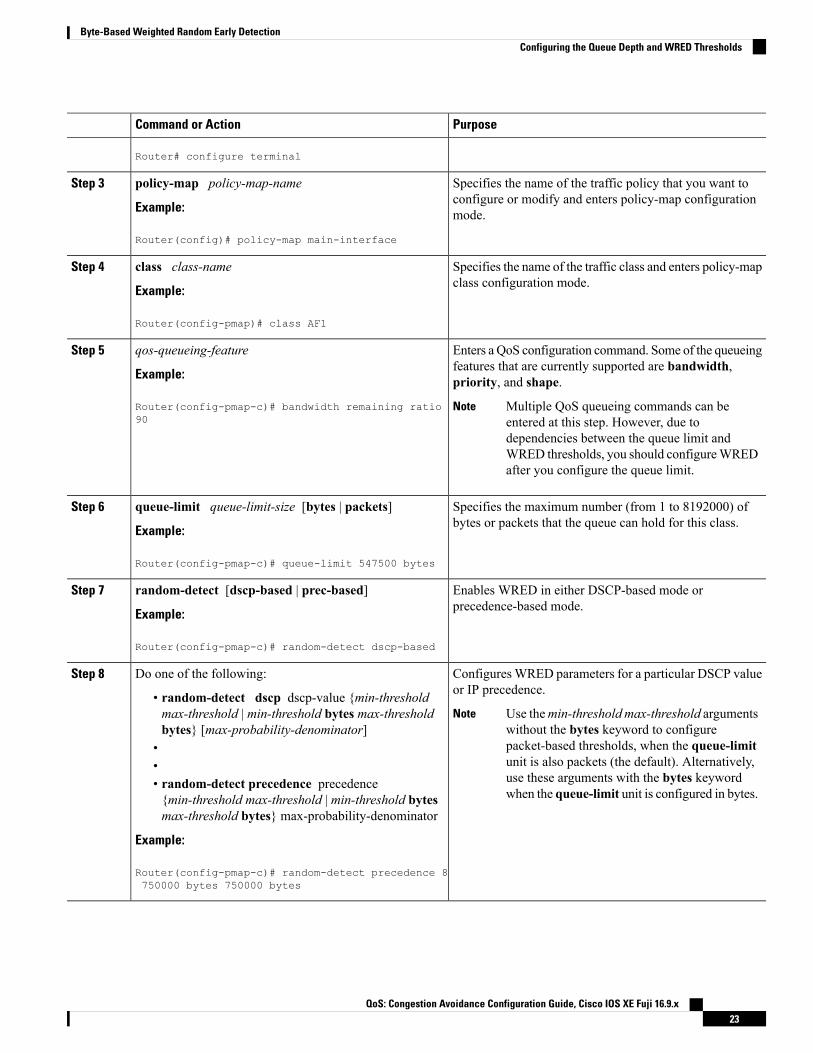
1. enable2. configure terminal3. policy-map policy-map-name4. class class-name5. qos-queueing-feature6. queue-limit queue-limit-size [bytes | packets]7. random-detect [dscp-based | prec-based]8. Do one of the following:
• random-detect dscp dscp-value {min-threshold max-threshold |min-threshold bytesmax-thresholdbytes} [max-probability-denominator]
••• random-detect precedence precedence {min-threshold max-threshold | min-threshold bytesmax-threshold bytes} max-probability-denominator
DETAILED STEPS
PurposeCommand or Action
Enables privileged EXEC mode.enableStep 1
Example: • Enter your password if prompted.
Router> enable
Enters global configuration mode.configure terminal
Example:
Step 2
QoS: Congestion Avoidance Configuration Guide, Cisco IOS XE Fuji 16.9.x22
Byte-Based Weighted Random Early DetectionConfiguring the Queue Depth and WRED Thresholds
PurposeCommand or Action
Router# configure terminal
Specifies the name of the traffic policy that you want toconfigure or modify and enters policy-map configurationmode.
policy-map policy-map-name
Example:
Router(config)# policy-map main-interface
Step 3
Specifies the name of the traffic class and enters policy-mapclass configuration mode.
class class-name
Example:
Step 4
Router(config-pmap)# class AF1
Enters a QoS configuration command. Some of the queueingfeatures that are currently supported are bandwidth,priority, and shape.
qos-queueing-feature
Example:
Router(config-pmap-c)# bandwidth remaining ratio90
Step 5
Multiple QoS queueing commands can beentered at this step. However, due todependencies between the queue limit andWRED thresholds, you should configureWREDafter you configure the queue limit.
Note
Specifies the maximum number (from 1 to 8192000) ofbytes or packets that the queue can hold for this class.
queue-limit queue-limit-size [bytes | packets]
Example:
Step 6
Router(config-pmap-c)# queue-limit 547500 bytes
Enables WRED in either DSCP-based mode orprecedence-based mode.
random-detect [dscp-based | prec-based]
Example:
Step 7
Router(config-pmap-c)# random-detect dscp-based
ConfiguresWRED parameters for a particular DSCP valueor IP precedence.
Do one of the following:Step 8
• random-detect dscp dscp-value {min-thresholdmax-threshold | min-threshold bytes max-thresholdbytes} [max-probability-denominator]
Use themin-threshold max-threshold argumentswithout the bytes keyword to configurepacket-based thresholds, when the queue-limitunit is also packets (the default). Alternatively,use these arguments with the bytes keywordwhen the queue-limit unit is configured in bytes.
Note
••• random-detect precedence precedence{min-threshold max-threshold | min-threshold bytesmax-threshold bytes} max-probability-denominator
Example:
Router(config-pmap-c)# random-detect precedence 8750000 bytes 750000 bytes
QoS: Congestion Avoidance Configuration Guide, Cisco IOS XE Fuji 16.9.x23
Byte-Based Weighted Random Early DetectionConfiguring the Queue Depth and WRED Thresholds

Examples
Correct Configuration
Invalid Configuration
Correct Configuration
Invalid Configuration
The following examples show both correct and invalid configurations to demonstrate some of therestrictions.
The following example shows the correct usage of setting the queue limit in bytes mode after thebandwidth remaining ratio queueing feature has been configured for a traffic class:
class AF1bandwidth remaining ratio 90queue-limit 750000 bytes
The following example shows an invalid configuration for the queue limit in bytes mode before thebandwidth remaining ratio queueing feature has been configured for a traffic class:
class AF1queue-limit 750000 bytesbandwidth remaining ratio 90
The following example shows the correct usage of setting the queue limit in bytes mode after thebandwidth remaining ratio queueing feature has been configured for a traffic class, followed bythe setting of the thresholds for WRED in compatible byte mode:
class AF1bandwidth remaining ratio 90queue-limit 750000 bytesrandom-detect dscp-basedrandom-detect dscp 8 750000 bytes 750000 bytes
This example shows an invalid configuration of the WRED threshold in bytes without any queuelimit configuration, which therefore defaults to a packet-based queue depth. Therefore, the WREDthreshold must also be in packets:
class AF1bandwidth remaining ratio 90random-detect dscp-basedrandom-detect dscp 8 750000 bytes 750000 bytes
Changing the Queue Depth and WRED Threshold Unit Modes
SUMMARY STEPS
1. enable2. configure terminal
QoS: Congestion Avoidance Configuration Guide, Cisco IOS XE Fuji 16.9.x24
Byte-Based Weighted Random Early DetectionChanging the Queue Depth and WRED Threshold Unit Modes

3. interface type number4. no service-policy output policy-map-name5. exit6. policy-map policy-map-name7. class class-name8. queue-limit queue-limit-size [bytes | packets]9. Do one of the following:
• no random-detect dscp dscp-value {min-threshold max-threshold | min-threshold bytesmax-threshold bytes} [max-probability-denominator]
••• no random-detect precedence precedence {min-threshold max-threshold | min-threshold bytesmax-threshold bytes} max-probability-denominator
10. Do one of the following:
• random-detect dscp dscp-value {min-threshold max-threshold | min-threshold bytesmax-threshold bytes} [max-probability-denominator]
••• random-detect precedence precedence {min-threshold max-threshold| min-threshold bytesmax-threshold bytes} max-probability-denominator
DETAILED STEPS
PurposeCommand or Action
Enables privileged EXEC mode.enableStep 1
Example: • Enter your password if prompted.
Router> enable
Enters global configuration mode.configure terminal
Example:
Step 2
Router# configure terminal
Specifies the interface where you want to remove a servicepolicy, and enters interface configuration mode.
interface type number
Example:
Step 3
Router(config)# policy-map main-interface
Removes a service policy applied to the specified interface.no service-policy output policy-map-name
Example:
Step 4
Router(config-if)# no service-policy outputmain-interface-policy
QoS: Congestion Avoidance Configuration Guide, Cisco IOS XE Fuji 16.9.x25
Byte-Based Weighted Random Early DetectionChanging the Queue Depth and WRED Threshold Unit Modes

PurposeCommand or Action
Exits interface configuration mode and returns you toglobal configuration mode.
exit
Example:
Step 5
Router(config-if)# exit
Specifies the name of the Traffic policy that you want tomodify and enters policy-map configuration mode.
policy-map policy-map-name
Example:
Step 6
Router(config)# policy-map main-interface-policy
Specifies the name of the traffic class and enterspolicy-map class configuration mode.
class class-name
Example:
Step 7
Router(config-pmap)# class AF1
Specifies the maximum number (from 1 to 8192000) ofbytes or packets that the queue can hold for this class.
queue-limit queue-limit-size [bytes | packets]
Example:
Step 8
Router(config-pmap-c)# queue-limit 5000 packets
Removes the previously configured WRED parametersfor a particular DSCP value or IP precedence.
Do one of the following:Step 9
• no random-detect dscp dscp-value {min-thresholdmax-threshold | min-threshold bytes max-thresholdbytes} [max-probability-denominator]
••• no random-detect precedence precedence{min-threshold max-threshold | min-threshold bytesmax-threshold bytes} max-probability-denominator
Example:
Router(config-pmap-c)# no random-detect dscp 8750000 bytes 750000 bytes
ConfiguresWRED parameters for a particular DSCP valueor IP precedence.
Do one of the following:Step 10
• random-detect dscp dscp-value {min-thresholdmax-threshold | min-threshold bytes max-thresholdbytes} [max-probability-denominator]
Use themin-threshold max-threshold argumentswithout the bytes keyword to configurepacket-based thresholds, when the queue-limitunit is also packets (the default). Alternatively,use these arguments with the bytes keywordwhen the queue-limit unit is configured in bytes.
Note
••• random-detect precedence precedence{min-threshold max-threshold| min-threshold bytesmax-threshold bytes} max-probability-denominator
Example:
QoS: Congestion Avoidance Configuration Guide, Cisco IOS XE Fuji 16.9.x26
Byte-Based Weighted Random Early DetectionChanging the Queue Depth and WRED Threshold Unit Modes

PurposeCommand or Action
Router(config-pmap-c)# random-detect dscp 8 40004000
Examples
The following example shows how to change the queue depth andWRED thresholds to packet-basedvalues once a service policy has been applied to an interface:
interface GigabitEthernet1/2/0no service-policy output main-interface-policyendpolicy-map main-interface-policyclass AF1queue-limit 5000 packetsno random-detect dscp 8 750000 bytes 750000 bytesrandom-detect dscp 8 4000 4000
Verifying the Configuration for Byte-Based WRED
SUMMARY STEPS
1. show policy-map2. The show policy-map interface command shows output for an interface that is configured for byte-based
WRED.
DETAILED STEPS
Step 1 show policy-map
The show policy-map command shows the output for a service policy called pol1 that is configured for byte-basedWRED.
Example:
Router# show policy-mapPolicy Map pol1Class class c1
Bandwidth 10 (%)exponential weight 9
class min-threshold(bytes) max-threshold(bytes) mark-probability-------------------------------------------------------------------
0 - - 1/101 20000 30000 1/102 - - 1/103 - - 1/104 - - 1/105 - - 1/106 - - 1/107 - - 1/10rsvp - - 1/10
QoS: Congestion Avoidance Configuration Guide, Cisco IOS XE Fuji 16.9.x27
Byte-Based Weighted Random Early DetectionVerifying the Configuration for Byte-Based WRED

Step 2 The show policy-map interface command shows output for an interface that is configured for byte-based WRED.
Example:
Router# show policy-map interfaceserial3/1Service-policy output: polClass-map: silver (match-all)366 packets, 87840 bytes30 second offered rate 15000 bps, drop rate 300 bpsMatch: ip precedence 1QueueingOutput Queue: Conversation 266Bandwidth 10 (%)(pkts matched/bytes matched) 363/87120depth/total drops/no-buffer drops) 147/38/0exponential weight: 9mean queue depth: 25920class Transmitted Random drop Tail drop Minimum Maximum Mark
pkts/bytes pkts/bytes pkts/bytes thresh thresh prob(bytes) (bytes)
0 0/0 0/0 0/0 20000 40000 1/101 328/78720 38/9120 0/0 22000 40000 1/102 0/0 0/0 0/0 24000 40000 1/103 0/0 0/0 0/0 26000 40000 1/104 0/0 0/0 0/0 28000 40000 1/10
Configuration Examples for Byte-Based Weighted Random Early Detection
Example Configuring Byte-Based WREDThe following example shows a service policy called wred-policy that sets up byte-based WRED for a classcalled prec2 and for the default class. The policy is then applied to Fast Ethernet interface 0/0/1.
policy wred-policyclass prec2bandwidth 1000random-detectrandom-detect precedence 2 100 bytes 200 bytes 10
class class-defaultrandom-detectrandom-detect precedence 4 150 bytes 300 bytes 15random-detect precedence 6 200 bytes 400 bytes 5
interface fastethernet0/0/1service-policy output wred-policy
The following example shows the byte-basedWRED results for the service policy attached to Ethernet interface0/0/1.
Router# show policy-map interfaceEthernet0/0/1Service-policy output: wred-policy (1177)Class-map: prec2 (match-all) (1178/10)0 packets, 0 bytes5 minute offered rate 0 bps, drop rate 0 bpsMatch: ip precedence 2 (1179)Queueing
QoS: Congestion Avoidance Configuration Guide, Cisco IOS XE Fuji 16.9.x28
Byte-Based Weighted Random Early DetectionConfiguration Examples for Byte-Based Weighted Random Early Detection

queue limit 62500 bytes(queue depth/total drops/no-buffer drops) 0/0/0(pkts queued/bytes queued) 0/0bandwidth 1000 (kbps)Exp-weight-constant: 9 (1/512)Mean queue depth: 0 bytesclass Transmitted Random drop Tail drop Minimum Maximum Mark
pkts/bytes pkts/bytes pkts/bytes thresh thresh probbytes bytes
0 0/0 0/0 0/0 15625 31250 1/101 0/0 0/0 0/0 17578 31250 1/102 0/0 0/0 0/0 100 200 1/103 0/0 0/0 0/0 21484 31250 1/104 0/0 0/0 0/0 23437 31250 1/105 0/0 0/0 0/0 25390 31250 1/106 0/0 0/0 0/0 27343 31250 1/107 0/0 0/0 0/0 29296 31250 1/10Class-map: class-default (match-any) (1182/0)0 packets, 0 bytes5 minute offered rate 0 bps, drop rate 0 bpsMatch: any (1183)0 packets, 0 bytes5 minute rate 0 bpsqueue limit 562500 bytes(queue depth/total drops/no-buffer drops) 0/0/0(pkts queued/bytes queued) 0/0Exp-weight-constant: 9 (1/512)Mean queue depth: 0 bytesclass Transmitted Random drop Tail drop Minimum Maximum Mark
pkts/bytes pkts/bytes pkts/bytes thresh thresh probbytes bytes
0 0/0 0/0 0/0 140625 281250 1/101 0/0 0/0 0/0 158203 281250 1/102 0/0 0/0 0/0 175781 281250 1/103 0/0 0/0 0/0 193359 281250 1/104 0/0 0/0 0/0 150 300 1/155 0/0 0/0 0/0 228515 281250 1/106 0/0 0/0 0/0 200 400 1/57 0/0 0/0 0/0 263671 281250 1/10
Additional References
Related Documents
Document TitleRelated Topic
Cisco IOS Quality of Service Solutions Command ReferenceQoS Commands
Modular Quality of Service Command-Line Interface moduleModular QoS CLI
Standards
TitleStandard
--No new or modified standards are supported, and support for existing standards has not been modified.
QoS: Congestion Avoidance Configuration Guide, Cisco IOS XE Fuji 16.9.x29
Byte-Based Weighted Random Early DetectionAdditional References

MIBs
MIBs LinkMIB
To locate and download MIBs for selected platforms, CiscoIOS XE software releases, and feature sets, use Cisco MIBLocator found at the following URL:
http://www.cisco.com/go/mibs
No new or modified MIBs are supported,and support for existing MIBs has not beenmodified.
RFCs
TitleRFC
--No new or modified RFCs are supported, and support for existing RFCs has not been modified.
Technical Assistance
LinkDescription
http://www.cisco.com/cisco/web/support/index.htmlTheCisco Support andDocumentationwebsite providesonline resources to download documentation, software,and tools. Use these resources to install and configurethe software and to troubleshoot and resolve technicalissues with Cisco products and technologies. Access tomost tools on the Cisco Support and Documentationwebsite requires a Cisco.com user ID and password.
Feature Information for Byte-Based Weighted Random Early DetectionThe following table provides release information about the feature or features described in this module. Thistable lists only the software release that introduced support for a given feature in a given software releasetrain. Unless noted otherwise, subsequent releases of that software release train also support that feature.
Use Cisco Feature Navigator to find information about platform support and Cisco software image support.To access Cisco Feature Navigator, go to www.cisco.com/go/cfn. An account on Cisco.com is not required.
Table 3: Feature Information for Byte-Based Weighted Random Early Detection
Feature InformationReleasesFeature Name
The Byte-Based Weighted Random Early Detection featureextends the functionality of WRED. In previous releases, youspecified theWRED actions based on the number of packets.Withthe byte-based WRED, you can specify WRED actions based onthe number of bytes.
This feature was introduced on Cisco ASR 1000 Series Routers.
The following commands were introduced or modified:random-detect, random-detect precedence, show policy-map,show policy-map interface.
Cisco IOS XERelease 2.4
Byte-Based WeightedRandom EarlyDetection
QoS: Congestion Avoidance Configuration Guide, Cisco IOS XE Fuji 16.9.x30
Byte-Based Weighted Random Early DetectionFeature Information for Byte-Based Weighted Random Early Detection

C H A P T E R 6WRED Explicit Congestion Notification
• WRED Explicit Congestion Notification, on page 31
WRED Explicit Congestion Notification
Finding Feature InformationYour software release may not support all the features documented in this module. For the latest caveats andfeature information, see Bug Search Tool and the release notes for your platform and software release. Tofind information about the features documented in this module, and to see a list of the releases in which eachfeature is supported, see the feature information table at the end of this module.
Use Cisco Feature Navigator to find information about platform support and Cisco software image support.To access Cisco Feature Navigator, go to www.cisco.com/go/cfn. An account on Cisco.com is not required.
Prerequisites for WRED-Explicit Congestion NotificationECNmust be configured through the Modular Quality of Service Command-Line Interface (MQC). For moreinformation about the MQC, see the "Applying QoS Features Using the MQC" module.
Information About WRED-Explicit Congestion Notification
WRED-Explicit Congestion Notification Feature OverviewCurrently, the congestion control and avoidance algorithms for Transmission Control Protocol (TCP) arebased on the idea that packet loss is an appropriate indication of congestion on networks transmitting datausing the best-effort service model. When a network uses the best-effort service model, the network deliversdata if it can, without any assurance of reliability, delay bounds, or throughput. However, these algorithmsand the best-effort service model are not suited to applications that are sensitive to delay or packet loss (forinstance, interactive traffic including Telnet, web-browsing, and transfer of audio and video data). WeightedRandom Early Detection (WRED), and by extension, Explicit Congestion Notification (ECN), helps to solvethis problem.
RFC 3168, The Addition of Explicit Congestion Notification (ECN) to IP, states that with the addition of activequeuemanagement (for example,WRED) to the Internet infrastructure, routers are no longer limited to packetloss as an indication of congestion.
QoS: Congestion Avoidance Configuration Guide, Cisco IOS XE Fuji 16.9.x31

How WRED WorksWRED makes early detection of congestion possible and provides a means for handling multiple classes oftraffic. WRED can selectively discard lower priority traffic when the router begins to experience congestionand provide differentiated performance characteristics for different classes of service. It also protects againstglobal synchronization. Global synchronization occurs as waves of congestion crest, only to be followed byperiods of time during which the transmission link is not used to capacity. For these reasons, WRED is usefulon any output interface or router where congestion is expected to occur.
WRED is implemented at the core routers of a network. Edge routers assign IP precedences to packets as thepackets enter the network. With WRED, core routers then use these precedences to determine how to treatdifferent types of traffic. WRED provides separate thresholds and weights for different IP precedences,enabling the network to provide different qualities of service, in regard to packet dropping, for different typesof traffic. Standard traffic may be dropped more frequently than premium traffic during periods of congestion.
For more information about WRED, refer to the "Congestion Avoidance Overview" module.
ECN Extends WRED FunctionalityWRED drops packets, based on the average queue length exceeding a specific threshold value, to indicatecongestion. ECN is an extension to WRED in that ECN marks packets instead of dropping them when theaverage queue length exceeds a specific threshold value. When configured with the WRED -- ExplicitCongestion Notification feature, routers and end hosts would use this marking as a signal that the network iscongested and slow down sending packets.
As stated in RFC 3168, The Addition of Explicit Congestion Notification (ECN) to IP,implementing ECNrequires an ECN-specific field that has two bits--the ECN-capable Transport (ECT) bit and the CE (CongestionExperienced) bit--in the IP header. The ECT bit and the CE bit can be used tomake four ECN field combinationsof 00 to 11. The first number is the ECT bit and the second number is the CE bit. The table below lists eachof the ECT and CE bit combination settings in the ECN field and what the combinations indicate.
Table 4: ECN Bit Setting
Combination IndicatesCEBit
ECTBit
Not ECN-capable00
Endpoints of the transport protocol are ECN-capable10
Endpoints of the transport protocol are ECN-capable01
Congestion experienced11
The ECN field combination 00 indicates that a packet is not using ECN.
The ECN field combinations 01 and 10--called ECT(1) and ECT(0), respectively--are set by the data senderto indicate that the endpoints of the transport protocol are ECN-capable. Routers treat these two fieldcombinations identically. Data senders can use either one or both of these two combinations. For moreinformation about these two field combinations, and the implications of using one over the other, refer to RFC3168, The Addition of Explicit Congestion Notification (ECN) to IP.
The ECN field combination 11 indicates congestion to the endpoints. Packets arriving a full queue of a routerwill be dropped.
QoS: Congestion Avoidance Configuration Guide, Cisco IOS XE Fuji 16.9.x32
WRED Explicit Congestion NotificationHow WRED Works

How Packets Are Treated When ECN Is Enabled
If the number of packets in the queue is below the minimum threshold, packets are transmitted. This happenswhether or not ECN is enabled, and this treatment is identical to the treatment a packet receives whenWREDonly is being used on the network.
If the number of packets in the queue is between the minimum threshold and the maximum threshold, one ofthe following three scenarios can occur:
• If the ECN field on the packet indicates that the endpoints are ECN-capable (that is, the ECT bit is setto 1 and the CE bit is set to 0, or the ECT bit is set to 0 and the CE bit is set to 1)--and theWRED algorithmdetermines that the packet should have been dropped based on the drop probability--the ECT and CEbits for the packet are changed to 1, and the packet is transmitted. This happens because ECN is enabledand the packet gets marked instead of dropped.
• If the ECN field on the packet indicates that neither endpoint is ECN-capable (that is, the ECT bit is setto 0 and the CE bit is set to 0), the packet may be dropped based on the WRED drop probability. This isthe identical treatment that a packet receives when WRED is enabled without ECN configured on therouter.
• If the ECN field on the packet indicates that the network is experiencing congestion (that is, both theECT bit and the CE bit are set to 1), the packet is transmitted. No further marking is required.
If the number of packets in the queue is above the maximum threshold, packets are dropped based on the dropprobability. This is the identical treatment a packet receives whenWRED is enabled without ECN configuredon the router.
Benefits of WRED Explicit Congestion Notification
Improved Method for Congestion Avoidance
This feature provides an improved method for congestion avoidance by allowing the network to mark packetsfor transmission later, rather than dropping them from the queue. Marking the packets for transmission lateraccommodates applications that are sensitive to delay or packet loss and provides improved throughput andapplication performance.
Enhanced Queue Management
Currently, dropped packets indicate that a queue is full and that the network is experiencing congestion.Whena network experiences congestion, this feature allows networks to mark the IP header of a packet with a CEbit. This marking, in turn, triggers the appropriate congestion avoidance mechanism and allows the networkto better manage the data queues. With this feature, ECN-capable routers and end hosts can respond tocongestion before a queue overflows and packets are dropped, providing enhanced queue management.
How to Configure WRED-Explicit Congestion Notification
Configuring Explicit Congestion NotificationTo configure ECN, complete the following steps.
SUMMARY STEPS
1. enable
QoS: Congestion Avoidance Configuration Guide, Cisco IOS XE Fuji 16.9.x33
WRED Explicit Congestion NotificationHow Packets Are Treated When ECN Is Enabled
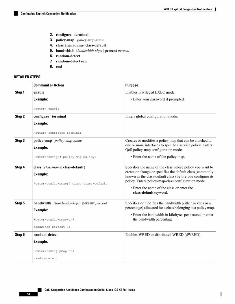
2. configure terminal3. policy-map policy-map-name4. class {class-name| class-default}5. bandwidth {bandwidth-kbps | percent percent6. random-detect7. random-detect ecn8. end
DETAILED STEPS
PurposeCommand or Action
Enables privileged EXEC mode.enableStep 1
Example: • Enter your password if prompted.
Router> enable
Enters global configuration mode.configure terminal
Example:
Step 2
Router# configure terminal
Creates or modifies a policy map that can be attached toone or more interfaces to specify a service policy. EntersQoS policy-map configuration mode.
policy-map policy-map-name
Example:
Router(config)# policy-map policy1
Step 3
• Enter the name of the policy map.
Specifies the name of the class whose policy you want tocreate or change or specifies the default class (commonly
class {class-name| class-default}
Example:
Step 4
known as the class-default class) before you configure itspolicy. Enters policy-map-class configuration mode.
Router(config-pmap)# class class-default
• Enter the name of the class or enter theclass-defaultkeyword.
Specifies or modifies the bandwidth (either in kbps or apercentage) allocated for a class belonging to a policy map.
bandwidth {bandwidth-kbps | percent percent
Example:
Step 5
• Enter the bandwidth in kilobytes per second or enterthe bandwidth percentage.Router(config-pmap-c)#
bandwidth percent 35
Enables WRED or distributed WRED (dWRED).random-detect
Example:
Step 6
Router(config-pmap-c)#
random-detect
QoS: Congestion Avoidance Configuration Guide, Cisco IOS XE Fuji 16.9.x34
WRED Explicit Congestion NotificationConfiguring Explicit Congestion Notification

PurposeCommand or Action
Enables ECN.random-detect ecn
Example:
Step 7
Router(config-pmap-c)#
random-detect ecn
(Optional) Exits policy-map class configuration mode.end
Example:
Step 8
Router(config-pmap-c)#
end
Verifying the Explicit Congestion Notification ConfigurationTo verify the ECN configuration, complete the following steps.
SUMMARY STEPS
1. enable2. show policy-map3. show policy-map interface4. end
DETAILED STEPS
PurposeCommand or Action
Enables privileged EXEC mode.enableStep 1
Example: • Enter your password if prompted.
Router> enable
If ECN is enabled, displays ECN marking information fora specified policy map.
show policy-map
Example:
Step 2
Router# show policy-map
If ECN is enabled, displays ECN marking information fora specified interface.
show policy-map interface
Example:
Step 3
Router# show policy-map interface
(Optional) Exits privileged EXEC mode.end
Example:
Step 4
Router#
QoS: Congestion Avoidance Configuration Guide, Cisco IOS XE Fuji 16.9.x35
WRED Explicit Congestion NotificationVerifying the Explicit Congestion Notification Configuration

PurposeCommand or Action
end
Configuration Examples for WRED-Explicit Congestion Notification
Example Enabling ECNThe following example enables ECN in the policy map called pol1:
Router(config)# policy-map pol1Router(config-pmap)# class class-defaultRouter(config-pmap-c)# bandwidth per 70Router(config-pmap-c)# random-detectRouter(config-pmap-c)# random-detect ecn
Example Verifying the ECN ConfigurationThe following is sample output from the show policy-map command. The words "explicit congestionnotification" (along with the ECN marking information) included in the output indicate that ECN has beenenabled.
Router# show policy-mapPolicy Map pol1Class class-defaultWeighted Fair Queueing
Bandwidth 70 (%)exponential weight 9explicit congestion notificationclass min-threshold max-threshold mark-probability--------------------------------------------------------------------------------------------------------------------
0 - - 1/101 - - 1/102 - - 1/103 - - 1/104 - - 1/105 - - 1/106 - - 1/107 - - 1/10rsvp - - 1/10
The following is sample output from the show policy-map interfacecommand. The words "explicit congestionnotification" included in the output indicate that ECN has been enabled.
Router# show policy-map interfaceSerial4/1Serial4/1Service-policy output:policy_ecn
Class-map:prec1 (match-all)1000 packets, 125000 bytes30 second offered rate 14000 bps, drop rate 5000 bpsMatch:ip precedence 1Weighted Fair QueueingOutput Queue:Conversation 42
QoS: Congestion Avoidance Configuration Guide, Cisco IOS XE Fuji 16.9.x36
WRED Explicit Congestion NotificationConfiguration Examples for WRED-Explicit Congestion Notification

Bandwidth 20 (%)Bandwidth 100 (kbps)(pkts matched/bytes matched) 989/123625
(depth/total drops/no-buffer drops) 0/455/0exponential weight:9explicit congestion notificationmean queue depth:0
class Transmitted Random drop Tail drop Minimum Maximum Markpkts/bytes pkts/bytes pkts/bytes threshold threshold probability
0 0/0 0/0 0/0 20 40 1/101 545/68125 0/0 0/0 22 40 1/102 0/0 0/0 0/0 24 40 1/103 0/0 0/0 0/0 26 40 1/104 0/0 0/0 0/0 28 40 1/105 0/0 0/0 0/0 30 40 1/106 0/0 0/0 0/0 32 40 1/107 0/0 0/0 0/0 34 40 1/10
rsvp 0/0 0/0 0/0 36 40 1/10class ECN Mark
pkts/bytes0 0/01 43/53752 0/03 0/04 0/05 0/06 0/07 0/0
rsvp 0/0
Additional References
Related Documents
Document TitleRelated Topic
Cisco IOS Quality of Service Solutions CommandReference
QoS commands: complete command syntax, commandmodes, command history, defaults, usage guidelines,and examples
"Applying QoS Features Using the MQC" moduleMQC
"Congestion Avoidance Overview" moduleCongestion avoidance concepts
Standards
TitleStandard
--No new or modified standards are supported, and support for existing standards has not been modified.
QoS: Congestion Avoidance Configuration Guide, Cisco IOS XE Fuji 16.9.x37
WRED Explicit Congestion NotificationAdditional References

MIBs
MIBs LinkMIB
To locate and download MIBs for selected platforms, CiscoIOS releases, and feature sets, use Cisco MIB Locator foundat the following URL:
http://www.cisco.com/go/mibs
No new ormodifiedMIBs are supported, andsupport for existing MIBs has not beenmodified.
RFCs
TitleRFC
Internet Performance RecommendationRFC2309
Performance Evaluation of Explicit Congestion Notification (ECN) in IP NetworksRFC2884
The Addition of Explicit Congestion Notification (ECN) to IPRFC3168
Technical Assistance
LinkDescription
http://www.cisco.com/cisco/web/support/index.html
The Cisco Support and Documentation website provides online resources todownload documentation, software, and tools. Use these resources to installand configure the software and to troubleshoot and resolve technical issueswith Cisco products and technologies. Access to most tools on the CiscoSupport and Documentation website requires a Cisco.com user ID andpassword.
Feature Information for WRED Explicit Congestion NotificationThe following table provides release information about the feature or features described in this module. Thistable lists only the software release that introduced support for a given feature in a given software releasetrain. Unless noted otherwise, subsequent releases of that software release train also support that feature.
Use Cisco Feature Navigator to find information about platform support and Cisco software image support.To access Cisco Feature Navigator, go to www.cisco.com/go/cfn. An account on Cisco.com is not required.
QoS: Congestion Avoidance Configuration Guide, Cisco IOS XE Fuji 16.9.x38
WRED Explicit Congestion NotificationFeature Information for WRED Explicit Congestion Notification

Table 5: Feature Information for WRED Explicit Congestion Notification
Feature Configuration InformationSoftwareReleases
Feature Name
Currently, the congestion control and avoidance algorithms forTransmission Control Protocol (TCP) are based on the idea that packetloss is an appropriate indication of congestion on networks transmittingdata using the best-effort service model. When a network uses thebest-effort service model, the network delivers data if it can, without anyassurance of reliability, delay bounds, or throughput. However, thesealgorithms and the best-effort service model are not suited to applicationsthat are sensitive to delay or packet loss (for instance, interactive trafficincluding Telnet, web-browsing, and transfer of audio and video data).Weighted Random Early Detection (WRED), and by extension, ExplicitCongestion Notification (ECN), helps to solve this problem.
The following commands were introduced or modified: random-detectecn, show policy-map, show policy-map interface.
Cisco IOS XERelease 2.1
WRED ExplicitCongestionNotification
QoS: Congestion Avoidance Configuration Guide, Cisco IOS XE Fuji 16.9.x39
WRED Explicit Congestion NotificationFeature Information for WRED Explicit Congestion Notification

QoS: Congestion Avoidance Configuration Guide, Cisco IOS XE Fuji 16.9.x40
WRED Explicit Congestion NotificationFeature Information for WRED Explicit Congestion Notification

C H A P T E R 7QoS Time-Based Thresholds for WRED andQueue Limit
• QoS Time-Based Thresholds for WRED and Queue Limit, on page 41
QoS Time-Based Thresholds for WRED and Queue LimitThe QoS Time-Based Thresholds for WRED and Queue Limit feature allows you to specify the WeightedRandom Early Detection (WRED) minimum and maximum thresholds or the queue limit threshold inmilliseconds (ms). Previously, these thresholds could only be specified in packets or bytes. Now, all threeunits of measure are available. Once the threshold limits are configured in a policy map, the policy map canbe used on multiple interfaces, including those with different amounts of bandwidth.
Finding Feature InformationYour software release may not support all the features documented in this module. For the latest caveats andfeature information, see Bug Search Tool and the release notes for your platform and software release. Tofind information about the features documented in this module, and to see a list of the releases in which eachfeature is supported, see the feature information table at the end of this module.
Use Cisco Feature Navigator to find information about platform support and Cisco software image support.To access Cisco Feature Navigator, go to www.cisco.com/go/cfn. An account on Cisco.com is not required.
Prerequisites for QoS Time-Based Thresholds for WRED and Queue LimitBefore configuring this feature, a traffic class must be configured and a policy map must exist. To create thetraffic class (specifying the appropriate match criteria) and the policy map, use the modular quality of service(QoS) command-line interface (MQC).
Restrictions for QoS Time-Based Thresholds for WRED and Queue LimitThis feature allows you to specify either the WRED thresholds or the queue limit threshold in packets (thedefault unit of measure), bytes, or milliseconds (ms). However, these units cannot be mixed. That is, the unitof measure in the same class, in the same policy map, cannot be mixed. For example, if you specify theminimum threshold for a particular class in milliseconds, the maximum threshold for that class must also bein milliseconds.
QoS: Congestion Avoidance Configuration Guide, Cisco IOS XE Fuji 16.9.x41

Information About QoS Time-Based Thresholds for WRED and Queue Limit
Benefits of QoS Time-Based Thresholds for WRED and Queue Limit
Queue Limit Thresholds Specified in Additional Units of Measure
Previously, the WRED thresholds and the queue limit thresholds could only be specified in packets or bytes.With this feature, the thresholds can be specified either in packets, bytes or milliseconds. These additionalunits of measure provide more flexibility and allow you to fine-tune your configuration.
Policy Maps Can be Reused as Needed on Multiple Interfaces
TheWRED and queue limit thresholds are specified and configured in policy maps. Once the threshold limitsare configured in a policy map, the policy map can be used onmultiple interfaces, including those with differentamounts of bandwidth. This is especially useful when the bandwidth for a class on given interface is beingspecified as a percentage of the total bandwidth available.
Setting Thresholds by Using WREDWRED is a congestion avoidancemechanism.WRED combines the capabilities of the RandomEarly Detection(RED) algorithm with the IP precedence feature to provide for preferential traffic handling of higher prioritypackets. WRED can selectively discard lower priority traffic when the interface begins to get congested andprovide differentiated performance characteristics for different classes of service.
WRED differs from other congestion avoidance techniques such as queueing strategies because it attemptsto anticipate and avoid congestion rather than control congestion once it occurs.
WRED is enabled by using the random-detectcommand. Then the minimum threshold, maximum threshold,and mark probability denominator can be set to determine the treatment that packets receive by using theappropriate command. For example, the random-detect precedence command can be used to determine thethresholds for a specific IP precedence.
Setting Thresholds by Using the queue-limit CommandThe queue-limitcommand allows you to specify or modify the maximum number of packets the queue canhold (that is, the threshold) for a class policy configured in a policy map. Packets belonging to a class aresubject to the guaranteed bandwidth allocation and the queue limits that characterize the traffic class. Withthe queue-limit command, the threshold is the aggregate threshold for the entire class.
After a queue has reached its configured queue limit, enqueuing of additional packets to the traffic class causestail drop or WRED (if configured) to take effect, depending on how the policy map is configured. (Tail dropis a means of avoiding congestion that treats all traffic equally and does not differentiate between classes ofservice.)
Queues fill during periods of congestion. When the output queue is full and tail drop is in effect, packets aredropped until the congestion is eliminated and the queue is no longer full).
Tail drop is used for distributed class-based weighted fair queueing (DCBWFQ) traffic classes unless youexplicitly configure a service policy to use WRED to drop packets as a means of avoiding congestion. Notethat if you use WRED instead of tail drop for one or more traffic classes making up a service policy, you mustensure that WRED is not configured for the interface to which you attach that service policy.
QoS: Congestion Avoidance Configuration Guide, Cisco IOS XE Fuji 16.9.x42
QoS Time-Based Thresholds for WRED and Queue LimitInformation About QoS Time-Based Thresholds for WRED and Queue Limit

random-detect Commands with the Milliseconds KeywordThis feature allows you to specify the WRED minimum and maximum thresholds in milliseconds (ms). Youcan specify the threshold inmilliseconds by using thems keyword available with the random-detect commandslisted in the table below.
Table 6: random-detect Commands with the Milliseconds (ms) Keyword
DescriptionCommand
Configures the WRED parameters for a particular cell loss priority (CLP)value, or a particular CLP value for a class policy in a policy map.
random-detect clp
Configures the WRED parameters for a particular class of service (CoS)value, or a particular CoS value for a class policy in a policy map.
random-detect cos
Configures the WRED parameters for a particular discard-class, or aparticular discard-class for a class policy in a policy map.
random-detect discard-class
Configures the WRED parameters for a particular differentiated servicescode point (DSCP) value, or a particular DSCP value for a class policy ina policy map.
random-detect dscp
ConfiguresWRED parameters for a particular IP precedence, or a particularIP precedence for a class policy in a policy map.
random-detect precedence
Mixing Threshold Units of MeasureWith this feature, the thresholds can be specified in packets (the default unit of measure), bytes, or milliseconds(ms). For instance, with WRED, you can specify the minimum threshold and the maximum threshold inpackets, bytes, or milliseconds. However, the units cannot be mixed. For example, if you specify the minimumthreshold in milliseconds, the maximum threshold must also be specified in milliseconds.
How to Configure QoS Time-Based Thresholds for WRED and Queue Limit
Enabling WRED and Using WRED to Specify Thresholds
SUMMARY STEPS
1. enable2. configure terminal3. policy-map policy-name4. class {class-nameclass-default}5. To continue with the configuration, you must either specify a bandwidth or enable traffic shaping.
Choose one or the other.6. bandwidth {bandwidth-kbps | remaining percent percentage | percent percentage}7. shape [average | peak] mean-rate [burst-size] [excess-burst-size]8. random-detect9. random-detect precedence {precedence | rsvp} min-threshold {bytes|ms| packets}
max-threshold{bytes |ms| packets} [mark-probability-denominator]
QoS: Congestion Avoidance Configuration Guide, Cisco IOS XE Fuji 16.9.x43
QoS Time-Based Thresholds for WRED and Queue Limitrandom-detect Commands with the Milliseconds Keyword

10. exit
DETAILED STEPS
PurposeCommand or Action
Enables privileged EXEC mode.enableStep 1
Example: • Enter your password if prompted.
Router> enable
Enters global configuration mode.configure terminal
Example:
Step 2
Router# configure terminal
Specifies the name of the policy map to be created. Enterspolicy-map configuration mode.
policy-map policy-name
Example:
Step 3
• Enter policy map name.Router(config)# policy-map policy1
Specifies the class so that you can configure or modify itspolicy. Enters policy-map class configuration mode.
class {class-nameclass-default}
Example:
Step 4
• Enter the class name or specify the default class(class-default).Router(config-pmap)# class class1
To continue with the configuration, youmust either specifya bandwidth or enable traffic shaping. Choose one or theother.
Step 5
(Optional) Specifies or modifies the bandwidth allocatedfor a class belonging to a policy map.
bandwidth {bandwidth-kbps | remaining percentpercentage | percent percentage}
Step 6
Example: • Enter the bandwidth to be set or modified.
Router(config-pmap-c)# bandwidth percent 40
(Optional) Enables either average or peak rate trafficshaping.
shape [average | peak] mean-rate [burst-size][excess-burst-size]
Step 7
Example: • Specify either average or peak traffic shaping.
Router(config-pmap-c)# shape average 51200
Enables WRED or distributed WRED (DWRED).random-detect
Example:
Step 8
Router(config-pmap-c)# random-detect
Configures WRED and DWRED parameters for aparticular IP precedence.
random-detect precedence {precedence | rsvp}min-threshold {bytes|ms| packets}max-threshold{bytes|ms| packets} [mark-probability-denominator]
Step 9
QoS: Congestion Avoidance Configuration Guide, Cisco IOS XE Fuji 16.9.x44
QoS Time-Based Thresholds for WRED and Queue LimitEnabling WRED and Using WRED to Specify Thresholds

PurposeCommand or Action
Example: • Specify the IP precedence or RSVP value, andthresholds, as needed.
Router(config-pmap-c)# random-detect precedence2 512 ms 1020 ms In this example, the WRED parameters were
specified for traffic with a specific IPprecedence value. Other values can be specifiedwith other random-detectcommands.
Note
(Optional) Exits policy-map class configuration mode.exit
Example:
Step 10
Router(config-pmap-c)# exit
Using the queue-limit Command to Specify the Thresholds
SUMMARY STEPS
1. enable2. configure terminal3. policy-map policy-name4. class {class-name class-default}5. To continue with the configuration, you must either specify a bandwidth or enable traffic shaping. Choose
one or the other.6. bandwidth {bandwidth-kbps | remaining percent percentage | percent percentage}7. shape [average | peak] mean-rate [[burst-size] [excess-burst-size]]8. queue-limit number-of-packets [bytes |ms | packets]9. exit
DETAILED STEPS
PurposeCommand or Action
Enables privileged EXEC mode.enableStep 1
Example: • Enter your password if prompted.
Router> enable
Enters global configuration mode.configure terminal
Example:
Step 2
Router# configure terminal
Specifies the name of the policy map to be created. Enterspolicy-map configuration mode.
policy-map policy-name
Example:
Step 3
• Enter policy map name.Router(config)#
QoS: Congestion Avoidance Configuration Guide, Cisco IOS XE Fuji 16.9.x45
QoS Time-Based Thresholds for WRED and Queue LimitUsing the queue-limit Command to Specify the Thresholds

PurposeCommand or Actionpolicy-map
policy1
Specifies the class so that you can configure or modify itspolicy. Enters policy-map class configuration mode.
class {class-name class-default}
Example:
Step 4
• Enter the class name or specify the default class(class-default).Router(config-pmap)# class class1
To continue with the configuration, you must either specifya bandwidth or enable traffic shaping. Choose one or theother.
Step 5
(Optional) Specifies or modifies the bandwidth allocatedfor a class belonging to a policy map.
bandwidth {bandwidth-kbps | remaining percentpercentage | percent percentage}
Step 6
Example: • Enter the bandwidth to be set or modified.
Router(config-pmap-c)# bandwidth percent 40
(Optional) Enables either average or peak rate trafficshaping.
shape [average | peak] mean-rate [[burst-size][excess-burst-size]]
Step 7
Example: • Specifies either average or peak traffic shaping.
Router(config-pmap-c)# shape average 51200
(Optional) Specifies or modifies the maximum number ofpackets the queue can hold (that is, the queue limit) for aclass configured in a policy map.
queue-limit number-of-packets [bytes |ms | packets]
Example:
Router(config-pmap-c)# queue-limit 200 ms
Step 8
• Enter the queue limit. The unit of measure can bebytes, milliseconds, or packets.
(Optional) Exits policy-map class configuration mode.exit
Example:
Step 9
Router(config-pmap-c)# exit
Attaching the Policy Map to an Interface in a QoS Time-Based Threshold for WRED Configuration
Depending on the needs of your network, you may need to attach the policy map to a subinterface, an ATMPVC, a Frame Relay DLCI, or other type of interface.
Note
SUMMARY STEPS
1. enable2. configure terminal
QoS: Congestion Avoidance Configuration Guide, Cisco IOS XE Fuji 16.9.x46
QoS Time-Based Thresholds for WRED and Queue LimitAttaching the Policy Map to an Interface in a QoS Time-Based Threshold for WRED Configuration

3. interface type number4. pvc [name] vpi / vci [ilmi | qsaal | smds]5. service-policy {input| output} policy-map-name6. exit
DETAILED STEPS
PurposeCommand or Action
Enables privileged EXEC mode.enableStep 1
Example: • Enter your password if prompted.
Router> enable
Enters global configuration mode.configure terminal
Example:
Step 2
Router# configure terminal
Configures an interface (or subinterface) type and entersinterface configuration mode.
interface type number
Example:
Step 3
• Enter the interface type number.Router(config)#
interface serial4/0
(Optional) Creates or assigns a name to an ATM PVC andspecifies the encapsulation type on an ATM PVC. EntersATM VC configuration mode.
pvc [name] vpi / vci [ilmi | qsaal | smds]
Example:
Router(config-if)# pvc cisco 0/16 ilmi
Step 4
This step is required only if you are attachingthe policy map to an ATM PVC. If you are notattaching the policy map to an ATM PVC, skipthis step and proceed with Step 5 .
Note
Specifies the name of the policy map to be attached to theinput or output direction of the interface.
service-policy {input| output} policy-map-name
Example:
Step 5
Policy maps can be configured on ingress oregress routers. They can also be attached in theinput or output direction of an interface. Thedirection (input or output) and the router (ingressor egress) to which the policy map should beattached varies according your networkconfiguration. When using the service-policycommand to attach the policy map to aninterface, be sure to choose the router and theinterface direction that are appropriate for yournetwork configuration.
NoteRouter(config-if)#
service-policy output policy1
Example:
• Enter the policy map name.
QoS: Congestion Avoidance Configuration Guide, Cisco IOS XE Fuji 16.9.x47
QoS Time-Based Thresholds for WRED and Queue LimitAttaching the Policy Map to an Interface in a QoS Time-Based Threshold for WRED Configuration

PurposeCommand or Action
(Optional) Exits interface configuration mode.exit
Example:
Step 6
Router(config-if)# exit
Verifying the QoS Time-Based Thresholds for WRED and Queue Limit Configuration
SUMMARY STEPS
1. enable2. show policy-map [policy-map]3. and/or4. show policy-map interface interface-name5. exit
DETAILED STEPS
PurposeCommand or Action
Enables privileged EXEC mode.enableStep 1
Example: • Enter your password if prompted.
Router> enable
Displays all information about a class map, including thematch criterion.
show policy-map [policy-map]
Example:
Step 2
• Enter class map name.Router# show policy-map policy1
and/orStep 3
Displays the packet statistics of all classes that areconfigured for all service policies either on the specified
show policy-map interface interface-name
Example:
Step 4
interface or subinterface or on a specific PVC on theinterface.
Router#show policy-map interface serial4/0 • Enter the interface name.
(Optional) Exits privileged EXEC mode.exit
Example:
Step 5
Router# exit
Troubleshooting Tips
The commands in the "Verifying the Configuration" section allow you to verify that you achieved the intendedconfiguration and that the feature is functioning correctly. If, after using the show commands listed above,
QoS: Congestion Avoidance Configuration Guide, Cisco IOS XE Fuji 16.9.x48
QoS Time-Based Thresholds for WRED and Queue LimitVerifying the QoS Time-Based Thresholds for WRED and Queue Limit Configuration

you find that the configuration is not correct or the feature is not functioning as expected, perform theseoperations:
If the configuration is not the one you intended, complete the following steps:
1. Use the show running-config command and analyze the output of the command.
2. If the policy map does not appear in the output of the show running-config command, enable the loggingconsole command.
3. Attach the policy map to the interface again.
If the packets are not beingmatched correctly (for example, the packet counters are not incrementing correctly),complete the following procedures:
1. Run the show policy-mapcommand and analyze the output of the command.
2. Run the show running-config command and analyze the output of the command.
3. Use the show policy-map interface command and analyze the output of the command. Check the thefollowing findings:
1. If a policymap applies queueing, and the packets are matching the correct class, but you see unexpectedresults, compare the number of the packets in the queue with the number of the packets matched.
If the interface is congested, and only a small number of the packets are being matched, check the tuning ofthe transmission (tx) ring, and evaluate whether the queueing is happening on the tx ring. To do this, use theshow controllers command, and look at the value of the tx count in the output of the command..
Configuration Examples for QoS Time-Based Thresholds for WRED and QueueLimit
Example Using WRED to Set ThresholdsIn the following example, WRED has been configured in the policy map called "policy1". In this WREDconfiguration, the bandwidth has been specified as a percentage (80%), and the minimum and maximumthresholds for IP precedence 2 are set to 512 milliseconds and 1020 milliseconds, respectively.
Router> enableRouter# configure terminalRouter(config)#
policy-map policy1Router(config-pmap)# class class1Router(config-pmap-c)# bandwidth percent 80Router(config-pmap-c)# random-detectRouter(config-pmap-c)# random-detect precedence 2 512 ms 1020 msRouter(config-pmap-c)# exit
Router(config-pmap)# exit
Router(config)# interface s4/0Router(config-if)#
service-policy output policy1Router(config-if)# end
QoS: Congestion Avoidance Configuration Guide, Cisco IOS XE Fuji 16.9.x49
QoS Time-Based Thresholds for WRED and Queue LimitConfiguration Examples for QoS Time-Based Thresholds for WRED and Queue Limit

Example Using the queue-limit Command to Set ThresholdsIn the following example, a policy map called "policy2" has been configured. The policy2 policy map containsa class called "class1." The bandwidth for this class has been specified as a percentage (80%) and thequeue-limit command has been used to set the threshold to 200 milliseconds.
Router> enableRouter# configure terminalRouter(config)#
policy-map policy2Router(config-pmap)# class class1Router(config-pmap-c)# bandwidth percent 80Router(config-pmap-c)# queue-limit 200 msRouter(config-pmap-c)# exit
Router(config-pmap)# exit
Router(config)# interface s4/0Router(config-if)#
service-policy output policy1Router(config-if)# end
Example Verifying the ConfigurationTo verify that this feature is configured correctly, use either the show policy-mapcommand or the showpolicy-map interface command.
This section contains two sets of sample output from the show policy-map interface command and the showpolicy-map command--one set showing the output when WRED is used to configure the feature, one setshowing the output when the queue-limitcommand is used to configure the feature.
Example WRED Threshold Configuration Sample OutputThe following is sample output of the show policy-map command when WRED has been used to specify thethresholds. The words "time-based wred" indicates that the thresholds have been specified in milliseconds(ms).
Router# show policy-mapPolicy Map policy1Class class1bandwidth 80 (%)time-based wred, exponential weight 9class min-threshold max-threshold mark-probability----------------------------------------------------------0 - - 1/101 - - 1/102 512 1024 1/103 - - 1/104 - - 1/105 - - 1/106 - - 1/107 - - 1/10
The following is sample output of the show policy-map interface command when WRED has been used tospecify the thresholds.
QoS: Congestion Avoidance Configuration Guide, Cisco IOS XE Fuji 16.9.x50
QoS Time-Based Thresholds for WRED and Queue LimitExample Using the queue-limit Command to Set Thresholds

Router# show policy-map interface Ethernet2/0Ethernet2/0Service-policy output: policy1 (1100)
Class-map: class1 (match-all) (1101/1)0 packets, 0 bytes5 minute offered rate 0 bps, drop rate 0 bpsMatch: protocol ftp (1102)Queueingqueue limit 16 ms/ 16000 bytes(queue depth/total drops/no-buffer drops) 0/0/0(pkts queued/bytes queued) 0/0bandwidth 80.00% (%) (8000 kbps)Exp-weight-constant: 9 (1/512)Mean queue depth: 0 ms/ 0 bytesclass Transmitted Random drop Tail drop Minimum Maximum Mark
pkts/bytes pkts/bytes pkts/bytes thresh thresh probms/bytes ms/bytes
0 0/0 0/0 0/0 4/4000 8/8000 1/101 0/0 0/0 0/0 4/4500 8/8000 1/102 0/0 0/0 0/0 512/512000 1024/1024000 1/103 0/0 0/0 0/0 5/5500 8/8000 1/104 0/0 0/0 0/0 6/6000 8/8000 1/105 0/0 0/0 0/0 6/6500 8/8000 1/106 0/0 0/0 0/0 7/7000 8/8000 1/107 0/0 0/0 0/0 7/7500 8/8000 1/10
Class-map: class-default (match-any) (1105/0)0 packets, 0 bytes5 minute offered rate 0 bps, drop rate 0 bpsMatch: any (1106)0 packets, 0 bytes5 minute rate 0 bps
queue limit 64 packets(queue depth/total drops/no-buffer drops) 0/0/0(pkts queued/bytes queued) 0/0
Formula for Converting the Threshold from Milliseconds to Bytes
When converting the threshold from milliseconds to bytes, the following formula is used:
milliseconds * (bandwidth configured for the class) / 8 = total number of bytes
For this example, the following numbers would be used in the formula:
512 ms * 8000 kbps / 8 = 512000 bytes
Class1 has a bandwidth of 8000 kbps.Note
Example queue-limit command Threshold Configuration Sample OutputThe following is sample output of the show policy-map command when the queue-limit command has beenused to specify the thresholds in milliseconds.
Router# show policy-mapPolicy Map policy1Class class1bandwidth 80 (%)queue-limit 200 ms
QoS: Congestion Avoidance Configuration Guide, Cisco IOS XE Fuji 16.9.x51
QoS Time-Based Thresholds for WRED and Queue LimitExample queue-limit command Threshold Configuration Sample Output

The following is sample output from the show policy-map interface commandwhen the queue-limit commandhas been used to specify the thresholds.
Router# show policy-map interfaceEthernet2/0Service-policy output: policy1 (1070)Class-map: class1 (match-all) (1071/1)0 packets, 0 bytes5 minute offered rate 0 bps, drop rate 0 bpsMatch: protocol ftp (1072)Queueingqueue limit 200 ms/ 200000 bytes(queue depth/total drops/no-buffer drops) 0/0/0(pkts queued/bytes queued) 0/0bandwidth 80.00% (%) (8000 kbps)
Class-map: class-default (match-any) (1075/0)0 packets, 0 bytes5 minute offered rate 0 bps, drop rate 0 bps
Match: any (1076)0 packets, 0 bytes5 minute rate 0 bps
queue limit 64 packets(queue depth/total drops/no-buffer drops) 0/0/0(pkts queued/bytes queued) 0/0
Formula for Converting the Threshold from Milliseconds to Bytes
When converting the threshold from milliseconds to bytes, the following formula is used:
milliseconds * (bandwidth configured for the class)/ 8 = total number of bytes
For this example, the following numbers would be used in the formula:
200 ms * 8000 kbps / 8 = 200000 bytes
Class1 has a bandwidth of 8000 kbps.Note
Additional References
Related Documents
Document TitleRelated Topic
Cisco IOS Master Commands List, All ReleasesCisco IOS commands
Cisco IOS Quality of Service Solutions CommandReference
Quality of service (QoS) commands: complete commandsyntax, command modes, command history, defaults,usage guidelines, and examples
Cisco IOS Quality of Service SolutionsConfiguration Guide
Congestion avoidance mechanisms, including tail drop,RED and WRED
QoS: Congestion Avoidance Configuration Guide, Cisco IOS XE Fuji 16.9.x52
QoS Time-Based Thresholds for WRED and Queue LimitAdditional References

Document TitleRelated Topic
Cisco IOS Quality of Service SolutionsConfiguration Guide
Congestion management mechanisms, includingCBWFQ, and DCBWFQ
Byte-Based Weight Random Early Detectionmodule
Byte-Based WRED
Standards
TitleStandard
--No new or modified standards are supported, and support for existing standards has not been modified.
MIBs
MIBs LinkMIB
To locate and download MIBs for selected platforms, CiscoIOS XE software releases, and feature sets, use Cisco MIBLocator found at the following URL:
http://www.cisco.com/go/mibs
No new or modified MIBs are supported,and support for existing MIBs has not beenmodified.
RFCs
TitleRFC
--No new or modified RFCs are supported, and support for existing RFCs has not been modified.
Technical Assistance
LinkDescription
http://www.cisco.com/cisco/web/support/index.htmlTheCisco Support andDocumentationwebsite providesonline resources to download documentation, software,and tools. Use these resources to install and configurethe software and to troubleshoot and resolve technicalissues with Cisco products and technologies. Access tomost tools on the Cisco Support and Documentationwebsite requires a Cisco.com user ID and password.
Feature Information for QoS Time-Based Thresholds for WRED and QueueLimit
The following table provides release information about the feature or features described in this module. Thistable lists only the software release that introduced support for a given feature in a given software releasetrain. Unless noted otherwise, subsequent releases of that software release train also support that feature.
QoS: Congestion Avoidance Configuration Guide, Cisco IOS XE Fuji 16.9.x53
QoS Time-Based Thresholds for WRED and Queue LimitFeature Information for QoS Time-Based Thresholds for WRED and Queue Limit

Use Cisco Feature Navigator to find information about platform support and Cisco software image support.To access Cisco Feature Navigator, go to www.cisco.com/go/cfn. An account on Cisco.com is not required.
Table 7: Feature Information for QoS Time-Based Thresholds for WRED and Queue Limit
Feature InformationReleasesFeature Name
The QoS Time-Based Thresholds for WRED and QueueLimit feature allows you to specify the Weighted RandomEarly Detection (WRED)minimum andmaximum thresholdsor the queue limit threshold in milliseconds (ms).
The following commands are introduced or modified:queue-limit, random-detect precedence, show policy-map,show policy-map interface.
Cisco IOS XERelease 3.2S
QoS Time-BasedThresholds for WREDand Queue Limit
QoS: Congestion Avoidance Configuration Guide, Cisco IOS XE Fuji 16.9.x54
QoS Time-Based Thresholds for WRED and Queue LimitFeature Information for QoS Time-Based Thresholds for WRED and Queue Limit

C H A P T E R 8DiffServ Compliant WRED
• DiffServ Compliant WRED, on page 55
DiffServ Compliant WREDDiffServ Compliant WRED extends the functionality of Weighted Random Early Detection to enable supportfor DiffServ and Assured Forwarding (AF) per hop behavior (PHB). This feature enables customers toimplement AF PHB by coloring packets according to Differentiated Services Code Point (DSCP) values andthen assigning preferential drop probabilities to those packets.
This feature can be used with IP packets only. It is not intended for use with Multiprotocol Label Switching(MPLS)-encapsulated packets.
Note
Finding Feature InformationYour software release may not support all the features documented in this module. For the latest caveats andfeature information, see Bug Search Tool and the release notes for your platform and software release. Tofind information about the features documented in this module, and to see a list of the releases in which eachfeature is supported, see the feature information table at the end of this module.
Use Cisco Feature Navigator to find information about platform support and Cisco software image support.To access Cisco Feature Navigator, go to www.cisco.com/go/cfn. An account on Cisco.com is not required.
Information About DiffServ Compliant WRED
Differentiated Services for WREDDifferentiated Services is a multiple service model that can satisfy differing Quality of Service (QoS)requirements. With Differentiated Services, the network tries to deliver a particular kind of service based onthe QoS specified by each packet. This specification can occur in different ways. The DiffServ CompliantWRED feature enables WRED to use either the 6-bit differentiated services code point (DSCP) or the IPPrecedence setting in IP packets when it calculates the drop probability for a packet. The DSCP value is thefirst six bits of the IP type of service (ToS) byte.
QoS: Congestion Avoidance Configuration Guide, Cisco IOS XE Fuji 16.9.x55

Usage Guidelines for DiffServ Compliant WREDTo configure the DiffServ CompliantWRED feature, first specify the policy map, add the class, and configurethe bandwidth or shape for the class. If you want WRED to use the DSCP value when it calculates the dropprobability, use the dscp-based argument with the random-detect command to specify the DSCP value andthen use the random-detect dscp command to modify the default minimum and maximum thresholds for theDSCP value. If you want WRED to use the IP Precedence value when it calculates the drop probability, usethe precedence-based argument with the random-detect command to specify the IP Precedence value. Thisconfiguration can then be applied wherever policy maps are attached (for example, at the interface level, theper-VC level, or the shaper level).
Remember the following points when using the commands included with this feature:
• If you use the dscp-based argument, WRED will use the DSCP value to calculate the drop probability.
• If you use the precedence-based argument, WREDwill use the IP Precedence value to calculate the dropprobability.
• The dscp-based and precedence-based arguments are mutually exclusive.
• If you do not specify either argument, WRED will use the IP Precedence value to calculate the dropprobability (the default method).
How to Configure DiffServ Compliant WRED
Configuring DiffServ Compliant WREDThis example configures DiffServ Compliant WRED to use the DSCP value to calculate the drop probabilityfor a packet.
SUMMARY STEPS
1. enable2. configure terminal3. interface type number [name-tag]4. class-map class-map-name5. match match-criterion6. policy-map policy-map-name7. class {class-name | class-default}8. bandwidth {kbps | remaining percentage | percent percentage}9. random-detect [dscp-based | precedence-based]10. random-detect dscp dscp-value min-threshold max-threshold [ mark-probability-denominator]11. exit12. exit13. interface type number [name-tag]14. service-policy output policy-map-name15. end16. show policy-map interface type number17. exit
QoS: Congestion Avoidance Configuration Guide, Cisco IOS XE Fuji 16.9.x56
DiffServ Compliant WREDUsage Guidelines for DiffServ Compliant WRED

DETAILED STEPS
PurposeCommand or Action
Enables privileged EXEC mode.enableStep 1
Example: • Enter your password if prompted.
Device> enable
Enters global configuration mode.configure terminal
Example:
Step 2
Device# configure terminal
Configures an interface type and enters interfaceconfiguration mode.
interface type number [name-tag]
Example:
Step 3
• Enter the interface type and number.Device(config)# interface GigabitEthernet 0/0/0
Specifies the name of the class map to be created and entersQoS class-map configuration mode.
class-map class-map-name
Example:
Step 4
Device(config-if)# class-map diffservclass
Configures the match criteria for a class map.match match-criterion
Example:
Step 5
Device(config-cmap)# match any
Creates or modifies a policy map that can be attached toone or more interfaces to specify a service policy, andenters QoS policy-map configuration mode.
policy-map policy-map-name
Example:
Device(config-cmap)# policy-map diffservpm
Step 6
Specifies the name of the class whose policy you want tocreate or change or specifies the default class (commonly
class {class-name | class-default}
Example:
Step 7
known as the class-default class) before you configure itspolicy.
Device(config-pmap)# class diffservclass
• Enters QoS policy-map class configuration mode.
Specifies the bandwidth allocated for a class belonging toa policy map.
bandwidth {kbps | remaining percentage | percentpercentage}
Example:
Step 8
Device(config-pmap-c)# bandwidth percent 30
Configures WRED for a class in a policy map.random-detect [dscp-based | precedence-based]
Example:
Step 9
QoS: Congestion Avoidance Configuration Guide, Cisco IOS XE Fuji 16.9.x57
DiffServ Compliant WREDConfiguring DiffServ Compliant WRED

PurposeCommand or Action
Device(config-pmap-c)# random-detect dscp-based
Changes the minimum and maximum packet thresholdsfor the differentiated services code point (DSCP) value.
random-detect dscp dscp-value min-thresholdmax-threshold [ mark-probability-denominator]
Example:
Step 10
Device(config-pmap-c)# random-detect dscp af1110000 30000 25
Exits QoS policy-map class configuration mode.exit
Example:
Step 11
Device(config-pmap-c)# exit
Exits QoS policy-map configuration mode.exit
Example:
Step 12
Device(config-pmap)# exit
Configures an interface type and enters interfaceconfiguration mode.
interface type number [name-tag]
Example:
Step 13
• Enter the interface type and number.Device(config)# interface GigabitEthernet 0/0/0
Attaches a policy map to an output interface.service-policy output policy-map-nameStep 14
Example: • Enter the policy map name.
Device(config-if)# service-policy output policy1 Policy maps can be configured on ingress oregress routers. They can also be attached in theinput or output direction of an interface. Thedirection (input or output) and the router(ingress or egress) to which the policy mapshould be attached varies according yournetwork configuration. When using theservice-policy command to attach the policymap to an interface, be sure to choose the routerand the interface direction that are appropriatefor your network configuration.
Note
Returns to privileged EXEC mode.end
Example:
Step 15
Device(config-if)# end
(Optional) Displays the traffic statistics of all classes thatare configured for all service policies either on the specified
show policy-map interface type number
Example:
Step 16
interface or subinterface or on a specific PVC on theinterface.
QoS: Congestion Avoidance Configuration Guide, Cisco IOS XE Fuji 16.9.x58
DiffServ Compliant WREDConfiguring DiffServ Compliant WRED

PurposeCommand or Action
Device# show policy-map interface GigabitEthernet0/0/0
• Enter the interface type and number.
(Optional) Exits privileged EXEC mode.exit
Example:
Step 17
Device# exit
Configuration Examples for DiffServ Compliant WRED
Example: DiffServ compliant WREDThe following example enables WRED to use the DSCP value 8 for the class c1. The minimum threshold forthe DSCP value 8 is 24 and the maximum threshold is 40. The last line attaches the traffic policy to the outputinterface or VC p1.
Device(config)# class-map c1Device(config-cmap)# match ip precedence 1Device(config-cmap)# policy-map p1Device(config-pmap)# class c1Device(config-pmap-c)# bandwidth 48Device(config-pmap-c)# random-detect dscp-basedDevice(config-pmap-c)# random-detect dscp 8 24 40 (bytes/ms)Device(config-if)# service-policy output p1
Additional References
Related Documents
Document TitleRelated Topic
Cisco IOSMaster Commands List,All Releases
Cisco IOS commands
Cisco IOS Quality of ServiceSolutions Command Reference
QoS commands
QoS: Modular QoS:Command-Line InterfaceConfiguration Guide
MQC
Standards and RFCs
TitleStandard/RFC
Definition of the Differentiated Services Field (DS Field) in the IPv4 and IPv6 HeadersRFC 2474
An Architecture for Differentiated Services FrameworkRFC 2475
QoS: Congestion Avoidance Configuration Guide, Cisco IOS XE Fuji 16.9.x59
DiffServ Compliant WREDConfiguration Examples for DiffServ Compliant WRED

TitleStandard/RFC
Assured Forwarding PHBRFC 2597
An Expedited Forwarding PHBRFC 2598
MIBs
MIBs LinkMIB
To locate and download MIBs for selected platforms,Cisco software releases, and feature sets, use CiscoMIBLocator found at the following URL:
http://www.cisco.com/go/mibs
CISCO-CLASS-BASED-QOS-MIB
CISCO-CLASS-BASED-QOS-CAPABILITY-MIB
Technical Assistance
LinkDescription
http://www.cisco.com/cisco/web/support/index.htmlTheCisco Support andDocumentationwebsite providesonline resources to download documentation, software,and tools. Use these resources to install and configurethe software and to troubleshoot and resolve technicalissues with Cisco products and technologies. Access tomost tools on the Cisco Support and Documentationwebsite requires a Cisco.com user ID and password.
Feature Information for DiffServ Compliant WREDThe following table provides release information about the feature or features described in this module. Thistable lists only the software release that introduced support for a given feature in a given software releasetrain. Unless noted otherwise, subsequent releases of that software release train also support that feature.
Use Cisco Feature Navigator to find information about platform support and Cisco software image support.To access Cisco Feature Navigator, go to www.cisco.com/go/cfn. An account on Cisco.com is not required.
QoS: Congestion Avoidance Configuration Guide, Cisco IOS XE Fuji 16.9.x60
DiffServ Compliant WREDFeature Information for DiffServ Compliant WRED

Table 8: Feature Information for DiffServ Compliant WRED
Feature InformationReleasesFeature Name
DiffServCompliantWREDextendsthe functionality of WRED toenable support for DiffServ and AFper-hop behavior.
In Cisco IOS XE Release 3.6S,support was added for the CiscoASR 903 Router.
The following commands wereintroduced or modified:random-detect, random-detectdscp, random-detect precedence.
Cisco IOS XE Release 3.6SDiffServ Compliant WRED
QoS: Congestion Avoidance Configuration Guide, Cisco IOS XE Fuji 16.9.x61
DiffServ Compliant WREDFeature Information for DiffServ Compliant WRED

QoS: Congestion Avoidance Configuration Guide, Cisco IOS XE Fuji 16.9.x62
DiffServ Compliant WREDFeature Information for DiffServ Compliant WRED

C H A P T E R 9Shaping on Dialer Interfaces
• Shaping on Dialer Interfaces, on page 63
Shaping on Dialer InterfacesThe Shaping on Dialer Interfaces feature provides support for Point-to-Point Protocol over Ethernet (PPPoE)and Point-to-Point Protocol over Asynchronous Transfer Mode (PPPoA) configurations on dialer interfaces.The feature provides support for Modular QoS CLI (MQC)-based queuing and shaping that supportsper-customer quality of service (QoS). Parent policies are attached to an Ethernet in the First Mile (EFM)interface, and child policies are attached to individual dialer interfaces. Class of service (CoS) values are setby applying a policy to the dialer interface. The feature also enables the collection of queuing statistics on thedialer interface and the polling of traffic counters for dialer interfaces.
Finding Feature InformationYour software release may not support all the features documented in this module. For the latest caveats andfeature information, see Bug Search Tool and the release notes for your platform and software release. Tofind information about the features documented in this module, and to see a list of the releases in which eachfeature is supported, see the feature information table.
Use Cisco Feature Navigator to find information about platform support and Cisco software image support.To access Cisco Feature Navigator, go to www.cisco.com/go/cfn. An account on Cisco.com is not required.
Restrictions for Shaping on Dialer Interfaces• The output queueing policy must have a parent class-default shaper, and any other queueing actions mustbe configured in a child policy.
Information About Shaping on Dialer Interfaces
QoS on PPP Session on Dialer InterfacesThe Shaping on Dialer Interfaces feature consolidates the output queueing and classification on the egressinterface (where all the queueing features are run). The police and set features (such as CoS marking) alsowork in the output path.
QoS: Congestion Avoidance Configuration Guide, Cisco IOS XE Fuji 16.9.x63

MQC-based QoS queuing and shaping features can be used to attach flat class-default shaped policies to theEFM and attach HQoS parent-shaped policies to the dialer interface.
Policies are applied to the dialer interface using the service-policy command. In addition the related showand debug commands display policy and queueing statistics associated with the dialer target.
QoS Dialer Interface TopologyThe following figure shows the supported topology for the Shaping on Dialer Interfaces feature:Figure 3: Shaping on Dialer Interfaces Topology
The Customer Premises Equipment (CPE) is shared between several customers. Each customer connects tothe CPE through a VLAN on a Gigabit Ethernet port. The CPE connects to the service over a DSL using anEFM interface (this looks like an Ethernet connection but uses DSL) over which all the incoming VLANswill be forwarded. The traffic for each VLAN (customer) is transmitted in a separate PPP session. Each sessionis set up using a dialer interface.
How to Configure Shaping on Dialer Interfaces
Configuring an Output Queueing Policy for Dialer Interfaces
Before you begin
Because the dialer target is added to the dynamic target API, the output queueing policy must have a parentclass-default shaper with any other queueing actions configured in a child policy.
SUMMARY STEPS
1. enable2. configure terminal3. policy-map policy-map-name4. class class-name5. priority percent percentage6. exit7. class class-name8. bandwidth percent percentage
QoS: Congestion Avoidance Configuration Guide, Cisco IOS XE Fuji 16.9.x64
Shaping on Dialer InterfacesQoS Dialer Interface Topology

9. exit10. class {class-name | class-default}11. fair-queue12. exit13. exit14. policy-map policy-map-name15. class class-default16. shape average target-bit-rate17. service-policy policy-map-name18. exit19. exit20. interface type number21. service-policy output policy-name22. exit
DETAILED STEPS
PurposeCommand or Action
Enables privileged EXEC mode.enableStep 1
Example: • Enter your password if prompted.
Device> enable
Enters global configuration mode.configure terminal
Example:
Step 2
Device# configure terminal
Specifies the name of the policy map created earlier andenters policy-map configuration mode.
policy-map policy-map-name
Example:
Step 3
• Enter the policy map name.Device(config)# policy-map child
Specifies the name of the class whose policy you want tocreate and enters policy-map class configuration mode.This class is associated with the class map created earlier.
class class-name
Example:
Device(config-pmap)# class voice
Step 4
• Enter the name of the class or enter the class-defaultkeyword.
Specifies that the amount of guaranteed bandwidth will bespecified by the percent of available bandwidth.
priority percent percentage
Example:
Step 5
Device(config-pmap-c)# priority percent 30
Returns to policy-map configuration mode.exit
Example:
Step 6
QoS: Congestion Avoidance Configuration Guide, Cisco IOS XE Fuji 16.9.x65
Shaping on Dialer InterfacesConfiguring an Output Queueing Policy for Dialer Interfaces

PurposeCommand or Action
Device(config-pmap-c)# exit
Specifies the name of the class whose policy you want tocreate and enters policy-map class configuration mode.This class is associated with the class map created earlier.
class class-name
Example:
Device(config-pmap)# class video
Step 7
• Enter the name of the class or enter the class-defaultkeyword.
Specifies that the amount of guaranteed bandwidth will bespecified by the percent of total bandwidth.
bandwidth percent percentage
Example:
Step 8
Device(config-pmap-c)# bandwidth percent 50
Returns to policy-map configuration mode.exit
Example:
Step 9
Device(config-pmap-c)# exit
Specifies the name of the class whose policy you want tocreate and enters policy-map class configuration mode.This class is associated with the class map created earlier.
class {class-name | class-default}
Example:
Device(config-pmap)# class class-default
Step 10
• Enter the name of the class or enter the class-defaultkeyword.
Enables flow-based fair queueing in this class.fair-queue
Example:
Step 11
Device(config-pmap-c)# fair-queue
Returns to policy-map configuration mode.exit
Example:
Step 12
Device(config-pmap-c) exit
Returns to global configuration mode.exit
Example:
Step 13
Device(config-pmap) exit
Specifies the name of a policy map and enters policy-mapconfiguration mode.
policy-map policy-map-name
Example:
Step 14
• Enter the policy map name.Device(config)# policy-map parent
Creates the class-default class.class class-default
Example:
Step 15
QoS: Congestion Avoidance Configuration Guide, Cisco IOS XE Fuji 16.9.x66
Shaping on Dialer InterfacesConfiguring an Output Queueing Policy for Dialer Interfaces

PurposeCommand or Action
Device(config-pmap)# class class-default
Specifies average rate traffic shaping as bits-per-secondon an interface.
shape average target-bit-rate
Example:
Step 16
Device(config-pmap-c)# shape average 1000000
Configures a service policy policy map.service-policy policy-map-name
Example:
Step 17
Device(config-pmap-c)# service policy child
Returns to policy-map configuration mode.exit
Example:
Step 18
Device(config-pmap-c) exit
Returns to global configuration mode.exit
Example:
Step 19
Device(config-pmap) exit
Configures an interface type and enters interfaceconfiguration mode.
interface type number
Example:
Step 20
• Enter the interface type and number.Device(config)# interface Dialer 0
Attaches a policy map to an output interface that will beused as the service policy for the interface.
service-policy output policy-name
Example:
Step 21
Device(config-if)# service-policy output parent
Returns to global configuration mode.exit
Example:
Step 22
Device(config-if) exit
Configuring QoS for PPPoEoA for Dialer Interfaces
SUMMARY STEPS
1. enable2. configure terminal3. interface type number [name-tag]4. no ip address5. no atm ilmi-keepalive6. exit7. interface type number [name-tag]
QoS: Congestion Avoidance Configuration Guide, Cisco IOS XE Fuji 16.9.x67
Shaping on Dialer InterfacesConfiguring QoS for PPPoEoA for Dialer Interfaces

8. pvc vpi/vci9. vbr-nrt output-pcr output-scr10. pppoe-client dial-pool-number number11. exit12. exit13. interface type number [name-tag]14. mtu ip-address15. ip address ip-address mask16. encapsulation encapsulation-type17. dialer pool number18. dialer-group number19. service-policy output name20. exit21. dialer-list dialer-group protocol protocol-name permit
DETAILED STEPS
PurposeCommand or Action
Enables privileged EXEC mode.enableStep 1
Example: • Enter your password if prompted.
Device> enable
Enters global configuration mode.configure terminal
Example:
Step 2
Device# configure terminal
Configures an interface type and enters interfaceconfiguration mode.
interface type number [name-tag]
Example:
Step 3
• Enter the interface type and number.Device(config)# interface ATM 0
Disables IP processing on the interface.no ip address
Example:
Step 4
Device(config-if)# no ip address
Disables Interim Local Management Interface (ILMI)keepalives on the interface.
no atm ilmi-keepalive
Example:
Step 5
Device(config-if)# no atm ilmi-keepalive
Exits interface configuration mode.exit
Example:
Step 6
Device(config-if)# exit
QoS: Congestion Avoidance Configuration Guide, Cisco IOS XE Fuji 16.9.x68
Shaping on Dialer InterfacesConfiguring QoS for PPPoEoA for Dialer Interfaces

PurposeCommand or Action
Configures an interface type and enters interfaceconfiguration mode.
interface type number [name-tag]
Example:
Step 7
• Enter the interface type, number, and name.Device(config)# interface ATM 0.1 point-to-point
Creates an ATM permanent virtual circuit (PVC), andenters ATM virtual circuit configuration mode.
pvc vpi/vci
Example:
Step 8
• Enter the ATM network virtual path identifier (VPI)and ATM network virtual channel identifier (VCI)for this PVC.
Device(config-if)# pvc 4/46
Configures the variable bit rate-nonreal time (VBR-NRT)quality of service (QoS) and specifies the output peak cell
vbr-nrt output-pcr output-scr
Example:
Step 9
rate (PCR), and output sustainable cell rate (SCR) for anATM permanent virtual circuit (PVC).
Device(config-if-atm-vc)# vbr-nrt 738 738
Configures a PPP over Ethernet (PPPoE) client andspecifies the dial-on-demand routing (DDR) functionality.
pppoe-client dial-pool-number number
Example:
Step 10
Device(config-if-atm-vc)# pppoe-clientdial-pool-number 1
Exits ATM virtual circuit configuration mode.exit
Example:
Step 11
Device(config-if-atm-vc)# exit
Exits interface configuration mode.exit
Example:
Step 12
Device(config-if)# exit
Configures an interface type and enters interfaceconfiguration mode.
interface type number [name-tag]
Example:
Step 13
• Enter the interface type and number.Device(config)# interface Dialer 0
Adjusts the maximum packet size or maximumtransmission unit (MTU) size.
mtu ip-address
Example:
Step 14
Device(config-if)# mtu 1200
Sets the primary IP address for the interface.ip address ip-address maskStep 15
Example: • Enter the IP address and the IP address mask.
Device(config-if)# ip address 172.16.0.0 255.0.0.0
QoS: Congestion Avoidance Configuration Guide, Cisco IOS XE Fuji 16.9.x69
Shaping on Dialer InterfacesConfiguring QoS for PPPoEoA for Dialer Interfaces

PurposeCommand or Action
Sets the encapsulation method used by the interface.encapsulation encapsulation-type
Example:
Step 16
Device(config-if)# encapsulation ppp
Specifies the dialing pool that the dialer interface uses toconnect to a specific destination subnetwork.
dialer pool number
Example:
Step 17
Device(config-if)# dialer pool 1
Controls access by configuring the interface to belong toa specific dialing group.
dialer-group number
Example:
Step 18
Device(config-if)# dialer-group 1
Attaches a policy map to an output interface that will beused as the service policy for the interface.
service-policy output name
Example:
Step 19
Device(config-if)# service-policy outputdialer-output-sp
Exits interface configuration mode.exit
Example:
Step 20
Device(config-if)# exit
Defines a dial-on-demand routing (DDR) dialer list fordialing by protocol or by a combination of a protocol anda previously defined access list.
dialer-list dialer-group protocol protocol-name permit
Example:
Device(config)# dialer-list 1 protocol ip permit
Step 21
Configuring QoS for PPPoE for Dialer Interfaces
SUMMARY STEPS
1. enable2. configure terminal3. interface type number [name-tag]4. ppp enable group group-name5. pppoe-client dial-pool-number number6. exit7. interface type number [name-tag]8. mtu ip-address9. ip address ip-address mask10. encapsulation encapsulation-type11. dialer pool number
QoS: Congestion Avoidance Configuration Guide, Cisco IOS XE Fuji 16.9.x70
Shaping on Dialer InterfacesConfiguring QoS for PPPoE for Dialer Interfaces

12. dialer-group number13. service-policy output name14. exit15. dialer-list dialer-group protocol protocol-name permit
DETAILED STEPS
PurposeCommand or Action
Enables privileged EXEC mode.enableStep 1
Example: • Enter your password if prompted.
Device> enable
Enters global configuration mode.configure terminal
Example:
Step 2
Device# configure terminal
Configures an interface type and enters interfaceconfiguration mode.
interface type number [name-tag]
Example:
Step 3
• Enter the interface type, number, and name.Device(config)# interface Ethernet 0/0
Enables PPPoE sessions on an Ethernet interface orsubinterface.
ppp enable group group-name
Example:
Step 4
Device(config-if)# ppp enable group global
Configures a PPPoE client and to specify thedial-on-demand routing (DDR) functionality.
pppoe-client dial-pool-number number
Example:
Step 5
Device(config-if)# pppoe-client dial-pool-number1
Exits interface configuration mode.exit
Example:
Step 6
Device(config-if)# exit
Configures an interface type and enters interfaceconfiguration mode.
interface type number [name-tag]
Example:
Step 7
• Enter the interface type and number.Device(config)# interface Dialer 0
Adjusts the maximum packet size or maximumtransmission unit (MTU) size.
mtu ip-address
Example:
Step 8
Device(config-if)# mtu 1200
QoS: Congestion Avoidance Configuration Guide, Cisco IOS XE Fuji 16.9.x71
Shaping on Dialer InterfacesConfiguring QoS for PPPoE for Dialer Interfaces

PurposeCommand or Action
Sets the primary IP address for the interface.ip address ip-address maskStep 9
Example: • Enter the IP address and the IP address mask.
Device(config-if)# ip address 172.16.0.0 255.0.0.0
Sets the encapsulation method used by the interface.encapsulation encapsulation-type
Example:
Step 10
Device(config-if)# encapsulation ppp
Specifies the dialing pool that the dialer interface uses toconnect to a specific destination subnetwork.
dialer pool number
Example:
Step 11
Device(config-if)# dialer pool 1
Controls access by configuring the interface to belong toa specific dialing group.
dialer-group number
Example:
Step 12
Device(config-if)# dialer-group 1
Attaches a policy map to an output interface that will beused as the service policy for the interface.
service-policy output name
Example:
Step 13
Device(config-if)# service-policy outputdialer-output-sp
Exits interface configuration mode.exit
Example:
Step 14
Device(config-if)# exit
Defines a dial-on-demand routing (DDR) dialer list fordialing by protocol or by a combination of a protocol anda previously defined access list.
dialer-list dialer-group protocol protocol-namepermit
Example:
Step 15
Device(config)# dialer-list 1 protocol ip permit
Configuring QoS for PPPoA for Dialer Interfaces
SUMMARY STEPS
1. enable2. configure terminal3. interface type number [name-tag]4. pvc vpi/vci5. vbr-nrt output-pcr output-scr output-maxburstsize
QoS: Congestion Avoidance Configuration Guide, Cisco IOS XE Fuji 16.9.x72
Shaping on Dialer InterfacesConfiguring QoS for PPPoA for Dialer Interfaces

6. dialer pool-member number7. protocol protocol8. exit9. exit10. interface type number [name-tag]11. mtu ip-address12. ip address ip-address mask13. encapsulation encapsulation-type14. dialer pool number15. dialer-group number16. service-policy output name17. exit18. dialer-list dialer-group protocol protocol-name permit
DETAILED STEPS
PurposeCommand or Action
Enables privileged EXEC mode.enableStep 1
Example: • Enter your password if prompted.
Device> enable
Enters global configuration mode.configure terminal
Example:
Step 2
Device# configure terminal
Configures an interface type and enters interfaceconfiguration mode.
interface type number [name-tag]
Example:
Step 3
• Enter the interface type, number, and name.Device(config)# interface ATM 0.1 point-to-point
Creates an ATM permanent virtual circuit (PVC), andenters ATM virtual circuit configuration mode.
pvc vpi/vci
Example:
Step 4
• Enter the ATM network virtual path identifier (VPI)and ATM network virtual channel identifier (VCI)for this PVC.
Device(config-if)# pvc 4/46
Configures the variable bit rate-nonreal time (VBR-NRT)quality of service (QoS) and specifies the output peak cell
vbr-nrt output-pcr output-scr output-maxburstsize
Example:
Step 5
rate (PCR), output sustainable cell rate (SCR), and output
Device(config-if-atm-vc)# vbr-nrt 738 738 32maximum burst cell size for an ATM permanent virtualcircuit (PVC).
Configures a physical interface to be a member of a dialerprofiles dialing pool.
dialer pool-member number
Example:
Step 6
QoS: Congestion Avoidance Configuration Guide, Cisco IOS XE Fuji 16.9.x73
Shaping on Dialer InterfacesConfiguring QoS for PPPoA for Dialer Interfaces

PurposeCommand or Action
Device(config-if-atm-vc)# dialer pool-member 1
Configures a static map for an ATM permanent virtualcircuit (PVC), switched virtual circuit (SVC), or virtualcircuit (VC) class.
protocol protocol
Example:
Device(config-if-atm-vc)# protocol ppp dialer
Step 7
Exits ATM virtual circuit configuration mode.exit
Example:
Step 8
Device(config-if-atm-vc)# exit
Exits interface configuration mode.exit
Example:
Step 9
Device(config-if)# exit
Configures an interface type and enters interfaceconfiguration mode.
interface type number [name-tag]
Example:
Step 10
• Enter the interface type and number.Device(config)# interface Dialer 0
Adjusts the maximum packet size or maximumtransmission unit (MTU) size.
mtu ip-address
Example:
Step 11
Device(config-if)# mtu 1200
Sets the primary IP address for the interface.ip address ip-address maskStep 12
Example: • Enter the IP address and the IP address mask.
Device(config-if)# ip address 172.16.0.0 255.0.0.0
Sets the encapsulation method used by the interface.encapsulation encapsulation-type
Example:
Step 13
Device(config-if)# encapsulation ppp
Specifies the dialing pool that the dialer interface uses toconnect to a specific destination subnetwork.
dialer pool number
Example:
Step 14
Device(config-if)# dialer pool 1
Controls access by configuring the interface to belong toa specific dialing group.
dialer-group number
Example:
Step 15
Device(config-if)# dialer-group 1
QoS: Congestion Avoidance Configuration Guide, Cisco IOS XE Fuji 16.9.x74
Shaping on Dialer InterfacesConfiguring QoS for PPPoA for Dialer Interfaces

PurposeCommand or Action
Attaches a policy map to an output interface that will beused as the service policy for the interface.
service-policy output name
Example:
Step 16
Device(config-if)# service-policy outputdialer-output-sp
Exits interface configuration mode.exit
Example:
Step 17
Device(config-if)# exit
Defines a dial-on-demand routing (DDR) dialer list fordialing by protocol or by a combination of a protocol anda previously defined access list, .
dialer-list dialer-group protocol protocol-namepermit
Example:
Step 18
Device(config)# dialer-list 1 protocol ip permit
Configuring QoS for Multiple Sessions on Dialer Interfaces
SUMMARY STEPS
1. enable2. configure terminal3. interface type number [name-tag]4. ppp enable group group-name5. pppoe-client dial-pool-number number6. pppoe-client dial-pool-number number7. pppoe-client dial-pool-number number8. exit9. interface type number [name-tag]10. dialer pool number11. service-policy output name12. exit13. interface type number [name-tag]14. dialer pool number15. service-policy output name16. exit17. interface type number [name-tag]18. dialer pool number19. service-policy output name20. exit
QoS: Congestion Avoidance Configuration Guide, Cisco IOS XE Fuji 16.9.x75
Shaping on Dialer InterfacesConfiguring QoS for Multiple Sessions on Dialer Interfaces

DETAILED STEPS
PurposeCommand or Action
Enables privileged EXEC mode.enableStep 1
Example: • Enter your password if prompted.
Device> enable
Enters global configuration mode.configure terminal
Example:
Step 2
Device# configure terminal
Configures an interface type and enters interfaceconfiguration mode.
interface type number [name-tag]
Example:
Step 3
• Enter the interface type, number, and name.Device(config)# interface Ethernet 0/0
Enables PPPoE sessions on an Ethernet interface orsubinterface.
ppp enable group group-name
Example:
Step 4
Device(config-if)# ppp enable group global
Configures a PPPoE client and to specify thedial-on-demand routing (DDR) functionality.
pppoe-client dial-pool-number number
Example:
Step 5
Device(config-if)# pppoe-client dial-pool-number1
Configures a PPPoE client and to specify thedial-on-demand routing (DDR) functionality.
pppoe-client dial-pool-number number
Example:
Step 6
Device(config-if)# pppoe-client dial-pool-number2
Configures a PPPoE client and to specify thedial-on-demand routing (DDR) functionality.
pppoe-client dial-pool-number number
Example:
Step 7
Device(config-if)# pppoe-client dial-pool-number3
Exits interface configuration mode.exit
Example:
Step 8
Device(config-if)# exit
Configures an interface type and enters interfaceconfiguration mode.
interface type number [name-tag]
Example:
Step 9
• Enter the interface type and number.
QoS: Congestion Avoidance Configuration Guide, Cisco IOS XE Fuji 16.9.x76
Shaping on Dialer InterfacesConfiguring QoS for Multiple Sessions on Dialer Interfaces

PurposeCommand or Action
Device(config)# interface Dialer 0
Specifies the dialing pool that the dialer interface uses toconnect to a specific destination subnetwork.
dialer pool number
Example:
Step 10
Device(config-if)# dialer pool 1
Attaches a policy map to an output interface that will beused as the service policy for the interface.
service-policy output name
Example:
Step 11
Device(config-if)# service-policy outputdialer-output-sp
Exits interface configuration mode.exit
Example:
Step 12
Device(config-if)# exit
Configures an interface type and enters interfaceconfiguration mode.
interface type number [name-tag]
Example:
Step 13
• Enter the interface type and number.Device(config)# interface Dialer 1
Specifies the dialing pool that the dialer interface uses toconnect to a specific destination subnetwork.
dialer pool number
Example:
Step 14
Device(config-if)# dialer pool 2
Attaches a policy map to an output interface that will beused as the service policy for the interface.
service-policy output name
Example:
Step 15
Device(config-if)# service-policy outputdialer-output-sp
Exits interface configuration mode.exit
Example:
Step 16
Device(config-if)# exit
Configures an interface type and enters interfaceconfiguration mode.
interface type number [name-tag]
Example:
Step 17
• Enter the interface type and number.Device(config)# interface Dialer 2
Specifies the dialing pool that the dialer interface uses toconnect to a specific destination subnetwork.
dialer pool number
Example:
Step 18
QoS: Congestion Avoidance Configuration Guide, Cisco IOS XE Fuji 16.9.x77
Shaping on Dialer InterfacesConfiguring QoS for Multiple Sessions on Dialer Interfaces

PurposeCommand or Action
Device(config-if)# dialer pool 3
Attaches a policy map to an output interface that will beused as the service policy for the interface.
service-policy output name
Example:
Step 19
Device(config-if)# service-policy outputdialer-output-sp
Exits interface configuration mode.exit
Example:
Step 20
Device(config-if)# exit
Applying CoS Values to a Dialer InterfaceClass of Service (CoS) values are set by applying a policy to the dialer interface.
SUMMARY STEPS
1. enable2. configure terminal3. policy-map policy-map-name4. class class-default5. set cos cos-value6. exit7. exit8. interface type number [name-tag]9. service-policy output name10. exit11. interface type number [name-tag]12. encapsulation encapsulation-type13. pppoe-client dial-pool-number number14. exit
DETAILED STEPS
PurposeCommand or Action
Enables privileged EXEC mode.enableStep 1
Example: • Enter your password if prompted.
Device> enable
Enters global configuration mode.configure terminal
Example:
Step 2
QoS: Congestion Avoidance Configuration Guide, Cisco IOS XE Fuji 16.9.x78
Shaping on Dialer InterfacesApplying CoS Values to a Dialer Interface

PurposeCommand or Action
Device# configure terminal
Specifies the name of the policy map created earlier andenters policy-map configuration mode.
policy-map policy-map-name
Example:
Step 3
• Enter the policy map name.Device(config)# policy-map output_cos
Creates the default class for traffic classification and enterspolicy-map class configuration mode.
class class-default
Example:
Step 4
Device(config-pmap)# class class-default
Specifies an IEEE 802.1Q CoS value from 0 to 7.set cos cos-value
Example:
Step 5
Device(config-pmap-c)# set cos 1
Returns to policy-map configuration mode.exit
Example:
Step 6
Device(config-pmap-c)# exit
Returns to global configuration mode.exit
Example:
Step 7
Device(config-pmap)# exit
Configures an interface type and enters interfaceconfiguration mode.
interface type number [name-tag]
Example:
Step 8
• Enter the interface type and number.Device(config)# interface Dialer 1
Attaches a policy map to an output interface that will beused as the service policy for the interface.
service-policy output name
Example:
Step 9
Device(config-if)# service-policy outputoutput-cos
Exits interface configuration mode.exit
Example:
Step 10
Device(config-if)# exit
Configures an interface type and enters sub-interfaceconfiguration mode.
interface type number [name-tag]
Example:
Step 11
• Enter the interface type and number.Device(config)# interface Ethernet 0.10
QoS: Congestion Avoidance Configuration Guide, Cisco IOS XE Fuji 16.9.x79
Shaping on Dialer InterfacesApplying CoS Values to a Dialer Interface

PurposeCommand or Action
Sets the encapsulation method used by the interface.encapsulation encapsulation-type
Example:
Step 12
Device(config-subif)# encapsulation dot1q 10
Configures a PPPoE client and to specify thedial-on-demand routing (DDR) functionality.
pppoe-client dial-pool-number number
Example:
Step 13
Device(config-subif)# pppoe-clientdial-pool-number 1
Returns to global configuration mode.exit
Example:
Step 14
Device(config-subif)# exit
Configuration Examples for Shaping on Dialer Interfaces
Example: Configuring Output Queuing Policy for a Dialer Interface
The following example shows how to configure parent and child policy maps and how to attach theparent map to the dialer interface:Device(config)# policy-map childExampleDevice(config-pmap)# class voiceDevice(config-pmap-c)# priority percent 30Device(config-pmap-c)# exit
Device(config-pmap)# class videoDevice(config-pmap-c)# bandwidth percent 50Device(config-pmap-c)# exit
Device(config-pmap)# class class-defaultDevice(config-pmap-c)# fair-queueDevice(config-pmap-c)# exit
Device(config)# policy-map parentDevice(config-pmap)# class class-defaultDevice(config-pmap-c)# shape average 1000000Device(config-pmap-c)# service-policy childDevice(config-pmap-c)# exit
Device(config)# interface dialer 0Device(config-if)# service-policy output parent
Example: Configuring QoS for PPPoEoA for a Dialer Interface
Device(config)# interface ATM 0Device(config-if)# no ip addressDevice(config-if)# no atm ilmi-keepalive
QoS: Congestion Avoidance Configuration Guide, Cisco IOS XE Fuji 16.9.x80
Shaping on Dialer InterfacesConfiguration Examples for Shaping on Dialer Interfaces

Device(config-if)# exit
Device(config)# interface ATM 0.1 point-to-pointDevice(config-if)# ip address 192.168.0.0 255.255.255.224Device(config-if)# pvc 4/46Device(config-if-atm-vc)# vbr-nrt 738 738Device(config-if-atm-vc)# pppoe-client dial-pool-number 1Device(config-if-atm-vc)# exitDevice(config-if)# exit
Device(config)# interface Dialer 0Device(config-if)# mtu 1200Device(config-if)# ip address 172.16.0.0 255.0.0.0Device(config-if)# encapsulation pppDevice(config-if)# dialer pool 1Device(config-if)# dialer-group 1Device(config-if)# service-policy output dialer-output-sp!Device(config)# dialer-list 1 protocol ip permit
Example: Configuring QoS for a PPPoE on a Dialer Interface
Device(config)# interface ethernet 0/0Device(config-if)# pppoe enable group globalDevice(config-if)# pppoe-client dial-pool-number 1Device(config-if)# exit
Device(config)# interface Dialer 0Device(config-if)# mtu 1200Device(config-if)# ip address 172.16.0.0 255.0.0.0Device(config-if)# encapsulation pppDevice(config-if)# dialer pool 1Device(config-if)# dialer-group 1Device(config-if)# service-policy output dialer-output-spDevice(config-if)# exit
Device(config)# dialer-list 1 protocol ip permit
Example: Configuring QoS for PPPoA on a Dialer Interface
Device(config)# interface ATM 0.1 point-to-pointDevice(config-if)# ip address 192.168.0.0 255.255.255.224Device(config-if)# pvc 4/46Device(config-if-atm-vc)# vbr-nrt 738 738Device(config-if-atm-vc)# dialer pool-member 1Device(config-if-atm-vc)# protocol ppp dialerDevice(config-if-atm-vc)# exitDevice(config-if)# exit
Device(config)# interface Dialer 0Device(config-if)# mtu 1200Device(config-if)# ip address 172.16.0.0 255.0.0.0Device(config-if)# encapsulation pppDevice(config-if)# dialer pool 1Device(config-if)# dialer-group 1Device(config-if)# service-policy output dialer-output-spDevice(config-if)# exit
QoS: Congestion Avoidance Configuration Guide, Cisco IOS XE Fuji 16.9.x81
Shaping on Dialer InterfacesExample: Configuring QoS for a PPPoE on a Dialer Interface

Device(config)# dialer-list 1 protocol ip permit
Example: Configuring QoS for Multiple Sessions on a Dialer Interface
Device(config)# interface ethernet 0/0Device(config-if)# pppoe enable group globalDevice(config-if)# pppoe-client dial-pool-number 1Device(config-if)# pppoe-client dial-pool-number 2Device(config-if)# pppoe-client dial-pool-number 3Device(config-if)# exit
Device(config)# interface Dialer 0Device(config-if)# dialer pool 1Device(config-if)# service-policy output dialer-output-spDevice(config-if)# exit
Device(config)# interface Dialer 1Device(config-if)# dialer pool 2Device(config-if)# service-policy output dialer-output-spDevice(config-if)# exit
Device(config)# interface Dialer 2Device(config-if)# dialer pool 3Device(config-if)# service-policy output dialer-output-spDevice(config-if)# exit
Example: Applying CoS Values to a Dialer Interface
Device> enableDevice# configure terminalDevice(config)# policy-map output_cosDevice(config-pmap)# class class-defaultDevice(config-pmap-c)# set cos 1Device(config-pmap-c)# exitDevice(config-pmap)# exitDevice(config)# interface Dialer 1Device(config-if)# service-policy output output-cosDevice(config-if)# exitDevice(config)# interface Ethernet 0.10Device(config-subif)# encapsulation dot1q 10Device(config-subif)# pppoe-client dial-pool-number 1Device(config-subif)# exit
Additional References for Shaping on Dialer Interfaces
Related Documents
Document TitleRelated Topic
Cisco IOS Master Commands List, All ReleasesCisco IOS commands
QoS: Congestion Avoidance Configuration Guide, Cisco IOS XE Fuji 16.9.x82
Shaping on Dialer InterfacesExample: Configuring QoS for Multiple Sessions on a Dialer Interface

Document TitleRelated Topic
Cisco IOS Quality of Service Solutions Command ReferenceQoS commands
QoS:Modular QoS: Command-Line Interface ConfigurationGuide
MQC
Technical Assistance
LinkDescription
http://www.cisco.com/cisco/web/support/index.htmlTheCisco Support andDocumentationwebsite providesonline resources to download documentation, software,and tools. Use these resources to install and configurethe software and to troubleshoot and resolve technicalissues with Cisco products and technologies. Access tomost tools on the Cisco Support and Documentationwebsite requires a Cisco.com user ID and password.
Feature Information for Shaping on Dialer InterfacesThe following table provides release information about the feature or features described in this module. Thistable lists only the software release that introduced support for a given feature in a given software releasetrain. Unless noted otherwise, subsequent releases of that software release train also support that feature.
Use Cisco Feature Navigator to find information about platform support and Cisco software image support.To access Cisco Feature Navigator, go to www.cisco.com/go/cfn. An account on Cisco.com is not required.
Table 9: Feature Information for Shaping on Dialer Interfaces
Feature InformationReleasesFeature Name
The Shaping on Dialer Interfacesfeature provides support forPPPoE/A configurations on dialerinterfaces.
15.3(1)T
Cisco IOS XE Release 3.13S
Shaping on Dialer Interfaces
QoS: Congestion Avoidance Configuration Guide, Cisco IOS XE Fuji 16.9.x83
Shaping on Dialer InterfacesFeature Information for Shaping on Dialer Interfaces

QoS: Congestion Avoidance Configuration Guide, Cisco IOS XE Fuji 16.9.x84
Shaping on Dialer InterfacesFeature Information for Shaping on Dialer Interfaces