Fuji-PHF-Manual.pdf - PAPERLESS RECORDER - Instrumart
114
PAPERLESS RECORDER TYPE: PHF Instruction Manual INP-TN1PHFc-E
-
Upload
khangminh22 -
Category
Documents
-
view
4 -
download
0
Transcript of Fuji-PHF-Manual.pdf - PAPERLESS RECORDER - Instrumart

PAPERLESS RECORDER
TYPE: PHF
Instruction Manual
INP-TN1PHFc-E

iINP-TN1PHF-E
Thank you for your purchasing Fuji Paperless Recorder (Type: PHF).
• Read this instruction manual carefully to ensure correct installation, operation and preparation.
Incorrect handling may lead to accident or injury.
• Specifications of this unit are subject to change without prior notice for improvement.
• Modification of this unit without permission is strictly prohibited. Fuji will not be bear any responsibility for a trouble caused by such a modification.
• This instruction manual should be kept by the person who is actually using the unit.
• After reading the manual, be sure to keep it at a place easy to access.
• This instruction manual should be delivered to the end user without fail.
Manufacturer : Fuji Electric Co., Ltd.
Type : Shown on nameplate of Paperless Recorder
Date of manufacture : Shown on nameplate of Paperless Recorder
Product nationality : Japan
(Note) Windows 2000/XP/7, Excel, WORD PAD are registered trademarks of Microsoft Corpora-tion.
(Note) Compact Flash is a trademark of Sandisk Corporation.
PREFACE
• It is prohibited to transfer part or all of the manual without Fuji’s permission.
• Description in this manual will be changed without prior notice.
© Fuji Electric Co., Ltd. 2007
Issued in September, 2007
Rev. 1st edition February, 2008
Rev. 2nd edition April, 2011
Rev. 3rd edition February, 2012
Request

ii INP-TN1PHF-E
Read this “Caution on Safety” carefully before using the instrument.
• Be sure to observe the instructions shown below, because they describe important information on safety. The degree of danger is classifi ed into the following two levels: “DANGER” and “CAUTION.”
The signs and their meanings are as follows:
Improper handling may cause dangerous situations that may result in death or severe injury.
Improper handling may cause dangerous situations that may result in moderate or light injuries or property damage.
CAUTION ON SAFETY
DANGER
DANGER
CAUTION
• When there is a possibility that the abnormality of this instrument may cause a major accident or damage to other instruments, externally install an adequate emergency stop circuit or a protection circuit to prevent accidents.
• This product is provided with a built-in fuse that cannot be replaced by the customer. Therefore, we recommend you to separately provide adequate fuses externally. (Rating: 250V, 1A) The details of the built-in fuse are as follows.
Type: TR-5 19372, 3.15A (Manufactured by Wickmann-Werke GmbH) Rating: 250V, 3.25A, Type: T (Slow-blow type)
• Feed the power-supply voltage to specifi cations to prevent damages to and breakdown of the instru-ment.
• Never turn on the power before all the mounting and wiring work are fi nished to prevent electric shock, malfunction or failure of the instrument.
• Never use this instrument in an environment where fl ammable or explosive gases exist, since this is not of intrinsically safe construction.
• Never disassemble, remodel, modify, or repair this instrument. Otherwise malfunction, electric shock, or failure may result.
• Never touch the terminal while the instrument is being energized. Otherwise electric shock or mal-function may result.
• Turn off the power before attaching/detaching the module/unit. Otherwise electric shock, malfunc-tion or failure may result.
• We recommend you to perform periodic maintenance for the safe and continuous use of this instru-ment, because consumable parts or those which deteriorate with time are mounted in this instrument.
• Do not block the ventilation holes at the top and the bottom of this instrument. Otherwise a failure, malfunction, shortened service life, or fi re may result.

iiiINP-TN1PHF-E
CAUTION
• Never use the instrument if it is found damaged or deformed when unpacked. Otherwise a fi re, mal-function, or failure may result.
• Check that the instrument is to the proper specifi cations. Otherwise damage or failure may result.
• Do not give a shock to the instrument by falling or toppling it. Otherwise damage or failure may result.
• Operate the instrument paying attention to prevent foreign matters such as scraps, electric wire chips, and iron powder from entering in the instrument.
• Check every six months that the terminal screws and mounting screws are securely fastened. Loose screws may cause fi re or malfunction.
• When changing the setting during the operation or forcibly outputting, starting or stopping the instru-ment, be sure to check that safety is ensured. Improper operation may result in damage or failure of the instrument.
• Be sure to keep the attached terminal cover mounted on the terminal block during the operation. Oth-erwise electric shock or fi re may result.
• Never install this instrument in the following environments.
A place where the ambient temperature goes beyond the range from 0 to 50°C (0 to 40°C when the instrument is mounted with its side face closely contacted)
A place where the ambient humidity goes beyond the range from 20 to 80% RH
A place where condensation occurs
A place where corrosive gases (sulfuric gases or ammonia, etc., in particular) or fl ammable gases exist
A place where vibration or impact may be applied to the instrument (permissible continuous vi-bration condition: 4.9 m/s2 or lower)
A place subjected to water, oil, chemicals, vapor, or steam
A place subjected to dust and high in salt or iron content
A place where inductive interference may have a great effect, thus causing static electricity, mag-netism, or noises
A place subjected to heat accumulation by radiant heat or the like
If the instrument is installed near other electronics instruments, such as TV in particular, noises may be caused. Take the following measures in these cases.
• Place the instrument as far from the TV or the radio as possible (1m or more)
• Change the orientation of the antenna of the TV or the radio.
• Use separate receptacles.
• When mounting this instrument against the panel, pay attention not to apply stress to the case. Other-wise the case may be damaged.
• Stop using the instrument if it is immersed in water. Otherwise electric leak, electric shock, or fi re may result.
• Do not use the wires other than the specifi ed compensation conducting wires for the thermocouple input connection. Otherwise improper indication or malfunction may result.
• Use a wire material with low wire resistance and with small resistance difference among the three wires for the resistance bulb input connection. Otherwise improper indication or malfunction may result.

iv INP-TN1PHF-E
• If a large noise is generated from the power supply, provide an isolating transformer and use a noise fi lter.
• Never use organic solvents such as alcohol or benzene when cleaning this instrument. Do not directly water the main unit. Otherwise deterioration, failure, electric leak, electric shock, or fi re may result. When cleaning the main unit, wipe with a dry cloth.
• Dispose the instrument as an industrial waste.
• Be sure to ground the instrument. Otherwise electric shock or malfunction may result.
• Only authorized workers should perform wiring. Improper wiring may cause fi re, failure, or electric shock.
• At this equipment, the electrostatic discharge is evaluated as performance criteria B in EN61326.
• This product contains a CR Coin Lithium Battery which contains Perchlorate Material-special handling may apply. See www.dtsc.ca.gov/hazardouswaste/perchlorate
CAUTION

vINP-TN1PHF-E
CONTENTS
PREFACE ...................................................................................................................... i
CAUTION ON SAFETY .............................................................................................ii
CONTENTS .................................................................................................................v
1. INTRODUCTION .............................................................................................1-1
1.1 Paperless recorder ...............................................................................................1-1
1.2 Product check ......................................................................................................1-1
1.3 Check on type and specifi cation ..........................................................................1-2
1.4 Handling memory card (Compact Flash) – Cautions on handling ......................1-2
2. NAMES AND FUNCTIONS OF PARTS ..........................................................2-1
2.1 Names and functions of parts ..............................................................................2-1
2.2 Inserting and removing the memory card ...........................................................2-3
2.3 Recording data to memory card ..........................................................................2-4
3. MOUNTING METHOD ....................................................................................3-1
3.1 Mounting location ...............................................................................................3-1
3.2 External dimensions and panel cutout dimensions (unit: mm) ...........................3-1
3.3 How to mount the unit onto the panel .................................................................3-2
4. WIRING .............................................................................................................4-1
4.1 Before wiring ......................................................................................................4-1
4.2 Connection to terminals ......................................................................................4-2
4.3 Connecting recorder to loader .............................................................................4-8
5. DISPLAY FUNCTION ......................................................................................5-1
5.1 Basic composition of Data Display screen .........................................................5-1
5.2 Real time trend display of measured data ...........................................................5-3
5.3 Display of measured data in bar graphs ..............................................................5-5
5.4 Digital display of measured data .........................................................................5-6
5.5 Event summary display .......................................................................................5-7
5.6 Ethernet log display ............................................................................................5-8
5.7 Historical trend display .......................................................................................5-9
5.8 Display on the occurrence of main unit failure .................................................5-10
5.9 Cautions about power ON/OFF ........................................................................5-11
6. OPERATION AND ACTIONS ..........................................................................6-1
6.1 Before running the recorder ................................................................................6-1
6.2 Power ON and state .............................................................................................6-2
6.3 Stopping and starting the recording operation ....................................................6-3
Refer to chapters 3 and 4 only when installing this instrument. Only qualifi ed workers should carry out mounting and wiring of this instrument.CAUTION

vi INP-TN1PHF-E
6.4 Switching data display screens ...........................................................................6-5
6.5 Display of alarm .................................................................................................6-6
7. SETTING AND CHECKING PARAMETERS .................................................7-1
7.1 Setting and checking ...........................................................................................7-1
7.2 Outline of parameter setting procedure ...............................................................7-6
7.3 Basic operation of setting screens .....................................................................7-10
8. SETTING PARAMETERS ................................................................................8-1
8.1 Basic setting ........................................................................................................8-1
8.2 Channel settings ..................................................................................................8-8
8.3 Copying parameters ..........................................................................................8-19
8.4 Setting for data display screen ..........................................................................8-21
8.5 Unit defi nition ...................................................................................................8-26
8.6 Setting for DI (external control unit) function ..................................................8-27
8.7 Ethernet function setting ...................................................................................8-29
8.8 Setting password for parameter setting .............................................................8-32
9. OPERATING MEMORY CARD ......................................................................9-1
9.1 Displaying record data of memory card ..............................................................9-1
9.2 Removing memory card (compact fl ash) ............................................................9-4
9.3 Function of reading settings from memory card (compact fl ash) .......................9-6
9.4 Function of writing settings in memory card (compact fl ash) ............................9-7
9.5 Setting password for memory card operation .....................................................9-9
10. MAINTENANCE AND INSPECTION ...........................................................10-1
10.1 Recommended replacement cycle of parts ........................................................10-1
10.2 Calibration ........................................................................................................10-1
10.3 Formatting the memory card ............................................................................10-1
11. CALIBRATION ...............................................................................................11-1
11.1 Calibration method of measured values ............................................................11-1
11.2 Initializing the measured value .........................................................................11-3
11.3 How to adjust the screen contrast ......................................................................11-5
12. TROUBLESHOOTING ...................................................................................12-1
13. SPECIFICATIONS ..........................................................................................13-1
APPENDICES ..........................................................................................................A-1
Appendix 1 Recording format (ASCII) ....................................................................... A-1
Appendix 2 Parameters that cannot be set during recording ....................................... A-3
Appendix 3 Opening the PHF record data in ASCII format on Excel ........................ A-4
Appendix 4 Timing of recording ................................................................................. A-5

1-1INP-TN1PHF-E
We thank you for purchasing Fuji Paperless Recorder PHF.
The instruction manual describes installation, operation, and maintenance of Paperless Recorder. Read this manual carefully before use.
1.1 Paperless recorder(1) This recorder displays measured data in real time on the liquid crystal display. It is a paperless
type that is also capable of saving the measured data to a compact fl ash card.
(2) It can set up to 6 channels for the input types such as thermocouple, resistance bulb, and DC voltage (or current).
(3) It allows the measured data saved to the compact fl ash card to be displayed on the display unit. Use of the support software attached to the recorder allows the saved data to be displayed on a personal computer.
1.2 Product checkUpon receiving the recorder unit, check the appearance for damage, and if the correct quantity of the accessories are supplied.
Check on accessories
This recorder comes with the accessories shown in Fig. 1-1. Check that they are all present.
1. INTRODUCTION
Fig. 1-1 Accessories
(1) Panel-mounting bracket
(2) PC support software(CD-ROM)
(3) Power supply noise filter
Product namePanel-mounting bracket
CD-ROM PC support software instruction manual
Quantity2
1
Power supply noise filter
(1)
(2)
(3) 1

1-2 INP-TN1PHF-E
1.4 Handling memory card (Compact Flash) – Cautions on handling
(1) Use a Compact Flash (sold separately) that we warrant its performance.
Use of a commercially available Compact Flash may cause failure.
1) When formatting the memory card, use a personal computer. (Refer to 10.3) as FAT32, FAT16 or FAT
2) The memory card should be inserted in the proper direction and fi xed securely to the slot.
3) Don’t turn OFF the power or remove the card from the slot while data is being written in or read from the card, or recorded data may be damaged or lost.
4) Measured data saved to the memory card should be backed up, if necessary.
5) Using CF card adaptor, please check maximum capacity it can deal with. If your CF card is out of the range, don’t format CF card using the adaptor. When formatting CF card by the adaptor, you may fi nd a complate format on Windows, but PHF might not read the card.
6) The compact fl ash card is a consumable item. If the following phenomena take place, the card must have come to the end of its service life. Replace the card in such cases.
• The number of recording fi les is found to be larger than expected even though power failure did not occur or recording was not interrupted.
• The recording fi le loaded into the PC cannot be opened with the data viewer.
7) If you insert a large-capacity Compact Flash, the recorder’s screen may stop about 3 seconds. Recording is still performed normally during this period.
1.3 Check on type and specifi cationCode symbols are marked on specifi cation nameplates. Check the type as ordered. (The specifi cation nameplates are attached to the right of the case and at the rear of the display unit).
4 5 6 7 8
4
11
12
56
1 E 1 V1B3F 1
2H
1P -
01
Number of input points
Alarm (relay) output/DI input board
Communication Ethernet
9 10 11 12 13
Digit
3-point input6-point input
WithoutWith
WithoutWith
Specifications
YE
CODE SYMBOLS
Item
CAUTION

1-3INP-TN1PHF-E
(2) Compact fl ash in the capacity range from 8MB to 2GB can be used.
Refer to the following tables for the storage capacity in the case of 6-channel recording (on condition that no events such as alarms or messages are occurring, and that totalizing is stopped).
(The number of days required for 3-channel recording is approximately 1.6 times of those shown in the table.)
(3) Data write to the memory card is performed according to the following timing. If the power is OFF in the writing cycle, note that the data will not be recorded.
Display refresh cycle
Compact flash size 16MB
1 sec 10 sec 30 sec 1 min 10 min 30 min
Recordable capacity(about)
ASCII format 39 hours 16 days 49 days 99 days 2.7 years 8.1 years
Binary format
Display refresh cycle
Compact flash size
Recordable capacity(about)
ASCII format
Binary format
Display refresh cycle
Compact flash size
Recordable capacity(about)
ASCII format
Binary format
156 hours 64 days 196 days 396 days 10.8 years 32.4 years
64MB
1 sec 10 sec 30 sec 1 min 10 min
159 hours 66 days 199 days 398 days 10.9 years
636 hours 264 days 796 days 1,592 days 43.6 years
256MB
1 sec 10 sec 30 sec 1 min
26 days 265 days 2.1 years 4.3 years
104 days 1060 days 8.4 years 17.2 years
Note: Refer to Item 8.1 “Basic Setting” for the selection of ASCII or binary format for data recording.
Display refresh cycle 1 sec to 1min 2 min 3 min 5 min 10 min 30 min
Write cycle 1 min 2 min 3 min 5 min 10 min 30 min
20 min
20 min
Display refresh cycle 1 hour 2 hours 3 hours 4 hours 6 hours
Write cycle
12 hours
1 hour 2 hours 3 hours 4 hours 6 hours 12 hours
(4) The data recorded in the compact fl ash can be regenerated on the PC by using the data viewer (contained in the attached CD-ROM).
If the data is recorded in ASCII format, it can be directly opened in a spreadsheet such as EXCEL. However, large-amount data cannot be opened (about 7MB or larger in the case of 6-point input, and about 4MB or larger in the case of 3-point input).
In those cases, read in data with the data viewer (contained in the attached CD-ROM), and perform CSV conversion to divide the fi le, which allows the data to be read in.
The data recorded in binary format cannot be directly opened in a spreadsheet such as EXCEL. Refer to Item 8.1 “Basic Setting” for details.
Note: 1) Be careful not to make the size of a fi le too large even if a large-capacity CF card is used. (Keep it to less than 10MB if possible.)
2) If the size of recording fi le becomes 256MB or more, a new fi le is created automatically to continue recording.
(5) Removing memory card
By prohibiting the writing on the memory card, the card can be taken out even if the recording or integration is not stopped. Refer to Item 9.2 “Removing memory card (compact fl ash)” for the procedure.
Make sure to prohibit writing before removing the memory card or when using FTP server function.CAUTION

1-4 INP-TN1PHF-E
(6) About communication function
By connecting the paperless recorder to Ethernet, the following function can be used (when “E” is selected for the 12th digit of the code symbols).
• FTP server function: Record fi les stored in the compact fl ash of the recorder can be downloaded from the PC on the network using Web browser (Microsoft Internet Explorer) or DOS prompt.
• Web server function: Measurements of the recorder or event log on the network can be displayed using Web browser (Microsoft Internet Explorer).
• E-mail function: E-mails can be sent to specifi ed addresses with the measurement of the record-er attached.
• MODBUS TCP/IP function: Settings of the recorder can be read or written from the PC on the network using MODBUS TCP/IP function.
Ethernet

2-1INP-TN1PHF-E
2. NAMES AND FUNCTIONS OF PARTS
(4) Memory card ejection button(6) Function keyboard
(3) Memory card slot
(2) Power switch(5) Connector forparameter loader
(1) Display unit
2.1 Names and functions of parts
(1) Display unit
Allows the Real time trend screen, Bar Graph Display screen, Digital Display screen, Historical trend screen and other various Parameter Set screens to be displayed.
(2) Power switch
Used to turn the power ON or OFF.
(3) Memory card slot
Used for inserting the memory card
(4) Memory card ejection button
To remove the memory card from the slot, press this button.
1) If you want to remove the memory card while recording is in progress (while REC in the display unit is highlighted) or during totalizing, refer to Item 9.2 or stop recording and totalizing before removing the memory card. Other-wise, the data cannot be recorded correctly, or the past data may be damaged. (If the memory card is removed and inserted again while recording or totalizing is in progress, it is recorded as a new fi le.)
2) While the compact fl ash of the paperless recorder is accessed by FTP commu-nication, do not take out the compact fl ash. Furthermore, when the FTP server function is used, inhibit access to the com-pact fl ash in the “Memory card abstract” screen, before taking out the compact fl ash.
(5) Connector for parameter loader
When changing parameters by using a loader, connect the exclusive cable (optional cable: PHZP0201) to the connector.
(6) Function keyboard
Used for operation, or setting and verifying each parameter.
CAUTION

2-2 INP-TN1PHF-E
Used to start or stop recording.
Pressing once, starts recording. After that pressing once again, stops recording.
Used to switch display contents. Each time the key is pressed, the display is switched to (1) → (2) → (3) → (4) → (5) → (6) and returns to (1).
(1) Real time trend display
Displays the measurement data of an arbitrary channel on data display screen (note 1)
(2) Key guidance
Key operation guidance appears.
(3) Bar graph display
Displays the measured data of the channel in a bar graph.
(4) Digital display.
Displays the measured data of the channel in numerical values.
(5) Event summary display
Displays the alarm summary or message summary.
(6) Ethernet log display
Pressing this key on the parameter setting screen (note 2), the display is swithed to the Real time
trend display.
Used to switch from the data display screen (note 1) to the parameter setting screen (note 2).
Pressing the key on the parameter setting screen switches to the screen one step up.
However, pressing the key on the menu screen does not change screens.
(1) Used for selection on the setting screen or registration of the set data.
(2) If the key is pressed while the scales are displayed on the real time trend display screen,
historical trend display screen (*1), or recorded data display screen, the channels for which
scales are to be displayed can be switched.
(Scale of ch1 → scale of ch2 → ….. → scale of ch6 → scale of ch1 → scale of ch2…..)
(1) Used to select setting items.
(2) Used to increase or decrease numerical values.
(3) Pressing the key on the real time trend displays the historical trend screen (*1).
At this time, the window can be scrolled using the cursor key.
Key name
(Record)
(Display)
(Select)
(Entry)
(Cursor)
Function
*1: The screen in the past of the data currently recorded
*1: The screen in the past of the data currently recorded
Note 1 : See Item 6.4 for detail.Note 2 : See Item 7.1 for detail.
REC
ENT
DISP
SEL

2-3INP-TN1PHF-E
2.2 Inserting and removing the memory cardThe memory card is used for saving measured data. Before attempting to use the recorder, set it in the recorder slot securely.
This section explains how to insert the memory card into or remove it from the slot.
(1) To insert memory card
Step 1) Open the panel unit.
Step 2) Insert the memory card into the slot at the right side of the panel unit as shown in Photo.
Insert straight the card in ac-cordance with the photo, or the inside pins might be broken. If you insert with wrong direction, the slot is broken.
(2) To remove memory card
Step 1) Press the memory card ejection button to remove the memory card from the slot.
1) Do not remove the memory card while data is written in it (while the lamp indicating writing status is kept on). Refer to Item 9.2 “Removing memory card (compact fl ash)” for the removal of the memory card while recording is in progress.
2) After inserting the memory card into the slot, don’t remove the card until the recorder can acknowl-edge it.
3) Be careful with static electricity when removing the memory card.
CAUTION
CAUTION
Memory card ejection button

2-4 INP-TN1PHF-E
Display refresh cycle
Compact flash size 16MB
1 sec 10 sec 30 sec 1 min 10 min 30 min
Recordable capacity(about)
ASCII format 39 hours 16 days 49 days 99 days 2.7 years 8.1 years
Binary format
Display refresh cycle
Compact flash size
Recordable capacity(about)
ASCII format
Binary format
Display refresh cycle
Compact flash size
Recordable capacity(about)
ASCII format
Binary format
156 hours 64 days 196 days 396 days 10.8 years 32.4 years
64MB
1 sec 10 sec 30 sec 1 min 10 min
159 hours 66 days 199 days 398 days 10.9 years
636 hours 264 days 796 days 1,592 days 43.6 years
256MB
1 sec 10 sec 30 sec 1 min
26 days 265 days 2.1 years 4.3 years
104 days 1060 days 8.4 years 17.2 years
Note: Refer to Item 8.1 “Basic Setting” for the selection of ASCII or binary format for data recording.
2.3 Recording data to memory card(1) Recorded data:
Data can be recorded in the following three formats. Either ASCII or binary format can be selected for recording. Refer to Item 8.1 “Basic Setting.”
Trend data : Records the maximum and the minimum values, average value or instan-taneous values of the measured value sampled at display update cycles.
Trend data fi le name to be created: S00****.FDT (**** is substituted by four-digit numerical value.)
Refer to “Appendix 1 (1) Trend data fi le” for recording format.
Event data : Records the information on occurrence or release of alarms and message issuing information.
Event data fi le name to be created: A00****.FDT (**** is substituted by four-digit numerical value.)
Refer to “Appendix 1 (2) Event data fi le” for recording format.
(2) Parameter save data:
Setting fi le: Stores the setting created on the recorder main unit or the parameter loader.
Name of setting fi le: PA00000.PHF
(3) Recording capacity:
It depends on the capacity of the memory card.
Refer to the following tables for the storage capacity in the case of 6-channel recording (on condition that no events such as alarms are occurring).
(The number of days required for 3-channel recording is approximately 1.6 times of those shown in the table.)

2-5INP-TN1PHF-E
Display reflesh cycle 1 sec to 1min 2 min 3 min 5 min 10 min 30 min
Writing cycle 1 min 2 min 3 min 5 min 10 min 30 min
20 min
20 min
Display reflesh cycle 1 hour 2 hours 3 hours 4 hours 6 hours
Writing cycle
12 hours
1 hour 2 hours 3 hours 4 hours 6 hours 12 hours
(4) Recording cycle:
Refer to the following tables for the timing of writing the trend data to the compact fl ash.
The event data is written in the compact fl ash by the minute.
(5) Timing to start recording:
The event data cannot be written in the compact fl ash until the fi rst display refreshment cycle passes by.

3-1INP-TN1PHF-E
3. MOUNTING METHOD
Note) If other instruments are placed under the recorder unit, provide a space of 100 mm or more from the instrument or floor.
137 +1.5 0 (160 × n–22) +2
0
137
+1.
5
0
137
+1.
5
0
Mounting 1 unit Mounting n units
144
161
136.
5
160 14018521.6
T2 ≤ T ≤ 26
Panel Mounting bracket
REC DISP SEL ENT
This unit is designed to be panel mounted.
3.1 Mounting locationSelect the following location for mounting the unit.
(1) A place that is not subject to vibration or shock.
(2) A place where there is no dust, dirt or corrosive gas.
(3) A place that is subject to little temperature variation and is in the range of 0 to 50°C.
(4) A place that is not struck directly by strong radiant heat.
(5) A place that is free from water drip or dew condensation in the range of 20 to 80%RH.
(6) A place that is well ventilated for the dispersion of heat generated from other devices.
(7) A space that is accessible for wiring, and maintenance and check.
(8) A place that is not affected by electromagnetic wave from wireless machine or portable telephones.
(9) Mount the unit horizontally, with no tilt to the left or right (The forward tilt should be 0° but the unit may be inclined 0 to 30° rearwards.
3.2 External dimensions and panel cutout dimensions (unit: mm)
External dimensions
Panel cutout dimensions
∠α = 60 to 90°
∠α

3-2 INP-TN1PHF-E
Panel Mounting bracket
3.3 How to mount the unit onto the panel
• Using the supplied mounting bracket, tighten the upper and lower screws unit the panel is fi xed.
• The panel to be used should be more than 2 mm and less than 26 mm thick.
CAUTION Excessive torque will cause damage to front panel frame or result in case de-formation.
Torque: 0.2 N·m

4-1INP-TN1PHF-E
4. WIRING
4.1 Before wiring(Note) When cables are connected to terminals of the recorder unit, don’t apply pulling force to them
excessively. Excessive force to the terminal may result in damage to the terminal or cable.
(1) Use the power cable that has the performance equivalent to or higher than 600-V vinyl insulated power cable.
(2) For the thermocouple input, be sure to use a compensated lead wire.
(3) Input signal cables should be wired separately as far as possible (30 cm or more) from power lines and high-voltage lines to minimize the effect of inductive noise. Shielded cables should preferably be used. In this case, the shield braids should be earthed at one point.
(4) Up to 2 solderless terminals should be used when connecting cables to terminals. Be sure to use an insulation cap.
(Note)
1) At the completion of wiring of the input terminals, be sure to close the rear cover to ensure the compensation of reference contact when thermocouple input is used.
In case of thermocouple input, follow the steps to stabilize temperature at the terminal.
• Be sure to attach input terminal cover.
• Don’t use a thick cable to prevent the effect of radiation. It is recommended that the cable with a diameter of 0.5 mm or less should be used.
• Don’t mount other instruments near a fan to keep temperature stable.
2) For connection of lead wires to terminals, use of sleeve-insulated clamping terminals is rec-ommended.
3) This product is provided with a built-in fuse that cannot be replaced by the customer. Therefore, we recommend you to separately provide adequate fuses externally. (Rating: 250V, 1A)
4) Don’t loosen screws that are secured to the terminal case and power terminal.
For M3screw terminal

4-2 INP-TN1PHF-E
4.2 Connection to terminals(1) Input terminal:
Connect signal cable for each channel.
(2) Alarm relay (DO)/DI (External control unit):
Connect the output of alarm signals and the input of DI (external control) signals (for alarm [DO] 1 to 10 and DI [external control] 1 to 5)
(3) Power terminal:
Connect power cable to L/N terminals. Power source to be connected should be free from noise.
(4) Earth terminal:
Connect grounding cable to “G” terminal (Class-D, 100 or less).
(5) Ethernet terminal
2 1
4
3
5
Do not loosen these screws.
Do not loosen these screws.
Note)
Note)
Note: Do not loosen these screws, or recorder can’t measure correctly at thermocouple input.

4-3INP-TN1PHF-E
Input terminal
CH4
RCJ
CH5
CH6
Resistancebulb
Resistancebulb
ThermocoupleThermocouple
VoltageVoltage
Note) For current input, connect optional shunt resitors to the voltage input terminals.
+
–
+
– CH1
CH2
CH3
+
–
+
–
+
–
+
–
+
–
+
–
+
–
+
–
+
–
+
–
11
12
13
41
42
4321
22
23
51
52
53
6131
6232
6333
+
Resistancebulb
Resistancebulb
ThermocoupleThermocoupleVoltageVoltage
CH1–
+
–
CH4
RCJ
CH5
CH6
CH2
+
–
+
–
CH3
+
–
+
–
+
–
+
–
+
–
+
–
+
–
+
–
(1) Connection of input terminal1) Input terminal No. is determined for each channel.
2) When changing the type of input signal (see Item 8.2) after purchasing the unit, connect input terminals according to the relation between terminal No. and channel No..
Note: Don’t input huge signal that is out of range, or recorder is broken.
In case channel 1 to 6
Note) Connect nothing to the terminals not used as input terminals.

4-4 INP-TN1PHF-E
Note)
1) An arbitrary input type can be set for channels 1, 2, 3, and 6. An input type can be selected from the same input group for channels 4 and 5.
Example) ch1: Thermocouple
ch2: Resistance bulb Any input type can be set.
ch3: 500mV
ch4: 5V
ch5: 5V 1 to 5V or 0 to 5V can be set.
For the setting method, see Item 8.2.
2) Don’t remove RCJ module, or indication of process variable is not correct at thermocouple input.
Not used
DC current input
Shunt resistor (option)(PHZP0101)
Example 1) For 4 to 20mA and 10 to 50mA input, 10Ω±0.1% shunt resistance is used. In this case, set the input range to ±500mV (see Item 8.2).Voltage conversion by shunt resistance of 10Ω 4 to 20mA DC : 40 to 200mV DC 10 to 50mA DC : 100 to 500mV DC
b
B
A
Red(A)White(B)White(b)
Resistance bulb
(4) Resistance input
(2) DC current input(1) DC voltage input
(3) Themocouple input
Compensating leads
DC voltage input
Not used
Not used
Thermocouple
Note) Avoid using thermocouple input with wiring parallel to other instruments.
Wiring of input terminals

4-5INP-TN1PHF-E
External control
(1) Recording start/stop
Recording start/stop by DI
Front key
In recordingstop
In recording
Recording start Recording start
Recording stop Recording stop
ON OFF
External control
(2) LCD ON
In LCD off LCD ON
ON OFF
DI1
For DI function, see “Setting of DI function”.
DI2
DI3
DI4
DI5
DI1231DI2DI3DI4DI5DO1DO2DO3DO4DO5DO6DO7DO8DO9DO10
Alarm output/DI input terminal
232
233
234
235
236
237
238
239
240
241
242
243
244
245
211
212
213
214
215
216
217
218
219
220
221
222
223
224
225
(2) Alarm relay output (DO)/DI (external control unit) (Option)About external control unit (DI)
1) This instrument is provided with the function of performing “start/stop of recording operation” and “LCD ON” in response to the contact signals (DI) received from outside the instrument.
Note 1) DI (external control) unit is not insulated and should be used with a relay connected to the outside.
External contact capacity: 20V/0.05A DC, 1a contact
Note 2) DI (external control) unit is operated as follows when the front switch is pressed.
The unit action will not be affected by items in the table.

4-6 INP-TN1PHF-E
DO1
DO2
DO3
DO4
DO5
DO6
DO7
DO8
DO9
DO10
DI1231DI2DI3DI4DI5DO1DO2DO3DO4DO5DO6DO7DO8DO9DO10
Alarm output/DI input terminal
232
233
234
235
236
237
238
239
240
241
242
243
244
245
211
212
213
214
215
216
217
218
219
220
221
222
223
224
225
Note) If lamps are provided on the outside, set a resistor to prevent rush current. When relays or solenoids are used, set elements for contact protection (diodes or surge killers, etc).
About alarm output (DO)
1) Alarm setting is provided at 4 points for each input channel. Up to 10 points for alarm output can be set as an option.
2) When an alarm occurs, the relevant terminals are shorted (ON).
1a contact output: Relay contact capacity : 150V AC/3A, 30V DC/3A (resistive load : DO1)
: 240V AC/3A, 30V DC/3A (resistive load : DO2 to DO10)

4-7INP-TN1PHF-E
(3) EthernetNote: Install the LAN cable far away from the power supply line or strong electric line as
possible to avoid the infl uence of induction noise.
(4) Caution on connection of input signal through barrier 1) Thermocouple input and resistance bulb input
Since the barrier internal resistance is added and causes an error in the measured value, perform “Calibration of measured value” with the input connected to the barrier recorder.
For the calibration method, refer to Item 11.1.
2) When using Fuji Zener Barrier (PWZ), a power supply of 100V AC line (85 to 150V AC) should be used to ensure safe operation of the unit.

4-8 INP-TN1PHF-E
(USB cable)
4.3 Connecting recorder to loader(1) When connecting the recorder to a loader, use optional PC loader communication cable (PHZP1801)
as shown below.
The loader cable should be connected to USB port of PC.
Be sure to display the data display screen (refer to Item 6.4) instead of the param-eter setting screen before using the loader. Otherwise, the set value may not be written.
CAUTION

5-1INP-TN1PHF-E
5. DISPLAY FUNCTION
(7) Memory card indicator
(1) Name of screen
(6) Memory card loading display
(9) Alarm display (5) Memory card writing status display
(3) Parameter memory lamp
(4) Record display
(8) Data display area
(2) Clock display
5.1 Basic composition of Data Display screen
(1) Name of screen
Displays the screen name (“Display Name”) that was set arbitrarily.
(2) Clock display
Displays date and time (Year/Month/date).
(3) Parameter memory lamp
If the lamp blinks in red, it means that parameters are not saved to the fl ash memory. Save the set value by selecting “Menu” / “Parameter setting” / “Basic setting” / “Register data” and press the
key.
(4) Record display
“REC” is lit when the measured data is being recorded. On the “Real Time Trend” screen, data will be displayed only when the recorder is in recording.
(5) Memory card writing status display
It is lit when measured data is being written in a memory card.
(6) Memory card loading display
It indicates the loading state of the memory card.
Blinks : shows the state where the memory card is not loaded in the slot.
Green display : shows the state where the memory card is loaded and can be pulled out.
Red display : shows the state where the memory card is loaded but must not be pulled out.
(7) Memory card indicator
It indicates how much of the memory card has been used in graphs. At 90%, it turns red. At 100%, the recorder stops recording. Replace the memory card before it is used up.
(8) Data display area
It displays measured data in real time trend, bar graph, digital display or event summary on the screen. (See Item 5.2 to 5.4.)

5-2 INP-TN1PHF-E
(9) Alarm display
It displays alarm information that occurs at present (channel No. and alarm No.).
If more than 1 alarm occurs, it displays one alarm after another in every 3 seconds.

5-3INP-TN1PHF-E
5.2 Real time trend display of measured dataMeasured data can be displayed in waveforms. The vertical or horizontal directions can be selected by setting.
Measured value display of eachchannel(point value)
Date and Time(Year / Month / Day hour : minute : second)(24-hour display)
Time(hour: minute)
(24-hour display)
Time scale display
Time scale display
Display division
Display division
Trend display
Trend display
Measured value display of eachchannel(point value)
Correct time may not be displayed because there may be a case where some digits of the time display are lacked.
*) The screens consist of those selected in “Menu” / “Parameter setting” / “Display setting”.
Measured value display in TAG No. or the unit is also available.
Vertical trend Horizontal trend
Display refresh cycle (sec) 1 2 3 5 10 30
Chart speed (mm/h) as converted 1296 648 432 260 130 43
20
65
Display refresh cycle (min) 1 2 3 5 10 30
Chart speed (mm/h) as converted 22 11 7.2 4.3 2.2 0.7
20
1.1
Display refresh cycle (hour) 1 2 3 4 6
Chart speed (mm/h) as converted 0.36 0.18 0.12 0.09 0.06
12
0.03
(1) The display unit allows measured data to be displayed in waveforms only when recording. If the recorded values exceed the limits of 0 % and 100%, they will be displayed at 0% and 100% positions, respectively. If waveforms of more than 1 channel are displayed at the same position, the trend lines overlap each other. In this case, color of the channel with the largest number is given priority over those of other channels. (Example: In the case of ch2 and ch6, the color of ch6 is displayed.)
(2) Display refresh cycles are selectable from parameters of 1 sec to 12 hours. Relations between the parameter and chart speed are shown in tables below. After the start of the recording, the initial refresh cycles will start at the time of 00: 00: 00 when the recording is continued.
(Example) When display refresh cycles are set to 1 minute, it will start at the next cycle of m hour: n minute: 0 second.

5-4 INP-TN1PHF-E
(3) The Historical Trend screen is displayed by pressing the down cursor key (▼) when the Real Time Trend is displayed. This screen allows currently recorded waveform data to be read from the memory card, tracing back to the past. To return to the Real Time Trend screen, press the key.
(4) The recorder performs the recording by pressing , and it displays waveforms without inserting the memory card into the slot. In this case, some 400 data can be displayed in historical trend. However, the data exceeding 400 items will be deleted. So, be sure to insert the memory card in the recorder slot before starting the recording.
(5) If the power is turned OFF while recorder is writing data to memory card, the data written in the memory card will be destroyed. Be sure to press the key to stop the recording, and then turn OFF the power.
(6) If the input signal is burnt out, or over/under range is displayed, the recording line is displayed at 0% or 100% position (at 100% position if the signal is burnt out). Note, however, the line is displayed at the position equivalent to 0.26V for 0-5V input with the input kept open, and at the position equivalent to 260mV for 0-500mV input with the input kept open.

5-5INP-TN1PHF-E
Bar graph display
Scale display
Measured value display of eachchannel(instantaneous value)
5.3 Display of measured data in bar graphsThe measured data can be displayed in bar graphs.
(1) Setting of display ranging from 0 to 100% is displayed in bar graphs.
(2) Display refreshment cycles are fi xed to 1 sec.
(3) The recorder displays measured data even when it stops recording.

5-6 INP-TN1PHF-E
Unit
Display ofmeasured value
TAG name
Display name
Channel No.
Alarm No.occurred
5.4 Digital display of measured dataMeasured data is displayed in numerical values.
(1) Measured values of each channel are displayed in digital value.
(2) Display refreshment cycles are fi xed to 1 sec.
(3) When an alarm occurs, Alarm No. at the channel is displayed in red.

5-7INP-TN1PHF-E
New
Old
Page of screen
ALM ON CH3 – 1H
Alarm (ON/OFF)
Channnel No.(1 to 6)
Setting alarm No.(1 to 4) and alarm types (H and L)
Example of alarm summary
5.5 Event summary displayAlarm information history can be displayed.
(1) A maximum of 180 events can be displayed on the screen.
(2) Page scrolling can be performed by pressing or key.
(3) When events occur, they are displayed on the screen despite in the recording state. If the recorder is not in the recording state, events are not recorded in the memory card.
(4) Once displayed, the event is kept displayed until the power is turned off (turning off the power clears the event buffer).
(5) How to view the event summary is shown below.
(6) When the battery for backup is empty, power off and power on are not displayed.
Alarm summary(Alarm ON)

5-8 INP-TN1PHF-E
5.6 Ethernet log displayThe use information of FTP, Web, E-mail, and MODBUS TCP/IP functions can be displayed.
(1) Up to 180 communication items can be displayed.
(2) Pages can be turned using horizontal cursor key.
(3) The log appears every time communication is carried out irrespective of the state of recording.
(4) Once displayed, the contents of communication are kept displayed until the power is set to OFF. (Communication buffer is cleared when the power is set to OFF.)
(5) Details of the display are as follows.
Communication contents display
• E-mail transmission display (E-mail No. is E-mail trigger No.)
E-mail sent : “E-mail No.1”
E-mail send error : “E-mail No.1 NG”
• FTP communication display
FTP server log in : “FTP LOGON USER1”
FTP server log off : “FTP LOGOFF USER1”
• MODBUS TCP/IP communication display
Communication start : “MODBUS Start”
Communication stop : “MODBUS Stop”
Communication connection lamp

5-9INP-TN1PHF-E
Measured value at cursor position of each cannnel(Min and Max values)
Time at cursor position
Cursor
5.7 Historical trend displayPressing the ▼ key on the real time trend screen, and following screen as shown below is displayed. This screen indicates the history of currently recorded data.
(1) It allows the data recorded in the memory card to be displayed. The display can be scrolled by using the cursor expressed in a white dotted line. The cursor can move vertically the (▲ or ▼) key or horizontally the (or ) key. Depending on recording type, either average, point or Min. value or Max. value at the position of the cursor are displayed at the lower part of the screen.
(2) Recording start/stop cannot be performed on the screen. To do this, switch the “Historical Trend” screen to “Real Time Trend” screen. However, this “Historical Trend” screen cannot be shifted to the “Parameter Set” screen. To shift the “Real Time Trend” screen, be sure to press the key.
(3) The data that can be displayed on the historical trend screen is the one currently recorded or the data held immediately before the recording is stopped. The data that was recorded in the past and whose recording was then stopped must be displayed on the “record data display” screen (refer to Item 9.1), or reproduced on the PC using the data viewer.
The following items are displayed on the historical trend screen based not on the setting of the past recording but on the currently selected values.
• Trend direction
• Number of screen partition
• Trend scale display
• Color bar display selection

5-10 INP-TN1PHF-E
(4) Press the key while the historical trend screen is displayed, and following “Display time setting” screen appears.
5.8 Display on the occurrence of main unit failure(1) Display at CF card memory FULL
If the memory of the CF card becomes full, recording is stopped with the following message displayed on the trend screen, etc. (totalizing is not suspended). Immediately replace the CF card.
(2) Display at the end of battery life
If the battery voltage becomes low, the following message appears on the trend screen, etc. Immediately stop the recording, and ask your distributor for repair.
Enter the time of currently recorded data you want to display and press the key. Then, PHF displays historical trend data at entered day and time. To display past data, entered day and time appears the bottom of the historical screen. To display farther data, entered day and time appears the top of this screen.

5-11INP-TN1PHF-E
5.9 Cautions about power ON/OFF(1) Recording state and record fi le
If the power is turned OFF when the recorder is in the recording, data written in the memory card may be damaged. Be sure to stop recording by pressing key, and then turn OFF the power.
In addition, if the power is OFF with the recorder in the recording, the recorder will start recording when the power is turned ON again. In this case, data will be recorded as a new fi le.
(2) Recording set values
After parameters have been set, register the set values by selecting “Basic settng” → “Register data”, or they will return to the former values when power is turned OFF.
(3) Clock function
The clock is backed up by an internal lithium battery. The battery life is expected to be about 10 years at normal temperature. Although there is no need to set the clock when the power is turned ON, an error may occur every time the power is turned ON/OFF (about 1 sec per ON/OFF operation).
(4) If the power is turned off due to a power failure and turned on again while recording is in progress, a message “Power & Rec.ON.” appears at the top of the event fi le and event display.

6-1INP-TN1PHF-E
6. OPERATION AND ACTIONS
Loading the memory card
(1) Inserting and removing the memory card·············································· See Item 2.2.
Conformity of input connection to recording channel
(1) Channel settings····················································································· See Item 8.2.
Wiring
(1) Input terminals······················································································· See Item 4.2.
(2) Alarm terminals (option)········································································ See Item 4.2.
(3) Power and ground terminals·································································· See Item 4.2.
6.1 Before running the recorderCheck the following points before starting operation.

6-2 INP-TN1PHF-E
Memory card indicatorMemory card load indicator
Measured data for each channel
6.2 Power ON and state(1) Open the panel unit. Turn “ON” the power switch at the upper center of the panel unit.
(2) After power ON, the self-check function starts up.
(3) Insert the memory card. Check if the unit is fi xed in the slot, as viewing the memory card load indicator. When you insert CF card to recorder, see the “Memory card load indicator” and check the status of CF card (refer to Item 6.1). If indicator blinks in red, remove the CF card and then insert again. After this operation, if it keeps on blinking in red, it might be broken.
(4) Measured data are displayed for each channel.
* TAG. No. or the unit display is also available according to screen confi guration setting.

6-3INP-TN1PHF-E
ON
Waveforms ofmeasured values
Press
6.3 Stopping and starting the recording operation
(1) Recording start
1) To start the recording, press the key, and password input screen appears. If password has not been set, this screen doesn’t appear. Recording password setting parameter, “Record Password” is as shown below.
Menu / Parameter setting / Confi g and rec password set See Item 8.8 for detail.
Input correct password, then the REC lamp is lighted and measured values are displayed in waveforms on the data display unit. Also, it starts saving the measured values to the memory card.
* Recording is performed at the timing described in “Appendix 4 Timing for recording.”
2) When Record password has been established, the following password screen appears. Enter the password. If the entered password is correct, the recording is started.
3) If the CF card is not inserted, the following message appears. Press the key to start recording. Press the key if you do not want to start recording.
Note: If recording is attempted with CF card not inserted, the result cannot be recorded.

6-4 INP-TN1PHF-E
OFF
Previously recordedwaveforms
Press
(2) Recording stop
1) To stop recording, press the key. The following message appears. To stop the recording, press the key, and press the key to continue recording.
2) After the stop of the recording, the REC lamp comes off. The trend display on the data display unit stops. In this case, even if there is some data that are not yet written in the memory card, the unit writes them in the card until the recording is fi nished.
(3) When Record password has been established, the following password screen appears. Enter the password. If the entered password is correct, the recording stop confi rmation screen appears.

6-5INP-TN1PHF-E
Real time trend screen
(Refer to Item 5.2.)
Key operationguide display
Event summary screen (Refer to Item 5.5.)
Ethernet log screen(Refer to Item 5.6.)
Historical trend screen (Refer to Item 5.7.)
The key operation procedure on the data display screen is displayed at the top of the real time trend screen.
Digital screen(Refer to Item 5.4.)
Bar graph screen(Refer to Item 5.3.)
6.4 Switching data display screensData display screens include real time trend screen, bar graph screen and digital screen. Every time the key is pressed, the screen switches to another one. To display the historical trend screen, press
the key in the real time trend screen.
The structure of the data display screen is as follows.

6-6 INP-TN1PHF-E
When an alarm occurs, its content is displayed.
Channel No.
It is indicated that an alarm of alarm No.4and alarm type H occur at channel 6.
Example of alarm display
Alarm No.
Alarm type
(The display is kept on until the alarm is reset.)
Alarm No.
6.5 Display of alarm
(1) Alarms that occurred on the Trend Display, Bar Graph and Digital Display screens:
Note) If an alarm occurs on the “Digital Display” screen, Alarm No. at upper right of “Measured value display” is lighted in red.
* If an alarm occurs against the current input, the alarm contents (and not the past alarm record) are displayed on the historical screen and the record data display screen of the memory card.

7-1INP-TN1PHF-E
7. SETTING AND CHECKING PARAMETERS
7.1 Setting and checkingFollow the description of Item 7.2 “Outline of parameter setting procedure” to enter into each screen, and then follow the description of Item 7.3 “Basic operation of setting screens” to make parameter setting.
(1) Parameters are factory-set as given in Item 7.1 table(1). Turning on power as they are initiates operation (indication and recording). Change the parameter setting as required.
(2) Recording range consists of multi-ranges. Set the range as desired. Not that the same input type should be set for ch4 and ch5.
(3) Alarms, TAG No. and messages are not set. Set them as needed. An input fi lter is set at 3 seconds.
(4) Press the key in the real time trend display screen to display the “Menu” screen. Refer to Item 7.2 for the contents and the operation of the “Menu” screen.

7-2 INP-TN1PHF-E
(5) To go to “Parameter setting” screen, “CF manager” screen or “Calibration password” screen, you must enter 4-digit password when you have already entered each password.
Example: Parameter setting screen
(in case of incorrect password)
(in case of correct password)
keys : To move the cursor,keys : To change numerical value,

7-3INP-TN1PHF-E
Note) After setting the parameters, select “Basic setting” / “Register data” in order to save the set information to a fl ash memory. To reset parameter set values, press key. So, the
following message appears. Press the key twice. The parameter has been reset.

7-4 INP-TN1PHF-E
Parameter nameBasic setting
Setting at delivery (Default value) Setting range Remarks
Channel setting
Display refresh cycle : 1 second
Alarm hysteresis : 0.2%Alarm latch : OFFLCD lights out time : 0DO output at memory FULL: NoneDO output at battery END: None
MODBUS station No. : 1Front communication : ONRecord data format : ASCIITime setting :
Input type: K-Type TC (K thermocouple)
TAG1: TAG ** (**: channel No.)TAG2 : BlankUnit : °C
Decimal point position : ****.*Input filter : 3 secondsSubtraction channel : NonePV shift : 0.0PV gain : 100%Recording type: Maximum/minimum value recordingRecording mode : With recordAlarm setting
1 second to 12 hours
From 0.00 to 100.00%Display compression : 1/1 1/1, 1/10, 1/30, 1/60
OFF, ON0 to 60 minutes *1
LCD keeps turning on when set “0”.
None, DO1 to DO10None, DO1 to DO10
0 to 255Select language : English English, French
OFF, ONASCII, Binary
Skip, K, E, J, T, R, S, B, N, W, L, U, PN thermocouple, Pt100, JPt100, Ni100, Cu50,Pt50, 50mV, 500mV, 1-5V and 0-5V rangeUp to 8 charactersUp to 8 characters°C, °F, Engineering unit in case of voltage input
Input range (range start/end): 0 to 1200 Engineering value
0 to 900 seconds (In increments of 1 second)0 to 6 (No subtraction at 0)Engineering value –3276.7 to 3276.70.00 to 327.67%Instantaneous value recording, average value recording, maximum/minimum value recordingWith record/Display only
Set point : 0.0°C Engineering valueOFF, H, L
DO relay No. : NoneFrom alarm No. 2 to No. 4 There are the same items above.
DO1 to DO10
Alarm No. 1 type : OFF
Select an input type from the same group for channels 4 and 5.
Register data :
*1
File overwrite : OFFDate format : yyyy/mm/dd
OFF, ONFile division cycle : No division No division, 1 hour, 1 day, 1 week, 1 month
yyyy/mm/dd, dd/mm/yyyy, dd-mmm-yy, mm/dd/yyyy, mmm-dd-yy
Display setting
Original unit definitionDI setting
Display configuration: No. 1 to 6 = ch1 to 6Unit : BlankDI function: Function invalid
No.1 to 6, Each provided with ch1 to 6
Subnet mask : 0.0.0.0 0 to 255
Up to 7 charactersFunction invalid, Rec start/Rec stop, LCD ON
Ethernet setting IP address : 0.0.0.0 0 to 255
Historical back color : Black White, BlackDisplay screen setting
Trend back color : White White, Black
E-mail setting SMTP IP address : 0.0.0.0 0 to 255
Default gateway : 0.0.0.0 0 to 255FTP server function : OFF OFF, ONFTP access control : OFF OFF, ONWeb server function : OFF OFF, ONE-mail function : OFF OFF, ONMODBUS TCP/IP : OFF OFF, ON
Name : Blank Up to 32 characters
Sender’s mailAdd : Blank
Up to 64 characters
Receiver’s mailAdd1 to Add8 : Blank
Up to 64 characters
Table (1) Parameters as set by factory (initial values) (1/2)

7-5INP-TN1PHF-E
Parameter name Setting at delivery (Default value) Setting range Remarks
E-mail trigger setting
Triigger timing : None None, DI ON, DI OFF,Alarm ON, Alarm OFF, Warning, Timer cycle
Config andrecord password
Record Password : 0000 0000 to 9999Password : 0000 0000 to 9999Security mode : Password Password, Logon
User account setting
User name : Blank Up to 16 characters
Alarm Channel : 1 Channel 1 to 6Alarm No. : 1 1 to 4Title : Blank Up to 32 charactersText1, 2 : Blank Up to 32 charactersPV value affixation : OFF OFF, ONReceiver’s add No. : 1 1 to 8Mail send test :
Password : Blank Up to 8 charactersUser Level : Administrator Administrator, Engineer, Operator, Guest
Table (1) Parameters as set by factory (initial values) (2/2)

7-6 INP-TN1PHF-E
Parameter setting
CF manager
Menu screenReal time trenddisplay screen
*1
Configrationpassword set
(Note)
Parameter settingmenu screen
Config and recpassword set
Configration password set screen
Basic setting screenBasic setting
Channel setting screenChannel setting
Channel setting copyChannel setting
copy screen
Ethernet setting screen
E-mail setting screen
E-mail trigger setting screen
User account setting screen
Original unit definition screen
Display setting screenDisplay setting
Original unit definition
DI function setting screenDI function setting
Ethernet setting
E-mail setting
E-mail trigger setting
User account setting
Important
*1) Parameter setting cannot be changed while recording is in progress.*2) It is only used for calibration. Don’t use it for other purposes.
CF manager menu screen
CF managerpassword set
CF managerpassword set
screen
Version
Record datadisplay screen
Calibration password
Record data display
Memory cardabstract screenMemory card abstract
Parameter file load screenParameter file load
Parameter file save screenParameter file save
CF manager menu screen
(Note)
(Note) In case the password has been set.
CF manager password set
Version displayscreen
Explanation of key
, keysPressing these keys allow you to shift menus one after another on the “Parameter Set” screen.
keyPressing this key allows you to confirm the menu item on the “Parameter Set” screen.
keyAfter the setting, pressing this key when registering data or canceling data registration returns to the Menu screen.
keyPressing this key in any screen returns to the Real time trend Display screen.
7.2 Outline of parameter setting procedureNote) The outline of the setting screen is switched by settings of “Security mode” in Item 8.8.
If “Logon” is selected in the settings of “Security mode,” the outline of the setting screen is also switched depending on the user level selected when logging on.
(1) Security mode : Password

7-7INP-TN1PHF-E
Calibration password Calibration password*2
Input adjustment screen
Contrast tuning screen
Other function
Parameter initialization
Input adjustment
Calibration menu screen
Parameter initiali-zation screen
Adjust data initialization
(Note)
(Note) In case the password has been set.
Contrast tuning
(2)(a) Security mode : Logon, Logon user : None
Logon/Logoff
Menu screenReal time trenddisplay screen
Logon/Logoff screen
Version display screenVersion

7-8 INP-TN1PHF-E
(2)(b) Security mode : Logon, Logon user : Administrator
Logon/Logoff
Menu screenReal time trenddisplay screen
Logon/Logoff screen
Version display screen
Parametr setting
Version
Calibration password
CF manager
Parameter settingmenu screen
Config and recpassword set
Basic setting
E-mail trigger setting
Menu screen is the same as that of the case where “Password” is selected in the settings of “Security mode” in Item 7.2 (1).
CF manager menu screen
Menu screen is the same as that of the case where “Password” is selected in the settings of “Security mode” in Item 7.2 (1).
Menu screen is the same as that of the case where “Password” is selected in the settings of “Security mode” in Item 7.2 (1).
Calibration menu screenCalibration password
User account setting

7-9INP-TN1PHF-E
(2)(c) Security mode : Logon, Logon user : Engineer
Logon/Logoff
Menu screenReal time trenddisplay screen
Parametr setting
Version
CF manager
Parameter settingmenu screen
Basic setting
E-mail trigger setting
Note: “User account setting” and “Password set” screens are not displayed.
CF manager menu screen
Menu screen is the same as that of the case where “Password” is selected in the settings of “Security mode” in Item 7.2 (1).
Logon/Logoff screen
Version display screen
(2)(d) Security mode : Logon, Logon user : Operator and Guest
Logon/Logoff
Menu screenReal time trenddisplay screen
Version
CF manager CF manager menu screen
Menu screen is the same as that of the case where “Password” is selected in the settings of “Security mode” in Item 7.2 (1).
Logon/Logoff screen
Version display screen

7-10 INP-TN1PHF-E
7.3 Basic operation of setting screensThe basic operation of the setting screens is classifi ed in the following 3 methods. In this case, use the up and down keys (▲ and ▼) to move setting items.
(1) Items to be selected with the ▲ or the ▼ key
Pressing the ▲ or the ▼ key switches the blinking between items.
Example: To change the input type from K-Type TC (K thermocouple) to E-Type TC (E thermocouple)
Press the key once.

7-11INP-TN1PHF-E
(2) To make the setting by entering numeric values
Select a numerical value using the ▲, ▼, or the key and then press the key to confi rm the entry.
Example: To select 10°C as the lowest temperature of the setting range
key three times.Press the
key once.Press the

7-12 INP-TN1PHF-E
Character entering field
Character display field
(3) To make the setting by entering characters
Select a position in the character entering fi eld you want to enter a character by pressing the or the key, and then press the key.
Select a character in the character display fi eld by pressing the , , ▲ or the ▼ key. The selected character blinks. Then press the key.
After entering characters in the character entering fi eld, press the key to confi rm the entry.
Example: To enter PHF for group screen name
(Move the cursor to “ENTRY” and then press the [ENT] key.)
key twelve times.Press the

8-1INP-TN1PHF-E
8. SETTING PARAMETERS
8.1 Basic setting[Explanation]
Follow the procedure shown below to make basic settings (including display refresh cycle, LCD lights out time, MODBUS, and current time) of the recorder main unit.
[Operation]
Move the cursor to “Parameter setting” on the Menu screen and press the key, the parrameter setting screen appears. If the password has been set, enter the password.
Move the cursor to “Basic setting” and press the key, the basic setting screen appears.
Display refresh cycle settingDisplay compression settingAlarm hysteresis settingAlarm latch settingLCD lights out time settingDO setting at the time of memory FULL DO setting at the time of battery ENDFile division cycleFile overwrite settingDate display format settingLanguage select settingMODBUS communication station No. settingMODBUS front communication settingRecord data format settingCurrent time settingRegister of data

8-2 INP-TN1PHF-E
Refresh cycle 1 sec 2 sec 3 sec 5 sec 10 sec 30 sec
Chart speed (as converted) 1296mm/h 648mm/h 432mm/h 260mm/h 130mm/h 43mm/h
20 sec
65mm/h
Refresh cycle 1 min 2 min 3 min 5 min 10 min 30 min
Chart speed (as converted) 22mm/h 11mm/h 7.2mm/h 4.3mm/h 2.2mm/h 0.7mm/h
20 min
1.1mm/h
Refresh cycle 1 hour 2 hours 3 hours 4 hours 6 hours
Chart speed (as converted) 0.36mm/h 0.18mm/h 0.12mm/h 0.09mm/h 0.06mm/h
12 hours
0.03mm/h
(1) To set display refresh cycle
Move the cursor to “Refreshment cycle” and press the key, then the cycle time screen shown below appears.
(Cycle time: 1, 2, 3, 5, 10, 20, 30 seconds,1, 2, 3, 5, 10, 20, 30 minutes, 1, 2, 3, 4, 6, and 12 hours)
The fi rst time of the display update is started from 00:00:00 of the following without fail.
(Example)
When refresh cycle is set to 1 min, the next cycle begins at hh : mm : 0 (sec).
Note) If the refresh cycle time is short and a large number of recording fi les exist, the re-cording at every refresh cycles may be skipped. Recording fi les should be limited to 100 or less.
Relationship between “Refresh cycle” and “Chart speed” (on screen) is given below.

8-3INP-TN1PHF-E
(3) To set the alarm output hysteresis width
Move the cursor to “Alarm hysteresis” and press the key. The alarm hysteresis screen appears (as shown below). Enter hysteresis width (0 to 100%) by the cursor key and then press the
key for confi rmation. It is applicable to all types of alarms. The numeric value is expressed as a percentage of the display range for each channel.
(4) To set alarm latch
Move the cursor to “Alarm latch” and press the key, then the alarm latch setting screen appears. Make the setting using the cursor key and press the key.
Alarm latch function keeps alarm output turning on even after the cause of the alarm has been removed. To cancel the alarm latch, select it to OFF. Alarm cancel is recorded in the event summary in this case.
(5) To enter LCD lights out time
Move the cursor to “LCD-lights out time” and press the key, then the LCD lights out time setting screen appears.
Make the setting (0 to 60 minutes) using the cursor key and press the key.
The LCD is kept on at all times by entering 0 minute.
* Press any key to turn on the LCD.
(2) To set display compression
Move the cursor to “Display compression” and press the key to display the setting screen. Select the compression ratio in the trend display, and press the key.
For example, when the display update cycle is 1 second, the trend display is updated in the cycles shown in the following table.
Compression ratio 1/1 1/10 1/30 1/60
Display time 1 sec 10 sec 30 sec 60 sec
(Note) 1. Compressed display cannot be made in the historical display screen. 2. Compression ratio cannot be changed while recording.

8-4 INP-TN1PHF-E
(6) To make DO setting at the time of memory FULL
Move the cursor to “Memory full alarm” and press the key, then the DO output setting screen appears. Select desired DO output No. using the cursor key and press the key.
DO output works when memory FULL is detected. Select “None” not to use this function.
Note) “Memory full alarm” is turned on when the remaining memory reaches 0%. This value cannot be set.
Note) When memory card is removed, DO output turns off. But the message of memory card full does not appear. Press the or key, it appears.
(7) To make DO setting at the time of battery END
Move the cursor to “Battery alarm” and press the key, then the DO output setting screen appears.
Select desired DO output No. using the cursor key and press the key.
DO output functions when the battery END is detected. Select “None” not to use the function.
When battery END is detected, a message is displayed on the trend screen.
(8) Setting the fi le division cycle
Move the cursor to “File division cycle” and then press the key to display the File division cycle setting screen.
If “No division” is selected, the archived fi le is not divided automatically.
If “1 hour,” “1 day” or “1 week” is selected, the archived fi le is divided hourly, daily or weekly from the start of recording.
If “1 month” is selected, the archived fi le is divided at 0:00 on the fi rst day of every month.
Note 1) If the “File division cycle” setting is shorter than the “Refreshment cycle” setting, the archived fi le without data is created.
Note 2) If “1 hour,” “1 day” or “1 week” is selected as the fi le division cycle, the number of data of the fi rst fi le is one larger than that of the second and the subsequent fi les.
Note 3) Even if you select “No division” for the fi le division cycle setting, when the size of re-cording fi le becomes 256MB or more, a new fi le is created automatically to continue recording.
If you select “1 week” or “1 month” for the fi le division cycle setting, when the size of recording fi le becomes 256MB or more before the pre-set fi le division cycle, a new fi le is created automatically to continue recording.

8-5INP-TN1PHF-E
(10) Date display format setting
The display format of dates that appear on the data display screen can be selected.
On the Basic setting screen, move the cursor to “Date format” and then press the key, and the display format select screen appears.
Move the cursor to the display format to be selected, and then press the key.
(11) Setting the language select
Move the cursor to “Language select” and press the key to select a language.
When a language is switched to another, a language in the Web screen and E-mail is switched accordingly.
(12) To select a station No. for MODBUS communication
Move the cursor to “MODBUS station No.” and press the key, then the station No. setting screen appears.
Select desired MODBUS TCP/IP station No. (0 to 255) using the cursor key and press the key. When set 0 to this parameter, communication does not work.
(9) Setting the fi le overwrite
Move the cursor to the “File overwrite” and press the key for setting.
If the overwrite function in the archived fi le is turned ON, the oldest fi le is deleted and the new record fi les are kept when the compact fl ash becomes full while recording.
The overwrite function on the archived fi le operates as follows.
• When the remaining capacity of compact fl ash is 1MB or less, the oldest fi le is deleted.
• The maximum number of record fi les is 1350 pieces. If the number of fi le exceeds 1350, the oldest fi le is deleted regardless of the remaining capacity of fl ash memory.
• When the available capacity (the capacity of the deletable record fi le included) is lees than 10MB, the overwrite function in the archived fi le does not operate.
(Note)
The overwrite function in the archived fi le stops recording as in CF FULL in the same state when the split function in the archived fi le is not operating, or when only one fi le is kept in the compact fl ash even thought the split function is operating.

8-6 INP-TN1PHF-E
(14) To set record data format
Move the cursor to “Record data format” and press the key, then the data format setting screen appears.
Select either ASCII or Binary as data recording format.
Each format has the following characteristics.
ASCII format
• Allows the recorded data to be opened directly on Excel or using text editor.
• The number of data that can be recorded is relatively small (approximately 1/4 of those recorded in binary format)
Binary format
• The recorded data cannot be opened directly on Excel or using text editor.
The recorded data can be opened using the attached data viewer software, and then by converting it to CSV fi le, it can be opened on Excel or the using text editor.
• The number of data that can be recorded is relatively large (approximately 4 times of those recorded in ASCII format).
(15) To select time
Move the cursor to “Time setting” and press the key, then the time setting screen appears.
Select desired time, year, month, hour and minute, using the cursor key and press the key.
Reference 1: The clock is set to the current time of Japan Standard Time by the fac-tory at shipment.
Since it is backed-up by a lithium-ion battery, it is always running with power interruption or power OFF. The lithium battery has a service life of about 10 years at normal temperature of 25°C.
Reference 2: The time scale is divided into 24 hours. The range is set from 00: 00 to 23: 59.
Reference 3: A “second” is not settable. But, the inside of the clock is treated as fol-lows. After setting the “minute”, press the key at the “Adjust” posi-tion. Then, the clock runs with the second counter set to 0.
(13) To select front communication setting (for loader)
Move the cursor to “Front communication” and press the key, then the front communication setting screen appears.
Select “ON” when this recorder is connected to a loader cable.

8-7INP-TN1PHF-E
(16) Registering method of set values (saving to fl ash memory)
Move the cursor to “Register data” and press the key, PHF registers the set value to the fl ash memory.
Note 1) When the parameter memory lamp blinks in red, it indicates that set parameters are not registered to the fl ash memory. Operate in accordance with above (11) to register to fl ash memory.
Note 2) After parameters have been set, operate in accordance with above (11). Otherwise, the set values returns to original values when turning OFF power.

8-8 INP-TN1PHF-E
8.2 Channel settings[Explanation]
Follow the procedure shown below to select input type, unit, scaling, input fi lter (time constant), PV shift, PV gain, subtraction, TAG No., recording type, recording mode, and alarm setting for each channel.
[Operation]
Move the cursor to “Parameter setting” on the Menu screen and press the key. If the password has been set, enter the password, and the parameter setting screen appears.
Move the cursor to “Channel setting” and press the key, then channel setting screen appears.
On this screen, select desired channel number and press the key. Following screen appears.
Input type settingTAG No. setting Scaling settingUnit settingMeasurement range settingDecimal point position settingEngineering value settingSquare root calculation settingDisplay range settingInput filter settingSubtraction channel settingPV shift value settingPV gain settingRecording type settingRecording mode settingAlarm setting

8-9INP-TN1PHF-E
(1) To set input type
Move the cursor to “Input type” and press the key, then the following input type selection screen appears. Select any input signal by using the cursor key and press the key. If you don’t want to perform “indication”, “recording”, and “alarm” operation, select “Skip”.
Note 1) When the “Input type” is set to “Skip”, indication, recording and alarm for the channel are not carried out.
Note 2) After the change of the “Input type”, wait for a while until the measured value stabilizes.
Note 3) When the recorder is in recording, the “Input type” cannot be changed.
Input type Details
Thermocouple, 50mV
Resistance bulb Pt100, JPt100, Ni100, Pt50, Cu50
K, E, J, T, R, S, B, N, W, L, U, and PN thermocouples, 50mV
500mV 500mV
5V 1 to 5V, 0 to 5V
Note) About input type setting
An arbitrary input type can be set for channels 1, 2, 3, and 6.
An input type can be selected from the same input group for channels 4 and 5.
If “Skip” has been selected for channel 4, arbitrary input type can be selected for channel 5.
The following input types are available.

8-10 INP-TN1PHF-E
Input type category DescriptionInput type
Channel 1 K thermocouple Thermocouple, 50mV An arbitrary input type can be set for channels 1 to 3.
An input type can be selected from the same input group for channels 4 and 5.
Channel 2 T thermocouple
Channel 3 1 to 5V 5V
5VChannel 4 0 to 5V
Channel 5 1 to 5V
Resistance bulb An arbitrary input type can be set for channel 6.Channel 6 JPt100
The sample of input type setting
(2) To set TAG 1 and TAG 2
• TAG 1 Move the cursor to “Tag 1” and press the key, then “TAG Setting” screen appears as shown
below. Enter the TAG name by using the cursor key and press the key for confi rmation. After entry of the TAG name, press the key to register the data.
Up to 8 characters can be entered. Note, however, that on some screens such as trend screen, only 7 characters can be displayed.
• TAG 2 Tag 2 is displayed on the screen for 4 channels. To display at the TAG display area on trend display screen is selectable by parameter, “Channel
index”. Regarding to setting method, refer to 8.4 (6), “To select channel index”.
(3) To set scaling
With DC voltage input, set scaling “ON” “OFF” with the cursor key.
Note) When scaling is set to “ON”, the recording range is zero-cleared. For details, refer to Item 8.2 (9) “To set display range”.

8-11INP-TN1PHF-E
Temperature· humidity
°C
°F
%RH
vol%
Flow rate
t/d
kg/d
g/d
m3/d
l/d
t/h
kg/h
g/h
m3/h
l/h
t/min
kg/min
g/min
m3/min
l/min
t/s
kg/s
g/s
m3/s
l/s
Pressure
mbar
bar
N/mm2
N/m2
mPa
Pa
kPa
MPa
Level·Height
mm
cm
m
Capacity · Weight · Area
ml
l
kl
mm3
cm3
m3
mm2
cm2
m2
g
kg
t
Density
g/cm3
kg/cm3
g/m3
kg/m3
Analysis
g/l
kg/l
g/ml
ppm
ppmNH3
ppmSO2
ppmH2S
ppmCO
ppmO2
ppmNOx
ppb
pH
mol
%
%H2
%CO2
%He
%Ar
%O2
%NaCl
%CO
Power · Acceleration
mN
N
N · m
J
kJ
mm/s
mm/min
mm/h
m/s
m/min
m/h
m/s2
rad/s
km/h
Time Electro-magnetism
rps
rpm
rph
μs
ms
s
min
h
day
mV
V
kV
A
mA
A
Electromagnetism
Hz
dB
W
kW
Heat · Light
Var
kVar
S/cm
μF
F
C
VA
kVA
mH
H
m ohm
ohm
k ohm
M ohm
(Unit 1)
(Unit 2)
(Unit 3)
(Unit 4)
(Unit 5)
(Unit 6)
(Unit 7)
(Unit 8)
(Unit 9)
(Unit 10)
(Unit 11)
(Unit 12)
lx
cd
lm
cd/m2
μSv/h
mSv/h
nGy/h
μGy/h
m
OtherRadiation
Pa · s
mPa · s
Customer-made(Note 2)
Unit code
Note 1) Blank consists of some spaces
Note 2) Units can be made by the customer (See Item 8.5).
(4) To set units
Units can only be set when the scaling is set to “ON”.
Move the cursor to “Unit” and press the key, then “Unit menu” screen (below) appears. Select any unit on the screen by using the cursor key, and press the key.
Unit select screen varies depending on the input type. (The following fi gure is the case of DC voltage input.)

8-12 INP-TN1PHF-E
(5) To enter the measuring range The measuring range can be set only when the scaling is set to ON at voltage input type. To display the measuring range setting screen, move the each cursor to “Measuring range” and
press the key. By using the cursor key and press the key for confi rmation.
(6) To set the decimal point position
Decimal point position can be set only when scaling is set to ON at voltage input type.
Move the cursor to “Decimal point” and press the key, then the following decimal point position setting screen appears. Select desired decimal point position using the cursor key and press the key for confi rmation.
(7) To enter the engineering unit
The engineering unit can be set only when the scaling is set to ON at voltage input type.
To display the engineering unit setting screen, move the cursor to “Engineering unit” and press the key. By using the cursor key and press the key for confi rmation.

8-13INP-TN1PHF-E
(8) To enter square rooter (rooter)
Square rooter “ON” and “OFF” can be set by using the cursor key in the case of DC voltage input.
Description of square rooter
The measuring range is set to 0 to 100%. For example, in case of DC1 to 5V input, 1V is 0% and 5V is 100%, and square rooter is performed against this percentage value. Refer to example be-low.
If the input value converted to percentage is minus, the result of square rooter should be 0%. The data after the square rooter (0 to 100%) is converted to industrial value with the obtained data
regarded as 0 to 100% of the engineering unit.
Example: In the case of the following input setting, the readings for the input values are as follows:
When input is 1V (0%) (1000-0) × √−0 = 0 (t/h)
When input is 3V (50%) (1000-0) × √−0.5 = 707 (t/h)
When input is 5V (100%) (1000-0) × √−1 = 1000 (t/h)
When input is 0.6V (-10%) (1000-0) × √−0.1 → 0 (t/h)
ReadingInput type: 1 to 5V
Measuring range:1 to 5V
Industrial value: 0 to 1000 (t/h)

8-14 INP-TN1PHF-E
(9) To set display range
Move the each cursor to “Display range” and press the key, then, the “Range setting” screen appears as shown below. Enter the range by the cursor key, and press the key for confi rma-tion.
For the setting range, refer to Table 1, “Display Range Set Range”.
Type
DC voltage
Thermocouple BRSKEJTNWLU
PN
Resistancebulb
JPt100Pt100Ni100Pt50Cu50
400 to 1760°C0 to 1760°C0 to 1760°C
–200 to 1370°C–200 to 800°C–200 to 1100°C–200 to 400°C
0 to 1300°C0 to 1760°C
–200 to 900°C–200 to 400°C
0 to 1300°C
–200 to 600°C–200 to 600°C–60 to 180°C
–200 to 600°C–50 to 200°C
Input range Record range set range
0 to + 50mV0 to +500mV
+ 1 to + 5V 0 to + 5V
370.0 to 1790.0°C– 30.0 to 1790.0°C– 30.0 to 1790.0°C–230.0 to 1400.0°C–230.0 to 830.0°C–230.0 to 1130.0°C–230.0 to 430.0°C– 30.0 to 1330.0°C– 30.0 to 1790.0°C–230.0 to 930.0°C–230.0 to 430.0°C– 30.0 to 1330.0°C
–230.0 to 630.0°C–230.0 to 630.0°C–90.0 to 210.0°C
–230.0 to 630.0°C–80.0 to 230.0°C
– 10.00 to + 55.00mV– 10.0 to + 550.0mV+ 0.500 to + 5.500V – 0.100 to + 5.500V
Table 1 Display Range Set Range
<In case of input type is thermocouple or Pt> <In case of input type is voltage input>

8-15INP-TN1PHF-E
(10) To set input fi lter (primary delay fi lter) Move the cursor to “Input fi lter” and press the key, then small window appears. Select nu-
merical values by using the cursor key.
Input fi lter range: 0 to 900 sec (step of 1 sec)
(11) To select subtraction channel
Move the cursor to “Subtract channel” and press the key, then small window appears. Select the channel No. for which subtraction is to be performed using the cursor.
[Subtraction function]
• The result of subtraction of the values for 2 channels is recorded to the channel to be set.
Example: When the result of ch1-ch2 is recorded to ch1
ch1=ch1-ch2
• Be sure to perform subtraction between the channels having the same unit and decimal point position. Otherwise the record cannot be guaranteed.
• Subtraction is not performed when “none” is selected.
• Limit doesn’t work for the result of subtraction.

8-16 INP-TN1PHF-E
(12) To set PV shift value
Move the cursor to “PV shift” and press the key, then “PV shift” screen appears as shown below.
Enter PV shift value by using the cursor key and press the key.
• Shift calculation
Recorded and displayed value
Recorded and displayed value
(Measured values after PV calculation)
Measured values
Shift setting = 10
Shift setting of 0
• Gain calculation
(Measured values after PV calculation)
Measured values
Gain setting = 110%
Gain setting of 100%
[PV shift function]
• Measured values can be calculated, recorded, and displayed with the PV shift constant.
• PV shift calculation can be achieved with the gain and shift values.
Conversion graphs relating to shift calculation and gain calculation are shown below.
• PV shift is calculated as follows;
P’ = AP + B
Where,
P’ : Measured value after calculation of PV shift
P : Measured value
A : Gain (0.00 to 327.67%)
B : Shift values (setting range: –32767 to 32767 engineering unit, decimal point de-pends on input type)
* The measured value after PV shift calculation is limited so that it falls within the settable record range by input type set for each channel. The judgement of input error (such as Burnout, Error, and Over) is performed against the input and not for the result of shift or gain calculation.
• If input type is changed or the scaling function is turned ON/OFF, the PV shift set value for the channel is cleared. (If the scaling function is turned ON/OFF by the setting copying function, the PV shift set value for the channel is not cleared.)
• The Copy function allows you to copy set values, but it is not provided with a means of making copy of PV shift set values.

8-17INP-TN1PHF-E
(14) To set recording type Move the cursor to “Recording type” and press the key, then the following recording type
selection screen appears. Select a desired recording type using the cursor key, and then press the key.
[About recording type]
Recording type can be selected from the following three.
• Point value recording: Records the instantaneous measurement value at every display refresh cycle.
• Average value recording: Records the average measurement value during the display refresh cycle at every display refresh cycle.
• Maximum/minimum recording: Records the maximum/minimum measurement value during the display refresh cycle at every display refresh cycle.
* Longer recording is allowed with instantaneous and average value recording than with maxi-mum/minimum value recording.
(15) To set recording mode Move the cursor to “Recording mode” and press the key, then recording mode screen appears. Select either “With record” or “Display only” by the cursor.
When setting “Display only”, trend display on the Trend screen and history display on the Histori-cal screen are not carried out. Further, nothing is recorded except for display of measured values.
(13) To set PV gain Move the cursor to “PV gain” and press the key, then the “PV gain” screen appears as shown
below.
Enter PV inclination by using the cursor key and press the key.

8-18 INP-TN1PHF-E
(16) To set alarms Move the cursor to “Alarm setting” and press the key, then following alarm setting screen ap-
pears.
Select a desired item by using the cursor key, and then press the key.
Alarms can be set up to 4 points per channel. (Alarm No. 1 to 4)
Alarm operation type settingAlarm point settingAlarm unit relay No. setting
Alarm No. 2
Alarm No. 3
Alarm No. 4
Alarm No. 1
(a) To set the type of alarm operation
Select from alarm types H and L by using the cursor key.
• Two alarm levels, H and L (H or L can be arbitrarily selected for each alarm.)
Select OFF to stop the alarm operation.
(b) To set alarm DO relay No.
Select alarm DO relay No. by using the cursor key.
In case of the 11th digits of Model code is “1”
• Select optional alarm unit relay No. 1 to 10. If not necessary, select “None” for no output.
These outputs are relay (SPST).
(c) To set alarm set point
Move the cursor to “Alarm set point” and press the key, and the following alarm setting screen appears. Enter desired alarm set point using the cursor key and the key.
• Make the setting using engineering values (absolute value alarm).

8-19INP-TN1PHF-E
8.3 Copying parameters[Explanation]
Parameters can be copied to other channels.
Parameters that can be copied are input type, input fi lter, scaling, recording range, unit, TAG No., alarm setting, and subtraction channel.
[Operation]
Select the “parameter setting” on the menu screen and enter the password if the confi guration password has been set, then select “Channel setting copy”. After that, following “channel setting copy” screen appears.
Copy screen used when the number of input points is 6
Channel No. to copy from
Channel No. to paste to
When parameters are pasted to all channels
Copy start button
(1) Channel No. to copy from Select a channel No. from which parameters are to be copied using the cursor key. Then press the
key, and following channel selection screen appears.
(2) Channel No. to paste to Select the channel No. to which parameters are to be pasted using the cursor key and press the
key. If you want to cancel, press the key. (When you want to paste to all the channels, select “All channels.”)

8-20 INP-TN1PHF-E
Guidance screen for the number of input points of 6
(3) Copy start button Move the cursor to “Copy start” by using the cursor key and press the key, then the guidance
screen as shown below appears.
Press the key to copy, and press the key to cancel.

8-21INP-TN1PHF-E
8.4 Setting for data display screenFour combinations of the input channels you want to display (called screen structure or group screen) can be set on the data display screen.
In addition, background color on the real-time trend screen and the historical trend screen can be set.
8.4.1 Display screen setting[Explanation]
• Background color on the real-time trend and historical trend screens is set.
[Operation]
On the “Menu” screen, select “Parameter setting” “Display setting” “Display screen setting”.
(1) To set trend back color Move the cursor to the “Trend back color” and press the [ENT] key to select a background color
in the real time trend screen. White or black color can be selected.
(2) To set historical back color Move the cursor to the “Historical back color” and press the [ENT] key to select a background
color in the historical trend screen. White or black color can be selected.

8-22 INP-TN1PHF-E
8.4.2 Display group setting
[Explanation]
• Set the name of group screen using alphanumerical characters. Up to 16 characters can be entered.
• Set the screen structure (group screen) on the data display screen.
[Operation]
Select the “parameter setting” on the menu screen and enter the password if the confi guration password has been set, then select “Display setting”.
After that, following display group setting screen appears.
Select screen name.
Select group structure.
Select trend direction. Select the number of screen split.Select trend screen scale display.Select color bar display.
• Set the group construction.
• Select the direction (vertical or horizontal) of the trend screen (real time trend screen and historical trend screen).
• Select the number of screen division.
• Select ON/OFF of the trend screen scale display.
• Select one from Tag No. display, unit display or channel No. display as display contents of the color bar.
• If a group has less than 4 channels, the real time trend display, etc. automatically switch to the screen for 4-channel display.

8-23INP-TN1PHF-E
(1) To set display name Move the cursor to “Display name” and press the key, then the following character entering
screen appears. Enter the display name using the cursor and press the key.
When the name is entered, press the key to register the screen name.
(2) To set display structure Move the cursor to the channel No. you want to make setting change on the display group setting
screen and press the key, then the following channel setting screen appears.
Note: The following fi gure is a channel setting screen for the number of inputs of 6.
channel setting screen
Select channel No. using the cursor and press the key.
Selecting “None” does not make recording at that position on the data display screen.
The following is the relation between the No. of the display structure and the data display screen.
No.1
No.4
No.2
No.5
No.3
No.6

8-24 INP-TN1PHF-E
(3) To set trend direction
Move the cursor to “Trend direction” and press the key, then the setting screen appears. Select trend display direction using the cursor key and press the key.
(4) To set the number of display division
Move the cursor to “Display divided” and press the key, then the number of display division setting screen (1 to 20) appears. Select the number of division using the cursor key and press the
key.
Note) Display division is not allowed if scale display has been selected.
(5) To set trend screen scale display
Move the cursor to “Scale display” and select “OFF” or “ON” using the cursor key. Then press the key.
The scale of the displayed channel can be arbitrarily changed using the key.
Note: If the input type is changed in the state where a chart is remaining on the trend screen, proper display cannot be obtained.

8-25INP-TN1PHF-E
(6) To select channel index
Move the cursor to “Channel index” and press the key, then the setting screen appears.
Select one from “Channel No. display,” “Tag No. display” and “Unit display” using the cursor key and press the key.
* Only seven characters are displayed as TAG No. on the color bar.
In case of 4 channel display
It is selectable to display the combination and the parameter, “Channel index”.
The combination on the real time trend screen and bargraph screen can be set as shown below.
Tag display
area
Channel No.
Tag 1
PV
Tag 1
Tag 2
PV
Tag 1
Unit
PV
Channel index CH No. disp. Tag No. disp. Unit disp.

8-26 INP-TN1PHF-E
8.5 Unit defi nition[Explanation]
The Original unit defi nition screen allows you to make units with up to 7 alphanumeric characters. Up to 12 types of units can be registered. The unit can be verifi ed by the unit selection given in Item 8.2.
[Operation]
Select the “parameter setting” on the menu screen and enter the password if the confi guration password has been set, then select “Original unit difi nition”.
Then following “Original unit defi nition” screen appears.
Move the cursor to the unit box that remains blank by the cursor key. Press the key, and the following unit naming screen appears.
Enter a unit by the cursor key and then press the key for confi rmation.
After entry of the unit, press the key to return to the “original unie defi nition” screen.

8-27INP-TN1PHF-E
8.6 Setting for DI (external control unit) function[Explanation]
Note: Up to 5 DIs are provided, which allows the following operations to be performed.
(1) Start/stop of record
Using DI, start/stop of the record can be switched.
• The record can also be started/stopped from the keypad on the front face.
• Start/stop switching function of the record is judged according to rise/fall edge of DI.
OFF ON (Rise): Recording start (No change if the recording is made from the start.)
ON OFF (Fall): Recording stop (No change if the recording is stopped from the start.)
(2) LCD ON
LCD can be turned on by DI.
It works as shown below.
StatusDIOFF ON ON OFF
LCD off LCD turns on No changeLED ON No change No change
DI function DI No.
(3) E-mail trigger set
E-mail trigger can be set using DI.
• In distinction from the functions described in (1) to (5) above, E-mail trigger can be set on the E-mail trigger set screen.
• The E-mail trigger function also works even when the functions described in (1) to (5) shown above are allocated to DI. (Both of functions allocated to DI and the E-mail trigger set function work.)
[Operation]
Select “Parameter setting” on the Menu screen and then “DI function setting” to display the DI function setting screen.

8-28 INP-TN1PHF-E
Move the cursor to the DI No. with which DI function is to be selected and press the key.
By using the cursor key, select either one of “Function invalid,” “Record start/stop,” or “LCD ON”.

8-29INP-TN1PHF-E
8.7 Ethernet function setting[Description]
Make the setting as follows to use Ethernet function.
IP address, subnet mask, and default gateway can be set to connect the recorder main unit to Ethernet.
[Note]
• Connect the recorder to Ethernet to use the FTP, Web, E-mail, and MODBUS TCP/IP functions.
Refer to the communication manual for details of connection.
• Contact the system administrator when connecting the recorder to the LAN.
• After making the setting of this parameter, store the setting (see P.8-3), turn off the power, and turn it on again. (Refer to “Note” of Item 7.1.)
[Operation]
Move the cursor to “Ethernet setting” on the Parameter setting screen and then press the key, and the Ethernet setting screen appears. Make the settings required to connect the recorder to Ethernet (Ethernet function, IP address, Subnet mask, Default, and gateway) and the settings of the functions to be used (FTP, Web, E-mail, and MODBUS). To use the E-mail function, E-mail setting (1) and E-mail trigger setting (2) must be made.
To use MODBUS TCP/IP function, Communication setting (3) is required. Refer to the communica-tion manual for details.
• The communication automatically disconnects, if no FTP communication request is made for 10 minutes.
• The display motion of the paperless recorder may slow down when taking out a fi le of large size.
• While the compact fl ash of the paperless recorder is accessed by FTP communi-cation, do not take out the compact fl ash.Furthermore, when the FTP server function is used, inhibit access to the compact fl ash in the “Memory card abstract” screen, before taking out the compact fl ash.
• Do not delete or change the name of a fi le while the fi le is being recorded or total-ized.
IP address settingSubnet mask settingDefault gateway settingFTP server function settingFTP access control settingWeb server function settingE-mail function settingModbus TCP/IP setting
CAUTION

8-30 INP-TN1PHF-E
(1) E-mail setting Check that E-mail function of Ethernet setting is set to ON before carrying out the E-mail setting.
If E-mail setting is made with E-mail function set to OFF, E-mail function cannot be used.
Move the cursor to “E-mail setting” on the Parameter setting screen and press the key. On the E-mail setting screen that appears, make the settings required to use the E-mail function (SMTP IP address, Sender’s mail add, Name, Receiver’s add). Refer to the communication manual for details of the setting.
(2) E-mail trigger setting
Check that the E-mail function of the Ethernet setting is set to ON before carrying out the E-mail trigger setting. If the setting is made with E-mail function set to OFF, E-mail function cannot be used. Move the cursor to “E-mail trigger setting” on the Parameter setting screen and press the key, and the E-mail trigger setting screen appears. Up to 10 patterns can be selected as E-mail send timing. Make the setting for E-mail send timing and the contents. Refer to the communication manual for details of the setting.
SMTP IP address setting
Sender’s mail address settingSender’s mail name setting
Receiver mail address setting
Trigger timing settingDI No. setting

8-31INP-TN1PHF-E
User name settingPassword settingUser level setting
(3) User account setting
The user account is used when security mode is in Logon mode and when FTP communication is made.
1) Explanation for use in Logon mode
When “Logon” is selected for security mode, logon can be made with the user name and the password.
The following operations are available depending on the operation level set for every user.
User levelTrend screen switching
Recording start and stop
Log ON / Log OFF
Parameter setting
User account mode switching
CF operation
Calibra-tion
FTP fi le deletion
Administrator ○ ○ ○ ○ ○ ○ ○ ○Engineer ○ ○ ○ ○ ○ ○Operator ○ ○ ○ ○ ○Guest ○ ○ ○No logon user ○ ○
○ : Available(Note) When security mode is used in Logon mode, be sure to register a user in one Administer
level.
2) Explanation for use in FTP function
Check that FTP server function and FTP access control of Ethernet setting are set to ON before carrying out the user account setting. If the setting is made with FTP server function and FTP access control set to OFF, connection with the FTP server cannot be established. Note, however, that if common user name is ftp, connection with the FTP server can be established even if FTP access control is set to OFF.
Move the cursor to “User account setting” on the Parameter setting screen and press the key, and the User account setting screen appears. The user name, password, and the access level for connection with the FTP server can be selected on the screen. Refer to the communication manual for details of the setting.
(Caution) Do not use blank space as a password.

8-32 INP-TN1PHF-E
8.8 Setting password for parameter setting[Explanation]
Security mode is selected for the recorder.
A password is set when “Password” is selected for the security mode.
Four-digit password required to display the parameter setting screen and recording start and/or stop screen can be set as follows.
Set “0000”, then password input isn’t required to display above screens.
[Operation]
(1) Setting of security mode
Select a security mode between “Password” and “Logon”.
When the Logon mode is selected, operations are made as follows.
• When parameters are changed or recording is started/sopped, the user name and the password should be input to log on to the recorder.
• User name, password and user level are set on the “User account setting “ screen.
• The following two methods are available for log off.
1) Log off can be made on “Logon/Logoff” screen in the parameter setting screen.
2) When no key is operated for 10 minutes, log off is made automatically.
(Note) When no user is registered in Administrator level, Logon cannot be selected for security mode.
(2) Setting of password
Select the “parameter setting” on the menu screen and enter the password, then select “Confi guration Password set”.
Then following “Confi guration Password set” screen appears.
Record key password settingConfiguration password setting
Press the key, and password entry screen appears. Enter the password using the cursor key and press the key.

9-1INP-TN1PHF-E
9.1 Displaying record data of memory card[Explanation]
The recorded data (trend data fi le) contained in the memory card set to the main unit can be displayed on the historical trend screen.
• The meaning of fi le name is as follows.
• S00****.FDT: File name of the trend data fi le (A00****.FDT, which is an event data fi le, is not displayed.)
The part **** is substituted by 4-digit numerical value, and every time a new fi le is created, the value increases sequentially beginning from 0000.
• Every time a recording is started using the key or by DI input, a new fi le is created.
A trend fi le and an event fi le are created as a set as a new fi le without fail.
• The date indicates the last time when the writing was conducted on the fi le.
• The fi le name cannot be changed on this screen. To change the fi le name, read in the data in a memory card on the PC. Observe the following when changing the fi le name.
1) Change both the trend data fi le (Sxx.FDT) and the event data fi le (Axx.FDT)
2) Be sure to give the trend data fi le a name beginning with S, and give the event data fi le a name beginning with A.
3) Be sure to give the same name to the part xxxx of Sxxxx.FDT and Axxxx.FDT. Other-wise the fi le may not be opened.
4) The fi le may not be opened with the names S.FDT and A.FDT.
5) Be sure to use 7 characters including S or A at the maximum. Otherwise the fi le may not be opened.
6) Do not give the same fi le name to the part xxxx of Sxxxx.FDT and Axxxx.FDT in sepa-rate pairs.
Otherwise the program may not be properly operated and forced termination etc. may occur.
[Example]
Avoid giving the same fi le name, 88, to S88 in the upper stage and A88 in the lower stage as in the example shown below.
Before changeS01. FDT/A01.FDT 2002-11-19 10:00S02. FDT/A02.FDT 2002-11-19 15:38
After changeS88. FDT/A01.FDT 2002-11-19 10:00==S02. FDT/A88.FDT 2002-11-19 15:38==
9. OPERATING MEMORY CARD

9-2 INP-TN1PHF-E
[Operation]
Select the “CF manager” on the menu screen and enter the password if the CF manager password has been set, then select “Record data display”. Then following “Record data display” screen appears.
(1) Select the fi le to be opened using the cursor key, and press the key to display the following record data display screen.

9-3INP-TN1PHF-E
(2) Move the cursor to “Record data display” and press the key. Then move the cursor to “ON” and press the key.
The historical trend screen is displayed.
Refer to Item 5.7 “Historical trend display” for the method of seeing the historical trend screen.
About loading data from the memory card, following settings are displayed according to currently settings not the saved settings
• Trend direction
• Number of screen division
• Trend scale display
• Color bar display selection
(3) Press the key while the historical trend screen is displayed, and following “Display time setting” screen appears.
Enter the time of currently recorded data you want to display and press the key. Then, PHF displays historical trend data at entered day and time. To display past data, entered day and time appears the bottom of the historical screen. To display farther data, entered day and time appear the top of this screen.

9-4 INP-TN1PHF-E
9.2 Removing memory card (compact fl ash)[Explanation]
By prohibiting the writing to the memory card, the memory card can be removed without stopping the recording while recording is in progress. Refer to [Operation] shown below for the removing proce-dure.
• If the internal buffer (memory) of PHF becomes full while the memory card is being removed, the record data is cut off.
• The internal buffer (memory) of PHF can store the data up to the following limit.
1) Trend data: 400 data (For 400 seconds when the display refresh cycle is 1 second)
2) Event data: 180 data
• When the memory card is reinserted after it is removed, a new record fi le (trend fi le, event fi le) is created.
[Operation]
Select the “CF manager and totalize exe.” on the menu screen and enter the password if the CF man-ager password has been set, then select “Memory card abstract”. The following message appears.
(1) Clock display
Displays the date and the time.
(2) Memory card loading display
Displays the memory card loading status.
Flashing: Indicates the state where a memory card is not inserted.
Lit in green: Indicates the state where the memory card can be removed.
Lit in red: Indicates the state where the memory card cannot be removed.
(3) Memory card indicator
Displays the usage of the memory card in a bar graph. Lit in red when 90% of the whole capacity has been used up.
(4) Memory card writing status display
Kept lit while the measured data is being written into the memory card.
(1) Clock display(2) Memory card loading display (3) Memory card indicator
(4) Memory card writing status display

9-5INP-TN1PHF-E
Press the key. The following screen appears and the writing into the memory card is prohibited. Check that the memory card loading display is lit in green. Then then remove the memory card and back up the recorded data. After that insert the memory card once again and press the key. The parameter display screen appears and the prohibition of writing into the memory card is released.

9-6 INP-TN1PHF-E
9.3 Function of reading settings from memory card (com-pact fl ash)
[Description]
The setting of the recorder can be read from the memory card.
Setting fi les (*******.PHF) can be created on the recorder main unit and the parameter loader. Setting fi les are stored in the PARAMET folder within the memory card. (See the following fi gure.)
Note: Settings cannot be read while recording is in progress.
[Operation]
Move the cursor to “Parameter fi le load” on the CF manager menu screen and press the key, and the Parameter fi le load list screen appears.
Move the cursor to the fi le to be read and press the key, and reading is started.
On completion of the reading of the setting, the following message screen appears.

9-7INP-TN1PHF-E
9.4 Function of writing settings in memory card (compact fl ash)
[Description]
The setting of the recorder can be written in a memory card.
Setting fi les (*******.PHF) can be created on the recorder main unit and the parameter loader. Setting fi les are stored in the PARAMET folder in the memory card. (See the following fi gure.)
Note: A new setting fi le cannot be created if a fi le having the same name already exists within the memory card. (The setting fi le cannot be overwritten.)
[Operation]
Move the cursor to “Parameter fi le save” on the CF manager menu screen and press the [ENT] key.
Move the cursor to “Save fi le name” and press the key, and the character entry screen (see below) appears. Enter the fi le name using the cursor key and the key. Then press the key at [ENTRY] to confi rm the entered fi le name.
Move the cursor to “Parameter save” and press the key, and writing of the setting into the memory card is started.

9-8 INP-TN1PHF-E
On completion of the writing of the setting, the following message screen appears.

9-9INP-TN1PHF-E
9.5 Setting password for memory card operation[Explanation]
Four-digit password is required to display the “CF manager” screen can be set as follows.
The default setting is “0000.”
[Operation]
Select the “CF manager” on the menu screen and enter the password if the CF manager password has been set, then select “CF manager password set”. The following “CF manager Password set” screen appears.
Press the key, and the following password entry screen appears.
Enter the password and press the key.

10-1INP-TN1PHF-E
10. MAINTENANCE AND INSPECTION
10.1 Recommended replacement cycle of parts
10.2 CalibrationTo assure measuring accuracy, perform calibration every year.
For calibration procedure, refer to Chapter 11. Contact our sales representative for details.
10.3 Formatting the memory cardThe memory card should be formatted by a personal computer (this recorder is not provided with a means of formatting the memory card).
Select a PC drive for the memory card and press the right-mouse button. The menu appears, prompt-ing you to select the option. Select “Format” as FAT32, FAT16 or FAT. On the screen that appears, select the “Start” button to initiate the formatting.
Using CF card adaptor, please check how many capacities it can deal with. If your CF card is out of the range, don’t format CF card using the adaptor. When format CF card by the adaptor, you may fi nd it complete format on the Windows. But in that case, PHF might not read the card.
Names of parts
LCD (front panel)LCD backlight cannot be replaced as a single unit. Return to factoryfor repair.
Cycle Remarks
5 years
When external fuses are used, replace them every 2 years for preventive maintenance.Fuse rating: 250V AC, 1A
2 years
• To prevent data from being lost, back up the recorded data once every 6 months.• If writing error occurs in the memory card, data may be lost. If data has been written in the memory card to some extent, check if data writing has been normally performed.• The compact flash card is a consumable item. If the following phenomena take place, the card must have come to the end of its service life. Replace the card in such cases. 1) The number of recording file is found to be larger than expected even though power failure did not occur or recording was not interrupted. 2) The recording file loaded into the PC cannot be opened with the data viewer.
6 months
Lithium battery It cannot be replaced as a single unit. Return to factory for repair.5 years
Fuse (external use)
Memory card

11-1INP-TN1PHF-E
11. CALIBRATION
The following operation can be carried out.
(1) Calibration of the measured value
(2) Initialization of the set value
11.1 Calibration method of measured values[Preparation]
Before calibration, prepare equipment as shown below:
Do not perform “Other functions” and “Adjust data initialization”, since they are intended to be performed by the manufacturer. Otherwise the instrument may not operate properly causing phenomena that the input reading is not properly displayed or the set parameter returns to the value set at the time of delivery.
CAUTION
[Explanation]
Adjustment is not required in an ordinary status. However, to maintain the desired accuracy of the mea-sured value display, we recommend you to perform calibration periodically by adding calibration input signals. Add calibration input signals to the channel to be calibrated. To calibrate the input of the resis-tance bulb, be sure to perform 500mV calibration beforehand, and then perform the calibration.
Note) If improper calibration input signals are added, the instrument operates improperly. Be sure to follow the procedure shown above to perform calibration. Otherwise the instru-ment may operate improperly.
[Operation]
(1) Select the “Calibration password” on the menu screen and enter the password, “1234”, then fol-lowing “Calibration” screen appears.
Equipment Specification
Power supply 0 to 300Vac / 5A
Voltage Generator 0 to 50VdcResolution: 10 μV (mV range)
Output impedance: less than 2 ohm
Resistance decade box Range: 0.01 to 400.000 ohmResolution: 0.01 ohm
Digital voltage meter Display: more than 5 and 1/2 digitsResolution: 1 μV (mV range)
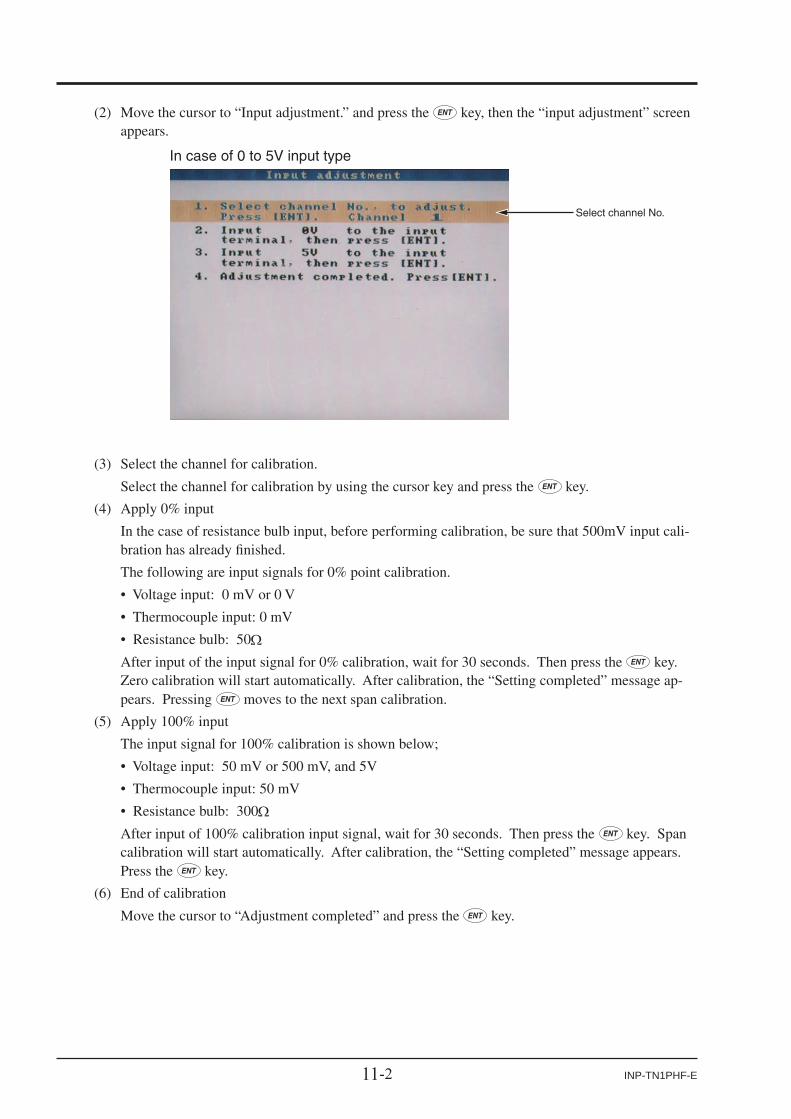
11-2 INP-TN1PHF-E
(3) Select the channel for calibration.
Select the channel for calibration by using the cursor key and press the key.
(4) Apply 0% input
In the case of resistance bulb input, before performing calibration, be sure that 500mV input cali-bration has already fi nished.
The following are input signals for 0% point calibration.
• Voltage input: 0 mV or 0 V
• Thermocouple input: 0 mV
• Resistance bulb: 50 After input of the input signal for 0% calibration, wait for 30 seconds. Then press the key.
Zero calibration will start automatically. After calibration, the “Setting completed” message ap-pears. Pressing moves to the next span calibration.
(5) Apply 100% input
The input signal for 100% calibration is shown below;
• Voltage input: 50 mV or 500 mV, and 5V
• Thermocouple input: 50 mV
• Resistance bulb: 300 After input of 100% calibration input signal, wait for 30 seconds. Then press the key. Span
calibration will start automatically. After calibration, the “Setting completed” message appears. Press the key.
(6) End of calibration
Move the cursor to “Adjustment completed” and press the key.
(2) Move the cursor to “Input adjustment.” and press the key, then the “input adjustment” screen appears.
Select channel No.
In case of 0 to 5V input type

11-3INP-TN1PHF-E
11.2 Initializing the measured value[Explanation]
Parameters can be returned to the value set at the time of delivery from the factory.
• After initializing the set value, be sure to store the initialized parameters in a nonvolatile memory. Otherwise they return to the values before the initialization when the power is turned off.
Note) Though this function is executed, the adjusted values are not initialized.
[Operation]
(1) Select the “Calibration password” on the menu screen and enter the password, then “Calibration”screen appears. After that, select “Parameter initialization”, then following “Parameter initializa-tion”screen appears.
(2) Press the key to start initialization. To cancel it, press the key.

11-4 INP-TN1PHF-E
(3) Press the key, and the setting value of parameters are initialized at the shipment.

11-5INP-TN1PHF-E
11.3 How to adjust the screen contrast[Explanation]
Contrast of screen can be adjusted.
Note that if the adjusted value is not held in the non-volatile storage, it returns to the original one when power is turned off.
[Operation]
(1) Select the “Calibration password” on the menu screen and enter the password, then “Calibration” screen appears. A fter that, select “Contrast tuning”, then following “Contrast tuning” screen ap-pears.
(2) Push , keys to change the contract and select the best one.
(3) When setting is completed, push key to fi nish the adjustment.

12-1INP-TN1PHF-E
12. TROUBLESHOOTING
Situation
Does not work at all.
Keys do not work.
“System Error” is displayed when power is ON.
The record swings over tothe 0% side or the 100%side.
The indication changestoo much.
The data indicatorindicates “Over”, “Under” or “Error”.
Recording data is not written in memory card
1) Is the power supply terminal connection correct?
Check Remedy
2) Is power being supplied properly?
Connect correctly.
Supply correctly.
1) Does the screen display correctly? If keys only do not work, key switch may be faulty.
2) There are some parameters that cannot be set during recording. Check if setting has been attempted during recording.
It is displayed when a fault occurs in CPU. Turn the powerON again. If it does not return to normal condition, CPU maybe faulty.
Contact our Service Center
Contact our Service Center.
Stop recording at once.
1) Is digital indication displayed correctly? If the input is not connected correctly, burnout may occur or over- or under- indication may occur
2) The record swings over the indication range if the indication range is not set correctly.
Connect correctly.
Set the indication rangecorrectly.
Fix the memory cardaccording to Item 2.2.
Check the status of the memory card with the PC.
• Connect correctly.• Set the input type according to the input signal.
1) Is the memory card connected properly?
2) Is the memory card full?
“Recording has been stopped because the compact flash has run out of capacity. Replace the compact flash.” is kept displayed.
1) The compact flash has run out of capacity.
“No battery! Please exchange the battery” is kept displayed.
Battery becomes low voltage. So, it might reset the clock at power.
Contact our ServiceCenter.
To match the indication to that of the field indicator, use PVshift given in Item 9.2 (12).
If the input is not connected correctly or a signal that isdifferent from the input type is connected, the indicationbecomes faulty.
3) If the measuring channel is set as “Indication only” or “Skip”, data is not recorded.
4) The memory card may be defective.
The number of recording file is found to be larger than expected.
1) Check if power failure occurred during recording.
2) Check if the auto file division function is performed.
3) The memory card may have come to the end of its service life.
Check the auto file division function setting.
Replace the memory card with a new one.
The recording file cannot be opened with the data viewer.
1) The version of the data viewer may not be the latest.
2) The memory card may have come to the end of its service life.
Check the version of the data viewer.
Replace the memory card with a new one.
2) Was the key pressed after the compact flash is replaced with the one with sufficient capacity?
1) Replace the compact flash with the one with sufficient capacity, and then press the key.2) Press the key.
If the recorder does not operate normally, take a remedy according to the table given below. For a complicated trouble, contact our Sales Representatives.

13-1INP-TN1PHF-E
13. SPECIFICATIONS
1. Input system
Number of input points:3 points or 6 points (Can be selected at the time of purchase)
Input circuit: Input mutual isolationResistance bulb measured current:about 1 mA
Measuring cycles:3 or 6 points….100ms cycles
Recording cycle: 1 sec to 12 hoursInput types: Thermocouple, resistance bulb, DC volt-
age, and DC current (Shunt resistors are fi tted in input terminals).Note) Order a shunt res is tor ( type:
PHZP0101) separately.Measuring range
Input types Reference rangeThermocouple B
RSKEJTNWLUPN
400.0 to 1760.0°C0.0 to 1760.0°C0.0 to 1760.0°C–200.0 to 1370.0°C–200.0 to 800.0°C–200.0 to 1100.0°C–200.0 to 400.0°C0.0 to 1300.0°C0.0 to 1760.0°C–200.0 to 900.0°C–200.0 to 400.0°C0.0 to 1300.0°C
Resistance bulb JPt100Pt100Ni100Pt50Cu50
–200.0 to 600.0°C–200.0 to 600.0°C–60.0 to 180.0°C–200.0 to 600.0°C–50.0 to 200.0°C
DC voltage 50mV500mV1-5V0-5V
0.00 to 50.00mV0.0 to 500.0mV1.000 to 5.000V0.000 to 5.000V
Note) B, R, S, K, E, J, T, N : JIS C 1602, DIN IEC 584-1 W : 5%Re-26%Re · W (Hoskins Mfg. Co. USA) L : Fe-Cu · Ni (DIN 43710) U : Cu-Cu · Ni (DIN 43710) PN: Platinum JPt100 : JIS C 1604-1989 (Old JIS Pt 100) Pt100, Pt50 : JIS 1604, DIN IEC 751
Selection of input types:By key operation on the front panel. Note that the same input type (thermo-couple, resistance bulb, voltage) should be selected for channel 4 and 5. Refer to "Setting method of input types" for details.
Burn-out function:Equipped in thermocouple and resis-tance bulb inputs as standard, and over-swings the recording to 100% side.Thermocouple burn-out current:
approx. 0.2 µAInput fi lter function:
Settable for each channel (primary de-lay fi lter) Time constants are settable in the range from 0 to 900 sec.
Scaling function: Possible by DC voltage (current) inputScaling range: -32767 to 32767Decimal position: settable at any pointUnit symbol: settable up to 7 digi ts
and 125+12 types
Subtraction function:Subtraction between each channel is al-lowed.
Square rooter function:Square rooter can be performed against the input value per each channel.
2. Indication system
Indicator: 5.7” STN color LCD (320 × 240 dots)with backlight
Note) The LCD may have some pixels that do not stay on or off.
Due to the characteristics of liquid crystal, the brightness may not be uniform, which is not a failure.
Color of indication:14 colors
Applicable language:English, French (switchable)
Life of backlight: 50,000 hours(the complete indicator unit should be replaced when replacing backlight).
Trend display: Direction: vertical and horizontalNumber of channels: 6 channels or 4 channels or 3 channels for the screen (Input: 6 points at the maximum).Display refreshment cycles:
select from 1 second to 12 hoursNo numerical value display. Scale dis-play/no-display can be selected.
Bar graph display:Direction: verticalNumber of channels: 6 channels or 4 channels or 3 channels for the screen (Input: 6 points at the maximum).Display refreshment cycles: 1 second.
Digital display: Number of channels: 6 channels or 4 channels or for the screen (Input: 6 points at the maximum).Display refreshment cycles: 1 second.
Event summary display:Alarm summary and message summary can be displayed.
Ethernet log display:E-mail sending, FTP server log in/off and MODBUS TCP/IP communication start/stop can be displayed.
Parameter display/set:A l ready-se t Data D isp lay and Set Change Display screen

13-2 INP-TN1PHF-E
TAG indication: Number. of characters to be displayed: Up to 8 characters at 6 channels on one screen or up to 16 (= 8 × 2) char-acters at 4 channels on one screen.
Characters to be displayed:Alphanumerical characters
Tag, unit and channel number display:It depends on the screen. See below table.
Screen Number of channelon one screen
Items
all items are displaed
TAG1 TAG2 unit ch numberTrend
Bar graph
Digital
4 or less more than 54 or less more than 5
+x+x
+ +
+x+x
+x+x
x: only 1 item can be displayed.+: only 2 items can be displayed.
Historical trend display:The past data can be displayed from the Compact Flash or internal memory. The past data fi le can be read and displayed with scroll display function or jump the cursor to the position which you entered date and time. Scale display/no-display can be selected.
Number of screen groups:1 group (Up to 6 channels per 1 group can be registered.)
3. Keyboard
No. of Keys: 8Function: Use to select various screens and set
various parameters.
4. Recording function
External memory media:Compact Flash card(Format as FAT32, FAT16 or FAT, or re-corder can’t read and write.)
Recording capacity:2 G B m a x i m u m ( c o m p a c t f l a s h ) . Limiting the recording file to 64MB is recommended (for 112 hours if display refreshment cycle is 1 second. See "18. Recording capacity” in the chapter.) I f the capaci ty becomes 256MB or more, a new fi le is created automatically to continue recording.*Please change the compact fl ash every six month to prevent the data losing.
Recording method:Turning ON the REC key allows mea-sured data to be written at fi xed cycles. Recorded as a new file whenever the recording starts
Data save cycles:Linked to the display refreshment cycles on the “Trend display” screen. However, they are automatically set to about 1 minute if the refreshment cycles are set to less than 1 minute.
Trend data: Average, instance or min. and max. measured values out of measured data that are sampled at the measuring cy-cles are saved.
Event data: Saves alarm data and power ON data when the power turns off and on during recording.
Storage capacity: Approximately 2 years when the display refresh cycle is 30 seconds (in the case of 6-channel recording in ASCII data format, and 256MB Compact Flash is used). Refer to Item 2.3.
Memory usage: I n d i c a t e s t h e m e m o r y w h i c h h a s already used on the screen. When all the memory is used up, you can stop recording or delete the oldest recording fi le to save the newest data.
Compact fl ash: Type : PHZP1301-512(If you use a CF card other than the above, we can not guarantee the proper operation. In addition, please check our web site for other CF cards which we conducted performance tests on. We will keep information updated .)
Recommended PC card adaptor:SanDisk Corp. SDAD-38
Data format: Either of ASCII or binary format can be selected. (Switching cannot be made while the recording is in progress. In the case of ASCII format, the data can be directly read on Excel, etc.)Note: The data recorded in binary for-mat cannot be read directly.Approximately 118 bytes per sample (for 6-channel input in ASCII format) or approximately 28 bytes (for 6-channel input in binary format)
5. Alarm function
No. of settings: Up to 4 alarms for each channel are settable.
Type of alarm: High/Low limitsIndication: Status (alarm types) is displayed on dig-
ital display unit when an alarm occurs.History display on alarm summary (Alarm start/cancel time and alarm types)
Hysteresis: Set within the recording range of 0 to 100% (it is effective only in case of high/low limit alarm)
Relay output: Number of points; 10Alarm latch function:
Keeps alarm indication and alarm out-put turning on after alarm reset.ON/OFF operation is performed accord-ing to key setting.

13-3INP-TN1PHF-E
6. Power supply
Rated power voltage:100 to 240V AC
Range of operating voltage:90 to 264V AC
Supply frequency:50/60Hz (both employable)
Power consumption
100V AC240V AC
About 32VAAbout 42VA
7. Structure
Mounting method:Panel-mounted (vertical panel)
Thickness of panel:2 to 26 mm
Materials: PC-ABS for case and bezelColor: BlackExternal dimensions:
Panel-mounted: 160 (W) × 144 (H) × 185 (D) mm
Mass: Approx. 1.5 kg (no option)External terminal board:
Screw terminals (M3 thread)
8. Normal operating condition
Power voltage: 90 to 264V ACSupply frequency:
50/60 Hz ±2% (both employable)Ambient temperature: Panel-mounted
0 to 50°C (without Ethernet option*1)0 to 40°C (with Ethernet option*2)
Note) When ambient temperature is 30°C or over, the whole screen may look whit-ish, but it is not a failure.
Ambient humidity:20 to 80%RH
Vibration: 10 to 60Hz 0.2m/s2 or lessShock: NoneMagnetic fi eld: 400 A/m or lessSignal source resistance:
Thermocouple input …. 1k or lessResistance bulb input… 10/wire or less (resistance of each wire of 3-wire system should be balanced).Voltage input… 0.1% or less of input re-sistance
Mounting posture:Forward tilt 0°, backward tilt within 30°, horizontal 0°
Warm-up time: One hour or more after power ON
*1: In case of the 12th digit of ordering code is “Y”.*2: In case of the 12th digit of ordering code is “E”.
9. Safety and EMC standard
Safety standard: Based on IEC61010-1EMC standard: Based on EN61326
10. Transportation/storage conditions
Temperature: −10 to +60°CHumidity: 5 to 90%RH, no condensationVibration: 10 to 60Hz, 2.45m/s2 or lowerShock: 294m/s2 or lower (packed state)
11. Reference standard
Accuracy/resolution:Measuring conditions (23±2°C, 65±10% RH, power voltage, frequency fl uctuation within ±1%, no external noise, warm-up time of 1 hour or more, vertical mounting, standard values of signal source resis-tance and wiring resistance... within 1%)
Input types Digital indicationaccuracy Note 1
Digital indicationresolution
Thermocouple BRSKEJTNWLUPN
±(0.15%+1 digit)
±(0.3%+1 digit) for the range shown below Thermocouple B : 400 to 600°C Thermocouples R and S : 0 to 300°C Thermocouples K, E, J, T, L and U : -200 to -100°C
Resistancebulb
JPt100Pt100Pt50Ni100Cu50 ±(0.5%+1 digit)
±(0.15%+1 digit)
DC voltage 50mV500mV1-5V0-5V
±(0.15%+1 digit)
0.1°C
10μV100μV1mV1mV
Note 1) Digital indication accuracy is a percentage (%) of the value in the measuring range on page 13-1.Note 2) No error of reference contact compensation of thermocouple is included.
0.1°C
Error of reference contact compensation:K, E, J, T, N, L, U, PN: ±0.5°CR, S, B, W: ±1.0°C(when measured at 0°C or more)
Max. input voltage:Thermocouple, resistance bulb, DC volt-age: ±10V DC (continuous)
Input resistance: Thermocouple, DC voltage: About 1M (at power on)About 100k (at power off)

13-4 INP-TN1PHF-E
12. Others
Clock: With calendar function (Christian era)Accuracy: ±100ppm or less (monthly error: about 4 minutes)
H o w ev e r , t i m e e r r o r a t a m b i e n t temperature 23±2°C and power ON/OFF is not included.
Memory backup: Parameters are saved to the internal non-volatile fl ash memory.The clock and totalized data are backed up with built-in lithium battery.
Insulation resistance:100 M (when measured between each terminal and ground by using a 500V DC megger)
Withstand voltage:Power terminal – ground: 2000V AC, 1 minInput terminal – ground: 500V AC, 1 minAlarm terminal – ground: 2000V AC, 1 minAlarm terminal – alarm terminal:
750V AC, 1 minCommunication terminal – ground:
500V AC, 1 minAlarm terminal (open-collector) – ground:
500V AC, 1 min
13. Effect on operation
Effect of power supply fl uctuation conditions:For the fl uctuation in the range from 90 to 264V AC (frequency: 50/60Hz)Reading change: ±(0.2%+1 digit) or lower.For the fl uctuation in the range from 47 to 63Hz (power voltage: 100V AC)Reading change: ±(0.2%+1 digit) or lower.
Effect of input signal resistance:Thermocouple input: 50µV±1 digit per 100DC voltage: Fluctuation for resistance value equivalent to 0.1% of the input re-sistance: ±(0.2%+1 digit) or lower.Resistance bulb (for wiring resistance of 10 for 1 line (the same for 3 lines))Reading change: ±(0.2%+1 digit) or lower.
Effect of ambient temperature:Reading change: ±(0.3%+1 digit)/10°C or lower.
Effect of Mounting position:For the backward 30° slantReading change: ±(0.2%+1 digit) or lower.
Effect of vibration:When sine wave of 10 to 60Hz with the acceleration of 0.2m/s2 is applied in each direction for 2 hours.Reading change: ±(0.2%+1 digit) or lower.
14. Additional function (option)
■ Alarm relay output/DI (11th digit of code symbols: “1”)A card with 10-point relay output and 5-point DI input can be mounted.Terminal structure:
M3 screw terminalAlarm relay output:
Contact output (SPST:10 points),Individual channel or common output (OR output) allowed.DO1: Contact capacity; 150V/3A AC, 30V/3A DC (resistance load)DO2-10: Contact capacity; 240/3A AC, 30V/3A DC (resistance load)
DI input: No-voltage contact input (5 points)The following control is allowed by con-tact input.(1) Recording start/stop(2) LCD turns on(3) E-mail sendingOn pulse width: 200msec or longerOff pulse width: 200msec or longer
15. Ethernet
The following can be performed through the Ethernet function.■ HTTP server (Internet Explorer 6 is compatible) Note 1
Measurement display:Digitally displays the measurement of each channel of the recorder and alarm occurrence status.
Event summary display:Displays event summary including alarm ON/OFF.
Main unit information display:Displays memory use conditions and information on the main unit such as the battery end warning.
Integrated value display:Digitally displays the integrated value of each channel of the recorder.
■ FTP server (Internet Explorer 6 is compatible.) Note 1
File download: Record fi les stored in compact fl ash (CF)can be downloaded from the browser.
File delete: Record fi les stored in CF can be deleted from the browser.
Access authentication:Authenticates access authority to FTP server.
■ SMTP (e-mail client)Transmits e-mails to specified address under the following conditions.(1) When an alarm turns on or off(2) When DI is set to ON or OFF(3) When an error occurs to the main
unit (such as low battery or no mem-ory space)
(4) At specifi ed intervals

13-5INP-TN1PHF-E
■MODBUSTC/IPDataread: Settingscanbe read throughMODBUS
TCP/IPcommunication.Datawrite: Settings can be written through MOD-
BUSTCP/IPcommunication.Note1: Neither Netscape nor Mozilla Firefox
isavailable.
16. Support software
Thefollowingsoftwareisprovidedasstandard.• PC/AT-compatiblemachine• Operation on PC98-series machines by NEC is not
guaranteed.• Operationonself-madeorshop-brandPCs isnotguar-
anteed.■LoadersoftwareforPCMajorfunction: Performs various parameter setting/
changeofthemainunitO/S: Windows 2000/XP,Windows 7 (Home
Premium, Professional (Not applicablefor64bitversion))
Requiredmemory:64MBorlarger
Diskdrive: Windows 2000/XP/7-capable CD-ROMdrive
Harddiskcapacity:Free capacity of 30MB or larger re-quired
Printer: Windows2000/XP/7-capableprinterandprinterdriver
Note) PC loadercommunicationcable (typePHZP1801)isseparatelyrequired.
■DataviewersoftwareMajorfunction: Regenerates the past trend record on
the PC from the data in the CompactFlash.Providedwithhistoricaltrenddis-playandeventdisplayfunctions.
O/S: Windows 2000/XP,Windows 7 (HomePremium,Professional)
Requiredmemory:64MBorlarger
Diskdrive: Windows2000/XP/7-complaintCD-ROMdrive
Harddiskdrive: Free capacity of 30MB or larger re-quired
Printer: Windows2000/XP/7-capableprinterandprinterdriver
17. Standard functions
FunctionRecord rangevoluntary settingInput type setting
Skip functionTrend display
TAG name displayScreen namedisplay Unit creation
Scaling function
PV shiftInput filter
Burnout function
Historicaltrend display
Description
Recording range can be set by channel.
Input can be set by channel.(Key operation on the front face)The same input type is selected for channel 4 and 5.See “SELECTING INPUT TYPE” on the last page.Skips arbitrary channel display/recording.Time display: Time is displayed at the top of the trend display screen.Alarm display: On occurrence of an alarm and the restoration, alarm is displayed in the alarm display field.The Compact Flash usage is displayed at the top of the bargraph.
By channel, Maximum of 8 characters.Displays the screen name (maximum of 16characters).Industrial units can be arbitrarily created, Maximumof 7 digits, 12 types.Arbitrary scaling is allowed in the case of DCvoltage input. Decimal point position can also bearbitrarily set in the range from -32767 to 32767.Shift the zero point and slant of the reading.Prevents sudden fluctuation of input for eachchannel (primary delay filter).Time constant: 0 to 900 seconds.Displays the break of thermocouple/resistance bulb input by scaling out to 100% side.Regenerates and displays the data stored in thecompact flash by scrolling the screen or jump totime when you entered.
18. Recording capacity
Inputpoint: 6Dataformat: ASCIITherecordingcanbemadefortheperiodoftimelistedinthe tablesshownbelow.When thenumberof inputpointsis3, theperiod isapproximately1.6 timesof those listedinthetable.In binary format, the period is approximately 4 times aslongasthoselistedinthetable.
Display refreshment cycle
CompactFlash size 64MB
1 sec 10 sec 30 sec 1 min 10 min
Recordable capacity(about) 159 hours 66 days 199 days 398 days 10.9 years
Display refreshment cycle
CompactFlash size 256MB
1 sec 10 sec 30 sec 1 min
Recordable capacity(about) 26 days 265 days 2.1 years 4.3 years
WhenCompactFlashisnotused,upto800Kbytesoftherecording data and the event data can be stored in themain unit. (In case of 6-channel in Max./Min. recording,approximately 27,000 data can be stored. For 7 hour atthedisplayrefreshcycleof1second. Thenumberof thesave data varies depending on the number of the eventdata.

A-1INP-TN1PHF-E
APPENDICES
Appendix 1 Recording format (ASCII)
(1) Trend data fi le
MAX. value and MIN. value of each channel
Parameter set values, channel No.,TAG name, recorded color, input types,units, display range (0%), display range (100%), etc.
Note) Data such as burn-out, error, and time of occurrence are recorded as –32768 (with decimal point). Over-/under range Indication is recorded as 32767/-32767 (with decimal point).
S000000.FDT PHF61B11-E10EV SNo.A6L0890T Ver.V04F 06,00,08,00 CH01,TAG 01 ,01,31,mV , 0.0, 500.0,0,0, 0.0, 0.0,000,100,1,0,00, 0.0,0,00, 0.0,0,00, 0.0,0,00, 0.0CH02,TAG 02 ,02,31,mV , 0.0, 500.0,1,0, 0.0, 0.0,000,100,1,0,00, 0.0,0,00, 0.0,0,00, 0.0,0,00, 0.0CH03,TAG 03 ,03,31,mV , 0.0, 500.0,2,0, 0.0, 0.0,000,100,1,0,00, 0.0,0,00, 0.0,0,00, 0.0,0,00, 0.0CH04,TAG 04 ,04,31,mV , 0.0, 500.0,0,0, 0.0, 0.0,000,100,1,0,00, 0.0,0,00, 0.0,0,00, 0.0,0,00, 0.0CH05,TAG 05 ,11,31,mV , 0.0, 500.0,0,0, 0.0, 0.0,000,100,1,0,00, 0.0,0,00, 0.0,0,00, 0.0,0,00, 0.0CH06,TAG 06 ,10,33,V , 0.000, 5.000,0,0, 0.000, 0.000,000,100,3,0,00, 0.000,0,00, 0.000,0,00, 0.000,0,00, 0.000G1,Display Group1 ,01,02,03,04,05,06,00,00,00,00G2,Display Group2 ,01,02,03,04,05,06,00,00,00,00G3,Display Group3 ,01,02,03,04,05,06,00,00,00,00G4,Display Group4 ,01,02,03,04,05,06,00,00,00,00 ,CH01MIN,CH01MAX,CH02PV ,CH03AVG,CH04MIN,CH04MAX,CH05MIN,CH05MAX,CH06MIN,CH06MAX2007/ 1/ 8 14:32:55, 60.7, 60.7, 164.4, 254.3, 364.3, 364.3, 463.5, 463.5, 0.276, 0.2762007/ 1/ 8 14:32:56, 60.7, 60.7, 164.6, 254.2, 363.9, 364.3, 463.2, 463.5, 0.276, 0.2762007/ 1/ 8 14:32:57, 60.7, 60.7, 164.3, 254.4, 364.0, 364.3, 463.3, 463.5, 0.276, 0.2762007/ 1/ 8 14:32:58, 60.7, 60.7, 164.7, 254.1, 363.9, 364.3, 463.2, 463.6, 0.276, 0.2762007/ 1/ 8 14:32:59, 60.7, 60.7, 164.4, 254.3, 364.0, 364.3, 463.3, 463.5, 0.276, 0.2762007/ 1/ 8 14:33:00, 60.7, 60.7, 164.7, 254.1, 363.9, 364.3, 463.2, 463.6, 0.276, 0.2762007/ 1/ 8 14:33:01, 60.7, 60.7, 164.4, 254.2, 364.0, 364.3, 463.3, 463.5, 0.276, 0.2762007/ 1/ 8 14:33:02, 60.7, 60.7, 164.7, 254.1, 363.9, 364.3, 463.2, 463.5, 0.276, 0.2762007/ 1/ 8 14:33:03, 60.7, 60.7, 164.4, 254.2, 364.0, 364.3, 463.3, 463.5, 0.276, 0.2762007/ 1/ 8 14:33:04, 60.7, 60.7, 164.7, 254.0, 363.9, 364.3, 463.2, 463.6, 0.276, 0.2762007/ 1/ 8 14:33:05, 60.7, 60.7, 164.4, 254.2, 364.0, 364.3, 463.3, 463.5, 0.276, 0.2762007/ 1/ 8 14:33:06, 60.7, 60.7, 164.7, 254.0, 364.0, 364.3, 463.2, 463.6, 0.276, 0.2762007/ 1/ 8 14:33:07, 60.7, 60.7, 164.4, 254.2, 364.1, 364.3, 463.3, 463.5, 0.276, 0.2762007/ 1/ 8 14:33:08, 60.7, 60.7, 164.7, 254.0, 364.0, 364.3, 463.2, 463.6, 0.276, 0.2762007/ 1/ 8 14:33:09, 60.7, 60.7, 164.4, 254.2, 364.1, 364.3, 463.3, 463.5, 0.276, 0.2762007/ 1/ 8 14:33:10, 60.7, 60.7, 164.7, 254.0, 364.0, 364.3, 463.2, 463.6, 0.276, 0.2762007/ 1/ 8 14:33:11, 60.7, 60.7, 164.4, 254.2, 364.1, 364.3, 463.3, 463.5, 0.276, 0.2762007/ 1/ 8 14:33:12, 60.7, 60.7, 164.7, 254.0, 363.9, 364.3, 463.2, 463.6, 0.276, 0.2762007/ 1/ 8 14:33:13, 60.7, 60.7, 164.4, 254.2, 364.0, 364.3, 463.3, 463.5, 0.276, 0.2762007/ 1/ 8 14:33:14, 60.7, 60.7, 164.7, 254.0, 364.0, 364.3, 463.2, 463.6, 0.276, 0.2762007/ 1/ 8 14:33:15, 60.7, 60.7, 164.4, 254.2, 364.1, 364.3, 463.3, 463.5, 0.276, 0.2762007/ 1/ 8 14:33:16, 60.7, 60.7, 164.7, 254.0, 364.0, 364.3, 463.2, 463.6, 0.276, 0.2762007/ 1/ 8 14:33:17, 60.7, 60.7, 164.4, 254.2, 364.1, 364.3, 463.3, 463.5, 0.276, 0.2762007/ 1/ 8 14:33:18, 60.7, 60.7, 164.7, 254.0, 363.9, 364.3, 463.2, 463.6, 0.276, 0.2762007/ 1/ 8 14:33:19, 60.7, 60.7, 164.4, 254.2, 364.0, 364.3, 463.3, 463.5, 0.276, 0.2762007/ 1/ 8 14:33:20, 60.7, 60.7, 164.7, 254.0, 364.0, 364.3, 463.2, 463.6, 0.276, 0.2762007/ 1/ 8 14:33:21, 60.7, 60.7, 164.4, 254.2, 364.1, 364.3, 463.3, 463.5, 0.276, 0.2762007/ 1/ 8 14:33:22, 60.7, 60.7, 164.7, 254.0, 364.0, 364.3, 463.2, 463.6, 0.276, 0.2762007/ 1/ 8 14:33:23, 60.7, 60.7, 164.4, 254.2, 364.1, 364.3, 463.3, 463.5, 0.276, 0.2762007/ 1/ 8 14:33:24, 60.7, 60.7, 164.7, 254.0, 364.0, 364.3, 463.2, 463.6, 0.276, 0.2762007/ 1/ 8 14:33:25, 60.7, 60.7, 164.4, 254.2, 364.1, 364.3, 463.3, 463.5, 0.276, 0.2762007/ 1/ 8 14:33:26, 60.7, 60.7, 164.7, 254.0, 364.0, 364.3, 463.2, 463.6, 0.276, 0.2762007/ 1/ 8 14:33:27, 60.7, 60.7, 164.4, 254.2, 364.1, 364.3, 463.3, 463.5, 0.276, 0.2762007/ 1/ 8 14:33:28, 60.7, 60.7, 164.7, 254.0, 364.0, 364.3, 463.2, 463.6, 0.276, 0.2762007/ 1/ 8 14:33:29, 60.7, 60.7, 164.4, 254.2, 364.0, 364.3, 463.3, 463.5, 0.276, 0.2762007/ 1/ 8 14:33:30, 60.7, 60.7, 164.7, 254.0, 363.9, 364.3, 463.2, 463.6, 0.276, 0.2762007/ 1/ 8 14:33:31, 60.7, 60.7, 164.4, 254.2, 364.0, 364.3, 463.3, 463.6, 0.276, 0.2762007/ 1/ 8 14:33:32, 60.7, 60.7, 164.7, 254.0, 364.0, 364.3, 463.2, 463.6, 0.276, 0.2762007/ 1/ 8 14:33:33, 60.7, 60.7, 164.4, 254.2, 364.1, 364.3, 463.3, 463.5, 0.276, 0.2762007/ 1/ 8 14:33:34, 60.7, 60.7, 164.7, 254.0, 364.0, 364.3, 463.2, 463.6, 0.276, 0.2762007/ 1/ 8 14:33:35, 60.7, 60.7, 164.4, 254.2, 364.1, 364.3, 463.3, 463.5, 0.276, 0.2762007/ 1/ 8 14:33:36, 60.7, 60.7, 164.7, 254.0, 364.0, 364.4, 463.2, 463.6, 0.276, 0.2762007/ 1/ 8 14:33:37, 60.7, 60.7, 164.5, 254.2, 364.0, 364.3, 463.3, 463.5, 0.276, 0.2762007/ 1/ 8 14:33:38, 60.7, 60.7, 164.7, 254.0, 364.0, 364.4, 463.2, 463.6, 0.276, 0.2762007/ 1/ 8 14:33:39, 60.7, 60.7, 164.5, 254.2, 364.0, 364.3, 463.3, 463.5, 0.276, 0.2762007/ 1/ 8 14:33:40, 60.7, 60.7, 164.6, 254.0, 364.0, 364.3, 463.2, 463.6, 0.276, 0.2762007/ 1/ 8 14:33:41, 60.7, 60.7, 164.4, 254.2, 364.0, 364.3, 463.3, 463.5, 0.276, 0.2762007/ 1/ 8 14:33:42, 60.7, 60.7, 164.7, 254.0, 364.0, 364.3, 463.2, 463.6, 0.276, 0.2762007/ 1/ 8 14:33:43, 60.7, 60.7, 164.4, 254.2, 364.0, 364.3, 463.3, 463.5, 0.276, 0.2762007/ 1/ 8 14:33:44, 60.7, 60.7, 164.7, 254.1, 364.0, 364.4, 463.2, 463.6, 0.276, 0.2762007/ 1/ 8 14:33:45, 60.7, 60.7, 164.5, 254.2, 364.0, 364.3, 463.3, 463.5, 0.276, 0.2762007/ 1/ 8 14:33:46, 60.7, 60.7, 164.7, 254.0, 364.0, 364.4, 463.2, 463.6, 0.276, 0.2762007/ 1/ 8 14:33:47, 60.7, 60.7, 164.5, 254.2, 364.0, 364.3, 463.3, 463.5, 0.276, 0.2762007/ 1/ 8 14:33:48, 60.7, 60.7, 164.7, 254.0, 363.9, 364.3, 463.2, 463.6, 0.276, 0.2762007/ 1/ 8 14:33:49, 60.7, 60.7, 164.5, 254.2, 364.0, 364.3, 463.2, 463.5, 0.276, 0.2762007/ 1/ 8 14:33:50, 60.7, 60.7, 164.7, 254.1, 364.0, 364.3, 463.2, 463.6, 0.276, 0.2762007/ 1/ 8 14:33:51, 60.7, 60.7, 164.5, 254.2, 364.0, 364.3, 463.2, 463.5, 0.276, 0.2762007/ 1/ 8 14:33:52, 60.7, 60.7, 164.7, 254.0, 364.0, 364.4, 463.2, 463.6, 0.276, 0.2762007/ 1/ 8 14:33:53, 60.7, 60.7, 164.5, 254.2, 364.0, 364.3, 463.2, 463.5, 0.276, 0.2762007/ 1/ 8 14:33:54, 60.7, 60.7, 164.7, 254.0, 364.0, 364.4, 463.2, 463.6, 0.276, 0.2762007/ 1/ 8 14:33:55, 60.7, 60.7, 164.5, 254.2, 364.0, 364.3, 463.3, 463.5, 0.276, 0.2762007/ 1/ 8 14:33:56, 60.7, 60.7, 164.7, 254.0, 364.0, 364.4, 463.2, 463.6, 0.276, 0.2762007/ 1/ 8 14:33:57, 60.7, 60.7, 164.5, 254.2, 364.0, 364.3, 463.3, 463.5, 0.276, 0.2762007/ 1/ 8 14:33:58, 60.7, 60.7, 164.6, 254.0, 364.0, 364.4, 463.2, 463.6, 0.276, 0.2762007/ 1/ 8 14:33:59, 60.7, 60.7, 164.4, 254.2, 364.0, 364.3, 463.3, 463.5, 0.276, 0.2762007/ 1/ 8 14:34:00, 60.7, 60.7, 164.7, 254.1, 364.0, 364.4, 463.2, 463.6, 0.276, 0.2762007/ 1/ 8 14:34:01, 60.7, 60.7, 164.5, 254.2, 364.0, 364.3, 463.3, 463.5, 0.276, 0.2762007/ 1/ 8 14:34:02, 60.7, 60.7, 164.7, 254.1, 364.0, 364.4, 463.2, 463.6, 0.276, 0.2762007/ 1/ 8 14:34:03, 60.7, 60.7, 164.5, 254.2, 364.0, 364.3, 463.2, 463.5, 0.276, 0.2762007/ 1/ 8 14:34:04, 60.7, 60.7, 164.7, 254.0, 364.0, 364.4, 463.2, 463.6, 0.276, 0.2762007/ 1/ 8 14:34:05, 60.7, 60.7, 164.5, 254.2, 364.0, 364.3, 463.2, 463.5, 0.276, 0.276

A-2 INP-TN1PHF-E
“Occurrence of alarm” dataYear, month, day, time, type (A), channel No., alarm No.Alarm types (1: H, 2: L)Alarm ON (1) and alarm OFF (0)
A000000.FDT PHF61B11-E10EV SNo.A6L0890T Ver.V04F 2007/ 1/ 8 14:33:17,A,01,1,01,1 2007/ 1/ 8 14:33:22,A,02,2,01,1 2007/ 1/ 8 14:33:26,A,03,3,01,1 2007/ 1/ 8 14:33:30,A,04,4,01,1 2007/ 1/ 8 14:33:42,A,04,4,01,0 2007/ 1/ 8 14:34:25,A,03,3,01,0 2007/ 1/ 8 14:34:30,A,02,2,01,0 2007/ 1/ 8 14:34:34,A,01,1,01,0 2007/ 1/ 8 14:34:54,A,01,1,01,1 2007/ 1/ 8 14:34:57,A,02,2,01,1 2007/ 1/ 8 14:35:01,A,03,3,01,1 2007/ 1/ 8 14:35:04,A,04,4,01,1 2007/ 1/ 8 14:35:09,A,06,4,01,1 2007/ 1/ 8 14:35:29,A,06,4,01,0
(2) Event data fi le

A-3INP-TN1PHF-E
Channel parameters Input typesUnitsScaling (measuring range, engineering unit)Square rooterTAG1, TAG2Display rangeRecording action
Unit parameters Display refreshment cyclesDisplay namingScreen structureClockRecord data formatDisplay compressionFile division cycleFile overwrite
Functions that cannot be used during recording
Channel parameter copying functionParameter initialization
Appendix 2 Parameters that cannot be set during recording

A-4 INP-TN1PHF-E
Appendix 3 Opening the PHF record data in ASCII format on Excel
Note 1: The record data in binary format cannot be opened following the procedure shown below. (Refer to Item 9.1 (11) for details.)
Note 2: The record data of 10MB or larger in case of 3-point input, and 5MB or larger in case of 6-point input cannot be opened on Excel. In these cases, read the data using the data viewer (contained in the attached CD-ROM) and perform CSV conversion to divide the fi le, which allows the data to be read.
(1) Start up Excel, select “File(F)” and the “Open (O)” on the menu to display the following screen.
(2) Select “All” for the fi le type, and select PHF record data (S****.FDT).
(3) Selecting the fi le displays the following data format setting screen. Select “Dividing characters such as a comma or a tab…..” for the original data format, and then press the “Next” button.
(4) Pressing the “Next” button displays the following screen.
Check “Comma (C)” in the dividing character setting.
(5) Pressing the “Exit (E)” button displays the record data of PHF.
(2)
(3)

A-5INP-TN1PHF-E
Appendix 4 Timing of recordingThe timing of recording varies depending on display refresh cycle and integration record cycle.
Example: When the recording is started at 08:45 at the display refresh cycle of 20 minutes, the data is re-corded next when the clock indicates 0, that is, at 09:00. The recording will thus be performed at 09:20, 09:40, 10:00 …..etc.
1 second
2 seconds
3 seconds
5 seconds
10 seconds
20 seconds
30 seconds
1 minute
2 minutes
3 minutes
5 minutes
10 minutes
20 minutes
30 minutes
1 hour
2 hours
3 hours
4 hours
6 hours
12 hours
Every second
Every even-numbered second
At 0, 3, 6, 9, 12, 15, 18, 21, 24, 27, 30, 33, 36, 39, 42, 45, 48, 51, 54, 57 seconds
At 0, 5, 10, 15, 20, 25, 30, 35, 40, 45, 50, 55 seconds
At 0, 10, 20, 30, 40, 50 seconds
At 0, 20, 40 seconds
At 0, 30 seconds
Every minute (When 0 is displayed. The same for the following)
Every even-numbered minute
At 0, 3, 6, 9, 12, 15, 18, 21, 24, 27, 30, 33, 36, 39, 42, 45, 48, 51, 54, 57 minutes
At 0, 5, 10, 15, 20, 25, 30, 35, 40, 45, 50, 55 minutes
At 0, 10, 20, 30, 40, 50 minutes
At 0, 20, 40 minutes
At 0, 30 minutes
Every hour (When “0 m :0 s” is displayed. The same for the following)
Every even-numbered hour
At 0, 3, 6, 9, 12, 15, 18, 21 hours
At 0, 4, 8, 12, 16, 20 hours
At 0, 6, 12, 18 hours
At 0, 12 hours
Display refresh cycle Data is recorded when the PHL clock indicates the following time.

Gate City Ohsaki, East Tower, 11-2, Osaki 1-chome,Shinagawa-ku, Tokyo 141-0032, Japanhttp://www.fujielectric.comPhone: 81-3-5435-7280, 7281 Fax: 81-3-5435-7425http://www.fujielectric.com/products/instruments/
International Sales DivSales Group