Proserve NMS83 - Instrumart
326
Products Solutions Services Operating Instructions Proservo NMS83 Tank Gauging BA01462G/00/EN/04.18 71411070 2018-07-13 Valid as of version 01.03.zz (Device firmware)
-
Upload
khangminh22 -
Category
Documents
-
view
1 -
download
0
Transcript of Proserve NMS83 - Instrumart

Products Solutions Services
Operating InstructionsProservo NMS83Tank Gauging
BA01462G/00/EN/04.18714110702018-07-13
Valid as of version01.03.zz (Device firmware)
Proservo NMS83
2 Endress+Hauser
Order code:
Ext. ord. cd.:
Ser. no.:
www.endress.com/deviceviewer Endress+Hauser
Operations App
XXXXXXXXXXXX
XXXXX-XXXXXX
XXX.XXXX.XX
Serial number
1.
3.
2.
A0023555

Proservo NMS83 Table of contents
Endress+Hauser 3
Table of contents
1 About this document . . . . . . . . . . . . . . . . 41.1 Document function . . . . . . . . . . . . . . . . . . . . . 41.2 Symbols . . . . . . . . . . . . . . . . . . . . . . . . . . . . . . 41.3 Documentation . . . . . . . . . . . . . . . . . . . . . . . . 71.4 Registered trademarks . . . . . . . . . . . . . . . . . . . 9
2 Basic safety instructions . . . . . . . . . . . 102.1 Requirements for the personnel . . . . . . . . . . . 102.2 Designated use . . . . . . . . . . . . . . . . . . . . . . . 102.3 Workplace safety . . . . . . . . . . . . . . . . . . . . . . 112.4 Operational safety . . . . . . . . . . . . . . . . . . . . . 112.5 Product safety . . . . . . . . . . . . . . . . . . . . . . . . 11
3 Product description . . . . . . . . . . . . . . . . 123.1 Product design . . . . . . . . . . . . . . . . . . . . . . . . 12
4 Incoming acceptance and productidentification . . . . . . . . . . . . . . . . . . . . . 13
4.1 Incoming acceptance . . . . . . . . . . . . . . . . . . . 134.2 Product identification . . . . . . . . . . . . . . . . . . 134.3 Storage and transport . . . . . . . . . . . . . . . . . . 15
5 Installation . . . . . . . . . . . . . . . . . . . . . . . 175.1 Requirements . . . . . . . . . . . . . . . . . . . . . . . . 175.2 Mounting of the device . . . . . . . . . . . . . . . . . 305.3 Post-installation check . . . . . . . . . . . . . . . . . . 36
6 Electrical connection . . . . . . . . . . . . . . 386.1 Terminal assignment . . . . . . . . . . . . . . . . . . . 386.2 Connecting requirements . . . . . . . . . . . . . . . . 536.3 Ensuring the degree of protection . . . . . . . . . . 546.4 Post-connection check . . . . . . . . . . . . . . . . . . 54
7 Operability . . . . . . . . . . . . . . . . . . . . . . . . 557.1 Overview of the operation options . . . . . . . . . 557.2 Structure and function of the operating
menu . . . . . . . . . . . . . . . . . . . . . . . . . . . . . . 567.3 Access to the operating menu via the local or
remote display and operating module. . . . . . . 587.4 Access to the operating menu via the service
interface and FieldCare . . . . . . . . . . . . . . . . . 717.5 Access to the operating menu via Tankvision
Tank Scanner NXA820 and FieldCare . . . . . . . 72
8 System integration . . . . . . . . . . . . . . . . 758.1 Overview of the Device Description files
(DTM) . . . . . . . . . . . . . . . . . . . . . . . . . . . . . . 75
9 Commissioning . . . . . . . . . . . . . . . . . . . . 769.1 Terms related to tank measurement . . . . . . . . 769.2 Initial settings . . . . . . . . . . . . . . . . . . . . . . . . 779.3 Calibration . . . . . . . . . . . . . . . . . . . . . . . . . . 799.4 Configuring the measuring device . . . . . . . . . . 879.5 Configuring the tank gauging application . . . . 999.6 Advanced settings . . . . . . . . . . . . . . . . . . . . 1219.7 Simulation . . . . . . . . . . . . . . . . . . . . . . . . . . 1219.8 Protecting settings from unauthorized
access . . . . . . . . . . . . . . . . . . . . . . . . . . . . . 121
10 Operation . . . . . . . . . . . . . . . . . . . . . . . 12210.1 Reading off the device locking status . . . . . . 12210.2 Reading off measured values . . . . . . . . . . . . 12210.3 Gauge commands . . . . . . . . . . . . . . . . . . . . 123
11 Diagnostics and troubleshooting . . 12911.1 General trouble shooting . . . . . . . . . . . . . . . 12911.2 Diagnostic information on local display . . . . . 13011.3 Diagnostic information in FieldCare . . . . . . . 13311.4 Overview of the diagnostic messages . . . . . . 13511.5 Diagnostic list . . . . . . . . . . . . . . . . . . . . . . . 14111.6 Reset measuring device . . . . . . . . . . . . . . . . 14211.7 Device information . . . . . . . . . . . . . . . . . . . 14211.8 Firmware history . . . . . . . . . . . . . . . . . . . . . 142
12 Maintenance . . . . . . . . . . . . . . . . . . . . 14312.1 Maintenance tasks . . . . . . . . . . . . . . . . . . . . 14312.2 Endress+Hauser services . . . . . . . . . . . . . . . 143
13 Repair . . . . . . . . . . . . . . . . . . . . . . . . . . . 14413.1 General information on repairs . . . . . . . . . . . 14413.2 Spare parts . . . . . . . . . . . . . . . . . . . . . . . . . 14413.3 Endress+Hauser services . . . . . . . . . . . . . . . 14513.4 Return . . . . . . . . . . . . . . . . . . . . . . . . . . . . . 14513.5 Disposal . . . . . . . . . . . . . . . . . . . . . . . . . . . 145
14 Accessories . . . . . . . . . . . . . . . . . . . . . . 14614.1 Device-specific accessories . . . . . . . . . . . . . . 14614.2 Communication-specific accessories . . . . . . . 14914.3 Service-specific accessories . . . . . . . . . . . . . . 14914.4 System components . . . . . . . . . . . . . . . . . . . 149
15 Operating menu . . . . . . . . . . . . . . . . . . 15015.1 Overview of the operating menu . . . . . . . . . . 15015.2 "Operation" menu . . . . . . . . . . . . . . . . . . . . . 16115.3 "Setup" menu . . . . . . . . . . . . . . . . . . . . . . . . 17715.4 "Diagnostics" menu . . . . . . . . . . . . . . . . . . . . 308
Index . . . . . . . . . . . . . . . . . . . . . . . . . . . . . . . . . 320

About this document Proservo NMS83
4 Endress+Hauser
1 About this document
1.1 Document functionThese Operating Instructions contain all the information that is required in various phasesof the life cycle of the device: from product identification, incoming acceptance andstorage, to mounting, connection, operation and commissioning through totroubleshooting, maintenance and disposal.
1.2 Symbols
1.2.1 Safety symbols
Symbol Meaning
DANGER
DANGER!This symbol alerts you to a dangerous situation. Failure to avoid this situation willresult in serious or fatal injury.
WARNING
WARNING!This symbol alerts you to a dangerous situation. Failure to avoid this situation canresult in serious or fatal injury.
CAUTION
CAUTION!This symbol alerts you to a dangerous situation. Failure to avoid this situation canresult in minor or medium injury.
NOTICE
NOTE!This symbol contains information on procedures and other facts which do not result inpersonal injury.
1.2.2 Electrical symbols
Symbol Meaning
Direct current
Alternating current
Direct current and alternating current
Ground connectionA grounded terminal which, as far as the operator is concerned, is grounded via agrounding system.
Protective ground connectionA terminal which must be connected to ground prior to establishing any otherconnections.
Equipotential connectionA connection that has to be connected to the plant grounding system: This may be apotential equalization line or a star grounding system depending on national orcompany codes of practice.

Proservo NMS83 About this document
Endress+Hauser 5
1.2.3 Tool symbols
Symbol Meaning
A0013442
Torx screwdriver
A0011220
Flat blade screwdriver
A0011219
Cross-head screwdriver
A0011221
Allen key
A0011222
Hexagon wrench
1.2.4 Symbols for certain types of information
Symbol Meaning
PermittedProcedures, processes or actions that are permitted.
PreferredProcedures, processes or actions that are preferred.
ForbiddenProcedures, processes or actions that are forbidden.
TipIndicates additional information.
Reference to documentation
A Reference to page
Reference to graphic
Notice or individual step to be observed
1. , 2. , 3.… Series of steps
Result of a step
Help in the event of a problem
Visual inspection
1.2.5 Symbols in graphics
Symbol Meaning
1, 2, 3 ... Item numbers
1. , 2. , 3.… Series of steps
A, B, C, ... Views
A-A, B-B, C-C, ... Sections
About this document Proservo NMS83
6 Endress+Hauser
Symbol Meaning
-Hazardous areaIndicates a hazardous area.
.Safe area (non-hazardous area)Indicates the non-hazardous area.
1.2.6 Symbols at the device
Symbol Meaning
Safety instructionsObserve the safety instructions contained in the associated Operating Instructions.
Temperature resistance of the connection cablesSpecifies the minimum value of the temperature resistance of the connection cables.
Proservo NMS83 About this document
Endress+Hauser 7
1.3 DocumentationFor an overview of the scope of the associated Technical Documentation, refer to thefollowing:• The W@M Device Viewer : Enter the serial number from the nameplate
(www.endress.com/deviceviewer)• The Endress+Hauser Operations App: Enter the serial number from the nameplate
or scan the 2-D matrix code (QR code) on the nameplate.
1.3.1 Technical Information (TI)The Technical Information contains all the technical data on the device and provides anoverview of the accessories and other products that can be ordered for the device.
Device Technical Information
Proservo NMS83 TI01250G
1.3.2 Brief Operating Instructions (KA)The Brief Operating Instructions contain all the essential information from incomingacceptance to initial commissioning.
Device Brief Operating Instructions
Proservo NMS83 KA01206G
1.3.3 Operating Instructions (BA)The Operating Instructions contain all the information that is required in various phases ofthe life cycle of the device: from product identification, incoming acceptance and storage,to mounting, connection, operation and commissioning through to troubleshooting,maintenance and disposal.
It also contains a detailed explanation of each individual parameter in the operating menu(except the Expert menu). The description is aimed at those who work with the deviceover the entire life cycle and perform specific configurations.
Device Operating Instructions
Proservo NMS83 BA01462G
1.3.4 Description of Device Parameters (GP)The Description of Device Parameters provides a detailed explanation of each individualparameter in the 2nd part of the operating menu: the Expert menu. It contains all thedevice parameters and allows direct access to the parameters by entering a specific code.The description is aimed at those who work with the device over the entire life cycle andperform specific configurations.
Device Description of Device Parameters
Proservo NMS83 GP01080G

About this document Proservo NMS83
8 Endress+Hauser
1.3.5 Safety instructions (XA)
Ordering feature 010 "Approval" Meaning XA
BC ATEX II 1/2G Ex db [ia Ga] IIC T6 Ga/Gb XA01495G
FD FM C/US XP-AIS Cl.I Div.1 Gr.BCD T6AEx db [ia Ga] IIC T6 Ga/Gb
XA01496G
GC EAC Ga/Gb Ex db [ia Ga] IIC T6...T1 X XA01711G
IC IEC Ex db [ia Ga] IIC T6 Ga/Gb XA01495G
KC 1) KC Ex d[ia] IIC T6 Ga/Gb XA01495G
MC INMETRO Ex d[ia] IIC T6 Ga/Gb XA01705G
NC NEPSI Ex d[ia] IIC T6 Ga/Gb XA01704G
TC TIIS Ex d[ia] IIC T4 Ga/Gb XA01600G
1) KC approval is covered with IEC Ex approval.

Proservo NMS83 About this document
Endress+Hauser 9
1.4 Registered trademarksFieldCare®
Registered trademark of the Endress+Hauser Process Solutions AG, Reinach, Switzerland
MODBUS®
Registered trademark of the MODBUS-IDA, Hopkinton, MA, USA

Basic safety instructions Proservo NMS83
10 Endress+Hauser
2 Basic safety instructions
2.1 Requirements for the personnelThe personnel for installation, commissioning, diagnostics and maintenance must fulfillthe following requirements:‣ Trained, qualified specialists must have a relevant qualification for this specific function
and task.‣ Are authorized by the plant owner/operator.‣ Are familiar with federal/national regulations.‣ Before starting work, read and understand the instructions in the manual and
supplementary documentation as well as the certificates (depending on theapplication).
‣ Follow instructions and comply with basic conditions.
The operating personnel must fulfill the following requirements:‣ Are instructed and authorized according to the requirements of the task by the facility's
owner-operator.‣ Follow the instructions in this manual.
2.2 Designated useApplication and measured materialsDepending on the version ordered, the measuring device can also measure potentiallyexplosive, flammable, poisonous and oxidizing media.
Measuring devices for use in hazardous areas, in hygienic applications or in applicationswhere there is an increased risk due to process pressure, are labeled accordingly on thenameplate.
To ensure that the measuring device remains in proper condition for the operation time:‣ Only use the measuring device in full compliance with the data on the nameplate and
the general conditions listed in the Operating Instructions and supplementarydocumentation.
‣ Check the nameplate to verify if the device ordered can be put to its intended use in theapproval-related area (e.g. explosion protection, pressure vessel safety).
‣ Use the measuring device only for media against which the process-wetted materialsare adequately resistant.
‣ If the measuring device is not operated at atmospheric temperature, compliance withthe relevant basic conditions specified in the associated device documentation isabsolutely essential.
‣ Protect the measuring device permanently against corrosion from environmentalinfluences.
‣ Observe the limit values in the "Technical Information".
The manufacturer is not liable for damage caused by improper or non-designated use.
Residual riskDuring operation the sensor may assume a temperature near the temperature of themeasured material.
Danger of burns due to heated surfaces!‣ For high process temperatures: Install protection against contact in order to prevent
burns.
Proservo NMS83 Basic safety instructions
Endress+Hauser 11
2.3 Workplace safetyFor work on and with the device:‣ Wear the required personal protective equipment according to federal/national
regulations.
2.4 Operational safetyRisk of injury.‣ Operate the device in proper technical condition and fail-safe condition only.‣ The operator is responsible for interference-free operation of the device.
Conversions to the deviceUnauthorized modifications to the device are not permitted and can lead to unforeseeabledangers.‣ If, despite this, modifications are required, consult with the manufacturer.
RepairTo ensure continued operational safety and reliability,‣ Carry out repairs on the device only if they are expressly permitted.‣ Observe federal/national regulations pertaining to repair of an electrical device.‣ Use original spare parts and accessories from the manufacturer only.
Hazardous areaTo eliminate a danger for persons or for the facility when the device is used in thehazardous area (e.g. explosion protection, pressure vessel safety):‣ Based on the nameplate, check whether the ordered device is permitted for the
intended use in the hazardous area.‣ Observe the specifications in the separate supplementary documentation that is an
integral part of these Instructions.
2.5 Product safetyThis measuring device is designed in accordance with good engineering practice to meetstate-of-the-art safety requirements, has been tested, and left the factory in a condition inwhich it is safe to operate. It meets general safety standards and legal requirements.
2.5.1 CE markThe measuring system meets the legal requirements of the applicable EC guidelines. Theseare listed in the corresponding EC Declaration of Conformity together with the standardsapplied.
Endress+Hauser confirms successful testing of the device by affixing to it the CE mark.
Product description Proservo NMS83
12 Endress+Hauser
3 Product description
3.1 Product design
2
1
3
4
A0028699
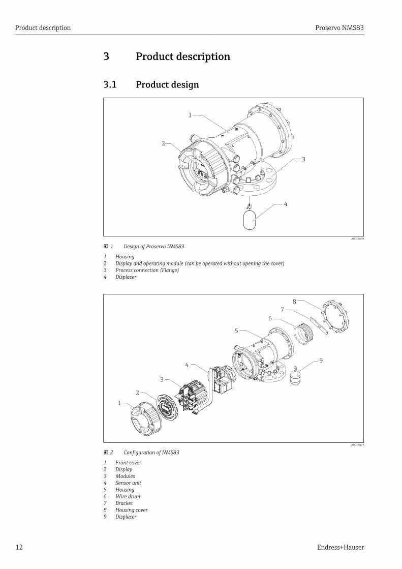
1 Design of Proservo NMS83
1 Housing2 Display and operating module (can be operated without opening the cover)3 Process connection (Flange)4 Displacer
5
6
7
8
1
2
3
49
A0028873
2 Configuration of NMS83
1 Front cover2 Display3 Modules4 Sensor unit5 Housing6 Wire drum7 Bracket8 Housing cover9 Displacer

Proservo NMS83 Incoming acceptance and product identification
Endress+Hauser 13
4 Incoming acceptance and productidentification
4.1 Incoming acceptanceUpon receipt of the goods check the following:• Are the order codes on the delivery note and the product sticker identical?• Are the goods undamaged?• Do the nameplate data match the ordering information on the delivery note?• If required (see nameplate): Are the Safety Instructions (XA) enclosed?
If one of these conditions is not satisfied, contact your Endress+Hauser Sales Center.
4.2 Product identificationThe following options are available for identification of the measuring device:• Nameplate specifications• Extended order code with breakdown of the device features on the delivery note• Enter serial numbers from nameplates in W@M Device Viewer
( www.endress.com/deviceviewer ): All information about the measuring device isdisplayed.
• Enter the serial number from the nameplates into the Endress+Hauser Operations Appor scan the 2-D matrix code (QR code) on the nameplate with the Endress+HauserOperations App: all the information for the measuring device is displayed.
For an overview of the scope of the associated Technical Documentation, refer to thefollowing:• The W@M Device Viewer: Enter the serial number from the nameplate
(www.endress.com/deviceviewer)• The Endress+Hauser Operations App: Enter the serial number from the nameplate or
scan the 2-D matrix code (QR code) on the nameplate.

Incoming acceptance and product identification Proservo NMS83
14 Endress+Hauser
4.2.1 Nameplate
1
3 21
22
23
67
8 9
14
16
15
19 20
11
18
1213
24
25
26 2827
4
5Ext. ord. cd.:
Order code:
Ser. no.:
Tp max.:
Mat.:
Date:
FW: Dev.Rev.: ex worksDeviceID:
Ta
Ta:
if modificationsee sep. labelX =
MWP:
Tank ID:
Tank ref.height:
2
Density range: Kg/m³
17
10
A0027791
3 Nameplate
1 Manufacturer address2 Device name3 Order code4 Serial number5 Extended order code6 Supply voltage7 Maximum process pressure8 Maximum process temperature9 Permitted ambient temperature (Ta)10 Temperature resistance of cable11 Thread for cable entry12 Material in contact with process13 Device ID14 Firmware version15 Device revision16 Metrology certification numbers17 Customized parametrization data18 Ambient temperature range19 CE mark / C-tick mark20 Additional information on the device version21 Ingress protection22 Certificate symbol23 Data concerning the Ex approval24 General certificate of approval25 Associated Safety Instructions (XA)26 Manufacturing date27 RoHS mark28 QR code for the Endress+Hauser Operations App

Proservo NMS83 Incoming acceptance and product identification
Endress+Hauser 15
Proservo NMS&'./0
1234: -20°C + °C~ 60
67: 89:;;<=び?@のBC、E/0をGわないでください。
PQRはT9をUVしないでください。 XY34 Z[のケーブルを`aしてください。85
&'67cdefg hi
+,-$%(2)
"#$%
j"#$%
Qk
+,-$%(3)
lm$%(4)
lm$%(5)
lm$%(6)
no,-$%(1)(2)
no+-$%(1)(2)
lm$%(1)
lm$%(2)
lm$%(3)
,-$%(1)
+,-$%( )1
+,-$%(4)
'pqr2sがuvしないことをyzしてからT9をUけてください。
&'():NMS
XA01600G
Ex d[ia] IIC T4 Ga/Gb
エンドレスハウザー)
いたで89のをらないでください。:
1
2
3
4
5
6
7
8
9
10
11
12
13
14
15
16
17
A0032435
4 Nameplate Proservo NMS8x for TIIS
1 Product type2 Ex type3 Input/Output circuit (1)4 Input/Output circuit (2)5 Signal circuit (1)6 Signal circuit (2)7 Signal circuit (3)8 Output circuit (1)9 Power supply10 Input/output circuit (3)11 Input/output circuit (4)12 Signal circuit (4)13 Signal circuit (5)14 Signal circuit (6)15 Contact output circuit (1) (2)16 Contact input circuit (1) (2)17 Drawing number
4.2.2 Manufacturer address
Endress+Hauser SE+Co. KGHauptstraße 179689 Maulburg, GermanyAddress of the manufacturing plant: See nameplate.
4.3 Storage and transport
4.3.1 Storage conditions• Storage temperature: –50 to +80 °C (–58 to +176 °F)• Store the device in its original packaging.

Incoming acceptance and product identification Proservo NMS83
16 Endress+Hauser
4.3.2 TransportNOTICE
Risk of injury‣ Transport the measuring device to the measuring point in its original packaging.‣ Take into account the mass center of the device in order to avoid unintended tilting.‣ Comply with the safety instructions, transport conditions for devices over 18kg
(39.6lbs) (IEC61010).
Proservo NMS83 Installation
Endress+Hauser 17
5 Installation
5.1 Requirements
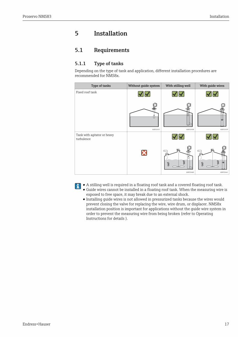
5.1.1 Type of tanksDepending on the type of tank and application, different installation procedures arerecommended for NMS8x.
Type of tanks Without guide system With stilling well With guide wires
Fixed roof tank
A0032437 A0032438 A0032439
Tank with agitator or heavyturbulence
A0032440 A0032441
• A stilling well is required in a floating roof tank and a covered floating roof tank.• Guide wires cannot be installed in a floating roof tank. When the measuring wire is
exposed to free space, it may break due to an external shock.• Installing guide wires is not allowed in pressurized tanks because the wires would
prevent closing the valve for replacing the wire, wire drum, or displacer. NMS8xinstallation position is important for applications without the guide wire system inorder to prevent the measuring wire from being broken (refer to OperatingInstructions for details ).
Installation Proservo NMS83
18 Endress+Hauser
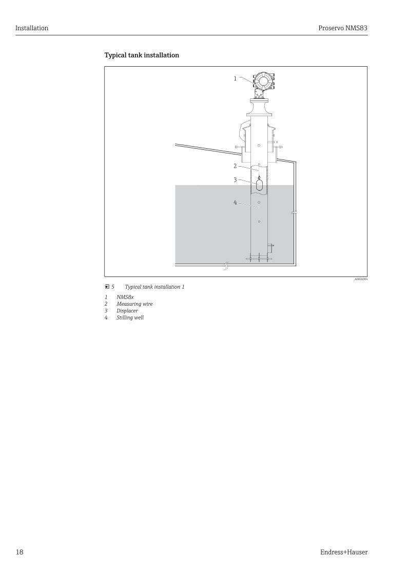
Typical tank installation
3
4
1
2
A0026904
5 Typical tank installation 1
1 NMS8x2 Measuring wire3 Displacer4 Stilling well
Proservo NMS83 Installation
Endress+Hauser 19
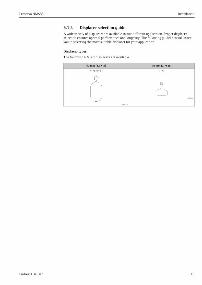
5.1.2 Displacer selection guideA wide variety of displacers are available to suit different application. Proper displacerselection ensures optimal performance and longevity. The following guidelines will assistyou in selecting the most suitable displacer for your application.
Displacer typesThe following NMS8x displacers are available.
50 mm (1.97 in) 70 mm (2.76 in)
316L/PTFE 316L
A0032429
A0032430

Installation Proservo NMS83
20 Endress+Hauser
Displacer dimensions
A
Ø50.8 (2)
a
45
(1
.77
) 85
(3
.35
)
11
6.6
(4
.59
)
2.5
(0
.09
)
B
Ø50 (1.97)
a
35
(1
.38
) 82
.7 (
3.2
6)
46
.7 (
1.8
4)
11
.5(0
.45
)1
1.5
(0.4
5)
C
17
(0
.67
)
46
.6 (
1.8
3)
1 (
0.0
3)
90
(3
.54
)
Ø70(2.76)
a
A0029581
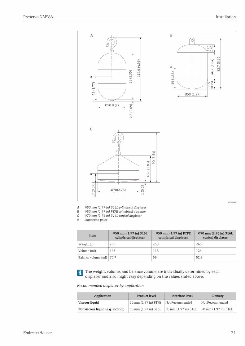
A 50 mm (1.97 in) 316L cylindrical displacerB 50 mm (1.97 in) PTFE cylindrical displacerC 70 mm (2.76 in) 316L conical displacera Immersion point
Proservo NMS83 Installation
Endress+Hauser 21
A
Ø50.8 (2)
a
45
(1
.77
) 85
(3
.35
)
11
6.6
(4
.59
)
2.5
(0
.09
)
B
Ø50 (1.97)
a
35
(1
.38
) 82
.7 (
3.2
6)
46
.7 (
1.8
4)
11
.5(0
.45
)1
1.5
(0.4
5)
C
17
(0
.67
)
46
.6 (
1.8
3)
1 (
0.0
3)
90
(3
.54
)
Ø70(2.76)
a
A0029581
A 50 mm (1.97 in) 316L cylindrical displacerB 50 mm (1.97 in) PTFE cylindrical displacerC 70 mm (2.76 in) 316L conical displacera Immersion point
Item 50 mm (1.97 in) 316Lcylindrical displacer
50 mm (1.97 in) PTFEcylindrical displacer
70 mm (2.76 in) 316Lconical displacer
Weight (g) 253 250 245
Volume (ml) 143 118 124
Balance volume (ml) 70.7 59 52.8
The weight, volume, and balance volume are individually determined by eachdisplacer and also might vary depending on the values stated above.
Recommended displacer by application
Application Product level Interface level Density
Viscous liquid 50 mm (1.97 in) PTFE Not Recommended Not Recommended
Not viscous liquid (e.g. alcohol) 50 mm (1.97 in) 316L 50 mm (1.97 in) 316L 50 mm (1.97 in) 316L
Installation Proservo NMS83
22 Endress+Hauser
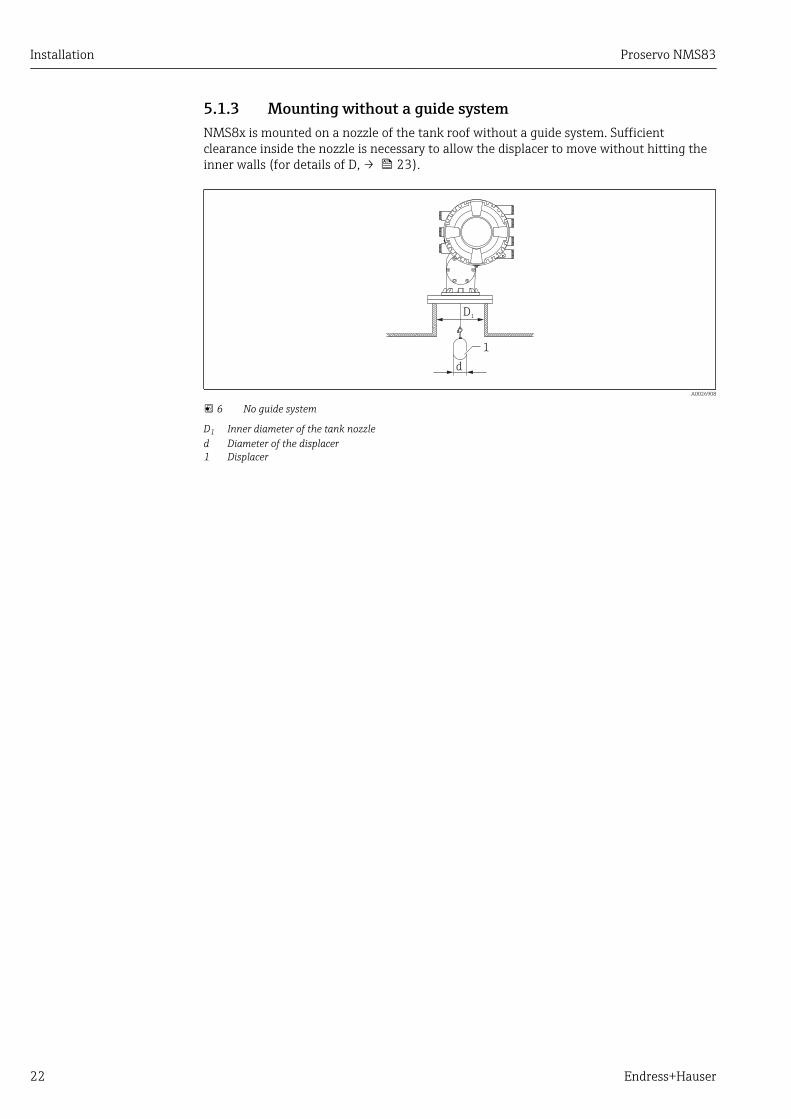
5.1.3 Mounting without a guide systemNMS8x is mounted on a nozzle of the tank roof without a guide system. Sufficientclearance inside the nozzle is necessary to allow the displacer to move without hitting theinner walls (for details of D, → 23).
1
d
D1
A0026908
6 No guide system
D1 Inner diameter of the tank nozzled Diameter of the displacer1 Displacer
Proservo NMS83 Installation
Endress+Hauser 23
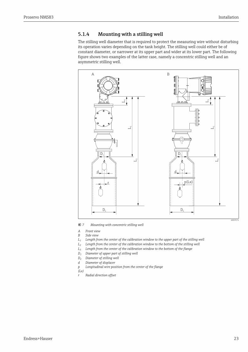
5.1.4 Mounting with a stilling wellThe stilling well diameter that is required to protect the measuring wire without disturbingits operation varies depending on the tank height. The stilling well could either be ofconstant diameter, or narrower at its upper part and wider at its lower part. The followingfigure shows two examples of the latter case, namely a concentric stilling well and anasymmetric stilling well.
L1
L2
L1
L2
A B
L3
L3
D2
D1
d
r
D1
d
D2
p(L )x
A0029574
7 Mounting with concentric stilling well
A Front viewB Side viewL1 Length from the center of the calibration window to the upper part of the stilling wellL2 Length from the center of the calibration window to the bottom of the stilling wellL3 Length from the center of the calibration window to the bottom of the flangeD1 Diameter of upper part of stilling wellD2 Diameter of stilling welld Diameter of displacerp(Lx)
Longitudinal wire position from the center of the flange
r Radial direction offset

Installation Proservo NMS83
24 Endress+Hauser
L1
L2
L1
L2
A B
L3
L3
D2
D1
d
r
D1
d
D2
p (L )x
A0026909
8 Mounting with asymmetric stilling well
A Front viewB Side viewL1 Length from the center of the calibration window to the upper part of the stilling wellL2 Length from the center of the calibration window to the bottom of the stilling wellL3 Length from the center of the calibration window to the bottom of the flangeD1 Diameter of upper part of stilling wellD2 Diameter of stilling welld Diameter of displacerp(Lx)
Longitudinal wire position from the center of the flange
r Radial direction offset
• L3: length from center of the calibration window to the bottom of the flange(77 mm (3.03 in) + flange thickness).For JIS 10K 150A RF, the flange thickness is 22 mm (0.87 in).
• When using an asymmetric stilling well, take into account the lateral shift of thedisplacer and follow the NMS8x mounting direction as shown in the figure.
• To calculate the required stilling well diameters, the formula below should be used.The following tables contain the necessary parameters in order to calculate thedimensions of the stilling well. Be sure to have appropriate dimensions of thestilling well according to each dimension in the table.
• The radial direction offset (r) is required for only the 47 m (154.20 ft) and55 m (180.45 ft) wire drum. For all other drums, the offset is 0 mm/in.

Proservo NMS83 Installation
Endress+Hauser 25
Feature: 110 Description(Measuring range; Wire;
Diameter)
NMS80 NMS81 NMS83 r
G1 47 m (154.20 ft); 316L;0.15 mm (0.00591 in)
6 mm (0.24 in)
H1 55 m (180.45 ft); 316L0.15 mm (0.00591 in)
6 mm (0.24 in)
Feature: 120 Description(Displacer material; Type)
NMS80 NMS81 NMS83 d
1AA 316L; 30 mm (1.18 in) cylindrical 30 mm (1.18 in)
1AC 316L; 50 mm (1.97 in) cylindrical 50 mm (1.97 in)
1BE 316L; 70 mm (2.76 in) conical 70 mm (2.76 in)
1BJ 316L;110 mm (4.33 in) conical 110 mm (4.33 in)
2AA PTFE; 30 mm (1.18 in) cylindrical 30 mm (1.18 in)
2AC PTFE; 50 mm (1.97 in) cylindrical 50 mm (1.97 in)
3AC AlloyC276; 50 mm (1.97 in)cylindrical
50 mm (1.97 in)
4AC 316L polished; 50 mm (1.97 in)cylindrical
50 mm (1.97 in)
4AE 316L polished; 70 mm (2.76 in)conical
70 mm (2.76 in)
5AC PTFE; 50 mm (1.97 in) cylindrical,hygienic white
50 mm (1.97 in)
Parameter Description
d Diameter of displacer
p(Lx) Longitudinal wire position from the center of the flangeThe value can be determined by using following graph.
r Radial direction offset
s Safety factor recommended: 5 mm (0.197 in)
The following graph shows the lateral shift of the displacer depending on the measureddistance for the different wire drums.

Installation Proservo NMS83
26 Endress+Hauser
L,
L(m
m)
()
12
in
p (Lx) (mm) ( )in
-1.4 -1.3 -1.2 -1.1 -1.0 -0.9 -0.8 -0.7 -0.6 -0.5 -0.4 -0.3 -0.2 -0.1 0.0 0.1 0.2 0.3
0
100
200
300
400
500
600
700
800
900
1000
1100
1200
1300
1400
1500
1600
1700
1800
1900
2000
2100
2200
0
2000
4000
6000
8000
10000
12000
14000
16000
18000
20000
22000
24000
26000
28000
30000
32000
34000
36000
38000
40000
42000
44000
46000
48000
50000
52000
54000
56000
-36 -32 -28 -24 -20 -16 -12 -8 -4 0 4 8
a
d
e
cb
f
A0027997
9 Lateral shift of displacer according to measurement range
a 16 m (A3) (NMS80/NMS81/NMS83)b 22 m (C2) (NMS80/NMS81/NMS83)c 28 m (D1) (NMS80/NMS81)d 36 m (F1) (NMS80/NMS81)e 47 m (G1) (NMS81)f 55 m(H1) (NMS81)
Upper diameter of stilling wellThe dimension of D1 has to be the largest value of the dimensions D1a, D1b , D1c, and D1daccording to the following formula.
D1 Dimension(Example)
D1x DimensionDescription Formula
Example Parameter
>68.1 mm(2.68 in)
68.1 mm(2.68 in)
D1a D1 dimension when thedisplacer is at the center of thecalibration window
= 2 x ( |p (0)|+ d/2 + s)
65.6 mm(2.58 in)
D1b D1 dimension when thedisplacer is at the upper part ofthe stilling well
= 2 x (|p (L1)|+ d/2 + s)

Proservo NMS83 Installation
Endress+Hauser 27
D1 Dimension(Example)
D1x DimensionDescription Formula
Example Parameter
50.9 mm(2.00 in)
D1c D1 dimension when thedisplacer is at the bottom of thestilling well
= 2 x ( |p (L2)|+ s)
D1d D1 dimension when the radialdirection offset is considered.This calculation is used onlywith the 47 m (154.20 ft) wiredrum (G1 in Feature110) and55 m (180.45 ft) (H1 in feature110)
= 2 x (d/2 + r + s)
Example: L1 = 1 000 mm, L2 = 20 000 mm, d = 50 mm, s = 5.0, 28 m drum
Lower diameter of stilling wellThe dimension of D2 has to be the larger value of the dimensions D1 and D2b .
See the table below.
Concentric pipe
D2 Dimension(Example)
D2x DimensionDescription Formula
Example Parameter
>100.9 mm(3.97 in)
68.1 mm(2.68 in)
D1 Calculated D1 value
100.9 mm(3.97 in)
D2b D2 dimension when the displacer isin L2 length
= 2 x (|p (L2)| + d/2 + s)
Example: L2 = 20 000 mm, d = 50 mm, s = 5.0, 28 m drum
Asymmetric pipe
D2 Dimension(Example)
D2x DimensionDescription Formula
Example Parameter
>84.5 mm(3.33 in)
68.1 mm(2.68 in)
D1 Calculated D1 value
84.5 mm(3.33 in)
D2b D2 dimension that the displacer canpass through (nth groove)
= |p (L2)| + d/2 + s + D1/2
Example: L2 = 20 000 mm, d = 50 mm, s = 5.0, 28 m drum
Recommendations for NMS8x mounting with a stilling wellFollow the recommendations for mounting NMS8x with a stilling well.
• Keep the pipe connection welds smooth.• When drilling holes into the pipe, keep the interior surface of the holes clear of
metal chips and burrs.• Keep the pipe as vertical as possible. Check using a plumb bob.• Install the asymmetric pipe under the valve and align the centers of the NMS8x and
the valve.• Set the center of the lower part of the asymmetric pipe in the direction of the lateral
motion.• Observe the recommendations as per API MPMS chapter 3.1B.• Confirm grounding between NMS8x and the tank nozzle.
Installation Proservo NMS83
28 Endress+Hauser
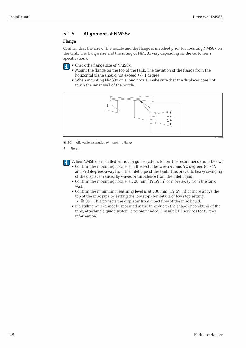
5.1.5 Alignment of NMS8xFlangeConfirm that the size of the nozzle and the flange is matched prior to mounting NMS8x onthe tank. The flange size and the rating of NMS8x vary depending on the customer’sspecifications.
• Check the flange size of NMS8x.• Mount the flange on the top of the tank. The deviation of the flange from the
horizontal plane should not exceed +/- 1 degree.• When mounting NMS8x on a long nozzle, make sure that the displacer does not
touch the inner wall of the nozzle.
+1
°-1
°
1
A0026889
10 Allowable inclination of mounting flange
1 Nozzle
When NMS8x is installed without a guide system, follow the recommendations below:• Confirm the mounting nozzle is in the sector between 45 and 90 degrees (or -45
and -90 degrees)away from the inlet pipe of the tank. This prevents heavy swingingof the displacer caused by waves or turbulence from the inlet liquid.
• Confirm the mounting nozzle is 500 mm (19.69 in) or more away from the tankwall.
• Confirm the minimum measuring level is at 500 mm (19.69 in) or more above thetop of the inlet pipe by setting the low stop (for details of low stop setting,→ 89). This protects the displacer from direct flow of the inlet liquid.
• If a stilling well cannot be mounted in the tank due to the shape or condition of thetank, attaching a guide system is recommended. Consult E+H services for furtherinformation.

Proservo NMS83 Installation
Endress+Hauser 29
≥500 (19.69)
90°-90°
0°
45°-45°
1
1
≥5
00
(1
9.6
9)
2
2
A0026890
11 Recommended position for mounting NMS8x and minimum measuring level; dimensions mm (in)
1 Inlet pipe2 Tank nozzle
• Before pouring liquid into the tank, confirm that liquid flowing through the inlet ofthe pipe will not contact the displacer directly.
• When discharging liquid out of the tank, ensure that the displacer will not getcaught in the liquid current and sucked into the outlet pipe.
5.1.6 Electrostatic chargeWhen liquid measured by NMS8x has a conductivity of 1 uS/m or less, it is quasi-nonconductive. In this case, using a stilling well or guide wire is recommended. Thisreleases the electrostatic charge on the liquid surface.

Installation Proservo NMS83
30 Endress+Hauser
5.2 Mounting of the deviceWhen NMS8x is delivered, the displacer is always shipped separately and there are twomethods to install displacer as follows.
• Installation for displacer shipped separately method• Installation through the calibration window
5.2.1 Available installationsThe following installation procedures are available for NMS8x.
• Mounting without guide system• Mounting with stilling well
Mounting options Free-space mounting With stilling well
Type of tanks
A0032437 A0032438
Type of installations • Displacer shipped separately• Displacer installation through calibration
window
• Displacer shipped separately• Displacer installation through calibration
window

Proservo NMS83 Installation
Endress+Hauser 31
5.2.2 Verification of displacer and wire drumPrior to installation of NMS8x, confirm that the serial numbers of displacer and the wiredrum match with those printed to the label attached on the housing.
316L50ml70.8ml141.6
g256.6
ØBVDVDm
NM
S8
Dis
pla
cer 12345678901Ser.no.:
712xxxxx
Spare
part-n
o.: H
NB
R
O-R
ing 2
8m
Range
NMS8
98765432109
Ser. n
o.:
3
1.
2.
12345678901
712xxxxx
m 256.6gD
V 141.6mLD
V 70.8mLB
!50 316L
Spare part-no.: 712xxxxx
mm302.xxxCir.
NM
S8
Wire
dru
m
98765432109Ser.no.:
1.35g/10mHNBR
28 m
WireWgt.O-Ring
RangeSpare part-no.: 712xxxxx
A0029470
12 Verification of displacer and wire drum
Installation Proservo NMS83
32 Endress+Hauser
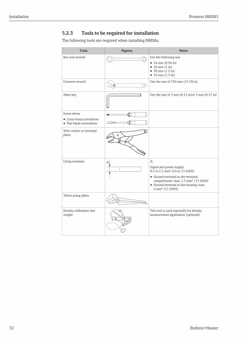
5.2.3 Tools to be required for installationThe following tools are required when installing NMS8x.
Tools Figures Notes
Box end wrench Use the following size
• 24 mm (0.94 in)• 26 mm (1 in)• 30 mm (1.2 in)• 32 mm (1.3 in)
Crescent wrench Use the size of 350 mm (13.78 in)
Allen key Use the size of 3 mm (0.12 in)or 5 mm (0.17 in)
Screw driver
• Cross-head screwdriver• Flat-blade screwdriver
Wire cutters or terminalpliers
Crimp terminal A A:
Signal and power supply:0.2 to 2.5 mm2 (24 to 13 AWG)
• Ground terminal in the terminalcompartment: max. 2.5 mm2 (13 AWG)
• Ground terminal at the housing: max.4 mm2 (11 AWG)
Water pump pliers
Density calibration testweight
This tool is used especially for densitymeasurement application (optional).
Proservo NMS83 Installation
Endress+Hauser 33
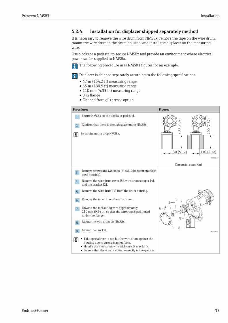
5.2.4 Installation for displacer shipped separately methodIt is necessary to remove the wire drum from NMS8x, remove the tape on the wire drum,mount the wire drum in the drum housing, and install the displacer on the measuringwire.
Use blocks or a pedestal to secure NMS8x and provide an environment where electricalpower can be supplied to NMS8x.
The following procedure uses NMS81 figures for an example.
Displacer is shipped separately according to the following specifications.
• 47 m (154.2 ft) measuring range• 55 m (180.5 ft) measuring range• 110 mm (4.33 in) measuring range• 8 in flange• Cleaned from oil+grease option
Procedures Figures
1.Secure NMS8x on the blocks or pedestal.
20
0 (
7.8
7)
20
0 (
7.8
7)
130 (5.12) 130 (5.12)
A0032442
Dimensions mm (in)
2.Confirm that there is enough space under NMS8x.
Be careful not to drop NMS8x.
3.Remove screws and M6 bolts [6] (M10 bolts for stainlesssteel housing).
3
12
5
6
4
A0028876
4. Remove the wire drum cover [5], wire drum stopper [4],and the bracket [2].
5.Remove the wire drum [1] from the drum housing.
6. Remove the tape [3] on the wire drum.
7.Unwind the measuring wire approximately250 mm (9.84 in) so that the wire ring is positionedunder the flange.
8. Mount the wire drum on NMS8x.
9. Mount the bracket.
• Take special care to not hit the wire drum against thehousing due to strong magnet force.
• Handle the measuring wire with care. It may kink.• Be sure that the wire is wound correctly in the grooves.

Installation Proservo NMS83
34 Endress+Hauser
Procedures Figures
10. Hook the displacer [3] on the ring [2].
1
3
2
A0029116
• Be sure that the wire is wound correctly in the grooves.• If not, remove the displacer and the wire drum, and
repeat step 7.
11. Turn on the power of NMS8x.
2
3
4
1
A0027017
12. Perform sensor calibration
13. Secure the displacer [2] to the measuring wire [1] usingthe securing wire [3].
14. Perform reference calibration.
15. Turn off the power.
16. Mount the wire drum cover [4].
• For sensor calibration, → 82• For reference calibration, → 84.
17. Mount NMS8x on the tank nozzle [1].
1
A0028877
18. Confirm that the displacer does not touch the inner wallof the nozzle.
19. Turn on the power.
20. Perform drum calibration.
For drum calibration, → 85
Proservo NMS83 Installation
Endress+Hauser 35
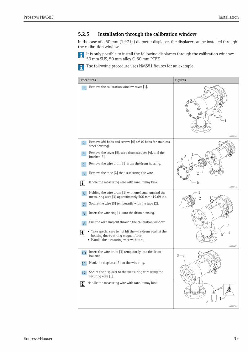
5.2.5 Installation through the calibration windowIn the case of a 50 mm (1.97 in) diameter displacer, the displacer can be installed throughthe calibration window.
It is only possible to install the following displacers through the calibration window:50 mm SUS, 50 mm alloy C, 50 mm PTFE
The following procedure uses NMS81 figures for an example.
Procedures Figures
1.Remove the calibration window cover [1].
1
A0032443
2.Remove M6 bolts and screws [6] (M10 bolts for stainlesssteel housing).
2
13
45
6
A0029118
3.Remove the cover [5], wire drum stopper [4], and thebracket [3].
4. Remove the wire drum [1] from the drum housing.
5.Remove the tape [2] that is securing the wire.
Handle the measuring wire with care. It may kink.
6. Holding the wire drum [1] with one hand, unwind themeasuring wire [3] approximately 500 mm (19.69 in).
3
4
2
1
A0028879
7.Secure the wire [3] temporarily with the tape [2].
8. Insert the wire ring [4] into the drum housing.
9. Pull the wire ring out through the calibration window.
• Take special care to not hit the wire drum against thehousing due to strong magnet force.
• Handle the measuring wire with care.
10. Insert the wire drum [3] temporarily into the drumhousing.
1
2
3
A0027984
11. Hook the displacer [2] on the wire ring.
12. Secure the displacer to the measuring wire using thesecuring wire [1].
Handle the measuring wire with care. It may kink.
Installation Proservo NMS83
36 Endress+Hauser
Procedures Figures
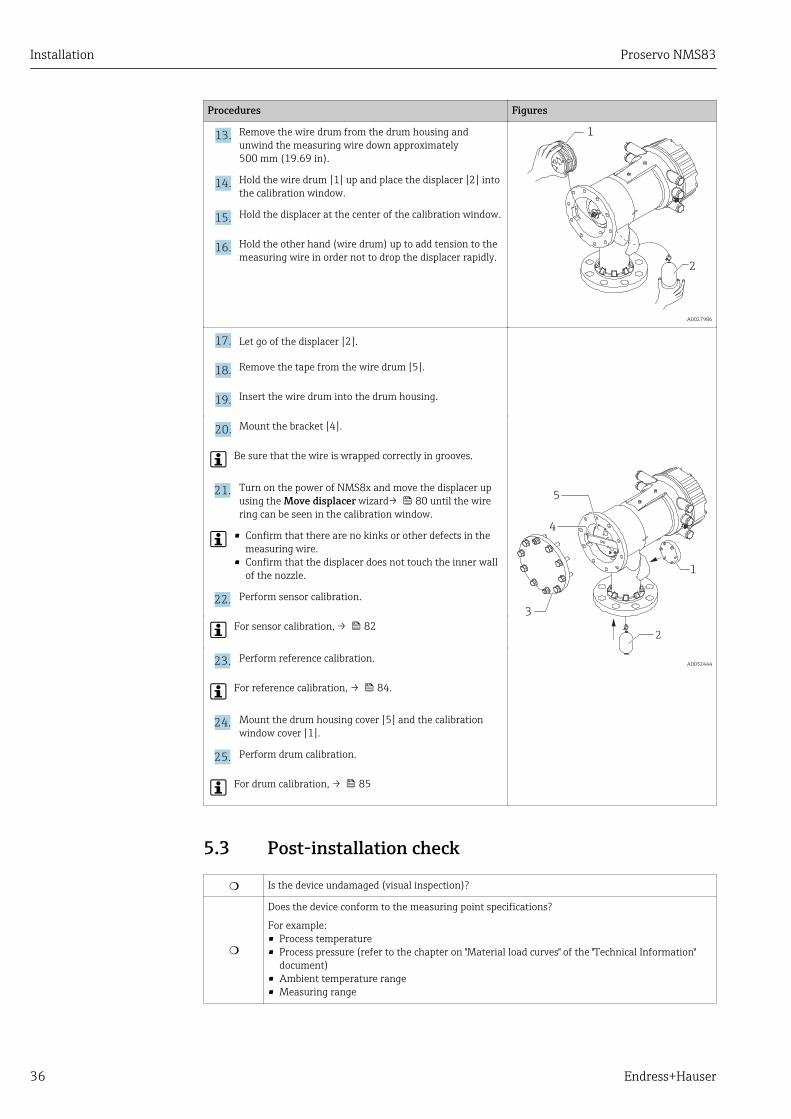
13. Remove the wire drum from the drum housing andunwind the measuring wire down approximately500 mm (19.69 in).
2
1
A0027986
14. Hold the wire drum [1] up and place the displacer [2] intothe calibration window.
15. Hold the displacer at the center of the calibration window.
16. Hold the other hand (wire drum) up to add tension to themeasuring wire in order not to drop the displacer rapidly.
17. Let go of the displacer [2].
3
4
5
2
1
A0032444
18. Remove the tape from the wire drum [5].
19. Insert the wire drum into the drum housing.
20. Mount the bracket [4].
Be sure that the wire is wrapped correctly in grooves.
21. Turn on the power of NMS8x and move the displacer upusing the Move displacer wizard→ 80 until the wirering can be seen in the calibration window.
• Confirm that there are no kinks or other defects in themeasuring wire.
• Confirm that the displacer does not touch the inner wallof the nozzle.
22. Perform sensor calibration.
For sensor calibration, → 82
23. Perform reference calibration.
For reference calibration, → 84.
24. Mount the drum housing cover [5] and the calibrationwindow cover [1].
25. Perform drum calibration.
For drum calibration, → 85
5.3 Post-installation check
m Is the device undamaged (visual inspection)?
m
Does the device conform to the measuring point specifications?
For example:• Process temperature• Process pressure (refer to the chapter on "Material load curves" of the "Technical Information"
document)• Ambient temperature range• Measuring range

Proservo NMS83 Installation
Endress+Hauser 37
m Are the measuring point identification and labeling correct (visual inspection)?
m Is the device adequately protected from precipitation and direct sunlight?
Connection check for wire ring of displacerTo keep it clean, the NMS83 displacer does not have any washers or nuts. When usingthe NMS83 in a hazardous area, make sure that the wire ring is connected to the wirehook of the displacer without any foreign matter interfering in order to prevent staticelectricity.

Electrical connection Proservo NMS83
38 Endress+Hauser
6 Electrical connection
6.1 Terminal assignment
D
E
G
F
C
B
A
1
1
1
1
1 3
2
2
2 4
1
HR
CDI
WP
on
SIM
2
2
3
3
4
4
1
1
2
2
3
3
4
4
5
5
6
6
7
7
8
8
POWER
i
D
E
F
C
B
A
1
1
1
1 3
2
2 4
1
HR
CDI
WPon
SIM
2
2
3
3
4
4
1
1
2
2
3
3
4
4
5
5
6
6
7
7
8
8
i
G1
3
2
POWER
G1 N
G3 LAC 85...264 V
A0032445
13 Terminal compartment (typical example) and ground terminals
Terminal area Module
A/B/C/D(slots for I/Omodules)
Up to four I/O modules, depending on the order code
• Modules with four terminals can be in any of these slots.• Modules with eight terminals can be in slot B or C.
The exact assignment of the modules to the slots is dependent on the device version→ 41.
E HART Ex i/IS interface• E1: H+• E2: H-
F Remote display• F1: VCC (connect to terminal 81 of the remote display)• F2: Signal B (connect to terminal 84 of the remote display)• F3: Signal A (connec t to terminal 83 of the remote display)• F4: Gnd (connect to terminal 82 of the remote display)
G
Power consumption: 28.8 VA 1)
Power supply: 85 to 264 VAC
• G1: N• G2: not connected• G3: L
A0018339
Protective ground connection (M4 screw)
1) Maximum power varies depending on the configuration of the modules. As the value of 28.8 VA showsmaximum apparent power, select the applicable cables accordingly. The actual consumed effective power is12 w.

Proservo NMS83 Electrical connection
Endress+Hauser 39
6.1.1 Power supply
D
E
F
C
B
A
1
1
1
1 3
2
2 4
1
HR
CDI
WPon
SIM
2
2
3
3
4
4
1
1
2
2
3
3
4
4
5
5
6
6
7
7
8
8
i
G1
3
2
POWER
4
F
1
1 3
2
2 4
HR
CDI
WP
SIM
G1
3
2
POWER
G1 NAC 85...264 V
A0033413
G1 NG2 not connectedG3 L4 Green LED: indicates power supply
Supply voltage85 to 264 VAC, 50/60 Hz, 28.8 VA 1)
The supply voltage is also indicated on the nameplate.
6.1.2 Remote display and operating module DKX001
1
3
Vcc
Gn
d
A B
2
D
E
F
C
B
A
1
1
1
1 3
2
2 4
1
HR
CDI
WPon
SIM
2
2
3
3
4
4
1
1
2
2
3
3
4
4
5
5
6
6
7
7
8
8
i
G1
3
2
POWER
F1 3
2 4
HR
WP
Vcc
Gn
dAB
81 82 83 84
F1 F2 F3 F4
A0037025
14 Connection of the remote display and operating module DKX001 to the Tank Gauging device (NMR8x,NMS8x or NRF8x)
1 Remote display and operating module2 Connecting cable3 Tank Gauging device (NMR8x, NMS8x or NRF8x)
The remote display and operating module DKX001 is available as an accessory. Fordetails refer to SD01763D.
• The measured value is indicated on the DKX001 and on the local display andoperating module simulataneously.
• The operating menu cannot be accessed on both modules at the same time. If theoperating menu is entered in one of these modules, the other module isautomatically locked. This locking remains active until the menu is closed in thefirst module (back to measured value display).
1) maximum value; actual value depending on modules installed. 28.8 VA includes the nominal power, and the cabling specification has to meetthis value. On the other hand, the effective power consumption is 12 W.

Electrical connection Proservo NMS83
40 Endress+Hauser
6.1.3 HART Ex i/IS interface
D
E
F
C
B
A
1
1
1
1 3
2
2 4
1
HR
CDI
WPon
SIM
2
2
3
3
4
4
1
1
2
2
3
3
4
4
5
5
6
6
7
7
8
8
i
E1
1
2
CDI
i
G1
3
2
POWER
3
A0033414
E1 H+E2 H-3 Orange LED: indicates data communication
This interface always operates as the main HART master for connected HART slavetransmitters. The Analog I/O modules, on the other hand, can be configured as aHART master or slave → 48 → 50.

Proservo NMS83 Electrical connection
Endress+Hauser 41
6.1.4 Slots for I/O modulesThe terminal compartment contains four slots (A, B, C and D) for I/O modules. Dependingon the device version (ordering features 040, 050 and 060) these slots contain differentI/O modules. The table below shows which module is located in which slot for a specificdevice version.
The slot assignment for the device is also indicated on a label attached to the backcover of the display module.
Spare parts for: Proservo NMS81
Ser.-no.:8A21AC098AF4
Spare part
Spare no./structure
DisplacerWire Drum
Additio
nal in
form
ation:
XPF0002-AABICR+
AAEAEBEFLALC76
XPF0002-AABEFEG+
XPF0002-AABEFEG+
XPF0002-AABEFEG+
XPF0002-AABEFEG+
XPF0002-AABEFEG+
XPF0002-AABEFEG+
XPF0002-AABEFEG+
XPF0002-AABEFEG+
712736897122xxxxXPF0002-AABEFEG+
AAAAACDEFEG+
XPF0002-AAACABADJ+
AAHAHCHRIJJAJBKP
71023451
71023451
71023451
Cover
IOM-V1IOM-A/RTDIOM-D
Slot A
Slot B
Slot C
Slot D
IO Mod FF
DisplayDisplay asm.
Detector
Main electr.
SMS electr.
6
7
8
91011
12
5
4321
ww
w.e
ndre
ss.c
om
/devic
evie
wer
D
C
B
A
1
A0030121
1 Label showing (among other things) the modules in the slots A to D.A Cable entry for slot AB Cable entry for slot BC Cable entry for slot CD Cable entry for slot D

Electrical connection Proservo NMS83
42 Endress+Hauser
"Primary Output" (040) = "Modbus" (A1)
Ordering feature
NMx8x - XX XX XXxxxx ...
060050040
Terminal area
040PrimaryOutput
050SecondaryIO Analog
060SecondaryIO DigitalEx d/XP
DCBA
11
22
33
44
11
22
33
44
55
66
77
88
A0023888
A1 X0 X0 Modbus - - -
A1 X0 A1 Modbus - - Digital
A1 X0 A2 Modbus - Digital Digital
A1 X0 A3 Modbus Digital Digital Digital
A1 X0 B1 Modbus Modbus - -
A1 X0 B2 Modbus Modbus - Digital
A1 X0 B3 Modbus Modbus Digital Digital
A1 A1 X0 Modbus Analog Ex d/XP - -
A1 A1 A1 Modbus Analog Ex d/XP - Digital
A1 A1 A2 Modbus Analog Ex d/XP Digital Digital
A1 A1 B1 Modbus Modbus Analog Ex d/XP -
A1 A1 B2 Modbus Modbus Analog Ex d/XP Digital
A1 A2 X0 Modbus Analog Ex d/XP Analog Ex d/XP -
A1 A2 A1 Modbus Analog Ex d/XP Analog Ex d/XP Digital
A1 A2 B1 Modbus Analog Ex d/XP Analog Ex d/XP Modbus
A1 B1 X0 Modbus Analog Ex i/IS - -
A1 B1 A1 Modbus Analog Ex i/IS - Digital
A1 B1 A2 Modbus Analog Ex i/IS Digital Digital
A1 B1 B1 Modbus Modbus Analog Ex i/IS -
A1 B1 B2 Modbus Modbus Analog Ex i/IS Digital
A1 B2 X0 Modbus Analog Ex i/IS Analog Ex i/IS -
A1 B2 A1 Modbus Analog Ex i/IS Analog Ex i/IS Digital
A1 B2 B1 Modbus Analog Ex i/IS Analog Ex i/IS Modbus
A1 C2 X0 Modbus Analog Ex i/IS Analog Ex d/XP -
A1 C2 A1 Modbus Analog Ex i/IS Analog Ex d/XP Digital
A1 C2 B1 Modbus Analog Ex i/IS Analog Ex d/XP Modbus
Proservo NMS83 Electrical connection
Endress+Hauser 43
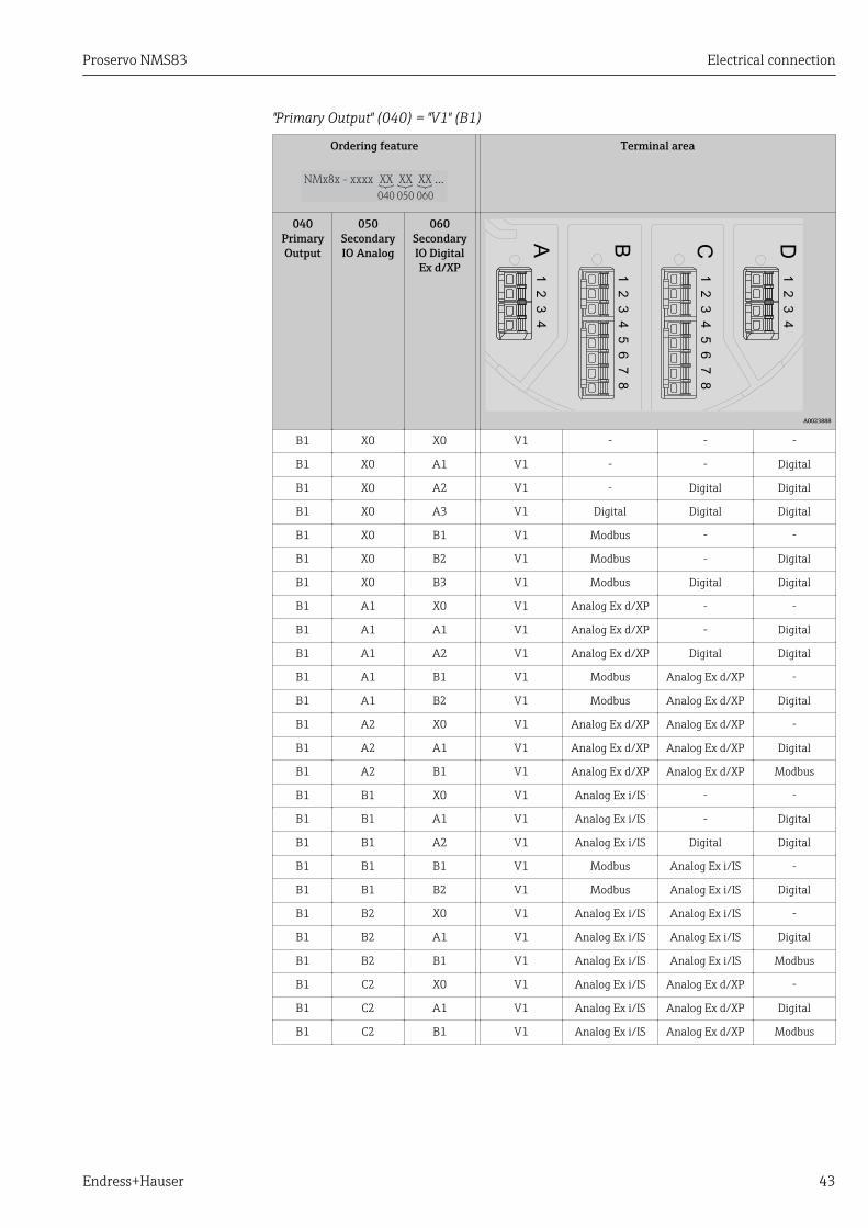
"Primary Output" (040) = "V1" (B1)
Ordering feature
NMx8x - XX XX XXxxxx ...
060050040
Terminal area
040PrimaryOutput
050SecondaryIO Analog
060SecondaryIO DigitalEx d/XP
DCBA
11
22
33
44
11
22
33
44
55
66
77
88
A0023888
B1 X0 X0 V1 - - -
B1 X0 A1 V1 - - Digital
B1 X0 A2 V1 - Digital Digital
B1 X0 A3 V1 Digital Digital Digital
B1 X0 B1 V1 Modbus - -
B1 X0 B2 V1 Modbus - Digital
B1 X0 B3 V1 Modbus Digital Digital
B1 A1 X0 V1 Analog Ex d/XP - -
B1 A1 A1 V1 Analog Ex d/XP - Digital
B1 A1 A2 V1 Analog Ex d/XP Digital Digital
B1 A1 B1 V1 Modbus Analog Ex d/XP -
B1 A1 B2 V1 Modbus Analog Ex d/XP Digital
B1 A2 X0 V1 Analog Ex d/XP Analog Ex d/XP -
B1 A2 A1 V1 Analog Ex d/XP Analog Ex d/XP Digital
B1 A2 B1 V1 Analog Ex d/XP Analog Ex d/XP Modbus
B1 B1 X0 V1 Analog Ex i/IS - -
B1 B1 A1 V1 Analog Ex i/IS - Digital
B1 B1 A2 V1 Analog Ex i/IS Digital Digital
B1 B1 B1 V1 Modbus Analog Ex i/IS -
B1 B1 B2 V1 Modbus Analog Ex i/IS Digital
B1 B2 X0 V1 Analog Ex i/IS Analog Ex i/IS -
B1 B2 A1 V1 Analog Ex i/IS Analog Ex i/IS Digital
B1 B2 B1 V1 Analog Ex i/IS Analog Ex i/IS Modbus
B1 C2 X0 V1 Analog Ex i/IS Analog Ex d/XP -
B1 C2 A1 V1 Analog Ex i/IS Analog Ex d/XP Digital
B1 C2 B1 V1 Analog Ex i/IS Analog Ex d/XP Modbus
Electrical connection Proservo NMS83
44 Endress+Hauser
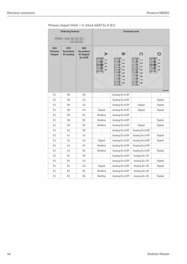
"Primary Output" (040) = "4-20mA HART Ex d" (E1)
Ordering feature
NMx8x - XX XX XXxxxx ...
060050040
Terminal area
040PrimaryOutput
050SecondaryIO Analog
060SecondaryIO DigitalEx d/XP
DCBA
11
22
33
44
11
22
33
44
55
66
77
88
A0023888
E1 X0 X0 - Analog Ex d/XP - -
E1 X0 A1 - Analog Ex d/XP - Digital
E1 X0 A2 - Analog Ex d/XP Digital Digital
E1 X0 A3 Digital Analog Ex d/XP Digital Digital
E1 X0 B1 Modbus Analog Ex d/XP - -
E1 X0 B2 Modbus Analog Ex d/XP - Digital
E1 X0 B3 Modbus Analog Ex d/XP Digital Digital
E1 A1 X0 - Analog Ex d/XP Analog Ex d/XP -
E1 A1 A1 - Analog Ex d/XP Analog Ex d/XP Digital
E1 A1 A2 Digital Analog Ex d/XP Analog Ex d/XP Digital
E1 A1 B1 Modbus Analog Ex d/XP Analog Ex d/XP -
E1 A1 B2 Modbus Analog Ex d/XP Analog Ex d/XP Digital
E1 B1 X0 - Analog Ex d/XP Analog Ex i/IS -
E1 B1 A1 - Analog Ex d/XP Analog Ex i/IS Digital
E1 B1 A2 Digital Analog Ex d/XP Analog Ex i/IS Digital
E1 B1 B1 Modbus Analog Ex d/XP Analog Ex i/IS -
E1 B1 B2 Modbus Analog Ex d/XP Analog Ex i/IS Digital

Proservo NMS83 Electrical connection
Endress+Hauser 45
"Primary Output" (040) = "4-20mA HART Ex i" (H1)
Ordering feature
NMx8x - XX XX XXxxxx ...
060050040
Terminal area
040PrimaryOutput
050SecondaryIO Analog
060SecondaryIO DigitalEx d/XP
DCBA
11
22
33
44
11
22
33
44
55
66
77
88
A0023888
H1 X0 X0 - Analog Ex i/IS - -
H1 X0 A1 - Analog Ex i/IS - Digital
H1 X0 A2 - Analog Ex i/IS Digital Digital
H1 X0 A3 Digital Analog Ex i/IS Digital Digital
H1 X0 B1 Modbus Analog Ex i/IS - -
H1 X0 B2 Modbus Analog Ex i/IS - Digital
H1 X0 B3 Modbus Analog Ex i/IS Digital Digital
H1 A1 X0 - Analog Ex i/IS Analog Ex d/XP -
H1 A1 A1 - Analog Ex i/IS Analog Ex d/XP Digital
H1 A1 A2 Digital Analog Ex i/IS Analog Ex d/XP Digital
H1 A1 B1 Modbus Analog Ex i/IS Analog Ex d/XP -
H1 A1 B2 Modbus Analog Ex i/IS Analog Ex d/XP Digital
H1 B1 X0 - Analog Ex i/IS Analog Ex i/IS -
H1 B1 A1 - Analog Ex i/IS Analog Ex i/IS Digital
H1 B1 A2 Digital Analog Ex i/IS Analog Ex i/IS Digital
H1 B1 B1 Modbus Analog Ex i/IS Analog Ex i/IS -
H1 B1 B2 Modbus Analog Ex i/IS Analog Ex i/IS Digital

Electrical connection Proservo NMS83
46 Endress+Hauser
6.1.5 Terminals of the "Modbus" or "V1" module
D
E
F
C
B
A
1
1
1
1 3
2
2 4
1
HR
CDI
WPon
SIM
2
2
3
3
4
4
1
1
2
2
3
3
4
4
5
5
6
6
7
7
8
8
POWER
A 1 2 3 4
A1-4
i
D 1 2 3 4
D1-4
A0031200
15 Designation of the "Modbus" or "V1" modules (examples); depending on the device version these modulesmay also be in slot B or C.
Depending on the device version, the "Modbus" and/or "V1" module may be in differentslots of the terminal compartment. In the operating menu the "Modbus" and "V1" interfacesare designated by the respective slot and the terminals within this slot: A1-4, B1-4, C1-4,D1-4.
Terminals of the "Modbus" module
Terminal 1) Name Description
X1 S Cable shielding connected via a capacitor to EARTH
X2 0V Common reference
X3 B- Non-inverting signal line
X4 A+ Inverting signal line
Designation of the module in the operating menu: Modbus X1-4; (X = A, B, C or D)
1) In this column, "X" stands for one of the slots "A", "B", "C", or "D".
Terminals of the "V1" module
Terminal 1) Name Description
X1 S Cable shielding connected via capacitor to EARTH
X2 not connected
X3 B- Protocol loop signal -
X4 A+ Protocol loop signal +
Designation of the module in the operating menu: V1 X1-4; (X = A, B, C or D)
1) In this column, "X" stands for one of the slots "A", "B", "C", or "D".

Proservo NMS83 Electrical connection
Endress+Hauser 47
6.1.6 Terminals of the "Analog I/O" module (Ex d /XP or Ex i/IS)
D
E
F
C
B
A
1
1
1
1 3
2
2 4
1
HR
CDI
WPon
SIM
2
2
3
3
4
4
1
1
2
2
3
3
4
4
5
5
6
6
7
7
8
8
POWER
i
B 1 2 3 4 5 6 7 8
B1-3 B4-8
C 1 2 3 4 5 6 7 8
C1-3 C4-8
A0031168
Terminals Function Connection diagrams Designation in the operating menu
B1-3 Analog input or output(configurable)
• Passive usage: → 48• Active usage: → 50
Analog I/O B1-3 (→ 205)
C1-3 Analog I/O C1-3 (→ 205)
B4-8 Analog input RTD: → 51 Analog IP B4-8 (→ 199)
C4-8 Analog IP C4-8 (→ 199)

Electrical connection Proservo NMS83
48 Endress+Hauser
6.1.7 Connection of the "Analog I/O" module for passive usage• In the passive usage the supply voltage for the communication line must be supplied
by an external source.• The wiring must be in accordance with the intended operating mode of the Analog
I/O module; see the drawings below.
"Operating mode" = "4..20mA output" or "HART slave +4..20mA output"
D
E
F
C
B
A
1
1
1
1 3
2
2 4
1
HR
CDI
WPon
SIM
2
2
3
3
4
4
1
1
2
2
3
3
4
4
5
5
6
6
7
7
8
8
i
G1
3
2
POWER
ca
b
-
+
!
E
G
F
1
1
1 3
2
2 4
HR
CDI
WPon
SIM
i
D
C
B
A
1
1
2
2
3
3
4
4
1
1
2
2
3
3
4
4
5
5
6
6
7
7
8
8
G1
3
2
POWER
A0027931
16 Passive usage of the Analog I/O module in the output mode
a Power supplyb HART signal outputc Analog signal evaluation
"Operating mode" = "4..20mA input" or "HART master+4..20mA input"
D
E
F
C
B
A
1
1
1
1 3
2
2 4
1
HR
CDI
WPon
SIM
2
2
3
3
4
4
1
1
2
2
3
3
4
4
5
5
6
6
7
7
8
8
i
G1
3
2
POWER
a
+
–
!
E
G
F
1
1
1 3
2
2 4
HR
CDI
WPon
SIM
i
D
C
B
A
1
1
2
2
3
3
4
4
1
1
2
2
3
3
4
4
5
5
6
6
7
7
8
8
G1
3
2
POWER
b
A0027933
17 Passive usage of the Analog I/O module in the input mode
a Power supplyb External device with 4...20mA and/or HART signal output

Proservo NMS83 Electrical connection
Endress+Hauser 49
"Operating mode" = "HART master"
D
E
F
C
B
A
1
1
1
1 3
2
2 4
1
HR
CDI
WPon
SIM
2
2
3
3
4
4
1
1
2
2
3
3
4
4
5
5
6
6
7
7
8
8
i
G1
3
2
POWER
a
+
–
!
E
G
F
1
1
1 3
2
2 4
HR
CDI
WPon
SIM
i
D
C
B
A
1
1
2
2
3
3
4
4
1
1
2
2
3
3
4
4
5
5
6
6
7
7
8
8
G1
3
2
POWER
b
A0027934
18 Passive usage of the Analog I/O module in the HART master mode
a Power supplyb Up to 6 external devices with HART signal output

Electrical connection Proservo NMS83
50 Endress+Hauser
6.1.8 Connection of the "Analog I/O" module for active usage• In the active usage the supply voltage for the communication line is supplied by the
device itself. There is no need of an external power supply.• The wiring must be in accordance with the intended operating mode of the Analog
I/O module; see the drawings below.
• Maximum current consumption of the connected HART devices: 24 mA(i.e. 4 mA per device if 6 devices are connected).
• Output voltage of the Ex-d module: 17.0 V@4 mA to 10.5 V@22 mA• Output voltage of the Ex-ia module: 18.5 V@4 mA to 12.5 V@22 mA
"Operating mode" = "4..20mA output" or "HART slave +4..20mA output"
D
E
F
C
B
A
1
1
1
1 3
2
2 4
1
HR
CDI
WPon
SIM
2
2
3
3
4
4
1
1
2
2
3
3
4
4
5
5
6
6
7
7
8
8
i
G1
3
2
POWER
b
a
- +
E
G
F
1
1
1 3
2
2 4
HR
CDI
WPon
SIM
i
D
C
B
A
1
1
2
2
3
3
4
4
1
1
2
2
3
3
4
4
5
5
6
6
7
7
8
8
G1
3
2
POWER
A0027932
19 Active usage of the Analog I/O module in the output mode
a HART signal outputb Analog signal evaluation
"Operating mode" = "4..20mA input" or "HART master+4..20mA input"
D
E
F
C
B
A
1
1
1
1 3
2
2 4
1
HR
CDI
WPon
SIM
2
2
3
3
4
4
1
1
2
2
3
3
4
4
5
5
6
6
7
7
8
8
i
G1
3
2
POWER
E
G
F
1
1
1 3
2
2 4
HR
CDI
WPon
SIM
i
D
C
B
A
1
1
2
2
3
3
4
4
1
1
2
2
3
3
4
4
5
5
6
6
7
7
8
8
G1
3
2
POWER- +
a
A0027935
20 Active usage of the Analog I/O module in the input mode
a External device with 4...20mA and/or HART signal output

Proservo NMS83 Electrical connection
Endress+Hauser 51
"Operating mode" = "HART master"
D
E
F
C
B
A
1
1
1
1 3
2
2 4
1
HR
CDI
WPon
SIM
2
2
3
3
4
4
1
1
2
2
3
3
4
4
5
5
6
6
7
7
8
8
i
G1
3
2
POWER
E
G
F
1
1
1 3
2
2 4
HR
CDI
WPon
SIM
i
D
C
B
A
1
1
2
2
3
3
4
4
1
1
2
2
3
3
4
4
5
5
6
6
7
7
8
8
G1
3
2
POWER
a
- +
A0027936
21 Active usage of the Analog I/O module in the HART master mode
a Up to 6 external devices with HART signal output
The maximum current consumption for the connected HART devices is 24 mA (i.e.4 mA per device if 6 devices are connected).
6.1.9 Connection of a RTD
A CB
1 112 223 334 445 556 667 778 88
A0026371
A 4-wire RTD connectionB 3-wire RTD connectionC 2-wire RTD connection
Electrical connection Proservo NMS83
52 Endress+Hauser
6.1.10 Terminals of the "Digital I/O" module
D
E
F
C
B
A
1
1
1
1 3
2
2 4
1
HR
CDI
WPon
SIM
2
2
3
3
4
4
1
1
2
2
3
3
4
4
5
5
6
6
7
7
8
8
POWER
A 1 2 3 4
A1-2 A3-4
i
C 1 2 3 4 5 6 7
C1-2 C3-4
A0026424
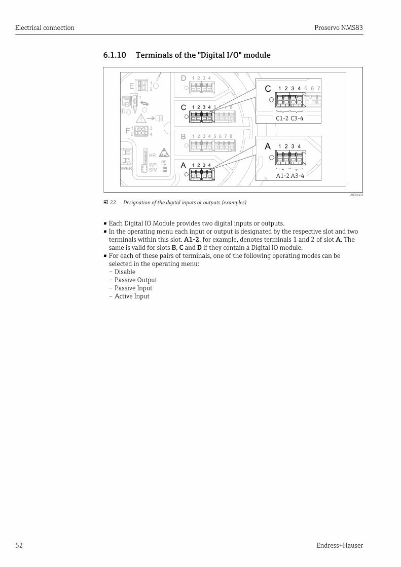
22 Designation of the digital inputs or outputs (examples)
• Each Digital IO Module provides two digital inputs or outputs.• In the operating menu each input or output is designated by the respective slot and two
terminals within this slot. A1-2, for example, denotes terminals 1 and 2 of slot A. Thesame is valid for slots B, C and D if they contain a Digital IO module.
• For each of these pairs of terminals, one of the following operating modes can beselected in the operating menu:– Disable– Passive Output– Passive Input– Active Input

Proservo NMS83 Electrical connection
Endress+Hauser 53
6.2 Connecting requirements
6.2.1 Cable specification
Terminals
Terminal Wire cross section
Signal and power supply• Spring terminals (NMx8x-xx1...)• Screw terminals (NMx8x-xx2...)
0.2 to 2.5 mm2 (24 to 13 AWG)
Ground terminal in the terminal compartment max. 2.5 mm2 (13 AWG)
Ground terminal at the housing max. 4 mm2 (11 AWG)
Power supply lineStandard device cable is sufficient for the power line.
HART communication line• Standard device cable is sufficient if only the analog signal is used.• Shielded cable is recommended if using the HART protocol. Observe the grounding
concept of the plant.
Modbus communication line• Observe the cable conditions from the TIA-485-A, Telecommunications Industry
Association.• Additional conditions: Use shielded cable.
V1 communication line• Two wire (twisted pair) screened or un-screened cable• Resistance in one cable: ≤ 120 Ω• Capacitance between lines: ≤ 0.3 µF

Electrical connection Proservo NMS83
54 Endress+Hauser
6.3 Ensuring the degree of protectionTo guarantee the specified degree of protection, carry out the following steps after theelectrical connection:
1. Check that the housing seals are clean and fitted correctly. Dry, clean or replace theseals if necessary.
2. Tighten all housing screws and screw covers.
3. Firmly tighten the cable glands.
4. To ensure that moisture does not enter the cable entry, route the cable so that itloops down before the cable entry ("water trap").
A0013960
5. Insert blind plugs appropriate for the safety rating of the device (e.g. Ex d/XP).
6.4 Post-connection check
m Are cables or the device undamaged (visual inspection)?
m Do the cables comply with the requirements?
m Do the cables have adequate strain relief?
m Are all cable glands installed, firmly tightened and correctly sealed?
m Does the supply voltage match the specifications on the transmitter nameplate?
m Is the terminal assignment correct → 38?
m If required: Is the protective earth connected correctly ?
mIf supply voltage is present: Is the device ready for operation and do values appear on the displaymodule?
m Are all housing covers installed and firmly tightened?
m Is the securing clamp tightened correctly?
Proservo NMS83 Operability
Endress+Hauser 55
7 Operability
7.1 Overview of the operation optionsThe device is operated via an operating menu → 56. This menu can be accessed bythe following interfaces:
• The display and operating module at the device or the remote display and operatingmodule DKX001 (→ 58).
• FieldCare connected through the service interface in the terminal compartment of thedevice (→ 71).
• FieldCare connected through Tankvision Tank Scanner NXA820 (remote operation;→ 72).
• FieldCare connected through Commubox FXA195 (→ 149) to a HART interface ofthe device.
Confirm that the servo motor stops before changing parameters for safety use.
Operability Proservo NMS83
56 Endress+Hauser
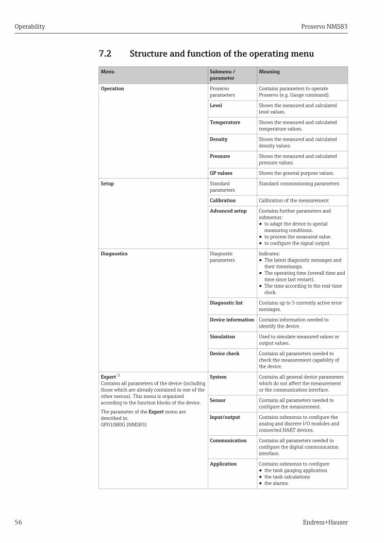
7.2 Structure and function of the operating menu
Menu Submenu /parameter
Meaning
Operation Proservoparameters
Contains parameters to operateProservo (e.g. Gauge command).
Level Shows the measured and calculatedlevel values.
Temperature Shows the measured and calculatedtemperature values.
Density Shows the measured and calculateddensity values.
Pressure Shows the measured and calculatedpressure values.
GP values Shows the general purpose values.
Setup Standardparameters
Standard commissioning parameters
Calibration Calibration of the measurement
Advanced setup Contains further parameters andsubmenus:• to adapt the device to special
measuring conditions.• to process the measured value.• to configure the signal output.
Diagnostics Diagnosticparameters
Indicates:• The latest diagnostic messages and
their timestamps.• The operating time (overall time and
time since last restart).• The time according to the real-time
clock.
Diagnostic list Contains up to 5 currently active errormessages.
Device information Contains information needed toidentify the device.
Simulation Used to simulate measured values oroutput values.
Device check Contains all parameters needed tocheck the measurement capability ofthe device.
Expert 1)
Contains all parameters of the device (includingthose which are already contained in one of theother menus). This menu is organizedaccording to the function blocks of the device.
The parameter of the Expert menu aredescribed in:GP01080G (NMS83)
System Contains all general device parameterswhich do not affect the measurementor the communication interface.
Sensor Contains all parameters needed toconfigure the measurement.
Input/output Contains submenus to configure theanalog and discrete I/O modules andconnected HART devices.
Communication Contains all parameters needed toconfigure the digital communicationinterface.
Application Contains submenus to configure• the tank gauging application• the tank calculations• the alarms.

Proservo NMS83 Operability
Endress+Hauser 57
Menu Submenu /parameter
Meaning
Tank values Shows measured and calculated tankvalues
Diagnostics Contains all parameters needed todetect and analyze operational errors.
1) On entering the "Expert" menu, an access code is always requested. If a customer specific access code hasnot been defined, "0000" has to be entered.
Operability Proservo NMS83
58 Endress+Hauser
7.3 Access to the operating menu via the local or remotedisplay and operating module.
• Operating via the remote display and operating module DKX001 (→ 39) or thelocal display and operating module at the device are equivalent.
• The measured value is indicated on the DKX001 and on the local display andoperating module simulataneously.
• The operating menu cannot be accessed on both modules at the same time. If theoperating menu is entered in one of these modules, the other module isautomatically locked. This locking remains active until the menu is closed in thefirst module (back to measured value display).
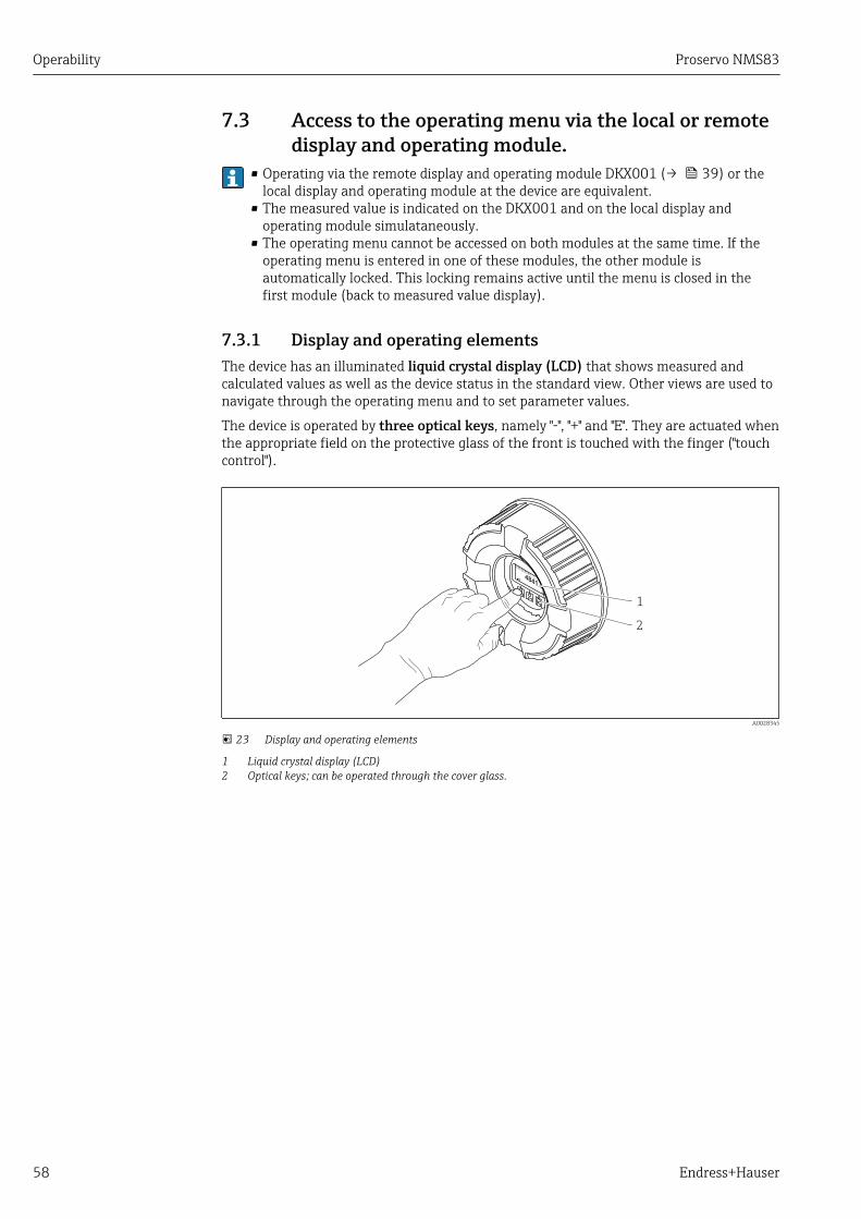
7.3.1 Display and operating elementsThe device has an illuminated liquid crystal display (LCD) that shows measured andcalculated values as well as the device status in the standard view. Other views are used tonavigate through the operating menu and to set parameter values.
The device is operated by three optical keys, namely "-", "+" and "E". They are actuated whenthe appropriate field on the protective glass of the front is touched with the finger ("touchcontrol").
XX
XX
XX
X
X
X
mm
1
2
A0028345
23 Display and operating elements
1 Liquid crystal display (LCD)2 Optical keys; can be operated through the cover glass.
Proservo NMS83 Operability
Endress+Hauser 59
7.3.2 Standard view (measured value display)
X X X X X X XX X
5
2
8
1
3
6
mm
4841.00
Level bal.
F
4
7
#
A0028702
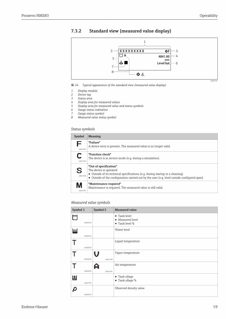
24 Typical appearance of the standard view (measured value display)
1 Display module2 Device tag3 Status area4 Display area for measured values5 Display area for measured value and status symbols6 Gauge status indication7 Gauge status symbol8 Measured value status symbol
Status symbols
Symbol Meaning
A0013956
"Failure"A device error is present. The measured value is no longer valid.
A0013959
"Function check"The device is in service mode (e.g. during a simulation).
A0013958
"Out of specification"The device is operated:• Outside of its technical specifications (e.g. during startup or a cleaning)• Outside of the configuration carried out by the user (e.g. level outside configured span)
A0013957
"Maintenance required"Maintenance is required. The measured value is still valid.
Measured value symbols
Symbol 1 Symbol 2 Measured value
A0028148
• Tank level• Measured level• Tank level %
A0028149
Water level
A0028528
Liquid temperature
A0028528 A0027990
Vapor temperature
A0028528 A0027991
Air temperature
A0027993
• Tank ullage• Tank ullage %
A0028150
Observed density value
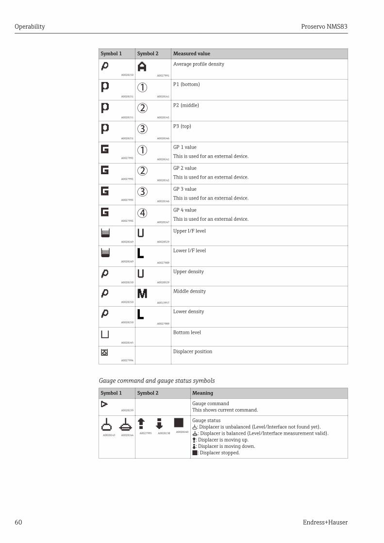
Operability Proservo NMS83
60 Endress+Hauser
Symbol 1 Symbol 2 Measured value
A0028150 A0027991
Average profile density
A0028151
1 A0028141
P1 (bottom)
A0028151
2 A0028142
P2 (middle)
A0028151
3 A0028146
P3 (top)
A0027992
1 A0028141
GP 1 value
This is used for an external device.
A0027992
2 A0028142
GP 2 value
This is used for an external device.
A0027992
3 A0028146
GP 3 value
This is used for an external device.
A0027992
4 A0028147
GP 4 value
This is used for an external device.
A0028149 A0028529
Upper I/F level
A0028149 A0027989
Lower I/F level
A0028150 A0028529
Upper density
A0028150 A0013957
Middle density
A0028150 A0027989
Lower density
A0028145
Bottom level
A0027994
Displacer position
Gauge command and gauge status symbols
Symbol 1 Symbol 2 Meaning
A0028139
Gauge commandThis shows current command.
A0028143 A0028144 A0027995 A0028138 A0028140
Gauge status: Displacer is unbalanced (Level/Interface not found yet).: Displacer is balanced (Level/Interface measurement valid).
: Displacer is moving up.: Displacer is moving down.: Displacer stopped.
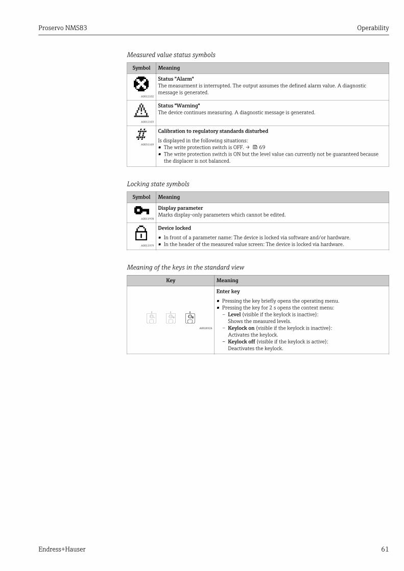
Proservo NMS83 Operability
Endress+Hauser 61
Measured value status symbols
Symbol Meaning
A0012102
Status "Alarm"The measurment is interrupted. The output assumes the defined alarm value. A diagnosticmessage is generated.
A0012103
Status "Warning"The device continues measuring. A diagnostic message is generated.
A0031169
Calibration to regulatory standards disturbed
Is displayed in the following situations:• The write protection switch is OFF. → 69• The write protection switch is ON but the level value can currently not be guaranteed because
the displacer is not balanced.
Locking state symbols
Symbol Meaning
A0011978
Display parameterMarks display-only parameters which cannot be edited.
A0011979
Device locked
• In front of a parameter name: The device is locked via software and/or hardware.• In the header of the measured value screen: The device is locked via hardware.
Meaning of the keys in the standard view
Key Meaning
A0028326
Enter key
• Pressing the key briefly opens the operating menu.• Pressing the key for 2 s opens the context menu:
– Level (visible if the keylock is inactive):Shows the measured levels.
– Keylock on (visible if the keylock is inactive):Activates the keylock.
– Keylock off (visible if the keylock is active):Deactivates the keylock.
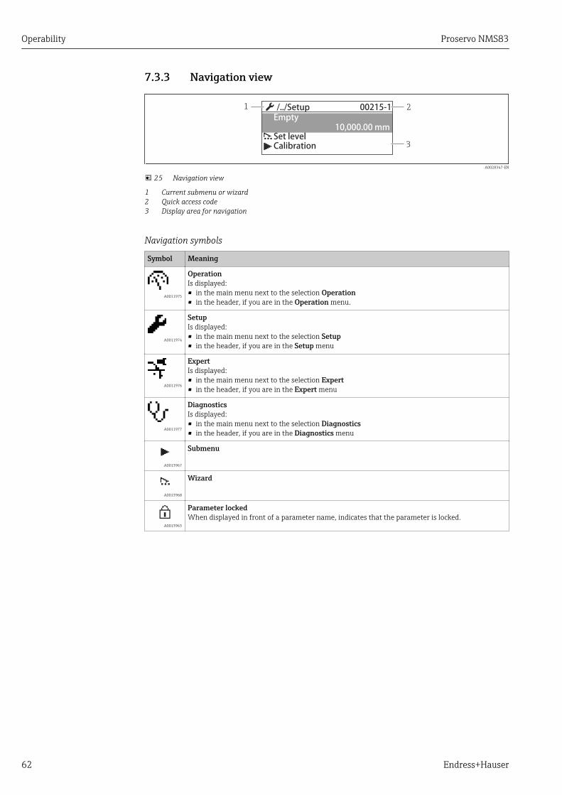
Operability Proservo NMS83
62 Endress+Hauser
7.3.3 Navigation view
3
1 2/../Setup 00215-1
10,000.00 mmEmpty
Set levelCalibration
A0028347-EN
25 Navigation view
1 Current submenu or wizard2 Quick access code3 Display area for navigation
Navigation symbols
Symbol Meaning
A0011975
OperationIs displayed:• in the main menu next to the selection Operation• in the header, if you are in the Operation menu.
A0011974
SetupIs displayed:• in the main menu next to the selection Setup• in the header, if you are in the Setup menu
A0011976
ExpertIs displayed:• in the main menu next to the selection Expert• in the header, if you are in the Expert menu
A0011977
DiagnosticsIs displayed:• in the main menu next to the selection Diagnostics• in the header, if you are in the Diagnostics menu
A0013967
Submenu
A0013968
Wizard
A0013963
Parameter lockedWhen displayed in front of a parameter name, indicates that the parameter is locked.

Proservo NMS83 Operability
Endress+Hauser 63
Meaning of the keys in the navigation view
Key Meaning
A0028324
Minus keyMoves the selection bar upwards in a picklist.
A0028325
Plus keyMoves the selection bar downwards in a picklist.
A0028326
Enter key
• Pressing the key briefly opens the selected menu, submenu orparameter.
• For parameters: Pressing the key for 2 s opens the help text for thefunction of the parameter (if present).
A0028327
Escape key combination (press keys simultaneously)
• Pressing the keys briefly– Exits the current menu level and takes you to the next higher level.– If help text is open, closes the help text of the parameter.
• Pressing the keys for 2 s returns you to the measured value display("standard view").

Operability Proservo NMS83
64 Endress+Hauser
7.3.4 Wizard view
2
1
0 mm
5000.0 mm
/../Set level
Level
Set level
A0028350-EN
26 Wizard view on the display module
1 Current wizard2 Display area for navigation
Wizard navigation symbols
Symbol Meaning
A0013972
Parameters within a wizard
A0013978
Switches to the previous parameter.
A0013976
Confirms the parameter value and switches to the next parameter.
A0013977
Opens the editing view of the parameter.
In the wizard view the meaning of the keys is indicated by the navigation symboldirectly above the respective key (softkey functionality).

Proservo NMS83 Operability
Endress+Hauser 65
7.3.5 Numeric editor
2
1
3 40 1 2
95 6 87
20
A0028341
27 Numeric editor on the display module
1 Display area of the entered value2 Input mask
Symbol Meaning
…0
9 A0013998
Selection of numbers from 0 to 9.
.
A0016619
Inserts decimal separator at the input position.
–
A0016620
Inserts minus sign at the input position.
A0013985
Confirms selection.
A0016621
Moves the input position one position to the left.
A0013986
Exits the input without applying the changes.
A0014040
Clears all entered characters.
Meaning of the keys in the numeric editor
Key Meaning
A0028324
Minus keyIn the input mask, moves the selection bar to the left (backwards).
A0028325
Plus keyIn the input mask, moves the selection bar to the right (forwards).
A0028326
Enter key
• Pressing the key briefly adds the selected number to the currentdecimal place or carries out the selected action.
• Pressing the key for 2 s confirms the edited parameter value.
A0028327
Escape key combination (press keys simultaneously)Closes the text or numeric editor without applying changes.

Operability Proservo NMS83
66 Endress+Hauser
7.3.6 Text editor
2
1
A0028342
28 Text editor on the display module
1 Display area of the entered text2 Input mask
Text editor symbols
Symbol Meaning
XYZ
ABC_…
A0013997
Selection of letters from A to Z
Aa1 A0013981
Toggle• Between upper-case and lower-case letters• For entering numbers• For entering special characters
A0013985
Confirms selection.
A0013987
Switches to the selection of the correction tools.
A0013986
Exits the input without applying the changes.
A0014040
Clears all entered characters.
Correction symbols under
A0013989
Clears all entered characters.
A0013991
Moves the input position one position to the right.
A0013990
Moves the input position one position to the left.
A0013988
Deletes one character immediately to the left of the input position.

Proservo NMS83 Operability
Endress+Hauser 67
Meaning of the keys in the text editor
Key Meaning
A0028324
Minus keyIn the input mask, moves the selection bar to the left (backwards).
A0028325
Plus keyIn the input mask, moves the selection bar to the right (forwards).
A0028326
Enter key
• Pressing the key briefly– Opens the selected group.– Carries out the selected action.
• Pressing the key for 2 s confirms the edited parameter value.
A0028327
Escape key combination (press keys simultaneously)Closes the text or numeric editor without applying changes.
7.3.7 Keypad lock
Automatic keypad lockOperation via the local display is automatically locked:• after a start-up or restart of the device.• if the device has not been operated via the display for > 1 minute.
When attempting to access the operating menu while the keylock is enabled, theKeylock on message appears.
Disabling the keypad lock1. The keylock is enabled.
Press for at least 2 seconds. A context menu appears.
2. Select Keylock off from the context menu. The keylock is disabled.
Manual activation of the keypad lockAfter commissioning of the device the keypad lock can be activated manually.
1. The device is in the measured value display.Press for at least 2 seconds. A context menu appears.
2. Select Keylock on from the context menu. The keylock is enabled.
Operability Proservo NMS83
68 Endress+Hauser
7.3.8 Access code and user roles
Meaning of the access codeAn access code can be defined in order to distinguish between the following user roles:
User role Definition
Maintenance • Knows the access code.• Has write access to all parameters (except service parameters).
Operator • Doesn't know the access code.• Has write access to only a few parameters.
• The description of parameters states which role is needed at least for read and writeaccess to each parameter.
• The current user role is indicated by the Access status display parameter.• If the access code is "0000", every user is in the Maintenance role. This is the
default setting on delivery of the device.
Defining an access code1. Navigate to: Setup → Advanced setup → Administration → Define access code
→ Define access code
2. Enter the intended access code (max. 4 digits).
3. Repeat the same code in the Confirm access code parameter. The user is in the Operator role. The -symbol appears in front of all write-
protected parameters.
Switching to the "Maintenance" roleIf the -symbol appears on the local display in front of a parameter, the parameter iswrite-protected because the user is in the Operator role. To switch to the Maintenancerole, proceed as follows:
1. Press . The input prompt for the access code appears.
2. Enter the access code. The user is in the Maintenance role. The -symbol in front of the parameters
disappears; all previously write-protected parameters are now re-enabled.
Switching back to the "Operator" role automaticallyThe user automatically switches back to the Operator role:• if no key is pressed for 10 minutes in the navigation and editing mode.• 60 s after going back from the navigation and editing mode to the standard view
(measured value display).

Proservo NMS83 Operability
Endress+Hauser 69
7.3.9 Write protection switchThe operating menu can be locked by a hardware switch in the connection compartment.In this locking state W&M related parameters are read only.
HR
WPon
SIMA 1 2
3 mm
2.5 Nm (1.84 lbf ft)
A0028693
1. Loosen the securing clamp.
2. Unscrew the housing cover.
3. Pull out the display module with a gentle rotation movement.
4. Using a flat blade screwdriver or a similar tool, set the write protection switch (WP)into the desired position. ON: operating menu is locked; OFF: operating menu isunlocked.
5. Put the display module onto the connection compartment, screw the cover closed andtighten the securing clamp.
To avoid acces to the write protection switch, the cover of the connectioncompartment can be secured by a lead seal.
A0033286
The display module can be attached to the edge of the electronics compartment. Thismakes it easier to access the lock switch.

Operability Proservo NMS83
70 Endress+Hauser
A0033458
A0029471
29 NMS83: Display module attached to the edge of the terminal compartment
Indication of the locking state
X X X X X X XX X
20.50XXXX
A0015870
30 Write protection symbol in the header of the display
Write protection via locking switch is indicated as follows:• Locking status (→ 191) = Hardware locked• appears in the header of the display.

Proservo NMS83 Operability
Endress+Hauser 71
7.4 Access to the operating menu via the serviceinterface and FieldCare
2
3
CDI1
A0028871
31 Operation via service interface
1 Service interface (CDI = Endress+Hauser Common Data Interface)2 Commubox FXA2913 Computer with "FieldCare" operating tool and "CDI Communication FXA291" COM DTM
The "Save/Restore" functionAfter a device configuration has been saved to a computer and restored to the deviceusing the Save/Restore function of FieldCare, the device must be restarted by thefollowing setting:Setup → Advanced setup → Administration → Device reset = Restart device.This ensures correct operation of the device after the restore.
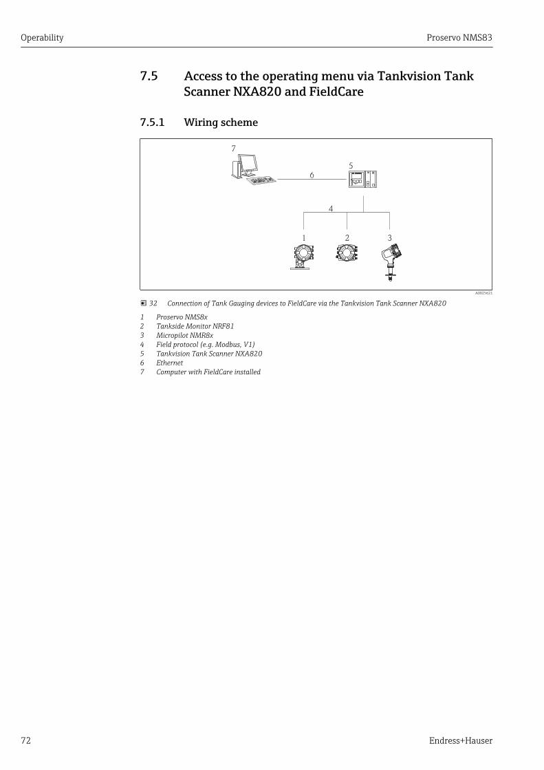
Operability Proservo NMS83
72 Endress+Hauser
7.5 Access to the operating menu via Tankvision TankScanner NXA820 and FieldCare
7.5.1 Wiring scheme
NXA820
5
6
4
1 2 3
7
A0025621
32 Connection of Tank Gauging devices to FieldCare via the Tankvision Tank Scanner NXA820
1 Proservo NMS8x2 Tankside Monitor NRF813 Micropilot NMR8x4 Field protocol (e.g. Modbus, V1)5 Tankvision Tank Scanner NXA8206 Ethernet7 Computer with FieldCare installed
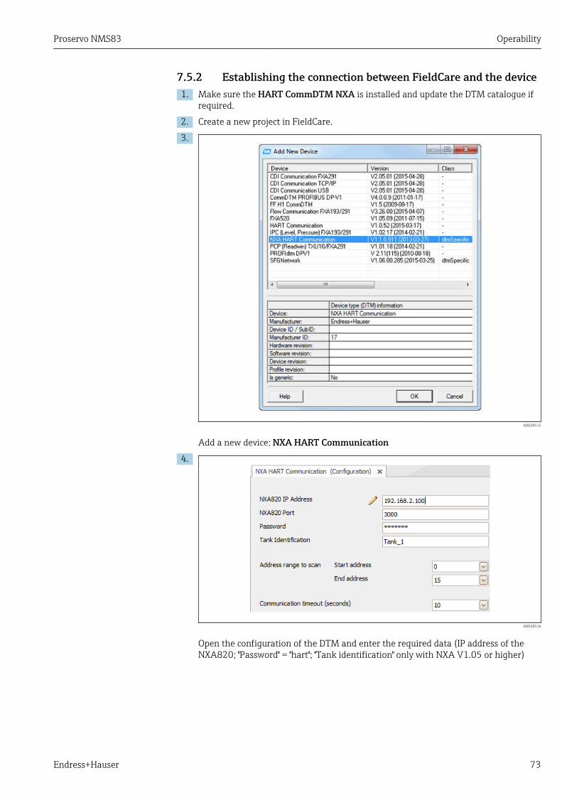
Proservo NMS83 Operability
Endress+Hauser 73
7.5.2 Establishing the connection between FieldCare and the device1. Make sure the HART CommDTM NXA is installed and update the DTM catalogue if
required.
2. Create a new project in FieldCare.
3.
A0028515
Add a new device: NXA HART Communication4.
A0028516
Open the configuration of the DTM and enter the required data (IP address of theNXA820; "Password" = "hart"; "Tank identification" only with NXA V1.05 or higher)

Operability Proservo NMS83
74 Endress+Hauser
5.
A0028517
Select Create network from the context menu. The device is detected and the DTM is assigned.
6.
A0032427
The device can be configured.
The "Save/Restore" functionAfter a device configuration has been saved to a computer and restored to the deviceusing the Save/Restore function of FieldCare, the device must be restarted by thefollowing setting:Setup → Advanced setup → Administration → Device reset = Restart device.This ensures correct operation of the device after the restore.
Proservo NMS83 System integration
Endress+Hauser 75
8 System integration
8.1 Overview of the Device Description files (DTM)To integrate the device via HART into FieldCare, a Device Description file (DTM) accordingto the following specification is required:
Manufacturer ID 0x11
Device type (NMS8x) 0x112D
HART specification 7.0
DD files For information and files see:www.endress.com

Commissioning Proservo NMS83
76 Endress+Hauser
9 Commissioning
9.1 Terms related to tank measurement
4
13
A
B
C
D
E
F
G5
H
1
2
14
15
16
17
10
1112
6789
3
A0033283
33 Terms concerning NMS8x installation (e.g. NMS81)
A Liquid levelB Upper interfaceC Lower interfaceD Gas phaseE Upper phaseF Middle phaseG Lower phaseH Tank bottom1 Gauge reference height2 Empty3 Datum plate4 Tank ullage5 Tank level6 Tank reference height7 High stop level8 Displacer position9 Standby level10 Upper interface level11 Lower interface level12 Low stop level13 Dipping reference

Proservo NMS83 Commissioning
Endress+Hauser 77
14 Mechanical stop15 Slow hoist zone16 Distance17 Reference position
9.2 Initial settingsDepending on NMS8x specification, some of the initial settings described below may notbe required.
9.2.1 Setting the display language
Setting the display language via the display module1. While in the standard view (→ 59), press "E". If required, select Keylock off from
the context menu and press "E" again. The Language parameter appears.
2. Open the Language parameter and select the display language.
Setting the display language via an operating tool (e.g. FieldCare)1. Navigate to: Setup → Advanced setup → Display → Language
2. Select the display language.
This setting only affects the language on the display module. To set the language inthe operating tool use the language setting functionality of FieldCare or DeviceCare,respectively.
9.2.2 Setting the real-time clock
Setting the real-time clock via the display module1. Navigate to: Setup → Advanced setup → Date / time → Set date
2. Use the following parameters to set the the real-time clock to the current date andtime: Year, Month, Day, Hour, Minutes.
Setting the real-time clock via an operating tool (e.g. FieldCare)1. Navigate to: Setup → Advanced setup → Date / time
2.
Go to the Set date parameter and select the Start option.
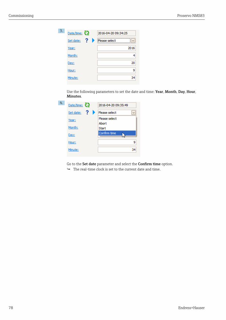
Commissioning Proservo NMS83
78 Endress+Hauser
3.
Use the following parameters to set the date and time: Year, Month, Day, Hour,Minutes.
4.
Go to the Set date parameter and select the Confirm time option. The real-time clock is set to the current date and time.

Proservo NMS83 Commissioning
Endress+Hauser 79
9.3 CalibrationAfter installing or replacing NMS8x or its parts (sensor module, detector unit, wire drum,or measuring wire), several calibration steps are required. All calibration steps may not berequired, depending on whether the device is being installed, adjusted, or replaced (seetable below).
Type of installation/replacement Calibration step
Sensor calibration Reference calibration Drum calibration
All-in one Not required Not required Not required
Displacer shipped separately Required Required Required
Displacer installation throughcalibration window
Required Required Required
Replacement/maintenance
Drum Required Required Required
Displacer Not required Required Required
Sensor module Not required Required Required
Detector unit Required Required Required
9.3.1 Verification of displacer and wire drumPrior to installation of NMS8x, confirm that all of the following data of the displacer andthe wire drum on the nameplate match with those programmed into the device.
Parameters to be confirmed
Parameters Navigate to:
Displacer diameter Setup → Advanced setup → Sensor config → Displacer → Displacer diameter
Displacer weight Setup → Advanced setup → Sensor config → Displacer → Displacer weight
Displacer volume Setup → Advanced setup → Sensor config → Displacer → Displacer volume
Displacer balance volume Setup → Advanced setup → Sensor config → Displacer → Displacer balancevolume
Drum circumference Setup → Advanced setup → Sensor config → Wiredrum
Wire weight Expert → Sensor → Sensor config → Wiredrum → Wire weight

Commissioning Proservo NMS83
80 Endress+Hauser
Data verification
Data verification procedure1. Check the displacer diameter, weight, volume, and balance volume for the Displacer
diameter parameter, the Displacer weight parameter, the Displacer volumeparameter, and the Displacer balance volume parameter.
2. Check the drum circumference and wire weight for the Drum circumferenceparameter and Wire weight parameter.
This completes the data verification procedure.
NM
S8
Dis
pla
cer
/../Displacer 08010-1
256.6g
Displacer diamet
Displacer weight
Displacer volume
316L50ml70.8ml141.6
g256.6
ØBVDVDm
Ser.no.: 12345678901Spare part-no.: 712xxxxx
mm302.xxxCir.
NM
S8
Wire
dru
m
1.35g/10mHNBR
28 m
WireWgt.O-Ring
RangeSpare part-no.: 712xxxxxSer.no.: 12345678901
A0029572
34 Data verification
9.3.2 Move displacerThe move displacer operation is optional and can be used to change the current position ofthe displacer in order to perform the calibration steps more easily.
1. Make sure that the wire drum stopper has been removed.
2. Navigate to: Setup → Calibration → Move displacer → Move distance
3. Input the relative moving distance for the Move distance parameter.
4. Select the Move down option or the Move up option
5. Select the Yes.
This completes move displacer commands procedure.

Proservo NMS83 Commissioning
Endress+Hauser 81
A0027996
35 Move displacer

Commissioning Proservo NMS83
82 Endress+Hauser
9.3.3 Sensor calibrationSensor calibration adjusts the weight measurement of the detector unit. The calibrationconsists of three steps as follows.
• ADC zero calibration• ADC offset calibration• ADC span calibration
For the ADC offset weight calibration, either 0 g or an offset weight (0 to 100 g) can beused.
Using an offset weight other than 0 g is recommended for density measurement.
mS
mO2
mz
m
B
mO1
A0029472
36 Concept of sensor calibration
m Weight of displacerB Binary value of AD-ConvertermS Span weightmo1 Offset weight in case of 0 to 100 g (50 g is recommended.)mo2 Offset weight in case of 0 gmz Zero weight
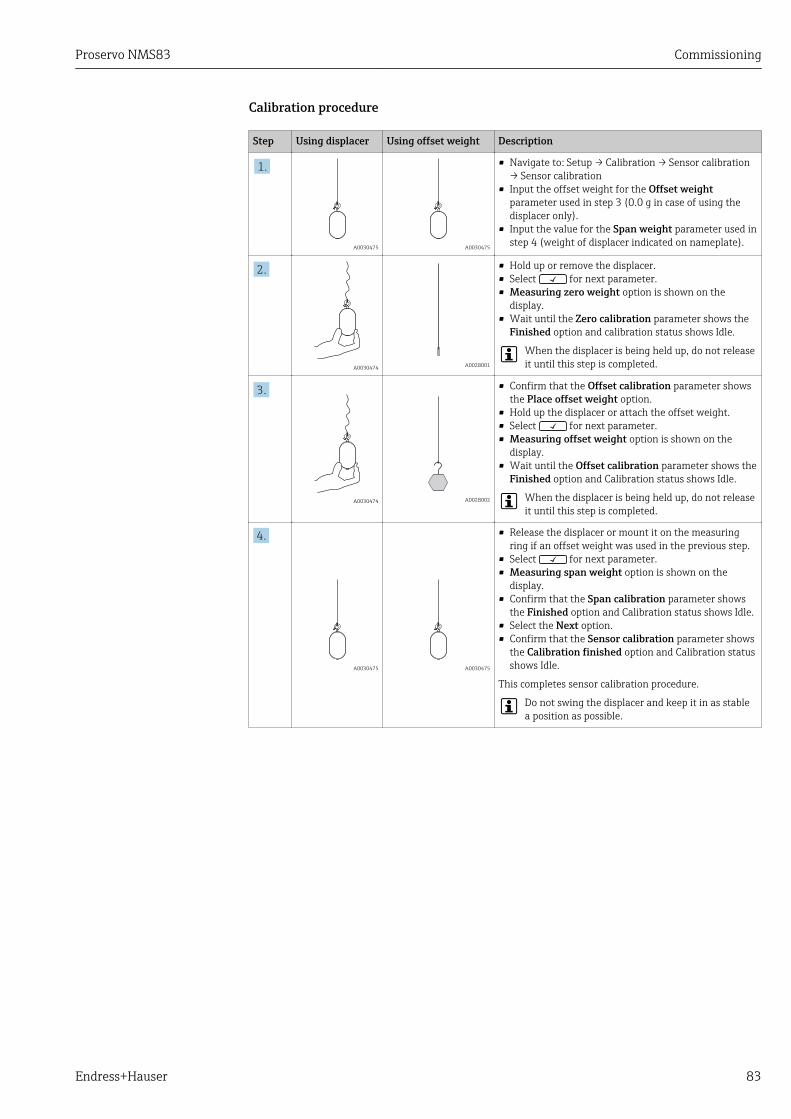
Proservo NMS83 Commissioning
Endress+Hauser 83
Calibration procedure
Step Using displacer Using offset weight Description
1.
A0030475 A0030475
• Navigate to: Setup → Calibration → Sensor calibration→ Sensor calibration
• Input the offset weight for the Offset weightparameter used in step 3 (0.0 g in case of using thedisplacer only).
• Input the value for the Span weight parameter used instep 4 (weight of displacer indicated on nameplate).
2.
A0030474 A0028001
• Hold up or remove the displacer.• Select for next parameter.• Measuring zero weight option is shown on the
display.• Wait until the Zero calibration parameter shows the
Finished option and calibration status shows Idle.
When the displacer is being held up, do not releaseit until this step is completed.
3.
A0030474 A0028002
• Confirm that the Offset calibration parameter showsthe Place offset weight option.
• Hold up the displacer or attach the offset weight.• Select for next parameter.• Measuring offset weight option is shown on the
display.• Wait until the Offset calibration parameter shows the
Finished option and Calibration status shows Idle.
When the displacer is being held up, do not releaseit until this step is completed.
4.
A0030475 A0030475
• Release the displacer or mount it on the measuringring if an offset weight was used in the previous step.
• Select for next parameter.• Measuring span weight option is shown on the
display.• Confirm that the Span calibration parameter shows
the Finished option and Calibration status shows Idle.• Select the Next option.• Confirm that the Sensor calibration parameter shows
the Calibration finished option and Calibration statusshows Idle.
This completes sensor calibration procedure.
Do not swing the displacer and keep it in as stablea position as possible.

Commissioning Proservo NMS83
84 Endress+Hauser
9.3.4 Reference calibrationThe reference calibration defines the zero distance position of the displacer from themechanical stop.
1. Navigate to: Setup → Calibration → Reference calibration → Reference calibration
2. Select the Start option
3. Check the reference position (e.g. 70 mm (2.76 in)). The reference position is preset prior to delivery.
4. Confirm that the displacer is correctly attached to the measuring wire.
5. The reference calibration starts automatically.
This completes the reference calibration.
1R
1.1. 2. 3.
A0028003
37 Reference calibration sequence
1 Mechanical stopR Reference position

Proservo NMS83 Commissioning
Endress+Hauser 85
9.3.5 Drum calibration1. Navigate to: Setup → Calibration → Drum calibration → Drum calibration
2. Ensure a distance of 500 mm (19.69 in) or more from the bottom of the displacer tothe liquid level.
3. Confirm that the displacer weight is correct for the Set high weight parameter.
4. Select the Start option. The drum calibration starts automatically.
The drum calibration records fifty points which will take approximately elevenminutes.
5. Select the No option as usual for the Make low table parameter. To make a low table for special applications, select the Yes and use 50 g weight.
This completes drum calibration procedure.
To cancel any calibration, press + simultaneously. If the drum calibration iscanceled while making the new table, the old table remains effective. If making a newtable fails due to an obstruction, NMS8x will not accept the new table and shows anerror message.
12
3…
50
A0029123
38 Making drum table

Commissioning Proservo NMS83
86 Endress+Hauser
9.3.6 Commissioning checkThis procedure is to confirm that all calibration steps have been completed appropriately.
1. Navigate to: Diagnostics → Device check → Commissioning check → Commissioningcheck
2. Select the Start option. Executing option is shown on the verify drum table.
3. Select the Next option.
4. Confirm that the Commissioning check wizard shows the Finished option.
5. Confirm that the Result drum check parameter is passed.
This completes the commissioning check procedure.
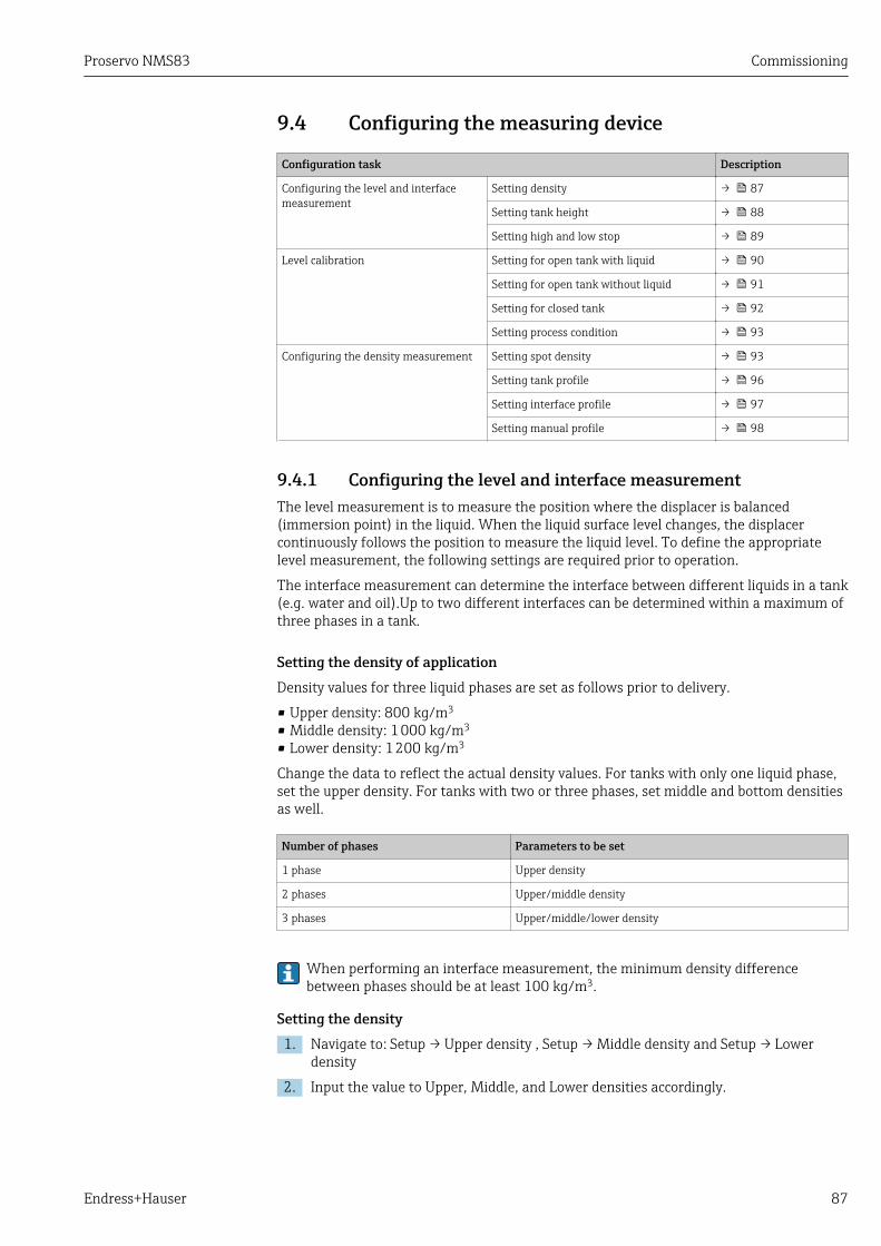
Proservo NMS83 Commissioning
Endress+Hauser 87
9.4 Configuring the measuring device
Configuration task Description
Configuring the level and interfacemeasurement
Setting density → 87
Setting tank height → 88
Setting high and low stop → 89
Level calibration Setting for open tank with liquid → 90
Setting for open tank without liquid → 91
Setting for closed tank → 92
Setting process condition → 93
Configuring the density measurement Setting spot density → 93
Setting tank profile → 96
Setting interface profile → 97
Setting manual profile → 98
9.4.1 Configuring the level and interface measurementThe level measurement is to measure the position where the displacer is balanced(immersion point) in the liquid. When the liquid surface level changes, the displacercontinuously follows the position to measure the liquid level. To define the appropriatelevel measurement, the following settings are required prior to operation.
The interface measurement can determine the interface between different liquids in a tank(e.g. water and oil).Up to two different interfaces can be determined within a maximum ofthree phases in a tank.
Setting the density of applicationDensity values for three liquid phases are set as follows prior to delivery.
• Upper density: 800 kg/m3
• Middle density: 1 000 kg/m3
• Lower density: 1 200 kg/m3
Change the data to reflect the actual density values. For tanks with only one liquid phase,set the upper density. For tanks with two or three phases, set middle and bottom densitiesas well.
Number of phases Parameters to be set
1 phase Upper density
2 phases Upper/middle density
3 phases Upper/middle/lower density
When performing an interface measurement, the minimum density differencebetween phases should be at least 100 kg/m3.
Setting the density1. Navigate to: Setup → Upper density , Setup → Middle density and Setup → Lower
density
2. Input the value to Upper, Middle, and Lower densities accordingly.
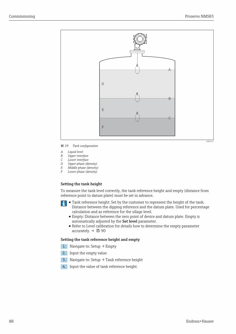
Commissioning Proservo NMS83
88 Endress+Hauser
A
B
C
D
E
F
A0029127
39 Tank configuration
A Liquid levelB Upper interfaceC Lower interfaceD Upper phase (density)E Middle phase (density)F Lower phase (density)
Setting the tank heightTo measure the tank level correctly, the tank reference height and empty (distance fromreference point to datum plate) must be set in advance.
• Tank reference height: Set by the customer to represent the height of the tank.Distance between the dipping reference and the datum plate. Used for percentagecalculation and as reference for the ullage level.
• Empty: Distance between the zero point of device and datum plate. Empty isautomatically adjusted by the Set level parameter.
• Refer to Level calibration for details how to determine the empty parameteraccurately. → 90
Setting the tank reference height and empty1. Navigate to: Setup → Empty
2. Input the empty value.
3. Navigate to: Setup → Tank reference height
4. Input the value of tank reference height.

Proservo NMS83 Commissioning
Endress+Hauser 89
1
3
2
54
A0028023
40 Tank height
1 High stop2 Low stop3 Datum plate4 Tank reference height5 Empty
Setting the high stop and low stopThe high stop and low stop determine the highest and lowest points of displacermovement. Set these data to the desired actual upper and lower limit values.
If the displacer should be able to determine a tank bottom that is below the datumplate, set the low stop to a negative value. To make sure that the displacer travels upto the reference position, set the high stop to a value greater than or equal to empty.
High stop and low stop setting procedure1. Navigate to: Setup → High stop level
2. Input the actual value for high stop.
3. Navigate to: Setup → Low stop level
4. Input the actual value for low stop.
This completes upper and lower stop setting procedure.

Commissioning Proservo NMS83
90 Endress+Hauser
9.4.2 Level calibrationThe following table shows the most likely options for setting the level calibration.
Open tank with liquid Open tank without liquid Closed tank
a
A0028865 A0029125 A0028875
Setting for an open tank with liquid
Level setting procedure1. Navigate to: Setup → Gauge command
2. Select the Level option for the Gauge command parameter. The displacer automatically searches for the point where it balances.
3. Wait until the displacer is balanced on the liquid.
4. Perform dipping to determine the liquid level (L) in the tank.
5. Navigate to: Setup → Set level
6. Input the determined level value for the Set level parameter.
The Set level parameter adjusts the Empty parameter to reflect the new level value.
This completes setting for open tank with liquid procedure.
a
1
L
A0028132
41 Set level for opened tank with liquid
1 DisplacerL Measured value

Proservo NMS83 Commissioning
Endress+Hauser 91
Setting for an open tank without liquidIf there is no liquid in the tank, the following procedure can be used to set the tank bottomor datum plate to 0 mm for the tank level.
Level setting procedure1. Navigate to: Operation → Gauge command → Gauge command
2. Select the Bottom level option to measure the tank bottom.
3. Navigate to: Operation → One-time command status
4. Wait until the Finished option is shown.
5. Navigate to: Operation → Level → Bottom level
6. Read the Bottom level parameter (Bv).
7. Navigate to: Setup → Empty
8. Read the actual empty value (Ea).
9. Calculate the new empty value using following formula. En = Ea - Bv - Z0
10. Input the calculated value for the Empty parameter.
Example: Ea = 28m, Bv = 10.5m, Z0 = 0.5m
En = 28m - 10.5m = 17m
A0029473
• The parameter Z0 defines the distance between the desired 0mm level value andthe physical tank bottom (if displacer measures the datum plate, Z0 = 0 mm (0 in)).
• Bottom level operation considers the immersion depth of the displacer in themeasurement.
This completes the level setting for open tank without liquid procedure.
Z0
2
1
En
Ea
Bv
A0028134
42 Open tank without liquid
1 Tank bottom2 Datum plateEa Initial empty settingBv Initial bottom levelEn New emptyZ0 Distance from tank bottom to datum plate
It is recommended to repeating the level calibration when there is liquid in the tank(→ 90).
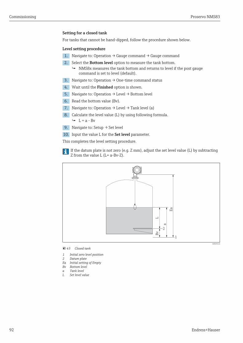
Commissioning Proservo NMS83
92 Endress+Hauser
Setting for a closed tankFor tanks that cannot be hand-dipped, follow the procedure shown below.
Level setting procedure1. Navigate to: Operation → Gauge command → Gauge command
2. Select the Bottom level option to measure the tank bottom. NMS8x measures the tank bottom and returns to level if the post gauge
command is set to level (default).
3. Navigate to: Operation → One-time command status
4. Wait until the Finished option is shown.
5. Navigate to: Operation → Level → Bottom level
6. Read the bottom value (Bv).
7. Navigate to: Operation → Level → Tank level (a)
8. Calculate the level value (L) by using following formula. L = a - Bv
9. Navigate to: Setup → Set level
10. Input the value L for the Set level parameter.
This completes the level setting procedure.
If the datum plate is not zero (e.g. Z mm), adjust the set level value (L) by subtractingZ from the value L (L= a-Bv-Z).
L
Ea
a
Bv
1
2
A0029124
43 Closed tank
1 Initial zero level position2 Datum plateEa Initial setting of EmptyBv Bottom levela Tank levelL Set level value
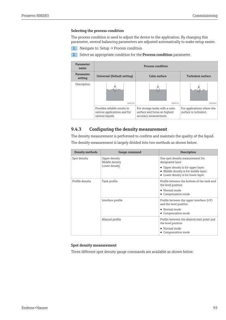
Proservo NMS83 Commissioning
Endress+Hauser 93
Selecting the process conditionThe process condition is used to adjust the device to the application. By changing thisparameter, several balancing parameters are adjusted automatically to make setup easier.
1. Navigate to: Setup → Process condition
2. Select an appropriate condition for the Process condition parameter.
Parametername Process condition
Parametersetting Universal (Default setting) Calm surface Turbulent surface
Description
A0029128 A0029129 A0028030
Provides reliable results invarious applications and forvarious liquids.
For storage tanks with a calmsurface and focus on highestaccuracy measurement.
For applications where thesurface is turbulent.
9.4.3 Configuring the density measurementThe density measurement is performed to confirm and maintain the quality of the liquid.
The density measurement is largely divided into two methods as shown below.
Density methods Gauge command Description
Spot density Upper densityMiddle densityLower density
One spot density measurement fordesignated layer
• Upper density is for upper layer.• Middle density is for middle layer.• Lower density is for lower layer.
Profile density Tank profile Profile between the bottom of the tank andthe level position
• Normal mode• Compensation mode
Interface profile Profile between the upper interface (I/F)and the level position
• Normal mode• Compensation mode
Manual profile Profile between the desired start point andthe level position
• Normal mode• Compensation mode
Spot density measurementThree different spot density gauge commands are available as shown below.
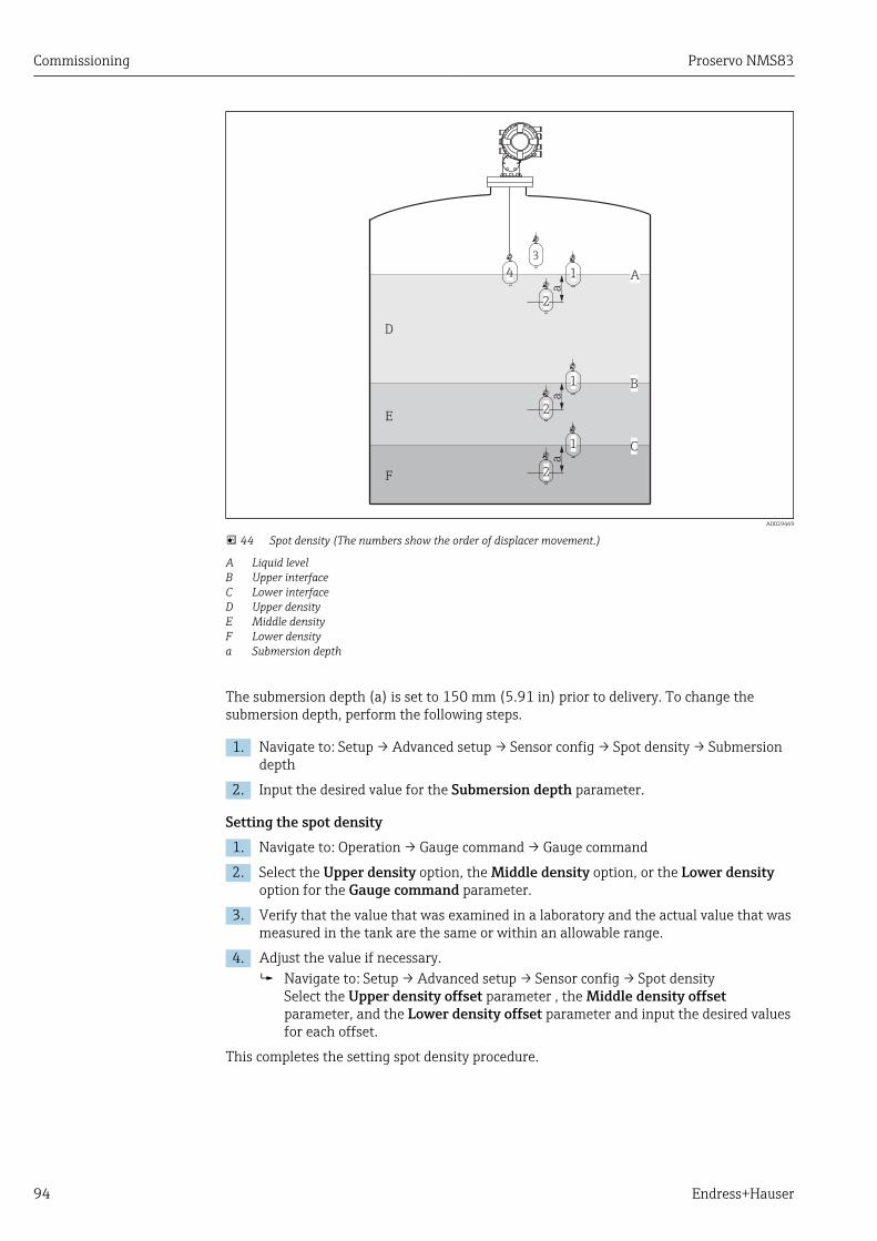
Commissioning Proservo NMS83
94 Endress+Hauser
A
D
E
B
C
F
a
1
2
3
4
a
1
2
a
1
2
A0029469
44 Spot density (The numbers show the order of displacer movement.)
A Liquid levelB Upper interfaceC Lower interfaceD Upper densityE Middle densityF Lower densitya Submersion depth
The submersion depth (a) is set to 150 mm (5.91 in) prior to delivery. To change thesubmersion depth, perform the following steps.
1. Navigate to: Setup → Advanced setup → Sensor config → Spot density → Submersiondepth
2. Input the desired value for the Submersion depth parameter.
Setting the spot density1. Navigate to: Operation → Gauge command → Gauge command
2. Select the Upper density option, the Middle density option, or the Lower densityoption for the Gauge command parameter.
3. Verify that the value that was examined in a laboratory and the actual value that wasmeasured in the tank are the same or within an allowable range.
4. Adjust the value if necessary. Navigate to: Setup → Advanced setup → Sensor config → Spot density
Select the Upper density offset parameter , the Middle density offsetparameter, and the Lower density offset parameter and input the desired valuesfor each offset.
This completes the setting spot density procedure.
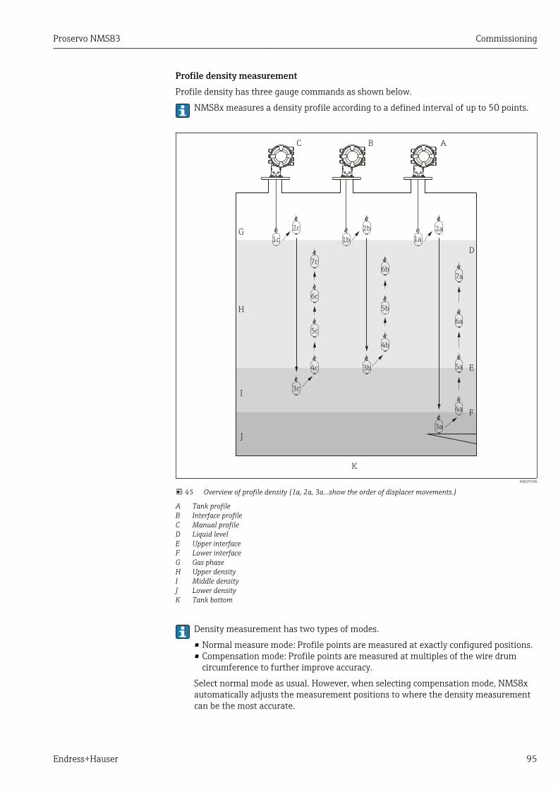
Proservo NMS83 Commissioning
Endress+Hauser 95
Profile density measurementProfile density has three gauge commands as shown below.
NMS8x measures a density profile according to a defined interval of up to 50 points.
ABC
1a
2a
3a
4a
5a
6a
7a
1b
2b
4b
6b
5b
1c
2c
3c
7c
6c
5c
4c 3b
D
E
F
G
H
I
J
K
A0029106
45 Overview of profile density (1a, 2a, 3a...show the order of displacer movements.)
A Tank profileB Interface profileC Manual profileD Liquid levelE Upper interfaceF Lower interfaceG Gas phaseH Upper densityI Middle densityJ Lower densityK Tank bottom
Density measurement has two types of modes.
• Normal measure mode: Profile points are measured at exactly configured positions.• Compensation mode: Profile points are measured at multiples of the wire drum
circumference to further improve accuracy.
Select normal mode as usual. However, when selecting compensation mode, NMS8xautomatically adjusts the measurement positions to where the density measurementcan be the most accurate.
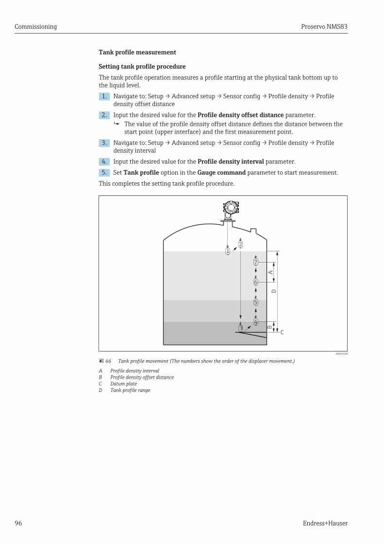
Commissioning Proservo NMS83
96 Endress+Hauser
Tank profile measurement
Setting tank profile procedureThe tank profile operation measures a profile starting at the physical tank bottom up tothe liquid level.
1. Navigate to: Setup → Advanced setup → Sensor config → Profile density → Profiledensity offset distance
2. Input the desired value for the Profile density offset distance parameter. The value of the profile density offset distance defines the distance between the
start point (upper interface) and the first measurement point.
3. Navigate to: Setup → Advanced setup → Sensor config → Profile density → Profiledensity interval
4. Input the desired value for the Profile density interval parameter.
5. Set Tank profile option in the Gauge command parameter to start measurement.
This completes the setting tank profile procedure.
2
3
5
6
7
AB
C
D
1
4
A0029108
46 Tank profile movement (The numbers show the order of the displacer movement.)
A Profile density intervalB Profile density offset distanceC Datum plateD Tank profile range

Proservo NMS83 Commissioning
Endress+Hauser 97
Interface profile measurement
Setting interface profile procedureThe interface profile operation measures a profile starting at the upper interface level upto the liquid level.
1. Navigate to: Setup → Advanced setup → Sensor config → Profile density → Profiledensity offset distance
2. Input the desired value for the Profile density offset distance parameter. The value of the profile density offset distance defines the distance between the
start point (upper interface profile) and the first measurement point.
3. Navigate to: Setup → Advanced setup → Sensor config → Profile density → Profiledensity interval
4. Input the desired value for the Profile density interval parameter.
5. Set Interface profile option in the Gauge command parameter to startmeasurement.
This completes the setting interface profile procedure.
2
3
4
A
C
B
1
5
6
A0029110
47 Interface profile movement (The numbers show the order of the displacer movement.)
A Profile density intervalB Profile density offset distanceC Tank profile range

Commissioning Proservo NMS83
98 Endress+Hauser
Manual profile measurement
Setting manual profile procedureThe manual profile operation measures a profile starting at a manually specified level upto the liquid level.
1. Navigate to: Setup → Advanced setup → Sensor config → Profile density → Manualprofile level
2. Input the desired value for the Manual profile level parameter.
3. Navigate to: Setup → Advanced setup → Sensor config → Profile density → Profiledensity offset distance For the manual profile, the level offset can be set to 0 so that the first point can
be measured at the manual profile level.
4. Input the desired value for the Profile density offset distance parameter. The value of the profile density offset distance defines the distance between the
start point (manual profile) and the first measurement point.
5. Navigate to: Setup → Advanced setup → Sensor config → Profile density → Profiledensity interval
6. Input the desired value for the Profile density interval parameter.
7. Set Manual profile option in the Gauge command parameter to start measurement.
This competes the setting manual profile.
12
3
4
6
7
A
C
B
D
5
A0029112
48 Manual profile movement (The numbers show the order of the displacer movement.)
A Profile density intervalB Profile density offset distanceC Manual profile rangeD Manual profile level

Proservo NMS83 Commissioning
Endress+Hauser 99
9.5 Configuring the tank gauging application
Configuration of the inputs: Description
HART inputs → 100
NMT532/539 connected via HART → 102
4-20mA inputs → 103
RTD input → 104
Digital inputs → 106
Configuration of the data processing in the device: Description
Linking input values to tank variables → 108
Tank calculation: Direct Level Measurement → 109
Tank calculation: Hybrid Tank Measurement System (HTMS) → 110
Tank calculation: Correction of the Hydrostatic Tank Deformation(HyTD)
→ 111
Tank calculation: Thermal Tank Shell Correction (CTSh) → 112
Alarms (limit evaluation) → 113
Configuration of the signal output: Description
4-20mA output → 114
HART slave + 4-20mA output → 115
Modbus → 117
V1 → 118
Digital outputs → 119

Commissioning Proservo NMS83
100 Endress+Hauser
9.5.1 Configuration of the HART inputs
Connecting and addressing HART devices
D
E
F
C
B
A
1
1
1
1 3
2
2 4
1
HR
CDI
WPon
SIM
2
2
3
3
4
4
1
1
2
2
3
3
4
4
5
5
6
6
7
7
8
8
POWER
i
B
B1-3 B4-8
1 2 3 4 5 6 7 8
C 1 2 3 4 5 6 7 8
C1-3 C4-8
A0032955
49 Possible terminals for HART loops
B Analog I/O module in slot B (availability depending on device version → 41)C Analog I/O module in slot C (availability depending on device version → 41)E HART Ex is output (available in all device versions)
HART devices must be configured and given a unique HART address in the range from1 to 15 via their own user interface before they are connected to the ProservoNMS8x 2). Make sure they are connected as defined by the terminal assignment→ 47. Devices with an address larger than 15 are not recognized by the Proservo.
Slot B or C: Setting the operating mode of the Analog I/O moduleThis section is not relevant for the HART Ex is output (Slot E). This output alwaysfunctions as a HART master for the connected HART slaves.
If HART devices are connected to an Analog I/O module (slot B or C in the terminalcompartment), this module must be configured as follows:
1. Navigate to the submenu of the respective Analog I/O module: Setup → Advancedsetup → Input/output → Analog I/O X1-3
2. Go to the Operating mode parameter (→ 205).
3. If only one HART device is connected to this loop:Select the HART master+4..20mA input option. In this case the 4-20mA signal canbe used in addition to the HART signal. For the configuration of the 4-20mA input:→ 103.
4. If up to 6 HART devices are connected to this loop:Select the HART master option.
2) The current software does not support HART devices with adress 0 (zero).

Proservo NMS83 Commissioning
Endress+Hauser 101
Defining the type of measured valueThis setting can be skipped for a connected Prothermo NMT5xx as the type ofmeasured value is automatically recognized by the Proservo NMS8x in this case.
• The measured values can only be used in the system if the unit of the assignedHART variable fits the type of measured value. The HART variable assigned toOutput temperature, for example, has to be in °C or °F.
• A HART variable with unit "%" can not be used for Output level. Instead, the HARTvariable must be in mm, m, ft or in.
The type of measured value must be specified for each HART variable (PV, SV, TV and QV).To do so, proceed as follows:
1. Navigate to: Setup → Advanced setup → Input/output → HART devices There is a submenu for each connected HART device.
2. For each device go to the corresponding submenu.
3. If the device measures a pressure:Go to the Output pressure parameter (→ 195) and specify which of the fourHART variables contains the measured pressure. Only a HART variable with apressure unit may be selected.
4. If the device measures a density:Go to the Output density parameter (→ 196) and specify which of the four HARTvariables contains the measured density. Only a HART variable with a density unitmay be selected.
5. If the device measures a temperature:Go to the Output temperature parameter (→ 196) and specify which of the fourHART variables contains the measured temperature. Only a HART variable with atemperature unit may be selected.
6. If the device measures the vapor temperature:Go to the Output vapor temperature parameter (→ 197) and specify which ofthe four HART variables contains the measured vapor temperature. Only a HARTvariable with a temperature unit may be selected.
7. If the device measures a level:Go to the Output level parameter (→ 197) and specify which of the four HARTvariables contains the measured level. Only a HART variable with a level unit (not "%")may be selected.
Disconnecting HART devicesWhen a HART device is disconnected from the device, it must also be logically removed asfollows:
1. Navigate to Setup → Advanced setup → Input/output → HART devices → Forgetdevice → Forget device
2. Select the HART device to be removed.
This procedure is also necessary if a defective device is exchanged.
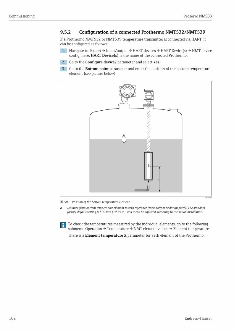
Commissioning Proservo NMS83
102 Endress+Hauser
9.5.2 Configuration of a connected Prothermo NMT532/NMT539If a Prothermo NMT532 or NMT539 temperature transmitter is connected via HART, itcan be configured as follows:
1. Navigate to: Expert → Input/output → HART devices → HART Device(s) → NMT deviceconfig; here, HART Device(s) is the name of the connected Prothermo.
2. Go to the Configure device? parameter and select Yes.
3. Go to the Bottom point parameter and enter the position of the bottom temperatureelement (see picture below).
a
A0030165
50 Position of the bottom temperature element
a Distance from bottom temperature element to zero reference (tank bottom or datum plate). The standardfactory default setting is 500 mm (19.69 in), and it can be adjusted according to the actual installation.
To check the temperatures measured by the individual elements, go to the followingsubmenu: Operation → Temperature → NMT element values → Element temperature
There is a Element temperature X parameter for each element of the Prothermo.

Proservo NMS83 Commissioning
Endress+Hauser 103
9.5.3 Configuration of the 4-20mA inputs
D
E
F
C
B
A
1
1
1
1 3
2
2 4
1
HR
CDI
WPon
SIM
2
2
3
3
4
4
1
1
2
2
3
3
4
4
5
5
6
6
7
7
8
8
POWER
i
B
B1-3 B4-8
1 2 3 4 5 6 7 8
C 1 2 3 4 5 6 7 8
C1-3 C4-8
A0032464
51 Possible locations of the Analog I/O modules, which can be used as a 4-20mA input. The order code of thedevice determines which of these modules is actually present → 41.
For each Analog I/O module to which a 4-20mA device is connected, proceed as follows:
1. Make sure the 4-20mA devices are connected as defined by the terminal assignment→ 47.
2. Navigate to the submenu of the respective Analog I/O module: Setup → Advancedsetup → Input/output → Analog I/O X1-3
3. Go to the Operating mode parameter (→ 205) and select 4..20mA input orHART master+4..20mA input.
4. Go to the Process variable parameter (→ 211) and specify which process variableis transmitted by the connected device.
5. Go to the Analog input 0% value parameter (→ 211) and define which value ofthe process variable corresponds to an input current of 4 mA (see diagram below).
6. Go to the Analog input 100% value parameter (→ 211) and define which valueof the process variable corresponds to an input current of 20 mA (see diagrambelow).
7. Go to the Process value parameter (→ 212) and check whether the indicatedvalue matches the actual value of the process variable.
4mA
1
20mA
0% 2 100%
I [mA]
A0029264
52 Scaling of the 4-20mA input to the process variable
1 Input value in mA2 Process value
The Analog I/O submenu contains additional parameters for a more detailedconfiguration of the Analog Input. For a description refer to : → 205

Commissioning Proservo NMS83
104 Endress+Hauser
9.5.4 Configuration of a connected RTD
D
E
F
C
B
A
1
1
1
1 3
2
2 4
1
HR
CDI
WPon
SIM
2
2
3
3
4
4
1 2 3 4 5 6 7 8
POWER
i
1 2 3 4 5 6 7 8
B
B1-3 B4-8
1 2 3 4 5 6 7 8
C 1 2 3 4 5 6 7 8
C1-3 C4-8
A0032465
53 Possible locations of the Analog I/O modules, to which an RTD can be connected. The order code of thedevice determines which of these modules is actually present → 41.
1. Make sure the RTD is connected as defined by the terminal assignment → 51.
2. Navigate to the submenu of the respective Analog I/O module: Setup → Advancedsetup → Input/output → Analog IP X4-8.
3. Go to the RTD type parameter (→ 199) and specify the type of the connectedRTD.
4.A CB
1 112 223 334 445 556 667 778 88
A0026371
54 RTD connection types
A 2 wire RTD connectionB 3 wire RTD connectionC 4 wire RTD connection
Go to the RTD connection type parameter (→ 200) and specify the type ofconnection of the RTD (2-, 3- or 4-wire).
5. Go to the Input value parameter (→ 202) and check whether the indicatedtemperature matches the actual temperature.
6. Go to the Minimum probe temperature parameter (→ 202) and specify theminimum approved temperature of the connected RTD.
7. Go to the Maximum probe temperature parameter (→ 202) and specify themaximum approved temperature of the connected RTD.
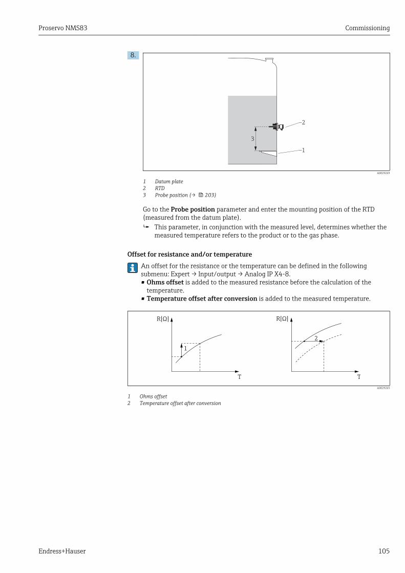
Proservo NMS83 Commissioning
Endress+Hauser 105
8.
2
1
3
A0029269
1 Datum plate2 RTD3 Probe position (→ 203)
Go to the Probe position parameter and enter the mounting position of the RTD(measured from the datum plate). This parameter, in conjunction with the measured level, determines whether the
measured temperature refers to the product or to the gas phase.
Offset for resistance and/or temperatureAn offset for the resistance or the temperature can be defined in the followingsubmenu: Expert → Input/output → Analog IP X4-8.• Ohms offset is added to the measured resistance before the calculation of the
temperature.• Temperature offset after conversion is added to the measured temperature.
R[ ]Ω R[ ]Ω
T T
1
2
A0029265
1 Ohms offset2 Temperature offset after conversion
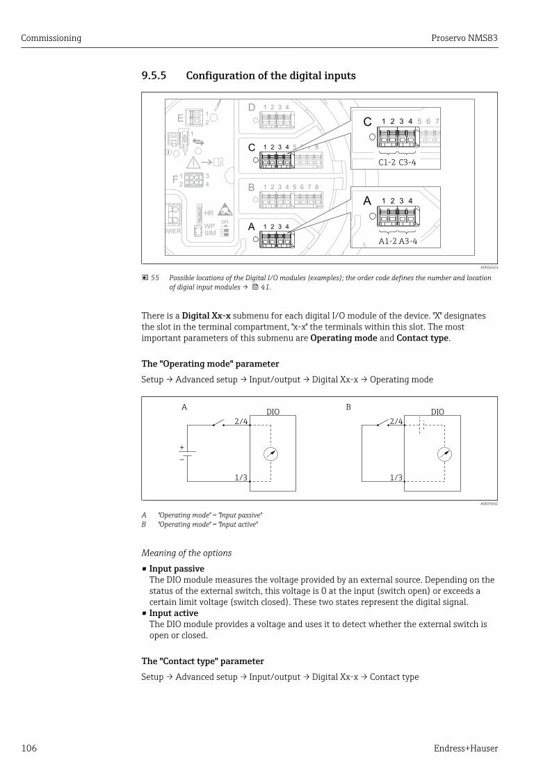
Commissioning Proservo NMS83
106 Endress+Hauser
9.5.5 Configuration of the digital inputs
D
E
F
C
B
A
1
1
1
1 3
2
2 4
1
HR
CDI
WPon
SIM
2
2
3
3
4
4
1
1
2
2
3
3
4
4
5
5
6
6
7
7
8
8
POWER
A 1 2 3 4
A1-2 A3-4
i
C 1 2 3 4 5 6 7
C1-2 C3-4
A0026424
55 Possible locations of the Digital I/O modules (examples); the order code defines the number and locationof digial input modules → 41.
There is a Digital Xx-x submenu for each digital I/O module of the device. "X" designatesthe slot in the terminal compartment, "x-x" the terminals within this slot. The mostimportant parameters of this submenu are Operating mode and Contact type.
The "Operating mode" parameterSetup → Advanced setup → Input/output → Digital Xx-x → Operating mode
DIO
2/4
+_
2/4
1/3 1/3
ADIO
B
A0029262
A "Operating mode" = "Input passive"B "Operating mode" = "Input active"
Meaning of the options
• Input passiveThe DIO module measures the voltage provided by an external source. Depending on thestatus of the external switch, this voltage is 0 at the input (switch open) or exceeds acertain limit voltage (switch closed). These two states represent the digital signal.
• Input activeThe DIO module provides a voltage and uses it to detect whether the external switch isopen or closed.
The "Contact type" parameterSetup → Advanced setup → Input/output → Digital Xx-x → Contact type
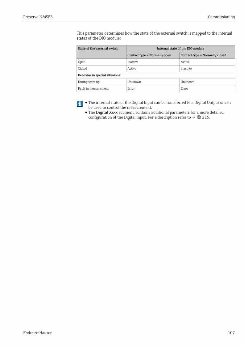
Proservo NMS83 Commissioning
Endress+Hauser 107
This parameter determines how the state of the external switch is mapped to the internalstates of the DIO module:
State of the external switch Internal state of the DIO module
Contact type = Normally open Contact type = Normally closed
Open Inactive Active
Closed Active Inactive
Behavior in special situaions:
During start-up Unknown Unknown
Fault in measurement Error Error
• The internal state of the Digital Input can be transferred to a Digital Output or canbe used to control the measurement.
• The Digital Xx-x submenu contains additional parameters for a more detailedconfiguration of the Digital Input. For a description refer to → 215.
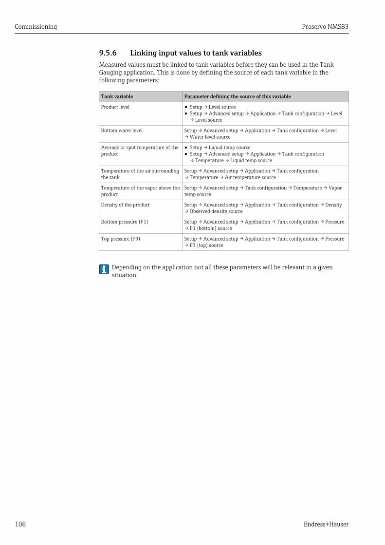
Commissioning Proservo NMS83
108 Endress+Hauser
9.5.6 Linking input values to tank variablesMeasured values must be linked to tank variables before they can be used in the TankGauging application. This is done by defining the source of each tank variable in thefollowing parameters:
Tank variable Parameter defining the source of this variable
Product level • Setup → Level source• Setup → Advanced setup → Application → Tank configuration → Level
→ Level source
Bottom water level Setup → Advanced setup → Application → Tank configuration → Level→ Water level source
Average or spot temperature of theproduct
• Setup → Liquid temp source• Setup → Advanced setup → Application → Tank configuration
→ Temperature → Liquid temp source
Temperature of the air surroundingthe tank
Setup → Advanced setup → Application → Tank configuration→ Temperature → Air temperature source
Temperature of the vapor above theproduct
Setup → Advanced setup → Tank configuration → Temperature → Vaportemp source
Density of the product Setup → Advanced setup → Application → Tank configuration → Density→ Observed density source
Bottom pressure (P1) Setup → Advanced setup → Application → Tank configuration → Pressure→ P1 (bottom) source
Top pressure (P3) Setup → Advanced setup → Application → Tank configuration → Pressure→ P3 (top) source
Depending on the application not all these parameters will be relevant in a givensituation.

Proservo NMS83 Commissioning
Endress+Hauser 109
9.5.7 Tank calculation: Direct level measurementIf no tank calculation is configured, level and temperature are measured directly.
A B
1
2
3
2
1
A0030167
A Direct level measurement (without temperature)B Direct level and temperature measurement1 NMS8x2 To inventory management system3 Temperature transmitter
1. Navigate to: "Setup → Level source" and specify from which device the level isobtained.
2. If a temperature transmitter is connected:Navigate to: "Setup → Liquid temp source" and specify from which device thetemperature is obtained.

Commissioning Proservo NMS83
110 Endress+Hauser
9.5.8 Tank calculation: Hybrid tank measurement system (HTMS)HTMS uses level and pressure measurements to calculate the density of the medium.
In non-atmospheric (i.e. pressurized) tanks it is recommended to use the HTMSP1+P3 mode. Two pressure sensors are required in this case. In atmospheric (i.e.unpressurized) tanks the HTMS P1 with only one pressure sensor is sufficient.
2
3D
1
1
2
3
4 1
D3
A B
D1
A0032436
A The "HTMS P1" measurement modeB The "HTMS P1+P3" measurement modeD1 P1 positionD3 P3 position1 NMS8x2 To inventory management system3 Pressure sensor (bottom)4 Pressure sensor (top)
1. Navigate to Setup → Advanced setup → Application → Tank configuration → Level
2. Go to Level source (→ 181) and specify from which device the level is obtained.
3. Navigate to Setup → Advanced setup → Application → Tank configuration → Pressure
4. Go to P1 (bottom) source (→ 253) and specify from which device the bottompressure (P1) is obtained.
5. If a top pressure transmitter (P3) is connected:Go to P3 (top) source (→ 255) and specify from which device the bottompressure (P1) is obtained.
6. Navigate to: Setup → Advanced setup → Application → Tank calculation → HTMS
7. Go to HTMS mode (→ 270) and specify the HTMS mode.
8. Navigate to Setup → Advanced setup → Application → Tank configuration → Density
9. Go to Observed density source (→ 251) and select HTMS.
10. Use the other parameters of the HTMS submenu to configure the calculation. For adetailed description: → 268
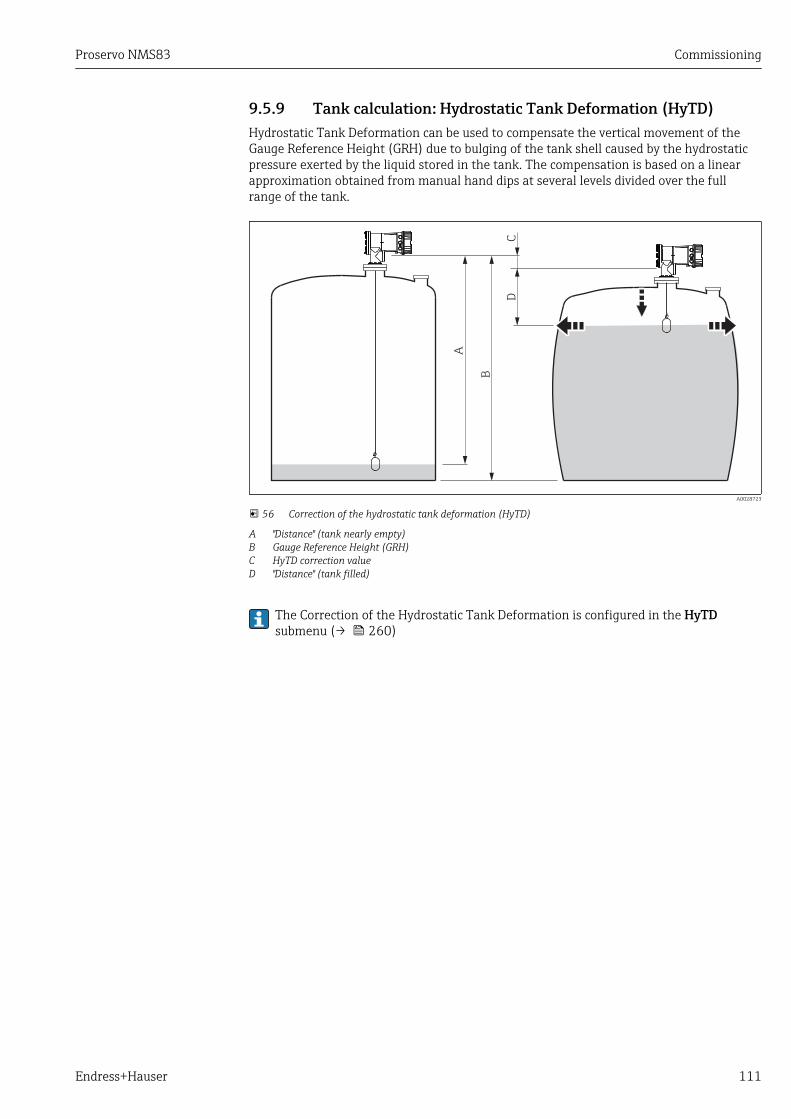
Proservo NMS83 Commissioning
Endress+Hauser 111
9.5.9 Tank calculation: Hydrostatic Tank Deformation (HyTD)Hydrostatic Tank Deformation can be used to compensate the vertical movement of theGauge Reference Height (GRH) due to bulging of the tank shell caused by the hydrostaticpressure exerted by the liquid stored in the tank. The compensation is based on a linearapproximation obtained from manual hand dips at several levels divided over the fullrange of the tank.
A
B
CD
A0028723
56 Correction of the hydrostatic tank deformation (HyTD)
A "Distance" (tank nearly empty)B Gauge Reference Height (GRH)C HyTD correction valueD "Distance" (tank filled)
The Correction of the Hydrostatic Tank Deformation is configured in the HyTDsubmenu (→ 260)

Commissioning Proservo NMS83
112 Endress+Hauser
9.5.10 Tank calculation: Thermal tank shell correction (CTSh)CTSh (correction for the thermal expansion of the tank shell) compensates for effects onthe Gauge Reference Height (GRH) and on the expansion or contraction of the measuringwire due to temperature effects on the tank shell or stilling well. The temperature effectsare separated into two parts, respectively affecting the 'dry' and 'wetted' part of the tankshell or stilling well. The correction function is based on thermal expansion coefficients ofsteel and insulation factors for both the 'dry' and 'wet' parts of the wire and the tank shell.The temperatures used for the correction can be selected from on manual or measuredvalues.
This correction is recommended for the following situations:• if the operating temperature deviates considederably from the temperature during
calibration (ΔT > 10 °C (18 °F))• for extremely high tanks• for refrigerated, cryogenic or heated applications
As the use of this correction will influence the innage level reading, it isrecommended to ensure the manual hand dip and level verification procedures arebeing conducted correctly before enabling this correction method.
This mode cannot be used in conjunction with HTG because the level is not measuredrelative to the gauge reference height with HTG.
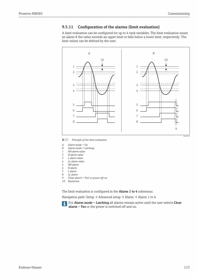
Proservo NMS83 Commissioning
Endress+Hauser 113
9.5.11 Configuration of the alarms (limit evaluation)A limit evaluation can be configured for up to 4 tank variables. The limit evaluation issuesan alarm if the value exceeds an upper limit or falls below a lower limit, respectively. Thelimit values can be defined by the user.
A B
1
2
3
4
5
6
7
8
1
2
3
4
5
6
7
8
9
10 10
A0029539
57 Principle of the limit evaluation
A Alarm mode = OnB Alarm mode = Latching1 HH alarm value2 H alarm value3 L alarm value4 LL alarm value5 HH alarm6 H alarm7 L alarm8 LL alarm9 "Clear alarm" = "Yes" or power off-on10 Hysteresis
The limit evaluation is configured in the Alarm 1 to 4 submenus.
Navigation path: Setup → Advanced setup → Alarm → Alarm 1 to 4
For Alarm mode = Latching all alarms remain active until the user selects Clearalarm = Yes or the power is switched off and on.
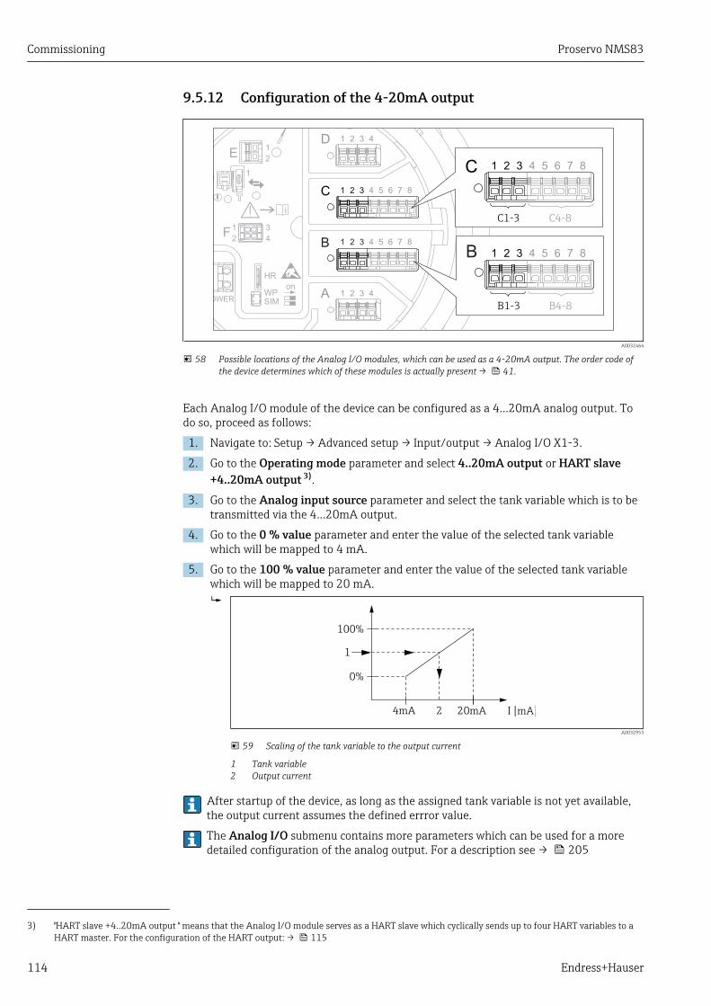
Commissioning Proservo NMS83
114 Endress+Hauser
9.5.12 Configuration of the 4-20mA output
D
E
F
C
B
A
1
1
1
1 3
2
2 4
1
HR
CDI
WPon
SIM
2
2
3
3
4
4
1
1
2
2
3
3
4
4
5
5
6
6
7
7
8
8
POWER
i
B
B1-3 B4-8
1 2 3 4 5 6 7 8
C 1 2 3 4 5 6 7 8
C1-3 C4-8
A0032464
58 Possible locations of the Analog I/O modules, which can be used as a 4-20mA output. The order code ofthe device determines which of these modules is actually present → 41.
Each Analog I/O module of the device can be configured as a 4...20mA analog output. Todo so, proceed as follows:
1. Navigate to: Setup → Advanced setup → Input/output → Analog I/O X1-3.
2. Go to the Operating mode parameter and select 4..20mA output or HART slave+4..20mA output 3).
3. Go to the Analog input source parameter and select the tank variable which is to betransmitted via the 4...20mA output.
4. Go to the 0 % value parameter and enter the value of the selected tank variablewhich will be mapped to 4 mA.
5. Go to the 100 % value parameter and enter the value of the selected tank variablewhich will be mapped to 20 mA.
0%
1
100%
4mA 2 20mA I [mA]
A0032953
59 Scaling of the tank variable to the output current
1 Tank variable2 Output current
After startup of the device, as long as the assigned tank variable is not yet available,the output current assumes the defined errror value.
The Analog I/O submenu contains more parameters which can be used for a moredetailed configuration of the analog output. For a description see → 205
3) "HART slave +4..20mA output " means that the Analog I/O module serves as a HART slave which cyclically sends up to four HART variables to aHART master. For the configuration of the HART output: → 115
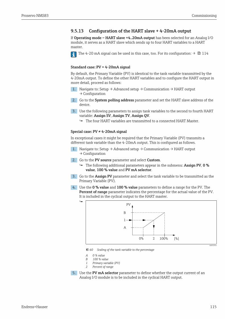
Proservo NMS83 Commissioning
Endress+Hauser 115
9.5.13 Configuration of the HART slave + 4-20mA outputIf Operating mode = HART slave +4..20mA output has been selected for an Analog I/Omodule, it serves as a HART slave which sends up to four HART variables to a HARTmaster.
The 4-20 mA signal can be used in this case, too. For its configuration: → 114
Standard case: PV = 4-20mA signalBy default, the Primary Variable (PV) is identical to the tank variable transmitted by the4-20mA output. To define the other HART variables and to configure the HART output inmore detail, proceed as follows:
1. Navigate to: Setup → Advanced setup → Communication → HART output→ Configuration
2. Go to the System polling address parameter and set the HART slave address of thedevice.
3. Use the following parameters to assign tank variables to the second to fourth HARTvariable: Assign SV, Assign TV, Assign QV. The four HART variables are transmitted to a connected HART Master.
Special case: PV ≠ 4-20mA signalIn exceptional cases it might be required that the Primary Variable (PV) transmits adifferent tank variable than the 4-20mA output. This is configured as follows.
1. Navigate to: Setup → Advanced setup → Communication → HART output→ Configuration
2. Go to the PV source parameter and select Custom. The following additional parameters appear in the submenu: Assign PV, 0 %
value, 100 % value and PV mA selector.
3. Go to the Assign PV parameter and select the tank variable to be transmitted as thePrimary Variable (PV).
4. Use the 0 % value and 100 % value parameters to define a range for the PV. ThePercent of range parameter indicates the percentage for the actual value of the PV.It is included in the cyclical output to the HART master.
1
B
A
0% 2 100% [%]
PV
A0032954
60 Scaling of the tank variable to the percentage
A 0 % valueB 100 % value1 Primary variable (PV)2 Percent of range
5. Use the PV mA selector parameter to define whether the output current of anAnalog I/O module is to be included in the cyclical HART output.

Commissioning Proservo NMS83
116 Endress+Hauser
After startup of the device, as long as the assigned tank variable is not yet available,the output current assumes the defined errror value.
The PV mA selector parameter does not influence the output current at the terminalsof the Analog I/O module. It only defines whether the value of this current is part ofthe HART output or not.

Proservo NMS83 Commissioning
Endress+Hauser 117
9.5.14 Configuration of the Modbus output
D
E
F
C
B
A
1
1
1
1 3
2
2 4
1
HR
CDI
WPon
SIM
2
2
3
3
4
4
1
1
2
2
3
3
4
4
5
5
6
6
7
7
8
8
POWER
A 1 2 3 4
A1-4
i
D 1 2 3 4
D1-4
A0031200
61 Possible locations of the Modbus modules (examples); depending on the device version these modulesmay also be in slot B or C → 41.
The Proservo NMS8x acts as a Modbus slave. Measured or calculated tank values arestored in registers which can be requested by a Modbus master.
The following submenu is used to configure the communication between the device andthe Modbus master:Setup → Advanced setup → Communication → Modbus X1-4 →Configuration (→ 225)

Commissioning Proservo NMS83
118 Endress+Hauser
9.5.15 Configuration of the V1 output
D
E
F
C
B
A
1
1
1
1 3
2
2 4
1
HR
CDI
WPon
SIM
2
2
3
3
4
4
1
1
2
2
3
3
4
4
5
5
6
6
7
7
8
8
POWER
A 1 2 3 4
A1-4
i
D 1 2 3 4
D1-4
A0031200
62 Possible locations of the V1 modules (examples); depending on the device version these modules may alsobe in slot B or C → 41.
The following submenus are used to configure the V1 communication between the deviceand the control system:• Setup → Advanced setup → Communication → V1 X1-4 → Configuration (→ 228)• Setup → Advanced setup → Communication → V1 X1-4 → V1 input selector (→ 231)
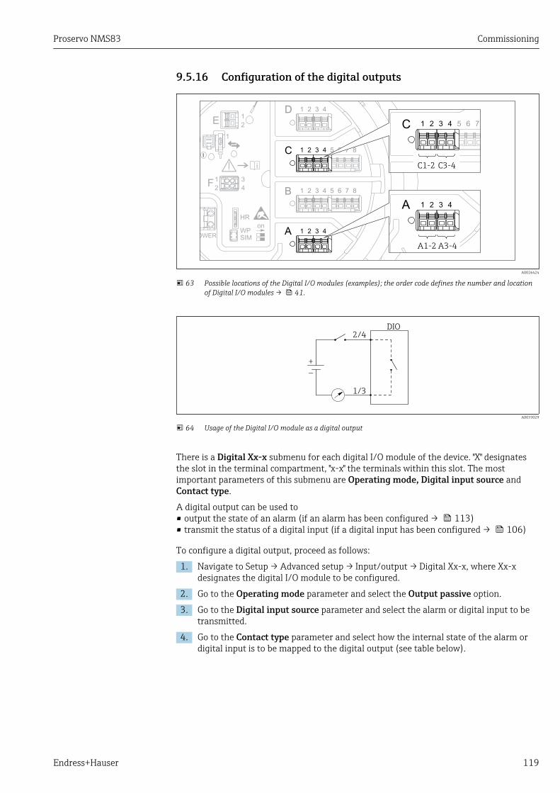
Proservo NMS83 Commissioning
Endress+Hauser 119
9.5.16 Configuration of the digital outputs
D
E
F
C
B
A
1
1
1
1 3
2
2 4
1
HR
CDI
WPon
SIM
2
2
3
3
4
4
1
1
2
2
3
3
4
4
5
5
6
6
7
7
8
8
POWER
A 1 2 3 4
A1-2 A3-4
i
C 1 2 3 4 5 6 7
C1-2 C3-4
A0026424
63 Possible locations of the Digital I/O modules (examples); the order code defines the number and locationof Digital I/O modules → 41.
DIO2/4
+_
1/3
A0033029
64 Usage of the Digital I/O module as a digital output
There is a Digital Xx-x submenu for each digital I/O module of the device. "X" designatesthe slot in the terminal compartment, "x-x" the terminals within this slot. The mostimportant parameters of this submenu are Operating mode, Digital input source andContact type.
A digital output can be used to• output the state of an alarm (if an alarm has been configured → 113)• transmit the status of a digital input (if a digital input has been configured → 106)
To configure a digital output, proceed as follows:
1. Navigate to Setup → Advanced setup → Input/output → Digital Xx-x, where Xx-xdesignates the digital I/O module to be configured.
2. Go to the Operating mode parameter and select the Output passive option.
3. Go to the Digital input source parameter and select the alarm or digital input to betransmitted.
4. Go to the Contact type parameter and select how the internal state of the alarm ordigital input is to be mapped to the digital output (see table below).

Commissioning Proservo NMS83
120 Endress+Hauser
• State of the alarm• Internal state of the digital input
Switching state of the digital output
Contact type = Normally open Contact type = Normally closed
Inactive Open Closed
Active Closed Open
• For SIL applications, Contact type is automatically set to Normally closed by thedevice when starting the SIL confirmation procedure.
• In case of a power supply failure, the switching state is always "open", irrespectiv ofthe selected option.
• The Digital Xx-x submenu contains additional parameters for a more detailedconfiguration of the Digital Input. For a description refer to → 215.

Proservo NMS83 Commissioning
Endress+Hauser 121
9.6 Advanced settingsFor a more detailed configuration of the signal inputs, the tank calculations and the signaloutputs refer to the Advanced setup submenu (→ 191).
9.7 SimulationTo check the correct configuration of the device and of the control system, it is possible tosimulate different situations (measured values, diagnostic messages etc.). See theSimulation submenu (→ 315) for details.
9.8 Protecting settings from unauthorized accessThere are two possibilities to protect the settings from unauthorized access:• By an access code (→ 68)
This locks the access via the display and operating module.• By the protection switch (→ 69)
This locks the access to W&M-related parameters by any user interface (display andoperating module, FieldCare, other configuration tools).

Operation Proservo NMS83
122 Endress+Hauser
10 Operation
10.1 Reading off the device locking statusDepending on the locking state of the device some operations may be locked. The currentlocking status is indicated at: Setup → Advanced setup → Locking status. The followingtable summarizes the different locking statuses:
Locking status Meaning Unlocking procedure
Hardware locked The device is locked by the write-protection switch in theterminal compartment.
→ 69
SIL locked The device is in SIL-locked mode. See the SIL Safetymanual
CT active - allparameters
The custody transfer mode is active. → 69
WHG locked (inpreparation)
The device is in WHG-locked mode. in preparation
Temporarily locked Write access to the parameters is temporarily lock due todevice-internal processing (e.g. data upload/download,reset). Once the internal processing has been completed,the parameters can be changed again.
Wait for completion ofthe device-internalprocessing.
A locking is indicated by the write protection symbol in the header of the display:
X X X X X X XX X
20.50XXXX
A0015870
10.2 Reading off measured valuesTank values can be read off in the following submenus:• Operation → Level• Operation → Temperature• Operation → Density• Operation → Pressure

Proservo NMS83 Operation
Endress+Hauser 123
10.3 Gauge commands
10.3.1 Overview of available device functionsGauge commands are mainly divided into two categories.
• Continuous gauge command• One-time gauge command (non-continuous)
One-time gauge commands have a defined end state. After a one-time gaugecommand is completed, another gauge command is executed which is defined by thePost gauge command parameter. If Post gauge command is set to None, theoperation will stop.
The gauge command can be chosen by navigating to Operation → Gauge command. Thestatus of the gauge command execution is shown in the Gauge status parameter. Thegauge status is displayed on the home screen by default.
X X X X X X XX X
5
2
8
1
3
6
mm
4841.00
Level bal.
F
4
7
#
A0028702
65 Typical appearance of the standard view (measured value display)
1 Display module2 Device tag3 Status area4 Display area for measured values5 Display area for measured value and status symbols6 Gauge status indication7 Gauge status symbol8 Measured value status symbol
For details of status symbols → 58
When a one-time gauge command is executed, additional information is shown in theOne-time command status parameter in the operation menu.
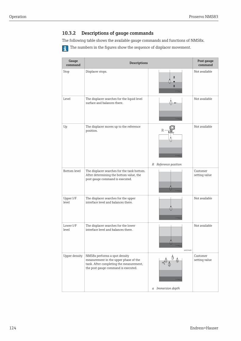
Operation Proservo NMS83
124 Endress+Hauser
10.3.2 Descriptions of gauge commandsThe following table shows the available gauge commands and functions of NMS8x.
The numbers in the figures show the sequence of displacer movement.
Gaugecommand Descriptions Post gauge
command
Stop Displacer stops. Not available
Level The displacer searches for the liquid levelsurface and balances there.
Not available
Up The displacer moves up to the referenceposition. R
R Reference position
Not available
Bottom level The displacer searches for the tank bottom.After determining the bottom value, thepost gauge command is executed.
Customersetting value
Upper I/Flevel
The displacer searches for the upperinterface level and balances there.
Not available
Lower I/Flevel
The displacer searches for the lowerinterface level and balances there.
A0029485
Not available
Upper density NMS8x performs a spot densitymeasurement in the upper phase of thetank. After completing the measurement,the post gauge command is executed.
a
4
2
31
a Immersion depth
Customersetting value
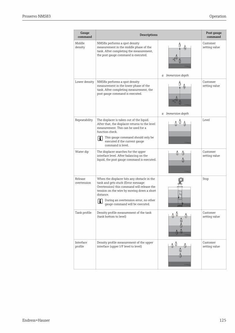
Proservo NMS83 Operation
Endress+Hauser 125
Gaugecommand Descriptions Post gauge
command
Middledensity
NMS8x performs a spot densitymeasurement in the middle phase of thetank. After completing the measurement,the post gauge command is executed.
a
2
1
34
a Immersion depth
Customersetting value
Lower density NMS8x performs a spot densitymeasurement in the lower phase of thetank. After completing measurement, thepost gauge command is executed.
a
2
1
34
a Immersion depth
Customersetting value
Repeatability The displacer is taken out of the liquid.After that, the displacer returns to the levelmeasurement. This can be used for afunction check.
This gauge command should only beexecuted if the current gaugecommand is level.
12
3
Level
Water dip The displacer searches for the upperinterface level. After balancing on theliquid, the post gauge command is executed.
1
2
3Customersetting value
Releaseovertension
When the displacer hits any obstacle in thetank and gets stuck (Error message:Overtension) this command will release thetension on the wire by moving down a shortdistance.
During an overtension error, no othergauge command will be executed.
Stop
Tank profile Density profile measurement of the tank(tank bottom to level)
3 4
5
6
72
1
Customersetting value
Interfaceprofile
Density profile measurement of the upperinterface (upper I/F level to level) 5
2
3
4
1
Customersetting value

Operation Proservo NMS83
126 Endress+Hauser
Gaugecommand Descriptions Post gauge
command
Manualprofile
Density profile measurement from amanually set position to level
3
4
5
62
1
Customersetting value
Level standby The displacer moves to a set position andstays there until the tank level reaches thisposition. After that, gauge command ischanged back to level.
This function can be used whensupplying or discharging liquid.
Level

Proservo NMS83 Operation
Endress+Hauser 127
10.3.3 Sources for gauge commandsGauge commands can be sent via various sources.
• Displays or CDI (e.g. FieldCare)• Digital input (e.g. control switch)• Fieldbus (Modbus, V1, HART)
The last received gauge command via any sources will be executed as usual.
During calibration, gauge commands are not accepted from any sources.
XX
XX
XX
X
X
X
mm
INST
LIFTSTOP
OFF
NXA820
1
23
A0029575
1 Display operation2 Digital input (e.g. control switch)3 Tankvision
Gauge command prioritiesThe priority of the gauge command for NMS8x is very simple. The last received gaugecommand via any sources will be executed to take of the former gauge command. Howeverthe priority varies depending on the devices. When replacing the device with the NMS8x,check the priorities shown below.
NOTICEUndesired gauge command will be executed.If the setting is not changed, an undesired gauge command will be executed (e.g. Levelcommand via Fieldbus would overwrite Stop command for maintenance.).‣ If the system has been automatically or semi-automatically programmed for operation,
maintenance or other purposes, the setting should be changed corresponding to use.
Proservo NMS8x
By display From digital input From Fieldbus
Command Priority Command Priority Command Priority
Level 1 Level 1 Level 1
Interface 1 Interface 1 Interface 1
Tank bottom 1 Tank bottom 1 Tank bottom 1

Operation Proservo NMS83
128 Endress+Hauser
By display From digital input From Fieldbus
Spot density 1 Spot density 1 Spot density 1
Profile density 1 Profile density 1 Profile density 1
Up 1 Up 1 Up 1
Stop 1 Stop 1 Stop 1
Proservo NMS5/NMS7
By display From NRF560 From digital input From Fieldbus
Command Priority Command Priority Command Priority Command Priority
Level 4 Level 4 Level 4 Level 4
Interface 2 Interface 3 Interface 1 Interface 4
Tank bottom 2 Tank bottom 3 N/A N/A Tank bottom 4
Spot density 2 Spot density 3 N/A N/A Spot density 4
Profile density 2 Profile density 3 N/A N/A Profile density 4
Up 2 Up 3 Up 1 Up 4
Stop 2 Stop 3 Stop 1 Stop 4
Servo level gauge TGM5
By display From NRF560 From DRM9700 From digital input From Fieldbus
Command Priority Command Priority Command Priority Command Priority Command Priority
Level 4 Level 4 Level 4 Level 4 Level 4
Interface 2 Interface 3 N/A N/A N/A N/A Interface 4
Tankbottom
2 Tankbottom
3 N/A N/A N/A N/A Tankbottom
4
Spot density 2 Spot density 3 N/A N/A N/A N/A Spot density 4
Profiledensity
2 Profiledensity
3 N/A N/A N/A N/A Profiledensity
4
Up 2 Up 3 Up 1 Up 1 Up 4
Stop 2 Stop 3 N/A N/A Stop 1 Stop 4
Servo level gauge TGM4000
By display From DRM9700 From digital input From Fieldbus
Command Priority Command Priority Command Priority Command Priority
Level 4 Level 4 Level 4 Level 4
Interface 2 Interface 1 N/A N/A Interface 4
Tank bottom 2 N/A N/A N/A N/A Tank bottom 4
Spot density 2 N/A N/A N/A N/A Spot density 4
Profile density 2 N/A N/A N/A N/A Profile density 4
Up 2 Up 1 Up 1 Up 4
Stop 2 Stop N/A Stop 1 Stop 4
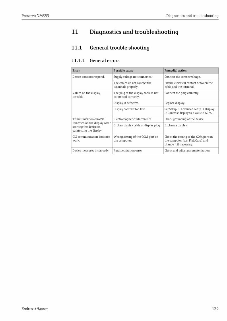
Proservo NMS83 Diagnostics and troubleshooting
Endress+Hauser 129
11 Diagnostics and troubleshooting
11.1 General trouble shooting
11.1.1 General errors
Error Possible cause Remedial action
Device does not respond. Supply voltage not connected. Connect the correct voltage.
The cables do not contact theterminals properly.
Ensure electrical contact between thecable and the terminal.
Values on the displayinvisible
The plug of the display cable is notconnected correctly.
Connect the plug correctly.
Display is defective. Replace display.
Display contrast too low. Set Setup → Advanced setup → Display→ Contrast display to a value ≥ 60 %.
"Communication error" isindicated on the display whenstarting the device orconnecting the display
Electromagnetic interference Check grounding of the device.
Broken display cable or display plug. Exchange display.
CDI communication does notwork.
Wrong setting of the COM port onthe computer.
Check the setting of the COM port onthe computer (e.g. FieldCare) andchange it if necessary.
Device measures incorrectly. Parametrization error Check and adjust parameterization.
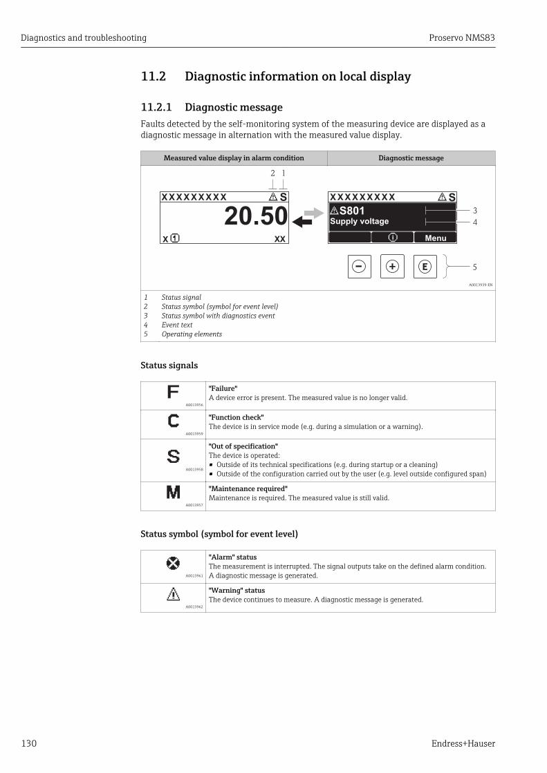
Diagnostics and troubleshooting Proservo NMS83
130 Endress+Hauser
11.2 Diagnostic information on local display
11.2.1 Diagnostic messageFaults detected by the self-monitoring system of the measuring device are displayed as adiagnostic message in alternation with the measured value display.
Measured value display in alarm condition Diagnostic message
1
4
3
X X X X X X XX X X X X X X X XX X
2
S S
XX
20.50
5
X i
S801
Menu
Supply voltage
A0013939-EN
12345
Status signalStatus symbol (symbol for event level)Status symbol with diagnostics eventEvent textOperating elements
Status signals
A0013956
"Failure"A device error is present. The measured value is no longer valid.
A0013959
"Function check"The device is in service mode (e.g. during a simulation or a warning).
A0013958
"Out of specification"The device is operated:• Outside of its technical specifications (e.g. during startup or a cleaning)• Outside of the configuration carried out by the user (e.g. level outside configured span)
A0013957
"Maintenance required"Maintenance is required. The measured value is still valid.
Status symbol (symbol for event level)
A0013961
"Alarm" statusThe measurement is interrupted. The signal outputs take on the defined alarm condition.A diagnostic message is generated.
A0013962
"Warning" statusThe device continues to measure. A diagnostic message is generated.
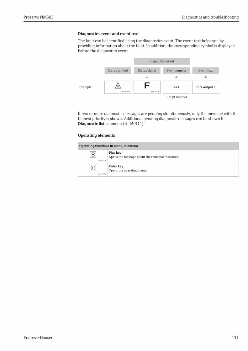
Proservo NMS83 Diagnostics and troubleshooting
Endress+Hauser 131
Diagnostics event and event textThe fault can be identified using the diagnostics event. The event text helps you byproviding information about the fault. In addition, the corresponding symbol is displayedbefore the diagnostics event.
Diagnostics event
Status symbol Status signal Event number Event text
↓ ↓ ↓
Example A0013962 A0013956
441 Curr.output 1
3-digit number
If two or more diagnostic messages are pending simultaneously, only the message with thehighest priority is shown. Additional pending diagnostic messages can be shown inDiagnostic list submenu (→ 311).
Operating elements
Operating functions in menu, submenu
A0013970
Plus keyOpens the message about the remedial measures.
A0013952
Enter keyOpens the operating menu.
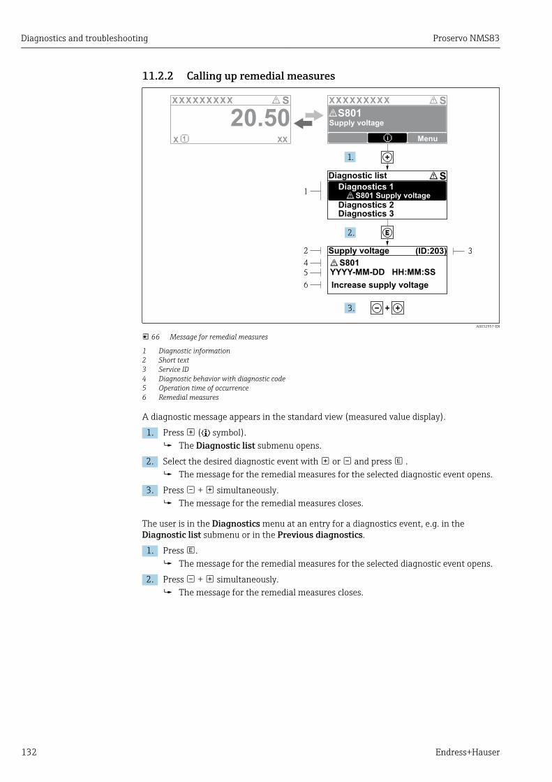
Diagnostics and troubleshooting Proservo NMS83
132 Endress+Hauser
11.2.2 Calling up remedial measures
X X X X X X XX X X X X X X X XX XS S
XX
20.50X i
S801
Menu
S
(ID:203)
S801
1
2
4
5
6
3
1.
2.
3.
YYYY-MM-DD HH:MM:SS
S801 Supply voltage
Diagnostic list
Diagnostics 1
Diagnostics 2Diagnostics 3
Supply voltage
Supply voltage
Increase supply voltage
A0032957-EN
66 Message for remedial measures
1 Diagnostic information2 Short text3 Service ID4 Diagnostic behavior with diagnostic code5 Operation time of occurrence6 Remedial measures
A diagnostic message appears in the standard view (measured value display).
1. Press ( symbol). The Diagnostic list submenu opens.
2. Select the desired diagnostic event with or and press . The message for the remedial measures for the selected diagnostic event opens.
3. Press + simultaneously. The message for the remedial measures closes.
The user is in the Diagnostics menu at an entry for a diagnostics event, e.g. in theDiagnostic list submenu or in the Previous diagnostics.
1. Press . The message for the remedial measures for the selected diagnostic event opens.
2. Press + simultaneously. The message for the remedial measures closes.

Proservo NMS83 Diagnostics and troubleshooting
Endress+Hauser 133
11.3 Diagnostic information in FieldCareAny faults detected by the measuring device are displayed on the home page of theoperating tool once the connection has been established.
Xxxxxx/…/…/
Xxxxxx
P
P
P
+
+
+
+Diagnostics 1:
Remedy information:
Failure (F)
Function check (C)
Out of spezification (S)
Maintenance required (M)
C485 Simulation measured vari...
Deactivate Simulation (Service...
Diagnostics 1: C485 Simu...
Remedy information: Deactivate...
Access status tooling: Mainenance
Operation
Setup
Diagnostics
Expert
Function check (C)Status signal:
Device tag:
Device name: Mass flow:
Volume flow:Xxxxxxx
12.34 kg/h
12.34 m /h³
Xxxxxxx
1
2
3
A0021799-EN
1 Status area with status signal2 Diagnostic information3 Remedial measures with Service ID
Furthermore, diagnostic events that have occurred can be viewed in the Diagnosticlist submenu.
11.3.1 Status signalsThe status signals provide information on the state and reliability of the device bycategorizing the cause of the diagnostic information (diagnostic event).
Symbol Meaning
A0017271
FailureA device error has occurred. The measured value is no longer valid.
A0017278
Function checkThe device is in service mode (e.g. during a simulation or a warning).
A0017277
Out of specificationThe device is operated outside its technical specification limits (e.g. outside the processtemperature range)
A0017276
Maintenance requiredMaintenance is required. The measured value is still valid.
The status signals are categorized in accordance with VDI/VDE 2650 and NAMURRecommendation NE 107.
Diagnostics and troubleshooting Proservo NMS83
134 Endress+Hauser
11.3.2 Calling up remedy informationRemedy information is provided for every diagnostic event to ensure that problems can berectified quickly:• On the home page
Remedy information is displayed in a separate field below the diagnostics information.• In the Diagnostics menu
Remedy information can be called up in the working area of the user interface.
The user is in the Diagnostics menu.
1. Call up the desired parameter.
2. On the right in the working area, mouse over the parameter. A tool tip with remedy information for the diagnostic event appears.
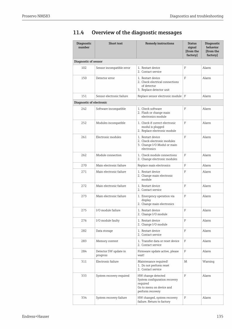
Proservo NMS83 Diagnostics and troubleshooting
Endress+Hauser 135
11.4 Overview of the diagnostic messages
Diagnosticnumber
Short text Remedy instructions Statussignal
[from thefactory]
Diagnosticbehavior[from thefactory]
Diagnostic of sensor
102 Sensor incompatible error 1. Restart device2. Contact service
F Alarm
150 Detector error 1. Restart device2. Check electrical connections
of detector3. Replace detector unit
F Alarm
151 Sensor electronic failure Replace sensor electronic module F Alarm
Diagnostic of electronic
242 Software incompatible 1. Check software2. Flash or change main
electronics module
F Alarm
252 Modules incompatible 1. Check if correct electronicmodul is plugged
2. Replace electronic module
F Alarm
261 Electronic modules 1. Restart device2. Check electronic modules3. Change I/O Modul or main
electronics
F Alarm
262 Module connection 1. Check module connections2. Change electronic modules
F Alarm
270 Main electronic failure Replace main electronics F Alarm
271 Main electronic failure 1. Restart device2. Change main electronic
module
F Alarm
272 Main electronic failure 1. Restart device2. Contact service
F Alarm
273 Main electronic failure 1. Emergency operation viadisplay
2. Change main electronics
F Alarm
275 I/O module failure 1. Restart device2. Change I/O module
F Alarm
276 I/O module faulty 1. Restart device2. Change I/O module
F Alarm
282 Data storage 1. Restart device2. Contact service
F Alarm
283 Memory content 1. Transfer data or reset device2. Contact service
F Alarm
284 Detector SW update inprogress
Firmware update active, pleasewait!
F Alarm
311 Electronic failure Maintenance required!1. Do not perform reset2. Contact service
M Warning
333 System recovery required HW change detectedSystem configuration recoveryrequiredGo to menu on device andperform recovery
F Alarm
334 System recovery failure HW changed, system recoveryfailure. Return to factory
F Alarm

Diagnostics and troubleshooting Proservo NMS83
136 Endress+Hauser
Diagnosticnumber
Short text Remedy instructions Statussignal
[from thefactory]
Diagnosticbehavior[from thefactory]
381 Displacer distance invalid 1. Calibrate sensor2. Restart device3. Replace sensor electronics
F Alarm
382 Sensor communication 1. Check connection of sensorelectronics
2. Restart device3. Replace sensor electronics
F Alarm
Diagnostic of configuration
400 AIO simulation output Deactivate simulation AIOoutput
C Warning
401 DIO simulation output Deactivate simulation DIO output C Warning
403 Calibration AIO 1. Restart device2. Change I/O module
F Alarm
404 Calibration AIP 1. Restart device2. Change I/O module
F Alarm
405 COMM timeout DIO 1 to 8 1. Check wiring2. Change I/O module
F Alarm
406 IOM offline 1. Check wiring2. Change I/O module
F Alarm
407 COMM timeout AIO 1 to 2 1. Check wiring2. Change I/O module
F Alarm
408 Invalid range AIO 1 to 2 1. Check device configuration.2. Check wiring.
C Warning
409 RTD temp out of range 1 to 2 1. Check electronic modules2. Change I/O or main electronic
module
C Warning
410 Data transfer 1. Check connection2. Retry data transfer
F Alarm
411 Hart device 1 to 15 hasmalfunction
1. Check HART device2. Change HART device
F Alarm 1)
412 Processing download Download active, please wait C Warning
413 NMT 1 to 15: element isopen or short
1. Check NMT wiring connection2. Replace NMT
C Warning
415 Hart device 1 to 15 offline 1. Check HART device2. Change HART device
C Warning
434 Real time clock defective Replace main electronics C Warning
436 Date/Time incorrect Check date and time settings. M Warning
437 Configuration incompatible 1. Restart device2. Contact service
F Alarm
438 Dataset 1. Check data set file2. Check device configuration3. Up- and download new
configuration
M Warning
441 AIO 1 to 2 current outputalarm
1. Check process2. Check current output settings
F Alarm
442 AIO 1 to 2 current outputwarning
1. Check process2. Check current output settings
C Warning
443 AIO 1 to 2 Input not HARTcompatible
Change PV source or AIO inputsource.
C Warning
484 Failure mode simulation Deactivate simulation C Alarm
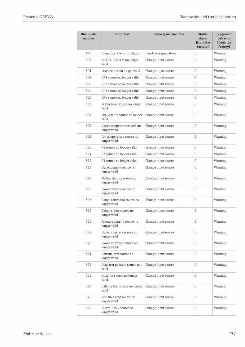
Proservo NMS83 Diagnostics and troubleshooting
Endress+Hauser 137
Diagnosticnumber
Short text Remedy instructions Statussignal
[from thefactory]
Diagnosticbehavior[from thefactory]
495 Diagnostic event simulation Deactivate simulation C Warning
500 AIO C1-3 source no longervalid
Change input source C Warning
501 Level source no longer valid Change input source C Warning
502 GP1 source no longer valid Change input source C Warning
503 GP2 source no longer valid Change input source C Warning
504 GP3 source no longer valid Change input source C Warning
505 GP4 source no longer valid Change input source C Warning
506 Water level source no longervalid
Change input source C Warning
507 Liquid temp source no longervalid
Change input source C Warning
508 Vapor temperatur source nolonger valid
Change input source C Warning
509 Air temperature source nolonger valid
Change input source C Warning
510 P1 source no longer valid Change input source C Warning
511 P2 source no longer valid Change input source C Warning
512 P3 source no longer valid Change input source C Warning
513 Upper density source nolonger valid
Change input source C Warning
514 Middle density source nolonger valid
Change input source C Warning
515 Lower density source nolonger valid
Change input source C Warning
516 Gauge command source nolonger valid
Change input source C Warning
517 Gauge status source nolonger valid
Change input source C Warning
518 Average density source nolonger valid
Change input source C Warning
519 Upper interface source nolonger valid
Change input source C Warning
520 Lower interface source nolonger valid
Change input source C Warning
521 Bottom level source nolonger valid
Change input source C Warning
522 Displacer position source notvalid
Change input source C Warning
523 Distance source no longervalid
Change input source C Warning
524 Balance flag source no longervalid
Change input source C Warning
525 One time cmd source nolonger valid
Change input source C Warning
526 Alarm 1 to 4 source nolonger valid
Change input source C Warning
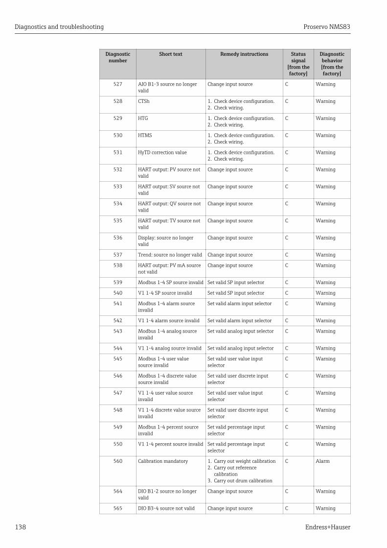
Diagnostics and troubleshooting Proservo NMS83
138 Endress+Hauser
Diagnosticnumber
Short text Remedy instructions Statussignal
[from thefactory]
Diagnosticbehavior[from thefactory]
527 AIO B1-3 source no longervalid
Change input source C Warning
528 CTSh 1. Check device configuration.2. Check wiring.
C Warning
529 HTG 1. Check device configuration.2. Check wiring.
C Warning
530 HTMS 1. Check device configuration.2. Check wiring.
C Warning
531 HyTD correction value 1. Check device configuration.2. Check wiring.
C Warning
532 HART output: PV source notvalid
Change input source C Warning
533 HART output: SV source notvalid
Change input source C Warning
534 HART output: QV source notvalid
Change input source C Warning
535 HART output: TV source notvalid
Change input source C Warning
536 Display: source no longervalid
Change input source C Warning
537 Trend: source no longer valid Change input source C Warning
538 HART output: PV mA sourcenot valid
Change input source C Warning
539 Modbus 1-4 SP source invalid Set valid SP input selector C Warning
540 V1 1-4 SP source invalid Set valid SP input selector C Warning
541 Modbus 1-4 alarm sourceinvalid
Set valid alarm input selector C Warning
542 V1 1-4 alarm source invalid Set valid alarm input selector C Warning
543 Modbus 1-4 analog sourceinvalid
Set valid analog input selector C Warning
544 V1 1-4 analog source invalid Set valid analog input selector C Warning
545 Modbus 1-4 user valuesource invalid
Set valid user value inputselector
C Warning
546 Modbus 1-4 discrete valuesource invalid
Set valid user discrete inputselector
C Warning
547 V1 1-4 user value sourceinvalid
Set valid user value inputselector
C Warning
548 V1 1-4 discrete value sourceinvalid
Set valid user discrete inputselector
C Warning
549 Modbus 1-4 percent sourceinvalid
Set valid percentage inputselector
C Warning
550 V1 1-4 percent source invalid Set valid percentage inputselector
C Warning
560 Calibration mandatory 1. Carry out weight calibration2. Carry out reference
calibration3. Carry out drum calibration
C Alarm
564 DIO B1-2 source no longervalid
Change input source C Warning
565 DIO B3-4 source not valid Change input source C Warning
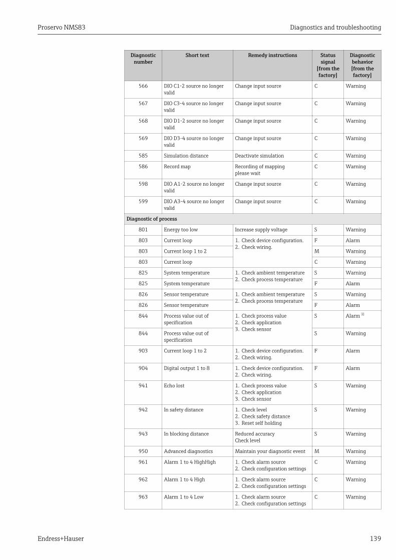
Proservo NMS83 Diagnostics and troubleshooting
Endress+Hauser 139
Diagnosticnumber
Short text Remedy instructions Statussignal
[from thefactory]
Diagnosticbehavior[from thefactory]
566 DIO C1-2 source no longervalid
Change input source C Warning
567 DIO C3-4 source no longervalid
Change input source C Warning
568 DIO D1-2 source no longervalid
Change input source C Warning
569 DIO D3-4 source no longervalid
Change input source C Warning
585 Simulation distance Deactivate simulation C Warning
586 Record map Recording of mappingplease wait
C Warning
598 DIO A1-2 source no longervalid
Change input source C Warning
599 DIO A3-4 source no longervalid
Change input source C Warning
Diagnostic of process
801 Energy too low Increase supply voltage S Warning
803 Current loop 1. Check device configuration.2. Check wiring.
F Alarm
803 Current loop 1 to 2 M Warning
803 Current loop C Warning
825 System temperature 1. Check ambient temperature2. Check process temperature
S Warning
825 System temperature F Alarm
826 Sensor temperature 1. Check ambient temperature2. Check process temperature
S Warning
826 Sensor temperature F Alarm
844 Process value out ofspecification
1. Check process value2. Check application3. Check sensor
S Alarm 1)
844 Process value out ofspecification
S Warning
903 Current loop 1 to 2 1. Check device configuration.2. Check wiring.
F Alarm
904 Digital output 1 to 8 1. Check device configuration.2. Check wiring.
F Alarm
941 Echo lost 1. Check process value2. Check application3. Check sensor
S Warning
942 In safety distance 1. Check level2. Check safety distance3. Reset self holding
S Warning
943 In blocking distance Reduced accuracyCheck level
S Warning
950 Advanced diagnostics Maintain your diagnostic event M Warning
961 Alarm 1 to 4 HighHigh 1. Check alarm source2. Check configuration settings
C Warning
962 Alarm 1 to 4 High 1. Check alarm source2. Check configuration settings
C Warning
963 Alarm 1 to 4 Low 1. Check alarm source2. Check configuration settings
C Warning
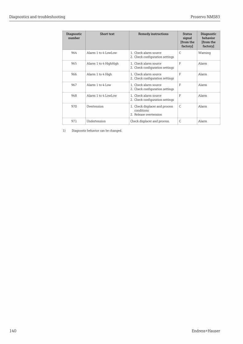
Diagnostics and troubleshooting Proservo NMS83
140 Endress+Hauser
Diagnosticnumber
Short text Remedy instructions Statussignal
[from thefactory]
Diagnosticbehavior[from thefactory]
964 Alarm 1 to 4 LowLow 1. Check alarm source2. Check configuration settings
C Warning
965 Alarm 1 to 4 HighHigh 1. Check alarm source2. Check configuration settings
F Alarm
966 Alarm 1 to 4 High 1. Check alarm source2. Check configuration settings
F Alarm
967 Alarm 1 to 4 Low 1. Check alarm source2. Check configuration settings
F Alarm
968 Alarm 1 to 4 LowLow 1. Check alarm source2. Check configuration settings
F Alarm
970 Overtension 1. Check displacer and processconditions
2. Release overtension
C Alarm
971 Undertension Check displacer and process. C Alarm
1) Diagnostic behavior can be changed.
Proservo NMS83 Diagnostics and troubleshooting
Endress+Hauser 141
11.5 Diagnostic listIn the Diagnostic list submenu, up to 5 currently pending diagnostic messages can bedisplayed. If more than 5 messages are pending, the messages with the highest priority areshown on the display.
Navigation pathDiagnostics → Diagnostic list
Calling up and closing the remedial measures1. Press .
The message for the remedial measures for the selected diagnostic event opens.
2. Press + simultaneously. The message about the remedial measures closes.
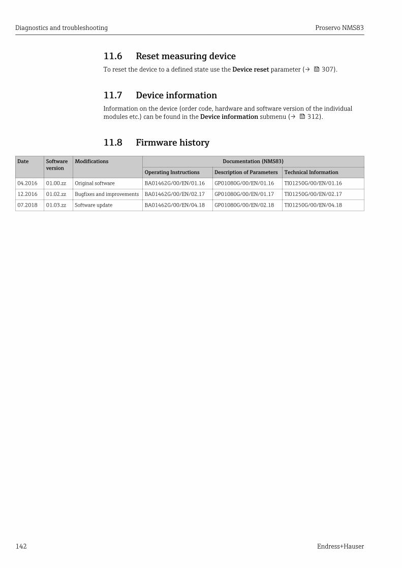
Diagnostics and troubleshooting Proservo NMS83
142 Endress+Hauser
11.6 Reset measuring deviceTo reset the device to a defined state use the Device reset parameter (→ 307).
11.7 Device informationInformation on the device (order code, hardware and software version of the individualmodules etc.) can be found in the Device information submenu (→ 312).
11.8 Firmware history
Date Softwareversion
Modifications Documentation (NMS83)
Operating Instructions Description of Parameters Technical Information
04.2016 01.00.zz Original software BA01462G/00/EN/01.16 GP01080G/00/EN/01.16 TI01250G/00/EN/01.16
12.2016 01.02.zz Bugfixes and improvements BA01462G/00/EN/02.17 GP01080G/00/EN/01.17 TI01250G/00/EN/02.17
07.2018 01.03.zz Software update BA01462G/00/EN/04.18 GP01080G/00/EN/02.18 TI01250G/00/EN/04.18

Proservo NMS83 Maintenance
Endress+Hauser 143
12 Maintenance
12.1 Maintenance tasksNo special maintenance work is required.
12.1.1 Exterior cleaningWhen cleaning the exterior of measuring devices, always use cleaning agents that do notattack the surface of the housing or the seals.
12.2 Endress+Hauser servicesEndress+Hauser offers a wide variety of services for maintenance such as recalibration,maintenance service or device tests.
Your Endress+Hauser Sales Center can provide detailed information on the services.
Repair Proservo NMS83
144 Endress+Hauser
13 Repair
13.1 General information on repairs
13.1.1 Repair conceptThe Endress+Hauser repair concept assumes that the devices have a modular design andthat repairs can be done by the Endress+Hauser service or specially trained customers.
Spare parts are contained in suitable kits. They contain the related replacementinstructions.
For more information on service and spare parts, contact the Service Department atEndress+Hauser.
13.1.2 Repairs to Ex-approved devicesWhen carrying out repairs to Ex-approved devices, please note the following:
• Repairs to Ex-approved devices may only be carried out by trained personnel or by theEndress+Hauser Service.
• Comply with the prevailing standards, national Ex-area regulations, safety instructions(XA) and certificates.
• Only use original spare parts from Endress+Hauser.• When ordering a spare part, please note the device designation on the nameplate. Only
replace parts with identical parts.• Carry out repairs according to the instructions. On completion of repairs, carry out the
specified routine test on the device.• Only Endress+Hauser Service may convert a certified device into a different certified
variant.• Document all repair work and conversions.
13.1.3 Replacement of a device or electronic moduleAfter a complete device or the electronic mainboard has been replaced, the parameters canbe downloaded into the instrument again via FieldCare.
Condition: The configuration of the old device has been saved to the computer viaFieldCare.
If an electronic module of the sensor or other parts of the sensor have been replaced,the servo calibration must be repeated. Please refer to → 79.
The "Save/Restore" functionAfter a device configuration has been saved to a computer and restored to the deviceusing the Save/Restore function of FieldCare, the device must be restarted by thefollowing setting:Setup → Advanced setup → Administration → Device reset = Restart device.This ensures correct operation of the device after the restore.
13.2 Spare partsSome interchangeable measuring device components are listed on an overview sign in theconnection compartment cover.

Proservo NMS83 Repair
Endress+Hauser 145
The spare part overview sign contains the following information:• A list of the most important spare parts for the measuring device, including their
ordering information.• The URL for the W@M Device Viewer (www.endress.com/deviceviewer):
All the spare parts for the measuring device, along with the order code, are listed hereand can be ordered. If available, users can also download the associated InstallationInstructions.
13.3 Endress+Hauser servicesEndress+Hauser offers a wide range of services.
Your Endress+Hauser Sales Center can provide detailed information on the services.
13.4 ReturnThe measuring device must be returned if it is need of repair or a factory calibration, or ifthe wrong measuring device has been delivered or ordered. Legal specifications requireEndress+Hauser, as an ISO-certified company, to follow certain procedures when handlingproducts that are in contact with the medium.
To ensure safe, swift and professional device returns, please refer to the procedure andconditions for returning devices provided on the Endress+Hauser website athttp://www.endress.com/support/return-material
13.5 DisposalObserve the following notes during disposal:• Observe valid federal/national regulations.• Ensure proper separation and reuse of the device components.

Accessories Proservo NMS83
146 Endress+Hauser
14 Accessories
14.1 Device-specific accessories
14.1.1 Weather protection cover
56
.1 (
2.2
1)
32
.5 (
1.2
8)
31
9 (
12
.6)
471.6 (18.6)
A0028872
67 Weather protection cover; dimensions: mm (in)
Materials
Part Material
Protection cover and mounting brackets 316L (1.4404)
Screws and washers A4
• The weather protection cover can be ordered together with the device:Ordering feature 620 "Accessory Enclosed", option PA "Weather Protection Cover")
• It can also be ordered as an accessory:Order code: 71305035 (for NMS8x)
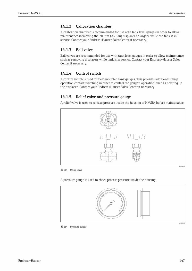
Proservo NMS83 Accessories
Endress+Hauser 147
14.1.2 Calibration chamberA calibration chamber is recommended for use with tank level gauges in order to allowmaintenance (removing the 70 mm (2.76 in) displacer or larger), while the tank is inservice. Contact your Endress+Hauser Sales Center if necessary.
14.1.3 Ball valveBall valves are recommended for use with tank level gauges in order to allow maintenancesuch as removing displacers while tank is in service. Contact your Endress+Hauser SalesCenter if necessary.
14.1.4 Control switchA control switch is used for field mounted tank gauges. This provides additional gaugeoperation contact switching in order to control the gauge’s operation, such as hoisting upthe displacer. Contact your Endress+Hauser Sales Center if necessary.
14.1.5 Relief valve and pressure gaugeA relief valve is used to release pressure inside the housing of NMS8x before maintenance.
A0028881
68 Relief valve
A pressure gauge is used to check process pressure inside the housing.
A0028882
69 Pressure gauge

Accessories Proservo NMS83
148 Endress+Hauser
1
2
A0029104
70 Mounting position of relief valve and pressure gauge
1 Pressure gauge2 Relief valve
14.1.6 Cleaning nozzle and gas purging nozzleA cleaning nozzle used for washing inside housing is especially recommended for F&B oralcohol applications.
A gas purging nozzle used for purging gas inside the housing is especially recommendedfor a nitrogen blanket for petrochemical or chemical applications.
1
2
A0028884
71 Holes for cleaning nozzle and gas purging nozzle
1 Cleaning nozzle2 Gas purging nozzle

Proservo NMS83 Accessories
Endress+Hauser 149
14.2 Communication-specific accessories
Accessory Description
WirelessHART AdapterSWA70
Connects field devices to a WirelessHART network.The WirelessHART adapter can be mounted directly at a HART device and is easlyintegrated into an existing HART network. It ensures safe data transmission andcan be operated in parallel with other wireless networks.
For details refer to Operating Instructions BA00061S
14.3 Service-specific accessories
Accessory Description
Commubox FXA195HART
For intrinsically safe HART communication with FieldCare via the USB interface.
For details refer to Technical Information TI00404F
Accessory Description
Commubox FXA291 Connects Endress+Hauser field devices with CDI interface (= Endress+HauserCommon Data Interface) to the USB interface of a computer.
For details refer to Technical Information TI00405C
Accessory Description
FieldCare Endress+Hauser's FDT-based Plant Asset Management tool.Helps to configure and maintain all field devices of your plant. By supplying statusinformation it also supports the diagnosis of the devices.
For details refer to Operating Instructions BA00027S and BA00059S.
14.4 System components
Accessory Description
RIA15 Compact process display unit with very low voltage drop for universal use to display4 to 20 mA/HART signals
For details refer to Technical Information TI01043K.
Tankvision• Tank Scanner NXA820• Data Concentrator
NXA821• Host Link NXA822
Inventory Management System with completely integrated software for operationvia standard web browser
For details refer to Technical Information TI00419G.
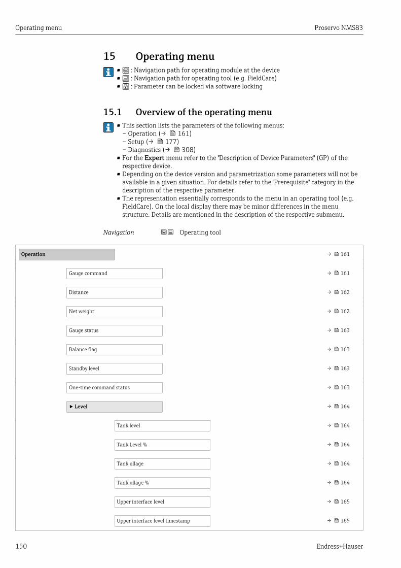
Operating menu Proservo NMS83
150 Endress+Hauser
15 Operating menu• : Navigation path for operating module at the device• : Navigation path for operating tool (e.g. FieldCare)• : Parameter can be locked via software locking
15.1 Overview of the operating menu• This section lists the parameters of the following menus:
– Operation (→ 161)– Setup (→ 177)– Diagnostics (→ 308)
• For the Expert menu refer to the "Description of Device Parameters" (GP) of therespective device.
• Depending on the device version and parametrization some parameters will not beavailable in a given situation. For details refer to the "Prerequisite" category in thedescription of the respective parameter.
• The representation essentially corresponds to the menu in an operating tool (e.g.FieldCare). On the local display there may be minor differences in the menustructure. Details are mentioned in the description of the respective submenu.
Navigation Operating tool
Operation → 161
Gauge command → 161
Distance → 162
Net weight → 162
Gauge status → 163
Balance flag → 163
Standby level → 163
One-time command status → 163
‣ Level → 164
Tank level → 164
Tank Level % → 164
Tank ullage → 164
Tank ullage % → 164
Upper interface level → 165
Upper interface level timestamp → 165

Proservo NMS83 Operating menu
Endress+Hauser 151
Lower interface level → 165
Lower interface level timestamp → 165
Bottom level → 166
Bottom level timestamp → 166
Water level → 166
Measured level → 166
Distance → 162
Displacer position → 167
‣ Temperature → 167
Air temperature → 167
Liquid temperature → 167
Vapor temperature → 168
‣ NMT element values → 168
‣ Element temperature → 168
Element temperature 1 to 24 → 168
‣ Element position → 169
Element position 1 to 24 → 169
‣ Density → 169
Observed density → 169
Vapor density → 169
Air density → 170
Measured upper density → 170
Upper density timestamp → 170
Measured middle density → 170
Middle Density Timestamp → 171
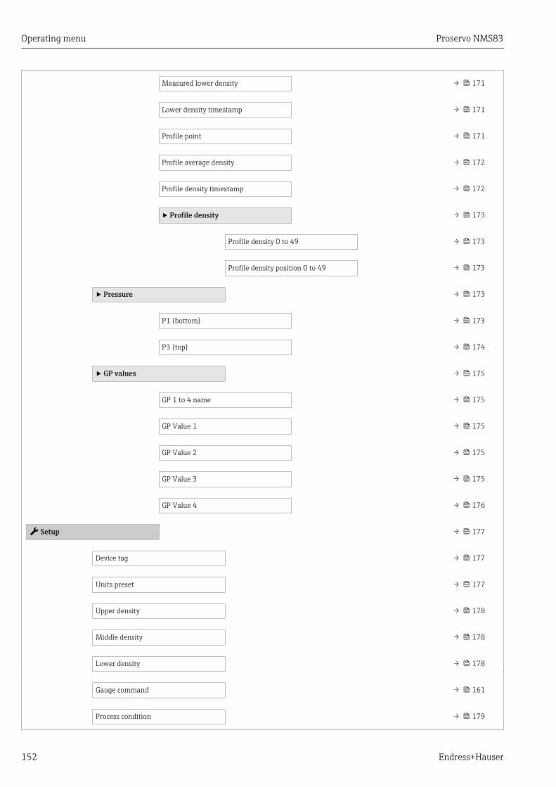
Operating menu Proservo NMS83
152 Endress+Hauser
Measured lower density → 171
Lower density timestamp → 171
Profile point → 171
Profile average density → 172
Profile density timestamp → 172
‣ Profile density → 173
Profile density 0 to 49 → 173
Profile density position 0 to 49 → 173
‣ Pressure → 173
P1 (bottom) → 173
P3 (top) → 174
‣ GP values → 175
GP 1 to 4 name → 175
GP Value 1 → 175
GP Value 2 → 175
GP Value 3 → 175
GP Value 4 → 176
Setup → 177
Device tag → 177
Units preset → 177
Upper density → 178
Middle density → 178
Lower density → 178
Gauge command → 161
Process condition → 179
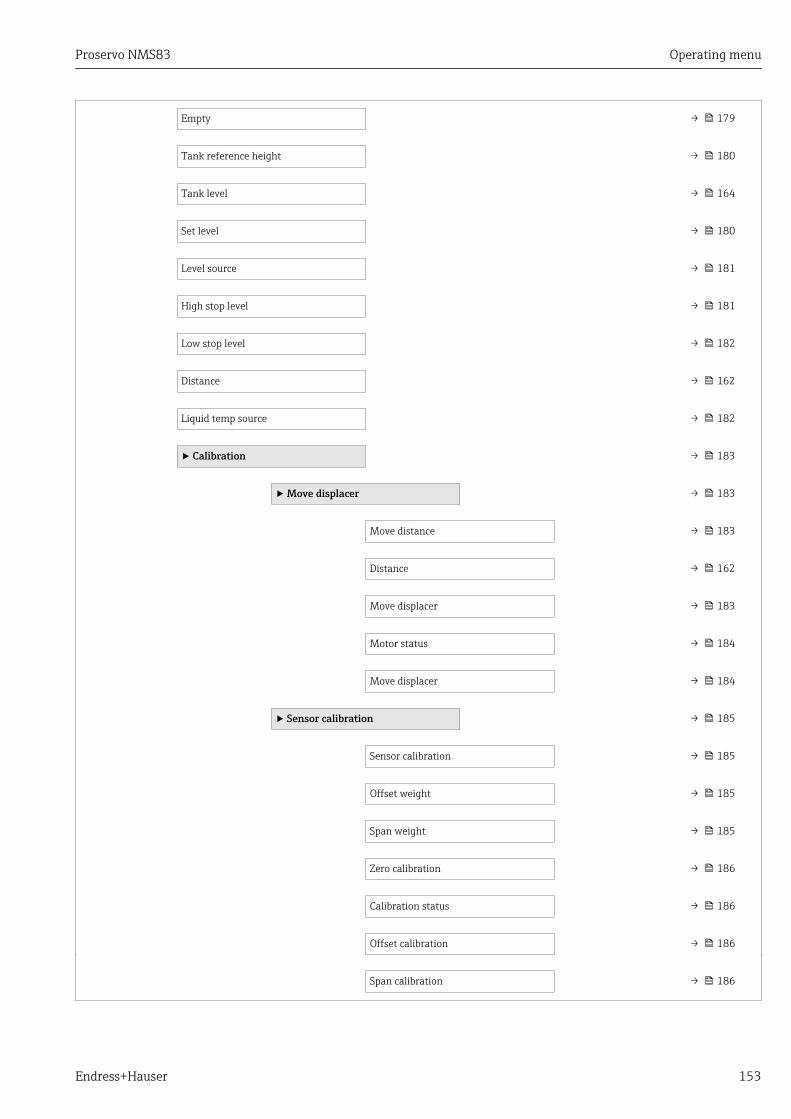
Proservo NMS83 Operating menu
Endress+Hauser 153
Empty → 179
Tank reference height → 180
Tank level → 164
Set level → 180
Level source → 181
High stop level → 181
Low stop level → 182
Distance → 162
Liquid temp source → 182
‣ Calibration → 183
‣ Move displacer → 183
Move distance → 183
Distance → 162
Move displacer → 183
Motor status → 184
Move displacer → 184
‣ Sensor calibration → 185
Sensor calibration → 185
Offset weight → 185
Span weight → 185
Zero calibration → 186
Calibration status → 186
Offset calibration → 186
Span calibration → 186

Operating menu Proservo NMS83
154 Endress+Hauser
‣ Reference calibration → 187
Reference calibration → 187
Reference position → 187
Progress → 187
Calibration status → 186
‣ Drum calibration → 189
Drum calibration → 189
Set high weight → 189
Make drum table → 189
Drum table point → 189
Calibration status → 186
Make low table → 190
Set low weight → 190
‣ Advanced setup → 191
Locking status → 191
Access status tooling → 191
Enter access code → 191
‣ Input/output → 192
‣ HART devices → 192
Number of devices → 192
‣ HART Device(s) → 193
‣ Forget device → 198
‣ Analog IP → 199
Operating mode → 199
RTD type → 199
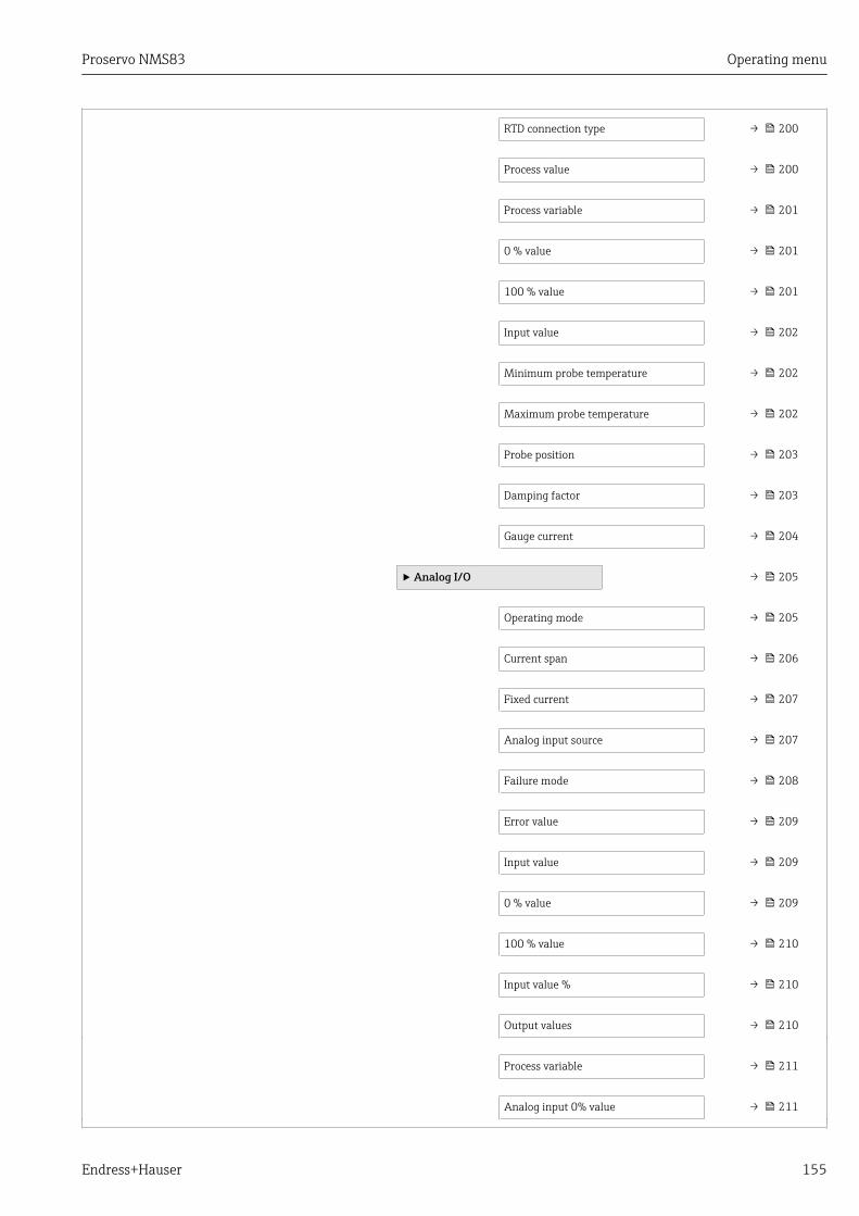
Proservo NMS83 Operating menu
Endress+Hauser 155
RTD connection type → 200
Process value → 200
Process variable → 201
0 % value → 201
100 % value → 201
Input value → 202
Minimum probe temperature → 202
Maximum probe temperature → 202
Probe position → 203
Damping factor → 203
Gauge current → 204
‣ Analog I/O → 205
Operating mode → 205
Current span → 206
Fixed current → 207
Analog input source → 207
Failure mode → 208
Error value → 209
Input value → 209
0 % value → 209
100 % value → 210
Input value % → 210
Output values → 210
Process variable → 211
Analog input 0% value → 211
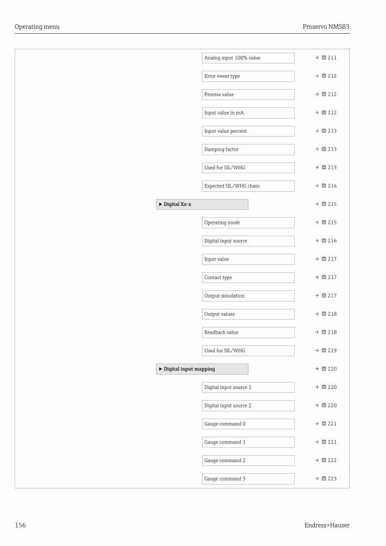
Operating menu Proservo NMS83
156 Endress+Hauser
Analog input 100% value → 211
Error event type → 212
Process value → 212
Input value in mA → 212
Input value percent → 213
Damping factor → 213
Used for SIL/WHG → 213
Expected SIL/WHG chain → 214
‣ Digital Xx-x → 215
Operating mode → 215
Digital input source → 216
Input value → 217
Contact type → 217
Output simulation → 217
Output values → 218
Readback value → 218
Used for SIL/WHG → 219
‣ Digital input mapping → 220
Digital input source 1 → 220
Digital input source 2 → 220
Gauge command 0 → 221
Gauge command 1 → 221
Gauge command 2 → 222
Gauge command 3 → 223
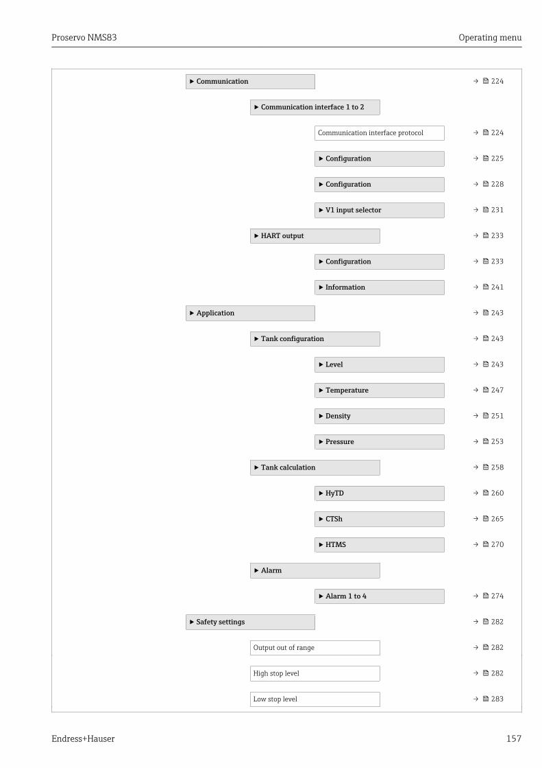
Proservo NMS83 Operating menu
Endress+Hauser 157
‣ Communication → 224
‣ Communication interface 1 to 2
Communication interface protocol → 224
‣ Configuration → 225
‣ Configuration → 228
‣ V1 input selector → 231
‣ HART output → 233
‣ Configuration → 233
‣ Information → 241
‣ Application → 243
‣ Tank configuration → 243
‣ Level → 243
‣ Temperature → 247
‣ Density → 251
‣ Pressure → 253
‣ Tank calculation → 258
‣ HyTD → 260
‣ CTSh → 265
‣ HTMS → 270
‣ Alarm
‣ Alarm 1 to 4 → 274
‣ Safety settings → 282
Output out of range → 282
High stop level → 282
Low stop level → 283
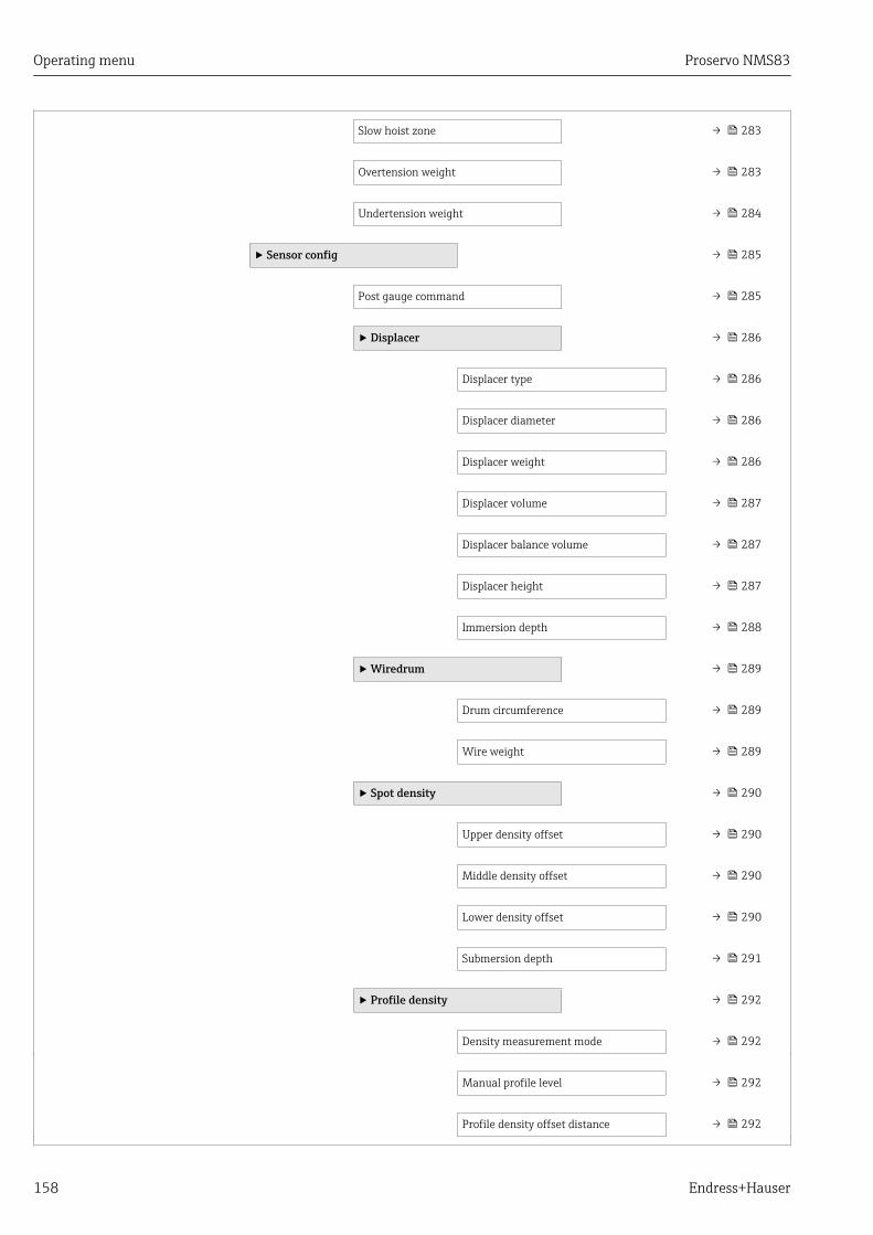
Operating menu Proservo NMS83
158 Endress+Hauser
Slow hoist zone → 283
Overtension weight → 283
Undertension weight → 284
‣ Sensor config → 285
Post gauge command → 285
‣ Displacer → 286
Displacer type → 286
Displacer diameter → 286
Displacer weight → 286
Displacer volume → 287
Displacer balance volume → 287
Displacer height → 287
Immersion depth → 288
‣ Wiredrum → 289
Drum circumference → 289
Wire weight → 289
‣ Spot density → 290
Upper density offset → 290
Middle density offset → 290
Lower density offset → 290
Submersion depth → 291
‣ Profile density → 292
Density measurement mode → 292
Manual profile level → 292
Profile density offset distance → 292
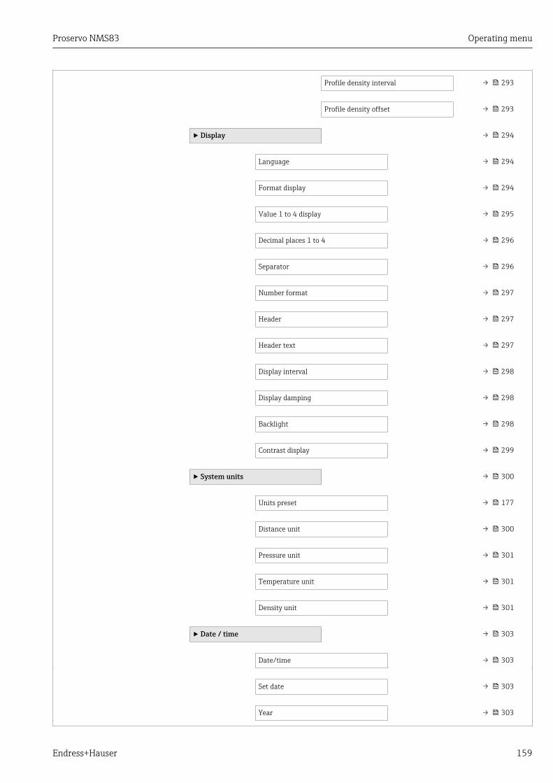
Proservo NMS83 Operating menu
Endress+Hauser 159
Profile density interval → 293
Profile density offset → 293
‣ Display → 294
Language → 294
Format display → 294
Value 1 to 4 display → 295
Decimal places 1 to 4 → 296
Separator → 296
Number format → 297
Header → 297
Header text → 297
Display interval → 298
Display damping → 298
Backlight → 298
Contrast display → 299
‣ System units → 300
Units preset → 177
Distance unit → 300
Pressure unit → 301
Temperature unit → 301
Density unit → 301
‣ Date / time → 303
Date/time → 303
Set date → 303
Year → 303
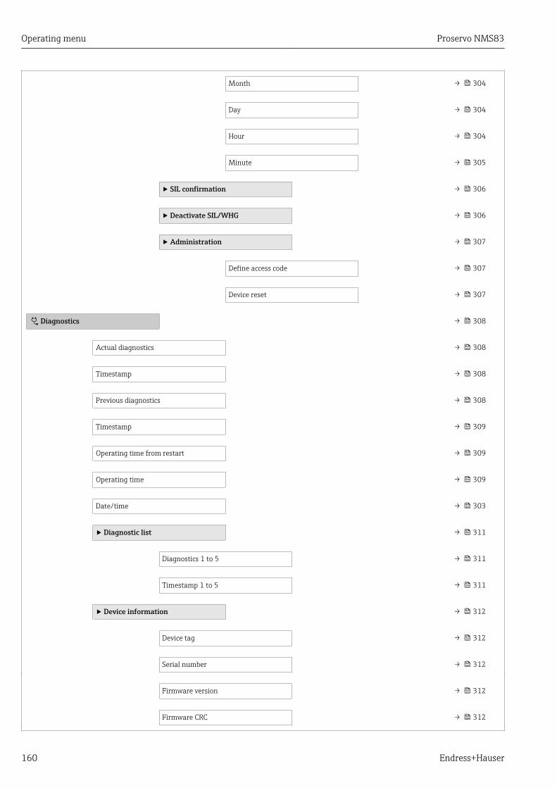
Operating menu Proservo NMS83
160 Endress+Hauser
Month → 304
Day → 304
Hour → 304
Minute → 305
‣ SIL confirmation → 306
‣ Deactivate SIL/WHG → 306
‣ Administration → 307
Define access code → 307
Device reset → 307
Diagnostics → 308
Actual diagnostics → 308
Timestamp → 308
Previous diagnostics → 308
Timestamp → 309
Operating time from restart → 309
Operating time → 309
Date/time → 303
‣ Diagnostic list → 311
Diagnostics 1 to 5 → 311
Timestamp 1 to 5 → 311
‣ Device information → 312
Device tag → 312
Serial number → 312
Firmware version → 312
Firmware CRC → 312
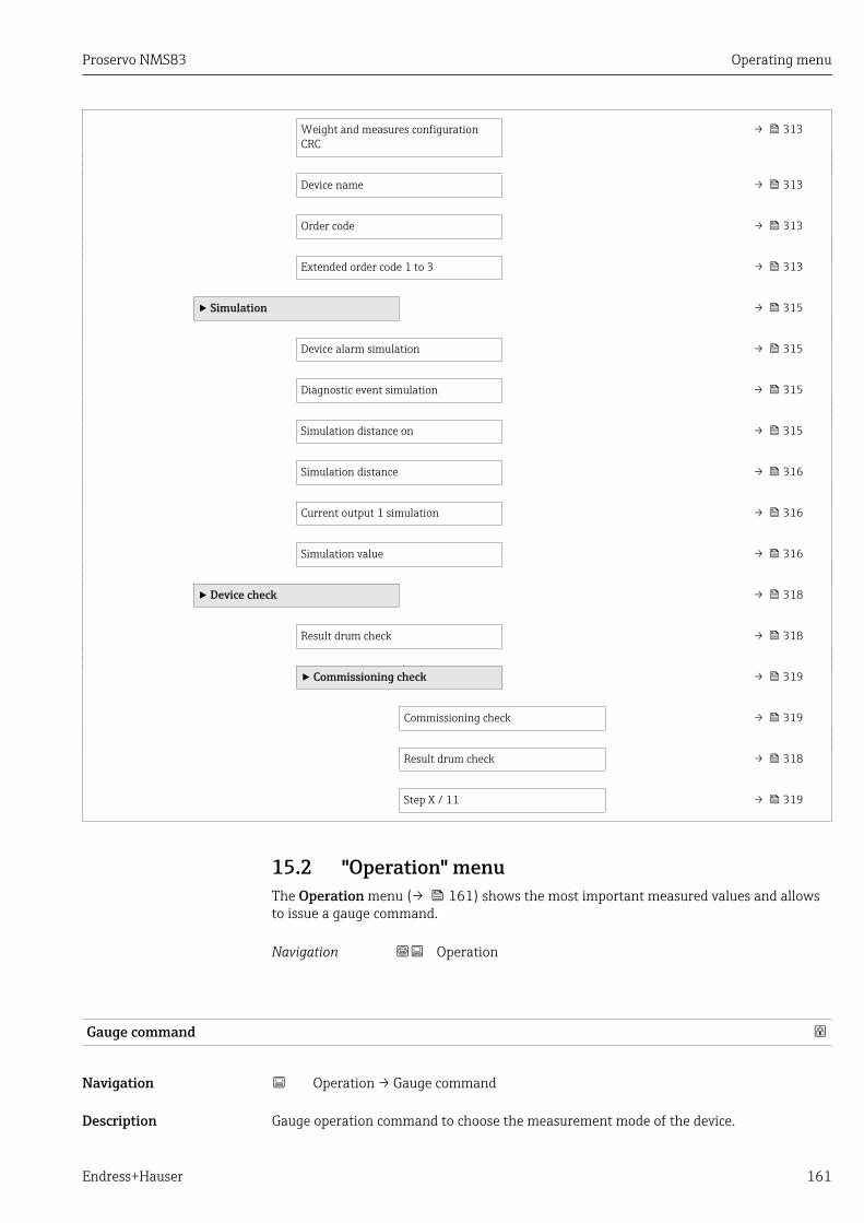
Proservo NMS83 Operating menu
Endress+Hauser 161
Weight and measures configurationCRC
→ 313
Device name → 313
Order code → 313
Extended order code 1 to 3 → 313
‣ Simulation → 315
Device alarm simulation → 315
Diagnostic event simulation → 315
Simulation distance on → 315
Simulation distance → 316
Current output 1 simulation → 316
Simulation value → 316
‣ Device check → 318
Result drum check → 318
‣ Commissioning check → 319
Commissioning check → 319
Result drum check → 318
Step X / 11 → 319
15.2 "Operation" menuThe Operation menu (→ 161) shows the most important measured values and allowsto issue a gauge command.
Navigation Operation
Gauge command
Navigation Operation → Gauge command
Description Gauge operation command to choose the measurement mode of the device.
Operating menu Proservo NMS83
162 Endress+Hauser
Selection • Stop• Level• Up• Bottom level• Upper I/F level• Lower I/F level• Upper density• Middle density• Lower density• Repeatability• Water dip• Release overtension• Tank profile• Interface profile• Manual profile• Level standby
Factory setting Stop
Additional information Read access Operator
Write access Maintenance
Distance
Navigation Operation → Distance
Description Shows measured distance from reference position.
Additional information Read access Operator
Write access -
Net weight
Navigation Operation → Net weight
Description Shows the corrected weight data from the detector, as compensated by the drum table,This weight is used for measurement.
Additional information Read access Operator
Write access -
Proservo NMS83 Operating menu
Endress+Hauser 163
Gauge status
Navigation Operation → Gauge status
Description Indicates the current status of the device gauge command.
Additional information Read access Operator
Write access -
Balance flag
Navigation Operation → Balance flag
Description Indicates the validity of the Measurement. If balanced, corresponding Value (Liquid Level,Upper Interface, Lower Interface, Tank Bottom ) is updated.
Additional information Read access Operator
Write access -
Standby level
Navigation Operation → Standby level
Description Defines the position in the tank where the displacer waits for the liquid level to rise duringstandby level gauge command.
User entry –999 999.9 to 999 999.9 mm
Factory setting 0 mm
Additional information Read access Operator
Write access Maintenance
One-time command status
Navigation Operation → One-time command status
Description Indicates the status of the last executed one-time gauge command.
Additional information Read access Operator
Write access -
Operating menu Proservo NMS83
164 Endress+Hauser
15.2.1 "Level" submenu
Navigation Operation → Level
Tank level
Navigation Operation → Level → Tank level
Description Shows the distance from the zero position (tank bottom or datum plate) to the productsurface.
Additional information Read access Operator
Write access -
Tank Level %
Navigation Operation → Level → Tank Level %
Description Shows the level as a percentage of the full measuring range.
Additional information Read access Operator
Write access -
Tank ullage
Navigation Operation → Level → Tank ullage
Description Shows the remaining empty space in the tank.
Additional information Read access Operator
Write access -
Tank ullage %
Navigation Operation → Level → Tank ullage %
Description Shows the remaining empty space in percentage related to parameter tank referenceheight.
Additional information Read access Operator
Write access -
Proservo NMS83 Operating menu
Endress+Hauser 165
Upper interface level
Navigation Operation → Level → Upper interface level
Description Shows measured interface level from zero position (tank bottom or datum plate). Value isupdated when device generates a valid Interface measurement.
Additional information Read access Maintenance
Write access -
Upper interface level timestamp
Navigation Operation → Level → Upper interface level timestamp
Description Shows timestamp for the last measured upper interface level.
Additional information Read access Operator
Write access -
Lower interface level
Navigation Operation → Level → Lower interface level
Description Shows measured interface level from zero position (tank bottom or datum plate). Value isupdated when device generates a valid interface measurement.
Additional information Read access Maintenance
Write access -
Lower interface level timestamp
Navigation Operation → Level → Lower interface level timestamp
Description Shows timestamp of the last measured lower interface level.
Additional information Read access Operator
Write access -

Operating menu Proservo NMS83
166 Endress+Hauser
Bottom level
Navigation Operation → Level → Bottom level
Description Shows the bottom level.
Additional information Read access Operator
Write access -
Bottom level timestamp
Navigation Operation → Level → Bottom level timestamp
Description Shows the timestamp for measured bottom level.
Additional information Read access Operator
Write access -
Water level
Navigation Operation → Level → Water level
Description Shows the bottom water level.
Additional information Read access Operator
Write access -
Measured level
Navigation Operation → Level → Measured level
Description Shows the measured level without any correction from the tank calculations.
Additional information Read access Operator
Write access -

Proservo NMS83 Operating menu
Endress+Hauser 167
Distance
Navigation Operation → Level → Distance
Description Shows measured distance from reference position.
Additional information Read access Operator
Write access -
Displacer position
Navigation Operation → Level → Displacer position
Description Shows the displacer position.
Additional information Read access Operator
Write access -
15.2.2 "Temperature" submenu
Navigation Operation → Temperature
Air temperature
Navigation Operation → Temperature → Air temperature
Description Shows the air temperature.
Additional information Read access Operator
Write access -
Liquid temperature
Navigation Operation → Temperature → Liquid temperature
Description Shows the average or spot temperature of the measured liquid.
Additional information Read access Operator
Write access -

Operating menu Proservo NMS83
168 Endress+Hauser
Vapor temperature
Navigation Operation → Temperature → Vapor temperature
Description Shows the measured vapor temperature.
Additional information Read access Operator
Write access -
"NMT element values" submenuThis submenu is only visible if a Prothermo NMT is connected.
Navigation Operation → Temperature → NMT element values
"Element temperature" submenu
Navigation Operation → Temperature → NMT element values → Elementtemperature
Element temperature 1 to 24
Navigation Operation → Temperature → NMT element values → Element temperature→ Element temperature 1 to 24
Description Shows the temperature of an element in the NMT.
Additional information Read access Operator
Write access -

Proservo NMS83 Operating menu
Endress+Hauser 169
"Element position" submenu
Navigation Operation → Temperature → NMT element values → Elementposition
Element position 1 to 24
Navigation Operation → Temperature → NMT element values → Element position → Elementposition 1 to 24
Description Shows the position of the selected element in the NMT.
Additional information Read access Operator
Write access -
15.2.3 "Density" submenu
Navigation Operation → Density
Observed density
Navigation Operation → Density → Observed density
Description Calculated density of the product.
Additional information Read access Operator
Write access -
This value is calculated from different measured variables depending on the selectedcalculation method → 258.
Vapor density
Navigation Operation → Density → Vapor density
Description Defines the density of the gas phase in the tank.
User entry 0.0 to 500.0 kg/m³
Factory setting 1.2 kg/m³
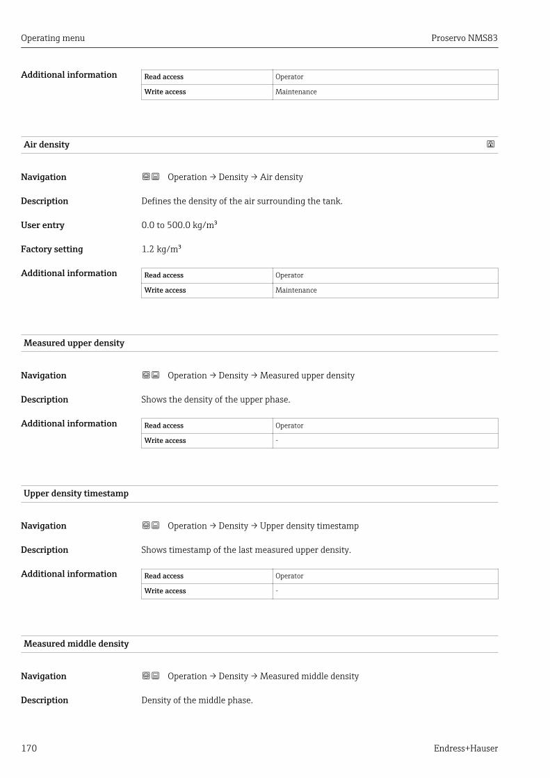
Operating menu Proservo NMS83
170 Endress+Hauser
Additional information Read access Operator
Write access Maintenance
Air density
Navigation Operation → Density → Air density
Description Defines the density of the air surrounding the tank.
User entry 0.0 to 500.0 kg/m³
Factory setting 1.2 kg/m³
Additional information Read access Operator
Write access Maintenance
Measured upper density
Navigation Operation → Density → Measured upper density
Description Shows the density of the upper phase.
Additional information Read access Operator
Write access -
Upper density timestamp
Navigation Operation → Density → Upper density timestamp
Description Shows timestamp of the last measured upper density.
Additional information Read access Operator
Write access -
Measured middle density
Navigation Operation → Density → Measured middle density
Description Density of the middle phase.

Proservo NMS83 Operating menu
Endress+Hauser 171
Additional information Read access Operator
Write access -
Middle Density Timestamp
Navigation Operation → Density → Middle Density Timestamp
Description Shows the timestamp of the last measured middle density.
Additional information Read access Operator
Write access -
Measured lower density
Navigation Operation → Density → Measured lower density
Description Density of the lower phase.
Additional information Read access Maintenance
Write access -
Lower density timestamp
Navigation Operation → Density → Lower density timestamp
Description Shows timestamp of last measured lower density.
Additional information Read access Operator
Write access -
Profile point
Navigation Operation → Density → Profile point
Description Shows actual number of Density Points measured so far in current operation, and the totalNumber of Points after Density Profile Operation is complete.
Additional information Read access Operator
Write access -
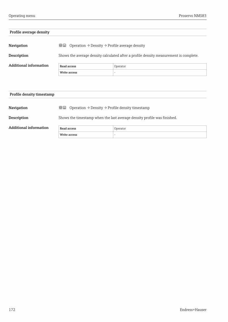
Operating menu Proservo NMS83
172 Endress+Hauser
Profile average density
Navigation Operation → Density → Profile average density
Description Shows the average density calculated after a profile density measurement is complete.
Additional information Read access Operator
Write access -
Profile density timestamp
Navigation Operation → Density → Profile density timestamp
Description Shows the timestamp when the last average density profile was finished.
Additional information Read access Operator
Write access -

Proservo NMS83 Operating menu
Endress+Hauser 173
"Profile density" submenu
Navigation Operation → Density → Profile density
Profile density 0 to 49
Navigation Operation → Density → Profile density → Profile density 0 to 49
Description Shows the density measurement at the corresponding profile density position.
Additional information Read access Operator
Write access -
Profile density position 0 to 49
Navigation Operation → Density → Profile density → Profile density position 0 to 49
Description Shows the position where the corresponding density was measured.
Additional information Read access Operator
Write access -
15.2.4 "Pressure" submenu
Navigation Operation → Pressure
P1 (bottom)
Navigation Operation → Pressure → P1 (bottom)
Description Shows the pressure at the tank bottom.
Additional information Read access Operator
Write access -

Operating menu Proservo NMS83
174 Endress+Hauser
P3 (top)
Navigation Operation → Pressure → P3 (top)
Description Shows the pressure (P3) at the top transmitter.
Additional information Read access Operator
Write access -
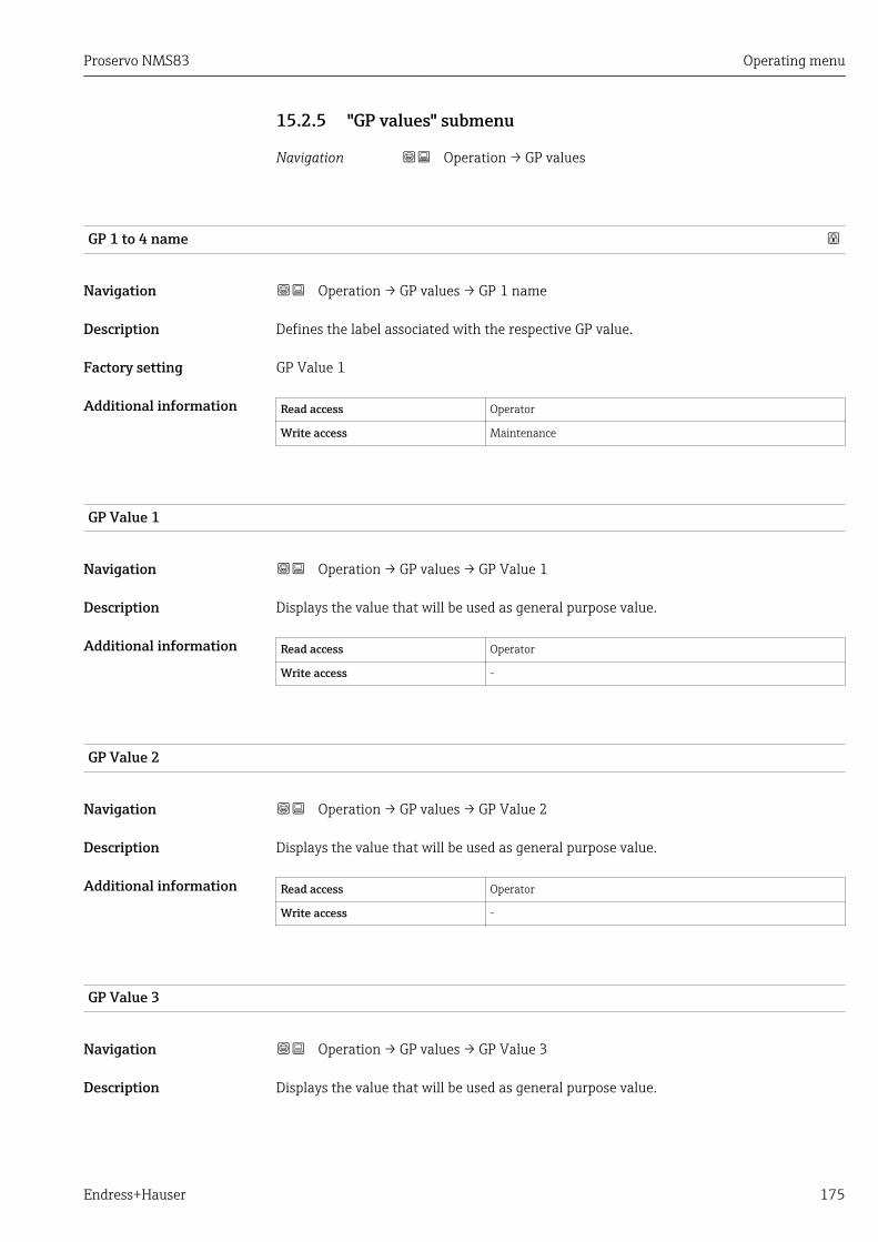
Proservo NMS83 Operating menu
Endress+Hauser 175
15.2.5 "GP values" submenu
Navigation Operation → GP values
GP 1 to 4 name
Navigation Operation → GP values → GP 1 name
Description Defines the label associated with the respective GP value.
Factory setting GP Value 1
Additional information Read access Operator
Write access Maintenance
GP Value 1
Navigation Operation → GP values → GP Value 1
Description Displays the value that will be used as general purpose value.
Additional information Read access Operator
Write access -
GP Value 2
Navigation Operation → GP values → GP Value 2
Description Displays the value that will be used as general purpose value.
Additional information Read access Operator
Write access -
GP Value 3
Navigation Operation → GP values → GP Value 3
Description Displays the value that will be used as general purpose value.

Operating menu Proservo NMS83
176 Endress+Hauser
Additional information Read access Operator
Write access -
GP Value 4
Navigation Operation → GP values → GP Value 4
Description Displays the value that will be used as general purpose value.
Additional information Read access Operator
Write access -
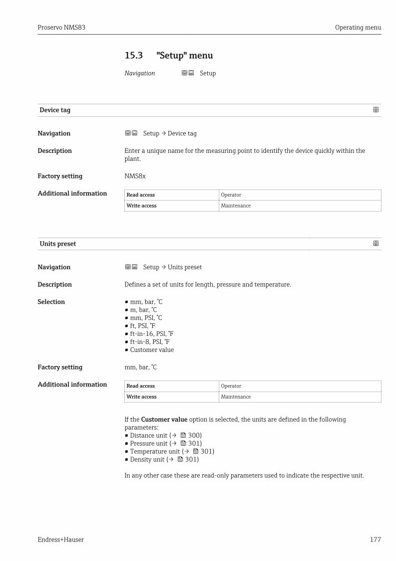
Proservo NMS83 Operating menu
Endress+Hauser 177
15.3 "Setup" menu
Navigation Setup
Device tag
Navigation Setup → Device tag
Description Enter a unique name for the measuring point to identify the device quickly within theplant.
Factory setting NMS8x
Additional information Read access Operator
Write access Maintenance
Units preset
Navigation Setup → Units preset
Description Defines a set of units for length, pressure and temperature.
Selection • mm, bar, °C• m, bar, °C• mm, PSI, °C• ft, PSI, °F• ft-in-16, PSI, °F• ft-in-8, PSI, °F• Customer value
Factory setting mm, bar, °C
Additional information Read access Operator
Write access Maintenance
If the Customer value option is selected, the units are defined in the followingparameters:• Distance unit (→ 300)• Pressure unit (→ 301)• Temperature unit (→ 301)• Density unit (→ 301)
In any other case these are read-only parameters used to indicate the respective unit.

Operating menu Proservo NMS83
178 Endress+Hauser
Upper density
Navigation Setup → Upper density
Description Sets the density of the upper phase of the liquid.
User entry 50 to 2 000 kg/m³
Factory setting 800 kg/m³
Additional information Read access Operator
Write access Maintenance
Middle density
Navigation Setup → Middle density
Description Sets Density of Middle Phase in the Tank if three Phases are available. Otherwise used forthe Lower Phase in the Tank if two Phases are available.
User entry 50 to 2 000 kg/m³
Factory setting 1 000 kg/m³
Additional information Read access Operator
Write access Maintenance
Lower density
Navigation Setup → Lower density
Description Sets the density of the lower Phase in the tank if three phases are available.
User entry 50 to 2 000 kg/m³
Factory setting 1 200 kg/m³
Additional information Read access Operator
Write access Maintenance
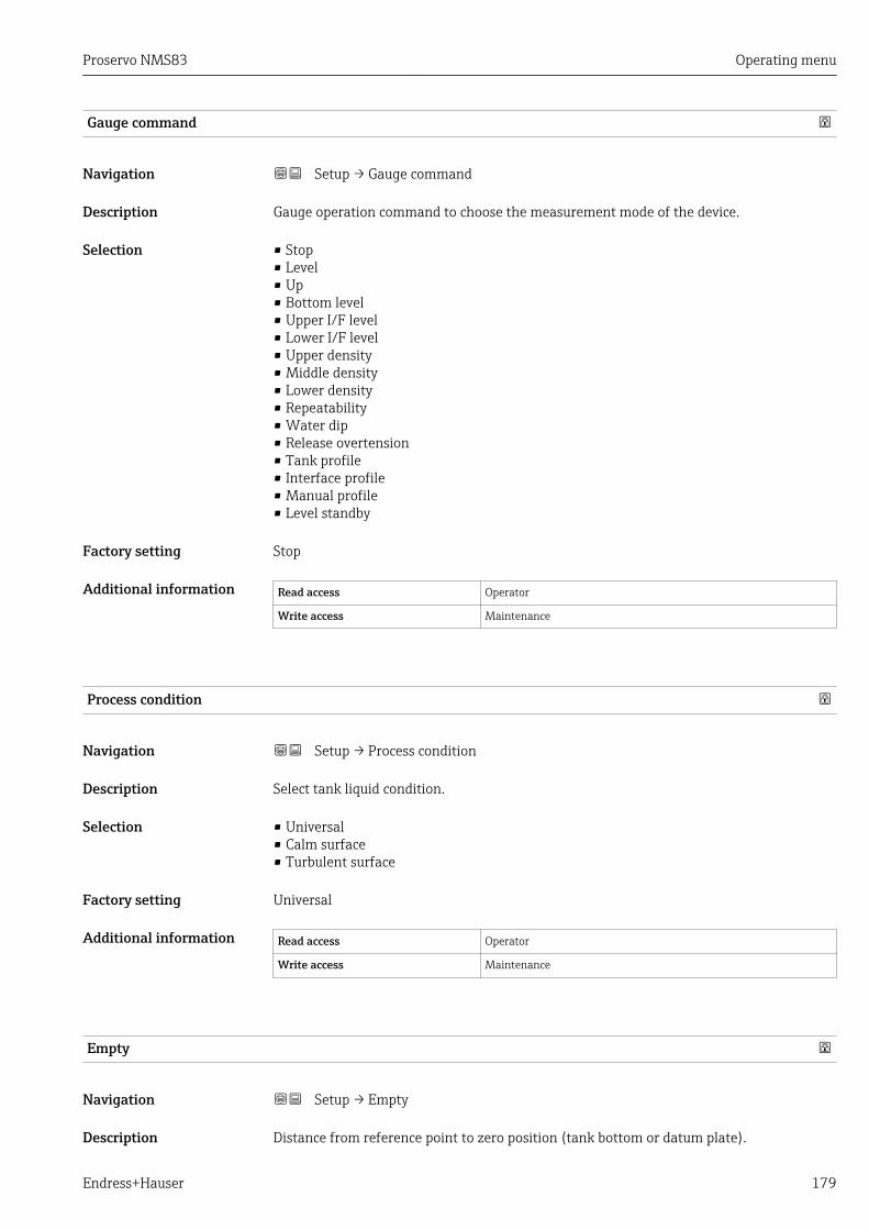
Proservo NMS83 Operating menu
Endress+Hauser 179
Gauge command
Navigation Setup → Gauge command
Description Gauge operation command to choose the measurement mode of the device.
Selection • Stop• Level• Up• Bottom level• Upper I/F level• Lower I/F level• Upper density• Middle density• Lower density• Repeatability• Water dip• Release overtension• Tank profile• Interface profile• Manual profile• Level standby
Factory setting Stop
Additional information Read access Operator
Write access Maintenance
Process condition
Navigation Setup → Process condition
Description Select tank liquid condition.
Selection • Universal• Calm surface• Turbulent surface
Factory setting Universal
Additional information Read access Operator
Write access Maintenance
Empty
Navigation Setup → Empty
Description Distance from reference point to zero position (tank bottom or datum plate).

Operating menu Proservo NMS83
180 Endress+Hauser
User entry 0 to 10 000.00 mm
Factory setting Dependent on the device version
Additional information Read access Operator
Write access Maintenance
The reference point is the reference line of the calibration window.
Tank reference height
Navigation Setup → Tank reference height
Description Defines the distance from the dipping reference point to the zero position (tank bottom ordatum plate).
User entry 0 to 10 000.00 mm
Factory setting Dependent on the device version
Additional information Read access Operator
Write access Maintenance
Tank level
Navigation Setup → Tank level
Description Shows the distance from the zero position (tank bottom or datum plate) to the productsurface.
Additional information Read access Operator
Write access -
Set level
Navigation Setup → Set level
Description If the level measured by the device does not match the actual level obtained by a manualdip, enter the correct level into this parameter.
User entry 0 to 10 000.00 mm
Factory setting 0 mm

Proservo NMS83 Operating menu
Endress+Hauser 181
Additional information Read access Operator
Write access Maintenance
The device adjusts the Empty parameter (→ 179) according to the entered value, suchthat the measured level will match the actual level.
Level source
Navigation Setup → Level source
Description Defines the source of the level value.
Selection • No input value• HART device 1 ... 15 level• Level SR *
• Level *• Displacer position *
• AIO B1-3 value *
• AIO C1-3 value *
• AIP B4-8 value *
• AIP C4-8 value *
Factory setting Dependent on the device version
Additional information Read access Operator
Write access Maintenance
High stop level
Navigation Setup → High stop level
Description Position of the displacer high stop as measured from defined zero position (tank bottom ordatum plate).
User entry –999 999.9 to 999 999.9 mm
Factory setting 20 000 mm
Additional information Read access Operator
Write access Maintenance
* Visibility depends on order options or device settings
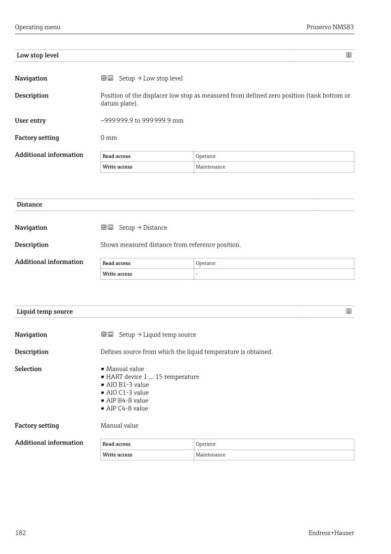
Operating menu Proservo NMS83
182 Endress+Hauser
Low stop level
Navigation Setup → Low stop level
Description Position of the displacer low stop as measured from defined zero position (tank bottom ordatum plate).
User entry –999 999.9 to 999 999.9 mm
Factory setting 0 mm
Additional information Read access Operator
Write access Maintenance
Distance
Navigation Setup → Distance
Description Shows measured distance from reference position.
Additional information Read access Operator
Write access -
Liquid temp source
Navigation Setup → Liquid temp source
Description Defines source from which the liquid temperature is obtained.
Selection • Manual value• HART device 1 ... 15 temperature• AIO B1-3 value• AIO C1-3 value• AIP B4-8 value• AIP C4-8 value
Factory setting Manual value
Additional information Read access Operator
Write access Maintenance
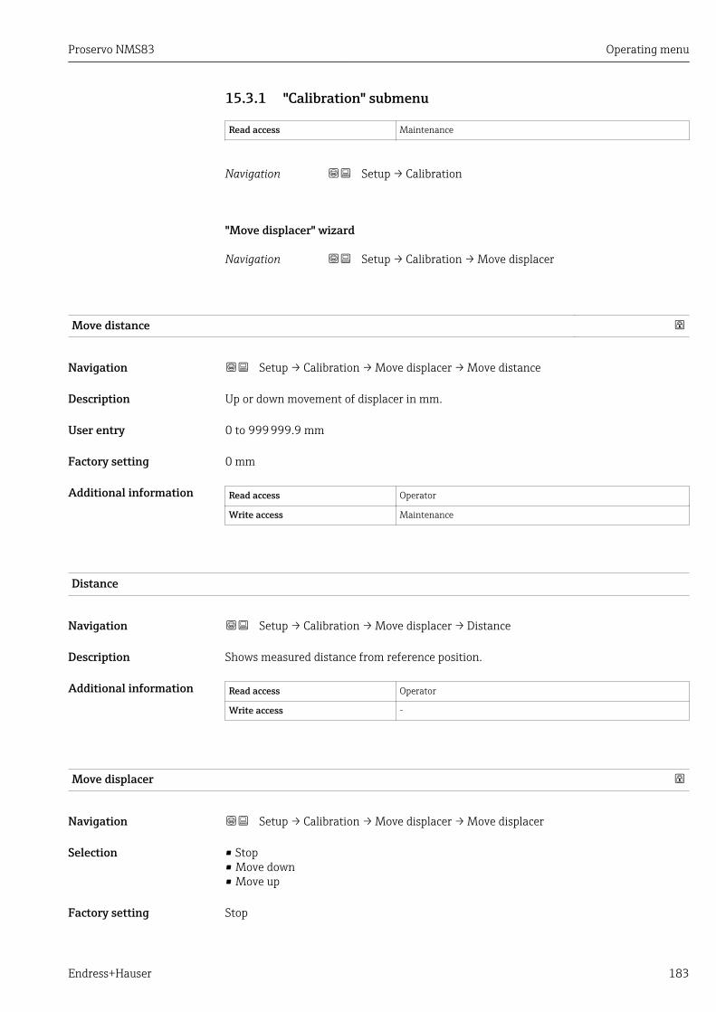
Proservo NMS83 Operating menu
Endress+Hauser 183
15.3.1 "Calibration" submenu
Read access Maintenance
Navigation Setup → Calibration
"Move displacer" wizard
Navigation Setup → Calibration → Move displacer
Move distance
Navigation Setup → Calibration → Move displacer → Move distance
Description Up or down movement of displacer in mm.
User entry 0 to 999 999.9 mm
Factory setting 0 mm
Additional information Read access Operator
Write access Maintenance
Distance
Navigation Setup → Calibration → Move displacer → Distance
Description Shows measured distance from reference position.
Additional information Read access Operator
Write access -
Move displacer
Navigation Setup → Calibration → Move displacer → Move displacer
Selection • Stop• Move down• Move up
Factory setting Stop

Operating menu Proservo NMS83
184 Endress+Hauser
Additional information Read access Operator
Write access Maintenance
Motor status
Navigation Setup → Calibration → Move displacer → Motor status
Description Shows the current moving Direction of the Motor.
Additional information Read access Operator
Write access -
Move displacer
Navigation Setup → Calibration → Move displacer → Move displacer
Selection • No• Yes
Factory setting No
Additional information Read access Operator
Write access Maintenance

Proservo NMS83 Operating menu
Endress+Hauser 185
"Sensor calibration" wizard
Navigation Setup → Calibration → Sensor calibration
Sensor calibration
Navigation Setup → Calibration → Sensor calibration → Sensor calibration
Description This sequence calibrates the sensor of the servo.
Additional information Read access Operator
Write access Maintenance
Offset weight
Navigation Setup → Calibration → Sensor calibration → Offset weight
Description Sets the weight that is used for the lower point sensor calibration. Changing the value willdelete the calibration data.
User entry 0 to 150 g
Factory setting Dependent on the device version
Additional information Read access Operator
Write access Maintenance
For density measurement application, it is recommended to apply 50 g.
Span weight
Navigation Setup → Calibration → Sensor calibration → Span weight
Description Sets the weight that is used for the middle point sensor calibration. Changing the valuewill delete the calibration data.
User entry 10 to 999.9 g
Factory setting Dependent on the device version
Additional information Read access Operator
Write access Maintenance
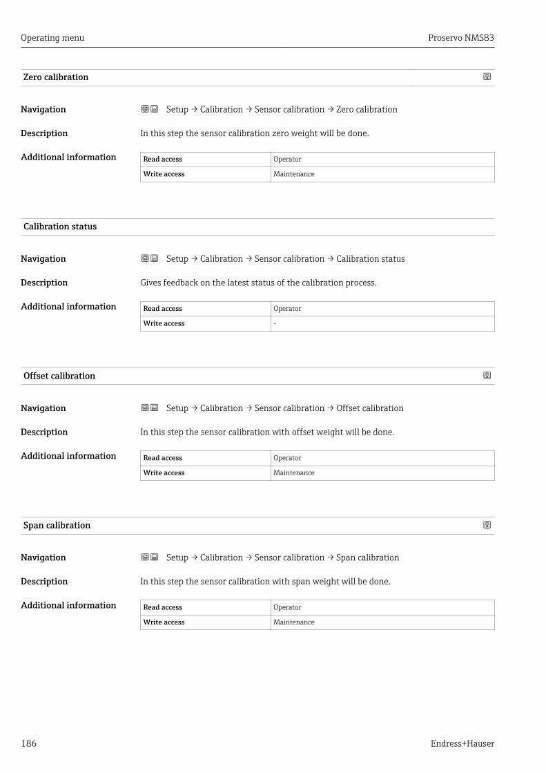
Operating menu Proservo NMS83
186 Endress+Hauser
Zero calibration
Navigation Setup → Calibration → Sensor calibration → Zero calibration
Description In this step the sensor calibration zero weight will be done.
Additional information Read access Operator
Write access Maintenance
Calibration status
Navigation Setup → Calibration → Sensor calibration → Calibration status
Description Gives feedback on the latest status of the calibration process.
Additional information Read access Operator
Write access -
Offset calibration
Navigation Setup → Calibration → Sensor calibration → Offset calibration
Description In this step the sensor calibration with offset weight will be done.
Additional information Read access Operator
Write access Maintenance
Span calibration
Navigation Setup → Calibration → Sensor calibration → Span calibration
Description In this step the sensor calibration with span weight will be done.
Additional information Read access Operator
Write access Maintenance
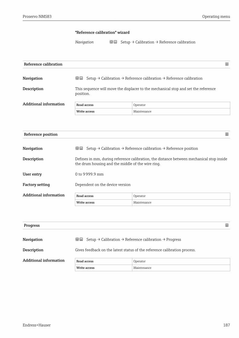
Proservo NMS83 Operating menu
Endress+Hauser 187
"Reference calibration" wizard
Navigation Setup → Calibration → Reference calibration
Reference calibration
Navigation Setup → Calibration → Reference calibration → Reference calibration
Description This sequence will move the displacer to the mechanical stop and set the referenceposition.
Additional information Read access Operator
Write access Maintenance
Reference position
Navigation Setup → Calibration → Reference calibration → Reference position
Description Defines in mm, during reference calibration, the distance between mechanical stop insidethe drum housing and the middle of the wire ring.
User entry 0 to 9 999.9 mm
Factory setting Dependent on the device version
Additional information Read access Operator
Write access Maintenance
Progress
Navigation Setup → Calibration → Reference calibration → Progress
Description Gives feedback on the latest status of the reference calibration process.
Additional information Read access Operator
Write access Maintenance

Operating menu Proservo NMS83
188 Endress+Hauser
Calibration status
Navigation Setup → Calibration → Reference calibration → Calibration status
Description Gives feedback on the latest status of the calibration process.
Additional information Read access Operator
Write access -
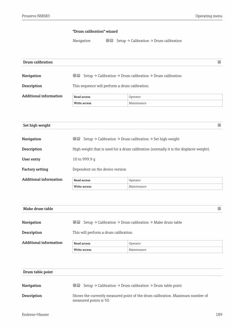
Proservo NMS83 Operating menu
Endress+Hauser 189
"Drum calibration" wizard
Navigation Setup → Calibration → Drum calibration
Drum calibration
Navigation Setup → Calibration → Drum calibration → Drum calibration
Description This sequence will perform a drum calibration.
Additional information Read access Operator
Write access Maintenance
Set high weight
Navigation Setup → Calibration → Drum calibration → Set high weight
Description High weight that is used for a drum calibration (normally it is the displacer weight).
User entry 10 to 999.9 g
Factory setting Dependent on the device version
Additional information Read access Operator
Write access Maintenance
Make drum table
Navigation Setup → Calibration → Drum calibration → Make drum table
Description This will perform a drum calibration.
Additional information Read access Operator
Write access Maintenance
Drum table point
Navigation Setup → Calibration → Drum calibration → Drum table point
Description Shows the currently measured point of the drum calibration. Maximum number ofmeasured points is 50.

Operating menu Proservo NMS83
190 Endress+Hauser
Additional information Read access Operator
Write access -
Calibration status
Navigation Setup → Calibration → Drum calibration → Calibration status
Description Gives feedback on the latest status of the calibration process.
Additional information Read access Operator
Write access -
Make low table
Navigation Setup → Calibration → Drum calibration → Make low table
Description For additional accuracy it is possible to perform a second drum calibration with low weight.Choose 'Yes' or 'No' to start/stop calibration.
Selection • No• Yes
Factory setting No
Additional information Read access Operator
Write access Maintenance
Set low weight
Navigation Setup → Calibration → Drum calibration → Set low weight
Description Set weight for additional drum calibration sequence.
User entry 10 to 999.9 g
Factory setting Dependent on the device version
Additional information Read access Operator
Write access Maintenance
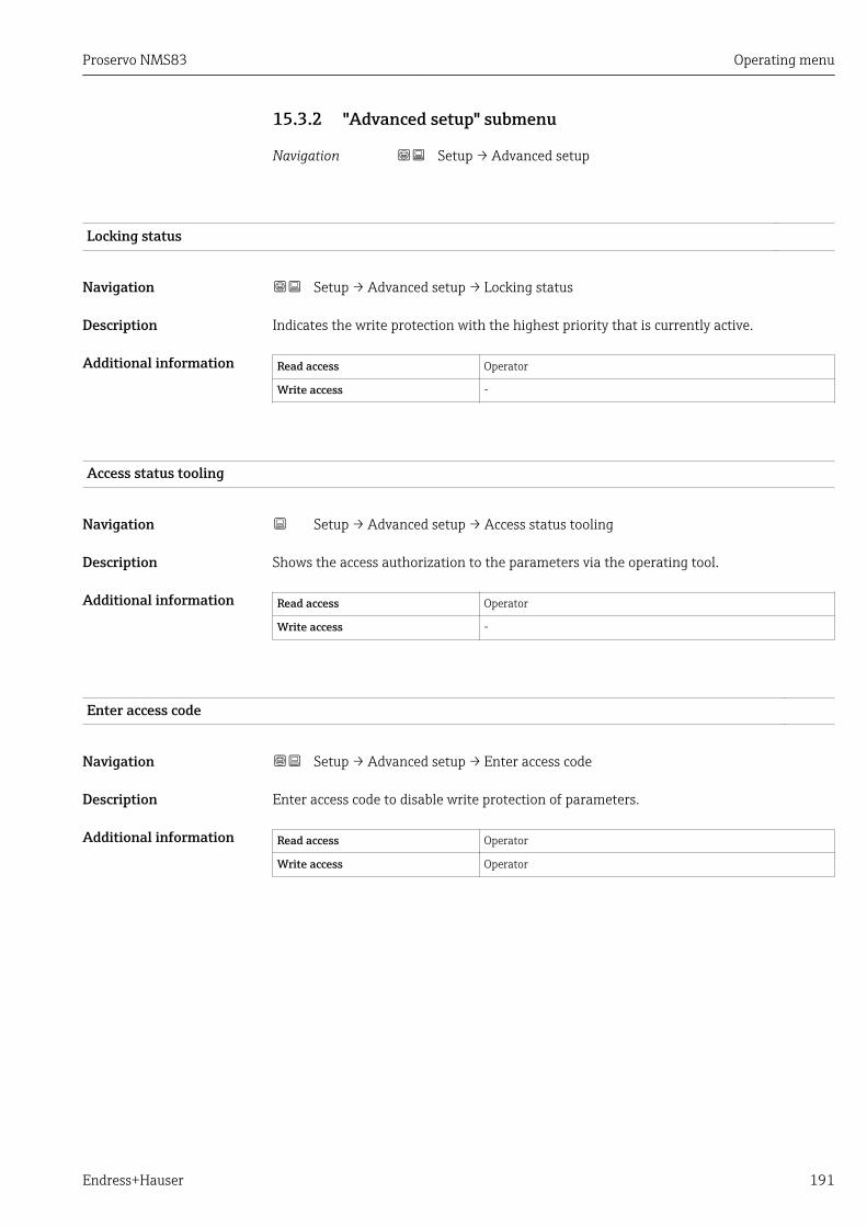
Proservo NMS83 Operating menu
Endress+Hauser 191
15.3.2 "Advanced setup" submenu
Navigation Setup → Advanced setup
Locking status
Navigation Setup → Advanced setup → Locking status
Description Indicates the write protection with the highest priority that is currently active.
Additional information Read access Operator
Write access -
Access status tooling
Navigation Setup → Advanced setup → Access status tooling
Description Shows the access authorization to the parameters via the operating tool.
Additional information Read access Operator
Write access -
Enter access code
Navigation Setup → Advanced setup → Enter access code
Description Enter access code to disable write protection of parameters.
Additional information Read access Operator
Write access Operator

Operating menu Proservo NMS83
192 Endress+Hauser
"Input/output" submenu
Navigation Setup → Advanced setup → Input/output
"HART devices" submenu
Navigation Setup → Advanced setup → Input/output → HART devices
Number of devices
Navigation Setup → Advanced setup → Input/output → HART devices → Number of devices
Description Shows the number of devices on the HART bus.
Additional information Read access Operator
Write access -

Proservo NMS83 Operating menu
Endress+Hauser 193
"HART Device(s)" submenu
There is a HART Device(s) submenu for each HART slave device found on the HARTloop.
Navigation Setup → Advanced setup → Input/output → HART devices→ HART Device(s)
Device name
Navigation Setup → Advanced setup → Input/output → HART devices → HART Device(s)→ Device name
Description Shows the name of the transmitter.
Additional information Read access Operator
Write access -
Polling address
Navigation Setup → Advanced setup → Input/output → HART devices → HART Device(s)→ Polling address
Description Shows the polling address of the transmitter.
Additional information Read access Operator
Write access -
Device tag
Navigation Setup → Advanced setup → Input/output → HART devices → HART Device(s)→ Device tag
Description Shows the device tag of the transmitter.
Additional information Read access Operator
Write access -

Operating menu Proservo NMS83
194 Endress+Hauser
Operating mode
Navigation Setup → Advanced setup → Input/output → HART devices → HART Device(s)→ Operating mode
Prerequisite Not available if the HART device is a Prothermo NMT.
Description Selection of the operation mode PV only or PV,SV,TV,QV. Devines which values are polledfrom the connected HART Device.
Selection • PV only• PV,SV,TV & QV• Level 4)
• Measured level 4)
Factory setting PV,SV,TV & QV
Additional information Read access Operator
Write access Maintenance
Communication status
Navigation Setup → Advanced setup → Input/output → HART devices → HART Device(s)→ Communication status
Description Shows the operating status of the transmitter.
User interface • Operating normally• Device offline
Additional information Read access Operator
Write access -
#blank# ( HART PV - designation dependent on device)
Navigation Setup → Advanced setup → Input/output → HART devices → HART Device(s)→ #blank#
Description Shows the first HART variable (PV).
Additional information Read access Operator
Write access -
4) only visible if the conneced device is a Micropilot

Proservo NMS83 Operating menu
Endress+Hauser 195
#blank# (HART SV - designation dependent on device)
Navigation Setup → Advanced setup → Input/output → HART devices → HART Device(s)→ #blank#
Prerequisite For HART devices other than NMT: Operating mode (→ 194) = PV,SV,TV & QV
Description Shows the second HART variable (SV).
Additional information Read access Operator
Write access -
#blank# (HART TV - designation dependent on device)
Navigation Setup → Advanced setup → Input/output → HART devices → HART Device(s)→ #blank#
Prerequisite For HART devices other than NMT: Operating mode (→ 194) = PV,SV,TV & QV
Description Shows the third HART variable (TV).
Additional information Read access Operator
Write access -
#blank# (HART QV - designation dependent on device)
Navigation Setup → Advanced setup → Input/output → HART devices → HART Device(s)→ #blank#
Prerequisite For HART devices other than NMT: Operating mode (→ 194) = PV,SV,TV & QV
Description Shows the fourth HART variable (QV).
Additional information Read access Operator
Write access -
Output pressure
Navigation Setup → Advanced setup → Input/output → HART devices → HART Device(s)→ Output pressure
Prerequisite Not available for Micropilot S FMR5xx and Prothermo 53x. (In these cases the measuredvariables are allocated automatically).

Operating menu Proservo NMS83
196 Endress+Hauser
Description Defines which HART variable is the pressure.
Selection • No value• Primary variable (PV)• Secondary variable (SV)• Tertiary variable (TV)• Quaternary variable (QV)
Factory setting No value
Additional information Read access Operator
Write access Maintenance
Output density
Navigation Setup → Advanced setup → Input/output → HART devices → HART Device(s)→ Output density
Prerequisite Not available for Micropilot S FMR5xx and Prothermo 53x. (In these cases the measuredvariables are allocated automatically).
Description Defines which HART variable is the density.
Selection • No value• Primary variable (PV)• Secondary variable (SV)• Tertiary variable (TV)• Quaternary variable (QV)
Factory setting No value
Additional information Read access Operator
Write access Maintenance
Output temperature
Navigation Setup → Advanced setup → Input/output → HART devices → HART Device(s)→ Output temperature
Prerequisite Not available for Micropilot S FMR5xx and Prothermo 53x. (In these cases the measuredvariables are allocated automatically).
Description Defines which HART variable is the temperature.
Selection • No value• Primary variable (PV)• Secondary variable (SV)• Tertiary variable (TV)• Quaternary variable (QV)

Proservo NMS83 Operating menu
Endress+Hauser 197
Factory setting No value
Additional information Read access Operator
Write access Maintenance
Output vapor temperature
Navigation Setup → Advanced setup → Input/output → HART devices → HART Device(s)→ Output vapor temperature
Prerequisite Not available for Micropilot S FMR5xx and Prothermo 53x. (In these cases the measuredvariables are allocated automatically).
Description Defines which HART variable is the vapor temperature.
Selection • No value• Primary variable (PV)• Secondary variable (SV)• Tertiary variable (TV)• Quaternary variable (QV)
Factory setting No value
Additional information Read access Operator
Write access Maintenance
Output level
Navigation Setup → Advanced setup → Input/output → HART devices → HART Device(s)→ Output level
Prerequisite Not available for Micropilot S FMR5xx and Prothermo 53x. (In these cases the measuredvariables are allocated automatically).
Description Defines which HART variable is the level.
Selection • No value• Primary variable (PV)• Secondary variable (SV)• Tertiary variable (TV)• Quaternary variable (QV)
Factory setting No value
Additional information Read access Operator
Write access Maintenance
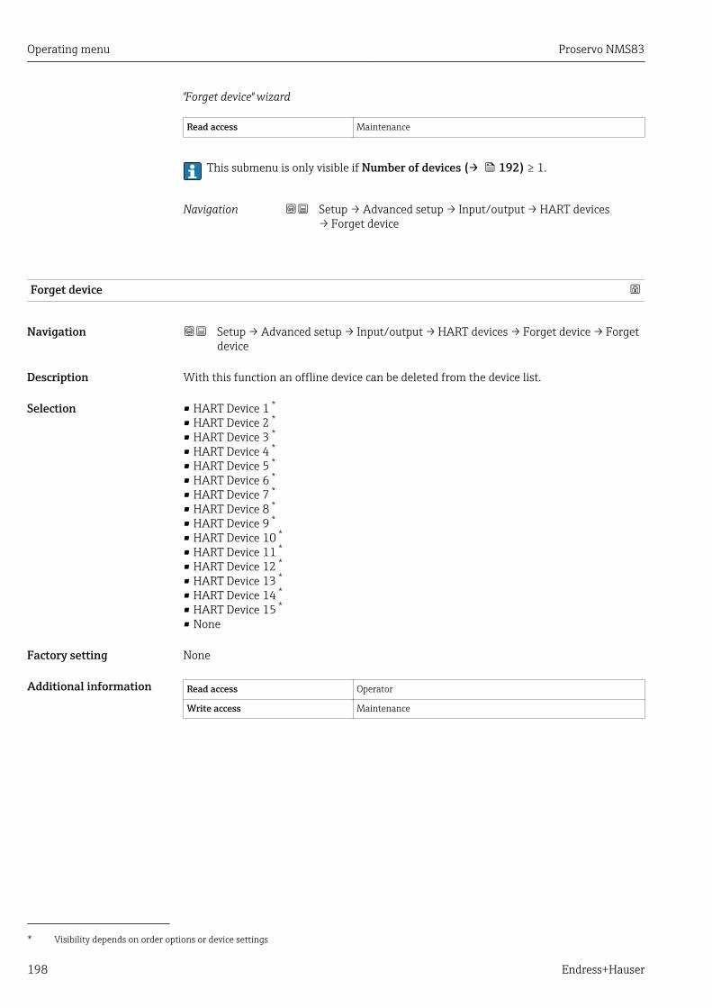
Operating menu Proservo NMS83
198 Endress+Hauser
"Forget device" wizard
Read access Maintenance
This submenu is only visible if Number of devices (→ 192) ≥ 1.
Navigation Setup → Advanced setup → Input/output → HART devices→ Forget device
Forget device
Navigation Setup → Advanced setup → Input/output → HART devices → Forget device → Forgetdevice
Description With this function an offline device can be deleted from the device list.
Selection • HART Device 1 *
• HART Device 2 *
• HART Device 3 *
• HART Device 4 *
• HART Device 5 *
• HART Device 6 *
• HART Device 7 *
• HART Device 8 *
• HART Device 9 *
• HART Device 10 *
• HART Device 11 *
• HART Device 12 *
• HART Device 13 *
• HART Device 14 *
• HART Device 15 *
• None
Factory setting None
Additional information Read access Operator
Write access Maintenance
* Visibility depends on order options or device settings

Proservo NMS83 Operating menu
Endress+Hauser 199
"Analog IP" submenu
There is a Analog IP submenu for each Analog I/O module of the device. Thissubmenu refers to terminals 4 to 8 of this module (the analog input). They areprimarily used to connect an RTD. For terminals 1 to 3 (analog input or output) referto → 205.
D
E
F
C
B
A
1
1
1
1 3
2
2 4
1
HR
CDI
WPon
SIM
2
2
3
3
4
4
1 2 3 4 5 6 7 8
POWER
i
1 2 3 4 5 6 7 8
B
B1-3 B4-8
1 2 3 4 5 6 7 8
C 1 2 3 4 5 6 7 8
C1-3 C4-8
A0032465
72 Terminals for the "Analog IP" submenu ("B4-8" or "C4-8", respectively)
Navigation Setup → Advanced setup → Input/output → Analog IP
Operating mode
Navigation Setup → Advanced setup → Input/output → Analog IP → Operating mode
Description Defines the operating mode of the analog input.
Selection • Disabled• RTD temperature input• Gauge power supply
Factory setting Disabled
Additional information Read access Operator
Write access Maintenance
RTD type
Navigation Setup → Advanced setup → Input/output → Analog IP → RTD type
Prerequisite Operating mode (→ 199) = RTD temperature input
Description Defines the type of the connected RTD.

Operating menu Proservo NMS83
200 Endress+Hauser
Selection • Cu50 (w=1.428, GOST)• Cu53 (w=1.426, GOST)• Cu90; 0°C (w=1.4274, GOST)• Cu100; 25°C (w=1.4274, GOST)• Cu100; 0°C(w=1.4274, GOST)• Pt46 (w=1.391, GOST)• Pt50 (w=1.391, GOST)• Pt100(385) (a=0.00385, IEC751)• Pt100(389) (a=0.00389, Canadian)• Pt100(391) (a=0.003916, JIS1604)• Pt100 (w=1.391, GOST)• Pt500(385) (a=0.00385, IEC751)• Pt1000(385) (a=0.00385, IEC751)• Ni100(617) (a=0.00617, DIN43760)• Ni120(672) (a=0.00672, DIN43760)• Ni1000(617) (a=0.00617, DIN43760)
Factory setting Pt100(385) (a=0.00385, IEC751)
Additional information Read access Operator
Write access Maintenance
RTD connection type
Navigation Setup → Advanced setup → Input/output → Analog IP → RTD connection type
Prerequisite Operating mode (→ 199) = RTD temperature input
Description Defines the connection type of the RTD.
Selection • 4 wire RTD connection• 2 wire RTD connection• 3 wire RTD connection
Factory setting 4 wire RTD connection
Additional information Read access Operator
Write access Maintenance
Process value
Navigation Setup → Advanced setup → Input/output → Analog IP → Process value
Prerequisite Operating mode (→ 199) ≠ Disabled
Description Shows the measured value received via the analog input.
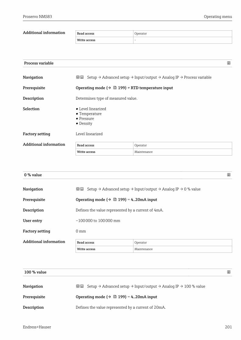
Proservo NMS83 Operating menu
Endress+Hauser 201
Additional information Read access Operator
Write access -
Process variable
Navigation Setup → Advanced setup → Input/output → Analog IP → Process variable
Prerequisite Operating mode (→ 199) ≠ RTD temperature input
Description Determines type of measured value.
Selection • Level linearized• Temperature• Pressure• Density
Factory setting Level linearized
Additional information Read access Operator
Write access Maintenance
0 % value
Navigation Setup → Advanced setup → Input/output → Analog IP → 0 % value
Prerequisite Operating mode (→ 199) = 4..20mA input
Description Defines the value represented by a current of 4mA.
User entry –100 000 to 100 000 mm
Factory setting 0 mm
Additional information Read access Operator
Write access Maintenance
100 % value
Navigation Setup → Advanced setup → Input/output → Analog IP → 100 % value
Prerequisite Operating mode (→ 199) = 4..20mA input
Description Defines the value represented by a current of 20mA.
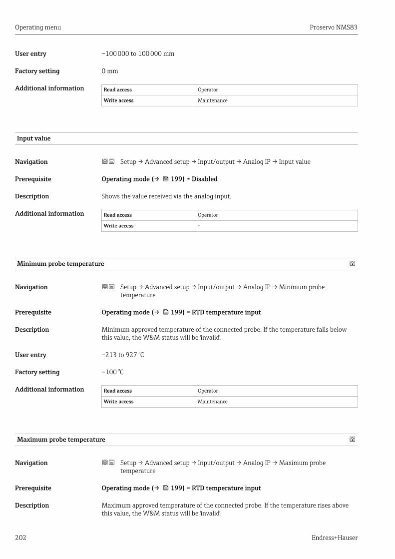
Operating menu Proservo NMS83
202 Endress+Hauser
User entry –100 000 to 100 000 mm
Factory setting 0 mm
Additional information Read access Operator
Write access Maintenance
Input value
Navigation Setup → Advanced setup → Input/output → Analog IP → Input value
Prerequisite Operating mode (→ 199) ≠ Disabled
Description Shows the value received via the analog input.
Additional information Read access Operator
Write access -
Minimum probe temperature
Navigation Setup → Advanced setup → Input/output → Analog IP → Minimum probetemperature
Prerequisite Operating mode (→ 199) = RTD temperature input
Description Minimum approved temperature of the connected probe. If the temperature falls belowthis value, the W&M status will be 'invalid'.
User entry –213 to 927 °C
Factory setting –100 °C
Additional information Read access Operator
Write access Maintenance
Maximum probe temperature
Navigation Setup → Advanced setup → Input/output → Analog IP → Maximum probetemperature
Prerequisite Operating mode (→ 199) = RTD temperature input
Description Maximum approved temperature of the connected probe. If the temperature rises abovethis value, the W&M status will be 'invalid'.
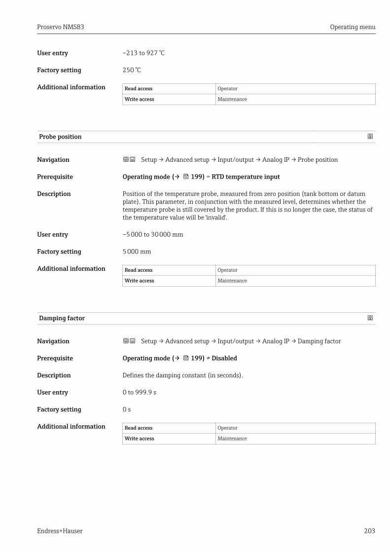
Proservo NMS83 Operating menu
Endress+Hauser 203
User entry –213 to 927 °C
Factory setting 250 °C
Additional information Read access Operator
Write access Maintenance
Probe position
Navigation Setup → Advanced setup → Input/output → Analog IP → Probe position
Prerequisite Operating mode (→ 199) = RTD temperature input
Description Position of the temperature probe, measured from zero position (tank bottom or datumplate). This parameter, in conjunction with the measured level, determines whether thetemperature probe is still covered by the product. If this is no longer the case, the status ofthe temperature value will be 'invalid'.
User entry –5 000 to 30 000 mm
Factory setting 5 000 mm
Additional information Read access Operator
Write access Maintenance
Damping factor
Navigation Setup → Advanced setup → Input/output → Analog IP → Damping factor
Prerequisite Operating mode (→ 199) ≠ Disabled
Description Defines the damping constant (in seconds).
User entry 0 to 999.9 s
Factory setting 0 s
Additional information Read access Operator
Write access Maintenance

Operating menu Proservo NMS83
204 Endress+Hauser
Gauge current
Navigation Setup → Advanced setup → Input/output → Analog IP → Gauge current
Prerequisite Operating mode (→ 199) = Gauge power supply
Description Shows the current on the power supply line for the connected device.
Additional information Read access Operator
Write access -

Proservo NMS83 Operating menu
Endress+Hauser 205
"Analog I/O" submenu
There is a Analog I/O submenu for each Analog I/O module of the device. Thissubmenu refers to terminals 1 to 3 of this module (an analog input or output). Forterminals 4 to 8 (always an analog input) refer to → 199.
D
E
F
C
B
A
1
1
1
1 3
2
2 4
1
HR
CDI
WPon
SIM
2
2
3
3
4
4
1
1
2
2
3
3
4
4
5
5
6
6
7
7
8
8
POWER
i
B
B1-3 B4-8
1 2 3 4 5 6 7 8
C 1 2 3 4 5 6 7 8
C1-3 C4-8
A0032464
73 Terminals for the "Analog I/O" submenu ("B1-3" or "C1-3", respectively)
Navigation Setup → Advanced setup → Input/output → Analog I/O
Operating mode
Navigation Setup → Advanced setup → Input/output → Analog I/O → Operating mode
Description Defines the operating mode of the analog I/O module.
Selection • Disabled• 4..20mA input• HART master+4..20mA input• HART master• 4..20mA output• HART slave +4..20mA output
Factory setting Disabled
Additional information Read access Operator
Write access Maintenance
Meaning of the options
Operating mode (→ 205) Direction of signal Type of signal
Disabled - -
4..20mA input Input from 1 external device Analog (4...20mA)
HART master+4..20mA input Input from 1 external device • Analog (4...20mA)• HART
HART master Input from up to 6 external devices HART
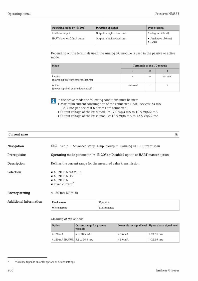
Operating menu Proservo NMS83
206 Endress+Hauser
Operating mode (→ 205) Direction of signal Type of signal
4..20mA output Output to higher-level unit Analog (4...20mA)
HART slave +4..20mA output Output to higher-level unit • Analog (4...20mA)• HART
Depending on the terminals used, the Analog I/O module is used in the passive or activemode.
Mode Terminals of the I/O module
1 2 3
Passive(power supply from external source)
- + not used
Active(power supplied by the device itself)
not used - +
In the active mode the following conditions must be met:• Maximum current consumption of the connected HART devices: 24 mA
(i.e. 4 mA per device if 6 devices are connected).• Output voltage of the Ex-d module: 17.0 V@4 mA to 10.5 V@22 mA• Output voltage of the Ex-ia module: 18.5 V@4 mA to 12.5 V@22 mA
Current span
Navigation Setup → Advanced setup → Input/output → Analog I/O → Current span
Prerequisite Operating mode parameter (→ 205) ≠ Disabled option or HART master option
Description Defines the current range for the measured value transmission.
Selection • 4...20 mA NAMUR• 4...20 mA US• 4...20 mA• Fixed current *
Factory setting 4...20 mA NAMUR
Additional information Read access Operator
Write access Maintenance
Meaning of the options
Option Current range for processvariable
Lower alarm signal level Upper alarm signal level
4...20 mA 4 to 20.5 mA < 3.6 mA > 21.95 mA
4...20 mA NAMUR 3.8 to 20.5 mA < 3.6 mA > 21.95 mA
* Visibility depends on order options or device settings

Proservo NMS83 Operating menu
Endress+Hauser 207
Option Current range for processvariable
Lower alarm signal level Upper alarm signal level
4...20 mA US 3.9 to 20.8 mA < 3.6 mA > 21.95 mA
Fixed current Constant current, defined in the Fixed current parameter (→ 207).
In the case of an error, the output current assumes the value defined in the Failuremode parameter (→ 208).
Fixed current
Navigation Setup → Advanced setup → Input/output → Analog I/O → Fixed current
Prerequisite Current span (→ 206) = Fixed current
Description Defines the fixed output current.
User entry 4 to 22.5 mA
Factory setting 4 mA
Additional information Read access Operator
Write access Maintenance
Analog input source
Navigation Setup → Advanced setup → Input/output → Analog I/O → Analog input source
Prerequisite • Operating mode (→ 205) = 4..20mA output or HART slave +4..20mA output• Current span (→ 206) ≠ Fixed current
Description Defines the process variable transmitted via the AIO.
Selection • None• Tank level• Tank level %• Tank ullage• Tank ullage %• Measured level• Distance• Displacer position• Water level• Upper interface level• Lower interface level• Bottom level• Tank reference height• Liquid temperature• Vapor temperature• Air temperature
Operating menu Proservo NMS83
208 Endress+Hauser
• Observed density value• Average profile density 5)
• Upper density• Middle density• Lower density• P1 (bottom)• P2 (middle)• P3 (top)• GP 1 ... 4 value• AIO B1-3 value 5)
• AIO B1-3 value mA 5)
• AIO C1-3 value 5)
• AIO C1-3 value mA 5)
• AIP B4-8 value 5)
• AIP C4-8 value 5)
• Element temperature 1 ... 24 5)
• HART device 1...15 PV 5)
• HART device 1 ... 15 PV mA 5)
• HART device 1 ... 15 PV % 5)
• HART device 1 ... 15 SV 5)
• HART device 1 ... 15 TV 5)
• HART device 1 ... 15 QV 5)
Factory setting Tank level
Additional information Read access Operator
Write access Maintenance
Failure mode
Navigation Setup → Advanced setup → Input/output → Analog I/O → Failure mode
Prerequisite Operating mode (→ 205) = 4..20mA output or HART slave +4..20mA output
Description Defines the output behavior in case of an error.
Selection • Min.• Max.• Last valid value• Actual value• Defined value
Factory setting Max.
Additional information Read access Operator
Write access Maintenance
5) Visibility depends on order options or device settings
Proservo NMS83 Operating menu
Endress+Hauser 209
Error value
Navigation Setup → Advanced setup → Input/output → Analog I/O → Error value
Prerequisite Failure mode (→ 208) = Defined value
Description Defines the output value in case of an error.
User entry 3.4 to 22.6 mA
Factory setting 22 mA
Additional information Read access Operator
Write access Maintenance
Input value
Navigation Setup → Advanced setup → Input/output → Analog I/O → Input value
Prerequisite • Operating mode (→ 205) = 4..20mA output or HART slave +4..20mA output• Current span (→ 206) ≠ Fixed current
Description Shows the input value of the analog I/O module.
Additional information Read access Operator
Write access -
0 % value
Navigation Setup → Advanced setup → Input/output → Analog I/O → 0 % value
Prerequisite • Operating mode (→ 205) = 4..20mA output or HART slave +4..20mA output• Current span (→ 206) ≠ Fixed current
Description Value corresponding to an output current of 0% (4mA).
User entry Signed floating-point number
Factory setting 0 Unitless
Additional information Read access Operator
Write access Maintenance
Operating menu Proservo NMS83
210 Endress+Hauser
100 % value
Navigation Setup → Advanced setup → Input/output → Analog I/O → 100 % value
Prerequisite • Operating mode (→ 205) = 4..20mA output or HART slave +4..20mA output• Current span (→ 206) ≠ Fixed current
Description Value corresponding to an output current of 100% (20mA).
User entry Signed floating-point number
Factory setting 0 Unitless
Additional information Read access Operator
Write access Maintenance
Input value %
Navigation Setup → Advanced setup → Input/output → Analog I/O → Input value %
Prerequisite • Operating mode (→ 205) = 4..20mA output or HART slave +4..20mA output• Current span (→ 206) ≠ Fixed current
Description Shows the output value as a percentage of the complete 4...20mA range.
Additional information Read access Operator
Write access -
Output value
Navigation Setup → Advanced setup → Input/output → Analog I/O → Output value
Prerequisite Operating mode (→ 205) = 4..20mA output or HART slave +4..20mA output
Description Shows the output value in mA.
Additional information Read access Operator
Write access -

Proservo NMS83 Operating menu
Endress+Hauser 211
Process variable
Navigation Setup → Advanced setup → Input/output → Analog I/O → Process variable
Prerequisite Operating mode (→ 205) = 4..20mA input or HART master+4..20mA input
Description Defines the type of measuring variable.
Selection • Level linearized• Temperature• Pressure• Density
Factory setting Level linearized
Additional information Read access Operator
Write access Maintenance
Analog input 0% value
Navigation Setup → Advanced setup → Input/output → Analog I/O → Analog input 0% value
Prerequisite Operating mode (→ 205) = 4..20mA input or HART master+4..20mA input
Description Value corresponding to an input current of 0% (4mA).
User entry –100 000 to 100 000 mm
Factory setting 0 mm
Additional information Read access Operator
Write access Maintenance
Analog input 100% value
Navigation Setup → Advanced setup → Input/output → Analog I/O → Analog input 100% value
Prerequisite Operating mode (→ 205) = 4..20mA input or HART master+4..20mA input
Description Value corresponding to an input current of 100% (20mA).
User entry –100 000 to 100 000 mm
Factory setting 0 mm

Operating menu Proservo NMS83
212 Endress+Hauser
Additional information Read access Operator
Write access Maintenance
Error event type
Navigation Setup → Advanced setup → Input/output → Analog I/O → Error event type
Prerequisite Operating mode (→ 205) ≠ Disabled or HART master
Description Defines the type of event message (alarm/warning) in case of an error or output out ofrange in the analog I/O module.
Selection • None• Warning• Alarm
Factory setting Warning
Additional information Read access Operator
Write access Maintenance
Process value
Navigation Setup → Advanced setup → Input/output → Analog I/O → Process value
Prerequisite Operating mode (→ 205) = 4..20mA input or HART master+4..20mA input
Description Shows the input value scaled to customer units.
Additional information Read access Operator
Write access -
Input value in mA
Navigation Setup → Advanced setup → Input/output → Analog I/O → Input value in mA
Prerequisite Operating mode (→ 205) = 4..20mA input or HART master+4..20mA input
Description Shows the input value in mA.
Additional information Read access Operator
Write access -
Proservo NMS83 Operating menu
Endress+Hauser 213
Input value percent
Navigation Setup → Advanced setup → Input/output → Analog I/O → Input value percent
Prerequisite Operating mode (→ 205) = 4..20mA input or HART master+4..20mA input
Description Shows the input value as a percentage of the complete 4...20mA current range.
Additional information Read access Operator
Write access -
Damping factor
Navigation Setup → Advanced setup → Input/output → Analog I/O → Damping factor
Prerequisite Operating mode (→ 205) ≠ Disabled or HART master
Description Defines the damping constant (in seconds).
User entry 0 to 999.9 s
Factory setting 0 s
Additional information Read access Operator
Write access Maintenance
Used for SIL/WHG
Navigation Setup → Advanced setup → Input/output → Analog I/O → Used for SIL/WHG
Prerequisite • Operating mode (→ 205) = 4..20mA output or HART slave +4..20mA output• The device has a SIL approval.
Description Determines whether the discrete I/O module is in SIL/WHG mode.
Selection • Enabled• Disabled
Factory setting Disabled
Additional information Read access Operator
Write access Maintenance
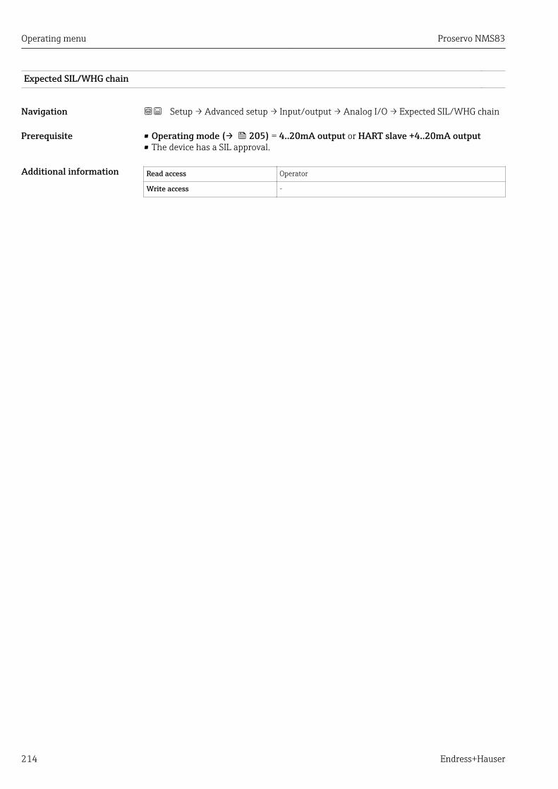
Operating menu Proservo NMS83
214 Endress+Hauser
Expected SIL/WHG chain
Navigation Setup → Advanced setup → Input/output → Analog I/O → Expected SIL/WHG chain
Prerequisite • Operating mode (→ 205) = 4..20mA output or HART slave +4..20mA output• The device has a SIL approval.
Additional information Read access Operator
Write access -

Proservo NMS83 Operating menu
Endress+Hauser 215
"Digital Xx-x" submenu
• In the operating menu, each digital input or output is designated by the respectiveslot of the terminal compartment and two terminals within this slot. A1-2, forexample, denotes terminals 1 and 2 of slot A. The same is valid for slots B, C and Dif they contain a Digital IO module.
• In this document, Xx-x designates any of these submenus. The structure of all thesesubmenus is the same.
D
E
F
C
B
A
1
1
1
1 3
2
2 4
1
HR
CDI
WPon
SIM
2
2
3
3
4
4
1
1
2
2
3
3
4
4
5
5
6
6
7
7
8
8
POWER
A 1 2 3 4
A1-2 A3-4
i
C 1 2 3 4 5 6 7
C1-2 C3-4
A0026424
74 Designation of the digital inputs or outputs (examples)
Navigation Setup → Advanced setup → Input/output → Digital Xx-x
Operating mode
Navigation Setup → Advanced setup → Input/output → Digital Xx-x → Operating mode
Description Defines the operating mode of the discrete I/O module.
Selection • Disabled• Output passive• Input passive• Input active
Factory setting Disabled
Operating menu Proservo NMS83
216 Endress+Hauser
Additional informationDIO DIO
2/4 2/4
1/3
+ +_ _
2/4
1/3 1/3
A CDIO
B
A0033028
75 Operating mopdes of the Digital I/O module
A Input passiveB Input activeC Output passive
Digital input source
Navigation Setup → Advanced setup → Input/output → Digital Xx-x → Digital input source
Prerequisite Operating mode (→ 215) = Output passive
Description Defines which device state is indicated by the digital output.
Selection • None• Alarm x any• Alarm x High• Alarm x HighHigh• Alarm x High or HighHigh• Alarm x Low• Alarm x LowLow• Alarm x Low or LowLow• Digital Xx-x• Pri. Modbus x• Sec. Modbus x
Factory setting None
Additional information Meaning of the options• Alarm x any, Alarm x High, Alarm x HighHigh, Alarm x High or HighHigh, Alarm x
Low, Alarm x LowLow, Alarm x Low or LowLowThe digital output indicates if the selected alarm is currently active. The alarmsthemselves are defined in the Alarm 1 to 4 submenus.
• Digital Xx-x 6)
The digital signal present at the digital input Xx-x is passed through to the digitaloutput.
• Modbus A1-4 Discrete xModbus B1-4 Discrete xModbus C1-4 Discrete xModbus D1-4 Discrete xThe digital value written by the Modbus Master device to the Modbus discrete xparameter 7) is passed to the digital output. For details refer to Special DocumentationSD02066G.
6) Only present if "Operating mode (→ 215)" = "Input passive" or "Input active" for the respective Digital I/O module.7) Expert → Communication → Modbus Xx-x → Modbus discrete x
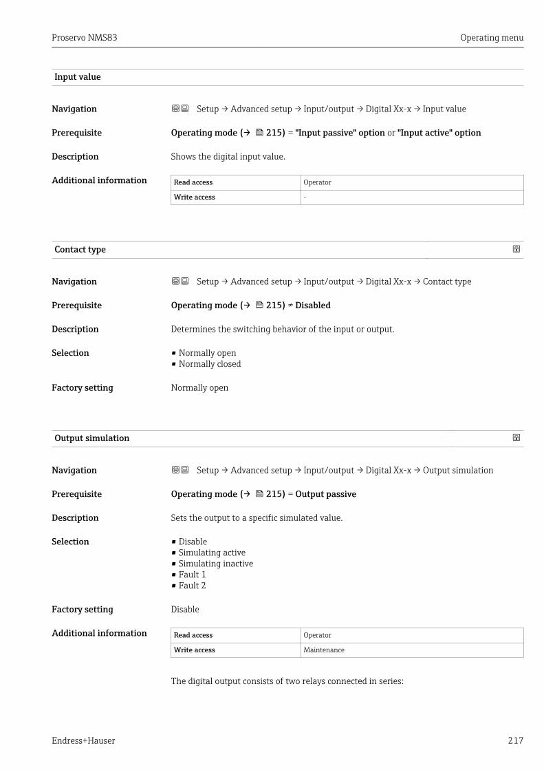
Proservo NMS83 Operating menu
Endress+Hauser 217
Input value
Navigation Setup → Advanced setup → Input/output → Digital Xx-x → Input value
Prerequisite Operating mode (→ 215) = "Input passive" option or "Input active" option
Description Shows the digital input value.
Additional information Read access Operator
Write access -
Contact type
Navigation Setup → Advanced setup → Input/output → Digital Xx-x → Contact type
Prerequisite Operating mode (→ 215) ≠ Disabled
Description Determines the switching behavior of the input or output.
Selection • Normally open• Normally closed
Factory setting Normally open
Output simulation
Navigation Setup → Advanced setup → Input/output → Digital Xx-x → Output simulation
Prerequisite Operating mode (→ 215) = Output passive
Description Sets the output to a specific simulated value.
Selection • Disable• Simulating active• Simulating inactive• Fault 1• Fault 2
Factory setting Disable
Additional information Read access Operator
Write access Maintenance
The digital output consists of two relays connected in series:
Operating menu Proservo NMS83
218 Endress+Hauser
3 1
2
4
A0028602
76 The two relays of a digital output
1/2 The relays3/4 The terminals of the digital output
The switching state of these relays is defined by the Output simulation parameter asfollows:
Output simulation State of relay 1 State of relay 2 Expected result on theterminals of the I/O module
Simulating active Closed Closed Closed
Simulating inactive Open Open Open
Fault 1 Closed Open Open
Fault 2 Open Closed Open
The Fault 1 and Fault 2 options can be used to check the correct switching behaviorof the two relays.
Output value
Navigation Setup → Advanced setup → Input/output → Digital Xx-x → Output values
Prerequisite Operating mode (→ 215) = Output passive
Description Shows the digital output value.
Additional information Read access Operator
Write access -
Readback value
Navigation Setup → Advanced setup → Input/output → Digital Xx-x → Readback value
Prerequisite Operating mode (→ 215) = Output passive
Description Shows the value read back from the output.

Proservo NMS83 Operating menu
Endress+Hauser 219
Additional information Read access Operator
Write access -
Used for SIL/WHG
Navigation Setup → Advanced setup → Input/output → Digital Xx-x → Used for SIL/WHG
Prerequisite • Operating mode (→ 215) = Output passive• The device has a SIL certificate.
Description Determines whether the discrete I/O module is in SIL/WHG mode.
Selection • Enabled• Disabled
Factory setting Disabled
Additional information Read access Operator
Write access Maintenance
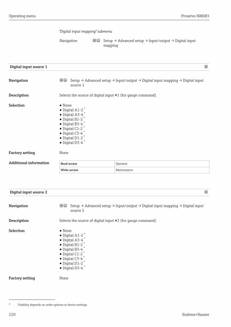
Operating menu Proservo NMS83
220 Endress+Hauser
"Digital input mapping" submenu
Navigation Setup → Advanced setup → Input/output → Digital inputmapping
Digital input source 1
Navigation Setup → Advanced setup → Input/output → Digital input mapping → Digital inputsource 1
Description Selects the source of digital input #1 (for gauge command).
Selection • None• Digital A1-2 *
• Digital A3-4 *
• Digital B1-2 *
• Digital B3-4 *
• Digital C1-2 *
• Digital C3-4 *
• Digital D1-2 *
• Digital D3-4 *
Factory setting None
Additional information Read access Operator
Write access Maintenance
Digital input source 2
Navigation Setup → Advanced setup → Input/output → Digital input mapping → Digital inputsource 2
Description Selects the source of digital input #2 (for gauge command).
Selection • None• Digital A1-2 *
• Digital A3-4 *
• Digital B1-2 *
• Digital B3-4 *
• Digital C1-2 *
• Digital C3-4 *
• Digital D1-2 *
• Digital D3-4 *
Factory setting None
* Visibility depends on order options or device settings

Proservo NMS83 Operating menu
Endress+Hauser 221
Additional information Read access Operator
Write access Maintenance
Gauge command 0
Navigation Setup → Advanced setup → Input/output → Digital input mapping → Gaugecommand 0
Prerequisite Digital input source 1 (→ 220) ≠ None
Description Gauge command assigned to digital input combination 0 (DI2=0, DI1=0).
Selection • Stop• Level• Up• Bottom level• Upper I/F level• Lower I/F level• Upper density• Middle density• Lower density• Repeatability• Water dip• Release overtension• Tank profile• Interface profile• Manual profile• Level standby
Factory setting Level
Additional information Read access Operator
Write access Maintenance
Gauge command 1
Navigation Setup → Advanced setup → Input/output → Digital input mapping → Gaugecommand 1
Prerequisite Digital input source 1 (→ 220) ≠ None
Description Gauge command assigned to digital input combination 1 (DI2=0, DI1=1).
Selection • Stop• Level• Up• Bottom level• Upper I/F level• Lower I/F level
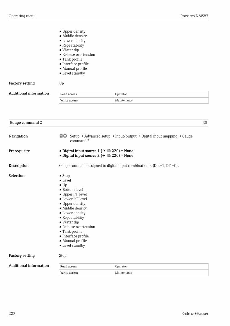
Operating menu Proservo NMS83
222 Endress+Hauser
• Upper density• Middle density• Lower density• Repeatability• Water dip• Release overtension• Tank profile• Interface profile• Manual profile• Level standby
Factory setting Up
Additional information Read access Operator
Write access Maintenance
Gauge command 2
Navigation Setup → Advanced setup → Input/output → Digital input mapping → Gaugecommand 2
Prerequisite • Digital input source 1 (→ 220) ≠ None• Digital input source 2 (→ 220) ≠ None
Description Gauge command assigned to digital Input combination 2 (DI2=1, DI1=0).
Selection • Stop• Level• Up• Bottom level• Upper I/F level• Lower I/F level• Upper density• Middle density• Lower density• Repeatability• Water dip• Release overtension• Tank profile• Interface profile• Manual profile• Level standby
Factory setting Stop
Additional information Read access Operator
Write access Maintenance
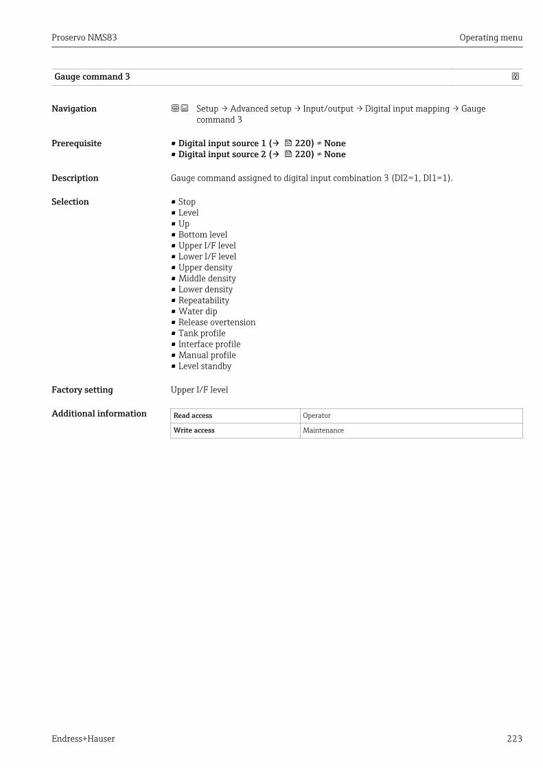
Proservo NMS83 Operating menu
Endress+Hauser 223
Gauge command 3
Navigation Setup → Advanced setup → Input/output → Digital input mapping → Gaugecommand 3
Prerequisite • Digital input source 1 (→ 220) ≠ None• Digital input source 2 (→ 220) ≠ None
Description Gauge command assigned to digital input combination 3 (DI2=1, DI1=1).
Selection • Stop• Level• Up• Bottom level• Upper I/F level• Lower I/F level• Upper density• Middle density• Lower density• Repeatability• Water dip• Release overtension• Tank profile• Interface profile• Manual profile• Level standby
Factory setting Upper I/F level
Additional information Read access Operator
Write access Maintenance

Operating menu Proservo NMS83
224 Endress+Hauser
"Communication" submenuThis menu contains a submenu for each digital communication interface of the device. Thecommunication interfaces are designated by "X1-4" where "X" specifies the slot in theterminal compartmen and "1-4" the terminals within this slot.
D
E
F
C
B
A
1
1
1
1 3
2
2 4
1
HR
CDI
WPon
SIM
2
2
3
3
4
4
1
1
2
2
3
3
4
4
5
5
6
6
7
7
8
8
POWER
A 1 2 3 4
A1-4
i
D 1 2 3 4
D1-4
A0031200
77 Designation of the "Modbus" or "V1" modules (examples); depending on the device version these modulesmay also be in slot B or C.
Navigation Setup → Advanced setup → Communication
"Modbus X1-4" or "V1 X1-4" submenu
This submenu is only present for devices with MODBUS and/or V1 communicationinterface. There is one submenu of this type for each communication interface.
Navigation Setup → Advanced setup → Communication → Modbus X1-4 /V1 X1-4
Communication interface protocol
Navigation Setup → Advanced setup → Communication → Modbus X1-4 / V1 X1-4→ Communication interface protocol
Description Shows the type of communication protocol.
Additional information Read access Operator
Write access -

Proservo NMS83 Operating menu
Endress+Hauser 225
"Configuration" submenu
This submenu is only present for devices with a MODBUS communication interface.
Navigation Setup → Advanced setup → Communication → Modbus X1-4→ Configuration
Baudrate
Navigation Setup → Advanced setup → Communication → Modbus X1-4 → Configuration→ Baudrate
Prerequisite Communication interface protocol (→ 224) = MODBUS
Description Defines the baud rate of the Modbus communication.
Selection • 300 BAUD• 600 BAUD• 1200 BAUD• 2400 BAUD• 4800 BAUD• 9600 BAUD• 19200 BAUD
Factory setting 9600 BAUD
Additional information Read access Operator
Write access Maintenance
Parity
Navigation Setup → Advanced setup → Communication → Modbus X1-4 → Configuration→ Parity
Prerequisite Communication interface protocol (→ 224) = MODBUS
Description Defines the parity of the Modbus communication.
Selection • Odd• Even• None / 1 stop bit• None / 2 stop bits
Factory setting None / 1 stop bit
Additional information Read access Operator
Write access Maintenance
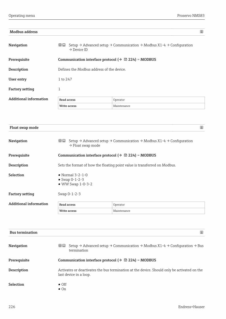
Operating menu Proservo NMS83
226 Endress+Hauser
Modbus address
Navigation Setup → Advanced setup → Communication → Modbus X1-4 → Configuration→ Device ID
Prerequisite Communication interface protocol (→ 224) = MODBUS
Description Defines the Modbus address of the device.
User entry 1 to 247
Factory setting 1
Additional information Read access Operator
Write access Maintenance
Float swap mode
Navigation Setup → Advanced setup → Communication → Modbus X1-4 → Configuration→ Float swap mode
Prerequisite Communication interface protocol (→ 224) = MODBUS
Description Sets the format of how the floating point value is transferred on Modbus.
Selection • Normal 3-2-1-0• Swap 0-1-2-3• WW Swap 1-0-3-2
Factory setting Swap 0-1-2-3
Additional information Read access Operator
Write access Maintenance
Bus termination
Navigation Setup → Advanced setup → Communication → Modbus X1-4 → Configuration → Bustermination
Prerequisite Communication interface protocol (→ 224) = MODBUS
Description Activates or deactivates the bus termination at the device. Should only be activated on thelast device in a loop.
Selection • Off• On

Proservo NMS83 Operating menu
Endress+Hauser 227
Factory setting Off
Additional information Read access Operator
Write access Maintenance

Operating menu Proservo NMS83
228 Endress+Hauser
"Configuration" submenu
This submenu is only present for devices with a V1 communication interface.
Navigation Setup → Advanced setup → Communication → V1 X1-4→ Configuration
Communication interface protocol variant
Navigation Setup → Advanced setup → Communication → V1 X1-4 → Configuration→ Communication interface protocol variant
Description Determines which variant of the V1 protocol is used.
User interface • None• V1 *
Factory setting None
Additional information Read access Operator
Write access Maintenance
V1 address
Navigation Setup → Advanced setup → Communication → V1 X1-4 → Configuration → V1address
Prerequisite Communication interface protocol variant (→ 228) = V1
Description Identifier of the device for the V1 communication.
User entry 0 to 99
Factory setting 1
Additional information Read access Operator
Write access Maintenance
* Visibility depends on order options or device settings

Proservo NMS83 Operating menu
Endress+Hauser 229
V1 address
Navigation Setup → Advanced setup → Communication → V1 X1-4 → Configuration → V1address
Prerequisite Communication interface protocol variant (→ 228)
Description Identifier of the previous device for V1 communication.
User entry 0 to 255
Factory setting 1
Additional information Read access Operator
Write access Maintenance
Level mapping
Navigation Setup → Advanced setup → Communication → V1 X1-4 → Configuration → Levelmapping
Prerequisite Communication interface protocol (→ 224) = V1
Description Determines the transmittable range of levels.
Selection • +ve• +ve & -ve
Factory setting +ve
Additional information Read access Operator
Write access Maintenance
In V1, the level is always represented by a number in the range from 0 to 999 999. Thisnumber corresponds to a level as follows:
"Level mapping" = "+ve"
Number Corresponding level
0 0.0 mm
999 999 99 999.9 mm
"Level mapping" = "+ve & -ve"
Number Corresponding level
0 0.0 mm
500 000 50 000.0 mm
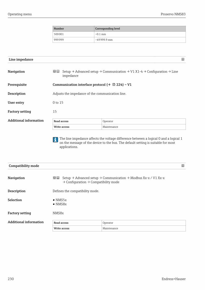
Operating menu Proservo NMS83
230 Endress+Hauser
Number Corresponding level
500 001 –0.1 mm
999 999 –49 999.9 mm
Line impedance
Navigation Setup → Advanced setup → Communication → V1 X1-4 → Configuration → Lineimpedance
Prerequisite Communication interface protocol (→ 224) = V1
Description Adjusts the impedance of the communication line.
User entry 0 to 15
Factory setting 15
Additional information Read access Operator
Write access Maintenance
The line impedance affects the voltage difference between a logical 0 and a logical 1on the message of the device to the bus. The default setting is suitable for mostapplications.
Compatibility mode
Navigation Setup → Advanced setup → Communication → Modbus Xx-x / V1 Xx-x→ Configuration → Compatibility mode
Description Defines the compatibility mode.
Selection • NMS5x• NMS8x
Factory setting NMS8x
Additional information Read access Operator
Write access Maintenance
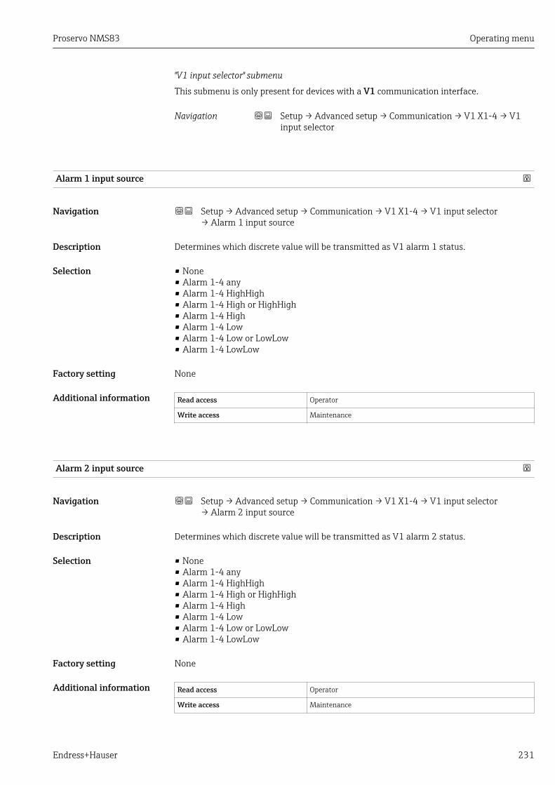
Proservo NMS83 Operating menu
Endress+Hauser 231
"V1 input selector" submenu
This submenu is only present for devices with a V1 communication interface.
Navigation Setup → Advanced setup → Communication → V1 X1-4 → V1input selector
Alarm 1 input source
Navigation Setup → Advanced setup → Communication → V1 X1-4 → V1 input selector→ Alarm 1 input source
Description Determines which discrete value will be transmitted as V1 alarm 1 status.
Selection • None• Alarm 1-4 any• Alarm 1-4 HighHigh• Alarm 1-4 High or HighHigh• Alarm 1-4 High• Alarm 1-4 Low• Alarm 1-4 Low or LowLow• Alarm 1-4 LowLow
Factory setting None
Additional information Read access Operator
Write access Maintenance
Alarm 2 input source
Navigation Setup → Advanced setup → Communication → V1 X1-4 → V1 input selector→ Alarm 2 input source
Description Determines which discrete value will be transmitted as V1 alarm 2 status.
Selection • None• Alarm 1-4 any• Alarm 1-4 HighHigh• Alarm 1-4 High or HighHigh• Alarm 1-4 High• Alarm 1-4 Low• Alarm 1-4 Low or LowLow• Alarm 1-4 LowLow
Factory setting None
Additional information Read access Operator
Write access Maintenance
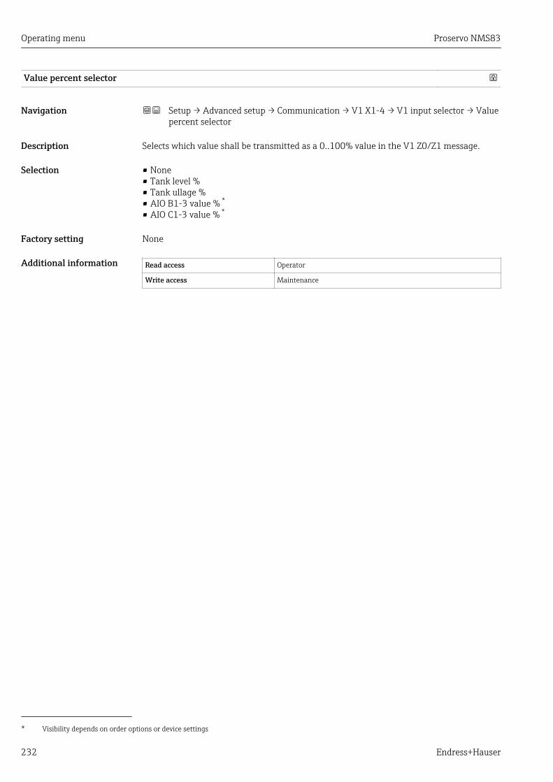
Operating menu Proservo NMS83
232 Endress+Hauser
Value percent selector
Navigation Setup → Advanced setup → Communication → V1 X1-4 → V1 input selector → Valuepercent selector
Description Selects which value shall be transmitted as a 0..100% value in the V1 Z0/Z1 message.
Selection • None• Tank level %• Tank ullage %• AIO B1-3 value % *
• AIO C1-3 value % *
Factory setting None
Additional information Read access Operator
Write access Maintenance
* Visibility depends on order options or device settings

Proservo NMS83 Operating menu
Endress+Hauser 233
"HART output" submenu
Navigation Setup → Advanced setup → Communication → HART output
"Configuration" submenu
Navigation Setup → Advanced setup → Communication → HART output→ Configuration
System polling address
Navigation Setup → Advanced setup → Communication → HART output → Configuration→ System polling address
Description Device address for HART communication.
User entry 0 to 63
Factory setting 15
Additional information Read access Operator
Write access Maintenance
No. of preambles
Navigation Setup → Advanced setup → Communication → HART output → Configuration → No.of preambles
Description Defines the number o preambles in the HART telegram.
User entry 5 to 20
Factory setting 5
Additional information Read access Operator
Write access Maintenance
PV source
Navigation Setup → Advanced setup → Communication → HART output → Configuration → PVsource
Description Decides, if the PV configuration is according to an analog output (HART slave) orcustomized (in case of HART tunneling only).

Operating menu Proservo NMS83
234 Endress+Hauser
Selection • AIO B1-3 *
• AIO C1-3 *
• Custom
Factory setting Custom
Additional information Read access Maintenance
Write access Maintenance
Assign PV
Navigation Setup → Advanced setup → Communication → HART output → Configuration→ Assign PV
Prerequisite PV source (→ 233) = Custom
Description Assigns a tank variable to the primary HART variable (PV).
Selection • None• Tank level• Tank ullage• Measured level• Distance• Displacer position• Water level• Upper interface level• Lower interface level• Bottom level• Tank reference height• Liquid temperature• Vapor temperature• Air temperature• Observed density value• Average profile density• Upper density• Middle density• Lower density• P1 (bottom)• P2 (middle)• P3 (top)• GP 1 value• GP 2 value• GP 3 value• GP 4 value
Factory setting Tank level
* Visibility depends on order options or device settings
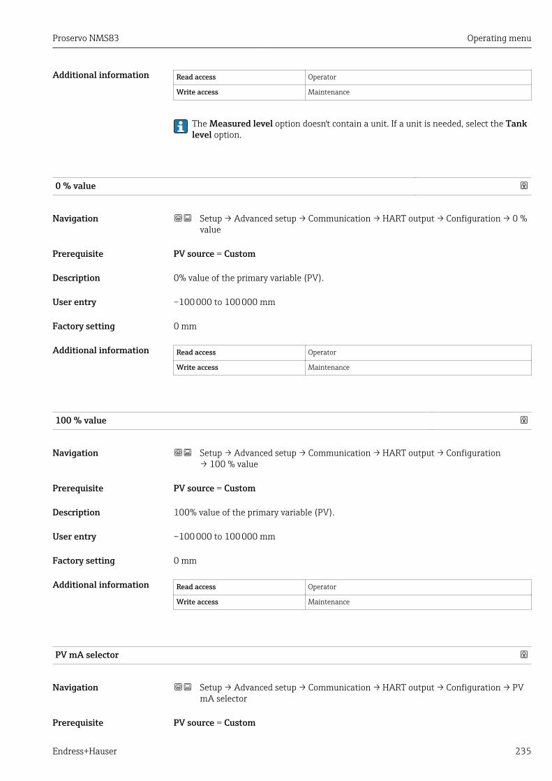
Proservo NMS83 Operating menu
Endress+Hauser 235
Additional information Read access Operator
Write access Maintenance
The Measured level option doesn't contain a unit. If a unit is needed, select the Tanklevel option.
0 % value
Navigation Setup → Advanced setup → Communication → HART output → Configuration → 0 %value
Prerequisite PV source = Custom
Description 0% value of the primary variable (PV).
User entry –100 000 to 100 000 mm
Factory setting 0 mm
Additional information Read access Operator
Write access Maintenance
100 % value
Navigation Setup → Advanced setup → Communication → HART output → Configuration→ 100 % value
Prerequisite PV source = Custom
Description 100% value of the primary variable (PV).
User entry –100 000 to 100 000 mm
Factory setting 0 mm
Additional information Read access Operator
Write access Maintenance
PV mA selector
Navigation Setup → Advanced setup → Communication → HART output → Configuration → PVmA selector
Prerequisite PV source = Custom
Operating menu Proservo NMS83
236 Endress+Hauser
Description Assigns a current to the primary HART variable (PV).
Selection • None• AIO B1-3 value mA *
• AIO C1-3 value mA *
Factory setting None
Additional information Read access Operator
Write access Maintenance
Primary variable (PV)
Navigation Setup → Advanced setup → Communication → HART output → Configuration→ Primary variable (PV)
Description Shows the value of the primary HART variable (PV).
Additional information Read access Operator
Write access -
Percent of range
Navigation Setup → Advanced setup → Communication → HART output → Configuration→ Percent of range
Description Shows the value of the primary variable (PV) as a percentage of the defined 0% to 100%range.
Additional information Read access Operator
Write access -
Assign SV
Navigation Setup → Advanced setup → Communication → HART output → Configuration→ Assign SV
Description Assigns a tank variable to the secondary HART variable (SV).
Selection • None• Tank level• Tank ullage
* Visibility depends on order options or device settings

Proservo NMS83 Operating menu
Endress+Hauser 237
• Measured level• Distance• Displacer position• Water level• Upper interface level• Lower interface level• Bottom level• Tank reference height• Liquid temperature• Vapor temperature• Air temperature• Observed density value• Average profile density• Upper density• Middle density• Lower density• P1 (bottom)• P2 (middle)• P3 (top)• GP 1 value• GP 2 value• GP 3 value• GP 4 value
Factory setting Liquid temperature
Additional information Read access Operator
Write access Maintenance
The Measured level option doesn't contain a unit. If a unit is needed, select the Tanklevel option.
Secondary variable (SV)
Navigation Setup → Advanced setup → Communication → HART output → Configuration→ Secondary variable (SV)
Prerequisite Assign SV (→ 236) ≠ None
Description Shows the value of the secondary HART variable (SV).
Additional information Read access Operator
Write access -

Operating menu Proservo NMS83
238 Endress+Hauser
Assign TV
Navigation Setup → Advanced setup → Communication → HART output → Configuration→ Assign TV
Description Assigns a tank variable to the third HART variable (TV).
Selection • None• Tank level• Tank ullage• Measured level• Distance• Displacer position• Water level• Upper interface level• Lower interface level• Bottom level• Tank reference height• Liquid temperature• Vapor temperature• Air temperature• Observed density value• Average profile density• Upper density• Middle density• Lower density• P1 (bottom)• P2 (middle)• P3 (top)• GP 1 value• GP 2 value• GP 3 value• GP 4 value
Factory setting Water level
Additional information Read access Operator
Write access Maintenance
The Measured level option doesn't contain a unit. If a unit is needed, select the Tanklevel option.
Tertiary variable (TV)
Navigation Setup → Advanced setup → Communication → HART output → Configuration→ Tertiary variable (TV)
Prerequisite Assign TV (→ 238) ≠ None
Description Shows the value of the third HART variable (TV).
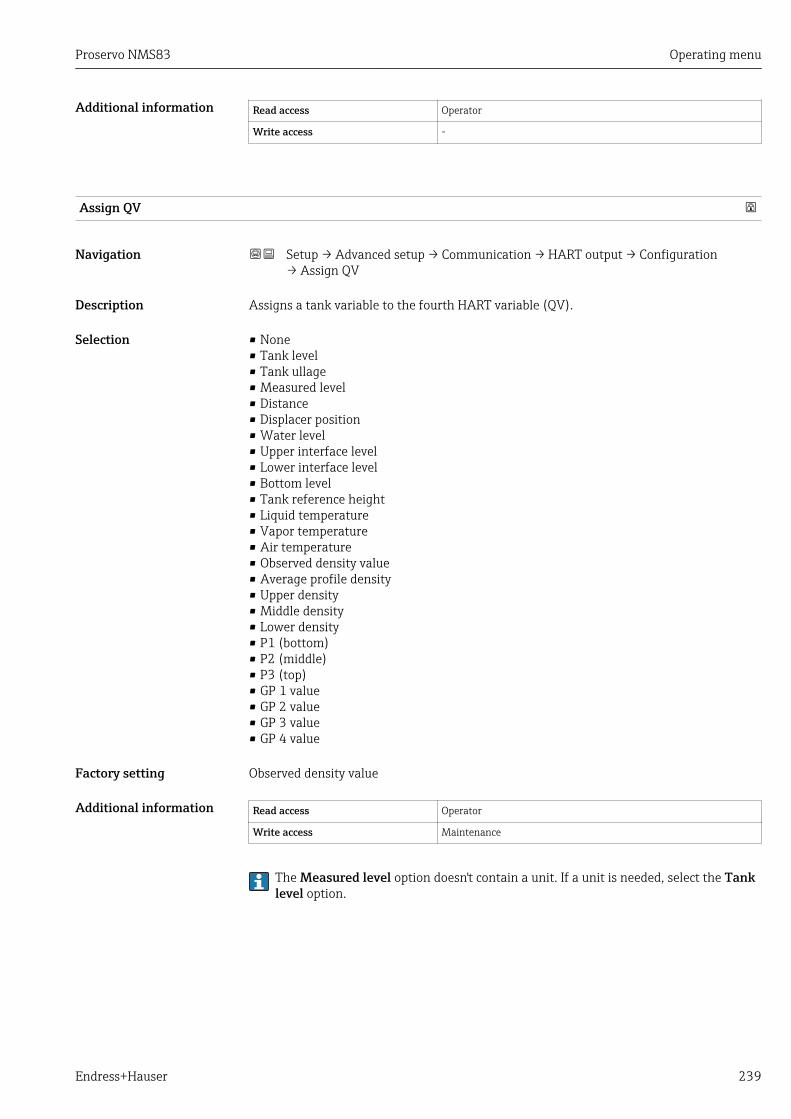
Proservo NMS83 Operating menu
Endress+Hauser 239
Additional information Read access Operator
Write access -
Assign QV
Navigation Setup → Advanced setup → Communication → HART output → Configuration→ Assign QV
Description Assigns a tank variable to the fourth HART variable (QV).
Selection • None• Tank level• Tank ullage• Measured level• Distance• Displacer position• Water level• Upper interface level• Lower interface level• Bottom level• Tank reference height• Liquid temperature• Vapor temperature• Air temperature• Observed density value• Average profile density• Upper density• Middle density• Lower density• P1 (bottom)• P2 (middle)• P3 (top)• GP 1 value• GP 2 value• GP 3 value• GP 4 value
Factory setting Observed density value
Additional information Read access Operator
Write access Maintenance
The Measured level option doesn't contain a unit. If a unit is needed, select the Tanklevel option.

Operating menu Proservo NMS83
240 Endress+Hauser
Quaternary variable (QV)
Navigation Setup → Advanced setup → Communication → HART output → Configuration→ Quaternary variable (QV)
Prerequisite Assign QV (→ 239) ≠ None
Description Shows the value of the fourth HART variable (QV).
Additional information Read access Operator
Write access -
Proservo NMS83 Operating menu
Endress+Hauser 241
"Information" submenu
Navigation Setup → Advanced setup → Communication → HART output→ Information
HART short tag
Navigation Setup → Advanced setup → Communication → HART output → Information → HARTshort tag
Description Defines the short tag for the measuring point. Maximum length: 8 characters Allowedcharacters: A-Z, 0-9, certain special characters.
Factory setting NMS8x
Additional information Read access Operator
Write access Maintenance
Device tag
Navigation Setup → Advanced setup → Communication → HART output → Information → Devicetag
Description Enter a unique name for the measuring point to identify the device quickly within theplant.
Factory setting NMS8x
Additional information Read access Operator
Write access Maintenance
HART descriptor
Navigation Setup → Advanced setup → Communication → HART output → Information → HARTdescriptor
Description User defined HART descriptor (16 characters).
Factory setting NMS8x
Additional information Read access Operator
Write access Maintenance
Operating menu Proservo NMS83
242 Endress+Hauser
HART message
Navigation Setup → Advanced setup → Communication → HART output → Information → HARTmessage
Description User defined HART message (32 characters).
Factory setting NMS8x
Additional information Read access Operator
Write access Maintenance
HART date code
Navigation Setup → Advanced setup → Communication → HART output → Information → HARTdate code
Description Enter date of the last configuration change. Use this format yyyy-mm-dd.
Factory setting 2009-07-20
Additional information Read access Operator
Write access Maintenance

Proservo NMS83 Operating menu
Endress+Hauser 243
"Application" submenu
Navigation Setup → Advanced setup → Application
"Tank configuration" submenu
Navigation Setup → Advanced setup → Application → Tank configuration
"Level" submenu
Navigation Setup → Advanced setup → Application → Tank configuration→ Level
Level source
Navigation Setup → Advanced setup → Application → Tank configuration → Level → Levelsource
Description Defines the source of the level value.
Selection • No input value• HART device 1 ... 15 level• Level SR *
• Level *• Displacer position *
• AIO B1-3 value *
• AIO C1-3 value *
• AIP B4-8 value *
• AIP C4-8 value *
Factory setting Dependent on the device version
Additional information Read access Operator
Write access Maintenance
Empty
Navigation Setup → Advanced setup → Application → Tank configuration → Level → Empty
Description Distance from reference point to zero position (tank bottom or datum plate).
User entry 0 to 10 000.00 mm
Factory setting Dependent on the device version
* Visibility depends on order options or device settings

Operating menu Proservo NMS83
244 Endress+Hauser
Additional information Read access Operator
Write access Maintenance
The reference point is the reference line of the calibration window.
Tank reference height
Navigation Setup → Advanced setup → Application → Tank configuration → Level → Tankreference height
Description Defines the distance from the dipping reference point to the zero position (tank bottom ordatum plate).
User entry 0 to 10 000.00 mm
Factory setting Dependent on the device version
Additional information Read access Operator
Write access Maintenance
Tank level
Navigation Setup → Advanced setup → Application → Tank configuration → Level → Tank level
Description Shows the distance from the zero position (tank bottom or datum plate) to the productsurface.
Additional information Read access Operator
Write access -
Set level
Navigation Setup → Advanced setup → Application → Tank configuration → Level → Set level
Description If the level measured by the device does not match the actual level obtained by a manualdip, enter the correct level into this parameter.
User entry 0 to 10 000.00 mm
Factory setting 0 mm
Additional information Read access Operator
Write access Maintenance

Proservo NMS83 Operating menu
Endress+Hauser 245
The device adjusts the Empty parameter (→ 179) according to the entered value, suchthat the measured level will match the actual level.
Water level source
Navigation Setup → Advanced setup → Application → Tank configuration → Level → Water levelsource
Description Defines the source of the bottom water level.
Selection • Manual value• Bottom level• HART device 1 ... 15 level• AIO B1-3 value• AIO C1-3 value• AIP B4-8 value• AIP C4-8 value
Factory setting Manual value
Additional information Read access Operator
Write access Maintenance
Manual water level
Navigation Setup → Advanced setup → Application → Tank configuration → Level → Manualwater level
Prerequisite Water level source (→ 245) = Manual value
Description Defines the manual value of the bottom water level.
User entry –2 000 to 5 000 mm
Factory setting 0 mm
Additional information Read access Operator
Write access Maintenance
Water level
Navigation Setup → Advanced setup → Application → Tank configuration → Level → Water level
Description Shows the bottom water level.

Operating menu Proservo NMS83
246 Endress+Hauser
Additional information Read access Operator
Write access -
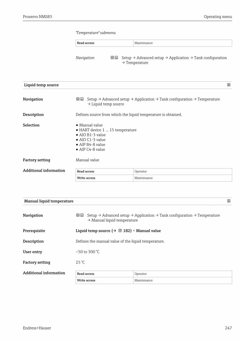
Proservo NMS83 Operating menu
Endress+Hauser 247
"Temperature" submenu
Read access Maintenance
Navigation Setup → Advanced setup → Application → Tank configuration→ Temperature
Liquid temp source
Navigation Setup → Advanced setup → Application → Tank configuration → Temperature→ Liquid temp source
Description Defines source from which the liquid temperature is obtained.
Selection • Manual value• HART device 1 ... 15 temperature• AIO B1-3 value• AIO C1-3 value• AIP B4-8 value• AIP C4-8 value
Factory setting Manual value
Additional information Read access Operator
Write access Maintenance
Manual liquid temperature
Navigation Setup → Advanced setup → Application → Tank configuration → Temperature→ Manual liquid temperature
Prerequisite Liquid temp source (→ 182) = Manual value
Description Defines the manual value of the liquid temperature.
User entry –50 to 300 °C
Factory setting 25 °C
Additional information Read access Operator
Write access Maintenance
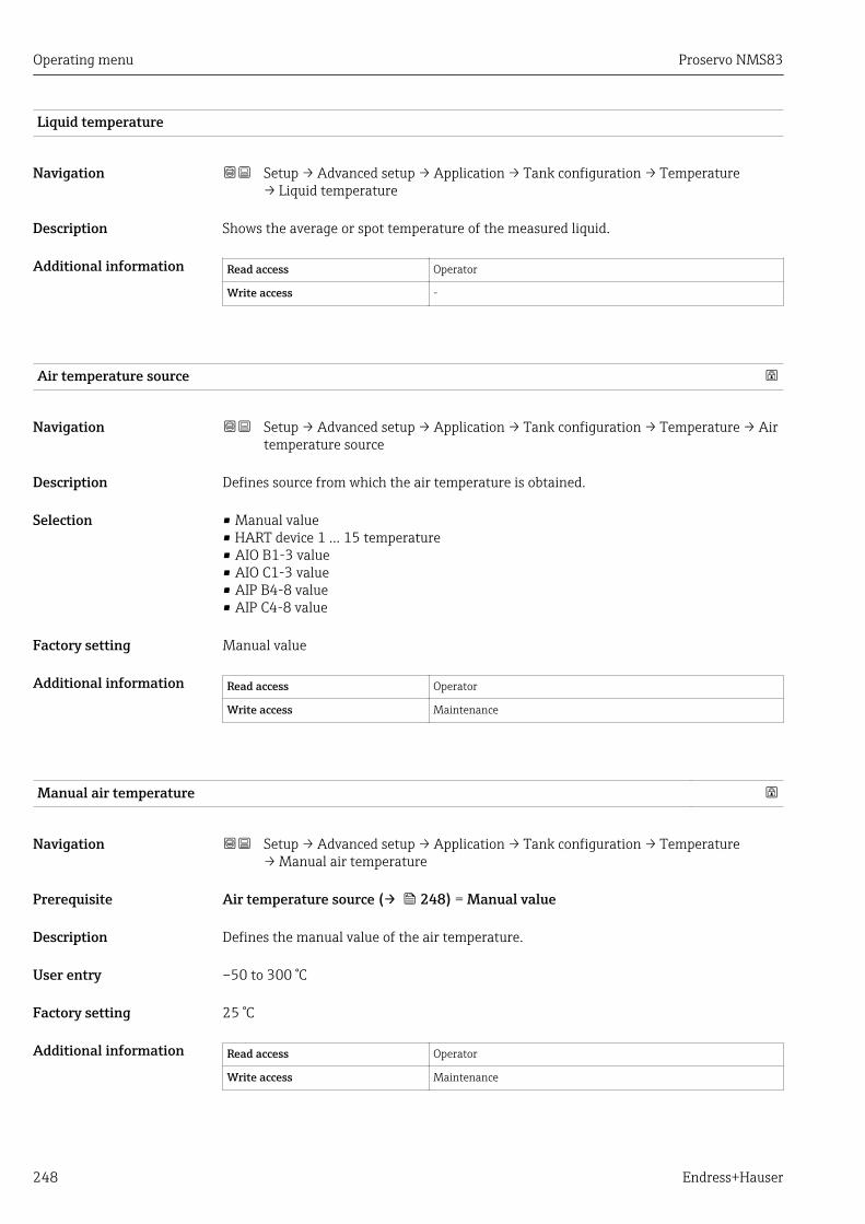
Operating menu Proservo NMS83
248 Endress+Hauser
Liquid temperature
Navigation Setup → Advanced setup → Application → Tank configuration → Temperature→ Liquid temperature
Description Shows the average or spot temperature of the measured liquid.
Additional information Read access Operator
Write access -
Air temperature source
Navigation Setup → Advanced setup → Application → Tank configuration → Temperature → Airtemperature source
Description Defines source from which the air temperature is obtained.
Selection • Manual value• HART device 1 ... 15 temperature• AIO B1-3 value• AIO C1-3 value• AIP B4-8 value• AIP C4-8 value
Factory setting Manual value
Additional information Read access Operator
Write access Maintenance
Manual air temperature
Navigation Setup → Advanced setup → Application → Tank configuration → Temperature→ Manual air temperature
Prerequisite Air temperature source (→ 248) = Manual value
Description Defines the manual value of the air temperature.
User entry –50 to 300 °C
Factory setting 25 °C
Additional information Read access Operator
Write access Maintenance
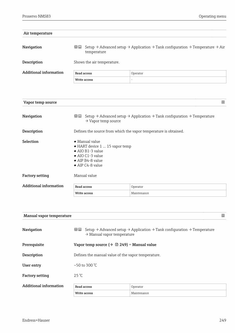
Proservo NMS83 Operating menu
Endress+Hauser 249
Air temperature
Navigation Setup → Advanced setup → Application → Tank configuration → Temperature → Airtemperature
Description Shows the air temperature.
Additional information Read access Operator
Write access -
Vapor temp source
Navigation Setup → Advanced setup → Application → Tank configuration → Temperature→ Vapor temp source
Description Defines the source from which the vapor temperature is obtained.
Selection • Manual value• HART device 1 ... 15 vapor temp• AIO B1-3 value• AIO C1-3 value• AIP B4-8 value• AIP C4-8 value
Factory setting Manual value
Additional information Read access Operator
Write access Maintenance
Manual vapor temperature
Navigation Setup → Advanced setup → Application → Tank configuration → Temperature→ Manual vapor temperature
Prerequisite Vapor temp source (→ 249) = Manual value
Description Defines the manual value of the vapor temperature.
User entry –50 to 300 °C
Factory setting 25 °C
Additional information Read access Operator
Write access Maintenance

Operating menu Proservo NMS83
250 Endress+Hauser
Vapor temperature
Navigation Setup → Advanced setup → Application → Tank configuration → Temperature→ Vapor temperature
Description Shows the measured vapor temperature.
Additional information Read access Operator
Write access -

Proservo NMS83 Operating menu
Endress+Hauser 251
"Density" submenu
Navigation Setup → Advanced setup → Application → Tank configuration→ Density
Observed density source
Navigation Setup → Advanced setup → Application → Tank configuration → Density → Observeddensity source
Description Determines how the density is obtained.
Selection • HTG *
• HTMS *
• Average profile density *
• Upper density• Middle density• Lower density
Factory setting Dependent on the device version
Additional information Read access Operator
Write access Maintenance
Observed density
Navigation Setup → Advanced setup → Application → Tank configuration → Density → Observeddensity
Description Shows the measured or calculated density.
Additional information Read access Operator
Write access -
Air density
Navigation Setup → Advanced setup → Application → Tank configuration → Density → Airdensity
Description Defines the density of the air surrounding the tank.
User entry 0.0 to 500.0 kg/m³
* Visibility depends on order options or device settings
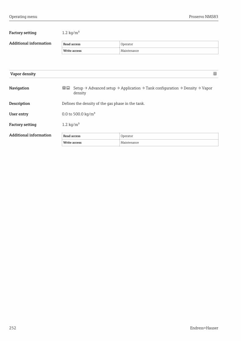
Operating menu Proservo NMS83
252 Endress+Hauser
Factory setting 1.2 kg/m³
Additional information Read access Operator
Write access Maintenance
Vapor density
Navigation Setup → Advanced setup → Application → Tank configuration → Density → Vapordensity
Description Defines the density of the gas phase in the tank.
User entry 0.0 to 500.0 kg/m³
Factory setting 1.2 kg/m³
Additional information Read access Operator
Write access Maintenance

Proservo NMS83 Operating menu
Endress+Hauser 253
"Pressure" submenu
Navigation Setup → Advanced setup → Application → Tank configuration→ Pressure
P1 (bottom) source
Navigation Setup → Advanced setup → Application → Tank configuration → Pressure → P1(bottom) source
Description Defines the source of the bottom pressure (P1).
Selection • Manual value• HART device 1 ... 15 pressure• AIO B1-3 value• AIO C1-3 value• AIP B4-8 value• AIP C4-8 value
Factory setting Manual value
Additional information Read access Operator
Write access Maintenance
P1 (bottom)
Navigation Setup → Advanced setup → Application → Tank configuration → Pressure → P1(bottom)
Description Shows the pressure at the tank bottom.
Additional information Read access Operator
Write access -
P1 (bottom) manual pressure
Navigation Setup → Advanced setup → Application → Tank configuration → Pressure → P1(bottom) manual pressure
Prerequisite P1 (bottom) source (→ 253) = Manual value
Description Defines the manual value of the bottom pressure (P1).
User entry –25 to 25 bar

Operating menu Proservo NMS83
254 Endress+Hauser
Factory setting 0 bar
Additional information Read access Operator
Write access Maintenance
P1 position
Navigation Setup → Advanced setup → Application → Tank configuration → Pressure → P1position
Description Defines the position of the bottom pressure transmitter (P1), measured from zero position(tank bottom or datum plate).
User entry –10 000 to 100 000 mm
Factory setting 5 000 mm
Additional information Read access Operator
Write access Maintenance
P1 offset
Navigation Setup → Advanced setup → Application → Tank configuration → Pressure → P1offset
Description Offset for the bottom pressure (P1). The offset is added to the measured pressure prior toany tank calculation.
User entry –25 to 25 bar
Factory setting 0 bar
Additional information Read access Operator
Write access Maintenance
P1 absolute / gauge
Navigation Setup → Advanced setup → Application → Tank configuration → Pressure → P1absolute / gauge
Description Defines whether the connected pressure transmitter measures an absolute or a gaugepressure.
Selection • Absolute• Gauge
Proservo NMS83 Operating menu
Endress+Hauser 255
Factory setting Gauge
Additional information Read access Operator
Write access Maintenance
P3 (top) source
Navigation Setup → Advanced setup → Application → Tank configuration → Pressure → P3 (top)source
Description Defines the source of the top pressure (P3).
Selection • Manual value• HART device 1 ... 15 pressure• AIO B1-3 value• AIO C1-3 value• AIP B4-8 value• AIP C4-8 value
Factory setting Manual value
Additional information Read access Operator
Write access Maintenance
P3 (top)
Navigation Setup → Advanced setup → Application → Tank configuration → Pressure → P3 (top)
Description Shows the pressure (P3) at the top transmitter.
Additional information Read access Operator
Write access -
P3 (top) manual pressure
Navigation Setup → Advanced setup → Application → Tank configuration → Pressure → P3 (top)manual pressure
Prerequisite P3 (top) source (→ 255) = Manual value
Description Defines the manual value of the top pressure (P3).
User entry –2.5 to 2.5 bar
Factory setting 0 bar
Operating menu Proservo NMS83
256 Endress+Hauser
Additional information Read access Operator
Write access Maintenance
P3 position
Navigation Setup → Advanced setup → Application → Tank configuration → Pressure → P3position
Description Defines the position of the top pressure transmitter (P3), measured from zero position(tank bottom or datum plate).
User entry 0 to 100 000 mm
Factory setting 20 000 mm
Additional information Read access Operator
Write access Maintenance
P3 offset
Navigation Setup → Advanced setup → Application → Tank configuration → Pressure → P3offset
Description Offset for the top pressure (P3). The offset is added to the measured pressure prior to anytank calculation.
User entry –2.5 to 2.5 bar
Factory setting 0 bar
Additional information Read access Operator
Write access Maintenance
P3 absolute / gauge
Navigation Setup → Advanced setup → Application → Tank configuration → Pressure → P3absolute / gauge
Description Defines whether the connected pressure transmitter measures an absolute or a gaugepressure.
Selection • Absolute• Gauge
Factory setting Gauge
Proservo NMS83 Operating menu
Endress+Hauser 257
Additional information Read access Operator
Write access Maintenance
Ambient pressure
Navigation Setup → Advanced setup → Application → Tank configuration → Pressure→ Ambient pressure
Description Defines the manual value of the ambient pressure.
User entry 0 to 2.5 bar
Factory setting 1 bar
Additional information Read access Operator
Write access Maintenance
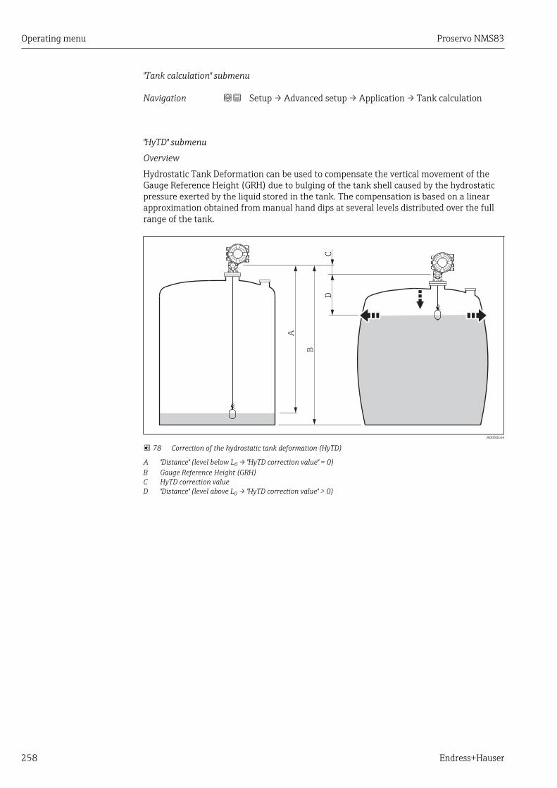
Operating menu Proservo NMS83
258 Endress+Hauser
"Tank calculation" submenu
Navigation Setup → Advanced setup → Application → Tank calculation
"HyTD" submenu
Overview
Hydrostatic Tank Deformation can be used to compensate the vertical movement of theGauge Reference Height (GRH) due to bulging of the tank shell caused by the hydrostaticpressure exerted by the liquid stored in the tank. The compensation is based on a linearapproximation obtained from manual hand dips at several levels distributed over the fullrange of the tank.
A
B
CD
A0030164
78 Correction of the hydrostatic tank deformation (HyTD)
A "Distance" (level below L0 → "HyTD correction value" = 0)B Gauge Reference Height (GRH)C HyTD correction valueD "Distance" (level above L0 → "HyTD correction value" > 0)

Proservo NMS83 Operating menu
Endress+Hauser 259
Linear approximation of the HyTD correction
The real amount of deformation varies non-linearly with the level due to the constructionof the tank. However, as the correction values are typically small compared to themeasured level, a simple straight line method can be used with good results.
H
2
1
L
L0
3
A0028724
79 Calculation of the HyTD correction
1 Linear correction according to "Deformation factor (→ 261)"2 Real correction3 Starting level (→ 260)L Measured levelH HyTD correction value (→ 260)
Calculation of the HyTD correction
L < L0 C = 0HyTD=
= C = - (L - L ) x DHyTD 0L > L0
A0028715
L Measured level
L0 Starting level
cHyTD HyTD correction value
D Deformation factor

Operating menu Proservo NMS83
260 Endress+Hauser
Description of parameters
Navigation Setup → Advanced setup → Application → Tank calculation→ HyTD
HyTD correction value
Navigation Setup → Advanced setup → Application → Tank calculation → HyTD → HyTDcorrection value
Description Shows the correction value from the Hydrostatic Tank Deformation.
Additional information Read access Operator
Write access -
HyTD mode
Navigation Setup → Advanced setup → Application → Tank calculation → HyTD → HyTD mode
Description Activates or deactivates the calculation of the Hydrostatic Tank Deformation.
Selection • No• Yes
Factory setting No
Additional information Read access Operator
Write access Maintenance
Starting level
Navigation Setup → Advanced setup → Application → Tank calculation → HyTD → Starting level
Description Defines the starting level for the Hydrostatic Tank Deformation. Levels below this valueare not corrected.
User entry 0 to 5 000 mm
Factory setting 500 mm
Additional information Read access Operator
Write access Maintenance
Proservo NMS83 Operating menu
Endress+Hauser 261
Deformation factor
Navigation Setup → Advanced setup → Application → Tank calculation → HyTD → Deformationfactor
Description Defines the deformation factor for the HyTD (change of device position per change oflevel).
User entry –1.0 to 1.0 %
Factory setting 0.2 %
Additional information Read access Operator
Write access Maintenance

Operating menu Proservo NMS83
262 Endress+Hauser
"CTSh" submenu
Overview
CTSh (correction for the thermal expansion of the tank shell) compensates for effects onthe Gauge Reference Height (GRH) and on the expansion or contraction of the measuringwire due to temperature effects on the tank shell or stilling well. The temperature effectsare separated into two parts, respectively affecting the 'dry' and 'wetted' part of the tankshell or stilling well. The correction function is based on thermal expansion coefficients ofsteel and insulation factors for both the 'dry' and 'wet' parts of the wire and the tank shell.The temperatures used for the correction can be selected from on manual or measuredvalues.
This correction is recommended for the following situations:• if the operating temperature deviates considederably from the temperature during
calibration (ΔT > 10 °C (18 °F))• for extremely high tanks• for refrigerated, cryogenic or heated applications
As the use of this correction will influence the innage level reading, it isrecommended to ensure the manual hand dip and level verification procedures arebeing conducted correctly before enabling this correction method.
This mode cannot be used in conjunction with HTG because the level is not measuredrelative to the gauge reference height with HTG.

Proservo NMS83 Operating menu
Endress+Hauser 263
CTSh: Calculation of the wall temperature
L
TP
TV S
D
TW
TA
E
TD
TR
H
A0028713
80 Parameters for the CTSh calculation
TW Temperature of the wetted part of the tank shell
TD Temperature of the dry part of the tank shell
TP Product temperature
TV Vapor temperature (in the tank)
TA Ambient temperature (atmosphere surrounding the tank)
Sd Measured distance (Empty to Level)
TRH Tank reference height
E Empty
L Level
CTSh: Calculation of the wall temperature
Depending on the parameters Covered tank (→ 265) and Stilling well (→ 266),the temperatures TW of the wetted and TD of the dry part of the tank wall are calculated asfollows:
Covered tank (→ 265) Stilling well (→ 266) TW TD
CoveredYes 1) TP TV
No (7/8) TP + (1/8) TA (1/2) TV + (1/2) TA
Open topYes TP TA
No (7/8) TP + (1/8) TA TA
1) This option is also valid for insulated tanks without a stilling welll. This is due to the temperature insideand outside of the tank shell being the same due to the insulation of the tank.
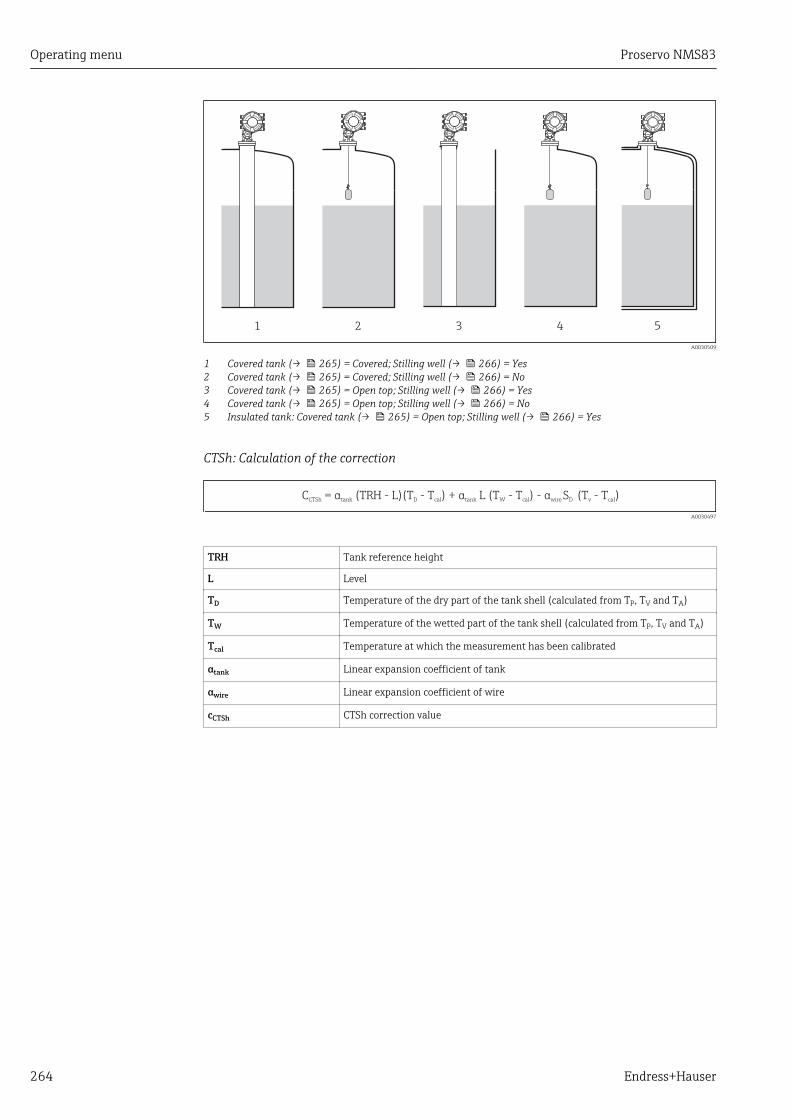
Operating menu Proservo NMS83
264 Endress+Hauser
1 2 3 4 5
A0030509
1 Covered tank (→ 265) = Covered; Stilling well (→ 266) = Yes2 Covered tank (→ 265) = Covered; Stilling well (→ 266) = No3 Covered tank (→ 265) = Open top; Stilling well (→ 266) = Yes4 Covered tank (→ 265) = Open top; Stilling well (→ 266) = No5 Insulated tank: Covered tank (→ 265) = Open top; Stilling well (→ 266) = Yes
CTSh: Calculation of the correction
C = ( H - L)(T - T ) + L (T - T ) (T - T )CTSh D cal W cal calα α αtank tank wire D vTR - S
A0030497
TRH Tank reference height
L Level
TD Temperature of the dry part of the tank shell (calculated from TP, TV and TA)
TW Temperature of the wetted part of the tank shell (calculated from TP, TV and TA)
Tcal Temperature at which the measurement has been calibrated
αtank Linear expansion coefficient of tank
αwire Linear expansion coefficient of wire
cCTSh CTSh correction value
Proservo NMS83 Operating menu
Endress+Hauser 265
Description of parameters
Navigation Setup → Advanced setup → Application → Tank calculation→ CTSh
CTSh correction value
Navigation Setup → Advanced setup → Application → Tank calculation → CTSh → CTShcorrection value
Description Shows the CTSh correction value.
Additional information Read access Operator
Write access -
CTSh mode
Navigation Setup → Advanced setup → Application → Tank calculation → CTSh → CTSh mode
Description Activates or deactivates the CTSh.
Selection • No• Yes• With wire *
• Only wire *
Factory setting No
Additional information Read access Operator
Write access Maintenance
Covered tank
Navigation Setup → Advanced setup → Application → Tank calculation → CTSh → Covered tank
Description Determines whether the tank is covered.
Selection • Open top• Covered
Factory setting Open top
* Visibility depends on order options or device settings
Operating menu Proservo NMS83
266 Endress+Hauser
Additional information Read access Operator
Write access Maintenance
The Covered option is only valid for fixed tank roofs. For a floating roof select Opentop.
Stilling well
Navigation Setup → Advanced setup → Application → Tank calculation → CTSh → Stilling well
Description Determines whether the device is mounted on a stilling well.
Selection • No• Yes
Factory setting No
Additional information Read access Operator
Write access Maintenance
Calibration temperature
Navigation Setup → Advanced setup → Application → Tank calculation → CTSh → Calibrationtemperature
Description Specify temperature at which the measurement has been calibrated.
User entry –50 to 250 °C
Factory setting 25 °C
Additional information Read access Operator
Write access Maintenance
Linear expansion coefficient
Navigation Setup → Advanced setup → Application → Tank calculation → CTSh → Linearexpansion coefficient
Description Defines the linear expansion coefficient of the tank shell material.
User entry 0 to 100 ppm
Factory setting 15 ppm

Proservo NMS83 Operating menu
Endress+Hauser 267
Additional information Read access Operator
Write access Maintenance
Wire expansion coefficient
Navigation Setup → Advanced setup → Application → Tank calculation → CTSh → Wireexpansion coefficient
Description Defines the expansion coefficient of the wire material of the drum. Value is programmedin factory.
User entry 0 to 100 ppm
Factory setting 15 ppm

Operating menu Proservo NMS83
268 Endress+Hauser
"HTMS" submenu
Overview
The Hybrid Tank Measurement System (HTMS) is a method to calculate the density of aproduct in a tank based on both a (top mounted) level and at least one (bottom mounted)pressure measurement. An additional pressure sensor can be installed at the top of thetank to provide information about the vapor pressure and to make the density calculationmore accurate. The calculation method also takes into account a possible level of water atthe bottom of the tank to make density calculations as accurate as possible.
HTMS parameters
HP1
V
g
P1
P3
LP
LW
HP3ρP
ρV
ρA
A
B
ΔP
A0030498
81 HTMS parameters
A ProductB Water
Parameter Navigation path
P1 (Bottom pressure) Setup → Advanced setup → Tank configuration → Pressure → P1 (bottom)
HP1 (Position of P1 transmitter) Setup → Advanced setup → Tank configuration → Pressure → P1 position
P3 (Top pressure) Setup → Advanced setup → Tank configuration → Pressure → P3 (top)
HP3 (Position of P3 transmitter) Setup → Advanced setup → Tank configuration → Pressure → P3 position
ρP (Density of the product 1)) • Measured value: Setup → Advanced setup → Calculation → HTMS → Density value• User-defined value: Setup → Advanced setup → Calculation → HTMS → Manual upper density
ρV (Vapor density) Expert → Application → Tank configuration → Density → Vapor density
ρA (Ambient air temperature) Setup → Advanced setup → Tank configuration → Density → Air density
g (Local gravity) Expert → Application → Tank Calculation → Local gravity
Lp (Level of the product) Operation → Tank level
LW (Bottom water level) Operation → Water level
V = LW - HP1
ΔP = LP - LW = LP - V - HP1
1) Depending on the situation this parameter is measured or a user-defined value is used.
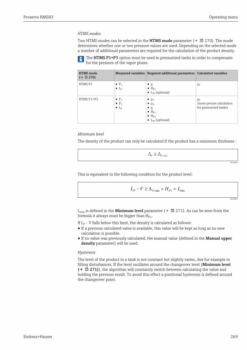
Proservo NMS83 Operating menu
Endress+Hauser 269
HTMS modes
Two HTMS modes can be selected in the HTMS mode parameter (→ 270). The modedetermines whether one or two pressure values are used. Depending on the selected modea number of additional parameters are required for the calculation of the product density.
The HTMS P1+P3 option must be used in pressurized tanks in order to compensatefor the pressure of the vapor phase.
HTMS mode(→ 270)
Measured variables Required additional parameters Calculated variables
HTMS P1 • P1• LP
• g• HP1• LW (optional)
ρP
HTMS P1+P3 • P1• P3• LP
• ρV• ρA• g• HP1• HP3• LW (optional)
ρP(more precise calculationfor pressurized tanks)
Minimum level
The density of the product can only be calculated if the product has a minimum thickness :
Δ ΔP P, min≥
A0028864
This is equivalent to the following condition for the product level:
L V H LP P P
- ³ + =D ,min min1
A0028863
Lmin is defined in the Minimum level parameter (→ 271). As can be seen from theformula it always must be bigger than HP1.
If LP - V falls below this limit, the density is calculated as follows:• If a previous calculated value is available, this value will be kept as long as no new
calculation is possible.• If no value was previously calculated, the manual value (defined in the Manual upper
density parameter) will be used.
Hysteresis
The level of the product in a tank is not constant but slightly varies, due for example tofilling disturbances. If the level oscillates around the changeover level (Minimum level(→ 271)), the algorithm will constantly switch between calculating the value andholding the previous result. To avoid this effect a positional hysteresis is defined aroundthe changeover point.

Operating menu Proservo NMS83
270 Endress+Hauser
Lmin
Hr
1
2
A0029148
82 HTMS hysteresis
1 Value calculated2 Value held/manualLmin Minimum level (→ 271)Hr Hysteresis (→ 272)
Description of parameters
Navigation Setup → Advanced setup → Application → Tank calculation→ HTMS
HTMS mode
Navigation Setup → Advanced setup → Application → Tank calculation → HTMS → HTMS mode
Description Defines the HTMS mode. Depending on the mode one or two pressure transmitters areused.
Selection • HTMS P1• HTMS P1+P3
Factory setting HTMS P1
Additional information Read access Operator
Write access Maintenance
Meaning of the options• HTMS P1
Only a bottom pressure transmitter (P1) is used.• HTMS P1+P3
A bottom (P1) and top (P3) pressure transmitter are used. This option should be selectedfor pressurized tanks.
Manual density
Navigation Setup → Advanced setup → Application → Tank calculation → HTMS → Manualdensity
Description Defines the manual density.
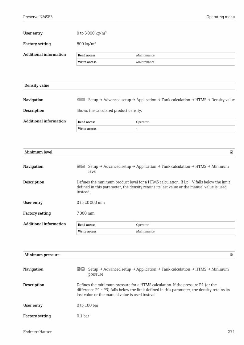
Proservo NMS83 Operating menu
Endress+Hauser 271
User entry 0 to 3 000 kg/m³
Factory setting 800 kg/m³
Additional information Read access Maintenance
Write access Maintenance
Density value
Navigation Setup → Advanced setup → Application → Tank calculation → HTMS → Density value
Description Shows the calculated product density.
Additional information Read access Operator
Write access -
Minimum level
Navigation Setup → Advanced setup → Application → Tank calculation → HTMS → Minimumlevel
Description Defines the minimum product level for a HTMS calculation. If Lp - V falls below the limitdefined in this parameter, the density retains its last value or the manual value is usedinstead.
User entry 0 to 20 000 mm
Factory setting 7 000 mm
Additional information Read access Operator
Write access Maintenance
Minimum pressure
Navigation Setup → Advanced setup → Application → Tank calculation → HTMS → Minimumpressure
Description Defines the minimum pressure for a HTMS calculation. If the pressure P1 (or thedifference P1 - P3) falls below the limit defined in this parameter, the density retains itslast value or the manual value is used instead.
User entry 0 to 100 bar
Factory setting 0.1 bar

Operating menu Proservo NMS83
272 Endress+Hauser
Additional information Read access Operator
Write access Maintenance
Safety distance
Navigation Setup → Advanced setup → Application → Tank calculation → HTMS → Safetydistance
Description Defines the minimum level which must be present above the bottom pressure sensorbefore its signal is used for the calculation.
User entry 0 to 10 000 mm
Factory setting 2 000 mm
Additional information Read access Operator
Write access Maintenance
Hysteresis
Navigation Setup → Advanced setup → Application → Tank calculation → HTMS → Hysteresis
Description Defines the hysteresis for the HTMS calculation. Prevents constant switching if the level isnear the switch-over point.
User entry 0 to 2 000 mm
Factory setting 50 mm
Additional information Read access Operator
Write access Maintenance
Water density
Navigation Setup → Advanced setup → Application → Tank calculation → HTMS → Waterdensity
Description Density of the water in the tank.
User entry Signed floating-point number
Factory setting 1 000 kg/m³

Proservo NMS83 Operating menu
Endress+Hauser 273
Additional information Read access Operator
Write access Maintenance

Operating menu Proservo NMS83
274 Endress+Hauser
"Alarm" submenu
Navigation Setup → Advanced setup → Application → Alarm → Alarm→ Alarm mode
Alarm mode
Navigation Setup → Advanced setup → Application → Alarm → Alarm → Alarm mode
Description Defines the alarm mode of the selected alarm.
Selection • Off• On• Latching
Factory setting Off
Additional information Read access Operator
Write access Maintenance
Meaning of the options
• OffNo alarms are generated.
• OnAn alarm disappears if the alarm condition is no longer present (taking intoconsideration the hysteresis).
• LatchingAll alarms remain active until the user selects Clear alarm (→ 280) = Yes or thepower is switched off and on.

Proservo NMS83 Operating menu
Endress+Hauser 275
A B
1
2
3
4
5
6
7
8
1
2
3
4
5
6
7
8
9
10 10
A0029539
83 Principle of the limit evaluation
A Alarm mode (→ 274) = OnB Alarm mode (→ 274) = Latching1 HH alarm value (→ 277)2 H alarm value (→ 277)3 L alarm value (→ 278)4 LL alarm value (→ 278)5 HH alarm (→ 278)6 H alarm (→ 279)7 L alarm (→ 279)8 LL alarm (→ 279)9 "Clear alarm (→ 280)" = "Yes" or power off-on10 Hysteresis (→ 281)
Error value
Navigation Setup → Advanced setup → Application → Alarm → Alarm → Error value
Prerequisite Alarm mode (→ 274) ≠ Off
Description Defines the alarm to be issued if the input value is invalid.
Selection • No alarm• HH+H alarm• H alarm• L alarm• LL+L alarm• All alarms
Factory setting All alarms
Additional information Read access Operator
Write access Maintenance

Operating menu Proservo NMS83
276 Endress+Hauser
Alarm value source
Navigation Setup → Advanced setup → Application → Alarm → Alarm → Alarm value source
Prerequisite Alarm mode (→ 274) ≠ Off
Description Determines the process variable to be monitored.
Selection • Tank level• Liquid temperature• Vapor temperature• Water level• P1 (bottom)• P2 (middle)• P3 (top)• Observed density value• Volume• Flow velocity• Volume flow• Vapor density• Middle density• Upper density• Correction• Tank level %• GP 1...4 value• Measured level• P3 position• Tank reference height• Local gravity• P1 position• Manual density• Tank ullage• Average profile density• Lower density• Upper interface level• Lower interface level• Bottom level• Displacer position• HART device 1...15 PV• HART device 1...15 SV• HART device 1...15 TV• HART device 1...15 QV• HART device 1...15 PV mA• HART device 1...15 PV %• Element temperature 1...24• AIO B1-3 value• AIO C1-3 value• AIP B4-8 value• AIP C4-8 value• None
Factory setting None
Additional information Read access Operator
Write access Maintenance

Proservo NMS83 Operating menu
Endress+Hauser 277
Alarm value
Navigation Setup → Advanced setup → Application → Alarm → Alarm → Alarm value
Prerequisite Alarm mode (→ 274) ≠ Off
Description Shows the current value of the process variable being monitored.
User interface Signed floating-point number
Factory setting 0 None
Additional information Read access Operator
Write access -
HH alarm value
Navigation Setup → Advanced setup → Application → Alarm → Alarm → HH alarm value
Prerequisite Alarm mode (→ 274) ≠ Off
Description Defines the high-high(HH) limit value.
User entry Signed floating-point number
Factory setting 0 None
Additional information Read access Operator
Write access Maintenance
H alarm value
Navigation Setup → Advanced setup → Application → Alarm → Alarm → H alarm value
Prerequisite Alarm mode (→ 274) ≠ Off
Description Defines the high(H) limit value.
User entry Signed floating-point number
Factory setting 0 None
Additional information Read access Operator
Write access Maintenance
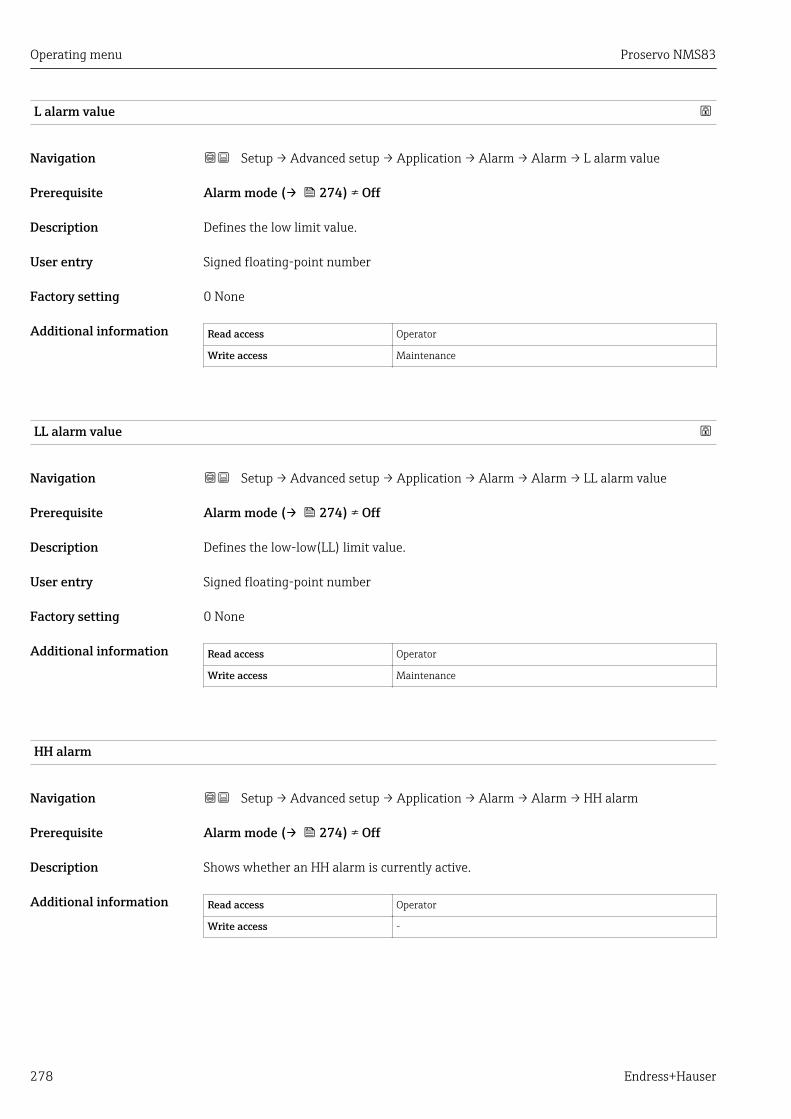
Operating menu Proservo NMS83
278 Endress+Hauser
L alarm value
Navigation Setup → Advanced setup → Application → Alarm → Alarm → L alarm value
Prerequisite Alarm mode (→ 274) ≠ Off
Description Defines the low limit value.
User entry Signed floating-point number
Factory setting 0 None
Additional information Read access Operator
Write access Maintenance
LL alarm value
Navigation Setup → Advanced setup → Application → Alarm → Alarm → LL alarm value
Prerequisite Alarm mode (→ 274) ≠ Off
Description Defines the low-low(LL) limit value.
User entry Signed floating-point number
Factory setting 0 None
Additional information Read access Operator
Write access Maintenance
HH alarm
Navigation Setup → Advanced setup → Application → Alarm → Alarm → HH alarm
Prerequisite Alarm mode (→ 274) ≠ Off
Description Shows whether an HH alarm is currently active.
Additional information Read access Operator
Write access -

Proservo NMS83 Operating menu
Endress+Hauser 279
H alarm
Navigation Setup → Advanced setup → Application → Alarm → Alarm → H alarm
Prerequisite Alarm mode (→ 274) ≠ Off
Description Shows whether an H alarm is currently active.
Additional information Read access Operator
Write access -
HH+H alarm
Navigation Setup → Advanced setup → Application → Alarm → Alarm → HH+H alarm
Prerequisite Alarm mode (→ 274) ≠ Off
Description Shows whether an HH or H alarm is currently active.
Additional information Read access Operator
Write access -
L alarm
Navigation Setup → Advanced setup → Application → Alarm → Alarm → L alarm
Prerequisite Alarm mode (→ 274) ≠ Off
Description Shows whether an L alarm is currently active.
Additional information Read access Operator
Write access -
LL alarm
Navigation Setup → Advanced setup → Application → Alarm → Alarm → LL alarm
Prerequisite Alarm mode (→ 274) ≠ Off
Description Shows whether an LL alarm is currently active.
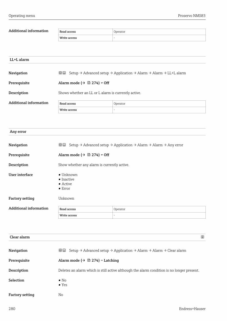
Operating menu Proservo NMS83
280 Endress+Hauser
Additional information Read access Operator
Write access -
LL+L alarm
Navigation Setup → Advanced setup → Application → Alarm → Alarm → LL+L alarm
Prerequisite Alarm mode (→ 274) ≠ Off
Description Shows whether an LL or L alarm is currently active.
Additional information Read access Operator
Write access -
Any error
Navigation Setup → Advanced setup → Application → Alarm → Alarm → Any error
Prerequisite Alarm mode (→ 274) ≠ Off
Description Show whether any alarm is currently active.
User interface • Unknown• Inactive• Active• Error
Factory setting Unknown
Additional information Read access Operator
Write access -
Clear alarm
Navigation Setup → Advanced setup → Application → Alarm → Alarm → Clear alarm
Prerequisite Alarm mode (→ 274) = Latching
Description Deletes an alarm which is still active although the alarm condition is no longer present.
Selection • No• Yes
Factory setting No
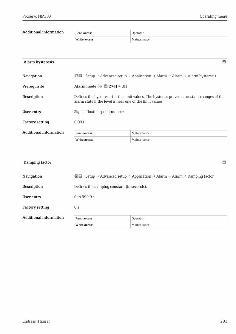
Proservo NMS83 Operating menu
Endress+Hauser 281
Additional information Read access Operator
Write access Maintenance
Alarm hysteresis
Navigation Setup → Advanced setup → Application → Alarm → Alarm → Alarm hysteresis
Prerequisite Alarm mode (→ 274) ≠ Off
Description Defines the hysteresis for the limit values. The hystersis prevents constant changes of thealarm state if the level is near one of the limit values.
User entry Signed floating-point number
Factory setting 0.001
Additional information Read access Maintenance
Write access Maintenance
Damping factor
Navigation Setup → Advanced setup → Application → Alarm → Alarm → Damping factor
Description Defines the damping constant (in seconds).
User entry 0 to 999.9 s
Factory setting 0 s
Additional information Read access Operator
Write access Maintenance
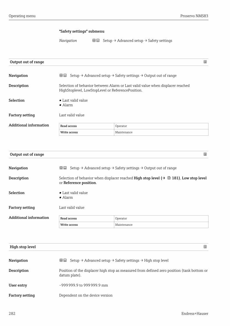
Operating menu Proservo NMS83
282 Endress+Hauser
"Safety settings" submenu
Navigation Setup → Advanced setup → Safety settings
Output out of range
Navigation Setup → Advanced setup → Safety settings → Output out of range
Description Selection of behavior between Alarm or Last valid value when displacer reachedHighStoplevel, LowStopLevel or ReferencePosition.
Selection • Last valid value• Alarm
Factory setting Last valid value
Additional information Read access Operator
Write access Maintenance
Output out of range
Navigation Setup → Advanced setup → Safety settings → Output out of range
Description Selection of behavior when displacer reached High stop level (→ 181), Low stop levelor Reference position.
Selection • Last valid value• Alarm
Factory setting Last valid value
Additional information Read access Operator
Write access Maintenance
High stop level
Navigation Setup → Advanced setup → Safety settings → High stop level
Description Position of the displacer high stop as measured from defined zero position (tank bottom ordatum plate).
User entry –999 999.9 to 999 999.9 mm
Factory setting Dependent on the device version

Proservo NMS83 Operating menu
Endress+Hauser 283
Additional information Read access Operator
Write access Maintenance
Low stop level
Navigation Setup → Advanced setup → Safety settings → Low stop level
Description Position of the displacer low stop as measured from defined zero position (tank bottom ordatum plate).
User entry –999 999.9 to 999 999.9 mm
Factory setting 0 mm
Additional information Read access Operator
Write access Maintenance
Slow hoist zone
Navigation Setup → Advanced setup → Safety settings → Slow hoist zone
Description Defines the interval in millimeters, measured down from the Reference Position, in whichthe Displacer reduces moving speed.
User entry 10 to 999 999.9 mm
Factory setting 70 mm
Additional information Read access Operator
Write access Maintenance
Overtension weight
Navigation Setup → Advanced setup → Safety settings → Overtension weight
Description Sets the minimum Weight in grams when Overtension Alarm will be set.
User entry 100 to 999.9 g
Factory setting 350 g
Additional information Read access Operator
Write access Maintenance

Operating menu Proservo NMS83
284 Endress+Hauser
Undertension weight
Navigation Setup → Advanced setup → Safety settings → Undertension weight
Description Defines the undertension error weight. Untertension error will be issued if displacerweight is below this value longer than 7 seconds.
User entry 0 to 300 g
Factory setting 10 g
Additional information Read access Operator
Write access Maintenance
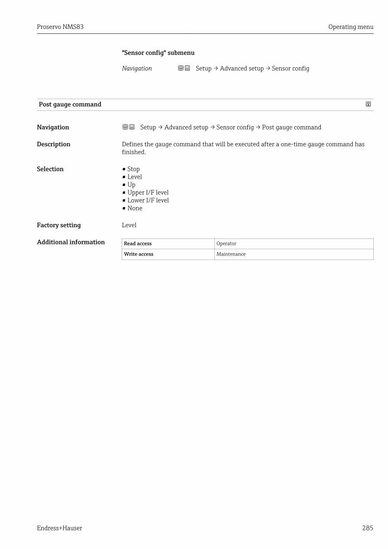
Proservo NMS83 Operating menu
Endress+Hauser 285
"Sensor config" submenu
Navigation Setup → Advanced setup → Sensor config
Post gauge command
Navigation Setup → Advanced setup → Sensor config → Post gauge command
Description Defines the gauge command that will be executed after a one-time gauge command hasfinished.
Selection • Stop• Level• Up• Upper I/F level• Lower I/F level• None
Factory setting Level
Additional information Read access Operator
Write access Maintenance

Operating menu Proservo NMS83
286 Endress+Hauser
"Displacer" submenu
Navigation Setup → Advanced setup → Sensor config → Displacer
Displacer type
Navigation Setup → Advanced setup → Sensor config → Displacer → Displacer type
Description Chooses the type of displacer used.
Selection • Custom diameter• Diameter 30 mm• Diameter 50 mm• Diameter 70 mm• Diameter 110 mm
Factory setting Dependent on the device version
Additional information Read access Operator
Write access Maintenance
Displacer diameter
Navigation Setup → Advanced setup → Sensor config → Displacer → Displacer diameter
Prerequisite Displacer type (→ 286) = Custom diameter
Description Sets the diameter of the cylindrical part of displacer.
User entry 0 to 999.9 mm
Factory setting See label on the device.
Additional information Read access Operator
Write access Maintenance
Displacer weight
Navigation Setup → Advanced setup → Sensor config → Displacer → Displacer weight
Description Set the weight of the diplacer in air. Indicated on the displacer in grams.
User entry 10 to 999.9 g
Factory setting See label on the device.

Proservo NMS83 Operating menu
Endress+Hauser 287
Additional information Read access Operator
Write access Maintenance
Displacer volume
Navigation Setup → Advanced setup → Sensor config → Displacer → Displacer volume
Description Displacer volume indicated on displacer in mililiter.
User entry 10 to 999.9 ml
Factory setting See label on the device.
Additional information Read access Operator
Write access Maintenance
Displacer balance volume
Navigation Setup → Advanced setup → Sensor config → Displacer → Displacer balance volume
Description Defines the balance volume of the displacer as the lower part of displacer immersed inliquid. Units in milliliters. Indicated on displacer.
User entry 10 to 999.9 ml
Factory setting See label on the device.
Additional information Read access Operator
Write access Maintenance
Displacer height
Navigation Setup → Advanced setup → Sensor config → Displacer → Displacer height
Description Sets the displacer height in mm.
User entry 10 to 300 mm
Factory setting Dependent on the device version
Additional information Read access Operator
Write access Maintenance

Operating menu Proservo NMS83
288 Endress+Hauser
Immersion depth
Navigation Setup → Advanced setup → Sensor config → Displacer → Immersion depth
Description Defines distance (mm) from displacer bottom to balancing line defined by balancedvolume. Value is needed for correct bottom level measurement.
User entry 0 to 99.9 mm
Factory setting Dependent on the device version
Additional information Read access Operator
Write access Maintenance
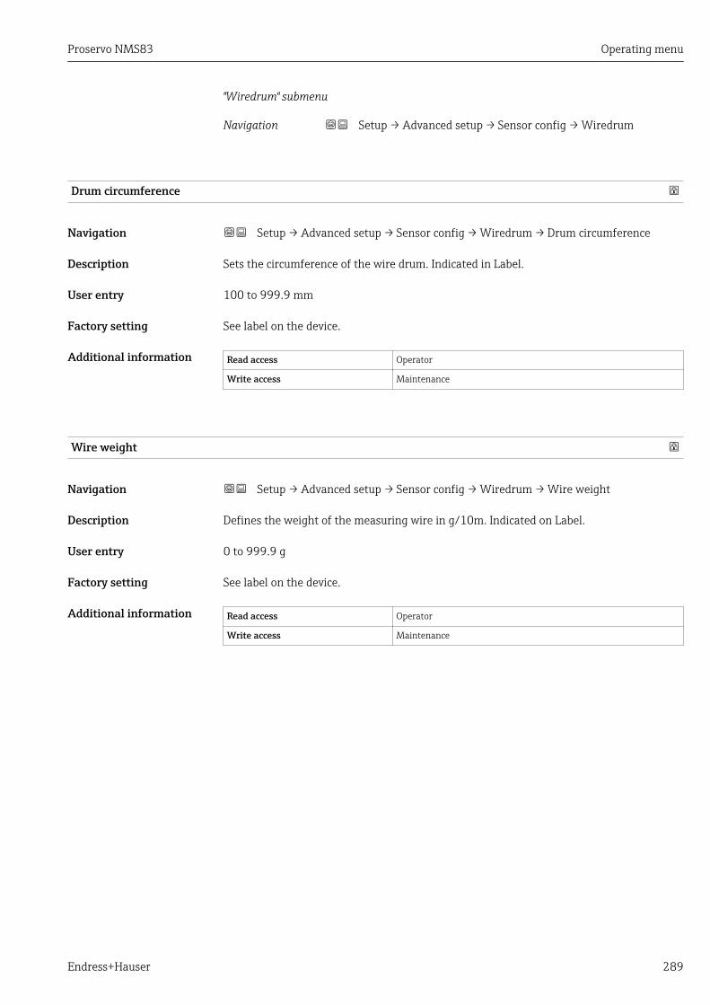
Proservo NMS83 Operating menu
Endress+Hauser 289
"Wiredrum" submenu
Navigation Setup → Advanced setup → Sensor config → Wiredrum
Drum circumference
Navigation Setup → Advanced setup → Sensor config → Wiredrum → Drum circumference
Description Sets the circumference of the wire drum. Indicated in Label.
User entry 100 to 999.9 mm
Factory setting See label on the device.
Additional information Read access Operator
Write access Maintenance
Wire weight
Navigation Setup → Advanced setup → Sensor config → Wiredrum → Wire weight
Description Defines the weight of the measuring wire in g/10m. Indicated on Label.
User entry 0 to 999.9 g
Factory setting See label on the device.
Additional information Read access Operator
Write access Maintenance

Operating menu Proservo NMS83
290 Endress+Hauser
"Spot density" submenu
Navigation Setup → Advanced setup → Sensor config → Spot density
Upper density offset
Navigation Setup → Advanced setup → Sensor config → Spot density → Upper density offset
Description Defines an offset value which is added to the measured upper density value.
User entry –999.99 to 999.99 kg/m³
Factory setting 0 kg/m³
Additional information Read access Operator
Write access Maintenance
Middle density offset
Navigation Setup → Advanced setup → Sensor config → Spot density → Middle density offset
Description Defines an Offset Value which is added to the measured Middle Density Value.
User entry –999.99 to 999.99 kg/m³
Factory setting 0 kg/m³
Additional information Read access Operator
Write access Maintenance
Lower density offset
Navigation Setup → Advanced setup → Sensor config → Spot density → Lower density offset
Description Defines an offset value which is added to the measured lower density value.
User entry –999.99 to 999.99 kg/m³
Factory setting 0 kg/m³
Additional information Read access Operator
Write access Maintenance

Proservo NMS83 Operating menu
Endress+Hauser 291
Submersion depth
Navigation Setup → Advanced setup → Sensor config → Spot density → Submersion depth
Description Sets the displacer submersion depth (mm) for spot density operations.
User entry 50 to 99 999.9 mm
Factory setting 150 mm
Additional information Read access Operator
Write access Maintenance

Operating menu Proservo NMS83
292 Endress+Hauser
"Profile density" submenu
Navigation Setup → Advanced setup → Sensor config → Profile density
Density measurement mode
Navigation Setup → Advanced setup → Sensor config → Profile density → Density measurementmode
Description In normal measure mode, measures at specified positions. In compensation modemeasures using next integer value of drum turns to improve accuracy.
Selection • Normal measure mode• Compensation mode
Factory setting Normal measure mode
Additional information Read access Operator
Write access Maintenance
Manual profile level
Navigation Setup → Advanced setup → Sensor config → Profile density → Manual profile level
Description Sets the level position in the tank where the manual profile density operation starts.
User entry –999 999.9 to 999 999.9 mm
Factory setting 1 000 mm
Additional information Read access Operator
Write access Maintenance
Profile density offset distance
Navigation Setup → Advanced setup → Sensor config → Profile density → Profile density offsetdistance
Description Profile density offset distance [mm] is the distance between start point and firstmeasurement point.
User entry 0 to 999 999.9 mm
Factory setting 500 mm
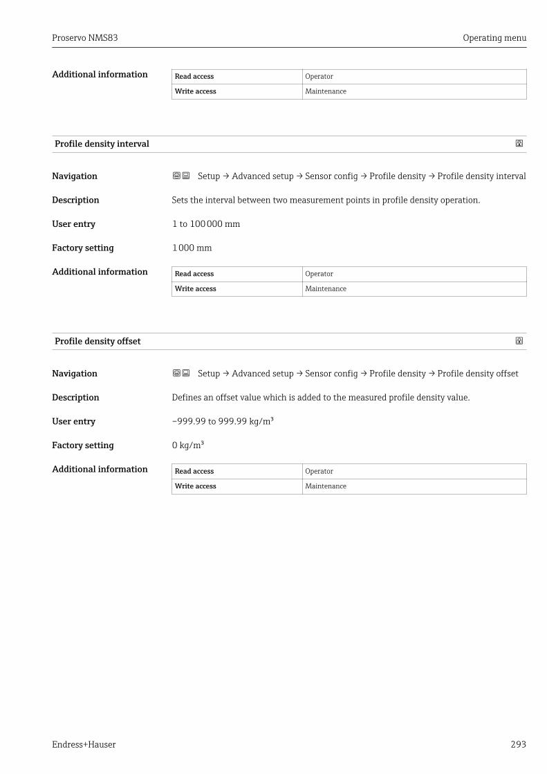
Proservo NMS83 Operating menu
Endress+Hauser 293
Additional information Read access Operator
Write access Maintenance
Profile density interval
Navigation Setup → Advanced setup → Sensor config → Profile density → Profile density interval
Description Sets the interval between two measurement points in profile density operation.
User entry 1 to 100 000 mm
Factory setting 1 000 mm
Additional information Read access Operator
Write access Maintenance
Profile density offset
Navigation Setup → Advanced setup → Sensor config → Profile density → Profile density offset
Description Defines an offset value which is added to the measured profile density value.
User entry –999.99 to 999.99 kg/m³
Factory setting 0 kg/m³
Additional information Read access Operator
Write access Maintenance

Operating menu Proservo NMS83
294 Endress+Hauser
"Display" submenuThis menu is only visible if the device has a local display.
Navigation Setup → Advanced setup → Display
Language
Navigation Setup → Advanced setup → Display → Language
Prerequisite The device has a local display.
Description Set display language.
Selection • English• Deutsch *
• Français *
• Español *• Italiano *
• Nederlands *
• Portuguesa *
• Polski *• русский язык (Russian) *
• Svenska *
• Türkçe *
• 中文 (Chinese) *
• 日本語 (Japanese) *
• 한국어 (Korean) *
• * (Arabic) العربية
• Bahasa Indonesia *
• ภาษาไทย (Thai) *
• tiếng Việt (Vietnamese) *
• čeština (Czech) *
Factory setting English
Additional information Read access Operator
Write access Operator
Format display
Navigation Setup → Advanced setup → Display → Format display
Prerequisite The device has a local display.
Description Select how measured values are shown on the display.
* Visibility depends on order options or device settings

Proservo NMS83 Operating menu
Endress+Hauser 295
Selection • 1 value, max. size• 1 bargraph + 1 value• 2 values• 1 value large + 2 values• 4 values
Factory setting 2 values
Additional information Read access Operator
Write access Operator
• The Value 1 to 4 display (→ 295) parameters specify which measured values areshown on the display and in which order.
• If more measured values are specified than the current display mode permits, the valuesalternate on the device display. The display time until the next change is configured inthe Display interval parameter (→ 298).
Value 1 to 4 display
Navigation Setup → Advanced setup → Display → Value 1 display
Prerequisite The device has a local display.
Description Select the measured value that is shown on the local display.
Selection • None 8)
• Tank level• Measured level• Tank level %• Water level 8)
• Liquid temperature 8)
• Vapor temperature 8)
• Air temperature 8)
• Tank ullage• Tank ullage %• Observed density value 8)
• P1 (bottom) 8)
• P2 (middle) 8)
• P3 (top) 8)
• GP 1 value 8)
• GP 2 value 8)
• GP 3 value 8)
• GP 4 value 8)
• Gauge command 8)
• Gauge status 8)
• AIO B1-3 value 8)
• AIO B1-3 value mA 8)
• AIO B1-3 value % 8)
• AIO C1-3 value 8)
• AIO C1-3 value mA 8)
• AIO C1-3 value % 8)
8) not available for the Value 1 display parameter
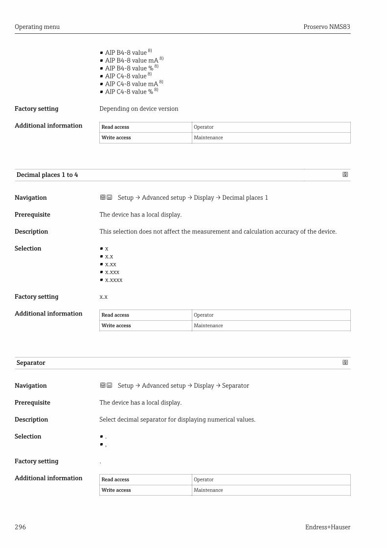
Operating menu Proservo NMS83
296 Endress+Hauser
• AIP B4-8 value 8)
• AIP B4-8 value mA 8)
• AIP B4-8 value % 8)
• AIP C4-8 value 8)
• AIP C4-8 value mA 8)
• AIP C4-8 value % 8)
Factory setting Depending on device version
Additional information Read access Operator
Write access Maintenance
Decimal places 1 to 4
Navigation Setup → Advanced setup → Display → Decimal places 1
Prerequisite The device has a local display.
Description This selection does not affect the measurement and calculation accuracy of the device.
Selection • x• x.x• x.xx• x.xxx• x.xxxx
Factory setting x.x
Additional information Read access Operator
Write access Maintenance
Separator
Navigation Setup → Advanced setup → Display → Separator
Prerequisite The device has a local display.
Description Select decimal separator for displaying numerical values.
Selection • .• ,
Factory setting .
Additional information Read access Operator
Write access Maintenance

Proservo NMS83 Operating menu
Endress+Hauser 297
Number format
Navigation Setup → Advanced setup → Display → Number format
Prerequisite The device has a local display.
Description Choose number format for the display.
Selection • Decimal• ft-in-1/16''
Factory setting Decimal
Additional information Read access Operator
Write access Maintenance
The ft-in-1/16'' option is only valid for distance values.
Header
Navigation Setup → Advanced setup → Display → Header
Prerequisite The device has a local display.
Description Select header contents on local display.
Selection • Device tag• Free text
Factory setting Device tag
Additional information Read access Operator
Write access Maintenance
Meaning of the options• Device tag
The header contents is defined in the Device tag parameter (→ 312).• Free text
The header contents is defined in the Header text parameter (→ 297).
Header text
Navigation Setup → Advanced setup → Display → Header text
Prerequisite Header (→ 297) = Free text
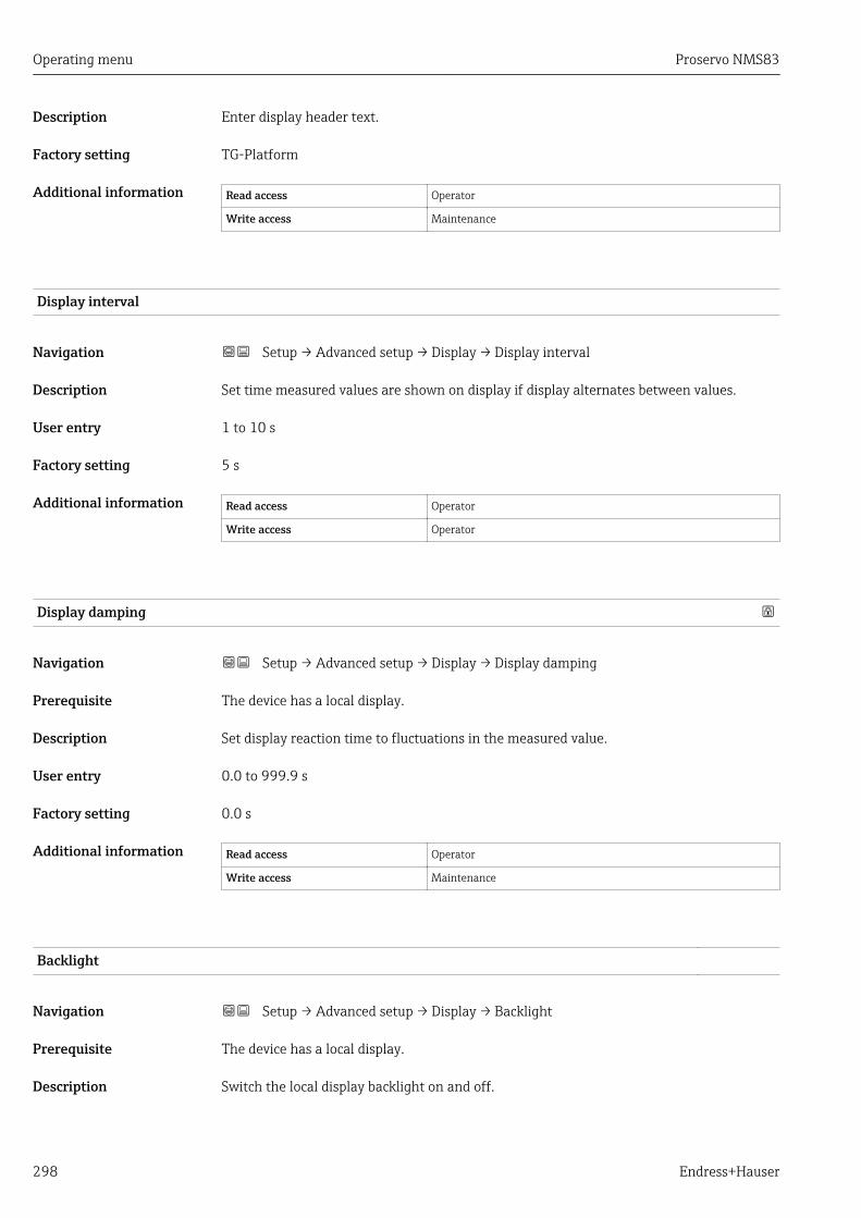
Operating menu Proservo NMS83
298 Endress+Hauser
Description Enter display header text.
Factory setting TG-Platform
Additional information Read access Operator
Write access Maintenance
Display interval
Navigation Setup → Advanced setup → Display → Display interval
Description Set time measured values are shown on display if display alternates between values.
User entry 1 to 10 s
Factory setting 5 s
Additional information Read access Operator
Write access Operator
Display damping
Navigation Setup → Advanced setup → Display → Display damping
Prerequisite The device has a local display.
Description Set display reaction time to fluctuations in the measured value.
User entry 0.0 to 999.9 s
Factory setting 0.0 s
Additional information Read access Operator
Write access Maintenance
Backlight
Navigation Setup → Advanced setup → Display → Backlight
Prerequisite The device has a local display.
Description Switch the local display backlight on and off.
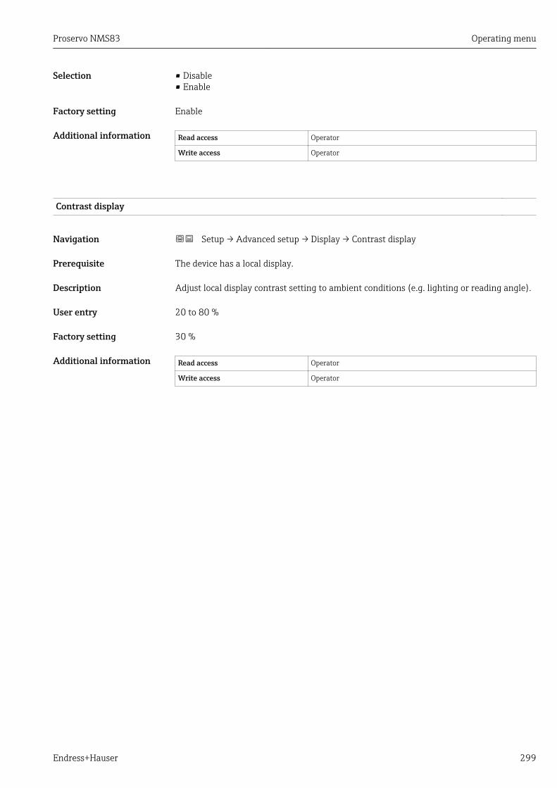
Proservo NMS83 Operating menu
Endress+Hauser 299
Selection • Disable• Enable
Factory setting Enable
Additional information Read access Operator
Write access Operator
Contrast display
Navigation Setup → Advanced setup → Display → Contrast display
Prerequisite The device has a local display.
Description Adjust local display contrast setting to ambient conditions (e.g. lighting or reading angle).
User entry 20 to 80 %
Factory setting 30 %
Additional information Read access Operator
Write access Operator

Operating menu Proservo NMS83
300 Endress+Hauser
"System units" submenu
Navigation Setup → Advanced setup → System units
Units preset
Navigation Setup → Advanced setup → System units → Units preset
Description Defines a set of units for length, pressure and temperature.
Selection • mm, bar, °C• m, bar, °C• mm, PSI, °C• ft, PSI, °F• ft-in-16, PSI, °F• ft-in-8, PSI, °F• Customer value
Factory setting mm, bar, °C
Additional information Read access Operator
Write access Maintenance
If the Customer value option is selected, the units are defined in the followingparameters:• Distance unit (→ 300)• Pressure unit (→ 301)• Temperature unit (→ 301)• Density unit (→ 301)
In any other case these are read-only parameters used to indicate the respective unit.
Distance unit
Navigation Setup → Advanced setup → System units → Distance unit
Description Select distance unit.
Selection SI units• m• mm• cm
US units• ft• in• ft-in-16• ft-in-8
Factory setting mm
Additional information Read access Operator
Write access Maintenance (if Units preset (→ 177) = Customer value)
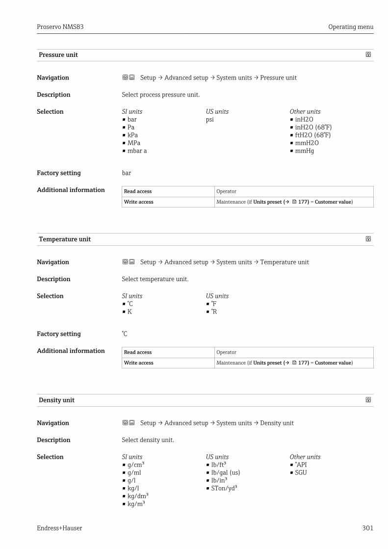
Proservo NMS83 Operating menu
Endress+Hauser 301
Pressure unit
Navigation Setup → Advanced setup → System units → Pressure unit
Description Select process pressure unit.
Selection SI units• bar• Pa• kPa• MPa• mbar a
US unitspsi
Other units• inH2O• inH2O (68°F)• ftH2O (68°F)• mmH2O• mmHg
Factory setting bar
Additional information Read access Operator
Write access Maintenance (if Units preset (→ 177) = Customer value)
Temperature unit
Navigation Setup → Advanced setup → System units → Temperature unit
Description Select temperature unit.
Selection SI units• °C• K
US units• °F• °R
Factory setting °C
Additional information Read access Operator
Write access Maintenance (if Units preset (→ 177) = Customer value)
Density unit
Navigation Setup → Advanced setup → System units → Density unit
Description Select density unit.
Selection SI units• g/cm³• g/ml• g/l• kg/l• kg/dm³• kg/m³
US units• lb/ft³• lb/gal (us)• lb/in³• STon/yd³
Other units• °API• SGU

Operating menu Proservo NMS83
302 Endress+Hauser
Factory setting kg/m³
Additional information Read access Operator
Write access Maintenance (if Units preset (→ 177) = Customer value)

Proservo NMS83 Operating menu
Endress+Hauser 303
"Date / time" submenu
Navigation Setup → Advanced setup → Date / time
Date/time
Navigation Setup → Advanced setup → Date / time → Date/time
Description Displays the device internal real time clock.
Additional information Read access Operator
Write access -
Set date
Navigation Setup → Advanced setup → Date / time → Set date
Description Controls the setting of the real-time clock.
Selection • Please select• Abort• Start• Confirm time
Factory setting Please select
Additional information Read access Operator
Write access Maintenance
Meaning of the options• Please select
Prompts the user to select an action.• Abort
Discards the entered date and time.• Start
Starts the setting of the real time clock.• Confirm time
Sets the real-time clock to the entered date and time.
Year
Navigation Setup → Advanced setup → Date / time → Year
Prerequisite Set date (→ 303) = Start

Operating menu Proservo NMS83
304 Endress+Hauser
Description Enter the current year.
User entry 2 016 to 2 079
Factory setting 2 016
Additional information Read access Operator
Write access Maintenance
Month
Navigation Setup → Advanced setup → Date / time → Month
Prerequisite Set date (→ 303) = Start
Description Enter the current month.
User entry 1 to 12
Factory setting 1
Additional information Read access Operator
Write access Maintenance
Day
Navigation Setup → Advanced setup → Date / time → Day
Prerequisite Set date (→ 303) = Start
Description Enter the current day.
User entry 1 to 31
Factory setting 1
Additional information Read access Operator
Write access Maintenance
Hour
Navigation Setup → Advanced setup → Date / time → Hour
Prerequisite Set date (→ 303) = Start

Proservo NMS83 Operating menu
Endress+Hauser 305
Description Enter the current hour.
User entry 0 to 23
Factory setting 0
Additional information Read access Operator
Write access Maintenance
Minute
Navigation Setup → Advanced setup → Date / time → Minute
Prerequisite Set date (→ 303) = Start
Description Enter the current minute.
User entry 0 to 59
Factory setting 0
Additional information Read access Operator
Write access Maintenance

Operating menu Proservo NMS83
306 Endress+Hauser
"SIL confirmation" wizard• The SIL confirmation wizard is only available for devices with SIL or WHG approval
(Feature 590: "Additional Approval", option LA: "SIL" or LC: "WHG overfillprevention" ) which are currently not in the SIL- or WHG-locked state.
• The SIL confirmation wizard is required to lock the device according to SIL or WHG.For details refer to the "Functional Safety Manual" of the respective device, whichdescribes the locking procedure and the parameters of this wizard.
Navigation Setup → Advanced setup → SIL confirmation
"Deactivate SIL/WHG" wizard• The Deactivate SIL/WHG wizard is only available for devices with SIL or WHG
approval (Feature 590: "Additional Approval", option LA: "SIL" or LC: "WHG overfillprevention" ) which are currently in the SIL- or WHG-locked state.
• The Deactivate SIL/WHG wizard is required to undo the locking of the deviceaccording to SIL or WHG. For details refer to the "Functional Safety Manual" of therespective device, which describes the locking procedure and the parameters of thiswizard.
Navigation Setup → Advanced setup → Deactivate SIL/WHG

Proservo NMS83 Operating menu
Endress+Hauser 307
"Administration" submenu
Navigation Setup → Advanced setup → Administration
Define access code
Navigation Setup → Advanced setup → Administration → Define access code
Description Define release code for write access to parameters.
User entry 0 to 9 999
Factory setting 0
Additional information Read access Operator
Write access Maintenance
If the factory setting is not changed or 0 is defined as the access code, the parametersare not write-protected and the configuration data of the device can then always bemodified. The user is logged on in the Maintenance role.
The write protection affects all parameters marked with the symbol in thisdocument.
Once the access code has been defined, write-protected parameters can only bemodified if the access code is entered in the Enter access code parameter.
Device reset
Navigation Setup → Advanced setup → Administration → Device reset
Description Reset the device configuration - either entirely or in part - to a defined state.
Selection • Cancel• To fieldbus defaults **
• To factory defaults *
• Restart device
Factory setting Cancel
Additional information Read access Operator
Write access Maintenance
** Visibility depends on communication* Visibility depends on order options or device settings
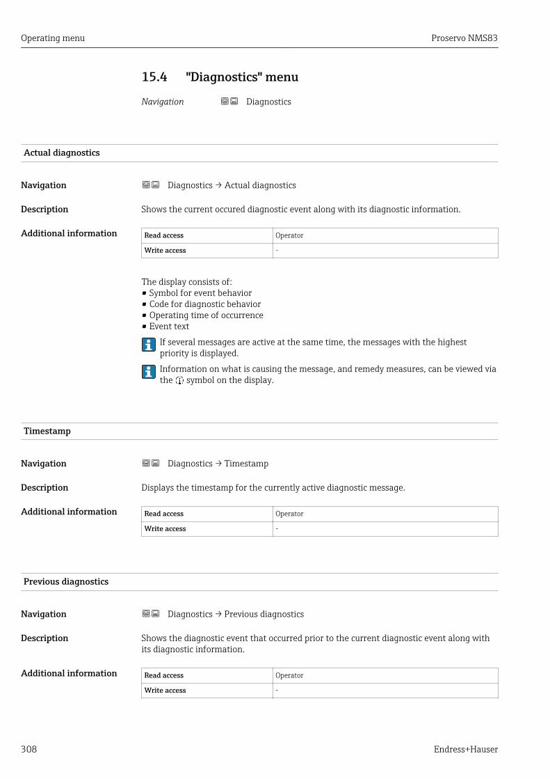
Operating menu Proservo NMS83
308 Endress+Hauser
15.4 "Diagnostics" menu
Navigation Diagnostics
Actual diagnostics
Navigation Diagnostics → Actual diagnostics
Description Shows the current occured diagnostic event along with its diagnostic information.
Additional information Read access Operator
Write access -
The display consists of:• Symbol for event behavior• Code for diagnostic behavior• Operating time of occurrence• Event text
If several messages are active at the same time, the messages with the highestpriority is displayed.
Information on what is causing the message, and remedy measures, can be viewed viathe symbol on the display.
Timestamp
Navigation Diagnostics → Timestamp
Description Displays the timestamp for the currently active diagnostic message.
Additional information Read access Operator
Write access -
Previous diagnostics
Navigation Diagnostics → Previous diagnostics
Description Shows the diagnostic event that occurred prior to the current diagnostic event along withits diagnostic information.
Additional information Read access Operator
Write access -
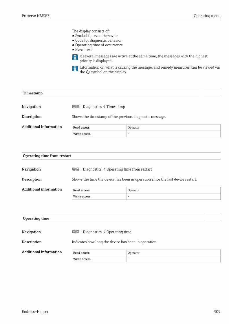
Proservo NMS83 Operating menu
Endress+Hauser 309
The display consists of:• Symbol for event behavior• Code for diagnostic behavior• Operating time of occurrence• Event text
If several messages are active at the same time, the messages with the highestpriority is displayed.
Information on what is causing the message, and remedy measures, can be viewed viathe symbol on the display.
Timestamp
Navigation Diagnostics → Timestamp
Description Shows the timestamp of the previous diagnostic message.
Additional information Read access Operator
Write access -
Operating time from restart
Navigation Diagnostics → Operating time from restart
Description Shows the time the device has been in operation since the last device restart.
Additional information Read access Operator
Write access -
Operating time
Navigation Diagnostics → Operating time
Description Indicates how long the device has been in operation.
Additional information Read access Operator
Write access -

Operating menu Proservo NMS83
310 Endress+Hauser
Date/time
Navigation Diagnostics → Date/time
Description Displays the device internal real time clock.
Additional information Read access Operator
Write access -
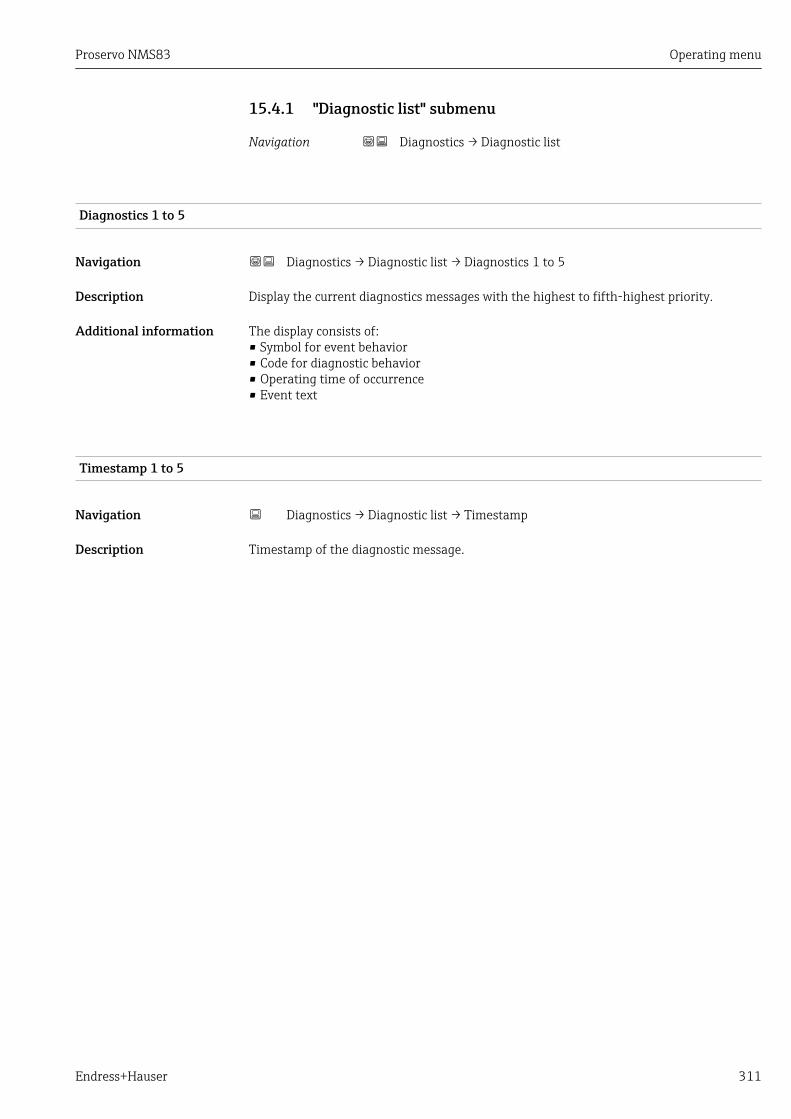
Proservo NMS83 Operating menu
Endress+Hauser 311
15.4.1 "Diagnostic list" submenu
Navigation Diagnostics → Diagnostic list
Diagnostics 1 to 5
Navigation Diagnostics → Diagnostic list → Diagnostics 1 to 5
Description Display the current diagnostics messages with the highest to fifth-highest priority.
Additional information The display consists of:• Symbol for event behavior• Code for diagnostic behavior• Operating time of occurrence• Event text
Timestamp 1 to 5
Navigation Diagnostics → Diagnostic list → Timestamp
Description Timestamp of the diagnostic message.
Operating menu Proservo NMS83
312 Endress+Hauser
15.4.2 "Device information" submenu
Navigation Diagnostics → Device information
Device tag
Navigation Diagnostics → Device information → Device tag
Description Shows the device tag.
Factory setting NMS8x
Additional information Read access Operator
Write access -
Serial number
Navigation Diagnostics → Device information → Serial number
Description Shows the serial number of the measuring device.
Additional information Read access Operator
Write access -
Firmware version
Navigation Diagnostics → Device information → Firmware version
Description Shows the device firmware version installed.
Additional information Read access Operator
Write access -
Firmware CRC
Navigation Diagnostics → Device information → Firmware CRC
Description Result of the cyclic redundancy check of the firmware.
Proservo NMS83 Operating menu
Endress+Hauser 313
Additional information Read access Operator
Write access -
Weight and measures configuration CRC
Navigation Diagnostics → Device information → Weight and measures configuration CRC
Description Result of the cyclic redundancy check of the weights and measure relevant parameters.
Additional information Read access Operator
Write access -
Device name
Navigation Diagnostics → Device information → Device name
Description Shows the name of the transmitter.
Additional information Read access Operator
Write access -
Order code
Navigation Diagnostics → Device information → Order code
Description Shows the device order code.
Additional information Read access Operator
Write access Service
Extended order code 1 to 3
Navigation Diagnostics → Device information → Extended order code 1
Description Display the three parts of the extended order code.
Additional information Read access Operator
Write access Service

Operating menu Proservo NMS83
314 Endress+Hauser
The extended order code indicates the selected option of all ordering features and thusuniquely identifies the device.
Proservo NMS83 Operating menu
Endress+Hauser 315
15.4.3 "Simulation" submenu
Read access Maintenance
Navigation Diagnostics → Simulation
Device alarm simulation
Navigation Diagnostics → Simulation → Device alarm simulation
Description Switch the device alarm on and off.
Selection • Off• On
Factory setting Off
Additional information Read access Operator
Write access Maintenance
Diagnostic event simulation
Navigation Diagnostics → Simulation → Diagnostic event simulation
Description Select a diagnostic event to simulate this event.
Selection The diagnostic events of the device
Factory setting Off
Additional information Read access Operator
Write access Maintenance
To terminate the simulation, select Off.
Simulation distance on
Navigation Diagnostics → Simulation → Simulation distance on
Description Switches the distance simulation on or off.
Selection • Off• On

Operating menu Proservo NMS83
316 Endress+Hauser
Factory setting Off
Additional information Read access Operator
Write access Maintenance
Simulation distance
Navigation Diagnostics → Simulation → Simulation distance
Prerequisite Simulation distance on (→ 315) = On
Description Defines the distance value to be simulated.
User entry Signed floating-point number
Factory setting 0 mm
Additional information Read access Operator
Write access Maintenance
Current output simulation
Navigation Diagnostics → Simulation → Current output 1 simulation
Diagnostics → Simulation → Current output 2 simulation
Prerequisite • The device has an Anlog I/O module.• Operating mode (→ 205) = 4..20mA output or HART slave +4..20mA output
Description Switches the simulation of the current on or off.
Selection • Off• On
Factory setting Off
Additional information Read access Operator
Write access Maintenance
Simulation value
Navigation Diagnostics → Simulation → Simulation value
Diagnostics → Simulation → Simulation value
Prerequisite Current output simulation (→ 316) = On

Proservo NMS83 Operating menu
Endress+Hauser 317
Description Defines the current to be simulated.
User entry 3.4 to 23 mA
Factory setting The current at the time the simulation was started.
Additional information Read access Operator
Write access Maintenance
Operating menu Proservo NMS83
318 Endress+Hauser
15.4.4 "Device check" submenu
Navigation Diagnostics → Device check
Result drum check
Navigation Diagnostics → Device check → Result drum check
Description Gives feedback on the latest status of the commissioning check.
Additional information Read access Operator
Write access -
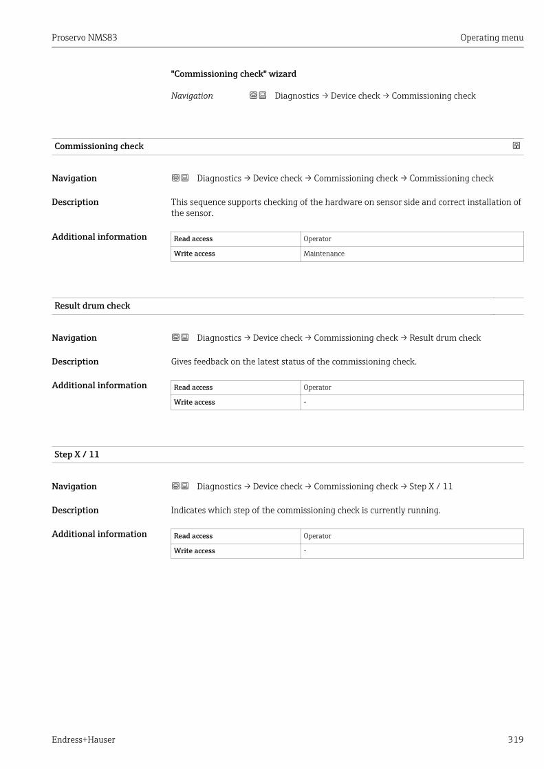
Proservo NMS83 Operating menu
Endress+Hauser 319
"Commissioning check" wizard
Navigation Diagnostics → Device check → Commissioning check
Commissioning check
Navigation Diagnostics → Device check → Commissioning check → Commissioning check
Description This sequence supports checking of the hardware on sensor side and correct installation ofthe sensor.
Additional information Read access Operator
Write access Maintenance
Result drum check
Navigation Diagnostics → Device check → Commissioning check → Result drum check
Description Gives feedback on the latest status of the commissioning check.
Additional information Read access Operator
Write access -
Step X / 11
Navigation Diagnostics → Device check → Commissioning check → Step X / 11
Description Indicates which step of the commissioning check is currently running.
Additional information Read access Operator
Write access -
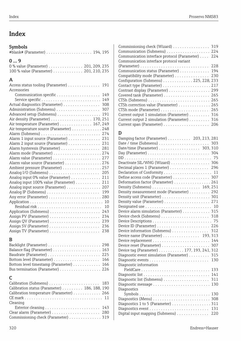
Index Proservo NMS83
320 Endress+Hauser
Index
Symbols#blank# (Parameter) . . . . . . . . . . . . . . . . . . . . 194, 195
0 … 90 % value (Parameter) . . . . . . . . . . . . . . . 201, 209, 235100 % value (Parameter) . . . . . . . . . . . . . 201, 210, 235
AAccess status tooling (Parameter) . . . . . . . . . . . . . . 191Accessories
Communication specific . . . . . . . . . . . . . . . . . . . 149Service specific . . . . . . . . . . . . . . . . . . . . . . . . . . 149
Actual diagnostics (Parameter) . . . . . . . . . . . . . . . . 308Administration (Submenu) . . . . . . . . . . . . . . . . . . . 307Advanced setup (Submenu) . . . . . . . . . . . . . . . . . . . 191Air density (Parameter) . . . . . . . . . . . . . . . . . . 170, 251Air temperature (Parameter) . . . . . . . . . . . . . . 167, 249Air temperature source (Parameter) . . . . . . . . . . . . . 248Alarm (Submenu) . . . . . . . . . . . . . . . . . . . . . . . . . . 274Alarm 1 input source (Parameter) . . . . . . . . . . . . . . 231Alarm 2 input source (Parameter) . . . . . . . . . . . . . . 231Alarm hysteresis (Parameter) . . . . . . . . . . . . . . . . . 281Alarm mode (Parameter) . . . . . . . . . . . . . . . . . . . . . 274Alarm value (Parameter) . . . . . . . . . . . . . . . . . . . . . 277Alarm value source (Parameter) . . . . . . . . . . . . . . . . 276Ambient pressure (Parameter) . . . . . . . . . . . . . . . . . 257Analog I/O (Submenu) . . . . . . . . . . . . . . . . . . . . . . 205Analog input 0% value (Parameter) . . . . . . . . . . . . . 211Analog input 100% value (Parameter) . . . . . . . . . . . 211Analog input source (Parameter) . . . . . . . . . . . . . . . 207Analog IP (Submenu) . . . . . . . . . . . . . . . . . . . . . . . 199Any error (Parameter) . . . . . . . . . . . . . . . . . . . . . . . 280Application . . . . . . . . . . . . . . . . . . . . . . . . . . . . . . . . 10
Residual risk . . . . . . . . . . . . . . . . . . . . . . . . . . . . 10Application (Submenu) . . . . . . . . . . . . . . . . . . . . . . 243Assign PV (Parameter) . . . . . . . . . . . . . . . . . . . . . . 234Assign QV (Parameter) . . . . . . . . . . . . . . . . . . . . . . 239Assign SV (Parameter) . . . . . . . . . . . . . . . . . . . . . . 236Assign TV (Parameter) . . . . . . . . . . . . . . . . . . . . . . 238
BBacklight (Parameter) . . . . . . . . . . . . . . . . . . . . . . . 298Balance flag (Parameter) . . . . . . . . . . . . . . . . . . . . . 163Baudrate (Parameter) . . . . . . . . . . . . . . . . . . . . . . . 225Bottom level (Parameter) . . . . . . . . . . . . . . . . . . . . 166Bottom level timestamp (Parameter) . . . . . . . . . . . . 166Bus termination (Parameter) . . . . . . . . . . . . . . . . . . 226
CCalibration (Submenu) . . . . . . . . . . . . . . . . . . . . . . 183Calibration status (Parameter) . . . . . . . . . 186, 188, 190Calibration temperature (Parameter) . . . . . . . . . . . . 266CE mark . . . . . . . . . . . . . . . . . . . . . . . . . . . . . . . . . . 11Cleaning
Exterior cleaning . . . . . . . . . . . . . . . . . . . . . . . . 143Clear alarm (Parameter) . . . . . . . . . . . . . . . . . . . . . 280Commissioning check (Parameter) . . . . . . . . . . . . . . 319
Commissioning check (Wizard) . . . . . . . . . . . . . . . . 319Communication (Submenu) . . . . . . . . . . . . . . . . . . . 224Communication interface protocol (Parameter) . . . . 224Communication interface protocol variant(Parameter) . . . . . . . . . . . . . . . . . . . . . . . . . . . . . . 228Communication status (Parameter) . . . . . . . . . . . . . 194Compatibility mode (Parameter) . . . . . . . . . . . . . . . 230Configuration (Submenu) . . . . . . . . . . . . . 225, 228, 233Contact type (Parameter) . . . . . . . . . . . . . . . . . . . . . 217Contrast display (Parameter) . . . . . . . . . . . . . . . . . . 299Covered tank (Parameter) . . . . . . . . . . . . . . . . . . . . 265CTSh (Submenu) . . . . . . . . . . . . . . . . . . . . . . . . . . . 265CTSh correction value (Parameter) . . . . . . . . . . . . . . 265CTSh mode (Parameter) . . . . . . . . . . . . . . . . . . . . . 265Current output 1 simulation (Parameter) . . . . . . . . . 316Current output 2 simulation (Parameter) . . . . . . . . . 316Current span (Parameter) . . . . . . . . . . . . . . . . . . . . 206
DDamping factor (Parameter) . . . . . . . . . . 203, 213, 281Date / time (Submenu) . . . . . . . . . . . . . . . . . . . . . . 303Date/time (Parameter) . . . . . . . . . . . . . . . . . . 303, 310Day (Parameter) . . . . . . . . . . . . . . . . . . . . . . . . . . . 304DD . . . . . . . . . . . . . . . . . . . . . . . . . . . . . . . . . . . . . . 75Deactivate SIL/WHG (Wizard) . . . . . . . . . . . . . . . . . 306Decimal places 1 (Parameter) . . . . . . . . . . . . . . . . . 296Declaration of Conformity . . . . . . . . . . . . . . . . . . . . . 11Define access code (Parameter) . . . . . . . . . . . . . . . . 307Deformation factor (Parameter) . . . . . . . . . . . . . . . . 261Density (Submenu) . . . . . . . . . . . . . . . . . . . . . 169, 251Density measurement mode (Parameter) . . . . . . . . . 292Density unit (Parameter) . . . . . . . . . . . . . . . . . . . . . 301Density value (Parameter) . . . . . . . . . . . . . . . . . . . . 271Designated use . . . . . . . . . . . . . . . . . . . . . . . . . . . . . 10Device alarm simulation (Parameter) . . . . . . . . . . . . 315Device check (Submenu) . . . . . . . . . . . . . . . . . . . . . 318Device Descriptions . . . . . . . . . . . . . . . . . . . . . . . . . . 75Device ID (Parameter) . . . . . . . . . . . . . . . . . . . . . . . 226Device information (Submenu) . . . . . . . . . . . . . . . . 312Device name (Parameter) . . . . . . . . . . . . . . . . 193, 313Device replacement . . . . . . . . . . . . . . . . . . . . . . . . . 144Device reset (Parameter) . . . . . . . . . . . . . . . . . . . . . 307Device tag (Parameter) . . . . . . . . . . . 177, 193, 241, 312Diagnostic event simulation (Parameter) . . . . . . . . . 315Diagnostic events . . . . . . . . . . . . . . . . . . . . . . . . . . 130Diagnostic information
FieldCare . . . . . . . . . . . . . . . . . . . . . . . . . . . . . . 133Diagnostic list . . . . . . . . . . . . . . . . . . . . . . . . . . . . . 141Diagnostic list (Submenu) . . . . . . . . . . . . . . . . . . . . 311Diagnostic message . . . . . . . . . . . . . . . . . . . . . . . . . 130Diagnostics
Symbols . . . . . . . . . . . . . . . . . . . . . . . . . . . . . . . 130Diagnostics (Menu) . . . . . . . . . . . . . . . . . . . . . . . . . 308Diagnostics 1 to 5 (Parameter) . . . . . . . . . . . . . . . . . 311Diagnostics event . . . . . . . . . . . . . . . . . . . . . . . . . . 131Digital input mapping (Submenu) . . . . . . . . . . . . . . 220

Proservo NMS83 Index
Endress+Hauser 321
Digital input source (Parameter) . . . . . . . . . . . . . . . 216Digital input source 1 (Parameter) . . . . . . . . . . . . . . 220Digital input source 2 (Parameter) . . . . . . . . . . . . . . 220Digital Xx-x (Submenu) . . . . . . . . . . . . . . . . . . . . . . 215DIP switch
see Write protection switchDisplacer (Submenu) . . . . . . . . . . . . . . . . . . . . . . . . 286Displacer balance volume (Parameter) . . . . . . . . . . . 287Displacer diameter (Parameter) . . . . . . . . . . . . . . . . 286Displacer height (Parameter) . . . . . . . . . . . . . . . . . . 287Displacer position (Parameter) . . . . . . . . . . . . . . . . . 167Displacer type (Parameter) . . . . . . . . . . . . . . . . . . . 286Displacer volume (Parameter) . . . . . . . . . . . . . . . . . 287Displacer weight (Parameter) . . . . . . . . . . . . . . . . . 286Display (Submenu) . . . . . . . . . . . . . . . . . . . . . . . . . 294Display damping (Parameter) . . . . . . . . . . . . . . . . . 298Display interval (Parameter) . . . . . . . . . . . . . . . . . . 298Disposal . . . . . . . . . . . . . . . . . . . . . . . . . . . . . . . . . 145Distance (Parameter) . . . . . . . . . . . . 162, 167, 182, 183Distance unit (Parameter) . . . . . . . . . . . . . . . . . . . . 300Document
Function . . . . . . . . . . . . . . . . . . . . . . . . . . . . . . . . 4Document function . . . . . . . . . . . . . . . . . . . . . . . . . . . 4Drum calibration (Parameter) . . . . . . . . . . . . . . . . . 189Drum calibration (Wizard) . . . . . . . . . . . . . . . . . . . . 189Drum circumference (Parameter) . . . . . . . . . . . . . . . 289Drum table point (Parameter) . . . . . . . . . . . . . . . . . 189
EElement position (Submenu) . . . . . . . . . . . . . . . . . . 169Element position 1 to 24 (Parameter) . . . . . . . . . . . 169Element temperature (Submenu) . . . . . . . . . . . . . . . 168Element temperature 1 to 24 (Parameter) . . . . . . . . 168Empty (Parameter) . . . . . . . . . . . . . . . . . . . . . 179, 243Endress+Hauser services
Maintenance . . . . . . . . . . . . . . . . . . . . . . . . . . . 143Repair . . . . . . . . . . . . . . . . . . . . . . . . . . . . . . . . 145
Enter access code (Parameter) . . . . . . . . . . . . . . . . . 191Error event type (Parameter) . . . . . . . . . . . . . . . . . . 212Error value (Parameter) . . . . . . . . . . . . . . . . . . 209, 275Event level
Explanation . . . . . . . . . . . . . . . . . . . . . . . . . . . . 130Symbols . . . . . . . . . . . . . . . . . . . . . . . . . . . . . . . 130
Event text . . . . . . . . . . . . . . . . . . . . . . . . . . . . . . . . 131Expected SIL/WHG chain (Parameter) . . . . . . . . . . . 214Extended order code 1 (Parameter) . . . . . . . . . . . . . 313Exterior cleaning . . . . . . . . . . . . . . . . . . . . . . . . . . . 143
FFailure mode (Parameter) . . . . . . . . . . . . . . . . . . . . 208Firmware CRC (Parameter) . . . . . . . . . . . . . . . . . . . 312Firmware version (Parameter) . . . . . . . . . . . . . . . . . 312Fixed current (Parameter) . . . . . . . . . . . . . . . . . . . . 207Float swap mode (Parameter) . . . . . . . . . . . . . . . . . 226Forget device (Parameter) . . . . . . . . . . . . . . . . . . . . 198Forget device (Wizard) . . . . . . . . . . . . . . . . . . . . . . 198Format display (Parameter) . . . . . . . . . . . . . . . . . . . 294
GGauge command (Parameter) . . . . . . . . . . . . . 161, 179Gauge command 0 (Parameter) . . . . . . . . . . . . . . . . 221Gauge command 1 (Parameter) . . . . . . . . . . . . . . . . 221Gauge command 2 (Parameter) . . . . . . . . . . . . . . . . 222Gauge command 3 (Parameter) . . . . . . . . . . . . . . . . 223Gauge current (Parameter) . . . . . . . . . . . . . . . . . . . 204Gauge status (Parameter) . . . . . . . . . . . . . . . . . . . . 163GP 1 name (Parameter) . . . . . . . . . . . . . . . . . . . . . . 175GP Value 1 (Parameter) . . . . . . . . . . . . . . . . . . . . . . 175GP Value 2 (Parameter) . . . . . . . . . . . . . . . . . . . . . . 175GP Value 3 (Parameter) . . . . . . . . . . . . . . . . . . . . . . 175GP Value 4 (Parameter) . . . . . . . . . . . . . . . . . . . . . . 176GP values (Submenu) . . . . . . . . . . . . . . . . . . . . . . . . 175
HH alarm (Parameter) . . . . . . . . . . . . . . . . . . . . . . . . 279H alarm value (Parameter) . . . . . . . . . . . . . . . . . . . 277Hardware write protection . . . . . . . . . . . . . . . . . . . . . 69HART date code (Parameter) . . . . . . . . . . . . . . . . . . 242HART descriptor (Parameter) . . . . . . . . . . . . . . . . . . 241HART Device(s) (Submenu) . . . . . . . . . . . . . . . . . . . 193HART devices (Submenu) . . . . . . . . . . . . . . . . . . . . 192HART message (Parameter) . . . . . . . . . . . . . . . . . . . 242HART output (Submenu) . . . . . . . . . . . . . . . . . . . . . 233HART short tag (Parameter) . . . . . . . . . . . . . . . . . . 241Header (Parameter) . . . . . . . . . . . . . . . . . . . . . . . . 297Header text (Parameter) . . . . . . . . . . . . . . . . . . . . . 297HH alarm (Parameter) . . . . . . . . . . . . . . . . . . . . . . . 278HH alarm value (Parameter) . . . . . . . . . . . . . . . . . . 277HH+H alarm (Parameter) . . . . . . . . . . . . . . . . . . . . 279High stop level (Parameter) . . . . . . . . . . . . . . . 181, 282Hour (Parameter) . . . . . . . . . . . . . . . . . . . . . . . . . . 304HTMS (Submenu) . . . . . . . . . . . . . . . . . . . . . . . . . . 270HTMS mode (Parameter) . . . . . . . . . . . . . . . . . . . . . 270Hysteresis (Parameter) . . . . . . . . . . . . . . . . . . . . . . 272HyTD (Submenu) . . . . . . . . . . . . . . . . . . . . . . . . . . . 260HyTD correction value (Parameter) . . . . . . . . . . . . . 260HyTD mode (Parameter) . . . . . . . . . . . . . . . . . . . . . 260
IImmersion depth (Parameter) . . . . . . . . . . . . . . . . . 288Information (Submenu) . . . . . . . . . . . . . . . . . . . . . . 241Input value (Parameter) . . . . . . . . . . . . . . 202, 209, 217Input value % (Parameter) . . . . . . . . . . . . . . . . . . . . 210Input value in mA (Parameter) . . . . . . . . . . . . . . . . 212Input value percent (Parameter) . . . . . . . . . . . . . . . 213Input/output (Submenu) . . . . . . . . . . . . . . . . . . . . . 192
LL alarm (Parameter) . . . . . . . . . . . . . . . . . . . . . . . . 279L alarm value (Parameter) . . . . . . . . . . . . . . . . . . . . 278Language (Parameter) . . . . . . . . . . . . . . . . . . . . . . . 294Level (Submenu) . . . . . . . . . . . . . . . . . . . . . . . 164, 243Level mapping (Parameter) . . . . . . . . . . . . . . . . . . . 229Level source (Parameter) . . . . . . . . . . . . . . . . . 181, 243Line impedance (Parameter) . . . . . . . . . . . . . . . . . . 230Linear expansion coefficient (Parameter) . . . . . . . . . 266Liquid temp source (Parameter) . . . . . . . . . . . . 182, 247
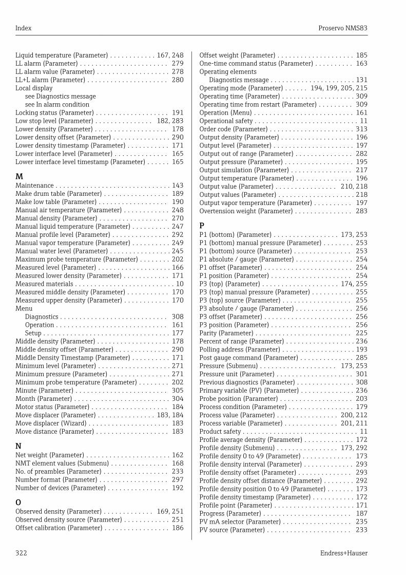
Index Proservo NMS83
322 Endress+Hauser
Liquid temperature (Parameter) . . . . . . . . . . . . 167, 248LL alarm (Parameter) . . . . . . . . . . . . . . . . . . . . . . . 279LL alarm value (Parameter) . . . . . . . . . . . . . . . . . . . 278LL+L alarm (Parameter) . . . . . . . . . . . . . . . . . . . . . 280Local display
see Diagnostics messagesee In alarm condition
Locking status (Parameter) . . . . . . . . . . . . . . . . . . . 191Low stop level (Parameter) . . . . . . . . . . . . . . . 182, 283Lower density (Parameter) . . . . . . . . . . . . . . . . . . . 178Lower density offset (Parameter) . . . . . . . . . . . . . . . 290Lower density timestamp (Parameter) . . . . . . . . . . . 171Lower interface level (Parameter) . . . . . . . . . . . . . . 165Lower interface level timestamp (Parameter) . . . . . . 165
MMaintenance . . . . . . . . . . . . . . . . . . . . . . . . . . . . . . 143Make drum table (Parameter) . . . . . . . . . . . . . . . . . 189Make low table (Parameter) . . . . . . . . . . . . . . . . . . 190Manual air temperature (Parameter) . . . . . . . . . . . . 248Manual density (Parameter) . . . . . . . . . . . . . . . . . . 270Manual liquid temperature (Parameter) . . . . . . . . . . 247Manual profile level (Parameter) . . . . . . . . . . . . . . . 292Manual vapor temperature (Parameter) . . . . . . . . . . 249Manual water level (Parameter) . . . . . . . . . . . . . . . . 245Maximum probe temperature (Parameter) . . . . . . . . 202Measured level (Parameter) . . . . . . . . . . . . . . . . . . . 166Measured lower density (Parameter) . . . . . . . . . . . . 171Measured materials . . . . . . . . . . . . . . . . . . . . . . . . . . 10Measured middle density (Parameter) . . . . . . . . . . . 170Measured upper density (Parameter) . . . . . . . . . . . . 170Menu
Diagnostics . . . . . . . . . . . . . . . . . . . . . . . . . . . . 308Operation . . . . . . . . . . . . . . . . . . . . . . . . . . . . . 161Setup . . . . . . . . . . . . . . . . . . . . . . . . . . . . . . . . . 177
Middle density (Parameter) . . . . . . . . . . . . . . . . . . . 178Middle density offset (Parameter) . . . . . . . . . . . . . . 290Middle Density Timestamp (Parameter) . . . . . . . . . . 171Minimum level (Parameter) . . . . . . . . . . . . . . . . . . . 271Minimum pressure (Parameter) . . . . . . . . . . . . . . . . 271Minimum probe temperature (Parameter) . . . . . . . . 202Minute (Parameter) . . . . . . . . . . . . . . . . . . . . . . . . 305Month (Parameter) . . . . . . . . . . . . . . . . . . . . . . . . . 304Motor status (Parameter) . . . . . . . . . . . . . . . . . . . . 184Move displacer (Parameter) . . . . . . . . . . . . . . . 183, 184Move displacer (Wizard) . . . . . . . . . . . . . . . . . . . . . 183Move distance (Parameter) . . . . . . . . . . . . . . . . . . . 183
NNet weight (Parameter) . . . . . . . . . . . . . . . . . . . . . . 162NMT element values (Submenu) . . . . . . . . . . . . . . . 168No. of preambles (Parameter) . . . . . . . . . . . . . . . . . 233Number format (Parameter) . . . . . . . . . . . . . . . . . . 297Number of devices (Parameter) . . . . . . . . . . . . . . . . 192
OObserved density (Parameter) . . . . . . . . . . . . . 169, 251Observed density source (Parameter) . . . . . . . . . . . . 251Offset calibration (Parameter) . . . . . . . . . . . . . . . . . 186
Offset weight (Parameter) . . . . . . . . . . . . . . . . . . . . 185One-time command status (Parameter) . . . . . . . . . . 163Operating elements
Diagnostics message . . . . . . . . . . . . . . . . . . . . . . 131Operating mode (Parameter) . . . . . . 194, 199, 205, 215Operating time (Parameter) . . . . . . . . . . . . . . . . . . . 309Operating time from restart (Parameter) . . . . . . . . . 309Operation (Menu) . . . . . . . . . . . . . . . . . . . . . . . . . . 161Operational safety . . . . . . . . . . . . . . . . . . . . . . . . . . . 11Order code (Parameter) . . . . . . . . . . . . . . . . . . . . . . 313Output density (Parameter) . . . . . . . . . . . . . . . . . . . 196Output level (Parameter) . . . . . . . . . . . . . . . . . . . . . 197Output out of range (Parameter) . . . . . . . . . . . . . . . 282Output pressure (Parameter) . . . . . . . . . . . . . . . . . . 195Output simulation (Parameter) . . . . . . . . . . . . . . . . 217Output temperature (Parameter) . . . . . . . . . . . . . . . 196Output value (Parameter) . . . . . . . . . . . . . . . . 210, 218Output values (Parameter) . . . . . . . . . . . . . . . . . . . . 218Output vapor temperature (Parameter) . . . . . . . . . . 197Overtension weight (Parameter) . . . . . . . . . . . . . . . 283
PP1 (bottom) (Parameter) . . . . . . . . . . . . . . . . . 173, 253P1 (bottom) manual pressure (Parameter) . . . . . . . . 253P1 (bottom) source (Parameter) . . . . . . . . . . . . . . . 253P1 absolute / gauge (Parameter) . . . . . . . . . . . . . . . 254P1 offset (Parameter) . . . . . . . . . . . . . . . . . . . . . . . 254P1 position (Parameter) . . . . . . . . . . . . . . . . . . . . . 254P3 (top) (Parameter) . . . . . . . . . . . . . . . . . . . . 174, 255P3 (top) manual pressure (Parameter) . . . . . . . . . . . 255P3 (top) source (Parameter) . . . . . . . . . . . . . . . . . . 255P3 absolute / gauge (Parameter) . . . . . . . . . . . . . . . 256P3 offset (Parameter) . . . . . . . . . . . . . . . . . . . . . . . 256P3 position (Parameter) . . . . . . . . . . . . . . . . . . . . . 256Parity (Parameter) . . . . . . . . . . . . . . . . . . . . . . . . . 225Percent of range (Parameter) . . . . . . . . . . . . . . . . . . 236Polling address (Parameter) . . . . . . . . . . . . . . . . . . . 193Post gauge command (Parameter) . . . . . . . . . . . . . . 285Pressure (Submenu) . . . . . . . . . . . . . . . . . . . . 173, 253Pressure unit (Parameter) . . . . . . . . . . . . . . . . . . . . 301Previous diagnostics (Parameter) . . . . . . . . . . . . . . . 308Primary variable (PV) (Parameter) . . . . . . . . . . . . . . 236Probe position (Parameter) . . . . . . . . . . . . . . . . . . . 203Process condition (Parameter) . . . . . . . . . . . . . . . . . 179Process value (Parameter) . . . . . . . . . . . . . . . . 200, 212Process variable (Parameter) . . . . . . . . . . . . . . 201, 211Product safety . . . . . . . . . . . . . . . . . . . . . . . . . . . . . . 11Profile average density (Parameter) . . . . . . . . . . . . . 172Profile density (Submenu) . . . . . . . . . . . . . . . . 173, 292Profile density 0 to 49 (Parameter) . . . . . . . . . . . . . 173Profile density interval (Parameter) . . . . . . . . . . . . . 293Profile density offset (Parameter) . . . . . . . . . . . . . . 293Profile density offset distance (Parameter) . . . . . . . . 292Profile density position 0 to 49 (Parameter) . . . . . . . 173Profile density timestamp (Parameter) . . . . . . . . . . . 172Profile point (Parameter) . . . . . . . . . . . . . . . . . . . . . 171Progress (Parameter) . . . . . . . . . . . . . . . . . . . . . . . 187PV mA selector (Parameter) . . . . . . . . . . . . . . . . . . 235PV source (Parameter) . . . . . . . . . . . . . . . . . . . . . . 233

Proservo NMS83 Index
Endress+Hauser 323
QQuaternary variable (QV) (Parameter) . . . . . . . . . . . 240
RReadback value (Parameter) . . . . . . . . . . . . . . . . . . 218Recalibration . . . . . . . . . . . . . . . . . . . . . . . . . . . . . . 143Reference calibration (Parameter) . . . . . . . . . . . . . . 187Reference calibration (Wizard) . . . . . . . . . . . . . . . . 187Reference position (Parameter) . . . . . . . . . . . . . . . . 187Remedial measures
Calling up . . . . . . . . . . . . . . . . . . . . . . . . . . . . . 132Closing . . . . . . . . . . . . . . . . . . . . . . . . . . . . . . . 132
Repair concept . . . . . . . . . . . . . . . . . . . . . . . . . . . . 144Replacing a device . . . . . . . . . . . . . . . . . . . . . . . . . . 144Requirements for personnel . . . . . . . . . . . . . . . . . . . . 10Result drum check (Parameter) . . . . . . . . . . . . 318, 319Return . . . . . . . . . . . . . . . . . . . . . . . . . . . . . . . . . . 145RTD connection type (Parameter) . . . . . . . . . . . . . . 200RTD type (Parameter) . . . . . . . . . . . . . . . . . . . . . . . 199
SSafety distance (Parameter) . . . . . . . . . . . . . . . . . . . 272Safety instructions
Basic . . . . . . . . . . . . . . . . . . . . . . . . . . . . . . . . . . 10Safety settings (Submenu) . . . . . . . . . . . . . . . . . . . . 282Secondary variable (SV) (Parameter) . . . . . . . . . . . . 237Sensor calibration (Parameter) . . . . . . . . . . . . . . . . 185Sensor calibration (Wizard) . . . . . . . . . . . . . . . . . . . 185Sensor config (Submenu) . . . . . . . . . . . . . . . . . . . . . 285Separator (Parameter) . . . . . . . . . . . . . . . . . . . . . . . 296Serial number (Parameter) . . . . . . . . . . . . . . . . . . . 312Set date (Parameter) . . . . . . . . . . . . . . . . . . . . . . . . 303Set high weight (Parameter) . . . . . . . . . . . . . . . . . . 189Set level (Parameter) . . . . . . . . . . . . . . . . . . . . 180, 244Set low weight (Parameter) . . . . . . . . . . . . . . . . . . . 190Setup (Menu) . . . . . . . . . . . . . . . . . . . . . . . . . . . . . 177SIL confirmation (Wizard) . . . . . . . . . . . . . . . . . . . . 306Simulation (Submenu) . . . . . . . . . . . . . . . . . . . . . . . 315Simulation distance (Parameter) . . . . . . . . . . . . . . . 316Simulation distance on (Parameter) . . . . . . . . . . . . . 315Simulation value (Parameter) . . . . . . . . . . . . . . . . . 316Slow hoist zone (Parameter) . . . . . . . . . . . . . . . . . . 283Span calibration (Parameter) . . . . . . . . . . . . . . . . . . 186Span weight (Parameter) . . . . . . . . . . . . . . . . . . . . . 185Spot density (Submenu) . . . . . . . . . . . . . . . . . . . . . . 290Standby level (Parameter) . . . . . . . . . . . . . . . . . . . . 163Starting level (Parameter) . . . . . . . . . . . . . . . . . . . . 260Status signals . . . . . . . . . . . . . . . . . . . . . . . . . 130, 133Step X / 11 (Parameter) . . . . . . . . . . . . . . . . . . . . . . 319Stilling well (Parameter) . . . . . . . . . . . . . . . . . . . . . 266Submenu
Administration . . . . . . . . . . . . . . . . . . . . . . . . . . 307Advanced setup . . . . . . . . . . . . . . . . . . . . . . . . . 191Alarm . . . . . . . . . . . . . . . . . . . . . . . . . . . . . . . . 274Analog I/O . . . . . . . . . . . . . . . . . . . . . . . . . . . . . 205Analog IP . . . . . . . . . . . . . . . . . . . . . . . . . . . . . . 199Application . . . . . . . . . . . . . . . . . . . . . . . . . . . . 243Calibration . . . . . . . . . . . . . . . . . . . . . . . . . . . . . 183Communication . . . . . . . . . . . . . . . . . . . . . . . . . 224
Configuration . . . . . . . . . . . . . . . . . . . 225, 228, 233CTSh . . . . . . . . . . . . . . . . . . . . . . . . . . . . . . . . . 265Date / time . . . . . . . . . . . . . . . . . . . . . . . . . . . . 303Density . . . . . . . . . . . . . . . . . . . . . . . . . . . 169, 251Device check . . . . . . . . . . . . . . . . . . . . . . . . . . . 318Device information . . . . . . . . . . . . . . . . . . . . . . . 312Diagnostic list . . . . . . . . . . . . . . . . . . . . . . . . . . 311Digital input mapping . . . . . . . . . . . . . . . . . . . . . 220Digital Xx-x . . . . . . . . . . . . . . . . . . . . . . . . . . . . 215Displacer . . . . . . . . . . . . . . . . . . . . . . . . . . . . . . 286Display . . . . . . . . . . . . . . . . . . . . . . . . . . . . . . . . 294Element position . . . . . . . . . . . . . . . . . . . . . . . . 169Element temperature . . . . . . . . . . . . . . . . . . . . . 168GP values . . . . . . . . . . . . . . . . . . . . . . . . . . . . . . 175HART Device(s) . . . . . . . . . . . . . . . . . . . . . . . . . 193HART devices . . . . . . . . . . . . . . . . . . . . . . . . . . . 192HART output . . . . . . . . . . . . . . . . . . . . . . . . . . . 233HTMS . . . . . . . . . . . . . . . . . . . . . . . . . . . . . . . . 270HyTD . . . . . . . . . . . . . . . . . . . . . . . . . . . . . . . . . 260Information . . . . . . . . . . . . . . . . . . . . . . . . . . . . 241Input/output . . . . . . . . . . . . . . . . . . . . . . . . . . . 192Level . . . . . . . . . . . . . . . . . . . . . . . . . . . . . 164, 243NMT element values . . . . . . . . . . . . . . . . . . . . . 168Pressure . . . . . . . . . . . . . . . . . . . . . . . . . . . 173, 253Profile density . . . . . . . . . . . . . . . . . . . . . . 173, 292Safety settings . . . . . . . . . . . . . . . . . . . . . . . . . . 282Sensor config . . . . . . . . . . . . . . . . . . . . . . . . . . . 285Simulation . . . . . . . . . . . . . . . . . . . . . . . . . . . . . 315Spot density . . . . . . . . . . . . . . . . . . . . . . . . . . . . 290System units . . . . . . . . . . . . . . . . . . . . . . . . . . . 300Tank calculation . . . . . . . . . . . . . . . . . . . . . . . . . 258Tank configuration . . . . . . . . . . . . . . . . . . . . . . . 243Temperature . . . . . . . . . . . . . . . . . . . . . . . 167, 247V1 input selector . . . . . . . . . . . . . . . . . . . . . . . . 231Wiredrum . . . . . . . . . . . . . . . . . . . . . . . . . . . . . 289
Submersion depth (Parameter) . . . . . . . . . . . . . . . . 291System components . . . . . . . . . . . . . . . . . . . . . . . . . 149System polling address (Parameter) . . . . . . . . . . . . . 233System units (Submenu) . . . . . . . . . . . . . . . . . . . . . 300
TTank calculation (Submenu) . . . . . . . . . . . . . . . . . . 258Tank configuration (Submenu) . . . . . . . . . . . . . . . . 243Tank level (Parameter) . . . . . . . . . . . . . . 164, 180, 244Tank Level % (Parameter) . . . . . . . . . . . . . . . . . . . . 164Tank reference height (Parameter) . . . . . . . . . 180, 244Tank ullage (Parameter) . . . . . . . . . . . . . . . . . . . . . 164Tank ullage % (Parameter) . . . . . . . . . . . . . . . . . . . 164Temperature (Submenu) . . . . . . . . . . . . . . . . . 167, 247Temperature unit (Parameter) . . . . . . . . . . . . . . . . . 301Tertiary variable (TV) (Parameter) . . . . . . . . . . . . . . 238Timestamp (Parameter) . . . . . . . . . . . . . . 308, 309, 311Trouble shooting . . . . . . . . . . . . . . . . . . . . . . . . . . . 129
UUndertension weight (Parameter) . . . . . . . . . . . . . . 284Units preset (Parameter) . . . . . . . . . . . . . . . . . 177, 300Upper density (Parameter) . . . . . . . . . . . . . . . . . . . 178Upper density offset (Parameter) . . . . . . . . . . . . . . . 290

Index Proservo NMS83
324 Endress+Hauser
Upper density timestamp (Parameter) . . . . . . . . . . . 170Upper interface level (Parameter) . . . . . . . . . . . . . . 165Upper interface level timestamp (Parameter) . . . . . . 165Used for SIL/WHG (Parameter) . . . . . . . . . . . . 213, 219
VV1 address (Parameter) . . . . . . . . . . . . . . . . . . 228, 229V1 input selector (Submenu) . . . . . . . . . . . . . . . . . . 231Value 1 display (Parameter) . . . . . . . . . . . . . . . . . . 295Value percent selector (Parameter) . . . . . . . . . . . . . 232Vapor density (Parameter) . . . . . . . . . . . . . . . . 169, 252Vapor temp source (Parameter) . . . . . . . . . . . . . . . . 249Vapor temperature (Parameter) . . . . . . . . . . . . 168, 250
WWater density (Parameter) . . . . . . . . . . . . . . . . . . . 272Water level (Parameter) . . . . . . . . . . . . . . . . . 166, 245Water level source (Parameter) . . . . . . . . . . . . . . . . 245Weight and measures configuration CRC (Parameter). . . . . . . . . . . . . . . . . . . . . . . . . . . . . . . . . . . . . . . 313
Wire expansion coefficient (Parameter) . . . . . . . . . . 267Wire weight (Parameter) . . . . . . . . . . . . . . . . . . . . . 289Wiredrum (Submenu) . . . . . . . . . . . . . . . . . . . . . . . 289Wizard
Commissioning check . . . . . . . . . . . . . . . . . . . . . 319Deactivate SIL/WHG . . . . . . . . . . . . . . . . . . . . . . 306Drum calibration . . . . . . . . . . . . . . . . . . . . . . . . 189Forget device . . . . . . . . . . . . . . . . . . . . . . . . . . . 198Move displacer . . . . . . . . . . . . . . . . . . . . . . . . . . 183Reference calibration . . . . . . . . . . . . . . . . . . . . . 187Sensor calibration . . . . . . . . . . . . . . . . . . . . . . . . 185SIL confirmation . . . . . . . . . . . . . . . . . . . . . . . . . 306
Workplace safety . . . . . . . . . . . . . . . . . . . . . . . . . . . 11Write protection
Via write protection switch . . . . . . . . . . . . . . . . . . 69Write protection switch . . . . . . . . . . . . . . . . . . . . . . . 69
YYear (Parameter) . . . . . . . . . . . . . . . . . . . . . . . . . . . 303
ZZero calibration (Parameter) . . . . . . . . . . . . . . . . . . 186


www.addresses.endress.com
*71411070*71411070