TS1000 Smart Hardware Specifications - Fuji Electric Europe
136
Hardware Specifications
-
Upload
khangminh22 -
Category
Documents
-
view
0 -
download
0
Transcript of TS1000 Smart Hardware Specifications - Fuji Electric Europe

Hardware Speci f icat ions

Record of Revisions
Reference numbers are shown at the bottom left corner on the back cover of each manual.
Printing Date Reference No. Revised Contents
August, 2018 2216NE0 First edition
September, 2018
2216NE1 Second edition


Preface
Thank you for selecting MONITOUCH TS1000 Smart (hereafter referred to as “TS1000S”).For correct use of the TS1000S, you are requested to read through this manual to understand more about the product.The manuals shown below are related manuals for the TS1000S. Refer to them as necessary.
For further details about controllers (PLCs, temperature controllers, etc.), refer to the manual issued by each controller manufacturer.
Manual Name Contents Reference No.
TS Reference Manual [1] Explains the functions and operation of the TS2060 and TS1000S.
1204NE
TS Reference Manual [2] 1205NE
TS1000 SmartConnection Manual [1]
Explains the connection and communication parameters for the TS1000S and controllers in detail.
2213NE
TS1000 SmartConnection Manual [2]
2214NE
TS1000 SmartConnection Manual [3]
2215NE
Notes:
1. This manual may not, in whole or in part, be printed or reproduced without the prior written consent of Hakko Electronics Co., Ltd.
2. The information in this manual is subject to change without prior notice.
3. Windows and Excel are registered trademarks of Microsoft Corporation in the United States and other countries.
4. All other company names or product names are trademarks or registered trademarks of their respective holders.
5. This manual is intended to give accurate information about MONITOUCH hardware. If you have any questions, please contact your local distributor.


Notes on Safe Usage of MONITOUCH
In this manual, you will find various notes categorized under the following levels with the signal words “DANGER” and “CAUTION”.
Note that there is a possibility that items listed with may have serious ramifications.
DANGERIndicates an imminently hazardous situation which, if not avoided, will result in death or serious injury.
CAUTIONIndicates a potentially hazardous situation which, if not avoided, may result in minor or moderate injury and could cause property damage.
Never use the output signal of the TS1000S for operations that may threaten human life or damage the system, such as signals used in case of emergency. Please design the system so that it can cope with a touch switch malfunction. A touch switch malfunction may result in machine accidents or damage.
Turn off the power supply when you set up the unit, connect new cables, or perform maintenance or inspections. Otherwise, electrical shock or damage may occur.
Never touch any terminals while the power is on. Otherwise, electrical shock may occur. The liquid crystal in the LCD panel is a hazardous substance. If the LCD panel is damaged, do not ingest the
leaked liquid crystal. If leaked liquid crystal makes contact with skin or clothing, wash it away with soap and water.
Never disassemble, recharge, deform by pressure, short-circuit, reverse the polarity of the lithium battery, nor dispose of the lithium battery in fire. Failure to follow these conditions will lead to explosion or ignition.
Never use a lithium battery that is deformed, leaking, or shows any other signs of abnormality. Failure to follow these conditions will lead to explosion or ignition.
Switches on the screen are operable even when the screen has become dark due to a faulty backlight or when the backlight has reached the end of its service life. If the screen is dark and hard to see, do not touch the screen. Otherwise, a malfunction may occur resulting in machine accidents or damage.
Check the appearance of the unit when it is unpacked. Do not use the unit if any damage or deformation is found. Failure to do so may lead to fire, damage, or malfunction.
For use in a facility or as part of a system related to nuclear energy, aerospace, medical, traffic equipment, or mobile installations, please consult your local distributor.
Operate (or store) the TS1000S under the conditions indicated in this manual and related manuals. Failure to do so could cause fire, malfunction, physical damage, or deterioration.
Observe the following environmental restrictions on use and storage of the unit. Otherwise, fire or damage to the unit may result.
- Avoid locations where there is a possibility that water, corrosive gas, flammable gas, solvents, grinding fluids, or cutting oil can come into contact with the unit.
- Avoid high temperatures, high humidity, and outside weather conditions, such as wind, rain, or direct sunlight.
- Avoid locations where excessive dust, salt, and metallic particles are present.- Avoid installing the unit in a location where vibrations or physical shocks may be transmitted.
CAUTION
DANGER
CAUTION

Equipment must be correctly mounted so that the main terminal of the TS1000S will not be touched inadvertently. Otherwise, an accident or electric shock may occur.
Tighten the mounting screws on the fixtures of the TS1000S uniformly to the specified torque. Excessive tightening may deform the panel surface. Loose mounting screws may cause the unit to fall down, malfunction, or short-circuit.
Check periodically that terminal screws on the power supply terminal block and fixtures are firmly tightened. Loose screws may result in fire or malfunction.
Tighten the terminal screws on the power supply terminal block of the TS1000S uniformly to a torque of 4 lbf-in (0.45 N·m). Improper tightening of screws may result in fire, malfunction, or other serious trouble.
The TS1000S has a glass screen. Do not drop or impart physical shocks to the unit. Otherwise, the screen may be damaged.
Correctly connect the cables to the terminals of the TS1000S in accordance with the specified voltage, current and wattage. Overvoltage, overcurrent, overwattage, or incorrect cable connection may cause fire, malfunction, or damage to the unit.
Do not use a positive ground for the 24-V power supply to the TS1000S. If a positive ground is used and an external communication device such as a computer is connected, the 24-V power supply may short circuit and cause damage. If a positive ground is unavoidable, refer to “Positive Grounding” (page 4-5).
Prevent any conductive particles from entering the TS1000S. Failure to do so may lead to fire, damage, or malfunction.
Do not attempt to repair the TS1000S yourself. Contact Hakko Electronics or the designated contractor for repairs.
Do not repair, disassemble, or modify the TS1000S. Hakko Electronics Co., Ltd. is not responsible for any damages resulting from repair, disassembly, or modification of the unit that was performed by an unauthorized person.
Do not use sharp-pointed tools to press touch switches. Doing so may damage the display unit. Only experts are authorized to set up the unit, connect cables, and perform maintenance and inspection. Lithium batteries contain combustible material such as lithium and organic solvents. Mishandling may cause
heat, explosion, or ignition resulting in fire or injury. Read the related manuals carefully and correctly handle the lithium battery as instructed.
Take safety precautions during operations such as changing settings when the unit is running, forced output, and starting and stopping the unit. Any misoperations may cause unexpected machine movement, resulting in machine accidents or damage.
In facilities where the failure of the TS1000S could lead to accidents that threaten human life or other serious damage, be sure that such facilities are equipped with adequate safeguards.
When disposing of the TS1000S, it must be treated as industrial waste. Before touching the TS1000S, discharge static electricity from your body by touching grounded metal.
Excessive static electricity may cause malfunction or trouble. Never remove a storage device (USB flash drive) when the storage device is being accessed. Doing so may
destroy the data on the storage device. Only remove a storage device when the Main Menu screen is displayed or after pressing the [Storage Removal] switch.
Do not press two or more positions on the screen at the same time. If two or more positions are pressed at the same time, a switch located between the pressed positions may be activated.
CAUTION

[General Notes]
Never bundle control cables or input/output cables with high-voltage and large-current carrying cables such as power supply cables. Keep control cables and input/output cables at least 200 mm away from high-voltage and large-current carrying cables. Otherwise, malfunction may occur due to noise.
When using the TS1000S in an environment where a source of high-frequency noise is present, it is recommended that the FG shielded cable (communication cable) be grounded at each end. However, when communication is unstable, select between grounding one or both ends, as permitted by the usage environment.
Be sure to plug connectors and sockets of the TS1000S in the correct orientation. Failure to do so may lead to damage or malfunction.
Do not use thinners for cleaning because it may discolor the TS1000S surface. Use commercially available alcohol.
If a data receive error occurs when the TS1000S unit and a counterpart unit (PLC, temperature controller, etc.) are started at the same time, read the manual of the counterpart unit to correctly resolve the error.
Clean the display area using a soft cloth to avoid scratching the surface. Avoid discharging static electricity on the mounting panel of the TS1000S. Static charge can damage the unit
and cause malfunctions. Discharging static electricity on the mounting panel may cause malfunction to occur due to noise.
Avoid prolonged display of any fixed pattern. Due to the characteristic of liquid crystal displays, an afterimage may occur. If prolonged display of a fixed pattern is expected, use the backlight’s auto OFF function.
The TS1000S is identified as a class-A product in industrial environments. In the case of use in a domestic environment, the unit is likely to cause electromagnetic interference. Preventive measures should thereby be taken appropriately.
[Notes on the LCD]Note that the following conditions may occur under normal circumstances. The response time, brightness, and colors of the TS1000S may be affected by the ambient temperature. Tiny spots (dark or luminescent) may appear on the display due to the characteristics of liquid crystal. There are variations in brightness and color between units.


Contents
Preface
Notes on Safe Usage of MONITOUCH
Chapter 1 Product Outline
1. Features ......................................................................................................... 1-1
2. Models and Peripheral Equipment ................................................................. 1-2
Models ....................................................................................................................... 1-2
Specification Comparison .......................................................................................... 1-2
Peripheral Equipment ................................................................................................ 1-3
3. System Configuration ..................................................................................... 1-4
TS1100Si and TS1070Si System Configuration ........................................................ 1-4
TS1070S System Configuration................................................................................. 1-5
Chapter 2 Specifications
1. Specifications ................................................................................................. 2-1
General Specifications ............................................................................................... 2-1
Installation Specifications........................................................................................... 2-2
Display Specifications ................................................................................................ 2-2
Touch Switch Specifications ...................................................................................... 2-2
Interface Specifications .............................................................................................. 2-3
Clock and Backup Memory Specifications ................................................................. 2-3
Screen Configuration Environment ............................................................................ 2-4
Display Function Specifications ................................................................................. 2-4
Function Performance Specifications......................................................................... 2-5
External Dimensions and Panel Cut-out Dimensions for TS1100S ........................... 2-6
External Dimensions and Panel Cut-out Dimensions for TS1070S ........................... 2-7
Chapter 3 Names and Specifications of Components
1. Names and Functions of Components ........................................................... 3-1
2. Specifications of Components........................................................................ 3-3
Serial Connector (COM1: RS-422/485) ..................................................................... 3-3
Serial Connector (COM2: RS-232C / COM3: RS-485) .............................................. 3-4
USB-A (U-A)............................................................................................................... 3-5
USB mini-B (U-B) ....................................................................................................... 3-9
LAN Connector (LAN) (TS1100Si and TS1070Si only)............................................ 3-13
DIP Switches (DIPSW)............................................................................................. 3-14

Chapter 4 Installation
1. Installation Procedure..................................................................................... 4-1
Installation Procedure ................................................................................................ 4-1
Installation Conditions ................................................................................................ 4-2
2. Power Supply Cable Connection.................................................................... 4-4
Power Supply Cable Connection ............................................................................... 4-4
Grounding .................................................................................................................. 4-5
3. Securing USB Cables..................................................................................... 4-6
Securing USB Cables ................................................................................................ 4-6
4. Installing the Battery....................................................................................... 4-7
Role of the Battery ..................................................................................................... 4-7
Battery Replacement Period ...................................................................................... 4-7
Battery Voltage Drop Detection.................................................................................. 4-7
Battery Replacement ................................................................................................. 4-8
Notes on the Battery: EU Directive 2006/66/EC ...................................................... 4-11
“Perchlorate Best Management Practices” Regulations in California State Law, U.S. .................................................................................... 4-11
Notes on Transport .................................................................................................. 4-11
Chapter 5 TS1000S Operations
1. Before Operation ............................................................................................ 5-1
Procedure before Operation ...................................................................................... 5-1
Screen Program Transfer........................................................................................... 5-2
2. Main Menu Screen ......................................................................................... 5-3
Displaying the Main Menu Screen ............................................................................. 5-3
Main Menu Screen..................................................................................................... 5-4
[Main Menu] Switch.................................................................................................... 5-5
Main Menu Screen Composition ................................................................................ 5-5
1. RUN.................................................................................................................... 5-6
2. Language Selection............................................................................................ 5-6
3. Communication Parameter................................................................................. 5-7
4. Ethernet (TS1100Si/TS1070Si Only) ................................................................. 5-8
4-1. IP Address Setting for the TS1000S ........................................................ 5-9
5. SRAM/Clock ..................................................................................................... 5-12
5-1. Date and Time Adjustment..................................................................... 5-13
5-2. Formatting SRAM................................................................................... 5-13
6. Extension Program Information........................................................................ 5-14
7. Storage Transfer .............................................................................................. 5-15
7-1. Storage Folder Configuration ................................................................. 5-16
7-2. Transferring Screen Data....................................................................... 5-17
7-3. Saving Backup Copies of SRAM............................................................ 5-23
7-4. Storage Data Deletion............................................................................ 5-25
7-5. Message Dialog Displayed during Data Transfer (between TS and Storage) ..................................................................... 5-26
8. Brightness Adjustment ..................................................................................... 5-27

9. I/O Test............................................................................................................. 5-28
9-1. Touch Switch Test.................................................................................. 5-29
9-2. Print Test................................................................................................ 5-31
9-3. Keyboard Selection ................................................................................ 5-32
9-4. USB Test................................................................................................ 5-33
9-5. Self-loop Test ......................................................................................... 5-34
10. Extended Setting (TS1100Si/TS1070Si Only).................................................. 5-38
10-1. Registering/Unregistering the License for the Remote Desktop Function .......................................................... 5-39
11. Trial Period Setting........................................................................................... 5-41
12. Extended Function Setting ............................................................................... 5-44
12-1. Setting Local Port Number ..................................................................... 5-45
3. System Menu ............................................................................................... 5-46
Types of the System Menu Switches ....................................................................... 5-46
Functions of the System Menu Switches ................................................................. 5-46
Chapter 6 Error Handling
1. Error Messages .............................................................................................. 6-1
1. Communication Error ......................................................................................... 6-1
2. Data Loading... ................................................................................................... 6-3
2-1. Error Numbers.......................................................................................... 6-4
3. Warning ............................................................................................................ 6-12
4. Touch Switch Is Active ..................................................................................... 6-12
2. Troubleshooting............................................................................................ 6-13
In the Event of an Error ............................................................................................ 6-13
Probable Symptoms................................................................................................. 6-13
Chapter 7 Inspection and Maintenance
1. Inspection and Maintenance .......................................................................... 7-1
Daily Inspection.......................................................................................................... 7-1
Periodical Inspection .................................................................................................. 7-1
2. Warranty Policy .............................................................................................. 7-2
Inquiries about Failure ............................................................................................... 7-2
Warranty Period ......................................................................................................... 7-2
Free-of-charge Repair................................................................................................ 7-2
Chargeable Repair ..................................................................................................... 7-2
Inquiry Form............................................................................................................... 7-3


11. Features
2. Models and Peripheral Equipment
3. System Configuration
Product Outline


1
1. Features 1-1
Pro
duct O
utline
1. Features
The TS1000 Smart (hereafter referred to as “TS1000S”) has the following features.
1. A programmable display unit that offers a maximum of 65,536 displayable colors and WVGA (800 480 dots) resolution, incorporating an LCD with an LED backlight.
2. LAN connector equipped as standard (TS1100Si and TS1070Si only)LAN connectors (10BASE-T/100BASE-TX) are provided as standard. This connector supports Auto-MDIX (straight/crossover cable automatic detection function).
3. Portrait orientation for TS1000S unitsMounting in a portrait orientation (90 left or 90 right) is possible to suit the installation environment of the TS1000S. Since screen editing in the screen configuration software also supports portrait orientations (left rotation/right rotation), screens can be edited for display in the target orientation.
4. 8-way communication (TS1100Si and TS1070Si only)A single TS1100Si or TS1070Si unit is capable of connecting to a maximum of eight types of different models, PLCs from other manufacturers, and other peripheral devices through a combination of Ethernet connections (up to eight protocols) and serial connections (up to three protocols). 8-way communication enables simultaneous communication and data transfer between eight types of devices.* The TS1070S (model without the “i”) only supports serial connections (up to three protocols).
5. VNC server function (TS1100Si and TS1070Si only)The TS1100Si and TS1070Si support the VNC server function.This means that the screen of the TS1100Si or TS1070Si unit can be monitored and remotely operated with ease from a PC on the network. Settings can also be configured to allow monitoring only.
COM3
COM2COM1
LAN
Ethernet
Ethernet
KEYPADCONTROL
PRO MODE
Hz
KW
A
RUN
STOP
PRGRESET
FUNCDATA
Inverter
Connection example: Mixed connections of Ethernet and 3-port serial connection
Manufacturer A
Manufacturer B
Manufacturer C
A maximum of 5 types of devices can be connected.
* The same connector is used for COM2 and COM3.Communication via COM2 (RS-232C) and via COM3 (RS-485) can take place at the same time.
TS1000S
Serial
LAN
VNC: Virtual Network Computing
VNC server
VNC client software
VNC client: PC
VNC client software

1-2 2. Models and Peripheral Equipment
2. Models and Peripheral Equipment
Models
There are three models as follows:
TS1100SiTS1070SiTS1070S
Specification Comparison
TS1100Si TS1070Si TS1070S
Unit Specifications
Screen size10.2-inch
widescreen7.0-inch widescreen
Display device TFT color
Resolution 800 480 dots
Touch switch Analog resistive film type
Power supply specifications DC power supply
Standards CE/KC/UL/c-UL approved
Function
Screen program capacity (FROM) 26 MB
Backup Memory (SRAM) 128 KB
Stroke font
External I/F
COM1/COM2/COM3
LAN
USB-A
USB mini-B

1
2. Models and Peripheral Equipment 1-3
Pro
duct O
utline
Peripheral Equipment
The following are the options for the TS1000S.
Configuration ToolV-SFT-6 (configuration software)
Application software for editing screen programs.
Supported OS:Windows XP / XP64Edition / Vista (32 bit, 64 bit) / 7 (32 bit, 64 bit) / 8 (32 bit, 64 bit) / 8.1 (32 bit, 64 bit) / 10 (32 bit, 64 bit)
Cables
UA-FR (for USB-A port) 1 mA cable for USB-A (master) that allows connection from the front of the control cabinet.
Waterproof Gasket
TS1xx0S-WPWaterproof gasket to make the front panel protection compliant with IP65.TS1100S-WP TS1100STS1070S-WP TS1070S
Other Options
TC-D9 (terminal converter)This converter is used for connecting the TS1000S with a controller at the RS-422/485 terminal block via COM1 (D-sub 9-pin).
+5V SG +SD -SD+RD -RD FG

1-4 3. System Configuration
3. System Configuration
TS1100Si and TS1070Si System Configuration
The following figure shows the possible system configurations when using the TS1100Si or TS1070Si.
EthernetUSB
USB-miniB
USB-A
LAN
Ethernet
COM3
COM1
COM2
(RS-422/485)
(RS-232C)
(RS-485)“V-SFT-6” KEYPAD
CONTROLPRO MODE
Hz
KW
A
RUN
STOP
PRGRESET
FUNCDATA
Inverter
PictBridge
V/TS seriesscreen configuration
software Creating screen programs
Screen program transfer
Temperature controller, inverter
PLC
Computer (PC)
PLC
Temperature controller, inverter
Barcode reader
PLC
Printer
Keyboard
Barcode reader
Computer (PC) Computer (PC)
Network camera
USB flash drive
Printer (PictBridge)
PLC
* The same connector is used for COM2 and COM3. Communication via COM2 (RS-232C) and via COM3 (RS-485) can take place at the same time.
Mouse
Printer
Serial

1
3. System Configuration 1-5
Pro
duct O
utline
TS1070S System Configuration
The following figure shows the possible system configurations when using the TS1070S.
USB
USB-miniB
USB-A COM3
COM1
COM2
(RS-422/485)
(RS-232C)
(RS-485)“V-SFT-6” KEYPAD
CONTROLPRO MODE
Hz
KW
A
RUN
STOP
PRGRESET
FUNCDATA
Inverter
PictBridge
V/TS seriesscreen configuration
software Creating screen programs
Screen program transfer
Temperature controller, inverter
Computer (PC)
PLC
Temperature controller, inverter
Barcode reader
PLC
Printer
Keyboard
Barcode reader
USB flash drive
Printer (PictBridge)
PLC
* The same connector is used for COM2 and COM3. Communication via COM2 (RS-232C) and via COM3 (RS-485) can take place at the same time.
Mouse
Printer
Serial

1-6 3. System Configuration
Please use this page freely.
21. Specifications
Specifications


2
1. Specifications 2-1
Specifications
1. Specifications
General Specifications
*1 Use the unit in an environment where the wet-bulb temperature is 39 C or less, otherwise the unit may be damaged.
*2 This indicates the distribution section to which the unit is intended to be connected to within the path between the distribution of the public power network and machinery in the facility.“Category II” applies to devices supplied with power from mains sockets or similar points. The withstand surge voltage is 500 V for devices rated up to 50 V.
*3 This is an index that expresses the degree of conductive pollution in the environment where the unit is used.“Pollution degree 2” indicates the conditions where only non-conductive pollution occurs. However, due to condensation, temporary conductive pollution may occur.
Item TS1100S TS1070S
Standards CE (EN61000-6-2, EN61000-6-4, EN50581) KC UL61010-1, UL61010-2-201 (File No. E313548)
Po
we
r su
pp
ly
Permissible Voltage Range 24 VDC 10 %
Rated Current 0.6 A
Permissible Momentary Power Failure
Within 1 ms
Power Consumption(Maximum Rating)
12 W or less 11 W or less
Rush Current 7 A or less, 6 ms (ambient temperature at 25 C)
Ph
ysic
al E
nvi
ronm
ent
Operational Ambient Temperature 0 C to +50 C *1
Storage Ambient Temperature 10 C to +60 C *1
Operational Ambient Humidity 85 % RH or less (without dew condensation) *1
Storage Ambient Humidity 85 % RH or less (without dew condensation) *1
Altitude 2000 m or less
Atmosphere No corrosive gas, no excessive dust, and no conductive dust
Overvoltage Category *2 Category II
Pollution degree *3 Pollution degree 2
Me
cha
nica
l Wo
rkin
g
Co
nd
itio
ns
Vibration Resistance
JIS B 3502 (IEC61131-2) compliantVibration frequency: 5 to 9 Hz, Half-amplitude: 3.5 mm,
Vibration frequency: 9 to 150 Hz, Constant acceleration: 9.8 m/s2 (1 G), X, Y, and Z: 3 directions (10 times each)
Shock ResistanceJIS B 3502 (IEC61131-2) compliant
Peak acceleration: 147 m/s2 (15 G), X, Y, and Z: 3 directions, 3 times each (18 times in total)
Ele
ctri
cal W
orki
ng
C
ond
itio
ns Noise Resistance
Noise voltage: 1000 Vp-p, Pulse width: 1 s, Rising time: 1 ns(Measured using a noise simulator)
Static Electricity Discharge Resistance
Compliant with IEC61000-4-2, Contact: 4 kV, Air: 8 kV
Mo
un
ting
Co
nditi
on
s Weight Approx. 1.0 kg Approx. 0.5 kg
Dimensions W H D 266.8 206.8 38.0 mm 198.8 141.8 38.0 mm
Panel cut-out dimensions 257.0 199.0 mm 189.0 134.0 mm
Case Color Black
Material PPE/PS
+0.50
+0.50
+0.50
+0.50

2-2 1. Specifications
Installation Specifications
*1 Protective structure for the front when the TS1000S is mounted on a mounting panel.While the protective structure has passed compliance testing, it is not guaranteed under all environments.
*2 Protection rating is in accordance with JIS standards.*3 To ensure stable protection, it is recommended to periodically check the tightening torque of the mounting
screws.*4 To achieve a protective structure compliant with IP65, use the optional waterproof gasket.
Note that depending on the material and size of the mounting panel, the panel itself may warp. Use a panel that can withstand the forces of mounting.
*5 Even when the mounting panel thickness is within the specified range, the panel itself may warp depending on the material and size of the mounting panel.Use a panel that can withstand the forces of mounting.
Display Specifications
Touch Switch Specifications
Item Specifications
Protection Structure
Panel Front
Surface *1With waterproof gasket “TS1xx0S-WP” (optional): Complies with IP65 *2 *3 *4
Without waterproof gasket “TS1xx0S-WP” (optional): Complies with IP40 *2
Rear Case Complies with IP20 *2
Cooling System Natural cooling
Structure Inserted in a mounting panel
Appropriate Mounting Panel Thickness 1.5 to 5.0 mm *5
Item TS1100S TS1070S
Display Device TFT color
Display Size 10.2-inch wide 7.0-inch wide
Colors 65,536 colors
Display Resolution (W H) 800 480 dots
Dot Pitch (W H) 0.2775 0.2760 mm 0.1926 0.1790 mm
Backlight LED
Backlight Auto OFF Function Always ON, random setting
Brightness AdjustmentSystem menu: 3 levelsMain Menu screen (Bright Adjustment screen): 128 levelsMacro: 128 levels
Surface Sheet PET: 0.188 mm
Item Specifications
Method Analog resistance film type
Switch Resolution 1024 1024
Mechanical Life One million activations or more
Surface Treatment Anti-glare treatment

2
1. Specifications 2-3
Specifications
Interface Specifications
*1 Use DIP switches to switch between RS-422 (4-wire connection) and RS-485 (2-wire connection). For more information, refer to page 3-14.
*2 For more information, refer to the TS1000 Smart Connection Manual 1.*3 The same connector is used for RS-232C and RS-485 (2-wire connection) ports. Communicating via RS-232C
(COM2) and RS-485 (COM3) can take place at the same time.*4 TS1100Si and TS1070Si only*5 Both straight and cross cables are usable, irrespective of the presence or absence of a hub.
Clock and Backup Memory Specifications
* When using the unit at an ambient temperature other than 25 C, clock deviation may increase. Check and correct the clock periodically.
Item Specifications
D-sub 9-pin (COM1/2/3)
COM1
Applicable Standards RS-422 (4-wire connection) / RS-485 (2-wire connection) *1
Synchronization Asynchronous type
Data Length 7- or 8-bit
Parity None, odd, even
Stop Bit 1- or 2-bit
Baud Rate4800, 9600, 19200, 38400, 57600, 76800, 115 Kbps
(For MPI/PPI connection with a Siemens PLC: 187.5 Kbps *2)
Applications PLC, temperature controller, etc.
COM2COM3
Applicable Standards COM2: RS-232C / COM3: RS-485 (2-wire connection) *3
Synchronization Asynchronous type
Data Length 7- or 8-bit
Parity None, odd, even
Stop Bit 1- or 2-bit
Baud Rate 4800, 9600, 19200, 38400, 57600, 76800, 115 Kbps
Applications PLC, temperature controller, barcode reader, printer connection, etc.
USB Connector(USB-A / B)
USB-A
Applicable Standards
Compliant with USB version 2.0
Baud Rate High speed 480 Mbps
ApplicationsPrinter (STYLUS PHOTO series), USB flash drive, keyboard, mouse connection, etc.
USB-miniB
Applicable Standards
Compliant with USB version 2.0
Baud Rate High speed 480 Mbps
Applications Screen data transfer, PictBridge-compatible printer
Ethernet Port 100BASE-TX / 10BASE-T
(LAN) *4
Applicable Standards IEEE802.3u (100BASE-TX), IEEE802.3 (10BASE-T)
Baud Rate 10 Mbps, 100 Mbps
Protocol TCP/IP, UDP/IP
Functions Auto-MDIX, Auto-Negotiation
Recommended cable *5 100 UTP (unshielded twist-pair cable), category 5, max. 100 m long
Applications Screen data transfer, PLC, etc.
Item Specifications
Battery Specification Coin-type lithium primary cell (CR2032)
Backup Memory SRAM 128 kbytes
Backup Period 3 years from the date of manufacturing (ambient temperature at 25 C)
Battery Voltage Drop Detection Provided (allocated to internal device memory address $s167)
Calendar Accuracy *When powered: Monthly deviation of 120 sec. (ambient temperature at 25 C)When unpowered: Monthly deviation of 90 sec. (ambient temperature at 25 C, with battery backup)

2-4 1. Specifications
Screen Configuration Environment
*1 Administrator privileges are required for installation.
Display Function Specifications
*1 For more information, refer to the TS Reference Manual 1.*2 Applicable when using gothic fonts.
When using Windows fonts, the range of point size specification is 6 to 999.
Item Specifications
Configuration Method Dedicated configuration software
Configuration Tool
Name of dedicated configuration software:V-SFT-6
Computer: Pentium 4, 2.0 GHz or above recommended
OS *1: Windows XP / XP64 Edition / Vista (32 bit, 64 bit) / 7 (32 bit, 64 bit) / 8 (32 bit, 64 bit) / 8.1 (32 bit, 64 bit) / 10 (32 bit, 64 bit)
Memory: 1.0 GB or above (2.0 GB or above recommended)Hard disk capacity: Free space of approx. 2.0 GB or moreOptical disc drive: DVD-ROM driveDisplay: Resolution of 1024 768 or above
Color depth of 16-bit or aboveOther: Microsoft .NET Framework 4.0 or 4.5
(If a PC does not have .NET Framework 4.0 or 4.5 installed, Framework 4.0 will be automatically installed on the PC.)
Item Specifications
Interface Language *1Japanese, English/Western Europe, Chinese (Traditional), Chinese (Simplified), Korean,
Central Europe, Cyrillic, Greek, Turkish, and Baltic
Font Types Bitmap fonts, gothic fonts, Windows fonts
Text Size
1/4-size 8 8 dots
1-byte 8 16 dots
2-byte 16 16 dots or 32 32 dots
Character Magnification
X: 1 to 8 times, Y: 1 to 8 times
Point size *2: 8, 9, 10, 11, 12, 14, 16, 18, 20, 22, 24, 26, 28, 36, 48, 72
Number of Displayable Characters
Display Resolution 800 480 dots
1/4-size 100 characters 60 lines
1-byte 100 characters 30 lines
2-byte 50 characters 30 lines
Character Properties
Display Properties Normal, blink, bold, shadow, transparent
Color65,536 colors (without blinking), 32,768 colors (with blinking),
128 colors (16 colors, with blinking)
Graphics
Lines Line, continuous line, box, parallelogram, polygon
Circles Circle, arc, sector, ellipse, elliptical arc
Other Pattern, data display (graphics library, data sheets)
Graphic Properties
Line Type 6 types (thin, thick, dotted, chain, dashed, two-dot chain)
Tile Patterns 16 types (including 8 user-definable patterns)
Display Properties Normal, blinking
Colors65,536 colors (without blinking), 32,768 colors (with blinking),
128 colors (16 colors, with blinking)
Color Selection Foreground, background, boundary (line)
2
1. Specifications 2-5
Specifications
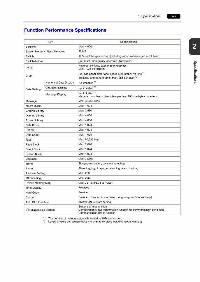
Function Performance Specifications
*1 The number of memory settings is limited to 1024 per screen.*2 Layer: 5 layers per screen (base + 4 overlap displays including global overlap)
Item Specifications
Screens Max. 4,000
Screen Memory (Flash Memory) 26 MB
Switch 1024 switches per screen (including slider switches and scroll bars)
Switch Actions Set, reset, momentary, alternate, illuminated
LampReverse, blinking, exchange of graphicsMax. 1024 per screen
GraphPie, bar, panel meter and closed area graph: No limit *1
Statistics and trend graphs: Max. 256 per layer *2
Data Setting
Numerical Data Display No limitation *1
Character Display No limitation *1
Message Display No limitation *1
Maximum number of characters per line: 100 one-byte characters
Message Max. 32,768 lines
Macro Block Max. 1,024
Graphic Library Max. 2,560
Overlap Library Max. 4,000
Screen Library Max. 4,000
Data Block Max. 1,024
Pattern Max. 1,024
Data Sheet Max. 1,024
Tags Max. 65,536 lines
Page Block Max. 2,048
Direct Block Max. 1,024
Screen Block Max. 1,024
Comment Max. 32,767
Trend Bit synchronization, constant sampling
Alarm Alarm logging, time order alarming, alarm tracking
Attribute Setting Max. 256
MES Setting Max. 256
Device Memory Map Max. 32 8 (PLC1 to PLC8)
Time Display Provided
Hard Copy Provided
Buzzer Provided, 3 sounds (short beep, long beep, continuous beep)
Auto OFF Function Always ON, custom setting
Self-diagnostic FunctionSwitch self-test functionConfiguration status confirmation function for communication conditionsCommunication check function

2-6 1. Specifications
External Dimensions and Panel Cut-out Dimensions for TS1100S
199.
0+0
.5-0
257.0 +0.5-0
266.8
206.
8
256.0
198.
0
256.0
38.0
6.0
32.0 Side View
Panel Cut-out Dimensions
Rear View
Bottom View
(Unit: mm) Front View

2
1. Specifications 2-7
Specifications
External Dimensions and Panel Cut-out Dimensions for TS1070S
134.
0+0
.5-0
189.0 +0.5-0
198.8
141.
8
188.0
133.
0
188.0
38.0
6.0
32.0
Side View
Panel Cut-out Dimensions
Rear View
Bottom View
(Unit: mm) Front View

2-8 1. Specifications
Please use this page freely.

31. Names and Functions of Components
2. Specifications of Components
Names and Specifications of Components


3
1. Names and Functions of Components 3-1
Nam
es and Specifications of C
omponents
1. Names and Functions of Components
1. DisplayThis is the display area.
2. DIP switchesThese DIP switches are for switching between RS-422 (4-wire connection) and RS-485 (2-wire connection) for COM1 and for setting the terminating resistance of the RS-422/RS-485 signal line for COM1/COM3.
3. Battery holderThis part contains the backup battery for the SRAM and clock.When the battery voltage drops, replace the battery with a new one.
4. USB mini-B (U-B)This port is used for transferring screen programs or connecting a PictBridge-compatible printer.
5. USB cable clamp holeThis clamp hole is used to attach a USB cable tie.
6. Mounting holesThese mounting holes are used for inserting fixtures when securing the TS1000S to a mounting panel.
1
3
876 69 10 11
2
45
1
3
6
87 9 10 11
2
45
TS1100S
TS1070S

3-2 1. Names and Functions of Components
7. Power supply terminal blockThis terminal block is for supplying power (24 VDC) to the TS1000S.
8. RS-422/RS-485 communication connector (COM1)This connector is for connecting a controller (PLC, temperature controller, inverter, etc.) via RS-422 (4-wire connection) or RS-485 (2-wire connection).
9. RS-232/RS-485 communication connector (COM2/COM3)This connector is used to connect a controller or barcode reader via RS-232C, or connect a controller via RS-485 (2-wire connection).
10. 100BASE-TX/10BASE-T connector (LAN) (TS1100Si and TS1070Si only)This connector is used for Ethernet communication.
11. USB-A (U-A)This port is used to connect a printer, USB flash drive, keyboard, or mouse.

3
2. Specifications of Components 3-3
Nam
es and Specifications of C
omponents
2. Specifications of Components
Serial Connector (COM1: RS-422/485)
This connector is for connecting a controller via RS-422 (4-wire connection) or RS-485 (2-wire connection).
The serial connector (COM1) pins correspond to signals as shown below.
* DIPSW2 and 3 are used to switch between RS-422 (4-wire connection) and RS-485 (2-wire connection). Set DIPSW2 and 3 to ON to internally jump the +RD and +SD as well as the -RD and -SD within the TS unit.For details on the DIP switches, refer to page 3-14.
Recommended Connector
The following connector is recommended for custom-made cables.
Application
COM1 (D-sub 9-pin, female) Pin No. Signal Name Description
1 + RD Receive data (+)
2 RD Receive data ()
3 SD Send data ()
4 + SD Send data (+)
5 SG Signal ground
6
NC Not used7
8
9
Bottom view
TS1100S TS1070S
Bottom view
9
5
6
1
Recommended Connector
DDK’s 17JE-23090-02(D8C)-CGD-sub 9-pin / male / inch screw thread (#4-40UNC) type / with hood / lead and cadmium free
Application V-SFT-6 Setting Refer to
PLC/temperature controller connection RequiredTS1000 Smart Connection Manual
Multi-link/Multi-link2 communication Required

3-4 2. Specifications of Components
Serial Connector (COM2: RS-232C / COM3: RS-485)
This connector is used to connect a controller or barcode reader via RS-232C, or connect a controller via RS-485 (2-wire connection).Communication via RS-232C (COM2) and via RS-485 (COM3) can take place at the same time.
The serial connector (COM2/COM3) pins correspond to signals as shown below.
Recommended Connector
The following connector is recommended for custom-made cables.
Application
COM2/COM3 (D-sub 9-pin, male)
Pin No.
RS-232C (COM2) RS-485 (COM3)
Signal Name
DescriptionSignal Name
Description
1 - - SD/RDSend/receive data
()
2 RD Receive data - -
3 TD Send data - -
4 NC Not used - -
5 SG Signal ground - -
6 - - +SD/RDSend/receive data
(+)
7 RTS Request to send - -
8 CTS Send permission - -
9 - - SG Signal ground
Recommended Connector
DDK’s 17JE-13090-02(D8C)A-CGD-sub 9-pin / female / inch screw thread (#4-40UNC) type / with hood / lead and cadmium free
Bottom view
TS1100S TS1070S
Bottom view
6
1
9
5
Application V-SFT-6 Setting Refer to
PLC/temperature controller connection RequiredTS1000 Smart Connection Manual
Barcode reader connection (COM2) Required
Printer connection (COM2) Required TS Reference Manual 1
Multi-link/Multi-link2 communication (COM3) Required TS1000 Smart Connection Manual
3
2. Specifications of Components 3-5
Nam
es and Specifications of C
omponents
USB-A (U-A)
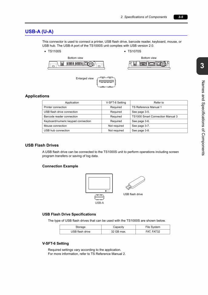
This connector is used to connect a printer, USB flash drive, barcode reader, keyboard, mouse, or USB hub. The USB-A port of the TS1000S unit complies with USB version 2.0.
Applications
USB Flash Drives
A USB flash drive can be connected to the TS1000S unit to perform operations including screen program transfers or saving of log data.
Connection Example
USB Flash Drive Specifications
The type of USB flash drives that can be used with the TS1000S are shown below.
V-SFT-6 Setting
Required settings vary according to the application.For more information, refer to TS Reference Manual 2.
Bottom view
TS1100S TS1070S
Bottom view
Enlarged view
Application V-SFT-6 Setting Refer to
Printer connection Required TS Reference Manual 1
USB flash drive connection Required See page 3-5.
Barcode reader connection Required TS1000 Smart Connection Manual 3
Keyboard/numeric keypad connection Required See page 3-6.
Mouse connection Not required See page 3-7.
USB hub connection Not required See page 3-8.
Storage Capacity File System
USB flash drive 32 GB max. FAT, FAT32
USB-A
USB flash drive

3-6 2. Specifications of Components
Notes on Handling a USB Flash Drive
1. Only remove a USB flash drive when the Main Menu screen is displayed or after pressing the [Storage Removal] switch.
2. Do not turn off power to the unit when the USB flash drive is being accessed.
3. Make a backup copy of the USB flash drive at regular intervals.
4. If a disk error occurs and data read/write operations are disabled, execute ScanDisk on Windows and try to restore the disk.If the disk cannot be restored, format the device. Note that formatting will completely erase all stored data. (For information on executing ScanDisk on Windows, refer to the relevant Windows manual.)
5. USB flash drives have a limited number of write cycles. Consequently, frequent writing at short intervals may shorten the service life of USB flash drives. When using a USB flash drive to save sampling data, take the acquisition interval and monitoring interval settings into consideration. Be sure to avoid constantly writing to a USB flash drive with the CYCLE macro command.
Keyboard and Numeric Keypad
Numeric values and characters can be entered by connecting a keyboard or numeric keypad to the TS1000S unit.
Connection Example
Compatible Keyboards
V-SFT-6 Setting
An [Entry] icon must be registered on the screen where the keyboard is to be used.In addition, setting of the numerical data or character display parts of [Entry Target] selected under [Function] is required.For details, refer to TS Reference Manual 1.
Type Description
Japanese keyboard 106 keyboard, 109 keyboard, etc.
US standard keyboard 101 keyboard, 104 keyboard, etc.
Numeric keypad
USB-A
Keyboard
or
Numeric keypad
3
2. Specifications of Components 3-7
Nam
es and Specifications of C
omponents
TS1000S Unit Settings
On the Main Menu screen, select the type of keyboard to be connected.For details, refer to “9-3. Keyboard Selection” (page 5-32).
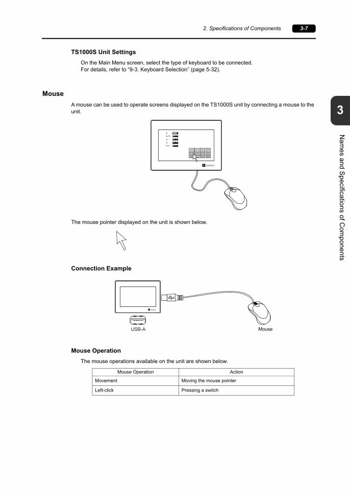
Mouse
A mouse can be used to operate screens displayed on the TS1000S unit by connecting a mouse to the unit.
The mouse pointer displayed on the unit is shown below.
Connection Example
Mouse Operation
The mouse operations available on the unit are shown below.
Mouse Operation Action
Movement Moving the mouse pointer
Left-click Pressing a switch
USB-A Mouse
3-8 2. Specifications of Components
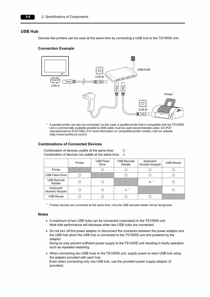
USB Hub
Devices like printers can be used at the same time by connecting a USB hub to the TS1000S unit.
Connection Example
* A parallel printer can also be connected. (In this case, a parallel printer that is compatible with the TS1000S and a commercially available parallel-to-USB cable must be used (recommended cable: UC-PGT manufactured by ELECOM).) For more information on compatible printer models, visit our website (http://www.monitouch.com/)).
Combinations of Connected Devices
Combination of devices usable at the same time:Combination of devices not usable at the same time:
* If these devices are connected at the same time, only the USB barcode reader will be recognized.
Notes
A maximum of two USB hubs can be connected (cascaded) to the TS1000S unit.Note that performance will decrease when two USB hubs are connected.
Do not turn off the power adaptor or disconnect the connector between the power adaptor and the USB hub when the USB hub is connected to the TS1000S unit and powered by the adaptor.Doing so may prevent sufficient power supply to the TS1000S unit resulting in faulty operation such as repeated restarting.
When connecting two USB hubs to the TS1000S unit, supply power to each USB hub using the adaptor provided with each hub.Even when connecting only one USB hub, use the provided power supply adaptor (if provided).
USB-A
USB-B
USB-B
USB-HUB
Printer *
PrinterUSB Flash
DriveUSB Barcode
ReaderKeyboard/
Numeric KeypadUSB Mouse
Printer -
USB Flash Drive -
USB Barcode Reader
-
Keyboard/Numeric Keypad
-
USB Mouse -
*
*

3
2. Specifications of Components 3-9
Nam
es and Specifications of C
omponents
USB mini-B (U-B)
This connector is used for screen program transfer or connection with a PictBridge-compatible printer.The USB mini-B port of the TS1000S unit complies with USB version 2.0.
Applications
*1 The ladder transfer function cannot be used simultaneously with 1:n communication (multi-drop) or multi-link communication.
Screen Program Transfer
Screen programs can be transferred using the U-B port (USB mini-B).A USB driver must be installed on the PC in advance to perform transfer.Refer to “Installing the USB Driver” (page 3-10) below for the driver installation procedure.
Connection Example
Rear view
TS1100S TS1070S
Rear view
Enlarged view
Application V-SFT-6 Setting Refer to
Ladder transfer function *1 Required TS Reference Manual 2
PictBridge-compatible printer connection Required TS Reference Manual 1
Screen program transfer Required See page 3-9.
USB-AUSB-miniB
PCUSB cable
3-10 2. Specifications of Components
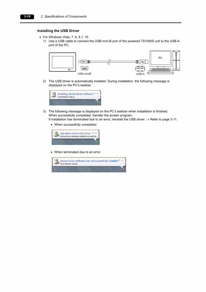
Installing the USB Driver
For Windows Vista, 7, 8, 8.1, 101) Use a USB cable to connect the USB-mini-B port of the powered TS1000S unit to the USB-A
port of the PC.
2) The USB driver is automatically installed. During installation, the following message is displayed on the PC’s taskbar.
3) The following message is displayed on the PC’s taskbar when installation is finished.When successfully completed, transfer the screen program.If installation has terminated due to an error, reinstall the USB driver. Refer to page 3-11.
When successfully completed
When terminated due to an error
USB-AUSB-miniB
PC

3
2. Specifications of Components 3-11
Nam
es and Specifications of C
omponents
When USB driver installation failsIf automatic installation of the USB driver fails, perform installation according to the following procedure.
1) Open the following folder using [My Computer] or [Windows Explorer].C:\MONITOUCH\Common\Driver
2) Double-click “USBDriverInstaller.exe”.
3) Click the [Next] button in the window below. Installation of the USB driver starts.
Depending on your OS, the following window may be displayed.Click [Install].

3-12 2. Specifications of Components
4) Click the [Finish] button in the window below.
USB driver installation is complete. Transfer the screen program.
Confirming installation of the USB driverWhen the driver has been installed successfully, “Operation Panel - Operation Panel USB Driver” appears in the [Device Manager] window.
This item disappears when the USB cable is removed from a powered TS1000S unit.If [Other Device] or a mark other than shown above is displayed even during USB connection, the USB driver is not recognized. If this happens, uninstall the USB driver and reinstall it.
3
2. Specifications of Components 3-13
Nam
es and Specifications of C
omponents
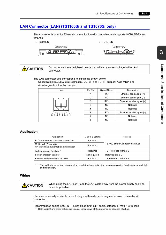
LAN Connector (LAN) (TS1100Si and TS1070Si only)
This connector is used for Ethernet communication with controllers and supports 100BASE-TX and 10BASE-T.
The LAN connector pins correspond to signals as shown below.Specification: IEEE802.3 (u)-compliant, UDP/IP and TCP/IP support, Auto-MDIX and Auto-Negotiation function support
Application
*1 The ladder transfer function cannot be used simultaneously with 1:n communication (multi-drop) or multi-link communication.
Wiring
Use a commercially available cable. Using a self-made cable may cause an error in network connection.
Recommended cable: 100 UTP (unshielded twist-pair) cable, category 5, max. 100-m long* Both straight and cross cables are usable, irrespective of the presence or absence of a hub.
Bottom view
TS1100Si TS1070Si
Bottom view
CAUTION Do not connect any peripheral device that will carry excess voltage to the LAN connector.
LAN Pin No. Signal Name Description
1 TX+ Ethernet send signal (+)
2 TX Ethernet send signal ()
3 RX+ Ethernet receive signal (+)
4 NC Not used
5 NC Not used
6 RX Ethernet receive signal ()
7 NC Not used
8 NC Not used
8 7 6 5 4 3 2 1
Application V-SFT-6 Setting Refer to
PLC/temperature controller connection Required
TS1000 Smart Connection ManualMulti-link2 (Ethernet) /1:n Multi-link2 (Ethernet) communication
Required
Ladder transfer function *1 Required TS Reference Manual 2
Screen program transfer Not required Refer topage 5-2
Ethernet communication function Required TS Reference Manual 2
CAUTION When using the LAN port, keep the LAN cable away from the power supply cable as much as possible.
3-14 2. Specifications of Components
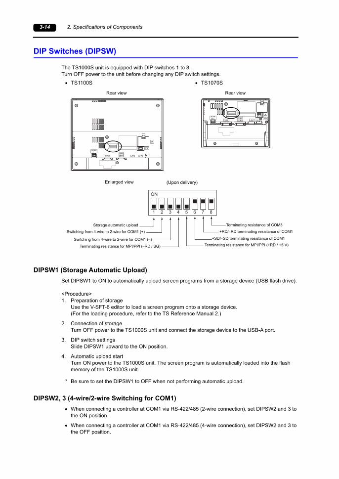
DIP Switches (DIPSW)
The TS1000S unit is equipped with DIP switches 1 to 8.Turn OFF power to the unit before changing any DIP switch settings.
DIPSW1 (Storage Automatic Upload)
Set DIPSW1 to ON to automatically upload screen programs from a storage device (USB flash drive).
<Procedure>1. Preparation of storage
Use the V-SFT-6 editor to load a screen program onto a storage device.(For the loading procedure, refer to the TS Reference Manual 2.)
2. Connection of storageTurn OFF power to the TS1000S unit and connect the storage device to the USB-A port.
3. DIP switch settingsSlide DIPSW1 upward to the ON position.
4. Automatic upload startTurn ON power to the TS1000S unit. The screen program is automatically loaded into the flash memory of the TS1000S unit.
* Be sure to set the DIPSW1 to OFF when not performing automatic upload.
DIPSW2, 3 (4-wire/2-wire Switching for COM1)
When connecting a controller at COM1 via RS-422/485 (2-wire connection), set DIPSW2 and 3 to the ON position.
When connecting a controller at COM1 via RS-422/485 (4-wire connection), set DIPSW2 and 3 to the OFF position.
Rear view
TS1100S TS1070S
Rear view
ON
1 2 3 4 5 6 7 8
(Upon delivery)Enlarged view
+RD/RD terminating resistance of COM1
+SD/SD terminating resistance of COM1
Terminating resistance of COM3
Terminating resistance for MPI/PPI (+RD / +5 V)
Switching from 4-wire to 2-wire for COM1 (+)
Switching from 4-wire to 2-wire for COM1 ()
Storage automatic upload
Terminating resistance for MPI/PPI (RD / SG)

3
2. Specifications of Components 3-15
Nam
es and Specifications of C
omponents
DIPSW4, 5 (Terminating Resistance for Siemens MPI/PPI Communication)
Set DIPSW4 and 5 to the ON position when using a Siemens PLC or performing MPI/PPI communication using COM1.
DIPSW6, 7, 8 (Terminating Resistance Setting)
When connecting a controller at COM1 via RS-422/485 (2-wire connection), set DIPSW7 to the ON position.
When connecting a controller at COM1 via RS-422/485 (4-wire connection), set DIPSW6 and 7 to the ON position.
When connecting a controller at COM3 via RS-422/485 (2-wire connection), set DIPSW8 to the ON position.

3-16 2. Specifications of Components
Please use this page freely.

41. Installation Procedure
2. Power Supply Cable Connection
3. Securing USB Cables
4. Installing the Battery
Installation


1. Installation Procedure 4-1
4
Installation
1. Installation Procedure
Installation Procedure
1. Mount the TS1000S unit into the mounting panel (maximum thickness of 5.0 mm).
* When using the optional waterproof gasket “TS1xx0S-WP”, firmly insert the gasket between the mounting panel and the TS1000S unit.
2. Insert the four fixtures provided with the TS1000S into the mounting holes and tighten them with the tightening screws (tightening torque: 3.54 lbf-in (0.4 N·m)).
* If the screws are tightened to a torque higher than stated above or the torque at each location is not equal, the surface sheet may warp due to deformation in the mounting panel and unit.
* Ground the mounting panel to prevent any buildup of static electricity.
Mounting panel
Panel cut-out hole
22.0
9.6
8.5
Fixture dimensions (unit: mm)
TS1100S TS1070S
Mounting panel
FixturesMounting holes
Mountingholes

4-2 1. Installation Procedure
Installation Conditions
Mounting Orientation
The TS1000S can be mounted in the following orientations.
Panel Cut-out Dimensions
(Unit: mm)
Upright 90 right 90 left
Model X Y Z (panel thickness)
TS1100S 257.0 199.0 1.5 to 5.0
TS1070S 189.0 134.0 1.5 to 5.0
X
YY
X
Z
+0.50
+0.50
+0.50
+0.50

1. Installation Procedure 4-3
4
Installation
Mounting Spatial Restrictions
Mount the TS1000S unit with approximately 100 mm of space around the maximum external dimensions of the unit.
Mounting Angle
Install the unit within the angle range of 15 to 135 degrees.
Ambient Temperature
Use the TS1000S in an ambient temperature range of 0 C to +50 C (wet-bulb temperature of 39 C or less).
100 100100
100
100
100
100
Front view Side view
(unit: mm)
Display Display

4-4 2. Power Supply Cable Connection
2. Power Supply Cable Connection
Power Supply Cable Connection
Connect the power supply cable to the terminal on the backside of the unit.
Cable Specifications
Tighten the terminal screws on the terminal to within the ranges shown in the table below.
When Using Bare Cables
Power Supply Cable Connection
The power supply must be used within the allowable range of voltage fluctuation. Use a power supply with low noise between cables and between the ground and cables. Do not insert two wires into a single terminal on the terminal block. Use the thickest power supply cable possible to minimize voltage drops, and twist the wire prior to
insertion. Keep power supply cables away from high-voltage, large-current carrying cables.
DANGER There is a risk of electric shock.Shut the power off before connecting the power supply cable.
Rear view
TS1100S TS1070S
Rear view
24 VDC power supply 10 %
Tightening torque 4 lbf-in (0.45 N·m)
CAUTION Do not solder the ends of wires. Doing so may lead to poor contact. When using stranded wire for cabling, make sure that the core is sufficiently twisted.
Otherwise, stray wires may cause a short-circuit with neighboring electrodes.
Cable size AWG18 to AWG14, discrete wire/solid wire (diameter: 1.0 to 1.6 mm)
Core length6.5 mm
DANGER Avoid applying excessive force to the power supply cable.A serious accident may result if the cable separates from the power supply terminal.
2. Power Supply Cable Connection 4-5
4
Installation
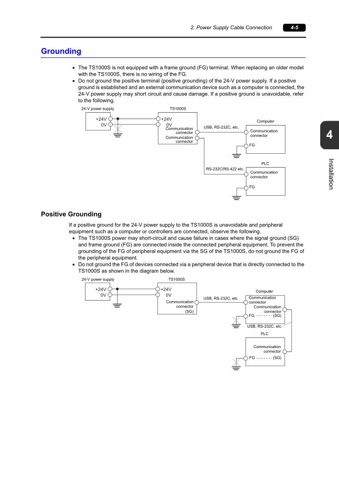
Grounding
The TS1000S is not equipped with a frame ground (FG) terminal. When replacing an older model with the TS1000S, there is no wiring of the FG.
Do not ground the positive terminal (positive grounding) of the 24-V power supply. If a positive ground is established and an external communication device such as a computer is connected, the 24-V power supply may short circuit and cause damage. If a positive ground is unavoidable, refer to the following.
Positive Grounding
If a positive ground for the 24-V power supply to the TS1000S is unavoidable and peripheral equipment such as a computer or controllers are connected, observe the following. The TS1000S power may short-circuit and cause failure in cases where the signal ground (SG)
and frame ground (FG) are connected inside the connected peripheral equipment. To prevent the grounding of the FG of peripheral equipment via the SG of the TS1000S, do not ground the FG of the peripheral equipment.
Do not ground the FG of devices connected via a peripheral device that is directly connected to the TS1000S as shown in the diagram below.
+24V0V
+24V0V
24-V power supply TS1000S
Communicationconnector
USB, RS-232C, etc.
Computer
FG
Communication connector
FG
Communication connector
PLC
Communicationconnector
RS-232C/RS-422 etc.
+24V0V
+24V0V
24-V power supply TS1000S
Communicationconnector
USB, RS-232C, etc.
Computer
FG
Communicationconnector
FG
Communicationconnector
PLC
USB, RS-232C, etc.
(SG)(SG)
(SG)
Communication connector

4-6 3. Securing USB Cables
3. Securing USB Cables
USB cables may disconnect from the TS1000S unit depending on the mounting conditions.Use a cable tie to prevent disconnection.
Securing USB Cables
1. Preparing and inserting a cable tiePrepare a commercially available cable tie about 3 mm in width.Pass the cable tie through the USB cable fixing hole from the lower side upward as shown in the figure below.
2. Inserting and securing a USB cableInsert a USB cable and secure it using the cable tie.
Example:
When only USB-A is used When only USB mini-B is usedWhen both USB-A and USB mini-B
(two cables) are used
Rear view

4. Installing the Battery 4-7
4
Installation
4. Installing the Battery
Role of the Battery
The battery provides backup power to the user memory area in SRAM (for non-volatile device memory $L and $LD, sampling data storage, etc.) as well as the built-in clock.
Battery Replacement Period
The service life of the battery is about 3 years from the date of manufacture.When the battery voltage has dropped, the message “Brownout of Battery” appears at the bottom of the Main Menu screen on the TS1000S unit.
* For details on the Main Menu screen, refer to “2. Main Menu Screen” (page 5-3).
Battery Voltage Drop Detection
The battery status is output to the internal device memory address $s167 of the TS1000S unit.When the battery voltage drops, the 4th bit of $s167 turns ON.If the battery voltage drops (4th bit turns ON) within the expiration date (three years), replace the battery immediately.
CAUTION A battery is already installed upon delivery.
Brownout of Battery
$s16715 14 13 12 11 10 09 08 07 06 05 04 03 02 01 00
0 0 0 0 0 0 0 0 0 0 0
MSB LSB
0 0 00
System reserved (setting: 0)
0: Battery OK.1: Battery voltage drop, no battery
System reserved (setting: 0)

4-8 4. Installing the Battery
Battery Replacement
Recommended Batteries
The required battery type and the recommended manufacturers are shown below.
Safety Instructions on Handling Batteries
Lithium batteries contain combustible material such as lithium and organic solvents. Mishandling may cause heat, explosion, or ignition resulting in fire or injury. To prevent accidents, pay attention to the following cautions when handling lithium batteries.
CAUTION The battery usage temperature range differs by the manufacturer. Select the battery to use while also taking note of the usage temperature range of the TS1000S.
Model Recommended Manufacturer TS1000S Usage Temperature Range
CR2032Coin-type lithium primary cell
Maxell Holdings0 C to +50 C
Panasonic
Mitsubishi0 C to +45 C
FDK
DANGER The battery indicates polarity with a “+” symbol so be sure to insert the battery in the correct direction. Inserting the battery in the wrong direction may cause the battery to burst or ignite.
The electrodes are exposed on CR2032 batteries. Do not carry or store replacement batteries together with metal objects. Short-circuiting of the electrodes may reduce battery capacity or cause batteries to burst or ignite.
Do not disassemble, incinerate, or heat batteries. Never attempt to recharge batteries.
CAUTION Only experts are authorized to perform battery replacement. Be sure to discharge static electricity from your body before performing battery
replacement. Use the recommended battery for replacement. Rough handling of the battery may cause fire or chemical burns. Do not disassemble, incinerate, or heat the battery. Observe local and governmental regulations when disposing of waste batteries. Keep batteries out of reach of children. (If swallowed, immediately consult a doctor.) If a battery leaks or smells, note that the leaking battery electrolyte is flammable.
Keep away from heat or flame.

4. Installing the Battery 4-9
4
Installation
SRAM Area Backup Procedure
Use the V-SFT-6 editor or a storage device to make a backup copy of the data in SRAM before replacing the battery.
When Using the V-SFT-6 Editor
1) Connecting a cableConnect the TS1000S unit and the computer using the transfer cable (USB cable or Ethernet cable).
2) Starting the V-SFT-6 editorStart the V-SFT-6 editor on the computer.
3) Displaying the [Transfer] dialogClick [Transfer] [Upload]. The [Transfer] dialog is displayed.
4) Selecting data to be transferredSelect [SRAM Data] for [Transfer Data].
5) Starting SRAM data transferClick the [PC ] button. Data transfer from the SRAM is started.
6) Saving the SRAM dataWhen the SRAM data has been transferred, the [Save As] dialog is displayed on the computer. Save the data as a backup copy. The file extension is “.RAM”.
* To transfer the “.RAM” data, which was saved as a backup copy, back to the TS1000S unit, click [Transfer] [Download] in step 3, and click the [PC ] button in step 5.
When Using a Storage Device
For details on the procedure for making backup using a storage device (USB flash drive), refer to “7-3. Saving Backup Copies of SRAM” (page 5-23).
Battery Replacement Procedure
1. Turn off power to the TS1000S unit.
2. Slide the battery holder cover in the direction of the arrow to open it, and then remove the cover.
DANGER There is a risk of electric shock.Turn off power to the TS1000S unit before performing steps 2. through 5. below.
Rear view

4-10 4. Installing the Battery
3. Press the tab to the right of the battery in the direction of the arrow. The right side of the battery will come up. Take the battery out with your fingers.
4. Slide a new battery left into the battery holder with the “+” side facing upward and then press the right side of the battery until it clicks.
5. Close the battery holder cover by inserting the tab on the bottom of the cover into the TS1000S unit and pressing the top of the cover until it clicks.
6. Turn on the TS1000S unit and check that the “Brownout of Battery” message has disappeared from the bottom of the Main Menu screen.
7. If a “*.RAM” backup file was saved, transfer it back to the TS1000S unit.When using the built-in clock, set the clock again. For details on clock correction, refer to “5-1. Date and Time Adjustment” (page 5-13).
Tab
Battery

4. Installing the Battery 4-11
4
Installation
Notes on the Battery: EU Directive 2006/66/EC
According to the EU directive 2006/66/EC effective in EU countries, the package box of the TS1000S have the marking shown below.
“Perchlorate Best Management Practices” Regulations in California State Law, U.S.
The TS1000S is an applicable product under the “Perchlorate Best Management Practices” regulations of California state law in the U.S. The package box of the TS1000S unit have the explanation shown below.
Perchlorate Material - special handling may apply.See www.dtsc.ca.gov/hazardouswaste/perchlorate
If exporting a product with an embedded TS1000S unit that contains a lithium primary battery to California, the above explanation must be printed on the product’s package box.
Notes on Transport
Transportation of batteries containing lithium must observe the transport regulations.
CAUTION The marking shown above is effective only in EU countries.
The details on the marking are designated in Article 20 “Information for end-users” and ANNEX II in EU directive 2006/66/EC.
The marking indicates that the battery should be disposed of separately from general household waste.
If element symbols are indicated below the marking, it means that the battery contains the specified heavy metal at a concentration exceeding the control value.The concentration control values are given below.Hg: mercury (0.0005 %), Cd: cadmium (0.002 %), Pb: lead (0.004 %)
The EU has determined the separating program for used batteries.Dispose of used batteries properly at your local waste-disposal/recycling center.

4-12 4. Installing the Battery
Please use this page freely.

51. Before Operation
2. Main Menu Screen
3. System Menu
TS1000S Operations


1. Before Operation 5-1
5
TS
10
00S
Ope
ration
s
1. Before Operation
Procedure before Operation
1. Mount the TS1000S on the mounting panel, install it and carry out wiring.For more information, refer to “Chapter 4”.
2. Install peripheral devices, such as PLCs or temperature controllers, and carry out wiring.For information on precautions, refer to the TS1000 Smart Connection Manual separately provided.
3. Turn the TS1000S on.
4. Transfer the created screen program.For details on screen program transfer, refer to “Screen Program Transfer” (page 5-2).
5. Start operation. To switch to RUN mode, refer to “Main Menu Screen” (page 5-3).When connection with controllers has been established, the RUN screen is displayed.
* If the TS1000S does not operate normally and shows an error message, refer to Chapter 6 and eliminate the cause of the error.
When turning the power on for the first time: Other cases:

5-2 1. Before Operation
Screen Program Transfer
There are four methods for transferring a screen program as described below.
1. Transfer via USBConnect a USB mini-B cable to the U-B port on the TS1000S, and transfer the screen program from a computer.
2. Transfer from storage deviceUse a USB flash drive.Load a screen program from the computer into the USB flash drive in advance. Press the [Storage (English)] switch on the initial screen to display the Storage Transfer screen from where you can transfer the screen program.
3. Transfer from storage device (automatic upload)Load a screen program from the computer into the USB flash drive in advance. When the power to the TS1000S is turned on, screen program transfer automatically starts.
4. Ethernet transfer (TS1100Si and TS1070Si only)Connect an Ethernet cable to the LAN port on the TS1000S, and transfer the screen program from a computer.Press the [IP Address (English)] switch on the initial screen to display the Ethernet screen where you can set the IP address for the TS1000S.
* For more information on methods 3 and 4, refer to the TS Reference Manual 2.
USB-miniB
LANEthernet
USB
USB-A
Initial screen displayed when the unit is turned on for the first time
IP address setting for the TS
Displays the state of communication between the TS and the computer.
Switches to the Storage Transfer screen.
USB flash drive

2. Main Menu Screen 5-3
5
TS
10
00S
Ope
ration
s
2. Main Menu Screen
Displaying the Main Menu Screen
To bring up the Main Menu screen in the RUN mode, press the corners on the TS1000S unit and the [MODE] switch on the System Menu *.
* For the details on the System Menu, refer to “System Menu” (page 5-46).
1. Press one corner of the screen for at least 2 seconds and release your finger when there is a beep.
2. Hold down one of the other three corners for two seconds or longer. Then the System Menu is displayed.
* When an item, such as a switch, data display part with switch, display area, slider switch, scroll bar, or table data display part, is placed on the position you press, the switch in the recognition area becomes invalid. Press a corner where none of the items described above is placed. If the items are placed on all of the corners, change the screen to another and display the Main Menu screen by following the procedure described above.
Recognition area2 cm
2 c
m
2 cm2
cm
2 cm
2 c
m
2 cm
2 cmRecognition area
Hold down the upper left corner for two second or longer.
Hold down one of the other three corners for two second or longer.System Menu

5-4 2. Main Menu Screen
3. Press the [MODE] switch while the System Menu is displayed. Then the Main Menu screen is displayed.
Main Menu Screen
The Main Menu screen indicates the TS1000S model, system information, and screen data information.Also, it works as the system screen when the screen data is transferred between a computer and the TS1000S.
Main Menu screen
Model
System program version
Screen data file comment,total amount of memory
occupied by the screen dataController and version of the I/F driver specified for the screen data file
Port used for screen data transfer
[Main Menu] switch
Clock
Font version
Ethernet information(on TS1100Si/TS1070Si only)
Error/warning (at the time of occurrence)

2. Main Menu Screen 5-5
5
TS
10
00S
Ope
ration
s
[Main Menu] Switch
Pressing the [Main Menu] switch brings up the following drop-down window.
Main Menu Screen Composition
The Main Menu screen is configured as shown below:
Main Menu screen Main Menu drop-down window
[RUN] (refer to page 5-6)
[Language] (refer to page 5-6)
[Comm. Parameter] (refer to page 5-7)
[SRAM/Clock] (refer to page 5-12)
[Extension Program Info.] (refer to page 5-14)
[Storage Transfer] (refer to page 5-15)
[Switch Check] (refer to page 5-29)
[Print Check] (refer to page 5-31)
[Main Menu]switch
Main Menu screen
Expanded function settingsPress the [Editor USB] switch at the lower left of the Main Menu screen for 3 seconds.For details, refer to “12. Extended Function Setting” (page 5-44).
[Simulator]Configure settings when using the simulator.
[Bright Adjustment] (refer to page 5-27)
[Ethernet] (TS1100Si and TS1070Si only) (refer to page 5-8)
[Keyboard] (refer to page 5-32)
[Extended Setting] (TS1100Si and TS1070Si only) (refer to page 5-33)
[I/O Test] (refer to page 5-28)
[Trial period Setting] (refer to page 5-41.)

5-6 2. Main Menu Screen
1. RUN
Pressing the [RUN] switch on the Main Menu drop-down window switches the screen to the RUN mode.
2. Language Selection
Pressing the [Language] switch on the Main Menu drop-down window brings up the Language Selection screen.Languages * selected in the [Font Setting] dialog of the V-SFT-6 editor are displayed on the Language Selection screen that is used for selecting an interface language for the Main Menu screen.
* The interface language for the Main Menu screen can be selected from English, Japanese, Chinese (Simplified), Chinese (Traditional) or Korean. English is always displayed.
Main Menu drop-down window
RUN screen
Main Menu drop-down window
Language Selection screen

2. Main Menu Screen 5-7
5
TS
10
00S
Ope
ration
s
3. Communication Parameter
Pressing the [Comm. Parameter] switch on the Main Menu drop-down window brings up the Comm. Param. screen.Communication parameters of PLC1 to PLC8 that are set on the V-SFT-6 editor can be checked on this screen.
Main Menu drop-down window
Comm. Param. screen
Moves back to the Main Menu screen.
Changes the display of the setting between PLC1 to PLC8.
Displays a specified communication parameter.

5-8 2. Main Menu Screen
4. Ethernet (TS1100Si/TS1070Si Only)
Pressing the [Ethernet] switch on the Main Menu drop-down window brings up the Ethernet screen.This screen is used to set an IP address for the TS1000S unit.
*1 For details, refer to the TS1000 Smart Connection Manual.*2 This switch is not displayed if [Local Port Address] is set ( page 5-10) using the V-SFT editor.
Moves back to the Main Menu screen or the initial screen.
Switches between [IP Address Setting] and [Select IP Address from
Network Table]. *1 *2
Displays the keypad for IP address setting.
Indicates whether the LAN port works correctly with an Ethernet cable inserted.
Normal: Connect (white)Abnormal: Disconnect (gray)
When making the setting, press the [Setting Finished] switch to determine the setting. The Main Menu screen is displayed.
Ethernet screen
Main Menu drop-down window
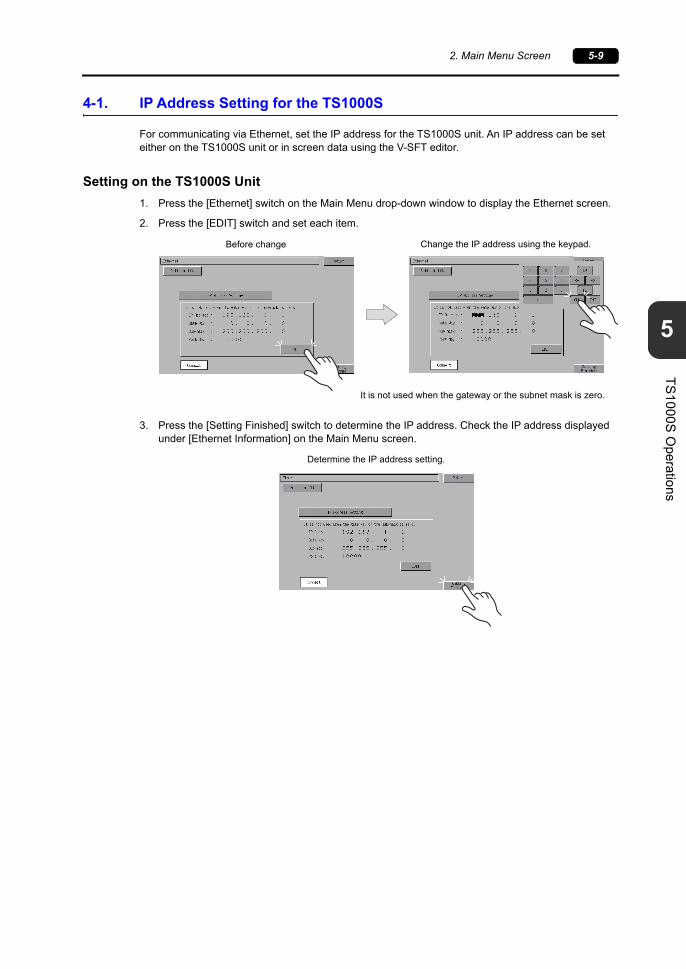
2. Main Menu Screen 5-9
5
TS
10
00S
Ope
ration
s
4-1. IP Address Setting for the TS1000S
For communicating via Ethernet, set the IP address for the TS1000S unit. An IP address can be set either on the TS1000S unit or in screen data using the V-SFT editor.
Setting on the TS1000S Unit
1. Press the [Ethernet] switch on the Main Menu drop-down window to display the Ethernet screen.
2. Press the [EDIT] switch and set each item.
3. Press the [Setting Finished] switch to determine the IP address. Check the IP address displayed under [Ethernet Information] on the Main Menu screen.
It is not used when the gateway or the subnet mask is zero.
Before change Change the IP address using the keypad.
Determine the IP address setting.

5-10 2. Main Menu Screen
Setting using the V-SFT Editor
1. Select [System Setting] [Ethernet Communication] [Local Port Address] on the V-SFT editor. The [IP Address Setting] dialog is displayed.
2. Check the [ Set IP] check box and set each item.
* For more information on setting items, refer to page 5-11.
3. Click [OK].
4. Transfer the screen data to the TS1000S unit. Check the IP address displayed under [Ethernet Information] on the Main Menu screen.
Select IP Address from Network Table
This is valid when the IP address of the TS1000S has been registered in the network table. Select a network table number from 0 to 99 to set the IP address.
IP Address * Set the IP address for the TS1000S.
Default Gateway * Set the default gateway.
Subnet Mask *
Set the subnet mask.When this box is not checked, the subnet mask is automatically assigned based on the byte at the extreme left of the IP address.
Example: IP address 172.16.200.185: “255.255.0.0” is set. IP address 192.168.1.185: “255.255.255.0” is set.
Port No. * Set a port No. 1024 to 65535, except for 8001.
Send TimeoutSet a timeout period for transmitting macro commands SEND, EREAD, EWRITE, MES or Ethernet DLL functions.
Retrials0 to 255Set the number of retrials to be performed when a time-out occurs.
Memory Protect
Internal Device
Memory Card Device
Check either check box to write-protect the memory from computers or other stations.

2. Main Menu Screen 5-11
5
TS
10
00S
Ope
ration
s
IP Address
This is an address that is used for recognizing each node on the Ethernet and should be unique.The IP address is 32-bit data which consists of the network address and the host address and can be classified into A to C depending on the network size.
NotationA string of 32-bit data is divided into four, and each segment delimited with a period is in decimal notation.Example: The IP address in class C shown below is represented as “192.128.1.50”.
11000000 10000000 00000001 00110010<Unusable IP addresses> “0” is specified for one byte at the extreme left. Example: 0.x.x.x “127” is specified for one byte at the extreme left (loop back address). Example: 127.x.x.x “224” or more is specified for one byte at the extreme left (for multi-cast or experiment). Example: 224.x.x.x The host address consists of only “0” or “255” (broadcast address). Example: 128.0.255.255, 192.168.1.0
Port Number
Multiple applications are running on each node, and communications are carried out for each application between the nodes. Consequently, it is necessary to have a means to identify the application that data should be transferred to. The port number works as this identifier. Each port number is 16-bit data (from 0 to 65535).The TS1000S uses ports for screen data transfer (8001), PLC communication (as desired), and the simulator (8020). Set a unique number in the range of 1024 to 65535. For a PLC or a computer, set the port number in the range of 256 to 65535. It is recommended to set a greater number.
Default Gateway
A gateway and a router are used for communication between different networks.The IP address of the gateway (router) should be set to communicate with the node(s) on other networks.
Subnet Mask
A subnet mask is used for dividing one network address into multiple networks (subnet).The subnet is assigned by specifying a part of the host address in the IP address as a subnet address.
<Unusable subnet masks> All bits are set to “0”. 0.0.0.0 All bits are set to “1”. 255.255.255.255
0
1 0
1 1 0
Class A
Class B
Class C
Network address (7)
Host address (8)
Host address (24)
Network address (14) Host address (16)
Network address (14)
255. 255. 255. 0
1 0
11111111 11111111 11111111 00000000
Class B
Subnet mask
Host address (16)
Network address Subnet address
Network address (14)
Host address

5-12 2. Main Menu Screen
5. SRAM/Clock
Pressing the [SRAM/Clock] switch on the Main Menu drop-down window brings up the SRAM/Clock screen.This screen is used for correcting the built-in calendar (date and time) and for formatting the SRAM area.
*1 Always install a battery. Otherwise, the clock setting of the built-in clock and contents in the SRAM area cannot be retained.
Displayed when the time for battery replacement is approaching. *1
Moves back to the Main Menu screen.
[] / [] switch: moves the cursor.[+] / [] switch: corrects the date and time.
Determines the changed date and time.Formats an SRAM area.
SRAM/Clock screen
Main Menu drop-down window

2. Main Menu Screen 5-13
5
TS
10
00S
Ope
ration
s
5-1. Date and Time Adjustment
This screen is used for correcting the built-in clock of the TS1000S.To use the built-in clock of the TS1000S, check [Use Built-in Clock] in the [SRAM/Clock Setting] dialog that is displayed by selecting [System Setting] [Unit Setting] [SRAM/Clock] on the V-SFT-6 editor.
1. Move the cursor using the [] and [] switches. Correct the date and time using the [+] and [] switches.
2. Press the [Set] switch to determine the setting. The clock displayed on the upper right is modified.
3. Pressing the [Return] switch displays the Main Menu screen again.
5-2. Formatting SRAM
Formats the SRAM area.When the SRAM area is formatted, any saved data (history data saved in SRAM, internal device memory $L, etc.) is completely cleared. Exercise caution when formatting the SRAM area.
1. Press the [Format] switch and the [Execute] switch.The SRAM area is formatted in the current screen data format. When formatting has been completed, the message “Format Completed” is displayed.
2. Pressing the [Return] switch displays the Main Menu screen again.
After changeBefore change
Format of the SRAM area completedBefore formatting the SRAM area

5-14 2. Main Menu Screen
6. Extension Program Information
Pressing the [Extension Program Info.] switch on the Main Menu drop-down window brings up the Extension Program Info. screen. This screen is used for checking program versions of the ladder transfer function, simulator, etc.
Extension Program Info. screen
Moves back to the Main Menu screen.
Changes the page of the extension program information.
Displays the extension program information.
Main Menu drop-down window

2. Main Menu Screen 5-15
5
TS
10
00S
Ope
ration
s
7. Storage Transfer
Pressing the [Storage Transfer] switch on the Main Menu drop-down window brings up the Storage Transfer screen.This screen is used for transferring data such as screen programs between the TS1000S and a USB flash drive.
1. [Data Selection] field [Screen Data]
Press this switch when transferring screen data to/from storage. [SRAM]
Press this switch when backing up data from the SRAM in the TS1000S to a storage device before battery replacement or when uploading from a storage device to the SRAM.
2. [Transfer Menu] field [Display <--- Storage]
Press this switch when transferring data from a storage device to the TS1000S. [Display---> Storage]
Press this switch when transferring data from the TS1000S to a storage device. [Display <--> Storage]
Press this switch when comparing stored data between the TS1000S and a storage device. [Delete]
Press this switch when deleting data from storage.
Moves back to the Main Menu screen or the initial screen.
2.1.
Main Menu drop-down window
Storage Transfer screen

5-16 2. Main Menu Screen
7-1. Storage Folder Configuration
The table below lists the folders in storage, the files in the folders, and the contained data.For more information, refer to the TS Reference Manual 2.
Folder Name (fixed)
Contents File NameTransfer Direction
BITMAP Pattern (bitmap) data BMPxxxx.BIN TS Storage
CARDRecipe data using the V6-compatible memory manager function
MCMHEAD.BINMCMxxxx.BIN
TS Storage
DSP Screen data DSP0000.BIN TS Storage
FONT Gothic fonts or language data xxxxxx.FTD TS Storage
HDCOPYHard copy image
(JPEG/BIN format selectable for 128-color display) *1
HDxxxx.JPGHDxxxx.BIN
xxxxxx.JPG *4TS Storage *5
JPEG JPEG file (except for some models)xxxxx.JPGJPxxxxx.JPG
TS Storage
LADDER Ladder data associated with the ladder monitor function *2 TS Storage
MEMO Memo pad data MEMxxxx.BIN TS Storage
MSG Message fileMSGxxyyy.BINMSGxxyyy.TXT
TS Storage
OPELOG Operation log file *3 OPELOG_hhmmss.BIN TS Storage
RECIPE Recipe data *1RECxxxx.CSVxxxxxxxx.CSV
TS Storage
SAMPLEData of data logging and alarm history
SMPxxxx.BINSMPxxxx.CSV TS Storage *6
Title file SMHxxxx.CSV TS Storage
SCRN
Header file SCHEADER.BIN
TS Storage
Screen fileComponent parts (macro blocks, sampling messages)
SCxxxx.BINMCRxxxx.BINMSGxxxx.BIN
3D parts file 3Dxxxx.BIN
Windows font file (graphics, messages)WFSxxxx.BINWFMxxxx.BIN
SNAP Network camera (Banner) snapshot images VDxxxxx.JPG TS Storage *5
SRAM Backup data of SRAM data SRM0000.BIN TS Storage
WEBSERV Files accessible from a web browser*.SHT, *.HTML, *.TXT etc.
TS Storage
Storage (USB memory)
DAT0000 (Access folder name: User-definable within 32 one-byte characters)
*1 Refer to the V Series Macro Reference Manual.*2 Refer to the V8 Series Ladder Monitor Specifications.*3 Refer to the TS Reference Manual 2.
*4 File name: 64 or less one-byte uppercase alphanumeric characters
*5 When using a web server: TS Storage*6 BIN file directly under the SAMPLE folder:
TS Storage
Folder Name (fixed)
Contents File NameTransfer Direction
DSPWhen a storage device is inserted into the TS1000S on condition that DIP switch settings on the unit are finished, screen data will automatically be uploaded into the unit.
DSPDEF.BIN TS Storage
Storage (USB memory)
DSPDEF (Screen data automatic upload folder: Fixed folder name)
(Other folders are the same as the “access folder”.)
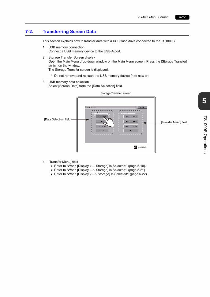
2. Main Menu Screen 5-17
5
TS
10
00S
Ope
ration
s
7-2. Transferring Screen Data
This section explains how to transfer data with a USB flash drive connected to the TS1000S.
1. USB memory connectionConnect a USB memory device to the USB-A port.
2. Storage Transfer Screen displayOpen the Main Menu drop-down window on the Main Menu screen. Press the [Storage Transfer] switch on the window.The Storage Transfer screen is displayed.
* Do not remove and reinsert the USB memory device from now on.
3. USB memory data selectionSelect [Screen Data] from the [Data Selection] field.
4. [Transfer Menu] field Refer to “When [Display Storage] Is Selected:” (page 5-18). Refer to “When [Display Storage] Is Selected:” (page 5-21). Refer to “When [Display Storage] Is Selected:” (page 5-22).
[Data Selection] field[Transfer Menu] field
Storage Transfer screen

5-18 2. Main Menu Screen
When [Display Storage] Is Selected:
1. When [Display Storage] is selected, the Storage Transfer screen below is displayed.
* The access folder name that is set for screen data is displayed as default. If there is no screen data in the TS1000S, “DAT0000” is displayed.
2. Access folder confirmationCheck [Folder Name], [Rest Size], and [Storage File Information]. When the selected folder is OK, go to step 4. To change the folder, go to step 3.
3. Access folder change (showing folders in storage)When changing the access folder to another folder, press the [Select Folder] switch.The Select Folder screen is displayed. Select the desired folder and press the [OK] switch.
Lights up during communication with a storage device.
Moves back to the previous screen.
Used for checking or renaming folder names. To step 3.
Remaining storage memory capacity
Folder name currently selected *
Information of the folder currently selected.
Starts [Display Storage] transfer.
Storage Transfer screen
Moves the cursor.
Displays the contents of the folder where the cursor is placed.
Determines the folder selection.
Shows the folders in storage.
Select Folder screen

2. Main Menu Screen 5-19
5
TS
10
00S
Ope
ration
s
4. Selection of data to transferAfter selecting a folder, press the [Select Data] switch.The Data Selection window appears and the [Select Data] switch changes to read [Start] at the same time.
* Press the [Return] switch to cancel the data transfer and dismiss the Data Selection window.
5. Data transfer startSelect the desired data, and press the [Start] switch. The [Start] switch changes to [Transferring].
Moves back to the Select Folder screen.
Moves the cursor.
Pressing the [Folder Detail] switch displays the contents of the folder where the cursor is placed.
Pressing the [] and [] switches scrolls the screen and shows the other folders listed below.[JPEG], [SNAP], [WAV], [FONT], [WEBSERV], [MSG], [SCRN], [OPELOG]
Data Selection window [Start] switch
Storage Transfer screen Data Selection
Start Transferring

5-20 2. Main Menu Screen
6. Data transfer completedWhen the data has been transferred successfully, the following message is displayed. Press the [OK] switch.Note that if [Sys. Program] or [Select All] was selected under [Data Selection], the Main Menu screen is automatically displayed on completion of data transfer.
* If any other error message window is displayed, refer to “Message Dialog Displayed during Data Transfer (between TS and Storage)” (page 5-26).
Data transfer completed
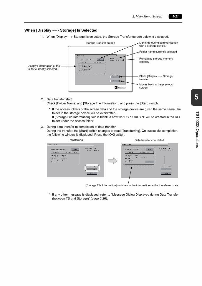
2. Main Menu Screen 5-21
5
TS
10
00S
Ope
ration
s
When [Display Storage] Is Selected:
1. When [Display Storage] is selected, the Storage Transfer screen below is displayed.
2. Data transfer startCheck [Folder Name] and [Storage File Information], and press the [Start] switch.
* If the access folders of the screen data and the storage device are given the same name, the folder in the storage device will be overwritten. If [Storage File Information] field is blank, a new file “DSP0000.BIN” will be created in the DSP folder under the access folder.
3. During data transfer to completion of data transferDuring the transfer, the [Start] switch changes to read [Transferring]. On successful completion, the following window is displayed. Press the [OK] switch.
* If any other message is displayed, refer to “Message Dialog Displayed during Data Transfer (between TS and Storage)” (page 5-26).
Folder name currently selected
Starts [Display Storage] transfer.
Lights up during communication with a storage device.
Moves back to the previous screen.
Displays information of the folder currently selected.
Remaining storage memory capacity
Storage Transfer screen
[Storage File Information] switches to the information on the transferred data.
Transferring Data transfer completed

5-22 2. Main Menu Screen
When [Display Storage] Is Selected:
1. When [Display Storage] is selected, the Storage Transfer screen below is displayed.The screen data in the unit is compared with the screen data (in the DSP folder) in the access folder.
2. Data comparison startPress the [Start] switch.
3. During data comparison to end of data comparisonDuring the comparison, the [Start] switch changes to read [Transferring]. On successful completion, the following window is displayed. Press the [OK] switch.
* If any other message is displayed, refer to “Message Dialog Displayed during Data Transfer (between TS and Storage)” (page 5-26).
Folder name currently selected
Remaining storage memory capacity
Starts comparison between [Display Storage].
Lights up during communication with a storage device.
Moves back to the previous screen.
Displays information of the folder currently selected.
Storage Transfer screen
Comparing Data comparison completed

2. Main Menu Screen 5-23
5
TS
10
00S
Ope
ration
s
7-3. Saving Backup Copies of SRAM
This section explains how to transfer data with a USB flash drive connected to the TS1000S.
1. USB flash drive connectionConnect a USB flash drive to the USB-A port.
2. Storage Transfer screen displayPress the [Storage Transfer] switch on the Main Menu drop-down window of the Main Menu screen.The Storage Transfer screen is displayed.
* Do not disconnect or reconnect the USB flash drive from this point on.
3. Data selectionPress the [SRAM] switch on the Storage Transfer screen. When the switch is in the pressed state, it is selected.
4. Transfer operation selectionSelect [Display Storage], [Display Storage] or [Display Storage] from [Transfer Menu] .
5. Access folder confirmation and selectionThe SRAM Transfer screen is displayed.
When [Display Storage] or [Display Storage] is selected:The access folder given the same name as the screen data in the TS1000S unit is selected from storage. The selected folder name is displayed.
[Transfer Menu] field
Folder name currently selected
Remaining storage memory capacity
Starts [Display Storage] transfer.
Lights up during communication with a storage device.
Moves back to the previous screen.
Shows [Display Storage] when [Display Storage] is selected.
Displays information of the file currently selected (file name fixed).
SRAM Transfer screen

5-24 2. Main Menu Screen
When [Display Storage]is Selected:
6. Transfer or comparison startCheck [Folder Name], [Rest Size], and the transfer direction. Press the [Start] switch.During data transfer or comparison, the [Start] switch changes to [Transferring].
7. Data transfer completedOn successful completion, the following message dialog is displayed. Press the [OK] switch.
* If any other message is displayed, refer to “Message Dialog Displayed during Data Transfer (between TS and Storage)” (page 5-26).
Used to check or change the folder name.For more information, refer to page 5-18.
Starts [Display Storage] transfer.
Moves back to the previous screen.
Displays information of the file currently selected(File name “SRM0000.BIN” fixed)
Folder name currently selected
SRAM Transfer screen
Remaining storage memory capacity
Lights up during communication with a storage device.
Transfer or comparison start During data transfer or comparison
Data transfer or comparison completed

2. Main Menu Screen 5-25
5
TS
10
00S
Ope
ration
s
7-4. Storage Data Deletion
This section explains how to transfer data with a USB flash drive connected to the TS1000S.
1. USB flash drive connectionConnect a USB flash drive to the USB-A port.
2. Storage Transfer screen displayPress the [Storage Transfer] switch on the Main Menu drop-down window of the Main Menu screen.The Storage Transfer screen is displayed.
* Do not disconnect or reconnect the USB flash drive from this point on.
3. Transfer operation selectionSelect [Delete] in the [Transfer Menu] field to display the Delete Data in Storage screen.To move back to the previous screen, press the [Return] switch.
4. Execution of data delete to during executionPress the [Execute] switch if deleting all data from storage. The switch is lit for a while.
5. Data delete completedWhen the data has been completely deleted, the message “Deleting Completed” is displayed. Data is completely deleted. Press the [Return] switch. The Storage Transfer screen is displayed again.
* Data in storage is completely deleted. However, redisplaying the Main Menu screen by the [Return] switch will automatically create the access folder of the screen data transferred to MONITOUCH.
[Transfer Menu] field Delete Data in Storage screen
Execution of data delete During execution
Lit.
Data delete completed

5-26 2. Main Menu Screen
7-5. Message Dialog Displayed during Data Transfer (between TS and Storage)
If an error occurs during data transfer, the message dialog shown on the right is displayed.
Messages and their contents are shown below.
Messages Contents Storage
Work normally finished. The specified operation has been concluded normally.
Storage is not connected. No storage device is inserted.
Storage Capacity overCannot write data to a storage device because the data size in the TS1000S unit is larger than the capacity of the storage device.
Write Protect: ONCannot write data to a storage device because the device is write-protected with the write-protect switch.
Writing Error occurred. An error occurred during writing to a storage device.
Selected data does not exist. The data does not exist in the reading target.
Data type is different.When writing to the TS1000S unit, the type of data in storage does not match the model of the TS unit.
Selected data can not be read. The data in storage cannot be read.
Reading Error occurred.An error occurred during writing to the flash ROM in the TS1000S unit.
Data discrepantData comparison found a discrepancy between the storage device and the TS.
Screen data on TS will be broken.
Warning about data destruction in the TS1000S unit that may occur when transferring font data larger than the present data from storage to the TS1000S unit.(When you press the [OK] switch to continue, transfer the screen data again.)
Undefined Error occurred.An error occurred due to a cause other than those mentioned above.
Invalid format.The format of the file system in storage cannot be identified.Reformat it to FAT or FAT32 in the computer.

2. Main Menu Screen 5-27
5
TS
10
00S
Ope
ration
s
8. Brightness Adjustment
Pressing the [Bright Adjustment] switch on the Main Menu drop-down window brings up the Bright Adjustment screen.This screen is used to adjust the brightness of the TS1000S.
Bright Adjustment screen
Main Menu drop-down window
Moves back to the Main Menu screen.
Brightness decreases upon each [+] press.
Adjusts the brightness to the medium level.(Setting: 63)
Press the [Setting Finished] switch to determine the setting. The Main Menu screen is displayed.
Brightness increases upon each [] press.
Adjusts the brightness to the highest level.(Setting: 0)
Adjusts the brightness to the lowest level.(Setting: 127)
Shows the current brightness. Setting: 0 to 127

5-28 2. Main Menu Screen
9. I/O Test
Pressing the [I/O Test] switch on the Main Menu drop-down window brings up the I/O Test screen.This screen is used to check that there is no problem with the TS1000S interfaces and touch switch operation.
Moves to the touch switch test screen. ( page 5-29)
Moves back to the Main Menu screen. ( page 5-3)
Performs a COM1/COM2/COM3 interface test. ( page 5-34)
I/O Test screen
Moves to the Print Test screen. ( page 5-31)
Main Menu drop-down window
Used to check USB connections. ( page 5-33)
Moves to the Keyboard Selection screen. ( page 5-32)

2. Main Menu Screen 5-29
5
TS
10
00S
Ope
ration
s
9-1. Touch Switch Test
If a touch switch does not activate at all or if an operation is performed without pressing any touch switch, check if the touch switches on the TS1000S panel are working properly.
1. Touch switch test screen:Press the [Switch Check] switch. Grids appear on the screen as shown below.
2. Checking the switch output state:Press a position on the panel, and check if the pressed position turns white. When the pressed position turns white, the switch is activated normally. To move back to the I/O Test screen, press the [Return] switch. To delete white dots, press the [Erase] switch.
* If a position different from the pressed position turns white, refer to “Touch Switch Adjustment” on the next page and adjust the touch switch position.
Touch switch test screenI/O Test screen
419 345
Touch switch test screen
Coordinates (0, 0)Output coordinates
Displays the I/O Test screen.
Deletes white dots.
Displays the Touch Switch
Adjustment screen. *
Output coordinates

5-30 2. Main Menu Screen
Touch Switch Adjustment
If a position different from the pressed position turns white on the touch switch test screen, follow the steps described below to adjust the touch switch position.
1. Press the [Adjust] switch on the touch switch test screen. The Touch Switch Adjustment screen appears.
2. Press on “1” that is flashing at the corner. When the finger is released, a beep sounds and the position is set. “2” flashes.
3. Press on “2” that is flashing at the corner. When the finger is released, a beep sounds and the position is set. “3” flashes.
4. Press on “3” that is flashing at the corner. When the finger is released, a beep sounds and the position is set. “4” flashes.
5. Press on “4” that is flashing at the corner. When the finger is released, a beep sounds and the position is set.
6. To re-set the positions, press the [Reset] switch and follow step 2 and later.
7. To cancel the setting, press the [Return] switch. The touch switch test screen is displayed again.
8. To determine the setting, press the [Fix] switch. A long beep sounds and the positions are determined. The touch switch test screen is displayed again.
Touch switch test screen Touch Switch Adjustment screen

2. Main Menu Screen 5-31
5
TS
10
00S
Ope
ration
s
9-2. Print Test
Pressing the [Print Check] switch on the I/O Test screen displays the Print Test screen. This screen is used to perform a print test with a printer connected.
* The printer port name specified on the V-SFT-6 editor is displayed. Either [USB-A (Host)] or [USB-B (Device)] is displayed.
Print Test Result Example
Pressing the [Print] switch executes a print test. When the print test has been finished successfully, a test result is printed out as shown below.
The I/O Test screen is displayed again.
Print Test screen
Performs a print test.Displays a printer port name. *
!"#$%&@ 0123456789 ABCDEFGHIJKLMNO!"#$%&@ 0123456789 ABCDEFGHIJKLMNO!"#$%&@ 0123456789 ABCDEFGHIJKLMNO!"#$%&@ 0123456789 ABCDEFGHIJKLMNO!"#$%&@ 0123456789 ABCDEFGHIJKLMNO!"#$%&@ 0123456789 ABCDEFGHIJKLMNO!"#$%&@ 0123456789 ABCDEFGHIJKLMNO

5-32 2. Main Menu Screen
9-3. Keyboard Selection
This section describes how to select the type of the keyboard to be connected to the USB-A (master) port.
1. Keyboard Selection screenPress the [Keyboard] switch to display the Keyboard Selection screen.
2. Keyboard type selectionSelect the keyboard type by pressing the [English] or [Japanese] switch.
* [English] is selected as the default.After selecting a keyboard type from the Keyboard Selection screen and pressing the [Setting Finished] switch, the selected keyboard remains effective even after turning off and on the power.
3. Press the [Setting Finished] switch to determine the setting. The I/O Test screen is displayed again.
Keyboard Selection screenI/O Test screen
Keyboard Selection screen
After selecting a keyboard, press the [Setting Finished] switch to determine the setting. The I/O Test screen is displayed again.
Moves back to the I/O Test screen.
Used to select a keyboard type: English or Japanese.

2. Main Menu Screen 5-33
5
TS
10
00S
Ope
ration
s
9-4. USB Test
This section describes how to check the connection to USB-A (master) port.
Checking the Connection Status
When the lamp shows [Connected], the USB device is identified.

5-34 2. Main Menu Screen
9-5. Self-loop Test
This is a signal test for communications through the COM1, COM2 or COM3 connector.Perform this test if the communication is not successfully established when connecting a controller (PLC, temperature controller, etc.) using COM1, COM2 or COM3.
COM1: RS-485 Signal Test
SD/RD Test
Check the signals [SD] and [RD].
1. Set DIP switch Nos. 2 and 3 to OFF.
* Turn the power off when setting DIP switches.
2. Install a jumper between pins 1 and 4, and between pins 2 and 3 of COM1 on the TS1000S.
3. Press the [COM1] switch in the [Communication Port] field. The [RS485] lamp comes on.
4. Press the [Self-Loop Test] switch. When the [OK] lamp lights up, the test is successfully completed.
* If the [NG] lamp lights up, a pin may be faulty. Contact your local distributor.
COM1 (D-sub 9-pin, female) COM2 / COM3 (D-sub 9-pin, male)
9
5
6
1
6
1
9
5
-RD
+RD 1
2
Name No.
+SD
-SD 3
4

2. Main Menu Screen 5-35
5
TS
10
00S
Ope
ration
s
COM2: RS-232C Signal Test
SD/RD Test
Check the signals [SD] and [RD].
1. Install a jumper between pins 2 and 3 of COM2 on the TS1000S.
2. Press the [COM2] switch in the [Communication Port] field. The [RS232C] lamp comes on.
3. Press the [Self-Loop Test] switch. When the [OK] lamp lights up, the test is successfully completed.
* If the [NG] lamp lights up, pin 2 or 3 may be faulty. Contact your local distributor.
SD
RD 2
3
Name No.

5-36 2. Main Menu Screen
CTS/RTS Test
Check the signals [CTS] and [RTS].
1. Install a jumper between pins 7 (RTS) and 8 (CTS) of COM2 on the TS1000S.
2. Press the [COM2] switch in the [Communication Port] field. The [RS232C] lamp comes on.
3. Press the [RTS] switch and check that both [RTS] and [CTS] lamps light up at the same time. Press the [RTS] switch again and check that both [RTS] and [CTS] lamps go off at the same time.
CTS
RTS 7
8
Name No.

2. Main Menu Screen 5-37
5
TS
10
00S
Ope
ration
s
COM3: RS-485 Signal Test
SD/RD Test
Check the signals [SD] and [RD]. Be sure that no problem is found in “COM1: RS-485 Signal Test” (page 5-34) beforehand.
1. Set DIP switch Nos. 2 and 3 to ON.
* Turn the power off when setting DIP switches.
2. On the TS1000S, connect pin 1 of COM1 with pin 6 of COM3, and pin 2 of COM1 with pin 1 of COM 3.
3. Press the [COM3] switch in the [Communication Port] field. The [RS485] lamp lights up.
4. Press the [Self-Loop Test] switch. When the [OK] lamp lights up, the test is successfully completed.
* If the [NG] lamp lights up, a pin may be faulty. Contact your local distributor.
-RD
+RD 1
2
Name No.
+SD/RD
-SD/RD 1
6
Name No.
COM1 COM3
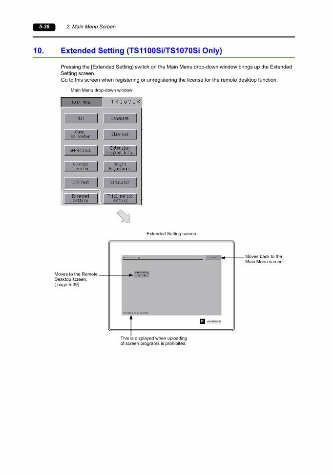
5-38 2. Main Menu Screen
10. Extended Setting (TS1100Si/TS1070Si Only)
Pressing the [Extended Setting] switch on the Main Menu drop-down window brings up the Extended Setting screen.Go to this screen when registering or unregistering the license for the remote desktop function.
Moves to the Remote Desktop screen.( page 5-39)
Extended Setting screen
Main Menu drop-down window
Moves back to the Main Menu screen.
This is displayed when uploading of screen programs is prohibited.

2. Main Menu Screen 5-39
5
TS
10
00S
Ope
ration
s
10-1. Registering/Unregistering the License for the Remote Desktop Function
Pressing the [Remote Desktop Key Code] switch on the Extended Setting screen brings up the Remote Desktop screen. This screen is used to register or unregister the license for the remote desktop function.Licensing is required for using the remote desktop function.One license is granted per TS1000S unit.
* For purchasing the license “V-RemoteDT”, please consult with your local distributor.
Registering the License
1. Key in the key code (8 numerals) on the keypad and enter the code by pressing the [Setting Finished] switch.
2. On completion of registration, the screen switches to the Main Menu screen.
Unregistering the License
The license registered with the TS1000S can be unregistered.
* If using the remote desktop function again, reregister the key code.Be careful in managing the key code because it will not be reissued.
1. Press the [Delete] switch. When the dialog appears, press the [Execute] switch.
Remote Desktop screen

5-40 2. Main Menu Screen
2. The [Delete] switch disappears, and the [Not registered] switch appears instead.
3. The procedure for unregistering is complete.
Password unregistered

2. Main Menu Screen 5-41
5
TS
10
00S
Ope
ration
s
11. Trial Period Setting
Pressing the [Trial period Setting] switch on the Main Menu drop-down window displays the following screen.The trial period function allows a trial period to be applied to the TS1000S. When a specified date and time arrive, a password will become necessary to start up the TS1000S.
Main Menu drop-down window
Switches to the Trial Period Setting screen.
When password protection is disabled
Returns to the Main Menu screen.
When password protection is enabled
Trial Period Setting screen

5-42 2. Main Menu Screen
Trial Period Settings
It is possible to unconditionally stop operation of the TS1000S when a specified date and time arrive.By configuring a trial period, use of the TS1000S can be restricted unless a password is entered.
Enabling Password Protection
1. Press the [Trial period Setting] switch in the Main Menu drop-down window.
2. The following screen is displayed. Press [OK].The Trial Period Setting screen is displayed.
3. Pressing the [Not Used] switch on the Trial Period Setting screen changes the switch to read [Used].
4. Press the [EDIT] switch and set the trial period expiry date and time and the warning display dates.
5. Press the [Change password] switch to enter the password (4 to 10 digits) for disabling password protection.
6. Press the [Setting Finished] switch to confirm the setting. The Main Menu screen is displayed again.

2. Main Menu Screen 5-43
5
TS
10
00S
Ope
ration
s
Disabling Password Protection
1. Press the [Trial period Setting] switch in the Main Menu drop-down window.
2. The following screen is displayed. Enter the password for disabling password protection and then press the [ENT] switch. If the password matches, the Trial Period Setting screen appears.
3. Pressing the [Used] switch on the Trial Period Setting screen changes the switch to read [Not Used].
4. Press the [Setting Finished] switch to confirm the setting. The Main Menu screen is displayed again.
When the Specified Date and Time is Reached
1. The following screen is displayed immediately after the power is turned on.
2. Enter the password for disabling password protection and then press the [ENT] switch. If the password matches, the Main Menu screen appears.
3. Press the [RUN] switch in the Main Menu drop-down window.
* Although the Main Menu screen appears even if the password does not match, attempting to transition to the RUN screen will display the screen shown in step 1.
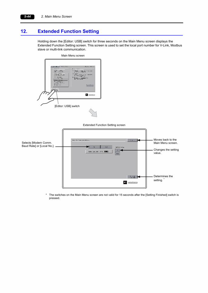
5-44 2. Main Menu Screen
12. Extended Function Setting
Holding down the [Editor: USB] switch for three seconds on the Main Menu screen displays the Extended Function Setting screen. This screen is used to set the local port number for V-Link, Modbus slave or multi-link communication.
* The switches on the Main Menu screen are not valid for 15 seconds after the [Setting Finished] switch is pressed.
Selects [Modem Comm. Baud Rate] or [Local No.].
Moves back to the Main Menu screen.
Changes the setting value.
Determines the
setting. *
[Editor: USB] switch
Main Menu screen
Extended Function Setting screen

2. Main Menu Screen 5-45
5
TS
10
00S
Ope
ration
s
12-1. Setting Local Port Number
For V-Link, Modbus slave or multi-link communication, set the local port number from the Main Menu screen.
(The local port number can be configured when [PLCn: V-Link] or [PLCn: Modbus Slave (RTU)] is selected as a device to connect or when [Connection Mode] is set to “Multi-link” under [Communication Setting], which are accessible via [System Setting] [Hardware Setting] in V-SFT-6.)
1. Displaying the [Local No.] field:Press the [Down] switch to display the [Local No.] field.
2. Setting the local port number:Select a local port number using the [+] or [] switch. The local port number can be selected from 1 to 254.Press the [Setting Finished] switch to complete the setting.
3. The Main Menu screen is automatically displayed again.
Local port number setting screen Setting completed

5-46 3. System Menu
3. System Menu
Types of the System Menu Switches
System menu switches comprise four kinds of switches: [OFF], [MODE], [BR], and [BACK LT].For the way to display the System Menu, refer to “Displaying the Main Menu Screen” on page 5-3.
Functions of the System Menu Switches
Function Specifications TS
OFF System Menu hiding Hides the System Menu.
MODE Mode selection Switches the screen from the RUN mode to the System Menu.
BR Brightness adjustment
Bright
BR Medium
BR Dark
BACK LT
Backlight control
Always ON -
Auto 1Auto 2Auto 3
The [BACK LT] switch turns the backlight off.
This is available when the backlight control bit (bit 11) in the read area “n+1” in the system memory is reset (OFF: 0).
ManualThe [BACK LT] switch turns the backlight off. To turn the backlight on, press somewhere on the screen.
61. Error Messages
2. Troubleshooting
Error Handling


1. Error Messages 6-1
6
Error H
andling
1. Error Messages
There are four kinds of error messages displayed on the TS1000S:
1. Communication error
2. Data Loading
3. Warning
4. Touch switch is active
1. Communication Error
When communication is not established between a TS1000S unit and a controller, or an abnormality (noise etc.) is detected, the following screen is displayed on the TS1000S unit.
* If the above error messages are displayed on the TS1000S unit without establishing communication between the unit and PLC, test the solution of remark “1”. If the error occurs suddenly during communication, test the solution of remark “2”.
When [Comm. Error Handling: Continue] is selected When [Comm. Error handling: Stop] is selected:
Error Messages Contents Solution Remarks
Time-OutAlthough a request to send is given to a controller, no answer is returned within the specified time.
1. Check the settings in the [System Setting] [Hardware Setting] [PLC Properties] window.
2. Check that the cable is correctly connected.1
3. Data may be corrupted due to noise. Take measures to prevent noise from affecting data.
2
Parity An error occurred in parity check.
1. Check that the cable is correctly connected. 1
2. Data may be corrupted due to noise. Take measures to prevent noise from affecting data.
2
FramingAlthough the stop bit must be “1”, it was detected as “0”.
1. Check the settings in the [System Setting] [Hardware Setting] [PLC Properties] window.
2. Check the cables and wiring.1
3. Data may be corrupted due to noise. Take measures to prevent noise from affecting data.
2
Over-RunAfter receiving one character, the next character was received before internal processing was completed.
1. Check the settings in the [System Setting] [Hardware Setting] [PLC Properties] window.
1
2. Data may be corrupted due to noise. Take measures to prevent noise from affecting data.
2
Check CodeThe check code in the controller response was not correct.
1. Check the settings in the [System Setting] [Hardware Setting] [PLC Properties] window.
1
2. Data may be corrupted due to noise. Take measures to prevent noise from affecting data.
2
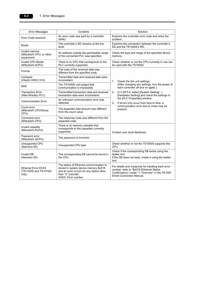
6-2 1. Error Messages
Error Messages Contents Solution
Error Code receivedAn error code was sent by a controller.(NAK)
Examine the controller error code and solve the problem.
BreakThe controller’s SD remains at the low level.
Examine the connection between the controller’s SD and the TS1000S’s RD.
Invalid memory(Mitsubishi CPU, or other equipment)
An address outside the permissible range of the connected PLC was specified.
Check the type and range of the specified device memory.
Invalid CPU Model(Mitsubishi ACPU)
There is no CPU that corresponds to the PLC currently supported.
Check whether or not the CPU currently in use can be used with the TS1000S.
FormatThe code of the received data was different from the specified code.
1. Check the link unit settings.(After changing any settings, turn the power of each controller off and on again.)
2. In V-SFT-6, select [System Setting] [Hardware Setting] and check the settings in the [PLC Properties] window.
3. If errors only occur from time to time, a communication error due to noise may be present.
Compare(Hitachi HIDIC S10)
Transmitted data and received data were inconsistent.
NAKThe TS1000S unit judged that communication is impossible.
Transaction Error(Allen-Bradley PLC)
Transmitted transaction data and received transaction data were inconsistent.
Communication ErrorAn unknown communication error was detected.
Count error(Mitsubishi CPU/Sharp CPU)
The expected data amount was different from the count value.
Command error(Mitsubishi CPU)
The response code was different from the expected code.
Invalid cassette(Mitsubishi ACPU)
There is no memory cassette that corresponds to the cassettes currently supported. Contact your local distributor.
Password error(Mitsubishi QCPU)
The password is incorrect.
Unsupported CPU(Siemens S5)
Unsupported CPU typeCheck whether or not the TS1000S supports this CPU.
Invalid DB(Siemens S5)
The corresponding DB cannot be found in the CPU.
Check if the corresponding DB exists using the ladder tool.If the DB does not exist, create it using the ladder tool.
Ethernet Error:XXXX(TS1100Si and TS1070Si only)
The status of Ethernet communication is stored in system device memory $s518 and an error occurs for any status other than “0” (normal).XXXX: Error number
For details and measures for handling each error number, refer to “$s518 (Ethernet Status Confirmation)” under “1. Overview” in the TS1000 Smart Connection Manual.

1. Error Messages 6-3
6
Error H
andling
2. Data Loading...
If an error is detected in the screen program when switching to RUN mode, the following messages are displayed on the TS1000S unit.
Screen No. Error screen Error: XX (XX:XXX) screen
Error Message Description Solution
Screen No. ErrorThe screen of the received number is not set.
When communication starts, the TS1000S unit determines the screen number set as the value stored at read area “n + 2”.Since the value of read area “n + 2” does not correspond to an existing screen number, check each controller.
Error: XX (XX:XXX)An error exists in the created screen program.
Check the screen causing the error as determined from the item number and sub-item number displayed on the TS1000S unit, check the error details (error number), and remove the cause of the error accordingly.
For details on item numbers and sub-item numbers, refer to the next page.
Sub-item numberItem numberError number

6-4 1. Error Messages
2-1. Error Numbers
Error Number
* Error numbers with “*” do not occur under ordinary circumstances.If any of these errors are displayed, contact your local distributor.
Error No. Contents Solution
3 Data version does not match the MONITOUCH system program version.
Transfer the MONITOUCH system program from the V-SFT editor.If the problem persists, check the editor version and the system program (SYSTEM PROG.) version of the TS1000S, and contact your local distributor.
10 The communication I/F unit is not installed, or it does not match the I/F driver.
Install the communication I/F unit.Transfer the I/F driver again.
11 The PLC model set in the screen program does not match the I/F driver.
Check the PLC model and transfer the I/F driver again.
12 The I/F driver version does not match the screen program version.
Check the editor version and the I/F driver version, and contact your local distributor.
13 The I/F driver version does not match the version of the MONITOUCH system program.
Check the I/F driver version and the system program (SYSTEM PROG.) version of the TS1000S, and contact your local distributor.
15 The interface language on MONITOUCH does not match the language set in the screen program.
Check the MONITOUCH model and the language set in the created program.
17 The network I/O number exceeds the usable number range.
Set a number within the usable range.
19 An I/F driver that is unsupported on MONITOUCH is transferred.
Transfer the correct I/F driver.
20 The maximum capacity of the buffering area has been exceeded.
The data capacity to be saved in DRAM at the primary storage target (buffering area setting) has exceeded the maximum available capacity.Reduce the number set for [Number of Data to Save].
22 The buffer number specified for the trend or alarm item has not been set.
In V-SFT-6, select [System Setting] [Buffering Area Setting] and set the relevant buffering area correctly.
23* Memory card file number error Contact your local distributor.
24 The output file number set in the buffering area setting is not unique or [Buffering File] is not set for the memory card setting.
When [Secondary storage target: Memory Card] is selected in the [Buffering Area Setting] window, the output file number can be set. However, the set output file number already exists.As another possibility, [Type: Buffering File] is not set in the [Memory Card Setting] window although [Secondary storage target: Memory Card] is selected.Check the output file number in the [Buffering Area Setting] window, and set correctly.If unsuccessful, check the setting in the [Memory Card Setting] window.
25 The amount of obtained data/number of monitoring alarms has exceeded the buffering area setting.
Check [Number of data to acquire] or [Number of Monitoring Alarms] in the [Buffering Area Setting] window.Bit synchronization, constant sampling, alarm tracking, alarm logging, time order alarming: 256 words maximumDevice memory map: 128 words maximum
26 There are too many trend and alarm items that refer to the buffering area.
There are too many items that refer to the logging server or alarm server (max. 16 items).Reduce the number of trend/alarm items placed on the screen.
27* There is an error in the buffering area setting. Contact your local distributor.

1. Error Messages 6-5
6
Error H
andling
28 The same function is set for both MJ1 and MJ2 ports.
Check the settings in the [System Setting] [Hardware Setting] window and specify the settings correctly.
29 The memory capacity is insufficient. Reduce the number set for [Number of Data to Save] for [DRAM] under [Primary storage target] in the [Buffering Area Setting] [Data Output Setting] tab window.Reduce the number set for [Number of Monitoring Alarms] for the alarm item.Delete the following settings if not necessary. Multi-link/Multi-link2 Connected devices not in use
If the problem is not resolved by taking the above measures, contact your local distributor.
30 There are too many registered items. Reduce the number of items.
31 The memory capacity for the registered items is insufficient.
Take the following action for the relevant screen.
Reduce the number set for [Number of Monitoring Alarms] for the time order alarming.Reduce the number set for [Number of Monitoring Alarms] for alarm tracking.Reduce the number set for [Number of Monitoring Alarms] for the bit order alarming.Reduce the number of items placed on the screen.
32 The number of items that uses the memory exceeds the available number.
Reduce the number of items.
33 The maximum number of switches and lamps that can be set has been exceeded.
The number of switches and lamps placed on the screen has exceeded 1024. Switches and lamps on overlap displays are included in this number.Reduce the number of switches and lamps.
34 The items that occupy the memory area exceed the available work memory capacity.
Reduce the amount of data.
35* Variable length data error
Contact your local distributor.
36* ITEM error
37* Component ITEM error
38* Component error
40* Group byte count error
41* Recognition flag error
42* Function ITEM error
43* Function ITEM end error
44* Group ITEM end error
46 An unavailable device memory address is set or the available device memory range is exceeded.
Check the device memory setting.
47 IDs of the items having setting limitations in the screen library are duplicated on a screen.
Check the IDs and keep them unique.
48 The network table number set for Ethernet local port IP address is the same as the network table number of the PLC.
Check and set the network table number again.
49* Group ITEM error
Contact your local distributor.50* Link ITEM error
51* Editor ITEM error
52 The overlap ID is incorrect and must be a value from “0” to “3”.
Check the overlap ID and set correctly.
53 In the call-overlap setting, an overlap library number with no data registration is specified.
Specify an overlap library number registered on the multi-overlap edit window.
Error No. Contents Solution

6-6 1. Error Messages
54 Overlap displays occupy too much memory capacity.
Reset the overlap display data size.
55* Multi-overlap header error
Contact your local distributor.
56* Graphic undefined command error
57* Graphic ITEM error
58* Graphic execution error
59* Switch function error
60 Switch operating area error Reset the switch operating area.
61* Statistic graph % display No. exceedingContact your local distributor.
62* Multi data exceeding
63 The ordinal number for data block selection (a maximum of four) is duplicated.
Check the ordinal number for data block selection, and set correctly.
64* Data display element No. error Contact your local distributor.
65 The scale or graph is not set correctly in the settings for trend graph or trend sampling.
Correct the settings for [Max. Scale Value] and [Min. Scale Value] or [Max.] and [Min.] in the [trend graph settings] window.
66* Internal circle radius is “0”.
Contact your local distributor.67* The number of points to display is equal to or smaller than zero.
68 The display area is insufficient for the area (lines) that is displayed by one bit (bit order alarming).
Check the [Message Lines] item set in the [Alarm] window ([Display Mode: Bit Order Alarming]) and enlarge the display area if necessary.
69 A pattern or frame larger than the screen size has been specified.
Re-set the pattern or frame.
70 Too many columns or lines on the data sheet Check the data sheet columns/lines, and set correctly.
71 The maximum part size in the closed area graph has been exceeded.
The part size in the closed area graph has exceeded 64 kbytes.Reduce the data size of the parts.
72 The setting for real time printing of alarm logging has exceeded the upper limit, or the specified buffer number is not unique.
There are more than four alarm logging parts with [Use the real-time printing function] selected. Or, there are more than two alarm logging parts for which the same buffering area number is set with [Use the real-time printing function] selected.Select the [Use the real-time printing function] setting within the limitations. If the problem persists, check the editor version and the system program (SYSTEM PROG.) version of the TS1000S unit and then contact your local distributor.
75 The model selected in the screen program is not consistent.
Transfer the system program of the TS1000S from the editor.
76 Too many monitoring alarms. Check the [Number of Monitoring Alarms] setting.4096 maximum
77* Expanded graphic ITEM errorContact your local distributor.
78* Expanded function ITEM error
79 Component parts occupy too much memory capacity.
Reduce the number of component parts.
80* Macro: Undefined command error Contact your local distributor.
81 Macro: The numbers of FOR and NEXT commands are not the same. FOR-NEXT commands are nested beyond 8 levels.
Correct the FOR-NEXT commands.
82 Macro: There are two different commands for the same label number.
Macro: Re-set the label.
Error No. Contents Solution

1. Error Messages 6-7
6
Error H
andling
83 Macro: There is no destination label for the jump.
Macro: Change or set the destination label.
84* Macro: Incorrect use of device memory Change the macro command.
85* Macro: Undefined system call Contact your local distributor.
90 Unregistered screen library is used. Check the screen library number.
91 Bitmap data for a switch or lamp is not registered.
Check the following points:No bitmap name is designated.The total count of 3D parts exceeds 1023 (maximum).The part size is too large.There is no bitmap file in the “Parts” folder located under “MONITOUCH” “User”.
92* Multi-language initial display string No. errorContact your local distributor.
94 Multi-language selection string number error
95 MR400 format table setting: String code error There is an invalid code after “\” in the string.
96 MR400 format table setting: String size error The total size of the string is too large.
97 Multi-language font setting error Transfer the first language font or screen program again.
99 Registration items occupy too much memory capacity.
Reduce the number of registration items.
100 Universal serial: GD-80 compatible entry mode is set.
Deselect [GD-80 Compatible] from the entry mode part.
101 Universal serial: System device memory setting error
Check whether or not access to the outside of the specified device memory address is attempted, such as by macro indirect designation.
102* Connection mode setting error
Contact your local distributor.103* Network I/O size setting error
104* Network table setting error
120 Multi-link2 is not selected for modular jack 1 or 2.
Check the connection port setting in the [Multi-link2] window.
121 Multi-link2 station number error. The value for [Local Port No.] or [Total] is out of the range of 1 to 4.
The value for [Local Port No.] or [Total] in the [Multi-link2] window is out of the range of 1 to 4. Set [Local Port No.] or [Total] within the range of 1 to 4.
122 Multi-link program is not registered.Transfer the multi-link program.
123 Multi-link2 program is not registered.
127 MONITOUCH does not support the remote desktop window display.
Check whether MONITOUCH is a model that supports the remote desktop window display. If not, remove the setting.
129 No remote desktop window display program is registered on the TS1000S unit.
Update the V-SFT version and resend the screen program to the TS1000S unit.When transferring the screen program to a storage device, use the storage manager to resend the program.
130* Ethernet: Network byte error Contact your local distributor.
131 Ethernet: The local port is not set in the table. Check the port number on the Main Menu screen of the TS1000S unit, and check that the local port is set in the network table edit window.
132 Ethernet: The network table is not found or is not the right one.
Configure the settings located at [System Setting] [Hardware Setting] [PLC Properties] [Target Setting] [PLC Table].
133 Ethernet: IP address No. error Check the IP address in the network table edit window or in the PLC table.
134 Ethernet: Port No. error Check the port number in the network table edit window or in the PLC table.
Error No. Contents Solution

6-8 1. Error Messages
135 FL-net: FL-net data error Check the [FL-Net] settings located at [System Setting] [Hardware Setting] [PLC1 Properties].
136 IP address setting error: The network table number selected for the local station IP address is not registered.
Check the network table number.
137 The Ethernet port number of the I/F driver is not unique.
Set a unique port number for the I/F driver.
138 The remote desktop table is not registered. Register the remote desktop table with the specified number.
139 The remote desktop table is not set correctly. Check the remote desktop table settings again. (Check, for example, whether an unregistered remote desktop table number is specified.)
140 The I/F driver version of MONITOUCH does not match the version of the MONITOUCH system program.
Check that the MONITOUCH system program (SYSTEM PROG.) version is compatible with the device connected, and if necessary, update the system program.
141* Multi-link2 connection is set. Contact your local distributor.
142 I/F driver not registered Transfer the I/F driver.Or check the device memory of the item.
143 Device memory maps in the buffering area setting are not set.
Check the device memory map setting, and set correctly.
145 The setting number of a device memory map in the buffering area setting is not unique.
Check that each device memory map number is unique in the buffering area setting, and set correctly.
146* Device memory map memory setting error Contact your local distributor.
150 Ladder monitor program is not registered. Transfer the ladder monitor program.
151 Ladder monitor program: Model setting error Check the PLC model of the connected device, and transfer the screen program again.
152 Ladder monitor program: Unsupported language
Check the TS1000S model and the language used in the screen data, and set correctly.
155 FROM data unregistered The “default.dtm” file has not been transferred although the [Use Internal Flash ROM as Back-up Area] checkbox is selected in the [System Setting] [Unit Setting] [General Settings] tab window of the editor.As another possibility, no port number table is found although [Use Port Number Table] is selected under [Communication Setting] located at [System Setting] [Hardware Setting] [PLC Properties].If selected, the amount of screen program capacity used for the Main Menu screen is 128 kbytes less than when it is not selected. Check that this is the case.If the capacity is not reduced, contact your local distributor.
156 “Backup area” and “port number table” cannot be used at the same time.
[Use Internal Flash ROM as Back-up Area] is selected in the [System Setting] [Unit Setting] [General Settings] tab window and [Use Port Number Table] is selected under [Communication Setting] located at [System Setting] [Hardware Setting] [PLC Properties].It is not possible to use both functions at the same time. Deselect either function, and transfer the screen program again.
157 Some port numbers in the port number table are duplicate.
Be sure to set unique port numbers when the port number table is changed using the FROM_WR macro command.
158 The model set for ladder monitor program is not consistent with the one for ladder data.
Transfer the ladder data of the correct model.
159 PLC ladder data is incorrect. Transfer the ladder data again.
Error No. Contents Solution

1. Error Messages 6-9
6
Error H
andling
160 The SRAM area size exceeds the available range.
Check the SRAM/clock setting.
161 The SRAM area is not formatted. Format the SRAM area on the SRAM/Clock screen that can be displayed from the Main Menu drop-down window.Check that the battery voltage does not drop.
162 Data in the SRAM area does not match the TS1000S unit system program version.
Check the TS1000S unit system program version, and contact your local distributor.
163 The SRAM/clock setting does not match the SRAM area format.
Format the SRAM area on the SRAM/Clock screen that can be displayed from the Main Menu drop-down window.
164 The simulator program version does not match the MONITOUCH system program version.
Check the MONITOUCH system program version and the compatible simulator program version.
165 Device memory map data is registered for a model that does not support device memory maps.
Delete the device memory map.
166 The function set for the serial port is duplicated.
The sub-item number denotes the ports as shown below:
0: COM11: COM22: COM3
Specify a unique function (simulator, etc.) for each port.
170 The ladder communication program does not exist on the TS1000S unit.
The ladder communication program is not stored on the TS1000S unit although [Use Ladder Transfer] is selected in the [System Setting] [Hardware Setting] [Ladder Transfer Setting] window.If not performing ladder transfer, deselect the relevant [Use Ladder Transfer] checkbox located in the [System Setting] [Hardware Setting] [Ladder Transfer Setting] window.When executing ladder transfer, transfer the ladder communication program to the TS1000S unit.
171 The PLC model set in the screen program does not match the model set in the ladder communication program.
Transfer the ladder communication program for the PLC model.
172 The ladder communication program is stored in the TS1000S unit.
The ladder communication program is stored on the TS1000S unit although [Use Ladder Transfer] is not selected in the [System Setting] [Hardware Setting] [Ladder Transfer Setting] window.Set the ladder transfer settings.
173 [Use Ladder Transfer] is selected in the [Device Connection Setting] window; however, a connection mode other than “1:1” is selected for [Connection Mode].
Ladder transfer supports “1:1” connections only.If not performing ladder transfer, deselect the relevant [Use Ladder Transfer] checkbox located in the [System Setting] [Hardware Setting] [Ladder Transfer Setting] window.When executing ladder transfer, select “1:1” for [Connection Mode] under [Communication Setting].
174 The I/F driver that does not support ladder communication is set.
Check that the I/F driver supports ladder communication.
183 The printer model is not correctly set. Transfer the printer driver suitable for the model set in the screen program.
184 Printer driver is not found. Transfer the printer driver.
187 Check that the device memory map number specified in the buffering area setting is used for periodical writing or synchronized writing.
Check the data in the device memory map.
Error No. Contents Solution
Sub-item number
Error : 166 (Header : x)

6-10 1. Error Messages
188 The same device memory address is specified for writing in the device memory map number set with periodical writing or synchronized writing.
Check the data in the device memory map.
189 The Japanese conversion program is not registered in MONITOUCH.
Transfer the Japanese conversion program.
192* I/F driver setting error
Contact your local distributor.
193* The common data sheet setting is not registered.
194* The memory card setting is not registered.
195* V-I/O input/output device memory is not registered.
196 Data stored in the storage device is different. This error may be relevant to the operation for storing data (screen, 3D parts, etc.) in a storage device.Connect a storage device in which data has been stored correctly using the storage manager.
199 Multiple functions are assigned to the USB port. Multiple functions are assigned to the USB-B port. Use the USB-B port only for any of the following functions: USB simulator, PictBridge printer, or USB ladder communication function.
201* Total byte count error Contact your local distributor.
204 Manual setting type font data is not transferred. Manual setting type font data is not transferred. While text that corresponds to an automatic setting type font is displayed correctly, any text that does not correspond to an automatic setting type font is tentatively displayed using a 12-point font.Check the setting in the [Manual Font Setting] dialog, and transfer the screen data again.
208 There is no gateway setting. To use the e-mail function, be sure to set gateway on the network table (Ethernet).
209 PLC ladder data is not registered. Transfer the ladder data.
214 No key code for the remote desktop window display is registered on the TS1000S unit.
Register the license key code for remote desktop window display via the Main Menu screen.
215 The SRAM area is in use. Install a battery. No battery is connected even though the use of SRAM is set in the [System Setting] [Unit Setting] [SRAM/Clock Setting] window. Install an optional battery (TS-BT) into the rear of the unit.
216 A data sheet includes an item that cannot be printed.
Recheck the data sheet screen. Remove any unusable items.
217 The source voltage of the touch panel does not conform to the specifications.
Check the voltage of the power supply. For details on the power supply, refer to Chapter 2.
Error No. Contents Solution

1. Error Messages 6-11
6
Error H
andling
Item Number
The item number shows the editing screen or other place where the error is detected.0: Header1: Network table2: Buffering area3: Barcode4: Memory card5: External character 166: External character 327: Message group8: Dot pattern9: Graphic library10: Page block11: Direct block12: Screen block13: Macro block14: Data block15: Data sheet16: Multi-overlap17: Screen18: Function switch19: Screen library20: Extended data21: Device memory map22: Extended font23: Alarm mask data24: SRAM25: Bitmap area26: Storage attributes27: Print format28: Tag table29: Slave communication memory table31: JPEG table33: Comment table34: Windows font table35: Windows font table (messages)36: Windows font table (text)37: Extended message, comment table50: I/F driver52: Remote desktop table70: No option driver90: Error detected in RUN mode
Sub-item Number
The sub-item number indicates the number of the screen where the error was detected.
Buffering area: 1 = common item, 0 to 11 = buffer No.
Message: Message group No.
For graphic library, the library linear number is shown.Graphic group No. 256 + No. in the group
Device memory map: xyy (x = PLC1 to 8, yy = table No.)
I/F driver: 1 to 8 = PLC1 to 8, 9 = simulator

6-12 1. Error Messages
3. Warning
“Warning” may be displayed on the Main Menu screen. This is a message displayed to give a warning.Select [Tool] [Error Check] in V-SFT-6, and correct the screen program by checking the details of the error as well as the solution.
4. Touch Switch Is Active
If the power is turned on while a touch switch is activated, the following error screen is displayed.If you are touching the screen, take your hand off the screen.If the error persists even though nothing is touching the screen, contact your local distributor.

2. Troubleshooting 6-13
6
Error H
andling
2. Troubleshooting
In the Event of an Error
Perform the steps below:
1. If the current error matches a symptom in the following table, correct it by following the instructions provided.
2. If the error does not match the symptoms in the table, contact your local distributor (specified on the back cover).Please provide the distributor with the detailed information, such as a MONITOUCH model, serial number, symptom of the error and error message displayed on MONITOUCH.
Probable Symptoms
Symptoms Causes Solutions
The TS1000S unit is connected to controllers; however, communication fails. “Communication Error: Time-Out” appears on the screen.
When [Comm. Error Handling: Continue] is selected
When [Comm. Error Handling: Stop] is selected:
Probable causes are:
1) Cables are not connected correctly or a cable is disconnected.
2) Parameter settings on the controller are not correct or do not match the settings on the TS1000S unit.
3) The TS1000S unit is faulty.
Solutions are:
1) Check the cable connection.
2) Recheck the parameter settings on the controller.
3) Perform a loopback test (refer to page 5-34) on the I/O Test screen of the TS1000S unit.If the loopback test fails, return the TS1000S unit to your local distributor as soon as possible.

6-14 2. Troubleshooting
Communications have been successful. However, opening a certain screen always causes a “Communication Error: Error code received” error.
When [Comm. Error Handling: Continue] is selected
When [Comm. Error Handling: Stop] is selected:
The error code denotes a controller error (NAK) displayed in hex.
1) When the error code only appears on a certain screen, a device memory address that does not exist on the controller may be set on the TS1000S unit.
2) If the error code appears at power-on, a device memory address that does not exist on any controller may be specified in the read/write area located at [System Setting] [Hardware Setting], buffering area settings, and initial macro in V-SFT-6.
1) Check if any address outside the permissible range of any controller device memory is specified on the screen.
2) Check that there is no address outside the permissible range of any controller set in the read/write area located at [System Setting] [Hardware Setting], buffering area settings, and initial macro.
Communications have been successful. However, “Communication Error: Parity” or “Communication Error: Framing” suddenly occurs.
When [Comm. Error Handling: Continue] is selected
When [Comm. Error Handling: Stop] is selected:
Noise may cause the error. Check if appropriate measures are taken against noise.
Example: Check if communication cables are
bundled together with power cables. Try to attach a ferrite core to the
communication cable. Try to attach a noise filter to the power
supply, etc.
“Communication Error: Simulator Not Connected” appears on the screen.
Simulator communications between TS1000S unit and PC are not successful.
1) When communicating with a PLC:Select [Not use] on the Simulator Setting screen via the Main Menu screen.Or deselect the [Use Simulator] checkbox in the [Transfer] window of V-SFT-6, and transfer the screen program again.
2) When communicating with the simulator:Select [Use Simulator] on the Simulator Setting screen via the Main Menu screen.Or select [Transfer] [Simulate] in V-SFT-6 to start the simulator.
Symptoms Causes Solutions

2. Troubleshooting 6-15
6
Error H
andling
“Insert Storage in TS” is displayed on the screen.
No storage device is inserted in the TS1000S unit although a setting is made to automatically upload a screen program from the storage device when the power to the TS1000S unit is turned on.
1) When enabling auto-uploadCheck that the storage device is correctly inserted.Check that data files to be uploaded automatically are stored in the storage device. For details on auto-uploading using a
storage device, refer to the TS Reference Manual 2.
2) When disabling auto-uploadTurn the power to the TS1000S unit off and set the DIP switch 1 (on the back of the unit) to the off position.
The screen becomes dark or black.
1) Touching the screen restores it to the previous illuminated state.The backlight is operating automatically and normally.
2) Touching the screen does not restore it. The backlight may have exceeded its service life or an error has occurred on MONITOUCH.
1) To change the timing that the backlight turns off, change the relevant setting in V-SFT-6.
2) Return the unit to your local distributor.
Switches do not work. 1) Switches do not work in RUN mode. Several beep sounds are emitted.The switches may be disabled by an interlock.
2) The switch activation position is wrong.The activation position is wrong when displaying the I/O Test screen from the Main Menu screen, pressing [Switch Check], and touching the screen.The switch activation position may be misaligned.
3) Switching to STOP mode does not restore switch operation.No part of the touch switch test screen is activated when displaying the I/O Test screen from the Main Menu screen, pressing [Switch Check], and touching the screen.The touch switch of the unit may be faulty.
1) Check the settings of switch functions, etc. in V-SFT-6.
2) Perform a touch switch adjustment (refer to page 5-30).
3) Return the unit to your local distributor.
The storage device is not recognized on the TS1000S.
1) The format type of the storage device is different.
2) An error code is stored in system device memory $s497 and $s1035.
3) The storage device is faulty.
1) The format type of a storage device available with the VTS1000S is FAT or FAT32. Check the format type of the storage device on the PC. If it is different, format the storage device again to either format type.
2) Check the value stored in $s497 or $s1035. (Assigning these addresses to the numerical data display part enables monitoring.) A value other than “0” indicates an error.For details on error codes, refer to the TS Reference Manual 1.
3) Check whether or not the storage device can be accessed from the PC. If not, use a different storage device.
Symptoms Causes Solutions

6-16 2. Troubleshooting
The screen program cannot be transferred.
There may be some errors in the Ethernet or USB settings.
Transfer via EthernetCheck that the IP address set on V-SFT-6 is the same as the one set on the TS1000S.Also check if any error due to Ethernet connection occurs on the TS1000S.
Transfer via USBCheck if the USB driver is correctly recognized and that driver installation (page 3-10) has successfully finished.
If the problem persists, contact your local distributor.
The “Brownout of Battery” message is displayed on the Main Menu screen.
The time to replace the battery is approaching or the battery is not connected.
Data in the SRAM area or built-in clock data cannot be retained unless power is supplied.Refer to “ Battery Replacement” (page 4-8) and install a battery.
Symptoms Causes Solutions

71. Inspection and Maintenance
2. Warranty Policy
Inspection and Maintenance


Inspection and Maintenance
1. Inspection and Maintenance 7-1
7
1. Inspection and Maintenance
Daily Inspection
Check that the screws on the TS1000S unit are tightened firmly.
Check that the connectors and terminal screws used for connection with other devices are tightened firmly.
If the display surface or frame is dirty, wipe it with a soft cloth soaked in commercially available alcohol.
Conduct periodical inspection once or twice a year. The number of inspections may be increased as necessary if facilities are relocated or modified, or the environment is hot, humid, or dusty.
Periodical Inspection
Inspect the following points periodically.
Are the ambient temperature and humidity appropriate?0 to +50 °C, 85 % RH or less
Are the environmental conditions appropriate?No excessive dust and no conductive dust
Is there corrosive gas in the atmosphere?
Is the source voltage in the allowable range?24 VDC 10 %
Are the TS1000S mounting screws tightened firmly?
Are the connectors and terminal screws used for connection with other devices tightened firmly?
Has the coin-type lithium battery passed its replacement date?Within about 3 years from the date of manufacture
DANGER Always turn OFF the power before conducting inspection or maintenance. Failure to do so could cause an electric shock or damage to the unit.

7-2 2. Warranty Policy
2. Warranty Policy
Inquiries about Failure
Please direct inquiries about failure or repair to your local distributor.Please provide information including the TS1000S model, serial number, symptoms of the failure, error messages (if shown), etc.
* An inquiry form is provided on the final page (page 7-3) of this chapter. This form may be used for inquiries.
Warranty Period
The product is under warranty for one year after the date of purchase or delivery to the specified place.On the assumption that the maximum stock period of the product after manufacture is 6 months, the warranty period is limited to 18 months (checked by the serial number) after manufacture. When a warranty period is specified in the contract, however, the period in the contract takes precedence.
Free-of-charge Repair
If the product fails before the expiry of the warranty, it will be repaired free of charge.However, repair of any failure resulting from the causes below will be chargeable even within the warranty period.
Breakage of or damage to the appearance (case or surface sheet), touch switches, LCD, or other components due to dropping, impact, or mishandling
End of service life of the LCD or backlight
Fusion of a printed circuit board pattern associated with connection to external devices, or fusion of a pattern in the terminal block or connector section of a printed circuit board caused by short-circuiting of an external load circuit.
Overvoltage or different voltage applied due to wiring mistakes (power supply terminal, external communication terminal, or other terminal blocks)
Failure caused by a lightning surge
Failure due to the entry of conductive substances, water, solvent, particles, etc. under inappropriate environmental conditions
Failure due to inappropriate environmental conditions (e.g. corrosive gas or high humidity)
Failure due to vibration or impact exceeding the specified level
Disassembly and modification by the customer or failure obviously resulting from improper handling by the customer
Chargeable Repair
Any failure that occurs after the expiry of the warranty or that does not satisfy the requirements for free-of-charge repair will be repaired on a chargeable basis.

Inspection and Maintenance
2. Warranty Policy 7-3
7
Inquiry Form
*1 See the label on the back of the unit for the model code and serial number (nine digits plus one letter of the alphabet).
*2 Enter the version if it can be verified.The version is displayed on [Main Menu Screen] (refer to page 5-3) of the TS1000S unit.
Your name
Company name
ContactTEL FAX
Model code *1 Ser. No. *1
MONITOUCH version *2 SYSTEM PRG. Ver:
Driver information *2 Maker, model name: Version:
Purchased from:(Distributor)
Person in chargeDate of purchase
Symptoms
(Please describe the symptoms of the failure and also include any displayed error messages.)

7-4 2. Warranty Policy
Please use this page freely.

2216NE1
890-1, Kamikashiwano-machi, Hakusan-shi, Ishikawa, 924-0035 JapanTEL +81-76-274-2144 FAX +81-76-274-5136
Sales
www.monitouch.com
80900000