
Cisco Unified Border Element?Fundamentals and Basic Setup ...
Upload
khangminh22Category
view
5download
0
REVIEW DRAFT - CISCO CONFIDENTIAL
System Configuration Guide for Cisco Unified CommunicationsManager, Release 12.0(1)First Published: --
Americas HeadquartersCisco Systems, Inc.170 West Tasman DriveSan Jose, CA 95134-1706USAhttp://www.cisco.comTel: 408 526-4000 800 553-NETS (6387)Fax: 408 527-0883

THE SPECIFICATIONS AND INFORMATION REGARDING THE PRODUCTS IN THIS MANUAL ARE SUBJECT TO CHANGE WITHOUT NOTICE. ALL STATEMENTS,INFORMATION, AND RECOMMENDATIONS IN THIS MANUAL ARE BELIEVED TO BE ACCURATE BUT ARE PRESENTED WITHOUT WARRANTY OF ANY KIND,EXPRESS OR IMPLIED. USERS MUST TAKE FULL RESPONSIBILITY FOR THEIR APPLICATION OF ANY PRODUCTS.
THE SOFTWARE LICENSE AND LIMITEDWARRANTY FOR THE ACCOMPANYING PRODUCT ARE SET FORTH IN THE INFORMATION PACKET THAT SHIPPED WITHTHE PRODUCT AND ARE INCORPORATED HEREIN BY THIS REFERENCE. IF YOU ARE UNABLE TO LOCATE THE SOFTWARE LICENSE OR LIMITED WARRANTY,CONTACT YOUR CISCO REPRESENTATIVE FOR A COPY.
The Cisco implementation of TCP header compression is an adaptation of a program developed by the University of California, Berkeley (UCB) as part of UCB's public domain versionof the UNIX operating system. All rights reserved. Copyright © 1981, Regents of the University of California.
NOTWITHSTANDINGANYOTHERWARRANTYHEREIN, ALL DOCUMENT FILES AND SOFTWARE OF THESE SUPPLIERS ARE PROVIDED “AS IS"WITH ALL FAULTS.CISCO AND THE ABOVE-NAMED SUPPLIERS DISCLAIM ALL WARRANTIES, EXPRESSED OR IMPLIED, INCLUDING, WITHOUT LIMITATION, THOSE OFMERCHANTABILITY, FITNESS FORA PARTICULAR PURPOSEANDNONINFRINGEMENTORARISING FROMACOURSEOFDEALING, USAGE, OR TRADE PRACTICE.
IN NO EVENT SHALL CISCO OR ITS SUPPLIERS BE LIABLE FOR ANY INDIRECT, SPECIAL, CONSEQUENTIAL, OR INCIDENTAL DAMAGES, INCLUDING, WITHOUTLIMITATION, LOST PROFITS OR LOSS OR DAMAGE TO DATA ARISING OUT OF THE USE OR INABILITY TO USE THIS MANUAL, EVEN IF CISCO OR ITS SUPPLIERSHAVE BEEN ADVISED OF THE POSSIBILITY OF SUCH DAMAGES.
Any Internet Protocol (IP) addresses and phone numbers used in this document are not intended to be actual addresses and phone numbers. Any examples, command display output, networktopology diagrams, and other figures included in the document are shown for illustrative purposes only. Any use of actual IP addresses or phone numbers in illustrative content is unintentionaland coincidental.
Cisco and the Cisco logo are trademarks or registered trademarks of Cisco and/or its affiliates in the U.S. and other countries. To view a list of Cisco trademarks, go to this URL: http://www.cisco.com/go/trademarks. Third-party trademarks mentioned are the property of their respective owners. The use of the word partner does not imply a partnershiprelationship between Cisco and any other company. (1110R)
© 2017 Cisco Systems, Inc. All rights reserved.

C O N T E N T S
C H A P T E R 1 System Configuration Overview 1
About System Configuration 1
System Configuration High-Level Task Flow 1
P A R T I Getting Started 3
C H A P T E R 2 Configuration Tools 5
Configuration Tools Overview 5
Cisco Unified Communications Manager Administration 5
Log In to Cisco Unified Communications Manager Administration 5
Cisco Unified Communications Manager Serviceability 6
Log into Cisco Unified Communications Manager Serviceability 7
P A R T I I Configure Initial Parameters for the System 9
C H A P T E R 3 Initial Configuration Overview 11
About Initial Configuration 11
Initial Configuration Task Flow 11
C H A P T E R 4 Smart Software Licensing 13
Smart Software Licensing Overview 13
Cisco Smart Software Manager 14
Cisco Smart Software Manager satellite 14
Product Instance Evaluation Mode 15
System Licensing Prerequisites 15
Smart Software Licensing Task Flow 15
Obtain the Product Instance Registration Token 15
Configure Transport Settings 16
System Configuration Guide for Cisco Unified Communications Manager, Release 12.0(1) iii
Register with Cisco Smart Software Manager 17
Smart Software Licensing Additional Operations 17
Renew Authorization 18
Renew Registration 19
Deregister 20
Reregister License with Cisco Smart Software Manager 20
C H A P T E R 5 Configure Server Information 23
System Information Overview 23
Server Configuration Task Flow 23
Configure Server Information 24
Configure Ports 24
Port Settings 25
Hostname Configuration 25
C H A P T E R 6 Configure System and Enterprise Parameters 29
Initial System and Enterprise Parameters Overview 29
Initial System and Enterprise Configuration Task Flow 29
Configure Initial System and Enterprise Parameters 30
Initial System and Enterprise Settings 32
Configure SSO Login Behavior for Cisco Jabber on iOS 37
Configure SSO for RTMT 37
C H A P T E R 7 Configure Service Parameters 39
Service Parameters Overview 39
Service Parameters Configuration Task Flow 39
Activate and Deactivate Services 40
Recommended Service Parameters for Publisher Nodes 40
Recommended Service Parameters for Subscriber Nodes 42
Configure Service Parameters for the Node 43
Display Services and Service Parameter Settings 43
C H A P T E R 8 Configure Core Settings for Device Pools 45
Core Settings for Device Pools Overview 45
Phone NTP References 45
System Configuration Guide for Cisco Unified Communications Manager, Release 12.0(1)iv
Contents
REVIEW DRAFT - CISCO CONFIDENTIAL

Date/Time Groups 45
Regions 46
Unified Communications Manager Groups 47
Device Pools 48
Core Settings for Device Pools Prerequisites 48
Core Settings for Device Pools Task Flow 48
Add a Phone NTP Reference 49
Add a Date/Time Group 50
Add Region 51
Configure Cisco Unified Communications Manager Groups 52
Configure a Basic Device Pool 52
Basic Device Pool Configuration Fields 53
P A R T I I I Enable Inbound and Outbound Calling 55
C H A P T E R 9 Inbound Outbound Calling Overview 57
About Inbound and Outbound Calling 57
Inbound and Outbound Calling Task Flow 57
C H A P T E R 1 0 Configure Gateways 59
Gateway Overview 59
Port and Trunk Connection Types 60
Gateway Setup Prerequisites 61
Gateway Configuration Task Flow 62
Configure MGCP Gateway 63
Configure MGCP (IOS) Gateway 64
Configure FXS Ports 65
Configure FXO Ports 66
Configure Digital Access T1 Ports for MGCP Gateway 67
Add Digital Access T1 Ports for MGCP Gateway 68
Configure Digital Access PRI Ports 69
Configure BRI Ports 70
Reset Gateway 71
Configure SCCP Gateway 71
Configure SIP Gateway 72
System Configuration Guide for Cisco Unified Communications Manager, Release 12.0(1) v
Contents
REVIEW DRAFT - CISCO CONFIDENTIAL

Configure SIP Profile 73
Configure SIP Trunk Security Profile 73
Configure SIP Trunk for SIP Gateway 74
Configure H.323 Gateway 75
Configure Clusterwide Call Classification for Gateway 75
Block OffNet Gateway Transfers 76
C H A P T E R 1 1 Configure SIP Normalization and Transparency 79
SIP Normalization and Transparency Overview 79
Default Scripts for SIP Normalization and Transparency 80
SIP Normalization and Transparency Prerequisites 80
SIP Normalization and Transparency Configuration Task Flow 81
Create New SIP Normalization and Transparency Scripts 81
Apply Normalization or Transparency Script to SIP Trunk 82
Apply Normalization or Transparency Script to SIP Lines 82
C H A P T E R 1 2 Configure SDP Transparency Profiles 85
SDP Transparency Profile Overview 85
SDP Transparency Profile Restrictions 85
SDP Transparency Profile Prerequisites 86
Configure SDP Transparency Profile 86
C H A P T E R 1 3 Configure SIP Profiles 87
SIP Profile Overview 87
Configure SIP Profiles 87
C H A P T E R 1 4 Configure IPv6 Stack 89
IPv6 Stack Overview 89
IPv6 Prerequisites 90
IPv6 Configuration Task Flow 90
Configure IPv6 in Operating System 91
Configure Server for IPv6 91
Enable IPv6 92
Configure IP Addressing Preference 92
Configure IP Addressing Preference for Cluster 93
System Configuration Guide for Cisco Unified Communications Manager, Release 12.0(1)vi
Contents
REVIEW DRAFT - CISCO CONFIDENTIAL

Configure IP Addressing Preferences for Devices 93
Restart Services 94
C H A P T E R 1 5 Configure SIP Trunks 97
SIP Trunk Overview 97
SIP Trunk Security Profile Overview 98
SIP Trunk Configuration Prerequisites 99
SIP Trunk Configuration Task Flow 99
Configure SIP Trunk Security Profile 100
Configure Common Device Configuration 100
Configure SIP Trunks 101
C H A P T E R 1 6 Configure H.323 Trunks 103
H.323 Trunk Overview 103
H.323 Trunk Prerequisites 104
Configure H.323 Trunks 104
C H A P T E R 1 7 Configure SRST 105
Survivable Remote Site Telephony Overview 105
Survivable Remote Site Telephony Configuration Task Flow 105
Configure an SRST Reference 106
Assign the SRST Reference to a Device Pool 107
Configure Connection Monitor Duration for the Cluster 107
Configure Connection Monitor Duration for a Device Pool 108
Enable SRST on the SRST Gateway 109
SRST Restrictions 110
P A R T I V Configure the Dial Plan 111
C H A P T E R 1 8 Dial Plan Overview 113
About the Dial Plan 113
Dial Plan Prerequisites 113
Dial Plan Configuration Task Flow 113
C H A P T E R 1 9 Configure Partitions 117
System Configuration Guide for Cisco Unified Communications Manager, Release 12.0(1) vii
Contents
REVIEW DRAFT - CISCO CONFIDENTIAL

Partitions Overview 117
Class of Service 117
Partition Configuration Task Flow 118
Configure Partitions 119
Partition Name Guidelines 120
Configure Calling Search Spaces 121
Partition Interactions and Restrictions 122
Partition Restrictions 122
C H A P T E R 2 0 Install a National Numbering Plan 123
National Numbering Plan Overview 123
National Numbering Plan Prerequisites 123
National Numbering Plan Installation Task Flow 124
Install the COP file 124
COP File Installation Fields 124
Install a National Numbering Plan 125
Restart the CallManager Service 125
C H A P T E R 2 1 Configure Call Routing 127
Call Routing Overview 127
Call Routing Prerequisites 128
Call Routing Configuration Task Flow 128
Configure Route Patterns 129
Wildcards and Special Characters in Route Patterns 130
Example of Pre-dot Digit Removal 132
Example of Digit Prefixing 133
Example of On-net and Off-net Patterns 133
Example of Block and Route Patterns 133
Configure Route Groups 133
Configure Route Lists 134
Configure Local Route Groups 135
Configure Local Route Group Names 136
Associate a Local Route Group with a Device Pool 136
Add Local Route Group to a Route List 137
Configure Route Filters 137
System Configuration Guide for Cisco Unified Communications Manager, Release 12.0(1)viii
Contents
REVIEW DRAFT - CISCO CONFIDENTIAL

Route Filter Tags 138
Route Filter Operators 140
Route Filter Examples 141
Configure Time of Day Routing 141
Configure a Time Period 141
Configure a Time Schedule 142
Associate a Time Schedule with a Partition 142
C H A P T E R 2 2 Configure Hunt Pilots 145
Hunt Pilot Overview 145
Hunt Pilot Configuration Task Flow 145
Configure Line Groups 146
Configure Hunt Lists 146
Configure Hunt Pilots 147
Wildcards and Special Characters in Hunt Pilots 148
Performance and Scalability for Hunt Pilots 149
C H A P T E R 2 3 Configure Translation Patterns 151
Translation Pattern Overview 151
Translation Pattern Prerequisites 152
Translation Pattern Configuration Task Flow 152
Configure Translation Patterns 152
C H A P T E R 2 4 Configure Transformation Patterns 155
Transformation Pattern Overview 155
Transformation Pattern Configuration Task Flow 156
Configure Calling Party Transformation Patterns 156
Configure Called Party Transformation Patterns 157
Configure Transformation Profiles 157
C H A P T E R 2 5 Configure Dial Rules 159
Dial Rules Overview 159
Dial Rules Prerequisites 159
Dial Rules Configuration Task Flow 160
Configure Application Dial Rules 160
System Configuration Guide for Cisco Unified Communications Manager, Release 12.0(1) ix
Contents
REVIEW DRAFT - CISCO CONFIDENTIAL

Configure Directory Lookup Dial Rules 161
Configure SIP Dial Rules 161
Pattern Formats 162
Set Up SIP Dial Rule 163
Reset SIP Dial Rule 163
Synchronize SIP Dial Rules Settings With SIP Phones 164
Reprioritize Dial Rule 165
Dial Rules Interactions and Restrictions 165
SIP Dial Rules Interactions 165
Directory Lookup Dial Rules Restrictions 166
C H A P T E R 2 6 Configure Intercluster Lookup Service 167
Intercluster Lookup Service Overview 167
Hub Clusters 167
Spoke Clusters 168
Global Dial Plan Imported Catalogs 168
ILS Prerequisites 168
ILS Configuration Task Flow 168
Activate Intercluster Lookup Service 169
Configure Cluster IDs 169
Configure Remote Clusters 170
Activate ILS on the Hub Cluster 171
Activate ILS on the Spoke Cluster 171
Enable TLS Authentication Between Clusters 172
Enable Password Authentication Between Clusters 173
Enable TLS with Password Authentication Between Clusters 173
Enable ILS Support for Global Dial Plan Replication 174
Import Catalogs in ILS Network 175
ILS Interactions and Restrictions 176
ILS Interactions 176
ILS Restrictions 177
C H A P T E R 2 7 Configure Global Dial Plan Replication 179
Global Dial Plan Replication Overview 179
Global Dial Plan Replication Prerequisites 181
System Configuration Guide for Cisco Unified Communications Manager, Release 12.0(1)x
Contents
REVIEW DRAFT - CISCO CONFIDENTIAL

Global Dial Plan Replication Task Flow 181
Enable ILS Support for Global Dial Plan Replication 182
Set Up Alternate Number 182
Set Up Advertised Pattern for Alternate Numbers 183
Set Up PSTN Failover 184
Assign Route Partitions 185
Block a Learned Pattern 186
Set Database Limits for Learned Data 186
Import Global Dial Plan Data 187
C H A P T E R 2 8 Configure URI Dialing 189
URI Dialing Overview 189
Directory URI Format 189
URI Dialing Prerequisites 190
URI Dialing Configuration Task Flow 190
Assign Directory URI to Users 191
Associate Directory URI with Directory Numbers 192
Assign Default Directory URI Partition 192
Configure SIP Profiles for URI Dialing 193
Configure SIP Trunks for URI Dialing 194
Configure SIP Route Patterns 194
Import Directory URI Catalogs 195
P A R T V Configure Call Admission Control 197
C H A P T E R 2 9 Call Admission Control Overview 199
About Call Admission Control 199
Call Admission Control Task Flow 199
C H A P T E R 3 0 Configure Enhanced Locations Call Admission Control 201
Enhanced Locations Call Admission Control Overview 201
Network Modeling 201
Location Bandwidth Manager 202
Intercluster Enhanced Locations Call Admission Control 202
Enhanced Locations Call Admission Control Prerequisites 202
System Configuration Guide for Cisco Unified Communications Manager, Release 12.0(1) xi
Contents
REVIEW DRAFT - CISCO CONFIDENTIAL

Enhanced Locations Call Admission Control Task Flow 203
Activate the LBM Service 204
Create an LBM Group 204
Configure Locations and Location Links 205
Assign Intra-Location Bandwidth 206
Establish External Communication 206
Configure the SIP Intercluster Trunk for Enhanced Location Call Admission
Control 207
Deduct Audio Bandwidth from Audio Pool for Video Calls 207
Enhanced Locations Call Admission Control Interactions and Restrictions 208
Enhanced Locations Call Admission Control Interactions 208
Enhanced Locations Call Admission Control Restrictions 209
C H A P T E R 3 1 Configure Resource Reservation Protocol 211
RSVP Call Admission Control Overview 211
RSVP Call Admission Control Prerequisites 211
RSVP Configuration Task Flow 211
Configure Clusterwide Default RSVP Policy 212
Configure Location-pair RSVP Policy 213
Configure RSVP Retry 214
Configure Midcall RSVP Error Handling 214
Configure MLPP-to-RSVP Priority Mapping 215
Configure the Application ID 216
Configure DSCP Marking 216
P A R T V I Configure End Users 219
C H A P T E R 3 2 End User Configuration Overview 221
About End User Configuration 221
End User Configuration Task Flow 221
C H A P T E R 3 3 Configure User Access 223
User Access Overview 223
Roles Overview 223
Access Control Group Overview 224
System Configuration Guide for Cisco Unified Communications Manager, Release 12.0(1)xii
Contents
REVIEW DRAFT - CISCO CONFIDENTIAL

User Rank Overview 225
User Access Prerequisites 225
User Access Configuration Task Flow 225
Create a Custom User Rank 226
Create a Custom Role 226
Copy an Existing Role 227
Create Access Control Groups 228
Copy Access Control Group 229
Assign Roles to Access Control Group 230
Configure Overlapping Privilege Policy 230
Standard Roles and Access Control Groups 231
C H A P T E R 3 4 Configure Credential Policy 241
Credential Policy Overview 241
Credential Policy Configuration Task Flow 242
Configure a Credential Policy 242
Configure Default Credentials for a Credential Policy 243
C H A P T E R 3 5 Configure User Profiles 245
User Profile Overview 245
User Profile Prerequisites 245
User Profile Configuration Task Flow 246
Configure a Universal Line Template 246
Configure a Universal Device Template 246
Configure a User Profile 247
C H A P T E R 3 6 Configure Service Profile 249
Service Profile Overview 249
Service Profile Configuration Task Flow 250
Add Voicemail Service 250
Add Mailstore Service 251
Add Conferencing Service 252
Add Directory Service 253
Add IM and Presence Service 254
Add CTI Service 254
System Configuration Guide for Cisco Unified Communications Manager, Release 12.0(1) xiii
Contents
REVIEW DRAFT - CISCO CONFIDENTIAL

Add Video Conference Scheduling Service 255
Configure a Service Profile 256
C H A P T E R 3 7 Configure Feature Group Template 257
Feature Group Template Overview 257
Feature Group Template Prerequisites 257
Configure a Feature Group Template 258
C H A P T E R 3 8 Import Users From LDAP Directory 259
LDAP Synchronization Overview 259
LDAP Authentication for End Users 260
Directory Server User Search for Cisco Mobile and Remote Access Clients and
Endpoints 260
LDAP Synchronization Prerequisites 261
LDAP Synchronization Configuration Task Flow 261
Activate the Cisco DirSync Service 263
Enable LDAP Directory Synchronization 263
Create an LDAP Filter 264
Configure LDAP Directory Sync 264
Configure Enterprise Directory User Search 266
LDAP Attributes for UDS Search of Directory Server 266
Configure LDAP Authentication 268
Customize LDAP Agreement Service Parameters 268
LDAP Directory Service Parameters 269
Convert LDAP Synchronized User to Local User 269
Assign LDAP Synchronized Users to an Access Control Group 270
C H A P T E R 3 9 Provision End Users Manually 271
Manual End User Provision Overview 271
Manual End User Provisioning Prerequisites 271
Import End Users using Bulk Administration 271
Manual End User Configuration Task Flow 272
Add a New End User 272
Assign End Users to an Access Control Group 272
Apply Credential Policy to End User 273
System Configuration Guide for Cisco Unified Communications Manager, Release 12.0(1)xiv
Contents
REVIEW DRAFT - CISCO CONFIDENTIAL

Assign Feature Group Template to Local End Users 274
P A R T V I I Configure Endpoint Devices 275
C H A P T E R 4 0 Endpoint Devices Overview 277
About Endpoint Device Configuration 277
Endpoint Device Configuration Task Flow 277
C H A P T E R 4 1 Configure Analog Telephone Adaptors 279
Analog Telephone Adaptor Overview 279
Configure Analog Telephone Adaptor 279
Analog Telephone Adaptor 186 Configuration Fields 280
Analog Telephone Adaptor 187 Configuration Fields 285
Analog Telephony Adaptor 190 Configuration Fields 296
C H A P T E R 4 2 Configure Software-Based Endpoints 307
Configure a CTI Port 307
CTI Port Settings 308
Configure an H.323 Client 315
H.323 Client Settings 316
Configure Cisco IP Communicator 316
C H A P T E R 4 3 Configure Cisco IP Phones 317
Cisco IP Phones Overview 317
Cisco IP Phones Configuration Task Flow 317
Configure Phones 319
Configure SIP Phone Secure Port 320
Restart Services 320
Configure SIP Profile 321
Configure Phone Security Profile 321
Configure a Phone 322
Configure Cisco Unified IP Phone Services 323
Configure EnergyWise 323
EnergyWise Configuration Fields 324
Configure a Client Services Framework Device 325
System Configuration Guide for Cisco Unified Communications Manager, Release 12.0(1) xv
Contents
REVIEW DRAFT - CISCO CONFIDENTIAL

Add a Client Services Framework Device 326
Client Services Framework Device Configuration Fields 326
Associate Device with End User 327
Configure CTI Remote Device 327
Configure a CTI Remote Device 328
CTI Remote Device Configuration Fields 328
Add a Directory Number to a Device 332
Configure a Remote Destination 332
Remote Destination Configuration Fields 333
Migrate Phone Data 334
Create a Phone Template 334
Migrate Phone Data 334
C H A P T E R 4 4 Configure Diagnostics and Reporting for Cisco Unified IP Phones 337
Diagnostics and Reporting Overview 337
Call Diagnostics Overview 337
Quality Report Tool Overview 338
Prerequisites 338
Call Diagnostics Prerequisites 338
Quality Report Tool Prerequisites 339
Diagnostics and Reporting Configuration Task Flow 339
Configure Call Diagnostics 340
Configure the Quality Report Tool 341
Configure a Softkey Template with the QRT Softkey 342
Associate a QRT Softkey Template with a Common Device Configuration 343
Add a QRT Softkey Template to a Common Device Configuration 343
Associate a Common Device Configuration with a Phone 344
Add the QRT Softkey Template to a Phone 344
Configure QRT in Cisco Unified Serviceability 345
Activate the Cisco Extended Functions Service 345
Configure Alarms 346
Configure Traces 347
Configure the Service Parameters for the Quality Report Tool 348
Quality Report Tool Service Parameters 348
System Configuration Guide for Cisco Unified Communications Manager, Release 12.0(1)xvi
Contents
REVIEW DRAFT - CISCO CONFIDENTIAL

C H A P T E R 4 5 Configure Third-Party SIP Phones 351
Third-Party SIP Endpoints Overview 351
Third-Party SIP Endpoints Configuration Task Flow 352
Configure a Digest User 352
Configure SIP Profile 353
Configure Phone Security Profile 353
Add a Third-Party SIP Endpoint 354
Associate Device with End User 355
Third-Party Interactions and Restrictions 356
Third-Party Restrictions 356
C H A P T E R 4 6 Device Profiles and Templates 357
Device Profiles and Templates Overview 357
Device Profiles 357
SIP Profiles for End Points 357
Device Profiles and Templates 357
Peer-to-Peer Image Distribution 357
Configure Device Profiles and Templates Task Flow 358
Configure a Softkey Template on the Default Device Profile 359
Associate a Softkey Template with a Common Device Configuration 360
Add a Softkey Template to a Common Device Configuration 361
Associate a Common Device Configuration with a Phone 361
Associate a Softkey Template with a Phone 362
Configure Feature Control Policy 362
Generate a Phone Feature List 363
Create a Feature Control Policy 363
Apply Feature Control Policy to a Phone 364
Apply Feature Control Policy to a Common Phone Profile 365
Apply Feature Control Policy to All Phones 365
Configure a Phone Button Template 365
Associate a Button Template with a Phone 366
Configure Device Profile 367
Configure SIP Profiles for Endpoints 367
Configure Default Device Profiles 367
System Configuration Guide for Cisco Unified Communications Manager, Release 12.0(1) xvii
Contents
REVIEW DRAFT - CISCO CONFIDENTIAL

Configure Peer-to-Peer Image Distribution Feature for Phones 368
C H A P T E R 4 7 Associate Users with Endpoints 369
Users to Endpoints Association Overview 369
Associate Users with Endpoints Prerequisites 369
Users and Devices Configuration Task Flow 369
Associate End Users with Devices 370
End User and Device Configuration Settings 370
Associate Application Users with Devices 373
Interactions and Restrictions 373
Interactions 373
Restrictions 374
P A R T V I I I Integrate Applications 375
C H A P T E R 4 8 Integrate Applications Overview 377
About Integrating Applications 377
Integrate Applications Task Flow 377
C H A P T E R 4 9 Configure Application Servers 379
Application Servers Overview 379
Application Servers Prerequisites 379
Application Servers Task Flow 379
Configure Application Servers 380
Configure Cisco WebDialer Servers 381
C H A P T E R 5 0 Install Plugins 383
Plugins Overview 383
Install Plugins Task Flow 384
Download a Plugin 384
Update the Plugin URLs 385
C H A P T E R 5 1 Configure Presence Redundancy Groups 387
Presence Redundancy Group Overview 387
High Availability 388
System Configuration Guide for Cisco Unified Communications Manager, Release 12.0(1)xviii
Contents
REVIEW DRAFT - CISCO CONFIDENTIAL

Presence Redundancy Group Prerequisites 388
Presence Redundancy Group Task Flow 388
Verify Database Replication 389
Verify Services 389
Configure a Presence Redundancy Group 390
Configure Failure Detection 391
Enable High Availability 392
C H A P T E R 5 2 Configure Cisco Unity Connection for Voicemail and Messaging 393
Cisco Unity Connection 393
Cisco Unity Connection for Voicemail and Messaging Configuration Task Flow 394
Enable PIN Synchronization 395
C H A P T E R 5 3 Configure Cisco Unified Contact Center Enterprise 397
Cisco Unified Contact Center Enterprise 397
C H A P T E R 5 4 Configure Cisco Unified Contact Center Express 399
Cisco Unified Contact Center Express 399
C H A P T E R 5 5 Configure CTI Applications 401
CTI Applications Overview 401
CTI Route Points Overview 402
CTI Redundancy on Cisco Unified Communications Manager 402
CTI Redundancy on CTIManager 402
CTI Redundancy for Application Failure 403
CTI Applications Prerequisites 403
Configure CTI Applications Task Flow 403
Activate the CTIManager Service 404
Configure CTIManager and Cisco Unified Communications Manager Service
Parameters 405
Configure CTI Route Points Task Flow 405
Configure CTI Route Points 406
Configure New Call Accept Timer 407
Configure Simultaneous Active Calls 407
Synchronize CTI Route Point 408
System Configuration Guide for Cisco Unified Communications Manager, Release 12.0(1) xix
Contents
REVIEW DRAFT - CISCO CONFIDENTIAL

Configure CTI Device Directory Number 408
Associate Devices with Groups 409
Add End Users and Application Users 409
Access Control Group Configuration Options 410
Configure CTI Redundancy for Application Failure 411
C H A P T E R 5 6 Configure Cisco TelePresence 413
Cisco TelePresence 413
Cisco TelePresence Conductor 413
Cisco TelePresence Conference Bridges 413
Cisco TelePresence Video Communication Server 414
Mobile and Remote Access Overview 414
Configure MRA User Policy for Cisco Jabber Users 416
C H A P T E R 5 7 Configure Cisco Jabber 419
Configure Cisco Jabber 419
OAuth Refresh Logins for Cisco Jabber 419
Cisco Jabber Configuration Task Flow 420
Enable Refresh Logins for Cisco Jabber 421
Configure Token Expiry for OAuth Refresh Logins 421
Regenerate Keys for OAuth Refresh Logins 422
Revoke Existing OAuth Refresh Tokens 423
Cisco Jabber Interactions and Restrictions 423
P A R T I X Configure Media Resources 425
C H A P T E R 5 8 Media Resources Overview 427
About Media Resources 427
Media Resource Configuration Task Flow 427
C H A P T E R 5 9 Define Media Resources 429
Media Resource Group Overview 429
Media Resource Group List 430
Media Resource Group Prerequisites 430
Media Resource Group Task Flow 430
System Configuration Guide for Cisco Unified Communications Manager, Release 12.0(1)xx
Contents
REVIEW DRAFT - CISCO CONFIDENTIAL

Configure Media Resource Group 431
Assign Device to a Media Resource Group 431
Create a Media Resource Group List 432
Assign Media Resource Group to Media Resource Group List 432
Assign Media Resource Group List to Device or Device Pool 433
Configure Media Resource Redundancy 434
Media Resource Group Interactions and Restrictions 434
Media Resource Group Interactions 434
Media Resource Group Restrictions 435
C H A P T E R 6 0 Configure Trusted Relay Points 437
Trusted Relay Point Overview 437
Trusted Relay Points Task Flow 437
Configure Trusted Relay Point for a Device 438
Configure Trusted Relay Point for Media Termination Point 439
Configure Trusted Relay Point for Transcoder 439
Enable Trusted Relay Point Service Parameter 440
Call Status When MTP and TRP Service Parameters are Selected 440
Call Status When MTP and TRP Service Parameters are Not Selected 441
Trusted Relay Points Interactions and Restrictions 441
Trusted Relay Points Interactions 441
Trusted Relay Points Restrictions 442
C H A P T E R 6 1 Configure Annunciator 443
Annunciator Overview 443
Default Announcements and Tones 444
Annunciator Use With Conference Bridges 445
Annunciator Configuration Task Flow 445
Activate the Annunciator 446
Change the Default Number of Media Streams 447
Override the Annunciator Security Mode 447
View List of Media Resource Groups That Have Annunciators 448
Configure Annunciator for Conference Bridges 448
C H A P T E R 6 2 Configure Interactive Voice Response 451
System Configuration Guide for Cisco Unified Communications Manager, Release 12.0(1) xxi
Contents
REVIEW DRAFT - CISCO CONFIDENTIAL

Interactive Voice Response Overview 451
Default Announcements and Tones 451
Interactive Voice Response Restrictions 452
Interactive Voice Response Configuration Task Flow 453
Activate the Interactive Voice Response 453
View List of Media Resource Groups That Have IVR 454
IVR Settings 454
Change IVR Parameters 456
C H A P T E R 6 3 Configure Video On Hold Server 457
Video On Hold Overview 457
Video on Hold Configuration Task Flow 457
Create a SIP Trunk to Cisco MediaSense Server 458
Configure a Video On Hold Server 459
Video On Hold Interactions 459
C H A P T E R 6 4 Configure Announcements 461
Announcements Configuration Overview 461
Default Announcements 461
Announcements Configuration Task Flow 462
Configure Announcement 462
Upload a Customized Announcement 463
C H A P T E R 6 5 Configure Conference Bridges 465
Conference Bridges Overview 465
Conference Bridge Types 465
Conference Bridge Configuration Task Flow 470
Configure Conference Bridges 470
Configure Service Parameters for Conference Bridges 471
Configure SIP Trunk Connection to Conference Bridge 471
C H A P T E R 6 6 Configure Flexible DSCP Marking and Video Promotion 473
Flexible DSCP Marking and Video Promotion Overview 473
Custom QoS Settings for Users 474
Traffic Class Label 475
System Configuration Guide for Cisco Unified Communications Manager, Release 12.0(1)xxii
Contents
REVIEW DRAFT - CISCO CONFIDENTIAL

DSCP Settings Configuration Task Flow 475
Configure Flexible DSCP Marking and Video Promotion Policy 475
Flexible DSCP Marking and Video Promotion Service Parameters 476
Configure Custom QoS Policy for Users 477
Configure Custom QoS Settings in SIP Profile 478
Apply Custom QoS Policy to a Phone 479
Flexible DSCP Marking and Video Promotion Interactions and Restrictions 480
Flexible DSCP Marking and Video Promotion Interactions 480
Flexible DSCP Marking and Video Promotion Restrictions 480
C H A P T E R 6 7 Configure Transcoders and Media Termination Points 483
Transcoders and Media Termination Points Overview 483
Transcoders 483
Transcoders and the Media Resource Manager 484
Transcoders as Media Termination Points 484
Transcoder Types 484
Transcoder Failover and Fallback 486
Media Termination Points 486
MTP Failover and Fallback 487
Software Media Termination Point Type 487
Transcoders and MTPs Configuration Task Flow 488
Configure Transcoders 489
Add a Transcoder 489
Add Transcoder to Media Resource Group 490
Synchronize Transcoder 490
Configure a Software MTP 491
Add a Software MTP 491
Add Software MTP to Media Resource Group 492
Transcoders and MTPs Interactions and Restrictions 493
Transcoder Restrictions 493
Media Termination Points Restrictions 493
P A R T X Register Devices 495
C H A P T E R 6 8 Register Devices Overview 497
System Configuration Guide for Cisco Unified Communications Manager, Release 12.0(1) xxiii
Contents
REVIEW DRAFT - CISCO CONFIDENTIAL

About Registering Devices 497
Registering Devices Task Flow 497
C H A P T E R 6 9 Configure TFTP Servers 499
Proxy TFTP Deployment Overview 499
Redundant and Peer Proxy TFTP Servers 499
TFTP Support for IPv4 and IPv6 Devices 500
Endpoints and Configuration Files for TFTP Deployments 500
Security Considerations for TFTP 500
TFTP Server Configuration Task Flow 501
Configure TFTP Server Dynamically 502
Configure TFTP Server Manually 502
Add TFTP Server Peer Relationships 503
Update the CTL File for TFTP Servers 504
Modify Non-Configuration Files for the TFTP Server 504
Stop and Start the TFTP service 505
C H A P T E R 7 0 Update Device Defaults 507
Device Defaults Overview 507
Update Device Defaults Task Flow 507
Update Device Default Settings 508
Device Defaults Settings 508
C H A P T E R 7 1 Configure Autoregistration 511
Autoregistration Overview 511
Configure Autoregistration Task Flow 511
Configure a Partition for Autoregistration 512
Configure a Calling Search Space for Autoregistration 513
Configure a Device Pool for Autoregistration 514
Set the Device Protocol Type for Autoregistration 515
Enable Autoregistration 515
Disable Autoregistration 517
Reuse Autoregistration Numbers 518
C H A P T E R 7 2 Manual Phone Registration 519
System Configuration Guide for Cisco Unified Communications Manager, Release 12.0(1)xxiv
Contents
REVIEW DRAFT - CISCO CONFIDENTIAL
Manual Phone Registration Overview 519
Manual Device Registration Task Flow 519
Add a Phone to the System Manually 520
Configure a Directory Number Manually for a Phone 520
C H A P T E R 7 3 Configure Self-Provisioning 523
Self-Provisioning Overview 523
Self-Provisioning Prerequisites 524
Self-Provisioning Configuration Task Flow 524
Activate Services for Self-Provisioning 525
Enable Autoregistration for Self-Provisioning 525
Configure CTI Route Point 526
Assign a Directory Number to the CTI Route Point 527
Configure Application User for Self-Provisioning 527
Configure the System for Self-Provisioning 528
P A R T X I Configure Advanced Call Handling 531
C H A P T E R 7 4 Advanced Call Handling Overview 533
About Advanced Call Handling 533
Advanced Call Handling Task Flow 533
C H A P T E R 7 5 Configure QoS with APIC-EM Controller 537
APIC-EM Controller Overview 537
APIC-EM Controller Prerequisites 538
APIC-EM Controller Configuration Task Flow 538
Configure the APIC-EM Controller 539
Upload APIC-EM Controller Certificate 539
Configure HTTPS Connection to APIC-EM Controller 540
Enable External QoS Service for System 540
Configure External QoS Service at SIP Profile Level 541
Assign SIP Profile to Phones 542
C H A P T E R 7 6 Configure Call Control Discovery 543
Call Control Discovery Overview 543
System Configuration Guide for Cisco Unified Communications Manager, Release 12.0(1) xxv
Contents
REVIEW DRAFT - CISCO CONFIDENTIAL

Call Control Discovery Prerequisites 543
Call Control Discovery Configuration Task Flow 543
Configure SAF Security Profile 545
Configure SAF Forwarders 545
Configure SIP or H.323 Intercluster Trunks 546
Configure Hosted DN Groups 547
Configure Hosted DN Patterns 547
Configure the Advertising Service 548
Configure the Partition for Call Control Discovery 548
Configure the Requesting Service 549
Block Learned Patterns 550
Call Control Discovery Interactions and Restrictions 551
Call Control Discovery Interactions 551
Call Control Discovery Restrictions 552
C H A P T E R 7 7 Configure External Call Control 553
External Call Control Overview 553
External Call Control Prerequisites 554
External Call Control Configuration Task Flow 554
Configure a Calling Search Space for External Call Control 555
Configure an External Call Control Profile 556
Assign a Profile to a Translation Pattern 556
Import the Route Server Certificate into the Trusted Store 557
Export the Self-Signed Certificate to the Route Server 558
Configure the Chaperone Function 558
Configure Customized Announcements 559
External Call Control Interactions and Restrictions 560
External Call Control Interactions 560
External Call Control Restrictions 562
C H A P T E R 7 8 Configure Call Queuing 565
Call Queuing Overview 565
Call Queuing Prerequisites 566
Call Queuing Task Flow 567
Configure Announcements 567
System Configuration Guide for Cisco Unified Communications Manager, Release 12.0(1)xxvi
Contents
REVIEW DRAFT - CISCO CONFIDENTIAL

Configure Music On Hold 568
Audio Source Fields for Music On Hold 568
Configure Hunt Pilot Queuing 571
Automatically Logout Hunt Member on No Answer 573
Call Queuing Interactions and Restrictions 574
Call Queuing Interactions 574
Call Queuing Restrictions 575
Performance and Scalability for Hunt Pilots with Call Queuing 575
C H A P T E R 7 9 Configure Call Throttling 577
Call Throttling Overview 577
Call Throttling Configuration 578
Call Throttling Service Parameters 578
C H A P T E R 8 0 Calling Party Normalization 581
Calling Party Normalization Overview 581
Calling Party Normalization Prerequisites 582
Calling Party Normalization Configuration Task Flow 582
Globalize Calling Party Numbers 583
Set up Calling Search Spaces 584
Create Calling Party Transformation Patterns 585
Apply Calling Party Transformation Patterns to a Calling Search Space 585
Calling Party Normalization Service Parameter Examples 586
Calling Party Normalization Interactions and Restrictions 587
Calling Party Normalization Interactions 587
Calling Party Normalization Restrictions 589
C H A P T E R 8 1 Configure Push Notifications for Cisco Jabber on iPhone and iPad 591
Push Notifications Overview 591
Push Notifications High Availability 593
Push Notifications Prerequisites 595
Push Notifications Configuration Task Flow 596
Open Ports for Push Notifications 597
Enable Push Notifications 598
Enable Push Notifications High Availability 599
System Configuration Guide for Cisco Unified Communications Manager, Release 12.0(1) xxvii
Contents
REVIEW DRAFT - CISCO CONFIDENTIAL

Configure Troubleshooting Options 600
Push Notifications Troubleshooting 600
Push Notifications Restrictions 602
C H A P T E R 8 2 Configure Logical Partitioning 603
Logical Partitioning Overview 603
Logical Partitioning Configuration Task Flow 603
Enable Logical Partitioning 604
Configure Geolocations 605
Define a Set of Geolocations 605
Assign Geolocations 605
Set the Default Geolocation 606
Configure a Logical Partitioning Default Policy 607
Configure Devices to Avoid Logical Partitioning Checks 607
Configure Geolocation Filters 608
Define Filter Rules 608
Assign Geolocation Filters 609
Set the Default Geolocation Filter 610
Define a Set of Logical Partitioning Policy Records 610
Enable Location Conveyance 611
Logical Partitioning Interactions and Restrictions 611
Logical Partitioning Interactions 611
Logical Partitioning Restrictions 613
C H A P T E R 8 3 Configure Geolocation and Location Conveyance 615
Geolocation and Location Conveyance Overview 615
Geolocation and Location Conveyance Task Flow 615
Configure Geolocations 616
Configure a Geolocation 616
Assign a Geolocation 617
Set the Default Geolocation 617
Configure Location Conveyance 618
Configure Geolocation Filters 618
Configure a Geolocation Filter 619
Assign a Geolocation Filter 619
System Configuration Guide for Cisco Unified Communications Manager, Release 12.0(1)xxviii
Contents
REVIEW DRAFT - CISCO CONFIDENTIAL

Set the Default Geolocation Filter 620
C H A P T E R 8 4 Configure Location Awareness 621
Location Awareness Overview 621
Wireless Network Updates 622
Wired Network Updates 622
Location Awareness Prerequisites 623
Location Awareness Configuration Task Flow 623
Start Services for Wireless Infrastructure Synchronization 624
Configure Wireless Access Point Controller 624
Insert Infrastructure Devices 625
Deactivate Infrastructure Device from Tracking 626
Related Documentation 626
C H A P T E R 8 5 Configure Automated Alternate Routing 629
Automated Alternate Routing Overview 629
AAR Configuration Task Flow 629
Enable Clusterwide AAR 630
Configure Automated Alternate Routing 630
C H A P T E R 8 6 Configure Multilevel Precedence and Preemption 633
Multilevel Precedence and Preemption Overview 633
Multilevel Precedence and Preemption Prerequisites 633
Multilevel Precendence and Preemption Task Flow 633
Configure Domains and Domain Lists 636
Configure a Multilevel Precedence and Preemption Domain 637
Configure a Resource Priority Namespace Network Domain 637
Configure a Resource Priority Namespace Network Domain List 638
Configure a Common Device Configuration for Multilevel Precedence and Preemption 639
Configure the Enterprise Parameters for Multilevel Precedence and Preemption 639
Enterprise Parameters for Multilevel Precedence and Preemption 640
Configure a Partition for Multilevel Precedence and Preemption 641
Partition Naming Guidelines 642
Configure a Calling Search Space for Multilevel Precedence and Preemption 643
Configure a Route Pattern for Multilevel Precedence and Preemption 643
System Configuration Guide for Cisco Unified Communications Manager, Release 12.0(1) xxix
Contents
REVIEW DRAFT - CISCO CONFIDENTIAL

Route Pattern Configuration Fields for Multilevel Precedence and Preemption 644
Configure a Translation Pattern for Multilevel Precedence and Preemption 645
Configure Multilevel Precedence and Preemption for Gateways 646
Configure Multilevel Precedence and Preemption for Phones 647
Multilevel Precedence and Preemption Settings for Phones 648
Configure a Directory Number to Place Multilevel Precedence and Preemption
Calls 649
Configure a User Device Profile for Multilevel Precedence and Preemption 650
Configure the Default Device Profile for Multilevel Precedence and Preemption 651
Multilevel Precedence and Preemption Interactions and Restrictions 652
Multilevel Precedence and Preemption Interactions 652
Multilevel Precedence and Preemption Restrictions 653
C H A P T E R 8 7 Configure Two Stacks (IPv4 and IPv6) 657
Two Stacks (IPv4 and IPv6) Overview 657
Two Stacks (IPv4 and IPv6) Prerequisites 657
Two Stacks (IPv4 and IPv6) Configuration Task Flow 658
Configure ANAT for a SIP Profile 658
Apply ANAT to SIP Phone 659
Apply ANAT to a SIP Trunk 659
Restart Services 660
P A R T X I I Reference Information 661
C H A P T E R 8 8 Cisco Unified Communications Manager TCP and UDP Port Usage 663
Port Usage 663
Port Descriptions 664
Intracluster Ports Between Cisco Unified Communications Manager Servers 664
Common Service Ports 667
Ports Between Cisco Unified Communications Manager and LDAP Directory 670
Web Requests From CCMAdmin or CCMUser to Cisco Unified Communications
Manager 671
Web Requests From Cisco Unified Communications Manager to Phone 671
Signaling, Media, and Other Communication Between Phones and Cisco Unified
Communications Manager 672
System Configuration Guide for Cisco Unified Communications Manager, Release 12.0(1)xxx
Contents
REVIEW DRAFT - CISCO CONFIDENTIAL

Signaling, Media, and Other Communication Between Gateways and Cisco Unified
Communications Manager 674
Communication Between Applications and Cisco Unified Communications Manager 676
Communication Between CTL Client and Firewalls 678
Special Ports on HP Servers 678
Port References 679
Firewall Application Inspection Guides 679
IETF TCP/UDP Port Assignment List 679
IP Telephony Configuration and Port Utilization Guides 679
VMware Port Assignment List 680
C H A P T E R 8 9 Port Usage Information for the IM and Presence Service 681
Port Usage Overview 681
Information Collated in Table 681
IM and Presence Service Port List 682
System Configuration Guide for Cisco Unified Communications Manager, Release 12.0(1) xxxi
Contents
REVIEW DRAFT - CISCO CONFIDENTIAL

System Configuration Guide for Cisco Unified Communications Manager, Release 12.0(1)xxxii
Contents
REVIEW DRAFT - CISCO CONFIDENTIAL

C H A P T E R 1System Configuration Overview
• About System Configuration, page 1
• System Configuration High-Level Task Flow, page 1
About System ConfigurationThis document provides information about the tasks that you need to perform in order to configure the callcontrol system. It contains information such as task flows, procedures, and prerequisites.
For information about system planning, see http://www.cisco.com/c/en/us/support/unified-communications/unified-communications-manager-callmanager/products-implementation-design-guides-list.html.
System Configuration High-Level Task FlowProcedure
PurposeCommand or Action
Complete the tasks in this part of the guide to configure the initialparameters for the system, such as licensing, server information,device pools, and port settings.
Configure InitialParameters for the System
Step 1
Complete the tasks in this part of the guide to configure gatewaysand survivable remote telephony systems.
Enable Inbound andOutbound Calling
Step 2
Complete the tasks in this part of the guide to configure the elementsof the dial plan, including the route plan, hunt pilots transformations,and URI dialing.
Configure the Dial PlanStep 3
Complete the tasks in this part of the guide to configure call admissioncontrol.
Configure Call AdmissionControl
Step 4
System Configuration Guide for Cisco Unified Communications Manager, Release 12.0(1) 1

PurposeCommand or Action
Complete the tasks in this part of the guide to configure roles andaccess control groups, and to configure end users and their profiles.
Configure End UsersStep 5
Complete the tasks in this part of the guide to configure endpointdevices such as analog telephone adaptors (ATAs), Cisco IP phones,
Configure EndpointDevices
Step 6
third-party SIP phones, and software-based endpoints. This part alsodescribes how to configure templates and profiles for endpointdevices, and how to enable diagnostics and reporting for Cisco IPphones.
Complete the tasks in this part of the guide to configure Cisco UnifiedCommunications Manager to work with other applications, such as
Integrate ApplicationsStep 7
CTI applications, Cisco Unity Connection, Cisco IM and PresenceService, Unified Contact Center Enterprise and Express, and CiscoTelePresence.
Complete the tasks in this part of the guide to configure audio andvideo resources, annunciators, transcoders, media termination points,and conference bridges.
Configure MediaResources
Step 8
Complete the tasks in this part of the guide to automatically registerendpoint devices, or to manually register endpoint devices.
Register DevicesStep 9
Complete the tasks in this part of the guide to configure call controls,including how calls are advertised, queued, and throttled. This part
Configure Advanced CallHandling
Step 10
also describes how to configure logical partitioning, calling partynormalization, geolocation conveyance, automated alternate routing(AAR), and multilevel precedence and preemption (MLPP).
This part of the guide provides information about the ports that CiscoUnified CommunicationsManager and the IM and Presence Service
Reference InformationStep 11
use for intracluster connections and for communication with externalapplications or devices.
System Configuration Guide for Cisco Unified Communications Manager, Release 12.0(1)2
System Configuration OverviewSystem Configuration High-Level Task Flow
REVIEW DRAFT - CISCO CONFIDENTIAL

P A R T IGetting Started• Configuration Tools, page 5


C H A P T E R 2Configuration Tools
• Configuration Tools Overview, page 5
• Cisco Unified Communications Manager Administration, page 5
• Cisco Unified Communications Manager Serviceability, page 6
Configuration Tools OverviewThe procedures in this guide require you to use the following two configuration tools:
• Cisco Unified Communications Manager Administration
• Cisco Unified Serviceability
This chapter provides a brief description of the tools and how to access them.
Cisco Unified Communications Manager AdministrationCisco Unified Communications Manager Administration is a web-based application that allows you to makeindividual, manual configuration changes to the Unified Communications Manager nodes. The procedures inthis guide describe how to configure features using this application.
If you need to perform bulk configuration tasks and want to automate the configuration process, you can usethe Cisco Unified Communications Manager Bulk Administration Tool (BAT) to make a large number ofconfiguration changes at the same time. For more information, see Cisco Unified Communications ManagerBulk Administration Guide at http://www.cisco.com/c/en/us/support/unified-communications/unified-communications-manager-callmanager/products-maintenance-guides-list.html.
Log In to Cisco Unified Communications Manager AdministrationUse the following procedure to log in to Cisco Unified Communications Manager Administration. After youlog in to Cisco Unified Communications Manager Administration, messages may display that indicate thecurrent state of licenses for Cisco Unified CommunicationsManager in the main window. For example, CiscoUnified Communications Manager may identify the following situations:
System Configuration Guide for Cisco Unified Communications Manager, Release 12.0(1) 5

• Cisco Unified Communications Manager currently operates with starter (demo) licenses, so upload theappropriate license files.
• Cisco Unified Communications Manager currently operates with an insufficient number of licenses, soupload additional license files.
• Cisco Unified Communications Manager does not currently use the correct software feature license. Inthis case, the Cisco CallManager service stops and does not start until you upload the appropriate softwareversion license and restart the Cisco CallManager service.
Use the following procedure to browse into the server and log in to Cisco Unified Communications ManagerAdministration.
Procedure
Step 1 Start your preferred operating system browser.Step 2 In the address bar of the web browser, enter the following case-sensitive URL:
https://<Unified CM-server-name>:{8443}/ccmadmin/showHome.do
where: <Unified CM-server-name> equals the name or IP address of the server
You can optionally specify a portnumber.
Note
Step 3 A Security Alert dialog box displays. Click the appropriate button.Step 4 Select Cisco Unified Communications Manager Administration from the main window that displays.Step 5 At themain CiscoUnified CommunicationsManager Administrationwindow, enter the username and password
that you specified during Cisco Unified Communications Manager installation and click Login. (If you wantto clear the content of both fields, click Reset.)
The window for entering username and password is not displayed if single sign- on is enabled forCisco Unified Communications Manager Administration. For more information on single sign-onfeature, see Single Sign On section in the Cisco Unified Communications Manager Features andServices Guide.
Note
For security purposes, Cisco Unified Communications Manager Administration logs you out after30 minutes of inactivity, and you must log back in.
Note
Cisco Unified Communications Manager ServiceabilitySome procedures in this guide require you to use the Cisco Unified Serviceability application to start or restartservices on the Cisco Unified Communications Manager nodes.
Draft comment: This content is conref'd from CUCM_RF_OEDABBF9_00_overview.xml
Cisco Unified Serviceability is a web-based troubleshooting tool that provides the following functionality:
• Saves alarms and events for troubleshooting and provides alarm message definitions.
• Saves trace information to log files for troubleshooting.
System Configuration Guide for Cisco Unified Communications Manager, Release 12.0(1)6
Cisco Unified Communications Manager Serviceability
REVIEW DRAFT - CISCO CONFIDENTIAL

• Monitors real-time behavior of components through the Cisco Unified Real-Time Monitoring Tool(Unified RTMT).
• Provides audit capability by logging configuration changes to the system by a user or as a result of theuser action. This functionality supports the Information Assurance feature of Cisco UnifiedCommunications Manager and Cisco Unity Connection.
• Provides feature services that you can activate, deactivate, and view through the Service Activationwindow.
• Generates and archives daily reports; for example, alert summary or server statistic reports.
• Allows Cisco Unified CommunicationsManager, IM and Presence Service and Cisco Unity Connectionto work as a managed device for Simple Network Management Protocol (SNMP) remote managementand troubleshooting.
• Monitors the disk usage of the log partition on a node (or all nodes in the cluster).
• Monitors the number of threads and processes in the system; uses cache to enhance the performance.
• Cisco Unified Communications Manager only: Generates Cisco Unified Communications Managerreports for Quality of Service, traffic, and billing information through Cisco Unified CommunicationsManager CDR Analysis and Reporting.
Log into Cisco Unified Communications Manager ServiceabilityUse the following procedure to log in to Cisco Unified Serviceability.
Procedure
Step 1 Start your preferred operating system browser.Step 2 In the address bar of the web browser, enter the following case-sensitive URL:
https://<Unified CM-server-name>:{8443}/ccmadmin/showHome.do
where: <Unified CM-server-name> equals the name or IP address of the server
Step 3 A Security Alert dialog box displays. Click the appropriate button.Step 4 At the main Cisco Unified Communications Manager Administration window, choose Cisco Unified
Serviceability from the Navigation menu.Step 5 Enter the username and password that you specified during CiscoUnified CommunicationsManager installation
and click Login.For security purposes, the system logs you out after 30 minutes of inactivity, and you must log backin.
Note
System Configuration Guide for Cisco Unified Communications Manager, Release 12.0(1) 7
Cisco Unified Communications Manager Serviceability
REVIEW DRAFT - CISCO CONFIDENTIAL

System Configuration Guide for Cisco Unified Communications Manager, Release 12.0(1)8
Cisco Unified Communications Manager Serviceability
REVIEW DRAFT - CISCO CONFIDENTIAL

P A R T IIConfigure Initial Parameters for the System• Initial Configuration Overview, page 11
• Smart Software Licensing, page 13
• Configure Server Information, page 23
• Configure System and Enterprise Parameters, page 29
• Configure Service Parameters, page 39
• Configure Core Settings for Device Pools, page 45


C H A P T E R 3Initial Configuration Overview
• About Initial Configuration, page 11
• Initial Configuration Task Flow, page 11
About Initial ConfigurationThe chapters in this section describe the initial setup tasks that youmust complete before you begin to configurethe call control system.
Initial Configuration Task Flow
Procedure
PurposeCommand or Action
Manage the license requirements for your system.Smart Software Licensing Task Flow,on page 15
Step 1
Configure basic server information, such as the servername and port settings.
Server Configuration Task Flow, onpage 23
Step 2
Configure the system-wide parameters that are requiredwhen you set up a node for the first time.
Initial System and EnterpriseConfiguration Task Flow, on page 29
Step 3
Configure the service parameters that are requiredwhen you set up a node for the first time.
Service Parameters Configuration TaskFlow, on page 39
Step 4
Configure core system settings, such as a server group,time zone information, and a region (codec selection).
Core Settings for Device Pools TaskFlow, on page 48
Step 5
These settings are fundamental and become thefoundation for basic device pools.
System Configuration Guide for Cisco Unified Communications Manager, Release 12.0(1) 11

System Configuration Guide for Cisco Unified Communications Manager, Release 12.0(1)12
Initial Configuration Task Flow
REVIEW DRAFT - CISCO CONFIDENTIAL

C H A P T E R 4Smart Software Licensing
• Smart Software Licensing Overview, page 13
• System Licensing Prerequisites, page 15
• Smart Software Licensing Task Flow, page 15
• Smart Software Licensing Additional Operations , page 17
Smart Software Licensing OverviewCisco Smart Software Licensing is a new way of thinking about licensing. It adds flexibility to your licensingand simplifies it across the enterprise. It also delivers visibility into your license ownership and consumption.
Cisco Smart Software Licensing helps you to procure, deploy, and manage licenses easily where devicesself-register and report license consumption, removing the need for product activation keys (PAK). It poolslicense entitlements in a single account and allows you to move licenses freely through the network, whereveryou need them. It is enabled across Cisco products andmanaged by a direct cloud-based ormediated deploymentmodel.
This service registers the product instance, reports license usage, and obtains the necessary authorization fromCisco Smart Software Manager or Cisco Smart Software Manager satellite.
You can use Smart Licensing to:
• Register with Cisco Smart Software Manager or Cisco Smart Software Manager satellite
• See the license usage and count
• See the status of each license type
• See the product licenses available on Cisco Smart Software Manager or Cisco Smart Software Managersatellite
• Renew License Authorization with Cisco Smart Software Manager or Cisco Smart Software Managersatellite
• Renew the License Registration
• Deregister with Cisco Smart Software Manager or Cisco Smart Software Manager satellite
The following licensing types are available to cover your needs:
System Configuration Guide for Cisco Unified Communications Manager, Release 12.0(1) 13

Cisco Unified Workspace Licensing
Cisco Unified Workspace Licensing (UWL) provides the most popular bundles of Cisco Collaborationapplications and services in a cost-effective, simple package. It includes soft clients, applications serversoftware, and licensing on a per-user basis.
Cisco User Connect Licensing
User Connect Licensing (UCL) is a per-user based license for individual Cisco Unified Communicationsapplications, which includes the applications server software, user licensing, and a soft client. Dependingon the type of device and number of devices that you require, UCL is available in Essential, Basic,Enhanced, and Enhanced Plus versions.
For more information about these license types and the versions in which they are available, see http://www.cisco.com/c/en/us/products/unified-communications/unified-communications-licensing/index.html.
Session Management Edition
Session Management Edition is similar to Cisco Unified Communications Manager and it can beregistered to Cisco Smart Software Manager or Cisco Smart Software Manager satellite. RegisterSession Management Edition servers under a separate virtual account. For details on how to registerthe Session Management Edition, see Register with Cisco Smart Software Manager, on page 17.
Cisco Smart Software ManagerCisco Smart Software Manager is hosted on software.cisco.com, allowing product instances to register andreport license consumption to it.
You can use Cisco Smart Software Manager to:
• Manage and track licenses
• Move licenses across virtual account
• Remove registered product instance
For more information about Cisco Smart Software Manager, see https://software.cisco.com/.
Cisco Smart Software Manager satelliteCisco Smart Software Manager satellite is a component of Cisco Smart Licensing that manages productregistrations and monitoring of smart license usage for Cisco products. If you do not want to manage Ciscoproducts directly using Cisco Smart Software Manager, either for policy or network availability reasons, youcan choose to install the Cisco Smart Software Manager satellite on-premises. Products register and reportlicense consumption to the Cisco Smart Software Manager satellite as it does on Cisco Smart SoftwareManager.
For more information about the Cisco Smart Software Manager satellite, see http://www.cisco.com/web/ordering/smart-software-manager/smart-software-manager-satellite.html.
System Configuration Guide for Cisco Unified Communications Manager, Release 12.0(1)14
Smart Software Licensing Overview
REVIEW DRAFT - CISCO CONFIDENTIAL

Product Instance Evaluation ModeAfter installation, Cisco Unified Communications Manager runs under the 90-day evaluation period. At theend of the evaluation period, Cisco Unified Communications Manager stops allowing addition of new usersor devices until registered with Cisco Smart Software Manager or Cisco Smart Software Manager satellite.
Evaluation period is before the product is registered.Note
System Licensing Prerequisites• Understand the Unified Communications (UC) licensing structure. For details, see http://www.cisco.com/c/en/us/products/unified-communications/unified-communications-licensing/index.html.
• Complete the steps to set up Smart and Virtual accounts. For more information about this process, seehttps://software.cisco.com/.
Smart Software Licensing Task Flow
Procedure
PurposeCommand or Action
Use this procedure to generate a product instance registrationtoken for your virtual account.
Obtain the Product InstanceRegistration Token, on page 15.
Step 1
Perform this step to select transport settings through whichCisco Unified Communications Manager can connect to
Configure Transport Settings, onpage 16.
Step 2
Cisco Smart SoftwareManager.Direct option is selected bydefault where the product communicates directly with Ciscolicensing servers.
Perform this step to register Cisco Unified CommunicationsManager with Cisco Smart SoftwareManager or Cisco SmartSoftware Manager satellite.
Register with Cisco Smart SoftwareManager, on page 17.
Step 3
Obtain the Product Instance Registration Token
Before You Begin
Obtain the product instance registration token from Cisco Smart Software Manager or Cisco Smart SoftwareManager satellite to register the product instance.
System Configuration Guide for Cisco Unified Communications Manager, Release 12.0(1) 15
System Licensing Prerequisites
REVIEW DRAFT - CISCO CONFIDENTIAL

Procedure
Step 1 Log in to your smart account in either Cisco Smart Software Manager or your Cisco Smart Software Managersatellite.
Step 2 Navigate to the virtual account with which you want to associate the Cisco Unified CommunicationsManagercluster.
Step 3 Generate a “Product Instance Registration Token”.Step 4 Copy the token or save it to another location.
For more information, see https://software.cisco.com/.
What to Do Next
Configure Transport Settings, on page 16.
Configure Transport SettingsUse this procedure to select transport settings through which Cisco Unified Communications Manager canconnect to Cisco Smart Software Manager.
Before You Begin
Obtain the Product Instance Registration Token, on page 15.
Procedure
Step 1 From Cisco Unified CM Administration, choose System > Licensing > License Management.The License Management window appears.
Step 2 From the Smart Software Licensing section, click the View/Edit the Licensing Smart Call Home settingslink.The Transport Settings dialog box appears.
Step 3 Select one of the following radio buttons:
• Direct—Cisco Unified Communications Manager sends usage information directly over the internet.No additional components are needed. This is the default setting.
• Cisco Smart Software Manager satellite—Cisco Unified Communications Manager sends usageinformation to an on-premise Cisco Smart Software Manager. Periodically, an exchange of informationis performed to keep the databases in synchronization. Enter the details in the URL text box.
For more information on installation or configuration of the Cisco Smart Software Manager satellite,go to this URL: www.cisco.com/go/smartsatellite.
• Proxy Server—Cisco Unified Communications Manager sends usage information over the internetthrough a proxy server. Enter the details in the following fields:
• IP Address/Host Name
• Port
System Configuration Guide for Cisco Unified Communications Manager, Release 12.0(1)16
Smart Software Licensing Task Flow
REVIEW DRAFT - CISCO CONFIDENTIAL

If you choose to use direct connection, then you must configure Domain Name System (DNS) onCisco Unified Communications Manager that can resolve tools.cisco.com.
Note
If you choose not to configure the domain and Domain Name System (DNS) on Cisco UnifiedCommunicationsManager, then you can select the Cisco Smart SoftwareManager satellite or transportgateway or proxy server under Transport settings. In such case, DNS that can resolve tools.cisco.comhas to be configured on the Cisco Smart Software Manager satellite or proxy server.
Note
If you choose not to use the DNS server in your deployment and not connect to the internet, then youcan select the Cisco Smart Software Manager satellite with manual synchronization in disconnectedmode.
Note
Step 4 Click Save.
What to Do Next
Register with Cisco Smart Software Manager, on page 17.
Register with Cisco Smart Software ManagerUse this procedure to register your product with Cisco Smart Software Manager or Cisco Smart SoftwareManager satellite. Until you register, your product is still in Evaluation Mode.
Before You Begin
Configure Transport Settings, on page 16.
Procedure
Step 1 From Cisco Unified CM Administration, choose System > Licensing > License Management.The License Management window appears.
Step 2 From the Smart Software Licensing section, click the Register button.The Registration window appears.
Step 3 In the Product Instance Registration Token section, paste the copied or saved “Registration Token Key”that you generated using the Smart Software Manager or Smart Software Manager satellite.
Step 4 Click Register to complete the registration process.Step 5 Click Close. For more information, see the online help.Step 6 In the License Usage Report section, click Update Usage Details to manually update the system license
usage information.Usage information is updated once every 6 hours automatically. For more information, see the onlinehelp.
Note
Smart Software Licensing Additional OperationsThe available Smart Software Licensing additional operations are:
• Renew Authorization, on page 18.
System Configuration Guide for Cisco Unified Communications Manager, Release 12.0(1) 17
Smart Software Licensing Additional Operations
REVIEW DRAFT - CISCO CONFIDENTIAL

Perform this step to manually renew the License Authorization Status for all the license listed under theLicense Type.
The license authorization is renewed automatically every 30 days. The authorizationstatus will expire after 90 days if it is not connected to Cisco Smart Software Manageror Cisco Smart Software Manager satellite.
Note
• Renew Registration, on page 19.
Perform this step to renew the registration information manually.
The initial registration is valid for one year. Renewal of registration is automaticallydone every six months provided the product is connected to Cisco Smart SoftwareManager or Cisco Smart Software Manager satellite.
Note
• Deregister, on page 20.Perform this step to disconnect the Cisco Unified Communications Manager cluster from Cisco SmartSoftware Manager or Cisco Smart Software Manager satellite. The product reverts to evaluation modeas long as the evaluation period is not expired. All license entitlements used for the product areimmediately released back to the virtual account and are available for other product instances to use it.
• Reregister License with Cisco Smart Software Manager, on page 20.
Perform this step to Reregister Cisco Unified Communications Manager with Cisco Smart SoftwareManager or Cisco Smart Software Manager satellite.
Product may migrate to a different virtual account by reregistering with token from anew virtual account.
Note
Renew AuthorizationUse this procedure to manually renew the License Authorization Status for all the licenses listed under theLicense Type.
Before You Begin
The product should be registered with Cisco Smart Software Manager or Cisco Smart Software Managersatellite.
Procedure
Step 1 From Cisco Unified CM Administration, choose System > Licensing > License Management.The License Management window appears.
Step 2 From the Smart Software Licensing section, click the Actions drop—down list.Step 3 Choose Renew Authorization Now.
System Configuration Guide for Cisco Unified Communications Manager, Release 12.0(1)18
Smart Software Licensing Additional Operations
REVIEW DRAFT - CISCO CONFIDENTIAL

The Renew Authorization window appears.Step 4 Click Ok.
Cisco Unified Communications Manager sends a request to Cisco Smart Software Manager or Cisco SmartSoftware Manager satellite to check the “License Authorization Status” and Cisco Smart Software Manageror Cisco Smart SoftwareManager satellite reports back the status to Cisco Unified CommunicationsManager.For more information, see the online help.
Step 5 In the License Usage Report section, click Update Usage Details to manually update the system licenseusage information.
Usage information is updated once every 6 hours automatically. For more information, see the onlinehelp.
Note
Renew RegistrationDuring product registration to Cisco Smart Software Manager or Cisco Smart Software Manager satellite,there is a security association used to identify the product and is anchored by the registration certificate, whichhas a lifetime of one year (that is, registration period). This is different from the registration token ID expiration,which has the time limit for the token to be active. This registration period is automatically renewed every 6months. However, if there is an issue, you can manually renew this registration period.
Before You Begin
The product should be registered with Cisco Smart Software Manager or Cisco Smart Software Managersatellite.
Procedure
Step 1 From Cisco Unified CM Administration, choose System > Licensing > License Management.The License Management window appears.
Step 2 From the Smart Software Licensing section, click the Actions drop—down list.Step 3 Choose Renew Registration Now.
The Renew Registration window appears.Step 4 Click Ok.
Cisco Unified Communications Manager sends a request to Cisco Smart Software Manager or Cisco SmartSoftware Manager satellite to check the “Registration Status” and Cisco Smart Software Manager or CiscoSmart Software Manager satellite reports back the status to Cisco Unified Communications Manager. Formore information, see the online help.
Step 5 In the License Usage Report section, click Update Usage Details to manually update the system licenseusage information.
Usage information is updated once every 6 hours automatically. For more information, see the onlinehelp.
Note
System Configuration Guide for Cisco Unified Communications Manager, Release 12.0(1) 19
Smart Software Licensing Additional Operations
REVIEW DRAFT - CISCO CONFIDENTIAL

DeregisterUse this procedure to unregister from Cisco Smart Software Manager or Cisco Smart Software Managersatellite and release all the licenses from the current virtual account. This procedure also disconnects CiscoUnified Communications Manager cluster from Cisco Smart Software Manager or Cisco Smart SoftwareManager satellite. All license entitlements used for the product are released back to the virtual account andis available for other product instances to use.
If Cisco Unified Communications Manager is unable to connect with the Cisco Smart Software Manageror Cisco Smart Software Manager satellite, and the product is still deregistered, then a warning messageis displayed. This message notifies you to remove the product manually from Cisco Smart SoftwareManager or Cisco Smart Software Manager satellite to free up licenses.
Note
Before You Begin
The product should be registered with Cisco Smart Software Manager or Cisco Smart Software Managersatellite.
Procedure
Step 1 From Cisco Unified CM Administration, choose System > Licensing > License Management.The License Management window appears.
Step 2 From the Smart Software Licensing section, click the Actions drop—down list.Step 3 Choose Deregister.
The Deregister window appears.Step 4 Click Ok.Step 5 In the License Usage Report section, click Update Usage Details to manually update the system license
usage information.Usage information is updated once every 6 hours automatically. For more information, see the onlinehelp.
Note
Reregister License with Cisco Smart Software ManagerUse this procedure to Reregister Cisco Unified CommunicationsManager with Cisco Smart SoftwareManageror Cisco Smart Software Manager satellite.
Before You Begin
Obtain the Product Instance Registration Token, on page 15.
Procedure
Step 1 From Cisco Unified CM Administration, choose System > Licensing > License Management.
System Configuration Guide for Cisco Unified Communications Manager, Release 12.0(1)20
Smart Software Licensing Additional Operations
REVIEW DRAFT - CISCO CONFIDENTIAL

The License Management window appears.Step 2 From the Smart Software Licensing section, click the Register button.
The Registration window appears.Step 3 From the Smart Software Licensing section, click the Actions drop—down list.Step 4 Choose Reregister.
The Reregister window appears.Step 5 Click Ok.Step 6 In the Product Instance Registration Token section, paste the copied or saved “Registration Token Key”
that you generated using the Cisco Smart Software Manager or Cisco Smart Software Manager satellite.Step 7 Click Register to complete the registration process.Step 8 Click Close. For more information, see the online help.Step 9 In the License Usage Report section, click Update Usage Details to manually update the system license
usage information.Usage information is updated once every 6 hours automatically. For more information, see the onlinehelp.
Note
System Configuration Guide for Cisco Unified Communications Manager, Release 12.0(1) 21
Smart Software Licensing Additional Operations
REVIEW DRAFT - CISCO CONFIDENTIAL

System Configuration Guide for Cisco Unified Communications Manager, Release 12.0(1)22
Smart Software Licensing Additional Operations
REVIEW DRAFT - CISCO CONFIDENTIAL

C H A P T E R 5Configure Server Information
• System Information Overview, page 23
• Server Configuration Task Flow, page 23
• Hostname Configuration, page 25
System Information OverviewThis chapter describes how to configure the properties of the Cisco Unified Communications Manager node.
Server Configuration Task Flow
Procedure
PurposeCommand or Action
Specify a name for the Cisco Unified CommunicationsManager node, and add a description.
Configure Server Information, onpage 24
Step 1
Configure the following ports:Configure Ports , on page 24Step 2
• Ethernet Phone Port
• MGCP Listen Port
• MGCP Keep-alive Port
• SIP Phone Port
• SIP Phone Secure Port
System Configuration Guide for Cisco Unified Communications Manager, Release 12.0(1) 23

Configure Server InformationSpecify a name for the Cisco Unified Communications Manager node, and add a description. You can alsouse this procedure to view the following read-only information:
• The computer telephony integration identification (CTI ID).
• The server where this Cisco Unified Communications Manager is installed.
Procedure
Step 1 From Cisco Unified Communications Manager Administration, select System > Cisco Unified CM.The Find and List Cisco Unified CMs window appears.
Step 2 Enter the appropriate search criteria and click Find.All matching Cisco Unified Communications Managers are displayed.
Step 3 Select the Cisco Unified CM that you want to view.The Cisco Unified CM Configuration window appears.
Step 4 In the Name field, enter the name that you want to assign to this Cisco Unified Communications Manager.Step 5 In the Description field, enter a description for the node.
The description can include up to 50 characters in any language, but it cannot include double-quotes ("),percentage sign (%), ampersand (&), back-slash (\), or angle brackets (<>).
Step 6 Click Save.
Configure Ports
Normally, you need not change the default port settings. Use this procedure only if you really want tochange the defaults.
Note
Procedure
Step 1 From Cisco Unified Communications Manager Administration, select System > Cisco Unified CM.The Find and List Cisco Unified CMs window appears.
Step 2 Enter the appropriate search criteria and click Find.All matching Cisco Unified Communications Managers are displayed.
Step 3 Select the Cisco Unified CM that you want to view.The Cisco Unified CM Configuration window appears.
Step 4 Navigate to the Cisco Unified Communications Manager TCP Port Settings for this Server section.Step 5 Click Save.Step 6 Click Apply Config.Step 7 Click OK.
System Configuration Guide for Cisco Unified Communications Manager, Release 12.0(1)24
Server Configuration Task Flow
REVIEW DRAFT - CISCO CONFIDENTIAL

Related Topics
Port Settings, on page 25
Port Settings
DescriptionField
The system uses this TCP port to communicate with the Cisco Unified IPPhones (SCCP only) on the network.
• Accept the default port value of 2000 unless this port is already in useon your system. Choosing 2000 identifies this port as non-secure.
• Ensure all port entries are unique.
• Valid port numbers range from 1024 to 49151.
Ethernet Phone Port
The system uses this TCP port to detect messages from its associatedMGCPgateway.
• Accept the default port of 2427 unless this port is already in use onyour system.
• Ensure all port entries are unique.
• Valid port numbers range from 1024 to 49151.
MGCP Listen Port
The system uses this TCP port to exchange keepalive messages with itsassociated MGCP gateway.
• Accept the default port of 2428 unless this port is already in use onyour system.
• Ensure all port entries are unique.
• Valid port numbers range from 1024 to 49151.
MGCP Keep-alive Port
This field specifies the port number that Cisco Unified CommunicationsManager uses to listen for SIP line registrations over TCP and UDP.
SIP Phone Port
This field specifies the port number that The system uses to listen for SIPline registrations over TLS.
SIP Phone Secure Port
Hostname ConfigurationTable 5-2 lists the locations where you can configure a host name for the Cisco Unified CommunicationsManager server, the allowed number of characters for the host name, and the recommended first and lastcharacters for the host name. Be aware that, if you do not configure the host name correctly, some components
System Configuration Guide for Cisco Unified Communications Manager, Release 12.0(1) 25
Hostname Configuration
REVIEW DRAFT - CISCO CONFIDENTIAL

in Cisco Unified Communications Manager, such as the operating system, database, installation, and so on,may not work as expected.
Before you change the host name or IP address for any locations that are listed in Table 5-2, see Changingthe IP Address and Host Name for Cisco Unified Communications Manager 8.5(1). Failing to update thehost name or IP address correctly after it is configured may cause problems for Cisco UnifiedCommunications Manager.
Caution
Table 1: Host Name Configuration in Cisco Unified Communications Manager
Recommended LastCharacter for HostName
Recommended FirstCharacter for HostName
Allowed Number ofCharacters
AllowedConfiguration
Host Name Location
alphanumericalphabetic2-63You can add orchange the hostname for a server.
Host Name/ IPAddress field
System > Server inCisco UnifiedCommunicationsManagerAdministration
alphanumericalphabetic1-63You can add thehost name for aserver.
Hostname field
Cisco UnifiedCommunicationsManager installation
alphanumericalphabetic1-63You can change, notadd, the host namefor a server.
Hostname field
Settings > IP >Ethernet in CiscoUnifiedCommunicationsOperating System
alphanumericalphabetic1-63You can change, notadd, the host namefor a server.
set networkhostname hostname
Command LineInterface
The host name must follow the rules for ARPANET host names. Between the first and last character ofthe host name, you can enter alphanumeric characters and hyphens.
Tip
Before you configure the host name in any location in Table 5-2, review the following information:
System Configuration Guide for Cisco Unified Communications Manager, Release 12.0(1)26
Hostname Configuration
REVIEW DRAFT - CISCO CONFIDENTIAL

• The Host Name/IP Address field in the Server Configuration window, which supports device-to-server,application-to-server, and server-to-server communication, allows you to enter an IPv4 address in dotteddecimal format or a host name.In this field, only configure a host name if Cisco Unified Communications Manager can access the DNSserver to resolve host names to IP addresses; make sure that you configure the Cisco UnifiedCommunications Manager name and address information on the DNS server.
In addition to configuring Cisco Unified Communications Manager information on the DNS server, youenter DNS information during the Cisco Unified Communications Manager installation.
Tip
System Configuration Guide for Cisco Unified Communications Manager, Release 12.0(1) 27
Hostname Configuration
REVIEW DRAFT - CISCO CONFIDENTIAL

System Configuration Guide for Cisco Unified Communications Manager, Release 12.0(1)28
Hostname Configuration
REVIEW DRAFT - CISCO CONFIDENTIAL

C H A P T E R 6Configure System and Enterprise Parameters
• Initial System and Enterprise Parameters Overview, page 29
• Initial System and Enterprise Configuration Task Flow, page 29
Initial System and Enterprise Parameters OverviewConsider the following system-wide parameters when you set up a Cisco Unified Communications Managernode for the first time. You can modify system-wide parameters for your deployment if needed; however, therecommended default settings should work in most cases.
• Set the fall-back connection monitor duration for IP phones.
• Allow searches of the corporate directory for all users.
• Set the Fully Qualified Directory Number (FQDN) for the cluster and the top-level domain for theorganization.
• Set the Cisco Jabber start condition for video.
• (Optional) Enable Multi-Level Precedence and Preemption (MLPP) if your cluster uses MLPP.
• (Optional) Enable IPv6 if your network uses IPv6.
• (Optional) Enter a remote syslog server name.
• (Optional) Set up call trace log to troubleshoot your deployment.
• (Optional) Enable dependency records.
Initial System and Enterprise Configuration Task Flow
Before You Begin
Set up your Cisco Unified Communications Manager node and port settings.
System Configuration Guide for Cisco Unified Communications Manager, Release 12.0(1) 29

Procedure
PurposeCommand or Action
Configure the system-wide parameters that are required foran initial setup of your Cisco Unified Communications
Configure Initial System andEnterprise Parameters, on page30
Step 1
Manager node. For a list of the recommended system settings,see Initial System and Enterprise Settings, on page 32.
Configure the enterprise parameter that is required to allowCisco Jabber to perform certificate-based authentication with
Configure SSOLogin Behavior forCisco Jabber on iOS, on page 37
Step 2
the IdP in a controlled mobile device management (MDM)deployment.
Configure the enterprise parameter through Cisco UnifiedCommunications Manager to enable SAML SSO forReal-Time Monitoring Tool (RTMT).
Configure SSO for RTMT, onpage 37
Step 3
What to Do Next
Configure some core settings for device pools to lay a foundation of common settings to apply across alldevices that are configured in the Cisco Unified Communications Manager cluster, see Core Settings forDevice Pools Task Flow, on page 48 .
Configure Initial System and Enterprise ParametersYou can use Cisco Unified Communications Manager Administration to configure system and enterpriseparameters for your particular deployment. Although we've listed parameters that are important for an initialsystem setup, the recommended default settings work for most deployments.
Parameters that are useful for troubleshooting, such as enabling call trace logs, should be disabled after youare finished troubleshooting so that network performance is not impacted.
Most parameters require that you reset all devices for the changes to take effect. Consider completing allconfiguration steps before you perform a reset of all devices. We recommend that you reset all devices duringoff-peak hours.
FromRelease 10.0(1), the same enterprise parameters are used on Cisco Unified CommunicationsManagerand IM and Presence Service. If you change the value of an enterprise parameter on IM and PresenceService, the changed value is automatically updated to Cisco Unified Communications Manager.
Note
Procedure
Step 1 In Cisco Unified Communications Manager Administration, choose System > Enterprise Parameters.Step 2 In theEnterprise Parameters Configuration section, enter the number of seconds in theConnectionMonitor
Duration field before a IP phone in the cluster falls back to the primary node when the TCP connectionbecomes available, then click Save. The default value is 120 seconds.
System Configuration Guide for Cisco Unified Communications Manager, Release 12.0(1)30
Initial System and Enterprise Configuration Task Flow
REVIEW DRAFT - CISCO CONFIDENTIAL

To apply the changes to all affected devices in the cluster without resetting all devices, click ApplyConfig, and then click OK.
Tip
Step 3 In theUser Data Service Parameters section, selectTrue in theEnable All User Search field to allow usersto search the corporate directory for all users when no last name, first name, or directory number is specified.
Step 4 In the Clusterwide Domain Configuration section, set up the clusterwide domain.a) Enter the top-level domain for the organization in the Organization Top Level Domain field. The
maximum length is 255 characters.b) Enter the Fully Qualified Domain Name (FQDN) for the cluster in the Cluster Fully Qualified Domain
Name field. The maximum length is 255 characters.Multiple FQDNs must be separated by a space. Wildcards can be specified within an FQDN using anasterisk (*). Example: cluster-1.cisco.com *.cisco.com.
Step 5 In the Cisco Jabber section, select False in the Never Start Call with Video field.Step 6 (Optional) In theMLPPandConfidential Access Level Parameters section, enter theMulti-Level Precedence
and Preemption (MLPP) domain and enable devices to use MLPP.a) Enter the domain for the MLPP service in theMLPP Domain Identifier field. This parameter accepts
hexadecimal values starting with 0x.b) SelectMLPP indication turned on in theMLPP Indication Status field.
Step 7 (Optional) In the IPv6 section, set the Enable IPv6 field to True.Step 8 (Optional) In the Cisco Syslog Agent section, enter the name or IP address of the remote Syslog server in
the Remote Syslog Server Name 1 field. If a server name is not specified, Cisco Unified Serviceability doesnot send the Syslog messages.
Step 9 (Optional) In the Call Trace Log Configuration for Session Trace section, set up the call trace log to allowthe collection of SIP call information for session traces.The Session Trace feature in the Real-Time Monitoring Tool (RTMT) uses this information to generate callflow diagrams that are useful for troubleshooting.
a) Set the Enable Call Trace Log field to True.b) Enter the maximum number of SIP call trace log files that Cisco Unified Communications Manager can
generate in theMax Number of Call Trace Log Files field.The default value is 2000. Valid range is from 5 to 4000.
c) Enter the maximum file size, in megabytes, of the SIP call trace log files in the Call Trace Log field.The default value is 2. Valid range is from 1 to 10.
Some performance degradation can occur during periods of high SIP call traffic. To reduce the impacton system performance, set the Cisco CallManager service parameter called Log Call-RelatedREFER/NOTIFY/SUBSCRIBE SIP Messages for Session Trace to False. This will omit theREFER, NOTIFY, and SUBSCRIBE messages from the SIP call tracing.
Note
Step 10 In the in the CCMAdmin Parameters section, select True in the Enable Dependency Records field.Step 11 Click Save.Step 12 Click Reset, and then click OK to reset all devices.
We recommend that you reset all devices during off-peak hours.To reset all devices, you can reset every device pool in the system.Tip
System Configuration Guide for Cisco Unified Communications Manager, Release 12.0(1) 31
Initial System and Enterprise Configuration Task Flow
REVIEW DRAFT - CISCO CONFIDENTIAL

Related Topics
Initial System and Enterprise Settings, on page 32
Initial System and Enterprise Settings
Table 2: System and Enterprise Parameters for an Initial Cisco Unified Communications Manager Setup
DescriptionParameter NameCategory
If an IP phone in the cluster registers on a secondary node, use thisparameter to set the amount of time that the IP phone waits beforeit falls back and re-registers with the primary node after the primarynode becomes available. This parameter affects all secure devicesfor a specific Secure Survivable Remote Site Telephony (SRST)router.
For more information, seeCiscoUnified CommunicationsManagerSecurity Guide at http://www.cisco.com/c/en/us/support/unified-communications/unified-communications-manager-callmanager/products-maintenance-guides-list.html.
Default: 120 seconds
Restart all services for the changes to take effect.
ConnectionMonitorDuration
EnterpriseParameters
This parameter is used to display dependency records, which arerequired for troubleshooting. Displaying dependency records maybe beneficial during an initial system setup.
Displaying dependency records could lead to high CPU usage spikesand could impact call processing. To avoid possible performanceissues, disable this parameter after the system setup is complete.We recommend displaying dependency records only during off-peakhours or during a maintenance window.
When enabled, you can select Dependency Records from theRelated Links drop-down list, which is accessible from mostconfiguration windows using Cisco Unified CommunicationsManager Administration.
Default: False
EnableDependencyRecords
CCMAdminParameters
System Configuration Guide for Cisco Unified Communications Manager, Release 12.0(1)32
Initial System and Enterprise Configuration Task Flow
REVIEW DRAFT - CISCO CONFIDENTIAL

DescriptionParameter NameCategory
This Multi-Level Precedence and Preemption (MLPP) parameterspecifies the domain for the MLPP service. Calls from an MLPPsubscriber in the MLPP domain are assigned a precedence level.Only calls of a higher precedence within the same MLPP domaincan preempt.
This parameter accepts hexadecimal values starting with 0x.
Default: 000000
Reset all devices for the changes to take affect. To reset all devices,reset every device pool in the system.
MLPP DomainIdentifier
MLPP andConfidential AccessLevel Parameters
Enable this parameter so that devices in the MLPP domain can usetheMLPP services. MLPP services include tones, special displays,and the sending of MLPP information elements (IE) and Signaland Cause IEs.
Default: MLPP indication turned off.
Reset all devices for the changes to take affect. To reset all devices,reset every device pool in the system.
MLPP IndicationStatus
This parameter allows users to search the corporate directory forall users when no last name, first name, or directory number isspecified. This parameter also applies to directory searches on theCisco CallManager Self Care (CCMUser) window.
Default: True
Enable All UserSearch
User Data ServiceParameters
System Configuration Guide for Cisco Unified Communications Manager, Release 12.0(1) 33
Initial System and Enterprise Configuration Task Flow
REVIEW DRAFT - CISCO CONFIDENTIAL

DescriptionParameter NameCategory
This parameter defines the top level domain for the organization.For example, cisco.com.
Maximum length: 255 characters
Allowed values: A valid domain using upper and lower case letters,numbers (0-9), hyphens, and dots (as a domain label separator).Domain labels must not start with a hyphen. The last label mustnot start with a number. For example, this domain is invalid-cisco.1om.
Organization TopLevel Domain
ClusterwideDomainConfiguration
This parameter defines one or more Fully Qualified Domain Names(FQDN) for the cluster. Multiple FQDNs must be separated by aspace.Wildcards can be specified within an FQDN using an asterisk(*). Example: cluster-1.cisco.com *.cisco.com.
Requests containing URLs, such as SIP calls, that have a hostportion that matches any of the FQDNs in this parameter are routedto that cluster and the attached devices.
Maximum length: 255 characters
Allowed values: An FQDN or a partial FQDN using the * wildcard.Upper and lower case letters, numbers (0-9), hyphens, and dots (asa domain label separator). Domain labels must not start with ahyphen. The last label must not start with a number. For example,this domain is invalid -cisco.1om.
Cluster FullyQualifiedDomain Name
This parameter determines whether Cisco Unified CommunicationsManager can negotiate Internet Protocol Version 6 (IPv6) andwhether phones are allowed to advertise IPv6 capability.
IPv6 must already be enabled on all other network componentsincluding on the platform of all nodes before you enable thisparameter. Otherwise, the system continues to run in IPv4-onlymode.
This is a required field.
Default: False (IPv6 is disabled)
You must restart the following services for the IPv6 parameterchange to take effect, as well as the affected services in the IM andPresence Service cluster.
• Cisco CallManager
• Cisco IP Voice Media Streaming App
• Cisco CTIManager
• Cisco Certificate Authority Proxy Function
Enable IPv6IPv6
System Configuration Guide for Cisco Unified Communications Manager, Release 12.0(1)34
Initial System and Enterprise Configuration Task Flow
REVIEW DRAFT - CISCO CONFIDENTIAL

DescriptionParameter NameCategory
Enter the name or IP address of the remote Syslog server. If a servername is not specified, Cisco Unified Serviceability does not sendthe Syslog messages. This parameter is required only if you areusing the Syslog server for logs.
Maximum length: 255 characters
Allowed values: A valid remote Sylog server name using upperand lower case letters, numbers (0-9), hyphens, and dots.
Do not specify another Cisco Unified Communications Managernode as the destination.
Remote SyslogServer Name 1
Cisco Syslog Agent
System Configuration Guide for Cisco Unified Communications Manager, Release 12.0(1) 35
Initial System and Enterprise Configuration Task Flow
REVIEW DRAFT - CISCO CONFIDENTIAL

DescriptionParameter NameCategory
This parameter enables Cisco Unified Communications Managerto collect information for SIP calls, including: device name, IPaddresses, and SIP methods used during the call. The Session Tracefeature in the Real-Time Monitoring Tool (RTMT) uses thisinformation to generate call flow diagrams that are useful fortroubleshooting.
Some performance degradation can occur during periods of highSIP call traffic. To reduce the impact on system performance, setthe Cisco CallManager service parameter called LogCall-RelatedREFER/NOTIFY/SUBSCRIBESIPMessages for SessionTraceto False. This will omit the REFER, NOTIFY, and SUBSCRIBEmessages from the SIP call tracing.
Default: True (enable SIP call trace logging)
Enable CallTrace Log
Call Trace LogConfiguration forSession Trace
This parameter specifies the maximum number of SIP call tracelog files that Cisco Unified CommunicationsManager can generate.The Session Trace feature in the Real-Time Monitoring Tool(RTMT) uses the information to generate call flow diagrams thatare useful for troubleshooting.
The size of the call trace log files is set using the Call Trace LogFile Size (MB) parameter.
Call trace log files are overwritten in round-robin fashion. Forexample, if you specify 10 as the number of call trace log files andset the call trace log file size to 5 MB, then Cisco UnifiedCommunications Manager will create a second call trace log fileafter the first call trace log file reaches 5 MB of data, and so on.After the 10 files have been written, the oldest call trace log file isoverwritten with the latest information.
Default: 2000
Minimum: 5
Maximum: 4000
Max Number ofCall Trace LogFiles
This parameter specifies the maximum file size, in megabytes, ofthe SIP call trace log files. The Session Trace feature in theReal-Time Monitoring Tool (RTMT) uses this information togenerate call flow diagrams that are useful for troubleshooting. IftheMax Number of Call Trace Log Files parameter is set to alarge number, consider reducing the value in this parameter so thatyou can better manage disk space usage.
Default: 2
Minimum: 1
Maximum: 10
Call Trace LogFile Size (MB)
System Configuration Guide for Cisco Unified Communications Manager, Release 12.0(1)36
Initial System and Enterprise Configuration Task Flow
REVIEW DRAFT - CISCO CONFIDENTIAL

DescriptionParameter NameCategory
This parameter determines if video is sent when a video call starts.SelectTrue to start video calls without immediately sending video.Anytime during the video call, you can choose to start sending yourvideo.
This parameter overrides any IM and Presence Service preferences.When set to False, video calls start according to the preferences setin IM and Presence Service.
Default: False
Never Start Callwith Video
Cisco Jabber
Configure SSO Login Behavior for Cisco Jabber on iOS
Procedure
Step 1 From Cisco Unified CM Administration, choose System > Enterprise Parameters.Step 2 To configure the opt-in control, in the SSO Configuration section, choose the Use Native Browser option
for the SSO Login Behavior for iOS parameter:The SSO Login Behavior for iOS parameter includes the following options:Note
• Use Embedded Browser—If you enable this option, Cisco Jabber uses the embedded browserfor SSO authentication. Use this option to allow iOS devices prior to version 9 to use SSOwithout cross-launching into the native Apple Safari browser. This option is enabled by default.
• Use Native Browser—If you enable this option, Cisco Jabber uses the Apple Safari frameworkon an iOS device to perform certificate-based authentication with an Identity Provider (IdP) inthe MDM deployment.
We don't recommend to configure this option, except in a controlledMDMdeployment,because using a native browser is not as secure as the using the embedded browser.
Note
Step 3 Click Save.
Configure SSO for RTMT
Procedure
Step 1 From Cisco Unified CM Administration, choose System > Enterprise Parameters.Step 2 To configure SSO for RTMT, in the SSO Configuration section, choose True for the Use SSO for RTMT
parameter:
System Configuration Guide for Cisco Unified Communications Manager, Release 12.0(1) 37
Initial System and Enterprise Configuration Task Flow
REVIEW DRAFT - CISCO CONFIDENTIAL

The Use SSO for RTMT parameter includes the following options:Note
• True—If you choose this option, RTMT displays the SAML SSO-based IdP sign-in window.
When you perform a fresh install, the default value of the Use SSO for RTMTparameter appears as True.
Note
• False—If you choose this option, RTMT displays the basic authentication sign-in window.When you perform an upgrade from a Cisco Unified CommunicationsManager versionwhereUse SSO for RTMT parameter does not exist, the default value of this parameterin the newer version appears as False.
Note
Step 3 Click Save.
System Configuration Guide for Cisco Unified Communications Manager, Release 12.0(1)38
Initial System and Enterprise Configuration Task Flow
REVIEW DRAFT - CISCO CONFIDENTIAL

C H A P T E R 7Configure Service Parameters
• Service Parameters Overview, page 39
• Service Parameters Configuration Task Flow, page 39
Service Parameters OverviewEach Cisco Unified Communications Manager node has a list of services that are available to that node. Theactive services depend on whether the node is a publisher node or a subscriber node, as well as the featuresthat you choose to configure.
There are feature services and network services. Some of those are cluster-wide and apply to all nodes withinthe cluster. Most services have parameters.We recommend that you keep the default service parameter settingsunless your specific deployment requires a change.
Feature services can be activated in the Service Activationwindow of Cisco Unified Serviceability. However,network services are active by default and are required for basic functionality. If you need to stop and start anetwork service for troubleshooting purposes, you must use theControl Center - Network Serviceswindowin Cisco Unified Serviceability.
You can view the status of services using Cisco Unified Communications Manager Administration or CiscoUnified Serviceability. To view service parameter settings and service parameter descriptions, use CiscoUnified Communications Manager Administration.
Service Parameters Configuration Task Flow
Procedure
PurposeCommand or Action
You can activate and deactivate services on the node using CiscoUnified Serviceability. For a list of the recommended services for
Activate and DeactivateServices, on page 40
Step 1
publisher nodes, see Recommended Service Parameters forPublisher Nodes, on page 40. For a list of the recommendedservices for subscriber nodes, see Recommended ServiceParameters for Subscriber Nodes, on page 42.
System Configuration Guide for Cisco Unified Communications Manager, Release 12.0(1) 39

PurposeCommand or Action
Configure service parameters for the Cisco UnifiedCommunicationManager publisher node and for subscriber nodesin the cluster.
Configure Service Parametersfor the Node, on page 43
Step 2
You can display the services for your nodes using Cisco UnifiedCommunications Manager Administration and Cisco Unified
Display Services and ServiceParameter Settings, on page 43
Step 3
Serviceability. To view service parameter settings and parameterdescriptions, use Cisco Unified Communications ManagerAdministration.
Activate and Deactivate ServicesYou must use Cisco Unified Serviceability to activate or deactivate a service.
When you change the status of a service, the information updates in both Cisco Unified CommunicationsManager Administration and Cisco Unified Serviceability. If you deactivate a service, Cisco UnifiedCommunications Manager keeps the current service parameter values. When you restart the service, CiscoUnified Communications Manager updates the service parameter values.
Procedure
Step 1 From Cisco Unified Serviceability, choose Tools > Service Activation.Step 2 Select a Server from the drop-down menu and click Go. The services and their current status display.Step 3 To activate a service, check the check box beside the service that you want to activate.Step 4 To deactivate a service, uncheck the check box beside the service that you want to deactivate.Step 5 Click Save.
Service activation may take a few minutes to complete. refresh the page to confirm the status change.
What to Do Next
Configure Service Parameters for the Node, on page 43
Recommended Service Parameters for Publisher Nodes
The following table lists the recommended services for a Cisco Unified Communications Manager publishernode when using a non-dedicated TFTP server.
System Configuration Guide for Cisco Unified Communications Manager, Release 12.0(1)40
Service Parameters Configuration Task Flow
REVIEW DRAFT - CISCO CONFIDENTIAL

Table 3: Recommended Publisher Node Services for Non-dedicated TFTP Server Deployments
Service NameType
Cisco CallManagerCM Services
Cisco Unified Mobile Voice Access Services
Cisco IP Voice Media Streaming App
Cisco CTIManager
Cisco Extended Functions
Cisco Intercluster Lookup Service
Cisco Location Bandwidth Manager
Cisco TFTP
Cisco IP Manager AssistantCTI Services
Cisco WebDialer Web Service
Cisco SOAP - CDRonDemand ServiceCDR Services
Cisco CAR Web Service
Cisco Bulk Provisioning ServiceDatabase and AdminServices
AXL Web Service
Cisco URL Web Service
Cisco Serviceability ReporterPerformance andMonitoring Services
Cisco Certificate Authority Proxy Function
Cisco DirSyncDirectory Services
System Configuration Guide for Cisco Unified Communications Manager, Release 12.0(1) 41
Service Parameters Configuration Task Flow
REVIEW DRAFT - CISCO CONFIDENTIAL

You can safely disable the following services if you don't plan to use them:Tip
• Cisco Messaging Interface
• Cisco DHCP Monitor Service
• Cisco TAPS Service
• Cisco Directory Number Alias Sync
• Cisco Directory Number Alias SyncCisco Dialed Number Analyzer Server
• Cisco Dialed Number Analyzer
• Self Provisioning IVR
Recommended Service Parameters for Subscriber Nodes
The following table lists the recommended services for a Cisco Unified Communications Manager subscribernode when using a non-dedicated TFTP server.
You can safely disable the other services if you don't plan to use them.Tip
Table 4: Recommended Subscriber Node Services for Non-dedicated TFTP Server Deployments
Service NameType
Cisco CallManagerCM Services
Cisco IP Voice Media Streaming App
Cisco CTIManager
Cisco Extension Mobility
Cisco Extended Functions
Cisco TFTP
You must activate the following services on each IM and Presence Service node in your cluster.
• Cisco SIP Proxy
• Cisco Presence Engine
• Cisco XCP Connection Manager
• Cisco XCP Authentication Service
System Configuration Guide for Cisco Unified Communications Manager, Release 12.0(1)42
Service Parameters Configuration Task Flow
REVIEW DRAFT - CISCO CONFIDENTIAL

Configure Service Parameters for the NodeYou can configure the service parameters on the node using Cisco Unified Communications ManagerAdministration. Service parameters that are marked as cluster-wide affect all nodes in the cluster.
Some changes to service parameters can cause system failure. We recommend that you do not make anychanges to service parameters unless you fully understand the feature that you are changing or unless theCisco Technical Assistance Center (TAC) specifies the changes.
Caution
Before You Begin
• Make sure that the Cisco Unified Communications Manager nodes are configured.
• Make sure that the service is active. For details, see Activate and Deactivate Services, on page 40.
Procedure
Step 1 In Cisco Unified Communications Manager Administration, select System > Service Parameters.Step 2 Select a node in the Server drop-down list.Step 3 Select a service in the Service drop-down list.
All parameters that apply to the selected node appear. Parameters that appear in theClusterwide Parameters(General) section apply to all nodes in the cluster.
Click the ? icon in the Service Parameter Configurationwindow to view a list of service parametersalong with their descriptions.
Tip
Step 4 Modify the service parameters and then click Save. The window refreshes and the service parameter valuesare updated.You can click the Set to Default button to update all parameters to the suggested value that appears after theParameter Value field. If a parameter does not have a suggested value, the service parameter value does notchange when you click the Set to Default button.
What to Do Next
Display Services and Service Parameter Settings, on page 43
Display Services and Service Parameter SettingsYou can use Cisco Unified Communications Manager Administration and Cisco Unified Serviceability toview the status of services for nodes in your cluster. To view service parameter settings and parameterdescriptions, use Cisco Unified Communications Manager Administration.
Before You Begin
Configure Service Parameters for the Node, on page 43
System Configuration Guide for Cisco Unified Communications Manager, Release 12.0(1) 43
Service Parameters Configuration Task Flow
REVIEW DRAFT - CISCO CONFIDENTIAL

Procedure
Step 1 To display services and view service parameter settings for a node using Cisco Unified CommunicationsManager Administration, perform the following steps.a) Select System > Service Parameters.b) In the Service Parameters Configuration window, select a node in the Server drop-down box.c) Select a service in the Service drop-down box.
All parameters that apply to the selected node appear. Parameters that appear in the ClusterwideParameters (General) section apply to all nodes in the cluster.
d) Click the (?) icon in the Service Parameter Configuration window to view a list of service parametersalong with their descriptions.
Step 2 To display the service parameters for a particular service on all nodes in a cluster, select Parameters for AllServers in the Related Links drop-down box in the Service Parameters Configuration window, then clickGo.The Parameters for All Servers window appears. You can click on a server name that is listed or on aparameter value to open the related Service Parameter Configuration window.
Step 3 To display out-of-sync service parameters for a particular service on all nodes in a cluster, selectOut of SyncParameters for All Servers in theRelated Links drop-down box in the Parameters for All Serverswindow,then click Go.The Out of Sync Parameters for All Servers window appears. You can click on a server name that is listedor on a parameter value to open the related Service Parameter Configuration window.
System Configuration Guide for Cisco Unified Communications Manager, Release 12.0(1)44
Service Parameters Configuration Task Flow
REVIEW DRAFT - CISCO CONFIDENTIAL

C H A P T E R 8Configure Core Settings for Device Pools
• Core Settings for Device Pools Overview, page 45
• Core Settings for Device Pools Prerequisites, page 48
• Core Settings for Device Pools Task Flow, page 48
Core Settings for Device Pools OverviewIn Cisco Unified Communications Manager, configure your core system settings, such as a server group, timezone information, and a region (codec selection). These settings are fundamental and become the foundationfor basic device pools.
Phone NTP ReferencesNetwork Time Protocol (NTP) references in Cisco Unified CM Administration ensures that an IP phone thatis running SIP gets its date and time from an NTP server. If a phone that is running SIP cannot get its dateand time information from the provisioned “Phone NTP Reference,” the phone receives this information whenit registers with Cisco Unified Communications Manager.
Date/Time GroupsWith date/time groups, you can define time zones for the various devices that are connected to Cisco UnifiedCommunicationsManager. The default group, CMLocal, configures automatically upon installation. However,We recommend that you configure a group for each local time zone.
CMLocal synchronizes to the operating system date and time whenever you restart your system or upgradeit to a new release. Do not change the name of CMLocal.
Note
System Configuration Guide for Cisco Unified Communications Manager, Release 12.0(1) 45
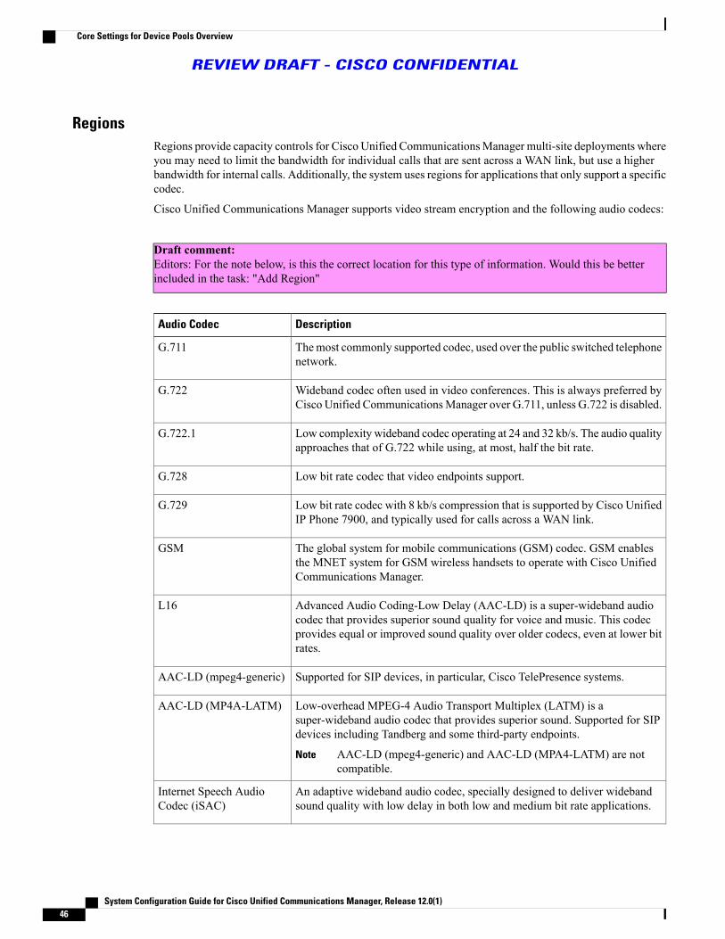
RegionsRegions provide capacity controls for Cisco Unified CommunicationsManager multi-site deployments whereyou may need to limit the bandwidth for individual calls that are sent across a WAN link, but use a higherbandwidth for internal calls. Additionally, the system uses regions for applications that only support a specificcodec.
Cisco Unified Communications Manager supports video stream encryption and the following audio codecs:
Draft comment:Editors: For the note below, is this the correct location for this type of information. Would this be betterincluded in the task: "Add Region"
DescriptionAudio Codec
Themost commonly supported codec, used over the public switched telephonenetwork.
G.711
Wideband codec often used in video conferences. This is always preferred byCisco Unified CommunicationsManager over G.711, unless G.722 is disabled.
G.722
Low complexity wideband codec operating at 24 and 32 kb/s. The audio qualityapproaches that of G.722 while using, at most, half the bit rate.
G.722.1
Low bit rate codec that video endpoints support.G.728
Low bit rate codec with 8 kb/s compression that is supported by Cisco UnifiedIP Phone 7900, and typically used for calls across a WAN link.
G.729
The global system for mobile communications (GSM) codec. GSM enablesthe MNET system for GSM wireless handsets to operate with Cisco UnifiedCommunications Manager.
GSM
Advanced Audio Coding-Low Delay (AAC-LD) is a super-wideband audiocodec that provides superior sound quality for voice and music. This codecprovides equal or improved sound quality over older codecs, even at lower bitrates.
L16
Supported for SIP devices, in particular, Cisco TelePresence systems.AAC-LD (mpeg4-generic)
Low-overhead MPEG-4 Audio Transport Multiplex (LATM) is asuper-wideband audio codec that provides superior sound. Supported for SIPdevices including Tandberg and some third-party endpoints.
AAC-LD (mpeg4-generic) and AAC-LD (MPA4-LATM) are notcompatible.
Note
AAC-LD (MP4A-LATM)
An adaptive wideband audio codec, specially designed to deliver widebandsound quality with low delay in both low and medium bit rate applications.
Internet Speech AudioCodec (iSAC)
System Configuration Guide for Cisco Unified Communications Manager, Release 12.0(1)46
Core Settings for Device Pools Overview
REVIEW DRAFT - CISCO CONFIDENTIAL

DescriptionAudio Codec
Provides audio quality between G.711 and G.729 at bit rates of 15.2 and 13.3kb/s while allowing for graceful speech quality degradation in a lossy networkdue to independently encoded speech frames. iLBC is supported for SIP, SCCP,H323, and MGCP devices.
H.323 Outbound FastStart does not support the iLBCcodec.
Note
Internet Low Bit RateCodec (iLBC)
The required standard codec for 2.5G/3G wireless networks based on GSM(WDMA, EDGE, GPRS). This codec encodes narrowband (200-3400 Hz)signals at variable bit rates ranging from 4.75 to 12.2 kb/s with toll qualityspeech starting at 7.4 kb/s. AMR is supported only for SIP devices.
Adaptive Multi-Rate(AMR)
Codified as G.722.2, an ITU-T standard speech codec formally known asWideband, codes speech at about 16 kb/s. This codec is preferred over othernarrowband speech codecs such as AMR and G.711 because it provides betterspeech quality due to a wider speech bandwidth of 50Hz to 7000Hz. AMR-WBis supported only for SIP devices.
Adaptive Multi-RateWideband (AMR-WB)
Opus codec is an interactive speech and audio codec, specially designed tohandle a wide range of interactive audio applications such as voice over IP,video conferencing, in-game chat, and live distributed music performance.
This codec scales from narrowband low bit rate to a very high quality bit rateranging from 6 to 510 kb/s.
Opus is supported for SIP devices. The Opus codec service parameter OpusCodec Enabled is set to Enabled for All Devices by default. The serviceparameter settings can be configured to Enable Opus codec for allnon-recording devices or can be set to Disabled in the Service ParameterConfiguration window.
The Advertise G.722 Codec service parameter in the EnterpriseParameters Configurationwindow should be set toEnabled for theSIP devices to use Opus codec. For more information on enterpriseparameters, see the System Configuration Guide for Cisco UnifiedCommunications Manager at http://www.cisco.com/c/en/us/td/docs/voice_ip_comm/cucm/admin/11_5_1/sysConfig/CUCM_BK_SE5DAF88_00_cucm-system-configuration-guide-1151.html.
Note
Opus
Unified Communications Manager GroupsDesignature backup Cisco Unified Communications Managers in your system. They handle call processingfor a node in your system that experiences an outage or failure.
A Cisco Unified Communications Manager group is a prioritized list of up to three nodes. Each group mustcontain a primary node, and the group can contain one or two backup nodes. The order in which you list thenodes in a group determines their priority.
Cisco Unified CommunicationsManager groups provide both call-processing redundancy and distributed callprocessing. How you distribute devices, device pools, and the nodes among the groups determines the level
System Configuration Guide for Cisco Unified Communications Manager, Release 12.0(1) 47
Core Settings for Device Pools Overview
REVIEW DRAFT - CISCO CONFIDENTIAL

of redundancy and load balancing in your system. In most cases, you must distribute the devices to preventthe other nodes from becoming overloaded if one of the nodes in the group fails.
Device PoolsUse a device pool to group together device-specific settings. After you create a device pool, you can associatedevices so that they inherit the device pool settings, rather than configuring each device individually.
Add new device pools based on what you want to do with them. For example, you can use device pools thatis configured with server load balancing or physical location in mind.
This section covers the steps to configure a basic device pool. As you configure further functions in yoursystem, you can return to the device pool or pools that you added and update them with the settings that youyou want to apply.
Core Settings for Device Pools Prerequisites
Draft comment: Reviewers: Please let me know if any further prerequisite information needs to be placedin this section? Also is the information currently included here correctly located?
To ensure that Cisco Unified Communications Manager includes the latest time zone information, you caninstall a Cisco Options Package (COP) file that updates the time zone information after you install CiscoUnified CommunicationsManager. After major time zone change events, we will contact you to let you knowthat you can download latest COP file at https://software.cisco.com/download/navigator.html.
Draft comment: Reviewers: Typically it seems that the best practice for this sort of configuration is to notuse the defaults (ex. for device pools, date/timegroups, etc). With that, should we remove this line, becauseit recommends to make changes to the default?
Change the settings for CMLocal to your local date and time.
Core Settings for Device Pools Task Flow
Procedure
PurposeCommand or Action
Configure phone Network Time Protocol (NTP) references to ensurethat an IP phone that is running SIP gets its date and time informationfrom an NTP server.
After you create an NTP reference you must add thereference to a date/time group. In the date/time group, youprioritize the phone NTP references, starting with the firstserver that you want the phone to contact.
Note
Add a Phone NTPReference, on page 49
Step 1
System Configuration Guide for Cisco Unified Communications Manager, Release 12.0(1)48
Core Settings for Device Pools Prerequisites
REVIEW DRAFT - CISCO CONFIDENTIAL

PurposeCommand or Action
Define time zones for the various devices that are connected to yoursystem. After adding a new date/time group to the database, you can
Add a Date/Time Group, onpage 50
Step 2
assign it to a device pool to configure the date and time informationfor that device pool.
Limit the bandwidth for individual calls that are sent across a WANlink while allowing you to use a higher bandwidth for internal calls.
You do not need to configure regions if you are using onlythe default G.711 audio codec.
Tip
Add Region, on page 51Step 3
Configure a Cisco Unified CommunicationsManager Group to grouptogether three nodes that devices can use for registration, callprocessing, and redundancy in the event of an outage.
Configure Cisco UnifiedCommunications ManagerGroups, on page 52
Step 4
Configure device pools to contain common settings that can beassigned to devices, rather than defining the same settings each time
Configure a Basic DevicePool, on page 52
Step 5
you add a device. Start with a basic device pool to configure UnifiedCommunications Managers, date/time information, and the codecsthat the associated devices will use.
Add a Phone NTP ReferenceConfigure phone Network Time Protocol (NTP) references to ensure that an IP phone that is running SIP getsits date and time information from an NTP server.
After you create an NTP reference you must add the reference to a date/time group. In the date/time group,you prioritize the phone NTP references, starting with the first server that you want the phone to contact.
Note
Cisco Unified CommunicationsManager does not support the multicast and anycast modes. If you chooseeither of these modes, your system defaults to the directed broadcast mode.
Note
Before You Begin
Draft comment: A link to the procedure which describes how the ports and other properties for CUCM arespecified.
System Configuration Guide for Cisco Unified Communications Manager, Release 12.0(1) 49
Core Settings for Device Pools Task Flow
REVIEW DRAFT - CISCO CONFIDENTIAL

Procedure
Step 1 From Cisco Unified CM Administration, choose System > Phone NTP Reference.Step 2 Click Add New.Step 3 Enter the NTP server's IPv4 Address or IPv6 Address, depending on which addressing system your phones
use.It is mandatory to enter either IPv4 address or IPv6 address to save the Phone NTP References. Ifyou are deploying both IPv4 phones and IPv6 phones, then provide both the IPv4 address and theIPv6 address for the NTP server.
Note
Step 4 In the Description field, enter a description for the phone NTP reference.Step 5 From theMode drop-down list, choose the mode for the phone NTP reference from the following list of
options:
• Unicast—If you choose this mode, the phone sends an NTP query packet to that particular NTP server.
• Directed Broadcast—If you choose this default NTP mode, the phone accesses date/time informationfrom any NTP server but gives the listed NTP servers (1st = primary, 2nd = secondary) priority.
Step 6 Click Save.
What to Do Next
Add a Date/Time Group, on page 50
Add a Date/Time GroupDefine time zones for the various devices that are connected to your system. After adding a new date/timegroup to the database, you can assign it to a device pool to configure the date and time information for thatdevice pool.
You must reset devices to apply any changes that you make.
For a worldwide distribution of Cisco Unified IP Phones, create a date/time group for each of the 24 timezones.
Tip
Before You Begin
Add a Phone NTP Reference, on page 49
System Configuration Guide for Cisco Unified Communications Manager, Release 12.0(1)50
Core Settings for Device Pools Task Flow
REVIEW DRAFT - CISCO CONFIDENTIAL

Procedure
Step 1 From Cisco Unified CM Administration, choose System > Date/Time Group.Step 2 Click Add New.Step 3 Configure the fields on theDate/TimeGroupConfigurationwindow. See the online help for more information
about the fields and their configuration options.Step 4 Click Save.
What to Do Next
Add Region, on page 51
Add RegionLimit the bandwidth for individual calls that are sent across a WAN link while allowing you to use a higherbandwidth for internal calls.
You do not need to configure regions if you are using only the default G.711 audio codec.Tip
For enhanced scalability and to ensure that the system uses fewer resources, we recommend that you set thedefault values in the Service Parameters Configuration window for the maximum bit rates for audio andvideo calls and the link loss type; then, when you configure regions, choose the default settings in theRegionConfiguration window.
Before You Begin
Add a Date/Time Group, on page 50
Procedure
Step 1 From Cisco Unified CM Administration, choose SystemService Parameters.Step 2 Choose the node.Step 3 Choose the Cisco CallManager service.Step 4 Scroll to the Clusterwide Parameters (System-Location and Region) pane.Step 5 Create regions specifying the maximum bit rates to use for calls within those regions and between other
regions.
• For audio calls, the default value within a region is 64 kb/s (which means that G.722 or G.711 may beused for the call, with G.722 being preferred because it has better audio quality).
• For audio calls, the default value between regions is 8 kb/s (G.729).
• For video calls (includes audio), the default value 384 kb/s.
Cisco Unified Communications Manager allows you to add a maximum of 2000 regions. You mustspecify the maximum bit rate for devices that are using regions.
Note
System Configuration Guide for Cisco Unified Communications Manager, Release 12.0(1) 51
Core Settings for Device Pools Task Flow
REVIEW DRAFT - CISCO CONFIDENTIAL

Step 6 Click Save
What to Do Next
Configure Cisco Unified Communications Manager Groups, on page 52
Configure Cisco Unified Communications Manager GroupsConfigure a Cisco Unified Communications Manager Group to group together three nodes that devices canuse for registration, call processing, and redundancy in the event of an outage.
Do not use the default server group, because it is not descriptive and can cause confusion.Note
Procedure
Step 1 From Cisco Unified CM Administration, choose System > Cisco Unified CM Group.Step 2 In the Name field, enter a name.
Consider identifying the order of the nodes in the name so that you can easily distinguish the group fromothers, for example, CUCM_PUB-SUB.
Step 3 From the Available Cisco Unified Communications Managers list, choose the node that you want to addto this group.
Step 4 Click the down arrow to move the node to the Selected Cisco Unified Communications Managers list.Step 5 Add any other nodes to this group as needed.Step 6 Click Save.
What to Do Next
Configure a Basic Device Pool, on page 52
Configure a Basic Device PoolConfigure device pools to contain common settings that can be assigned to devices, rather than defining thesame settings each time you add a device. Start with a basic device pool to configure Unified CommunicationsManagers, date/time information, and the codecs that the associated devices will use.
Do not use the default device pool, because it is not descriptive and can cause confusion.Note
Before You Begin
• Configure Cisco Unified Communications Manager Groups, on page 52
• Add a Date/Time Group, on page 50
System Configuration Guide for Cisco Unified Communications Manager, Release 12.0(1)52
Core Settings for Device Pools Task Flow
REVIEW DRAFT - CISCO CONFIDENTIAL

• Add Region, on page 51
Procedure
Step 1 From Cisco Unified CM Administration, choose System > Device Pool.Step 2 Click Add New.Step 3 Configure the fields on the Device Pool Configuration window.Step 4 Click Save.
Related Topics
Basic Device Pool Configuration Fields, on page 53
Basic Device Pool Configuration Fields
Table 5: Basic Device Pool Configuration Fields
DescriptionField
Enter the name of the new device pool. You can enter up to 50characters, which include alphanumeric characters, periods (.),hyphens (-), underscores (_), and blank spaces.
Device Pool Name
Choose the Cisco Unified Communications Manager group toassign to devices in this device pool. A Cisco UnifiedCommunications Manager group specifies a prioritized list ofup to three Cisco Unified Communications Manager nodes.The first node in the list serves as the primary node for thatgroup, and the other members of the group serve as backupnodes for redundancy.
Cisco Unified Communications ManagerGroup
Choose the date/time group to assign to devices in this devicepool. The date/time group specifies the time zone and thedisplay formats for date and time.
Date/Time Group
Choose the region to assign to devices in this device pool. Theregion settings specify voice and video codecs that can be usedfor communications within a region and between other regions.
Region
System Configuration Guide for Cisco Unified Communications Manager, Release 12.0(1) 53
Core Settings for Device Pools Task Flow
REVIEW DRAFT - CISCO CONFIDENTIAL

System Configuration Guide for Cisco Unified Communications Manager, Release 12.0(1)54
Core Settings for Device Pools Task Flow
REVIEW DRAFT - CISCO CONFIDENTIAL

P A R T IIIEnable Inbound and Outbound Calling• Inbound Outbound Calling Overview, page 57
• Configure Gateways, page 59
• Configure SIP Normalization and Transparency, page 79
• Configure SDP Transparency Profiles, page 85
• Configure SIP Profiles, page 87
• Configure IPv6 Stack, page 89
• Configure SIP Trunks, page 97
• Configure H.323 Trunks, page 103
• Configure SRST, page 105


C H A P T E R 9Inbound Outbound Calling Overview
• About Inbound and Outbound Calling, page 57
• Inbound and Outbound Calling Task Flow, page 57
About Inbound and Outbound CallingThis part describes how to set up the inbound and outbound calling for your system.
Inbound and Outbound Calling Task Flow
Procedure
PurposeCommand or Action
Add gateways to your system.Configure GatewaysStep 1
Optional. Configure SIP Normalization and transparencyscripts that you can assign to SIP trunks or SIP devices inorder to resolve SIP interoperability issues.
Configure SIP Normalizationand Transparency
Step 2
Optional. If your SIP deployment requires support for SDPattributes that are not natively supported by Cisco Unified
Configure SDP TransparencyProfiles
Step 3
Communications Manager, set up an SDP transparencyprofile that includes the non-supported attributes.
Configure SIP profiles for your SIP trunks and SIP devices.Configure SIP ProfilesStep 4
Optional. If your SIP deployment requires support for IPv6devices, configure dual stack IPv6 support in your system.Dual stack can be configured for SIP deployments only.
Configure IPv6Step 5
Configure SIP trunks for your system.Configure SIP TrunksStep 6
Configure H.323 trunks for your system.Configure H.323 TrunksStep 7
System Configuration Guide for Cisco Unified Communications Manager, Release 12.0(1) 57

PurposeCommand or Action
Configure your system for SRST.Configure SRSTStep 8
System Configuration Guide for Cisco Unified Communications Manager, Release 12.0(1)58
Inbound and Outbound Calling Task Flow
REVIEW DRAFT - CISCO CONFIDENTIAL

C H A P T E R 10Configure Gateways
• Gateway Overview, page 59
• Gateway Setup Prerequisites, page 61
• Gateway Configuration Task Flow, page 62
Gateway OverviewCisco offers a wide variety of voice and video gateways. A gateway provides interfaces that allow the UnifiedCommunications network to communicate with an external network. Traditionally, gateways have been usedto connect the IP-based Unified Communications network to legacy telephone interfaces such as the PSTN,a private branch exchange (PBX), or legacy devices such as an analog phone or fax machine. In its simplestform, a voice gateway has an IP interface and a legacy telephony interface, and the gateway translates messagesbetween the two networks so that the two networks can communicate.
Gateway Protocols
Most Cisco gateways offer multiple deployment options and can be deployed using any one of a number ofprotocols. Depending on the gateway that you want to deploy, your gateway may be configurable using anyof the following communication protocols:
• Media Gateway Control Protocol (MGCP)
• Skinny Call Control Policy (SCCP)
• Session Initiation Protocol (SIP)
• H.323
Vendor Interface Cards
The Vendor Interface Card (VIC) must be installed on the gateway to provide a connection interface forexternal networks. Most gateways offer multiple VIC options and each VIC may offer many different portsand connection types for both analog and digital connections.
Refer to your gateway documentation for the protocols, cards, and connections that are offered with yourgateway.
System Configuration Guide for Cisco Unified Communications Manager, Release 12.0(1) 59

Port and Trunk Connection TypesFollowing are the main types of port connections that you can configure on gateways:
• Foreign Exchange Station (FXS)—FXS ports offer connections to analog stations such as an analogphone, speakerphone, or legacy voicemail system.
• Foreign Exchange Office (FXO)—FXO ports offer analog connections to the PSTN or a legacy PBX.
• T1Channel Assocatied Signaling (T1/E1 CAS)—T1/E1 CAS connections offer digital trunk connectionsto a central office, PBX, or other analog device.
• Primary Rate Interface (T1/E1 PRI)—Digital access PRI connections are widely used in corporatecommunications. T1 PRI is widely used in North America and Japan and offers 23 B-channels for voiceand data and one D-channel for common channel signaling at a rate of 1.544 Mb/s. E1 is widely usedin Europe, offering 30 B-channels for voice and data, one D-channel for common signaling, and oneframing channel. E1 uses of rate of 2.048 Mb/s.
• Basic Rate Interface (BRI)—BRI is a digital telephony protocol, which is used for small office and homecommunications links, provides two B-channels for voice and data and one D-channel for signaling.
Connection Types per Protocol
MGCP gateways offer the following connection types:
• TI/E1 PRI Digital access
• T1 CAS
• BRI
• FXO
• FXS
Draft comment: Can you connect a J1 connection directly to a MGCP GW? There is no J1 config option,but the J1 documentation says it supports MGCP.
SCCP gateways offer the following connection types:
• FXS
• BRI
SIP gateways offer the following connections:
• FXS
• FXS-DID
• E&M
• BRI
• BRI QSIG
System Configuration Guide for Cisco Unified Communications Manager, Release 12.0(1)60
Gateway Overview
REVIEW DRAFT - CISCO CONFIDENTIAL

• T1 CAS
• T1 FGD
• E1 CAS
• T1/E1 PRI
• T1/E1 QSIG
• T1/E1 NFAS
• T1/E1 PRI (MegacomISDN)
• Centralized Automatic Message Accounting (CAMA)
• J1
H.323 gateways offer the following connection types:
• FXS
• FXS-DID
• E&M
• BRI
• BRI QSIG
• T1 CAS
• T1 FGD
• E1 CAS
• T1/E1 PRI
• T1/E1 QSIG
• T1/E1 NFAS
• T1/E1 PRI (MegacomISDN)
• Centralized Automatic Message Accounting (CAMA)
• J1
Gateway Setup Prerequisites
Install the Hardware
Before you configure the gateway in Cisco Unified CommunicationsManager, youmust perform the followingtasks on your gateway hardware:
• Install and configure the gateway
• Install any vendor interface cards (VICs) on the gateway.
• Use the CLI to configure IOS on the gateway.
System Configuration Guide for Cisco Unified Communications Manager, Release 12.0(1) 61
Gateway Setup Prerequisites
REVIEW DRAFT - CISCO CONFIDENTIAL

For details, refer to the hardware and software documentation that comes with your gateway.
To get to the default web pages for many gateway devices, you can use the IP address of that gateway.Make your hyperlink url = http://x.x.x.x/, where x.x.x.x is the dot-form IP address of the device. The webpage for each gateway contains device information and the real-time status of the gateway.
Note
Plan the Gateway Deployment
Before configuring the gateway in Cisco Unified Communications Manager, make sure that you adequatelyplan the types of connections that you want to configure on the gateway. Many gateways can be configuredusing any one of MGCP, SIP, H.323, or SCCP as the gateway protocol. The connection types for each typeof deployment vary according to the protocol that you choose and the VICs that are installed on the gateway.Be sure to understand the following:
•Which gateway protocols does your gateway support.
•What types of port connections the VICs on the gateway support.
•What types of connections are you planning on configuring?
• For analog connections, are you connecting to the PSTN, legacy PBX, or to legacy devices.
• For digital access connections, are you connecting to a T1 CAS interface, or to a PRI interface?
• For FXO connections, how do you want to direct incoming calls? Are you directing incoming calls toan automated IVR or to an attendant?
Gateway Configuration Task FlowPerform the following tasks to add your network gateways to Cisco Unified Communications Manager.
Before You Begin
Review the Gateway Setup Prerequisites, on page 61.
Procedure
PurposeCommand or Action
Many Cisco gateways can be deployed using any one ofMGCP, SCCP, SIP, or H.323 as the gateway protocol. Review
Configure your gateways in CiscoUnified Communications Manager.
Step 1
your gateway documentation to determine which protocolsPerform any of the followingyour gateway supports and which protocol is best for yourdeployment.
procedures depending on the protocolthat you wan to deploy:
SCCP gateways can connect only to analog access or ISDNBRI connections.
• Configure MGCP Gateway, onpage 63
• Configure SCCP Gateway, onpage 71
System Configuration Guide for Cisco Unified Communications Manager, Release 12.0(1)62
Gateway Configuration Task Flow
REVIEW DRAFT - CISCO CONFIDENTIAL

PurposeCommand or Action
• Configure SIP Gateway, on page72
• Configure H.323 Gateway, onpage 75
Optional. Configure a clusterwide service parameter toclassify all calls coming from the gateway ports in yournetwork to be internal (OnNet) or external (OffNet).
Configure Clusterwide CallClassification for Gateway, on page75
Step 2
The call classification setting in the PortConfiguration for individual gateway port interfacesoverrides the clusterwide setting. However, thedefault setting for gateway ports is to use the settingfrom the clusterwide service parameter.
Note
Optional. If youwant to block CiscoUnified CommunicationsManager from transferring calls from one external (OffNet)
Block OffNet Gateway Transfers, onpage 76
Step 3
gateway to another external gateway, configure the BlockOffNet to Offnet Transfer service parameter. By default,this service parameter is configured to allow transfers fromone external (OffNet) gateway to another.
Configure MGCP GatewayPerform the following tasks to configure a Cisco gateway to use an MGCP configuration.
Before You Begin
Gateway Setup Prerequisites, on page 61
Procedure
PurposeCommand or Action
Add the gateway in Cisco Unified CMAdministrationand chooseMGCP as the gateway protocol. Configure
Configure MGCP (IOS) Gateway, on page64
Step 1
the gateway with the appropriate slots and vendorinterface cards (VICs).
Configure the port connections for the devices thatconnect to the VICs that are installed on the gateway.Draft comment: Is it more accurate to
describe this as a port interface or a trunk
Step 2
Most VICs include multiple port connections andoptions so you may have to configure a few differentport interface types.interface? For example, FXO port interface
or FXO trunk?
System Configuration Guide for Cisco Unified Communications Manager, Release 12.0(1) 63
Gateway Configuration Task Flow
REVIEW DRAFT - CISCO CONFIDENTIAL

PurposeCommand or Action
After you configure a port interface, from theRelated Links drop-down list box, select theBack to MGCP Configuration option toreturn to theGatewayConfigurationwindow,where you can select and configure anotherport interface.
Tip
Configure the gateway port interface. Selectany of the following tasks, depending on thetype of interface that you want to configure:
• Configure Digital Access PRI Ports,on page 69
• Configure Digital Access T1 Ports forMGCP Gateway, on page 67
• Configure FXS Ports, on page 65
• Configure FXO Ports, on page 66
• Configure BRI Ports, on page 70
Optional. If you have configured a digital access T1CAS port interface, add T1 CAS ports to the gateway.
Add Digital Access T1 Ports for MGCPGateway, on page 68
Step 3
You can add ports on an individual basis or add arange of ports simultaneously.
The configuration changes take effect after you resetthe gateway
Reset Gateway, on page 71Step 4
Related Topics
Configure Call Routing
Configure MGCP (IOS) Gateway
Perform the following procedure to add and configure an MGCP (IOS) gateway on Cisco UnifiedCommunications Manager.
Procedure
Step 1 From Cisco Unified CM Administration, choose Device > Gateway.Step 2 Click Add New.Step 3 From the Gateway Type drop-down list box, select the gateway and click Next.Step 4 From the Protocol drop-down list box, chooseMGCP and click Next.Step 5 In the Configured Slots, VICs and Endpoints area, perform the following steps:
a) From eachModule drop-down list box, select the slot that corresponds to the Network Interface Modulehardware that is installed on the gateway.
b) From each Subunit drop-down list box, select the VIC that is installed on the gateway.c) Click Save.
System Configuration Guide for Cisco Unified Communications Manager, Release 12.0(1)64
Gateway Configuration Task Flow
REVIEW DRAFT - CISCO CONFIDENTIAL

The port icons appear. Each port icon corresponds to an available port interface on the gateway. You canconfigure any port interface by clicking the corresponding port icon.
Step 6 Complete the remaining fields in theGateway Configurationwindow. For help with the fields, see the onlinehelp.
Step 7 Click Save.
What to Do Next
Configure the port interface for the gateway:
• Configure FXS Ports, on page 65
• Configure FXO Ports, on page 66
• Configure Digital Access PRI Ports, on page 69
• Configure Digital Access T1 Ports for MGCP Gateway, on page 67
• Configure BRI Ports, on page 70
Configure FXS Ports
Configure Foreign Exchange Station (FXS) ports on an MGCP gateway. You can use FXS ports to connectthe gateway to a Plain Old Telephone Service (POTS) legacy phone or to another legacy device such as a faxmachine, speakerphone, legacy voice-messaging system, or IVR.
Before You Begin
You must add a gateway before configuring ports.
Procedure
Step 1 In the Cisco Unified CM Administration, choose Device > Gateway.Step 2 Click Find and select the gateway on which you want to configure FXS ports.Step 3 In the Configured Slots, VICs, and Endpoints area, click the FXS port icon for the port that you want to
configure.The Port Selection area displays.
Step 4 From the Port Type drop-down list box, choose the type of connection that you want to configure:
• POTS—choose this option if you want to connect this port to a POTS device such as a legacy phone.
• Ground Start—choose this option if you want to use ground start signaling to connect this port to anunattended legacy device such as a fax machine, legacy voice-messaging system, or IVR.
• Loop Start—choose this option if youwant to use loop start signaling to connect this port to an unattendedlegacy device such as a fax machine, legacy voice-messaging system, or IVR.
Step 5 Click Next.
System Configuration Guide for Cisco Unified Communications Manager, Release 12.0(1) 65
Gateway Configuration Task Flow
REVIEW DRAFT - CISCO CONFIDENTIAL

The Port Configuration window displays the configuration for the port interface with analog access as thedevice protocol.
Step 6 From the Device Pool drop-down list box, select a device pool.Step 7 Complete the remaining fields in thePort Configurationwindow. Refer to the online help for field descriptions.Step 8 Click Save.Step 9 Optional. To configure additional port interfaces on the MGCP IOS gateway, from the Related Links
drop-down list box, select Back to Gateway and click Go.The Gateway Configuration window displays the available ports for the gateway.
What to Do Next
To configure additional ports:
• Configure FXS Ports, on page 65
• Configure FXO Ports, on page 66
• Configure Digital Access PRI Ports, on page 69
• Configure Digital Access T1 Ports for MGCP Gateway, on page 67
• Configure BRI Ports, on page 70
If you are done configuring ports:
• Reset Gateway, on page 71
Configure FXO Ports
Configure Foreign Exchange Office (FXO) ports on an MGCP (IOS) gateway. You can use FXO ports toconnect the gateway to the PSTN or a legacy PBX.
Cisco Unified CommunicationsManager assumes all loop-start trunks lack positive disconnect supervision.Configure trunks with positive disconnect supervision as ground start, so active calls can be maintainedduring a server failover.
Note
Before You Begin
Configure MGCP (IOS) Gateway, on page 64
Procedure
Step 1 In Cisco Unified CM Administration, choose Device > Gateway.Step 2 Click Find and select the gateway for which you want to configure FXO ports.Step 3 From the Configured Slots, VICs, and Endpoints area, locate theModule and Subunit that contain the
FXO port on which you want to set up an FXO port interface and click the port icon for the port that you wantto configure.
Step 4 From the Port Type drop-down list, select either Ground-Start or Loop-Start.
System Configuration Guide for Cisco Unified Communications Manager, Release 12.0(1)66
Gateway Configuration Task Flow
REVIEW DRAFT - CISCO CONFIDENTIAL

If you are configuring the VIC-2 FXO port, you must select the same port type for both ports of thesubunit module.
Note
Step 5 From the Device Pool drop-down list box, select a device pool.Step 6 In the Attendant DN text box, enter the directory number to which you want to route all incoming calls from
this port connection. For example, a zero or the directory number for an attendant.Step 7 Complete any remaining fields in the Port Configuration window. Refer to the online help for field
descriptions.Step 8 Click Save.Step 9 Optional. To configure additional port interfaces on the MGCP IOS gateway, from the Related Links
drop-down list box, select Back to Gateway and click Go.The Gateway Configuration window displays the available ports for the gateway.
What to Do Next
To configure additional ports:
• Configure FXS Ports, on page 65
• Configure FXO Ports, on page 66
• Configure Digital Access PRI Ports, on page 69
• Configure Digital Access T1 Ports for MGCP Gateway, on page 67
• Configure BRI Ports, on page 70
If you are done configuring ports:
• Reset Gateway, on page 71
Configure Digital Access T1 Ports for MGCP Gateway
Configure the port interface for digital access T1 CAS ports on an MGCP (IOS) gateway.
Before You Begin
Configure MGCP (IOS) Gateway, on page 64
Procedure
Step 1 From Cisco Unified CM Administration, choose Device > Gateway.Step 2 Click Find and select the gateway on which you want to configure a T1 port.Step 3 In the Configured Slots, VICs and Endpoints area, locate the module and subunit on which you want to set
up a Digital Access T1 (T1-CAS) port and click the corresponding port icon.Step 4 From the Device Protocol drop-down list box, choose Digital Access T1 and click Next.Step 5 Enter the appropriate gateway configuration settings. See the online help for more information about the fields
and their configuration options.Step 6 Click Save.
System Configuration Guide for Cisco Unified Communications Manager, Release 12.0(1) 67
Gateway Configuration Task Flow
REVIEW DRAFT - CISCO CONFIDENTIAL
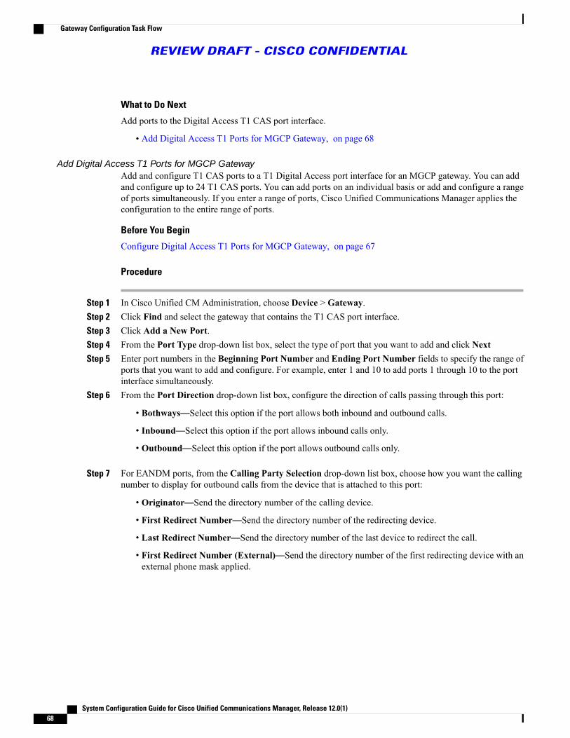
What to Do Next
Add ports to the Digital Access T1 CAS port interface.
• Add Digital Access T1 Ports for MGCP Gateway, on page 68
Add Digital Access T1 Ports for MGCP GatewayAdd and configure T1 CAS ports to a T1 Digital Access port interface for an MGCP gateway. You can addand configure up to 24 T1 CAS ports. You can add ports on an individual basis or add and configure a rangeof ports simultaneously. If you enter a range of ports, Cisco Unified Communications Manager applies theconfiguration to the entire range of ports.
Before You Begin
Configure Digital Access T1 Ports for MGCP Gateway, on page 67
Procedure
Step 1 In Cisco Unified CM Administration, choose Device > Gateway.Step 2 Click Find and select the gateway that contains the T1 CAS port interface.Step 3 Click Add a New Port.Step 4 From the Port Type drop-down list box, select the type of port that you want to add and click NextStep 5 Enter port numbers in the Beginning Port Number and Ending Port Number fields to specify the range of
ports that you want to add and configure. For example, enter 1 and 10 to add ports 1 through 10 to the portinterface simultaneously.
Step 6 From the Port Direction drop-down list box, configure the direction of calls passing through this port:
• Bothways—Select this option if the port allows both inbound and outbound calls.
• Inbound—Select this option if the port allows inbound calls only.
• Outbound—Select this option if the port allows outbound calls only.
Step 7 For EANDM ports, from the Calling Party Selection drop-down list box, choose how you want the callingnumber to display for outbound calls from the device that is attached to this port:
• Originator—Send the directory number of the calling device.
• First Redirect Number—Send the directory number of the redirecting device.
• Last Redirect Number—Send the directory number of the last device to redirect the call.
• First Redirect Number (External)—Send the directory number of the first redirecting device with anexternal phone mask applied.
System Configuration Guide for Cisco Unified Communications Manager, Release 12.0(1)68
Gateway Configuration Task Flow
REVIEW DRAFT - CISCO CONFIDENTIAL

• Last Redirect Number (External)—Send the directory number of the last redirecting device with theexternal phone mask applied.
Step 8 Click Save.Step 9 Optional. If you want to configure additional ports for the MGCP gateway, from Related Links select Back
to Gateway and clickGo. When the Digital Access T1 port interface appears, perform either of the followingsteps:
• If you want to add additional Digital Access T1 CAS ports to this port interface, return to step 3 of thisprocedure.
• If you want to configure additional port interfaces on the gateway, from Related Links select Back toMGCPConfiguration and clickGo. TheGateway Configurationwindow displays the available portsfor the gateway subunit modules.
What to Do Next
If you want to configure additional port interfaces on the gateway:
• Configure FXS Ports, on page 65
• Configure FXO Ports, on page 66
• Configure Digital Access T1 Ports for MGCP Gateway, on page 67
• Configure Digital Access PRI Ports, on page 69
• Configure BRI Ports, on page 70
If you have completed the port configuration:
• Reset Gateway, on page 71
Configure Digital Access PRI Ports
Configure the PRI port interface for an MGCP (IOS) gateway.
Before You Begin
Configure MGCP (IOS) Gateway, on page 64
Procedure
Step 1 In the Cisco Unified CM Administration, choose Device > Gateway.Step 2 Click Find and select the gateway on which you want to configure PRI ports.Step 3 In the Configured Slots, VICs, and Endpoints area, locate the Module and subunit that contains the BRI
port that you want to configure and click the port icon that corresponds to the BRI port that you want toconfigure.
System Configuration Guide for Cisco Unified Communications Manager, Release 12.0(1) 69
Gateway Configuration Task Flow
REVIEW DRAFT - CISCO CONFIDENTIAL

The Gateway Configuration window displays the BRI port interface.Step 4 From the Device Pool drop-down list box, select a device pool.Step 5 Complete the remaining fields in the Gateway Configuration window. Refer to the online help for field
descriptions.Step 6 Click Save.Step 7 Optional. If you want to configure additional port interfaces for the gateway, from theRelated Links drop-down
list box, choose Back to MGCP Configuration and click Go.The Gateway Configuration window displays the available port interfaces for the gateway.
What to Do Next
If you want to configure additional port interfaces:
• Configure FXS Ports, on page 65
◦Configure FXO Ports, on page 66
• Configure Digital Access T1 Ports for MGCP Gateway, on page 67
• Configure BRI Ports, on page 70
If you are done configuring ports:
• Reset Gateway, on page 71
Configure BRI Ports
Configure a BRI port interface for an MGCP (IOS) gateway.
Before You Begin
Configure MGCP (IOS) Gateway, on page 64
Procedure
Step 1 In the Cisco Unified CM Administration, choose Device > Gateway.Step 2 ClickFind and select the gateway on which you want to configure BRI ports.Step 3 In the Configured Slots, VICs, and Endpoints section, locate the subunit that uses BRI ports and click the
port icon for the port that you want to configure.The Gateway Configuration window displays the information for the BRI port interface.
Step 4 From the Device Pool drop-down list box, select a device pool.Step 5 Enter the appropriate Gateway Information and Port Information settings. See the online help for more
information about the fields and their configuration options.Step 6 Click Save.Step 7 Optional. If you want to configure additional port interfaces for the gateway, from theRelated Links drop-down
list box, choose Back to MGCP Configuration and click Go.The Gateway Configuration window appears displays the available port interfaces for the MGCP gateway.
System Configuration Guide for Cisco Unified Communications Manager, Release 12.0(1)70
Gateway Configuration Task Flow
REVIEW DRAFT - CISCO CONFIDENTIAL

What to Do Next
To configure additional ports on the gateway, perform any of the following procedures:
• Configure FXS Ports, on page 65
• Configure FXO Ports, on page 66
• Configure Digital Access T1 Ports for MGCP Gateway, on page 67
• Configure Digital Access PRI Ports, on page 69
If you are done configuring ports:
• Reset Gateway, on page 71
Reset Gateway
Draft comment: Question for reviewers: You can also restart gateways, or apply configuration. Are thereguidelines for when you would choose one or the other?
Most gateways need to be reset for configuration changes to take effect. We recommend that you completeall necessary gateway configuration before performing a reset.
Resetting an H.323 gateway only reinitializes the configuration that Cisco Unified CommunicationsManager loaded and does not physically restart or reset the gateway.
Note
Procedure
Step 1 From Cisco Unified CM Administration, choose Device > Gateway.Step 2 Click Find and select the gateway.Step 3 Click the check box beside the gateway that you want to reset and click Reset Selected. The Device Reset
dialog box appears. Do one of the following actions:Step 4 Click Reset.
Configure SCCP GatewayConfigure a Cisco gateway to use SCCP as the gateway protocol. You can use this deployment option toconnect Cisco Unified Communications Manager to analog access devices or ISDN BRI devices using FXSor BRI ports. You cannot connect an SCCP gateway to digital access T1 or E1 trunks.
System Configuration Guide for Cisco Unified Communications Manager, Release 12.0(1) 71
Gateway Configuration Task Flow
REVIEW DRAFT - CISCO CONFIDENTIAL

Procedure
Step 1 From Cisco Unified CM Administration, choose Device > Gateway.Step 2 Click Add New.Step 3 From the Gateway Type drop-down list box, choose a gateway that uses SCCP and click Next.Step 4 From the Protocol drop-down list box, choose SCCP.Step 5 In the Configured Slots, VICs and Subunits area, perform the following steps:
a) For eachModule drop-down list box, select the slot that corresponds to the Network Interface Modulehardware that is installed on the gateway
b) For each Subunit, select the VIC that is installed on the gateway.
Step 6 Complete the remaining fields in the Gateway Configuration window. Refer to the online help for fielddescriptions.
Step 7 Click SaveThe port icons appear alongside the subunit modules. Each port icon corresponds to a configurable portinterface on the gateway. You can configure an analog access or ISDN BRI phone on a port by clicking thecorresponding port icon.
Step 8 Once your updates are complete, apply the changes to the gateway by performing the following steps:a) Click Reset Gateway. The Restart Gateway popup appears.b) Click Reset.
What to Do Next
Draft comment: Question for reviewers: Is it Best Practices that the ISDNBRI phone or analog access phoneat this time in the process? Procedures for both of these will be added later in the book (under configureEndpoints)
Related Topics
Configure Call RoutingConfigure Analog Access PhoneConfigure ISDN BRI Phone
Configure SIP GatewayPerform the following tasks to configure a SIP gateway in Cisco Unified Communications Manager. ManyCisco gateways and third-party gateways can be configured to use SIP. Please note that Cisco UnifiedCommunications Manager does not contain a gateway device type for SIP gateways.
Before You Begin
You must install the gateway hardware in your network and configure the IOS software on the gateway beforeyou add the gateway in Cisco Unified Communications Manager. For additional information, review thegateway prerequisites:
System Configuration Guide for Cisco Unified Communications Manager, Release 12.0(1)72
Gateway Configuration Task Flow
REVIEW DRAFT - CISCO CONFIDENTIAL

• Gateway Setup Prerequisites, on page 61
Procedure
PurposeCommand or Action
Configure SIP settings and apply them to a SIP profile that beused by the trunk that connects to the SIP gateway.
Configure SIP ProfileStep 1
Configure a SIP Trunk Security Profile to be used by the trunkthat connects to the SIP gateway. You can configure security
Configure SIP Trunk SecurityProfile, on page 73
Step 2
settings, such as device security mode, digest authentication,and incoming/outgoing transport type settings.
Configure a SIP trunk that points to the SIP gateway. Applythe SIP Profile and the SIP Trunk Security Profile to the SIPtrunk.
Configure SIP Trunk for SIPGateway, on page 74
Step 3
Related Topics
Configure Call Routing
Configure SIP Profile
Configure a SIP Profile for your SIP gateway connection.
Procedure
Step 1 From Cisco Unified CM Administration, choose Device > Device Settings > SIP Profile.Step 2 Perform either of the following steps:
• To create a new profile, click Add New.
• To select an existing profile, click Find and select a SIP profile.
Step 3 Complete the fields in the SIP Profile Configuration window. For help with the fields, refer to the onlinehelp.
Step 4 Click Save.
Configure SIP Trunk Security Profile
Configure a SIP trunk security profile with security settings for a trunk that connects to a SIP gateway.
Before You Begin
Configure SIP Profile
System Configuration Guide for Cisco Unified Communications Manager, Release 12.0(1) 73
Gateway Configuration Task Flow
REVIEW DRAFT - CISCO CONFIDENTIAL

Procedure
Step 1 In Cisco Unified CM Administration, choose System > Security > SIP Trunk Security Profile.Step 2 Perform either of the following steps:
a) To select an existing profile, click Find and select an existing profile.b) To create a new profile, click Add New.
Step 3 Complete the fields in the SIP Trunk Security Profile Configurationwindow. For detailed field descriptions,refer to the online help.
Step 4 Click Save
What to Do Next
Configure SIP Trunk for SIP Gateway, on page 74
Configure SIP Trunk for SIP Gateway
Configure a SIP trunk to connect Cisco Unified Communications Manager to a Cisco or third party gatewaythat uses SIP. Under this configuration, you don't have to enter the gateway as a device in the GatewayConfiguration window.
Before You Begin
Configure SIP Trunk Security Profile, on page 73
Procedure
Step 1 From Cisco Unified CM Administration, choose Device > Trunk.Step 2 Click Add New to set up a new SIP trunk.Step 3 From the Trunk Type drop-down list box choose SIP Trunk.Step 4 From the Protocol drop-down list box, choose None.Step 5 In the Destination Address field of the SIP Information pane, enter an IP address, fully qualified domain
name, or DNS SRV record for the SIP gateway.Step 6 From the SIP Trunk Security Profile drop-down list box, choose the SIP trunk security profile that you
configured for this gateway.Step 7 From the SIP Profile drop-down list box, choose the SIP profile that you configured for this gateway.Step 8 Complete the fields in the SIP Trunk Configuration window. Refer to the online help for field descriptions.Step 9 Click Save.
Related Topics
Configure Call Routing
System Configuration Guide for Cisco Unified Communications Manager, Release 12.0(1)74
Gateway Configuration Task Flow
REVIEW DRAFT - CISCO CONFIDENTIAL

Configure H.323 GatewayConfigure an H.323 gateway in Cisco Unified Communications Manager for a non-gatekeeper H.323deployment.
If your deployment includes H.323 gatekeepers, you can also add an H.323 gateway by setting up agatekeeper-controlled H.225 trunk. This scenario is not documented in this guide because gatekeeperusage has been in steady decline recent years. If you want to configure gatekeepers and H.225gatekeeper-controlled trunks, refer to theCisco Unified Communications Manager Administration Guide,Release 10.0(1).
Note
After a gateway is registered with Cisco Unified Communications Manager, gateway registration statusmay display in Cisco Unified Communications Manager Administration as unknown.
Draft comment: *Question for reviewers: what are customers supposed to do if they see "unknown" inthe status? Is there a way to confirm that the registration has been successful? Is this note useful to admins?
Note
Procedure
Step 1 From Cisco Unified CM Administration, choose Device > Gateway.Step 2 Click Add New.Step 3 From the Gateway Type drop-down list box, choose H.323 Gateway.Step 4 In the Device Name field, enter the IP address or hostname of the gateway.Step 5 If you want to use H.235 to configure a secure channel, check the H.235 Data Passthrough check box.Step 6 Configure the fields in the Gateway Configuration window.
See the online help for more information about the fields and their configuration options.
Step 7 Click Save.Step 8 Click Reset to reset the gateway and apply the changes.
Most gateways need to be reset for configuration changes to take affect. We recommend that you completeall necessary gateway configuration before performing a reset.
Related Topics
Configure Call Routing
Configure Clusterwide Call Classification for GatewayConfigure the Call Classification setting for your network gateways. This setting determines whether thesystem considers the gateways in the network to be internal (OnNet) or external (OffNet).
System Configuration Guide for Cisco Unified Communications Manager, Release 12.0(1) 75
Gateway Configuration Task Flow
REVIEW DRAFT - CISCO CONFIDENTIAL

TheCall Classification field also appears in the configuration window for individual gateway port interfaces.By default, each gateway port interface is configured to use the setting from the clusterwide service parameter.However, if Call Classfication on a port is configured differently from the clusterwide service parameter,the setting on that port overrides the service parameter setting.
Procedure
Step 1 From Cisco Unified CM Administration, choose System > Service Parameters.Step 2 From the Server drop-down list box, choose the server on which the Cisco CallManager service is running.Step 3 From the Service drop-down list box, choose Cisco CallManager.Step 4 Under Clusterwide Parameters (Device - General), configure one of the following values for the Call
Classification service parameter.
• OnNet—Calls from this gateway are classified as originating from inside the company network.
• OffNet—Calls from this gateway are classified as originating from outside the company network.
Step 5 Click Save.
What to Do Next
Block OffNet Gateway Transfers, on page 76
Block OffNet Gateway TransfersUse this procedure if you want to configure the system to block calls from being transferred from one external(OffNet) gateway to another external (OffNet) gateway. By default, the system allows transfers from oneexternal gateway to another external gateway.
The setting that determines whether a gateway is external (OffNet) or internal (OnNet) is determined by theCall Classification setting. This field can be configured using a clusterwide service parameter, or by configuringany of the following port interfaces:
• MGCP T1/E1 port interfaces
• MGCP FXO port interface
• H.323 gateways
• SIP trunks
Before You Begin
Configure Clusterwide Call Classification for Gateway, on page 75
System Configuration Guide for Cisco Unified Communications Manager, Release 12.0(1)76
Gateway Configuration Task Flow
REVIEW DRAFT - CISCO CONFIDENTIAL

Procedure
Step 1 From Cisco Unified CM Administration, choose System > Service Parameters.Step 2 From the Server drop-down list box, choose the server on which the Cisco CallManager service is running.Step 3 From the Service drop-down list box, choose Cisco CallManager.Step 4 Configure a setting for the Block OffNet to Offnet Transfer service parameter:
• True—Select this option to prohibit transfers between two external (OffNet) gateways.
• False—Select this option to allow transfers between two external (OffNet) gateways. This is the defaultoption.
Step 5 Click Save.You can also classify calls through a gateway as OnNet or OffNet by associating the gateway to aroute pattern and configuring Call Classification in the Route Pattern Configuration window.
Note
System Configuration Guide for Cisco Unified Communications Manager, Release 12.0(1) 77
Gateway Configuration Task Flow
REVIEW DRAFT - CISCO CONFIDENTIAL

System Configuration Guide for Cisco Unified Communications Manager, Release 12.0(1)78
Gateway Configuration Task Flow
REVIEW DRAFT - CISCO CONFIDENTIAL

C H A P T E R 11Configure SIP Normalization and Transparency
• SIP Normalization and Transparency Overview, page 79
• SIP Normalization and Transparency Prerequisites, page 80
• SIP Normalization and Transparency Configuration Task Flow, page 81
SIP Normalization and Transparency OverviewSIP normalization and transparency is an optional feature that handles SIP interoperability issues betweenCiscoUnified CommunicationsManager and endpoints, service providers, PBXs, or gateways that implementSIP differently. To configure SIP normalization and transparency, apply a customized lua script to a SIP trunkor SIP line. Cisco Unified Communications Manager applies the script to the SIP messaging that passesthrough the SIP trunks or SIP lines.
Upon installation Cisco Unified Communications Manager contains default normalization and transparencyscripts that you can assign to the SIP trunks and SIP profiles in your system. You can also create and importyour own customized scripts.
SIP Normalization
SIP normalization scripts modify incoming and outgoing SIP messages. For example, if you are interoperatingCisco Unified Communications Manager with a Cisco TelePresence Video Communications Server, applythe vcs-interop script to the SIP trunk that connects the two. The script resolves the differences in the SIPmessaging so that the two products can communicate.
You can apply a normalization script to any SIP trunk connection, regardless of which protocol is being usedby the endpoint that connects to that SIP trunk.
SIP Transparency
SIP transparency scripts enable Cisco Unified CommunicationsManager to transparently pass SIP information,such as proprietary headers, from one call leg to the other. For transparency to work, both call legs must beSIP.
Another feature of SIP transparency is REFER transparency, which allows Cisco Unified CommunicationsManager to pass on REFER requests without acting on them. You can use REFER transparency in call centerenvironments where a centralized agent may answer a call and then transfer the call to an agent who resides
System Configuration Guide for Cisco Unified Communications Manager, Release 12.0(1) 79

in the same geographical area as the caller. REFER transparency allows the centralized Cisco UnifiedCommunications Manager to drop the call and shift call control to the new agent.
Default Scripts for SIP Normalization and TransparencyUpon installation, Cisco Unified Communications Manager contains the following default scripts for SIPNormalization and Transparency. You can apply these scripts to a SIP trunk or SIP profile, but you cannotedit these scripts:
• HCS-PCV-PAI passthrough—Provides Cisco HCS platform integration with Enterprise IMS.
• cisco-telepresence-conductor-interop—Provides interoperability for endpoints registered to TelePresenceConductor.
• cisco-telepresence-mcu-ts-direct-interop—Provides interoperability between Cisco UnifiedCommunications Manager and either Cisco TelePresence MCU or Cisco TelePresence Server.
• cisco-meeting-server-interop— Provides interoperability between Cisco Unified CommunicationsManager and Cisco Meeting Server (CMS).
• diversion-counter—Provides capability to adjust the diversion counter.
• refer-passthrough—Removes Cisco Unified Communications Manager from the call due to a blindtransfer between SIP trunks.
• vcs-interop—Provides interoperability for endpoints that are registered to the Cisco TelePresence VideoCommunications Server.
SIP Normalization and Transparency PrerequisitesReview the following prerequisites before configuring SIP Normalization and Transparency:
• Make sure that you understand how the SIP devices that you are deploying implement SIP. For example,if you are interoperating Cisco Unified Communications Manager with a Cisco TelePresence VideoCommunications Server, you must apply the vcs-interop script to the SIP trunk that connects the twoproducts.
• Review the default scripts and verify if they meet your needs. For details, see Default Scripts for SIPNormalization and Transparency, on page 80.
• If you plan to interoperate Cisco Unified CommunicationsManager with a third-party SIP product, makesure that you understand how the third-party product implements SIP so that you know whether youneed to create a custom script.
• If you plan to develop your own custom scripts, review theDeveloper Guide for SIP Normalization andTransparency at http://www.cisco.com/c/en/us/support/unified-communications/unified-communications-manager-callmanager/products-programming-reference-guides-list.html.
System Configuration Guide for Cisco Unified Communications Manager, Release 12.0(1)80
SIP Normalization and Transparency Prerequisites
REVIEW DRAFT - CISCO CONFIDENTIAL

SIP Normalization and Transparency Configuration Task Flow
Procedure
PurposeCommand or Action
Optional. If none of the preinstalled scripts meet your needs,use this procedure to configure a customized script. You can
Create New SIP Normalization andTransparency Scripts, on page 81
Step 1
create your new script in the SIP Normalization ScriptConfigurationwindow or you can import a customized script.
In the Trunk Configuration window, apply a script directly toa SIP trunk. Cisco Unified Communications Manager applies
Apply Normalization orTransparency Script to SIP Trunk,on page 82
Step 2
the script to all the SIP messaging that passes through thetrunk
If you want to apply a normalization or transparency script toa SIP line, apply a script to the SIP profile that is associated
Apply Normalization orTransparency Script to SIP Lines,on page 82
Step 3
to that SIP line. Cisco Unified Communications Managerapplies the script to all SIP messaging that uses that SIPprofile.
Create New SIP Normalization and Transparency ScriptsIf the default normalization and transparency scripts do not meet your needs, use this procedure to create anew LUA script. You can either write the new script in Cisco Unified Communications Manager or import afile into the system.
If the script that you want to create closely resembles a default script, open the default script in the SIPNormalization Script Configuration window and copy the Contents text box. Create a new script andpaste the contents into the Contents text box. You can then edit the content in the new script.
Tip
Procedure
Step 1 In Cisco Unified CM Administration, choose Device > Device Settings > SIP Normalization Script.Step 2 Click Add New.
The SIP Normalization Script Configuration window appears.Step 3 Enter a Name and Description for your script.Step 4 If you are writing a new script, edit the script in the Contents text box.Step 5 Optional. If you have an external file that you want to import, do the following
a) Click Import File.b) Browse to locate the file and select the file.c) Click Import File.
System Configuration Guide for Cisco Unified Communications Manager, Release 12.0(1) 81
SIP Normalization and Transparency Configuration Task Flow
REVIEW DRAFT - CISCO CONFIDENTIAL

The SIP Normalization Script Configuration window displays the contents of the imported file in theContents text box.
Step 6 Complete the fields in the SIP Normalization Script Configuration window. For help with the fields andtheir contents, refer to the online help.
Step 7 Click Save.
What to Do Next
Assign the script to a SIP profile or SIP trunk:
• Apply Normalization or Transparency Script to SIP Trunk, on page 82
• Apply Normalization or Transparency Script to SIP Lines, on page 82
Apply Normalization or Transparency Script to SIP TrunkUse this procedure to apply a SIP normalization or transparency script to a SIP trunk. Cisco UnifiedCommunications Manager applies the script to all SIP messaging that passes through the trunk.
Procedure
Step 1 From Cisco Unified CM Administration, choose Device > Trunk.Step 2 Click Find and select the trunk to which you want to apply a script.Step 3 From the Normalization Script drop-down list box, choose the script that you want to apply to the trunk.Step 4 Optional. If you want to normalize specific parameters within the SIP messaging, do the following:
a) Enter the Parameter Name that you want to normalize, and the Parameter Value for the value that youwant to apply to the parameter. For example, you could enter a Location parameter and North Carolina asthe value.
b) To add additional parameters, click the (+) button to create additional lines where you can enter additionalparameters and values.
Step 5 Optional. If you want to produce SDI traces against the script, check the Enable Trace check box.Cisco recommends that you enable tracing while debugging yourscripts.
Note
Step 6 Click Save.
Apply Normalization or Transparency Script to SIP LinesYou can apply a normalization or transparency script to a SIP line by applying the script to the SIP profilethat is used by that SIP line. Cisco Unified CommunicationsManager applies the script to all the SIPmessagingthat uses that SIP profile.
System Configuration Guide for Cisco Unified Communications Manager, Release 12.0(1)82
SIP Normalization and Transparency Configuration Task Flow
REVIEW DRAFT - CISCO CONFIDENTIAL

Procedure
Step 1 From Cisco Unified CM Administration, choose Device > Device Settings > SIP Profile.Step 2 Click Find and select the SIP profile to which you want to apply a script.Step 3 From the Normalization Script drop-down list box, choose the script that you want to apply to the trunk.Step 4 Optional. If you want to normalize specific parameters within the SIP messaging, do the following:
a) Enter the Parameter Name that you want to normalize, and the Parameter Value for the value that youwant to apply to the parameter. For example, you could enter a Location parameter and North Carolina asthe value.
b) To add additional parameters, click the (+) button to create additional lines where you can enter additionalparameters and values.
Step 5 Optional. If you want to produce SDI traces against the script, check the Enable Trace check box.Cisco recommends that you enable tracing while debugging yourscripts.
Note
Step 6 Click Save.
System Configuration Guide for Cisco Unified Communications Manager, Release 12.0(1) 83
SIP Normalization and Transparency Configuration Task Flow
REVIEW DRAFT - CISCO CONFIDENTIAL

System Configuration Guide for Cisco Unified Communications Manager, Release 12.0(1)84
SIP Normalization and Transparency Configuration Task Flow
REVIEW DRAFT - CISCO CONFIDENTIAL

C H A P T E R 12Configure SDP Transparency Profiles
• SDP Transparency Profile Overview, page 85
• SDP Transparency Profile Restrictions, page 85
• SDP Transparency Profile Prerequisites, page 86
• Configure SDP Transparency Profile, page 86
SDP Transparency Profile OverviewSDP transparency profiles contain a set of rules for declarative SDP attributes that allow the system to passthrough declarative attributes that are not natively supported by Cisco Unified Communications Managerfrom the ingress to the egress call leg. Without an SDP transparency profile, Cisco Unified CommunicationsManager drops non-supported SDP attributes.
You can configure SDP transparency profiles with multiple rules and apply them to SIP devices or trunks viathe SIP profile. In order for the SDP transparency profile to be applied, both call legs must be SIP. You canconfigure the following types of rules for SDP attributes:
• Property—If a rule is configured for a property attribute, Cisco Unified CommunicationsManager passesthrough the SDP attribute unless the attribute has a value.
• Any Value—If a rule is configured for any value, the SDP attribute gets passed through so long as ithas a value that consists of at least one non-white space character.
• Value From List—If a rule is configured using this option, the SDP attribute gets passed through so longas it matches one of the specified values. You can configure up to five possible values
SDP Transparency Profile RestrictionsThe following restrictions apply to SDP transparency profiles. If any of these situations occur on the egresscall leg, Cisco Unified Communications Manager will not pass through the declarative SDP attribute:
• One or more Media Termination Points (MTPs) or Trusted Relay Points (TRPs) that do not supportpassthrough are allocated
• The Media Termination Point Required check box is checked for the SIP trunk
System Configuration Guide for Cisco Unified Communications Manager, Release 12.0(1) 85

• A transcoder is being used
• RSVP is being used
• The ingress call leg is using Delayed Offer while the egress call leg is using Early Offer
• The media line has been rejected (port=0)
• Either call leg is using a protocol other than SIP
SDP Transparency Profile PrerequisitesIf you plan to deploy any third-party SIP products, make sure that you understand how the products implementthe Session Description Protocol (SDP).
Configure SDP Transparency ProfileConfigure an SDP transparency profile with a set of rules for declarative SDP attributes that are not nativelysupported by Cisco Unified Communications Manager. If the SDP transparency profile is applied to a SIPdevice, Cisco Unified Communications Manager passes the SDP attribute from the ingress to the egress callleg.
Procedure
Step 1 From Cisco Unified CM Administration, choose Device > Device Settings > SDP Transparency Profile.Step 2 Click Add New.Step 3 Enter a Name and Description.Step 4 In the Attribute Information pane, create the rules for the SDP attributes that you want to pass through:
• To pass through a property attribute, enter the attribute in the Name text box (for example, a=recvonly)and from the Type drop-down list box, select Property.
• To pass through a value attribute, enter the attribute in the Name text box (for example, a=rtpmap), andselect Any Value from the Type drop-down list box.
• To pass through a value attribute with any of up to five values, enter the attribute in the Name field (forexample, a=rtpmap) and select Any Value from the Type drop-down list box. In the resulting Valuetext box, enter the value of the attribute. You can click + to add up to five possible values for this attribute.
Step 5 Click the (+) to create new lines where you can enter additional SDP attributes for this transparency profile.Step 6 Click Save.
System Configuration Guide for Cisco Unified Communications Manager, Release 12.0(1)86
SDP Transparency Profile Prerequisites
REVIEW DRAFT - CISCO CONFIDENTIAL
C H A P T E R 13Configure SIP Profiles
• SIP Profile Overview, page 87
• Configure SIP Profiles, page 87
SIP Profile OverviewA SIP profile is a template that comprises common SIP settings. You must assign a SIP profile for every SIPtrunk and SIP device in your network. When you configure a SIP profile and then assign that profile to a SIPtrunk, or a SIP device, the system applies the configured SIP settings to that trunk or device.
Without the SIP profile, you would have to configure SIP settings individually for every SIP trunk and SIPdevice in your network. However, you can use the SIP profile to assignmany SIP settings, such as the following:
• MTP Telephony Payload Types
• SIP header details
• Timers and counters for SIP messages
• SDP transparency profiles for SDP interoperability
• SIP Normalization and Transparency scripts for SIP lines
• SIP OPTIONS settings
• SIP Early Offer support
• Call Pickup URIs
Configure SIP ProfilesUse this procedure to configure a SIP profile. Upon installation, Cisco Unified Communications Managercontains a group of default SIP profiles. You can either edit any of the default SIP profiles or create new SIPprofiles.
System Configuration Guide for Cisco Unified Communications Manager, Release 12.0(1) 87

Procedure
Step 1 From Cisco Unified CM Administration, choose Device > Device Settings > SIP Profile.Step 2 Perform either of the following steps:
• To edit an existing profile, click Find and select the SIP profile.
• To create a new profile, click Add New.
Step 3 If you want your SIP phones and trunks to support both IPv4 and IPv6 stacks, check the Enable ANAT checkbox to enable Alternate Network Address Types. With this configuration, SIP signaling from the device ortrunk can include both an IPv4 address and an IPv6 address simultaneously.
Step 4 If you want to assign an SDP transparency profile to the devices and trunks that use this SIP profile, from theSDP Transparency Profile drop-down list box, choose the profile.
Step 5 If you want to assign a normalization or transparency script to SIP devices that use this SIP profile, from theNormalization Script drop-down list box, select the script that you want to apply.
Step 6 Complete the remaining fields in the SIP Profile Configuration window. For help with the fields and theirsettings, refer to the online help.
Step 7 Click Save.
What to Do Next
In order for a trunk or device to be able to use a SIP profile, you must associate the profile to a trunk or devicein the Trunk Configuration or Phone Configuration windows.
Draft comment: Add Related Link to Configure IP Phones or Configure SIP Phones when it's ready.
Related Topics
Configure SIP Trunks
System Configuration Guide for Cisco Unified Communications Manager, Release 12.0(1)88
Configure SIP Profiles
REVIEW DRAFT - CISCO CONFIDENTIAL

C H A P T E R 14Configure IPv6 Stack
• IPv6 Stack Overview, page 89
• IPv6 Prerequisites, page 90
• IPv6 Configuration Task Flow, page 90
IPv6 Stack OverviewIPv6 is an expanded IP addressing protocol that uses 128 bits instead of the 32 bits that IPv4 addresses use.IPv6 provides a much broader range of IP address than IPv4, which greatly reduces the risk of IP addressexhaustion, which is among the main concerns with IPv4 addressing.
By default, Cisco Unified Communications Manager is configured to use IPv4 addressing. However, you canalso configure the system to support the IPv6 stack thereby allowing you to deploy a SIP network withIPv6-only endpoints. In addition to reducing the risk of IP address exhaustion, IPv6 provides some of thefollowing benefits:
• Stateless address autoconfiguration
• Simplified multicasting functionality
• Simplified routing, minimizing the need for routing tables
• Delivery of services optimization
• Better handling of mobility
• Greater privacy and security
IPv6 at the System Level
If you are deploying an IPv6 network, the Cisco Unified Communications Manager server still uses IPv4 forsome internal communications. This is because some internal system components and applications supportonly IPv4. As a result, even if all of your devices operate in IPv6-onlymode, the Cisco Unified CommunicationsManager server will still have both an IPv4 and IPv6 address as the server must use IPv4 for some internalcommunications.
System Configuration Guide for Cisco Unified Communications Manager, Release 12.0(1) 89

If you need your SIP devices to operate in both IPv4 and IPv6 networks, you will need to configure twostacks. After you complete the tasks in this chapter to enable the IPv6 stack in Cisco UnifiedCommunicationsManager, youwill then have to also enable your SIP network for two stacks. See ConfigureTwo Stacks (IPv4 and IPv6).
Note
IPv6 PrerequisitesBefore you configure Cisco Unified Communications Manager with IPv6 support, you must configure thefollowing network servers and devices to support IPv6. For details, refer to your device user documentation:
• Provision a DHCP and DNS server with IPv6 support. The Cisco Network Registrar server supportsIPv6 for DHCP and DNS.
• Configure the IOS for network devices such as gateways, routers, and MTPs with IPv6 support.
• Configure your TFTP server to run IPv6.
IPv6 Configuration Task FlowComplete the following tasks to configure the system for IPv6.
Procedure
PurposeCommand or Action
Configure the operating system with support for IPv6addresses.
Configure IPv6 in Operating System,on page 91
Step 1
Configure the servers in your cluster with IPv6addresses.
Configure Server for IPv6, on page91
Step 2
Configure enterprise parameters that enable the systemfor IPv6.
Enable IPv6, on page 92Step 3
Configure cluster settings for which IP addressingmethod is preferred.
Configure IP Addressing Preference,on page 92
Step 4
Restart the following network services:Restart Services, on page 94Step 5
• Cisco CallManager
• Cisco CTIManager
• Cisco IP Voice Media Streaming App
• Cisco Certificate Authority Proxy Function
System Configuration Guide for Cisco Unified Communications Manager, Release 12.0(1)90
IPv6 Prerequisites
REVIEW DRAFT - CISCO CONFIDENTIAL

What to Do Next
To configure dual stack trunks, refer to the chapters for configuring SIP trunks.
• Configure SIP Trunks
To configure dual stack for SIP devices, refer to the sections for the SIP devices that you want to configure.
Configure IPv6 in Operating SystemUse this procedure to set up Ethernet IPv6 in Cisco Unified OS Administration.
Use Cisco IOS IPv6 DHCP server because the IPv6 DHCP server configuration is not supported onWindows.
Note
Procedure
Step 1 From Cisco Unified OS Administration, choose Settings > IPv6 > Ethernet.Step 2 Check the Enable IPv6 check box.Step 3 From the Address Source drop-down list box, configure how the system acquires the IPv6 address:
• Router Advertisement—The system uses stateless autoconfiguration to acquire an IPv6 address.
• DHCP—The system acquires an IPv6 address from a DHCP server.
• Manual Entry—Choose this option if you want to enter the IPv6 address manually.
Step 4 If you have configured Manual Entry as the means of acquiring an IPv6 address, complete the followingfields:
• Enter an IPv6 Address. For example, fd62:6:96:2le:bff:fecc:2e3a.
• Enter an IPv6 Mask. for example, 64.
Step 5 Check the Update with Reboot check box to ensure that the system reboots after you save.Step 6 Click Save.
What to Do Next
Configure Server for IPv6, on page 91
Configure Server for IPv6Configure the servers in your cluster with IPv6 addresses.
System Configuration Guide for Cisco Unified Communications Manager, Release 12.0(1) 91
IPv6 Configuration Task Flow
REVIEW DRAFT - CISCO CONFIDENTIAL

Procedure
Step 1 From Cisco Unified CM Administration, choose System > Server.Step 2 In the IPv6 Name field, enter one of the following values:
• If you have DNS configured, and your DNS server supports IPv6, enter the server hostname.
• Otherwise, enter the non-link local IPv6 address.
Step 3 Click Save.Step 4 Repeat these steps for each cluster node.
What to Do Next
Enable IPv6, on page 92
Enable IPv6If you want to set up IPv6 support in your system, you must enable the system to support IPv6 devices.
Procedure
Step 1 From Cisco Unified CM Administration, choose System > Enterprise Parameters.Step 2 Set the value of the Enable IPv6 enterprise parameter to True.Step 3 Click Save.
What to Do Next
Configure IP Addressing Preference, on page 92
Configure IP Addressing PreferenceYou can configure the IP Addressing preference for individual trunks or SIP devices by configuring a CommonDevice Configuration that includes the IP address preferences and then applying that configuration to a trunkor device.
Procedure
PurposeCommand or Action
Configure the IP Address preference at the system level usingclusterwide enterprise parameters. The setting applies to all SIP
Configure IP AddressingPreference for Cluster, on page93
Step 1
devices and trunks in the cluster unless an overriding CommonDevice Configuration is applied to a trunk or device.
System Configuration Guide for Cisco Unified Communications Manager, Release 12.0(1)92
IPv6 Configuration Task Flow
REVIEW DRAFT - CISCO CONFIDENTIAL

PurposeCommand or Action
Configure a Common Device Configuration with IP addressingpreferences. You can apply the configuration to dual stack devicessuch SIP trunks, SIP phones, conference bridges, and transcoders.
Configure IP AddressingPreferences for Devices, onpage 93
Step 2
The IP addressing preference settings in the CommonDevice Configuration override the clusterwide enterpriseparameter settings for the devices that use the CommonDevice Configuration.
Note
Configure IP Addressing Preference for Cluster
Use this procedure to use enterprise parameters to configure clusterwide IP addressing preferences for IPv6.The system applies these settings to all SIP trunks and devices unless an overriding Common DeviceConfiguration is applied to a specific trunk or device.
Procedure
Step 1 From Cisco Unified CM Administration, choose System > Enterprise Parameters.Step 2 Set the value of the IP Addressing Mode Preference for Media enterprise parameter to IPv4 or IPv6Step 3 Set the value of the IP Addressing Mode Preference for Signaling enterprise parameter to IPv4 or IPv6.Step 4 Click Save.
What to Do Next
Use a Common Device Configuration to apply IP address preferences to specific SIP devices. For details,Configure IP Addressing Preference, on page 92.
Configure IP Addressing Preferences for Devices
You can configure IP addressing preferences for individual devices by configuring a Common DeviceConfiguration with the preference settings. You can apply the Common Device Configuration to SIP devicesthat support IPv6 addressing such as trunks, phones, conferences bridges, and transcoders.
The IP address preferences in a commonDevice Configuration override the clusterwide enterprise parametersettings for the devices that use that Common Device Configuration.
Note
System Configuration Guide for Cisco Unified Communications Manager, Release 12.0(1) 93
IPv6 Configuration Task Flow
REVIEW DRAFT - CISCO CONFIDENTIAL

Procedure
Step 1 FromCisco Unified CMAdministration, chooseDevice >Device Settings >CommonDevice Configuration.Step 2 Click Add New.Step 3 Configure the fields in theCommonDevice Configurationwindow. For help with the fields and their settings,
refer to the online help.Step 4 For SIP trunks or SCCP phones, choose a value for the IP Addressing Mode drop-down list box:
• IPv4 Only—The device uses only an IPv4 address for media and signaling.
• IPv6 Only—The device uses only an IPv6 address for media and signaling.
• IPv4 and IPv6 (Default)—The device is a dual-stack device and uses whichever IP address type isavailable. If both IP address types are configured on the device, for signaling the device uses the IPAddressing Mode Preference for Signaling setting and for media the device uses the IP AddressingMode Preference for Media enterprise parameter setting.
Step 5 For dual stack phones or trunks, configure an IP addressing preference for the IP Addressing Mode forSignaling drop-down list box:
• IPv4—The dual stack device prefers IPv4 address for signaling.
• IPv6—The dual stack device prefers IPv6 address for signaling.
• Use SystemDefault—The device uses the setting for the IPAddressingMode Preference for Signalingenterprise parameter.
Step 6 Click Save.
What to Do Next
If your IPv6 configuration is complete, Restart Services, on page 94.
If you want your SIP devices to support both IPv4 and IPv6 networks simultaneously, you must configurethe system to support both stacks at the device level. For details, see Configure Two Stacks (IPv4 and IPv6).
Restart ServicesAfter configuring your system for IPv6, restart essential services.
Procedure
Step 1 Log into Cisco Unified Serviceability and choose Tools > Control Center - Feature Services.Step 2 Check the check box corresponding to each of the following services:
• Cisco CallManager
• Cisco CTIManager
• Cisco Certificate Authority Proxy Function
System Configuration Guide for Cisco Unified Communications Manager, Release 12.0(1)94
IPv6 Configuration Task Flow
REVIEW DRAFT - CISCO CONFIDENTIAL

• Cisco IP Voice Media Streaming App
Step 3 Click Restart.Step 4 Click OK.
System Configuration Guide for Cisco Unified Communications Manager, Release 12.0(1) 95
IPv6 Configuration Task Flow
REVIEW DRAFT - CISCO CONFIDENTIAL

System Configuration Guide for Cisco Unified Communications Manager, Release 12.0(1)96
IPv6 Configuration Task Flow
REVIEW DRAFT - CISCO CONFIDENTIAL

C H A P T E R 15Configure SIP Trunks
• SIP Trunk Overview, page 97
• SIP Trunk Configuration Prerequisites, page 99
• SIP Trunk Configuration Task Flow, page 99
SIP Trunk OverviewIf you are deploying SIP for call control signaling, configure SIP trunks that connect Cisco UnifiedCommunications Manager to external devices such as SIP gateways, SIP Proxy Servers, UnifiedCommunications applications, remote clusters, or a Session Management Edition.
Within Cisco Unified CM Administration, the SIP Trunk Configuration window contains the SIP signalingconfigurations that Cisco Unified Communications Manager uses to manage SIP calls.
You can assign up to 16 different destination addresses for a SIP trunk, using IPv4 or IPv6 addressing, fullyqualified domain names, or you can use a single DNS SRV record.
You can configure the following features on SIP trunks:
• Line and Name Identification Services
• Delayed Offer, Early Offer and Best Effort Early Offer
• Signaling encryption and authentication
• Media encryption with SRTP
• IPv6 dual stack support
• Video
• Presentation sharing with BFCP
• Far end camera control
• DTMF relay
• Calling party normalization
• URI dialing
• Q.SIG support
System Configuration Guide for Cisco Unified Communications Manager, Release 12.0(1) 97

• T.38 fax support
• SIP OPTIONS
• Choice of DTMF signaling
IPv6 Dual Stack Support
You can also configure your SIP trunks with dual stack support by configuring the IP Addressing Mode in aCommon Device Configuration and then applying that configuration to the SIP trunk. Add additional detailhere.
Draft comment: ANAT, SIP Profiles, enabling system for dual stack
Secure SIP Trunks
You can also configure your trunks with security such as digest authentication and signaling and mediaencryption by configuring a SIP trunk security profile that includes security features such as digestauthentication and TLS signaling and associate that profile to the SIP trunks in your network. To encrypt callmedia, you must also configure the trunk to allow SRTP media.
Draft comment: add item on CTL client and mixed mode - security guide
SIP Trunk Security Profile OverviewYou must assign a SIP trunk security profile to each SIP trunk in your network. By default, Cisco UnifiedCommunications Manager applies a predefined, nonsecure SIP trunk security profile for autoregistration toall SIP trunks.
The SIP trunk security profile allows you to configure security settings such as digest authentication and TLSsignaling encryption for the SIP trunks in your network. When you configure a SIP trunk security profile, andthen assign that profile to a SIP trunk, the security settings from the profile get applied to the trunk.
You can configure multiple SIP trunk security profiles to cover the different security requirements that youhave for different sets of SIP trunks in your network.
Draft comment: Question: It looks like there is a requirement for nonsecure trunks or lines and autoregistration.My understanding is that you can configure secure trunks and still use autoregistration so long as the line isnonsecure. Is this true? Otherwise, we need to add a comment that you should leave the trunks nonsecureuntil after you use autoregistration to register devices (assuming you want to use autoregistration).
To configure your network with security, you must also set up a CTL client and configure IPSec. Fordetails, see the Security Guide for Cisco Unified Communications Manager.
Note
System Configuration Guide for Cisco Unified Communications Manager, Release 12.0(1)98
SIP Trunk Overview
REVIEW DRAFT - CISCO CONFIDENTIAL

SIP Trunk Configuration PrerequisitesBefore you configure your SIP trunks, do the following:
• Plan your network topology so that you understand your trunk connections.
• Make sure that you understand the devices to which you want to connect your trunks and how thosedevices implement SIP. If those devices implement SIP, you may need to apply a SIP normalizationscript.
• Configure SIP profiles for your trunks.
In addition, configure the following before you configure your SIP trunks:
• SIP Normalization and Transparency Configuration Task Flow, on page 81
• Configure SIP Profiles, on page 87
SIP Trunk Configuration Task Flow
Procedure
PurposeCommand or Action
Configure SIP trunk security profiles with any security settings thatyou want to apply to your SIP trunks. For example, you can configure
Configure SIP TrunkSecurity Profile, on page100
Step 1
digest authentication, device security mode, and TLS encryption forSIP signaling.
If you don't configure SIP trunk security profiles, by default, CiscoUnified Communications Manager applies a nonsecure sip trunksecurity profile.
Set up a Common Device Configuration for the trunk. For dual-stacktrunks, configure the IP addressing preference.
Configure CommonDeviceConfiguration, on page 100
Step 2
Configure the SIP trunks in your network. In theTrunkConfigurationwindow, configure the SIP settings for your trunks. Assign a SIP
Configure SIP Trunks, onpage 101
Step 3
profile, SIP trunk security profile, and a Common DeviceConfiguration to your SIP trunk. In addition, assign any SIPnormalization or transparency scripts that your trunk connectionrequires. For example, if your SIP trunk connects to a CiscoTelePresence VCS, you must assign the vcs-interop script to the SIPtrunk.
System Configuration Guide for Cisco Unified Communications Manager, Release 12.0(1) 99
SIP Trunk Configuration Prerequisites
REVIEW DRAFT - CISCO CONFIDENTIAL

Configure SIP Trunk Security ProfileUse this procedure to configure a SIP trunk security profile that you can assign to the SIP trunks in yournetwork. You can assign the profile to a SIP trunk in order to configure security settings such as digestauthentication or TLS signaling encryption. If you don't configure a SIP trunk security profile, Cisco UnifiedCommunications Manager assigns a nonsecure profile to the SIP trunks in your network.
Procedure
Step 1 From Cisco Unified CM Administration, choose System > Security > SIP Trunk Security Profile.Step 2 Click Add New.Step 3 To enable SIP signaling encryption with TLS, do the following:
a) From the Device Security Mode drop-down list box, select Encrypted.b) From both the Incoming Transport Type and Outgoing Transport Type drop-down list boxes, chooseTLS.c) For device authentication, in theX.509 Subject Name field, enter the subject name of the X.509 certificate.d) In the Incoming Port field, enter the port on which you want to receive TLS requests. The default for
TLS is 5061.
Step 4 To enable digest authentication, do the followinga) Check the Enable Digest Authentication check boxb) Enter a Nonce Validity Timer value to indicate the number of seconds that must pass before the system
generates a new nonce. The default is 600 (10 minutes).c) To enable digest authentication for applications, check the Enable Application Level Authorization
check box.
Step 5 Complete the additional fields in the SIP Trunk Security Profile Configuration window. For help with thefields and their settings, refer to the online help.
Step 6 Click Save.For detailed information on setting up network security, refer to the Security Guide for Cisco UnifiedCommunications Manager.
Note
What to Do Next
Use the following procedure to assign the SIP trunk security profile to a SIP trunk:
• Configure SIP Trunks, on page 101
Configure Common Device ConfigurationA common device configuration comprises user-specific service and feature attributes. If you are configuringdual stack phones or trunks, you can use the Common Device Configuration to configure the IP addressingpreference.
System Configuration Guide for Cisco Unified Communications Manager, Release 12.0(1)100
SIP Trunk Configuration Task Flow
REVIEW DRAFT - CISCO CONFIDENTIAL

Procedure
Step 1 FromCisco Unified CMAdministration, chooseDevice >Device Settings >CommonDevice Configuration.Step 2 Click Add New.Step 3 Configure the fields in theCommonDevice Configurationwindow. For help with the fields and their settings,
refer to the online help.Step 4 For SIP trunks or SCCP phones, choose a value for the IP Addressing Mode drop-down list box:
• IPv4 Only—The device uses only an IPv4 address for media and signaling.
• IPv6 Only—The device uses only an IPv6 address for media and signaling.
• IPv4 and IPv6 (Default)—The device is a dual-stack device and uses whichever IP address type isavailable. If both IP address types are configured on the device, for signaling the device uses the IPAddressing Mode Preference for Signaling setting and for media the device uses the IP AddressingMode Preference for Media enterprise parameter setting.
Step 5 For dual stack phones or trunks, configure an IP addressing preference for the IP Addressing Mode forSignaling drop-down list box:
• IPv4—The dual stack device prefers IPv4 address for signaling.
• IPv6—The dual stack device prefers IPv6 address for signaling.
• Use SystemDefault—The device uses the setting for the IPAddressingMode Preference for Signalingenterprise parameter.
Step 6 Click Save.
Configure SIP TrunksUse this procedure to configure settings for a SIP trunk.
Before You Begin
Configure SIP Trunk Security Profile, on page 100
Procedure
Step 1 From Cisco Unified CM Administration, choose Device > Trunk.Step 2 Click Add New.Step 3 From the Trunk Type drop-down list box, choose SIP Trunk.Step 4 From the Protocol Type drop-down list box, choose the type of SIP trunk that you want to configure:
• None (Default)—The trunk will not be used for Call Control Discovery, Extension MobilityCross-Cluster, Intercompany Media Engine, or IP Multimedia System Service Control.
• Call Control Discovery—The trunk supports the Call Control Discovery feature.
System Configuration Guide for Cisco Unified Communications Manager, Release 12.0(1) 101
SIP Trunk Configuration Task Flow
REVIEW DRAFT - CISCO CONFIDENTIAL

• Extension Mobility Cross Cluster—The trunk supports Extension Mobility Cross Cluster.
• Cisco IntercompanyMedia Engine—The trunk supports the IntercompanyMedia Engine (IME).Makesure the IME server is installed before you configure this type of trunk.
• IP Multimedia System Service Control—Choose this option to enable the trunk with support for IPMultimedia System Service Control.
Step 5 Click Next.Step 6 If you want to apply a CommonDevice Configuration to this trunk, select the configuration from theCommon
Device Configuration drop-down list box.Step 7 Configure the destination address for the SIP trunk:
a) In the Destination Address text box, enter an IPv4 address, fully qualified domain name, or DNS SRVrecord for the server or endpoint that you want to connect to the trunk.
b) If the trunk is a dual stack trunk, in the Destination Address IPv6 text box, enter an IPv6 address, fullyqualified domain name, or DNS SRV record for the server or endpoint that you want to connect to thetrunk.
c) If the destination is a DNS SRV record, check the Destination Address is an SRV check box.d) To add additional destinations, click the (+) button. You can add up to 16 destinations for a SIP trunk.
Step 8 From the SIP Trunk Security Profile drop-down list box, assign a SIP trunk security profile to this trunk.Step 9 From the SIP Profile drop-down list box, assign a SIP profile to this trunk.Step 10 Optional. If you want to assign a normalization script to this SIP trunk, from the Normalization Script
drop-down list box, select the script that you want to assign.Step 11 Configure any additional fields in the Trunk Configuration window. For help with the fields and their
settings, refer to the online help.Step 12 Click Save.
System Configuration Guide for Cisco Unified Communications Manager, Release 12.0(1)102
SIP Trunk Configuration Task Flow
REVIEW DRAFT - CISCO CONFIDENTIAL

C H A P T E R 16Configure H.323 Trunks
• H.323 Trunk Overview, page 103
• H.323 Trunk Prerequisites, page 104
• Configure H.323 Trunks, page 104
H.323 Trunk OverviewIf you have an H.323 deployment, H.323 trunks provide connectivity to remote clusters and other H.323devices, such as gateways. H.323 trunks support most of the audio and video codecs that Cisco UnifiedCommunications Manager supports for intra-cluster communications, with the exception of wideband audioand wideband video. H.323 trunks use the H.225 protocol for call control signaling and the H.245 protocolfor media signaling.
Within Cisco Unified CM Administration, H.323 trunks can be configured using the Inter-cluster Trunk(Non-Gatekeeper Controlled) trunk type and protocol options.
If you have a non-gatekeeper H.323 deployment, you must configure a separate intercluster trunk for eachdevice pool in the remote cluster that the local Cisco Unified Communications Manager can call over the IPWAN. The intercluster trunks statically specify either the IPv4 addresses or hostnames of the remote devices.
You can configure up to 16 destination addresses for a single trunk.
Intercluster Trunks
When configuring intercluster trunk connections between two remote clusters, youmust configure an interclustertrunk on each cluster and match the trunk configurations so that the destination addresses used by one trunkmatch the call processing nodes that are used by the trunk from the remote cluster. For example:
• Remote cluster trunk uses Run on all Active Nodes—The remote cluster trunk uses all nodes for callprocessing and load balancing. In the local intercluster trunk that originates in the local cluster, add inthe IP addresses or hostnames for each server in the remote cluster.
• Remote cluster does not use Run on all Active Nodes—The remote cluster trunk uses the servers fromthe Cisco Unified Communications Manager Group that is assigned to the trunk's device pool for callprocessing and load balancing. In the local intercluster trunk configuration, you must add the IP addressor hostname of each node from the Cisco Unified Communications Manager group used by the remotecluster trunk's device pool.
System Configuration Guide for Cisco Unified Communications Manager, Release 12.0(1) 103

Secure Trunks
To configure secure signaling for H.323 trunks, you must configure IPSec on the trunk. For details, see theSecurity Guide for Cisco Unified CommunicationsManager. To configure the trunk to allowmedia encryption,check the SRTP allowed check box in the Trunk Configuration window.
Gatekeepers are no longer widely used, but you can also configure your H.323 deployment to usegatekeeper-controlled trunks. For details on how to set up gatekeeper-controlled trunks, refer to CiscoUnified Communications Manager Administration Guide, Release 10.0(1).
Note
H.323 Trunk PrerequisitesPlan out your H.323 deployment topology. For intercluster trunks, make sure you know which servers thecorresponding remote cluster trunks use for call processing and load balancing. You will have to configureyour local intercluster trunk to connect to each call processing server used by the trunk in the remote cluster.
If you are using Cisco Unified Communications Manager groups assigned to a trunk device pool for loadbalancing on the trunk, complete the following configurations:
• Core Settings for Device Pools Task Flow, on page 48
Configure H.323 TrunksUse this procedure to configure trunks for an H.323 deployment.
Procedure
Step 1 From Cisco Unified CM Administration, choose Device > Trunk.Step 2 Click Add New.Step 3 From the Trunk Type drop-down list box, choose Inter-Cluster Trunk (Non-Gatekeeper Controlled).Step 4 From the Protocol drop-down list box, choose Inter-Cluster Trunk.Step 5 In the Device Name text box, enter the unique identifier for the trunk.Step 6 From the Device Pool drop-down list box, select the device pool that you configured for this trunk.Step 7 If you want to use every node in the local cluster for processing for this trunk, check the Run on all Active
Unified CM Nodes check box.Step 8 If you want to allow encrypted media across the trunk, check the SRTP Allowed check box.Step 9 If you want to configure H.235 pass through, check the H.235 Pass Through Allowed check box.Step 10 In the Remote Cisco Unified Communications Manager Information section, enter an IP address or
hostname for each remote server to which this trunk connects.
System Configuration Guide for Cisco Unified Communications Manager, Release 12.0(1)104
H.323 Trunk Prerequisites
REVIEW DRAFT - CISCO CONFIDENTIAL

C H A P T E R 17Configure SRST
• Survivable Remote Site Telephony Overview, page 105
• Survivable Remote Site Telephony Configuration Task Flow, page 105
• SRST Restrictions, page 110
Survivable Remote Site Telephony OverviewSurvivable Remote Site Telephony (SRST) is an optional feature for sites that depend on aWide Area Network(WAN) connection to a Cisco Unified CommunicationsManager node. SRST references, which are configuredin the Cisco Unified CommunicationsManager Administration interface, allow IP gateways to provide limitedtelephony service to IP phones at the remote site in the event of a WAN outage:
• IP phones at the remote site can call each other
• calls from the PSTN can reach the IP phones
• calls from the IP phones can reach the external world through the PSTN
When phones at the remote site lose connectivity to all associated Cisco Unified Communications Managernodes, the phones connect to the SRST reference IP gateway. The status line indication on the IP phone showsthe phone has failed over to the backup SRST gateway.When the connection to Cisco Unified CommunicationsManager is restored, the IP phones reregister with Cisco Unified CommunicationsManager and full telephonyservices are restored.
SRST supports remote sites that may have a mix of SCCP and SIP endpoints in addition to PSTN gatewayaccess.
Survivable Remote Site Telephony Configuration Task Flow
Before You Begin
Examine the dial plan. If there are 7 or 8 digits in the dial plan, you may need to configure translation rules.For more information about translation rules, see Translation Pattern Configuration Task Flow, on page 152.
System Configuration Guide for Cisco Unified Communications Manager, Release 12.0(1) 105

Procedure
PurposeCommand or Action
Configure the gateway that can provide limited CiscoUnified Communications Manager functionality when
Configure an SRST Reference, on page106
Step 1
all other Cisco Unified CommunicationsManager nodesfor a device are unreachable.
For each device pool, assign the gateways that callingdevices search when they attempt to complete a call ifCisco Unified CommunicationsManager is unavailable.
Assign the SRST Reference to a DevicePool, on page 107
Step 2
Optional. Configure the connection monitor durationvalue for the entire cluster or for the device pool. The
Perform one of the following tasks:Step 3
• Configure Connection MonitorDuration for the Cluster, on page107
default value is 120 seconds for the cluster. If no valueis defined for the device pool, the value defined for thecluster is used.
• Configure Connection MonitorDuration for a Device Pool, onpage 108
Configure SRST parameters on the gateway.Enable SRST on the SRSTGateway, onpage 109
Step 4
Configure an SRST ReferenceAn SRST reference comprises the gateway that can provide limited Cisco Unified Communications Managerfunctionality when all other Cisco Unified Communications Manager nodes for a device are unreachable.
Procedure
Step 1 Log into Cisco Unified CM Administration and choose System > SRST.Step 2 Click Add New.Step 3 Configure the fields in the SRSTReference Configurationwindow. See the online help for more information
about the fields and their configuration options.Step 4 Click Save.
What to Do Next
Assign the SRST Reference to a Device Pool, on page 107
System Configuration Guide for Cisco Unified Communications Manager, Release 12.0(1)106
Survivable Remote Site Telephony Configuration Task Flow
REVIEW DRAFT - CISCO CONFIDENTIAL

Assign the SRST Reference to a Device PoolYou can configure SRST for each device pool of phones. When you assign an SRST reference to a devicepool, all phones in the device pool try to connect to the assigned SRST gateway if they cannot reach any CiscoUnified Communications Manager node.
Before You Begin
Configure an SRST Reference, on page 106
Procedure
Step 1 From Cisco Unified CM Administration, choose System > Device Pool.Step 2 Click Find and choose the device pool to which the remote IP phones are registered.Step 3 In the Roaming Sensitive Settings area, choose the SRST reference from the SRST Reference drop-down
list.The SRST Reference drop-down list contains the following options:
• Disable—If a phone cannot reach any Cisco Unified Communications Manager node, it does not try toconnect to an SRST gateway.
• Use Default Gateway—If a phone cannot reach any Cisco Unified Communications Manager node, ittries to connect to its IP gateway as an SRST gateway.
• User-defined—If a phone cannot reach any Cisco Unified Communications Manager node, it tries toconnect to this SRST gateway.
Step 4 Click Save.
What to Do Next
• Perform one of the following tasks:
◦Configure Connection Monitor Duration for the Cluster, on page 107
◦Configure Connection Monitor Duration for a Device Pool, on page 108
• Enable SRST on the SRST Gateway, on page 109
Configure Connection Monitor Duration for the ClusterAn IP phone that connects to an SRST gateway over a Wide Area Network (WAN) reconnects itself to CiscoUnified CommunicationsManager as soon as it can establish a connection with Cisco Unified CommunicationsManager over the WAN link. However, if the WAN link is unstable, the IP phone switches back and forthbetween the SRST gateway and Cisco Unified Communications Manager. This situation causes temporaryloss of phone service (no dial tone). These reconnect attempts, known as WAN link flapping issues, continueuntil the IP phone successfully reconnects itself to Cisco Unified Communications Manager.
To resolve the WAN link flapping issues between Cisco Unified Communications Manager and an SRSTgateway, you can define the number of seconds (connection monitor duration) that the IP Phone monitors its
System Configuration Guide for Cisco Unified Communications Manager, Release 12.0(1) 107
Survivable Remote Site Telephony Configuration Task Flow
REVIEW DRAFT - CISCO CONFIDENTIAL

connection to Cisco Unified Communications Manager before it unregisters from the SRST gateway andreregisters to Cisco Unified CommunicationsManager. The IP phone receives the connectionmonitor durationvalue in the XML configuration file.
This procedure is optional. Complete this procedure only if you want to change the system value (enterpriseparameter) for the connection monitor duration.
Before You Begin
Assign the SRST Reference to a Device Pool, on page 107
Procedure
Step 1 From Cisco Unified CM Administration, choose System > Enterprise Parameters.Step 2 Enter a value in the Connection Monitor Duration field. The default value is 120 seconds. The maximum
number of seconds that you can enter in the field is 2592000.Step 3 Click Save.
You must restart all services for the change to take effect.
What to Do Next
Enable SRST on the SRST Gateway, on page 109
Configure Connection Monitor Duration for a Device PoolAn IP phone that connects to an SRST gateway over a Wide Area Network (WAN) reconnects itself to CiscoUnified CommunicationsManager as soon as it can establish a connection with Cisco Unified CommunicationsManager over the WAN link. However, if the WAN link is unstable, the IP phone switches back and forthbetween the SRST gateway and Cisco Unified Communications Manager. This situation causes temporaryloss of phone service (no dial tone). These reconnect attempts, known as WAN link flapping issues, continueuntil the IP phone successfully reconnects itself to Cisco Unified Communications Manager.
To resolve the WAN link flapping issues between Cisco Unified Communications Manager and an SRSTgateway, you can define the number of seconds (connection monitor duration) that the IP Phone monitors itsconnection to Cisco Unified Communications Manager before it unregisters from the SRST gateway andreregisters to Cisco Unified CommunicationsManager. The IP phone receives the connectionmonitor durationvalue in the XML configuration file.
When you change the value of the connection monitor duration for a device pool, it applies only to thedevice pool that is being updated. All other device pools use the value in their own Connection MonitorDuration fields or use the cluster-wide value that is configured in the Connection Monitor Durationenterprise parameter.
Tip
This procedure is optional. Complete this procedure only if the following is true:
• you do not want to use the cluster-wide value for the connection monitor duration, and,
• you want to define a separate connection monitor duration value for this device pool
System Configuration Guide for Cisco Unified Communications Manager, Release 12.0(1)108
Survivable Remote Site Telephony Configuration Task Flow
REVIEW DRAFT - CISCO CONFIDENTIAL

Before You Begin
Assign the SRST Reference to a Device Pool, on page 107
Procedure
Step 1 From Cisco Unified CM Administration, choose System > Device Pool.Step 2 Click Find and choose the device pool to which the remote IP phones are registered.Step 3 In the Roaming Sensitive Settings area, enter a value in theConnectionMonitor Duration field. Themaximum
number of seconds that you can enter in the field is 2592000.This setting overrides the enterprise parameter setting for connectionmonitor duration.Note
Step 4 Click Save.
What to Do Next
Enable SRST on the SRST Gateway, on page 109
Enable SRST on the SRST Gateway
Draft comment: Reviewers: please review this procedure carefully because it was pieced together usingYouTube videos - there was no existing content available.
Before You Begin
• Assign the SRST Reference to a Device Pool, on page 107
• (Optional) Perform one of the following tasks:
◦Configure Connection Monitor Duration for the Cluster, on page 107
◦Configure Connection Monitor Duration for a Device Pool, on page 108
Procedure
Step 1 Log into the SRST gateway (router).Step 2 Enter the command call-manager-fallback
This command enables SRST on the router.Step 3 Enter the commandmax-ephones max-phones, where max-phones is the maximum number of supported
Cisco IP phones.Step 4 Enter the commandmax-dnmax-directory-numbers where max-directory-numbers is the maximum number
of directory numbers (DN) or virtual voice ports that can be supported by a router.Step 5 Enter the command ip source-address ip-address where ip-address is a preexisting router IP address, typically
one of the addresses of the Ethernet port of the router.
System Configuration Guide for Cisco Unified Communications Manager, Release 12.0(1) 109
Survivable Remote Site Telephony Configuration Task Flow
REVIEW DRAFT - CISCO CONFIDENTIAL

This command enables the SRST router to receive messages from Cisco IP phones through the specified IPaddress.
SRST RestrictionsDescriptionRestriction
You cannot delete SRST references that device poolsor other items are using. To find out which devicepools are using the SRST reference, click theDependencyRecords link from the SRSTReferenceConfiguration window. If the dependency recordsare not enabled for the system, the dependencyrecords summary window displays a message. If youtry to delete an SRST reference that is in use, CiscoUnified Communications Manager displays an errormessage. Before you delete an SRST reference thatis currently in use, perform either or both of thefollowing tasks:
• Assign a different SRST reference to any devicepools that are using the SRST reference that youwant to delete.
• Delete the device pools that are using the SRSTreference that you want to delete.
Before you delete an SRST reference, checkcarefully to ensure that you are deleting thecorrect SRST reference. You cannot retrievedeleted SRST references. If an SRSTreference is accidentally deleted, you mustrebuild it.
Note
Deleting SRST references
System Configuration Guide for Cisco Unified Communications Manager, Release 12.0(1)110
SRST Restrictions
REVIEW DRAFT - CISCO CONFIDENTIAL

P A R T IVConfigure the Dial Plan• Dial Plan Overview, page 113
• Configure Partitions, page 117
• Install a National Numbering Plan, page 123
• Configure Call Routing, page 127
• Configure Hunt Pilots, page 145
• Configure Translation Patterns, page 151
• Configure Transformation Patterns, page 155
• Configure Dial Rules, page 159
• Configure Intercluster Lookup Service, page 167
• Configure Global Dial Plan Replication, page 179
• Configure URI Dialing, page 189


C H A P T E R 18Dial Plan Overview
• About the Dial Plan, page 113
• Dial Plan Prerequisites, page 113
• Dial Plan Configuration Task Flow, page 113
About the Dial PlanThe dial plan is responsible for instructing the Cisco Unified Communications Manager system about howto route calls. When you configure a dial plan, you define such rules as:
• the type of calls that are allowed
• the preferred path that the system uses to place a call, as well as alternate paths
• how extensions are dialed
• how called and calling numbers are presented
Dial Plan PrerequisitesBefore you configure the dial plan, complete these tasks:
• Configure Initial Parameters for the System
• Enable Inbound and Outbound Calling
Dial Plan Configuration Task Flow
Procedure
PurposeCommand or Action
Configure partitions to create a logical grouping of directory numbers (DNs)and route patterns with similar reachability characteristics. Partitions
Configure PartitionsStep 1
System Configuration Guide for Cisco Unified Communications Manager, Release 12.0(1) 113

PurposeCommand or Action
facilitate call routing by dividing the route plan into logical subsets that arebased on organization, location, and call type.
Optional. Cisco Unified CommunicationsManager provides a default NorthAmerican Numbering Plan (NANP). For countries with different dial plan
Install a NationalNumbering Plan
Step 2
requirements, you can install a Cisco International Dial Plan and use it tocreate a unique numbering plan that is specific to your requirements. Whenyou use a national numbering plan, you can configure route patterns thatuse the @ symbol, along with route filters, to create patterns for local,national, long distance, and emergency calling.
Using a national numbering dial plan is optional. If you do not use a nationalnumbering plan, you can configure one manually.
Configure a route plan to route internal calls and external calls to a privatenetwork or the public switched telephone network (PSTN).
Configure CallRouting
Step 3
Configure a hunt pilot when you want to extend a call to one or more listsof numbers, where each list specifies a hunting order. When a call extends
Configure Hunt PilotsStep 4
to a hunt party from these lists and the party fails to answer or is busy,hunting resumes with the next hunt party.
Configure translation patterns to manipulate inbound numbers from yourvoice gateway to the Cisco Unified Communications Manager. You can
Configure TranslationPatterns
Step 5
use translation patterns to change the calling and called number before thesystem forwards the call to the receiving endpoint. This translation istransparent and allows you to map extensions from the public to the privatenetwork.
Configure transformation patterns for phones when you want to modify thecalling number display on an inbound call. Configure transformation patterns
ConfigureTransformationPatterns
Step 6
for gateways or trunks when you want to modify the outgoing calling orcalled number display sent out for outbound calls. You can also usetransformation patterns to modify the outbound redirecting number (knownas a diversion header in SIP devices).
You can configure different types of dial rules: application dial rules,directory lookup dial rules, and SIP dial rules.
Configure Dial RulesStep 7
• Configure application dial rules to add and sort the priority of dialingrules for applications such as Cisco Web Dialer and Cisco UnifiedCommunications Manager Assistant.
• Configure directory lookup dial rules to transform caller identificationnumbers into numbers that can be looked up in the directory.
• Configure the SIP Dial Rules to create dial patterns for phones thatare running SIP. This procedure is typically for legacy SIP phones.
System Configuration Guide for Cisco Unified Communications Manager, Release 12.0(1)114
Dial Plan Configuration Task Flow
REVIEW DRAFT - CISCO CONFIDENTIAL

PurposeCommand or Action
Configure Intercluster Lookup Service (ILS) to create networks of remoteCisco Unified Communications Manager clusters. You can configure ILSon a pair of clusters and then join those clusters to form an ILS network.
Configure InterclusterLookup Service
Step 8
If you have configured an Intercluster Lookup Service (ILS) network, youcan configure global dial plan replication to create a global dial plan that
Configure Global DialPlan Replication
Step 9
spans across the ILS network and includes intercluster dialing of directoryURIs and alternate numbers.
Configure URI dialing when you want to route calls to an endpoint usingthe directory URI as the call address. The directory URI follows the
Configure URIDialing
Step 10
username@host format, where the host portion is an IPv4 address or a fullyqualified domain name.
System Configuration Guide for Cisco Unified Communications Manager, Release 12.0(1) 115
Dial Plan Configuration Task Flow
REVIEW DRAFT - CISCO CONFIDENTIAL

System Configuration Guide for Cisco Unified Communications Manager, Release 12.0(1)116
Dial Plan Configuration Task Flow
REVIEW DRAFT - CISCO CONFIDENTIAL

C H A P T E R 19Configure Partitions
• Partitions Overview, page 117
• Partition Configuration Task Flow, page 118
• Partition Interactions and Restrictions , page 122
Partitions OverviewPartitions are logical groupings of any of the following:
• route patterns
• directory numbers (DNs)
• translation patterns
• transformation patterns
• universal resource indicators (URIs)
• hunt pilots
Partitions facilitate call routing by dividing the route plan into logical subsets that are based on organization,location, and call type.
Partitions work in conjunction with calling search spaces (CSSs). A calling search space is an ordered list ofpartitions. Calling search spaces determine the partitions that calling devices, such as IP phones, softphones,and gateways, can search when they place a call.
Class of ServiceYou can use partitions and calling search spaces (CSS) to configure classes of service. The table below providesan example of partitions and calling search spaces that you can create for classes of service that provide PSTNaccess to:
• emergency calls
• local calls
• national calls
System Configuration Guide for Cisco Unified Communications Manager, Release 12.0(1) 117

• international dialing
Table 6: Examples of Partitions and Calling Search Spaces
CapabilitiesRoute Partition 3Route Partition 2Route Partition 1Calling Search Space
• Emergency
• On-net
——Base_PTBase_CSS
• Emergency
• On-net
• Local
——PSTN_Local_PTLocalPSTN_CSS
• Emergency
• On-net
• Local
• National
—PSTN_National_PTPSTN_Local_PTNationalPSTN_CSS
• Emergency
• On-net
• Local
• National
• International
PSTN_Intl_PTPSTN_National_PTPSTN_Local_PTInternationalPSTN_CSS
Devices automatically register with a calling search space such as Base_CSS. This allows all devices to dialboth on-net and emergency off-net numbers. You must assign the remaining calling search spaces to thedirectory number on the user device profile to provide local 7-digit or local 10-digit, national, and internationaldialing capabilities.
Partition Configuration Task Flow
Procedure
PurposeCommand or Action
Configure partitions to create a logical groupings of system resourceswith similar reachability characteristics. You can create partitions forany of the following:
Configure Partitions, onpage 119
Step 1
System Configuration Guide for Cisco Unified Communications Manager, Release 12.0(1)118
Partition Configuration Task Flow
REVIEW DRAFT - CISCO CONFIDENTIAL

PurposeCommand or Action
• route patterns
• directory numbers (DNs)
• translation patterns
• transformation patterns
• universal resource indicators (URIs)
• hunt pilots
Partitions facilitate call routing by dividing the route plan into logicalsubsets that are based on organization, location, and call type.
A calling search space is an ordered list of partitions that are assignedto devices. Calling search spaces determine the partitions that callingdevices can search when they are attempting to complete a call.
Configure Calling SearchSpaces, on page 121
Step 2
Configure PartitionsConfigure partitions to create a logical grouping of system resources with similar reachability characteristics.You can create partitions for any of the following:
• route patterns
• directory numbers (DNs)
• translation patterns
• transformation patterns
• universal resource indicators (URIs)
• hunt pilots
Partitions facilitate call routing by dividing the route plan into logical subsets that are based on organization,location, and call type. You can configure multiple partitions.
Procedure
Step 1 From Cisco Unified CM Administration, choose Call Routing > Class of Control > Partition.Step 2 Click Add New to create a new partition.Step 3 In the Partition Name, Description field, enter a name for the partition that is unique to the route plan.
Partition names can contain alphanumeric characters, as well as spaces, hyphens (-), and underscore characters(_). See the online help for guidelines about partition names.
Step 4 Enter a comma (,) after the partition name and enter a description of the partition on the same line.The description can contain up to 50 characters in any language, but it cannot include double quotes ("),percentage sign (%), ampersand (&), backslash (\), angle brackets (<>), or square brackets ([ ]). If you do not
System Configuration Guide for Cisco Unified Communications Manager, Release 12.0(1) 119
Partition Configuration Task Flow
REVIEW DRAFT - CISCO CONFIDENTIAL

enter a description, Cisco Unified Communications Manager automatically enters the partition name in thisfield.
Step 5 To create multiple partitions, use one line for each partition entry.Step 6 From the Time Schedule drop-down list, choose a time schedule to associate with this partition.
The time schedule specifies when the partition is available to receive incoming calls. If you chooseNone, thepartition remains active at all times.
Step 7 Select one of the following radio buttons to configure the Time Zone:
• Originating Device—When you select this radio button, the system compares the time zone of thecalling device to theTime Schedule to determine whether the partition is available is available to receivean incoming call.
• Specific Time Zone—After you select this radio button, choose a time zone from the drop-down list.The system compares the chosen time zone to the Time Schedule to determine whether the partition isavailable is available to receive an incoming call.
Step 8 Click Save.
Related Topics
Partition Name Guidelines, on page 120
Partition Name Guidelines
The list of partitions in a calling search space is limited to a maximum of 1024 characters. This means thatthe maximum number of partitions in a CSS varies depending on the length of the partition names. Use thefollowing table to determine the maximum number of partitions that you can add to a calling search space ifpartition names are of fixed length.
Table 7: Partition Name Guidelines
Maximum Number of PartitionsPartition Name Length
3402 characters
2563 characters
2044 characters
1725 characters
. . .. . .
9210 characters
6415 characters
System Configuration Guide for Cisco Unified Communications Manager, Release 12.0(1)120
Partition Configuration Task Flow
REVIEW DRAFT - CISCO CONFIDENTIAL

Draft comment:*Question for reviewers: This table is taken from our existing documentation. I don't think the ... is veryhelpful. Can you help me to determine another number for this table (eg 7 or 8 characters) to provide someinfo that fills the jump from 86 to 46 partitions?
Configure Calling Search SpacesA calling search space is an ordered list of route partitions that are typically assigned to devices. Calling searchspaces determine the partitions that calling devices can search when they are attempting to complete a call.
Before You Begin
Configure Partitions, on page 119
Procedure
Step 1 From Cisco Unified CM Administration, choose Call Routing > Class of Control > Calling Search Space.Step 2 Click Add New.Step 3 In the Name field, enter a name.
Ensure that each calling search space name is unique to the system. The name can include up to 50 alphanumericcharacters and can contain any combination of spaces, periods (.), hyphens (-), and underscore characters (_).
Step 4 In the Description field, enter a description.The description can include up to 50 characters in any language, but it cannot include double-quotes ("),percentage sign (%), ampersand (&), back-slash (\), or angle brackets (<>).
Step 5 From the Available Partitions drop-down list, perform one of the following steps:
• For a single partition, select that partition.
• For multiple partitions, hold down the Control (CTRL) key, then select the appropriate partitions.
Step 6 Select the down arrow between the boxes to move the partitions to the Selected Partitions field.Step 7 (Optional) Change the priority of selected partitions by using the arrow keys to the right of the Selected
Partitions box.Step 8 Click Save.
System Configuration Guide for Cisco Unified Communications Manager, Release 12.0(1) 121
Partition Configuration Task Flow
REVIEW DRAFT - CISCO CONFIDENTIAL

Partition Interactions and Restrictions
Partition Restrictions
Table 8: Partition Restrictions
RestrictionFunction or Action
Before you delete a partition, ensure that you complete one of thefollowing tasks:
• Assign a different partition to any calling search spaces, devices,or other items that are using the partition that you want to delete.
• Delete the calling search spaces, devices, or other items that areusing the partition that you want to delete.
Check carefully to ensure that you are deleting the correct partition,because you cannot retrieve deleted partitions. If you accidentallydelete a partition, you must rebuild it.
Delete a partition
System Configuration Guide for Cisco Unified Communications Manager, Release 12.0(1)122
Partition Interactions and Restrictions
REVIEW DRAFT - CISCO CONFIDENTIAL

C H A P T E R 20Install a National Numbering Plan
• National Numbering Plan Overview, page 123
• National Numbering Plan Prerequisites, page 123
• National Numbering Plan Installation Task Flow, page 124
National Numbering Plan OverviewCisco Unified Communications Manager provides a default North American Numbering Plan (NANP). Forcountries with different dial plan requirements, you can install a Cisco International Dial Plan and use it tocreate a unique numbering plan that is specific to your requirements.
This chapter describes how to install a national numbering plan. For more information about using a nationalnumbering plan, see the Cisco Unified Communications Manager Dial Plan Deployment Guide at http://www.cisco.com/c/en/us/support/unified-communications/unified-communications-manager-callmanager/products-maintenance-guides-list.html.
National Numbering Plan PrerequisitesIf you are installing a national numbering plan for countries outside of North America, download the CiscoOption Package (COP) file that contains the international dial plans for the current release. The COP file usesthe naming convention IDP v.x, and is available from the Cisco website:
• https://software.cisco.com/download/navigator.html
Place the file on an external FTP or SFTP server that Cisco Unified Communications Manager can access.
System Configuration Guide for Cisco Unified Communications Manager, Release 12.0(1) 123

National Numbering Plan Installation Task Flow
Procedure
PurposeCommand or Action
Optional. To install a numbering plan for countries outside ofNorth America, download the Cisco Option Package (COP)
Install the COP file, on page 124Step 1
file that contains the international dial plans for the currentrelease.
Install the national numbering plan on each Cisco UnifiedCommunications Manager node in the cluster. Perform this
Install a National NumberingPlan, on page 125
Step 2
procedure only if you are installing a national numbering planfor countries outside of North America.
The changes take effect after you restart the service.Restart the CallManager Service,on page 125
Step 3
Install the COP fileUse this procedure to install a Cisco Option Package (COP) file that contains international dial plans.
What to Do Next
Install a National Numbering Plan, on page 125
Related Topics
COP File Installation Fields, on page 124
COP File Installation Fields
DescriptionField
Enter the directory where the COP file is located.Directory
Enter the host name or IP address of the server where COPfile is located.
Remote Server
Enter the user name for the remote server.Remote User
Enter the password for the remote server.Remote Password
Select a protocol to use when connecting with the remoteserver.
Transfer Protocol
System Configuration Guide for Cisco Unified Communications Manager, Release 12.0(1)124
National Numbering Plan Installation Task Flow
REVIEW DRAFT - CISCO CONFIDENTIAL

Install a National Numbering PlanPerform this procedure only if you are installing a national numbering plan for countries outside of NorthAmerica.
Install the national numbering plan on each Cisco Unified Communications Manager node in the cluster.Begin with the Cisco Unified Communications Manager publisher node.
Before You Begin
Install the COP file, on page 124
Procedure
Step 1 From Cisco Unified Communications Manager Administration, chooseCall Routing > Dial Plan Installer.Step 2 Enter search criteria and click Find.Step 3 Choose the dial plan version that you want to install from the Available Version drop-down list.Step 4 Click Install.
The Status displays that the dial plan has been installed.Step 5 Repeat this procedure for every subscriber node in the cluster.
What to Do Next
Restart the CallManager Service, on page 125
Restart the CallManager Service
Before You Begin
Install a National Numbering Plan, on page 125
Procedure
Step 1 From the Cisco Unified Serviceability interface, choose Tools > Control Center - Feature Services.Step 2 Choose the Cisco Unified Communications Manager server from the Servers drop-down list.
In the CM Services area, Cisco CallManager displays in the Service Name column.Step 3 Click the radio button that corresponds to the Cisco CallManager service.Step 4 Click Restart.
The service restarts and displays the message, Service Successfully Restarted.
System Configuration Guide for Cisco Unified Communications Manager, Release 12.0(1) 125
National Numbering Plan Installation Task Flow
REVIEW DRAFT - CISCO CONFIDENTIAL

System Configuration Guide for Cisco Unified Communications Manager, Release 12.0(1)126
National Numbering Plan Installation Task Flow
REVIEW DRAFT - CISCO CONFIDENTIAL

C H A P T E R 21Configure Call Routing
• Call Routing Overview, page 127
• Call Routing Prerequisites, page 128
• Call Routing Configuration Task Flow, page 128
Call Routing Overview
Draft comment: *Question for reviewers:This chapter was originally titled Configure a Route Plan, butone reviewer raised some questions about that terminology. I have changed the title to "Call Routing" but Iwondered if you could provide feedback about the terminology that would be most familiar to customers?Would a sys admin typically understand "route plan" as the overall term to describe the routing instructionsthat he or she configures?
The system uses route plans to determine how to route calls between clusters, and how to route external callsto a private network or to the public switched telephone network (PSTN). The route plan that you configurespecifies the path that the system uses to route each type of call. For example, you can create a route plan thatuses the IP network for on-net calls, or that uses one carrier for local PSTN calls and another for internationalcalls.
The system has a three-tiered approach to route planning that uses the following components:
• route patterns—the system searches for a configured route pattern that matches the external dialed stringand uses it to select a gateway or a corresponding route list
• route lists—a prioritized list of the available paths for the call
• route groups— the available paths; the route group distributes the call to gateways and trunks
In addition to these building blocks, the route plan can also include the following components:
• local route groups—decouple the location of a PSTN gateway from the route patterns that are used toaccess the gateway.
• route filters—restrict certain numbers that are otherwise allowed by the route pattern
System Configuration Guide for Cisco Unified Communications Manager, Release 12.0(1) 127

• automated alternate routing—automatically reroute calls through the PSTN or other network when thesystem blocks a call due to insufficient bandwidth
• time-of-day routing—create a time schedule that specifies when a partition is available to receiveincoming calls
Call Routing Prerequisites• Complete the tasks in the chapter Configure Partitions.
• Ensure that you have the following information:
◦internal number extensions
◦a plan listing the calls that route to each gateway
Call Routing Configuration Task Flow
Draft comment: *Question for reviewers: I understand that the call routing construct is that a route patternpoints to a route group, which in turn points to a route list (which points to a device). From a configurationperspective, however, does the sys admin need to configure this from the bottom up? For example, does thesys admin need to configure the route list before configuring the route group, and then configure the routepattern last?
Procedure
PurposeCommand or Action
Configure route patterns to direct calls to specific devices and toinclude or exclude specific digit patterns. You can assign route
Configure Route Patterns, onpage 129
Step 1
patterns to gateways, to trunks, or to a route list that contains one ormore route groups.
Optional. Configure route groups to set the selection order of thegateway devices. Route groups contain one or more devices.
Configure Route Groups, onpage 133
Step 2
Optional. Route lists contain one or more route groups. Configureroute lists to control the selection order of the route groups. If youconfigure a route list, you must configure at least one route group.
Configure Route Lists, onpage 134
Step 3
Optional. You can configure local route groups to reduce the numberof route lists that you need. Route lists point to the PSTN gateway
To configure local routegroups, complete thefollowing subtasks:
Step 4
that the system uses to route the call, based on the location of thePSTN gateway. As an alternative, you can use local route groups to
• Configure Local RouteGroup Names, on page136
decouple the location of a PSTN gateway from the route patterns thatare used to access the gateway. This configuration allows phones andother devices from different locations to use a single set of route
System Configuration Guide for Cisco Unified Communications Manager, Release 12.0(1)128
Call Routing Prerequisites
REVIEW DRAFT - CISCO CONFIDENTIAL

PurposeCommand or Action
patterns, while Cisco Unified Communication Manager selects thecorrect gateway to route the call.
• Associate a Local RouteGroup with a DevicePool, on page 136 For example, a local route group allows you to have a single dial plan
for a whole country rather than have separate dial plans for every city• Add Local Route Groupto a Route List, on page137
in the country. This approach works for centralized call-deploymentscenarios only.
Use route filters to restrict certain numbers that are otherwise allowedby a route pattern. Route filters are mandatory if you are using a dial
Configure Route Filters, onpage 137
Step 5
plan installer; that is, if you install a dial plan file and then configurea route pattern based on that numbering plan. Route filters are optionalif you are configuring a dial plan manually.If you are configuring a dial plan manually, you need to configureroute filters whenever you have a route pattern that contains the @wildcard.When the route pattern contains the@wildcard, the systemroutes calls according to the numbering plan that you specify with aroute filter.
Draft comment: *Question for reviewers: does the user need todefine the filter before configuring the route pattern? or if the userdoes it after the route pattern, then does the user need to go back andassociate a route filter with a route pattern?
Optional. Create a time schedule that specifies when a partition isavailable to receive incoming calls.
Configure Time of DayRouting, on page 141
Step 6
Configure Route PatternsCisco Unified Communications Manager uses route patterns to route or block internal and external calls. Youcan assign route patterns to gateways, to trunks, or to a route list that contains one or more route groups.
Although the route pattern can point directly to a gateway, we recommend that you configure route listsand route groups. This approach provides the greatest flexibility in call routing and scalability.
Note
Procedure
Step 1 In Cisco Unified Communications Manager Administration, choose Call Routing > Route/Hunt > RoutePattern.
Step 2 Choose one of the following options:
System Configuration Guide for Cisco Unified Communications Manager, Release 12.0(1) 129
Call Routing Configuration Task Flow
REVIEW DRAFT - CISCO CONFIDENTIAL

• To add a new route pattern, click the Add New button.
• To modify the settings for an existing route pattern, enter the search criteria, click Find, and choose aroute pattern from the resulting list.
The Route Pattern Configuration window appears.Step 3 Configure the fields in the Route Pattern Configuration window. See the online help for more information
about the fields and their configuration options.
Draft comment: *Question for reviewers: are the calling party/called party transformations on this pagedifferent than the ones under the Call Routing >Transformation menu? Is it just two ways to access the samesettings? or is there a functional difference?
Step 4 Click Save.
Draft comment: *Note to self: the OLH for this window in the UI does not currently link to the list of fielddescriptions. Need to move the marker so that the context is correct.
What to Do Next
(Optional) Configure Route Groups, on page 133
Related Topics
Wildcards and Special Characters in Route Patterns, on page 130Example of Pre-dot Digit Removal, on page 132Example of Digit Prefixing, on page 133Example of On-net and Off-net Patterns, on page 133Example of Block and Route Patterns, on page 133
Wildcards and Special Characters in Route Patterns
Wildcards and special characters in route patterns allow a single route pattern to match a range of numbers(addresses). Use these wildcards and special characters also to build instructions that enable the Cisco UnifiedCommunications Manager to manipulate a number before sending it to an adjacent system.
The following table describes the wildcards and special characters that Cisco Unified CommunicationsManagersupports.
System Configuration Guide for Cisco Unified Communications Manager, Release 12.0(1)130
Call Routing Configuration Task Flow
REVIEW DRAFT - CISCO CONFIDENTIAL
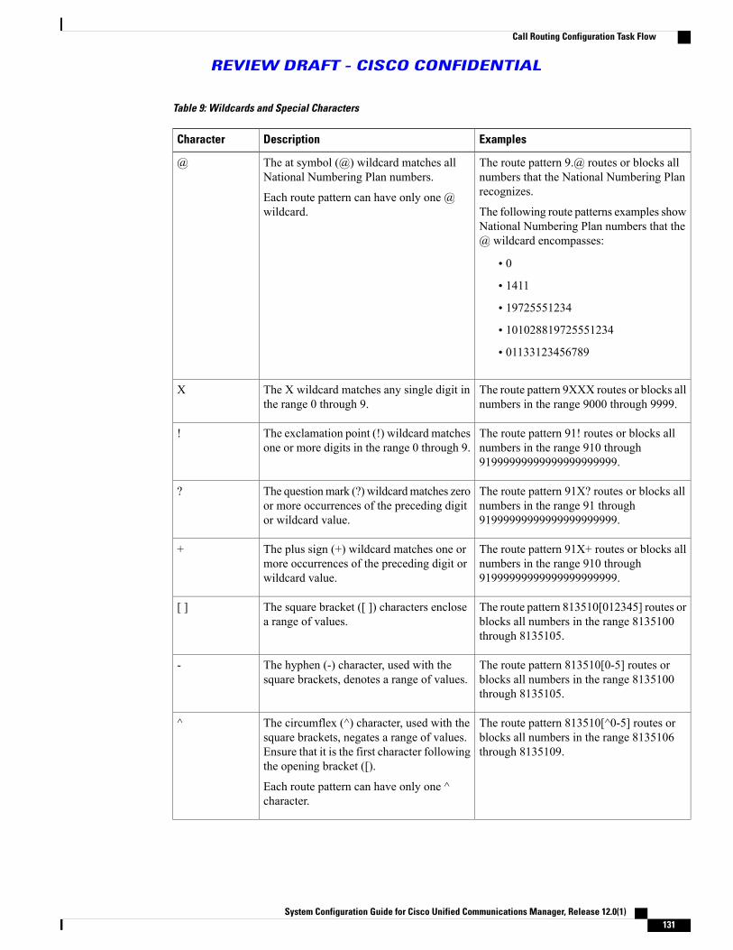
Table 9: Wildcards and Special Characters
ExamplesDescriptionCharacter
The route pattern 9.@ routes or blocks allnumbers that the National Numbering Planrecognizes.
The following route patterns examples showNational Numbering Plan numbers that the@ wildcard encompasses:
• 0
• 1411
• 19725551234
• 101028819725551234
• 01133123456789
The at symbol (@) wildcard matches allNational Numbering Plan numbers.
Each route pattern can have only one @wildcard.
@
The route pattern 9XXX routes or blocks allnumbers in the range 9000 through 9999.
The X wildcard matches any single digit inthe range 0 through 9.
X
The route pattern 91! routes or blocks allnumbers in the range 910 through91999999999999999999999.
The exclamation point (!) wildcard matchesone or more digits in the range 0 through 9.
!
The route pattern 91X? routes or blocks allnumbers in the range 91 through91999999999999999999999.
The questionmark (?) wildcardmatches zeroor more occurrences of the preceding digitor wildcard value.
?
The route pattern 91X+ routes or blocks allnumbers in the range 910 through91999999999999999999999.
The plus sign (+) wildcard matches one ormore occurrences of the preceding digit orwildcard value.
+
The route pattern 813510[012345] routes orblocks all numbers in the range 8135100through 8135105.
The square bracket ([ ]) characters enclosea range of values.
[ ]
The route pattern 813510[0-5] routes orblocks all numbers in the range 8135100through 8135105.
The hyphen (-) character, used with thesquare brackets, denotes a range of values.
-
The route pattern 813510[^0-5] routes orblocks all numbers in the range 8135106through 8135109.
The circumflex (^) character, used with thesquare brackets, negates a range of values.Ensure that it is the first character followingthe opening bracket ([).
Each route pattern can have only one ^character.
^
System Configuration Guide for Cisco Unified Communications Manager, Release 12.0(1) 131
Call Routing Configuration Task Flow
REVIEW DRAFT - CISCO CONFIDENTIAL

ExamplesDescriptionCharacter
The route pattern 9.@ identifies the initial9 as the Cisco Unified CommunicationsManager access code in a NationalNumbering Plan call.
The dot (.) character, used as a delimiter,separates the CiscoUnified CommunicationsManager access code from the directorynumber.
Use this special character, with the discarddigits instructions, to strip off the CiscoUnified Communications Manager accesscode before sending the number to anadjacent system.
Each route pattern can have only one dot (.)character.
.
You can configure the route pattern *411 toprovide access to the internal operator fordirectory assistance.
The asterisk (*) character can provide anextra digit for special dialed numbers.
*
The route pattern 901181910555# routes orblocks an international number that is dialedfrom within the National Numbering Plan.The # character after the last 5 identifies thisdigit as the last digit in the sequence.
The octothorpe (#) character generallyidentifies the end of the dialing sequence.
Ensure the # character is the last characterin the pattern.
#
Using \+ means that the international escapecharacter + is used as a dialable digit, not asa wildcard.
A plus sign preceded by a backslash, that is,\+, indicates that you want to configure theinternational escape character +.
\+
Example of Pre-dot Digit Removal
One example of using pre-dot digit removal in a route pattern is when you want phone users to dial an accesscode to reach an outside line. In North America, phone users typically dial 9 to access an outside line, whichyou can specify using the following route patterns:
• Local calls: 9.@ or 9.[2-9]XXXXXX
• National calls: 9.1[2-9]XX
• International calls: 9.011!#
In these patterns, 9 is the access code for an external line, and the dot (.) is a separator that helps format theroute pattern by indicating which digits are internal to your network, and which ones are outside digits. Whenthe system sends the dialed digits to the PSTN, you can use the Discard Digits option to strip the pre-dot digitfrom the dialed string so that the PSTN can route the call.
Related Topics
Wildcards and Special Characters in Route Patterns, on page 130Configure Route Patterns, on page 129
System Configuration Guide for Cisco Unified Communications Manager, Release 12.0(1)132
Call Routing Configuration Task Flow
REVIEW DRAFT - CISCO CONFIDENTIAL

Example of Digit Prefixing
One example of using digit prefixing in a route pattern is when you configure on-net dialing between sites.You can create a route pattern so that users within your organization dial 8 + XXX-XXXX to place a callbetween sites. For off-net calls, you can remove the prefix digit (8) and add a new prefix of 1<area code> sothat you can route the call to the PSTN in E.164 format.
Related Topics
Wildcards and Special Characters in Route Patterns, on page 130Configure Route Patterns, on page 129
Example of On-net and Off-net Patterns
You can configure a route pattern as OffNet or OnNet using the Call Classification field. You can classifycalls as off-net in cases where you want your users to get a secondary dial tone to let them know that theircall is going outside your organization. For example, if you create a route pattern that requires users to dial 9to access an outside line, and you classify it as an off-net pattern, the system provides the following dial tones:
• a dial tone when the phone is off-hook, before the user dials 9
• a secondary dial tone, after the user dials 9, to indicate that the system is ready to place a call to thepublic switched telephone network (PSTN)
Ensure that you deselect the Allow Device Override check box when you use this option.
Related Topics
Wildcards and Special Characters in Route Patterns, on page 130Configure Route Patterns, on page 129
Example of Block and Route Patterns
Use block and route patterns to prevent outgoing or incoming calls that you do not want to route. Use blockpatterns to:
• block specific patterns; for example, blocking the pattern 91900XXXXXXX will prevent users fromplacing calls to 900 services
• prevent toll fraud by blocking calls to specific area codes and locations
Related Topics
Wildcards and Special Characters in Route Patterns, on page 130Configure Route Patterns, on page 129
Configure Route GroupsConfigure a route group to prioritize the order in which the system selects gateways for outgoing calls. Usethis procedure to group together gateways that have similar characteristics, so that any gateway in the groupcan dial the call. The system selects the gateway to use based on the order that you specify when you configurethe route group.
System Configuration Guide for Cisco Unified Communications Manager, Release 12.0(1) 133
Call Routing Configuration Task Flow
REVIEW DRAFT - CISCO CONFIDENTIAL

You can assign a device to multiple route groups.
Before You Begin
Configure Route Patterns, on page 129
Procedure
Step 1 FromCisco Unified CommunicationsManager Administration, chooseCall Routing > Route/Hunt > RouteGroup.The Route Group Configuration window appears.
Step 2 Choose one of the following options:
• To add a new route group, click the Add New button.
• To modify the settings for an existing route group, enter the search criteria, click Find, and choose aroute group from the resulting list.
The Route Group Configuration window appears.Step 3 Configure the fields in the Route Group Configuration window. See the online help for more information
about the fields and their configuration options.Step 4 Click Save.
What to Do Next
Configure Route Lists, on page 134
Optional.Configure Local Route Group Names, on page 136
Draft comment: *Question for reviewers: After the system administrator configures a route group, do theyhave to configure a route list? or can they just use local route groups instead? Or would the sys admin haveto configure a route list, and have the option to also configure local route groups. (ie this is not an either/orsituation, but possibly both?)
Configure Route ListsConfigure a route list to identify a set of route groups and place them in priority order. Cisco UnifiedCommunications Manager uses the order in the route list to search for available devices for outgoing calls.
A route list can contain only route groups and local route groups.
When an outbound call is sent out through route list, the route list process locks the outbound device toprevent sending an alerting message before a call is completed. After the outbound device is locked, theHunt List stops hunting down the incoming calls.
Note
Before You Begin
Configure Route Groups, on page 133
System Configuration Guide for Cisco Unified Communications Manager, Release 12.0(1)134
Call Routing Configuration Task Flow
REVIEW DRAFT - CISCO CONFIDENTIAL

Procedure
Step 1 In Cisco Unified Communications Manager Administration, choose Call Routing > Route/Hunt > RouteList.
Step 2 Choose one of the following options:
• To add a new route list, click the Add New button.
• To modify the settings for an existing route list, enter the search criteria, click Find, and choose a routelist from the resulting list.
Step 3 Configure the fields in theRoute List Configurationwindow. See the online help for more information aboutfields and their configuration options.
Step 4 To add a route group to the route list, click the Add Route Group button.Step 5 From the Route Group drop-down list, choose a route group to add to the route list.Step 6 Click Save.Step 7 Click Apply Config.
What to Do Next
(Optional) Configure Local Route Groups, on page 135
Configure Local Route GroupsOptional. You can configure local route groups to reduce the number of route lists that you need. Route listspoint to the PSTN gateway that the system uses to route the call, based on the location of the PSTN gateway.As an alternative, you can use local route groups to decouple the location of a PSTN gateway from the routepatterns that are used to access the gateway. This configuration allows phones and other devices from differentlocations to use a single set of route patterns, while Cisco Unified CommunicationManager selects the correctgateway to route the call.
For example, a local route group allows you to have a single dial plan for a whole country rather than haveseparate dial plans for every city in the country. This approach works for centralized call-deployment scenariosonly.
Before You Begin
Configure Route Groups, on page 133
Procedure
PurposeCommand or Action
Optional. The system provides a default local route groupcalled Standard Local Route Group, but you can configure
Configure Local Route GroupNames, on page 136
Step 1
additional local route groups. Use this procedure to name theadditional local route groups.
System Configuration Guide for Cisco Unified Communications Manager, Release 12.0(1) 135
Call Routing Configuration Task Flow
REVIEW DRAFT - CISCO CONFIDENTIAL

PurposeCommand or Action
To ensure that each device in the system is provisioned toknow its local route group, associate the local route groupwith a device pool.
Associate a Local Route Groupwith a Device Pool, on page 136
Step 2
Optional. Configure a local route group that you can add toyour route list. When you create a local route group, the
Add Local Route Group to a RouteList, on page 137
Step 3
system routes outgoing calls to the gateways that are definedfor the user at the device pool level.
Configure Local Route Group Names
Optional. The system provides a default local route group called Standard Local Route Group, but you canconfigure additional local route groups. Use this procedure to name the additional local route groups.
Procedure
Step 1 FromCisco Unified CommunicationsManager Administration, chooseCall Routing >Route/Hunt > LocalRoute Group Names.
Step 2 Click Add Row.Step 3 Enter a name and description for the new local route group.Step 4 Click Save.
What to Do Next
Associate a Local Route Group with a Device Pool, on page 136
Associate a Local Route Group with a Device Pool
You can assign a local route group to use an existing route group, based on the device pool setting of theoriginating device. This configuration allows phones and other devices from different locations to use a singleset of route patterns, while Cisco Unified Communication Manager selects the correct gateway to route thecall.
To ensure that each device in the system is provisioned to know its local route group, associate the local routegroup with a device pool.
Before You Begin
Optional. Configure Local Route Group Names, on page 136
System Configuration Guide for Cisco Unified Communications Manager, Release 12.0(1)136
Call Routing Configuration Task Flow
REVIEW DRAFT - CISCO CONFIDENTIAL

Procedure
Step 1 From Cisco Unified Communications Manager Administration, choose System > Device Pool.Step 2 Enter search criteria, click Find, and choose a device pool from the resulting list.Step 3 In the Local Route Group Settings area, select a route group from the Standard Local Route Group
drop-down list.Step 4 Click Save.
What to Do Next
Add Local Route Group to a Route List, on page 137
Add Local Route Group to a Route List
Configure a local route group that you can add to your route list. When you create a local route group, thesystem routes outgoing calls to the gateways that are defined for the user at the device pool level.
Before You Begin
Associate a Local Route Group with a Device Pool, on page 136
Procedure
Step 1 In Cisco Unified Communications Manager Administration, choose Call Routing > Route/Hunt > RouteList.
Step 2 Choose one of the following options:
• To add a new route list, click the Add New button.
• To modify the settings for an existing route list, enter the search criteria, click Find, and choose a routelist from the resulting list.
The Route List Configuration window appears.Step 3 To add a local route group to the route list, click the Add Route Group button.Step 4 From the Route Group drop-down list, choose a local route group to add to the route list. You can add the
standard local route group, or you can add a custom local route group that you have created.Step 5 Click Save.Step 6 Click Apply Config.
Configure Route FiltersRoute filters use dialed-digit strings to determine how a call is handled. Route filters apply only when youconfigure a route pattern that contains the@wildcard. When the route pattern contains the@wildcard, CiscoUnified Communications Manager routes calls according to the numbering plan that you specify in thisprocedure.
System Configuration Guide for Cisco Unified Communications Manager, Release 12.0(1) 137
Call Routing Configuration Task Flow
REVIEW DRAFT - CISCO CONFIDENTIAL

Draft comment: *Question for reviewers: Are route filters also part of hunt pilots? when we provideprocedures for configuring hunt pilots, will the user need to perform this procedure as part of that task?
Procedure
Step 1 In Cisco Unified Communications Manager Administration, choose Call Routing > Route Filter.Step 2 From the Numbering Plan drop-down list, choose a dial plan and click Next.Step 3 Enter a name in the Route Filter Name field.
Ensure each route filter name is unique to the route plan.Step 4 Choose the route filter tags and operators and enter data, where appropriate, to create a clause for this route
filter.See the Related Topics section for information about available route filter tags.
Do not enter route filter tag values for tags that are using the operators EXISTS, DOES-NOT-EXIST,or NOT-SELECTED.
Note
Step 5 Choose the route filter operators and enter data, where appropriate, to create a clause for this route filter.See the Related Topics section for information about available route filter operators.
Step 6 Click Save.Step 7 Click Apply Config.
Related Topics
Route Filter Tags, on page 138Route Filter Operators, on page 140Route Filter Examples , on page 141
Route Filter Tags
The tag serves as the core component of a route filter. A tag applies a name to a subset of the dialed-digitstring. For example, theNANPnumber 972-555-1234 comprises LOCAL-AREA-CODE (972), OFFICE-CODE(555), and SUBSCRIBER (1234) route filter tags.
Route filter tags require operators and can require additional values to decide which calls are filtered.
The values for route filter tag fields can contain the wildcard characters X, *, #, [, ], -, ^, and the numbers 0through 9. The descriptions in the following table use the notations [2-9] and XXXX to represent actual digits.In this notation, [2-9] represents any single digit in the range 2 through 9, and X represents any single digitin the range 0 through 9. Therefore, the three-digit area code in the form [2-9]XX means that you can enterthe actual digits 200 through 999, or all wildcards, or any mixture of actual digits and wildcards that resultsin a pattern with that range.
Route filter tags vary depending on the numbering plan that you choose from the Numbering Plan drop-downlist box on the Route Filter Configuration window. The following table describes the route filter tags for theNorth American Numbering Plan.
System Configuration Guide for Cisco Unified Communications Manager, Release 12.0(1)138
Call Routing Configuration Task Flow
REVIEW DRAFT - CISCO CONFIDENTIAL

Table 10: Route Filter Tags
DescriptionTag
This three-digit area code in the form [2-9]XX identifies the areacode for long-distance calls.
AREA-CODE
These one-, two-, or three-digit codes specify the destination countryfor international calls.
COUNTRY CODE
This single character identifies the end of the dialed-digit string.The # character serves as the end-of-dialing signal for internationalnumbers that are dialed within the NANP.
END-OF-DIALING
This two-digit access code specifies international dialing. Calls thatoriginate in the U.S. use 01 for this code.
INTERNATIONAL-ACCESS
This one-digit code identifies a direct-dialed international call. Callsthat originate in the U.S. use 1 for this code.
INTERNATIONAL-DIRECT-DIAL
This one-digit code identifies an operator-assisted international call.This code specifies 0 for calls that originate in the U.S.
INTERNATIONAL-OPERATOR
This three-digit local area code in the form [2-9]XX identifies thelocal area code for 10-digit local calls.
LOCAL-AREA-CODE
This one-digit code identifies a direct-dialed local call. NANP callsuse 1 for this code.
LOCAL-DIRECT-DIAL
This one-digit code identifies an operator-assisted local call. NANPcalls use 0 for this code.
LOCAL-OPERATOR
This one-digit code identifies a direct-dialed, long-distance call.NANP calls use 1 for this code.
LONG-DISTANCE-DIRECT-DIAL
These one- or two-digit codes identify an operator-assisted,long-distance call within the NANP. Operator-assisted calls use 0for this code, and operator access uses 00.
LONG-DISTANCE-OPERATOR
This tag specifies the nation-specific part of the digit string for aninternational call.
NATIONAL-NUMBER
This tag designates the first three digits of a seven-digit directorynumber in the form [2-9]XX.
OFFICE-CODE
This one-digit code provides access to satellite connections forinternational calls.
SATELLITE-SERVICE
This three-digit code designates services such as 911 for emergency,611 for repair, and 411 for information.
SERVICE
System Configuration Guide for Cisco Unified Communications Manager, Release 12.0(1) 139
Call Routing Configuration Task Flow
REVIEW DRAFT - CISCO CONFIDENTIAL

DescriptionTag
This tag specifies the last four digits of a seven-digit directorynumber in the form XXXX.
SUBSCRIBER
This four-digit value identifies a long-distance carrier.
Do not include the leading 101 carrier access code prefix in theTRANSIT-NETWORKvalue. SeeTRANSIT-NETWORK-ESCAPEfor more information.
TRANSIT-NETWORK
This three-digit value precedes the long-distance carrier identifier.The value for this field specifies 101. Do not include the four-digitcarrier identification code in the TRANSIT-NETWORK-ESCAPEvalue. See TRANSIT-NETWORK for more information.
TRANSIT-NETWORK-ESCAPE
Route Filter Operators
Route filter tag operators determine whether a call is filtered based on the dialed-digit string that is associatedwith that tag. The operators EXISTS and DOES-NOT-EXIST simply check for the existence of that part ofthe dialed-digit string. The operator == matches the actual dialed digits with the specified value or pattern.The following table describes the operators that you can use with route filter tags.
Table 11: Route Filter Operators
DescriptionOperator
Specifies do not filter calls based on the dialed-digit string that is associated withthis tag.
The presence or absence of the tag with which the operator is associateddoes not prevent Cisco Unified CommunicationsManager from routing thecall.
Note
NOT-SELECTED
Specifies filter calls when the dialed-digit string that is associated with this tag isfound.
Cisco Unified Communications Manager routes or blocks the call only ifthe dialed-digit string contains a sequence of digits that are associated withthe tag.
Note
EXISTS
Specifies filter calls when the dialed-digit string that is associated with this tag isnot found.
Cisco Unified Communications Manager routes or blocks the call only ifthe dialed-digit string does not contain a sequence of digits that areassociated with the tag.
Note
DOES-NOT-EXIST
Specifies filter calls when the dialed-digit string that is associated with this tagmatches the specified value.
Cisco Unified Communications Manager routes or blocks the call only ifthe dialed-digit string contains a sequence of digits that are associated withthe tag and within the numbering range that is specified in the attached field.
Note
==
System Configuration Guide for Cisco Unified Communications Manager, Release 12.0(1)140
Call Routing Configuration Task Flow
REVIEW DRAFT - CISCO CONFIDENTIAL

Route Filter Examples
Example 1: A route filter that uses AREA-CODE and the operator DOES-NOT-EXIST selects all dialed-digitstrings that do not include an area code.
Example 2: A route filter that uses AREA-CODE, the operator ==, and the entry 515 selects all dialed-digitstrings that include the 515 area code.
Example 3: A route filter that uses AREA-CODE, the operator ==, and the entry 5[2-9]X selects all dialed-digitstrings that include area codes in the range of 520 through 599.
Example 4: A route filter that uses TRANSIT-NETWORK, the operator ==, and the entry 0288 selects alldialed-digit strings with the carrier access code 1010288.
Configure Time of Day RoutingOptional. Create a time schedule that specifies when a partition is available to receive incoming calls.
Time of Day routing is not implemented for Message Waiting Indication (MWI) intercept.Note
Procedure
PurposeCommand or Action
Use this procedure to define time periods. You can define astart time and an end time, and also specify repetition interval
Configure a Time Period, onpage 141
Step 1
either as days of the week or a specified date on the yearlycalendar.
Use this procedure to create a schedule. The time periods thatyou configured in the previous procedure are building blocks
Configure a Time Schedule, onpage 142
Step 2
for this schedule. You can assign time periods to multipleschedules.
Associate time schedules with partitions to determine wherecalling devices search when they are attempting to complete acall during a particular time of day.
Associate a Time Schedule witha Partition, on page 142
Step 3
Configure a Time Period
Use this procedure to define time periods. You can define a start time and an end time, and also specifyrepetition interval either as days of the week or a specified date on the yearly calendar.
System Configuration Guide for Cisco Unified Communications Manager, Release 12.0(1) 141
Call Routing Configuration Task Flow
REVIEW DRAFT - CISCO CONFIDENTIAL

Procedure
Step 1 In Cisco Unified CommunicationsManager Administration, chooseCall Routing >Class of Control > TimePeriod.
Step 2 Configure the fields in the Time Period Configuration window. See the online help for more informationabout the fields and their configuration options.
Step 3 Click Save.
What to Do Next
Configure a Time Schedule, on page 142
Configure a Time Schedule
Use this procedure to create a schedule. The time periods that you configured in the previous procedure arebuilding blocks for this schedule. You can assign time periods to multiple schedules.
Before You Begin
Configure a Time Schedule, on page 142
Procedure
Step 1 Choose Call Routing > Class of Control > Time Schedule.Step 2 Configure the fields in the Time Schedule Configuration window. See the online help for more information
about the fields and their configuration options.Step 3 Click Save.
What to Do Next
Associate a Time Schedule with a Partition, on page 142
Associate a Time Schedule with a Partition
Associate time schedules with partitions to determine where calling devices search when they are attemptingto complete a call during a particular time of day.
Before You Begin
Configure a Time Schedule, on page 142
Procedure
Step 1 Choose Call Routing > Class of Control > Partition.Step 2 From the Time Schedule drop-down list, choose a time schedule to associate with this partition.
System Configuration Guide for Cisco Unified Communications Manager, Release 12.0(1)142
Call Routing Configuration Task Flow
REVIEW DRAFT - CISCO CONFIDENTIAL

The time schedule specifies when the partition is available to receive incoming calls. If you chooseNone, thepartition remains active at all times.
Step 3 Click Save.
System Configuration Guide for Cisco Unified Communications Manager, Release 12.0(1) 143
Call Routing Configuration Task Flow
REVIEW DRAFT - CISCO CONFIDENTIAL

System Configuration Guide for Cisco Unified Communications Manager, Release 12.0(1)144
Call Routing Configuration Task Flow
REVIEW DRAFT - CISCO CONFIDENTIAL

C H A P T E R 22Configure Hunt Pilots
• Hunt Pilot Overview, page 145
• Hunt Pilot Configuration Task Flow, page 145
Hunt Pilot OverviewHunt pilots are strings of digits and wildcards that the system uses to route calls to directory numbers (DNs).Hunt pilots work in conjunction with hunt lists, which are prioritized lists of eligible paths (line groups) forincoming calls. When a call is placed to a hunt pilot DN, the system offers the call to the first line groupspecified in the hunt list. If no one in the first line group answers the call, the system offers the call to the nextline group specified in the hunt list. Line groups control the order in which the call is distributed to phoneswithin the group. They point to specific extensions, which are typically IP phone extensions or voicemailports. Line groups cannot point to Computer Telephony Integration (CTI) ports and CTI route points, so youcannot use hunt pilots to distribute calls to endpoints that are controlled through CTI applications such asCisco Customer Response Solution (CRS) or IP Interactive Voice Response (IP IVR).
A hunt pilot can distribute calls to any of its assigned line groups, even if the line groups and the hunt pilotreside in different partitions. A call distributed by the hunt pilot overrides all the partitions and calling searchspace restrictions.
Draft comment: *Note to self: double-check that hunt forward settings, log in/out of hunt groups, and relatedfunctionality is documented in feature config guide, and provide xref
Hunt Pilot Configuration Task Flow
Procedure
PurposeCommand or Action
Create a line group to enable multiple phones to answer callsthat are directed to a single directory number (DN).
Configure Line Groups, on page146
Step 1
System Configuration Guide for Cisco Unified Communications Manager, Release 12.0(1) 145

PurposeCommand or Action
Configure a hunt list to prioritize the line groups. When thesystem routes a call through a hunt list, it uses the line groupsin the order that you define in the hunt list.
Configure Hunt Lists, on page146
Step 2
Configure hunt pilots to specify the strings of digits andwildcards that the system uses to route calls to directorynumbers (DNs).
Configure Hunt Pilots, on page147
Step 3
Configure Line GroupsCreate a line group to enable multiple phones to answer calls that are directed to a single directory number(DN). Line groups control the order in which an incoming call is distributed to phones within the group.
Procedure
Step 1 From Cisco Unified CM Administration, choose Call Routing > Route/Hunt > Line Group.Step 2 Choose one of the following options:
• To add a new line group, click the Add New button.
• To modify the settings for an existing line group, enter the search criteria, click Find, and choose a linegroup from the resulting list.
The Line Group Configuration window appears.Step 3 Configure the fields on the Line Group Configuration window. See the online help for more information
about the fields and their configuration options.Step 4 Click Save.
What to Do Next
Configure Hunt Lists, on page 146
Configure Hunt ListsA hunt list is a prioritized list of line groups. When the system routes a call through a hunt list, it uses the linegroups in the order that you define in the hunt list.
Before You Begin
Configure Line Groups, on page 146
System Configuration Guide for Cisco Unified Communications Manager, Release 12.0(1)146
Hunt Pilot Configuration Task Flow
REVIEW DRAFT - CISCO CONFIDENTIAL

Procedure
Step 1 From Cisco Unified CM Administration, choose Call Routing > Route/Hunt > Hunt List.Step 2 Choose one of the following options:
• To add a new hunt list, click the Add New button.
• To modify the settings for an existing hunt list, enter the search criteria, click Find, and choose a huntlist from the resulting list.
The Hunt List Configuration window appears.Step 3 Configure the fields on theHunt List Configurationwindow. See the online help for more information about
the fields and their configuration options.Step 4 Click Save.
What to Do Next
Configure Hunt Pilots, on page 147
Configure Hunt PilotsConfigure hunt pilots to specify the strings of digits and wildcards that the system uses to route calls to directorynumbers (DNs).
Before You Begin
Configure Hunt Lists, on page 146
Procedure
Step 1 From Cisco Unified CM Administration, choose Call Routing > Route/Hunt > Hunt Pilot.Step 2 Choose one of the following options:
• To add a new hunt pilot, click the Add New button.
• To modify the settings for an existing hunt pilot, enter the search criteria, click Find, and choose a huntpilot from the resulting list.
The Hunt Pilot Configuration window appears.Step 3 Configure the fields on the Hunt Pilot Configuration window. See the online help for more information
about the fields and their configuration options. For information about the wildcards and special charactersthat you can use, see Wildcards and Special Characters in Hunt Pilots, on page 148.
Step 4 Click Save.
System Configuration Guide for Cisco Unified Communications Manager, Release 12.0(1) 147
Hunt Pilot Configuration Task Flow
REVIEW DRAFT - CISCO CONFIDENTIAL

Wildcards and Special Characters in Hunt Pilots
Wildcards and special characters in hunt pilots allow a hunt pilot to match a range of numbers (addresses).Use these wildcards and special characters also to build instructions that enable the Cisco UnifiedCommunications Manager to manipulate a number before sending it to an adjacent system.
The following table describes the wildcards and special characters that Cisco Unified CommunicationsManagersupports.
Table 12: Wildcards and Special Characters
ExamplesDescriptionCharacter
The route pattern 9.@ routes or blocks allnumbers that the National Numbering Planrecognizes.
The following route patterns examples showNational Numbering Plan numbers that the@ wildcard encompasses:
• 0
• 1411
• 19725551234
• 101028819725551234
• 01133123456789
The at symbol (@) wildcard matches allNational Numbering Plan numbers.
Each route pattern can have only one @wildcard.
@
The route pattern 9XXX routes or blocks allnumbers in the range 9000 through 9999.
The X wildcard matches any single digit inthe range 0 through 9.
X
The route pattern 91! routes or blocks allnumbers in the range 910 through91999999999999999999999.
The exclamation point (!) wildcard matchesone or more digits in the range 0 through 9.
!
The route pattern 91X? routes or blocks allnumbers in the range 91 through91999999999999999999999.
The questionmark (?) wildcardmatches zeroor more occurrences of the preceding digitor wildcard value.
?
The route pattern 91X+ routes or blocks allnumbers in the range 910 through91999999999999999999999.
The plus sign (+) wildcard matches one ormore occurrences of the preceding digit orwildcard value.
+
The route pattern 813510[012345] routes orblocks all numbers in the range 8135100through 8135105.
The square bracket ([ ]) characters enclosea range of values.
[ ]
The route pattern 813510[0-5] routes orblocks all numbers in the range 8135100through 8135105.
The hyphen (-) character, used with thesquare brackets, denotes a range of values.
-
System Configuration Guide for Cisco Unified Communications Manager, Release 12.0(1)148
Hunt Pilot Configuration Task Flow
REVIEW DRAFT - CISCO CONFIDENTIAL

ExamplesDescriptionCharacter
The route pattern 813510[^0-5] routes orblocks all numbers in the range 8135106through 8135109.
The circumflex (^) character, used with thesquare brackets, negates a range of values.Ensure that it is the first character followingthe opening bracket ([).
Each route pattern can have only one ^character.
^
The route pattern 9.@ identifies the initial9 as the Cisco Unified CommunicationsManager access code in a NationalNumbering Plan call.
The dot (.) character, used as a delimiter,separates the CiscoUnified CommunicationsManager access code from the directorynumber.
Use this special character, with the discarddigits instructions, to strip off the CiscoUnified Communications Manager accesscode before sending the number to anadjacent system.
Each route pattern can have only one dot (.)character.
.
You can configure the route pattern *411 toprovide access to the internal operator fordirectory assistance.
The asterisk (*) character can provide anextra digit for special dialed numbers.
*
The route pattern 901181910555# routes orblocks an international number that is dialedfrom within the National Numbering Plan.The # character after the last 5 identifies thisdigit as the last digit in the sequence.
The octothorpe (#) character generallyidentifies the end of the dialing sequence.
Ensure the # character is the last characterin the pattern.
#
Using \+ means that the international escapecharacter + is used as a dialable digit, not asa wildcard.
A plus sign preceded by a backslash, that is,\+, indicates that you want to configure theinternational escape character +.
\+
Performance and Scalability for Hunt Pilots
The following performance and scalability restrictions apply:
• A single Unified CM Cluster supports a maximum of 15,000 hunt list devices.
• A single Unified CM Subscriber supports a maximum of 100 hunt pilots with call queuing enabled pernode
• Hunt list devices may be a combination of 1500 hunt lists with ten IP phones in each hunt list, 750 huntlists with twenty IP phones in each hunt list, or similar combinations
System Configuration Guide for Cisco Unified Communications Manager, Release 12.0(1) 149
Hunt Pilot Configuration Task Flow
REVIEW DRAFT - CISCO CONFIDENTIAL

When using the broadcast algorithm for call coverage, the number of hunt list devicesis limited by the number of busy hour call attempts (BHCA). Note that a BHCA of 10on a hunt pilot pointing to a hunt list or hunt group containing 10 phones and using thebroadcast algorithm is equivalent to 10 phones with a BHCA of 10.
Note
• Themaximum number of simultaneous callers in queue for each hunt pilot that you can configure rangesfrom 1 to 100 (default 32).
• The maximum wait time in queue for each hunt pilot that you can configure ranges from 0 to 3600seconds (default 900). An increase in the number of hunt lists can require you to increase the dial planinitialization timer that is specified in the Unified Communications Manager service parameters. Werecommend that you set the dial plan initialization timer to 600 seconds if you have 1500 hunt listsconfigured.
•We recommend having no more than 35 directory numbers for a single line group when using broadcastalgorithms with call queuing. Additionally, the number of broadcast line groups depends on the busyhour call completion rate (BHCC). If there are multiple broadcast line groups in a Unified CM system,the number of maximum directory numbers in a line group must be less than 35. The number of busyhour call attempts (BHCA) for all the broadcast line groups should not exceed 35 calls set up per second.
System Configuration Guide for Cisco Unified Communications Manager, Release 12.0(1)150
Hunt Pilot Configuration Task Flow
REVIEW DRAFT - CISCO CONFIDENTIAL

C H A P T E R 23Configure Translation Patterns
• Translation Pattern Overview, page 151
• Translation Pattern Prerequisites, page 152
• Translation Pattern Configuration Task Flow, page 152
Translation Pattern OverviewYou can configure translation patterns to manipulate digits for any type of call. Translation patterns followthe same general rules and use the same wildcards as route patterns. As with route patterns, you assign atranslation pattern to a partition. However, when the dialed digits match the translation pattern, Cisco UnifiedCommunications Manager does not route the call to an outside entity such as a gateway; instead, it performsthe translation first and then routes the call again, this time using the calling search space configured withinthe translation pattern.
Draft comment: Questions for reviewers: translation pattern fields appear on the UI in a few places:
1 Call Routing > Translation Pattern (the subject of this chapter)
2 also on the route pattern window (Call Routing > Route/Hunt > Route Pattern)
When you configure these fields in the Route Pattern configuration window, they would be directly appliedto that route pattern. For the fields on the Call Routing > Translation Pattern window, I don't see how youcan relate it to a particular route pattern, so are the settings on this page somehow separate?When you configurethe fields on the Call Routing > Translation Pattern window, which calls does these fields apply to?
Also, there are transformation fields on the Call Routing > Translation Pattern window; how are theydifferent than the transformation fields on Call Routing > Route/Hunt > Calling Party Transformationand Call Routing > Route/Hunt >Connected Party Transformation windows?
Do the transformation fields here serve a different purpose than the transformation fields elsewhere on theUI?
System Configuration Guide for Cisco Unified Communications Manager, Release 12.0(1) 151

Translation Pattern PrerequisitesBefore you configure a translation pattern, you must complete the following tasks:
• Configure Partitions
• Configure Call Routing
For each translation pattern that you create, ensure that the combination of partition, route filter, andnumbering plan is unique. If you receive an error that indicates duplicate entries, check the route patternor hunt pilot, translation pattern, directory number, call park number, call pickup number, or meet-menumber configuration windows.
Note
Translation Pattern Configuration Task Flow
Procedure
PurposeCommand or Action
Configure translation patterns to specify how toroute a call after it is placed.
Configure Translation Patterns, on page152
Step 1
Configure Translation PatternsConfigure translation patterns to specify how to route a call after it is placed. Configuring translation patternsallows Cisco Unified Communications Manager to manipulate calling and called digits as appropriate. Whenthe system identifies that a pattern match occurred, Cisco Unified Communications Manager uses the callingsearch space that is configured for the translation pattern to perform the subsequent match.
Procedure
Step 1 From Cisco Unified CM Administration, choose Call Routing > Translation Pattern.Step 2 Choose one of the following options:
• To add a new translation pattern, click the Add New button.
• Tomodify the settings for an existing translation pattern, enter the search criteria, click Find, and choosea translation pattern from the resulting list.
System Configuration Guide for Cisco Unified Communications Manager, Release 12.0(1)152
Translation Pattern Prerequisites
REVIEW DRAFT - CISCO CONFIDENTIAL

The Translation Pattern Configuration window appears.Step 3 Configure the fields on the Translation Pattern Configuration window. See the online help for more
information about the fields and their configuration options.Step 4 Click Save.
System Configuration Guide for Cisco Unified Communications Manager, Release 12.0(1) 153
Translation Pattern Configuration Task Flow
REVIEW DRAFT - CISCO CONFIDENTIAL

System Configuration Guide for Cisco Unified Communications Manager, Release 12.0(1)154
Translation Pattern Configuration Task Flow
REVIEW DRAFT - CISCO CONFIDENTIAL

C H A P T E R 24Configure Transformation Patterns
• Transformation Pattern Overview, page 155
• Transformation Pattern Configuration Task Flow, page 156
Transformation Pattern OverviewTransformation patterns determine how the system manipulates the digits that were dialed in an incoming oroutgoing call. You can configure transformation patterns when you need to change the calling or called numberbefore the system sends it to the phone or the PSTN.
You can use transformation patterns to discard digits, prefix digits, add a calling party transformation mask,and control the presentation of the calling party number.
You can:
• Hit a Calling Party Transformation Pattern with a Called Party Transformation CSS.
• Hit a Called Party Transformation Pattern with a Calling Party Transformation CSS.
Draft comment: *Questions for reviewers: transformation pattern fields appear on the UI in a few differentplaces: 1. Call Routing > Translation Pattern; 2. Call Routing > Route/Hunt > Route Pattern; and 3. CallRouting > Transformation > Transformation Pattern > etc. Is it just a case where there are 3 places to configurethe same fields, or are there functional differences? For example, do the transformation fields inCall Routing> Route/Hunt > Route Pattern serve a different purpose than the transformation fields located at CallRouting > Transformation > Transformation Pattern or elsewhere on the UI?
System Configuration Guide for Cisco Unified Communications Manager, Release 12.0(1) 155

Transformation Pattern Configuration Task Flow
Procedure
PurposeCommand or Action
Use this procedure to transform the calling number. Forexample, you can configure a transformation pattern that
Configure Calling PartyTransformation Patterns, on page156
Step 1
replaces a caller's extension with the office's main numberwhen calling the PSTN.
Use this procedure to transform the called number. Forexample, you can configure a transformation pattern that
Configure Called PartyTransformation Patterns, on page157
Step 2
retains only the last five digits of a call dialed as a ten-digitnumber.
Optional. Perform this procedure only if you are using CiscoIntercompanyMedia Engine (Cisco IME). Youmust configure
Configure TransformationProfiles, on page 157
Step 3
a transformation profile to convert dialed numbers into theE.164 format.
Configure Calling Party Transformation PatternsUse this procedure to transform the calling number. For example, you can configure a transformation patternthat replaces a caller's extension with the office's main number when calling the PSTN.
Procedure
Step 1 From Cisco Unified Communications Manager Administration, choose Call Routing > Transformation >Transformation Pattern > Calling Party Transformation Pattern.
Step 2 Choose one of the following options:
• To add a new calling party transformation pattern, click the Add New button.
• To modify the settings for an existing calling party transformation pattern, enter the search criteria, clickFind, and choose a pattern from the resulting list.
The Calling Party Transformation Pattern Configuration window appears.Step 3 Configure the fields in the Calling Party Transformation Pattern Configuration window. See the online
help for more information about fields and their configuration options.Step 4 Click Save.
What to Do Next
Configure Called Party Transformation Patterns, on page 157
System Configuration Guide for Cisco Unified Communications Manager, Release 12.0(1)156
Transformation Pattern Configuration Task Flow
REVIEW DRAFT - CISCO CONFIDENTIAL

Configure Called Party Transformation PatternsUse this procedure to transform the called number. For example, you can configure a transformation patternthat retains only the last five digits of a call dialed as a ten-digit number.
Before You Begin
Configure Calling Party Transformation Patterns, on page 156
Procedure
Step 1 From Cisco Unified Communications Manager Administration, choose Call Routing > Transformation >Transformation Pattern > Called Party Transformation Pattern.
Step 2 Choose one of the following options:
• To add a new called party transformation pattern, click the Add New button.
• To modify the settings for an existing called party transformation pattern, enter the search criteria, clickFind, and choose a pattern from the resulting list.
The Called Party Transformation Pattern Configuration window appears.Step 3 Configure the fields in the Called Party Transformation Pattern Configuration window. See the online
help for more information about fields and their configuration options.Step 4 Click Save.
What to Do Next
Optional. Configure Transformation Profiles, on page 157
Configure Transformation ProfilesPerform this procedure only if you are using Cisco Intercompany Media Engine (Cisco IME). You mustconfigure a transformation profile to convert dialed numbers into the E.164 format. The E.164 format includesthe international "+" prefix; for example, "+14085551212".
Procedure
Step 1 From Cisco Unified Communications Manager Administration, choose Call Routing > Transformation >Transformation Profile.
Step 2 Choose one of the following options:
• To add a new transformation profile, click the Add New button.
• To modify the settings for an existing transformation profile, enter the search criteria, click Find, andchoose a pattern from the resulting list.
System Configuration Guide for Cisco Unified Communications Manager, Release 12.0(1) 157
Transformation Pattern Configuration Task Flow
REVIEW DRAFT - CISCO CONFIDENTIAL

The Transformation Profile Configuration window appears.Step 3 Configure the fields in the Transformation Profile Configuration window. See the online help for more
information about fields and their configuration options.Step 4 Click Save.
System Configuration Guide for Cisco Unified Communications Manager, Release 12.0(1)158
Transformation Pattern Configuration Task Flow
REVIEW DRAFT - CISCO CONFIDENTIAL

C H A P T E R 25Configure Dial Rules
• Dial Rules Overview, page 159
• Dial Rules Prerequisites, page 159
• Dial Rules Configuration Task Flow, page 160
• Dial Rules Interactions and Restrictions, page 165
Dial Rules OverviewCisco Unified Communications Manager supports the following types of dial rules:
• application dial rules
• directory lookup dial rules
• SIP dial rules
The administrator uses application dial rules to add and sort the priority of dialing rules for applications suchas Cisco web dialer and Cisco Unified Communications Manager Assistant.
The administrator uses directory lookup dial rules to transform caller identification numbers and perform adirectory search from the assistant console in application such as Cisco Unified Communications ManagerAssistant.
The administrator uses SIP dial rules to perform system digit analysis and routing. The administrator configuresSIP dial rules and adds the SIP dial rule to the Cisco Unified IP Phone before the call processing takes place.
Dial Rules Prerequisites
Draft comment: Are there any other items that a user must configure before they configure the dial rules?Are there any requirements or best practices to be followed?
• For SIP dial rules configuration, the devices must be running SIP
System Configuration Guide for Cisco Unified Communications Manager, Release 12.0(1) 159

• The administrator associates the SIP dial rules with the following devices: Cisco Unified IP Phones7911, 7940, 7941, 7960, 7961, 7970, and 7971
Dial Rules Configuration Task Flow
Procedure
PurposeCommand or Action
Configure application dial rules to add and sort the priorityof dialing rules for applications such as Cisco web dialerand Cisco Unified Communications Manager Assistant.
Configure Application Dial Rules,on page 160
Step 1
Configure directory lookup dial rules to transform calleridentification numbers into numbers that can be looked upin the directory.
Configure Directory Lookup DialRules, on page 161
Step 2
Use SIP dial rules configuration to configure dial plans forphones that are running SIP.
Configure SIP Dial Rules, on page161
Step 3
Optional. Change the priority of the dial rules in the CiscoUnified CommunicationsManager Administration window,if more than one dial rule exists.
Reprioritize Dial Rule, on page165
Step 4
Configure Application Dial RulesCisco Unified Communications Manager supports application dial rules that allow you to add and sort thepriority of dialing rules for applications such as Cisco web dialer and Cisco Unified CommunicationsManagerAssistant. Application dial rules automatically strip numbers from or add numbers to telephone numbers thatthe user dials. For example, the dial rules automatically add the digit 9 in front of a 7-digit telephone numberto provide access to an outside line.
CiscoUnified CommunicationsManager automatically applies application dial rules to all remote destinationnumbers for CTI remote devices.
Note
Perform the following procedure to add a new application dial rule or update an existing application dial rule.
Procedure
Step 1 From Cisco Unified Communications Manager Administration, choose Call Routing > Dial Rules >Application Dial Rules.
Step 2 In the Find and List Application Dial Rules window, perform one of the following steps:
• Click Add New.
System Configuration Guide for Cisco Unified Communications Manager, Release 12.0(1)160
Dial Rules Configuration Task Flow
REVIEW DRAFT - CISCO CONFIDENTIAL

• Click Find and choose an existing application dial rule.
Step 3 Configure the fields in the Application Dial Rule Configuration window. For detailed field descriptions,refer to the online help.
Step 4 Click Save.
What to Do Next
Perform the following tasks:
• Configure Directory Lookup Dial Rules, on page 161
• Configure SIP Dial Rules, on page 161
Configure Directory Lookup Dial RulesDirectory lookup dial rules transform caller identification numbers into numbers that can be looked up in thedirectory. Each rule specifies which numbers to transform, based on the beginning digits and length of thenumber. For example, you can create a directory lookup dial rule that automatically removes the area codeand two prefix digits from a 10-digit telephone, which would transform 4085551212 into 51212.
Perform the following procedure to add a new directory lookup dial rule or update an existing directory lookupdial rule.
Procedure
Step 1 FromCiscoUnified CommunicationsManager Administration, chooseCall Routing >Dial Rules >DirectoryLookup Dial Rules.
Step 2 In the Directory Lookup Dial Rule Find and List window Directory Lookup Dial Rule Find and Listwindow, perform one of the following steps:
• Click Add New.
• Click Find and choose an existing directory lookup dial rule.
Step 3 Configure the fields in theDirectory LookupDial Rule Configurationwindow. For detailed field descriptions,refer to the online help.
Step 4 Click Save.
What to Do Next
Configure SIP Dial Rules, on page 161
Configure SIP Dial RulesSIP dial rules provide local dial plans for Cisco Unified IP Phones that are running SIP, so users do not haveto press a key or wait for a timer before the call gets processed. The administrator configures the SIP dial ruleand applies it to the phone that is running SIP.
System Configuration Guide for Cisco Unified Communications Manager, Release 12.0(1) 161
Dial Rules Configuration Task Flow
REVIEW DRAFT - CISCO CONFIDENTIAL

Procedure
PurposeCommand or Action
Configure and update SIP dial rules and associate them withthe phones that are running SIP.
Set Up SIP Dial Rule, on page163
Step 1
Reset or restart the phone that is running SIP when the SIPdial rule gets updated, so that the phone is updated with thenew SIP dial rule.
Reset SIP Dial Rule, on page 163Step 2
(Optional) Synchronize a SIP phone with a SIP dial rule thathas undergone configuration changes, which applies any
Synchronize SIP Dial RulesSettings With SIP Phones, onpage 164
Step 3
outstanding configuration settings in the least intrusive mannerpossible. For example, a reset or restart may not be requiredon some affected SIP phones.
Related Topics
Pattern Formats, on page 162
Pattern Formats
Table 13: Pattern Formats for SIP Dial Rules
ValueDial Rule Pattern
• Period (.) matches any character
• Pound sign (#) acts as the terminating key, and you can applytermination only after matching hits >#. So >* means that theterminating character specifies the asterisk (*); that is, theterminating key must follow the greater-than sign (>).
You must configure the pound sign in the pattern field sothat it is valid for 7940_7960_OTHER.
Note
• Asterisk (*) matches one or more characters and it gets processedas a wildcard character. You can override this by preceding the *with a backward slash (\) escape sequence, which results in thesequence \*. The phone automatically strips the \, so it does notappear in the outgoing dial string. When * is received as a dialdigit, it gets matched by the wildcard characters * and period (.).
• Comma (,) causes the phone to generate a secondary dial tone.For example, 7.... will match any 4-digit DN that starts with 7.8,..... will match 8, play secondary dial tone (default value), andthen match any 5-digit DN.
7940_7960_OTHER
System Configuration Guide for Cisco Unified Communications Manager, Release 12.0(1)162
Dial Rules Configuration Task Flow
REVIEW DRAFT - CISCO CONFIDENTIAL

Set Up SIP Dial Rule
To configure dial plans for phones that are running SIP.
Procedure
Step 1 From Cisco Unified Communications Manager Administration, choose Call Routing > Dial Rules > SIPDial Rules.
Step 2 In the Find and List SIP Dial Rules window. Perform one of the following steps:
• Click Add New
• Click Find and choose an existing SIP Dial Rule
Step 3 Configure the fields in the SIP Dial Rule Configuration window. For detailed field descriptions, refer to theonline help.
Step 4 Click Save.When you add or update a SIP dial rule in Cisco Unified Communications Manager Administration,be aware that the Cisco TFTP service rebuilds all phone configuration files, which may cause CPUto spike on the server where the Cisco TFTP service runs, especially if you have a large system withmany phones. To ensure that CPU does not spike, add or update the SIP dial rule during a maintenancewindow or temporarily stop the Cisco TFTP service in Cisco Unified Serviceability before you makethe configuration change. If you stop the Cisco TFTP service, remember to restart the service inCisco Unified Serviceability after you add or update the SIP dial rule.
Note
What to Do Next
Reset SIP Dial Rule, on page 163
Related Topics
Pattern Formats, on page 162
Reset SIP Dial Rule
Perform the following procedure to reset or restart the phone that is running SIP when the SIP dial rule getsupdated, so the phone gets updated with the new SIP dial rule.
Before You Begin
Set Up SIP Dial Rule, on page 163
System Configuration Guide for Cisco Unified Communications Manager, Release 12.0(1) 163
Dial Rules Configuration Task Flow
REVIEW DRAFT - CISCO CONFIDENTIAL

Procedure
Step 1 From Cisco Unified Communications Manager Administration, choose Call Routing > Dial Rules >Application Dial Rules.
Step 2 In the Find and List SIP Dial Rules window, click Find and choose an existing SIP dial rule that you wantto reset.
Step 3 In the SIP Dial Rule Configuration window, click Reset.Step 4 Perform one of the following tasks in the Device Reset dialog box:
• To restart the chosen devices without shutting them down and reregister them with Cisco UnifiedCommunications Manager, click Restart.
• To shut down, and then restart the device, click Reset.
• To close the Device Reset dialog box without performing any action, click Close.
After the administrator configures the SIP dial rule and applies it to the phone that is running SIP, the databasesends the TFTP server a notification, so it can build a new set of configuration files for the phone that isrunning SIP. The TFTP server notifies Cisco Unified Communications Manager about the new configurationfile, and the updated configuration file is sent to the phone. See Configure TFTP Servers for Cisco UnifiedIP phones that run SIP for more information.
What to Do Next
Synchronize SIP Dial Rules Settings With SIP Phones, on page 164
Synchronize SIP Dial Rules Settings With SIP Phones
To synchronize a SIP phone with a SIP dial rule that has undergone configuration changes, perform thefollowing procedure.
Before You Begin
Reset SIP Dial Rule, on page 163
Procedure
Step 1 From Cisco Unified Communications Manager Administration, choose Call Routing > Dial Rules > SIPDial Rules.
Step 2 In the Find and List SIP Dial Rules window, click Find and choose an existing SIP dial rule to which youwant to synchronize applicable SIP phones.
Step 3 Make any additional configuration changes and click Save in the SIP Dial Rule Configuration.Step 4 Click Apply Config.Step 5 Click OK.
System Configuration Guide for Cisco Unified Communications Manager, Release 12.0(1)164
Dial Rules Configuration Task Flow
REVIEW DRAFT - CISCO CONFIDENTIAL

Reprioritize Dial RuleTo add and sort the priority of dialing rules in the Dial Rule Configuration window.
Procedure
Step 1 From Cisco Unified Communications Manager Administration, choose Call Routing > Dial Rules.Step 2 Select one of the following:
• Application Dial Rules
• Directory Lookup Dial Rules
• SIP Dial Rules
Step 3 In the Find and List window, choose a dial rule and click the dial rule name.The Dial Rule Configuration window appears.
Step 4 Use the up and down arrows to move the dial rule up or down the list.Step 5 After you complete prioritizing the order, click Save.
Dial Rules Interactions and Restrictions
SIP Dial Rules Interactions
SIP Dial Rules Interactions
InteractionCisco Unified IP Phone
These phones use the 7940_7960_OTHER dial rulespatterns. Key PressMarkup Language (KPML) allowsfor the digits to be sent to Cisco UnifiedCommunications Manager digit by digit; SIP dialrules allow for a pattern of digits to be collectedlocally on the phone prior to sending to Cisco UnifiedCommunications Manager. If SIP dial rules are notconfigured, KPML is used. To increase theperformance of Cisco Unified CommunicationsManager (increasing the number of calls that getprocessed), Cisco recommends that administratorsconfigure SIP dial rules.
7911, 7941, 7961, 7970, and 7971 that are runningSIP
System Configuration Guide for Cisco Unified Communications Manager, Release 12.0(1) 165
Dial Rules Interactions and Restrictions
REVIEW DRAFT - CISCO CONFIDENTIAL

InteractionCisco Unified IP Phone
These phones use the 7940_7960_OTHER dial rulespattern and do not support KPML. If the administratordoes not configure a SIP dial plan for these phones,the user must wait a specified time before the digitsare sent to Cisco Unified Communications Managerfor processing. This delays the processing of theactual call.
7940 and 7960 that are running SIP
Directory Lookup Dial Rules Restrictions
Directory Lookup Dial Rules Restrictions
RestrictionField
This field supports only digits and the characters +,*,and #. The length cannot exceed 100 characters.
Number Begins With
This field supports only digits, and the value in thisfield cannot be less than the length of the pattern thatis specified in the pattern field.
Number of Digits
This field supports only digits, and the value in thisfield cannot be more than the value in the Numberof Digits field.
Total Digits to be Removed
The prefix it with field supports only digits and thecharacters +,*, and #. The length cannot exceed 100characters.
You cannot allow both the Total Digits tobe Removed field and the Prefix withPattern field to be blank for a dial rule.
Note
Prefix with Pattern
System Configuration Guide for Cisco Unified Communications Manager, Release 12.0(1)166
Dial Rules Interactions and Restrictions
REVIEW DRAFT - CISCO CONFIDENTIAL

C H A P T E R 26Configure Intercluster Lookup Service
• Intercluster Lookup Service Overview, page 167
• ILS Prerequisites, page 168
• ILS Configuration Task Flow, page 168
• ILS Interactions and Restrictions, page 176
Intercluster Lookup Service OverviewThe Intercluster Lookup Service (ILS) allows you to create networks of remote Cisco Unified CommunicationsManager clusters. When you configure ILS on multiple clusters, it updates Cisco Unified CommunicationsManager with the current status of remote clusters in the ILS network.
In Cisco Unified CM Administration, you can configure ILS on a pair of clusters and then join those clustersto form an ILS network. ILS allows you to join additional clusters to the network without having to configurethe connections between each cluster.
An ILS network comprises the following components:
• Hub clusters
• Spoke clusters
• Global dial plan imported catalogs
Hub ClustersHub clusters form the backbone of an ILS network. Hub clusters exchange ILS updates with the other hubclusters in the ILS network, and then relay that information to and from their spoke clusters.
When a new hub cluster registers to another hub cluster in an existing ILS network, ILS automatically createsa full mesh connection between the new hub cluster and all the existing hub clusters in the ILS network.
System Configuration Guide for Cisco Unified Communications Manager, Release 12.0(1) 167

Spoke ClustersA spoke cluster connects to the hub cluster in an ILS network to relay ILS updates to and from the rest of theILS network. Spoke clusters contact only their local hub cluster and never directly contact other hub clustersor other spoke clusters.
Global Dial Plan Imported CatalogsTo provide URI dialing compatibility with third-party systems, you can manually import a third-party directoryURI or +E.164 number catalog from a CSV file into any hub cluster in the ILS network. ILS maintains theimported catalog and replicates that catalog out to the other clusters in the network. You can dial one of thethird-party directory URIs or +E.164 numbers catalog from any server in the ILS network.
ILS PrerequisitesYou must study your network and design an ILS topology.
For more information about the Solution Reference Network Design, see the Cisco Unified CommunicationsSolution Reference Network Design guide at http://www.cisco.com/c/en/us/support/unified-communications/unified-communications-manager-callmanager/products-implementation-design-guides-list.html.
ILS Configuration Task Flow
Procedure
PurposeCommand or Action
Activate Intercluster Lookup Service to configurecluster IDs and remote clusters.
Activate Intercluster Lookup Service, onpage 169
Step 1
Provide a unique identifier for each cluster in the ILSnetwork.
Configure Cluster IDs, on page 169Step 2
Configure remote clusters in the ILS network.Configure Remote Clusters, on page 170Step 3
Activate ILS on the hub cluster and spoke cluster inthe ILS network.
Youmust configure each cluster in your ILSnetwork as either a hub cluster or a spokecluster.
Note
To activate ILS on the various clusters,complete the following tasks:
Step 4
• Activate ILS on the Hub Cluster, onpage 171
• Activate ILS on the Spoke Cluster,on page 171
Use TLS authentication between clusters in the ILSnetwork.
(Optional) Configure authentication betweenyour cluster. Select one of the followingprocedures:
Step 5
Use password authentication between remote clustersin the ILS network.
System Configuration Guide for Cisco Unified Communications Manager, Release 12.0(1)168
ILS Prerequisites
REVIEW DRAFT - CISCO CONFIDENTIAL

PurposeCommand or Action
Use TLS and password authentication to setup a ILSnetwork using common Certificate Authority (CA)
• Enable TLS Authentication BetweenClusters, on page 172
signed certificates without exchanging self-signedcertificates between clusters.• Enable Password Authentication
Between Clusters, on page 173
• Enable TLS with PasswordAuthentication Between Clusters, onpage 173
(Optional) Enable ILS support for Global Dial PlanReplication to share dial plan information betweenparticipating ILS enabled clusters.
Enable ILS Support for Global Dial PlanReplication, on page 182
Step 6
(Optional) To provide URI dialing compatibility withthird party systems, you can manually import a third
Import Catalogs in ILS Network, on page175
Step 7
party directory URI or +E.164 number catalog froma csv file into any hub cluster in the ILS network.
Activate Intercluster Lookup ServiceYou must activate the Intercluster Lookup Service to configure Cluster IDs and Remote Clusters.
Procedure
Step 1 From Cisco Unified Serviceability, choose Tools > Service Activation.Step 2 From the Server drop-down list, choose the node on which you want to activate Cisco Intercluster Lookup
Service, and then click Go.Step 3 Check the Cisco Intercluster Lookup Service check box.Step 4 Click Save.
What to Do Next
Configure Cluster IDs, on page 169
Configure Cluster IDsYou must configure a unique identifier for each cluster in the ILS network. The clusters use this identifierwhen they exchange status messages.
For example, if you have an existing ILS network of four Cisco Unified Communications Manager clustersand you want to add an additional cluster, you can configure ILS on the new cluster and then register thatcluster to any hub cluster in the existing ILS network. ILS automatically informs the new cluster of all clustersin the existing network.
System Configuration Guide for Cisco Unified Communications Manager, Release 12.0(1) 169
ILS Configuration Task Flow
REVIEW DRAFT - CISCO CONFIDENTIAL

Each cluster in an ILS network exchanges update messages, called peer info vectors, that are designed toinform remote clusters of the status of each cluster in the network. The update messages contain informationabout the known clusters in the network, including:
• Cluster IDs
• Cluster descriptions and versions
• Fully Qualified Domain Name (FQDN) of the host
• IP addresses and host names for the cluster nodes that have ILS activated
Perform the following procedure to configure a unique identifier for each cluster in the network.
Before You Begin
Activate Intercluster Lookup Service, on page 169
Procedure
Step 1 Log in to the Unified Communications Manager publisher node.Step 2 In Cisco Unified Communications Manager Administration, choose System > Enterprise Parameters.Step 3 In the Enterprise Parameters Configuration window Cluster ID field, enter a name of the cluster that you
want to configure in your network.You can enter up to 50 characters. You can enter alphanumeric characters, period (.), and hyphen (-). Thedefault value is StandAloneCluster.
Step 4 Click Save.
What to Do Next
Configure Remote Clusters, on page 170
Configure Remote ClustersPerform the following steps to configure remote clusters in the ILS network.
Before You Begin
Configure Cluster IDs, on page 169
Procedure
Step 1 In Cisco Unified Communications Manager Administration, choose Advanced Features > Cluster View.Step 2 In the Find and List Remote Clusters window, choose any previously created remote cluster.Step 3 From the Remote Cluster Service Configuration window, check the appropriate check box to configure
services such as Extension Mobility Cross Cluster, TFTP, and RSVP Agent for remote clusters.
System Configuration Guide for Cisco Unified Communications Manager, Release 12.0(1)170
ILS Configuration Task Flow
REVIEW DRAFT - CISCO CONFIDENTIAL

What to Do Next
Perform one of the following procedures:
• Activate ILS on the Hub Cluster, on page 171
• Activate ILS on the Spoke Cluster, on page 171
Activate ILS on the Hub ClusterYou must configure each cluster in your ILS network as either a hub cluster or a spoke cluster. Each ILSnetwork must have at least one hub cluster. You can connect a hub cluster to other hub clusters, or you canconfigure a hub cluster as the only hub cluster in the network. In addition, you can connect a hub cluster tomultiple spoke clusters, or you can configure the hub cluster with no spoke clusters.
Perform the following procedure to activate the ILS on the hub cluster in the ILS network.
Before You Begin
Configure Remote Clusters, on page 170
Procedure
Step 1 Log in to the Cisco Unified Communications Manager publisher node.Step 2 Choose Advanced Features > ILS Configuration.Step 3 In the ILS Configuration window, from the Role drop-down list, select Hub Cluster and click Save.Step 4 In the ILS Configuration Registration popup window, leave the Registration Server text box empty and
click OK.
What to Do Next
• Activate ILS on the Spoke Cluster, on page 171
Activate ILS on the Spoke ClusterA spoke cluster connects to the hub cluster in an ILS network to relay ILS updates to and from the rest of theILS network. Follow this procedure to activate ILS on the spoke cluster.
Before You Begin
• Configure Cluster IDs, on page 169
• Configure Remote Clusters, on page 170
System Configuration Guide for Cisco Unified Communications Manager, Release 12.0(1) 171
ILS Configuration Task Flow
REVIEW DRAFT - CISCO CONFIDENTIAL

Procedure
Step 1 Log in to the Unified Communications Manager publisher node.Step 2 In Cisco Unified CM Administration, choose Advanced Features > ILS Configuration.Step 3 From the Role drop-down list, select Spoke Cluster and click Save.Step 4 In the ILS Configuration Registration popup window, enter the IP address or fully qualified domain name
of the publisher node for an existing hub cluster in your ILS network in theRegistration Server text box andclick OK.
Step 5 Confirm that your ILS network is configured by viewing the network in the ILS Clusters and Global DialPlan Imported Catalogs section.When the full network appears, your ILS network is configured for cluster discovery.
What to Do Next
Perform any of these optional procedures:
• Enable TLS with Password Authentication Between Clusters, on page 173
• Enable TLS Authentication Between Clusters, on page 172
• Enable Password Authentication Between Clusters, on page 173
• Enable ILS Support for Global Dial Plan Replication, on page 182
Enable TLS Authentication Between Clusters(Optional) Use this procedure for the TLS authentication to encrypt communications between remote clustersin the ILS network:
Before You Begin
To use Transport Layer Security (TLS) authentication between clusters, you must exchange Tomcat certificatesbetween the publisher node of each cluster in the ILS network. From Cisco Unified Operating SystemAdministration, use the Bulk Certificate Management feature to:
• export certificates from the publisher node to a central location, for each cluster in your network
• consolidate exported certificates from any publisher node server in your ILS network
• import certificates into the publisher node for each cluster in your network
For more information about enabling TLSAuthentication Between Clusters, see the Administration Guidefor Cisco Unified Communications Manager at http://www.cisco.com/c/en/us/support/unified-communications/unified-communications-manager-callmanager/products-maintenance-guides-list.html.
Note
System Configuration Guide for Cisco Unified Communications Manager, Release 12.0(1)172
ILS Configuration Task Flow
REVIEW DRAFT - CISCO CONFIDENTIAL

Procedure
Step 1 Log in to the Unified Communications Manager publisher node.Step 2 In Cisco Unified CM Administration, choose Advanced Features > ILS Configuration.Step 3 In the ILS Configuration window, check the Use TLS Certificates check box under ILS Authentication.Step 4 Click Save.
What to Do Next
Perform any of these optional procedures:
• Enable Password Authentication Between Clusters, on page 173
• Enable ILS Support for Global Dial Plan Replication, on page 182
Enable Password Authentication Between Clusters(Optional) To use password authentication between remote clusters, you must assign a password for allcommunications between clusters in your ILS network.
Procedure
Step 1 Log in to the Unified Communications Manager publisher node.Step 2 In Cisco Unified CM Administration, choose Advanced Features > ILS Configuration.Step 3 In the ILS Configuration window, check the Use Password check box under ILS Authentication.Step 4 Enter a password in the Use Password text box.
Youmust configure all clusters in your network with the same password.Note
Step 5 Re-enter the password in the Confirm Password text box.Step 6 Click Save.
What to Do Next
Perform any of these optional procedures:
• Enable TLS Authentication Between Clusters, on page 172
• Enable ILS Support for Global Dial Plan Replication, on page 182
Enable TLS with Password Authentication Between Clusters
Before You Begin
To use Transport Layer Security (TLS) and password authentication without exchanging certificates betweenclusters, you must upload the certificate authority root certificates to the Tomcat trust and get the Tomcat
System Configuration Guide for Cisco Unified Communications Manager, Release 12.0(1) 173
ILS Configuration Task Flow
REVIEW DRAFT - CISCO CONFIDENTIAL

certificate signed by the certificate authority root certificate. The certificate is then imported back on the samecluster. The clusters can be connected to Intercluster Lookup Service (ILS) network once the certificates areuploaded with the same password for all the clusters.
For more information about enabling TLSAuthentication Between Clusters, see the Administration Guidefor Cisco Unified Communications Manager at http://www.cisco.com/c/en/us/support/unified-communications/unified-communications-manager-callmanager/products-maintenance-guides-list.html.
Note
Procedure
Step 1 Log in to the Cisco Unified Communications Manager publisher node.Step 2 In Cisco Unified CM Administration, choose Advanced Features > ILS Configuration.Step 3 In the ILS Configuration window, check the Use TLS Certificates check box under ILS Authentication..Step 4 In the ILS Configuration window, check the Use Password check box under ILS Authentication.Step 5 Enter a password in the Use Password text box.
Youmust configure all clusters in your network with the same password.Note
Step 6 Re-enter the password in the Confirm Password text box.Step 7 Click Save.
What to Do Next
(Optional)Enable ILS Support for Global Dial Plan Replication, on page 182
Enable ILS Support for Global Dial Plan Replication(Optional) To enable ILS support for Global Dial Plan Replication in the local cluster, follow this procedure:
Procedure
Step 1 Log in to the Unified Communications Manager publisher node.Step 2 In CiscoUnified CommunicationsManager Administration, chooseAdvanced Features > ILSConfiguration.Step 3 In the ILS Configuration window, check the Exchange Global Dial Plan Replication Data with Remote
Clusters check box.Step 4 In the Advertised Route String text box, enter a route string for the local cluster.Step 5 Click Save.
What to Do Next
Import Catalogs in ILS Network, on page 175
System Configuration Guide for Cisco Unified Communications Manager, Release 12.0(1)174
ILS Configuration Task Flow
REVIEW DRAFT - CISCO CONFIDENTIAL

Import Catalogs in ILS Network(Optional) To provide URI dialing compatibility with third party systems, you can manually import a thirdparty directory URI or +E.164 number catalog from a csv file into any hub cluster in the ILS network. ToImport Catalogs in the ILS network, follow this procedure:
Procedure
Step 1 In Cisco Unified Communications Manager Administration, choose Call Routing > Global Dial PlanReplication > Imported Global Dial Plan Catalogs.
Step 2 In the Find and List Imported Global Dial Plan Catalogs window, click Add New.Step 3 Enter a Name, Description and Route String for the catalog and click Save.Step 4 In CiscoUnifiedCommunicationsManagerAdministration, choose BulkAdministration>Upload/Download
Files.Step 5 Click Choose and select the CSV file that you want to import for the catalogs.Step 6 From the Select the Target drop-down list, choose Imported Directory URIs and Patterns.Step 7 From the Select Transaction Type drop-down list, choose Insert Imported Directory URIs and Patterns.Step 8 Click Save.
System Configuration Guide for Cisco Unified Communications Manager, Release 12.0(1) 175
ILS Configuration Task Flow
REVIEW DRAFT - CISCO CONFIDENTIAL

ILS Interactions and Restrictions
ILS Interactions
Table 14: ILS Interactions
InteractionFeature
ILS cluster discovery allows Cisco Unified Communications Manager clusters to learndynamically about remote clusters without the need for an administrator to manuallyconfigure connections between those clusters.
Each cluster in an ILS network exchanges update messages, called peer info vectors, thatare designed to inform remote clusters of the status of each cluster in the network. Theupdate messages contain information about the known clusters in the network, including:
• Cluster IDs
• Cluster descriptions and versions
• Fully qualified domain name of the host
• IP addresses and hostnames for the cluster nodes that have ILS activated
The ILS cluster discovery feature automatically populates the list of remote clusters thatcan be viewed in Cisco Unified CM Administration by choosing Advanced Features >Cluster View. From this window, you can configure services such as ExtensionMobilityCross Cluster, TFTP, and RSVP Agent for remote clusters.
A fully qualified domain name of the remote cluster, as seen in the Cluster View,must be DNS resolvable for ILS discovery to work.
Note
Cluster discovery
When Global Dial Plan Replication is enabled across an ILS network, remote clusters inan ILS network share global dial plan data, including the following:
• Directory URIs
• Alternate numbers
• Alternate number patterns
• Route strings
• PSTN failover numbers
Global Dial PlanReplication
System Configuration Guide for Cisco Unified Communications Manager, Release 12.0(1)176
ILS Interactions and Restrictions
REVIEW DRAFT - CISCO CONFIDENTIAL

ILS Restrictions
Table 15: ILS Restrictions
DescriptionRestriction
The ILS Service runs only on the Unified Communications manager publisher node.ILS Service
A hub cluster can have many spokes but, a spoke cluster can have only one hub cluster.Clusters
You cannot connect a third-party call control system into an ILS network.ILS Network
You can import a third-party catalog into a hub cluster only.Cluster Import
If a learned ILS cluster contains duplicated URIs from a different remote cluster andwhen a call is placed to that URI, it will be routed to the cluster whose URI has beenlearned and inserted into the database first.
Duplicated URI
Although the Global dial plan data is exchanged successfully on the ILS Network, anILS receiving cluster will not write learned information into the database until itcompletes its database replication status.
DatabaseReplication Status
For imported third-party directory URIs and patterns, the CSV file format must matchthe exact syntax as shown in the administration window sample file otherwise, theimport fails.
Import
When adding an additional hub cluster into the ILS network ensure to verify thefollowing conditions are met for the primary ILS hub node:
• Cluster ID is unique across all the hub nodes in the ILS cluster.
• Fully Qualified Domain Name (FQDN) is configured.
• UDS and EM services are running on the all of the hub nodes in the ILS cluster
• DNS primary and reverse resolution are working fine.
• Import consolidated Tomcat certificates from all the hub nodes.
Else, the "version" information will not get displayed in the Find and List RemoteClusters window even after rebooting the clusters or correcting the errors. Theworkaround is to remove the hub cluster from the ILS network, comply with the aboverequirements and add the hub cluster back into the ILS network.
ILS Hub
System Configuration Guide for Cisco Unified Communications Manager, Release 12.0(1) 177
ILS Interactions and Restrictions
REVIEW DRAFT - CISCO CONFIDENTIAL

System Configuration Guide for Cisco Unified Communications Manager, Release 12.0(1)178
ILS Interactions and Restrictions
REVIEW DRAFT - CISCO CONFIDENTIAL

C H A P T E R 27Configure Global Dial Plan Replication
• Global Dial Plan Replication Overview, page 179
• Global Dial Plan Replication Prerequisites, page 181
• Global Dial Plan Replication Task Flow, page 181
Global Dial Plan Replication OverviewUse global dial plan replication to create a global dial plan that spans across the Intercluster Lookup Service(ILS) network. When you enable Global Dial Plan Replication, you configure the dial plan component on onecluster, and ILS replicates that information throughout the ILS network.
When you enable Global Dial Plan Replication, each cluster in an ILS network advertises its global dial plandata, including the global dial plan data that was configured locally and any data that was learned from otherclusters, to the ILS network. Global dial plan data includes the following:
• Directory universal resource indicators (URIs)
• Alternate numbers
• Advertised patterns
• PSTN failover
• Route strings
• Learned Global Dial Plan Data
• Imported Global Dial Plan Data
Directory URIs
ILS advertises the full catalog of locally configured directory URIs when you chooseAdvertise Globally viaILS option. See the URI Dialing Overview, on page 189 for more information on how to configure URIdialing.
Alternate Numbers
Alternate numbers allow you to configure globally routable numbers that can be dialed from anywhere withinan ILS network. Cisco Unified CommunicationsManager allows you to create two types of alternate numbers:
System Configuration Guide for Cisco Unified Communications Manager, Release 12.0(1) 179

• Enterprise alternate numbers
• +E.164 alternate numbers
Advertised Patterns
Advertised patterns allow you to create summarized routing instructions for a range of enterprise alternatenumbers or +E.164 alternate numbers and replicate that pattern throughout an ILS network so that all clusterswithin the ILS network know the pattern. Advertised patterns prevent you from individually configuringrouting information for each alternate number. Advertised patterns are never used by the local cluster on whichthey are configured; they are only used by remote clusters that learn the pattern through ILS. You can alsoconfigure Public Switched Telephone Network(PSTN) failover information for patterns that are advertisedby ILS.
PSTN Failovers
Cisco Unified Communications Manager uses a PSTN failover number to reroute only those calls that areplaced to patterns, alternate numbers, or directory URIs that were learned through ILS. Cisco UnifiedCommunications Manager does not reroute calls to the PSTN failover number for calls that are placed tolocally configured patterns, alternate numbers, and directory URIs.
When you enable Global Dial Plan Replication, you can configure ILS to replicate a PSTN failover rule forlearned directory URIs, learned numbers, and learned patterns. If the dial string for an outgoing call matchesa learned pattern, learned alternate number, or learned directory URI, and Cisco Unified CommunicationsManager cannot route the call over a SIP trunk, Cisco Unified Communications Manager uses the callingparty's Automatic Alternate Routing (AAR) CSS to reroute the call to the associated PSTN failover number.
Route Strings
ILS advertises the local route string to the ILS network. Each global dial plan data element associates to aroute string that identifies the home cluster for that element. Remote clusters use the route string with a SIProute pattern to route to the various clusters in an ILS network.When a user in a remote cluster dials a directoryURI or alternate number that was learned through ILS, Cisco Unified Communications Manager matches theassociated route string to a SIP route pattern, and routes the call to the trunk that is specified by the SIP routepattern.
When a user assigns route string to a cluster, ILS associates that route string to all the global dial plan datathat is local to that cluster (including locally configured directory URIs, alternate numbers, advertised patterns,and PSTN failover information).
Learned Global Dial Plan Data
Cisco Unified Communications Manager stores in the local database all global dial plan data that is learnedthrough ILS. In addition to replicating locally configured data, ILS advertises all global dial plan data that thelocal cluster has learned from other clusters in the ILS network. This ensures that all advertised data reacheseach cluster in the ILS network. Learned global dial plan data includes learned directory URIs, learned alternatenumbers, learned patterns, learned PSTN failover rules, and learned route strings.
In Cisco Unified CM Administration, you can view the following types of learned global dial plan data:
• Learned Alternate Numbers
• Learned Enterprise and +E.164 Patterns
• Learned Directory URIs
System Configuration Guide for Cisco Unified Communications Manager, Release 12.0(1)180
Global Dial Plan Replication Overview
REVIEW DRAFT - CISCO CONFIDENTIAL

Imported Global Dial Plan Data
Cisco Unified Communications Manager allows you to import global dial plan data from a CSV file into anyhub cluster in an ILS network. ILS replicates the imported global dial plan data throughout the ILS networkthat allows you to interoperate Cisco Unified Communications Manager with a Cisco TelePresence VideoCommunications Server or a third-party call control system. Imported global dial plan data includes directoryURIs, +E.164 patterns, and PSTN failover rules that were imported manually from a CSV file
Imported data includes only global dial plan data that is imported manually into Cisco UnifiedCommunications Manager. Imported global dial plan data does not include data that was learned throughILS.
Note
Global Dial Plan Replication PrerequisitesFollow the procedures to set up an ILS network in the ILS Configuration Task Flow, on page 168.
Global Dial Plan Replication Task Flow
Procedure
PurposeCommand or Action
Enable ILS support for Global Dial Plan Replication to sharedial plan information between participating ILS-enabledclusters.
Enable ILS Support for GlobalDial Plan Replication, on page182.
Step 1
(Optional) If you want to set up alternate numbers that you candial between clusters, configure alternate number replication.
Set Up Alternate Number, onpage 182.
Step 2
(Optional) If you want to summarize your alternate numberswith a pattern, set up an advertised pattern, and assign a PSTNfailover rule for the pattern.
Set Up Advertised Pattern forAlternateNumbers, on page 183.
Step 3
(Optional) If you want to set up a PSTN failover number forspecific directory URIs or alternate numbers, assign an alternate
Set Up PSTN Failover, on page184.
Step 4
number as the PSTN failover number for all the directory URIsand alternate numbers that are associated to a specific directorynumber.
(Optional) Assign route partitions to the alternate numbers andpatterns that the local cluster learns through ILS.
Assign Route Partitions, on page185.
Step 5
(Optional) To prevent a local Cisco Unified CommunicationsManager cluster from routing calls to a learned alternate number
Block a Learned Pattern, onpage 186.
Step 6
or learned alternate number pattern, you can configure a localblocking rule on that cluster.
System Configuration Guide for Cisco Unified Communications Manager, Release 12.0(1) 181
Global Dial Plan Replication Prerequisites
REVIEW DRAFT - CISCO CONFIDENTIAL

PurposeCommand or Action
Set a database limit to determine the number of learned objectsthat Cisco Unified Communications Manager can write to thelocal database.
Set Database Limits for LearnedData, on page 186.
Step 7
(Optional) If you want your ILS network to interoperate witha Cisco Tele Presence Video Communication Server or
Import Global Dial Plan Data,on page 187.
Step 8
third-party call control system, import directory URI catalogsfrom a CSV file for the other system into any hub cluster in theILS network.
What to Do Next
If you want to dial directory universal resource indicators (URIs) across clusters, set up URI dialing in thelocal cluster. For details, see the URI Dialing Overview, on page 189.
Enable ILS Support for Global Dial Plan ReplicationTo enable ILS support for Global Dial Plan Replication in the local cluster, follow this procedure:
Procedure
Step 1 Log in to the Cisco Unified Communications Manager publisher node.Step 2 From Cisco Unified CM Administration, choose Advanced Features > ILS Configuration.Step 3 From the ILSConfigurationwindow, check theExchangeGlobal Dial Plan Replication Data with Remote
Clusters check box.Step 4 In the Advertised Route String text box, enter a route string for the local cluster.Step 5 Click Save.
What to Do Next
Set Up Alternate Number, on page 182.
Set Up Alternate NumberCreate an enterprise alternate number or +E.164 alternate number and associate the alternate number with adirectory number. When you dial the alternate number, the phone that is registered to the associated directorynumber, rings.
Each alternate number that you set up must associate with a single directory number. However, thatdirectory number can associate to both an enterprise alternate number and a +E.164 alternate number atthe same time.
Note
System Configuration Guide for Cisco Unified Communications Manager, Release 12.0(1)182
Global Dial Plan Replication Task Flow
REVIEW DRAFT - CISCO CONFIDENTIAL

Before You Begin
Enable ILS Support for Global Dial Plan Replication, on page 182.
Procedure
Step 1 From Cisco Unified CM Administration, choose Call Routing > Directory Number.Step 2 From the Find and List Directory Numbers window, find and select the directory number to which you
want to associate the alternate number.Step 3 From the Directory Number Configuration window, click one of the following options depending on the
type of alternate number that you want to assign:
• Add Enterprise Alternate Number.
• Add +E.164 Alternate Number.
Step 4 In the Number Mask field, enter the number mask that you want to apply to the directory number.TheAlternate Number field displays how the alternate number appears after Cisco Unified CommunicationsManager applies the number mask.
Step 5 (Optional) If you want to enable local routing for the alternate number, perform the following steps:a) Check the Add to Local Route Partition check box.b) From theRoute Partition drop-down list, choose a route partition that is assigned to a local calling search
space.
Step 6 (Optional) If you want to use a number pattern to set up intercluster routing for this alternate number, clickSave.
Step 7 (Optional) If you want to set up intercluster routing for this alternate number, check the Advertise Globallyvia ILS check box for this alternate number.
Step 8 (Optional) If you want to assign a PSTN failover number to this alternate number, from the PSTN failoverdrop-down list, assign a number as the PSTN failover.
Step 9 Click Save.
What to Do Next
Set Up Advertised Pattern for Alternate Numbers, on page 183.
Set Up Advertised Pattern for Alternate NumbersPerform the following procedure to create a pattern that summarizes a range of alternate numbers and advertisesthe pattern to the intercluster lookup service (ILS) network.
Before You Begin
Set Up Alternate Number, on page 182.
System Configuration Guide for Cisco Unified Communications Manager, Release 12.0(1) 183
Global Dial Plan Replication Task Flow
REVIEW DRAFT - CISCO CONFIDENTIAL

Procedure
Step 1 FromCisco Unified CMAdministration, chooseCall Routing >Global Dial PlanReplication >AdvertisedPatterns.
Step 2 From the Find and List Advertised Patterns window, perform one of the following tasks:
• To modify the configuration for an existing number pattern, enter search criteria, click Find, and selectan existing advertised pattern from the resulting list.
• To add a new advertised pattern, click Add New.
Step 3 Configure the fields in the Advertised Pattern Configuration window. See the online help for moreinformation about the fields and their configuration options.
Step 4 Click Save.
What to Do Next
Set Up PSTN Failover, on page 184.
Set Up PSTN FailoverPerform the following procedure to assign a PSTN failover number for directory URIs or alternate numbersand advertise that PSTN failover number to the ILS network. Remote clusters can use the PSTN failovernumber for calls to learned directory URIs or learned alternate numbers.
Before You Begin
Set Up Advertised Pattern for Alternate Numbers, on page 183.
Procedure
Step 1 From Cisco Unified CM Administration, choose Call Routing > Directory Number.Step 2 From the Find and List Directory Numbers window, find and select the directory number that is associated
to the directory URI or alternate number for which you want to assign a PSTN failover number.The appears.
Step 3 (Optional) If the alternate number that you want to use as the PSTN failover does not exist, in the DirectoryNumber Configuration window, choose one of the following options depending on the type of alternatenumber that you want to assign:
• Add Enterprise Alternate Number.
• Add +E.164 Alternate Number.
Step 4 In the PSTN Failover drop-down list, choose the alternate number that you want to use as the PSTN failover.Step 5 Click Save.
System Configuration Guide for Cisco Unified Communications Manager, Release 12.0(1)184
Global Dial Plan Replication Task Flow
REVIEW DRAFT - CISCO CONFIDENTIAL

Cisco Unified Communications Manager associates that PSTN failover number to that directory number.Global Dial Plan Replication advertises that number to the ILS network as the PSTN failover number for allthe directory URIs and alternate numbers that are associated to that directory number.
What to Do Next
Assign Route Partitions, on page 185.
Assign Route PartitionsYou must assign learned numbers and learned patterns to a partition. You can define your own partitions oruse the predefined default partitions. Cisco Unified Communications Manager is installed with the followingpredefined partitions for learned alternate numbers and number patterns:
• Global Learned Enterprise Numbers.
• Global Learned E.164 Numbers.
• Global Learned Enterprise Patterns.
• Global Learned E.164 Patterns.
You cannot assign a learned number or learned pattern to a NULL partition.Note
Perform the following procedure to assign route partitions to the alternate numbers and patterns that CiscoUnified Communications Manager learns through the Global Dial Plan Replication feature with ILS.
Before You Begin
Set Up PSTN Failover, on page 184.
Procedure
Step 1 From Cisco Unified CMAdministration, chooseCall Routing >Global Dial Plan Replication > Partitionsfor Learned Numbers and Patterns.
Step 2 Configure the fields in the Partitions for Learned Numbers and Patterns window. See the online help formore information about the fields and their configuration options.
Step 3 Click Save.
What to Do Next
• (Optional) Block a Learned Pattern, on page 186.
• Set Database Limits for Learned Data, on page 186.
System Configuration Guide for Cisco Unified Communications Manager, Release 12.0(1) 185
Global Dial Plan Replication Task Flow
REVIEW DRAFT - CISCO CONFIDENTIAL

Block a Learned PatternBefore routing a call to a learned number or learned pattern, ILS checks to see if a local blocking rule matchesthe dial string. If the blocking rule matches, Cisco Unified Communications Manager does not route the call.
Perform the following steps to set up a blocking rule that prevent the local cluster from routing calls to specificenterprise and +E.164 alternate numbers or number patterns that were learned through the ILS.
Before You Begin
Assign Route Partitions, on page 185
Procedure
Step 1 In Cisco Unified Communications Manager Administration, choose Call Routing > Global Dial PlanReplication > Block Learned Numbers and Patterns.The Find and List Blocked Learned Patterns window appears.
Step 2 Perform one of the following tasks:
• To modify the settings for an existing learned pattern, enter search criteria, click Find and select anexisting blocked learned pattern from the resulting list.
• To add a new blocked learned pattern, click Add New.
Step 3 Configure the fields in the Blocked Learned Pattern window. See the online help for more informationabout the fields and their configuration options.
Step 4 Click Save.
What to Do Next
Set Database Limits for Learned Data, on page 186.
Set Database Limits for Learned DataSet a database limit to determine the number of learned objects that Cisco Unified Communications Managercan write to the local database.
Before You Begin
• Assign Route Partitions, on page 185.
• (Optional) Block a Learned Pattern, on page 186.
Procedure
Step 1 In Cisco Unified CM Administration, choose System > Service Parameters.
System Configuration Guide for Cisco Unified Communications Manager, Release 12.0(1)186
Global Dial Plan Replication Task Flow
REVIEW DRAFT - CISCO CONFIDENTIAL

appears.Step 2 From the Service Parameter Configuration window, from the Server drop-down list, choose the server
where you want to configure the parameter.Step 3 From the Service drop-down list, choose Cisco Intercluster Lookup Service (Active).
If the service does not appear as active, ensure that the service is activated in Cisco Unified Serviceability.For information on how to activate ILS, see the Related Topics.
Step 4 In theClusterwide Parameters (ILS) section, find the ILSMax Number of Learned Objects in Databaseservice parameter.
For information on the parameter, click the parameter name or click the question mark that displaysin the Service Parameter Configuration window.
Tip
Step 5 Set an upper limit value for the ILS Max Number of Learned Objects in Database parameter.The ILS Max Number of Learned Objects in Database service parameter determines the maximum numberof entries that Cisco Unified Communications Manager can write to the database for data that is learnedthrough ILS. The default value of the service parameter is 100,000 while the maximum value of the serviceparameter is 1,000,000.
If you reduce the service parameter to a value that is lower than the current number of ILS-learnedentries that are saved in the database, Cisco Unified Communications Manager does not writeadditional ILS learned objects to the database. However, the existing database entries remain.
Note
Step 6 Click Save.
What to Do Next
Import Global Dial Plan Data, on page 187.
Related Topics
Configure Intercluster Lookup Service
Import Global Dial Plan DataPerform the following procedure to manually import directory URIs, +E.164 patterns and PSTN failover rulesfrom a CSV file for a call control system that is not running ILS, such as a Cisco TelePresence VideoCommunication Server or a third-party call control system.
Before You Begin
Set Database Limits for Learned Data, on page 186.
Procedure
Step 1 From Cisco Unified CM Administration, choose Call Routing >Global Dial Plan RepIication > ImportedGlobal Dial Plan Catalog.
Step 2 From the Find and List Imported Global Dial Plan Catalogs window, perform one of the following tasks:
• To modify the configuration of an existing dial plan catalog, click Find and select an existing catalogfrom the resulting list.
System Configuration Guide for Cisco Unified Communications Manager, Release 12.0(1) 187
Global Dial Plan Replication Task Flow
REVIEW DRAFT - CISCO CONFIDENTIAL

• To add a new catalog, click Add New.
Step 3 From the Imported Global Dial Plan Catalog Settings window, in the Name field, enter a unique name toidentify the catalog that you want to import.
Step 4 (Optional) In the Description field, enter a description of the catalog.Step 5 In the Route String field, create a route string for the system from which you are importing the catalog.
Route strings can be up to 250 alphanumeric characters long and can include dots and dashes.
Step 6 Click Save.Step 7 In CiscoUnified CommunicationsManagerAdministration, chooseBulkAdministration>Upload/Download
Files.Step 8 Click Add New.Step 9 Click Browse and select the CSV file for the catalog that you want to import.
Ensure that the CSV file that you use for the import is compatible with the version of Cisco UnifiedCommunications Manager. For example, a CSV file that is compatible to import into Version 9.0(1) is notcompatible with Version 10.0(1).
Step 10 In the Select the Target drop-down list, select Imported Directory URIs and Patterns.Step 11 In the Select Transaction Type drop-down list, select Insert Imported Directory URIs and Patterns.Step 12 Click Save.Step 13 In Cisco Unified CMAdministration, chooseBulk Administration >Directory URIs and Patterns > Insert
Imported Directory URIs and Patterns.Step 14 In the File Name drop-down list, choose the CSV file that contains the catalog that you want to import.Step 15 In the Imported Directory URI Catalog drop-down list, choose the catalog that you named in the Imported
Global Dial Plan Catalog window.Step 16 In the Job Description text box, enter a name for the job that you are about to run.Step 17 Perform one of the following steps:
• If you want to run the job now, select the Run Immediately option, and click Submit.
• If you want to schedule the job to run at a specified time, select the Run Later radio button and clickSubmit.
If you choose the Run Later option, you must use the Bulk Administration Job Scheduler to schedule whenthe job runs.
Cisco Unified Communications Manager saves all imported +E.164 patterns to the Global Learned +E.164Patterns partition.
System Configuration Guide for Cisco Unified Communications Manager, Release 12.0(1)188
Global Dial Plan Replication Task Flow
REVIEW DRAFT - CISCO CONFIDENTIAL

C H A P T E R 28Configure URI Dialing
• URI Dialing Overview, page 189
• URI Dialing Prerequisites, page 190
• URI Dialing Configuration Task Flow, page 190
URI Dialing OverviewCisco Unified CommunicationsManager supports dialing using directory URIs for call addressing. A directoryURI is a uniform resource identifier, a string of characters that can be used to identify a directory number.Directory URIs look like email addresses and follow the username@host format where the host portion is anIPv4 address or a fully qualified domain name. If that directory number is assigned to a phone, Cisco UnifiedCommunications Manager can route calls to that phone using the directory URI. URI dialing is available forSIP and SCCP endpoints that support directory URIs.
Directory URI FormatDirectory URIs are alphanumeric strings consisting of a user and a host address separated by the @ symbol.
Cisco Unified Communications Manager supports the following formats for directory URIs:
• user@domain (for example, [email protected])
• user@ip_address (for example, [email protected])
The system supports the following formats in the user portion of a directory URI (the portion before the @symbol):
• Accepted characters are a-z, A-Z, 0-9, !, $, %, &, *, _, +, ~, -, =, \, ?, \, ‘, ,, ., /.
• The user portion has a maximum length of 47 characters.
• Cisco Unified Communications Manager automatically applies percent encoding to the followingcharacters when the directory URI is saved in the database:
# % ^ ` { } | \ : ” < > [ ] \ ‘ and spaces.
System Configuration Guide for Cisco Unified Communications Manager, Release 12.0(1) 189

When you apply percent encoding, the digit length of the directory URI increases. For example, if youinput joe smith#@cisco.com (20 characters) as a directory URI, Cisco Unified CommunicationsManagerstores the directory URI in the database as joe%20smith%[email protected] (24 characters). Dueto database restrictions, the Directory URI field has a maximum length of 254 characters.
Note
Cisco Unified Communications Manager supports the following formats in the host portion of a directoryURI (the portion after the @ symbol):
• Supports IPv4 addresses or fully qualified domain names.
• Accepted characters are alphanumeric characters, hyphens (-), and dots (.).
• The host portion cannot start or end with a hyphen (-).
• The host portion cannot have two dots in a row.
• The host portion has a minimum length of two characters.
• The host portion is not case sensitive.
Within Cisco Unified Communications Manager Administration, when you use Bulk Administrationto import a CSV file that contains directory URIs with embedded double quotes and commas, you mustenclose the entire directory URI in double quotes (").
Note
URI Dialing PrerequisitesBefore you configure the URI dialing, you must set up an ILS network and enable Global Dial Plan Replicationin the ILS network. Refer the following sections to complete this task:
• Global Dial Plan Replication Task Flow, on page 181
• ILS Configuration Task Flow, on page 168
URI Dialing Configuration Task Flow
Procedure
PurposeCommand or Action
Provision end users into your system and assign directoryURI to those end users. Also, configure a directory numberand associate a directory URI with that directory number.
Assign directory URIs to the localcluster in the network:
Step 1
• Assign Directory URI toUsers, on page 191
System Configuration Guide for Cisco Unified Communications Manager, Release 12.0(1)190
URI Dialing Prerequisites
REVIEW DRAFT - CISCO CONFIDENTIAL

PurposeCommand or Action
For both end user configuration and directory numberconfiguration, you can also use Bulk Administrationto import end users, directory URIs, directorynumbers, and phones into Cisco UnifiedCommunications Manager. For more information,see the Bulk Administration Guide for Cisco UnifiedCommunicationsManager at http://www.cisco.com/c/en/us/support/unified-communications/unified-communications-manager-callmanager/products-maintenance-guides-list.html.
Note• Associate Directory URI withDirectory Numbers, on page192
Assign the default directory URI partition to an existingpartition that is located in a calling search space.
Assign Default Directory URIPartition, on page 192
Step 2
Configure the SIP profiles to configure intercluster URIdialing in your network.
Configure SIP Profiles for URIDialing, on page 193
Step 3
Configure whether Cisco Unified Communications Managerinserts a directory number, a directory URI, or a blendedaddress for outgoing SIP messages.
Configure SIP Trunks for URIDialing, on page 194
Step 4
Configure SIP route patterns to route intercluster directoryURI calls.
Configure SIP Route Patterns, onpage 194
Step 5
Perform this step if you have multiple clusters in your ILSnetwork.
Repeat step 1 to step 5 for all theclusters in your ILS network.
Step 6
(Optional) If you want to place directory URI calls to a CiscoTelePresence Video Communications Server, or a third-party
Import Directory URI Catalogs, onpage 195
Step 7
call control system, import directory URI catalogs from aCSV file for the other system into any hub cluster in the ILSnetwork.
Assign Directory URI to UsersPerform the following steps to assign a directory URI to an end user.
Procedure
Step 1 In Cisco Unified CM Administration, choose User Management > End User.Step 2 In the Find and List Users window, specify the search criteria and click Find.Step 3 Choose a user from the resulting list. The End User Configuration window appears.Step 4 In the Directory URI field, enter a directory URI that you want to associate to this end user. A directory URI
looks like an email address and follows the user@host format.If you enter a directory URI and also enter a directory number in the Primary Extension field, thisdirectory URI automatically becomes the primary directory URI that is associated to that directorynumber.
Note
System Configuration Guide for Cisco Unified Communications Manager, Release 12.0(1) 191
URI Dialing Configuration Task Flow
REVIEW DRAFT - CISCO CONFIDENTIAL

Step 5 Click Save.
What to Do Next
Associate Directory URI with Directory Numbers, on page 192
Related Topics
Directory URI Format, on page 189
Associate Directory URI with Directory NumbersPerform the following procedure to associate a directory URI with a directory number. If that directory numberis assigned to a phone, Cisco Unified Communications Manager allows you to dial that phone using thedirectory URI.
Before You Begin
Assign Directory URI to Users, on page 191
Procedure
Step 1 In Cisco Unified CM Administration, choose Device > Phone. The Find and List Phones window appears.Step 2 Specify the filter criteria and click Find.Step 3 Click on the device for which you want to associate the directory number. The Phone Configurationwindow
appears.Step 4 In the Association pane:
• Click on an existing directory number.
• Click on Add a new DN if no directory numbers are configured.
Step 5 In the Directory Number Configuration window, enter the directory URI address in the URI text box.Step 6 From the Partition drop-down list, choose the partition to which the directory URI belongs.
Ensure that the directory URI that you enter is unique within the partition that you choose. If you do not wantto restrict access to the URI, choose None for the partition.
Step 7 Click Save.
What to Do Next
Assign Default Directory URI Partition, on page 192
Assign Default Directory URI PartitionPerform the following procedure to assign a default directory URI partition.
Before You Begin
Associate Directory URI with Directory Numbers, on page 192
System Configuration Guide for Cisco Unified Communications Manager, Release 12.0(1)192
URI Dialing Configuration Task Flow
REVIEW DRAFT - CISCO CONFIDENTIAL

Procedure
Step 1 In Cisco Unified CMAdministration, choose System >Enterprise Parameters. TheEnterprise ParametersConfiguration window appears.
Step 2 For the Directory URI Alias Partition in the End User Parameters area, choose an existing partition thatis in an existing calling search space.
Step 3 Click Save.
What to Do Next
Configure SIP Profiles for URI Dialing, on page 193
Configure SIP Profiles for URI Dialing
Before You Begin
Assign Default Directory URI Partition, on page 192
Procedure
Step 1 In Cisco Unified CM Administration, choose Device > Device Settings > SIP Profile. The Find and ListSIP Profiles window appears.
Step 2 Enter the appropriate search criteria and click Find. A list of existing SIP profiles appear.Step 3 Select the SIP profile that you want to view. The SIP Profile Configuration window appears.Step 4 From the Dial String Interpretation drop-down list, choose one of the following options:
• Always treat all dial strings as URI addresses—Select this option to treat the address of incomingcalls as URI addresses.
• Phone number consists of characters 0–9, A–D, *, and + (others treated as URI addresses)—Selectthis option to treat the incoming call as a directory number if all the characters in the user portion of theSIP identity header fall within this range. If the user portion of the address uses any characters that donot fall within this range, the address is treated as a URI.
• Phone number consists of characters 0-9, *, and + (others treated as URI addresses—Select thisoption to treat the incoming call as a directory number if all the characters in the user portion of the SIPidentity header fall within this range. If the user portion of the address uses any characters that do notfall within this range, the address is treated as a URI.
Step 5 Check the Use Fully Qualified Domain Name in SIP Requests check box for all the SIP profiles in yournetwork.
Step 6 Click Apply Config.
What to Do Next
Configure SIP Trunks for URI Dialing, on page 194
System Configuration Guide for Cisco Unified Communications Manager, Release 12.0(1) 193
URI Dialing Configuration Task Flow
REVIEW DRAFT - CISCO CONFIDENTIAL

Configure SIP Trunks for URI DialingConfigure SIP trunks in your network to check whether Cisco Unified Communications Manager inserts adirectory number, a directory URI, or a blended address that includes both the directory number and directoryURI in the SIP identity headers for outgoing SIP messages.
Before You Begin
Configure SIP Profiles for URI Dialing, on page 193
Procedure
Step 1 In Cisco Unified CM Administration, choose Device > Trunk. The Find and List Trunks window appears.Step 2 Enter the details for the search criteria and click Find. The Find and List Trunk Configuration window
appears.Step 3 In the Outbound Calls area, from the Calling and Connected Party Info Format drop-down list, choose
one of the following:
• Deliver DN only in connected party—In outgoing SIP messages, Cisco Unified CommunicationsManager inserts the calling party’s directory number in the SIP contact header information. This is thedefault setting.
• Deliver URI only in connected party, if available—In outgoing SIP messages, Cisco UnifiedCommunications Manager inserts the sending party’s directory URI in the SIP contact header. If adirectory URI is not available, Cisco Unified Communications Manager inserts the directory numberinstead.
• Deliver URI and DN in connected party, if available—In outgoing SIP messages, Cisco UnifiedCommunications Manager inserts a blended address that includes the calling party's directory URI anddirectory number in the SIP contact headers. If a directory URI is not available, Cisco UnifiedCommunications Manager includes the directory number only.
Step 4 Click Save.
What to Do Next
Configure SIP Route Patterns, on page 194
Configure SIP Route PatternsYou must configure SIP route patterns to route intercluster directory URI calls.
Follow these steps to configure SIP route patterns.
Before You Begin
Configure SIP Trunks for URI Dialing, on page 194
System Configuration Guide for Cisco Unified Communications Manager, Release 12.0(1)194
URI Dialing Configuration Task Flow
REVIEW DRAFT - CISCO CONFIDENTIAL

Procedure
Step 1 In Cisco Unified CM Administration, choose Call Routing > SIP Route Pattern.Step 2 Choose one of the following options:
• To add a new SIP route pattern, click the Add New button.
• To modify the settings for an existing SIP route pattern, enter the search criteria, click Find, and choosea SIP route pattern from the resulting list.
Step 3 Configure the fields in the SIPRoute PatternConfigurationwindow. See the online help for more informationabout the fields and their configuration options.
Step 4 Click Save.
What to Do Next
(Optional) Import Directory URI Catalogs, on page 195
Import Directory URI CatalogsCisco Unified Communications Manager allows you to import global dial plan data from a CSV file into anyhub cluster in an ILS network and ILS replicates the imported global dial plan data throughout the ILS networkallowing you to interoperate Cisco Unified Communications Manager with a Cisco TelePresence VideoCommunications Server or a third-party call control system.
(Optional) To import directory URI catalogs, follow this procedure:
Procedure
Step 1 From Cisco Unified CM Administration, choose Call Routing >Global Dial Plan RepIication > ImportedGlobal Dial Plan Catalog.
Step 2 From the Find and List Imported Global Dial Plan Catalogs window, perform one of the following tasks:
• To modify the configuration of an existing dial plan catalog, click Find and select an existing catalogfrom the resulting list.
• To add a new catalog, click Add New.
Step 3 From the Imported Global Dial Plan Catalog Settings window, in the Name field, enter a unique name toidentify the catalog that you want to import.
Step 4 (Optional) In the Description field, enter a description of the catalog.Step 5 In the Route String field, create a route string for the system from which you are importing the catalog.
Route strings can be up to 250 alphanumeric characters long and can include dots and dashes.
System Configuration Guide for Cisco Unified Communications Manager, Release 12.0(1) 195
URI Dialing Configuration Task Flow
REVIEW DRAFT - CISCO CONFIDENTIAL

Step 6 Click Save.Step 7 In CiscoUnified CommunicationsManagerAdministration, chooseBulkAdministration>Upload/Download
Files.Step 8 Click Add New.Step 9 Click Browse and select the CSV file for the catalog that you want to import.
Ensure that the CSV file that you use for the import is compatible with the version of Cisco UnifiedCommunications Manager. For example, a CSV file that is compatible to import into Version 9.0(1) is notcompatible with Version 10.0(1).
Step 10 In the Select the Target drop-down list, select Imported Directory URIs and Patterns.Step 11 In the Select Transaction Type drop-down list, select Insert Imported Directory URIs and Patterns.Step 12 Click Save.Step 13 In Cisco Unified CMAdministration, chooseBulk Administration >Directory URIs and Patterns > Insert
Imported Directory URIs and Patterns.Step 14 In the File Name drop-down list, choose the CSV file that contains the catalog that you want to import.Step 15 In the Imported Directory URI Catalog drop-down list, choose the catalog that you named in the Imported
Global Dial Plan Catalog window.Step 16 In the Job Description text box, enter a name for the job that you are about to run.Step 17 Perform one of the following steps:
• If you want to run the job now, select the Run Immediately option, and click Submit.
• If you want to schedule the job to run at a specified time, select the Run Later radio button and clickSubmit.
If you choose the Run Later option, you must use the Bulk Administration Job Scheduler to schedule whenthe job runs.
Cisco Unified Communications Manager saves all imported +E.164 patterns to the Global Learned +E.164Patterns partition.
System Configuration Guide for Cisco Unified Communications Manager, Release 12.0(1)196
URI Dialing Configuration Task Flow
REVIEW DRAFT - CISCO CONFIDENTIAL

P A R T VConfigure Call Admission Control• Call Admission Control Overview, page 199
• Configure Enhanced Locations Call Admission Control, page 201
• Configure Resource Reservation Protocol, page 211


C H A P T E R 29Call Admission Control Overview
• About Call Admission Control, page 199
• Call Admission Control Task Flow, page 199
About Call Admission ControlUse call admission control (CAC) to regulate voice quality over a WAN link.
Voice quality can degrade when too many active calls exist on a link and the amount of bandwidth isoversubscribed. Call admission control regulates voice quality by limiting the number of calls that can beactive at the same time on a particular link. Call admission control does not guarantee a particular level ofaudio quality on the link, but it does allow you to regulate the amount of bandwidth that active calls on thelink consume.
Call admission control operates by rejecting a call for bandwidth and policy reasons. When a call is rejecteddue to call admission control, the phone of the called party does not ring, and the caller receives a busy tone.The caller also receives a message on their phone, such as “Not enough bandwidth.” If you have enabledautomated alternate routing (AAR), call admission control automatically diverts calls to alternate publicswitched telephone network (PSTN) routes when WAN bandwidth is not available.
Call Admission Control Task FlowChoose one of the following methods to implement call admission control (CAC).
Procedure
PurposeCommand or Action
(Optional)Use enhanced locations CAC in distributed deployments, where multipleclusters manage devices in the same physical sites using the same WAN
Configure EnhancedLocations CallAdmission Control
Step 1
uplinks. Enhanced locations CAC lets you regulate voice quality by limitingthe amount of bandwidth that is available for calls over links between thelocations. It also allows you to control call admissions for immersive videocalls, such as TelePresence, separately from other video calls.
System Configuration Guide for Cisco Unified Communications Manager, Release 12.0(1) 199

PurposeCommand or Action
(Optional)Use RSVP to implement call admission control in complex, multi-tieredtopologies that include IP telephony and videoconferencing applications.RSVP is also able to handle dynamic changes to bandwidth.
Configure ResourceReservation Protocol
Step 2
Draft comment: *Question for reviewers: I understand that RSVP is notthe recommended method for CAC anymore, now that we have EnhancedLocations CAC. I am guessing that we still need to include it here in the11.0 docs because it is still in use in the field(?). Do you have a sense ofhow common it is for customers to use this (eg do 50% of existing customersstill use this? 10%?)
System Configuration Guide for Cisco Unified Communications Manager, Release 12.0(1)200
Call Admission Control Task Flow
REVIEW DRAFT - CISCO CONFIDENTIAL

C H A P T E R 30Configure Enhanced Locations Call AdmissionControl
• Enhanced Locations Call Admission Control Overview, page 201
• Enhanced Locations Call Admission Control Prerequisites, page 202
• Enhanced Locations Call Admission Control Task Flow, page 203
• Enhanced Locations Call Admission Control Interactions and Restrictions, page 208
Enhanced Locations Call Admission Control OverviewEnhanced locations call admission control (CAC) provides control over WAN bandwidth in complex WANtopologies as well as distributed deployments, where multiple clusters manage devices in the same physicalsites using the same uplinks. Enhanced locations CAC also allows you to control call admissions for immersivevideo calls, such as TelePresence separately from other video calls.
You can effectively share locations between clusters by enabling the clusters to communicate with one anotherto reserve, release, and adjust allocated bandwidth for the same locations across clusters.1
Network ModelingTo define how your system handles media, you structure your network model around the concepts of locationsand links.
A location represents a local area network (LAN). It could contain endpoints or simply serve as a transitlocation between links for wide area network (WAN) network modeling.
Links interconnect locations and are used to define bandwidth available between locations. Links representthe WAN link.
1 Locations Media Resource Audio Bit Rate Policy service parameter determines the bit rate value to deduct from the audiobandwidth pools within and between the locations of the parties for an audio-only call when a media resource such as a transcoderis inserted into the media path and for more complex scenarios. This service parameter does not have any impact if there is nomedia in one of the call legs. In such cases, location bandwidth manager deducts the maximum hop bandwidth that is configuredfor the source destination from the available bandwidth of that location.
System Configuration Guide for Cisco Unified Communications Manager, Release 12.0(1) 201

Weights are measurements of bandwidth pathways. These are used on links to provide a cost to the effectivepath. Weights are provided when there is more than one path between any two locations.
Your system calculates shortest paths (least cost) from all locations to all locations and builds effective paths.These have the least overall weight and are the most efficient pathways.
Your system tracks bandwidth across any link that the network model indicates from originating location toterminating location.
Location Bandwidth ManagerThe location bandwidthmanager (LBM) service computes the effective path from source location to destinationlocation. It provides useful functions behind the scenes, such as handling bandwidth requests from UnifiedCommunications Manager call control and replicating bandwidth information within the cluster and betweenclusters. You can find the configured and realtime information this function provides in ServiceabilityAdministration.
Locations Media Resource Audio Bit Rate Policy service parameter determines the bit rate value to deductfrom the audio bandwidth pools within and between the locations of the parties for an audio-only call whena Media Resource such as a transcoder is inserted into the media path and for more complex scenarios. Thisservice parameter does not have any impact if there is no media in one of the call legs. In such cases, locationbandwidth manager deducts the maximum hop bandwidth configured for the source destination from theavailable bandwidth of that location.
Intercluster Enhanced Locations Call Admission ControlThe intercluster function extends enhanced locations CAC network modeling across multiple clusters. Eachcluster manages its own network topology. They then propogate their topologies to other clusters that areconfigured In the LBM intercluster replication network.
A shared location is a location that is configured with the same name on clusters participating in a the LBMreplication network.
This type of location serves the following purposes:
• Enables clusters to share their respective configured topologies with one another
• Lets multiple clusters perform CAC on the same locations
Enhanced Locations Call Admission Control Prerequisites• Unified Communications Manager and location bandwidth manager (LBM) manage bandwidth for alltypes of devices, including IP phones, gateways, and H.323 and SIP trunk destinations. However,intercluster enhanced locations CAC requires SIP intercluster trunks that are assigned to the systemshadow location, which is a special location that has no links to other locations and no bandwidthallocations. All other types of devices are supported only when assigned to ordinary (fixed) locations.
• Unified Communications Manager and LBM do not manage bandwidth for media resources. For casesin whichmedia resources change the bandwidth requirement for a call, you can change a global parametersetting that determines whether the minimum or maximum bandwidth is reserved.
System Configuration Guide for Cisco Unified Communications Manager, Release 12.0(1)202
Enhanced Locations Call Admission Control Prerequisites
REVIEW DRAFT - CISCO CONFIDENTIAL

Draft comment: REVIEWERS/SMEs: Which global parameter is referred to here? Call TreatmentWhen No LBMAvailable?And is there a procedure for doing this? (eg. configure reserved bandwidth)
Enhanced Locations Call Admission Control Task Flow
Procedure
PurposeCommand or Action
Verify whether the Cisco Location Bandwidth Manager service isactivated. For a new system install, you must manually enable the
Activate the LBM Service,on page 204
Step 1
service on the desired nodes. For enhanced locations CAC to workproperly, one instance of this service must run on each cluster.
If LBM is not running on the same node, configure an LBM group andassign the LBM group to the server. The LBM group lets you optimize
Create an LBM Group, onpage 204
Step 2
network delay and performance. Each server must communicate withan LBM service to determine the available bandwidth for each calland to deduct bandwidth for the duration of each call.
Configure locations to implement call admission control in a centralizedcall-processing system. A location represents a local area network
Configure Locations andLocationLinks, on page 205
Step 3
(LAN), and can contain endpoints or simply serve as a transit locationbetween links for wide area network (WAN) network modeling.Locations provide bandwidth accounting within a location as well asin or out of a location. Links provide bandwidth accounting betweenlocations and interconnect locations.
(Optional)Assign intra-location bandwidth to the location, if you do not want touse the default of unlimited bandwidth. By default, when you create
Assign Intra-LocationBandwidth, on page 206
Step 4
a new location, a link from the newly added location to the Hub_Noneis added as well, with unlimited audio bandwidth, 384 kbps videobandwidth and 384 kbps immersive video bandwidth. You can adjustthis allotment to match your network model.
Configure the LBM hub group to allow the LBM servers acting ashubs to find LBM servers in remote clusters. This step establishes
Establish ExternalCommunication, on page206
Step 5
external communication with those clusters. An LBM service becomesa hub when an LBM hub group is assigned to it. Any LBM serversthat are assigned an LBM hub group establish communication with allother LBM servers that are assigned the same or an overlapping LBMhub group.
Assign a SIP intercluster trunk (ICT) to the shadow location to establishproper intercluster operation. SIP trunks that are linked to devices with
Configure the SIPIntercluster Trunk for
Step 6
a specific location, such as SIP gateways, can be assigned to ordinaryEnhanced Location Calllocations. A shadow location is a special location that contains no linksto other locations and no bandwidth allocations.
System Configuration Guide for Cisco Unified Communications Manager, Release 12.0(1) 203
Enhanced Locations Call Admission Control Task Flow
REVIEW DRAFT - CISCO CONFIDENTIAL

PurposeCommand or Action
Admission Control, onpage 207
(Optional)Use this procedure if you want to split the audio and video bandwidthdeductions into separate pools for video calls. By default, the system
Deduct Audio Bandwidthfrom Audio Pool for VideoCalls, on page 207
Step 7
deducts the bandwidth requirement for both the audio stream and videostream from the video pool for video calls.
Activate the LBM ServiceVerify whether the Cisco Location Bandwidth Manager service is activated. For a new system install, youmust manually enable the service on the desired nodes. For enhanced locations CAC to work properly, oneinstance of this service must run on each cluster.
Procedure
Step 1 From Cisco Unified Serviceability, choose Tools > Service Activation.Step 2 From the Server drop-down list, choose a server, and then click Go.Step 3 If needed, check the Cisco Location Bandwidth Manager check box.Step 4 Click Save.
What to Do Next
Create an LBM Group, on page 204
Create an LBM GroupIf LBM is not running on the same node, configure an LBM group and assign the LBM group to the server.The LBM group lets you optimize network delay and performance. Each server must communicate with anLBM service to determine the available bandwidth for each call and to deduct bandwidth for the duration ofeach call.
Before You Begin
Activate the LBM Service, on page 204
Procedure
Step 1 From Cisco Unified CM Administration, choose System > Location Info > Location Bandwidth ManagerGroup.
Step 2 Perform one of the following tasks:
System Configuration Guide for Cisco Unified Communications Manager, Release 12.0(1)204
Enhanced Locations Call Admission Control Task Flow
REVIEW DRAFT - CISCO CONFIDENTIAL

• To modify the settings for an existing LBM group, enter search criteria, click Find, and then choose anexisting LBM group from the resulting list.
• To add a new LBM group, click Add New.
Step 3 Configure the fields on the Location Bandwidth Manager Group Configuration window. See the onlinehelp for more information about the fields and their configuration options.
Step 4 Click Save.
Draft comment: REVIEWERS: At this point does the admin need to go back to the System >Cisco UnifiedCM menu and assign the LBM group to the node?
What to Do Next
Configure Locations and Location Links, on page 205
Configure Locations and Location LinksConfigure locations to implement call admission control in a centralized call-processing system. A locationrepresents a local area network (LAN), and can contain endpoints or simply serve as a transit location betweenlinks for wide area network (WAN) network modeling. Locations provide bandwidth accounting within alocation as well as in or out of a location. Links provide bandwidth accounting between locations andinterconnect locations.
Before You Begin
Create an LBM Group, on page 204
Procedure
Step 1 From Cisco Unified CM Administration, choose System > Location Info > Location.Step 2 Perform one of the following tasks:
• To modify the settings for an existing location, enter search criteria, click Find, and then choose anexisting location from the resulting list.
• To add a new location, click Add New.
Step 3 Configure the fields on the Location Configurationwindow. See the online help for more information aboutthe fields and their configuration options.
Step 4 Click Save.
What to Do Next
• (Optional) Assign Intra-Location Bandwidth, on page 206
System Configuration Guide for Cisco Unified Communications Manager, Release 12.0(1) 205
Enhanced Locations Call Admission Control Task Flow
REVIEW DRAFT - CISCO CONFIDENTIAL

Assign Intra-Location BandwidthAssign intra-location bandwidth to the location, if you do not want to use the default of unlimited bandwidth.By default, when you create a new location, a link from the newly added location to the Hub_None is addedas well, with unlimited audio bandwidth, 384 kbps video bandwidth and 384 kbps immersive video bandwidth.You can adjust this allotment to match your network model.
If the audio quality is poor or choppy, lower the bandwidth setting. For example, for ISDN use multiplesof 56 kbps or 64 kbps.
Tip
Before You Begin
Configure Locations and Location Links, on page 205
Procedure
Step 1 From Cisco Unified CM Administration, choose System > Location Info > Location.Step 2 Enter search criteria, click Find, and then choose a location from the resulting list.Step 3 Click Show Advanced to show the intra-location bandwidth fields.Step 4 If required, choose the kbps radio button for Audio Bandwidth, and then enter a bandwidth value in the text
box.Step 5 If required, choose the kbps radio button for Video Bandwidth, and then enter a bandwidth value in the text
box.Step 6 If required, choose the kbps radio button for Immersive Video Bandwidth, and then enter a bandwidth value
in the text box.Step 7 Click Save.
What to Do Next
Establish External Communication, on page 206
Establish External CommunicationConfigure the LBM hub group to allow the LBM servers acting as hubs to find LBM servers in remote clusters.This step establishes external communication with those clusters. An LBM service becomes a hub when anLBM hub group is assigned to it. Any LBM servers that are assigned an LBM hub group establishcommunication with all other LBM servers that are assigned the same or an overlapping LBM hub group.
Before You Begin
(Optional) Assign Intra-Location Bandwidth, on page 206
System Configuration Guide for Cisco Unified Communications Manager, Release 12.0(1)206
Enhanced Locations Call Admission Control Task Flow
REVIEW DRAFT - CISCO CONFIDENTIAL

Procedure
Step 1 From Cisco Unified CM Administration, choose System > Location Info > Location Bandwidth Manager(LBM) Intercluster Replication Group.
Step 2 Perform one of the following tasks:
• To modify the settings for an LBM intercluster replication group, enter search criteria, click Find, andchoose an existing LBM intercluster replication group from the resulting list.
• To add a new LBM intercluster replication group, click Add New.
Step 3 Configure the fields on the Location BandwidthManager Intercluster Replication Group Configurationwindow. See the online help for more information about the fields and their configuration options.
Step 4 Click Save.
What to Do Next
Configure the SIP Intercluster Trunk for Enhanced Location Call Admission Control, on page 207
Configure the SIP Intercluster Trunk for Enhanced Location Call Admission ControlAssign a SIP intercluster trunk (ICT) to the shadow location to establish proper intercluster operation. SIPtrunks that are linked to devices with a specific location, such as SIP gateways, can be assigned to ordinarylocations. A shadow location is a special location that contains no links to other locations and no bandwidthallocations.
Before You Begin
• A configured SIP intercluster trunk. See SIP Trunk Configuration Task Flow, on page 99for moreinformation.
• Establish External Communication, on page 206
Procedure
Step 1 From Cisco Unified CM Administration, choose Device > Trunk.Step 2 Enter search criteria, click Find, and then choose an existing SIP intercluster trunk from the resulting list.Step 3 From the Location drop-down list, choose Shadow.Step 4 Click Save.
Deduct Audio Bandwidth from Audio Pool for Video CallsUse this procedure if you want to split the audio and video bandwidth deductions into separate pools for videocalls. By default, the system deducts the bandwidth requirement for both the audio stream and video streamfrom the video pool for video calls.
System Configuration Guide for Cisco Unified Communications Manager, Release 12.0(1) 207
Enhanced Locations Call Admission Control Task Flow
REVIEW DRAFT - CISCO CONFIDENTIAL

When you enable this feature, CAC includes the bandwidth required for the IP/UDP network overheadin the audio bandwidth deduction. This audio bandwidth deduction equates to the audio bit rate plus theIP/UDP network overhead bandwidth requirement. The video bandwidth deduction is the video bit rateonly.
Note
Procedure
Step 1 From Cisco Unified CM Administration, choose System > Service Parameters.Step 2 From the Server drop-down list, choose the publisher node.Step 3 From the Service drop-down list, choose Cisco CallManager.Step 4 From the Clusterwide Parameters (Call Admission Control) area, set the value of the Deduct Audio
Bandwidth Portion from Audio Pool for a Video Call service parameter to True.Step 5 Click Save.
Enhanced Locations Call Admission Control Interactions and Restrictions
Enhanced Locations Call Admission Control Interactions
Table 16: Enhanced Locations Call Admission Control Interactions
InteractionFeature
If there is a conflict in bandwidth capacity or weight assignment on the commonlinks or locations, the local cluster uses the minimum of the assigned values.
Bandwidth
Your system and LBM manage bandwidth for all types of devices, including IPphones, gateways, and H.323 and SIP trunk destinations. However, interclusterenhanced locations CAC requires SIP ICTs assigned to the system shadow location.All other types of devices are supported only when assigned to ordinary (fixed)locations.
Device support
System Configuration Guide for Cisco Unified Communications Manager, Release 12.0(1)208
Enhanced Locations Call Admission Control Interactions and Restrictions
REVIEW DRAFT - CISCO CONFIDENTIAL

Enhanced Locations Call Admission Control Restrictions
Table 17: Enhanced Locations Call Admission Control Restrictions
DescriptionRestriction
During network failure conditions, the bandwidth reservation path calculatedby Unified CommunicationsManager might not accurately reflect networkconditions. There is no satisfactory way to allow for this scenario in themodel.
Bandwidth Reservation Path
If video capabilities are enabled, then bandwidth for audio will be allocatedfrom video.
Bandwidth and VideoCapabilities
The model created by the system is not perfectly synchronized at all times.Use conservative bandwidth allocations to accommodate this restriction.
Synchronization
System Configuration Guide for Cisco Unified Communications Manager, Release 12.0(1) 209
Enhanced Locations Call Admission Control Interactions and Restrictions
REVIEW DRAFT - CISCO CONFIDENTIAL

System Configuration Guide for Cisco Unified Communications Manager, Release 12.0(1)210
Enhanced Locations Call Admission Control Interactions and Restrictions
REVIEW DRAFT - CISCO CONFIDENTIAL

C H A P T E R 31Configure Resource Reservation Protocol
• RSVP Call Admission Control Overview, page 211
• RSVP Call Admission Control Prerequisites, page 211
• RSVP Configuration Task Flow, page 211
RSVP Call Admission Control OverviewResource Reservation Protocol (RSVP) is a resource-reservation, transport-level protocol for reservingresources in IP networks. You can use RSVP as an alternative to enhanced-locations call admission control(CAC). RSVP reserves resources for specific sessions. A session is a flow that has a particular destinationaddress, destination port, and a protocol identifier (TCP or UDP).
RSVP Call Admission Control PrerequisitesYou must use IPv4 addressing. RSVP does not support IPv6 addressing.
RSVP Configuration Task Flow
Procedure
PurposeCommand or Action
Configure the RSVP policy for all nodes in the cluster.Configure Clusterwide DefaultRSVP Policy, on page 212
Step 1
Optional. You can configure the RSVP policy for a specificlocation pair if you want the location pair to use a differentpolicy than the rest of the cluster.
Configure Location-pair RSVPPolicy, on page 213
Step 2
Configure the frequency and number of RSVP retries.Configure RSVP Retry, on page214
Step 3
System Configuration Guide for Cisco Unified Communications Manager, Release 12.0(1) 211

PurposeCommand or Action
Configure how the system responds when RSVP fails duringa call.
Configure Midcall RSVP ErrorHandling, on page 214
Step 4
Optional. If you use multilevel precedence and preemption(MLPP), map the caller MLPP precedence level to an RSVPpriority.
Configure MLPP-to-RSVPPriority Mapping, on page 215
Step 5
Perform this IOS procedure on your gateway device. See thedocumentation for device for information about how toconfigure an RSVP agent.
Configure RSVP agents.Step 6
When you configure the RSVP application ID, the system addsan identifier to both the voice and video traffic so that the Cisco
Configure the Application ID,on page 216
Step 7
RSVP Agent can set a separate bandwidth limit on either typeof traffic, based on the identifier it receives.
Draft comment: *Question for reviewers: Is this procedureoptional. If so, is this a recommended practice?
Configure DSCPmarking so that if the RSVP reservation fails,the system can instruct the RSVP agent or endpoint devices
Configure DSCP Marking, onpage 216
Step 8
to changemedia Differentiated Services Control Point (DSCP)marking to best effort. Otherwise, an excess of EF-markedmedia packets can degrade quality of service (QoS) even forflows that have a reservation.
Configure Clusterwide Default RSVP PolicyConfigure the RSVP policy for all nodes in the cluster.
Procedure
Step 1 In Cisco Unified Communications Manager Administration, choose System > Service Parameters.Step 2 In the Service Parameter Configurationwindow, choose a server and choose the Cisco CallManager service.Step 3 In the Clusterwide Parameters (System - RSVP) section, configure the Default Interlocation RSVP Policy
service parameter.You can set this service parameter to the following values:
• No Reservation-No RSVP reservations get made between any two locations.
• Optional (Video Desired)-A call can proceed as a best-effort, audio-only call if failure to obtainreservations for both audio and video streams occurs. RSVP agent continues to attempt RSVP reservationfor audio and informs Cisco Unified Communications Manager if reservation succeeds.
System Configuration Guide for Cisco Unified Communications Manager, Release 12.0(1)212
RSVP Configuration Task Flow
REVIEW DRAFT - CISCO CONFIDENTIAL

• Mandatory-Cisco Unified Communications Manager does not ring the terminating device until RSVPreservation succeeds for the audio stream and, if the call is a video call, for the video stream as well.
• Mandatory (Video Desired)-A video call can proceed as an audio-only call if a reservation for the audiostream succeeds but a reservation for the video stream does not succeed.
What to Do Next
Choose one of the following options:
• If you want a location pair to use a different policy than the rest of the cluster, Configure Location-pairRSVP Policy, on page 213.
• If you are using the same RSVP policy for all nodes in the cluster, Configure RSVP Retry, on page 214.
Configure Location-pair RSVP PolicyYou can configure the RSVP policy for a specific location pair if you want the location pair to use a differentpolicy than the rest of the cluster. When you use this procedure, the RSVP policy that you configure for thelocation pair overrides the policy that you configured for the cluster.
Procedure
Step 1 In Cisco Unified Communications Manager Administration, choose the System > Location.Step 2 Find one location of the location pair and select this location.Step 3 To modify the RSVP policy between the selected location and another location, select the other location in
the location pair.Step 4 In the RSVP Setting drop-down list, choose an RSVP policy for this location pair.
You can set this field to the following values:
• Use System Default–The RSVP policy for the location pair matches the cluster-wide RSVP policy.
• No Reservation–No RSVP reservations get made between any two locations.
• Video Desired (Optional) –A call can proceed as a best-effort, audio-only call if failure to obtainreservations for both audio and video streams occurs. The RSVP agent continues to attempt RSVPreservation for audio and informs Cisco Unified Communications Manager if reservation succeeds. Thesystem does not ring the terminating device until RSVP reservation succeeds for the audio stream and,if the call is a video call, for the video stream as well.
• Video Desired–A video call can proceed as an audio-only call if a reservation for the audio streamsucceeds but the reservation for the video stream does not succeed.
What to Do Next
Configure RSVP Retry, on page 214
System Configuration Guide for Cisco Unified Communications Manager, Release 12.0(1) 213
RSVP Configuration Task Flow
REVIEW DRAFT - CISCO CONFIDENTIAL

Configure RSVP RetryUse this procedure to configure the frequency and number of RSVP retries.
Before You Begin
• Configure Clusterwide Default RSVP Policy, on page 212
• Optional. Configure Location-pair RSVP Policy, on page 213
Procedure
Step 1 In Cisco Unified Communications Manager Administration, choose System > Service Parameters .Step 2 In the Service Parameter Configuration window, choose a server and choose the Cisco CallManager service.Step 3 In the Clusterwide Parameters (System - RSVP) section, configure the specified service parameters.
You can set these service parameters to the following values:
• RSVP Retry Timer-Specify the RSVP retry timer value in seconds. If you set this parameter to 0, youdisable RSVP retry on the system.
• Mandatory RSVPMidcall Retry Counter-Specify the midcall RSVP retry counter when the RSVP policyspecifiesMandatory andmidcall error handling option is set to “call fails following retry counter exceeds.”The default value specifies 1 time. If you set the service parameter to -1, retry continues indefinitelyuntil either the reservation succeeds or the call gets torn down.
What to Do Next
Configure Midcall RSVP Error Handling, on page 214
Configure Midcall RSVP Error HandlingUse this procedure to configure midcall RSVP error handling.
Before You Begin
Configure RSVP Retry, on page 214
Procedure
Step 1 In Cisco Unified Communications Manager Administration, choose System > Service Parameters.Step 2 In the Service Parameter Configuration window, choose a server and choose the Cisco CallManager service.Step 3 In the Clusterwide Parameters (System - RSVP) section, configure the specified service parameter.
You can set the Mandatory RSVP mid call error handle option service parameter to the following values:
• Call becomes best effort-If RSVP fails during a call, the call becomes a best-effort call. If retry is enabled,RSVP retry attempts begin simultaneously.
System Configuration Guide for Cisco Unified Communications Manager, Release 12.0(1)214
RSVP Configuration Task Flow
REVIEW DRAFT - CISCO CONFIDENTIAL

• Call fails following retry counter exceeded-If RSVP fails during a call, the call fails after N retries ofRSVP, where the Mandatory RSVP Mid-call Retry Counter service parameter specifies N.
What to Do Next
Configure RSVP agents on your gateway device. See the documentation for device for information abouthow to configure an RSVP agent. After you have configure RSVP agents on your gateway, return to CiscoUnified Communications Manager Administration and choose one of the following options:
• Optional. ConfigureMLPP-to-RSVPPriorityMapping, on page 215 if you are usingmultilevel precedenceand preemption in your network.
• Configure the Application ID, on page 216
Configure MLPP-to-RSVP Priority MappingOptional. Use the following clusterwide (System - RSVP) service parameters to configure the mapping froma caller MLPP precedence level to RSVP priority:
Draft comment: *Not sure about the best placement of this procedure. Should it be in the MLPP chapterinstead?
• MLPP EXECUTIVE OVERRIDE To RSVP Priority Mapping
• MLPP FLASH OVERRIDE To RSVP Priority Mapping
• MLPP FLASH To RSVP Priority Mapping
• MLPP IMMEDIATE To RSVP Priority Mapping
• MLPP PL PRIORITY To RSVP Priority Mapping
• MLPP PL ROUTINE To RSVP Priority Mapping
To locate and configure these service parameters, follow these steps:
Procedure
Step 1 In Cisco Unified Communications Manager Administration, choose System > Service Parameters.Step 2 In the Service Parameter Configuration window, choose a server and choose the Cisco CallManager service.Step 3 In the Clusterwide Parameters (System - RSVP) section, configure the specified service parameters.
These service parameters function as follows:
• Cisco Unified Communications Manager maps the caller precedence level to RSVP priority wheninitiating an RSVP reservation based on the following configuration: the higher the service parametervalue, the higher the priority.
• The IOS router preempts the call based on RSVP priority.
System Configuration Guide for Cisco Unified Communications Manager, Release 12.0(1) 215
RSVP Configuration Task Flow
REVIEW DRAFT - CISCO CONFIDENTIAL

• The RSVP agent must notify Cisco Unified Communications Manager about the reason for an RSVPreservation failure, including the cause for preemption.
• Cisco Unified Communications Manager uses the existing MLPP mechanism to notify the preemptedcalling and called parties about the preemption.
What to Do Next
Configure RSVP agents on your gateway device. See the documentation for device for information abouthow to configure an RSVP agent. After you have configure RSVP agents on your gateway, return to CiscoUnified Communications Manager Administration and Configure the Application ID, on page 216.
Configure the Application IDWhen you configure the RSVP application ID, the system adds an identifier to both the voice and video trafficso that the Cisco RSVPAgent can set a separate bandwidth limit on either type of traffic, based on the identifierit receives.
Before you begin this procedure, configure RSVP agents on your gateway device. See the documentation fordevice for information about how to configure an RSVP agent.
Before You Begin
To deploy the RSVP application ID in the network, you must use a minimum version of Cisco IOS Release12.4(6)T or higher on the Cisco RSVP Agent router.
Procedure
Step 1 In Cisco Unified Communications Manager Administration, choose System > Service Parameters.Step 2 In the Service Parameter Configurationwindow, choose a server and choose the Cisco CallManager service.Step 3 In theClusterwide Parameters (System - RSVP) section, configure the RSVPAudio Application ID service
parameter.(Default = AudioStream)
Step 4 In the Clusterwide Parameters (System - RSVP) section, configure the RSVP Video Application ID(Default = VideoStream)
What to Do Next
Configure DSCP Marking, on page 216
Configure DSCP MarkingIf the RSVP reservation fails, the system instructs the RSVP agent or endpoint devices (in case a failure toallocate an RSVP agent occurs) to change media Differentiated Services Control Point (DSCP) marking tobest effort. Otherwise, an excess of EF-marked media packets can degrade quality of service (QoS) even forflows that have a reservation.
System Configuration Guide for Cisco Unified Communications Manager, Release 12.0(1)216
RSVP Configuration Task Flow
REVIEW DRAFT - CISCO CONFIDENTIAL

Before You Begin
Configure the Application ID, on page 216
Procedure
Step 1 In Cisco Unified Communications Manager Administration, choose System > Service Parameters.Step 2 In the Service Parameter Configurationwindow, choose a server and choose the Cisco CallManager service.Step 3 In theClusterwide Parameters (System - QoS) section, configure theDSCP for Audio Calls When RSVP
Fails service parameter.Step 4 In the Clusterwide Parameters (System - QoS) section, configure the DSCP for Video Calls When RSVP
Fails service parameter.
System Configuration Guide for Cisco Unified Communications Manager, Release 12.0(1) 217
RSVP Configuration Task Flow
REVIEW DRAFT - CISCO CONFIDENTIAL

System Configuration Guide for Cisco Unified Communications Manager, Release 12.0(1)218
RSVP Configuration Task Flow
REVIEW DRAFT - CISCO CONFIDENTIAL

P A R T VIConfigure End Users• End User Configuration Overview, page 221
• Configure User Access, page 223
• Configure Credential Policy, page 241
• Configure User Profiles, page 245
• Configure Service Profile, page 249
• Configure Feature Group Template, page 257
• Import Users From LDAP Directory, page 259
• Provision End Users Manually, page 271


C H A P T E R 32End User Configuration Overview
• About End User Configuration, page 221
• End User Configuration Task Flow, page 221
About End User ConfigurationThe chapters in this part describe how to provision and configure end users for your system.
End users are the main consumers of Cisco Unified Communications Manager features. End users can beassigned with phones and directory numbers thereby allowing your end users to make calls and communicatewith other users in the system as well as placing calls to external networks such as the PSTN.
For provisioning large numbers of end users at once, Cisco Unified Communications Manager provides thefollowing features:
• LDAP Directory Integration—You can synchronize Cisco Unified Communications Manager with anexternal LDAP directory thereby allowing you to import end user data from the LDAP directory.
• Bulk Administration Tool—You can use the Bulk Administration Tool to import and configure a largenumber of end users, and associated user data, from a CSV file in a single operation.
After your end users are provisioned, you can configure user settings such as user profiles that allow yourusers to provision their own phones, in addition to phone services and credential policies.
End User Configuration Task Flow
Draft comment: Question to reviewers: Is this the best order for end user provisioning and configuring?Should credential policies be configured before or after users are imported? Also, should FGT be configuredprior to provisioning?
System Configuration Guide for Cisco Unified Communications Manager, Release 12.0(1) 221

Procedure
PurposeCommand or Action
Plan the roles and access control groups for your end users. Decidewhether the system-defined roles and access control groups have the
Configure User AccessStep 1
access privileges that your deployment requires or if you need to createnew roles and new access control groups.
Configure credential policies for your end users.Configure CredentialPolicy
Step 2
Configure user profiles for groups of users who meet the same accessand functionality requirements. The user profile consists of common
Configure User ProfilesStep 3
phone and phone line settings that can allow you to quickly configurenew phones and phone lines for users who use this user profile. Youcan also enable self-provisioning for users who use this profile.
Configure a service profile with settings for Unified Communications(UC) services. You can apply the service profile to groups of users who
Configure ServiceProfile
Step 4
have the same services requirements. The service profile allows you toconfigure UC services for any new phones provisioned for users whouse this service profile.
Optional. Configure a feature group template to your end users. A featuregroup template contains a set of common feature configurations as well
Configure FeatureGroupTemplate
Step 5
as an assigned user profile and service profile. For LDAP synchronizedusers you can assign the feature group template during the LDAP syncthereby assigning a user profile, service profile, line and devicetemplates, and self-provisioning capability to the user.
If your deployment includes a company LDAP directory, you can importyour end users directly from the LDAP directory into the Cisco UnifiedCommunications Manager database.
Import Users FromLDAP Directory
Step 6
If you are not importing end users from an LDAP directory, you canuse the Bulk Administration Tool to import the end user list, and end
Import End Users usingthe Bulk AdministrationTool
Step 7
user configurations, from a CSV file into the Cisco UnifiedCommunications Manager database.
For details on how to use the Bulk Administration Guide to performbulk transactions to the database, see the Bulk Administration Guide forCisco Unified CommunicationsManager at http://www.cisco.com/c/en/us/support/unified-communications/unified-communications-manager-callmanager/products-maintenance-guides-list.html.
Optional. Add new users to the database manually.Provision End UsersManually
Step 8
System Configuration Guide for Cisco Unified Communications Manager, Release 12.0(1)222
End User Configuration Task Flow
REVIEW DRAFT - CISCO CONFIDENTIAL

C H A P T E R 33Configure User Access
• User Access Overview, page 223
• User Access Prerequisites, page 225
• User Access Configuration Task Flow, page 225
• Standard Roles and Access Control Groups, page 231
User Access OverviewYou can manage user access to Cisco Unified Communications Manager by assigning the following items toyour end users:
• Roles
• Access Control Groups
• User Rank
Roles, access control groups and user rank controls provide multiple levels of security to Cisco UnifiedCommunications Manager. Each role defines a set of permissions for a specific resource within Cisco UnifiedCommunications Manager. When you assign a role to an access control group and then assign end users tothat access control group, you grant those end users all the access permissions that are defined by the role.
The User Rank framework overlays the roles and access control group framework and governs which groupsare available for an end user. End users and application users can be assigned to only those access controlgroups that their user rank allows.
Roles OverviewWhen you provision end users, you must decide on what roles you want to assign to your users. You canassign roles to an end user, application user, or to an access control group. You can assign multiple roles toa single user.
Each role contains a set of privileges that are attached to a specific resource or application. For example, theStandard CCM End Users role provides users who are assigned that role with access to the Cisco UnifiedCommunications Self Care Portal. You can also assign roles that provide access to resources such as CiscoUnified Communications Manager Administration, Cisco CDR Analysis and Reporting, the Dialed Number
System Configuration Guide for Cisco Unified Communications Manager, Release 12.0(1) 223

Analyzer, and the CTI interface. For most resources with graphical user interfaces, such as a specificconfiguration window, the privileges that are attached to the role allow the user to view or update data in thatwindow, or in a group of related windows.
Configuring and Assigning Roles
You must decide whether you want to assign standard roles to your users, or create custom roles:
• Standard roles—Standard roles are predefined, default roles that come installed in Cisco UnifiedCommunications Manager. You cannot edit the privileges or modify the role in any way.
• Custom roles—Custom roles are roles that you create. You can create custom roles when there are nostandard roles that contain the privileges that you want to assign to your users. For example, if you wantto assign a standard role, but want to modify one of the privileges, you can copy the privileges of thestandard role into a custom role and then edit the privileges in that custom role.
Privilege Types
Each role contains a set of privileges that are attached to a specific resource. There are two types of privilegesthat you can assign to a resource:
• Read—Read privilege gives the user the ability to view the settings for that resource, but the user cannotmake any configuration updates. For example, the privilege may allow the user to view the settings ona particular configuration window, but the configuration window for that application will not displayupdate buttons or icons.
• Update—Update privileges give the user the ability to modify the settings for that resource. For example,the privileges may allow the user to make updates in a specific configuration window.
End User and Administrator Roles
The Standard CCM End Users role provides end users with access to the Cisco Unified Communications SelfCare Portal. For additional privileges, such as CTI access, you must assign additional roles, such as theStandard CTI Enabled role.
The Standard CCMAdminUsers role is the base role for all administration tasks and serves as the authenticationrole. This role provides users with administrative access to the Cisco Unified Communications ManagerAdministration user interface. Cisco Unified Communications Manager Administration defines this role asthe role that is necessary to log in to Cisco Unified Communications Manager Administration.
Related Topics
Standard Roles and Access Control Groups, on page 231
Access Control Group OverviewYou can use access control groups along with roles to quickly assign network access permissions to a groupof users with similar access requirements.
An access control group is a list of end users and application users. You can assign end users or applicationusers who share similar access needs to an access control group that contains the roles and permissions thatthey need. For an end user or application user to be assigned to an access control group, the user must meetthe minimum rank requirement for that access control group. For example, an end user with a User Rank of4 can be assigned only to access control groups with minimum rank requirements between 4 and 10.
System Configuration Guide for Cisco Unified Communications Manager, Release 12.0(1)224
User Access Overview
REVIEW DRAFT - CISCO CONFIDENTIAL

The system includes a set of predefined standard access control groups. Each standard access control grouphas a set of roles assigned by default. When you assign a user to that access control group, those roles are alsoassigned to that end user.
You cannot edit the roles that are assigned to standard access control groups. However, you can createcustomized access control groups and assign the roles that you choose to your customized access controlgroups.
Related Topics
Standard Roles and Access Control Groups, on page 231
User Rank OverviewUser Rank Access Control provides a set of controls over the level of access that an administrator can provideto an end user or application user. TheUser Rank parameter is a 1–10 integer with 1 being the highest possiblerank. The user rank is assigned to both users and access control groups thereby creating a rank hierarchy thatgoverns which users can be assigned to a particular access control group.
When provisioning end users or application users, administrators must assign a user rank for each user.Administrators must also assign a user rank to each access control group. Administrators can assign users toonly those access control groups with the same or lower rank. For example, if an end user has a user rank of3, they can be assigned to access control groups that have a user rank between 3 and 10. That user cannot beassigned to an access control group that requires a user rank of 1.
Administrators can customize user rank hierarchy within the User Rank Configuration window and thenassign those ranks to end users, application users, and access control groups.
User Access PrerequisitesBefore you provision end users:
• Standard Roles and Access Control Groups, on page 231—Review the list of predefined roles and accesscontrol groups. Determine if you will need to configure customized roles and groups.
• Plan which user ranks you will assign to your users and groups.
User Access Configuration Task Flow
Procedure
PurposeCommand or Action
Set up the user rank hierarchy for your system.Create a Custom User Rank, on page226
Step 1
Use the 'Create' procedure if you want to create andconfigure a new role from scratch. Use the 'Copy'
If you need to create a new role, use oneof the following methods:
Step 2
procedure if the new role has similar privileges to an• Create a Custom Role, on page226
existing role. You can copy the privileges from the
System Configuration Guide for Cisco Unified Communications Manager, Release 12.0(1) 225
User Access Prerequisites
REVIEW DRAFT - CISCO CONFIDENTIAL

PurposeCommand or Action
existing role into a new role, and then make edits to theprivileges in the new role.
• Copy an Existing Role, on page227
Use the 'Create' procedure to create a new access controlgroup from scratch. Use the 'Copy' procedure if the new
If you need to create new access controlgroups, use one of the followingmethods:
Step 3
access control group has similar settings to an existingaccess control group. You can copy the settings from the
• Create Access Control Groups,on page 228
existing access control group into a new group and thenedit the settings.
• Copy Access Control Group, onpage 229
If you created a new access control group, assign roles toyour access control group.
Assign Roles to Access Control Group,on page 230
Step 4
Configure an enterprise policy to cover overlapping accessprivileges. This covers the situation where end users or
Configure Overlapping PrivilegePolicy, on page 230
Step 5
application users are assigned to multiple access controlgroups or roles, each with conflicting privilege settings.
Related Topics
Standard Roles and Access Control Groups, on page 231
Create a Custom User RankUse this procedure to create a custom user rank for your rank hierarchy.
Procedure
Step 1 From Cisco Unified CM Administration, chooseUser Management > User Settings > User Rank.Step 2 Click Add New.Step 3 From the User Rank drop-down menu, select a rank setting between 1–10. The highest rank is 1.Step 4 Enter a Rank Name and Description.Step 5 Click Save.
Create a Custom RoleCreate a custom role when there is no system-defined role with the privilege settings that you require.
System Configuration Guide for Cisco Unified Communications Manager, Release 12.0(1)226
User Access Configuration Task Flow
REVIEW DRAFT - CISCO CONFIDENTIAL

If the privileges in the new role that you want to create are similar to that of an existing role, follow theprocedure Copy an Existing Role, on page 227 to copy the existing privileges into a new role that you canedit.
Tip
Procedure
Step 1 In Cisco Unified CM Administration, click User Management > User Settings > Role.Step 2 From the Application drop-down list box, choose the application with which this role associates.
The Role Configuration window displays.Step 3 Click Next.Step 4 In the Name text box, enter a name for the role.
Names can comprise up to 128 characters. Valid characters include letters, numbers, dashes, dots (periods),spaces, and underscores.
Step 5 In the Description text box, enter a description for the role.Descriptions can have up to 128 characters.
Step 6 For each resource in the new role, edit the privileges as follows:
• if you want the role to be able to view that resource, click the Read check box
• if you want the role to be able to edit that resource, click the Update check box
• if you want the role to be able to view and edit that resource, check both the Read and Update checkboxes
• If you do not want the role to have any access to that resource, leave both check boxes unchecked.
Step 7 Click Grant access to all or Deny access to all button to grant or remove privileges to all resources thatdisplay on a page for this role.
If the list of resources displays on more than one page, this button applies only to the resources thatdisplay on the current page. You must display other pages and use the button on those pages to changethe access to the resources that are listed on those pages.
Note
Step 8 Click Save.
What to Do Next
Create Access Control Groups, on page 228
Copy an Existing RoleThe Copy command allows you to create new roles that are based on the settings of existing roles. CiscoUnified Communications Manager does not allow you to edit standard roles, but you can use the Copycommand to create a new role with the identical resources and privileges as the standard role. You can thenedit the privileges in the new role that you created.
System Configuration Guide for Cisco Unified Communications Manager, Release 12.0(1) 227
User Access Configuration Task Flow
REVIEW DRAFT - CISCO CONFIDENTIAL

Procedure
Step 1 In Cisco Unified Communications Manager Administration, click User Management > User Settings >Role.
Step 2 Click Find and select the role whose resources and privileges you want to copy.Step 3 Click Copy.Step 4 Enter the name of the new role and click OK.
The Role Configuration window displays the settings of the new role. The privileges for the new role arethe same as the privileges for the role you copied.
Step 5 For any of the resources in the new role, edit the privileges as follows:
• Check the Read check box to allow users to view the resource.
• Check the Update check box to allow users to edit the resource.
• To restrict access to the resource, leave both check boxes unchecked.
Step 6 Click Save.
What to Do Next
Create a new access control group using one of the following methods:
• Create Access Control Groups, on page 228
• Copy Access Control Group, on page 229
Related Topics
Standard Roles and Access Control Groups, on page 231
Create Access Control GroupsUse this procedure is you need to create a new access control group. You may need to create a new accesscontrol group if the system-defined access control groups do not meet your deployment needs.
Before You Begin
If you need to create new roles, perform one of the following procedures:
• Create a Custom Role, on page 226
• Copy an Existing Role, on page 227
System Configuration Guide for Cisco Unified Communications Manager, Release 12.0(1)228
User Access Configuration Task Flow
REVIEW DRAFT - CISCO CONFIDENTIAL

Procedure
Step 1 In Cisco Unified CMAdministration, chooseUserManagement >User Settings >Access Control Groups.Step 2 Click Add New.Step 3 Enter a Name for the access control group.Step 4 From the Available for Users with User Rank as drop-down, select the minimum User Rank for a user to
be assigned to this group. The default user rank is 1.Step 5 Click Save.
What to Do Next
Assign Roles to Access Control Group, on page 230
Copy Access Control GroupCreate a custom access control group by copying the settings from an existing access control group. Whenyou copy an existing access control group, the system copies all the settings, including any assigned roles andusers, to the new access control group. However, unlike default access control groups, you can make edits tothe roles assigned to a custom access control group.
Before You Begin
If you need to create a new role, perform either of the following steps:
• Create a Custom Role, on page 226
• Copy an Existing Role, on page 227
Procedure
Step 1 In Cisco Unified CMAdministration, chooseUserManagement >User Settings >Access Control Groups.Step 2 Click Find and select the access control group whose settings you want to copy.Step 3 Click Copy.Step 4 Enter a name for the new access control group and click OK.Step 5 From the Available for Users with User Rank as drop-down, select the minimum User Rank for a user to
be assigned to this group.Step 6 Click Save.
What to Do Next
Assign Roles to Access Control Group, on page 230
Related Topics
Standard Roles and Access Control Groups, on page 231Assign LDAP Synchronized Users to an Access Control Group, on page 270
System Configuration Guide for Cisco Unified Communications Manager, Release 12.0(1) 229
User Access Configuration Task Flow
REVIEW DRAFT - CISCO CONFIDENTIAL

Assign End Users to an Access Control Group, on page 272
Assign Roles to Access Control GroupFor any new access control groups that you create, assign roles to the access control group. If you copied theaccess control group from an existing group, you may also need to delete a role.
You cannot edit the role assignments for any of the standard access control groups that are are configuredby default.
Note
Before You Begin
Perform either of the following tasks to create a new access control group:
• Create Access Control Groups, on page 228
• Copy Access Control Group, on page 229
Procedure
Step 1 In Cisco Unified CM Administration, choose User Management > User Settings > Access Control Group.Step 2 Click Find and select an access control group.Step 3 From the Related Links drop-down list box, select Assign Role to Access Control Group and click Go.Step 4 If you need to assign a role:
a) Click Assign Role to Group.b) In the Find and List Roles window, check the roles that you want to assign to the group.c) Click Add Selected.
Step 5 If you need to delete a role:a) In the Role list box, highlight the role that you want to delete.b) Click Delete Role Assignment.
Step 6 Click Save.
What to Do Next
Configure Overlapping Privilege Policy, on page 230
Configure Overlapping Privilege PolicyConfigure how Cisco Unified CommunicationsManager handles overlapping user privileges in access controlgroup assignments. This is to cover situations where an end user is assigned to multiple access control groups,each with conflicting roles and access privileges.
Before You Begin
Assign Roles to Access Control Group, on page 230
System Configuration Guide for Cisco Unified Communications Manager, Release 12.0(1)230
User Access Configuration Task Flow
REVIEW DRAFT - CISCO CONFIDENTIAL

Procedure
Step 1 In Cisco Unified CM Administration, choose System > Enterprise Parameters.Step 2 Under User Management Parameters, configure one of the following values for the Effective Access
Privileges For Overlapping User Groups and Roles as follows:
• Maximum—The effective privilege represents the maximum of the privileges of all the overlappingaccess control groups. This is the default option.
• Minimum—The effective privilege represents the minimum of the privileges of all the overlappingaccess control groups.
Step 3 Click Save.
Standard Roles and Access Control GroupsThe following table summarizes the standard roles and access control groups that come preconfigured onCisco Unified Communications Manager. The privileges for a standard role are configured by default. Inaddition, the access control groups that are associated with a standard role are also configured by default.
For both standard roles and the associated access control group, you cannot edit any of the privileges, or therole assignments.
Table 18: Standard Roles, Privileges, and Access Control Groups
Associated Standard Access ControlGroup(s)
Privileges/Resources for the RoleStandard Role
Standard CCM Super UsersAllows access to the AXL database APIStandard AXL API Access
Grants login rights to execute AXL APIs.Standard AXL API Users
Allows you to execute AXL read only APIs (list APIs, getAPIs, executeSQLQuery API) by default.
Standard AXL Read Only APIAccess
StandardCARAdminUsers, StandardCCM Super Users
Allows you to view and configure Cisco UnifiedCommunications Manager CDR Analysis and Reporting(CAR).
Standard Admin Rep ToolAdmin
System Configuration Guide for Cisco Unified Communications Manager, Release 12.0(1) 231
Standard Roles and Access Control Groups
REVIEW DRAFT - CISCO CONFIDENTIAL

Associated Standard Access ControlGroup(s)
Privileges/Resources for the RoleStandard Role
Standard Audit UsersAllows you to perform the following tasks for the auditlogging feature :
• View and configure audit logging in the Audit LogConfiguration window in Cisco Unified Serviceability
• View and configure trace in Cisco UnifiedServiceability and collect traces for the audit logfeature in the Real-Time Monitoring Tool
• View and start/stop the Cisco Audit Event service inCisco Unified Serviceability
• View and update the associated alert in the RTMT
Standard Audit LogAdministration
Standard CCM Admin Users,Standard CCM GatewayAdministration, StandardCCMPhoneAdministration, Standard CCMReadOnly, Standard CCM ServerMonitoring, Standard CCM SuperUsers, Standard CCM ServerMaintenance, Standard Packet SnifferUsers
Grants log-in rights to Cisco Unified CommunicationsManager Administration.
Standard CCM Admin Users
Standard CCM End UsersGrant an end user log-in rights to the Cisco UnifiedCommunications Self Care Portal
Standard CCM End Users
System Configuration Guide for Cisco Unified Communications Manager, Release 12.0(1)232
Standard Roles and Access Control Groups
REVIEW DRAFT - CISCO CONFIDENTIAL

Associated Standard Access ControlGroup(s)
Privileges/Resources for the RoleStandard Role
Standard CCM Server MaintenanceAllows you to perform the following tasks in Cisco UnifiedCommunications Manager Administration:
• View, delete, and insert the following items by usingthe Bulk Administration Tool:
◦Client matter codes and forced authorizationcodes
◦Call pickup groups
• View and configure the following items in CiscoUnified Communications Manager Administration:
◦Client matter codes and forced authorizationcodes
◦Call park
◦Call pickup
◦Meet-Me numbers/patterns
◦Message Waiting
◦Cisco Unified IP Phone Services
◦Voice mail pilots, voice mail port wizard, voicemail ports, and voice mail profiles
Standard CCM FeatureManagement
Standard CCM GatewayAdministration
Allows you to perform the following tasks in Cisco UnifiedCommunications Manager Administration:
• View and configure gateway templates in the BulkAdministration Tool
• View and configure gatekeepers, gateways, and trunks
Standard CCM GatewayManagement
System Configuration Guide for Cisco Unified Communications Manager, Release 12.0(1) 233
Standard Roles and Access Control Groups
REVIEW DRAFT - CISCO CONFIDENTIAL

Associated Standard Access ControlGroup(s)
Privileges/Resources for the RoleStandard Role
Standard CCMPhone AdministrationAllows you to perform the following tasks in Cisco UnifiedCommunications Manager Administration:
• View and export phones in the Bulk AdministrationTool
• View and insert user device profiles in the BulkAdministration Tool
• View and configure the following items in CiscoUnified Communications Manager Administration:
◦BLF speed dials
◦CTI route points
◦Default device profiles or default profiles
◦Directory numbers and line appearances
◦Firmware load information
◦Phone button templates or softkey templates
◦Phones
◦Reorder phone button information for a particularphone by clicking the Modify Button Itemsbutton in the Phone Configuration window
Standard CCM PhoneManagement
Allows you to perform the following tasks in Cisco UnifiedCommunications Manager Administration:
• View and configure application dial rules
• View and configure calling search spaces andpartitions
• View and configure dial rules, including dial rulepatterns
• View and configure hunt lists, hunt pilots, and linegroups
• View and configure route filters, route groups, routehunt list, route lists, route patterns, and route planreport
• View and configure time period and time schedule
• View and configure translation patterns
Standard CCM Route PlanManagement
System Configuration Guide for Cisco Unified Communications Manager, Release 12.0(1)234
Standard Roles and Access Control Groups
REVIEW DRAFT - CISCO CONFIDENTIAL

Associated Standard Access ControlGroup(s)
Privileges/Resources for the RoleStandard Role
Standard CCM Server MaintenanceAllows you to perform the following tasks in Cisco UnifiedCommunications Manager Administration:
• View and configure the following items:
◦Annunciators, conference bridges, andtranscoders
◦audio sources and MOH servers
◦Media resource groups andmedia resource grouplists
◦Media termination point
◦Cisco Unified Communications ManagerAssistant wizard
• View and configure the Delete Managers, DeleteManagers/Assistants, and Insert Managers/Assistantswindows in the Bulk Administration Tool
Standard CCM ServiceManagement
System Configuration Guide for Cisco Unified Communications Manager, Release 12.0(1) 235
Standard Roles and Access Control Groups
REVIEW DRAFT - CISCO CONFIDENTIAL

Associated Standard Access ControlGroup(s)
Privileges/Resources for the RoleStandard Role
Standard CCM Server MaintenanceAllows you to perform the following tasks in Cisco UnifiedCommunications Manager Administration:
• View and configure the following items:
◦Automate Alternate Routing (AAR) groups
◦CiscoUnified CommunicationsManagers (CiscoUnified CMs) and Cisco UnifiedCommunications Manager groups
◦Date and time groups
◦Device defaults
◦Device pools
◦Enterprise parameters
◦Enterprise phone configuration
◦Locations
◦Network Time Protocol (NTP) servers
◦Plug-ins
◦Security profiles for phones that run Skinny CallControl Protocol (SCCP) or Session InitiationProtocol (SIP); security profiles for SIP trunks
◦Survivable Remote Site Telephony (SRST)references
◦Servers
• View and configure the Job Scheduler windows in theBulk Administration Tool
Standard CCM SystemManagement
Allows you to view and configure application users in CiscoUnified Communications Manager Administration.
Standard CCM User PrivilegeManagement
Allows you access to all aspects of the CCMAdmin systemStandard CCMADMINAdministration
Standard CCM Super UsersAllows you to view and configure all items in Cisco UnifiedCommunications Manager Administration and the BulkAdministration Tool.
Standard CCMADMINAdministration
Allows you to view and configure information in the DialedNumber Analyzer.
Standard CCMADMINAdministration
Allows read access to all CCMAdmin resourcesStandard CCMADMIN ReadOnly
System Configuration Guide for Cisco Unified Communications Manager, Release 12.0(1)236
Standard Roles and Access Control Groups
REVIEW DRAFT - CISCO CONFIDENTIAL

Associated Standard Access ControlGroup(s)
Privileges/Resources for the RoleStandard Role
Standard CCM GatewayAdministration, StandardCCMPhoneAdministration, Standard CCMReadOnly, Standard CCM ServerMaintenance, Standard CCM ServerMonitoring
Allows you to view configurations in Cisco UnifiedCommunications Manager Administration and the BulkAdministration Tool.
Standard CCMADMIN ReadOnly
Allows you to analyze routing configurations in the DialedNumber Analyzer.
Standard CCMADMIN ReadOnly
Standard CCM End UsersAllows access to the Cisco Unified Communications SelfCare Portal.
Standard CCMUSERAdministration
Standard CTI Allow Call MonitoringAllows CTI applications/devices to monitor callsStandard CTI Allow CallMonitoring
Standard CTI Allow Call ParkMonitoring
Allows CTI applications/devices to use call parkStandard CTI Allow Call ParkMonitoring
Standard CTI Allow Call RecordingAllows CTI applications/devices to record callsStandard CTI Allow CallRecording
Standard CTI Allow Calling NumberModification
Allows CTI applications to transform calling party numbersduring a call
Standard CTI Allow CallingNumber Modification
Standard CTI Allow Control of AllDevices
Allows control of all CTI-controllable devicesStandard CTI AllowControl ofAll Devices
Standard CTI Allow Control ofPhones supporting Connected Xferand conf
Allows control of all CTI devices that supported connectedtransfer and conferencing
Standard CTI AllowControl ofPhones Supporting ConnectedXfer and conf
Standard CTI Allow Control ofPhones supporting Rollover Mode
Allows control of all CTI devices that supported Rollovermode
Standard CTI AllowControl ofPhones Supporting RolloverMode
Standard CTI Allow Reception ofSRTP Key Material
Allows CTI applications to access and distribute SRTP keymaterial
Standard CTI AllowReceptionof SRTP Key Material
Standard CTI EnabledEnables CTI application controlStandard CTI Enabled
Standard CTI Secure ConnectionEnables a secure CTI connection to Cisco UnifiedCommunications Manager
Standard CTI SecureConnection
Allows application users to generate reports from varioussources
Standard CUReporting
System Configuration Guide for Cisco Unified Communications Manager, Release 12.0(1) 237
Standard Roles and Access Control Groups
REVIEW DRAFT - CISCO CONFIDENTIAL

Associated Standard Access ControlGroup(s)
Privileges/Resources for the RoleStandard Role
Standard CCMAdministration Users,Standard CCM Super Users
Allows you to view, download, generate, and upload reportsin Cisco Unified Reporting
Standard CUReporting
Standard CCMSuper Users, StandardEM Authentication Proxy Rights
Manages Cisco Extension Mobility (EM) authenticationrights for applications; required for all application users thatinteract with Cisco Extension Mobility (for example, CiscoUnified CommunicationsManager Assistant and CiscoWebDialer)
Standard EM AuthenticationProxy Rights
Standard Packet Sniffer UsersAllows you to access Cisco Unified CommunicationsManager Administration to enable packet sniffing(capturing).
Standard Packet Sniffing
StandardRealtimeAndTraceCollection
Allows an you to access Cisco Unified Serviceability andthe Real-Time Monitoring Tool view and use the followingitems:
• Simple Object Access Protocol (SOAP) ServiceabilityAXL APIs
• SOAP Call Record APIs
• SOAPDiagnostic Portal (AnalysisManager) DatabaseService
• configure trace for the audit log feature
• configure Real-Time Monitoring Tool, includingcollecting traces
StandardRealtimeAndTraceCollection
System Configuration Guide for Cisco Unified Communications Manager, Release 12.0(1)238
Standard Roles and Access Control Groups
REVIEW DRAFT - CISCO CONFIDENTIAL

Associated Standard Access ControlGroup(s)
Privileges/Resources for the RoleStandard Role
Standard CCM Server Monitoring,Standard CCM Super Users
Allows you to view and configure the following windowsin Cisco Unified Serviceability or the Real-TimeMonitoringTool:
• Alarm Configuration and Alarm Definitions (CiscoUnified Serviceability)
• Audit Trace (marked as read/view only)
• SNMP-relatedwindows (CiscoUnified Serviceability)
• Trace Configuration and Troubleshooting of TraceConfiguration (Cisco Unified Serviceability)
• Log Partition Monitoring
• Alert Configuration (RTMT), Profile Configuration(RTMT), and Trace Collection (RTMT)
Allows you to view and use the SOAP Serviceability AXLAPIs, the SOAP Call Record APIs, and the SOAPDiagnostic Portal (Analysis Manager) Database Service.
For the SOAP Call Record API, the RTMT AnalysisManager Call Record permission is controlled through thisresource.
For the SOAP Diagnostic Portal Database Service, theRTMT Analysis Manager Hosting Database accesscontrolled thorough this resource.
Standard SERVICEABILITY
A serviceability administrator can access the Plugin windowin CiscoUnified CommunicationsManager Administrationand download plugins from this window.
Standard SERVICEABILITYAdministration
Allows you to administer all aspects of serviceability forthe Dialed Number Analyzer.
Standard SERVICEABILITYAdministration
Allows you to view and configure all windows in CiscoUnified Serviceability and Real-Time Monitoring Tool.(Audit Trace supports viewing only.)
Allows you to view and use all SOAP Serviceability AXLAPIs.
Standard SERVICEABILITYAdministration
Standard CCM Read OnlyAllows you to view all serviceability-related data forcomponents in the Dialed Number Analyzer.
Standard SERVICEABILITYRead Only
System Configuration Guide for Cisco Unified Communications Manager, Release 12.0(1) 239
Standard Roles and Access Control Groups
REVIEW DRAFT - CISCO CONFIDENTIAL

Associated Standard Access ControlGroup(s)
Privileges/Resources for the RoleStandard Role
Allows you to view configuration in Cisco UnifiedServiceability and Real-Time Monitoring Tool. (excludingaudit configuration window, which is represented by theStandard Audit Log Administration role)
Allows an you to view all SOAP Serviceability AXL APIs,the SOAP Call Record APIs, and the SOAP DiagnosticPortal (Analysis Manager) Database Service.
Standard SERVICEABILITYRead Only
Allows you to view, activate, start, and stop services in CiscoUnified Serviceability.
Standard System ServiceManagement
Allows you to administer all aspects of SAML SSOconfiguration
Standard SSO Config Admin
Standard Cisco Call ManagerAdministration
Allows you to access all the Confidential Access LevelPages
Standard Confidential AccessLevel Users
Standard Cisco Unified CM IM andPresence Administration
Allows you to administer all aspects of CCMAdmin systemStandard CCMADMINAdministration
Standard Cisco Unified CM IM andPresence Administration
Allows read access to all CCMAdmin resourcesStandard CCMADMIN ReadOnly
Standard Cisco Unified CM IM andPresence Reporting
Allows application users to generate reports from varioussources
Standard CUReporting
System Configuration Guide for Cisco Unified Communications Manager, Release 12.0(1)240
Standard Roles and Access Control Groups
REVIEW DRAFT - CISCO CONFIDENTIAL

C H A P T E R 34Configure Credential Policy
• Credential Policy Overview, page 241
• Credential Policy Configuration Task Flow, page 242
Credential Policy OverviewCredential policies control the authentication process for resources in Cisco Unified CommunicationsManager.A credential policy defines password requirements and account lockout details such as failed login attempts,expiration periods and lockout durations for end user passwords, end user PINs, and application user passwords.Credential policies can be assigned broadly to all accounts of a specific credential types, such as all end userPINs, or they can be customized for a specific application user, or end user.
Credential Types
In Credential Policy Configuration you can configure a new credential policy and then apply that new policyas the default credential policy for each of the following three credential types:
• End User PINs
• End User Passwords
• Application User Passwords
You can also apply the credential policy to a specific end user PIN, end user password, or application userpassword.
Trivial Passwords
The system can be configured to check for trivial passwords and PINs. A trivial password is a credential thatcan be easily hacked, such as a password that be guessed easily such as using ABCD as your password or123456 as your PIN.
Non-trivial passwords meet the following requirements:
• Must contain three of the following four characteristics: uppercase character, lowercase character,number, or symbol.
• Must not use a character or number more than three times consecutively.
System Configuration Guide for Cisco Unified Communications Manager, Release 12.0(1) 241

• Must not repeat or include the alias, username, or extension.
• Cannot consist of consecutive characters or numbers. For example, passwords such as 654321 orABCDEFG are not allowed.
PINs can contain digits (0-9) only. A non-trivial PIN meets the following criteria:
• Must not use the same number more than two times consecutively.
• Must not repeat or include the user extension, mailbox, or the reverse of the user extension or mailbox.
• Must contain three different numbers. For example, a PIN such as 121212 is trivial.
• Must not match the numeric representation (that is, dial by name) for the first or last name of the user.
• Must not contain groups of repeated digits, such as 408408, or patterns that are dialed in a straight lineon a keypad, such as 2580, 159, or 753.
Credential Policy Configuration Task Flow
Procedure
PurposeCommand or Action
Configure credential policies for end users and applicationusers.
Configure a Credential Policy, onpage 242
Step 1
Apply the configured credential policy as the defaultcredential policy for any of three credential types: end user
Configure Default Credentials for aCredential Policy, on page 243
Step 2
passwords, and application users. The default credentialpolicy will be applied by default to that credential type fornewly provisioned users.
Related Topics
Apply Credential Policy to End User, on page 273
Configure a Credential PolicyConfigure a credential policy that you can apply as the default credential policy for all credentials that matcha specific credential type such as end user PINs or end user passwords.
Procedure
Step 1 From Cisco Unified CM Administration, choose User Management > Credential Policy.Step 2 Perform one of the following steps:
• Click Find and select an existing credential policy.
System Configuration Guide for Cisco Unified Communications Manager, Release 12.0(1)242
Credential Policy Configuration Task Flow
REVIEW DRAFT - CISCO CONFIDENTIAL

• Click Add New to create a new credential policy.
Step 3 Complete the fields in theCredential Policy Configurationwindow. See the online help for more informationabout the fields and their configuration settings.
Step 4 Click Save.
What to Do Next
Configure Default Credentials for a Credential Policy, on page 243
Configure Default Credentials for a Credential PolicyPerform these steps to configure the default credentials for your credential policy. You can assign defaultcredentials to assign a temporary password that a user must change upon their next login.
Before You Begin
Configure a Credential Policy, on page 242
Procedure
Step 1 In Cisco Unified CM Administration, choose User Management > Credential Policy Default.Step 2 From the Credential Policy drop-down list box, choose the credential policy for this group.Step 3 Enter the password in both the Change Credential and Confirm Credential configuration windows.Step 4 Check theUser Cannot Change check box if you do not want your users to be able to change this credential.Step 5 Check the User Must Change at Next Login check box if you want to use this credential as a temporary
credential that an end user must change the next time that they login.Step 6 If you do not want the credential to expire, check the Does Not Expire check box.Step 7 Click Save.
What to Do Next
If you want to apply a credential policy to a specific end user or PIN:
• Apply Credential Policy to End User, on page 273
System Configuration Guide for Cisco Unified Communications Manager, Release 12.0(1) 243
Credential Policy Configuration Task Flow
REVIEW DRAFT - CISCO CONFIDENTIAL

System Configuration Guide for Cisco Unified Communications Manager, Release 12.0(1)244
Credential Policy Configuration Task Flow
REVIEW DRAFT - CISCO CONFIDENTIAL

C H A P T E R 35Configure User Profiles
• User Profile Overview, page 245
• User Profile Prerequisites, page 245
• User Profile Configuration Task Flow, page 246
User Profile OverviewUser profiles contain common directory number and device settings. You can configure different user profilesthat contain the most common directory number settings and device settings that your users require and thenassign each user profile to the users that require those settings. You can configure different user profiles fordifferent groups of users in your company, according to the phone line and phone setting requirements foreach set of users.
For those end users who are enabled for self-provisioning, the phone and phone line settings from the userprofile get applied to any new phones that the user provisions. If the user is not enabled for self-provisioning,the user profile settings can be applied to any new phones that the administrator provisions on behalf of theend user.
User profiles use settings from the following phone and phone line templates to build a profile for the enduser:
• Universal Line Template—a collection of common phone line settings that are typically assigned to adirectory number. Universal line templates allow you to quickly configure phone lines for new directorynumbers that get assigned to an end user.
• Universal Device Template—a collection of common device settings that are typically assigned to aphone or other device. Universal device templates allow you to quickly configure new phones that getassigned to an end user.
User Profile PrerequisitesBefore configuring your user profiles, make sure to plan how you are going to provision phones for yourdeployment. Decide whether you are going to use self-provisioning to allow end users to provision their ownphones.
System Configuration Guide for Cisco Unified Communications Manager, Release 12.0(1) 245

User Profile Configuration Task Flow
Procedure
PurposeCommand or Action
Configure universal line templates with commonsettings that are typically applied to a directory number.
Configure a Universal Line Template,on page 246
Step 1
Configure universal device templates with commonsettings that are typically applied to phones and otherdevices.
Configure a Universal DeviceTemplate, on page 246
Step 2
Assign the universal line and universal device templatesto a user profile.
Configure a User Profile, on page 247Step 3
Configure a Universal Line TemplateConfigure a universal line template with common settings that are typically applied to a directory number.You can create one or more universal line templates to create a collection of settings that reflect the mostcommon directory number configurations in your organization and, through the user profile, you can applythose settings to new directory numbers that you provision for an end user.
Procedure
Step 1 In Cisco Unified CM Administration, choose User Management > User/Phone Add > Universal LineTemplate.
Step 2 Click Add New.Step 3 Configure the fields in the Universal Line Template Configuration window. See the online help for more
information about the fields and their configuration options.Step 4 Click Save.
What to Do Next
Configure a Universal Device Template, on page 246
Configure a Universal Device TemplateConfigure a universal device template. A universal device template contains a set of common settings thatare typically applied to a phone, remote destination profile, or an extension mobility profile. You can createone or more universal device templates that reflect the most common device configurations in your organizationand through a user profile, you can apply those settings to any new devices that you provision for an end user.
System Configuration Guide for Cisco Unified Communications Manager, Release 12.0(1)246
User Profile Configuration Task Flow
REVIEW DRAFT - CISCO CONFIDENTIAL

Before You Begin
Configure a Universal Line Template, on page 246
Procedure
Step 1 In Cisco Unified CM Administration, choose User Management > User/Phone Add > Universal DeviceTemplate.
Step 2 Click Add New.Step 3 Complete the fields in the Universal Device Template Configuration window. For field descriptions, see
the online help.Step 4 Click Save.
What to Do Next
Configure a User Profile, on page 247
Configure a User ProfileConfigure a user profile that includes the universal line templates and universal device templates that youwant to assign to users who use that profile. You can also enable self-provisioning for users who use thisservice profile.
Before You Begin
Configure a Universal Device Template, on page 246
Procedure
Step 1 In Cisco Unified CM Administration, choose User Management > User Settings > User Profile.Step 2 Click Add New.Step 3 Enter a Name and Description for the user profile.Step 4 Assign a Universal Device Template to apply to users' Desk Phones,Mobile and Desktop Devices, and
Remote Destination/Device Profiles.Step 5 Assign a Universal Line Template to apply to the phone lines for users in this user profile.Step 6 If you want the users in this user profile to be able to use the self-provisioning feature to provision their own
phones, do the following:a) Check the Allow end user to provision their own phones check box.b) In the Limit Provisioning once End User has this many phones field, enter a maximum number of
phones the user is allowed to provision. The maximum is 20.
Step 7 If you want Cisco Jabber users associated with this user profile, to be able to use the Mobile and RemoteAccess (MRA) feature, check the Enable Mobile and Remote Access check box.
By default, this check box is selected.When you uncheck this check box, the Jabber Policies sectionis disabled and No Service client policy option is selected by default.
Note
System Configuration Guide for Cisco Unified Communications Manager, Release 12.0(1) 247
User Profile Configuration Task Flow
REVIEW DRAFT - CISCO CONFIDENTIAL

This setting is mandatory only for Cisco Jabber users. Non-Jabber users do not need this setting tobe able to use MRA. MRA feature is applicable only for the Jabber MRA users and not to any otherendpoints or clients.
Note
Step 8 Assign the Jabber policies for this user profile. From the Jabber Desktop Client Policy, and Jabber MobileClient Policy drop-down list box, choose one of the following options:
• No Service—This policy disables access to all Jabber services.
• IM & Presence only—This policy enables only instant messaging and presence capabilities.
• IM & Presence, Voice and Video calls—This policy enables instant messaging, presence, voicemail,and conferencing capabilities for all users with audio or video devices. This is the default option.
Jabber desktop client includes Cisco Jabber for Windows users and Cisco Jabber for Mac users.Jabber mobile client includes Cisco Jabber for iPad and iPhone users and Cisco Jabber for Androidusers.
Note
Step 9 Click Save.
Related Topics
Configure Self-Provisioning
System Configuration Guide for Cisco Unified Communications Manager, Release 12.0(1)248
User Profile Configuration Task Flow
REVIEW DRAFT - CISCO CONFIDENTIAL

C H A P T E R 36Configure Service Profile
• Service Profile Overview, page 249
• Service Profile Configuration Task Flow, page 250
Service Profile OverviewA Service Profile allows you to create a profile that comprises common Unified Communications (UC)Services settings. You can then apply the service profile to an end user in order to assign the UC servicesconfiguration settings in the Service Profile to that end user. You can configure different service profiles fordifferent groups of users in your company so that each group of users has the appropriate services configuredfor their job.
A Service Profile comprises configuration settings for the following UC services:
• Voicemail
• Mailstore
• Conferencing
• Directory
• IM and Presence
• CTI
• Video conferencing services
Applying Service Profiles to End Users
You can use the following methods to apply a service profile to an end user:
• For LDAP Synchronized Users—If you have imported end users from an LDAP directory, you canassign the service profile to a feature group template and then apply that feature group template to yourend users
• For Active Local Users (i.e. non-LDAP users)—In End User Configuration, you can assign a serviceprofile for an individual end user. You can also use the Bulk Administration Tool to assign a serviceprofiles for many end users at once. For details, see the Bulk Administration Guide for Cisco UnifiedCommunications Manager.
System Configuration Guide for Cisco Unified Communications Manager, Release 12.0(1) 249

Service Profile Configuration Task Flow
Procedure
PurposeCommand or Action
Configure the UC services settings thatyou want to set up for your serviceprofiles.
Configure any of the following Unified Communications(UC) services that you want to assign to this service profile:
Step 1
• Add Voicemail Service, on page 250
• Add Mailstore Service, on page 251
• Add Conferencing Service, on page 252
• Add Directory Service, on page 253
• Add IM and Presence Service, on page 254
• Add CTI Service, on page 254
• Add Video Conference Scheduling Service, on page255
Configure the user's service profile topoint to the UC services that you wantto apply to this service profile.
Configure a Service Profile, on page 256Step 2
Add Voicemail ServiceAdd a voicemail service to your system. You can add multiple voicemail services and then select which serviceyou want to add to your service profiles.
Procedure
Step 1 From Cisco Unified CM Administration choose User Management > User Settings > UC Service.Step 2 Click Add New.Step 3 From the UC Service Type drop-down list box, choose Voicemail.Step 4 From the Product Type drop-down list box, choose Unity or Unity Connection.Step 5 Enter a Name for the voicemail service.Step 6 Enter a Description that helps you distinguish between services.Step 7 In the Hostname/IP Address field, enter the hostname, IP address, or fully qualified domain name of the
server that hosts the voicemail service.Step 8 In the Port field, enter a port to connect to the voicemail service. The default port is 443.Step 9 In the Protocol field, enter the protocol that will be used to route voicemail messages. The available options
are HTTP and HTTPS.
System Configuration Guide for Cisco Unified Communications Manager, Release 12.0(1)250
Service Profile Configuration Task Flow
REVIEW DRAFT - CISCO CONFIDENTIAL

Cisco recommends that you use HTTPS as the voicemail transport protocol for Cisco Unity and CiscoUnity Connection servers. Only change to HTTP if your network configuration does not supportHTTPS.
Note
Step 10 Click Save.
What to Do Next
Add Mailstore Service, on page 251
Add Mailstore ServiceAdd a mailstore service to your system. Cisco Jabber clients use the mailstore service for visual voicemailfunctionality.
Cisco Unity creates subscriber mailboxes for message storage on the Microsoft Exchange server.
Cisco Unity Connection usually provides a mailstore service, and hosts the mailstore service on the sameserver.
Note
Before You Begin
Add Voicemail Service, on page 250
Procedure
Step 1 From Cisco Unified CM Administration, choose User Management > User Settings > UC Service.Step 2 Click Add New.Step 3 From the UC Service Type drop-down list box, chooseMailstore.Step 4 Enter a Name for the mailstore service.Step 5 Enter a Description for the mailstore service.Step 6 In the Hostname/IP Address field, enter the hostname, IP address, or fully qualified domain name for the
server that hosts the mailstore service.Step 7 In the Port field, specify a port between 1–65535 that matches the available port on the mailstore service.
number between 1 - 65535. The default mailstore port is 143.For secure voice messaging with Cisco Unity connection, use7993.
Note
Step 8 In the Protocol field, enter the protocol that will be used to route voicemail messages: TCP (default), TLS,UDP, or SSL.
For secure messaging with Cisco Unity Connection, useTLS.
Note
Step 9 Click Save.
What to Do Next
Add Conferencing Service, on page 252
System Configuration Guide for Cisco Unified Communications Manager, Release 12.0(1) 251
Service Profile Configuration Task Flow
REVIEW DRAFT - CISCO CONFIDENTIAL

Add Conferencing ServiceAdd a conferencing service to your system.
Before You Begin
Add Mailstore Service, on page 251
Procedure
Step 1 From Cisco Unified CM Administration, choose User Management > User Settings > UC Service.Step 2 Click Add New.Step 3 From the UC Service Type drop-down list box, choose Conferencing.Step 4 From the Product Type drop-down list box, choose the product that you want to use for conferencing:
• MeetingPlace Classic
• MettingPlace Express
•WebEx
Step 5 Enter a Name for the conferencing service.Step 6 Enter a Description for the conferencing service.Step 7 In the Hostname/IP Address field, enter the hostname, IP address, or fully qualified domain name of the
server that hosts the conferencing service.Step 8 In the Port field, enter a port value that matches the available port on the conferencing service. The
recommended values are:
• 80 (default setting)—Use this port for HTTP
• 443—Use this port for HTTPS
Step 9 From the Protocol drop-down list box, choose the Protocol to use when endpoints contact this service:
• TCP (default setting)
• UDP
• SSL
• TLS
For secure messaging with Cisco Unity Connection, useTLS.
Note
Step 10 Click Save.
What to Do Next
Add Directory Service, on page 253
System Configuration Guide for Cisco Unified Communications Manager, Release 12.0(1)252
Service Profile Configuration Task Flow
REVIEW DRAFT - CISCO CONFIDENTIAL

Add Directory ServiceAdd a directory service to your system if you want to point Cisco Unified Communications Manager towardsan external LDAP directory for directory lookups.
Before You Begin
Add Conferencing Service, on page 252
Procedure
Step 1 From Cisco Unified CM Administration, choose USer Management > User Settings > UC Service.Step 2 Click Add New.Step 3 From the UC Service Type drop-down list box, choose Directory.Step 4
Draft comment: Reviewers: Is the below correct? Or is the distinction between different types of LDAP (forexample, AD vs LDS)?
From the Product Type field, choose either of the following:
• Directory—Choose this option if you want your clients to use UDS to connect to the Cisco UnifiedCommunications Manager database for directory lookups.
• Enhanced Directory—Choose this option if you want your clients to connect to an external LDAPdirectory for directory lookups.
Step 5 Enter a Name for the directory service.Step 6 Enter a Description for the directory service.Step 7 In the Hostname/IP Address field, enter the hostname, IP address, or fully qualified domain name of the
server that hosts the directory service that you want your clients to use for directory lookups.If you are using an external LDAP directory for directory lookups, enter the hostname, IP address,or fully qualified domain name of the LDAP directory.
Note
Step 8 In the Port field, enter a port number that matches the available port on the directory service. The default portvalue is 389. In addition, ports 636, 3628, 3629 can connect to an external LDAP directory.
Step 9 In the Protocol field, enter the protocol that will be used to route communications between the directoryservice and endpoints. The available options are:
• TCP (default setting)
• UDP
• TLS
Step 10 Click Save.
What to Do Next
Add IM and Presence Service, on page 254
System Configuration Guide for Cisco Unified Communications Manager, Release 12.0(1) 253
Service Profile Configuration Task Flow
REVIEW DRAFT - CISCO CONFIDENTIAL

Add IM and Presence ServiceAdd an IM and Presence service to your system.
Before You Begin
Add Directory Service, on page 253
Procedure
Step 1 From Cisco Unified CM Administration, choose User Management > User Settings > UC Service.Step 2 Click Add New.Step 3 From the UC Service Type drop-down list box, choose IM and Presence.Step 4 From the Product Type drop-down list box, choose one of the following options:
• Unified CM (IM and Presence)
•WeEx (IM and Presence)
Step 5 Enter a Name for the IM and Presence service.Step 6 Enter a Description for the IM and Presence service.Step 7 In the Hostname/IP Address field, enter the hostname, IP address, or DNS SRV for the server that hosts the
IM and Presence service.Cisco recommends DNS SRV to help the client find the correct IM and Presence service for theuser.
Tip
Step 8 Click Save.
What to Do Next
Add CTI Service, on page 254
Add CTI ServiceAdd a CTI service to your system.
Before You Begin
Add IM and Presence Service, on page 254
System Configuration Guide for Cisco Unified Communications Manager, Release 12.0(1)254
Service Profile Configuration Task Flow
REVIEW DRAFT - CISCO CONFIDENTIAL

Procedure
Step 1 From Cisco Unified CM Administration, choose User Management > User Settings > UC Service.Step 2 Click Add New.Step 3 From the UC Service Type drop-down list box, choose CTI.Step 4 Enter a Name for the CTI service.Step 5 Enter a Description for the CTI service.Step 6 In the Hostname/IP Address field, enter the hostname, IP address, or fully qualified domain name for the
server that hosts the CTI service.Step 7 In the Port field, enter the port number of the CTI service. The default port is 2748.Step 8 Click Save.
What to Do Next
Add Video Conference Scheduling Service, on page 255
Add Video Conference Scheduling ServiceAdd a video conference scheduling service that provides a portal to the TelePresence Management Systemfor video conference scheduling.
Draft comment: Confirm port values.
Before You Begin
Add CTI Service, on page 254
Procedure
Step 1 From Cisco Unified CM Administration, choose User Management > User Settings > UC Service.Step 2 Click Add New.Step 3 Enter a Name for the service.Step 4 Enter a Description for the service.Step 5 In the IP Address/Hostname field, enter the hostname, IP address, or fully qualified domain name of the
server that hosts the video conferencing scheduling service.Step 6 In the Port field, enter a port number that matches the available port on the video conference scheduling
service. The available ports are:
• 80 (default) or 8080—use these ports for HTTP
• 443 or 8443—use these ports for HTTPS
Step 7 From the Protocol drop-down list box, choose one of the following protocols for communications with thevideo conference scheduling service:
System Configuration Guide for Cisco Unified Communications Manager, Release 12.0(1) 255
Service Profile Configuration Task Flow
REVIEW DRAFT - CISCO CONFIDENTIAL

• HTTP
• HTTPS
Step 8 In the Portal URL field, enter a URL that points to the TelePresence Management System.Step 9 Click Save.
What to Do Next
Configure a Service Profile, on page 256
Configure a Service ProfilePerform this procedure to set up a service profile that you can assign to your users. For each service, theservice profile points to the appropriate servers that are set up for that service. For example, the service profilepoints the voicemail service to a primary server, secondary server, and a tertiary server, if applicable.
Before You Begin
You must set up your Unified Communications (UC) services prior to setting up a service profile. You canset up any of the following UC services:
• Add Voicemail Service, on page 250
• Add Mailstore Service, on page 251
• Add Conferencing Service, on page 252
• Add Directory Service, on page 253
• Add IM and Presence Service, on page 254
• Add CTI Service, on page 254
• Add Video Conference Scheduling Service, on page 255
Procedure
Step 1 In Cisco Unified CM Administration, choose User Management > User Settings > Service Profile.Step 2 Click Add New.Step 3 Complete the fields in the Service Profile Configuration window. For detailed field descriptions, see the
online help.Step 4 Click Save.
System Configuration Guide for Cisco Unified Communications Manager, Release 12.0(1)256
Service Profile Configuration Task Flow
REVIEW DRAFT - CISCO CONFIDENTIAL

C H A P T E R 37Configure Feature Group Template
• Feature Group Template Overview, page 257
• Feature Group Template Prerequisites, page 257
• Configure a Feature Group Template, page 258
Feature Group Template OverviewFeature group templates help you deploy your end users with configured phones and phone lines. Featuregroup templates allow you to assign common phone, phone line, and service settings to all users who areassigned that feature group template. If you have also enabled self-provisioning for your end users, the featuregroup template allows your users to quickly provision and set up their phones with the desired phone, phoneline and services settings.
The feature group template configuration includes the following profiles that you can assign to the featuregroup template:
• User Profile—contains a set of common phone and phone line settings. You must configure the userprofile with a universal line template, which assigns the common phone line settings, and a universaldevice template, which assigns the common phone settings. These templates assist users who are set upfor self-provisioning to configure their own phones.
• Service Profile—contains a group of common settings for Unified Communications services such asconferencing and directory services.
When you configure a feature group template to include a user profile and service profile and then assign thatfeature group template to an end user, the user profile and service profile settings propagate through to anynew phones that the end user provisions.
If you are deploying the IM and Presence Service, you can use the feature group template to enableLDAP-synchronized users with instant messaging and presence capability.
Feature Group Template PrerequisitesBefore you configure a feature group template, configure a user profile and service profile for your end users.
• User Profile Configuration Task Flow, on page 246
System Configuration Guide for Cisco Unified Communications Manager, Release 12.0(1) 257

• Service Profile Configuration Task Flow, on page 250
Configure a Feature Group TemplateA feature group template contains a set of common line, device, and feature settings. When you apply thefeature group template to a new user, those line, device, and feature settings are applied to the user phonesand phone lines. Feature group templates aid in your system deployment by helping you to very quicklyconfigure phones, lines, and features for your provisioned users.
Procedure
Step 1 In Cisco Unified CM Administration, choose User Management > User/Phone Add > Feature GroupTemplate.
Step 2 Click Add New.Step 3 Check theHome Cluster check box if you want to use the local cluster as the home cluster for all users whom
use this template.Step 4 Check theEnable Users for Unified CM IMand Presence check box if you want users who use this template
to be enabled to use the IM and Presence Service for instant messaging.Step 5 From the drop-down menus, select a Service Profile and User Profile.Step 6 Complete the remaining fields in the Feature Group Template Configuration window. Refer to the online
help for field descriptions.Step 7 Click Save.
Related Topics
Import Users From LDAP
System Configuration Guide for Cisco Unified Communications Manager, Release 12.0(1)258
Configure a Feature Group Template
REVIEW DRAFT - CISCO CONFIDENTIAL

C H A P T E R 38Import Users From LDAP Directory
• LDAP Synchronization Overview, page 259
• LDAP Synchronization Prerequisites, page 261
• LDAP Synchronization Configuration Task Flow, page 261
LDAP Synchronization OverviewLightweight Directory Access Protocol (LDAP) synchronization helps you to provision and configure endusers for your system. During LDAP synchronization, the system imports a list of users and associated userdata from an external LDAP directory into the Cisco Unified Communications Manager database. You canalso configure your end users while the import occurs. In addition, a regular synchronization schedule picksup any changes in your employee data.
Importing End Users
You can use LDAP synchronization during the initial system set up to import your user list from a companyLDAP directory into the Cisco Unified Communications Manager database. The LDAP synchronizationprocess imports the list of users as well as user-specific data, such as phone numbers or email addresses, andstores the data in the corresponding fields in the End User Configuration window.
If you want to limit the LDAP import to a subset of users from the LDAP directory you can configure andapply an LDAP filter to your LDAP sync.
Configuring Imported End Users
If you have already configured items such as access control groups, credential policies and feature grouptemplates, you can also configure your imported end users at the same time as the users are being imported.TheLDAPDirectory Configurationwindow allows you to configure the following items for your end users.Cisco Unified Communications Manager assigns these configurations to the imported end users while thesynchronization occurs. For example, you can assign the following for your end users:
• Assign your end users to an access control group
• Assign a default credential policy
• Assign a universal line template to be applied to the user's primary extension
• Assign a universal device template to be applied to the user's phones
System Configuration Guide for Cisco Unified Communications Manager, Release 12.0(1) 259

• Assign a primary extension
• Enable the user to provision his or her own phones
When applying configurations to your end users, make sure to use LDAP filters so that the end userconfigurations are applied only to those end users who meet specific requirements. You can set up additionalLDAP directory configurations in Cisco Unified Communications Manager for other end users who meet thesame criteria.
Scheduled Updates
You can configure Cisco Unified Communications Manager to synchronize with multiple LDAP directoriesat scheduled intervals to ensure that the database is updated regularly and that all user data stays current. Forexample, if you have a sync schedule set up and you update a phone number in the company LDAP directory,that update propagates to Cisco Unified Communications Manager automatically when the next scheduledLDAP sync occurs. Synchronization schedules help you to manage your company network on an ongoingbasis by creating a single repository for you to manage and update employee data.
LDAP Authentication for End UsersLDAP synchronization allows you to configure your system to authenticate end user passwords against theLDAP directory rather than the Cisco Unified Communications Manager database. LDAP authenticationprovides companies with the ability to assign a single password to end users for all company applications.This functionality does not apply to PINs or application user passwords.
Directory Server User Search for Cisco Mobile and Remote Access Clients and EndpointsIn previous releases, when a user with a Cisco mobile and remote access client (for example, Cisco Jabber)or endpoint (for example, Cisco DX 80 phone) performed a user search while outside the enterprise firewall,results were based on those user accounts that are saved in the Cisco Unified Communications Managerdatabase. The database contains user accounts which are either configured locally or synchronized from thecorporate directory.
With this release, Cisco mobile and remote access clients and endpoints can now search a corporate directoryserver even when operating outside the enterprise firewall. When this feature is enabled, the User Data Service(UDS) acts as a proxy and sends the user search request to the corporate directory instead of sending it to theCisco Unified Communications Manager database.
Use this feature to achieve the following results:
• Deliver the same user search results regardless of geographic location—Mobile and remote access clientsand endpoints can perform user searches by using the corporate directory; even when they are connectedoutside the enterprise firewall.
• Reduce the number of user accounts that are configured in the Cisco Unified Communications Managerdatabase—Mobile clients can now search users in the corporate directory. In the previous releases, usersearch results were based on the users that are configured in the database. Now, administrators no longerneed to configure or synchronize user accounts to the database solely for user searches. Administratorsneed to configure only those user accounts that are served by a cluster. Reducing the total number ofuser accounts in the database shortens software upgrade time frames while improving overall databaseperformance.
System Configuration Guide for Cisco Unified Communications Manager, Release 12.0(1)260
LDAP Synchronization Overview
REVIEW DRAFT - CISCO CONFIDENTIAL

To configure this feature, you must enable the Enable user search to Enterprise Directory Server optionin the LDAP Search Configuration window, and configure the LDAP directory server details. For details,see the Configure Enterprise Directory User Search, on page 266 procedure.
LDAP Synchronization Prerequisites
Prerequisite Tasks
Before you import end users from an LDAP directory, complete the following tasks:
• User Access Configuration Task Flow, on page 225
• Credential Policy Configuration Task Flow, on page 242
• Feature Group Template Configuration Task Flow
For users whose data you want to synchronize to your system, ensure that their email ID fields on the activedirectory server are unique entries or left blank.
Supported LDAP Directories
Draft comment: Note to reviewers: This list changes from release to release. Is there a devnet site that listssupported LDAP directories? If so, it might be better to point to that URL.
Cisco Unified Communications Manager supports synchronization with the following LDAP directories:
• Microsoft Active Directory 2008 R1/R2
• Microsoft Active Directory 2012 R1/R2
• Microsoft Lightweight Directory Services 2008 R1/R2
• Microsoft Lightweight Directory Services 2012 R1/R2
• Microsoft Active Directory 2016
• Oracle Directory Server Enterprise Edition 11gR1
• Oracle Unified Directory 11gR2
• Open LDAP 2.4.44 or later
LDAP Synchronization Configuration Task FlowPerform the following tasks to synchronize the Cisco Unified Communications Manager database with acompany LDAP directory. LDAP synchronization allows you to pull a user list from the external LDAPdirectory and import it into the Cisco Unified Communications Manager database. This process helpsadministrators to provision end users during first time setup.
System Configuration Guide for Cisco Unified Communications Manager, Release 12.0(1) 261
LDAP Synchronization Prerequisites
REVIEW DRAFT - CISCO CONFIDENTIAL

Procedure
PurposeCommand or Action
Log in to Cisco Unified Serviceability and activate the CiscoDirSync service.
Activate the Cisco DirSyncService, on page 263
Step 1
Enable LDAP directory synchronization in Cisco UnifiedCommunications Manager.
Enable LDAP DirectorySynchronization, on page 263
Step 2
Optional. Create an LDAP filter if you want Cisco UnifiedCommunications Manager to synchronize only a subset of users
Create an LDAP Filter, onpage 264
Step 3
from your corporate LDAP directory. For example, you couldcreate a filter that imports only those users who belong to aspecific access control group, or whom use a specific user profile.
Configure settings for the LDAP directory sync such as fieldsettings, LDAP server locations, synchronization schedules, and
Configure LDAP DirectorySync, on page 264
Step 4
assignments for access control groups, feature group templatesand primary extensions.
Optional. Configure the system for enterprise directory serveruser searches. Follow this procedure to configure phones and
Configure Enterprise DirectoryUser Search, on page 266
Step 5
clients in your system to perform user searches against anenterprise directory server instead of the database.
Optional. If you want to use the LDAP directory for end userpassword authentication, configure LDAP authentication settings.
Configure LDAPAuthentication, on page 268
Step 6
Optional. Configure LDAP Synchronization service parameters.For most deployments, the default values will be sufficient.However, you can reconfigure the following values:
Customize LDAP AgreementService Parameters, on page268
Step 7
• Maximum number of LDAP synchronization agreements
• Maximum number of LDAP hostnames for failover
• Delay timers for host failure or hostlist failure
• Connection timeouts
• Delays for LDAP syncs
Convert LDAP SynchronizedUser to Local User, on page269
Step 8
Draft comment: Note: this topic is probably better placed undergeneral user provisioning tasks. Including it here to ensure it'sdocumented
Optional. If you need to update to an End User Configurationsetting that is synchronized with an LDAP attribute, and you donot want to use the field from the LDAP directory, convert theLDAP user to a local user.
System Configuration Guide for Cisco Unified Communications Manager, Release 12.0(1)262
LDAP Synchronization Configuration Task Flow
REVIEW DRAFT - CISCO CONFIDENTIAL

Activate the Cisco DirSync Service
Draft comment: Check whether you have to enable this on just the publisher.
Perform this procedure to activate the Cisco DirSync Service in Cisco Unified Serviceability. You mustactivate this service if you want to synchronize end user settings from a corporate LDAP directory.
Procedure
Step 1 From Cisco Unified Serviceability, choose Tools > Service Activation.Step 2 From the Server drop-down list box, choose the publisher node.Step 3 Under Directory Services, click the Cisco DirSync radio button.Step 4 Click Save.
What to Do Next
Enable LDAP Directory Synchronization, on page 263
Enable LDAP Directory SynchronizationPerform this procedure if you want to configure Cisco Unified Communications Manager to synchronize enduser settings from a corporate LDAP directory.
Before You Begin
Activate the Cisco DirSync Service, on page 263
Procedure
Step 1 In Cisco Unified CM Administration, choose System > LDAP > LDAP System.Step 2 If you want Cisco Unified Communications Manager to import users from your LDAP directory, check the
Enable Synchronizing from LDAP Server check box.Step 3 From theLDAPServer Type drop-down list box, choose the type of LDAP directory server that your company
uses.Step 4 From the LDAP Attribute for User ID drop-down list box, choose the attribute from your corporate LDAP
directory that you want Cisco Unified Communications Manager to synchronize with for the User ID fieldin End User Configuration.
Step 5 Click Save.
System Configuration Guide for Cisco Unified Communications Manager, Release 12.0(1) 263
LDAP Synchronization Configuration Task Flow
REVIEW DRAFT - CISCO CONFIDENTIAL

What to Do Next
Perform one of the following procedures:
• Create an LDAP Filter, on page 264 if you want to limit the LDAP sync to a subset of users.
• Configure LDAP Directory Sync, on page 264 to configure the LDAP directory.
Create an LDAP FilterPerform this optional procedure if you want to create an LDAP filter to limit your LDAP synchronization toa subset of users from your LDAP directory. When you apply the LDAP filter to your LDAP directory, CiscoUnified Communications Manager imports only those users from the LDAP directory who match the filter.
Any LDAP filter that you configure must comply with the LDAP search filter standards that are specified inRFC4515.
Before You Begin
Enable LDAP Directory Synchronization, on page 263
Procedure
Step 1 In Cisco Unified CM Administration, choose System > LDAP > LDAP Filter.Step 2 Click Add New to create a new LDAP filter.Step 3 In the Filter Name text box, enter a name for your LDAP filter.Step 4 In the Filter text box, enter a filter. The filter can contain a maximum of 1024 UTF-8 characters and must be
enclosed in parentheses ().Step 5 Click Save.
What to Do Next
Go to Configure LDAP Directory Sync, on page 264 to apply the LDAP filter to an LDAP directory.
Configure LDAP Directory SyncUse this procedure to configure Cisco Unified Communications Manager to synchronize with an LDAPdirectory. LDAP directory synchronization allows you to import end user data from an external LDAP directoryinto the Cisco Unified Communications Manager database such that it displays in End User Configurationwindow. You can set up a sync schedule so that updates made to the LDAP directory propagate to CiscoUnified Communications Manager regularly.
In addition, if you have already planned your access control groups, feature group templates, and universalline and device templates then you can immediately configure your imported end users with access controlgroups, a primary extension, and self-provisioning capability.
If you are assigning access control groups or feature group templates, you can use an LDAP filter to limitthe import to the group of users with the same configuration requirements.
Tip
System Configuration Guide for Cisco Unified Communications Manager, Release 12.0(1)264
LDAP Synchronization Configuration Task Flow
REVIEW DRAFT - CISCO CONFIDENTIAL

Before You Begin
• Enable LDAP Directory Synchronization, on page 263
• Create an LDAP Filter, on page 264 if you want to limit the LDAP sync to a subset of users.
Procedure
Step 1 In Cisco Unified CM Administration, choose System > LDAP > LDAP Directory.Step 2 Perform one of the following steps:
• Click Find and select an existing LDAP directory.
• Click Add New to create a new LDAP directory.
Step 3 Complete the fields in the LDAP Directory Configuration window. For help with the fields and theirdescriptions, refer to the online help.
Step 4 In the LDAP Configuration Name text box, assign a unique name to the LDAP directory.Step 5 In the LDAPManager Distinguished Name field, enter a user ID with access to the LDAP directory server.Step 6 Enter and confirm the password details.Step 7 Optional. If you want to limit the import to only a subset of users who meet a specific profile, from the LDAP
Custom Filter drop-down list box, select an LDAP filter.Step 8 In the LDAP Directory Synchronization Schedule fields, create a schedule that Cisco Unified
Communications Manager uses to synchronize data with the external LDAP directory.Step 9 Complete the Standard User Fields to be Synchronized section. For each End User field, choose an LDAP
attribute. The synchronization process assigns the value of the LDAP attribute to the end user field in CiscoUnified Communications Manager.
Step 10 To assign the imported end users to an access control group that is common to all the imported end users, dothe followinga) Click Add to Access Control Group.b) In the popup window, click the corresponding check box for each access control group that you want to
assign to the imported end users.c) Click Add Selected.
Step 11 If you want to assign a feature group template, select the template from the Feature Group Templatedrop-down list box.The user profile, service profile, universal line and device templates, and self-provisioning settings that areassociated to the feature group template get assigned to the synced end users.
The end users will be synced with the assigned Feature Group Template only for the first timewhen the users are not present. If an existing Feature Group Template is modified and a full syncis performed for the associated LDAP, the modifications will not get updated.
Note
Step 12 If you want to assign primary extension by applying a mask to imported telephone numbers, do the following:a) Check the Apply Mask to synced telephone numbers to create a new line for inserted users check
box.b) Enter aMask. For example, a mask of 11XX will create a primary extension of 1145 if the imported
telephone number is 8889945.
Step 13 If you want to assign primary extensions from a pool of directory numbers, do the following:
System Configuration Guide for Cisco Unified Communications Manager, Release 12.0(1) 265
LDAP Synchronization Configuration Task Flow
REVIEW DRAFT - CISCO CONFIDENTIAL

a) Check theAssign new line from the pool list if one was not created based on a synced LDAP telephonenumber check box.
b) In the DN Pool Start and DN Pool End text boxes, enter the range of directory numbers from which toselect primary extensions.
Step 14 In the LDAP Server Information area, enter the hostname or IP address of the LDAP server.Step 15 If you want to use SSL to create a secure connection to the LDAP server, check the Use SSL check box.Step 16 Click Save.
What to Do Next
Configure LDAP Authentication, on page 268
Configure Enterprise Directory User SearchUse this procedure to configure phones and clients in your system to perform user searches against an enterprisedirectory server instead of the database.
Before You Begin
• Ensure that the primary, secondary, and tertiary servers, which you choose for LDAP user search, arenetwork reachable to the Cisco Unified Communications Manager subscriber nodes.
• Configure the type of LDAP server from the LDAP Server Type drop-down list in the LDAP SystemConfiguration window by choosing System > LDAP > LDAP System.
Procedure
Step 1 In Cisco Unified CM Administration, choose System > LDAP > LDAP Search.Step 2 To enable user searches to be performed using an enterprise LDAP directory server, check the Enable user
search to Enterprise Directory Server check box.The fields in this window are enabled.
Step 3 Configure the fields in the LDAP Search Configuration window. See the online help for more informationabout the fields and their configuration options.
Step 4 Click Save.
LDAP Attributes for UDS Search of Directory Server
The following table lists the LDAP attributes that UDS users search request uses when theEnable user searchto Enterprise Directory Server option is enabled. For these types of directory requests, UDS acts as a proxyand relays the search request to the corporate directory server.
System Configuration Guide for Cisco Unified Communications Manager, Release 12.0(1)266
LDAP Synchronization Configuration Task Flow
REVIEW DRAFT - CISCO CONFIDENTIAL

UDS users response tag may be mapped to one of the LDAP attributes. The mapping of the attributes isdetermined by the option you select from the LDAP Server Type drop-down list. Access this drop-downlist from System > LDAP > LDAP System Configuration window.
Note
LDAP AttributeUDS Users Response Tag
• samAccountName
• uid
userName
givenNamefirstName
snlastName
• initials
• middleName
middleName
nickNamenickName
displayNamedisplayName
• telephonenumber
• ipPhone
phoneNumber
homephonehomeNumber
mobilemobileNumber
mailemail
• msRTCSIP-primaryuseraddress
directoryUri
• department
• departmentNumber
department
managermanager
titletitle
pagerpager
System Configuration Guide for Cisco Unified Communications Manager, Release 12.0(1) 267
LDAP Synchronization Configuration Task Flow
REVIEW DRAFT - CISCO CONFIDENTIAL

Configure LDAP AuthenticationPerform this procedure if you want to enable LDAP authentication so that end user passwords are authenticatedagainst the password that is assigned in the company LDAP directory. LDAP authentication gives systemadministrators the ability to assign an end user a single password for all company applications. Thisconfiguration applies to end user passwords only and does not apply to end user PINs or application userpasswords.
Before You Begin
Configure LDAP Directory Sync, on page 264
Procedure
Step 1 In Cisco Unified CM Administration, choose System > LDAP > LDAP Authentication.Step 2 Check the Use LDAP Authentication for End Users check box to use your LDAP directory for user
authentication.Step 3 In the LDAP Manager Distinguished Name field, enter the user ID of the LDAP Manager who has access
rights to the LDAP directory.Step 4 In the Password field, enter the password for the LDAP Manager.Step 5 Click Save.
What to Do Next
Customize LDAP Agreement Service Parameters, on page 268
Customize LDAP Agreement Service ParametersPerform this procedure to configure service parameters that customize the system-level settings for LDAPagreements. If you do not configure these service parameters, Cisco Unified CommunicationsManager appliesthe default settings for LDAP directory integration.
You can use service parameters to customize the below settings:
• Maximum number of LDAP agreements
• Maximum number of hosts
• Retry delay on host or hostlist failure
• Connection timeouts
• Delayed start time for LDAP syncs
.
System Configuration Guide for Cisco Unified Communications Manager, Release 12.0(1)268
LDAP Synchronization Configuration Task Flow
REVIEW DRAFT - CISCO CONFIDENTIAL

Procedure
Step 1 In Cisco Unified CM Administration, choose System > Service Parameters.Step 2 From the Server drop-down list box, choose the publisher node.Step 3 From the Service drop-down list box, choose Cisco DirSync.Step 4 Configure values for the Cisco DirSync service parameters. See the Related Topics for service parameter
descriptions.Step 5 Click Save.
Related Topics
LDAP Directory Service Parameters, on page 269
LDAP Directory Service Parameters
DescriptionService Parameter
The maximum number of LDAP directories that you can configure. Thedefault setting is 20.
Maximum Number OfAgreements
The maximum number of LDAP hostnames that you can configure forfailover purposes. The default value is 3.
Maximum Number Of Hosts
After a host failure, the number of seconds that Cisco UnifiedCommunications Manager delays before it retries the connection to thefirst LDAP server (hostname). The default value is 5.
Retry Delay On Host Failure(secs)
After a hostlist failure, the number of minutes that Cisco UnifiedCommunicationsManager delays before it retries every configured LDAPserver (hostnames). The default is 10.
Retry Delay On HostList Failure(mins)
The number of seconds that Cisco Unified Communications Managerallows for establishing the LDAP connection. The LDAP service provideraborts the connection attempt if a connection cannot be established in thespecified amount of time. The default is 5.
LDAP Connection Timeout(secs)
The number of minutes that Cisco Unified Communications Managerdelays in starting the directory synchronization process after the CiscoDirSync service starts. The default is 5.
Delayed Sync Start time (mins)
Convert LDAP Synchronized User to Local UserWhen you synchronize your LDAP directory with Cisco Unified Communications Manager, forLDAP-synchronized end users, you cannot edit any of the fields within theEnd User Configurationwindowunless you convert the LDAP-synchronized user to a local user.
System Configuration Guide for Cisco Unified Communications Manager, Release 12.0(1) 269
LDAP Synchronization Configuration Task Flow
REVIEW DRAFT - CISCO CONFIDENTIAL

To edit to an LDAP-synchronized field in the End User Configuration window, convert the user to a localuser. However, if you perform this conversion, the end user will not be updated when Cisco UnifiedCommunications Manager synchronizes with the LDAP directory.
Procedure
Step 1 In Cisco Unified CM Administration, choose End Users > End User Management.Step 2 Click Find and select the end user.Step 3 Click the Convert to Local User button.Step 4 Make your updates in the End User Configuration window.Step 5 Click Save.
Assign LDAP Synchronized Users to an Access Control Group
Draft comment: Double-check this procedure to ensure accuracy.
Perform this procedure to assign LDAP synchronized users to an access control group.
Before You Begin
Cisco Unified CommunicationsManager must be configured to synchronize end users with an external LDAPdirectory.
Procedure
Step 1 In Cisco Unified CM Administration, choose System > LDAP > LDAP Directory.Step 2 Click Find and select a configured LDAP Directory.Step 3 Click the Add to Access Control Group button.Step 4 Select the access control groups that you want to apply to the end users in this LDAP directory.Step 5 Click Add Selected.Step 6 Click SaveStep 7 Click Perform Full Sync.
Cisco Unified Communications Manager syncs with the external LDAP directory and synchronized users getinserted into the correct access control group.
The synchronized users get inserted into the selected access group only when you add an accesscontrol group for the first time. Any subsequent group that you add to LDAP will not be applied tothe synchronized users after performing a full sync.
Note
System Configuration Guide for Cisco Unified Communications Manager, Release 12.0(1)270
LDAP Synchronization Configuration Task Flow
REVIEW DRAFT - CISCO CONFIDENTIAL

C H A P T E R 39Provision End Users Manually
• Manual End User Provision Overview, page 271
• Manual End User Provisioning Prerequisites, page 271
• Import End Users using Bulk Administration, page 271
• Manual End User Configuration Task Flow, page 272
Manual End User Provision OverviewIf you are not importing end users from an LDAP directory, you can use either of the following methods toadd your end users to the Cisco Unified Communications Manager database:
• Import using Bulk Administration Tool
• Manually add new users
Manual End User Provisioning PrerequisitesBefore importing your end users, plan and configure the roles, access aontrol groups, and credential policiesfor your end users.
• User Access Configuration Task Flow, on page 225
• Credential Policy Configuration Task Flow, on page 242
Import End Users using Bulk AdministrationUsing the Bulk Administration Tool, you can perform bulk transactions to the Cisco Unified CommunicationsManager database, including importing and updating large numbers of end users, phones, and ports, in a singleprocess. The Bulk Administration Tool allows you to import the end user list, and end user configurations,from a CSV file into the database.
For details on how to use the Bulk Administration Tool to import end users, see the Bulk Administration Guidefor Cisco Unified Communications Manager.
System Configuration Guide for Cisco Unified Communications Manager, Release 12.0(1) 271

Manual End User Configuration Task Flow
Procedure
PurposeCommand or Action
Add a new end user to the database manually.Add a New End User, on page272
Step 1
Assign any local end users that you provision to an accesscontrol group with the required role permissions. Local users
Assign End Users to an AccessControl Group, on page 272
Step 2
include any manually provisioned end users as well as any endusers whom you import using the Bulk Administration Tool.Local users have a User Status of 'Active Local User' in EndUser Configuration.
Optional. Confirm if the default credential policy can be appliedto this end user. If not, apply a credential policy to the end userPIN or password.
Apply Credential Policy to EndUser, on page 273
Step 3
Assign a feature group template for the end user. When youassign the feature group template, the system assigns to the end
Assign Feature Group Templateto Local End Users, on page 274
Step 4
user the user profile, service profile, universal line and devicetemplates, and self-provisioning settings that are associated tothat feature group template.
Add a New End UserUse this procedure to add a new end user to the Cisco Unified Communications Manager database manually.
Procedure
Step 1 In Cisco Unified CM Administration, choose User Management > End User.Step 2 Click Add New.Step 3 Complete the fields in the End User Configuration window. For field descriptions, refer to the online help.Step 4 Click Save.
What to Do Next
Assign End Users to an Access Control Group, on page 272
Assign End Users to an Access Control GroupUse this procedure to assign users to an access control group. For LDAP Synchronized users that were assignedto an access control group during the LDAP sync, you can also use this procedure to assign additional access
System Configuration Guide for Cisco Unified Communications Manager, Release 12.0(1)272
Manual End User Configuration Task Flow
REVIEW DRAFT - CISCO CONFIDENTIAL

control groups. This may be useful if your LDAP sync configuration included a common access control group,but you require that some users be assigned to additional access control groups based on their role.
Before You Begin
Add a New End User, on page 272
Procedure
Step 1 In Cisco Unified CM Administration, choose User Management > User Settings > Access Control Group.Step 2 Click Find and select an access control group.Step 3 Click Add End Users to Group.Step 4 In the Find and List Users popup, select the end users whom you want to add to the group.Step 5 Click Add Selected.Step 6 Click Save.
Related Topics
Configure Roles and Access Control Groups
Apply Credential Policy to End UserApply a configured credential policy to a specific end user password or end user PIN. You may need to dothis if you need to make an updae from the default credential policy.
You can also apply a credential policy to an application user password. For details, see the AdministrationGuide for Cisco Unified Communications Manager.
Note
Before You Begin
Credential Policy Configuration Task Flow, on page 242
Procedure
Step 1 From Cisco Unified CM Administration, choose User Management > End User.Step 2 Click Find and select the end user.Step 3 Click the Edit Credential button that corresponds to the password or PIN, depending on the credential to
which you want to apply the credential policy.Step 4 From the Authentication Rule drop-down list box, choose the credential policy that you want to apply.Step 5 Complete any additional fields in the Credential Configuration window. For help with the fields and their
settings, refer to the online help.Step 6 Click Save.
System Configuration Guide for Cisco Unified Communications Manager, Release 12.0(1) 273
Manual End User Configuration Task Flow
REVIEW DRAFT - CISCO CONFIDENTIAL

Related Topics
Configure Credential Policy
Assign Feature Group Template to Local End UsersAssign a feature group template to a local end user. A local end user is an end user who has been either addedto the databasemanually, or imported using the Bulk Administration Tool. Local end users are not synchronizedwith an external LDAP directory.
Before You Begin
Configure a Feature Group Template, on page 258
Procedure
Step 1 In Cisco Unified CM Administration, choose User Management > User/Phone Add > Quick User/PhoneAdd.
Step 2 Click Find and select an end user.Step 3 From the Feature Group Template drop-down list box, select the feature group template that you have
configured for this end user.Step 4 Click Save.
System Configuration Guide for Cisco Unified Communications Manager, Release 12.0(1)274
Manual End User Configuration Task Flow
REVIEW DRAFT - CISCO CONFIDENTIAL

P A R T VIIConfigure Endpoint Devices• Endpoint Devices Overview, page 277
• Configure Analog Telephone Adaptors, page 279
• Configure Software-Based Endpoints, page 307
• Configure Cisco IP Phones, page 317
• Configure Diagnostics and Reporting for Cisco Unified IP Phones, page 337
• Configure Third-Party SIP Phones, page 351
• Device Profiles and Templates, page 357
• Associate Users with Endpoints, page 369


C H A P T E R 40Endpoint Devices Overview
• About Endpoint Device Configuration, page 277
• Endpoint Device Configuration Task Flow, page 277
About Endpoint Device ConfigurationThe chapters in this part provide information about how to configure endpoint devices, and how to associateusers with endpoints.
Endpoint Device Configuration Task Flow
Procedure
PurposeCommand or Action
Configure an analog telephone adapter that acts as aninterface between analog telephones and IP-basedtelephony networks.
Configure Analog TelephoneAdaptors
Step 1
Configure software-based endpoints such as CTI ports,H.323 clients, and Cisco IP Communicator.
Configure Software-Based EndpointsStep 2
Configure Cisco IP Phones to function on your network.Configure Cisco IP PhonesStep 3
Use call diagnostics and the Quality Reporting Tool(QRT) to ensure call quality on Cisco IP Phones.
Configure Diagnostics and Reportingfor Cisco Unified IP Phones
Step 4
Configure third-party SIP endpoints.Configure Third-Party SIP PhonesStep 5
Configure the profiles and templates that define theservices, features, and directory numbers that associatewith a particular device.
Device Profiles and TemplatesStep 6
Associate devices with end users and application users.Associate Users with EndpointsStep 7
System Configuration Guide for Cisco Unified Communications Manager, Release 12.0(1) 277

System Configuration Guide for Cisco Unified Communications Manager, Release 12.0(1)278
Endpoint Device Configuration Task Flow
REVIEW DRAFT - CISCO CONFIDENTIAL

C H A P T E R 41Configure Analog Telephone Adaptors
• Analog Telephone Adaptor Overview, page 279
• Configure Analog Telephone Adaptor, page 279
Analog Telephone Adaptor OverviewThe Cisco Analog Telephone Adaptor (ATA) functions as an analog telephone adapter that interfaces regularanalog telephones to IP-based telephony networks. The Cisco ATA converts any regular analog telephoneinto an Internet telephone. Each adapter supports two voice ports, each with its own telephone number.
Like other IP devices, the Cisco ATA receives its configuration file and list of Cisco Unified CommunicationsManagers from the TFTP server. If the TFTP server does not have a configuration file, the Cisco ATA usesthe TFTP server name or IP address and port number as the primary Cisco Unified Communications Managername or IP address and port number.
The Cisco ATA:
• Contains a single 10 BaseT RJ-45 port and two RJ-11 FXS standard analog telephone ports
• Supports G.711 alaw, G.711 mulaw, and G.723 and G.729a voice codecs
• Uses the Skinny Client Control Protocol (SCCP)
• Converts voice into IP data packets
• Supports redial, speed dial, call forwarding, call waiting, call hold, transfer, conference, voice messaging,message-waiting indication, off-hook ringing, caller-ID, callee-ID, and call waiting caller-ID
Configure Analog Telephone Adaptor
Procedure
Step 1 From Cisco Unified CM Administration, choose Device > Phone.
System Configuration Guide for Cisco Unified Communications Manager, Release 12.0(1) 279

The Find and List Phones window appears.Step 2 Click Add New.Step 3 From the Phone Type drop down list, select the Analog Telephone Adaptor model you have and click Next.
The Phone Configuration window appears.Step 4 Configure the fields in the Phone Configuration window.
See the Related Topics section for more information about the fields and their configuration options.
Step 5 Click Save.Step 6 Click Apply Config for your changes to take effect and synchronize the phone.
Related Topics
Analog Telephone Adaptor 186 Configuration Fields, on page 280Analog Telephone Adaptor 187 Configuration Fields, on page 285Analog Telephony Adaptor 190 Configuration Fields, on page 296
Analog Telephone Adaptor 186 Configuration Fields
Table 19: Analog Telephony Adaptor 186 Configuration Fields
DescriptionField
Enter the Media Access Control (MAC) address that identifies ATA 186. Makesure that the value comprises 12 hexadecimal characters.
You can determine the MAC address for ATA 186 in any of these ways:
• Look at the MAC label on the back of ATA 186.
• Display the web page for ATA 186 and click the Device Informationhyperlink.
MAC Address
Enter a text description of the ATA 186.
This field can contain up to 128 characters. You can use all characters exceptquotes (“), close angle bracket (>), open angle bracket (<), backslash (\),ampersand (&), and percent sign (%).
Description
Choose the device pool to which you want the ATA 186 assigned. The devicepool defines sets of common characteristics for devices, such as region, date/timegroup, and softkey template.
To see the Device Pool configuration settings, click the View Details link.
Device Pool
Choose the Common Device Configuration to which you want the ATA 186assigned.
To see the Common Device Configuration settings, click the View Details link.
Common DeviceConfiguration
System Configuration Guide for Cisco Unified Communications Manager, Release 12.0(1)280
Configure Analog Telephone Adaptor
REVIEW DRAFT - CISCO CONFIDENTIAL

DescriptionField
Choose the appropriate phone button template. The phone button templatedetermines the configuration of buttons on a phone and identifies which feature(line, speed dial, and so on) is used for each button.
Phone Button Template
From the drop-down list, choose a common phone profile from the list ofavailable common phone profiles.
To see the Common Phone Profile settings, click the View Details link.
Common Phone Profile
From the drop-down list, choose the calling search space or leave the callingsearch space as the default of <None>.
Calling Search Space
From the drop-down list, choose the appropriate calling search space for thedevice to use when it performs automated alternate routing (AAR) or leave thecalling search space as the default of <None>.
AARCalling Search Space
Choose the appropriate Media Resource Group List. A Media Resource GroupList comprises a prioritized grouping of media resource groups.
If you choose <None>, Cisco Unified CM uses the Media Resource Group Listthat is defined in the device pool.
Media Resource GroupList
From the drop-down list, choose the location that is associated with the phonesand gateways in the device pool.
Location
Choose the automated alternate routing (AAR) group for this device. The AARgroup provides the prefix digits that are used to route calls that are otherwiseblocked due to insufficient bandwidth. Cisco Unified CM uses the AAR groupthat is associated with Device Pool or Line.
AAR Group
From the drop-down list, choose the user locale that is associated with the ATA186. The user locale identifies a set of detailed information to support users,including language and font.
If you do not specify a user locale, Cisco Unified CM uses the user locale thatis associated with the device pool.
User Locale
From the drop-down list, choose the network locale that is associated with theATA 186. The network locale contains a definition of the tones and cadencesthat the phone in a specific geographic area uses.
If you do not specify a network locale, Cisco Unified CM uses the networklocale that is associated with the device pool.
Network Locale
From the drop-down list, turn the device mobility feature on or off for this deviceor choose Default to use the default device mobility mode. Default setting usesthe value for the Device Mobility Mode service parameter for the device.
Device Mobility Mode
Select User or Anonymous (Public/Shared Space, for the owner type.Owner User ID
System Configuration Guide for Cisco Unified Communications Manager, Release 12.0(1) 281
Configure Analog Telephone Adaptor
REVIEW DRAFT - CISCO CONFIDENTIAL

DescriptionField
From the drop-down list, choose the user ID of the assigned phone user. Theuser ID gets recorded in the call detail record (CDR) for all calls made fromthis device. Assigning a user ID to the device also moves the device from“Unassigned Devices” to “Users” in the License Usage Report.
Do not configure this field if you are using extension mobility.Extension mobility does not support device owners.
Note
Phone Load Name
Choose one of the following values:
• Off—Choose this value to disable the use of a Trusted Relay Point (TRP)with this device. This setting overrides the Use Trusted Relay Point settingin the common device configuration with which this device associates.
• On—Choose this value to enable the use of a TRP with this device. Thissetting overrides the Use Trusted Relay Point setting in the common deviceconfiguration with which this device associates.
• Default—If you choose this value, the device uses the Use Trusted RelayPoint setting from the common device configuration with which this deviceassociates.
Use Trusted Relay Point
From the drop-down list, choose one of the following options:
• Off—When the phone is idle and receives a call on any line, the phoneuser answers the call from the line on which the call is received.
• On—When the phone is idle (off hook) and receives a call on any line,the primary line gets chosen for the call. Calls on other lines continue toring, and the phone user must select those other lines to answer these calls.
• Default—Cisco Unified CommunicationsManager uses the configurationfrom the Always Use Prime Line service parameter, which supports theCisco CallManager service.
Always Use Prime Line
From the drop-down list, choose one of the following options:
• Off—If the phone is idle, pressing the Messages button on the phoneautomatically dials the voice-messaging system from the line that has avoice message. Cisco Unified Communications Manager always selectsthe first line that has a voice message. If no line has a voice message, theprimary line gets used when the phone user presses the Messages button.
• On—If the phone is idle, the primary line on the phone becomes the activeline for retrieving voice messages when the phone user presses theMessages button on the phone
• Default—Cisco Unified CommunicationsManager uses the configurationfrom the Always Use Prime Line for Voice Message service parameter,which supports the Cisco CallManager service.
Always Use Prime Linefor Voice Message
System Configuration Guide for Cisco Unified Communications Manager, Release 12.0(1)282
Configure Analog Telephone Adaptor
REVIEW DRAFT - CISCO CONFIDENTIAL

DescriptionField
From the drop-down list, choose a geolocation.
You can choose the Unspecified geolocation, which designates that this devicedoes not associate with a geolocation.
You can also choose a geolocation that has been configured with the System >Geolocation Configuration menu option.
Geolocation
Check this check box to configure call display restrictions on a call-by-callbasis.When this check box is checked, Cisco Unified CommunicationsManagerignores any presentation restriction that is received for internal calls.
Use this configuration in combination with the calling line ID presentation andconnected line ID presentation configuration at the translation pattern level.Together, these settings allow you to configure call display restrictions toselectively present or block calling and/or connected line display informationfor each call.
Ignore PresentationIndicators (internal callsonly)
Check this check box to allow CTI to control and monitor this device.
If the associated directory number specifies a shared line, the check box shouldbe enabled as long as at least one associated device specifies a combination ofdevice type and protocol that CTI supports.
Allow Control of Devicefrom CTI
When the CTI port gets added to a hunt list, the administrator can log the userin or out by checking (and unchecking) this check box.
Users use the softkey on the phone to log their phone in or out of the hunt list.
Logged into Hunt Group
Check this box to allocate a buffer for the device when it registers and to bundleSCCP messages to the phone.
Because this feature consumes resources, be sure to check this checkbox only when you are experiencing signaling delays.
Tip
Remote Device
Check this check box to make this device a Hotline device. Hotline devices canonly connect to other Hotline devices. This feature is an extension of PLAR,which configures a phone to automatically dial one directory number when itgoes off-hook. Hotline provides additional restrictions that you can apply todevices that use PLAR.
To implement Hotline, you must also create a softkey template withoutsupplementary service softkeys, and apply it to the Hotline device.
Hot Line Device
System Configuration Guide for Cisco Unified Communications Manager, Release 12.0(1) 283
Configure Analog Telephone Adaptor
REVIEW DRAFT - CISCO CONFIDENTIAL

Number Presentation Transformation
Table 20: Caller ID for Calls From This Phone
DescriptionField
This setting allows you to localize the calling party number on the device. Makesure that the Calling Party Transformation CSS that you choose contains thecalling party transformation pattern that you want to assign to this device.
Calling PartyTransformation CSS
To use the Calling Party Transformation CSS that is configured in the devicepool that is assigned to this device, check this check box. If you do not checkthis check box, the device uses the Calling Party Transformation CSS that youconfigured in the Trunk Configuration window.
Use Device Pool CallingParty Transformation CSS
Table 21: Remote Number
DescriptionField
From the drop-down list, choose the calling search space (CSS) that containsthe calling party transformation pattern that you want to apply on the remotecalling number for calls received on this device.
Calling PartyTransformation CSS
Check this check box to apply the Calling Party Transformation CSS configuredat the device pool to which this device belongs to transform the remote callingand remote connected number.
Use Device Pool CallingParty Transformation CSS
Table 22: Protocol Specific Information
DescriptionField
From the drop-down list, choose a Busy Lamp Field (BLF) presence group forthe end user. The selected group specifies the destinations that the end user canmonitor
The default value for BLF Presence Group specifies Standard Presence group,configured with installation. BLF Presence Groups that are configured in CiscoUnified Administration also appear in the drop-down list.
BLF Presence Group
Choose the security profile to apply to the device.
You must apply a security profile to all devices that are configured in CiscoUnified Communications Manager Administration.
Device Security Profile
System Configuration Guide for Cisco Unified Communications Manager, Release 12.0(1)284
Configure Analog Telephone Adaptor
REVIEW DRAFT - CISCO CONFIDENTIAL

DescriptionField
Supported with the Presence feature, the SUBSCRIBE calling search spacedetermines how Cisco Unified Communications Manager routes presencerequests that come from the end user. This setting allows you to apply a callingsearch space separate from the call-processing search space for presence(SUBSCRIBE) requests for the end user.
From the drop-down list, choose the SUBSCRIBE calling search space to usefor presence requests for the end user. All calling search spaces that youconfigure in Cisco Unified Communications Manager Administration displayin the SUBSCRIBE Calling Search Space drop-down list.
If you do not select a different calling search space for the end user from thedrop-down list, the SUBSCRIBE calling search space defaults to None.
To configure a SUBSCRIBE calling search space specifically for this purpose,you can configure a calling search space as you do all calling search spaces.
SUBSCRIBE CallingSearch Space
Check this check box to indicate an unattended port on this device.Unattended Port
For devices that are running SCCP, check this check box to disable RFC2833support.
RFCC 2833 Disabled
Table 23: Product-Specific Configuration Layout
DescriptionField
To view field descriptions and help for product-specific configuration items,click the “?” information icon in the Product Specific Configuration area todisplay help in a popup dialog box.
If you need more information, see the documentation for ATA 186.
Model-specificconfiguration fields thatthe device manufacturerdefines
Analog Telephone Adaptor 187 Configuration Fields
Table 24: Analog Telephony Adaptor 187 Configuration Fields
DescriptionField
Enter the Media Access Control (MAC) address that identifies ATA 187. Makesure that the value comprises 12 hexadecimal characters.
You can determine the MAC address for ATA 187 in any of these ways:
• Look at the MAC label on the back of ATA 187.
• Display the web page for ATA 187 and click the Device Informationhyperlink.
MAC Address
System Configuration Guide for Cisco Unified Communications Manager, Release 12.0(1) 285
Configure Analog Telephone Adaptor
REVIEW DRAFT - CISCO CONFIDENTIAL

DescriptionField
Enter a text description of the ATA 187.
This field can contain up to 128 characters. You can use all characters exceptquotes (“), close angle bracket (>), open angle bracket (<), backslash (\), ampersand(&), and percent sign (%).
Description
Choose the device pool to which you want the ATA 187 assigned. The devicepool defines sets of common characteristics for devices, such as region, date/timegroup, and softkey template.
To see the Device Pool configuration settings, click the View Details link.
Device Pool
Choose the Common Device Configuration to which you want the ATA 187assigned.
To see the Common Device Configuration settings, click the View Details link.
Common DeviceConfiguration
Choose the appropriate phone button template. The phone button templatedetermines the configuration of buttons on a phone and identifies which feature(line, speed dial, and so on) is used for each button.
Phone Button Template
From the drop-down list, choose a common phone profile from the list of availablecommon phone profiles.
To see the Common Phone Profile settings, click the View Details link.
Common Phone Profile
From the drop-down list, choose the calling search space or leave the calling searchspace as the default of <None>.
Calling Search Space
From the drop-down list, choose the appropriate calling search space for the deviceto use when it performs automated alternate routing (AAR) or leave the callingsearch space as the default of <None>.
AAR Calling SearchSpace
Choose the appropriate Media Resource Group List. A Media Resource GroupList comprises a prioritized grouping of media resource groups.
If you choose <None>, Cisco Unified CM uses the Media Resource Group Listthat is defined in the device pool.
Media Resource GroupList
From the drop-down list, choose the audio source to use for music on hold (MOH)when a user initiates a hold action.
User Hold MOH AudioSource
From the drop-down list, choose the location that is associated with the phonesand gateways in the device pool.
Location
Choose the automated alternate routing (AAR) group for this device. The AARgroup provides the prefix digits that are used to route calls that are otherwiseblocked due to insufficient bandwidth. If no AAR group is specified, Cisco UnifiedCM uses the AAR group that is associated with Device Pool or Line.
AAR Group
System Configuration Guide for Cisco Unified Communications Manager, Release 12.0(1)286
Configure Analog Telephone Adaptor
REVIEW DRAFT - CISCO CONFIDENTIAL

DescriptionField
From the drop-down list, choose the user locale that is associated with the CTIPort. The user locale identifies a set of detailed information to support users,including language and font.
If you do not specify a user locale, Cisco Unified CM uses the user locale that isassociated with the device pool.
User Locale
From the drop-down list, choose the network locale that is associated with theCTI Port. The network locale contains a definition of the tones and cadences thatthe phone in a specific geographic area uses.
If you do not specify a network locale, Cisco Unified CM uses the network localethat is associated with the device pool.
Network Locale
Enable or disable the built-in conference bridge for the barge feature by using theBuilt In Bridge drop-down list. Choose one of the following:
• On
• Off
• Default
Built in Bridge
For Privacy, choose On in the Privacy drop-down list.Privacy
From the drop-down list, turn the device mobility feature on or off for this deviceor choose Default to use the default device mobility mode. Default setting usesthe value for the Device Mobility Mode service parameter for the device.
Device Mobility Mode
Select User or Anonymous (Public/Shared Space) , for the owner type.Owner
From the drop-down list, choose the user ID of the assigned phone user. The userID gets recorded in the call detail record (CDR) for all calls made from this device.Assigning a user ID to the device alsomoves the device from “UnassignedDevices”to “Users” in the License Usage Report.
Do not configure this field if you are using extension mobility. Extensionmobility does not support device owners.
Note
Owner User ID
Enter the custom software for ATA 187.Phone Load Name
System Configuration Guide for Cisco Unified Communications Manager, Release 12.0(1) 287
Configure Analog Telephone Adaptor
REVIEW DRAFT - CISCO CONFIDENTIAL

DescriptionField
Choose one of the following values:
• Off—Choose this value to disable the use of a Trusted Relay Point (TRP)with this device. This setting overrides the Use Trusted Relay Point settingin the common device configuration with which this device associates.
• On—Choose this value to enable the use of a TRP with this device. Thissetting overrides the Use Trusted Relay Point setting in the common deviceconfiguration with which this device associates.
• Default—If you choose this value, the device uses the Use Trusted RelayPoint setting from the common device configuration with which this deviceassociates.
Use Trusted Relay Point
From the drop-down list, choose one of the following options:
• Off—When the phone is idle and receives a call on any line, the phone useranswers the call from the line on which the call is received.
• On—When the phone is idle (off hook) and receives a call on any line, theprimary line gets chosen for the call. Calls on other lines continue to ring,and the phone user must select those other lines to answer these calls.
• Default—Cisco Unified Communications Manager uses the configurationfrom the Always Use Prime Line service parameter, which supports theCisco CallManager service.
Always Use Prime Line
From the drop-down list, choose one of the following options:
• Off—If the phone is idle, pressing the Messages button on the phoneautomatically dials the voice-messaging system from the line that has a voicemessage. Cisco Unified Communications Manager always selects the firstline that has a voice message. If no line has a voice message, the primaryline gets used when the phone user presses the Messages button.
• On—If the phone is idle, the primary line on the phone becomes the activeline for retrieving voice messages when the phone user presses theMessagesbutton on the phone
• Default—Cisco Unified Communications Manager uses the configurationfrom the Always Use Prime Line for Voice Message service parameter,which supports the Cisco CallManager service.
Always Use Prime Linefor Voice Message
From the drop-down list, choose a geolocation.
You can choose the Unspecified geolocation, which designates that this devicedoes not associate with a geolocation.
You can also choose a geolocation that has been configured with the System >Geolocation Configuration menu option.
Geolocation
System Configuration Guide for Cisco Unified Communications Manager, Release 12.0(1)288
Configure Analog Telephone Adaptor
REVIEW DRAFT - CISCO CONFIDENTIAL

DescriptionField
Check this check box to configure call display restrictions on a call-by-call basis.When this check box is checked, Cisco Unified CommunicationsManager ignoresany presentation restriction that is received for internal calls.
Use this configuration in combination with the calling line ID presentation andconnected line ID presentation configuration at the translation pattern level.Together, these settings allow you to configure call display restrictions toselectively present or block calling and/or connected line display information foreach call.
Ignore PresentationIndicators (internal callsonly)
When the ATA 187 gets added to a hunt list, the administrator can log the user inor out by checking (and unchecking) this check box.
Users use the softkey on the phone to log their phone in or out of the hunt list.
Logged into Hunt Group
Check this box to allocate a buffer for the device when it registers and to bundleSCCP messages to the phone.
Because this feature consumes resources, be sure to check this check boxonly when you are experiencing signaling delays.
Tip
Remote Device
Check this check box to designate a phone as protected, which enables the phoneto play a 2-second tone to notify the user when a call is encrypted and both phonesare configured as protected devices. The tone plays for both parties when the callis answered. The tone does not play unless both phones are protected and the calloccurs over encrypted media.
Checking this check box represents only one of several configuration requirementsfor the secure indication tone to play. For a detailed description of the secureindication tone feature and the configuration requirements, see the FeatureConfiguration Guide for Cisco Unified Communications Manager at http://www.cisco.com/c/en/us/support/unified-communications/unified-communications-manager-callmanager/products-installation-and-configuration-guides-list.html.
If you check this check box and the system determines that the call is not encrypted,the phone plays nonsecure indication tone to alert the user that the call is notprotected.
Protected Device
Number Presentation Transformation
Table 25: Caller ID for Calls From This Phone
DescriptionField
This setting allows you to localize the calling party number on the device. Makesure that the Calling Party Transformation CSS that you choose contains the callingparty transformation pattern that you want to assign to this device.
Calling PartyTransformation CSS
System Configuration Guide for Cisco Unified Communications Manager, Release 12.0(1) 289
Configure Analog Telephone Adaptor
REVIEW DRAFT - CISCO CONFIDENTIAL

DescriptionField
To use the Calling Party Transformation CSS that is configured in the device poolthat is assigned to this device, check this check box. If you do not check this checkbox, the device uses the Calling Party Transformation CSS that you configuredin the Trunk Configuration window.
Use Device Pool CallingParty TransformationCSS
Table 26: Remote Number
DescriptionField
From the drop-down list, choose the calling search space (CSS) that contains thecalling party transformation pattern that you want to apply on the remote callingnumber for calls received on this device.
Calling PartyTransformation CSS
Check this check box to apply the Calling Party Transformation CSS configuredat the device pool to which this device belongs to transform the remote callingand remote connected number.
Use Device Pool CallingParty TransformationCSS
Table 27: Protocol Specific Information
DescriptionField
This setting exists for troubleshooting encryption only; packet capturing maycause high CPU usage or call-processing interruptions. Choose one of the followingoptions from the drop-down list:
• None—This option, which serves as the default setting, indicates that nopacket capturing is occurring. After you complete packet capturing, configurethis setting.
• Batch Processing Mode—Cisco Unified CM writes the decrypted ornonencrypted messages to a file, and the system encrypts each file. On adaily basis, the system creates a new file with a new encryption key. CiscoUnified CM, which stores the file for seven days, also stores the keys thatencrypt the file in a secure location. Cisco Unified CM stores the file in thePktCap virtual directory. A single file contains the time stamp, source IPaddress, source IP port, destination IP address, packet protocol, messagelength, and themessage. The TAC debugging tool uses HTTPS, administratorusername and password, and the specified day to request a single encryptedfile that contains the captured packets. Likewise, the tool requests the keyinformation to decrypt the encrypted file.
Packet Capture Mode
System Configuration Guide for Cisco Unified Communications Manager, Release 12.0(1)290
Configure Analog Telephone Adaptor
REVIEW DRAFT - CISCO CONFIDENTIAL

DescriptionField
This setting exists for troubleshooting encryption only; packet capturing maycause high CPU usage or call-processing interruptions.
This field specifies the maximum number of minutes that is allotted for one sessionof packet capturing. The default setting equals 0, although the range exists from0 to 300 minutes.
To initiate packet capturing, enter a value other than 0 in the field. After packetcapturing completes, the value, 0, displays.
Packet Capture Duration
From the drop-down list, choose a Busy Lamp Field (BLF) presence group forthe end user. The selected group specifies the destinations that the end user canmonitor
The default value for BLF Presence Group specifies Standard Presence group,configured with installation. BLF Presence Groups that are configured in CiscoUnified Administration also appear in the drop-down list.
BLF Presence Group
If required, choose the appropriate SIP dial rule. SIP dial rules provide local dialplans for Cisco Unified IP Phones 7940, and 7960, so users do not have to pressa key or wait for a timer before the call gets processed.
Leave the SIP Dial Rules field set to <None> if you do not want dial rules to applyto the IP phone that is running SIP. This means that the user must use the Dialsoftkey or wait for the timer to expire before the call gets processed.
SIP Dial Rules
From the drop-down list, choose the codec to use if a media termination point isrequired for SIP calls.
MTP PreferredOriginating Codec
Choose the security profile to apply to the device.
Youmust apply a security profile to all devices that are configured in Cisco UnifiedCommunications Manager Administration.
Device Security Profile
From the drop-down list, choose a calling search space to use for rerouting.
The rerouting calling search space of the referrer gets used to find the route to therefer-to target. When the Refer fails due to the rerouting calling search space, theRefer Primitive rejects the request with the “405 Method Not Allowed” message.The redirection (3xx) primitive and transfer feature also uses the rerouting callingsearch space to find the redirect-to or transfer-to target.
Rerouting CallingSearch Space
System Configuration Guide for Cisco Unified Communications Manager, Release 12.0(1) 291
Configure Analog Telephone Adaptor
REVIEW DRAFT - CISCO CONFIDENTIAL

DescriptionField
Supported with the Presence feature, the SUBSCRIBE calling search spacedetermines howCisco Unified CommunicationsManager routes presence requeststhat come from the end user. This setting allows you to apply a calling searchspace separate from the call-processing search space for presence (SUBSCRIBE)requests for the end user.
From the drop-down list, choose the SUBSCRIBE calling search space to use forpresence requests for the end user. All calling search spaces that you configure inCisco Unified Communications Manager Administration display in theSUBSCRIBE Calling Search Space drop-down list.
If you do not select a different calling search space for the end user from thedrop-down list, the SUBSCRIBE calling search space defaults to None.
To configure a SUBSCRIBE calling search space specifically for this purpose,you can configure a calling search space as you do all calling search spaces.
SUBSCRIBE CallingSearch Space
Choose the default SIP profile or a specific profile that was previously created.SIP profiles provide specific SIP information for the phone such as registrationand keepalive timers, media ports, and do not disturb control.
SIP Profile
Choose an end user that you want to associate with the phone for this setting thatis used with digest authentication (SIP security).
Ensure that you configured digest credentials for the user that you choose, asspecified in the End User Configuration window.
After you save the phone configuration and apply the configuration update to thephone, the digest credentials for the user get added to the phone configurationfile.
Digest User
Use this field to indicate whether a media termination point is used to implementfeatures that ATA 187 does not support (such as hold and transfer).
Check the Media Termination Point Required check box if you want to use anMTP to implement features. Uncheck the Media Termination Point Requiredcheck box if you do not want to use an MTP to implement features.
Use this check box only for ATA 187 clients and those ATA 187 devices that donot support the H.245 empty capabilities set or if you want media streaming toterminate through a single source.
If you check this check box to require an MTP and this device becomes theendpoint of a video call, the call will be audio only.
Media TerminationPoint Required
Check this check box to indicate an unattended port on this device.Unattended Port
For devices that are running SIP and SCCP, check this check box to require DTMFreception for this phone.
In configuring Cisco Unified Mobility features, when using interclusterDNs as remote destinations for an IP phone via SIP trunk (eitherintercluster trunk [ICT] or gateway), check this check box so that DTMFdigits can be received out of band, which is crucial for Enterprise FeatureAccess midcall features.
Note
Required DTMFReception
System Configuration Guide for Cisco Unified Communications Manager, Release 12.0(1)292
Configure Analog Telephone Adaptor
REVIEW DRAFT - CISCO CONFIDENTIAL

Table 28: Certification Authority Proxy Function (CAPF) Information
DescriptionField
From the drop-down list, choose one of the following options:
• No Pending Operation—Displays when no certificate operation is occurring(default setting).
• Install/Upgrade—Installs a new or upgrades an existing locally significantcertificate in the phone.
• Delete—Deletes the locally significant certificate that exists in the phone.
• Troubleshoot—Retrieves the locally significant certificate (LSC) or themanufacture installed certificate (MIC), so you can view the certificatecredentials in the CAPF trace file. If both certificate types exist in the phone,Cisco Unified CM creates two trace files, one for each certificate type.
By choosing the Troubleshooting option, you can verify that an LSC orMICexists in the phone.
Certificate Operation
System Configuration Guide for Cisco Unified Communications Manager, Release 12.0(1) 293
Configure Analog Telephone Adaptor
REVIEW DRAFT - CISCO CONFIDENTIAL

DescriptionField
This field allows you to choose the authentication method that the phone usesduring the CAPF certificate operation.
From the drop-down list, choose one of the following options:
• By Authentication String—Installs/upgrades, deletes, or troubleshoots alocally significant certificate only when the user enters the CAPFauthentication string on the phone.
• By Null String— Installs/upgrades, deletes, or troubleshoots a locallysignificant certificate without user intervention.
This option provides no security; Cisco strongly recommends that you choosethis option only for closed, secure environments.
• By Existing Certificate (Precedence to LSC)—Installs/upgrades, deletes, ortroubleshoots a locally significant certificate if a manufacture-installedcertificate (MIC) or locally significant certificate (LSC) exists in the phone.If a LSC exists in the phone, authentication occurs via the LSC, regardlesswhether a MIC exists in the phone. If a MIC and LSC exist in the phone,authentication occurs via the LSC. If a LSC does not exist in the phone, buta MIC does exist, authentication occurs via the MIC.
Before you choose this option, verify that a certificate exists in the phone.If you choose this option and no certificate exists in the phone, the operationfails.
At any time, the phone uses only one certificate to authenticate to CAPFeven though a MIC and LSC can exist in the phone at the same time. If theprimary certificate, which takes precedence, becomes compromised for anyreason, or, if you want to authenticate via the other certificate, you mustupdate the authentication mode.
• By Existing Certificate (Precedence to MIC)—Installs, upgrades, deletes,or troubleshoots a locally significant certificate if a LSC or MIC exists inthe phone. If a MIC exists in the phone, authentication occurs via the MIC,regardless whether a LSC exists in the phone. If a LSC exists in the phone,but a MIC does not exist, authentication occurs via the LSC.Before you choose this option, verify that a certificate exists in the phone.If you choose this option and no certificate exists in the phone, the operationfails.
The CAPF settings that are configured in the Phone Security Profilewindow interact with the CAPF parameters that are configured in thePhone Configuration window.
Note
Authentication Mode
If you chose the By Authentication String option in the Authentication Modedrop-down list, this field applies. Manually enter a string or generate a string byclicking theGenerate String button. Ensure that the string contains 4 to 10 digits.
To install, upgrade, delete, or troubleshoot a locally significant certificate, thephone user or administrator must enter the authentication string on the phone.
Authentication String
System Configuration Guide for Cisco Unified Communications Manager, Release 12.0(1)294
Configure Analog Telephone Adaptor
REVIEW DRAFT - CISCO CONFIDENTIAL

DescriptionField
For this setting that is used for CAPF, choose the key size for the certificate fromthe drop-down list. The default setting equals 1024. Other options include 512and 2048.
If you choose a higher key size than the default setting, the phones take longer togenerate the entropy that is required to generate the keys. Key generation, whichis set at low priority, allows the phone to function while the action occurs.Depending on the phone model, you may notice that key generation takes up to30 or more minutes to complete.
The CAPF settings that are configured in the Phone Security Profilewindow interact with the CAPF parameters that are configured in thePhone Configuration window.
Note
Key Size (Bits)
This field, which supports the Install/Upgrade, Delete, and Troubleshoot CertificateOperation options, specifies the date and time in which you must complete theoperation.
The values that display apply for the publisher database server.
Operation Completes by
This field displays the progress of the certificate operation; for example, <operationtype> pending, failed, or successful, where operating type equals theInstall/Upgrade, Delete, or Troubleshoot Certificate Operation options. You cannotchange the information that displays in this field.
Certificate OperationStatus
Table 29: Secure Shell User
DescriptionField
Enter a user ID for the secure shell user. You can enter any alphanumeric or specialcharacters up to 50 characters. Invalid characters include ", %, &, <, >, and \. Thisfield displays when the phone device that you are configuring supports SSH access.
Cisco Technical Assistance Center (TAC) uses secure shell for troubleshootingand debugging. Contact TAC for further assistance.
See the Cisco Unified Communications Manager Security Guide at http://www.cisco.com/c/en/us/support/unified-communications/unified-communications-manager-callmanager/products-maintenance-guides-list.html for this release for information about howto configure encrypted phone configuration files to ensure that Cisco Unified CMdoes not send SSH credentials to the phone in the clear.
Secure Shell User
Enter the password for a secure shell user. You can enter any alphanumeric orspecial characters up to 200 characters. Invalid characters include ", %, &, <, >,and \. Contact TAC for further assistance.
See the Cisco Unified Communications Manager Security Guide at
Secure Shell Password
System Configuration Guide for Cisco Unified Communications Manager, Release 12.0(1) 295
Configure Analog Telephone Adaptor
REVIEW DRAFT - CISCO CONFIDENTIAL

Table 30: Product-Specific Configuration Layout
DescriptionField
To view field descriptions and help for product-specific configuration items, clickthe “?” information icon in the Product Specific Configuration area to display helpin a popup dialog box.
If you need more information, see the documentation for ATA 187.
Model-specificconfiguration fields thatthe device manufacturerdefines
Analog Telephony Adaptor 190 Configuration Fields
Table 31: Analog Telephony Adaptor 190 Configuration Fields
DescriptionField
Enter the Media Access Control (MAC) address that identifies ATA 190. Makesure that the value comprises 12 hexadecimal characters.
You can determine the MAC address for ATA 190 in any of these ways:
• Look at the MAC label on the back of ATA 190.
• Display the web page for ATA 190 and click the Device Informationhyperlink.
MAC Address
Enter a text description of the ATA 190.
This field can contain up to 128 characters. You can use all characters exceptquotes (“), close angle bracket (>), open angle bracket (<), backslash (\), ampersand(&), and percent sign (%).
Description
Choose the device pool to which you want the ATA 190 assigned. The devicepool defines sets of common characteristics for devices, such as region, date/timegroup, and softkey template.
To see the Device Pool configuration settings, click the View Details link.
Device Pool
Choose the Common Device Configuration to which you want the ATA 190assigned.
To see the Common Device Configuration settings, click the View Details link.
Common DeviceConfiguration
Choose the appropriate phone button template. The phone button templatedetermines the configuration of buttons on a phone and identifies which feature(line, speed dial, and so on) is used for each button.
Phone Button Template
From the drop-down list, choose a common phone profile from the list of availablecommon phone profiles.
To see the Common Phone Profile settings, click the View Details link.
Common Phone Profile
System Configuration Guide for Cisco Unified Communications Manager, Release 12.0(1)296
Configure Analog Telephone Adaptor
REVIEW DRAFT - CISCO CONFIDENTIAL

DescriptionField
From the drop-down list, choose the calling search space or leave the calling searchspace as the default of <None>.
Calling Search Space
From the drop-down list, choose the appropriate calling search space for the deviceto use when it performs automated alternate routing (AAR) or leave the callingsearch space as the default of <None>.
AAR Calling SearchSpace
Choose the appropriate Media Resource Group List. A Media Resource GroupList comprises a prioritized grouping of media resource groups.
If you choose <None>, Cisco Unified CM uses the Media Resource Group Listthat is defined in the device pool.
Media Resource GroupList
From the drop-down list, choose the audio source to use for music on hold (MOH)when a user initiates a hold action.
User Hold MOH AudioSource
From the drop-down list, choose the location that is associated with the phonesand gateways in the device pool.
Location
Choose the automated alternate routing (AAR) group for this device. The AARgroup provides the prefix digits that are used to route calls that are otherwiseblocked due to insufficient bandwidth. If no AAR group is specified, Cisco UnifiedCM uses the AAR group that is associated with Device Pool or Line.
AAR Group
From the drop-down list, choose the user locale that is associated with the CTIPort. The user locale identifies a set of detailed information to support users,including language and font.
If you do not specify a user locale, Cisco Unified CM uses the user locale that isassociated with the device pool.
User Locale
From the drop-down list, choose the network locale that is associated with theCTI Port. The network locale contains a definition of the tones and cadences thatthe phone in a specific geographic area uses.
If you do not specify a network locale, Cisco Unified CM uses the network localethat is associated with the device pool.
Network Locale
Enable or disable the built-in conference bridge for the barge feature by using theBuilt In Bridge drop-down list. Choose one of the following:
• On
• Off
• Default
Built in Bridge
For Privacy, choose On in the Privacy drop-down list.Privacy
From the drop-down list, turn the device mobility feature on or off for this deviceor choose Default to use the default device mobility mode. Default setting usesthe value for the Device Mobility Mode service parameter for the device.
Device Mobility Mode
System Configuration Guide for Cisco Unified Communications Manager, Release 12.0(1) 297
Configure Analog Telephone Adaptor
REVIEW DRAFT - CISCO CONFIDENTIAL

DescriptionField
Select User or Anonymous (Public/Shared Space) , for the owner type.Owner
From the drop-down list, choose the user ID of the assigned phone user. The userID gets recorded in the call detail record (CDR) for all calls made from this device.Assigning a user ID to the device alsomoves the device from “UnassignedDevices”to “Users” in the License Usage Report.
Do not configure this field if you are using extension mobility. Extensionmobility does not support device owners.
Note
Owner User ID
Enter the custom software for ATA 190.Phone Load Name
Choose one of the following values:
• Off—Choose this value to disable the use of a Trusted Relay Point (TRP)with this device. This setting overrides the Use Trusted Relay Point settingin the common device configuration with which this device associates.
• On—Choose this value to enable the use of a TRP with this device. Thissetting overrides the Use Trusted Relay Point setting in the common deviceconfiguration with which this device associates.
• Default—If you choose this value, the device uses the Use Trusted RelayPoint setting from the common device configuration with which this deviceassociates.
Use Trusted Relay Point
From the drop-down list, choose one of the following options:
• Off—When the phone is idle and receives a call on any line, the phone useranswers the call from the line on which the call is received.
• On—When the phone is idle (off hook) and receives a call on any line, theprimary line gets chosen for the call. Calls on other lines continue to ring,and the phone user must select those other lines to answer these calls.
• Default—Cisco Unified Communications Manager uses the configurationfrom the Always Use Prime Line service parameter, which supports theCisco CallManager service.
Always Use Prime Line
System Configuration Guide for Cisco Unified Communications Manager, Release 12.0(1)298
Configure Analog Telephone Adaptor
REVIEW DRAFT - CISCO CONFIDENTIAL

DescriptionField
From the drop-down list, choose one of the following options:
• Off—If the phone is idle, pressing the Messages button on the phoneautomatically dials the voice-messaging system from the line that has a voicemessage. Cisco Unified Communications Manager always selects the firstline that has a voice message. If no line has a voice message, the primaryline gets used when the phone user presses the Messages button.
• On—If the phone is idle, the primary line on the phone becomes the activeline for retrieving voice messages when the phone user presses theMessagesbutton on the phone
• Default—Cisco Unified Communications Manager uses the configurationfrom the Always Use Prime Line for Voice Message service parameter,which supports the Cisco CallManager service.
Always Use Prime Linefor Voice Message
From the drop-down list, choose a geolocation.
You can choose the Unspecified geolocation, which designates that this devicedoes not associate with a geolocation.
You can also choose a geolocation that has been configured with the System >Geolocation Configuration menu option.
Geolocation
Check this check box to configure call display restrictions on a call-by-call basis.When this check box is checked, Cisco Unified CommunicationsManager ignoresany presentation restriction that is received for internal calls.
Use this configuration in combination with the calling line ID presentation andconnected line ID presentation configuration at the translation pattern level.Together, these settings allow you to configure call display restrictions toselectively present or block calling and/or connected line display information foreach call.
Ignore PresentationIndicators (internal callsonly)
When the ATA 190 gets added to a hunt list, the administrator can log the user inor out by checking (and unchecking) this check box.
Users use the softkey on the phone to log their phone in or out of the hunt list.
Logged into Hunt Group
Check this box to allocate a buffer for the device when it registers and to bundleSCCP messages to the phone.
Because this feature consumes resources, be sure to check this check boxonly when you are experiencing signaling delays.
Tip
Remote Device
System Configuration Guide for Cisco Unified Communications Manager, Release 12.0(1) 299
Configure Analog Telephone Adaptor
REVIEW DRAFT - CISCO CONFIDENTIAL

DescriptionField
Check this check box to designate a phone as protected, which enables the phoneto play a 2-second tone to notify the user when a call is encrypted and both phonesare configured as protected devices. The tone plays for both parties when the callis answered. The tone does not play unless both phones are protected and the calloccurs over encrypted media.
Checking this check box represents only one of several configuration requirementsfor the secure indication tone to play. For a detailed description of the secureindication tone feature and the configuration requirements, see the Cisco UnifiedCommunicationsManager SecurityGuide at http://www.cisco.com/c/en/us/support/unified-communications/unified-communications-manager-callmanager/products-maintenance-guides-list.html.
If you check this check box and the system determines that the call is not encrypted,the phone plays nonsecure indication tone to alert the user that the call is notprotected.
Protected Device
Number Presentation Transformation
Table 32: Caller ID for Calls From This Phone
DescriptionField
This setting allows you to localize the calling party number on the device. Makesure that the Calling Party Transformation CSS that you choose contains the callingparty transformation pattern that you want to assign to this device.
Calling PartyTransformation CSS
To use the Calling Party Transformation CSS that is configured in the device poolthat is assigned to this device, check this check box. If you do not check this checkbox, the device uses the Calling Party Transformation CSS that you configuredin the Trunk Configuration window.
Use Device Pool CallingParty TransformationCSS
Table 33: Remote Number
DescriptionField
From the drop-down list, choose the calling search space (CSS) that contains thecalling party transformation pattern that you want to apply on the remote callingnumber for calls received on this device.
Calling PartyTransformation CSS
Check this check box to apply the Calling Party Transformation CSS configuredat the device pool to which this device belongs to transform the remote callingand remote connected number.
Use Device Pool CallingParty TransformationCSS
System Configuration Guide for Cisco Unified Communications Manager, Release 12.0(1)300
Configure Analog Telephone Adaptor
REVIEW DRAFT - CISCO CONFIDENTIAL

Table 34: Protocol Specific Information
DescriptionField
This setting exists for troubleshooting encryption only; packet capturing maycause high CPU usage or call-processing interruptions. Choose one of the followingoptions from the drop-down list:
• None—This option, which serves as the default setting, indicates that nopacket capturing is occurring. After you complete packet capturing, configurethis setting.
• Batch Processing Mode—Cisco Unified CM writes the decrypted ornonencrypted messages to a file, and the system encrypts each file. On adaily basis, the system creates a new file with a new encryption key. CiscoUnified CM, which stores the file for seven days, also stores the keys thatencrypt the file in a secure location. Cisco Unified CM stores the file in thePktCap virtual directory. A single file contains the time stamp, source IPaddress, source IP port, destination IP address, packet protocol, messagelength, and themessage. The TAC debugging tool uses HTTPS, administratorusername and password, and the specified day to request a single encryptedfile that contains the captured packets. Likewise, the tool requests the keyinformation to decrypt the encrypted file.
Packet Capture Mode
This setting exists for troubleshooting encryption only; packet capturing maycause high CPU usage or call-processing interruptions.
This field specifies the maximum number of minutes that is allotted for one sessionof packet capturing. The default setting equals 0, although the range exists from0 to 300 minutes.
To initiate packet capturing, enter a value other than 0 in the field. After packetcapturing completes, the value, 0, displays.
Packet Capture Duration
From the drop-down list, choose a Busy Lamp Field (BLF) presence group forthe end user. The selected group specifies the destinations that the end user canmonitor
The default value for BLF Presence Group specifies Standard Presence group,configured with installation. BLF Presence Groups that are configured in CiscoUnified Administration also appear in the drop-down list.
BLF Presence Group
If required, choose the appropriate SIP dial rule. SIP dial rules provide local dialplans for Cisco Unified IP Phones 7940, and 7960, so users do not have to pressa key or wait for a timer before the call gets processed.
Leave the SIP Dial Rules field set to <None> if you do not want dial rules to applyto the IP phone that is running SIP. This means that the user must use the Dialsoftkey or wait for the timer to expire before the call gets processed.
SIP Dial Rules
From the drop-down list, choose the codec to use if a media termination point isrequired for SIP calls.
MTP PreferredOriginating Codec
System Configuration Guide for Cisco Unified Communications Manager, Release 12.0(1) 301
Configure Analog Telephone Adaptor
REVIEW DRAFT - CISCO CONFIDENTIAL

DescriptionField
Choose the security profile to apply to the device.
Youmust apply a security profile to all devices that are configured in Cisco UnifiedCommunications Manager Administration.
Device Security Profile
From the drop-down list, choose a calling search space to use for rerouting.
The rerouting calling search space of the referrer gets used to find the route to therefer-to target. When the Refer fails due to the rerouting calling search space, theRefer Primitive rejects the request with the “405 Method Not Allowed” message.The redirection (3xx) primitive and transfer feature also uses the rerouting callingsearch space to find the redirect-to or transfer-to target.
Rerouting CallingSearch Space
Supported with the Presence feature, the SUBSCRIBE calling search spacedetermines howCisco Unified CommunicationsManager routes presence requeststhat come from the end user. This setting allows you to apply a calling searchspace separate from the call-processing search space for presence (SUBSCRIBE)requests for the end user.
From the drop-down list, choose the SUBSCRIBE calling search space to use forpresence requests for the end user. All calling search spaces that you configure inCisco Unified Communications Manager Administration display in theSUBSCRIBE Calling Search Space drop-down list.
If you do not select a different calling search space for the end user from thedrop-down list, the SUBSCRIBE calling search space defaults to None.
To configure a SUBSCRIBE calling search space specifically for this purpose,you can configure a calling search space as you do all calling search spaces.
SUBSCRIBE CallingSearch Space
Choose the default SIP profile or a specific profile that was previously created.SIP profiles provide specific SIP information for the phone such as registrationand keepalive timers, media ports, and do not disturb control.
SIP Profile
Choose an end user that you want to associate with the phone for this setting thatis used with digest authentication (SIP security).
Ensure that you configured digest credentials for the user that you choose, asspecified in the End User Configuration window.
After you save the phone configuration and apply the configuration update to thephone, the digest credentials for the user get added to the phone configurationfile.
For more information on digest authentication, see the Cisco UnifiedCommunicationsManager SecurityGuide at http://www.cisco.com/c/en/us/support/unified-communications/unified-communications-manager-callmanager/products-maintenance-guides-list.html .
Digest User
System Configuration Guide for Cisco Unified Communications Manager, Release 12.0(1)302
Configure Analog Telephone Adaptor
REVIEW DRAFT - CISCO CONFIDENTIAL

DescriptionField
Use this field to indicate whether a media termination point is used to implementfeatures that ATA 190 does not support (such as hold and transfer).
Check the Media Termination Point Required check box if you want to use anMTP to implement features. Uncheck the Media Termination Point Requiredcheck box if you do not want to use an MTP to implement features.
Use this check box only for ATA 190 clients and those ATA 190 devices that donot support the H.245 empty capabilities set or if you want media streaming toterminate through a single source.
If you check this check box to require an MTP and this device becomes theendpoint of a video call, the call will be audio only.
Media TerminationPoint Required
Check this check box to indicate an unattended port on this device.Unattended Port
For devices that are running SIP and SCCP, check this check box to require DTMFreception for this phone.
In configuring Cisco Unified Mobility features, when using interclusterDNs as remote destinations for an IP phone via SIP trunk (eitherintercluster trunk [ICT] or gateway), check this check box so that DTMFdigits can be received out of band, which is crucial for Enterprise FeatureAccess midcall features.
Note
Required DTMFReception
Table 35: Certification Authority Proxy Function (CAPF) Information
DescriptionField
From the drop-down list, choose one of the following options:
• No Pending Operation—Displays when no certificate operation is occurring(default setting).
• Install/Upgrade—Installs a new or upgrades an existing locally significantcertificate in the phone.
• Delete—Deletes the locally significant certificate that exists in the phone.
• Troubleshoot—Retrieves the locally significant certificate (LSC) or themanufacture installed certificate (MIC), so you can view the certificatecredentials in the CAPF trace file. If both certificate types exist in the phone,Cisco Unified CM creates two trace files, one for each certificate type.
By choosing the Troubleshooting option, you can verify that an LSC orMICexists in the phone.
For more information on CAPF operations, see theCisco Unified CommunicationsManager Security Guide at http://www.cisco.com/c/en/us/support/unified-communications/unified-communications-manager-callmanager/products-maintenance-guides-list.html.
Certificate Operation
System Configuration Guide for Cisco Unified Communications Manager, Release 12.0(1) 303
Configure Analog Telephone Adaptor
REVIEW DRAFT - CISCO CONFIDENTIAL

DescriptionField
This field allows you to choose the authentication method that the phone usesduring the CAPF certificate operation.
From the drop-down list, choose one of the following options:
• By Authentication String—Installs/upgrades, deletes, or troubleshoots alocally significant certificate only when the user enters the CAPFauthentication string on the phone.
• By Null String— Installs/upgrades, deletes, or troubleshoots a locallysignificant certificate without user intervention.
This option provides no security; Cisco strongly recommends that you choosethis option only for closed, secure environments.
• By Existing Certificate (Precedence to LSC)—Installs/upgrades, deletes, ortroubleshoots a locally significant certificate if a manufacture-installedcertificate (MIC) or locally significant certificate (LSC) exists in the phone.If a LSC exists in the phone, authentication occurs via the LSC, regardlesswhether a MIC exists in the phone. If a MIC and LSC exist in the phone,authentication occurs via the LSC. If a LSC does not exist in the phone, buta MIC does exist, authentication occurs via the MIC.
Before you choose this option, verify that a certificate exists in the phone.If you choose this option and no certificate exists in the phone, the operationfails.
At any time, the phone uses only one certificate to authenticate to CAPFeven though a MIC and LSC can exist in the phone at the same time. If theprimary certificate, which takes precedence, becomes compromised for anyreason, or, if you want to authenticate via the other certificate, you mustupdate the authentication mode.
• By Existing Certificate (Precedence to MIC)—Installs, upgrades, deletes,or troubleshoots a locally significant certificate if a LSC or MIC exists inthe phone. If a MIC exists in the phone, authentication occurs via the MIC,regardless whether a LSC exists in the phone. If a LSC exists in the phone,but a MIC does not exist, authentication occurs via the LSC.
Before you choose this option, verify that a certificate exists in the phone.If you choose this option and no certificate exists in the phone, the operationfails.
The CAPF settings that are configured in the Phone Security Profilewindow interact with the CAPF parameters that are configured in thePhone Configuration window.
Note
Authentication Mode
If you chose the By Authentication String option in the Authentication Modedrop-down list, this field applies. Manually enter a string or generate a string byclicking theGenerate String button. Ensure that the string contains 4 to 10 digits.
To install, upgrade, delete, or troubleshoot a locally significant certificate, thephone user or administrator must enter the authentication string on the phone.
Authentication String
System Configuration Guide for Cisco Unified Communications Manager, Release 12.0(1)304
Configure Analog Telephone Adaptor
REVIEW DRAFT - CISCO CONFIDENTIAL

DescriptionField
For this setting that is used for CAPF, choose the key size for the certificate fromthe drop-down list. The default setting equals 1024. Other options include 512and 2048.
If you choose a higher key size than the default setting, the phones take longer togenerate the entropy that is required to generate the keys. Key generation, whichis set at low priority, allows the phone to function while the action occurs.Depending on the phone model, you may notice that key generation takes up to30 or more minutes to complete.
The CAPF settings that are configured in the Phone Security Profilewindow interact with the CAPF parameters that are configured in thePhone Configuration window.
Note
Key Size (Bits)
This field, which supports the Install/Upgrade, Delete, and Troubleshoot CertificateOperation options, specifies the date and time in which you must complete theoperation.
The values that display apply for the publisher database server.
Operation Completes by
This field displays the progress of the certificate operation; for example, <operationtype> pending, failed, or successful, where operating type equals theInstall/Upgrade, Delete, or Troubleshoot Certificate Operation options. You cannotchange the information that displays in this field.
Certificate OperationStatus
Table 36: Secure Shell User
DescriptionField
Enter a user ID for the secure shell user. You can enter any alphanumeric or specialcharacters up to 50 characters. Invalid characters include ", %, &, <, >, and \. Thisfield displays when the phone device that you are configuring supports SSH access.
Cisco Technical Assistance Center (TAC) uses secure shell for troubleshootingand debugging. Contact TAC for further assistance.
See the Cisco Unified Communications Manager Security Guide at http://www.cisco.com/c/en/us/support/unified-communications/unified-communications-manager-callmanager/products-maintenance-guides-list.html for this release for information about howto configure encrypted phone configuration files to ensure that Cisco Unified CMdoes not send SSH credentials to the phone in the clear.
Secure Shell User
System Configuration Guide for Cisco Unified Communications Manager, Release 12.0(1) 305
Configure Analog Telephone Adaptor
REVIEW DRAFT - CISCO CONFIDENTIAL

DescriptionField
Enter the password for a secure shell user. You can enter any alphanumeric orspecial characters up to 127 characters. Invalid characters include ", %, &, <, >,and \. Contact TAC for further assistance.
See the Cisco Unified Communications Manager Security Guide at http://www.cisco.com/c/en/us/support/unified-communications/unified-communications-manager-callmanager/products-maintenance-guides-list.html for this release for information about howto configure encrypted phone configuration files to ensure that Cisco Unified CMdoes not send SSH passwords to the phone in the clear.
Secure Shell Password
Table 37: Product-Specific Configuration Layout
DescriptionField
To view field descriptions and help for product-specific configuration items, clickthe “?” information icon in the Product Specific Configuration area to display helpin a popup dialog box.
If you need more information, see the documentation for ATA 190.
Model-specificconfiguration fields thatthe device manufacturerdefines
System Configuration Guide for Cisco Unified Communications Manager, Release 12.0(1)306
Configure Analog Telephone Adaptor
REVIEW DRAFT - CISCO CONFIDENTIAL

C H A P T E R 42Configure Software-Based Endpoints
• Configure a CTI Port, page 307
• Configure an H.323 Client, page 315
• Configure Cisco IP Communicator, page 316
Configure a CTI Port
Procedure
Step 1 From Cisco Unified CM Administration, choose Device > Phone.The Find and List Phones window appears.
Step 2 Click Add New.Step 3 From the Phone Type drop down list, select CTI Port and click Next.
The Phone Configuration window appears.Step 4 Configure the fields in the Phone Configurationwindow. See the Related Topics section for more information
about the fields and their configuration options.Step 5 Click Save.
Related Topics
CTI Port Settings, on page 308
System Configuration Guide for Cisco Unified Communications Manager, Release 12.0(1) 307

CTI Port Settings
Table 38: CTI Port Settings
DescriptionField
Specifies the name for the CTI Port that isautomatically populated based on the Owner UserID.
The format of the device name isCTIRD<OwnerUserID> by default.
This field is editable. The device name can compriseup to 15 characters. Valid characters include letters,numbers, dashes, dots (periods), spaces, andunderscores.
Device Name
Enter a text description of the CTI Port.
This field can contain up to 128 characters. You canuse all characters except quotes (“), close anglebracket (>), open angle bracket (<), backslash (\),ampersand (&), and percent sign (%).
Description
Choose the device pool to which you want the CTIPort assigned. The device pool defines sets ofcommon characteristics for devices, such as region,date/time group, and softkey template.
To see the Device Pool configuration settings, clickthe View Details link.
Device Pool
Choose the Common Device Configuration to whichyou want the CTI Port assigned.
To see the Common Device Configuration settings,click the View Details link.
Common Device Configuration
From the drop-down list box, choose a common phoneprofile from the list of available common phoneprofiles.
To see the Common Phone Profile settings, click theView Details link.
Common Phone Profile
From the drop-down list, choose the calling searchspace or leave the calling search space as the defaultof <None>.
Calling Search Space
System Configuration Guide for Cisco Unified Communications Manager, Release 12.0(1)308
Configure a CTI Port
REVIEW DRAFT - CISCO CONFIDENTIAL

DescriptionField
From the drop-down list, choose the appropriatecalling search space for the device to use when itperforms automated alternate routing (AAR) or leavethe calling search space as the default of <None>.
AAR Calling Search Space
Choose the appropriate Media Resource Group List.AMedia Resource Group List comprises a prioritizedgrouping of media resource groups.
If you choose <None>, Cisco Unified CM uses theMedia Resource Group List that is defined in thedevice pool.
Media Resource Group List
From the drop-down list, choose the audio source touse for music on hold (MOH) when a user initiates ahold action.
User Hold MOH Audio Source
From the drop-down list, choose the audio source touse forMOHwhen the network initiates a hold action.
Network Hold MOH Audio Source
From the drop-down list, choose the location that isassociated with the phones and gateways in the devicepool.
Location
Choose the automated alternate routing (AAR) groupfor this device. The AAR group provides the prefixdigits that are used to route calls that are otherwiseblocked due to insufficient bandwidth. If no AARgroup is specified, Cisco Unified CM uses the AARgroup that is associated with Device Pool or Line.
AAR Group
From the drop-down list box, choose the user localethat is associated with the CTI Port. The user localeidentifies a set of detailed information to supportusers, including language and font.
If no user locale is specified, Cisco Unified CM usesthe user locale that is associated with the device pool.
User Locale
From the drop-down list box, choose the networklocale that is associated with the CTI Port. Thenetwork locale contains a definition of the tones andcadences that the phone in a specific geographic areauses.
If no network locale is specified, Cisco Unified CMuses the user locale that is associated with the devicepool.
Network Locale
For Privacy, chooseOn in the Privacy drop-down listbox.
Privacy
System Configuration Guide for Cisco Unified Communications Manager, Release 12.0(1) 309
Configure a CTI Port
REVIEW DRAFT - CISCO CONFIDENTIAL

DescriptionField
Select User or Anonymous (Public/Shared Space,for the owner type.
Owner
From the drop-down list box, choose the user ID ofthe assigned CTI Port user. The user ID gets recordedin the call detail record (CDR) for all calls made fromthis device. Assigning a user ID to the device alsomoves the device from “Unassigned Devices” to“Users” in the License Usage Report.
Owner User ID
From the drop-down list box, enable or disable theJoin Across Lines feature for this device or chooseDefault to use the service parameter setting.
Join Across Lines
Choose one of the following values:
• Off—Choose this value to disable the use of aTrusted Relay Point (TRP) with this device.This setting overrides the Use Trusted RelayPoint setting in the common deviceconfiguration with which this device associates.
• On—Choose this value to enable the use of aTRPwith this device. This setting overrides theUse Trusted Relay Point setting in the commondevice configuration with which this deviceassociates.
• Default—If you choose this value, the deviceuses the Use Trusted Relay Point setting fromthe common device configuration with whichthis device associates.
Use Trusted Relay Point
From the drop-down list box, choose one of thefollowing options:
• Off—When the phone is idle and receives a callon any line, the phone user answers the callfrom the line on which the call is received.
• On—When the phone is idle (off hook) andreceives a call on any line, the primary line getschosen for the call. Calls on other lines continueto ring, and the phone user must select thoseother lines to answer these calls.
• Default—Cisco Unified CommunicationsManager uses the configuration from theAlways Use Prime Line service parameter,which supports the Cisco CallManager service.
Always Use Prime Line
System Configuration Guide for Cisco Unified Communications Manager, Release 12.0(1)310
Configure a CTI Port
REVIEW DRAFT - CISCO CONFIDENTIAL

DescriptionField
From the drop-down list box, choose one of thefollowing options:
• Off—If the phone is idle, pressing theMessagesbutton on the phone automatically dials thevoice-messaging system from the line that hasa voice message. Cisco UnifiedCommunications Manager always selects thefirst line that has a voice message. If no line hasa voice message, the primary line gets usedwhen the phone user presses the Messagesbutton.
• On—If the phone is idle, the primary line onthe phone becomes the active line for retrievingvoice messages when the phone user pressesthe Messages button on the phone
• Default—Cisco Unified CommunicationsManager uses the configuration from theAlways Use Prime Line for Voice Messageservice parameter, which supports the CiscoCallManager service.
Always Use Prime Line for Voice Message
From the drop-down list box, choose a geolocation.
You can choose the Unspecified geolocation, whichdesignates that this device does not associate with ageolocation.
You can also choose a geolocation that has beenconfigured with the System > GeolocationConfiguration menu option.
Geolocation
Check this check box to configure call displayrestrictions on a call-by-call basis. When this checkbox is checked, Cisco Unified CommunicationsManager ignores any presentation restriction that isreceived for internal calls.
Use this configuration in combination with the callingline ID presentation and connected line IDpresentation configuration at the translation patternlevel. Together, these settings allow you to configurecall display restrictions to selectively present or blockcalling and/or connected line display information foreach call.
Ignore Presentation Indicators (internal calls only)
System Configuration Guide for Cisco Unified Communications Manager, Release 12.0(1) 311
Configure a CTI Port
REVIEW DRAFT - CISCO CONFIDENTIAL

DescriptionField
When the CTI port gets added to a hunt list, theadministrator can log the user in or out by checking(and unchecking) this check box.
Users use the softkey on the phone to log their phonein or out of the hunt list.
Logged into Hunt Group
Check this box to allocate a buffer for the devicewhen it registers and to bundle SCCP messages tothe phone.
Because this feature consumes resources, besure to check this check box only when youare experiencing signaling delays.
Tip
Remote Device
Number Presentation Transformation
Table 39: Caller ID for Calls From This Phone
DescriptionField
This setting allows you to localize the calling partynumber on the device. Make sure that the CallingParty Transformation CSS that you choose containsthe calling party transformation pattern that you wantto assign to this device.
Calling Party Transformation CSS
To use the Calling Party Transformation CSS that isconfigured in the device pool that is assigned to thisdevice, check this check box. If you do not check thischeck box, the device uses the Calling PartyTransformation CSS that you configured in the TrunkConfiguration window.
Use Device Pool Calling Party Transformation CSS
Table 40: Remote Number
DescriptionField
From the drop-down list box, choose the callingsearch space (CSS) that contains the calling partytransformation pattern that you want to apply on theremote calling number for calls received on thisdevice.
Calling Party Transformation CSS
Check this check box to apply the Calling PartyTransformation CSS configured at the device pool towhich this device belongs to transform the remotecalling and remote connected number.
Use Device Pool Calling Party Transformation CSS
System Configuration Guide for Cisco Unified Communications Manager, Release 12.0(1)312
Configure a CTI Port
REVIEW DRAFT - CISCO CONFIDENTIAL

Table 41: Protocol Specific Information
DescriptionField
From the drop-down list box, choose a Busy LampField (BLF) presence group for the end user. Theselected group specifies the destinations that the enduser can monitor
The default value for BLF Presence Group specifiesStandard Presence group, configuredwith installation.BLF Presence Groups that are configured in CiscoUnified Administration also appear in the drop-downlist box.
BLF Presence Group
Choose the security profile to apply to the device.
You must apply a security profile to all devices thatare configured in Cisco Unified CommunicationsManager Administration.
Device Security Profile
Supportedwith the Presence feature, the SUBSCRIBEcalling search space determines how Cisco UnifiedCommunications Manager routes presence requeststhat come from the end user. This setting allows youto apply a calling search space separate from thecall-processing search space for presence(SUBSCRIBE) requests for the end user.
From the drop-down list, choose the SUBSCRIBEcalling search space to use for presence requests forthe end user. All calling search spaces that youconfigure in CiscoUnified CommunicationsManagerAdministration display in the SUBSCRIBE CallingSearch Space drop-down list.
If you do not select a different calling search spacefor the end user from the drop-down list, theSUBSCRIBE calling search space defaults to None.
To configure a SUBSCRIBE calling search spacespecifically for this purpose, you can configure acalling search space as you do all calling searchspaces.
SUBSCRIBE Calling Search Space
Check this check box to indicate an unattended porton this device.
Unattended Port
System Configuration Guide for Cisco Unified Communications Manager, Release 12.0(1) 313
Configure a CTI Port
REVIEW DRAFT - CISCO CONFIDENTIAL

Table 42: MLPP and Confidential Access Level Information
DescriptionField
From the drop-down list, choose an MultilevelPrecedence and Preemption (MLPP) domain toassociate with this device. If you leave this fieldblank, this device inherits its MLPP domain from thevalue that is set for the device pool. If the device pooldoes not have an MLPP Domain setting, this deviceinherits its MLPP Domain from the value that is setfor theMLPPDomain Identifier enterprise parameter.
The default value for MLPP Domain specifies None.
MLPP Domain
From the drop-down list box, select one of thefollowing options to set the Confidential Access Levelmode:
• Fixed—Confidential Access Level value hashigher precedence over call completion.
• Variable—Call completion has higherprecedence over CAL level.
Confidential Access Mode
Select the appropriate Confidential Access Levelvalue from the drop-down list box.
Confidential Access Level
Table 43: Do Not Disturb Information
DescriptionField
Check this check box to enable Do Not Disturb onthe remote device.
Do Not Disturb
When you enable DND, Call Reject option specifiesthat no incoming call information gets presented tothe user. Depending on how you configure the DNDIncoming Call Alert parameter, the device may playa beep or display a flash notification of the call.
DND Option
System Configuration Guide for Cisco Unified Communications Manager, Release 12.0(1)314
Configure a CTI Port
REVIEW DRAFT - CISCO CONFIDENTIAL

DescriptionField
When you enable the DND Ringer Off or Call Rejectoption, this parameter specifies how a call displayson the device.
From the drop-down list, choose one of the followingoptions:
• None—This option specifies that the DNDIncoming Call Alert setting from the CommonPhone Profile window gets used for this device
• Disable—This option disables both beep andflash notification of a call, but, for the DNDRinger Off option, incoming call informationstill gets displayed. For the DND Call Rejectoption, no call alerts display, and no informationgets sent to the device.
• Beep Only—For an incoming call, this optioncauses the device to play a beep tone only.
• Flash Only—For an incoming call, this optioncauses the device to display a flash alert.
DND Incoming Call Alert
Configure an H.323 Client
Procedure
Step 1 From Cisco Unified CM Administration, choose Device > Phone.The Find and List Phones window appears.
Step 2 Click Add New.Step 3 From the Phone Type drop down list, select H.323 Client and click Next.
The Phone Configuration window appears.Step 4 Configure the fields in the Phone Configurationwindow. See the Related Topics section for more information
about the fields and their configuration options.Step 5 Click Save.
Related Topics
H.323 Client Settings, on page 316
System Configuration Guide for Cisco Unified Communications Manager, Release 12.0(1) 315
Configure an H.323 Client
REVIEW DRAFT - CISCO CONFIDENTIAL

H.323 Client Settings
Configure Cisco IP CommunicatorCisco IP Communicator is a software-based application that allows users to place and receive phone calls byusing their personal computers. It provides the same functionality as a full-featured Cisco Unified IP Phone.Cisco IP Communicator depends upon the Cisco Unified Communications Manager call-processing systemto provide telephony features and voice-over-IP capabilities. You administer Cisco IP Communicator as aphone device by using the Cisco Unified Communications Manager Administration Phone Configurationwindow.
Procedure
Step 1 From Cisco Unified CM Administration, choose Device > Phone.The Find and List Phones window appears.
Step 2 Click Add New.Step 3 From the Phone Type drop down list, select Cisco IP Communicator and click Next.Step 4 From the Select the device protocol drop-down list, select either SCCP or SIP and click Next.
The Phone Configuration window appears.Step 5 Configure the following mandatory fields in the Phone Configuration window.
• Device Name—enter a name to identify the Cisco IP Communicator device.
• Device Pool–—choose the device pool to which you want this phone assigned. The device pool definessets of common characteristics for devices, such as region, date/time group, and softkey template.
• Phone Button Template—choose the appropriate phone button template. The phone button templatedetermines the configuration of buttons on a phone and identifies which feature (line, speed dial, andso on) is used for each button.
• Owner User ID—from the drop-down list box, choose the user ID of the assigned phone user.
• Device Security Profile–—choose the security profile to apply to the device.
You can use default configuration for the remaining fields. See the online help for more information aboutthe fields and their configuration options.
Step 6 Click Save.
Draft comment: Question for Reviewers: Are steps 7-9 needed if autoregistration is enabled?
Step 7 In the Association area, click Line [1] - Add a new DN.Step 8 In the Directory Number field, enter the directory number that you want to associate with the phone.Step 9 Click Save.
System Configuration Guide for Cisco Unified Communications Manager, Release 12.0(1)316
Configure Cisco IP Communicator
REVIEW DRAFT - CISCO CONFIDENTIAL

C H A P T E R 43Configure Cisco IP Phones
• Cisco IP Phones Overview, page 317
• Cisco IP Phones Configuration Task Flow, page 317
Cisco IP Phones OverviewCisco Unified IP Phones are full-featured telephones that provide voice communication over an IP network.To provide this capability, the IP phones interact with several other key Cisco Unified IP Telephony andnetwork components, such as Cisco Unified Communications Manager, DNS and DHCP servers, TFTPservers, media resources, Cisco Power over Ethernet (PoE), and others. These IP phones function much likedigital business phones that allow you to place and receive phone calls and to access features such as mute,hold, transfer, speed dial, call forward, and more. In addition, because Cisco Unified IP Phones connect toyour data network, they offer enhanced IP telephony features, such as access to network information andservices and customizable features and services. The phones also support security features that include fileauthentication, device authentication, signaling encryption, and media encryption.
This chapter describes how to configure a phone to make it operational on your system. To configure featuressuch as Call Park, Call Forward, Busy Lamp Field (BLF), Call Pickup, and Speed Dial, see the FeatureConfiguration Guide for Cisco Unified Communications Manager at http://www.cisco.com/c/en/us/support/unified-communications/unified-communications-manager-callmanager/products-installation-and-configuration-guides-list.html
Cisco IP Phones Configuration Task Flow
Procedure
PurposeCommand or Action
Perform this task to configure a SIP or an SCCP Phone.Configure Phones, onpage 319
Step 1
To reduce power consumption, configure the phone to power down(sleep) and power up (wake) automatically.
Configure EnergyWise,on page 323
Step 2
System Configuration Guide for Cisco Unified Communications Manager, Release 12.0(1) 317

PurposeCommand or Action
Perform this procedure to configure a Client Services Frameworkdevice. A Client Services Framework device can be any of thefollowing:
Configure a ClientServices FrameworkDevice, on page 325
Step 3
• Cisco Unified Communications Integration for Microsoft OfficeCommunicator
• Cisco Unified Communications Integration for WebEx Connect
• Cisco Unified Personal Communicator (Release 8.0 and later)
Perform this procedure to configure a CTI Remote Device. A CTIremote device is a device type that represents off-cluster phones that
Configure a CTI RemoteDevice, on page 328
Step 4
users can use with CiscoUC applications. The device type is configuredwith one or more lines (directory numbers) and one or more remotedestinations.
Perform this procedure to configure a Cisco Spark remote device. ACisco Spark remote device represents a Cisco Spark client that users
Configure a Cisco SparkRemote Device
Step 5
can use with Cisco UC applications. The device type supports multipleactive calls to the configured remote destination.
A Cisco Spark remote device requires an enhanced license, except inthe following scenario:
•When the Owner User ID for the Cisco Spark remote device isalso assigned an IP Phone or Jabber client, a single enhancedlicense is used for both devices.
•When the Owner User ID for the Cisco Spark remote device isalso assigned a TelePresence device, a single TelePresence licenseis used for both devices.
The Cisco Spark remote device is supported only forconnecting your on-premises environment to Cisco cloudservices. Use of this remote device for any other purposeis not supported.
Caution
Perform this procedure if you are migrating from one phone to anotherand you do not need to use the old phone anymore.
Migrate Phone Data, onpage 334
Step 6
Step 7
System Configuration Guide for Cisco Unified Communications Manager, Release 12.0(1)318
Cisco IP Phones Configuration Task Flow
REVIEW DRAFT - CISCO CONFIDENTIAL

Configure Phones
Procedure
PurposeCommand or Action
Perform these procedures if you have phones that use SessionInitiation Protocol (SIP). SIP provides the primary interface
To configure SIP phones, perform thefollowing procedures:
Step 1
between the phone and other network components. In addition• Configure SIP Phone SecurePort, on page 320
to SIP, other protocols are used for various functions such asDHCP for IP address assignment, DNS for domain name toaddress resolution, and TFTP for downloading image andconfiguration data.For detailed steps about configuring a VPN client, see theFeature Configuration Guide for Cisco Unified
• Restart Services, on page 320
• Configure SIP Profile, on page321
Communications Manager at http://www.cisco.com/c/en/us/• Configure Phone SecurityProfile, on page 353 support/unified-communications/
unified-communications-manager-callmanager/products-installation-and-configuration-guides-list.html.• Configure a Phone, on page 322
• Configure Cisco Unified IPPhone Services, on page 323
• Configure a VPN client.
Perform these procedures if you want to configure Cisco IPPhones that use the Skinny Client Control Protocol (SCCP).
To configure SCCP Phones, performthe following procedures:
Step 2
SCCP uses Cisco-proprietary messages to communicate• Configure Phone SecurityProfile, on page 353
between IP devices and Cisco Unified CommunicationsManager. SCCP easily coexists in a multiple protocolenvironment. During registration, a Cisco Unified IP Phone• Configure a Phone, on page 322receives its line and all other configurations fromCisco UnifiedCommunications Manager.• Configure Cisco Unified IP
Phone Services, on page 323For detailed steps about configuring a VPN client, see theFeature Configuration Guide for Cisco Unified• Configure a VPN clientCommunications Manager at http://www.cisco.com/c/en/us/support/unified-communications/unified-communications-manager-callmanager/products-installation-and-configuration-guides-list.html.
What to Do Next
Provide power, verify network connectivity, and configure network settings for the Cisco Unified IP Phone.For more information about configuring network settings, see the Cisco Unified IP Phone AdministrationGuide for your Cisco Unified IP Phone model.
System Configuration Guide for Cisco Unified Communications Manager, Release 12.0(1) 319
Cisco IP Phones Configuration Task Flow
REVIEW DRAFT - CISCO CONFIDENTIAL

Configure SIP Phone Secure Port
Follow these steps to configure the SIP Phone Secure Port. Cisco Unified CommunicationsManager uses thisport to listen to SIP phones for SIP line registrations over TLS.
Procedure
Step 1 From Cisco Unified CM Administration, choose System > Cisco Unified CM.Step 2 In the Cisco Unified Communications Manager TCP Port Settings for this Server section, specify a port
number in the SIP Phone Secure Port field, or leave the field set to default. The default value is 5061.Step 3 Click Save.Step 4 Click Apply Config.Step 5 Click Ok.
What to Do Next
If you modify the default port number, do the following:
• Restart Services, on page 320.
• Reset the SIP phones.
Restart Services
Follow these steps to restart Cisco CallManager and Cisco CTL Provider services.
Before You Begin
Configure SIP Phone Secure Port, on page 320
Procedure
Step 1 From the Cisco Unified Serviceability interface, choose Tools > Control Center - Feature Services.Step 2 Choose the Cisco Unified Communications Manager server from the Servers drop-down list.
In the CM Services area, Cisco CallManager displays in the Service Name column.Step 3 Click the radio button that corresponds to the Cisco CallManager service.Step 4 Click Restart.
The service restarts and displays the message, Service Successfully Restarted.Step 5 Repeat step 3 and step 4 to restart Cisco CTL Provider service.
What to Do Next
Reset the SIP Phones.
System Configuration Guide for Cisco Unified Communications Manager, Release 12.0(1)320
Cisco IP Phones Configuration Task Flow
REVIEW DRAFT - CISCO CONFIDENTIAL

Configure SIP Profile
Before You Begin
• Configure SIP Phone Secure Port, on page 320
• Restart Services, on page 320
Procedure
Step 1 In Cisco Unified CM Administration, choose Device > Device Settings > SIP Profile.Step 2 Click Find.Step 3 For the profile that you want to copy, click the file icon in the Copy column.Step 4 Enter the name and description of the new profile.Step 5 If Cisco Unity Connection uses IPv6 or dual-stack IPv4 and IPv6 to communicate with Cisco Unified
Communications Manager, check the Enable ANAT check box.You must perform this step to ensure proper handling of callers in an IPv6 or dual-stack environment.
Step 6 Click Save.
What to Do Next
Configure Phone Security Profile, on page 353
Configure Phone Security Profile
Cisco Unified CommunicationsManager provides a set of predefined, nonsecure profiles for autoregistration.If you want to enable security features for a phone, you must configure a new security profile and apply it tothe phone. Follow these steps to configure a new security profile:
Procedure
Step 1 From Cisco Unified CM Administration, choose System > Security > Phone Security Profile.Step 2 Click Add New.Step 3 From the Phone Security Profile Type drop down list, choose the type of profile that you want to create.Step 4 Click Next.Step 5 From the Select the phone security profile protocol drop down list, choose the protocol.Step 6 Click Next.Step 7 Enter an appropriate name for the profile in the Name field.Step 8 Enter a brief description of the profile.Step 9 Click Save.
System Configuration Guide for Cisco Unified Communications Manager, Release 12.0(1) 321
Cisco IP Phones Configuration Task Flow
REVIEW DRAFT - CISCO CONFIDENTIAL

Configure a Phone
Perform these steps to manually add the phone to the Cisco Unified Communications Manager database. Youdo not have to perform these steps if you are using autoregistration. If you opt for autoregistration, CiscoUnified Communications Manager automatically adds the phone and assigns the directory number. For moreinformation about enabling autoregistration, see Configure Autoregistration.
Before You Begin
• Add a Phone NTP Reference, on page 49
• Configure Phone Security Profile, on page 353
• Add a Date/Time Group, on page 50
• Set Up SIP Dial Rule, on page 163 (when configuring a SIP phone)
Procedure
Step 1 From Cisco Unified CM Administration, choose Device > Phone.Step 2 Click Add New.Step 3 From the Phone Type drop-down list, select the appropriate Cisco IP Phone model.Step 4 Click Next.Step 5 From the Select the device protocol drop-down list, choose one of the following:
• SCCP
• SIP
Step 6 Click Next.Step 7 Configure the fields in the Phone Configuration window. See the online help for more information about
the fields and their configuration options.The CAPF settings that are configured in the security profile relate to the Certificate Authority ProxyFunction settings that display in the Phone Configuration window. Youmust configure CAPF settingsfor certificate operations that involve manufacturer-installed certificates (MICs) or locally significantcertificates (LSC). See the Cisco Unified Communications Manager Security Guide for moreinformation about how CAPF settings that you update in the phone configuration window affectsecurity profile CAPF settings.
Note
Step 8 Click Save.Step 9 In the Association area, click Line [1] - Add a new DN.Step 10 In the Directory Number field, enter the directory number that you want to associate with the phone.Step 11 Click Save.
What to Do Next
For SIP or SCCP phones:
Configure Cisco Unified IP Phone Services, on page 323
System Configuration Guide for Cisco Unified Communications Manager, Release 12.0(1)322
Cisco IP Phones Configuration Task Flow
REVIEW DRAFT - CISCO CONFIDENTIAL

Configure Cisco Unified IP Phone Services
Configure services for Cisco Unified IP Phones if you want to provide phone services such as a companydirectory, visual voicemail, or weather forecasts to the Cisco Unified IP Phones. Cisco provides certain defaultIP phone services, which install automatically with Cisco Unified Communications Manager. You can alsocreate customized Cisco Unified IP Phone services for your site. Follow these steps to configure the customizedservices in Cisco Unified Communications Manager.
Before You Begin
Configure a Phone, on page 322
Procedure
Step 1 From Cisco Unified CM Administration, choose Device > Device Settings > Phone Services.Step 2 Click Add New.Step 3 Configure the fields in the IP Phone Services Configurationwindow. See the online help for more information
about the fields and their configuration options.Step 4 Click Save.
What to Do Next
• Add services to the phones in the database if they are not classified as enterprise subscriptions. You canadd services to the phones using Bulk Administration Tool (BAT) or Cisco Unified CommunicationsSelf Care Portal. For more information, seeCisco Unified CommunicationsManager Bulk AdministrationGuide at http://www.cisco.com/c/en/us/support/unified-communications/unified-communications-manager-callmanager/products-maintenance-guides-list.html andCisco UnifiedCommunications Self Care Portal User Guide at http://www.cisco.com/c/en/us/support/unified-communications/unified-communications-manager-callmanager/products-user-guide-list.html.
• You can assign the services to the phone buttons, if the phone model supports these buttons. For moreinformation about assigning services, see Cisco Unified IP Phone User Guide for your phone model.
• Configure VPN Client (optional).
Configure EnergyWise
Before You Begin
• Ensure that your system includes an EnergyWise controller. For example, a Cisco Switch with theEnergyWise feature enabled.
• See the user documentation for your phone model to check whether your phone model supports theEnergyWise feature.
System Configuration Guide for Cisco Unified Communications Manager, Release 12.0(1) 323
Cisco IP Phones Configuration Task Flow
REVIEW DRAFT - CISCO CONFIDENTIAL

Procedure
Step 1 From Cisco Unified CM Administration, choose Device > Phone.Step 2 Specify the search criteria and click Find.
A list of phones that are configured on the Cisco Unified Communications Manager is displayed.Step 3 Choose the phone for which you want to configure the EnergyWise feature.Step 4 Configure the EnergyWise fields in the Product Specific Configuration Layout section. See the Related
Topics section for more information about the fields and their configuration options.Step 5 Click Save.
Related Topics
EnergyWise Configuration Fields, on page 324
EnergyWise Configuration Fields
Table 44: EnergyWise Configuration Fields
DescriptionField
Select the day for which you want the phone toautomatically power off. You can select multiple daysby pressing and holding the Control key whileclicking on the days for the schedule.
By default, no days are selected.
Enable Power Save Plus
Enter the time in 24 hour format, where 00:00 ismidnight. This value determines when the phoneautomatically powers on for the days selected in theEnable Power Save Plus field.
To wake up the phone before the Phone OnTime, you must power on the phone fromthe switch. For more information, see theswitch documentation.
Note
Phone On Time
Enter the time in 24 hour format, where 00:00 ismidnight. This value determines when the phoneautomatically powers down for the days selected inthe Enable Power Save Plus field. If the Phone OnTime and thePhoneOff Time fields contain the samevalue, the phone does not power down.
Phone Off Time
Specify the duration for which the phone must be idlebefore the phone powers down. You can specify anyvalue from 20 minutes to 1440 minutes. The defaultvalue is 60 minutes.
Phone Off Idle Timeout
System Configuration Guide for Cisco Unified Communications Manager, Release 12.0(1)324
Cisco IP Phones Configuration Task Flow
REVIEW DRAFT - CISCO CONFIDENTIAL

DescriptionField
Check this check box to instruct the phone to play anaudible alert 10 minutes before to the time specifiedin the Phone Off Time field. This check box appliesonly if the Enable Power Save Plus list box has oneor more days selected.
Enable Audible Alert
Specify the EnergyWise domain that the phone is in.The maximum length allowed is 127 characters.
EnergyWise Domain
Specify the security secret password that is used tocommunicate with the endpoints in the EnergyWisedomain. The maximum length allowed is 127characters
EnergyWise Secret
Check this check box to disable Power Save Plus. Ifyou check this check box, the EnergyWise domaincontroller policy overrides the Power On Time andPower Off Time values.
Leaving the Allow EnergyWise Overridescheck box checked with no days selected inthe Enable Power Save Plus field does notdisable Power Save Plus.
Note
Allow EnergyWise Overrides
Configure a Client Services Framework DevicePerform this procedure to configure a Client Services Framework device. A Client Services Framework devicecan be any of the following:
• Cisco Unified Communications Integration for Microsoft Office Communicator
• Cisco Unified Communications Integration for WebEx Connect
• Cisco Unified Personal Communicator (Release 8.0 and later)
Procedure
PurposeCommand or Action
Add a device that uses the Client ServicesFramework.
Add a Client Services Framework Device,on page 326
Step 1
Associate an end user account to the ClientServices Framework device.
Associate Device with End User, on page355
Step 2
System Configuration Guide for Cisco Unified Communications Manager, Release 12.0(1) 325
Cisco IP Phones Configuration Task Flow
REVIEW DRAFT - CISCO CONFIDENTIAL

Add a Client Services Framework Device
Procedure
Step 1 From Cisco Unified CM Administration, choose Device > Phone.Step 2 Click Add New.Step 3 From the Phone Type drop-down list, choose Cisco Unified Client Services Framework.Step 4 Click Next.Step 5 Configure the fields in the Phone Configurationwindow. See the Related Topics section for more information
about the fields and their configuration options.Step 6 Click Save.Step 7 In the Association area, click Line [1] - Add a new DN.Step 8 In the Directory Number field, enter the directory number that you want to associate with the client services
framework device.Step 9 Click Save.
Related Topics
Client Services Framework Device Configuration Fields, on page 326
Client Services Framework Device Configuration Fields
Table 45: Client Services Framework Device Configuration Fields
DescriptionField
Enter a name to identify the Client ServicesFramework device. The name can include up to 15alphanumeric characters and can contain anycombination of spaces, periods (.), hyphens (-), andunderscore characters (_).
When you configure the device name for theCiscoUnified Personal Communicator, makesure that the name starts with UPC.
Note
Device Name
Enter a brief description for the device. Thedescription can include up to 50 characters in anylanguage, but it cannot include double-quotes ("),percentage sign (%), ampersand (&), back-slash (\),or angle brackets (<>).
Description
Choose the device pool to which you want this deviceassigned.
Device Pool
Choose Standard Client Services Framework.Phone Button Template
System Configuration Guide for Cisco Unified Communications Manager, Release 12.0(1)326
Cisco IP Phones Configuration Task Flow
REVIEW DRAFT - CISCO CONFIDENTIAL

DescriptionField
Choose the user ID of the assigned Client ServicesFramework device user. The user ID is recorded inthe call detail record (CDR) for all calls made fromthis device.
Owner User ID
Choose Cisco Unified Client Services Framework- Standard SIP Non-secure Profile.
Device Security Profile
Choose Standard SIP Profile.SIP Profile
Associate Device with End User
Procedure
Step 1 From Cisco Unified CM Administration, choose User Management > End User.Step 2 Specify the appropriate filters in the Find User Where field to and then click Find to retrieve a list of users.Step 3 Select the user from the list.Step 4 Locate the Device Information section.Step 5 Click Device Association.
The User Device Association window appears.Step 6 Find and select the device.Step 7 To complete the association, click Save Selected/Changes.Step 8 From Related Links drop-down list box, choose Back to User, and then click Go.
The End User Configuration window appears, and the associated device that you chose appears in theControlled Devices pane.
Configure CTI Remote Device
Procedure
PurposeCommand or Action
Create a CTI Remote Device.Configure a CTI Remote Device, on page328
Step 1
To register a CTI Remote Device, you must adda Directory Number to that device.
Add a Directory Number to a Device, onpage 332
Step 2
Configure the remote destinations that you wantto associate with the CTI remote device.
Configure a Remote Destination, on page332
Step 3
System Configuration Guide for Cisco Unified Communications Manager, Release 12.0(1) 327
Cisco IP Phones Configuration Task Flow
REVIEW DRAFT - CISCO CONFIDENTIAL

Configure a CTI Remote Device
Procedure
Step 1 From Cisco Unified CM Administration, choose Device > Phone.Step 2 Click Add New.Step 3 From the Phone Type drop down list, select CTI Remote Device and click Next.Step 4 Configure the fields in the Phone Configurationwindow. See the Related Topics section for more information
about the fields and their configuration options.Step 5 Click Save.
Related Topics
CTI Remote Device Configuration Fields, on page 328
CTI Remote Device Configuration Fields
CTI Remote Device Information
Table 46: Device Information
DescriptionField
Specifies the registration status of the CTI RemoteDevice.
Registration
Specifies if the device is active or inactive.Device Status
Specifies if the device is trusted.Device Trust
Specifies if the remote destination which is active.The CTI client can specify one remote destination as'active' at any one given time. Incoming calls and Dialvia Office (DVO) calls are routed to the active remotedestination.
Active Remote Destination
From the drop-down list, choose the user ID of theassigned phone user. The user ID gets recorded in thecall detail record (CDR) for all calls made from thisdevice.
Owner User ID
System Configuration Guide for Cisco Unified Communications Manager, Release 12.0(1)328
Cisco IP Phones Configuration Task Flow
REVIEW DRAFT - CISCO CONFIDENTIAL

DescriptionField
Specifies the name for the CTI Remote Device thatis automatically populated based on the Owner UserID.
The format of the device name isCTIRD<OwnerUserID> by default.
This field is editable. The device name can compriseup to 15 characters. Valid characters include letters,numbers, dashes, dots (periods), spaces, andunderscores.
Device Name
Enter a text description of the CTI remote device.
This field can contain up to 128 characters. You canuse all characters except quotes (“), close anglebracket (>), open angle bracket (<), backslash (\),ampersand (&), and percent sign (%).
Description
Select the device pool which defines the commoncharacteristics for CTI remote devices.
For more information on how to configure the devicepool, see Device Pool Configuration Settings.
Device Pool
From the drop-down list, choose the calling searchspace or leave the calling search space as the defaultof <None>.
Calling Search Space
From the drop-down list, choose the audio source touse for music on hold (MOH) when a user initiates ahold action.
User Hold MOH Audio Source
From the drop-down list, choose the audio source touse forMOHwhen the network initiates a hold action.
Network Hold MOH Audio Source
From the drop-down list, choose the location that isassociated with the phones and gateways in the devicepool.
Location
This setting allows you to localize the calling partynumber on the device. Make sure that the CallingParty Transformation CSS that you choose containsthe calling party transformation pattern that you wantto assign to this device pool.
Calling Party Transformation CSS
Check this check box to configure call displayrestrictions on a call-by-call basis. When this checkbox is checked, Cisco Unified CM ignores anypresentation restriction that is received for internalcalls.
Ignore Presentation Indicators (internal calls only)
System Configuration Guide for Cisco Unified Communications Manager, Release 12.0(1) 329
Cisco IP Phones Configuration Task Flow
REVIEW DRAFT - CISCO CONFIDENTIAL

Call Routing Information
Table 47: Inbound/Outbound Calls Information
DescriptionField
This setting allows you to localize the calling partynumber on the device. Make sure that the CallingParty Transformation CSS that you choose containsthe calling party transformation pattern that you wantto assign to this device.
Calling Party Transformation CSS
To use the Calling Party Transformation CSS that isconfigured in the device pool that is assigned to thisdevice, check this check box. If you do not check thischeck box, the device uses the Calling PartyTransformation CSS that you configured in the TrunkConfiguration window.
Use Device Pool Calling Party Transformation CSS
Table 48: Protocol Specific Information
DescriptionField
Configure this field with the Presence feature.
If you are not using this application user withpresence, leave the default (None) setting for presencegroup.
From the drop-down list, choose a Presence groupfor the application user. The group selected specifiesthe destinations that the application user, such asIPMASysUser, can monitor.
Presence Group
System Configuration Guide for Cisco Unified Communications Manager, Release 12.0(1)330
Cisco IP Phones Configuration Task Flow
REVIEW DRAFT - CISCO CONFIDENTIAL

DescriptionField
Supportedwith the Presence feature, the SUBSCRIBEcalling search space determines how Cisco UnifiedCommunications Manager routes presence requeststhat come from the end user. This setting allows youto apply a calling search space separate from thecall-processing search space for presence(SUBSCRIBE) requests for the end user.
From the drop-down list, choose the SUBSCRIBEcalling search space to use for presence requests forthe end user. All calling search spaces that youconfigure in CiscoUnified CommunicationsManagerAdministration display in the SUBSCRIBE CallingSearch Space drop-down list.
If you do not select a different calling search spacefor the end user from the drop-down list, theSUBSCRIBE calling search space defaults to None.
To configure a SUBSCRIBE calling search spacespecifically for this purpose, you can configure acalling search space as you do all calling searchspaces.
SUBSCRIBE Calling Search Space
From the drop-down list, choose a calling searchspace to use for rerouting.
The rerouting calling search space of the referrer isused to find the route to the refer-to target. When theRefer message fails due to the rerouting calling searchspace, the Refer Primitive rejects the request with the“405 Method Not Allowed” message.The redirection (3xx) primitive and transfer featurealso uses the rerouting calling search space to findthe redirect-to or transfer-to target.
Rerouting Calling Search Space
Table 49: Do Not Disturb Information
DescriptionField
Check this check box to enable Do Not Disturb onthe remote device.
Do Not Disturb
When you enable DND on the phone, Call Rejectoption specifies that no incoming call informationgets presented to the user. Depending on how youconfigure the DND Incoming Call Alert parameter,the phone may play a beep or display a flashnotification of the call.
DND Option
System Configuration Guide for Cisco Unified Communications Manager, Release 12.0(1) 331
Cisco IP Phones Configuration Task Flow
REVIEW DRAFT - CISCO CONFIDENTIAL

Add a Directory Number to a Device
To register a CTI Remote Device, you must add a Directory Number to that device. You cannot register aCTI Remote Device without a Directory Number. You can add a maximum of five Directory Numbers to theCTI Remote Device.
Procedure
Step 1 From Cisco Unified CM Administration, choose Device > Phone.Step 2 Specify the filter criteria and click on the CTI Remote Device for which you want to associate the directory
number.Step 3 In the Association pane, click Add a new DN link.Step 4 Configure the fields in theDirectoryNumberConfigurationwindow. See the online help for more information
about the fields and their configuration options.Step 5 Click Save.
Configure a Remote Destination
You can configure one or more remote destinations for a CTI Remote Device. A remote destination is a mobileor other phone that you can configure to perform remote destination pickup (accept transfers from the deskphone of the user) and accept incoming Cisco UnifiedMobility calls. The remote destination that is associatedwith the CTI Remote Device specifies the phone number to reach the remote device. The maximum numberof remote destinations that you can configure for a CTI Remote Device is dependent on the Remote Destinationlimit set for the Owner User ID.
Remote destinations can include any of the following devices:
• Single-mode mobile (cellular) phones
• Smartphones
• Dual-mode phones
• Enterprise IP phones that are not in the same cluster as the desk phone
• Home phone numbers in the PSTN
Procedure
Step 1 FromCiscoUnified CMAdministration, chooseDevice >Phone >CTIRemote Device >AssociatedRemoteDestinations.
Step 2 Specify the filter criteria and click on the CTI Remote Device for which you want to configure the remotedestination.
Step 3 In the Associated Remote Destinations pane, select Add a New Remote Destination.Alternatively, you can also use the Device > Phone > Add Newmenu path to configure a remote destination.
System Configuration Guide for Cisco Unified Communications Manager, Release 12.0(1)332
Cisco IP Phones Configuration Task Flow
REVIEW DRAFT - CISCO CONFIDENTIAL

Step 4 Configure the fields in the Remote Destination Configuration window. See the Related Topics section formore information about the fields and their configuration options.
Step 5 Click Save.
Related Topics
Remote Destination Configuration Fields, on page 333
Remote Destination Configuration Fields
Table 50: Remote Destination Configuration Fields
DescriptionField
Enter the name of the remote destination.Name
Enter the number that you would dial fromwithin theenterprise. Include the area code and any additionaldigits that are required to reach an outside line. Themaximum field length is 24 characters; individualcharacters can take the values 0-9, *, #, and +. Ciscorecommends that you configure the caller ID of theremote destination.
Destination Number
From the drop-down list, choose the owner of theremote destination.
Owner User ID
Check the check box to enable Unified Mobilityfeatures.
Enable Unified Mobility features
From drop-down list, choose the profile that youconfigured.
Remote Destination Profile
Check the check box to enable Single-Number_Reachfor the remote destination.
Enable Single Number Reach
This is an optional field. If your phone is a mobilephone, check this check box.
Enable Move to Mobile
System Configuration Guide for Cisco Unified Communications Manager, Release 12.0(1) 333
Cisco IP Phones Configuration Task Flow
REVIEW DRAFT - CISCO CONFIDENTIAL

Migrate Phone Data
Procedure
PurposeCommand or Action
Create a phone template in Bulk Administration Tool(BAT) for the phone model and protocol to which youwant to migrate the data.
Create a Phone Template, on page 334Step 1
Migrate phone data to a different phone.Migrate Phone Data, on page 334Step 2
Create a Phone Template
Procedure
Step 1 From Cisco Unified CM Administration, choose Bulk Administration > Phones > Phone Template.Step 2 Click Add New.
The Add a New Phone Template window displays.Step 3 From the Phone Type drop-down list, choose the phone model for which you are creating the template. Click
Next.Step 4 From the Select the Device Protocol drop-down list, choose the device protocol. Click Next.
The Phone Template Configuration window appears with fields and default entries for the chosen devicetype.
Step 5 Configure the fields in the Phone Template Configurationwindow. See the online help for more informationabout the fields and their configuration options.
Step 6 Click Save.
Migrate Phone Data
Before You Begin
• Unplug the phone from the network.
• Ensure that there are enough device license units for the new phone.
• Ensure that the phone model supports phone migration.
System Configuration Guide for Cisco Unified Communications Manager, Release 12.0(1)334
Cisco IP Phones Configuration Task Flow
REVIEW DRAFT - CISCO CONFIDENTIAL

Procedure
Step 1 From Cisco Unified CM Administration, choose Device > Phone.Step 2 Specify the search criteria and click Find.Step 3 Choose and click the phone configuration that you want to migrate.Step 4 ChooseMigrate Phone from the Related Links drop-down list.
The Phone Migration Configuration window appears.Step 5 From the drop-down list, choose the phone template for the phone model to which you want to migrate the
phone configuration.Step 6 Enter theMedia Access Control (MAC) address for the new Cisco Unified IP Phone to which you are
migrating the configuration. The MAC address must contain 12 hexadecimal characters.Step 7 (Optional) Enter a description for the new phone. The description can include up to 50 characters in any
language, but it cannot include double-quotes ("), percentage sign (%), ampersand (&), back-slash (\), or anglebrackets (<>).
Step 8 Click Save.Step 9 If a warning displays that the new phone may lose feature functionality, click OK.
What to Do Next
Plug the new phone into the network and register the device.
System Configuration Guide for Cisco Unified Communications Manager, Release 12.0(1) 335
Cisco IP Phones Configuration Task Flow
REVIEW DRAFT - CISCO CONFIDENTIAL

System Configuration Guide for Cisco Unified Communications Manager, Release 12.0(1)336
Cisco IP Phones Configuration Task Flow
REVIEW DRAFT - CISCO CONFIDENTIAL

C H A P T E R 44Configure Diagnostics and Reporting for CiscoUnified IP Phones
• Diagnostics and Reporting Overview, page 337
• Prerequisites, page 338
• Diagnostics and Reporting Configuration Task Flow, page 339
Diagnostics and Reporting OverviewCisco Unified Communications Manager offers two options for ensuring call quality on Cisco IP Phones:
• Call Diagnostics—Call diagnostics includes generating Call Management Records (CMR) and voicequality metrics.
• Quality Report Tool QRT)—QRT is a voice-quality and general problem-reporting tool for Cisco UnifiedIP Phones. This tool allows users to easily and accurately report audio and other general problems withtheir IP phone.
Call Diagnostics OverviewYou can configure Cisco Unified IP Phones that are running SCCP and SIP to collect call diagnostics. Calldiagnostics comprises Call Management Records (CMR), also called diagnostic records, and voice qualitymetrics.
Voice quality metrics are enabled by default and supported on most of the Cisco Unified IP Phones. CiscoUnified IP Phones calculate voice quality metrics based onMOS (Mean Opinion Square) value. Voice qualitymetrics do not account for noise or distortion, only frame loss.
The CMR records store information about the quality of the streamed audio of the call. You can configurethe Cisco Unified CommunicationsManager to generate CMRs. This information is useful for post-processingactivities such as generating billing records and network analysis.
System Configuration Guide for Cisco Unified Communications Manager, Release 12.0(1) 337

Quality Report Tool OverviewThe Quality Report Tool (QRT) is a voice-quality and general problem-reporting tool for Cisco Unified IPPhones. This tool allows users to easily and accurately report audio and other general problems with their IPphone.
As a system administrator, you can enable QRT functionality by configuring and assigning a softkey templateto display the QRT softkey on a user IP phone. You can choose from two different user modes, dependingon the level of user interaction that you want with QRT. You then define how the feature works in your systemby configuring system parameters and setting up Cisco Unified Serviceability tools. You can create, customize,and view phone problem reports by using the QRT Viewer application.
When users experience problems with their IP phones, they can report the type of problem and other relevantstatistics by pressing the QRT softkey on the Cisco Unified IP Phone during the On Hook or Connected callstates. Users can then choose the reason code that best describes the problem that is being reported for the IPphone. A customized phone problem report provides you with the specific information.
QRT attempts to collect the streaming statistics after a user selects the type of problem by pressing the QRTsoftkey. A call should be active for a minimum of 5 seconds for QRT to collect the streaming statistics.
Prerequisites
Call Diagnostics PrerequisitesCheck if your Cisco Unified IP Phone supports Call Diagnostics.
Use this table to determine if your phone supports Call Diagnostics. The Support for Call Diagnostics legendis as follows:
• X—Supported by phones that are running both SCCP and SIP
• S—SCCP feature only
Table 51: Device Support for Call Diagnostics
Support for Call DiagnosticsDevice
XCisco Unified IP Phone 7906
XCisco Unified IP Phone 7911
XCisco Unified IP Phone 7921
XCisco Unified IP Phone 7931
SCisco Unified IP Phone 7940
XCisco Unified IP Phone 7941
XCisco Unified IP Phone 7942-G
System Configuration Guide for Cisco Unified Communications Manager, Release 12.0(1)338
Prerequisites
REVIEW DRAFT - CISCO CONFIDENTIAL

Support for Call DiagnosticsDevice
XCisco Unified IP Phone 7942-G/GE
XCisco Unified IP Phone 7945
SCisco Unified IP Phone 7960
XCisco Unified IP Phone 7961
XCisco Unified IP Phone 7962-G
XCisco Unified IP Phone 7962-G/GE
XCisco Unified IP Phone 7965
XCisco Unified IP Phone 7970
XCisco Unified IP Phone 7971
XCisco Unified IP Phone 7972-G/GE
XCisco Unified IP Phone 7975
Quality Report Tool PrerequisitesAny Cisco IP Phone that includes the following capabilities:
• Support for softkey templates
• Support for IP phone services
• Controllable by CTI
• Contains an internal HTTP server
For more information, see the guide for your phone model.
Diagnostics and Reporting Configuration Task Flow
Procedure
PurposeCommand or Action
Perform this task to configure Cisco UnifiedCommunicationsManager to generate CMRs. TheCMR
Configure Call Diagnostics, on page 340Step 1
records store information about the quality of thestreamed audio of the call. For more information about
System Configuration Guide for Cisco Unified Communications Manager, Release 12.0(1) 339
Diagnostics and Reporting Configuration Task Flow
REVIEW DRAFT - CISCO CONFIDENTIAL
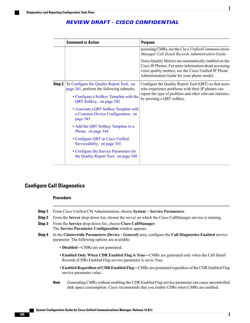
PurposeCommand or Action
accessingCMRs, see theCiscoUnified CommunicationsManager Call Detail Records Administration Guide .
Voice Quality Metrics are automatically enabled on theCisco IP Phones. For more information about accessingvoice quality metrics, see the Cisco Unified IP PhoneAdministration Guide for your phone model.
Configure the Quality Report Tool (QRT) so that userswho experience problems with their IP phones can
To Configure the Quality Report Tool, onpage 341, perform the following subtasks:
Step 2
report the type of problem and other relevant statisticsby pressing a QRT softkey.• Configure a Softkey Template with the
QRT Softkey, on page 342
• Associate a QRT Softkey Template witha Common Device Configuration, onpage 343
• Add the QRT Softkey Template to aPhone, on page 344
• Configure QRT in Cisco UnifiedServiceability, on page 345
• Configure the Service Parameters forthe Quality Report Tool, on page 348
Configure Call Diagnostics
Procedure
Step 1 From Cisco Unified CM Administration, choose System > Service Parameters.Step 2 From the Server drop-down list, choose the server on which the Cisco CallManager service is running.Step 3 From the Service drop-down list, choose Cisco CallManager.
The Service Parameter Configuration window appears.Step 4 In the Clusterwide Parameters (Device - General) area, configure the Call Diagnostics Enabled service
parameter. The following options are available:
• Disabled—CMRs are not generated.
• Enabled Only When CDR Enabled Flag is True—CMRs are generated only when the Call DetailRecords (CDR) Enabled Flag service parameter is set to True.
• EnabledRegardless of CDREnabled Flag—CMRs are generated regardless of the CDREnabled Flagservice parameter value.
Generating CMRs without enabling the CDR Enabled Flag service parameter can cause uncontrolleddisk space consumption. Cisco recommends that you enable CDRs when CMRs are enabled.
Note
System Configuration Guide for Cisco Unified Communications Manager, Release 12.0(1)340
Diagnostics and Reporting Configuration Task Flow
REVIEW DRAFT - CISCO CONFIDENTIAL

Step 5 Click Save.
Configure the Quality Report ToolConfigure the Quality Report Tool (QRT) so that users who experience problems with their IP phones canreport the type of problem and other relevant statistics by pressing a QRT softkey.
Procedure
PurposeCommand or Action
You must configure the On Hook and Connectedcall states for the QRT Softkey. The following callstates are also available:
Configure a Softkey Template with the QRTSoftkey, on page 342
Step 1
• Connected Conference
• Connected Transfer
(Optional)To make the softkey template available to phones,you must complete either this step or the following
To Associate a QRT Softkey Template witha Common Device Configuration, on page343, perform the following subtasks:
Step 2
step. Follow this step if your system uses aCommon• Add a QRT Softkey Template to aCommon Device Configuration, onpage 343
DeviceConfiguration to apply configuration optionsto phones. This is the most commonly used methodfor making a softkey template available to phones.
• Associate a Common DeviceConfiguration with a Phone, on page344
(Optional)Use this procedure either as an alternative toassociating the softkey template with the Common
Add the QRT Softkey Template to a Phone,on page 344
Step 3
Device Configuration, or in conjunction with theCommon Device Configuration. Use this procedurein conjunction with the Common DeviceConfiguration if you need assign a softkey templatethat overrides the assignment in the CommonDeviceConfiguration or any other default softkeyassignment.
To Configure QRT in Cisco UnifiedServiceability, on page 345, perform thefollowing subtasks:
Step 4
• Activate the Cisco Extended FunctionsService, on page 345
• Configure Alarms, on page 346
System Configuration Guide for Cisco Unified Communications Manager, Release 12.0(1) 341
Diagnostics and Reporting Configuration Task Flow
REVIEW DRAFT - CISCO CONFIDENTIAL

PurposeCommand or Action
• Configure Traces, on page 347
(Optional)Configure the Service Parameters for theQuality Report Tool, on page 348
Step 5
Configure a Softkey Template with the QRT Softkey
You must configure the On Hook and Connected call states for the QRT Softkey. The following call statesare also available:
• Connected Conference
• Connected Transfer
Procedure
Step 1 From Cisco Unified CM Administration, choose Device > Device Settings > Softkey Template.The Softkey Template Configuration window appears.
Step 2 Perform this step to create a new softkey template; otherwise, proceed to the next step.a) Click Add New.b) Select a default template and click Copy.c) In the Softkey Template Name field, enter a new name for the template.d) Click Save.
Step 3 Perform this step to add softkeys to an existing template.a) Enter search criteria and click Find.b) Choose an existing template.The Softkey Template Configuration window appears.
Step 4 Check the Default Softkey Template check box to designate this softkey template as the default softkeytemplate.
If you designate a softkey template as the default softkey template, you cannot delete it unless youfirst remove the default designation.
Note
Step 5 Choose Configure Softkey Layout from the Related Links drop-down list in the upper right corner andclick Go.
Step 6 From the Select a Call State to Configure drop-down list, choose the call state for which you want the softkeyto display.
Step 7 From the Unselected Softkeys list, choose the softkey to add and click the right arrow to move the softkeyto the Selected Softkeys list. Use the up and down arrows to change the position of the new softkey.
Step 8 To display the softkey in additional call states, repeat the previous step.Step 9 Click Save.Step 10 Perform one of the following tasks:
System Configuration Guide for Cisco Unified Communications Manager, Release 12.0(1)342
Diagnostics and Reporting Configuration Task Flow
REVIEW DRAFT - CISCO CONFIDENTIAL

• If you modified a template that is already associated with devices, click Apply Config to restart thedevices.
• If you created a new softkey template, associate the template with the devices and then restart them. Seethe What to Do Next section for more information.
What to Do Next
Perform one of the following steps:
• Add a QRT Softkey Template to a Common Device Configuration, on page 343
• Add the QRT Softkey Template to a Phone, on page 344
Associate a QRT Softkey Template with a Common Device Configuration
Optional. There are two ways to associate a softkey template with a phone:
• Add the softkey template to the Phone Configuration.
• Add the softkey template to the Common Device Configuration.
The procedures in this section describe how to associate the softkey template with a Common DeviceConfiguration. Follow these procedures if your system uses a Common Device Configuration to applyconfiguration options to phones. This is the most commonly used method for making a softkey templateavailable to phones.
To use the alternative method, see Add the QRT Softkey Template to a Phone, on page 344.
Procedure
PurposeCommand or Action
Add a QRT Softkey Template to a Common Device Configuration, onpage 343
Step 1
Associate a Common Device Configuration with a Phone, on page 344Step 2
Add a QRT Softkey Template to a Common Device Configuration
Before You Begin
Configure a Softkey Template with the QRT Softkey, on page 342
Procedure
Step 1 FromCisco Unified CMAdministration, chooseDevice >Device Settings >CommonDevice Configuration.The Find and List Common Device Configuration window appears.
Step 2 Perform this step to create a new Common Device Configuration and associate the softkey template with it;otherwise, proceed to the next step.
System Configuration Guide for Cisco Unified Communications Manager, Release 12.0(1) 343
Diagnostics and Reporting Configuration Task Flow
REVIEW DRAFT - CISCO CONFIDENTIAL

a) Click Add New.b) In the Name field, enter a name for the Common Device Configuration.c) Click Save.
Step 3 Perform this step to add the softkey template to an existing Common Device Configuration.a) Enter search criteria and click Find.b) Choose an existing Common Device Configuration.The Common Device Configuration window appears.
Step 4 In the Softkey Template drop-down list, choose the softkey template that contains the softkey that you wantto make available.
Step 5 Click Save.Step 6 Perform one of the following tasks:
• If you created a new Common Device Configuration, associate the configuration with devices and thenrestart them. See the What to Do Next section for more information.
• If you modified a Common Device Configuration that is already associated with devices, click ApplyConfig to restart the devices.
What to Do Next
Associate a Common Device Configuration with a Phone, on page 344
Associate a Common Device Configuration with a Phone
Before You Begin
Add a QRT Softkey Template to a Common Device Configuration, on page 343
Procedure
Step 1 From Cisco Unified CM Administration, choose Device > Phone.The Find and List Phones window appears.
Step 2 Find the phone to which to add the softkey template.Step 3 From the Common Device Configuration drop-down list, choose the common device configuration that
contains the new softkey template.Step 4 Click Save.Step 5 Click Reset to update the phone settings.
Add the QRT Softkey Template to a Phone
Before You Begin
Configure a Softkey Template with the QRT Softkey, on page 342
System Configuration Guide for Cisco Unified Communications Manager, Release 12.0(1)344
Diagnostics and Reporting Configuration Task Flow
REVIEW DRAFT - CISCO CONFIDENTIAL

Procedure
Step 1 From Cisco Unified CM Administration, choose Device > Phone.The Find and List Phones window is displayed.
Step 2 From the Find and List Phones window, click Find.A list of phones that are configured on the Cisco Unified Communications Manager is displayed.
Step 3 Choose the phone to which you want to add the phone button template.The Phone Configuration window appears.
Step 4 In the Phone Button Template drop-down list, choose the phone button template that contains the new featurebutton.
Step 5 Click Save.A dialog box is displayed with a message to press Reset to update the phone settings.
Configure QRT in Cisco Unified Serviceability
Procedure
PurposeCommand or Action
Activate the Cisco Extended Functions Service to provide supportfor voice-quality features such as the Quality Report Tool.
Activate the Cisco ExtendedFunctions Service, on page345
Step 1
Configure alarms for the QRT to log errors in the Application Logswithin SysLog Viewer. This function logs alarms, provides a
Configure Alarms, on page346
Step 2
description of the alarms, and recommended actions. You can accessthe SysLog Viewer from the Cisco Unified Real-Time MonitoringTool.
Configure traces for the QRT to log trace information for your voiceapplication. After configure the information that you want to include
Configure Traces, on page347
Step 3
in the trace files for the QRT, you can collect and view trace filesby using the Trace and Log Central option in the Cisco UnifiedReal-Time Monitoring Tool.
Activate the Cisco Extended Functions ServiceActivate the Cisco Extended Functions Service to provide support for voice-quality features such as the QualityReport Tool.
System Configuration Guide for Cisco Unified Communications Manager, Release 12.0(1) 345
Diagnostics and Reporting Configuration Task Flow
REVIEW DRAFT - CISCO CONFIDENTIAL

Procedure
Step 1 From Cisco Unified Serviceability, choose Tools > Service Activation.Step 2 From the Server drop-down list, choose the node on which you want to activate the Cisco Extended Functions
service.Step 3 Check the Cisco Extended Functions check box.Step 4 Click Save.
What to Do Next
Configure Alarms, on page 346
Configure AlarmsConfigure alarms for the QRT to log errors in the Application Logs within SysLog Viewer. This function logsalarms, provides a description of the alarms, and recommended actions. You can access the SysLog Viewerfrom the Cisco Unified Real-Time Monitoring Tool.
Before You Begin
Activate the Cisco Extended Functions Service, on page 345
Procedure
Step 1 From the Cisco Unified Serviceability, choose Alarm > Configuration.Step 2 From the Server drop-down list, choose the node on which you want to configure alarms.Step 3 From the Service Group drop-down list, choose CM Services.Step 4 From the Service drop-down list, choose Cisco Extended Functions.Step 5 Check the Enable Alarm check box for both Local Syslogs and SDI Trace.Step 6 From the drop-down list, configure the Alarm Event Level for both Local Syslogs and SDI Trace by choosing
one of the following options:
• Emergency—Designates the system as unusable.
• Alert—Indicates that immediate action is needed.
• Critical—The system detects a critical condition.
• Error—Indicates that an error condition is detected.
• Warning—Indicates that a warning condition is detected.
• Notice—Indicates that a normal but significant condition is detected.
• Informational—Indicates only information messages.
• Debug— Indicates detailed event information that Cisco Technical Assistance Center (TAC) engineersuse for debugging.
The default value is Error.
System Configuration Guide for Cisco Unified Communications Manager, Release 12.0(1)346
Diagnostics and Reporting Configuration Task Flow
REVIEW DRAFT - CISCO CONFIDENTIAL

Step 7 Click Save.
What to Do Next
Configure Traces, on page 347
Configure TracesConfigure traces for the QRT to log trace information for your voice application. After configure the informationthat you want to include in the trace files for the QRT, you can collect and view trace files by using the Traceand Log Central option in the Cisco Unified Real-Time Monitoring Tool.
Before You Begin
Configure Alarms, on page 346
Procedure
Step 1 From Cisco Unified Serviceability, choose Trace > Configuration.Step 2 From the Server drop-down list, choose the node on which you want to configure traces.Step 3 From the Service Group drop-down list, choose CM Services.Step 4 From the Service drop-down list, choose Cisco Extended Functions.Step 5 Check the Trace On check box.Step 6 From the Debug Trace Level drop-down list, choose one of the following options:
• Error—Traces all error conditions, as well as process and device initialization messages.
• Special—Traces all special conditions and subsystem state transitions that occur during normal operation.Traces call-processing events.
• State Transition—Traces all state transition conditions andmedia layer events that occur during normaloperation.
• Significant—Traces all significant conditions, as well as entry and exit points of routines. Not all servicesuse this trace level.
• Entry_exit—Traces all entry and exit conditions, plus low-level debugging information.
• Arbitrary—Traces all Arbitrary conditions plus detailed debugging information.
•Draft comment: *SME REVIEWERS*: Please advise on these definitions. The source doc appearsto be "off" (Error has the Special definition, Special has the State Transition def, etc. Are these definitionscorrect? Especially Detailed below, because I had to guess at that one as I reordered the source content.
Detailed— Traces alarm conditions and events. Used for all traces that are generated in abnormal path.Uses minimum number of CPU cycles.
The default value is Error.
We recommend that you check all the check boxes in this section for troubleshooting purposes.Tip
System Configuration Guide for Cisco Unified Communications Manager, Release 12.0(1) 347
Diagnostics and Reporting Configuration Task Flow
REVIEW DRAFT - CISCO CONFIDENTIAL

Step 7 Click Save.
What to Do Next
(Optional) Configure the Service Parameters for the Quality Report Tool, on page 348
Configure the Service Parameters for the Quality Report Tool
We recommend that you use the default service parameters settings unless the Cisco Technical AssistanceCenter (TAC) instructs otherwise.
Caution
Procedure
Step 1 From Cisco Unified Communications Manager Administration , choose System > Service Parameters.Step 2 Choose the node where the QRT application resides.Step 3 Choose the Cisco Extended Functions service.Step 4 Configure the service parameters. See the Related Topics section for more information about the service
parameters and their configuration options.Step 5 Click Save.
Related Topics
Quality Report Tool Service Parameters, on page 348
Quality Report Tool Service Parameters
Table 52: Quality Report Tool Service Parameters
DescriptionParameter
Determines whether extended menu choices arepresented to the user. You can choose one of thefollowing configuration options:
• Set this field to true to display extended menuchoices (interview mode).
• Set this field to false to not display extendedmenu choices (silent mode).
• The recommended default value is false (silentmode).
Display Extended QRT Menu Choices
System Configuration Guide for Cisco Unified Communications Manager, Release 12.0(1)348
Diagnostics and Reporting Configuration Task Flow
REVIEW DRAFT - CISCO CONFIDENTIAL

DescriptionParameter
Determines the duration that is to be used for pollingstreaming statistics. You can choose one of thefollowing configuration options:
• Set this field to -1 to poll until the call ends.
• Set this field to 0 to not poll at all.
• Set it to any positive value to poll for that manyseconds. Polling stops when the call ends.
• The recommended default value is -1 (poll untilthe call ends).
Streaming Statistics Polling Duration
Enter the number of seconds to wait between eachpoll.The value ranges between 30 and 3600. Therecommended default value is 30.
Streaming Statistics Polling Frequency (seconds)
Enter the maximum number of files before the filecount restarts and overwrites the old files.Valid values are between 1 and 10000. Therecommended default value is 250.
Maximum No. of Files
Enter the maximum number of lines in each filebefore starting the next file:
• The value ranges between 100 and 2000.
• The recommended default value specifies 2000.
Maximum No. of Lines per File
Enter the Instance ID of the Application CAPF Profilefor application user CCMQRTSysUser that the CiscoExtended Function service will use to open a secureconnection to CTI Manager. You must configure thisparameter if CTI Manager Connection Security Flagis enabled.
Turn on security by enabling the CTIManager Connection Security Flag serviceparameter. You must restart the CiscoExtended Functions service for the changesto take effect.
Note
CAPF Profile Instance Id for Secure Connection toCTI Manager
Choose whether security for Cisco ExtendedFunctions service CTIManager connection is enabledor disabled. If enabled, Cisco Extended Functionswill open a secure connection to CTI Manager usingthe Application CAPF Profile configured for theInstance ID for application user CCMQRTSysUser.The value choices are True and False. You mustchoose True to enable a secure connection to CTI.
CTI Manager Connection Security Flag
System Configuration Guide for Cisco Unified Communications Manager, Release 12.0(1) 349
Diagnostics and Reporting Configuration Task Flow
REVIEW DRAFT - CISCO CONFIDENTIAL

System Configuration Guide for Cisco Unified Communications Manager, Release 12.0(1)350
Diagnostics and Reporting Configuration Task Flow
REVIEW DRAFT - CISCO CONFIDENTIAL

C H A P T E R 45Configure Third-Party SIP Phones
• Third-Party SIP Endpoints Overview, page 351
• Third-Party SIP Endpoints Configuration Task Flow, page 352
Third-Party SIP Endpoints OverviewIn addition to the Cisco Unified IP Phones that run SIP, Cisco Unified Communications Manager supports avariety of third-party SIP endpoints. You can configure the following third-party SIP endpoints in CiscoUnified Communications Manager Administration:
• Third-Party SIP Device (Advanced)-This eight-line SIP device is an RFC3261-compliant phone that isrunning SIP from third-party companies.
• Third-Party SIP Device (Basic)-This one-line SIP device is an RFC3261-compliant phone that is runningSIP from third-party companies.
• Third-Party AS-SIP Device - Assured Services SIP (AS-SIP) endpoints are SIP endpoints compliantwith MLPP, DSCP, TLS/SRTP, and IPv6 requirements. AS-SIP provides multiple endpoint interfaceson the Unified Communications Manager.
• Generic Desktop Video Endpoint-This SIP device supports video, security, configurable trust, and Ciscoextensions. This device supports 8 lines; the maximum number of calls and busy trigger for each line is4 and 2, respectively.
• Generic Single Screen Room System-This SIP device supports single screen telepresence (room systems),video, security, configurable trust, and Cisco extensions. This device supports 8 lines; the maximumnumber of calls and busy trigger for each line is 4 and 2, respectively.
• Generic Multiple Screen Room System-This SIP device supports multiple screen telepresence (roomsystems), video, security, configurable trust, and Cisco extensions. This device supports 8 lines; themaximum number of calls and busy trigger for each line is 4 and 2, respectively.
System Configuration Guide for Cisco Unified Communications Manager, Release 12.0(1) 351

Third-Party SIP Endpoints Configuration Task Flow
Procedure
PurposeCommand or Action
To enable digest authentication, configure an end user that is adigest user. Cisco Unified Communications Manager uses the
Configure a Digest User, onpage 352
Step 1
digest credentials that you specify in the End UserConfiguration window to validate the SIP user agent responseduring a challenge to the SIP trunk.
If the third-party SIP phone does not support a digest user, createa user with a user ID that matches the directory number of thethird-party SIP phone. For example, create an end user named1000 and create a directory number of 1000 for the phone. Assignthis user to the phone.
Provide a set of SIP attributes that are associated with SIP trunks.Configure SIP Profile, on page321
Step 2
To use digest authentication, you must configure a new phonesecurity profile. If you use one of the standard, nonsecure SIP
Configure Phone SecurityProfile, on page 353
Step 3
profiles that are provided for auto-registration, you cannot enabledigest authentication.
Configure a third-party endpoint.Add a Third-Party SIPEndpoint, on page 354
Step 4
Associate the third-party endpoint with an end user.Associate Device with EndUser, on page 355
Step 5
What to Do Next
Provide power, verify network connectivity, and configure network settings for the third-party SIP endpoint.For more information about configuring network settings, see the user guide for your third-party SIP endpoint.
Configure a Digest UserPerform these steps to configure an end user as a digest user. Digest authentication allows Cisco UnifiedCommunications Manager to challenge the identity of a device that is connecting to Cisco UnifiedCommunications Manager. When challenged, the device presents its digest credentials, similar to a usernameand password, to Cisco Unified CommunicationsManager for verification. If the credentials that are presentedmatch those that are configured in the database for that device, digest authentication succeeds, and CiscoUnified Communications Manager processes the SIP request.
System Configuration Guide for Cisco Unified Communications Manager, Release 12.0(1)352
Third-Party SIP Endpoints Configuration Task Flow
REVIEW DRAFT - CISCO CONFIDENTIAL

Procedure
Step 1 From Cisco Unified CM Administration, choose User Management > End User.Step 2 Click Add New.Step 3 Enter a User ID.Step 4 Enter a Last Name.Step 5 Enter Digest Credentials. The digest credentials are a string of alphanumeric characters.Step 6 Complete any remaining fields in the End User Configuration window. See the online help for more
information about the fields and their configuration options..Step 7 Click Save.
What to Do Next
Configure SIP Profile, on page 321
Configure SIP Profile
Before You Begin
• Configure SIP Phone Secure Port, on page 320
• Restart Services, on page 320
Procedure
Step 1 In Cisco Unified CM Administration, choose Device > Device Settings > SIP Profile.Step 2 Click Find.Step 3 For the profile that you want to copy, click the file icon in the Copy column.Step 4 Enter the name and description of the new profile.Step 5 If Cisco Unity Connection uses IPv6 or dual-stack IPv4 and IPv6 to communicate with Cisco Unified
Communications Manager, check the Enable ANAT check box.You must perform this step to ensure proper handling of callers in an IPv6 or dual-stack environment.
Step 6 Click Save.
What to Do Next
Configure Phone Security Profile, on page 353
Configure Phone Security ProfileCisco Unified CommunicationsManager provides a set of predefined, nonsecure profiles for autoregistration.If you want to enable security features for a phone, you must configure a new security profile and apply it tothe phone. Follow these steps to configure a new security profile:
System Configuration Guide for Cisco Unified Communications Manager, Release 12.0(1) 353
Third-Party SIP Endpoints Configuration Task Flow
REVIEW DRAFT - CISCO CONFIDENTIAL

Before You Begin
If you are configuring SIP phones, complete the following procedures:
• Configure SIP Phone Secure Port, on page 320
• Restart Services, on page 320
• Configure SIP Profile, on page 321
If you are configuring SCCP phones, there are no prerequisites to complete before you begin this procedure.
Procedure
Step 1 From Cisco Unified CM Administration, choose System > Security > Phone Security Profile.Step 2 Click Add New.Step 3 From the Phone Security Profile Type drop down list, choose the type of profile that you want to create.Step 4 Click Next.Step 5 From the Select the phone security profile protocol drop down list, choose the protocol.Step 6 Click Next.Step 7 Enter an appropriate name for the profile in the Name field.Step 8 Enter a brief description of the profile.Step 9 Click Save.
What to Do Next
For both SIP and SCCP phones:
Add a Third-Party SIP Endpoint, on page 354
Add a Third-Party SIP Endpoint
Before You Begin
Configure a Digest User, on page 352
Procedure
Step 1 From Cisco Unified CM Administration, choose Device > Phone.Step 2 Click Add New.Step 3 From the Phone Type drop-down list, choose one of the following:
• Third-party SIP Device (Basic)
• Third-party SIP Device (Advanced)
• Third-Party AS-SIP Device
• Generic Desktop Video Endpoint
System Configuration Guide for Cisco Unified Communications Manager, Release 12.0(1)354
Third-Party SIP Endpoints Configuration Task Flow
REVIEW DRAFT - CISCO CONFIDENTIAL

• Generic Single Screen Room System
• Generic Multiple Screen Room System
Step 4 Configure the fields in the Phone Configuration window. See the online help for more information aboutthe fields and their configuration options.
Step 5 Click Save.Step 6 To configure a directory number for the third-party endpoint, click the Add a New DN link that displays in
the Association Information area on the left side of the window.TheDirectoryNumberConfigurationwindow appears. See topics related to adding and configuring directorynumbers for details.
What to Do Next
Associate Device with End User, on page 355
Associate Device with End User
Procedure
Step 1 From Cisco Unified CM Administration, choose User Management > End User.Step 2 Specify the appropriate filters in the Find User Where field to and then click Find to retrieve a list of users.Step 3 Select the user from the list.Step 4 Locate the Device Information section.Step 5 Click Device Association.
The User Device Association window appears.Step 6 Find and select the device.Step 7 To complete the association, click Save Selected/Changes.Step 8 From Related Links drop-down list box, choose Back to User, and then click Go.
The End User Configuration window appears, and the associated device that you chose appears in theControlled Devices pane.
System Configuration Guide for Cisco Unified Communications Manager, Release 12.0(1) 355
Third-Party SIP Endpoints Configuration Task Flow
REVIEW DRAFT - CISCO CONFIDENTIAL

Third-Party Interactions and Restrictions
Third-Party Restrictions
Table 53: Third-Party SIP Endpoints Restrictions
DescriptionRestriction
Blind transfer or switch to request the transfer whichoccurs over VCS registered endpoints with CiscoUnified Communications Manager will not have aringback tone. If you do a supervised transfer, thenyou allocate Music On Hold (MOH) but, not aringback tone.
Ringback tone restriction for Cisco VideoCommunications Server (VCS) registered tothird-party SIP Endpoints
System Configuration Guide for Cisco Unified Communications Manager, Release 12.0(1)356
Third-Party SIP Endpoints Configuration Task Flow
REVIEW DRAFT - CISCO CONFIDENTIAL

C H A P T E R 46Device Profiles and Templates
• Device Profiles and Templates Overview, page 357
• Configure Device Profiles and Templates Task Flow, page 358
Device Profiles and Templates OverviewThis chapter explains how to configure device profiles and templates. For information about configuringspecific features, see the Features and Services Guide at http://www.cisco.com/c/en/us/support/unified-communications/unified-communications-manager-callmanager/products-maintenance-guides-list.html.
Device ProfilesA device profile defines the services, features, and directory numbers that associate with a particular device.You can configure a device profile and then you can assign the user device profile to a user, so that when theuser logs in to a device, those features and services are available on that device.
SIP Profiles for End PointsA SIP profile comprises the set of SIP attributes that are associated with SIP endpoints. SIP profiles includeinformation such as name, description, timing, retry, call pickup URI, and so on. The profiles contain somestandard entries that cannot be deleted or changed.
Device Profiles and TemplatesCisco Unified CommunicationsManager also supports a default device profile. Cisco Unified CommunicationsManager uses the default device profile whenever a user logs on to a phone model for which no user deviceprofile exists.
Peer-to-Peer Image DistributionThe peer firmware sharing feature provides these advantages in high-speed campus LAN settings:
• Limits congestion on TFTP transfers to centralized TFTP servers.
System Configuration Guide for Cisco Unified Communications Manager, Release 12.0(1) 357

• Eliminates the need to manually control firmware upgrades.
• Reduces phone downtime during upgrades when large numbers of devices are reset simultaneously.
In most conditions, the peer firmware sharing feature optimizes firmware upgrades in branch deploymentscenarios over bandwidth-limited WAN links.
When the feature is enabled, it allows the phone to discover similar phones on the subnet that are requestingthe files that make up the firmware image and to automatically assemble transfer hierarchies on a per-filebasis. The individual files that make up the firmware image get retrieved from the TFTP server by only theroot phone in the hierarchy and are then rapidly transferred down the transfer hierarchy to the other phoneson the subnet using TCP connections.
Configure Device Profiles and Templates Task Flow
Procedure
PurposeCommand or Action
Add the default device profile to a softkey template.Configure a Softkey Template onthe Default Device Profile, onpage 359
Step 1
Optional. To make the softkey template available to phones, youmust complete either this step or the following step. Follow this
Associate a Softkey Template witha CommonDevice Configuration,
Step 2
step if your system uses a common device configuration to applyon page 360, complete thefollowing subtasks: configuration options to phones. This is the most commonly
used method for making a softkey template available to phones.• Add a Softkey Template toa Common DeviceConfiguration
For information on how to associate a common deviceconfiguration on multiple phones by using the BulkAdministration Tool, see the Cisco UnifiedCommunications Manager Bulk Administration Guideat http://www.cisco.com/c/en/us/support/unified-communications/unified-communications-manager-callmanager/products-maintenance-guides-list.html.
Note
• Associate a CommonDeviceConfiguration with a Phone
Optional. Use this procedure either as an alternative toassociating the softkey template with the common device
Associate a Softkey Template witha Phone, on page 362
Step 3
configuration, or in conjunction with the common deviceconfiguration. Use this procedure in conjunction with thecommon device configuration if you need assign a softkeytemplate that overrides the assignment in the common deviceconfiguration or any other default softkey assignment.
Optional. Use this procedure as an alternative to configuringsoftkey templates. Configure feature control policies to enable
Configure Feature Control Policy,on page 362
Step 4
or disable a particular feature and thereby control the appearanceof softkeys that display on the phone. You can create a featurecontrol policy for a group of users that wants to use a commonset of features. For example, call park and call pickup features
System Configuration Guide for Cisco Unified Communications Manager, Release 12.0(1)358
Configure Device Profiles and Templates Task Flow
REVIEW DRAFT - CISCO CONFIDENTIAL

PurposeCommand or Action
are typically used by the employees from the sales group andnot all the employees in a company. You can create a featurecontrol policy that enables only these two features and assignthat policy to the sales group. After you create a feature controlpolicy, you can associate that policy with an individual phone,a group of phones, or with all phones in the system.
Use this procedure to include default templates for each CiscoUnified IP Phone model. When you add phones, you can assign
Configure a Phone ButtonTemplate, on page 365
Step 5
one of these templates to the phone or create a template of yourown.• Associate a Button Template
with a Phone, on page 366
Configure the device profile for any phone model that supportsSIP or SCCP.
Configure Device Profile, on page367
Step 6
To configure a new SIP profile for the phone.Configure SIP Profiles forEndpoints , on page 367
Step 7
Configure the default device profile for any phone model thatsupports SIP or SCCP.
Configure Default Device Profiles, on page 367
Step 8
Configure a Softkey Template on the Default Device ProfileCisco Unified Communications Manager includes standard softkey templates for call processing andapplications. When creating custom softkey templates, copy the standard templates and make modificationsas required.
Procedure
Step 1 From Cisco Unified CM Administration, choose Device > Device Settings > Softkey Template.The Softkey Template Configuration window appears.
Step 2 Perform this step to create a new softkey template; otherwise, proceed to the next step.a) Click Add New.b) Select a default template and click Copy.c) In the Softkey Template Name field, enter a new name for the template.d) Click Save.
Step 3 Perform this step to add softkeys to an existing template.a) Enter search criteria and click Find.b) Choose an existing template.The Softkey Template Configuration window appears.
Step 4 Check the Default Softkey Template check box to designate this softkey template as the default softkeytemplate.
System Configuration Guide for Cisco Unified Communications Manager, Release 12.0(1) 359
Configure Device Profiles and Templates Task Flow
REVIEW DRAFT - CISCO CONFIDENTIAL

If you designate a softkey template as the default softkey template, you cannot delete it unless youfirst remove the default designation.
Note
Step 5 Choose Configure Softkey Layout from the Related Links drop-down list in the upper right corner andclick Go.
Step 6 From the Select a Call State to Configure drop-down list, choose the call state for which you want the softkeyto display.
Step 7 From the Unselected Softkeys list, choose the softkey to add and click the right arrow to move the softkeyto the Selected Softkeys list. Use the up and down arrows to change the position of the new softkey.
Step 8 To display the softkey in additional call states, repeat the previous step.Step 9 Click Save.Step 10 Perform one of the following tasks:
• If you modified a template that is already associated with devices, click Apply Config to restart thedevices.
• If you created a new softkey template, associate the template with the devices and then restart them. Seethe What to Do Next section for more information.
What to Do Next
Perform one the following procedures:
• Add a Softkey Template to a Common Device Configuration , on page 361
• Associate a Softkey Template with a Phone, on page 362
Associate a Softkey Template with a Common Device ConfigurationOptional. There are two ways to associate a softkey template with a phone:
• Add the softkey template to the Phone Configuration.
• Add the softkey template to the Common Device Configuration.
The procedures in this section describe how to associate the softkey template with a Common DeviceConfiguration. Follow these procedures if your system uses a Common Device Configuration to applyconfiguration options to phones. This is the most commonly used method for making a softkey templateavailable to phones.
To use the alternative method, see Associate a Softkey Template with a Phone, on page 362.
Procedure
PurposeCommand or Action
Add a Softkey Template to a Common Device Configuration , on page361
Step 1
Associate a Common Device Configuration with a Phone, on page 361Step 2
System Configuration Guide for Cisco Unified Communications Manager, Release 12.0(1)360
Configure Device Profiles and Templates Task Flow
REVIEW DRAFT - CISCO CONFIDENTIAL

Add a Softkey Template to a Common Device Configuration
Before You Begin
Associate a Softkey Template with a Common Device Configuration
Procedure
Step 1 FromCisco Unified CMAdministration, chooseDevice >Device Settings >CommonDevice Configuration.The Find and List Common Device Configuration window appears.
Step 2 Perform this step to create a new Common Device Configuration and associate the softkey template with it;otherwise, proceed to the next step.a) Click Add New.b) In the Name field, enter a name for the Common Device Configuration.c) Click Save.
Step 3 Perform this step to add the softkey template to an existing Common Device Configuration.a) Enter search criteria and click Find.b) Choose an existing Common Device Configuration.The Common Device Configuration window appears.
Step 4 In the Softkey Template drop-down list, choose the softkey template that contains the softkey that you wantto make available.
Step 5 Click Save.Step 6 Perform one of the following tasks:
• If you created a new Common Device Configuration, associate the configuration with devices and thenrestart them. See the What to Do Next section for more information.
• If you modified a Common Device Configuration that is already associated with devices, click ApplyConfig to restart the devices.
What to Do Next
Associate a Common Device Configuration with a Phone, on page 361
Associate a Common Device Configuration with a Phone
Procedure
Step 1 From Cisco Unified CM Administration, choose Device > Phone.
System Configuration Guide for Cisco Unified Communications Manager, Release 12.0(1) 361
Configure Device Profiles and Templates Task Flow
REVIEW DRAFT - CISCO CONFIDENTIAL

The Find and List Phones window appears.Step 2 Find the phone to which to add the softkey template.Step 3 From the Common Device Configuration drop-down list, choose the common device configuration that
contains the new softkey template.Step 4 Click Save.Step 5 Click Reset to update the phone settings.
Associate a Softkey Template with a PhoneThis procedure is optional. You can use this procedure as an alternative to associating the softkey templatewith the Common Device Configuration. This procedure also works in conjunction with the Common DeviceConfiguration: use it when you need to assign a softkey template that overrides the assignment in the CommonDevice Configuration or any other default softkey assignment.
Procedure
Step 1 From Cisco Unified CM Administration, choose Device > Phone.The Find and List Phones window appears.
Step 2 Choose the phone to which you want to add the softkey template.The Phone Configuration window appears.
Step 3 From the Softkey Template drop-down list, choose the template that contains the new softkey.Step 4 Click Save.Step 5 Press Reset to update the phone settings.
Configure Feature Control Policy
Procedure
PurposeCommand or Action
Log in to Cisco Unified Reporting and run a phone featurelist report to determine which phones support FeatureControl Policy.
Generate a Phone Feature List, on page363
Step 1
Create a Feature Control Policy for Cisco Unified IPPhones.
Create a Feature Control Policy, on page363
Step 2
After you create a Feature Control Policy, you mustassociate that policy to an individual phone, a group of
Perform one of the following tasks:Step 3
• Apply Feature Control Policy to aPhone, on page 364
phones, or to all phones in the system. The feature controlpolicy for an individual phone overrides the clusterwidefeature control policy.
System Configuration Guide for Cisco Unified Communications Manager, Release 12.0(1)362
Configure Device Profiles and Templates Task Flow
REVIEW DRAFT - CISCO CONFIDENTIAL

PurposeCommand or Action
For information on how to apply feature controlpolicy on multiple phones by using the BulkAdministration Tool , see the Cisco UnifiedCommunications Manager Bulk AdministrationGuide.
Note• Apply Feature Control Policy to aCommon Phone Profile, on page365
• Apply Feature Control Policy toAll Phones, on page 365
Generate a Phone Feature List
Generate a phone feature list report to determine which devices support the feature that you want to configure.
Procedure
Step 1 From Cisco Unified Reporting Administration, choose System Reports.Step 2 From the list of reports, click Unified CM Phone Feature List.Step 3 Perform one of the following steps:
• Choose Generate New Report (the bar chart icon) to generate a new report.
• Choose Unified CM Phone Feature List if a report already exists.
Step 4 From the Product drop-down list, choose All.Step 5 Click the name of the feature that you want to configure.Step 6 Click Submit.
The report is generated.
Create a Feature Control Policy
Follow these steps to create a feature control policy. You can configure multiple feature control policies onCisco Unified Communications Manager.
Procedure
Step 1 From Cisco Unified CM Administration, choose Device > Device Settings > Feature Control Policy.Step 2 Perform one of the following tasks:
• To modify the settings for an existing policy, enter search criteria, click Find and choose the policyfrom the resulting list.
• To add a new policy, click Add New.
System Configuration Guide for Cisco Unified Communications Manager, Release 12.0(1) 363
Configure Device Profiles and Templates Task Flow
REVIEW DRAFT - CISCO CONFIDENTIAL

The Feature Control Policy Configuration window is displayed.Step 3 In the Name field, enter a name for the feature control policy. The name can include up to 50 alphanumeric
characters and can contain any combination of spaces, periods (.), hyphens (-), and underscore characters (_).Ensure that each feature control policy name is unique to the system.
Step 4 In the Description field, enter a brief description for the feature control policy. The description can includeup to 50 alphanumeric characters and can contain any combination of spaces, periods (.), hyphens (-), andunderscore characters (_).
Step 5 In the Feature Control Section, for each feature listed, choose whether you want to override the systemdefault and enable or disable the setting:
• If the feature is enabled by default and you want to disable the setting, check the check box underOverride Default and uncheck the check box under Enable Setting.
• If the feature is disabled by default and you want to enable the setting, check the check box underOverride Default and check the check box under Enable Setting.
Step 6 Click Save.
What to Do Next
Perform one of the following:
• Apply Feature Control Policy to a Phone, on page 364
• Apply Feature Control Policy to a Common Phone Profile, on page 365
• Apply Feature Control Policy to All Phones, on page 365
Apply Feature Control Policy to a Phone
Before You Begin
• Ensure that the phone model supports Feature Control Policy. For more information, see Generate aPhone Feature List, on page 363.
• Create a Feature Control Policy, on page 363
Procedure
Step 1 From Cisco Unified CM Administration, choose Device > Phone.Step 2 Enter the search criteria and click Find.
A list of phones that are configured on the Cisco Unified Communications Manager is displayed.Step 3 Choose a phone to which you want to apply a feature control policy.Step 4 From the Feature Control Policy drop-down list, choose the required feature control policy.Step 5 Click Save.Step 6 Click Apply Config.Step 7 Click OK.
System Configuration Guide for Cisco Unified Communications Manager, Release 12.0(1)364
Configure Device Profiles and Templates Task Flow
REVIEW DRAFT - CISCO CONFIDENTIAL

Apply Feature Control Policy to a Common Phone Profile
Common Phone Profiles allow you to configure Feature Control Policy settings and then apply those settingsto all of the phones in your network that use that profile.
Before You Begin
Create a Feature Control Policy, on page 363
Procedure
Step 1 From Cisco Unified CM Administration, choose Device > Device Settings > Common Phone Profile.Step 2 Enter the search criteria and click Find.Step 3 Choose a common phone profile to which you want to apply a feature control policy.Step 4 From the Feature Control Policy drop-down list, choose the required feature control policy.Step 5 Click Save.Step 6 Click Apply Config.Step 7 Click OK.
Apply Feature Control Policy to All Phones
Before You Begin
Create a Feature Control Policy, on page 363
Procedure
Step 1 From Cisco Unified CM Administration, choose System > Enterprise Parameters.Step 2 From the Feature Control Policy drop-down list, choose the required feature control policy.Step 3 Click Save.Step 4 Click Apply Config.Step 5 Click OK.
Configure a Phone Button Template
Procedure
Step 1 From Cisco Unified CM Administration, choose Device > Device Settings > Phone Button Template.
System Configuration Guide for Cisco Unified Communications Manager, Release 12.0(1) 365
Configure Device Profiles and Templates Task Flow
REVIEW DRAFT - CISCO CONFIDENTIAL

The Find and List Phone Button Templates window appears.Step 2 Click Find.
The window displays a list of templates for the supported phones.Step 3 Perform this step if you want to create a new phone button template; otherwise, proceed to the next step.
a) Select a default template for the model of phone and click Copy.b) In the Phone Button Template Information field, enter a new name for the template.c) Click Save.
Step 4 Perform this step if you want to add phone buttons to an existing template.a) Enter search criteria and click Find .b) Choose an existing template.The Phone Button Template Configuration window appears.
Step 5 From the Line drop-down list, choose feature that you want to add to the template.Step 6 Click Save.Step 7 Perform one of the following tasks:
• If you modified a template that is already associated with devices, click Apply Config to restart thedevices.
• If you created a new softkey template, associate the template with the devices and then restart them. Seethe What to Do Next section for more information.
What to Do Next
Associate a Button Template with a Phone, on page 366
Associate a Button Template with a Phone
Before You Begin
Configure a Phone Button Template, on page 365
Procedure
Step 1 From Cisco Unified CM Administration, choose Device > Phone.The Find and List Phones window is displayed.
Step 2 From the Find and List Phones window, click Find.A list of phones that are configured on the Cisco Unified Communications Manager is displayed.
Step 3 Choose the phone to which you want to add the phone button template.The Phone Configuration window appears.
Step 4 In the Phone Button Template drop-down list, choose the phone button template that contains the new featurebutton.
Step 5 Click Save.A dialog box is displayed with a message to press Reset to update the phone settings.
System Configuration Guide for Cisco Unified Communications Manager, Release 12.0(1)366
Configure Device Profiles and Templates Task Flow
REVIEW DRAFT - CISCO CONFIDENTIAL

Configure Device ProfileA device profile comprises the set of attributes that associate with a particular device.
Before You Begin
Perform one the following procedures:
• Configure a Softkey Template on the Default Device Profile, on page 359
• Configure a Phone Button Template, on page 365
Procedure
Step 1 From the Cisco Unified CM Administration window, choose Device > Device Settings > Device Profile.Step 2 In the Device Profile Configuration window, from the Device Profile Type drop-down list, choose the
appropriate Cisco Unified IP Phone.Step 3 Click Next.Step 4 From the Device Protocol drop-down list, choose the appropriate protocol.Step 5 Click Next.Step 6 Configure the fields in the Device Profile Configuration window. See the online help for more information
about the fields and their configuration options.Step 7 Click Save.
Configure SIP Profiles for EndpointsCisco Unified Communications Manager uses SIP profiles to define SIP attributes that are associated withSIP trunks and Cisco Unified IP Phones.
Procedure
Step 1 In the Cisco Unified CM Administration window, choose Device > Device Settings > SIP Profiles.Step 2 To add a new SIP Profile, click the Add New button.Step 3 Configure the fields in the SIP Profile Configuration window. See the online help for more information
about the fields and their configuration options.Step 4 Click Apply Config.
Configure Default Device ProfilesThe phone takes on the default device profile whenever a user logs into a phone for which that user does nothave a user device profile.
System Configuration Guide for Cisco Unified Communications Manager, Release 12.0(1) 367
Configure Device Profiles and Templates Task Flow
REVIEW DRAFT - CISCO CONFIDENTIAL

A default device profile includes device type (phone), user locale, phone button template, softkey template,and multilevel precedence and preemption (MLPP) information.
Before You Begin
Perform one the following procedures:
• Configure a Softkey Template on the Default Device Profile, on page 359
• Configure a Phone Button Template, on page 365
Procedure
Step 1 From the Cisco Unified CM Administration window, choose Device > Device Settings > Default DeviceProfile.
Step 2 In the Default Device Profile Configuration window, from the Device Profile Type drop-down list, choosethe appropriate Cisco Unified IP Phone.
Step 3 Click Next.Step 4 From the Device Protocol drop-down list, choose the appropriate protocol.Step 5 Click Next.Step 6 Configure the fields in the Default Device Profile Configuration window. See the online help for more
information about the fields and their configuration options.Step 7 Click Save.
Configure Peer-to-Peer Image Distribution Feature for Phones
Procedure
Step 1 In Cisco Unified Communications Manager Administration, choose Device > Phone.Step 2 In the Find and List Phones window, to select a phone, specify the appropriate filters in the Find Phone
where field, click Find to retrieve a list of phones, and then select the phone from the list.Step 3 In thePhoneConfigurationwindow, from thePeer Firmware Sharing drop-down list in the Product Specific
Configuration Layout pane, choose one the following options.
• Enabled (default)—Indicates that the phone supports Peer-to-Peer Image Distribution (PPID).
• Disabled—Indicates that the phone does not support Peer-to-Peer Image Distribution (PPID).
Step 4 Click Apply Config.
System Configuration Guide for Cisco Unified Communications Manager, Release 12.0(1)368
Configure Device Profiles and Templates Task Flow
REVIEW DRAFT - CISCO CONFIDENTIAL

C H A P T E R 47Associate Users with Endpoints
• Users to Endpoints Association Overview, page 369
• Associate Users with Endpoints Prerequisites, page 369
• Users and Devices Configuration Task Flow, page 369
• Interactions and Restrictions, page 373
Users to Endpoints Association OverviewThis chapter describes how to associate devices with end users and application users. End users can controlthe devices that you associate with them. Applications that are identified as users can control devices, suchas phones and Computer Telephony Integration (CTI) ports.
Associate Users with Endpoints PrerequisitesConfigure end users and application users before you associate themwith endpoints. See Associate End Userswith Devices, on page 370 and Associate Application Users with Devices, on page 373.
Users and Devices Configuration Task Flow
Procedure
PurposeCommand or Action
Associate end users with devices.Associate End Users with Devices, on page 370.Step 1
Associate application users with devices.Associate Application Users with Devices, onpage 373.
Step 2
System Configuration Guide for Cisco Unified Communications Manager, Release 12.0(1) 369

Associate End Users with DevicesCisco Unified Communications Manager does not allow duplicate end user IDs.
Procedure
Step 1 From Cisco Unified CM Administration, choose User Management > End User.Step 2 From the Find and List Application Users window, click Find.Step 3 From the window that displays a list of end users, click the link for the relevant end user.Step 4 From the End User Configuration window, scroll down to the Device Information area and select the
devices that you want to associate with the end user. In the Available Devices box, choose a device that youwant to associate with the application user and click the down arrow below the box.
If no devices exist in the Device Information area, click the Device Association button to open theUserDevice Associationwindow. Select one ormultiple devices and click the Save Selected/Changesbutton. The selected devices appear in the Controlled Devices list box of the Device Informationarea. Then, follow Steps 1 to 4 and associate a device.
Note
Step 5 (Optional) To associate a line appearance to an end user for presence and to enable the on-the-phone statusinformation to IM and Presence clients when this line appearance is off-hook, click the Line AppearanceAssociation from Presence button. The Line Appearance Association for Presence window appears fromwhere you can choose product type, device name, directory, partition, or description. The choices availablein this window depend on the lines associated with the controlled devices. Click Save.
Step 6 Configure the fields from the End User Configuration window. See the Related Topics section for moreinformation about the fields and their configuration options.
Step 7 Click Save.
What to Do Next
Associate Application Users with Devices, on page 373.
Related Topics
End User and Device Configuration Settings, on page 370
End User and Device Configuration Settings
Table 54: User Information
DescriptionField
Enter the end user identification name. Cisco UnifiedCommunicationsManager does not permit modifyingthe user ID after it is created. You may use thefollowing special characters: =, +, <, >, #, ;, \, , “”,and blank spaces.
User ID
System Configuration Guide for Cisco Unified Communications Manager, Release 12.0(1)370
Users and Devices Configuration Task Flow
REVIEW DRAFT - CISCO CONFIDENTIAL

DescriptionField
Enter five or more alphanumeric or special charactersfor the end user password. Youmay use the followingspecial characters: =, +, <, >, #, ;, \, , “”, and blankspaces
Password
Enter five or more numeric characters for the PersonalIdentification Number.
PIN
Enter the end user last name. You may use thefollowing special characters: =,+, <, >, #, ;, \, , “”, andblank spaces
Last Name
Enter the end user middle name. You may use thefollowing special characters: =,+, <, >, #, ;, \, , “”, andblank spaces
Middle Name
Enter the end user first name. You may use thefollowing special characters: =,+, <, >, #, ;, \, , “”, andblank spaces
First Name
Table 55: Device Associations
DescriptionField
From the drop-down list, choose the type of deviceto associate with this end user.
Product Type
Enter a unique MAC address for the new device thatyou are associating with the new user. The MACaddress comprises exactly 12 hexadecimal digits (0to 9, A to F).
MAC Address
From the drop-down list, choose the calling searchspace for the directory number that you areassociating with this user and device.
Calling Search Space DN
From the drop-down list, choose the calling searchspace for the phone that you are associating with thisuser and device.
Calling Search Space Phone
System Configuration Guide for Cisco Unified Communications Manager, Release 12.0(1) 371
Users and Devices Configuration Task Flow
REVIEW DRAFT - CISCO CONFIDENTIAL

DescriptionField
Specify the mask that is used to format caller IDinformation for external (outbound) calls that aremade from the associated device.
• Themask can contain up to 24 characters. Validcharacters specify 0 to 9, *, #, and X.
• Enter the literal digits that you want to appearin the caller ID information and use Xs torepresent the directory number of the associateddevice.
• If you specify a mask of 972813XXXX, anexternal call from extension 1234 displays acaller ID number of 9728131234 if the UseExternal PhoneNumberMask option is checkedon the route pattern that is used to make theexternal call. If you specify a mask of all literaldigits, such as 9728135000 to represent a mainattendant number, that literal number(9728135000) displays as the caller ID for anexternal call from any associated device.
External Phone Number Mask
Enter an extension for the new user and phone. Youmay use the following characters: 0 to 9, ?, [, ], +, -,*, ^, #, !.
This field represents the primary directory numberfor the end user. End users can have multiple lineson their phones.
Extension
From the drop-down list, choose a partition for thedirectory number that you specified in the Extensionfield.
Route Partition
From the drop-down list, choose a voice mail profilefor the directory number.
Choose None to use the system default.
Voice Mail Profile
Check this check box to enable extension mobility.
After you add the new user, you can use the UserManagement > End User menu option to choosean Extension Mobility profile.
Enable Extension Mobility
System Configuration Guide for Cisco Unified Communications Manager, Release 12.0(1)372
Users and Devices Configuration Task Flow
REVIEW DRAFT - CISCO CONFIDENTIAL

Associate Application Users with DevicesYou can associate devices over which application users have control. Application users can control devices,such as phones. Applications that are identified as users can control other devices, such as CTI ports. Whenapplication users have control of a phone, they can control certain settings for that phone, such as speed dialand call forwarding.
Before You Begin
Associate End Users with Devices, on page 370.
Procedure
Step 1 From Cisco Unified CM Administration, choose User Management > Application User.appears.
Step 2 From the Find and List Application Users window, click Find.Step 3 From the list of application users, click the link for the relevant Application User.Step 4 From the Application User Configuration window, scroll down to the Device Information area. In the
Available Devices box, choose a device that you want to associate with the application user and click thedown arrow below the box.The device is moved to the Controlled Devices box.
Step 5 To add to the list of available devices, click one of the following buttons:
• Find more Phones—To find the phones to associate with this application user.
• Find more Route Points—To find the CTI route points to associate with this application user.
• Find more Pilot Points—To find the pilot points to associate with this application user.
Step 6 Repeat Step 5 for each device that you want to assign to the application user.Step 7 Click Save.
Interactions and Restrictions
Interactions
Table 56: Users with Endpoints Association Interactions
InteractionFeature
For devices that are not CTI-controllable, such as H.323 devices, an asterisk (*)appears next to the device icon in the list of available devices.
Non-CTI-controllabledevices
System Configuration Guide for Cisco Unified Communications Manager, Release 12.0(1) 373
Interactions and Restrictions
REVIEW DRAFT - CISCO CONFIDENTIAL

InteractionFeature
Use Cisco Extension Mobility feature to configure a Cisco Unified IP Phone totemporarily display as the phone of an end user. The end user can sign in to aphone, and the ExtensionMobility profile (including line and speed-dial numbers)for the end user resides on the phone. This feature applies primarily inenvironments where end users are not permanently assigned to physical phones.
Cisco ExtensionMobility
Use Cisco Unified Communications Manager Administration to assign end usersto IM and Presence Service server nodes and clusters for end users to receive theavailability and Instant Messaging services of IM and Presence Service.
IM and Presence Service
Restrictions
Table 57: Users with Endpoints Association Restrictions
DescriptionRestriction
You can modify end user information only ifsynchronization with an LDAP server is not enabled.To check whether synchronization with an LDAPserver is enabled, choose System > LDAP > LDAPSystem.
Modification of end user information
System Configuration Guide for Cisco Unified Communications Manager, Release 12.0(1)374
Interactions and Restrictions
REVIEW DRAFT - CISCO CONFIDENTIAL

P A R T VIIIIntegrate Applications• Integrate Applications Overview, page 377
• Configure Application Servers, page 379
• Install Plugins, page 383
• Configure Presence Redundancy Groups, page 387
• Configure Cisco Unity Connection for Voicemail and Messaging, page 393
• Configure Cisco Unified Contact Center Enterprise, page 397
• Configure Cisco Unified Contact Center Express, page 399
• Configure CTI Applications, page 401
• Configure Cisco TelePresence, page 413
• Configure Cisco Jabber, page 419


C H A P T E R 48Integrate Applications Overview
• About Integrating Applications, page 377
• Integrate Applications Task Flow, page 377
About Integrating ApplicationsThe chapters in this part describe how to extend the functionality of your system by integrating applications.You can add various functions such as voicemail, contact center features, rich conferencing, or features tomonitor the health of your system. Some applications, such as the Cisco Unified Real-Time Monitoring Tool,are built into your system and can be downloaded from the administration interface. Other applications, suchas Cisco Jabber or Cisco Unified Contact Center Express, are external to your system and can be configuredto interoperate with Cisco Unified Communications Manager.
Integrate Applications Task Flow
Procedure
PurposeCommand or Action
Configure application servers to add other product servers to yourcluster and establish secure operations between them.
Configure ApplicationServers
Step 1
Use application plugins to extend the functionality of your system.Install PluginsStep 2
Configure a presence redundancy group which is comprised of two IMand Presence Service nodes from the same cluster. This group provides
Configure PresenceRedundancy Groups
Step 3
both redundancy and recovery for IM and Presence Service clients andapplications.
Integrate Cisco Unity Connection with your system so that you canprovide voicemail and messaging features to your users.
Configure Cisco UnityConnection for Voicemailand Messaging
Step 4
Configure Cisco Unified Contact Center Enterprise (Unified CCE) todeploy an advanced, distributed contact center. Unified CCE provides
Configure Cisco UnifiedContact Center Enterprise
Step 5
System Configuration Guide for Cisco Unified Communications Manager, Release 12.0(1) 377

PurposeCommand or Action
intelligent call routing, network-to-desktop Computer TelephonyIntegration (CTI), and multichannel contact management to contactcenter agents over an IP network.
Configure Cisco Unified Contact Center Express (Unified CCX) toprovide your systemwith the features of a large contact center packagedin a single- or dual-server deployment.
Configure Cisco UnifiedContact Center Express
Step 6
Use computer telephony integration (CTI) to take advantage ofcomputer-processing functions while making, receiving, and managing
Configure CTIApplications
Step 7
telephone calls. CTI applications allow you to perform such tasks asretrieving customer information from a database based on a caller ID,or to work with the information gathered by an interactive voiceresponse (IVR) system to route a customer’s call, along with theirinformation, to the appropriate customer service representative.
Integrate TelePresence functionality into your system. If UnifiedCommunications Manager is your main call processing agent, you can
Configure CiscoTelePresence
Step 8
add the Cisco Video Communications Server (VCS) to providefull-featured interoperability with H.323 endpoints and interworkingwith SIP, integration with third-party video endpoints, and alternatesolutions for conferencing. You can also add Cisco TelePresenceConductor which works in conjunction with your system or Cisco VCSto simplify conferencing and the management of multipoint devices.TelePresence Conductor is able to manage multiple conference bridges(Cisco MCUs and TelePresence Servers) for ad-hoc, rendezvous, andscheduled conferences.
Configure Cisco Jabber, a suite of Unified Communicationsapplications, to allow your users seamless interaction with their contacts
Configure Cisco JabberStep 9
from anywhere. This suite offers IM, availability, audio and videocalling, voicemail, and conferencing on a variety of platforms.
System Configuration Guide for Cisco Unified Communications Manager, Release 12.0(1)378
Integrate Applications Task Flow
REVIEW DRAFT - CISCO CONFIDENTIAL

C H A P T E R 49Configure Application Servers
• Application Servers Overview, page 379
• Application Servers Prerequisites, page 379
• Application Servers Task Flow, page 379
Application Servers OverviewUse the application server function to maintain associations between the Cisco Unified CommunicationsManager and off-cluster, external applications, such as Cisco Unity Connection and Cisco EmergencyResponder. Application servers also synchronize information between CiscoUnified CommunicationsManagerand applications such as Cisco WebDialer.
Application Servers PrerequisitesFor Cisco Unity and Cisco Unity Connection, make sure that the AXL web service is running on the CiscoUnified Communications Manager node that is configured to communicate with the Cisco Unity and CiscoUnity Connection server.
Application Servers Task FlowPerform either of the following tasks, depending on the type of application server that you want to configure.
Procedure
PurposeCommand or Action
Configure application servers that you want to securely join, interoperate,and share information within your cluster.
Configure ApplicationServers, on page 380
Step 1
Configure CiscoWebDialer Servers, onpage 381
Step 2
System Configuration Guide for Cisco Unified Communications Manager, Release 12.0(1) 379

PurposeCommand or Action
Draft comment: SMEReviewers: Is there any other reason why an adminwould want to use this task for Web Dialer as opposed to the serviceparameter? Is it easier to configure the feature this way? Please advise.
Configure Cisco WebDialer application servers as an alternative to the Listof WebDialers service parameter, which limits the number of charactersthat you can enter. After you add a Cisco WebDialer application server inthe Application Server Configuration window, the server appears in theList of WebDialers field in the Service Parameter Configurationwindowfor the Cisco WebDialer Web Service. For complete details aboutconfiguring Cisco WebDialer, see the Feature Configuration Guide forCisco Unified Communications Manager at http://www.cisco.com/c/en/us/support/unified-communications/unified-communications-manager-callmanager/products-installation-and-configuration-guides-list.html.
Configure Application ServersConfigure application servers that you want to securely join, interoperate, and share information within yourcluster.
Procedure
Step 1 From Cisco Unified CM Administration, choose System > Application Server.Step 2 Click Add New.Step 3 From the Application Server Type drop-down list, choose one of the following server options:
• Cisco Unity Voice Mail 4.x or later
• Cisco Unity Connection
• CUMA Provisioning Server
• CER Location Management
• Remote System Log Server
Step 4 Click Next.Step 5 Configure the fields on the Application Server Configuration window. See the online help for more
information about the fields and their configuration options.Step 6 Click Save.
System Configuration Guide for Cisco Unified Communications Manager, Release 12.0(1)380
Application Servers Task Flow
REVIEW DRAFT - CISCO CONFIDENTIAL

Configure Cisco WebDialer Servers
Draft comment: SME Reviewers: Is there any other reason why an admin would want to use this task forWeb Dialer as opposed to the service parameter? Is it easier to configure the feature this way? Please advise.
Configure CiscoWebDialer application servers as an alternative to theList ofWebDialers service parameter,which limits the number of characters that you can enter. After you add a Cisco WebDialer application serverin the Application Server Configuration window, the server appears in the List of WebDialers field in theService Parameter Configurationwindow for the CiscoWebDialerWeb Service. For complete details aboutconfiguring Cisco WebDialer, see the Feature Configuration Guide for Cisco Unified CommunicationsManager at http://www.cisco.com/c/en/us/support/unified-communications/unified-communications-manager-callmanager/products-installation-and-configuration-guides-list.html.
Procedure
Step 1 From Cisco Unified CM Administration, choose System > Application Server.Step 2 Click Add New.Step 3 From the Application Server Type drop-down list, choose Cisco Web Dialer, and then click Next.Step 4 In the Hostname or IP Address field, enter the hostname or IP address of the WebDialer server.Step 5 From theRedirector Node drop-down list, choose < None > or a specific Unified Communications Manager
node.< None > indicates the WebDialer Server would apply to all nodes.
Step 6 Click Save.Step 7 From Cisco Unified Serviceability, choose Tools > Control Center - Feature ServicesStep 8 Click the Cisco WebDialer Web Service radio button.Step 9 Click Restart.
System Configuration Guide for Cisco Unified Communications Manager, Release 12.0(1) 381
Application Servers Task Flow
REVIEW DRAFT - CISCO CONFIDENTIAL

System Configuration Guide for Cisco Unified Communications Manager, Release 12.0(1)382
Application Servers Task Flow
REVIEW DRAFT - CISCO CONFIDENTIAL

C H A P T E R 50Install Plugins
• Plugins Overview, page 383
• Install Plugins Task Flow, page 384
Plugins OverviewApplication plugins extend the functionality of your system.
The following plugins are available from the Application > Plugins menu:
• Cisco AXL Toolkit—Lets developers create applications that create, read, update and delete provisioningobjects on the publisher node. The zip file contains Java-based libraries that use SOAP over HTTP/HTTPSto send and receive AXL requests and responses.
• Cisco CTL Client— Digitally signs certificates that are stored on the TFTP server. The client retrievesthe CTL file from the Cisco TFTP server, digitally signs the CTL file using a security token and thenupdates the file on the Cisco TFTP server.
• Cisco IP Phone Address Book Synchronizer—Synchronizes a Microsoft Windows address book witha Cisco personal address book.
• Cisco JTAPI Client—Provides a standard programming interface for communication-enabled applicationsthat are written in the Java programming language.
• Cisco TAPI Client—Provides a standard programming interface for communication-enabled applicationsthat are running on Microsoft Windows.
• Cisco Tool for Auto-Registered Phone Support (TAPS)—Helps users remotely download preconfiguredphone settings to provision their devices.
• Cisco Unified CMAssistant Console—Helps assistants more effectively handle calls for their managers.The assistant console connects to the Cisco Unified Communications Manager IP Manager Assistant(IPMA) Service for login and directory services.
• CiscoUnified Real-TimeMonitoring Tool—Monitors device status system performance device discoveryand CTI applications running on your cluster in real-time. RTMT also connects directly to devices toaid in troubleshooting.
System Configuration Guide for Cisco Unified Communications Manager, Release 12.0(1) 383

Install Plugins Task FlowPerform the following tasks as needed.
Procedure
PurposeCommand or Action
Download a plugin, and then follow installation instructions fromthe executable or ZIP file. After you upgrade your system, youmust reinstall all plugins.
Download a Plugin, on page384
Step 1
(Optional)Update the plugin URLs if your domain name server (DNS)changes. At the time of your system installation, the DNS provides
Update the Plugin URLs, onpage 385
Step 2
the basis for the plugin URL. If the DNS changes, the URL is notautomatically updated.
Download a PluginDownload a plugin, and then follow installation instructions from the executable or ZIP file. After you upgradeyour system, you must reinstall all plugins.
Before You Begin
Temporarily disable all intrusion detection or antivirus services that run on the server where you plan to installthe plugin.
Procedure
Step 1 From Cisco Unified CM Administration, choose Application > Plugins.Step 2 Enter search criteria or leave the dialog box blank, and then click Find.
The window that appears contains more information about the application plugins.
Step 3 Click Download for the plugin that you want to download and install.You can also right click Download and click Save As to choose a folder that is easy for you to find.
Step 4 (Optional) If your plugin is a ZIP file, unzip this file using a built-in or third-party zip program.Step 5 Run the executable file or, if applicable, consult the readme file contained in a ZIP file.
What to Do Next
Walk through the instructions in the executable file to install the plugin.
System Configuration Guide for Cisco Unified Communications Manager, Release 12.0(1)384
Install Plugins Task Flow
REVIEW DRAFT - CISCO CONFIDENTIAL

Update the Plugin URLsUpdate the plugin URLs if your domain name server (DNS) changes. At the time of your system installation,the DNS provides the basis for the plugin URL. If the DNS changes, the URL is not automatically updated.
Procedure
Step 1 From Cisco Unified CM Administration, choose Application > Plugins.Step 2 Click Find.Step 3 Click the plugin name that you want to update.Step 4 In the Custom URL field, enter the updated URL for the plugin.Step 5 Click Save.
System Configuration Guide for Cisco Unified Communications Manager, Release 12.0(1) 385
Install Plugins Task Flow
REVIEW DRAFT - CISCO CONFIDENTIAL

System Configuration Guide for Cisco Unified Communications Manager, Release 12.0(1)386
Install Plugins Task Flow
REVIEW DRAFT - CISCO CONFIDENTIAL

C H A P T E R 51Configure Presence Redundancy Groups
• Presence Redundancy Group Overview, page 387
• Presence Redundancy Group Prerequisites, page 388
• Presence Redundancy Group Task Flow, page 388
Presence Redundancy Group OverviewA presence redundancy group is comprised of two IM and Presence Service nodes from the same cluster.Each node in the presence redundancy group monitors the status, or heartbeat, of the peer node. You canconfigure a presence redundancy group to provide both redundancy and recovery for IM and Presence Serviceclients and applications.
• Failover—Occurs in a presence redundancy group when one or more critical services fails on an IM andPresence Service node in the group or a node in the group fails. Clients automatically connect to theother IM and Presence Service node in that group.
• Fallback—Occurs when a fallback command is issued from the CLI or Cisco Unified CommunicationsManager during either of these conditions:
◦The failed IM and Presence Service node comes back into service and all critical services arerunning. The failed-over clients in that group reconnect with the recovered node when it becomesavailable.
◦The backup activated IM and Presence Service node fails due to a critical service failure, and thepeer node is in the Failed Over state and supports the automatic recovery fallback.
For example, if you are using presence redundancy groups, Cisco Jabber clients will fail over to a backup IMand Presence Service node if the services or hardware fail on the local IM and Presence Service node. Whenthe failed node comes online again, the clients automatically reconnect to the local IM and Presence Servicenode if you have configured automatic fallback. If you have not configured automatic fallback, you canmanually initiate the fallback when the failed node comes online.
In addition to redundancy and recovery, presence redundancy groups also allow you to configure highavailability for your cluster.
System Configuration Guide for Cisco Unified Communications Manager, Release 12.0(1) 387

High AvailabilityThe IM and Presence Service supports high availability for multiple-node deployments.
After you configure a presence redundancy group, you can enable high availability for the group. A pair ofnodes is required for high availability. Each node has an independent database and set of users operating witha shared availability database that is able to support common users.
All IM and Presence Service nodes must belong to a presence redundancy group, which can consist of a singleIM and Presence Service node or a pair of IM and Presence Service nodes.
Draft comment: *Question for reviewers: is this statement correct? If the customer has a single-nodedeployment, do they have to add that single node to a presence redundancy group?
You can configure high availability using two different modes:
• Balanced mode: This mode provides redundant high availability with automatic user load balancing anduser failover in the event that one nodes fails because of component failure or power outage.
• Active/standby mode: The standby node automatically takes over for the active node if the active nodefails. It does not provide automatic load balancing.
We recommend that you configure your IM and Presence Service deployments as high availability deployments.Although you are permitted to have both high availability and non-high availability presence redundancygroups configured in a single deployment, this configuration is not recommended.
Presence Redundancy Group PrerequisitesFor deployments over the WAN, a minimum of 10 megabits per second of dedicated bandwidth is requiredfor each IM and Presence Service cluster, with no more than an 80-millisecond round-trip latency. Anybandwidth less than this recommendation can adversely impact performance.
Presence Redundancy Group Task FlowAn IM and Presence Service node can be assigned to only one presence redundancy group. For high availability,youmust assign two nodes from the same cluster to the presence redundancy group and enable high availabilityfor the group.
Procedure
PurposeCommand or Action
Ensure that database replication is setup in the IM andPresence Service cluster.
Verify Database Replication, onpage 389
Step 1
Make sure critical services are running on the nodes thatyou plan to add to a presence redundancy group.
Verify Services, on page 389Step 2
System Configuration Guide for Cisco Unified Communications Manager, Release 12.0(1)388
Presence Redundancy Group Prerequisites
REVIEW DRAFT - CISCO CONFIDENTIAL

PurposeCommand or Action
Provide redundancy and recovery for IM and PresenceService clients and applications.
Configure a Presence RedundancyGroup, on page 390
Step 3
Optional. Each node in the presence redundancy groupmonitors the status, or heartbeat, of the peer node. You can
Configure Failure Detection, onpage 391
Step 4
configure the intervals at which the nodes monitors itspeer.
Optional. Follow this procedure if you did not enable highavailability when you configured the presence redundancygroup.
Enable High Availability, on page392
Step 5
Verify Database ReplicationEnsure that database replication is setup in the IM and Presence Service cluster before you enable highavailability for a presence redundancy group.
Procedure
Step 1 Start a CLI session using one of the following methods:
• From a remote system, use SSH to connect securely to the Cisco Unified Operating System. In yourSSH client, enter your ssh adminname@hostname and enter your password.
• From a direct connection to the serial port, enter your credentials at the prompt that displays automatically.
Step 2 Execute the utils dbreplication status command to check for errors or mismatches in the database tables.Step 3 Execute the utils dbreplication runtimestate command to check if the database replication is active on the
node.The output lists all the nodes and if database replication is set up and in a good state, the replication setupvalue for each node is 2.
If a value other than 2 is returned, you must resolve the errors before proceeding with the upgrade.
What to Do Next
Verify Services, on page 389
Verify ServicesMake sure critical services are running on the nodes that you plan to add to a presence redundancy group.Critical services must be running before you turn on high availability. If critical services are not running oneither node, the presence redundancy group will go into a Failed state when you turn on high availability. If
System Configuration Guide for Cisco Unified Communications Manager, Release 12.0(1) 389
Presence Redundancy Group Task Flow
REVIEW DRAFT - CISCO CONFIDENTIAL

critical services are not running on one node, then that node fails over to the other node when you turn onhigh availability.
Draft comment: *Question for reviewers: which services are considered critical? I took a guess based onother procedures but it's only a guestimate. Please confirm.
Before You Begin
Verify Database Replication, on page 389
Procedure
Step 1 From Cisco Unified IM and Presence Serviceability, choose Tools > Control Center - Network Services.Step 2 From the Server list, choose the node on which you want to reactivate services and click Go.Step 3 In the IM and Presence Services area, ensure that the following services are enabled:
• Cisco Client Profile Agent
• Cisco Sync Agent
• Cisco XCP Router
Step 4 From the Related Links drop-down list, select Service Activation and click Go.Step 5 In the IM and Presence Services area, ensure that the following services are enabled:
• Cisco SIP Proxy
• Cisco Presence Engine
What to Do Next
Configure a Presence Redundancy Group, on page 390
Configure a Presence Redundancy GroupUse Cisco Unified Communications Manager to configure redundancy for IM and Presence Service nodes.
Each presence redundancy group can contain two IM and Presence Service nodes. Each node can be assignedto only one presence redundancy group. Both nodes in the presence redundancy group must be on the samecluster and have the same IM and Presence Service database publisher node.
Before You Begin
• Verify Services, on page 389
• Ensure that the IM and Presence Service nodes you are adding to a presence redundancy group arerunning the same software version.
System Configuration Guide for Cisco Unified Communications Manager, Release 12.0(1)390
Presence Redundancy Group Task Flow
REVIEW DRAFT - CISCO CONFIDENTIAL

Procedure
Step 1 From Cisco Unified CM Administration, choose System > Presence Redundancy Groups.Step 2 Click Add New.Step 3 Enter a unique name for the presence redundancy group.
You can enter a maximum of 128 alphanumeric characters, including underscore (_) and dash (-).
Step 4 Enter a description of the group.You can enter a maximum of 128 alphanumeric characters including symbols, but it cannot includedouble-quotes ("), percentage sign (%), ampersand (&), forward slash (\), or angle brackets (<>).
Step 5 Choose two different IM and Presence Service nodes in the Presence Server fields to assign them to thegroup.
Step 6 (Optional) Check the Enable High Availability check box to enable high availability for the presenceredundancy group.
Step 7 Click Save.
What to Do Next
Configure Failure Detection, on page 391
Configure Failure DetectionThe IM and Presence Service provides a failure detection mechanism for presence redundancy groups. Eachnode in the presence redundancy group monitors the status, or heartbeat, of the peer node. You can configurethe intervals at which the nodes monitors its peer.
Before You Begin
Configure a Presence Redundancy Group, on page 390
Procedure
PurposeCommand or Action
In Cisco Unified CM IM and Presence Administration, choose System >Service Parameters > Server Recovery Manager (service).
Step 1
Cisco recommend thatyou configure these
In the section General Server Recovery Manager Parameters(Clusterwide), configure the following parameters:
Step 2
parameters with thedefault values.• Heart Beat Interval: This parameter specifies how often in seconds
the Server Recovery Manager sends a heartbeat message to the peerServer Recovery Manager in the same presence redundancy group.The heartbeat is used to determine network availability. The defaultvalue is 60 seconds.
• Connect Timeout: This parameter specifies how long in secondsthe Server Recovery Manager waits to receive a response from a
System Configuration Guide for Cisco Unified Communications Manager, Release 12.0(1) 391
Presence Redundancy Group Task Flow
REVIEW DRAFT - CISCO CONFIDENTIAL

PurposeCommand or Action
connection request to the peer Server RecoveryManager. The defaultvalue is 30 seconds.
What to Do Next
If you did not enable high availability when you configured the presence redundancy group, Enable HighAvailability, on page 392 now.
Enable High Availability
Failure to set up replication in the IM and Presence Service cluster and ensure that all critical services arerunning may result in an immediate failover when high availability is enabled for the presence redundancygroup.
Caution
Before You Begin
• Configure a Presence Redundancy Group, on page 390
• Ensure that replication is set up in the IM and Presence Service cluster.
• Ensure that all critical services are running.
Procedure
Step 1 From Cisco Unified CM Administration, choose System > Presence Redundancy Groups.Step 2 Specify search criteria and then click Find.Step 3 Choose the presence redundancy group that you configured.Step 4 To enable high availability, check the Enable High Availability check box.Step 5 Click Save.
System Configuration Guide for Cisco Unified Communications Manager, Release 12.0(1)392
Presence Redundancy Group Task Flow
REVIEW DRAFT - CISCO CONFIDENTIAL

C H A P T E R 52Configure Cisco Unity Connection for Voicemailand Messaging
• Cisco Unity Connection, page 393
• Cisco Unity Connection for Voicemail and Messaging Configuration Task Flow, page 394
Cisco Unity ConnectionAs you start configuring your voicemail and messaging system, be aware of the options that you have foradding users, enabling features, and integrating Cisco Unified Communications Manager with Cisco UnityConnection.
When integrated with Cisco Unified Communications Manager, Cisco Unity Connection (the voicemail andmessaging system) provides voice-messaging features for users that you configure manually, through AXLservices, or through LDAP integration. After receiving voice messages in their mailboxes, users receivemessage-waiting lights on their phones. Users can retrieve, listen to, reply to, forward, and delete their messagesby accessing the voice-messaging system with an internal or external call.
Your system supports both directly connected and gateway-based messaging systems. Directly connectedvoice-messaging systems communicate with Cisco Unified Communications Manager by using a packetprotocol. A gateway-based voice-messaging system connects to Cisco Unified Communications Managerthrough analog or digital trunks that then connect to Cisco gateways.
When you integrate Unified Communications Manager and Cisco Unity Connection, you can configure thefollowing features for your users:
• Call forward to personal greeting
• Call forward to busy greeting
• Caller ID
• Easy message access (a user can retrieve messages without entering an ID; Cisco Unity Connectionidentifies a user based on the extension from which the call originated; a password may be required)
• Identified user messaging (Cisco Unity Connection automatically identifies a user who leaves a messageduring a forwarded internal call, based on the extension from which the call originated)
• Message waiting indication (MWI)
System Configuration Guide for Cisco Unified Communications Manager, Release 12.0(1) 393

Cisco Unified Communications Manager interacts with Cisco Unity Connection through one of the followinginterfaces:
• SIP Trunk—You can integrate Cisco Unity Connection and Unified CommunicationsManager by usingSIP. Instead of multiple SCCP ports involved with traditional integrations, SIP uses a single trunk perUnity Connection server. The SIP integration eliminates the requirement to configure directory numbersfor Voicemail Ports and message-waiting indicators (MWI).
• SCCP Protocol—You configure the interface to directly connected voice-messaging systems by creatingvoicemail ports. These establish a link between Unified Communications Manager and Cisco UnityConnection.
To handle multiple, simultaneous calls to a voice-messaging system, you create multiple voicemail portsand place the ports in a line group and the line group in a route/hunt list.
Cisco Unified CommunicationsManager generates SCCPmessages, which are translated by Cisco UnityConnection. The voicemail system sends message-waiting indications (MWIs) by calling amessage-waiting on and off number.
When you configure security for voicemail ports and Cisco Unity SCCP devices, a TLS connection(handshake) opens for authenticated devices after each device accepts the certificate of the other device;likewise, the system sends SRTP streams between devices; that is, if you configure the devices forencryption.
When the device security mode is set to authenticated or encrypted, the Cisco Unity TSP connects toCisco Unified Communications Manager through the Unified Communications Manager TLS port.When the security mode is nonsecure, the Cisco Unity TSP connects to Cisco CommunicationsManagerthrough the Unified Communications Manager SCCP port.
For more information about configuring Cisco Unity Connection to integrate with your system, see the CiscoUnified Communications Manager SCCP Integration Guide for Cisco Unity Connection or the Cisco UnifiedCommunicationsManager SIP Trunk Integration Guide for Cisco Unity Connection at http://www.cisco.com/c/en/us/support/unified-communications/unity-connection/products-installation-and-configuration-guides-list.html.
Cisco Unity Connection for Voicemail and Messaging Configuration Task Flow
Procedure
PurposeCommand or Action
To configure Cisco Unity Connection, see the Cisco UnifiedCommunications Manager SCCP Integration Guide for Cisco
Configure Cisco UnityConnection for Voicemail andmessaging.
Step 1
Unity Connection or theCiscoUnified CommunicationsManagerSIP Trunk Integration Guide for Cisco Unity Connection at http://www.cisco.com/c/en/us/support/unified-communications/unity-connection/products-installation-and-configuration-guides-list.html
Optional. Use this procedure to enable a common PINsynchronization so that
Enable PIN Synchronization ,on page 395
Step 2
System Configuration Guide for Cisco Unified Communications Manager, Release 12.0(1)394
Cisco Unity Connection for Voicemail and Messaging Configuration Task Flow
REVIEW DRAFT - CISCO CONFIDENTIAL

Enable PIN SynchronizationUse this procedure to enable PIN synchronization so that the end users can log in to Extension Mobility,Conference Now, Mobile Connect, and the Cisco Unity Connection Voicemail using the same PIN.
The pin synchronization between Cisco Unity Connection and Cisco Unified Communications Manageris successful, only when Cisco Unified Communications Manager publisher database server is runningand completes its database replication. Following error message is displayed when the pin synchronizationfails on Cisco Unity Connection: Failed to update PIN on CUCM. Reason: Errorgetting the pin.
Note
If the pin synchronization is enabled and the end user changes the pin, then pin is updated in Cisco UnifiedCommunications Manager. This happens only when the pin update is successful in at least one of theconfigured Unity Connection Application server(s).
Note
Before You Begin
This procedure assumes that you already have your application server connection to Cisco Unity Connectionset up. If not, for more information on how to add a new application server, see the Related Topics sectionbelow.
To enable PIN Synchronization feature you need to first upload a valid certificate for the Cisco Unity Serverconnection from the Cisco Unified OS Administration page to the Cisco Unified Communications Managertomcat-trust. For more information on how to upload the certificate, see the “Manage Security Certificates”chapter in the Administration Guide for Cisco Unified Communications Manager at http://www.cisco.com/c/en/us/support/unified-communications/unified-communications-manager-callmanager/products-maintenance-guides-list.html
The user ID in the Cisco Unity Connection Server must match the user ID in Cisco Unified CommunicationsManager.
Procedure
Step 1 From Cisco Unified CM Administration, choose System > Application Servers.Step 2 Select the application server that you set up for Cisco Unity Connection.Step 3 Check the Enable End User PIN Synchronization check box.Step 4 Click Save.
Related Topics
Configure Application Servers, on page 380
System Configuration Guide for Cisco Unified Communications Manager, Release 12.0(1) 395
Cisco Unity Connection for Voicemail and Messaging Configuration Task Flow
REVIEW DRAFT - CISCO CONFIDENTIAL

System Configuration Guide for Cisco Unified Communications Manager, Release 12.0(1)396
Cisco Unity Connection for Voicemail and Messaging Configuration Task Flow
REVIEW DRAFT - CISCO CONFIDENTIAL

C H A P T E R 53Configure Cisco Unified Contact CenterEnterprise
• Cisco Unified Contact Center Enterprise, page 397
Cisco Unified Contact Center EnterpriseYou can use Cisco Unified Contact Center Enterprise (Unified CCE) in your system to integrate intelligentcall routing, network-to-desktop computer telephony integration (CTI), and multichannel contact managementto contact center agents over an IP network. Unified CCE combines software IP automatic call distribution(ACD) with Cisco Unified Communications so that you can rapidly deploy an advanced, distributed contactcenter.
For detailed tasks about how to configure Unified CCE to integrate with your system, see the Cisco UnifiedContact Center Enterprise Installation and Upgrade Guide at http://www.cisco.com/c/en/us/support/customer-collaboration/unified-contact-center-enterprise/products-installation-guides-list.html.
System Configuration Guide for Cisco Unified Communications Manager, Release 12.0(1) 397

System Configuration Guide for Cisco Unified Communications Manager, Release 12.0(1)398
Cisco Unified Contact Center Enterprise
REVIEW DRAFT - CISCO CONFIDENTIAL

C H A P T E R 54Configure Cisco Unified Contact Center Express
• Cisco Unified Contact Center Express, page 399
Cisco Unified Contact Center ExpressCisco Unified Contact Center Express (Unified CCX) provides your systemwith the features of a large contactcenter packaged into a single- or dual-server deployment. Unified CCX scales up to 400 concurrent agents,42 supervisors, 150 agent groups, and 150 skill groups. It includes email, chat, outbound calling, inboundcalling, workforce optimization, and reporting.
Unified CCX works with Unified Communication Manager, which manages all contact center calls on behalfof Unified CCX. When a call is placed to your help desk, your call system recognizes that the number isdestined for the Unified CCX application server. With this configuration, Unified CCX receives the incomingcall and handles the request based on the extension number that was dialed. The script plays prompts, collectsdigits and, if necessary, uses the information from the caller to select an appropriate agent. If an assignedagent is not available, the call is put into an appropriate queue and a recorded message or music is streamedto the caller. As soon as an agent is available, Unified CCX instructs Unified Communications Manager toring the agent’s phone.When the agent picks up, relative call context is provided in the agent’s desktop application. This step ensuresthat agents have the proper information in front of them to support the customer.
For detailed tasks about how to configure Unified CCX to integrate with your system, see the Cisco UnifiedCCX Administration Guide at http://www.cisco.com/c/en/us/support/customer-collaboration/unified-contact-center-express/products-installation-and-configuration-guides-list.html.
System Configuration Guide for Cisco Unified Communications Manager, Release 12.0(1) 399

System Configuration Guide for Cisco Unified Communications Manager, Release 12.0(1)400
Cisco Unified Contact Center Express
REVIEW DRAFT - CISCO CONFIDENTIAL

C H A P T E R 55Configure CTI Applications
• CTI Applications Overview, page 401
• CTI Applications Prerequisites, page 403
• Configure CTI Applications Task Flow, page 403
CTI Applications OverviewYou can use Computer Telephony Integration (CTI) to take advantage of computer-processing functions whilemaking, receiving, andmanaging telephone calls. CTI applications allow you to perform such tasks as retrievingcustomer information from a database using a caller ID, or to work with the information gathered by anInteractive Voice Response (IVR) system to route a customer’s call, along with their information, to theappropriate customer service representative.
Applications that want to terminate media for calls at route points must specify the media and port for the callon a per-call basis. CTI applications can terminate media on CTI ports and CTI route points using either staticor dynamic IP addresses and port numbers.
This chapter describes how to configure CiscoUnified CommunicationsManager to workwith CTI applications.For information about how to configure specific applications, see the Feature Configuration Guide for CiscoUnified Communications Manager.
Some of the Cisco CTI applications available are:
• Cisco IP Communicator: A desktop application which turns your computer into a full-feature telephonewith the added advantages of call tracking, desktop collaboration, and one-click dialing from onlinedirectories.
• Cisco Unified Communications Manager Auto-Attendant: Works with Cisco Unified CommunicationsManager to receive calls on specific telephone extensions and to allow the caller to choose an appropriateextension.
• CiscoWebDialer: Allows Cisco Unified IP Phone users to make calls fromweb and desktop applications.
• Cisco Unified Communications Manager Assistant: Enables managers and their assistants to worktogether more effectively. The feature comprises a call-routing service, enhancements to phone capabilitiesfor the manager and the assistant, and assistant console interfaces that are primarily used by the assistant.
System Configuration Guide for Cisco Unified Communications Manager, Release 12.0(1) 401

To determine which Cisco Unified Communications Manager CTI applications support SIP IP phones,see the application-specific documentation.
Note
CTI Route Points OverviewACTI route point virtual device can receive multiple, simultaneous calls for application-controlled redirection.You can configure one or more lines on a CTI route point that users can call to access the application.Applications can answer calls at a route point and can also redirect calls to a CTI port or IP phone. When aCTI application requests to redirect a call by using the Redirect API, Cisco Unified CommunicationsManageruses the configuration for the line/device calling search space for the redirected party.
With CTI route points you can:
• Answer a call
• Make and receive multiple active calls
• Redirect a call
• Hold a call
• Unhold a call
• Drop a call
CTI Redundancy on Cisco Unified Communications ManagerWhen a Cisco Unified CommunicationsManager node in a cluster fails, the CTIManager recovers the affectedCTI ports and route points by reopening these devices on another Cisco Unified Communications Managernode. If an application has a phone device open, the CTIManager also reopens the phone when the phonefails over to a different Cisco Unified Communications Manager. If the Cisco Unified IP Phone does not failover to a different Cisco Unified Communications Manager, the CTIManager cannot open the phone or a lineon the phone. The CTIManager uses the Cisco Unified Communications Manager group that is assigned tothe device pool to determine which Cisco Unified CommunicationsManager to use to recover the CTI devicesand phones that the applications opened.
CTI Redundancy on CTIManagerWhen a CTIManager fails, the applications that are connected to the CTIManager can recover the affectedresources by reopening these devices on another CTIManager. An application determines which CTIManagerto use on the basis of CTIManagers that you defined as primary and backup when you set up the application(if supported by the application). When the application connects to the new CTIManager, it can reopen thedevices and lines that previously opened. An application can reopen a Cisco Unified IP Phone before thephone rehomes to the new Cisco Unified Communications Manager; however, it cannot control the phoneuntil the rehoming completes.
System Configuration Guide for Cisco Unified Communications Manager, Release 12.0(1)402
CTI Applications Overview
REVIEW DRAFT - CISCO CONFIDENTIAL

The applications do not rehome to the primary CTIManager when it comes back in service. Applicationsfail back to the primary CTIManager if you restart the application or if the backup CTIManager fails.
Note
CTI Redundancy for Application FailureWhen an application (TAPI/JTAPI or an application that directly connects to the CTIManager) fails, theCTIManager closes the application and redirects unterminated calls at CTI ports and route points to theconfigured call forward on failure (CFOF) number. The CTIManager also routes subsequent calls into thoseCTI ports and route points to the configured Call Forward No Answer (CFNA) number until the applicationrecovers and reregisters those devices.
CTI Applications Prerequisites
Draft comment: Reviewers: Are these prerequisites correct and should any further prerequisites be addedto this section?
You must have device pools configured before you can configure Cisco Unified Communications Managerfor CTI Applications.
Add and configure IP phones for each CTI application. For further information on adding and configuring IPPhones see, Cisco Unified IP Phones.
Configure the end users and application users that will use CTI applications.
Computer Telephony Integration (CTI) provides IP address information through the JTAPI and TAPI interfaces,which can support IPv4 and IPv6 addresses. If you want to support IPv6 addresses, make sure that yourapplications are using a JTAPI /TAPI client interface version that supports IPv6.
Configure CTI Applications Task FlowTo configure Cisco Unified Communications Manager for CTI applications follow these tasks.
Procedure
PurposeCommand or Action
Activate the CTIManager service on the appropriateservers, if not already activated.
Activate the CTIManager Service, on page404
Step 1
Configure CTIManager advanced clusterwide serviceparameters that are used in conjunction with the CTISuper Provider capability.
Configure CTIManager and Cisco UnifiedCommunications Manager ServiceParameters, on page 405
Step 2
System Configuration Guide for Cisco Unified Communications Manager, Release 12.0(1) 403
CTI Applications Prerequisites
REVIEW DRAFT - CISCO CONFIDENTIAL

PurposeCommand or Action
Configure one or more CTI route point virtual deviceswhich can receive multiple, simultaneous calls forapplication-controlled redirection.
To configure CTI Route Points perform thefollowing procedure:
Step 3
• Configure CTI Route Points, on page406
• Configure New Call Accept Timer,on page 407
• Configure Simultaneous ActiveCalls, on page 407
• Synchronize CTI Route Point, onpage 408
Configure the directory number for the CTI device.Configure CTI Device Directory Number,on page 408
Step 4
Associate all devices that the application will use forapplication users and end users with the appropriate
Associate Devices with Groups, on page409
Step 5
Cisco Unified Communications Manager group (viathe device pool).
Allow a CTI application to control anyCTI-controllable devices that are configured in the
Add End Users and Application Users, onpage 409
Step 6
Cisco Unified Communications Manager system byadding the end users and application users to theStandard CTI Enabled user group.
To define the interval at which CTIManager expectsto receive a message from an application within twoconsecutive intervals.
(Optional) Configure CTI Redundancy forApplication Failure, on page 411
Step 7
Activate the CTIManager Service
Procedure
Step 1 On Cisco Unified Serviceability, choose Tools > Service Activation.Step 2 Choose the node from the Server drop-down list.Step 3 Check the Cisco CTIManager check box in the CM Services section.Step 4 Click Save.
What to Do Next
Configure CTIManager and Cisco Unified Communications Manager Service Parameters, on page 405
System Configuration Guide for Cisco Unified Communications Manager, Release 12.0(1)404
Configure CTI Applications Task Flow
REVIEW DRAFT - CISCO CONFIDENTIAL

Configure CTIManager and Cisco Unified Communications Manager Service ParametersConfigure CTIManager advanced clusterwide service parameters that are used in conjunction with the CTISuper Provider capability.
Draft comment: Reviewers: are there any other service parameters that should be configured here? Are theyCTIManager only, or are there also CUCM Service Parameters that should be configured?
If the configured limits are exceeded, CTI generates alarms, but the applications continue to operate withthe extra devices.
Note
Before You Begin
Activate the CTIManager Service, on page 404
Procedure
Step 1 From Cisco Unified CM Administration, choose System > Service Parameters.Step 2 Choose the node from the Server drop-down list.Step 3 Choose Cisco CTIManager (Active) from the Service drop-down list.Step 4 On the Service Parameter Configuration window, click Advanced.Step 5 In theMaximumDevices Per Provider field, enter themaximum number of devices that a single CTI application
can open. The default is 2000 devices.Step 6 In the Maximum Devices Per Node field, enter the maximum number of devices that all CTI applications can
open on any CTIManager node in the Cisco Unified Communications Manager system. The default is 800devices.
Step 7 Click Save.
What to Do Next
Configure CTI Route Points, on page 406
Configure CTI Route Points Task Flow
Draft comment: Reviewers: Is this the correct order for this task flow? Note: The bread crumb links at thestart and finish of these tasks are provisional and will be updated if this is not the correct order.
System Configuration Guide for Cisco Unified Communications Manager, Release 12.0(1) 405
Configure CTI Applications Task Flow
REVIEW DRAFT - CISCO CONFIDENTIAL

Procedure
PurposeCommand or Action
Add a new, or modify an existing CTI route point.Configure CTI Route Points, onpage 406
Step 1
Configure the New Call Accept Timer so that when a callarrives at a route point, the application will handle (accept,answer, redirect) it within the time specified.
Configure New Call Accept Timer,on page 407
Step 2
Configure the number of simultaneous active calls on theroute point.
Configure Simultaneous ActiveCalls, on page 407
Step 3
Synchronize a CTI route point with the most recentconfiguration changes, which applies any outstanding
(Optional) Synchronize CTI RoutePoint, on page 408
Step 4
configuration settings in the least intrusivemanner possible.(For example, a reset/restart may not be required on someaffected devices.)
Configure CTI Route Points
Add a new, or modify an existing CTI route point.
Before You Begin
Configure CTIManager and Cisco Unified Communications Manager Service Parameters, on page 405
Procedure
Step 1 From Cisco Unified CM Administration, click Device > CTI Route Point.Step 2 Perform one of the following tasks:
• To modify the settings for an existing CTI route point, enter search criteria, click Find and choose aCTI route point from the resulting list.
• To add a new gateway, click Add New.
Step 3 Configure the fields in theCTI Route Point Configurationwindow. See the online help for more informationabout the fields and their configuration options.
Step 4 Click Save.
What to Do Next
Configure New Call Accept Timer, on page 407
System Configuration Guide for Cisco Unified Communications Manager, Release 12.0(1)406
Configure CTI Applications Task Flow
REVIEW DRAFT - CISCO CONFIDENTIAL

Configure New Call Accept Timer
Configure the New Call Accept Timer so that when a call arrives at a route point, the application will handle(accept, answer, redirect) it within the time specified.
Before You Begin
Configure CTI Route Points, on page 406
Procedure
Step 1 From Cisco Unified CM Administration, choose System > Service Parameters.Step 2 Choose the node from the Server drop-down list.Step 3 Choose Cisco CallManager (Active) from the Service drop-down list.Step 4 In the CTI New Call Accept Timer field, specify the time that you want to allow for a call to be answered.
The default value is 4.Step 5 Click Save.
What to Do Next
Configure Simultaneous Active Calls, on page 407
Configure Simultaneous Active Calls
Configure the number of simultaneous active calls on the route point.
If you are planning to use a TAPI application to control CTI port devices by using the Cisco CallManagerTelephony Service Provider (TSP), you may only configure one line per CTI port device.
Note
Before You Begin
Configure New Call Accept Timer, on page 407
Procedure
Step 1 From Cisco Unified CM Administration, click Call Routing > Directory Number.
Draft comment:Reviewers: Is this the correct location to Configure Simultaneous Active Calls?
Step 2 On the Directory Number Configuration window, click Add New.Step 3 Fill in the required fields.
System Configuration Guide for Cisco Unified Communications Manager, Release 12.0(1) 407
Configure CTI Applications Task Flow
REVIEW DRAFT - CISCO CONFIDENTIAL

Draft comment: Reviewers:What are the fields that need to be completed to correctly configure SimultaneousActive Calls?When I establish what the correct fields are, I will add a table beneath this task further explainingto the user the correct fields that have to be filled out to Configure Simultaneous Active Calls.
Step 4 Click Save.
Synchronize CTI Route Point
Synchronize a CTI route point with the most recent configuration changes, which applies any outstandingconfiguration settings in the least intrusive manner possible. (For example, a reset/restart may not be requiredon some affected devices.)
Procedure
Step 1 From Cisco Unified CM Administration, click Device > CTI Route Point.Step 2 On the Find and List CTI Route Points window, click Find to display the list of CTI route points.Step 3 Check the check boxes next to the CTI route points that you want to synchronize. To choose all CTI route
points in the window, check the check box in the matching records title bar.Step 4 Click Apply Config to Selected.Step 5 Click OK.
Configure CTI Device Directory NumberConfigure the directory number for the CTI device.
Before You Begin
Configure Simultaneous Active Calls, on page 407
Procedure
Step 1 From Cisco Unified CM Administration, choose Call Routing > Directory Number.Step 2 On the Find and List Directory Numbers window, click Add New.Step 3 On the Directory Number Configuration window, fill out the required fields.
Draft comment: Reviewers: Could more information be supplied on the particular fields that should becompleted to configure the CTI Device Directory Number?
Step 4 Click Save.
System Configuration Guide for Cisco Unified Communications Manager, Release 12.0(1)408
Configure CTI Applications Task Flow
REVIEW DRAFT - CISCO CONFIDENTIAL

What to Do Next
Associate Devices with Groups, on page 409
Associate Devices with GroupsAssociate all devices that the application will use for application users and end users with the appropriateCisco Unified Communications Manager group (via the device pool).
Before You Begin
Configure CTI Device Directory Number, on page 408
Procedure
Step 1 From Cisco Unified CM Administration, click User Management > Application User.Step 2 On the Find and List Application Users window, click Add New. This brings you to the Application User
Configuration window.Step 3 In the Device Information pane, associate your devices by moving them from the Available Devices list to
the Controlled Devices list.Step 4 Click Save.Step 5 To Associate Devices for end users, click User Management > End User.Step 6 Repeat steps 2 - 4.
What to Do Next
Add End Users and Application Users, on page 409
Add End Users and Application UsersAllow a CTI application to control any CTI-controllable devices that are configured in the Cisco UnifiedCommunications Manager system by adding the end users and application users to the Standard CTI Enableduser group.
Before You Begin
Associate Devices with Groups, on page 409
System Configuration Guide for Cisco Unified Communications Manager, Release 12.0(1) 409
Configure CTI Applications Task Flow
REVIEW DRAFT - CISCO CONFIDENTIAL

Procedure
Step 1 FromCisco Unified CMAdministration, clickUserManagement >User Settings >Access Control Group.Step 2 On the Find and List Access Control Groups window, click Find to display the current list of access control
groups.Step 3 Click Standard CTI Enabled, this brings you to the Access Control Group Configuration window for this
group. Ensure all CTI users are in the Standard CTI Enabled user group. See Access Control GroupConfiguration Options, for a full list of available groups and their capabilities.
Step 4 If you want to add end users, click Add End Users to Group or, if you want to add application users, clickAdd App Users to Group.
Step 5 Click Find, to display the list of current users.Step 6 Check the users you want to assign to the Standard CTI Enabled user group.Step 7 Click Add Selected.
What to Do Next
Configure CTI Redundancy for Application Failure, on page 411
Access Control Group Configuration Options
The CTI application must support the specified user group to which it is assigned.Note
Cisco recommends that users who are associated with the Standard CTI Allow Control of All Devicesuser group also be associated with the Standard CTI Secure Connection user group.
Note
DescriptionField
This user group allows an application tomonitor calls.Standard CTI Allow Call Monitoring
This user group allows an application to receive anotification when calls are parked/unparked to allCall Park directory numbers.
Standard CTI Allow Call Park Monitoring
This user group allows an application to record calls.Standard CTI Allow Call Recording
This user group allows an application to modify thecalling party number in supported CTI applications.
Standard CTI Allow Calling Number Modification
This user group allows an application to control ormonitor any CTI-controllable device in the system.
Standard CTI Allow Control of All Devices
System Configuration Guide for Cisco Unified Communications Manager, Release 12.0(1)410
Configure CTI Applications Task Flow
REVIEW DRAFT - CISCO CONFIDENTIAL

DescriptionField
This user group allows an application to receiveinformation that is necessary to decrypt encryptedmedia streams. This group typically gets used forrecording and monitoring purposes.
Standard CTIAllowReception of SRTPKeyMaterial
This user group, which is required for all CTIapplications, allows an application to connect to CiscoUnified CommunicationsManager and to access CTIfunctionality.
Standard CTI Enabled
Inclusion into this group requires that the applicationhas a secure (TLS) CTI connection to Cisco UnifiedCommunicationsManager and that the Cisco UnifiedCommunications Manager cluster has securityenabled.
Standard CTI Secure Connection
Configure CTI Redundancy for Application Failure
Draft comment: Reviewers: Are any further procedures required to configure redundancy for CUCM andCTIManager?
To define the interval at which CTIManager expects to receive a message from an application within twoconsecutive intervals.
Before You Begin
Add End Users and Application Users, on page 409
Procedure
Step 1 From Cisco Unified CM Administration, choose System > Service Parameters.Step 2 Choose the node from the Server drop-down list.Step 3 Choose Cisco CTIManager (Active) from the Service drop-down list.Step 4 On the Service Parameter Configuration window, click Advanced.Step 5 In the Application Heartbeat Minimum Interval field, enter the time for the minimum interval. The default is
5.Step 6 In the Application Heartbeat Maximum Interval field, enter the time for the maximum interval. The default
is 3600.Step 7 Click Save.
System Configuration Guide for Cisco Unified Communications Manager, Release 12.0(1) 411
Configure CTI Applications Task Flow
REVIEW DRAFT - CISCO CONFIDENTIAL

System Configuration Guide for Cisco Unified Communications Manager, Release 12.0(1)412
Configure CTI Applications Task Flow
REVIEW DRAFT - CISCO CONFIDENTIAL

C H A P T E R 56Configure Cisco TelePresence
• Cisco TelePresence, page 413
Cisco TelePresence
Cisco TelePresence ConductorThe Cisco TelePresence Conductor simplifies multiparty video communications. The conductor lies withina video communications network, working in conjunction with one or more conference bridges and one ormore call control devices (either Cisco TelePresence Video Communication Servers (VCSs) or UnifiedCommunicationsManagers). It allows the video network to be configured so you can spontaneous or rendezvousconferences can be easily provisioned, initiated, accessed, and managed.
For ad hoc conferences, a SIP trunk is used fromUnified CommunicationsManager to TelePresence Conductor.Set up the relevant TelePresence Conductor Location’s ad hoc IP address as the destination of a SIP trunk onUnified Communications Manager. Ad hoc calls for that location can then be routed down that SIP trunk.
For rendezvous conferences a separate SIP trunk is used from Unified Communications Manager toTelePresence Conductor. Set up the relevant TelePresence Conductor Location’s rendezvous IP address asthe destination of a SIP trunk on Unified Communications Manager. Rendezvous calls for that location canthen be routed down that SIP trunk.
For detailed tasks about how to configure your systemwith Cisco TelePresence Conductor, see the deploymentguides at http://www.cisco.com/c/en/us/support/conferencing/telepresence-conductor/products-installation-and-configuration-guides-list.html.
Cisco TelePresence Conference BridgesThe Cisco TelePresence Server is a scalable videoconferencing bridge that works with Cisco UnifiedCommunications Manager to bring multiparty video to your unified communications deployments. It offersflexible video, audio, and content-sharing capabilities for multiparty videoconferencing. You can easily create,launch, and join meetings using standards-based video endpoints, mobile devices, Cisco WebEx clients, andthird-party video endpoints.
The Cisco TelePresence Multipoint Control Unit (MCU) is a high definition multipoint video conferencingbridge. It delivers up to 1080p at 30 frames per second, full continuous presence for all conferences, full
System Configuration Guide for Cisco Unified Communications Manager, Release 12.0(1) 413

transcoding, and is ideal if you want to configure mixed high definition endpoint environments. The CiscoTelePresence MCU supports SIP as the signaling call control protocol. It has a built in Web Server that allowsfor complete configuration, control, and monitoring of the system and conferences.
The Cisco TelePresence Server is primarily controlled by Cisco TelePresence Conductor. For detailed tasksabout how to configure these conference bridges within your system, see the deployment guides at http://www.cisco.com/c/en/us/support/conferencing/telepresence-conductor/products-installation-and-configuration-guides-list.html.
Cisco TelePresence Video Communication ServerThe Cisco TelePresence Video Communication Server (VCS) simplifies session management and control oftelepresence conferences. The VCS delivers provides secure communications, simplified large-scaleprovisioning, and network administration in conjunction with Cisco TelePresence Management Suite (CiscoTMS). TheVCS interworkswith CiscoUnified CommunicationsManager (Unified CommunicationsManager),bringing rich telepresence services to your system.
For detailed tasks about how to configure Cisco TelePresence VCS to integrate with your system, see thedeployment guides at http://www.cisco.com/c/en/us/support/unified-communications/telepresence-video-communication-server-vcs/products-installation-and-configuration-guides-list.html.
Mobile and Remote Access OverviewCisco Unified Communications Mobile and Remote Access is a core part of the Cisco Collaboration EdgeArchitecture. It allows endpoints such as Cisco Jabber to have their registration, call control, provisioning,messaging, and presence services provided by Cisco Unified Communications Manager when the endpointis not within the enterprise network. Cisco Expressway connects the mobile endpoint to the on-premisenetwork, providing secure firewall traversal and line-side support for Unified CM registrations.
The overall solution provides:
• Off-premises access: a consistent experience outside the network for Jabber and EX/MX/SX Seriesclients
• Security: secure business-to-business communications
• Cloud services: enterprise grade flexibility and scalable solutions providing rich WebEx integration andService Provider offerings
System Configuration Guide for Cisco Unified Communications Manager, Release 12.0(1)414
Cisco TelePresence
REVIEW DRAFT - CISCO CONFIDENTIAL

• Gateway and interoperability services: media and signaling normalization, and support for non-standardendpoints
Figure 1: Unified Communications: Mobile and Remote Access
Third-party SIP or H.323 devices can register to the Expressway-C and, if necessary, interoperate with UnifiedCM-registered devices over a SIP trunk.
Figure 2: Typical Call Flow: Signaling and Media Paths
• Unified CM provides call control for both mobile and on-premises endpoints.
• Signaling traverses the Expressway solution between the mobile endpoint and Unified CM.
• Media traverses the Expressway solution and is relayed between endpoints directly; all media is encryptedbetween the Expressway-C and the mobile endpoint.
System Configuration Guide for Cisco Unified Communications Manager, Release 12.0(1) 415
Cisco TelePresence
REVIEW DRAFT - CISCO CONFIDENTIAL

Configuring Mobile and Remote Access
To enable Cisco Jabber users with MRA functionality, set up an MRA User Policy within the User ProfileConfiguration window of Cisco Unified Communications Manager. The MRA User Policy is not requiredfor non-Jabber endpoints.
In addition, you must configure Cisco Expressway with Mobile and Remote Access. For details, see theMobile and Remote Access via Cisco ExpresswayDeployment Guide at http://www.cisco.com/c/en/us/support/unified-communications/expressway-series/products-installation-and-configuration-guides-list.html.
Configure MRA User Policy for Cisco Jabber Users
Use this procedure to set up an MRA User Policy for Cisco Jabber users. Cisco Jabber users must be enabledwith MRA access within their user profiles in order to use the MRA feature.
The MRA User Policy is not required for non-Jabber users.Note
For more details on user profiles, see Configure User Profiles.Note
Procedure
Step 1 In Cisco Unified CM Administration, choose User Management > User Settings > User Profile.Step 2 Click Add New.Step 3 Enter a Name and Description for the user profile.Step 4 Assign a Universal Device Template to apply to users' Desk Phones,Mobile and Desktop Devices, and
Remote Destination/Device Profiles.Step 5 Assign a Universal Line Template to apply to the phone lines for users in this user profile.Step 6 If you want the users in this user profile to be able to use the self-provisioning feature to provision their own
phones, do the following:a) Check the Allow end user to provision their own phones check box.b) In the Limit Provisioning once End User has this many phones field, enter a maximum number of
phones the user is allowed to provision. The maximum is 20.
Step 7 If you want Cisco Jabber users associated with this user profile, to be able to use the Mobile and RemoteAccess (MRA) feature, check the Enable Mobile and Remote Access check box.
By default, this check box is selected.When you uncheck this check box, the Jabber Policies sectionis disabled and No Service client policy option is selected by default.
Note
This setting is mandatory only for Cisco Jabber users. Non-Jabber users do not need this setting tobe able to use MRA. MRA feature is applicable only for the Jabber MRA users and not to any otherendpoints or clients.
Note
Step 8 Assign the Jabber policies for this user profile. From the Jabber Desktop Client Policy, and Jabber MobileClient Policy drop-down list box, choose one of the following options:
• No Service—This policy disables access to all Jabber services.
• IM & Presence only—This policy enables only instant messaging and presence capabilities.
System Configuration Guide for Cisco Unified Communications Manager, Release 12.0(1)416
Cisco TelePresence
REVIEW DRAFT - CISCO CONFIDENTIAL

• IM & Presence, Voice and Video calls—This policy enables instant messaging, presence, voicemail,and conferencing capabilities for all users with audio or video devices. This is the default option.
Jabber desktop client includes Cisco Jabber for Windows users and Cisco Jabber for Mac users.Jabber mobile client includes Cisco Jabber for iPad and iPhone users and Cisco Jabber for Androidusers.
Note
Step 9 Click Save.
What to Do Next
Configure Mobile and Remote Access on Cisco Expressway. For details, see the Mobile and Remote Accessvia Cisco Expressway Deployment Guide at http://www.cisco.com/c/en/us/support/unified-communications/expressway-series/products-installation-and-configuration-guides-list.html.
System Configuration Guide for Cisco Unified Communications Manager, Release 12.0(1) 417
Cisco TelePresence
REVIEW DRAFT - CISCO CONFIDENTIAL

System Configuration Guide for Cisco Unified Communications Manager, Release 12.0(1)418
Cisco TelePresence
REVIEW DRAFT - CISCO CONFIDENTIAL

C H A P T E R 57Configure Cisco Jabber
• Configure Cisco Jabber, page 419
• Cisco Jabber Configuration Task Flow, page 420
• Cisco Jabber Interactions and Restrictions, page 423
Configure Cisco JabberCisco Jabber is a suite of Unified Communications applications that allow seamless interaction with yourcontacts from anywhere. Cisco Jabber offers IM, presence, audio and video calling, voicemail, and conferencing.
The applications in the Cisco Jabber family of products are:
• Cisco Jabber for Android
• Cisco Jabber for iPhone and iPad
• Cisco Jabber for Mac
• Cisco Jabber for Windows
For more information about the Cisco Jabber suite of products, see http://www.cisco.com/go/jabber.
For detailed information about how to configure your system to work with Cisco Jabber, see the Cisco JabberDeployment and Installation Guide at http://www.cisco.com/c/en/us/support/unified-communications/jabber-windows/products-installation-guides-list.html.
OAuth Refresh Logins for Cisco JabberAs of Cisco Jabber 11.9, you can enable OAuth Refresh Logins. This feature simplifies the login process,removes the need for Cisco Jabber clients to re-authenticate frequently, and provides the same login behaviorin SSO and non-SSO environments.
With OAuth Refresh Logins, Cisco Unified Communications Manager issues clusterwide access tokens andrefresh tokens that use the OAuth standard. All tokens are encrypted, signed, and self-contained using theJWT format (RFC7519). Cisco Unified Communications Manager and IM and Presence Service use theshort-lived access tokens to authenticate Jabber (the default lifespan for an access token is 60 minutes). Thelonger-lived refresh tokens provide Jabber with new access tokens as the old access tokens expire. So long
System Configuration Guide for Cisco Unified Communications Manager, Release 12.0(1) 419

as the refresh token is valid the Jabber client can obtain new access tokens without the user having to re-entercredentials (the default refresh token lifespan is 60 days).
OAuth authentication is also supported by Cisco Expressway and Cisco Unified Connection. Make sure tocheck with those products for compatible versions. Refer to Cisco Jabber documentation for details on Jabberbehavior if you are running incompatible versions.
Authentication Process
When a Cisco Jabber client authenticates, or when a refresh token is sent, Cisco Unified CommunicationsManager checks the following conditions, each of which must be met for authentication to succeed.
• Verifies the signature.
• Decrypts and verifies the token.
• Verifies that the user is an active user. For example, an LDAP-synced user whom is subsequentlyremoved from the external LDAP directory, will remain in the database, but will appear as an inactiveuser in the User Status of End User Configuration.
• Verifies that the user has access to resources, as provided by their role, access control group, and userrank configuration.
For backward compatibility, older Jabber clients can authenticate using the implicit grant flow model,which is the system default.
Note
Cisco Jabber Configuration Task FlowComplete these tasks in Cisco Unified Communications Manager to configure the system for Cisco Jabberclients.
Procedure
PurposeCommand or Action
Enable Cisco Unified Communications Manager and the IM andPresence Service to use OAuth refresh logins for Cisco Jabberauthentication.
Enable Refresh Logins forCisco Jabber, on page 421
Step 1
If you enabled OAuth refresh logins, configure system expirytimers for access tokens and refresh tokens.
Configure Token Expiry forOAuth Refresh Logins, onpage 421
Step 2
If you are deploying Cisco Jabber for iPhone or iPad, enable PushNotifications on your system.
Configure Push Notificationsfor Cisco Jabber on iPhone andiPad, on page 591
Step 3
Push Notifications is a mandatory configuration for CiscoJabber on iPhone and iPad. The feature is not requiredfor Android, Mac, or Windows users.
Note
Refer to the On-Premises Deployment for Cisco Jabber guide foryour platform.
Configure additional CiscoJabber settings.
Step 4
System Configuration Guide for Cisco Unified Communications Manager, Release 12.0(1)420
Cisco Jabber Configuration Task Flow
REVIEW DRAFT - CISCO CONFIDENTIAL

PurposeCommand or Action
• Android—http://www.cisco.com/c/en/us/support/unified-communications/jabber-android/products-installation-guides-list.html
• iPhone or iPad—http://www.cisco.com/c/en/us/support/customer-collaboration/jabber-iphone-ipad/products-installation-guides-list.html
• Mac—http://www.cisco.com/c/en/us/support/unified-communications/jabber-mac/products-installation-guides-list.html
•Windows—http://www.cisco.com/c/en/us/support/unified-communications/jabber-windows/products-installation-guides-list.html
Enable Refresh Logins for Cisco JabberUse this procedure to enable your Jabber deployment for Refresh Logins with OAuth access tokens and refreshtokens. Enabling this feature allows the OAuth system to provide refresh logins, which provides a morestreamlined login flow that doesn't require users to re-login after network changes.
If you leave this feature disabled, Cisco Jabber uses the pre-existing Implicit Grant Flow for logins.
To ensure compatibility, make sure that the various Unified Communications components of yourdeployment, such as Cisco Expressway and Cisco Unity Connection, support refresh logins.
Note
Procedure
Step 1 From Cisco Unified CM Administration, choose System > Enterprise Parameters.Step 2 Under SSO Configuration, set the OAuth with Refresh Login Flow enterprise parameter to Enabled.Step 3 Click Save.
What to Do Next
Configure Token Expiry for OAuth Refresh Logins, on page 421
Configure Token Expiry for OAuth Refresh LoginsUse this procedure to configure OAuth access token and refresh token expiries. After the timer expires, theprevious access token or refresh token is invalid.
System Configuration Guide for Cisco Unified Communications Manager, Release 12.0(1) 421
Cisco Jabber Configuration Task Flow
REVIEW DRAFT - CISCO CONFIDENTIAL

Procedure
Step 1 From Cisco Unified CM Administration, choose System > Enterprise Parameters.Step 2 Under SSO and OAuth Configuration, configure values for the following enterprise parameters. Refer to
the embedded Help system for detailed parameter descriptions:
• OAuth Access Token Expiry Timer (minutes)—This parameter specifies the expiry timer, in minutes,for individual OAuth access tokens. The OAuth access token is invalid after the timer expires, but theJabber client can request and obtain new access tokens without the user having to re-authenticate solong as the refresh token is valid. The valid range is from 1 - 1440 minutes with a default of 60 minutes.
• OAuth Refresh Token Expiry Timer (days)—This parameter specifies the expiry timer, in days, forOAuth refresh tokens. After the timer expires, the refresh token becomes invalid and the Jabber clientmust re-authenticate to get a new refresh token. The valid range is from 1 - 365 days with a default of60 days.
Step 3 Click Save.
Regenerate Keys for OAuth Refresh LoginsComplete this task only if the encryption key or signing key that Cisco Jabber uses for OAuth authenticationwith Cisco Unified Communications Manager has been compromised. You can use the Command LineInterface on the Cisco Unified Communications Manager publisher node to regenerate either, or both, keys.The signing key is asymmetric and RSA-based whereas the encryption key is a symmetric key.
We recommend that you complete this task only during off-hours to minimize the impact to end users. Afteryou complete this task, the current access and refresh tokens that use these keys become invalid.
You can also regenerate the signing key from Certificate Management in the Cisco Unified OSAdministration interface. From the certificate list, select and view the Authz certificate details, and clickRegenerate.
Note
Procedure
Step 1 Log in to the Command Line Interface on the Cisco Unified Communications Manager publisher node.Step 2 If you want to regenerate the encryption key:
a) Run the set key regen authz encryption command.b) Enter yes.
Step 3 If you want to regenerate the signing key:a) Run the set key regen authz signing command.b) Enter yes.
System Configuration Guide for Cisco Unified Communications Manager, Release 12.0(1)422
Cisco Jabber Configuration Task Flow
REVIEW DRAFT - CISCO CONFIDENTIAL

The Cisco Unified CommunicationsManager publisher node regenerates keys and replicates the new keysto all Cisco Unified CommunicationsManager cluster nodes, including any local IM and Presence Servicenodes.
What to Do Next
If you are deploying the IM and Presence Service centralized cluster deployment, your IM and Presence nodesare running on a separate cluster. In this case, repeat this procedure on the Cisco Unified CommunicationsManager publisher of the IM and Presence Service central cluster
If you are also deploying Cisco Expressway or Cisco Unity Connection, make sure to regenerate the keys onthose clusters as well. See your Cisco Expressway and Cisco Unity Connection documentation for details.
Revoke Existing OAuth Refresh TokensUse an AXLAPI to revoke existing OAuth refresh tokens. For example, if an employee leaves your company,you can use this API to revoke that employee's current refresh token so that they cannot obtain new accesstokens and will no longer be able to log in to the company account. The API is a REST-based API that isprotected by AXL credentials. You can use any command-line tool to invoke the API. The following commandprovides an example of a cURL command that can be used to revoke a refresh token:
curl -k -u "admin:password" https://<UCMaddress:8443/ssosp/token/revoke?user_id=<end_user>
where:
• admin:password is the login ID and password for the Cisco Unified Communications Manageradministrator account.
• UCMaddress is the FQDN or IP address of the Cisco Unified Communications Manger publisher node.
• end_user is the user ID for the user for whom you want to revoke refresh tokens.
Cisco Jabber Interactions and RestrictionsInteractionsFeature
Graceful registration covers dual registration attempts from two CiscoJabber clients with the same device name (for example, Jabber runningon both an office laptop and a home office laptop). The featurede-registers the initial registration automatically so that the secondregistration can proceed. The de-registered Jabber client does notre-register.
Graceful registration is supported automatically for Cisco Jabber, exceptwhen Jabber is deployed in a Mobile and Remote Access (MRA)deployment. In MRA deployments, the de-registered Jabber clientattempts to re-register.
ForMRA deployments, if you have Cisco Jabber running on two deviceswith the same device name, make sure to log Jabber out of one devicebefore you use the other.
Graceful registration
System Configuration Guide for Cisco Unified Communications Manager, Release 12.0(1) 423
Cisco Jabber Interactions and Restrictions
REVIEW DRAFT - CISCO CONFIDENTIAL

System Configuration Guide for Cisco Unified Communications Manager, Release 12.0(1)424
Cisco Jabber Interactions and Restrictions
REVIEW DRAFT - CISCO CONFIDENTIAL

P A R T IXConfigure Media Resources• Media Resources Overview, page 427
• Define Media Resources, page 429
• Configure Trusted Relay Points, page 437
• Configure Annunciator, page 443
• Configure Interactive Voice Response, page 451
• Configure Video On Hold Server, page 457
• Configure Announcements, page 461
• Configure Conference Bridges, page 465
• Configure Flexible DSCP Marking and Video Promotion, page 473
• Configure Transcoders and Media Termination Points, page 483


C H A P T E R 58Media Resources Overview
• About Media Resources, page 427
• Media Resource Configuration Task Flow, page 427
About Media ResourcesCisco Unified Communications Manager functionality requires the use of media resources. Media resourcesprovide services such as annunciator, interactive voice response (IVR), transcoding, conferencing, music onhold, and media termination.
Media Resource Configuration Task Flow
Procedure
PurposeCommand or Action
Use the procedures in this chapter to define logical groupings ofmedia servers.
Define Media ResourcesStep 1
Insert trusted relay points into a media stream to act as a controlpoint for that stream. This device provides further processing on
Configure Trusted RelayPoints
Step 2
that stream or as a method to ensure that the stream follows aspecific path.
Configure the annunciator to enable Cisco UnifiedCommunications Manager to play prerecorded announcements
Configure AnnunciatorStep 3
(.wav files) and to send tones to devices such as Cisco Unified IPPhones and gateways that are configured for Cisco MultilevelPrecedence and Preemption.
Use the Interactive Voice Response (IVR) device to playprerecorded feature announcements (.wav files) to devices such
Configure Interactive VoiceResponse
Step 4
as Cisco Unified IP Phones and Gateways. These announcements
System Configuration Guide for Cisco Unified Communications Manager, Release 12.0(1) 427

PurposeCommand or Action
play on devices that use features which require IVRannouncements, like Conference Now.
Configure video on hold in video contact centers where customerscalling into the video contact center are able to watch a specificvideo after initial consultation with the agent at the contact center.
Configure Video On HoldServer
Step 5
Use the procedures in this chapter to use pre-definedannouncements or upload custom announcements.
Configure AnnouncementsStep 6
Configure software and hardware applications that allow ad hocand meet-me voice conferencing, as well as video conferencing.
Configure ConferenceBridges
Step 7
Use flexible DSCP marking and video promotion to configure apolicy that specifies which applications receive the most favorable
Configure Flexible DSCPMarking and VideoPromotion
Step 8
call admission control (CAC) and quality of service (QoS)treatment.
Configure transcoders to convert an input stream from one codecinto an output stream that uses a different codec.
Configure Transcoders andMedia Termination Points
Step 9
System Configuration Guide for Cisco Unified Communications Manager, Release 12.0(1)428
Media Resource Configuration Task Flow
REVIEW DRAFT - CISCO CONFIDENTIAL

C H A P T E R 59Define Media Resources
• Media Resource Group Overview, page 429
• Media Resource Group List, page 430
• Media Resource Group Prerequisites, page 430
• Media Resource Group Task Flow, page 430
• Media Resource Group Interactions and Restrictions, page 434
Media Resource Group OverviewMedia resource groups define logical groupings of media servers. You can associate a media resource groupwith a geographical location or a site, as desired. You can also form media resource groups to control theusage of servers or the type of service (unicast or multicast) that is required.
The system has a two-tiered approach to managing media resources:
• Media resource groups—A logical grouping a media servers.
• Media resource group lists—A prioritized list of media resource groups. An application selects therequired media resource, such as a music on hold server from the available media resources accordingto the priority order that you define in a media resource group list. Media resource group lists, whichare associated with devices, provide media resource group redundancy.
You can group devices of the following types into a media resource group:
• Conference Bridge (CFB)
• Media Termination Point (MTP)
• Music On Hold Server (MOH)
• Transcoder (XCODE)
• Annunciator (ANN)
System Configuration Guide for Cisco Unified Communications Manager, Release 12.0(1) 429

After you configure media resources and if you have not defined any media resource groups, all mediaresources belong to the default group, and all media resources are available to all Cisco UnifiedCommunications Managers within a given cluster.
Note
Media Resource Group ListA media resource group list provides a prioritized grouping of media resource groups. An application selectsthe required media resource, such as a music on hold server from the available media resources according tothe priority order that you define in a media resource group List. Media resource group lists, which areassociated with devices or device pools, provide media resource group redundancy.
Media Resource Group PrerequisitesEnsure that Cisco Unified Communications Manager has media resources to provide services, such asannunciator, transcoding, conferencing, music on hold, and media termination.
Media Resource Group Task Flow
Procedure
PurposeCommand or Action
Configure media resource group to define a logicalgroupings of media servers.
Configure Media Resource Group, onpage 431.
Step 1
Assign a device to a media resource group.Assign Device to a Media ResourceGroup, on page 431.
Step 2
Order of assigning a device is notsignificant.
Note
Create media resource group list to specify a list ofprioritized media resource groups. Media resource
Create a Media Resource Group List,on page 432.
Step 3
group lists, which are associated with devices or devicepools, provide media resource group redundancy.
Order of assigning a device issignificant.
Note
Assign the newly created media resource group to themedia resource group list.
AssignMedia Resource Group toMediaResource Group List, on page 432.
Step 4
Assign the existing or newly created media resourcegroup list to a device or a device pool.
Assign Media Resource Group List toDevice or Device Pool, on page 433.
Step 5
Confirm media resources redundancy for a scenariowhen a media resource fails.
(Optional) Configure Media ResourceRedundancy, on page 434.
Step 6
System Configuration Guide for Cisco Unified Communications Manager, Release 12.0(1)430
Media Resource Group List
REVIEW DRAFT - CISCO CONFIDENTIAL

Configure Media Resource GroupMedia resource group is then configured to be a member of a media resource group list. You can then associatea device, such as phones, with the media resource group.
Procedure
Step 1 From the Cisco Unified CM Administration, chooseMedia Resources >Media Resource Group.Step 2 To configure an existing media resource group, from the Find and List Media Resource Group window,
specify the appropriate filters, and click Find.Step 3 To configure new media resource group, click Add New.Step 4 Configure the fields in theMedia Resource Group Configuration window. See the online help about the
fields and their configuration options.Step 5 In the Name field, enter a name for the media resource group.Step 6 (Optional) To use multicast for music on hold audio, check the Use Multi-cast for MOH Audio check box.Step 7 Click Save.
What to Do Next
Assign Device to a Media Resource Group, on page 431.
Assign Device to a Media Resource GroupYou can assign devices, such as annunciators (ANN), interactive voice responses (IVR), conference bridges(CFB), media termination points (MTP), music on hold (MOH) servers and transcoders to a media resourcegroup. The order is which you assign the devices is not significant.
Before You Begin
Configure Media Resource Group, on page 431.
Procedure
Step 1 From the Cisco Unified CM Administration, chooseMedia Resources >Media Resource Group.Step 2 To configure an existing media resource group, Find and List Media Resource Group window, specify the
appropriate filters and click Find.Step 3 To configure new media resource group, click Add New.Step 4 From the Available Media Resources field, choose the one or multiple devices and click the down-arrow
key.The selected devices appear in the Selected Media Resources field.
Step 5 Click Save.
System Configuration Guide for Cisco Unified Communications Manager, Release 12.0(1) 431
Media Resource Group Task Flow
REVIEW DRAFT - CISCO CONFIDENTIAL

What to Do Next
Create a Media Resource Group List, on page 432.
Create a Media Resource Group List
Before You Begin
Assign Device to a Media Resource Group, on page 431.
Procedure
Step 1 From the Cisco Unified CM Administration, chooseMedia Resources >Media Resource Group List.Step 2 To configure an existing media resource group list, enter search parameters to find a media resource group
listThe system displays the records that match all the criteria in theMedia Resource Group List Configurationwindow.
Step 3 To configure a new media resource group list, click Add New.Step 4 Configure the following fields in theMedia Resource Group List Configuration window:
• Name—Enter a name for the media resource group list.
• Available Media Resources—From this list, select one or multiple media resources.
• Selected Media Resources—Using the arrow key, select one or multiple media resources to use formulticasting.
Step 5 Configure the fields in theMedia Resource Group List Configuration window. See the online help aboutthe fields and their configuration options.
Step 6 Click Save.The media resource group list is created. Cisco Unified Communications Manager uses this list to allocate aMusic On Hold resource.
What to Do Next
Assign Media Resource Group to Media Resource Group List, on page 432.
Assign Media Resource Group to Media Resource Group List
Before You Begin
Create a Media Resource Group List, on page 432.
System Configuration Guide for Cisco Unified Communications Manager, Release 12.0(1)432
Media Resource Group Task Flow
REVIEW DRAFT - CISCO CONFIDENTIAL

Procedure
Step 1 From the Cisco Unified CM Administration, chooseMedia Resources >Media Resource Group.Step 2 To configure an existing media resource group, from the Find and List Media Resource Group window,
specify the appropriate filters and click Find.Step 3 From the Available Media Resources list, select one or multiple media resources and click the down arrow
key.The selected media resources appear in the Selected Media Resources list.
Step 4 Click Save.
What to Do Next
Assign Media Resource Group List to Device or Device Pool, on page 433.
Assign Media Resource Group List to Device or Device Pool
Before You Begin
Assign Media Resource Group to Media Resource Group List, on page 432.
Procedure
Step 1 From the Cisco Unified CM Administration, choose Devices > Phone.Step 2 To find a media resource group list to assign to a device or device pool, from the Find and List Phonewindow,
specify the appropriate filters and click Find.Step 3 Select one or multiple devices or device pools from the available list.Step 4 Click Apply Config to Selected.
TheApply Configurationwindow appears showing the device name and the applicable configuration changes.Step 5 To assign a media resource group list to a device, click the link of the device.Step 6 From the Phone Configuration window, in the Device Information section, from theMedia Resource
Group List drop-down list, choose a value.Step 7 Click Save.Step 8 Click Apply Config to Selected.
TheApply Configurationwindow appears showing the device name and the applicable configuration changes.Step 9 Click OK.
What to Do Next
(Optional) Configure Media Resource Redundancy, on page 434.
System Configuration Guide for Cisco Unified Communications Manager, Release 12.0(1) 433
Media Resource Group Task Flow
REVIEW DRAFT - CISCO CONFIDENTIAL

Configure Media Resource RedundancyMedia resource group lists provide media resource redundancy by specifying a prioritized list of media resourcegroups. An application can select required media resources from among the available ones according to thepriority order that is defined in the media resource list.
To configure media resource groups and media resource group lists for redundancy, perform the ConfigureMedia Resource Group, on page 431 and Media Resource Group List, on page 430 procedures.
Media Resource Group Interactions and Restrictions
Media Resource Group Interactions
Table 58: Media Resource Group Interactions
InteractionFeature
Call processing uses a media resource group list inthe device level if you select the media resource grouplist. If a resource is not found, call processing mayretrieve it from the default allocation.
Call processing uses media resource group list in thedevice pool only if you do not select a media resourcegroup list in the device level. If a resource is notfound, call processing may retrieve it from the defaultallocation.
Call processing
Cisco Unified Communications Manager providesannunciator resource support to a conference bridgeif the media resource group list that contains theannunciator is assigned to the device pool where theconference bridge exists.
Cisco Unified Communications Manager does notprovide annunciator resource support for a conferencebridge if the media resource group list is assigneddirectly to the device that controls the conference.
Annunciator resource support
To ensure that only a video conference bridge getsused when a user wants to hold a video conference,add the video conference bridge to a media resourcegroup. Add the media resource group to a mediaresource group list and assign the media resourcegroup list to the device or device pool that will usethe video conference bridge.
Video conference
System Configuration Guide for Cisco Unified Communications Manager, Release 12.0(1)434
Media Resource Group Interactions and Restrictions
REVIEW DRAFT - CISCO CONFIDENTIAL

Media Resource Group Restrictions
Table 59: Media Resource Group Restrictions
DescriptionRestriction
You cannot delete a media resource group that is assigned to a MediaResource Group List.
Deletion of a media resourcegroup
You cannot delete a transcoder that is assigned to a media resource group.Deletion of a transcoder
You cannot delete a media resource, such as a conference bridge, that ispart of a media resource group unless you first remove the resource fromthe media resource group or you delete the media resource group thatcontains the media resource.
Deletion of a media resource
System Configuration Guide for Cisco Unified Communications Manager, Release 12.0(1) 435
Media Resource Group Interactions and Restrictions
REVIEW DRAFT - CISCO CONFIDENTIAL

System Configuration Guide for Cisco Unified Communications Manager, Release 12.0(1)436
Media Resource Group Interactions and Restrictions
REVIEW DRAFT - CISCO CONFIDENTIAL

C H A P T E R 60Configure Trusted Relay Points
• Trusted Relay Point Overview, page 437
• Trusted Relay Points Task Flow, page 437
• Trusted Relay Points Interactions and Restrictions, page 441
Trusted Relay Point OverviewA Trusted Relay Point (TRP) is a device that you can insert into a media stream to act as a control point forthat stream. This device provides further processing on that stream or as a method to ensure that the streamfollows a specific path. There are two components to the TRP functionality:
• The logic utilized that Cisco Unified Communications Manager uses to invoke the TRP.
• The actual device that is invoked as the anchor point of the call. For example, an Media TerminationPoint (MTP) device can act as that anchor point.
Cisco Unified Communications Manager provides a configuration parameter for individual phone devices.This parameter invokes a TRP for any call to or from that phone. The system utilizes the media resource poolmechanisms to manage the TRP resources. The media resource pool of that device must have an availabledevice that is to be invoked as a TRP.
Trusted Relay Points Task Flow
Procedure
PurposeCommand or Action
Configure trusted relay points (TRP) for one or multiple deviceswhere media ends and insert TRP in Cisco UnifiedCommunications Manager.
Configure Trusted Relay Point fora Device, on page 438.
Step 1
System Configuration Guide for Cisco Unified Communications Manager, Release 12.0(1) 437

PurposeCommand or Action
Configure media termination point (MTP) so that you can usethe device as a trusted relay point.
Ensure that a device that is configured as a TRP inCisco Unified Communications Manager has theappropriate network connectivity and configurationbetween the TRP and any endpoints that are involvedin the call.
Note
Configure Trusted Relay Point forMedia Termination Point, onpage 439.
Step 2
Configure transcoder so that you can use the device as a trustedrelay point.
Configure Trusted Relay Point forTranscoder, on page 439.
Step 3
Ensure that a device that is configured as a TRP inCisco Unified Communications Manager has theappropriate network connectivity and configurationbetween the TRP and any endpoints that are involvedin the call.
Note
Enable the TRP service parameter to determine whether a callthat requires a TRP is allowed to proceed if no TRP resourceis available.
Enable Trusted Relay PointService Parameter, on page 440.
Step 4
Configure Trusted Relay Point for a DeviceYou can configure trusted relay points (TRP) for one or multiple devices where media ends and insert TRPin Cisco Unified Communications Manager. By configuring the TRP for a device, the device provides furtherprocessing on that stream or acts as a method to ensure that the stream follows a specific path.
Procedure
Step 1 From the Cisco Unified CM Administration, choose Device > Device Settings > Common DeviceConfiguration.
Step 2 To configure a trusted relay point for an existing device, from the Find and List Common DeviceConfigurations window, specify the appropriate filters and click Find.
Step 3 To configure trusted relay point for a new device, from the Common Device Configuration window, clickAdd New.
Step 4 Configure the fields in theCommonDevice Configurationwindow. See the online help for more informationabout the fields and their configuration options.
Step 5 In the Common Device Configuration Information section, click the Use Trusted Relay Point check box.Step 6 Click Save.
What to Do Next
Configure Trusted Relay Point for Media Termination Point, on page 439.
System Configuration Guide for Cisco Unified Communications Manager, Release 12.0(1)438
Trusted Relay Points Task Flow
REVIEW DRAFT - CISCO CONFIDENTIAL

Configure Trusted Relay Point for Media Termination PointYou can configure a media termination point (MTP) so that you can use a device as a trusted relay point.
Before You Begin
Configure Trusted Relay Point for a Device, on page 438.
Procedure
Step 1 From the Cisco Unified CM Administration, chooseMedia Resources >Media Termination Point.Step 2 To configure a trusted relay point for an existing media termination point, from the Find and List Media
Termination Points window, specify the appropriate filters and click Find.Step 3 To configure trusted relay point for a new media termination point, click Add New.Step 4 Configure the fields on theMedia Termination Point Configuration window. See the online help for more
information about the fields and their configuration options.Step 5 In theMedia Termination Point Information section, click the Use Trusted Relay Point check box.Step 6 Click Save.
What to Do Next
Configure Trusted Relay Point for Transcoder, on page 439.
Configure Trusted Relay Point for TranscoderYou can configure a transcoder so that you can use the device as a trusted relay point.
Before You Begin
Configure Trusted Relay Point for Media Termination Point, on page 439.
Procedure
Step 1 From the Cisco Unified CM Administration, chooseMedia Resources > Transcoder.Step 2 To configure a trusted relay point for an existing transcoder, from the Find and List Transcoder window,
specify the appropriate filters and click Find.Step 3 To configure trusted relay point for a new transcoder, click Add New.Step 4 Configure the fields on the Transcoder Configuration window. See the online help for more information
about the fields and their configuration options.Step 5 In theMedia Server Transcoder Info section, click the Use Trusted Relay Point check box.Step 6 Click Save.
What to Do Next
Enable Trusted Relay Point Service Parameter, on page 440.
System Configuration Guide for Cisco Unified Communications Manager, Release 12.0(1) 439
Trusted Relay Points Task Flow
REVIEW DRAFT - CISCO CONFIDENTIAL

Enable Trusted Relay Point Service ParameterYou can enable the TRP service parameter to determine whether a call that requires a TRP is allowed toproceed if no TRP resource is available.
Before You Begin
Configure Trusted Relay Point for Transcoder, on page 439.
Procedure
Step 1 From the Cisco Unified CM Administration, choose System > Service Parameters.Only Server drop-down list appears.
Step 2 From the Service Parameter Configuration window, choose a server from the Server drop-down list.The Service drop-down list appears.
Step 3 Choose a Cisco Unified Communications Manager server from the Server drop-down list.Based on the selected server and service, the service parameters appear.
Step 4 From the Clusterwide Parameters (Device - General) section, choose True for Fail Call If Trusted RelayPoint Allocation Fails drop-down list. See the Related Topics section about the fields and their configurationoptions.
Step 5 From the Clusterwide Parameters (Device - H323) section, choose True for Fail Call If MTP AllocationFails drop-down list. See the Related Topics section about the fields and their configuration options.
Step 6 Click Save.
Related Topics
Call Status When MTP and TRP Service Parameters are Selected, on page 440Call Status When MTP and TRP Service Parameters are Not Selected, on page 441
Call Status When MTP and TRP Service Parameters are Selected
If you check both theMedia Termination Point Required and the Use Trusted Relay Point check boxesfor an endpoint, Cisco Unified Communications Manager allocates a Media Termination Point (MTP) that isalso a Trusted Relay Point (TRP). If the administrator fails to allocate such an MTP or TRP, the call statusappears.
The following table shows the call status with the values of the Fail Call If Trusted Relay Point AllocationFails and the Fail Call if MTP Allocation Fails service parameters when a call fails.
Fail Call?Fail Call If MTP Allocation FailsFail Call If TRP Allocation Fails
YesTrueTrue
YesFalseTrue
Yes, if MTP is required for H.323endpoint. No, if MTP is required forSIP endpoint.
TrueFalse
System Configuration Guide for Cisco Unified Communications Manager, Release 12.0(1)440
Trusted Relay Points Task Flow
REVIEW DRAFT - CISCO CONFIDENTIAL

Fail Call?Fail Call If MTP Allocation FailsFail Call If TRP Allocation Fails
NoFalseFalse
Call Status When MTP and TRP Service Parameters are Not Selected
If both the Fail Call If Trusted Relay Point Allocation Fails service parameter and the Fail Call If MTPAllocation Fails service parameter are set to False, the following table shows the call behavior in relationshipto the MTP that is required and Use Trusted Relay Point configuration and the resource allocation status.
Call BehaviorResource AllocationStatus
Use TRPMTP Required
Audio call only because no pass-throughsupport exists.
TRP allocatedYY
Audio call only. No TRP support.MTP onlyY or NY
If MTP required is checked for H.323endpoint, supplementary services willbe disabled.
None allocatedY or NY
Audio or video call depends on endpointcapabilities, and call admission control(CAC). Supplementary services stillwork.
TRP allocatedYN
Audio or video call. Supplementaryservices still work, but no TRP supportexists.
None allocatedYN
Trusted Relay Points Interactions and Restrictions
Trusted Relay Points Interactions
InteractionFeature
If RSVP is enabled for the call, Cisco UnifiedCommunications Manager first tries to allocate anRSVPAgent that is also labeled as TRP. Otherwise,another TRP device is inserted between theRSVPAgent and the endpoint.
Resource Reservation Protocol (RSVP)
System Configuration Guide for Cisco Unified Communications Manager, Release 12.0(1) 441
Trusted Relay Points Interactions and Restrictions
REVIEW DRAFT - CISCO CONFIDENTIAL

InteractionFeature
If you need a transcoder for the call and need toallocate it on the same side as the endpoint that needsTRP, Cisco Unified Communications Manager firsttries to allocate a transcoder that is also labeled asTRP. Otherwise, another TRP device is insertedbetween the transcoder and the endpoint.
Transcoder for call
Trusted Relay Points Restrictions
Table 60: Trusted Relay Points Restrictions
DescriptionRestriction
Cisco Unified CommunicationsManager must inserta TRP for the endpoint if you have checked the UseTrusted Relay Point check box for either theendpoint or the device pool that is associated with thedevice. The call may fail if Cisco UnifiedCommunications Manager fails to allocate a TRPwhile the Fail Call If Trusted Relay PointAllocation Fails service parameter is set to True.
Insertion of trusted relay point for an endpoint
If you check both theMedia Termination PointRequired check box and the Use Trusted RelayPoint check box for an endpoint, Cisco UnifiedCommunications Manager should allocate an MTPthat is also a TRP. If the administrator fails to allocatesuch an MTP or TRP, the call status appears.
Allocation of media termination point for an endpoint
In most instances, TRP is allocated after users answerthe call, so if a call fails due to failure to allocate theTRP, users may receive fast-busy tone after answeringthe call. (The SIP outbound leg with MTP required,or H.323 outbound faststart, represents an exception.)
Allocation of trusted relay point
System Configuration Guide for Cisco Unified Communications Manager, Release 12.0(1)442
Trusted Relay Points Interactions and Restrictions
REVIEW DRAFT - CISCO CONFIDENTIAL

C H A P T E R 61Configure Annunciator
• Annunciator Overview , page 443
• Annunciator Configuration Task Flow, page 445
Annunciator OverviewThe annunciator enables Cisco Unified Communications Manager to play prerecorded announcements (.wavfiles) and to send tones to devices such as Cisco Unified IP Phones and gateways. Announcements are playedfor devices that are configured for Cisco Multilevel Precedence and Preemption.
When you add a node, an annunciator device is automatically added for that node. The annunciator remainsinactive until the Cisco IP Voice Media Streaming Application service is activated on the node.
We recommend that you do not activate the annunciator on Cisco Unified Communications Managernodes that have a high call-processing load.
Caution
An annunciator supports 48 simultaneous media streams by default. You can change the default number ofannunciator media streams using the annunciator service parameter; however, we recommend that you do notexceed 48 annunciator streams on a node.
If the annunciator runs on a dedicated subscriber node where the Cisco Unified Communications Managerservice does not run, the annunciator can support up to 255 simultaneous announcement streams. If thededicated subscriber node meets the OVA virtual machine configuration for 10,000 users, the annunciatorcan support up to 400 simultaneous announcement streams.
If the node uses IPv6, the annunciator supports both IPv4 and IPv6 audio media connections and is configuredautomatically in dual mode. Otherwise, the annunciator is configured automatically for IPv4 only mode.
For Cisco Unified Communications Manager nodes that have Secure Real-Time Protocol (SRTP) enabled,the annunciator automatically registers as a secured SRTP device. Optionally, you can choose not to encryptannouncements and tones when the annunciator is operating in secured mode.
Tomanage themedia resources, you can add the annunciator tomedia resource groups and lists. The annunciatoralso supports serviceability performance counters. For example, you can monitor the number of streams thatare used, which streams are currently active, the total number of streams that are available for use, and thenumber of failed annunciator streams. You can also use the Real-Time Monitoring Tool (RTMT) to retrieveCisco IP Voice Media Streaming App traces to troubleshoot the annunciator performance.
System Configuration Guide for Cisco Unified Communications Manager, Release 12.0(1) 443

For more information about monitoring media stream activity and status, see the Cisco Unified ServiceabilityAdministration Guide and the Cisco Unified Real-Time Monitoring Tool Administration Guide.
Default Announcements and TonesCisco Unified Communications Manager automatically provides a set of prerecorded annunciatorannouncements when you activate the Cisco IP Media Streaming Application service. An announcement ora tone is played for the following conditions:
• Announcement— Played for devices that are configured for CiscoMultilevel Precedence and Preemption.
• Barge tone— Heard before a participant joins an ad hoc conference.
• Ring back tone—When you transfer a call over the PSTN through an IOS gateway, the annunciatorplays the tone because the gateway cannot play the tone when the call is active.
• Ring back tone—When you transfer calls over an H.323 intercluster trunk, a tone is played.
• Ring back tone—When you transfer calls to the SIP client from a phone that is running SCCP, a toneis played.
You cannot change the default prerecorded annunciator announcements or add additional announcements.Localization of the announcement is supported if the Cisco Unified CommunicationsManager Locale Installeris installed and the locale settings are configured for the Cisco Unified IP Phone or device pool. For informationabout the Locale Installer and the files to install for user and (combined) network locales, see Installing CiscoUnified CommunicationsManager. To download the locale installer, see the support pages at www.cisco.com.
Table 61: Prerecorded Annunciator Announcements
AnnouncementCondition
Precedence access limitation has prevented the completion of yourcall. Please hang up and try again. This is a recording.
An equal or higher precedence call isin progress.
Precedence access limitation has prevented the completion of yourcall. Please hang up and try again. This is a recording.
A precedence access limitation exists.
The precedence used is not authorized for your line. Please use anauthorized precedence or ask your operator for assistance. This isa recording.
Someone attempted an unauthorizedprecedence level.
The number you have dialed is busy and not equipped for callwaiting or preemption. Please hang up and try again. This is arecording.
The call appears busy, or theadministrator did not configure thedirectory number for call waiting orpreemption.
Your call cannot be completed as dialed. Please consult yourdirectory and call again or ask your operator for assistance. This isa recording.
The system cannot complete the call.
A service disruption has prevented the completion of your call. Incase of emergency call your operator. This is a recording.
A service interruption occurred.
System Configuration Guide for Cisco Unified Communications Manager, Release 12.0(1)444
Annunciator Overview
REVIEW DRAFT - CISCO CONFIDENTIAL

The following table lists the tones that the annunciator supports.
Table 62: Tone Description
DescriptionType
A busy tone is heard when the dialed number is busy.Busy tone
A conference barge-in tone is heard before the participant joins an ad hoc conference.Barge tone
An alert tone is heard for the following scenarios:
•When you transfer a call over the PSTN through an IOS gateway.
•When you transfer a call over an H.323 intercluster trunk.
•When you transfer a call to the SIP client from an SCCP phone.
Ring back tone
Annunciator Use With Conference BridgesThe Annunciator is available to a conference bridge under the following conditions:
• If the media resource group list that contains the annunciator is assigned to the device pool where theconference bridge exists.
• If the annunciator is configured as the default media resource.
The annunciator is not available to a conference bridge if the media resource group list is assigned directlyto the device that controls the conference.
Each conference supports only one announcement. If the system requests another announcement while thecurrent announcement is playing, the new announcement preempts the one that is playing.
Related Topics
Media Resource Group Overview
Annunciator Configuration Task Flow
Procedure
PurposeCommand or Action
Activate the Cisco IP Voice Media Streaming Applicationservice on the node to activate the annunciator for that node.
Activate the Annunciator, onpage 446
Step 1
Activate only one Cisco IP VoiceMedia Streaming Applicationservice for each annunciator device in the cluster.
System Configuration Guide for Cisco Unified Communications Manager, Release 12.0(1) 445
Annunciator Configuration Task Flow
REVIEW DRAFT - CISCO CONFIDENTIAL

PurposeCommand or Action
Add the annunciator to media resource groups and lists tomanage your media resources using Cisco Unified
Media Resource Group TaskFlow, on page 430
Step 2
Communications Manager Administration. You can see whichmedia resource groups have annunciators from theDependencyRecords Summary window.
Add the media resource group that includes the annunciator toa device pool using Cisco Unified Communications Manager
Configure a Basic Device Pool,on page 52
Step 3
Administration. Repeat this step for each annunciator. Eachannunciator must belong to a device pool.
(Optional)You can change the default number of media streams for anannunciator.
Change the Default Number ofMedia Streams, on page 447
Step 4
(Optional)When Cisco Unified Communications Manager is configuredin a secured deployment, the media streaming between the
Override the AnnunciatorSecurity Mode, on page 447
Step 5
annunciator and security enabled devices is automaticallyencrypted using the Secure Real-Time Protocol (SRTP). Youcan override the annunciator security settings so that mediastreamed from the secured annunciator is not encrypted.
(Optional)You can see which media resource groups use the annunciatordevice.
View List of Media ResourceGroups That HaveAnnunciators,on page 448
Step 6
(Optional)You can use the annunciator with conference bridges when theannunciator and conference bridge belong to the same devicepool.
Configure Annunciator forConference Bridges, on page 448
Step 7
Activate the AnnunciatorActivate only one Cisco IP Voice Media Streaming Application service for each annunciator device in thecluster.
We recommend that you do not activate the annunciator on Cisco Unified Communications Managernodes that have a high call-processing load.
Caution
System Configuration Guide for Cisco Unified Communications Manager, Release 12.0(1)446
Annunciator Configuration Task Flow
REVIEW DRAFT - CISCO CONFIDENTIAL

Procedure
Step 1 From the Serviceability GUI, choose Tools > Activation. The Service Activation window appears.Step 2 Select the node in the Server field and click Go.Step 3 Check Cisco IP Voice Media Streaming Application, and then click Save.
What to Do Next
If you haven't yet set up your media resource group and assigned it to a device pool, Media ResourceConfiguration Task Flow, on page 427.
Otherwise, Change the Default Number of Media Streams, on page 447.
Change the Default Number of Media StreamsAn annunciator supports 48 simultaneous media streams by default. You can change the default number ofmedia streams using the annunciator service parameter; however, we recommend that you do not exceed 48annunciator streams on a node.
Before You Begin
Activate the Annunciator, on page 446
Procedure
Step 1 From Cisco Unified Communications Manager Administration, choose System > Service Parameters.Step 2 In the Service Parameters Configuration window, select the server and then select the service called Cisco
IP Voice Media Streaming App.Step 3 In the Service Parameter Configuration window, enter the number of simultaneous media streams in the
Call Count field of the Annunciator (ANN) Parameters section, and then click Save.When you update the annunciator, the changes automatically occur when the annunciator is idle and no activeannouncements are playing.
What to Do Next
Override the Annunciator Security Mode, on page 447
Override the Annunciator Security ModeWhen the enterprise parameter called Cluster Security Mode is set to 1 (mixed mode), annunciator devicesare automatically enable for security. The annunciator registers as a secured SRTP device on Cisco UnifiedCommunicationsManager nodes that have Secure Real-Time Protocol (SRTP) enabled. A locked icon appearson SRTP capable devices. Announcements from a secured annunciator are encrypted if the receiving deviceis also SRTP capable; otherwise, unsecured announcements and tones are sent.
System Configuration Guide for Cisco Unified Communications Manager, Release 12.0(1) 447
Annunciator Configuration Task Flow
REVIEW DRAFT - CISCO CONFIDENTIAL

You can override the annunciator security mode using the service parameter called Make AnnunciatorNon-secure when Cluster Security isMixed.When the annunciator security mode is overridden, an unencryptedannouncement is played even if the receiving device is SRTP capable.
Before You Begin
Change the Default Number of Media Streams, on page 447
Procedure
Step 1 From Cisco Unified Communications Manager Administration, choose System > Service Parameters.Step 2 Select the node in the Server field.Step 3 Select Cisco Unified IP Voice Media Streaming Application in the Service field.Step 4 SetMake Annunciator Non-secure when Cluster Security is Mixed to True, and then click Save.
Click Advanced if you do not see the Make Annunciator Non-secure when Cluster Security is Mixedparameter.
Tip
What to Do Next
View List of Media Resource Groups That Have Annunciators, on page 448
View List of Media Resource Groups That Have AnnunciatorsView the Dependency Records Summary window to see which media resource groups use the annunciatordevice.
Before You Begin
Override the Annunciator Security Mode, on page 447
Procedure
Step 1 From Cisco Unified CM Administration, chooseMedia Resources > Annunciator.Step 2 Select the annunciator that is set up for your system.Step 3 From the Related Links drop-down list box, choose Dependency Records and click Go.
The Dependency Records Summary window displays the media resource groups that use the annunciatordevice.
What to Do Next
Configure Annunciator for Conference Bridges, on page 448
Configure Annunciator for Conference BridgesYou can use the annunciator with conference bridges.
System Configuration Guide for Cisco Unified Communications Manager, Release 12.0(1)448
Annunciator Configuration Task Flow
REVIEW DRAFT - CISCO CONFIDENTIAL

Before You Begin
View List of Media Resource Groups That Have Annunciators, on page 448
Procedure
Step 1 Add the annunciator to a media resource group list.Step 2 Assign the media resource group list that contains the annunciator to the device pool of the conference bridge
to make the annunciator available to all devices in the cluster.
Related Topics
Media Resource Group OverviewMedia Resource Group Task Flow, on page 430Device Pools, on page 48Configure a Basic Device Pool, on page 52
System Configuration Guide for Cisco Unified Communications Manager, Release 12.0(1) 449
Annunciator Configuration Task Flow
REVIEW DRAFT - CISCO CONFIDENTIAL

System Configuration Guide for Cisco Unified Communications Manager, Release 12.0(1)450
Annunciator Configuration Task Flow
REVIEW DRAFT - CISCO CONFIDENTIAL

C H A P T E R 62Configure Interactive Voice Response
• Interactive Voice Response Overview, page 451
• Default Announcements and Tones, page 451
• Interactive Voice Response Restrictions, page 452
• Interactive Voice Response Configuration Task Flow, page 453
Interactive Voice Response OverviewThe Interactive Voice Response (IVR) device enables Cisco Unified Communications Manager to playprerecorded feature announcements (.wav files) to devices such as Cisco Unified IP Phones and Gateways.These announcements play on devices that use features which require IVR announcements, like ConferenceNow.
When you add a node, an IVR device is automatically added to that node. The IVR device remains inactiveuntil the Cisco IP Voice Media Streaming Application service is activated on that node.
An IVR supports 48 simultaneous callers by default. You can change the number of IVR callers using theCisco IP Voice Media Streaming Application service parameter. However, we recommend that you do notexceed 48 IVR callers on a node. You can configure the number of callers for IVR based on expectedsimultaneous calls to IVR for joining Conference Now.
Do not activate the IVR device on Cisco Unified Communications Manager nodes that have a highcall-processing load.
Caution
Default Announcements and TonesCisco Unified Communications Manager automatically provides a set of prerecorded Interactive VoiceResponse (IVR) announcements when you activate the Cisco IP Media Streaming Application service. Youcan replace the default prerecorded IVR announcements. An announcement is played for the followingconditions:
System Configuration Guide for Cisco Unified Communications Manager, Release 12.0(1) 451

Table 63: Prerecorded IVR Announcements
ConditionAnnouncement
Plays when an attendee enters the wrong access codeto join ConferenceNow after exceeding themaximumnumber of attempts.
ConferenceNowAccessCodeFailed Announcement
Plays when an attendee enters the wrong access code.ConferenceNowAccessCodeInvalid Announcement
Plays when the conference bridge capacity limit isexceeded while initiating Conference Now.
ConferenceNowCFBFailed Announcement
Plays when an attendee joins Conference Now andthe host sets an attendee access code.
ConferenceNowEnterAccessCode Announcement
Plays when a host or attendee tries to join a meeting.ConferenceNowEnterPIN Announcement
Plays after the host exceeds the maximum number ofattempts to enter a correct PIN.
ConferenceNowFailedPIN Announcement
Plays a greeting prompt for Conference Now.ConferenceNowGreeting Announcement
Plays when the host enters a wrong PIN.ConferenceNowInvalidPIN Announcement
Plays when a host or attendee enters the wrongmeeting number after exceeding the maximumnumber of attempts.
ConferenceNowNumberFailed Announcement
Plays when a host or attendee enters a wrongmeetingnumber.
ConferenceNowNumberInvalid Announcement
Interactive Voice Response RestrictionsRestrictionFeature
The InteractiveVoice Response (IVR) uses Real-TimeProtocol (RTP) streams through a common mediadevice driver. This device driver is also used by othersoftware media devices provided by the Cisco IPVoice Media Streaming Application services such asMusic OnHold (MOH), SoftwareMedia TerminationPoint (MTP), Software Conference Bridge (CFB),and Annunciator.
Configuring more number of calls on a device affectsthe system performance. This also impacts callprocessing if the Call Manager service is active onthe same server node.
IVR
System Configuration Guide for Cisco Unified Communications Manager, Release 12.0(1)452
Interactive Voice Response Restrictions
REVIEW DRAFT - CISCO CONFIDENTIAL

RestrictionFeature
The IVR supports only Out-Of-Band (OOB) DTMFdigit collection method. If there is a DTMF capabilitymismatch between the calling device and the IVR, anMTP will be allocated.
IVR
The IVR only supports codec G.711 (a-law andmu-law), G.729, and Wide Band 256k. If there is acodec mismatch between the calling device and theIVR, a transcoder will be allocated.
IVR
Interactive Voice Response Configuration Task Flow
Procedure
PurposeCommand or Action
Activate the Cisco IP VoiceMedia Streaming Applicationservice on the node to activate the IVR for that node.
Activate the Interactive VoiceResponse, on page 453
Step 1
Activate only one Cisco IP Voice Media StreamingApplication service for each IVR device in the cluster.
Add the IVR to media resource groups and lists to manageyour media resources using Cisco UnifiedCommunications Manager Administration.
View List of Media Resource GroupsThat Have IVR, on page 454
Step 2
(Optional)You can change the default number of media streams foran IVR.
Change the Default Number ofMediaStreams, on page 447
Step 3
Activate the Interactive Voice ResponseActivate one or more Cisco IP Voice Media Streaming Application service for each node to have InteractiveVoice Response (IVR) device registered in the cluster.
Do not activate the IVR on Cisco Unified CommunicationsManager nodes that have a high call-processingload.
Caution
System Configuration Guide for Cisco Unified Communications Manager, Release 12.0(1) 453
Interactive Voice Response Configuration Task Flow
REVIEW DRAFT - CISCO CONFIDENTIAL

Procedure
Step 1 From the Cisco Unified Serviceability GUI, choose Tools > Activation. The Service Activation windowappears.
Step 2 Select the node in the Server field and click Go.Step 3 Check the Cisco IP Voice Media Streaming Application check box, and then click Save.
View List of Media Resource Groups That Have IVR
Procedure
Step 1 From Cisco Unified CM Administration, chooseMedia Resources > Interactive Voice Response (IVR).The Find and List Interactive Voice Response (IVR) window is displayed.
Step 2 From the Find and List Interactive Voice Response (IVR) where window, click Find.A list of IVRs that are available on Cisco Unified Communications Manager is displayed.
Step 3 Choose the IVR on which you want to see the associated list of media resource groups.Step 4 Choose Dependency Records from the Related Links drop-down list and click Go.
If the dependency records are not enabled for the system, the Dependency Records Summary windowdisplays a message.
IVR Settings
DescriptionField
The system automatically displays the preconfigured server (serversare added at installation).
Server
This field designates the name that is used when the device registerswith the Cisco Unified Communications Manager. Enter a name of upto 15 alphanumeric characters (you can use periods, dashes, andunderscores).
Name
Enter a description of up to 128 alphanumeric characters (you can useperiods, dashes, and underscores). Default uses the server name, whichincludes the prefix IVR_.
Description
Choose Default or choose a device pool from the drop-down list ofconfigured device pools.
Device Pool
System Configuration Guide for Cisco Unified Communications Manager, Release 12.0(1)454
Interactive Voice Response Configuration Task Flow
REVIEW DRAFT - CISCO CONFIDENTIAL

DescriptionField
Use locations to implement call admission control (CAC) in a centralizedcall-processing system. CAC allows you to regulate audio quality andvideo availability by limiting the bandwidth that is available for audioand video calls over links between locations. The location specifies thetotal bandwidth that is available for calls to and from this location.
From the drop-down list, choose the appropriate location for this IVR.
A location setting of Hub_None means that the locations feature doesnot keep track of the bandwidth that this IVR consumes. A locationsetting of Phantom specifies a location that enables successful CACacross intercluster trunks that use H.323 protocol or SIP.
To configure a new location, use the System > Location menu option.
For details on setting up a location-based CAC across intercluster trunks,see the SystemConfiguration Guide for Cisco Unified CommunicationsManager .
Location
From the drop-down list, enable or disable whether Cisco UnifiedCommunications Manager inserts a trusted relay point (TRP) devicewith this media endpoint. Choose one of the following values:
• Off—Choose this value to disable the use of a TRP with thisdevice.
• On—Choose this value to enable the use of a TRPwith this device.
A Trusted Relay Point (TRP) device designates an MTP or transcoderdevice that is labeled as Trusted Relay Point.
Cisco Unified Communications Manager places the TRP closest to theassociated endpoint device if more than one resource is needed for theendpoint (for example, a transcoder or RSVPAgent).
If both TRP and MTP are required for the endpoint, TRP gets used asthe required MTP.
If both TRP and RSVPAgent are needed for the endpoint,Cisco UnifiedCommunications Manager searches for an RSVPAgent that can also beused as a TRP.
If both TRP and transcoder are needed for the endpoint, Cisco UnifiedCommunications Manager searches for a transcoder that is alsodesignated as a TRP.
Use Trusted Relay Point
System Configuration Guide for Cisco Unified Communications Manager, Release 12.0(1) 455
Interactive Voice Response Configuration Task Flow
REVIEW DRAFT - CISCO CONFIDENTIAL

Change IVR Parameters
Procedure
Step 1 From Cisco Unified Communications Manager Administration, choose System > Service Parameters. TheService Parameters Configuration window appears.
Step 2 Select the server and then select the service called Cisco IP Voice Media Streaming App. The ServiceParameter Configuration window appears.
Step 3 Enter the number of simultaneous media streams in the Call Count field of the Interactive Voice Response(IVR) Parameters section, and then click Save.When you update the IVR, the changes automatically occur when the IVR is idle and no active announcementsare playing.
System Configuration Guide for Cisco Unified Communications Manager, Release 12.0(1)456
Interactive Voice Response Configuration Task Flow
REVIEW DRAFT - CISCO CONFIDENTIAL

C H A P T E R 63Configure Video On Hold Server
• Video On Hold Overview, page 457
• Video on Hold Configuration Task Flow, page 457
• Video On Hold Interactions, page 459
Video On Hold OverviewThe video on hold feature is for video contact centres where customers calling into the video contact centreare able to watch a specific video after initial consultation with the agent at the contact centre. In this case,the agent selects the video stream that is played to the customer while the customer is on hold.
The video on hold server is a media content server that can stream audio and video content when directed byCisco Unified Communications Manager. The media content server is an external device that can store andstream audio and video content under Unified Communications Manager control using SIP as the signalprotocol. The media content server is capable of providing hi-definition video content at 1080p, 720p, orlower resolutions such as 360p. Cisco MediaSense is used as the media content server.
In addition to the video contact centre, video on hold can be deployed within any enterprise if the deploymentrequires a generic video on hold capability. You can configure a Default Video Content Identifier for thevideo on hold server which identifies the video stream that is played to the user that is on hold.
In a Unified Contact Center with Customer Voice Portal (CVP) post-routed deployment, to get video onhold functionality, you must allocate video on hold resources in the SIP trunk that runs between UnifiedCommunications Manager and CVP.
Note
Video on Hold Configuration Task Flow
Before You Begin
System Configuration Guide for Cisco Unified Communications Manager, Release 12.0(1) 457

Draft comment: Question for Reviewers:Are there any tasks that must be completed before you configureCIPC? In a couple of YouTube videos, they talk about making sure that the CallManager and TFTP servicesare activated.
Procedure
PurposeCommand or Action
Configure a SIP trunk to the Cisco MediaSensecluster.
Create a SIP Trunk to Cisco MediaSenseServer, on page 458
Step 1
Configure a video on hold server in Cisco UnifiedCommunications Manager that identifies the videocontent that is stored on the MediaSense server.
Configure a Video On Hold Server, onpage 459
Step 2
Create a SIP Trunk to Cisco MediaSense ServerYou must configure Unified Communications Manager with a SIP trunk to a Cisco MediaSense cluster. TheSIP trunk to the Cisco MediaSense server contains the IP addresses of the Cisco MediaSense nodes. TheUnified Communications Manager SIP trunk supports up to 16 destination IP addresses.
Cisco MediaSense cluster should have two or more nodes for redundancy and scalability purposes.
You configure the SIP trunk with default configuration. Other configurations on the SIP trunk are notsupported for the video on hold feature.
Note
Procedure
Step 1 In Cisco Unified CM Administration, choose Device > Trunk.Step 2 Click Add New.Step 3 From the Trunk Type drop-down list, choose SIP Trunk.Step 4 From the Device Protocol drop-down list, ensure that SIP is entered as the protocol and click Next.Step 5 In the Device Information area, enter the following fields:
• Device Name—Enter a trunk name.
• Description—Enter a trunk description.
• Device Pool—Choose the appropriate device pool for the SIP trunk.
• Location—Choose the appropriate location for this trunk.
Step 6 In the SIP Information area, enter the following fields:
• Destination Address—Enter the IP address of the Cisco MediaSense server. You can specify mulitpleIP addresses.
System Configuration Guide for Cisco Unified Communications Manager, Release 12.0(1)458
Video on Hold Configuration Task Flow
REVIEW DRAFT - CISCO CONFIDENTIAL

• Destination Port—Enter the port number, we recommend that you accept the default port number,5060. You can specify multiple ports.
• SIP Trunk Security Profile—From the drop-down list, choose a SIP trunk security profile.
• SIP Profile—From the drop-down list, choose a SIP profile. Select a SIP profile with the option pingconfigured. If none exists, create one. This is not mandatory but will improve the user experience.
Step 7 Click Save.
What to Do Next
Configure a Video On Hold Server, on page 459
Configure a Video On Hold ServerThe SIP trunk for the video on hold server points to the Cisco MediaSense server and the default contentidentifier points to a stream ID that exists on the MediaSense server. The content identifier can be anyalphanumeric string.
Before You Begin
Create a SIP Trunk to Cisco MediaSense Server, on page 458
Procedure
Step 1 In Cisco Unified Communications Manager Administration, chooseMedia Resources > Video on HoldServer.
Step 2 Click Add New to set up a new video on hold server.Step 3 Enter the name of the video on hold server.Step 4 Enter a description for the server.Step 5 Enter an alphanumeric string for the Default Video Content Identifier.Step 6 Select the SIP trunk to be used from the drop-down list. If a new SIP trunk needs to be created, click the
Create SIP Trunk buttonStep 7 Click Save.
Video On Hold InteractionsFor the Enhanced Location Call Admission Control feature, the Cisco MediaSense servers can be co-locatedin a Unified Communications Manager cluster (the Cisco MediaSense cluster is directly connected to thecluster where the holding party is registered). In that case, the Unified Communications Manager cluster isresponsible for deducting the bandwidth between the location of the party on hold and the Cisco MediaSenselocation. Since video on hold interactions make use of 720p or 1080p video streams, it is important to takethe bandwidth usage into account before allowing new sessions in order to maintain video quality of existingsessions.
System Configuration Guide for Cisco Unified Communications Manager, Release 12.0(1) 459
Video On Hold Interactions
REVIEW DRAFT - CISCO CONFIDENTIAL

System Configuration Guide for Cisco Unified Communications Manager, Release 12.0(1)460
Video On Hold Interactions
REVIEW DRAFT - CISCO CONFIDENTIAL

C H A P T E R 64Configure Announcements
• Announcements Configuration Overview, page 461
• Announcements Configuration Task Flow, page 462
Announcements Configuration OverviewYou can use pre-defined announcements or upload custom announcements to provide information to users.
Cisco Unified Communications Manager includes the following announcements:
• SystemAnnouncements—These announcements are pre-defined announcements that are used in normalcall processing or provided as sample feature announcements.
• Feature Announcements— These announcements are used by features, such as music on hold (MOH)along with hunt pilot call queuing or external call control.
There are up to 50 feature announcements available when you click theAddNew button on theAnnouncementConfiguration window. These announcements may be Cisco-provided audio files or uploaded custom .wavfiles. Upload all custom announcement .wav files to all servers in the cluster.
Default AnnouncementsYou can upload custom announcement .wav files or change the Cisco-provided file for a system announcement.However, you cannot change the announcement identifier. For example, the System announcement(VCA_00121) is played when a caller dials an invalid number. This is commonly known as the vacant callannouncement.
Table 64: Announcements in the Find and List Announcements Window
DescriptionAnnouncement Identifier
System: GoneGone_00126
System: MLPP Busy not equippedMLPP-BNEA_00123
System: MLPP Higher precedenceMLPP-BPA_00122
System Configuration Guide for Cisco Unified Communications Manager, Release 12.0(1) 461

DescriptionAnnouncement Identifier
System: MLPP Service disruptionMLPP-ICA_00120
System: MLPP Precedence access limitMLPP-PALA_00119
System: MLPP Unauthorized precedenceMLPP-UPA_00124
Please press 1 to be connectedMobility_VMA
System: Monitoring or RecordingMonitoringWarning_00055
System: RecordingRecordingWarning_00038
System: Temporary unavailableTemporaryUnavailable_00125
System: Vacant number / invalid number dialedVCA_00121
Builtin: Sample queued caller periodic announcementWait_In_Queue_Sample
Builtin: Sample caller greetingWelcome_Greeting_Sample
Announcements Configuration Task Flow
Procedure
PurposeCommand or Action
Configure an announcement that you can use with features, suchas Music On Hold (MoH) along with Hunt Pilot call queuing orExternal Call Control.
Configure Announcement, onpage 462.
Step 1
Upload custom announcement .wav files or change theCisco-provided file for a system announcement. However, you
Upload a CustomizedAnnouncement, on page 463.
Step 2
cannot change the announcement identifier. The customizedannouncements are underlined with a hyperlink and appear in theFind and List Announcements window of Cisco UnifiedCommunications Manager.
Configure AnnouncementYou can configure an announcement that you can use as a system announcement or as a feature announcement.A system announcement is used for call processing or for the use of sample feature announcements whereasa feature announcement is used for specific features, such as music on hold (MOH) in association with huntpilot call queuing or external call control.
System Configuration Guide for Cisco Unified Communications Manager, Release 12.0(1)462
Announcements Configuration Task Flow
REVIEW DRAFT - CISCO CONFIDENTIAL

You canmodify an existing announcement or configure a new announcement in CiscoUnified CommunicationsManager.
Procedure
Step 1 From Cisco Unified CM Administration, chooseMedia Resources > Announcement.Step 2 From the Find and List Announcement window, perform one of the following tasks:
• To modify the fields for an existing announcement, enter search criteria, click Find and choose anannouncement from the resulting list.
• To add a new announcement, click Add New.
Step 3 Configure the fields in theAnnouncement Configurationwindow. See the online help for more informationabout the fields and their configuration options.
Step 4 Click Save.
What to Do Next
Upload a Customized Announcement, on page 463.
Upload a Customized AnnouncementYou can modify a default announcement with an uploaded custom .wav file with a different announcement.When you import an audio source file, Cisco Unified CommunicationsManager processes the file and convertsthe file to the proper formats for use by the music on hold (MOH) server.
Announcements are specific to the locale (language). If your installation is using more than one languagelocale, you have to record each custom announcement each language as a separate .wav file and uploadwith the correct locale assignment. This task also requires that the correct locale package is installed oneach server before uploading custom announcement .wav files for languages other than United StatesEnglish.
Similar to MOH audio source files, the recommended format for announcements includes the followingspecifications:
Note
• 16-bit PCM .wav file
• Stereo or mono
• Sample rates of 48 kHz, 44.1 kHz, 32 kHz, 16 kHz, or 8 kHz
You cannot update announcements that are not hyperlinked in the Find and List Announcementswindowin Cisco Unified Communications Manager. You can add customized announcements for Cisco-providedannouncements that are underlined with a hyperlink in this window. For example, MLPP-ICA_00120 andMonitoringWarning_00055.
Note
System Configuration Guide for Cisco Unified Communications Manager, Release 12.0(1) 463
Announcements Configuration Task Flow
REVIEW DRAFT - CISCO CONFIDENTIAL

Before You Begin
Configure Announcement, on page 462.
Procedure
Step 1 From Cisco Unified CM Administration, chooseMedia Resources > Announcement.Step 2 From the Find and List Announcements window, enter search criteria, click Find, and click the hyperlink
for the announcement from the resulting list.Step 3 From the Announcement Configuration window, click Upload File.Step 4 From the Upload File pop-up window, choose the locale, enter the filename and browse to select the .wav
file, and click Upload File.The upload process begins and the status is updated after the processing is complete. Select Close to closethe Upload File window.
Step 5 (Optional) If you want Cisco Unified CommunicationsManager to play the customized announcement insteadof playing the Cisco-provided announcement, check the Enable check box appears in the Announcementby Locale pane in the Announcements Configuration window.If the Enable check box is unchecked, Cisco Unified Communications Manager plays the Cisco-providedannouncement.
Step 6 Click Save.
What to Do Next
Upload the announcement on each node in the cluster as the announcement files are not propagated betweenservers in a cluster. Browse for Cisco Unified Communications Manager Administration on each server inthe cluster and repeat the upload process.
System Configuration Guide for Cisco Unified Communications Manager, Release 12.0(1)464
Announcements Configuration Task Flow
REVIEW DRAFT - CISCO CONFIDENTIAL

C H A P T E R 65Configure Conference Bridges
• Conference Bridges Overview, page 465
• Conference Bridge Types, page 465
• Conference Bridge Configuration Task Flow, page 470
Conference Bridges OverviewConference bridge for Cisco Unified Communications Manager is a software or hardware application that isdesigned to allow both ad hoc and meet-me voice conferencing. Additional conference bridge types supportother types of conferences, including video conferences. Each conference bridge can host several simultaneous,multiparty conferences. Both hardware and software conference bridges can be active at the same time.Software and hardware conference bridges differ in the number of streams and the types of codec that theysupport. When you add a new server, the system automatically adds software conference bridges.
When Cisco Unified Communications Manager server is created, the Conference Bridge Software is alsocreated automatically and it cannot be deleted. You cannot add Conference Bridge Software to CiscoUnified Communications Manager Administration.
Note
Conference Bridge TypesThe following conference bridge types are available in CiscoUnified CommunicationsManager Administration.
System Configuration Guide for Cisco Unified Communications Manager, Release 12.0(1) 465

Table 65: Conference Bridge Types
DescriptionConference Bridge Type
This type supports the Cisco Catalyst 4000 and 6000 Voice Gateway Modulesand the following number of conference sessions:
Cisco Catalyst 6000
• G.711 or G.729a conference - 32 participants per port; six participantsmaximum per conference; 256 total participants per module; 10bridges with three participants.
• GSM - 24 participants per port; six participants maximum perconference; 192 total participants per module.
Cisco Catalyst 4000
G.711 conference only - 24 conference participants; maximum of fourconferences with six participants each.
Cisco Conference BridgeHardware
Software conference devices support G.711 codecs by default.
The maximum number of audio streams for this type equals 256. With 256streams, a software conference media resource can handle 256 users in a singleconference, or the software conference media resource can handle up to 42conferencing resources with three users per conference.
If the Cisco IP Voice Media Streaming Application service runs onthe same server as the Cisco CallManager service, a softwareconference should not exceed the maximum limit of 48 participants.
Caution
Cisco Conference BridgeSoftware
• Uses the NM-HDV or NM-HDV-FARM network modules.
• G.711 a/mu-law, G.729, G.729a, G.729b, and G.729ab participants canjoin in a single conference call
• Up to six parties can join in a single conference call
Cisco Unified Communications Manager assigns conference resources to callson a dynamic basis.
For more information about Cisco IOS Conferencing and Transcoding for VoiceGateway Routers, see the Cisco IOS documentation that you received with thisproduct.
Cisco IOS ConferenceBridge
System Configuration Guide for Cisco Unified Communications Manager, Release 12.0(1)466
Conference Bridge Types
REVIEW DRAFT - CISCO CONFIDENTIAL

DescriptionConference Bridge Type
• Uses the onboard Cisco Packet Voice/Fax Digital Signal ProcessorModules(PVDM2) on the Cisco 2800 and 3800 series voice gateway routers or usesthe NM-HD or NM-HDV2 network modules.
• G.711 a-law/mu-law, G.729, G.729a, G.729b, G.729ab, GSMFR, andGSMEFR participants can join in a single conference
• Up to eight parties can join in a single call.
Cisco Unified Communications Manager assigns conference resources to callson a dynamic basis.
For more information about Cisco IOS Enhanced Conferencing and Transcodingfor Voice Gateway Routers, see the Cisco IOS documentation that you receivedwith this product.
This conference bridge type supports SRTP media encryption withAES_CM_128_HMAC_SHA1_80 for supported SIP phones where an ISR 4000series gateway is deployed. SCCP phones and non-supported SIP phones fallback to AES_CM_128_HMAC_SHA1_32 encryption.
Make sure that the gateway load supports the cipher. Please review yourgateway documentation for support details.
Note
Cisco IOS EnhancedBridges
This conference bridge type supports the Cisco Catalyst 6500 series and Cisco7600 series Communication Media Module (CMM).
It supports up to eight parties per conference and up to 64 conferences per portadapter. This conference bridge type supports the following codecs: Thisconference bridge type supports ad hoc conferencing.
• G.711 a-law/mu-law
• G.729 annex A and annex B
• G.723.1
Cisco Conference Bridge(WS-SVC-CMM)
The Cisco Video Conference Bridge provides audio and video conferencingfunctions for Cisco IP video phones, H.323 endpoints, and audio-only CiscoUnified IP Phones. The Cisco Video Conference Bridge supports the H.261,H.263, and H.264 codecs for video.
Cisco Video ConferenceBridge (IPVC-35xx)
System Configuration Guide for Cisco Unified Communications Manager, Release 12.0(1) 467
Conference Bridge Types
REVIEW DRAFT - CISCO CONFIDENTIAL

DescriptionConference Bridge Type
Cisco Integrated Services Routers Generation 2 (ISR G2) can act as IOS-basedconference bridges that support ad hoc and meet-me video conferencing. DSPmodules must be installed on the router to enable the router as a conferencebridge.
In a heterogeneous video conference, all the conference participants connect tothe conference bridge with phones that use different video format attributes. Inheterogeneous conferences, transcoding and transsizing features are requiredfrom the DSP to convert the signal between the various formats.
For heterogeneous video conferences, callers connect to the conference as audioparticipants under either of the following conditions:
• Insufficient DSP resources.
• The conference bridge is not configured to support the video capabilitiesof the phone.
For more detailed information about video conferencing with ISR G2 routers,refer to the document Configuring Video Conferences and Video Transcoding.
Cisco IOSHeterogeneousVideo Conference Bridge
Cisco Integrated Services Routers Generation 2 (ISR G2) can act as IOS-basedconference bridges that support ad hoc andmeet-me voice and video conferencing.DSP modules must be installed on the router to enable the router as a conferencebridge.
DSP resources are reserved for the audio portion of the conference, and videoservice is not guaranteed. Callers on video phones may have video service if DSPresources are available at the start of the conference. Otherwise, the callers connectto the conference as audio participants.
For more detailed information about video conferencing with ISR G2 routers,refer to the document Configuring Video Conferences and Video Transcoding.
Cisco Guaranteed AudioVideo Conference Bridge
Cisco Integrated Services Routers Generation 2 (ISR G2) can act as IOS-basedconference bridges that support ad hoc and meet-me video conferencing. DSPmodules must be installed on the router to enable the router as a conferencebridge.
Cisco IOS Homogeneous Video Conference Bridge specifies the IOS-basedconference bridge type that supports homogeneous video conferencing. Ahomogeneous video conference is a video conference in which all participantsconnect using the same video format attributes. All the video phones support thesame video format and the conference bridge sends the same data stream formatto all the video participants.
If the conference bridge is not configured to support the video format of a phone,the caller on that phone connects to the conference as an audio only participant.
For more detailed information about video conferencing with ISR G2 routers,refer to the document Configuring Video Conferences and Video Transcoding.
Cisco IOSHomogeneousVideo Conference Bridge
System Configuration Guide for Cisco Unified Communications Manager, Release 12.0(1)468
Conference Bridge Types
REVIEW DRAFT - CISCO CONFIDENTIAL

DescriptionConference Bridge Type
Cisco TelePresence MCU is a set of hardware conference bridges for CiscoUnified Communications Manager.
The Cisco TelePresence MCU is a high-definition (HD) multipoint videoconferencing bridge. It delivers up to 1080p at 30 frames per second, fullcontinuous presence for all conferences, full transcoding, and is ideal for mixedHD endpoint environments.
The Cisco TelePresenceMCU supports SIP as the signaling call control protocol.It has a built in Web Server that allows for complete configuration, control, andmonitoring of the system and conferences. The Cisco TelePresenceMCUprovidesXML management API over HTTP.
Cisco TelePresence MCU allows both ad hoc and meet-me voice and videoconferencing. Each conference bridge can host several simultaneous, multipartyconferences.
Cisco Unified Communications Manager supports presentation sharing with theBinary Floor Control Protocol (BFCP) betweenUnified CommunicationsManagerand a Cisco TelePresence MCU.
Cisco TelePresence MCU must be configured in Port Reservation mode. Formore information, consult the Cisco TelePresence MCU Configuration Guide.
Cisco TelePresence MCU does not support a common out-of-bandDTMFmethod. Under the default setting, CiscoUnified CommunicationsManager will not require a Media Termination Point (MTP). However,if the Media Termination Point Required check box is checked, CiscoUnified Communications Manager will allocate an MTP and the SIPtrunk will negotiate DTMF according to RFC 2833.
Note
Cisco TelePresenceMCU
Cisco TelePresence Conductor provides intelligent conference administrativecontrols and is scalable, supporting device clustering for load balancing acrossMCUs and multiple device availability. Administrators can implement the CiscoTelePresence Conductor as either an appliance or a virtualized application onVMware with support for Cisco Unified Computing System (Cisco UCS)platforms or third-party-based platforms.
Cisco TelePresence Conductor dynamically selects the most appropriate CiscoTelePresence resource for each new conference. Ad hoc, “MeetMe”, and scheduledvoice and video conferences can dynamically grow and exceed the capacity ofindividual MCUs. Up to three Cisco TelePresence Conductor appliances orvirtualized applications may be clustered to provide greater resilience. One CiscoTelePresence Conductor appliance or Cisco TelePresence Conductor cluster hasa system capacity of 30 MCUs or 2400 MCU ports.
Cisco TelePresenceConductor
System Configuration Guide for Cisco Unified Communications Manager, Release 12.0(1) 469
Conference Bridge Types
REVIEW DRAFT - CISCO CONFIDENTIAL

DescriptionConference Bridge Type
The Cisco Meeting Server conference bridge solution allows Ad Hoc, Meet-Me,Conference Now, and Rendezvous conferences. This conference bridge offerspremises-based audio, video, and web conferencing, and works with third-partyon-premises infrastructure. It scales for small or large deployments. You can addcapacity incrementally as needed, to ensure that you can support the current andfuture needs of your organization. This conference bridge provides advancedinteroperability. Any number of participants can create and join meetings from:
• Cisco or third-party room or desktop video systems
• Cisco Jabber Client
• Cisco Meeting App (can be native or with a WebRTC compatible browser)
• Skype for Business
A minimum release of Cisco Meeting Server 2.0 is required to use the CiscoMeeting Server conference bridge.
The Cisco Meeting Server supports SIP as the signaling call control protocol. Ithas a built in Web Server that allows for complete configuration, control, andmonitoring of the system and conferences. The Cisco Meeting Server providesXML management API over HTTP.
Cisco Meeting Server does not support H.265 video codec and Far Endcamera Control.
Note
Cisco Meeting Server
Conference Bridge Configuration Task Flow
Procedure
PurposeCommand or Action
Configure a hardware or software conference bridgeto allow ad hoc and meet-me voice conferencing.
Configure Conference Bridges, on page470
Step 1
Perform this procedure when your network includesboth Cisco IOS Conference Bridge and Cisco IOSEnhanced Conference Bridge.
Configure Service Parameters forConference Bridges, on page 471
Step 2
Perform this procedure to configure a SIP trunkconnection to your conference bridge.
Configure SIP Trunk Connection toConference Bridge, on page 471
Step 3
Configure Conference BridgesYoumust configure a hardware or software conference bridge to allow ad hoc andmeet-me voice conferencing.
System Configuration Guide for Cisco Unified Communications Manager, Release 12.0(1)470
Conference Bridge Configuration Task Flow
REVIEW DRAFT - CISCO CONFIDENTIAL

Procedure
Step 1 From Cisco Unified CM Administration, chooseMedia Resources > Conference Bridge.Step 2 Click Add New.Step 3 Configure the fields in the Conference Bridge Configuration window. For detailed field descriptions, refer
to the online help.Step 4 Click Save.
What to Do Next
If your network includes both Cisco IOS Conference Bridge and Cisco IOS Enhanced Conference Bridge,Configure Service Parameters for Conference Bridges, on page 471.
Configure Service Parameters for Conference BridgesPerform this procedure when your network includes both Cisco IOS Conference Bridge and Cisco IOSEnhanced Conference Bridge.
Procedure
Step 1 From Cisco Unified CM Administration, choose System > Service Parameters.Step 2 In the Service Parameter Configuration window, choose a server and choose the Cisco CallManager service.Step 3 In the Clusterwide Parameters (Features - Conference) section, set the following parameters to 6:
• Maximum Ad Hoc Conference
• Maximum MeetMe Conference Unicast
Step 4 Click Save.
Configure SIP Trunk Connection to Conference Bridge
Procedure
Step 1 From Cisco Unified CM Administration, choose Device > TrunkStep 2 Complete one of the following steps:
• To create a new SIP trunk, click Add New.
System Configuration Guide for Cisco Unified Communications Manager, Release 12.0(1) 471
Conference Bridge Configuration Task Flow
REVIEW DRAFT - CISCO CONFIDENTIAL

• To add the connection to an existing trunk, click Find and select the appropriate trunk.
Step 3 Select the Device Protocol as SIP.Step 4 Select the Trunk Service Type as None.Step 5 Create an entry for the conference bridge in the Destination area by adding the IP address or hostname for
the conference bridge. If you need a new line, you can click (+) to add it.Step 6 From theNormalization Script drop-down list box, select a normalization script. For example, the following
scripts are mandatory
• cisco-telepresence-conductor-interop – select this script if you are connecting this trunk to a CiscoTelePresence Conductor.
• cisco-telepresence-mcu-ts-direct-interop – select this script if you are connecting this trunk to a CiscoTelePresence MCU.
• cisco-meeting-server-interop – select this script if you are connecting this trunk to a Cisco MeetingServer.
Step 7 Complete any remaining fields in the Trunk Configuration window. For help with the fields and their settings,refer to the online help.
Step 8 Click Save.
System Configuration Guide for Cisco Unified Communications Manager, Release 12.0(1)472
Conference Bridge Configuration Task Flow
REVIEW DRAFT - CISCO CONFIDENTIAL

C H A P T E R 66Configure Flexible DSCP Marking and VideoPromotion
• Flexible DSCP Marking and Video Promotion Overview, page 473
• Custom QoS Settings for Users, page 474
• Traffic Class Label, page 475
• DSCP Settings Configuration Task Flow, page 475
• Flexible DSCP Marking and Video Promotion Interactions and Restrictions, page 480
Flexible DSCP Marking and Video Promotion OverviewDevices and applications use Differentiated Services Code Point (DSCP) markings to indicate the Quality ofService (QoS) treatment of IP communications. For example, desktop video endpoints may use multimediaconferencing AF41 marking for video media streams, while high-definition video room systems may usereal-time interactive CS4 marking. When an application sends and receives IP communications to and fromthe same type of application, the DSCP markings are symmetric, and the QoS treatments of the IPcommunications that each application sends and receives are the same. However, when an application sendsand receives media to and from a different type of application, the DSCP markings may be asymmetric, andthe QoS treatments of the IP communications that each application sends and receives may be inconsistent.For example, the QoS treatment of the video media stream that a video room system receives from a desktopvideo endpoint may be inadequate to support the expected quality of the video room system.
Devices and applications are subjected to Call Admission Control (CAC) to ensure that adequate bandwidthis available for the duration of established sessions. The bandwidth that is utilized by established sessions isupdated as the sessions begin and end. Attempts to establish new sessions that would exceed the availablebandwidth are blocked. The amount of bandwidth available may be tracked independently for devices andapplications of different types. For example, independent tracking of bandwidth may be available for desktopvideo endpoints and high-definition video room systems to send and receive video media streams.
When devices and applications of the same type send and receive communications, the same type of bandwidthdeductions are made in each direction. However, when devices and applications of different types send andreceive communications, different types of bandwidth deductions must be made in each direction. Moreover,the bandwidth deductions are usually symmetric in amount, by design, to reflect the usual behavior of an IPnetwork. As a result, when devices and applications of different types send and receive communications, the
System Configuration Guide for Cisco Unified Communications Manager, Release 12.0(1) 473

total bandwidth deductions may be up to double the amount of network bandwidth that is actually utilized.This inconsistency in bandwidth accounting may cause attempts to establish new sessions to be blockedunnecessarily.
The Flexible DSCP Marking and Video Promotion feature allows you to configure a Video Promotion policythat reconciles the inconsistency in bandwidth accounting in favor of the application that receives morefavorable CAC and QoS treatment. For example, if a session between a desktop video endpoint and ahigh-definition video room system is reconciled in favor of the video room system, then the reconciliation isdeemed a promotion for the desktop video endpoint.
When reconciliation is in effect between devices and applications of different types, bandwidth is deductedonly for the type of application that is favored by reconciliation. If sufficient bandwidth is available for asession of this type to be admitted, the device or application of the type that is not favored by reconciliationis instructed to change the DSCP markings that it uses to those that are used by the device or application ofthe type that is favored by reconciliation. For example, if a desktop video endpoint is promoted in a sessionwith a high-definition video room system, bandwidth accounting takes place as if the desktop video endpointwere an application of the same type as the video room system. The desktop video endpoint is instructed tochange its DSCP markings to those that are used by the video room system. The QoS treatment is consistentin both directions, bandwidth is deducted for a session between devices and applications of the same type asthe video room system, and bandwidth is not deducted for a session between devices and applications of thesame type as the desktop video endpoint.
When you activate the Flexible DSCP Marking and Video Promotion feature, Unified CommunicationsManager dynamically signals desktop video devices a Traffic Class Label that is indicative of the DSCPmarking for each negotiated media stream.
Custom QoS Settings for UsersWith Release 11.0(1), you can customize Quality of Service (QoS) settings within a SIP profile and applythose settings to your users. The SIP Profile Configuration window has been enhanced with the followingtypes of QoS settings:
• Custom DSCP values for audio and video streams
• Custom UDP port ranges for audio and video streams
Custom DSCP Values for Audio and Video
You can configure DSCP values for audio and video calls within a SIP profile and apply them to the SIPphones that use that profile. The SIP Profile Configuration window includes custom DSCP settings for thefollowing types of calls:
• Audio calls
• Video calls
• Audio portion of a video call
• TelePresence calls
• Audio portion of a TelePresence call
If your company has a set of employees, such as a sales force, or a CEO, who require higher QoS prioritysettings than the majority of your employees, you can use the SIP profile configurations to configure custom
System Configuration Guide for Cisco Unified Communications Manager, Release 12.0(1)474
Custom QoS Settings for Users
REVIEW DRAFT - CISCO CONFIDENTIAL

DSCP values for those users. The settings within the SIP profile override the corresponding clusterwide serviceparameter settings.
Custom UDP Port Ranges for Audio and Video
You can configure separate UDP port ranges for the audio stream and video stream of a SIP call. Becausevideo typically requires considerably more bandwidth than audio, creating dedicated port ranges for eachmedia type simplifies network bandwidth management. It also protects against audio stream degradation byguaranteeing that the audio stream will have a dedicated channel that is separate from the higher-bandwidthvideo stream.
You can apply this configuration by setting theMedia Port Ranges field in the SIP profile to Separate PortRanges for Audio and Video. You can then apply the configuration to a phone by associating the SIP profileto a phone.
Traffic Class LabelThe Flexible DSCP and Video Promotion feature uses the Traffic Class Label (TCL) to instruct the SIPendpoint dynamically to mark its DSCP on a per call basis, based on the Video Promotion policy that youconfigure. Because TCL is a SIP Session Description Protocol (SDP) attribute that is defined per media line,the TCL and its associated DSCP markings can be different for the audio media line and the video media lineof a video call. You can choose different DSCP markings for the audio stream and the video stream of thevideo call.
DSCP Settings Configuration Task FlowPerform the following tasks to configure DSCP values and a video promotion policy for your network.
Procedure
PurposeCommand or Action
Configure a video promotion policy to handle the differenttypes of video.
Configure Flexible DSCP Markingand Video Promotion Policy, onpage 475
Step 1
If your company has users that require higher priority thanother users in your company, configure a SIP Profile that
Configure Custom QoS Policy forUsers, on page 477
Step 2
includes custom DSCP values for audio and video streams.For example, if your company has a telephone sales force orCEO whom require higher priority, you can apply thecustomized SIP profile to those users' phones.
Configure Flexible DSCP Marking and Video Promotion PolicyFollow these steps to configure a video promotion policy to handle the different types of video.
System Configuration Guide for Cisco Unified Communications Manager, Release 12.0(1) 475
Traffic Class Label
REVIEW DRAFT - CISCO CONFIDENTIAL

Procedure
Step 1 In Cisco Unified Communications Manager Administration, choose System > Service Parameters.Step 2 From the Server drop-down list, choose the server where you want to configure the parameters.Step 3 From the Service drop-down list, choose the Cisco CallManager (Active) service.
If the service does not display as active, ensure that the service is activated in Cisco Unified Serviceability.
Step 4 To configure a Video Promotion policy that promotes desktop video endpoints to immersive video endpoints,set the Use Video BandwidthPool for Immersive Video Calls parameter to False and set the Video CallQoS Marking Policy parameter to Promote to Immersive.
Step 5 To configure other parameters, scroll to the appropriate area of the Service Parameter Configurationwindowand update the parameter values. See the Related Topics section for information about the service parametersand their configuration options.
Step 6 Click Save.
Related Topics
Flexible DSCP Marking and Video Promotion Service Parameters, on page 476
Flexible DSCP Marking and Video Promotion Service Parameters
For more information about the service parameters, click the parameter name or click the question mark(?) icon that displays in the Service Parameter Configuration window.
Note
Table 66: Flexible DSCP Marking and Video Promotion Service Parameters
DescriptionParameter
This section of service parameters includesclusterwide DSCP values for a wide range of audioand video call types, including DSCP for audio calls,video calls, the audio portion of a video call,TelePresence calls, and the audio portion of aTelePresence call.
It is highly recommended that you keep theseparameters set to the default value unless a Ciscosupport engineer instructs otherwise.
Clusterwide Parameters (System - QoS)
Clusterwide Parameters (Call Admission Control)
System Configuration Guide for Cisco Unified Communications Manager, Release 12.0(1)476
DSCP Settings Configuration Task Flow
REVIEW DRAFT - CISCO CONFIDENTIAL

DescriptionParameter
This parameter allows you to configure a Promote toImmersive policy that reconciles bandwidth allocationinconsistencies between a desktop video endpoint anda Cisco TelePresence immersive video endpoint infavor of the immersive endpoint. When promotion isperformed, the audio and video bandwidth arereserved from the immersive bandwidth poolallocation. The policy of Promote to Immersive takeseffect only for calls between an immersive videodevice and a desktop video device that supportsflexible DSCP marking.
Video Call QoS Marking Policy
Clusterwide Parameters (System - Location andRegion)
This parameter specifies the default maximum totalbit rate for each immersive video call within aparticular region, when the Use System Defaultoption is selected as theMax Immersive Video CallBit Rate in the Region Configuration window forthe relationship of the region with itself.
Default Intraregion Max Immersive Video Call BitRate (Includes Audio)
This parameter specifies the default maximum totalbit rate for each immersive video call between aparticular region and another region, when the UseSystem Default option is selected as theMaxImmersive Video Call Bit Rate in the RegionConfiguration window for the relationship of theregion with the other region.
Default Interregion Max Immersive Video Call BitRate (Includes Audio)
This parameter specifies whether UnifiedCommunications Manager reserves bandwidth fromthe desktop video bandwidth pool for immersive videocalls.
Use Video BandwidthPool for Immersive Video Calls
Configure Custom QoS Policy for UsersPerform the following tasks to set up a custom Quality of Service (QoS) policy for users. You may want toapply a custom policy if a set of users within your company has different QoS requirements from the rest ofthe company. For example, a telephone sales force or a CEO.
System Configuration Guide for Cisco Unified Communications Manager, Release 12.0(1) 477
DSCP Settings Configuration Task Flow
REVIEW DRAFT - CISCO CONFIDENTIAL

Procedure
PurposeCommand or Action
Configure a SIP Profile with customized DSCP valuesand a UDP port range for audio and video streams.
Configure Custom QoS Settings in SIPProfile, on page 478
Step 1
Apply the SIP Profile to a phone. The DSCP settingsin the SIP Profile override the DSCP clusterwide serviceparameter settings..
Apply Custom QoS Policy to a Phone,on page 479
Step 2
Configure Custom QoS Settings in SIP Profile
Configure custom DSCP values and UDP port ranges for the phones that use this SIP Profile. You can usethese settings to configure a customized QoS policy that you can apply to specific phones and users withinyour network. You may want to do this if you want to apply specific QoS settings to specific users withinyour enterprise, such as a sales force, or a CEO.
Procedure
Step 1 From Cisco Unified CM Administration, choose Device > Device Settings > SIP Profile.Step 2 Perform either of the following steps:
• Click Find and select an existing SIP Profile.
• Click Add New to create a new SIP Profile.
Step 3 From theMedia Port Ranges field, select whether you want to assign a single UDP port range that handlesboth audio and video media, or separate port ranges for audio and video streams.
• If you want to configure a single port range for audio and video media, enter the range of ports in theStart Media Port and Stop Media Port fields. The possible port values are between 2048 and 65535.
• If you want separate port ranges for audio and video streams, enter the range of audio ports using theStart Audio Port and Stop Audio Port fields. Enter the range of video ports using the Start VideoPort and Stop Video Port fields. The possible port values for each are between 2048 and 65535.Thetwo port ranges must not overlap.
Step 4 In the following fields, configure customized DSCP values for audio and video streams.
• DSCP for Audio Calls
• DSCP for Video Calls
• DSCP for Audio Portion of Video Calls
• DSCP for TelePresence Calls
• DSCP for Audio Portion of TelePresence Calls
System Configuration Guide for Cisco Unified Communications Manager, Release 12.0(1)478
DSCP Settings Configuration Task Flow
REVIEW DRAFT - CISCO CONFIDENTIAL

By default, each of the above fields is configured to use the value from a corresponding serviceparameter. If you assign new values, the new value overrides the service parameter setting.
Note
Step 5 Complete the remaining fields in the SIP Profile Configuration window. For help with the fields and theirsettings, refer to the online help.
Step 6 Click Save.
What to Do Next
Apply Custom QoS Policy to a Phone, on page 479
Apply Custom QoS Policy to a Phone
Use this procedure to apply a SIP Profile that contains customized QoS settings, including DSCP values anda UDP port range for audio and video media. When you apply this SIP profile to a phone, the phone uses thecustom settings from the SIP Profile.
Before You Begin
Configure Custom QoS Settings in SIP Profile, on page 478
Procedure
Step 1 From Cisco Unified CM Administration, choose Device > Phone.Step 2 Perform either of the following steps:
• Click Find and select an existing phone.
• Click Add New to create a new phone.
Step 3 From the SIP Profile drop-down list, select the SIP profile that you set up with the custom DSCP values andUDP port range values.
Step 4 Complete the remaining fields in the Phone Configurationwindow. For help with the fields and their settings,refer to the online help.
Step 5 Click Save.
System Configuration Guide for Cisco Unified Communications Manager, Release 12.0(1) 479
DSCP Settings Configuration Task Flow
REVIEW DRAFT - CISCO CONFIDENTIAL

Flexible DSCP Marking and Video Promotion Interactions and Restrictions
Flexible DSCP Marking and Video Promotion Interactions
Table 67: Flexible DSCP Marking and Video Promotion Interactions
InteractionDevice
The Flexible DSCP Marking and Video Promotionfeature is supported over SIP intercluster trunks.
SIP Intercluster Trunks
The Flexible DSCP Marking and Video Promotionfeature is supported for SCCP devices.
Skinny Client Control Protocol (SCCP) Devices
If pass-through MTPs are inserted in a call, UnifiedCommunications Manager signals the MTP to markthe packets with the DSCP marking that is expectedfrom the endpoint device that originally emitted thepacket for the video stream. If the two endpoints ona call use different DSCP markings (for example, aCisco TelePresence immersive video endpoint and adesktop video endpoint without Video Promotion),theMTPs preserve the DSCPmarking in each streamdirection.
Pass-Through MTPs
Flexible DSCP Marking and Video Promotion Restrictions
Table 68: Flexible DSCP Marking and Video Promotion Restrictions
DescriptionRestriction
The Flexible DSCP Marking and Video Promotionfeature is not supported over H.323 trunks andMediaGateway Control Protocol (MGCP) gateways.
Trunks and gateways
System Configuration Guide for Cisco Unified Communications Manager, Release 12.0(1)480
Flexible DSCP Marking and Video Promotion Interactions and Restrictions
REVIEW DRAFT - CISCO CONFIDENTIAL

DescriptionRestriction
Cisco recommends that you do not use the FlexibleDSCP Marking and Video Promotion feature withMultilevel Precedence and Preemption (MLPP)service calls. When you need MLPP servicefunctionality, Cisco recommends that you set theVideo Call QoS Marking Policy and Use VideoBandwidthPool for Immersive Video Calls serviceparameters to their default values.With default valuesfor the Video Call QoS Marking Policy and UseVideo BandwidthPool for Immersive Video Callsservice parameters, UnifiedCommunicationsManagerand endpoints use MLPP DSCP markings for themedia packets.
Multilevel Precedence and Preemption
The Flexible DSCP Marking and Video Promotionfeature is dependent on desktop SIP video endpointsupport. Currently, only Cisco DX650 series SIPphones provide the required endpoint support.
SIP video endpoints
System Configuration Guide for Cisco Unified Communications Manager, Release 12.0(1) 481
Flexible DSCP Marking and Video Promotion Interactions and Restrictions
REVIEW DRAFT - CISCO CONFIDENTIAL

System Configuration Guide for Cisco Unified Communications Manager, Release 12.0(1)482
Flexible DSCP Marking and Video Promotion Interactions and Restrictions
REVIEW DRAFT - CISCO CONFIDENTIAL

C H A P T E R 67Configure Transcoders and Media TerminationPoints
• Transcoders and Media Termination Points Overview, page 483
• Transcoders and MTPs Configuration Task Flow, page 488
• Transcoders and MTPs Interactions and Restrictions, page 493
Transcoders and Media Termination Points Overview
TranscodersA transcoder is a device that converts an input stream from one codec into an output stream that uses a differentcodec. For example, it could take a stream from a G.711 codec and convert it in real time to a G.729 stream.In addition to codec conversion, a transcoder is also capable of performing the same functionality as a mediatermination point (MTP). In cases where transcoder functionality and MTP functionality are both needed, atranscoder is allocated by the system. If MTP functionality is required, the system will allocate either atranscoder or an MTP from the resource pool, and the choice of resource will be determined by the mediaresource groups.
Draft comment: Need to insert a cross-ref to the MRG content.
The transcoder supports transcoding between G.711 and all codecs, including G.711, when functioningas a transcoder and when providing MTP/TRP functionality.
Note
Cisco Unified Communications Manager invokes a transcoder on behalf of endpoint devices when the twodevices use different voice codecs and would normally not be able to communicate. When inserted into a call,the transcoder converts the data streams between the two incompatible codecs to enable communicationsbetween them. The transcoder is invisible to either the user or the endpoints that are involved in a call.
System Configuration Guide for Cisco Unified Communications Manager, Release 12.0(1) 483

Transcoders and the Media Resource Manager
All Cisco Unified Communications Manager nodes can access transcoders through the Media ResourceManager (MRM). The MRM manages access to transcoders.
The MRMmakes use of Cisco Unified Communications Manager media resource groups and media resourcegroup lists. The media resource group list allows transcoders to communicate with other devices in the assignedmedia resource group, which in turn, provides management of resources within a cluster.
A transcoder control process gets created for each transcoder device that is defined in the database. TheMRMkeeps track of the transcoder resources and advertises their availability throughout the cluster.
Transcoders as Media Termination Points
Hardware-based transcoder resources also support Media Termination Point ( MTP) and/or Trust Relay Point(TRP) functionality. In this capacity, when Cisco Unified Communications Manager determines that anendpoint in a call requires an MTP or TRP, it can allocate a transcoder resource and inserts it into the call,where it acts like an MTP transcoder.
Cisco Unified CommunicationsManager supportsMTP and TRP and transcoding functionality simultaneously.For example, if a call originates from a Cisco Unified IP Phone (located in the G723 region) to NetMeeting(located in the G711 region), one transcoder resource supports MTP and transcoding functionalitysimultaneously.
If a software MTP resource is not available when it is needed, the call tries to connect without using an MTPresource and MTP/TRP services. If hardware transcoder functionality is required (to convert one codec toanother) and a transcoder is not available, the call will fail.
The transcoder supports transcoding between G.711 and all codecs, including G.711, when functioningas a transcoder and when providing MTP/TRP functionality.
Note
Transcoder Types
Transcoder types in Cisco Unified Communications Manager Administration are listed in the following table.
The transcoder supports transcoding between G.711 and all codecs, including G.711, when functioningas a transcoder and when providing MTP/TRP functionality.
Note
System Configuration Guide for Cisco Unified Communications Manager, Release 12.0(1)484
Transcoders and Media Termination Points Overview
REVIEW DRAFT - CISCO CONFIDENTIAL

Table 69: Transcoder Types
DescriptionTranscoder Type
This type, which supports the Cisco Catalyst 4000 WS-X4604-GWYand the Cisco Catalyst 6000WS-6608-T1 orWS-6608-E1, provides thefollowing number of transcoding sessions:
For the Cisco Catalyst 4000 WS-X4604-GWY
• For transcoding to G.711-16 MTP transcoding sessions
For the Cisco Catalyst 6000 WS-6608-T1 or WS-6608-E1
• For transcoding from G.723 to G.711/For transcoding from G.729to G.711-24 MTP transcoding sessions per physical port; 192sessions per module
Cisco Media Termination PointHardware
This type, which supports the Cisco 2600XM, Cisco 2691, Cisco 3725,Cisco 3745, Cisco 3660, Cisco 3640, Cisco 3620, Cisco 2600, and CiscoVG200 gateways, provides the following number of transcoding sessions:
Per NM-HDV
• Transcoding from G.711 to G.729-60
• Transcoding from G.711 to GSM FR/GSM EFR- 45
Cisco IOS Media TerminationPoint (hardware)
Per NM-HD
This type, which supports Cisco 2600XM, Cisco 2691, Cisco 3660,Cisco 3725, Cisco 3745, and Cisco 3660 Access Routers, provides thefollowing number of transcoding sessions:
• Transcoding for G.711 to G.729a/G.729ab/GSMFR-24
• Transcoding for G.711 to G.729/G.729b/GSM EFR-18
Per NM-HDV2
This type, which supports Cisco 2600XM, Cisco 2691, Cisco 3725,Cisco 3745, and Cisco 3660 Access Routers, provides the followingnumber of transcoding sessions:
• Transcoding for G.711 to G.729a/G.729ab/GSMFR-128
• Transcoding for G.711 to G.729/G.729b/GSM EFR-96
Cisco IOS Enhanced MediaTermination Point (hardware)
System Configuration Guide for Cisco Unified Communications Manager, Release 12.0(1) 485
Transcoders and Media Termination Points Overview
REVIEW DRAFT - CISCO CONFIDENTIAL

DescriptionTranscoder Type
This type provides 64 transcoding sessions per daughter card that ispopulated: 64 transcoding sessions with one daughter card, 128transcoding sessions with two daughter cards, 192 transcoding sessionswith three daughter cards, and 256 transcoding sessions with fourdaughter cards (maximum).
This type provides transcoding between any combination of the followingcodecs:
• G.711 a-law and G.711 mu-law
• G.729 annex A and annex B
• G.723.1
• GSM (FR)
• GSM (EFR)
Cisco Media Termination Point(WS-SVC-CMM)
Transcoder Failover and Fallback
The following items describe the transcoder device recovery methods when the transcoder is registered to aCisco Unified Communications Manager node that goes inactive:
• If the primary Cisco Unified Communications Manager node fails, the transcoder attempts to registerwith the next available node in the Cisco Unified Communications Manager Group that is specified forthe device pool to which the transcoder belongs.
• The transcoder device reregisters with the primary Cisco Unified Communications Manager node assoon as it becomes available.
• A transcoder device unregisters with a Cisco Unified Communications Manager node that becomesunreachable. The calls that were on that node will register with the next Cisco Unified CommunicationsManager node in the list.
• If a transcoder attempts to register with a new Cisco Unified Communications Manager node and theregister acknowledgment is never received, the transcoder registers with the next node in the list.
Transcoder devices will unregister and then disconnect after a hard or soft reset. After the reset completes,the devices reregister with the primary Cisco Unified Communications Manager node.
Media Termination PointsMedia Termination Points (MTP) allow Cisco Unified CommunicationsManager to relay calls that are routedthrough SIP or H.323 endpoints or gateways. Media Termination Points extend supplementary services, suchas call hold, call transfer, call park, and conferencing, that are normally not available when a call is routed toan H.323 endpoint. For H.323 supplementary services, MTPs are only required for endpoints that do notsupport EmptyCapability Set (ECS) or FastStart. All Cisco and other third party other endpoints that supportECS and FastStart do not require an MTP.
System Configuration Guide for Cisco Unified Communications Manager, Release 12.0(1)486
Transcoders and Media Termination Points Overview
REVIEW DRAFT - CISCO CONFIDENTIAL

An MTP device always registers with its primary Cisco Unified Communications Manager if that CiscoUnified Communications Manager is available and informs the Cisco Unified Communications Managerabout the number of MTP resources it supports. You can register multiple MTPs with the same Cisco UnifiedCommunications Manager. When more than one MTP is registered with a Cisco Unified CommunicationsManager, that Cisco Unified Communications Manager controls the set of resources for each MTP.
For example, consider MTP server 1 as configured for 48MTP resources, and theMTP server 2 as configuredfor 24 resources. If both MTPs register with the same Cisco Unified Communications Manager, that CiscoUnified CommunicationsManager maintains both sets of resources for a total of 72 registeredMTP resources.
When the Cisco Unified CommunicationsManager determines that a call endpoint requires anMTP, it allocatesan MTP resource from the MTP that has the least active streams. That MTP resource gets inserted into thecall on behalf of the endpoint. MTP resource use remains invisible to both the users of the system and to theendpoint on whose behalf it was inserted. If an MTP resource is not available when it is needed, the callconnects without using an MTP resource, and that call does not have supplementary services.
MTP Failover and Fallback
This section describes how MTP devices failover and fallback when the Cisco Unified CommunicationsManager to which they are registered becomes unreachable:
• If the primary Cisco Unified Communications Manager fails, the MTP attempts to register with the nextavailable Cisco Unified Communications Manager in the Cisco Unified Communications ManagerGroup that is specified for the device pool to which the MTP belongs.
• The MTP device reregisters with the primary Cisco Unified Communications Manager as soon as itbecomes available after a failure and is currently not in use.
• The system maintains the calls or conferences that were active in call preservation mode until all partiesdisconnect. The system does not make supplementary services available.
• If an MTP attempts to register with a new Cisco Unified Communications Manager and the registeracknowledgment is never received, the MTP registers with the next Cisco Unified CommunicationsManager.
The MTP devices unregister and then disconnect after a hard or soft reset. After the reset completes, thedevices reregister with the Cisco Unified Communications Manager.
Software Media Termination Point Type
Software Media Termination Point type in Cisco Unified Communications Manager Administration is listedin the following table.
System Configuration Guide for Cisco Unified Communications Manager, Release 12.0(1) 487
Transcoders and Media Termination Points Overview
REVIEW DRAFT - CISCO CONFIDENTIAL

DescriptionSoftware MTP Type
A single MTP provides a default of 48 MTP (userconfigurable) resources, depending on the speed ofthe network and the network interface card (NIC).For example, a 100-MB Network/NIC card cansupport 48 MTP resources, while a 10-MB NIC cardcannot.
For a 10-MB Network/NIC card, approximately 24MTP resources can be provided; however, the exactnumber of MTP resources that are available dependson the resources that other applications on that PCare consuming, the speed of the processor, networkloading, and various other factors.
Cisco Media Termination Point Software
Transcoders and MTPs Configuration Task Flow
Procedure
PurposeCommand or Action
If you need to configure a transcoder, follow thisstep. Transcoders convert an input stream from
ToConfigure Transcoders, on page 489,completethe following sub tasks:
Step 1
one codec into an output stream that uses adifferent codec.• Add a Transcoder, on page 489
• Add Transcoder toMedia Resource Group,on page 490
If you need to configure a software MTP, followthis step. Software MTPs allow Cisco Unified
To Configure a Software MTP, on page 491,complete the following sub tasks:
Step 2
Communications Manager to relay calls that are• Add a Software MTP, on page 491 routed through SIP or H.323 endpoints or
gateways.• Add Software MTP to Media ResourceGroup, on page 492
System Configuration Guide for Cisco Unified Communications Manager, Release 12.0(1)488
Transcoders and MTPs Configuration Task Flow
REVIEW DRAFT - CISCO CONFIDENTIAL

Configure Transcoders
Procedure
PurposeCommand or Action
For a multi-site deployment, Cisco recommends placing atranscoder local at each site where it might be required. If
Determine the number of transcoderresources that are needed and the
Step 1
multiple codecs are needed, it is necessary to know hownumber of transcoder devices that areneeded to provide these resources. many endpoints do not support all codecs, where those
endpoints are located, what other groups will be accessingthose resources, how many maximum simultaneous callsthese device must support, and where those resources arelocated in the network.
Configure transcoders to convert an input stream from onecodec into an output stream that uses a different codec.
Add a Transcoder, on page 489Step 2
Add the new transcoders to the appropriate media resourcegroups.
Add Transcoder to Media ResourceGroup, on page 490
Step 3
See the transcoder documentation for details.Restart the transcoder devices.Step 4
Add a Transcoder
A transcoder is a device that converts an input stream from one codec into an output stream that uses a differentcodec.
Before You Begin
Determine the number of transcoder resources that are needed and the number of transcoder devices that areneeded to provide these resources.
Procedure
Step 1 Log into Cisco Unified CM Administration and chooseMedia Resources > Transcoder.Step 2 Click Add New.Step 3 Configure the fields in the Transcoder Configuration window. See the online help for more information
about the fields and their configuration options.Step 4 Click Save.
What to Do Next
Add Transcoder to Media Resource Group, on page 490
System Configuration Guide for Cisco Unified Communications Manager, Release 12.0(1) 489
Transcoders and MTPs Configuration Task Flow
REVIEW DRAFT - CISCO CONFIDENTIAL

Add Transcoder to Media Resource Group
Before You Begin
Add a Transcoder, on page 489
Procedure
Step 1 ChooseMedia Resources >Media Resource Group.Step 2 Click Find to display the list of configured Media Resource Groups.Step 3 Click on the required Media Resource Group.
TheMedia Resource Group Configuration window displays.Step 4 Select the transcoder from the list of available media resources and add it to the Selected Media Resources
list.Step 5 Click Save.Step 6 Navigate toMedia Resources >Media Resource Group.Step 7 In the Find and List Transcoders window, check the check boxes next to the transcoders that you want to
synchronize. To choose all transcoders in the window, check the check box in the matching records title bar.Step 8 Click Apply Config to Selected.
The Apply Configuration Information dialog box displays.Step 9 Click OK.
What to Do Next
Restart the transcoder device.
Synchronize Transcoder
Draft comment: Question for Reviewers: When is this procedure necessary?
To synchronize a transcoder with the most recent configuration changes, perform the following procedure,which applies any outstanding configuration settings in the least-intrusive manner possible. (For example, areset/restart may not be required on some affected devices.).
Procedure
Step 1 ChooseMedia Resources > Transcoder.The Find and List Transcoders window displays.
Step 2 Choose the search criteria to use.Step 3 Click Find.
The window displays a list of transcoders that match the search criteria.
System Configuration Guide for Cisco Unified Communications Manager, Release 12.0(1)490
Transcoders and MTPs Configuration Task Flow
REVIEW DRAFT - CISCO CONFIDENTIAL

Step 4 Check the check boxes next to the transcoders that you want to synchronize. To choose all transcoders in thewindow, check the check box in the matching records title bar.
Step 5 Click Apply Config to Selected.The Apply Configuration Information dialog box displays.
Step 6 Click OK.
Configure a Software MTPThis procedure describes the steps to configure a softwareMTP. For information about configuring a hardwareMTP, see Configure Transcoders, on page 489.
Procedure
PurposeCommand or Action
Configure a media termination point to relaycalls that are routed through SIP endpoints orgateways.
Add a Software MTP, on page 491Step 1
Add the new media termination point to theappropriate media resource groups.
Add Software MTP to Media ResourceGroup, on page 492
Step 2
Restart the media termination point devices.Step 3
Add a Software MTP
Before You Begin
Determine the number of MTP resources that are needed and the number of MTP devices that are needed toprovide these resources.
Procedure
Step 1 From Cisco Unified CM Administration, chooseMedia Resources >Media Termination Point.Step 2 Click Add New.Step 3 Configure the fields in theMedia Termination Point Configuration window. See the online help for more
information about the fields and their configuration options.Step 4 Click Save.
What to Do Next
Add Software MTP to Media Resource Group, on page 492
System Configuration Guide for Cisco Unified Communications Manager, Release 12.0(1) 491
Transcoders and MTPs Configuration Task Flow
REVIEW DRAFT - CISCO CONFIDENTIAL

Add Software MTP to Media Resource Group
Before You Begin
Add a Software MTP, on page 491
Procedure
Step 1 ChooseMedia Resources >Media Resource Group.Step 2 Click Find to display the list of configured Media Resource Groups.Step 3 Click on the required Media Resource Group.
TheMedia Resource Group Configuration window displays.Step 4 Select the transcoder from the list ofAvailableMedia Resources and add it to the SelectedMedia Resources
list.Step 5 Click Save.
What to Do Next
Restart the media termination point device.
System Configuration Guide for Cisco Unified Communications Manager, Release 12.0(1)492
Transcoders and MTPs Configuration Task Flow
REVIEW DRAFT - CISCO CONFIDENTIAL

Transcoders and MTPs Interactions and Restrictions
Transcoder Restrictions
Transcoder Restrictions
DescriptionRestriction
You cannot delete a transcoder that is assigned to amedia resource group. To find out which mediaresource groups are using the transcoder, clickDependency Records from the Related Linksdrop-down list box on theTranscoderConfigurationwindow and click Go. The Dependency RecordsSummary window displays information about mediaresource groups that are using the transcoder. To findout more information about themedia resource group,click the media resource group, and the DependencyRecords Details window displays. If the dependencyrecords are not enabled for the system, thedependency records summary window displays amessage. If you try to delete a transcoder that is inuse, CiscoUnified CommunicationsManager displaysa message. Before deleting a transcoder that iscurrently in use, youmust remove the transcoder fromthe media resource group(s) to which it is assigned.
Transcoder Deletion
Media Termination Points Restrictions
Table 70: Media Termination Points Restrictions
DescriptionRestriction
You can activate only one Cisco IP Voice StreamingApplication per server. To provide more MTPresources, you can activate the Cisco IP VoiceStreaming application on additional networkedservers.
Cisco strongly recommends that you do not activatethe Cisco IP Voice Streaming Media Application ona Cisco Unified Communications Manager with ahigh call-processing load because it can adverselyaffect the performance of the Cisco UnifiedCommunications Manager.
Cisco IP Voice Streaming Application
System Configuration Guide for Cisco Unified Communications Manager, Release 12.0(1) 493
Transcoders and MTPs Interactions and Restrictions
REVIEW DRAFT - CISCO CONFIDENTIAL

DescriptionRestriction
Each MTP can register with only one Cisco UnifiedCommunicationsManager at a time. The systemmayhavemultipleMTPs, each of whichmay be registeredto one Cisco Unified Communications Manager,depending on how your system is configured.
Registering with Cisco Unified CommunoicationsManager
System Configuration Guide for Cisco Unified Communications Manager, Release 12.0(1)494
Transcoders and MTPs Interactions and Restrictions
REVIEW DRAFT - CISCO CONFIDENTIAL

P A R T XRegister Devices• Register Devices Overview, page 497
• Configure TFTP Servers, page 499
• Update Device Defaults, page 507
• Configure Autoregistration, page 511
• Manual Phone Registration, page 519
• Configure Self-Provisioning, page 523


C H A P T E R 68Register Devices Overview
• About Registering Devices, page 497
• Registering Devices Task Flow, page 497
About Registering DevicesThe chapters in this section describe the tasks that you perform to register new endpoint devices and to setup proxy TFTP servers for your endpoints and gateway devices.
You can choose to register new phones manually or use autoregistration. To register more than 100 phones,use the Bulk Administration Tool (BAT). For more information, see Cisco Unified Communications ManagerBulk Administration Guide at http://www.cisco.com/c/en/us/support/unified-communications/unified-communications-manager-callmanager/products-maintenance-guides-list.html.
You cannot create new settings using BAT, but you can configure phone parameters when you use theBAT to register phones. Make sure that phone settings such as device pool, location, calling search space,button template, and softkey templates have already been configured using Cisco Unified CommunicationsManager Administration.
Note
Registering Devices Task Flow
Procedure
PurposeCommand or Action
Configure the proxy Trivial File Transfer Protocol (TFTP) serverthat provides the configuration files for endpoints in your network.
Configure TFTP ServersStep 1
System Configuration Guide for Cisco Unified Communications Manager, Release 12.0(1) 497

PurposeCommand or Action
(Optional)Modify the device load, device pool, and the phone buttontemplate values that are applied to endpoints when they register.
Update Device DefaultsStep 2
Enable autoregistration for your network. Because of the inherentsecurity risk of allowing devices to register automatically on the
Configure AutoregistrationStep 3
network, we recommend that you disable autoregistration as soonas you have registered your new endpoints.
Manually register an IP phone and assign a new directory number.Manual Phone RegistrationStep 4
Optional. If you want your end users to be able to provision theirown phones without the aid of an administrator, configureself-provisioning.
Configure Self-ProvisioningStep 5
System Configuration Guide for Cisco Unified Communications Manager, Release 12.0(1)498
Registering Devices Task Flow
REVIEW DRAFT - CISCO CONFIDENTIAL

C H A P T E R 69Configure TFTP Servers
• Proxy TFTP Deployment Overview, page 499
• TFTP Server Configuration Task Flow, page 501
Proxy TFTP Deployment OverviewUse a proxy Trivial File Transfer Protocol (TFTP) server to provide the configuration files that endpoints inyour network need, such as: dial plans, ringer files, and device configuration files. A TFTP server can beinstalled in any cluster in your deployment and can service requests from endpoints on multiple clusters. TheDHCP scope specifies the IP address of the proxy TFTP server to use to get the configuration files.
Redundant and Peer Proxy TFTP ServersIn a single cluster deployment, the cluster must have at least one proxy TFTP server. You can add anotherproxy TFTP server to the cluster for redundancy. The second proxy TFTP server is added in option 150 forIPv4. For IPv6, you add the second proxy TFTP server to TFTP Server Addresses sub-option type 1 in theDHCP scope.
In a multiple cluster deployment, you can specify up to three remote proxy TFTP servers as peer clusters ofthe primary proxy TFTP server. This is useful if you want to configure only one proxy TFTP server for manyDHCP scopes, or have only one DHCP scope. The primary proxy TFTP server provides the configurationfiles for all phones and devices in the network.
You must create a peer relationship between each remote proxy TFTP server and the primary proxy TFTPserver.
When you configure peer relationships between the remote proxy TFTP servers in your network, keepthe relationships hierarchical. Ensure that the peer proxy TFTP servers on the remote clusters do not pointto each other to avoid possible looping. For example, if the primary node A has a peer relationship withnodes B and C. You should not create a peer relationship between nodes B and C. If you do, then youhave created a loop.
Tip
System Configuration Guide for Cisco Unified Communications Manager, Release 12.0(1) 499

TFTP Support for IPv4 and IPv6 DevicesWe recommend that you enable IPv4 phones and gateways to use the DHCP custom option 150 to discoverthe TFTP server IP address. Using option 150, gateways and phones discover the TFTP server IP address.For more information, see the documentation that came with your device.
In an IPv6 network, we recommend that you use the Cisco vendor-specific DHCPv6 information to pass theTFTP server IPv6 address to the endpoint. With this method, you configure the TFTP server IP address asthe option value.
If you have some endpoints that use IPv4 and some that use IPv6, we recommend that you use DHCP customoption 150 for IPv4 and use the TFTP Server Addresses sub-option type 1, a Cisco vendor-specific informationoption, for IPv6. If the endpoint obtains an IPv6 address and sends a request to the TFTP server while theTFTP server is using IPv4 to process requests, the TFTP server does not receive the request because the TFTPserver is not listening for the request on the IPv6 stack. In this case, the endpoint cannot register with CiscoUnified Communications Manager.
There are alternative methods that you could use for your IPv4 and IPv6 devices to discover the IP addressof the TFTP server. For example, you could use DHCP option 066 or CiscoCM1 for your IPv4 devices. Foryour IPv6 devices, other methods include using TFTP Service sub-option type 2 or configuring the IP addressof the TFTP server on the endpoint. These alternative methods are not recommended. Consult your Ciscoservice provider before using any alternative methods.
Endpoints and Configuration Files for TFTP DeploymentsSCCP phones, SIP phones, and gateways, request a configuration file when they are initialized. An updatedconfiguration file gets sent to the endpoint whenever you change the device configuration.
The configuration file contains information such as a prioritized list of Cisco Unified CommunicationsManagernodes, the TCP ports used to connect to those nodes, as well other executables. For some endpoints, theconfiguration file also contains locale information and URLs for phone buttons, such as: messages, directories,services, and information. Configuration files for gateways contain all the configuration information that thedevice requires.
Security Considerations for TFTPCisco proxy TFTP servers can handle both signed and non-signed requests and can operate in either non-securedmode or in mixed-mode. The proxy TFTP server signs files with their own TFTP private key before sendingthe files to the endpoints.
For single cluster deployments where a proxy TFTP server resides in the home cluster of the endpoints, theendpoints automatically trust the signed configuration files.
If your proxy TFTP deployment has remote clusters, you must add the proxy TFTP servers to the TrustVerification List (TVL) of all remote endpoints. Otherwise, the endpoints will refuse the signed files fromthe remote proxy TFTP server. See the documentation that supports your endpoint device for instructions.
All TFTP servers on remote clusters that are operating in mixed-mode must have the primary proxy TFTPserver or its IP address added to their off-clusters CTL file. Otherwise, endpoints that register to a clusterwhere security is enabled will be unable to download the files that they need.
System Configuration Guide for Cisco Unified Communications Manager, Release 12.0(1)500
Proxy TFTP Deployment Overview
REVIEW DRAFT - CISCO CONFIDENTIAL

TFTP Server Configuration Task FlowYou can let the system dynamically configure the proxy TFTP server if you have Extension Mobility CrossCluster (EMCC) configured for your cluster. If you don't, then you can set up the TFTP server and set thesecurity mode manually.
Draft comment: SME Question: If you do the dynamic process, do you have to go in and manually set thesecurity mode for the remote TFTP cluster for a secured deployment?
Procedure
PurposeCommand or Action
If you have Extension Mobility Cross Cluster (EMCC)configured, you can set up your TFTP server dynamically.
Set up the TFTP server using one ofthe following methods:
Step 1
If you don't have EMCC configured, set up your TFTPserver manually. You must indicate if the cluster is secured
• Configure TFTP ServerDynamically, on page 502
or non-secured. The cluster is treated as non-secure bydefault.• Configure TFTP Server
Manually, on page 502
(Optional)Set up a peer relationship with the primary proxy TFTPserver to add an additional remote proxy TFTP server.
Add TFTP Server Peer Relationships,on page 503
Step 2
(Optional)Install the CTL client plug-in and add the primary proxyTFTP server to the Cisco Certificate Trust List (CTL) file
Update the CTL File for TFTPServers, on page 504
Step 3
of all proxy TFTP servers in all remote clusters that areoperating in mixed-mode.
(Optional)Add the proxy TFTP servers to the Trust Verification List(TVL) of all remote endpoints if your proxy TFTPdeployment has remote clusters.
See the documentation that supportsyour endpoint device.
Step 4
(Optional)You can modify non-configuration files that the end pointsrequest from the proxy TFTP server.
Modify Non-Configuration Files forthe TFTP Server, on page 504
Step 5
(Optional)Stop and Start the TFTP service, onpage 505
Step 6Stop and restart the TFTP service on the proxy TFTP nodeif you have uploaded modified non-configuration files foryour endpoints.
System Configuration Guide for Cisco Unified Communications Manager, Release 12.0(1) 501
TFTP Server Configuration Task Flow
REVIEW DRAFT - CISCO CONFIDENTIAL

PurposeCommand or Action
(Optional)For multiple cluster deployments, modify the DHCP scopefor individual remote nodes to include the IP address ofthe primary proxy TFTP server.
See the documentation that supportsyour DHCP server.
Step 7
Configure TFTP Server DynamicallyYou can configure a Cisco proxy TFTP server dynamically if you have Extension Mobility Cross Cluster(EMCC) configured for your network.
Before You Begin
Configure EMCC for your network. For more information, see the Features and Services Guide for CiscoUnified Communications Manager at http://www.cisco.com/c/en/us/support/unified-communications/unified-communications-manager-callmanager/products-maintenance-guides-list.html.
Procedure
In Cisco Unified Communications Manager Administration, choose Advanced Features > Cluster View >Update Remote Cluster Now. The TFTP server is automatically configured for the cluster.
What to Do Next
Youmust add any remote proxy TFTP servers to the Trust Verification Lists (TVL) of the endpoints; otherwise,they will not accept the configuration files from the proxy TFTP server that is on a remote cluster. See thedocumentation that supports your endpoint device for instructions.
Configure TFTP Server ManuallyTo configure TFTP in your network when you don't have EMCC configured, you must use the manualprocedure.
You set up peer relationships between the primary proxy TFTP server and other TFTP servers from the ClusterView. You can add up to three peer TFTP servers.
Each remote TFTP server in the proxy TFTP deployment must include a peer relationship to the primaryproxy TFTP server. To avoid creating a loop, ensure that the peer TFTP servers on the remote clusters do notpoint to each other.
Procedure
Step 1 Create a remote cluster. Perform the following actions:a) In Cisco Unified Communications Manager Administration, select Advanced Features > Cluster View.b) Click Add New. The Remote Cluster Configuration window appears.
System Configuration Guide for Cisco Unified Communications Manager, Release 12.0(1)502
TFTP Server Configuration Task Flow
REVIEW DRAFT - CISCO CONFIDENTIAL

c) Enter a cluster ID and a Fully Qualified Domain Name (FQDN) of up to 50 characters for the TFTP server,then click Save.Valid values for the cluster ID include alphanumeric characters, period (.), and hyphen (-). Valid valuesfor the FQDN include alphanumeric characters, period (.), dash (-), asterisk (*), and space.
d) (Optional) In the Remote Cluster Service Configuration window, enter a description of up to 128characters for the remote cluster.Do not use quotes (“), closed or open angle brackets (> <), backslash (\), dash (-), ampersand (&), or thepercent sign (%).
Step 2 Check the TFTP check box to enable TFTP for the remote cluster.Step 3 Click TFTP.Step 4 In the Remote Cluster Service Manually Override Configuration window, selectManually configure
remote service addresses.Step 5 Enter the IP addresses of the TFTP server to create a peer relationships to those TFTP servers.
You can enter up to three TFTP server IP addresses.
Step 6 (Optional) Check the Cluster is Secure check box if the proxy TFTP server is deployed in a secured cluster.Step 7 Click Save.
What to Do Next
You must add any remote TFTP servers to the Trust Verification Lists (TVL) of the endpoints; otherwise,they will not accept the configuration files from the proxy TFTP server that is on a remote cluster. See thedocumentation that supports your endpoint device for instructions.
Add TFTP Server Peer RelationshipsThe primary proxy TFTP server uses peer relationships with the other proxy TFTP servers in the network tolocate configuration files that are not found in its own database. The primary TFTP server provides configurationfiles from these remote proxy TFTP servers for all the phones and devices in the network.
Each remote proxy TFTP server in the deployment must have a peer relationship with the primary proxyTFTP server. You set up peer relationships from the Cluster View. To avoid creating a loop, ensure that thepeer proxy TFTP servers on the remote clusters do not point to each other.
Procedure
Step 1 In Cisco Unified Communications Manager Administration, select Advanced Features > Cluster View.Step 2 In the Cluster View window, select the cluster that has the primary proxy TFTP server.Step 3 In the Remote Cluster Service Configuration window, click TFTP.Step 4 In the Remote Cluster Service Manually Override Configuration window, selectManually configure
remote service addresses.Step 5 Enter the IP addresses of the TFTP server to create a peer relationships to those TFTP servers.
You can enter up to three TFTP server IP addresses.
System Configuration Guide for Cisco Unified Communications Manager, Release 12.0(1) 503
TFTP Server Configuration Task Flow
REVIEW DRAFT - CISCO CONFIDENTIAL

Step 6 (Optional) Check the Cluster is Secure check box if the proxy TFTP server is deployed in a secured cluster,then click Save.
What to Do Next
Youmust add any remote proxy TFTP servers to the Trust Verification Lists (TVL) of the endpoints; otherwise,they will not accept the configuration files from the proxy TFTP server that is on a remote cluster. See thedocumentation that supports your endpoint device for instructions.
Update the CTL File for TFTP ServersYou must add the primary TFTP server or the IP address of the primary TFTP server to the Cisco CertificateTrust List (CTL) file of all TFTP servers in remote clusters that are operating in mixed-mode. This is necessaryso that endpoints in security-enabled clusters can successfully download their configuration files.
You must download and install the CTL client plug-in on the proxy TFTP servers. The CTL client retrievesthe CTL file from the proxy TFTP server, digitally signs the CTL file using a security token, and then updatesthe file on the proxy TFTP server.
For more information about security and using the Cisco CTL Client, see the Cisco Unified CommunicationsManager Security Guide at http://www.cisco.com/c/en/us/support/unified-communications/unified-communications-manager-callmanager/products-maintenance-guides-list.html.
Procedure
Step 1 In Cisco Unified Communications Manager Administration, select Application > Plugins, then click Findin the Find and List Plugins window.A list of all the plug-ins that you can install appear.
Step 2 Click the Download link for the Cisco CTL Client.The system installs the client that digitally signs certificates stored on the TFTP server.
Step 3 Reboot the TFTP server.
Modify Non-Configuration Files for the TFTP ServerYou can modify a non-configuration file, such as a load file or RingList.xml, that the endpoints requestfrom the proxy TFTP server. After you complete this procedure, upload the modified files to the TFTP directoryof the proxy TFTP server.
Procedure
Step 1 In Cisco Unified Communications Operating System Administration, select Software Upgrades > TFTPFile Management.The TFTP File Management window appears.
Step 2 Click Upload File.
System Configuration Guide for Cisco Unified Communications Manager, Release 12.0(1)504
TFTP Server Configuration Task Flow
REVIEW DRAFT - CISCO CONFIDENTIAL

The Upload File pop-up appears.Step 3 Perform one of the following actions:
• Click Browse to browse to the directory location of the file to upload.
• Paste the full directory path of the updated file in to the Directory field.
Step 4 Click Upload File or click Close to exit without uploading the file.
What to Do Next
Stop and restart the Cisco TFTP service on the proxy TFTP node using Cisco Unified ServiceabilityAdministration.
Related Topics
Stop and Start the TFTP service, on page 505
Stop and Start the TFTP serviceUse the following procedure to stop and restart the TFTP service on the proxy TFTP node.
For more information about service activation, deactivation, and restarts, see the Cisco Unified ServiceabilityAdministration Guide at http://www.cisco.com/c/en/us/support/unified-communications/unified-communications-manager-callmanager/products-maintenance-guides-list.html.
Procedure
Step 1 In Cisco Unified Serviceability, select Tools > Control Center - Feature Services.Step 2 In the Control Center–Feature Services window, select the proxy TFTP node in the Server drop-down list.Step 3 Select the TFTP service in the CM Services area, then click Stop.
The status changes to reflect the updated status.
To see the latest status of services, clickRefresh.
Tip
Step 4 Select the TFTP service in the CM Services area, then click Start.The status changes to reflect the updated status.
System Configuration Guide for Cisco Unified Communications Manager, Release 12.0(1) 505
TFTP Server Configuration Task Flow
REVIEW DRAFT - CISCO CONFIDENTIAL

System Configuration Guide for Cisco Unified Communications Manager, Release 12.0(1)506
TFTP Server Configuration Task Flow
REVIEW DRAFT - CISCO CONFIDENTIAL

C H A P T E R 70Update Device Defaults
• Device Defaults Overview, page 507
• Update Device Defaults Task Flow, page 507
Device Defaults OverviewEach device that registers with a Cisco Unified CommunicationsManager node is configured with the defaultsfor that type of device. Device defaults are applied to all auto-registering devices in the cluster. Afterregistration, you can change the device's configuration.
You cannot create new device defaults or delete existing ones, but you can change the default settings thatget applied to devices that auto-register.
These are the device default settings that you can change.
• Device load
• Device pool
• Phone button template
Installing a Cisco Unified Communications Manager automatically sets device defaults.
Update Device Defaults Task Flow
Procedure
PurposeCommand or Action
You can change the default settings that are applied to devicesthat auto-register with a Cisco Unified Communications
Update Device Default Settings,on page 508
Step 1
Manager node. Each type of device has a specific set ofdefaults.
System Configuration Guide for Cisco Unified Communications Manager, Release 12.0(1) 507

Update Device Default Settings
Before You Begin
Before updating the device default settings, perform any of the following tasks that apply to your system.
• Add new firmware files for the devices to the TFTP server.
• If you use device defaults to assign a firmware load that does not exist in the directory, those deviceswill fail to load the assigned firmware.
• Configure new device pools. If the device is a phone, configure new phone templates.
Procedure
Step 1 In Cisco Unified Communications Manager Administration, select Device > Device Settings > DeviceDefaults.
Step 2 In the Device Defaults Configurationwindow, modify the applicable settings for the type of device that youwant to update, then click Save. For field descriptions, see the online help.
• Load Information
• Device Pool
• Phone Template
Step 3 Click the Reset icon that appears to the left of the device name to reset all the devices of that type and loadthe new defaults to all devices of that type on all nodes in the cluster.If you do not reset all devices, then only new devices that auto-register on the node are configured with theupdated default values.
Related Topics
Configure a Basic Device Pool, on page 52Configure Device Profiles and Templates Task Flow, on page 358
Device Defaults Settings
Table 71: Device Defaults Settings
DescriptionField Name
This field displays the type of device to which the defaults apply.Device Type
This field displays the protocol that is used for this type of device.Protocol
Enter the ID number of the firmware load that is used with a particular type of hardwaredevice. If you install an upgrade or patch load, you must update the load informationfor each type of device that uses the new load.
Load Information
System Configuration Guide for Cisco Unified Communications Manager, Release 12.0(1)508
Update Device Defaults Task Flow
REVIEW DRAFT - CISCO CONFIDENTIAL

DescriptionField Name
Choose the device pool to associate with each type of device. The device pool definescommon characteristics for all devices in the pool.
Device Pool
Choose the phone button template that each type of Cisco Unified IP Phone uses. Thetemplate defines the function of the keys on the phone.
Phone Template
System Configuration Guide for Cisco Unified Communications Manager, Release 12.0(1) 509
Update Device Defaults Task Flow
REVIEW DRAFT - CISCO CONFIDENTIAL

System Configuration Guide for Cisco Unified Communications Manager, Release 12.0(1)510
Update Device Defaults Task Flow
REVIEW DRAFT - CISCO CONFIDENTIAL

C H A P T E R 71Configure Autoregistration
• Autoregistration Overview, page 511
• Configure Autoregistration Task Flow, page 511
Autoregistration OverviewAutoregistration allows Cisco Unified Communications Manager to automatically assign directory numbersto new phones when you plug those phones in to your network.
Autoregistration is enabled on secure mode now. This enhancement provides greater security for your systembecause you can secure your cluster while provisioning new phones. It also simplifies the registration processbecause you don't have to disable cluster security to register new phones.
If you create a device pool that allows only 911 (emergency) and 0 (operator) calls, you can use that to preventunauthorized endpoints from connecting to your network when autoregistration is enabled. New endpointscan register to this pool, but their access is limited. Unauthorized access by rogue devices that continuouslyboot in and attempt to register to your network is prevented. You can move a phone that has auto-registeredto a new location and assign it to a different device pool without affecting its directory number.
The system doesn't know whether the new phones that are auto-registering are running SIP or SCCP, so youmust specify this when you enable autoregistration. Devices that support both SIP and SCCP (such as CiscoUnified IP Phones 7911, 7940, 7941, 7960, 7961, 7970, and 7971) auto-register with the protocol that isspecified in the enterprise parameter called Auto Registration Phone Protocol.
Devices that support only a single protocol will auto-register with that protocol. The Auto Registration PhoneProtocol setting is ignored. For example, any Cisco Unified IP Phones that support SCCP only will autoregisterwith SCCP even if the Auto Registration Phone Protocol parameter is set to SIP.
We recommend that you use autoregistration to add fewer than 100 phones to your network. To add morethan 100 phones, use the Bulk Administration Tool (BAT). For more information, see Cisco UnifiedCommunications Manager Bulk Administration Guide at http://www.cisco.com/c/en/us/support/unified-communications/unified-communications-manager-callmanager/products-maintenance-guides-list.html.
Configure Autoregistration Task FlowEnabling autoregistration carries a security risk. Enable autoregistration only for brief periods while you addnew endpoints to the network.
System Configuration Guide for Cisco Unified Communications Manager, Release 12.0(1) 511

Procedure
PurposeCommand or Action
Configure a route partition to use specifically forautoregistration to limit auto-registered phones to internalcalls only.
Configure a Partition forAutoregistration, on page 512
Step 1
Configure a calling search space to use specifically forautoregistration to limit auto-registered phones to internalcalls only.
Configure a Calling Search Spacefor Autoregistration, on page 513
Step 2
Create a device pool that uses the calling search space thatis configured for autoregistration.
Configure a Device Pool forAutoregistration, on page 514
Step 3
Use this procedure to set the protocol to SCCP or SIP tomatch the type of phones you are auto-registering.
Set the Device Protocol Type forAutoregistration, on page 515
Step 4
Enable autoregistration on the node to use forautoregistration and set theAuto-registrationCisco Unified
Enable Autoregistration, on page515
Step 5
Communications Manager Group parameter to enableautoregistration for the Cisco Unified CommunicationsManager group that is to be used for autoregistration.
Disable autoregistration for the node as soon as you arefinished registering new devices.
Disable Autoregistration, on page517
Step 6
Optional. Autoregistration numbers for devices that havebeen disabled can be reused. When you reset the range of
Reuse Autoregistration Numbers,on page 518
Step 7
autoregistration directory numbers, you force the system tosearch again from the starting number. Available directorynumbers are reused.
Configure a Partition for AutoregistrationConfigure a route partition to use specifically for autoregistration to limit auto-registered phones to internalcalls only.
Procedure
Step 1 From Cisco Unified CM Administration, choose Call Routing > Class of Control > Partition.Step 2 Click Add New to create a new partition.Step 3 In the Partition Name, Description field, enter a name for the partition that is unique to the route plan.
Partition names can contain alphanumeric characters, as well as spaces, hyphens (-), and underscore characters(_). See the online help for guidelines about partition names.
Step 4 Enter a comma (,) after the partition name and enter a description of the partition on the same line.The description can contain up to 50 characters in any language, but it cannot include double quotes ("),percentage sign (%), ampersand (&), backslash (\), angle brackets (<>), or square brackets ([ ]). If you do not
System Configuration Guide for Cisco Unified Communications Manager, Release 12.0(1)512
Configure Autoregistration Task Flow
REVIEW DRAFT - CISCO CONFIDENTIAL

enter a description, Cisco Unified Communications Manager automatically enters the partition name in thisfield.
Step 5 To create multiple partitions, use one line for each partition entry.Step 6 From the Time Schedule drop-down list, choose a time schedule to associate with this partition.
The time schedule specifies when the partition is available to receive incoming calls. If you chooseNone, thepartition remains active at all times.
Step 7 Select one of the following radio buttons to configure the Time Zone:
• Originating Device—When you select this radio button, the system compares the time zone of thecalling device to theTime Schedule to determine whether the partition is available is available to receivean incoming call.
• Specific Time Zone—After you select this radio button, choose a time zone from the drop-down list.The system compares the chosen time zone to the Time Schedule to determine whether the partition isavailable is available to receive an incoming call.
Step 8 Click Save.
What to Do Next
Configure a Calling Search Space for Autoregistration, on page 513
Configure a Calling Search Space for AutoregistrationConfigure a calling search space to use specifically for autoregistration to limit auto-registered phones tointernal calls only.
Before You Begin
Configure a Partition for Autoregistration, on page 512
Procedure
Step 1 From Cisco Unified CM Administration, choose Call Routing > Class of Control > Calling Search Space.Step 2 Click Add New.Step 3 In the Name field, enter a name.
Ensure that each calling search space name is unique to the system. The name can include up to 50 alphanumericcharacters and can contain any combination of spaces, periods (.), hyphens (-), and underscore characters (_).
Step 4 In the Description field, enter a description.The description can include up to 50 characters in any language, but it cannot include double-quotes ("),percentage sign (%), ampersand (&), back-slash (\), or angle brackets (<>).
Step 5 From the Available Partitions drop-down list, perform one of the following steps:
• For a single partition, select that partition.
System Configuration Guide for Cisco Unified Communications Manager, Release 12.0(1) 513
Configure Autoregistration Task Flow
REVIEW DRAFT - CISCO CONFIDENTIAL

• For multiple partitions, hold down the Control (CTRL) key, then select the appropriate partitions.
Step 6 Select the down arrow between the boxes to move the partitions to the Selected Partitions field.Step 7 (Optional) Change the priority of selected partitions by using the arrow keys to the right of the Selected
Partitions box.Step 8 Click Save.
What to Do Next
Configure a Device Pool for Autoregistration, on page 514
Related Topics
Class of Service, on page 117
Configure a Device Pool for AutoregistrationYou can use the Default device pool for autoregistration or configure separate device pools for SIP and SCCPdevices to use for autoregistration.
To configure the Default device pool for autoregistration, assign the Default Cisco Unified CommunicationsManager Group and the autoregistration calling search space (CSS) to the Default device pool. If you chooseto configure a separate default device pool for SIP and SCCP devices, use the default device pool values.
Before You Begin
Configure a Calling Search Space for Autoregistration, on page 513
Procedure
Step 1 From Cisco Unified Communications Manager Administration, choose System > Device Pool.Step 2 To modify the Default device pool for autoregistration, perform the following actions:
a) Click Find, then select Default from the list of device pools.b) In the Device Pool Configuration window, select the CSS to be used for autoregistration in the Calling
Search Space for Auto-registration field, then click Save.
Step 3 To create a new device pool for autoregistration, perform the following actions:a) Click Add New.b) In the Device Pool Configuration window, enter a unique name for the device pool.
You can enter up to 50 characters, which include alphanumeric characters, periods (.), hyphens (-),underscores (_), and blank spaces.
c) Set the following fields to match the Default device pool. See the online help for field descriptions.
• In Cisco Unified Communications Manager Group, select Default.
• In Date/Time Group, select CMLocal
• In Region, select Default.
System Configuration Guide for Cisco Unified Communications Manager, Release 12.0(1)514
Configure Autoregistration Task Flow
REVIEW DRAFT - CISCO CONFIDENTIAL

d) Select the CSS to be used for autoregistration in the Calling Search Space for Auto-registration field,then click Save.
What to Do Next
Set the Device Protocol Type for Autoregistration, on page 515
Set the Device Protocol Type for AutoregistrationIf you have SIP and SCCP devices to auto-register, you must first set the Auto Registration Phone Protocolparameter to SCCP and install all the devices that are running SCCP. Then change the Auto RegistrationPhone Protocol parameter to SIP and auto-register all the devices that are running SIP.
Before You Begin
Configure a Device Pool for Autoregistration, on page 514
Procedure
Step 1 In Cisco Unified Communications Manager Administration, select System > Enterprise Parameters.Step 2 In the Enterprise Parameters Configuration window, select either SCCP or SIP in the Auto Registration
Phone Protocol drop-down list, then click Save.
What to Do Next
Enable Autoregistration, on page 515
Enable AutoregistrationWhen you enable autoregistration, you must specify a range of directory numbers that get assigned to the newendpoints as they connect to the network. As each new endpoint connects, the next available directory numberis assigned. After all the available autoregistration directory numbers are used up, no more endpoints canauto-register.
New endpoints auto-register with the first Cisco Unified Communications Manager node in the group thathas the Auto-Registration Cisco Unified Communications Manager Group setting enabled. That nodethen automatically assigns each auto-registered endpoint to a default device pool according to the device type.
Before You Begin
Set the Device Protocol Type for Autoregistration, on page 515
• Create a device pool, calling search space, and route partition that restricts the access of devices that areauto-registering to allow only internal calls.
• Ensure that directory numbers are available in the autoregistration range.
• Ensure that there are enough license points available to register the new phones.
System Configuration Guide for Cisco Unified Communications Manager, Release 12.0(1) 515
Configure Autoregistration Task Flow
REVIEW DRAFT - CISCO CONFIDENTIAL

• Check that the correct phone image names for SIP and SCCP appear on the Device DefaultsConfiguration window. Although most of the common device configuration files should be availableon the TFTP server, make sure that the configuration files for your devices are there.
• Ensure that the Cisco Proxy TFTP server is up and running and that the DHCP option for TFTP specifiesthe correct server.
Procedure
Step 1 In Cisco Unified Communications Manager Administration, select System > Cisco Unified CM, then clickFind in the Find and List Cisco Unified Communications Managers window.
Step 2 Select the Cisco Unified Communications Manager in the cluster to use for autoregistration.appears.
Step 3 In the Cisco Unified CM Configuration widow, configure the autoregistration parameters for the node inthe Auto-registration Information section, then click Save. For field descriptions, see the online help.a) Select the universal device template to use for autoregistration from the drop-down list.
If no universal device template is created for autoregistration, you can select Default Universal DeviceTemplate. Just make sure that the selected template specifies the device pool that is to be used forautoregistration from User Management > User/Phone Add > Universal Device Template.
b) Select the universal line template to use for autoregistration from the drop-down list.If no universal line template is created for autoregistration, you can select Default Universal LineTemplate. Just make sure that the selected template specifies the calling search space and the route partitionthat are to be used for autoregistration from User Management > User/Phone Add > Universal LineTemplate.
c) Enter the starting and ending directory numbers in to the Starting Directory Number and EndingDirectory Number fields.Setting the starting and ending directory numbers to the same value disables autoregistration.
d) Uncheck Auto-registration Disabled on this Cisco Unified Communications Manager to enableautoregistration for this node.
Always enable or disable autoregistration on only the selected Cisco Unified CommunicationsManager node.If you switch the autoregistration function to another node in the cluster, you must reconfigure the CiscoUnified Communications Manager nodes, the Default Cisco Unified Communications Manager group, andthe default device pools that you used.
Step 4 Select System > Cisco Unified CM Group, then click Find in the Find and List Cisco UnifiedCommunications Manager Groups window.
Step 5 Select the Cisco Unified Communications Manager group to enable for autoregistration.In most cases, the name of this group is Default. You can choose a different Cisco Unified CommunicationsManager group. The group must have at least one node selected.
Step 6 In the Cisco Unified CM Group Configuration window for that group, select Auto-registration CiscoUnified Communications Manager Group to enable autoregistration for the group, then click Save.
Ensure that the Selected Cisco Unified Communications Managers list contains the node that youconfigured for autoregistration. Use the arrows to move the node to appear in the list. The Cisco UnifiedCommunications Manager nodes get selected in the order in which they are listed. Save your changes.
Tip
Step 7 Install the devices that you want to auto-register.
System Configuration Guide for Cisco Unified Communications Manager, Release 12.0(1)516
Configure Autoregistration Task Flow
REVIEW DRAFT - CISCO CONFIDENTIAL

You can proceed to reconfigure the auto-registered phones and assign them to their permanent devicepools. The directory number that is assigned to the phone does not change when you change the phonelocation.
Note
To register phones of a different type, change the device protocol type and install those devices beforedisabling autoregistration.
Note
What to Do Next
If you have finished registering new phones, Disable Autoregistration, on page 517.
Related Topics
Set the Device Protocol Type for Autoregistration, on page 515Disable Autoregistration, on page 517Configure a Universal Device Template, on page 246Configure a Universal Line Template, on page 246TFTP Server Configuration Task Flow, on page 501
Disable AutoregistrationDisable autoregistration for the node as soon as you are finished registering new devices.
Before You Begin
Enable Autoregistration, on page 515
Procedure
Step 1 In Cisco Unified Communications Manager Administration, select System > Cisco Unified CM, then clickFind in the Find and List Cisco Unified CM window.
Step 2 Select the Cisco Unified Communications Manager from the list of nodes.Step 3 In theCisco Unified CMConfigurationwidow for the selected node, check theAuto-registration Disabled
on this Cisco Unified Communications Manager check box to disable autoregistration for this node, thenclick Save.
Setting the same value in the Starting Directory Number and Ending Directory Number fields alsodisables autoregistration.
Tip
What to Do Next
Optional. If you manually changed the directory number of an auto-registered device, or if you delete thatdevice from the database, you can reuse the directory number. For details, see Reuse Autoregistration Numbers,on page 518.
System Configuration Guide for Cisco Unified Communications Manager, Release 12.0(1) 517
Configure Autoregistration Task Flow
REVIEW DRAFT - CISCO CONFIDENTIAL

Reuse Autoregistration NumbersWhen you connect a new device to the network, the system assigns the next available autoregistration directorynumber to that device. If you manually change the directory number of an auto-registered device, or if youdelete that device from the database, the autoregistration directory number of that device can be reused.
When a device attempts to auto-register, the system searches the range of autoregistration numbers that youspecified and tries to find the next available directory number to assign to the device. It begins the search withthe next directory number in sequence after the last one that was assigned. If it reaches the ending directorynumber in the range, the system continues to search from the starting directory number in the range.
You can reset the range of autoregistration directory numbers and force the system to search from the startingnumber in the range.
Procedure
Step 1 In Cisco Unified CommunicationsManager Administration, select System >Cisco Unified CommunicationsManager
Step 2 Select the Cisco Unified Communications Manager to reset for autoregistration.Step 3 Write down the current settings in the Starting Directory Number and Ending Directory Number fields.Step 4 Click Auto-registration Disabled on this Cisco Unified Communications Manager, then click Save.
New phones cannot auto-register while autoregistration is disabled.
Step 5 Set the Starting Directory Number and Ending Directory Number fields to their previous values, thenclick Save.
You could set the fields to newvalues.
Tip
System Configuration Guide for Cisco Unified Communications Manager, Release 12.0(1)518
Configure Autoregistration Task Flow
REVIEW DRAFT - CISCO CONFIDENTIAL

C H A P T E R 72Manual Phone Registration
• Manual Phone Registration Overview, page 519
• Manual Device Registration Task Flow, page 519
Manual Phone Registration OverviewTo manually register a new Cisco IP phone, you must add the phone to the Cisco Unified CommunicationsManager node using Cisco Unified Communications Manager Administration, then configure the directorynumber for the phone
You should have already set up the new phone with the proxy TFTP server IP address so that the new phoneknows how to locate the Cisco Unified Communications Manager node. See the documentation that supportsyour endpoint device for instructions.
Related Topics
Proxy TFTP Deployment Overview, on page 499
Manual Device Registration Task Flow
Procedure
PurposeCommand or Action
Set up the new phone with the proxy TFTP server IPaddress so that the new phone knows how to locatethe Cisco Unified Communications Manager node.
See the documentation that supports yourendpoint device.
Step 1
Add the phone to the Cisco Unified CommunicationsManager node.
Add a Phone to the System Manually,on page 520
Step 2
Add a directory number for the phone and configuresome basic settings for the directory number.
Configure a Directory NumberManuallyfor a Phone , on page 520
Step 3
System Configuration Guide for Cisco Unified Communications Manager, Release 12.0(1) 519

Add a Phone to the System ManuallyManually add a new phone to the Cisco Unified Communications Manager node.
Procedure
Step 1 In Cisco Unified Communications Manager Administration, select Device > Phone, then click Add New.Step 2 In the Add a New Phone window, select your phone model in the Phone Type field, then click Next.Step 3 In the Phone Configurationwindow, select the protocol type for your device in the Select the device protocol
field, then click Next.Step 4 In the Device Information area, perform the following actions.
a) Enter a name in the Device Name field.The name entered here must match the Device Name that is configured on your phone. See thedocumentation that supports your endpoint device for more information.
b) Select a device pool for the phone from the list of device pools.c) Select the phone button template to use from the list of phone button templates.
Step 5 In the Protocol Specific Information area, select the non-secure profile for your type of phone in the DeviceSecurity Profile field.
Step 6 Click Save.
What to Do Next
Configure a Directory Number Manually for a Phone , on page 520
Configure a Directory Number Manually for a PhoneThere are multiple ways to manually add and configure a directory number (DN) using Cisco UnifiedCommunications Manager Administration.
• From the Directory Number Configuration window using Call Routing > Directory Number.
• From the Phone Configuration window using Device > Phone when you select either Line [1] - Adda new DN or Line [2] - Add a new DN link in the Association Information area.
• From the Phone Configuration window using Call Routing > Phone after you add the phone undercall routing.
• From theCTI Route Point Configurationwindow when you configure a CTI route point usingDevice> CTI Route Point.
This procedure assumes that you are configuring a DN for a new phone using the Phone Configurationwindow that appeared after you added the new phone to the Cisco Unified Communications Manager node.
Only the settings that apply to your phone model display using this method.
System Configuration Guide for Cisco Unified Communications Manager, Release 12.0(1)520
Manual Device Registration Task Flow
REVIEW DRAFT - CISCO CONFIDENTIAL

You can configure phone features at the same time that you add the new DN for the phone. To see allavailable DN settings, you must access the Directory Number Configuration window from call routingin the user interface.
Tip
Before You Begin
The phone is added to the node. The Phone Configuration window should still be visible for the new phonethat you are registering.
If your system uses partitions, collect the route partition and calling search space information to use for thenew phone.
Procedure
Step 1 Click Line [1] - Add a new DN in the Association area of the Phone Configuration window.If the Phone Configuration window is not already visible, select Device > Phone, then click Findand select the phone from the list of phones.
Tip
Step 2 In the Directory Number Configuration window, enter a dialable phone number in the Directory Numberfield.
Step 3 (Optional) Select a partition in the Route Partition field.Step 4 (Optional) Select a calling search space in theCalling Search Space field in theDirectory Number Settings
area.Step 5 (Optional) Configure other directory number features as applicable for the new phone, then click Save.
For example, if you already know the user name for the new phone, you can enter that in the Display (CallerID) field. See the online help for field descriptions.
Related Topics
Class of Service, on page 117
System Configuration Guide for Cisco Unified Communications Manager, Release 12.0(1) 521
Manual Device Registration Task Flow
REVIEW DRAFT - CISCO CONFIDENTIAL

System Configuration Guide for Cisco Unified Communications Manager, Release 12.0(1)522
Manual Device Registration Task Flow
REVIEW DRAFT - CISCO CONFIDENTIAL

C H A P T E R 73Configure Self-Provisioning
• Self-Provisioning Overview, page 523
• Self-Provisioning Prerequisites, page 524
• Self-Provisioning Configuration Task Flow, page 524
Self-Provisioning OverviewThe Self-Provisioning feature helps you provision phones for your network by giving end users the ability toprovision their own phones without contacting an administrator. If the system is configured for self-provisioning,and an individual end user is enabled for self-provisioning, that end user can provision a new phone by pluggingthe phone into the network and then following a few prompts. Cisco Unified Communications Managerconfigures the phone and the phone line by applying pre-configured templates.
Self-provisioning can be used either by administrators to provision phones on behalf of their end users, orend users can use self-provisioning to provision their own phones.
Self-provisioning is supported whether the cluster security setting is non secure or mixed mode.
Security Modes
You can configure self-provisioning in one of two modes:
• Secure mode—In secure mode, users or administrators must be authenticated in order to accessself-provisioning. End users can be authenticated against their password or PIN. Administrators canenter a pre-configured authentication code.
• Non-secure mode—In non-secure mode, users or administrators can enter their user ID, or aself-provisioning ID, in order to associate the phone to a user account. Non-secure mode is notrecommended for day-to-day use.
Configuration through Universal Line and Device Templates
Self-provisioning uses the universal line template and universal device template configurations to configureprovisioned phones and phone lines for an end user. When a user provisions their own phone, the systemreferences the user profile for that user and applies the associated universal line template to the provisionedphone line and the universal device template to the provisioned phone.
System Configuration Guide for Cisco Unified Communications Manager, Release 12.0(1) 523

Self-Provisioning Phones
Once the feature is configured, you can provision a phone by doing the following:
• Plug the phone into the network.
• Dial the self-provisioning IVR extension.
• Follow the prompts to configure the phone, and associate the phone to an end user. Depending on howyou have configured self-provisioning, the end user may to enter the user password, PIN, or anadministrative authentication code.
If you are provisioning a large number of phones on behalf of your end users, configure a speed dial onthe universal device template that forwards to the self-provisioning IVR extension.
Tip
Self-Provisioning PrerequisitesBefore your end users can use self-provisioning, your end users be configured with the following items:
• Your end users must have a primary extension.
• Your end users must be associated to a user profile or feature group template that includes a universalline template, universal device template. The user profile must be enabled for self-provisioning. Fordetails, see Configure User Profiles.
Related Topics
Configure End Users
Self-Provisioning Configuration Task Flow
Procedure
PurposeCommand or Action
In Cisco Unified Serviceability, activate theSelf-Provisioning IVR and CTI Manager services.
Activate Services for Self-Provisioning,on page 525
Step 1
Enable autoregistration parameter for self-provisioningEnable Autoregistration forSelf-Provisioning, on page 525
Step 2
Configure a CTI route point to handle theself-provisioning IVR service.
Configure CTI Route Point, on page 526Step 3
Configure the extension that users will dial in order toaccess the self-provisioning IVR and associate thatextension to the CTI route point.
Assign a Directory Number to the CTIRoute Point, on page 527
Step 4
System Configuration Guide for Cisco Unified Communications Manager, Release 12.0(1)524
Self-Provisioning Prerequisites
REVIEW DRAFT - CISCO CONFIDENTIAL

PurposeCommand or Action
Configure an application user for the self-provisioningIVR. Associate the CTI route point to the applicationuser.
Configure Application User forSelf-Provisioning, on page 527
Step 5
Configure self-provisioning settings for your system,including associating the application user and CTIroute point to the self-provisioning IVR.
Configure the System forSelf-Provisioning, on page 528
Step 6
Activate Services for Self-ProvisioningUse this procedure to activate the services that support the Self-Provisioning feature. Both the Self-ProvisioningIVR and Cisco CTI Manager services must be running.
Procedure
Step 1 From Cisco Unified Serviceability, choose Tools > Service Activation.Step 2 From the Server drop-down list box, select the publisher node and click Go.Step 3 Under CM Services, check Cisco CTI Manager.Step 4 Under CTI Services, check Self Provisioning IVR.Step 5 Click Save.
What to Do Next
Enable Autoregistration for Self-Provisioning, on page 525
Enable Autoregistration for Self-ProvisioningIn order to use self-provisioning, You must configure the autoregistration parameters on the publisher.
Before You Begin
Activate Services for Self-Provisioning, on page 525
System Configuration Guide for Cisco Unified Communications Manager, Release 12.0(1) 525
Self-Provisioning Configuration Task Flow
REVIEW DRAFT - CISCO CONFIDENTIAL

Procedure
Step 1 In Cisco Unified CM Administration, choose System > Cisco Unified CM.Step 2 Click on the publisher node.Step 3 Select the Universal Device Template that you want to be applied to provisioned phones.Step 4 Select the Universal Line Template that you want to be applied to the phone lines for provisioned phones.Step 5 Use the Starting Directory Number and Ending Directory Number fields to enter a range of directory
numbers to apply to provisioned phones.Step 6 Uncheck the Auto-registration Disabled on the Cisco Unified Communications Manager check box.Step 7 Click Save.
What to Do Next
Configure CTI Route Point, on page 526
Configure CTI Route PointYou must configure a CTI Route Point for the Self-Provisioning IVR.
Before You Begin
Enable Autoregistration for Self-Provisioning, on page 525
Procedure
Step 1 From Cisco Unified CM Administration, choose, Device > CTI Route Points.Step 2 Complete either of the following steps:
a) Click Find and select an existing CTI route point.b) Click Add New to create a new CTI route point.
Step 3 In the Device Name field, enter a unique name to identify the route point.Step 4 From the Device Pool drop-down list box, select the device pool that specifies the properties for this device.Step 5 From the Location drop-down list box, select the appropriate location for this CTI route point.Step 6 From the Use Trusted Relay Point drop-down list box, enable or disable whether Cisco Unified
Communications Manager inserts a trusted relay point (TRP) device with this media endpoint. The defaultsetting is to use the Common Device Configuration setting that is associated to this device.
Step 7 Complete the remaining fields in the CTI Route Point Configuration window. for help with the fields andtheir settings, refer to the online help.
Step 8 Click Save.
What to Do Next
Assign a Directory Number to the CTI Route Point, on page 527
System Configuration Guide for Cisco Unified Communications Manager, Release 12.0(1)526
Self-Provisioning Configuration Task Flow
REVIEW DRAFT - CISCO CONFIDENTIAL

Assign a Directory Number to the CTI Route PointUse this procedure to set up the extension that users will dial in order to access the self-provisioning IVR.You must associate this extension to the CTI route point that you want to use for self-provisioning.
Before You Begin
Configure CTI Route Point, on page 526
Procedure
Step 1 From Cisco Unified CM Administration, choose Device > CTI Route Point.Step 2 Click Find and select the CTI route point that you set up for self-provisioning.Step 3 Under Association click Line [1] - Add a new DN.
The Directory Number Configuration window displays.Step 4 In theDirectory Number field, enter the extension that you want users to dial to access the Self-Provisioning
IVR service.Step 5 Click Save.Step 6 Complete the remaining fields in the Directory Number Configuration window. For help with the fields
and their settings, refer to the online help.Step 7 Click Save.
What to Do Next
Configure Application User for Self-Provisioning, on page 527
Configure Application User for Self-ProvisioningYou must set up an application user for the self-provisioning IVR and associate the CTI route point that youcreated to the application user.
Before You Begin
Assign a Directory Number to the CTI Route Point, on page 527
Procedure
Step 1 From Cisco Unified CM Administration, choose User > Application User.Step 2 Perform either of the following steps:
a) To select an existing application user, click Find and select the application user.b) To create a new application user, click Add New.
Step 3 In the User ID text box, enter a unique ID for the application user.Step 4 Select a BLF Presence Group for the application user.Step 5 Associate the CTI route point that you created to the application user by performing the following steps:
System Configuration Guide for Cisco Unified Communications Manager, Release 12.0(1) 527
Self-Provisioning Configuration Task Flow
REVIEW DRAFT - CISCO CONFIDENTIAL

a) If the CTI route point that you created does not appear in theAvailable Devices list box, click FindMoreRoute Points.The CTI route point that you created displays as an available device.
b) In the Available Devices list box, select the CTI route point that you created for self-provisioning andclick the down arrow.The CTI route point displays in the Controlled Devices list box.
Step 6 Complete the remaining fields in the Application User Configuration window. For help with the fields andtheir settings, refer to the online help.
Step 7 Click Save.
What to Do Next
Configure the System for Self-Provisioning, on page 528
Configure the System for Self-ProvisioningUse this procedure to configure your system for self-provisioning. Self-provisioning provides users in yournetwork with the ability to add their own desk phone or soft client through an IVR system, without contactingan administrator.
In order to use the self-provisioning feature, your end users must also have the feature enabled in theiruser profiles.
Note
Procedure
Step 1 From Cisco Unified CM Administration, choose User Management > Self-Provisioning.Step 2 Configure whether you want the self-provisioning IVR to authenticate end users by clicking one of the
following radio buttons:
• Require Authentication—In order to use the self-provisioning IVR, end users must enter their password,PIN, or a system authentication code.
• No Authentication Required—End users can access the self-provisioning IVR without authenticating.
Step 3 If the self-provisioning IVR is configured to require authentication, click one of the following radio buttonsto configure the method whereby the IVR authenticates end users:
• Allow authentication for end users only—End users must enter their password or PIN.
• Allow authentication for users (via Password/PIN) and Administrators (via AuthenticationCode)—End Users must enter an authentication code. If you choose this option, configure the
System Configuration Guide for Cisco Unified Communications Manager, Release 12.0(1)528
Self-Provisioning Configuration Task Flow
REVIEW DRAFT - CISCO CONFIDENTIAL

authentication code by entering an integer between 0 and 20 digits in the Authentication Code textbox.
Step 4 In the IVR Settings list boxes, use the arrows to select the Language that you prefer to use for IVR prompts.The list of available languages depends on the language packs that you have installed on your system. Referto the Downloads section of cisco.com if you want to download additional language packs.
Step 5 From the CTI Route Points drop-down list box, choose the CTI route point that you have configured foryour self-provisioning IVR.
Step 6 From the Application User drop-down list box, choose the application user that you have configured forself-provisioning.
Step 7 Click Save.
Related Topics
Configure a User Profile, on page 247
System Configuration Guide for Cisco Unified Communications Manager, Release 12.0(1) 529
Self-Provisioning Configuration Task Flow
REVIEW DRAFT - CISCO CONFIDENTIAL

System Configuration Guide for Cisco Unified Communications Manager, Release 12.0(1)530
Self-Provisioning Configuration Task Flow
REVIEW DRAFT - CISCO CONFIDENTIAL

P A R T XIConfigure Advanced Call Handling• Advanced Call Handling Overview, page 533
• Configure QoS with APIC-EM Controller, page 537
• Configure Call Control Discovery, page 543
• Configure External Call Control, page 553
• Configure Call Queuing, page 565
• Configure Call Throttling, page 577
• Calling Party Normalization, page 581
• Configure Push Notifications for Cisco Jabber on iPhone and iPad, page 591
• Configure Logical Partitioning, page 603
• Configure Geolocation and Location Conveyance, page 615
• Configure Location Awareness, page 621
• Configure Automated Alternate Routing, page 629
• Configure Multilevel Precedence and Preemption, page 633
• Configure Two Stacks (IPv4 and IPv6), page 657


C H A P T E R 74Advanced Call Handling Overview
• About Advanced Call Handling, page 533
• Advanced Call Handling Task Flow, page 533
About Advanced Call HandlingThe chapters in this part describe different ways to configure advanced call handling in your system. Withthe functions outlined in this part, you can configure how your system handles a call at any point in the callflow at a more granular level than basic call handling features such as call forwarding. The task flow in thispart lists each call handling function, describes the purpose for configuring it, and links to the applicablechapter that provides further details.
Advanced Call Handling Task Flow
Procedure
PurposeCommand or Action
In order to manage network quality of service (QoS) for SIPcalls, deploy a Cisco Application Policy Infrastructure
APIC-EMController ConfigurationTask Flow, on page 538
Step 1
controller Enterprise module (APIC-EM). APIC-EM appliesDSCP markings to media flows created by communicationsessions among Cisco Unified CommunicationsManager-managed SIP endpoints and trunks. Applying DSCPmarkings to media flows ensures that audio and video mediawill not be blocked by other lower priority network traffic suchas email, print jobs, and software downloads.
Configure call control discovery to advertise the Cisco UnifiedCommunications Manager to other call control entities that
Call Control DiscoveryConfiguration Task Flow, on page543
Step 2
use the Service Advertisement Framework (SAF) network.These call control entities can use the advertised informationto dynamically configure their routing operations for the call.
System Configuration Guide for Cisco Unified Communications Manager, Release 12.0(1) 533

PurposeCommand or Action
Configure external call control to have an adjunct route servermake call-routing decisions for your system. Unified
External Call ControlConfiguration Task Flow, on page554
Step 3
Communications Manager issues a route request to an adjunctroute server, which provides instructions about how to routethe call, along with any additional call treatment to apply.
Configure call queueing to place callers in a queue until huntmembers are available to answer them.
Call Queuing Task Flow, on page567
Step 4
Configure call throttling to automatically throttle or deny newcall attempts when system conditions can cause users to
Call Throttling Configuration, onpage 578
Step 5
experience a delay in the interval between going off hook andreceiving a dial tone. We recommend that you not modify callthrottling parameters unless advised to do so by Cisco customersupport.
Configure calling party normalization to reformat incomingphone numbers so that they display on the recipient's phone
Calling Party NormalizationConfiguration Task Flow, on page582
Step 6
as globalized or localized phone numbers. Use this feature toimprove callback functionality when a call is routed to multiplegeographic locations, and to map a global calling party numberto its localized variant so that a phone can return a call withoutmodifying the directory number in the call log directories onthe phone.
Push Notifications ConfigurationTask Flow, on page 596
Step 7
Draft comment: May 2017 -New chapter needs infocompleted
Configure logical partitioning to satisfy regulatory requirementsin markets where toll bypass is forbidden. For example, you
Logical Partitioning ConfigurationTask Flow, on page 603
Step 8
can configur ea policy prevent users from initiating restrictedcalls by using midcall features such as conference join andredirect.
Specify a geolocation for every device and communicategeolocation information across clusters. Geolocations assign
Geolocation and LocationConveyance Task Flow, on page615
Step 9
a civic address to devices so that communication betweendevices can be controlled based on legal requirements in certaincountries.
Location Awareness ConfigurationTask Flow, on page 623
Step 10
Draft comment: Need Info on this.
Draft comment: May 2017: ThisStep was missing from table, butchapter is in book, so I added stephere. Need Info though. Or should
System Configuration Guide for Cisco Unified Communications Manager, Release 12.0(1)534
Advanced Call Handling Task Flow
REVIEW DRAFT - CISCO CONFIDENTIAL

PurposeCommand or Action
chapter no longer be part of thebook?
Configure your system to automatically reroute calls throughthe PSTN or other networks when your system blocks a call
AAR Configuration Task Flow,on page 629
Step 11
due to insufficient location bandwidth. With automatedalternate routing, the caller does not need to hang up and redialthe called party.
Configure Multilevel Precedence and Preemption (MLPP) ifyou want to allow validated users to place priority calls. Ifnecessary, these users can preempt lower priority phone calls.
Multilevel Precendence andPreemption Task Flow, on page633
Step 12
Two Stacks (IPv4 and IPv6)Configuration Task Flow, on page658
Step 13
Draft comment: Need Info for this step
Draft comment: May 2017Addedthis step as was missing from table.
System Configuration Guide for Cisco Unified Communications Manager, Release 12.0(1) 535
Advanced Call Handling Task Flow
REVIEW DRAFT - CISCO CONFIDENTIAL

System Configuration Guide for Cisco Unified Communications Manager, Release 12.0(1)536
Advanced Call Handling Task Flow
REVIEW DRAFT - CISCO CONFIDENTIAL

C H A P T E R 75Configure QoS with APIC-EM Controller
• APIC-EM Controller Overview, page 537
• APIC-EM Controller Prerequisites, page 538
• APIC-EM Controller Configuration Task Flow, page 538
APIC-EM Controller OverviewThe APIC-EMController provides a centralized system for managing network traffic so that you always havethe bandwidth to maintain communications, even in congested networks. You can configure Cisco UnifiedCommunications Manager to use the APIC-EM Controller to manage SIP media flows thereby providing thefollowing benefits:
• Centralizes QoS management, thereby eliminating the need for endpoints to assign DSCP values.
• Applies differential QoS treatment for different media flows. For example, you can prioritize audio overvideo to ensure that basic audio communication is always maintained, even when network bandwidthis low.
• External QoS setting in the SIP Profile allows you to target which users will use the APIC-EM. Forexample, you may have Cisco Jabber users use the APIC-EM to manage media flows, while CiscoUnified IP Phone users use the DSCP settings in Cisco Unified Communications Manager.
SIP Media Flow Management
For SIP calls that use APIC-EM, Cisco Unified Communications Manger sends the policy request to theAPIC-EM Controller at the call outset notifying the APIC-EM of the media flow that is being set up. Thepolicy request contains information about the call, including the IP address and ports for source and destinationdevices, the media type for the flow and the protocol.
The APIC-EM notifies the switch at the beginning of the call flow of the DSCP values for the associatedmedia flows. The switch inserts those DSCP values into individual media packets, overwriting any valuesthat the endpoint inserts. If a gateway in the call flow experiences congestion, that gateway sends through thepackets with the higher DSCP values first. This ensures that high priority audio and video streams are notblocked by lower-priority network traffic such as email, print jobs, or software downloads. When the callends, Cisco Unified Communications Manager notifies the APIC-EM and the APIC-EM notifies the switchto delete the flow.
System Configuration Guide for Cisco Unified Communications Manager, Release 12.0(1) 537

External QoS Support
In order for Cisco Unified CommunicationsManager to use the APIC-EM tomanagemedia flows, the ExternalQoS parameter must be enabled at both the system level, via a clusterwide service parameter, and at the devicelevel, via the SIP Profile.
APIC-EM Controller PrerequisitesBefore using APIC-EM, you must do the following:
• Configure DSCP priority for different SIP media flows in Cisco Unified Communications Manager. Fordetails, see DSCP Settings Configuration Task Flow, on page 475.
• Configure the APIC-EM controller hardware within your network. For details, see the hardwaredocumentation that comes with the APIC-EM controller.
APIC-EM Controller Configuration Task FlowComplete these tasks on Cisco Unified Communications Manager to enable APIC-EM Controller to manageSIP media flows.
Before You Begin
• Review APIC-EM Controller Prerequisites, on page 538.
Procedure
PurposeCommand or Action
Upload the APIC-EM certificate into Cisco Unified OSAdministration.
Upload APIC-EM ControllerCertificate, on page 539
Step 1
Configure an HTTP Profile that points to the APIC-EMservice.
Configure HTTPS Connection toAPIC-EM Controller, on page 540
Step 2
Enable the External QoS Enable service parameter toconfigure the system to use the APIC-EM to manage media
Enable External QoS Service forSystem, on page 540
Step 3
flows. The service parameter must be enabled for devices touse the APIC-EM for SIP media flow management.
You must also enable external QoS within the SIPProfile for devices that will use the APIC-EM forSIP media flow management.
Note
Enable external QoS within a SIP Profile. All devices thatuse this SIP Profile will be able to use the APIC-EM tomanage SIP media flows
Configure External QoS Service atSIP Profile Level, on page 541
Step 4
You can use the SIP Profile setting to configure whichdevices and device types you want the APIC-EM to managemedia flows.
System Configuration Guide for Cisco Unified Communications Manager, Release 12.0(1)538
APIC-EM Controller Prerequisites
REVIEW DRAFT - CISCO CONFIDENTIAL

PurposeCommand or Action
Associate the external QoS-enabled SIP Profile to a phone.Assign SIP Profile to Phones, onpage 542
Step 5
Configure the APIC-EM ControllerUse this procedure on the APIC-EM Controller to add Cisco Unified Communications Manager as a user.APIC-EM's role-based access control feature provides Cisco Unified Communications Manager with accessto APIC-EM resources.
Procedure
Step 1 On the APIC-EM Controller, choose Settings > Internal Users.Step 2 Create a new user with the following role: ROLE_POLICY_ADMIN. Keep track of the username and
password that you enter because you must enter identical credentials in Cisco Unified CommunicationsManager's HTTP Profile window.
Step 3 Go to the Discovery tab and add a discovery with CDP or the IP address range of the available devices.Step 4 Select the Device Inventory tab and select the reachable devices.Step 5 Click on Set Policy Tag.Step 6 Create a policy tag and set it for the devices.Step 7 On the EasyQoS tab, select the policy that you created and enable DynamicQoS.
What to Do Next
Upload APIC-EM Controller Certificate, on page 539
Upload APIC-EM Controller CertificateUse this procedure to upload the APIC-EM controller certificate into Cisco Unified CommunicationsManager.
Procedure
Step 1 From Cisco Unified OS Administration, choose Security > Certificate Management.Step 2 Click Upload Certificate/Certificate Chain.
The Upload Certificate/Certificate Chain popup window appears.Step 3 From the Certificate Purpose drop-down list, choose CallManager-trust.Step 4 Enter a Description for the certificate.Step 5 Click Browse to search for, and select, the certificate.Step 6 Click Upload.
System Configuration Guide for Cisco Unified Communications Manager, Release 12.0(1) 539
APIC-EM Controller Configuration Task Flow
REVIEW DRAFT - CISCO CONFIDENTIAL

What to Do Next
Configure HTTPS Connection to APIC-EM Controller, on page 540
Configure HTTPS Connection to APIC-EM ControllerUse this procedure to set up an HTTP Profile to connect Cisco Unified Communications Manager to theAPIC-EM Controller. In this connection, Cisco Unified Communications Manager acts as an HTTP user andthe APIC-EM acts as the HTTP server.
Before You Begin
Upload APIC-EM Controller Certificate, on page 539
Procedure
Step 1 From Cisco Unified CM Administration, choose Call Routing > HTTP Profile.Step 2 Enter a Name for the service.Step 3 Enter theUser Name and Password for this HTTP connection. The user name does not have to be a configured
end user in Cisco Unified Communications Manager, but the user name and password must match the valuesthat are configured in the APIC-EM Controller.
Step 4 In theWeb Service Root URI text box, enter the IP address or fully qualified domain name of the APIC-EMservice.
Step 5 Configure any remaining fields in the HTTP Profile window. For help with the fields and their options, referto the online help.
Step 6 Click Save.
What to Do Next
Enable External QoS Service for System, on page 540
Enable External QoS Service for SystemUse this procedure to configure Cisco Unified Communications Manager to use an external service for QoSmanagement. You must enable this service parameter in order to use an APIC-EM controller for QoS.
Before You Begin
Configure HTTPS Connection to APIC-EM Controller, on page 540
System Configuration Guide for Cisco Unified Communications Manager, Release 12.0(1)540
APIC-EM Controller Configuration Task Flow
REVIEW DRAFT - CISCO CONFIDENTIAL

Procedure
Step 1 From Cisco Unified CM Administration, choose System > Service Parameters.Step 2 From the Server drop-down list, select the publisher node.Step 3 From the Service drop-down list, select Cisco CallManager.Step 4 Set the value of the External QoS Enabled service parameter to True.Step 5 Click Save.
To use the APIC-EM to manage call flows for devices, you must also enable external QoS withinthe SIP Profile for the device.
Note
What to Do Next
Configure External QoS Service at SIP Profile Level, on page 541
Configure External QoS Service at SIP Profile LevelIf you have enabled the External QoS Enabled clusterwide service parameter, use this procedure to enableexternal QoS for SIP devices that use this SIP Profile.
External QoS must be enabled at both the system level and in the SIP Profile to use the APIC-EM tomanage QoS.
Note
Before You Begin
Enable External QoS Service for System, on page 540
Procedure
Step 1 In Cisco Unified CM Administration, choose Device > Device Settings > SIP Profile.Step 2 Do one of the following:
• Click Find and select an existing SIP Profile.
• Click Add New to create a new SIP Profile.
Step 3 Check the Enable External QoS check box. This check box must be checked for phones that use this SIPProfile to use the APIC-EM Controller to manage QoS.
Step 4 Complete the remaining fields in the SIP Profile Configuration window. For help with the fields and theirsettings, see the online help.
Step 5 Click Save.
What to Do Next
Assign SIP Profile to Phones, on page 542
System Configuration Guide for Cisco Unified Communications Manager, Release 12.0(1) 541
APIC-EM Controller Configuration Task Flow
REVIEW DRAFT - CISCO CONFIDENTIAL

Assign SIP Profile to PhonesUse this procedure if you want to assign the external QoS-enabled SIP Profile that you created to a phone.
Use the Bulk Administration Tool to update the SIP Profile for a large selection of phones in a singleoperation. For details, see the Bulk Administration Guide for Cisco Unified Communications Manager.
Tip
Before You Begin
Assign SIP Profile to Phones, on page 542
Procedure
Step 1 In Cisco Unified CM Administration, choose Device > Phone.Step 2 Click Find and select an existing phone.Step 3 From the SIP Profile drop-down list box, select the SIP Profile that you updated for phones that will use the
APIC-EM Controller to manage traffic.Step 4 Complete any remaining fields in the Phone Configurationwindow. For help with the fields and their settings,
see the online help.Step 5 Click Save.
System Configuration Guide for Cisco Unified Communications Manager, Release 12.0(1)542
APIC-EM Controller Configuration Task Flow
REVIEW DRAFT - CISCO CONFIDENTIAL

C H A P T E R 76Configure Call Control Discovery
• Call Control Discovery Overview, page 543
• Call Control Discovery Prerequisites, page 543
• Call Control Discovery Configuration Task Flow, page 543
• Call Control Discovery Interactions and Restrictions, page 551
Call Control Discovery OverviewUse Call Control Discovery (CCD) to advertise Cisco Unified Communications Manager information alongwith other key attributes, such as directory number patterns. Other call control entities that use the ServiceAdvertisement Framework (SAF) network can use the advertised information to dynamically configure andadapt their routing operations. All entities that use SAF advertise their directory number patterns along withother key information. Other remote call control entities can learn the information from this broadcast andadapt the routing operations of the call.
Call Control Discovery Prerequisites• SAF-enabled SIP or H.323 intercluster (non-gatekeeper controlled) trunks
• Remote call control entities that support and use the SAF network; for example, other Cisco UnifiedCommunications Manager or Cisco Unified Communications Manager Express servers
• Cisco IOS routers that are configured as SAF forwarders
Call Control Discovery Configuration Task Flow
Before You Begin
• Review Call Control Discovery Prerequisites, on page 543.
System Configuration Guide for Cisco Unified Communications Manager, Release 12.0(1) 543

Procedure
PurposeCommand or Action
Configure a Cisco IOS router as the SAF forwarder.See the documentation thatsupports your Cisco IOS router.
Step 1
Cisco Feature Navigator (http://www.cisco.com/go/cfn) allowsyou to determine which CiscoIOS and Catalyst OS softwareimages support a specificsoftware release, feature set, orplatform.
Configure the SAF security profile for the SAF forwarder toprovide a secure connection between the SAF forwarder andCisco Unified Communications Manager.
Configure SAF Security Profile,on page 545
Step 2
Configure the SAF forwarders, which are Cisco IOS routersconfigured for SAF. They notify the local cluster when remote
Configure SAF Forwarders, onpage 545
Step 3
call-control entities advertise their hosted DNs patterns. Inaddition, the SAF forwarder receives publishing requests fromthe local cluster for each configured and registered trunk that isconfigured; the publishing request contains the Hosted DNpatterns for the Cisco Unified Communications Manager, thePSTN failover configuration, the listening port for the trunk, and,for SIP trunks, the SIP route header field, which contains a URIfor the trunk.
Configure SIP or H.323 intercluster (non-gatekeeper controlled)trunks for SAF support. The local cluster uses SAF-enabled trunks
Configure SIP or H.323Intercluster Trunks, on page 546
Step 4
that are assigned to the CCD requesting service to route outboundcalls to remote call-control entities that use the SAF network.
Configure hosted DN groups, which are collections of hosted DNpatterns. After you assign a hosted DN group to the CCD
Configure Hosted DN Groups,on page 547
Step 5
advertising service, the CCD advertising service advertises allthe hosted DN patterns that are a part of the hosted DN group.You can assign only one hosted DN group per CCD advertisingservice.
Configure hosted DN patterns, which are directory numberpatterns that belong to Cisco Unified CommunicationsManager;
Configure Hosted DN Patterns,on page 547
Step 6
the CCD advertising service advertises these patterns to otherremote call-control entities that use the SAF network. Youassociate these patterns with hosted DN groups, which allow youto easily associate multiple patterns to a CCD advertising service.
Configure the call control discovery advertising service, whichallows Cisco Unified Communications Manager to advertise the
Configure the AdvertisingService, on page 548
Step 7
hosted DNs for the cluster and the PSTN failover configurationto remote call-control entities that use the SAF network.
System Configuration Guide for Cisco Unified Communications Manager, Release 12.0(1)544
Call Control Discovery Configuration Task Flow
REVIEW DRAFT - CISCO CONFIDENTIAL

PurposeCommand or Action
Configure a call control discovery partition to ensure that thelearned patterns are inserted into digit analysis under this partition.
Configure the Partition for CallControl Discovery, on page 548
Step 8
To ensure that your local cluster can detect advertisements fromthe SAF network, configure one call control discovery requesting
Configure the RequestingService, on page 549
Step 9
service to listen for advertisements from remote call controlentities that use the SAF network. In addition, the CCD requestingservice ensures that learned patterns are inserted into the digitanalysis.
Block learned patterns that remote call control entities send tothe local Cisco Unified Communications Manager. Perform thisprocedure on learned patterns that you no longer want to use.
Block Learned Patterns, on page550
Step 10
Configure SAF Security ProfileConfigure the SAF security profile for the SAF forwarder to provide a secure connection between the SAFforwarder and Cisco Unified Communications Manager.
Use the same username and password that you entered on the router (SAF forwarder).Tip
Before You Begin
Configure a Cisco IOS router as the SAF forwarder. (See the Cisco Feature Navigator at http://www.cisco.com/go/cfn.)
Procedure
Step 1 From Cisco Unified CM Administration, choose Advanced Features > SAF > SAF Security Profile.Step 2 Configure the fields on the SAF Security Profile Configuration window. See the online help for more
information about the fields and their configuration options.Step 3 Click Save.
What to Do Next
Configure SAF Forwarders, on page 545
Configure SAF ForwardersConfigure the SAF forwarders, which are Cisco IOS routers configured for SAF. They notify the local clusterwhen remote call-control entities advertise their hosted DNs patterns. In addition, the SAF forwarder receivespublishing requests from the local cluster for each configured and registered trunk that is configured; the
System Configuration Guide for Cisco Unified Communications Manager, Release 12.0(1) 545
Call Control Discovery Configuration Task Flow
REVIEW DRAFT - CISCO CONFIDENTIAL

publishing request contains the Hosted DN patterns for the Cisco Unified Communications Manager, thePSTN failover configuration, the listening port for the trunk, and, for SIP trunks, the SIP route header field,which contains a URI for the trunk.
If more than one node appears in the Selected Cisco Unified Communications Managers pane, append@ to the client label value; otherwise, errors can occur if each node uses the same client label to registerwith the SAF forwarder.
Tip
Before You Begin
Configure SAF Security Profile, on page 545
Procedure
Step 1 From Cisco Unified CM Administration, choose Advanced Features > SAF > SAF Forwarder.Step 2 Configure the fields on the SAF Forwarder Configurationwindow. See the online help for more information
about the fields and their configuration options.Step 3 Click Save.
What to Do Next
Configure SIP or H.323 Intercluster Trunks, on page 546
Configure SIP or H.323 Intercluster TrunksConfigure SIP or H.323 intercluster (non-gatekeeper controlled) trunks for SAF support. The local clusteruses SAF-enabled trunks that are assigned to the CCD requesting service to route outbound calls to remotecall-control entities that use the SAF network.
Before You Begin
Configure SAF Forwarders, on page 545
Procedure
Step 1 From Cisco Unified CM Administration, choose Device > Trunk.Step 2 Click Add New.Step 3 Perform one of the following tasks:
• For SIP trunks:
1 From the Trunk Service Type Type drop-down list, choose Call Control Discovery. You cannotchange the trunk service type after you select it from the drop-down list.
2 Click Next.
3 Configure the fields on the Trunk Configurationwindow. See the online help for more informationabout the fields and their configuration options.
System Configuration Guide for Cisco Unified Communications Manager, Release 12.0(1)546
Call Control Discovery Configuration Task Flow
REVIEW DRAFT - CISCO CONFIDENTIAL

• For intercluster (non-gatekeeper controlled) trunks:
1 Click Next.
2 Check the Enable SAF check box.
3 Configure the other fields on the Trunk Configuration window. See the online help for moreinformation about the fields and their configuration options.
Step 4 Click Save.
What to Do Next
Configure Hosted DN Groups, on page 547
Configure Hosted DN GroupsConfigure hosted DN groups, which are collections of hosted DN patterns. After you assign a hosted DNgroup to the CCD advertising service, the CCD advertising service advertises all the hosted DN patterns thatare a part of the hosted DN group. You can assign only one hosted DN group per CCD advertising service.
Before You Begin
Configure SIP or H.323 Intercluster Trunks, on page 546
Procedure
Step 1 From Cisco Unified CM Administration, choose Call Routing > Call Control Discovery > Hosted DNGroup.
Step 2 Configure the fields on the Hosted DNGroups Configuration window. See the online help for more informationabout the fields and their configuration options.
Step 3 Click Save.
What to Do Next
Configure Hosted DN Patterns, on page 547
Configure Hosted DN PatternsConfigure hosted DN patterns, which are directory number patterns that belong to Cisco UnifiedCommunications Manager; the CCD advertising service advertises these patterns to other remote call-controlentities that use the SAF network. You associate these patterns with hosted DN groups, which allow you toeasily associate multiple patterns to a CCD advertising service.
Before You Begin
Configure Hosted DN Groups, on page 547
System Configuration Guide for Cisco Unified Communications Manager, Release 12.0(1) 547
Call Control Discovery Configuration Task Flow
REVIEW DRAFT - CISCO CONFIDENTIAL

Procedure
Step 1 From Cisco Unified CM Administration, choose Call Routing > Call Control Discovery > Hosted DNPatterns.
Step 2 Configure the fields on the Hosted DN Patterns Configuration window. See the online help for moreinformation about the fields and their configuration options.
Step 3 Click Save.
What to Do Next
Configure the Advertising Service, on page 548
Configure the Advertising ServiceConfigure the call control discovery advertising service, which allows Cisco Unified CommunicationsManagerto advertise the hosted DNs for the cluster and the PSTN failover configuration to remote call-control entitiesthat use the SAF network.
Before You Begin
Configure Hosted DN Patterns, on page 547
Procedure
Step 1 From Cisco Unified CM Administration, choose Call Routing > Call Control Discovery > AdvertisingService.
Step 2 Configure the fields in the Advertising Service Configuration window. See the online help for moreinformation about the fields and their configuration options.
Step 3 Click Save.
What to Do Next
Configure the Partition for Call Control Discovery, on page 548
Configure the Partition for Call Control DiscoveryConfigure a call control discovery partition to ensure that the learned patterns are inserted into digit analysisunder this partition.
The CCD partition does not appear under Call Routing > Class of Control > Partition in Cisco UnifiedCommunications Manager Administration.
Note
System Configuration Guide for Cisco Unified Communications Manager, Release 12.0(1)548
Call Control Discovery Configuration Task Flow
REVIEW DRAFT - CISCO CONFIDENTIAL

Before You Begin
Configure the Advertising Service, on page 548
Procedure
Step 1 From Cisco Unified CM Administration, choose Call Routing > Call Control Discovery > Partition.Step 2 Configure the fields in the Call Control Discovery Partition Configuration window. See the online help
for more information about the fields and their configuration options.Step 3 Click Save.
What to Do Next
Configure the Requesting Service, on page 549
Configure the Requesting Service
Updating the Learned Pattern Prefix orRoute Partition fields can affect system performance. To avoidsystem performance issues, we recommend that you update these fields during off-peak hours.
Caution
To ensure that your local cluster can detect advertisements from the SAF network, configure one call controldiscovery requesting service to listen for advertisements from remote call control entities that use the SAFnetwork. In addition, the CCD requesting service ensures that learned patterns are inserted into the digitanalysis.
Before You Begin
Configure the Partition for Call Control Discovery, on page 548
Procedure
Step 1 From Cisco Unified CM Administration, choose Call Routing > Call Control Discovery > RequestingService.
Step 2 Configure the fields in the Requesting Service Configuration window. See the online help for moreinformation about the fields and their configuration options.
Step 3 Click Save.
What to Do Next
• Configure your remote call control entity to use the SAF network. (See the documentation for yourremote call control entity.)
• Block Learned Patterns, on page 550
System Configuration Guide for Cisco Unified Communications Manager, Release 12.0(1) 549
Call Control Discovery Configuration Task Flow
REVIEW DRAFT - CISCO CONFIDENTIAL

Block Learned PatternsBlock learned patterns that remote call control entities send to the local Cisco Unified CommunicationsManager. Perform this procedure on learned patterns that you no longer want to use.
Before You Begin
Configure your remote call control entity to use the SAF network. See the documentation that supports yourremote call control entity.
Procedure
Step 1 From Cisco Unified CM Administration, choose Call Routing > Call Control Discovery > Block LearnedPatterns.
Step 2 Click Add New.Step 3 Configure one of the following fields:
• In the Learned Pattern field, enter the exact learned pattern that you want to block. You must enter theexact pattern that you want Cisco Unified Communications Manager to block.
• In the Learned Pattern Prefix field, enter the prefix to block a learned pattern based on the prefix thatis prepended to the pattern.
Example:For Learned Pattern, enter 235XX to block 235XX patterns.
Example:For Learned Pattern Prefix, enter +1 to block patterns that use +1.
Step 4 In the Remote Call Control Entity field, enter the name of the remote call control entity that advertises thepattern that you want to block.
Step 5 In the Remote IP field, enter the IP address for the remote call control entity where you want to block thelearned pattern.
Step 6 Click Save.
System Configuration Guide for Cisco Unified Communications Manager, Release 12.0(1)550
Call Control Discovery Configuration Task Flow
REVIEW DRAFT - CISCO CONFIDENTIAL

Call Control Discovery Interactions and Restrictions
Call Control Discovery Interactions
Table 72: Call Control Discovery Interactions
InteractionFeature
Cisco Unified Serviceability provides alarms to support the call control discoveryfeature. For information about how to configure alarms, see the Cisco UnifiedServiceability Administration Guide at http://www.cisco.com/c/en/us/support/unified-communications/unified-communications-manager-callmanager/products-maintenance-guides-list.html.
Alarms
For a user to subscribe BLF status of a SAF learned pattern, Cisco UnifiedCommunications Manager sends a SIP subscribe message over a SIP trunk to theremote cluster.
This functionality is supported with only SAF-enabled SIP trunks.
BLF Subscriptions
In the Bulk Administration Tool, you can import and export the configuration forSAF security profiles, SAF forwarder, CCD advertising service, CCD requestingservice, hosted DN groups, and hosted DN patterns.
Bulk AdministrationTool
Cisco Unified Communications Manager supports redirecting onBehalfOf asSAFCCDRequestingService with a redirection reason asSS_RFR_SAF_CCD_PSTNFAILOVER, which indicates that the call is redirectedto a PSTN failover number.
Call Detail Records
The H.323 protocol does not support the international escape character +. To ensurethat the correct DN patterns are used with SAF and call control discovery forinbound calls over H.323 gateways or trunks, you must configure the incomingcalled party settings in the service parameter, device pool, H.323 gateway, or H.323trunk windows; that is, configure the incoming called party settings to ensure thatwhen a inbound call comes from a H.323 gateway or trunk, Cisco UnifiedCommunications Manager transforms the called party number back to the valuethat was originally sent over the trunk or gateway.
For example, a caller places a call to +19721230000 to Cisco UnifiedCommunications Manager A.
Cisco Unified CommunicationsManager A receives +19721230000 and transformsthe number to 55519721230000 before sending the call to the H.323 trunk. In thiscase, your configuration indicates that the international escape character + shouldbe stripped and 555 should be prepended for calls of International type.
For this inbound call from the trunk, Cisco Unified Communications Manager Breceives 55519721230000 and transforms the number back to +19721230000 sothat digit analysis can use the value as it was sent by the caller. In this case, yourconfiguration for the incoming called party settings indicates that you want 555 tobe stripped and +1 to be prepended to called party numbers of International type.
Incoming Called PartySettings
System Configuration Guide for Cisco Unified Communications Manager, Release 12.0(1) 551
Call Control Discovery Interactions and Restrictions
REVIEW DRAFT - CISCO CONFIDENTIAL

InteractionFeature
Cisco Unified CommunicationsManager uses digest authentication (without TLS)to authenticate to the SAF forwarder.WhenCiscoUnified CommunicationsManagersends a message to the SAF forwarder, Cisco Unified Communications Managercomputes the SHA1 checksum and includes it in the MESSAGE-INTEGRITYfield in the message.
Digest Authentication
The QSIG Variant and ASN.1 ROSE OID Encoding settings in the H.323Configuration window are advertised by the CCD advertising service. Thesesettings affect decoding of QSIG messages for inbound tunneled calls; for callcontrol discovery, they do not affect outgoing calls.
The remote call-control entity determines whether QSIG tunneling is required foroutgoing calls over H.323 trunks. If the remote call-control entity advertises thatQSIG tunneling is required, the QSIG message is tunneled in the message of theoutgoing call, even if the H.323 Configuration window in Cisco Unified CMAdministration indicates that QSIG support is not required.
QSIG
Call Control Discovery RestrictionsAll clusters are limited to advertised or learned routes within the same autonomous system (AS).
System Configuration Guide for Cisco Unified Communications Manager, Release 12.0(1)552
Call Control Discovery Interactions and Restrictions
REVIEW DRAFT - CISCO CONFIDENTIAL

C H A P T E R 77Configure External Call Control
• External Call Control Overview, page 553
• External Call Control Prerequisites, page 554
• External Call Control Configuration Task Flow, page 554
• External Call Control Interactions and Restrictions, page 560
External Call Control OverviewExternal call control lets an adjunct route server make call routing decisions for Cisco Unified CommunicationsManager by using the Cisco Unified Routing Rules Interface.When you configure external call control, CiscoUnified Communications Manager issues a route request that contains the calling party and called partyinformation to the adjunct route server. That server receives the request, applies appropriate business logic,and returns a route response that instructs your system on how to route the call and any additional call treatmentto apply.
The adjunct router influences how your system allows, diverts, or denies calls; modifies calling and calledparty information; plays announcements to callers; resets call history so that adjunct voicemail and IVR serverscan properly interpret calling and called party information; and logs reason codes that indicate why calls werediverted or denied.
External call control provides the following functions:
• Best Quality Voice Routing—The adjunct route server monitors network link availability, bandwidthusage, latency, jitter, and MOS scores to ensure that calls are routed through voice gateways that deliverthe best voice quality to all call participants.
• Least Cost Routing—The adjunct route server is configured with carrier contract information such aslocal access and transport area (LATA) and inter-LATA rate plans, trunking costs, and burst utilizationcosts to ensure that calls are routed over the most cost effective links.
• EthicalWall—The adjunct route server is configured with corporate policies that determine reachability,for example, whether user 1 is allowed to call user 2.
System Configuration Guide for Cisco Unified Communications Manager, Release 12.0(1) 553

External Call Control PrerequisitesThis feature requires the Cisco Unified Routing Rules XML Interface, which directs your system on how tohandle calls.
Formore information, see theCiscoUnified Routing Rules InterfaceDevelopers Guide (CURRI documentation)at https://developer.cisco.com.
External Call Control Configuration Task Flow
Before You Begin
• Review External Call Control Prerequisites, on page 554.
Procedure
PurposeCommand or Action
Configure a calling search space for your system to use when theroute server sends a divert obligation. A calling search space comprises
Configure a Calling SearchSpace for External CallControl, on page 555
Step 1
an ordered list of route partitions that you assign to devices. Callingsearch spaces determine the partitions that calling devices search whenthey attempt to complete a call.
Configure an external call control profile to provide the URIs for theadjunct route server, a calling search space that is used for diverting
Configure an External CallControl Profile, on page 556
Step 2
calls, a timer that indicates how long your systemwaits for a responsefrom the adjunct route server, and so on.
For the translated patterns that you want to use with external callcontrol, assign an external call control profile to the pattern. When a
Assign a Profile to aTranslation Pattern, on page556
Step 3
call occurs that matches the translation pattern, your systemimmediately sends a call routing query to an adjunct route server, andthe adjunct route server directs your system on how to handle the call.
(Optional)If the route server uses HTTPS, import the certificate for the routeserver into the trusted store on your system node. You must perform
Import the Route ServerCertificate into the TrustedStore, on page 557
Step 4
this task on each node in the cluster that can send routing queries tothe route server. If you use HTTPS for the primary or secondary webservice URIs in the external call control profile, your system usescertificates to mutually authenticate through a TLS connection to theconfigured adjunct route servers.
(Optional)If the route server uses HTTPS, export the Cisco UnifiedCommunications Manager self-signed certificate to the route server.
Export the Self-SignedCertificate to the RouteServer, on page 558
Step 5
You must perform this task for each node in the cluster that can sendrouting queries to the route server. To ensure that the primary andredundant route servers can authenticate with Cisco Unified
System Configuration Guide for Cisco Unified Communications Manager, Release 12.0(1)554
External Call Control Prerequisites
REVIEW DRAFT - CISCO CONFIDENTIAL

PurposeCommand or Action
Communications Manager through HTTPS, you must generate aself-signed certificate that you can import to each adjunct route serverthat sends directives to your system.
Perform this procedure for each node in the cluster that can contactthe primary and redundant adjunct route server.
(Optional)Configure chaperone functionality if your routing rules from the routeserver state that a chaperone must monitor or record a call. A
Configure the ChaperoneFunction, on page 558
Step 6
chaperone is a designated phone user who can announce companypolicies in the call, monitor the call, and record the call.
(Optional)Follow this procedure if your routing rules require that anannouncement is played for some calls and you do not want to usethe Cisco-provided announcements.
Configure CustomizedAnnouncements, on page 559
Step 7
Configure a Calling Search Space for External Call ControlConfigure a calling search space for your system to use when the route server sends a divert obligation. Acalling search space comprises an ordered list of route partitions that you assign to devices. Calling searchspaces determine the partitions that calling devices search when they attempt to complete a call.
Procedure
Step 1 From Cisco Unified CM Administration, choose Call Routing > Class of Control > Calling Search Space.Step 2 Click Add New.Step 3 In the Name field, enter a name.
Ensure that each calling search space name is unique to the system. The name can include up to 50 alphanumericcharacters and can contain any combination of spaces, periods (.), hyphens (-), and underscore characters (_).
Step 4 In the Description field, enter a description.The description can include up to 50 characters in any language, but it cannot include double-quotes ("),percentage sign (%), ampersand (&), back-slash (\), or angle brackets (<>).
Step 5 From the Available Partitions drop-down list, perform one of the following steps:
• For a single partition, select that partition.
System Configuration Guide for Cisco Unified Communications Manager, Release 12.0(1) 555
External Call Control Configuration Task Flow
REVIEW DRAFT - CISCO CONFIDENTIAL

• For multiple partitions, hold down the Control (CTRL) key, then select the appropriate partitions.
Step 6 Select the down arrow between the boxes to move the partitions to the Selected Partitions field.Step 7 (Optional) Change the priority of selected partitions by using the arrow keys to the right of the Selected
Partitions box.Step 8 Click Save.
What to Do Next
Configure an External Call Control Profile, on page 556
Configure an External Call Control ProfileConfigure an external call control profile to provide the URIs for the adjunct route server, a calling searchspace that is used for diverting calls, a timer that indicates how long your system waits for a response fromthe adjunct route server, and so on.
Before You Begin
Configure a Calling Search Space for External Call Control, on page 555
Procedure
Step 1 From Cisco Unified CM Administration, choose Call Routing > External Call Control Profile.Step 2 Perform one of the following tasks:
• To modify the settings for an an existing external call control profile, enter search criteria, click Find,and then choose an existing external call control profile from the resulting list.
• To add a new external call control profile, click Add New.
Step 3 Configure the fields on the External Call Control Profile Configuration window. See the online help formore information about the fields and their configuration options.
Step 4 Click Save.
What to Do Next
Assign a Profile to a Translation Pattern, on page 556
Assign a Profile to a Translation PatternConfigure an external call control profile to provide the URIs for the adjunct route server, a calling searchspace that is used for diverting calls, a timer that indicates how long your system waits for a response fromthe adjunct route server, and so on.
Before You Begin
Configure an External Call Control Profile, on page 556
System Configuration Guide for Cisco Unified Communications Manager, Release 12.0(1)556
External Call Control Configuration Task Flow
REVIEW DRAFT - CISCO CONFIDENTIAL

Procedure
Step 1 From Cisco Unified CM Administration, choose Call Routing > Translation Pattern.Step 2 Perform one of the following tasks:
• Tomodify the settings for an existing translated pattern, enter search criteria, click Find, and then choosean existing translated pattern from the resulting list.
• To add a new translated pattern, click Add New.
Step 3 From theExternal Call Control Profile drop-down list, choose the external call control profile that you wantto assign to the pattern.
Step 4 Configure other fields as needed in the Translation Pattern Configuration window. See the online help formore information about the fields and their configuration options.
Step 5 Click Save.
What to Do Next
(Optional) Import the Route Server Certificate into the Trusted Store, on page 557
Import the Route Server Certificate into the Trusted StoreIf the route server uses HTTPS, import the certificate for the route server into the trusted store on your systemnode. You must perform this task on each node in the cluster that can send routing queries to the route server.If you use HTTPS for the primary or secondary web service URIs in the external call control profile, yoursystem uses certificates to mutually authenticate through a TLS connection to the configured adjunct routeservers.
Before You Begin
Assign a Profile to a Translation Pattern, on page 556
Procedure
Step 1 From Cisco Unified Operating System Administration, choose Security > Certificate Management.Step 2 Click Upload Certificate.Step 3 In the Upload Certificate popup window, click CallManager-trust from the Certificate Name drop-down
list, and browse to the certificate for the adjunct route server.Step 4 After the certificate appears in the Upload File field, click Upload.Step 5 (Optional) Perform this procedure again if your system can contact a redundant adjunct route server.
What to Do Next
Export the Self-Signed Certificate to the Route Server, on page 558
System Configuration Guide for Cisco Unified Communications Manager, Release 12.0(1) 557
External Call Control Configuration Task Flow
REVIEW DRAFT - CISCO CONFIDENTIAL

Export the Self-Signed Certificate to the Route ServerIf the route server uses HTTPS, export the Cisco Unified Communications Manager self-signed certificate tothe route server. You must perform this task for each node in the cluster that can send routing queries to theroute server. To ensure that the primary and redundant route servers can authenticate with Cisco UnifiedCommunications Manager through HTTPS, you must generate a self-signed certificate that you can importto each adjunct route server that sends directives to your system.
Perform this procedure for each node in the cluster that can contact the primary and redundant adjunct routeserver.
Before You Begin
Import the Route Server Certificate into the Trusted Store, on page 557
Procedure
Step 1 From Cisco Unified Operating Administration, choose Security > Certificate Management.Step 2 In the Certificate List window, click Generate New.Step 3 From the Certificate Name drop-down list, choose CallManager.Step 4 Click Generate New.Step 5 From the Find and List Certificateswindow, choose theCallManager.pem certificate that you just created.Step 6 After the certificate file data appears, click Download to download the certificate to a location that you can
use for exporting the certificate to the adjunct route server.Step 7 Export the certificate to each adjunct route server that sends directives.
What to Do Next
(Optional) Configure the Chaperone Function, on page 558
Configure the Chaperone FunctionConfigure chaperone functionality if your routing rules from the route server state that a chaperone mustmonitor or record a call. A chaperone is a designated phone user who can announce company policies in thecall, monitor the call, and record the call.
Cisco Unified CommunicationsManager provides the following capabilities to support chaperone functionality,as directed by the adjunct route server:
• Redirect an incoming call to a chaperone, hunt group, or a list of chaperones.
• Provide a chaperone with the ability to record a call.
When the chaperone is connected to the caller or when the chaperoned conference is established, the Recordsoftkey or programmable line key (PLK) (depending on the phone model) is active on the phone so that thechaperone can invoke call recording. Call recording occurs for only the current call, and call recording stopswhen the current call ends. Messages that indicate the status of recording may display on the phone when thechaperone presses the recording softkey or PLK.
System Configuration Guide for Cisco Unified Communications Manager, Release 12.0(1)558
External Call Control Configuration Task Flow
REVIEW DRAFT - CISCO CONFIDENTIAL

Before You Begin
(Optional) Export the Self-Signed Certificate to the Route Server, on page 558
Procedure
Step 1 For phones on which you want to enable recording, set the Built-in-Bridge toOn in the Phone Configurationwindow.
Step 2 Create a recording profile:a) Choose Device > Device Settings > Recording Profile.b) Create a Call Recording Profile for the phones that can record chaperoned conferences.
Step 3 Apply the recording profile to the line appearance.Step 4 Add a SIP trunk to point to the recorder.Step 5 Create a route pattern that points to the SIP trunk.Step 6 Configure the following service parameters:
a) Play Recording Notification Tone to Observed Targetb) Play Recording Notification Tone to Observed Connected Target
Step 7 Assign the Standard Chaperone Phone softkey template to the phone that the chaperone uses.Step 8 Perform the following steps from Call Routing > Directory Number for a new phone or from Device >
Phone if the phone is already configured:a) Configure only one directory number (DN) for the chaperone phone.b) For the DN on the chaperone phone, chooseDevice InvokedCall Recording Enabled from theRecording
Option drop-down list.c) For the DN on the chaperone phone, enter 2 for theMaximum Number of Calls setting, and enter 1 for
the Busy Trigger setting.
Step 9 For Cisco Unified IP Phones that support theRecord softkey, configure the Standard Chaperone Phone softkeytemplate so that only the Conference, Record, and End Call softkeys display on the phone in a connectedstate.
Step 10 For Cisco Unified IP Phones that support the record programmable line key (PLK), configure the PLK in thePhone Button Template Configuration window.
Step 11 (Optional) If you have more than one chaperone in your cluster, add the chaperone DN to the chaperone linegroup that you plan to assign to the chaperone hunt list.This step ensures that an available chaperone monitors the call.
What to Do Next
(Optional) Configure Customized Announcements, on page 559
Configure Customized AnnouncementsFollow this procedure if your routing rules require that an announcement is played for some calls and you donot want to use the Cisco-provided announcements.
System Configuration Guide for Cisco Unified Communications Manager, Release 12.0(1) 559
External Call Control Configuration Task Flow
REVIEW DRAFT - CISCO CONFIDENTIAL

Do not use embedded spaces for the announcement identifier.Tip
If other language locales are installed, you can upload other .wav files for this announcement to use with thoselocales.
Procedure
Step 1 From Cisco Unified CM Administration, chooseMedia Resources > Announcement.Step 2 Perform one of the following tasks:
• To add a new announcement:
a) Click Add New.b) In the Announcement Identifier field, enter an announcement identifier.c) In the Description, enter a description of the announcement.d) From the Default Announcement drop-down list, choose a default Cisco-provided announcement if
desired.e) Click Save.
• To upload a custom .wav file for the announcement:
a) Click Upload File.b) From the Locale drop-down list, choose the locale language for the announcement.c) Click Choose File, and then choose a .wav file to upload.d) Click Upload File.e) When the upload finishes, click Close to refresh the window and show the uploaded announcement.
External Call Control Interactions and Restrictions
External Call Control Interactions
Table 73: External Call Control Interactions
InteractionFeature
You can set up routing rules on the adjunct route server that determine which gatewayto use for a call, taking voice quality into consideration. For example, gateway Aprovides the best voice quality, so it is used for the call. In this case, the adjunct routeserver monitors network link availability, bandwidth usage, latency, jitter, and meanopinion scores (MOS) to ensure that calls are routed through voice gateways thatdeliver the best voice quality to all call participants.
Best Call QualityRouting
System Configuration Guide for Cisco Unified Communications Manager, Release 12.0(1)560
External Call Control Interactions and Restrictions
REVIEW DRAFT - CISCO CONFIDENTIAL

InteractionFeature
External Call Control functions can be displayed in call detail records; for example,the call detail record can indicate whether the adjunct route server permitted or rejecteda call. In addition, the call detail record can indicate whether Cisco UnifiedCommunications Manager blocked or allowed calls during which it did not receivea decision from the adjunct route server.
Call Detail Records
External Call Control intercepts calls at the translation pattern level, while CallForward intercepts calls at the directory number level. External Call Control has ahigher priority than Call Forward; for calls that invoke Call Forward, Cisco UnifiedCommunications Manager sends a routing query to the adjunct route server if thetranslation pattern is assigned to an External Call Control profile. Call Forward istriggered only when the adjunct route server sends a Permit decision with a Continueobligation to the Cisco Unified Communications Manager.
The Call Diversion Hop Count service parameter that supports ExternalCall Control and theCall Forward Call Hop Count service parameter thatsupports Call Forward are independent of each other.
Note
Call Forward
When a phone user tries to pick up a call by using the Call Pickup feature, ExternalCall Control is not invoked; Cisco Unified Communications Manager does not senda routing query to the adjunct route server for that portion of the call.
Call Pickup
A chaperone is a designated phone user who can announce company policies to thecall, monitor the call, and record the call, if required. Chaperone restrictions exist sothat the parties that are involved in the call cannot converse without the presence ofthe chaperone.
Chaperones
Cisco Unified Communications Manager allows the route decision from the adjunctroute server for the following Cisco Unified Mobility features:
• Mobile Voice Access
• Enterprise Feature Access
• Dial-via-Office Reverse Callback
Cisco Unified Communications Manager does not send a routing query for thefollowing Cisco Unified Mobility features:
• Cell pickup
• Desk pickup
• Session handoff
Cisco UnifiedMobility
When a phone user creates a conference, External Call Control may be invoked forthe primary call and consultative call.
Conferences
System Configuration Guide for Cisco Unified Communications Manager, Release 12.0(1) 561
External Call Control Interactions and Restrictions
REVIEW DRAFT - CISCO CONFIDENTIAL

InteractionFeature
When you configure directory numbers as four- or five-digit extensions (enterpriseextensions), you need to configure two translation patterns if on-net dialing supportsfour or five digits. One translation pattern supports globalizing the calling and callednumbers, and a second translation pattern supports localizing the calling and callednumbers.
Directory Numbers
By default, the DND setting for the user takes effect when the user rule on the adjunctroute server indicates that the adjunct route server sent a continue obligation. Forexample, if the adjunct route server sends a continue obligation, and the user hasDND-R enabled, Cisco Unified Communications Manager rejects the call.
Do Not Disturb
We strongly recommend that you configure a very explicit set of patternsfor emergency calls (for example, 911 or 9.11) so that the calls route totheir proper destination (for example, to Cisco Emergency Responder ora gateway) without having to contact the route server for instructions onhow to handle the call.
CautionEmergency CallHandling
When a phone user transfers a call, External Call Control may be invoked for boththe primary call and consultative call. However, Cisco Unified CommunicationsManager cannot enforce any routing rules from the adjunct route server between theparty that transfers and the target of the transfer.
Transfer
External Call Control Restrictions
Table 74: External Call Control Restrictions
DescriptionRestriction
The chaperone cannot use the phone to add parties to a conference after the conferencebegins, because the call must be put on hold for the chaperone to add parties.
The other parties on the conference may add additional parties to the conference. Theconfiguration for the Advanced Ad Hoc Conference Enabled service parameter,which supports the Cisco CallManager service, determines whether other parties canadd participants to the conference. If the service parameter is set toTrue, other partiescan add participants to the conference.
Adding Parties
The chaperone cannot use the phone to transfer the conference call to another party.Call Transfer
When the chaperone leaves the conference, the entire conference ends.Conference Log Out
After the chaperone creates a conference, the Conference softkey, if available, isdisabled on the phone.
Conference Softkey
The chaperone cannot use the phone to put the conference call on hold.Hold
System Configuration Guide for Cisco Unified Communications Manager, Release 12.0(1)562
External Call Control Interactions and Restrictions
REVIEW DRAFT - CISCO CONFIDENTIAL

DescriptionRestriction
If the chaperone starts recording before the feature makes a consultative call to theparty that will join the conference, Cisco Unified CommunicationsManager suspendsrecording while the chaperone makes the consultative call; recording resumes afterthe conference is established.
Recording
System Configuration Guide for Cisco Unified Communications Manager, Release 12.0(1) 563
External Call Control Interactions and Restrictions
REVIEW DRAFT - CISCO CONFIDENTIAL

System Configuration Guide for Cisco Unified Communications Manager, Release 12.0(1)564
External Call Control Interactions and Restrictions
REVIEW DRAFT - CISCO CONFIDENTIAL

C H A P T E R 78Configure Call Queuing
• Call Queuing Overview, page 565
• Call Queuing Prerequisites, page 566
• Call Queuing Task Flow, page 567
• Call Queuing Interactions and Restrictions, page 574
Call Queuing OverviewCisco Unified CommunicationsManager provides Call Queuing to place callers in a queue until hunt membersare available to answer them. An administrator can set the default so callers receive an initial greetingannouncement before the call is extended to an agent or the default can be changed so the initial announcementplays only after the caller is put in the queue followed by Music On Hold or Tone On Hold. If the callerremains in queue for a specified period of time, a secondary announcement is played at a configured intervaluntil the call can be answered or until the maximum wait timer expires.
When an incoming call reaches the hunt pilot, the following functions are provided:
• A caller may be connected to an initial customizable greeting announcement before proceeding.
• If one or more line members are logged in to the hunt pilot and are in an idle state, and if no calls arequeued, the call is extended to the line member that has been idle for the longest period of time.
• If no line members answer a call, that caller is not placed in queue. The call is routed to a new destinationor disconnected, based on the setting When no hunt members answer, are logged in, or registered.
• If a line member does not answer a queue-enabled call, that line member is logged off the hunt grouponly if the setting Automatically Logout Hunt Member on No Answer is selected in the Line Groupsetting window.
• Calls are placed in queue only if all members are busy.
• A caller who is waiting in queue may hear Music On Hold and a repeating (customizable) periodicannouncement.
• After a line member becomes idle, the caller with the longest wait time across multiple hunt groups isextended to the idle line member. If the idle line member does not answer the call, the caller is returnedto the previous position in the queue.
System Configuration Guide for Cisco Unified Communications Manager, Release 12.0(1) 565

• If a queued call exceeds its maximum wait time or the maximum number of callers allowed in queue isexceeded, the call can be routed to an alternate number or it can be disconnected, depending on how thehunt pilot is configured. The alternate number can be one of the following:
◦A hunt pilot DN with queuing either enabled or disabled
◦A voicemail DN
◦A line DN
◦A shared DN
• Line members can display the queue status of their queue-enabled hunt pilots. The queue status displayprovides the following types of information:
◦Hunt pilot pattern
◦Number of queued callers on each hunt pilot
◦Longest waiting time
Call queuing works in conjunction with existing hunt pilots, but there are no changes in the behavior of thehunting operation for either queuing or nonqueuing hunt pilots. Hunt pilots that have call queuing enabledprovide the following features:
• Queuing-enabled hunt pilot calls can only be received by line members one call at a time. Twoqueuing-enabled hunt pilot calls cannot be offered to a line member. A line member can receive callsdirectly to the DN or from non-queuing hunt pilots.
• Line members who do not answer calls that are routed by hunt pilots are automatically logged out. Aline member is automatically logged out of a device if the line member receives a queuing-enabled huntpilot call and does not answer the call before timeout occurs. In the case of a shared-line deployment,all devices configured with the same shared line are logged out. You can configure this behavior fromthe Line Group setting window by selecting Automatically Logout Hunt Member on No Answer. Linemembers are logged out only if this check box is checked.
For information about Call Queuing monitoring or announcements monitoring, see Cisco Unified Real TimeMonitoring Tool Administration Guide.
You can configure the inbound calls to change to the connected call state before playing the queuingannouncement while the call is extended to a hunt member in the queuing-enabled hunt pilot.
Call Queuing Prerequisites• Cisco IP Voice Media Streaming (IPVMS) Application, which should be activated on at least one nodein the cluster
• Cisco CallManager service that is running on at least one server in the cluster
• Cisco RIS Data Collector service that is running on the same server as the Cisco CallManager service
• Cisco Unified Communications Manager Locale Installer, if you want to use non-English phone localesor country-specific tones
System Configuration Guide for Cisco Unified Communications Manager, Release 12.0(1)566
Call Queuing Prerequisites
REVIEW DRAFT - CISCO CONFIDENTIAL

Call Queuing Task Flow
Before You Begin
Configure AnnouncementsCisco Unified Communications Manager allows you to:
• use the existing Cisco-provided announcements,
• change the message or tone that you want an announcement to play,
• insert custom announcement .wav files,
• assign the locale for the announcement,
• change the description for the announcement,
• change the message or tone that you want an announcement to play.
Feature announcements are used by specific features such as Music On Hold (MoH) in association with HuntPilot call queuing or External Call Control.
There are up to 50 feature announcements available. These announcements can be Cisco-provided audio filesor uploaded custom .wav files.
All custom announcement .wav files must be uploaded to all servers in the cluster.
Procedure
Step 1 In Cisco Unified Communications Manager, selectMedia Resources > Announcements.The Find and List Announcements window displays.
Step 2 Select a hyperlink to the announcement you want to use.
Example:Hyperlink—Wait_In_Queue_SampleYou can edit the announcement description or choose a customized announcement if uploaded.
Step 3 To upload a .wav file to use as a custom announcement, click Upload File.The Upload File window opens.
Step 4 In the Upload File window, choose the locale, enter the filename or browse to select the .wav file, and clickUpload File.The upload process begins, and may take a few minutes depending on the file. The Status is updated afterprocessing is complete.
Step 5 Click Close to close the upload window.The Announcement Configuration window refreshes to update the uploaded file status.
Step 6 To play the customized announcement, ensure that the Enable check box is checked in the Announcementby Locale pane in the Announcements Configuration window.
Step 7 After you make the changes in the Announcements Configuration window, click Save.
System Configuration Guide for Cisco Unified Communications Manager, Release 12.0(1) 567
Call Queuing Task Flow
REVIEW DRAFT - CISCO CONFIDENTIAL

What to Do Next
You must upload the announcement on each node in the cluster, because the announcement files are notpropagated between servers in a cluster. Browse to Cisco Unified Communications Manager Administrationon each server in the cluster and repeat the upload process.
Configure Music On HoldYou can configure Music On Hold (MoH) to play an optional initial greeting announcement when a caller isfirst put on hold and also to play a periodic repeating announcement. These announcements can use one ofthe Cisco-provided audio files or a file that is uploaded into the system.
Perform the following procedure to add or update a Music On Hold audio source, to associate an existingaudio source with an audio stream number, or to upload a new custom audio source.
Procedure
Step 1 From the Cisco Unified Communications Manager, chooseMedia Resources >Music On Hold AudioSource.The Find and List Music On Hold Audio Sources window appears.
Step 2 To add a new Music On Hold audio source, click Add New. To update a Music On Hold audio source, locatea specific Music On Hold audio source. Based on the search criteria you specify, the system displays searchresults for the record that matches all the criteria.
Step 3 Enter the appropriate settings, as described in Audio Source Fields for Music On Hold, on page 568.Step 4 Click Save.
The list box at the bottom of the window shows the new Music On Hold audio source. The MOH AudioSource File Status pane shows the MOH audio translation status for the added source.
Audio Source Fields for Music On Hold
Table 75: Music On Hold Audio Source Information
DescriptionField
Use this field to choose the stream number for this MOH audiosource. Click the drop-down arrow and choose a value from thelist. For existing MOH audio sources, the value appears in theMOH Audio Source title.
MOH Audio Stream Number
Use this field to choose the file for this MOH audio source. Clickthe drop-down arrow and choose a value from the list.
MOH Audio Source File
Enter a unique name in this field for the MOH audio source. Thisname includes up to 50 valid characters, such as letters, numbers,spaces, dashes, dots (periods), and underscores.
MOH Audio Source Name
System Configuration Guide for Cisco Unified Communications Manager, Release 12.0(1)568
Call Queuing Task Flow
REVIEW DRAFT - CISCO CONFIDENTIAL

DescriptionField
Check this check box to specify that the selected MOH audiosource allows multicasting.
Allow Multicasting
This pane displays the following information about the sourcefile for the selected MOH audio source:
• InputFileName
• ErrorCode
• ErrorText
• DurationSeconds
• DiskSpaceKB
• LowDateTime
• HighDateTime
• OutputFileList
• MOH Audio Translation completion date
OutputFileList includes information on ULAW, ALAW,G.729, and Wideband wav files and status options.
Note
MOH Audio Source File Status
Table 76: Announcement Settings
DescriptionField
Choose an initial announcement from the drop-down list.
To select MoHwith no initial announcement, choose theNot Selected option.
Note
Click the View Details link to view the following InitialAnnouncement information:
• Announcement Identifier
• Description
• Default Announcement
Note • Played byMOH server onlywhen theAudio Sourcehas “Allow Multi-casting” unchecked and “InitialAnnouncement Played” set to 'Only for queuedcalls'.
• Played byANN if “AllowMulti-casting” is checkedor if “Initial Announcement Played” is set to'Always.'
Initial Announcement
System Configuration Guide for Cisco Unified Communications Manager, Release 12.0(1) 569
Call Queuing Task Flow
REVIEW DRAFT - CISCO CONFIDENTIAL

DescriptionField
Choose one of the following to determine when to play the initialannouncement:
• Play announcement before routing to Hunt Member
• Play announcement if call is queued
Initial Announcement Played
Choose a periodic announcement from the drop-down list.
To select MoH with no periodic announcement, choosethe Not Selected option.
Note
Click the View Details link to view the following PeriodicAnnouncement information:
• Announcement Identifier
• Description
• Default Announcement
TheMOH server always plays the periodic announcementregardless of other settings.
Note
Periodic Announcement
Enter a value (in seconds) that specifies the periodic announcementinterval. Valid values are 10 to 300. The default value is 30.
Periodic Announcement Interval
Locale Announcement depends upon the locale installationpackage that has been installed.
Note • Prompts played by MOH will use the setting forLocale Announcement.
• Prompts played by ANN will use the User Localeof the calling party.
Locale Announcement
System Configuration Guide for Cisco Unified Communications Manager, Release 12.0(1)570
Call Queuing Task Flow
REVIEW DRAFT - CISCO CONFIDENTIAL

Table 77: Music On Hold Audio Sources
DescriptionField
This list box shows the MOH audio source that you add. Selectthe audio stream number of an MOH audio source to configurethat MoH audio source.
Audio source ID is an ID that represents an audio source in theMusic On Hold server. The audio source can include either a fileon a disk or a fixed device from which a source streamMusic OnHold server obtains the streaming data. An MOH server cansupport up to 51 audio source IDs. Each audio source, representedby an audio source ID, can stream as unicast and multicast mode,if needed.
If you select <None> , the system default MoH audiosource service parameter (Default Network HoldMoHAudio Source ID) is used for the MoH audio source.
Note
(list of MoH audio sources)
To upload an MOH audio source file that does not appear in thedrop-down list, click Upload File. In the Upload File window,either enter the path of an audio source file or navigate to the fileby clicking Browse. After you locate the audio source file, clickthe Upload File button to complete the upload. After the audiofile gets uploaded, the Upload Result window displays the resultof the upload. Click Close to close this window.
When you upload a file, the file is uploaded to the CiscoUnified Communications Manager server and performsaudio conversions to create codec-specific audio files forMOH. Depending on the size of the original file,processing may take several minutes to complete.
Note
Uploading an audio source file to anMOH server uploadsthe file only to one MOH server. You must upload anaudio source file to each MOH server in a cluster byusing Cisco Unified Communications ManagerAdministration on each server. MOH audio source filesdo not automatically propagate to other MOH servers ina cluster.
Note
Upload File
Configure Hunt Pilot QueuingWhen a hunt pilot has more calls distributed through the call distribution feature than its hunt members canhandle at any given time, call queuing holds these calls in a queue until they can be answered.
When queuing is enabled, both Forward Hunt No Answer and Forward Hunt Busy are automatically disabled.Conversely, if Forward Hunt No Answer or Forward Hunt Busy is enabled, queuing is automatically disabled.
System Configuration Guide for Cisco Unified Communications Manager, Release 12.0(1) 571
Call Queuing Task Flow
REVIEW DRAFT - CISCO CONFIDENTIAL

Procedure
Step 1 In Cisco Unified Communications Manager Administration, select Call Routing > Route/Hunt > HuntPilot to configure hunt pilots.
Step 2 Select the hunt pilot that you need to configure for Queuing.Step 3 Navigate to the Queuing section of the Hunt Pilot Configuration window.Step 4 Check the Queue Calls check box to enable queuing.Step 5 Choose a Music On Hold (MoH) source from the drop-down list box to be used to play announcements and
provide queue hold treatments.TheMoH source can be configured as unicast or multicast. The caller-sideMedia Resource Group List (MRGL)takes precedence for multicast or unicast.
If you do not select a source, the default Network Hold MoH/MoH Source and Announcements is used.
The MoH source announcement locale is used to determine the language used for the announcement. Onlyone type of language announcement can be played per hunt pilot.
Step 6 In theMaximumNumber of Callers Allowed inQueue field, enter an integer value for the number of callersallowed in the queue for this hunt pilot.The default value is 32. The field range is from 1 to 100.
Step 7 Choose one of the following options when the maximum number of callers in the queue is reached:
• If you want subsequent calls to be disconnected, select Disconnect the call.
• If you want subsequent calls to be routed to a secondary destination, select Route the call to thisdestination. Provide a specific device DN, shared line DN, or another hunt pilot DN.
• (Optional) You may also select Full Queue Calling Search Space from the drop-down list. Used todetermine which partition to search when attempting to complete a call.
Step 8 In the MaximumWait Time in Queue field, enter an integer value to set the maximum wait time, in seconds,in a queue.The default value is 900 seconds. The field range is from 10 to 3600 seconds.
Step 9 Choose one of the following options when the maximum wait time is reached:
• If you want that call to be disconnected, select Disconnect the call.
• If you want that call to be routed to a secondary destination, select Route the call to this destination.Provide a specific device DN, shared line DN, or another hunt pilot DN.
• (Optional) You may also select MaximumWait Time Calling Search Space from the drop-down list.Used to determine which partition to search when attempting to complete a call.
Step 10 When no line members are logged in or registered at the time of an incoming call, choose one of the followingoptions:
• If you need that call to be disconnected, select Disconnect the call.
• If you need that call to be routed to a secondary destination, select Route the call to this destination.Provide a specific device DN, shared line DN, or another hunt pilot DN.
System Configuration Guide for Cisco Unified Communications Manager, Release 12.0(1)572
Call Queuing Task Flow
REVIEW DRAFT - CISCO CONFIDENTIAL

• (Optional) You may also selectNo hunt members logged in or registered Calling Search Space fromthe drop-down list. Used to determine which partition to search when attempting to complete a call.
Step 11 Click Save.
Automatically Logout Hunt Member on No Answer
Procedure
Step 1 In Cisco Unified Communications Manager Administration, choose Call Routing > Route/Hunt > LineGroup to configure line groups.
Step 2 Choose the line group that you need to configure from the Find and List Line Groups window.Step 3 Navigate to the Hunt Options section of the Line Group Configuration window.Step 4 Ensure that the Automatically Logout Hunt Member on No Answer check box is checked.Step 5 Click Save.
System Configuration Guide for Cisco Unified Communications Manager, Release 12.0(1) 573
Call Queuing Task Flow
REVIEW DRAFT - CISCO CONFIDENTIAL

Call Queuing Interactions and Restrictions
Call Queuing Interactions
InteractionFeature
If a call is routed to a queuing-enabled hunt pilotthrough SIP ICT, the SIP ICT uses the SIP profilethat has SIP Rel1XX Options set to Send PRACKif 1XX contains SDP. As a result, the initialannouncement is played to every call before the callis extended to the line member.
The above existing interaction for SIP ICT does notapply if Connect Inbound Call before PlayingQueuingAnnouncement checkbox is checked underDeviceDevice Settings SIP Profile >Trunk SpecificConfiguration in Cisco Unified CMAdministration.
If Connect Inbound Call before Playing QueuingAnnouncement checkbox is not checked theinteraction for SIP ICT remains the same. However,it does not guarantee the initial announcement canalways be heard by a caller from the PSTN side. Theinitial announcement will not be heard by a callerfrom the PSTN side if the PSTN provider doesn'topen the voice path until a Connect message isreceived on the call.
SIP Rel1XX Options
• The logoff notification functionality for huntgroups changes when Call Queuing is enabledfor a hunt pilot. If Call Queuing is enabled fora hunt pilot, the Hunt Group Logoff Notificationdoes not play when users log out of a hunt groupor are logged off because they missed their turnin the queue.
• If the hunt list has multiple line groups, theseline groups must have the same setting forAutomatically Logout Hunt Member on NoAnswer.
• All hunt options must be set to Try NextMember, then Try Next Group in the hunt list.
Hunt Pilots and Hunt Groups
System Configuration Guide for Cisco Unified Communications Manager, Release 12.0(1)574
Call Queuing Interactions and Restrictions
REVIEW DRAFT - CISCO CONFIDENTIAL

Call Queuing RestrictionsThe following general restrictions apply to call queuing:
• H.323 Fast Start does not support Call Queuing.
• Queue status PLK is supported only with the following LCD display phones for both SCCP and SIP:6921, 6941, 6945, 6961, 7911G, 7931G, 7942G, 7945G, 7962G, 7965G, 7975G, 8961, 8945, 8941,9951, and 9971.
• LogOut of Hunt Groups (HLog) is not compatible with Cisco ExtensionMobility Cross Cluster (EMCC);Call Queuing should not be deployed with EMCC.
• Cisco Unified Communications Manager does not support Unified Mobility with Call Queuing.
• In a H323 to SIP interworking scenario, the user may not hear initial announcement, MoH, periodicannouncement or observe call failure in a native call queuing flow due to interworking delays. In sucha scenario it is advised to use only SIP protocol.
Performance and Scalability for Hunt Pilots with Call QueuingThe following performance and scalability restrictions apply:
• A single Unified CM Cluster supports a maximum of 15,000 hunt list devices.
• A single Unified CM Subscriber supports a maximum of 100 hunt pilots with call queuing enabled pernode
• Hunt list devices may be a combination of 1500 hunt lists with ten IP phones in each hunt list, 750 huntlists with twenty IP phones in each hunt list, or similar combinations
When using the broadcast algorithm for call coverage, the number of hunt list devicesis limited by the number of busy hour call attempts (BHCA). Note that a BHCA of 10on a hunt pilot pointing to a hunt list or hunt group containing 10 phones and using thebroadcast algorithm is equivalent to 10 phones with a BHCA of 10.
Note
• Themaximum number of simultaneous callers in queue for each hunt pilot that you can configure rangesfrom 1 to 100 (default 32).
• The maximum wait time in queue for each hunt pilot that you can configure ranges from 0 to 3600seconds (default 900). An increase in the number of hunt lists can require you to increase the dial planinitialization timer that is specified in the Unified Communications Manager service parameters. Werecommend that you set the dial plan initialization timer to 600 seconds if you have 1500 hunt listsconfigured.
•We recommend having no more than 35 directory numbers for a single line group when using broadcastalgorithms with call queuing. Additionally, the number of broadcast line groups depends on the busyhour call completion rate (BHCC). If there are multiple broadcast line groups in a Unified CM system,the number of maximum directory numbers in a line group must be less than 35. The number of busyhour call attempts (BHCA) for all the broadcast line groups should not exceed 35 calls set up per second.
System Configuration Guide for Cisco Unified Communications Manager, Release 12.0(1) 575
Call Queuing Interactions and Restrictions
REVIEW DRAFT - CISCO CONFIDENTIAL

System Configuration Guide for Cisco Unified Communications Manager, Release 12.0(1)576
Call Queuing Interactions and Restrictions
REVIEW DRAFT - CISCO CONFIDENTIAL

C H A P T E R 79Configure Call Throttling
• Call Throttling Overview, page 577
• Call Throttling Configuration, page 578
Call Throttling OverviewCall Throttling allows your system to automatically throttle or deny new call attempts. The system takes thisaction when conditions cause users to experience a delay in the interval between going off hook and receivinga dial tone.
Some factors that can result in this delay are as follows:
• Heavy call activity
• Low CPU availability
• Routing loops
• Disk I/O limitations
• Disk fragmentation
The system uses the values that are specified in the call throttling parameters to determine a possible delayto dialtone and also to determine when conditions no longer require call throttling.
When throttling is necessary to prevent excessive delay to dialtone, the system enters a Code Yellow stateand new call attempts are throttled (denied).
When the system calculates the delay to dialtone as being over the threshold that is configured in the callthrottling service parameters, Cisco Unified CommunicationsManager rejects new calls. When call throttlingactivates, a user who attempts a new call receives a reorder tone and, depending on the phone model, mayalso receive a prompt on the phone display.
Call throttling effectively prevents the type of excessive delays that can cause a user to complain to the systemadministrator or question whether the system is down or the phone is broken. Your system constantly monitorthe system to anticipate when such latency could occur.
When the delay to dialtone is within the guidelines of the call throttling service parameters, Cisco UnifiedCommunications Manager stops throttling calls by exiting the Code Yellow state and new calls are againallowed.
System Configuration Guide for Cisco Unified Communications Manager, Release 12.0(1) 577

Call Throttling Configuration
We recommend that you not modify call throttling parameters unless advised to do so by customer support.Caution
Call throttling occurs automatically when your system detects conditions such as heavy call activity, low CPUavailability, and disk fragmentation. The system automatically exits throttling when these conditions are fixed.
Related Topics
Call Throttling Service Parameters, on page 578
Call Throttling Service Parameters
Table 78: Call Throttling Service Parameters
DescriptionService Parameter
Defines the maximum allowable delay, in milliseconds, to handle SystemDiagnostic Layer (SDL) messages that are sent to Cisco UnifiedCommunications Manager by the various devices in the system. Thismaximum also applies to internal messages that are received and sentby Cisco Unified Communications Manager for various activities, suchas keepalive intervals and change notification. If the calculated averageexpected delay is more than the value that is specified in this serviceparameter, the system enters a Code Yellow state to initiate call throttlingand stops accepting new calls.
Code Yellow Entry Latency
System Configuration Guide for Cisco Unified Communications Manager, Release 12.0(1)578
Call Throttling Configuration
REVIEW DRAFT - CISCO CONFIDENTIAL

DescriptionService Parameter
Determines the acceptable percentage of Code Yellow Entry Latency tospecify exit criteria for leaving the Code Yellow state (call throttling)after Cisco Unified Communications Manager initiates call throttling.
The value that you specify in this parameter derives from a formula thatuses the value in the Code Yellow Entry Latency parameter (the delayas measured in milliseconds).
To arrive at a percentage, use the following formula:
Code Yellow Entry Latency value multiplied by the Code Yellow ExitLatency value
For example:
• Code Yellow Entry Latency service parameter value: 20milliseconds
• Code Yellow Exit Latency service parameter value: 40%
• Code Yellow Exit Latency value = 20 X 0.4 = 8 milliseconds,which means Cisco Unified Communications Manager exits CodeYellow state if the calculated message latency drops to 8milliseconds or lower.
To exit the Code Yellow state, Cisco Unified Communications Managerensures that the average expected delay is less than the value of the CodeYellow Exit Latency.
Code Yellow Exit LatencyCalculation
Specifies the number of minutes that a Cisco Unified CommunicationsManager system can remain in a Code Yellow state (call throttling).
If this duration is met and the system is still in Code Yellow state, CiscoUnified Communications Manager enters a Code Red state, whichindicates that Cisco Unified Communications Manager has remained ina Code Yellow state for an extended period and cannot recover.
When Cisco Unified CommunicationsManager enters a Code Red state,the Cisco CallManager service restarts, which also produces a memorydump that may be helpful for analyzing the failure.
Code Yellow Duration
Indicates the size of the sample, in seconds, that is used to calculate theaverage expected delay for Cisco Unified Communications Manager tohandle an SDL message.
For example, a sample size of 10 means that Cisco UnifiedCommunications Manager must calculate a nonzero latency value for10 consecutive seconds before it will calculate the average expecteddelay and compare it to the value in the CodeYellow Entry Latencyparameter.
You can disable call throttling by using this parameter.
System Throttle Sample Size
System Configuration Guide for Cisco Unified Communications Manager, Release 12.0(1) 579
Call Throttling Configuration
REVIEW DRAFT - CISCO CONFIDENTIAL

System Configuration Guide for Cisco Unified Communications Manager, Release 12.0(1)580
Call Throttling Configuration
REVIEW DRAFT - CISCO CONFIDENTIAL

C H A P T E R 80Calling Party Normalization
• Calling Party Normalization Overview, page 581
• Calling Party Normalization Prerequisites, page 582
• Calling Party Normalization Configuration Task Flow, page 582
• Calling Party Normalization Interactions and Restrictions, page 587
Calling Party Normalization OverviewCalling Party Normalization allows you to globalize and localize phone numbers so that the appropriate callingpresentation displays on the phone. Calling Party Normalization enhances the dialing capabilities of somephones and improves callback functionality when a call is routed to multiple geographic locations. The featureallows you to map a global calling party number to its localized variant such that a phone can return a callwithout modifying the directory number in the call log directories on the phone.
Globalization of the Calling Party Number
By configuring a Calling Party Number Type and prefixes in Cisco Unified CM Administration, you can setCisco Unified Communications Manager to reformat the calling party number that displays on the calledphone to a globalized version that includes prefixes such as international country codes, thereby allowing thenumber to be dialed from anywhere in the world.
Cisco Unified Communications Manager uses various number patterns, such as route patterns or translationpatterns, along with the value for the Calling Party Number Type to globalize a phone number. For example,you can configure Cisco Unified Communications Manager to take a localized German phone number of069XXXXXXXwith a Subscriber calling party number type and globalize it to +49 40 69XXXXXXX, whichincludes the German country code and city code.
For calls that are routed to multiple geographic locations, the different translation settings that are applied foreach routing path can globalize the calling party number uniquely for each call path. Cisco UnifiedCommunicationsManager can also be configured such that the phone displays a localized calling party numberon the phone screen and the globalized number in the call log directories on the phone. To ensure that thephone user does not need to edit the call log directory entry on the phone before placing a call, map the globalcalling party number to its local variant.
System Configuration Guide for Cisco Unified Communications Manager, Release 12.0(1) 581

Localization of the Calling Party Number
For the final presentation of the calling party number, you can configure calling party transformation patternsfor each calling party number type (National, International, Subscriber, and Unknown), and apply strip digitsand prefix instructions specific to the calling party number type for that call. This allows Cisco UnifiedCommunicationsManager to reformat the calling party number such that the calling party number that displayson the called phone is a localized number that does not include unnecessary country codes and internationalaccess codes.
For example, assume an incoming number arrives from the PSTN with a globalized number of +49 4069XXXXXXX where +49 represents the country code, 40 represents the city code, and the calling partynumber type is Subscriber. Cisco Unified Communications Manager can be configured with a calling partytransformation pattern, along with instructions to strip the country code, city code, and add a prefix of 0. Afterthe instructions are applied, the calling party number displays in the dialed phone as 069XXXXXXX.
Map Globalized Calling Party Number to a Localized Version
To ensure that the phone user does not need to edit the call log directory entry on the phone before placing acall, use route patterns and called party transformation patterns to map the global calling party number to alocalized version. This ensures that when the called party returns the call, Cisco Unified CommunicationsManager can route the call to the correct gateway.
Mapping the global calling party number improves callback functionality so that the called party can returna call without having to modify the directory number in the call log directories on the phone.
Calling Party Normalization PrerequisitesMake sure to activate the Cisco CallManager service in Cisco Unified Serviceability before you configureCalling Party Normalization. For more information, see theCisco Unified Serviceability Administration Guide.
If you want Cisco Unified Communications Manager to determine the Calling Party Number Type, configurepatterns that assign the Calling Party Number Type value that matches the calls that you expect. You cancreate and apply patterns in the following configuration windows:
• Route patterns
• Hunt pilots
• Translation patterns
• Calling party number transformation patterns
Calling Party Transformation works only with the original calling party. Any modifications done forredirecting numbers affect only the diversion header. Review your configuration from the SIP trunkchapter, and add a diversion header on the SIP trunk itself.
Note
Calling Party Normalization Configuration Task FlowCalling Party Normalization prefixes and strip digits rules can be applied in a variety of ways in Cisco UnifiedCommunications Manager. For example, you can apply digit transformations to device pools, route patterns,translation patterns, hunt pilots, gateways, and trunks. The manner in which you apply digit transformations
System Configuration Guide for Cisco Unified Communications Manager, Release 12.0(1)582
Calling Party Normalization Prerequisites
REVIEW DRAFT - CISCO CONFIDENTIAL

depends on how you deploy your dial plan, devices, and trunks. For details, review topics relating to dialplans, route patterns, translation patterns, and transformation patterns.
Draft comment: Reviewers: Is it required that you configure the CPN number type first? Can you do thisstep last in the process? It might make more sense since one of the options involves using a CSS.
Before You Begin
Procedure
PurposeCommand or Action
If youwant CiscoUnified CommunicationsManagerto determine the calling party number type, create a
Step 1
pattern and configure the Calling Party Number Typethat matches the calls that you expect. You cancreate and apply patterns in the followingconfiguration windows:
• Route patterns
• Hunt pilots
• Translation patterns
• Calling party number transformation patterns
For incoming calls that arrive through thePSTN, configure settings that will globalizecalling party numbers.
Globalize Calling Party Numbers, on page 583Step 2
Set up your partitions and calling searchspaces.
Set up Calling Search Spaces, on page 584Step 3
Create calling party transformation patternsthat transform the calling party number to a
Create Calling Party Transformation Patterns, onpage 585
Step 4
globalized or localized version and assigneach pattern to a partition.
Apply the incoming Calling PartyTransformation CSS to your devices suchas device pools, gateways, and trunks
Apply Calling Party Transformation Patterns to aCalling Search Space, on page 585
Step 5
Globalize Calling Party NumbersFor incoming calls that arrive via the PSTN, configure settings that will globalize calling party numbers. Youcan apply settings that will globalize calling party numbers and apply them to a device pool, or to individualdevices. Alternatively, you can configure service parameters that will apply calling party normalization settingson a clusterwide basis.
System Configuration Guide for Cisco Unified Communications Manager, Release 12.0(1) 583
Calling Party Normalization Configuration Task Flow
REVIEW DRAFT - CISCO CONFIDENTIAL

To globalize calling party numbers, perform the following steps:
Procedure
Step 1 If you want to apply calling party normalization settings to particular devices, perform the following steps:a) Open the configuration window for the device on which you want to apply settings. For example, device
pools, gateways, phones, and trunks.b) In the Incoming Calling Party Settings section for the configuration window, apply prefix and strip digit
instructions for each calling party number type.Cisco Unified Communications Manager includes the prefix in the calling party number field forall additional actions, such as supplementary services including call forwarding, call park, voicemessaging, and CDR data that pertain to the call.
Note
Step 2 If you want to use service parameters to globalize calling party numbers on all devices clusterwide, performthe following steps:a) From Cisco Unified CM Administration, choose System > Service Parameters.b) From the Server drop-down list, select the server on which you want the service to run.c) From the Service drop-down list, select Cisco CallManager.d) Click Advanced.e) Configure values for the following parameters, which can be applied on a clusterwide basis to phones,
MGCP gateways, or H.323 gateways:
• Incoming Calling Party National Number Prefix
• Incoming Calling Party International Number Prefix
• Incoming Calling Party Unknown Number Prefix
• Incoming Calling Party Subscriber Number Prefix
In order for Cisco Unified Communications Manager to apply the clusterwide service parametersettings on a particular phone, the prefix setting for that phone must be set to the default option atboth the device and device pool levels.
Note
What to Do Next
Set up Calling Search Spaces, on page 584
Set up Calling Search SpacesUse this procedure if you are setting up calling search spaces to handle the calling party normalization feature.
Before You Begin
Globalize Calling Party Numbers, on page 583
System Configuration Guide for Cisco Unified Communications Manager, Release 12.0(1)584
Calling Party Normalization Configuration Task Flow
REVIEW DRAFT - CISCO CONFIDENTIAL

Procedure
Step 1 In Cisco Unified CM Administration, choose Call Routing > Class of Control > Partitions.Step 2 Create partitions for your network.Step 3 In Cisco Unified CM Administration, choose Call Routing > Class of Control > Calling Search Space.Step 4 Create calling search spaces for your calling party transformation patterns.Step 5 For each calling search space, assign partitions to the calling search spaces
What to Do Next
Create Calling Party Transformation Patterns, on page 585
Create Calling Party Transformation PatternsUse this procedure if you are setting up calling party transformation patterns to handle the calling partynormalization feature.
Before You Begin
Set up Calling Search Spaces, on page 584
Procedure
Step 1 In Cisco Unified CM Administration, choose Call Routing > Transformation Pattern > Calling PartyTransformation Pattern.
Step 2 Create transformation patterns.Step 3 For each calling party transformation pattern that you create, assign prefixes or strip digits commands that
will globalize or localize the calling party number.Step 4 For each calling party transformation pattern, assign a partition that is associated to one of your calling search
spaces.
What to Do Next
Apply Calling Party Transformation Patterns to a Calling Search Space, on page 585
Apply Calling Party Transformation Patterns to a Calling Search SpaceFor your devices, assign the incoming Calling Party Transformation CSS to your devices such as device pools,gateways, and trunks.
Before You Begin
Create Calling Party Transformation Patterns, on page 585
System Configuration Guide for Cisco Unified Communications Manager, Release 12.0(1) 585
Calling Party Normalization Configuration Task Flow
REVIEW DRAFT - CISCO CONFIDENTIAL

Procedure
Step 1 In Cisco Unified CM Administration, choose the configuration window that applies to the device on whichyou want to apply calling party transformations.
• Gateways
• Trunks
• Device Pools
Step 2 To localize calling party numbers, in the Calling Search Space drop-down list box, choose the CSS thatcontains the calling party transformation pattern that you want to apply.
If you configure the CSS against the Device Pool, you must also apply that device pool to yourphones.
Note
Step 3 To globalize calling party numbers, in the Incoming Calling Party Settings section, choose the calling searchspace that contains the calling party transformation pattern that you want to apply.
Calling Party Normalization Service Parameter ExamplesThe following service parameters can be applied on a clusterwide basis to phones, MGCP gateways, or H.323gateways. In order for a particular device to use the clusterwide parameter, the prefix in the device configurationmust be set to Default.:
• Incoming Calling Party National Number Prefix
• Incoming Calling Party International Number Prefix
• Incoming Calling Party Unknown Number Prefix
• Incoming Calling Party Subscriber Number Prefix
The following table provides examples of prefix and strip digits configurations and how these values can beused to transform the display of the calling party number. For the service parameter configurations, the numbersafter the colon represent the number of digits to strip from the beginning of the calling party number whilethe digits after the colon represent the prefix to add to the beginning of the calling party number.
Table 79: Calling Party Number Normalization Service Parameter Examples
Final Calling NumberDescriptionService ParameterValue
Original Calling Number
+4423452345Strip the first digit then adda prefix of +
+:104423452345
423452345Strip the first two digits:204423452345
+1Strip the first 6 digits andthen add a prefix of +1
+1:6552345
System Configuration Guide for Cisco Unified Communications Manager, Release 12.0(1)586
Calling Party Normalization Configuration Task Flow
REVIEW DRAFT - CISCO CONFIDENTIAL

Final Calling NumberDescriptionService ParameterValue
Original Calling Number
Final number is blankbecause more digits arestripped than are available
+1:8552345
123552345Add a prefix of 123123552345
blankIf calling number is blankno prefix is applied
+1:2blank
Cisco UnifiedCommunicationsManager does not allowthis configuration
Calling Party Normalizationallows only 24 digits to bestripped
:260442345
Calling Party Normalization Interactions and Restrictions
Calling Party Normalization InteractionsThe following table describes feature interactions with the Calling Party Normalization feature.
InteractionFeature
Calling Party Normalization may not be supported for some transferred callscenarios because the transfer feature relies on midcall updates and callingparty normalization occurs during initial call setup for each call hop. Followingis one example of how calling party normalization can work for transfer.
Phone Awith extension 12345 and phone number of 972 500 2345 calls PhoneB with extension 54321 and phone number 972 500 4321. On Phone B, thecalling party number 12345 displays, but Phone B transfers the call througha San Jose gateway to Phone C. During the initial transfer, Phone C displaysa calling party number of 972 500 4321, but after the transfer completes,Phone C displays the calling party number for Phone A as 12345.
Transferred Calls
Forwarded calls support globalization and localization of calling partynumbers. For example, a caller with Phone F calls Phone G in Dallas throughthe PSTN, but Phone G has forwarded calls to Phone H in San Jose. On theincoming Dallas gateway the calling party number displays as555-5555/Subscriber, but the call is forwarded to a San Jose gateway. Theoutgoing call from Dallas displays as 972 555 5555. On the incoming SanJose gateway the +1 is prefixed and Phone F displays a calling number of +1972 555 5555.
Forwarded Calls
System Configuration Guide for Cisco Unified Communications Manager, Release 12.0(1) 587
Calling Party Normalization Interactions and Restrictions
REVIEW DRAFT - CISCO CONFIDENTIAL

InteractionFeature
For details of how calling party normalization works with CDR records, seethe Cisco Unified Communications Manager Call Detail RecordsAdministration Guide.
Call Detail Records
Cisco Unified Communications Manager Assistant automatically supportslocalized and globalized calls if you configure the Calling Party Normalizationfeature. Cisco Unified Communications Manager Assistant can displaylocalized calling party numbers on the user interfaces. In addition, for anincoming call to the manager, Cisco Unified Communications ManagerAssistant can display localized and globalized calling party numbers whenfilter pattern matching occurs. For information on configuring Cisco UnifiedCommunications Manager Assistant, see the Feature Configuration Guidefor Cisco Unified Communications Manager at http://www.cisco.com/c/en/us/support/unified-communications/unified-communications-manager-callmanager/products-installation-and-configuration-guides-list.html.
Cisco UnifiedCommunications ManagerAssistant
Cisco Unity Connection does not support the international escape character(+). Therefore, you must ensure that calls to Cisco Unity Connection do notcontain the +, so that voice-messaging features work as expected.
For Cisco Unity Connection to work as expected, treat this application as adevice and configure calling party transformations that ensure that the + doesnot get sent to this voice-messaging application. If the Cisco Unity Connectionserver uses a North American-based dial plan, localize the calling party numberto NANP format before Cisco Unity Connection receives the calling partynumber. Because no calling party transformation options exist in Cisco UnifiedCommunications Manager Administration for voice-messaging ports, makesure that you configure the calling party number transformations in the devicepool that is associated with the voice-messaging ports. To localize the callingparty number, also consider adding prefixes for access codes so that thevoice-messaging application easily can redial the number for certain features,such as Live Reply. For example, you can convert +12225551234 to912225551234, and you can convert international number, +4423453456, toinclude the international escape code, 90114423453456.
Cisco Unity Connection
System Configuration Guide for Cisco Unified Communications Manager, Release 12.0(1)588
Calling Party Normalization Interactions and Restrictions
REVIEW DRAFT - CISCO CONFIDENTIAL

InteractionFeature
The Calling Party Transformation CSS of the roaming device pool overridesthe device-level configuration of the phone roaming within same DeviceMobility Group, even when the Use Device Pool Calling Party TransformationCSS check box in the phone configuration window remains unchecked.
The following examples demonstrate how calling party normalization workswith device mobility for a phone with a home location of Dallas which iscurrently roaming in San Jose.
When the phone is roaming in San Jose, a call comes through the PSTN from972 500 1212 <National> in Dallas. On the incoming San Jose gateway, thecalling party number gets converted to the global format of + 1 408 500 1212.On the phone that currently is in San Jose, the calling party number displaysas 1 972 500 1212.
When the phone is roaming in San Jose, a call comes through the PSTN from500 1212 <Subscriber> from a seven-digit dialing area in San Jose. On theincoming San Jose gateway, the calling party number gets converted to theglobal format of + 1 408 500 1212. On the phone that currently is in San Jose,the calling party number displays as 9 500 1212.
Device Mobility
Calling Party Normalization RestrictionsThe following table displays restrictions that the Calling Party Normalization feature has with certain featuresand system components of Cisco Unified Communications Manager.
Table 80: Restrictions with Calling Party Normalization
RestrictionFeature
The calling party number that displays for a shared line depends on thesequence of call control events in Cisco Unified CommunicationsManager. To avoid displaying an incorrect localized calling party numberon a shared line, especially when the shared line occurs in differentgeographical locations, make sure that you configure the same CallingParty Transformation CSS for different devices that share the same line.
Share lines
SIP trunks and MGCP gateways can support sending the internationalescape character, (+) for calls. H.323 gateways do not support the +.QSIG trunks do not attempt to send the +. For outgoing calls througha gateway that supports +, Cisco Unified Communications Managercan send the + with the dialed digits to the gateway. For outgoing callsthrough a gateway that does not support +, the international escapecharacter + gets stripped when Cisco Unified CommunicationsManagersends the call information to the gateway.
SIP trunks and MGCP gateways
SIP does not support the number type, so calls through SIP trunkssupport only the Incoming Number settings for calling party numbertypes of Unknown.
SIP
System Configuration Guide for Cisco Unified Communications Manager, Release 12.0(1) 589
Calling Party Normalization Interactions and Restrictions
REVIEW DRAFT - CISCO CONFIDENTIAL

RestrictionFeature
A QSIG configuration usually supports a uniform dial plan.Transformation of numbers and prefixes may cause feature interactionissues if you use QSIG.
QSIG
For localizing the calling party number, the device must apply thetransformation by using digit analysis. If you configure the Calling PartyTransformation CSS as None, the transformation does not match anddoes not get applied. Ensure that you configure the Calling PartyTransformation Pattern in a non-null partition that is not used for routing.
Calling Party Transformation CSS
The Calling Party Transformation CSS settings do not apply to T1-CASand FXO ports on the gateway.
T1-CAS and FXO ports
Cisco Unity Connection does not support the international escapecharacter (+). Therefore, you must ensure that calls to Cisco UnityConnection do not contain the +, so that voice-messaging features workas expected.
For detailed information on Cisco Unity Connection, go to http://www.cisco.com/c/en/us/products/unified-communications/unity-connection/index.html.
Cisco Unity Connection
System Configuration Guide for Cisco Unified Communications Manager, Release 12.0(1)590
Calling Party Normalization Interactions and Restrictions
REVIEW DRAFT - CISCO CONFIDENTIAL

C H A P T E R 81Configure Push Notifications for Cisco Jabberon iPhone and iPad
• Push Notifications Overview, page 591
• Push Notifications Prerequisites, page 595
• Push Notifications Configuration Task Flow, page 596
• Push Notifications Troubleshooting, page 600
• Push Notifications Restrictions, page 602
Push Notifications OverviewWhen your cluster is enabled for Push Notifications, Cisco Unified Communications Manager and the IMand Presence Service use Apple’s cloud-based Push Notification service to push voice and video calls, instantmessaging notifications, and Cisco WebEx invitations to Cisco Jabber for iPhone and iPad clients that arerunning in suspendedmode. Enable Push Notifications in Cisco Unified CommunicationsManager to maintaina persistent communication with Cisco Jabber. Push Notifications is required both for Cisco Jabber for iPhoneand iPad clients that connect from within the enterprise network, and for clients that register to an on-premisedeployment via Expressway's Mobile and Remote Access (MRA) feature.
Push Notifications is required only for Cisco Jabber for iPhone and iPad clients. Android, Windows, andMac users are unaffected.
Note
How Push Notifications Works
At startup, Cisco Jabber clients that are installed on iPhone and iPad devices register to Cisco UnifiedCommunications Manager, the IM and Presence Service and to the Apple cloud. With MRA deployments,the Cisco Jabber for iPhone or iPad client registers to the on-premises servers via Expressway. So long as theJabber client remains in foreground mode, Cisco Unified Communications Manager and the IM and PresenceService can send calls and instant messages to the Jabber client directly.
However, once the Cisco Jabber client moves to suspended mode, the standard communication channel isunavailable, preventing Cisco Unified Communications Manager and IM and Presence Service from
System Configuration Guide for Cisco Unified Communications Manager, Release 12.0(1) 591

communicating directly with the client. Push Notifications provides another channel to reach the Jabber clientvia the Cisco and Apple clouds.
Cisco Jabber is considered to be running in suspended mode if any of the following conditions are true:Note
• the Cisco Jabber application is running off-screen (i.e., in the background)
• the iPhone or iPad is locked
• the iPhone or iPad screen is turned off
Figure 3: Push Notifications Architecture for Cisco Jabber for iPhone and iPad
The above diagram displays what happens when Cisco Jabber for iPhone and iPad clients run in the backgroundor are stopped. The figure illustrates: (1) an MRA deployment where the Cisco Jabber client that connectswith an on-premises Cisco Unified Communications Manager and IM and Presence Service deployment viaExpressway, and (2) a Cisco Jabber for iPhone or iPad client that connects directly to the on-premisesdeployment from within the enterprise network.
For a detailed description of what happens with each use case, see the following table:
System Configuration Guide for Cisco Unified Communications Manager, Release 12.0(1)592
Push Notifications Overview
REVIEW DRAFT - CISCO CONFIDENTIAL

Table 81: Message Flow for Cisco Jabber for iPhone and iPad when Push Notifications is Enabled
Cisco Unified Communications Manager and IM and Presence Servicesend push notification to...
Jabber client is running...
Standard communication channels are used for voice, video, IM andPresence:
• For on-premises mobile clients, Cisco Unified CommunicationsManager and IM and Presence Service send the call or instantmessage to the Jabber client directly.
• For MRA clients, the call or IM notification is sent to the Jabberclient via Expressway.
For voice and video calls, the Push Notification is still sent viathe Push Notification channel, but the Cisco Jabber client usesthe standard channel.
Note
Foreground Mode
Voice or Video Calls
Standard communication channels are unavailable. Cisco UnifiedCommunications Manager uses the Push Notifications channel.
Upon receiving the notification, the Jabber client re-enters foregroundmode automatically and the client rings.
Instant Messaging
Standard communication channels are unavailable. IM and PresenceService uses the Push Notifications channel to send IM notifications asfollows:
1 IM and Presence Service sends the IM notification to the Push RESTservice in the Cisco cloud, which forwards the notification to theApple cloud.
2 The Apple cloud pushes the IM notification to the Jabber client anda notification appears on the Jabber client.
3 When the user clicks the notification, the Jabber client moves backthe foreground. The Jabber client resumes the session with the IMand Presence Service and downloads the instant message.
While the Cisco Jabber client is in suspended mode, the user'sPresence status display's as Away.
Note
Suspended Mode
Push Notifications High AvailabilityPush Notifications High Availability provides failover and redundancy for Push Notifications-enabled IMand Presence sessions for Cisco Jabber on iPhone and iPad clients. With this feature, the IM and PresenceService saves the IM session in the local in-memory database (IMDB), which gets replicated automaticallyto the in-memory database on the subcluster backup node. This ensures that the backup node has the sessioninformation and can take over the session without user action from the Jabber user.
System Configuration Guide for Cisco Unified Communications Manager, Release 12.0(1) 593
Push Notifications Overview
REVIEW DRAFT - CISCO CONFIDENTIAL

IM History
When Push Notifications High Availability is configured, the Jabber user does not lose the chat history whenfailover occurs.
Unread Message Queue when Jabber is in Suspended Mode
For Push Notifications-enabled IM sessions, when a Cisco Jabber for iPhone or iPad client moves intosuspended mode, the IM and Presence Service sends Push Notifications to the Jabber client, but stops sendingunread instant messages, Presence updates, and other XMPP stanzas (for example, chat room invites). Instead,these messages are queued on the local server until the Jabber client clicks on a Push Notification, or reentersforeground mode.
There is a limitation involving the unread message queue for Push Notifications-enabled IM sessions whereCisco Jabber is in suspended mode. In some failover use cases, the unread message queue is lost. See"Redundancy and Failover Use Cases" for a description of when this occurs.
Redundancy and Failover Use Cases
The following use cases are covered by this feature:
• Node failure (automatic failover)— If a node fails suddenly, the backup node takes over the IM sessionand Push Notifications continue to be sent to the Jabber user, this time from the backup node. Jabberusers can continue working without any user action or loss of IM history. However, the unread messagesthat were queued on the failed server while Jabber was in suspended mode, and which had not yet beensent to the Jabber client, are lost.
• Node shutdown (manual failover)—If a node is shut down gracefully, the backup node takes over theIM session and Push Notifications continue to be sent, this time from the backup node. Jabber users cancontinue working without any user action or loss of IM history. The unread messages that were queuedon the original node, and which were waiting to be sent to the Jabber client, are lost temporarily whenthe backup node takes over. However, after the original node comes back up, and the user falls back tothe original node, that message queue is retrieved, and is sent to the user.
• Cisco XCP Router crash— If the Cisco XCP Router crashes suddenly, once the router comes back up,the node resumes the session and continues to send Push Notifications. The IM history is maintained,and Jabber users can continue working without any user action. However, the unread messages that werequeued on the server prior to the router crash, and which had not yet been sent to the Jabber client, arelost
• Cisco XCP Router restarts— If an administrator restarts the Cisco XCP Router, such as may happenafter a configuration update, both the IM history and the unread message queue are maintained. Oncethe router restarts, the IM and Presence Service resumes sending Push Notifications. The unread messagequeue is sent once the Jabber client logs in again.
Push Notifications High Availability applies only to IM and Presence sessions for Cisco Jabber on iPhoneand iPad clients. For voice and video calls, redundancy and failover is handled by Cisco UnifiedCommunications Manager Groups.
Note
System Configuration Guide for Cisco Unified Communications Manager, Release 12.0(1)594
Push Notifications Overview
REVIEW DRAFT - CISCO CONFIDENTIAL

Push Notifications PrerequisitesThe following prerequisites are required to onboard Push Notifications for on-premises deployments:
• DNSmust be configured in both Cisco Unified Communications Manager and IM and Presence Serviceand must be able to resolve externally routable addresses.
• Connectivity must be enabled from Cisco Unified Communications Manager and IM and PresenceService over port 443 for the following connections to the Cisco cloud:
◦Fusion Onboarding Service at fos-a.wbx2.com—Cisco Unified Communications Managerconnects to this service for Push Notification subscription requests. Cisco Unified CommunicationsManager communicates with the Fusion Onboarding Service (FOS) in order to provision a CommonIdentity (CI) machine account.
◦Push REST service at push.webexconnect.com—IM and Presence Service connects to thisservice to send Push Notifications.
◦Common Identity service at idbroker.webex.com—IM and Presence Service authenticatesto this service prior to sending a Push Notification.
• TheMultiple DeviceMessaging feature must be configured on the IM and Presence Service. For details,see theConfiguration and Administration of IM and Presence Service on Cisco Unified CommunicationsManager at http://www.cisco.com/c/en/us/support/unified-communications/unified-communications-manager-callmanager/products-installation-and-configuration-guides-list.html.
• SMART Licensing must be configured in Cisco Unified Communications Manager. For details, see the"SMART Software Licensing" chapter of the System Configuration Guide for Cisco UnifiedCommunications Manager.
• Push Notifications is dependent on the following network services. You can confirm that these servicesare running in the Control Center - Network Services window of Cisco Unified Serviceability. Bothservices are enabled by default.
◦Cisco Push Notification Service—handles the Push Notification for voice and video calls.
◦Cisco Management Agent Service—handles the sending of troubleshooting information relatedto Push Notifications.
• The iOS device must be configured to allow notifications from the Cisco Jabber application.
• Make sure that your deployment meets the minimum release requirements for Push Notifications as perthe below table:
Minimum ReleasesPush Notifications Support
• Cisco Unified Communications Manager 11.5(1)SU3
• IM and Presence Service 11.5(1)SU3
• Cisco Jabber 11.9
• Cisco Expressway X8.10.1 ( if MRA is deployed)
Calling with IM and Presence
System Configuration Guide for Cisco Unified Communications Manager, Release 12.0(1) 595
Push Notifications Prerequisites
REVIEW DRAFT - CISCO CONFIDENTIAL

Minimum ReleasesPush Notifications Support
• Cisco Unified Communications Manager 11.5(1)SU2
• IM and Presence Service 11.5(1)SU2
• Cisco Jabber 11.8.1
• Cisco Expressway X8.9 ( if MRA is deployed)
IM and Presence only
Push Notifications Configuration Task FlowComplete the following tasks to configure your on-premises Cisco Unified Communications Manager andIM and Presence Service clusters for Push Notifications. This configuration is required for Cisco Jabber clientsthat are installed on iPhone and iPad devices.
Before You Begin
• Review Push Notifications Prerequisites, on page 595.
Procedure
PurposeCommand or Action
Open the ports that are required to communicate with the Apple'scloud.
Open Ports for PushNotifications, on page 597
Step 1
Enable Push Notifications for the Cisco Unified CommunicationsManager and IM and Presence Service cluster.
Enable Push Notifications,on page 598
Step 2
For IM and Presence deployments, enable Push Notifications HighAvailability.
Enable Push NotificationsHigh Availability, on page599
Step 3
Configure troubleshooting parameters that determine how often youupload syslogs to the Cisco cloud, and for which alarm severities.
Configure TroubleshootingOptions, on page 600
Step 4
These uploads will be used to ensure that your system is always upand running.
For Mobile and Remote Access (MRA) deployments withExpressway, no specific configuration is required to supportPush Notifications, beyond the standard MRAconfiguration. However, some recommendations aboutauthentication and the use of a forward proxy apply. Forthese and other Expressway configuration details, refer totheMobile and Remote Access via Cisco ExpresswayDeployment Guide at http://www.cisco.com/c/en/us/support/unified-communications/expressway-series/products-installation-and-configuration-guides-list.html.
Note
System Configuration Guide for Cisco Unified Communications Manager, Release 12.0(1)596
Push Notifications Configuration Task Flow
REVIEW DRAFT - CISCO CONFIDENTIAL

Open Ports for Push NotificationsAfter you have configured the IM and Presence Service to use Push Notifications, make sure that the followingoutbound ports are open in Cisco Unified Communications Manager, IM and Presence Service, and in yourCisco Jabber for iPhone or iPad client.
Table 82: Port Requirements for Push Notifications
Port DescriptionPortToFrom
HTTPS-basedsubscription requests tothe Fusion OnboardingService atfos-a.wbx2.comfrom the publisher node.
443/TCPCisco cloudCisco UnifiedCommunicationsManager
HTTPS-based pushnotifications to the PushREST service atpush.webexconnect.comand authenticationrequests to the CommonIdentity service atidbroker.webex.com.This port should be openfor all cluster nodes.
443/TCPCisco cloudIM and Presence Service
Communications withApple Push Notificationservice.
5223/TCPApple cloudCisco Jabber client (whenoperating behind afirewall)
Fallback port for 5223 ifwi-fi is used.
443/TCPApple cloudCisco Jabber client
In addition, port 9966 is used internally by the Cisco Push Notification Service to communicate with theCisco CallManager Service on all Cisco Unified Communications Manager cluster nodes. This port doesnot need to be open in your company firewall.
Note
What to Do Next
Enable Push Notifications for your release:
• Enable Push Notifications, on page 598
System Configuration Guide for Cisco Unified Communications Manager, Release 12.0(1) 597
Push Notifications Configuration Task Flow
REVIEW DRAFT - CISCO CONFIDENTIAL

Enable Push NotificationsUse this procedure to set up the Push Notifications feature for Cisco Jabber for iPhone and iPad clients. Thisrelease provides Push Notifications support for both calls and instant messaging.
Before You Begin
Make sure of the following:
• Port 443 must be open from the Cisco Unified Communications Manager publisher node for outboundHTTPS requests.
• Both theCisco Push Notification Service and theCiscoManagement Agent Service network servicesmust be running in Cisco Unified Serviceability. Both services are enabled by default.
Procedure
Step 1 Log in to the Cisco Unified Communications Manger publisher node.Step 2 From Cisco Unified CM Administration, choose Advanced Features > Cisco Cloud Onboarding.
The page may take a minute to load while Cisco Unified Communications Manager checks whether the Ciscocloud is reachable, and whether certificates are present.
Step 3 Click the Generate Voucher button to synchronize system licensing.Step 4 Check the Enable Push Notifications check box.Step 5 Check the I want Cisco to manage the Cisco Cloud Service CA Certificates required for this trust check
box to have the system update certificates automatically.If you leave the check box unchecked, you will have to obtain CA certificates manually and copythem to Cisco Unified Communications Manager and IM and Presence Service. For details, seeCertificates for Cloud Connection.
Note
Step 6 If you want to use an HTTP or HTTPS Proxy to reach the Cisco cloud, check the Enable HTTP Proxy checkbox and enter the server details.
Step 7 Click Save.Step 8 On the publisher node only, restart the Cisco Tomcat service to install Cisco-managed certificates.
a) Log in to the Command Line Interface.b) Run the utils service restart Cisco Tomcat command.
After the Cisco Tomcat service restarts, the Status in theCiscoCloudOnboardingConfiguration indicates"Cisco Cloud Onboarding Pending".
Step 9 In theCisco Cloud Onboarding Configurationwindow, make sure that the Enable Push Notifications andI want Cisco to manage the Cisco Cloud Service CA Certificates required for this trust check boxes arestill checked. You may need to recheck them.
Step 10 Optional. Configure troubleshooting settings to ensure that system issues can be resolved quickly. See theonline help for field descriptions.a) Check the Send Troubleshooting Information to the Cisco Cloud check box.b) Check the Send encrypted PII to the Cisco Cloud for troubleshooting check box.
Step 11 Click Save
System Configuration Guide for Cisco Unified Communications Manager, Release 12.0(1)598
Push Notifications Configuration Task Flow
REVIEW DRAFT - CISCO CONFIDENTIAL

The cluster initiates a Push Notifications subscription request. When the request completes, and PushNotifications is enabled, the Status field displays the message "Cloud Onboarding Completed".
Step 12 If your deployment includes the IM and Presence Service, restart the Cisco XCP Router service for all IMand Presence Service cluster nodes:a) Click the Control Center - Network Services link that appears in the Status area of the Cisco Cloud
Onboarding window. If no link appears, log in to the Cisco Unified Serviceability interface and selectTools > Control Center - Network Services.
b) From the Server drop-down list box, choose the IM and Presence database publisher node, and clickGo.c) Under IM and Presence Services, select the Cisco XCP Router service.d) Click Restart.e) Repeat this step for all IM and Presence cluster nodes.
Restarting the Cisco XCP Router does not update the Status message in the Cisco Cloud OnboardingConfiguration window. If you complete the above procedure for all nodes and then return to the CiscoCloud Onboarding Configuration window, the Statusmessage will still say that you need to restart theCisco XCP router. However, you need restart it only once on each IM and Presence cluster node.
Note
To disable Push Notifications, uncheck the Enable Push Notifications check box and click Save. Aftersaving, restart the Cisco XCP Router on all IM and Presence Service cluster nodes.
Note
What to Do Next
Enable Push Notifications High Availability, on page 599
Enable Push Notifications High AvailabilityUse this procedure to confirm that Push Notifications High Availability is enabled. This feature is requiredto provide redundancy and failover for Cisco Jabber on iPhone and iPad clients that are in suspended mode.
Procedure
Step 1 From Cisco Unified CM IM and Presence Administration, choose System > Service Parameters.Step 2 Under Push Notifications (Clusterwide), set the Push Notifications High Availability service parameter
to Enabled.Step 3 Click Save.Step 4 If you edited the setting of this service parameter, restart theCisco XCPRouter on all IM and Presence nodes.
Otherwise, you can go to the next task:a) From Cisco Unified Serviceability, choose Tools > Control Center - Network Services.b) From the Server drop-down, choose an IM and Presence cluster node and click Go.c) Select Cisco XCP Router and click Restart.d) Repeat this procedure on all IM and Presence cluster nodes.
System Configuration Guide for Cisco Unified Communications Manager, Release 12.0(1) 599
Push Notifications Configuration Task Flow
REVIEW DRAFT - CISCO CONFIDENTIAL

What to Do Next
Configure Troubleshooting Options, on page 600
Configure Troubleshooting OptionsUse this procedure on the Cisco Unified Communications Manager publisher node to configure parametersthat determine how often you send Push Notifications alarms to the Cisco cloud, and for which alarm severities.
Before You Begin
TheCiscoManagement Agent Service network service must be running for Cisco Unified CommunicationsManager to send Push Notifications alarms to the Cisco Cloud. You can confirm that the service is runningin the Control Center - Network Services window of Cisco Unified Serviceability. The service is enabledby default.
Procedure
Step 1 Log in to the Command Line Interface.Step 2 To configure how often Push Notifications alarms are sent to the cloud, run the utils managementAgent
alarms pushfrequency <minutes > command where <minutes> represents an integer between 5 and 90minutes. The default value is 30 minutes.
Step 3 To configure the minimum alarm severity for sending Push Notifications alarms to the Cisco Cloud, run theutils managementAgent alarms minpushlevel <alarm_level> commandwhere <alarm_level> representsthe minimum severity. Push Notifications alarms below this severity will not be sent to the Cisco Cloud.For Push Notifications, the <alarm_level> options from most-to-least severe are as follows:
• Critical
• Error (Default value)
• Warning
• Notice
• Information
Step 4 If you want to send Push Notifications alarms to the Cisco Cloud immediately, and can't wait for the scheduledupload, run the utils managementAgent alarms pushnow command.
Push Notifications TroubleshootingPush Notifications impacts many different components, some of which are hosted locally and some of whichare in the cloud. It's important to configure Push Notifications troubleshooting so that Cisco TAC has therequired information to troubleshoot system issues proactively.
System Configuration Guide for Cisco Unified Communications Manager, Release 12.0(1)600
Push Notifications Troubleshooting
REVIEW DRAFT - CISCO CONFIDENTIAL

Send Troubleshooting information to Cisco Cloud
By default, Cisco Unified Communications Manager sends Push Notifications troubleshooting informationto the Cisco Cloud at regular intervals. Cisco may use this information for proactive debugging of PushNotifications and system components. This speeds up system troubleshooting by ensuring that PushNotificationsalarms can be accessed quickly by Cisco TAC.
This option is enabled by default after Push Notifications is enabled, but administrators can disable it in theCiscoCloudOnboardingConfigurationwindow.When this option is enabled, CiscoUnified CommunicationsManager also generates a Customer Cluster ID and saves the ID in the customer's home Cisco UnifiedCommunicationsManager cluster. Customers who call Cisco TAC for Push Notifications issues must providethe ID so that TAC personnel can locate the customer's Push Notifications alarms.
Personally-Identifiable Information (PII) Encryption
You can also configure Cisco Unified CommunicationsManager to encrypt personally-identifiable information(PII) that is saved with the Push Notifications alarms. PII data includes any data that allows you to identify aspecific person, such as a username, hostname, or device name. Select the Send encrypted PII to the CiscoCloud for Troubleshooting option to enable this feature.
To provide greater security, the Cisco Support Token that decrypts the PII data is provided only in the CiscoCloudOnboardingConfigurationwindow of the customer's Cisco Unified CommunicationsManager server.Cisco cannot decrypt this data unless you provide the token. Customers who call Cisco TAC for PushNotifications issues must provide the token (assuming that PII encryption is configured) so that TAC can readthe encrypted information with the Push Notifications alarms.
If you don't select this option, no personally-identifiable information is sent to the Cisco Cloud.
CLI Commands for Troubleshooting Push Notifications
Push Notifications provides the following CLI commands, which can be run on the Cisco UnifiedCommunications Manager publisher node for troubleshooting:
• utilsmanagementAgent alarms pushfrequency—Run this command to configure the interval followingwhich Cisco Unified Communications Manager sends Push Notifications alarms to the Cisco Cloud.The default value is 30 minutes.
• utils managementAgent alarms pushlevel—Run this command to configure the minimum severitylevel for which Cisco Unified Communications Manager sends Push Notifications alarms to the CiscoCloud. The default severity is Error.
• utils managementAgent alarms pushnow—Run this command to upload Push Notifications alarmsto the Cisco Cloud immediately, without waiting for the interval to expire.
Traces
You can also run traces on the Cisco Management Agent Service and the Cisco Push Notification Service.By default, traces are set to the Info level and get saved to the following location:
• Cisco Management Agent Service—/var/log/active/cm/trace/cmas/log4j/
• Cisco Push Notification Service—/var/log/active/cm/trace/ccmpns/log4j/
For details on how to configure trace, refer to the "Traces" chapter of the Cisco Unified ServiceabilityAdministration Guide at http://www.cisco.com/c/en/us/support/unified-communications/unified-communications-manager-callmanager/products-maintenance-guides-list.html.
System Configuration Guide for Cisco Unified Communications Manager, Release 12.0(1) 601
Push Notifications Troubleshooting
REVIEW DRAFT - CISCO CONFIDENTIAL

Push Notifications RestrictionsPush Notifications has no restrictions for instant messaging–all normal feature functionality is included.However, for voice and video calls, Push Notifications has the following restrictions.
Table 83: Feature Restrictions for Push Notifications.
RestrictionFeature
Voice and video calls will continue to work via sockets, but a mandatoryupgrade will be necessary later in 2017 once the Phase 2 deliverableshave been made available. For more information, see Important Notice.
Voice calls in 11.5(1)SU2
For voice and video calls, where Cisco Jabber is in suspended mode,there may be a delay in connecting a call while the Push Notificationschannel is established. After 5 seconds, if the call hasn't yet connected,Cisco Unified Communications Manager provides a ring on the callingdevice.
If the call still hasn't connected after 13 seconds, Cisco UnifiedCommunications Manager drops the call.
Voice calls in 11.5(1)SU3 and later
Push Notifications High Availability is not supported in 11.5(1)SU2.
With 11.5(1)SU3 and later, Push Notifications High Availabilityprovides failover and redundancy. In the event of a node failure orunexpected crash of the Cisco XCP Router, the user's IM session,including the IM history, is maintained without the need for any useraction. However, if the Cisco Jabber on iPhone or iPad client was insuspended mode, it will not be able to retrieve unread messages thatwere queued on the server when it crashed.
Push Notifications HighAvailability
System Configuration Guide for Cisco Unified Communications Manager, Release 12.0(1)602
Push Notifications Restrictions
REVIEW DRAFT - CISCO CONFIDENTIAL

C H A P T E R 82Configure Logical Partitioning
• Logical Partitioning Overview, page 603
• Logical Partitioning Configuration Task Flow, page 603
• Logical Partitioning Interactions and Restrictions, page 611
Logical Partitioning OverviewWith logical partitioning, you can support PSTN and VoIP calls on a single system while meeting regulatoryrequirements for call separation. For example, under regulatory constraints in India, all calls that are receivedfrom or sent to an external phonemust be handed off to and carried by a local or long-distance service providerover the full length of the connection, with the applicable toll charges. You can create a single UnifiedCommunications Manager cluster that routes calls appropriately to the PSTN or the VoIP network accordingto the caller's location and the phone number being called.
logical partitioning defines which sets of VoIP devices are allowed to communicate with each other. Usersdo not have to remember to use one line for PSTN and one line for VoIP. Phones making off-net calls areonly allowed to talk to a PSTN gateway. It's like having two networks to separately handle your VoIP andPSTN calls, but without the expense of dual infrastructure.
Logical Partitioning Configuration Task Flow
Procedure
PurposeCommand or Action
Enable Logical Partitioning, on page 604Step 1
Configuring geolocations is a two-step process: defininglocations and assigning them to devices. You also can
To Configure Geolocations, on page 605,perform the following subtasks:
Step 2
set the default location to be used by all devices in thecluster.• Define a Set of Geolocations, on
page 605
• Assign Geolocations, on page 605
System Configuration Guide for Cisco Unified Communications Manager, Release 12.0(1) 603

PurposeCommand or Action
• Set the Default Geolocation, onpage 606
Set up a default policy for devices that are not associatedwith a geolocation or geolocation filter. The policyallows or denies PSTN calls between these devices.
Configure a Logical Partitioning DefaultPolicy, on page 607
Step 3
You can specifically exempt devices and device poolsfrom the partitioning checks.
Configure Devices to Avoid LogicalPartitioning Checks, on page 607
Step 4
Logical partitioning assigns a unique identifier to eachdevice based on its location. When one device calls
To Configure Geolocation Filters, onpage 608, perform the following subtasks:
Step 5
another, these identifiers are used to determine whether• Define Filter Rules, on page 608 the call is allowed and what routing is appropriate. You
can choose which fields are used to create this identifier.• Assign Geolocation Filters, on page609 For example, you can apply different policies based on
the room or floor within a building.• Set the Default Geolocation Filter,on page 610
Define a set of logical partitioning policies for allowingor denying calls between geolocations. Before calls
Define a Set of Logical Partitioning PolicyRecords, on page 610
Step 6
between geolocations are allowed to proceed, the systemchecks to be sure that calls are allowed between thespecified geolocations based on these policies.
(Optional)Configure location conveyance if you want tocommunicate geolocation information about devicesacross clusters.
Enable Location Conveyance, on page611
Step 7
Enable Logical Partitioning
Procedure
Step 1 From Cisco Unified CM Administration, choose System > Enterprise Parameters.Step 2 For the Enable Logical Parititioning enterprise parameter, choose True from the drop-down list.Step 3 Click Save.
What to Do Next
Define a Set of Geolocations, on page 605
System Configuration Guide for Cisco Unified Communications Manager, Release 12.0(1)604
Logical Partitioning Configuration Task Flow
REVIEW DRAFT - CISCO CONFIDENTIAL

Configure GeolocationsConfiguring geolocations is a two-step process: defining locations and assigning them to devices. You alsocan set the default location to be used by all devices in the cluster.
Procedure
PurposeCommand or Action
Configure geolocations to specify geographic locations.These are used to associate devices with regulatory features
Define a Set of Geolocations, onpage 605
Step 1
such as logical partitioning. Geolocations are used in policydecisions, such as in-country regulations.
Assign a geolocation to a device or device pool.Assign Geolocations, on page 605Step 2
Specify a default geolocation for all devices and devicepools in this cluster.
Set the Default Geolocation, onpage 606
Step 3
Define a Set of Geolocations
Configure geolocations to specify geographic locations. These are used to associate devices with regulatoryfeatures such as logical partitioning. Geolocations are used in policy decisions, such as in-country regulations.
Before You Begin
Enable Logical Partitioning, on page 604
Procedure
Step 1 From Cisco Unified CM Administration, choose System > Geolocation Configuration.Step 2 Click Add New.Step 3 Configure the fields on the Geolocation Configuration window. See the online help for more information
about the fields and their configuration options.Step 4 Click Save.
What to Do Next
Assign Geolocations, on page 605
Assign Geolocations
Assign a geolocation to a device or device pool.
Before You Begin
Define a Set of Geolocations, on page 605
System Configuration Guide for Cisco Unified Communications Manager, Release 12.0(1) 605
Logical Partitioning Configuration Task Flow
REVIEW DRAFT - CISCO CONFIDENTIAL

Procedure
Step 1 From Cisco Unified CM Administration, choose one of the following menu items:
• Device > Phone
• Device > Trunk
• Device > Gateway
• System > Device Pool
Step 2 Perform one of the following tasks:
• To modify the settings for an existing device or device pool, enter search criteria, click Find, and thenchoose an existing device or device pool from the resulting list.
• To add a new device or device pool, click Add New. For devices, choose device types and protocols asneeded and click Next.
Step 3 From the Geolocation drop-down list, choose a geolocation that you configured.Step 4 Click Save.
What to Do Next
Set the Default Geolocation, on page 606
Set the Default Geolocation
Specify a default geolocation for all devices and device pools in this cluster.
Before You Begin
Assign Geolocations, on page 605
Procedure
Step 1 From Cisco Unified CM Administration, choose System > Enterprise Parameters.Step 2 From the Default Geolocation drop-down list, choose a Geolocation that you configured. The default value
is Unspecified.Step 3 Click Save.Step 4 Click Apply Config.Step 5 (Optional) If you need to override this default for a specific device or device pool, enter the value on either
the Device Configuration or Device Pool Configuration window, and then click Save.
What to Do Next
Configure a Logical Partitioning Default Policy, on page 607
System Configuration Guide for Cisco Unified Communications Manager, Release 12.0(1)606
Logical Partitioning Configuration Task Flow
REVIEW DRAFT - CISCO CONFIDENTIAL

Configure a Logical Partitioning Default PolicySet up a default policy for devices that are not associated with a geolocation or geolocation filter. The policyallows or denies PSTN calls between these devices.
Before You Begin
Set the Default Geolocation, on page 606
Procedure
Step 1 FromCisco Unified CMAdministration, chooseCall Routing >Logical Partitioning Policy ConfigurationStep 2 Click Add New.Step 3 Configure the fields on the Logical Partition Policy Configuration window. See the online help for more
information about the fields and their configuration options.Step 4 Click Save.
If a policy that contained the value Allow is then later changed to Deny, then it remains Deny. Theopposite is also true. A policy previously set to Deny, later changed to Allow is an Allow. The CiscoUnified Reporting > Geolocation Policy Report can help you identify policies that overlap.
Note
What to Do Next
Configure Devices to Avoid Logical Partitioning Checks, on page 607
Configure Devices to Avoid Logical Partitioning ChecksYou can specifically exempt devices and device pools from the partitioning checks.
Before You Begin
Configure a Logical Partitioning Default Policy, on page 607
Procedure
Step 1 From Cisco Unified CM Administration, choose one of the following menu items:
• Device > Phone
• Device > Trunk
• Device > Gateway
• System > Device Pool
Step 2 Perform one of the following tasks:
• To modify the settings for an existing device or device pool, enter search criteria, click Find, and thenchoose an existing device or device pool from the resulting list.
System Configuration Guide for Cisco Unified Communications Manager, Release 12.0(1) 607
Logical Partitioning Configuration Task Flow
REVIEW DRAFT - CISCO CONFIDENTIAL

• To add a new device or device pool, click Add New. For devices, choose device types and protocols asneeded and click Next.
Step 3 From the Geolocation drop-down list, choose Unspecified.Step 4 Click Save.
What to Do Next
Define Filter Rules, on page 608
Configure Geolocation FiltersLogical partitioning assigns a unique identifier to each device based on its location. When one device callsanother, these identifiers are used to determine whether the call is allowed and what routing is appropriate.You can choose which fields are used to create this identifier. For example, you can apply different policiesbased on the room or floor within a building.
Procedure
PurposeCommand or Action
Geolocation filters allow you to specify which fields are usedto create a geolocation identifier. This feature is used to makepolicy decisions on a subset of the geolocation objects.
Define Filter Rules, on page 608Step 1
Assign Geolocation Filters, onpage 609
Step 2
Configure the Default Geolocation Filter enterprise parameterto specify a default geolocation filter for a cluster. This
Set the Default GeolocationFilter, on page 610
Step 3
parameter determines the default geolocation filter setting forall devices and device pools that are not associated with ageolocation filter.
Define Filter Rules
Geolocation filters allow you to specify which fields are used to create a geolocation identifier. This featureis used to make policy decisions on a subset of the geolocation objects.
Before You Begin
Configure Devices to Avoid Logical Partitioning Checks, on page 607
System Configuration Guide for Cisco Unified Communications Manager, Release 12.0(1)608
Logical Partitioning Configuration Task Flow
REVIEW DRAFT - CISCO CONFIDENTIAL

Procedure
Step 1 From Cisco Unified CM Administration, choose System > Geolocation Filter.Step 2 Click Add New.Step 3 Configure the fields on theGeolocation Filter Configurationwindow. See the online help for more information
about the fields and their configuration options.Step 4 Click Save.
What to Do Next
Assign Geolocation Filters, on page 609
Assign Geolocation Filters
Before You Begin
Define Filter Rules, on page 608
Procedure
Step 1 From Cisco Unified CM Administration, choose one of the following menu items:
• Device > Phone
• Device > Trunk
• Device > Gateway
• System > Device Pool
Step 2 Perform one of the following tasks:
• To modify the settings for an existing device or device pool, enter search criteria, click Find, and thenchoose an existing device or device pool from the resulting list.
• To add a new device or device pool, click Add New. For devices, choose device types and protocols asneeded and click Next.
Step 3 From the Geolocation Filter drop-down list, choose a geolocation filter that you configured.Step 4 Click Save.
What to Do Next
Set the Default Geolocation Filter, on page 610
System Configuration Guide for Cisco Unified Communications Manager, Release 12.0(1) 609
Logical Partitioning Configuration Task Flow
REVIEW DRAFT - CISCO CONFIDENTIAL

Set the Default Geolocation Filter
Before You Begin
Assign Geolocation Filters, on page 609
Procedure
Step 1 From Cisco Unified CM Administration, choose System > Enterprise Parameters.Step 2 From the Default Geolocation drop-down list, choose a Geolocation that you configured. The default value
is Unspecified.Step 3 Click Save.Step 4 Click Apply Config.Step 5 (Optional) If you need to override this default for a specific device or device pool, specify the default
geolocation filter value on either theDevice Configuration orDevice Pool Configurationwindow, and thenclick Save.
What to Do Next
Define a Set of Logical Partitioning Policy Records, on page 610
Define a Set of Logical Partitioning Policy RecordsDefine a set of logical partitioning policies for allowing or denying calls between geolocations. Before callsbetween geolocations are allowed to proceed, the system checks to be sure that calls are allowed between thespecified geolocations based on these policies.
Before You Begin
Configure Geolocation Filters, on page 608
Procedure
Step 1 FromCisco Unified CMAdministration, choose,Call Routing >Logical Partitioning Policy Configuration.Step 2 Perform one of the following tasks:
• To modify the settings for an existing logical partitioning policy, enter search criteria, click Find, andthen choose an existing logical partitioning policy from the resulting list.
• To add a new logical partitioning policy, click Add New.
Step 3 Configure the fields on theLogical Partitioning Policy Configurationwindow. See the online help for moreinformation about the fields and their configuration options.
Step 4 Click Save.
System Configuration Guide for Cisco Unified Communications Manager, Release 12.0(1)610
Logical Partitioning Configuration Task Flow
REVIEW DRAFT - CISCO CONFIDENTIAL

What to Do Next
Enable Location Conveyance, on page 611
Enable Location ConveyanceConfigure location conveyance if you want to communicate geolocation information about devices acrossclusters.
Before You Begin
Define a Set of Logical Partitioning Policy Records, on page 610
Procedure
Step 1 Check the Send Geolocation Information check box in the intercluster trunk (ICT) or SIP trunk of the localcluster.
Step 2 Click Save.Step 3 Check the Send Geolocation Information check box in the ICT or SIP trunk of the remote cluster.Step 4 Click Save.
Logical Partitioning Interactions and Restrictions
Logical Partitioning Interactions
Table 84: Logical Partitioning Interactions
InteractionFeature
Logical partitioning handling does not take place in the following circumstances:
•When all participants are VoIP phones.
•When the geolocation or geolocation filter does not associate with a device.
Ad Hoc Conference, Join,Join Across Lines, CallForwarding, Call Transfer
Logical partitioning handling does not take place in the following circumstances:
•When both the caller and the callee devices are VoIP phones, logicalpartitioning policy checks are ignored.
• For the participants in cBarge/Barge, no logical partitioning policychecking exists, and you cannot prevent logical-partitioning-deniedscenarios.
Barge, cBarge, and RemoteResume
System Configuration Guide for Cisco Unified Communications Manager, Release 12.0(1) 611
Logical Partitioning Interactions and Restrictions
REVIEW DRAFT - CISCO CONFIDENTIAL

InteractionFeature
Logical partitioning handling does not take place in the following circumstances:
• Geolocation or geolocation filter does not associate with the involveddevices.
• No logical partitioning support exists when a dual-mode phone is used.
Cisco Unified Mobility
Logical partitioning handling does not take place in the following circumstances:
•When a geolocation or geolocation filter does not associate with anydevice, handling does not occur.
•When all the involved devices specify VoIP phones, handling does notoccur.
CTI Handling
Logical partitioning handling does not take place in the following circumstances:
• A geolocation or geolocation filter does not associate with a VoIP phonethat is logged on to Cisco Extension Mobility, nor does it associate withthe calling party or called party device.
• The VoIP phone that is logged on to Cisco Extension Mobility calls orreceives a call from a VoIP phone.
Extension Mobility
Logical partitioning handling does not take place in the following circumstances:
•When all participants are VoIP phones, handling does not occur.
•When geolocation or geolocation filter does not associate with a device,no policy check takes place for that device.
Meet-Me Conference
Logical partitioning handling does not take place in the following circumstances:
•When both the calling party and called party devices are VoIP phones,handling does not occur.
• All devices must associate with both a geolocation and geolocation filter.If any device does not associate with both geolocation and geolocationfilter, handling does not occur.
Route Lists andHunt Pilots
Logical partitioning handling does not take place in the following circumstances:
•When both the caller and the callee devices are VoIP phones, no handlingoccurs.
•When geolocation or geolocation filter does not associate with any device,no handling occurs.
Shared Line
System Configuration Guide for Cisco Unified Communications Manager, Release 12.0(1)612
Logical Partitioning Interactions and Restrictions
REVIEW DRAFT - CISCO CONFIDENTIAL

Logical Partitioning Restrictions
Table 85: Logical Partitioning Restrictions
DescriptionRestriction
Barge/cBarge does not occur; the call instance is dropped.
For the participants in cBarge/Barge, no logical partitioning policy checkingexists, and you cannot prevent logical-partitioning-denied scenarios.
Barge/cBarge
BLF Presence notifications are not checked for a logical partitioning policy.BLF Presence
When Cisco Extension Mobility logs in to a phone in a differentgeolocation, outgoing PSTN calls can occur when Local Route Groups areconfigured. Incoming PSTN calls are not placed to the phone but receivea reorder tone.
Cisco Extension Mobility
The system does not support the logical partitioning feature for calls thatinvolve Cisco Unified MeetingPlace or Cisco Unified MeetingPlaceExpress.
Cisco Unified MeetingPlace
The logical partitioning checks are not supported for participants acrossconferences in conference chaining.
For example, meet-me and ad hoc chained conferences can have participantsthat are logical partitioning denied.
Conferences
CiscoUnifiedCommunicationsManager does not communicate geolocationinformation over a H.225 gatekeeper-controlled trunk.
H.225 gatekeeper-controlledtrunk
CiscoUnifiedCommunicationsManager does not communicate geolocationinfo to H.323 or MGCP gateways.
Communication to a SIP gateway can be disabled through the SIP trunkcheck box.
H.323 and MGCP Gateways
Logical partitioning deny handling takes place after call is answered onthe mobile phone.
The logical partitioning policy check does not occur before the call isplaced to the mobile phone (as it happens for a basic SNR call). The systemchecks the logical partitioning policy after the mobile phone answers thecall.
Mobility Cell Pickup
Intercluster trunks (ICT) with the Q.SIG protocol are not allowed tocommunicate geolocation inforomation for the caller or receiving device.The ICT configuration for “Send Geolocation Information” is disabledwhen the Q.SIG tunneled protocol is selected.
Q.SIG intercluster trunk
No reorder tone (fast busy tone) is provided on IOSH.323 and SIP gatewaysupon release of connected calls due to logical partitioning policies.
Reorder Tones
System Configuration Guide for Cisco Unified Communications Manager, Release 12.0(1) 613
Logical Partitioning Interactions and Restrictions
REVIEW DRAFT - CISCO CONFIDENTIAL

DescriptionRestriction
For a restricted logical partitioning scenario, the shared line drops the activecall information for the duration of the call, even if a feature moves theshared-line call to the allowed category.
Shared Line Active Call
The logical partitioning policy checks in the logical partitioning-awarecluster that receives this geolocation may cancel the call if the policy isdenied.
User Agent Server
System Configuration Guide for Cisco Unified Communications Manager, Release 12.0(1)614
Logical Partitioning Interactions and Restrictions
REVIEW DRAFT - CISCO CONFIDENTIAL

C H A P T E R 83Configure Geolocation and Location Conveyance
• Geolocation and Location Conveyance Overview, page 615
• Geolocation and Location Conveyance Task Flow, page 615
Geolocation and Location Conveyance OverviewUse Geolocations to define the geographical location (or civic address) of devices that is used in policydecisions, such as whether a call from one phone to another is allowed. The Request for Comments (RFC)4119 standard provides the basis for geolocations.
Use Location Conveyance to allow communication of geolocation information from one cluster to another,when a call is established and during a call.
Geolocation and Location Conveyance Task Flow
Procedure
PurposeCommand or Action
Configure geolocations to specify geographic locations.These are used to associate devices with regulatory
To Configure Geolocations, on page 616,perform the following subtasks:
Step 1
features such as logical partitioning. Geolocations areused in policy decisions, such as in-country regulations.• Configure a Geolocation, on page 616
• Assign a Geolocation, on page 617
• Set the Default Geolocation, on page617
• Configure Location Conveyance, onpage 618
Configure geolocation filters to choose which fields areused to create a geolocation identifier. This feature is
To Configure Geolocation Filters, on page618, configure the following subtasks:
Step 2
used to make policy decisions on a subset of the
System Configuration Guide for Cisco Unified Communications Manager, Release 12.0(1) 615

PurposeCommand or Action
geolocation objects. Geolocation filters define which ofthe geolocation objects should be used when comparing
• Configure a Geolocation Filter, onpage 619
the geolocations of different devices. For example, a• Assign a Geolocation Filter, on page619
group of phones may be assigned identical geolocations,except for the room and floor in which they are located.Even though the actual geolocations of each phone differ,the filtered geolocation is the same.
• Set the Default Geolocation Filter, onpage 620
Configure Geolocations
Procedure
PurposeCommand or Action
Configure geolocations to specify geographic locations.These are used to associate devices with regulatory features
Configure a Geolocation, on page616
Step 1
such as logical partitioning. Geolocations are used in policydecisions, such as in-country regulations.
Assign a geolocation to a device or device pool.Assign a Geolocation, on page 617Step 2
Specify a default geolocation for all devices and devicepools in this cluster.
Set the Default Geolocation, onpage 617
Step 3
(Optional)Configure location conveyance if youwant to communicategeolocation information about devices across clusters.
Configure Location Conveyance,on page 618
Step 4
Configure a Geolocation
Configure geolocations to specify geographic locations. These are used to associate devices with regulatoryfeatures such as logical partitioning. Geolocations are used in policy decisions, such as in-country regulations.
Procedure
Step 1 From Cisco Unified CM Administration, choose System > Geolocation Configuration.Step 2 Click Add New.Step 3 Configure the fields on the Geolocation Configuration window. See the online help for more information
about the fields and their configuration options.Step 4 Click Save.
System Configuration Guide for Cisco Unified Communications Manager, Release 12.0(1)616
Geolocation and Location Conveyance Task Flow
REVIEW DRAFT - CISCO CONFIDENTIAL

What to Do Next
Assign a Geolocation, on page 617
Assign a Geolocation
Assign a geolocation to a device or device pool.
Before You Begin
Configure a Geolocation, on page 616
Procedure
Step 1 From Cisco Unified CM Administration, choose one of the following menu items:
• Device > Phone
• Device > Trunk
• Device > Gateway
• System > Device Pool
Step 2 Perform one of the following tasks:
• To modify the settings for an existing device or device pool, enter search criteria, click Find, and thenchoose an existing device or device pool from the resulting list.
• To add a new device or device pool, click Add New. For devices, choose device types and protocols asneeded and click Next.
Step 3 From the Geolocation drop-down list, choose a geolocation that you configured.Step 4 Click Save.
What to Do Next
Set the Default Geolocation, on page 617
Set the Default Geolocation
Specify a default geolocation for all devices and device pools in this cluster.
Before You Begin
Assign a Geolocation, on page 617
System Configuration Guide for Cisco Unified Communications Manager, Release 12.0(1) 617
Geolocation and Location Conveyance Task Flow
REVIEW DRAFT - CISCO CONFIDENTIAL

Procedure
Step 1 From Cisco Unified CM Administration, choose System > Enterprise Parameters.Step 2 From the Default Geolocation drop-down list, choose a Geolocation that you configured. The default value
is Unspecified.Step 3 Click Save.Step 4 Click Apply Config.Step 5 (Optional) If you need to override this default for a specific device or device pool, enter the value on either
the Device Configuration or Device Pool Configuration window, and then click Save.
What to Do Next
• (Optional) Configure Location Conveyance, on page 618
• Configure Geolocation Filters, on page 618
Configure Location Conveyance
Configure location conveyance if you want to communicate geolocation information about devices acrossclusters.
Before You Begin
• Configure a Geolocation, on page 616
• Assign a Geolocation, on page 617
• Set the Default Geolocation, on page 617
Procedure
Step 1 Check the Send Geolocation Information check box in the intercluster trunk (ICT) or SIP trunk of the localcluster.
Step 2 Click Save.Step 3 Check the Send Geolocation Information check box in the ICT or SIP trunk of the remote cluster.Step 4 Click Save.
Configure Geolocation FiltersConfigure geolocation filters to choose which fields are used to create a geolocation identifier. This featureis used to make policy decisions on a subset of the geolocation objects. Geolocation filters define which ofthe geolocation objects should be used when comparing the geolocations of different devices. For example,a group of phones may be assigned identical geolocations, except for the room and floor in which they arelocated. Even though the actual geolocations of each phone differ, the filtered geolocation is the same.
System Configuration Guide for Cisco Unified Communications Manager, Release 12.0(1)618
Geolocation and Location Conveyance Task Flow
REVIEW DRAFT - CISCO CONFIDENTIAL

Procedure
PurposeCommand or Action
Geolocation filters allow you to specify which fields are usedto create a geolocation identifier. This feature is used to makepolicy decisions on a subset of the geolocation objects.
Configure a Geolocation Filter, onpage 619
Step 1
Assign a Geolocation Filter, onpage 619
Step 2
Configure the Default Geolocation Filter enterprise parameterto specify a default geolocation filter for a cluster. This
Set the Default Geolocation Filter,on page 620
Step 3
parameter determines the default geolocation filter settingfor all devices and device pools that are not associated witha geolocation filter.
Configure a Geolocation Filter
Geolocation filters allow you to specify which fields are used to create a geolocation identifier. This featureis used to make policy decisions on a subset of the geolocation objects.
Procedure
Step 1 From Cisco Unified CM Administration, choose System > Geolocation Filter.Step 2 Click Add New.Step 3 Configure the fields on theGeolocation Filter Configurationwindow. See the online help for more information
about the fields and their configuration options.Step 4 Click Save.
What to Do Next
Assign a Geolocation Filter, on page 619
Assign a Geolocation Filter
Before You Begin
Configure a Geolocation Filter, on page 619
Procedure
Step 1 From Cisco Unified CM Administration, choose one of the following menu items:
• Device > Phone
System Configuration Guide for Cisco Unified Communications Manager, Release 12.0(1) 619
Geolocation and Location Conveyance Task Flow
REVIEW DRAFT - CISCO CONFIDENTIAL

• Device > Trunk
• Device > Gateway
• System > Device Pool
Step 2 Perform one of the following tasks:
• To modify the settings for an existing device or device pool, enter search criteria, click Find, and thenchoose an existing device or device pool from the resulting list.
• To add a new device or device pool, click Add New. For devices, choose device types and protocols asneeded and click Next.
Step 3 From the Geolocation Filter drop-down list, choose a geolocation filter that you configured.Step 4 Click Save.
What to Do Next
Set the Default Geolocation Filter, on page 620
Set the Default Geolocation Filter
Configure the Default Geolocation Filter enterprise parameter to specify a default geolocation filter for acluster. This parameter determines the default geolocation filter setting for all devices and device pools thatare not associated with a geolocation filter.
Before You Begin
Assign a Geolocation Filter, on page 619
Procedure
Step 1 From Cisco Unified CM Administration, choose System > Enterprise Parameters.Step 2 From the Default Geolocation drop-down list, choose a Geolocation that you configured. The default value
is Unspecified.Step 3 Click Save.Step 4 Click Apply Config.Step 5 (Optional) If you need to override this default for a specific device or device pool, specify the default
geolocation filter value on either theDevice Configuration orDevice Pool Configurationwindow, and thenclick Save.
System Configuration Guide for Cisco Unified Communications Manager, Release 12.0(1)620
Geolocation and Location Conveyance Task Flow
REVIEW DRAFT - CISCO CONFIDENTIAL

C H A P T E R 84Configure Location Awareness
• Location Awareness Overview, page 621
• Location Awareness Prerequisites, page 623
• Location Awareness Configuration Task Flow, page 623
Location Awareness OverviewLocation Awareness allows administrators to determine the physical location from which a phone connectsto the company network. For wireless networks, you can view the wireless access point infrastructure, andwhich mobile devices currently associate to those access points. For wired networks, you can view the ethernetswitch infrastructure and see which devices are currently connect to those switches. This allows you todetermine the building, floor and cube from which a call was placed.
You can view your network infrastructure from the Find and List Switches and Access Points window inCisco Unified Communications Manager.
This feature updates the Cisco Unified Communications Manager database dynamically with the followinginformation:
• Network infrastructure devices such as switches and wireless access points, including IP addresses,hostnames, and BSSID info (where applicable) for each infrastructure device.
• Associated endpoints for each infrastructure device, including:
◦For wireless networks, the list of devices that are currently associated to a wireless access point.
◦For wired networks, the list of devices and device types that are currently connected to an ethernetswitch.
Cisco Emergency Responder Integration
Location Awareness helps integrated applications such as Cisco Emergency Responder to determine thephysical location of a user who places an emergency call. When Location Awareness is enabled, CiscoEmergency Responder learns of a new device to infrastructure association within minutes of a mobile deviceassociating with a new wireless access point, or a desk phone being connected to a new ethernet switch.
System Configuration Guide for Cisco Unified Communications Manager, Release 12.0(1) 621

When Cisco Emergency Responder first starts up, it queries the Cisco Unified Communications Managerdatabase for the current device to network infrastructure associations. Every two minutes following, CiscoEmergency Responder checks for updates to the existing associations. As a result, even if a mobile callerplaces an emergency call while in a roaming situation, Cisco Emergency Responder can quickly determinethe physical location of the caller and send emergency services to the appropriate building, floor, or cube.
Wireless Network UpdatesTo enable Location Awareness for your wireless infrastructure, you can configure Cisco UnifiedCommunications Manager to synchronize with a Cisco Wireless LAN Controller. You can synchronize CiscoUnified Communications Manager with up to fifty controllers. During the synchronization process, CiscoUnified Communications Manager updates its database with the access point infrastructure that the controllermanages. In Cisco Unified CM Administration, you can view the status for your wireless access points,including the list of mobile clients that are associated to each access point.
As mobile clients roam between access points, SIP and SCCP signaling from the endpoint communicates thenew device to access point association to Cisco Unified CommunicationsManager, which updates its database.Cisco Emergency Responder also learns of the new association by querying the Cisco Unified CommunicationsManager database every few minutes for new endpoints that have changed their association. As a result, if amobile client places an emergency call, Cisco Emergency Responder has accurate information on the physicallocation of the user whom placed the call.
If you have a regular synchronization schedule for your Wireless Access Point controllers, Cisco UnifiedCommunications Manager adds and updates access points from the database dynamically following eachsynchronization.
Using Bulk Administration to insert Access Points
If you are using a third-party wireless access point controller, or if you want to export your access points fromCisco Prime Infrastructure, you can use the Bulk Administration Tool to bulk insert your wireless access pointinfrastructure from a CSV file into the Cisco Unified Communications Manager database. Following the bulkinsert, the next location update from the mobile device updates the database with the current access pointassociation.
However, Bulk Administration does not allow you to update your access point infrastructure dynamically asnew access points get added to your wireless network. If a mobile call gets placed through an access pointthat was added after the bulk insert, that access point will not have a record in the database, Cisco UnifiedCommunications Manager will not be able to match the BSSID of the new access point, and will mark theinfrastructure for the wireless device as UNIDENTIFIED AP.
For detailed information on the Bulk Administration Tool, refer to the 'Manage Infrastructure Devices' chapterof the Bulk Administration Guide for Cisco Unified Communications Manager.
Wired Network UpdatesNo configuration is required to enable Location Awareness for your wired infrastructure–the feature is enabledautomatically.
As your wired phones register, signaling between the phone and Cisco Unified Communications Managerupdates the database dynamically with the switch infrastructure. You can view details on your company'sswitch infrastructure in Cisco Unified CM Administration, including the list of phones that are connected toa specific switch.
System Configuration Guide for Cisco Unified Communications Manager, Release 12.0(1)622
Location Awareness Overview
REVIEW DRAFT - CISCO CONFIDENTIAL

Unlike mobile devices, wired devices do not typically roam from one switch to another. If a phone does getmoved, such as could happen if a worker switches desks within a company, the database gets updated withthe new switch information after the phone re-registers from the new location. In CiscoUnified CommunicationsManager, the new switch displays the moved phone as a connected endpoint.
If a switch gets deprecated and removed from the network infrastructure, that switch remains visible withinCisco Unified Communications Manager. To remove the old switch from the infrastructure view, you mustdeactivate the switch from the Access Point and Switch Configuration window.
Location Awareness PrerequisitesThis feature allows you to synchronize the Cisco Unified Communications Manager database with multipleCisco Wireless LAN Controllers. You must also set up your Cisco Wireless LAN Controller hardware andyour infrastructure of access points. For details, see your controller documentation.
Location Awareness Configuration Task FlowComplete the following tasks to set up Location Awareness in Cisco Unified Communications Manager.
Before You Begin
• Review Location Awareness Prerequisites, on page 623.
Procedure
PurposeCommand or Action
In Cisco Unified Serviceability, start services that support theLocation Awareness feature.
Start Services for WirelessInfrastructure Synchronization,on page 624
Step 1
Synchronize the database with a Cisco wireless access pointcontroller. The sync imports the wireless infrastructure into thedatabase.
Configure Wireless Access PointController, on page 624
Step 2
Set up a sync schedule for automaticupdates.
Tip
Optional. If you want to add your wireless infrastructure fromCisco Prime Infrastructure, or if you are using a third-party
Insert Infrastructure Devices, onpage 625
Step 3
wireless LAN controller, use Bulk Administration to updatethe database from a CSV file.
This method does not allow you to set up automaticupdates.
Note
Optional. If your synchronization includes access points thatyou do not want to track (for example, if the synchronization
Deactivate Infrastructure Devicefrom Tracking, on page 626
Step 4
pulls in access points from a lab), you can deactivate the accesspoint and Cisco Unified Communications Manager will nottrack updates to the access point.
System Configuration Guide for Cisco Unified Communications Manager, Release 12.0(1) 623
Location Awareness Prerequisites
REVIEW DRAFT - CISCO CONFIDENTIAL

Start Services for Wireless Infrastructure SynchronizationUse this procedure to start services that support synchronization with a Cisco Wireless LAN Controller insupport of the Location Awareness feature.
Procedure
Step 1 Log in to Cisco Unified Serviceability and choose Tools > Service Activation.Step 2 From the Server drop-down list box, select the publisher node.Step 3 Make sure that the following services are checked:
• Cisco CallManager
• Cisco AXLWeb Service
• Cisco Wireless Controller Synchronization Service
Step 4 Optional. If you want to use Bulk Administration to import your network infrastructure from a CSV file, makesure that Bulk Provisioning Service is checked.
Step 5 Click Save.
What to Do Next
Configure Wireless Access Point Controller, on page 624
Configure Wireless Access Point ControllerUse this procedure to synchronize the database with a Cisco wireless access point controller. During the sync,Cisco Unified Communications Manager updates its database with the wireless access point infrastructurethat the controller manages. You can add up to fifty wireless access point controllers.
Before You Begin
Start Services for Wireless Infrastructure Synchronization, on page 624
Procedure
Step 1 In Cisco Unified CM Administration, choose Advanced Features > Device Location Tracking Services >Wireless Access Point Controllers.
Step 2 Select the controller that you want to configure:
• To edit an existing controller, click Find and select the controller.
• To add a new controller, click Add New.
Step 3 In the Name field, enter the IP address or hostname for the controller.Step 4 Enter a Description for the controller.Step 5 Complete the SNMP settings that will be used for SNMP messaging to the controller:
System Configuration Guide for Cisco Unified Communications Manager, Release 12.0(1)624
Location Awareness Configuration Task Flow
REVIEW DRAFT - CISCO CONFIDENTIAL

a) From the SNMP Version drop-down list box, select the SNMP version protocol that the controller uses.b) Complete the remaining SNMP authentication fields. For help with the fields and their settings, refer to
the online help.c) Click the Test SNMP Settings button to confirm that you entered valid SNMP settings.
Step 6 If you want to configure scheduled syncs to regularly update the database:a) Check the Enable scheduled synchronization to discover Infrastructure Devices check box.b) In the Perform a Re-sync Every fields, create the synchronization schedule.
Step 7 Click Save.Step 8 Optional. To update the database immediately, click Synchronize.
What to Do Next
Optional. If the synchronization pulls in access points that you do not want to track (for example, lab equipmentor access points that are not in use) you can remove the access point from tracking:
• Deactivate Infrastructure Device from Tracking, on page 626
Insert Infrastructure DevicesUse this procedure to complete a bulk import of your wireless access point infrastructure from a CSV file intothe Cisco Unified Communications Manager database. You can use this procedure to import a CSV file thatwas exported fromCisco Prime Infrastructure or if you want to import access points from a third-party wirelessaccess point controller.
Before You Begin
You must have a data file in comma separated value (CSV) format with the following delineated columns:
• AccessPoint or Switch Name
• IPv4 Address
• IPv6 Address
• BSSID—Required for Wireless Access Protocol (WAP) infrastructure devices
• Description—A location identifier, a combination of switch type and location, or another meaningfulidentifier
You can define both an IPv4 and IPv6 address, or you can define an IPv4 or an IPv6 address.Note
For the BSSID value, enter the BSSID mask, ending in 0, that uniquely identifies the access point asopposed to the BSSIDs for the individual channels on the access point.
Note
System Configuration Guide for Cisco Unified Communications Manager, Release 12.0(1) 625
Location Awareness Configuration Task Flow
REVIEW DRAFT - CISCO CONFIDENTIAL

Procedure
Step 1 Choose Bulk Administration > Infrastructure Device > Insert Infrastructure Device.The Insert Infrastructure Device Configuration window displays.
Step 2 In the File Name field, choose the CSV data file that you created for this transaction.Step 3 In the Job Information area, enter the Job description.
The default description is Insert Infrastructure Device.
Step 4 Select when you want to run the job:
• If you want to run the job immediately, select the Run Immediately radio button.
• If you want to schedule the job for later, select the Run Later radio button.
Step 5 Click Submit.If you chose to run the job immediately, the job runs.
Step 6 If you chose to run the job later, schedule when the job runs:a) Choose Bulk Administration > Job Scheduler.b) Click Find and select the job that you just created.c) In the Job Scheduler window, schedule when you want to run the job.d) Click Save.
At the scheduled time, the job runs.
Deactivate Infrastructure Device from TrackingIf the synchronization includes access points or switches that you do not want to track (for example, if thesync pulls in lab equipment or access points that are not in use), you can deactivate the access point or switchfrom tracking. Cisco Unified Communications Manager will not update the status for the access point orswitch.
Procedure
Step 1 In Cisco Unified CM Administration, choose Advanced Features > Device Location Tracking Services >Switches and Access Points.
Step 2 Click Find and select the switch or access point that you want to stop tracking.Step 3 Click Deactivate Selected.
Related DocumentationAfter you complete your system configuration, and your system is up and running, you can use tasks in thefollowing chapter to manage your infrastructure on an ongoing basis:
System Configuration Guide for Cisco Unified Communications Manager, Release 12.0(1)626
Location Awareness Configuration Task Flow
REVIEW DRAFT - CISCO CONFIDENTIAL

"Manage Infrastructure", Administration Guide for Cisco Unified Communications Manager and IM andPresence Service
System Configuration Guide for Cisco Unified Communications Manager, Release 12.0(1) 627
Location Awareness Configuration Task Flow
REVIEW DRAFT - CISCO CONFIDENTIAL

System Configuration Guide for Cisco Unified Communications Manager, Release 12.0(1)628
Location Awareness Configuration Task Flow
REVIEW DRAFT - CISCO CONFIDENTIAL

C H A P T E R 85Configure Automated Alternate Routing
• Automated Alternate Routing Overview, page 629
• AAR Configuration Task Flow, page 629
Automated Alternate Routing OverviewConfigure automated alternate routing (AAR) to automatically reroute calls through the PSTN or other networkswhen the system blocks a call due to insufficient location bandwidth. With automated alternate routing, thecaller does not need to hang up and redial the called party.
AAR Configuration Task Flow
Procedure
PurposeCommand or Action
Enable automated alternate routing for the cluster.Enable Clusterwide AAR, on page630
Step 1
Configure automated alternate routing (AAR) to reroutecalls through the PSTN or other network by using an
Configure Automated AlternateRouting, on page 630
Step 2
alternate number when Cisco Unified CommunicationsManager blocks a call due to insufficient locationbandwidth.
System Configuration Guide for Cisco Unified Communications Manager, Release 12.0(1) 629

Enable Clusterwide AAR
Procedure
Step 1 In Cisco Unified Communications Manager Administration, select System > Service Parameters.Step 2 Select a node in the Server drop-down box.Step 3 From the Service drop-down list, select Cisco Call Manager.Step 4 In the Clusterwide Parameters (System - CCM Automated Alternate Routing) area, set the Automated
Alternate Routing Enable parameter to True.
What to Do Next
Configure Automated Alternate Routing, on page 630
Configure Automated Alternate RoutingConfigure automated alternate routing (AAR) to reroute calls through the PSTN or other network by usingan alternate number when Cisco Unified Communications Manager blocks a call due to insufficient locationbandwidth.
Draft comment: *Question for reviewers: Are AAR groups optional? and if so, is it a best practice to usethem? Also, I understand that in addition to devices, AAR groups can be associated with a calling searchspace, but is that optional? if it is optional to associate an AAR group with a CSS, under what circumstanceswould a user want to do that?
Before You Begin
Enable Clusterwide AAR, on page 630
Procedure
Step 1 Select Call Routing > AAR Group.Step 2 Choose one of the following options:
• To add a new AAR group, click the Add New button.
• To modify the settings for an existing AAR group, enter the search criteria, click Find, and choose anAAR group from the resulting list.
The AAR Group Configuration window appears.Step 3 In the Name field, enter the name that you want to assign to the new AAR group.
The name can contain up to 20 alphanumeric characters and can contain any combination of spaces, periods(.), hyphens (-), and underscore characters (_).
System Configuration Guide for Cisco Unified Communications Manager, Release 12.0(1)630
AAR Configuration Task Flow
REVIEW DRAFT - CISCO CONFIDENTIAL

The window refreshes and displays additional fields.Step 4 Configure the fields on the AAR Group Configuration window. See the online help for more information
about the fields and their configuration options.Step 5 Click Save.
What to Do Next
Optional. To enable AAR to work with hunt pilots, see Configure Hunt Pilots
System Configuration Guide for Cisco Unified Communications Manager, Release 12.0(1) 631
AAR Configuration Task Flow
REVIEW DRAFT - CISCO CONFIDENTIAL

System Configuration Guide for Cisco Unified Communications Manager, Release 12.0(1)632
AAR Configuration Task Flow
REVIEW DRAFT - CISCO CONFIDENTIAL

C H A P T E R 86Configure Multilevel Precedence and Preemption
• Multilevel Precedence and Preemption Overview, page 633
• Multilevel Precedence and Preemption Prerequisites, page 633
• Multilevel Precendence and Preemption Task Flow, page 633
• Multilevel Precedence and Preemption Interactions and Restrictions, page 652
Multilevel Precedence and Preemption OverviewThe Multilevel Precedence and Preemption (MLPP) service allows placement of priority calls. Properlyvalidated users can preempt lower priority phone calls with higher priority calls. An authenticated user canpreempt calls either to targeted stations or through fully subscribed TDM trunks. This capability assureshigh-ranking personnel of communication to critical organizations and personnel during network stresssituations, such as a national emergency or degraded network situations.
Multilevel Precedence and Preemption PrerequisitesSupported SCCP or SIP phones. See the relevant phone administration and user guides for Cisco IP phonesupport information.
Multilevel Precendence and Preemption Task Flow
Before You Begin
• Review Multilevel Precedence and Preemption Prerequisites, on page 633.
System Configuration Guide for Cisco Unified Communications Manager, Release 12.0(1) 633

Procedure
PurposeCommand or Action
Configure anMLPP domain to specify the devices and resourcesthat are associated with an MLPP subscriber.
To Configure Domains and DomainLists, on page 636, perform thefollowing subtasks:
Step 1
• Configure a MultilevelPrecedence and PreemptionDomain, on page 637
• Configure a Resource PriorityNamespaceNetworkDomain,on page 637
• Configure a Resource PriorityNamespace Network DomainList, on page 638
A common device configuration includes MLPP-relatedinformation that can be applied to multiple users and their
Configure a Common DeviceConfiguration for Multilevel
Step 2
devices. Ensure that each device is associated with a commonPrecedence and Preemption, onpage 639 device configuration. These settings override the enterprise
parameter settings.
Configure the Enterprise Parametersfor Multilevel Precedence andPreemption, on page 639
Step 3
Draft comment: REVIEWERS: Do enterprise parametersapply to the entire cluster, and then if you configure somethingat the device level, then then the device-level setting appliesfor that device and overrides the setting for the cluster? Wouldlike to understand the layers of settings and how they apply. Ithink a sys admin can use either approach, or both. For example,using both allows a sys admin to set a parameter for the wholecluster, and then make exceptions for specific users.
Set enterprise parameters to enable MLPP indication andpreemption. If individual devices and devices in common deviceconfigurations have MLPP settings of Default, theMLLP-related enterprise parameters apply to these devices andcommon device configurations.
Configure a Partition for MultilevelPrecedence and Preemption, onpage 641
Step 4
Draft comment: REVIEWERS: The following are typicalexamples, but what gets placed in the partition for MLPP? Isee in step 10 there is a procedure to configure a directorynumber. Does that need to be placed in this partition? and ifso, at what point does it get added to the partition?
System Configuration Guide for Cisco Unified Communications Manager, Release 12.0(1)634
Multilevel Precendence and Preemption Task Flow
REVIEW DRAFT - CISCO CONFIDENTIAL

PurposeCommand or Action
Configure a partition to create a logical grouping of directorynumbers (DNs) and route patterns with similar reachabilitycharacteristics. Devices that are typically placed in partitionsinclude DNs and route patterns. These entities associate withDNs that users dial. For simplicity, partition names usuallyreflect their characteristics.
A calling search space is an ordered list of partitions. Callingsearch spaces determine the partitions that calling devices,
Configure a Calling Search Spacefor Multilevel Precedence andPreemption, on page 643
Step 5
including IP phones, softphones, and gateways, can searchwhen attempting to complete a call.
Configure route patterns to route or block both internal andexternal calls.
Configure a Route Pattern forMultilevel Precedence andPreemption, on page 643
Step 6
Configure translation patterns to specify how to route a callafter it is placed. Configuring translation patterns allows your
Configure a Translation Pattern forMultilevel Precedence andPreemption, on page 645
Step 7
system tomanipulate calling and called digits as needed.Whenthe system identifies that a pattern match occurred, your systemuses the calling search space that is configured for thetranslation pattern to perform the subsequent match.
Configure Cisco Unified Communications Manager tocommunicate with non-IP telecommunications devices.
Configure Multilevel Precedenceand Preemption for Gateways, onpage 646
Step 8
Configure Multilevel Precedenceand Preemption for Phones, onpage 647
Step 9
Draft comment: REVIEWERS: Once we have an answerabout enterprise parameters vs device configuration, we shouldadd some text here to clarify whether the settings here overridethe enterprise parameters, etc. Please advise.
After you configure a device, you can add a line (directorynumber) from the updated Device Configuration window.
Configure a Directory Number toPlace Multilevel Precedence andPreemption Calls, on page 649
Step 10
Configure a User Device Profile forMultilevel Precedence andPreemption, on page 650
Step 11
Draft comment: REVIEWERS:I am confused about when the sys admin would configure:
-a user device profile
-a common device profile
-a default device profile
Would the sys admin choose to do one or the other? Or wouldthe procedures be used in conjunction?We need more guidanceabout which to use, and when.
System Configuration Guide for Cisco Unified Communications Manager, Release 12.0(1) 635
Multilevel Precendence and Preemption Task Flow
REVIEW DRAFT - CISCO CONFIDENTIAL

PurposeCommand or Action
When a user profile is assigned to a phone, the phone inheritsthe configuration of the assigned user, including any CSS thatis associated with the user. The phone CSS can, however,override the user profile. Cisco Unified CommunicationsManager assigns the precedence level that is associated withthe dialed pattern to the call when a pattern match occurs. Thesystem sets the call request as a precedence call with theassigned precedence level.
Use the default device profile for whenever a user logs on to aphone model for which no user device profile exists. A default
Configure the Default DeviceProfile for Multilevel Precedenceand Preemption, on page 651
Step 12
device profile comprises the set of services and features thatare associated with a particular device.
Configure Domains and Domain ListsConfigure anMLPP domain to specify the devices and resources that are associated with anMLPP subscriber.
Procedure
PurposeCommand or Action
Associate devices and resources with an MLPP subscriber. When anMLPP subscriber that belongs to a particular domain places a
Configure a MultilevelPrecedence and PreemptionDomain, on page 637
Step 1
precedence call to another MLPP subscriber that belongs to the samedomain, theMLPP service can preempt the existing call that the calledMLPP subscriber is on for a higher precedence call. MLPP serviceavailability does not span across different domains.
The MLPP domain subscription of the originating user determinesthe domain of the call and its connections. Only higher precedencecalls in one domain can preempt connections that calls in the samedomain are using.
Configure namespace domains for a Voice over Secured IP (VoSIP)network that uses SIP trunks. Your system prioritizes the SIP-signaled
Configure a Resource PriorityNamespaceNetworkDomain,on page 637
Step 2
resources so that those resources can be used most effectively duringemergencies and congestion of telephone circuits, IP bandwidth, andgateways. Endpoints receive the precedence and preemptioninformation.
Configure a Resource PriorityNamespace Network DomainList, on page 638
Step 3
Draft comment: REVIEWERS: Is Creating a SIP Profile aprerequisite for this task?
System Configuration Guide for Cisco Unified Communications Manager, Release 12.0(1)636
Multilevel Precendence and Preemption Task Flow
REVIEW DRAFT - CISCO CONFIDENTIAL

PurposeCommand or Action
Configure a list of acceptable network domains. Incoming calls arecompared to the list and processed, if an acceptable network domainis in the list.
Configure a Multilevel Precedence and Preemption Domain
Associate devices and resources with an MLPP subscriber. When an MLPP subscriber that belongs to aparticular domain places a precedence call to another MLPP subscriber that belongs to the same domain, theMLPP service can preempt the existing call that the called MLPP subscriber is on for a higher precedencecall. MLPP service availability does not span across different domains.
The MLPP domain subscription of the originating user determines the domain of the call and its connections.Only higher precedence calls in one domain can preempt connections that calls in the same domain are using.
Procedure
Step 1 From Cisco Unified CM Administration, choose System >MLPP > Domain >MLPP Domain.Step 2 Click Add New.Step 3 In the Domain Name field, enter the name that you want to assign to the new MLPP domain.
You can enter up to 50 alphanumeric characters, and any combination of spaces, periods (.), hyphens (-), andunderscore characters (_).
Step 4 In the Domain ID field, enter a unique six-character hexadecimal MLPP domain ID.Domain IDs must fall in the range between 000001 and FFFFFF. (000000 is reserved for the default MLPPdomain ID.)
Step 5 Click Save.
What to Do Next
Configure a Resource Priority Namespace Network Domain, on page 637
Configure a Resource Priority Namespace Network Domain
Configure namespace domains for a Voice over Secured IP (VoSIP) network that uses SIP trunks. Your systemprioritizes the SIP-signaled resources so that those resources can be used most effectively during emergenciesand congestion of telephone circuits, IP bandwidth, and gateways. Endpoints receive the precedence andpreemption information.
Before You Begin
Configure a Multilevel Precedence and Preemption Domain, on page 637
System Configuration Guide for Cisco Unified Communications Manager, Release 12.0(1) 637
Multilevel Precendence and Preemption Task Flow
REVIEW DRAFT - CISCO CONFIDENTIAL

Procedure
Step 1 From Cisco Unified CM Administration, System >MLPP > Namespace > Resource Priority NamespaceNetwork Domain.
Step 2 Enter the name for the Resource Priority NamespaceNetworkDomain in the information section. Themaximumnumber of domain names is 100.
Step 3 Enter a description for the domain name.The description can include up to 50 characters in any language, but it cannot include double-quotes ("),percentage sign (%), ampersand (&), or angle brackets (<>).
Step 4 Check theMake this the Default Resource Priority Namespace Network Domain check box if you wantthe domain name to be the default.
Step 5 Click Save.
What to Do Next
Configure a Resource Priority Namespace Network Domain List, on page 638
Configure a Resource Priority Namespace Network Domain List
Draft comment: REVIEWERS: Is Creating a SIP Profile a prerequisite for this task?
Configure a list of acceptable network domains. Incoming calls are compared to the list and processed, if anacceptable network domain is in the list.
Before You Begin
Configure a Resource Priority Namespace Network Domain, on page 637
Procedure
Step 1 From Cisco Unified CM Administration, choose System >MLPP > Namespace > Resource PriorityNamespace List.
Step 2 Enter the name for the Resource Priority Namespace List. The maximum number of characters is 50.Step 3 Enter a description for the list. The description can include up to 50 characters in any language, but it cannot
include double-quotes ("), percentage sign (%), ampersand (&), back-slash (\), or angle brackets (<>).Step 4 Use the Up and Down Arrows to move a Resource Priority Namespace Network Domain to the Selected
Resource Priority Namespaces field.Step 5 Click Save.
What to Do Next
Configure a Common Device Configuration for Multilevel Precedence and Preemption, on page 639
System Configuration Guide for Cisco Unified Communications Manager, Release 12.0(1)638
Multilevel Precendence and Preemption Task Flow
REVIEW DRAFT - CISCO CONFIDENTIAL

Configure a Common Device Configuration for Multilevel Precedence and PreemptionA common device configuration includes MLPP-related information that can be applied to multiple users andtheir devices. Ensure that each device is associated with a common device configuration. These settingsoverride the enterprise parameter settings.
Before You Begin
Configure Domains and Domain Lists, on page 636
Procedure
Step 1 FromCisco Unified CMAdministration, chooseDevice >Device Settings >CommonDevice Configuration.Step 2 Perform one of the following tasks:
• To modify an existing common device configuration, enter search criteria, click Find, and choose acommon device configuration from the resulting list.
• To add a new common device configuration, click Add New.
Step 3 Configure the fields on theCommonDevice Configurationwindow. See the online help for more informationabout the fields and their configuration options.
Step 4 Click Save.
What to Do Next
Configure the Enterprise Parameters for Multilevel Precedence and Preemption, on page 639
Configure the Enterprise Parameters for Multilevel Precedence and Preemption
Draft comment: REVIEWERS:Do enterprise parameters apply to the entire cluster, and then if you configuresomething at the device level, then then the device-level setting applies for that device and overrides the settingfor the cluster? Would like to understand the layers of settings and how they apply. I think a sys admin canuse either approach, or both. For example, using both allows a sys admin to set a parameter for the wholecluster, and then make exceptions for specific users.
Set enterprise parameters to enable MLPP indication and preemption. If individual devices and devices incommon device configurations haveMLPP settings of Default, theMLLP-related enterprise parameters applyto these devices and common device configurations.
Before You Begin
Configure a Common Device Configuration for Multilevel Precedence and Preemption, on page 639
System Configuration Guide for Cisco Unified Communications Manager, Release 12.0(1) 639
Multilevel Precendence and Preemption Task Flow
REVIEW DRAFT - CISCO CONFIDENTIAL

Procedure
Step 1 Choose System > Enterprise Parameters.Step 2 Configure the MLPP enterprise parameters on the Enterprise Parameters Configuration window. See the
Related Topics section for more information about the parameters and their configuration options.Step 3 Click Save.
What to Do Next
Configure a Partition for Multilevel Precedence and Preemption, on page 641
Related Topics
Enterprise Parameters for Multilevel Precedence and Preemption, on page 640
Enterprise Parameters for Multilevel Precedence and Preemption
Table 86: Enterprise Parameters for Multilevel Precedence and Preemption
DescriptionParameter
Set this parameter to define a domain. Because MLPP service applies to adomain, Cisco Unified CommunicationsManager marks only connections andresources that belong to calls from MLPP users in a given domain with aprecedence level. Cisco Unified Communications Manager can preempt onlylower precedence calls from MLPP users in the same domain.
The default is 000000.
MLPP Domain Identifier
This parameter specifies whether devices useMLPP tones and special displaysto indicate MLPP precedence calls. To enable MLPP indication across theenterprise, set this parameter to MLPP Indication turned on.
The default isMLPP Indication turned off.
MLPP Indication Status
This parameter determines whether devices should apply preemption andpreemption signaling (such as preemption tones) to accommodate higherprecedence calls. To enable MLPP preemption across the enterprise, set thisparameter to Forceful Preemption.
The default is No preemption allowed.
MLPP Preemption Setting
In a precedence call, if the called party subscribes to alternate party diversion,this timer indicates the seconds after which Cisco Unified CommunicationsManager will divert the call to the alternate party if the called party does notacknowledge preemption or does not answer a precedence call.
The default is 30 seconds.
Precedence Alternate PartyTimeout
System Configuration Guide for Cisco Unified Communications Manager, Release 12.0(1)640
Multilevel Precendence and Preemption Task Flow
REVIEW DRAFT - CISCO CONFIDENTIAL

DescriptionParameter
This parameter determines whether a precedence call will forward to thevoice-messaging system.
If the parameter is set to False, precedence calls do not forward to thevoice-messaging system. If the parameter is set to True, precedence callsforward to the voice-messaging system.
For MLPP, the recommended setting for this parameter is False, as users, notthe voice-messaging system, should always answer precedence calls.
The default is False.
Use StandardVMHandlingFor Precedence Calls
Configure a Partition for Multilevel Precedence and Preemption
Draft comment: REVIEWERS: The following are typical examples, but what gets placed in the partitionfor MLPP? I see in step 10 there is a procedure to configure a directory number. Does that need to be placedin this partition? and if so, at what point does it get added to the partition?
Configure a partition to create a logical grouping of directory numbers (DNs) and route patterns with similarreachability characteristics. Devices that are typically placed in partitions include DNs and route patterns.These entities associate with DNs that users dial. For simplicity, partition names usually reflect theircharacteristics.
Before You Begin
Configure the Enterprise Parameters for Multilevel Precedence and Preemption, on page 639
Procedure
Step 1 From Cisco Unified CM Administration, choose Call Routing > Class of Control > Partition.Step 2 Click Add New to create a new partition.Step 3 In the Partition Name, Description field, enter a name for the partition that is unique to the route plan.
Partition names can contain alphanumeric characters, as well as spaces, hyphens (-), and underscore characters(_). See the online help for guidelines about partition names.
Step 4 Enter a comma (,) after the partition name and enter a description of the partition on the same line.The description can contain up to 50 characters in any language, but it cannot include double quotes ("),percentage sign (%), ampersand (&), backslash (\), angle brackets (<>), or square brackets ([ ]). If you do notenter a description, Cisco Unified Communications Manager automatically enters the partition name in thisfield.
Step 5 To create multiple partitions, use one line for each partition entry.Step 6 From the Time Schedule drop-down list, choose a time schedule to associate with this partition.
The time schedule specifies when the partition is available to receive incoming calls. If you chooseNone, thepartition remains active at all times.
Step 7 Select one of the following radio buttons to configure the Time Zone:
System Configuration Guide for Cisco Unified Communications Manager, Release 12.0(1) 641
Multilevel Precendence and Preemption Task Flow
REVIEW DRAFT - CISCO CONFIDENTIAL

• Originating Device—When you select this radio button, the system compares the time zone of thecalling device to theTime Schedule to determine whether the partition is available is available to receivean incoming call.
• Specific Time Zone—After you select this radio button, choose a time zone from the drop-down list.The system compares the chosen time zone to the Time Schedule to determine whether the partition isavailable is available to receive an incoming call.
Step 8 Click Save.
What to Do Next
Configure a Calling Search Space for Multilevel Precedence and Preemption, on page 643
Related Topics
Partition Naming Guidelines, on page 642
Partition Naming Guidelines
The list of partitions in a calling search space is limited to a maximum of 1024 characters. This means thatthe maximum number of partitions in a CSS varies depending on the length of the partition names. Use thefollowing table to determine the maximum number of partitions that you can add to a calling search space ifpartition names are of fixed length.
Table 87: Partition Name Guidelines
Maximum Number of PartitionsPartition Name Length
3402 characters
2563 characters
2044 characters
1725 characters
. . .. . .
9210 characters
6415 characters
Draft comment:*Question for reviewers: This table is taken from our existing documentation. I don't think the ... is veryhelpful. Can you help me to determine another number for this table (eg 7 or 8 characters) to provide someinfo that fills the jump from 86 to 46 partitions?
System Configuration Guide for Cisco Unified Communications Manager, Release 12.0(1)642
Multilevel Precendence and Preemption Task Flow
REVIEW DRAFT - CISCO CONFIDENTIAL

Configure a Calling Search Space for Multilevel Precedence and PreemptionA calling search space is an ordered list of partitions. Calling search spaces determine the partitions that callingdevices, including IP phones, softphones, and gateways, can search when attempting to complete a call.
Before You Begin
Configure a Partition for Multilevel Precedence and Preemption, on page 641
Procedure
Step 1 From Cisco Unified CM Administration, choose Call Routing > Class of Control > Calling Search Space.Step 2 Click Add New.Step 3 In the Name field, enter a name.
Ensure that each calling search space name is unique to the system. The name can include up to 50 alphanumericcharacters and can contain any combination of spaces, periods (.), hyphens (-), and underscore characters (_).
Step 4 In the Description field, enter a description.The description can include up to 50 characters in any language, but it cannot include double-quotes ("),percentage sign (%), ampersand (&), back-slash (\), or angle brackets (<>).
Step 5 From the Available Partitions drop-down list, perform one of the following steps:
• For a single partition, select that partition.
• For multiple partitions, hold down the Control (CTRL) key, then select the appropriate partitions.
Step 6 Select the down arrow between the boxes to move the partitions to the Selected Partitions field.Step 7 (Optional) Change the priority of selected partitions by using the arrow keys to the right of the Selected
Partitions box.Step 8 Click Save.
What to Do Next
Configure a Route Pattern for Multilevel Precedence and Preemption, on page 643
Configure a Route Pattern for Multilevel Precedence and PreemptionConfigure route patterns to route or block both internal and external calls.
Before You Begin
Configure a Calling Search Space for Multilevel Precedence and Preemption, on page 643
System Configuration Guide for Cisco Unified Communications Manager, Release 12.0(1) 643
Multilevel Precendence and Preemption Task Flow
REVIEW DRAFT - CISCO CONFIDENTIAL

Procedure
Step 1 From Cisco Unified CM Administration, choose Call Routing > Route/Hunt > Route Pattern.Step 2 Perform one of the following tasks:
• To modify the settings for an existing route pattern, enter search criteria, click Find, and then choosean existing route pattern from the resulting list.
• To add a new route pattern, click Add New.
Step 3 Configure the fields on the Route Pattern Configuration window. See the Related Topics section for moreinformation about the fields and their configuration options.
Step 4 Click Save.
What to Do Next
Configure a Translation Pattern for Multilevel Precedence and Preemption, on page 645
Related Topics
Route Pattern Configuration Fields for Multilevel Precedence and Preemption, on page 644
Route Pattern Configuration Fields for Multilevel Precedence and Preemption
Table 88: Route Pattern Configuration Fields for Multilevel Precedence and Preemption
DescriptionField
Enter the route pattern, including numbers and wildcards, without spaces. Forexample, for NANP, enter 9.@ for typical local access or 8XXX for a typical privatenetwork numbering plan. Valid characters include the uppercase characters A, B,C, and D and \+, which represents the international escape character +.
Route Pattern
Choose an MLPP precedence setting for this route pattern from the drop-down listbox:
• Executive Override—Highest precedence setting for MLPP calls.
• Flash Override—Second highest precedence setting for MLPP calls.
• Flash—Third highest precedence setting for MLPP calls.
• Immediate—Fourth highest precedence setting for MLPP calls.
• Priority—Fifth highest precedence setting for MLPP calls.
• Routine—Lowest precedence setting for MLPP calls.
• Default-—Does not override the incoming precedence level but rather lets itpass unchanged.
MLPP Precedence
System Configuration Guide for Cisco Unified Communications Manager, Release 12.0(1)644
Multilevel Precendence and Preemption Task Flow
REVIEW DRAFT - CISCO CONFIDENTIAL

DescriptionField
Check this check box to enable the Destination Code Control (DCC) feature. Byenabling DCC, all calls other than flash and higher precedence calls made to thedestination are filtered and allowed or disallowed based on the Call BlockingPercentage quota set for the destination. Flash and higher precedence calls are allowedat all times. DCC is disabled by default.
The Apply Call Blocking Percentage field is enabled only if the MLPP level isimmediate, priority, routine or default.
Apply Call BlockingPercentage
Enter the percentage of calls to be blocked for this destination in numerals. Thisvalue specifies the percentage of lower precedence calls made to this destinationthat get blocked by the route pattern. This percentage limits the lower precedencecalls only; the flash and higher precedence calls made to this destination are allowedat all times
The Call Blocking Percentage (%) field is enabled only if the Apply Call BlockingPercentage check box is checked.
Call BlockingPercentage (%)
Choose a Resource Priority Namespace Network Domain from the drop-down listbox. To configure the Resource Priority Namespace Network Domains, chooseSystem > MLPP > Namespace > Resource Priority Namespace Network Domain.
Resource PriorityNamespace NetworkDomain
Configure a Translation Pattern for Multilevel Precedence and PreemptionConfigure translation patterns to specify how to route a call after it is placed. Configuring translation patternsallows your system to manipulate calling and called digits as needed.When the system identifies that a patternmatch occurred, your system uses the calling search space that is configured for the translation pattern toperform the subsequent match.
Before You Begin
Configure a Route Pattern for Multilevel Precedence and Preemption, on page 643
Procedure
Step 1 In Cisco Unified CM Administration, choose Call Routing > Translation Pattern.Step 2 Perform one of the following tasks:
• To modify the settings for an existing translation pattern, enter search criteria, click Find, and choosean existing Translation Pattern from the resulting list.
• To add a new translation pattern, click Add New.
Step 3 From theMLPP Precedence drop-down list, choose one of the following settings for this translation pattern:
• Executive Override—Highest precedence setting for MLPP calls.
• Flash Override—Second highest precedence setting for MLPP calls.
System Configuration Guide for Cisco Unified Communications Manager, Release 12.0(1) 645
Multilevel Precendence and Preemption Task Flow
REVIEW DRAFT - CISCO CONFIDENTIAL

• Flash—Third highest precedence setting for MLPP calls.
• Immediate—Fourth highest precedence setting for MLPP calls.
• Priority—Fifth highest precedence setting for MLPP calls.
• Routine—Lowest precedence setting for MLPP calls.
• Default—Does not override the incoming precedence level but rather lets it pass unchanged.
Step 4 From the Resource-Priority Namespace Network Domain drop-down list, choose a resource prioritynamespace network domain that you configured.
Step 5 From the Calling Search Space drop-down list, choose the calling search space that you configured.Step 6 Click Save.
What to Do Next
Configure Multilevel Precedence and Preemption for Gateways, on page 646
Configure Multilevel Precedence and Preemption for GatewaysConfigure Cisco Unified CommunicationsManager to communicate with non-IP telecommunications devices.
Before You Begin
• Configure one of the following gateways:
◦Cisco Catalyst 6000 24 port FXS Gateway
◦Cisco Catalyst 6000 E1 VoIP Gateway
◦Cisco Catalyst 6000 T1 VoIP Gateway
◦Cisco DE-30+ Gateway
◦Cisco DT-24+ Gateway
◦H.323 Gateway
For more information about gateway configuration, see Gateway Configuration Task Flow, on page62.
• Configure a Translation Pattern for Multilevel Precedence and Preemption, on page 645
Procedure
Step 1 From Cisco Unified CM Administration, choose Device > GatewayStep 2 Perform one of the following tasks:
• To modify the settings for an existing gateway, enter search criteria, click Find, and choose a gatewayfrom the resulting list.
• To add a new gateway:
System Configuration Guide for Cisco Unified Communications Manager, Release 12.0(1)646
Multilevel Precendence and Preemption Task Flow
REVIEW DRAFT - CISCO CONFIDENTIAL

1 Click Add New.
2 From the Gateway Type drop-down list, choose one of the supported gateway models.
3 Click Next.
Step 3 Configure the MLPP fields on theGateway Configurationwindow. See the Related Topics section for moreinformation about the fields and their configuration options.
Step 4 Click Save.
What to Do Next
Configure Multilevel Precedence and Preemption for Phones, on page 647
Related Topics
Multilevel Precedence and Preemption Settings for Gateways
Configure Multilevel Precedence and Preemption for Phones
Draft comment: REVIEWERS: Oncewe have an answer about enterprise parameters vs device configuration,we should add some text here to clarify whether the settings here override the enterprise parameters, etc.Please advise.
Do not configure a device with the following combination of settings: MLPP Indication is set to Off orDefault (when default is Off) while MLPP Preemption is set to Forceful.
Caution
Before You Begin
• Configure IP phones. For more information, see Endpoint Device Configuration Task Flow, on page277.
• Configure Multilevel Precedence and Preemption for Gateways, on page 646
Procedure
Step 1 From Cisco Unified CM Administration, choose Device > Phone.Step 2 Enter search criteria.Step 3 Click Find and choose a phone from the resulting list.Step 4 Configure the MLPP fields on the Phone Configuration window. See the Related Topics section for more
information about the fields and their configuration options.
System Configuration Guide for Cisco Unified Communications Manager, Release 12.0(1) 647
Multilevel Precendence and Preemption Task Flow
REVIEW DRAFT - CISCO CONFIDENTIAL

What to Do Next
Configure a Directory Number to Place Multilevel Precedence and Preemption Calls, on page 649
Multilevel Precedence and Preemption Settings for Phones
Table 89: Multilevel Precedence and Preemption Settings for Phones
DescriptionMLPP Settings for PhonesField
Choose the common device configuration that you configured. The commondevice configuration includes the attributes (services or features) that areassociated with a particular user.
Common Device Configuration
From the drop-down list, choose a calling search space (CSS) that youconfigured . A calling search space comprises a collection of partitionsthat are searched to determine how a dialed number should be routed. Thecalling search space for the device and the calling search space for thedirectory number are used together. The directory number CSS takesprecedence over the device CSS.
Calling Search Space
Choose an MLPP domain from the drop-down list for the MLPP domainthat is associated with this device. If you leave theNone value, this deviceinherits itsMLPP domain from the value that was set in the common deviceconfiguration. If the common device configuration does not have anMLPPdomain setting, this device inherits its MLPP domain from the value thatwas set for the MLPP Domain Identifier enterprise parameter.
MLPP Domain
If available, this setting specifies whether a device that can play precedencetones will use the capability when it places an MLPP precedence call.
From the drop-down list, choose a setting to assign to this device from thefollowing options:
• Default—This device inherits its MLPP indication setting from thecommon device configuration.
• Off—This device does not handle nor process indication of anMLPPprecedence call.
• On—This device handles and processes indication of an MLPPprecedence call.
Do not configure a device with the following combination ofsettings: MLPP Indication is set to Off or Default (when defaultis Off) while MLPP Preemption is set to Forceful.
Turning onMLPP Indication (at the enterprise parameter or devicelevel) disables normal Ring Setting behavior for the lines on adevice, unless MLPP Indication is turned off (overridden) for thedevice.
Note
MLPP Indication
System Configuration Guide for Cisco Unified Communications Manager, Release 12.0(1)648
Multilevel Precendence and Preemption Task Flow
REVIEW DRAFT - CISCO CONFIDENTIAL

DescriptionMLPP Settings for PhonesField
Be aware that this setting is not available on all devices. If available, thissetting specifies whether a device that can preempt calls in progress willuse the capability when it places an MLPP precedence call.
From the drop-down list, choose a setting to assign to this device from thefollowing options:
• Default—This device inherits itsMLPP preemption setting from thecommon device configuration.
• Disabled—This device does not allow preemption of lowerprecedence calls to take place when necessary for completion ofhigher precedence calls.
• Forceful—This device allows preemption of lower precedence callsto take place when necessary for completion of higher precedencecalls.
MLPP Preemption
Configure a Directory Number to Place Multilevel Precedence and Preemption CallsAfter you configure a device, you can add a line (directory number) from the updated Device Configurationwindow.
Before You Begin
Configure Multilevel Precedence and Preemption for Phones, on page 647
Procedure
Step 1 From Cisco Unified CM Administration in the Device Configuration window, click Add a new DN for theappropriate line.
Step 2 In the Target (Destination) field, enter the number to which MLPP precedence calls should be diverted ifthis directory number receives a precedence call and neither this number nor its call forward destinationanswers the precedence call.Values can include numeric characters, octothorpe (#), and asterisk (*).
Step 3 From theMLPP Calling Search Space drop-down list, choose the calling search space to associate with theMLPP alternate party target (destination) number.
Step 4 In theMLPP No Answer Ring Duration (seconds), enter the number of seconds (between 4 and 60) afterwhich an MLPP precedence call is directed to this directory number alternate party if this directory numberand its call-forwarding destination have not answered the precedence call.Leave this setting blank to use the value that is set in the Precedence Alternate Party Timeout enterpriseparameter.
Step 5 Click Save.
System Configuration Guide for Cisco Unified Communications Manager, Release 12.0(1) 649
Multilevel Precendence and Preemption Task Flow
REVIEW DRAFT - CISCO CONFIDENTIAL

What to Do Next
Configure a User Device Profile for Multilevel Precedence and Preemption, on page 650
Configure a User Device Profile for Multilevel Precedence and Preemption
Draft comment: REVIEWERS:I am confused about when the sys admin would configure:
-a user device profile
-a common device profile
-a default device profile
Would the sys admin choose to do one or the other? Or would the procedures be used in conjunction? Weneed more guidance about which to use, and when.
When a user profile is assigned to a phone, the phone inherits the configuration of the assigned user, includingany CSS that is associated with the user. The phone CSS can, however, override the user profile. Cisco UnifiedCommunications Manager assigns the precedence level that is associated with the dialed pattern to the callwhen a pattern match occurs. The system sets the call request as a precedence call with the assigned precedencelevel.
Before You Begin
Configure a Directory Number to Place Multilevel Precedence and Preemption Calls, on page 649
Procedure
Step 1 From Cisco Unified CM Administration, choose Device > Device Settings > Device Profile.Step 2 Perform one of the following tasks:
• To modify the settings for an existing device profile, enter search criteria, click Find, and then choosean existing device profile from the resulting list.
• To add a new device profile:
◦Click Add New.
◦From the Device Profile Type drop-down list, choose a profile type.
◦Click Next.
◦From the Device Protocol drop-down list, choose either SIP or SCCP.
Step 3 Click Next.Step 4 From theMLPP Domain drop-down list, choose an MLLP domain that you configured.Step 5 From theMLPP Indication drop-down list, choose one of the following settings to specify whether a device
that is capable of playing precedence tones will use the capability when it places an MLPP precedence call:
• ◦Default—This device inherits its MLPP indication setting from its device pool.
System Configuration Guide for Cisco Unified Communications Manager, Release 12.0(1)650
Multilevel Precendence and Preemption Task Flow
REVIEW DRAFT - CISCO CONFIDENTIAL

◦Off—This device does not handle nor process indication of an MLPP precedence call.
◦On—This device does handle and process indication of an MLPP precedence call.
Step 6 From theMLPPPreemption drop-down list, choose one of the following settings to specify whether a devicethat is capable of preempting calls in progress will use the capability when it places an MLPP precedencecall:
• ◦Default—This device inherits its MLPP preemption setting from its device pool.
◦Disabled—This device does not allow preemption of lower precedence calls to take place whennecessary for completion of higher precedence calls.
◦Forceful—This device allows preemption of lower precedence calls to take place when necessaryfor completion of higher precedence calls.
Step 7 Click Save.
What to Do Next
Configure the Default Device Profile for Multilevel Precedence and Preemption, on page 651
Configure the Default Device Profile for Multilevel Precedence and PreemptionUse the default device profile for whenever a user logs on to a phone model for which no user device profileexists. A default device profile comprises the set of services and features that are associated with a particulardevice.
Do not configure a default device profile with the following combination of settings: MLPP Indication isset to Off or Default (when default is Off) while MLPP Preemption is set to Forceful.
Caution
Before You Begin
Configure a User Device Profile for Multilevel Precedence and Preemption, on page 650
Procedure
Step 1 In Cisco Unified CM Administration, choose Device > Device Settings > Default Device Profile.Step 2 Perform one of the following tasks:
• To modify the settings for an existing default device profile, choose an existing default device profilefrom the Device Profile Defaults section.
System Configuration Guide for Cisco Unified Communications Manager, Release 12.0(1) 651
Multilevel Precendence and Preemption Task Flow
REVIEW DRAFT - CISCO CONFIDENTIAL

• To add a new default device profile, choose a device profile type from the drop-down list, click Next,choose a device protocol, and then click Next.
Step 3 From theMLPP Domain drop-down list, choose an MLPP domain that you configured to associate to thedevice.
Step 4 From theMLPP Indication drop-down list, choose one of the following settings to specify whether a devicethat is capable of playing precedence tones will use the capability when it places an MLPP precedence call:
• Default—This device inherits its MLPP indication setting from its device pool.
• Off—This device does not handle nor process indication of an MLPP precedence call.
• On—This device does handle and process indication of an MLPP precedence call.
Step 5 From theMLPPPreemption drop-down list, choose one of the following settings to specify whether a devicethat is capable of preempting calls in progress will use the capability when it places an MLPP precedencecall:
• Default—This device inherits its MLPP preemption setting from its device pool.
• Disabled—This device does not allow preemption of lower precedence calls to take place when necessaryfor completion of higher precedence calls.
• Forceful—This device allows preemption of lower precedence calls to take place when necessary forcompletion of higher precedence calls.
Step 6 Click Save.
Multilevel Precedence and Preemption Interactions and Restrictions
Multilevel Precedence and Preemption Interactions
Table 90: Multilevel Precedence and Preemption Interactions
InteractionFeature
729 Annex A is supported.729 Annex A
The MLPP service domain remains associated with a user device profilewhen a user logs in to a device by using extension mobility. The MLPPIndication and Preemption settings also propagate with extension mobility.If either the device or the device profile do not support MLPP, these settingsdo not propagate.
Cisco Extension Mobility
System Configuration Guide for Cisco Unified Communications Manager, Release 12.0(1)652
Multilevel Precedence and Preemption Interactions and Restrictions
REVIEW DRAFT - CISCO CONFIDENTIAL

InteractionFeature
MLPP interacts with Cisco Unified Communications Manager Assistant asfollows:
•When Cisco Unified Communications Manager Assistant handles anMLPP precedence call, Cisco Unified Communications ManagerAssistant preserves call precedence.
• Cisco Unified Communications Manager Assistant filters MLPPprecedence calls in the same manner as it filters all other calls. Theprecedence of a call does not affect whether the call is filtered.
• Because Cisco Unified Communications Manager Assistant does notregister the precedence of a call, it does not provide any additionalindication of the precedence of a call on the assistant console.
Cisco UnifiedCommunications ManagerAssistant
Immediate Divert diverts calls to voice-messaging mail boxes regardless ofthe type of call (for example, a precedence call). When Alternate PartyDiversion (call precedence) is activated, Call Forward No Answer (CFNA)is also deactivated.
Immediate Divert
RSVP supports MLPP inherently. The Cisco Unified CommunicationsManager System Guide explains how MLPP functions when RSVP isactivated.
Resource Reservation Protocol(RSVP)
MLPP interacts with multiple line appearances, call transfer, call forwarding,three-way calling, call pickup, and hunt pilots as documented in the and thesubsections that describe the interaction with each service.
Supplementary Services
Multilevel Precedence and Preemption Restrictions
Table 91: Multilevel Precedence and Preemption Restrictions
DescriptionRestriction
Cisco Unified Communications Manager preempts lower precedencecalls when adjusting video bandwidth for high priority calls. If thebandwidth is not sufficient to preempt, Cisco Unified CommunicationsManager instructs endpoints to use previously reserved lower videobandwidth. When Cisco Unified Communications Manager preempts avideo call, the preempted party receives a preemption tone and the callgets cleared.
Bandwidth
For the DRSN, CDRs represent precedence levels with values 0, 1, 2, 3,and 4 where 0 specifies Executive Override and 4 specifies Routine, asused in DSN. CDRs thus do not use the DRSN format.
Call Detail Records
System Configuration Guide for Cisco Unified Communications Manager, Release 12.0(1) 653
Multilevel Precedence and Preemption Interactions and Restrictions
REVIEW DRAFT - CISCO CONFIDENTIAL

DescriptionRestriction
Common Network Facility Preemption support exists only for T1-CASand T1-PRI (North American) interfaces on targeted Voice over IPgateways that Cisco Unified CommunicationsManager controls by usingMGCP protocol and that have been configured as MLPP PreemptionEnabled.
Common Network FacilityPreemption
Intercluster trunk MLPP carries precedence information through dialeddigits. Domain information does not get preserved andmust be configuredper trunk for incoming calls.
Intercluster trunks
MLPP-enabled devices are not supported in line groups. We recommendthe following guidelines:
• MLPP-enabled devices should not be configured in a line group.Route groups, however, are supported. Both trunk selection andhunting methods are supported.
• If an MLPP-enabled device is configured in a line group or routegroup, in the event of preemption, if the route list does not lock ontothe device, the preempted call may be rerouted to other devices inthe route/hunt list and preemption indication may be returned onlyafter no devices are able to receive the call.
• Route lists can be configured to support either of two algorithmsof trunk selection and hunting for precedence calls. In method 1,perform a preemptive search directly. In method 2, first perform afriendly search. If this search is not successful, perform a preemptivesearch. Method 2 requires two iterations through devices in a routelist. If route lists are configured for method 2, in certain scenariosinvolving line groups, route lists may seem to iterate through thedevices twice for precedence calls.
Line Groups
Cisco Unified Communications Manager does not support the LookAhead for Busy (LFB) option.
Look Ahead For Busy
Only MLPP Indication Enabled devices generate MLPP-relatednotifications, such as tones and ringers. If a precedence call terminatesat a device that is not MLPP Indication Enabled, no precedence ringergets applied. If a precedence call originates from a device that is notMLPP Indication Enabled, no precedence ringback tone gets applied. Ifa device that is not MLPP Indication Enabled is involved in a call that ispreempted (that is, the other side of the call initiated preemption), nopreemption tone gets applied to the device.
MLPP Notification
For phones, devices that are MLPP indication disabled (that is, MLPPIndication is set to Off) cannot be preempted. For trunks,MLPP indicationand preemption function independently.
Phones and trunks
System Configuration Guide for Cisco Unified Communications Manager, Release 12.0(1)654
Multilevel Precedence and Preemption Interactions and Restrictions
REVIEW DRAFT - CISCO CONFIDENTIAL

DescriptionRestriction
Turning onMLPP Indication (at the enterprise parameter, common deviceconfiguration, or device level) disables normal Ring Setting behavior forthe lines on a device, unless MLPP Indication is turned off (overridden)for the device.
Ring Setting Behavior
IOS gateways support the SCCP interface to Cisco UnifiedCommunications Manager. They support BRI and analog phones whichappear on Cisco Unified Communications Manager as supported phonemodels. SCCP phones support theMLPP feature, and so do some phoneswith specific SIP loads. See the relevant phone administration and userguides for Cisco IP phone support information.
SCCP
MLPP support for supplementary services specifies the followingrestrictions:
• MLPP addresses only the basic Call Pickup feature and Group CallPickup feature, not Other Group Pickup.
• Call Forward All (CFA) support for inbound MLPP calls alwaysforwards the call to the MLPP Alternate Party (MAP) target of thecalled party, if the MAP target is configured. In the event of anincorrect configuration (that is, if no MAP target is specified), thecall is rejected, and the calling party receives a reorder tone.
• Call Forward No Answer (CFNA) support for inboundMLPP callsforwards the call once to a CFNA target. After the first hop, if thecall is unanswered, the call is sent to the MAP target of the originalcalled party, if the MAP target has been configured. In the event ofan incorrect configuration (that is, if no MAP target is specified),the call gets rejected, and the calling party receives reorder tone.
• Call Forward Busy (CFB) support for inboundMLPP calls forwardsthe call up to the maximum number that has been configured forforwarding hops. If the maximum hop count gets reached, the callgets sent to the MAP target of the original called party, if the MAPtarget has been configured. In the event of an incorrect configuration(that is, no MAP target is specified), the call gets rejected, and thecalling party receives reorder tone.
• For hunt pilot support, the hunt group algorithm must specifyLongest Idle Time, Top Down, or Circular. Ensure the hunt groupoptions for busy treatment, no answer treatment, and unregisteredtreatment are set to Try next member, but do not go to next group.Preemption only occurs across a single hunt group.
Supplementary Services
User Access Channel support exists only for the following Cisco UnifiedIP Phone models, which must be configured as MLPP PreemptionEnabled:
• Cisco Unified IP Phone 7960, 7962, 7965
• Cisco Unified IP Phone 7940, 7942, 7945
User Access Channel
System Configuration Guide for Cisco Unified Communications Manager, Release 12.0(1) 655
Multilevel Precedence and Preemption Interactions and Restrictions
REVIEW DRAFT - CISCO CONFIDENTIAL

System Configuration Guide for Cisco Unified Communications Manager, Release 12.0(1)656
Multilevel Precedence and Preemption Interactions and Restrictions
REVIEW DRAFT - CISCO CONFIDENTIAL

C H A P T E R 87Configure Two Stacks (IPv4 and IPv6)
• Two Stacks (IPv4 and IPv6) Overview, page 657
• Two Stacks (IPv4 and IPv6) Prerequisites, page 657
• Two Stacks (IPv4 and IPv6) Configuration Task Flow, page 658
Two Stacks (IPv4 and IPv6) OverviewWhen your SIP network is configured for both IPv4 and IPv6 stacks SIP devices can handle calls for each ofthe following scenarios:
• All devices in the call support IPv4 only
• All devices in the call support IPv6 only
• All devices in the call support both IPv4 and IPv6 stacks. In this scenario, the system determines the IPaddress type by the configuration for the IP Addressing Mode Preference for Signaling setting forsignaling events and the IP Addressing Mode Preference for Media enterprise parameter for mediaevents.
• One device supports IPv4 only and the other supports IPv6 only. In this scenario, Cisco UnifiedCommunications Manager inserts an MTP into the call path to translate the signaling between the twoaddressing types.
For SIP devices and trunks, you can enable two-stack support by configuring Alternate Network AddressTypes (ANAT). When ANAT is applied to a SIP device or trunk, the SIP signaling that the device or trunksends includes both an IPv4 and IPv6 address, if both are available. ANAT allows the endpoint to interoperateseamlessly in both IPv4-only and IPv6-only networks.
Two Stacks (IPv4 and IPv6) PrerequisitesYou must first configure Cisco Unified Communications Manager to support the IPv6 stack (IPv4 is enabledby default). This includes setting IP addressing preferences for both media and signaling. For configurationdetails, see Configure IPv6.
System Configuration Guide for Cisco Unified Communications Manager, Release 12.0(1) 657

Two Stacks (IPv4 and IPv6) Configuration Task FlowComplete the following tasks to configure SIP devices and trunks to support both IPv4 and IPv6 addressingsimultaneously.
Before You Begin
Procedure
PurposeCommand or Action
Configure a SIP Profile that supports both IPv4 and IPv6stacks simultaneously.
Configure ANAT for a SIP Profile,on page 658
Step 1
Apply the ANAT-enabled SIP Profile to a SIP phone. Thisallows the SIP phone to support both IPv4 and IPv6 stackssimultaneously.
Apply ANAT to SIP Phone, onpage 659
Step 2
Apply the ANAT-enabled SIP Profile to a SIP trunk. Thisallows the trunk to support both IPv4 and IPv6 stackssimultaneously.
Apply ANAT to a SIP Trunk, onpage 659
Step 3
After configuring your system to support both IPv4 andIPv6 stacks simultaneously, restart essential services.
Restart Services, on page 660Step 4
Configure ANAT for a SIP ProfileUse this procedure to configure a SIP Profile that supports Alternate Network Address Types (ANAT). SIPdevices and trunks that use this profile can interoperate seamlessly between IPv4-only and IPv6-only networks.
Procedure
Step 1 From Cisco Unified CM Administration, choose Device > Device Settings > SIP Profile.Step 2 Do one of the following:
a) Click Add New to create a new SIP Profile.b) Click Findand select an existing SIP Profile.
Step 3 Check the Enable ANAT check box.Step 4 Complete the remaining fields in the SIP Profile Configuration window. For help with the fields and their
settings, see the online help.Step 5 Click Save.
What to Do Next
You must apply the SIP Profile to a SIP phone or SIP trunk to enable those devices to support both IPv4 andIPv6 stacks simultaneously.
System Configuration Guide for Cisco Unified Communications Manager, Release 12.0(1)658
Two Stacks (IPv4 and IPv6) Configuration Task Flow
REVIEW DRAFT - CISCO CONFIDENTIAL

• Apply ANAT to SIP Phone, on page 659
• Apply ANAT to a SIP Trunk, on page 659
Apply ANAT to SIP PhoneUse this procedure to apply the Alternate Network Address Types (ANAT) configuration to a SIP phone.When ANAT is enabled, the phone can communicate with both IPv4-only and IPv6-only networkssimultaneously.
Before You Begin
Configure ANAT for a SIP Profile, on page 658
Procedure
Step 1 From Cisco Unified CM Administration, choose Device > Phone.Step 2 Click Find and select an existing phone.Step 3 From the SIP Profile drop-down list box, select the SIP Profile on which you enabled ANAT.Step 4 Complete the remaining fields in the Phone Configurationwindow. For help with the fields and their settings,
see the online help.Step 5 Click Save.
What to Do Next
To configure both stacks on a SIP trunk, Apply ANAT to a SIP Trunk, on page 659.
Otherwise, if your configuration is done, Restart Services, on page 660.
Apply ANAT to a SIP TrunkUse this procedure to apply the Alternate Network Address Types configuration to an existing SIP trunk. Thisallows the trunk to support both IPv4 and IPv6 stacks simultaneously.
For more information on SIP trunk configuration options, see Configure SIP Trunks, on page 97.Note
Before You Begin
Configure ANAT for a SIP Profile, on page 658
System Configuration Guide for Cisco Unified Communications Manager, Release 12.0(1) 659
Two Stacks (IPv4 and IPv6) Configuration Task Flow
REVIEW DRAFT - CISCO CONFIDENTIAL

Procedure
Step 1 From Cisco Unified CM Administration, choose Device > Trunk.Step 2 Click Find and select an existing SIP trunk.Step 3 From the SIP Profile drop-down list box, select the SIP Profile on which you enabled ANAT.Step 4 Complete the remaining fields in theTrunkConfigurationwindow. For help with the fields and their settings,
see the online help.Step 5 Click Save
What to Do Next
Restart Services, on page 660
Restart ServicesAfter configuring your system to support both IPv4 and IPv6 stacks simultaneously, restart essential services.
Procedure
Step 1 Log into Cisco Unified Serviceability and choose Tools > Control Center - Feature Services.Step 2 Check the check box corresponding to each of the following services:
• Cisco CallManager
• Cisco CTIManager
• Cisco Certificate Authority Proxy Function
• Cisco IP Voice Media Streaming App
Step 3 Click Restart.Step 4 Click OK.
System Configuration Guide for Cisco Unified Communications Manager, Release 12.0(1)660
Two Stacks (IPv4 and IPv6) Configuration Task Flow
REVIEW DRAFT - CISCO CONFIDENTIAL

P A R T XIIReference Information• Cisco Unified Communications Manager TCP and UDP Port Usage, page 663
• Port Usage Information for the IM and Presence Service, page 681


C H A P T E R 88Cisco Unified Communications Manager TCP andUDP Port Usage
• Port Usage, page 663
• Port Descriptions, page 664
• Port References, page 679
Port UsageCisco Unified Communications Manager TCP and UDP ports are organized into the following categories:
• Intracluster Ports Between Cisco Unified Communications Manager Servers
• Common Service Ports
• Ports Between Cisco Unified Communications Manager and LDAP Directory
•Web Requests From CCMAdmin or CCMUser to Cisco Unified Communications Manager
•Web Requests From Cisco Unified Communications Manager to Phone
• Signaling, Media, and Other Communication Between Phones and Cisco Unified CommunicationsManager
• Signaling, Media, and Other Communication Between Gateways and Cisco Unified CommunicationsManager
• Communication Between Applications and Cisco Unified Communications Manager
• Communication Between CTL Client and Firewalls
• Special Ports on HP Servers
See “Port Descriptions” for port details in each of the above categories.
Cisco has not verified all possible configuration scenarios for these ports. If you are having configurationproblems using this list, contact Cisco technical support for assistance.
Note
System Configuration Guide for Cisco Unified Communications Manager, Release 12.0(1) 663

Port references apply specifically to Cisco Unified Communications Manager. Some ports change from onerelease to another, and future releases may introduce new ports. Therefore, make sure that you are using thecorrect version of this document for the version of Cisco Unified Communications Manager that is installed.
While virtually all protocols are bidirectional, directionality from the session originator perspective is presumed.In some cases, the administrator can manually change the default port numbers, though Cisco does notrecommend this as a best practice. Be aware that Cisco Unified CommunicationsManager opens several portsstrictly for internal use.
Installing Cisco Unified Communications Manager software automatically installs the following networkservices for serviceability and activates them by default. Refer to “Intracluster Ports Between Cisco UnifiedCommunications Manager Servers” for details:
• Cisco Log Partition Monitoring (To monitor and purge the common partition. This uses no customcommon port.)
• Cisco Trace Collection Service (TCTS port usage)
• Cisco RIS Data Collector (RIS server port usage)
• Cisco AMC Service (AMC port usage)
Configuration of firewalls, ACLs, or QoS will vary depending on topology, placement of telephony devicesand services relative to the placement of network security devices, and which applications and telephonyextensions are in use. Also, bear in mind that ACLs vary in format with different devices and versions.
You can also configureMulticastMusic on Hold (MOH) ports in Cisco Unified CommunicationsManager.Port values for multicast MOH are not provided because the administrator specifies the actual port values.
Note
The ephemeral port range for the system is 32768 to 61000. For more information, see http://www.cisco.com/c/en/us/support/security/asa-5500-series-next-generation-firewalls/tsd-products-support-series-home.html.
Note
Port Descriptions
Intracluster Ports Between Cisco Unified Communications Manager Servers
Table 92: Intracluster Ports Between Cisco Unified Communications Manager Servers
PurposeDestination PortTo (Listener)From (Sender)
Cisco AMC Service forRTMT performancemonitors, data collection,logging, and alerting
1090, 1099 / TCPRTMTUnified CommunicationsManager
System Configuration Guide for Cisco Unified Communications Manager, Release 12.0(1)664
Port Descriptions
REVIEW DRAFT - CISCO CONFIDENTIAL

PurposeDestination PortTo (Listener)From (Sender)
Database connection(1501 / TCP is thesecondary connection)
1500, 1501 / TCPUnified CommunicationsManager (DB)
Unified CommunicationsManager (DB)
CAR IDS DB. CAR IDSengine listens on waitingfor connection requestsfrom the clients.
1510 / TCPUnified CommunicationsManager (DB)
Unified CommunicationsManager (DB)
CAR IDS DB. Analternate port used tobring up a secondinstance of CAR IDSduring upgrade.
1511 / TCPUnified CommunicationsManager (DB)
Unified CommunicationsManager (DB)
Database replicationbetween nodes duringinstallation
1515 / TCPUnified CommunicationsManager (DB)
Unified CommunicationsManager (DB)
Allows subscribers toreceive Cisco UnifiedCommunicationsManager database changenotification
2552 / TCPUnified CommunicationsManager (DB)
Cisco Extended Functions(QRT)
Intraclustercommunication betweenCisco Extended Servicesfor Active/Backupdetermination
2551 / TCPUnified CommunicationsManager
Unified CommunicationsManager
Real-time InformationServices (RIS) databaseserver
2555 / TCPUnified CommunicationsManager (RIS)
Unified CommunicationsManager (RIS)
Real-time InformationServices (RIS) databaseclient for Cisco RIS
2556 / TCPUnified CommunicationsManager (RIS)
Unified CommunicationsManager(RTMT/AMC/SOAP)
DRS Master Agent4040 / TCPUnified CommunicationsManager (DRS)
Unified CommunicationsManager (DRS)
This port is used bySOAP monitor for RealTimeMonitoring Service.
5001/TCPUnified CommunicationsManager (SOAP)
Unified CommunicationsManager (Tomcat)
System Configuration Guide for Cisco Unified Communications Manager, Release 12.0(1) 665
Port Descriptions
REVIEW DRAFT - CISCO CONFIDENTIAL

PurposeDestination PortTo (Listener)From (Sender)
This port is used bySOAP monitor forPerformance MonitorService.
5002/TCPUnified CommunicationsManager (SOAP)
Unified CommunicationsManager (Tomcat)
This port is used bySOAP monitor forControl Center Service.
5003/TCPUnified CommunicationsManager (SOAP)
Unified CommunicationsManager (Tomcat)
This port is used bySOAP monitor for LogCollection Service.
5004/TCPUnified CommunicationsManager (SOAP)
Unified CommunicationsManager (Tomcat)
SOAP monitor5007 / TCPUnified CommunicationsManager (SOAP)
Unified CommunicationsManager (Tomcat)
Cisco Trace CollectionTool Service (TCTS) --the back end service forRTMT Trace and LogCentral (TLC)
Ephemeral / TCPUnified CommunicationsManager (TCTS)
Unified CommunicationsManager (RTMT)
This port is used forcommunication betweenCisco Trace CollectionTool Service and CiscoTrace Collection servlet.
7000, 7001, 7002 / TCPUnified CommunicationsManager (TCTS)Draft comment: From
CSCui58272: Re-evaluatethe trace collection on tcp7000, 7001, 7002. Ibelieve this is allloopback tcp connections
Unified CommunicationsManager (Tomcat)
Client database changenotification
8001 / TCPUnified CommunicationsManager (CDLM)
Unified CommunicationsManager (DB)
Intraclustercommunication service
8002 / TCPUnified CommunicationsManager (SDL)
Unified CommunicationsManager (SDL)
Intraclustercommunication service(to CTI)
8003 / TCPUnified CommunicationsManager (SDL)
Unified CommunicationsManager (SDL)
System Configuration Guide for Cisco Unified Communications Manager, Release 12.0(1)666
Port Descriptions
REVIEW DRAFT - CISCO CONFIDENTIAL

PurposeDestination PortTo (Listener)From (Sender)
Intraclustercommunication betweenCisco UnifiedCommunicationsManager and CMIManager
8004 / TCPCMI ManagerUnified CommunicationsManager
Internal listening portused by Tomcat shutdownscripts
8005 / TCPUnified CommunicationsManager (Tomcat)
Unified CommunicationsManager (Tomcat)
Communication betweenservers used fordiagnostic tests
8080 / TCPUnified CommunicationsManager (Tomcat)
Unified CommunicationsManager (Tomcat)
HTTP Port forcommunication betweenCuCM and GW (Cayugainterfae) for GatewayRecording feature.
8090Unified CommunicationsManager
Gateway
GatewayUnified CommunicationsManager
Intracluster replication ofsystem data by IPSecCluster Manager
8500 / TCP and UDPUnified CommunicationsManager (IPSec)
Unified CommunicationsManager (IPSec)
RIS Service Managerstatus request and reply
8888 - 8889 / TCPUnified CommunicationsManager (RIS)
Unified CommunicationsManager (RIS)
Intraclustercommunication betweenLBMs
9004 / TCPLocation BandwidthManager (LBM)
Location BandwidthManager (LBM)
Common Service Ports
Table 93: Common Service Ports
PurposeDestination PortTo (Listener)From (Sender)
Internet Control MessageProtocol (ICMP) This protocolnumber carries echo-relatedtraffic. It does not constitute aport as indicated in the columnheading.
7UnifiedCommunicationsManager
Endpoint
EndpointUnifiedCommunicationsManager
System Configuration Guide for Cisco Unified Communications Manager, Release 12.0(1) 667
Port Descriptions
REVIEW DRAFT - CISCO CONFIDENTIAL

PurposeDestination PortTo (Listener)From (Sender)
Send the backup data to SFTPserver. (DRS Local Agent)
Send the CDR data to SFTPserver.
22 / TCPSFTP serverUnifiedCommunicationsManager (DRS,CDR)
Cisco Unified CommunicationsManager acting as aDHCP server
Cisco does notrecommend runningDHCP server on CiscoUnifiedCommunicationsManager.
Note
67 / UDPUnifiedCommunicationsManager (DHCPServer)
Endpoint
Cisco Unified CommunicationsManager acting as a DHCP client
Cisco does notrecommend runningDHCP client on CiscoUnifiedCommunicationsManager. ConfigureCisco UnifiedCommunicationsManager with static IPaddresses instead.)
Note
68 / UDPDHCP ServerUnifiedCommunicationsManager
Trivial File Transfer Protocol(TFTP) service to phones andgateways
69, 6969, then Ephemeral/ UDP
UnifiedCommunicationsManager
Endpoint or Gateway
Trivial File Transfer Protocol(TFTP) between master andproxy servers.
HTTP service from the TFTPserver to phones and gateways.
6970 / TCPUnifiedCommunicationsManager
Endpoint or Gateway
Network Time Protocol (NTP)123 / UDPNTP ServerUnifiedCommunicationsManager
SNMP service response (requestsfrom management applications)
161 / UDPUnifiedCommunicationsManager
SNMP Server
SNMP traps162 / UDPSNMP trapdestination
CUCM ServerSNMPMaster Agentapplication
System Configuration Guide for Cisco Unified Communications Manager, Release 12.0(1)668
Port Descriptions
REVIEW DRAFT - CISCO CONFIDENTIAL

PurposeDestination PortTo (Listener)From (Sender)
Native SNMP agent listening portfor SMUX support
199 / TCPUnifiedCommunicationsManager
SNMP Server
DHCPv6. DHCP port for IPv6.546 / UDPDHCP ServerUnifiedCommunicationsManager
Enhanced Location CACServiceability
5546 / TCPLocation BandwidthManager (LBM)
UnifiedCommunicationsManagerServiceability
Call Admission requests andbandwidth deductions
5547 / TCPLocation BandwidthManager (LBM)
UnifiedCommunicationsManager
Used for communication betweenMaster Agent and Native Agentto process Native agent MIBrequests
6161 / UDPUnifiedCommunicationsManager
UnifiedCommunicationsManager
Used for communication betweenMaster Agent and Native Agentto forward notifications generatedfrom Native Agent
6162 / UDPUnifiedCommunicationsManager
UnifiedCommunicationsManager
Centralized TFTP File LocatorService
6970 / TCPAlternate TFTPCentralized TFTP
Used for communication betweenSNMP Master Agent andsubagents
7161 / TCPUnifiedCommunicationsManager
UnifiedCommunicationsManager
Cisco Discovery Protocol (CDP)agent communicates with CDPexecutable
7999 / TCPUnifiedCommunicationsManager
SNMP Server
Used for Cisco User DataServices (UDS) requests
443, 8443 / TCPUnifiedCommunicationsManager
Endpoint
Service CRS requests through theTAPS residing on Cisco UnifiedCommunications Manager
9050 / TCPUnifiedCommunicationsManager
UnifiedCommunicationsManager
System Configuration Guide for Cisco Unified Communications Manager, Release 12.0(1) 669
Port Descriptions
REVIEW DRAFT - CISCO CONFIDENTIAL

PurposeDestination PortTo (Listener)From (Sender)
Cisco Unified CommunicationsManager applications send outalarms to this port through UDP.Cisco Unified CommunicationsManager MIB agent listens onthis port and generates SNMPtraps per Cisco UnifiedCommunications Manager MIBdefinition.
61441 / UDPUnifiedCommunicationsManager
UnifiedCommunicationsManager
Provide trunk-based SIP services5060, 5061 / TCPUnifiedCommunicationsManager
UnifiedCommunicationsManager
Used by Intercluster LookupService (ILS) for certificate basedauthentication.
7501UnifiedCommunicationsManager
UnifiedCommunicationsManager
Used by ILS for password basedauthentication.
7502UnifiedCommunicationsManager
UnifiedCommunicationsManager
Ports Between Cisco Unified Communications Manager and LDAP Directory
Table 94: Ports Between Cisco Unified Communications Manager and LDAP Directory
PurposeDestination PortTo (Listener)From (Sender)
Lightweight DirectoryAccess Protocol (LDAP)query to externaldirectory (ActiveDirectory, NetscapeDirectory)
389, 636, 3268, 3269 /TCP
External DirectoryUnified CommunicationsManager
Draft comment: Addedthis row to addressCSCul08363
Ephemeral
Unified CommunicationsManager
External Directory
System Configuration Guide for Cisco Unified Communications Manager, Release 12.0(1)670
Port Descriptions
REVIEW DRAFT - CISCO CONFIDENTIAL

Web Requests From CCMAdmin or CCMUser to Cisco Unified Communications Manager
Table 95: Web Requests From CCMAdmin or CCMUser to Cisco Unified Communications Manager
PurposeDestination PortTo (Listener)From (Sender)
Hypertext TransportProtocol (HTTP)
80, 8080 / TCPUnified CommunicationsManager
Browser
Hypertext TransportProtocol over SSL(HTTPS)
443, 8443 / TCPUnified CommunicationsManager
Browser
Web Requests From Cisco Unified Communications Manager to Phone
Table 96: Web Requests From Cisco Unified Communications Manager to Phone
PurposeDestination PortTo (Listener)From (Sender)
Hypertext TransportProtocol (HTTP)
80 / TCPPhoneUnified CommunicationsManager
• QRT
• RTMT
• Find and ListPhones page
• PhoneConfiguration page
System Configuration Guide for Cisco Unified Communications Manager, Release 12.0(1) 671
Port Descriptions
REVIEW DRAFT - CISCO CONFIDENTIAL

Signaling, Media, and Other Communication Between Phones and Cisco UnifiedCommunications Manager
Table 97: Signaling, Media, and Other Communication Between Phones and Cisco Unified Communications Manager
PurposeDestination PortTo (Listener)From (Sender)
Session InitiationProtocol (SIP) phonesresolve the FullyQualified Domain Name(FQDN) using a DomainName System (DNS)
By default, somewireless accesspoints block TCP53 port, whichprevents wirelessSIP phones fromregistering whenCUCM isconfigured usingFQDN.
Note
53/ TCPUnified CommunicationsManager
Phone
Trivial File TransferProtocol (TFTP) used todownload firmware andconfiguration files
69, then Ephemeral / UDPUnified CommunicationsManager (TFTP)
Phone
Skinny Client ControlProtocol (SCCP)
2000 / TCPUnified CommunicationsManager
Phone
Secure Skinny ClientControl Protocol(SCCPS)
2443 / TCPUnified CommunicationsManager
Phone
Provide trust verificationservice to endpoints.
2445 / TCPUnified CommunicationsManager
Phone
Certificate AuthorityProxy Function (CAPF)listening port for issuingLocally SignificantCertificates (LSCs) to IPphones
3804 / TCPUnified CommunicationsManager (CAPF)
Phone
System Configuration Guide for Cisco Unified Communications Manager, Release 12.0(1)672
Port Descriptions
REVIEW DRAFT - CISCO CONFIDENTIAL

PurposeDestination PortTo (Listener)From (Sender)
Session InitiationProtocol (SIP) phone
5060 / TCP and UDPUnified CommunicationsManager
Phone
PhoneUnified CommunicationsManager
Secure Session InitiationProtocol (SIPS) phone
5061 TCPUnified CommunicationsManager
Phone
PhoneUnified CommunicationsManager
HTTP-based download offirmware andconfiguration files
6970 TCPUnified CommunicationsManager (TFTP)
Phone
HTTPS interface toTFTP. Phones use thisport to download a secureconfiguration file fromTFTP.
6971, 6972 / TCPUnified CommunicationsManager (TFTP)
Phone
Phone URLs for XMLapplications,authentication,directories, services, etc.You can configure theseports on a per-servicebasis.
8080 / TCPUnified CommunicationsManager
Phone
Phone use this port forauthenticated contactsearch.
9443 / TCPUnified CommunicationsManager
Phone
Real-Time Protocol(RTP), Secure Real-TimeProtocol (SRTP)
Cisco UnifiedCommunicationsManager onlyuses24576-32767although otherdevices use thefull range.
Note
16384 - 32767 / UDPPhoneIP VMS
IP VMSPhone
System Configuration Guide for Cisco Unified Communications Manager, Release 12.0(1) 673
Port Descriptions
REVIEW DRAFT - CISCO CONFIDENTIAL

Signaling, Media, and Other Communication Between Gateways and Cisco UnifiedCommunications Manager
Table 98: Signaling, Media, and Other Communication Between Gateways and Cisco Unified Communications Manager
PurposeDestination PortTo (Listener)From (Sender)
Generic RoutingEncapsulation (GRE),Encapsulating SecurityPayload (ESP),Authentication Header(AH). These protocolsnumbers carry encryptedIPSec traffic. They do notconstitute a port asindicated in the columnheading.
47, 50, 51Unified CommunicationsManager
Gateway
GatewayUnified CommunicationsManager
Internet Key Exchange(IKE) for IP Securityprotocol (IPSec)establishment
500 / UDPUnified CommunicationsManager
Gateway
GatewayUnified CommunicationsManager
Trivial File TransferProtocol (TFTP)
69, then Ephemeral / UDPUnified CommunicationsManager (TFTP)
Gateway
Port mapping service.Only used in the CIMEoff-path deploymentmodel.
1024-65535 / TCPCIME ASAUnified CommunicationsManager with CiscoIntercompany MediaEngine (CIME) trunk
Gatekeeper (H.225) RAS1719 / UDPUnified CommunicationsManager
Gatekeeper
H.225 signaling servicesfor H.323 gateways andIntercluster Trunk (ICT)
1720 / TCPUnified CommunicationsManager
Gateway
GatewayUnified CommunicationsManager
H.225 signaling serviceson gatekeeper-controlledtrunk
Ephemeral / TCPUnified CommunicationsManager
Gateway
GatewayUnified CommunicationsManager
System Configuration Guide for Cisco Unified Communications Manager, Release 12.0(1)674
Port Descriptions
REVIEW DRAFT - CISCO CONFIDENTIAL

PurposeDestination PortTo (Listener)From (Sender)
H.245 signaling servicesfor establishing voice,video, and data
The H.245 portused by theremote systemdepends on thetype of gateway.
For IOSgateways, theH.245 port rangeis from 11000 to65535.
Note
Ephemeral / TCPUnified CommunicationsManager
Gateway
GatewayUnified CommunicationsManager
Skinny Client ControlProtocol (SCCP)
2000 / TCPUnified CommunicationsManager
Gateway
Upgrade port for 6608gateways with CiscoUnified CommunicationsManager deployments
2001 / TCPUnified CommunicationsManager
Gateway
Upgrade port for 6624gateways with CiscoUnified CommunicationsManager deployments
2002 / TCPUnified CommunicationsManager
Gateway
Media Gateway ControlProtocol (MGCP)gateway control
2427 / UDPUnified CommunicationsManager
Gateway
Media Gateway ControlProtocol (MGCP)backhaul
2428 / TCPUnified CommunicationsManager
Gateway
These ports are used asphantom Real-TimeTransport Protocol (RTP)and Real-Time TransportControl Protocol (RTCP)ports for audio, video anddata channel when CiscoUnified CommunicationsManager does not haveports for these media.
4000 - 4005 / TCP----
System Configuration Guide for Cisco Unified Communications Manager, Release 12.0(1) 675
Port Descriptions
REVIEW DRAFT - CISCO CONFIDENTIAL

PurposeDestination PortTo (Listener)From (Sender)
Session InitiationProtocol (SIP) gatewayand Intercluster Trunk(ICT)
5060 / TCP and UDPUnified CommunicationsManager
Gateway
GatewayUnified CommunicationsManager
Secure Session InitiationProtocol (SIPS) gatewayand Intercluster Trunk(ICT)
5061 / TCPUnified CommunicationsManager
Gateway
GatewayUnified CommunicationsManager
Real-Time Protocol(RTP), Secure Real-TimeProtocol (SRTP)
Cisco UnifiedCommunicationsManager onlyuses24576-32767although otherdevices use thefull range.
Note
16384 - 32767 / UDPUnified CommunicationsManager
Gateway
GatewayUnified CommunicationsManager
Communication Between Applications and Cisco Unified Communications Manager
Table 99: Communication Between Applications and Cisco Unified Communications Manager
PurposeDestination PortTo (Listener)From (Sender)
Certificate Trust List(CTL) provider listeningservice in Cisco UnifiedCommunicationsManager
2444 / TCPUnified CommunicationsManager CTL Provider
CTL Client
CTI application server2748 / TCPUnified CommunicationsManager
Cisco UnifiedCommunications App
TLS connection betweenCTI applications(JTAPI/TSP) andCTIManager
2749 / TCPUnified CommunicationsManager
Cisco UnifiedCommunications App
JTAPI application server2789 / TCPUnified CommunicationsManager
Cisco UnifiedCommunications App
System Configuration Guide for Cisco Unified Communications Manager, Release 12.0(1)676
Port Descriptions
REVIEW DRAFT - CISCO CONFIDENTIAL

PurposeDestination PortTo (Listener)From (Sender)
Cisco UnifiedCommunicationsManager Assistant server(formerly IPMA)
2912 / TCPUnified CommunicationsManager
Unified CommunicationsManager AssistantConsole
Cisco UnifiedCommunicationsManager AttendantConsole (AC) JAVARMIRegistry server
1103 -1129 / TCPUnified CommunicationsManager
Unified CommunicationsManager AttendantConsole
RMI server sends RMIcallback messages toclients on these ports.
1101 / TCPUnified CommunicationsManager
Unified CommunicationsManager AttendantConsole
Attendant Console (AC)RMI server bind port --RMI server sends RMImessages on these ports.
1102 / TCPUnified CommunicationsManager
Unified CommunicationsManager AttendantConsole
Cisco UnifiedCommunicationsManager AttendantConsole (AC) server linestate port receives pingand registration messagefrom, and sends line statesto, the attendant consoleserver.
3223 / UDPUnified CommunicationsManager
Unified CommunicationsManager AttendantConsole
Cisco UnifiedCommunicationsManager AttendantConsole (AC) clientsregister with the ACserver for line and devicestate information.
3224 / UDPUnified CommunicationsManager
Unified CommunicationsManager AttendantConsole
Cisco UnifiedCommunicationsManager AttendantConsole (AC) clientsregister to the AC serverfor call control.
4321 / UDPUnified CommunicationsManager
Unified CommunicationsManagerAttendantConsole
Multi-Service IOSRouterrunning EIGRP/SAFProtocol.
5050 / TCPIOS Router running SAFimage
Unified CommunicationsManager with SAF/CCD
System Configuration Guide for Cisco Unified Communications Manager, Release 12.0(1) 677
Port Descriptions
REVIEW DRAFT - CISCO CONFIDENTIAL

PurposeDestination PortTo (Listener)From (Sender)
VAP protocol used tocommunicate to the CiscoIntercompany MediaEngine server.
5620 / TCP
Cisco recommends avalue of 5620 for thisport, but you can changethe value by executing theadd ime vapserver or setime vapserver port CLIcommand on the CiscoIME server.
Cisco IntercompanyMedia Engine (IME)Server
Unified CommunicationsManager
AXL / SOAP API forprogrammatic reads fromor writes to the CiscoUnified CommunicationsManager database thatthird parties such asbilling or telephonymanagement applicationsuse.
8443 / TCPUnified CommunicationsManager
Cisco UnifiedCommunications App
Communication Between CTL Client and Firewalls
Table 100: Communication Between CTL Client and Firewalls
PurposeDestination PortTo (Listener)From (Sender)
Certificate Trust List(CTL) provider listeningservice in an ASAfirewall
2444 / TCPTLS Proxy ServerCTL Client
Special Ports on HP Servers
Table 101: Special Ports on HP Servers
PurposeDestination PortTo (Listener)From (Sender)
HTTP port to HP agent2301 / TCPHP SIMEndpoint
HTTPS port to HP agent2381 / TCPHP SIMEndpoint
COMPAQ ManagementAgent extension (cmaX)
25375, 25376, 25393 /UDP
Compaq ManagementAgent
Endpoint
System Configuration Guide for Cisco Unified Communications Manager, Release 12.0(1)678
Port Descriptions
REVIEW DRAFT - CISCO CONFIDENTIAL

PurposeDestination PortTo (Listener)From (Sender)
HTTPS port to HP SIM50000 - 50004 / TCPHP SIMEndpoint
Port References
Firewall Application Inspection GuidesASA Series reference information
http://www.cisco.com/c/en/us/support/security/asa-5500-series-next-generation-firewalls/tsd-products-support-series-home.html
PIX Application Inspection Configuration Guides
http://www.cisco.com/c/en/us/support/security/pix-firewall-software/products-installation-and-configuration-guides-list.html
FWSM 3.1 Application Inspection Configuration Guide
http://www-author.cisco.com/c/en/us/td/docs/security/fwsm/fwsm31/configuration/guide/fwsm_cfg/inspct_f.html
IETF TCP/UDP Port Assignment ListInternet Assigned Numbers Authority (IANA) IETF assigned Port List
http://www.iana.org/assignments/port-numbers
IP Telephony Configuration and Port Utilization GuidesCisco CRS 4.0 (IP IVR and IPCC Express) Port Utilization Guide
http://www.cisco.com/en/US/products/sw/custcosw/ps1846/products_installation_and_configuration_guides_list.html
Port Utilization Guide for Cisco ICM/IPCC Enterprise and Hosted Editions
http://www.cisco.com/en/US/products/sw/custcosw/ps1001/products_installation_and_configuration_guides_list.html
Cisco Unified Communications Manager Express Security Guide to Best Practices
http://www.cisco.com/en/US/netsol/ns340/ns394/ns165/ns391/networking_solutions_design_guidance09186a00801f8e30.html
Cisco Unity Express Security Guide to Best Practices
http://www.cisco.com/en/US/netsol/ns340/ns394/ns165/ns391/networking_solutions_design_guidance09186a00801f8e31.html#wp41149
System Configuration Guide for Cisco Unified Communications Manager, Release 12.0(1) 679
Port References
REVIEW DRAFT - CISCO CONFIDENTIAL

VMware Port Assignment ListTCP and UDP Ports for vCenter Server, ESX hosts, and Other Network Components Management Access
System Configuration Guide for Cisco Unified Communications Manager, Release 12.0(1)680
Port References
REVIEW DRAFT - CISCO CONFIDENTIAL

C H A P T E R 89Port Usage Information for the IM and PresenceService
• Port Usage Overview, page 681
• Information Collated in Table, page 681
• IM and Presence Service Port List, page 682
Port Usage OverviewThis document provides a list of the TCP and UDP ports that the IM and Presence Service uses for intraclusterconnections and for communications with external applications or devices. It provides important informationfor the configuration of firewalls, Access Control Lists (ACLs), and quality of service (QoS) on a networkwhen an IP Communications solution is implemented.
Cisco has not verified all possible configuration scenarios for these ports. If you are having configurationproblems using this list, contact Cisco technical support for assistance.
Note
While virtually all protocols are bidirectional, this document gives directionality from the session originatorperspective. In some cases, the administrator can manually change the default port numbers, though Ciscodoes not recommend this as a best practice. Be aware that the IM and Presence Service opens several portsstrictly for internal use.
Ports in this document apply specifically to the IM and Presence Service. Some ports change from one releaseto another, and future releases may introduce new ports. Therefore, make sure that you are using the correctversion of this document for the version of IM and Presence Service that is installed.
Configuration of firewalls, ACLs, or QoS will vary depending on topology, placement of devices and servicesrelative to the placement of network security devices, and which applications and telephony extensions arein use. Also, bear in mind that ACLs vary in format with different devices and versions.
Information Collated in TableThis table defines the information collated in each of the tables in this document.
System Configuration Guide for Cisco Unified Communications Manager, Release 12.0(1) 681

Table 102: Definition of Table Information
DescriptionTable Heading
The client sending requests to this portFrom
The client receiving requests on this portTo
A client or server application or processRole
Either a Session-layer protocol used for establishingand ending communications, or an Application-layerprotocol used for request and response transactions
Protocol
A Transport-layer protocol that is connection-oriented(TCP) or connectionless (UDP)
Transport Protocol
The port used for receiving requestsDestination / Listener
The port used for sending requestsSource / Sender
IM and Presence Service Port ListThe following tables show the ports that the IM and Presence Service uses for intracluster and interclustertraffic.
Table 103: IM and Presence Service Ports - SIP Proxy Requests
RemarksSource /Sender
Destination/ Listener
TransportProtocol
ProtocolTo (Listener)From(Sender)
Default SIP Proxy UDPand TCP Listener
Ephemeral5060TCP/UDPSIPIM andPresence
--------------
SIP Gateway
SIP Gateway
--------------
IM andPresence
TLS ServerAuthentication listenerport
Ephemeral5061TLSSIPIM andPresence
SIP Gateway
TLS MutualAuthentication listenerport
Ephemeral5062TLSSIPIM andPresence
IM andPresence
Internal port. Localhosttraffic only.
Ephemeral5049UDP /TCP
SIPIM andPresence
IM andPresence
System Configuration Guide for Cisco Unified Communications Manager, Release 12.0(1)682
IM and Presence Service Port List
REVIEW DRAFT - CISCO CONFIDENTIAL

RemarksSource /Sender
Destination/ Listener
TransportProtocol
ProtocolTo (Listener)From(Sender)
Used for HTTP requestsfrom the Config Agent toindicate a change inconfiguration.
Ephemeral8081TCPHTTPIM andPresence
IM andPresence
Default IM and PresenceHTTP Listener. Used forThird-Party Clients toconnect
Ephemeral8082TCPHTTPIM andPresence
Third-partyClient
Default IM and PresenceHTTPS Listener. Usedfor Third-Party Clients toconnect
Ephemeral8083TLS / TCPHTTPSIM andPresence
Third-partyClient
Draft comment: CSCui19978: Updated IMP UDP/TCP Destination Listener port to 5080.
Table 104: IM and Presence Service Ports - Presence Engine Requests
RemarksSource /Sender
Destination/ Listener
TransportProtocol
ProtocolTo (Listener)From(Sender)
Default SIP UDP/TCPListener port
Ephemeral5080UDP /TCP
SIPIM andPresence(PresenceEngine)
IM andPresence
Internal port. Localhosttraffic only. LiveBusmessaging port. The IMand Presence Serviceuses this port for clustercommunication.
Ephemeral50000UDPLivebusIM andPresence(PresenceEngine)
IM andPresence(PresenceEngine)
Table 105: IM and Presence Service Ports - Cisco Tomcat WebRequests
RemarksSource /Sender
Destination/ Listener
TransportProtocol
ProtocolTo (Listener)From(Sender)
Used for web accessEphemeral8080TCPHTTPSIM andPresence
Browser
System Configuration Guide for Cisco Unified Communications Manager, Release 12.0(1) 683
IM and Presence Service Port List
REVIEW DRAFT - CISCO CONFIDENTIAL

RemarksSource /Sender
Destination/ Listener
TransportProtocol
ProtocolTo (Listener)From(Sender)
Provides database andserviceability access viaSOAP
Ephemeral8443TLS / TCPAXL /HTTPS
IM andPresence
Browser
Provides access to Webadministration
Ephemeral8443TLS / TCPHTTPSIM andPresence
Browser
Provides access to Useroption pages
Ephemeral8443TLS / TCPHTTPSIM andPresence
Browser
Provides access to CiscoUnified PersonalCommunicator, CiscoUnified MobilityAdvantage, andthird-party API clientsvia SOAP
Ephemeral8443TLS / TCPSOAPIM andPresence
Browser
Table 106: IM and Presence Service Ports - External Corporate Directory Requests
RemarksSource /Sender
Destination/ Listener
TransportProtocolProtocolTo (Listener)From
(Sender)
Allows the Directoryprotocol to integrate withthe external CorporateDirectory. The LDAPport depends on theCorporate Directory (389is the default). In case ofNetscape Directory,customer can configuredifferent port to acceptLDAP traffic.
Allows LDAP tocommunicate betweenIM&P and the LDAPserver for authentication.
Ephemeral389
/ 3268
TCPLDAPExternalCorporateDirectory
--------------
IM andPresence
IM andPresence
--------------
ExternalCorporateDirectory
Allows the Directoryprotocol to integrate withthe external CorporateDirectory. LDAP portdepends on the CorporateDirectory (636 is thedefault).
Ephemeral636TCPLDAPSExternalCorporateDirectory
IM andPresence
System Configuration Guide for Cisco Unified Communications Manager, Release 12.0(1)684
IM and Presence Service Port List
REVIEW DRAFT - CISCO CONFIDENTIAL

Table 107: IM and Presence Service Ports - Configuration Requests
RemarksSource /Sender
Destination/ Listener
TransportProtocol
ProtocolTo (Listener)From(Sender)
Config Agent heartbeatport
Ephemeral8600TCPTCPIM andPresence(ConfigAgent)
IM andPresence(ConfigAgent)
Table 108: IM and Presence Service Ports - Certificate Manager Requests
RemarksSource /Sender
Destination/ Listener
TransportProtocol
ProtocolTo (Listener)From(Sender)
Internal port - Localhosttraffic only
Ephemeral7070TCPTCPCertificateManager
IM andPresence
Table 109: IM and Presence Service Ports - IDS Database Requests
RemarksSource /Sender
Destination/ Listener
TransportProtocol
ProtocolTo (Listener)From(Sender)
Internal IDS port forDatabase clients.Localhost traffic only.
Ephemeral1500TCPTCPIM andPresence(Database)
IM andPresence(Database)
Internal port - this is analternate port to bring upa second instance of IDSduring upgrade.Localhost traffic only.
Ephemeral1501TCPTCPIM andPresence(Database)
IM andPresence(Database)
Internal port. Localhosttraffic only. DBreplication port
Ephemeral1515TCPXMLIM andPresence(Database)
IM andPresence(Database)
System Configuration Guide for Cisco Unified Communications Manager, Release 12.0(1) 685
IM and Presence Service Port List
REVIEW DRAFT - CISCO CONFIDENTIAL

Table 110: IM and Presence Service Ports - IPSec Manager Requests
RemarksSource /Sender
Destination/ Listener
TransportProtocol
ProtocolTo (Listener)From(Sender)
Internal port - clustermanager port used by theipsec_mgr daemon forcluster replication ofplatform data (hosts)certs
85008500UDP/TCPProprietaryIM andPresence(IPSec)
IM andPresence(IPSec)
Table 111: IM and Presence Service Ports - DRF Master Agent Server Requests
RemarksSource /Sender
Destination/ Listener
TransportProtocol
ProtocolTo (Listener)From(Sender)
DRF Master Agentserver port, whichaccepts connections fromLocal Agent, GUI, andCLI
Ephemeral4040TCPTCPIM andPresence(DRF)
IM andPresence(DRF)
Table 112: IM and Presence Service Ports - RISDC Requests
RemarksSource /Sender
Destination/ Listener
TransportProtocol
ProtocolTo (Listener)From(Sender)
Real-time InformationServices (RIS) databaseserver. Connects to otherRISDC services in thecluster to provideclusterwide real-timeinformation
Ephemeral2555TCPTCPIM andPresence(RIS)
IM andPresence(RIS)
Real-time InformationServices (RIS) databaseclient for Cisco RIS.Allows RIS clientconnection to retrievereal-time information
Ephemeral2556TCPTCPIM andPresence(RIS)
IM andPresence(RTMT/AMC/
SOAP)
System Configuration Guide for Cisco Unified Communications Manager, Release 12.0(1)686
IM and Presence Service Port List
REVIEW DRAFT - CISCO CONFIDENTIAL

RemarksSource /Sender
Destination/ Listener
TransportProtocol
ProtocolTo (Listener)From(Sender)
Internal port. Localhosttraffic only. Used byRISDC (System Access)to link to servM via TCPfor service status requestand reply
88888889TCPTCPIM andPresence(RIS)
IM andPresence(RIS)
Table 113: IM and Presence Service Ports - SNMP Requests
RemarksSource /Sender
Destination/ Listener
TransportProtocol
ProtocolTo (Listener)From(Sender)
Provides services forSNMP-basedmanagement applications
Ephemeral161, 8161UDPSNMPIM andPresence
SNMPServer
Native SNMP agent thatlistens for requestsforwarded by SNMPmaster agents
Ephemeral6162UDPSNMPIM andPresence
IM andPresence
SNMPMaster agent thatlistens for traps from thenative SNMP agent, andforwards to managementapplications
Ephemeral6161UDPSNMPIM andPresence
IM andPresence
Used as a socket for thecdp agent tocommunicate with thecdp binary
Ephemeral7999TCPTCPIM andPresence
SNMPServer
Used for communicationbetween the SNMPmaster agent andsubagents
Ephemeral7161TCPTCPIM andPresence
IM andPresence
Sends SNMP traps tomanagement applications
Ephemeral162UDPSNMPSNMP TrapMonitor
IM andPresence
Internal SNMP trapreceiver
61441ConfigurableUDPSNMPIM andPresence
IM andPresence
System Configuration Guide for Cisco Unified Communications Manager, Release 12.0(1) 687
IM and Presence Service Port List
REVIEW DRAFT - CISCO CONFIDENTIAL

Table 114: IM and Presence Service Ports - Racoon Server Requests
RemarksSource /Sender
Destination/ Listener
TransportProtocol
ProtocolTo (Listener)From(Sender)
Enables Internet SecurityAssociation and theKey ManagementProtocol
Ephemeral500UDPIpsecIM andPresence
--------------
Gateway
Gateway
--------------
IM andPresence
Table 115: IM and Presence Service Ports - System Service Requests
RemarksSource /Sender
Destination/ Listener
TransportProtocol
ProtocolTo (Listener)From(Sender)
Internal port. Localhosttraffic only. Used tolisten to clientscommunicating with theRIS Service Manager(servM).
Ephemeral8888 and8889
TCPXMLIM andPresence(RIS)
IM andPresence(RIS)
Table 116: IM and Presence Service Ports - DNS Requests
RemarksSource /Sender
Destination/ Listener
TransportProtocol
ProtocolTo (Listener)From(Sender)
The port that DNS serverlisten on for IM andPresence DNS queries.
To: DNS Server | From:IM and Presence
Ephemeral53UDPDNSDNS ServerIM andPresence
Table 117: IM and Presence Service Ports - SSH/SFTP Requests
RemarksSource /Sender
Destination/ Listener
TransportProtocol
ProtocolTo (Listener)From(Sender)
Used by manyapplications to getcommand line access tothe server. Also usedbetween nodes forcertificate and other fileexchanges (sftp)
Ephemeral22TCPSSH /SFTP
EndpointIM andPresence
System Configuration Guide for Cisco Unified Communications Manager, Release 12.0(1)688
IM and Presence Service Port List
REVIEW DRAFT - CISCO CONFIDENTIAL

Table 118: IM and Presence Service Ports - ICMP Requests
RemarksSource /Sender
Destination/ Listener
TransportProtocol
ProtocolTo (Listener)From(Sender)
Internet ControlMessageProtocol (ICMP). Usedto communicate with theCisco UnifiedCommunicationsManager server
EphemeralNotApplicable
IPICMPCiscoUnifiedCommunicationsManager
--------------
IM andPresence
IM andPresence
--------------
CiscoUnifiedCommunicationsManager
Table 119: IM and Presence Service Ports - NTP Requests
RemarksSource /Sender
Destination/ Listener
TransportProtocol
ProtocolTo (Listener)From(Sender)
Cisco UnifiedCommunicationsManager is the actingNTP server. Used bysubscriber nodes tosynchronize time withthe publisher node.
Ephemeral123UDPNTPNTP ServerIM andPresence
System Configuration Guide for Cisco Unified Communications Manager, Release 12.0(1) 689
IM and Presence Service Port List
REVIEW DRAFT - CISCO CONFIDENTIAL

Table 120: IM and Presence Service Ports - Microsoft Exchange Notify Requests
RemarksSource /Sender
Destination/ Listener
TransportProtocol
ProtocolTo (Listener)From(Sender)
Microsoft Exchange usesthis port to sendnotifications (usingNOTIFY message) toindicate a change to aparticular subscriptionidentifier for calendarevents. Used to integratewith any Exchangeserver in the networkconfiguration. Both portsare created. The kind ofmessages that are sentdepend on the type ofCalendar PresenceBackend gateway(s) thatare configured.
EphemeralIM andPresenceserver port(default50020)
)WebDAV- HTTP/UDP/IPnotifications
2) EWS -HTTP/TCP/IP SOAPnotifications
HTTP(HTTPu)
IM andPresence
MicrosoftExchange
Table 121: IM and Presence Service Ports - SOAP Services Requests
RemarksSource /Sender
Destination/ Listener
TransportProtocol
ProtocolTo (Listener)From(Sender)
SOAP monitor portEphemeral5007TCPTCPIM andPresence(SOAP)
IM andPresence(Tomcat)
Table 122: IM and Presence Service Ports - AMC RMI Requests
RemarksSource /Sender
Destination/ Listener
TransportProtocol
ProtocolTo (Listener)From(Sender)
AMC RMI Object port.Cisco AMC Service forRTMT performancemonitors, data collection,logging, and alerting.
Ephemeral1090TCPTCPRTMTIM andPresence
AMCRMIRegistry port.Cisco AMC Service forRTMT performancemonitors, data collection,logging, and alerting.
Ephemeral1099TCPTCPRTMTIM andPresence
System Configuration Guide for Cisco Unified Communications Manager, Release 12.0(1)690
IM and Presence Service Port List
REVIEW DRAFT - CISCO CONFIDENTIAL

Table 123: IM and Presence Service Ports - XCP Requests
RemarksSource /Sender
Destination/ Listener
TransportProtocol
ProtocolTo (Listener)From(Sender)
Client access portEphemeral5222TCPTCPIM andPresence
XMPPClient
Server to Serverconnection (S2S) port
Ephemeral5269TCPTCPIM andPresence
IM andPresence
HTTP listening port usedby the XCP WebConnection Manager forBOSH third-party APIconnections
Ephemeral7335TCPTCPIM andPresence
Third-partyBOSH client
XCP Router MasterAccept Port. XCPservices that connect tothe router from an OpenPort Configuration (forexample XCPAuthenticationComponent Service)typically connect on thisport.
Ephemeral7400TCPTCPIM andPresence(XCP Router
IM andPresence(XCPServices)
MDNSport. XCP routersin a cluster use this portto discover each other.
Ephemeral5353UDPUDPIM andPresence(XCP Router
IM andPresence(XCP Router
Table 124: IM and Presence Service Ports - External Database (PostgreSQL) Requests
RemarksSource /Sender
Destination/ Listener
TransportProtocol
ProtocolTo (Listener)From(Sender)
PostgreSQL databaselistening port
Ephemeral54322TCPTCPPostgreSQLdatabase
IM andPresence
2 This is the default port, however you can configure the PostgreSQL database to listen on any port.
System Configuration Guide for Cisco Unified Communications Manager, Release 12.0(1) 691
IM and Presence Service Port List
REVIEW DRAFT - CISCO CONFIDENTIAL

Table 125: IM and Presence Service Ports - High Availability Requests
RemarksSource /Sender
Destination/ Listener
TransportProtocol
ProtocolTo (Listener)From(Sender)
The port that CiscoServer RecoveryManager uses to provideadmin rpc requests.
Ephemeral20075TCPTCPIM andPresence(ServerRecoveryManager)
IM andPresence(ServerRecoveryManager)
The port that CiscoServer RecoveryManager uses tocommunicate with itspeer.
Ephemeral22001UDPUDPIM andPresence(ServerRecoveryManager)
IM andPresence(ServerRecoveryManager)
Table 126: IM and Presence Service Ports - In Memory Database Replication Messages
RemarksSource /Sender
Destination/ Listener
TransportProtocol
ProtocolTo (Listener)From(Sender)
Cisco PresenceDatastoreEphemeral6603*TCPProprietaryIM andPresence
IM andPresence
Cisco Login DatastoreEphemeral6604*TCPProprietaryIM andPresence
IM andPresence
Cisco SIP RegistrationDatastore
Ephemeral6605*TCPProprietaryIM andPresence
IM andPresence
Cisco PresenceDatastoredual node presenceredundancy groupreplication.
Ephemeral9003TCPProprietaryIM andPresence
IM andPresence
Cisco Login Datastoredual node presenceredundancy groupreplication.
Ephemeral9004TCPProprietaryIM andPresence
IM andPresence
Cisco SIP RegistrationDatastore dual nodepresence redundancygroup replication.
Ephemeral9005TCPProprietaryIM andPresence
IM andPresence
System Configuration Guide for Cisco Unified Communications Manager, Release 12.0(1)692
IM and Presence Service Port List
REVIEW DRAFT - CISCO CONFIDENTIAL

* If you want to run the Administration CLI Diagnostic Utility, using the utils imdb_replication status
command, these ports must be open on all firewalls that are configured between IM and Presence Servicenodes in the cluster. This setup is not required for normal operation.
Table 127: IM and Presence Service Ports - In Memory Database SQL Messages
RemarksSource /Sender
Destination/ Listener
TransportProtocol
ProtocolTo (Listener)From(Sender)
Cisco PresenceDatastoreSQL Queries.
Ephemeral6603TCPProprietaryIM andPresence
IM andPresence
Cisco Login DatastoreSQL Queries.
Ephemeral6604TCPProprietaryIM andPresence
IM andPresence
Cisco SIP RegistrationDatastore SQL Queries.
Ephemeral6605TCPProprietaryIM andPresence
IM andPresence
Cisco Route DatastoreSQL Queries.
Ephemeral6606TCPProprietaryIM andPresence
IM andPresence
Table 128: IM and Presence Service Ports - In Memory Database Notification Messages
RemarksSource /Sender
Destination/ Listener
TransportProtocol
ProtocolTo (Listener)From(Sender)
Cisco PresenceDatastoreXML-based changenotification.
Ephemeral6607TCPProprietaryIM andPresence
IM andPresence
Cisco Login DatastoreXML-based changenotification.
Ephemeral6608TCPProprietaryIM andPresence
IM andPresence
Cisco SIP RegistrationDatastore XML-basedchange notification.
Ephemeral6609TCPProprietaryIM andPresence
IM andPresence
Cisco Route DatastoreXML-based changenotification.
Ephemeral6610TCPProprietaryIM andPresence
IM andPresence
Draft comment:During Eagle conversion project two conditioned rows for 'Geolocation' were found within the originalFramemaker source. Unable to find original writer. Included as draft comment. Will not appear on Cisco.com:jmullany June 27,2011.
Geolocation Requests
System Configuration Guide for Cisco Unified Communications Manager, Release 12.0(1) 693
IM and Presence Service Port List
REVIEW DRAFT - CISCO CONFIDENTIAL

The port thatCisco UnifiedPresence usestocommunicatewith theCiscoMobilityServicesEngine.
Ephemeral443TCPTCPCiscoMobilityServicesEngine
Cisco UnifiedPresence(Geolocation)
See the Cisco Unified Serviceability Administration Guide for information about SNMP.
System Configuration Guide for Cisco Unified Communications Manager, Release 12.0(1)694
IM and Presence Service Port List
REVIEW DRAFT - CISCO CONFIDENTIAL
Copyright © 2022 FDOKUMEN