Configuration Fundamentals Configuration Guide, Cisco IOS ...
Upload
khangminh22Category
view
2download
0
CPS Mobile Configuration Guide, Release 19.4.0 (1)First Published: 2019-07-25
Last Modified: 2019-11-19
Americas HeadquartersCisco Systems, Inc.170 West Tasman DriveSan Jose, CA 95134-1706USAhttp://www.cisco.comTel: 408 526-4000
800 553-NETS (6387)Fax: 408 527-0883
THE SPECIFICATIONS AND INFORMATION REGARDING THE PRODUCTS IN THIS MANUAL ARE SUBJECT TO CHANGE WITHOUT NOTICE. ALL STATEMENTS,INFORMATION, AND RECOMMENDATIONS IN THIS MANUAL ARE BELIEVED TO BE ACCURATE BUT ARE PRESENTED WITHOUT WARRANTY OF ANY KIND,EXPRESS OR IMPLIED. USERS MUST TAKE FULL RESPONSIBILITY FOR THEIR APPLICATION OF ANY PRODUCTS.
THE SOFTWARE LICENSE AND LIMITED WARRANTY FOR THE ACCOMPANYING PRODUCT ARE SET FORTH IN THE INFORMATION PACKET THAT SHIPPED WITHTHE PRODUCT AND ARE INCORPORATED HEREIN BY THIS REFERENCE. IF YOU ARE UNABLE TO LOCATE THE SOFTWARE LICENSE OR LIMITED WARRANTY,CONTACT YOUR CISCO REPRESENTATIVE FOR A COPY.
The Cisco implementation of TCP header compression is an adaptation of a program developed by the University of California, Berkeley (UCB) as part of UCB's public domain version ofthe UNIX operating system. All rights reserved. Copyright © 1981, Regents of the University of California.
NOTWITHSTANDING ANY OTHERWARRANTY HEREIN, ALL DOCUMENT FILES AND SOFTWARE OF THESE SUPPLIERS ARE PROVIDED “AS IS" WITH ALL FAULTS.CISCO AND THE ABOVE-NAMED SUPPLIERS DISCLAIM ALL WARRANTIES, EXPRESSED OR IMPLIED, INCLUDING, WITHOUT LIMITATION, THOSE OFMERCHANTABILITY, FITNESS FOR A PARTICULAR PURPOSE AND NONINFRINGEMENT OR ARISING FROM A COURSE OF DEALING, USAGE, OR TRADE PRACTICE.
IN NO EVENT SHALL CISCO OR ITS SUPPLIERS BE LIABLE FOR ANY INDIRECT, SPECIAL, CONSEQUENTIAL, OR INCIDENTAL DAMAGES, INCLUDING, WITHOUTLIMITATION, LOST PROFITS OR LOSS OR DAMAGE TO DATA ARISING OUT OF THE USE OR INABILITY TO USE THIS MANUAL, EVEN IF CISCO OR ITS SUPPLIERSHAVE BEEN ADVISED OF THE POSSIBILITY OF SUCH DAMAGES.
Any Internet Protocol (IP) addresses and phone numbers used in this document are not intended to be actual addresses and phone numbers. Any examples, command display output, networktopology diagrams, and other figures included in the document are shown for illustrative purposes only. Any use of actual IP addresses or phone numbers in illustrative content is unintentionaland coincidental.
All printed copies and duplicate soft copies of this document are considered uncontrolled. See the current online version for the latest version.
Cisco has more than 200 offices worldwide. Addresses and phone numbers are listed on the Cisco website at www.cisco.com/go/offices.
Cisco and the Cisco logo are trademarks or registered trademarks of Cisco and/or its affiliates in the U.S. and other countries. To view a list of Cisco trademarks, go to this URL: www.cisco.comgo trademarks. Third-party trademarks mentioned are the property of their respective owners. The use of the word partner does not imply a partnership relationship between Cisco and anyother company. (1721R)
© 2019 Cisco Systems, Inc. All rights reserved.

C O N T E N T S
Preface xviiP R E F A C E
About This Guide xvii
Audience xvii
Additional Support xvii
Conventions (all documentation) xviii
Communications, Services, and Additional Information xix
Important Notes xix
Policy Builder Overview 1C H A P T E R 1
Overview 1
Reference Data 2
Services 3
Policies 3
Summary of Policy Tab Capabilities 6
Advantages 6
Considerations 6
Accessing the Policy Builder 7
Policy Builder Field Value Validation 8
Basic Systems Configuration 9C H A P T E R 2
Overview 9
Policy Builder Repository Configuration 9
Default Repositories 10
Adding a Client Repository Definition 10
Editing a Client Repository Definition 13
Removing a Client Repository Definition 13
CPS Mobile Configuration Guide, Release 19.4.0 (1)iii

Saving Policy Builder Configuration Data to a Client Repository 13
Auto Save Policy Builder Configuration Changes 14
Publishing the Client Repository 15
Error Notification during Publishing 17
Adding a Runtime Repository Definition 19
Editing a Runtime Repository Definition 20
Removing a Runtime Repository Definition 21
Saving Policy Builder Configuration Data to a Runtime Repository 21
Switching to a Different Client Repository 21
Reverting Changes 22
Unpublished Changes 22
Published Changes 22
System Configuration 25
Adding a System 25
Soft Delete Session 28
Adding an HA Cluster 28
Adding an Instance 35
Adding a GR Cluster 35
Endpoint Database Configuration 36
Plug-in Configuration 37C H A P T E R 3
Overview 37
Threading Configuration 38
Portal Configuration 40
Async Threading Configuration 41
Custom Reference Data Configuration 44
Balance Configuration 45
Diameter Configuration 50
Voucher Configuration 51
Unified API Configuration 52
Notification Configuration 53
Audit Configuration 54
USuM Configuration 55
Scheduled Events 61
CPS Mobile Configuration Guide, Release 19.4.0 (1)iv
Contents

Enable Scheduled Events 62
Scheduled Events Configuration 62
LDAP/Ud Configuration 66
Subscriber Lookup Server Configuration 69
Cluster Peer Configuration 70
Diameter Configuration 73C H A P T E R 4
Diameter Configuration 73
Inbound Message Overload Handling 77
Next Hop Routing 85
Message Timeout and Retry Configuration 88
Result Code Based Action Configuration 90
Message Buffering Configuration 92
PolicyDRA Health Check 95
Diameter Messages Action on Threshold in LB 96
Gx Offline Stale Session Cleanup 97
Diameter Stack Configuration 99
Settings 101
Auto Provision Avp Parser 103
Inbound Peers 104
Outbound Peers 106
Diameter Agents 108
Diameter Agent Configuration 108
DiameterAgentInfo Service Configuration Object Setup 109
Diameter Clients 111
Diameter Clients 113
Gx Clients 114
Basic Options 114
Advanced Options 120
Rx Clients 129
Netloc Access Not Supported Configuration 136
Gy Clients 138
Sy Clients 140
Diameter Defaults 141
CPS Mobile Configuration Guide, Release 19.4.0 (1)v
Contents

Custom AVP Profile 141
Custom Avp Table 141
Avp Mappings 143
ToD Schedule 146
Sd Push Rules 148
Gx Profile 149
ARP 151
Relaxed USAGE_REPORT Event-Trigger Handling 153
QoS Retry on APN-AMBR_FAILURE_MODIFICATION 154
MPS Profile 155
Rx Profile 156
Basic Options 156
Advanced Options 160
Rule Retry Profiles 164
Create a Rule Retry Profile 165
Profile Based On Failure Code 167
Associate a Rule Retry Profile with a Rule 167
Interface Configuration 169C H A P T E R 5
Gx Interface Configuration 169
Gy Interface Configuration 171
Sy Interface Configuration 173
Rx Interface Configuration 178
Sd Interface Configuration 181
Sh Interface Configuration 185
Create the Diameter Outbound Peer and Realm Connection to HSS 186
Configure the Sh Domain 186
Configure Multiple Sh Entitlements 186
LDAP/Ud Interface Configuration 190
Domains 191C H A P T E R 6
Overview 191
Strategies for Defining Domains 192
Defining a Domain 192
CPS Mobile Configuration Guide, Release 19.4.0 (1)vi
Contents
Defining the General Attributes of the Domain 192
Authorization 194
Defining the Provisioning Attributes of the Domain 195
External Profile Cache 195
Defining the Additional Profile Data of the Domain 197
Retrieving a Subscriber Profile from an HSS 197
Retrieving Subscriber Profile from an LDAP/Ud Server 205
Retrieving Subscriber Profile from an UDC Server 212
Defining the Location Attributes of the Domain 213
Defining the Advanced Rules of the Domain 214
Creating a Custom Reference Data (CRD) table for APN mapping 215
Define the APN Mapping Search Table Group 215
Define the APN Mapping Custom Reference Table 216
Load Data into the APN Mapping Table 218
Validation Steps 218
Configuring Domain to Parse Sh Attributes in Date and Time Format 220
Configuring a Virtual Service 221
Services 223C H A P T E R 7
Overview 223
Service 223
Service Option 224
Service Configuration 224
Use Case Templates 225
Use Case Template tab Order 225
Use Case Option 227
Service Example 227
Service Screens 228
Services 229
Service Options 231
Use Case Templates 232
Use Case Initiators 233
Documentation 244
Custom Reference Data Tables 244
CPS Mobile Configuration Guide, Release 19.4.0 (1)vii
Contents

Overview 244
Example 245
Screens 245
Search Table Groups 245
Custom Reference Data Table 246
Custom Reference Data Trigger 253
OOC and ROC Policy CRD Event Trigger Configuration 253
Expose Rules Installed to Policy CRD 255
Gx/Sd Services 261C H A P T E R 8
Gx Services 261
QoS Profile 261
Overview 261
Policy Builder Configuration 262
Parameter Descriptions 267
Default Bearer QoS Algorithm 268
QoS Authorization Algorithm 269
PCC Rules 270
Overview 270
Policy Builder Configuration 270
Table (CRD) Driven Rules 272
Overview 272
Policy Builder Configuration 273
Common Steps 279
Control Center Configuration 279
CRD Supported Features 279
Table (CRD) Driven Rule Refresh on Rule Failure 285
Overview 285
TableDrivenChargingRuleRefresh Service Option 286
Policy Builder Configuration 287
Control Center Configuration 289
Custom Features 290
Service Group QoS 290
Content Filtering 291
CPS Mobile Configuration Guide, Release 19.4.0 (1)viii
Contents

Emergency Data Services 292
Overview 292
Configure Diameter Gx Client for Emergency APNs 292
Configure Service for Emergency Sessions 294
Configure Prioritizing Emergency Sessions using APNs 294
RAN Congestion 296
Overview 296
Policy Builder Configuration 297
Control Center Configuration 299
Parameter Descriptions 300
Usage Monitoring 301
Overview 301
Policy Builder Configuration 301
Scheduled Usage Monitoring 301
Time Usage Monitoring 303
Bandwidth Monitoring 304
Overview 304
Policy Builder Configuration 304
Parameter Descriptions 306
Override Control AVP 307
Overview 307
Policy Builder Configuration 307
Gx RAR Traffic 309
Configuring Policies Based on Gx Events 310
Overview 310
Policy Builder Configuration 311
Common Parameters Used 313
Sd Services 315
Overview 315
Policy Builder Configuration 316
Common Parameters Used 317
Rx Services 321C H A P T E R 9
Overview 321
CPS Mobile Configuration Guide, Release 19.4.0 (1)ix
Contents

VoLTE 321
Policy Builder Configuration 323
Diameter Stack for Rx 323
Service Configuration for VoLTE 323
Service Configuration to Handle VoLTE Issues 329
Support Stale Session for VoLTE 335
Dynamic Rule Naming (Multiple Dedicated Bearer QoS) 337
QoS Selection 337
Dynamic QoS 338
Programmatic CRD (QoS Action) 338
Policy Builder Configuration 340
Control Center Configuration 343
Logical Operator Support in Programmatic CRD tables for RxSTGConfiguration 344
Policy Builder Configuration 344
Support of Charging Parameters for Dynamic Rules using CRD Tables 346
Policy Builder Configuration 346
Control Center Configuration 348
Charging Parameters for Sponsored Data 348
Policy Builder Configuration 349
SRVCC 349
NPLI (Access Network) 349
Dynamic PCC (MOG) 350
Default Bearer 351
Dedicated Bearer 351
Policy Builder Configuration 352
VoLTE Emergency Calls 352
Sponsored Data 352
Multi-Media Priority Services 354
Gx Service Configuration 355
EMPS Service Configuration 355
Reference Data for Always-on MPS Priority 356
On-demand MPS-Identifier 357
Obtaining Highest Priority Qci Using Max Function 357
On Demand Without Always-on Configuration 357
CPS Mobile Configuration Guide, Release 19.4.0 (1)x
Contents

On Demand With Always-On Configuration 358
Balance Services 359C H A P T E R 1 0
Account Balance Templates 359
CRD Based Account Balance Templates 361
Quota Templates 362
Recurring 362
Refresh Dates 365
Rollover 366
One Time 368
Stackable Quota or MsBM Multiple Prepaid Plans 370
BillCycle 372
Repurposing Recurring Quota Templates 372
End Date and Last Recurring Refresh (LRR) 373
Thresholds 373
Threshold Event Types 374
Balance Functions That Evaluate Thresholds 374
Reference Data vs. Subscriber Specific Thresholds 374
Depletion and Exhaustion 376
Depletion and Exhaustion vs. Thresholds 377
Charging Expired Reservations 377
Credit Selection Logic for Reservations and Debits 377
Rates and Tariff Times 378
Tariff Times 378
Tariff Times Configuration 378
Edge Cases 380
Subscriber Record 380
Subscriber Account 381
Account Balance 382
Quota 382
Credit 382
Debit 382
Reservations 383
Reservation Debits 383
CPS Mobile Configuration Guide, Release 19.4.0 (1)xi
Contents

Thresholds 383
Expired Reservations 383
Shared Quota 383
Shared Per User Limit Use Case 384
Policy Engine 384
Proration 385
Proration Example 385
Quota Refresh Throttling 385
Sy Server Implementation in OCS 385
Sy Client and Diameter Stack Configuration 386
Account Balance Configuration 386
Use Case Template and Service Configuration 387
Loading Sy Session When Gy Session is From Different Realm 389
Notification Services 391C H A P T E R 1 1
Apple Push Notifications 391
Notification Configuration 391
Message Configuration 392
Email Notifications 394
Configure Notifications 394
Configure Messages 396
Multiple Email Notification Configuration 399
Configure Notifications 399
SMS Notifications 400
Configure Notifications 400
Configure Messages 402
SMS Notification Extension 406
Multiple SMSC Server Configuration 408
Configure Notifications 408
Real Time Notifications 410
Configure Notifications 411
Configure Messages 411
Service Option Configuration 416
NAP Notification 417
CPS Mobile Configuration Guide, Release 19.4.0 (1)xii
Contents

Service Configuration Objects 419C H A P T E R 1 2
diameter2 Configuration Objects 419
RequestReject 419
ResetDiameterSession 420
Gx Service Configuration Objects 421
ActionBasedOnGxEventTrigger 421
ActionOnDefaultBearerQoSChange 422
ADTMAttributeStagePriority 423
ADTMIMSServiceAction 424
ADTMMogServiceAction 425
ADTMSDServiceAction 427
ADTMSPRBearerAction 428
ApnMapping 430
BandwidthMonitor 430
BearerControlMode 431
CcGroup 431
ChargingInformation 432
CiscoContentFilteringPolicy 432
CiscoEventTriggerType 433
CiscoOverrideControl 433
CiscoQosGroupRule 434
CSGReporting 435
DefaultBearerQoS 436
DefaultBearerQoSActions 436
DefaultBearerQciArpOverride 437
DelayBearerCreation 437
DetectedAppDefaultBearerQos 438
DetectedAppPriorityDeafaultBearerQoS 439
DynamicTrafficSteering 439
EMPS 439
EventTrigger 440
EventTrigger 48 440
GxDynamicRuleReference 441
CPS Mobile Configuration Guide, Release 19.4.0 (1)xiii
Contents

IntermediateRulesParamOnFailure 441
MaxQos 442
ModifyChargingRules 442
OverrideQoS 444
PreConfiguredRule 445
PreDefinedRule 449
PreDefinedRuleBase 449
PresenceReportingAreaConfiguration 450
ReleaseBearerDelayMessage 451
ReprovisionObjects 451
RevalidationTime 451
SupressRxMessage 452
TableDrivenChargingRule 453
TableDrivenChargingRuleRefresh 456
TableDrivenCiscoQosGroupRules 457
TableDrivenPredefinedChargingRule 458
TableDrivenRuleNameSupport 459
TDFServerInformation 460
UsageMonitoringKey 461
UsageMonitoringKeyDual 462
Gy Service Configuration Objects 463
ExternalRatingGroup 463
GySessionWallet 464
RatingGroup 464
RatingGroupServiceId 466
LDAP Service Configuration Objects 468
LdapAddProfile 468
LdapAddEntries 469
LdapSynchProfile 471
Rx Service Configuration Objects 472
ActionBasedOnSyPolicyCounters 472
ModifyRxDynamicRule 474
RxAppQoSInformation 475
RxAuthorizationSTGConfiguration 476
CPS Mobile Configuration Guide, Release 19.4.0 (1)xiv
Contents

RxChargingParameterSTGConfiguration 478
RxDelayedMCDProcessing 479
RxDRMPSTGConfiguration 479
RxGuaranteedBitRateOverride 480
RxQoSInformation 480
RxSponsoredDataChargingParameterSTGConfiguration 481
RxSTGConfiguration 481
RxSTGDefaultBearerConfiguration 484
RxTableDrivenEventTriggers 486
EvaluateRxDedicatedBearer 487
EvaluateRxDedicatedBearerCreate 487
ThrottleRxBasedOnBearer 487
ThrottleRxBasedOnMediaType 488
RxClient Service Configuration Objects 489
BindingDbHealthCheck 489
Sd Service Configuration Objects 489
ADCPreconfiguredRule 489
ADCPredefinedRule 490
ADCPredefinedRuleBase 491
EventTrigger 491
SdDynamicRuleReference 491
SdDefaultBearerQosADCRuleConfiguration 492
SdToggleMonitoringKey 493
Service Configuration Objects 494
ServiceNotification 494
Sy Service Configuration Objects 496
SpendingLimitReport 496
SyAction 498
TableDrivenActionOverSy 499
UDC Client Service Configuration Objects 500
ADTMAttribue 500
Common Parameter Descriptions 500
CPS Mobile Configuration Guide, Release 19.4.0 (1)xv
Contents

CPS Mobile Configuration Guide, Release 19.4.0 (1)xvi
Contents

Preface
• About This Guide, on page xvii• Audience, on page xvii• Additional Support, on page xvii• Conventions (all documentation), on page xviii• Communications, Services, and Additional Information, on page xix• Important Notes, on page xix
About This GuideThis document is a part of the Cisco Policy Suite documentation set.
For information about available documentation, see theCPSDocumentationMap for this release at Cisco.com.
AudienceThis guide is best used by these readers:
• Network administrators
• Network engineers
• Network operators
• System administrators
This document assumes a general understanding of network architecture, configuration, and operations.
Additional SupportFor further documentation and support:
• Contact your Cisco Systems, Inc. technical representative.
• Call the Cisco Systems, Inc. technical support number.
• Write to Cisco Systems, Inc. at [email protected].
CPS Mobile Configuration Guide, Release 19.4.0 (1)xvii
• Refer to support matrix at https://www.cisco.com/c/en/us/support/index.html and to other documentsrelated to Cisco Policy Suite.
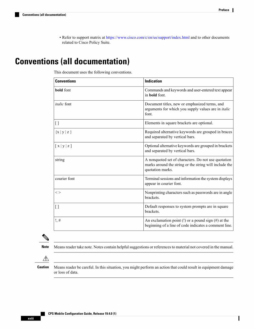
Conventions (all documentation)This document uses the following conventions.
IndicationConventions
Commands and keywords and user-entered text appearin bold font.
bold font
Document titles, new or emphasized terms, andarguments for which you supply values are in italicfont.
italic font
Elements in square brackets are optional.[ ]
Required alternative keywords are grouped in bracesand separated by vertical bars.
{x | y | z }
Optional alternative keywords are grouped in bracketsand separated by vertical bars.
[ x | y | z ]
A nonquoted set of characters. Do not use quotationmarks around the string or the string will include thequotation marks.
string
Terminal sessions and information the system displaysappear in courier font.
courier font
Nonprinting characters such as passwords are in anglebrackets.
< >
Default responses to system prompts are in squarebrackets.
[ ]
An exclamation point (!) or a pound sign (#) at thebeginning of a line of code indicates a comment line.
!, #
Means reader take note. Notes contain helpful suggestions or references to material not covered in the manual.Note
Means reader be careful. In this situation, you might perform an action that could result in equipment damageor loss of data.
Caution
CPS Mobile Configuration Guide, Release 19.4.0 (1)xviii
PrefaceConventions (all documentation)

IMPORTANT SAFETY INSTRUCTIONS.
Means danger. You are in a situation that could cause bodily injury. Before you work on any equipment, beaware of the hazards involved with electrical circuitry and be familiar with standard practices for preventingaccidents. Use the statement number provided at the end of each warning to locate its translation in thetranslated safety warnings that accompanied this device.
SAVE THESE INSTRUCTIONS
Warning
Regulatory: Provided for additional information and to comply with regulatory and customer requirements.Note
Communications, Services, and Additional Information• To receive timely, relevant information from Cisco, sign up at Cisco Profile Manager.
• To get the business impact you’re looking for with the technologies that matter, visit Cisco Services.
• To submit a service request, visit Cisco Support.
• To discover and browse secure, validated enterprise-class apps, products, solutions and services, visitCisco Marketplace.
• To obtain general networking, training, and certification titles, visit Cisco Press.
• To find warranty information for a specific product or product family, access Cisco Warranty Finder.
Cisco Bug Search Tool
Cisco Bug Search Tool (BST) is a web-based tool that acts as a gateway to the Cisco bug tracking systemthat maintains a comprehensive list of defects and vulnerabilities in Cisco products and software. BST providesyou with detailed defect information about your products and software.
Important Notes
Any feature or GUI functionality that is not documented may not be supported in this release or may becustomer specific, and must not be used without consulting your Cisco Account representative.
Important
CPS Mobile Configuration Guide, Release 19.4.0 (1)xix
PrefaceCommunications, Services, and Additional Information

CPS Mobile Configuration Guide, Release 19.4.0 (1)xx
PrefaceImportant Notes
C H A P T E R 1Policy Builder Overview
• Overview, on page 1• Reference Data, on page 2• Services, on page 3• Policies, on page 3• Accessing the Policy Builder, on page 7• Policy Builder Field Value Validation, on page 8
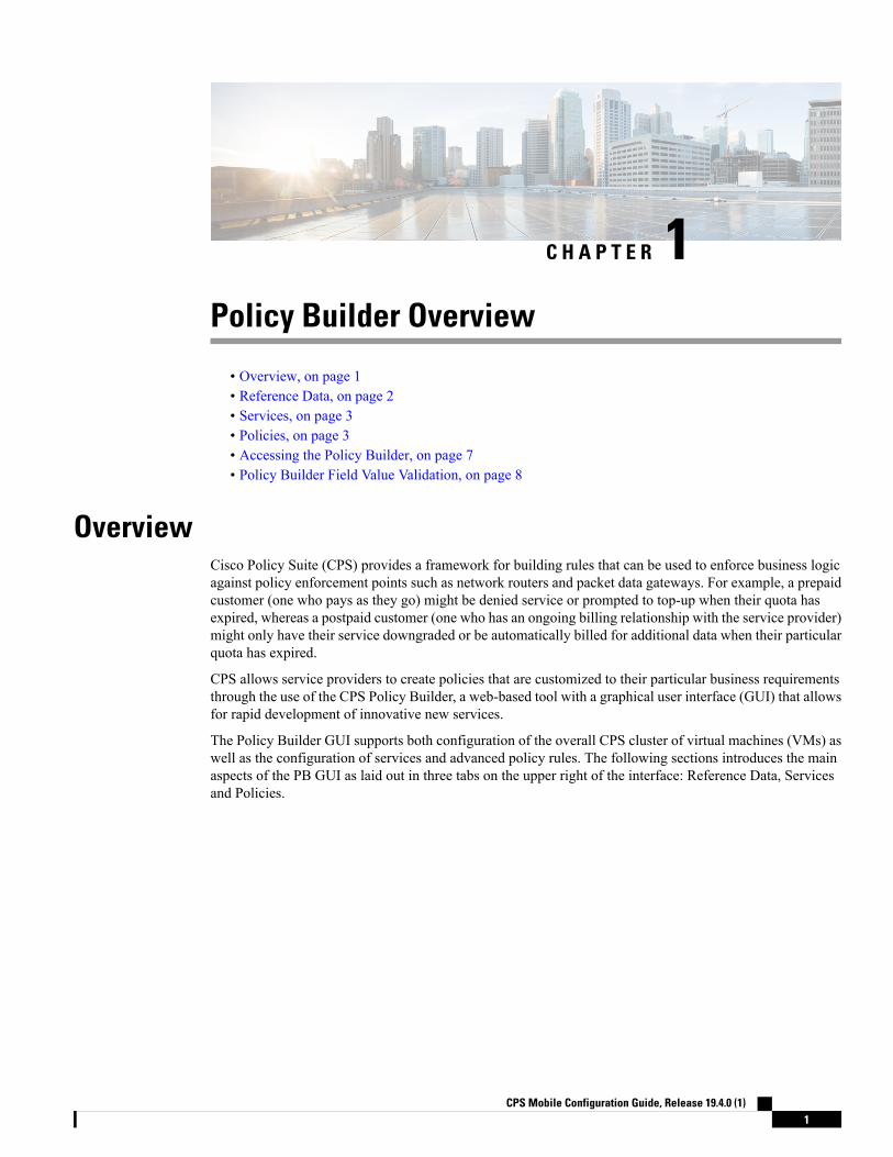
OverviewCisco Policy Suite (CPS) provides a framework for building rules that can be used to enforce business logicagainst policy enforcement points such as network routers and packet data gateways. For example, a prepaidcustomer (one who pays as they go) might be denied service or prompted to top-up when their quota hasexpired, whereas a postpaid customer (one who has an ongoing billing relationship with the service provider)might only have their service downgraded or be automatically billed for additional data when their particularquota has expired.
CPS allows service providers to create policies that are customized to their particular business requirementsthrough the use of the CPS Policy Builder, a web-based tool with a graphical user interface (GUI) that allowsfor rapid development of innovative new services.
The Policy Builder GUI supports both configuration of the overall CPS cluster of virtual machines (VMs) aswell as the configuration of services and advanced policy rules. The following sections introduces the mainaspects of the PB GUI as laid out in three tabs on the upper right of the interface: Reference Data, Servicesand Policies.
CPS Mobile Configuration Guide, Release 19.4.0 (1)1

Figure 1: Cisco Policy Guilder GUI
Reference DataThe Reference Data tab of the PB GUI provides access for configuring various aspects of the system in orderto make the system ready for operation. Reference Data are used to not only configure the system, but arealso used to provide settings and parameters that are referenced by policy rules across various services; forexample, Account Balances and Notifications are configured as Reference Data but are then referenced andreused bymultiple services as needed. Details of the various Reference Data configuration options are describedin more detail in other chapters of this guide.
The Reference Data tab contains static system, network, and template definition. It is not directly related topolicy, services, or use cases, but does define the reference points for the following types of information:
• Systems, cluster, and instance data
• Jdbc query string definitions
• Balance and quota definitions
• Diameter agents, clients, and defaults information
• Query strings
• Custom reference data tables (custom look up tables such as apn names)
• Notification addresses and text templates
• Policy reporting criteria
• Subscriber data repositories
• Tariff switch times
• Fault list - For more information, refer to CPS Operations Guide for this release.
CPS Mobile Configuration Guide, Release 19.4.0 (1)2
Policy Builder OverviewReference Data

ServicesThe Services tab allows for creation of reusable policy rules that control how subscribers are granted networkservices, quota and notifications. Services are broken down into three core areas: Domains, Services and UseCase Templates. The following section provides an overview of the Services tab, however detailed instructionson how to build a service are covered in later chapters of this guide.
The creation of a new service begins with creating a Use Case Template (UCT) for the service. UCTs consistof Service Configurations specific to the service that will be created. For example, a Service Configurationmight provide for the setup of a Gx Rule or Basic QoS. The UCT is also used to configure Use Case Initiators(UCI) which are instructions on when a specific Service Configuration should be in effect. An example ofthe UCI might be “only send this Gx Rule when the account balance is depleted”. Multiple UCIs can beconfigured for each Service Configuration allowing for complex logic as to when the configuration shouldor should not be in effect.
Once a UCT and associated UCIs are defined, it becomes the basis for Service Options, which are specificinstances of the UCT that are populated with data specific to the service. Multiple Service Options can becreated from a single UCT; for example, a UCT that provides for passing QoS parameters can be reused withdifferent QoS values for different customers. Multiple Service Options can be layered to create the end Service.Figure 2: Services tab
The Domains panel within the Services tab handles the initial interaction of the client device with the policyengine, and covers tasks including client authentication, default provisioning of unknown clients and qualifyinga client for particular system defaults and services.
For more information on the Services tab, refer to the Services, on page 223 chapter.
PoliciesWhile the Services tab, through Use Case Templates and Service Options, makes it easy to create reusableand extensible services, the Policies tab allows direct access to the underlying policy engine. The Policies tabholds the CPS core system Blueprint, which is composed of various Extension Points that break the policyengine flow into sections that occur within the execution of the policy. For example, the point in the policy
CPS Mobile Configuration Guide, Release 19.4.0 (1)3
Policy Builder OverviewServices

flow where a Gx connection is received, parsed, and processed before the point in the policy flow where therelated subscriber data is evaluated.
Within the various Extension Points are Policies that define Conditions (events and data from the policy flowand external systems) that can then trigger Actions (manipulation of data and communication back to externalsystems).
Note that the configuration of services for most deployments will be handled through use of the ReferenceData and Services tabs; advanced policies as defined on the Policies tab and discussed above are only requiredfor complex deployments. It is recommended that only experienced users access the Policies tab as errors incustom policies can have negative impact on the operation of the system. Detailed discussion of custompolicies is outside of the scope of this document.
By default, the Policies and Blueprint tabs are disabled.
The Policy Builder offers the Blueprint section under Policies tab to enable Cisco recommended changes tothe Policy Engine. Changes made without Cisco guidance are not supported and can result in poor performance,platform instability, or reduced capacity.
Important
Enabling POLICIES tab
In Policy Builder, Tools > Preferences to open Preferences pop-up window.Figure 3: Preferences - Policies
Select Show Policies (custom configuration) editing options? and click Apply.
Warning pop-up dialog box opens up.
CPS Mobile Configuration Guide, Release 19.4.0 (1)4
Policy Builder OverviewPolicies
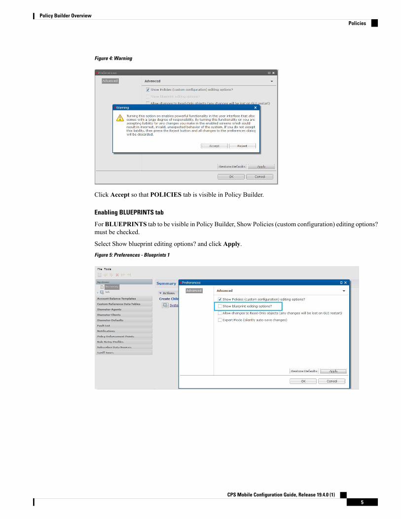
Figure 4: Warning
Click Accept so that POLICIES tab is visible in Policy Builder.
Enabling BLUEPRINTS tab
ForBLUEPRINTS tab to be visible in Policy Builder, Show Policies (custom configuration) editing options?must be checked.
Select Show blueprint editing options? and click Apply.Figure 5: Preferences - Blueprints 1
CPS Mobile Configuration Guide, Release 19.4.0 (1)5
Policy Builder OverviewPolicies
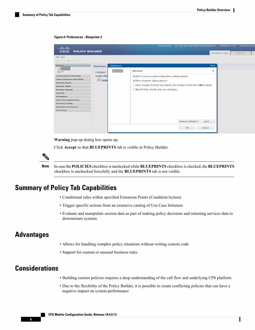
Figure 6: Preferences - Blueprints 2
Warning pop-up dialog box opens up.
Click Accept so that BLUEPRINTS tab is visible in Policy Builder.
In case thePOLICIES checkbox is uncheckedwhileBLUEPRINTS checkbox is checked, theBLUEPRINTScheckbox is unchecked forcefully and the BLUEPRINTS tab is not visible.
Note
Summary of Policy Tab Capabilities• Conditional rules within specified Extension Points (Condition/Action)
• Trigger specific actions from an extensive catalog of Use Case Initiators
• Evaluate and manipulate session data as part of making policy decisions and returning services data todownstream systems
Advantages• Allows for handling complex policy situations without writing custom code
• Support for custom or unusual business rules
Considerations• Building custom policies requires a deep understanding of the call flow and underlying CPS platform
• Due to the flexibility of the Policy Builder, it is possible to create conflicting policies that can have anegative impact on system performance
CPS Mobile Configuration Guide, Release 19.4.0 (1)6
Policy Builder OverviewSummary of Policy Tab Capabilities

Accessing the Policy BuilderThe Policy Builder is the web-based client interface for the configuration of policies to the Cisco Policy Suite.Initial accounts are created during the software installation with the default CPS install username as qns-svnand password as cisco123.
URL to Access Policy Builder Interface:
• For HA: https://<lbvip01>:7443/pb
• For AIO: http://<aio_ip>:7070/pb
The Policy Builder provides a PAM based and SVN based authentication mechanism to support theauthentication of Linux user credentials. The disablePamAuthentication flag is used to enable or disableuser login and to perform PAM based authentication.
The following tables describes the user roles and credentials supported:
Table 1: User Roles and Authentication Mechanism
Authentication MechanismUser RolesUser Access toPolicy Builder
SVN accessLinux access
PAM (Linux Systems) (setdisablePamAuthentication = false)
Read onlyYesNot an SVNuserRead/Write
PAM (Linux Systems) (setdisablePamAuthentication = false)
Read onlyYesNot an SVNuserRead only
PAM (Linux Systems) (setdisablePamAuthentication = false)
AdminYesRead/WriteRead/Write
PAM (Linux Systems) (setdisablePamAuthentication = false)
Read onlyYesRead onlyRead/Write
PAM (Linux Systems) (setdisablePamAuthentication = false)
AdminYesRead/WriteRead only
PAM (Linux Systems) (setdisablePamAuthentication = false)
Read onlyYesRead onlyRead only
SVN (set disablePamAuthentication= true)
Read onlyYesRead onlyNot a Linuxuser
SVN (set disablePamAuthentication= true)
AdminYesRead/WriteNot a Linuxuser
PAM/SVNInvalidusername orpassword error
NoNot an SVNuserNot a Linuxuser
CPS enables users to be aware of its current privileges while accessing Policy Builder as described below:
• If a user has read-write privilege then ADMIN is displayed adjacent to user name in the GUI.
CPS Mobile Configuration Guide, Release 19.4.0 (1)7
Policy Builder OverviewAccessing the Policy Builder

• If a user has read-only privilege then READONLY is displayed adjacent to user name in the GUI.
The hostname is displayed in the login dialog box and system banner to differentiate between open windowswhile performing any operation of the CPS system. It indicates which system is being modified and preventsany errors or misconfigurations.
The hostname is displayed when the parameter -Dhostname=lab is configured in pb/qns.conf files. If it is notconfigured in the qns.conf file, it is displayed as a result of the command "hostname" on the server.
The hostname is displayed in the login panel only when the following argument is set to true:
-DshowSitenameLogin
Enable TACACS+ authentication for Policy Builder by enabling PAM authentication (set-DdisablePAMAuthentication to false) and enabling TACACS+ along with tacacs_on_ui flag set to true inConfiguration.csv file.
Enabling Logout Option
To enable the logout option in Policy Builder, the following parameter must be configured in/etc/broadhop/pb/pb.conf file.
• –DlogoutLinkVisibility
To view the Logout link on Policy Builder banner, set the parameter to true value.
To support backward compatibility, -DlogoutLinkVisibility flag is not present in pb.conf by default. Ifflag is not present, then the value is considered as false.
When the parameter is configured or updated, restartall.sh is required.
Executing restartall.sh will cause messages to be dropped.Caution
Policy Builder Field Value ValidationThe Policy Builder uses the eCore framework to configure UI fields and their data types. The Policy Buildervalidation is triggered when a field is updated. The validation depends on the data type and valid value thatyou have defined for the field.
When you start the Policy Builder, the last recorded valid value defined in the eCore is set as the default value.If the value is not set in the eCore, the valid value is taken based on the eCore data type. For numeric datatypes, the Policy Builder displays 0 as a default value. For string data types, the Policy Builder displays null(empty) as a default value.
The Policy Builder validates the value that is configured in the field.
When you enter a value in the field and the value passes validation, the newly entered value is recorded asthe last valid value. If the validation fails, the last recorded valid value is reverted.
CPS Mobile Configuration Guide, Release 19.4.0 (1)8
Policy Builder OverviewPolicy Builder Field Value Validation

C H A P T E R 2Basic Systems Configuration
• Overview, on page 9• Policy Builder Repository Configuration, on page 9• System Configuration, on page 25
OverviewThe Cisco Policy Suite provides the Policy Builder as an interface for policy management. Policies translatea Service Provider’s business rules into actionable, logical processing methods that the Cisco Policy Suiteenforces on the network.
The Cisco Policy Suite ships with some standard base policies that serve as a starting point for customizationto suit a Service Provider's specific business rules.
Policy Builder Repository ConfigurationThe Policy Builder uses a Subversion version control repository to store the configuration data created in theUI. The data entered in the UI is translated into XML (Eclipse Modeling Framework xmi files) when saved.
As work is done in the UI, changes are saved to a temporary directory on the pcrfclient01. (The directory isspecified in the Repository configuration dialog.) Therefore, you can log out and back in and the latest changeswill remain. However, if someone else makes a change and commits, then your local changes are lost.
There are two options for saving configuration changes:
• Publish to Runtime
• Save to Client Repository
When saving to the client repository, the configuration is pushed to Subversion, but it is saved in a client onlyrepository and not copied over to the runtime environment repository. If you 'Publish to Runtime', theconfiguration is saved to the client repository and also copied to the runtime environment repository. TheCPS servers check the runtime environment repository for changes and will update automatically when changesare committed.
CPS Mobile Configuration Guide, Release 19.4.0 (1)9

Best Practices
Typically, publishing configuration changes to a lab environment to run tests is best. And then when satisfiedwith the test results, you can publish the new configuration to a production environment.
Revert
As Subversion is a source code tracking repository, each version of a configuration is numbered and storedin the Subversion repository history. Therefore, it is also possible to revert to any version of a configuration.The Policy Builder does not have a way to do this via the GUI, but using the Subversion command line tools,any version of the configuration can be made the current revision. For more information, refer to Subversiondocumentation for how to use the command line tools.
Default RepositoriesThe CPS deployment installs Subversion and creates a default client and runtime repository. The Subversionrepositories are synced using Subversion's Master/Slave replication between the pcrfclient01 and pcrfclient02nodes.
• Client - http://pcrfclient01/repos/configuration
• Runtime - http://pcrfclient01/repos/run
The Policy Builder start screen shows a dialog that lets you define repositories and choose a repository tocheck out for editing. A repository definition named “Repository” is installed by default and uses the defaultclient repository (http://pcrfclient01/repos/configuration). The default PB user (qns-svn) with the defaultpassword is also setup.Figure 7: Choose Policy Builder Data
Adding a Client Repository Definition
Step 1 Start Cisco Policy Builder.
CPS Mobile Configuration Guide, Release 19.4.0 (1)10
Basic Systems ConfigurationDefault Repositories

Step 2 In the Choose Policy Builder data repository ... dialog box, select Add New Repository from the drop-down list.Figure 8: Adding a New Repository Definition
The Repository dialog box appears.Figure 9: Repository Configuration Fields
The following parameters can be configured under Repository:
Configure the parameters according to the network requirements.
CPS Mobile Configuration Guide, Release 19.4.0 (1)11
Basic Systems ConfigurationAdding a Client Repository Definition

Table 2: Repository Parameters
DescriptionParameter
This required field uniquely identifies your repository's site with a name.
We recommend the following format for naming repositories:customername_project_date, where underscores are used to separatecustomer name, project and date. Date can be entered in the format:MMDDYYYY.
Note
Name
Enter a username that is configured to view Policy Builder data. The password can besaved for faster access, but it is less secure. A password, used with the Username,permits, or denies access to make changes to the repository.
Username and Password
Select this check box to save the password on the local hard drive. This password isencrypted and saved as a cookie on the server.
Save Password
You can have several branches in the version control software to save different versionsof configuration data. Create a branch in the version control software before assigningit in this screen.
Enter the URL of the branch of the version control software server that is used tocheck-in this version of the data.
Url
This value do not need to be changed.
This is the location on the hard drive where the Policy Builder configuration objectsare stored in version control.
When you click either Publish or Save to Repository, the data is saved from thisdirectory to the version control application specified in the Url text field.
The field supports the following characrters:
• Uppercase: A to Z
• Lowercase: a to z
• Digits: 1 to 9
• Non-alphanumeric: /
The user needs to provide the specified characters above.Note
Local Directory
Select this check box to see if the values for Username, Password, or the URL arelegitimate and unique. If not, the screen displays an error message and provides achance to correct the errors.
Validate on Close
Removes the display of the repository in Cisco Policy Builder.
The remove link here does not delete any data at that URL. The localdirectory is deleted.
Note
Remove
Step 3 Click OK to save your work to the local directory.
CPS Mobile Configuration Guide, Release 19.4.0 (1)12
Basic Systems ConfigurationAdding a Client Repository Definition

When your change screens, Cisco Policy Builder automatically saves your work. Cisco recommends savingyour work to the local directory by clicking on the diskette icon on the Policy Builder GUI or CTRL-S on thekeyboard.
Note
Step 4 If you are ready to commit these changes to the version control software, select File > Save to Client Repository on thePolicy Builder home screen.
Editing a Client Repository DefinitionUse this procedure to change any of the following details of client repository:
• Client repository name
• Username, password, and password save mechanism
• Client repository temporary save URL
• Client repository local directory save file path
Step 1 Open a browser and enter the URL of the Cisco Policy Builder.Step 2 Use the drop-down list in the Choose Policy Builder data repository... dialog box to select the desired repository.Step 3 Click the Edit button.Step 4 In the Repository dialog box, make the required changes.Step 5 Click OK to save the changes to the repository definition.
Removing a Client Repository DefinitionThis procedure removes a repository from Cisco Policy Builder. This procedure does not delete the actualSubversion repository, just the definition for access in the Policy Builder.
Step 1 Open a browser and enter the URL of the Cisco Policy Builder.Step 2 Use the drop-down list in the Choose Policy Builder data... dialog box to select the desired repository.Step 3 Click Remove. A confirmation dialog box appears.Step 4 Click OK to delete the repository.
Saving Policy Builder Configuration Data to a Client Repository
Step 1 Open a browser and enter the URL of the Cisco Policy Builder.Step 2 Use the drop-down list on the Choose Policy Builder data... dialog box to select the desired repository.Step 3 Click OK to open the Policy Builder GUI.
CPS Mobile Configuration Guide, Release 19.4.0 (1)13
Basic Systems ConfigurationEditing a Client Repository Definition

Step 4 Make the necessary modifications in the Policy Builder.Step 5 To save the modifications done, select File > Save to Client Repository, or click the diskette icon on the Policy Builder
GUI or use CTRL-S on the keyboard.Step 6 Enter a commit message for the modifications done.Step 7 ClickOK. The modified configurations are saved to the client repository for later updating and publishing to the runtime
environment.
Auto Save Policy Builder Configuration Changes
Step 1 Open a browser and enter the URL of the Cisco Policy Builder.Step 2 Use the drop-down list on the Choose Policy Builder data... dialog box to select the desired repository.Step 3 Click OK to open the Policy Builder GUI.Step 4 Make changes to configuration data as necessary. For example, if you move from configuration to another configuration
without saving the changes, a pop-up Are you sure? dialog box for saving the changes is displayed.Step 5 ClickYes to save the changes. If you want to disable this notification, click Tools > Preferences. This opens Preferences
window.Figure 10: Preferences
Step 6 Check Expert Mode (silently auto-save changes) flag to enable auto-save option.
CPS Mobile Configuration Guide, Release 19.4.0 (1)14
Basic Systems ConfigurationAuto Save Policy Builder Configuration Changes

By default, the flag is not checked. You have to check it in order to turn off the Are you sure? save prompt.Figure 11: Are you sure?
Note
If the flag is not checked, the following options are displayed when updating/creating/copying an object:
• Updating an Object: While updating an object the PB asks Do you want to save this object? with option buttonsas OK and Cancel. If you click OK, the data being worked on is saved and if you click Cancel, the data beingworked on is not saved to the repository.
• Creating an Object: While creating an object the PB asks Are you sure you want to create this object? withoption buttons asOK andCancel. If you clickOK, the new object is created with the default values and if you clickCancel, the object is not created.
• Copying an Object: While copying an object the PB asksAre you sure you want to copy this object?with optionbuttons as OK and Cancel. If you click OK, the object is copied and if you click Cancel, the object is not copied.
• This prompt is also displayed for File menu options when you use Publish to Runtime Environment or Save toClient Repository....
Step 7 Once flag is checked, click Apply and OK to save the changes.
Publishing the Client RepositoryTo put changes into effect and have the Cisco Policy Builder server recognize the configuration changes madein your client session, use the Publish option and save the changes to the server repository.
To save the practice version, publish the client repository to the server. This is the version the server uses forproduction.
Note
Do not publish to the Policy Builder unless you are completely satisfied with the configuration data in yourclient repository.
• Use the Policy Builder interface to either commit or set up a commit repository.
• Verify your work either by going to a web browser or by looking at the config.properties file.
• Unpublish with an SVN delete and restore.
When you are ready to put your Policy Builder changes into production, you need to publish them to Subversion.This preserves version history.
CPS Mobile Configuration Guide, Release 19.4.0 (1)15
Basic Systems ConfigurationPublishing the Client Repository

CPS supports to save the unpublished commit messages in a property file into the file system. This file issaved in the user directory under the selected repository location. For different users, Policy Builder willgenerate different property files.
Policy Builder saves the unpublished commit messages into the file system for the following cases:
• When loading Publish dialog box (File > Publish to Runtime Environment…) then saved commitmessage, if any, appears for that user in Commit Message pane.
• While publishing the policy configuration, if publish fails then the entered commit message is saved intothe file system.
• While publishing the policy configuration, if publish succeeds then remove the message from file forthe logged in user.
• If you clickCancel on Publish dialog box then the entered commit message is saved into the file system.
• If you click Cross (x) on Publish dialog box then the entered commit message is saved into the filesystem.
• When loading Saving to Repository dialog box (File > Save to Client Repository…) then saved commitmessage, if any, appears for that user in Commit Message pane.
• While saving to client repository, if operation fails then the entered commit message is saved into thefile system.
• While saving to client repository, if operation succeeds then remove the message from file for the loggedin user.
• If you click Cancel on Saving to Repository dialog box then the entered commit message is saved intothe file system.
• If you click Cross (x) on Saving to Repository dialog box then the entered commit message is savedinto the file system.
Step 1 To publish in Cisco Policy Builder, select File > Publish to Runtime Environment. The Publish dialog box appears.
CPS Mobile Configuration Guide, Release 19.4.0 (1)16
Basic Systems ConfigurationPublishing the Client Repository

Figure 12: Publishing to the Runtime Environment
Step 2 If you have already set up the repository to publish to, just enter a commit message.Step 3 If you have not set up the repository, select Add New Repository from the Publish to: drop-down list and enter the
required details for the new repository. For more information, refer to Adding a Client Repository Definition, on page10.
Step 4 Verify the changes to Production repository:
• All changes are published to Subversion, so they are version-controlled and can be rolled back.
• To verify a publish as part of a troubleshooting process, take the URL seen in the previous screen and put it into aweb browser (you may need to substitute the IP). The password is the same as in Cisco Policy Builder.
• If a traditional web browser cannot access the system, you can use a command line browser from the CPS VM’sURL.
Error Notification during PublishingDuring publishing, if there are any errors, the Publish dialog box will display the list of unresolved errors.
Policy Builder does not report errors for read-only objects.Note
The errors are created in the session and are updated accordingly as the errors are resolved or are newlyintroduced with respect to their IDs.
The format of error string is as:
<Object_Name> <Feature_Name> :: <Error_String>
You can select and copy one or more of the errors in the list and paste them into another window (for example,in an email or in a file to mask the acceptable errors).
CPS Mobile Configuration Guide, Release 19.4.0 (1)17
Basic Systems ConfigurationError Notification during Publishing

Figure 13: Publish - Unresolved Errors
If you click OK with any unresolved errors in the list then you are prompted with a confirmation asking ifthe unresolved errors should be published to the repository.Figure 14: Publishing with Errors - Override
CPS Mobile Configuration Guide, Release 19.4.0 (1)18
Basic Systems ConfigurationError Notification during Publishing

If you click No, then the publish does not happen.
If you clickYes then the commit message is amended to include a note that you have committed with # errors.For example, “User forced the Publish with 3 unresolved errors: <user's commit message>”.
Masking Errors
You can mask the errors if needed where an error is reported by Policy Builder but can still be loaded by thePolicy Server. This allows configuration of CPS so that the specified errors are not displayed and you do notignore the list of unresolved errors and the real errors are not lost amongst a list of acceptable errors.
The file named maskPublishErrors.txt file is created in the folder /etc/broadhop/pb on ClusterManager (CM). After creating the file, run build_all.sh from CM to rebuild CPS package and push thechanges to each VM. The file is populated with the exact message displayed in the GUI. No wildcarding isallowed (so as to prevent accidentally filtering out important messages). The GUI does not display anymessages that are in the maskPublishErrors.txt file. The GUI does not count any messages that arein the maskPublishErrors.txt file. If all of the errors in the list are masked because they are in thefile then clicking OK in the Publish dialog will not cause the override dialog to be displayed.
Adding a Runtime Repository DefinitionA repository definition named Publish Repository is installed by default and uses the default Runtimerepository (http://pcrfclient01/repos/run). The default Policy Builder user (qns-svn) with the default passwordis also setup. The Runtime repository matches the value setup in the /etc/broadhop/qns.conf file.
The qns.conf file is read by all of the active Policy Server and Policy Director nodes and when the policyserver process starts up, it checks out the configuration from the Runtime repository.
CPS Mobile Configuration Guide, Release 19.4.0 (1)19
Basic Systems ConfigurationAdding a Runtime Repository Definition
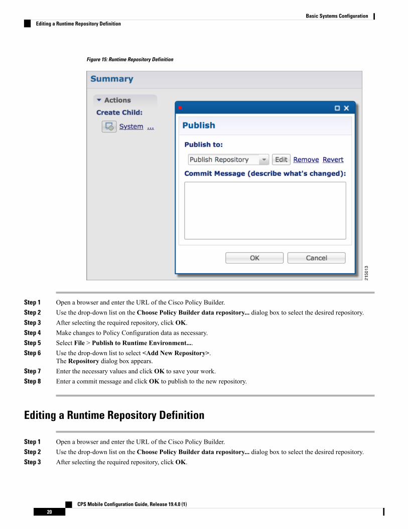
Figure 15: Runtime Repository Definition
Step 1 Open a browser and enter the URL of the Cisco Policy Builder.Step 2 Use the drop-down list on the Choose Policy Builder data repository... dialog box to select the desired repository.Step 3 After selecting the required repository, click OK.Step 4 Make changes to Policy Configuration data as necessary.Step 5 Select File > Publish to Runtime Environment....Step 6 Use the drop-down list to select <Add New Repository>.
The Repository dialog box appears.Step 7 Enter the necessary values and click OK to save your work.Step 8 Enter a commit message and click OK to publish to the new repository.
Editing a Runtime Repository Definition
Step 1 Open a browser and enter the URL of the Cisco Policy Builder.Step 2 Use the drop-down list on the Choose Policy Builder data repository... dialog box to select the desired repository.Step 3 After selecting the required repository, click OK.
CPS Mobile Configuration Guide, Release 19.4.0 (1)20
Basic Systems ConfigurationEditing a Runtime Repository Definition

Step 4 Make changes to Policy Configuration data as necessary.Step 5 Select File > Publish to Runtime Environment....Step 6 Use the drop-down list to select the desired repository.Step 7 In the Repository dialog box, make your changes.Step 8 Click OK to save the changes to the repository definition.Step 9 Enter a commit message and click OK to publish to the new repository.
Removing a Runtime Repository DefinitionThis procedure removes a runtime repository definition from the Cisco Policy Builder. This procedure doesnot delete the actual Subversion repository, just the definition for access in the Policy Builder.
Step 1 Open a browser and enter the URL of the Cisco Policy Builder.Step 2 Use the drop-down list on the Choose Policy Builder data repository... dialog box to select the desired repository.Step 3 After selecting the required repository, click OK.Step 4 Make changes to Policy Configuration data as necessary.Step 5 Select File > Publish to Runtime Environment....Step 6 Use the drop-down list to select the desired repository.Step 7 Click Remove. A confirmation dialog appears.Step 8 Click OK to delete the repository.Step 9 Click Cancel to close the dialog box.
Saving Policy Builder Configuration Data to a Runtime Repository
Step 1 Open a browser and enter the URL of the Cisco Policy Builder.Step 2 Use the drop-down list in the Choose Policy Builder data repository... dialog box to select the desired repository.Step 3 After selecting the required repository, click OK.Step 4 Make changes to Policy Configuration data as necessary.Step 5 Select File > Publish to Runtime Environment....Step 6 Use the drop-down list to select the desired repository.Step 7 Enter a commit message.Step 8 Click OK. The data will be saved to the client repository for later updating and publish to the runtime environment.
Switching to a Different Client RepositoryYoumay have several variations of your client repository. Onemay reflect the configuration currently publishedto the server. Another might be developed for test purposes.
CPS Mobile Configuration Guide, Release 19.4.0 (1)21
Basic Systems ConfigurationRemoving a Runtime Repository Definition

There are two ways to switch to a different repository:
• File > Switch Repository...
• File >Exit/Logout: You can select the required repository fromChoose Policy Builder data repository...dialog box.
When you click Ok after repository selection, a validation prompt Are you sure? is displayed.
• Select Discard to discard the uncommitted changes.
• Select Retain to retain the uncommitted changes.
If the dialog box is dismissed without clicking escape or close, the uncommitted changes are retained.
Reverting ChangesThere are two main SVN repositories (repos) in the system.
• Repository publish which contains ONLY the currently running set of policies.
• Runtime repository which contains a copy of the currently running set of policies along with copies ofall previous sets.
To rollback Policy Builder changes, there are two methods:
• Rollback the configuration repository Policy Builder and then perform a publish as described inUnpublished Changes, on page 22.
• Rollback the runtime repository Policy Builder uses and the configuration repository Policy Builder uses.
For more information, refer to Published Changes, on page 22.
Unpublished ChangesIf you do not want to save the changes, click the Revert link on the Policy Builder start window. All changesthat have not been committed to a repository will be removed.
Step 1 Open a browser and enter the URL of the Cisco Policy Builder.Step 2 Use the drop-down list in the Choose Policy Builder data repository... dialog box to select the desired repository.Step 3 Click the Revert link. A confirmation dialog appears.
The Revert link is only available if there are uncommitted local changes.
Step 4 Click OK to revert changes to the repository definition.
Published Changes
Step 1 Check the configuration repository name Policy Builder uses (config_repo). To check the name, use the following steps:a) Open a browser and enter the URL of the Cisco Policy Builder.
CPS Mobile Configuration Guide, Release 19.4.0 (1)22
Basic Systems ConfigurationReverting Changes

b) In the Choose Policy Builder data repository... dialog box, click Edit.Figure 16: Choose Policy Builder Data Repository
c) In the Repository dialog box, look at the contents of the Url field to see the repository name used by the PolicyBuilder. For example, it is configuration.Figure 17: Repository
d) Record the Policy Builder repository name (config_repo). For example, it is configuration.
Step 2 To locate the ‘r’ number in the repository used by Policy Builder, execute the following command:
svn log http://pcrfclient01/repos/<config_repo> | more
The <config_repo> value comes from Step 1.d, on page 23.
The following is an example of the svn log command, where <config_repo> is configuration as shown in Step 1.d, onpage 23.
CPS Mobile Configuration Guide, Release 19.4.0 (1)23
Basic Systems ConfigurationPublished Changes

svn log http://pcrfclient01/repos/configuration | more------------------------------------------------------------------------r367 | qns-svn | 2015-06-18 12:15:34 -0600 (Thu, 18 Jun 2015) | 1 linesecond try------------------------------------------------------------------------r364 | qns-svn | 2015-06-17 15:46:19 -0600 (Wed, 17 Jun 2015) | 1 linecorrected java issue------------------------------------------------------------------------r361 | qns-svn | 2015-06-16 15:38:28 -0600 (Tue, 16 Jun 2015) | 1 line
Added new Policies------------------------------------------------------------------------r358 | qns-svn | 2015-06-16 15:06:57 -0600 (Tue, 16 Jun 2015) | 1 line""------------------------------------------------------------------------r355 | qns-svn | 2015-06-16 14:58:41 -0600 (Tue, 16 Jun 2015) | 1 line""------------------------------------------------------------------------r352 | qns-svn | 2015-06-16 14:52:29 -0600 (Tue, 16 Jun 2015) | 1 line
a) In the example above, the comment we are looking for is in r361 which is the ‘r’ number we want to rollback to.b) Record the config_repo ‘r_number’. In this example, it is r361.
Step 3 Execute the following command to delete the current version from the configuration repository Policy Builder uses:
svn delete http://pcrfclient01/repos/<config_repo> -m ‘deleting for rollback’
Use the <config_repo> value from Step 1.d, on page 23.
The following is an example of the svn delete command where <config_repo> is configuration.
svn delete http://pcrfclient01/repos/configuration -m ‘deleting for rollback’
Step 4 Execute the following command to restore the Policy Builder configuration repository to a previous version.
svn cp http://pcrfclient01/repos/<config_repo>@<r_number> http://pcrfclient01/repos/<config_repo> -m
‘rolling back to <r_number>’
The <r_number> value is from Step 2.a, on page 24 and the <config_repo> value is from Step 1.d, on page 23. The ‘-m’option should be used to add a comment indicating what is being done.
The following is an example of the svn copy command with the <r_number> set to 361 and the <config_repo> set toconfiguration:svn cp http://pcrfclient01/repos/configuration@361 http://pcrfclient01/repos/configuration -m ‘rollingback to 361’
Step 5 Execute the following command to verify if the rollback is successful:
svn log http://pcrfclient01/repos/<config_repo> | more
The <config_repo> value is from Step 1.d, on page 23.
The following is an example of the svn copy command:svn log http://pcrfclient01/repos/configuration | more----------------------------------------------------------------------r367 | qns-svn | 2015-06-18 12:15:34 -0600 (Thu, 18 Jun 2015) | 1 linerolling back to 361-----------------------------------------------------------------------
The output should have the ‘-m’ option's text entered in Step 4, on page 24 as the comment.Note
CPS Mobile Configuration Guide, Release 19.4.0 (1)24
Basic Systems ConfigurationPublished Changes

Step 6 Open Policy Builder and verify the polices to which you have rolled back. Normally the customer should be able to verifythe policies in Policy Builder.
Step 7 Perform a publish in Policy Builder and make sure to add a comment indicating that the publish is being done to completethe rollback. For example, “publishing to complete rollback to <r_number>”.
System ConfigurationThe Systems node in the Reference Data tab represents the Cisco Policy Suite runtime environment as it existsin the network environment.
• System: There must always be at least one system defined in the Policy Builder. The system representsthe customer deployment. In HA, the system represents a set of PCRF clusters that share the same sessiondatabase. System is used to define any common things across the clusters, such as load balancing, andso on.
• Cluster: Each system contains one or more clusters - each of which represents a single High-Availability(HA) site environment. A cluster is used for define the configurations related to the blades. A clustershares the same set of policy directors (that communicates as a group). A customer can take a fullyinstalled PCRF and replicate it to a second cluster.
Each cluster can contain node instances. A node instance corresponds to a physical node in a deploymentcluster such as a session manager or Policy Director (load balancer). It is very rare that a deployed systemneeds to have node instances configured in the Policy Builder. Configurations flow downhill, meaningthat if you define a Plugin Configuration for Unified API at the system level, each cluster and subsequentlyeach instance gets that configuration by default.
There are two types of clusters: HA and GR. This document discusses HA clusters. For informationrelated to GR clusters, refer to CPS Geographic Redundancy Guide for this release.
In an HA environment you should not make any configuration in Cluster node.Note
Plug-in configuration done at cluster level overrides the same definition at system level. For example, if youconfigure Custom Reference Data at cluster level, it will override the Custom Reference Data configurationdone at system level.
There is a default deployment configuration for mobile. system-1 is the default system name and cluster-1is the default cluster name.
If a customer wants to change the system name, they need to change it in qns.conf(/etc/broadhop/qns.conf) file also to reflect it in Policy Builder:
-Dcom.broadhop.run.systemId=<system name>
Adding a SystemAfter installation, use this procedure to set up your Cisco Policy Builder by using an example populated withdefault data. You can change anything that does not apply to your deployment.
CPS Mobile Configuration Guide, Release 19.4.0 (1)25
Basic Systems ConfigurationSystem Configuration

Step 1 Click the Reference Data tab, and then click the Systems node to display the Systems tree.Figure 18: Systems Tree
Step 2 Click System... under Create Child: to open the System pane on the right side.Figure 19: System Pane
Step 3 Fill in the Name field, and provide a description of this system. Enter the rest of the parameters based on your networkrequirements.
Table 3: System Parameters
DescriptionParameter
The name of the CPS system.Name
Description of this entire system.Description
If no messages are received in x hours, the session will be removed.
The maximum value allowed for this parameter is 590 hours. However,the combination of the number of hours specified for this parameter andthe number of minutes specified for the Session Expiration Minutesparameter cannot exceed 35,400 minutes.
Note
Default value is 8.
Session Expiration Hours
CPS Mobile Configuration Guide, Release 19.4.0 (1)26
Basic Systems ConfigurationAdding a System

DescriptionParameter
If no messages are received in x minutes, the session will be removed.
The combined value of Session Expiration Hoursmultiplied by 60 plusSession Expiration Minutes should not exceed 35,400.
Note
Default value is 0.
Session Expiration Minutes
Time in minutes that CPS keeps a session alive after the subscriber logs off. Withthis, other network entities involved in the session can let the session close gracefully.
Default value is 0.
Timeout for Unknown Session
Determines the time in seconds during which a 'soft delete' session is maintainedfor a CPS session after session stop.
Default value is 30.
Timeout For Soft Delete
This parameter is used to protect the session database from crashing. CPS does notallow session creation when a current system session count exceeds the SessionLimit Overload Protection value.
The default value is set to 0 which infinitely accepts the Diameter messages andCPS triggers alarms so that you change the value before session count goes beyondthe database capacity. This value must be replaced by session capacity that iscalculated for each deployment.
Default value is 0.
Session Limit Overload Protection value must be changed than using thedefault value (0).
Note
The recommended value for Session Limit Overload Protection has tobe derived by Cisco Account representative for each deployment.
Note
Session Limit Overload Protection
Select this check box to allow two primary keys to be utilized by maintaining a mapof each separate primary key and storing the 'true' multi-primary key as a UUIDrelated to the two maps. Changing this setting has a negative performance impactand should only be done at the request of the BU. Recommendation is to keep EnableMulti Primary Key unchecked.
Default is unchecked.
Enable Multi Primary Key
Click this link to create a cluster under this system.Cluster link
Click this link to make a copy of this system, with its clusters and instances.Current System Link
Step 4 If the created system needs to be used, then after publishing, the following property needs to be updated in the qns.confconfiguration file:
-Dcom.broadhop.run.systemId=<system name>
where <system name> is the system name defined in the Step 3, on page 26.
CPS Mobile Configuration Guide, Release 19.4.0 (1)27
Basic Systems ConfigurationAdding a System
Soft Delete SessionA soft delete session is an entry in the session database which maintains session data after session stop withan auto-generated unique primary key, but still maintains needed secondary keys. This allowsmessages whichcome after session stop to still be processed while also allowing a session with the same primary key to beimmediately created. The CPS code determines when soft delete sessions are required and what secondarykeys are needed.
Soft Delete Example (Mobile)
A Gx session with a Gy associated session exists. A Gx CCR-T is received that terminates the CPS session,resulting in a soft-delete session which contains Gy session information and associated Gy secondary keys.A Gy CCR-t is received and the soft-delete session is loaded and updated with the charging informationthrough the end of the session. After the soft delete timeout, the soft delete session is removed.
Adding an HA ClusterThis section describes how to add an HA cluster. Asystem, a cluster, and an instance are set up at install time.If you have to change the cluster definition, or want to add more clusters, use these steps.
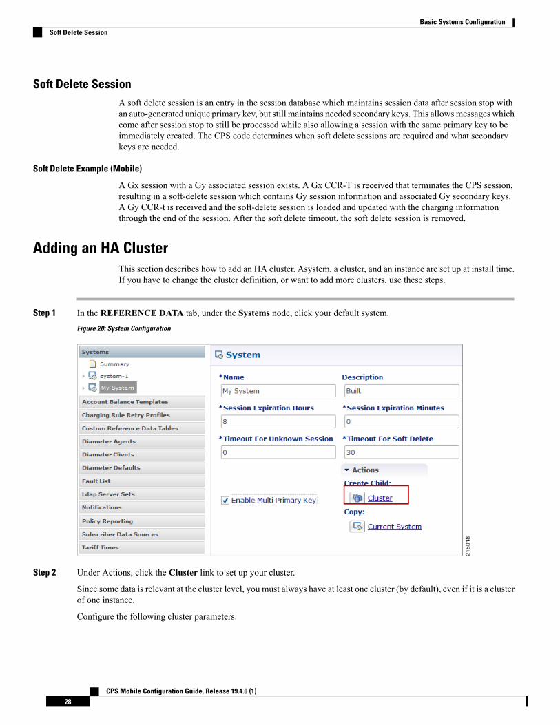
Step 1 In the REFERENCE DATA tab, under the Systems node, click your default system.Figure 20: System Configuration
Step 2 Under Actions, click the Cluster link to set up your cluster.
Since some data is relevant at the cluster level, you must always have at least one cluster (by default), even if it is a clusterof one instance.
Configure the following cluster parameters.
CPS Mobile Configuration Guide, Release 19.4.0 (1)28
Basic Systems ConfigurationSoft Delete Session
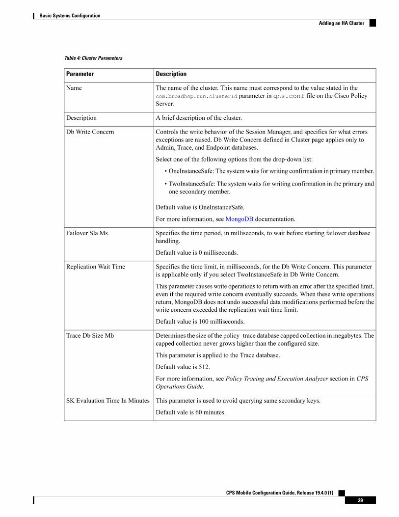
Table 4: Cluster Parameters
DescriptionParameter
The name of the cluster. This name must correspond to the value stated in thecom.broadhop.run.clusterId parameter in qns.conf file on the Cisco PolicyServer.
Name
A brief description of the cluster.Description
Controls the write behavior of the Session Manager, and specifies for what errorsexceptions are raised. Db Write Concern defined in Cluster page applies only toAdmin, Trace, and Endpoint databases.
Select one of the following options from the drop-down list:
• OneInstanceSafe: The systemwaits for writing confirmation in primarymember.
• TwoInstanceSafe: The system waits for writing confirmation in the primary andone secondary member.
Default value is OneInstanceSafe.
For more information, see MongoDB documentation.
Db Write Concern
Specifies the time period, in milliseconds, to wait before starting failover databasehandling.
Default value is 0 milliseconds.
Failover Sla Ms
Specifies the time limit, in milliseconds, for the Db Write Concern. This parameteris applicable only if you select TwoInstanceSafe in Db Write Concern.
This parameter causes write operations to return with an error after the specified limit,even if the required write concern eventually succeeds. When these write operationsreturn, MongoDB does not undo successful data modifications performed before thewrite concern exceeded the replication wait time limit.
Default value is 100 milliseconds.
Replication Wait Time
Determines the size of the policy_trace database capped collection in megabytes. Thecapped collection never grows higher than the configured size.
This parameter is applied to the Trace database.
Default value is 512.
For more information, see Policy Tracing and Execution Analyzer section in CPSOperations Guide.
Trace Db Size Mb
This parameter is used to avoid querying same secondary keys.
Default vale is 60 minutes.
SK Evaluation Time In Minutes
CPS Mobile Configuration Guide, Release 19.4.0 (1)29
Basic Systems ConfigurationAdding an HA Cluster

DescriptionParameter
Specifies the maximum number of internally generated transactions per second (TPS)the system produces.
This parameter affects the RAR generated by CPS when they are triggered by aninternal time event (change of time or quota refresh).
For example, if the system needs to generate RAR messages to refresh quotas, themax TPS for the creation of the RAR messages is limited by this value.
Default value is 2000.
Internal timer TPS is calculated based upon the value specified for Max Timer TPSin Policy Builder, number of session shards, and number of Policy Server (QNS)VMs.
Max Timer Expired TPS = (Max Timer TPS / Number of Session Shards) * (Lowerof Number of Session Shards or Policy Server (QNS))
Here are examples that specify how the internal timer TPS is calculated:
1. When number of session shards are higher or same as number of QNSVMs:If configuredMax Timer TPS in Policy Builder is 2000, number of session shardsare 88 and number of QNS are 50. In this case, max TPS per QNSVM is 2000/88(no. of session shards) = 22 (value in floored). Actual maximum timer TPS is 22* 50 (no. of QNS) = 1100.
2. When number of session shards are lower thanQNSVMs: If configuredMaxTimer TPS in Policy Builder is 2000, number of session shards are 12 and numberof QNS are 20. In this case, max TPS per QNS VM is be 2000/12 (no. of sessionshards) = 166 (value is floored). Actual maximum timer TPS is 166 * 10 (no. ofsession shards) = 1660.
Max Timer T P S
Specifies the number of batches, or “buckets”, into which CPS divides the transactionsto be processed when the rate limiting TPS function of CPS is triggered. The ratelimiting feature is defined in theMax Timer T P S field above.
When a TPS rate limit condition is encountered, CPS divides the total number ofre-evaluation transactions to be processed by the number of buckets defined in thisfield. CPS processes the transactions in each bucket, one by one, while also addinga brief delay between the processing of each bucket. Refer to the Re-evaluationdiffusion interval parameter below to configure this delay.
This functionality prevents spikes in traffic when a large number of sessions qualifyfor re-evaluation at the exact same time. This functionality only diffuses the rate atwhich transactions are sent to the CPS policy engine. It does not wait for end-to-endprocessing to occur.
To disable this functionality, set both Re-evaluation diffusion buckets andRe-evaluation diffusion interval parameters to 0 (zero).
If the TPS rate limiting functionality has been disabled, this functionality is alsodisabled.
Default value is 50 (buckets).
Re-evaluation diffusion buckets
CPS Mobile Configuration Guide, Release 19.4.0 (1)30
Basic Systems ConfigurationAdding an HA Cluster

DescriptionParameter
Specifies the delay, in milliseconds, before processing the next bucket. Enter the sumof all the delays between all the buckets.
Assuming Re-evaluation diffusion buckets is configured as 50, and theRe-evaluation diffusion interval is configured as 20000 milliseconds, it introducesa delay of 408 milliseconds before proceeding with the next bucket of transactions.
Delay between buckets = Diffusion Interval (ms) / (Diffusion Buckets - 1)
Delay between buckets = 20000/49
Delay between buckets = 408 (ms)
Default value is 20 milliseconds.
With default configuration, there will be no diffusion. As 20/50 will be 0 (It ignoresdecimal).
Re-evaluation diffusion interval( in milliseconds )
Specifies the time period, in milliseconds, for the Policy Engine to wait betweensending each Broadcast Policy Message.
Default value is 50.
Broadcast Msg Wait Timer Ms
Specifies the maximum number of sessions that can be stored in each shard that hasbeen created within a Session Database Replica Set.
Value ‘0’ in this parameter means that monitoring is not implemented.
It is recommended to add new shards and rebalance sessions duringmaintenance window.
Note
Default value is 0.
Max Sessions Per Shard
CPS Mobile Configuration Guide, Release 19.4.0 (1)31
Basic Systems ConfigurationAdding an HA Cluster

DescriptionParameter
To improve Gx/Rx lookup and caching performance, we can add the lookaside keyprefixes. In order to identify the correct shard for subscriber lookup/query, the PCRFneeds to know the secondary key (which is internally stored in secondary key cache)for mapping and the exact shard that will be queried for subscriber data. This helpsprevent the system from scanning/querying all the available shards in the system tofetch the subscriber record. Reducing the data range for scanning/querying leads toenhanced system performance.
The following keys should be added so that the secondary keys for session bindingare stored in the secondary key cache.
• diameter - This key should be added for local session affinity or when Sh interfaceis in use.
• RxTGPPSessionKey - This key should be added only when Rx interface is used.
• FramedIpKey - This key should be added if Gx Session lookup is based onIPADDRESS.
• framedIpV6PrefixKey - This key should be added if Gx Session lookup is basedon IPADDRESS.
• USuMSubscriberIdKey – This key should be added only when SPR is used.
• MSBMSubscriberIdKey – This key should be added only when balance is used.
• RxClientSessionKey - This key should be added if PAS health check feature isenabled.
• imsiApnKey - This key should be added if Gx Session lookup based on IMSIand APN is enabled or Load by IMSI and Load By Called Station ID is enabled.
• msisdnApnKey - This key should be added if Gx Session lookup based onMSISDN and APN is enabled.
• userIdentityKey - This key should be added when Sh related messages have'msisdn' AVP or Sh profile has sipUri related information.
CPS uses this key to find the session based on the message AVPs present in therequest message. For example, when MSISDN is present in request messageand sipUri information is present in profile.
This would prevent the system from scanning/querying all the available shards in thesystem to fetch the subscriber record, which eventually leads to enhanced systemperformance.
For GR setup, a Lookaside Key Prefix called single must be added underthe Cluster session for each Cluster for faster session Lookups based onmemcache when SingleSy feature is enabled.
Note
Lookaside Key Prefixes
CPS Mobile Configuration Guide, Release 19.4.0 (1)32
Basic Systems ConfigurationAdding an HA Cluster

DescriptionParameter
Specifies whether full scan for secondary key database lookups is enabled or disabled.By default, it is enabled.
Disabling secondary key database lookups helps in reducing PCRF processinglatencies.
To disable full scan for specific keys:
• Uncheck Disable Secondary Key Full Scan DB For All Keys
• Add the list of key prefixes to be disabled for full scan
Disable Secondary Key Full ScanD B For Selected Keys
Enable or disable full scan for secondary key database lookups. By default, thesecondary key database lookups is enabled (unchecked).
Disabling secondary key database lookups helps in reducing PCRF processinglatencies.
If this is checked, when the memcache look up fails for a secondary key, the fulldatabase scan to find the session in database is not performed.
When the secondary full scan database is disabled, number of 5065 errorsthrown increases as memcache works on UDP and looking memcachealone can cause missed sessions count to increase.
Note
Disable Secondary Key Full ScanDB For All Keys
• Primary Database IP Address: The IP address of the session manager databasethat holds session information for Cisco Policy Builder and Cisco Policy Server.
• Secondary Database IP Address: The IP address of the database that providesfail over support for the primary database.
This is the mirror of the database specified in the Primary IP Address field. Usethis only for replication or replica pairs architecture. This field is present butdeprecated to maintain downward compatibility.
• Database Port: Port number of the database for session data.
Default value is 27717.
It is recommended to set port to 27721 or any other port different than 27717so that the admin database is not in the same replica-set as sessions (it is tmpfs)and data can be lost.
Admin Database
CPS Mobile Configuration Guide, Release 19.4.0 (1)33
Basic Systems ConfigurationAdding an HA Cluster
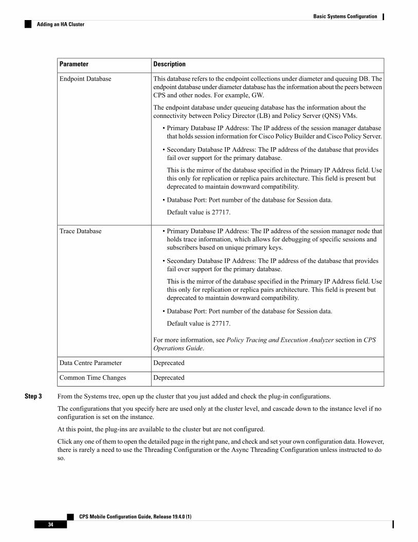
DescriptionParameter
This database refers to the endpoint collections under diameter and queuing DB. Theendpoint database under diameter database has the information about the peers betweenCPS and other nodes. For example, GW.
The endpoint database under queueing database has the information about theconnectivity between Policy Director (LB) and Policy Server (QNS) VMs.
• Primary Database IP Address: The IP address of the session manager databasethat holds session information for Cisco Policy Builder and Cisco Policy Server.
• Secondary Database IP Address: The IP address of the database that providesfail over support for the primary database.
This is the mirror of the database specified in the Primary IP Address field. Usethis only for replication or replica pairs architecture. This field is present butdeprecated to maintain downward compatibility.
• Database Port: Port number of the database for Session data.
Default value is 27717.
Endpoint Database
• Primary Database IP Address: The IP address of the session manager node thatholds trace information, which allows for debugging of specific sessions andsubscribers based on unique primary keys.
• Secondary Database IP Address: The IP address of the database that providesfail over support for the primary database.
This is the mirror of the database specified in the Primary IP Address field. Usethis only for replication or replica pairs architecture. This field is present butdeprecated to maintain downward compatibility.
• Database Port: Port number of the database for Session data.
Default value is 27717.
For more information, see Policy Tracing and Execution Analyzer section in CPSOperations Guide.
Trace Database
DeprecatedData Centre Parameter
DeprecatedCommon Time Changes
Step 3 From the Systems tree, open up the cluster that you just added and check the plug-in configurations.
The configurations that you specify here are used only at the cluster level, and cascade down to the instance level if noconfiguration is set on the instance.
At this point, the plug-ins are available to the cluster but are not configured.
Click any one of them to open the detailed page in the right pane, and check and set your own configuration data. However,there is rarely a need to use the Threading Configuration or the Async Threading Configuration unless instructed to doso.
CPS Mobile Configuration Guide, Release 19.4.0 (1)34
Basic Systems ConfigurationAdding an HA Cluster

Step 4 If the configured cluster has to be used, after publishing, the following parameter must be updated in the qns.confconfiguration file:
-Dcom.broadhop.run.clusterId=<cluster name>
where, <cluster name> is the cluster name defined in Policy Builder.
Adding an Instance
Step 1 Begin with a Cluster at the Systems node in the Reference Data tab.Step 2 Under Create Child:, click the Instance link to open the Instance pane.
Figure 21: Instance Configuration
Step 3 Type the Name and Description.Step 4 From the Systems tree, open up the instance node that you just added and check the plug-in configurations.
At this point, plug-ins are available but not configured at the instance level.
Click any one of the plug-ins to open the detailed page in the right pane and check and set your own configuration data.
Any of the configuration data you have here are used at the instance level, overriding any plug-ins set at the system levelor the cluster level.
Adding a GR ClusterAt install time, a system, cluster, and instance are set up. If you need to change the cluster definition, or wantto add others, use the information mentioned in Adding an HA Cluster and Endpoint Database Configuration.
For configuration details, refer to Adding an HA Cluster, on page 28.
For Endpoint Database parameters, refer to Endpoint Database Configuration, on page 36.
CPS Mobile Configuration Guide, Release 19.4.0 (1)35
Basic Systems ConfigurationAdding an Instance

Endpoint Database ConfigurationFor GR setup, Endpoint Database should be configured local to the site under Reporting/Balance Database.Figure 22: Endpoint Database
CPS Mobile Configuration Guide, Release 19.4.0 (1)36
Basic Systems ConfigurationEndpoint Database Configuration

C H A P T E R 3Plug-in Configuration
• Overview, on page 37• Threading Configuration, on page 38• Portal Configuration, on page 40• Async Threading Configuration, on page 41• Custom Reference Data Configuration, on page 44• Balance Configuration, on page 45• Diameter Configuration, on page 50• Voucher Configuration, on page 51• Unified API Configuration, on page 52• Notification Configuration, on page 53• Audit Configuration, on page 54• USuM Configuration, on page 55• Scheduled Events, on page 61• LDAP/Ud Configuration, on page 66• Subscriber Lookup Server Configuration, on page 69
OverviewIn CPS, reference data is considered information that is needed to operate the policy engine, but not used forevaluating policies. For example, in the Reference Data tab in Cisco Policy Builder, are the forms used todefine systems, clusters, and instances, and to set times and dates used for tariff switching. The policy engineneeds to refer to this data only to process policies correctly. However, the data does not define the policyitself.
Cisco Policy Builder provides core plug-ins for customizing and optimizing your installation.
• Configurations set at the system level are system-wide except as noted in the bullet items below.
• Configurations set at the cluster level apply to that cluster and the instances in it. A value set here overridesthe same value set at the system level.
• Configurations set at the instance level apply to the instance only and override the same value set at thecluster or system level.
Select the Create Child action in a Plug-in Configuration node in the Systems tree to define them. You canchange any of the variables from the default, or choose not to use a plug-in, as necessary.
CPS Mobile Configuration Guide, Release 19.4.0 (1)37

When you create a system from the example, the following configuration stubs appear at the cluster andinstance level:Figure 23: Create Child Action
You are notified when a new policy is applied that overrides the existing configuration.
The notification is displayed as a warning icon above the configuration heading. When you hover over thewarning icon, it displays the notificationmessage as a tooltip.When there is an error and warning in the pluginconfiguration, then the error is overridden by a warning message.
A warning message is displayed under the following conditions:
• At the System level, if the selected plugin configuration is overridden by cluster or Instance pluginconfiguration.
• At the Cluster level, if the selected plugin configuration overrides the same plugin configuration at thesystem level or is overridden by the same plugin configuration at an Instance level.
• At the Instance level, if the selected plugin configuration overrides the same plugin configuration atsystem or cluster level.
Threading ConfigurationA threading configuration utility is provided for advanced users.
Click Threading Configuration in the right pane to add the threading configuration to the system. This is aperformance tuning parameter and can be changed in case of a performance issue according to the call modeland hardware. For further information, contact your Cisco Account representative.
CPS Mobile Configuration Guide, Release 19.4.0 (1)38
Plug-in ConfigurationThreading Configuration

The Threading Plug-in is for Mobility. The only value to set is rules. It controls the total number of threadsin the Policy Engine (QNS) that are executing at any given time. The default value is 50.
It is recommended not to configure the value below 50. It can be set higher to help increase performance incertain situations where the queue full issue or performance issue is being observed. The value also dependson call model, hardware type.
A configuration example is shown below:Figure 24: Thread Pool Configuration
The following parameters can be configured under Threading Configuration:
Table 5: Threading Configuration Parameters
DescriptionParameter
Name of the Cisco thread pool i.e., rules.Thread Pool Name
Specify the threads to set in the thread pool. You can set rules thread rangingfrom 50 to 100 depending on the call flow (based on number of lookup operations).
• rules = 50; Queue Size = 0; Scale By Cpu Core = unchecked
• rules = 100; Queue Size = 0 (If TPS is > 2000 per Policy Server (QNS)depending on call model used; for example, if LDAP is enabled); Scale ByCpu core = unchecked
The threads are driven based upon average response time of the message. Theresponse time is call model dependent.
Threads
CPS Mobile Configuration Guide, Release 19.4.0 (1)39
Plug-in ConfigurationThreading Configuration

DescriptionParameter
Specify the size of the queue before the threads are rejected.
If value is greater than 50, performance may degrade because it holds the numberof tasks in queue waiting for threads to be executed when TPS is high.
If the value is lower than 50, the requests start dropping when all worker threadsare busy in executing actions.
The queue belongs to each Policy Server (QNS) process, and it holds incomingmessages from Policy Directors (LB), but also internal events/messages (forexample, an internal time change that triggers a policy evaluation).
This is a performance tuning parameter and can be changed in case of aperformance issue according to the call model and hardware.
Default value is 0.
In most of the setups, keep the queue size value default.Note
Queue Size
Select this check box to enable the processor cores to scale the maximum numberof threads.
By default, this check box is unchecked.
Scale By Cpu Core
Portal ConfigurationClick Portal Configuration from right pane to add the configuration in the system.Figure 25: Portal Configuration
DescriptionParameter
IP address or a host name of the sessionmgr database.Primary Database Host/IP Address
CPS Mobile Configuration Guide, Release 19.4.0 (1)40
Plug-in ConfigurationPortal Configuration

DescriptionParameter
Optional, this field is the IP address or a host nameof a secondary, backup, or failover sessionmgrdatabase.
Secondary Database Host/IP Address
This is required. This is the port the Balance databaseuses, that is, the port of sessionmgr.
Database Port
Async Threading ConfigurationClick Async Threading Configuration under Systems > Name of the system > Plugin Configuration inthe right pane to add the configuration in the system.
Use the default values for the Async Threading Plug-in. Similar to the Threading Plug-in, the Asyncconfiguration controls the number of asynchronous threads operating in the Policy Engine. The Policy Enginehandles two basic types of messages - synchronous and asynchronous. Synchronous messages block andexpect a response.
Asynchronous messages are sent into the Policy Engine but do not expect a response. Therefore, the PolicyEngine can defer those to worker threads that operate along side the main Policy Engine threading executionwithout causing too much traffic for performance.
For example, when an NDM calls an aynsc action based on call flow and the same threads are used to performasync action across async submissions into engine from multiple NDM's.
Always select the link for Async Threading Configuration to configure your CPS system.Note
Figure 26: Async Threading Configuration
CPS Mobile Configuration Guide, Release 19.4.0 (1)41
Plug-in ConfigurationAsync Threading Configuration

The following parameters can be configured under Async Threading Configuration.
Table 6: Async Threading Configuration
DescriptionParameter
Specifies the number of threads that are allocated to process actions based onpriority.
When you increase the value of this parameter, the number of asynchronousthreads in the pool increases and more number of threads are able to executeasynchronous actions. Although the value depends on TPS, if increased toomuch, it degrades the performance. That is because these threads would occupymore resources to execute more actions simultaneously.
By decreasing the value, the number of threads in pool decrease and there maybe a delay in processing actions.
Default value is 5.
Default ProcessingThreads
Specifies the priority assigned to an action when it is not specified in the ActionConfigurations table.
Default value is 5.
If default action priority is set when there is no action specified in the actiontable, there is no impact. However, if action priority is specified in the actiontable and also in the default action priority, then the action with the higher prioritytakes precedence.
Example 1:
• Action Configuration table: 600 (task priority)
• Default Action Priority: 700
In the preceding example, the default action takes priority over the action definedin the action configuration table.
Example 2:
• Action Configuration table: 600 (task priority)
• Default Action Priority: 500
In the preceding example, the action defined in the action configuration tabletakes priority over the action defined in the default action priority.
Default Action Priority
Specifies the number of threads assigned to process the action when it is notspecified in the Action Configurations table.
These are action specific threads, therefore, based on the increased or decreasedvalue, the number of threads are allocated to a specific action. It is recommendedthat the default action thread value be maintained. However, if there are actionsthat are executed more frequently, then enter a value in the action table that ishigher than the one in the default action thread.
Default value is 10.
Default Action Threads
CPS Mobile Configuration Guide, Release 19.4.0 (1)42
Plug-in ConfigurationAsync Threading Configuration
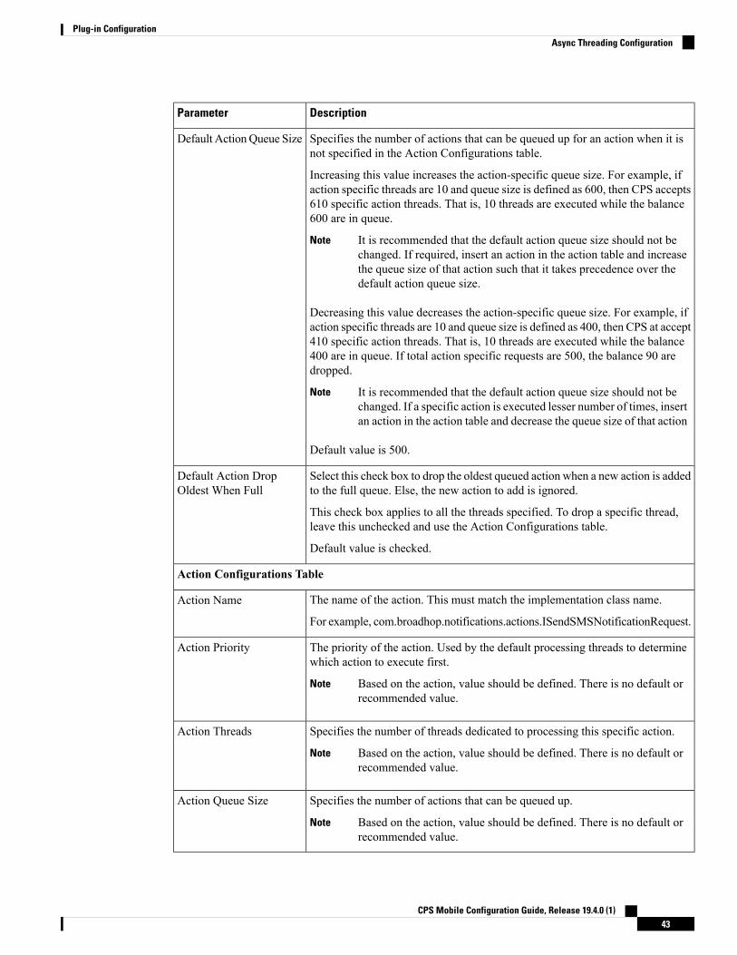
DescriptionParameter
Specifies the number of actions that can be queued up for an action when it isnot specified in the Action Configurations table.
Increasing this value increases the action-specific queue size. For example, ifaction specific threads are 10 and queue size is defined as 600, then CPS accepts610 specific action threads. That is, 10 threads are executed while the balance600 are in queue.
It is recommended that the default action queue size should not bechanged. If required, insert an action in the action table and increasethe queue size of that action such that it takes precedence over thedefault action queue size.
Note
Decreasing this value decreases the action-specific queue size. For example, ifaction specific threads are 10 and queue size is defined as 400, then CPS at accept410 specific action threads. That is, 10 threads are executed while the balance400 are in queue. If total action specific requests are 500, the balance 90 aredropped.
It is recommended that the default action queue size should not bechanged. If a specific action is executed lesser number of times, insertan action in the action table and decrease the queue size of that action
Note
Default value is 500.
Default ActionQueue Size
Select this check box to drop the oldest queued action when a new action is addedto the full queue. Else, the new action to add is ignored.
This check box applies to all the threads specified. To drop a specific thread,leave this unchecked and use the Action Configurations table.
Default value is checked.
Default Action DropOldest When Full
Action Configurations Table
The name of the action. This must match the implementation class name.
For example, com.broadhop.notifications.actions.ISendSMSNotificationRequest.
Action Name
The priority of the action. Used by the default processing threads to determinewhich action to execute first.
Based on the action, value should be defined. There is no default orrecommended value.
Note
Action Priority
Specifies the number of threads dedicated to processing this specific action.
Based on the action, value should be defined. There is no default orrecommended value.
Note
Action Threads
Specifies the number of actions that can be queued up.
Based on the action, value should be defined. There is no default orrecommended value.
Note
Action Queue Size
CPS Mobile Configuration Guide, Release 19.4.0 (1)43
Plug-in ConfigurationAsync Threading Configuration

DescriptionParameter
Select this check box to drop the oldest queued action when a new action is addedto the full queue. Else, the new action to add is ignored.
This parameter applies only to the specified action.
Default value is checked.
Action Drop Oldest WhenFull
Custom Reference Data ConfigurationConfigure your system, cluster, and instance for the first time to use Custom Reference Data Table plug-in.Then you can create as many tables as needed.
Click Custom Reference Data Configuration from right pane to add the configuration in the system.
Here is an example for HA and AIO setups:
• HA example:
• Primary Database Host/IP Address: sessionmgr01
• Secondary Database Host/IP Address: sessionmgr02
• Database Port: 27717
• AIO example:
• Primary Database Host/IP Address: localhost or 127.0.0.1
• Secondary Database Host/IP Address: NA (leave blank)
• Database Port: 27017
The following parameters can be configured under Custom Reference Data Configuration.
Table 7: Custom Reference Data Configuration Parameters
DescriptionParameter
IP address or a host name of the sessionmgr database.
For example, sessionmgr01.
Primary Database Host/IPAddress
(Optional) This field is the IP address or a host name of a secondary, backup,or failover sessionmgr database.
For example, sessionmgr02.
Secondary Database Host/IPAddress
Port number of the sessionmgr.
Make sure that the value for this field is same as filled in for boththe Primary Database Host/IP Address and Secondary DatabaseHost/IP Address fields.
Note
Default value is 27717.
Database Port
CPS Mobile Configuration Guide, Release 19.4.0 (1)44
Plug-in ConfigurationCustom Reference Data Configuration

DescriptionParameter
Describes how sessionmgr clients route read operations to members of areplica set. Select one of the following options from drop-down list:
• Primary: All operations read from the current replica set primarymember.
• PrimaryPreferred: In most situations, operations read from the primarydatabase host. However, if this host is unavailable, operations readfrom the secondary databse host.
• Secondary: All operations read from the secondary members of thereplica set.
• SecondaryPreferred: Inmost situations, operations read from secondarymembers. However, if a secondary database host is unavailable,operations read from the primary database host.
Default value is Primary.
For more information, see http://docs.mongodb.org/manual/core/read-preference/.
Db Read Preference
Number of connections that are allowed for each database host.
Default value is 100.
Connection Per Host is a performance tuning parameter and can be changedin case of a performance issue according to the call model and hardware.
Connection Per Host
Use this table to configure certain AVPs that you want to store in the sessiondatabase. AVPs that are not configured as part of this table, are not persisted.
• Name: Enter the name for the AVP value.
• Avp Name: The name of the CRD/policy derived AVP.
To retrieve the stored AVPs from the session, use the Customer ReferenceData Debug AVPs. This retriever is used to send the stored AVPs in anydiameter message, and available in thePolicyState/Session data to CustomAVP Mapping under Custom AVP Profiles.
When you configure the AVP Persists table in the Policy Builder,for each AVP, configure both the AVP name and name. If novalues are added for these fields, then the particular AVP is notadded to the Gx session. This scenario leads to unavailability ofthe specific AVP and hence, no custom AVP are sent.
Restriction
Avp Persists
For more information on Custom Reference Data API Usage, see the CPS Operations Guide for this release.
Balance ConfigurationClick Balance Configuration in the right pane to add the configuration in the system.
CPS Mobile Configuration Guide, Release 19.4.0 (1)45
Plug-in ConfigurationBalance Configuration
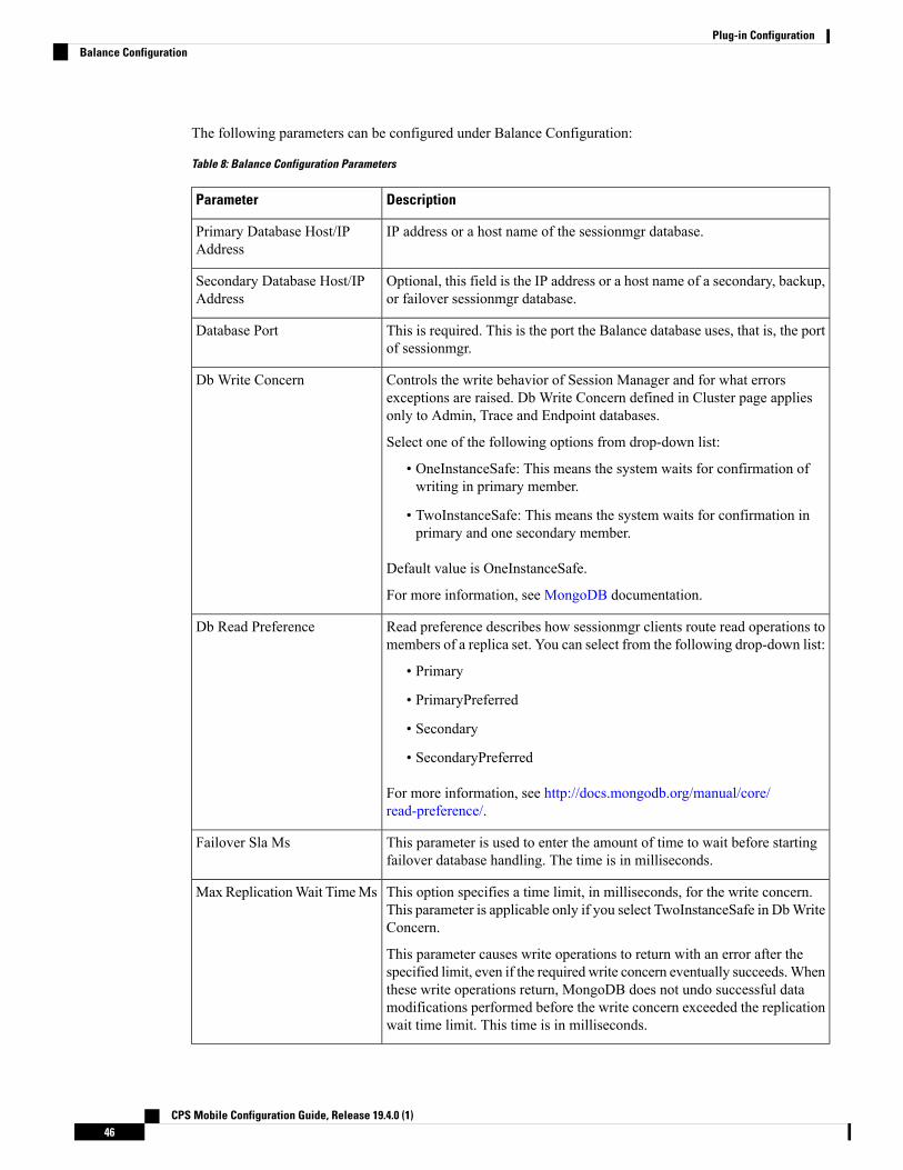
The following parameters can be configured under Balance Configuration:
Table 8: Balance Configuration Parameters
DescriptionParameter
IP address or a host name of the sessionmgr database.Primary Database Host/IPAddress
Optional, this field is the IP address or a host name of a secondary, backup,or failover sessionmgr database.
Secondary Database Host/IPAddress
This is required. This is the port the Balance database uses, that is, the portof sessionmgr.
Database Port
Controls the write behavior of Session Manager and for what errorsexceptions are raised. Db Write Concern defined in Cluster page appliesonly to Admin, Trace and Endpoint databases.
Select one of the following options from drop-down list:
• OneInstanceSafe: This means the system waits for confirmation ofwriting in primary member.
• TwoInstanceSafe: This means the system waits for confirmation inprimary and one secondary member.
Default value is OneInstanceSafe.
For more information, see MongoDB documentation.
Db Write Concern
Read preference describes how sessionmgr clients route read operations tomembers of a replica set. You can select from the following drop-down list:
• Primary
• PrimaryPreferred
• Secondary
• SecondaryPreferred
For more information, see http://docs.mongodb.org/manual/core/read-preference/.
Db Read Preference
This parameter is used to enter the amount of time to wait before startingfailover database handling. The time is in milliseconds.
Failover Sla Ms
This option specifies a time limit, in milliseconds, for the write concern.This parameter is applicable only if you select TwoInstanceSafe in DbWriteConcern.
This parameter causes write operations to return with an error after thespecified limit, even if the required write concern eventually succeeds.Whenthese write operations return, MongoDB does not undo successful datamodifications performed before the write concern exceeded the replicationwait time limit. This time is in milliseconds.
Max ReplicationWait TimeMs
CPS Mobile Configuration Guide, Release 19.4.0 (1)46
Plug-in ConfigurationBalance Configuration

DescriptionParameter
This field is optional but recommended.
This is the minimum amount of time that is granted for a reservation,assuming quota is not exhausted.
If you want to manage subscriber balances on the basis of time used, checkwith the network device administrator and configure this value to be slightlylarger than the minimum amount of time the network device such as an SCEor ISG accepts for a reservation.
Minimum value is 2 seconds.
DefaultMinimumDosage TimeBased
This field is optional but recommended.
This is the minimum amount of volume that is granted for a reservation,assuming quota is not exhausted.
If you try to make a reservation for 1 KB, and your minimum is 10 KB, therouter rejects it because it is too small an amount to bother with.
Default Minimum DosageVolume Based
The amount of time a record of expired reservations is retained and CiscoMsBM attempts to charge them. Expired reservations are charged only ifsufficient quota is still available; that is, expired reservations do not retainthe lock on quota that current reservations do.
Default value is 0.
Expired Reservations PurgeTime (minutes)
CPS Mobile Configuration Guide, Release 19.4.0 (1)47
Plug-in ConfigurationBalance Configuration

DescriptionParameter
The amount of time refreshing of recurring quotas are staggered acrossrandomly, for sessions that are not actively using quota but are stillestablished.
This parameter is used in cases where subscribers always have a session,but is not using their quota actively. This allows staggering of recurringrefreshes where you have set all their subscribers to refresh at the same time,say midnight. It avoids spiking the CPU.
Default value is 0.
To calculate the Recurring Refresh Max Delay, use the following:
Recurring Refresh Max Delay = (Number of sessions / Max Timer TPS) *2
For example:
If 30 million sessions are present on the system, and Max Timer TPS isconfigured to 2000, then
= (30,000,000 / 2000) * 2Recurring Refresh Max Delay
= 500 minutes ~ 8.33 hours
In case you want to configure a lesser time for the Recurring Refresh MaxDelay, then the Max Timer TPS needs to be increased accordingly.
Cisco recommends using Re-evaluation diffusion buckets andRe-evaluation diffusion interval (in milliseconds) instead ofRecurring Refresh Max Delay (minutes). For more information,see Adding an HA Cluster, on page 28.
Note
Recurring Refresh Max Delay(minutes)
This drop-down list is used to do a lookup in remote databases bases onselected filter type. This is similar to Filter Type drop-down under APIRouter Configuration.
By default, NetworkId is selected.
Filter type must be same in API Router Configuration andBalance Configuration in Policy Builder.
Note
RemoteDatabase Lookup FilterType
When checked, reservation dosages are reduced as a CiscoMsBM thresholdis approached. This way, a dosage does not pass a threshold by a largeamount before notification of the breach is sent out. When unchecked,normal dosage is granted. Recall that when enabled, messaging becomesmuch more chatty, but threshold breach accuracy is enhanced.
Reduce Dosage on Threshold
Submits balance transaction to the policy engine, and these can be reflectedin reporting.
Submit Balance Events ToReporting
CPS Mobile Configuration Guide, Release 19.4.0 (1)48
Plug-in ConfigurationBalance Configuration

DescriptionParameter
When checked, CPS is enabled to lookup CRD defined balance templates.If the CRD tables are not defined, this feature is disabled.
Even if the CRD tables are not defined as required, and thisfeature is disabled, the Dynamic Reference Data Key field isstill enabled but only for Policy Builder defined Account BalanceTemplates. For more information, see Table 96: Pull ValueFrom....
Note
Enable Crd Balance TemplateLookups
Remote Database
String - Name of the remote database.Name
Key prefix to be match for the remote database to be selected for lookup.Key Prefix
Number of connections that can be created per host.
Default value is 5.
Connections Per Host
Read preference describes how sessionmgr clients route read operations tomembers of a replica set. You can select from the following drop-down list:
• Primary
• PrimaryPreferred
• Secondary
• SecondaryPreferred
For more information, see http://docs.mongodb.org/manual/core/read-preference/.
Db Read Preference
IP address or a host name of the sessionmgr database.Primary Database Host/IPaddress
Optional, this field is the IP address or a host name of a secondary, backup,or failover sessionmgr database.
Secondary Database Host/IPaddress
Port number of the remote sessionmgr database. It must be the same forboth the primary and secondary databases.
Port
String - The host name of backup database for remote balance for currentsite.
Default value is sessionmgr01.
Backup Db Host On Local Site
The port number of backup database for remote balance for current site.
Default value is 27719.
Backup Db Port on Local Site
If you have a Geo-Redundancy setup, click Backup Db Configuration. It stores back up of entire balancerecords. If the primary balance database goes down, CPS will check the balance record on both secondaryand backup databases, and take the latest version for processing.
CPS Mobile Configuration Guide, Release 19.4.0 (1)49
Plug-in ConfigurationBalance Configuration

Figure 27: Backup Db Configuration
The following parameters can be configured under Backup Db Configuration:
Table 9: Backup Db Configuration Parameters
DescriptionParameter
Default value is sessionmgr01.Backup Db Host
Default value is 27719.Backup Db Port
Used in thread which updates the primary balance DB (when primarybalanceDB is available after fail over) with 'BackupBalance' db records.
Default value is 3 seconds.
Backup Db Monitor IntervalIn Sec
Used to control the TPS (with how much TPS reconciliation should happenonce primary balance db is up).
Rate Limit
Diameter ConfigurationClick Diameter Configuration in the right pane to add the configuration in the system.
CPS Mobile Configuration Guide, Release 19.4.0 (1)50
Plug-in ConfigurationDiameter Configuration

Figure 28: Diameter Configuration
For more information on the parameters under this plug-in, see Diameter Configuration, on page 73.
Voucher ConfigurationClick Voucher Configuration in the right pane to add the configuration in the system.Figure 29: Voucher Configuration
The voucher plug-in uses the following defaults:
• HA example:
CPS Mobile Configuration Guide, Release 19.4.0 (1)51
Plug-in ConfigurationVoucher Configuration
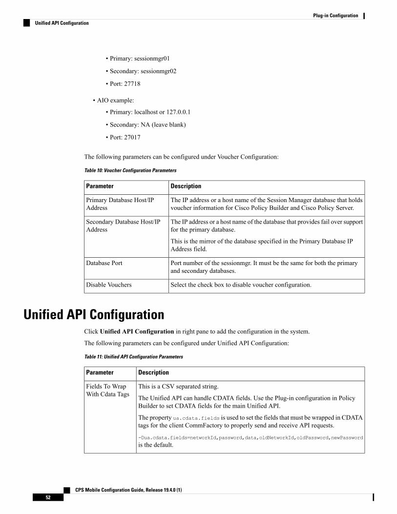
• Primary: sessionmgr01
• Secondary: sessionmgr02
• Port: 27718
• AIO example:
• Primary: localhost or 127.0.0.1
• Secondary: NA (leave blank)
• Port: 27017
The following parameters can be configured under Voucher Configuration:
Table 10: Voucher Configuration Parameters
DescriptionParameter
The IP address or a host name of the Session Manager database that holdsvoucher information for Cisco Policy Builder and Cisco Policy Server.
Primary Database Host/IPAddress
The IP address or a host name of the database that provides fail over supportfor the primary database.
This is the mirror of the database specified in the Primary Database IPAddress field.
Secondary Database Host/IPAddress
Port number of the sessionmgr. It must be the same for both the primaryand secondary databases.
Database Port
Select the check box to disable voucher configuration.Disable Vouchers
Unified API ConfigurationClick Unified API Configuration in right pane to add the configuration in the system.
The following parameters can be configured under Unified API Configuration:
Table 11: Unified API Configuration Parameters
DescriptionParameter
This is a CSV separated string.
The Unified API can handle CDATA fields. Use the Plug-in configuration in PolicyBuilder to set CDATA fields for the main Unified API.
The property ua.cdata.fields is used to set the fields that must be wrapped in CDATAtags for the client CommFactory to properly send and receive API requests.
-Dua.cdata.fields=networkId,password,data,oldNetworkId,oldPassword,newPassword
is the default.
Fields To WrapWith Cdata Tags
CPS Mobile Configuration Guide, Release 19.4.0 (1)52
Plug-in ConfigurationUnified API Configuration

DescriptionParameter
Session route key that vDRA uses to look up the peer group and route the Rx AARmessage to the correct PCRF.
When vDRA makes REST API requests to multiple PCRFs for session query using theFramed-IPv6-Prefix received in the Rx AAR message, one of the PCRF that has thecorresponding Gx session sends this session route key in the response. vDRA then usesthis key to look up the peer group and route the Rx AAR message to the correct PCRF.
Session Route Key
This value defines maximum API TPS supported per Policy Server (qns) process.
Default value is 0.
For API rate limiting at HAProxy, refer to Note 1.
Max API TPSThreshold
HTTP response code to send when API request is throttled (rate limiter acquire fails).
Default value is 500 (Internal Server Error).
HTTP Error Codeon ThresholdReached
Select the check box to log requests to API in audit log.
Default value is True (checked).
Submit RequestsTo Audit Log
Select this check box to log read requests in audit log.
Default value is False (unchecked).
Submit ReadRequests To AuditLog
1 HAProxy has maxconn <conns> configuration which manages the total number of connections thathaproxy, as a service, queues or processes at a single point of time.
Notification ConfigurationNotification in Cisco Policy Builder relates to pushing messages from Cisco Policy Builder to subscribers.The messages are used to alert the subscriber of issues as well as opportunities on their network. Not onlycan you alert subscribers, but you can also send messages to any address, for example, system monitoringaddresses.
Currently, Cisco Policy Builder offers following notification types for Mobile:
• Apple iOS devices/iPhone® push (iOS devices)
• Email (IMAP only)
• SMS notification (SMPP v 3.4)
• Realtime Notification
The following parameters can be configured under Notification Configuration. For more information aboutthese parameters, see the Notification Services chapter.
CPS Mobile Configuration Guide, Release 19.4.0 (1)53
Plug-in ConfigurationNotification Configuration
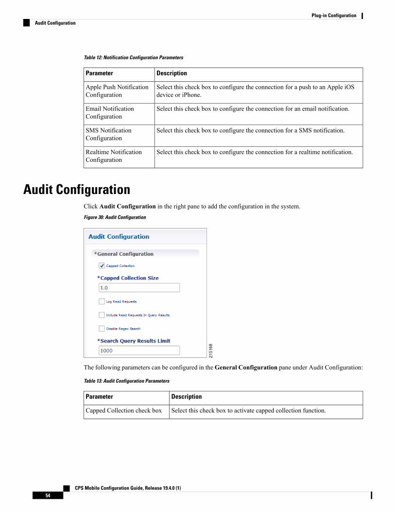
Table 12: Notification Configuration Parameters
DescriptionParameter
Select this check box to configure the connection for a push to an Apple iOSdevice or iPhone.
Apple Push NotificationConfiguration
Select this check box to configure the connection for an email notification.Email NotificationConfiguration
Select this check box to configure the connection for a SMS notification.SMS NotificationConfiguration
Select this check box to configure the connection for a realtime notification.Realtime NotificationConfiguration
Audit ConfigurationClick Audit Configuration in the right pane to add the configuration in the system.Figure 30: Audit Configuration
The following parameters can be configured in theGeneral Configuration pane under Audit Configuration:
Table 13: Audit Configuration Parameters
DescriptionParameter
Select this check box to activate capped collection function.Capped Collection check box
CPS Mobile Configuration Guide, Release 19.4.0 (1)54
Plug-in ConfigurationAudit Configuration

DescriptionParameter
By default, the Audit History uses a 1 GB capped collection in MongoDB.The capped collection automatically removes documents when the sizerestriction threshold is hit.
Configuration in Policy Builder is done in GB increments. It is possible toenter decimals, for example, 9.5 will set the capped collection to 9.5 GB.
Capped Collection Size
Select this check box if you want read requests to be logged.Log Read Requests check box
Select this check box only if you want to include read requests to bedisplayed in query results.
Include Read Requests In QueryResults check box
If you select this check box, the use of regular expressions for queries isturned off in the Policy Builder configuration.
Disable Regex Search check box
This parameter limits the search results.Search Query Results Limit
Formore information related to other parameters likeQueue Submission Configuration, Database Configuration,Shard Configuration under Audit Configuration, refer to the CPS Operations Guide for this release.
USuM ConfigurationClick USuM Configuration from right pane to add the configuration in the system.Figure 31: USuM Configuration
The following parameters can be configured in the Spr Configuration pane under USuM Configuration:
CPS Mobile Configuration Guide, Release 19.4.0 (1)55
Plug-in ConfigurationUSuM Configuration

Table 14: USuM Configuration Parameters - 1
DescriptionParameter
Spr Configuration
For SP Wi-Fi, you can use email ID which has realm, username, and so on,as key of SPR. So, part of the string needs to match for regex support.
RADIUS-based policy control is no longer supported in CPS 14.0.0and later releases as 3GPP Gx Diameter interface has become theindustry-standard policy control interface.
Note
Disable Regex Search
For regex search on values for AVP for SPR.Enable Avp Regex Search
If the subscriber state is Suspended, SPR does not validate IMSI.Exclude SuspendedSubscribers From Policy
Used to limit search if you are not passing any IMSI/MSISDN (NetworkID)in control center to list subscriber.
Default value is 1000.
Search Query Results Limit
It is used to track subscriber last location to maintain history. Maximum “n”last locations are stored as location history.
Max Number Of LocationsTo Store In History
This parameter is used to identify if the subscriber is visiting same locationagain (based on the location history). If the subscriber is vising the samelocation, then it will change the last visited date if current visited date is morethan last visited date + “n” days defined here.
Last Visited Date Threshold
Figure 32: Policy Engine Submission Configuration
The following parameters can be configured in the Policy Engine Submission Configuration pane underUSuM Configuration:
CPS Mobile Configuration Guide, Release 19.4.0 (1)56
Plug-in ConfigurationUSuM Configuration

Table 15: USuM Configuration Parameters - 2
DescriptionParameter
Keep it default.Enable check box
Queue to hold data to generate internal SPR Refresh events for policyengine during Create, Update, Delete of subscriber.
Message Queue Size
Sleep before popping next batch for generating SPR Refresh events forpolicy engine for RAR processing.
Message Queue Sleep
Batch size for fetching number of subscriberIds in one go for generatingSPR Refresh events for policy engine for RAR processing.
Message Queue Batch Size
Message queue pool size to consume the data from queue and generateSPR Refresh events.
Message Queue Pool Size
Rate limiting for generating SPR Refresh events. SPR Refresh events isused to generate RAR for active session where subscriber data has beenchange.
Notification Rate Limit
CPS Mobile Configuration Guide, Release 19.4.0 (1)57
Plug-in ConfigurationUSuM Configuration

Figure 33: Database Configuration
The following parameters can be configured in Database Configuration pane under USuM Configuration:
Table 16: USuM Configuration Parameters - 3
DescriptionParameter
Database Configuration
CPS Mobile Configuration Guide, Release 19.4.0 (1)58
Plug-in ConfigurationUSuM Configuration

DescriptionParameter
It is used to decide what all indexes need to be created on SPR collection bydefault. You need all the indexes to be created (You can select this check boxwhen number of subscribers are low, for example, less than 50K). Defaultvalue is unchecked.
Use Minimum Indexes
Controls the write behavior of SessionManager and for what errors exceptionsare raised. Db Write Concern defined in Cluster page applies only to Admin,Trace and Endpoint databases.
Select one of the following options from drop-down list:
• OneInstanceSafe: This means the systemwaits for confirmation of writingin primary member.
• TwoInstanceSafe: This means the systemwaits for confirmation in primaryand one secondary member.
Default value is OneInstanceSafe.
For more information, see MongoDB documentation.
Db Write Concern
Read preference describes how sessionmgr clients route read operations tomembers of a replica set. You can select from the following drop-down list:
• Primary
• PrimaryPreferred
• Secondary
• SecondaryPreferred
For more information, refer to http://docs.mongodb.org/manual/core/read-preference/.
For consistent profile updates across multiple sessions for samesubscriber, Cisco recommends to set the Db Read Preference asPrimaryPreferred.
Important
Db Read Preference
This parameter is used to enter the amount of time to wait before startingfailover database handling. The time is in milliseconds.
Failover Sla Ms
This option specifies a time limit, in milliseconds, for the write concern. Thisparameter is applicable only if you select TwoInstanceSafe in Db WriteConcern.
This parameter causes write operations to return with an error after the specifiedlimit, even if the required write concern eventually succeeds.When these writeoperations return, MongoDB does not undo successful data modificationsperformed before the write concern exceeded the replication wait time limit.This time is in milliseconds.
Max Replication Wait TimeMs
CPS Mobile Configuration Guide, Release 19.4.0 (1)59
Plug-in ConfigurationUSuM Configuration

DescriptionParameter
Shard Configuration
The host names must exactly be the same host name used when the corresponding replica-set iscreated in Mongo. Only the data holding members need to be configured (and not the arbiters).
Important
String - Primary Host Address.Primary Database Host
String - Secondary Host Address.Secondary Database Host
Default value is 27720.Database Port
Remote Shard Configuration
Remote shard configuration is used only for GR deployments. The host names must exactly bethe same host name used when the corresponding replica-set is created in Mongo. Only the dataholding members need to be configured (and not the arbiters).
Important
String - Tertiary Host Address.Tertiary Database Host
String - Quaternary Host Address.Quaternary Database Host
Figure 34: Remote Database Configuration
Click Add to add a new row in the Remote Database Configuration pane. The following parameters canbe configured in the Remote Database Configuration pane under USuM Configuration:
To enable CPS to route the Sh data based on Gx CCR-I origin-host pattern, you need to enable RemoteDatabase Configuration. For more information, see External Profile Cache, on page 195.
Note
Remote database configuration is used only for GR deployments. The host names must exactly be the samehost name used when the corresponding replica-set is created in Mongo. Only the data holding members needto be configured (and not the arbiters).
Important
Table 17: USuM Configuration Parameters - 4
DescriptionParameter
String - Name of the remote database.Name
CPS Mobile Configuration Guide, Release 19.4.0 (1)60
Plug-in ConfigurationUSuM Configuration

DescriptionParameter
Select any one of the following values from the drop down:
• StartsWith
• Regex
• EndsWith
• Equals
Match Type
A string value which matches the MatchType specified. In case of Regex, youneed to specify valid java regex pattern.
This is used to lookup the remoteDB specified for a subscriber match for read/writeoperations on the SPR database.
Match Value
This parameter is not used in USuM Configuration.Connections Per Host
Read preference describes how sessionmgr clients route read operations tomembersof a replica set. You can select from the following drop-down list:
• Primary
• PrimaryPreferred
• Secondary
• SecondaryPreferred
For more information, refer to http://docs.mongodb.org/manual/core/read-preference/.
Db Read Preference
Host name of the remote sessionmgr database.Primary Database Host
(Optional) Host name of a secondary, backup, or failover sessionmgr database.SecondaryDatabaseHost
Host name of the tertiary database.Tertiary Database Host
Host name of the quaternary database.Quaternary DatabaseHost
Port number of the remote sessionmgr database. It must be the same for both theprimary and secondary databases.
Default value is 27720.
Port
Scheduled EventsThe Scheduled Events plug-in is configured in the Policy Builder to implement offline notifications and SPRcleanup. Offline notifications send an SMS notification to an off-line subscriber indicating that their quota isabout to expire. SPR cleanup allows you to delete subscriber data that is no longer needed or valid. Forexample, a subscriber account no longer has any services assigned to it, and therefore should be deleted fromthe database.
CPS Mobile Configuration Guide, Release 19.4.0 (1)61
Plug-in ConfigurationScheduled Events

Enable Scheduled EventsTo enable the scheduled events framework, this feature has to be enabled in the feature set of Policy Serverand Policy Builder. The following packages, when added to the respective servers, deploy the functionalityof scheduledEvents during a session:
• In the Policy Builder – com.broadhop.client.feature.scheduledevents package is added.
• In the Policy Server – com.broadhop.scheduledevents.service.feature package is added.
To add Scheduled Events Configuration, perform the following steps:
Step 1 If this is HA environment, edit the corresponding features files in Cluster Manager VM:
In the /var/qps/current_config/etc/broadhop/pb/features file, add the following line:
com.broadhop.client.feature.scheduledevents
In the /var/qps/current_config/etc/broadhop/pcrf/features file, add the following line:
com.broadhop.scheduledevents.service.feature
Step 2 If this is AIO environment, edit the features files in Cluster Manager VM:
In the /var/qps/current_config/etc_aio/broadhop/pb/features file, add the following line:
com.broadhop.client.feature.scheduledevents
In the /var/qps/current_config/etc_aio/broadhop/pcrf/features file, add the following line:
com.broadhop.scheduledevents.service.feature
Step 3 After modifying the feature files, execute the following commands:
/var/qps/install/current/scripts/build_all.sh
/var/qps/install/current/scripts/upgrade/reinit.sh
reinit.sh executes puppet on AIO and also checks if it is executed successfully.Note
Scheduled Events Configuration
Step 1 Click Scheduled Events Configuration in the right pane.Step 2 In the Scheduled Event Configuration pane and enter the values for the fields provided.
CPS Mobile Configuration Guide, Release 19.4.0 (1)62
Plug-in ConfigurationEnable Scheduled Events

Figure 35: Scheduled Events Configuration
The following table describes the parameters that can be configured under Scheduled Events Configuration.
Table 18: Scheduled Events Configuration Parameters
DescriptionParameter
The IP address of the sessionmgr database.Primary Database Address
The IP address of a secondary, backup, or failover sessionmgr database.Secondary Database Address
The port used by the database; this is the sessionmgr port.Database Port
Controls the write behavior of Session Manager and for what errors exceptionsare raised. DbWrite Concern defined in Cluster page applies only to Admin, Traceand Endpoint databases.
Select one of the following options from drop-down list:
• OneInstanceSafe: This means the system waits for confirmation of writingin primary member.
• TwoInstanceSafe: This means the system waits for confirmation in primaryand one secondary member.
Default value is OneInstanceSafe.
For more information, see MongoDB documentation.
DB Write Concern
CPS Mobile Configuration Guide, Release 19.4.0 (1)63
Plug-in ConfigurationScheduled Events Configuration

DescriptionParameter
Describes how sessionmgr clients route read operations to members of a replicaset. You can select from the following drop-down list:
• Primary – Default mode. All operations read from the current replica setprimary.
• PrimaryPreferred – In most situations, operations read from the primary butif it is unavailable, operations read from secondary members.
• Secondary – All operations read from the secondary members of the replicaset.
• SecondaryPreferred – In most situations, operations read from secondarymembers but if no secondary members are available, operations read fromthe primary.
For more information, refer to http://docs.mongodb.org/manual/core/read-preference/.
DB Read Preference
Controls the maximum number of internally generated transactions per secondthat the system will produce.
Transactions Per Second
The hour at which the event is triggered. The value specified should be in therange of 0 to 23 (24-hour format).
Scheduled Start Hour
The minute at which the event is triggered. The value specified should be in therange 0 to 59.
Scheduled Start Minute
The type of event that will be triggered. You can select either of the following:
QuotaExpiration – The scheduled event will be triggered when the system detectsthat a subscriber's quota is going to expire within the number of hours specifiedin the Hours Left Before Quota Exhausts parameter.
SubscriberInactivity – The scheduled event will be triggered when the systemdetects that a subscriber is inactive. If you select this event type, the Hours LeftBefore Quota Exhausts and Notify Time in Hours parameters are ignored.
Event Type
Processes only those subscribers whose account balance is specified in theconfiguration. Other subscribers are ignored.
The Account Balance and Service parameters filter for subscribers having theconfigured balance and service. If these columns are not specified, the eventprocesses all subscribers.
Account Balance
CPS Mobile Configuration Guide, Release 19.4.0 (1)64
Plug-in ConfigurationScheduled Events Configuration

DescriptionParameter
Used only with the QuotaExpiration event type. This parameter specifies thenumber of hours before the subscriber's quota expires.
The system checks this field in the scheduled events loop and looks for quotasthat are about to expire within the number of hours specified. If the number ofhours before expiration is less than the value in this column, then subscribers withthat quota will be added to the eventsCollection in the ScheduleEvents mongodatabase.
For example, if this value is 8, when the scheduled events task runs, any subscribeswho have the service specified and whose quota will expire in less than 8 hourswill be added to the eventsCollection. Once in eventsCollection, new actions aretaken for that subscriber depending on scheduled event configuration.
Hours Left Before Quota Exhausts
Used only with the QuotaExpiration event type. This parameter specifies thenumber of hours before a notification is sent to the subscriber.
This parameter is used in conjunctionwith theHours Left BeforeQuota Exhaustsparameter. When this number is reached, CPS submits a QuotaExpiredEvent tothe policy engine with the subscriber's balance information. When this occurs,the state of the entry in the eventsCollection changes to "notified."
For example, if Hours Left Before Quota Exhausts = 8 and Notify Time inHours = 4, an entry is created with the subscriber's balance information in theeventCollections 8 hours prior to quota expiration, and a QuotaExpiration eventis submitted to the policy engine 4 hours before expiration.
You can set up polices to send out notifications when this event occurs; forexample, you might set up scheduled events to send out notifications 8 hours, 6hours, 4, hours, and 2 hours before a subscriber's quota expires, reminding thesubscriber to "top up."
Notify Time in Hours
Processes only those subscribers who have the configured service associated.Other subscribers are ignored.
The Account Balance and Service parameters filter for subscribers having theconfigured balance and service. If these columns are not specified, the eventprocesses all subscribers.
Service
Used only with the SubscriberInactivity event type.
This parameter specifies the duration in days to retain the subscriber in the inactivestate. If the status of a subscriber remains inactive for longer than the configuredmaximum number of days, the subscriber is automatically deleted from thedatabase.
Max Number of Days
CPS Mobile Configuration Guide, Release 19.4.0 (1)65
Plug-in ConfigurationScheduled Events Configuration

DescriptionParameter
A string value that is used to provide additional information about the event thatis being submitted. This string can be used in the polices that look for eventssubmitted to the policy engine.
For example, when used with a QuotaExpiration event type, the command couldbe set to "8 hours" or "6 hours," or to any other string. A policy can use this stringin its condition parameters to send one notification as opposed to another, or totake one action as opposed to another.
Command
LDAP/Ud ConfigurationCPS has capability to access subscriber profile data either from internal or external database. LDAP/Ud featurefetches subscriber profile data from the external database.
In this section, LDAP plug-in configuration is used an example.
LDAP plugin queries the LDAP server to fetch attributes depending on the configuration. This feature hascapability to refresh the profile and fetch the latest updated attribute from the LDAP server. CPS connects tomultiple LDAP severs and queries them depending on the LDAP server priority.
Refer to CPS Installation Guide for VMware to configure this plugin.Note
Click LDAP Configuration from the right pane to add the configuration in the system.
Click Ldap Server Configuration.Figure 36: LDAP Configuration
CPS Mobile Configuration Guide, Release 19.4.0 (1)66
Plug-in ConfigurationLDAP/Ud Configuration

Figure 37: LDAP Server Configuration
The following parameters can be configured under LDAP Server Configuration:
Table 19: LDAP Server Configuration Parameters – 1
DescriptionParameter
Assign this to the LDAP Server Set.Ldap Server
The user DN for connecting to the LDAP server; for example,cn=managerou=accountso=profile.
Search User Dn
The password for connecting to the LDAP server.
The same password must apply to all servers defined in thisconfiguration.
Note
Search User Password
The LDAP authorization type required by the LDAP server.
Default: SIMPLE
Auth Type
Set the initial connections to “50.” This represents the number ofconnections from a Policy Director (load balancer) to the LDAP server(s).
Initial Connections
The total number of tries the system executes for a given LDAP query.For example, a value of 2 indicates one try and then one more attemptwhen the query times out.
Retry Count
CPS Mobile Configuration Guide, Release 19.4.0 (1)67
Plug-in ConfigurationLDAP/Ud Configuration

DescriptionParameter
The time period when the policy engine retries to a second Policy Director(load balancer) to send the request.
Setting this value too low results in a large number of additionalrequests. This value should be set to a value close to the SLAprovided by the LDAP server in servicing requests.
Note
Retry Time Ms
The time in milliseconds a secondary connection is used before checkingto determine if the original primary server is available.
This is the time to fall back from a failover connection. CPS returns theconnection to the LDAP connection pool and gets another connection.
Default: 60000 milliseconds (1 minute)
Max Failover Connection AgeMs
The maximum rate at which to connect to the LDAP server. Setting thisto a high value may result in extra load on the peer LDAP server.
Binds Per Second
The time in milliseconds to generate a health check message; for example,5000 milliseconds (5 seconds).
Health Check Interval Ms
The health check DN that is sent on the health check LDAP query.Health Check Dn
The filter that is sent on the health check LDAP query.Health Check Filter
A comma-delimited list of attributes to retrieve in the LDAP health checkquery.
Health Check Attrs
Select this check box to enable the health check.Health Check
The number of timeouts that trigger a bad connection and force areconnection.
A value of -1 disables this function, preventing CPS from marking anyconnection bad.
Default: -1
Number Consecutive TimeoutsFor Bad Connection
Add entries to the LDAP Servers to represent the primary and secondary connections from the CPS systemto the LDAP servers.Figure 38: LDAP Servers
You can configure the following parameters under LDAP Servers:
CPS Mobile Configuration Guide, Release 19.4.0 (1)68
Plug-in ConfigurationLDAP/Ud Configuration

Table 20: LDAP Server Configuration Parameters – 2
DescriptionParameter
The priority of the server when sending requests. Higher number is equalto higher priority.
Priority
The IP address of the server to send requests.Address
The port address of the LDAP Server.Port
This setting is not currently used.Connection Rule
This setting is not currently used.Auto Reconnect
The SLA for queries for the LDAP server. Cisco recommends a value of5000 milliseconds.
Timeout Ms
The SLA for binds to the LDAP server.Bind Timeout Ms
Subscriber Lookup Server Configuration
Refer to the section Subscriber Lookup Feature Installation inCPS Installation Guide for VMware to configurethis plugin.
Note
You can configure CPS to act as an LDAP server to support LDAP search queries that useframedIp/msisdn/imsi/framedIpv6Prefix key to get subscriber details.
In case multiple sessions are found for matching the same LDAP query, CPS responds with details of all thesessions to LDAP client.
The search query can come to any clusters in the deployment. For configuring cluster peer, refer to ClusterPeer Configuration, on page 70. The cluster that receives the request forwards the request to all other clustersbased on Cluster Peer Configuration.
In Policy Builder, click Subscriber Lookup Server Configuration from the right pane to add the configurationin the system.
The following parameters can be configured under Subscriber Lookup Server Configuration:
Table 21: Subscriber Lookup Server Configuration Parameters
DescriptionParameter
Used to authenticate the LDAP search request before getting processed.
Default: admin/password
Bind DN/Bind DN (Admin)Password
Used to configure the port where you want to start the LDAP server.
Default: 1399
Ldap Server Port
CPS Mobile Configuration Guide, Release 19.4.0 (1)69
Plug-in ConfigurationSubscriber Lookup Server Configuration
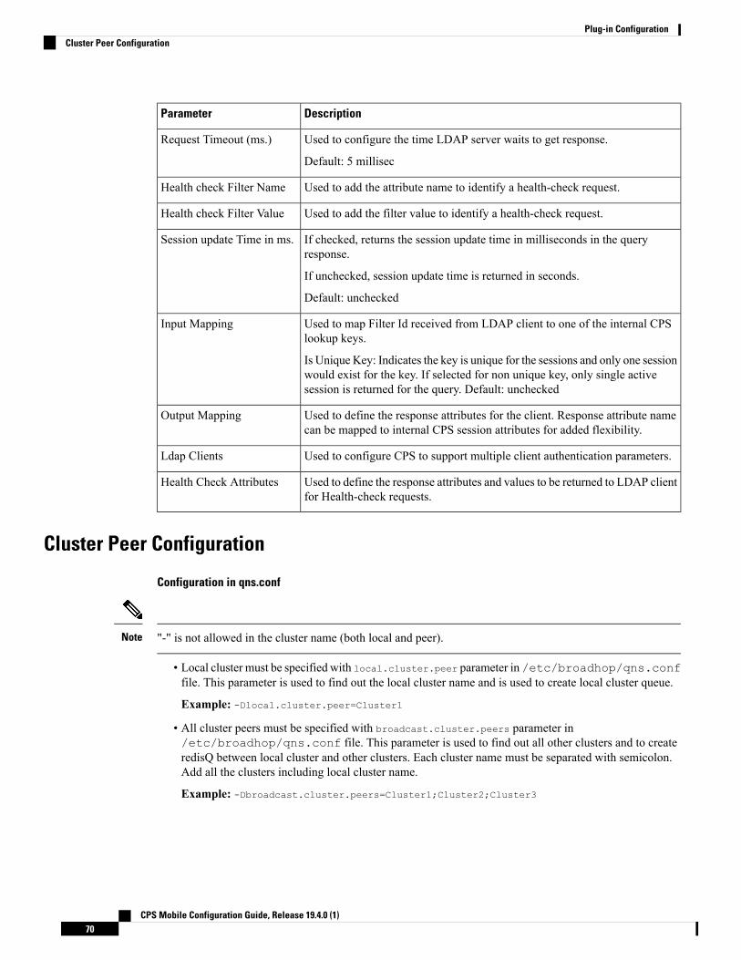
DescriptionParameter
Used to configure the time LDAP server waits to get response.
Default: 5 millisec
Request Timeout (ms.)
Used to add the attribute name to identify a health-check request.Health check Filter Name
Used to add the filter value to identify a health-check request.Health check Filter Value
If checked, returns the session update time in milliseconds in the queryresponse.
If unchecked, session update time is returned in seconds.
Default: unchecked
Session update Time in ms.
Used to map Filter Id received from LDAP client to one of the internal CPSlookup keys.
Is Unique Key: Indicates the key is unique for the sessions and only one sessionwould exist for the key. If selected for non unique key, only single activesession is returned for the query. Default: unchecked
Input Mapping
Used to define the response attributes for the client. Response attribute namecan be mapped to internal CPS session attributes for added flexibility.
Output Mapping
Used to configure CPS to support multiple client authentication parameters.Ldap Clients
Used to define the response attributes and values to be returned to LDAP clientfor Health-check requests.
Health Check Attributes
Cluster Peer Configuration
Configuration in qns.conf
"-" is not allowed in the cluster name (both local and peer).Note
• Local cluster must be specified with local.cluster.peer parameter in /etc/broadhop/qns.conffile. This parameter is used to find out the local cluster name and is used to create local cluster queue.
Example: -Dlocal.cluster.peer=Cluster1
• All cluster peers must be specified with broadcast.cluster.peers parameter in/etc/broadhop/qns.conf file. This parameter is used to find out all other clusters and to createredisQ between local cluster and other clusters. Each cluster name must be separated with semicolon.Add all the clusters including local cluster name.
Example: -Dbroadcast.cluster.peers=Cluster1;Cluster2;Cluster3
CPS Mobile Configuration Guide, Release 19.4.0 (1)70
Plug-in ConfigurationCluster Peer Configuration

Configuration for RedisQ Servers
• Redis server peers must be configured in /etc/broadhop/broadcast-cluster.conf file:
This file has information about the redisQ servers. You need to provide Policy Directory (lb) VIP addressif this is a HA setup. Each cluster specified in broadcast.cluster.peers must have one entry in thisfile to represent redis server related to that cluster.
Syntax: <ClusterName>-clusterBroadcastQ.redis.qserver=<lbvipIPadress>
where, <lbvipIPadress> is the IP address of Policy Director (LB) VIP.
ClusterName is the local cluster peer (configured for local.cluster.peer parameter in qns.conffile) of every cluster.
Example:[root@lb02 broadhop]# cat /etc/broadhop/broadcast-cluster.confCluster1-clusterBroadcastQ.redis.qserver=IPaddress1Cluster2-clusterBroadcastQ.redis.qserver=IPaddress2Cluster3-clusterBroadcastQ.redis.qserver=IPaddress3
• During replica-set failover, some of the LDAP search requests coming from LDAP clients to a CPS sitefail to respond back with session details. This is because CPS reads the session details from the nearestsecondary replica-set member, and with two replica-set members present on a site when the Primarymember goes down the only remaining secondary member transitions to Primary state. During thistransition, there is no Secondary member available in the nearest location (or local site) and thereforeMongo is not able to read the session information. As a result, the CPS application responds back to theLDAP request without any session information. However, since the failover transition period is less than30 seconds, so a retry from the LDAP client after this period results in an LDAP response with sessioninformation.
• If local session affinity is enabled in CPS, then during migration of sessions to replica-set of a remoteCPS site, some of the LDAP search requests coming from LDAP clients to the local CPS site fail torespond back with session details. This is because CPS reads the session details from the nearest secondaryreplica-set member, and with migration in progress the nearest secondary members of the remote sitereplica-set present on the local CPS site is not in sync with the corresponding Primary member presenton the remote site. This can happen due to latency between the two CPS sites. As a result, the CPSapplication responds back to the LDAP request without any session information. However, dependingupon the delay in sync between the two site replica-set members, a retry of the LDAP client requestresults in an LDAP response with session information.
Note
CPS Mobile Configuration Guide, Release 19.4.0 (1)71
Plug-in ConfigurationCluster Peer Configuration

CPS Mobile Configuration Guide, Release 19.4.0 (1)72
Plug-in ConfigurationCluster Peer Configuration

C H A P T E R 4Diameter Configuration
• Diameter Configuration, on page 73• Diameter Stack Configuration, on page 99• Diameter Agents, on page 108• Diameter Clients, on page 111• Diameter Defaults, on page 141• Rule Retry Profiles, on page 164
Diameter ConfigurationThe Diameter Configuration section allows for the configuration of the diameter plug-in. We recommendconfiguring the diameter plug-in at system level.
At System Level
In order to define a Diameter Configuration at system level, you need to perform the following steps:
1. Login into Policy Builder.2. Select Reference Data tab.3. From the left pane, select Systems.4. Select and expand your system name.5. Select Plugin Configurations.6. Select Diameter Configuration.
At Cluster Level
In order to define a Diameter Configuration at cluster level you need to perform the following steps:
1. Log in into Policy Builder.2. Select Reference Data tab.3. From the left pane, select Systems.4. Select and expand your system name.5. Select and expand your cluster name. If no cluster has been created, create one by selecting the Cluster
action.
6. Select Plugin Configurations.7. Select Diameter Configuration.
CPS Mobile Configuration Guide, Release 19.4.0 (1)73

The following parameters can be configured under Diameter Configuration.
Table 22: Diameter Configuration Parameters
DescriptionParameter
This timer is armed every time a message is received or sent for any given Gx session.When the timer expires (or more precisely within the next minute after the timerexpires) a Gx RAR having the Re-Auth-Request-Type AVP set toAUTHORIZE_ONLY (0) message is triggered for that Gx session. If a Gx RAA isreceived having Result-Code AVP value set toDIAMETER_UNKNOWN_SESSION_ID (5002) orDIAMETER_UNABLE_TO_COMPLY (5012) the Gx session is deemed as staleand removed from the PCRF internal database. On any activity over Gx interface(RAR/CCR) the timer is reset.
Default value is 180 minutes.
Note • This timer unit is minute.• Stale Gx session removal triggers the PCRF session terminationprocedure for any other diameter sessions that were bound to the Gxsession.
Default Gx StaleSession TimerMinutes
This option allows for a different set of list of valid values and their interpretation tobe used for the Event-Trigger enumerated AVP in order to accommodate the changethat occurred in the Gx specification between 3GPP TS 29.212 v9.5 (and prior) and3GPP TS 29.212 v9.7 (and following including v10 v11 and v12). Default value ischecked.
List of valid values is provided in Table 23: Use V9 Event Trigger Mapping ValidValues, on page 75.
Note • The Event-Trigger AVP list of valid values and their interpretationdefined in 3GPP TS 29.212 v9.6 is not supported.
• Use V9 Event Trigger Mapping checked uses 3GPP TS 29.212 v9.5as a reference while 3GPP TS 29.212 v110.10 is used as a referencewhen not checked.
Use V9 EventTrigger Mapping
This option allows for the Gx usage monitoring feature to be supported even whenthe PCEF advertises support for Rel8 feature under Supported-Features AVP in GxCCR-i.
Default value is checked.
Rel8 UsageMonitoringSupported
When checked, it enables the support for 3GPP Rel-15 Extended BW-NR feature.PCRF sends response to AF/PCEFwith Rel-15 Extended BW-NR feature bit set whenthe feature is enabled and AF/PCEF has also set the bit in the request message. PCRFsends extended QoS AVPs only if the configuration is enabled.
When unchecked, it disabled the support for 3GPP Rel-15 Extended BW-NR feature.
Default value is unchecked (disabled).
Rel15 Ext Bw NrSupported
CPS Mobile Configuration Guide, Release 19.4.0 (1)74
Diameter ConfigurationDiameter Configuration

DescriptionParameter
When a new row is added in “Stale Session Configuration” table the default value forthe GX_TGPP SD_V11 and SY_V11 Stale session timer is 180 minutes.
The maximum value allowed for the Stale Session Timer parameter is35000 minutes.
Note
If GX_TGPP Stale Session Timer value is not configured in this table, then the valueis selected from the retained/old variable “Default Gx Stale Session Timer Minutes”.
If there are multiple values configured against any interface then the lowest amongall would be considered as the stale session timer.
Stale SessionConfiguration
When enabled allows you to configure different message processing priorities basedon the DRMP value received in the incoming request.
• Default Inbound Priority - The default inbound priority value.
• Inbound DRMP Prioritization
• DRMP - DRMP AVP value in the incoming request.
• Priority - Priority value assigned to the incoming message. Based on thisvalue the message processing is prioritized. Higher Priority messages arebe processed first compared to lower priority messages.
DRMP Prioritization
If Gx stale session timer is set for both “Default Gx Stale Session timer Minutes” and “Stale SessionConfiguration” then the value configured Under “Stale Session Configuration” would take the precedence.
Note
Table 23: Use V9 Event Trigger Mapping Valid Values
Interpretation - Use V9 Event TriggerMapping is not checked
ValueInterpretation - Use V9 EventTrigger Mapping is checked
SGSN_CHANGE0SGSN_CHANGE
QOS_CHANGE1QOS_CHANGE
RAT_CHANGE2RAT_CHANGE
TFT_CHANGE3TFT_CHANGE
PLMN_CHANGE4PLMN_CHANGE
LOSS_OF_BEARER5LOSS_OF_BEARER
RECOVERY_OF_BEARER6RECOVERY_OF_BEARER
IP_CAN_CHANGE7IP_CAN_CHANGE
CPS Mobile Configuration Guide, Release 19.4.0 (1)75
Diameter ConfigurationDiameter Configuration

Interpretation - Use V9 Event TriggerMapping is not checked
ValueInterpretation - Use V9 EventTrigger Mapping is checked
QOS_CHANGE_EXCEEDING
_AUTHORIZATION
11QOS_CHANGE_EXCEEDING
_AUTHORIZATION
RAI_CHANGE12RAI_CHANGE
USER_LOCATION_CHANGE13USER_LOCATION_CHANGE
NO_EVENT_TRIGGERS14NO_EVENT_TRIGGERS
OUT_OF_CREDIT15OUT_OF_CREDIT
REALLOCATION_OF_CREDIT16REALLOCATION_OF_CREDIT
REVALIDATION_TIMEOUT17REVALIDATION_TIMEOUT
UE_IP_ADDRESS_ALLOCATE18UE_IP_ADDRESS_ALLOCATE
UE_IP_ADDRESS_RELEASE19UE_IP_ADDRESS_RELEASE
DEFAULT_EPS_BEARER
_QOS_CHANGE
20DEFAULT_EPS_BEARER
_QOS_CHANGE
AN_GW_CHANGE21AN_GW_CHANGE
SUCCESSFUL_RESOURCE
_ALLOCATION
22SUCCESSFUL_RESOURCE
_ALLOCATION
RESOURCE_MODIFICATION
_REQUEST
23RESOURCE_MODIFICATION
_REQUEST
PGW_TRACE_CONTROL24PGW_TRACE_CONTROL
UE_TIME_ZONE_CHANGE25UE_TIME_ZONE_CHANGE
TAI_CHANGE26USAGE_REPORT
ECGI_CHANGE27TAI_CHANGE
CHARGING_CORRELATION
_EXCHANGE
28ECGI_CHANGE
APN_AMBR_MODIFICATION
_FAILURE
29CHARGING_CORRELATION
_EXCHANGE
USER_CSG_INFORMATION
_CHANGE
30USER_CSG_INFORMATION
_CHANGE
CPS Mobile Configuration Guide, Release 19.4.0 (1)76
Diameter ConfigurationDiameter Configuration
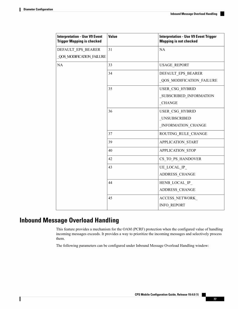
Interpretation - Use V9 Event TriggerMapping is not checked
ValueInterpretation - Use V9 EventTrigger Mapping is checked
NA31DEFAULT_EPS_BEARER
_QOS_MODIFICATION_FAILURE
USAGE_REPORT33NA
DEFAULT_EPS_BEARER
_QOS_MODIFICATION_FAILURE
34
USER_CSG_HYBRID
_SUBSCRIBED_INFORMATION
_CHANGE
35
USER_CSG_HYBRID
_UNSUBSCRIBED
_INFORMATION_CHANGE
36
ROUTING_RULE_CHANGE37
APPLICATION_START39
APPLICATION_STOP40
CS_TO_PS_HANDOVER42
UE_LOCAL_IP_
ADDRESS_CHANGE
43
HENB_LOCAL_IP_
ADDRESS_CHANGE
44
ACCESS_NETWORK_
INFO_REPORT
45
Inbound Message Overload HandlingThis feature provides a mechanism for the OAM (PCRF) protection when the configured value of handlingincoming messages exceeds. It provides a way to prioritize the incoming messages and selectively processthem.
The following parameters can be configured under Inbound Message Overload Handling window:
CPS Mobile Configuration Guide, Release 19.4.0 (1)77
Diameter ConfigurationInbound Message Overload Handling

Table 24: Inbound Message Overload Handling Parameters
DescriptionParameter
Default priority to be assigned to an incoming message if no specificpriority is defined in the Message Handling Rules table.
Default value is 0.
Default Priority
Service Level Agreement (SLA) in milliseconds, defines the number ofmilliseconds that are associated with an incoming event or message withinwhich Policy Director (load balancer) has to submit it to Policy Server(QNS) for processing. In case the configured duration times out, theDefault Discard Behavior is applied.
Maximum time (in millisec) that a message has in an inbound messagehandling queue waiting for a worker thread. Configuring this value avoidsprocessing a message to time out by a remote peer.
An SLA time that is too large can result in wasted processing on messagesalready timed out on a remote peer (i.e. PGW) and creation of stalesessions.
An SLA time that is too small can result in dropping the messages thatcould have been successfully processed.
Default value is 1500 ms.
The value must be less than timeout configured at Gateway.Note
If you have not selected Inbound Message Overload Handling checkbox under Diameter Configuration, you can define inboundMessageSlaMsand inboundMessageQueueSize in/etc/broadhop/qns.conf file.If inboundMessageSlaMs is not defined in qns.conf file, then defaultvalue of 9000 is used.
Example: -DinboundMessageSlaMs=2000
After modifying the configuration on ClusterManager execute reinit.shor copytoall.sh scripts for applying the changes on all VMs as describedin the CPS Installation Guide for VMware for this release.
If you select Inbound Message Overload Handling check box underDiameter Configuration, then the value you configured in Policy Builderis used.
The "Message Sla Ms" time out configuration value should be less thanthe timeout value in PGW or PCSF.
Message Sla Ms
CPS Mobile Configuration Guide, Release 19.4.0 (1)78
Diameter ConfigurationInbound Message Overload Handling

DescriptionParameter
Number of messages waiting to be processed before the inbound overloadfeature is activated.
Default value is 1000.
If InboundMessageOverloadHandling check box is not selected underDiameter Configuration, define inboundMessageSlaMs andinboundMessageQueueSize in /etc/broadhop/qns.conf file. IfinboundMessageQueueSize is not defined in qns.conf file, then defaultvalue of 1000 is used.
Example: -DinboundMessageQueueSize=5000
After modifying the configuration on ClusterManager execute reinit.shor copytoall.sh scripts for applying the changes on all VMs as describedin the CPS Installation Guide for VMware for this release.
If InboundMessage Overload Handling check box is selected underDiameter Configuration, then the value you configured in Policy Builderis used.
It is recommended not to increase this queue size beyond thedefault value. This queue size is applicable per Policy Server(qns) node.
Configure the message queue size to allow buffering for a burstof messages that can be processed before SLA expiry. A queuesize that is too large consumes memory resources. A queuesize that is too small drops messages.
Configure this parameter help to prevent unnecessaryconsumption of memory resources for messages that cannotbe processed in time.
Note
Inbound Message Queue Size
Use this parameter to trigger the overload protection handling. If this isconfigured to value x TPS, then whenever x exceeds CPS applies messagehandling rules to additional requests. 0 (default) TPS indicates no limit.
It is recommended to use the default value to avoid limit onthe performance of Policy Server (QNS).
Note
Default value is 0.
Default Instance Rate Limit
CPS Mobile Configuration Guide, Release 19.4.0 (1)79
Diameter ConfigurationInbound Message Overload Handling

DescriptionParameter
Default priority assigned to messages related to an emergency session.
This parameter categorizes Gx messages as emergency priority based onAPN. Emergency priority messages are queued ahead of non-emergencyservicemessages for quick servicing and prevent them from being droppedusing overload controls.
If the queue is full, the lowest-priority message is dropped.
RecommendedValue:Regexmatch of SOSAPNs for emergency priorityclassification. Set emergency priority to highest for priority handling inPolicy Server (QNS) Inbound Message Queue.
Default value is 1.
Gx Emergency Message Priority
Default behavior to be applied to an incoming message if no specificpriority is defined in the Message Handling Rules table.
• MESSAGE_DROP: Discards the request.
• DIAMETER_TOO_BUSY: Sends a response message havingResult-Code AVP value set to DIAMETER_TOO_BUSY (3004)
Default value is MESSAGE_DROP.
Default Discard Behavior
Indicates if Emergency Messages can be discarded under overloadconditions.
Default value is not checked.
Apply Discard Behavior ForEmergency Messages
Defines Rx eMPS message handling priority under overload conditionbased on Rx AAR MPS-Identifier and Reservation-Priority AVPs.
Rx Message Prioritization
Defines specific inbound message overload handling rules based ondifferent criteria. For more information, see Table 26: Message HandlingRules Parameters, on page 82.
Message Handling Rules
If you do not select Inbound Message Overload Handling check box in Diameter Configuration, you candefine inboundMessageSlaMs and inboundMessageQueueSize in /etc/broadhop/qns.conf file. Formore information, see Table 24: Inbound Message Overload Handling Parameters, on page 78.
Note
Table 25: Rx Message Prioritization Parameters
DescriptionParameter
MPS-Identifier indicates that an AF session relates toan MPS session. It contains the national variant forMPS service name. For example, NGN GETS.
MPS Identifier
CPS Mobile Configuration Guide, Release 19.4.0 (1)80
Diameter ConfigurationInbound Message Overload Handling

DescriptionParameter
The AF specifies the Reservation-Priority AVP atrequest level in the AA-Request in order to assign apriority to the AF session as well as specify theReservation-Priority AVP at themedia-component-description AVP level to assign apriority to the IP flow.
The Reservation-Priority AVP available at the requestlevel only is used under Rx Message Prioritizationtable.
Range: Any number
Example: 10
Reservation Priority
A user defined priority based on MPS-Identifier andReservation-Priority combination.Make sure that theMessage priority defined in RxMessage Prioritizationtable and should be unique per row.
Higher Priority messages are processed first comparedto lower priority messages.
Range: Any number (User priority)
Example: 10
Priority
CPS Mobile Configuration Guide, Release 19.4.0 (1)81
Diameter ConfigurationInbound Message Overload Handling

Table 26: Message Handling Rules Parameters
DescriptionAttributeParameter Type
(Optional) This field is used to configuredifferent priorities for different clients based onrealms. For more information, see DiameterClients, on page 111.
Diameter ClientINPUT
Specific application id value to be used forscoring. This value is used to matchAuth-Application-Id AVP value. For moreinformation, see Table 27: Protocols, on page84.
Protocol
Specific command code value to be used forscoring. This value is used to match theCommand-Code field. These command codesmap to different types of Diameter messages(CCR = 272 RAR = 258 etc).
Default value is 0.
Command Code
Request Type
CPS Mobile Configuration Guide, Release 19.4.0 (1)82
Diameter ConfigurationInbound Message Overload Handling

DescriptionAttributeParameter Type
Specific request type value to be used for scoring.This value should match the value of theCC-Request-Type AVP for Gx CCR messages.
• 0: Request Type not used for scoring
• 1: INITIAL_REQUEST (1)
• 2: UPDATE_REQUEST (2)
• 3: TERMINATION_REQUEST (3)
Default value is 0.
Request type should match the value of theRx-Request-Type AVP for Rx AAR messages.
• 0 INITIAL_REQUEST (0)
• 1 UPDATE_REQUEST (1)
Request type should match the value ofSL-Request-Type AVP for Sy SLR messages.The possible values are:
• INITIAL_REQUEST (0)
• INTERMEDIATE_REQUEST (1)
It has to be configured to zero if the incomingmessage does not have a request type AVP. Forexample, Rx STR does not have a request typeAVP or Rx-Request-Type AVP is unavailablein Rx AAR as it is not a mandatory AVP per3GPP TS 29.214.
CPS Mobile Configuration Guide, Release 19.4.0 (1)83
Diameter ConfigurationInbound Message Overload Handling

DescriptionAttributeParameter Type
Priority value assigned to the message. Highernumerical value has the higher priority.
Default value is 0.
For example, 10, 20, 100, 200, 300, 500 and soon.
PriorityOUTPUT
Transactions per second limit per process. Thisvalue is the TPS that these messages are limitedto. Note that this is per CPS process so if thereare 20 Policy Server VM's with 1 Policy Serverjava process the total TPS is this number x 20.
The actual system's transaction per second limitcan be calculated using the following formula:
Per Instance Tps x Number of instances per VMx Number of VMs.
Default value is 0.
For example, 1000, 2000, 5000 and so on.
Per Instance Tps
Behavior to be applied to an incoming message.
• MESSAGE_DROP: Discards the request.
• DIAMETER_TOO_BUSY: Sends aresponsemessage having Result-CodeAVPvalue configured toDIAMETER_TOO_BUSY (3004).
Default value is MESSAGE_DROP.
Discard Behavior
A Diameter message even if prioritized under an overload condition could be dropped by CPS if one of thefollowing conditions are met:
• Per Instance TPS configured limit exceeds except for Gx Emergency/Rx eMPS/DRMP calls.
• Inbound Message Queue size exceeds for a message.
• Inbound Message Sla Ms exceeds for a message.
Note
Table 27: Protocols
DescriptionAttribute
Standard Gy application as per 3GPP TS 32.299GY_V8
Custom Gx implementationGX_SCE
CPS Mobile Configuration Guide, Release 19.4.0 (1)84
Diameter ConfigurationInbound Message Overload Handling

DescriptionAttribute
Not supportedRF_V10
Not supportedRF_VERIZON
Standard Rx application as per 3GPP TS 29.214RX_TGPP
Standard Sh application as per 3GPP TS 29.329SH_TGPP
Standard Sy application as per 3GPP TS 29.219SY_V11
Custom Gx implementationGX_HUAWEI
Standard Sd application as per 3GPP TS 29.212SD_V11
Standard Gx application as per 3GPP TS 29.212GX_TGPP (default)
Not supportedGXX_TGPP
Custom Gx implementationGX_ALLOT
Local MINE adapterRX_CLIENT
Gy proxy implementation as per RFC 3588GY_V8_PROXY
Gx proxy implementation as per RFC 3588GX_TGPP_PROXY
Sy proxy implementation as per RFC 3588SY_TGPP_PROXY
Sy Proxy from OAM (PCRF) endSY_OCS
Support Gy client functionality with external OCS (ECUR modelonly)
GY_RECHARGE_WALLET
Custom Sy implementation as per RFC 3588SY_PRIME
Rx proxy implementation as per RFC 3588RX_TGPP_PROXY
OCS Sy server endpoint conforming to 3GPP TS 29.219SY_OCS_SERVER
When a Diameter Stack with a diameter realm is imported with unassigned protocol, the default value ofGX_TGPP is used.
Note
Next Hop RoutingThis feature provides support for inter-working with a DRA that is not configured in topology hiding mode.This is required because while the DRA advertises its own origin host and realm values when the diameterconnection is established all the diameter application messages feature the actual host's origin host and realm(i.e. PCEF TDF AF). PCRF needs a way to figure out which particular DRA connection should use in orderto deliver a message to the desired host.
CPS Mobile Configuration Guide, Release 19.4.0 (1)85
Diameter ConfigurationNext Hop Routing
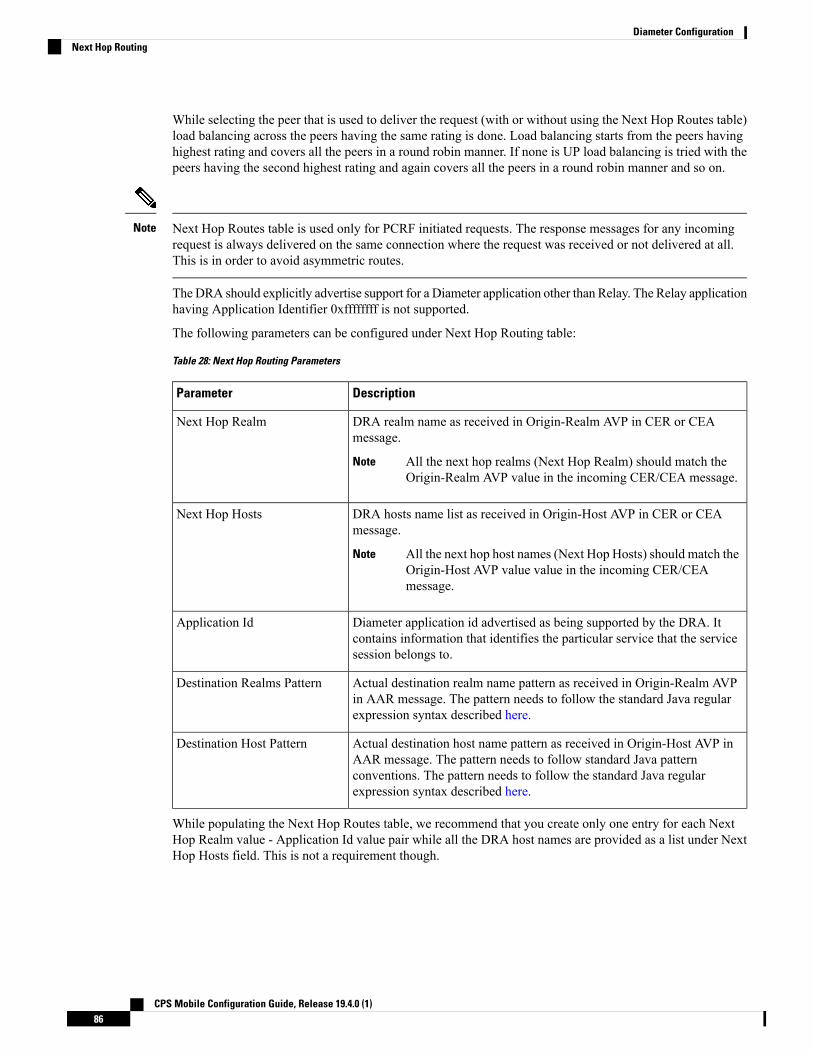
While selecting the peer that is used to deliver the request (with or without using the Next Hop Routes table)load balancing across the peers having the same rating is done. Load balancing starts from the peers havinghighest rating and covers all the peers in a round robin manner. If none is UP load balancing is tried with thepeers having the second highest rating and again covers all the peers in a round robin manner and so on.
Next Hop Routes table is used only for PCRF initiated requests. The response messages for any incomingrequest is always delivered on the same connection where the request was received or not delivered at all.This is in order to avoid asymmetric routes.
Note
TheDRA should explicitly advertise support for a Diameter application other than Relay. The Relay applicationhaving Application Identifier 0xffffffff is not supported.
The following parameters can be configured under Next Hop Routing table:
Table 28: Next Hop Routing Parameters
DescriptionParameter
DRA realm name as received in Origin-Realm AVP in CER or CEAmessage.
All the next hop realms (Next Hop Realm) should match theOrigin-Realm AVP value in the incoming CER/CEA message.
Note
Next Hop Realm
DRA hosts name list as received in Origin-Host AVP in CER or CEAmessage.
All the next hop host names (Next Hop Hosts) should match theOrigin-Host AVP value value in the incoming CER/CEAmessage.
Note
Next Hop Hosts
Diameter application id advertised as being supported by the DRA. Itcontains information that identifies the particular service that the servicesession belongs to.
Application Id
Actual destination realm name pattern as received in Origin-Realm AVPin AAR message. The pattern needs to follow the standard Java regularexpression syntax described here.
Destination Realms Pattern
Actual destination host name pattern as received in Origin-Host AVP inAAR message. The pattern needs to follow standard Java patternconventions. The pattern needs to follow the standard Java regularexpression syntax described here.
Destination Host Pattern
While populating the Next Hop Routes table, we recommend that you create only one entry for each NextHop Realm value - Application Id value pair while all the DRA host names are provided as a list under NextHop Hosts field. This is not a requirement though.
CPS Mobile Configuration Guide, Release 19.4.0 (1)86
Diameter ConfigurationNext Hop Routing

• The order in which the routes are provisioned in the Next Hop Routes table is relevant. While lookingfor a DRA connection that could be used to deliver a particular message the table is checked top tobottom.
• The order in which the DRA hosts are provisioned in the Next Hop Hosts field for any given next hoproute is not relevant. The DRA host having the highest rating (priority) value is used. In case multiplehosts have the same rating one is randomly selected. Refer to Diameter Stack Configuration, on page99 for more details about host rating.
Note
CPS supports grouping of realms and application identifiers using wildcarding and assigns it to a group ofnext hop peers. CPS routes outgoing messages by selecting the peer with highest priority.
An example configuration for Grouping and Wildcarding in the Next Hop Routing table is shown below:Figure 39: Grouping and Wildcarding in the Next Hop Routing Table
Destination Realm andDestination Hosts are used tomapwith the Peer configuration as defined in the DiameterStack. The figure given below shows the mapping of the message containing the Realm from a peer to aprotocol or interface. For more information on peer configuration refer to Diameter Stack Configuration, onpage 99.
CPS Mobile Configuration Guide, Release 19.4.0 (1)87
Diameter ConfigurationNext Hop Routing

Figure 40: Rating
Message Timeout and Retry ConfigurationMessage Timeout and Retry Configuration table can be configured under Diameter Configuration plug-in inPolicy Builder.
This table allows for the configuration of different message timeout value and retry behavior using thecombination of Application Id, Command Code and (experimental) result code parameters.
Sh Interface (Auth-Application-Id 16777217) message retry information can be configured using:
• Message Timeout and Retry Configuration table
• Setting Up Additional Profile Data, on page 197
Only one of the two retry configuration options should be used for Sh Interface.
Note
The following parameters can be configured in the Message Timeouts and Retry Configuration table.
Table 29: Message Timeout and Retry Configuration Parameters
DescriptionParameter
The Diameter Application ID (Auth-Application-Id) on the message which isto be retired.
Default: 0
Application Id
The Diameter command code of the message which is to be retried.
Default: 0
Command Code
CPS Mobile Configuration Guide, Release 19.4.0 (1)88
Diameter ConfigurationMessage Timeout and Retry Configuration

DescriptionParameter
This is the result code received in the diameter response for which the user wantsto retry. The values configured should be a valid diameter result code value oran experimental result code value. For example, 3002(DIAMETER_UNABLE_TO_DELIVER) received in RAA.
Permanent failure result codes 5xxx and successful result codes 2xxx should notbe configured (where, x denotes a valid number).
However, if configured, CPS retries for it.
For retry on timeout, the result code should be configured as 7000.Note
Default: 0
Result Code
If this check-box is selected, it means that the value configured in the ResultCode column is an Experimental-Result-Code value.
This is necessary because there are few values which are the same for bothexperimental-result-code and result-code.
Default: Not selected
Is Experimental
The action for the CPS platform to take after the Diameter Response is received.The options are Retry or None.
• Retry - CPS will retry the request message identified by the value in thecommand code column depending on the retry count configured in RetryCount column.
• None - No retry.
Default: None
Action
The amount of time in milliseconds for CPS to wait before retry.
For more information, refer to 2.
Default: 0
Action Timer (Ms)
The number of times to retry when the action is “Retry”.
This retry count does not include the initial attempt made by CPS.Note
Default: 1
Retry Count
Configures CPS to retry on any alternate peer configured in Policy Builder.
Default: Not selected
Retry on Alternate
CPS Mobile Configuration Guide, Release 19.4.0 (1)89
Diameter ConfigurationMessage Timeout and Retry Configuration
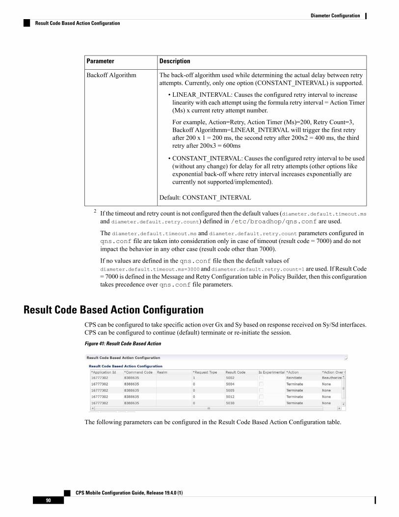
DescriptionParameter
The back-off algorithm used while determining the actual delay between retryattempts. Currently, only one option (CONSTANT_INTERVAL) is supported.
• LINEAR_INTERVAL: Causes the configured retry interval to increaselinearity with each attempt using the formula retry interval = Action Timer(Ms) x current retry attempt number.
For example, Action=Retry, Action Timer (Ms)=200, Retry Count=3,Backoff Algorithmm=LINEAR_INTERVAL will trigger the first retryafter 200 x 1 = 200 ms, the second retry after 200x2 = 400 ms, the thirdretry after 200x3 = 600ms
• CONSTANT_INTERVAL: Causes the configured retry interval to be used(without any change) for delay for all retry attempts (other options likeexponential back-off where retry interval increases exponentially arecurrently not supported/implemented).
Default: CONSTANT_INTERVAL
Backoff Algorithm
2 If the timeout and retry count is not configured then the default values (diameter.default.timeout.msand diameter.default.retry.count) defined in /etc/broadhop/qns.conf are used.
The diameter.default.timeout.ms and diameter.default.retry.count parameters configured inqns.conf file are taken into consideration only in case of timeout (result code = 7000) and do notimpact the behavior in any other case (result code other than 7000).
If no values are defined in the qns.conf file then the default values ofdiameter.default.timeout.ms=3000 and diameter.default.retry.count=1 are used. If Result Code= 7000 is defined in theMessage and Retry Configuration table in Policy Builder, then this configurationtakes precedence over qns.conf file parameters.
Result Code Based Action ConfigurationCPS can be configured to take specific action over Gx and Sy based on response received on Sy/Sd interfaces.CPS can be configured to continue (default) terminate or re-initiate the session.Figure 41: Result Code Based Action
The following parameters can be configured in the Result Code Based Action Configuration table.
CPS Mobile Configuration Guide, Release 19.4.0 (1)90
Diameter ConfigurationResult Code Based Action Configuration

Table 30: Result Code Based Action Configuration
DescriptionParameter
The diameter interface in numeric format (Auth-Application-Id) on which themessage is received. For example Sy (16777302) and Sd (16777303).
Currently only Sd and Sy interfaces are supported.
Default: 0
Application Id
The diameter message type. For example SLR (8388635) in case of Sy and RAR(258) in case of Sd.
Default: 0
Command Code
New key added as Sy client realm. If the realm value is not specified, then therealm key is not be considered (CPS only performs action on keyapplicationid:commadcode:realm:requestType:resultcode ).
Realm
The request type of themessage for Sy interface. For example INITIAL_REQUEST(0) INTERMEDIATE_REQUEST (1). For Sd Request Type is not valid.
Default: 0
Request Type
The result-code received in the response for which the action over Gx and/or Sy/Sdis to be taken.
Default: 0
Result Code
If this check-box is selected, it means that the value configured in the Result Codecolumn is an Experimental-Result-Code value.
This is necessary because there are few values which are the same for bothexperimental-result-code and result-code.
Default: Not selected
Is Experimental
The action to be taken over the Sy/Sd interface when the response is received.Possible actions are Continue/Terminate/Reinitiate.
• Continue (default) In case of Continue CPS just continues with the sessionand does not clear the session from the DB.
• Terminate (for Sd) In case of Terminate CPS removes the session fromdatabase after triggering a Session Removal RAR over Sd interface.
Terminate (for Sy) In case of Terminate CPS removes the session fromdatabase after triggering a Session Removal STR over Sy interface.
• Reinitiate (for Sd) In case of Reinitiate CPS first triggers a Session RemovalRAR over Sd interface. Once we receive Sd RAR response (any result-code)CPS removes the old session and triggers creation of a new session by sendingout a TSR towards TDF.
Reinitiate (for Sy) In case of Reinitiate CPS first triggers a Session RemovalSTR over Sy interface. Once we receive Sy STR response (any result-code)CPS removes the old session and triggers creation of a new session by sendingout SLR towards OCS.
Action
CPS Mobile Configuration Guide, Release 19.4.0 (1)91
Diameter ConfigurationResult Code Based Action Configuration

DescriptionParameter
The action to be taken over the Gx interface when the response is received. Possibleactions are None/Terminate/Reauthorize.
Currently Action over Gx is not supported for Sd RAR.
• None (default) No action would be taken on Gx interface.• Terminate In case of Terminate CPS would terminate the Gx session bysending a RAR with Session Release Cause. Also CPS would be sendingSTR which would then clear the corresponding Sy device session. If theaction over Gx is TERMINATE the action over Sy does not matter as the Sysession would be terminated.
• Reauthorize In case of Reauthorize CPSwouldmark the Sy session as waitingfor action over Gx and would mark corresponding Gx session as needingaction over Gx as Re-Auth.
The Gx Network Device Manager would then perform the ReAuthorization bysending RAR over Gx interface. On receiving RAA the action over Sy interfacewould then be performed. If the Gx session is stale and we receiveDIAMTER_UNKNOWN_SESSION_ID the Sy session would then beautomatically terminated irrespective of the action configured on Sy interface.
The actions TERMINATE and REAUTHORIZE over Gx does notwork with SLA-Initial if the SLR is sent synchronously. In case theSLR is triggered synchronously and the action over Gx is configuredas TERMINATE/REAUTH the CPS would log an error message andwould continue the session. The synchronous/asynchronous sendingof SLR can be configured in the SpendingLimitReport serviceconfiguration.
Note
Action Over Gx
Message Buffering ConfigurationWhen Gx features for OneGxRulePerFlow is enabled then the gateway triggers simultaneous Gx-CCR-Usfor APPLICATION-STARTwithin a short time span. This causes a burst of CCR-Umessage on CPS. Becauseof the burst, CPS fails to process all the CCR-U message due to "cache out of date" errors and sendsDIAMETER_UNABLE_TO_DELIVER errors to gateway. So in order to support the processing of all theCCR-U messages, Message Buffering Configuration can be used.
Message Buffering Configuration can be configured underDiameter Configuration plug-in in Policy Builder.
The following parameters can be configured underMessage Buffering Configuration:
Table 31: Message Buffering Configuration Parameters
DescriptionParameter
The time in milliseconds to hold the diameter messages in the buffer afterthe buffering has been triggered for a particular session ID.
Default value is 15 ms.
Buffer Timeout InMilliseconds
CPS Mobile Configuration Guide, Release 19.4.0 (1)92
Diameter ConfigurationMessage Buffering Configuration
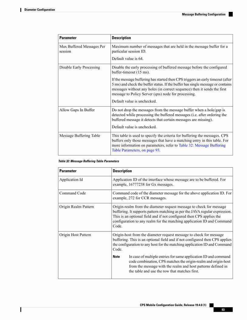
DescriptionParameter
Maximum number of messages that are held in the message buffer for aparticular session ID.
Default value is 64.
Max Buffered Messages Persession
Disable the early processing of buffered message before the configuredbuffer-timeout (15 ms).
If the message buffering has started then CPS triggers an early timeout (after5 ms) and check the buffer status. If the buffer has single message or containsmessages without any holes (in correct sequence) then it sends the firstmessage to Policy Server (qns) node for processing.
Default value is unchecked.
Disable Early Processing
Do not drop the messages from the message buffer when a hole/gap isdetected while processing the buffered messages (i.e. after ordering thebuffered message it detects that certain messages are missing).
Default value is unchecked.
Allow Gaps In Buffer
This table is used to specify the criteria for buffering the messages. CPSbuffers only those messages that have a matching entry in this table. Formore information on parameters, refer to Table 32: Message BufferingTable Parameters, on page 93.
Message Buffering Table
Table 32: Message Buffering Table Parameters
DescriptionParameter
Application ID of the interface whose message are to be buffered. Forexample, 16777238 for Gx messages.
Application Id
Command code of the diameter message for the above application ID. Forexample, 272 for CCR messages.
Command Code
Origin-realm from the diameter request message to check for messagebuffering. It supports pattern matching as per the JAVA regular expression.This is an optional field and if not configured then CPS applies theconfiguration to any realm for the matching application ID and CommandCode.
Origin Realm Pattern
Origin-host from the diameter request message to check for messagebuffering. This is an optional field and if not configured then CPS appliesthe configuration to any host for the matching application ID and CommandCode.
In case of multiple entries for same application ID and commandcode combination, CPSmatches the origin-realm and origin-hostfrom the message with the realm and host patterns defined inthe table and use the row that matches first.
Note
Origin Host Pattern
CPS Mobile Configuration Guide, Release 19.4.0 (1)93
Diameter ConfigurationMessage Buffering Configuration

DescriptionParameter
Diameter AVP code for the AVP that would trigger the start for bufferingthe messages. For example, 1006 is the diameter AVP code forEvent-Trigger AVP.
Allowed parameters are of string type so that child AVP pathcan also be used.
For example, To give Charging-Rule-Report >Rule-Failure-Code, you have to mention '1018.1031' (where,1018 is an AVP Code for 'Charging-Rule-Report' and 1031 isan AVP Code for 'Rule-Failure-Code').
All rows having same 'Application Id' and 'Command Code'should have same Order AVP Code and Order AVP Type.
Note
CPS goes through all the rows one by one and verifies whether configuredAVP exist in the incoming message and buffers the message accordingly.
Buffer Start Avp Code
A drop-down list to select the data-type of the AVP to trigger buffering ofmessage. This is required for correctly extracting the AVP value.
Buffer Start Avp Type
The possible values for the diameter AVP for starting the buffering ofmessage. List supported to configure multiple values.
Buffer Start Avp Value
The diameter AVP code for the AVP whose value can be used forsequencing/ordering the buffered message while sending them to PolicyServer (qns) node for processing.
Order Avp Code
A drop-down list to select the type of the Order AVP for extracting itsvalue.
CPS currently supports only numeric values for ordering the bufferedmessages.
Order Avp Type
Memory Impact
• The memory usage of diameter endpoint process (qns process on lb) may be increased when it startsbuffering messages for multiple sessions.
Configuration and Restrictions
• Buffered messages are lost if the diameter-endpoint (qns process) on LB node goes down.
• All the CCR-U messages in the burst are processed sequentially, that is, only after a CCA-U is sent outfor a CCR-U message then the next CCR-U message is taken up for processing.
• CPS initiated messages (for example, Gx RAR) are not considered for buffering and are sent out as theyare triggered. Also, if terminate message (for example, Gx CCR-T) is received in between a messageburst then CPS drops all further messages from the buffer after processing the terminate message.
• As the buffered messages are processed sequentially the response time (towards PCEF) increases. Forexample, for a burst of 64 simultaneous CCR-U messages, CCA-U for the last message (that is, CCR-Umessage with highest sequence number) is after a duration of 64*20+15 ms (approx. 1300 ms).
CPS Mobile Configuration Guide, Release 19.4.0 (1)94
Diameter ConfigurationMessage Buffering Configuration

• The response time (towards PCEF) for normal messages (not received in a burst but matches the messagebuffering criteria) has an impact of at least 5 ms (the early processing time). For example, if CCR-Uprocessing takes 20 ms then for a single user plane CCR-U message, the minimum response time is 25ms.
• If CPS receives negative response from Policy Server (qns) node while processing a buffered messagethen CPS stops processing the message buffer for that session and drops all further buffered messages.
• While processing a buffered message if Policy Director (lb) node does not get a response from PolicyServer (qns) node within the configured time (SLA) then it drops all the remaining messages from themessage buffer of that session. The SLA time is calculated from the time the message was sent fromPolicy Director (lb) to Policy Server (qns) node and the time that the message spends while waiting forprocessing in the message buffer.
• CPS checks only for 3GPP vendor ID while matching the diameter AVP code defined for Buffer startAVP and Order AVP. If vendor ID is not available in the received AVP then it is assumed to be of default3GPP vendor ID.
• While processing the buffered messages, if another burst of CCR-U messages is received then CPSappends those messages to the existing buffer. In doing so if the buffer size reaches the Max BufferedMessages per session then CPS drops those messages.
• CPS maintains the order only for buffered messages. Order is not checked for messages across multiplemessage bursts for same session.
PolicyDRA Health CheckPolicyDRA Health Check is used to initiate a dummy AAR message that results in querying the bindingdatabase allowing the PCRF to take corrective action based on the response.
PolicyDRA Health Check is configured under Diameter Configuration plug-in in Policy Builder. SelectPolicyDRA Health Check and Binding Db configuration to enable the feature.
The following parameters can be configured under PolicyDRA Health Check:
Table 33: PolicyDRA Health Check Configuration Parameters
DescriptionParameter
When selected, it enables the feature.
When unselected, the feature is disabled.
• Health Check Time Interval: Time interval in seconds when periodic AAR issent.
• Session Release T P S: Per Policy Server (QNS) Gx RAR (with session releasecause) TPS when binding database is down.
Default value is 0.
Binding Db
CPS Mobile Configuration Guide, Release 19.4.0 (1)95
Diameter ConfigurationPolicyDRA Health Check

DescriptionParameter
When selected, it enables the generation of alarms or traps.
When unselected, the alarms are not generated.
• Primary Ip Address: Primary database IP address where the alarm informationis stored.
Whenever PolicyDRA binding database down is detected i.e., whenAAA comeswith error result code, CPS generates a trap/notification/alarm. The generationtime of this alarm is stored in the database configured. After the Alarm ClearanceInterval, the trap/notification/alarm is cleared by CPS. In between this duration,CPS does not generate trap/notification/alarm on detection of binding databasefailure. Only one trap/notification/alarm is generated by CPS.
• Secondary Ip Address: Secondary database IP address where the alarminformation is stored.
• Port: Port number of the database.
Default value is 0.
• Alarm Clearance Interval: Timer interval in seconds after which the alarm iscleared.
• Policy Dra Resultcode: AAA result-codes for which alarms are generated.
• Severity: Severity of the alarm.
Default value is Critical.
Alarm Config
When checked, it makes sure P-Bit is set and Destination-Host AVP is not set for theoutgoing AAR messages for PAS Health check.
Default value is unchecked.
Enable Proxy
To improve the performance when PolicyDRA Health Check is enabled, you must configure‘RxClientSessionKey’ key as the Lookaside Key Prefix so that memcache is used and full database scan isavoided. This is highly recommended for higher capacity systems.
Note
Diameter Messages Action on Threshold in LBWhenDiameterMessages Action on Threshold in LB check box is enabled andDiameterMessage CountThreshold for PD is configured with value greater than 0, the Policy Director processes keep track of messagesbeing handled at process level and when number of messages being tracked crosses the configured DiameterMessage Count Threshold for PD, the messages are dropped or responded with DiameterBusy.
Diameter Messages Action on Threshold in LB configuration is optional. When this configuration is notused, all the messages are sent from LB (Policy Director) to Policy Engines.
• The following parameters can be configured under Diameter Messages Action on Threshold:
CPS Mobile Configuration Guide, Release 19.4.0 (1)96
Diameter ConfigurationDiameter Messages Action on Threshold in LB

Table 34: Diameter Messages Action on Threshold
DescriptionParameter
Diameter Interface in Diameter message selected from drop-down list.Diameter Interface
Command code in Diameter message.
When Command Code is set to 0, it applies to all Command Codes of theApplication ID configured in the row.
Command Code
CCR Request type.
Default value is 0.
When Request Type is set to 0, it applies all the CCR Request types, namelyInitial(1), Update(2) and Terminate(3). For non-CCR messages default 0 is mustbe set.
Request Type
What action to take when the Diameter message is received at LB (Policy Director)when outstanding Diameter messages have reached theMessage CountThreshold.
Possible Values: MESSAGE_DROP and DIAMETER_TOO_BUSY
Default value is MESSAGE_DROP.
Action
• Diameter Message Count Threshold for PD: This value defines the maximum number of a DiameterInbound/Outboundmessages per PD (Policy Director) process from the tableDiameterMessages Actionon Threshold in LB. Default value is 0.
• Max TPS per PD: Defines maximum TPS supported per PD process. Default value is 0.
• Default Discard Behavior: Describes the action to be taken when a Diameter request message is receivedin LB and rate limiter acquire fails. Possible values includeMESSAGE_DROP andDIAMETER_TOO_BUSY. Default value isMESSAGE_DROP.
If DIAMETER_TOO_BUSY is selected from the drop-down list, at very highTPS, it can lead to higher CPU consumption on Policy Director (LB) VM. Thiscan lead to performance degradation. Cisco recommends usingMESSAGE_DROP.
Note
Gx Offline Stale Session Cleanup
This feature is only enabled for deployments with arbitervip running on pcrfclient VMs.Important
Stale session builds up due to network issues, timeout at PAS and so on. As a result CPS starts rejecting newsessions due to capacity or session license limit. The offline Stale Session cleanup helps to remove the stalesessions having duplicate IMSI and AON combination.
CPS Mobile Configuration Guide, Release 19.4.0 (1)97
Diameter ConfigurationGx Offline Stale Session Cleanup

Execute the following command in the pcrfclient where the application is running, to stop the application:
monit stop stale-session-cleaner-helper
Execute the following command in the pcrfclient where the application is not running, to restart the application:
monit restart stale-session-cleaner-helper
The following table lists parameters in the/etc/broadhop/stale-session-cleaner/stale-session-cleaner.conf file:
Table 35: Gx Offline Stale Session Cleanup Configuration Parameters
DescriptionParameter
VM name which hosts the primary member of the PCRF Admin replica-set.
Any sessionmgr VM names.
Default value is localhost.
Example: sessionmgr01
-Dadmin.primary.host
VM name that hosts a secondary member of the PCRF Admin replica-set. Ifthe primary Admin member fails, the Stale Session Cleaner tries to connect tothis secondary member.
Any sessionmgr VM names.
Default value is localhost.
Example: sessionmgr02
-Dadmin.secondary.host
Port of the PCRF Admin replica-set.
Possible values can be Integers.
Default value is 27017.
Example: 27721
-Dadmin.port
The Host and Port which memcache is running on.
Strings in the following format: <host>:<port>
Default value is localhost : 11211
-Dmemcache.host
Number of executions per second per shard.
Possible values are Integers.
Default value is 200.
-Dtps.per.shards
Number of records in the results for each query to the Session replica-set.
Possible values are Integers.
Default value is 1000.
-Dmongo.query.batch.size
CPS Mobile Configuration Guide, Release 19.4.0 (1)98
Diameter ConfigurationGx Offline Stale Session Cleanup

DescriptionParameter
If the number of deleted sessions reaches a multiple of this parameter’s value,it performs audit log.
For example, if the parameter value is 100, then the deleted count is printedin the logs on 100 deletions, 200 deletions, 300 deletions, and so on.
Possible values are Integers.
Default value is 10000.
-Dfactor.count.audit.log
The threshold number of sessions that triggers the utility.
Possible values are Integers.
Default value is 15000000.
-Dsession.count.threshold
The frequency in minutes where utility monitors session threshold breach tostart deletion of stale session.
Possible values are Integers.
Default value is 5.
-Dsession.threshold.timer
The frequency in minutes where utility updates the latest session ID in thelocal cache. This parameter should be in the multiple of"session.threshold.timer."
Possible values are Integers.
Default value is 30.
-Dsession.cache.update.timer
Total number of shards for the Session replica-sets.
Possible values are Integers.
Default value is 80.
-Dnumber.of.shards
The path to the log configuration file.
Any directory path with a logback file for the application.
Default value is /etc/broadhop/logback-stale-session-cleaner.xml.
-Dlogback.configurationFile
Diameter Stack ConfigurationThis section allows for the creation of the stacks that handle the diameter traffic. Depending on your particularrequirements one or more stacks can be created.
At System Level
In order to define a Diameter stack at system level you need to perform the following steps:
1. Login into Policy Builder.
2. Select Reference Data tab.
CPS Mobile Configuration Guide, Release 19.4.0 (1)99
Diameter ConfigurationDiameter Stack Configuration
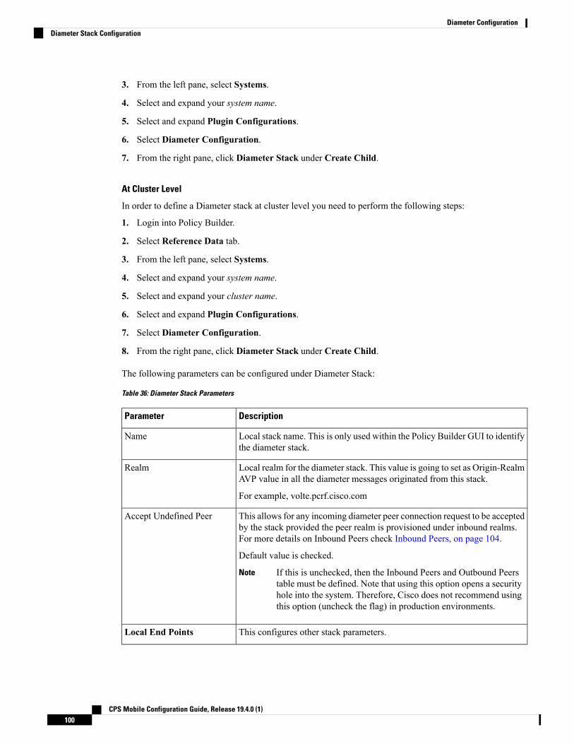
3. From the left pane, select Systems.
4. Select and expand your system name.
5. Select and expand Plugin Configurations.
6. Select Diameter Configuration.
7. From the right pane, click Diameter Stack under Create Child.
At Cluster Level
In order to define a Diameter stack at cluster level you need to perform the following steps:
1. Login into Policy Builder.
2. Select Reference Data tab.
3. From the left pane, select Systems.
4. Select and expand your system name.
5. Select and expand your cluster name.
6. Select and expand Plugin Configurations.
7. Select Diameter Configuration.
8. From the right pane, click Diameter Stack under Create Child.
The following parameters can be configured under Diameter Stack:
Table 36: Diameter Stack Parameters
DescriptionParameter
Local stack name. This is only used within the Policy Builder GUI to identifythe diameter stack.
Name
Local realm for the diameter stack. This value is going to set as Origin-RealmAVP value in all the diameter messages originated from this stack.
For example, volte.pcrf.cisco.com
Realm
This allows for any incoming diameter peer connection request to be acceptedby the stack provided the peer realm is provisioned under inbound realms.For more details on Inbound Peers check Inbound Peers, on page 104.
Default value is checked.
If this is unchecked, then the Inbound Peers and Outbound Peerstable must be defined. Note that using this option opens a securityhole into the system. Therefore, Cisco does not recommend usingthis option (uncheck the flag) in production environments.
Note
Accept Undefined Peer
This configures other stack parameters.Local End Points
CPS Mobile Configuration Guide, Release 19.4.0 (1)100
Diameter ConfigurationDiameter Stack Configuration

DescriptionParameter
The host local name where this stack is going to be created.
If Local Host Name value does not map to a valid IP the stackbinds to localhost (127.0.0.1).
Note
Local Host Name
Indicates the Instance number of the Policy Server process on Policy Directorfor which this entry applies. On a Policy Director each Policy Server processis assigned an Instance Number.
Instance Number
This value is going to be set as Origin-Host AVP value in all the diametermessages originated from this stack.
The Advertised Diameter FQDN value needs to map to a valid IP addressbecause that IP address is going to be set as Host-IP-Address AVP value inCER/CEA. As per RFC 3588 Host-IP-Address is a mandatory AVP inCER/CEA.
Advertised Diameter FQDN
The port the stack is listening to on the host identified by Local Host Nameattribute. Default value is 3868.
Listening Port
Allows the stack to bind to a different IP than the one that Local Host Namevalue maps to. When provisioned Local Bind Ip value overrides the LocalHost Name value.
Local Bind Ip
Allows you to select either 'TCP' or 'SCTP' for the selected diameter endpoint.
Default value is TCP.
Transport Protocol
This is a comma separated list of IP addresses that CPS uses to start thediameter stack with multi-homing enabled for SCTP transport. Diameter stackwith TCP transport still uses the existing 'Local Bind Ip' field to specify anyspecific IP address for TCP stack.
CPS uses the 'Local Bind Ip' to bring up SCTP stack and use it along with the‘Multi Homing Hosts' to start the SCTP transport with multi-homing support.
While using SCTP multi-homing functionality review the Linuxnetwork and gateway configurations for supporting multiplenetworks on different subnets. CPS supports Centos 6 release andreverse path filtering kernel parameter (rp_filter) values can be setfor allowing packets from different subnets on Policy DirectorVMs. The default behavior in Centos 6 is to discard the packets insuch scenarios.
Note
Multi Homing Hosts
SettingsYou can provision different timers that are available at the diameter stack level.
CPS Mobile Configuration Guide, Release 19.4.0 (1)101
Diameter ConfigurationSettings

Figure 42: Settings
The following parameters can be configured under Settings:
Table 37: Settings Parameters
DescriptionParameter
Sets the Origin-Host AVP value in CER/CEA to theuser URI value instead of FQDn value.
Default value is not set.
User Uri As Fqdn
Sets the timeout duration for a stack to wait till all theresources stop. The delay is in milliseconds.
Default value is 10000.
Stop Timeout Ms
Sets the CER or CEA exchange timeout duration incase of no response. The delay is in milliseconds.
Default value is 10000.
Cea Timeout Ms
CPS Mobile Configuration Guide, Release 19.4.0 (1)102
Diameter ConfigurationSettings
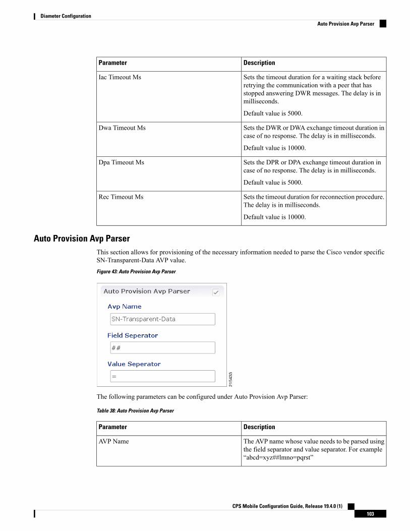
DescriptionParameter
Sets the timeout duration for a waiting stack beforeretrying the communication with a peer that hasstopped answering DWR messages. The delay is inmilliseconds.
Default value is 5000.
Iac Timeout Ms
Sets the DWR or DWA exchange timeout duration incase of no response. The delay is in milliseconds.
Default value is 10000.
Dwa Timeout Ms
Sets the DPR or DPA exchange timeout duration incase of no response. The delay is in milliseconds.
Default value is 5000.
Dpa Timeout Ms
Sets the timeout duration for reconnection procedure.The delay is in milliseconds.
Default value is 10000.
Rec Timeout Ms
Auto Provision Avp ParserThis section allows for provisioning of the necessary information needed to parse the Cisco vendor specificSN-Transparent-Data AVP value.Figure 43: Auto Provision Avp Parser
The following parameters can be configured under Auto Provision Avp Parser:
Table 38: Auto Provision Avp Parser
DescriptionParameter
The AVP name whose value needs to be parsed usingthe field separator and value separator. For example“abcd=xyz##lmno=pqrst”
AVP Name
CPS Mobile Configuration Guide, Release 19.4.0 (1)103
Diameter ConfigurationAuto Provision Avp Parser

DescriptionParameter
String value used as a token to split pairs of attributeand values. In the above example # is the fieldseparator.
Field Separator
String value used as a token to split pairs of attributeand values. In the above example = is the valueseparator.
Value Separator
Inbound PeersThis section allows for the provisioning of the diameter peers that are allowed to initiate connections towardsPCRF. The PCRF does not initiate diameter connections with these peers.
Peer name and peer realm are independently checked against the two tables.
The following parameters can be configured under Inbound Peers:
Table 39: Inbound Peers Parameters
DescriptionParameter
Defines which peer names are allowed to initiate connections towards PCRF.Peers
Identifies the local host name of the Policy Director (load balancer) thatidentifies and allows an incoming connection from the Peer.
Local Host Name
Indicates the assigned number of the Policy Server (QNS) process thatinitiates a connection with the Outbound Peer.
Local Host Name and Instance Number should be specified ifthe intention is for only a single Policy Server (QNS) process onPolicy Builder (load balancer) to allow/initiate a connection withthe said peer else Instance number can be kept as “0”. In whichcase all the Policy Server (QNS) processes on Policy Director(load balancer) shall attempt/allow connection with the peer.
Note
Default value is 0.
Instance Number
Priority assigned to this peer for delivering a PCRF initiated request. Thehigher the rating value the higher is the priority assigned to the peer.
Default value is 1.
Rating
Should be specified only when the underlying transport connection Is SCTPand not required when the same is TCP.
Port Range
Cisco recommends not to use this parameter.Response Timeout
CPS Mobile Configuration Guide, Release 19.4.0 (1)104
Diameter ConfigurationInbound Peers

DescriptionParameter
Origin-Host AVP value in CER needs to validate against this pattern inorder for the connection to be established. If that does not happen the CERis silently discarded and the TCP connection is reset by PCRF.
Name pattern check does not happen if Accept Undefined Peer optiondescribed in Diameter Stack Configuration, on page 99 is checked.
The Name Pattern needs to follow the standard Java regular expressionsyntax described here.
Name Pattern
Table 40: Inbound Realms Parameters
DescriptionParameter
Defines which peer realms are allowed to initiate connections towardsPCRF.
Realms
Not used with inbound realms.Peer Type
Mapping between the realm name and the specific PCRF logic that shouldbe applied for the message. For more information on processing protocolrefer to Table 27: Protocols, on page 84.
When a Diameter Stack with a diameter realm is imported withno protocol assigned, it takes the default value as GX_TGPP.
Note
Processing Protocol
Priority assigned to this realm for delivering a PCRF initiated request. Thisis only used with SY_PRIME processing protocol.
Default value is 0.
The lower the rating value, the higher is the priority assigned tothe realm. For example, a realm having Rating=10 is used aftera realm having Rating=1.
Note
Rating
Whatever the statistics that gets generated for the respective realm gets thename that is configured in “Stats Alias” appended to those statistics.
This is applicable for com.broadhop.message mbean statistics only.
Stats Alias
Origin-Realm AVP value in CER needs to validate against this pattern inorder for the incoming message to be processed. If that does not happenthe message is silently discarded and the TCP connection is reset by PCRF.
The Name Pattern needs to follow the standard Java regular expressionsyntax described here.
Name Pattern
InMessage Timeout and Retry Configuration, diameter response timeout is defined using the combinationof Application Id and Command Code parameters.
Important
CPS Mobile Configuration Guide, Release 19.4.0 (1)105
Diameter ConfigurationInbound Peers

When PCRF is configured to work with a DRA the actual system's host name does not need to be provisionedin the Peers table for the message to be answered.
When PCRF is configured to work with a DRA the actual system's origin realm name does need to beprovisioned in the Peers table for the message to be processed. If it is not provisioned then PCRF shall sendan error response containing the Result-CodeAVPwith valueDIAMETER_APPLICATION_UNSUPPORTED(3007).
Outbound PeersThis section allows for the provisioning of the diameter peers to which the PCRF initiates the diameterconnections.
Peer name and peer realm are independently checked against the two tables.
The following parameters can be configured under Outbound Peers:
Table 41: Outbound Peers Parameters
DescriptionParameter
Defines the peers to which CPS can initiate connections.Peers
Identifies the local host name of the Policy Director (load balancer) thatinitiates a connection with the said Peer.
Local Host Name
Indicates the assigned number of the Policy Server (QNS) process that allowsan incoming connection from the Peer.
Default: 0
Instance Number
Priority assigned to this peer for delivering a PCRF initiated request. Thehigher the rating value the higher is the priority assigned to the peer.
Default: 1
Rating
Should be specified only when the underlying transport connection is SCTPand not required when the same is TCP. However in mixed mode where bothSCTP and TCP co-exist then it is mandatory to provide port range values forboth TCP and SCTP peers in order to avoid any conflicts on using local portson same host.
Port Range
Cisco recommends not to use this parameter.Response Timeout
Peer host name. Peer host name needs to be mapped to a valid IP address orthe diameter connection is not initiated. By default the connection is initiatedon the standard diameter port (3868). If a different port needs to be used thanthe peer name shall be defined using the host:port format.
Default value is “default”.
We recommend that the peer names (Name) should match theOrigin-Host AVP value in the incoming CER/CEA message.
Note
Name
Allows you to select either 'TCP' or 'SCTP' for the selected diameter stackinstance. Default value is TCP.
Transport Protocol
CPS Mobile Configuration Guide, Release 19.4.0 (1)106
Diameter ConfigurationOutbound Peers

DescriptionParameter
This is a comma separated IP addresses list that CPS uses to start the clientconnections towards external diameter peer. If either TCP/SCTP or both TCPand SCTP are configured in the Outbound Peers (Peers) table then clientconnections to the peers are initiated based on whether the PD instance isstarted as a ‘SCTP’ or ‘TCP’ stack. Mixed mode of client and stack runningon both ‘TCP’ and ‘SCTP’ is not currently supported by diameter.
While using SCTP multi-homing functionality review the Linuxnetwork and gateway configurations for supporting multiplenetworks on different subnets. CPS supports Centos 6 release andreverse path filtering kernel parameter (rp_filter) values can be setfor allowing packets from different subnets on Policy Director(load balancer) VMs. The default behavior in Centos 6 is to discardthe packets in such scenarios.
Note
Multi Homing Hosts
Table 42: Outbound Realms Parameters
DescriptionParameter
Defines the realms to which CPS can initiate connections.Realms
This indicates which diameter server to use when there are multiple targetservers for the same protocol. This is only used with SY_PRIME processingprotocol.
Peer Type
Mapping between the realm name and the specific PCRF logic that should beapplied for the message. For more information on processing protocol referto Table 27: Protocols, on page 84.
Processing Protocol
Priority assigned to this realm for delivering a PCRF initiated request. Thisis only used with SY_PRIME processing protocol.
Default value is 0.
The lower the rating value, the higher is the priority assigned tothe realm. For example, a realm having Rating=10 is used after arealm having Rating=1.
Note
Rating
Whatever the statistics that gets generated for the respective realm gets thename that is configured in “Stats Alias” appended to those statistics.
This is applicable for com.broadhop.message mbean statistics only.
Stats Alias
Origin-RealmAVP value in CER needs to validate against this pattern in orderfor the incoming message to be processed. If that doesn't happen the messageis silently discarded and the TCP connection is reset by PCRF.
The Name Pattern needs to follow the standard Java regular expression syntaxdescribed here.
Name
CPS Mobile Configuration Guide, Release 19.4.0 (1)107
Diameter ConfigurationOutbound Peers

InMessage Timeout and Retry Configuration, diameter response timeout is defined using the combinationof Application Id and Command Code parameters.
Important
When PCRF is configured to work with a DRA the actual system's host name does not need to be provisionedin the Peers table for the message to be answered.
When PCRF is configured to work with a DRA the actual system's origin realm name does need to beprovisioned in the Peers table for the message to be processed. If it is not provisioned than PCRF shall sendan error response containing the Result-CodeAVPwith valueDIAMETER_APPLICATION_UNSUPPORTED(3007).
The following restrictions are applicable while configuring CPS for SCTP:
When using SCTP as a transport protocol, CPS selects the 'Multi Homing Hosts' values along with the 'localbind ip' defined in local endpoints. But for TCP transport protocol CPS ignores the 'Multi home hosts' value.
When using SCTP as a transport protocol, CPS selects the 'Multi Homing Hosts' values along with 'OutboundPeers' defined in 'Peers' table. But for TCP transport protocol CPS ignores the 'Multi Homing Hosts' value.
Configuring Port-Range for SCTP outbound peers is mandatory. We also recommend using non-overlappingport ranges across different PDs within same Policy Director (load balancer) node while configuring multiplePDs.
For example:
PD1 (qns-2 process in the Policy Director (load balancer) VM) 12000-12500
PD2 (qns-3 process in the Policy Director (load balancer) VM) 13000-13500
PD3 (qns-4 process in the Policy Director (load balancer) VM) 14000-14500
Diameter AgentsThe Diameter Agent in CPS currently supports only the PROXY mode of operation (for more information,see RFC 6733 – Diameter Base Protocol at https://tools.ietf.org/html/rfc6733). In Proxy mode, all relevantmessages that are received by the CPS node (based on the applied filter on which the message is to be proxied)are forwarded to the given agent.
Policy Builder currently supports proxy functionality for Gx, Gy, and Rx interfaces. Messages reaching CPSmay be proxied to an alternate realm based on the "Application-ID" and/or the "Command-Code" within theincoming message. As part of the Diameter agent's configuration (described in Diameter Agent Configuration,on page 108), the specified realm translates to a destination realm, and a destination node is selected based onoutbound peers and priority/rating.
The filter information on which the Application/message needs to be proxied by CPS is provided by configuringa Use Case Template containing the DiameterAgentInfo service configuration (described in DiameterAgentInfoService Configuration Object Setup, on page 109) as part of the configured service.
Diameter Agent ConfigurationA diameter agent is defined with a name and an associated realm, and is then used when configuring theDiameterAgentInfo service configuration object.
CPS Mobile Configuration Guide, Release 19.4.0 (1)108
Diameter ConfigurationDiameter Agents

Step 1 Log in to Policy Builder.Step 2 Select the Reference Data tab.Step 3 In the left pane, select Diameter Agents.Step 4 In the Summary pane, click Diameter Agent under Create Child.Step 5 In the Diameter Agent pane, type the Name and the Realm for the agent.
Figure 44: Diameter Agent Configuration
DiameterAgentInfo Service Configuration Object SetupThis section describes how to configure the DiameterAgentInfo service configuration object.
Step 1 In Policy Builder, select the Services tab.Step 2 In the left pane, select Use Case Templates.Step 3 Select Summary and from right side pane, click Use Case Template under Create Child.Step 4 In the Name field, type a name for the template.Step 5 select the Actions tab, and then click Add under Service Configurations.
CPS Mobile Configuration Guide, Release 19.4.0 (1)109
Diameter ConfigurationDiameterAgentInfo Service Configuration Object Setup

Figure 45: Use Case Template Actions Tab
Step 6 In the Select Service Configuration dialog box, scroll down to the proxy section, select DiameterAgentInfo, and clickOK.
Step 7 Configure the DiameterAgentInfo parameters as described in the following table:
Table 43: DiameterAgentInfo Parameters
DescriptionParameter
Click in the Value column beside Diameter Agent Name, and type the name thatyou supplied when you configured the Diameter agent.
Diameter Agent Name
Proxy is the only agent type that has been implemented.Diameter Agent Type
CPS Mobile Configuration Guide, Release 19.4.0 (1)110
Diameter ConfigurationDiameterAgentInfo Service Configuration Object Setup

DescriptionParameter
Select one of the following protocols from the drop-down list:
• GX_TGPP
• GY_V8
• RX_TGPP
The other protocols in the list are not currently supported.
Proxy Protocol
In this section, you can define additional AVPs to add to the proxy request. Thefollowing parameters can be configured:
Command Code –
Request Type –
Code – Type a code for the AVP.
Value – Type a value for the AVP.
Type – Select the AVP type from the drop-down list.
Operation – Select the Operation from the drop-down list.
Vendor – Select the AVP Vendor from the drop-down list.
Proxy Request A V Ps (List)
In this section, you can define additional AVPs to add to the proxy response. Thefollowing parameters can be configured:
Command Code –
Request Type –
Code – Type a code for the AVP.
Value – Type a value for the AVP.
Type – Select the AVP type from the drop-down list.
Operation – Select the Operation from the drop-down list.
Vendor – Select the AVP Vendor from the drop-down list.
Proxy Response A V Ps (List)
Diameter ClientsThe Diameter Clients section allows for the creation of different clients identified by their realm. The clientsdefined in this section can be further used while configuring a policy so that different clients get differentservice configuration objects.
In order to define a Diameter Client you need to perform the following steps:
1. Login into Policy Builder.
2. Select Reference Data tab.
CPS Mobile Configuration Guide, Release 19.4.0 (1)111
Diameter ConfigurationDiameter Clients

3. From the left pane, select Diameter Clients.
4. Select Summary.
5. Create the specific client that corresponds to your interface. If there is no specific client for your interfaceselect the generic Diameter Clients.
6. Provide values for at least the mandatory attributes.
Figure 46: Gx Client
The mandatory fields are marked with a “*” on the upper left corner of the field name label.Note
Once you have done that you can use the diameter client to filter the service objects that are going to be usedin a policy.
More details about each client field and attribute will be provided in the following sections dedicated to eachtype of client.
In order to filter a Service Option based on the Diameter Client you need to perform the following steps:
1. Login into Policy Builder.
2. Select Services tab
3. From the left pane, select Services.
4. Expand Service Options tree.
5. Select and expand your service option.
6. Select the service option object.
7. Select the Value cell corresponding to the Diameter Client Display Name.
8. Click the “…” button.
9. Select the Diameter Client from the popup window.
CPS Mobile Configuration Guide, Release 19.4.0 (1)112
Diameter ConfigurationDiameter Clients

10. Click OK.
For more details about how to define a service option refer to Services, on page 223.
If your service configuration object does not have a Diameter Client attribute it means it is not diameter relatedand it cannot be filtered out based on diameter client.
Note
Currently, the following diameter client types are supported:
• Diameter Clients
• Gx Clients
• Rx Clients
• Gy Clients
The diameter client feature is mainly for use with inbound realms. No validation is done as to whether a realmis unique for a specific client type. If multiple clients are defined for the same realm the behavior may beunpredictable. The interface specific diameter clients are built on top of the generic Diameter Clients. Theyadd specific behavior and this is why they should always be used in the context of the specific interface.
Note
Diameter ClientsThis generic diameter client object is supposed to be used for any interface that does not have a matchingspecific diameter client.
The following parameters can be configured under generic Diameter Client:
Table 44: Diameter Client Parameters
DescriptionParameter
The client name that is going to be used to referencethis particular client in the service configurationobject.
Name
The pattern that peer realm name should match inorder for this diameter client to be used. The patternneeds to follow the standard Java regular expressionsyntax described here.
The first choice for Realm Pattern value should alwaysbe the exact peer realm name whenever possible.
Realm Pattern
See Extract Avps, on page 127Extract Avps
CPS Mobile Configuration Guide, Release 19.4.0 (1)113
Diameter ConfigurationDiameter Clients

DescriptionParameter
Currently, not supported.
This table is only supported for Gx and Rxclient.
Note
Override Supported Features
This action creates a new diameter client that is anexact copy of the current diameter client. The onlydifference between the original and the copy is that“-Copy” is appended to the name of the copy.
The Copy action works exactly the same for all typesof diameter clients.
Copy Current Diameter Client
Gx ClientsThis specific diameter client object is supposed to be used only in relation with the Gx interface. It adds Gxspecific features to the generic diameter client already described in Diameter Clients, on page 113.
Basic OptionsThe following parameters can be configured for Basic Options under Gx Client:
Table 45: Gx Client Parameters - Basic Options
DescriptionParameter
Adds Subscription-Id groupedAVP inGxCCA-imessagewith one of the followingSubscription-Id-Type AVP value and Subscription-Id-Data AVP value dependingon the selection. The values will be copied from the incoming Gx CCR-i messageif available.
• NONE (default): No Subscription-Id grouped AVP in Gx CCA
• IMSI: END_USER_IMSI (1)
• MSISDN: END_USER_E164 (0)
• NAI: END_USER_NAI (3)
Add Subscriber Id
Controls how the Flow-Direction AVP value under Flow-Information groupedAVP is derived. This option is only used for Rx dedicated bearers.
• Derive Flow-Direction: Flow-Direction AVP is derived based onFlow-Description AVP value and Flow-Status AVP value. This option isused only in case the PCEF advertised support for Rel10 feature underSupported-Features AVP. For more information refer to Table 46:Flow-Direction AVP Values, on page 118.
• 3GPP Gx Rel11 Compliant: Flow-Direction AVP is derived as per 3GPP TS29.212 v11
• Exclude Flow-Direction (default): Flow-Direction AVP is not set.
Rx PCC Rule FlowDirection Behavior
CPS Mobile Configuration Guide, Release 19.4.0 (1)114
Diameter ConfigurationGx Clients

DescriptionParameter
This parameter specifies the amount of time the Gx RAR is delayed after Gx CCAis sent when "Gx Triggered Session-Release-Cause in RAR" is enabled.
Default value is 500 milliseconds.
Sending DelayedMessage Wait Time Ms
This parameter specifies the maximum number of dynamic rules supported perGx session.
Default value is 100.
Allowed value > 10
Max Num of DynamicRule Supported
This parameter indicates the maximum number of PRA identifiers CPS supports.
When PresenceReportingAreaConfiguration service configuration is configuredwith number of PRA Identifiers more than the this value, the PRA Identifiersconfigured beyond this value are ignored.
Default value is 8.
Max Number of PRAIdentifiers Supported
The list of APNs that are allowed to initiate IMS emergency calls as per proceduresdescribed in 3GPP TS 29.212.
Emergency CalledStation Ids
Decides whether all the other sessions bound to the current Gx session getterminated upon Gx session termination.
Default value is checked.
Controls SessionLifecycle
If checked, attempts to load the session by IMSI (Subscription-Id-Data AVP valueunder Subscription-Id grouped AVP where Subscription-Id-Type AVP value isEND_USER_IMSI (1)).
Default value is unchecked.
Load By Imsi
If checked, attempts to load the session by NAI (Subscription-Id-Data AVP valueunder Subscription-Id grouped AVP where Subscription-Id-Type AVP value isEND_USER_NAI (3)).
Default value is unchecked.
Load By Nai
If checked, attempts to load the session by MSISDN (Subscription-Id-Data AVPvalue under Subscription-Id grouped AVPwhere Subscription-Id-Type AVP valueis END_USER_E164 (0)).
Default value is unchecked.
Load By Msisdn
If checked, the subscriber is identified by PCRF using “IMSI based NAI”, wherethe identity is represented in NAI form as specified in RFC 4282 [5], and formattedas defined in 3GPP TS 23.003 [6], clause 19.3.2. The IMSI based NAI is sentwithin the Subscription-Id AVP with the Subscription-Id-Type set toEND_USER_NAI at IP-CAN session establishment.
Default value is unchecked.
Imsi Based Nai
CPS Mobile Configuration Guide, Release 19.4.0 (1)115
Diameter ConfigurationBasic Options

DescriptionParameter
If checked, attempts to load the session by IPv4 address (Framed-IP-Address AVPvalue).
Default value is unchecked.
Load By Framed Ip
If checked, attempts to load the session by IPv6 address (Framed-IPv6-Prefix AVpvalue).
Default value is unchecked.
Load By Ip V6 Prefix
If checked, it does not attempt to terminate the Gx session by sending a Gx RARto PCEF.
Default value is unchecked.
Session Chained
If checked, removes the realm from the NAI (if present) before attempting to loadthe session by username. For more details on NAI see RFC 2486.
Default value is unchecked.
Remove Realm In UserId Mapping
If checked, it does not add the Sponsor-Identity AVP to theCharging-Rule-Definition grouped AVP. This option is used only in case the PCEFadvertised support for SponsoredConnectivity feature under Supported-FeaturesAVP.
Default value is unchecked.
Exclude Sponsor IdentityAvp
If checked, attempts to load the session by IMSI and APN. In order for this optionto be effectively used 'Load By Imsi' option (described above) needs to be checked.
Default value is unchecked.
Load By Called StationId
If checked, attempts to reinstall a charging rule in case the only AVP value thatchanged for a PreConfiguredRule is the monitoring key value.
Re-install Rule onMonitoring Key Change
If checked, authorizes bound QoS between retained and calculated QoS after CPShas received QoS modification failure event from PCEF.
Default value is checked.
Limit with RequestedQoS on modificationfailure
The default value of this new attribute is TRUE (checked); that is, CPSwill performmissing Enforce Missing AVP Check, on page 119 validations and sendDIAMETER_MISSING_AVP (5005) result in the answer message.
However, if this attribute is FALSE (unchecked), CPS will not perform the missingAVP validation.
Enforce Missing AvpCheck
CPS Mobile Configuration Guide, Release 19.4.0 (1)116
Diameter ConfigurationBasic Options

DescriptionParameter
This parameter applies only to the dynamic charging rules over Gx that aregenerated by CPS due to the APPLICATION_START event trigger received overthe Sd interface for ADC rules.
If checked, CPS creates one dynamic charging rule over Gx per flow informationreceived in the Application-Detection-Info AVP over the Sd interface. CPS alsocreates a unique TDF-Application-Identifier over Gx for each of these rules. So,each generated rule has a unique TDF-Application-Identifier and only oneFlow-Information AVP.
If unchecked, CPS generates only one rule per TDF-Application-Identifier receivedover the Sd interface. This one rule has all the Flow-Information AVPs. TheTDF-Application-Identifier over Gx is same as over Sd.
By default, the check box is unchecked.
One Gx Rule Per Flow
If checked, CPS selectively mutes the flow corresponding to aTDF-Application-Identifier on the dedicated bearer after it receives the firstApplication_Start event trigger on the dedicated bearer from PCEF.
For default bearer, CPS selectively mutes the flow corresponding to aTDF-Application-Identifier after it receives the Application_Start event trigger onthe default bearer from PCEF and maximum limit is reached on the dedicatedbearer.
Limit on number of flows on a given dedicated bearer is based on aunique combination of QCI and ARP Priority Level. This value isconfigurable in Policy Builder.
Note
After CPS receives Application_Stop event trigger from PCEF for a specificTDF-Application-Identifier (with TDF-App-Instance-ID=0), CPS removes thatrule from the dedicated bearer and installs the rule on the default bearer and unmutesall the rules related to that Sd TDF-Application-Identifier on the default bearer.
PCEF sends the TDF-App-Instance-ID as 0 only after all applicationsrelated to a TDF-Application-Identifier are stopped.
Note
Selective Muting
Indicates whether all the existing predefined rules that are applicable for the sessionare re-installed if there is a Rule-Base change. Select this option if you want allthe predefined rules (that are applicable to the session) to be re-installed if theRule-Base changes due to any reason. If unchecked, whenever there is a Rule-Basechange, CPS only notifies the changes (if any) in predefined rules to PCEF anddoes not re-install all the existing predefined rules.
The rules that are not applicable are removed.
This option does not apply to preconfigured or dynamic rules fromRx/Sd.
Note
Use this checkbox only in consultation with Cisco TechnicalRepresentative.
Restriction
Re-Install PredefinedRules on RulebaseChange
CPS Mobile Configuration Guide, Release 19.4.0 (1)117
Diameter ConfigurationBasic Options

DescriptionParameter
If checked (enabled), any Gx initiated session termination is responded to with aRAR immediately after CCR/CCA exchange with the PCEF. The RAR containsthe Session-Release-Cause AVP.
If unchecked (disabled), any Gx initiated session termination response from thePCRF in the CCA-U contains the Session-Release-Cause AVP. This is the defaultbehavior.
When the Gx RAR option is enabled, it is sent after the number ofmilliseconds specified under "Sending Delayed Message Wait TimeMs" field.
Note
Gx triggeredSession-Release-Causein RAR
If checked, Redirect-Support as disabled is only sent when enable was sentpreviously.
By default, the check box is unchecked.
Enhanced Logic forPreconfigure RuleRedirection Support
If checked (enabled), the desired behavior is exhibited for call flows.
By default, the check box is unchecked for backward compatibility.
Enhanced Gx-RARBehavior
If checked (enabled), Gx session state is restored following a failed Gx RAA(Result-Code AVP value not equal to DIAMETER_SUCCESS (2001)) to the stateit was before the Gx RAR was sent. The behavior is same for both sync and asyncGx RAR.
By default, the check box is unchecked to for backward compatibility.
Save Session State
Indicates whether to use IPME rules during handover or not.
If checked, CPS does not consider the IPME rules during handover.
If unchecked, CPS considers IPME rules during handover.
By default, the check box is selected.
Ignore IPME Rule OnHandover
Table 46: Flow-Direction AVP Values
Flow-Direction AVP ValuesCriteriaPriority
UPLINK (2)Flow-Description AVP value contains “permitin”
1
DOWNLINK (1)Flow-Description AVP value contains “permitout”
2
BIDIRECTIONAL (3)FlowStatus AVP value is ENABLED (2)3
UPLINK (2)FlowStatus AVP value is ENABLED_UPLINK(0)
4
DOWNLINK (1)FlowStatus AVP value isENABLED_DOWNLINK (1)
5
CPS Mobile Configuration Guide, Release 19.4.0 (1)118
Diameter ConfigurationBasic Options

Enforce Missing AVP Check
The following is the list of AVPs for which CPS performs the missing AVP validation if Enforce MissingAvp Check check box is selected:
• Mandatory AVPs: Origin-Host, Destination-Realm, CC-Request-Type, CC-Request-Number
• Conditional AVPs for session establishment: Subscription-Id (Subscription-Id-Type, Subscription-Id-Data),IP-CAN-Type, RAT-Type , Framed-IP-Address OR Framed-IPv6-Prefix (one must be present),AN-GW-Address (If IP-CAN-TYPE = '3GPP-EPS' or '3GPP2')
• Conditional AVPs for session modification: These AVPs are required based on the event trigger type.
• SGSN_CHANGE Event Trigger: 3GPP-SGSN-Address or 3GPP-SGSN-IPv6-Address
Applicable only to 3GPP-GPRS access types and 3GPP-EPS access types with access to the P-GWusing Gn/Gp.
• QOS_CHANGE Event Trigger: Bearer-Identifier, QoS-Information
When IP-CAN-Type is 3GPP-GPRS and if the PCRF performs bearer binding, the Bearer-IdentifierAVP shall be provided to indicate the affected bearer. QoS-Information AVP is required to beprovided in the same request with the new value.
• RAT_CHANGE Event Trigger: RAT-Type
The new RAT type must be provided in the RAT-Type AVP.
• PLMN_CHANGE Event Trigger: 3GPP-SGSN-MCC-MNC
• IP_CAN_CHANGE Event Trigger: IP-CAN-Type
The RAT-Type AVP must also be provided when applicable to the specific IP-CAN Type (forexample, 3GPP IP-CAN Type).
• RAI_CHANGE Event Trigger: RAI
Applicable only to 3GPP-GPRS and 3GPP-EPS access types.
• USER_LOCATION_CHANGE Event Trigger: 3GPP-User-Location-Info
Applicable only to 3GPP-GPRS and 3GPP-EPS access types.
• USER_LOCATION_CHANGE Event Trigger: 3GPP2-BSID
Applicable only to 3GPP2 access types.
• OUT_OF_CREDIT Event Trigger: Charging-Rule-Report, Final-Unit-Action
• REALLOCATION_OF_CREDIT Event Trigger: Charging-Rule-Report
• AN_GW_CHANGE Event Trigger: AN-GW-Address
• UE_TIME_ZONE_CHANGE Event Trigger: 3GPP-MS-TimeZone
• LOSS_OF_BEARER,RECOVERY_OF_BEARER,SUCCESSFUL_RESOURCE_ALLOCATION:Charging-Rule-Report
• DEFAULT _EPS_BEARER_QOS_CHANGE: Default-EPS-Bearer-QoS
• ECGI_CHANGE or TAI_CHANGE Event Trigger: 3GPP-User-Location-Info
• ACCESS_NETWORK_INFO_REPORT Event Trigger:
CPS Mobile Configuration Guide, Release 19.4.0 (1)119
Diameter ConfigurationBasic Options

3GPP-User-Location-Info, if Required-Access-Info = USER_LOCATION
3GPP-MS-Timezone, if Required-Access-Info = MS_TIMEZONE
• APPLICATION_START or APPLICATION_STOP Event Trigger over Gx:TDF-Application-Identifier
Advanced Options
Cisco Pending Transaction Retry
StarOS 16 introduces optional custom behavior for handling overlapping Gx transactions so that the potentialrace conditions that can occur on Gx interface are to be handled deterministically.
This feature introduces a new error indication to allow the transaction originator to determine if a re-attemptof the transaction is appropriate. The PCRF shall send an error response to the PCEF containing theExperimental-Result-CodeAVPwith Cisco specific value DIAMETER_PENDING_TRANSACTION (4198)if the PCRF expects a response to a pending request that it initiated. The PCRF shall also have the ability toretry the request message for which it received an error response containing the Experimental-Result-CodeAVP with Cisco specific value DIAMETER_PENDING_TRANSACTION (4198).
Refer to the CISCO StarOS 16 and CISCO ASR5500 documentation for more details.
Default value (if enabled) is 1.Figure 47: Cisco Pending Transaction Retry
Max Pending Transaction Retry Count does not include the initial request. For example, in the above casethe system will send a initial message and if it fails, it will send the same message 1 more time (retry).
PCRF will cache and retry only one message per Gx session. If due to Rx IMS session interaction multipleGx RAR messages are being evaluated while another Gx RAR message is already pending than PCRF willnot reply on the Rx IMS session.
Note
Sponsored Profile
The default monitoring key name format used to track the usage when the AF provides sponsored dataconnectivity to the subscriber is:
_<Sponsor-Id>_< Rx-Session-No>
where:
• <Sponsor-Id>: Sponsor-Identity AVP value under the Sponsored-Connectivity-Data grouped AVP.
• <Rx-Session-No>: Counts how many Rx sessions have bound so far to the Gx session by the time thecurrent Rx session is created. This is an attribute of the Rx session stored on PCRF side and it doesn't
CPS Mobile Configuration Guide, Release 19.4.0 (1)120
Diameter ConfigurationAdvanced Options

change during the Rx session lifetime. The value starts from zero and it increases with one for each newRx session that binds.
This feature allows for customization of the monitoring key name. The monitoring key name matching theSponsor-Identity AVP value and Application-Service-Provider-Identity AVP value will be used instead ofthe default one.Figure 48: Sponsored Profile
This option is used only in case the PCEF advertised support for SponsoredConnectivity feature underSupported-Features AVP.
Rx Based QoS Upgrade of Default Bearer
• Override Boost with Throttle for Similar Priority: This provides an option to over-ride Throttle withBoost for same priority values received in Dynamic-PCC-Request-QoS.
• This feature is applicable for QoS uplift on Default Bearer only.
• This feature overrides the earlier implementation of QoS uplift done in CPS7.0.5 and earlier versions.
Restriction
• Atomic Update of QCI and ARP: This check box has been added to support QCI and ARP atomicity.When checked, on receiving boost request, ARP gets modified only when QCI is modified.
Count of Flow Description in one Charging Rule
CPS now supports the ability to split Flow Information received from the Traffic Detection Function (TDF)in a CCR-Update across multiple Charging Rules and sent over the Gx interface.
This release provides the ability for CPS to distribute the TFTs across multiple CRNs. The distribution ofTFTs keeps the Uplink and Downlink flows together in the same CRN. The number of TFTs per CRN isconfigurable. By default, CPS is configured to allow 8 TFTs per CRN.
CPS Mobile Configuration Guide, Release 19.4.0 (1)121
Diameter ConfigurationRx Based QoS Upgrade of Default Bearer

Figure 49: Count of Flow
The following parameter can be configured:
Table 47: Count of Flow Descriptions in one Charging Rule Parameters
DescriptionParameter
One TFT is equivalent to or denotes oneFlow-Description AVP received in the message.
Count of TFT’s in one Charging Rule
Max Number of Flow Descriptions on a bearer (per QCI)
Here, you can set the maximum number of flows that can be configured on the default and dedicated bearer(per QCI).
The following parameters can be configured:
These parameters apply only to the dynamic charging rules over Gx that are generated by CPS due to theAPPLICATION_START event trigger received over the Sd interface for ADC rules.
Note
Table 48: Max Number of Flow Descriptions on a bearer (per QCI) Parameters
DescriptionParameter
This parameter defines themaximum number of flowsthat can be installed on a default bearer per QCI. So,on receiving the APPLICATION_START eventtrigger over the Sd interface, CPS installs thecorresponding flows over the Gx interface and QCImaps to that of the default bearer. Essentially, this isthe limit of flows per QCI that CPS can accept fromTDF over the Sd interface. Once this limit is reached,CPS ignores any more flows received from TDF, thatis, CPS does not install any rules for those flows.
Default value is 64.
MaxNumber of FlowDescriptions on a default bearer(per QCI)
CPS Mobile Configuration Guide, Release 19.4.0 (1)122
Diameter ConfigurationMax Number of Flow Descriptions on a bearer (per QCI)
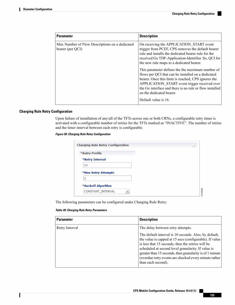
DescriptionParameter
On receiving the APPLICATION_START eventtrigger from PCEF, CPS removes the default bearerrule and installs the dedicated bearer rule for thereceived Gx TDF-Application-Identifier. So, QCI forthe new rule maps to a dedicated bearer.
This parameter defines the the maximum number offlows per QCI that can be installed on a dedicatedbearer. Once this limit is reached, CPS ignores theAPPLICATION_START event trigger received overthe Gx interface and there is no rule or flow installedon the dedicated bearer.
Default value is 16.
Max Number of Flow Descriptions on a dedicatedbearer (per QCI)
Charging Rule Retry Configuration
Upon failure of installation of any/all of the TFTs across one or both CRNs, a configurable retry timer isactivated with a configurable number of retries for the TFTs marked as “INACTIVE”. The number of retriesand the timer interval between each retry is configurable.Figure 50: Charging Rule Retry Configuration
The following parameters can be configured under Charging Rule Retry:
Table 49: Charging Rule Retry Parameters
DescriptionParameter
The delay between retry attempts.
The default interval is 10 seconds. Also, by default,the value is capped at 15 secs (configurable). If valueis less that 15 seconds, then the retries will bescheduled at second level granularity. If value isgreater than 15 seconds, then granularity is of 1minute(overdue retry events are checked every minute ratherthan each second).
Retry Interval
CPS Mobile Configuration Guide, Release 19.4.0 (1)123
Diameter ConfigurationCharging Rule Retry Configuration

DescriptionParameter
The maximum times retry is attempted for a rule.
Default value is 3 attempts.
Max Retry Attempts
The back-off algorithm used while determining theactual delay between retry attempts.
Currently only one option is supported:
Constant Interval: Causes the configured retry intervalto be used (without any change) for delay for all retryattempts (other options like exponential back-offwhere retry interval increases exponentially arecurrently not supported/implemented).
Backoff Algorithm
Upon failure to install TFTs even after retry, all remaining flows are removed (if there were any successfullyinstalled)followed by termination of the Sd Session. After a refresh, CPS attempts to re-establish the Sd-Session.CPS also marks the failed flows as INACTIVE.
Redirect Requests
CPS can reject incoming CCR-I messages with DIAMETER_REDIRECT_INDICATION (3006) error byacting as a redirect agent (RFC 3588). This decision to redirect a request is configured using an STG or CRD.CPS expects the STG or CRD to include a Redirect Request Column (of type True or False). There is norestriction on the condition that determines the redirect behavior.
The following parameters can be configured under Redirect Requests:
Table 50: Redirect Requests Parameters
DescriptionParameter
The result column (True/False) from the CRD usedto determine if the session needs to be redirected. Ifresult column specified here evaluates to True, sessionis redirected, else it continues as usual.
Redirect Request Column
The list of Redirect-Host AVP values to be includedin the response. If there are more than one hosts listed,all the hosts are included in the response.
Redirect Host
The Redirect-Max-Cache-Time AVP value (inseconds) to be included in the response.
Redirect Max Cache Time (in seconds)
CPS Mobile Configuration Guide, Release 19.4.0 (1)124
Diameter ConfigurationRedirect Requests

DescriptionParameter
The Redirect-Host-Usage AVP value (in seconds) tobe included in the response. Redirect-Host-UsageAVP supports the following values:
• DONT_CACHE: The host specified in theRedirect-Host AVP should not be cached. Thisis the default value.
• ALL_SESSION: All messages within the samesession, as defined by the same value of theSession-ID AVP may be sent to the hostspecified in the Redirect-Host AVP. That is, thereis no need to consult the redirect agent for all themessages associated in the session. Identityreceived is stored until the session terminates.
• ALL_REALM: All messages destined for therealm requested may be sent to the host specifiedin the Redirect-Host AVP.
• REALM_AND_APPLICATION: All messagesfor the application requested to the realmspecified may be sent to the host specified in theRedirect-Host AVP.
• ALL_APPLICATION: All messages for theapplication requested may be sent to the hostspecified in the Redirect-Host AVP.
• ALL_HOST: All messages that would be sentto the host that generated the Redirect-Host maybe sent to the host specified in the Redirect- HostAVP.
• ALL_USER:All messages for the user requestedmay be sent to the host specified in theRedirect-Host AVP.
Redirect Host Usage
Creating an STG to Redirect Requests
You must configure an STG to determine whether an incoming CCR-I needs to be rejected or not. The stepsto configure the decision table are as follows:
The below procedure is a sample configuration based on APN and Billing plan.Note
Step 1 Log into Policy Builder.Step 2 Select the Reference Data tab.Step 3 Click Custom Reference Data Tables and select Search Table Groups.
CPS Mobile Configuration Guide, Release 19.4.0 (1)125
Diameter ConfigurationCreating an STG to Redirect Requests

Step 4 Under Actions, click Search Table Groups.Step 5 Enter a name for the STG.Step 6 UnderResult Columns, clickAdd and enter aName,Display Name, and select the check box underUse In Condition.Step 7 Click Custom Reference Data Table under Actions > Create Child.Step 8 Enter a Name and Display Name for the CRD Table.Step 9 Under Columns, click Add and enter the following parameters as shown in the following figure:
Figure 51: Custom Reference Data Table Parameters
For apn, make sure you select Bind to Session/Policy State Field, click select and select Gx APN. Similarly, forbilling_plan, selectBind to Subscriber AVP code and enter the name or code for the AVP that represents the subscriber'sbilling plan (for example, billingplan).
Step 10 Save the PB configuration.
Pending Transaction Retry
When a Gx session is established, the Supported-Features AVP value is checked for Pending Transactionsbit in accordance with 3GPP TS 29.212. The AVP value is stored in the Gx session.
This feature is disabled by default. Select the Pending Transaction Retry check box to enable the feature.
On enabling this feature, make sure to disable the Cisco Pending Transaction Retry feature.Important
If the Pending Transaction Retry check box is unchecked (that is, disabled) in Policy Builder, the systemdefaults to 3GPP handling of race conditions or pending transactions.
The following parameters can be configured under Pending Transaction Retry:
CPS Mobile Configuration Guide, Release 19.4.0 (1)126
Diameter ConfigurationPending Transaction Retry

Table 51: Pending Transaction Retry Parameters
DescriptionParameter
• Constant_Interval: The configured retry Interval is used(without any change) for all retry attempts.
• Linear_Interval: Retry interval is derived by multiplyingthe attempt number with the retry interval. This isapplicable only when RAR messages are retried due topending transactions.
Default value is Constant_Interval.
Back Off Algorithm
Retry time interval (milliseconds) after which same RAR isretried after receipt of Pending Transactions (4144)Experimental Result code in RAA.
Default value is 1000 milliseconds.
RAR Retry Interval (MilliSeconds)
Time interval (milliseconds) during which CCR-U processingis withheld till pending RAA is received from PCEF.
Default value is 1000 milliseconds.
Time (MilliSeconds) to hold CCR-Uprocessing
Time interval (milliseconds) during which CPS should waitfor PCEF to initiate a CCR-U retry after sending a RAA withPending Transactions (4144) Experimental Result code.
Default value is 1000 milliseconds.
Time (MilliSeconds) to wait for CCR-U retry
Number of RARs generated during pending transactionssituations that need to be held and retried in sequence.Additional maximum RARs that can be stored is three. If thisvalue is more that three, Policy Builder displays configurationviolation error message.
Default value is 1. If set to 0, additional RAR's are discarded.
Max No of additional RAR's to be stored
Extract Avps
AVPs that are required for policy decisions are extracted from the diameter message. The AVPs are specifiedby their path within the diameter message. Additionally, nested AVPs (each level delimited with ".") can alsobe extracted with or without qualifiers.
Once extracted, the AVPs are then available for use in Initiator conditions or as key AVP in CRD tables forpolicy decisions. The AVPs are not stored with the session. Thus, if some policy is enabled because of areceived message, and if there is a subsequent trigger message that does not contain that AVP, the initiatorconditions will fail and the policy is reverted.
If the AVP to be extracted appears multiple times, each of the instance will be extracted and made availableas a policy AVP. Initiator conditions can be written for one or more of these instances. Each condition willcheck all the available instances for evaluation. Thus if there are multiple instances, multiple conditions (ifconfigured) can be true for the same AVP but with different values.
The Extract Avps table lists the AVPs that must be extracted from the diameter message.
CPS Mobile Configuration Guide, Release 19.4.0 (1)127
Diameter ConfigurationExtract Avps

• Name: Enter a logical name for the extracted AVP. This name will be used in Initiator conditions andCRD tables to identify the extracted AVP. This is a mandatory parameter.
• Avp Path: Enter the complete AVP path. This is a mandatory parameter.
• Command Code: If Command Code is specified, CPS attempts to extract the AVPs from only thatcommand (and skip the rest). This is an optional parameter.
For example:
• Name: Event-Trigger
• Avp Path: Event-Trigger
• Command Code: 272
For the above example, given a CCRwith Event-Trigger AVPs, CPS extracts each Event-Trigger AVP instanceand adds it to the current policy state.
Override Supported Features
CPS supports override of Supported-Features with configured value (instead of internally calculated value).The override Supported-Features value can be defined in a CRD table. If the value is configured, CPS compares(bitwise AND) the incoming PCEF advertised value with the configured value and uses the result as thenegotiated value. This negotiated value is included in the response message.
If the Override functionality is not enabled or table evaluation provided under the Override Supported-Featuresdoes not return a result, CPS falls back to the internal Supported-Features calculation.
CPS does not validate the configured Feature-List value. If wrong value is configured, CPS still evaluatesnegotiated features based on this wrong value and can enable features which CPS does not actually support.
Note
The following parameters can be configured:
Table 52: Override Supported Features Parameters
DescriptionParameter
The STG to lookup for determining the configured Supported-Features(for override).
Search Table Group
The Result column from the selected STG that corresponds toVendor-Id AVP value.
Vendor Id
The Result column from the selected STG that corresponds toFeature-List-Id AVP value.
Feature List Id
The Result column from the selected STG that corresponds toFeature-List AVP value.
Feature List
Multiple entries can be configured, which are evaluated in order.Note
CPS Mobile Configuration Guide, Release 19.4.0 (1)128
Diameter ConfigurationOverride Supported Features

Custom Dynamic Rule Name
For an Rx call a different Rx dedicated bearer is created for each Media-Sub-Component grouped AVP inthe incoming Rx AARmessage. This feature allows for customization of the Rx dedicated bearer name basedon the AF-Application-Identifier AVP value and Media-Type AVP value received in Rx AAR message.Figure 52: Custom Dynamic Rule Name
The default Rx dedicated bearer name format is:_<Rx-Session-No>_<MCD-No>_<Flow-Number>_<partialRulename>_<Media-Type>
where:
• <Rx-Session-No>: Counts how many Rx sessions have bound so far to the Gx session by the time thecurrent Rx session is created. This is an attribute of the Rx session stored on PCRF side and it doesn'tchange during the Rx session lifetime. The value starts from zero and it increases with one for each newRx session that binds.
• <MCD-No>: Media-Component-Number AVP value under Media-Component-Description groupedAVP for the current Media-Sub-Component grouped AVP.
• <Flow-Number>: Flow-Number AVP value for the current Media-Sub-Component grouped AVP.
• <partialRulename>: Partial Rule Name value matching the current Af Application Id and Media Typevalues for the current Media-Sub-Component grouped AVP or “AF” if no match.
• <Media-Type>: Media-Type AVP value for the current Media-Sub-Component grouped AVP.
Only the <partialRulename> part can be customized.Note
Rx ClientsThis specific diameter client object is supposed to be used only in relation with the Rx interface. It adds Rxspecific features to the generic diameter client already described in Diameter Clients, on page 111.
The parameters described in the following table can be configured for the Rx client:
CPS Mobile Configuration Guide, Release 19.4.0 (1)129
Diameter ConfigurationCustom Dynamic Rule Name

Table 53: Rx Client Parameters
DescriptionParameters
Allows the Rx sessions initiated by this client to bind to the Gx session byother attribute than the IP address as per 3GPP TS 29.214. For moreinformation refer to Table 54: Session Binding Attribute Values, on page 135.
Session Binding Attribute
• None: When selected, CPS does not take any action on source IP.
• Replace with 'any': When selected, CPS replaces the flow descriptionsource IP with ‘any’.
• Replace with UE IP: When selected, CPS replaces flow descriptionsource IP with UE framed IP.
Flow Description Source IpEvaluation
This parameter is used to define the timer by which the STA is held back.Once the timer expires even if the CCR-U is not received, STA is sent to theAF and the rxSession is removed.
Default value is 4000 milliseconds.
STA Hold Time Ms
CCR-U Timer is the time to wait for CCR-U from PGWwhen the AF starteda request and Specific-Action CUSTOM_DPCC_STATUS_REPORT wasarmed in AAR.
CCR-U timer is started for every request (default bearer boost/spawning ofdedicated bearer) from AF if the CCR-U is configured in Policy Builder andCUSTOM_DPCC_STATUS_REPORT(200) is armed in AAR request. Thereis a separate timer event for different Rx client.
This timer is stopped by PCRF when CCR-U is received from P-GW. Alsoin case when P-GWdoes not respond to Gx-RAR then CCR-U timer is stoppedon receiving internal Gx-RAA (result-code=7000) message.
CCR-U timer is helpful in informing AF if the QoS requested through AF isupdated on P-GW. In case of default bearer QoS boost/throttle request fromAF, there is no notification sent by the P-GW to PCRF. In this case PCRFinternally runs this CCR-U time which on expiry sends an update (throughRx_RAR having DPCC-Status AVP) to AF that QoS request is served.
There is no default value for this timer. If you want to start CCR-U timer,then you need to configure through Policy Builder. The maximum value is15 seconds.
CCR-U Wait Time (inseconds)
This parameter is used to configure wait timer for sending delayed messages.
Default value is 500 milliseconds.
In case of multipleMedia-Component-Descriptions being received in an AARmessage by CPS, where one of them is rejected after evaluating for RxAuthorization, CPS sends a successful AAA for the acceptedMedia-Component-Descriptions and also creates a scheduled event for sendinga delayed Rx RAR for rejected Media component.
This Rx RAR is sent to AF based on Sending Delayed Message Wait Timeconfigured.
Sending Delayed MessageWait Time Ms
CPS Mobile Configuration Guide, Release 19.4.0 (1)130
Diameter ConfigurationRx Clients

DescriptionParameters
The list of URNs that are used to indicate that a AF session relates toemergency traffic as per procedures described in 3GPP TS 29.214. For moreinformation refer to Wildcard URN. See Emergency URN List, on page 135.
Emergency URN List
When selected, CPS overrides the AF-Application-Identifier AVP value withthe Service-URN AVP value for emergency calls. This option is provided inorder to overcome the lack of AF-Application-Identifier AVP value in RxAAR in case of IMS emergency calls.
The default setting is unchecked.
Override AF App Id withURN for Emergency sessions
When selected, CPS validates the Flow-Description AVP values received aspart of Media-Sub-Component based on restrictions provided in the 3GPP29.214 Release 11 specification. If the Flow-Description value does notcomply with the format specified then the AAR request is rejected withFILTER_RESTRICTIONS (5062) value in Experimental-Result-Code.
When unchecked, CPS does not validate the Flow-Description AVP valueand simply forwards it is as is to PCEF as part of generated rules.
The default setting is unchecked.
Validate Flow-DescriptionAVP Value
When checked, CPS supports the QoS handling for Preliminary Service Status.So, on receiving Service-Info-Status AVP as preliminary service informationfrom AF, CPS generates the dynamic PCC rule and assign QCI and ARPvalues of the default bearer to these PCC rule to avoid signaling to the UE.
When unchecked, CPS ignores the Service-Info-Status AVP value and derivethe ARP andQCI values as per the QoS derivation algorithm defined in 3GPPTS 29.213 specification.
The default setting is unchecked.
29.213 standard QoS forpreliminary service
When checked, CPS always sends the ANI to AF on receiving ANI eventfrom the PCEF. So, in case of bearer release that is either in Rx_RAR (whenfew rules are impacted) or in Rx_STA when all the rules are impacted, PCRFadds the ANI (access network information) towards AF.
When unchecked, CPS does not report ANI to the AF every time the ANIevent is received from PCEF.
In case of Rx session termination by PCRF that is, when PCRF sends RxASRto the AF; PCRF sends the ANI in the Rx STA message even if AF has notasserted the Required-Access-Info AVP for ANI in the Rx STR message.
The checkbox can be used only when NetLoc feature has beennegotiated over Gx and Rx and the AF has requested for ANI inthe Rx AAR message.
Note
The default setting is unchecked.
NetLoc: Report ANI on rulefailure
CPS Mobile Configuration Guide, Release 19.4.0 (1)131
Diameter ConfigurationRx Clients

DescriptionParameters
When RAN-NAS-Cause feature is enabled, CPS sends access networkinformation and RAN-NAS-Release-Cause to AF in STA. So, when this checkbox is selected, CPS waits for this information from the PCEF and does notsend STA till it receives the CCR-U from the PCEF.
The default setting is checked (TRUE).
The check box is only applicable when RAN-NAS-Cause featurehas been negotiated over Gx and Rx.
Note
Hold STA ifRAN-NAS-Cause enabled
When selected, CPS automatically increments the precedence AVP value by1 for every Rx charging rule that is installed as part of any Rx session that isusing this Rx client within the same Gx session. For example, Gx session(Gx1) has one Rx session (Rx1). When Rx1 is created, two charging rulesare installed and they are assigned precedence values 1 and 2. A second Rxsession (Rx2) starts for Gx1 and also installs two Rx charging rules. Theserules are assigned precedence values 3 and 4.
The precedence values are stored in the Gx session in the rxPrecedenceCounterattribute.
Using this option overrides any other Rx charging rule precedence settings(for example, any that may have been configured for theRxSponsoredDataChargingParameters service option).
When this option is enabled, existing VoLTE deployments maybe impacted. After upgrading to CPS 11.0.0, make sure that thegateway's configuration is changed to consider precedence values.
Note
You can use the Precedence Start Value and Precedence EndValue optionsto set lower and upper limits for the precedence AVP values. If you do notset these options, the starting precedence value is set to 1 and is incrementedto 9223372036854775807.
The default setting is unchecked.
Auto Increment PrecedenceAvp
When selected, CPSmanages the expiration of Rule-Deactivation time triggers.On expiration of the installed Rule-Deactivation time, CPS initiates removalof the inactive dynamic rules and tear-down of the existing Rx session.
The default setting is unchecked (false).
Remove Rule On RuleDeactivation
When selected, CPS validates the sponsor ID received in AAR request. If thereceived sponsor ID is unauthorized, CPS returnsUNAUTHORIZED_SPONSORED_DATA_CONNECTIVITY (5067) codein AAA.
The default setting is unchecked (false).
Authorize Sponsor DataConnectivity
CPS Mobile Configuration Guide, Release 19.4.0 (1)132
Diameter ConfigurationRx Clients

DescriptionParameters
When selected, CPS enforces a unique AF-Charging-Identifier across all Rxsessions within a given subscriber or network session. During an Rx sessionestablishment, if there is already an Rx session (within the subscriber ornetwork session) containing the same AF-Charging-Identifier value, CPSrejects the new Rx session with DUPLICATED_AF_SESSION (5064)experimental result code.
The default setting is unchecked.
Enforce UniqueAF-Charging-Identifier
The AF-Application-Identifier AVP present in the AAR message indicatesthe particular service that the AF session belongs to. This AVP can be presentat the command level and within the Media-Component-Description AVP.
When selected, and if the AF-Application-Identifier is sent both at commandlevel and within the Media-Component-Description AVP, theAF-Application-Identifier AVP value present at the command level isconsidered.
The default setting is unchecked, that is, the AF-Application Identifier providedwithin the Media-Component-Description AVP is considered.
Prefer command levelAF-Application-Identifier
When selected, CPS sends time zone and location information in Rx AAA,STA, and Rx RAR response messages provided that 3GPP-MS-TimeZoneAVP and 3GPP-User-Location-Info AVP are already received in the CCRmessage.
To receive the updated time zone and location information in the messages,CPS should arm the UE_TIME_ZONE_CHANGE event trigger andUSER_LOCATION_CHANGE event trigger in the service option underEvent-Trigger configuration.
CPS does not report this information until it is received in a CCRmessage from PCEF.
Note
Send timezone and locationinfo
When selected, CPS can trigger RAR instead of ASR when all rules fail withrule failure code PS_TO_CS_HANDOVER.
The default setting is unchecked.
Trigger RAR when all rulesfail (for SRVCC)
When selected, if Media-Type is found to be missing in anyMedia-Component-Descriptions in Rx_AAR, CPS rejects the Rx_AAR withExperimental-Result-Code= INVALID_SERVICE_INFORMATION (5061).
The default setting is unchecked.
Reject AAR with InvalidService Info for missingMedia-Type
Precedence Avp Lower And Upper
When selected, CPS automatically increments the precedence AVP value by1 for every Rx charging rule that is installed as part of any Rx session usingthis Rx Client, within the same Gx session. The precedence values are storedin the Gx session in the rxPrecedenceCounter attribute.
This value is optional, but when used, must be greater than 0 and less thanthe Precedence End Value.
Precedence Start Value
CPS Mobile Configuration Guide, Release 19.4.0 (1)133
Diameter ConfigurationRx Clients

DescriptionParameters
The upper limit of the precedence values for Rx charging rules that areinstalled. When this value is reached, the rxPrecedenceCounter is reset to thePrecedence Start Value.
This value is required when using the Precedence Start Value. It must begreater than the start value.
Precedence End Value
See Netloc Access Not Supported Configuration, on page 136.Netloc Access Not SupportedConfiguration
See Table 54: Session Binding Attribute Values, on page 135.Session Binding Overriding
By default, the table is empty and unchecked (for backward compatibility)but if you want to override the default behavior, then you need to configureall the error codes received over Gx via CCR-U or RAA message for whichRx RAR needs to be sent.
You can create two tables for mapping rule-failure-code to specific-action(for sending in Rx RAR) and rule-failure-code to abort-cause (for sending inRx ASR).
If you have checked Rule Failure Mapping Table checkbox and did notconfigure anymappings then neither default Specific Action nor Abort Causeis applied for any of the Failure Code.
If you have not checkedRule FailureMapping Table checkbox then defaultSpecific Action and Abort Cause is applied.
• For mapping rule-failure-code to specific-action:
Table Name: Gx Rule Failure To Rx Specific Action Mapping
• For mapping rule-failure-code to abort-cause:
Table Name: Gx Rule Failure To Rx Abort Cause Mapping
In order to successfully map the rule-failure-code to specific-action,the P-CSCF/AF must have the corresponding specific-action onCPS.
Note
Rule Failure Mapping Table
CPS Mobile Configuration Guide, Release 19.4.0 (1)134
Diameter ConfigurationRx Clients

DescriptionParameters
By default, the table is empty and unchecked (for backward compatibility).This configuration is used to determine the Gx event triggers that CPS shouldsubscribe in GxRAR (dummyRAR) before it processes themedia informationthat it has received in Rx AAR message.
The event triggers are determined based on a CRD table (dummy RAR table)whose input columns are bound to Rxmedia details (for example,Media-Type,AF-Application-Id, and so on) and output columns specify the event-triggernumbers that are to be subscribed/enabled on PCEF.
The evaluation of this CRD table per media (Media-Component-Description)is defined through Rx STG lookup binding configuration under Rx Profile.The Rx CRD AVP names to extract Event-Triggers list is used to specifythe Rx CRD AVP names. These Rx CRD AVPs are created based on theoutput columnmapping defined for the CRD table (dummyRAR table) underRx STG lookup binding (AVP name defined under Output column AVPpairs).
Request Gx RAA forEvent-Triggers
See Extract Avps, on page 127.Extract Avps
See Override Supported Features, on page 128.Override Supported Features
Table 54: Session Binding Attribute Values
DescriptionSession Binding Attributevalue
Attempts to bind by
• 1 Framed-IP-Address
• 2 Framed-IPv6-Prefix
IP Address (default)
IMSI value and APN value from incoming request.IMSI and APN
MSISDN value and APN value from incoming request.MSISDN and APN
IMSI value, IP address value, and IPv6-Prefix value from incoming request.
On receiving Rx session request, keys are generated for IMSI and IP Addressor IMSI and IPv6-Prefix combination to load the session based on these keys.
IMSI And IP Address
“IMSI and APN” and “MSISDN and APN” session binding attribute values are provided in order to supportnon 3GPP TS 29.214 compliant Rx clients.
Emergency URN List
CPS supports wildcard service URN. For example if sos.* is configured under Emergency URN List in PolicyBuilder and when Service-URN is received from AF with “sos” “sos.fire” “sos.police” and “sos.ambulance”and so on. indicating an emergency session CPS applies special policies that are configured for Emergencysessions.
1. Select the Rx Client name created.
CPS Mobile Configuration Guide, Release 19.4.0 (1)135
Diameter ConfigurationRx Clients

2. Click Add near the Emergency URN List box. A new window Add Values is displayed.Figure 53: Add Values
3. Type the name of the emergency URN that you want to add in the Value to Add (String) text box andclick Add.
4. ClickOK. In the example shown below, three URNs entries are added. To remove an URN from this listselect the URN to be removed and click Remove.Figure 54: Add/Remove URN
As shown in the example, '*' has been used for wildcarding. CPS uses standard Java pattern characters forEmergency URNs. The pattern needs to follow the standard Java regular expression syntax described here.
Note
Netloc Access Not Supported ConfigurationCPS supports to send NetLoc-Access-Support AVP in Rx AAA or STA message based on the currentIP-CAN-Type or the values of Rat-Type AVP and AN-Trusted AVP. This is in accordance with the section4.4.6.7 of the 3GPP 29.214.
CPS Mobile Configuration Guide, Release 19.4.0 (1)136
Diameter ConfigurationNetloc Access Not Supported Configuration

To enable this, Netloc Access Not Supported Configuration has been added under Rx Client.Figure 55: Netloc Access Not Supported Configuration
By default, this configuration is disabled. This means that PCRF will not check for NetLoc access supportbased on IP-CAN-Type or Rat-Type AVP and AN-Trusted AVP.
If this configuration is enabled but there are no entries in the two tables associated with it, then PCRF willnot check for NetLoc access support based on IP-CAN-Type or Rat-Type AVP and AN-Trusted AVP.
The following table provides description related to the two tables under this configuration:
Table 55: Netloc Access Not Supported Configuration Tables
DescriptionTable Name
This is the list of IP-CAN-Type values for which NetLoc access is not supported. Forvalid values of the IP-CAN-Type, refer the 3GPP specification 29.212.
This table only takes integer values as input.
Default value is -1.
An entry with value = -1 must not be used for validation of NetLoc access.
List Of Ip Can Type
CPS Mobile Configuration Guide, Release 19.4.0 (1)137
Diameter ConfigurationNetloc Access Not Supported Configuration

DescriptionTable Name
This is the list of Rat-Type AVP & AN-Trusted AVP values for which NetLoc accessis not supported. For valid values of the Rat-Type & AN-Trusted, refer the 3GPPspecification 29.212.
This table only takes integer values as input.
Default value is -1.
Rat Type entry with value = -1 must not be used for validation of NetLoc access.
An Trusted entry with value = -1 means that the AN-Trusted value does not care forthis entry.
List Of Rat Type
When the PCRF receives a request to report the access network information from the AF in an AAR commandor in an STR command triggered by the AF, the PCRF tries to determine whether the access network supportsthe access network information reporting based on the currently used IP-CAN type or the values of RAT-TypeAVP and AN-Trusted AVP.
PCRF first searches the list of configured IP-CAN-Type and if no match is found in the IP-CAN-Type list,then it searches the list of Rat-Type and AN-Trusted. If there is a match in any one list i.e. either the currentlyused IP-CAN-Typematches or current value of the Rat-Type andAN-Trustedmatches, then the PCRF respondsto AF with an AAA or STA command including the NetLoc-Access-Surpport AVP set to the value of 0(NETLOC_ACCESS_NOT_SUPPORTED); otherwise, it immediately configures the PCEF to provide suchaccess network information.
Gy ClientsThis specific diameter client object is supposed to be used only in relation with the Gy interface. It adds Gyspecific features to the generic diameter client already described in Diameter Clients, on page 111.
The following parameters can be configured under Gy Client:
Table 56: Gy Client Parameters
DescriptionParameters
If checked attempts to load the session by realm (Origin-Realm AVP value) andUser Id.
Default value is unchecked.
Load By Realm And UserId
If checked attempts to load the session by APN (Called-Station-Id AVP value)and User Id.
Default value is unchecked.
Load By Apn And User Id
CPS Mobile Configuration Guide, Release 19.4.0 (1)138
Diameter ConfigurationGy Clients

DescriptionParameters
This check box controls whether you want to run the Gy as primary (for example,for Gy only call model) or secondary (for example, Gx + Gy call model).
gyAsPK parameter in qns.conf file is also used to run Gy as primary orsecondary. This flag is system wide parameter. In case you want to run Gy onlycall model and Gx + Gy call model both on the same system, the qns.confparameter cannot be used.
The new check box field added under Gy Client is backward compatible withqns.conf parameter settings. For example, if -DgyAsPK=true parameter isconfigured in qns.conf file, the check box is overwritten with the valueconfigured in qns.conf file.
To run both Gy only and Gx + Gy call model on same system:
• First delete the parameter (-DgyAsPK=true) if it is already configured inqns.conf file.
• In Policy Builder, create separate Gy Clients for primary Gy and secondaryGy.
• Next check the "Gy As Primary" check box in this Gy Client, if you wantGy as primary.
• Uncheck the "Gy As Primary" check box in this Gy client, if you do notwant Gy as primary.
Gy As Primary
See Extract Avps, on page 127Extract Avps
Currently, not supported.
This table is only supported for Gx and Rx client.Note
Override SupportedFeatures
Both of the above mentioned flags help in binding the Gy session to correct Gx session when multiple Gxsessions exist for the same user.
In both cases User Id is:
AVP ValueUser Id
Subscription-Id-Data AVP value underSubscription-Id grouped AVP whereSubscription-Id-Type AVP value isEND_USER_IMSI (1)
IMSI
Subscription-Id-Data AVP value underSubscription-Id grouped AVP whereSubscription-Id-Type AVP value isEND_USER_E164 (0)
MSISDN
CPS Mobile Configuration Guide, Release 19.4.0 (1)139
Diameter ConfigurationGy Clients

AVP ValueUser Id
Subscription-Id-Data AVP value underSubscription-Id grouped AVP whereSubscription-Id-TypeAVP value is END_USER_NAI(3)
NAI
When gyAsPK flag set to true in qns.conf file (/etc/broadhop), it loads the Gy session using the Gysession ID as the primary key. In CPS 12.1.0, CPS 13.1.0, and CPS 14.0.0 and higher releases, this parameteris enforced on all Gy messages. In other CPS releases, the parameter is ignored on CCR-I's, and the sessionis loaded by secondary keys specified in the Gy client. If there are no keys configured for the Gy client, CPSuses the default: IMSI and MSISDN from the Gy message. Default value is false.
Note
Sy ClientsThis specific diameter client object is supposed to be used to access the Sy Server.
The following parameters can be configured under Sy Client:
Table 57: Sy Client Parameters
DescriptionParameter
The client name that is going to be used to referencethis particular client in the service configurationobject.
Name
The pattern that peer realm name should match inorder for this diameter client to be used. The patternneeds to follow the standard Java regular expressionsyntax described here.
The first choice for Realm Pattern value should alwaysbe the exact peer realm name whenever possible.
Realm Pattern
Dynamic calculation of policy counters events thatare subjected to an update for the interval specified.If the look ahead interval is specified, CPS evaluatesall policy counters and if a policy counter is about toexpire before the interval, CPS sends thepolicy-counter-stats.
Default value is 180 minutes.
Counter Lookahead Interval
See Extract Avps, on page 127Extract Avps
CPS Mobile Configuration Guide, Release 19.4.0 (1)140
Diameter ConfigurationSy Clients

Diameter DefaultsThe Diameter Defaults section provides global default values for different modules of the system.
In order to define a Diameter Default you need to perform the following steps:
1. Login into Policy Builder.2. Select Reference Data tab.3. From the left pane select Diameter Defaults.4. Select Summary.5. Create the specific default object according to your needs.6. Provide values for at least the mandatory fields.
• The mandatory fields are marked with a “*” on the upper left corner of the field name label.
• There should be at most one object for each diameter default type or the results will be unpredictable.The Policy Builder GUI does not enforce this restriction though.
Note
Custom AVP ProfileThis feature allows the Service Provider to extend the Diameter dictionary with new vendor specific AVPsalong with a source for that AVP and a destination where the AVP is going to be used.
The feature itself consists of two components:
• Custom Avp Table• Avp Mappings
Custom Avp TableThis table allows for the definition of the custom AVP with all the standard attributes of an AVP.
The following parameters can be configured under Custom Avp Table:
Table 58: Custom Avp Table Parameters
DescriptionParameter
Any string that is used to identify this custom AVP.AVP Name
AVP Code combined with Vendor Id field identifies the attribute uniquely.
• 1 - 255 Backward compatibility with Radius without setting the Vendor Id field.
RADIUS-based policy control is no longer supported in CPS 14.0.0and later releases as 3GPP Gx Diameter interface has become theindustry-standard policy control interface.
Note
• 256 - above Used for Diameter and are allocated by IANA.
Avp Code
CPS Mobile Configuration Guide, Release 19.4.0 (1)141
Diameter ConfigurationDiameter Defaults

DescriptionParameter
It indicates the Vendor Id of the AVP. The following are the supported Vendor Ids:
• base (0)
• ciscoSystems (9)
• Ericsson (193)
• Tekelec (323)
• TGPP2 (5535)
• Openet (7898)
• Starent (8164)
• TGPP (10415)
• ETSI (13019)
• NSN (28458)
• Nokia (34326)
• Lucent (1751)
• Verizon (12951)
• Camiant (21274)
• Huawei (2011)
Vendor Id
Vendor Id value as assigned by IANA. The Vendor Id bit known as theVendor-Specific bit indicates whether the optional Vendor Code field is present inthe AVP header. When set the AVP Code belongs to the specific vendor code addressspace.
Vendor Code
Indicates whether support of the AVP is required. If this Bit is checked then DiameterClient Server Proxy and Translation Agent must support the handling of this AVP.
Mandatory Bit
Indicates the need for encryption for end-to-end security. If this bit is checked indicatesthat AVP data is encrypted for end-to-end security.
Protected Bit
Indicates whether the optional Vendor-ID field is present in the AVP header.Vendor Id Bit
CPS Mobile Configuration Guide, Release 19.4.0 (1)142
Diameter ConfigurationCustom Avp Table

DescriptionParameter
Any valid basic AVP data format
• Float32Avp
• Float64Avp
• Integer32Avp
• Integer64Avp
• OctetStringAvp
• Unsigned32Avp
• Unsigned64Avp
• UTF8String
Data Type
Avp MappingsThis table allows for the mapping between the source and the destination for the custom AVP (defined in theprevious section). Multiple attributes can be used to identify both the source for the custom AVP value aswell as the destination where the AVP is going to be used.
The following mappings are supported:
• Custom AVP to Custom AVP Mapping Maps a custom AVP to another custom AVP.• 3gpp / spr AVP to 3gpp AVP Mapping Maps a 3GPP AVP or a SPR attribute to a 3GPP AVP.• 3GPP / SPR AVP to Custom AVP Mapping Maps a 3GPP AVP or a SPR attribute to a custom AVP.
Custom AVP to Custom AVP Mapping
The following parameters can be configured under Custom AVP to Custom AVP Mapping:
Table 59: Custom AVP to Custom AVP Mapping Table Parameters
DescriptionParameter
Name of AVP that has to be looked up for possiblemapping.
Source Avp
The Application Interface Id (Gx) in numeric format(16777238) on which the Source AVP is received.
Source App Id
The command code of the message on interfaceSource APPID that contains the Source AVP.
Source Cmd Code
The message indicated by Source Command Code isa request or response. Types:
• Request• Response
Source Cmd Type
This field contains the identification of the sourcepoint of the operation.
Origin Host
CPS Mobile Configuration Guide, Release 19.4.0 (1)143
Diameter ConfigurationAvp Mappings

DescriptionParameter
This field contains the identification of the realm ofthe operation originator.
Origin Realm
AVP Name that is actually mapped to Source AVP.Target Avp
Target Application Identifier (Sy - 16777302 - for thisrelease).
Target App Id
The command code of themessage that goes on TargetAPPID and have Target AVP.
Target Cmd Code
The message having Target Command Code requestor a response.
Types:
• Request• Response
Target Cmd Type
This field contains the identification of the destinationpoint of the operation.
Destination Host
This field contains the realm of the operationdestination.
Destination Realm
Response value for Source Cmd Type and Target Cmd Type is not currently supported.
3gpp / spr AVP to 3gpp AVP Mapping
The following parameters can be configured under 3gpp / spr AVP to 3gpp AVP Mapping:
Table 60: 3gpp / spr AVP to 3gpp AVP Mapping Table Parameters
DescriptionParameter
Name of AVP that has to be looked up for possiblemapping.
Source Avp
Check if the source is an SPR attribute. The SourceAVP originates from a Source Command or fromSubscriber profile in Subscriber Profile Repository.
Default value is unchecked.
Is SPR AVP?
The Application Interface Id (Gx) in numeric format(16777238) on which the Source AVP is received.
Source App Id
The command code of the message on interfaceSource APPID that contains the Source AVP.
Source Cmd Code
CPS Mobile Configuration Guide, Release 19.4.0 (1)144
Diameter ConfigurationAvp Mappings

DescriptionParameter
The message indicated by Source Command Code isa request or response. Types:
• None• Request• Response
Source Cmd Type
This field contains the identification of the sourcepoint of the operation.
Origin Host
This field contains the identification of the realm ofthe operation originator.
Origin Realm
AVP Name that is actually mapped to Source AVP.Target Avp
Target Application Identifier (Sy - 16777302 - for thisrelease).
Target App Id
The command code of themessage that goes on TargetAPPID and have Target AVP.
Target Cmd Code
The message having Target Command Code requestor a response.
Types:
• Request• Response
Target Cmd Type
This field contains the identification of the destinationpoint of the operation.
Destination Host
This field contains the realm of the operationdestination.
Destination Realm
Response value for Source Cmd Type and Target Cmd Type is not currently supported.
3GPP / SPR AVP to Custom AVP Mapping
The following parameters can be configured under 3GPP / SPR AVP to Custom AVP Mapping:
Table 61: 3GPP / SPR AVP to Custom AVP Mapping Table Parameters
DescriptionParameter
Name of AVP that has to be looked up for possiblemapping.
Source Avp
Check if the source is an SPR attribute. The SourceAVP originates from a Source Command or fromSubscriber profile in Subscriber Profile Repository.
Default value is unchecked.
Is SPR AVP?
CPS Mobile Configuration Guide, Release 19.4.0 (1)145
Diameter ConfigurationAvp Mappings

DescriptionParameter
The Application Interface Id (Gx) in numeric format(16777238) on which the Source AVP is received.
Source App Id
The command code of the message on interfaceSource APPID that contains the Source AVP.
Source Cmd Code
The message indicated by Source Command Code isa request or response. Types:
• None• Request• Response
Source Cmd Type
This field contains the identification of the sourcepoint of the operation.
Origin Host
This field contains the identification of the realm ofthe operation originator.
Origin Realm
AVP Name that is actually mapped to Source AVP.Target Avp
Target Application Identifier (Sy - 16777302 - for thisrelease).
Target App Id
The command code of themessage that goes on TargetAPPID and have Target AVP.
Target Cmd Code
The message having Target Command Code requestor a response.
Types:
• Request• Response
Target Cmd Type
This field contains the identification of the destinationpoint of the operation.
Destination Host
This field contains the realm of the operationdestination.
Destination Realm
Response value for Source Cmd Type and Target Cmd Type is not currently supported.
ToD ScheduleThis feature allows for different PCC rules to be installed on a per time-of-day basis. Based on the definedschedules PCRFwill look ahead one scheduled interval every time the policy is re-evaluated and will schedulefor each PCC rule an activation time using the Rule-Activation-Time AVP and de-activation time using theRule-Deactivation-Time AVP.
CPS Mobile Configuration Guide, Release 19.4.0 (1)146
Diameter ConfigurationToD Schedule
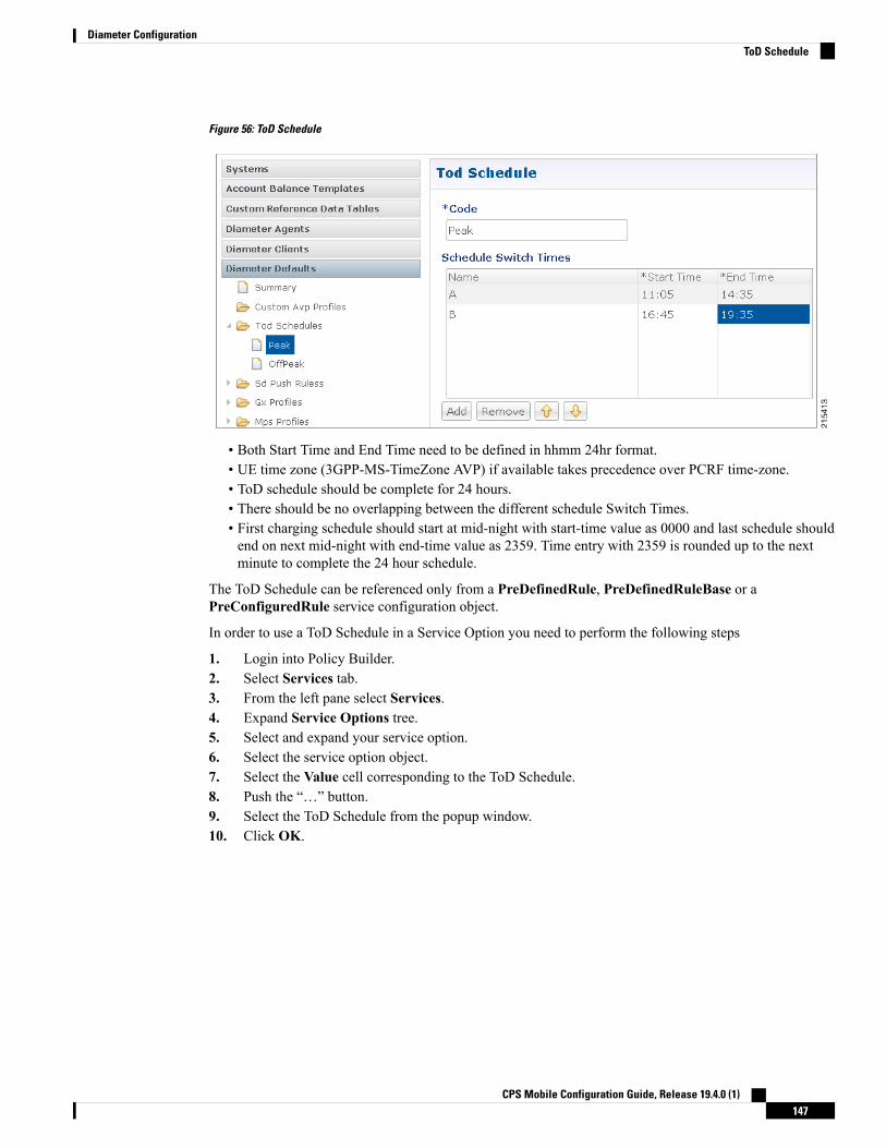
Figure 56: ToD Schedule
• Both Start Time and End Time need to be defined in hhmm 24hr format.• UE time zone (3GPP-MS-TimeZone AVP) if available takes precedence over PCRF time-zone.• ToD schedule should be complete for 24 hours.• There should be no overlapping between the different schedule Switch Times.• First charging schedule should start at mid-night with start-time value as 0000 and last schedule shouldend on next mid-night with end-time value as 2359. Time entry with 2359 is rounded up to the nextminute to complete the 24 hour schedule.
The ToD Schedule can be referenced only from a PreDefinedRule, PreDefinedRuleBase or aPreConfiguredRule service configuration object.
In order to use a ToD Schedule in a Service Option you need to perform the following steps
1. Login into Policy Builder.2. Select Services tab.3. From the left pane select Services.4. Expand Service Options tree.5. Select and expand your service option.6. Select the service option object.7. Select the Value cell corresponding to the ToD Schedule.8. Push the “…” button.9. Select the ToD Schedule from the popup window.10. Click OK.
CPS Mobile Configuration Guide, Release 19.4.0 (1)147
Diameter ConfigurationToD Schedule

Figure 57: ToD Schedule - Service Option
For more details about how to define a service option refer to Services, on page 223.
Sd Push RulesThis section supports the Sd solicited reporting scenario when the TDF-Information grouped AVP is not sentfrom the PCEF to the PCRF in a Gx CCR-i. For more information on Sd solicited reporting refer to 3GPP TS29.212.Figure 58: Sd Push Rules
The following parameters can be configured under Sd Push Rules:
Table 62: Sd Sync Mode
DescriptionParameters
Select to enable TSR in sync mode.Sync TSR
CPS Mobile Configuration Guide, Release 19.4.0 (1)148
Diameter ConfigurationSd Push Rules
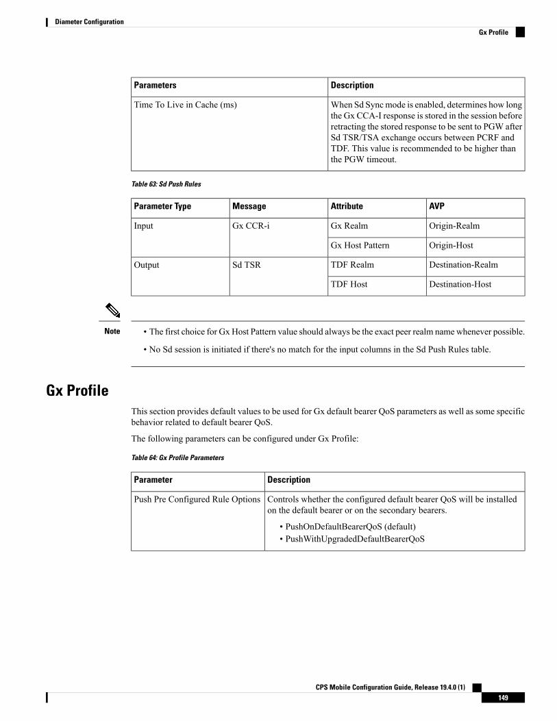
DescriptionParameters
When Sd Syncmode is enabled, determines how longthe Gx CCA-I response is stored in the session beforeretracting the stored response to be sent to PGW afterSd TSR/TSA exchange occurs between PCRF andTDF. This value is recommended to be higher thanthe PGW timeout.
Time To Live in Cache (ms)
Table 63: Sd Push Rules
AVPAttributeMessageParameter Type
Origin-RealmGx RealmGx CCR-iInput
Origin-HostGx Host Pattern
Destination-RealmTDF RealmSd TSROutput
Destination-HostTDF Host
• The first choice for Gx Host Pattern value should always be the exact peer realm namewhenever possible.
• No Sd session is initiated if there's no match for the input columns in the Sd Push Rules table.
Note
Gx ProfileThis section provides default values to be used for Gx default bearer QoS parameters as well as some specificbehavior related to default bearer QoS.
The following parameters can be configured under Gx Profile:
Table 64: Gx Profile Parameters
DescriptionParameter
Controls whether the configured default bearer QoS will be installedon the default bearer or on the secondary bearers.
• PushOnDefaultBearerQoS (default)• PushWithUpgradedDefaultBearerQoS
Push Pre Configured Rule Options
CPS Mobile Configuration Guide, Release 19.4.0 (1)149
Diameter ConfigurationGx Profile

DescriptionParameter
Allows for a default APN name to be defined. This APN name is goingto be further used as an input into the AF Application Id Validationfeature described below. The APN value will be set based on theavailable data and the priorities described below.
• 1 - A policy derived AVP having the same value as the LogicalApn
• 2 - Called-Station-Id AVP from incoming Rx AAR• 3 - Called-Station-Id AVP from Gx session
Logical Apn
Gx client names that are allowed not to have a default bearer QoSinstalled. In case a default bearer QoS has not been configured in thepolicy and the Gx client name has not been added to this list an errorresponse will be sent to the PCEF containing the Result-Code AVPvalueDIAMETER_ERROR_BEARER_NOT_AUTHORIZED(5143).
Gx Client QoS Exclusion List
Controls whether the requested QoS should be granted or not as thedefault bearer QoS.
Default value is unchecked.
Grant Requested QoS
If this option is selected then the requested QoS should be granted evenif the global QoS is provisioned. There are three type of QoS first istaken from service second is from default QoS and third one is fromrequest. If this flag is checked then requested QoS will take priorityover default QoS.
Default value is unchecked.
Grant Requested Qos Over GlobalQos
Global Default Granted QoS
The QoS class identifier identifies a set of IP-CAN specific QoSparameters that define QoS excluding the applicable bitrates and ARP.It is applicable both for uplink and downlink direction. The QCI values0 10 – 255 are divided for usage as follows
• 0 - Reserved• 10-127 - Reserved• 128-254 - Operator specific• 255 - Reserved
Qci
It defines the maximum bit rate allowed for the uplink direction.Max Req Bandwidth UL
It defines the maximum bit rate allowed for the downlink direction.Max Req Bandwidth DL
It defines the guaranteed bit rate allowed for the uplink direction.Guaranteed Bit Rate UL
It defines the guaranteed bit rate allowed for the downlink direction.Guaranteed Bit Rate DL
It defines the total bandwidth usage for the uplink direction of non-GBRQCIs at the APN.
Apn Agg Max Bit Rate UL
CPS Mobile Configuration Guide, Release 19.4.0 (1)150
Diameter ConfigurationGx Profile

DescriptionParameter
It defines the total bandwidth usage for the downlink direction ofnon-GBR QCIs at the APN.
Apn Agg Max Bit Rate DL
When selected, pending policy calculation is enabled for one look aheadin advance.
Default value is unchecked.
Enable Pending Policy Evaluation
ARPSelect the Arp type from the drop-down list to open parameters for the corresponding selection. ARP is usedto indicate the priority of allocation and retention.
The following parameters can be configured under Arp:
CPS Mobile Configuration Guide, Release 19.4.0 (1)151
Diameter ConfigurationARP

Table 65: ARP Parameters
DescriptionParametersSelection
The priority level is used to decide whether a bearer establishment ormodification request can be accepted or needs to be rejected in case ofresource limitations (typically used for admission control of GBR traffic).The AVP can also be used to decide which existing bearers to pre-emptduring resource limitations. The priority level defines the relativeimportance of a resource request. Values 1 to 15 are defined with value1 as the highest level of priority.
• Values 1 to 8 - assigned for services that are authorized to receiveprioritized treatment within an operator domain.
• Values 9 to 15 - Can be assigned to resources that are authorizedby the home network and thus applicable when a UE is roaming.
Priority LevelAllocationRetentionPriority
If it is provided within the QoS-Information AVP the AVP defineswhether a service data flow can get resources that were already assignedto another service data flow with a lower priority level. If it is providedwithin the Default-EPS-Bearer-QoS AVP the AVP defines whether thedefault bearer can get resources that were already assigned to anotherbearer with a lower priority level.
• 0 This value indicates that the service data flow or bearer is allowedto get resources that were already assigned to another service dataflow or bearer with a lower priority level.
• 1 This value indicates that the service data flow or bearer is notallowed to get resources that were already assigned to anotherservice data flow or bearer with a lower priority level. This is thedefault value applicable if this AVP is not supplied.
PreemptionCapability
If it is provided within the QoS-Information AVP the AVP defineswhether a service data flow can lose the resources assigned to it in orderto admit a service data flow with higher priority level. If it is providedwithin the Default-EPS-Bearer-QoS AVP the AVP defines whether thedefault bearer can lose the resources assigned to it in order to admit apre-emption capable bearer with a higher priority level.
• 0 This value indicates that the resources assigned to the service dataflow or bearer can be pre-empted and allocated to a service dataflow or bearer with a higher priority level. This is the default valueapplicable if this AVP is not supplied.
• 1 This value indicates that the resources assigned to the service dataflow or bearer shall not be pre-empted and allocated to a servicedata flow or bearer with a higher priority level.
PreemptionVulnerability
CPS Mobile Configuration Guide, Release 19.4.0 (1)152
Diameter ConfigurationARP

DescriptionParametersSelection
It contains information that identifies the particular service that the AFservice session belongs to. This information may be used by the PCRFto differentiate QoS for different application services.
You can specify regular expressions for this parameter as needed.
AF ApplicationIdentifier Pattern
ApplicationQoS Policy
Applicable Media-Type (session level or specific toMedia-Component-Description). The list includes Audio Video DataApplication Control Text Message and Other.
Media Type
The Reservation Priority includes the priority value of the related priorityservice. The Reservation Priority is populated with a default value if thepriority value is unknown.
ReservationPriority
ReservationPriority QoSPolicy
The QoS class identifier identifies a set of IP-CAN specific QoSparameters that define QoS excluding the applicable bit rates and ARP.It is applicable both for uplink and downlink direction. The QCI values0 10 – 255 are divided for usage as follows:
• 0 Reserved• 10-127 Reserved• 128-254 Operator specific• 255 Reserved
QciBase MPSQoS/BaseMPSQoS Gx
TheMPS Id contains the national variant forMPS service name indicatingan MPS session.
MPS IdMPS QoS
Applicable Media-Type (session level or specific toMedia-Component-Description). Select from drop-down list. The listincludes Audio Video Data Application Control TextMessage and Other.
Media Type
Relaxed USAGE_REPORT Event-Trigger HandlingUse this checkbox to enable the functionality for supporting old event-trigger value (26) for the usage report.This configuration will be applicable only when CPS is configured to use R10 event-trigger values byunchecking the 'Use V9 Event Trigger Mapping' flag in Diameter Configuration.
Peers using Event-Trigger value (26) for USAGE_REPORT
The following table contains the list of realm and host entries for which CPS will support old event-triggervalue (26) for USAGE_REPORT.
The parameters can be configured under Relaxed USAGE_REPORT Event-Trigger Handling:
Table 66: Relaxed USAGE_REPORT Event-Trigger Handling Parameters
DescriptionParameter
The pattern that peer realm name should match in order for this diameter client tobe used.
The pattern needs to follow the standard Java regular expression syntax describedhere.
Realm Pattern
CPS Mobile Configuration Guide, Release 19.4.0 (1)153
Diameter ConfigurationRelaxed USAGE_REPORT Event-Trigger Handling

DescriptionParameter
Host name pattern as received in Origin-Host AVP in AAR message. The patternneeds to follow standard Java pattern conventions. The pattern needs to follow thestandard Java regular expression syntax described here.
Host Pattern
QoS Retry on APN-AMBR_FAILURE_MODIFICATIONUse this check box to receive APN-AMBR_FAILURE_MODIFICATION events from PCEF.
The following parameters can be configured underQoS retry onAPN-AMBR_FAILURE_MODIFICATION:
Table 67: QoS retry on APN-AMBR_FAILURE_MODIFICATION Parameters
DescriptionParameter
Number of retries to push calculated QoS information.Number Of Retry
In the caseGGSN sendsAPN-AMBR_FAILURE_MODIFICATION reportto CPS, following are the retry options in which CPS sends the QoSinformation:
• Immediate Retry: CPS calculates QoS based on the configured policyand sends it immediately in a CCA message.
• Delayed Retry: CPS responds to CCA-Uwithout any QoS informationunless there is difference between the current derived QoS andpreviously sent QoS. CPS sends the QoS information in the next RARor CCA-U message.
QoS Retry Options
CPS retries sending the QoS information "n” times, to avoid looping. Afterexhaustion of the retries, following are the options:
• Continue Session: CPS does not send same QoS information insubsequent CCA-U message unless there is a difference between thecurrent calculated QoS and previously sent QoS.
• Terminate Session: CPS sends RAR with Release Cause value asUNSPECIFIED_REASON after the time configured in Time ToTrigger Release RAR expires. On receiving CCR-T, CPS terminatesthe session.
Action On QoS Retry Exhaust
CPS sends RAR with Release Cause value as UNSPECIFIED_REASONafter the time configured in Time To Trigger Release RAR expires.
Time To Trigger Release RARIn Minutes
Once CPS receives APN-AMBR_FAILURE_MODIFICATION, CPS setsnext reset timer to value configured in Time to Reset QoS Retry Counter.If CPS does not receive APN-AMBR_FAILURE_MODIFICATIONwithinthis specified time, CPS resets the retry count to 0.
Time To Reset QoS RetryCounter In Minutes
CPS Mobile Configuration Guide, Release 19.4.0 (1)154
Diameter ConfigurationQoS Retry on APN-AMBR_FAILURE_MODIFICATION

MPS ProfileThis section provides default values to be used if MPS feature is needed to support eMPS priority. The MPSProfile providesMPS attributes required for priority service provisioning. The priority level value from Serviceconfiguration takes precedence over MPS Profile value.
There must be at least one Mps Profile defined underMps Profiles.Note
Figure 59: MPS Profile
The following parameters can be configured underMps Profile:
Table 68: MPS Profile Parameters
DescriptionParameter
List of IMS APNs for which the MPS feature issupported.
This field can accommodate several Ims Apn that areused to match with the incoming service request forpriority service. The values that are received by theDefault Bearer QoS are looked up for a suitable ImsApn match. If the APN value of a Gx session requestmatches IMSAPN IMS signaling priority fromEMPSservice is used as priority level.
Ims Apn
CPS Mobile Configuration Guide, Release 19.4.0 (1)155
Diameter ConfigurationMPS Profile

DescriptionParameter
For information on parameters under Mps QoS referto ARP Parameters.
Mps QoS
For additional information on 3GPP specifications refer to http//www.3gpp.org/DynaReport/29212.htm.
The above link is compliant with Release 11.
Rx ProfileThis section provides default and specific values to be used by the different QoS parameter mapping functionsat PCRF as per 3GPP TS 29.213. This section also provides a mechanism to authorize the Rx IMS sessions.
Basic OptionsPrefer answer Codec-Data: Select Prefer answer Codec-Data if you want the default priority to be givento the answer codec (when both answer and offer are present within the AAR). By default, this option isunchecked (not selected).
Disable Always On EMPS Service: If the checkbox is selected, then the featureAlways On EMPS Servicegets disabled otherwise the feature works by default (when the checkbox is not selected).
Disable Downgrade of Normalised ARP and QCI: If this checkbox is selected, the Normalised ARP andQCI is not downgraded till all the Rx sessions terminate. By default, this option is not selected.
If this checkbox is not selected, the Normalised ARP and QCI is downgraded when RxSession with PriorityARP terminates.
Default QoS Policy
Provides the values to be used during the derivation of the Maximum Authorized Data Rates AuthorizedGuaranteed Data Rates MaximumAuthorized QoS Class per IP flow or bidirectional combination of IP flowsin the PCRF and for calculating the MaximumAuthorized/Guaranteed Data Rates QCI and ARP in the PCRFwhenever the “as set by the operator” phrase is used in the algorithm description.
For description of different parameters under Default QoS Policy refer to Table 64: Gx Profile Parameters,on page 149.
Rx Sync Mode
The following tables describes parameters under the Rx Sync Mode:
Table 69: Rx Sync Mode Parameters
DescriptionParameters
Select to enable AAR in sync mode.Sync AAR
Select to enable STR in sync mode.Sync STR
CPS Mobile Configuration Guide, Release 19.4.0 (1)156
Diameter ConfigurationRx Profile

DescriptionParameters
When Rx Syncmode is enabled, determines how longthe Rx AAR/STR response is stored in the sessionbefore retracting the stored response to be sent towardsPCSCF after GxRAR/RAA exchange occurs betweenPGW and PCRF. This value is recommended to behigher than the PCSCF timeout.
Time To Live in Cache Millis
MPS QoS Policy
Provides a way to derive QoS attributes for MPS sessions based on some other AVP values.
For description of different parameters under MPS QoS Policy refer to Table 65: ARP Parameters, on page152.
A Media-Type having an empty label shall be used only to get the output values to be used for default bearerQoS.
Note
Application QoS Policy
Provides a way to derive Rx dedicated bearers QoS attributes based on AF-Application-Identifier AVP valueas per 3GPP TS 29.213.
For description of different parameters under Application QoS Policy refer to Table 64: Gx Profile Parameters,on page 149 and Table 65: ARP Parameters, on page 152.
Codec QoS Policy
Provide a way to derive Rx dedicated bearers QoS attributes based on Codec-Data AVP value as per 3GPPTS 29.213.
For description of different parameters under Codec QoS Policy refer to Table 64: Gx Profile Parameters, onpage 149 and Table 65: ARP Parameters, on page 152.
The additional parameters Codec Data Pattern and Codec Details Pattern contains codec related informationknown at the AF. This information is encoded as per 3GPP 29.214 specifications
The first line of the value of the Codec-Data AVP consists of either the word uplink or the word downlink
(in ASCII) followed by a new-line character. The semantics of these words are the following:
• uplink indicates that the SDP was received from the UE and sent to the network.
• downlink indicates that the SDP was received from the network and sent to the UE.
The second line of the value of the Codec-Data AVP consists of either the word offer, the word answer, orthe word description.
The rest of the value consists of the SDP line(s) in ASCII encoding separated by new-line characters, asspecified in IETF RFC 4566. The first of these line(s) is an m line. The remaining lines are any available SDPa and b lines related to that m line.
Restrictions
• You should not configure 'Codec QoS Policy' table with ambiguous entry. If multiple rows are configuredwhich matches same 'Codec-Data' and 'Codec-Details' values then CPS will fetch first matched row.
CPS Mobile Configuration Guide, Release 19.4.0 (1)157
Diameter ConfigurationBasic Options

• Codec-Data column value is mandatory in Policy Builder configuration while adding entry in the 'CodecQoS Policy' table.
• CPS considers the first Codec-Data AVP if AAR request has multiple 'Codec-Data' AVPs.
• By default, CPS uses the first Codec-Data AVP with offer or answer on the second line if the AARrequest has multiple Codec-Data AVPs. If Prefer Answer is set to true, CPS uses the first Codec-DataAVP with answer on the second line, or the first Codec-Data AVP with offer if there is no Codec-DataAVP with answer.
• CPS considers only the first media format in the m= line.
• You should configure the 'Codec Data Pattern' and 'Codec Details Pattern' column values with wildcardsas per the standard Java regular expression syntax described at the link.
CPS supports leading middle and trailing wildcards. Multiple wildcards shouldbe possible in a single string. The following sections provides few examples onhow to configure the wildcards).
Important
• Case sensitivity is supported for both 'Codec Data Pattern' and 'Codec Details Pattern' columns so youshould provide the values accordingly.
If multiple Codec-Data AVPs are reported in multiple AAR messages for a single Rx session then CPS willconsider the first Codec-Data AVP value received in first AAR message for selecting QoS policies.
For example:
1. Codec Data value used as the search key in this table is the 4th group (of numbers) from the 3rd line ofthe Codec-Data AVP string value.
In the example below only the value 116 is going to be used as a search key in the Codec QoS Policytable.uplinkofferm=audio 50000 RTP/AVP 116 107 97 115 111 110a=rtpmap116 AMR-WB/16000a=rtpmap107 AMR-WB/16000a=rtpmap97 AMR/8000a=rtpmap115 AMR/8000a=rtpmap111 telephone-event/16000a=rtpmap110 telephone-event/8000a=currqos local nonea=currqos remote nonea=desqos mandatory local sendrecva=desqos optional remote sendrecva=sendrecva=ptime20a=maxptime240
2. Only the first Codec-Data AVP value is used.3. You can configure Codec Details Pattern and Codec Data Pattern columns with wildcards as per java
regular expressions (for example, .* $, and so on) so that CPS can compare the AVP values with thisregex and fetch the appropriate QoS values.
Example:
CPS Mobile Configuration Guide, Release 19.4.0 (1)158
Diameter ConfigurationBasic Options

Consider you want to configure “Codec Data Pattern 98" and “Codec Details Pattern AMR/8000”.
There are multiple combination you can configure. Some examples are given below :
With ExactMatch:
• Codec Data Pattern 98 Codec Details Pattern AMR/8000.• Codec Data Pattern 98 Codec Details Pattern <No value specified>, that is, null
With wildcards
• Codec Data Pattern .*8 Codec Details Pattern AM.*• Codec Data Pattern 9.* Codec Details Pattern .*80• Codec Data Pattern 9.* Codec Details Pattern AM.*80• Codec Data Pattern .* Codec Details Pattern ^AM.*80
AM.*80 indicates that String that has AM and any number characters and 80. It does not mean that stringshould start with AM and end with 80.
If you want to specify starting and ending characters explicitly then you should use '^' for starting (say^77 value should start with 77) and '$' for ending (say AM.*80$ value should end with 80); you shouldconfigure the 'Codec Data Pattern' and 'Codec Details Pattern' column as per the standard Java regularexpression syntax.
Suppose you configure multiple rows matching the same values; for example, as shown in the followingfigure, both rows can be matched with values “Codec-Data 98 and Codec-Details AMR/8000." In thiscase, CPS will select the first matched row.Figure 60: Codec QoS Policy
Reservation Priority QoS Policy
Provides a way to derive Rx dedicated bearers QoS attributes based on Reservation-Priority AVP value asper 3GPP TS 29.213.
For description of different parameters under Reservation Priority QoS Policy refer to Table 64: Gx ProfileParameters, on page 149 and Table 65: ARP Parameters, on page 152.
Af Application Id Validation
Provides a way to authorize the Rx IMS sessions. In case there's not a match between the AVP values belowin the table the PCRF shall send an error response to the AF containing the Experimental-Result-Code AVPwith value REQUESTED_SERVICE_NOT_AUTHORIZED (5063) as per 3GPP TS 29.214.
AVP ValueInterface
Refer to Logical APN attribute under Gx Profile, onpage 149.
Gx
CPS Mobile Configuration Guide, Release 19.4.0 (1)159
Diameter ConfigurationBasic Options

AF-Application-IdentifierRx
Media-Type
• Called-Station-Id AVP value is retrieved from the Gx session the Rx session binds to.• If the incoming Rx AAR message contains multiple flows having different AF-Application-IdentifierAVP value or Media-Type AVP value and any of these flows is not authorized than the PCRF shall sendan error response as described above.
• If no AF-Application-Identifier AVP is present in the incoming request the validation is skipped.
Note
Advanced OptionsYou can get access to these features by creating child objects to your Rx profile object.
There should be at least one object of each type for any Rx profile object or the results will be unpredictable.The Policy Builder GUI does not enforce this restriction though.
Note
Sponsored Data Charging Parameters
The Sponsored Data Charging Parameters allows you to configure specific charging parameters for theSponsored Data scenarios depending on some AVPs from the incoming Rx AAR. These parameters are goingto be set under Charging-Rule-Definition grouped AVP.
The required charging parameters are as follows:
• Rating-Group• Reporting-Level• Online• Offline• Metering-Method
To map the above mentioned parameters the following keys are used:
• Sponsor-Id• Application-Service-Provider-Identity• Media Type
These keys are applicable for Sponsored Data Charging Parameters only.
Themapping configuration for the charging parameters is configured underPolicy Builder >Reference Datatab > Diameter Defaults > Rx Profile.
CPS Mobile Configuration Guide, Release 19.4.0 (1)160
Diameter ConfigurationAdvanced Options

Figure 61: Sponsor Data Charging
In the Sponsor Data Charging table, you can define the parameter values in all the columns including thevalues for the key parameters such as - Sponsor Identity App Service Provider Identity and Media Type.
Default Sponsor Data Charging
Defines the default values for the sponsor data charging parameters under Charging-Rule-Definition groupedAVP to be used in case there's no match in the Sponsor Data Charging. This configuration is optional. Defaultvalue is unchecked.
The following parameters can be configured under Sponsor Data Charging:
Table 70: Sponsor Data Charging Parameters
DescriptionParameter
The identity of the service or service component the service data flow in aPCC rule relates to.
Service Identifier
The charging key for the PCC rule used for rating purposes.Rating Group
It defines whether the online charging interface from the PCEF for theassociated PCC rule is enabled. The default charging method provided by theCPS takes precedence over any pre-configured default charging method at thePCEF.
• Enable This value is used to indicate that the online charging interfacefor the associated PCC rule is enabled.
• Disable This value is used to indicate that the online charging interfacefor the associated PCC rule is disabled.
Online
It defines whether the offline charging interface from the PCEF for theassociated PCC rule is enabled.The default charging method provided by theCPS takes precedence over any pre-configured default charging method at thePCEF.
• Enable This value is used to indicate that the offline charging interfacefor the associated PCC rule is enabled.
• Disable This value is used to indicate that the offline charging interfacefor the associated PCC rule is disabled.
Offline
CPS Mobile Configuration Guide, Release 19.4.0 (1)161
Diameter ConfigurationAdvanced Options

DescriptionParameter
The Metering-Method AVP (AVP code 1007) is of type Enumerated and itdefines what parameters shall be metered for offline charging. The PCEFmayuse the AVP for online charging in case of decentralized unit determinationand having three values
• DURATION (0) This value shall be used to indicate that the duration ofthe service data flow shall be metered.
• VOLUME (1) This value shall be used to indicate that volume of theservice data flow traffic shall be metered.
• DURATION_VOLUME (2) This value shall be used to indicate that theduration and the volume of the service data flow traffic shall be metered.
Metering Method
The Reporting-Level AVP is of type Enumerated and it defines on what levelthe PCEF reports the usage for the related PCC rule.There are three types ofreporting levels
• SERVICE_IDENTIFIER_LEVEL (0) This value shall be used to indicatethat the usage shall be reported on service id and rating group combinationlevel and is applicable when the Service-Identifier and Rating-Grouphave been provisioned within the Charging-Rule-Definition AVP andRating-Group AVP have been provisioned within theCharging-Rule-Definition AVP. Applicable for offline charging.
• RATING_GROUP_LEVEL (1) This value shall be used to indicate thatthe usage shall be reported on rating group level and is applicable whenthe Rating-Group has been provisioned within theCharging-Rule-Definition AVP and Rating-Group AVP have beenprovisioned within the Charging-Rule-Definition AVP. Applicable foroffline charging.
• SPONSORED_CONNECTIVITY_LEVEL (2) This value shall be usedto indicate that the usage shall be reported on sponsor identity and ratinggroup combination level and is applicable when the Sponsor-IdentityAVPApplication-Service-Provider-Identity AVP and Rating-Group AVP havebeen provisioned within the Charging-Rule-Definition AVP. Applicablefor offline charging.
Reporting Level
This determines the order in which the service data flow templates are appliedat service data flow detection at the PCEF. A PCC rule with the PrecedenceAVP with lower value shall be applied before a PCC rule with the PrecedenceAVP with higher value.
Precedence
Sponsor-Identity AVP value under the Sponsored-Connectivity-Data groupedAVP.
Sponsor Identity
App Service Provider Id is same as Sponsor-Identity. It is an AVP under theSponsored-Connectivity-Data grouped AVP.
App Service Provider
Applicable Media-Type (session level or specific toMedia-Component-Description). Select from drop-down list. The list includesAudio Video Data Application Control Text Message and Other.
Media Type
CPS Mobile Configuration Guide, Release 19.4.0 (1)162
Diameter ConfigurationAdvanced Options
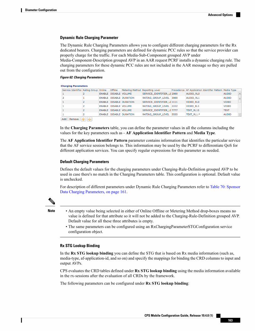
Dynamic Rule Charging Parameter
The Dynamic Rule Charging Parameters allows you to configure different charging parameters for the Rxdedicated bearers. Charging parameters are defined for dynamic PCC rules so that the service provider canproperly charge for the traffic. For each Media-Sub-Component grouped AVP underMedia-Component-Description grouped AVP in an AAR request PCRF installs a dynamic charging rule. Thecharging parameters for these dynamic PCC rules are not included in the AAR message so they are pulledout from the configuration.Figure 62: Charging Parameters
In the Charging Parameters table, you can define the parameter values in all the columns including thevalues for the key parameters such as - AF Application Identifier Pattern andMedia Type.
The AF Application Identifier Pattern parameter contains information that identifies the particular servicethat the AF service session belongs to. This information may be used by the PCRF to differentiate QoS fordifferent application services. You can specify regular expressions for this parameter as needed.
Default Charging Parameters
Defines the default values for the charging parameters under Charging-Rule-Definition grouped AVP to beused in case there's no match in the Charging Parameters table. This configuration is optional. Default valueis unchecked.
For description of different parameters under Dynamic Rule Charging Parameters refer to Table 70: SponsorData Charging Parameters, on page 161.
• An empty value being selected in either of Online Offline or Metering Method drop-boxes means novalue is defined for that attribute so it will not be added to the Charging-Rule-Definition grouped AVP.Default value for all these three attributes is empty.
• The same parameters can be configured using an RxChargingParameterSTGConfiguration serviceconfiguration object.
Note
Rx STG Lookup Binding
In the Rx STG lookup binding you can define the STG that is based on Rx media information (such as,media-type, af-application-id, and so on) and specify the mappings for binding the CRD columns to input andoutput AVPs.
CPS evaluates the CRD tables defined underRx STG lookup binding using the media information availablein the rx-sessions after the evaluation of all CRDs by the framework.
The following parameters can be configured under Rx STG lookup binding:
CPS Mobile Configuration Guide, Release 19.4.0 (1)163
Diameter ConfigurationAdvanced Options

Table 71: Rx STG lookup binding Parameters
DescriptionParameter
The name of the Rx STG lookup binding.Name
Reference to the Search Table Group containing theCRD tables that defines parameters for Rx specificmedia information.
Stg Reference
Defines the mapping between the AVP Names andthe key Columns defined in the selected STG. TheseAVPs are inputs while evaluating the CRD table inSTG.
• Avp Name: Name of the diameter AVP (receivedin Media Component Description AVP of theAAR message) which is to be used as input forCRD table evaluation. For example,Media-Type,AF-Application-Identifier, and so on.
• Column: Reference to the key column in STGcorresponding to the specified AVP.
List Of Input Column Avp Pairs
Defines the mapping between the AVP Names andthe output columns defined in the STG selected. Thesemapping indicate how the output column's values aremapped to AVPs after the CRD is evaluated.
• Avp Name: The name/code of the Rx CRDAVPthat is created for the output column. The RxCRD AVP stores the information related to themedia (media-type, mcd number, rx-session-id,and so on). There are multiple such AVPs withsame code for the evaluated MCDs.
• Column: Reference to the output column definedin the STG selected.
List Of Output Column Avp Pairs
Evaluation of STGs defined in Rx STG lookup binding (evaluated for each media in the Rx session) createsmultiple Rx CRD result AVP for each configured output column. Along with the code and CRD outputvalue, this result AVP also stores themedia component details such as,Media-Component-Number,Media-Typeand Rx session-id. This information can be used for creating conditions (for example, An Rx CRD result Avpexists).
Rule Retry ProfilesCPS can be configured to selectively re-attempt to install rules that fail to install or activate. Upon receipt ofa Charging-Rule-Report indicating the failure to install or activate one or more rules CPS will evaluate thefailed rules and take further action.
CPS Mobile Configuration Guide, Release 19.4.0 (1)164
Diameter ConfigurationRule Retry Profiles

CPS decides whether to reinstall a failed rule based on the Rule Retry Profile configured for the rule. Theconfiguration of this Rule Retry behavior takes place in the Rule Retry Profile screen in Policy Builder.
• CPS will not re-attempt to install a failed rule unless the rule has a Rule Retry Profile associated with it.If no Rule Retry Profile is configured the rule status and failure code are updated immediately and noattempt to install the rules is made. This is the default behavior.
• If the Rule Retry Profile is configured but the reported rule failure code does not match any of the failurecodes defined in the associated Rule Retry Profile the rule status and failure code are updated immediatelyand no attempt to install the rules is made regardless of the status of the other parameters.
• The rule status is not updated until the last retry fails.
Create a Rule Retry Profile
Step 1 Login to Policy Builder.Step 2 Go to Reference Data > Rule Retry Profiles.Step 3 From the right pane, click Rule Retry Profile under Create Child to open a Rule Retry Profile.
The following parameters can be configured for each Rule Retry Profile:
Table 72: Rule Retry Profile Parameters
DescriptionParameter
The number of seconds to wait before retrying to install a rule. See also BackoffAlgorithm parameter.
Default: 10 seconds
If the value is less than 15 seconds, then the retries are scheduled atsecond level granularity. If the value is greater than 15 seconds, thengranularity is in minutes. For example, if the interval is configuredas 30 seconds, the timer may expire within 30 sec + 1 minapproximately.
Note
Retry Interval
The maximum number of retry attempts to make. When CPS reaches thismaximum retry value without successfully installing the rule the rule statusand failure code are updated immediately and no further attempts are made toinstall the rule.
Note This value does not include the initial installation attempt that is reportedas failed but only the subsequent attempts.
Default: 3
Max Retry Attempts
The algorithm to be used for calculating the time between retries.
CONSTANT_INTERVAL Each retry is scheduled after an interval equal toRetry Interval seconds since the last report.
LINEAR_INTERVAL Each retry is scheduled after an interval equal to RetryInterval x Current Attempt Number seconds since the last report.
Default: CONSTANT_INTERVAL
Backoff Algorithm
CPS Mobile Configuration Guide, Release 19.4.0 (1)165
Diameter ConfigurationCreate a Rule Retry Profile

DescriptionParameter
Select the failure codes for which CPS retries as specified in 3GPP TS29.212v11.10 Section 5.3.38 Rule-Failure-Code AVP.
Click Add then select one or more failure codes from the drop down menu.Click Add to include them to the list. Click OK when you are done.
If no Rule Failure Code is specified, then CPS retries regardless of the failurecode reported.
Rule Failure Code
Enter a unique name for this Rule Retry Profile.
This name is used to associate Rules to this Rule Retry Profile.
Name
Enter the maximum time in seconds between the first and the last retry.
If set to zero, the PCRF does not enforce a time limit for sending the retrymessages.
Default: 0 (zero)
Max Retry Interval
When a Cisco-CC-Failure-Type AVP is received to report Gy failure, CPSmatches the Cisco-CC-Failure-Type AVP value in the diameter messageCCR-Update with the Cisco Event Failure Code for the rule. If the valuematches, then CPS retries the rule. Cisco Event Failure Code supports all valuesof type Unsigned32 from PGW.
The following are some examples values for the Cisco Event Failure code:
• 0 - CC_CONNECTION_FAILURE
• 1 - CC_RESPONSE_TIMEOUT
• 3* - 3xxx Protocol Error result-codes (For example, 3004 -DIAMETER_TOO_BUSY)
• 4* - 4xxx Transient Failure result-codes (For example, 4002 -DIAMETER_OUT_OF_SPACE)
• 5* - 5xxx Permanent Failure result-codes (For example, 5001 -DIAMETER_AVP_UNSUPPORTED)
For more information on codes, refer to RFC 3588.
Cisco Event Failure code
This check box is used to configure profiles based on failure codes.
By default, this checkbox is not selected.
For more information, refer to Profile Based On Failure Code, on page 167.
Enable Profiles Based On Failure Code
If there is still time to retry a rule installation (First Retry Time + Max Retry Interval <= Current Time) then the rulestatus and failure code are not updated immediately such that no policy change based on rule failure status is triggered.
CPS Mobile Configuration Guide, Release 19.4.0 (1)166
Diameter ConfigurationCreate a Rule Retry Profile

Profile Based On Failure CodeThis table is used to override the attributes Retry Interval, Backoff Algorithm, Max retry Attempts, and MaxRetry Interval of generic profile which is already available.
CPS uses the following columns to select a row from this table:
• Cisco Event Failure Code
• Rule Failure Code
• Sy Realm
• Cisco Event Failure Code or Rule Failure Code column value is mandatory to select the row. If both hasNull values, then CPS ignores that row.
• If Sy session exist, then only CPS considers Sy Realm column value. There is no need to add a value ifyou do not want to consider SyRealm.
• If there is no value configured for Retry Interval, Backoff Algorithm,Max retry Attempts, andMax RetryInterval columns for a selected row in the table then CPS sets those attributes with already existing fieldvalues present under generic Rule Rety Profile.
Note
Sy Realm Value
This parameter is used to derive SyRealm from CRD. User has to select CRD output column so that SyRealmvalue is pulled from the CRD table. If there is no Sy realm value derived from this field, then CPS tries to getthe realm information from local Sy session.
The CRD output column values takes precedence over local Sy session.
Associate a Rule Retry Profile with a RuleEach type of Service Configuration Object Rule in CPS (PreDefinedRule PreDefinedRuleBasePreConfiguredRule) can be associated with the Rule Retry Profile created in the previous section.
Step 1 In Policy Builder select the Services tab.Step 2 From the left pane select Services.Step 3 Expand Service Options tree.Step 4 Select and expand your service option.Step 5 Select the service option object.Step 6 In the Service Option screen select the Service Configuration object. A Rule Retry Profile can be referenced only from
a PreDefinedRule, PreDefinedRuleBase or a PreConfiguredRule service configuration object.Step 7 Select the Value cell corresponding to the Retry Profile.Step 8 Click the “…” button.Step 9 Select the Rule Retry Profile from the popup window then click OK.Step 10 Click OK.
CPS Mobile Configuration Guide, Release 19.4.0 (1)167
Diameter ConfigurationProfile Based On Failure Code

For more details about how to define a service option refer to Services chapter.
CPS Mobile Configuration Guide, Release 19.4.0 (1)168
Diameter ConfigurationAssociate a Rule Retry Profile with a Rule

C H A P T E R 5Interface Configuration
• Gx Interface Configuration, on page 169• Gy Interface Configuration, on page 171• Sy Interface Configuration, on page 173• Rx Interface Configuration, on page 178• Sd Interface Configuration, on page 181• Sh Interface Configuration, on page 185• LDAP/Ud Interface Configuration, on page 190
Gx Interface ConfigurationThis procedure describes how to create a Gx service in which the PCRF mirrors the QoS received from thePCEF/Gateway. When the PCRF receives a Credit-Control-Request (Initial) message, it sends the same QoSparameters back to the PCEF in the Credit-Control-Answer (Initial) message.
Step 1 Open Policy Builder, and select the Services tab.Step 2 In the left-hand pane, select Use Case Templates > Summary.Step 3 In the Summary pane, click Use Case Template under Create Child, and then do the following:
a) In the Name field, type MirrorQoS (using this name for example Use Case Template).b) Select Actions tab.c) Click Add under Service Configurations.
The Select Service Configuration dialog box opens, and all of the service configuration objects that are availableon the PCRF are listed.
d) Scroll down to the gx area in the list of service configuration objects, and select DefaultBearerQoS.e) Click OK.
The Select Service Configuration dialog box closes, and the DefaultBearerQoS object is displayed under ServiceConfigurations.
f) Click Add again under Service Configurations.g) In the Select Service Configuration dialog box, scroll down to the gx section, and selectDefaultBearerQoSActions.h) Click OK.
Now both added service configuration objects are displayed under Service Configurations pane.
Step 4 From the left-hand pane, select Services > Service Options.
CPS Mobile Configuration Guide, Release 19.4.0 (1)169
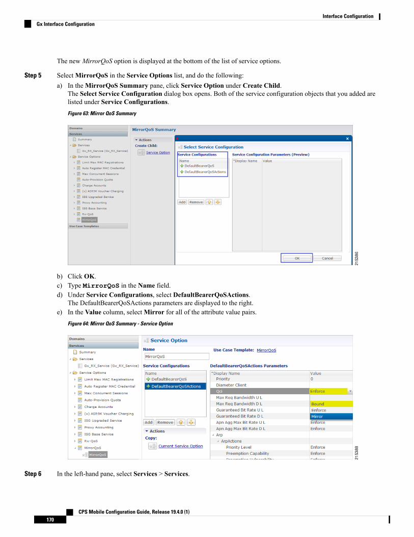
The newMirrorQoS option is displayed at the bottom of the list of service options.
Step 5 SelectMirrorQoS in the Service Options list, and do the following:a) In theMirrorQoS Summary pane, click Service Option under Create Child.
The Select Service Configuration dialog box opens. Both of the service configuration objects that you added arelisted under Service Configurations.Figure 63: Mirror QoS Summary
b) Click OK.c) Type MirrorQoS in the Name field.d) Under Service Configurations, select DefaultBearerQoSActions.
The DefaultBearerQoSActions parameters are displayed to the right.e) In the Value column, selectMirror for all of the attribute value pairs.
Figure 64: Mirror QoS Summary - Service Option
Step 6 In the left-hand pane, select Services > Services.
CPS Mobile Configuration Guide, Release 19.4.0 (1)170
Interface ConfigurationGx Interface Configuration

Step 7 In the Services Summary pane, click Service under Create Child, and do the following:a) Type a descriptive code for the MirrorQoS service in the Code field.b) Type MirrorQoS in the Name field.c) Uncheck the Balance Service option.d) Click Add.e) In the Select Service Configuration dialog box, select the MirrorQoS service option, and click OK.
Step 8 Select File > Publish to Runtime Environment.The new MirrorQoS service is now available to all Policy Server (QNS) nodes for processing.
Step 9 Verify that the newly created service is available for use by doing the following:a) Open the Control Center GUI and go to the Subscribers section.b) Click Create Subscriber.c) Enter the IMSI/MSISDN and the name of the subscriber, and then click Save & Continue.
Figure 65: Create Subscriber
d) Go to the Services section.e) Click the Add section, which lists the available services, and select the new MirrorQoS service.f) Click Save and run a test call to verify that the QoS parameters are mirrored by PCRF in Credit-Control-Answer(Initial)
message back to the PCEF.
Gy Interface ConfigurationThe Diameter Gy reference point is located between the OCS and the PCEF. The CPS supports using the Gyreference point for usage monitoring of the on-board OCS known as the Multi-service Balance Manager(MsBM) against a PCEF.
CPS uses the Gy RatingGroup Service Configuration Object within the Use Case Templates to hold theconfiguration parameters for Gy. The following procedure describes how to set up a Gy RatingGroup thatwill be sent upon a CCR-i request from the PCEF. The Gy RatingGroup service option would then be addedto a service along with a Gx rule or QoS.
For more information, see Gx Interface Configuration, on page 169 for details on how to create a valid Gxservice.
CPS Mobile Configuration Guide, Release 19.4.0 (1)171
Interface ConfigurationGy Interface Configuration

The following procedure is based on the ASR5K acting as the PCEF supporting the Enhanced ChargingService (ECS) mechanism for Gy “Pull” UsageMonitoring. The RatingGroup configuration for Gy will workin a similar method with any supported PCEF using the Gy interface.
Step 1 Open the Policy Builder GUI, and select the Services tab.Step 2 In the left-hand pane, select Use Case Templates > Summary.Step 3 In the Summary pane, click Use Case Template under Create Child, and then do the following:
a) In the Name field, type Gy.b) Select Actions tab.c) Click Add under Service Configurations.
The Select Service Configuration dialog box opens, and all of the service configuration objects that are availableon the PCRF are listed.
d) Scroll down to the gy area in the list of service configuration objects, and select RatingGroup.The Select Service Configuration dialog box closes, and the RatingGroup object is displayed under ServiceConfigurations.
Step 4 In the left-hand pane, select Services > Service Options.
The new Gy option is displayed at the bottom of the list of service options.
Step 5 Select Gy in the Service Options list, and do the following:a) In the Gy Summary pane, click Service Option under Create Child.
The Select Service Configuration dialog box opens. The RatingGroup service configuration object is listed underService Configurations.
b) Click OK.c) Type Gy in the Name field.d) Under Service Configurations, select RatingGroup.
The RatingGroup parameters display to the right.
The following table describes the parameters that are necessary to support the ASR5000 ECS Usage Monitoring fora volume quota service:
Table 73: RatingGroup Parameters
DescriptionParameter
Corresponds to a value configured on the ASR5000 that represents which data shouldbe monitored.
Rating Group
Rating Group Type supports one of two values either “volume” or “time”.RG Type
How much quota to initially give the client (in bytes).Dosage
Balance Code
In this example, we will use TERMINATE as the default Final Unit Action on quotadepletion, which will send a CCR-u with the final usage for the rating group. Otheroptions supported include NONE (no action taken) RESTRICT_ACCESS (send aRestriction Filter Rule and Filter ID) and REDIRECT (send a Redirect Address ofRedirect Address Type).
Final Unit Action
CPS Mobile Configuration Guide, Release 19.4.0 (1)172
Interface ConfigurationGy Interface Configuration

DescriptionParameter
Sets a session timer for the Gy quota grant; even if quota is not exhausted the PCEFmust check back in at the end of the validity time (in seconds).
Validity Time
PCEF will check back in with OCS when the Volume Quota Threshold has beenreached; value must be set as less than the overall Dosage (in bytes).
Volume Quota Threshold
The amount of time the quota should be available on the PCEF without activity fromthe user (in seconds)
Quota Holding Time
Idle traffic threshold time (in seconds); only used with time quota rating groups.Quota Consumption Time
Used in a shared quota use case in which the same account balance and rating groupcan be used within a shared group of users.
Default: false
Use Shared Bucket
Priority and Diameter Client do not need to be set. Priority can be used to set the priority for the RatingGroup ifmultiple RatingGroups are on a service.
Tariff Switch Model and Tariff Change Time are outside the scope of this document.
If Tariff Switch Model is not set, any value set in Tariff Change Time is ignored.Note
Step 6 Validate the Gy service configuration as follows:a) Create a new service in Policy Builder that contains a Gx rule service configuration and the Gy RatingGroup service
configuration.
The Gx rule must be a rule defined on the PGW that is associated with a Gy service to the CPS as the OCS.Note
b) Per the Gy pull model, when the PCEF receives the appropriate Gx rule, it initiates a CCR-i to the OCS, which willreply back with the RatingGroup service option values in a CCA.
c) Using tcpdump, verify that the CCA contains the appropriate values as defined in the RatingGroup.
Sy Interface ConfigurationThe Sy reference point is located between the Policy and Charging Rules Function (PCRF) and the OnlineCharging System (OCS). The Sy reference point enables the transfer of information relating to subscriberspending from OCS to PCRF and supports the following functions:
• Request of policy counter status reporting from PCRF to OCS• Notifications of policy counter status change from OCS to PCRF• Cancellations of policy counter status reporting from PCRF to OCS
Since the Sy interface resides between PCRF and OCS in the HPLMN, roaming with home routed or visitedaccess as well as non-roaming scenarios is supported in the same manner.
The following procedure describes how to subscribe to the OCS (Online charging system) counter statusupdates from the PRCF side by initiating a 'Spending Limit Request (SLR)' message:
CPS Mobile Configuration Guide, Release 19.4.0 (1)173
Interface ConfigurationSy Interface Configuration

Step 1 Open the Policy Builder GUI, and select the Services tab.Step 2 Create a Gx service as described in Gx Interface Configuration, on page 169.
Now you are ready to create an Sy service as described in the following steps.
Step 3 In the left-hand pane, select Use Case Templates > Summary.Step 4 In the Summary pane, click Use Case Template under Create Child, and then do the following:
a) In the Name field, type Sy.b) Select Actions tab.c) Click Add under Service Configurations.
The Select Service Configuration dialog box opens, and all of the service configuration objects that are availableon the PCRF are listed.
d) Scroll down to the sy area in the list of service configuration objects, and select SpendingLimitReport.e) Click OK.
The Select Service Configuration dialog box closes, and the SpendingLimitReport object is displayed underService Configurations.
Step 5 In the left-hand pane, select Services > Service Options.
The new Sy option is displayed at the bottom of the list of service options.
Step 6 Select Sy in the Service Options list, and do the following:a) In the Sy Summary pane, click Service Option under Create Child.
The Select Service Configuration dialog box opens. The SpendingLimitReport service configuration object islisted under Service Configurations.
b) Click OK.c) Type Sy in the Name field.d) Under Service Configurations, select SpendingLimitReport.
The SpendingLimitReport parameters display to the right.e) In the list of parameters, expand Subscriber Id (List) > SubscriberId parameter.
The Identifier parameter appears.f) Click in the Value column beside the Identifier parameter, and then click the ... button.
CPS Mobile Configuration Guide, Release 19.4.0 (1)174
Interface ConfigurationSy Interface Configuration

Figure 66: Identifier Parameter
A dialog box containing a list of identifiers opens.g) Select Session MSISDN in the list, and click OK. Based on your requirements, you can also use other identifiers
such as IMSI, and so on.Figure 67: Session MSISDN Identifier
h) Update theRealm parameter with the Sy peer realm (OCS Realm) where the message needs to be sent from PCRF.
In this configuration we are not specifying any counter name in the Identifier columns, which means that the PCRFsubscribes to all the counter statuses available on the OCS for the subscriber.
CPS Mobile Configuration Guide, Release 19.4.0 (1)175
Interface ConfigurationSy Interface Configuration

Figure 68: Realm Parameter
Step 7 In the left-hand pane, select Services > Services.Step 8 In the Services Summary pane, click Service under Create Child, and do the following:
a) Type a descriptive code for the Sy service in the Code field.b) Type Sy in the Name field.c) Uncheck the Balance Service option.d) Click Add.e) In the Select Service Configuration dialog box, select the Sy service option, and click OK.f) Click Add again, select the MirrorQoS service option, and click OK.
Figure 69: Adding the Mirror QoS Service Option
• By adding the Gx interface 'MirrorQoS' service, PCRF will mirror the QoS for this subscriber.
• By adding the Sy interface 'Sy' service, PCRF will subscribe with OCS for all the counters per user.
• Both Gx/Sy service options together will generate a successful end-to-end subscriber call.
CPS Mobile Configuration Guide, Release 19.4.0 (1)176
Interface ConfigurationSy Interface Configuration
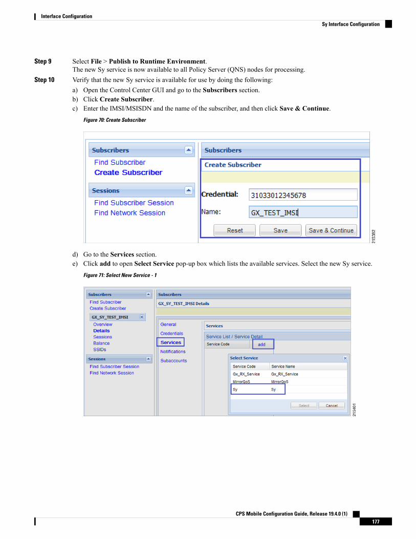
Step 9 Select File > Publish to Runtime Environment.The new Sy service is now available to all Policy Server (QNS) nodes for processing.
Step 10 Verify that the new Sy service is available for use by doing the following:a) Open the Control Center GUI and go to the Subscribers section.b) Click Create Subscriber.c) Enter the IMSI/MSISDN and the name of the subscriber, and then click Save & Continue.
Figure 70: Create Subscriber
d) Go to the Services section.e) Click add to open Select Service pop-up box which lists the available services. Select the new Sy service.
Figure 71: Select New Service - 1
CPS Mobile Configuration Guide, Release 19.4.0 (1)177
Interface ConfigurationSy Interface Configuration

Figure 72: Select New Service - 2
f) Click Save and run a test call to verify the following:
• QoS parameters are mirrored by PCRF in Credit-Control-Answer (Initial) message back to the PCEF.
• PCRF sends a Spending Limit Request message to the PCS on the Sy interface receives Spending Limit Answermessage from the OCS.
Rx Interface ConfigurationThe Rx reference point is used to exchange application-level session information between the Policy andCharging Rules Function (PCRF) and the Application Function (AF). This information is part of the inputused by the PCRF for the Policy and Charging Control (PCC) decisions.
The PCRF exchanges the PCC rules with the Policy and Charging Enforcement Function (PCEF) and QoSrules with the Bearer Binding and Event Reporting Function (BBERF).
CPS Mobile Configuration Guide, Release 19.4.0 (1)178
Interface ConfigurationRx Interface Configuration

Figure 73: Rx Reference Point
The PCRF provides network control regarding the service data flow detection gating QoS and flow basedcharging (except credit management) towards the PCEF. The PCRF receives session and media relatedinformation from the AF and informs AF of traffic plane events.
When a new AF session is being established and media information for this AF session is available at the AFand the related media require PCC supervision the AF shall open an Rx Diameter session with the PCRF forthe AF session using an AA-Request command unless an Rx session has already been established for the AFsession.
The AF shall provide the full IP address of the UE using either Framed-IP-Address AVP or Framed-Ipv6-PrefixAVP and the corresponding Service Information withinMedia-Component-Description AVP(s). The AF shallindicate to the PCRF as part of the Media-Component-Description whether the media IP flow(s) should beenabled or disabled with the Flow-Status AVP.
The AFmay include the AF-Application-Identifier AVP into the AA-Request in order to indicate the particularservice that the AF session belongs to. This AVP can be provided at both AF session level andMedia-Component-Description level. When provided at both levels the AF-Application Identifier providedwithin the Media-Component-Description AVP will have precedence.
Use Case:
The following procedure describes how to configure the Rx parameters that are necessary for the establishmentof a dedicated bearer and calculating/deriving the QoS for the Dynamic Charging rule names that PCRF sendsto the PCEF using a Gx RARmessage:
Step 1 Open the Policy Builder GUI, and select the Reference Data tab.Step 2 In the left-hand pane, select Diameter Defaults.Step 3 In the Summary pane, click Rx Profiles under Create Child.
The Rx Profile configuration pane appears.Whenmultiple Rx profiles are configured, the first profile should be configuredas described in the following steps.
CPS Mobile Configuration Guide, Release 19.4.0 (1)179
Interface ConfigurationRx Interface Configuration

Step 4 Select Prefer answer Codec-Data if you want the default priority to be given to the answer codec (when both answerand offer are present within the AAR). This option is not selected by default.
CPS will by default select the first of offer or answer that is present in the sent XML. By selecting this checkbox,CPS will prefer answer regardless of the order sent by the Rx endpoint.
Note
Figure 74: Rx Profile Configuration
Step 5 In the Default QoS Policy area, update the mandatory attribute value pairs as required.
The Default QoS Policy area is used when there is no Application QoS Policy or Codec QoS Policy defined,or when the incoming call doesn't match the configured values (with regard to AF ID or other parameters).
Note
If AF Application Identifier (AF-ID)-specific QoS handling is needed, the Application QoS Policy table needsto be updated. If the AF-ID received in the AAR message from the AF matches the AF Application Identifierconfigured under the Application QoS Policy section, then the PCRF uses QoS attributes from this table topopulate the dynamic rule QoS AVPs, which is then sent to the PCEF for dedicated bearer establishment.
Note
Step 6 Scroll down to the Actions area in the Rx Profile pane, and click Dynamic Rule Charging Parameters under CreateChild.
Step 7 Update the fields using one of the following methods as per requirements:
• Update the default Dynamic Rule Charging Parameters.
This is used in case the provisioned values (AF Identifier based) do not match the incomingAARmessage,essentially signifying that the AF ID in the AAR message is not provisioned or that the AAR message didnot contain an AF Identifier.
Note
• Update AF ID-specific Dynamic Rule Charging Parameters.
This is used when the incoming AAR contains AF Identifier that is provisioned in the table shown in thefollowing figure.
Note
CPS Mobile Configuration Guide, Release 19.4.0 (1)180
Interface ConfigurationRx Interface Configuration
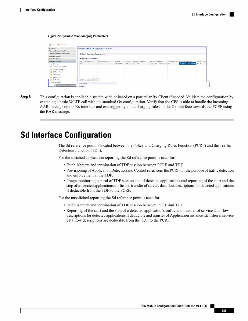
Figure 75: Dynamic Rule Charging Parameters
Step 8 This configuration is applicable system wide or based on a particular Rx Client if needed. Validate the configuration byexecuting a basic VoLTE call with the standard Gx configuration. Verify that the CPS is able to handle the incomingAAR message on the Rx interface and can trigger dynamic charging rules on the Gx interface towards the PCEF usingthe RAR message.
Sd Interface ConfigurationThe Sd reference point is located between the Policy and Charging Rules Function (PCRF) and the TrafficDetection Function (TDF).
For the solicited application reporting the Sd reference point is used for:
• Establishment and termination of TDF session between PCRF and TDF.• Provisioning of Application Detection and Control rules from the PCRF for the purpose of traffic detectionand enforcement at the TDF.
• Usage monitoring control of TDF session and of detected applications and reporting of the start and thestop of a detected applications traffic and transfer of service data flow descriptions for detected applicationsif deducible from the TDF to the PCRF.
For the unsolicited reporting the Sd reference point is used for:
• Establishment and termination of TDF session between PCRF and TDF.• Reporting of the start and the stop of a detected application's traffic and transfer of service data flowdescriptions for detected applications if deducible and transfer of Application instance identifier if servicedata flow descriptions are deducible from the TDF to the PCRF.
CPS Mobile Configuration Guide, Release 19.4.0 (1)181
Interface ConfigurationSd Interface Configuration

Figure 76: Sd Reference Point
The PCRF may provide ADC Rules to the TDF by using Sd interface.
Once the start or stop of the application's traffic matching one of the ADC Rules is detected if PCRF haspreviously subscribed to the APPLICATION_START/APPLICATION_STOP Event-Triggers unless a requestto mute such a notification (Mute-Notification AVP) is part of the corresponding ADC Rule the TDF shallreport the information regarding the detected application's traffic to the PCRF and apply the enforcementactions if defined within the corresponding ADC Rule.
Use-Case:
The following procedure describes how to initiate an Sd session from PCRF towards the TDF by sending aPredefined ADC Rule using a TDF-Session-Request (TSR) message to the TDF and getting a successfulTDF-Session-Answer (TSA) message on the PCRF:
Step 1 Open the Policy Builder GUI, and select the Services tab.Step 2 Create a Gx service as described in Gx Interface Configuration, on page 169.
Now you are ready to create an Sd service as described in the following steps.
Step 3 In the left-hand pane, select Use Case Templates > Summary.Step 4 In the Summary pane, click Use Case Template under Create Child, and then do the following:
a) In the Name field, type Sd.b) Select Actions tab.c) Click Add under Service Configurations.
The Select Service Configuration dialog box opens, and all of the service configuration objects that are availableon the PCRF are listed.
d) Scroll down to the sd area in the list of service configuration objects, and select ADCPredefinedRule.e) Click OK.
CPS Mobile Configuration Guide, Release 19.4.0 (1)182
Interface ConfigurationSd Interface Configuration
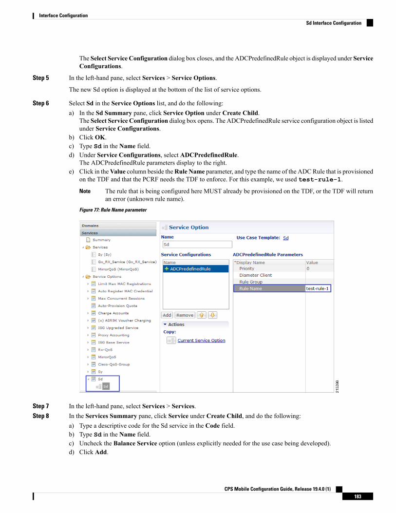
The Select Service Configuration dialog box closes, and the ADCPredefinedRule object is displayed under ServiceConfigurations.
Step 5 In the left-hand pane, select Services > Service Options.
The new Sd option is displayed at the bottom of the list of service options.
Step 6 Select Sd in the Service Options list, and do the following:a) In the Sd Summary pane, click Service Option under Create Child.
The Select Service Configuration dialog box opens. The ADCPredefinedRule service configuration object is listedunder Service Configurations.
b) Click OK.c) Type Sd in the Name field.d) Under Service Configurations, select ADCPredefinedRule.
The ADCPredefinedRule parameters display to the right.e) Click in theValue column beside theRule Name parameter, and type the name of the ADCRule that is provisioned
on the TDF and that the PCRF needs the TDF to enforce. For this example, we used test-rule-1.
The rule that is being configured here MUST already be provisioned on the TDF, or the TDF will returnan error (unknown rule name).
Note
Figure 77: Rule Name parameter
Step 7 In the left-hand pane, select Services > Services.Step 8 In the Services Summary pane, click Service under Create Child, and do the following:
a) Type a descriptive code for the Sd service in the Code field.b) Type Sd in the Name field.c) Uncheck the Balance Service option (unless explicitly needed for the use case being developed).d) Click Add.
CPS Mobile Configuration Guide, Release 19.4.0 (1)183
Interface ConfigurationSd Interface Configuration
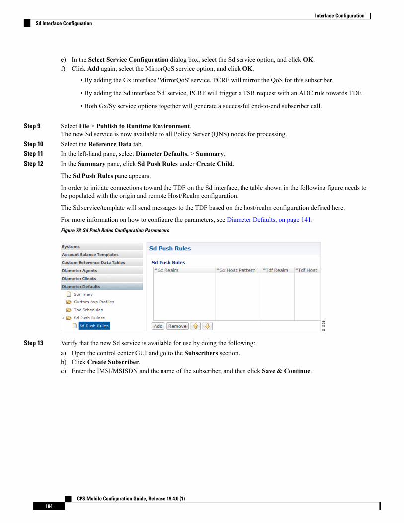
e) In the Select Service Configuration dialog box, select the Sd service option, and click OK.f) Click Add again, select the MirrorQoS service option, and click OK.
• By adding the Gx interface 'MirrorQoS' service, PCRF will mirror the QoS for this subscriber.
• By adding the Sd interface 'Sd' service, PCRF will trigger a TSR request with an ADC rule towards TDF.
• Both Gx/Sy service options together will generate a successful end-to-end subscriber call.
Step 9 Select File > Publish to Runtime Environment.The new Sd service is now available to all Policy Server (QNS) nodes for processing.
Step 10 Select the Reference Data tab.Step 11 In the left-hand pane, select Diameter Defaults. > Summary.Step 12 In the Summary pane, click Sd Push Rules under Create Child.
The Sd Push Rules pane appears.
In order to initiate connections toward the TDF on the Sd interface, the table shown in the following figure needs tobe populated with the origin and remote Host/Realm configuration.
The Sd service/template will send messages to the TDF based on the host/realm configuration defined here.
For more information on how to configure the parameters, see Diameter Defaults, on page 141.Figure 78: Sd Push Rules Configuration Parameters
Step 13 Verify that the new Sd service is available for use by doing the following:a) Open the control center GUI and go to the Subscribers section.b) Click Create Subscriber.c) Enter the IMSI/MSISDN and the name of the subscriber, and then click Save & Continue.
CPS Mobile Configuration Guide, Release 19.4.0 (1)184
Interface ConfigurationSd Interface Configuration

d) Go to the Services section.e) Click add to open Select Service pop-up box which lists the available services, and select the new Sd service.
f) Click Save and run a test call to verify the following:
• QoS parameters are mirrored by PCRF in Credit-Control-Answer (Initial) message back to the PCEF.
• PCRF sends a TDF-Session-Request message to the TDF on the Sd interface (with the Predefined ADC rule),receives TDF-Session-Answer message from the TDF.
Sh Interface ConfigurationCPS supports the ability to connect to the Home Subscriber Server (HSS) over the Sh interface to parsesubscriber profile data in order to make policy decisions.
CPS Mobile Configuration Guide, Release 19.4.0 (1)185
Interface ConfigurationSh Interface Configuration

CPS queries the HSS on Gx session establishment and caches the subscriber data locally. CPS allows theoperator to configure which attributes need to be extracted from the User-Data AVP and stored.
Create the Diameter Outbound Peer and Realm Connection to HSSThe connection to the HSS must be enabled by configuring it in the Outbound Peers section in the DiameterStack configuration.
Refer to Outbound Peers, on page 106 for instructions.
When defining the Realm in the Realms table, enter the Processing Protocol as SH_TGPP.Note
Configure the Sh DomainSh interface connections in CPS are defined per domain and therefore are configured on the Domains screenin Policy Builder.
Refer to Domains, on page 191 for more information.
The following steps represent the most common way to configure an Sh interface connection, but otherconfiguration options are available.
Note
Step 1 Follow the steps in Defining the General Attributes of the Domain, on page 192 to create a new domain for the Sh Interface.Step 2 On the General tab, set Authorization to Allow all Users.
While Allow all Users is the most common setting, CPS can be set to have subscribers in the SPR (USuMAuthorization) and still use the Sh mechanism for additional profile data.
Note
Step 3 On the Provisioning tab, set Provisioning to <not set>.Step 4 On the Advanced Rules tab, select the appropriate service in the Default Service field. The default service applies to
all subscribers’ requests that hit the Sh domain.Step 5 Continue with the instructions in Defining the Additional Profile Data of the Domain, on page 197.
Configure Multiple Sh Entitlements
Enabling this feature may result in CPS system performance degradation.Note
CPS can now receive and parse multiple values via Sh that use the same location in the data structure. Thesevalues are then resolved in conjunction with CRD tables to determine the service and appropriate AVPs to
CPS Mobile Configuration Guide, Release 19.4.0 (1)186
Interface ConfigurationCreate the Diameter Outbound Peer and Realm Connection to HSS

add to the session. This capability allows duplicate data structures to be processed and resolved rather thanrequiring unique data structures for all values, as was the case for CPS versions prior to 11.0.
The following example illustrates an incoming Sh response that contains multiple Entitlement and CustomAttributeName='4GPFO' values that are not unique. A maximum of five values from the incoming responsewill be used to determine a "bundled" result. The incoming values are processed against the CRD to compressthem into a final result based on priorities.<Sh-Data>
<RepositoryData><ServiceIndication>CamiantUserData</ServiceIndication><SequenceNumber>0</SequenceNumber><ServiceData><CamiantShUser xmlns:xsi='http://www.w3.org/2001/XMLSchema-instance'
xsi:noNamespaceSchemaLocation='CamiantShUser.xsd'><![CDATA[<Version>1.0</Version><AccountId>274500345196</AccountId><Entitlement>RTA</Entitlement><Entitlement>RTB</Entitlement><Entitlement>RTC</Entitlement><Custom AttributeName='BillingPlanCode'>L03</Custom><Custom AttributeName='4GPFO'>THR200k200k</Custom><Custom AttributeName='4GPFO'>THR200k300k</Custom><UserId Type='E164' Scope='Public'>2345557890</UserId><UserId Type='NAI'
Scope='Private'>[email protected]</UserId><EquipmentId Type='IMEISV' DeviceType='Phone'>35-209900-176148-23</EquipmentId>]]></CamiantShUser></ServiceData></RepositoryData>
</Sh-Data>
This procedure describes how to configure Policy Builder to assign multiple entitlements to a subscriber,which allows services to be used in a more targeted manner.
Step 1 Log in to Policy Builder.Step 2 Create a Search Table Group and a corresponding Custom Reference Data Table as follows:
a) Select the Reference Data tab.b) In the left pane, select Custom Reference Data Tables.c) Click Search Table Groups.d) In the Search Table Groups Summary pane, click Search Table Group under Create Child.e) In the Search Table Group pane, type a name for the group; for example, subscriber_sh. An example is shown
below:
CPS Mobile Configuration Guide, Release 19.4.0 (1)187
Interface ConfigurationConfigure Multiple Sh Entitlements

Figure 79: Search Table Group
f) Click Custom Reference Data Table under Create Child.g) In the Custom Reference Data pane, type a Name for the CDR; for example, subscriber_sh_key.h) Under Columns, add a key column, an output column, and a priority column. An example is shown below.
Figure 80: Custom Reference Data Table
Step 3 Configure a bundle profile as follows:a) Under Custom Reference Data Tables in the left pane, click Bundle Profiles.b) In the Bundle Profiles Summary pane, click Bundle Profile under Create Child.c) In the Bundle Profile pane, type a Name for the profile; for example, Entitlement.d) If you want the bundle profile to apply to the CRD and/or Service Resolution processes, selectUse for CrdResolution
and/or Use for Service Resolution.e) In the Search Table Group field, type the name of the search table group.f) In the Key Column, Priority Column and Output Column fields, use the Select button to select the names of the
columns that were configured in the CRD table. An example is shown below:
CPS Mobile Configuration Guide, Release 19.4.0 (1)188
Interface ConfigurationConfigure Multiple Sh Entitlements

Figure 81: Bundle Profile
Step 4 Configure the Sh Profile in a new domain or in an existing one:a) Select the Policy Builder Services tab.b) In the left pane, select Domains.c) Select an existing domain under Domains to edit, or click Domain under Create Child in the Service Reference
Data Objects pane to create a new one.
If this is a new domain type a name for it; for example, Sh MultipleEntitlements.Note
d) In the Domain pane, click the Additional Profile Data tab.e) Select Sh Profile in the pull-down menu on the right-hand side of the Additional Profile section heading.f) Under Profile Mappings, add a new External Code and name it using the bundle profile name; in our example, the
bundle profile name is Entitlement. An example configuration is shown below:Figure 82: External Code Configuration using Bundle Profile Name
g) On rare occasions, you may want to select the Use Service Indications For Service Resolution option if you wantthe Service Indications to be put into the policy state for services resolution. Service Indications are used in theoutgoing UDR/SNR to tell the HSS what data to send back to CPS.
If you decide to select this option, do so only after consulting with Cisco Advanced Services.Note
CPS Mobile Configuration Guide, Release 19.4.0 (1)189
Interface ConfigurationConfigure Multiple Sh Entitlements

LDAP/Ud Interface ConfigurationFor more information on LDAP/Ud interface configuration, refer to Domains.
CPS Mobile Configuration Guide, Release 19.4.0 (1)190
Interface ConfigurationLDAP/Ud Interface Configuration

C H A P T E R 6Domains
• Overview, on page 191• Strategies for Defining Domains, on page 192• Defining a Domain, on page 192• Creating a Custom Reference Data (CRD) table for APN mapping, on page 215• Validation Steps, on page 218• Configuring Domain to Parse Sh Attributes in Date and Time Format, on page 220• Configuring a Virtual Service, on page 221
OverviewThe Access Point Network (APN) attribute is sent to the CPS PCRF on the diameter Gx CCR-I message orwithin the Gy CCR-I message. Generally, an operator will want to define specific subscriber profile rules andservice definitions that apply to all subscribers that are attached to the given APN. Within CPS, the APNprofile rules are defined in the Domains section of the Services tab is shown below:Figure 83: APN Profile Rules
The Domain definition within the system controls the following behavior:
• Retrieves the user profile from the CPS SPR database. This step is optional and depends upon whetherthe operator is storing subscriber profiles in the CPS SPR database.
• Retrieves a user profile from an external data source using the LDAP/Ud protocols or the Diameter Shprotocol.
• Defines the default service(s) that are assigned to a user's session under the given conditions. Forinformation on services, Services, on page 223.
CPS Mobile Configuration Guide, Release 19.4.0 (1)191
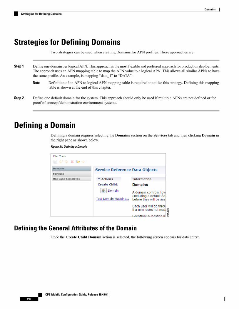
Strategies for Defining DomainsTwo strategies can be used when creating Domains for APN profiles. These approaches are:
Step 1 Define one domain per logical APN. This approach is the most flexible and preferred approach for production deployments.The approach uses an APN mapping table to map the APN value to a logical APN. This allows all similar APNs to havethe same profile. An example, is mapping “data_1” to “DATA”.
Definition of an APN to logical APN mapping table is required to utilize this strategy. Defining this mappingtable is shown at the end of this chapter.
Note
Step 2 Define one default domain for the system. This approach should only be used if multiple APNs are not defined or forproof of concept/demonstration environment systems.
Defining a DomainDefining a domain requires selecting the Domains section on the Services tab and then clicking Domain inthe right pane as shown below.Figure 84: Defining a Domain
Defining the General Attributes of the DomainOnce the Create Child Domain action is selected, the following screen appears for data entry:
CPS Mobile Configuration Guide, Release 19.4.0 (1)192
DomainsStrategies for Defining Domains

Figure 85: Naming the Domain
The following parameters can be configured on the General tab.
Table 74: General Tab Parameters
DescriptionParameter
This is a short textual name of the domain that describes the APN that is mappedinto this domain node. For example, VoLTE would imply this domain contains allVoLTE sessions. This name should be short and descriptive for an end user to findthe associated business rules.
After a domain is defined changing the name of an APN invalidates allexisting sessions attached to the APN. The system does not prevent namechanges and as a result this restriction must be enforced as part of thebusiness process in using the system. If a name change is required thenimpacted sessions must be deleted from the session data store manually.
Restriction
Name
This indicates that this domain is the “default” domain if the incoming messagedoes not map to any of the other domains.
Restrictions The system must have at least one default domain to ensure that allnew sessions map to a domain. The preferred approaches are (1) to create a defaultdomain with a restricted service definition or (2) assign the default domain to themost common domain (for example, DATA).
Is Default
This section defines whether the local CPS SPR should be used for profile retrieval.There are a number of options that are available in this section to support non-mobileuse cases. For more information, see Authorization, on page 194.
Authorization
CPS Mobile Configuration Guide, Release 19.4.0 (1)193
DomainsDefining the General Attributes of the Domain

AuthorizationThe only valid options for use in a mobile configuration are:
• USuMAuthorization: Select this option if a local CPS SPR lookup should be executed upon new sessioncreation.Figure 86: USuM Authorization Option
Figure 87: USuM Authorization Configuration
The following parameters can be configured under USuM Authorization:
DescriptionParameter
Set this to either Session MSISDN or Session IMSI dependingon which credential is used to store the data in the SPR.
User ID Field
Password Field
This field is optional and should be used only in conjunction withUSuM remote DB functionality. If this functionality is enabled,then the key field should match the user id field.
Remove Db Lookup Key Field
• Allow All Users: Select this option when defining an Sh interface Domain that will retrieve informationfrom an HSS.
See Configure the Sh Domain, on page 186 for more information.
CPS Mobile Configuration Guide, Release 19.4.0 (1)194
DomainsAuthorization
All other options should not be used in a mobile configuration. One option must be selected.
Defining the Provisioning Attributes of the DomainThe Provisioning tab defines whether auto provisioning of subscribers within the SPR should occur. Thismethod is generally used in scenarios where the system is configured to “auto-learn” subscribers and assigna default service profile.
For mobile configurations, set the attributes under the Provisioning tab as follows:
External Profile CacheCPS uses the local SPR database (formerly referred to as the USuM database) to temporarily cache thesubscriber profile fetched from an external data source (HSS/External-SPR) using the Diameter Sh interface.The cached subscriber record in the SPR database has the custom AVPs created for each attribute that isretrieved from HSS/External-SPR and mapped as per the Profile Mapping defined in the Sh Profile.
The following parameters can be configured:
• The PrimaryCredential field defines the primary key for the provisioned subscriber record (for example,IMSI, MSISDN, and so on.)
• The Subscriber Validity Period (mins) denotes the time (inminutes) for which the provisioned subscriberrecord is valid.
CPS Mobile Configuration Guide, Release 19.4.0 (1)195
DomainsDefining the Provisioning Attributes of the Domain

• The Subscriber Validity Period (mins) is set only when the subscriberrecord is created the first time for that subscriber. This value is not changedif CCR-I (s) are received before the subscriber validity period expires. Incase a CCR-I is received after the validity period has expired, the existingSPR cache record is deleted. Once the existing SPR record is deleted, a newUDR/UDA exchange happens and the subscriber validity period is updatedalong with the new SPR cache record.
• Since CPS creates a local CPS SPR to temporarily cache the subscriber’sprofile, and this impacts the overall response time. To reduce the impact,you need to configure Mongo database to use tmpfs for storage.
• You must consider the size of the database depending on the number orsubscriber's profile to cache.
• For consistent profile updates across multiple sessions for the samesubscriber, it is recommended to set the DB Read Preference drop-downlist to PrimaryPreferred in REFERENCE DATA > Systems > PluginConfigurations > USuM Configuration.
• If the first session is created using UDR or UDA and the subscriber data isstored in the CPS SPR database, and if there is any change for the samesubscriber's data in SPR/HSS, the change is not reflected for another Gxsession for same subscriber. The new Gx session still refers to the cachedsubscriber profile.
• If this feature is enabled, you must not provision or delete the subscriber’sprofile using Control Center or Unified APIs.
• Domain naming configuration, if used, affects the subscriber's primarycredential used for storing or accessing the profile in CPS SPR. Hence, youmust configure it based on the desired unique identity for the subscriber.
Note
• Select theUseRemote SPRDatabases check box to enable CPS to use the remote SPRMongo databases.CPS uses the primary credential (for example, IMSI/MSISDN extracted based on the retriever) and passesit as remoteLookupKeyValue when it performs the SPR look-up operation to create, update, or deletesubscriber records in the CPS SPR databases for fetched external subscriber profiles.
CPS Mobile Configuration Guide, Release 19.4.0 (1)196
DomainsExternal Profile Cache

• This parameter takes effect only when Remote Database Configurationis configured in USuM Configuration under Plugin Configuration.
See USuM Configuration, on page 55
• Enabling this parameter causes CPS to distribute the SPR operations acrossdifferent SPR databases, thus usingmemory for each extra CPS SPR (remote)databases instance.
• If this feature is enabled for Geographic Redundancy deployment, the CPSSPR Mongo database must be local to each site and must not be replicatedacross sites. However, if additional SPR Mongo databases are present on aremote site, the latency between the two sites must be considered whiledefining the message timeout values.
• To create additional newmongo database instances, refer to chapter 'DeployCPS VMs' in CPS Installation Guide for VMware.
Note
• SelectUse origin-host for SPR lookup to save or retrieve the Sh profile data to and from the appropriateSPR database based on Gx CCR-I origin-host pattern.
You need to select Use Remote SPR Databases in addition to Use origin-hostfor SPR lookup. For more information, see Remote Database Configurationunder USuM Configuration.
Note
Defining the Additional Profile Data of the Domain
Retrieving a Subscriber Profile from an HSSFor retrieving a connection from a Home Subscriber Server (HSS) it is necessary to define the data sets toenable the retrieval.
See Sh Interface Configuration, on page 185 for configuring the connection to the HSS.
Setting Up Additional Profile Data
Step 1 Complete the preliminary configuration in Sh Interface Configuration, on page 185.Step 2 Click the Additional Profile Data tab of the Sh interface domain.Step 3 Check the Additional Profile check box.
If you have installed the LDAP plug-in, this check box is replaced with a drop-down menu. In this scenario,select the Sh Profile option.
Note
Step 4 In the Profile Mappings table, click Add to add one row for each Sh AVP attribute that is retrieved from the HSS.
CPS Mobile Configuration Guide, Release 19.4.0 (1)197
DomainsDefining the Additional Profile Data of the Domain

Table 75: Profile Mapping Parameters
DescriptionParameter
Defines the attribute name to retrieve. This field should match the Code Literal field inthe Sh Parsing Rules table. This represents the internal system attribute name which canbe used to apply policies.
External Code
Defines the mapping of the data to an internal CPS data type. Select SubscriberAttribute.
The following data types are supported:
• Service: Selecting this type will add a service to the user profile with the codereturned on the HSS attribute.
• ChargingId: Selecting this type will allow the External Charging Id retriever toretrieve the HSS value. This attribute would only be used if the local balance databaseis enabled and provisioned with the external charging ID and the charging id isdefined in the HSS.
• SubscriberAttribute: Selecting this type will add a policy derived AVP with theexternal code mapped to the code field and the value mapped to the value field. Thisattribute type is the most common type to set in the profile mappings.
• SubscriberIdentifier: Selecting this type will allow the “An external subscriber idexists” condition within a policy to return the subscriber id.
Mapping Type
If parsing of the incoming AVP is required then a regular expression and regularexpression group can be defined to support retrieval of the parsed values.
In general, Regex Expression can be left blank and each attribute should be assigned toRegex Group number 1.
Regex Expression andRegex Group
Defines the default AVP value when subscriber attribute received from the externalprofile is missing.
Note • If a subscriber attribute is missing but its missing AVP value is notconfigured, CPS does not create or update policy derived AVP for thissubscriber with Missing Avp Value.
• This parameter is applicable only forMapping Type as SubscriberAttribute or Service. For all other mapping types this column is notapplicable.
Missing Avp Value
Defines the default AVP value when subscriber attribute received from external profilehas empty or blank value.
Note • If a subscriber attribute is empty or blank but its empty or blank AVPvalue is not configured, CPS does not create or update policy derivedAVP for this subscriber with Empty Avp Value.
• This parameter is applicable only forMapping Type as SubscriberAttribute or Service. For all other mapping types this column is notapplicable.
Empty Avp Value
CPS Mobile Configuration Guide, Release 19.4.0 (1)198
DomainsSetting Up Additional Profile Data

DescriptionParameter
This check box indicates whether 'Timer Attribute' is applicable to other subscriberattributes or not. You need to select the checkbox if 'Timer Attribute' needs to be appliedfor that subscriber attribute.
Apply Timer
When checked, deletes the LDAP attribute from the session (thus preventing any furtheruse) if regex (when configured) does not match the received value.
By default, the checkbox is unchecked (false).
Discard If Empty
Currently, the column support has been added for Entitlement (External Code).
In the Entitlement row, create a string named concatenated_entitlement on ConcatenatedAttribute column. The concatenated_entitlement string parameter is of generic name(user-defined name).
If the Concatenated Attribute column is empty, then concatenated entitlement is notenabled. It behaves as the default implementation of Entitlement.
When the concatenated_entitlement is configured, the default Entitlement AVP as wellas concatenated_entitlement AVP is supported.
When the UDA message is received with multiple Entitlement values and theconcatenated_entitlement flag is configured in Policy Builder, then all the EntitlementAVP values are concatenated as a single string
So, all the Profile Mapping Entitlement AVP must be concatenated asconcatenated_entitlement with comma separator AVP values.
In the CRD table, a new mapping named concatenated_entitlement_bundle_mappingmust be created. It must be mapped with the new concatenated entitlement, which willbind to the Subscriber AVP code concatenated_entitlement.
Concatenated Attribute
Step 5 In the Sh Realm field, enter the HSS Diameter realm name.Step 6 If Subscribe to Notifications is checked, CPS subscribes to HSS notifications by sending SNR. By default, this option
is enabled. If not checked, CPS will send UDR.Step 7 Select the Enable External Profile Cache Lookup check box to allow CPS to use subscriber profile cached in the
local CPS SPR database (if available) before querying the external SPR/HSS. The fetched profile is provisioned as perthe provisioning configuration in the Provisioning tab (see External Profile Cache, on page 195). This configuration isused to reduce the number of Sh requests (SNR/UDR) in case there are multiple Gx sessions for a single subscriber.The first Gx session initiates the Sh request and retrieves the profile and all further Gx sessions for the same subscriberlookup the local SPR database for the subscriber's profile.
Step 8 Select the Broadcast Profile Change check box to enable triggering a broadcast message for changes in subscriberprofile due to a PNRmessage. A broadcast message is sent only when there are multiple sessions for the same subscriber.
Step 9 Select Convert All SNA Attributes to Lowercase and Convert SubscriberID to Lowercase to convert and storelowercase values of Sh code in external-profile. This makes implementation generic and CRD table population easier.
Step 10 In User Identity Avp Formatting drop down menu, select either SIPURI or TBCD. This setting configures theUser-Identity AVP Format as eitherMSISDNTBCD encoding or SIP URI (Session Initiation Protocol UniformResourceIdentifier).
If SIPURI is selected, use the Sip Parsing Rules table to determine how the SIP URI is constructed.
a) In the Sip Parsing Rules table, click Add to define a parsing rule.
CPS Mobile Configuration Guide, Release 19.4.0 (1)199
DomainsSetting Up Additional Profile Data

Table 76: Sip Parsing Rules Parameters
DescriptionParameter
A literal String value that will be inserted into the SIP URI as is.Static
Dynamic uses the Retrievers paradigm to get dynamic data from the policy session andinsert it into the SIP URI.
Dynamic
For example, the SIP Parsing Rules in Table 76: Sip Parsing Rules Parameters, on page 200 would generate a SIPURI with this format:
The static values are highlighted in bold text. The dynamic portions of the SIP URI are extracted from the followingpolicy session objects, as follows:
• Gx IMSI: 456123000000001
• Gx MNC Trailing Zero IMSI Based: 123
• Gx MCC IMSI Based: 456
Table 77: Sip Parsing Rules Example
DynamicStatic
sip:
Gx IMSI
@nai.epc.mnc
Gx MNC Trailing Zero IMSI Based
.mcc
Gx MCC IMSI Based
.3gppnetwork.org
Step 11 In the Service Indications table, click Add to filter users by a service indication (group) name.
If no Service Indication value is entered, the HSS will deliver data from all available service indication groups.
In the XML sample below, the Service Indication is “Service1”:
<ServiceIndication>Service1</ServiceIndication>.
Step 12 In the Sh Parsing Rules table, click Add to define which parameters to parse from the XML provided by the HSS.Each AVP includes a Code and Value pair, and this table allows you to define which literal or dynamic XML valuesshould be parsed from the XML file.
CPS Mobile Configuration Guide, Release 19.4.0 (1)200
DomainsSetting Up Additional Profile Data

Table 78: Sh Parsing Rules Parameters
DescriptionParameter
Use this field to define the literal XML element which represents the Code portion of theuser’s AVP. Use this when a static value should be set.
For example: Entitlement
Code Literal
Use this field to define a dynamic XML element which represents the Code portion of theuser’s AVP. Use this when a dynamic value should be parsed.
For example: /SampleShUser/Custom[@AttributeName='BillingPlan']
To map default empty and missing value, Sh parsing rule needs to be with Code XPath:
Sample XML:<Sh-Data>
<RepositoryData><ServiceIndication>CamiantUserData</ServiceIndication><SequenceNumber>0</SequenceNumber><ServiceData>
<CamiantShUser xmlns:xsi="http://www.w3.org/2001/XMLSchema-instance"xsi:noNamespaceSchemaLocation="CamiantShUser.xsd">
<Version>1.0</Version><UserId Type="E164" Scope="Public">19010921003</UserId><UserId Type="NAI"
Scope="Private">[email protected]</UserId>
<UserId Type="IMSI" Scope="Private">311482310921003</UserId><Custom AttributeName="BillingPlanCode">BPC_LO3</Custom><Custom AttributeName="ServiceName">ServiceA</Custom></CamiantShUser></ServiceData></RepositoryData>
</Sh-Data>
Code Xpath
Use this field to define the literal XML element which represents the Value portion of theuser’s AVP. Use this when a static value should be set.
Value Literal
Use this field to define a dynamic XML element which represents the Value portion of theuser’s AVP. Use this when a dynamic value should be parsed.
For example:
/SampleShUser/Custom[@AttributeName='4G']
Value Xpath
The parsed Code value from the XML file must be mapped to one of the attributes in the Profile Mappingtable as defined in #unique_146 unique_146_Connect_42_table_E9C733052AE443A8BB19B1BD885BAD8B.
Note
The following example shows how to pair a Code Literal with a Value Xpath to parse the Entitlement information fromthe following XML:
Code Literal = Entitlement
Value Xpath = /SampleShUser/Entitlement<?xml version="1.0" encoding="UTF-8"?><Sh-Data><RepositoryData><ServiceIndication>Service1</ServiceIndication><SequenceNumber>0</SequenceNumber>
CPS Mobile Configuration Guide, Release 19.4.0 (1)201
DomainsSetting Up Additional Profile Data

<ServiceData><SampleShUser xmlns:xsi="http://www.w3.org/2001/XMLSchema-instance"xsi:noNamespaceSchemaLocation="SampleShUser.xsd"><Version>1.0</Version><UserId Type="E164" Scope="Public">11122333444</UserId><UserId Type="NAI"Scope="Private">[email protected]</UserId><UserId Type="IMSI" Scope="Private">456123000000001</UserId><Entitlement>Gold</Entitlement><Custom AttributeName="BillingPlan">Level1</Custom><Custom AttributeName="4G">200k200k</Custom>
</SampleShUser></ServiceData>
</RepositoryData></Sh-Data>
Step 13 Enable Use Service Indications for Service Data Caching in Sh Profile. When selected, on receiving Sh messages(SNA/PNR) with Sh-User-Data, CPS verifies if there is any XML blob with ServiceIndication matching the configuredService-Indication in the PB Domain configuration for that Gx Session. If a match is found, corresponding ServiceDataattributes are updated for that session.
Step 14 If you want to configure Sh retry, define the parameter values in the Retry Profile area. Click the check box to openthe Retry Profile parameters.
Table 79: Retry Profile Parameters
DescriptionParameter
Determines the number of minutes between retry attempts.Retry Interval
Determines the maximum number of retries that occur after a failed attempt.
The default value is 3 attempts.
Max Retry Attempts
Determines the actual delay between retry attempts. Following are the options:
Constant_Interval: The configured Retry Interval is used (without any change) for all retryattempts.
Linear_Interval: Each retry is scheduled after the number of minutes derived frommultiplying the Retry Interval by the number of attempts since the last report.
Backoff Algorithm
CPS Mobile Configuration Guide, Release 19.4.0 (1)202
DomainsSetting Up Additional Profile Data

DescriptionParameter
Determines the retry interval granularity.
The default setting isMinutes.
Note • To change the granularity to lower than 1 second (1000 ms), change thefollowing parameter in the qns.conf file:
-Dscheduler.executor.granularity=200 (to set the granularity to 200ms). Setting the value to lower than 200 can cause issues if the retry load ishigh.
• By default, the CPS scheduler does not accept any event that is scheduledto greater than 15 seconds of the current time. To increase this interval,change the following parameter in the qns.conf file:
-Dscheduler.interval.max=60000 (to accept events up to 60 seconds).The retry interval should be up to 60 seconds. Setting this value to greaterthan 60 seconds is not recommended.
• The default scheduler queue capacity is 50000. The system discards anyevent if the queue is full.
• If UDR retry from CCR-I and CCR-U come at the same time, there may bean extra UDR generated due to concurrent update of the session.
Retry IntervalGranularity
When selected, the system will attempt Sh UDR on CCR-u if the UDR is not successfulduring CCR-i. If the UDR is not successful, the Sh Retry Interval (if active) will be reset.
The default setting is false (unchecked).
Retry on CCR-u
When selected, the system sends the Sh retry messages to a different host in the same realmprovided there are multiple hosts in the same realm.
The default setting is false (unchecked).
Retry on Alternate Host
Determines the result codes for which the Sh UDR/SNR retries should happen. Followingare the options:
• Result Code: The result codes for which Sh UDR/SNR needs to be retried by QNS. Ifthis list is empty, the Sh UDR/SNR is retried for all 3xxx and 4xxx result codes.
• Is Experimental: Indicates that the configured result code is an experimental resultcode. Hence, retry happens only if the result code is received inExperimental-Result-Code AVP.
Result Code BasedRetries
Configuring MNC Length
To accommodate networks where both 2-digit and 3-digit MNCs are used, additional identifiers are neededsince the same MCC can be used with both MNC lengths. In those cases, an XML file is used to establish arelationship between the MNC length and the MCC (Mobile Country Code). This XML file lists the actual,possible MNC values.
CPS Mobile Configuration Guide, Release 19.4.0 (1)203
DomainsConfiguring MNC Length

For example:
For MCC 405, the MNC length is 2 for Reliance in most cases, for example, 03.
For the same MCC 405, the MNC length is 3 for TATA DOCOMO in most cases, for example, 030.
For the vast majority of cases, the XML file has sufficient information to determine the MNC length just fromthe country code. In countries where both 2 and 3 digit MNC values are used, adding the actual MNC intothe XML is usually sufficient, but there still are a small number of cases that cannot be differentiated correctly.In the above example, the MCC is 405 in both cases and the problem is that the MNC in both cases starts with03. CPS checks for both 03 and 030, but because both are found, there is no way to know which is correct.The IMSI is built in the following manner: 3 digit MCC, 2 or 3 digit MNC, and 9 or 10 digit MIN so the totalIMSI is 15 digits (an exception to this is some old IMSIs which are 14 digits).
The following known conflicts are included in the XML file.<country name="in" mnc="03" mncLength="2" carrier="Reliance" operator="Bihar" /><country name="in" mnc="04" mncLength="2" carrier="Reliance" operator="Chennai" /><country name="in" mnc="030" mncLength="3" carrier="TATADOCOMO" operator="Gujarat"/><country name="in" mnc="031" mncLength="3" carrier="TATADOCOMO" operator="Haryana"/><country name="in" mnc="032" mncLength="3" carrier="TATADOCOMO" operator="HimachalPradesh"/><country name="in" mnc="033" mncLength="3" carrier="TATADOCOMO" operator="JammuAndKashmir"/><country name="in" mnc="034" mncLength="3" carrier="TATADOCOMO" operator="Karnataka"/><country name="in" mnc="035" mncLength="3" carrier="TATADOCOMO" operator="Kerala"/><country name="in" mnc="036" mncLength="3" carrier="TATADOCOMO" operator="Kolkata"/><country name="in" mnc="037" mncLength="3" carrier="TATADOCOMO" operator="MaharashtraAndGoa"/><country name="in" mnc="038" mncLength="3" carrier="TATADOCOMO" operator="MadhyaPradesh"/><country name="in" mnc="039" mncLength="3" carrier="TATADOCOMO" operator="Mumbai"/><country name="in" mnc="041" mncLength="3" carrier="TATADOCOMO" operator="Orissa"/><country name="in" mnc="042" mncLength="3" carrier="TATADOCOMO" operator="Punjab"/><country name="in" mnc="043" mncLength="3" carrier="TATADOCOMO" operator="Rajasthan"/><country name="in" mnc="044" mncLength="3" carrier="TATADOCOMO" operator="TamilNaduChennai"/><country name="in" mnc="045" mncLength="3" carrier="TATADOCOMO" operator="UttarPradeshE"/><country name="in" mnc="046" mncLength="3" carrier="TATADOCOMO"operator="UttarPradeshWAndUttarkhand"/><country name="in" mnc="047" mncLength="3" carrier="TATADOCOMO" operator="WestBengal"/>
This XML configuration file is available in the following directory: /etc/broadhop/pcrf/mcc.xml.
Modifications to this file requires a server restart (restartall.sh).
Executing restartall.sh will cause messages to be dropped.Caution
mcc.xml Schema
The mcc.xml file has the following schema:<?xml version="1.0" encoding="UTF-8"?><xs:schema xmlns:xs="http://www.w3.org/2001/XMLSchema" elementFormDefault="qualified"attributeFormDefault="unqualified"><xs:element name="mccList"><xs:complexType><xs:sequence><xs:element name="mcc" maxOccurs="unbounded"><xs:complexType><xs:sequence><xs:element name="country"><xs:complexType><xs:attribute name="name" type="xs:string"></xs:attribute>
CPS Mobile Configuration Guide, Release 19.4.0 (1)204
DomainsConfiguring MNC Length

<xs:attribute name="mnc" type="xs:int"></xs:attribute><xs:attribute name="mncLength" type="xs:int"></xs:attribute>
</xs:complexType></xs:element>
</xs:sequence><xs:attribute name="id" type="xs:int"></xs:attribute>
</xs:complexType></xs:element>
</xs:sequence></xs:complexType>
</xs:element></xs:schema>
XML Example
The following file shows an example of a simple mcc.xml file with several values:<?xml version='1.0' encoding='UTF-8'?><mccList><mcc id="202"><country name="gr" mncLength="2" /></mcc><!-- Greece --><mcc id="250"><country name="ru" mncLength="2" /><country name="ru" mnc="811" mncLength="3" operator="VotekMobile" />
</mcc><!-- Russian Federation --></mccList>
XML Nodes Explained
A single mncLength for a country code has a node structure like the following:
<mcc id="202"><country name="gr" mncLength="2" /></mcc><!-- Greece -->
The code then parses the MCC element into a single id:country:mncLength relationship so that the MNClength returns as 2 in the above case. For a country or carrier that needs to have an MNC length of 3, thefollowing node produces this outcome:
<mcc id="310"><country name="us" mncLength="3" /></mcc><!-- United States -->
A country that uses bothMNC lengths may needmultiple child nodes that specify exceptions like the following:<mcc id="405"><country name="in" mnc="01" mncLength="2" carrier="Reliance"
operator="AndhraPradeshAndTelangana" /><!-- more country codes here--></mcc>
The features code then parses these exceptions for MNC length retrieval looking for matching conditionswithin the list of provided specifics to create the relationship between the country code and the MNC length.If a match is not found an empty string is returned as a default. An empty string is returned so that an incorrectSIP URI is not built.
Retrieving Subscriber Profile from an LDAP/Ud ServerFor retrieving a connection from an LDAP/Ud server it is necessary to define the following sets of data toenable this retrieval.
CPS Mobile Configuration Guide, Release 19.4.0 (1)205
DomainsRetrieving Subscriber Profile from an LDAP/Ud Server

LDAP Server Set Definition
Within theLdap Server Sets section on theReference Data tab, create an LDAP Server Set. The Ldap ServerSet represents a connection to a logical set of LDAP servers that is reusable across Domain definitions. As aresult, most deployments have only one Ldap Server Set defined in this section.
The following parameters can be configured under Ldap Server Set:
Table 80: Ldap Server Set Parameters
DescriptionParameter
A textual description of the LDAP connection. This should be something easilyrecognizable as the name of the LDAP server containing the subscriber profiles.
Name
Result code expected from LDAP Server in case BaseDN for attribute additionis missing.
Missing Attribute ResultCode
The parameter accepts a list of integer result codes. If an Ldap search responsecontains one of the configured result codes, then the response is not flagged aserror and instead, the NO_LDAP_ATTRIBUTE_FOUND LDAP attribute is created locallyfor use in policy.
Ignore Ldap Error ResultCodes
This should be is checked (true). Setting to unchecked (false) can result inunpredictable performance and is not supported.
Use AsynchronousOperations
If checked, continue creation of attributes even though parent DN creation issuccess or failure.
Add Child On ParentCreate Failure
This table is used to define the attributes that can be used while sending addParent DN request in case modifyRequest fails.
Add Request Attributes
LDAP Configuration
Within the Systems section on the Reference Data tab, create a new plugin configuration for LdapConfiguration. Under the Ldap Configuration create a child Ldap Server Configuration.
CPS Mobile Configuration Guide, Release 19.4.0 (1)206
DomainsRetrieving Subscriber Profile from an LDAP/Ud Server

Figure 88: Ldap Server Configuration
The following parameters can be configured under Ldap Server Configuration:
Table 81: Ldap Server Configuration Parameters
DescriptionParameter
Assign this to the Ldap Server Set created in the previous step.Ldap Server
Set this to the user DN for connecting to the LDAP server. An example iscn=managerou=accountso=profile.
Search User Dn
Set this to the password for connecting to the LDAP server.
The same password must apply to all servers defined in this configuration.Note
SearchUser Password
Select the LDAP auth type required by the LDAP server.
Default value is SIMPLE.
Auth Type
Set the initial connections to “50”. This represents the number of connections froma Policy Director (load balancer) to the LDAP server(s).
Initial Connections
Set this value to the same value as the initial connections.Max Connections
CPS Mobile Configuration Guide, Release 19.4.0 (1)207
DomainsRetrieving Subscriber Profile from an LDAP/Ud Server

DescriptionParameter
Set this to the total number of “tries” the system should execute for a give LDAPquery. For example a value of 2 would indicate one try and then on timeout one moreattempt.
Retry Count
Set this to the time period when the policy engine retries to a second Policy Director(load balancer) to send the request.
Setting this value too low results in a large number of additional requestsand this value should be set to a value close to the SLA provided by theLDAP server in servicing requests.
Note
Retry Timer Ms
Set this value to the time period a secondary connection to be utilized before checkingto determine if the original primary server is available. An example value is 60000ms (1minute).
Max FailoverConnection Age Ms
Set this to the maximum rate at which to connect to the LDAP server. Setting this toa high value may result in extra load on the peer LDAP server.
Binds Per Second
Set this to the period of time to generate a health check message. An example valueis 5000 ms (5 seconds).
Health Check IntervalMs
Set this to the health check DN sent on the health check LDAP query.Health Check Dn
Set this to the filter sent on the health check LDAP query.Health Check Filter
Set this to a comma delimited list of attributes to retrieve in the LDAP health checkquery.
Health Check Attrs
Set this to checked (true) to enable the health check.
Default is checked.
Health Check
Set this to the number of timeouts that triggers a bad connection and force areconnection.
Number ofConsecutive Timeoutsfor Bad Connection
Add entries to the LDAP Servers to represent the primary and secondary connections from the CPS systemto the LDAP servers. The following parameters can be configured:
Table 82: LDAP Servers
DescriptionParameter
The priority of the server when sending requests. Higher number is equal to higherpriority.
Priority
The IP address of the server to send requests.Address
CPS Mobile Configuration Guide, Release 19.4.0 (1)208
DomainsRetrieving Subscriber Profile from an LDAP/Ud Server

DescriptionParameter
Cisco recommends not to use this setting.
However, the following options are available:
• ROUND_ROBIN: CPS uses a round-robin algorithm to select the server toestablish the connection. This is the default setting.
• FASTEST: CPS attempts to establish connections to all associated servers inparallel. However, the first successful connection is kept while the otherconnections are closed.
If the Priority setting is the same for multiple LDAP servers withROUND_ROBIN connection rule, CPS makes connections evenly withconfigured multiple LDAP servers.
Note
Connection Rule
This setting is not currently used.Auto Reconnect
Set this to the SLA for queries for the LDAP server.Timeout Ms
Set this to the SLA for binds to the LDAP server.Bind Timeout Ms
Setting Up Additional Profile Data
Within theAdditional Profile Data tab of theDomain, selectGeneric Ldap Search in the upper right cornerso that this Domain should retrieve data from an LDAP query.
The following parameters can be configured under Additional Profile Data:
Table 83: Additional Profile Data Parameters
DescriptionParameter
In the profile mappings table add one row for each attribute that is retrieved fromthe LDAP server.
Profile Mappings
The LDAP attribute name to retrieve.External Code
CPS Mobile Configuration Guide, Release 19.4.0 (1)209
DomainsRetrieving Subscriber Profile from an LDAP/Ud Server

DescriptionParameter
The mapping of the data to an internal CPS data type. The following data types aresupported
• Service Selecting this type adds a service to the user profile with the codereturned on the LDAP attribute.
• ChargingId Selecting this type allows the External Charging Id retriever toretrieve the LDAP value. This attribute would only be used if the local balancedatabase is enabled and provisioned with the external charging ID and thecharging id is defined in the LDAP server.
• SubscriberIdentifier Selecting this type allows the “An external subscriber idexists” condition within a policy to return the subscriber id.
• SubscriberAttribute Selecting this type adds a policy derived AVP with theexternal code mapped to the code field and the value mapped to the valuefield. This attribute type is the most common type to set in the profilemappings.
Mapping Type
If parsing of the incoming AVP is required then a regular expression and regularexpression group can be defined to support retrieval of the parsed values.
Regex Expression andRegex Group
Defines the default AVP value when subscriber attribute received from the externalprofile is missing.
Note • If a subscriber attribute is missing but its missing AVP value is notconfigured, CPS does not create or update policy derived AVP forthis subscriber with Missing Avp Value.
• This parameter is applicable only forMapping Type as SubscriberAttribute or Service. For all other mapping types this column isnot applicable.
Missing Avp Value
Defines the default AVP value when subscriber attribute received from externalprofile has empty or blank value.
Note • If a subscriber attribute is empty or blank but its empty or blankAVP value is not configured, CPS does not create or update policyderived AVP for this subscriber with Empty Avp Value.
• This parameter is applicable only forMapping Type as SubscriberAttribute or Service. For all other mapping types this column isnot applicable.
Empty Avp Value
This check box indicates whether 'Timer Attribute' is applicable to other subscriberattributes or not. You need to select the checkbox if 'Timer Attribute' needs to beapplied for that subscriber attribute.
Apply Timer
When checked, deletes the LDAP attribute from the session (thus preventing anyfurther use) if regex (when configured) does not match the received value.
By default, the checkbox is unchecked (false).
Discard If Empty
CPS Mobile Configuration Guide, Release 19.4.0 (1)210
DomainsRetrieving Subscriber Profile from an LDAP/Ud Server

DescriptionParameter
Associate the LDAP server set defined in the LDAP Server Set Definition.Ldap Server Set
This should be set to the Base DN sent in the LDAP query. If not defined, then therequest does not contain a base DN.
This string supports string replacement using the find / replace of stringswith variables from the policy state as defined in the “ReplacementRules” table.
Note
Base Dn
This should be set to the Filter sent in the LDAP query. If not defined, then therequest does not contain a filter.
This string supports string replacement using the find / replace of stringswith variables from the policy state as defined in the “ReplacementRules” table.
Note
Filter
Set this to the dereference policy that the LDAP query requires.
Default value is NEVER.
Dereference Policy
This is an optional field that controls whether to disable the LDAP query. This isoften used in conjunction with Custom Reference Data tables and other sessionattributes to optionally disable an LDAP query. If the calculated CRD AVP has avalue (ignoring case) of “false” then the LDAP query is skipped.
Avp Code to DisableQuery
Set this value to automatically refresh a profile by querying the profile after aspecified delay.
Profile Refresh Interval(mins)
In the replacement rules table add one row per replacement string to substitute intothe Base DN or Filter string on a request by request basis.
Replacement Rules
The literal string used in the “From” operation. The best practice is to use a symbol(for example, $) at the front of the string to ensure uniqueness in the find andreplacement operation.
Replacement String
The source of the data for the “To” operation. The most common examples are“Session MSISDN” and “Session IMSI”.
Replacement Source
This parameter indicates which attribute is timer attribute among all the LDAPserver attributes.
The timer follows the ISO 8601 time standards. Refer to ISO 8601 for moreinformation.
Subscriber TimerAttribute
This parameter is used to indicate howmuch time before the start time of SubscriberTimer Attribute CPS has to accept when LDAP server sends timer attribute.
Default value is 30 minutes.
Lower Bound For TimerAttribute In Minutes
This parameter indicates how much time after the start time of Subscriber TimerAttribute CPS has to accept when LDAP server sends timer attribute.
Default value is 100. Possible range is from 1 to 100.
Elapsed Time For TimerAttribute In Percentage
For more information, refer to the Table 84: Service Attribute Info, on page 212.Service Attribute Info
CPS Mobile Configuration Guide, Release 19.4.0 (1)211
DomainsRetrieving Subscriber Profile from an LDAP/Ud Server

Table 84: Service Attribute Info
DescriptionParameter
This parameter is used to match an External Attribute Code and create a VirtualService object with that value.
Attribute Name
While using Param Attribute Name, the value should have one of its fields matchthe value of the attribute defined under Attribute Name. This field should have afixed name "service". The virtual service is created with the value of this fieldname "service".
All the fields in the Param Attribute Name should be provided in-order in theParameter Fields list (even if some fields are not required/have no value, theyneed to be included in the list in the expected order). Both Attribute Name andParam Attribute Name can contain the same attribute name.
Param Attribute Name
The delimiter string to be used for splitting the attribute value into fields.Delimiter
The list of field names in order as extracted from the parameter attribute valueusing the delimiter. The field that matches the parameter attribute with thecorresponding service attribute value (Attribute Name) is expected to be provideda fixed name called "service".
If CPS fails to parse the Parameter Fields, it creates a virtual-service with noAVPs.
Parameter Fields
This parameter must be one of the field names from the Parameter Fields list thatidentifies the virtual service expiration date field.
If CPS is able to extract the field for expiration-time and also decode a valid dateout of it then CPS uses the decoded date value as expiration-date on thevirtual-service.
If CPS is not able to extract the fields using the delimiter or is not able to decodethe date value using the Expiration Date Code and Expiration Date Format values,then that virtual-service never expires and remains active.
Expiration Date Code
The JAVA date format string that is used to decode and extract the exact date-timevalue for expiration-date.
If CPS fails to decode the ExpirationDate using the JAVA date value then theexpiration-date does not need to be set on the virtual service.
Expiration Date Format
Retrieving Subscriber Profile from an UDC ServerWithin the Additional Profile Data tab of the Domain, select UDC Profile in the upper right corner so thatthis Domain should retrieve data from an UDC server.
The following parameters can be configured under Additional Profile Data for UDC:
CPS Mobile Configuration Guide, Release 19.4.0 (1)212
DomainsRetrieving Subscriber Profile from an UDC Server

Table 85: Additional Profile Data Parameters - UDC Profile
DescriptionParameter
In the profile mappings table add one row for each attribute that is retrieved fromthe UDC server.
Under Profile Mappings table, the External Code can be any LDAPattribute or Sy Counter. The Mapping Type that is supported by UDCcurrently is SubscriberAttribute (no other Mapping Type is supported).
Note
Profile Mappings
This parameter indicates which attribute is timer attribute among all the serverattributes.
The timer follows the ISO 8601 time standards. Refer to ISO 8601 for moreinformation.
Subscriber TimerAttribute
This parameter is used to indicate howmuch time before the start time of SubscriberTimer Attribute CPS has to accept when the server sends timer attribute.
Default value is 30 minutes.
Lower Bound For TimerAttribute In Minutes
This parameter indicates how much time after the start time of Subscriber TimerAttribute CPS has to accept when the server sends timer attribute.
Default value is 100. Possible range is from 1 to 100.
Elapsed Time For TimerAttribute In Percentage
CPS uses this field to identify Active Traffic Management attribute when CPSreceives profile attributes from UDC.
The value of this field should be in same as configured in ADTMAttribute serviceconfiguration.
Active TrafficManagement
Defining the Location Attributes of the DomainThe content of the Locations attributes tab is only required if the “Define one domain per logical APN”strategy is used in defining domains. If this strategy is selected then the following attributes should be set onthe location form
CPS Mobile Configuration Guide, Release 19.4.0 (1)213
DomainsDefining the Location Attributes of the Domain

Figure 89: Domain Location Attributes
The following parameters can be configured under Locations tab:
Table 86: Location Tab Parameters
DescriptionParameter
This attribute should be set to AVP value. The AVP value matching type allows theinformation from a Custom Reference Data table (CRD) to be used in the domainassignment.
Location MatchingType
One entry should be added with a name equal to the logical APN and the mappingvalue equal to the CRD column code (for example, logical_apn) with a “\” and thenthe logical APN value.
The Timezone attribute is not used in mobility configurations and should be left blank.
Location MatchingType Table
Defining the Advanced Rules of the DomainThere are only three fields that should be set on this form when supporting a mobile configuration.
• If the deployed system is using the CPS USuM subscriber database, then there are two options:
• Default Service:The default service applies if the user profile exists in the local SPR and the profilehas no associated services.
• Unknown Service: The unknown service applies if the user profile lookup failed against the localSPR.
• Otherwise set the Anonymous Service to apply a service to users that map to this Domain.
CPS Mobile Configuration Guide, Release 19.4.0 (1)214
DomainsDefining the Advanced Rules of the Domain
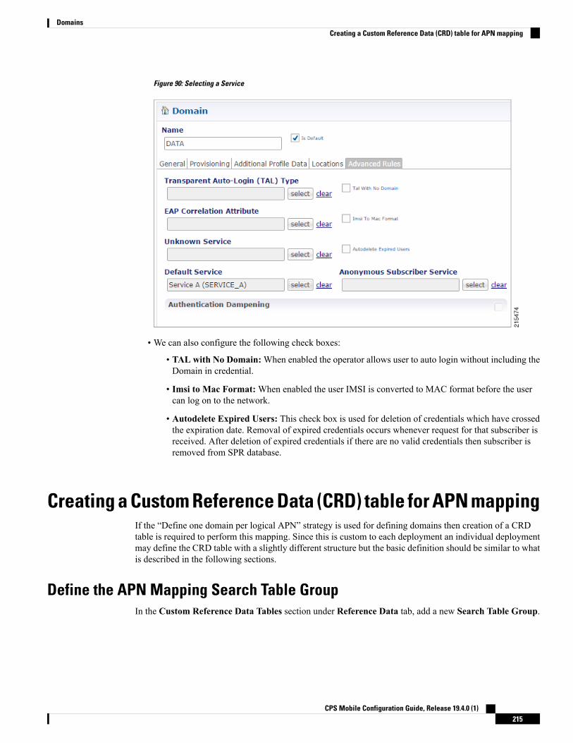
Figure 90: Selecting a Service
• We can also configure the following check boxes:
• TAL with No Domain:When enabled the operator allows user to auto login without including theDomain in credential.
• Imsi to Mac Format:When enabled the user IMSI is converted to MAC format before the usercan log on to the network.
• Autodelete Expired Users: This check box is used for deletion of credentials which have crossedthe expiration date. Removal of expired credentials occurs whenever request for that subscriber isreceived. After deletion of expired credentials if there are no valid credentials then subscriber isremoved from SPR database.
Creating a Custom Reference Data (CRD) table for APN mappingIf the “Define one domain per logical APN” strategy is used for defining domains then creation of a CRDtable is required to perform this mapping. Since this is custom to each deployment an individual deploymentmay define the CRD table with a slightly different structure but the basic definition should be similar to whatis described in the following sections.
Define the APN Mapping Search Table GroupIn the Custom Reference Data Tables section under Reference Data tab, add a new Search Table Group.
CPS Mobile Configuration Guide, Release 19.4.0 (1)215
DomainsCreating a Custom Reference Data (CRD) table for APN mapping

Figure 91: Search Table Group Configuration
The following parameters can be configured under Search Table Group:
Table 87: Search Table Group Parameters
DescriptionParameter
Set to recognizable name to indicate that this is the APN mapping search table group.An example is “APN Mapping”.
Name
Set to “0” to ensure that this group is processed before other search tables are processed.Evaluation Order
Results Column
Set to logical_apn. This is the name of the AVP that will be populated into the policyengine representing the logical APN. The name must not have spaces or specialcharacters. Best practice is to use “_” character for spaces and lowercase letters in placeof mixes case or all uppercase letters.
Name
Set to “Logical APN” or equivalent display name for use in reference data screens. Thisfield is only used for display purposes and as a result can contain spaces and specialcharacters.
Display Name
Set this to “true” which is a checked value.Use In Condition
Set this to the default logical APN to if a match is not found in the mapping table. Anexample of this value is “DATA”.
Default Value
Define the APN Mapping Custom Reference TableOn the “APN Mapping” search table group, create a new Custom Reference Table.
CPS Mobile Configuration Guide, Release 19.4.0 (1)216
DomainsDefine the APN Mapping Custom Reference Table

Figure 92: Custom Reference Data Table Configuration
The following parameters can be configured under Custom Reference Data Table:
Table 88: Custom Reference Data Table Parameters
DescriptionParameter
Set this to “apn_mapping” or an equivalent table name to contain the mapping data. Thename should not have spaces or special characters. A best practice is to use “_” characterfor spaces and lowercase letters in place of mixes case or all uppercase letters.
Name
Set this to “APNMapping” or equivalent display name for use in reference data screens.This field is only used for display purposes and as a result can contain spaces and specialcharacters.
Display Name
Set this to “true” which is a checked value.Cache Results
This should be set to “false” unless regular expression or defaulting with “*” matchesis used in the key fields.
Best Match
Set to “0” to ensure that this group is processed before other search tables are processed.Evaluation Order
For more information, see Table 89: Columns Table, on page 218.Columns
CPS Mobile Configuration Guide, Release 19.4.0 (1)217
DomainsDefine the APN Mapping Custom Reference Table

Table 89: Columns Table
ExampleParameterName
apnNameapn
APNDisplay Name
trueKey
trueRequired
Gx APNBind to Session/Policy State Field
logical_apnNameLogical_apn
Logical APNDisplay Name
trueRequired
Load Data into the APN Mapping TableAfter successfully publishing the configuration to the running system, new APN(s) are defined by enteringthe data through the Control Center GUI or through API calls (refer to theCPS Installation Guide for VMwarefor this release for instructions on how to access the Control Center).
An example of the definition is shown below:Figure 93: APN Mapping Table
Validation StepsThe following validation steps are designed to verify whether the “Define one domain per logical APN”approach to APN Profiles is properly configured or not. We will create two domains and map them to a defaultservice based on two different APNs.
CPS Mobile Configuration Guide, Release 19.4.0 (1)218
DomainsLoad Data into the APN Mapping Table

The ability to generate a Gx CCR-i from two different APNs. The actual APN names are not important howeverthey must be different.
Step 1 Configure the CRD table as described in Creating a Custom Reference Data (CRD) table for APNmapping, on page 215.Step 2 Publish the configuration to the running environment. This is required before data can be loaded into the CRD tables.Step 3 The actual CRD data to be evaluated is located in the Control Center interface (refer to Load Data into the APNMapping
Table, on page 218). In the control center, make sure there are two different logical APN groups with each group mappingto the Gx APN value that will be passed in the CCR-i. Navigate to the table in Control Center and map each Gx APN todifferent logical APNs (for example: column apn might have “data.apn.com” and would map to logical APN “DATA”while another “apn” row might map to logical APN “VOICE”).Figure 94: APN Mapping
Step 4 Configure two different PB domains, one for DATA and one for VOICE.
For more information, see Defining a Domain, on page 192.
Step 5 In each domain, in the Location tab, configure the Location Mapping Type of AVP Value to map logical_apn\DATAon the DATA domain and logical_apn\VOICE on the VOICE domain as described in Defining the Location Attributesof the Domain, on page 213.
Step 6 Set the default or anonymous service on the domain's Advanced tab to match the service required for the domain.Step 7 Generate Gx CCR-i from each different APN, validate that the service assigned to the client matches the default/anonymous
service for the domain. As per the log below, check that the (location) debug message shows “Location found for avpmatching: logical_apn\DATA”:[20XX-XX-XX 12:34:50,025] ===============================================POLICY RESULT SUCCESS:
session action = CreatedomainId = location_testlocationId = apnSERVICES: DefaultDataServiceTRIGGER: Message: com.broadhop.diameter2.messages.DiameterRequestMessage
Application Id: Gx (16777238)Command Code: Gx_CCR-I (272)Dest host: nullDest realm: pcrf.cisco.comDevice protocol: GX_TGPPEnd to end id: 3024
CPS Mobile Configuration Guide, Release 19.4.0 (1)219
DomainsValidation Steps

Hop by hop id: 6001Origin host: pcef-gxOrigin realm: pcef.cisco.comOrigin state: 0Stack name: nullSession-Id: .;1096298393;1Session-Id: .;1096298393;1Auth-Application-Id: 16777238Origin-Host: pcef-gxOrigin-Realm: pcef.cisco.comDestination-Realm: pcrf.cisco.comCC-Request-Type: 1CC-Request-Number: 1RAT-Type: 1000IP-CAN-Type: 0Called-Station-Id: data.apn.comFramed-IP-Address: 0x010108f0Framed-IPv6-Prefix: 0x004020010b680014000000000000000000003GPP-SGSN-Address: 0x010101013GPP-SGSN-MCC-MNC: 71617Supported-Features:
Vendor-Id: 10415Feature-List-ID: 1Feature-List: 1
Subscription-Id:Subscription-Id-Type: 1Subscription-Id-Data: 1234567890
Subscription-Id:Subscription-Id-Type: 0Subscription-Id-Data: AAAA.BBBB.CCCC
QPS-Internal-Route-Record-Host: pcef-gxQPS-Internal-Route-Record-Realm: pcef.cisco.com
DEBUG MSGS:INFO : (core) Tagging message with ID: GX_TGPPINFO : (core) Lock obtained on key: diameterSessionKey:.%3B1096298393%3B1INFO : (core) Start session triggeredINFO : (gx) Rel8 feature supported on session .;1096298393;1INFO : (gx) Creating new diameter session .;1096298393;1INFO : (custrefdata) Adding AVP [GetLogicalApn/logical_apn], value: DATAINFO : (location) Location found for avp matching: logical_apn\DATAINFO : (auth) Success ALLOW_ALL authorizationINFO : (core) No service is associated, added default service code:
DefaultDataService for session
Configuring Domain to Parse Sh Attributes in Date and TimeFormat
Step 1 Log in to Policy Builder.Step 2 Navigate to Services tab.Step 3 Select Domain and configure a new domain.Step 4 Go to Additional Profile Data tab and select Sh Profile.Step 5 Under Profile Mappings, add the following:
CPS Mobile Configuration Guide, Release 19.4.0 (1)220
DomainsConfiguring Domain to Parse Sh Attributes in Date and Time Format

Table 90: Profile Mappings
Mapping TypeExternal Code
SubscriberAttribute
vdsThrtlPlcyExpireTs
SubscriberAttribute
vdsThrtlExpireTs_Reval
Step 6 Under Sh Parsing, add the following:
Table 91: Sh Parsing
Value XpathCode Literal
[Name=‘vdsThrtlPlcyExpireTs’vdsThrtlPlcyExpireTs
Configuring a Virtual Service
Step 1 Log in to Policy Builder.Step 2 Navigate to Services tab.Step 3 Select Domain and configure a new domain.Step 4 Go to Additional Profile Data and select Sh Profile.Step 5 Under Profile Mappings, add the following:
Table 92: Profile Mappings
Mapping TypeExternalCode
SubscriberAttributesvcplan
Step 6 Go to Advanced Rules.Step 7 Set Service Resolver to the configured virtual service.Step 8 Select Services tab and configure a virtual service.
CPS Mobile Configuration Guide, Release 19.4.0 (1)221
DomainsConfiguring a Virtual Service

CPS Mobile Configuration Guide, Release 19.4.0 (1)222
DomainsConfiguring a Virtual Service

C H A P T E R 7Services
• Overview, on page 223• Service Example, on page 227• Service Screens, on page 228• Custom Reference Data Tables, on page 244
OverviewIn CPS, a 'Service' it what is assigned to a subscriber (in USuM) to define how that subscriber is treated. Somebasic examples of services would be a 'GOLD' user might get a high upload/download speed whereas a'BRONZE' user would get a low one. Other examples would include having one type of user be redirected toa portal when their Quota is exhausted whereas another type would only have their speed downgraded.
As the Service maps as closely as possible to how a Service Provider wants to classify their customers, theService in CPS is flexibly defined to allow configuration at different levels.
Below is an overview of the different objects referenced in the Services tab in PB. The detailed descriptionof each object is provided in below sections.Figure 95: Services
Service• A service is effectively just a 'code' to label the service and a collection of Service Options which containthe definition of what a service 'is'.
• What a Customer Service Representative assigns to a subscriber to describe the user's plan.
• Multiple services can be assigned to a single subscriber
CPS Mobile Configuration Guide, Release 19.4.0 (1)223

• If multiple services are assigned to a subscriber, the service options are combined between all assignedservices.
Therefore, there is no logical difference between a subscriber with:
• A single service with 10 service options
• 10 services with 1 option each
Service Option• Provides the concrete values which can be re-used for multiple services.
For example, one subscriber might have one service option which describes the values for 10 MBUpload/Download speed and another subscriber which describes 1 MB Upload/Download speed.Continuing the example from above, 10 MB could be assigned to a GOLD service and 1 MB could beassigned to BRONZE.
• What values are configurable in a Service Option are setup by the Use Case Template object. The UseCase Template can provide defaults to the Service Option or hide values in Service Configuration objectsnot necessary for certain use cases.
• If a Service Configuration's value is not defined in a Service Option, the value from the Use Case Templateis used.
Service Configuration• The low-level configuration objects used by the CPS code to drive functionality. These objects are usedto drive functionality in the system. The whole point of the Service > Service Option > Use Case Templatechain of functionality is to flexibly configure these Service Configuration objects which the code usesto drive system logic.
• These objects are defined by the CPS code.
Types of service configurations:
• PriorityConfiguration: Only one allowed to be active at a time. If multiples priority configurations areadded, highest priority is used.
These are used in cases where only a single value makes sense. For example, when sending an 'Accept'message, we can only have one template and multiples do not make sense.
Objects of this type always have a priority field. If multiple priority configurations are added, the highestpriority object is used.
Example: AccessAcceptConfiguration, RegisterMacAddress
• GroupConfiguration (most common): Only 1 per 'Group Name' are allowed to be active. If multipleconfigurations are added highest priority per 'Group Name' is used.
These are used in cases where a configuration only makes sense for a single 'group' (key). For example,if it makes sense to control the upload/download speed based on the network type (cell, Wi-Fi, and soon) a service configuration to control network speed with a group set for cell/Wi-Fi would allowmultipleservice configurations to be added.
CPS Mobile Configuration Guide, Release 19.4.0 (1)224
ServicesService Option

RADIUS-based policy control is no longer supported in CPS 14.0.0 and laterreleases as 3GPP Gx Diameter interface has become the industry-standard policycontrol interface.
Note
These objects always have a group field as well as a priority field. For each unique group value, thehighest priority is used.
Example: IsgServiceConfiguration, All Diameter Configurations, OneTimeUsageCharge
• ServiceConfiguration: Multiples allowed. If multiple configurations are added, all are used. 'Modify'functionality in PB for Use Case Options/Service Options can override values conditionally.
Example: AutoChargeUpAccounts, AutoProvisionQuota, BalanceRateConfiguration
Use Case TemplatesUse case templates are the building blocks of the Cisco Policy Builder Service Model architecture.
• Defines the Service Configuration objects to be set by a Service Option.
• Provide default values and/or hide values which do not need to be set by a use case
• Optionally, contains 'Initiators' (Conditions) which define when the template is active.
• Created by an advanced user (usually Engineering/AS).
• Makes Service Option and Service creation easier.
For example, a Use Case Template set up to create different upload or download speeds includes a'DefaultBearer' QoS Service Configuration object. The user creating a Use Case Template can default and/orhide the values for 'ARP' and other values not directly related to upload or download speed. This allows thecreation of the Service Option to be much simpler.
A copy of the Use Case Options is created while copying a Use Case Template.
Use Case Template tab OrderA new parameter -DshowUseCaseInitiatorTabFirst can be added in pb.conf (/etc/broadhop/pb/)file on pcrfclient01/02 to re-order the Use Case Template and Use Case Option tabs. This parameter alsorenames Use Case Template and Use Case Option tabs to Actions tab.
By default, -DshowUseCaseInitiatorTabFirst is set to true (does not required to be added in pb.conf fileby default).
• If set to true, the tabs will be displayed in the following order:
CPS Mobile Configuration Guide, Release 19.4.0 (1)225
ServicesUse Case Templates
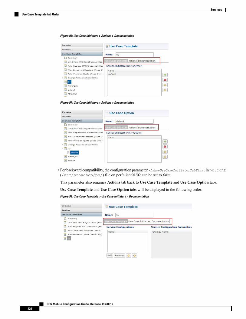
Figure 96: Use Case Initiators > Actions > Documentation
Figure 97: Use Case Initiators > Actions > Documentation
• For backward compatibility, the configuration parameter -DshowUseCaseInitiatorTabFirst inpb.conf(/etc/broadhop/pb/) file on pcrfclient01/02 can be set to false.
This parameter also renames Actions tab back to Use Case Template and Use Case Option tabs.
Use Case Template and Use Case Option tabs will be displayed in the following order:Figure 98: Use Case Template > Use Case Initiators > Documentation
CPS Mobile Configuration Guide, Release 19.4.0 (1)226
ServicesUse Case Template tab Order

Figure 99: Use Case Option > Use Case Initiators > Documentation
Use Case Option• A child of Use Case Template used to add or modify Service Configurations objects when certainconditions occur.
• Provides a way to separate Service Configurations within a use case based on conditions.
• Contains the same functionality of a Use Case Template.
• Adds or modifies new service options from parent Use Case Template.
While copying a Use Case Option, all the corresponding children Use Case Options get copied as well.
For example, if a user's upload or download speed should be decreased when they are out of quota, a UseCase Option is added with a condition indicating the user is out of quota. The service configurations in theuse case options can have a higher priority than those in the use case template to override the normal values.The service option then allows setting both the normal upload or download speed and the upload or downloadspeed when the user is out of quota.
Service ExampleThe following diagram illustrates how a 'Service Configuration' object called PredefinedRule can be flexiblyconfigured as part of a service. For those unfamiliar, a predefined rule is just an identifier sent to PCEF whichcontrols a users upload or download speed (QoS) among other things.
In this case, the service gold is assigned a Service Option called 10MB Fair Use. This service option resultsin a rule being passed to PCEF called 10MB by default and switching the rule to 5 MB when the users quotais depleted.
Notice that it would be easy to add another service option for 20MB Fair use, and so on.
The Use case template defines the low-level information that a 'PredefinedRule' be created of priority five.This rule is default and always present. Additionally, a Use Case Option defaults that another PredefinedRuleof priority ten be added. The higher priority results in the new rule name being switched when quota is depleted.
CPS Mobile Configuration Guide, Release 19.4.0 (1)227
ServicesUse Case Option

Figure 100: Service Using Use Case Option
Instead of using a Use Case Option to define what happens when a user is depleted, they set up another UseCase Template.
This could have an advantage if a customer wanted services for a large combination of values (10 MB defaultwith any combination of 1 MB - 9 MB depleted speed). Also, to support a use case where the end user couldbe independently assigned a default speed and a depleted or downgrade speed. A service for 10 MB defaultand 5 MB depleted would also be functionally equivalent.
This flexibility in the service model allowsmapping CPS closely to the Service Providers concept of a service.Figure 101: Service Using Use Case Template
Service ScreensThe following screens set up the example seen in the previous section. Service 'Gold' with two separate serviceoptions. The 'Predefined Rule' that is part of the setup is just an example, so not all fields on the PredefinedRule are described.
For example, a 'Rule Name' is a label and can be assigned to a subscriber on a PCEF. PCEF is responsiblefor defining what the rule 'means'. In this example, we make the assumption that PCEF has rules set up for'10_MB' and '5_MB' which control the users QoS (Quality of Service - effectively upload or download speed)to 10 MB upload or download and 5 MB upload or download respectively.
CPS Mobile Configuration Guide, Release 19.4.0 (1)228
ServicesService Screens

The subtle difference between 10 MB and '10_MB' is to ensure that it is clear which name is used for internalreference and which is sent to PCEF.
Note
ServicesFigure 102: Service Page
The following parameters can be configured under Service:
Table 93: Service Parameters
DescriptionParameter
This is what is saved on the subscriber. It defaults to 'default'. This value is the linkbetween the Services assigned a subscriber in Control Center and the Service in PolicyBuilder. This value is not updated if existing users have it assigned, as the 'link' is bebroken. Instead, the name is updated.
Code
This is the name displayed in Control Center.Name
If this value is unchecked, the service is not evaluated by the Policy Engine and is notdisplayed in Control Center.
Default value is checked (true).
Enabled
CPS Mobile Configuration Guide, Release 19.4.0 (1)229
ServicesServices

DescriptionParameter
If this value is checked, this Service is not displayed in the Portal. This is specific forSP Wi-Fi call flows.
Default value is unchecked (false).
RADIUS-based policy control is no longer supported in CPS 14.0.0 andlater releases as 3GPP Gx Diameter interface has become theindustry-standard policy control interface.
Note
Suppress in Portal
If this value is checked, the Service runs through balance processing. This results inone database read or write against the balance database. Performance improves (dueto fewer database read or writes).
For the services which don't rely on Balance or Quota, this value is unchecked.
Default value is checked (true).
Balance Service
If this value is checked, this service is considered to be also assigned to any 'subaccounts'associated to the main subscriber. This is useful if you had a family plan where theQoS is controlled at the main subscriber level and 'trickles down' to the family subaccounts rather than being set at each individual level.
Default value is unchecked (false).
Add to SubAccounts
Service Options Table
This table displays a read-only version of the service options associated to the Service. Service Options canbe added or removed to the service.
Table 94: Service Options Table Parameters
DescriptionParameter
The name of the associated Service Option.Name
The name of the associated use case template.Use Case Template
Allows adding another Service Option to this service. The Add dialog shows the UseCase Template > Service Option hierarchy on the left and a preview of the parametersset by the Service Option or Use Case Template on the right.
Add
Removes a Service Option from the Service.Remove
Allows moving a Service Option up or down. This only affects the ordering of serviceoptions in the list and does not functionally affect the resolution of services.
Up or Down Arrow
View Service Option Parameters
This hyperlink shows a consolidated list of the Service Configuration Parameters from the Use Case Templateand Service Options. This view is useful for simple service options or use case templates. However, since itdoes not show the distinction between different Service Configuration objects. Hence, it can be difficult toread for more complicated configurations.
CPS Mobile Configuration Guide, Release 19.4.0 (1)230
ServicesServices

Service OptionsThe service option dialog allows setting the concrete values for service configuration parameters used in theUse Case Template. The groups under service options are Use Case Templates. Adding a new Use CaseTemplate adds a new group under Service Options so you can provide concrete values for the Use CaseTemplates.
The following parameters can be configured under Service Option:
Table 95: Service Option Parameters
DescriptionParameter
This is the name of the service option which is referenced by the Service.Name
This is a link that allows quickly seeing the associated Use Case Template and goingstraight to this Use Case Template.
You can use the 'left' arrow in the Policy Builder toolbar to go 'back' tothe service option after clicking into the Use Case Template.
Note
Use Case Template
This is a list of the 'Service Configuration' objects that are to be set as part of theService Option. This list can usually be used 'as is' upon creation. The ServiceConfiguration objects from the Use case template is used as a default and any valuesset here 'overrides' the use case template.
• Add: This allows adding a new Service Configuration that has been added tothe Use Case Template. This is only really useful when a new ServiceConfiguration object was added to a Use Case Template after this service optionwas created and you now what to override some values on this new object.
• Remove: This is only really useful if you don't want to use your configuredvalues at all and just use the values from the Use Case Template. In that caseyou can just remove the Service Configuration Objects and the values from theUse Case Template is used.
Service Configurations
These are the parameters being overridden from the use case template.PreDefinedRuleParameters
This allows adding a parameter from the Use Case Template even if it is not markedas 'AllowOverride'. It also allows customizing a parameter that didn't exist previouslyin the Use Case Template or was removed from the Service Option.
Add
This allows removing a parameter from the Service Option. This means that thevalue specified for the Use Case Template's version of this parameter is used.
Remove
This column shows the 'Display Name' of the parameter. This name can be updatedby either the Service Option or the Use Case Template to make it clearer for usersto understand what this value does. The 'true' name of the field can be seen byhovering over the cell.
Display Name
This is the value of the parameter which should be set. If there is a value set in the'Pull Value From…' column, this value is used as the default and overridden withthe 'Pull Value From…' information.
Value
CPS Mobile Configuration Guide, Release 19.4.0 (1)231
ServicesService Options

DescriptionParameter
This allows setting this value dynamically through AVP's, Custom Reference Dataor the 'Policy State'. For more information, refer to Table 96: Pull Value From...,on page 232.
Pull Value From...
Table 96: Pull Value From...
DescriptionParameter
This allows pulling values fromAVPs on the subscriber. This field now also supportsAVP's on the subscriber's session and 'Policy Derived AVP's added in policies.
Subscriber AVP Code
This allows pulling the value from the Custom Reference Data table's columnspecified.
Custom Reference Data takes care of which 'row' in the column ismatched, so this ends up specifying a single value.
Note
Custom ReferenceData Column
This allows pulling the value from the state of the system. This uses any of thepreconfigured 'Policy State Data Retrievers' that are plug-in code that know how toget a certain value from the system.
Bind to Session/PolicyState
This allows pulling the value from other reference data configuration (Policy Builderor CRD, for example, Account Balance Templates) as value for the use case attribute.
Currently, only Account Balance Template type attributes are supported. Theintended Account Balance Template code can be configured in the text field. BothPolicy Builder and CRD Balance templates can be pulled using this field. PolicyBuilder templates are checked first, if not found then CRD templates are searched.
Dynamic ReferenceData Key
Use Case TemplatesUse case templates form the basis of a service and are in general more complicated than creating a service orservice option. For more information on creating Use Case Templates, contact your Cisco TechnicalRepresentative.
The following parameters can be configured under Actions (Use Case Template) tab:
Table 97: Actions (Use Case Template) Parameters
DescriptionParameter
This is the name used to identify the Use Case Template. It can be changed.Name
CPS Mobile Configuration Guide, Release 19.4.0 (1)232
ServicesUse Case Templates

DescriptionParameter
This is where you add the Service Configuration objects needed to configure youruse case.
• Add: The Add button brings up the full list of Service Configuration objects.Which to choose should be based on the use case documentation you areimplementing. The right column of the screen displays the parameters that arein a specific service configuration. If you 'uncheck' a parameter, the default asseen on this screen (from the code) will be utilized. Unchecking is functionallyequivalent to 'removing' a field from the table after adding it.
• Add New: Implies that you are adding a new Service Configuration to beconfigured. This is almost always what you want.
• Modify: Implies that you are modifying an existing Service Configuration.This is used in a 'Use Case Option' and in general not recommended asit's preferred to use the 'priority' fields to update the service configurationobjects.
Service Configurations
This allows creating a child use case option of this use case template.Create Child: Use CaseOption
PreDefinedRule Parameters
This allows adding a parameter to the Use Case Template even if it wasn't addedinitially (unchecked or a code update added a new parameter).
Add
This allows removing a parameter from the Use Case Template. This means thatthe value specified in the code (as seen on the Add Service Configuration screen)will be utilized.
Remove
This column shows the 'Display Name' of the parameter. This name can be updatedby either in the Use Case Template to make it clearer for users to understand whatthis value does. The 'true' name of the field can be seen by hovering over the cell.
Display Name
This is the value of the parameter which should be set. If there is also a value setin the 'Pull Value From…' column, this value will be used as the default andoverridden with the 'Pull Value From…' information.
Value
This allows setting this value dynamically through AVP's, Custom Reference Dataor the 'Policy State'.
Pull Value From…
This value indicates whether this option will show up for configuration in the ServiceOption by default. In general, it is best to only check this box for values you expectto be configured in the Service Option. This will make it easier to configure andmaintain the service options.
Allow Override
Use Case InitiatorsUse Case Initiators are groups of conditions that indicate whether or not the Service Configuration objectswithin this use case template are used. If no use case initiators are specified, the Service Configuration objectswill always be added.
CPS Mobile Configuration Guide, Release 19.4.0 (1)233
ServicesUse Case Initiators

The following parameters can be configured under the Use Case Initiators tab.
Table 98: Use Case Initiators Parameters
DescriptionParameter
Service Initiators are a grouping of conditions. If ANY of the service initiators ona Use Case Template are true then that Use Case template is active and the ServiceConfigurations are used.
When you add multiple Service Initiators, the Use Case Template is activated andService Configurations are used when ANY one of these initiators are true, asindicated by the caption “(OR Together)”.
• Plus/X: Lets the user add or remove a service initiator.
• Up/Down arrow: The user can move the initiators up and down. This affectsthe order in which the service initiators are evaluated.
Service Initiators (ORTogether)
This is a logical name for this grouping of conditions.Initiator Name
These are the conditions associated with the service initiator. Conditions usuallypertain to this messages session, subscriber information, balance information, orthe message itself. The current values of the condition are set up by thecode/messaging.
When you add multiple conditions, ALL of the listed conditions must be true, asindicated by the caption “(AND Together)”.
• Add/Remove: Lets the user add or remove a condition.
• Up/Down arrow: Lets the user move a condition up or down in the list. Thisis usually only needed when referencing a previous condition in this condition.For example, the user can check a 'session exists' in the first condition andthen use the 'session user name' in the second condition. The user can onlyreference previous conditions.
• Input Variables (AND Together): These input variables are specific to eachcondition. If the current value of the condition matches the input variable, thiscondition is true.
When you define multiple input variables for a condition, ALL of the variablesare evaluated and must be true for the condition to be true, as indicated by thecaption "(AND Together)".
• Input Variable: This is the name of the variable.
• Type: This is either 'Literal' matching where we match against ahard-coded 'value' or 'Output' where the value is pulled from a previous(or current) condition. If output is chosen, a popup will appear where thevalues from the current or previous conditions can be selected and the'value' box is replaced with the selection.
• Operator: This allows editing how 'true' is determined given the currentvalue of the condition and the value specified. The default and by farmost common option is '=' equals.
Conditions (ANDTogether)
CPS Mobile Configuration Guide, Release 19.4.0 (1)234
ServicesUse Case Initiators

DescriptionParameter
= (Equals): The condition is true if the values are equal. This uses the Java equals()function.
Multiple value with comma separated is not allowed with = operator for stringdatatype.
Operator
<> (Not Equals): The condition is true if the values are not equal.
isNull: The condition is true if the value is null (empty).
!isNull: The condition is true if the value is not null (empty).
Matches: The condition is true and the value is a regex that successfully matchesthe current value. Java regex is utilized. Example: .* matches anything.
[0-9]+: Matches 1 or more numbers.
^[0-9]*$: Matches a string which is only numbers or empty.
!matches: The logical opposite of matches (if matches would be true, !matches isfalse).
In: This is true if the current value is equal to one of the values listed (commaseparated).
!In: This is the logical opposite of In (if In would be true; !In is false).
Contains (Only for lists): True if the list contains the value or values.
!Contains (Only for list): The logical opposite of contains.
Value: This is the hard-coded value which should be compared against the currentvalue in the system.
Remove (link): This allows removing this input variable.
The following sections describe the input variables that can be configured for the following conditions:
A Customer Reference Data AVP Exists
This condition indicates that a custom reference data table exists in the Policy Builder configuration with oneor more Column Names mapped to a unique Attribute Value pair. Any column marked as Use in conditionscan be used.
In order to protect a customer reference column's integrity, once it has been created and published, it cannotbe changed.
The following condition input variables can be exposed in the Policy Builder GUI:
Table 99: Available Input Variables used for A Customer Reference Data AVP Exists
AVP Used/DescriptionCondition Input Variable
The custom Reference Table Name.tableName
CPS Mobile Configuration Guide, Release 19.4.0 (1)235
ServicesA Customer Reference Data AVP Exists

AVP Used/DescriptionCondition Input Variable
The custom AVP column Name.code
The custom AVP column’s value.value
A Customer Reference Data AVP Does Not Exist
This condition indicates that a custom reference data table exists in the Policy Builder configuration with oneor more Column Names not mapped to a unique Attribute Value pair. Any column, which is not marked asUse in conditions cannot be used.
In order to protect a customer reference column's integrity, once it has been created and published, it cannotbe changed.
The input variables that can be exposed for this condition in the Policy Builder GUI are the same as describedin A Customer Reference Data AVP Exists, on page 235.
A Diameter Gx TGPP Session Exists
This condition indicates that a valid Diameter Gx 3GPP session exists in the Policy Builder configuration fora given subscriber. The following condition input variables can be exposed in the Policy Builder GUI:
Table 100: Available Input Variables for Diameter Gx TGPP Session Exists
AVP Used/DescriptionCondition Input Variable
The subscriber identity in the Subscription-Id AVP being msisdn.msisdn
The subscriber identity in the Subscription-Id AVP being imsi.imsi
The Ipv6 prefix allocated for the user.framedIpv6
The Ipv4 address allocated for the user.framedIp
The unique Id of the session generated by PCEFsessionId
The unique Command Code to identify the Gx Request/Response Type –CCR/CCA or RAR/RAA.
commandCode
The type of the request (initial, update, termination).requestType
The destination realm derived from the Origin-Realm of CCR-I and used inPCRF RAR request.
destRealm
The destination host derived from the Origin-Host of CCR-I and used in PCRFRAR request.
destHost
Identifies the radio access technology that is serving the UE.
PCRF supports devices using narrow band Internet of Things (NB-IoT) RATthat is a 3GPP radio interface to support IoT devices.
PCRF can create a session with UE having RAT-type as NB-IOT and providesall functionalities (such as policy control and charging rule functionality) toan NB-IOT devices.
ratType
CPS Mobile Configuration Guide, Release 19.4.0 (1)236
ServicesA Customer Reference Data AVP Does Not Exist

AVP Used/DescriptionCondition Input Variable
The Unique Application Identifier to identify the Gx Session.appId
Concatenated value ofMobile Country Code (mcc) andMobile Network Code.mccmnc
The address the user is connected to. For GPRS the APN.calledStationId
Extracted from either the 3GPP-User-Location-Info AVP, which providesdetails of where the UE is currently located, or the RAI AVP, which containsthe Routing Area Identity of the SGSN where the UE is registered.
lac
Extracted from either the 3GPP-User-Location-Info AVP, which providesdetails of where the UE is currently located, or the RAI AVP, which containsthe Routing Area Identity of the SGSN where the UE is registered.
rac
Extracted from 3GPP-User-Location-Info AVP. Provides details of wherethe UE is currently located.
sac
Extracted from 3GPP-User-Location-Info AVP. Provides details of wherethe UE is currently located.
ci
3GPP-RAT-Type AVP. Indicates the Radio Access Technology that iscurrently serving the UE.
tgppRatType
NAeventTriggers
An OUT_OF_CREDIT trigger reported by Event-Trigger AVP.outofCredit
Extracted from 3GPP-User-Location-Info AVP. Provides details of wherethe UE is currently located.
cgi
Extracted from 3GPP-User-Location-Info AVP. Provides details of wherethe UE is currently located.
Ecgi
Extracted from 3GPP-User-Location-Info AVP. Provides details of wherethe UE is currently located.
Tai
Extracted from 3GPP-User-Location-Info AVP. Provides details of wherethe UE is currently located.
Sai
Extracted from 3GPP-User-Location-Info AVP. Provides details of wherethe UE is currently located.
Tac
Extracted from 3GPP-User-Location-Info AVP. Provides details of wherethe UE is currently located.
Eci
International Mobile Equipment Identifier along with Software Version.Extracted from User-Equipment-Info-Value AVP.
Imeisv
Network-Request-SupportAVP. Indicates whether or not the UE and accessnetwork supports the network requested bearer control mode.
networkRequestSupport
The Network Access Identifier.Nai
CPS Mobile Configuration Guide, Release 19.4.0 (1)237
ServicesA Diameter Gx TGPP Session Exists

AVP Used/DescriptionCondition Input Variable
Bearer-Control-ModeAVP. Indicates the PCRF selected bearer control mode.bearerControlMode
3GGP-SGSN-Address AVP. Indicates the Ipv4 address of the SGSN.sgsnIpAddress
IP-CAN-Type AVP. Indicates the type of Connectivity Access Network inwhich the user is connected.
ipcanType
Extracted from either the 3GPP-User-Location-Info AVP, which providesdetails of where the UE is currently located or the RAI AVP, which Containsthe Routing Area Identity of the SGSN where the UE is registered.
Mnc
Extracted from either the 3GPP-User-Location-Info AVP, which providesdetails of where the UE is currently located, or the RAI AVP, which containsthe Routing Area Identity of the SGSN where the UE is registered.
Mcc
Extracted from either the 3GPP-User-Location-Info AVP, which providesdetails of where the UE is currently located, or the RAI AVP, which containsthe Routing Area Identity of the SGSN where the UE is registered.
Rai
Qos-Upgrade AVP. Indicates whether the SGSN Supports the QOS Upgradeor not.
qosUpgrade
3GPP-SGSN-IPv6-Address AVP. Indicates the Ipv6 address of the SGSN.sgsnIpv6Address
Called-Station-Id AVP. The same as called Station Id condition.targetApn
Extracted from 3GPP-User-Location-Info AVP. Provides details of wherethe UE is currently located.
globalCiCode
Extracted from 3GPP-User-Location-Info AVP. Provides details of wherethe UE is currently located.
globalAreaCode
Same as Imeisv extracted from User-Equipment-Info-Value AVP.imeiTac
Extracted from User-Equipment-Info-Value AVP. The identification andcapabilities of the terminal.
Mac
Extracted from User-Equipment-Info-Value AVP. The identification andcapabilities of the terminal.
Eui64
Extracted from User-Equipment-Info-Value AVP. The identification andcapabilities of the terminal.
modifiedEui64
Qos-NegotiationAVP. Indicates if the PCRF is allowed to negotiate the QoS.qosNegotiation
Offline AVP. Defines whether the offline-charging interface from the TDFshall be enabled.
Offline
Online AVP. Defines whether the offline charging interface from the TDFshall be enabled.
Online
IPv4 Gateway Address.Ipv4AnGWAddress
CPS Mobile Configuration Guide, Release 19.4.0 (1)238
ServicesA Diameter Gx TGPP Session Exists

AVP Used/DescriptionCondition Input Variable
IPv6 Gateway Address.Ipv6AnGWAddress
Value of the mspEpsPriority set.mpsEpsPriority
3GPP-MS-TimeZone AVP. Indicates the offset between universal time andlocal time in steps of 15 minutes of where the MS currently resides.
tgppMsTimeZone
Access-Network-Charging-Address AVP. Indicates the IP Address of thenetwork entity within the access networks performing charging (e.g. the GGSNIP address).
accessNetworkChargingAddress
NAusageReportET
Extracted from User-Equipment-Info-Value AVP. The identification andcapabilities of the terminal.
Meid
Base Station Identifier.Bsid
3GPP-Charging-CharacteristicsAVP. The Charging Characteristics appliedto the IP-CAN session.
chargingCharacteristics
Extracted from 3GPP-Charging-Characteristics AVP. The ChargingCharacteristics applied to the IP-CAN session
chargingCharacteristicsBits
Application Name.appName
A Diameter Gy v8 TGPP Session Exists
This condition indicates that a valid Diameter Gy v8 3GPP session exists in the Policy Builder configurationfor a given subscriber. The following condition input variables can be exposed in the Policy Builder GUI:
Table 101: Available Input Variables for Diameter Gy v8 TGPP Session Exists
AVP Used/DescriptionCondition Input Variables
Subscription-Id-Data AVP. The identification of the subscription (IMSI,MSISDN, etc.).
Msisdn
The unique Id of the session generated by PCEF.sessionId
CC-Request-TypeAVP. The type of the request (initial, update, termination).requestType
CC-Request-Number AVP. The number of the request for mapping requestsand answers.
requestNumber
Destination-RealmAVP. The destination realm derived from theOrigin-Realmof CCR-I and used in PCRF RAR request.
destRealm
Destination-Host AVP. The destination host derived from the Origin-Hostof CCR-I and used in PCRF RAR request.
destHost
3GPP-RAT-Type AVP. Indicates the Radio Access Technology is currentlyserving the UE.
ratType
CPS Mobile Configuration Guide, Release 19.4.0 (1)239
ServicesA Diameter Gy v8 TGPP Session Exists
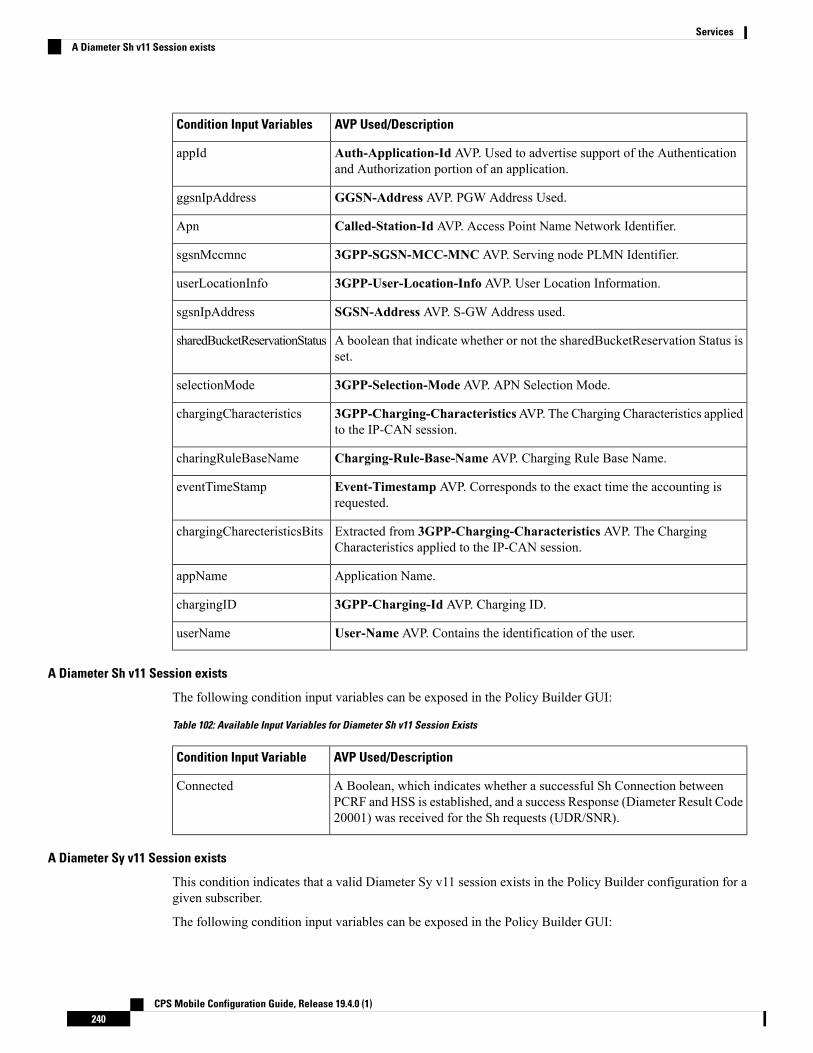
AVP Used/DescriptionCondition Input Variables
Auth-Application-Id AVP. Used to advertise support of the Authenticationand Authorization portion of an application.
appId
GGSN-Address AVP. PGW Address Used.ggsnIpAddress
Called-Station-Id AVP. Access Point Name Network Identifier.Apn
3GPP-SGSN-MCC-MNC AVP. Serving node PLMN Identifier.sgsnMccmnc
3GPP-User-Location-Info AVP. User Location Information.userLocationInfo
SGSN-Address AVP. S-GW Address used.sgsnIpAddress
A boolean that indicate whether or not the sharedBucketReservation Status isset.
sharedBucketReservationStatus
3GPP-Selection-Mode AVP. APN Selection Mode.selectionMode
3GPP-Charging-CharacteristicsAVP. The Charging Characteristics appliedto the IP-CAN session.
chargingCharacteristics
Charging-Rule-Base-Name AVP. Charging Rule Base Name.charingRuleBaseName
Event-Timestamp AVP. Corresponds to the exact time the accounting isrequested.
eventTimeStamp
Extracted from 3GPP-Charging-Characteristics AVP. The ChargingCharacteristics applied to the IP-CAN session.
chargingCharecteristicsBits
Application Name.appName
3GPP-Charging-Id AVP. Charging ID.chargingID
User-Name AVP. Contains the identification of the user.userName
A Diameter Sh v11 Session exists
The following condition input variables can be exposed in the Policy Builder GUI:
Table 102: Available Input Variables for Diameter Sh v11 Session Exists
AVP Used/DescriptionCondition Input Variable
A Boolean, which indicates whether a successful Sh Connection betweenPCRF and HSS is established, and a success Response (Diameter Result Code20001) was received for the Sh requests (UDR/SNR).
Connected
A Diameter Sy v11 Session exists
This condition indicates that a valid Diameter Sy v11 session exists in the Policy Builder configuration for agiven subscriber.
The following condition input variables can be exposed in the Policy Builder GUI:
CPS Mobile Configuration Guide, Release 19.4.0 (1)240
ServicesA Diameter Sh v11 Session exists

Table 103: Available Input Variables for Diameter Sy v11 Session Exists
AVP Used/DescriptionCondition Input Variable
Destination realm for Sy.destRealm
Destination host for Sy.destHost
The reason for failure in case Sy session is not established due to error (Lasterror code only).
failureReason
Destination queue (Internal field to know which policy director instance pickthe request for processing).
destQueue
Retry timer in case connection fails.retryTime
Last spending limit request type.lastSLReqType
Last Sy result code.lastSyResultCode
Sy counter identifier and status.syCountersIdentifierAndStatus
Subscriber account status.subscriberAccState
A Boolean, set to true when a successful SLA-Initial is received.slaReceived
The unique id of the session.sessionId
A Boolean, which indicates whether a successful Sy peer connection isestablished or not.
connected
A Policy Derived AVP Exists
This condition indicates that a custom policy AVP that has been derived out of PolicyState exists in the system.The following condition input variables can be exposed in the Policy Builder GUI:
Table 104: Available Input Variables used for A Policy Derived AVP Exists
AVP Used/DescriptionCondition Input Variable
A derived AVP Name from the PolicyState.code
A derived AVP value from the PolicyState.value
The following AVPs are treated as Policy-Derived AVPs:
• Gx
3GPP-MS-TimeZone and SN-Transparent-Data
The following policy-derived AVP codes from the above AVPs can be used in the Use case Initiators:
• UE HOUR OFFSET
• UE MINUTE OFFSET
• UE DST
CPS Mobile Configuration Guide, Release 19.4.0 (1)241
ServicesA Policy Derived AVP Exists

• UE DST
• BganMonthlyFapVolume
• Rx
Dynamic-PCC-Parameter AVP
• Dynamic-PCC-APN-Aggregate-Max-Bitrate-DL
• Dynamic-PCC-APN-Aggregate-Max-Bitrate-UL
• DynamicPCC-Congestion-Level
• Profile Related Mapping
The following profile related derived AVP codes can be used in the Use Case Initiators:
• Sh Profile
• LDAP Profile
• SPR Profile
• Additional ones
Charging – congestionNextHourLevel
A Policy Derived AVP Does Not Exist
This condition indicates that a custom policy AVP that has been derived out of PolicyState does not exist inthe system.
The input variables that can be exposed for this condition in the Policy Builder GUI are the same as thosedescribed in A Policy Derived AVP Exists, on page 241.
An APN Bearer Details exists
This condition indicates APN bearer details as received in Active Traffic Management attribute exists inPCRF. The following condition input variables can be exposed in the Policy Builder GUI:
Table 105: Available Input Variables for Diameter Gx TGPP Session Exists
AVP Used/DescriptionCondition Input Variable
Stage string as received in Active Traffic Management Attribute notificationfrom UDC FE.
Valid value is string.
stage
Acknowledge mode QCI as received in Active Traffic Management Attributenotification from UDC FE.
Valid value is an Integer.
ackMode
UnacknowledgemodeQCI as received in Active TrafficManagement Attributenotification from UDC FE.
Valid value is an Integer.
unackMode
CPS Mobile Configuration Guide, Release 19.4.0 (1)242
ServicesA Policy Derived AVP Does Not Exist

AVP Used/DescriptionCondition Input Variable
Logical APN string as received in Active Traffic Management Attributenotification from UDC FE.
Valid value is string.
logicalAPN
Front End ID string as received in Active Traffic Management Attributenotification from UDC FE.
Valid value is string.
frontEndId
Priority value as received in Active Traffic Management Attribute notificationfrom UDC FE.
Valid value is an Integer.
priority
An APN Bearer Details does not exists
This condition indicates no APN bearer details exist in Active Traffic Management attribute in PCRF. Theinput variables that can be exposed for this condition in the Policy Builder GUI are the same as described inAn APN Bearer Details exists , on page 242.
There Exists a Network Session
This condition indicates that a valid network session exists in the Policy Builder configuration for a givensubscriber. The network session exists irrespective of the interface type – Gx/Gy/Sh/Sy.
The following condition input variables can be exposed in the Policy Builder GUI:
Table 106: Available Input Variables for There Exists a Network Session
AVP Used/DescriptionCondition Input Variable
The mac address present in the session.Mac Address
User Identifier – Can be msisdn or extracted from Network Access Identifier.User Id
Framed-IP-Address AVP. The Ipv4 address allocated for the user.Framed IP
When the session starts.Start Time
How the subscriber is accessing network.Access Type
The subscriber identity in the Subscription-Id AVP being imsi.Imsi
The subscriber identity in the Subscription-Id AVP being msisdn.Msisdn
The ID of the cell tower.Cell Site Id
If the session is set to end, this gets set.End Time
Framed-IPv6-Prefix AVP. The Ipv6 prefix allocated for the user.Framed IPV6 Prefix
NAMsbm Initialized
The Subscriber Profile Repository credential.Credential Id
CPS Mobile Configuration Guide, Release 19.4.0 (1)243
ServicesAn APN Bearer Details does not exists

AVP Used/DescriptionCondition Input Variable
Version loaded from SPR in case an update is needed.Spr Version
How long the session has been going.Current Session Duration
The time when CPS will wake itself up and re-evaluate the session if anothermessage is not received.
Next Evaluation Date
Used on soft delete to note when the session should be cleaned upExpiration Date
There does not exist a network session
This condition indicates that a valid network session does not exist in the Policy Builder configuration for agiven subscriber. The network session does not exist irrespective of the interface type – Gx/Gy/Sh/Sy.
The input variables that can be exposed for this condition in the Policy Builder GUI are the same as describedin There Exists a Network Session, on page 243.
ADTM Attribute Bearer Details Exists
This condition provides option to check for total of ACKmode, UNACKmode and combined for the subscriberacross all the existing APNs.
The following condition input variables can be exposed in the Policy Builder GUI:
Table 107: Available Input Variables used for ADTM Attribute Bearer Details Exists
AVP Used/DescriptionCondition Input Variable
Total ACK mode bearers (count) across all existing APNs for a subscriber.
Valid value is an Integer.
totalAckMode
Total UNACKmode bearers (count) across all existing APNs for a subscriber.
Valid value is an Integer.
totalUnAckMode
Total number of bearers (count) across all existing APNs for a subscriber.
Valid value is an Integer.
totalCount
DocumentationThe documentation tab allows writing notes about the implementation which can be referred to later.
Custom Reference Data Tables
OverviewCustom Reference Data tables allow defining custom derived data for your installation and making decisionbased upon that data.
CPS Mobile Configuration Guide, Release 19.4.0 (1)244
ServicesThere does not exist a network session

For example, a customer may not want to directly assign each subscriber a service so they get the appropriateQoS, instead, they want to derive the QoS based on data we get from the subscribers session. CustomReferenceData tables are the way to do that. Then (as per the previous section) we can wire the derived data directlyinto the service with the “Bind Field…” or “Pull Value From…” options.
ExampleThe following screens have a simple example setup. The example is that we want to derive the PCEF RuleName based on the users APN (Access Point Name) and RAT (Radio Access Technology) name.
The logic is as follows:
Table 108: Example Table
Rule Name DepletedRule NameRATAPN
5_MB10_MB3GCisco
5_MB20_MBWi-FiCisco
1_MB5_MB*Cisco
5_KB1_MB3GCiscoTest
50_KB2_MBWi-FiCiscoTest
500_KB1_MB**
The * (asterisk) can be read as a wildcard, but the table should match the 'most specific' entry. So, if my APNand RAT are Cisco and 3G, match the first row, not the 3rd row (Cisco, *) or the last row (*,*).
These values are for example purposes only. Things like the RAT type value have been simplified to makethe example easier to understand.
Note
RADIUS-based policy control is no longer supported in CPS 14.0.0 and later releases as 3GPP Gx Diameterinterface has become the industry-standard policy control interface.
Note
Screens
Search Table GroupsSearch table groups allow groupingmultiple CustomReference Data Tables together logically, only executingthe searching when needed. It also allows ordering the execution of tables so that tables can reference outputof one table group in another to provide consistent and expected results. Additionally, Search Table Groupsallows multiple different tables to populate the same AVPs in different ways.
CPS Mobile Configuration Guide, Release 19.4.0 (1)245
ServicesExample

Search table groups and their respective CRD tables are listed based on the evaluation order value. If theevaluation order value is same for two or more tables then they are listed alphabetically.
Note
The following parameters are configured under Search Table Group:
Table 109: Search Table Group Parameters
DescriptionParameter
The name of the Search Table Group.Name
The order in which groups get evaluated, starting with 0 and going higher.Evaluation Order
These are the AVPs that will be added into processing. These need to be mapped to bethe same as values from underlying tables. This allows populating the same AVPs fromdifferent tables.
• Name: The name of the AVP. It should start with alphanumeric characters, shouldbe lowercase, and should not start with numbers, no special characters are allowed,use “_” to separate words. For example, logical_apn = GOOD, logicalAPN =BAD,no_spaces
• Display Name: The more human readable name of the AVP.
• Use In Condition: This represents whether this row will be available for conditionsin Policies or Use Case Templates. There is a performance cost to having thesechecked, so we recommend not checking them unless they are required.
Default value is checked (true).
• Default Value: The default value if no results are found from a Custom ReferenceData Table.
• Add/Remove: Adds or removes a row from the table.
• Up/Down: Allows ordering the list, but has no impact on processing.
Results Columns
This section controls whether or not the Search Table Group and all tables below willbe executed.
When you add multiple Initiators to the Search Table Group, the search is activated whenANY one of these initiators are true, as indicated by the caption “(OR Together)”.
For more information, refer to table in section Use Case Initiators, on page 233.
Table SearchInitiators (ORTogether)
Custom Reference Data TablePolicy Builder can be thought of as defining the 'schema' for the Custom Reference Data and the ControlCenter is responsible for filling out the schema.
CPS Mobile Configuration Guide, Release 19.4.0 (1)246
ServicesCustom Reference Data Table

Cisco recommends creating Custom Reference Data Tables under Search Table Groups. This allows you tospecify the order in which the tables are searched and provide the default values if nothing is found. It ispossible to re-parent a Custom Reference Data Table to another Search Table Group.
Note
The following parameters can be configured under Custom Reference Data Table:
Table 110: Custom Reference Data Table Parameters
DescriptionParameter
This is the name of the table that is stored in the database. It must:
• Start with alphanumeric characters
• Have lowercase OR uppercase but no mixed case
• Not start with numbers
• Not have special characters
• Use “_” to separate words
For example, logical_apn = GOOD, logicalAPN = BAD, no_spaces.
Name
This is the name of the table that is displayed in Control Center.Display Name
This indicates whether the tables are cached in memory. This must be checked forproduction.
Cache Results
This is the Custom Reference Data Trigger, which must be true before evaluating thistable. This can be used to have multiple tables create the same data depending onconditions or to improve performance if tables are not required to be evaluated basedon an initial condition.
ActivationCondition
When enabled, indicates that the CRD table is an SVN CRD table and CRD data forthe table is fetched from CRD CSV file present in SVN data source.
When disabled, indicates that the CRD table data needs to be fetched from Mongodatabase.
Svn Crd Data
If checked, look-ups occur within a CRD table in the following order:
• Exact string match
• Higher priority regex match (if multiple regex patterns match)
• Regular expression match (default behavior)
• Wildcard character (*)
For more information, refer to Best Match, on page 249.
Best Match
This indicates the order the tables within the search table group should be evaluated.Starting with 0 and increasing.
Evaluation Order
CPS Mobile Configuration Guide, Release 19.4.0 (1)247
ServicesCustom Reference Data Table

DescriptionParameter
Columns correspond to the schema for each column you are creating for this customreference data table.
• Name: The name of the column in the database.
• Display Name: A more readable display name.
• Use In Conditions: This represents whether this row is available for conditions inPolicies or Use Case Templates. There is a performance cost to having thesechecked, so we recommend leaving them unchecked unless they are required.
Default value is checked (true).
• Type: the type determines what values are allowed when creating them in ControlCenter.
• Text: The value is allowed to be any characters. For example, example123!.
• Number: The value is allowed to be any whole number. For example, 1234.
• Decimal: The value is allowed to be any number (including decimals). Forexample, 1.234.
• True or False: The value must be true or false. For example, true.
• Date: The value is a date without a time component (May 17th, 2020).
• DateTime: The value is a date + time (May 17th, 2020 5:00pm).
• Key: This indicates that this column is all or part of the key for the table that makesthis row unique. By default, a key is required. Keys are also allowed to set theRuntime Binding fields to populate the data from the current message and session.Typically, keys are bound to data from the current session (APN, RAT Type) andother values are derived from them. Keys can also be set to a value derived fromanother custom reference data table.
• Required: This indicates whether this field is marked required in Control Center.A key is always required.
Columns
These are the valid values which are allowed in Control Center (creates a list box).
• List of Valid Values: A list of name and display name pairs which are used tocreate the list. Valid values can also contain a name which is the actual value ofthe column and a display value which allows Control Center to display an easierto use name.
• Valid Values pulled from another Table: This allows initializing the list based onanother custom reference data table. The name value is pulled from another table.There is no way to customize a display name in this manner.
Valid Values
CPS Mobile Configuration Guide, Release 19.4.0 (1)248
ServicesCustom Reference Data Table

DescriptionParameter
The validation set here is checked by the Control Center before allowing a row to beadded.
• Regular Expression: This is the Java regular expression that is run on the proposednew cell value to validate it as described here.
• Regular Expression Description: This is a message to the user indicating what theregular expression is trying to check.
Validation
Runtime binding is how key column data gets filled out (bound) from data in the currentsession. There are multiple ways to bind this data and it is also possible to set an operatorto define what must match (equals, less than, and so on).
• Bind to Subscriber AVP Code: This pulls the value from an AVP on the subscriber.It also pulls values from a session AVP or a Policy Derived AVP.
• Bind to Session and Policy State Field: This pulls the value from a Policy StateData Retriever which knows how to retrieve a single value for a session
The following Policy State Data Retrievers cannot be used for binding in CRDTables:
• Gx Predefined Charging Rules Retriever
• Gx Charging Rulebase Names Retriever
• Sd TDF Application Id List Retriever
• Bind to a Result Column from another Table: This allows the key to be filled outfrom a columns value from another table. This allows normalizing the table structureand not having a large table with many duplicated values.
• Bind to Diameter Request AVP code: This allows the key be filled out from anAVP on the Diameter request.
• Matching Operator: This allows the row to be matched in other ways than havingthe value be equals. Default value is equals.
• eq: Equal
• ne: Not Equal
• gt: Greater than
• gte: Greater than or equal
• lt: Less than
• lte: Less than or equal
Runtime Binding
Best Match
CRD best match uses a hierarchical structure to perform match. The hierarchical structure is based on theinput columns that is, key columns. The order of the input column is important in this hierarchy.
CPS Mobile Configuration Guide, Release 19.4.0 (1)249
ServicesCustom Reference Data Table

The data in the CRD table is cached in memory according to the hierarchy described in the following section:
Values in the first column are the root of the hierarchy. Number of unique values in the first column createsthose many hierarchies. Then under the root, the values of the second key column similarly create those manychildren, and so on, and so forth, for other columns in the order.
While performing the best match, the value for the first column is used to select the root of the hierarchy.Once the root is selected, then the next match is performed only under the selected hierarchy so on, and soforth, for the children. At any level, first exact match is performed, if that fails then the pattern match isperformed. Once the root or the child is selected, next search for the remaining column is restricted only tothat hierarchy.
Example 1
If there are four columns in a best match table that is, {A,B,C,D} out of which key columns are {A,B,C} andoutput column is D and the table has the following values:
DCBA
4321
53*1
6**1
732*
This results in the hierarchy as follows:
{1={2=
{3=4}{*=
{3=5}{*=6}
{*={2=
{3=7}
In the hierarchy, following input {4,6,3} results in no output. 4 matches "*" hierarchy thereby restricting thenext input key to have only value 2 and the other key to have only value 3.
Regex Example:
Regex can be assigned priority by using numbers such as, "match1=" instead of "match=". The higher thenumber, higher is the priority.
Table 111: First Column is the Output Column
"*""b""a"Test1
"c""b""a"Test2
"d""b""*"Test3
"*""*""*"Test4
CPS Mobile Configuration Guide, Release 19.4.0 (1)250
ServicesCustom Reference Data Table

"*""c""a"Test5
"7""*""*"Test6
"*""match=[a-zA-Z]""a"Test7
"match=[a-zA-Z]""7""a"Test8
"1""match=[a-zA-Z]""a"Test9
"2""match=[a-zA-Z]""a"Test10
"2001"" match=P03.*""Internet"Test11
"2001""match3=P03-Sy.*""Internet"Test12
"2001""match2=P03-S.*""Internet"Test13
"2001""match2=P03-[abc].*""Internet"Test14
"2001""match1=P03-.*""Internet"Test15
"2001""match3=P03-Gy.*""Internet"Test16
Table 112: Output with following Input
("Test1")("a", "b", "4")
("Test2")("a", "b", "c")
("Test3")("7", "b", "d")
("Test4")("7", "b", "e")
("Test5")("a", "c", "4")
("Test5")("a", "c", "7")
("Test6")("a", "3", "7")
("Test6")("a", "dd", "7")
("Test6")("a", "7", "7")
("Test7")("a", "W", "79")
("Test8")("a", "7", "a")
("Test9")("a", "W", "1")
("Test10")("a", "W", "2")
("Test11")("Internet", "P03", "2001")
("Test12")("Internet", "P03-Sy", "2001")
CPS Mobile Configuration Guide, Release 19.4.0 (1)251
ServicesCustom Reference Data Table

("Test13")("Internet", "P03-S", "2001")
("Test14")("Internet", "P03-a", "2001")
("Test15")("Internet", "P03-", "2001")
("Test16")("Internet", "P03-Gy", "2001")
Example 2
Based on first key column (if all first key columns are same, then based on second key column and so on):
1. CPS selects root node of the search and gives preference to that row to continue the search in that row.
2. While traversing from top to bottom, this root node selection happens by giving preference to exact match.
3. If there is a priority configured, CPS gives preference to that row irrespective of the position of the row(except exact match scenario).
In case column values are same and one row has priority and other does not, then CPS ignores the rowwith the priority.
If there are four columns in a best match table that is, {A,B,C,D} out of which input columns are {A,B,C}and output column is D:
For example, if MYPHONE, 4EG_MRCM, 12.2 are the first three inputs in the following rows, other areoutputs:
• Case 1:
DCBA
^MRCM_TG.* * M52428800 BM
*match= (̂4EG?_)?MRCM$
|^(4EG?_)?MRCM_
NOTFD.
match=ROADBAND|
PHONE|MYPHONE
4EG_M 524288000 BM12.2match=^4EG_MRCM.*match=MYPHONE|SPOT
In this case, while traversing from top to bottom, CPS took the Row1 and continued the search and wasable to satisfy the input.
• Case 2: Here Row2, first column has exact match for input, so preference is given to Row2.
DCBA
^MRCM_TG.* * M52428800 BM
*match= (̂4EG?_)?MRCM$
|^(4EG?_)?MRCM_
NOTFD
match=ROADBAND|
PHONE|MYPHONE
4EG_M 524288000 BM12.2match=^4EG_MRCM.*MYPHONE
In this case, based on first key, column Row2 is chosen (as it is exact match for the input) and search iscontinued in Row2. If Row2 search fails, then preference is given to Row1.
CPS Mobile Configuration Guide, Release 19.4.0 (1)252
ServicesCustom Reference Data Table

• Case 3: In case of priority configuration, root node is selected based on the priority (if exact match ispresent, then CPS goes for exact match row).
DCBA
4EG_M 524288000 BM12.2match=^4EG_MRCM.*match=MYPHONE
* M 52428800 BM^MRCM_TG.*match= (̂4EG?_)?MRCM$
|^(4EG?_)?MRCM_
NOTFD.*
match1=ROADBAND|
PHONE|MYPHONE
In this case Row2 has the priority. CPS selects Row2 as the root node and takes Row2 as output, or elseit goes for Row1.
• Case 3a:When first column has priority but has same values, then priority is ignored.
DCBA
4EG_M 524288000BM
12.2match=^4EG_MRCM.*match=ROADBAND|
PHONE|MYPHONE
* M 52428800 BM^MRCM_TG.*match=̂ (4EG?_)?MRCM$
|^(4EG?_)?MRCM_
NOTFD.*
match1=ROADBAND|
PHONE|MYPHONE
In this case, Row1 is the output.
Custom Reference Data TriggerA custom reference Data Trigger is group of conditions that can be used to decide whether to evaluate a tableor not. This can be used to derive the same data in different ways depending on conditions.
Refer to Use Case Initiators, on page 233 as it is identical in function of setting up conditions and only differentin what it is used for.
OOC and ROC Policy CRD Event Trigger ConfigurationTo enable a trigger for Out of Credit (OOC) and Retrieval of Credit (ROC) events, you must configure theGx Out of Credit Retriever event in the session_action_mapping_gx CRD table. The configuration is used inconjunction with the other columns in the Session_Actions_Gx table in Control Center to derive the actionsin the Session_Action output column.
Step 1 In Policy Builder, select the Reference Data tab.Step 2 In the left pane, select Custom Reference Data Tables > Search Table Groups > session_action_mapping >
session_action_mapping_gx.Step 3 In the Custom Reference Data Table pane under Columns, select ET_OOC_ROC in the Display Name column.
CPS Mobile Configuration Guide, Release 19.4.0 (1)253
ServicesCustom Reference Data Trigger

Figure 103: ET OOC ROC Column Display Name
Step 4 In the Runtime area, select the Bind to Session/Policy State option, and click Select.Figure 104: Bind to Session/Policy State Option
Step 5 In the Please select an object dialog box, locate and select Gx Out Of Credit Retriever, and click OK.
CPS Mobile Configuration Guide, Release 19.4.0 (1)254
ServicesOOC and ROC Policy CRD Event Trigger Configuration

Figure 105: Gx Out Of Credit Retriever Object
In the CCR-U message, the PCEF/PGW sends the following AVPs:<messageid="CCR_U_01"appInterface="GX_TGPP"><avp name="Charging-Rule-Report">
<avp name="Charging-Rule-Name" value="SessionAction-Table_output-Column"></avp></avp>
The following AVP is sent for an Out of Credit event:<avpname="Event-Trigger" value="15"></avp>
The following AVP is sent for a Reallocation of Credit event:
<avp name="Event-Trigger" value="16"></avp>
Expose Rules Installed to Policy CRDTwo parameters have been provided in the Gx PreConfiguredRule, TableDrivenChargingRule, andTableDrivenPredefinedChargingRule service configuration objects to expose installed PCC rules to the policyengine to be used for policy decisions in the CRD. These parameters are described below:
• Use In Rule Status Condition – Controls whether or not the PCC rule reported status AVPs are created.By default, this parameter is set to true for PreConfiguredRule and TableDrivenChargingRule, and tofalse for TableDrivenPredefinedChargingRule.
• Use in Rule Install Condition – Controls whether or not the PCC rule installed AVPs are created. Bydefault, this parameter is set to false.
CPS Mobile Configuration Guide, Release 19.4.0 (1)255
ServicesExpose Rules Installed to Policy CRD
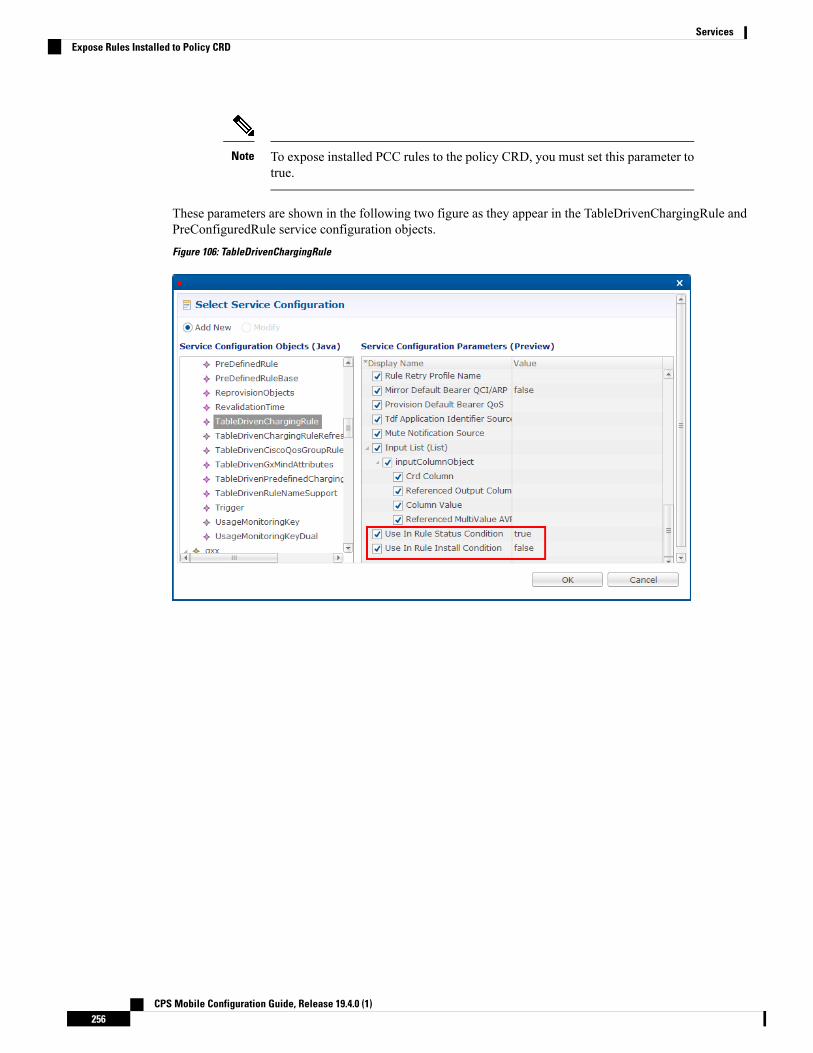
To expose installed PCC rules to the policy CRD, you must set this parameter totrue.
Note
These parameters are shown in the following two figure as they appear in the TableDrivenChargingRule andPreConfiguredRule service configuration objects.Figure 106: TableDrivenChargingRule
CPS Mobile Configuration Guide, Release 19.4.0 (1)256
ServicesExpose Rules Installed to Policy CRD

Figure 107: PreConfiguredRule
The following figure shows the two parameters as they appear in the TableDrivenPredefinedChargingRuleservice configuration object.Figure 108: TableDrivenPredefinedChargingRule
In the CCR-U request, the PCEF/PGW sends the following AVPs:<avp name="Charging-Rule-Report">
<avp name="Charging-Rule-Name" value="DTL3300"> </avp>
CPS Mobile Configuration Guide, Release 19.4.0 (1)257
ServicesExpose Rules Installed to Policy CRD

<avp name="PCC-Rule-Status" value="0"> </avp></avp>
Youmust also configure your CRD table by binding the <RuleName>_installed columnwith RI-<RuleName>and by binding the <RuleName>_Status column with RS-<RuleName>.
Step 1 In Policy Builder, select the Services tab.Step 2 In the left pane, click Services.Step 3 Navigate to any service options that use the PreConfiguredRule, TableDrivenChargingRule, and
TableDrivenPredefinedChargingRule service configuration objects, and change their Use In Rule Install Conditionparameters to true.
Step 4 In Policy Builder, select the Reference Data tab.Step 5 In the left pane, select Custom Reference Data Tables > Search Table Groups.Step 6 Go to your CRD table; for example, under session_action_mapping > session_action_mapping_gx.Step 7 In the Custom Reference Data Table pane under Columns, select <Rulename>_Installed.Step 8 In the Runtime area, select the Bind to Subscriber AVP code option, and type RI-<RuleName>.
An example is shown in the following figure.Figure 109: Binding to RI-RTRULE3300 Subscriber AVP code
Step 9 Select <RuleName>_STATUS under Columns.Step 10 In the Runtime area, select the Bind to Subscriber AVP code option, and type RS-<RuleName>.
An example is shown in the following figure.
CPS Mobile Configuration Guide, Release 19.4.0 (1)258
ServicesExpose Rules Installed to Policy CRD

Figure 110: Binding to RS-RTRULE3300 Subscriber AVP code
CPS Mobile Configuration Guide, Release 19.4.0 (1)259
ServicesExpose Rules Installed to Policy CRD

CPS Mobile Configuration Guide, Release 19.4.0 (1)260
ServicesExpose Rules Installed to Policy CRD
C H A P T E R 8Gx/Sd Services
• Gx Services, on page 261• Sd Services, on page 315
Gx ServicesThis section covers the following topics:
• QoS Profile, on page 261
• PCC Rules, on page 270
• Table (CRD) Driven Rules, on page 272
• Table (CRD) Driven Rule Refresh on Rule Failure, on page 285
• Custom Features, on page 290
• Emergency Data Services, on page 292
• RAN Congestion, on page 296
• Usage Monitoring, on page 301
• Bandwidth Monitoring, on page 304
• Override Control AVP, on page 307
• Common Parameters Used, on page 313
QoS Profile
OverviewWhen UE attaches to the network for the first time, it will be assigned default bearer which remains as longas UE is attached. Default bearer is best effort service. Each default bearer comes with an IP address.
This section provides details of Gx default bearer QoS parameters and also explains how CPS derives QoSin different configurations.
CPS Mobile Configuration Guide, Release 19.4.0 (1)261

Policy Builder Configuration
Case 1- QoS under Gx Profile
Step 1 Log into Policy Builder.Step 2 Select the Reference Data tab, and click Diameter Defaults > Gx Profile.Step 3 On the right side, click Create Child to the open the Gx Profile pane.
Case 2 - Default Bearer QoS in Service
Step 1 Log into Policy Builder.Step 2 Select the Services tab, and then click Use Case Templates > Summary.Step 3 Click Use Case Template link from the right side under Create Child to create a use case template.Step 4 Enter the name for use case template.Step 5 Select Actions tab.Step 6 Click Add under Service Configurations to open the Select Service Configuration dialog box.Step 7 Select DefaultBearerQoS under gx and select the required service configuration parameters.Step 8 Click OK to add the service in the Service Configuration pane.Step 9 On the Services tab, click Services > Service Options to create a service option, and add the use case template that
the user just configured.
An example is shown.Figure 111: Creating a Service Option
Step 10 On the Services tab, click Services > Services to create a service, and add the same use case template.
CPS Mobile Configuration Guide, Release 19.4.0 (1)262
Gx/Sd ServicesPolicy Builder Configuration

An example is shown.Figure 112: Creating a Service
Default Bearer QoS Enhancements - Gx
CPS supports the management of Default Bearer QoS attribute values for IP-CAN sessions by applyingQoS-Bounding, QoS-Mirroring and QoS-Enforced on Default Bearer QoS and these actions for individualQoS attributes can be derived based on SPR or Gx session attributes.
• QoS-Bounding is the ability for the PCRF to calculate the minimum QoS between the Requested QoS(from the P-GW) and the Authorized QoS (based on internal computation of the Logic in the PCRF) andassign that in the response message back to the P-GW.
• QoS-Mirroring is the ability for the PCRF to mirror the same QoS values back that were being requestedby the P-GW in the Request Message.
• QoS-Enforcement is the ability for the PCRF to enforce the Authorized QoS computed based on itsinternal logic back to the P-GW in the request/response message.
To support QoS Enhancements, the user can configure object DefaultBearerQoSAction with action attributefor each possible QoS attribute and bind to the QoS action columns of the Default Bearer CRD. Also CPS
CPS Mobile Configuration Guide, Release 19.4.0 (1)263
Gx/Sd ServicesDefault Bearer QoS Enhancements - Gx
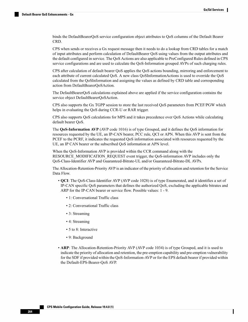
binds the DefaultBearerQoS service configuration object attributes to QoS columns of the Default BearerCRD.
CPS when sends or receives a Gx request message then it needs to do a lookup from CRD tables for a matchof input attributes and perform calculation of DefaultBearer QoS using values from the output attributes andthe default configured in service. The QoS Actions are also applicable to PreConfigured Rules defined in CPSservice configurations and are used to calculate the QoS-Information grouped AVPs of such charging rules.
CPS after calculation of default bearer QoS applies the QoS actions bounding, mirroring and enforcement toeach attribute of current calculated QoS. A new class QoSInformationActions is used to override the QoScalculated from the QoSInformation and assigning the values as defined by CRD table and correspondingaction from DefaultBearerQoSAction.
The DefaultBearerQoS calculations explained above are applied if the service configuration contains theservice object DefaultBearerQoSAction.
CPS also supports the Gx TGPP session to store the last received QoS parameters from PCEF/PGW whichhelps in evaluating the QoS during CCR-U or RAR trigger.
CPS also supports QoS calculations for MPS and it takes precedence over QoS Actions while calculatingdefault bearer QoS.
The QoS-Information AVP (AVP code 1016) is of type Grouped, and it defines the QoS information forresources requested by the UE, an IP-CAN bearer, PCC rule, QCI or APN. When this AVP is sent from thePCEF to the PCRF, it indicates the requested QoS information associated with resources requested by theUE, an IP CAN bearer or the subscribed QoS information at APN level.
When the QoS-Information AVP is provided within the CCR command along with theRESOURCE_MODIFICATION_REQUEST event trigger, the QoS-information AVP includes only theQoS-Class-Identifier AVP and Guaranteed-Bitrate-UL and/or Guaranteed-Bitrate-DL AVPs.
The Allocation-Retention-Priority AVP is an indicator of the priority of allocation and retention for the ServiceData Flow.
• QCI: The QoS-Class-Identifier AVP (AVP code 1028) is of type Enumerated, and it identifies a set ofIP-CAN specific QoS parameters that defines the authorized QoS, excluding the applicable bitrates andARP for the IP-CAN bearer or service flow. Possible values: 1 - 9.
• 1: Conversational Traffic class
• 2: Conversational Traffic class
• 3: Streaming
• 4: Streaming
• 5 to 8: Interactive
• 9: Background
• ARP: The Allocation-Retention-Priority AVP (AVP code 1034) is of type Grouped, and it is used toindicate the priority of allocation and retention, the pre-emption capability and pre-emption vulnerabilityfor the SDF if provided within the QoS-Information-AVP or for the EPS default bearer if provided withinthe Default-EPS-Bearer-QoS AVP.
CPS Mobile Configuration Guide, Release 19.4.0 (1)264
Gx/Sd ServicesDefault Bearer QoS Enhancements - Gx

The Priority-Level AVP of the default bearer will be set to a sufficiently highlevel of priority to minimize the risk for unexpected PDN disconnection or UEdetach from the network according to operator specific policies.
AVP Format:Allocation-Retention-Priority ::= < AVP Header: 1034 >
{ Priority-Level }[ Pre-emption-Capability ][ Pre-emption-Vulnerability ]
Note
MIRRORING ACTION
Table 113: Mirroring Action
CCA (OUTPUT)QoS ActionCalculated QoS ValueCCR (INPUT)
MBRMIRRORMBRMBR3
GBRMIRRORGBRGBR4
QCIMIRRORQCIQCI 5
ARPMIRRORARPARP6
3 Maximum -Bit-Rate4 Guaranteed-Bit-Rate5 QoS-Class-Identifier AVP6 Allocation-Retention-Priority
ENFORCING ACTION
Table 114: Enforcing Action
CCA (OUTPUT)QoS ActionCalculated QoS ValueCCR (INPUT)
MBRENFORCEMBRMBR
GBRENFORCEGBRGBR
QCIENFORCEQCIQCI
ARPENFORCEARPARP
BOUNDING ACTION
Italics text: In the Table 115: Bounding Action, on page 266, theMBR, GBR, QCI, and PL represents valuesreceived in CCR request (CCR (INPUT)).
Bold text: In the Table 115: Bounding Action, on page 266,MBR, GBR, QCI, and PL represents valuescalculated internally in CPS (Calculated QosS Value).
CPS Mobile Configuration Guide, Release 19.4.0 (1)265
Gx/Sd ServicesDefault Bearer QoS Enhancements - Gx

Table 115: Bounding Action
CCA (OUTPUT)QoS ActionCalculated QoS ValueCCR (INPUT)
min(MBR,MBR)
CCA value for the MBR AVP isminimum of MBR andMBR.
BOUNDMBRMBR
min(GBR, GBR)
CCA value for the GBR AVP isminimum of GBR and GBR.
BOUNDGBRGBR
max(QCI, QCI)
CCA value for the QCI AVP ismaximum of QCI and QCI.
BOUNDQCIQCI
max(PL, PL) and PV, PC based onchosen ARP
BOUNDARP-PLARP-PL7
Set based on PL. IF PL comes fromCCR set CCR Value, or retainGranted QoS Values
BOUNDARP-PVARP-PV
Set based on PL. IF PL comes fromCCR set CCR Value, or retainCalculated/Granted Values
BOUNDARP-PCARP-PC
7 The Priority-Level AVP (AVP code 1046) is of type Unsigned 32. The AVP is used for deciding whethera bearer establishment or modification request can be accepted or needs to be rejected in case of resourcelimitations (typically used for admission control of GBR traffic). The AVP can also be used to decidewhich existing bearers to pre-empt during resource limitations. The priority level defines the relativeimportance of a resource request. Values 1 to 15 are defined, with value 1 as the highest priority level.Values 1 to 8 should only be assigned for services that are authorised to receive prioritised treatmentwithin an operator domain. Values 9 to 15 may be assigned to resources that are authorised by the homenetwork and thus applicable when a UE is roaming.
If the received and calculated PL values are equal, then the configured/calculated (not received) ARP isconsidered for PCI and PVI.
Note
Creating the CRD Table
The user must take special care while defining the CRD table to avoid an unconditional loop in case CRDuses cross referencing data from one table to another table.
Step 1 Log into Policy Builder.Step 2 Select the Reference Data tab.Step 3 Click Custom Reference Data Tables and create a CRD table.
CPS Mobile Configuration Guide, Release 19.4.0 (1)266
Gx/Sd ServicesCreating the CRD Table

Step 4 Select the Services tab, and then click Use Case Templates > Summary.Step 5 Click Use Case Template link from the right side under Create Child to create a use case template.Step 6 Enter the name for use case template.Step 7 Select Actions tab.Step 8 Click Add in the Service Configuration pane to open the Select Service Configuration dialog box.Step 9 Select DefaultBearerQoSActions and click OK to add it in the Service Configurations pane.Step 10 Click DefaultBearerQoSActions to open the parameters pane on the right side.
By default, Enforce is selected.Note
Use the following table if the user wants to bind QoS with the CRD table.Figure 113: Custom Reference Data Column
When the use case template is used in a Service Options, the user can bind each DefaultBearerQoSAction service objectaction attribute to the QoS action columns of the CRD. Similar binding of DefaultBearerQoS service configurationobject attributes to QoS columns of the Default Bearer CRD can be done.
Step 11 Log into the Control Center to define the values for the parameters defined in Custom Reference Data tables.Step 12 Select the Configuration tab.Step 13 Under Reference Data, click the Custom Reference Data Table name to open a dialog box. Select a row and edit the
values according to the user requirements.
Parameter DescriptionsThe following table contains a list of common parameters:
CPS Mobile Configuration Guide, Release 19.4.0 (1)267
Gx/Sd ServicesParameter Descriptions
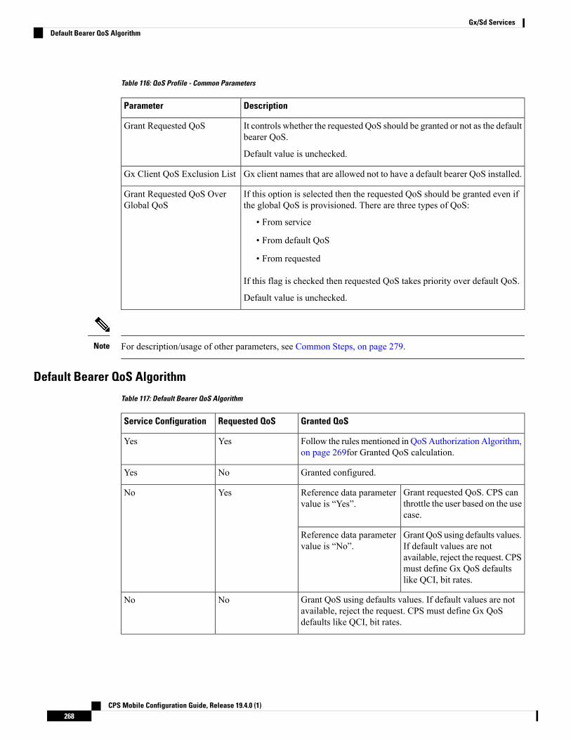
Table 116: QoS Profile - Common Parameters
DescriptionParameter
It controls whether the requested QoS should be granted or not as the defaultbearer QoS.
Default value is unchecked.
Grant Requested QoS
Gx client names that are allowed not to have a default bearer QoS installed.Gx Client QoS Exclusion List
If this option is selected then the requested QoS should be granted even ifthe global QoS is provisioned. There are three types of QoS:
• From service
• From default QoS
• From requested
If this flag is checked then requested QoS takes priority over default QoS.
Default value is unchecked.
Grant Requested QoS OverGlobal QoS
For description/usage of other parameters, see Common Steps, on page 279.Note
Default Bearer QoS Algorithm
Table 117: Default Bearer QoS Algorithm
Granted QoSRequested QoSService Configuration
Follow the rules mentioned in QoSAuthorization Algorithm,on page 269for Granted QoS calculation.
YesYes
Granted configured.NoYes
Grant requested QoS. CPS canthrottle the user based on the usecase.
Reference data parametervalue is “Yes”.
YesNo
Grant QoS using defaults values.If default values are notavailable, reject the request. CPSmust define Gx QoS defaultslike QCI, bit rates.
Reference data parametervalue is “No”.
Grant QoS using defaults values. If default values are notavailable, reject the request. CPS must define Gx QoSdefaults like QCI, bit rates.
NoNo
CPS Mobile Configuration Guide, Release 19.4.0 (1)268
Gx/Sd ServicesDefault Bearer QoS Algorithm
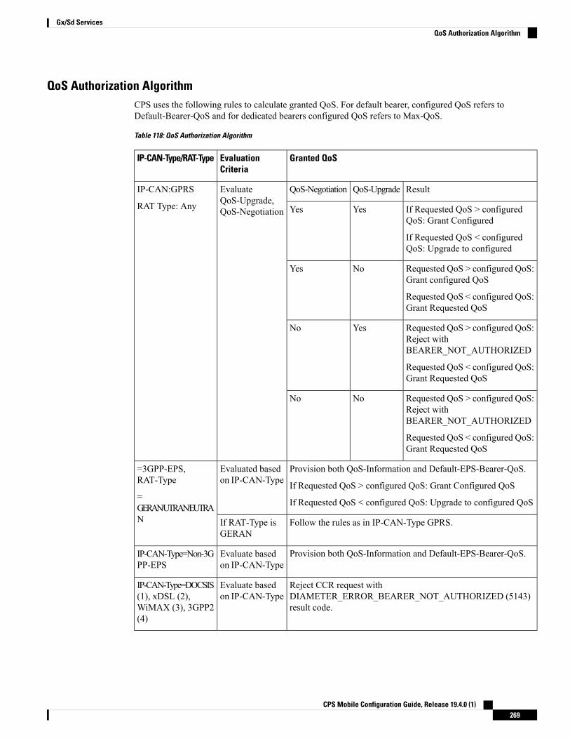
QoS Authorization AlgorithmCPS uses the following rules to calculate granted QoS. For default bearer, configured QoS refers toDefault-Bearer-QoS and for dedicated bearers configured QoS refers to Max-QoS.
Table 118: QoS Authorization Algorithm
Granted QoSEvaluationCriteria
IP-CAN-Type/RAT-Type
ResultQoS-UpgradeQoS-NegotiationEvaluateQoS-Upgrade,QoS-Negotiation
IP-CAN:GPRS
RAT Type: Any If Requested QoS > configuredQoS: Grant Configured
If Requested QoS < configuredQoS: Upgrade to configured
YesYes
Requested QoS > configured QoS:Grant configured QoS
Requested QoS < configured QoS:Grant Requested QoS
NoYes
Requested QoS > configured QoS:Reject withBEARER_NOT_AUTHORIZED
Requested QoS < configured QoS:Grant Requested QoS
YesNo
Requested QoS > configured QoS:Reject withBEARER_NOT_AUTHORIZED
Requested QoS < configured QoS:Grant Requested QoS
NoNo
Provision both QoS-Information and Default-EPS-Bearer-QoS.
If Requested QoS > configured QoS: Grant Configured QoS
If Requested QoS < configured QoS: Upgrade to configured QoS
Evaluated basedon IP-CAN-Type
=3GPP-EPS,RAT-Type
=GERAN/UTRAN/EUTRAN Follow the rules as in IP-CAN-Type GPRS.If RAT-Type is
GERAN
Provision both QoS-Information and Default-EPS-Bearer-QoS.Evaluate basedon IP-CAN-Type
IP-CAN-Type=Non-3GPP-EPS
Reject CCR request withDIAMETER_ERROR_BEARER_NOT_AUTHORIZED (5143)result code.
Evaluate basedon IP-CAN-Type
IP-CAN-Type=DOCSIS(1), xDSL (2),WiMAX (3), 3GPP2(4)
CPS Mobile Configuration Guide, Release 19.4.0 (1)269
Gx/Sd ServicesQoS Authorization Algorithm

PCC Rules
OverviewThe purpose of the PCC rule is:
• To detect a packet belonging to an SDF to map that packet to proper IP-CAN bearer in downlink anduplink direction
• To identify the service
• To provide appropriate applicable charging
• To provide policy control
There are two different types of PCC rules:
• Dynamic PCC rules: These PCC rules are dynamically provisioned by PCRF to PCEF over Gx interface.
• Pre-configured dynamic rules: These rules can be configured using Policy Builder
• Dynamic generated rules: These rules can be generated by CPS e.g., as result of Rx interaction.
• Pre-defined PCC rules: These PCC rules are pre-configured in the PCEF. The PCRF can advise the PCEFto activate a set of PCC rules over Gx interface.
CPS can be configured to re-attempt to install PCC rules that fail to install or activate. See Rule Retry Profiles,on page 164 for more information.
Policy Builder Configuration
Step 1 Log into Policy Builder.Step 2 Select the Services tab, and then click Use Case Templates > Summary.Step 3 Click Use Case Template link from the right side under Create Child to create a use case template for
PreConfiguredRule.Step 4 Enter the name for use case template. For example, name the new template as PreConfiguredRule.Step 5 Select Actions tab.Step 6 Click Add to open the Select Service Configuration dialog box.Step 7 Select PreConfiguredRule, PreDefinedRule, and PreDefinedRuleBase one after another, and select the required
service configuration parameters.Step 8 Click OK to add the service in the Service Configuration pane.
A PCC rules consists of following parameters:
Table 119: PCC Rules Parameters
DescriptionParameter
The service identifier is used to identify a service or service component the SDF relatesto.
Service Identifier
CPS Mobile Configuration Guide, Release 19.4.0 (1)270
Gx/Sd ServicesPCC Rules
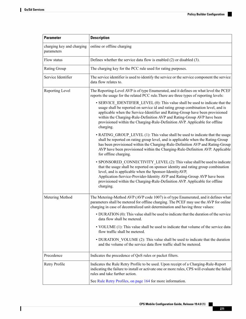
DescriptionParameter
online or offline chargingcharging key and chargingparameters
Defines whether the service data flow is enabled (2) or disabled (3).Flow status
The charging key for the PCC rule used for rating purposes.Rating Group
The service identifier is used to identify the service or the service component the servicedata flow relates to.
Service Identifier
The Reporting-Level AVP is of type Enumerated, and it defines on what level the PCEFreports the usage for the related PCC rule.There are three types of reporting levels:
• SERVICE_IDENTIFIER_LEVEL (0): This value shall be used to indicate that theusage shall be reported on service id and rating group combination level, and isapplicable when the Service-Identifier and Rating-Group have been provisionedwithin the Charging-Rule-Definition AVP and Rating-Group AVP have beenprovisioned within the Charging-Rule-Definition AVP. Applicable for offlinecharging.
• RATING_GROUP_LEVEL (1): This value shall be used to indicate that the usageshall be reported on rating group level, and is applicable when the Rating-Grouphas been provisioned within the Charging-Rule-Definition AVP and Rating-GroupAVP have been provisioned within the Charging-Rule-Definition AVP. Applicablefor offline charging.
• SPONSORED_CONNECTIVITY_LEVEL (2): This value shall be used to indicatethat the usage shall be reported on sponsor identity and rating group combinationlevel, and is applicable when the Sponsor-IdentityAVP,Application-Service-Provider-Identity AVP and Rating-Group AVP have beenprovisioned within the Charging-Rule-Definition AVP. Applicable for offlinecharging.
Reporting Level
The Metering-Method AVP (AVP code 1007) is of type Enumerated, and it defines whatparameters shall be metered for offline charging. The PCEF may use the AVP for onlinecharging in case of decentralized unit determination and having three values:
• DURATION (0): This value shall be used to indicate that the duration of the servicedata flow shall be metered.
• VOLUME (1): This value shall be used to indicate that volume of the service dataflow traffic shall be metered.
• DURATION_VOLUME (2): This value shall be used to indicate that the durationand the volume of the service data flow traffic shall be metered.
Metering Method
Indicates the precedence of QoS rules or packet filters.Precedence
Indicates the Rule Retry Profile to be used. Upon receipt of a Charging-Rule-Reportindicating the failure to install or activate one or more rules, CPS will evaluate the failedrules and take further action.
See Rule Retry Profiles, on page 164 for more information.
Retry Profile
CPS Mobile Configuration Guide, Release 19.4.0 (1)271
Gx/Sd ServicesPolicy Builder Configuration

Step 9 On the Services tab, click Services > Service Options to create a service option and add the configured use casetemplate.
To activate a predefined charging rule at PCEF, charging rule name must be used as a reference to thepredefined charging rule. To activate a group of predefined charging rules within PCEF (For example, Goldusers or gaming services) charging rule base name must be used as a reference to the group of predefinedcharging rules.
Note
Step 10 On the Services tab, click Services > Services to create a service and add the configured use case template.
Table (CRD) Driven Rules
OverviewASR5K supports handling of Service Group QoS and defines new Gx AVPs which are exchanged betweenPCEF and PCRF. Additionally, CPS (PCRF) already supports various use cases related to PCC Rulesprovisioning and usage monitoring control as defined in 3GPP specification 29.212. Also, the new AVPsrelated to CISCO Service Group QoS are already supported in CPS.
This feature uses capabilities of Custom Reference Data tables and Search Table Group functionality of CPS.
CPS supports defining a Custom Reference Data table where in all sub-elements of Cisco QoS Group rulesare possible to be configured with different values for each element. Also, it is possible to group these rulesunder a logical group. The application at run time supports queries based on this configured logical group,and Search Table Group, and is able to retrieve all applicable CISCO Service QoS Group rules and itssub-elements.
This feature can be configured by using three service options namely, TableDrivenCiscoQosGroupRule (ForCisco QoS Group rules), TableDrivenChargingRule (For dynamic PCC rules), andTableDrivenPredefinedChargingRule (For predefined PCC charging rules) . Description of their commonparameters is listed in the following table.
Currently, Table Driven Rules does not support wildcards.Note
Table 120: Common Parameters between TableDrivenCiscoQosGroupRule, TableDrivenChargingRule, andTableDrivenPredefinedChargingRule
DescriptionParameter
Search Group is a constant value which CPS uses to search within the Search TableGroup indicated by “Search Table” element.
Search Group
Search Column must be bound to the Key column of the STG (which must begiven a data type of Text).
Search Column
Rule Name Source must be a key column as well. This filed must be bound to therule name column within the STG which should be Text.
Rule Name Source
CPS Mobile Configuration Guide, Release 19.4.0 (1)272
Gx/Sd ServicesTable (CRD) Driven Rules

Table 121: Common Parameters between TableDrivenCiscoQosGroupRule and TableDrivenChargingRule
DescriptionParameter
Flow Status Source must be bound to the Flow status columnwithin the STGwhichshould be Text.
Flow Status Source
Monitoring key Source must be bound to the Monitoring Key column within theSTG which should be Text.
Monitoring key Source
Encoding format Source must be bound to the Encoding format column within theSTG which should be either Boolean or Text. If this is defined as Text Data Typethen Valid Values must be provided as (True/False).
Encoding format Source
Redirect Enabled Source must be bound to the Redirect Enabled column withinthe STG which should be either Boolean or Text. If this is defined as Text DataType then Valid Values must be provided as (True/False).
Redirect Enabled Source
Redirect Address Type Source must be bound to the Redirect Address Type columnwithin the STG which should be Text.
Redirect Address TypeSource
Redirect Address Source must be bound to the Redirect Address column withinthe STG which should be Text.
Redirect Address Source
Use Override Server Address must be bound to the Use Override Server Addresscolumn within the STG which should be either Boolean or Text. If this is definedas Text Data Type then Valid Values must be provided as (True/False). If this flagis true then it will take the address from the service option and if it is false then itwould not override the redirect server address.
Use Override ServerAddress
Table 122: Common Parameters between TableDrivenChargingRule and TableDrivenPredefinedChargingRule
DescriptionParameter
Input List (List)
The Crd column is bound to the appropriate key column within the STG for thoseAVPs which are inputs to this table.
Crd Column
Reserved for future use.Referenced OutputColumn
The value of the AVP that is bound to the Crd Column and has a single value.Column Value
The name of the attribute that is bound to the Crd Column and has multiple values.Referenced MultiValueAVP Name
Policy Builder Configuration
Table Driven Cisco QoS Group Rule
Step 1 Log into Policy Builder.
CPS Mobile Configuration Guide, Release 19.4.0 (1)273
Gx/Sd ServicesPolicy Builder Configuration

Step 2 Select the Services tab, and then click Use Case Templates > Summary.Step 3 Click Use Case Template link from the right side under Create Child to create a use case template for
TableDrivenCiscoQosGroupRule.a) Enter the name for use case template. For example, name the new template as TableDrivenCiscoQoSGroupRule.b) Select Actions tab.c) Click Add under Service Configurations.
Select Service Configuration dialog box opens, and all of the service configuration objects that are available on thePCRF are listed.
d) Scroll down to the gx area in the list of service configuration objects, and select TableDrivenCiscoQoSGroupRule.
Step 4 Select Services > Summary.Step 5 Click the Service Option link from the right side under Actions to create a service option using the
TableDrivenCiscoQosGroupRule use case template.
For usage of common parameters, see Common Parameter Descriptions, on page 500.
Step 6 To bind the Value, select the name from the Display Name column and in Value column click .... to open Please selecta 'CustomerReferenceDataTable' object.
See Common Steps, on page 279 to continue with the configuration.
Table Driven Charging Rule
Step 1 Log into Policy Builder.Step 2 Select the Services tab, and then select Use Case Templates > Summary.Step 3 Click Use Case Template link from the right side under Create Child to create a use case template for Table Driven
Charging Rule.a) Enter the name for use case template. For example, name the new template as TableDrivenChargingRule.b) Select Actions tab.c) Click Add under Service Configurations.
Select Service Configuration dialog box opens, and all of the service configuration objects that are available on thePCRF are listed.
d) Scroll down to the gx area in the list of service configuration objects, and select TableDrivenChargingRule.
Step 4 Select Services > Summary.Step 5 Click the Service Option link from the right side under Actions to create a service option using the
TableDrivenChargingRule use case template.
For usage of common parameters, see Common Parameter Descriptions, on page 500. Other parameters can be configuredas follows:
Table 123: TableDrivenChargingRule Parameters
DescriptionParameter
Online Source must be bound to the appropriate columnwithin the STG, and Type shouldbe Number. The possible values are mentioned in 3GPP specification 29.212.
Online Source
CPS Mobile Configuration Guide, Release 19.4.0 (1)274
Gx/Sd ServicesTable Driven Charging Rule

DescriptionParameter
Offline Source must be bound to the appropriate columnwithin the STG, and Type shouldbe Number. The possible values are mentioned in 3GPP specification 29.212.
Offline Source
Rating Group Source must be bound to the appropriate column within the STG, and Typeshould be Number. The possible values are mentioned in 3GPP specification 29.212.
Rating Group Source
Service Id Source must be bound to the appropriate column within the STG, and Typeshould be Number. The possible values are mentioned in 3GPP specification 29.212.
Service Id Source
Reporting Level Source must be bound to the appropriate column within the STG, andType should be Number. The possible values are mentioned in 3GPP specification 29.212.
Reporting Level Source
Precedence Source must be bound to the appropriate column within the STG, and Typeshould be Number. The possible values are mentioned in 3GPP specification 29.212.
Precedence Source
Metering Method Source must be bound to the appropriate column within the STG, andType should be Number. The possible values are mentioned in 3GPP specification 29.212.
Metering Method Source
Flow Information Source must be bound to the appropriate column within the STG, andType should be Text.
A particular format should be used when adding Flow Information Sourceparameter so that CPS can perform proper Flow Information grouped AVPmapping. A wrongly formatted Flow Information Source can result in missingAVPs under Gx Flow Information AVP. Here is the format:<Flow-Description>;<Flow-Direction>;<Decimal valueof first octet of ToS-Class-AVP>;<Decimal value ofsecond octet of ToS-Class-AVP>
Note
Flow Information Source
Use Override Server Address must be bound to the appropriate column within the STG,and Type should be either True/False or Text. If this is defined as Text Type then validvalues must be provided as True/False.
Use Override Server Address
Override Server Address is a constant value and if the Use Override Server Address flagis set to False, the parameter value is ignored.
Override Server Address
Qci Source must be bound to the appropriate column within the STG, and Type shouldbe Number.
For more information, refer to Common Parameters Used, on page 313.
Qci Source
Max Req Bandwidth U L Source must be bound to the appropriate column within theSTG, and Type should be Number.
For more information, refer to Common Parameters Used, on page 313.
Max Req Bandwidth U LSource
Max Req Bandwidth D L Source must be bound to the appropriate column within theSTG, and Type should be Number.
For more information, refer to Common Parameters Used, on page 313.
Max Req Bandwidth D LSource
CPS Mobile Configuration Guide, Release 19.4.0 (1)275
Gx/Sd ServicesTable Driven Charging Rule

DescriptionParameter
Guaranteed Bit Rate U L Source must be bound to the appropriate column within theSTG, and Type should be Number.
For more information, refer to Common Parameters Used, on page 313.
Guaranteed Bit Rate U LSource
Guaranteed Bit Rate D L Source must be bound to the appropriate column within theSTG, and Type should be Number.
For more information, refer to Common Parameters Used, on page 313.
Guaranteed Bit Rate D LSource
Arp Priority Level Source must be bound to the appropriate column within the STG, andType should be Number.
For more information, refer to Common Parameters Used, on page 313.
Arp Priority Level Source
Arp Preemption Capability Source must be bound to the appropriate column within theSTG, and Type should be Number.
For more information, refer to Common Parameters Used, on page 313.
Arp Preemption CapabilitySource
Arp Preemption Vulnerability Source must be bound to the appropriate column withinthe STG, and Type should be Number.
For more information, refer to Common Parameters Used, on page 313.
Arp PreemptionVulnerabilitySource
Apn Agg Max Bit Rate U L Source must be bound to the appropriate column within theSTG, and Type should be Number.
For more information, refer to Common Parameters Used, on page 313.
Apn Agg Max Bit Rate U LSource
Apn Agg Max Bit Rate D L Source must be bound to the appropriate column within theSTG, and Type should be Number.
For more information, refer to Common Parameters Used, on page 313.
Apn Agg Max Bit Rate D LSource
Rule Retry Profile Name must be bound to the appropriate column within the STG, andType should be Text.
For more information, refer to Common Parameters Used, on page 313.
Rule Retry Profile Name
Provision Default Bearer Qo S must be bound to the appropriate column within the STG,and Type should be either True/False or Text. If Type is defined as Text, then valid valuesmust be provided as True/False. If the value is True, the Default Bearer QoS informationfrom the session is applied to the rule while QoS information derived from the aboveparameters in this STG are ignored.
Provision Default Bearer QoS
Tdf Application Identifier Source references the application detection filter (for example,its value may represent an application such as a list of URLs, etc.), which the PCC rulefor application detection and control in the PCEF applies. Tdf Application IdentifierSource must be bound to the appropriate column within the STG, and Type should beText.
Tdf Application IdentifierSource
An indication whether application start/stop notification is to be muted for ADC Rule bythe TDF. Mute Notification Source must be bound to the appropriate column within theSTG, and it should be either Number or Decimal.
Mute Notification Source
CPS Mobile Configuration Guide, Release 19.4.0 (1)276
Gx/Sd ServicesTable Driven Charging Rule

DescriptionParameter
Input List (List)
The Crd column is bound to the appropriate key column within the STG for those AVPswhich are inputs to this table.
Crd Column
Reserved for future use.Referenced Output Column
The value of the AVP that is bound to the Crd Column and has a single value.Column Value
The name of the attribute that is bound to the Crd Column and has multiple values.Referenced MultiValue AVPName
Step 6 To bind the value, click the Value field, and then click ... to select a value.Step 7 Select the required object to bind and click OK.
A sample selection is shown as follows:Figure 114: Binding a Value
See Common Steps, on page 279 to continue with the configuration.
Table Driven Predefined Charging Rule
Step 1 Log into Policy Builder.Step 2 Select the Services tab, and then select Use Case Templates > Summary.
CPS Mobile Configuration Guide, Release 19.4.0 (1)277
Gx/Sd ServicesTable Driven Predefined Charging Rule

Step 3 Click Use Case Template link from the right side under Create Child to create a use case template for Table DrivenPredefined Charging Rule.a) Enter the name for use case template. For example, name the new template asTableDrivenPredefinedChargingRule.b) Select Actions tab.c) Click Add under Service Configurations.
Select Service Configuration dialog box opens, and all of the service configuration objects that are available on thePCRF are listed.
d) Scroll down to the gx area in the list of service configuration objects, and selectTableDrivenPredefinedChargingRule.e) Save the use case template.
Step 4 Select Services > Summary.Step 5 Click the Service Option link from the right side under Actions to create a service option using the
TableDrivenPredefinedChargingRule use case template.
For description/usage of common parameters, see Overview, on page 272 and Common Parameter Descriptions, on page500.
Step 6 To bind the value, click the Value field and enter a value or click ... to select a value.Step 7 Select the required object to bind and click OK.
A sample selection is shown as follows:Figure 115: Binding a Value
See Common Steps, on page 279 to continue with the configuration.
CPS Mobile Configuration Guide, Release 19.4.0 (1)278
Gx/Sd ServicesTable Driven Predefined Charging Rule

Common Steps
Step 1 Since this approach leverages Custom Reference and Search Table Group capabilities of CPS, we need to configure aSearch Table Group to be able to use the above Service Configuration to configure a Search-Group-Table with the outputcolumn specified.
• The “Rule_Group” in the STG is the key column indicating that searches need to be based on it.
• The “Search Group” and “Search Column” are expected to be configured or bound to the “Rule_Group” column ofthe STG.
Step 2 It is possible to retrieve the redirect Address related elements of CISCO Service Group QoS from another table.
In other cases if Redirect URL STG is not required, and if redirect URL is being derived from other componentsof CPS, the use of override address is essential. The override server address can be derived from retrieverswhen the redirect address is not populated from CRD.
Note
Control Center Configuration
Step 1 Log into Control Center.Step 2 Select the Configuration tab, and then select Configuration > Reference Data.Step 3 Select the STG created in Policy Builder and add data by creating new rows.
CRD Supported Features
Table Driven Rule Name Support
This feature allows CPS to filter the table generated rules (TableDrivenCiscoQosGroupRule,TableDrivenChargingRule, and TableDrivenPredefinedChargingRule) based on what the PCEF supports (viaanother rule list from CRD). Only rules common to both tables are included in actual policy.
Step 1 Create a new STG/CRD called 'gw-version-mapping-table'.
• Based on the incoming Gx origin Host and Gx Origin Realm, determine the GW Version.
• Make this table as 'Best Match': Enable the check box for best match utility.
Table 124: gw-version-mapping-table Parameters
GW Version (Output)Original Realm (Input)Origin Host (Input)
gw_versiongx_origin_realmgx_origin_host
NABind to 'Gx Request Origin-Realm'Bind to 'Gx Request Origin-Host'
CPS Mobile Configuration Guide, Release 19.4.0 (1)279
Gx/Sd ServicesCommon Steps

Figure 116: Origin Host
Figure 117: Origin Realm
CPS Mobile Configuration Guide, Release 19.4.0 (1)280
Gx/Sd ServicesTable Driven Rule Name Support

Figure 118: GW Version
Step 2 Create another STG/CRD called 'gw-rule-mapping-table'.
• Link the input column 'gw_version' in this table to the output from the earlier table.
• Both columns are input columns in this case.
Table 125: gw-rule-mapping-table Parameters
Rule Name (Input)GW Version (Input)
Rule_nameGw_version
NABind to result column from 'gw_version_mapping-table'
For same GW version, we can define multiple rules, so we need to have each rule name as an input column.Note
CPS Mobile Configuration Guide, Release 19.4.0 (1)281
Gx/Sd ServicesTable Driven Rule Name Support

Figure 119: GW Version
Step 3 In the existing 'QoS-Group-Rules' template (where we already have the Table Driven objects) add the new object'TableDrivenRuleNameSupport'.
Step 4 In the same Service Configuration Object 'QoS-Group-Rules', then click add. The new service configuration object (addedin the template) is available here.
Update the following fields in the new service configuration object:
• Search Table: Click the icon in the Value section and select gw-rule-mapping-table from the drop-down list.
• Search Group: Click the icon in the Pull Value from section and select the Group level output gw_version fromgw-version-mapping-table.
• Search Column: Click the icon theValue section and select gw_version input column from gw-rule-mapping-table.
• Rule Name Source: Click the icon the Value section and select rule_name input column from the samegw-rule-mapping-table as above.
With this configuration, CPS would do a UNION operation with the QoS groups obtained from the new'TableDrivenRuleNames' Object (based on theGWversion) and the ones retrieved from 'TableDrivenCiscoQoSGroupRules'(based on Rule-Mapping table & Rule-Group-Mapping table).
Mapping for Search Table of TableDrivenRuleNameSupport:
CPS Mobile Configuration Guide, Release 19.4.0 (1)282
Gx/Sd ServicesTable Driven Rule Name Support

Figure 120: Search Table Mapping
Mapping for Search Group of TableDrivenRuleNameSupport:Figure 121: Search Group Mapping
Mapping for Search Column of TableDrivenRuleNameSupport:
CPS Mobile Configuration Guide, Release 19.4.0 (1)283
Gx/Sd ServicesTable Driven Rule Name Support

Figure 122: Search Column Mapping
Figure 123: Rule Name Source
Best Match Table Logic
CPS supports each table look-up in CRD, which needs to be one of the match types shown in the followinglist, along with Best Match table. This approach is fast, efficient, and very easy to troubleshoot, and scaleswhen there are dozens, scores, or hundreds of combinations of values.
When the Best Match option is selected in the Custom Reference Data Table configuration, look-ups occurwithin a CRD table in the following order:
CPS Mobile Configuration Guide, Release 19.4.0 (1)284
Gx/Sd ServicesBest Match Table Logic

• Exact string match
• Higher priority regex match (if multiple regex patterns match)
• Regular expression match (default behavior)
• Wild card character (*)
The following figures contain examples of a CRD table configuration and its corresponding output table inControl Center.
• STG Table as Input for Best Match:Figure 124: Best Match Option
• Output Table, which can take an exact string match, a higher priority regex match, a regular expressionmatch, and a wildcard entry like *.Figure 125: Matching Examples
Table (CRD) Driven Rule Refresh on Rule Failure
OverviewCPS now supports the ability to install new charging rules based on the Charging rule name and its statusreported in CCR-U from PCEF in Charging Rule Report AVP for a particular rule/rules.
CPS Mobile Configuration Guide, Release 19.4.0 (1)285
Gx/Sd ServicesTable (CRD) Driven Rule Refresh on Rule Failure
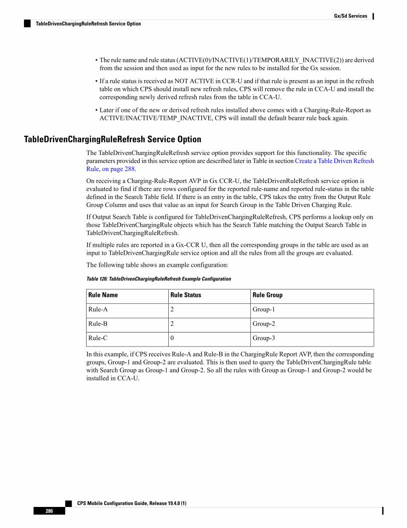
• The rule name and rule status (ACTIVE(0)/INACTIVE(1)/TEMPORARILY_INACTIVE(2)) are derivedfrom the session and then used as input for the new rules to be installed for the Gx session.
• If a rule status is received as NOT ACTIVE in CCR-U and if that rule is present as an input in the refreshtable on which CPS should install new refresh rules, CPS will remove the rule in CCA-U and install thecorresponding newly derived refresh rules from the table in CCA-U.
• Later if one of the new or derived refresh rules installed above comes with a Charging-Rule-Report asACTIVE/INACTIVE/TEMP_INACTIVE, CPS will install the default bearer rule back again.
TableDrivenChargingRuleRefresh Service OptionThe TableDrivenChargingRuleRefresh service option provides support for this functionality. The specificparameters provided in this service option are described later in Table in section Create a Table Driven RefreshRule, on page 288.
On receiving a Charging-Rule-Report AVP in Gx CCR-U, the TableDrivenRuleRefresh service option isevaluated to find if there are rows configured for the reported rule-name and reported rule-status in the tabledefined in the Search Table field. If there is an entry in the table, CPS takes the entry from the Output RuleGroup Column and uses that value as an input for Search Group in the Table Driven Charging Rule.
If Output Search Table is configured for TableDrivenChargingRuleRefresh, CPS performs a lookup only onthose TableDrivenChargingRule objects which has the Search Table matching the Output Search Table inTableDrivenChargingRuleRefresh.
If multiple rules are reported in a Gx-CCR U, then all the corresponding groups in the table are used as aninput to TableDrivenChargingRule service option and all the rules from all the groups are evaluated.
The following table shows an example configuration:
Table 126: TableDrivenChargingRuleRefresh Example Configuration
Rule GroupRule StatusRule Name
Group-12Rule-A
Group-22Rule-B
Group-30Rule-C
In this example, if CPS receives Rule-A and Rule-B in the ChargingRule Report AVP, then the correspondinggroups, Group-1 and Group-2 are evaluated. This is then used to query the TableDrivenChargingRule tablewith Search Group as Group-1 and Group-2. So all the rules with Group as Group-1 and Group-2 would beinstalled in CCA-U.
CPS Mobile Configuration Guide, Release 19.4.0 (1)286
Gx/Sd ServicesTableDrivenChargingRuleRefresh Service Option

• The TableDrivenChargingRule would have the Search Table and Search Column configured as describedabove. The Search Group would come as an output of the query done using TableDrivenRuleRefreshservice option. Even if the Search Group is blank, if there are Output Rule Groups evaluated due toTableDrivenChargingRuleRefresh, CPS queries the TableDrivenChargingRule with the Search Groupvalue as the Output Rule Groups. (If more than one are configured, CPS queries them one by one.)
• In case there is a value in Search Group in the TableDrivenChargingRule, CPS first evaluates theTableDrivenChargingRules with the mentioned Search Group. After finishing the above query, CPS thenproceeds to look up the Output Search Groups retrieved as a result of TableDrivenChargingRuleRefreshqueries.
• If the refresh rule and the default bearer rule come as OUT_OF_CREDIT immediately or simultaneously,it can create a loop. To prevent a loop, refer to Prevention of a Refresh Loop, on page 290. However, thisis not an ideal situation and it is agreed upon that in production we won't encounter looping. Also CPScannot guarantee stopping of loops in such scenario as the session may connect and disconnect and maygo into loop each time.
• Also, the feature does not actually look at the event trigger but only on the rule name and status reported.
Note
Policy Builder Configuration
Create a Table Driven Rule Refresh CRD Table
Step 1 In Policy Builder, create and configure a Search Table Group (STG).Figure 126: Search Table Group (STG)
Step 2 Create and configure a Custom Reference Data Table under this STG.
CPS Mobile Configuration Guide, Release 19.4.0 (1)287
Gx/Sd ServicesPolicy Builder Configuration

Figure 127: Custom Reference Data Table
The Rule_Group output column shown above is used as an input to evaluate TableDrivenChargingRule service option.
Create a Table Driven Refresh Rule
Step 1 Log into Policy Builder.Step 2 Select the Services tab, and then click Use Case Templates > Summary.Step 3 Click Use Case Template link from the right side under Create Child to create a use case template for
TableDrivenChargingRuleRefresh.Step 4 Select Services > Summary. Click Service Option link from the right side under Actions to create a service option
using Use Case Template created above.Step 5 In the Search Table row, select the ‘TableDrivenRuleRefresh’ CRD table created in the previous section to bind it to this
service option.
To bind the value, select the name from the Display Name column and in Value column click .... to open Please selecta 'CustomerReferenceDataTable' object.
CPS Mobile Configuration Guide, Release 19.4.0 (1)288
Gx/Sd ServicesCreate a Table Driven Refresh Rule

For usage of common parameters, see Common Parameter Descriptions, on page 500. Other parameters can beconfigured as follows:
Table 127: TableDrivenChargingRuleRefresh Parameters
DescriptionParameter
The search table to lookup from.Search Table
The input column for the SearchTableGroup (STG),which contains the rule name.
Input Rule Name Column
The input column for the STG, which contains the rulestatus against which new rules are to be added.
Output Rule Status Column
The output column for the STG, which contains therule group, which would be used as a group to searchthe TableDrivenChargingRule.
Output Rule Group Column
In case there are multiple TableDrivenChargingRulesmapped with multiple Search Tables, and if we wantto use only one table to be looked upon for new rulesinstallation on rule failure, we can give the table asOutput Search Table so that only oneTableDrivenChargingRule object, which has the‘Search Table’ matching the ‘Output Search Table’ inTableDrivenChargingRuleRefresh, is evaluated forrefresh rules and not all the objects.
Output Search Table
Note
The Output Search Table in TableDrivenChargingRuleRefresh should match with the Search Table in theTableDrivenChargingRule for looking up the output groups in the table for deriving the table driven charging rules.
The Search Group in TableDrivenChargingRules is not bound to anything. The output Rule_Group from the RefreshTable is automatically taken as input to the TableDrivenChargingRules service option.
Control Center Configuration
Step 1 Log into Control Center.Step 2 Select Configuration > Configuration > Reference Data.Step 3 Select the STG created in Policy Builder and add data by creating new rows.
CPS Mobile Configuration Guide, Release 19.4.0 (1)289
Gx/Sd ServicesControl Center Configuration

Figure 128: Configuring Reference Data
Prevention of a Refresh Loop
To prevent a scenario where successive INACTIVE statuses would cause CPS to repeatedly attempt to installthe same 2 rules, CPS tracks the number of times a refresh rule is installed within a specific time period. If aloop is detected, CPS will skip the rule installation.
The settings which control the loop detection can be customized. Contact your Cisco representative for moreinformation.
Custom Features
Service Group QoS
Overview
The goal of Service Group QoS is to provide support within PCRF in ASR5K to define and enforceFair-Usage-Policy (FUP) per subscriber. CPS provides support for CISCO Service Group QoS in ASR5Kbased deployment of PCEF. Service Group QoS is sent over the Gx interface when CPS (PCRF) tries to installor remove rules for a subscription based on various triggers. These attributes are CISCO deployment specificand are enabled only for the “Gx clients” which support Service Group QoS Rules.
Policy Builder Configuration
Step 1 Log into Policy Builder.Step 2 Select the Services tab, and then click Use Case Templates > Summary.
CPS Mobile Configuration Guide, Release 19.4.0 (1)290
Gx/Sd ServicesPrevention of a Refresh Loop

Step 3 Click Use Case Template link from the right side under Create Child to create a use case template forCiscoQoSGroupRule.a) Enter the name for use case template. For example, name the new template as CiscoQoSGroupRule.b) Select Actions tab.c) Click Add under Service Configurations.
Select Service Configuration dialog box opens, and all of the service configuration objects that are available on thePCRF are listed.
d) Scroll down to the gx area in the list of service configuration objects, and select CiscoQoSGroupRule.
User can configure various QoS Group Rule parameters depending on the network requirements. Forconfiguration/usage of different parameters, refer to Common Steps, on page 279
Step 4 Select CiscoQoSGroupRule and click required service configuration parameters that need to be configured. Click OKto add the service in Service Configuration pane.
Step 5 In Services tab, click Services > Service Options to create a service option and add the configured Use Case Templatein CiscoQoSGroupRule to configure Service Option.
Step 6 In Services tab, click Services > Services to create a service and add the configured Use Case Template inCiscoQoSGroupRule to configure Service.
Content Filtering
Overview
The goal of Content Filtering is to provide support for content filtering within the network by use of PolicyID's. Policy identifiers (Policy IDs) are rules that are configured on the ASR 5000 platform and invoked bythe CPS. Policy IDs are used to implement the required Content Filtering policies defined for the subscriber.The Policy IDs are selected at the ASR 5000 by provisioning their values through the Gx interface by thePCRF.
When a user initiates a session, the ASR5K communicates with the CPS to initialize the defined policies. CPSprovides the Policy ID to the ASR5K to provide the necessary Content Filtering services for the user.
The main aim of this feature is for CPS to provide Policy ID's configured in the subscriber's service to thePCEF (ASR5K).
Policy Builder Configuration
There are three sequential procedures to configure the Policy IDs using the CPS.
Step 1 Log into Policy Builder.Step 2 Select the Services tab, and then click Use Case Templates > Summary.Step 3 Click Use Case Template link from the right side under Create Child to create a use case template.Step 4 Provide a name for the template in the Name field.Step 5 Select Actions tab.Step 6 To define the basic template, under Service Configurations, click Add. Select the required configurations from the
popup window and click OK.
CPS Mobile Configuration Guide, Release 19.4.0 (1)291
Gx/Sd ServicesContent Filtering

• Cisco Content Filtering Policy optionmust be selected along with other configurations to provide ContentFiltering services.
• The check boxes in the Allow Override column are checked by default. This allows the subscriber tochange the values in the Service Option. Otherwise, the value remains constant.
Note
Step 7 Click the save icon.Step 8 In the left column, select Services.Step 9 Locate the template that was defined in the above procedure and click Service Option in the summary window. The
configurations that had been selected appears in the window.Step 10 Click OK. Define the required parameters.Step 11 Select the configuration to define the parameters from the list of Service Configurations.Step 12 In the Parameters columns, set the required values.Step 13 Click CiscoContentFilteringPolicy and set the Policy ID value in the parameters field.
Value for Policy ID should not be set to zero (0). Policy IDs can be dynamically assigned to the subscriberby referring to the Custom Reference Data Tables.
Note
Step 14 Click Pull value from in the parameters column to assign Policy IDs dynamically from a predefined Custom ReferenceData Table.
Emergency Data Services
OverviewCPS supports Emergency Data Services as per the procedures defined in 3GPP TS 29.212. The operator hasto configure a list of Emergency Access Point Names (APNs) that are valid for the operator. These APNs arethen used by CPS to identify a session as an Emergency session. CPS also supports installation of QoS andRules for emergency sessions.
Configure Diameter Gx Client for Emergency APNsThe emergency APNs have to be configured in the Diameter Gx Client configuration. So, first you need toconfigure a Diameter Gx Client.
For more details on how to configure the Diameter Gx Client, refer Diameter Clients, on page 111.
Step 1 Log into Policy Builder.Step 2 Select the Reference Data tab.Step 3 From the left pane, select Diameter Clients.Step 4 Expand the Gx Clients by clicking on the arrow right next to “Gx Clients”. If you do not see this arrow, this means the
Gx Client has not been created.
Refer Diameter Clients, on page 113 to create a Gx Client.
Step 5 Select the Gx Client name created by you. Gx Client attributes as shown below will come up in the right pane.
CPS Mobile Configuration Guide, Release 19.4.0 (1)292
Gx/Sd ServicesEmergency Data Services

Figure 129: Gx Client Attributes
Step 6 Click Add to configure the emergency APNs. The following window is displayed.Figure 130: Emergency APN Configuration
Step 7 Type the name of the emergency APN that you want to add in the Value to Add (String) text box and click Add.Step 8 ClickOK. In the example shown above, four APN entries are already added.To remove an APN from this list, select the
APN to be removed and click Remove.
CPS Mobile Configuration Guide, Release 19.4.0 (1)293
Gx/Sd ServicesConfigure Diameter Gx Client for Emergency APNs

CPS supports wildcarding for the EmergencyAPN names. As shown in the example above, we have used '*' for wildcarding.CPS uses standard Java pattern characters for APN names. The pattern needs to follow the standard Java regular expressionsyntax described here.
Configure Service for Emergency SessionsFor emergency APNs, the IMSI may not be present. Hence, CPS allows emergency sessions without subscriberauthentication.
Step 1 Log into Policy Builder.Step 2 Select the Services tab.Step 3 From the left pane, select Domains.Step 4 Select the domain name that you want to use for emergency subscribers. Domain attributes open up in the right pane.
To create a new Domain, refer Overview, on page 191.
Step 5 Select the Advanced Rules tab.Step 6 Click select near Anonymous Subscriber Service.Step 7 In the new window displayed, select the service that you want to assign for emergency sessions and click OK.
Configure Prioritizing Emergency Sessions using APNsEmergency calls are fast-tracked through the CPS platform by bypassing authorization logic. As a user, theCPS platform enables to prioritize these emergency calls by APN. CPS uses “Emergency Message Priority”,for this prioritization. These attributes are part of “Inbound Message Overload Handling” feature under“Diameter Configuration”.
For more details, refer Inbound Message Overload Handling, on page 77.
Step 1 Log into Policy Builder.Step 2 Select the Reference Data tab.Step 3 From the left pane, select Systems and expand your system name or cluster name.Step 4 Select and expand the Plugin Configurations.Step 5 Select Diameter Configuration. Diameter configuration screen appears in the right pane.Step 6 Check Inbound Message Overload Handling check box.Step 7 Click Add under Message Handling Rules table.
CPS Mobile Configuration Guide, Release 19.4.0 (1)294
Gx/Sd ServicesConfigure Service for Emergency Sessions

Figure 131: Adding a New Row
Step 8 Click ... in the Diameter Client column.Figure 132: Selecting a DiameterClient Object
Step 9 Select the Gx Client in which we added the emergency APNs in Configure Diameter Gx Client for Emergency APNs,on page 292 and click OK.
Step 10 Configure the other parameters of the table.Figure 133: Sample Configuration
For the detailed explanation of all the parameters of the Inbound Message Overload Handling feature, referInbound Message Overload Handling, on page 77. The following table explains the parameters relevant tothe prioritization of emergency sessions.
Note
CPS Mobile Configuration Guide, Release 19.4.0 (1)295
Gx/Sd ServicesConfigure Prioritizing Emergency Sessions using APNs

Table 128: Prioritization of Emergency Session - Parameters
DescriptionParameter
Default priority to be assigned to an incoming message, if no specific one is defined inthe Message Handling Rules table.
Default value is 0.
Default Priority
Default priority assigned to incoming messages related to an emergency session.
Default value is 0.
Emergency MessagePriority
Defines specific inbound message overload handling rules based on different criteria.Message Handling Rules are generic. This means for all CCR-I messages, if you want toprocess with priority, user needs to set the configuration in Message Handling Rules.
Message Handling Rules
Higher the value of the priority, the higher is the priority. User must take care that the Emergency MessagePriority field value is higher than the priority column values present in the Message Handling Rules, so thatthe EmergencyMessages are processed first than the usual messages. If we take the example values configuredabove, then this is how the priority is assigned to the incoming messages.
Note
DescriptionPriorityIncoming Message
The default emergency message priority is assigned as thisis emergency APN.
5Anymessage for any emergency session/APN
The protocol, command code, and request type match themessage handling rules.
3AGxCCR-Imessage for the non-emergencyAPN
Request type does not match with the value in the “MessageHandling Rules”. So, the default priority is assigned.
0AGxCCR-Umessage for the non-emergencyAPN
By default, the emergency message priority is higher than the default priority. This means, if you do notconfigure the InboundMessage Overload Handling, then default priority = 0 and emergencymessage priority= 1.
Note
RAN Congestion
OverviewCurrently, when RAN congestion is configured, at the hour boundary there is a check for congestion levelchange. If the congestion level has changed then RAR is sent in which new rules corresponding to changedcongestion level are applied.
The next evaluation time for session is set to the time when the congestion level changes next. At that hourboundary again the session is evaluated, and new rules applicable to changed level are applied. Since all thesessions are getting re-evaluated at applicable hour boundaries where the congestion level changes, there isa possibility of huge amount of RAR's being generated by CPS. CPS can generate this load of RARs withoutany issues as it is distributed among the CPS VMs. However, there might be limitation on other networkelements to handle the RAR surge.
CPS Mobile Configuration Guide, Release 19.4.0 (1)296
Gx/Sd ServicesRAN Congestion

To prevent RAR burst at the hour boundary, evaluate configured services for the next hour based on theappropriate congestion levels. Also, preinstall the rules specifying Activation and Deactivation times.
Policy Builder Configuration
Step 1 Log into Policy Builder.Step 2 Select the Services tab, and then click Use Case Templates > Summary.Step 3 Click Use Case Template link from the right side under Create Child to create a use case template for
PreDefinedRuleBase.Step 4 Enter the name for use case template. For example, name the new template as PreDefinedRuleBase.Step 5 Select Actions tab.Step 6 Click Add to open Select Service Configuration.Step 7 Select PreDefinedRuleBase and click required service configuration parameters that need to be configured. Click OK
to add the service in Service Configuration pane.Figure 134: Configuration for Current Hour
CPS Mobile Configuration Guide, Release 19.4.0 (1)297
Gx/Sd ServicesPolicy Builder Configuration

Figure 135: Configuration for Next Hour
• In order to achieve the RAN congestion use case to install rules based on congestion levels, we need to configureuse case initiators to modify the rules based on congestion level.
• Use case initiator - on condition that congestionLevel = 1, changes rulename to internetlvl1
• Use case initiator - on condition that congestionLevel = 2, changes rulename to internetlvl2
• Use case initiator - on condition that congestionLevel = 3, changes rulename to internetlvl3
• Assume congestionLevel is 1 for current hour and 2 for next hour. When services are evaluated for current time,this evaluates only to internetlvl1. In order to also evaluate services for the look ahead hour, we need to addcorresponding modified rules for each with use case initiators as follows:
• Use case initiator - on condition that congestionNextHourLevel = 1, changes rulename to internetlvl1
• Use case initiator - on condition that congestionNextHourLevel = 2, changes rulename to internetlvl2
• Use case initiator - on condition that congestionNextHourLevel = 3, changes rulename to internetlvl3
Example of configuration for one of the use case modifiers is shown below:
CPS Mobile Configuration Guide, Release 19.4.0 (1)298
Gx/Sd ServicesPolicy Builder Configuration

Figure 136: Use Case Option Tab
Figure 137: Use Case Initiators Tab
Control Center Configuration
Step 1 Log into Control Center.Step 2 Select Configuration > Configuration > Reference Data.Step 3 Select the STG created in Policy Builder and add data by creating new rows.
CPS Mobile Configuration Guide, Release 19.4.0 (1)299
Gx/Sd ServicesControl Center Configuration

A sample configuration is as follows:Figure 138: Sample Configuration
• 0-3 are congestion levels
• Currently, we supports only current and next level congestion.
Note
Parameter DescriptionsThe following table provides information related to RAN Congestion parameters:
Table 129: RAN Congestion Parameters
DescriptionParameter
Any name which you want to give for rule name.Rule Name
Default: It turns OFF Hour Boundary RAR enhancement feature for lookahead rules installation at hour boundary and causes rules to behave in normalfashion of getting installed at hour boundary as applicable
CurrentHour: For the current hour rule activation time will be current time,deactivation time will be next hour.
NextHour: For the next hour rule activation time will be next hour,deactivation time will be next-next hour.
Scheduled Hour: drop-downlist with three values.
By default, CPS sets the next evaluation time as per the next change in congestion level. To configure CPSto do a forward lookup for multiple changes in congestion level, add the following parameter to qns.conf:
-DcongDataLookAhead=true
Note
CPS Mobile Configuration Guide, Release 19.4.0 (1)300
Gx/Sd ServicesParameter Descriptions

Usage Monitoring
OverviewCPS supports Usage-Monitoring over Diameter Gx interface with different Balance Code, Dosage andmonitoring level. Usage monitoring key Identifies the usage monitoring control instance and is subscribedusing Event-Trigger AVP = USAGE_REPORT.
CPS also supports time based Gx usage monitoring control and reporting based on as 3GPP 29.212 Rel 12Sections 4.5.16 and 4.5.17. It supports the ability to configure a Gx usage monitoring key as volume, time orboth.
Policy Builder Configuration
Step 1 Login to Policy Builder.Step 2 Select the Services tab, and then click Use Case Templates > Summary.Step 3 Click Use Case Template link from the right side under Create Child to create a use case template for
TableDrivenCiscoQosGroupRule.a) Enter the name for use case template. For example, name the new template as UsageMonitoringKey.b) Select Actions tab.c) Click Add under Service Configurations.
Select Service Configuration dialog box opens, and all of the service configuration objects that are available on thePCRF are listed.
d) Scroll down to the gx area in the list of service configuration objects, and select the required usage monitoring object.For example, UsageMonitoringKey.
For parameter descriptions under UsageMonitoringKey, refer to UsageMonitoringKey, on page 461.
For parameter descriptions under UsageMonitoringKeyDual, refer to UsageMonitoringKeyDual, on page 462.
Step 4 In the left pane of the Services tab, click Services > Service Options to create a service option and add theUsageMonitoringKey use case template.
Step 5 In the left pane of the Services tab, click Services > Services to create a service and add the configuredUsageMonitoringKey use case template.
Scheduled Usage MonitoringTo support scheduling, CPS uses Monitoring-Time AVP in Monitoring information. To use Monitoring-TimeAVP CPS supports Usage Monitoring Congestion Handling (UMCH) feature on Gx. If the PCEF does notsupport UMCH feature, CPS uses the RAR message to request account balance usage details of the previousor older schedule. CPS will charge the account balance usage against the old schedule and further grants anew dosage value as per the new schedule.
CPS uses the next evaluation time set on the diameter session to trigger the RAR message for requesting theusage-report on schedule's time boundary. The current Usage-Monitoring information in the Gx session isadded with monitoring schedules to grant and track the usage for the PCEF, based on current and adjacentschedules. It also provides support to bind different balance code to each schedule. CPS grants, reserves andcharges the respective balance as per the usage monitoring schedule defined. CPS defines dosage on each
CPS Mobile Configuration Guide, Release 19.4.0 (1)301
Gx/Sd ServicesUsage Monitoring

schedule and accordingly grants single units to PCEF in Granted-Service-Units AVP. It also defines chargingrate on each schedule. The default charging rate is 1.
This feature provides support to configure multiple schedules in monitoring-key service configuration.
Configure Scheduled Usage Monitoring
Scheduled Usage Monitoring is configured in the Service Options section of the Services tab. The ServiceConfiguration UsageMonitoringKey allows scheduledmonitoring in theMonitoring Schedule (List) parameter.
Before configuring a scheduled monitoring, the following configuration must be completed in the PolicyBuilder:
• Configure the Account Balance Templates in the Reference Data tab.
For more information, see Account Balance Templates, on page 359.
• Configure a Use Case Template in the Services tab.
For more information, see Use Case Templates, on page 225.
Configuration restrictions while defining Monitoring schedule in Policy Builder:
• The time value should be entered in hh:mm format.
• Monitoring schedule should be complete for 24 hours.
• First monitoring schedule should start at midnight with start-time value as 00:00 and last schedule shouldend on next midnight with end-time value as 23:59.
• Time entry with 23:59 will be rounded-up to complete the 24 hour schedule.
Step 1 Select the Services tab.Step 2 Click Services > Service Options, and select the corresponding Service option whose name matches the Use Case
Template.Step 3 Provide a name for the service in the Name field.Step 4 In the Service Configurations section, click Add. The Select Service Configuration dialog box is displayed.Step 5 Select UsageMonitoringKey and click OK.
For parameter descriptions under UsageMonitoringKey, refer to UsageMonitoringKey, on page 461.
Step 6 In the Service configuration parameters, selectMonitoring Schedule and click Add Child to add aUsageMonitoringSchedule.
Step 7 Select the UsageMonitoringSchedule to provide the values as shown in the example.
CPS Mobile Configuration Guide, Release 19.4.0 (1)302
Gx/Sd ServicesConfigure Scheduled Usage Monitoring

Figure 139: Usage Monitoring Schedule
a) Enter the Start Time in 24 hrs format (00:00 to 23:59).b) Enter the End Time in 24 hrs format (00:00 to 23:59).c) Provide a value for the Balance Code. Click the ... button. A window appears. Select the required Balance Code and
click OK.d) Enter the Dosage value.e) Enter the Rate value.
To add multiple UsageMonitoringSchedule, click Add Child and add the parameters according to your requirements.
Time Usage MonitoringCPS supports time based Gx usagemonitoring control and reporting based on as 3GPP 29.212 Rel 12 Sections4.5.16 and 4.5.17.
It supports the ability to configure a Gx usage monitoring key as volume, time or both.
Balance: This feature reuses the time related units like seconds, minutes, hours, and so on for balance thatare already provided by Account Balance Templates. No new threshold types have been added. Only %thresholds can be used with Time balances.
Use Case Template: A new UsageMonitoringKeyDual service configuration has been added to support thetime usage monitoring (The existing UsageMonitoringKey is still supported for Volume Usage monitoring).This new option provides a way to configure usage monitoring for both time and volume (independently aswell as together under single monitoring key). To monitor usage under one key for Volume and Time, boththe balance codes need to be provided in the Service Configuration. For independent monitoring, only therelevant type of fields can be set. For example, for only Volume monitoring, fields related to time monitoring
CPS Mobile Configuration Guide, Release 19.4.0 (1)303
Gx/Sd ServicesTime Usage Monitoring

can be left blank/null and vice versa. Multiple instances of UsageMonitoringKeyDual can also be includedin the service configuration each corresponding to a unique monitoring key.
Gx Message Handling: The following new AVPs are now supported under this feature:
• CC-Time (within Granted-Service-Unit and Used-Service-Unit)
• Quota-Consumption-Time (within Usage-Monitoring-Information)
For configuration in Policy Builder, refer to Policy Builder Configuration, on page 301.
Bandwidth Monitoring
OverviewThe purpose of this feature is to track bandwidth and apply policies based on that. Normal usage monitoringis used to track usage but not bandwidth. This feature is based on usage monitoring key being installed inorder to have the usage reported by the PCEF. Using this feature, the service provider can install a monitoringkey and the different thresholds that are used to flag the subscriber. This feature works in parallel with theusage monitoring feature but the usage monitoring feature has a higher priority since that one is about chargingtraffic. In this context 'higher priority' means that usage monitoring feature installs any usage monitoring keysit needs to do its job.
Bandwidth monitoring installs any additional monitoring keys it needs while reusing any monitoring keysthat were already installed. In order to reuse a monitoring key the same monitoring key name should be usedin both BandwidthMonitor and UsageMonitoringKey objects. ReportingTimeout value is in minutes and isused to set the Revalidation-Time AVP so that the subscriber has a chance to get unthrottled before the allocateddosage is used. The BandwidthThreshold Lower Value is in kbps and when the computed bandwidth used isover that value, the corresponding Label is set to the subscriber for the particular application identified byName attribute.
Policy Builder Configuration
Step 1 Log into Policy Builder.Step 2 Select the Services tab and then click Use Case Templates.Step 3 If you want to create a new use case template, click Use Case Template in the main window under Create Child to
open the default use case template.Step 4 Enter the name for the template. For our example, name it as Bandwidth Monitoring.Step 5 Select Actions tab.Step 6 Click Add under Service Configurations to open the Select Service Configuration dialog box.Step 7 Select the necessary service configuration objects and click OK to add the objects in Service Configurations pane.
The Bandwidth Monitoring service option includes the BaseUsageMonitoringKey that enables Gx usagemonitoring for this subscriber.
Note
Step 8 Click Services > Service Options > name of the Use Case Template.Step 9 Click Service Options in the main window under Create Child to open the Select Service Configuration dialog box,
which contains already defined Service Configurations, and click OK.Step 10 Select BandwidthMonitor from the Service Configurations pane.
CPS Mobile Configuration Guide, Release 19.4.0 (1)304
Gx/Sd ServicesBandwidth Monitoring

a) We can monitor the Bandwidth usage on a per session rule base or per PCC rule base. For example, let us namethis bandwidth monitor per session base as SESSION.
b) UnderMonitoring Key, enter the values for Monitoring Key, Dosage, and Monitoring Level. For session level,the Monitoring Level should be 0.
c) Also enable the BaseUsageMonotoringKey.d) Under Bandwidth Threshold, define three levels for bandwidth - Low, Medium and High.
Step 11 Click Services > Service Options > name of the Use Case Template.Step 12 Click Use Case Option in the main window under Create Child to open the Use Case Option pane and name it as
Low Bandwidth Usage.Step 13 Click Add to open the Select Service Configuration dialog box, select DefaultBearerQoS and click OK to add the
service.Step 14 Rename the configured service as LowDefaultBearerQoS.Step 15 Click Use Case Initiators tab. Click plus sign (+) to add a service initiator. Rename the initiator as Low.Step 16 UnderConditions, clickAdd to open the Select the Condition Phrase which you would like to use dialog box, select
the required condition and click OK.
The added condition is displayed in Conditions pane.
Step 17 Click Add All under Available Input Variables.a) In the Value column under name (String), enter the name for the bandwidth monitor that you specified in 10.a, on
page 305.b) In the Value column under label (String), enter the Bandwidth threshold value defined in 10.d, on page 305.
Step 18 Create another initiator and add the conditionA bandwidth monitor status does not exist to it. Add the name (String)to the condition.
Step 19 Repeat the steps from Step 12, on page 305 to Step 17, on page 305 for Medium and High bandwidth usage.Step 20 Click Services > Service Options > name of the Use Case Template provided in Step 4, on page 304. Add all the
service configurations.Step 21 Define the different parameters for low, medium and high bandwidth usage monitoring in the Service Configurations
pane according to the customer requirements.
A sample configuration for Low Bandwidth Usage Monitoring is shown below.
CPS Mobile Configuration Guide, Release 19.4.0 (1)305
Gx/Sd ServicesPolicy Builder Configuration

Figure 140: Low Bandwidth Usage Monitoring
Step 22 Click Services > Services, and the click Service under Create Child to open the Service dialog box.Step 23 Enter the name in Code and Name text fields.Step 24 Click Add to open the Select Service Configuration dialog box. Select the service that you configured in Step 4, on
page 304, and click OK.Step 25 Select Use V9 Event Trigger Mapping and Rel8 Usage Monitoring Supported under Diameter Configuration.
• If Use V9 Event Trigger Mapping check box is not selected, the event trigger mapping ID (33) from 3GPP TS29.212 V11.10.0 (2013-09) is used.
• If Use V9 Event Trigger Mapping check box is selected, the event trigger mapping ID (26) from 3GPP TS 29.212V9.5.0 (2013-09) is used.
Parameter DescriptionsThe following parameters can be configured in Bandwidth Monitoring:
DescriptionParameter
Any name you can give.Name
The revalidation timer for defined dosage.Reporting Timeout
The minimum bandwidth value that you can give for that particular Label. Thisvalue is not standard and defined as per requirement and should be an integer.
Lower Value
The name of label, which can depend upon the user's requirement.Label
CPS Mobile Configuration Guide, Release 19.4.0 (1)306
Gx/Sd ServicesParameter Descriptions

Override Control AVP
OverviewCPS supports Override-Control specific AVPs in CCA-i and CCA-u responses to the PCEF on the Gx Interfaceand Gx RAR message. These AVPs are used to override charging parameters for predefined and static ruleson the PCEF.
Policy Builder Configuration
Step 1 Log into Policy Builder.Step 2 Select the Services tab, and then click Use Case Templates > Summary.Step 3 Click Use Case Template link from the right side under Create Child to create a use case template.Step 4 Enter the name for the template. For our example, name the new template as CiscoOverrideControl.Step 5 Select Actions tab.Step 6 In the newly created template, clickAdd under the Service Configurations pane. This will list all the service configuration
objects available on the PCRF. Select the CiscoOverrideControl object from the gx section.Step 7 After selecting the necessary service configuration object, click OK to add the object in Service Configurations pane.
The following parameters can be configured for Override Control AVP.
Table 130: Override Control AVP Parameters
DescriptionParameter
Specifies the name of the rule (predefined or static) for whichthe override values are sent.
The "Charging-Action-Name” and “Exclude-Rule”AVPs should not be sent and shall be ignored if thisAVP is present.
Note
Override Rule Name
Specifies the name of the charging action for which overridevalues are sent.
Charging-Action-Name
Defines the rule name where the override will not be applied.Override Charging Action Exclude Rule (List)
Used to override the value of Service Identifier configured in thecharging action.
Override Service Identifier
Defines the value of the rating group configured for astatic/predefined rule.
Override Rating Group
Used to override the value of reporting level configured in thecharging action.
Override Reporitng Level
If Enabled, it overrides the online value configured forstatic/predefined rule.
Default value is Enable.
Override Online
CPS Mobile Configuration Guide, Release 19.4.0 (1)307
Gx/Sd ServicesOverride Control AVP

DescriptionParameter
If Enabled, it overrides the offline value configured forstatic/predefined rule.
Default value is Enable.
Override Offline
Used to override the value of Metering Method configured inthe charging action.
Override Metering Method
This AVP is used to Override QoS-Information for a predefinedrule or charging action. These values are ignored (if present)while applying override values to a static rule.
Override QoS
Defines the maximum bit rate allowed for the uplink direction.Override-Max-Requested-Bandwidth-UL
Defines the maximum bit rate allowed for the downlink direction.Override-Max-Requested-Bandwidth-DL
Defines the guaranteed bit rate allowed for Uplink direction. ThisAVP should be included only for rules on dedicated bearers.
Override-Guaranteed-Bitrate-UL
Defines the guaranteed bit rate allowed for downlink direction.This AVP should be included only for rules on dedicated bearers.
Override-Guaranteed-Bitrate-DL
This AVP is of type grouped and is used to override thepre-configured value of ARP.
Override-Allocation-Retention-Priority
Used to merge override control charging/policy parametersbetween override control with specific charging action andwildcard override control.
Override Merge Wildcard
AVP Structure in response/request message:
Override-Control*Override-Rule-NameOverride-Charging-Action-Parameters
Override-Control-Merge-WildcardCharging-Action-Name*Online-Charging-Action-Exclude-RuleOverride-Charging-ParametersOverride-Service-IdentifierOverride-Rating-GroupOverride-Reporting-LevelOverride-OnlineOverride-OfflineOverride-Metering-MethodOverride-Policy-ParametersOverride-QoS-InformationOverride-QoS-Class-IdentifierOverride-Max-Requested-Bandwidth-ULOverride-Max-Requested-Bandwidth-DLOverride-Guaranteed-Bitrate-ULOverride-Guaranteed-Bitrate-DLOverride-Allocation-Retention-PriorityOverride-Priority-LevelOverride-Pre-emption-CapabilityOverride-Pre-emption-Vulnerability
CPS Mobile Configuration Guide, Release 19.4.0 (1)308
Gx/Sd ServicesPolicy Builder Configuration

FlagsVendor-IDCodeName
PVM
0109132017Override-Control
0109132018Override-Rule-Name
0109132019Override-Charging-Action-Parameters
0109132021Override-Charging-Action-Exclude-Rule
0109132022Override-Charging-Parameters
0109132023Override-Service-Identifier
0109132024Override-Rating-Group
0109132025Override-Reporting-Level
0109132026Override-Online
0109132027Override-Offline
0109132028Override-Metering-Method
0109132029Override-Policy-Parameters
0109132030Override-QoS-Information
0109132031Override-QoS-Class-Identifier
0109132032Override-Max-Requested-Bandwidth-UL
0109132033Override-Max-Requested-Bandwidth-DL
0109132034Override-Guaranteed-Bitrate-UL
0109132035Override-Guaranteed-Bitrate-DL
0109132036Override-Allocation-Retention-Priority
0109132037Override-Priority-Level
0109132038Override-Pre-Emption-Capability
0109132039Override-Pre-Emption-Vulnerability
0109132079Override Merge Wildcard
Gx RAR TrafficCPS is enhanced to support certain call flows and reduce Gx-RAR traffic towards PCEF as follows:
CPS Mobile Configuration Guide, Release 19.4.0 (1)309
Gx/Sd ServicesGx RAR Traffic

• Gx CCR-U reports all Rx Charging-Rule as inactive in which case PCRF terminates the Rx Session andavoids sending Gx-RAR to remove rules already reported as inactive.
• Gx CCR-U reports one or more Rx Charging Rule as inactive in which case PCRF would trigger a RxRAR to PCSF which if responded with a DIAMETER_UNKNOWN_SESSION_ID (5002) terminatesthe Rx Session and avoids sending Gx RARwith Charging-Rule-RemoveAVPS for rules already reportedas inactive.
• Gx CCR-U reports one or more Rx Charging Rule as inactive in which case PCRF would trigger a RxRAR to PCSF which is responded with a DIAMETER_SUCCESS (2001). Any subsequent AAR-UwithMCD/MSC flow status reported as removed, removes the corresponding Rx Charging-Rule and doesnot trigger a Gx RAR with Charging-Rule-Remove AVP.
Configuring Policies Based on Gx EventsThis section covers the following topics:
• Overview, on page 310• Policy Builder Configuration, on page 311
OverviewCPS supports the ability to make policy decisions based on the following event triggers received over the Gxinterface:
• OUT_OF_CREDIT
• REALLOCATION_OF_CREDIT
• CREDIT_MANAGEMENT_SESSION_FAILURE
• CISCO_EVENT_TRIGGER
The policy decisions based on the above event triggers could be the following:
For Gx interface:
• Switch the UE from ONLINE to OFFLINE or vice versa
• Change the Charging-Rule-Base-Name of the UE
• Change (add/delete) the Charging-Rule-Name (predefined) of the UE
• Change (add/modify/delete) the Charging-Rule-Name (Dynamic) of the UE
• Ability to retry the impacted rule, number of retries, and the unique retries between each retry
For Rx interface:
• Initiate a tear down/removal of the IMS rule over Rx
• Inform the Rx client of the impacted rule and the reason for impact
For Sy interface:
• Ability to terminate or reinitiate Sy session
CPS Mobile Configuration Guide, Release 19.4.0 (1)310
Gx/Sd ServicesConfiguring Policies Based on Gx Events

For Sd interface:
• Ability to terminate Sd session
Policy Builder ConfigurationThe following procedure is an example of how to configure Policy Builder to use theActionBasedOnGxEventTrigger service configuration object to make policy decisions based on event triggersand associated rule failure codes received over the Gx interface.
Step 1 Log into Policy Builder.Step 2 Click REFERENCE DATA > Custom Reference Data Tables > Search Table Groups.Step 3 Click Search Table Group.Step 4 Under Table Search Initiators do the following to evaluate the CRD such that the condition is always false and table is
not evaluated every time on any event by the policy engine:a) Click the + sign to add an initiator.b) Enter a name for the initiator in the Initiator Name field.c) Select A customer reference data AVP exists as the initiator conditions.d) Select A customer reference data AVP exists, click the Add code, and then enter CRD-CODE (dummy value
to restrict CRD evaluation) as the code value. Similarly, click Add value, and then enter true as the value.
Step 5 Click the Custom Reference Data Table link.Step 6 Under Columns, click Add and enter the following input and output values:
• CHARGING-RULE-NAME: This input value should be set toKey and Runtime Binding should be set to None.
• RULE-FAILURE-CODE: This input value should be set to Key and Runtime Binding should be set to None.
• CISCO-CC-FAILURE-TYPE: This input value should be set toKey andRuntime Binding should be set toNone.
• Credit-Management-Status: This input value should be set toKey. ForRuntime Binding, selectBind to Diameterrequest AVP code and enter Credit-Management-Status.
• Rx-Rule-Remove: Output value. Possible values are true and false.
• Session-ReInitiate: Output value. Possible value is SY_V11.
• Session-Terminate: Output value. Possible values are: SY_V11, SD_V11, or SY_V11;SD_V11.
The input AVPs and their corresponding CRD input columnsmust be configured in the ActionBasedOnGxEventTriggerservice configuration object. When CPS receives a Gx CCR message with the Charging-Rule-Report AVP or theCredit-Management-Status AVP, CPS performs a one-time query on this CRD table.
A one-time query on this CRD is also performed when CPS receives Charging-Rule-Report AVP withACTIVE_WITHOUT_CREDIT_CONTROL(10) for PCC-Rule-Status and Cisco-Event with Cisco-CC-Failure-Type.
If the Remove-Rx-Rule AVP exists in the output with value = true, the following conditions can occur:
• In case the query is based on Charging-Rule-Report AVP, then the rule status is updated as INACTIVE for all thereported rules and CPS sends Rx RAR for those rules.
CPS Mobile Configuration Guide, Release 19.4.0 (1)311
Gx/Sd ServicesPolicy Builder Configuration

Rx RAR will only be sent if Specific-Action =INDICATION_OF_FAILED_RESOURCES_ALLOCATION is subscribed by theAF or Specific-Action= INDICATION_OF_OUT_OF_CREDIT is subscribed by the AF andOUT_OF_CREDIT event trigger(Gx) is received in CCR-U.
Note
• In case the query is based on Credit-Management-Status AVP, then all Rx rules are removed and Rx session isterminated by sending Rx ASR.
Step 7 Select the Services tab, and then click Use Case Templates > Summary.Step 8 Click the Use Case Template link from the right side under Create Child to create a use case template.Step 9 Enter the name for the template. In this example, name the new template as ActionBasedOnGxEventTrigger .Step 10 Click the Actions tab.Step 11 In the newly created template, click Add under the Service Configurations pane. This will list all the service
configuration objects available on PCRF. Select the ActionBasedOnGxEventTrigger object under the gx section.Step 12 Click OK to add the object in Service Configurations pane.
For the list of configurable parameters see ActionBasedOnGxEventTrigger , on page 421
The AVP Name must be the same as mentioned in the following table while defining parameter values forActionBasedOnGxEventTrigger Service Configuration object. The Column values are referenced fromexample CRD table columns created in Step 6, on page 311. The other values mentioned in the table are usedfor example purpose only.
Important
Table 131: Parameter Values for ActionBasedOnGxEventTrigger Service Configuration Object
ValueParameter
Event-Rule-Failure-MappingStg Reference
List of Input Column Avp Pairs
Charging-Rule-NameAvp Name
CHARGING-RULE-NAMEColumn
Rule-Failure-CodeAvp Name
RULE-FAILURE-CODEColumn
Cisco-CC-Failure-TypeAvp Name
CISCO-CC-FAILURE-TYPEColumn
List of Output Column Avp Pairs
Remove-Rx-RuleAvp Name
Rx-Rule-RemoveColumn
Terminate-SessionAvp Name
Session-TerminateColumn
CPS Mobile Configuration Guide, Release 19.4.0 (1)312
Gx/Sd ServicesPolicy Builder Configuration

ValueParameter
Reinitiate-SessionAvp Name
Session-ReInitiateColumn
For any Gx action, a generic output column can be added which can be used as an input to any other CRDtable.
Important
Step 13 Click Use Case Initiators and do the following so that the use case is true only in the following conditions:
When CPS receives event trigger CREDIT_MANAGEMENT_SESSION_FAILURE:
a) Click the + sign to add a service initiator.b) Enter a name for the initiator in the Initiator Name field.c) Select A Gx Event Triggr exists as the initiator conditions.d) Select A Gx Event Triggr exists, click the Add All, and then enter 46 as the eventTrigger value.
When CPS receives event trigger CREDIT_MANAGEMENT_SESSION_FAILURE (46) and/or Cisco-Event withCREDIT-CONTROL-FAILURE (5):
a) Click the + sign to add a service initiator.b) Enter a name for the initiator in the Initiator Name field.c) Select CustomCiscoEvent as the initiator conditions.d) Select A Cisco Custom Gx Event Trigger exists, click the Add All, and then enter 5 as the eventTrigger value.e) Select A Gx Event Trigger exists as the initiator conditions.f) Select A Gx Event Trigger exists, click the Add All, and then enter 46 as the eventTrigger value.
Common Parameters UsedThe following table contains the common parameters that can be configured under all the sections mentionedin this chapter:
Table 132: Common Parameters
DescriptionParameter
The QoS class identifier identifies a set of IP-CAN specific QoS parametersthat define QoS, excluding the applicable bitrates and ARP. It is applicable bothfor uplink and downlink direction. The QCI values 0, 10 – 255 are divided forusage as follows:
• 0: Reserved
• 10-127: Reserved
• 128-254: Operator specific
• 255: Reserved
Qci
It defines the maximum bit rate allowed for the uplink direction.Max Req Bandwidth UL
CPS Mobile Configuration Guide, Release 19.4.0 (1)313
Gx/Sd ServicesCommon Parameters Used

DescriptionParameter
It defines the maximum bit rate allowed for the downlink direction.Max Req Bandwidth DL
It defines the guaranteed bit rate allowed for the uplink direction.Guaranteed Bit Rate UL
It defines the guaranteed bit rate allowed for the downlink direction.Guaranteed Bit Rate DL
It defines the total bandwidth usage for the uplink direction of non-GBR QCIsat the APN.
Apn AggMax Bit Rate UL
It defines the total bandwidth usage for the downlink direction of non-GBRQCIs at the APN.
Apn AggMax Bit Rate DL
The priority level is used to decide whether a bearer establishment ormodification request can be accepted or needs to be rejected in case of resourcelimitations (typically used for admission control of GBR traffic). The AVP canalso be used to decide which existing bearers to pre-empt during resourcelimitations. The priority level defines the relative importance of a resourcerequest.
Values 1 to 15 are defined, with value 1 as the highest level of priority.
• Values: 1 to 8 - assigned for services that are authorized to receiveprioritized treatment within an operator domain.
• Values: 9 to 15 - Can be assigned to resources that are authorized by thehome network and thus applicable when a UE is roaming.
Priority Level Values: 1 to8 - assigned for servicesthat are authorized toreceive prioritizedtreatment within anoperator domain. Values:9 to 15 - Can be assignedto resources that areauthorized by the homenetwork and thusapplicable when a UE isroaming.
If it is provided within the QoS-Information AVP, the AVP defines whether aservice data flow can get resources that were already assigned to another servicedata flow with a lower priority level. If it is provided within theDefault-EPS-Bearer-QoS AVP, the AVP defines whether the default bearer canget resources that were already assigned to another bearer with a lower prioritylevel.
• 0: This value indicates that the service data flow or bearer is allowed to getresources that were already assigned to another service data flow or bearerwith a lower priority level.
• 1: This value indicates that the service data flow or bearer is not allowedto get resources that were already assigned to another service data flow orbearer with a lower priority level. This is the default value applicable ifthis AVP is not supplied.
Preemption Capability
CPS Mobile Configuration Guide, Release 19.4.0 (1)314
Gx/Sd ServicesCommon Parameters Used

DescriptionParameter
If it is provided within the QoS-Information AVP, the AVP defines whether aservice data flow can lose the resources assigned to it in order to admit a servicedata flow with higher priority level. If it is provided within theDefault-EPS-Bearer-QoS AVP, the AVP defines whether the default bearer canlose the resources assigned to it in order to admit a pre-emption capable bearerwith a higher priority level.
• 0: This value indicates that the resources assigned to the service data flowor bearer can be pre-empted and allocated to a service data flow or bearerwith a higher priority level. This is the default value applicable if this AVPis not supplied.
• 1: This value indicates that the resources assigned to the service data flowor bearer shall not be pre-empted and allocated to a service data flow orbearer with a higher priority level.
Preemption Vulnerability
Identifies a usage monitoring control instance. Any value can be given.Monitoring Key
It is priority of the service option within the service.Priority
The client configuration is used to apply different policies based on PCEF type.This is optional parameter.
Diameter Client
Rule Group is to classify rules at PCRF to change set of predefined rules basedon policy. This is an optional parameter.
Rule Group
This is having two values Enabled and Disabled. Default value is disabled.Enable ResourceAllocation Notification
This is having two values Enabled and Disabled. Default value is disabled.Dual Stack Session
It is having four options. Default option is ANY_ONE.
• ANY_ONE
• BOTH
• IPv4_ADDRESS
• IPv6_ADDRESS
Framed I P Type
Identifies the schedule for rule activation and deactivation.ToD Schedule
Sd Services
OverviewThe Sd reference point is located between the Policy and Charging Rules Function (PCRF) and the TrafficDetection Function (TDF). The Diameter session on Sd is established either at the request of the PCRF in
CPS Mobile Configuration Guide, Release 19.4.0 (1)315
Gx/Sd ServicesSd Services

case of solicited application reporting by initiating a (TSR - TDF Session Request) or at the request of theTDF by initiating an (CCR-I) in case of unsolicited application reporting. Session modifications may beinitiated by either TDF or PCRF.
Solicited Application
For the solicited application reporting, the Sd reference point is used for:
• Establishment and termination of TDF session between PCRF and TDF.
• Provisioning of Application Detection and Control rules from the PCRF for the purpose of traffic detectionand enforcement at the TDF.
• Usage monitoring control of TDF session and of detected applications.
• Reporting of the start and the stop of a detected application’s traffic and transfer of service data flowdescriptions for detected applications, if deducible, from the TDF to the PCRF.
Unsolicited Application
For the unsolicited application reporting, the Sd reference point is used for:
• Establishment and termination of TDF session between PCRF and TDF.
• Reporting of the start and the stop of a detected application’s traffic.
• Transfer of service data flow descriptions for detected applications, if deducible, and transfer of Applicationinstance identifier, if service data flow descriptions are deducible, from the TDF to the PCRF.
As part of the IP-CAN Session Establishment or Modification procedure, in case of solicited applicationreporting with a TDF, the PCRF initiates a TDF Session Establishment with the selected TDF. The TDF isselected based on data received from the PCEF or a local configuration at the PCRF and or SPR data for thesubscriber.
TDF Session Termination happens in any of the following cases:
• The corresponding IP-CAN session is terminated.
• At any point of time when the PCRF decides that the session with TDF is to be terminated (for example,subscriber profile changes).
Policy Builder Configuration
Step 1 Log into Policy Builder.Step 2 Select the Services tab, and then click Use Case Templates. Click Summary and select Use Case Template.Step 3 Click Actions tab.Step 4 Click Add to open the Select Service Configuration dialog box.Step 5 Select ADC-Predefined-Rule and click required service configuration parameters that need to be configured. ClickOK
to add the service in Service Configuration pane.Step 6 In the Services tab, click Services > Service Options to create a service option and add the Use Case Template that you
just configured.
CPS Mobile Configuration Guide, Release 19.4.0 (1)316
Gx/Sd ServicesPolicy Builder Configuration

Step 7 In the Services tab, click Services > Services to create a service and add the Use Case Template that you just configured.
Common Parameters UsedThe following table contains the common parameters configured for Sd Services:
Table 133: Common Parameters
DescriptionParameter
The QoS class identifier identifies a set of IP-CAN specific QoS parameters thatdefine QoS, excluding the applicable bitrates and ARP. It is applicable both foruplink and downlink direction. The QCI values 0, 10 – 255 are divided for usageas follows:
• 0: Reserved
• 10-127: Reserved
• 128-254: Operator specific
• 255: Reserved
Qci
It defines the maximum bit rate allowed for the uplink direction.Max Req Bandwidth UL
It defines the maximum bit rate allowed for the downlink direction.Max Req Bandwidth DL
It defines the guaranteed bit rate allowed for the uplink direction.Guaranteed Bit Rate UL
It defines the guaranteed bit rate allowed for the downlink direction.Guaranteed Bit Rate DL
It defines the total bandwidth usage for the uplink direction of non-GBR QCIs atthe APN.
Apn Agg Max Bit RateUL
It defines the total bandwidth usage for the downlink direction of non-GBRQCIsat the APN.
Apn Agg Max Bit RateDL
The priority level is used to decide whether a bearer establishment or modificationrequest can be accepted or needs to be rejected in case of resource limitations(typically used for admission control of GBR traffic). The AVP can also be usedto decide which existing bearers to pre-empt during resource limitations. Thepriority level defines the relative importance of a resource request.
Values 1 to 15 are defined, with value 1 as the highest level of priority.
• Values: 1 to 8 - assigned for services that are authorized to receive prioritizedtreatment within an operator domain.
• Values: 9 to 15 - Can be assigned to resources that are authorized by thehome network and thus applicable when a UE is roaming.
Priority Level Values: 1to 8 - assigned forservices that areauthorized to receiveprioritized treatmentwithin an operatordomain. Values: 9 to 15 -Can be assigned toresources that areauthorized by the homenetwork and thusapplicable when a UE isroaming.
CPS Mobile Configuration Guide, Release 19.4.0 (1)317
Gx/Sd ServicesCommon Parameters Used

DescriptionParameter
If it is provided within the QoS-Information AVP, the AVP defines whether aservice data flow can get resources that were already assigned to another servicedata flow with a lower priority level. If it is provided within theDefault-EPS-Bearer-QoS AVP, the AVP defines whether the default bearer canget resources that were already assigned to another bearer with a lower prioritylevel.
• 0: This value indicates that the service data flow or bearer is allowed to getresources that were already assigned to another service data flow or bearerwith a lower priority level.
• 1: This value indicates that the service data flow or bearer is not allowed toget resources that were already assigned to another service data flow orbearer with a lower priority level. This is the default value applicable if thisAVP is not supplied.
Preemption Capability
If it is provided within the QoS-Information AVP, the AVP defines whether aservice data flow can lose the resources assigned to it in order to admit a servicedata flow with higher priority level. If it is provided within theDefault-EPS-Bearer-QoS AVP, the AVP defines whether the default bearer canlose the resources assigned to it in order to admit a preemption capable bearerwith a higher priority level.
• 0: This value indicates that the resources assigned to the service data flowor bearer can be pre-empted and allocated to a service data flow or bearerwith a higher priority level. This is the default value applicable if this AVPis not supplied.
• 1: This value indicates that the resources assigned to the service data flowor bearer shall not be pre-empted and allocated to a service data flow orbearer with a higher priority level.
Preemption Vulnerability
Identifies a usage monitoring control instance. Any value can be given.Monitoring Key
It is priority of the service option within the service.Priority
The client configuration is used to apply different policies based on PCEF type.This is optional parameter.
Diameter Client
Rule Group is to classify rules at PCRF to change set of predefined rules basedon policy. This is an optional parameter.
Rule Group
Defines whether the service data flow is enabled or disabled.Flow Status
Defines the address type of the address given in the Redirect-Server-AddressAVP.
Redirect Address Type
This value indicates that redirection is enabled for a detected application's traffic.Redirect Support
This value indicates the target for redirected application traffic.Redirect Server Address
CPS Mobile Configuration Guide, Release 19.4.0 (1)318
Gx/Sd ServicesCommon Parameters Used

DescriptionParameter
This is not to re-request rules. Primarily to notify start/stop of applications orreport usage.
Event-Trigger
Table 134: Sd Parameters
DescriptionParameter
This references the application detection filter (for example, its value mayrepresent an application such as a list of URLs, etc.), which the PCC rule forapplication detection and control in the PCEF applies.
Tdf Application Identifier
An indication whether application start/stop notification is to be muted for ADCRule by the TDF.
Mute Notification
CPS Mobile Configuration Guide, Release 19.4.0 (1)319
Gx/Sd ServicesCommon Parameters Used

CPS Mobile Configuration Guide, Release 19.4.0 (1)320
Gx/Sd ServicesCommon Parameters Used

C H A P T E R 9Rx Services
• Overview, on page 321• VoLTE, on page 321• Dynamic Rule Naming (Multiple Dedicated Bearer QoS), on page 337• QoS Selection, on page 337• Dynamic QoS, on page 338• SRVCC, on page 349• NPLI (Access Network), on page 349• Dynamic PCC (MOG), on page 350• VoLTE Emergency Calls, on page 352• Sponsored Data, on page 352• Multi-Media Priority Services, on page 354
OverviewCisco Policy Suite (CPS) for Mobile is a carrier-grade policy, charging, and subscriber data managementsolution. It helps service providers rapidly create and bring services to market, deliver a positive user experience,and optimize network resources. It also generates monetization opportunities across 3G, 4G, and LTE accessnetworks as well as IP Multimedia Subsystem (IMS) service architectures.
CPS supports various carrier-based multi-media services by acting as a gateway between the IMS core andPacket core network. CPS PCRF supports 3GPP standard Rx interface and comply with related specifications(29.214, 29.213 and 29.212). With these capabilities CPS supports VoLTE, VoLTE emergency calls, DynamicPCC, MPS, Sponsored Data, QoS enhancements, SRVCC, Access network information reporting and manymore such functionalities.
This chapter covers information on various services and policies related to Rx interface mentioned above. Itgives functional information, configuration details and troubleshooting steps for setting up Rx related servicesand features in CPS.
VoLTEThis section explains CPS policy management configuration for Voice over LTE (VoLTE). VoLTE requiresa policy management solution to:
• Establish and release the bearer for voice traffic on behalf of the IP multimedia system (IMS) domain.
CPS Mobile Configuration Guide, Release 19.4.0 (1)321

• Forward the bearer allocation status and subscriber location from the packet core to the IMS domain.
• Forward charging information from the IMS domain to the evolved packet core.
• Handle supplementary services, such as call forwarding and call holding, that are delivered in the IMSdomain.
A normal VoLTE call includes:
1. Creating a Gx session with default bearer activation (for example, QCI=5 for SIP signaling).
2. UE IMS (SIP) registration.
3. P-CSCF (AF) initiates dedicated bearer requests to CPS (AAR with Media-Component-Description,Specific-Action, and so on.
4. Creating a Rx session and session binding at CPS (bind to Gx session).
5. PCRF authorizes QoS and dedicated bearer activation (for example, QCI=1 for VoLTE voice bearer,MBR, GBR, and so on).
6. QoS information is derived based on algorithm defined in section 6.3 of 3GPP 29.213 specifications.
7. QoS information is updated based on QoS policies or services configured in CPS (for example, DynamicQoS).
8. PCEF reports bearer creation status and same is indicated to P-CSCF by CPS.
The following diagram shows the above steps with an example for dedicated bearer establishment in VoLTEcall flow:
CPS Mobile Configuration Guide, Release 19.4.0 (1)322
Rx ServicesVoLTE
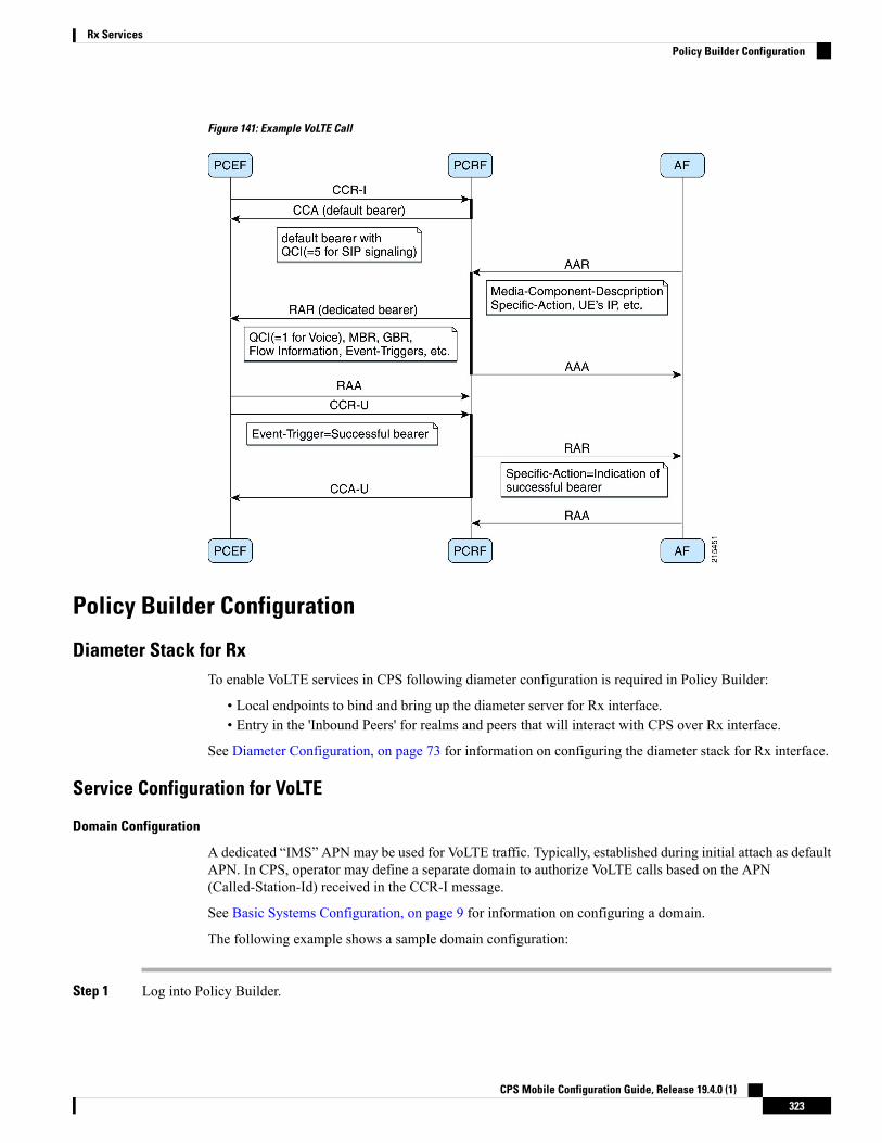
Figure 141: Example VoLTE Call
Policy Builder Configuration
Diameter Stack for RxTo enable VoLTE services in CPS following diameter configuration is required in Policy Builder:
• Local endpoints to bind and bring up the diameter server for Rx interface.• Entry in the 'Inbound Peers' for realms and peers that will interact with CPS over Rx interface.
See Diameter Configuration, on page 73 for information on configuring the diameter stack for Rx interface.
Service Configuration for VoLTE
Domain Configuration
A dedicated “IMS” APN may be used for VoLTE traffic. Typically, established during initial attach as defaultAPN. In CPS, operator may define a separate domain to authorize VoLTE calls based on the APN(Called-Station-Id) received in the CCR-I message.
See Basic Systems Configuration, on page 9 for information on configuring a domain.
The following example shows a sample domain configuration:
Step 1 Log into Policy Builder.
CPS Mobile Configuration Guide, Release 19.4.0 (1)323
Rx ServicesPolicy Builder Configuration

Step 2 Click the Services tab.Step 3 Under Domains, click Summary and then create a child domain.Step 4 Configure the domain by setting the required configuration for Authorization, Location and default service details as
shown in example below.
In this example the domain is configured for messages received with “IMS” APN (Called-Station-Id), it authorizes alluser and attaches a default service (with name “IMS”) to the subscriber.
Select Allow all Users for Authorization:Figure 142: General Domain Information
Use this domain for calls received for “IMS” APN (APN is derived from 'Called-Station-Id' AVP received in CCR-Imessage and mapped to a LOGICAL_APN AVP):Figure 143: Domain Locations
Defining a default service:
CPS Mobile Configuration Guide, Release 19.4.0 (1)324
Rx ServicesDomain Configuration

Figure 144: Default Service
See Basic Systems Configuration, on page 9 for more information on Domain configuration.
Service Configuration
While defining the service for VoLTE call, following service options can be used.
RxQoSInformation Service Configuration
This service configuration provides an option to define QoS values at service level to be used for dedicatedbearer. It provides values to be used during the derivation of theMaximumAuthorized Data Rates AuthorizedGuaranteed Data Rates and Maximum Authorized QoS Class Id in the PCRF whenever the “operator specialpolicy exists” phrase is used in the algorithm (3GPP 29.213) description.
The service configuration provides only the QoS AVP output values. It does not have any key parameters.So the QoS values are applied based upon the service (code) enabled for the subscriber.
Table 135: RxQosInformation Service Configuration Parameters
DescriptionParameter
QoS-Class-Identifier AVP valueQci
Max-Requested-Bandwidth-UL AVP valueMax Requested Bandwidth U L
Max-Requested-Bandwidth-DL AVP valueMax Requested Bandwidth D L
Guaranteed-Bitrate-UL AVP valueGuaranteed Bitrate UL
Guaranteed-Bitrate-DL AVP valueGuaranteed Bitrate DL
ARP (Allocation Retention Priority)
Priority-Level AVP valuePriority-Level
Pre-emption-Capability AVP valuePreemption-Capability
CPS Mobile Configuration Guide, Release 19.4.0 (1)325
Rx ServicesService Configuration
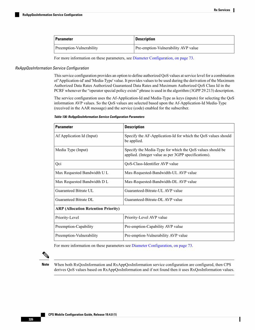
DescriptionParameter
Pre-emption-Vulnerability AVP valuePreemption-Vulnerability
For more information on these parameters, see Diameter Configuration, on page 73.
RxAppQosInformation Service Configuration
This service configuration provides an option to define authorized QoS values at service level for a combinationof 'Application-id' and 'Media-Type' value. It provides values to be used during the derivation of theMaximumAuthorized Data Rates Authorized Guaranteed Data Rates and Maximum Authorized QoS Class Id in thePCRFwhenever the “operator special policy exists” phrase is used in the algorithm (3GPP 29.213) description.
The service configuration uses the Af-Application-Id and Media-Type as keys (inputs) for selecting the QoSinformation AVP values. So the QoS values are selected based upon the Af-Application-Id Media-Type(received in the AAR message) and the service (code) enabled for the subscriber.
Table 136: RxAppQosInformation Service Configuration Parameters
DescriptionParameter
Specify the AF-Application-Id for which the QoS values shouldbe applied.
Af Application Id (Input)
Specify the Media-Type for which the QoS values should beapplied. (Integer value as per 3GPP specifications).
Media Type (Input)
QoS-Class-Identifier AVP valueQci
Max-Requested-Bandwidth-UL AVP valueMax Requested Bandwidth U L
Max-Requested-Bandwidth-DL AVP valueMax Requested Bandwidth D L
Guaranteed-Bitrate-UL AVP valueGuaranteed Bitrate UL
Guaranteed-Bitrate-DL AVP valueGuaranteed Bitrate DL
ARP (Allocation Retention Priority)
Priority-Level AVP valuePriority-Level
Pre-emption-Capability AVP valuePreemption-Capability
Pre-emption-Vulnerability AVP valuePreemption-Vulnerability
For more information on these parameters see Diameter Configuration, on page 73.
When both RxQosInformation and RxAppQosInformation service configuration are configured, then CPSderives QoS values based on RxAppQosInformation and if not found then it uses RxQosInformation values.
Note
CPS Mobile Configuration Guide, Release 19.4.0 (1)326
Rx ServicesRxAppQosInformation Service Configuration

RxGaranteedBitRateOverride Service Configuration
This service configuration provides a configuration option for copying the Max Requested Bit-rate valuesinto Guaranteed Bit-rate. This configuration is applicable when CPS is not able to derive Guaranteed Bitratevalues based on the QoS derivation algorithm defined in 3GPP 29.213 specification. So if GBR is not derivedand this service option is configured then CPS will copy the values derived for Max Requested Bitrates intoGuranteed Bitrates (applicable for both UL and DL).
Table 137: RxGaranteedBitRateOverride Parameter
DescriptionParameter
Flag that indicates whether to copy theMBR values into GBR valueswhen GBR is not derived
Default value is checked (true).
Set Guaranteed Bitrates from Maxrequested Bitrates
In a VoLTE specific service Operator can also define basic Gx specific services configurations likeDefaultBearerQos Event-Trigger and so on. For more information on these services configuration, see Gx/SdServices, on page 261.
Note
The following steps configure the Service options details (RxAppQosInformation RxAppQosInformation)for setting up a sample VoLTE specific service.
Step 1 Log into Policy Builder.Step 2 Go to the Services tab.Step 3 Under Use Case Templates, click Summary and then create a child Use Case Template.Step 4 Add a name to the template, for example, Rx_VoLTE.Step 5 Click Actions tab.Step 6 Click Add in the Service Configuration pane and add “RxQosInfomration” service configurations listed under the
'rx' section.
Similarly, operator can optionally add other service configurations like RxAppQosInformation,RxGuaranteedBitrateOverride, listed under 'rx' section as well as DefaultBearerQos, Event-Trigger, and so on. listedunder 'gx' section.
Step 7 Click Services Options. The newly created template is available here.Step 8 Create a child Service Option, for example, volte.Step 9 ClickOK. The newly created service options should have the service configuration objects that were added previously
at the template level.Step 10 Select the RxQoSInfomration service configuration and configure it as per your requirements.
CPS Mobile Configuration Guide, Release 19.4.0 (1)327
Rx ServicesRxGaranteedBitRateOverride Service Configuration

Figure 145: RxQoSInformation Service
Step 11 Select the RxAppQoSInfomration service configuration and configure it as per your requirements.Figure 146: RxAppQoSInformation Service
Step 12 Select the RxGuaranteedBitrateOverride service configuration and configure it as per your requirements.
CPS Mobile Configuration Guide, Release 19.4.0 (1)328
Rx ServicesRxGaranteedBitRateOverride Service Configuration

Figure 147: RxGuaranteedBitrateOverride Service
Step 13 Click Services and create a child service, for example, volte_service.Step 14 Update the Code and Name as volte_service.Step 15 Click Add and select the Service Option volte created earlier.
Service Configuration to Handle VoLTE Issues
Dedicated Bearer Creation Fails
In case VoLTE setup fails, that is, the dedicated bearer creation fails with some RAN/NAS cause code, CPSreceives the rule failure report with a RAN/NAS cause code from PCEF. CPS can retry the dedicated bearersetup based on these RAN/NAS cause codes, so that the failure to create the dedicated bearer can be minimized.
Use the RxRanNasCauseRetry service option to handle this issue. For this, create the following list of RAN/NASSearch Table Groups (STGs):
Table 138: STG Name Reference Mapping
Stg NameStg Reference
Ran_Nas_Cause_MappingRan_Nas_Cause_Mapping_Table
Rx_ParametersRx_Parameters_Table
Gx_ParametersGx_Parameters_Table
Sy_ParametersSy_Parameters_Table
Ran_Nas_Retry_MappingRan_Nas_Retry_Mapping_Table
CPS Mobile Configuration Guide, Release 19.4.0 (1)329
Rx ServicesService Configuration to Handle VoLTE Issues

• Stg Reference is bound to the CRD table created by the user.• Stg Name is the corresponding CRD table name entered by the user in the RxRanNasCauseRetry serviceoption. The STG name should be same as the Stg Name values in the above table.
• For more information on how to create Search Table Groups, refer to RxSTGConfiguration ServiceConfiguration, on page 340.
• CPS supports wildcarding for all the input values in the CRD tables. To use wildcarding, select the BestMatch check box in the STG table. CPS supports wildcarding as per the standard Java regex patterns.
Note
Step 1 Create the Ran_Nas_Cause_Mapping CRD table as follows:a) This table is used to find the RAN/NAS Cause group from Protocol type and Cause type.
The Protocol Type and Cause Type are decoded from the RAN-NAS-Release-Cause AVP. For example,if the system receives 1234 as the RAN-NAS-Release-Cause AVP, 1 is decoded as the Protocol Type and2 is decoded as the Cause Type. Cause value 34 can be ignored.
If multiple instances of RAN-NAS-Release-Cause AVP are received in a message, CPS runs a CRD queryfor each RAN/NAS cause code and gets the corresponding RAN/NAS cause group. The group with thehighest priority is chosen.
Note
b) Refer to the following table for its parameters.
Avp Name column is the corresponding AVP name entered by the user in the RxRanNasCauseRetry serviceoption. The AVP name should be same as the Avp Name values shown in the following table.
Note
Table 139: Ran_Nas_Cause_Mapping CRD Table
Column TypeBinding/RetrieverAvp NameColumn Name
InputNoneRan-Nas-Protocol-TypeRan_Nas_Protocol_Type
InputNoneRan-Nas-Cause-TypeRan_Nas_Cause_Type
OutputNot ApplicableGroup-PriorityGroup_Priority
OutputNot ApplicableRan-Nas-Cause-GroupRan_Nas_Cause_Group
c) Configure the Ran_Nas_Cause_Mapping table in the RxRanNasCauseRetry service option.
CPS Mobile Configuration Guide, Release 19.4.0 (1)330
Rx ServicesDedicated Bearer Creation Fails

Figure 148: RxRanNasCauseRetry Service Option for Ran_Nas_Cause_Mapping
Where,
• Use Success Event Trigger in Rule Retry:
• When set to true: CPS adds the SUCCESSFUL_RESOURCE_ALLOCATION event trigger in rule retryCCA message. This is added so that PCEF can notify the successful allocation of the rule. On receipt ofsuccessful resource event for the rule from PCEF, CPS sends success Rx RAR to AFwith success RAN/NAScause and all last known RAN/NAS cause AVPs received from PCEF for this rule.
• When set to false: CPS does not use SUCCESSFUL_RESOURCE_ALLOCATION event trigger. So,on Ran Nas Retry timer expiry, CPS treats it as successful installation of the rule and sends success RxRAR to AF with success RAN/NAS cause and all last known RAN/NAS cause AVPs received from PCEFfor this rule.
CPS sends success Rx RAR only if Rx-Message-On-Retry-Success is true in the CRD data.Note
• Ran Nas Retry Timeout in Ms: The time (in milliseconds) after which the TimerExpired message is pushedinto policy engine to evaluate rule retry as success or failure and also send RAR on Rx and Gx.
• IfUse Success Event Trigger in Rule Retry is true, rule retry is treated as failure on this timerexpiry.
• If Use Success Event Trigger in Rule Retry is false, rule retry is treated as success on thistimer expiry.
Note
CPS Mobile Configuration Guide, Release 19.4.0 (1)331
Rx ServicesDedicated Bearer Creation Fails

Step 2 Create the Rx_Parameters CRD table as follows:a) This table is used to configure Rx parameters to be used in RAN/NAS retry algorithm. Input is one or more of the
following supported Rx Parameters and Output is Rx_Parameters_Group.b) Refer to the following table for the list of currently supported input parameters on the Rx interface.
• Avp Name column is the corresponding AVP name entered by the user in the RxRanNasCauseRetryservice option. The AVP name should be same as the Avp Name values shown in the following table.
• Not all parameters are mandatory. Choose the parameters as per your requirement.
Note
Table 140: Rx_Parameters CRD Table
Column TypeBinding/RetrieverAvp NameColumn Name
InputNoneAF-Application-IdentifierAF_Application_Identifier
InputNoneMedia-TypeMedia_Type
InputNoneBearer-SetupBearer_Setup
InputNoneRx-Session-NumberRx_Session_Number
InputNoneSponsor-IdentitySponsor_Identity
InputNoneApplication-Service-
Provider-Identity
Application_Service_
Provider_Identity
InputNoneService-URNService_URN
InputNoneRx-Request-TypeRx_Request_Type
InputNoneRan-Nas-Cause-GroupRan_Nas_Cause_Group
OutputNot ApplicableRx-Parameters-GroupRx_Parameters_Group
c) Configure the Rx Parameters table in the RxRanNasCauseRetry service option as shown in Figure 148:RxRanNasCauseRetry Service Option for Ran_Nas_Cause_Mapping, on page 331.
Step 3 Create the Gx_Parameters CRD table as follows:a) This table is optional and is used to configure Gx parameters to be used in RAN/NAS retry algorithm. Inputs are one
or more of the following supported GxParameters and Output is Gx_Parameters_Group.b) Refer to the following table for the list of currently supported input parameters on the Gx interface.
Avp Name column is the corresponding AVP name entered by the user in the RxRanNasCauseRetry serviceoption. The AVP name should be same as the Avp Name values shown in the following table.
Note
Table 141: Gx_Parameters CRD Table
Column TypeBinding/RetrieverAvp NameColumn Name
InputSession MSISDNIMSIIMSI
InputSession IMSIMSISDNMSISDN
CPS Mobile Configuration Guide, Release 19.4.0 (1)332
Rx ServicesDedicated Bearer Creation Fails
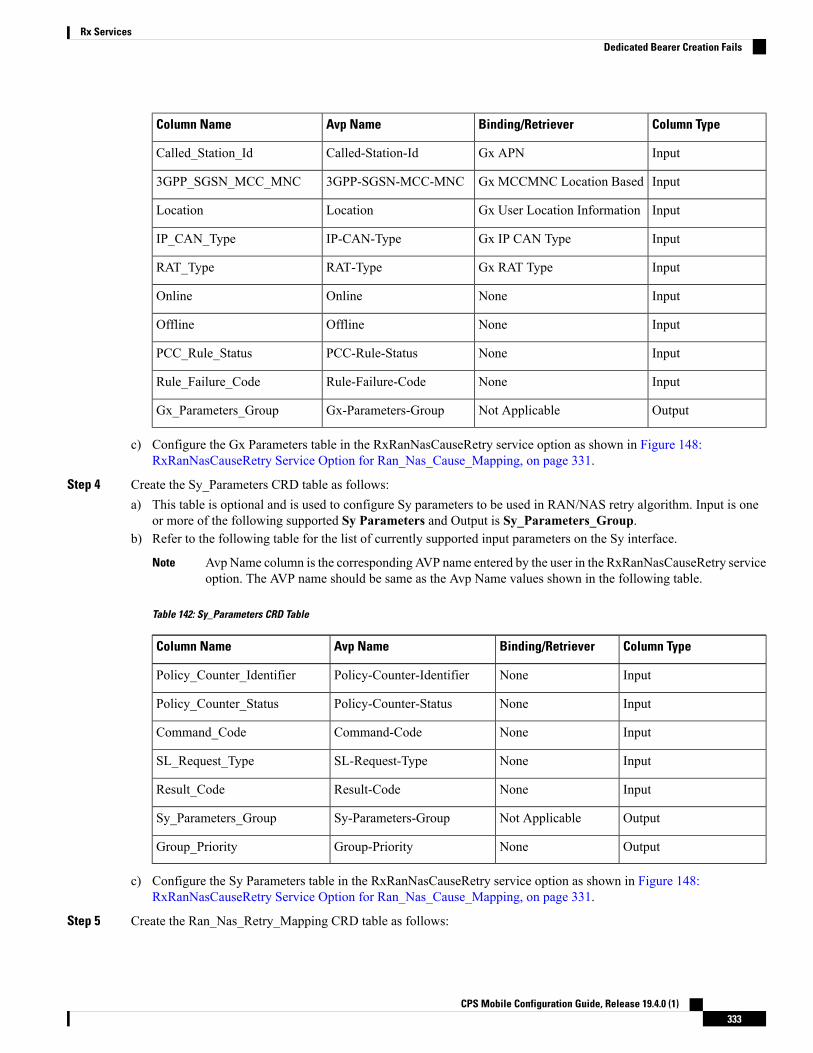
Column TypeBinding/RetrieverAvp NameColumn Name
InputGx APNCalled-Station-IdCalled_Station_Id
InputGx MCCMNC Location Based3GPP-SGSN-MCC-MNC3GPP_SGSN_MCC_MNC
InputGx User Location InformationLocationLocation
InputGx IP CAN TypeIP-CAN-TypeIP_CAN_Type
InputGx RAT TypeRAT-TypeRAT_Type
InputNoneOnlineOnline
InputNoneOfflineOffline
InputNonePCC-Rule-StatusPCC_Rule_Status
InputNoneRule-Failure-CodeRule_Failure_Code
OutputNot ApplicableGx-Parameters-GroupGx_Parameters_Group
c) Configure the Gx Parameters table in the RxRanNasCauseRetry service option as shown in Figure 148:RxRanNasCauseRetry Service Option for Ran_Nas_Cause_Mapping, on page 331.
Step 4 Create the Sy_Parameters CRD table as follows:a) This table is optional and is used to configure Sy parameters to be used in RAN/NAS retry algorithm. Input is one
or more of the following supported Sy Parameters and Output is Sy_Parameters_Group.b) Refer to the following table for the list of currently supported input parameters on the Sy interface.
Avp Name column is the corresponding AVP name entered by the user in the RxRanNasCauseRetry serviceoption. The AVP name should be same as the Avp Name values shown in the following table.
Note
Table 142: Sy_Parameters CRD Table
Column TypeBinding/RetrieverAvp NameColumn Name
InputNonePolicy-Counter-IdentifierPolicy_Counter_Identifier
InputNonePolicy-Counter-StatusPolicy_Counter_Status
InputNoneCommand-CodeCommand_Code
InputNoneSL-Request-TypeSL_Request_Type
InputNoneResult-CodeResult_Code
OutputNot ApplicableSy-Parameters-GroupSy_Parameters_Group
OutputNoneGroup-PriorityGroup_Priority
c) Configure the Sy Parameters table in the RxRanNasCauseRetry service option as shown in Figure 148:RxRanNasCauseRetry Service Option for Ran_Nas_Cause_Mapping, on page 331.
Step 5 Create the Ran_Nas_Retry_Mapping CRD table as follows:
CPS Mobile Configuration Guide, Release 19.4.0 (1)333
Rx ServicesDedicated Bearer Creation Fails

a) This is the final table that uses the output values from the above tables.b) Refer to the following table for its parameters.
Avp Name column is the corresponding AVP name entered by the user in the RxRanNasCauseRetry serviceoption. The AVP name should be same as the Avp Name values shown in the following table.
Note
Table 143: Ran_Nas_Retry_Mapping CRD Table
Column TypeBinding/RetrieverAvp NameColumn Name
InputNoneGx-Parameters-GroupGx_Parameters_Group
InputNoneRx-Parameters-GroupRx_Parameters_Group
InputNoneSy-Parameters-GroupSy_Parameters_Group
OutputNot ApplicableMax-Retry-AttemptMax_Retry_Attempt
OutputNot ApplicableRx-Message-On-Retry-SuccessRx_Message_On_Retry_Success
OutputNot ApplicableRan-Nas-Custom-Success-CodeRan_Nas_Custom_Success_Code
Where,
• Max-Retry-Attempt: Maximum retry attempts to be done before considering it as failure.
• Rx_Message_On_Retry_Success: Decides whether to send Rx RAR on successful retry.
• If value configured as true: Sends Rx RAR on successful retry with all the RAN/NAS cause codes receivedso far from the PCEF.
• If value configured as false: Does not send Rx RAR on successful retry.
• Ran-Nas-Custom-Success-Code: This is one of the spare values in the RAN-NAS-Cause protocol type field.Valid values are 6 to 15. So, to indicate that the Rx RAR is sent for a successful retry, PCRF encodes oneRAN-NAS-Release-Cause AVP with this protocol type value. The cause type and cause value should be ignoredby the receiver.
c) Configure the Ran_Nas_Retry_Mapping table in the RxRanNasCauseRetry service option.
CPS Mobile Configuration Guide, Release 19.4.0 (1)334
Rx ServicesDedicated Bearer Creation Fails

Figure 149: RxRanNasCauseRetry Service Option for Ran_Nas_Retry_Mapping
Support Stale Session for VoLTEFor VoLTE calls, CPS identifies a stale Gx session from the latest Gx session thus allowing CPS to load thelatest Gx session and act accordingly. For this, the secondary key mapping stores the primary key in additionto the bucket ID and the site ID, that is, SecondaryKey = <BucketId>; <Site Id>; <Primary Key>.
To enable this feature, add the following parameter in the /etc/broadhop/qns.conf file:
-Dcache.config.version=1
After migration starts, QNS queries with the old format first. If secondary key mapping is not found with theold format, QNS queries with the new format. This leads to increase in query on cache ring during the datamigration process. Due to this, there could be some performance impact during the migration process.
Primary keys are stored in the memcache. This increases storage on the memcache. By default, memcachehas two GB memory limit. Once memory limit is reached, memcache automatically deletes old records toaccommodate new records.
CPS Mobile Configuration Guide, Release 19.4.0 (1)335
Rx ServicesSupport Stale Session for VoLTE

To accommodate more sessions, add more ringsets to distribute data among multiple ringsets.
In case no sessionmgr is available to add a ringset, memory limit can be increased on each sessionmgrs (defaulttwo GB) by changing the value of CACHESIZE in the /etc/sysconfig/memcached file on sessionmgr.
Key storage (memcache) size can be obtained using the following command on sessionmgr:
• Max Limit (in MBs): echo "stats" | nc sessionmgr01 11211 | grep "STAT limit_maxbytes" |
awk '{print $3/1024/1024}'
• Used (in MBs): echo "stats" | nc sessionmgr02 11211 | grep "STAT bytes " | awk '{print
$3/1024/1024}'
• Available (in MBs) = Max Limit - Used (in MBs)
Upgrading CPS to use the new mapping format
To upgrade CPS to change the mapping to the new format, do the following:
1. Add the flag -Dcache.config.version=1 in /etc/broadhop/qns.conf file.
2. Copy the file to all VMs.
3. Restart the QNS service.
4. Repeat the above steps for all the sites.
5. Wait for all sites to come up.
6. Add the keys being used for the look up inLookasideKeys Prefixes inREFERENCEDATA > Systems ><Name of Cluster> in Policy Builder. See Adding an HA Cluster, on page 28.
7. Run rebuildAllSkRings fromQNS on one of the sites. This starts the data migration process and changesthe mapping to the new format.
8. Once migration is complete, CPS uses the new format.
Restoring CPS to use the old mapping format
To restore CPS to use the old format, that is, disable the feature, do the following:
1. Clear scheduler and ring set in Admin DB. To do this:
1. Log into the administration database primary member.
2. Run the following commands in Mongo:PRIMARY> use schedulerPRIMARY> db.tasks.remove({"type":"migrateCache"});PRIMARY> use shardingPRIMARY> db.versions.update({"_id":"cache_config"},{$set:{"migrationStatus":"READY"}});PRIMARY> db.cache_config.update({},{$unset:{migratingShards:1}},false,true);PRIMARY> db.config.update({},{$inc: {version:1}})
3. Run the following commands to verify there is no pending task:PRIMARY> use schedulerPRIMARY> db.tasks.find({"type":"migrateCache"});
2. Set -Dcache.config.version=0 in /etc/broadhop/qns.conf. Copy the file to all VMs and restartthe QNS service.
CPS Mobile Configuration Guide, Release 19.4.0 (1)336
Rx ServicesSupport Stale Session for VoLTE

3. Repeat Step 2, on page 336 for all the sites.
4. Wait for all sites to come up.
5. Once all sites are up, run rebuildAllSkRings from QNS on one of the sites. This starts the data migrationprocess and changes the mapping back to the old format.
6. You can keep checking the status of data migration by running skRingRebuildStatus.
7. Once migration is complete, CPS uses the old format.
Dynamic Rule Naming (Multiple Dedicated Bearer QoS)CPS supports multiple dedicated QoS Bearers (video and audio) within a subscriber's IP-CAN session includessplitting up Gx based RAR messages to provides quality video calls.
When a AAR message is received through the Rx interface with Media-Component-Description a Gx RARrequest is sent with the new dynamic PCC rules for initiating new dedicated bearers. Since CPS generatesthese rules dynamically it automatically generates the rule-name using the following syntax:
_<Rx-Linked-Session-Number>_<Media-Component-Number>_<Media-Sub-ComponentFlow-Number>_<Rule-Name>_<Media-Type>
The items in this name are:
• Rx-Linked-Session-Number: An internal number that identifies an Rx-session bound to a Gx-session.• Media-Component-Number: Corresponding AVP value as received in Media-Component-DescriptionGrouped AVP for an AAR message.
• Media-Sub-ComponentFlow-Number: Corresponding AVP value as received inMedia-Component-Description->Media-Sub-Component Grouped AVP for an AAR message.
• Rule-Name: A partial name configured in Policy Builder (as derived using AF-Application-Identifierand Media-Type values from 'Custom dynamic rule name' table in Gx Client. Default value “AF”).
for example, “_1_1_1_SIP_AUDIO” “_2_3_1_SIP_VIDEO” and so on.
See Gx Clients, on page 114 for more information on configuring the table in Gx client.
QoS SelectionQoS on dynamic rule (dedicated bearer) created for rx session is derived based upon the algorithm mentionedin section 6.3 of 3GPP 29.213 specification. This algorithm specifies how QoS Class (QCI) MaximumAuthorized Data Rates (MBR) Authorized Guaranteed Data Rates (GBR) and Allocation Retention Policy(ARP) are derived based on the media details (Media-Component-Description) send by the AF (IMS).
Table 144: QoS Selection Parameters
Policy Builder section to referPhrase mentioned in Algorithm
“RxQosInformation” and “RxAppQosInformation”service configuration.
“as defined by operator specific algorithm”
“Application Qos Policy” defined in Rx Profile“AF-Application-Identifier AVP demands applicationspecific data rate”
CPS Mobile Configuration Guide, Release 19.4.0 (1)337
Rx ServicesDynamic Rule Naming (Multiple Dedicated Bearer QoS)

Policy Builder section to referPhrase mentioned in Algorithm
“Codec Qos Policy” defined in Rx Profile“Codec-Data AVP provides Codec information for acodec that is supported by a specific algorithm”
(See Rx Profile, on page 156 for more information on configuration of Rx Profile).
Dynamic QoSThis section covers the following topics:
• Programmatic CRD (QoS Action), on page 338
• Logical Operator Support in Programmatic CRD tables for RxSTGConfiguration, on page 344
• Support of Charging Parameters for Dynamic Rules using CRD Tables, on page 346
• Charging Parameters for Sponsored Data, on page 348
Programmatic CRD (QoS Action)CPS supports the management of Dedicated Bearer QoS attribute values for Rx IMS application sessions byapplying actions QoS-Bounding QoS-Mirroring and QoS-Enforced on Dedicated Bearer QoS calculated asper specification 29.213.
CPS will set the QoS attributes values on the dedicated bearer based on the following QoS actions
• Enforce: This action for any QoS attribute will enforce the values from custom reference data (CRD)table.
• Mirror: This action will copy the QoS attributes values requested by the AF (received in the AARmessage).
• Bound: This action will calculate the minimum value between the QoS defined in CRD table and AFrequested values or values calculated as per QoS derivation algorithm (29.213).
The following table explains how CPS will derive dedicated bearer QoS-information attributes based on:
• The value received in AAR message (AF requested QoS)
• Value derived from QoS derivation algorithm defined in 29.213
• QoS-Action (Mirror Enforce Bound) and their respective values configured in CRD table
The pattern of the attributes in output column indicates from which input column the value is derived.
QoS-Action Mirror:
Table 145: QoS-Action Mirror
OutputInput
CRD ValueQoS Derivation AlgorithmAAR
MBRMBRMBRMBR
CPS Mobile Configuration Guide, Release 19.4.0 (1)338
Rx ServicesDynamic QoS

OutputInput
CRD ValueQoS Derivation AlgorithmAAR
GBRGBRGBR
QCIQCIQCI
ARPARPARP
QoS-Action Enforce:
Table 146: QoS-Action Enforce
OutputInput
CRD ValueQoS Derivation AlgorithmAAR
MBRMBRMBRMBR
GBRGBRGBR
QCIQCIQCI
ARPARPARP
QoS-Action Bound:
Table 147: QoS-Action Bound
OutputInput
CRD ValueQoS Derivation AlgorithmAAR
min(MBR, MBR)MBRMBRMBR
min(GBR, GBR)GBRGBR
min8 (QCI, QCI)QCIQCI
min(PL, PL) and PV, PCbased on chosen ARP
ARPARP
8 As per Bound definition, we still select min value, but min value for QCI translates to max QCI value.
In order to apply the various QoS actions Enforce, Mirror and Bounding CPS needs to provide a new Rxservice configuration object which can be applied to subscriber. CPS also supports custom reference data(CRD) tables where for a combination of subscriber and session attributes can be used as an input to derivethe output values. These lookup can be performed by using the Input attributes and values as a key and derivea result set of Output attribute and value which can be used to calculate various applicable QoS parameters.
CPS Mobile Configuration Guide, Release 19.4.0 (1)339
Rx ServicesProgrammatic CRD (QoS Action)

Policy Builder ConfigurationPolicy builder configuration for this feature requires configuring a CRD table in reference data section and'RxSTGConfiguration' service configuration object in use case template.
RxSTGConfiguration Service Configuration
Table 148: RxSTGConfiguration Service Configuration Parameters
DescriptionParameter
Reference to the Search Table Group containing the CRD tables that definesthe QoS Action for Rx specific dynamic rules (dedicated bearer).
Stg Name
Define themapping between the 'AVPNames' and the key 'Columns' definedin the selected STG. These AVPs will be the inputs while evaluating theCRD table in STG.
List of Input Columns (List ofColumnAndAvpPair)
Name of the diameter AVP (received in Media Component Description AVPof the AAR message) which is to be used as input for CRD table evaluation.(for example, “Flow-Number” “Media-Component-Number” etc).
Avp Name
Reference to the key column in STG corresponding to the specified AVP.Column
Define the mapping between the AVPNames and the output columns definedin the STG selected. These mapping indicate how the output column's valuesare mapped to AVPs after the CRD is evaluated.
List of Output Columns (Listof ColumnAndAvpPair)
Name of the diameter AVP (attribute from Qos-Information) to which thevalue of the output column should be mapped to while setting theQos-Information for the dedicated bearer on Gx. (for example,“Qos-Class-Identifier”)
Similarly for Qos-Actions on the attribute the AVP Name specifies theqos-action for a specific Qos-Information attribute (for example, “Qci”).Refer the note below.
Avp Name
Reference to the output column defined in the STG selected.Column
The values of “AVP name”must be exact same as per specifications (for example, Media-Component-NumberFlow-Number etc.) while defining input columns to RxSTGConfiguration.
Note
Output columns can be defined for one or more of the QoS attributes.When a QoS attribute is added to output,it requires defining two column entries one for QoS action and one for QoS value. The QoS value AVP nameneeds to be defined as per standard (3GPP TS 29.214) QoS attribute AVP name whereas QoS action AVPname needs to be as mentioned below (for the corresponding QoS attribute):
• Qci• Max Req Bandwidth U L• Max Req Bandwidth D L• Guaranteed Bit Rate U L
CPS Mobile Configuration Guide, Release 19.4.0 (1)340
Rx ServicesPolicy Builder Configuration

• Guaranteed Bit Rate D L• Priority Level• Preemption Capability• Preemption Vulnerability
Similarly when mapping the output columns for CRD values of Qos-Information attribute use the exact QoSattribute name (for example, “Qos-Class-Identifier” “Max-Requested-Bandwidth-UL” etc.)
Output columns can also be defined for flow-information attributes (FlowDescription and Flow Status). Whena flow-information attribute is added to output, it requires defining two column entries one for action and theother for value. The value AVP name needs to be defined as per standard (3GPP TS 29.214) attribute AVPname whereas the action AVP name needs to be as mentioned below (for the corresponding flow-informationattributes):
• Flow Description
• Flow Status
Similarly when mapping the output columns for CRD values of flow-information attributes use the exactattribute name (for example, “ Flow-Description” “ Flow-Status”.)
• Bound action is not applicable for Flow-Description and Flow-Status.
• CPS does not apply the Actions if the Flow-Status is reported as 'Removed' by AF in the AAR message.CPS does not install the Charging-Rule for the corresponding Media-Sub-Component (or CPS willuninstall it if a Charging-Rule is already installed).
• If the Flow-Status received in AAR is of any value other than 'Removed' and the Action is to Enforce itwith value 'Removed', the Charging-Rule for the corresponding Media-Sub-Component is not installed.
• CPS enforces the Flow-Status value as per the CRD configuration and it may override the 3GPP 29.214specifications. For example, as per 3GPP specifications, RTCP flows are always enabled. If the CRD isconfigured to enforce Flow-Status with any other value, CPS overrides it with the configured value.
• Gx client 'Rx PCC Rule Flow Direction Behavior' is applicable for Flow-Description derived afterapplying the Action.
Note
The following steps configure the CRD table for defining the Qos-Action details and Service options details(RxSTGConfiguration) for setting up the service.
Step 1 Log into Policy Builder.Step 2 Select the Reference Data tab.Step 3 Click Custom Reference Data Tables and create a CRD table under Search Table Group as shown in example below.
For more information on how to configure Search Table Groups, see Services, on page 223.
The following example shows three key columns for the CRD table. 'Media-Component-Number' and 'Flow-Number'columns will be mapped to the respective AVPs by setting the respective AVP Names in service-option configuration.Whereas the additional 'RAT-Type' key column is bound to the Gx session attribute.
CPS Mobile Configuration Guide, Release 19.4.0 (1)341
Rx ServicesRxSTGConfiguration Service Configuration
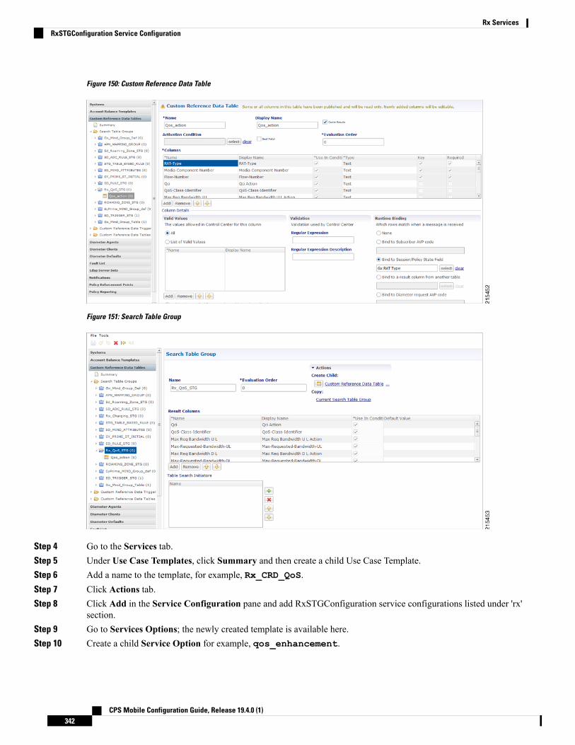
Figure 150: Custom Reference Data Table
Figure 151: Search Table Group
Step 4 Go to the Services tab.Step 5 Under Use Case Templates, click Summary and then create a child Use Case Template.Step 6 Add a name to the template, for example, Rx_CRD_QoS.Step 7 Click Actions tab.Step 8 Click Add in the Service Configuration pane and add RxSTGConfiguration service configurations listed under 'rx'
section.Step 9 Go to Services Options; the newly created template is available here.Step 10 Create a child Service Option for example, qos_enhancement.
CPS Mobile Configuration Guide, Release 19.4.0 (1)342
Rx ServicesRxSTGConfiguration Service Configuration

Step 11 ClickOK. The newly created service options should have the service configuration objects which were added previouslyat the template level.
Step 12 Select the RxSTGConfiguration service configuration and configure it as per the following example:
Refer to the example configuration below that shows 'Media-Component-Number' and 'Flow-Number' Columns inCRD are bound to respective AVP names (received in 'Media-Component-Description' AVP received in AARmessage).For output column pairs the sample configuration shows 'Qci' and 'Max Req Bandwidth U L' being mapped to therespective columns in CRD for QoS actions and 'Qos-Class-Identifier' and 'Max-Requested-Bandwidth-UL' columnsare mapped to the respective AVPs for CRD values.
To add multiple input columns select List of Input Column AVP Pairs (List) row and click Add Child tocreate a new ColumnAndAvpPair row to add the input column details. Follow same steps to add outputcolumns in 'List of Output Column Avp Pairs'.
Note
Figure 152: Service Option
Step 13 Click Services and create a child service, for example, rx_qos_action.Step 14 Update the Code and Name as rx_qos_action.Step 15 Click Add and select the qos_enhancement service option created earlier.
Control Center Configuration
Setting up the CRD table in the STG
Step 1 Log into Control Center to define the values for the parameters defined in Custom Reference Data tables.Step 2 Select the Configuration tab.
CPS Mobile Configuration Guide, Release 19.4.0 (1)343
Rx ServicesControl Center Configuration
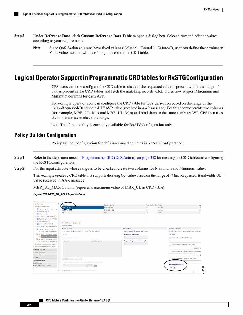
Step 3 Under Reference Data, click Custom Reference Data Table to open a dialog box. Select a row and edit the valuesaccording to your requirements.
Since QoS Action columns have fixed values (“Mirror”, “Bound”, “Enforce”), user can define these values inValid Values section while defining the column for CRD table.
Note
Logical Operator Support in Programmatic CRD tables for RxSTGConfigurationCPS users can now configure the CRD table to check if the requested value is present within the range ofvalues present in the CRD tables and fetch the matching records. CRD tables now support Maximum andMinimum columns for each AVP.
For example operator now can configure the CRD table for QoS derivation based on the range of the“Max-Requested-Bandwidth-UL”AVP value (received in AARmessage). For this operator create two columns(for example, MBR_UL_Max and MBR_UL_Min) and bind them to the same attribute/AVP. CPS then usesthe min and max to check the range.
Note This functionality is currently available for RxSTGConfiguration only.
Policy Builder ConfigurationPolicy Builder configuration for defining ranged columns in RxSTGConfiguration:
Step 1 Refer to the steps mentioned in Programmatic CRD (QoSAction), on page 338 for creating the CRD table and configuringthe RxSTGConfiguration.
Step 2 For the input attribute whose range is to be checked, create two columns for Maximum and Minimum value.
This example creates a CRD table that supports deriving Qci value based on the range of “Max-Requested-Bandwidth-UL”value received in AAR message.
MBR_UL_MAX Column (represents maximum value of MBR_UL in CRD table).Figure 153: MBR_UL_MAX Input Column
CPS Mobile Configuration Guide, Release 19.4.0 (1)344
Rx ServicesLogical Operator Support in Programmatic CRD tables for RxSTGConfiguration

MBR_UL_MIN (represents minimum value of MBR_UL in CRD table).Figure 154: MBR_UL_MIN Input Column
Make sure that Matching Operator is selected properly i.e for Maximum value column need to select 'gt' or 'gte' and forMinimum value column select 'lt' or 'lte' and QCI column is a result column need to specify that at result column sectionof STG table.
Step 3 In RxSTGconfiguration, map the corresponding input columns defined above with the same AVP name(Max-Requested-Bandwidth-UL) as shown below:Figure 155: RxSTGconfiguration Column Parameter
Step 4 Set Control Center table values as follows:
CPS Mobile Configuration Guide, Release 19.4.0 (1)345
Rx ServicesPolicy Builder Configuration

Figure 156: Setting Control Center Table Values
So with the above configuration, If CPS receives an Rx-AAR message with “Max-Requested-Bandwidth-UL” AVPhaving value as “4000” then the dynamic rule generated will have Qci value as '6' based on following evaluation:
• 2000 (MBR Min CRD value) < 4000 (Requested value)
• 8000 (MBR Max CRD value) > 4000 (Requested value)
Fetch the record and give the Result Column value (QCI as 6).
Step 5 Use the same AVP name in the List of Input AVP columns in the service configuration.
Support of Charging Parameters for Dynamic Rules using CRD TablesCPS supports configurations for setting up the charging parameters on the dedicated bearer created for IMSapplication sessions (Rx sessions). The charging parameters (like Rating-Group Service-IdentifierMetering-Method etc.) can be derived based on certain parameters in theMedia-Component-DescriptionAVPreceived in AAR message (for example, AF-Application-Identifier Flow-Status etc) or any session or SPRattributes. CPS supports configuration of static tables as well as CRD tables to define the criteria for selectingthe desired charging parameters on the dynamic PCC rule (dedicated bearer).
CPS will first evaluate the CRD table defined in 'RxChargingParameterSTGConfig' service configuration andif no parameters are derived then CPS will look into the static table defined in 'Dynamic Rule chargingparameters' section under Rx-Profile. (See Diameter Configuration, on page 73 for more information.)
CPS also supports a separate configuration for deriving the charging parameters when dedicated bearer iscreated for sponsored data. CPSwill first evaluate the CRD table defined in 'RxSponsoredDataChargingParam'service configuration and if no parameters are derived then CPS will look into the static table defined in'Sponsored Data Charging Parameter' section under Rx-Profile.
Policy Builder ConfigurationUse RxChargingParameterSTGConfig service configuration for setting the charging parameters for dedicatedbearers created for IMS session (non-sponsored data case).
RxChargingParameterSTGConfig Service Configuration
The following steps configure the STG for defining the charging parameters details and Service options details(RxChargingParameterSTGConfig) for setting up the service.
Step 1 Log into Policy Builder.Step 2 Select the Reference Data tab.
CPS Mobile Configuration Guide, Release 19.4.0 (1)346
Rx ServicesSupport of Charging Parameters for Dynamic Rules using CRD Tables

Step 3 Click Custom Reference Data Tables and create a CRD table under Search Table Group as shown in the followingfigures.
For more information on how to configure Search Table Groups, see Services, on page 223.
The following figures show three key columns for the CRD. TheMedia-Type and Flow-Status columns will be mappedto the respective AVPs from AAR message (by setting the corresponding AVP Names in service-option configurationin Step 10, on page 348). And an additional RAT_Type key column is used, which is bound to the Gx session attribute.Figure 157: RAT_Type key column
Figure 158: Media Type key column
Step 4 Select the Services tab.Step 5 Under Use Case Templates, click Summary and then create a child Use Case Template.
CPS Mobile Configuration Guide, Release 19.4.0 (1)347
Rx ServicesRxChargingParameterSTGConfig Service Configuration

Step 6 Add a name to the template, for example, Rx_Doc.Step 7 Click Actions tab.Step 8 Click Add in the Service Configuration pane and add RxChargingParameterSTGConfig service configurations
listed under 'rx' section.Step 9 Go to Services Options; the newly created template is available here.Step 10 Create a child Service Option for example, rx_charging.Step 11 ClickOK. The newly created service options should have the service configuration objects that were added previously
at the template level.Step 12 Select the RxChargingParameterSTGConfig service configuration and configure it as per your requirements.
To add multiple input columns, select the List of Input Column AVP Pairs (List) row and click Add Childto create a new ColumnAndAvpPair row to add the input column details. Follow the same steps to add outputcolumns in List of Output Column Avp Pairs.
Note
The values of “AVP name” must be same as per specifications (for example, Media-Component-NumberFlow-Number etc.) while defining input columns to RxChargingParameterSTGConfig.
Whereas for output column AVP Pairs in RxChargingParameterSTGConfig while defining the chargingparameter attribute use the exact AVP name for charging parameters in Charging-Rule-Definition as perspecification. (for example, Rating-Group Service-Identifier etc.)
Note
For parameter descriptions, refer to RxChargingParameterSTGConfiguration, on page 478.
Step 13 Click Services and create a child service, for example, abc.Step 14 Update the Code and Name as abc.Step 15 Click Add and select the abc service option created earlier.
Control Center Configuration
Setting Up the CRD Table in the STG
Step 1 Log into Control Center to define the values for the parameters defined in Custom Reference Data tables.Step 2 Select the Configuration tab.Step 3 Under Reference Data, click Custom Reference Data Table name to open a dialog box.Step 4 Select a row and edit the values according to your requirements.
A few columns have fixed values (For example, value for Flow-Status column is “ENABLED-UPLINK (0)”,“ENABLED-DOWNLINK (1)”, “ENABLED (2)”, and so on.) So, you can define these values in the Valid Values sectionwhile defining the column for the CRD table.
Charging Parameters for Sponsored DataAs explained in the previous section CPS supports defining CRD tables to set the charging parameters ondynamic rules (dedicated bearer) created for IMS session. User can define various inputs to the CRD table todefine different evaluation criteria.
CPS Mobile Configuration Guide, Release 19.4.0 (1)348
Rx ServicesControl Center Configuration

In case the dedicated bearer is created for a sponsored data access CPS supports a different service configurationand CRD tables to define the evaluation criteria for selecting charging parameters on dynamic rules.RxSponsoredDataChargingParam is the service configuration defined in CPS to configure the CRD detailsfor setting charging parameters on dedicated bearer created for sponsored data. This service configurationsupports defining Sponsor-Identity (provided in Sponsored-Connectivity-Data) as one of the input column inthe CRD table created for charging parameters of sponsored-data.
CPS will first evaluate the CRD table defined in 'RxSponsoredDataChargingParam service configuration andif no parameters are derived then CPS will look into the static table defined in 'Sponsored Data chargingparameters' section under Rx-Profile. (See Diameter Configuration, on page 73 for more information.)
Policy Builder ConfigurationRefer to the policy-builder configuration in Logical Operator Support in Programmatic CRD tables forRxSTGConfiguration, on page 344. Create an extra key column for Sponsor-Identity in the CRD table.Correspondingly, in the service configuration, add an extra input AVP mapping for Sponsor-Identity AVPand its CRD column.
SRVCCSingle Radio Voice Call Continuity (SRVCC) solution seamlessly maintains voice calls as mobile users movefrom LTE to non-LTE coverage areas. This solution transfers VoLTE calls in progress from LTE to legacyvoice networks. Without SRVCC, a VoLTE call on a device moving out of LTE coverage will be dropped.
To support SRVCC solution, CPS support notifying the AF (IMS System) when dynamic rules (created forRx) on Gx fails because of handover from packet switched (PS) to Circuit Switched (CS).
NPLI (Access Network)Cisco Policy Suite (CPS) provides Access Network Information (Network Provided Location Information)(for example User Location User Timezone information and so on) Reporting over Gx and Rx Interfaces.
In this feature CPS supports ACCESS_NETWORK_INFO_REPORT Event-Trigger and specific-action onGx and Rx interface respectively to provide the necessary Access Network Information.
WhenAF requests the PCRF for access network information the PCRF (CPS) subscribes the requested AccessNetwork Information from the PCEF within the Required-Access-Info AVP which is included in theCharging-Rule-Definition AVP. When the Access Network Information is available the PCEF provides therequired Access Network Information to the PCRF within the 3GPP-User-Location-Info AVP or3GPP-MS-TimeZone AVP or both as requested by the PCRF.
If CPS receives STRwith 'Required-Access-Info' AVP then the samewill be send in 'Charging-Rule-Remove'.Only in this case STA message will be held till CPS receives CCR-U with access-network-info AVPs(location/timezone).
Note PCEF PCRF and the AF should be compliant with the NetLOC supported feature.
CPSwill report NetLoc-Access-Support (0) AVP in AAA and STAmessage when it gets Required-Access-InfoAVP but PCEF does not support NetLoc feature. CPS will reportINDICATION_OF_ACCESS_NETWORK_INFO_REPORTING_FAILURESpecificAction in RARmessagewhen gateway reports NetLoc-Access-Support (0) in CCR-U.
CPS Mobile Configuration Guide, Release 19.4.0 (1)349
Rx ServicesPolicy Builder Configuration

The PCEF provides the following information during anACCESS_NETWORK_INFO_REPORT event triggerwithin the Event-Trigger AVP:
• 3GPP-User-Location-Info AVP (If available)• User-Location-Info-Time AVP (If available)• 3GPP-SGSN-MCC-MNC AVP (If the location information is not available) or 3GPP-MS-TimeZoneAVP or both.
The Gx Event-Trigger used in this feature is specific to 3GPP R11 specification. Make sure the CPS is notconfigured to use V9 Event-Triggers.Figure 159: Diameter Configuration
Note
To enable NetLoc support:
• NetLoc flag must be enabled on both Gx and Rx sessions.
• For Gx CCR(I) and CCA(I) should have Supported-Features Group AVP with Feature-List and featurebit 10 enabled.
• For Rx initial AAR should have Supported-Features Group AVP with Feature-List feature bit 5 enabled.
See Diameter Configuration, on page 73 for more information on configuring the parameters.
Dynamic PCC (MOG)CPS supports the creation and modification of default and dedicated bearers based on attributes received fromMOG over the Rx prime interface.
CPS Mobile Configuration Guide, Release 19.4.0 (1)350
Rx ServicesDynamic PCC (MOG)
Default BearerDefault bearer characteristics can be dynamically modified to support higher bit rates in run time. This is anopt-in service and allows the user to request and update (boost/throttle) in QoS on demand.
To support this functionality CPS can boost/throttle the QoS values on Default Bearer based on a trigger fromthe AF/MOG on the Rx prime interface. MOG initiates an Rx session with CPS as an AF to establish an Rxsession by sending an AAR.
CPS parses the AAR to look for Dynamic-PCC-requested-QoS custom AVP that has the QoS values andadditionally Priority and Intention values as well.
Intention values are Boost and Throttle.
• In case of boost, CPS checks if the requested QoS values (either from the AARmessage or derived valuesfrom the CRD table) are higher than existing. It then uplifts the bearer. If the requested QoS values arelower than existing, CPS does not uplift the bearer.
• In case of throttle, CPS checks if the requested QoS values (either from the AAR message or derivedvalues from the CRD table) are lower than existing. It then downgrades the bearer. If the requested valuesare higher than existing, CPS ignores the request.
CPS makes sure that if the uplift/downgrade of QoS attributes results in the default bearer having QCI andARP same as any existing dedicated bearer then those rules and flows are installed on the default bearerassociated with the existing dedicated bearer. That is, the dedicated bearer is removed when its QCI and ARPmatch the default bearer. With the removal of the dedicated bearer, all the flows and rules associated withthis bearer are also removed.
QoS attributes are also derived from the CRD evaluation if the corresponding action defined in theRxSTGDefaultBearerConfiguration table for the QoS attributes is "Enforce". For theRxSTGDefaultBearerConfiguration service option parameters, see RxSTGDefaultBearerConfiguration, onpage 484.
It is possible that there are multiple Rx (IMS) sessions for a single Gx session and each Rx session mayinfluence the QoS values by sending the Dynamic-PCC-requested-QoS AVP. CPS takes into considerationthe 'Priority' 'Intent' 'MOG/AF requested QoS' and 'calculated QoS' for deriving the values for modified defaultbearer QoS.
Dedicated BearerAARmessage havingMedia-Type AVP inMedia-Component-Description AVP and Service-Info-Status AVPset to value FINAL_SERVICE_INFO(0) indicates the creation of a dedicated bearer over the Rx primeinterface. If Service-Info-Status AVP is not present, the Dedicated-Bearer-QoSAVP can also result in creationof the dedicated bearer.
CPS also uses the Media-Type AVP value received in the AAR message to spawn the dedicated bearer.
QoS attributes are also derived from the CRD evaluation. The default action defined in the RxSTGConfigurationtable for the QoS attributes is "Enforce".
In case of multi-value QCIMedia-Type, the QCI value is obtained through the Dynamic-Requested-PCC-QoSAVP.
CPS Mobile Configuration Guide, Release 19.4.0 (1)351
Rx ServicesDefault Bearer

Policy Builder ConfigurationRxSTGDefaultBearerConfiguration service configuration is used for CRD evaluation of Default bearer QoSon receiving Rx AAR with Dynamic-PCC-Requested-QoS AVP. For more information on theRxSTGDefaultBearerConfiguration service option parameters, see RxSTGDefaultBearerConfiguration, onpage 484.
ModifyChargingRules service configuration is used to modify the default bearer charging rule AVPs basedon TDF-Application Identifier, QoS-Class-Identifier, Sponsor-Identity, andApplication-Service-Provider-Identity of already installed charging rule. For more information on theModifyChargingRules service option parameters, see ModifyChargingRules, on page 442.
In the ActionOnDefaultBearerQoSChange service configuration, if CollapseDedicatedBearer value is set totrue then CPS makes sure that if the uplift or downgrade of QoS attributes results in the default bearer havingQCI and ARP same as any existing dedicated bearer then it installs those rules and flows on the default bearerassociated with the existing dedicated bearer. This is due to the fact that PCEF removes the dedicated bearerwhen QCI and ARP matches with the default bearer. With the removal of the dedicated bearer all the flowsand rules associated with that bearers are removed. For more information on theActionOnDefaultBearerQoSChange service option parameters, see ActionOnDefaultBearerQoSChange, onpage 422.
When there are multiple Rx sessions with dynamic PCC requests having same priority, CPS by default selectsthe QoS values from the BOOST request. CPS provides a configuration flag in 'Gx Client' for overriding thedefault behavior of 'BOOST' with 'THROTTLE'. So:
• If the check box (Override Boost with Throttle for Similar Priority) is checked, then throttle request takesprecedence over boost request.
• If the check box is unchecked, then throttle takes precedence over boost.
See Diameter Configuration, on page 73 for more information.
VoLTE Emergency CallsVoLTE Emergency Calls can be processed only if the Rx session is linked to a Gx session which has a defaultbearer established towards an emergencyAPN. See RxClients, on page 129 formore information on configuringVoLTE emergency details in Rx Client.
For an emergency call Service-URN is used instead of AF Application ID and thus can be configured usingall options where AF-Application-ID is used. Refer to option Override AF App Id with URN for Emergencysessions in the parameters table under Rx Clients, on page 129. The AF may include the Service-URN AVPin order to indicate that the new AF session relates to emergency traffic. If the CPS receives the Service-URNAVP indicating an emergency session then CPS can prioritizing service flows relating to the new AF session.
Sponsored DataCPS supports 'Sponsored Connectivity Data' over Rx interface (IMS session). Sponsored data connectivityis supported by CPS based on service data flows associated with one or more PCC rules if the informationabout the sponsor the application service provider and optionally the threshold values are provided by the AF.When CPS receives the flow based usage thresholds from the AF then it uses the sponsor identity to generatea monitoring key.
CPS Mobile Configuration Guide, Release 19.4.0 (1)352
Rx ServicesPolicy Builder Configuration

Operator can override the Monitoring-Key generated by CPS by specifying the desired monitoring-keys in'Sponsored Profile' table under Gx Client in 'Reference Data' section. Key to this table are the 'Sponsored-Id'and 'Application-Service-Provider-Identifier' AVP values received from the AF.
An example configuration is given below:Figure 160: Sponsored Configuration
CPS also supports suppressing the 'Sponsor-Identity' AVP from PCC rules generated for Sponsored Data.This configuration is required when the PCEF does not support 'Sponsor-Identity' AVP. In this case if CPSrequests a PCEF to create a dedicated bearer with Sponsor-Identity then the PCEF may reject the requestbecause it does not support the Sponsor-Identity AVP. So by selecting the check box shown below CPS canexclude the Sponsor-Identity AVP from the PCC rule definition. (By default the value is unchecked).
CPS Mobile Configuration Guide, Release 19.4.0 (1)353
Rx ServicesSponsored Data
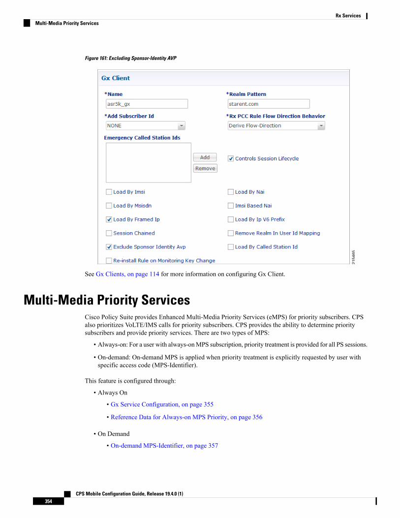
Figure 161: Excluding Sponsor-Identity AVP
See Gx Clients, on page 114 for more information on configuring Gx Client.
Multi-Media Priority ServicesCisco Policy Suite provides Enhanced Multi-Media Priority Services (eMPS) for priority subscribers. CPSalso prioritizes VoLTE/IMS calls for priority subscribers. CPS provides the ability to determine prioritysubscribers and provide priority services. There are two types of MPS:
• Always-on: For a user with always-onMPS subscription, priority treatment is provided for all PS sessions.
• On-demand: On-demand MPS is applied when priority treatment is explicitly requested by user withspecific access code (MPS-Identifier).
This feature is configured through:
• Always On
• Gx Service Configuration, on page 355
• Reference Data for Always-on MPS Priority, on page 356
• On Demand
• On-demand MPS-Identifier, on page 357
CPS Mobile Configuration Guide, Release 19.4.0 (1)354
Rx ServicesMulti-Media Priority Services

• Obtaining Highest Priority Qci Using Max Function, on page 357
Gx Service Configuration
EMPS Service ConfigurationCPS provides a service configuration ('EMPS' under 'gx' service configuration) for defining the MPS EPSPriority MPS Priority Level and IMS Signaling Priority level. This is required for Always on MPS.
When a user configured with MPS subscription initiates a session the priority level from the subscription dataQCI Preemption Capability and Preemption Vulnerability from MPS profile are used to set default bearerQoS. Also all preconfigured dynamic rules are updated to use the new priority level.
When the session is initiated from IMS APN the IMS Signaling Priority is used as priority level if configuredunder subscription data.
Table 149: EMPS Service Configuration Parameters
DescriptionParameter
Field to invoke Priority EPS Service.
• 1 enable• 0 disable
Mps Eps Priority Enabled
Indicates the priority level (Integer range 1-15).Mps Priority Level
IMS signaling priority level (Integer range 1-15).IMS Signaling Priority
The following are the steps to configure this service configuration:
Step 1 Log into Policy Builder.Step 2 Select the Services tab.Step 3 Under Use Case Templates, click Summary and then create a child Use Case Template.Step 4 Add a Name to the template, for example, IMS_usecase.Step 5 Select Actions tab.Step 6 Click Add in the Service Configuration pane and add EMPS service configurations listed under 'gx' section.Step 7 Go to Services Options; the newly created template would be available here.Step 8 Create a child Service Option for example, eMPS.Step 9 ClickOK. The newly created service options should have the service configuration objects which were added previously
at the template level.Step 10 Select the EMPS service configuration and configure it as per your requirements.
CPS Mobile Configuration Guide, Release 19.4.0 (1)355
Rx ServicesGx Service Configuration

Reference Data for Always-on MPS PriorityIn the Policy Builder's Reference Data, a new profile Mps Profiles is added under Diameter Defaults to supporteMPS priority. The MPS Profile provides MPS attributes required for priority service provisioning. Thepriority level value from Service configuration takes precedence over MPS Profile value.
Step 1 Log into Policy Builder.Step 2 Select the Reference Data tab.Step 3 Select Diameter Defaults >Mps Profiles.Step 4 In the summary window, clickMps Profile to create an Mps Profile.Step 5 To add an Ims Apn, click Add, enter the Ims Apn in the field provided and click OK.
This field can accommodate several Ims Apn that are used to match with the incoming service request for priority service.The values that are received by the Default Bearer QoS are looked up for a suitable Ims Apn match. If the APN value ofa Gx session request matches IMS APN, IMS signaling priority from EMPS service is used as priority level.
Step 6 Assign values for Always-on MPS attributes in the MPS QoS section.
An example is given below.Figure 162: MPS Profile Configuration
For information on the parameters mentioned above, see MPS Profile, on page 155.
On receiving a request, the Ims Apn is checked up for a match, if there is suitable match then the values assigned in theMps Qos section CPS selects the IMS signaling priority from EMPS service.
CPS Mobile Configuration Guide, Release 19.4.0 (1)356
Rx ServicesReference Data for Always-on MPS Priority

On-demand MPS-IdentifierThe section, Reference Data > Diameter Defaults > Rx Profiles has a new table to support Rx initiated sessions.When an Rx session is initiated with anMPS-Identifier, the incomingmessage is mapped with input parameterssuch as MPS Id and Media Type, and the session is processed further. MPS QoS Policy table is the newlyadded table to the Rx Profiles in the Policy Builder.
The incoming message is mapped with the input parameters, which are MPS Id and Media Type, if theparameters match the corresponding value from the other columns - Priority Level, Preemption Capability,Preemption Vulnerability and Qci, are provided to provide the necessary service. For more information, seeRx Profile, on page 156.
Obtaining Highest Priority Qci Using Max FunctionWhen an EPS subscription for a subscriber is configured to be always-on, and an Rx session is initiated withMPS-ID, the higher priority level and higher QCI is derived and applied to the default EPS. ARP of the Rxdynamic rule is derived from Reservation priority if present in the AAR, otherwise defaulted to the value inconfiguration.
The Max function uses the following precedence order to derive the QCI values:
2 > 1 > 4 > 3 > 5 > 6 > 7 > 8 > 9
For additional information refer to 3GPP spec 29.213 (R11).
When there are multiple Rx sessions, the default bearer and default EPS bearer QoS is updated with the highestvalue of QCI, ARP.
• The highest value is derived from the Rx sessions and Default Bearer if subscribed to always-on MPS.
• The highest value is derived from the Rx session if not subscribed to always-on MPS.
Rx session termination: When a Rx session terminates, and if it is the last Rx session to terminate, the defaultbearer and default EPS bearer QCI/ARP is reverted to:
• Single Rx session with MPS: revert Default Bearer to normal or always-on Qci or ARP.
• Multiple Rx sessions with differentMPS: revert default bearer to highest Qci or ARP among the remainingRx sessions.
There are two main scenarios that take place during an Rx Session:
• On Demand without Always-on Configuration
• On Demand with Always-on Configuration
On Demand Without Always-on Configuration
Default Bearer
• When multiple Rx sessions are initiated with MPS-ID, the highest priority level and highest QCI isderived and applied to the default EPS.
CPS Mobile Configuration Guide, Release 19.4.0 (1)357
Rx ServicesOn-demand MPS-Identifier

• If reservation priority is not present in AAR, the priority configured for the particular MPS-ID is used.In the Rx profile > MPS Qos Policy table, a blank value is defined in the Media Type column, whichapplies to the Default Bearer. If the configuration is missing, default reservation priority (0) is used.
The new Priority Level and Qci are applied to the Default Bearer QoS and also to the Gx pre-configured rules.
Dedicated Bearer
Priority Level of the Rx dynamic rule is derived from Reservation priority if present in the AAR from themedia component description; otherwise the default value in the configuration is used. QCI of Rx dynamicrule is derived from the Rx profile configuration. Preemption Capability and Preemption Vulnerability aredetermined from Rx profile for each MPS-Id.
On Demand With Always-On Configuration
Default Bearer
When an Rx session request is received with anMPS-ID along with message level (AAR) reservation-priority:
• The ARP priority level is derived from the highest value between reservation priority and always-onpriority (or IMS priority if applicable).
• The value of QCI is derived from the highest value between MPS-ID specific Qci and always-on Qci.When multiple Rx sessions are created with MPS-ID and message level (AAR) reservation priority.
• The ARP Priority Level is derived from highest value between session level reservation-priority (amongactive sessions) and always-on priority (or IMS priority if applicable).
• The value of Qci is derived from the highest value between MPS-ID specific Qci and always-on Qci.
In both cases, if reservation priority is not present in the AAR, the priority configured for each MPS-Id isused. In the Rx profile > MPS Qos Policy table, a blank value is defined for the Media Type column, whichapplies to the Default Bearer. If the configuration is missing, default reservation priority (0) is used.
The new Priority Level and Qci is applied to the Default Bearer QoS and also to the Gx pre-configured rules.
Dedicated Bearer
Priority Level of the Rx dynamic rules is derived from the highest value between always-on MPS and thereservation priority, if the reservation priority is defined in the AAR Media component description.
If the reservation priority is not present in Media-Component-Description, the value of reservation priorityis derived from the highest value between always-on MPS and from the Rx Profile configuration (based onMPS-ID and Media Type).
Preemption Capability and Preemption Vulnerability are determined from Rx profile for each MPS-Id andMedia Type. QCI value is derived from the higher value between MPS profile and Rx MPS profile (based onMedia Type and MPS-ID).
CPS Mobile Configuration Guide, Release 19.4.0 (1)358
Rx ServicesOn Demand With Always-On Configuration

C H A P T E R 10Balance Services
• Account Balance Templates, on page 359• Quota Templates, on page 362• Rates and Tariff Times, on page 378• Subscriber Record, on page 380• Shared Quota, on page 383• Policy Engine, on page 384• Proration, on page 385• Quota Refresh Throttling, on page 385• Sy Server Implementation in OCS, on page 385
Account Balance TemplatesAccount Balance templates provide the overall structure to the data provisioned to a given subscriber.
CPS Mobile Configuration Guide, Release 19.4.0 (1)359

Figure 163: Account Balance Template
The following parameters can be configured under Account Balance Template:
Table 150: Account Balance Template Parameters
DescriptionParameters
Required unique name for the template.Code
Optional field to contain a brief description of the template's use case.Description
The choice of units determines functionality options within the system. Forexample, Time units such as seconds or minutes will cause the system to behavedifferently than Data units like Bytes or Megabytes. Additionally, currency is anoption and can be used to account for usage credit in a direct manner.
Balance does not do any type of currency exchange rate calculation.The values are stored as is and represent whatever currency the SP andtheir subscribers commonly use.
Note
Default value is Bytes.
Units
Limiting Balance refers to a Balance template that is used by a shared balancetemplate. This establishes a link from the shared balance to a “limit” balance, sothat Balance Manager knows which two balance codes it needs to reserve/chargeagainst in the shared per user limit use case.
The limiting MsBM account must be the MsBM account tied to theindividual subscriber's credential. The limiting MsBM balance andquota must be provisioned in separate Balance/MsBM operation fromthe provisioning of the shared account, balance, and quota.
Note
Limiting Balance
CPS Mobile Configuration Guide, Release 19.4.0 (1)360
Balance ServicesAccount Balance Templates

DescriptionParameters
If a provisioning request is made (specifically any request that credits or provisionsa subscriber balance) when there is remaining balance, i.e. non-zero amount, thenthe Balance module throws an error and does not provision the quota.
Default value is False (unchecked).
Error on Provision WithNon Zero Balance
Thresholds
Unique name for the threshold object.Code
An integer representing the amount of quota that will trigger the thresholdnotification.
Amount
Unit of calculation like Percentage or Bytes.Type
Thresholds can be associated with each other as a group. When thresholds aregrouped by name, only messages for the first (top to bottom in the table in PolicyBuilder) threshold breached in the given threshold group will be returned.
Group
This inverts the threshold function. Typically a threshold is calculated against theusage. For example, if a threshold is defined for 80%, by default that means 80%of quota used or 20% remaining. If the Trigger on Remaining check box is selected,then the function inverts and a threshold defined as 80% would trigger when 80%of the quota remains.
Trigger on Remaining
CRD Based Account Balance TemplatesCRD balance table definitions are pre-shipped (read only) as part of the Policy Builder configuration. Forthis, the "CRDBalance" feature (com.broadhop.balance.crdbalance.feature) needs to be installed. Enablethis functionality by selecting theEnable Crd Balance Template Lookups check box. For more information,see Balance Configuration, on page 45.
The following required tables include result columns that directly map to the corresponding fields in Balanceand Quota Templates. For more information on individual field description, see Account Balance Templates,on page 359.
• q_account_balance: Top Level Account Balance Template fields
• q_one_time_quota: One Time Quota Template definition
• q_recurring_quota: Recurring Quota Template definition
• q_rollover_quota: Rollover Quota Template definition
• q_threshold_definition: Threshold definitions
• q_threshold_balance_association: Balance to threshold association
• q_threshold_quota_association: Quota to threshold association
CPS Mobile Configuration Guide, Release 19.4.0 (1)361
Balance ServicesCRD Based Account Balance Templates

Threshold Priorities and Groups
Thresholds defined in Policy Builder (under Balance and Quota templates) have implicit top to down priorityincase threshold group is defined. Same functionality is achieved using 'priority' column inq_threshold_definition table. Internally, thresholds defined in CRD are prioritized based on provided'priority' column value. Higher the value, higher the priority (that is, higher in the Policy Builder list). Priorityvalue has no effect if thresholds are not grouped.
Quota TemplatesQuota templates define the specifics of how quota behaves. There are 3 basic types of quota: One Time,Recurring, and Rollover. Within that there are additional behavioral functions like BillCycle and Stackable,but those are just modifications to one of the three basic types.
This section covers the following topics:
• Recurring
• Rollover
• One Time
• BillCycle
• Thresholds
• Depletion and Exhaustion
• Charging Expired Reservations
• Credit Selection Logic for Reservations and Debits
RecurringRecurring quota is refreshed periodically with a specific amount each refresh. It defaults to infinite durationmeaning that it continues until the account is deleted from the system. However, it is possible to limit theduration of a recurring quota using the Recurrence Limit field. The most common time period is Monthly.Time periods defined in hours, days, weeks, months are possible. Initial credit and refreshed amounts bydefault expire at the end of the current time period.
The following parameters can be configured under Recurring Quota Templates:
Table 151: Recurring Quota Templates Parameters
DescriptionParameters
Unique name that identifies the quota template.Code
Optional field to contain a brief description of the template's use case.Description
CPS Mobile Configuration Guide, Release 19.4.0 (1)362
Balance ServicesQuota Templates

DescriptionParameters
A default provisioning amount which can be overridden at the initial provisiontime via API or Policy configuration.
Note • The upper limit on the amount is 1 Exabyte.
• Future amount changes can be accomplished with the CreditAPI.
Amount
Priority ranks the template so when the Balance module is determining thenext credit to use for reservations and debits, the template with the highest rank(Positive number Integer) wins. 1 is the highest rank. The default of no valueis lowest priority. After priority, the most recent end date (Next to Expire) isused to determine the next credit.
Default value is null.
Priority
Integer used in conjunction with the Recurrence Frequency to determine therefresh period.
Default value is 1.
Recurrence FrequencyAmount
Value used in conjunction with the Recurrence Frequency Amount to determinethe refresh period.
You can select the value from the drop-down list based on your requirements.The following values are supported:
• Bill Cycle (RFAmt ignored): Refresh interval is based on bill cycle dayfor each quota independently.
• Day(s): Refresh interval is based on day(s).
• Hour(s): Refresh interval is based on hour(s).
• Minute(s): Refresh interval is based on minute(s).
• Month(s): Refresh interval is based on month(s).
• Week(s): Refresh interval is based on week(s).
Default value is Month(s).
Recurrence Frequency
A Rollover Quota Template that this recurring quota rollovers unused quotato when the quota refreshes for the next recurrence period.
Rollover Quota
CPS Mobile Configuration Guide, Release 19.4.0 (1)363
Balance ServicesRecurring

DescriptionParameters
MsBM supports both the Gregorian and Hijra calendar. The Hijri calendar isthe Islamic calendar which is a moon-phase based calendar. Cisco has severalcustomers in theMiddle East who use the Hijri calendar instead of the Gregoriancalendar to determine refresh dates.
The data is still stored in the database as Gregorian dates, but theBalance module translates those to Hijri for any processing. SPRand the Unified API do not support Hijri dates.
Note
Default value is Gregorian.
Calendar Type
Integer that determines the duration for a recurring quota. When set to 0, theduration is infinite. When set to any positive number, the quota refreshes thatnumber of times and then stop. For example, if the Recurrence Frequency isset to 1 Month, and the Recurrence Limit is set to 6, then the quota refreshes6 times. If the quota is provisioned on January 1st, it expires on June 30th.
Default value is 0.
Recurrence Limit
When selected, automatically roll unexpired quota over into a Rollover quotawhen the refresh occurs.
When not checked then rollovers can only be triggered by using theRolloverCredit API.
Note
If checked, the Recurrence Frequency for the quota must be >= 1day.
Note
Default value is false (unchecked).
Auto Rollover
When selected, the Balance module uses the sum of recurring quota template'scredit end date and the rollover credit's end date to determine priority for whichcredit to debit in the normal processing of charges.
Default value is false (unchecked).
Use Rollover ExpirationTime for Charge Priority
When selected, BillCycle on quota level is used.
When not selected, BillCycle on account level is used.
Default value is false (unchecked).
BillCycle Per Quota
Thresholds
Unique name for the threshold object.Code
An integer representing the amount of quota that triggers the thresholdnotification.
Amount
Unit of calculation like Percentage or Bytes.Type
Thresholds can be associated with each other as a group. When thresholds aregrouped by name, only messages for the first (top to bottom in the table inPolicy Builder) threshold breached in the given threshold group are returned.
Group
CPS Mobile Configuration Guide, Release 19.4.0 (1)364
Balance ServicesRecurring

DescriptionParameters
This inverts the threshold function. Typically a threshold is calculated againstthe usage. For example, if a threshold is defined for 80%, by default that means80% of quota used or 20% remaining. If the Trigger on Remaining check boxis selected, then the function inverts and a threshold defined as 80% wouldtrigger when 80% of the quota remains.
Trigger on Remaining
All the dates in Balance such as start, expiration, refresh, etc. have a time element. What is set for the timeelement affects expiration and refresh time on the given day.
Note
Refresh DatesThere are two important dates - Last Recurring Refresh (LRR) and Next Refresh. The LRR is used to calculatethe Next Refresh. The LRR is the value stored in the database while the Next Refresh is the value that iscalculated during processing and is returned in API responses.
The LRR is set to the provision date by default. For a monthly recurrence frequency that means, if provisionedon the 12th, it will refresh again on the 12th of the next month. The LRR can be overridden in a provisioningrequest (CreateBalance API). When creating quota with the CreateBalance API, set the LRR date to the daywhen the refresh would have occurred had the quota existed. For example, if the CreateBalanceRequest issent on 01/01/2012 at 08:00:00 (January 1st, 2012) and the intention is to have the quota refresh on the 28thof the month, then the LRR (lastRecurringRefresh) should be set to 28/12/2011T00:00:00 (December 28,2011) in the request. The Balance engine uses the LRR to calculate the Next Refresh date, so by setting theLRR to December 28th (the previous month in relation to the provision) the new refresh date of January 28th,2012 will be calculated correctly. Please note that months have a variable amount days and will refreshaccordingly.
Valid date formats for API requests are explained in the Unified API documentation. Contact your CiscoTechnical Representative for the API documentation.
Note
Manual LRR Override
When overriding the LRR via API, make sure that the start date and end date align properly. That is, the enddate must be the same date as what the Next Refresh date would be (LRR + recurrence frequency) whencalculated by the Balance engine. This means that the provisioned credit will end when the new credit iscreated via the refresh which is how the system operates by default.
The refresh occurs on the next Balance action instead of on the actual Next Refresh date so that not allsubscriber accounts refresh at the exact same moment, thus balancing load and resources. However, it shouldbe noted that the date of the new credit created by the refresh will still have its dates based on the stored LRRand not on when it is actually refreshed by the Balance engine. The new credit will have a start date equal tothe new LRR after the refresh has occurred. The new credit end date will be the start date + recurrencefrequency. This value is also the new Next Refresh Date.
CPS Mobile Configuration Guide, Release 19.4.0 (1)365
Balance ServicesRefresh Dates

RolloverRollover quota templates are special quotas that store leftover amounts from a Recurring quota. Rolloveroccurs when the Recurring quota refreshes. Rollovers can also be triggered manually via API. The amountto rollover can be limited, and the total amount in the rollover quota can be limited.
Rollover quota templates behaves like One Time quota templates, but should not be provisioned directly.Unlike One Time quotas, Rollover quotas have no default/initial amount.Figure 164: Rollover Quota Template
The following parameters can be configured under Rollover Quota Template:
Table 152: Rollover Quota Template Parameters
DescriptionParameters
Unique name that identifies the quota template.Code
Optional field to contain a brief description of the template's use case.Description
A default provisioning amount which can be overridden at the initial provision timevia API or Policy configuration.
Future amount changes can be accomplished with the Credit API.Note
Amount
CPS Mobile Configuration Guide, Release 19.4.0 (1)366
Balance ServicesRollover

DescriptionParameters
Priority ranks the template so when the Balance module is determining the next creditto use for reservations and debits, the template with the highest rank (Positive numberInteger) wins. 1 is the highest rank. The default of no value is lowest priority. Afterpriority, the most recent end date (Next to Expire) is used to determine the next credit.
Default value is null.
Priority
Integer used in conjunction with the Validity Period to determine the length of timefor which the quota is valid.
Default value is 30.
Validity PeriodAmount
Value used in conjunction with the Validity Period Amount to determine the lengthof time for which the quota is valid.
Default value is Days.
Validity Period Units
The maximum amount of quota that can be rolled over at any one time.Maximum RolloverAmount
The total amount of rollover the quota can contain.Quota MaximumAmount
Thresholds
Unique name for the threshold object.Code
An integer representing the amount of quota that will trigger the threshold notification.Amount
Unit of calculation like Percentage or Bytes.Type
Thresholds can be associated with each other as a group.When thresholds are groupedby name, only messages for the first (top to bottom in the table in Policy Builder)threshold breached in the given threshold group will be returned.
Group
This inverts the threshold function. Typically a threshold is calculated against theusage. For example, if a threshold is defined for 80%, by default that means 80% ofquota used or 20% remaining. If the Trigger on Remaining check box is selected,then the function inverts and a threshold defined as 80% would trigger when 80% ofthe quota remains.
Trigger on Remaining
Rollover Quota Example
Assumptions:
• Assume the parent Balance Template's units are Megabytes.
• Assume the Maximum Rollover Amount is 100 MB.
• Assume the Quota Maximum Amount is 2048 MB (or 2 GB).
• Assume the current balance of the rollover quota is 1.95 GB.
• Assume the unused usage at recurring quota refresh time is 200 MB.
CPS Mobile Configuration Guide, Release 19.4.0 (1)367
Balance ServicesRollover

• Assume the Auto Rollover checkbox is checked.
Function:
• The recurring quota has 200 MB, but only 100 MB is allowed to be rolled over because the MaximumRollover Amount is set to that value.
• Rolling over 100MBwould cause the total amount of the rollover quota to exceed 2 GB (QuotaMaximumAmount is set to 2048 MB).
• Therefore, 2 GB - 1.95 GB = 50 MB, which is the amount that is actually rolled over.
Limitations and Restrictions
Rollover Quotas may experience undesirable behavior when used in conjunction with Recurring Quotas thathave a recurrence frequency of less than 1 day.
The recurring quota and rollover quota involved in the rollover operation must be defined under the sameBalance template. Rolling over from one Balance template to another Balance template is not supported.
Do not provision rollover quotas using the Control Center. Even though Rollover quota is a special type ofOne Time quota, they are not designed for manual provisioning. They are designed to work with a Recurringquota and receive credits only based on the unused amounts rolled over from that Recurring quota to whichthey are linked.
Note
Adjustments can be made to Rollover quota via the Credit or Debit APIs, but this is not a typical or commonuse case, and is not recommended by Cisco.
One TimeOne Time quota templates are used for one time applications like TopUp or Bonus quota that has a finiteduration (start and end date) and amount. One Time quota does not refresh automatically.
CPS Mobile Configuration Guide, Release 19.4.0 (1)368
Balance ServicesOne Time

Figure 165: One Time Quota Template
The following parameters can be configured under One Time Quota Template:
Table 153: One Time Quota Template Parameters
DescriptionParameters
Unique name that identifies the quota template.Code
Optional field to contain a brief description of the template's use case.Description
A default provisioning amount which can be overridden at the initial provision time viaAPI or Policy configuration.
Future amount changes can be accomplished with the Credit API.Note
Amount
Priority ranks the template so when the Balance module is determining the next creditto use for reservations and debits, the template with the highest rank (Positive numberInteger) wins. 1 is the highest rank. The default of no value is lowest priority. Afterpriority, the most recent end date (Next to Expire) is used to determine the next credit.
Default value is null.
Priority
CPS Mobile Configuration Guide, Release 19.4.0 (1)369
Balance ServicesOne Time
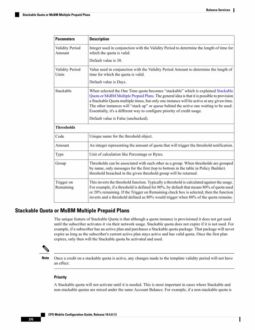
DescriptionParameters
Integer used in conjunction with the Validity Period to determine the length of time forwhich the quota is valid.
Default value is 30.
Validity PeriodAmount
Value used in conjunction with the Validity Period Amount to determine the length oftime for which the quota is valid.
Default value is Days.
Validity PeriodUnits
When selected the One Time quota becomes “stackable” which is explained StackableQuota orMsBMMultiple Prepaid Plans. The general idea is that it is possible to provisiona Stackable Quota multiple times, but only one instance will be active at any given time.The other instances will “stack up” or queue behind the active one waiting to be used.Essentially, it's a different way to configure priority of credit usage.
Default value is False (unchecked).
Stackable
Thresholds
Unique name for the threshold object.Code
An integer representing the amount of quota that will trigger the threshold notification.Amount
Unit of calculation like Percentage or Bytes.Type
Thresholds can be associated with each other as a group. When thresholds are groupedby name, only messages for the first (top to bottom in the table in Policy Builder)threshold breached in the given threshold group will be returned.
Group
This inverts the threshold function. Typically a threshold is calculated against the usage.For example, if a threshold is defined for 80%, by default that means 80% of quota usedor 20% remaining. If the Trigger on Remaining check box is selected, then the functioninverts and a threshold defined as 80% would trigger when 80% of the quota remains.
Trigger onRemaining
Stackable Quota or MsBM Multiple Prepaid PlansThe unique feature of Stackable Quota is that although a quota instance is provisioned it does not get useduntil the subscriber activates it via their network usage. Stackable quota does not expire if it is not used. Forexample, if a subscriber has an active plan and purchases a Stackable quota package. That package will neverexpire as long as the subscriber's current active plan stays active and has valid quota. Once the first planexpires, only then will the Stackable quota be activated and used.
Once a credit on a stackable quota is active, any changes made to the template validity period will not havean effect.
Note
Priority
A Stackable quota will not activate until it is needed. This is most important in cases where Stackable andnon-stackable quotas are mixed under the same Account Balance. For example, if a non-stackable quota is
CPS Mobile Configuration Guide, Release 19.4.0 (1)370
Balance ServicesStackable Quota or MsBM Multiple Prepaid Plans

selected first based on Priority and the Next to Expire rules, the Stackable quota will not be activated untilthe non-stackable quota exhausts.
Pre-Paid Data Example
A subscriber purchases 5 pre-paid blocks of data quota with a default amount of 100MB and a validity periodof 10 days. When the subscriber connects, the first instance becomes active, meaning the start date is set tothe current date and time and the end date is set to 10 days later. So if the subscriber connected on January1st, the quota became valid until January 11th (10 days from January 1st). After the subscriber uses all 100MB or the 10 days passes, the next instance of quota is activated with the start/end dates set in the samemanner- the start date is the current time at activation and the end date is set to 10 days from that time.
Pre-Paid Time Example
A subscriber purchases a time limit package that limits both "wall clock time duration" (calendar time sincethe package was bought) and volume of fair use quota. The package does not renew automatically, howeverthe subscriber is able to purchase additional pre-paid plans prior to the expiration of the current package theyhave. Each pre-paid package will automatically start upon expiration of the previous plan just as in the dataexample. Like the data example, if the time limit is reached, the next package becomes active. If a subscriberreaches the volume of fair use quota limit, the current plan expires and the next plan becomes active regardlessof the time remaining on the previous package. If there are no additional pre-paid plans available uponexpiration of the current active package, the subscriber is redirected to a self-care portal and offered moreoptions to purchase packages.
Provisioning
Provisioning a Stackable quota sets the start time to the current system time by default, and if a start datevalue is passed in, it is set to the passed in value. If the start date passed in is in the past and another Stackablequota is currently active, the new quota will not be used until the currently active Stackable quota is exhausted.
Debits and Reservations
As the accounting functions operate, reservations check for active credits. When a credit expires, the systemautomatically looks to find the next credit based on various criteria including the next most recent expirationdate. If the found credit is part of a Stackable quota and is not currently active, the system will activate it bysetting the start date to the current date and time and setting the end date to the start date plus the validityperiod.
If it is necessary to activate a second stackable quota to satisfy the requested reservation amount, even if yourelease the reservation (charge zero or less than what is remaining on the first quota), the system will maintaintwo active Stackable quotas.
If no quota is active for a subscriber, a Stackable quota will not get activated until a reservation is made.
QueryBalance API
The QueryBalance API displays all credits whether the Stackable quota is active or not. The API does notprovide an indication of whether a quota is Stackable.
Template Definition Changes
If a quota template is changed from stackable to not stackable or from not stackable to stackable, any creditsfor quotas of that quota code provisioned/credited prior to this template change will behave in the followingmanner:
CPS Mobile Configuration Guide, Release 19.4.0 (1)371
Balance ServicesStackable Quota or MsBM Multiple Prepaid Plans

• From Stackable to Not Stackable: Any credits on quotas of that quota type that have already beenprovisioned/credited will have those existing credits behave as a normal one time quota's credits with noexpiration date regardless of any set validity period. Future credits will have their end dates set by thevalidity period.
• From Not Stackable to Stackable: Any credits on quotas of that quota type that have already beenprovisioned/credited will have those existing credits behave as a normal one time quota's credits withthe start date of the provision date or the start date that was passed in if it was specified and the end datethat was specified or if not specified the start date plus validity period at provision time. Any futurecredits will be treated as stackable credits on a stackable quota.
BillCycleBillCycle quotas were introduced in Balance 2.3.0. BillCycle is a special type of Recurring quota that handlesend of month refresh dates better than the typical Recurring quota template. The Bill Cycle functionality alignsbetter with some customers' billing cycles and removes the recommended limitation of only using days 1 -28 for Recurring quota starts/ends.
The “RFAmt ignored” hint that appears on BillCycle in Policy Builder is just a reminder that the RecurrenceFrequency Amount field is ignored if you select a Recurrence Frequency of BillCycle. Refresh happens every1 BillCycle regardless. The system cannot wait 2 or more BillCycles before refreshing.
Note
Updating BillCycle
The ChangeBillCycle API is the only way to change the BillCycle value for a subscriber.
Repurposing Recurring Quota TemplatesIt is possible to use BillCycle by repurposing a currently existing Recurring quota that has a recurrencefrequency other than BillCycle. When repurposing an existing Recurring quota template and changing it toBillCycle, existing subscribers will have the BillCycle value set automatically at the next refresh time to theday that the quota refreshes. For example, if a subscriber’s quota is scheduled to refresh on the 25th, he/shewill continue to use quota until the refresh date as normal. When the quota refreshes on the 25th, the BillCyclevalue will be set to 25, and the subscriber’s quota will now follow the BillCycle frequency rules instead ofthe previous recurrence rules.
Repurposing works best with Recurring quota templates that have a recurrence period of 1 Month.Note
Monthly vs. BillCycle
Monthly and BillCycle really only differ when BillCycle is set to 29, 30, or 31. Current subscribers won’t beable to take advantage of 29, 30, 31 if you reuse a quota code. However, using the ChangeBillCycle APIexisting subscribers can update their BillCycle setting to 29, 30, or 31.
Any new subscribers provisioned with a repurposed quota template will start out with BillCycle functionalityand a BillCycle value must be passed in with the CreateBalance API.
CPS Mobile Configuration Guide, Release 19.4.0 (1)372
Balance ServicesBillCycle

End Date and Last Recurring Refresh (LRR)End Date will be set to 23:59:59.999 in the server's local time zone on the day before the BillCycle day. Forexample, if the BillCycle value is 15, with the server set to GMT (Zulu time), then the end date in Marchwould be 2013-03-14T23:59:59.999Z.
The Last Recurring Refresh (LRR), which drives the Next Refresh date that appears in API responses anddrives the actual quota refresh trigger, will be midnight on the BillCycle day in the previous month. Forexample, if the BillCycle value is 15, with the server set to GMT (Zulu time), then the LRR in the credit periodbefore March 15th will be 2013-02-15T00:00:00.000Z, which would display a Next Refresh date in aQueryBalance response as 2013-03-15T00:00:00.000Z.
End Date Provisioning
The start date defaults to the date the provisioning call is made. The LRR defaults to the start date. The enddate defaults to the start date plus one month with any necessary modifications of the day to respect theBillCycle value. The start, end, and LRR dates can be overridden if a start, end, or LRR date is passed in onthe CreateBalance API request. Overriding those dates can cause Balance malfunctions if incorrectly set, souse caution!
Month End Dates Example
Recurring Quota templates are only able to use 1-28 for refresh dates. BillCycle was an enhancement forRecurring quota that allows Balance to accommodate the number of days variance of months. If the subscriber'sBillCycle is set to 30, the refresh in February will be on the 28th or 29th if a leap year, and QueryBalanceAPI responses would show the Next Refresh Date as YYYY-02-28 or YYYY-02-29. And once the refreshhas occurred and it's now March the system is able to reset the Next Refresh date back to the 30th based onthe BillCycle and would show as YYYY-03-30. Compare this to regular Recurring quota which would changethe refresh date to the 28th or 29th permanently for the rest of the year. Even if the refresh occurred on January30th, when February arrived, the refresh would be set to the 28th or 29th if a leap year. Unlike BillCycle,once the refresh has occurred and it's now March the system does not know how to reset the refresh back tothe 30th as is occurred in January for regular Recurring quota. The Next Refresh date would show asYYYY-03-28 or YYYY-03-29.
All the dates in Balance such as start, expiration, refresh, etc. have a time element. What is set for the timeelement will affect expiration and refresh time on the given day.
Note
ThresholdsThresholds allow policy actions to be taken when a certain amount of quota has been used. Actions can betaken on threshold breach, unbreach, and continued breach status. Thresholds can be grouped to suppress pastthreshold breaches.
The threshold table in the Policy Builder sets thresholds that will be reported on when breached/unbreachedand what their current amount is while breached. These messages are sent back to the policy engine fromMsBM on Credit, Debit, Charge, and Provision functions so that policies can make decisions and take actionsbased on the threshold breach.
The basic conditions to use in policy configuration are:
• An OCSThresholdBreach exists
CPS Mobile Configuration Guide, Release 19.4.0 (1)373
Balance ServicesEnd Date and Last Recurring Refresh (LRR)

• An OCSThresholdUnbreach exists
• An OCSThresholdStatus exists
A typical action upon threshold breach is “Send a SMS notification”. To send an SMS notification, theNotifications feature must be installed and configured in the system.
Threshold Event Types• OCSThresholdBreach: It occurs when a threshold is violated for the first time
• OCSThresholdUnbreach: It occurs when a credit, provision, refresh, or other action causes usage to dropback below a given threshold
• OCSThresholdStatus: It is the message that is sent every time an action is conducted against an accountwhere a balance threshold or quota threshold is currently exceeded. This message reports the fact thatthe threshold is still breached and what the current level of the breach is.
A threshold is breached when the value is greater than or equal to the threshold value.Note
Balance Functions That Evaluate Thresholds• Charge: Checks thresholds of the account balance specified in the charge request and any quotas underthat account balance whose total changed due to the charge.
• Credit: Checks the thresholds of the account balance and quota specified in the credit request.
• Debit: Checks the thresholds of the account balance specified in the debit request and all quota codesunder that account balance unless a quota code is specified on the debit request, in which case, it onlychecks the thresholds of that quota.
• Reserve: Checks all thresholds on the account.
• QuerySubscriber: Checks all thresholds on the account.
Reference Data vs. Subscriber Specific Thresholds
Reference Data Thresholds (RDT)
• Reference Data thresholds (RDT) are defined on the Balance or Quota Template in Policy Builder.• RDTs are evaluated for all subscribers provisioned with the related balance or quota code whose templatehas the threshold defined.
• RDTs are stored in the reference data that the Policy Engine reads for operational configuration.
Subscriber Specific Thresholds (SST)
• Subscriber Specific Thresholds (SST) are defined via API or Policy Action.• SSTs are only applicable for the subscriber for which the SST was defined via API or Policy Action.You must defined the SST individually for each subscriber for which you want the threshold applicable.
• SSTs contain the same types of information as RDTs, but the information is stored on the subscriberaccount in the database.
CPS Mobile Configuration Guide, Release 19.4.0 (1)374
Balance ServicesThreshold Event Types

Unique Names
Thresholds must have unique names. SSTs and RDTs must have unique names as well. The same SST namecan be used for multiple subscribers, but that value must be unique compared to the name values for the RDTs.
Important Clarifications
• Even though both kinds of thresholds share the same types of information, there is no crossover betweenthe two sets of information. RDT definition via the Policy Builder is for RDTs only. SST definition viaAPI is for SSTs only.
• It is important to understand that the codes and information defined in Policy Builder for RDTs have norelationship to SSTs.
• If you use an RDT code when creating an SST, the information needs to be defined for the SST and willnot read the RDT information just because it's the same code.
Threshold Groups
Thresholds with the same value in the Group columnwill be "grouped" together.When thresholds are groupedin this manner, only messages for the first (top to bottom in the table in Policy Builder) threshold breachedin the given threshold group will be returned.
For example, if you define a 80 percent, a 60 percent, and 50 percent threshold and they are in descendingorder, top to bottom in the table, and put them in a threshold group named CiscoPercents, the system will onlysend threshold messages about the highest threshold breached. This helps reduce duplicate messages. Forexample, a subscriber's usage is at 62%, the subscriber will only get messages about the 60 percent threshold'sstatus.When the usage crosses 80% and goes to 81%, the subscriber will no longer get the 60 percent threshold'sstatus message, but instead will get an 80 percent breachmessage andmoving forward will only get 80 percentthreshold status messages.
Order is very important! This functionality is not based on the highest value. If there are two thresholds in agroup say at 60 percent and 80 percent and they are ordered in the table top to bottom in ascending order, thatis, 60 nearest the top, the subscriber will never get 80 percent threshold notifications unless you select theamount remaining option instead of amount used (default).
Note
Thresholds and Reduction of Reservation Granted Amounts
AThreshold defined on an Account Balance Template reduces the reservation amount as it nears the threshold.For example if the subscriber is 50 MB away from the threshold and the default reservation amount is 100MB, the reservation will be reduced to 50 MB so as to not exceed the threshold.
For all Balance versions/revisions built prior to 7 Jan 2014, reservation amount reduction as a threshold isapproached only works for thresholds NOT defined as Trigger On Remaining, that is, it only works forthresholds that measure the amount used.
Note
A Threshold defined on a Quota Template does NOT reduce the reservation amount as it nears the threshold.
When the reservation granted amount is reduced from the requested amount due to a threshold, the quotagranted is reduced to the amount between the current usage level and the value where the threshold would bebreached. This reduction continues on each successive reservation until the Default MinimumDosage defined
CPS Mobile Configuration Guide, Release 19.4.0 (1)375
Balance ServicesReference Data vs. Subscriber Specific Thresholds

on the Balance Plugin Configuration is reached. After that value is reached for the granted amount, the nextreservation will go back to normal behavior and trigger the OCSThresholdBreachOccurred condition.
Soft vs. Hard Thresholds
Currently, all thresholds in CPS are “soft” thresholds.
The difference between a soft and hard cap is that the system would still grant the minimum dosage with asoft cap; however with a hard cap the systemwill deny the quota request if the minimum dosage would breachthe threshold. The plan is that when a hard threshold is implemented, an API call or Policy Action would haveto be made to “unlock” the threshold to allow reservations to breach the threshold and for normal operationto resume.
Other Threshold Information
• Thresholds are based on CHARGED amounts. Reserved amounts are not included.
• Thresholds can be defined on the Account Balance Template (monitors all child quotas as an aggregate)and the Quota Template (only monitors the credits of that quota).
• Thresholds are based on the total of all currently valid credits under the specified balance/quota. A“currently valid credit” is a credit for which its start date is before the current date and its end date isafter the current date. For example:
1. There is a credit of 1 GB that ends on Oct 15th.
2. There is a percentage threshold at 90%.
3. The subscriber uses 900 MB of data, which triggers the threshold.
4. Another 1 GB credit is applied that ends on Oct 31st.
5. The calculated percentage against the threshold is now 55%. However, if the subscriber waits to usethe network until after Oct 15th, then the calculated value will be 0%.
• Percentage based balance thresholds are based on the ((amount charged divided by the original amount)* 100) across all currently valid credits of all quotas defined under the given balance. For quota thresholdsonly the currently valid credits of that specific quota are considered
• Using the QuerySubscriber API:
• The original amount that a threshold is compared against can be determined using the calculationof balanceTotal + debitedTotal + reservedTotal.
• The amount charged is the debitedTotal.
• Therefore a percentage threshold is calculated as (debitedAmount/(balanceTotal + debitedTotal +reservedTotal)) * 100.
Depletion and ExhaustionThe Depleted flag is set when isExhausted is set to true and the granted quota is zero on theOCSCreateReservationResponse from the Balance Manager.
IsExhausted is set whenever the full requested reservation amount cannot be fulfilled.
CPS Mobile Configuration Guide, Release 19.4.0 (1)376
Balance ServicesDepletion and Exhaustion

Keep in mind that in both cases these conditions may not mean that the balance is completely exhaustedpermanently. If there is more than one reservation against the balance, one of those reservations may only bepartially charged or released altogether (either through expiration or zero charge) which will release an amountof quota which will again become available for use.
Note
Depletion and Exhaustion vs. ThresholdsDepletion and Exhaustion, as discussed above, are based on BOTH Charged and Reserved amounts.
Thresholds are ONLY based on Charged amounts.
This differentiation is particularly important when using 100% or total amount used thresholds. Just becausethe Depleted flag is set to True DOES NOT mean a 100% Threshold will have been breached yet. Theoutstanding reservations that may exist when Depleted is triggered need to be FULLY charged before theThreshold Breach will occur.
Charging Expired ReservationsThe Balance Plug-in Configuration contains a field called Expired Reservations Purge Time, which when setallows the retention and charging of expired reservations. In some systems with significant lags in usagereporting, this option provides a mechanism to maintain more accurate accounting.
The Expired Reservations Purge Time is how long reservations can be charged after they expire as long asquota is not exhausted.
• A 0 value for Expired Reservations Purge Time means it doesn’t keep any expired reservations after theyexpire.
• A non-zero amount is the amount of time in minutes it will keep a reservation and allow charges againstsaid expired reservation.
• There is not a recommended value other than zero which is the default for legacy reasons. The valuedepends on how the system is being used, what network device is being used, and how often and howlate it reports usage.
Credit Selection Logic for Reservations and DebitsDetermining the next active credit to reserve against is done by the following logic:
• Credits belonging to the highest priority (lowest numerical priority value; priority 1 is highest) quotasare examined first.
• Credits that are next to expire are examined next. That is, credits with the soonest end date. If there aremultiple credits with the same soonest end date, then the credit will be selected from that subset as theone with the oldest start date.
• If no credits with end dates are found, credits with no end date are examined, and the credit with theoldest start date is used first.
CPS Mobile Configuration Guide, Release 19.4.0 (1)377
Balance ServicesDepletion and Exhaustion vs. Thresholds

This logic is restricted to a given quota code when a Debit is performed with a quota code specified as opposedto a Debit without a quota code which will check across all the quotas defined for the subscriber to find anapplicable credit.
Note
Rates and Tariff TimesRates provide a mechanism to alter how quota is billed to a customer. Typically, it's a 1 to 1 relationship. Acustomer uses 1 MB and is charged an amount, say $1, for that 1 MB. By changing the rate, the SP changesthe cost that the subscriber pays. For example, a rate of 0.25 will charge quota at a cost of 1 MB for every 4MB used. A rate of 2 will charge quota at a cost of 2 MB for every 1 MB used.
The rate is specified when the system makes a reservation. The default rate is 1.
Tariff TimesTariff Times is the CPS nomenclature for defining rates and when to apply them. To determine the currentTariffSwitchTime, Balance takes the current time (using the time zone specified on the tariff time referencedata configuration) and checks each switch time in order top to bottom to see if the current time matches aTariffSwitchTime. The first tariff switch time that matches (including the associated valid dates OR a holidaydate) will be used. The time of the tariff switch will be the end of the current tariff period. Then the next tariffswitch time is calculated, by taking the end of the current tariff switch time, adding one second and searchingeach tariff switch time (top to bottom) to find the first one that matches.
Tariff Times ConfigurationThis covers setting up rates for any component which uses Autowire Balance. Autowire Balance is the defaultblueprint for Balance that must be configured in the Policy Builder for use in the base system setup. AutowireBalance is an extension of the main system blueprint which Cisco engineering refers to as Autowire.
1. In Policy Builder, select Reference Data > Tariff Times.
2. Create a new child.
3. Set the timezone if needed.
4. Make sure that you make rows which cover all 24 hours in a day.
A Start Time of 00:00 (midnight) is inclusive. An End Time of 00:00 (midnight) is exclusive because 00:00technically is the start of any given day. By using 00:00 for the end time instead of 11:59, it allows the systemto account for all 86,400 seconds (24 hours) in a day.
Note
CPS Mobile Configuration Guide, Release 19.4.0 (1)378
Balance ServicesRates and Tariff Times

Figure 166: Tariff Time
5. In Policy Builder, select Service > Use Case Templates.
6. Click Actions tab.
7. Select Add in Service Configuration.
8. Select BalanceRateConfiguration.
9. Choose an Account Balance Template.
10. Under the Rates List, choose a Tariff Switch Time (Key).
11. Under the Rates List, change the Rate as needed.
12. Click Add Child to add more Rate options.
13. In Policy Builder, select Services > Service Options > Rates.
14. Click Create Child Service Option.
15. Click Add in Service Configuration. Select BalanceRateConfiguration.
CPS Mobile Configuration Guide, Release 19.4.0 (1)379
Balance ServicesTariff Times Configuration
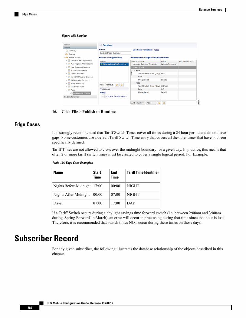
Figure 167: Service
16. Click File > Publish to Runtime.
Edge CasesIt is strongly recommended that Tariff Switch Times cover all times during a 24 hour period and do not havegaps. Some customers use a default Tariff Switch Time entry that covers all the other times that have not beenspecifically defined.
Tariff Times are not allowed to cross over the midnight boundary for a given day. In practice, this means thatoften 2 or more tariff switch times must be created to cover a single logical period. For Example:
Table 154: Edge Case Examples
Tariff Time IdentifierEndTime
StartTime
Name
NIGHT00:0017:00Nights BeforeMidnight
NIGHT07:0000:00Nights After Midnight
DAY17:0007:00Days
If a Tariff Switch occurs during a daylight savings time forward switch (i.e. between 2:00am and 3:00amduring 'Spring Forward' in March), an error will occur in processing during that time since that hour is lost.Therefore, it is recommended that switch times NOT occur during these times on those days.
Subscriber RecordFor any given subscriber, the following illustrates the database relationship of the objects described in thischapter.
CPS Mobile Configuration Guide, Release 19.4.0 (1)380
Balance ServicesEdge Cases

Figure 168: Subscriber Records
An important point to keep in mind when looking at the data structure for MsBM is that this is a documentbased database and not a relational database. The below description attempts to describe the equivalent RDMSconcepts as far as primary and foreign keys are concerned; however, these concepts are not the same in adocument based database, and are includedmerely to assist in providing understanding since most of audiencesare familiar with RDMS.
For example, since Mongo stores data in a structure that is essentially a map of maps, there is no need for theconcepts of a primary key (PK) or a foreign key (FK) since relationships between the data is defined by thephysical structure. Conceptual PKs and FKs are only needed when interaction with the QNS system or whenthe querying is necessary and the full document is not retrieved.
This listing is not a complete listing of all fields (conceptually columns) in each map (conceptually table), butonly the important fields used for data structuring or querying.
Note
Subscriber Account• subscriberId (PK)
• Key field to reference a given subscriber account. This account may be shared among multiplesubscribers.
• Value is also stored as _id which is a key field for the Mongo database document. These valueswere different in early versions of MsBM, but have been aligned to ensure greater system stability.The _id was originally a Mongo assigned UUID.
• The Subscriber Account contains all data structures related to a specific subscriber's account as it relatesto MsBM. When you retrieve a Subscriber Account, you obtain all MsBM information for a givensubscriber.
CPS Mobile Configuration Guide, Release 19.4.0 (1)381
Balance ServicesSubscriber Account

Account Balance• accountBalanceCode (PK within the scope of a given subscriber account)
• relates to the Account Balance Template reference data information defined in Policy Builder.
• key for Policy Engine to access this balance's information for a selected subscriber account.
• An account balance, or simply a balance as it is often referred to, is essentially a group of quotas. Theidea is that a customer could create a balance (quota grouping) called Data and within that have severalquotas defined, likeMonthly, Topup, and Bonus. Then when the subscriber uses account, usage is chargedagainst their Data balance and MsBM determines which underlying quota should be debited based onrules set up in Policy Server (QNS). The intent here is to simplify charging so that specific “buckets” donot need to be specified and necessary business rules can be defined once in the Policy Engine.
Quota• quotaCode (PK within the scope of a given subscriber account)
• relates to the Quota Template reference data information defined in Policy Builder.
• key for Policy Engine to access this quota's information for a selected subscriber account.
• A quota defines the actual amount or “bucket” that can be drawn from for tracking of usage. This valueinternally is unit-less and thus can be defined to be whatever is needed in the implementation. Some unitsare provided in reference data in Policy Builder to assist users. Common usages for quota amounts arebytes of volume, seconds of time, but other counts can also be tracked.
Credit• A UUID (PK) is used as a key to the map containing all the credits for a given quota.
• A UUID was selected since the data structure was defined for transactional speed and stability and wasnot intended to be queried directly. MsBM records are intended to be accessed using the Policy Engine,the provided APIs, and the Reporting Engine. The intent in the design of this structure was transactionalusage and performance, not queryability. A sequence concept or other more predictable key was not usedsince a sequence would most likely be rapidly exhausted and more difficult to manage since credits areregularly created and destroyed as part of the normal operation of MsBM. Uniqueness and assurance ofavoidance of deadlocking is the primary concern.
• Credits can be viewed as positive entries on an accounting balance sheet.
Debit• A UUID (PK) is used as a key to the map containing all the debits for a given credit.
• The reasoning for selection of the UUID is the same as discussed under Credit, on page 382.
• Debits can be viewed as negative entries on an accounting balance sheet for a specific credit. Debitsunder a given parent credit cannot exceed the amount of the parent credit.
CPS Mobile Configuration Guide, Release 19.4.0 (1)382
Balance ServicesAccount Balance

Reservations• reservationId (PK)
• Also a UUID and was selected for similar reasons as discussed under Credit, on page 382.
• Reservations describe an amount of conditional debiting of quota that is reserved until a network devicereports that the quota has actually been utilized.
Reservation Debits• reservationDebitId(PK)
• Also a UUID and was selected for similar reasons as discussed under Credit, on page 382.
• reservationId (FK)
• debitId (FK)
• Reservation debits serve the purpose of providing a link between a reservation and an actual debit entry.When a reservation is charged, the reservation and associated reservation debits are removed and thedebit linked to those reservation debits are made permanent. That is, as long as a debit has a linkedreservation debit, that debit is not permanent, but only reserved in a non-committed state.
ThresholdsThe Thresholds collection contains any reference data thresholds (defined in Policy Builder) that are currentlybreached or any user-defined thresholds that are specific to a given subscriber account.
The thresholds map is not utilized and may not appear in all implementations. It will only appear as neededif the related functionality in Policy Server (QNS) is active.
Expired ReservationsAn identical structure as Reservations is used for Expired Reservations, except that Reservation Debits donot have a link to Debits. Functionality for charging expired reservations, that is, creating debits, is handledin a different fashion.
The expired reservations map is not utilized and may not appear in all implementations. It will only appearas needed if the related functionality in Policy Server (QNS) is active.
Shared QuotaIn CPS there are several ways to set up shared quota. SPR supports parent and child profiles, for example oneparent in a household is the primary SPR record and all the other members of the household are set as childrecords of that SPR profile. This would allow for shared quota and is mostly configured through SPR datamanagement. Because Balance and SPR can be used separately, Balance also supports shared quota use casesthat are configured solely within the Balance module.
CPS Mobile Configuration Guide, Release 19.4.0 (1)383
Balance ServicesReservations

Shared Per User Limit Use CaseThere will be two Balance accounts associated with a subscriber that is participating in a shared quota butalso needs a per user limit on said shared quota. The first Balance account is the subscriber's personal account.This account will contain any balances/quotas that are only available to the subscriber. This account will alsocontain one balance that will be used for tracking the per user limit. The second Balance account is not ownedby the subscriber and contains the shared balance/quotas.
The two Balance accounts need to be provisioned separately.Note
The shared balance template contains a field called Limit Balance that links the shared balance to a limitbalance (the personal account), so that the Balance module knows which two balance codes it needs toreserve/charge against in the shared per user limit case. Since the per use limit is tied to a quota template, onlydiscrete per user limits are supported. The number of balance/quota templates defined is not limited, but thetemplates must be defined for each per use limit level. The limit quotas must be defined in a balance/quotatemplate.
The subscriber must be provisioned with the limit balance and an associated quota with a valid amount forthe per user limit to be enforced. An AVP must added to the subscriber profile in SPR indicating the Balanceaccount record and the Balance template name of the shared quota. This is done currently for some deployments.The subscriber must have the AVP set up prior to per user limits being available.
If the subscriber does not have the limit balance provisioned, then the subscriber will draw from the sharedbalance with no per user limit enforced.
Hard thresholds (meaning the subscriber cannot use more than a certain amount of the shared quota) will beenforced by the amount provisioned in the limit balance.
Soft thresholds (meaning the subscriber can continue to use more up to the hard threshold, but somethingshould happen when the soft threshold is crossed) will be supported using the threshold mechanism definedon the limit balance.
The charge and reserve function of the Balance module were enhanced with conditional logic to make newcalls to handle the shared per user limit reservations. The new calls allow charges or reservations against twoBalance accounts at the same time. The two Balance accounts are the shared account, as indicated by theAVP, and the subscriber's personal balance account (the limit balance).
Policy EngineThe Balance module exposes various policy objects that can be used to monitor the status of an account. Aptlynamed theMsBMAccount Status object, it contains information about a specific balance of a given subscriber.Each of the subscriber's balances will have its own MsBM Account Status object in the Policy Engine duringpolicy execution.
The Amount Remaining value on the MsBM Account Status object DOES contain the values of any currentreservations.
CPS Mobile Configuration Guide, Release 19.4.0 (1)384
Balance ServicesShared Per User Limit Use Case

ProrationBalance provides some limited proration capabilities but in general, proration must be handled manually viaAPI calls (Credit, Debit, ExtendCredit, CreateBalance).
Proration ExampleA subscriber has 5 GB on the first plan and has used 3 GB of it. The subscriber then switches to a differentplan with 2 GB. The subscriber will start with 2 GB of available quota UNLESS the CreateBalance APIoverrides the initial amount. Setting the override amount is a manual step that is handled by the calling system,i.e. customer portal or OSS/BSS application.
Quota Refresh ThrottlingBalance has the ability to cause a batch of quota refreshes to be staggered over a time period, which causessession wakes up to be staggered, which not only keeps masses of subscriber accounts from being refreshedat the same exact time, but also causes any other events related to a session wake up to be staggered, i.e.RARs. This concept is called the Callback Validity Time (CBVT). The CBVT is usually set to the time wheresomething changes in a subscriber’s balances/quotas. Typically this is the expiration date of their quota. TheCBVT is that time at which a session will “wake up” and create a new reservation of quota. This "wake up"activity triggers a quota refresh if one is valid for a recurring quota.
For example, let's say that 50,000 subscribers on a monthly quota have their quota set to expire at 1 AM andall have sessions established. Normally their quota wouldn’t refresh until they next accessed their account,i.e. had an active session that made a reservation or other Balance request (the refresh is retroactive however).However, some deployments have subscribers who always have a session, but it may not be actively usingquota, i.e. idle cable modem. In this scenario, at 1 AM, 50,000 subscriber sessions will “wake up” and refreshtheir accounts which could easily cause a serious load spike for system resources.
To combat this problem, the Recurring Refresh Max Delay parameter defined in the Balance Plug-inConfiguration, is used to pad the CBVT value by a random number of minutes between 0 and the parametervalue. If the Recurring Refresh Max Delay param is set to 120, then the CBVT value on the session will beset to 1 AM plus a random number of minutes chosen from between 0 and 120. Now, the 50,000 sessions willnot all wake up at 1 AM. Because the CBVT values are set to the range from 1 AM to 3 AM, at any givenminute only a small percentage of the total 50,000 sessions will wake up and refresh.
Active Session vs. Inactive Session
Any subscriber actively using their quota will refresh immediately at 1 AM when they qualify for the refreshand will not have their quota refresh delayed. Only subscribers with sessions that are not actively using quotawill have their refreshes delayed.
Sy Server Implementation in OCSThis section describes how to configure an OCS Sy server to manage policy counters that map to a subscriber’saccount balance template in an OCS node deployment.
CPS Mobile Configuration Guide, Release 19.4.0 (1)385
Balance ServicesProration

Sy Client and Diameter Stack ConfigurationThis section describes how to configure the Diameter Sy client and the associated Diameter stack.
Step 1 In Policy Builder’s Reference Data tab, select Diameter Clients in the left pane.Step 2 Expand Sy Clients, and click Sy Client under Create Child in the Sy Clients Summary pane.Step 3 Configure the client as needed.Step 4 Set the Counter Lookahead Interval Minutes option to the number of minutes to look ahead to determine when the
lookahead balance states configured for the SyServerSLRInformation service configuration object will expire, refresh,or start. It is set to 180 minutes by default.
Step 5 In the left pane, select Systems > system_name > Plugin Configuration > Diameter Configuration.Step 6 In the Diameter Configuration pane, click Create Child, click Diameter Stack.Step 7 In the Diameter Stack pane, type a Name and a Realm.Step 8 Under Inbound Peers in the Realms table, select SY_OCS_SERVER in the Processing Protocol pull-down menu.Step 9 Provide a Rating and a Name Pattern as well.
Figure 169: SY_OCS_SERVER Processing Protocol
Account Balance ConfigurationThe Sy server uses the CPS balance manager for volume/quota definition, and association to subscriber andthreshold configuration. For configuration information, refer to Quota Templates, on page 362.
CPS Mobile Configuration Guide, Release 19.4.0 (1)386
Balance ServicesSy Client and Diameter Stack Configuration

Use Case Template and Service ConfigurationThis section describes how to configure a use case template that uses the SyServerSLRInformation serviceconfiguration object. You should create a use case template using this object based on the account balancetemplate and configured thresholds.
Step 1 Select the Policy Builder Services tab.Step 2 In the Summary pane, click Use Case Template under Create Child.Step 3 In the Use Case Template pane, select the Actions tab.Step 4 Type a Name; for example, xyz_green.Step 5 Under Service Configurations, click Add.Step 6 In the Select Service Configuration dialog box, scroll down to the sy Server section, select SyServerSLRInformation,
and click OK.Step 7 Configure the SyServerSLRInformation parameters.
The following figure shows an example configuration.Figure 170: SyServerSLRInformation Service Configuration Object
The SyServerSLRInformation parameters are described in the following table:
Table 155: SyServerSLRInformation Parameters
DescriptionParameter
The priority of the message for processing. The higher the number, the higher thepriority.
Default for most settings: 0
Priority
CPS Mobile Configuration Guide, Release 19.4.0 (1)387
Balance ServicesUse Case Template and Service Configuration

DescriptionParameter
The client configuration is used to apply different policies based on PCRF type.To filter a service based on the Diameter client, specify which Diameter client youwant the service to be applied to.
This parameter is optional.
Diameter Client
Identifier – The user identity, which is mapped to the Subscription-Id AVP. Basedon your requirements, you can configure one or more identifiers. Possible valuesfor identifiers include:
Session MSISDN – The MSISDN value of the subscriber.
Session IMSI – The IMSI value of the subscriber.
Subscriber ID (List)
Identifier Name – The subscribed Sy Policy Counter Identifier list, which mapsto the Policy-Counter-Identifier AVP. OCS uses this list to send thePolicy-Counter-Identifiers to the PCRF in the SLA/SSNR message.
Identifier (List)
Contains the Policy Counter Identifier AVP, the status of this AVP, and the PendingPolicy Counter List.
PolicyCounterStatusReport
Contains the list of Pending Policy Counters. You can configure a maximum ofthree counters.
• Policy Counter Status – You can name this anything.
• Lookahead Balance State –You can select one of the following:FutureExpiry, FutureRefresh and FutureStart.
This state is the future balance event—quota expiration, quotarefresh, or quota starting in the future. Based on the look-aheadtime interval, if a balance state event is going to occur within thelook-ahead interval period, then the pending policy counter statusis populated in the SLA/SSNR messages.
Note
Pending Policy Counter List (List)
Step 8 Select the User Case Initiator tab, and configure a use case initiator for this use case template.
An example is shown below:
CPS Mobile Configuration Guide, Release 19.4.0 (1)388
Balance ServicesUse Case Template and Service Configuration

Figure 171: Use Case Initiator
Step 9 Configure a Service Option using the use case template.Step 10 Configure a Service using the Service Option.
Loading Sy Session When Gy Session is From Different RealmSy and Gy calls originate from the same realm where SY OCS Server considers Gy as a secondary session.In such a call model, Gy CCR-I is ignored if the Gy CCR-I is received before Sy SLR the Gy CCR-I.
Sy and Gy calls can originate from different realms and Gy CCR-I needs to be handled even when Sy sessionis not present. In this scenario, both Gy and Sy sessions are independent of each other. Gy CCR-I can bereceived before Sy SLR and this needs to be handled.
You need to apply policy configuration to load an Sy session to a Gy session. The MSISDNkey andUSuMSubscriberIdkey are used to correlate the Gy and Sy sessions.
Perform the following steps to load an Sy session to a Gy session:
Step 1 Log in to Policy Builder.Step 2 Navigate to Policies.Step 3 Load keys to Gy session and add the following two conditions to the policy configuration:
• A Diameter Gy v8 Session exists
• There exists an USuMSubscriber
Step 4 Under Actions, add the following keys:
• Add a MSISDNkey
CPS Mobile Configuration Guide, Release 19.4.0 (1)389
Balance ServicesLoading Sy Session When Gy Session is From Different Realm

• Add an USuMSubscriberIdKey
Step 5 To load Sy session, add the following conditions:
• A Diameter Gy v8 Session exists
• There exists a MsisdnKey
• There exists an USuMSubscriberIdKey
• An OCSThresholdBreach exists
Step 6 Under Actions, add the following key:
Retrieve a session from the cache
CPS Mobile Configuration Guide, Release 19.4.0 (1)390
Balance ServicesLoading Sy Session When Gy Session is From Different Realm

C H A P T E R 11Notification Services
• Apple Push Notifications, on page 391• Email Notifications, on page 394• Multiple Email Notification Configuration, on page 399• SMS Notifications, on page 400• Multiple SMSC Server Configuration, on page 408• Real Time Notifications, on page 410• Service Option Configuration, on page 416• NAP Notification, on page 417
Apple Push Notifications
Notification ConfigurationTo configure CPS to send a message to a subscriber with an Apple iPhone or other iOS device, perform thefollowing steps.
Step 1 Log in to Policy Builder.Step 2 Go to Reference Data tab > Systems > a system or a cluster > Plugin Configurations > Notification Configuration.Step 3 Click the check box next to Apple Push Notification Configuration.Step 4 View the Notification Configuration screen.
The following parameters can be configured under Apple Push Notification Configuration:
CPS Mobile Configuration Guide, Release 19.4.0 (1)391

Table 156: Apple Push Notification Parameters
DescriptionParameter
• Apple Production: Connects to gateway.push.apple.com on port 2195.
• Apple Test: Connects to gateway.sandbox.push.apple.com on port 2195.
• Other: Uses a server address other than the standard Apple ones. It also uses the othergateway and server port fields defined in Other Server Gateway and Other Server Port fieldsbelow.
Other: Uses a server address other than the standard Apple ones. It also uses the other gatewayand server port fields defined in Other Server Gateway and Other Server Port fields below.
Recommendation: Other
APNSServerAddress
Name of a server gateway if Other is selected as APNS Server Address.Other ServerGateway
Port number of the server gateway if Other is selected as APNS Server Address.Other Server Port
The certificate for the authorization to the gateway. You must provide a certificate file that isloaded into CPS.
Certificate
Password added to the certificate when connecting to the APNS.Certificate Password
Step 5 Go to Message Configuration, on page 392 to configure the message to be sent for the notification configuration doneabove.
Message ConfigurationTo create the messages for a subscriber’s Apple iPhone or the Apple iOS operating system to be sent by CPS,perform the following steps.
Step 1 Select Reference Data tab > Notifications > Apple Push Notifications.Step 2 From right side, click Apple Push Notification under Create Child to open the pane.
CPS Mobile Configuration Guide, Release 19.4.0 (1)392
Notification ServicesMessage Configuration

Figure 172: Apple Push Notification Pane
The following parameters can be configured under Apple Push Notification:
Table 157: Apple Push Notification Message Configuration Parameters
DescriptionParameter
The name of the notificationmessage. This name is used in the action phrase in the policy definition.Best practice is to make this short, but meaningful and unique.
Name
Default is 0 (number).
The number to display as the badge of the Apple Push Notification icon. If this property is absent,the badge is not changed. To remove the badge, set the value of this property to 0.
Example: 1, 2, 3, ….
Badge
Default is 'default'.
The name of a sound file in the application bundle. The sound in this file is played as an alert. Ifthe sound file doesn't exist or default is specified as the value, the default alert sound is played.The audio must be in one of the audio data formats that are compatible with system sounds. Formore information, see https://developer.apple.com/library/ios/documentation/NetworkingInternet/Conceptual/RemoteNotificationsPG/Chapters/IPhoneOSClientImp.html#//apple_ref/doc/uid/TP40008194-CH103-SW6.
Example: sound1, alert7, buzzSound_A
Sound
Click this check box if you want to send the notification once per session.Send Once PerSession
CPS Mobile Configuration Guide, Release 19.4.0 (1)393
Notification ServicesMessage Configuration

DescriptionParameter
You can add custom fields with values that can be sent to the application.Custom Fields
String
Example:
“high_score”: “1000”
“custom_field_1”: “display1”
“custom_field_2”: “false”
For more information on custom fields, refer to the following links:
• https://developer.apple.com/library/ios/documentation/networkinginternet/conceptual/remotenotificationspg/chapters/applepushservice.html
• http://docs.appcelerator.com/platform/latest/#!/guide/Sending_and_Scheduling_Push_Notifications-section-43298780_SendingandSchedulingPushNotifications-CustomJSONpayloads
Field Name/FieldValue
This is the text that appears on the subscriber’s iPhone. If the message is too long, it is simplytruncated. Test your messages before you place into production.
If you want to use a string, and substitute session information, use the syntax $Name, for example,to insert the receiver’s name in the email.
Alerts are limited to 160 characters. Alerts longer than that are truncated.
Alert
To use Apple Push Notifications, you need to configure Service Options.
For more information on the configuration, see Service Option Configuration, on page 416.
Email Notifications
Configure NotificationsCPS supports sending email notifications to one primary and one secondary email server, or alternatively toa pool of email servers
(See Multiple Email Notification Configuration).
When configured for one primary and one secondary email server, CPS will send all email notifications tothe primary server. If the primary fails, CPS will retry the notification to the secondary server, if configured.If the secondary server notification fails, CPS will log that the notification was unable to be delivered.
To configure the primary and secondary email server connections that CPSwill use to send email notificationsto subscribers:
Step 1 Login to Policy Builder.Step 2 Go to Reference Data > Systems > a system or a cluster > Plugin Configurations > Notification Configuration.
CPS Mobile Configuration Guide, Release 19.4.0 (1)394
Notification ServicesEmail Notifications

Step 3 Click the check box next to Email Notification Configuration.Step 4 View the Notification Configuration screen that drops down.
The following parameters can be configured under Email Notification Configuration:
Table 158: Email Notification Configuration Parameters
DescriptionParameter
IP address or host name of the mail server to which the notification emails will be sent. OnlyIMAP email is supported at this time.
Mail Server Address
Enter any login and password information needed.Login/Password
Enables transport layer security. This option is used for connecting to services other than basicIMAP services, such as Google’s Gmail.
Enable TLS
Specifies the SMTP port. This option is used for connecting to services other than basic IMAPservices, such as Google’s Gmail.
Smtp Port
The following screen shows an example configuration using smtp.gmail.com.Figure 173: Notification Configuration
Step 5 (Optional) To configure a secondary (backup) email server, click the check box next to Secondary Email Server andconfigure the parameters for the secondary server.
Step 6 Go to Configure Messages, on page 396 to configure the message to be sent for the notification configuration.
CPS Mobile Configuration Guide, Release 19.4.0 (1)395
Notification ServicesConfigure Notifications

Configure MessagesSubstitution value can be set from SPR, Balance, or the session and placed in the email body using $[variable].
In the following example, we are using a subscriber AVP code for email. The value “$email” is used in thebody of the text and replaced then the email is sent.
We are also using $timeStamp to add the Date/Time.Figure 174: Email Notification
The following parameters can be configured under Email Notifications:
CPS Mobile Configuration Guide, Release 19.4.0 (1)396
Notification ServicesConfigure Messages

Table 159: Email Notification Message Configuration Parameters
DescriptionParameter
Name of the message.Name
Select the required message coding from drop-down list. Valid values areISO-8859-1, US-ASCII, UTF-16 (UCS-2) and UTF-8. Default value is UTF-8.
Message Encoding (DCS)
This is the subject line of the email to the subscriber.Subject
The From field in the email.From Email Address
Who the subscriber may reply to.Reply To Email Address
The text of the email the subscriber receives in plain formatBody (Text/Plain)
The text of the email the subscriber receives in HTML format.Body (Text/HTML)
To pull the values from SPR and replace in the email, we use the service option setting from the notification:Figure 175: Service Option
For the timestamp, use the Value Retriever.
For the email, select from the “Pull value from…” column.
CPS Mobile Configuration Guide, Release 19.4.0 (1)397
Notification ServicesConfigure Messages

Figure 176: Subscriber AVP code Email Values
For reference, our subscriber has a Custom Data AVP set in the details of his subscriber record. This is wherethe value is being pulled from in Control Center.Figure 177: Subscriber General Details
Logging2015-05-01 14:34:46,345 [pool-2-thread-1] DEBUG c.b.n.impl.NotificationsManager.? - Emailencoding : UTF82015-05-01 14:34:46,345 [pool-2-thread-1] DEBUG c.b.n.impl.NotificationsManager.? - EmailText body : Date/Time: 1430512486305Dear [email protected], your new session has started2015-05-01 14:34:46,345 [pool-2-thread-1] DEBUG c.b.n.impl.NotificationsManager.? - EmailHTML body : <br/><br/>Date/Time: 1430512486305<br/><br/><b>Dear [email protected], your new session has started.</b>
To use Email Notifications, we need to configure Service Options.
For more information on the configuration, refer to Service Option Configuration, on page 416.
CPS Mobile Configuration Guide, Release 19.4.0 (1)398
Notification ServicesConfigure Messages
Multiple Email Notification Configuration
Configure NotificationsThis section describes how to configure CPS to send email notifications to multiple email servers.
When multiple email servers are configured, CPS utilizes a round-robin selection scheme to distribute theemail notifications to subscribers. No weighting is used when selecting the email servers from the configuredpool.
If CPS detects that the running status of an email server is DOWN, CPS will automatically skip this serverand send the notifications to the next email server. If a message cannot be delivered by an email server, CPSwill retry the same message to the next email server.
In a CPS High Availability deployment, where two Policy Director (load balancer) VMs (lb01 and lb02) areused, each Policy Director operates a separate notification service. As a result, email notifications are firstbalanced across each Policy Director, and then each Policy Director delivers the message to an email serverin a round robin fashion. This can result in concurrent messages being delivered to the same email server.
Note
The following SNMP Notifications (Alarms) are used to monitor these email server connections. Refer toCPS SNMP and AlarmsGuide, Release 9.1.0 and prior releases orCPS SNMP, Alarms and Clearing ProceduresGuide, Release 10.0.0 and later releases for more information.
• AllEmailNotificationServerDown
• AtLeastOneEmailNotificationServerUp
• EmailNotificationServerDown
• EmailNotificationServerUp
To generate the SNMP Notifications (alarms), you need to configure-Dnotification.interface.monitor.emailserver=true in /etc/broadhop/qns.conf file. Afterconfiguring the parameter, run the following commands:
/var/qps/install/current/scripts/build_all.sh
/var/qps/install/current/scripts/upgrade/reinit.sh
Before continuing with these steps to add a pool of email servers, first remove the Primary and Secondaryservers configured under the Email Notification section of Policy Builder.
Note
To configure a pool of email server connections that CPS uses to send email notifications to subscribers:
1. Login to Policy Builder.
2. Go to Reference Data > Systems > a system or a cluster > Plugin Configurations > NotificationConfiguration.
3. Click the check box next toMultiple Email Notification Configuration.
CPS Mobile Configuration Guide, Release 19.4.0 (1)399
Notification ServicesMultiple Email Notification Configuration

4. View the Notification Configuration screen that drops down.
5. Click Add to add an email server to the list.Figure 178: Multiple Email Notification Configuration
Moving an entry up or down in the table reflects only the display order; it has no impact on the selection whenprocessing email notifications.
Note
The following parameters can be configured for each email server:
Table 160: Email Notification Configuration Parameters
DescriptionParameter
IP address or host name of the mail server to which the notification emails willbe sent. Only IMAP email is supported at this time.
Mail Server Address
Enter any login and password information needed.Login/Password
Enables transport layer security. This option is used for connecting to servicesother than basic IMAP services, such as Google’s Gmail.
Enable TLS
Specifies the SMTP port. This option is used for connecting to services otherthan basic IMAP services, such as Google’s Gmail.
Smtp Port
6. Go to Configure Messages, to configure the message to be sent for the notification configuration.
SMS Notifications
Configure NotificationsCPS supports sending Short Message Service (SMS) notifications to one primary and one secondary SMSCserver, or alternatively to a pool of SMSC servers.
CPS Mobile Configuration Guide, Release 19.4.0 (1)400
Notification ServicesSMS Notifications

See Multiple SMSC Server Configuration
The following section describes how to configure CPS to send SMS notifications to a primary SMSC serverand a secondary SMSC server.
Step 1 Login to Policy Builder.Step 2 Go to Reference Data > Systems > a system or a cluster > Plugin Configurations > Notification Configuration .Step 3 Click the check box next to SMS Notification Configuration.Step 4 View the Notification Configuration screen that drops down.
The following parameters can be configured under SMS Notification:
Table 161: SMS Notification Parameters
DescriptionParameter
The TCP/IP address or host name of the SMPP server, thatis, the URL of the SMSC host that pushes the SMSmessage.
SMSC Host Address
The TCP/IP port on the SMPP server to which the gatewayconnects.
SMSC Port
The user name for the gateway to use when connecting tothe SMPP server
System ID
The password for the gateway to use when connecting tothe SMPP server.
Password
An optional login parameter used only if required by theSMPP server. The SMPP system administrator providesthis value, usually a short text string.
System Type
Optional field for some custom deployments.Registered Delivery
Optional field for some custom deployments.
Data Coding can be used instead of the Message Encodingand the other DCS fields on the Notification messagedefinition screen, but should be used with care.
If it is necessary to use a specific value in thisfield for data coding, then the message alphabetinformation should be included in the DataCoding value per the SMS specification as wellas any other necessary data coding information.The result is a combination of the capabilities ofthe SMSC and is not totally controlled by CPS.
Note
DataCoding (Advanced Use Only)
Optional field for some custom deployments.Priority Flag
TX (transmit)
or
TRX (transceiver)
Binding Type
CPS Mobile Configuration Guide, Release 19.4.0 (1)401
Notification ServicesConfigure Notifications

DescriptionParameter
Specifies the Enquire Link Timer value. The plug-ininstance performs an Enquire Link operation to the SMSCto keep the connection alive. The time between inquiries isspecified by this timer value. Default value is 5000 seconds.
Enquire Link Time
If checked, CPS will check connection to the SMSC at theinterval specified in the“Reconnect Smsc Time” field.
Reconnect
The interval to check the connection to the SMSC, andreconnect if lost. This will check the primary and secondaryif the secondary properties are set.
Reconnect Smsc Time
Other then the parameters mentioned in Table 161: SMS Notification Parameters, on page 401, the user can configure thefollowing parameters after selecting Retry Configuration check box.
The following parameters can be configured under Retry.
Table 162: Retry Parameters
DescriptionParameter
Number of retries allowed to resubmit the message.No. Of Retries
Interval in which message are resubmitted until success.Retry Interval
Go to Configure Messages, to configure the SMS message to be sent for the notification configuration done above.
Configure MessagesTo create the SMS to be sent by CPS, perform the following steps:
1. Select Reference Data > Notifications > SMS Notifications.
2. From right side, click SMS Notification under Create Child to open the pane.
The following parameters can be configured under SMS Notification:
Table 163: SMS Notification Parameters
DescriptionParameter
Name of the notification message. This name is used later in the policydefinition to send the SMS.
Name
Source address of the SMS message.Source Address
CPS Mobile Configuration Guide, Release 19.4.0 (1)402
Notification ServicesConfigure Messages

DescriptionParameter
This is an optional field. This parameter is used to configure the callbacknumber adhering to specification.The input format is a hexadecimal string.It will correspond to the exact hexadecimal sent in the stream.
Currently, only a single callback number is supported.
For more information, refer to SMS Notification Extension.
Callback Number
Type of Number for the source. It defines the format of the phone numbers.
Values: ABBREVIATED, ALPHANUMERIC, INTERNATIONAL,NATIONAL, NETWORK_SPECIFIC, SUBSCRIBER_NUMBER,UNKNOWN
Address TON
Numbering Plan Indicator. It defines the format of the addresses.
Values: DATA, ERMES, INTERNET, ISDN, LAND_MOBILE,NATIONAL, PRIVATE, TELEX, UNKNOWN, WAP
Address NPI
The message class per the SMPP specification. Valid values are CLASS0,CLASS1, CLASS2. Default value is CLASS1.
Message Class (DCS)
Defines the alphabet and byte encoding used for the message. Valid valuesare US-ASCII (7 bit), ISO-8859-1 (8 bit), and UTF-16 (UCS-2) which is 16bit. Default value is US-ASCII.
Message Encoding (DCS)
Some SMSCs create multi-part messages for long SMS messages instead ofhaving CPS create the multiple messages. This option provides such behaviorby overriding the default single message size.
This option is for advanced use only. The reason is that if space in themessage submitted from CPS does not allow for header information, suchas the User Data Header (UDH), then many SMSC are not accepted themessages at all.
Override Character Limit(Advanced)
Select this check box to set whether compression is used per the SMPPspecification. Default is false.
Compressed (DCS)
Select this check box when you want to use the value specified in DataCoding field in the Notifications Configuration screen instead of theMessageClass, Message Encoding, Compressed, and Contain Message Class valueson this screen.
Use Plugin Config DataCoding Instead (DCS
Select this check box to set whether the contain message class options isused per the SMPP specification. Default is false.
Contain Message Class
CPS Mobile Configuration Guide, Release 19.4.0 (1)403
Notification ServicesConfigure Messages

DescriptionParameter
Select this check box when the “Use Plugin Config Data Coding Instead”check box above is checked. The check box "Use Plugin Config Data CodingInstead” must be true to use this value.
This check box allows the Message Encoding value on this screen to definethe byte conversion method that is used in conjunction with the Data Codingvalue in the Notifications Configuration screen.
By default, the byte conversion method is US-ASCII regardless of the PluginConfiguration’s Data Coding value. Other UTF-16 conversions may use BigEndian, Little Endian or Byte Order Mark (BOM).
This field is also important for ensuring the proper division of messages,particularly for non-English languages, for multi-part SMSmessage support.
Use Message Encodingwith Plugin Config DataCoding
The text that the subscriber receives.
SMS messages have character limits dependent on the selected DCS values.Text in excess of this limit triggers the submission of the multi-part messagesto the SMSC.
Message
WAP Settings
WAP push over SMS has been added to facilitate another way of initiation of notification fromANDSF serverto the client (UE).Figure 179: WAP Push Configuration
The following parameters can be configured underWAP Push Configuration:
CPS Mobile Configuration Guide, Release 19.4.0 (1)404
Notification ServicesConfigure Messages

Table 164: WAP Push Configuration Parameters
DescriptionParameter
String, version of WAP message. This can be updated to reflect changes. Forexample, 1.0, 2.0, 2.1.
No characters are allowed. Only numbers or '.' are allowed.
Version
(User InteractiveMode): This field specifies the server recommendations whetherthe server wants the management session to be executed in background or showa notification to the user.
Values: NOT_SPECIFIED, INFORMATIVE, BACKGROUND,USER_INTERACTION
Default is NOT_SPECIFIED.
• NOT_SPECIFIED: Specifies that the server doesn't have a recommendationto this element.
• INFORMATIVE: Specifies that the server recommends the client to displayan informative notification or maybe emitting a beep sound announcing thebeginning of the provisioning session to the device user.
• BACKGROUND: Specifies that the server recommends the managementaction SHOULD be done as a background event.
• USER_INTERACTION: Specifies that the server recommends the clientto prompt the device user for acceptance of the offeredmanagement sessionbefore the management session takes place.
UI Mode
Specifies how the server has interpreted the initiation of the management action,either because the end user requested it or because the server has managementactions to perform. Value from drop down is added to the WAP message anddoes not trigger any action on the CPS side.
• Client: Specifies that the end user caused the device management sessionto start.
• Server: Specifies that the server (operator, enterprise) caused the devicemanagement session to start.
Initiator
Integer - Up to 16Session Id Length
Session Id is 16 bits which is 2 ASCII character according to the specification.However, there is no restriction on ANDSF session-id size, it can be of anylength. In PB, session-id length is made configurable per notification template(Shown in snapshot above). When actual session id length is greater that theconfigured size then the notification would not be sent and an error would belogged.
However, if session is less than the configured size, then zero would be prefixedin order to make sure that it satisfies session-id length configured in PB. It isassumed that the client would strip off the prefix and send the server initiatedpolicy pull.
SessionID
CPS Mobile Configuration Guide, Release 19.4.0 (1)405
Notification ServicesConfigure Messages

DescriptionParameter
String - Up to 255 Characters
The field specifies the Server Identifier of the management server. For example,“Server_1”, “WAP_SERVER_2”
ServerID
For more information on WAP fields, click WAP Fields.
To use SMS Notifications, we need to configure Service Options.
For more information on the configuration, refer to Service Option Configuration, on page 416.
SMS Notification ExtensionA new Service Configuration named as SmsNotificationExtension has been added. Note that since its anextension, it needs the base NotificationService also configured as a part of the main service for it to fetchthe base template details. For example, an operator can specify their call-center number for subscribers to callback.Figure 180: Select Service Configuration
The following parameters are configured under SmsNotificationExtension:
CPS Mobile Configuration Guide, Release 19.4.0 (1)406
Notification ServicesSMS Notification Extension

Table 165: SmsNotificationExtension Parameters
DescriptionParameter
If there are multiple SMS Notification Extension configurations, thisparameter will decide which Service configuration and correspondingparameter values to use. Higher the value, higher precedence it will have.For example, if there are two extension templates having priority as 1 and 2each, the one with priority value 2 will be used.
Default value is 0.
Priority
This is the service configuration level value for the callback number. Thiswill satisfy the need of overriding the template value.
Callback Number must be the exact hexadecimal string convertedvalue of the call back number sent in the stream.
Note
Currently, only a single callback number is supported.
Callback Number
This parameter helps to decide whether to use the service configurationcallback number to override the template or not.
Default value is true.
Override Callback OfTemplate
Configure a service with the base Notification Service and select the SMS Notification Template.Figure 181: Notification Object
Create a Use Case Template using the new SMS Extension.
Add multiple extensions at service option level and configure the corresponding values.
CPS Mobile Configuration Guide, Release 19.4.0 (1)407
Notification ServicesSMS Notification Extension

Figure 182: SMS Extension Configuration
Configure a Service which has the NotificationService configured with corresponding SMS Template chosenand on top we can add the other SMSExtensions.
Multiple SMSC Server Configuration
Configure NotificationsThis section describes how to configure CPS to send SMS notifications to multiple SMSC servers.
When multiple SMSC servers are configured, CPS utilizes a round-robin selection scheme to distribute theSMS notifications to subscribers. No weighting is used when selecting the SMSC servers from the configuredpool.
If CPS detects that the running status of an SMSC server is DOWN, or if the SMSC server is marked disabledin the Policy Builder interface, CPS will automatically skip this server and send the messages to the nextSMSC server. If a message cannot be sent to an SMSC server, CPS will retry to send it to the next SMSCserver.
In the event that an SMSC server goes down, CPS can also be configured to reconnect to the serverautomatically. The frequency at which CPS will attempt to reconnect is also configurable.
In a CPS High Availability deployment, where two Policy Director (load balancer) VMs (lb01 and lb02) areused, each Policy Director operates a separate notification service. As a result, SMS notifications are firstbalanced across each Policy Director, and then each Policy Director delivers the message to an SMSC serverin a round robin fashion. This can result in concurrent SMS messages being delivered to the same SMSCserver.
Note
CPS Mobile Configuration Guide, Release 19.4.0 (1)408
Notification ServicesMultiple SMSC Server Configuration

The following SNMP Notifications (Alarms) have been introduced to monitor the SMSC server connections.Refer to CPS SNMP and Alarms Guide, Release 9.1.0 and prior releases or CPS SNMP, Alarms and ClearingProcedures Guide, Release 10.0.0 and later releases for more information.
• AllSMSCNotificationServerDown
• AtLeastOneSMSCNotificationServerUp
• SMSCNotificationServerDown
• SMSCNotificationServerUp
Before continuing with these steps to add a pool of SMSC servers, first remove the Primary and Secondaryservers configured under the SMS Notification Configuration section of Policy Builder.
Note
To configure CPS to send SMS notifications to a pool of SMSC servers:
1. Login to Policy Builder.
2. Go to Reference Data > Systems > a system or a cluster > Plugin Configurations > NotificationConfiguration.
3. Click the check box next toMultiple SMSC Server Configuration.
4. View the Notification Configuration screen that drops down.
5. Click Add to add an SMSC server to the list.
Moving an entry up or down in the table reflects only the display order; it has no impact on the selection whenprocessing SMS notifications.
Note
The following parameters can be configured for each SMSC server:
Table 166: SMSC Server Parameters
DescriptionParameter
This field allows the operator to disable a specific SMSC server withoutremoving the configuration entirely. If a server is disabled, CPSwill not sendany SMS notifications to it.
Admin Status
The TCP/IP address or host name of the SMPP server, that is, the URL ofthe SMSC host that pushes the SMS message.
SMSC Host Address
The TCP/IP port on the SMPP server to which the gateway connects.SMSC Port
TX (transmit)
or
TRX (transceiver)
Binding Type
The user name to use when connecting to the SMSC serverSystem ID
CPS Mobile Configuration Guide, Release 19.4.0 (1)409
Notification ServicesConfigure Notifications

DescriptionParameter
The password to use when connecting to the SMSC server.Password
Specifies the time between Enquiry Link operations in seconds. CPS performsan Enquire Link operation to the SMSC server to keep the connection alive.
Default: 5000 seconds.
Enquire Link Time
An optional login parameter used only if required by the SMSC server. TheSMSC system administrator provides this value, usually a short text string.
System Type
Optional field for some custom deployments.Registered Delivery
Optional field for some custom deployments.DataCoding
Data Coding can be used instead of theMessage Encoding and the other DCSfields on the Notification message definition screen, but should be used withcare.
If it is necessary to use a specific value in this field for data coding,then the message alphabet information should be included in theData Coding value per the SMS specification as well as any othernecessary data coding information. The result is a combination ofthe capabilities of the SMSC and is not totally controlled by CPS.
Note
Optional field for some custom deployments.Priority Flag
If checked, CPSwill attempt to reconnect to an SMSC server if the connectionwas lost or server was down.
Reconnect SMSC SMS
The interval in which CPS will attempt to reconnect to the SMSC server.
Default: 300 seconds
Reconnect SMSC Timer(seconds)
Refer to ConfigureMessages, to configure the SMSmessage to be sent for the notification configuration doneabove.
Real Time NotificationsReal time Notifications allows you to send SOAP/XML and REST/JSON messages to a defined server whenpolicy thresholds are breached. The information related to real time notification is provided in the followingfeature files:
• For AIO Setup:
In /etc/broadhop/pb/features:
• com.broadhop.client.feature.notifications
In /etc/broadhop/pcrf/features:
• com.broadhop.notifications.local.feature
• com.broadhop.notifications.realtime.service.feature
CPS Mobile Configuration Guide, Release 19.4.0 (1)410
Notification ServicesReal Time Notifications

• com.broadhop.notifications.service.feature
• For HA Setup:
In /etc/broadhop/pb/features:
• com.broadhop.client.feature.notifications
In /etc/broadhop/pcrf/features:
• com.broadhop.notifications.local.feature
In /etc/broadhop/iomanager/features:
• com.broadhop.notifications.realtime.service.feature
• com.broadhop.notifications.service.feature
Configure Notifications
Step 1 Log in to Policy Builder.Step 2 Go to Reference Data > Systems > a system or a cluster > Plugin Configurations > Notification Configuration.Step 3 Click the check box next to Realtime Notification Configuration.Step 4 View the Notification Configuration screen that drops down
The following parameters can be configured under Realtime Notification Configuration.
Table 167: Realtime Notification Configuration Parameters
DescriptionParameter
File system path where failed notifications are stored. So when CPS is not ableto send notification on both Server URL and Server Fallback URL then thatnotification is stored in this path.
The path to the failed notifications directory needs to be created manually onPolicy Directors (load balancers) (lb01 and lb02).
Failed Notifications Directory
Maximum size up to which CPS can store failed notifications in the failednotifications directory.
Max Storage allowed for failedNotifications (in MB)
Go to Configure Messages, on page 411, to configure the realtime notification message to be sent for the notificationconfiguration done above.
Configure MessagesTo create the realtime notification to be sent by CPS, perform the following steps:
CPS Mobile Configuration Guide, Release 19.4.0 (1)411
Notification ServicesConfigure Notifications

Step 1 Select Reference Data > Notifications > Real Time Notifications.Step 2 On the right-hand-side panel, click Real Time Notification under Create Child to open the Notifications pane.
Figure 183: Real Time Notifications
The following parameters can be configured under Real Time Notifications:
Table 168: Real Time Notifications Parameters
DescriptionParameter
Name of the real-time notification message.Name
When CPS sends real-time notification to the provided Server URL and if it is not reachablethen this field specifies how many times CPS should send the notification. Same is truefor Server Fallback URL.
Default value is 3.
No of Retries
The time to wait between retries configured in the No of Retries field.
Default value is 3.
Retry Interval (secs)
CPS Mobile Configuration Guide, Release 19.4.0 (1)412
Notification ServicesConfigure Messages

DescriptionParameter
The content type is set based on the type of the payload template (Text/XML/JSON). Youcan select the following:
• text/xml
• application/json
• application/x-www-form-urlencoded
The content type that you choose must match the template in the Payload Template field.
The default value is text/xml.
Content Type
The user name for accessing the endpoint specified in the ServerURL and Server FallbackURL fields.
If no user name is required, leave this field blank.
User Name
The password for accessing the endpoint specified in the Server URL and Server FallbackURL fields.
If no password is required, leave this field blank.
Password
If checked, real-time notifications are generated for each session and not for all messageswithin that session.
Default value is true.
Send Once Per Session
Primary URL where CPS sends real-time notifications.Server URL
When the Primary URL is not reachable, CPS tries to send notification to this URL forthe configuredNo of Retries. When the number of retries are exhausted, CPS tries to sendnotification to the Server Fallback URL.
Server Fallback URL
For SOAP this field is not applicable and hence should be blank. This field specifies theHTTP Post parameter name.
HTTP Post Parameter name(Keep this field if notapplicable, Eg: SOAP)
This field contains the payload template, so real-time notifications are generated using theconfigured template. CPS provides values to the fields specified in the template from theongoing session. For all fields that are specified in the template with values found, thereal-time notification is generated.
The names of the variables/placeholders defined here must match with the notificationservice parameter codes defined in service parameters of the corresponding use casetemplate.
You should also ensure that the correct value retriever is selected for each notificationservice parameter code in the use case template.
Payload Template(Text/XML/JSON)
The following example shows a JSON payload template for reference only.
{"notifications": [
{
CPS Mobile Configuration Guide, Release 19.4.0 (1)413
Notification ServicesConfigure Messages

"ctn_id": "$msisdn","eventType":"$eventType","eventData":{
"services":["$service"]}
}]
}
Configure the NotificationService parameters in a use case template that pertains to the JSON example above.Figure 184: NotificationService Parameter Configuration for JSON Example
• The $msisdn, $eventType, and $service notifications in the JSON example are added asCode values underMessageParameters.
• These values are pulled using the Value Retriever for each message parameter. Use the select box provided in eachValue Retriever field to select the retrievers.
• For Code type eventType, the Value Retriever is Device Indicator Event Type which allows the retrieval ofevent type. This is currently hard-coded to QoS_Change.
• For Code type service, theValue Retriever is Device Indicator Service which allows retrieval of service status(ON or OFF).
• For the Notification To Send parameter, select the Real Time Notification you want from the list.
The following example shows an XML payload template for reference only.
<?xml version="1.0" encoding="utf-8"?>
CPS Mobile Configuration Guide, Release 19.4.0 (1)414
Notification ServicesConfigure Messages

<soapenv:Envelope xmlns:soapenv="http://schemas.xmlsoap.org/soap/envelope/"xmlns:ser="http://localhost:8080/dataTest/services/">
<soapenv:Header/><soapenv:Body>
<ser:NewServiceStartedRequest><UserId>$userId</UserId><Balance>$balance</Balance><Quota>$quota</Quota><Timestamp>$timeStamp</Timestamp>
</ser:NewServiceStartedRequest></soapenv:Body>
</soapenv:Envelope>
Configure the NotificationService parameters in a use case template that pertains to the XML example above.Figure 185: NotificationService Parameter Configuration for XML Example
• Adding substitute values into the message body.
To substitute any value into your message, add the character '$' to the beginning of the variable name. For example,$userName.
The XML Template example contains the $userId, $balance, $quota, and $timeStamp variables, which we willreplace with values from the session and post to the Server URL defined in the Notifications Plugin.
• The Server URL is the destination of the message, and this is not set as an attribute of the subscriber like the othernotifications.
CPS Mobile Configuration Guide, Release 19.4.0 (1)415
Notification ServicesConfigure Messages

• Notification To Send: Select the Real Time Notification you want from the list.
Message Parameters (using the example XML payload template):
• userId: This value is pulled using the Session User Name Retriever. Use the select box from the Value Retrieverfield.
• balance: This value is pulled using the Balance Code Retriever. Use the select box from the Value Retriever field.
• quota: This value is pulled using the Balance Code Retriever. Use the select box from the Value Retriever field.
• timestamp: This value is pulled using the Timestamp Retriever. Use the select box from the Value Retriever field.
For more information on service options, refer to Service Option Configuration, on page 416.
Service Option ConfigurationThis section provides an example Service Options configuration which can be used for SMS, EMAIL, ApplePush, and GMC notifications. The bodies of the messages are identical to make the service options parameterssimpler to follow.
Adding substitute values into the message body
To substitute any value into your message, add the character '$' to the beginning of the variable name. Forexample, Ex. $userName.
This set of substitute variables are used as an example for SMS, EMAIL, Apple Push, and GCM.
• $timeStamp
• $userId
• $nickName
You assign the variables their value using the Notification Service Parameters.
There are four values provide for the example configuration:
• Notification To Send: Select the Notification you want from the list.
• Timestamp: This value is pulled using Timestamp Retriever. Use the select box from the Value Retrieverfield.
• userId: This value is pulled using Session User Name Retriever. Use the select box from the ValueRetriever field.
• Nickname: We are filling this value using the Subscriber AVP Code action, pulling from the CustomData attached to the subscriber. You can see these values in the Control Center.
nickName example: Custom AVP in the Control Center
CPS Mobile Configuration Guide, Release 19.4.0 (1)416
Notification ServicesService Option Configuration

Figure 186: nickName Configuration
Apple Push Notification Destination
By default, this notification will go the Destination set in the Notifications section under the subscriber detailsfor the type of Notification being sent.
For example, an Apple Push message will go to Apple Push Destination, and SMS to SMS, and so on.Figure 187: Notification Destinations
To override the destination set for the subscriber, you can use the Override Destination field in the ServiceOption.
NAP NotificationCPS is enhanced to support decoding of the URL sent from the LDAP/NAP server.
Create (Payload):
%3C%3Fxml+version%3D%221.0%22+encoding%3D%22UTF-8%22+standalone%3D%22yes%22%3F%3E%3CCustomerTransactions%3E%3CCustomerTransaction%3E%3CTransactionInfo%3E%3CRequestedAction%3Ecreate%3C%2FRequestedAction%3E%3CCustomerID%3E200569444%3C%2FCustomerID%3E%3Cmsisdn%3E4047047821%3C%2Fmsisdn%3E%3CVersion%3E1.4%3C%2
CPS Mobile Configuration Guide, Release 19.4.0 (1)417
Notification ServicesNAP Notification

FVersion%3E%3CTransactionID%3E5153654875871906187%3C%2FTransactionID%3E%3CVendorID%3E53%3C%2FVendorID%3E%3C%2FTransactionInfo%3E%3CAccountInfo%3E%3CCustomerID%3E200569444%3C%2FCustomerID%3E%3Cmsisdn%3E4047047821%3C%2Fmsisdn%3E%3Cimsi%3E310260399339533%3C%2Fimsi%3E%3Cban%3E932945358%3C%2Fban%3E%3CaccountType%3EI%3C%2FaccountType%3E%3CaccountSubType%3ER%3C%2FaccountSubType%3E%3CbillCyclePeriod%3E14%3C%2FbillCyclePeriod%3E%3CStatusCode%3EA%3C%2FStatusCode%3E%3CCustomerType%3E1%3C%2FCustomerType%3E%3CPAHmsisdn%3E4047047821%3C%2FPAHmsisdn%3E%3CLanguage%3Eeng%3C%2FLanguage%3E%3CPairingFlag%3E1%3C%2FPairingFlag%3E%3C%2FAccountInfo%3E%3CServiceInfo%3E%3CVendorID%3E53%3C%2FVendorID%3E%3CFeatures%3E%3CFeature%3E%3CName%3EB52ROAM%3C%2FName%3E%3C%2FFeature%3E%3C%2FFeatures%3E%3C%2FServiceInfo%3E%3C%2FCustomerTransaction%3E%3C%2FCustomerTransactions%3E
After URL Decoding:
<?xml+version="1.0"+encoding="UTF-8"+standalone="yes"?><CustomerTransactions><CustomerTransaction><TransactionInfo><RequestedAction>create</RequestedAction><CustomerID>200569444</CustomerID><msisdn>4047047821</msisdn><Version>1.4</Version><TransactionID>5153654875871906187</TransactionID><VendorID>53</VendorID></TransactionInfo><AccountInfo><CustomerID>200569444</CustomerID><msisdn>4047047821</msisdn><imsi>310260399339533</imsi><ban>932945358</ban><accountType>I</accountType><accountSubType>R</accountSubType><billCyclePeriod>14</billCyclePeriod><StatusCode>A</StatusCode><CustomerType>1</CustomerType><PAHmsisdn>4047047821</PAHmsisdn><Language>eng</Language><PairingFlag>1</PairingFlag></AccountInfo><ServiceInfo><VendorID>53</VendorID><Features><Feature><Name>B52ROAM</Name></Feature></Features></ServiceInfo></CustomerTransaction></CustomerTransactions>
The schema for such NAP notifications is not defined in a XSD but is a free flowing XML as defined by NAP.CPS has adapted its parsing code to ensure the entire XML is received and processed although only IMSI,service level and prepaid flag are submitted to the policy engine as LDAP change event message from theservlet.
CPS Mobile Configuration Guide, Release 19.4.0 (1)418
Notification ServicesNAP Notification

C H A P T E R 12Service Configuration Objects
• diameter2 Configuration Objects, on page 419• Gx Service Configuration Objects, on page 421• Gy Service Configuration Objects, on page 463• LDAP Service Configuration Objects, on page 468• Rx Service Configuration Objects, on page 472• RxClient Service Configuration Objects, on page 489• Sd Service Configuration Objects, on page 489• Service Configuration Objects, on page 494• Sy Service Configuration Objects, on page 496• UDC Client Service Configuration Objects, on page 500• Common Parameter Descriptions, on page 500
diameter2 Configuration Objects
RequestRejectRequestReject service configuration can be used to send an error code to reject a session during initial attachor update when certain condition (such as, APN-RAT combination) is met.
The RequestReject service configuration functionality remains the same whether the policy configuration isCRD based or not.
For explanation purposes, CRD based functionality is described in this section.
Note
This configuration has two attributes, ErrorCode and IsExperimentalErrorCode and values to these twoattributes gets populated using result column of STG (output columns of CRD).
Error-Code is a Number type column and IsExpermentalErrorCode is a Boolean type column.Note
CRD table gets evaluated with retrievers/request bindings (such as, APN, RAT-TYPE, Cmd-Code,application-id, Request-Type) done at CRD level and gives ErrorCode and IsExperimentalErrorCode as
CPS Mobile Configuration Guide, Release 19.4.0 (1)419

derived output. Based on this ErrorCode, CPS sends the response message. If no Error-Code is derived, thenCPS behaves normally.
CPS logs a counter for each request rejection. For this a new statistics,<InterfaceName>_<RequestType>_policy_driven_rejection_<ResultCode> has been added.
Table 169: RequestReject Service Configuration Parameters
DescriptionParameter
See Common Parameter Descriptions, on page 500.Priority
Diameter Client
Value of this field is pulled from the CRD output column which is of typeNumber (need to configure pull value from column to map to a result columnof the CRD table), which represents the error code that needs to be sent inresponse.
Default value of Error Code is 0.
If application detects an error and decides to reject the request, theError Code value configured in the service configuration object takesprecedence over any other Result-Code that the application wouldhave normally sent (for example,DIAMETER_UNKNOWN_SESSION_ID (5002),DIAMETER_PENDING_TRANSACTION (4144)).
Note
Error Code
Value of this field is pulled from the CRD output column which is of typeBoolean (need to configure pull value from column to map to a result columnof the CRD table), which represents how CPS has to send the Error Code inresponse either through Result-CodeAVP or 'Experimental-Result-Code' groupedAVP.
Default value is false that means CPS sends an error code in response throughResult-Code AVP.
Is Experimental ErrorCode
ResetDiameterSessionResetDiameterSession service configuration is used to release the primary Gx session of the subscriber whenprimary Gx session has released all the other secondary sessions gracefully.
Table 170: ResetDiameterSession Service Configuration Parameters
DescriptionParameter
See Common Parameter Descriptions, on page 500.Priority
Diameter Client
Currently, GX_TGPP is the only protocol supported.
You can configure other interfaces but they are not supported by CPS.Note
Protocol
CPS Mobile Configuration Guide, Release 19.4.0 (1)420
Service Configuration ObjectsResetDiameterSession

DescriptionParameter
Reason for aborting Gx session.
Default value is UNSPECIFIED_REASON(0).
The following release causes are supported:
• Default: UNSPECIFIED_REASON(0)
• UE_SUBSCRIPTION_REASON(1)
• INSUFFICIENT_SERVER_RESOURCES(2)
• IP_CAN_SESSION_TERMINATION(3)
• UE_IP_ADDRESS_RELEASE(4)
Release Cause
Gx Service Configuration Objects
ActionBasedOnGxEventTriggerThe ActionBasedOnGxEventTrigger service configuration object allows CPS to make policy decisions basedon the following event triggers received over Gx:
• OUT_OF_CREDIT
• REALLOCATION_OF_CREDIT
• CREDIT_MANAGEMENT_SESSION_FAILURE
• CISCO_EVENT_TRIGGER
Table 171: ActionBasedOnGxEventTrigger Service Configuration Parameters
DescriptionParameter
See Common Parameter Descriptions, on page 500.Priority
Diameter Client
CPS Mobile Configuration Guide, Release 19.4.0 (1)421
Service Configuration ObjectsGx Service Configuration Objects

DescriptionParameter
StgNameReferencePair:
• Stg Name (Optional): This can be left blank
• Stg Reference (Mandatory): This is the reference to the CRD table
• List Of Input ColumnAvp Pairs (Mandatory): Defines themapping betweenthe AVP Names and the key columns defined in the selected STG. TheseAVPs are used as inputs while evaluating the CRD table in STG.
• Avp Name: The name of the Diameter AVP that is used as input forCRD table evaluation. Supported values are Cisco-CC-Failure-Type,Charging-Rule-Name, and Rule-Failure-Code.
• Column: The reference to the CRD column for the input AVP.
• List Of Output Column Avp Pairs (Mandatory): Defines the mappingbetween the AVP Names and the output columns defined in the selectedSTG. Thesemappings indicate how the output columns' values are mappedto AVPs after the CRD is evaluated.
• Avp Name: The name of the Diameter AVP to which the value of theoutput column is mapped. Supported values are Remove-Rx-Rule,Terminate-Session, and Reinitiate-Session.
• Column: The reference to the CRD column for the output AVP.
Event Trigger Stg
ActionOnDefaultBearerQoSChangeTable 172: RxAppQoSInformation Service Configuration Parameters
DescriptionParameter
See Common Parameter Descriptions, on page 500.Priority
Diameter Client
If this value is set to true, then on Default Bearer QoS uplift, a check is doneto see if any of the existing dedicated bearers have the same QoS as theuplifted QoS (specifically same QCI and ARP). CPS then installs those rulesand flows on the default bearer associated with existing dedicated bearer.This is due to the fact that PGW removes the dedicated bearer when QCI andARP matches with the default bearer. With the removal of the dedicatedbearer all the flows and rules associated with that bearers are removed.
Collapse Dedicated Bearer
Reserved for future use.Evaluate Static Rules
Reserved for future use.Evaluate Qo S Group Rules
CPS Mobile Configuration Guide, Release 19.4.0 (1)422
Service Configuration ObjectsActionOnDefaultBearerQoSChange

ADTMAttributeStagePriorityADTMAttributeStagePriority configuration object is used to provide stage and priority values for the ActiveTraffic Management (ADTM) attribute.
The following table describes the service configuration parameters:
Table 173: ADTMAttributeStagePriority Service Configuration Parameters
DescriptionParameter
See Common Parameter Descriptions, on page 500.Priority
Diameter Client
Search Table Group table that is being referenced. The STG (and the containedCRDs) can also contain key columns that do not directly refer to Diameter AVPsin the trigger message. For example, Outputs of other tables. These columnsmust be bound correctly.
Search Table Group
Input parameters in terms of CRD column name and mapped AVP Code.
ColumnAndAvpPair
• Avp Name: Supported custom input AVP names are:
• Message: This represents the incoming or outgoing message type.Supported values are CCR-I, CCA-I, GX-RAR and RX-AAR.
• APNString: This represents the existing active APNs for the subscriber.Various names are separated by colon in an alphabetical order. Forexample, Hotspot:IMS:SOS are in alphabetical order.
• APNCount: APN count is the total count of existing active APNs forthe subscriber.
• Column: The key column in the STG that corresponds to the specifiedAVP.
Input Column Binding(List)
CRD table output column having the priority value. Value can be any positiveinteger. 0 is an invalid value.
Themaximum value is based on the bit length configured under Attribute EncodeTable in Policy Builder. Lesser the number higher the priority.
There is no default value.
Priority Level
CRD table output column having Stage column value. These is the stage columnvalid value present in Stage table under Attribute Encoding Table in PolicyBuilder.
Valid value is any string.
Stage
CPS Mobile Configuration Guide, Release 19.4.0 (1)423
Service Configuration ObjectsADTMAttributeStagePriority

ADTMIMSServiceActionADTMIMSServiceAction configuration object is used to define IMS service action.
The following table describes the service configuration parameters:
Table 174: ADTMIMSServiceAction Service Configuration Parameters
DescriptionParameter
See Common Parameter Descriptions, on page 500.Priority
Diameter Client
Search Table Group table that is being referenced. The STG (and the containedCRDs) can also contain key columns that do not directly refer to Diameter AVPsin the trigger message. For example, Outputs of other tables. These columnsmust be bound correctly.
Search Table Group
Input parameters in terms of CRD column name and mapped AVP Code.
ColumnAndAvpPair
• Avp Name: Supported custom input AVP names are:
• Stage: Stage value as received in Active TrafficManagement (ADTM)Attribute notification fromUDC FE. This is the stage of the incomingcall which leads to deletion or pause of the existing bearer.
• Priority: Priority value as received in Active Traffic Management(ADTM) Attribute notification from UDC FE. This is the priority ofthe incoming call which leads to deletion or pause of the existingbearer.
• RemoteLogicalApn: APN value as received in Active TrafficManagement (ADTM) Attribute notification from UDC FE. This isthe APN priority of the incoming call which leads to deletion or pauseof the existing bearer.
• RemoteFrontEndId: Front End Id value as received in Active TrafficManagement (ADTM) Attribute notification from UDC FE. This isthe front end ID of the incoming call which leads to deletion or pauseof the existing bearer.
• MPS-Identifier: MPS identifier of the existing Rx session.
• Reservation-Priority: Reservation priority of the existing Rx session.
• MCPTT-Identifier: MCPTT identifier of the existing Rx session.
• Media-Type: Media Type of the existing Rx session.
• Column: The key column in the STG that corresponds to the specifiedAVP.
Input Column Binding(List)
CPS Mobile Configuration Guide, Release 19.4.0 (1)424
Service Configuration ObjectsADTMIMSServiceAction

DescriptionParameter
CRD table output column having the priority value. Value can be any positiveinteger. 0 is an invalid value.
Themaximum value is based on the bit length configured under Attribute EncodeTable in Policy Builder. Lesser the number higher the priority.
There is no default value.
Priority Level
CRD table output column for the action value. Valid values are DELETE andPAUSE.
Configuring DELETE results in removal of the rules from gateway andtermination on Rx.
Currently, PAUSE is not supported for IMS service.
There is no default value.
Action
ADTMMogServiceActionADTMMogServiceAction configuration object is used to define MOG service action.
The following table describes the service configuration parameters:
Table 175: ADTMMogServiceAction Service Configuration Parameters
DescriptionParameter
See Common Parameter Descriptions, on page 500.Priority
Diameter Client
Search Table Group table that is being referenced. The STG (and the containedCRDs) can also contain key columns that do not directly refer to Diameter AVPsin the trigger message. For example, Outputs of other tables. These columnsmust be bound correctly.
Search Table Group
CPS Mobile Configuration Guide, Release 19.4.0 (1)425
Service Configuration ObjectsADTMMogServiceAction

DescriptionParameter
Input parameters in terms of CRD column name and mapped AVP Code.
ColumnAndAvpPair
• Avp Name: Supported input AVP names are:
• Stage: Stage value as received in Active TrafficManagement (ADTM)Attribute notification fromUDC FE. This is the stage of the incomingcall which leads to deletion or pause of the existing bearer.
• Priority: Priority value as received in Active Traffic Management(ADTM) Attribute notification from UDC FE. This is the priority ofthe incoming call which leads to deletion or pause of the existingbearer.
• RemoteLogicalApn: APN value as received in Active TrafficManagement (ADTM) Attribute notification from UDC FE. This isthe APN priority of the incoming call which leads to deletion or pauseof the existing bearer.
• RemoteFrontEndId: Front End Id value as received in Active TrafficManagement (ADTM) Attribute notification from UDC FE. This isthe front end ID of the incoming call which leads to deletion or pauseof the existing bearer.
• Service-Info-Status: Service Info Status of the existing Rx session.
• Sponsor-Identity: Sponsor Identity of the existing Rx session.
• DPCC-Name: DPCC Name of the existing Rx session.
• DPCC-Value: DPCC Value of the existing Rx session.
• Intention: Intent of the existing Rx session.
• Media-Type: Media Type of the existing Rx session.
• Column: The key column in the STG that corresponds to the specifiedAVP.
Input Column Binding(List)
CRD table output column having the priority value. Value can be any positiveinteger. 0 is an invalid value.
Themaximum value is based on the bit length configured under Attribute EncodeTable in Policy Builder. Lesser the number higher the priority.
There is no default value.
Priority Level
CPS Mobile Configuration Guide, Release 19.4.0 (1)426
Service Configuration ObjectsADTMMogServiceAction

DescriptionParameter
CRD table output column for the action value. Valid values are DELETE andPAUSE.
Configuring DELETE results in rule removal or QoS reversal and terminationon Rx
Configuring PAUSE results in rule removal or QoS reversal at gateway but notermination on Rx. The rules are re-installed or QoS is re-installed when thePAUSE condition is gone.
There is no default value.
Action
ADTMSDServiceActionADTMSDServiceAction configuration object is used to define TDF Sd service action.
The following table describes the service configuration parameters:
Table 176: ADTMSDServiceAction Service Configuration Parameters
DescriptionParameter
See Common Parameter Descriptions, on page 500.Priority
Diameter Client
Search Table Group table that is being referenced. The STG (and the containedCRDs) can also contain key columns that do not directly refer to Diameter AVPsin the trigger message. For example, Outputs of other tables. These columnsmust be bound correctly.
Search Table Group
CPS Mobile Configuration Guide, Release 19.4.0 (1)427
Service Configuration ObjectsADTMSDServiceAction

DescriptionParameter
Input parameters in terms of CRD column name and mapped AVP Code.
ColumnAndAvpPair
• Avp Name: Supported custom input AVP names are:
• Stage: Stage value as received in Active TrafficManagement (ADTM)Attribute notification fromUDC FE. This is the stage of the incomingcall which leads to deletion or pause of the existing bearer.
• Priority: Priority value as received in Active Traffic Management(ADTM) Attribute notification from UDC FE. This is the priority ofthe incoming call which leads to deletion or pause of the existingbearer.
• RemoteLogicalApn: APN value as received in Active TrafficManagement (ADTM) Attribute notification from UDC FE. This isthe APN priority of the incoming call which leads to deletion or pauseof the existing bearer.
• RemoteFrontEndId: Front End Id value as received in Active TrafficManagement (ADTM) Attribute notification from UDC FE. This isthe front end ID of the incoming call which leads to deletion or pauseof the existing bearer.
• TDF-App-Id: TDF application identifier of the existing Sd detectedapplication.
• Sponsor-Id: Sponsor identity of the existing Sd detected application.
• Column: The key column in the STG that corresponds to the specifiedAVP.
Input Column Binding(List)
CRD table output column having the priority value. Value can be any positiveinteger. 0 is an invalid value.
Themaximum value is based on the bit length configured under Attribute EncodeTable in Policy Builder. Lesser the number higher the priority.
There is no default value.
Priority Level
CRD table output column for the action value. Valid values are DELETE andPAUSE.
When custom muting is enabled and PAUSE is configured, all the services aremoved to default bearer and are custom muted.
Configuring DELETE removes the services from the gateway.
There is no default value.
Action
ADTMSPRBearerActionADTMSPRBearerAction configuration object is used to define SPR Bearer service action.
CPS Mobile Configuration Guide, Release 19.4.0 (1)428
Service Configuration ObjectsADTMSPRBearerAction

The following table describes the service configuration parameters:
Table 177: ADTMSPRBearerAction Service Configuration Parameters
DescriptionParameter
See Common Parameter Descriptions, on page 500.Priority
Diameter Client
Search Table Group table that is being referenced. The STG (and the containedCRDs) can also contain key columns that do not directly refer to Diameter AVPsin the trigger message. For example, Outputs of other tables. These columnsmust be bound correctly.
Search Table Group
Input parameters in terms of CRD column name and mapped AVP Code.
ColumnAndAvpPair
• Avp Name: Supported input AVP names are:
• Stage: Stage value as received in Active TrafficManagement (ADTM)Attribute notification fromUDC FE. This is the stage of the incomingcall which leads to deletion or pause of the existing bearer.
• Priority: Priority value as received in Active Traffic Management(ADTM) Attribute notification from UDC FE. This is the priority ofthe incoming call which leads to deletion or pause of the existingbearer.
• RemoteLogicalApn: APN value as received in Active TrafficManagement (ADTM) Attribute notification from UDC FE. This isthe APN priority of the incoming call which leads to deletion or pauseof the existing bearer.
• RemoteFrontEndId: Front End Id value as received in Active TrafficManagement (ADTM) Attribute notification from UDC FE. This isthe front end ID of the incoming call which leads to deletion or pauseof the existing bearer.
• Attribute-Name: Name of the existing subscriber attribute.
• Attribute-Value: Value of the same existing subscriber attribute.
• Column: The key column in the STG that corresponds to the specifiedAVP.
Input Column Binding(List)
CRD table output column having the priority value. Value can be any positiveinteger. 0 is an invalid value.
Themaximum value is based on the bit length configured under Attribute EncodeTable in Policy Builder. Lesser the number higher the priority.
There is no default value.
Priority Level
CPS Mobile Configuration Guide, Release 19.4.0 (1)429
Service Configuration ObjectsADTMSPRBearerAction

DescriptionParameter
CRD table output column for the action value. Valid values are DELETE andPAUSE.
When DELETE is configured, SPR attributes does not participate in the policyevaluation.
When PAUSE is configured, SPR attribute does not participate in policyevaluation until PAUSE condition is valid.
There is no default value.
Action
ApnMappingThe ApnMapping service configuration object pushes the configured Target APN in a CCA-I message bymatching the incoming APN in a CCR-I message with the configured source APN.
Table 178: ApnMapping Service Configuration Parameters
DescriptionParameter
See Common Parameter Descriptions, on page 500.Priority
Diameter Client
The APN that will be mapped to the target APN.Source APN
The APN that will be the used instead of the source APN.Target APN
BandwidthMonitorThe BandwidthMonitor service configuration object grants PCEF a specified amount/dosage and records thetimestamp when it was granted.
Table 179: BandwidthMonitor Service Configuration Parameters
DescriptionParameter
See Common Parameter Descriptions, on page 500.Priority
Diameter Client
Any name can be specified.Name
The number of minutes used to set the Revalidation-Time AVP so that thesubscriber has a chance to get unthrottled before the allocated dosage is used.
Reporting Timeout
CPS Mobile Configuration Guide, Release 19.4.0 (1)430
Service Configuration ObjectsApnMapping

DescriptionParameter
BaseUsageMonitoringKey
For detailed descriptions of these parameters, see Common Parameter Descriptions,on page 500.
• Encoding Format
• Monitoring Key
• Dosage
• Monitoring Level
• Enabled
Monitoring Key
BandwidthThresthold
• Lower Value – The minimum bandwidth value (in kbps) that you can specifyfor the corresponding Label. This value should be an integer.
When the computed bandwidth used is greater than this value, thecorresponding Label is set to the subscriber for the particular applicationidentified by the Name option.
• Label – The name of the label, which depends upon user requirements.
Bandwidth Threshold(List)
BearerControlModeThe BearerControlMode service configuration object sets the Bearer Control Mode to the specified value. Ifyou do not specify a value, the value is derived. This value overwrites any previously specified value.
Table 180: BearerControlMode Service Configuration Parameters
DescriptionParameter
See Common Parameter Descriptions, on page 500.Priority
Diameter Client
The type of mode that is being set explicitly.Mode Type
CcGroupThe CcGroup service configuration object is used with entitlement to specify which credit-control-group thesession should be associated with.
This configuration object requires custom properties be enabled in the qns.conf file.Note
CPS Mobile Configuration Guide, Release 19.4.0 (1)431
Service Configuration ObjectsBearerControlMode

Table 181: CcGroup Service Configuration Parameters
DescriptionParameter
See Common Parameter Descriptions, on page 500.Priority
Diameter Client
The name of the CC-Group value to be assigned to the user's session.Name
ChargingInformationThe ChargingInformation service configuration object sets the session charging information to the specifiedvalue.
Table 182: ChargingInformation Service Configuration Parameters
DescriptionParameter
See Common Parameter Descriptions, on page 500.
Priority
Diameter Client
Online
Offline
The primary Online Charging System to be used.Primary O C S
The secondary Online Charging System to be used.Secondary O C S
The primary Offline Charging System to be used.Primary O F C S
The secondary Offline Charging System to be used.Secondary O F C S
CiscoContentFilteringPolicyThe goal of Content Filtering is to provide support for content filtering within the network by use of PolicyIDs. Policy identifiers (Policy IDs) are rules that are configured on the ASR 5000 platform and invoked bythe CPS. Policy IDs are used to implement the required Content Filtering policies defined for the subscriber.The Policy IDs are selected at the ASR 5000 by provisioning their values through the Gx interface by thePCRF.
When a user initiates a session, the ASR5K communicates with the CPS to initialize the defined policies. CPSprovides the Policy ID to the ASR5K to provide the necessary Content Filtering services for the user.
The primary purpose of this feature is for CPS to provide Policy IDs configured in the subscriber's service tothe PCEF (ASR5K).
CPS Mobile Configuration Guide, Release 19.4.0 (1)432
Service Configuration ObjectsChargingInformation

Table 183: CiscoContentFilteringPolicy Service Configuration Parameters
DescriptionParameter
See Common Parameter Descriptions, on page 500.Priority
Diameter Client
The name of the policy being applied by this configuration.CiscoContent Filtering Policy
CiscoEventTriggerTypeThe CiscoEventTriggerType service configuration object allows CPS to armCisco Custom event to get notifiedwhenever a Gy failure occurs at PCEF. For arming event, 5 is sent and for disarming, 0 is sent.
• 0 - NO_CISCO_EVENT_TRIGGERS
• 5 - CREDIT_CONTROL_FAILURE
Table 184: CiscoEventTriggerType Service Configuration Parameters
DescriptionParameter
See Common Parameter Descriptions, on page 500.
Priority
Diameter Client
Event Trigger
CiscoOverrideControlCPS supports Override-Control specific AVPs in CCA-i and CCA-u responses to the PCEF on the Gx Interfaceand Gx RAR message. These AVPs are used to override charging parameters for predefined and static ruleson the PCEF.
Table 185: CiscoOverrideControl Service Configuration Parameters
DescriptionParameter
See Common Parameter Descriptions, on page 500.Priority
Diameter Client
Specifies the name of the rule (predefined or static) for whichoverride values are sent.
Override Rule (List)
Exclude Rule – Defines the rule name where the overridewill not be applied.
• Rule Name – the name of the rule to be excluded.
Override Charging Action Exclude Rule (List)
CPS Mobile Configuration Guide, Release 19.4.0 (1)433
Service Configuration ObjectsCiscoEventTriggerType

DescriptionParameter
Used to override the value of Service Identifier configuredin the charging action.
Override Service Identifier
Defines the value of the rating group configured for astatic/predefined rule.
Override Rating Group
Used to override the value of reporting level configured inthe charging action.
Override Reporting Level
See Common Parameter Descriptions, on page 500.Override Online
Override Offline
Used to override the value of Metering Method configuredin the charging action.
Override Metering Method
Used to Override QoS-Information for a predefined rule orcharging action.
Override QoS
Defines themaximumbit rate allowed for the uplink direction.Override-Max-Requested-Bandwidth-UL
Defines the maximum bit rate allowed for the downlinkdirection.
Override-Max-Requested-Bandwidth-DL
Defines the guaranteed bit rate allowed for Uplink direction.This AVP should be included only for rules on dedicatedbearers.
Override-Guaranteed-Bitrate-UL
Defines the guaranteed bit rate allowed for downlinkdirection. This AVP should be included only for rules ondedicated bearers.
Override-Guaranteed-Bitrate-DL
Used to override the pre-configured value of ARP.Override-Allocation-Retention-Priority
Used to merge override control charging/policy parametersbetween override control with specific charging action andwildcard override control.
Override Merge Wildcard
CiscoQosGroupRuleThe CiscoQosGroupRule service configuration object defines QoS Group Rules (and their sub-rules), onwhich CRD Driven rules depend.
Table 186: CiscoQosGroupRule Service Configuration Parameters
DescriptionParameter
See Common Parameter Descriptions, on page 500.Priority
Diameter Client
CPS Mobile Configuration Guide, Release 19.4.0 (1)434
Service Configuration ObjectsCiscoQosGroupRule
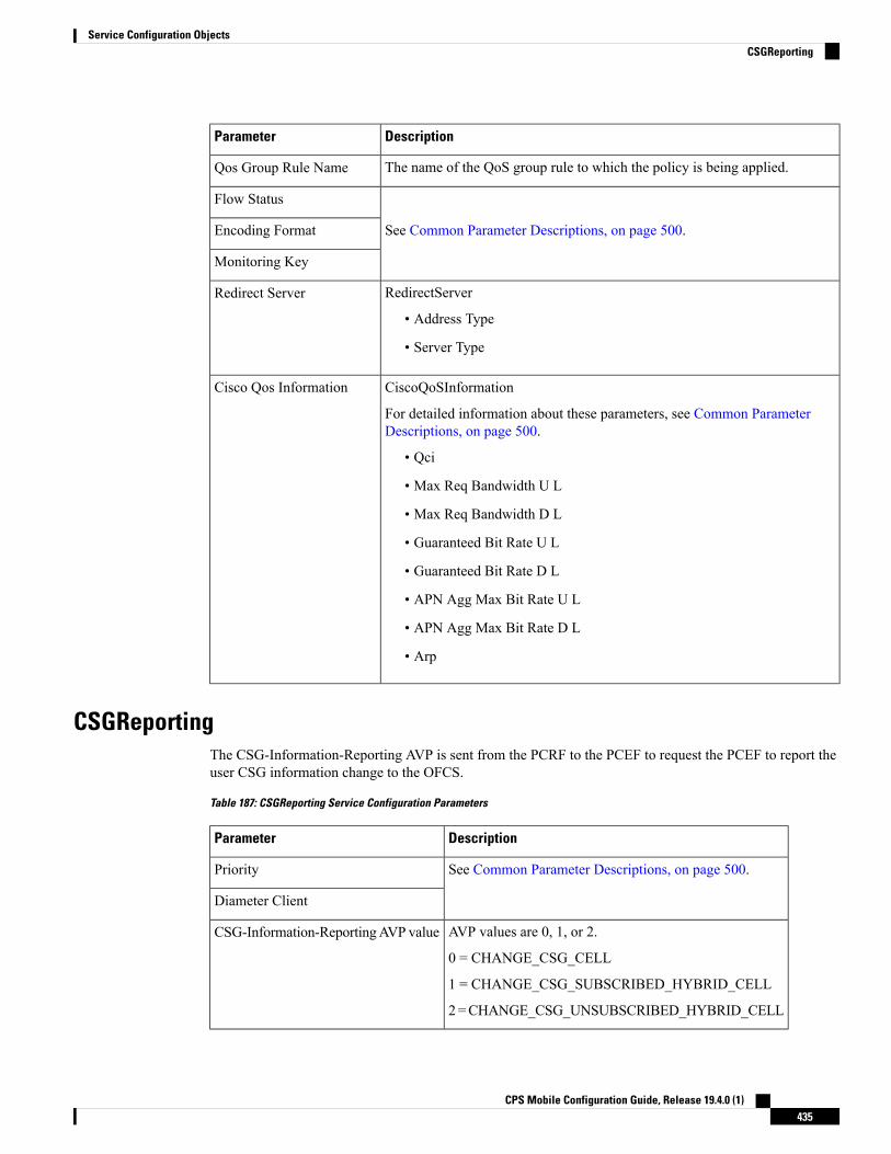
DescriptionParameter
The name of the QoS group rule to which the policy is being applied.Qos Group Rule Name
See Common Parameter Descriptions, on page 500.
Flow Status
Encoding Format
Monitoring Key
RedirectServer
• Address Type
• Server Type
Redirect Server
CiscoQoSInformation
For detailed information about these parameters, see Common ParameterDescriptions, on page 500.
• Qci
• Max Req Bandwidth U L
• Max Req Bandwidth D L
• Guaranteed Bit Rate U L
• Guaranteed Bit Rate D L
• APN Agg Max Bit Rate U L
• APN Agg Max Bit Rate D L
• Arp
Cisco Qos Information
CSGReportingThe CSG-Information-Reporting AVP is sent from the PCRF to the PCEF to request the PCEF to report theuser CSG information change to the OFCS.
Table 187: CSGReporting Service Configuration Parameters
DescriptionParameter
See Common Parameter Descriptions, on page 500.Priority
Diameter Client
AVP values are 0, 1, or 2.
0 = CHANGE_CSG_CELL
1 = CHANGE_CSG_SUBSCRIBED_HYBRID_CELL
2=CHANGE_CSG_UNSUBSCRIBED_HYBRID_CELL
CSG-Information-ReportingAVP value
CPS Mobile Configuration Guide, Release 19.4.0 (1)435
Service Configuration ObjectsCSGReporting

DefaultBearerQoSThe DefaultBearerQoS service configuration object configures the QoS attributes for the default bearer.
Table 188: DefaultBearerQoS Service Configuration Parameters
DescriptionParameter
See Common Parameter Descriptions, on page 500
Priority
Diameter Client
Qci
Max Req Bandwidth U L
Max Req Bandwidth D L
Guaranteed Bit Rate U L
Guarnateed Bit Rate D L
Apn Agg Max Bit Rate U L
Apn Agg Max Bit Rate D L
Arp
Stores values corresponding to the Conditional-APN-Agg-Max-Bitrategrouped AVP.
ConditionalApnAggregateMaxBitrate
DefaultBearerQoSActionsThe DefaultBearerQoSActions service configuration object sets the values for the various DBQ Attributesbased on Policy or the configured DBQ object. There are three types of DefaultBearerQoSActions:
• Mirror: The value requested is granted.
• Enforce: (Default) The default bearer qos value is granted.
• Bound: A min between the two is granted.
CPS Mobile Configuration Guide, Release 19.4.0 (1)436
Service Configuration ObjectsDefaultBearerQoS

Table 189: DefaultBearerQoSActions Service Configuration Parameters
DescriptionParameter
See Common Parameter Descriptions, on page 500
Priority
Diameter Client
Qci
Max Req Bandwidth U L
Max Req Bandwidth D L
Guaranteed Bit Rate U L
Guarnateed Bit Rate D L
Apn Agg Max Bit Rate U L
Apn Agg Max Bit Rate D L
Arp
DefaultBearerQciArpOverrideThe DefaultBearerQciArpOverride service configuration object is used to override the calculated defaultbearer Qci and ARP attributes.
Table 190: DefaultBearerQciArpOverride Service Configuration Parameters
DescriptionParameter
See Common Parameter Descriptions, on page 500Priority
Diameter Client
Qci
Allocation Retention Priority
Priority Level AVP value.Priority Level
Pre-emption Capability AVP value.Preemption Capability
Pre-emption Vulnerability AVP value.Preemption Vulnerability
DelayBearerCreationThe DelayBearerCreation service configuration object is used to decide whether to delay the bearer creationor not. Delay value can be configured in the service (or) can be pulled from CRD. Using this configurationCPS holds the CCA-I and Gx-RAR messages for the configured delay time. This service configuration getsadded to policy state based on specific use case initiators.
CPS Mobile Configuration Guide, Release 19.4.0 (1)437
Service Configuration ObjectsDefaultBearerQciArpOverride

Table 191: DelayBearerCreation Service Configuration Parameters
DescriptionParameter
See Common Parameter Descriptions, on page 500Priority
Diameter Client
Based on this value CPS initiates delay timer for holding the CCA-Imessage.
Default value is zero which indicates that there is no delay.
Default Bearer Delay InMilliseconds
Based on this value CPS initiates delay timer for holding the Gx-RARmessage.
Default value is zero which indicates that there is no delay.
Dedicated Bearer Delay InMilliseconds
DetectedAppDefaultBearerQosThe DetectedAppDefaultBearerQos service configuration object is used to apply the Default Bearer QoSbased on the TDF-Application-Identifier received in Sd CCR-U and Gx CCR-U. This can be used for bothGx and Sd detected applications.
Table 192: DetectedAppDefaultBearerQos Service Configuration Parameters
DescriptionParameter
See Common Parameter Descriptions, on page 500.Priority
Diameter Client
Name of the CRD table used in the service configuration.Search Table Group
By default, the value is set to false that indicates CPS considers QoS derivedfrom Rx and default bearer QoS service for missing QoS attributes.
If set to true, CPS considers QoS derived from previously applied TDF IDQoSfor missing QoS attributes.
Apply Prev Applied T D FId Qos
Input parameters in terms of CRD column name and mapped AVP Code.Supported AVP code is TDF-Application-Identifier.
Input ColumnBinding (List)
Output parameters in terms of CRD column name and mapped AVP Code.Supported AVP codes are: QoS-Class-Identifier, Priority-Level, PreemptionCapability, Preemption Vulnerability, APN-Aggregate-Max-Bitrate-UL,APN-Aggregate-Max-Bitrate-DL, Max-Requested-Bandwidth-UL,Max-Requested-Bandwidth-DL, Guaranteed-Bitrate-UL, andGuaranteed-Bitrate-DL.
Output Column Binding(List)
CPS Mobile Configuration Guide, Release 19.4.0 (1)438
Service Configuration ObjectsDetectedAppDefaultBearerQos

DetectedAppPriorityDeafaultBearerQoSThe DetectedAppPriorityDeafaultBearerQoS to populate 'Priority' and 'CC-Time' by takingTDF-Application-Identifier as input. This can be used for both Gx and Sd detected applications.
Table 193: DetectedAppPriorityDeafaultBearerQoS Service Configuration Parameters
DescriptionParameter
See Common Parameter Descriptions, on page 500.Priority
Diameter Client
When default value for the TDF Id is not configured, CPS considers this bydefault value is -1, which takes high precedence and if multiple TDF-APP-Id`sdoes not have priority then both will have same priority then CPS may notprocess in order so behavior would vary every time CPS evaluate this table.
Default T D F App IdPriority
Default CC-Time when not received in Sd_CCR-U.Default C C Time InSeconds
Name of the CRD table used in this service configuration.Stg Name
Defines the mapping between the AVP Names and the key columns definedin the selected STG. These AVPs are used as inputs while evaluating the CRDtable in STG.
• Avp Name - The name of the AVP that is used as input for CRD tableevaluation. Supported value is TDF-Application-Identifier.
• Column - The reference to the CRD column for the input AVP.
List Of Input Column AvpPairs (List)
Priority Configured for TDF-Application-Identifier.TDF App Id priorityColumn
CC-Time Configured for the TDF-Application-Identifier.C C Time Output Column
• TDF Application Identifier must be unique.
• Priority must be mandatory and it should be unique.
Note
DynamicTrafficSteeringThe DynamicTrafficSteering service configuration object is not used.
EMPSThe EMPS (EnhancedMultimedia Priority System) service configuration object defines theMPS EPS PriorityMPS Priority Level and IMS Signaling Priority level. This is required for Always on MPS.
CPS Mobile Configuration Guide, Release 19.4.0 (1)439
Service Configuration ObjectsDetectedAppPriorityDeafaultBearerQoS

Table 194: EMPS Service Configuration Parameters
DescriptionParameter
See Common Parameter Descriptions, on page 500.Priority
Diameter Client
When selected, invokes the Priority EPS Service.
• 1: Enable
• 0: Disable
Mps Eps PriorityEnabled
Indicates the priority level (Integer range 1-15).Mps Priority Level
IMS signaling priority level (Integer range 1-15).Ims Signaling Priority
EventTriggerThe EventTrigger service configuration object specifies the event to be sent.
Table 195: EventTrigger Service Configuration Parameters
DescriptionParameter
See Common Parameter Descriptions, on page 500.
Priority
Diameter Client
Event Trigger
EventTrigger 48The PresenceReportingAreaConfiguration service configuration object indicates the maximum number ofPRA identifiers supported.
Table 196: EventTrigger 48 Service Configuration Parameters
DescriptionParameter
See Common Parameter Descriptions, on page 500.Priority
Diameter Client
Indicates value of the event trigger.Event Trigger
CPS Mobile Configuration Guide, Release 19.4.0 (1)440
Service Configuration ObjectsEventTrigger

GxDynamicRuleReferenceThe GxDynamicRuleReference configuration object is used only when the ADC (Application Detection &Control) Feature is enabled at PCEF and new dynamic rules need to be installed over the Gx interface basedon Application Detection on the Gx interface by the PCEF.
Table 197: GxDynamicRuleReference Service Configuration Parameters
DescriptionParameter
See Common Parameter Descriptions, on page 500.Priority
Diameter Client
The name of the Search Table group table that is being referenced.STG Table
See Common Parameter Descriptions, on page 500.List Of Input Column Avp Paris (List)
List Of Output ColumnAvp Paris (List)
Can be set to true or false.
Default: false
Retry Pcc Rules On Failure
IntermediateRulesParamOnFailureThe IntermediateRulesParamOnFailure service configuration is used to send Flow-Status, Rating-Group,Service-Id when Retry Profile is configured with interval.
The following table describes the service configuration parameters:
Table 198: IntermediateRulesParamOnFailure Service Configuration Parameters
DescriptionParameter
See Common Parameter Descriptions, on page 500.Priority
Diameter Client
References the Search table group containing the CRD table. This is amandatory parameter.
Stg Name
Defines the mapping between the AVP Names and the key columns definedin the selected STG. These AVPs are used as inputs while evaluating theCRD table in STG.
• Avp Name – The name of the AVP that is used as input for CRD tableevaluation. Supported values are Charging-Rule-Name,Rule-Failure-Code, Cisco-CC-Failure-Type, TDF-Application-Identifier,Application-Service-Provider-Identity, DPCC-Name, DPCC-Value,AF-Application-Identifier, and Sponsor-Identity.
• Column – The reference to the CRD column for the input AVP.
List of Input Column AvpPairs (List)
CPS Mobile Configuration Guide, Release 19.4.0 (1)441
Service Configuration ObjectsGxDynamicRuleReference

DescriptionParameter
List of Output AVPs for the CRD.
• Avp Name – The name of the AVP that is used as input for CRD tableevaluation. Supported values are Service-Identifier, Rating-Group,Flow-Status, Online, Offline, Metering-Method, Reporting-Level,Precedence, Redirect-Support, Redirect-Address-Type andRedirect-Server-Address.
• Column – The reference to the CRD column for the output AVP.
List of Output Column AvpPairs (List)
MaxQosThe MaxQoS service configuration object authorizes the requested QoS against the maximum-allowed QoS.
Table 199: MaxQoS Service Configuration Parameters
DescriptionParameter
See Common Parameter Descriptions, on page 500.
Priority
Diameter Client
Qci
Max Req Bandwidth U L
Max Req Bandwidth D L
Guaranteed Bit Rate U L
Guaranteed Bit Rate D L
Apn Agg Max Bit Rate U L
Apn Agg Max Bit Rate D L
Arp
ModifyChargingRulesTable 200: ModifyChargingRules Service Configuration Parameters
DescriptionParameter
See Common Parameter Descriptions, on page 500.Priority
Diameter Client
References the Search table group containing the CRD tables thatdefine the Qos Action.
Stg Name
CPS Mobile Configuration Guide, Release 19.4.0 (1)442
Service Configuration ObjectsMaxQos

DescriptionParameter
Defines the mapping between the 'AVP Names' and the key'Columns' defined in the selected STG. These AVPs will be theinputs while evaluating the CRD table in STG.
ColumnAndAvpPair:
• Avp Name – The name of the diameter AVP (received inMediaComponent Description AVP of the AAR message) that willbe used as input for CRD table evaluation. Supported list ofAVPs are: QoS-Class-Identifier, TDF-Application-Identifier,Sponsor-Identity, Application-Service-Provider-Identity,Priority-Level, Pre-emption-Capability,Pre-emption-Vulnerability.
DPCC_NAME - Used to derive the Dynamic PCC rule fromCRD tables.
DPCC_VALUE - Used to derive the Dynamic PCC rule fromCRD tables.
• Column – References the key column defined in the selectedSTG.
List Of Input Column Avp Pairs (List)
CPS Mobile Configuration Guide, Release 19.4.0 (1)443
Service Configuration ObjectsModifyChargingRules

DescriptionParameter
Defines the mapping between the 'AVP Names' and the outputcolumns defined in the selected STG. Thesemappings indicate howthe output column values are mapped to AVPs after the CRD isevaluated.
ColumnAndAvpPair:
• Avp Name – The name of the diameter AVP (attribute fromQos-Information) to which the value of the output columnshould be mapped while setting the Qos-Information for thededicated bearer on Gx. Supported values are:
• Rating-Group
• Reporting-Level
• Service-Identifier
• Online
• Offline
• Flow-Status
• Metering-Method
• Precedence
• Allow-Usage-Monitoring (Map to corresponding crdcolumn which is of type boolean).
CPS sends Monitoring key for pre-configured rulesonly when ‘CC-Total-Octets’ is sent in Rx-AARrequest (granted service units) andAllow-Usage-Monitoring is configured as true.
Note
The values for 'AVP name' must be exactly the same as thoseused while defining the input columns.
• Column – References the output column defined in the selectedSTG.
List of Output Column Avp Pairs (List)
OverrideQoSOverride QoS service configuration is used to allow configuring override for Gx default bearer QoS APNAMBR UL/DL values.
CPS first evaluates the derived QoS values for default bearer. CPS then evaluates the table provided in OverrideQoS service configuration by using the key values and determine the result APN AMBR UL/DL values. Ifthe "Condition to Override" is "LT", then CPS limits the derived QoS values with these override values. Ifthe "Condition to Override" is "GT", then CPS selects the maximum UL/DL among the derived and overridevalues.
CPS Mobile Configuration Guide, Release 19.4.0 (1)444
Service Configuration ObjectsOverrideQoS

Table 201: OverrideQoS Service Configuration Parameters
DescriptionParameter
See Common Parameter Descriptions, on page 500.Priority
Diameter Client
This is the reference to the STG that contains the QoS reference and the QoSparameter values (QCI, APN-MBR-UL, and so on).
Stg Reference
Defines the list to specify the mapping for input (key) columns for determiningtheir values for querying the STG.
• ColumnAndAvpPair
• Avp Name: Specify the AVP name whose value is used to map to thecorresponding key Column for querying the STG.
• Column: The key column in the STG that corresponds to the specifiedAVP.
List Of Input Column AvpPairs (List)
Reference to the STG output column that gives the"APN-Aggregate-Max-Bitrate-UL" value for limiting QoS. This value and thecorresponding value derived after QoS actions are compared to determine thefinal value for APN-Aggregate-Max-Bitrate-UL.
Apn Agg Max Bit Rate UL
Reference to the STG output column that gives the"APN-Aggregate-Max-Bitrate-DL" value for limiting QoS. This value and thecorresponding value derived after QoS actions are compared to determine thefinal value for APN-Aggregate-Max-Bitrate-DL.
Apn Agg Max Bit Rate DL
The condition to compare the values. Only two values are supported "LT" and"GT".
If LT is selected, CPS picks the lowest QoS parameter value from the two QoSreferences.
If GT is selected, CPS picks the highest QoS parameter value from the two QoSreferences.
Possible Values:
• LT: Less than (Default)
• GT: Greater than
Condition to Override
PreConfiguredRuleThe PreConfiguredRule service configuration object configures a dynamic rule; these values are then used inthe charging rule definition.
CPS Mobile Configuration Guide, Release 19.4.0 (1)445
Service Configuration ObjectsPreConfiguredRule
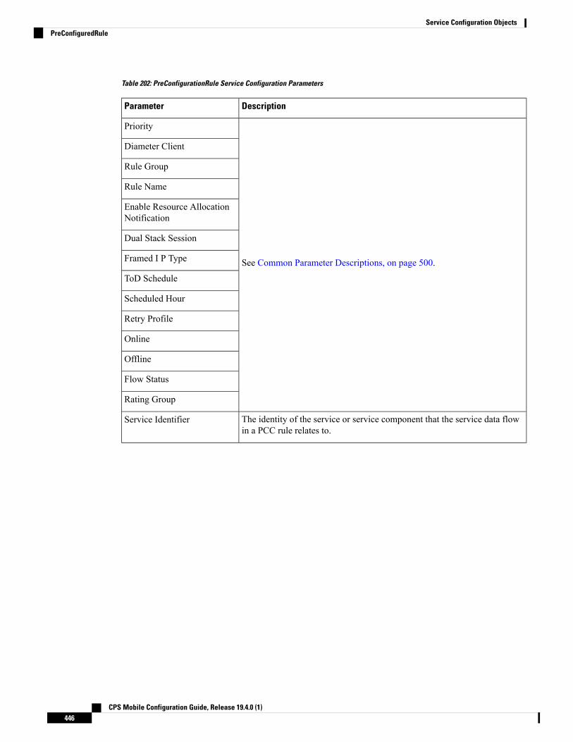
Table 202: PreConfigurationRule Service Configuration Parameters
DescriptionParameter
See Common Parameter Descriptions, on page 500.
Priority
Diameter Client
Rule Group
Rule Name
Enable Resource AllocationNotification
Dual Stack Session
Framed I P Type
ToD Schedule
Scheduled Hour
Retry Profile
Online
Offline
Flow Status
Rating Group
The identity of the service or service component that the service data flowin a PCC rule relates to.
Service Identifier
CPS Mobile Configuration Guide, Release 19.4.0 (1)446
Service Configuration ObjectsPreConfiguredRule

DescriptionParameter
The Reporting-Level AVP is of type Enumerated and it defines on what levelthe PCEF reports the usage for the related PCC rule. There are three typesof reporting levels:
• SERVICE_IDENTIFIER_LEVEL (0): Usagewill be reported on serviceid and rating group combination level and is applicable when theService-Identifier and Rating-Group have been provisioned within theCharging-Rule-Definition AVP, and Rating-Group AVP have beenprovisioned within the Charging-Rule-Definition AVP. Applicable foroffline charging.
• RATING_GROUP_LEVEL (1): Usage will be reported on rating grouplevel and is applicable when the Rating-Group has been provisionedwithin the Charging-Rule-Definition AVP, and Rating-Group AVP havebeen provisioned within the Charging-Rule-Definition AVP. Applicablefor offline charging.
• SPONSORED_CONNECTIVITY_LEVEL (2):Usage will be reportedon sponsor identity and rating group combination level and is applicablewhen the Sponsor-IdentityAVP Application-Service-Provider-IdentityAVP and Rating-Group AVP have been provisioned within theCharging-Rule-Definition AVP. Applicable for offline charging.
Reporting Level
Determines the order in which the service data flow templates are applied atservice data flow detection at the PCEF. A PCC rule with the PrecedenceAVP having a lower value will be applied before a PCC rule with thePrecedence AVP having a higher value.
Precedence
The Metering-Method AVP (AVP code 1007) is of type Enumerated and itdefines what parameters will be metered for offline charging. The PCEFmayuse the AVP for online charging in case of decentralized unit determination.There are three types of metering method:
• DURATION (0): The duration of the service data flow will be metered.
• VOLUME (1): The volume of the service data flow traffic will bemetered.
• DURATION_VOLUME (2): The duration and the volume of the servicedata flow traffic will be metered.
Metering Method
See Common Parameter Descriptions, on page 500.Monitoring Key
FlowInformation
• Flow Description
• Tos Traffic Class
• Flow Direction
Flow Information (List)
CPS Mobile Configuration Guide, Release 19.4.0 (1)447
Service Configuration ObjectsPreConfiguredRule

DescriptionParameter
QoSInformation
For detailed information about these parameters, see Common ParameterDescriptions, on page 500.
• Qci
• Max Req Bandwidth U L
• Max Req Bandwidth D L
• Guaranteed Bit Rate U L
• Guaranteed Bit Rate D L
• Apn Agg Max Bit Rate U L
• Apn Agg Max Bit Rate D L
• Arp
QoS Information
RedirectInformation
For detailed information about these parameters, see Common ParameterDescriptions, on page 500.
• Redirect Support
• Redirect Address Type
• Redirect Server Address
Redirect Information
When set to true, CPS mirrors the QCI and ARP from the command level tothe rule level, and enforces the rule levelMBR values from the Policy Builderconfiguration for the rule level.
Default: false.
Mirror Default BearerQCI/ARP
See Common Parameter Descriptions, on page 500.
Provision Default Bearer QoS
Tdf Application Identifier
Mute Notification
Controls whether or not the PCC rule reported status AVPs are created.
Default: true
Use in Rule Status Condition
Controls whether or not the PCC rule installed AVPs are created.
Default: false
Use in Rule Install Condition
CPS Mobile Configuration Guide, Release 19.4.0 (1)448
Service Configuration ObjectsPreConfiguredRule

PreDefinedRuleThe PreDefinedRule service configuration object creates static rules that will be mapped to the charging rulesthat will be installed.
Table 203: PreDefinedRule Service Configuration Parameters
DescriptionParameter
See Common Parameter Descriptions, on page 500.
Priority
Diameter Client
Rule Group
Rule Name
Enable Resource AllocationNotification
Dual Stack Session
Framed I P Type
ToD Schedule
Scheduled Hour
Retry Profile
PreDefinedRuleBaseThe PreDefinedRuleBase service configuration object creates static rules that will be mapped to the chargingrule base name.
CPS Mobile Configuration Guide, Release 19.4.0 (1)449
Service Configuration ObjectsPreDefinedRule

Table 204: PreDefinedRuleBase Service Configuration Parameters
DescriptionParameter
See Common Parameter Descriptions, on page 500.
Priority
Diameter Client
Rule Group
Rule Name
Enable Resource AllocationNotification
Dual Stack Session
Framed I P Type
ToD Schedule
Scheduled Hour
Retry Profile
PresenceReportingAreaConfigurationThe PresenceReportingAreaConfiguration service configuration configures the PRA identifiers supported.
Table 205: PresenceReportingAreaConfiguration Service Configuration Parameters
DescriptionParameter
See Common Parameter Descriptions, on page 500.Priority
Diameter Client
When this flag is "false", the PCRF forwards PRA statuswhen available to TDF, if TDF has subscribed with EventTriggerCHANGE_OF_UE_PRESENCE_IN_PRESENCE_REPORTING_AREA_REPORT(48).
When this flag is "true" and the PRA status is available it isforwarded to TDF without waiting for the Event Trigger 48subscription from TDF.
Sd Auto Subscribe
This list contains the PRA identifier names which PCRFneeds, to subscribe to PCEF with Event TriggerCHANGE_OF_UE_PRESENCE_IN_PRESENCE_REPORTING_AREA_REPORT.
Presence Reporting Area Identifier List
CPS Mobile Configuration Guide, Release 19.4.0 (1)450
Service Configuration ObjectsPresenceReportingAreaConfiguration

AddEvent Trigger CHANGE_OF_UE_PRESENCE_IN_PRESENCE_REPORTING_AREA_REPORT (48)in the service configurations for the PRA identifiers to be subscribed towards PCEF.
Note
ReleaseBearerDelayMessageThe ReleaseBearerDelayMessage service configuration object is used to release CCA-I /Gx-RAR messageswhich is held based on delay bearer creation configuration. For more information on Delay Bearer Creationservice configuration object, refer to DelayBearerCreation, on page 437.
Table 206: ReleaseBearerDelayMessage Service Configuration Parameters
DescriptionParameter
See Common Parameter Descriptions, on page 500Priority
Diameter Client
ReprovisionObjectsThe ReprovisionObjects service configuration object forces the Policy Charging Control (PCC) rules to bereprovisioned when the flag is set to true.
Table 207: ReprovisionObjects Service Configuration Parameters
DescriptionParameter
See Common Parameter Descriptions, on page 500.Priority
Diameter Client
Can be set to true or false. When set to true, the PCC rules will bereprovisioned.
Default: false
PCC Rules
Can be set to true or false. When set to true, the Default Bearer QoS will bereprovisioned.
Default: false
Default Bearer QoS
Can be set to true or false. When set to true, the AVP Override Control isrepovisioned during handoff.
Default: false
Override Control
RevalidationTimeThe RevalidationTime service configuration object populates the revalidation time AVP at the message level;the PCEF will come back to the PCRF when that timestamp is hit.
CPS Mobile Configuration Guide, Release 19.4.0 (1)451
Service Configuration ObjectsReleaseBearerDelayMessage

Table 208: RevalidationTime Service Configuration Parameters
DescriptionParameter
See Common Parameter Descriptions, on page 500.Priority
Diameter Client
This flag can be set to true or false.
true – The next revalidation time is set using the absolute values specifiedfor the following three revalidation attributes (Hour Minute, and Sec).
false – The next revalidation time is derived by adding the values specifiedfor the following three revalidation attributes to the system time.
Absolute Time Flag
The hour the revalidation will occur.
Specify this value using 24-hour format.
Revalidation Time in Hour
The minutes setting in the revalidation timestamp.Revalidation Time in Minute
The seconds setting in the revalidation timestamp.Revalidation Time in Sec
SupressRxMessageThe SupressRxMessage service configuration object is used to suppress the Rx ASR message. CPS evaluatesthe STG configured in this service and derives the information whether to suppress Rx ASR or not.
Table 209: SupressRxMessage Service Configuration Parameters
DescriptionParameter
See Common Parameter Descriptions, on page 500Priority
Diameter Client
Search Table Group table that is being referenced. The STG (and thecontained CRDs) can also contain key columns that do not directly referto Diameter AVPs in the trigger message. For example, Outputs of othertables. These columns must be bound correctly.
Search Table Group
ColumnAndAvpPair
• Avp Name: The name of the Diameter AVP that is used as input forCRD table evaluation.
• Column: The key column in the STG that corresponds to the specifiedAVP.
Input Column Binding (List)
References to the output column defined in the CRD.Is Message Suppressed OutputColumn
CPS Mobile Configuration Guide, Release 19.4.0 (1)452
Service Configuration ObjectsSupressRxMessage

TableDrivenChargingRuleThe TableDrivenChargingRule service configuration object represents a charging rule in stored CRD format;there can be multiple charging rules.
Table 210: TableDrivenChargingRule Service Configuration Parameters
DescriptionParameter
See Common Parameter Descriptions, on page 500.Priority
Diameter Client
No longer used.Logical Grouping
The name of the table from which to perform a lookup.Search Table
A constant value that CPS uses to search within the Search Table Groupindicated by “Search Table” element.
Search Group
Must be bound to the key column of the STG. The data contained in theSTG column is of type Text.
Search Column
By default, the parameter is set to true.
When set to true, the best match result records with exact match and if theexact match records are not found then it return records with star and patternmatch.
When set to false, then the result includes exact match as well as star andpattern match.
Best Match Excludes StarMatch
A key column that must be bound to the Rule Name column within theSTG. The data in the STG column is of type Text.
Rule Name Source
Must be bound to the Flow Status column in the Search Table Groups(STG). The data contained in the STG column is of type Text.
Flow Status Source
Must be bound to the Monitoring Key column in the STG. The datacontained in the STG column is of type Text.
Monitoring Key Source
The name of the Redirect Address Table. This table contains redirectedattributes, such as these (described in the following four rows):
• Redirect Enabled Source
• Redirect Address Type Source
• Redirect Address Source
• Redirect Support Source
Redirect Address Table
Must be bound to the Redirect Enabled column in the STG. The datacontained in the STG column is of type True/False.
Redirect Enabled Source
CPS Mobile Configuration Guide, Release 19.4.0 (1)453
Service Configuration ObjectsTableDrivenChargingRule

DescriptionParameter
Must be bound to the Redirect Address Type column in the STG. The datacontained in the STG column is of type Text.
Redirect Address Type Source
Must be bound to the Redirect Address column in the STG. The datacontained in the STG column is of type Text.
Redirect Address Source
Must be bound to the Redirect Support column in the STG.Redirect Support Source
Must be bound to the Online column in the STG. The data contained in theSTG column is of Type Number. The possible values are mentioned in3GPP specification 29.212.
Online Source
Must be bound to the Offline column in the STG. The data contained inthe STG column is of Type Number. The possible values are mentioned in3GPP specification 29.212.
Offline Source
Must be bound to the Rating Group column in the STG. The data containedin the STG column is of Type Number. The possible values are mentionedin 3GPP specification 29.212.
Rating Group Source
Must be bound to the Service ID column in the STG. The data containedin the STG column is of Type Number. The possible values are mentionedin 3GPP specification 29.212.
Service Id Source
Must be bound to the Reporting Level column in the STG. The datacontained in the STG column is of Type Number. The possible values arementioned in 3GPP specification 29.212.
Reporting Level Source
Must be bound to the Precedence column in the STG. The data containedin the STG column is of Type Number. The possible values are mentionedin 3GPP specification 29.212.
Precedence Source
Must be bound to the Metering Method column in the STG. The datacontained in the STG column is of Type Number. The possible values arementioned in 3GPP specification 29.212.
Metering Method Source
Must be bound to the Flow Information column in the STG. The datacontained in the STG column is of type Text.
A particular format should be used when adding Flow InformationSource parameter so that CPS can perform proper Flow Informationgrouped AVP mapping. A wrongly formatted Flow InformationSource can result in missing AVPs under Gx Flow InformationAVP. Here is the format:<Flow-Description>;<Flow-Direction>;<Decimalvalue of first octet ofToS-Class-AVP>;<Decimal value of second octetof ToS-Class-AVP>
Note
Flow Information Source
CPS Mobile Configuration Guide, Release 19.4.0 (1)454
Service Configuration ObjectsTableDrivenChargingRule

DescriptionParameter
Must be bound to the Override Server Address column in the STG. Thedata contained in the STG column is of type True/False.
If set to true, the address is taken from the service option. If set to false,the redirect server address will not be overridden.
Use Override Server Address
Must be bound to the corresponding column within the STG.Override Server Address
Must be bound to the QCI column in the STG. The data contained in theSTG column is of Type Number. For more information, see CommonParameter Descriptions, on page 500.
Qci Source
Must be bound to the Max Req Bandwidth UL column in the STG. Thedata contained in the STG column is of Type Number. For more informationabout Max Req Bandwidth U L, see Common Parameter Descriptions, onpage 500.
Max Req Bandwidth U LSource
Must be bound to the Max Req Bandwidth DL column in the STG. Thedata contained in the STG column is of Type Number. For more informationabout Max Req Bandwidth D L Source, see Common ParameterDescriptions, on page 500.
Max Req Bandwidth D LSource
Must be bound to the Guaranteed Bit Rate UL column in the STG. Thedata contained in the STG column is of Type Number. For more informationabout Guaranteed Bit Rate U L see Common Parameter Descriptions, onpage 500.
Guaranteed Bit Rate U L Source
Must be bound to the Guaranteed Bit Rate DL column in the STG. Thedata contained in the STG column is of Type Number. For more informationabout Guaranteed Bit Rate D L, see Common Parameter Descriptions, onpage 500.
Guaranteed Bit Rate D L Source
Must be bound to the ARP Priority Level column in the STG. The datacontained in the STG column is of Type Number. For more informationabout Priority Levels, see Common Parameter Descriptions, on page 500.
ARP Priority Level Source
Must be bound to the ARP Preemption Capability column in the STG. Thedata contained in the STG column is of Type Number. For more informationabout Preemption Capability, see Common Parameter Descriptions, onpage 500.
ARP Preemption CapabilitySource
Must be bound to the ARP Preemption Vulnerability column in the STG.The data contained in the STG column is of Type Number. For moreinformation about Preemption Vulnerability, see Common ParameterDescriptions, on page 500.
ARP Preemption VulnerabilitySource
See Common Parameter Descriptions, on page 500.Apn Agg Max Bit Rate U L
Apn Agg Max Bit Rate D L
Must be bound to the Rule Retry Profile column in the STG. The datacontained in the STG column is of type Text.
Rule Retry Profile Name
CPS Mobile Configuration Guide, Release 19.4.0 (1)455
Service Configuration ObjectsTableDrivenChargingRule

DescriptionParameter
When set to true, CPS mirrors the QCI and ARP from the command levelto the rule level, and enforces the rule level MBR values from the PolicyBuilder configuration for the rule level.
Default: false.
Mirror Default Bearer QCI/ARP
See Common Parameter Descriptions, on page 500.Provision Default Bearer QoS
References the application detection filter (for example, its value mayrepresent an application such as a list of URLs, etc.) to which the PCC rulefor application detection and control in the PCEF applies. Tdf ApplicationIdentifier Source must be bound to the appropriate column in the STG, andType should be Text. For more information about Tdf Application Identifier,see Common Parameter Descriptions, on page 500.
Tdf Application IdentifierSource
Must be bound to the Mute Notification column in the STG. The datacontained in the STG column is of Type Number or Decimal. For moreinformation aboutMute Notification, see Common Parameter Descriptions,on page 500.
Mute Notification Source
Must be bound to the Enable Resource Allocation Notification column inthe STG. The data contained in the STG column is of Type Number. Thepossible values are mentioned in 3GPP specification 29.212.
Enable Resource AllocationNotification Source
InputColumnObject:
• Crd Column – Is bound to the appropriate key column in the STG forthose AVPs that are inputs to this table.
• Referenced Output Column – Reserved for future use.
• ColumnValue – The value of the AVP that is bound to the Crd Columnand has a single value.
• Referenced MultiValue AVP Name – The name of the attribute thatis bound to the Crd Column and has multiple values.
Input List (List)
Controls whether or not the PCC rule reported status AVPs are created. Bydefault, this parameter is set to true.
Use in Rule Status Condition
Controls whether or not the PCC rule installed AVPs are created. By default,this parameter is set to false.
Use in Rule Install Condition
TableDrivenChargingRuleRefreshThe TableDrivenChargingRuleRefresh service configuration object forces a rule revalidation based on therule reporting status.
CPS Mobile Configuration Guide, Release 19.4.0 (1)456
Service Configuration ObjectsTableDrivenChargingRuleRefresh

Table 211: TableDrivenChargingRuleRefresh Service Configuration Parameters
DescriptionParameter
See Common Parameter Descriptions, on page 500.Priority
Diameter Client
The name of the table from which to perform a lookup.Search Table
The input column for the Search Table Group (STG), which contains therule name.
Input Rule Name Column
The input column for the STG, which contains the rule status against whichnew rules are to be added.
Input Rule Status Column
The output column for the STG, which contains the rule group used as agroup to search the TableDrivenChargingRule.
Output Rule Group Column
If there are multiple TableDrivenChargingRules mapped with multipleSearch Tables, and if we want to use only one table to be looked at for newrules installation on rule failure, we can give the table as Output SearchTable so that only one TableDrivenChargingRule object, which has the‘Search Table’ matching the ‘Output Search Table’ inTableDrivenChargingRuleRefresh, is evaluated for refresh rules.
Output Search Table
TableDrivenCiscoQosGroupRulesThe TableDrivenChargingRuleRefresh service configuration option forces a rule revalidation based on therule reporting status.
Table 212: TableDrivenCiscoQosGroupRules Service Configuration Parameters
DiscriptionParameter
See Common Parameter Descriptions, on page 500.Priority
Diameter Client
No longer used.Logical Grouping
The name of the table from which to perform a lookup.Search Table
A constant value that CPS uses to search within the STG indicatedby “Search Table” element.
Search Group
Must be bound to the key column of the STG. The data containedin the STG column is of type Text.
Search Column
CPS Mobile Configuration Guide, Release 19.4.0 (1)457
Service Configuration ObjectsTableDrivenCiscoQosGroupRules

DiscriptionParameter
By default, the parameter is set to true.
When set to true, the best match result records with exact matchand if the exact match records are not found then it return recordswith star and pattern match.
When set to false, then the result includes exact match as well asstar and pattern match.
Best Match Excludes Star Match
A key column that must be bound to the Rule Name column withinthe STG. The data contained in the STG column is of type Text.
Rule Name Source
Must be bound to the Monitoring Key column within the STG. Thedata contained in the STG column is of type Text.
Monitoring Key Source
Must be bound to the Encoding format columnwithin the STG. Thedata contained in the STG column is of type True/False.
Encoding Format Source
The name of the Redirect Address Table. This table containsredirected attributes, such as these (described below):
• Redirect Enabled Source
• Redirect Address Type Source
• Redirect Address Source
Redirect Address Table
Must be bound to the Redirect Enabled column within the STG.The data contained in the STG column is of type True/False.
Redirect Enabled Source
Must be bound to the Redirect Address Type column within theSTG. The data contained in the STG column is of type Text.
Redirect Address Type Source
Must be bound to the Redirect Address column within the STG.The data contained in the STG column is of type Text.
Redirect Address Source
Must be bound to the Override Server Address column within theSTG. The data contained in the STG column is of type True/False.
If set to true, the address is taken from the service option. If set tofalse, the redirect server address will not be overridden.
Use Override Server Address
Must be bound to the corresponding column within the STG.Override Server Address
TableDrivenPredefinedChargingRuleThe TableDrivenPredefinedChargingRule service configuration object represents a charging rule in storedCRD format; there can be multiple charging rules.
CPS Mobile Configuration Guide, Release 19.4.0 (1)458
Service Configuration ObjectsTableDrivenPredefinedChargingRule

Table 213: TableDrivenPredefinedChargingRule Service Configuration Parameters
DescriptionParameter
See Common Parameter Descriptions, on page 500.Priority
Diameter Client
No longer used.Logical Grouping
The name of the table from which to perform a lookup.Search Table
A constant value that CPS uses to search within the Search Table Groupindicated by “Search Table” element.
Search Group
Must be bound to the key column of the STG. The data contained in theSTG column is of type Text.
Search Column
By default, the parameter is set to true.
When set to true, the best match result records with exact match and if theexact match records are not found then it return records with star and patternmatch.
When set to false, then the result includes exact match as well as star andpattern match.
Best Match Excludes StarMatch
A key column that must be bound to the Rule Name column within theSTG. The data in the STG column is of type Text.
Rule Name Source
InputColumnObject:
• Crd Column – Is bound to the appropriate key column in the STG forthose AVPs that are inputs to this table.
• Referenced Output Column – Reserved for future use.
• ColumnValue – The value of the AVP that is bound to the Crd Columnand has a single value.
• Referenced MultiValue AVP Name – The name of the attribute thatis bound to the Crd Column and has multiple values.
Input List (list)
Controls whether or not the PCC rule reported status AVPs are created. Bydefault, this parameter is set to false.
Use In Rule Status Condition
Controls whether or not the PCC rule installed AVPs are created. By default,this parameter is set to false.
Use In Rule Install Condition
TableDrivenRuleNameSupportThe TableDrivenRuleNameSupport service configuration object allows CPS to perform a UNION operationon two sets of rule lists. This operation uses the rules that are common to both lists obtained from two differentSearch Table Groups (STGs).
CPS Mobile Configuration Guide, Release 19.4.0 (1)459
Service Configuration ObjectsTableDrivenRuleNameSupport

Table 214: TableDrivenRuleNameSupport Service Configuration Parameters
DescriptionParameter
See Common Parameter Descriptions, on page 500.Priority
Diameter Client
No longer used.Logical Grouping
The name of the table from which to perform a lookup.Search Table
A constant value that CPS uses to search within the STG indicated by“Search Table” element.
Search Group
Must be bound to the key column of the STG. The data contained in theSTG column is of type Text.
Search Column
By default, the parameter is set to true.
When set to true, the best match result records with exact match and if theexact match records are not found then it return records with star and patternmatch.
When set to false, then the result includes exact match as well as star andpattern match.
Best Match Excludes StarMatch
A key column that must be bound to the Rule Name column within theSTG. The data contained in the STG column is of type Text.
Rule Name Source
TDFServerInformationThe TDFServerInformation service configuration object is used to configure TDF-Server-Information basedon Gx APN, GX-MCCMNC and LDAP attribute SUB_TYPE. Based on the service configuration, CRD lookup is done to obtain the TDF-Server-Information and TSR would be initiated towards Sd interface.
Table 215: TDFServerInformation Service Configuration Parameters
DescriptionParameter
The priority of the message for processing. The higher the number, thehigher the priority.
Default: 0
For more information, see Common Parameter Descriptions, on page 500.
Priority
The client configuration is used to apply different policies based on PCEFtype.
This is optional parameter.
For more information, see Common Parameter Descriptions, on page 500.
Diameter Client
CPS Mobile Configuration Guide, Release 19.4.0 (1)460
Service Configuration ObjectsTDFServerInformation

DescriptionParameter
Search Table Group table that is being referenced. The STG (and thecontained CRDs) can also contain key columns that do not directly referto Diameter AVPs in the trigger message. For example, Outputs of othertables. These columns must be bound correctly.
Search Table Group
Defines themapping between the AVPNames and the key columns definedin the selected STG. These AVPs are used as inputs while evaluating theCRD table in STG.
ColumnAndAvpPair
• Avp Name: The name of the Diameter AVP that is used as input forCRD table evaluation.
• Column: The key column in the STG that corresponds to the specifiedAVP.
List Of Input ColumnAvp Pairs(List)
Defines the mapping between the AVP Names and the output columnsdefined in the STG selected. These mapping indicate how the outputcolumn's values are mapped to AVPs after the CRD is evaluated.
ColumnAndAvpPair
• Avp Name: The name of the Diameter AVP to which the value of theoutput column is mapped.
• Column: The reference to the CRD column for the output AVP.
List Of Output Column AvpPairs (List)
UsageMonitoringKeyTheUsageMonitoringKey service configuration object allows scheduledmonitoring in theMonitoring Schedule(List) parameter.
Table 216: UsageMonitoringKey Service Configuration Parameters
DescriptionParameter
See Common Parameter Descriptions, on page 500.
Priority
Diameter Client
Encoding Format
Monitoring Key
Dosage
Monitoring Level
CPS Mobile Configuration Guide, Release 19.4.0 (1)461
Service Configuration ObjectsUsageMonitoringKey

DescriptionParameter
Can be set to true or false.
• True – Monitoring information will flow to PCEF.
• False – Monitoring information will not flow to PCEF.
Enabled
See Common Parameter Descriptions, on page 500.Balance Code
The number of minutes that the balance code representing the quota is valid.The default value is 60 minutes.
This parameter is deprecated.
Validity Period Minutes
Not used.Reporting Threshold
Default dosage override based on remaining balance on the selected account.
• Remaining Balance Below Megabytes
• Dosage Override Megabytes
Dosage Override (List)
UsageMonitoringSchedule:
• Start Time – Enter the time in 24-hour format (00:00 to 23:59).
• End Time – Enter the time in 24-hour format (00:00 to 23:59).
• Balance Code – See Common Parameter Descriptions, on page 500.
• Dosage – See Common Parameter Descriptions, on page 500.
• Rate – Enter the numeric value which to charge usage.
Monitoring Schedule (List)
Indicates a text input for the balance code name to be mapped to the specifictarget balance.
Target Balance Code
UsageMonitoringKeyDualThe UsageMonitoringKeyDual service configuration object allows time usage monitoring (TheUsageMonitoringKey is supported for Volume Usage monitoring). This service configuration object providesa way to configure usage monitoring for both time and volume (independently as well as together under singlemonitoring key). To monitor usage under one key for Volume and Time, both the balance codes need to beprovided in the Service Configuration. For independent monitoring, only the relevant type of fields can beset. For example, for only Volume monitoring, fields related to time monitoring can be left blank/null andvice versa. Multiple instances of UsageMonitoringKeyDual can also be included in the service configurationeach corresponding to a unique monitoring key.
CPS Mobile Configuration Guide, Release 19.4.0 (1)462
Service Configuration ObjectsUsageMonitoringKeyDual

Table 217: UsageMonitoringKeyDual Service Configuration Parameters
DescriptionParameter
See Common Parameter Descriptions, on page 500.
Priority
Diameter Client
Encoding Format
Monitoring Key
Dosage
Monitoring Level
Can be set to true or false.
• True – Monitoring information will flow to PCEF.
• False – Monitoring information will not flow to PCEF.
Enabled
The number of minutes that the balance code representing the quota is valid.The default value is 60 minutes.
This parameter is deprecated.
Validity Period Minutes
This value indicates the Volume type balance with which the key is associated.Volume >UsageMonitoringBucket >Balance Code
This value indicates the Time type balance with which the key is associated.Time >UsageMonitoringBucket >Balance Code
Indicates a text input for the balance code name to be mapped to the specifictarget balance.
Target Balance Code
The time interval in seconds after which the time measurement shall stop fortheMonitoring Key, if no packets are received belonging to the correspondingMonitoring Key. Corresponds to Quota-Consumption-Time AVP
Inactivity Detection Time
Gy Service Configuration ObjectsThis section describes the parameters for the following Gy Service Configuration Objects:
ExternalRatingGroupThe ExternalRatingGroup service configuration object is used to identify if a rating group status is indicatedby an external component. If the status is invalid, the final unit actions are applied as specified in this object.
The rating group for this object is list of values identifying all external rating groups.
CPS Mobile Configuration Guide, Release 19.4.0 (1)463
Service Configuration ObjectsGy Service Configuration Objects

Table 218: ExternalRatingGroup Service Configuration Parameters
DescriptionParameter
See Common Parameter Descriptions, on page 500.Priority
Diameter Client
Corresponds to a value configured on the ASR5000 that represents which datashould be monitored.
Rating Group
Indicates the status of the external rating group as notified by the externalcomponent. The possible values are VALID/INVALID.
Default: VALID
Ocs State
Can be set to one of the following options:
• TERMINATE – Send a CCR-u with the final usage for the rating group.
• NONE – No action taken.
• RESTRICT_ACCESS – Send a Restriction Filter Rule and Filter ID.
• REDIRECT – Send a Redirect Address of Redirect Address Type.
Default: TERMINATE
Final Unit Action
See Common Parameter Descriptions, on page 500.Redirect Address Type
Redirect Address
When the Final Unit Action is RESTRICT_ACCESS, the access device mustrestrict the user access to the IP packet filters identified by Filter-id AVP.
Filter ID
When the Final Unit Action is RESTRICT_ACCESS, the access device mustrestrict the user access to the IP packet filters defined in theRestriction-Filter-Rule AVP.
Restriction Filter Rule
GySessionWalletPlease configure the GySessionWallet service configuration object only with the help of Cisco AdvancedServices or the Cisco Technical Assistance Center (TAC).
RatingGroupCPS uses the RatingGroup Service Configuration Object to hold the configuration parameters for Gy towardsOCS. The RatingGroup object can be added to a service upon a CCR-i request from the PCEF with a Gx ruleor QoS. This object is used if the RatingGroupServiceID object is not used.
CPS Mobile Configuration Guide, Release 19.4.0 (1)464
Service Configuration ObjectsGySessionWallet

Table 219: RatingGroup Service Configuration Parameters
DescriptionParameter
See Common Parameter Descriptions, on page 500.Priority
Diameter Client
Corresponds to a value that represents which data should be monitored.Rating Group
Rating Group Type. The value can be set to either Volume or Time.Rg Type
See Common Parameter Descriptions, on page 500.Dosage
Balance Code
Can be set to one of the following options:
• TERMINATE – Send a CCR-u with the final usage for the rating group.
• NONE – No action taken.
• RESTRICT_ACCESS – Send a Restriction Filter Rule and Filter ID.
• REDIRECT – Send a Redirect Address of Redirect Address Type.
Default: TERMINATE
Final Unit Action
See Common Parameter Descriptions, on page 500.Redirect Address Type
Redirect Address
When the Final Unit Action is RESTRICT_ACCESS, the access device mustrestrict the user access to the IP packet filters defined in theRestriction-Filter-Rule AVP.
Restriction Filter Rule
When the Final Unit Action is RESTRICT_ACCESS, the access device mustrestrict the user access to the IP packet filters identified by Filter-id AVP.
Filter ID
Outside the scope of this document.
Default: 0
Tariff Change Time
Outside the scope of this document.
Default: SINGLE_COUPON
Tariff Switch Model
Sets a session timer for the Gy quota grant; even if quota is not exhausted, thePCEF must check back in at the end of the validity time (in seconds).
Default: 3600
Validity Time
PCEF will check back in with OCS when the Volume Quota Threshold hasbeen reached. The value must be set to less than the overall Dosage (in bytes).
Default: 0
Volume Quota Threshold
CPS Mobile Configuration Guide, Release 19.4.0 (1)465
Service Configuration ObjectsRatingGroup

DescriptionParameter
PCEF will check back in with OCS when the Time Quota Threshold has beenreached. The value must be set to less than the overall Dosage (in seconds).
Default: 0
Time Quota Threshold
The amount of time the quota should be available on the PCEF without activityfrom the user (in seconds).
Default: 0
Quota Holding Time
Idle traffic threshold time (in seconds); only used with time quota rating groups.
Default: 0
Quota Consumption Time
Used in a shared quota use case in which the same account balance and ratinggroup can be used within a shared group of users.
Default: false
Use Shared Bucket
RatingGroupServiceIdThe RatingGroupServiceId service configuration object identifies a set of services that are identified byService-Identifier and subject to the same cost and rating type. The service identifier is provisioned alongwith the rating group this object is used.
Table 220: RatingGroupServiceId Service Configuration Parameters
DescriptionParameter
See Common Parameter Descriptions, on page 500.Priority
Diameter Client
Corresponds to a value configured on the ASR5000 that represents which datashould be monitored.
Rating Group
Identifies a set of services subject to the same cost and rating type.Service Identifier
Rating Group Type. The value can be either Volume or Time.Rg Type
See Common Parameter Descriptions, on page 500.Dosage
Balance Code
CPS Mobile Configuration Guide, Release 19.4.0 (1)466
Service Configuration ObjectsRatingGroupServiceId

DescriptionParameter
Can be set to one of the following options:
• TERMINATE – Send a CCR-u with the final usage for the rating group.
• NONE – No action taken.
• RESTRICT_ACCESS – Send a Restriction Filter Rule and Filter ID.
• REDIRECT – Send a Redirect Address of Redirect Address Type.
Default: TERMINATE
Final Unit Action
See Common Parameter Descriptions, on page 500.Redirect Address Type
Redirect Address
When the Final Unit Action is RESTRICT_ACCESS, the access device mustrestrict the user access to the IP packet filters defined in theRestriction-Filter-Rule AVP.
Restriction Filter Rule
When the Final Unit Action is RESTRICT_ACCESS, the access device mustrestrict the user access to the IP packet filters identified by Filter-id AVP.
Filter ID
Outside the scope of this document.
Default: 0
Tariff Change Time
Outside the scope of this document.
Default: SINGLE_COUPON
Tariff Switch Model
Sets a session timer for the Gy quota grant; even if quota is not exhausted, thePCEF must check back in at the end of the validity time (in seconds).
Validity Time
PCEF will check back in with OCS when the Volume Quota Threshold hasbeen reached; value must be set as less than the overall Dosage (in bytes).
Volume Quota Threshold
The threshold value in seconds and can be provisioned by OCS when grantedservice units include cc-time. The PCEF shall seek re-authorization fromOCSfor the quota when the quota contents fall below the supplied threshold.
Time Quota Threshold
The amount of time the quota should be available on the PCEFwithout activityfrom the user (in seconds).
Quota Holding Time
Idle traffic threshold time (in seconds); only used with time quota rating groups.Quota Consumption Time
When tariff time is provisioned by OCS, PCEF reports usage before and aftertariff change time when reporting after tariff change time. Rate 1 indicates atwhat rate usage before tariff change time is charged.
Rate1
When tariff time is provisioned by OCS, PCEF reports usage before and aftertariff change time when reporting after tariff change time. Rate2 indicates atwhat rate usage after tariff change time is charged.
Rate2
CPS Mobile Configuration Guide, Release 19.4.0 (1)467
Service Configuration ObjectsRatingGroupServiceId

DescriptionParameter
Used in a shared quota use case in which the same account balance and ratinggroup can be used within a shared group of users.
Default: false
Use Shared Bucket
LDAP Service Configuration Objects
LdapAddProfile
In CPS 13.1.0 and higher releases, LdapAddProfile service configuration has been deprecated. Instead ofusing LdapAddProfile, you can use LdapAddEntries.
Attention
LdapAddProfile service configuration can be used to define an LDAP profile (list of attributes) that can bewritten to an external LDAP server.
Table 221: LdapAddProfile Service Configuration Parameters
DescriptionParameter
The parameter is used to define the target server set to which the add request issent.
Ldap Server Set
This is the LDAP Distinguished Name for the new entry that is added via theadd request.
Dn
This parameter is used to specify the replacement rules (one for each Dnparameter) that helps to resolve the parameters provided as part of Dn.
ReplacementMapping:
• Replacement String: This is used to specify the variable (one for eachparameter) used in the DN.
• Replacement Source: This is a policy-state retriever that can be used toretrieve the required value for replacement.
Dn Replacement Rules(List)
This parameter is used to specify the list of attributes (name/value pairs) thatare to be included in the new profile added using add request.
LdapSynchAttribute:
• Type: This is the LDAP attribute name.
• Value: This is the LDAP attribute value which can be dynamically set byusing the Pull value from... field to get its value from CRD output,subscriber AVP, and so on.
Ldap Add Attribute (List)
CPS Mobile Configuration Guide, Release 19.4.0 (1)468
Service Configuration ObjectsLDAP Service Configuration Objects

DescriptionParameter
This parameter is used to specify the LDAP controls that needs to be send inthe LDAP modifyRequest. Control is a way to specify extension information tothe LDAP server.
Control: A control is a way to specify extension information. Controls whichare sent as part of a request apply only to that request and are not saved.
• Control Type: This field MUST be a UTF-8 encoded dotted-decimalrepresentation of an OBJECT IDENTIFIER which uniquely identifies thecontrol. This prevents conflicts between control names.
• Criticality: Currently, not supported.
• Control Value: Currently, not supported.
These abovementioned configuration fields are added as per the LDAP controlsdefined in RFC-2251.
Controls (List)
LdapAddEntriesLdapAddEntries service configuration allows you to define multiple LDAP entries (DNs) to add on externalserver in specified order (sequential in synchronous mode).
Table 222: LdapAddEntries Service Configuration Parameters
DescriptionParameter
The parameter is used to define the target server set to which the add request issent.
Ldap Server Set
Multiple attributes can be defined to be added under each LDAP entry (whichare added under the specified DN). If an entry already exists or add operationfor an entry returns an error, CPS continues sequentially adding other entries inthe list as long as the connection is usable.
LdapEntries: For more information, refer to Table 223: LdapEntries, on page469.
Entries (List)
Table 223: LdapEntries
DescriptionParameter
This is the LDAP Distinguished Name for the new entry that is added viathe add request.
Dn
CPS Mobile Configuration Guide, Release 19.4.0 (1)469
Service Configuration ObjectsLdapAddEntries
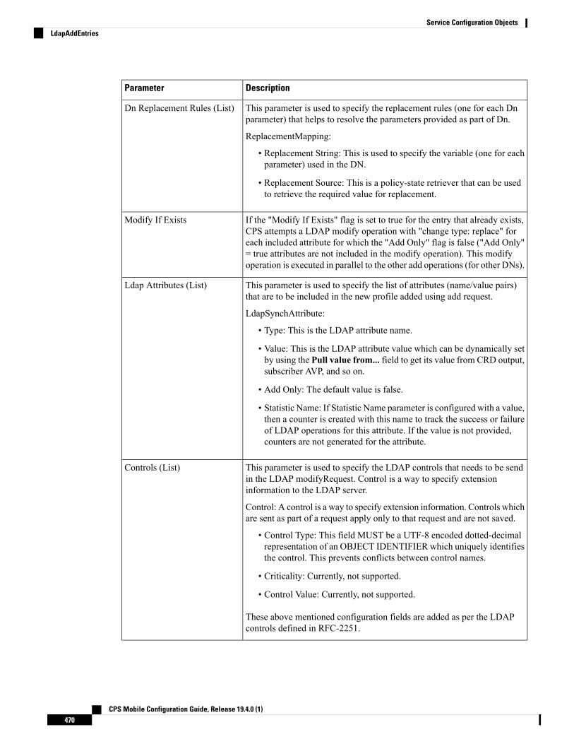
DescriptionParameter
This parameter is used to specify the replacement rules (one for each Dnparameter) that helps to resolve the parameters provided as part of Dn.
ReplacementMapping:
• Replacement String: This is used to specify the variable (one for eachparameter) used in the DN.
• Replacement Source: This is a policy-state retriever that can be usedto retrieve the required value for replacement.
Dn Replacement Rules (List)
If the "Modify If Exists" flag is set to true for the entry that already exists,CPS attempts a LDAP modify operation with "change type: replace" foreach included attribute for which the "Add Only" flag is false ("Add Only"= true attributes are not included in the modify operation). This modifyoperation is executed in parallel to the other add operations (for other DNs).
Modify If Exists
This parameter is used to specify the list of attributes (name/value pairs)that are to be included in the new profile added using add request.
LdapSynchAttribute:
• Type: This is the LDAP attribute name.
• Value: This is the LDAP attribute value which can be dynamically setby using the Pull value from... field to get its value from CRD output,subscriber AVP, and so on.
• Add Only: The default value is false.
• Statistic Name: If Statistic Name parameter is configured with a value,then a counter is created with this name to track the success or failureof LDAP operations for this attribute. If the value is not provided,counters are not generated for the attribute.
Ldap Attributes (List)
This parameter is used to specify the LDAP controls that needs to be sendin the LDAP modifyRequest. Control is a way to specify extensioninformation to the LDAP server.
Control: A control is a way to specify extension information. Controls whichare sent as part of a request apply only to that request and are not saved.
• Control Type: This field MUST be a UTF-8 encoded dotted-decimalrepresentation of an OBJECT IDENTIFIER which uniquely identifiesthe control. This prevents conflicts between control names.
• Criticality: Currently, not supported.
• Control Value: Currently, not supported.
These above mentioned configuration fields are added as per the LDAPcontrols defined in RFC-2251.
Controls (List)
CPS Mobile Configuration Guide, Release 19.4.0 (1)470
Service Configuration ObjectsLdapAddEntries

If both LdapAddEntries and LdapSynchProfile are found in policy, CPS consolidates the LDAP add (fromLdapAddEntries) and LDAP modify (from LdapSynchProfile) operations into a single LDAP add operationif any of the LDAP DNs provided under LdapAddEntries matches the DN provided under LdapSynchProfile.If a match is found, all attributes under LdapSynchProfile are copied into the LDAP add operation (and the"Modify If Exists" flag is overridden to "true" for that DN entry). If a DN match is not found, both operationsexecute separately in parallel.
Note
LdapSynchProfileLdapSyncProfile service configuration can be used to define a LDAP profile (list of attributes) that is updatedon the external LDAP server. CPS calculates the values and tracks the LDAP attributes (included in the profile)for any changes through the lifetime of the session. If changes are detected, the server is updated with the newversion of the profile.
Table 224: LdapSynchProfile Service Configuration Parameters
DescriptionParameter
A reference to the LdapServerSet configured in the reference-data. It links tothe LDAP Plugin Configuration to identify the LDAP server configurationparameters.
Ldap Server Set
This is the Distinguished Name for identifying the subscriber to be updated onthe LDAP directory.
Dn
This gives the option to dynamically replace the variables (identified with $)defined in DN.
ReplacementMapping:
• Replacement String: This is used to specify the variable used in the DN.
• Replacement Source: This is a policy-state retriever that can be used toretrieve the required value for replacement.
Dn Replacement Rules(List)
Specifies the LDAP attribute name for storing the date when the LDAPModifyrequest is triggered.
Modified Date AttributeName
CPS Mobile Configuration Guide, Release 19.4.0 (1)471
Service Configuration ObjectsLdapSynchProfile

DescriptionParameter
Specifies the list of attributes that should be updated on the LDAP server throughthe modify request.
LdapSynchAttribute:
• Type: This is the LDAP attribute name.
• Value: This is the LDAP attribute value which can be dynamically set byusing the Pull value from... field to get its value from CRD output,subscriber AVP, and so on.
• Add Only: The default value is false.
• Statistic Name: If Statistic Name parameter is configured with a value, thena counter is created with this name to track the success or failure of LDAPoperations for this attribute. If the value is not provided, counters are notgenerated for the attribute.
Ldap Synch Attribute(List)
Specifies the LDAP controls that needs to be send in the LDAPmodifyRequest.Control is a way to specify extension information to the LDAP server.
Control: A control is a way to specify extension information. Controls whichare sent as part of a request apply only to that request and are not saved.
• Control Type: This field MUST be a UTF-8 encoded dotted-decimalrepresentation of an OBJECT IDENTIFIER which uniquely identifies thecontrol. This prevents conflicts between control names.
• Criticality: Currently, not supported.
• Control Value: Currently, not supported.
These abovementioned configuration fields are added as per the LDAP controlsdefined in RFC-2251.
Controls (List)
Rx Service Configuration ObjectsThis section describes the parameters for the following Rx Service Configuration Objects:
ActionBasedOnSyPolicyCountersActionBasedOnSyPolicyCounters Service Configuration is used to pull CRD data from the STG.
The input parameters are: The Sy Policy Counter Identifier and Status in the format Identifier:Status. Formultiple Policy Counters, each set of identifiers and counters are separated with semi-colons, for example:Identifier1:Status1;Identifier2:Status
When CPS receives Rx AAR or Sy SLA/SNR messages, CPS performs a one-time query on the CRD Tablewith the Sy Policy Counter Status as the input Key. Based on the output parameters, CPS sets SyCounterActionsObject in Policy State with output parameters to handle in triggerAdditionalMessages method.
The output parameters are:
CPS Mobile Configuration Guide, Release 19.4.0 (1)472
Service Configuration ObjectsRx Service Configuration Objects
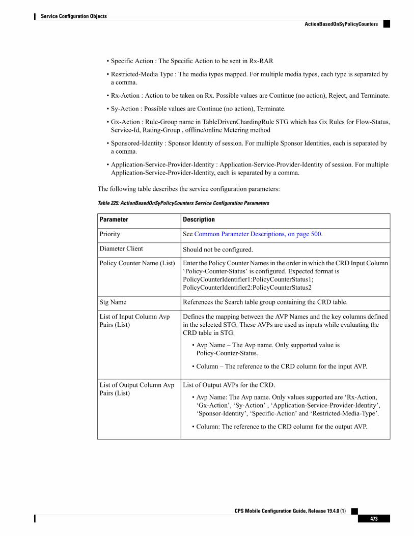
• Specific Action : The Specific Action to be sent in Rx-RAR
• Restricted-Media Type : The media types mapped. For multiple media types, each type is separated bya comma.
• Rx-Action : Action to be taken on Rx. Possible values are Continue (no action), Reject, and Terminate.
• Sy-Action : Possible values are Continue (no action), Terminate.
• Gx-Action : Rule-Group name in TableDrivenChardingRule STG which has Gx Rules for Flow-Status,Service-Id, Rating-Group , offline/online Metering method
• Sponsored-Identity : Sponsor Identity of session. For multiple Sponsor Identities, each is separated bya comma.
• Application-Service-Provider-Identity : Application-Service-Provider-Identity of session. For multipleApplication-Service-Provider-Identity, each is separated by a comma.
The following table describes the service configuration parameters:
Table 225: ActionBasedOnSyPolicyCounters Service Configuration Parameters
DescriptionParameter
See Common Parameter Descriptions, on page 500.Priority
Should not be configured.Diameter Client
Enter the Policy Counter Names in the order in which the CRD Input Column‘Policy-Counter-Status’ is configured. Expected format isPolicyCounterIdentifier1:PolicyCounterStatus1;PolicyCounterIdentifier2:PolicyCounterStatus2
Policy Counter Name (List)
References the Search table group containing the CRD table.Stg Name
Defines the mapping between the AVP Names and the key columns definedin the selected STG. These AVPs are used as inputs while evaluating theCRD table in STG.
• Avp Name – The Avp name. Only supported value isPolicy-Counter-Status.
• Column – The reference to the CRD column for the input AVP.
List of Input Column AvpPairs (List)
List of Output AVPs for the CRD.
• Avp Name: The Avp name. Only values supported are ‘Rx-Action,‘Gx-Action’, ‘Sy-Action’ , ‘Application-Service-Provider-Identity’,‘Sponsor-Identity’, ‘Specific-Action’ and ‘Restricted-Media-Type’.
• Column: The reference to the CRD column for the output AVP.
List of Output Column AvpPairs (List)
CPS Mobile Configuration Guide, Release 19.4.0 (1)473
Service Configuration ObjectsActionBasedOnSyPolicyCounters
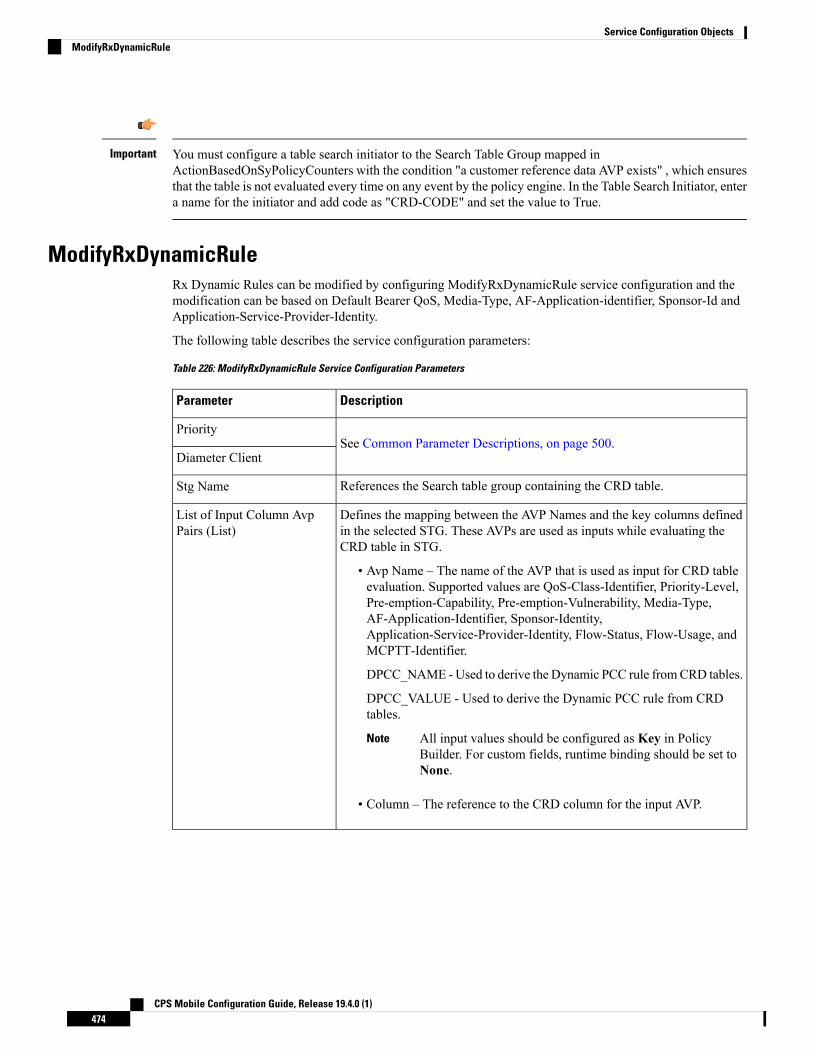
You must configure a table search initiator to the Search Table Group mapped inActionBasedOnSyPolicyCounters with the condition "a customer reference data AVP exists" , which ensuresthat the table is not evaluated every time on any event by the policy engine. In the Table Search Initiator, entera name for the initiator and add code as "CRD-CODE" and set the value to True.
Important
ModifyRxDynamicRuleRx Dynamic Rules can be modified by configuring ModifyRxDynamicRule service configuration and themodification can be based on Default Bearer QoS, Media-Type, AF-Application-identifier, Sponsor-Id andApplication-Service-Provider-Identity.
The following table describes the service configuration parameters:
Table 226: ModifyRxDynamicRule Service Configuration Parameters
DescriptionParameter
See Common Parameter Descriptions, on page 500.Priority
Diameter Client
References the Search table group containing the CRD table.Stg Name
Defines the mapping between the AVP Names and the key columns definedin the selected STG. These AVPs are used as inputs while evaluating theCRD table in STG.
• Avp Name – The name of the AVP that is used as input for CRD tableevaluation. Supported values are QoS-Class-Identifier, Priority-Level,Pre-emption-Capability, Pre-emption-Vulnerability, Media-Type,AF-Application-Identifier, Sponsor-Identity,Application-Service-Provider-Identity, Flow-Status, Flow-Usage, andMCPTT-Identifier.
DPCC_NAME -Used to derive the Dynamic PCC rule fromCRD tables.
DPCC_VALUE - Used to derive the Dynamic PCC rule from CRDtables.
All input values should be configured as Key in PolicyBuilder. For custom fields, runtime binding should be set toNone.
Note
• Column – The reference to the CRD column for the input AVP.
List of Input Column AvpPairs (List)
CPS Mobile Configuration Guide, Release 19.4.0 (1)474
Service Configuration ObjectsModifyRxDynamicRule

DescriptionParameter
List of Output AVPs for the CRD.
• Avp Name – The name of the AVP that is used as input for CRD tableevaluation. Supported values are QoS-Class-Identifier, Qci,Priority-Level, Priority Level, Pre-emption-Capability, PreemptionCapability, Pre-emption-Vulnerability, Preemption Vulnerability,Guaranteed-Bitrate-UL, Guaranteed Bit Rate U L,Guaranteed-Bitrate-DL, Guaranteed Bit Rate D L,Max-Requested-Bandwidth-UL, Max Req Bandwidth U L,Max-Requested-Bandwidth-DL, and Max Req Bandwidth D L.
• Column – The reference to the CRD column for the output AVP.
List of Output Column AvpPairs (List)
This flag is used to ignore modification of existing Rx dedicated bearer whichneeds to be true to avoid existing rule modification on default bearer boost.
Ignore Existing Rule
When set to true, modified QCI/ARP are sent under same rule instead ofgenerating new rule.
When set to false, make and break functionality for Rx Dynamic Rule works.A new rule gets generated when QCI/ARP gets changed for current rule.
Default: false
Disable Make N Break Ruleon Qos Change
When set to true, existing dedicated bearer is not modified and boost/throttleis terminated.
Default: false
Type: Boolean
RetainModificationOnBoostTermination
The AVP Names Qci, Priority Level, Preemption Capability, Preemption Vulnerability, Guaranteed Bit RateU L, Guaranteed Bit Rate D L, Max Req Bandwidth U L, and Max Req Bandwidth D L support QoS ActionMirror, Enforce or Bound.
For more details on QoS Action, refer to Programmatic CRD (QoS Action), on page 338.
Important
RxAppQoSInformationThe RxAppQoSInformation service configuration option defines the QoS to be used for Rx dedicated bearerbased on the application ID and media type.
CPS Mobile Configuration Guide, Release 19.4.0 (1)475
Service Configuration ObjectsRxAppQoSInformation

Table 227: RxAppQoSInformation Service Configuration Parameters
DescriptionParameter
See Common Parameter Descriptions, on page 500.
Priority
Diameter Client
Qci
Max Req Bandwidth U L
Max Req Bandwidth D L
Guaranteed Bit Rate U L
Guaranteed Bit Rate D L
Arp
The AF-Application-Id for which the QoS values should be applied.Af Application Id
TheMedia-Type for which the QoS values should be applied. (Use an Integervalue as per 3GPP specifications).
Media Type
For more information, refer to RxAppQosInformation Service Configuration, on page 326.
RxAuthorizationSTGConfigurationRxAuthorizationSTGConfiguration service configuration can be used to evaluate Rx Authorization table andobtain the output values configured. The RxAuthorizationSTGConfiguration supports chained evaluation ofSTGs which means multiple Search Table Groups can be configured hierarchically in theRxAuthorizationSTGConfiguration and outputs of one table can be used as input keys for another table. TheRx Authorization table from which Bearer Authorization and Error Cause output values are received needsto be configured as the last table in the list of chained STGs configured underRxAuthorizationSTGConfiguration.
• Rx Authorization in AAR messages is supported for only new bearers, and not modification of existingbearers.
• Rx_RAR on failure of Rx Authorization is sent only if Specific-Action=INDICATION_OF_FAILED_RESOURCES_ALLOCATION is armed in AAR message.
Note
The following table describes the service configuration parameters:
CPS Mobile Configuration Guide, Release 19.4.0 (1)476
Service Configuration ObjectsRxAuthorizationSTGConfiguration

Table 228: RxAuthorizationSTGConfiguration Service Configuration Parameters
DescriptionParameter
See Common Parameter Descriptions, on page 500.Priority
Diameter Client
StgNameReferencePair:
• Stg Name (Optional): References the Search table group containing theCRD table. STG names configured have to be unique.
• Stg Reference (Mandatory): This is the reference to the CRD table
• List Of Input Column Avp Pairs (Mandatory): Defines the mappingbetween the AVP Names and the key columns defined in the selectedSTG. These AVPs are used as inputs while evaluating the CRD table inSTG.
• Avp Name: Incase the Input AVP is a standard AVP, then the AVPName can be configured to the name of the diameter AVP (receivedinMedia Component Description AVP of the AARmessage) whichis to be used as input for CRD table evaluation. (For example,AF-Application-Identifier, Media-Type and so on).
AVPs present at Media-Sub-Component level are notsupported. In case of chained evaluation of STGs, theAVP Name must be exactly the same as the Output AVPwhich it is being mapped to.
Note
• Column: The reference to the CRD column for the input AVP.
• List Of Output Column Avp Pairs (Mandatory): Defines the mappingbetween the AVP Names and the output columns defined in the selectedSTG. These mappings indicate how the output columns' values aremapped to AVPs after the CRD is evaluated.
• Avp Name: The name of the AVP to which the value of the outputcolumn is mapped.
The final STG fromwhich you want to derive the output must haveits output columns namedBearer-Authorization and Error-Message.The intermediate STGs used for chained evaluation can have anyAVPs standard/non-standard. Supported values forBearer-Authorization are Accept/Reject.
In case the output column is not a standard AVP, then you can useany AVP Name (for example, Bearer-Throttling). But if this outputcolumn is chained into another STG's input column (for example,STG B's input column), then the AVP name for STG B's inputcolumn should also be Bearer-Throttling.
• Column: The reference to the CRD column for the output AVP.
Stg Details (List)
CPS Mobile Configuration Guide, Release 19.4.0 (1)477
Service Configuration ObjectsRxAuthorizationSTGConfiguration

RxChargingParameterSTGConfigurationThe RxChargingParameterSTGConfiguration service configuration object sets the charging parameters fordedicated bearers created for IMS session (non-sponsored data case).
Table 229: RxChargingParametersSTGConfiguration Service Configuration Parameters
DescriptionParameter
See Common Parameter Descriptions, on page 500.Priority
Diameter Client
References the Search table group containing the CRD tables that definethe Qos Action.
Chargingparameterstg Name
See Common Parameter Descriptions, on page 500.
The following is the list of supported AVP Names under Input Column:
• AF-Application-Identifier
• Media-Type
• Flow-Status
• Reservation-Priority
• Flow-Number
• Flow-Usage
• AF-Signalling-Protocol
• DPCC_NAME - Used to derive the Dynamic PCC rule from CRDtables.
• DPCC_VALUE - Used to derive the Dynamic PCC rule from CRDtables.
List Of Input Column AvpPairs (List)
See Common Parameter Descriptions, on page 500.
The following is the list of supported AVP Names under Output Column:
• Metering-Method
• Offline
• Online
• Rating-Group
• Service-Identifier
• Reporting-Level
• Precedence
List Of Output Column AvpPairs (List)
CPS Mobile Configuration Guide, Release 19.4.0 (1)478
Service Configuration ObjectsRxChargingParameterSTGConfiguration

RxDelayedMCDProcessingRxDelayedMCDProcessing service configuration is used to delay the processing of media reported in AARuntil it receives response for Gx RAR triggered based on Event-Triggers enabled based onRxTableDrivenEventTriggers, on page 486.
The following table describes the service configuration parameters:
Table 230: RxDelayedMCDProcessing Service Configuration Parameters
DescriptionParameter
See Common Parameter Descriptions, on page 500.Priority
Diameter Client
Restrictions
RxDelayedMCDProcessing service configuration also requires defining the RxTableDrivenEventTriggers todetermine the Event-Triggers to be sent on the dummy Gx RAR message.
When CPS evaluates the RxDelayedMCDProcessing and determines that a dummy Gx RAR is required tobe triggered then CPS skips the Rx Authorization processing. No need to add specific condition onRxAuthorizationSTGConfiguration template to disable it when dummy RAR needs to be triggered.
A policy with policy-action "Create Sy Service Session" is required to be configured for selectively triggeringSy SLR only after dummy RAR response is received. But if the CPS service does not have "Balance Service"check-box enabled and selective Sy needs to be triggered after dummyRAR response is received then "Calculateservice configuration - on demand" policy-action is required to be added before the policy-action for triggeringthe "Create Sy Service Session".
RxDRMPSTGConfigurationThe RxDRMPSTGConfiguration service configuration object sets the priority of the Gx-RAR diametermessage using the DRMP AVP in the circumstance of high priority traffic (for example, Multimedia PriorityService (MPS)) from the Rx interface. The DRMP AVP value is derived based on the Reservation-PriorityAVP and MPS-Identifier AVP. Both, Reservation-Priority AVP and MPS-Identifier AVP, must present inthe AAR message.
Reservation-Priority AVP present at the message level in the AAR is only used. Reservation-Priority AVPpresent at Media-Component-Description level is not used.
Note
Table 231: RxDRMPSTGConfiguration Service Configuration Parameters
DescriptionParameter
The name of the STG that is referenced.D R M P Reservation PriorityTable
The output column of the STG, whose value on evaluation of the table, setsthe DRMP AVP to set the priority of the Gx-RAR diameter message.
Drmp Output Column
CPS Mobile Configuration Guide, Release 19.4.0 (1)479
Service Configuration ObjectsRxDelayedMCDProcessing

DescriptionParameter
Defines the mapping between the AVP names and the key columns definedin the selected STG. These AVPs are used as inputs while evaluating theCRD table in the STG.
• Avp Name – The name of the AVP that is used as input for the CRDtable evaluation.
The following is the list of supported AVP names under Input Column:
• Reservation-Priority
• MPS-Identifier
• Column – The key column in the STG that corresponds to the specifiedAVP.
List Of Input Column AvpPairs (List)
RxGuaranteedBitRateOverrideThe RxGuaranteedBitRateOverride service configuration object overrides the GBR, and sets it from theMBRvalue.
Table 232: RxGuaranteedBitRateOverride Service Configuration Parameters
DescriptionParameter
See Common Parameter Descriptions, on page 500.Priority
Diameter Client
This configuration is applicable when CPS is not able to derive guaranteedbit rate values based on the QoS derivation algorithm defined in 3GPP 29.213specification. So if GBR is not derived and this service option is configured,then CPS copies the values derived for Max Requested Bitrates intoGuranteed Bitrates (applicable for both UL and DL).
Default: true
Set Guaranteed Bit Rate fromMax Requested
Set this flag to true for copying the Max-Requested-Bitrate values intoGuaranteed-Bitrate after QoS-Actions (RxSTGConfiguration) are applied.The bit rate values are copied only if the new QCI is < 5 and the Qos-Actionon Guaranteed Bitrates (UL/DL) is Mirror.
Default: false
Set Guaranteed Bit Rate fromMax Requested (Qos-Action)
For more information, refer to RxGaranteedBitRateOverride Service Configuration, on page 327.
RxQoSInformationThe RxQoSInformation service configuration option sets QoS values for Rx dedicated bearer.
CPS Mobile Configuration Guide, Release 19.4.0 (1)480
Service Configuration ObjectsRxGuaranteedBitRateOverride

Table 233: RxQoSInformation Service Configuration Parameters
DescriptionParameter
See Common Parameter Descriptions, on page 500.
Priority
Diameter Client
Qci
Max Req Bandwidth U L
Max Req Bandwidth D L
Guaranteed Bit Rate U L
Guaranteed Bit Rate D L
Arp
For more information, refer to RxQoSInformation Service Configuration, on page 325.
RxSponsoredDataChargingParameterSTGConfigurationThe RxSponsoredDataChargingParameterSTGConfiguration service configuration object configures the CRDdetails for setting charging parameters for dedicated bearers that are created for sponsored data.
Table 234: RxSponsoredDataChargingParameterSTGConfiguration Service Configuration Parameters
DescriptionParameter
See Common Parameter Descriptions, on page 500.Priority
Diameter Client
References the Search table group containing the CRD tables thatdefine the Qos Action.
Sponsored DatachargingparameterstgName
See Common Parameter Descriptions, on page 500.
DPCC_NAME - Used to derive the Dynamic PCC rule from CRDtables.
DPCC_VALUE - Used to derive the Dynamic PCC rule from CRDtables.
List Of Input Column Avp Pairs (List)
See Common Parameter Descriptions, on page 500.List Of Output ColumnAvp Pairs (List)
RxSTGConfigurationThe following parameters can be configured under RxSTGConfiguration service configuration:
CPS Mobile Configuration Guide, Release 19.4.0 (1)481
Service Configuration ObjectsRxSponsoredDataChargingParameterSTGConfiguration

Table 235: RxSTGConfiguration Service Configuration Parameters
DescriptionParameter
See Common Parameter Descriptions, on page 500.Priority
Diameter Client
References the Search table group containing the CRD tables thatdefine the Qos Action for Rx specific dynamic rules (dedicatedbearer).
Stg Name
Define themapping between the 'AVPNames' and the key 'Columns'defined in the selected STG. These AVPs will be the inputs whileevaluating the CRD table in STG.
ColumnAndAvpPair:
• Avp Name – The name of the Diameter AVP (received inMedia Component DescriptionAVP of the AARmessage) thatare used as input for CRD table evaluation. For example:Flow-Number,Media-Component-Number,MCPTT-Identifier,and so on.
DPCC_NAME - Used to derive the Dynamic PCC rule fromCRD tables.
DPCC_VALUE - Used to derive the Dynamic PCC rule fromCRD tables.
• Column – References the key column defined in the selectedSTG.
List Of Input Column Avp Pairs (List)
See Table 236: Input Codec Data Parameters, on page 483.Input Codec Data
Determines which RxSTGConfiguration to use for the new ARPeMPS feature.
ArpPrecedence
Determines which RxSTGConfiguration to use for QCI lookup.QosPrecedence
When set to true, CPS disables modification of Dedicated bearerQoS.
Default: false
Disable Qos Change
CPS Mobile Configuration Guide, Release 19.4.0 (1)482
Service Configuration ObjectsRxSTGConfiguration

Table 236: Input Codec Data Parameters
DescriptionParameter
Supported values are:
• true – CPS uses the first Codec-Data AVP with "answer" onthe second line, or the first Codec-Data AVP with "offer" ifthere is no Codec-Data AVP with "answer".
• false – CPS uses the first Codec-Data AVP with "offer" or"answer" on the second line if AAR request has multiple'Codec-Data' AVPs.
Prefer Answer
InputCodecMediaFormatColumns
• Column Encoding Name – Column from a Search Table Groupand a corresponding Custom Reference Data Table for QoSinformation. The encoding name extracted from the a:rtpmapline is used to match the column in the Search Table Groupand the corresponding Custom Reference Data Table.
• Column Clock Rate – Column from a Search Table Group anda corresponding Custom Reference Data Table for QoSinformation. The clock rate extracted from the a:rtpmap lineis used to match the column in the Search Table Group andthe corresponding Custom Reference Data Table.
• Column Encoding Parameters – Column from a Search TableGroup and a corresponding Custom Reference Data Table forQoS information. The encoding parameters extracted from thea:rtpmap line is used to match the column in the Search TableGroup and the corresponding Custom Reference Data Table.
• List of Input Column Parameter Pairs
• Parameter –Media Specific Parameter name in the a:fmtpline to extract the value from. For example, mode-set,octet-align.
• Default – Optional default parameter value. If Codec-DataAVP does not include the SDP parameter, the defaultvalue is used.
• Column – Column from a Search Table Group and acorresponding Custom Reference Data Table for QoSinformation. The parameter value extracted from thestandalone line or the default value is used to match thecolumn in the Search Table Group and the correspondingCustom Reference Data Table.
Input Columns Media Format
CPS Mobile Configuration Guide, Release 19.4.0 (1)483
Service Configuration ObjectsRxSTGConfiguration

DescriptionParameter
InputCodecParameterColumnPair
• Parameter – SDP parameter name in the standalone line toextract the value from. For example, "a=ptime".
• Default – Optional default parameter value. If Codec-DataAVP does not include the SDP parameter, the default value isused.
• Column – Column from a Search Table Group and acorresponding Custom Reference Data Table for QoSinformation. The parameter value extracted from the standaloneline or the default value is used to match the column in theSearch Table Group and the corresponding Custom ReferenceData Table.
List of Input Columns Sdp Pairs
Indicates which RTP map line to be used for codec matching. Forexample, index 2 indicates that the second rtp-map/fmtp line incodec AVP is used for configuration matching.
To disable this parameter, the value must be less than 1.
If Media Component Description AVP comes withmultiple codec-data AVP (offer and answer), then inorder to select the codec-data with answer,"prefer_answer" configuration has to be enabled underservice option. If the configuration is not enabled, firstcodec-data is used for configuration matching, whichmeans offer is expected to be first codec-data.
Restriction
Media Comp Rtpmap Payload TypeIndex
• CPS supports default values for media specific parameters in a=fmtp line and SDP standalone lines.
• CPS supports SDP standalone lines in the form of <char>=<name>:<value>.
Note
For more information, see Basic Options, on page 156.
RxSTGDefaultBearerConfigurationRxSTGDefaultBearerConfiguration service configuration is used for CRD evaluation of default bearer QoSon receiving Rx AAR with Dynamic-PCC-Requested-QoS AVP. The same service configuration can also beused to support modification of default bearer based on MPS-Identifier and Reservation-Priority received inAAR from P-CSCF.
The following parameters can be configured under RxSTGDefaultBearerConfiguration service configuration:
CPS Mobile Configuration Guide, Release 19.4.0 (1)484
Service Configuration ObjectsRxSTGDefaultBearerConfiguration

Table 237: RxSTGDefaultBearerConfiguration Service Configuration Parameters
DescriptionParameter
See Common Parameter Descriptions, on page 500.Priority
Diameter Client
References the Search table group containing the CRD tables thatdefine the Qos Action for Rx specific dynamic rules (dedicatedbearer).
Stg Name
Defines the mapping between the 'AVP Names' and the key'Columns' defined in the selected STG. These AVPs are the inputswhile evaluating the CRD table in STG.
ColumnAndAvpPair:
• Avp Name – The name of the Diameter AVP (received inMedia Component DescriptionAVP of the AARmessage) thatis used as input for CRD table evaluation. Supported inputAVPs are: Sponsor-Identity,Application-Service-Provider-Identity, Media-Type, Intention,Service-Info-Status, MPS_Identifier, Reservation-Priority,MCPTT-Identifier, and so on.
DPCC_NAME - Used to derive the Dynamic PCC rule fromCRD tables.
DPCC_VALUE - Used to derive the Dynamic PCC rule fromCRD tables.
• Column – References the key column defined in the selectedSTG.
List Of Input Column Avp Pairs (List)
ColumnAndAvpPair:
• Avp Name – The name of the diameter AVP (attribute fromQos-Information) to which the value of the output columnshould be mapped while setting the Qos-Information for thededicated bearer on Gx. Supported list of output AVPs are:QoS-Class-Identifier, Priority-Level, Pre-emption-Capability,Pre-emption-Vulnerability, APN-Aggregate-Max-Bitrate-UL,APN-Aggregate-Max-Bitrate-DL.
Similarly, for Qos-Actions on the attribute, the AVP Namespecifies the qos-action for a specific Qos-Information attribute;supported corresponding action AVPs are : Qci, Priority Level,Preemption Capability, Preemption Vulnerability, Apn AggMax Bit Rate U L, Apn Agg Max Bit Rate D L.
The values for AVP name must be exactly the same as thoseused while defining the input columns.
• Column – References the output column defined in the selectedSTG.
List of Output Column Avp Pairs (List)
CPS Mobile Configuration Guide, Release 19.4.0 (1)485
Service Configuration ObjectsRxSTGDefaultBearerConfiguration

RxTableDrivenEventTriggersRxTableDrivenEventTriggers service configuration is used to derive a list of event-triggers that CPS shouldsubscribe based on table evaluation. The input columns to this table are the Media-Component-DescriptionAVP values or any other input parameters (derived from gx-session) and the output columns give the list ofapplicable event-triggers. Based on the selection logic user can configure any AVP received at MCD level tothe input columns. In the CRD table, output columns can give an event-trigger number. So, there can bemultiple output columns depending upon the number of event-triggers that are to be supported. You need toconfigure all these output columns that derive the event-trigger number in the service configuration.
This service configuration is also used for configuring the STG used to specify the event-triggers to be sentin dummy GxRAR. In this case, the same service option needs to be linked to two separate CRD tables(Rx-Table or dummy RAR Event-Trigger table). So, these service-options are created by modifying theRxTableDrivenEventTriggers Use Case Template with Use Case Initiator conditions that checks for triggeringdummy RAR. This avoids enabling both the service option at the same time.
The following table describes the service configuration parameters:
Table 238: RxTableDrivenEventTriggers Service Configuration Parameters
DescriptionParameter
See Common Parameter Descriptions, on page 500.Priority
Diameter Client
References the Search table group containing the CRD tables that define theQos Action for Rx specific dynamic rules (dedicated bearer).
Stg Name
Defines the mapping between the 'AVPNames' and the key 'Columns' definedin the selected STG. These AVPs are the inputs while evaluating the CRDtable in STG.
ColumnAndAvpPair:
• Avp Name – The name of the diameter AVP that is used as input forCRD table evaluation.
• Column – References the key column defined in the selected STG.
List Of Input Column AvpPairs (List)
ColumnAndAvpPair:
• Avp Name – The name of the diameter AVP to which the value of theoutput column should be mapped.
The output AVP namemapping indicates how the output column's valuesare mapped to AVPs after the CRD is evaluated.
• Column – References the output column defined in the selected STG.
List of Output Column AvpPairs (List)
Restrictions
When using RxTableDrivenEventTriggers for both Rx-Table event-triggers and dummy RAR event-triggers,the template must be configured with modify conditions to have two service options that can be linked to the
CPS Mobile Configuration Guide, Release 19.4.0 (1)486
Service Configuration ObjectsRxTableDrivenEventTriggers
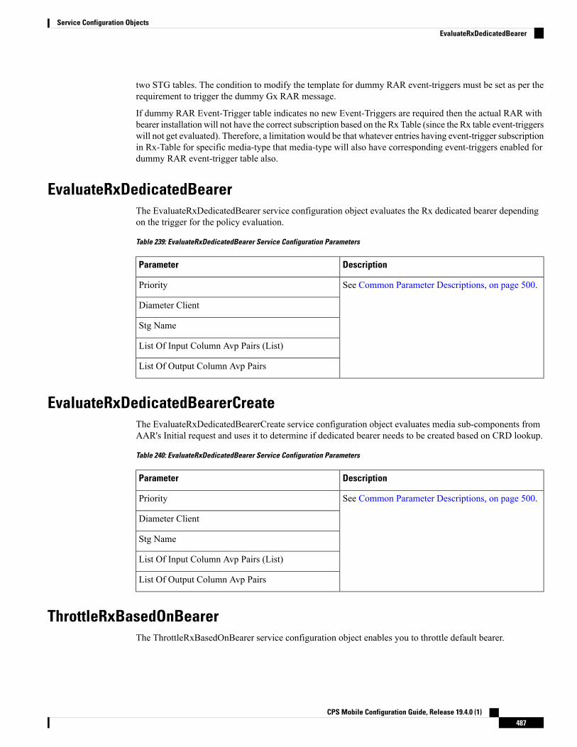
two STG tables. The condition to modify the template for dummy RAR event-triggers must be set as per therequirement to trigger the dummy Gx RAR message.
If dummy RAR Event-Trigger table indicates no new Event-Triggers are required then the actual RAR withbearer installation will not have the correct subscription based on the Rx Table (since the Rx table event-triggerswill not get evaluated). Therefore, a limitation would be that whatever entries having event-trigger subscriptionin Rx-Table for specific media-type that media-type will also have corresponding event-triggers enabled fordummy RAR event-trigger table also.
EvaluateRxDedicatedBearerThe EvaluateRxDedicatedBearer service configuration object evaluates the Rx dedicated bearer dependingon the trigger for the policy evaluation.
Table 239: EvaluateRxDedicatedBearer Service Configuration Parameters
DescriptionParameter
See Common Parameter Descriptions, on page 500.Priority
Diameter Client
Stg Name
List Of Input Column Avp Pairs (List)
List Of Output Column Avp Pairs
EvaluateRxDedicatedBearerCreateThe EvaluateRxDedicatedBearerCreate service configuration object evaluates media sub-components fromAAR's Initial request and uses it to determine if dedicated bearer needs to be created based on CRD lookup.
Table 240: EvaluateRxDedicatedBearer Service Configuration Parameters
DescriptionParameter
See Common Parameter Descriptions, on page 500.Priority
Diameter Client
Stg Name
List Of Input Column Avp Pairs (List)
List Of Output Column Avp Pairs
ThrottleRxBasedOnBearerThe ThrottleRxBasedOnBearer service configuration object enables you to throttle default bearer.
CPS Mobile Configuration Guide, Release 19.4.0 (1)487
Service Configuration ObjectsEvaluateRxDedicatedBearer

Table 241: ThrottleRxBasedOnBearer Service Configuration Parameters
DescriptionParameter
See Common Parameter Descriptions, on page 500.Priority
Diameter Client
Qci
Allocation Retention Priority
Max Required Bandwidth U L
Max Required Bandwidth D L
ThrottleRxBasedOnMediaTypeThe ThrottleRxBasedOnMediaType service configuration object enables you to throttle Rx calls based onmedia type.
Table 242: ThrottleRxBasedOnMediaType Service Configuration Parameters
DescriptionParameter
See Common Parameter Descriptions, on page 500.Priority
Diameter Client
List of parameters that can be configured to enableyou to throttle Rx calls with the media type as follows:
• Media Type - Type of Media.
• Bandwidth Allocation For Media Type -Allocated bandwidth for the selectedmedia type.
• PercentageAllocation For R T P - Correspondingpercentage of the bandwidth that needs toalloctaed for RTP.
• Percentage Allocation For R T C P -Corresponding percentage of the bandwidth thatneeds to alloctaed for RTPC.
Q O S Allocation Parameters (List)
CPS Mobile Configuration Guide, Release 19.4.0 (1)488
Service Configuration ObjectsThrottleRxBasedOnMediaType

RxClient Service Configuration Objects
BindingDbHealthCheckThe BindingDbHealthCheck service configuration object is used to configure PCRF to initiate a message thatresults in sending dummy AAR to PolicyDRA to check if binding is available at PolicyDRA and allowingthe PCRF to take corrective action based on the response.
Table 243: BindingDbHealthCheck Service Configuration Parameters
DescriptionParameter
This field is used to enable the feature for a particular APN. This field can beread from a CRD table which has mapping to an APN name.
Enable Health Check
This field notifies the destination realm of the Policy DRA or Rx peer.Destination Realm
The dummy AAR sent by PCRF for PolicyDRA binding database health check is routed back to PCRF. Thisdummy AAR has to be ignored/rejected. To identify the dummy (health-check) AAR the diameter sessionID is appended with BindingDbCheck keyword. When PCRF receives an AAR with session ID ending withBindingDbCheck keyword, it needs to be replied by using RequestReject configuration that must be enabledusing the condition that makes use of session ID having BindingDbCheck keyword. For configuration, referto RequestReject , on page 419.
Note
To improve the performance when PolicyDRA Health Check is enabled, you must configure‘RxClientSessionKey’ key as the Lookaside Key Prefix so that memcache is used and full database scan isavoided. This is highly recommended for higher capacity systems.
Note
Sd Service Configuration ObjectsThis section describes the parameters for the following Sd Service Configuration Objects:
ADCPreconfiguredRuleThe ADCPreconfiguredRule service configuration object configures a dynamic application detection rule.
CPS Mobile Configuration Guide, Release 19.4.0 (1)489
Service Configuration ObjectsRxClient Service Configuration Objects

Table 244: ADCPreconfiguredRule Service Configuration Parameters
DescriptionParameter
See Common Parameter Descriptions, on page 500.Priority
Diameter Client
Not usedRule Group
Not usedRule Name
The name of the ADC rule.Adc Rule Name
See Common Parameter Descriptions, on page 500.
Tdf Application Identifier
Flow Status
Mute Notification
Monitoring Key
QoSInformation
For detailed information about the following parameters, see Common ParameterDescriptions, on page 500.
• Max Req Bandwidth U L
• Max Req Bandwidth D L
• Guaranteed Bit Rate U L
• Guaranteed Bit Rate D L
• Apn Agg Max Bit Rate U L
• Apn Agg Max Bit Rate U L
• Arp
QoS Information
RedirectInformation
For detailed information about the following parameters, see Common ParameterDescriptions, on page 500.
• Redirect Address Type
• Redirect Support
• Redirect Server Address
Redirect Information
ADCPredefinedRuleThe ADCPredefinedRule object configures a static ADC rule.
CPS Mobile Configuration Guide, Release 19.4.0 (1)490
Service Configuration ObjectsADCPredefinedRule

Table 245: ADCPredefinedRule Service Configuration Parameters
DescriptionParameter
See Common Parameter Descriptions, on page 500.
Priority
Diameter Client
Rule Group
Rule Name
ADCPredefinedRuleBaseThe ADCPredefinedRuleBase object configures a predefined group of ADC rules. The group can containpredefined, pre-configured, dynamic, and predefined rule base rules.
Table 246: ADCPredefinedRuleBase Service Configuration Parameters
DescriptionParameter
See Common Parameter Descriptions, on page 500.
Priority
Diameter Client
Rule Group
Rule Name
EventTriggerThe EventTrigger service configuration object specifies the event to be sent.
Table 247: EventTrigger Service Configuration Parameters
DescriptionParameter
See Common Parameter Descriptions, on page 500.
Priority
Diameter Client
Event Trigger
SdDynamicRuleReferenceThe SdDynamicRuleReference service configuration object is used to define the CRD table and column detailsfor determining the rule-name and charging-parameters for the Sd Sponsored Data Dynamic PCC Rule.
CPS Mobile Configuration Guide, Release 19.4.0 (1)491
Service Configuration ObjectsADCPredefinedRuleBase

Table 248: SdDynamicRuleReference Service Configuration Parameters
DescriptionParameter
See Common Parameter Descriptions, on page 500.Priority
Diameter Client
The name of the Search Table group table that is being referenced.STG Table
See Common Parameter Descriptions, on page 500.List Of Input Column Avp Pairs (List)
List Of Output ColumnAvp Pairs (List)
Can be set to true or false.
Default: false
Retry Pcc Rules On Failure
SdDefaultBearerQosADCRuleConfigurationThe SdDefaultBearerQosADCRuleConfiguration service configuration object is used to derive ADC rules.
The following Query Table Input/Output can be used:
• Inputs:
• LDAP Attributes
• Sy-Counter-Id and Sy-Counter-Status
• Gx-Attributes: APN, Roaming-Status (RMS Table) and so on
• Output: ADC-Rule-Name, TDF-Application-Identifier, Event-Trigger
Table 249: SdDefaultBearerQosADCRuleConfiguration Service Configuration Parameters
DescriptionParameter
See Common Parameter Descriptions, on page 500.Priority
Diameter Client
CPS Mobile Configuration Guide, Release 19.4.0 (1)492
Service Configuration ObjectsSdDefaultBearerQosADCRuleConfiguration

DescriptionParameter
QueryTable
Each Query Table represents a Customer Reference Data table. The applicationreferences the Input List and selects parameters and values along with it toquery the table.
Provide the input and output parameters according to your requirements.
• Table name – Click the ... button, and select a table name from the list.
• Input List (List) – Click the arrow to expand the contents.
InputColumnObject – Click the arrow to expand the contents.
• Crd Column – Click the ... button, and select a CRD column fromthe list.
• Referenced Output Column – Click the ... button, and select anoutput column from the list.
• Column Value – Enter the column value.
• Referenced MultiValue AVP Name – Enter the referencedmulti-value AVP name.
• Output List (List) – Gives the application relevant hints on how to use thequery results.
OutputColumnObject
• Crd Column – Click the ... button, and select a CRD column fromthe list.
• Target Avp Name – Enter the target AVP name.
• QueryOrder – Enter a numeric value. (The default is 0.) QPS determinesthe Query Table that needs to be queried based on the Query Order. TheQuery Order is based on the ascending order of precedence, that is, 0 > 1> 2 > 3 and so on.
All inputs to CRD table must be through retrievers only.Restriction
Crd Tables (List)
See Common Parameter Descriptions, on page 500.
This value provides the information on the TDF node to which the Sd DiameterInterface connects.
Realm
SdToggleMonitoringKeyThe SdToggleMonitoringKey service configuration object defines the monitoring-key to be used for theSponsored Data Dynamic PCC Rule.
CPS Mobile Configuration Guide, Release 19.4.0 (1)493
Service Configuration ObjectsSdToggleMonitoringKey
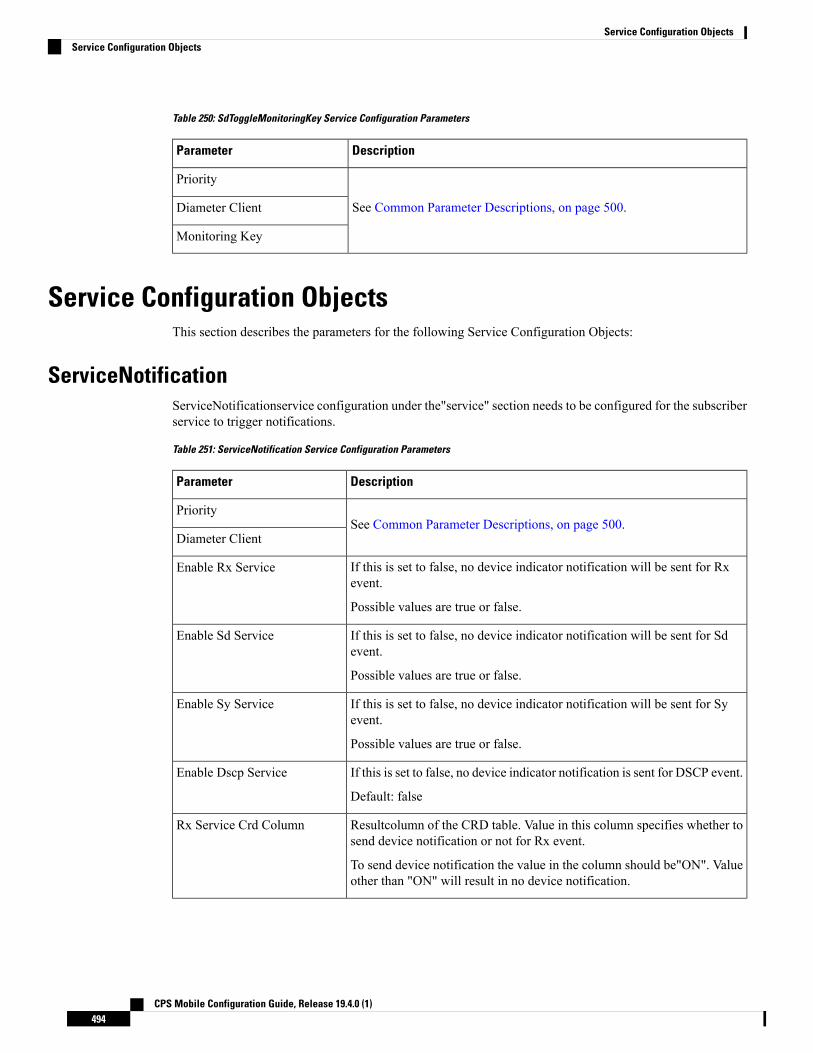
Table 250: SdToggleMonitoringKey Service Configuration Parameters
DescriptionParameter
See Common Parameter Descriptions, on page 500.
Priority
Diameter Client
Monitoring Key
Service Configuration ObjectsThis section describes the parameters for the following Service Configuration Objects:
ServiceNotificationServiceNotificationservice configuration under the"service" section needs to be configured for the subscriberservice to trigger notifications.
Table 251: ServiceNotification Service Configuration Parameters
DescriptionParameter
See Common Parameter Descriptions, on page 500.Priority
Diameter Client
If this is set to false, no device indicator notification will be sent for Rxevent.
Possible values are true or false.
Enable Rx Service
If this is set to false, no device indicator notification will be sent for Sdevent.
Possible values are true or false.
Enable Sd Service
If this is set to false, no device indicator notification will be sent for Syevent.
Possible values are true or false.
Enable Sy Service
If this is set to false, no device indicator notification is sent for DSCP event.
Default: false
Enable Dscp Service
Resultcolumn of the CRD table. Value in this column specifies whether tosend device notification or not for Rx event.
To send device notification the value in the column should be"ON". Valueother than "ON" will result in no device notification.
Rx Service Crd Column
CPS Mobile Configuration Guide, Release 19.4.0 (1)494
Service Configuration ObjectsService Configuration Objects

DescriptionParameter
Result column of the CRD table. Value in this column specifies whetherto send device notification or not for Sy event.
To send device notification the value in the column should be "ON". Valueother than "ON" will result in no device notification.
Sy Service Crd Column
Result column of the CRD table. Value in this column specifies whetherto send device notification or not for Sd event.
To send device notification the value in the column should be "ON". Valueother than "ON" will result in no device notification.
Sd Service Crd Column
Result column of the CRD table. Value in this column specifies whetherto send device notification or not for Dscp event.
To send device notification the value in the column should be "ON". Valueother than "ON", results in no device notification.
Dscp Service Crd Column
ServiceSTGConfiguration: STG Configuration for Sy Event.
• Search Table Group: CRD table to decide whether to send devicenotification for the Sy event.
• List of Input Column Avp pair (List): This is the list of column andAVP pair and is used as input to the CRD table.
ColumnAndAvpPair: In the column and AVP pair, column is thecolumn in the CRD table and AVP name is AVP received in SNR onSy. While searching the table the values of the AVPs are populatedfor the corresponding table column. AVP name can havePolicy-Counter-Identifier or Policy-Counter-Status as values.
Sy Service STG
ServiceSTGConfiguration: STG Configuration for Sd Event.
• Search Table Group: CRD table to decide whether to send devicenotification for the Sd event.
• List of Input Column Avp pair (List): This is the list of column andAVP pair and is used as input to the CRD table.
ColumnAndAvpPair: In the column and AVP pair, column is thecolumn in the CRD table and AVP name is AVP received in CCR-Uon Sd. While searching the table the values of the AVPs are populatedfor the corresponding table column. AVP name can haveTDF-Application-Identifier or Sponsor-Identity as values.
Sd Service STG
Default: trueInitial Off On C C R I
Default: falseInitial Off On Sy S L A
CPS Mobile Configuration Guide, Release 19.4.0 (1)495
Service Configuration ObjectsServiceNotification

DescriptionParameter
ServiceSTGConfiguration: STG Configuration for DSCP Event.
• Search Table Group: CRD table to decide whether to send devicenotification for the DSCP event.
• List of Input Column Avp pair (List): This is the list of column andAVP pair and is used as input to the CRD table.
Dscp Service STG
Sy Service Configuration ObjectsThis section describes the parameters for the following Sy Service Configuration Object:
SpendingLimitReportThe SpendingLimitReport service configuration object is used for the 3GPP Sy interface. The Sy referencepoint is located between the Policy and Charging Rules Function (PCRF) and the Online Charging System(OCS). The Sy reference point enables transfer of policy counter status information relating to subscriberspending from OCS to PCRF and supports the following functions:
• Request of policy counter status reporting from PCRF to OCS, and subscribe to or unsubscribe fromspending limit reports (notifications of policy counter status changes).
• Notification of spending limit reports from OCS to PCRF.
• Cancellation of spending limit reporting from PCRF to OCS.
Table 252: SpendingLimitReport Service Configuration Parameters
DescriptionParameter
See Common Parameter Descriptions, on page 500.Priority
Diameter Client
CPS Mobile Configuration Guide, Release 19.4.0 (1)496
Service Configuration ObjectsSy Service Configuration Objects

DescriptionParameter
Identifier – The user identity, which is mapped to the Subscription-Id AVP.Based on your requirements, you can configure one or more identifiers.Possible values for identifiers include:
• Session MSISDN – The MSISDN value of the subscriber.
• Session IMSI – The IMSI value of the subscriber.
Skip Subscriber Id in SLR Initial – Flag to skip configured Subscriber idin SLR initial. When set to true, skips configured subscriber id in SLRinitial. When set to false, subscriber id is sent in SLR initial. Default valueis false.
Skip Subscriber Id in SLR Intermediate – Flag to skip configured subscriberid in SLR intermediate. When set to true, skips configured subscriber id inSLR intermediate. When set to false, subscriber id is sent in SLRintermediate. Default value is false.
Subscriber Id (List)
This parameter can be set to true or false.
True – Use asynchronous mode for Sy interface (PCRF will not wait forSLA response from OCS before sending the message on another interfacelike Gx.)
False – Use synchronous mode for Sy interface (PCRF waits for the SLAresponse from the OCS or SLA timeout before sending the message onanother interface like Gx.)
Asynchronous mode is preferred.
Asynchronous
Not used.Retry Time Seconds
The Sy peer realm (OCS) where the message needs to be sent from PCRF.Realm
Identifier Name – The subscribed Sy Policy Counter Identifier list, whichmaps to the Policy-Counter-Identifier AVP. PCRF uses this list to send thePolicy-Counter-Identifiers to the OCS in the SLR message.
If this list is blank, the PCRF requests subscription to all available policycounters.
Identifier (List)
DefaultSpendingLimitReport – The default list of Policy Counter Identifiersthat are subscribed to in case of failures. This parameter is optional.
• Failure Reason – One of the failure codes from the drop-down list forwhich the default identifier and it's status is given below.
• Identifier – The policy counter identifier name.
• Status – The policy counter identifier status.
Defaults On Failure (List)
CPS Mobile Configuration Guide, Release 19.4.0 (1)497
Service Configuration ObjectsSpendingLimitReport

DescriptionParameter
This parameter can be set to true or false. It specifies whether to sendsubscriber-id AVP in the STR message. This is a custom feature, and is notas per 3GPP standards.
Default: false
Subscriber Id In S T R
This parameter can be set to true or false. It specifies whether to sendsubscriber-id AVP in the SNA message. This is a custom feature, and isnot as per 3GPP standards.
Default: false
Subscriber Id In S N A
This parameter can be set to true or false. When set to true, it initiates a newSy session (if one does not already exist) irrespective of the policy eventor the re-initiation count/time.
Default: false
Force Create Session
When this flag is set to true, CPS sends counter in SLR intermediate.
Default value is false.
Resend Counter In SLR InterMediate
When this flag is set to true, CPS honors the unknown counters received inSNR message.
Default value is false.
Receive Unknown Counter
When this flag is set to true, CPS keeps sending check-alive SLR based onstale session configuration and does not extend time of check-alive SLR ifSNR is received.
Update Next Evaltime ofsession On Expiry
SyActionThe Sy Action service configuration object is used to send the SLR-U during policy counter-conflicts.
Table 253: SyAction Service Configuration Parameters
DescriptionParameter
The priority of the message for processing. The higher the number, thehigher the priority.
Default for most settings: 0
Priority
The client configuration is used to apply different policies based on OCStype.
To filter a service based on the Diameter client, specify which Diameterclient you want the service to be applied to. Diameter clients are configuredin Policies > Diameter Clients.
This parameter is optional.
Diameter Client
CPS Mobile Configuration Guide, Release 19.4.0 (1)498
Service Configuration ObjectsSyAction

DescriptionParameter
When this parameter is set to true, CPS sends an SLR-U with a list ofcurrently subscribed policy counter-identifiers.
Default value is false.
Send SLR-Intermediate
Number of retry attempts allowed on a non-successful SLR-Intermediaterequest.
Default value is 1.
SLR-Intermediate Max Retry
TableDrivenActionOverSyTableDrivenActionOverSy service configuration is used to evaluate and retrieve action to be taken over Syinterface on receivingmessages. On each policy evaluation (includingGxCCR-U), if TableDrivenActionOverSyis found in policy, CPS evaluates the referenced table and determine the Action to be executed on the Syinterface. If the Action value is Update, CPS then initiates a sync SLR-Inter message (provided Sy sessionexists). When the SLR-Inter response is received (Result Code 7000 if there is timeout), CPS reevaluates theTableDrivenActionOverSy configuration and determines the next Action. If that Action is Reinitiate, CPSterminates the existing session and initiates a new one (by sending an SLR-Initial).
When CPS terminates the existing session, if the Standard Sy flag is false, the STR message is not sent outand instead the session is cleaned up immediately. If the Standard Sy flag is true, then a sync Sy STR is sentout. On receiving response (can be success or failure or timeout), CPS cleans up the session.
To allow TableDrivenActionOverSy to be evaluated properly for timeouts, the Policy Director (LB) nodemust send back the 7000 response before the Sync action (for sending SLR-Inter message) times out. Also,CPS by default, retries the timed out request once directly from the Policy Director (LB) node.
Note
Table 254: TableDrivenActionOverSy Service Configuration Parameters
DescriptionParameter
See Common Parameter Descriptions, on page 500.Priority
Diameter Client
Search Table Group table that is being referenced. The STG (and thecontained CRDs) can also contain key columns that do not directly refer toDiameter AVPs in the trigger message. For example, Outputs of other tables.These columns must be bound correctly.
Search Table Group
ColumnAndAvpPair
• Avp Name: The name of the Diameter AVP that is used as input forCRD table evaluation.
• Column: The key column in the STG that corresponds to the specifiedAVP.
Input Column Binding (List)
CPS Mobile Configuration Guide, Release 19.4.0 (1)499
Service Configuration ObjectsTableDrivenActionOverSy

DescriptionParameter
ColumnAndAvpPair
• Avp Name: The name of the Diameter AVP to which the value of theoutput column is mapped.
• Column: The reference to the CRD column for the output AVP.
The list of Output column to AVP bindings currently supportsonly one column/AVP binding for fixed AVP codeAction-Over-Sy.
Note
Output Column Binding (List)
TableDrivenActionOverSy service configuration only accepts trigger Diameter message AVPs for Inputcolumn binding. Thus, the AVP Code has to exactly match to what is received in the message. In addition tomessage AVPs, the following AVP codes can be used as input AVP codes:
• Command-Code: To use command code of trigger message as Input key.
• Application-Id: The Diameter Application Identifier for the trigger message
Note
UDC Client Service Configuration Objects
ADTMAttribueThe ADTMAttribue service configuration object is used to specify the attribute name which should be a LDAPattribute.
The following table describes the service configuration parameters:
Table 255: ADTMAttribue Service Configuration Parameters
DescriptionParameter
This parameter is used by CPS to inform UDC about the attribute update.Attribute Name
Specifies the different Logical APN values for the encoded LDAP Attribute value.Logical Apn
For more information, refer to ADTMAttribute Service Configuration Object section in CPS UDC Guide.
Common Parameter DescriptionsThese parameters are common between many service configuration objects. They are listed in alphabeticalorder.
CPS Mobile Configuration Guide, Release 19.4.0 (1)500
Service Configuration ObjectsUDC Client Service Configuration Objects

Table 256: Common Service Configuration Object Parameters
DescriptionParameter
Defines the total bandwidth usage for the downlink direction of non-GBRQCIs at the APN.
Apn Agg Max Bit Rate DL
Defines the total bandwidth usage for the uplink direction of non-GBRQCIs at the APN.
Apn Agg Max Bit Rate UL
AllocationRetentionPriority
• Priority Level – Priority-Level AVP value.
• Preemption Capability – Preemption-Capability AVP value
• Preemption Vulnerability – Preemption-Vulnerability AVP value.
Arp
Indicates with which balance the quota is associated. You can subscribeto multiple balances, but the monitoring key is associated with one balance.
Balance Code
The client configuration is used to apply different policies based on PCEFtype.
To filter a service based on the Diameter client, specify which Diameterclient you want the service to be applied to. Diameter clients are configuredin the Reference Data > Diameter Clients > Diameter Clients sectionof the interface.
This parameter is optional.
Diameter Client
How much quota to initially give the client (in bytes).
Default: 0
Dosage
Can be set to enabled or disabled.
Default: disabled
Dual Stack Session
Can be set to enabled or disabled.
Default: disabled
Enable Resource AllocationNotification
Can be set to true or false. If the Monitoring Key parameter is numeric,set this parameter to true.
Default: false
Encoding Format
Used primarily to notify the starting and stopping of applications or toreport usage. It is not used to rerequest rules.
Event Trigger
Defines whether the service data flow is enabled or disabled.Flow Status
CPS Mobile Configuration Guide, Release 19.4.0 (1)501
Service Configuration ObjectsCommon Parameter Descriptions

DescriptionParameter
Can be set to one of the following options:
• ANY_ONE
• BOTH
• IPv4_ADDRESS
• IPv6_ADDRESS
Default: ANY_ONE
Framed I P Type
Defines the guaranteed bit rate allowed for the downlink direction.Guaranteed Bit Rate DL
Defines the guaranteed bit rate allowed for the uplink direction.Guaranteed Bit Rate UL
Defines themapping between the AVPNames and the key columns definedin the selected STG. These AVPs are used as inputs while evaluating theCRD table in STG.
• Avp Name – The name of the Diameter AVP that is used as input forCRD table evaluation. For example: Flow-Number,Media-Component-Number, and so on.
• Column – The key column in STG that corresponds to the specifiedAVP.
List of Input Column Avp Pairs(List)
Defines the mapping between the AVP Names and the output columnsdefined in the selected STG. These mappings indicate how the outputcolumns' values are mapped to AVPs after the CRD is evaluated.
• Avp Name – The name of the Diameter AVP to which the value ofthe output column is mapped while setting the charging parameterson the dynamic rule (for the Dedicated Bearer). For example:Rating-Group Service-Identifier.
• Column – The output column defined in the selected STG.
List Of Output Column AvpPairs (List)
Defines the maximum bit rate allowed for the downlink direction.Max Req Bandwidth DL
Defines the maximum bit rate allowed for the uplink direction.Max Req Bandwidth UL
Identifies a usage monitoring control instance. You can specify any value.Monitoring Key
Can be set to one of the following values:
• SESSION_LEVEL (0)
• PCC_RULE_LEVEL (1)
• ADC_RULE_LEVEL (2)
Monitoring Level
Indicates whether notifications for application starts and stops are mutedfor ADC Rule by the TDF.
Mute Notification
CPS Mobile Configuration Guide, Release 19.4.0 (1)502
Service Configuration ObjectsCommon Parameter Descriptions

DescriptionParameter
The new string value that is used to overwrite the “String Value” if thevalue of “String Value” field matches exactly with the value of “StringValue To Override”.
New String Value
Defines whether the online charging interface from the PCEF for theassociated PCC rule is enabled. The default charging method provided bythe CPS takes precedence over any preconfigured default charging methodat the PCEF.
• Enable: Indicates that the online charging interface for the associatedPCC rule is enabled.
• Disable: Indicates that the online charging interface for the associatedPCC rule is disabled.
Online
Defines whether the offline charging interface from the PCEF for theassociated PCC rule is enabled. The default charging method provided bythe CPS takes precedence over any preconfigured default charging methodat the PCEF.
• Enable: Indicates that the offline charging interface for the associatedPCC rule is enabled.
• Disable: Indicates that the offline charging interface for the associatedPCC rule is disabled.
Offline
Defines the second level priority when the highest priority matches amongthe multiple generic service configurations.
Precedence
When provided within the QoS-Information AVP, the AVP defines whethera service data flow can get resources that were already assigned to anotherservice data flow that has a lower priority level. If it is provided within theDefault-EPS-Bearer-QoS AVP, the AVP defines whether the DefaultBearer can get resources that were already assigned to another bearer witha lower priority level.
• 0: Indicates that the service data flow or bearer is allowed to getresources that were already assigned to another service data flow orbearer with a lower priority level.
• 1: Indicates that the service data flow or bearer is not allowed to getresources that were already assigned to another service data flow orbearer with a lower priority level. This is the default value applicableif this AVP is not supplied.
Preemption Capability
CPS Mobile Configuration Guide, Release 19.4.0 (1)503
Service Configuration ObjectsCommon Parameter Descriptions

DescriptionParameter
When provided within the QoS-Information AVP, the AVP defines whethera service data flow can lose the resources assigned to it in order to admita service data flow that has a higher priority level. If it is provided withinthe Default-EPS-Bearer-QoS AVP, the AVP defines whether the DefaultBearer can lose the resources assigned to it in order to admit a pre-emptioncapable bearer with a higher priority level.
• 0: Indicates that the resources assigned to the service data flow orbearer can be pre-empted and allocated to a service data flow or bearerwith a higher priority level. This is the default value applicable if thisAVP is not supplied.
• 1: Indicates that the resources assigned to the service data flow orbearer cannot be pre-empted and allocated to a service data flow orbearer with a higher priority level.
Preemption Vulnerability
The priority of the message for processing. The higher the number, thehigher the priority.
Default for most settings: 0
Priority
Used to decide whether a bearer establishment or modification request canbe accepted, or rejected due to resource limitations (typically used foradmission control of GBR traffic). The AVP can also be used to decidewhich existing bearers to pre-empt during resource limitations. The prioritylevel defines the relative importance of a resource request.
Values 1 to 15 are defined, with value 1 as the highest level of priority.
• Values: 1 to 8 – Assigned for services that are authorized to receiveprioritized treatment within an operator domain.
• Values: 9 to 15 – Assigned to resources that are authorized by theHome network and thus applicable when a UE is roaming.
Priority Levels
Must be bound to the appropriate column in the STG. The data containedin the STG column is of type True/False.
If the value is True, the Default Bearer QoS information from the sessionis applied to the rule, while QoS information derived from the priorparameters in this STG is ignored.
Provision Default Bearer QoS
CPS Mobile Configuration Guide, Release 19.4.0 (1)504
Service Configuration ObjectsCommon Parameter Descriptions

DescriptionParameter
The Quality of Service (QoS) Class Identifier.
The QoS class identifier identifies a set of IP-CAN specific QoS parametersthat define QoS, excluding the applicable bitrates and ARP. It is applicableboth for uplink and downlink direction. The QCI values 0, 10 to 255 aredivided for usage as follows:
• 0: Reserved
• 10-127: Reserved
• 128-254: Operator specific
• 255: Reserved
Qci
The charging key for the PCC rule used for rating purposes.Rating Group
The destination realm where the message is sent from PCRF.Realm
Indicates the target for redirected application traffic.Redirect Address
Defines the address type of the address given in theRedirect-Server-Address AVP.
Default: IPV4_ADDRESS
Redirect Address Type
Indicates the target for redirected application traffic.Redirect Server Address
This value indicates that Redirection is enabled for a detected application'straffic.
Redirect Support
Indicates the Rule Retry Profile to be used. When CPS receives aCharging-Rule-Report indicating failure to install or to activate one ormore rules, it evaluates the failed rules and takes further action.
Retry Profile
Used to classify rules at PCRF to change set of predefined rules based onpolicy.
This parameter is optional.
Rule Group
A partial name configured in Policy Builder (as derived usingAF-Application-Identifier and Media-Type values from the Customdynamic rule name table in Gx Client).
Default: AF
Rule Name
CPS Mobile Configuration Guide, Release 19.4.0 (1)505
Service Configuration ObjectsCommon Parameter Descriptions
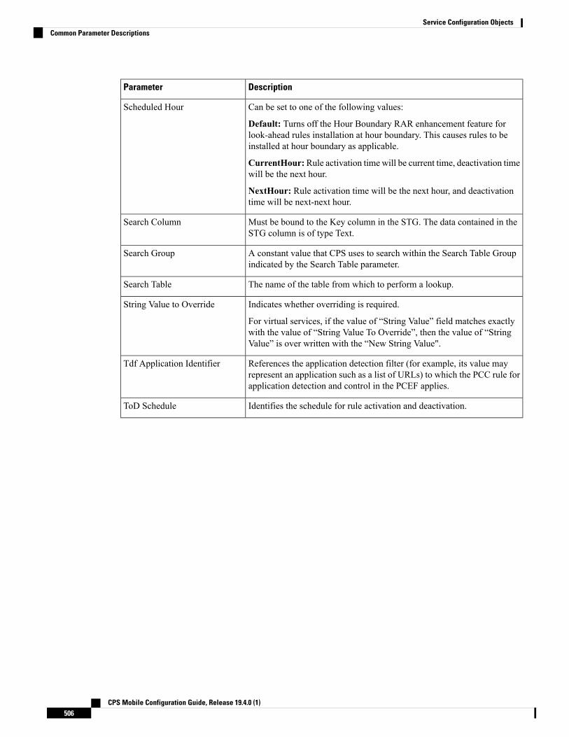
DescriptionParameter
Can be set to one of the following values:
Default: Turns off the Hour Boundary RAR enhancement feature forlook-ahead rules installation at hour boundary. This causes rules to beinstalled at hour boundary as applicable.
CurrentHour:Rule activation time will be current time, deactivation timewill be the next hour.
NextHour: Rule activation time will be the next hour, and deactivationtime will be next-next hour.
Scheduled Hour
Must be bound to the Key column in the STG. The data contained in theSTG column is of type Text.
Search Column
A constant value that CPS uses to search within the Search Table Groupindicated by the Search Table parameter.
Search Group
The name of the table from which to perform a lookup.Search Table
Indicates whether overriding is required.
For virtual services, if the value of “String Value” field matches exactlywith the value of “String Value To Override”, then the value of “StringValue” is over written with the “New String Value".
String Value to Override
References the application detection filter (for example, its value mayrepresent an application such as a list of URLs) to which the PCC rule forapplication detection and control in the PCEF applies.
Tdf Application Identifier
Identifies the schedule for rule activation and deactivation.ToD Schedule
CPS Mobile Configuration Guide, Release 19.4.0 (1)506
Service Configuration ObjectsCommon Parameter Descriptions
Copyright © 2022 FDOKUMEN