
IP Multicast Routing Configuration Guide, Cisco IOS XE ...
358
IP Multicast Routing Configuration Guide, Cisco IOS XE Release 3SE (Catalyst 3850 Switches) First Published: 2013-01-29 Last Modified: 2013-10-22 Americas Headquarters Cisco Systems, Inc. 170 West Tasman Drive San Jose, CA 95134-1706 USA http://www.cisco.com Tel: 408 526-4000 800 553-NETS (6387) Fax: 408 527-0883 Text Part Number: OL-26766-02
-
Upload
khangminh22 -
Category
Documents
-
view
0 -
download
0
Transcript of IP Multicast Routing Configuration Guide, Cisco IOS XE ...

IP Multicast Routing Configuration Guide, Cisco IOS XE Release 3SE(Catalyst 3850 Switches)First Published: 2013-01-29
Last Modified: 2013-10-22
Americas HeadquartersCisco Systems, Inc.170 West Tasman DriveSan Jose, CA 95134-1706USAhttp://www.cisco.comTel: 408 526-4000
800 553-NETS (6387)Fax: 408 527-0883
Text Part Number: OL-26766-02

THE SPECIFICATIONS AND INFORMATION REGARDING THE PRODUCTS IN THIS MANUAL ARE SUBJECT TO CHANGE WITHOUT NOTICE. ALL STATEMENTS,INFORMATION, AND RECOMMENDATIONS IN THIS MANUAL ARE BELIEVED TO BE ACCURATE BUT ARE PRESENTED WITHOUT WARRANTY OF ANY KIND,EXPRESS OR IMPLIED. USERS MUST TAKE FULL RESPONSIBILITY FOR THEIR APPLICATION OF ANY PRODUCTS.
THE SOFTWARE LICENSE AND LIMITED WARRANTY FOR THE ACCOMPANYING PRODUCT ARE SET FORTH IN THE INFORMATION PACKET THAT SHIPPED WITHTHE PRODUCT AND ARE INCORPORATED HEREIN BY THIS REFERENCE. IF YOU ARE UNABLE TO LOCATE THE SOFTWARE LICENSE OR LIMITED WARRANTY,CONTACT YOUR CISCO REPRESENTATIVE FOR A COPY.
The Cisco implementation of TCP header compression is an adaptation of a program developed by the University of California, Berkeley (UCB) as part of UCB's public domain version ofthe UNIX operating system. All rights reserved. Copyright © 1981, Regents of the University of California.
NOTWITHSTANDING ANY OTHERWARRANTY HEREIN, ALL DOCUMENT FILES AND SOFTWARE OF THESE SUPPLIERS ARE PROVIDED “AS IS" WITH ALL FAULTS.CISCO AND THE ABOVE-NAMED SUPPLIERS DISCLAIM ALL WARRANTIES, EXPRESSED OR IMPLIED, INCLUDING, WITHOUT LIMITATION, THOSE OFMERCHANTABILITY, FITNESS FOR A PARTICULAR PURPOSE AND NONINFRINGEMENT OR ARISING FROM A COURSE OF DEALING, USAGE, OR TRADE PRACTICE.
IN NO EVENT SHALL CISCO OR ITS SUPPLIERS BE LIABLE FOR ANY INDIRECT, SPECIAL, CONSEQUENTIAL, OR INCIDENTAL DAMAGES, INCLUDING, WITHOUTLIMITATION, LOST PROFITS OR LOSS OR DAMAGE TO DATA ARISING OUT OF THE USE OR INABILITY TO USE THIS MANUAL, EVEN IF CISCO OR ITS SUPPLIERSHAVE BEEN ADVISED OF THE POSSIBILITY OF SUCH DAMAGES.
Any Internet Protocol (IP) addresses and phone numbers used in this document are not intended to be actual addresses and phone numbers. Any examples, command display output, networktopology diagrams, and other figures included in the document are shown for illustrative purposes only. Any use of actual IP addresses or phone numbers in illustrative content is unintentionaland coincidental.
All printed copies and duplicate soft copies of this document are considered uncontrolled. See the current online version for the latest version.
Cisco has more than 200 offices worldwide. Addresses and phone numbers are listed on the Cisco website at www.cisco.com/go/offices.
Cisco and the Cisco logo are trademarks or registered trademarks of Cisco and/or its affiliates in the U.S. and other countries. To view a list of Cisco trademarks, go to this URL: www.cisco.comgo trademarks. Third-party trademarks mentioned are the property of their respective owners. The use of the word partner does not imply a partnership relationship between Cisco and anyother company. (1721R)
© 2013 Cisco Systems, Inc. All rights reserved.

C O N T E N T S
Preface xixP R E F A C E
Document Conventions xix
Related Documentation xxi
Obtaining Documentation and Submitting a Service Request xxi
Using the Command-Line Interface 1C H A P T E R 1
Information About Using the Command-Line Interface 1
Command Modes 1
Understanding Abbreviated Commands 3
No and Default Forms of Commands 3
CLI Error Messages 3
Configuration Logging 4
Using the Help System 4
How to Use the CLI to Configure Features 5
Configuring the Command History 5
Changing the Command History Buffer Size 5
Recalling Commands 6
Disabling the Command History Feature 6
Enabling and Disabling Editing Features 7
Editing Commands Through Keystrokes 7
Editing Command Lines That Wrap 8
Searching and Filtering Output of show and more Commands 9
Accessing the CLI 10
Accessing the CLI Through a Console Connection or Through Telnet 10
Using the Web Graphical User Interface 13C H A P T E R 2
IP Multicast Routing Configuration Guide, Cisco IOS XE Release 3SE (Catalyst 3850 Switches)iiiOL-26766-02

Prerequisites for Using the Web GUI 13
Information About Using The Web GUI 14
Web GUI Features 14
Connecting the Console Port of the Device 15
Logging On to the GUI 15
Enabling Web and Secure Web Modes 16
Configuring the Device Web GUI 16
Configuring IGMP 21C H A P T E R 3
Finding Feature Information 21
Restrictions for Configuring IGMP 21
Information About IGMP 22
IP Multicast Group Addresses 22
IGMP Versions 23
IGMP Version 1 23
IGMP Version 2 23
IGMP Version 3 23
IGMP Versions Differences 23
IGMPv3 Host Signalling 25
IGMP Join and Leave Process 26
IGMP Join Process 26
IGMP Leave Process 26
IGMP Snooping 27
Joining a Multicast Group 27
Leaving a Multicast Group 29
Immediate Leave 29
IGMP Configurable-Leave Timer 30
IGMP Report Suppression 30
IGMP Snooping and Device Stacks 30
IGMP Filtering and Throttling 30
Default IGMP Configuration 31
Default IGMP Snooping Configuration 32
Default IGMP Filtering and Throttling Configuration 32
How to Configure IGMP 33
IP Multicast Routing Configuration Guide, Cisco IOS XE Release 3SE (Catalyst 3850 Switches)OL-26766-02iv
Contents

Configuring the Device as a Member of a Group (CLI) 33
Controlling Access to IP Multicast Group (CLI) 35
Modifying the IGMP Host-Query Message Interval (CLI) 37
Changing the IGMP Query Timeout for IGMPv2 (CLI) 38
Changing the Maximum Query Response Time for IGMPv2 (CLI) 40
Configuring the Device as a Statically Connected Member (CLI) 42
Configuring IGMP Profiles (CLI) 44
Applying IGMP Profiles (CLI) 46
Setting the Maximum Number of IGMP Groups (CLI) 47
Configuring the IGMP Throttling Action (CLI) 48
Configuring the Device to Forward Multicast Traffic in the Absence of Directly Connected IGMPHosts 50
Controlling Access to an SSM Network Using IGMP Extended Access Lists 52
How to Configure IGMP Snooping 54
Enabling or Disabling IGMP Snooping on a Device (CLI) 54
Enabling or Disabling IGMP Snooping on a VLAN Interface (CLI) 55
Setting the Snooping Method (CLI) 56
Configuring a Multicast Router Port (CLI) 58
Configuring a Host Statically to Join a Group (CLI) 59
Enabling IGMP Immediate Leave (CLI) 60
Configuring the IGMP Leave Timer (CLI) 61
Configuring the IGMP Robustness-Variable (CLI) 63
Configuring the IGMP Last Member Query Count (CLI) 64
Configuring TCN-Related Commands 66
Configuring the IGMP Snooping Querier (CLI) 69
Disabling IGMP Report Suppression (CLI) 71
Monitoring IGMP 73
Monitoring IGMP Snooping Information 73
Monitoring IGMP Filtering and Throttling Configuration 75
Configuration Examples for IGMP 75
Example: Configuring the Device as a Member of a Multicast Group 75
Example: Controlling Access to Multicast Groups 75
Examples: Configuring IGMP Snooping 76
Examples: Configuring Filtering and Throttling 77
IP Multicast Routing Configuration Guide, Cisco IOS XE Release 3SE (Catalyst 3850 Switches)vOL-26766-02
Contents

Example: Interface Configuration as a Routed Port 77
Example: Interface Configuration as an SVI 78
Example: Configuring the Device to ForwardMulticast Traffic in the Absence of Directly ConnectedIGMP Hosts 78
Controlling Access to an SSM Network Using IGMP Extended Access Lists 79
Example: Denying All States for a Group G 79
Example: Denying All States for a Source S 79
Example: Permitting All States for a Group G 80
Example: Permitting All States for a Source S 80
Example: Filtering a Source S for a Group G 80
Where to Go Next for IGMP 80
Additional References 81
Feature History and Information for IGMP 82
Configuring IGMP Proxy 83C H A P T E R 4
Finding Feature Information 83
Prerequisites for IGMP Proxy 83
Information about IGMP Proxy 84
IGMP Proxy 84
How to Configure IGMP Proxy 86
Configuring the Upstream UDL Device for IGMP UDLR 86
Configuring the Downstream UDL Device for IGMP UDLR with IGMP Proxy Support 87
Configuration Examples for IGMP Proxy 90
Example: IGMP Proxy Configuration 90
Where to Go Next for IGMP Proxy 91
Additional References 91
Feature History and Information for IGMP Proxy 92
Constraining IP Multicast in Switched Ethernet 93C H A P T E R 5
Finding Feature Information 93
Prerequisites for Constraining IP Multicast in a Switched Ethernet Network 93
Information About IP Multicast in a Switched Ethernet Network 94
IP Multicast Traffic and Layer 2 Switches 94
CGMP on Catalyst Switches for IP Multicast 94
IP Multicast Routing Configuration Guide, Cisco IOS XE Release 3SE (Catalyst 3850 Switches)OL-26766-02vi
Contents

IGMP Snooping 95
Router-Port Group Management Protocol (RGMP) 95
How to Constrain Multicast in a Switched Ethernet Network 95
Configuring Switches for IP Multicast 95
Configuring IGMP Snooping 96
Enabling CGMP 96
Configuring IP Multicast in a Layer 2 Switched Ethernet Network 97
Configuration Examples for Constraining IP Multicast in a Switched Ethernet Network 98
Example: CGMP Configuration 98
RGMP Configuration Example 99
Where to Go Next for Constraining IP Multicast in Switched Ethernet 99
Additional References 100
Feature History and Information for Constraining IP Multicast in a Switched Ethernet Network 100
Configuring Protocol Independent Multicast (PIM) 101C H A P T E R 6
Finding Feature Information 101
Prerequisites for Configuring PIM 101
Restrictions for Configuring PIM 102
Restrictions for Configuring Auto-RP 102
Restrictions for Auto-RP Enhancement 103
Restrictions for Configuring Auto-RP and BSR 103
Information About PIM 103
PIM Versions 104
PIMv1 and PIMv2 Interoperability 104
PIM Modes 105
PIM DM 105
PIM-SM 105
PIM Stub Routing 106
IGMP Helper 107
Auto-RP 107
The Role of Auto-RP in a PIM Network 108
IP Multicast Boundary 108
Auto-RP Benefits 109
PIMv2 Bootstrap Router 110
IP Multicast Routing Configuration Guide, Cisco IOS XE Release 3SE (Catalyst 3850 Switches)viiOL-26766-02
Contents

PIM Domain Border 110
Multicast Forwarding and Reverse Path Check 110
PIM Shared Tree and Source Tree 112
Default PIM Routing Configuration 113
How to Configure PIM 114
Enabling PIM Stub Routing (CLI) 114
Configuring a Rendezvous Point 116
Manually Assigning an RP to Multicast Groups (CLI) 116
Setting Up Auto-RP in a New Internetwork (CLI) 119
Adding Auto-RP to an Existing Sparse-Mode Cloud (CLI) 121
Preventing Join Messages to False RPs (CLI) 124
Filtering Incoming RP Announcement Messages (CLI) 125
Configuring PIMv2 BSR 126
Defining the PIM Domain Border (CLI) 127
Defining the IP Multicast Boundary (CLI) 128
Configuring Candidate BSRs (CLI) 130
Configuring the Candidate RPs (CLI) 132
Configuring Sparse Mode with Auto-RP(CLI) 134
Delaying the Use of PIM Shortest-Path Tree (CLI) 139
Modifying the PIM Router-Query Message Interval (CLI) 140
Monitoring PIM Information 142
Monitoring the RP Mapping and BSR Information 143
Troubleshooting PIMv1 and PIMv2 Interoperability Problems 144
Configuration Examples for PIM 144
Example: Enabling PIM Stub Routing 144
Example: Verifying PIM Stub Routing 144
Example: Manually Assigning an RP to Multicast Groups 145
Example: Configuring Auto-RP 145
Example: Sparse Mode with Auto-RP 145
Example: Defining the IP Multicast Boundary to Deny Auto-RP Information 146
Example: Filtering Incoming RP Announcement Messages 146
Example: Preventing Join Messages to False RPs 146
Example: Configuring Candidate BSRs 147
Example: Configuring Candidate RPs 147
IP Multicast Routing Configuration Guide, Cisco IOS XE Release 3SE (Catalyst 3850 Switches)OL-26766-02viii
Contents

Where to Go Next for PIM 147
Additional References 148
Feature History and Information for PIM 149
Configuring PIM MIB Extension for IP Multicast 151C H A P T E R 7
Finding Feature Information 151
Information About PIM MIB Extension for IP Multicast 151
PIM MIB Extensions for SNMP Traps for IP Multicast 151
Benefits of PIM MIB Extensions 152
How to Configure PIM MIB Extension for IP Multicast 152
Enabling PIM MIB Extensions for IP Multicast 152
Configuration Examples for PIM MIB Extensions 154
Example Enabling PIM MIB Extensions for IP Multicast 154
Additional References 154
Configuring MSDP 157C H A P T E R 8
Finding Feature Information 157
157
Information About Using MSDP to Interconnect Multiple PIM-SM Domains 157
Benefits of Using MSDP to Interconnect Multiple PIM-SM Domains 157
158
MSDP Message Types 160
SA Messages 160
SA Request Messages 160
SA Response Messages 161
Keepalive Messages 161
SA Message Origination Receipt and Processing 161
SA Message Origination 161
SA Message Receipt 161
SA Message Processing 164
MSDP Peers 164
MSDP MD5 Password Authentication 164
How MSDP MD5 Password Authentication Works 164
Benefits of MSDP MD5 Password Authentication 165
IP Multicast Routing Configuration Guide, Cisco IOS XE Release 3SE (Catalyst 3850 Switches)ixOL-26766-02
Contents

SA Message Limits 165
MSDP Keepalive and Hold-Time Intervals 165
MSDP Connection-Retry Interval 166
Default MSDP Peers 166
MSDP Mesh Groups 167
Benefits of MSDP Mesh Groups 167
SA Origination Filters 168
Use of Outgoing Filter Lists in MSDP 168
Use of Incoming Filter Lists in MSDP 169
TTL Thresholds in MSDP 170
SA Request Messages 170
SA Request Filters 170
How to Use MSDP to Interconnect Multiple PIM-SM Domains 171
Configuring an MSDP Peer 171
Shutting Down an MSDP Peer 172
Configuring MSDP MD5 Password Authentication Between MSDP Peers 173
Troubleshooting Tips 175
Preventing DoS Attacks by Limiting the Number of SA Messages Allowed in the SA Cache fromSpecified MSDP Peers 175
Adjusting the MSDP Keepalive and Hold-Time Intervals 176
Adjusting the MSDP Connection-Retry Interval 177
Configuring a Default MSDP Peer 178
Configuring an MSDP Mesh Group 179
Controlling SA Messages Originated by an RP for Local Sources 180
Controlling the Forwarding of SA Messages to MSDP Peers Using Outgoing Filter Lists 181
Controlling the Receipt of SA Messages from MSDP Peers Using Incoming Filter Lists 182
Using TTL Thresholds to Limit the Multicast Data Sent in SA Messages 183
Controlling the Response to Outgoing SA Request Messages from MSDP Peers Using SA RequestFilters 184
Including a Bordering PIM Dense Mode Region in MSDP 185
Configuring an Originating Address Other Than the RP Address 186
Monitoring MSDP 187
Clearing MSDP Connections Statistics and SA Cache Entries 190
Enabling SNMP Monitoring of MSDP 190
IP Multicast Routing Configuration Guide, Cisco IOS XE Release 3SE (Catalyst 3850 Switches)OL-26766-02x
Contents
Troubleshooting Tips 191
Configuration Examples for Using MSDP to Interconnect Multiple PIM-SM Domains 192
Example: Configuring an MSDP Peer 192
Example: Configuring MSDP MD5 Password Authentication 192
Example: Configuring a Default MSDP Peer 193
Example: Configuring MSDP Mesh Groups 195
Where to Go Next for MSDP 195
Additional References 196
Feature History and Information for Multicast Source Discovery Protocol 197
Configuring Wireless Multicast 199C H A P T E R 9
Finding Feature Information 199
Prerequisites for Configuring Wireless Multicast 199
Restrictions on Configuring Wireless Multicast 200
Restrictions for IPv6 Snooping 200
Restrictions for IPv6 RA Guard 200
Information About Wireless Multicast 200
Multicast Optimization 201
IPv6 Global Policies 202
IPv6 RA Guard 202
Information About IPv6 Snooping 202
IPv6 Neighbor Discovery Inspection 202
How to Configure Wireless Multicast 204
Configuring Wireless Multicast-MCMC Mode (CLI) 204
Configuring Wireless Multicast-MCUC Mode (CLI) 205
Configuring IPv6 Snooping (CLI) 206
Configuring IPv6 Snooping Policy (CLI) 207
Configuring Layer 2 Port as Multicast Router Port (CLI) 207
Configuring IPv6 RA Guard (CLI) 208
Configuring Non-IP Wireless Multicast (CLI) 209
Configuring Wireless Broadcast (CLI) 210
Configuring IP Multicast VLAN for WLAN (CLI) 211
Verifying Wireless Multicast 212
Where to Go Next for Wireless Multicast 212
IP Multicast Routing Configuration Guide, Cisco IOS XE Release 3SE (Catalyst 3850 Switches)xiOL-26766-02
Contents

Additional References 213
Configuring SSM 215C H A P T E R 1 0
Finding Feature Information 215
Prerequisites for Configuring SSM 215
Restrictions for Configuring SSM 216
Information About SSM 217
SSM Components Overview 217
How SSM Differs from Internet Standard Multicast 217
SSM Operations 218
Benefits of SSM 218
SSM Mapping 220
Static SSM Mapping 220
DNS-Based SSM Mapping 220
How to Configure SSM 221
Configuring Source Specific Multicast 221
Configuring Source Specific Multicast Mapping 223
Configuring Static SSM Mapping (CLI) 223
Configuring DNS-Based SSM Mapping (CLI) 225
Configuring Static Traffic Forwarding with SSM Mapping (CLI) 227
Monitoring SSM 229
Monitoring SSM Mapping 229
Configuration Examples for Source Specific Multicast 230
SSM with IGMPv3 Example 230
Where to Go Next for SSM 230
Additional References 231
Feature History and Information for SSM 232
Configuring Basic IP Multicast Routing 233C H A P T E R 1 1
Finding Feature Information 233
Prerequisites for Configuring IP Multicast Routing 233
Restrictions for Configuring IP Multicast Routing 234
Information About Basic IP Multicast Routing 234
Cisco’s Implementation of IP Multicast Routing 234
IP Multicast Routing Configuration Guide, Cisco IOS XE Release 3SE (Catalyst 3850 Switches)OL-26766-02xii
Contents

Multicast Forwarding Information Base Overview 235
Multicast Group Concept 236
Multicast Boundaries 236
Multicast Routing and Device Stacks 237
Default Multicast Routing Configuration 237
How to Configure Basic IP Multicast Routing 238
Configuring Basic IP Multicast Routing (CLI) 238
Configuring IP Multicast Forwarding (CLI) 240
Configuring a Static Multicast Route (mroute) (CLI) 242
Configuring sdr Listener Support 243
Enabling sdr Listener Support (CLI) 244
Limiting How Long an sdr Cache Entry Exists (CLI) 245
Configuring an IP Multicast Boundary (CLI) 246
Monitoring and Maintaining Basic IP Multicast Routing 249
Clearing Caches, Tables, and Databases 249
Displaying System and Network Statistics 250
Monitoring IP Multicast Routing 252
Configuration Examples for IP Multicast Routing 252
Example: Configuring an IP Multicast Boundary 252
Example: Responding to mrinfo Requests 253
Where to Go Next for IP Multicast 253
Additional References 254
Feature History and Information for IP Multicast 255
Configuring the Service Discovery Gateway 257C H A P T E R 1 2
Finding Feature Information 257
Restrictions for Configuring the Service Discovery Gateway 257
Information about the Service Discovery Gateway and mDNS 258
mDNS 258
mDNS-SD 258
Service Discovery Gateway 259
mDNS Gateway and Subnets 259
Filtering 260
How to Configure the Service Discovery Gateway 261
IP Multicast Routing Configuration Guide, Cisco IOS XE Release 3SE (Catalyst 3850 Switches)xiiiOL-26766-02
Contents

Configuring the Service List (CLI) 261
Configuring the Service List (GUI) 263
Enabling mDNS Gateway and Redistributing Services (CLI) 264
Configuring Interface Service Rules (GUI) 267
Configuring mDNS Global Rules (GUI) 267
Monitoring Service Discovery Gateway 268
Configuration Examples 268
Example: Specify Alternative Source Interface for Outgoing mDNS Packets 268
Example: Redistribute Service Announcements 268
Example: Disable Bridging of mDNS Packets to Wireless Clients 269
Example: Creating a Service-List, Applying a Filter and Configuring Parameters 269
Example: Enabling mDNS Gateway and Redistributing Services 269
Example: Global mDNS Configuration 270
Example: Interface mDNS Configuration 270
Monitoring Service Cache (GUI) 270
Monitoring Static Service Cache (GUI) 271
Where to Go Next for Configuring Services Discovery Gateway 272
Additional References 272
Feature History and Information for Services Discovery Gateway 273
IP Multicast Optimization: Optimizing PIM Sparse Mode in a Large IP Multicast Deployment 275C H A P T E R 1 3
Finding Feature Information 275
Prerequisites for Optimizing PIM Sparse Mode in a Large IP Multicast Deployment 275
Information About Optimizing PIM Sparse Mode in a Large IP Multicast Deployment 276
PIM Registering Process 276
PIM Version 1 Compatibility 276
PIM Designated Router 277
PIM Sparse-Mode Register Messages 277
Preventing Use of Shortest-Path Tree to Reduce Memory Requirement 277
PIM Shared Tree and Source Tree - Shortest-Path Tree 277
Benefit of Preventing or Delaying the Use of the Shortest-Path Tree 279
How to Optimize PIM Sparse Mode in a Large IP Multicast Deployment 279
Optimizing PIM Sparse Mode in a Large Deployment 279
Configuration Examples for Optimizing PIM Sparse Mode in a Large Multicast Deployment 281
IP Multicast Routing Configuration Guide, Cisco IOS XE Release 3SE (Catalyst 3850 Switches)OL-26766-02xiv
Contents

Optimizing PIM Sparse Mode in a Large IP Multicast Deployment Example 281
Additional References 281
Feature History and Information for Optimizing PIM Sparse Mode in a Large IP MulticastDeployment 282
IP Multicast Optimization: Multicast Subsecond Convergence 283C H A P T E R 1 4
Finding Feature Information 283
Prerequisites for Multicast Subsecond Convergence 283
Restrictions for Multicast Subsecond Convergence 283
Information About Multicast Subsecond Convergence 284
Benefits of Multicast Subsecond Convergence 284
Multicast Subsecond Convergence Scalability Enhancements 284
PIM Router Query Messages 284
Reverse Path Forwarding 284
RPF Checks 285
Triggered RPF Checks 285
RPF Failover 285
Topology Changes and Multicast Routing Recovery 286
How to Configure Multicast Subsecond Convergence 286
Modifying the Periodic RPF Check Interval 286
Configuring PIM RPF Failover Intervals 287
Modifying the PIM Router Query Message Interval 287
Verifying Multicast Subsecond Convergence Configurations 288
Configuration Examples for Multicast Subsecond Convergence 289
Example Modifying the Periodic RPF Check Interval 289
Example Configuring PIM RPF Failover Intervals 290
Modifying the PIM Router Query Message Interval Example 290
Additional References 291
Feature History and Information for Multicast Subsecond Convergence 291
IP Multicast Optimization: IP Multicast Load Splitting across Equal-Cost Paths 293C H A P T E R 1 5
Finding Feature Information 293
Prerequisites for IP Multicast Load Splitting across Equal-Cost Paths 293
Information About IP Multicast Load Splitting across Equal-Cost Paths 294
IP Multicast Routing Configuration Guide, Cisco IOS XE Release 3SE (Catalyst 3850 Switches)xvOL-26766-02
Contents

Load Splitting Versus Load Balancing 294
Default Behavior for IP Multicast When Multiple Equal-Cost Paths Exist 294
Methods to Load Split IP Multicast Traffic 296
Overview of ECMP Multicast Load Splitting 296
ECMP Multicast Load Splitting Based on Source Address Using the S-Hash Algorithm 296
ECMP Multicast Load Splitting Based on Source and Group Address Using the Basic S-G-HashAlgorithm 297
Predictability As a By-Product of Using the S-Hash and Basic S-G-Hash Algorithms 297
Polarization As a By-Product of Using the S-Hash and Basic S-G-Hash Algorithms 297
ECMP Multicast Load Splitting Based on Source Group and Next-Hop Address 298
Effect of ECMP Multicast Load Splitting on PIM Neighbor Query and Hello Messages for RPFPath Selection 299
Effect of ECMP Multicast Loading Splitting on Assert Processing in PIM-DM and DF Electionin Bidir-PIM 300
Effect of ECMPMulticast Load Splitting on the PIM Assert Process in PIM-SM and PIM-SSM301
ECMP Multicast Load Splitting and Reconvergence When Unicast Routing Changes 302
Use of BGP with ECMP Multicast Load Splitting 302
Use of ECMP Multicast Load Splitting with Static Mroutes 302
Alternative Methods of Load Splitting IP Multicast Traffic 303
How to Load Split IP Multicast Traffic over ECMP 303
Enabling ECMP Multicast Load Splitting 303
Prerequisites for IP Multicast Load Splitting - ECMP 303
Restrictions 304
Enabling ECMP Multicast Load Splitting Based on Source Address 304
Enabling ECMP Multicast Load Splitting Based on Source and Group Address 306
Enabling ECMP Multicast Load Splitting Based on Source Group and Next-Hop Address 308
Configuration Examples for Load Splitting IP Multicast Traffic over ECMP 310
Example Enabling ECMP Multicast Load Splitting Based on Source Address 310
Example Enabling ECMP Multicast Load Splitting Based on Source and Group Address 310
Example Enabling ECMPMulticast Load Splitting Based on Source Group and Next-Hop Address310
Additional References 311
Feature History and Information for Load Splitting IP Multicast Traffic over ECMP 312
IP Multicast Routing Configuration Guide, Cisco IOS XE Release 3SE (Catalyst 3850 Switches)OL-26766-02xvi
Contents

IP Multicast Optimization: SSM Channel Based Filtering for Multicast 313C H A P T E R 1 6
Finding Feature Information 313
Finding Feature Information 313
Prerequisites for SSM Channel Based Filtering for Multicast Boundaries 314
Information About the SSM Channel Based Filtering for Multicast Boundaries Feature 314
Rules for Multicast Boundaries 314
Benefits of SSM Channel Based Filtering for Multicast Boundaries 314
How to Configure SSM Channel Based Filtering for Multicast Boundaries 315
Configuring Multicast Boundaries 315
Configuration Examples for SSM Channel Based Filtering for Multicast Boundaries 316
Configuring the Multicast Boundaries Permitting and Denying Traffic Example 316
Configuring the Multicast Boundaries Permitting Traffic Example 316
Configuring the Multicast Boundaries Denying Traffic Example 317
Additional References 317
Feature History and Information for SSM Channel Based Filtering for Multicast Boundaries 318
IP Multicast Optimization: PIM Dense Mode State Refresh 319C H A P T E R 1 7
Finding Feature Information 319
Prerequisite for PIM Dense Mode State Refresh 319
Restrictions on PIM Dense Mode State Refresh 319
Information About PIM Dense Mode State Refresh 320
PIM Dense Mode State Refresh Overview 320
Benefits of PIM Dense Mode State Refresh 320
How to Configure PIM Dense Mode State Refresh 320
Configuring PIM Dense Mode State Refresh 320
Verifying PIM Dense Mode State Refresh Configuration 321
Monitoring and Maintaining PIM DM State Refresh 322
Configuration Examples for PIM Dense Mode State Refresh 322
Originating Processing and Forwarding PIMDenseMode State Refresh ControlMessages Example322
Processing and Forwarding PIM Dense Mode State Refresh Control Messages Example 323
Additional References 323
Feature History and Information for PIM Dense Mode State Refresh 324
IP Multicast Routing Configuration Guide, Cisco IOS XE Release 3SE (Catalyst 3850 Switches)xviiOL-26766-02
Contents
IP Multicast Optimization: IGMP State Limit 325C H A P T E R 1 8
Finding Feature Information 325
Prerequisites for IGMP State Limit 325
Restrictions for IGMP State Limit 325
Information About IGMP State Limit 326
IGMP State Limit 326
IGMP State Limit Feature Design 326
Mechanics of IGMP State Limiters 326
How to Configure IGMP State Limit 327
Configuring IGMP State Limiters 327
Configuring Global IGMP State Limiters 327
Configuring Per Interface IGMP State Limiters 328
Configuration examples for IGMP State Limit 329
Configuring IGMP State Limiters Example 329
Additional References 331
Feature History and Information for IGMP State Limit 331
IP Multicast Routing Configuration Guide, Cisco IOS XE Release 3SE (Catalyst 3850 Switches)OL-26766-02xviii
Contents

Preface
• Document Conventions , on page xix• Related Documentation, on page xxi• Obtaining Documentation and Submitting a Service Request, on page xxi
Document ConventionsThis document uses the following conventions:
DescriptionConvention
Both the ^ symbol and Ctrl represent the Control (Ctrl) key on a keyboard. Forexample, the key combination ^D orCtrl-Dmeans that you hold down the Controlkey while you press the D key. (Keys are indicated in capital letters but are notcase sensitive.)
^ or Ctrl
Commands and keywords and user-entered text appear in bold font.bold font
Document titles, new or emphasized terms, and arguments for which you supplyvalues are in italic font.
Italic font
Terminal sessions and information the system displays appear in courier font.Courier font
Bold Courier font indicates text that the user must enter.Bold Courier font
Elements in square brackets are optional.[x]
An ellipsis (three consecutive nonbolded periods without spaces) after a syntaxelement indicates that the element can be repeated.
...
A vertical line, called a pipe, indicates a choice within a set of keywords orarguments.
|
Optional alternative keywords are grouped in brackets and separated by verticalbars.
[x | y]
Required alternative keywords are grouped in braces and separated by verticalbars.
{x | y}
IP Multicast Routing Configuration Guide, Cisco IOS XE Release 3SE (Catalyst 3850 Switches)xixOL-26766-02

DescriptionConvention
Nested set of square brackets or braces indicate optional or required choices withinoptional or required elements. Braces and a vertical bar within square bracketsindicate a required choice within an optional element.
[x {y | z}]
A nonquoted set of characters. Do not use quotation marks around the string orthe string will include the quotation marks.
string
Nonprinting characters such as passwords are in angle brackets.< >
Default responses to system prompts are in square brackets.[ ]
An exclamation point (!) or a pound sign (#) at the beginning of a line of codeindicates a comment line.
!, #
Reader Alert Conventions
This document may use the following conventions for reader alerts:
Means reader take note. Notes contain helpful suggestions or references to material not covered in the manual.Note
Means the following information will help you solve a problem.Tip
Means reader be careful. In this situation, you might do something that could result in equipment damage orloss of data.
Caution
Means the described action saves time.You can save time by performing the action described in the paragraph.Timesaver
IMPORTANT SAFETY INSTRUCTIONS
This warning symbol means danger. You are in a situation that could cause bodily injury. Before you workon any equipment, be aware of the hazards involved with electrical circuitry and be familiar with standardpractices for preventing accidents. Use the statement number provided at the end of each warning to locateits translation in the translated safety warnings that accompanied this device. Statement 1071
SAVE THESE INSTRUCTIONS
Warning
IP Multicast Routing Configuration Guide, Cisco IOS XE Release 3SE (Catalyst 3850 Switches)OL-26766-02xx
PrefacePreface

Related Documentation
Before installing or upgrading the device, refer to the device release notes.Note
• Cisco Catalyst 3850 Series Switches documentation, located at:
http://www.cisco.com/go/cat3850_docs
• Cisco SFP, SFP+, and QSFP+ modules documentation, including compatibility matrixes, located at:
http://www.cisco.com/en/US/products/hw/modules/ps5455/tsd_products_support_series_home.html
• Cisco Validated Designs documents, located at:
http://www.cisco.com/go/designzone
Obtaining Documentation and Submitting a Service RequestFor information on obtaining documentation, submitting a service request, and gathering additional information,see the monthlyWhat's New in Cisco Product Documentation, which also lists all new and revised Ciscotechnical documentation, at:
http://www.cisco.com/c/en/us/td/docs/general/whatsnew/whatsnew.html
Subscribe to theWhat's New in Cisco Product Documentation as a Really Simple Syndication (RSS) feedand set content to be delivered directly to your desktop using a reader application. The RSS feeds are a freeservice and Cisco currently supports RSS version 2.0.
IP Multicast Routing Configuration Guide, Cisco IOS XE Release 3SE (Catalyst 3850 Switches)xxiOL-26766-02
PrefaceRelated Documentation

IP Multicast Routing Configuration Guide, Cisco IOS XE Release 3SE (Catalyst 3850 Switches)OL-26766-02xxii
PrefaceObtaining Documentation and Submitting a Service Request

C H A P T E R 1Using the Command-Line Interface
• Information About Using the Command-Line Interface, on page 1• How to Use the CLI to Configure Features, on page 5
Information About Using the Command-Line Interface
Search options on the GUI and CLI are case sensitive.Note
Command ModesThe Cisco IOS user interface is divided into many different modes. The commands available to you dependon whichmode you are currently in. Enter a questionmark (?) at the system prompt to obtain a list of commandsavailable for each command mode.
You can start a CLI session through a console connection, through Telnet, an SSH, or by using the browser.
When you start a session, you begin in user mode, often called user EXEC mode. Only a limited subset ofthe commands are available in user EXECmode. For example, most of the user EXEC commands are one-timecommands, such as show commands, which show the current configuration status, and clear commands,which clear counters or interfaces. The user EXEC commands are not saved when the device reboots.
To have access to all commands, youmust enter privileged EXECmode. Normally, youmust enter a passwordto enter privileged EXEC mode. From this mode, you can enter any privileged EXEC command or enterglobal configuration mode.
Using the configurationmodes (global, interface, and line), you canmake changes to the running configuration.If you save the configuration, these commands are stored and used when the device reboots. To access thevarious configuration modes, you must start at global configuration mode. From global configuration mode,you can enter interface configuration mode and line configuration mode .
This table describes the main command modes, how to access each one, the prompt you see in that mode, andhow to exit the mode.
IP Multicast Routing Configuration Guide, Cisco IOS XE Release 3SE (Catalyst 3850 Switches)1OL-26766-02

Table 1: Command Mode Summary
About This ModeExit MethodPromptAccess MethodMode
Use this mode to
• Changeterminalsettings.
• Perform basictests.
• Display systeminformation.
Enter logout orquit.Device>
Begin a sessionusing Telnet, SSH,or console.
User EXEC
Use this mode toverify commandsthat you haveentered. Use apassword to protectaccess to this mode.
Enter disable toexit.Device#
While in userEXEC mode, enterthe enablecommand.
Privileged EXEC
Use this mode toconfigure parametersthat apply to theentire device.
To exit toprivilegedEXEC mode,enter exit orend, or pressCtrl-Z.
Device(config)#While in privilegedEXEC mode, enterthe configurecommand.
Globalconfiguration
Use this mode toconfigure VLANparameters. WhenVTP mode istransparent, you cancreateextended-rangeVLANs (VLAN IDsgreater than 1005)and saveconfigurations in thedevice startupconfiguration file.
To exit toglobalconfigurationmode, enter theexit command.
To return toprivilegedEXEC mode,press Ctrl-Z orenter end.
Device(config-vlan)#While in globalconfigurationmode,enter the vlanvlan-id command.
VLANconfiguration
IP Multicast Routing Configuration Guide, Cisco IOS XE Release 3SE (Catalyst 3850 Switches)OL-26766-022
Using the Command-Line InterfaceCommand Modes

About This ModeExit MethodPromptAccess MethodMode
Use this mode toconfigure parametersfor the Ethernetports.
To exit toglobalconfigurationmode, enterexit.
To return toprivilegedEXEC mode,press Ctrl-Z orenter end.
Device(config-if)#While in globalconfigurationmode,enter the interfacecommand (with aspecific interface).
Interfaceconfiguration
Use this mode toconfigure parametersfor the terminal line.
To exit toglobalconfigurationmode, enterexit.
To return toprivilegedEXEC mode,press Ctrl-Z orenter end.
Device(config-line)#While in globalconfigurationmode,specify a line withthe line vty or lineconsole command.
Line configuration
Understanding Abbreviated CommandsYou need to enter only enough characters for the device to recognize the command as unique.
This example shows how to enter the show configuration privileged EXEC command in an abbreviated form:
Device# show conf
No and Default Forms of CommandsAlmost every configuration command also has a no form. In general, use the no form to disable a feature orfunction or reverse the action of a command. For example, the no shutdown interface configuration commandreverses the shutdown of an interface. Use the command without the keyword no to reenable a disabled featureor to enable a feature that is disabled by default.
Configuration commands can also have a default form. The default form of a command returns the commandsetting to its default. Most commands are disabled by default, so the default form is the same as the no form.However, some commands are enabled by default and have variables set to certain default values. In thesecases, the default command enables the command and sets variables to their default values.
CLI Error MessagesThis table lists some error messages that you might encounter while using the CLI to configure your device.
IP Multicast Routing Configuration Guide, Cisco IOS XE Release 3SE (Catalyst 3850 Switches)3OL-26766-02
Using the Command-Line InterfaceUnderstanding Abbreviated Commands

Table 2: Common CLI Error Messages
How to Get HelpMeaningError Message
Reenter the command followed by a question mark(?) without any space between the command andthe question mark.
The possible keywords that you can enter with thecommand appear.
You did not enter enoughcharacters for your device torecognize the command.
% Ambiguouscommand: "showcon"
Reenter the command followed by a question mark(?) with a space between the command and thequestion mark.
The possible keywords that you can enter with thecommand appear.
You did not enter all of thekeywords or values required bythis command.
% Incompletecommand.
Enter a question mark (?) to display all of thecommands that are available in this commandmode.
The possible keywords that you can enter with thecommand appear.
You entered the commandincorrectly. The caret (^) marksthe point of the error.
% Invalid inputdetected at ‘^’marker.
Configuration LoggingYou can log and view changes to the device configuration. You can use the Configuration Change Loggingand Notification feature to track changes on a per-session and per-user basis. The logger tracks eachconfiguration command that is applied, the user who entered the command, the time that the command wasentered, and the parser return code for the command. This feature includes a mechanism for asynchronousnotification to registered applications whenever the configuration changes. You can choose to have thenotifications sent to the syslog.
Only CLI or HTTP changes are logged.Note
Using the Help SystemYou can enter a question mark (?) at the system prompt to display a list of commands available for eachcommand mode. You can also obtain a list of associated keywords and arguments for any command.
SUMMARY STEPS
1. help2. abbreviated-command-entry ?3. abbreviated-command-entry <Tab>4. ?5. command ?6. command keyword ?
IP Multicast Routing Configuration Guide, Cisco IOS XE Release 3SE (Catalyst 3850 Switches)OL-26766-024
Using the Command-Line InterfaceConfiguration Logging

DETAILED STEPS
PurposeCommand or Action
Obtains a brief description of the help system in anycommand mode.
help
Example:
Step 1
Device# help
Obtains a list of commands that begin with a particularcharacter string.
abbreviated-command-entry ?
Example:
Step 2
Device# di?dir disable disconnect
Completes a partial command name.abbreviated-command-entry <Tab>
Example:
Step 3
Device# sh conf<tab>Device# show configuration
Lists all commands available for a particular commandmode.
?
Example:
Step 4
Device> ?
Lists the associated keywords for a command.command ?
Example:
Step 5
Device> show ?
Lists the associated arguments for a keyword.command keyword ?
Example:
Step 6
Device(config)# cdp holdtime ?<10-255> Length of time (in sec) that receiver
must keep this packet
How to Use the CLI to Configure Features
Configuring the Command HistoryThe software provides a history or record of commands that you have entered. The command history featureis particularly useful for recalling long or complex commands or entries, including access lists. You cancustomize this feature to suit your needs.
Changing the Command History Buffer SizeBy default, the device records ten command lines in its history buffer. You can alter this number for a currentterminal session or for all sessions on a particular line. This procedure is optional.
IP Multicast Routing Configuration Guide, Cisco IOS XE Release 3SE (Catalyst 3850 Switches)5OL-26766-02
Using the Command-Line InterfaceHow to Use the CLI to Configure Features

SUMMARY STEPS
1. terminal history [size number-of-lines]
DETAILED STEPS
PurposeCommand or Action
Changes the number of command lines that the devicerecords during the current terminal session in privilegedEXEC mode. You can configure the size from 0 to 256.
terminal history [size number-of-lines]
Example:Device# terminal history size 200
Step 1
Recalling CommandsTo recall commands from the history buffer, perform one of the actions listed in this table. These actions areoptional.
The arrow keys function only on ANSI-compatible terminals such as VT100s.Note
SUMMARY STEPS
1. Ctrl-P or use the up arrow key2. Ctrl-N or use the down arrow key3. show history
DETAILED STEPS
PurposeCommand or Action
Recalls commands in the history buffer, beginning with themost recent command. Repeat the key sequence to recallsuccessively older commands.
Ctrl-P or use the up arrow keyStep 1
Returns to more recent commands in the history buffer afterrecalling commandswithCtrl-P or the up arrow key. Repeat
Ctrl-N or use the down arrow keyStep 2
the key sequence to recall successively more recentcommands.
Lists the last several commands that you just entered inprivileged EXEC mode. The number of commands that
show history
Example:
Step 3
appear is controlled by the setting of the terminal historyDevice# show history global configuration command and the history line
configuration command.
Disabling the Command History FeatureThe command history feature is automatically enabled. You can disable it for the current terminal session orfor the command line. This procedure is optional.
IP Multicast Routing Configuration Guide, Cisco IOS XE Release 3SE (Catalyst 3850 Switches)OL-26766-026
Using the Command-Line InterfaceRecalling Commands

SUMMARY STEPS
1. terminal no history
DETAILED STEPS
PurposeCommand or Action
Disables the feature during the current terminal session inprivileged EXEC mode.
terminal no history
Example:
Step 1
Device# terminal no history
Enabling and Disabling Editing FeaturesAlthough enhanced editing mode is automatically enabled, you can disable it and reenable it.
SUMMARY STEPS
1. terminal editing2. terminal no editing
DETAILED STEPS
PurposeCommand or Action
Reenables the enhanced editing mode for the currentterminal session in privileged EXEC mode.
terminal editing
Example:
Step 1
Device# terminal editing
Disables the enhanced editing mode for the current terminalsession in privileged EXEC mode.
terminal no editing
Example:
Step 2
Device# terminal no editing
Editing Commands Through KeystrokesThe keystrokes help you to edit the command lines. These keystrokes are optional.
The arrow keys function only on ANSI-compatible terminals such as VT100s.Note
Table 3: Editing Commands
DescriptionEditing Commands
Moves the cursor back one character.Ctrl-B or use the left arrow key
Moves the cursor forward one character.Ctrl-F or use the right arrowkey
IP Multicast Routing Configuration Guide, Cisco IOS XE Release 3SE (Catalyst 3850 Switches)7OL-26766-02
Using the Command-Line InterfaceEnabling and Disabling Editing Features

Moves the cursor to the beginning of the command line.Ctrl-A
Moves the cursor to the end of the command line.Ctrl-E
Moves the cursor back one word.Esc B
Moves the cursor forward one word.Esc F
Transposes the character to the left of the cursor with the character locatedat the cursor.
Ctrl-T
Erases the character to the left of the cursor.Delete or Backspace key
Deletes the character at the cursor.Ctrl-D
Deletes all characters from the cursor to the end of the command line.Ctrl-K
Deletes all characters from the cursor to the beginning of the commandline.
Ctrl-U or Ctrl-X
Deletes the word to the left of the cursor.Ctrl-W
Deletes from the cursor to the end of the word.Esc D
Capitalizes at the cursor.Esc C
Changes the word at the cursor to lowercase.Esc L
Capitalizes letters from the cursor to the end of the word.Esc U
Designates a particular keystroke as an executable command, perhaps asa shortcut.
Ctrl-V or Esc Q
Scrolls down a line or screen on displays that are longer than the terminalscreen can display.
The More prompt is used for any output that has more linesthan can be displayed on the terminal screen, including showcommand output. You can use the Return and Space barkeystrokes whenever you see the More prompt.
Note
Return key
Scrolls down one screen.Space bar
Redisplays the current command line if the device suddenly sends amessage to your screen.
Ctrl-L or Ctrl-R
Editing Command Lines That WrapYou can use a wraparound feature for commands that extend beyond a single line on the screen. When thecursor reaches the right margin, the command line shifts ten spaces to the left. You cannot see the first tencharacters of the line, but you can scroll back and check the syntax at the beginning of the command. Thekeystroke actions are optional.
To scroll back to the beginning of the command entry, press Ctrl-B or the left arrow key repeatedly. You canalso press Ctrl-A to immediately move to the beginning of the line.
IP Multicast Routing Configuration Guide, Cisco IOS XE Release 3SE (Catalyst 3850 Switches)OL-26766-028
Using the Command-Line InterfaceEditing Command Lines That Wrap

The arrow keys function only on ANSI-compatible terminals such as VT100s.Note
The following example shows how to wrap a command line that extends beyond a single line on the screen.
SUMMARY STEPS
1. access-list2. Ctrl-A3. Return key
DETAILED STEPS
PurposeCommand or Action
Displays the global configuration command entry thatextends beyond one line.
access-list
Example:
Step 1
When the cursor first reaches the end of the line, the line isshifted ten spaces to the left and redisplayed. The dollarDevice(config)# access-list 101 permit tcp
10.15.22.25 255.255.255.0 10.15.22.35 sign ($) shows that the line has been scrolled to the left.Device(config)# $ 101 permit tcp 10.15.22.25 Each time the cursor reaches the end of the line, the line is
again shifted ten spaces to the left.255.255.255.0 10.15.22.35 255.25Device(config)# $t tcp 10.15.22.25 255.255.255.0131.108.1.20 255.255.255.0 eqDevice(config)# $15.22.25 255.255.255.0 10.15.22.35255.255.255.0 eq 45
Checks the complete syntax.Ctrl-AStep 2
Example: The dollar sign ($) appears at the end of the line to showthat the line has been scrolled to the right.Device(config)# access-list 101 permit tcp
10.15.22.25 255.255.255.0 10.15.2$
Execute the commands.Return keyStep 3
The software assumes that you have a terminal screen thatis 80 columns wide. If you have a different width, use theterminal width privileged EXEC command to set the widthof your terminal.
Use line wrapping with the command history feature torecall and modify previous complex command entries.
Searching and Filtering Output of show and more CommandsYou can search and filter the output for show andmore commands. This is useful when you need to sortthrough large amounts of output or if you want to exclude output that you do not need to see. Using thesecommands is optional.
IP Multicast Routing Configuration Guide, Cisco IOS XE Release 3SE (Catalyst 3850 Switches)9OL-26766-02
Using the Command-Line InterfaceSearching and Filtering Output of show and more Commands
SUMMARY STEPS
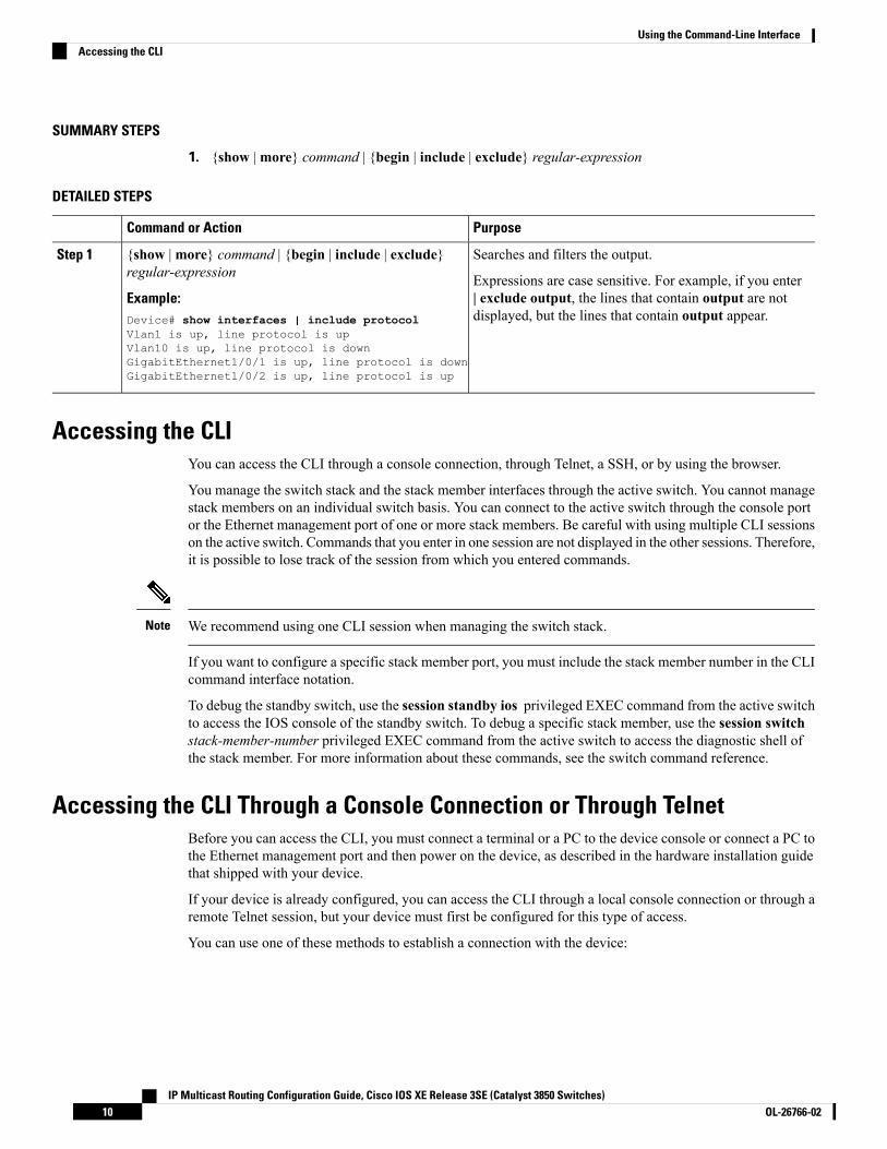
1. {show |more} command | {begin | include | exclude} regular-expression
DETAILED STEPS
PurposeCommand or Action
Searches and filters the output.{show |more} command | {begin | include | exclude}regular-expression
Step 1
Expressions are case sensitive. For example, if you enter| exclude output, the lines that contain output are notdisplayed, but the lines that contain output appear.
Example:Device# show interfaces | include protocolVlan1 is up, line protocol is upVlan10 is up, line protocol is downGigabitEthernet1/0/1 is up, line protocol is downGigabitEthernet1/0/2 is up, line protocol is up
Accessing the CLIYou can access the CLI through a console connection, through Telnet, a SSH, or by using the browser.
You manage the switch stack and the stack member interfaces through the active switch. You cannot managestack members on an individual switch basis. You can connect to the active switch through the console portor the Ethernet management port of one or more stack members. Be careful with using multiple CLI sessionson the active switch. Commands that you enter in one session are not displayed in the other sessions. Therefore,it is possible to lose track of the session from which you entered commands.
We recommend using one CLI session when managing the switch stack.Note
If you want to configure a specific stack member port, you must include the stack member number in the CLIcommand interface notation.
To debug the standby switch, use the session standby ios privileged EXEC command from the active switchto access the IOS console of the standby switch. To debug a specific stack member, use the session switchstack-member-number privileged EXEC command from the active switch to access the diagnostic shell ofthe stack member. For more information about these commands, see the switch command reference.
Accessing the CLI Through a Console Connection or Through TelnetBefore you can access the CLI, you must connect a terminal or a PC to the device console or connect a PC tothe Ethernet management port and then power on the device, as described in the hardware installation guidethat shipped with your device.
If your device is already configured, you can access the CLI through a local console connection or through aremote Telnet session, but your device must first be configured for this type of access.
You can use one of these methods to establish a connection with the device:
IP Multicast Routing Configuration Guide, Cisco IOS XE Release 3SE (Catalyst 3850 Switches)OL-26766-0210
Using the Command-Line InterfaceAccessing the CLI

Procedure
• Connect the device console port to a management station or dial-up modem, or connect the Ethernetmanagement port to a PC. For information about connecting to the console or Ethernet management port,see the device hardware installation guide.
• Use any Telnet TCP/IP or encrypted Secure Shell (SSH) package from a remote management station.The device must have network connectivity with the Telnet or SSH client, and the device must have anenable secret password configured.
• The device supports up to 16 simultaneous Telnet sessions. Changes made by one Telnet user arereflected in all other Telnet sessions.
• The device supports up to five simultaneous secure SSH sessions.
After you connect through the console port, through the Ethernet management port, through a Telnetsession or through an SSH session, the user EXEC prompt appears on the management station.
IP Multicast Routing Configuration Guide, Cisco IOS XE Release 3SE (Catalyst 3850 Switches)11OL-26766-02
Using the Command-Line InterfaceAccessing the CLI Through a Console Connection or Through Telnet

IP Multicast Routing Configuration Guide, Cisco IOS XE Release 3SE (Catalyst 3850 Switches)OL-26766-0212
Using the Command-Line InterfaceAccessing the CLI Through a Console Connection or Through Telnet

C H A P T E R 2Using the Web Graphical User Interface
• Prerequisites for Using the Web GUI, on page 13• Information About Using The Web GUI, on page 14• Connecting the Console Port of the Device , on page 15• Logging On to the GUI, on page 15• Enabling Web and Secure Web Modes , on page 16• Configuring the Device Web GUI, on page 16
Prerequisites for Using the Web GUIWired Web UI (Device Manager) System Requirements
Hardware Requirements
Table 4: Minimum Hardware Requirements
Font SizeResolutionNumber of ColorsDRAMProcessor Speed
Small1024 x 768256512 MB2
233 MHz minimum1
1 We recommend 1 GHz.2 We recommend 1 GB DRAM.
Software Requirements
• – Windows 7, Windows Vista, Windows XP, Windows 2003, or Windows 2000
• –Microsoft Internet Explorer 6.0 and 7.0, andMozilla Firefox up to version 26.0, with JavaScript enabled.
Wireless Web UI Software Requirements
• Operating Systems
• Windows 7
• Windows 8
• Mac OS X 10.8
IP Multicast Routing Configuration Guide, Cisco IOS XE Release 3SE (Catalyst 3850 Switches)13OL-26766-02

• Browsers:
• Google Chrome, version 35
• Microsoft Internet Explorer, versions 10 or 11
• Mozilla Firefox, version 30 or later
• Safari, version 6.1
Information About Using The Web GUIA web browser, or graphical user interface (GUI), is built into each device.
You can use either the service port interface or the management interface to access the GUI. We recommendthat you use the service-port interface. Click Help at the top of any page in the GUI to display online help.You might need to disable your browser’s pop-up blocker to view the online help.
The following special characters are not supported in the GUI: ampersand (&), semicolon (;), and lesser than(<).
Note
Web GUI FeaturesThe device web GUI supports the following:
The Configuration Wizard—After initial configuration of the IP address and the local username/password orauth via the authentication server (privilege 15 needed), the wizard provides a method to complete the initialwireless configuration. Start the wizard through Configuration -> Wizard and follow the nine-step process toconfigure the following:
• Admin Users• SNMP System Summary• Management Port• Wireless Management• RF Mobility and Country code• Mobility configuration• WLANs• 802.11 Configuration• Set Time
The Monitor tab:
• Displays summary details of device, clients, and access points.• Displays all radio and AP join statistics.• Displays air quality on access points.• Displays list of all Cisco Discovery Protocol (CDP) neighbors on all interfaces and the CDP trafficinformation.
IP Multicast Routing Configuration Guide, Cisco IOS XE Release 3SE (Catalyst 3850 Switches)OL-26766-0214
Using the Web Graphical User InterfaceInformation About Using The Web GUI

• Displays all rogue access points based on their classification-friendly, malicious, ad hoc, classified, andunclassified.
The Configuration tab:
• Enables you to configure the device for all initial operation using the web Configuration Wizard. Thewizard allows you to configure user details, management interface, and so on.
• Enables you to configure the system, internal DHCP server, management, and mobility managementparameters.
• Enables you to configure the device, WLAN, and radios.• Enables you to configure and set security policies on your device.• Enables you to access the device operating system software management commands.
The Administration tab enables you to configure system logs.
Connecting the Console Port of the DeviceBefore you begin
Before you can configure the device for basic operations, you need to connect it to a PC that uses a VT-100terminal emulation program (such as HyperTerminal, ProComm, Minicom, or Tip).
Step 1 Connect one end of a null-modem serial cable to the device's RJ-45 console port and the other end to your PC's serialport.
Step 2 Plug the AC power cord into the device and a grounded 100 to 240 VAC, 50/60-Hz electrical outlet. Turn on the powersupply. The bootup script displays operating system software initialization (code download and power-on self-testverification) and basic configuration. If the device passes the power-on self-test, the bootup script runs the configurationwizard, which prompts you for basic configuration input.
Step 3 Enter yes. Proceed with basic initial setup configuration parameters in the CLI setup wizard. Specify the IP address forthe service port which is the gigabitethernet 0/0 interface.
After entering the configuration parameters in the configuration wizard, you can access the Web GUI. Now, the deviceis configured with the IP address for service port.
Logging On to the GUI
Do not configure TACACS+ authentication when the controller is set to use local authentication.Note
Enter the device IP address in your browser’s address bar. For a secure connection, enter https://ip-address. Fora less secure connection, enter https://ip-address.
IP Multicast Routing Configuration Guide, Cisco IOS XE Release 3SE (Catalyst 3850 Switches)15OL-26766-02
Using the Web Graphical User InterfaceConnecting the Console Port of the Device

Enabling Web and Secure Web Modes
Step 1 Choose Configuration >Management > Protocol Management > HTTP-HTTPS.
The HTTP-HTTPS Configuration page appears.
Step 2 To enable web mode, which allows users to access the device GUI using “http://ip-address,” choose Enabled from theHTTP Access drop-down list. Otherwise, choose Disabled. Web mode (HTTP) is not a secure connection.
Step 3 To enable secure web mode, which allows users to access the device GUI using “https://ip-address,” choose Enabledfrom the HTTPSAccess drop-down list. Otherwise, choose Disabled. Secure webmode (HTTPS) is a secure connection.
Step 4 Choose to track the device in the IP Device Tracking check box.Step 5 Choose to enable the trust point in the Enable check box.Step 6 Choose the trustpoints from the Trustpoints drop-down list.Step 7 Enter the amount of time, in seconds, before the web session times out due to inactivity in the HTTP Timeout-policy
(1 to 600 sec) text box.
The valid range is from 1 to 600 seconds.
Step 8 Enter the server life time in the Server Life Time (1 to 86400 sec) text box.
The valid range is from1 to 86400 seconds.
Step 9 Enter the maximum number of connection requests that the server can accept in the Maximum number of Requests (1to 86400) text box.
The valid range is from 1 to 86400 connections.
Step 10 Click Apply.Step 11 Click Save Configuration.
Configuring the Device Web GUIThe configuration wizard enables you to configure basic settings on the device. You can run the wizard afteryou receive the device from the factory or after the device has been reset to factory defaults. The configurationwizard is available in both GUI and CLI formats.
Step 1 Connect your PC to the service port and configure an IPv4 address to use the same subnet as the device. The device isloaded with IOS XE image and the service port interface is configured as gigabitethernet 0/0.
Step 2 Start Internet Explorer 10 (or later), Firefox 2.0.0.11 (or later), or Google Chrome on your PC and enter the managementinterface IP address on the browser window. The management interface IP address is same as the gigabitethernet 0/0(also known as service port interface). When you log in for the first time, you need to enter HTTP username andpassword. By default, the username is admin and the password is cisco.
You can use both HTTP and HTTPS when using the service port interface. HTTPS is enabled by default and HTTPcan also be enabled.
IP Multicast Routing Configuration Guide, Cisco IOS XE Release 3SE (Catalyst 3850 Switches)OL-26766-0216
Using the Web Graphical User InterfaceEnabling Web and Secure Web Modes

When you log in for the first time, the <Model Number> <Hostname> page appears.
Step 3 On the page, click theWireless Web GUI link to access device web GUI Home page.Step 4 Choose Configuration >Wizard to perform all steps that you need to configure the device initially.
The Admin Users page appears.
Step 5 On the Admin Users page, enter the administrative username to be assigned to this device in the User Name text boxand the administrative password to be assigned to this device in the Password and Confirm Password text boxes. ClickNext.
The default username is admin and the default password is cisco. You can also create a new administrator user for thedevice. You can enter up to 24 ASCII characters for username and password.
The SNMP System Summary page appears.
Step 6 On the SNMP System Summary page, enter the following SNMP system parameters for the device, and click Next:
• Customer-definable device location in the Location text box.
• Customer-definable contact details such as phone number with names in the Contact text box.
• Choose enabled to send SNMP notifications for various SNMP traps or disabled not to send SNMP notificationsfor various SNMP traps from the SNMP Global Trap drop-down list.
• Choose enabled to send system logmessages or disabled not to send system logmessages from the SNMPLoggingdrop-down list.
The SNMP trap server, must be reachable through the distribution ports (and not through the gigabitethernet0/0service or management interface).
Note
TheManagement Port page appears.
Step 7 In theManagement Port page, enter the following parameters for the management port interface (gigabitethernet 0/0)and click Next.
• Interface IP address that you assigned for the service port in the IP Address text box.
• Network mask address of the management port interface in the Netmask text box.
• The IPv4 Dynamic Host Configuration Protocol (DHCP) address for the selected port in the IPv4 DHCP Servertext box.
TheWireless Management page appears.
Step 8 In theWireless Management page, enter the following wireless interface management details, and click Next.
• Choose the interface—VLAN, or Ten Gigabit Ethernet from the Select Interface drop-down list.
• VLAN tag identifier, or 0 for no VLAN tag in the VLAN id text box.
• IP address of wireless management interface where access points are connected in the IP Address text box.
• Network mask address of the wireless management interface in the Netmask text box.
• DHCP IPv4 IP address in the IPv4 DHCP Server text box.
When selecting VLAN as interface, you can specify the ports as –Trunk or Access ports from the selected list displayedin the Switch Port Configuration text box.
IP Multicast Routing Configuration Guide, Cisco IOS XE Release 3SE (Catalyst 3850 Switches)17OL-26766-02
Using the Web Graphical User InterfaceConfiguring the Device Web GUI
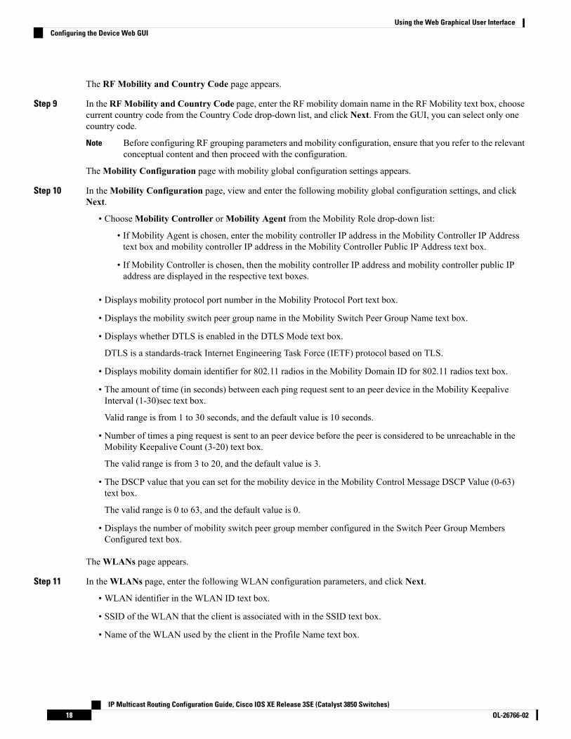
The RF Mobility and Country Code page appears.
Step 9 In the RFMobility and Country Code page, enter the RF mobility domain name in the RF Mobility text box, choosecurrent country code from the Country Code drop-down list, and click Next. From the GUI, you can select only onecountry code.
Before configuring RF grouping parameters and mobility configuration, ensure that you refer to the relevantconceptual content and then proceed with the configuration.
Note
TheMobility Configuration page with mobility global configuration settings appears.
Step 10 In theMobility Configuration page, view and enter the following mobility global configuration settings, and clickNext.
• ChooseMobility Controller orMobility Agent from the Mobility Role drop-down list:
• If Mobility Agent is chosen, enter the mobility controller IP address in the Mobility Controller IP Addresstext box and mobility controller IP address in the Mobility Controller Public IP Address text box.
• If Mobility Controller is chosen, then the mobility controller IP address and mobility controller public IPaddress are displayed in the respective text boxes.
• Displays mobility protocol port number in the Mobility Protocol Port text box.
• Displays the mobility switch peer group name in the Mobility Switch Peer Group Name text box.
• Displays whether DTLS is enabled in the DTLS Mode text box.
DTLS is a standards-track Internet Engineering Task Force (IETF) protocol based on TLS.
• Displays mobility domain identifier for 802.11 radios in the Mobility Domain ID for 802.11 radios text box.
• The amount of time (in seconds) between each ping request sent to an peer device in the Mobility KeepaliveInterval (1-30)sec text box.
Valid range is from 1 to 30 seconds, and the default value is 10 seconds.
• Number of times a ping request is sent to an peer device before the peer is considered to be unreachable in theMobility Keepalive Count (3-20) text box.
The valid range is from 3 to 20, and the default value is 3.
• The DSCP value that you can set for the mobility device in the Mobility Control Message DSCP Value (0-63)text box.
The valid range is 0 to 63, and the default value is 0.
• Displays the number of mobility switch peer group member configured in the Switch Peer Group MembersConfigured text box.
TheWLANs page appears.
Step 11 In theWLANs page, enter the following WLAN configuration parameters, and click Next.
• WLAN identifier in the WLAN ID text box.
• SSID of the WLAN that the client is associated with in the SSID text box.
• Name of the WLAN used by the client in the Profile Name text box.
IP Multicast Routing Configuration Guide, Cisco IOS XE Release 3SE (Catalyst 3850 Switches)OL-26766-0218
Using the Web Graphical User InterfaceConfiguring the Device Web GUI

The 802.11 Configuration page appears.
Step 12 In the 802.11 Configuration page, check either one or both 802.11a/n/ac and 802.11b/g/n check boxes to enable the802.11 radios, and click Next.
The Set Time page appears.
Step 13 In the Set Time page, you can configure the time and date on the device based on the following parameters, and clickNext.
• Displays current timestamp on the device in the Current Time text box.
• Choose either Manual or NTP from the Mode drop-down list.
On using the NTP server, all access points connected to the device, synchronizes its time based on the NTP serversettings available.
• Choose date on the device from the Year, Month, and Day drop-down list.
• Choose time from the Hours, Minutes, and Seconds drop-down list.
• Enter the time zone in the Zone text box and select the off setting required when compared to the current timeconfigured on the device from the Offset drop-down list.
The Save Wizard page appears.
Step 14 In the Save Wizard page, you can review the configuration settings performed on the device using these steps, and ifyou wish to change any configuration value, click Previous and navigate to that page.
You can save the device configuration created using the wizard only if a success message is displayed for all the wizards.If the Save Wizard page displays errors, you must recreate the wizard for initial configuration of the device.
IP Multicast Routing Configuration Guide, Cisco IOS XE Release 3SE (Catalyst 3850 Switches)19OL-26766-02
Using the Web Graphical User InterfaceConfiguring the Device Web GUI

IP Multicast Routing Configuration Guide, Cisco IOS XE Release 3SE (Catalyst 3850 Switches)OL-26766-0220
Using the Web Graphical User InterfaceConfiguring the Device Web GUI

C H A P T E R 3Configuring IGMP
• Finding Feature Information, on page 21• Restrictions for Configuring IGMP, on page 21• Information About IGMP, on page 22• How to Configure IGMP, on page 33• Monitoring IGMP, on page 73• Configuration Examples for IGMP, on page 75• Where to Go Next for IGMP, on page 80• Additional References, on page 81• Feature History and Information for IGMP, on page 82
Finding Feature InformationYour software release may not support all the features documented in this module. For the latest caveats andfeature information, see Bug Search Tool and the release notes for your platform and software release. Tofind information about the features documented in this module, and to see a list of the releases in which eachfeature is supported, see the feature information table at the end of this module.
Use Cisco Feature Navigator to find information about platform support and Cisco software image support.To access Cisco Feature Navigator, go to http://www.cisco.com/go/cfn. An account on Cisco.com is notrequired.
Restrictions for Configuring IGMPThe following are the restrictions for configuring IGMP:
• The device supports IGMP Versions 1, 2 , and 3.
For IGMP Version 3, only IGMP Version 3 BISS (Basic IGMPv3 SnoopingSupport) is supported.
Note
• IGMP Version 3 uses new membership report messages that might not be correctly recognized by olderIGMP snooping devices.
IP Multicast Routing Configuration Guide, Cisco IOS XE Release 3SE (Catalyst 3850 Switches)21OL-26766-02
• IGMPv3 can operate with both ISM and SSM. In ISM, both exclude and include mode reports areapplicable. In SSM, only include mode reports are accepted by the last-hop router. Exclude mode reportsare ignored.
• IGMP filtering and throttling is not supported under the WLAN.
• You cannot have a device stack containing a mix of Catalyst 3850 and Catalyst 3650 devices.
Information About IGMPInternet Group Management Protocol (IGMP) is used to dynamically register individual hosts in a multicastgroup on a particular LAN. Enabling PIM on an interface also enables IGMP. IGMP provides a means toautomatically control and limit the flow of multicast traffic throughout your network with the use of specialmulticast queriers and hosts.
To participate in IP multicasting, multicast hosts, routers, and multilayer devices must have the Internet GroupManagement Protocol (IGMP) operating. This protocol defines the querier and host roles:
• A querier is a network device that sends query messages to discover which network devices are membersof a given multicast group.
• A host is a receiver that sends report messages (in response to query messages) to inform a querier of ahost membership.
Hosts identify group memberships by sending IGMP messages to their local multicast device. Under IGMP,devices listen to IGMP messages and periodically send out queries to discover which groups are active orinactive on a particular subnet.
A set of queriers and hosts that receive multicast data streams from the same source is called a multicast group.Queriers and hosts use IGMP messages to join and leave multicast groups.
Any host, regardless of whether it is a member of a group, can send to a group. However, only the membersof a group receive the message. Membership in a multicast group is dynamic; hosts can join and leave at anytime. There is no restriction on the location or number of members in a multicast group. A host can be amember of more than one multicast group at a time. How active a multicast group is and what members it hascan vary from group to group and from time to time. A multicast group can be active for a long time, or it canbe very short-lived. Membership in a group can constantly change.
IP Multicast Group AddressesIP multicast traffic uses group addresses, which are class D addresses. The high-order bits of a Class D addressare 1110. Therefore, host group addresses can be in the range 224.0.0.0 through 239.255.255.255. Multicastaddresses in the range 224.0.0.0 to 224.0.0.255 are reserved for use by routing protocols and other networkcontrol traffic. The address 224.0.0.0 is guaranteed not to be assigned to any group.
IGMP packets are sent using these IP multicast group addresses:
• IGMP general queries are destined to the address 224.0.0.1 (all systems on a subnet).
• IGMP group-specific queries are destined to the group IP address for which the device is querying.
• IGMP group membership reports are destined to the group IP address for which the device is reporting.
IP Multicast Routing Configuration Guide, Cisco IOS XE Release 3SE (Catalyst 3850 Switches)OL-26766-0222
Configuring IGMPInformation About IGMP

• IGMP Version 2 (IGMPv2) leave messages are destined to the address 224.0.0.2 (all multicast routerson a subnet). In some old host IP stacks, leave messages might be destined to the group IP address ratherthan to the all-routers address.
Related TopicsConfiguring the Device as a Member of a Group (CLI), on page 33Example: Configuring the Device as a Member of a Multicast Group, on page 75
IGMP VersionsThe device supports IGMP version 1, IGMP version 2, and IGMP version 3. These versions are interoperableon the device. For example, if IGMP snooping is enabled and the querier's version is IGMPv2, and the devicereceives an IGMPv3 report from a host, then the device can forward the IGMPv3 report to the multicast router.
An IGMPv3 device can receive messages from and forward messages to a device running the Source SpecificMulticast (SSM) feature.
IGMP Version 1IGMP version 1 (IGMPv1) primarily uses a query-response model that enables the multicast router andmultilayer device to find which multicast groups are active (have one or more hosts interested in a multicastgroup) on the local subnet. IGMPv1 has other processes that enable a host to join and leave a multicast group.For more information, see RFC 1112.
IGMP Version 2IGMPv2 extends IGMP functionality by providing such features as the IGMP leave process to reduce leavelatency, group-specific queries, and an explicit maximum query response time. IGMPv2 also adds the capabilityfor routers to elect the IGMP querier without depending on the multicast protocol to perform this task. Formore information, see RFC 2236.
IGMP version 2 is the default version for the device.Note
IGMP Version 3The device supports IGMP version 3.
An IGMPv3 device supports Basic IGMPv3 Snooping Support (BISS), which includes support for the snoopingfeatures on IGMPv1 and IGMPv2 switches and for IGMPv3 membership report messages. BISS constrainsthe flooding ofmulticast traffic when your network includes IGMPv3 hosts. It constrains traffic to approximatelythe same set of ports as the IGMP snooping feature on IGMPv2 or IGMPv1 hosts.
An IGMPv3 device can receive messages from and forward messages to a device running the Source SpecificMulticast (SSM) feature.
IGMP Versions DifferencesThere are three versions of IGMP, as defined by Request for Comments (RFC) documents of the InternetEngineering Task Force (IETF). IGMPv2 improves over IGMPv1 by adding the ability for a host to signal
IP Multicast Routing Configuration Guide, Cisco IOS XE Release 3SE (Catalyst 3850 Switches)23OL-26766-02
Configuring IGMPIGMP Versions

desire to leave a multicast group and IGMPv3 improves over IGMPv2 mainly by adding the ability to listento multicast originating from a set of source IP addresses only.
Table 5: IGMP Versions
DescriptionIGMP Version
Provides the basic query-response mechanism that allows the multicastdevice to determine which multicast groups are active and otherprocesses that enable hosts to join and leave a multicast group. RFC1112 defines the IGMPv1 host extensions for IP multicasting.
IGMPv1
Extends IGMP, allowing such capabilities as the IGMP leave process,group-specific queries, and an explicit maximum response time field.IGMPv2 also adds the capability for devices to elect the IGMP querierwithout dependence on the multicast protocol to perform this task. RFC2236 defines IGMPv2.
IGMPv2
By default, enabling a PIM on an interface enables IGMPv2 on that device. IGMPv2 was designed to be asbackward compatible with IGMPv1 as possible. To accomplish this backward compatibility, RFC 2236 definedspecial interoperability rules. If your network contains legacy IGMPv1 hosts, you should be familiar withthese operability rules. For more information about IGMPv1 and IGMPv2 interoperability, see RFC 2236,Internet Group Management Protocol, Version 2 .
Note
Devices That Run IGMPv1
IGMPv1 devices send IGMP queries to the “all-hosts” multicast address of 224.0.0.1 to solicit multicastgroups with active multicast receivers. The multicast receivers also can send IGMP reports to the device tonotify it that they are interested in receiving a particular multicast stream. Hosts can send the reportasynchronously or in response to the IGMP queries sent by the device. If more than one multicast receiverexists for the same multicast group, only one of these hosts sends an IGMP report message; the other hostssuppress their report messages.
In IGMPv1, there is no election of an IGMP querier. If more than one device on the segment exists, all thedevices send periodic IGMP queries. IGMPv1 has no special mechanism by which the hosts can leave thegroup. If the hosts are no longer interested in receiving multicast packets for a particular group, they simplydo not reply to the IGMP query packets sent from the device. The device continues sending query packets. Ifthe device does not hear a response in three IGMP queries, the group times out and the device stops sendingmulticast packets on the segment for the group. If the host later wants to receive multicast packets after thetimeout period, the host simply sends a new IGMP join to the device, and the device begins to forward themulticast packet again.
If there are multiple devices on a LAN, a designated router (DR) must be elected to avoid duplicating multicasttraffic for connected hosts. PIM devices follow an election process to select a DR. The PIM device with thehighest IP address becomes the DR.
The DR is responsible for the following tasks:
• Sending PIM register and PIM Join and Prune messages toward the rendezvous point (RP) to inform itabout host group membership.
• Sending IGMP host-query messages.
IP Multicast Routing Configuration Guide, Cisco IOS XE Release 3SE (Catalyst 3850 Switches)OL-26766-0224
Configuring IGMPIGMP Versions Differences

• Sending host-query messages by default every 60 seconds in order to keep the IGMP overhead on hostsand networks very low.
Devices That Run IGMPv2
IGMPv2 improves the query messaging capabilities of IGMPv1.
The query and membership report messages in IGMPv2 are identical to the IGMPv1 messages with twoexceptions:
• IGMPv2 query messages are broken into two categories: general queries (identical to IGMPv1 queries)and group-specific queries.
• IGMPv1 membership reports and IGMPv2 membership reports have different IGMP type codes.
IGMPv2 also enhances IGMP by providing support for the following capabilities:
• Querier election process--Provides the capability for IGMPv2 devices to elect the IGMP querier withouthaving to rely on the multicast routing protocol to perform the process.
• Maximum Response Time field--A new field in query messages permits the IGMP querier to specify themaximum query-response time. This field permits the tuning of the query-response process to controlresponse burstiness and to fine-tune leave latencies.
• Group-Specific Query messages--Permits the IGMP querier to perform the query operation on a specificgroup instead of all groups.
• Leave-Groupmessages--Provides hosts with a method of notifying devices on the network that they wishto leave the group.
Unlike IGMPv1, in which the DR and the IGMP querier are typically the same device, in IGMPv2 the twofunctions are decoupled. The DR and the IGMP querier are selected based on different criteria and may bedifferent devices on the same subnet. The DR is the device with the highest IP address on the subnet, whereasthe IGMP querier is the device with the lowest IP address.
Query messages are used to elect the IGMP querier as follows:
1. When IGMPv2 devices start, they each multicast a general query message to the all-systems group addressof 224.0.0.1 with their interface address in the source IP address field of the message.
2. When an IGMPv2 device receives a general query message, the device compares the source IP addressin the message with its own interface address. The device with the lowest IP address on the subnet iselected the IGMP querier.
3. All devices (excluding the querier) start the query timer, which is reset whenever a general query messageis received from the IGMP querier. If the query timer expires, it is assumed that the IGMP querier hasgone down, and the election process is performed again to elect a new IGMP querier.
By default, the timer is two times the query interval.
IGMPv3 Host SignallingIn IGMPv3, hosts signal membership to last hop routers of multicast groups. Hosts can signal groupmembershipwith filtering capabilities with respect to sources. A host can either signal that it wants to receive traffic fromall sources sending to a group except for some specific sources (called exclude mode), or that it wants toreceive traffic only from some specific sources sending to the group (called include mode).
IP Multicast Routing Configuration Guide, Cisco IOS XE Release 3SE (Catalyst 3850 Switches)25OL-26766-02
Configuring IGMPIGMPv3 Host Signalling

IGMPv3 can operate with both Internet Standard Multicast (ISM) and Source Specific Multicast (SSM). InISM, both exclude and include mode reports are applicable. In SSM, only include mode reports are acceptedby the last-hop router. Exclude mode reports are ignored.
IGMP Join and Leave Process
IGMP Join ProcessWhen a host wants to join a multicast group, the host sends one or more unsolicited membership reports forthe multicast group it wants to join. The IGMP join process is the same for IGMPv1 and IGMPv2 hosts.
In IGMPv3, the join process for hosts proceeds as follows:
• When a hosts wants to join a group, it sends an IGMPv3 membership report to 224.0.0.22 with an emptyEXCLUDE list.
• When a host wants to join a specific channel, it sends an IGMPv3 membership report to 224.0.0.22 withthe address of the specific source included in the INCLUDE list.
• When a host wants to join a group excluding particular sources, it sends an IGMPv3 membership reportto 224.0.0.22 excluding those sources in the EXCLUDE list.
If some IGMPv3 hosts on a LAN wish to exclude a source and others wish to include the source, then thedevice will send traffic for the source on the LAN (that is, inclusion trumps exclusion in this situation).
Note
IGMP Leave ProcessThe method that hosts use to leave a group varies depending on the version of IGMP in operation.
IGMPv1 Leave Process
There is no leave-group message in IGMPv1 to notify the devices on the subnet that a host no longer wantsto receive the multicast traffic from a specific group. The host simply stops processing traffic for the multicastgroup and ceases responding to IGMP queries with IGMP membership reports for the group. As a result, theonly way IGMPv1 devices know that there are no longer any active receivers for a particular multicast groupon a subnet is when the devices stop receivingmembership reports. To facilitate this process, IGMPv1 devicesassociate a countdown timer with an IGMP group on a subnet. When a membership report is received for thegroup on the subnet, the timer is reset. For IGMPv1 devices, this timeout interval is typically three times thequery interval (3 minutes). This timeout interval means that the device may continue to forward multicasttraffic onto the subnet for up to 3 minutes after all hosts have left the multicast group.
IGMPv2 Leave Process
IGMPv2 incorporates a leave-group message that provides the means for a host to indicate that it wishes tostop receiving multicast traffic for a specific group. When an IGMPv2 host leaves a multicast group, if it wasthe last host to respond to a query with a membership report for that group, it sends a leave-group messageto the all-devices multicast group (224.0.0.2).
IP Multicast Routing Configuration Guide, Cisco IOS XE Release 3SE (Catalyst 3850 Switches)OL-26766-0226
Configuring IGMPIGMP Join and Leave Process

IGMPv3 Leave Process
IGMPv3 enhances the leave process by introducing the capability for a host to stop receiving traffic from aparticular group, source, or channel in IGMP by including or excluding sources, groups, or channels in IGMPv3membership reports.
IGMP SnoopingLayer 2 devices can use IGMP snooping to constrain the flooding ofmulticast traffic by dynamically configuringLayer 2 interfaces so that multicast traffic is forwarded to only those interfaces associated with IP multicastdevices. As the name implies, IGMP snooping requires the LAN device to snoop on the IGMP transmissionsbetween the host and the router and to keep track of multicast groups and member ports. When the devicereceives an IGMP report from a host for a particular multicast group, the device adds the host port number tothe forwarding table entry; when it receives an IGMP Leave Group message from a host, it removes the hostport from the table entry. It also periodically deletes entries if it does not receive IGMP membership reportsfrom the multicast clients.
For more information on IP multicast and IGMP, see RFC 1112 and RFC 2236.Note
The multicast router (which could be a device with the IP services feature) set on the active device sends outperiodic general queries to all VLANs. All hosts interested in this multicast traffic send join requests and areadded to the forwarding table entry. The device creates one entry per VLAN in the IGMP snooping IP multicastforwarding table for each group from which it receives an IGMP join request.
The device supports IP multicast group-based bridging, instead of MAC-addressed based groups. Withmulticast MAC address-based groups, if an IP address being configured translates (aliases) to a previouslyconfiguredMAC address or to any reservedmulticastMAC addresses (in the range 224.0.0.xxx), the commandfails. Because the device uses IP multicast groups, there are no address aliasing issues.
The IP multicast groups learned through IGMP snooping are dynamic. However, you can statically configuremulticast groups by using the ip igmp snooping vlan vlan-id static ip_address interface interface-id globalconfiguration command. If you specify group membership for a multicast group address statically, your settingsupersedes any automatic manipulation by IGMP snooping. Multicast group membership lists can consist ofboth user-defined and IGMP snooping-learned settings.
You can configure an IGMP snooping querier to support IGMP snooping in subnets without multicast interfacesbecause the multicast traffic does not need to be routed.
If a port spanning-tree, a port group, or a VLAN ID change occurs, the IGMP snooping-learned multicastgroups from this port on the VLAN are deleted.
These sections describe IGMP snooping characteristics:
Related TopicsEnabling or Disabling IGMP Snooping on a Device (CLI), on page 54Examples: Configuring IGMP Snooping, on page 76
Joining a Multicast GroupFigure 1: Initial IGMP Join Message
When a host connected to the device wants to join an IP multicast group and it is an IGMP version 2 client,it sends an unsolicited IGMP join message, specifying the IP multicast group to join. Alternatively, when the
IP Multicast Routing Configuration Guide, Cisco IOS XE Release 3SE (Catalyst 3850 Switches)27OL-26766-02
Configuring IGMPIGMP Snooping

device receives a general query from the router, it forwards the query to all ports in the VLAN. IGMP version1 or version 2 hosts wanting to join the multicast group respond by sending a join message to the device. Thedevice CPU creates a multicast forwarding-table entry for the group if it is not already present. The CPU alsoadds the interface where the join message was received to the forwarding-table entry. The host associatedwith that interface receives multicast traffic for that multicast group.
Router A sends a general query to the device, which forwards the query to ports 2 through 5, all of which aremembers of the same VLAN. Host 1 wants to join multicast group 224.1.2.3 and multicasts an IGMPmembership report (IGMP join message) to the group. The device CPU uses the information in the IGMPreport to set up a forwarding-table entry that includes the port numbers connected to Host 1 and to the router.
Table 6: IGMP Snooping Forwarding Table
PortsType of PacketDestination Address
1, 2IGMP224.1.2.3
The device hardware can distinguish IGMP information packets from other packets for the multicast group.The information in the table tells the switching engine to send frames addressed to the 224.1.2.3 multicast IPaddress that are not IGMP packets to the router and to the host that has joined the group.Figure 2: Second Host Joining a Multicast Group
If another host (for example, Host 4) sends an unsolicited IGMP join message for the same group, the CPUreceives that message and adds the port number of Host 4 to the forwarding table. Because the forwardingtable directs IGMP messages only to the CPU, the message is not flooded to other ports on the device. Any
IP Multicast Routing Configuration Guide, Cisco IOS XE Release 3SE (Catalyst 3850 Switches)OL-26766-0228
Configuring IGMPJoining a Multicast Group

known multicast traffic is forwarded to the group and not to the CPU.
Table 7: Updated IGMP Snooping Forwarding Table
PortsType of PacketDestination Address
1, 2, 5IGMP224.1.2.3
Related TopicsConfiguring the Device as a Member of a Group (CLI), on page 33Example: Configuring the Device as a Member of a Multicast Group, on page 75
Leaving a Multicast GroupThe router sends periodic multicast general queries, and the device forwards these queries through all portsin the VLAN. Interested hosts respond to the queries. If at least one host in the VLAN wants to receivemulticast traffic, the router continues forwarding the multicast traffic to the VLAN. The device forwardsmulticast group traffic only to those hosts listed in the forwarding table for that IP multicast group maintainedby IGMP snooping.
When hosts want to leave a multicast group, they can silently leave, or they can send a leave message. Whenthe device receives a leave message from a host, it sends a group-specific query to learn if any other devicesconnected to that interface are interested in traffic for the specific multicast group. The device then updatesthe forwarding table for that MAC group so that only those hosts interested in receiving multicast traffic forthe group are listed in the forwarding table. If the router receives no reports from a VLAN, it removes thegroup for the VLAN from its IGMP cache.
Immediate LeaveThe device uses IGMP snooping Immediate Leave to remove from the forwarding table an interface that sendsa leave message without the device sending group-specific queries to the interface. The VLAN interface ispruned from the multicast tree for the multicast group specified in the original leave message. ImmediateLeave ensures optimal bandwidth management for all hosts on a switched network, even when multiplemulticast groups are simultaneously in use.
Immediate Leave is only supported on IGMP version 2 hosts. IGMP version 2 is the default version for thedevice.
IP Multicast Routing Configuration Guide, Cisco IOS XE Release 3SE (Catalyst 3850 Switches)29OL-26766-02
Configuring IGMPLeaving a Multicast Group

You should use the Immediate Leave feature only on VLANs where a single host is connected to each port.If Immediate Leave is enabled on VLANs where more than one host is connected to a port, some hosts maybe dropped inadvertently.
Note
IGMP Configurable-Leave TimerYou can configure the time that the device waits after sending a group-specific query to determine if hostsare still interested in a specific multicast group. The IGMP leave response time can be configured from 100to 32767 milliseconds.
Related TopicsConfiguring the IGMP Leave Timer (CLI), on page 61
IGMP Report Suppression
IGMP report suppression is supported only when the multicast query has IGMPv1 and IGMPv2 reports. Thisfeature is not supported when the query includes IGMPv3 reports.
Note
The device uses IGMP report suppression to forward only one IGMP report per multicast router query tomulticast devices. When IGMP report suppression is enabled (the default), the device sends the first IGMPreport from all hosts for a group to all the multicast routers. The device does not send the remaining IGMPreports for the group to the multicast routers. This feature prevents duplicate reports from being sent to themulticast devices.
If the multicast router query includes requests only for IGMPv1 and IGMPv2 reports, the device forwardsonly the first IGMPv1 or IGMPv2 report from all hosts for a group to all the multicast routers.
If the multicast router query also includes requests for IGMPv3 reports, the device forwards all IGMPv1,IGMPv2, and IGMPv3 reports for a group to the multicast devices.
If you disable IGMP report suppression, all IGMP reports are forwarded to the multicast routers.
IGMP Snooping and Device StacksIGMP snooping functions across the device stack; that is, IGMP control information from one device isdistributed to all devices in the stack. Regardless of the stack member through which IGMP multicast dataenters the stack, the data reaches the hosts that have registered for that group.
If a device in the stack fails or is removed from the stack, only the members of the multicast group that areon that device will not receive the multicast data. All other members of a multicast group on other devices inthe stack continue to receive multicast data streams. However, multicast groups that are common for bothLayer 2 and Layer 3 (IP multicast routing) might take longer to converge if the active device is removed.
IGMP Filtering and ThrottlingIn some environments, for example, metropolitan or multiple-dwelling unit (MDU) installations, you mightwant to control the set of multicast groups to which a user on a device port can belong. You can control thedistribution of multicast services, such as IP/TV, based on some type of subscription or service plan. Youmight also want to limit the number of multicast groups to which a user on a device port can belong.
IP Multicast Routing Configuration Guide, Cisco IOS XE Release 3SE (Catalyst 3850 Switches)OL-26766-0230
Configuring IGMPIGMP Configurable-Leave Timer

With the IGMP filtering feature, you can filter multicast joins on a per-port basis by configuring IP multicastprofiles and associating themwith individual device ports. An IGMP profile can contain one or more multicastgroups and specifies whether access to the group is permitted or denied. If an IGMP profile denying accessto a multicast group is applied to a device port, the IGMP join report requesting the stream of IP multicasttraffic is dropped, and the port is not allowed to receive IP multicast traffic from that group. If the filteringaction permits access to the multicast group, the IGMP report from the port is forwarded for normal processing.You can also set the maximum number of IGMP groups that a Layer 2 interface can join.
IGMP filtering controls only group-specific query and membership reports, including join and leave reports.It does not control general IGMP queries. IGMP filtering has no relationship with the function that directsthe forwarding of IP multicast traffic. The filtering feature operates in the same manner whether CGMP orMVR is used to forward the multicast traffic.
IGMP filtering applies only to the dynamic learning of IP multicast group addresses, not static configuration.
With the IGMP throttling feature, you can set the maximum number of IGMP groups that a Layer 2 interfacecan join. If the maximum number of IGMP groups is set, the IGMP snooping forwarding table contains themaximum number of entries, and the interface receives an IGMP join report, you can configure an interfaceto drop the IGMP report or to replace the randomly selected multicast entry with the received IGMP report.
IGMPv3 join and leave messages are not supported on devices running IGMP filtering.Note
Related TopicsConfiguring the IGMP Throttling Action (CLI), on page 48Examples: Configuring Filtering and Throttling, on page 77
Default IGMP ConfigurationThis table displays the default IGMP configuration for the device.
Table 8: Default IGMP Configuration
Default SettingFeature
No group memberships are defined.Multilayer device as a member of a multicast group
All groups are allowed on an interface.Access to multicast groups
Version 2 on all interfaces.IGMP version
60 seconds on all interfaces.IGMP host-query message interval
60 seconds on all interfaces.IGMP query timeout
10 seconds on all interfaces.IGMP maximum query response time
Disabled.Multilayer device as a statically connected member
IP Multicast Routing Configuration Guide, Cisco IOS XE Release 3SE (Catalyst 3850 Switches)31OL-26766-02
Configuring IGMPDefault IGMP Configuration
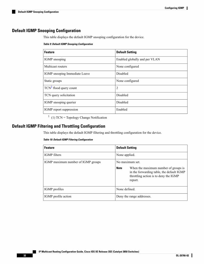
Default IGMP Snooping ConfigurationThis table displays the default IGMP snooping configuration for the device.
Table 9: Default IGMP Snooping Configuration
Default SettingFeature
Enabled globally and per VLANIGMP snooping
None configuredMulticast routers
DisabledIGMP snooping Immediate Leave
None configuredStatic groups
2TCN3 flood query count
DisabledTCN query solicitation
DisabledIGMP snooping querier
EnabledIGMP report suppression
3 (1) TCN = Topology Change Notification
Default IGMP Filtering and Throttling ConfigurationThis table displays the default IGMP filtering and throttling configuration for the device.
Table 10: Default IGMP Filtering Configuration
Default SettingFeature
None applied.IGMP filters
No maximum set.
When the maximum number of groups isin the forwarding table, the default IGMPthrottling action is to deny the IGMPreport.
Note
IGMP maximum number of IGMP groups
None defined.IGMP profiles
Deny the range addresses.IGMP profile action
IP Multicast Routing Configuration Guide, Cisco IOS XE Release 3SE (Catalyst 3850 Switches)OL-26766-0232
Configuring IGMPDefault IGMP Snooping Configuration

How to Configure IGMP
Configuring the Device as a Member of a Group (CLI)You can configure the device as a member of a multicast group and discover multicast reachability in anetwork. If all the multicast-capable routers and multilayer devices that you administer are members of amulticast group, pinging that group causes all of these devices to respond. The devices respond to ICMPecho-request packets addressed to a group of which they are members. Another example is the multicasttrace-route tools provided in the software.
Performing this procedure might impact the CPU performance because the CPU will receive all data trafficfor the group address.
Caution
This procedure is optional.
SUMMARY STEPS
1. enable2. configure terminal3. interface interface-id4. ip igmp join-group group-address5. end6. show ip igmp interface [interface-id]7. copy running-config startup-config
DETAILED STEPS
PurposeCommand or Action
Enables privileged EXEC mode.enableStep 1
Example: • Enter your password if prompted.
Device> enable
Enters global configuration mode.configure terminal
Example:
Step 2
Device# configure terminal
Specifies the Layer 3 interface on which you want to enablemulticast routing, and enters interface configuration mode.
interface interface-id
Example:
Step 3
The specified interface must be one of the following:Device(config)# interface
IP Multicast Routing Configuration Guide, Cisco IOS XE Release 3SE (Catalyst 3850 Switches)33OL-26766-02
Configuring IGMPHow to Configure IGMP

PurposeCommand or Actiongigabitethernet 1/0/1 • A routed port—A physical port that has been
configured as a Layer 3 port by entering the noswitchport interface configuration command.
You will also need to enable IP PIMsparse-dense-mode on the interface, and join theinterface as a statically connected member to an IGMPstatic group.
• An SVI—A VLAN interface created by using theinterface vlan vlan-id global configuration command.
You will also need to enable IP PIMsparse-dense-mode on the VLAN, join the VLAN asa statically connectedmember to an IGMP static group,and then enable IGMP snooping on the VLAN, theIGMP static group, and physical interface.
These interfaces must have IP addresses assigned to them.
Configures the device to join a multicast group.ip igmp join-group group-addressStep 4
Example: By default, no group memberships are defined.
Device(config-if)# ip igmpFor group-address, specify themulticast IP address in dotteddecimal notation.join-group 225.2.2.2
Returns to privileged EXEC mode.end
Example:
Step 5
Device(config)# end
Verifies your entries.show ip igmp interface [interface-id]
Example:
Step 6
Device# show ip igmp interface
(Optional) Saves your entries in the configuration file.copy running-config startup-config
Example:
Step 7
Device# copy running-config startup-config
Related TopicsJoining a Multicast Group, on page 27Example: Configuring the Device as a Member of a Multicast Group, on page 75IP Multicast Group Addresses, on page 22
IP Multicast Routing Configuration Guide, Cisco IOS XE Release 3SE (Catalyst 3850 Switches)OL-26766-0234
Configuring IGMPConfiguring the Device as a Member of a Group (CLI)

Controlling Access to IP Multicast Group (CLI)The device sends IGMP host-query messages to find which multicast groups have members on attached localnetworks. The device then forwards to these group members all packets addressed to the multicast group.You can place a filter on each interface to restrict the multicast groups that hosts on the subnet serviced bythe interface can join.
To limit the number of joins on the interface, configure the port for the filter which associates with the IGMPprofile.
This procedure is optional.
SUMMARY STEPS
1. enable2. configure terminal3. ip igmp profile4. permit5. exit6. interface interface-id7. ip igmp filter filter_number8. end9. show ip igmp interface [interface-id]10. copy running-config startup-config
DETAILED STEPS
PurposeCommand or Action
Enables privileged EXEC mode.enableStep 1
Example: • Enter your password if prompted.
Device> enable
Enters global configuration mode.configure terminal
Example:
Step 2
Device# configure terminal
Enters an IGMP filter profile number from 1 to4294967295.
ip igmp profile
Example:
Step 3
For additional information about configuring IGMP filterprofiles, see Configuring IGMP Profiles (CLI), on page44.
Device(config)# ip igmp profile 10Device(config-igmp-profile)# ?
Enters an IGMP profile configuration action. The followingIGMP profile configuration actions are supported:
permit
Example:
Step 4
• deny—Matching IP addresses are denied.Device(config-igmp-profile)#
IP Multicast Routing Configuration Guide, Cisco IOS XE Release 3SE (Catalyst 3850 Switches)35OL-26766-02
Configuring IGMPControlling Access to IP Multicast Group (CLI)

PurposeCommand or Actionpermit 229.9.9.0 • exit—Exits from the IGMP profile configuration
mode.
• no—Negates a command or set its defaults.
• permit—Matching addresses are permitted.
• range—Adds a range to the set.
Returns to global configuration mode.exit
Example:
Step 5
Device(config-igmp-profile)# exit
Specifies the interface to be configured, and enters interfaceconfiguration mode.
interface interface-id
Example:
Step 6
Device(config)# interfacegigabitethernet 1/0/1
Specifies the IGMP filter profile number.ip igmp filter filter_numberStep 7
Example: For additional information about applying IGMP filterprofiles, see Applying IGMP Profiles (CLI), on page 46.
Device(config-if)# ip igmp filter 10
Returns to privileged EXEC mode.end
Example:
Step 8
Device(config)# end
Verifies your entries.show ip igmp interface [interface-id]
Example:
Step 9
Device# show ip igmp interface
(Optional) Saves your entries in the configuration file.copy running-config startup-config
Example:
Step 10
Device# copy running-config startup-config
Related TopicsExample: Controlling Access to Multicast Groups, on page 75
IP Multicast Routing Configuration Guide, Cisco IOS XE Release 3SE (Catalyst 3850 Switches)OL-26766-0236
Configuring IGMPControlling Access to IP Multicast Group (CLI)
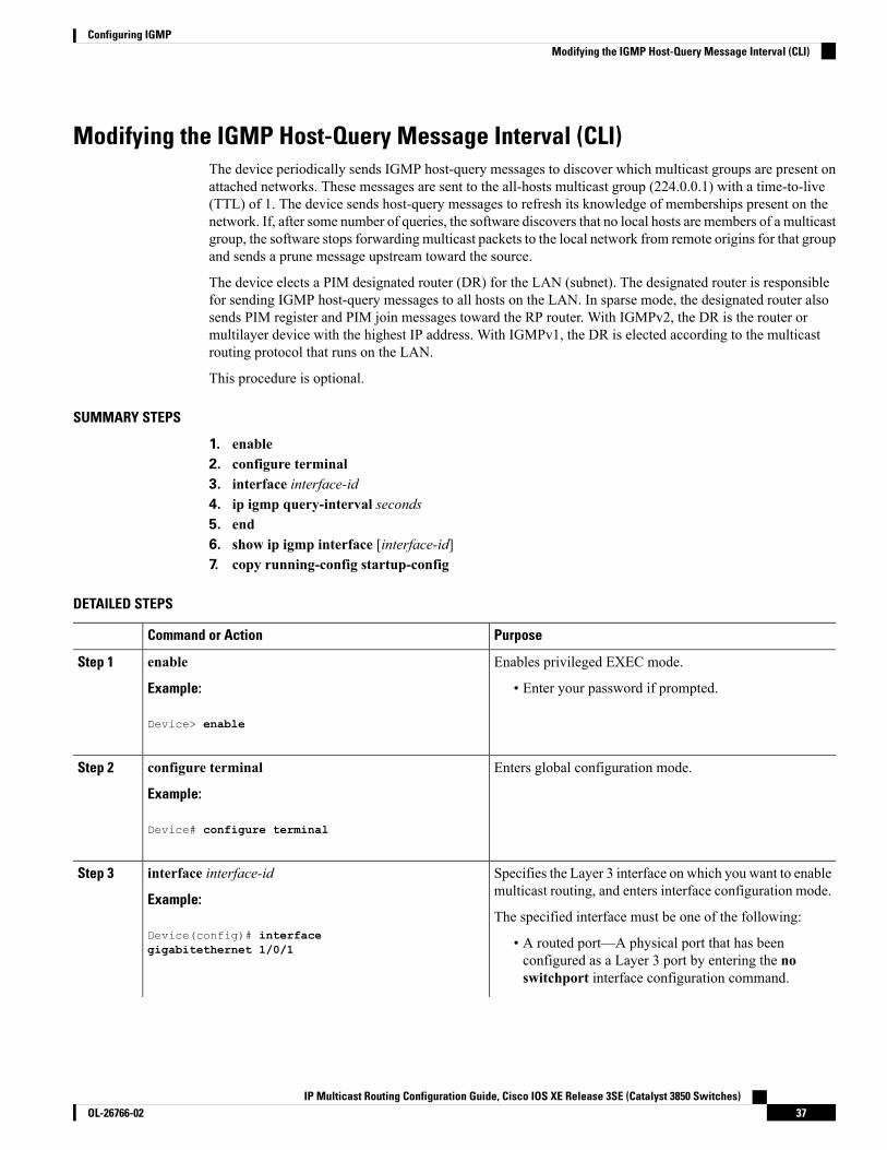
Modifying the IGMP Host-Query Message Interval (CLI)The device periodically sends IGMP host-query messages to discover which multicast groups are present onattached networks. These messages are sent to the all-hosts multicast group (224.0.0.1) with a time-to-live(TTL) of 1. The device sends host-query messages to refresh its knowledge of memberships present on thenetwork. If, after some number of queries, the software discovers that no local hosts are members of a multicastgroup, the software stops forwarding multicast packets to the local network from remote origins for that groupand sends a prune message upstream toward the source.
The device elects a PIM designated router (DR) for the LAN (subnet). The designated router is responsiblefor sending IGMP host-query messages to all hosts on the LAN. In sparse mode, the designated router alsosends PIM register and PIM join messages toward the RP router. With IGMPv2, the DR is the router ormultilayer device with the highest IP address. With IGMPv1, the DR is elected according to the multicastrouting protocol that runs on the LAN.
This procedure is optional.
SUMMARY STEPS
1. enable2. configure terminal3. interface interface-id4. ip igmp query-interval seconds5. end6. show ip igmp interface [interface-id]7. copy running-config startup-config
DETAILED STEPS
PurposeCommand or Action
Enables privileged EXEC mode.enableStep 1
Example: • Enter your password if prompted.
Device> enable
Enters global configuration mode.configure terminal
Example:
Step 2
Device# configure terminal
Specifies the Layer 3 interface on which you want to enablemulticast routing, and enters interface configuration mode.
interface interface-id
Example:
Step 3
The specified interface must be one of the following:Device(config)# interface • A routed port—A physical port that has been
configured as a Layer 3 port by entering the noswitchport interface configuration command.
gigabitethernet 1/0/1
IP Multicast Routing Configuration Guide, Cisco IOS XE Release 3SE (Catalyst 3850 Switches)37OL-26766-02
Configuring IGMPModifying the IGMP Host-Query Message Interval (CLI)

PurposeCommand or Action
You will also need to enable IP PIMsparse-dense-mode on the interface, and join theinterface as a statically connected member to an IGMPstatic group.
• An SVI—A VLAN interface created by using theinterface vlan vlan-id global configuration command.
You will also need to enable IP PIMsparse-dense-mode on the VLAN, join the VLAN asa statically connectedmember to an IGMP static group,and then enable IGMP snooping on the VLAN, theIGMP static group, and physical interface.
These interfaces must have IP addresses assigned to them.
Configures the frequency at which the designated routersends IGMP host-query messages.
ip igmp query-interval seconds
Example:
Step 4
By default, the designated router sends IGMP host-querymessages every 60 seconds to keep the IGMP overheadvery low on hosts and networks.
Device(config-if)# ip igmpquery-interval 75
The range is 1 to 65535.
Returns to privileged EXEC mode.end
Example:
Step 5
Device(config)# end
Verifies your entries.show ip igmp interface [interface-id]
Example:
Step 6
Device# show ip igmp interface
(Optional) Saves your entries in the configuration file.copy running-config startup-config
Example:
Step 7
Device# copy running-config startup-config
Changing the IGMP Query Timeout for IGMPv2 (CLI)If you are using IGMPv2, you can specify the period of time before the device takes over as the querier forthe interface. By default, the device waits twice the query interval period controlled by the ip igmpquery-interval interface configuration command. After that time, if the device has received no queries, itbecomes the querier.
This procedure is optional.
IP Multicast Routing Configuration Guide, Cisco IOS XE Release 3SE (Catalyst 3850 Switches)OL-26766-0238
Configuring IGMPChanging the IGMP Query Timeout for IGMPv2 (CLI)

SUMMARY STEPS
1. enable2. configure terminal3. interface interface-id4. ip igmp querier-timeout seconds5. end6. show ip igmp interface [interface-id]7. copy running-config startup-config
DETAILED STEPS
PurposeCommand or Action
Enables privileged EXEC mode.enableStep 1
Example: • Enter your password if prompted.
Device> enable
Enters global configuration mode.configure terminal
Example:
Step 2
Device# configure terminal
Specifies the Layer 3 interface on which you want to enablemulticast routing, and enters interface configuration mode.
interface interface-id
Example:
Step 3
The specified interface must be one of the following:Device(config)# interface • A routed port—A physical port that has been
configured as a Layer 3 port by entering the noswitchport interface configuration command.
gigabitethernet 1/0/1
You will also need to enable IP PIMsparse-dense-mode on the interface, and join theinterface as a statically connected member to an IGMPstatic group.
• An SVI—A VLAN interface created by using theinterface vlan vlan-id global configuration command.
You will also need to enable IP PIMsparse-dense-mode on the VLAN, join the VLAN asa statically connectedmember to an IGMP static group,and then enable IGMP snooping on the VLAN, theIGMP static group, and physical interface.
These interfaces must have IP addresses assigned to them.
Specifies the IGMP query timeout.ip igmp querier-timeout secondsStep 4
Example:
IP Multicast Routing Configuration Guide, Cisco IOS XE Release 3SE (Catalyst 3850 Switches)39OL-26766-02
Configuring IGMPChanging the IGMP Query Timeout for IGMPv2 (CLI)
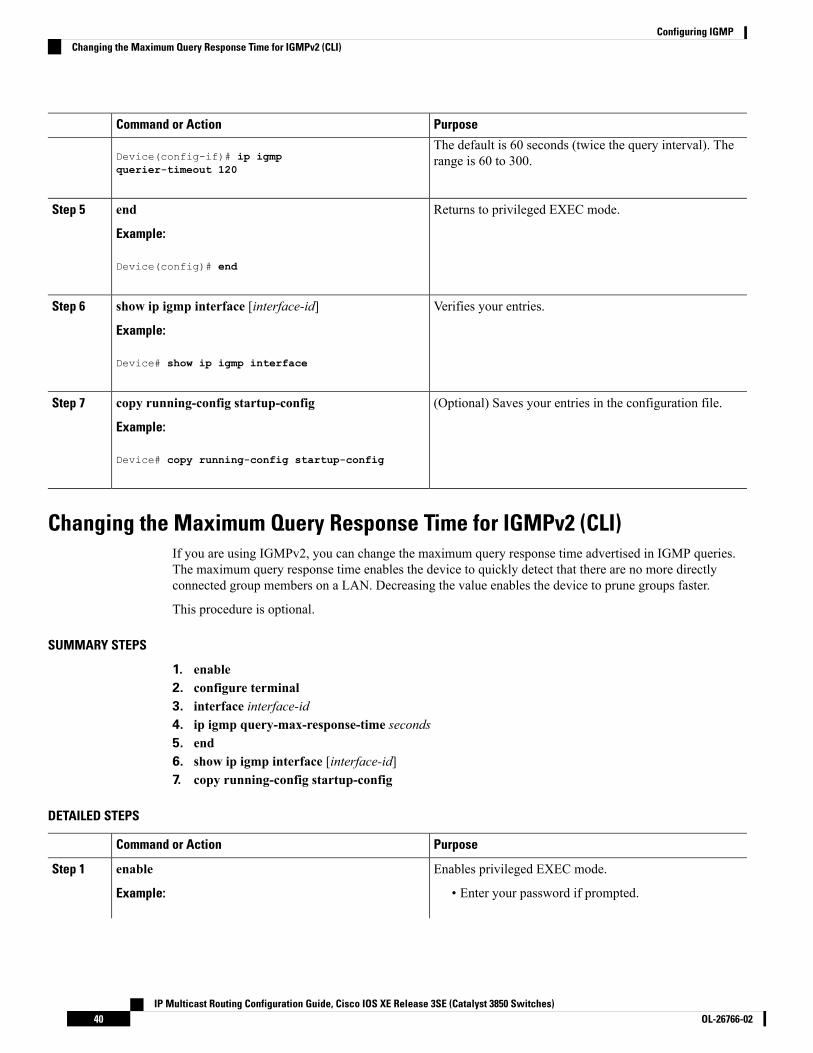
PurposeCommand or Action
The default is 60 seconds (twice the query interval). Therange is 60 to 300.Device(config-if)# ip igmp
querier-timeout 120
Returns to privileged EXEC mode.end
Example:
Step 5
Device(config)# end
Verifies your entries.show ip igmp interface [interface-id]
Example:
Step 6
Device# show ip igmp interface
(Optional) Saves your entries in the configuration file.copy running-config startup-config
Example:
Step 7
Device# copy running-config startup-config
Changing the Maximum Query Response Time for IGMPv2 (CLI)If you are using IGMPv2, you can change the maximum query response time advertised in IGMP queries.The maximum query response time enables the device to quickly detect that there are no more directlyconnected group members on a LAN. Decreasing the value enables the device to prune groups faster.
This procedure is optional.
SUMMARY STEPS
1. enable2. configure terminal3. interface interface-id4. ip igmp query-max-response-time seconds5. end6. show ip igmp interface [interface-id]7. copy running-config startup-config
DETAILED STEPS
PurposeCommand or Action
Enables privileged EXEC mode.enableStep 1
Example: • Enter your password if prompted.
IP Multicast Routing Configuration Guide, Cisco IOS XE Release 3SE (Catalyst 3850 Switches)OL-26766-0240
Configuring IGMPChanging the Maximum Query Response Time for IGMPv2 (CLI)

PurposeCommand or Action
Device> enable
Enters global configuration mode.configure terminal
Example:
Step 2
Device# configure terminal
Specifies the Layer 3 interface on which you want to enablemulticast routing, and enters interface configuration mode.
interface interface-id
Example:
Step 3
The specified interface must be one of the following:Device(config)# interface • A routed port—A physical port that has been
configured as a Layer 3 port by entering the noswitchport interface configuration command.
gigabitethernet 1/0/1
You will also need to enable IP PIMsparse-dense-mode on the interface, and join theinterface as a statically connected member to an IGMPstatic group.
• An SVI—A VLAN interface created by using theinterface vlan vlan-id global configuration command.
You will also need to enable IP PIMsparse-dense-mode on the VLAN, join the VLAN asa statically connectedmember to an IGMP static group,and then enable IGMP snooping on the VLAN, theIGMP static group, and physical interface.
These interfaces must have IP addresses assigned to them.
Changes the maximum query response time advertised inIGMP queries.
ip igmp query-max-response-time seconds
Example:
Step 4
The default is 10 seconds. The range is 1 to 25.Device(config-if)# ip igmpquery-max-response-time 15
Returns to privileged EXEC mode.end
Example:
Step 5
Device(config)# end
Verifies your entries.show ip igmp interface [interface-id]
Example:
Step 6
Device# show ip igmp interface
IP Multicast Routing Configuration Guide, Cisco IOS XE Release 3SE (Catalyst 3850 Switches)41OL-26766-02
Configuring IGMPChanging the Maximum Query Response Time for IGMPv2 (CLI)

PurposeCommand or Action
(Optional) Saves your entries in the configuration file.copy running-config startup-config
Example:
Step 7
Device# copy running-config startup-config
Configuring the Device as a Statically Connected Member (CLI)At various times, either there is not a group member on a network segment or a host that cannot report itsgroup membership by using IGMP. However, you may want multicast traffic to be sent to that networksegment. The following commands are used to pull multicast traffic down to a network segment:
• ip igmp join-group—The device accepts the multicast packets in addition to forwarding them. Acceptingthe multicast packets prevents the device from fast switching.
• ip igmp static-group—The device does not accept the packets itself, but only forwards them. Thismethod enables fast switching. The outgoing interface appears in the IGMP cache, but the device itselfis not a member, as evidenced by lack of an L (local) flag in the multicast route entry.
This procedure is optional.
SUMMARY STEPS
1. enable2. configure terminal3. interface interface-id4. ip igmp static-group group-address5. end6. show ip igmp interface [interface-id]7. copy running-config startup-config
DETAILED STEPS
PurposeCommand or Action
Enables privileged EXEC mode.enableStep 1
Example: • Enter your password if prompted.
Device> enable
Enters global configuration mode.configure terminal
Example:
Step 2
Device# configure terminal
IP Multicast Routing Configuration Guide, Cisco IOS XE Release 3SE (Catalyst 3850 Switches)OL-26766-0242
Configuring IGMPConfiguring the Device as a Statically Connected Member (CLI)

PurposeCommand or Action
Specifies the Layer 3 interface on which you want to enablemulticast routing, and enters interface configuration mode.
interface interface-id
Example:
Step 3
The specified interface must be one of the following:Device(config)# interface • A routed port—A physical port that has been
configured as a Layer 3 port by entering the noswitchport interface configuration command.
gigabitethernet 1/0/1
You will also need to enable IP PIMsparse-dense-mode on the interface, and join theinterface as a statically connected member to an IGMPstatic group.
• An SVI—A VLAN interface created by using theinterface vlan vlan-id global configuration command.
You will also need to enable IP PIMsparse-dense-mode on the VLAN, join the VLAN asa statically connectedmember to an IGMP static group,and then enable IGMP snooping on the VLAN, theIGMP static group, and physical interface.
These interfaces must have IP addresses assigned to them.
Configures the device as a statically connected member ofa group.
ip igmp static-group group-address
Example:
Step 4
By default, this feature is disabled.Device(config-if)# ip igmp static-group239.100.100.101
Returns to privileged EXEC mode.end
Example:
Step 5
Device(config)# end
Verifies your entries.show ip igmp interface [interface-id]
Example:
Step 6
Device# show ip igmp interfacegigabitethernet 1/0/1
(Optional) Saves your entries in the configuration file.copy running-config startup-config
Example:
Step 7
Device# copy running-config startup-config
IP Multicast Routing Configuration Guide, Cisco IOS XE Release 3SE (Catalyst 3850 Switches)43OL-26766-02
Configuring IGMPConfiguring the Device as a Statically Connected Member (CLI)
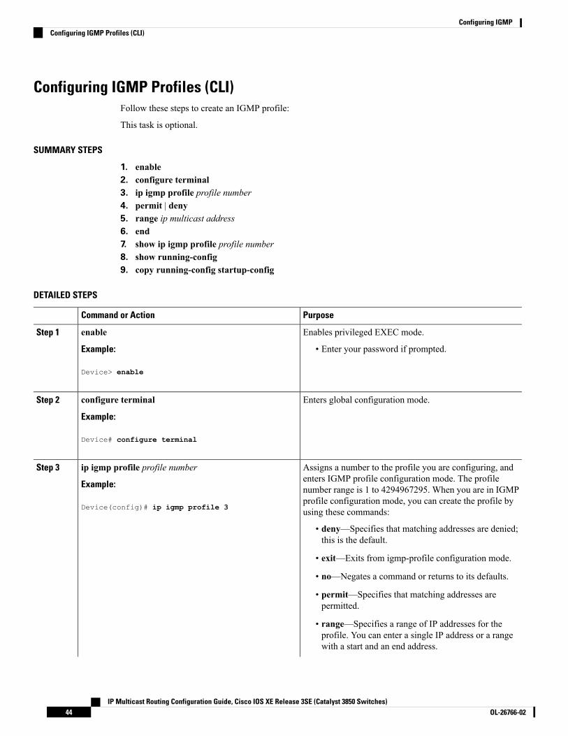
Configuring IGMP Profiles (CLI)Follow these steps to create an IGMP profile:
This task is optional.
SUMMARY STEPS
1. enable2. configure terminal3. ip igmp profile profile number4. permit | deny5. range ip multicast address6. end7. show ip igmp profile profile number8. show running-config9. copy running-config startup-config
DETAILED STEPS
PurposeCommand or Action
Enables privileged EXEC mode.enableStep 1
Example: • Enter your password if prompted.
Device> enable
Enters global configuration mode.configure terminal
Example:
Step 2
Device# configure terminal
Assigns a number to the profile you are configuring, andenters IGMP profile configuration mode. The profile
ip igmp profile profile number
Example:
Step 3
number range is 1 to 4294967295. When you are in IGMP
Device(config)# ip igmp profile 3profile configuration mode, you can create the profile byusing these commands:
• deny—Specifies that matching addresses are denied;this is the default.
• exit—Exits from igmp-profile configuration mode.
• no—Negates a command or returns to its defaults.
• permit—Specifies that matching addresses arepermitted.
• range—Specifies a range of IP addresses for theprofile. You can enter a single IP address or a rangewith a start and an end address.
IP Multicast Routing Configuration Guide, Cisco IOS XE Release 3SE (Catalyst 3850 Switches)OL-26766-0244
Configuring IGMPConfiguring IGMP Profiles (CLI)

PurposeCommand or Action
The default is for the device to have no IGMP profilesconfigured.
To delete a profile, use the no ip igmp profileprofile number global configuration command.
Note
(Optional) Sets the action to permit or deny access to theIP multicast address. If no action is configured, the defaultfor the profile is to deny access.
permit | deny
Example:
Device(config-igmp-profile)# permit
Step 4
Enters the IP multicast address or range of IP multicastaddresses to which access is being controlled. If entering a
range ip multicast address
Example:
Step 5
range, enter the low IP multicast address, a space, and thehigh IP multicast address.
Device(config-igmp-profile)# range 229.9.9.0
You can use the range command multiple times to entermultiple addresses or ranges of addresses.
To delete an IP multicast address or range of IPmulticast addresses, use the no range ipmulticast address IGMP profile configurationcommand.
Note
Returns to privileged EXEC mode.end
Example:
Step 6
Device(config)# end
Verifies the profile configuration.show ip igmp profile profile number
Example:
Step 7
Device# show ip igmp profile 3
Verifies your entries.show running-config
Example:
Step 8
Device# show running-config
(Optional) Saves your entries in the configuration file.copy running-config startup-config
Example:
Step 9
Device# copy running-config startup-config
IP Multicast Routing Configuration Guide, Cisco IOS XE Release 3SE (Catalyst 3850 Switches)45OL-26766-02
Configuring IGMPConfiguring IGMP Profiles (CLI)

Applying IGMP Profiles (CLI)To control access as defined in an IGMP profile, you have to apply the profile to the appropriate interfaces.You can apply IGMP profiles only to Layer 2 access ports; you cannot apply IGMP profiles to routed portsor SVIs. You cannot apply profiles to ports that belong to an EtherChannel port group. You can apply a profileto multiple interfaces, but each interface can have only one profile applied to it.
Follow these steps to apply an IGMP profile to a switch port:
SUMMARY STEPS
1. enable2. configure terminal3. interface interface-id4. ip igmp filter profile number5. end6. show running-config7. copy running-config startup-config
DETAILED STEPS
PurposeCommand or Action
Enables privileged EXEC mode.enableStep 1
Example: • Enter your password if prompted.
Device> enable
Enters global configuration mode.configure terminal
Example:
Step 2
Device# configure terminal
Specifies the physical interface, and enters interfaceconfiguration mode. The interface must be a Layer 2 portthat does not belong to an EtherChannel port group.
interface interface-id
Example:
Device(config)# interface gigabitethernet1/0/1
Step 3
Applies the specified IGMP profile to the interface. Therange is 1 to 4294967295.
ip igmp filter profile number
Example:
Step 4
To remove a profile from an interface, use theno ip igmp filter profile number interfaceconfiguration command.
NoteDevice(config-if)# ip igmp filter 321
Returns to privileged EXEC mode.end
Example:
Step 5
IP Multicast Routing Configuration Guide, Cisco IOS XE Release 3SE (Catalyst 3850 Switches)OL-26766-0246
Configuring IGMPApplying IGMP Profiles (CLI)

PurposeCommand or Action
Device(config-if)# end
Verifies your entries.show running-config
Example:
Step 6
Device# show running-config
(Optional) Saves your entries in the configuration file.copy running-config startup-config
Example:
Step 7
Device# copy running-config startup-config
Setting the Maximum Number of IGMP Groups (CLI)Follow these steps to set the maximum number of IGMP groups that a Layer 2 interface can join:
Before you begin
This restriction can be applied to Layer 2 ports only; you cannot set a maximum number of IGMP groups onrouted ports or SVIs. You also can use this command on a logical EtherChannel interface but cannot use iton ports that belong to an EtherChannel port group.
SUMMARY STEPS
1. enable2. configure terminal3. interface interface-id4. ip igmp max-groups number5. end6. show running-config interface interface-id7. copy running-config startup-config
DETAILED STEPS
PurposeCommand or Action
Enables privileged EXEC mode.enableStep 1
Example: • Enter your password if prompted.
Device> enable
Enters global configuration mode.configure terminal
Example:
Step 2
IP Multicast Routing Configuration Guide, Cisco IOS XE Release 3SE (Catalyst 3850 Switches)47OL-26766-02
Configuring IGMPSetting the Maximum Number of IGMP Groups (CLI)

PurposeCommand or Action
Device# configure terminal
Specifies the interface to be configured, and enters interfaceconfiguration mode. The interface can be a Layer 2 port
interface interface-id
Example:
Step 3
that does not belong to an EtherChannel group or aEtherChannel interface.
Device(config)# interface gigabitethernet1/0/2
Sets the maximum number of IGMP groups that theinterface can join. The range is 0 to 4294967294. Thedefault is to have no maximum set.
ip igmp max-groups number
Example:
Device(config-if)# ip igmp max-groups 20
Step 4
The device supports a maximum number of 4096Layer 2 IGMP groups and 2048 Layer 3 IGMPgroups.
Note
Returns to privileged EXEC mode.end
Example:
Step 5
Device(config)# end
Verifies your entries.show running-config interface interface-id
Example:
Step 6
Device# interface gigabitethernet1/0/1
(Optional) Saves your entries in the configuration file.copy running-config startup-config
Example:
Step 7
Device# copy running-config startup-config
Configuring the IGMP Throttling Action (CLI)After you set the maximum number of IGMP groups that a Layer 2 interface can join, you can configure aninterface to replace the existing group with the new group for which the IGMP report was received.
Follow these steps to configure the throttling action when the maximum number of entries is in the forwardingtable:
SUMMARY STEPS
1. enable2. configure terminal3. interface interface-id
IP Multicast Routing Configuration Guide, Cisco IOS XE Release 3SE (Catalyst 3850 Switches)OL-26766-0248
Configuring IGMPConfiguring the IGMP Throttling Action (CLI)

4. ip igmp max-groups action {deny | replace}5. end6. show running-config interface interface-id7. copy running-config startup-config
DETAILED STEPS
PurposeCommand or Action
Enables privileged EXEC mode.enableStep 1
Example: • Enter your password if prompted.
Device> enable
Enters global configuration mode.configure terminal
Example:
Step 2
Device# configure terminal
Specifies the physical interface to be configured, and entersinterface configuration mode. The interface can be a Layer
interface interface-id
Example:
Step 3
2 port that does not belong to an EtherChannel group or an
Device(config)# interface gigabitethernet1/0/1EtherChannel interface. The interface cannot be a trunkport.
When an interface receives an IGMP report and themaximum number of entries is in the forwarding table,specifies the action that the interface takes:
ip igmp max-groups action {deny | replace}
Example:
Device(config-if)# ip igmp max-groups action
Step 4
• deny—Drops the report. If you configure this throttlingaction, the entries that were previously in thereplace
forwarding table are not removed but are aged out.After these entries are aged out and the maximumnumber of entries is in the forwarding table, the devicedrops the next IGMP report received on the interface.
• replace—Replaces the existing group with the newgroup for which the IGMP report was received. If youconfigure this throttling action, the entries that werepreviously in the forwarding table are removed.Whenthe maximum number of entries is in the forwardingtable, the device replaces a randomly selected entrywith the received IGMP report.
To prevent the device from removing the forwarding-tableentries, you can configure the IGMP throttling action beforean interface adds entries to the forwarding table.
IP Multicast Routing Configuration Guide, Cisco IOS XE Release 3SE (Catalyst 3850 Switches)49OL-26766-02
Configuring IGMPConfiguring the IGMP Throttling Action (CLI)

PurposeCommand or Action
To return to the default action of dropping thereport, use the no ip igmp max-groups actioninterface configuration command.
Note
Returns to privileged EXEC mode.end
Example:
Step 5
Device(config)# end
Verifies your entries.show running-config interface interface-id
Example:
Step 6
Device# show running-config interfacegigabitethernet1/0/1
(Optional) Saves your entries in the configuration file.copy running-config startup-config
Example:
Step 7
Device# copy running-config startup-config
Related TopicsIGMP Filtering and Throttling, on page 30Examples: Configuring Filtering and Throttling, on page 77
Configuring the Device to Forward Multicast Traffic in the Absence of DirectlyConnected IGMP Hosts
Perform this optional task to configure the device to forward multicast traffic in the absence of directlyconnected IGMP hosts.
SUMMARY STEPS
1. enable2. configure terminal3. interface type number4. Do one of the following:
• ip igmp join-group group-address• ip igmp static-group {* | group-address [source source-address]}
5. end6. show ip igmp interface [interface-type interface-number]
IP Multicast Routing Configuration Guide, Cisco IOS XE Release 3SE (Catalyst 3850 Switches)OL-26766-0250
Configuring IGMPConfiguring the Device to Forward Multicast Traffic in the Absence of Directly Connected IGMP Hosts

DETAILED STEPS
PurposeCommand or Action
Enables privileged EXEC mode.enableStep 1
Example: • Enter your password if prompted.
Device> enable
Enters global configuration mode.configure terminal
Example:
Step 2
device# configure terminal
Enters interface configuration mode.interface type numberStep 3
Example: • For the type and number arguments, specify aninterface that is connected to hosts.
device(config)# interface gigabitethernet 1
The first sample shows how to configure an interface onthe device to join the specified group.
Do one of the following:Step 4
• ip igmp join-group group-addressWith this method, the device accepts the multicast packetsin addition to forwarding them. Accepting the multicastpackets prevents the device from fast switching.
• ip igmp static-group {* | group-address [sourcesource-address]}
Example:The second example shows how to configure static groupmembership entries on an interface. With this method, thedevice(config-if)# ip igmp join-group 225.2.2.2device does not accept the packets itself, but only forwards
Example: them. Hence, this method allows fast switching. The
device(config-if)# ip igmp static-group 225.2.2.2outgoing interface appears in the IGMP cache, but thedevice itself is not a member, as evidenced by lack of an“L” (local) flag in the multicast route entry
Returns to privileged EXEC mode.end
Example:
Step 5
device#(config-if)# end
(Optional) Displays multicast-related information about aninterface.
show ip igmp interface [interface-type interface-number]
Example:
Step 6
device# show ip igmp interface
Related TopicsExample: Configuring the Device to Forward Multicast Traffic in the Absence of Directly ConnectedIGMP Hosts, on page 78
IP Multicast Routing Configuration Guide, Cisco IOS XE Release 3SE (Catalyst 3850 Switches)51OL-26766-02
Configuring IGMPConfiguring the Device to Forward Multicast Traffic in the Absence of Directly Connected IGMP Hosts
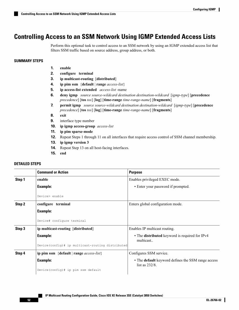
Controlling Access to an SSM Network Using IGMP Extended Access ListsPerform this optional task to control access to an SSM network by using an IGMP extended access list thatfilters SSM traffic based on source address, group address, or both.
SUMMARY STEPS
1. enable2. configure terminal3. ip multicast-routing [distributed]4. ip pim ssm {default | range access-list}5. ip access-list extended access-list -name6. deny igmp source source-wildcard destination destination-wildcard [igmp-type] [precedence
precedence] [tos tos] [log] [time-range time-range-name] [fragments]7. permit igmp source source-wildcard destination destination-wildcard [igmp-type] [precedence
precedence] [tos tos] [log] [time-range time-range-name] [fragments]8. exit9. interface type number10. ip igmp access-group access-list11. ip pim sparse-mode12. Repeat Steps 1 through 11 on all interfaces that require access control of SSM channel membership.13. ip igmp version 314. Repeat Step 13 on all host-facing interfaces.15. end
DETAILED STEPS
PurposeCommand or Action
Enables privileged EXEC mode.enableStep 1
Example: • Enter your password if prompted.
Device> enable
Enters global configuration mode.configure terminal
Example:
Step 2
Device# configure terminal
Enables IP multicast routing.ip multicast-routing [distributed]Step 3
Example: • The distributed keyword is required for IPv4multicast..
Device(config)# ip multicast-routing distributed
Configures SSM service.ip pim ssm {default | range access-list}Step 4
Example: • The default keyword defines the SSM range accesslist as 232/8.
Device(config)# ip pim ssm default
IP Multicast Routing Configuration Guide, Cisco IOS XE Release 3SE (Catalyst 3850 Switches)OL-26766-0252
Configuring IGMPControlling Access to an SSM Network Using IGMP Extended Access Lists

PurposeCommand or Action
• The range keyword specifies the standard IP accesslist number or name that defines the SSM range.
Specifies an extended named IP access list.ip access-list extended access-list -name
Example:
Step 5
Device(config)# ip access-list extended mygroup
(Optional) Filters the specified source address or groupaddress from the IGMP report, thereby restricting hostson a subnet from membership to the (S, G) channel.
deny igmp source source-wildcard destinationdestination-wildcard [igmp-type] [precedence precedence][tos tos] [log] [time-range time-range-name] [fragments]
Step 6
Example: • Repeat this step to restrict hosts on a subnetmembership to other (S, G) channels. (These sources
Device(config-ext-nacl)# deny igmp host 10.1.2.3any
should be more specific than a subsequent permitstatement because any sources or groups notspecifically permitted are denied.)
• Remember that the access list ends in an implicit denystatement.
• This example shows how to create a deny statementthat filters all groups for source 10.1.2.3, whicheffectively denies the source.
Allows a source address or group address in an IGMPreport to pass the IP access list.
permit igmp source source-wildcard destinationdestination-wildcard [igmp-type] [precedence precedence][tos tos] [log] [time-range time-range-name] [fragments]
Step 7
• You must have at least one permit statement in anaccess list.Example:
Device(config-ext-nacl)# permit igmp any any • Repeat this step to allow other sources to pass the IPaccess list.
• This example shows how to allow groupmembershipto sources and groups not denied by prior denystatements.
Exits the current configuration session and returns to globalconfiguration mode.
exit
Example:
Step 8
Device(config-ext-nacl)# exit
Selects an interface that is connected to hosts on whichIGMPv3 can be enabled.
interface type number
Example:
Step 9
Device(config)# interface ethernet 0
Applies the specified access list to IGMP reports.ip igmp access-group access-list
Example:
Step 10
IP Multicast Routing Configuration Guide, Cisco IOS XE Release 3SE (Catalyst 3850 Switches)53OL-26766-02
Configuring IGMPControlling Access to an SSM Network Using IGMP Extended Access Lists

PurposeCommand or Action
Device(config-if)# ip igmp access-group mygroup
Enables PIM-SM on the interface.ip pim sparse-modeStep 11
Example: You must use sparse mode.Note
Device(config-if)# ip pim sparse-mode
--Repeat Steps 1 through 11 on all interfaces that requireaccess control of SSM channel membership.
Step 12
Enables IGMPv3 on this interface. The default version ofIGMP is IGMP version 2. Version 3 is required by SSM.
ip igmp version 3
Example:
Step 13
Device(config-if)# ip igmp version 3
--Repeat Step 13 on all host-facing interfaces.Step 14
Returns to privileged EXEC mode.end
Example:
Step 15
Device(config-if)# end
Related TopicsControlling Access to an SSM Network Using IGMP Extended Access Lists , on page 79Example: Denying All States for a Group G, on page 79Example: Denying All States for a Source S, on page 79Example: Permitting All States for a Group G, on page 80Example: Permitting All States for a Source S, on page 80Example: Filtering a Source S for a Group G, on page 80
How to Configure IGMP Snooping
Enabling or Disabling IGMP Snooping on a Device (CLI)When IGMP snooping is globally enabled or disabled, it is also enabled or disabled in all existing VLANinterfaces. IGMP snooping is enabled on all VLANs by default, but can be enabled and disabled on a per-VLANbasis.
Global IGMP snooping overrides the VLAN IGMP snooping. If global snooping is disabled, you cannotenable VLAN snooping. If global snooping is enabled, you can enable or disable VLAN snooping.
Follow these steps to globally enable IGMP snooping on the device:
SUMMARY STEPS
1. enable2. configure terminal3. ip igmp snooping
IP Multicast Routing Configuration Guide, Cisco IOS XE Release 3SE (Catalyst 3850 Switches)OL-26766-0254
Configuring IGMPHow to Configure IGMP Snooping

4. end5. copy running-config startup-config
DETAILED STEPS
PurposeCommand or Action
Enables privileged EXEC mode.enableStep 1
Example: • Enter your password if prompted.
Device> enable
Enters global configuration mode.configure terminal
Example:
Step 2
Device# configure terminal
Globally enables IGMP snooping in all existing VLANinterfaces.
ip igmp snooping
Example:
Step 3
To globally disable IGMP snooping on all VLANinterfaces, use the no ip igmp snooping globalconfiguration command.
NoteDevice(config)# ip igmp snooping
Returns to privileged EXEC mode.end
Example:
Step 4
Device(config)# end
(Optional) Saves your entries in the configuration file.copy running-config startup-config
Example:
Step 5
Device# copy running-config startup-config
Related TopicsIGMP Snooping, on page 27Examples: Configuring IGMP Snooping, on page 76
Enabling or Disabling IGMP Snooping on a VLAN Interface (CLI)Follow these steps to enable IGMP snooping on a VLAN interface:
SUMMARY STEPS
1. enable2. configure terminal3. ip igmp snooping vlan vlan-id
IP Multicast Routing Configuration Guide, Cisco IOS XE Release 3SE (Catalyst 3850 Switches)55OL-26766-02
Configuring IGMPEnabling or Disabling IGMP Snooping on a VLAN Interface (CLI)

4. end5. copy running-config startup-config
DETAILED STEPS
PurposeCommand or Action
Enables privileged EXEC mode.enableStep 1
Example: • Enter your password if prompted.
Device> enable
Enters global configuration mode.configure terminal
Example:
Step 2
Device# configure terminal
Enables IGMP snooping on theVLAN interface. TheVLANID range is 1 to 1001 and 1006 to 4094.
ip igmp snooping vlan vlan-id
Example:
Step 3
IGMP snooping must be globally enabled before you canenable VLAN snooping.Device(config)# ip igmp snooping vlan 7
To disable IGMP snooping on aVLAN interface,use the no ip igmp snooping vlan vlan-id globalconfiguration command for the specified VLANnumber.
Note
Returns to privileged EXEC mode.end
Example:
Step 4
Device(config)# end
(Optional) Saves your entries in the configuration file.copy running-config startup-config
Example:
Step 5
Device# copy running-config startup-config
Setting the Snooping Method (CLI)Multicast-capable router ports are added to the forwarding table for every Layer 2 multicast entry. The devicelearns of the ports through one of these methods:
• Snooping on IGMP queries, Protocol-Independent Multicast (PIM) packets
• Statically connecting to a multicast router port using the ip igmp snoopingmrouter global configurationcommand
IP Multicast Routing Configuration Guide, Cisco IOS XE Release 3SE (Catalyst 3850 Switches)OL-26766-0256
Configuring IGMPSetting the Snooping Method (CLI)

Beginning in privileged EXEC mode, follow these steps to alter the method in which a VLAN interfaceaccesses a multicast router:
SUMMARY STEPS
1. enable2. configure terminal3. ip igmp snooping vlan vlan-id mrouter interface {GigabitEthernet | Port-Channel |
TenGigabitEthernet}4. end5. show ip igmp snooping6. copy running-config startup-config
DETAILED STEPS
PurposeCommand or Action
Enables privileged EXEC mode.enableStep 1
Example: Enter your password, if prompted.
Device> enable
Enters global configuration mode.configure terminal
Example:
Step 2
Device# configure terminal
Enables IGMP snooping on a VLAN. The VLAN ID rangeis 1 to 1001 and 1006 to 4094.
ip igmp snooping vlan vlan-id mrouter interface{GigabitEthernet | Port-Channel |TenGigabitEthernet}
Example:
Step 3
Device(config)# ip igmp snoopingvlan 1 mrouter interface GigabitEthernet1/0/3
Returns to privileged EXEC mode.end
Example:
Step 4
Device(config)# end
Verifies the configuration.show ip igmp snooping
Example:
Step 5
Device# show ip igmp snooping
(Optional) Saves your entries in the configuration file.copy running-config startup-config
Example:
Step 6
IP Multicast Routing Configuration Guide, Cisco IOS XE Release 3SE (Catalyst 3850 Switches)57OL-26766-02
Configuring IGMPSetting the Snooping Method (CLI)

PurposeCommand or Action
Device# copy running-config startup-config
Configuring a Multicast Router Port (CLI)Perform these steps to add a multicast router port (enable a static connection to a multicast router) on thedevice.
Static connections to multicast routers are supported only on device ports.Note
SUMMARY STEPS
1. enable2. configure terminal3. ip igmp snooping vlan vlan-idmrouter interface interface-id4. end5. show ip igmp snooping mrouter [vlan vlan-id]6. copy running-config startup-config
DETAILED STEPS
PurposeCommand or Action
Enables privileged EXEC mode.enableStep 1
Example: • Enter your password if prompted.
Device> enable
Enters global configuration mode.configure terminal
Example:
Step 2
Device# configure terminal
Specifies the multicast router VLAN ID and the interfaceto the multicast router.
ip igmp snooping vlan vlan-idmrouter interfaceinterface-id
Step 3
Example: • The VLAN ID range is 1 to 1001 and 1006 to 4094.
Device(config)# ip igmp snooping vlan 5 mrouter • The interface can be a physical interface or a portchannel. The port-channel range is 1 to 128.interface gigabitethernet1/0/1
To remove a multicast router port from theVLAN, use the no ip igmp snooping vlanvlan-idmrouter interface interface-id globalconfiguration command.
Note
IP Multicast Routing Configuration Guide, Cisco IOS XE Release 3SE (Catalyst 3850 Switches)OL-26766-0258
Configuring IGMPConfiguring a Multicast Router Port (CLI)
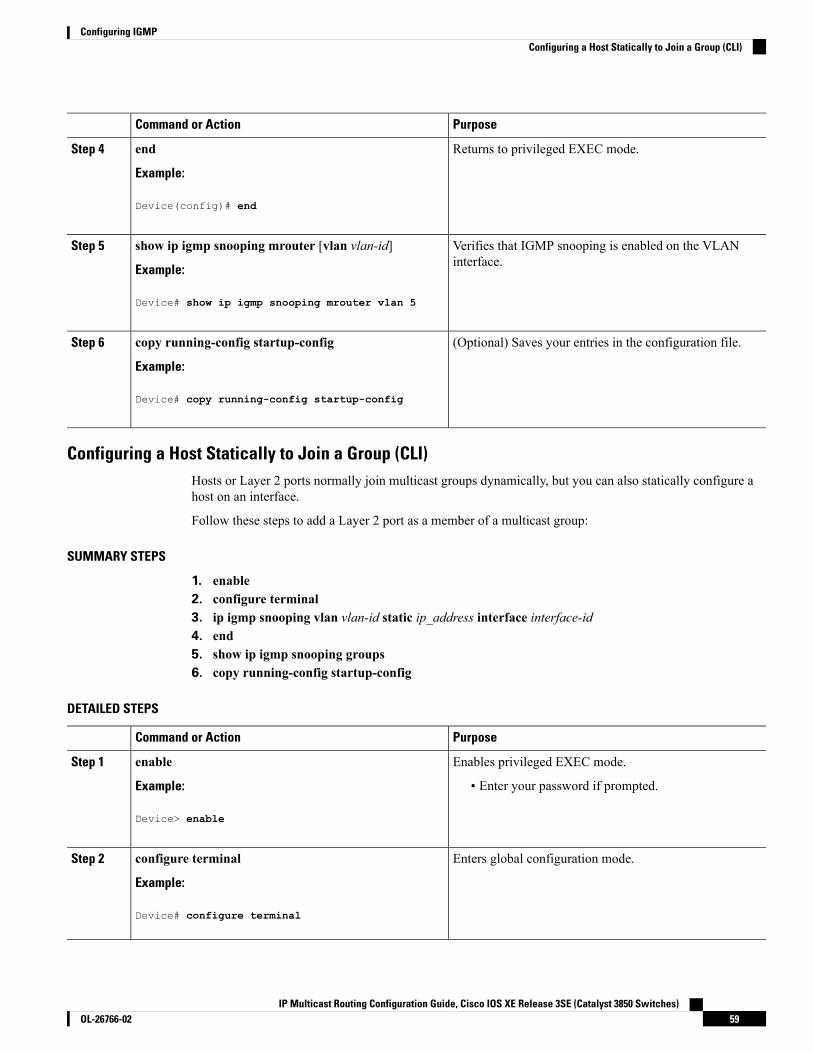
PurposeCommand or Action
Returns to privileged EXEC mode.end
Example:
Step 4
Device(config)# end
Verifies that IGMP snooping is enabled on the VLANinterface.
show ip igmp snooping mrouter [vlan vlan-id]
Example:
Step 5
Device# show ip igmp snooping mrouter vlan 5
(Optional) Saves your entries in the configuration file.copy running-config startup-config
Example:
Step 6
Device# copy running-config startup-config
Configuring a Host Statically to Join a Group (CLI)Hosts or Layer 2 ports normally join multicast groups dynamically, but you can also statically configure ahost on an interface.
Follow these steps to add a Layer 2 port as a member of a multicast group:
SUMMARY STEPS
1. enable2. configure terminal3. ip igmp snooping vlan vlan-id static ip_address interface interface-id4. end5. show ip igmp snooping groups6. copy running-config startup-config
DETAILED STEPS
PurposeCommand or Action
Enables privileged EXEC mode.enableStep 1
Example: • Enter your password if prompted.
Device> enable
Enters global configuration mode.configure terminal
Example:
Step 2
Device# configure terminal
IP Multicast Routing Configuration Guide, Cisco IOS XE Release 3SE (Catalyst 3850 Switches)59OL-26766-02
Configuring IGMPConfiguring a Host Statically to Join a Group (CLI)

PurposeCommand or Action
Statically configures a Layer 2 port as a member of amulticast group:
ip igmp snooping vlan vlan-id static ip_address interfaceinterface-id
Step 3
Example: • vlan-id is the multicast group VLAN ID. The range is1 to 1001 and 1006 to 4094.
Device(config)# ip igmp snooping vlan 105 static• ip-address is the group IP address.230.0.0.1 interface gigabitethernet1/0/1
• interface-id is the member port. It can be a physicalinterface or a port channel (1 to 128).
To remove the Layer 2 port from the multicastgroup, use the no ip igmp snooping vlan vlan-idstaticmac-address interface interface-id globalconfiguration command.
Note
Returns to privileged EXEC mode.end
Example:
Step 4
Device(config)# end
Verifies the member port and the IP address.show ip igmp snooping groups
Example:
Step 5
Device# show ip igmp snooping groups
(Optional) Saves your entries in the configuration file.copy running-config startup-config
Example:
Step 6
Device# copy running-config startup-config
Enabling IGMP Immediate Leave (CLI)When you enable IGMP Immediate Leave, the device immediately removes a port when it detects an IGMPVersion 2 leave message on that port. You should use the Immediate-Leave feature only when there is a singlereceiver present on every port in the VLAN.
Immediate Leave is supported only on IGMP Version 2 hosts. IGMP Version 2 is the default version for thedevice.
Note
SUMMARY STEPS
1. enable2. configure terminal
IP Multicast Routing Configuration Guide, Cisco IOS XE Release 3SE (Catalyst 3850 Switches)OL-26766-0260
Configuring IGMPEnabling IGMP Immediate Leave (CLI)

3. ip igmp snooping vlan vlan-id immediate-leave4. end5. show ip igmp snooping vlan vlan-id6. end
DETAILED STEPS
PurposeCommand or Action
Enables privileged EXEC mode.enableStep 1
Example: • Enter your password if prompted.
Device> enable
Enters global configuration mode.configure terminal
Example:
Step 2
Device# configure terminal
Enables IGMP Immediate Leave on the VLAN interface.ip igmp snooping vlan vlan-id immediate-leaveStep 3
Example: To disable IGMP Immediate Leave on a VLAN,use the no ip igmp snooping vlan vlan-idimmediate-leave global configuration command.
Note
Device(config)# ip igmp snooping vlan 21immediate-leave
Returns to privileged EXEC mode.end
Example:
Step 4
Device(config)# end
Verifies that Immediate Leave is enabled on the VLANinterface.
show ip igmp snooping vlan vlan-id
Example:
Step 5
Device# show ip igmp snooping vlan 21
Returns to privileged EXEC mode.end
Example:
Step 6
Device(config)# end
Configuring the IGMP Leave Timer (CLI)You can configure the leave time globally or on a per-VLAN basis. Follow these steps to enable the IGMPconfigurable-leave timer:
IP Multicast Routing Configuration Guide, Cisco IOS XE Release 3SE (Catalyst 3850 Switches)61OL-26766-02
Configuring IGMPConfiguring the IGMP Leave Timer (CLI)

SUMMARY STEPS
1. enable2. configure terminal3. ip igmp snooping last-member-query-interval time4. ip igmp snooping vlan vlan-id last-member-query-interval time5. end6. show ip igmp snooping7. copy running-config startup-config
DETAILED STEPS
PurposeCommand or Action
Enables privileged EXEC mode.enableStep 1
Example: • Enter your password if prompted.
Device> enable
Enters global configuration mode.configure terminal
Example:
Step 2
Device# configure terminal
Configures the IGMP leave timer globally. The range is100 to 32767 milliseconds.
ip igmp snooping last-member-query-interval time
Example:
Step 3
The default leave time is 1000 milliseconds.Device(config)# ip igmp snooping To globally reset the IGMP leave timer to the
default setting, use the no ip igmp snoopinglast-member-query-interval globalconfiguration command.
Notelast-member-query-interval 1000
(Optional) Configures the IGMP leave time on the VLANinterface. The range is 100 to 32767 milliseconds.
ip igmp snooping vlan vlan-idlast-member-query-interval time
Step 4
Example: Configuring the leave time on a VLAN overridesthe globally configured timer.
Note
Device(config)# ip igmp snooping vlan 210last-member-query-interval 1000 To remove the configured IGMP leave-time
setting from the specified VLAN, use the no ipigmp snooping vlan vlan-idlast-member-query-interval globalconfiguration command.
Note
Returns to privileged EXEC mode.end
Example:
Step 5
IP Multicast Routing Configuration Guide, Cisco IOS XE Release 3SE (Catalyst 3850 Switches)OL-26766-0262
Configuring IGMPConfiguring the IGMP Leave Timer (CLI)

PurposeCommand or Action
Device(config)# end
(Optional) Displays the configured IGMP leave time.show ip igmp snooping
Example:
Step 6
Device# show ip igmp snooping
(Optional) Saves your entries in the configuration file.copy running-config startup-config
Example:
Step 7
Device# copy running-config startup-config
Related TopicsIGMP Configurable-Leave Timer, on page 30
Configuring the IGMP Robustness-Variable (CLI)Use the following procedure to configure the IGMP robustness variable on the device.
The robustness variable is the integer used by IGMP snooping during calculations for IGMP messages. Therobustness variable provides fine tuning to allow for expected packet loss.
SUMMARY STEPS
1. enable2. configure terminal3. ip igmp snooping robustness-variable count4. ip igmp snooping vlan vlan-id robustness-variable count5. end6. show ip igmp snooping7. copy running-config startup-config
DETAILED STEPS
PurposeCommand or Action
Enables privileged EXEC mode.enableStep 1
Example: Enter your password, if prompted.
Device> enable
Enters global configuration mode.configure terminal
Example:
Step 2
IP Multicast Routing Configuration Guide, Cisco IOS XE Release 3SE (Catalyst 3850 Switches)63OL-26766-02
Configuring IGMPConfiguring the IGMP Robustness-Variable (CLI)

PurposeCommand or Action
Device# configure terminal
Configures the IGMP robustness variable. The range is 1to 3 times.
ip igmp snooping robustness-variable count
Example:
Step 3
The recommended value for the robustness variable is 2.Use this command to change the value of the robustnessDevice(config)# ip igmp snooping
robustness-variable 3 variable for IGMP snooping from the default (2) to aspecified value.
(Optional) Configures the IGMP robustness variable on theVLAN interface. The range is 1 to 3 times. Therecommended value for the robustness variable is 2.
ip igmp snooping vlan vlan-id robustness-variable count
Example:
Device(config)#ip igmp snooping vlan 100
Step 4
Configuring the robustness variable count on aVLAN overrides the globally configured value.
Noterobustness-variable 3
Returns to privileged EXEC mode.end
Example:
Step 5
Device(config)# end
(Optional) Displays the configured IGMP robustnessvariable count.
show ip igmp snooping
Example:
Step 6
Device# show ip igmp snooping
(Optional) Saves your entries in the configuration file.copy running-config startup-config
Example:
Step 7
Device# copy running-config startup-config
Configuring the IGMP Last Member Query Count (CLI)To configure the number of times the device sends IGMP group-specific or group-source-specific (with IGMPversion 3) query messages in response to receiving a group-specific or group-source-specific leave message,use this command.
SUMMARY STEPS
1. enable2. configure terminal3. ip igmp snooping last-member-query-count count4. ip igmp snooping vlan vlan-id last-member-query-count count5. end
IP Multicast Routing Configuration Guide, Cisco IOS XE Release 3SE (Catalyst 3850 Switches)OL-26766-0264
Configuring IGMPConfiguring the IGMP Last Member Query Count (CLI)

6. show ip igmp snooping7. copy running-config startup-config
DETAILED STEPS
PurposeCommand or Action
Enables privileged EXEC mode.enableStep 1
Example: Enter your password, if prompted.
Device> enable
Enters global configuration mode.configure terminal
Example:
Step 2
Device# configure terminal
Configures the IGMP last member query count. The rangeis 1 to 7 messages. The default is 2 messages.
ip igmp snooping last-member-query-count count
Example:
Step 3
Device(config)# ip igmp snoopinglast-member-query-count 3
(Optional) Configures the IGMP last member query counton the VLAN interface. The range is 1 to 7 messages.
ip igmp snooping vlan vlan-id last-member-query-countcount
Step 4
Example: Configuring the last member query count on aVLAN overrides the globally configured timer.
Note
Device(config)#ip igmp snooping vlan 100last-member-query-count 3
Returns to privileged EXEC mode.end
Example:
Step 5
Device(config)# end
(Optional) Displays the configured IGMP last memberquery count.
show ip igmp snooping
Example:
Step 6
Device# show ip igmp snooping
(Optional) Saves your entries in the configuration file.copy running-config startup-config
Example:
Step 7
Device# copy running-config startup-config
IP Multicast Routing Configuration Guide, Cisco IOS XE Release 3SE (Catalyst 3850 Switches)65OL-26766-02
Configuring IGMPConfiguring the IGMP Last Member Query Count (CLI)

Configuring TCN-Related Commands
Controlling the Multicast Flooding Time After a TCN Event (CLI)
You can configure the number of general queries by which multicast data traffic is flooded after a topologychange notification (TCN) event. If you set the TCN flood query count to 1 the flooding stops after receiving1 general query. If you set the count to 7, the flooding continues until 7 general queries are received. Groupsare relearned based on the general queries received during the TCN event.
Some examples of TCN events are when the client location is changed and the receiver is on same port thatwas blocked but is now forwarding, and when a port goes down without sending a leave message.
Follow these steps to configure the TCN flood query count:
SUMMARY STEPS
1. enable2. configure terminal3. ip igmp snooping tcn flood query count count4. end5. show ip igmp snooping6. copy running-config startup-config
DETAILED STEPS
PurposeCommand or Action
Enables privileged EXEC mode.enableStep 1
Example: • Enter your password if prompted.
Device> enable
Enters global configuration mode.configure terminal
Example:
Step 2
Device# configure terminal
Specifies the number of IGMP general queries for whichthe multicast traffic is flooded.
ip igmp snooping tcn flood query count count
Example:
Step 3
The range is 1 to 10. The default, the flooding query countis 2.Device(config)# ip igmp snooping tcn flood query
count 3To return to the default flooding query count,use the no ip igmp snooping tcn flood querycount global configuration command.
Note
Returns to privileged EXEC mode.end
Example:
Step 4
IP Multicast Routing Configuration Guide, Cisco IOS XE Release 3SE (Catalyst 3850 Switches)OL-26766-0266
Configuring IGMPConfiguring TCN-Related Commands

PurposeCommand or Action
Device(config)# end
Verifies the TCN settings.show ip igmp snooping
Example:
Step 5
Device# show ip igmp snooping
(Optional) Saves your entries in the configuration file.copy running-config startup-config
Example:
Step 6
Device# copy running-config startup-config
Recovering from Flood Mode (CLI)
When a topology change occurs, the spanning-tree root sends a special IGMP leave message (also known asglobal leave) with the group multicast address 0.0.0.0. However, you can enable the device to send the globalleave message whether it is the spanning-tree root or not. When the router receives this special leave, itimmediately sends general queries, which expedite the process of recovering from the flood mode during theTCN event. Leaves are always sent if the device is the spanning-tree root regardless of this configuration.
Follow these steps to enable sending of leave messages:
SUMMARY STEPS
1. enable2. configure terminal3. ip igmp snooping tcn query solicit4. end5. show ip igmp snooping6. copy running-config startup-config
DETAILED STEPS
PurposeCommand or Action
Enables privileged EXEC mode.enableStep 1
Example: • Enter your password if prompted.
Device> enable
Enters global configuration mode.configure terminal
Example:
Step 2
Device# configure terminal
IP Multicast Routing Configuration Guide, Cisco IOS XE Release 3SE (Catalyst 3850 Switches)67OL-26766-02
Configuring IGMPRecovering from Flood Mode (CLI)

PurposeCommand or Action
Sends an IGMP leave message (global leave) to speed theprocess of recovering from the flood mode caused duringa TCN event. By default, query solicitation is disabled.
ip igmp snooping tcn query solicit
Example:
Device(config)# ip igmp snooping tcn query solicit
Step 3
To return to the default query solicitation, usethe no ip igmp snooping tcn query solicitglobal configuration command.
Note
Returns to privileged EXEC mode.end
Example:
Step 4
Device(config)# end
Verifies the TCN settings.show ip igmp snooping
Example:
Step 5
Device# show ip igmp snooping
(Optional) Saves your entries in the configuration file.copy running-config startup-config
Example:
Step 6
Device# copy running-config startup-config
Disabling Multicast Flooding During a TCN Event (CLI)
When the device receives a TCN, multicast traffic is flooded to all the ports until 2 general queries are received.If the device has many ports with attached hosts that are subscribed to different multicast groups, this floodingmight exceed the capacity of the link and cause packet loss. Follow these steps to control TCN flooding:
SUMMARY STEPS
1. enable2. configure terminal3. interface interface-id4. no ip igmp snooping tcn flood5. end6. show ip igmp snooping7. copy running-config startup-config
DETAILED STEPS
PurposeCommand or Action
Enables privileged EXEC mode.enableStep 1
Example: • Enter your password if prompted.
IP Multicast Routing Configuration Guide, Cisco IOS XE Release 3SE (Catalyst 3850 Switches)OL-26766-0268
Configuring IGMPDisabling Multicast Flooding During a TCN Event (CLI)

PurposeCommand or Action
Device> enable
Enters global configuration mode.configure terminal
Example:
Step 2
Device# configure terminal
Specifies the interface to be configured, and enters interfaceconfiguration mode.
interface interface-id
Example:
Step 3
Device(config)# interface gigabitethernet 1/0/1
Disables the flooding of multicast traffic during aspanning-tree TCN event.
no ip igmp snooping tcn flood
Example:
Step 4
By default, multicast flooding is enabled on an interface.Device(config-if)# no ip igmp snooping tcn flood To re-enable multicast flooding on an interface,
use the ip igmp snooping tcn flood interfaceconfiguration command.
Note
Returns to privileged EXEC mode.end
Example:
Step 5
Device(config)# end
Verifies the TCN settings.show ip igmp snooping
Example:
Step 6
Device# show ip igmp snooping
(Optional) Saves your entries in the configuration file.copy running-config startup-config
Example:
Step 7
Device# copy running-config startup-config
Configuring the IGMP Snooping Querier (CLI)Follow these steps to enable the IGMP snooping querier feature in a VLAN:
SUMMARY STEPS
1. enable
IP Multicast Routing Configuration Guide, Cisco IOS XE Release 3SE (Catalyst 3850 Switches)69OL-26766-02
Configuring IGMPConfiguring the IGMP Snooping Querier (CLI)

2. configure terminal3. ip igmp snooping querier4. ip igmp snooping querier address ip_address5. ip igmp snooping querier query-interval interval-count6. ip igmp snooping querier tcn query [count count | interval interval]7. ip igmp snooping querier timer expiry timeout8. ip igmp snooping querier version version9. end10. show ip igmp snooping vlan vlan-id11. copy running-config startup-config
DETAILED STEPS
PurposeCommand or Action
Enables privileged EXEC mode.enableStep 1
Example: • Enter your password if prompted.
Device> enable
Enters global configuration mode.configure terminal
Example:
Step 2
Device# configure terminal
Enables the IGMP snooping querier.ip igmp snooping querier
Example:
Step 3
Device(config)# ip igmp snooping querier
(Optional) Specifies an IP address for the IGMP snoopingquerier. If you do not specify an IP address, the querier
ip igmp snooping querier address ip_address
Example:
Step 4
tries to use the global IP address configured for the IGMPquerier.
Device(config)# ip igmp snooping querier address172.16.24.1 The IGMP snooping querier does not generate
an IGMP general query if it cannot find an IPaddress on the device.
Note
(Optional) Sets the interval between IGMP queriers. Therange is 1 to 18000 seconds.
ip igmp snooping querier query-interval interval-count
Example:
Step 5
Device(config)# ip igmp snooping querierquery-interval 30
IP Multicast Routing Configuration Guide, Cisco IOS XE Release 3SE (Catalyst 3850 Switches)OL-26766-0270
Configuring IGMPConfiguring the IGMP Snooping Querier (CLI)

PurposeCommand or Action
(Optional) Sets the time between Topology ChangeNotification (TCN) queries. The count range is 1 to 10.The interval range is 1 to 255 seconds.
ip igmp snooping querier tcn query [count count |interval interval]
Example:
Step 6
Device(config)# ip igmp snooping querier tcn queryinterval 20
(Optional) Sets the length of time until the IGMP querierexpires. The range is 60 to 300 seconds.
ip igmp snooping querier timer expiry timeout
Example:
Step 7
Device(config)# ip igmp snooping querier timerexpiry 180
(Optional) Selects the IGMP version number that thequerier feature uses. Select 1 or 2.
ip igmp snooping querier version version
Example:
Step 8
Device(config)# ip igmp snooping querier version2
Returns to privileged EXEC mode.end
Example:
Step 9
Device(config)# end
(Optional) Verifies that the IGMP snooping querier isenabled on the VLAN interface. The VLAN ID range is1 to 1001 and 1006 to 4094.
show ip igmp snooping vlan vlan-id
Example:
Device# show ip igmp snooping vlan 30
Step 10
(Optional) Saves your entries in the configuration file.copy running-config startup-config
Example:
Step 11
Device# copy running-config startup-config
Disabling IGMP Report Suppression (CLI)Follow these steps to disable IGMP report suppression:
SUMMARY STEPS
1. enable2. configure terminal3. no ip igmp snooping report-suppression
IP Multicast Routing Configuration Guide, Cisco IOS XE Release 3SE (Catalyst 3850 Switches)71OL-26766-02
Configuring IGMPDisabling IGMP Report Suppression (CLI)

4. end5. show ip igmp snooping6. copy running-config startup-config
DETAILED STEPS
PurposeCommand or Action
Enables privileged EXEC mode.enableStep 1
Example: • Enter your password if prompted.
Device> enable
Enters global configuration mode.configure terminal
Example:
Step 2
Device# configure terminal
Disables IGMP report suppression.When report suppressionis disabled, all IGMP reports are forwarded to the multicastrouters.
no ip igmp snooping report-suppression
Example:
Device(config)# no ip igmp snooping
Step 3
IGMP report suppression is enabled by default.report-suppression
When IGMP report supression is enabled, the deviceforwards only one IGMP report per multicast router query.
To re-enable IGMP report suppression, use theip igmp snooping report-suppression globalconfiguration command.
Note
Returns to privileged EXEC mode.end
Example:
Step 4
Device(config)# end
Verifies that IGMP report suppression is disabled.show ip igmp snooping
Example:
Step 5
Device# show ip igmp snooping
(Optional) Saves your entries in the configuration file.copy running-config startup-config
Example:
Step 6
Device# copy running-config startup-config
IP Multicast Routing Configuration Guide, Cisco IOS XE Release 3SE (Catalyst 3850 Switches)OL-26766-0272
Configuring IGMPDisabling IGMP Report Suppression (CLI)
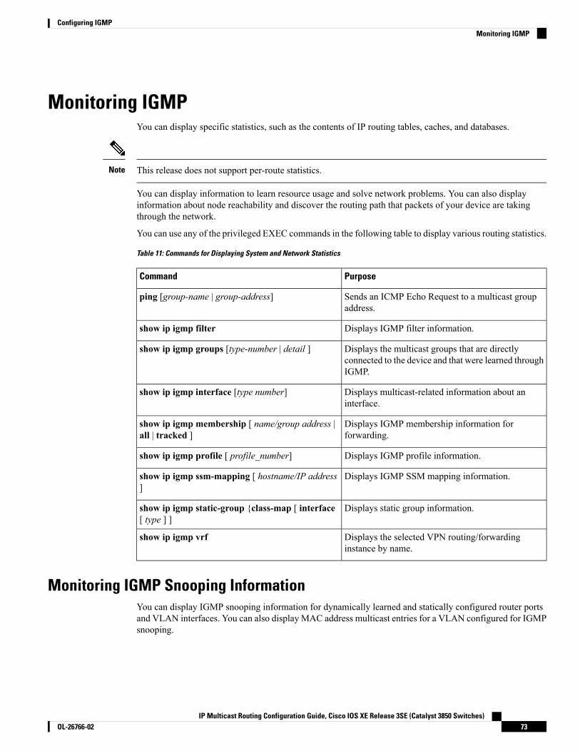
Monitoring IGMPYou can display specific statistics, such as the contents of IP routing tables, caches, and databases.
This release does not support per-route statistics.Note
You can display information to learn resource usage and solve network problems. You can also displayinformation about node reachability and discover the routing path that packets of your device are takingthrough the network.
You can use any of the privileged EXEC commands in the following table to display various routing statistics.
Table 11: Commands for Displaying System and Network Statistics
PurposeCommand
Sends an ICMP Echo Request to a multicast groupaddress.
ping [group-name | group-address]
Displays IGMP filter information.show ip igmp filter
Displays the multicast groups that are directlyconnected to the device and that were learned throughIGMP.
show ip igmp groups [type-number | detail ]
Displays multicast-related information about aninterface.
show ip igmp interface [type number]
Displays IGMP membership information forforwarding.
show ip igmp membership [ name/group address |all | tracked ]
Displays IGMP profile information.show ip igmp profile [ profile_number]
Displays IGMP SSM mapping information.show ip igmp ssm-mapping [ hostname/IP address]
Displays static group information.show ip igmp static-group {class-map [ interface[ type ] ]
Displays the selected VPN routing/forwardinginstance by name.
show ip igmp vrf
Monitoring IGMP Snooping InformationYou can display IGMP snooping information for dynamically learned and statically configured router portsand VLAN interfaces. You can also display MAC address multicast entries for a VLAN configured for IGMPsnooping.
IP Multicast Routing Configuration Guide, Cisco IOS XE Release 3SE (Catalyst 3850 Switches)73OL-26766-02
Configuring IGMPMonitoring IGMP

Table 12: Commands for Displaying IGMP Snooping Information
PurposeCommand
Displays the operational state information.show ip igmp snooping detail
Displays multicast table information for the device orabout a specific parameter:
• count—Displays the total number of groups.
• vlan—Displays group information by VLANID.
show ip igmp snooping groups [ count | [vlanvlan-id [A.B.C.D | count ] ]
Displays the IGMP snooping tracking.
This command displays group and IPaddress entries only for wireless multicastIGMP joins and not for wired IGMP joins.Wireless IP multicast must be enabled forthis command to display.
Note
show ip igmp snooping igmpv2-tracking
Displays information on dynamically learned andmanually configured multicast router interfaces.
When you enable IGMP snooping, thedevice automatically learns the interfaceto which a multicast router is connected.These are dynamically learned interfaces.
Note
(Optional) Enter vlan vlan-id to display informationfor a single VLAN.
show ip igmp snooping mrouter [vlan vlan-id]
Displays information about the IP address andreceiving port for the most-recently received IGMPquery messages in the VLAN.
(Optional) Enter detail to display the detailed IGMPquerier information in a VLAN.
(Optional) Enter vlan vlan-id to display informationfor a single VLAN.
show ip igmp snooping querier [ detail | vlanvlan-id]
Displays the snooping configuration information forall VLANs on the device or for a specified VLAN.
(Optional) Enter vlan vlan-id to display informationfor a single VLAN. The VLAN ID range is 1 to 1001and 1006 to 4094.
show ip igmp snooping [vlan vlan-id [ detail ] ]
Displays wireless-related events.show ip igmp snooping wireless mgid
IP Multicast Routing Configuration Guide, Cisco IOS XE Release 3SE (Catalyst 3850 Switches)OL-26766-0274
Configuring IGMPMonitoring IGMP Snooping Information

Monitoring IGMP Filtering and Throttling ConfigurationYou can display IGMP profile characteristics, and you can display the IGMP profile and maximum groupconfiguration for all interfaces on the device or for a specified interface. You can also display the IGMPthrottling configuration for all interfaces on the device or for a specified interface.
Table 13: Commands for Displaying IGMP Filtering and Throttling Configuration
PurposeCommand
Displays the specified IGMP profile or all the IGMPprofiles defined on the device.
show ip igmp profile [profile number]
Displays the configuration of the specified interfaceor the configuration of all interfaces on the device,including (if configured) the maximum number ofIGMP groups to which an interface can belong andthe IGMP profile applied to the interface.
show running-config [interface interface-id]
Configuration Examples for IGMP
Example: Configuring the Device as a Member of a Multicast GroupThis example shows how to enable the device to join multicast group 255.2.2.2:
Device(config)# interface gigabitethernet1/0/1Device(config-if)# ip igmp join-group 255.2.2.2Device(config-if)#
Related TopicsConfiguring the Device as a Member of a Group (CLI), on page 33Joining a Multicast Group, on page 27IP Multicast Group Addresses, on page 22
Example: Controlling Access to Multicast GroupsTo limit the number of joins on the interface, configure the port for filter which associates with the IGMPprofile.
Device# configure terminalDevice(config)# ip igmp profile 10Device(config-igmp-profile)# ?
IGMP profile configuration commands:deny matching addresses are deniedexit Exit from igmp profile configuration modeno Negate a command or set its defaultspermit matching addresses are permitted
IP Multicast Routing Configuration Guide, Cisco IOS XE Release 3SE (Catalyst 3850 Switches)75OL-26766-02
Configuring IGMPMonitoring IGMP Filtering and Throttling Configuration

range add a range to the set
Device(config-igmp-profile)# range 172.16.5.1Device(config-igmp-profile)# exitDevice(config)#Device(config)# interface gigabitEthernet 2/0/10Device(config-if)# ip igmp filter 10
Related TopicsControlling Access to IP Multicast Group (CLI), on page 35
Examples: Configuring IGMP SnoopingThis example shows how to enable a static connection to a multicast router:
Device# configure terminalDevice(config)# ip igmp snooping vlan 200 mrouter interface gigabitethernet1/0/2Device(config)# end
This example shows how to statically configure a host on a port:
Device# configure terminalDevice(config)# ip igmp snooping vlan 105 static 224.2.4.12 interface gigabitethernet1/0/1Device(config)# end
This example shows how to enable IGMP Immediate Leave on VLAN 130:
Device# configure terminalDevice(config)# ip igmp snooping vlan 130 immediate-leaveDevice(config)# end
This example shows how to set the IGMP snooping querier source address to 10.0.0.64:
Device# configure terminalDevice(config)# ip igmp snooping querier 10.0.0.64Device(config)# end
This example shows how to set the IGMP snooping querier maximum response time to 25 seconds:
Device# configure terminalDevice(config)# ip igmp snooping querier query-interval 25Device(config)# end
This example shows how to set the IGMP snooping querier timeout to 60 seconds:
Device# configure terminalDevice(config)# ip igmp snooping querier timer expiry 60Device(config)# end
This example shows how to set the IGMP snooping querier feature to Version 2:
IP Multicast Routing Configuration Guide, Cisco IOS XE Release 3SE (Catalyst 3850 Switches)OL-26766-0276
Configuring IGMPExamples: Configuring IGMP Snooping

Device# configure terminalDevice(config)# no ip igmp snooping querier version 2Device(config)# end
Related TopicsEnabling or Disabling IGMP Snooping on a Device (CLI), on page 54IGMP Snooping, on page 27
Examples: Configuring Filtering and ThrottlingThis example shows how to create IGMP profile 4 allowing access to the single IP multicast address and howto verify the configuration. If the action was to deny (the default), it would not appear in the show ip igmpprofile output display.
Device(config)# ip igmp profile 4Device(config-igmp-profile)# permitDevice(config-igmp-profile)# range 229.9.9.0Device(config-igmp-profile)# endDevice# show ip igmp profile 4IGMP Profile 4
permitrange 229.9.9.0 229.9.9.0
This example shows how to apply IGMP profile 4 to a port:
Device(config)# interface gigabitethernet1/0/2Device(config-if)# ip igmp filter 4Device(config-if)# end
This example shows how to limit to 25 the number of IGMP groups that a port can join:
Device(config)# interface gigabitethernet1/0/2Device(config-if)# ip igmp max-groups 25Device(config-if)# end
Related TopicsConfiguring the IGMP Throttling Action (CLI), on page 48IGMP Filtering and Throttling, on page 30
Example: Interface Configuration as a Routed PortThis example shows how to configure an interface on the device as a routed port. This configuration is requiredon the interface for several IP multicast routing configuration procedures that require running the no switchportcommand.
Device configure terminalDevice(config)# interface GigabitEthernet1/0/9Device(config-if)# description interface to be use as routed portDevice(config-if)# no switchportDevice(config-if)# ip address 10.20.20.1 255.255.255.0
IP Multicast Routing Configuration Guide, Cisco IOS XE Release 3SE (Catalyst 3850 Switches)77OL-26766-02
Configuring IGMPExamples: Configuring Filtering and Throttling

Device(config-if)# ip pim sparse-modeDevice(config-if)# ip igmp join-group 224.1.2.3 source 15.15.15.2Device(config-if)# endDevice# configure terminalDevice# show run interface gigabitEthernet 1/0/9
Current configuration : 166 bytes!interface GigabitEthernet1/0/9no switchportip address 10.20.20.1 255.255.255.0ip pim sparse-modeip igmp static-group 224.1.2.3 source 15.15.15.2end
Example: Interface Configuration as an SVIThis example shows how to configure an interface on the device as an SVI. This configuration is required onthe interface for several IP multicast routing configuration procedures that require running the no switchportcommand.
Device(config)# interface vlan 150Device(config-if)# ip address 10.20.20.1 255.255.255.0Device(config-if)# ip pim sparse-modeDevice(config-if)# ip igmp join-group 224.1.2.3 source 15.15.15.2Device(config-if)# endDevice# configure terminalDevice(config)# ip igmp snooping vlan 20 static 224.1.2.3interface gigabitEthernet 1/0/9Device# show run interface vlan 150
Current configuration : 137 bytes!interface Vlan150ip address 10.20.20.1 255.255.255.0ip pim sparse-modeip igmp static-group 224.1.2.3 source 15.15.15.2end
Example: Configuring the Device to Forward Multicast Traffic in the Absenceof Directly Connected IGMP Hosts
The following example shows how to configure a device to forward multicast traffic in the absence of directlyconnected IGMP hosts using the ip igmp join-group command. With this method, the device accepts themulticast packets in addition to forwarding them. Accepting the multicast packets prevents the device fromfast switching.
In this example, Fast Ethernet interface 0/0/0 on the device is configured to join the group 225.2.2.2:
interface FastEthernet0/0/0ip igmp join-group 225.2.2.2
The following example shows how to configure a device to forward multicast traffic in the absence of directlyconnected IGMP hosts using the ip igmp static-group command. With this method, the device does not
IP Multicast Routing Configuration Guide, Cisco IOS XE Release 3SE (Catalyst 3850 Switches)OL-26766-0278
Configuring IGMPExample: Interface Configuration as an SVI

accept the packets itself, but only forwards them. Hence, this method allows fast switching. The outgoinginterface appears in the IGMP cache, but the device itself is not a member, as evidenced by lack of an “L”(local) flag in the multicast route entry.
In this example, static group membership entries for group 225.2.2.2 are configured on Fast Ethernet interface0/1/0:
interface FastEthernet0/1/0ip igmp static-group 225.2.2.2
Related TopicsConfiguring the Device to ForwardMulticast Traffic in the Absence of Directly Connected IGMPHosts,on page 50
Controlling Access to an SSM Network Using IGMP Extended Access ListsThis section contains the following configuration examples for controlling access to an SSM network usingIGMP extended access lists:
Keep in mind that access lists are very flexible: there are many combinations of permit and deny statementsone could use in an access list to filter multicast traffic. The examples in this section simply provide a fewexamples of how it can be done.
Note
Related TopicsControlling Access to an SSM Network Using IGMP Extended Access Lists, on page 52
Example: Denying All States for a Group GThe following example shows how to deny all states for a group G. In this example, Fast Ethernet interface0/0/0 is configured to filter all sources for SSM group 232.2.2.2 in IGMPv3 reports, which effectively deniesthis group.
ip access-list extended test1deny igmp any host 232.2.2.2permit igmp any any!interface FastEthernet0/0/0ip igmp access-group test1
Related TopicsControlling Access to an SSM Network Using IGMP Extended Access Lists, on page 52
Example: Denying All States for a Source SThe following example shows how to deny all states for a source S. In this example, Gigabit Ethernet interface1/1/0 is configured to filter all groups for source 10.2.1.32 in IGMPv3 reports, which effectively denies thissource.
ip access-list extended test2deny igmp host 10.2.1.32 anypermit igmp any any!
IP Multicast Routing Configuration Guide, Cisco IOS XE Release 3SE (Catalyst 3850 Switches)79OL-26766-02
Configuring IGMPControlling Access to an SSM Network Using IGMP Extended Access Lists

interface GigabitEthernet1/1/0ip igmp access-group test2
Related TopicsControlling Access to an SSM Network Using IGMP Extended Access Lists, on page 52
Example: Permitting All States for a Group GThe following example shows how to permit all states for a group G. In this example, Gigabit Ethernet interface1/2/0 is configured to accept all sources for SSM group 232.1.1.10 in IGMPv3 reports, which effectivelyaccepts this group altogether.
ip access-list extended test3permit igmp any host 232.1.1.10!interface GigabitEthernet1/2/0ip igmp access-group test3
Related TopicsControlling Access to an SSM Network Using IGMP Extended Access Lists, on page 52
Example: Permitting All States for a Source SThe following example shows how to permit all states for a source S. In this example, Gigabit Ethernetinterface 1/2 is configured to accept all groups for source 10.6.23.32 in IGMPv3 reports, which effectivelyaccepts this source altogether.
ip access-list extended test4permit igmp host 10.6.23.32 any!interface GigabitEthernet1/2/0ip igmp access-group test4
Related TopicsControlling Access to an SSM Network Using IGMP Extended Access Lists, on page 52
Example: Filtering a Source S for a Group GThe following example shows how to filter a particular source S for a group G. In this example, GigabitEthernet interface 0/3/0 is configured to filter source 232.2.2.2 for SSM group 232.2.30.30 in IGMPv3 reports.
ip access-list extended test5deny igmp host 10.4.4.4 host 232.2.30.30permit igmp any any!interface GigabitEthernet0/3/0ip igmp access-group test5
Related TopicsControlling Access to an SSM Network Using IGMP Extended Access Lists, on page 52
Where to Go Next for IGMPYou can configure the following:
IP Multicast Routing Configuration Guide, Cisco IOS XE Release 3SE (Catalyst 3850 Switches)OL-26766-0280
Configuring IGMPExample: Permitting All States for a Group G

• Wireless Multicast
• PIM
• SSM
• IP Multicast Routing
• Service Discovery Gateway
You can also review the following IP Multicast Optimization processes for your configuration:
• Optimizing PIM Sparse Mode in a Large IP Multicast Deployment
• Multicast Subsecond Convergence
• IP Multicast Load Splitting across Equal-Cost Paths
• SSM Channel Based Filtering for Multicast
• PIM Dense Mode State Refresh
• IGMP State Limit
Additional ReferencesRelated Documents
Document TitleRelated Topic
IP Multicast Routing Command Reference (Catalyst3850 Switches)
For complete syntax and usage information for thecommands used in this chapter.
Cisco IOS Master Commands List, All ReleasesCisco IOS commands
Cisco IOS IP Multicast Command ReferenceCisco IOS IP SLAs commands
Error Message Decoder
LinkDescription
https://www.cisco.com/cgi-bin/Support/Errordecoder/index.cgiTo help you research and resolve systemerror messages in this release, use the ErrorMessage Decoder tool.
Standards and RFCs
TitleStandard/RFC
Host Extensions for IP MulticastingRFC 1112
Internet Group Management Protocol, Version 2RFC 2236
Internet Group Management Protocol, Version 3RFC 3376
IP Multicast Routing Configuration Guide, Cisco IOS XE Release 3SE (Catalyst 3850 Switches)81OL-26766-02
Configuring IGMPAdditional References

MIBs
MIBs LinkMIB
To locate and downloadMIBs for selected platforms, Cisco IOS releases,and feature sets, use Cisco MIB Locator found at the following URL:
http://www.cisco.com/go/mibs
All the supported MIBs for thisrelease.
Technical Assistance
LinkDescription
http://www.cisco.com/supportThe Cisco Support website provides extensive online resources, includingdocumentation and tools for troubleshooting and resolving technical issueswith Cisco products and technologies.
To receive security and technical information about your products, you cansubscribe to various services, such as the Product Alert Tool (accessed fromField Notices), the Cisco Technical Services Newsletter, and Really SimpleSyndication (RSS) Feeds.
Access to most tools on the Cisco Support website requires a Cisco.com userID and password.
Feature History and Information for IGMPModificationRelease
This feature was introduced.Cisco IOS XE 3.2SE
IP Multicast Routing Configuration Guide, Cisco IOS XE Release 3SE (Catalyst 3850 Switches)OL-26766-0282
Configuring IGMPFeature History and Information for IGMP

C H A P T E R 4Configuring IGMP Proxy
• Finding Feature Information, on page 83• Prerequisites for IGMP Proxy, on page 83• Information about IGMP Proxy, on page 84• How to Configure IGMP Proxy, on page 86• Configuration Examples for IGMP Proxy, on page 90• Where to Go Next for IGMP Proxy, on page 91• Additional References, on page 91• Feature History and Information for IGMP Proxy, on page 92
Finding Feature InformationYour software release may not support all the features documented in this module. For the latest caveats andfeature information, see Bug Search Tool and the release notes for your platform and software release. Tofind information about the features documented in this module, and to see a list of the releases in which eachfeature is supported, see the feature information table at the end of this module.
Use Cisco Feature Navigator to find information about platform support and Cisco software image support.To access Cisco Feature Navigator, go to http://www.cisco.com/go/cfn. An account on Cisco.com is notrequired.
Prerequisites for IGMP Proxy• All devices on the IGMP UDL have the same subnet address. If all devices on the UDL cannot have thesame subnet address, the upstream device must be configured with secondary addresses to match all ofthe subnets to which the downstream devices are attached.
• IP multicast is enabled and the PIM interfaces are configured.
Use the following guidelines when configuring PIM interfaces for IGMP proxy:Note
• Use PIM sparse mode (PIM-SM) when the interface is operating in a sparse-mode region and youare running static RP, bootstrap (BSR), or Auto-RP with the Auto-RP listener capability.
IP Multicast Routing Configuration Guide, Cisco IOS XE Release 3SE (Catalyst 3850 Switches)83OL-26766-02

• Use PIM sparse-dense mode when the interface is running in a sparse-dense mode region and youare running Auto-RP without the Auto-RP listener capability.
• Use PIM dense mode (PIM-DM) when the interface is operating in dense mode and is, thus,participating in a dense-mode region.
• Use PIM-DM with the proxy-register capability when the interface is receiving source traffic froma dense-mode region that needs to reach receivers that are in a sparse-mode region.
Information about IGMP Proxy
IGMP ProxyAn IGMP proxy enables hosts in a unidirectional link routing (UDLR) environment that are not directlyconnected to a downstream router to join a multicast group sourced from an upstream network.
The figure below illustrates a sample topology that shows two UDLR scenarios:
• Traditional UDL routing scenario--A UDL device with directly connected receivers.
• IGMP proxy scenario--UDL device without directly connected receivers.
IGMP UDLs are needed on the upstream and downstream devices.Note
Although the following illustration and example uses routers in the configuration, any device (router or switch)can be used.
Note
IP Multicast Routing Configuration Guide, Cisco IOS XE Release 3SE (Catalyst 3850 Switches)OL-26766-0284
Configuring IGMP ProxyInformation about IGMP Proxy
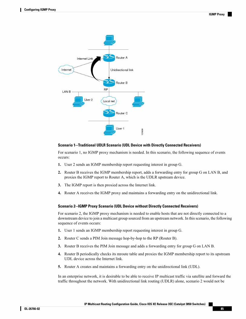
Scenario 1--Traditional UDLR Scenario (UDL Device with Directly Connected Receivers)
For scenario 1, no IGMP proxy mechanism is needed. In this scenario, the following sequence of eventsoccurs:
1. User 2 sends an IGMP membership report requesting interest in group G.
2. Router B receives the IGMP membership report, adds a forwarding entry for group G on LAN B, andproxies the IGMP report to Router A, which is the UDLR upstream device.
3. The IGMP report is then proxied across the Internet link.
4. Router A receives the IGMP proxy and maintains a forwarding entry on the unidirectional link.
Scenario 2--IGMP Proxy Scenario (UDL Device without Directly Connected Receivers)
For scenario 2, the IGMP proxy mechanism is needed to enable hosts that are not directly connected to adownstream device to join a multicast group sourced from an upstream network. In this scenario, the followingsequence of events occurs:
1. User 1 sends an IGMP membership report requesting interest in group G.
2. Router C sends a PIM Join message hop-by-hop to the RP (Router B).
3. Router B receives the PIM Join message and adds a forwarding entry for group G on LAN B.
4. Router B periodically checks its mroute table and proxies the IGMP membership report to its upstreamUDL device across the Internet link.
5. Router A creates and maintains a forwarding entry on the unidirectional link (UDL).
In an enterprise network, it is desirable to be able to receive IP multicast traffic via satellite and forward thetraffic throughout the network. With unidirectional link routing (UDLR) alone, scenario 2 would not be
IP Multicast Routing Configuration Guide, Cisco IOS XE Release 3SE (Catalyst 3850 Switches)85OL-26766-02
Configuring IGMP ProxyIGMP Proxy

possible because receiving hosts must be directly connected to the downstream device, Router B. The IGMPproxy mechanism overcomes this limitation by creating an IGMP report for (*, G) entries in the multicastforwarding table. To make this scenario functional, therefore, you must enable IGMP report forwarding ofproxied (*, G) multicast static route (mroute) entries (using the ip igmpmroute-proxy command) and enablethe mroute proxy service (using the ip igmp proxy-service command) on interfaces leading to PIM-enablednetworks with potential members.
Because PIM messages are not forwarded upstream, each downstream network and the upstream networkhave a separate domain.
Note
Related TopicsConfiguring the Upstream UDL Device for IGMP UDLR, on page 86Configuring the Downstream UDL Device for IGMP UDLR with IGMP Proxy Support, on page 87Example: IGMP Proxy Configuration, on page 90
How to Configure IGMP Proxy
Configuring the Upstream UDL Device for IGMP UDLRPerform this task to configure the upstream UDL device for IGMP UDLR.
SUMMARY STEPS
1. enable2. configure terminal3. interface type number4. ip igmp unidirectional-link5. end
DETAILED STEPS
PurposeCommand or Action
Enables privileged EXEC mode.enableStep 1
Example: • Enter your password if prompted.
Device> enable
Enters global configuration mode.configure terminal
Example:
Step 2
Device# configure terminal
Enters interface configuration mode.interface type numberStep 3
Example:
IP Multicast Routing Configuration Guide, Cisco IOS XE Release 3SE (Catalyst 3850 Switches)OL-26766-0286
Configuring IGMP ProxyHow to Configure IGMP Proxy

PurposeCommand or Action
Device(config)# interface gigabitethernet 1/0/0• For the type and number arguments, specify theinterface to be used as the UDL on the upstreamdevice.
Configures IGMP on the interface to be unidirectional forIGMP UDLR.
ip igmp unidirectional-link
Example:
Step 4
Device(config-if)# ip igmp unidirectional-link
Ends the current configuration session and returns toprivileged EXEC mode.
end
Example:
Step 5
Device(config-if)# end
Related TopicsIGMP Proxy, on page 84Example: IGMP Proxy Configuration, on page 90
Configuring the Downstream UDL Device for IGMP UDLR with IGMP ProxySupport
Perform this task to configure the downstream UDL device for IGMP UDLR with IGMP proxy support.
SUMMARY STEPS
1. enable2. configure terminal3. interface type number4. ip igmp unidirectional-link5. exit6. interface type number7. ip igmp mroute-proxy type number8. exit9. interface type number10. ip igmp helper-address udl interface-type interface-number11. ip igmp proxy-service12. end13. show ip igmp interface14. show ip igmp udlr
DETAILED STEPS
PurposeCommand or Action
Enables privileged EXEC mode.enableStep 1
IP Multicast Routing Configuration Guide, Cisco IOS XE Release 3SE (Catalyst 3850 Switches)87OL-26766-02
Configuring IGMP ProxyConfiguring the Downstream UDL Device for IGMP UDLR with IGMP Proxy Support
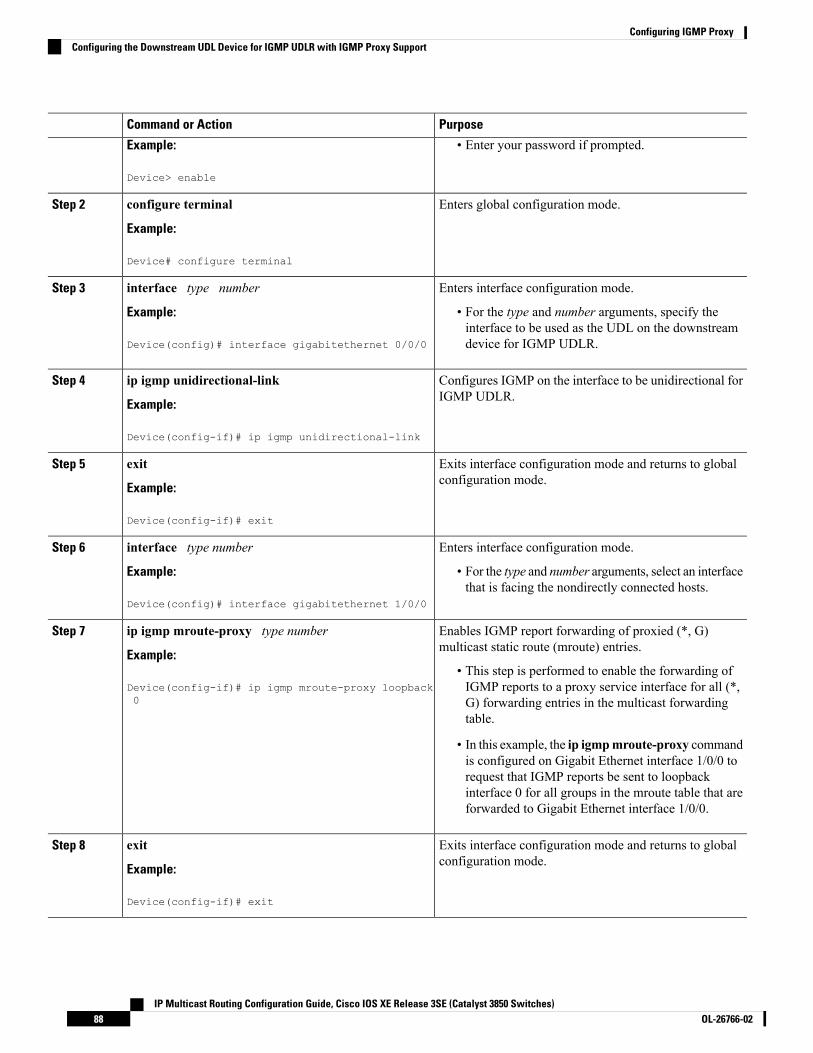
PurposeCommand or Action
Example: • Enter your password if prompted.
Device> enable
Enters global configuration mode.configure terminal
Example:
Step 2
Device# configure terminal
Enters interface configuration mode.interface type numberStep 3
Example: • For the type and number arguments, specify theinterface to be used as the UDL on the downstreamdevice for IGMP UDLR.Device(config)# interface gigabitethernet 0/0/0
Configures IGMP on the interface to be unidirectional forIGMP UDLR.
ip igmp unidirectional-link
Example:
Step 4
Device(config-if)# ip igmp unidirectional-link
Exits interface configuration mode and returns to globalconfiguration mode.
exit
Example:
Step 5
Device(config-if)# exit
Enters interface configuration mode.interface type numberStep 6
Example: • For the type and number arguments, select an interfacethat is facing the nondirectly connected hosts.
Device(config)# interface gigabitethernet 1/0/0
Enables IGMP report forwarding of proxied (*, G)multicast static route (mroute) entries.
ip igmp mroute-proxy type number
Example:
Step 7
• This step is performed to enable the forwarding ofIGMP reports to a proxy service interface for all (*,Device(config-if)# ip igmp mroute-proxy loopback
0 G) forwarding entries in the multicast forwardingtable.
• In this example, the ip igmpmroute-proxy commandis configured on Gigabit Ethernet interface 1/0/0 torequest that IGMP reports be sent to loopbackinterface 0 for all groups in the mroute table that areforwarded to Gigabit Ethernet interface 1/0/0.
Exits interface configuration mode and returns to globalconfiguration mode.
exit
Example:
Step 8
Device(config-if)# exit
IP Multicast Routing Configuration Guide, Cisco IOS XE Release 3SE (Catalyst 3850 Switches)OL-26766-0288
Configuring IGMP ProxyConfiguring the Downstream UDL Device for IGMP UDLR with IGMP Proxy Support

PurposeCommand or Action
Enters interface configuration mode for the specifiedinterface.
interface type number
Example:
Step 9
• In this example, loopback interface 0 is specified.Device(config)# interface loopback 0
Configures IGMP helpering for UDLR.ip igmp helper-address udl interface-typeinterface-number
Step 10
• This step allows the downstream device to helperIGMP reports received from hosts to an upstreamExample:device connected to a UDL associated with the
Device(config-if)# ip igmp helper-address udlgigabitethernet 0/0/0
interface specified for the interface-type andinterface-number arguments.
• In the example topology, IGMP helpering isconfigured over loopback interface 0 on thedownstream device. Loopback interface 0, thus, isconfigured to helper IGMP reports from hosts to anupstream device connected to Gigabit Ethernetinterface 0/0/0.
Enables the mroute proxy service.ip igmp proxy-serviceStep 11
Example: • When the mroute proxy service is enabled, the deviceperiodically checks the static mroute table for (*, G)
Device(config-if)# ip igmp proxy-service forwarding entries that match interfaces configuredwith the ip igmp mroute-proxy command (see Step7) based on the IGMP query interval. Where there isa match, one IGMP report is created and received onthis interface.
The ip igmp proxy-service command isintended to be used with the ip igmphelper-address (UDL) command.
Note
• In this example, the ip igmp proxy-service commandis configured on loopback interface 0 to enable theforwarding of IGMP reports out the interface for allgroups on interfaces registered through the ip igmpmroute-proxy command (see Step 7).
Ends the current configuration session and returns toprivileged EXEC mode.
end
Example:
Step 12
Device(config-if)# end
(Optional) Displays multicast-related information aboutan interface.
show ip igmp interface
Example:
Step 13
Device# show ip igmp interface
IP Multicast Routing Configuration Guide, Cisco IOS XE Release 3SE (Catalyst 3850 Switches)89OL-26766-02
Configuring IGMP ProxyConfiguring the Downstream UDL Device for IGMP UDLR with IGMP Proxy Support

PurposeCommand or Action
(Optional) Displays UDLR information for directlyconnected multicast groups on interfaces that have a UDLhelper address configured.
show ip igmp udlr
Example:
Device# show ip igmp udlr
Step 14
Related TopicsIGMP Proxy, on page 84Example: IGMP Proxy Configuration, on page 90
Configuration Examples for IGMP Proxy
Example: IGMP Proxy ConfigurationThe following example shows how to configure the upstreamUDL device for IGMPUDLR and the downstreamUDL device for IGMP UDLR with IGMP proxy support.
Upstream Device Configuration
interface gigabitethernet 0/0/0ip address 10.1.1.1 255.255.255.0ip pim sparse-mode!interface gigabitethernet 1/0/0ip address 10.2.1.1 255.255.255.0ip pim sparse-modeip igmp unidirectional-link!interface gigabitethernet 2/0/0ip address 10.3.1.1 255.255.255.0
Downstream Device Configuration
ip pim rp-address 10.5.1.1 5access-list 5 permit 239.0.0.0 0.255.255.255!interface loopback 0ip address 10.7.1.1 255.255.255.0ip pim sparse-modeip igmp helper-address udl ethernet 0ip igmp proxy-service!interface gigabitethernet 0/0/0ip address 10.2.1.2 255.255.255.0ip pim sparse-modeip igmp unidirectional-link!interface gigabitethernet 1/0/0ip address 10.5.1.1 255.255.255.0ip pim sparse-modeip igmp mroute-proxy loopback 0!
IP Multicast Routing Configuration Guide, Cisco IOS XE Release 3SE (Catalyst 3850 Switches)OL-26766-0290
Configuring IGMP ProxyConfiguration Examples for IGMP Proxy

interface gigabitethernet 2/0/0ip address 10.6.1.1 255.255.255.0
Related TopicsConfiguring the Upstream UDL Device for IGMP UDLR, on page 86Configuring the Downstream UDL Device for IGMP UDLR with IGMP Proxy Support, on page 87IGMP Proxy, on page 84
Where to Go Next for IGMP ProxyYou can configure the following:
• IGMP
• PIM
• SSM
• IP Multicast Routing
• Service Discovery Gateway
You can also review the following IP Multicast Optimization processes for your configuration:
• Optimizing PIM Sparse Mode in a Large IP Multicast Deployment
• Multicast Subsecond Convergence
• IP Multicast Load Splitting across Equal-Cost Paths
• SSM Channel Based Filtering for Multicast
• PIM Dense Mode State Refresh
• IGMP State Limit
Additional ReferencesThe following sections provide references related to customizing IGMP.
Related Documents
Document TitleRelated Topic
Cisco IOS Master Commands List, All ReleasesCisco IOS commands
Cisco IOS IP Multicast Command ReferenceCisco IOS IP SLAs commands
“ IP Multicast Technology Overview ” moduleOverview of the IP multicast technology area
“ Configuring Basic IP Multicast ” or “Configuring IPMulticast in IPv6 Networks” module
Basic IP multicast concepts, configuration tasks,and examples
IP Multicast Routing Configuration Guide, Cisco IOS XE Release 3SE (Catalyst 3850 Switches)91OL-26766-02
Configuring IGMP ProxyWhere to Go Next for IGMP Proxy

Standards and RFCs
TitleStandard/RFC
Host extensions for IP multicastingRFC 1112
Internet Group Management Protocol, Version 2RFC 2236
Internet Group Management Protocol, Version 3RFC 3376
MIBs
MIBs LinkMIB
To locate and downloadMIBs for selected platforms, CiscoIOS XE releases, and feature sets, use Cisco MIB Locatorfound at the following URL:
http://www.cisco.com/go/mibs
No new or modifiedMIBs are supported by thesefeatures, and support for existing MIBs has notbeen modified by these features.
Technical Assistance
LinkDescription
http://www.cisco.com/cisco/web/support/index.htmlTheCisco Support andDocumentationwebsite providesonline resources to download documentation, software,and tools. Use these resources to install and configurethe software and to troubleshoot and resolve technicalissues with Cisco products and technologies. Access tomost tools on the Cisco Support and Documentationwebsite requires a Cisco.com user ID and password.
Feature History and Information for IGMP ProxyModificationRelease
This feature was introduced.Cisco IOS XE 3.2SE
IP Multicast Routing Configuration Guide, Cisco IOS XE Release 3SE (Catalyst 3850 Switches)OL-26766-0292
Configuring IGMP ProxyFeature History and Information for IGMP Proxy

C H A P T E R 5Constraining IP Multicast in Switched Ethernet
• Finding Feature Information, on page 93• Prerequisites for Constraining IP Multicast in a Switched Ethernet Network, on page 93• Information About IP Multicast in a Switched Ethernet Network, on page 94• How to Constrain Multicast in a Switched Ethernet Network, on page 95• Configuration Examples for Constraining IP Multicast in a Switched Ethernet Network, on page 98• Where to Go Next for Constraining IP Multicast in Switched Ethernet, on page 99• Additional References, on page 100• Feature History and Information for Constraining IP Multicast in a Switched Ethernet Network, on page100
Finding Feature InformationYour software release may not support all the features documented in this module. For the latest caveats andfeature information, see Bug Search Tool and the release notes for your platform and software release. Tofind information about the features documented in this module, and to see a list of the releases in which eachfeature is supported, see the feature information table at the end of this module.
Use Cisco Feature Navigator to find information about platform support and Cisco software image support.To access Cisco Feature Navigator, go to http://www.cisco.com/go/cfn. An account on Cisco.com is notrequired.
Prerequisites for Constraining IP Multicast in a SwitchedEthernet Network
Before using the tasks in this module, you should be familiar with the concepts described in the “IP MulticastTechnology Overview” module.
IP Multicast Routing Configuration Guide, Cisco IOS XE Release 3SE (Catalyst 3850 Switches)93OL-26766-02

Information About IP Multicast in a Switched Ethernet Network
IP Multicast Traffic and Layer 2 SwitchesThe default behavior for a Layer 2 switch is to forward all multicast traffic to every port that belongs to thedestination LAN on the switch. This behavior reduces the efficiency of the switch, whose purpose is to limittraffic to the ports that need to receive the data. This behavior requires a constraining mechanism to reduceunnecessary multicast traffic, which improves switch performance.
Cisco Group Management Protocol (CGMP), Router Group Management Protocol (RGMP), and IGMPsnooping efficiently constrain IP multicast in a Layer 2 switching environment.
• CGMP and IGMP snooping are used on subnets that include end users or receiver clients.
• RGMP is used on routed segments that contain only routers, such as in a collapsed backbone.
• RGMP and CGMP cannot interoperate. However, Internet Group Management Protocol (IGMP) caninteroperate with CGMP and RGMP snooping.
CGMP on Catalyst Switches for IP MulticastCGMP is a Cisco-developed protocol used on device connected to Catalyst switches to perform tasks similarto those performed by IGMP. CGMP is necessary for those Catalyst switches that do not distinguish betweenIP multicast data packets and IGMP report messages, both of which are addressed to the same group addressat the MAC level. The switch can distinguish IGMP packets, but would need to use software on the switch,greatly impacting its performance.
You must configure CGMP on the multicast device and the Layer 2 switches. The result is that, with CGMP,IP multicast traffic is delivered only to those Catalyst switch ports that are attached to interested receivers.All other ports that have not explicitly requested the traffic will not receive it unless these ports are connectedto a multicast router. Multicast router ports must receive every IP multicast data packet.
Using CGMP, when a host joins a multicast group, it multicasts an unsolicited IGMP membership reportmessage to the target group. The IGMP report is passed through the switch to the router for normal IGMPprocessing. The router (which must have CGMP enabled on this interface) receives the IGMP report andprocesses it as it normally would, but also creates a CGMP Join message and sends it to the switch. The Joinmessage includes the MAC address of the end station and the MAC address of the group it has joined.
The switch receives this CGMP Join message and then adds the port to its content-addressable memory (CAM)table for that multicast group. All subsequent traffic directed to this multicast group is then forwarded out theport for that host.
The Layer 2 switches are designed so that several destination MAC addresses could be assigned to a singlephysical port. This design allows switches to be connected in a hierarchy and also allows many multicastdestination addresses to be forwarded out a single port.
The device port also is added to the entry for the multicast group. Multicast device must listen to all multicasttraffic for every group because IGMP control messages are also sent as multicast traffic. The rest of themulticast traffic is forwarded using the CAM table with the new entries created by CGMP.
Related TopicsEnabling CGMP, on page 96
IP Multicast Routing Configuration Guide, Cisco IOS XE Release 3SE (Catalyst 3850 Switches)OL-26766-0294
Constraining IP Multicast in Switched EthernetInformation About IP Multicast in a Switched Ethernet Network

Example: CGMP Configuration, on page 98
IGMP SnoopingIGMP snooping is an IPmulticast constrainingmechanism that runs on a Layer 2 LAN switch. IGMP snoopingrequires the LAN switch to examine, or “snoop,” some Layer 3 information (IGMP Join/Leave messages) inthe IGMP packets sent between the hosts and the router. When the switch receives the IGMP host report froma host for a particular multicast group, the switch adds the port number of the host to the associated multicasttable entry. When the switch hears the IGMP Leave group message from a host, the switch removes the tableentry of the host.
Because IGMP control messages are sent as multicast packets, they are indistinguishable from multicast dataat Layer 2. A switch running IGMP snooping must examine every multicast data packet to determine if itcontains any pertinent IGMP control information. IGMP snooping implemented on a low-end switch with aslow CPU could have a severe performance impact when data is sent at high rates. The solution is to implementIGMP snooping on high-end switches with special application-specific integrated circuits (ASICs) that canperform the IGMP checks in hardware. CGMP is a better option for low-end switches without special hardware.
Router-Port Group Management Protocol (RGMP)CGMP and IGMP snooping are IP multicast constraining mechanisms designed to work on routed networksegments that have active receivers. They both depend on IGMP control messages that are sent between thehosts and the routers to determine which switch ports are connected to interested receivers.
Switched Ethernet backbone network segments typically consist of several routers connected to a switchwithout any hosts on that segment. Because routers do not generate IGMP host reports, CGMP and IGMPsnooping will not be able to constrain the multicast traffic, which will be flooded to every port on the VLAN.Routers instead generate Protocol Independent Multicast (PIM) messages to Join and Prune multicast trafficflows at a Layer 3 level.
Router-Port Group Management Protocol (RGMP) is an IP multicast constraining mechanism for router-onlynetwork segments. RGMP must be enabled on the routers and on the Layer 2 switches. A multicast routerindicates that it is interested in receiving a data flow by sending an RGMP Join message for a particular group.The switch then adds the appropriate port to its forwarding table for that multicast group--similar to the wayit handles a CGMP Join message. IP multicast data flows will be forwarded only to the interested router ports.When the router no longer is interested in that data flow, it sends an RGMP Leave message and the switchremoves the forwarding entry.
If there are any routers that are not RGMP-enabled, they will continue to receive all multicast data.
Related TopicsConfiguring IP Multicast in a Layer 2 Switched Ethernet Network, on page 97RGMP Configuration Example, on page 99
How to Constrain Multicast in a Switched Ethernet Network
Configuring Switches for IP MulticastIf you have switching in your multicast network, consult the documentation for the switch you are workingwith for information about how to configure IP multicast.
IP Multicast Routing Configuration Guide, Cisco IOS XE Release 3SE (Catalyst 3850 Switches)95OL-26766-02
Constraining IP Multicast in Switched EthernetIGMP Snooping
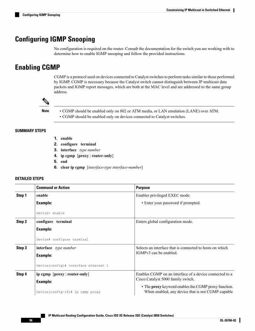
Configuring IGMP SnoopingNo configuration is required on the router. Consult the documentation for the switch you are working with todetermine how to enable IGMP snooping and follow the provided instructions.
Enabling CGMPCGMP is a protocol used on devices connected to Catalyst switches to perform tasks similar to those performedby IGMP. CGMP is necessary because the Catalyst switch cannot distinguish between IP multicast datapackets and IGMP report messages, which are both at the MAC level and are addressed to the same groupaddress.
• CGMP should be enabled only on 802 or ATM media, or LAN emulation (LANE) over ATM.• CGMP should be enabled only on devices connected to Catalyst switches.
Note
SUMMARY STEPS
1. enable2. configure terminal3. interface type number4. ip cgmp [proxy | router-only]5. end6. clear ip cgmp [interface-type interface-number]
DETAILED STEPS
PurposeCommand or Action
Enables privileged EXEC mode.enableStep 1
Example: • Enter your password if prompted.
Device> enable
Enters global configuration mode.configure terminal
Example:
Step 2
Device# configure terminal
Selects an interface that is connected to hosts on whichIGMPv3 can be enabled.
interface type number
Example:
Step 3
Device(config)# interface ethernet 1
Enables CGMP on an interface of a device connected to aCisco Catalyst 5000 family switch.
ip cgmp [proxy | router-only]
Example:
Step 4
• The proxy keyword enables the CGMPproxy function.When enabled, any device that is not CGMP-capableDevice(config-if)# ip cgmp proxy
IP Multicast Routing Configuration Guide, Cisco IOS XE Release 3SE (Catalyst 3850 Switches)OL-26766-0296
Constraining IP Multicast in Switched EthernetConfiguring IGMP Snooping

PurposeCommand or Action
will be advertised by the proxy router. The proxy routeradvertises the existence of other non-CGMP-capabledevices by sending a CGMP Join message with theMAC address of the non-CGMP-capable device andgroup address of 0000.0000.0000.
Ends the current configuration session and returns to EXECmode.
end
Example:
Step 5
Device(config-if)# end
(Optional) Clears all group entries from the caches ofCatalyst switches.
clear ip cgmp [interface-type interface-number]
Example:
Step 6
Device# clear ip cgmp
Related TopicsCGMP on Catalyst Switches for IP Multicast, on page 94Example: CGMP Configuration, on page 98
Configuring IP Multicast in a Layer 2 Switched Ethernet NetworkPerform this task to configure IP multicast in a Layer 2 Switched Ethernet network using RGMP.
SUMMARY STEPS
1. enable2. configure terminal3. interface type number4. ip rgmp5. end6. debug ip rgmp7. show ip igmp interface
DETAILED STEPS
PurposeCommand or Action
Enables privileged EXEC mode.enableStep 1
Example: • Enter your password if prompted.
Device> enable
Enters global configuration mode.configure terminal
Example:
Step 2
IP Multicast Routing Configuration Guide, Cisco IOS XE Release 3SE (Catalyst 3850 Switches)97OL-26766-02
Constraining IP Multicast in Switched EthernetConfiguring IP Multicast in a Layer 2 Switched Ethernet Network
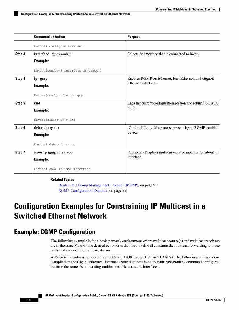
PurposeCommand or Action
Device# configure terminal
Selects an interface that is connected to hosts.interface type number
Example:
Step 3
Device(config)# interface ethernet 1
Enables RGMP on Ethernet, Fast Ethernet, and GigabitEthernet interfaces.
ip rgmp
Example:
Step 4
Device(config-if)# ip rgmp
Ends the current configuration session and returns to EXECmode.
end
Example:
Step 5
Device(config-if)# end
(Optional) Logs debugmessages sent by an RGMP-enableddevice.
debug ip rgmp
Example:
Step 6
Device# debug ip rgmp
(Optional) Displays multicast-related information about aninterface.
show ip igmp interface
Example:
Step 7
Device# show ip igmp interface
Related TopicsRouter-Port Group Management Protocol (RGMP), on page 95RGMP Configuration Example, on page 99
Configuration Examples for Constraining IP Multicast in aSwitched Ethernet Network
Example: CGMP ConfigurationThe following example is for a basic network environment where multicast source(s) and multicast receiversare in the same VLAN. The desired behavior is that the switch will constrain the multicast forwarding to thoseports that request the multicast stream.
A 4908G-L3 router is connected to the Catalyst 4003 on port 3/1 in VLAN 50. The following configurationis applied on the GigabitEthernet1 interface. Note that there is no ip multicast-routing command configuredbecause the router is not routing multicast traffic across its interfaces.
IP Multicast Routing Configuration Guide, Cisco IOS XE Release 3SE (Catalyst 3850 Switches)OL-26766-0298
Constraining IP Multicast in Switched EthernetConfiguration Examples for Constraining IP Multicast in a Switched Ethernet Network

interface GigabitEthernet1ip address 192.168.50.11 255.255.255.0ip pim dense-modeip cgmp
Related TopicsEnabling CGMP, on page 96CGMP on Catalyst Switches for IP Multicast, on page 94
RGMP Configuration ExampleThe following example shows how to configure RGMP on a router:
ip multicast-routingip pim sparse-modeinterface ethernet 0ip rgmp
Related TopicsConfiguring IP Multicast in a Layer 2 Switched Ethernet Network, on page 97Router-Port Group Management Protocol (RGMP), on page 95
Where to Go Next for Constraining IP Multicast in SwitchedEthernet
You can configure the following:
• IGMP
• PIM
• SSM
• IP Multicast Routing
• Service Discovery Gateway
You can also review the following IP Multicast Optimization processes for your configuration:
• Optimizing PIM Sparse Mode in a Large IP Multicast Deployment
• Multicast Subsecond Convergence
• IP Multicast Load Splitting across Equal-Cost Paths
• SSM Channel Based Filtering for Multicast
• PIM Dense Mode State Refresh
• IGMP State Limit
IP Multicast Routing Configuration Guide, Cisco IOS XE Release 3SE (Catalyst 3850 Switches)99OL-26766-02
Constraining IP Multicast in Switched EthernetRGMP Configuration Example

Additional ReferencesThe following sections provide references related to constraining IP multicast in a switched Ethernet network.
Related Documents
Document TitleRelated Topic
Cisco IOS Master Commands List, All ReleasesCisco IOS commands
Cisco IOS IP Multicast Command ReferenceCisco IOS IP SLAs commands
The “IGMP Snooping” module of the IP Multicast: IGMP ConfigurationGuide
IGMP snooping
The “Configuring Router-Port GroupManagement Protocol”module of theIP Multicast: IGMP Configuration Guide
RGMP
MIBs
MIBs LinkMIB
To locate and download MIBs for selected platforms, Cisco IOS releases, and feature sets, use CiscoMIB Locator found at the following URL:
http://www.cisco.com/go/mibs
None
Technical Assistance
LinkDescription
http://www.cisco.com/public/support/tac/home.shtmlTechnical Assistance Center (TAC) home page,containing 30,000 pages of searchable technicalcontent, including links to products, technologies,solutions, technical tips, and tools. RegisteredCisco.com users can log in from this page to accesseven more content.
Feature History and Information for Constraining IP Multicastin a Switched Ethernet Network
ModificationRelease
This feature was introduced.Cisco IOS XE 3.2SE
IP Multicast Routing Configuration Guide, Cisco IOS XE Release 3SE (Catalyst 3850 Switches)OL-26766-02100
Constraining IP Multicast in Switched EthernetAdditional References

C H A P T E R 6Configuring Protocol Independent Multicast(PIM)
• Finding Feature Information, on page 101• Prerequisites for Configuring PIM, on page 101• Restrictions for Configuring PIM, on page 102• Restrictions for Configuring Auto-RP, on page 102• Restrictions for Configuring Auto-RP and BSR, on page 103• Information About PIM, on page 103• How to Configure PIM, on page 114• Monitoring PIM Information, on page 142• Troubleshooting PIMv1 and PIMv2 Interoperability Problems, on page 144• Configuration Examples for PIM, on page 144• Where to Go Next for PIM , on page 147• Additional References, on page 148• Feature History and Information for PIM, on page 149
Finding Feature InformationYour software release may not support all the features documented in this module. For the latest caveats andfeature information, see Bug Search Tool and the release notes for your platform and software release. Tofind information about the features documented in this module, and to see a list of the releases in which eachfeature is supported, see the feature information table at the end of this module.
Use Cisco Feature Navigator to find information about platform support and Cisco software image support.To access Cisco Feature Navigator, go to http://www.cisco.com/go/cfn. An account on Cisco.com is notrequired.
Prerequisites for Configuring PIMThe following are the prerequisites for configuring PIM and PIM stub routing:
• Before configuring PIM stub routing, you must have IP multicast routing configured on both the stubrouter and the central router. You must also have PIM mode (dense-mode, sparse-mode, orsparse-dense-mode) configured on the uplink interface of the stub router.
IP Multicast Routing Configuration Guide, Cisco IOS XE Release 3SE (Catalyst 3850 Switches)101OL-26766-02

• Before configuring PIM stub routing, youmust also configure either Enhanced Interior Gateway RoutingProtocol (EIGRP) stub routing or Open Shortest Path First (OSPF) stub routing on the device. The PIMstub router does not route the transit traffic between the distribution routers. Unicast (EIGRP) stub routingenforces this behavior. You must configure unicast stub routing to assist the PIM stub router behavior.
For information about EIGRP or OSPF configurations, see the Catalyst 3850Routing Configuration Guide, Release 3SE.
Note
Restrictions for Configuring PIMThe following are the restrictions for configuring PIM:
• PIM
• PIM is not supported when running the LAN Base feature set.
• Bidirectional PIM is not supported.
• PIM stub routing
• The IP Services image contains complete multicast routing.
• In a network using PIM stub routing, the only allowable route for IP traffic to the user is through adevice that is configured with PIM stub routing.
• The redundant PIM stub router topology is not supported. Only the nonredundant access routertopology is supported by the PIM stub feature.
• Only directly connected multicast (IGMP) receivers and sources are allowed in the Layer 2 accessdomains. The PIM protocol is not supported in access domains.
• PIM stub routing is supported when running the IP Base and IP Services feature sets.
Restrictions for Configuring Auto-RPThe following are restrictions for configuring Auto-RP (if used in your network configuration):
• Auto-RP is not supported when running the LAN Base feature set.
• If you configure PIM in sparse mode or sparse-dense mode and do not configure Auto-RP, you mustmanually configure an RP.
• If routed interfaces are configured in sparse mode, Auto-RP can still be used if all devices are configuredwith a manual RP address for the Auto-RP groups.
• If routed interfaces are configured in sparse mode and you enter the ip pim autorp listener globalconfiguration command, Auto-RP can still be used even if all devices are not configured with a manualRP address for the Auto-RP groups.
IP Multicast Routing Configuration Guide, Cisco IOS XE Release 3SE (Catalyst 3850 Switches)OL-26766-02102
Configuring Protocol Independent Multicast (PIM)Restrictions for Configuring PIM

Restrictions for Auto-RP EnhancementThe simultaneous deployment of Auto-RP and bootstrap router (BSR) is not supported.
Restrictions for Configuring Auto-RP and BSRThe following are restrictions for configuring Auto-RP and BSR (if used in your network configuration):
• If your network is all Cisco routers and multilayer devices, you can use either Auto-RP or BSR.
• If you have non-Cisco routers in your network, you must use BSR.
• If you have Cisco PIMv1 and PIMv2 routers and multilayer devices and non-Cisco routers, you mustuse both Auto-RP and BSR. If your network includes routers from other vendors, configure the Auto-RPmapping agent and the BSR on a Cisco PIMv2 device. Ensure that no PIMv1 device is located in thepath a between the BSR and a non-Cisco PIMv2 device.
There are two approaches to using PIMv2. You can use Version 2 exclusively inyour network or migrate to Version 2 by employing a mixed PIM versionenvironment.
Note
• Because bootstrap messages are sent hop-by-hop, a PIMv1 device prevents these messages from reachingall routers and multilayer devices in your network. Therefore, if your network has a PIMv1 device in itand only Cisco routers and multilayer devices, it is best to use Auto-RP.
• If you have a network that includes non-Cisco routers, configure the Auto-RP mapping agent and theBSR on a Cisco PIMv2 router or multilayer device. Ensure that no PIMv1 device is on the path betweenthe BSR and a non-Cisco PIMv2 router.
• If you have non-Cisco PIMv2 routers that need to interoperate with Cisco PIMv1 routers and multilayerdevices, both Auto-RP and a BSR are required. We recommend that a Cisco PIMv2 device be both theAuto-RP mapping agent and the BSR.
Information About PIMProtocol-IndependentMulticast (PIM) is called protocol-independent because regardless of the unicast routingprotocols used to populate the unicast routing table, PIM uses this information to performmulticast forwardinginstead of maintaining a separate multicast routing table.
PIM can leverage whichever unicast routing protocols are used to populate the unicast routing table, includingEIGRP, OSPF, BGP, or static routes. PIM uses this unicast routing information to perform the multicastforwarding function, so it is IP protocol independent. Although PIM is called a multicast routing protocol, itactually uses the unicast routing table to perform the reverse path forwarding (RPF) check function insteadof building up a completely independent multicast routing table. PIM does not send and receive multicastrouting updates between routers as the other routing protocols do.
PIM is defined in RFC 4601, Protocol-IndependentMulticast-SparseMode (PIM-SM): Protocol Specification.PIM is defined in these Internet Engineering Task Force (IETF) Internet drafts:
IP Multicast Routing Configuration Guide, Cisco IOS XE Release 3SE (Catalyst 3850 Switches)103OL-26766-02
Configuring Protocol Independent Multicast (PIM)Restrictions for Auto-RP Enhancement

• Protocol Independent Multicast (PIM): Motivation and Architecture
• Protocol Independent Multicast (PIM), Dense Mode Protocol Specification
• Protocol Independent Multicast (PIM), Sparse Mode Protocol Specification
• draft-ietf-idmr-igmp-v2-06.txt, Internet Group Management Protocol, Version 2
• draft-ietf-pim-v2-dm-03.txt, PIM Version 2 Dense Mode
PIM VersionsPIMv2 includes these improvements over PIMv1:
• A single, active rendezvous point (RP) exists per multicast group, with multiple backup RPs. This singleRP compares to multiple active RPs for the same group in PIMv1.
• A bootstrap router (BSR) provides a fault-tolerant, automated RP discovery and distribution functionthat enables routers and multilayer devices to dynamically learn the group-to-RP mappings.
• Sparse mode and dense mode are properties of a group, as opposed to an interface.
We strongly recommend using sparse-dense mode as opposed to either sparsemode or dense mode only.
Note
• PIM join and prune messages have more flexible encoding for multiple address families.
• A more flexible hello packet format replaces the query packet to encode current and future capabilityoptions.
• Register messages sent to an RP specify whether they are sent by a border router or a designated router.
• PIM packets are no longer inside IGMP packets; they are standalone packets.
PIMv1 and PIMv2 InteroperabilityTo avoid misconfiguring multicast routing on your device, review the information in this section.
The Cisco PIMv2 implementation provides interoperability and transition between Version 1 and Version 2,although there might be some minor problems.
You can upgrade to PIMv2 incrementally. PIM Versions 1 and 2 can be configured on different routers andmultilayer devices within one network. Internally, all routers and multilayer devices on a shared media networkmust run the same PIM version. Therefore, if a PIMv2 device detects a PIMv1 device, the Version 2 devicedowngrades itself to Version 1 until all Version 1 devices have been shut down or upgraded.
PIMv2 uses the BSR to discover and announce RP-set information for each group prefix to all the routers andmultilayer devices in a PIM domain. PIMv1, together with the Auto-RP feature, can perform the same tasksas the PIMv2 BSR. However, Auto-RP is a standalone protocol, separate from PIMv1, and is a proprietaryCisco protocol. PIMv2 is a standards track protocol in the IETF.
IP Multicast Routing Configuration Guide, Cisco IOS XE Release 3SE (Catalyst 3850 Switches)OL-26766-02104
Configuring Protocol Independent Multicast (PIM)PIM Versions

We recommend that you use PIMv2. The BSR function interoperates with Auto-RP on Cisco routers andmultilayer devices.
Note
When PIMv2 devices interoperate with PIMv1 devices, Auto-RP should have already been deployed. A PIMv2BSR that is also an Auto-RP mapping agent automatically advertises the RP elected by Auto-RP. That is,Auto-RP sets its single RP on every router or multilayer device in the group. Not all routers and devices inthe domain use the PIMv2 hash function to select multiple RPs.
Sparse-mode groups in a mixed PIMv1 and PIMv2 region are possible because the Auto-RP feature in PIMv1interoperates with the PIMv2 RP feature. Although all PIMv2 devices can also use PIMv1, we recommendthat the RPs be upgraded to PIMv2. To ease the transition to PIMv2, we recommend:
• Using Auto-RP throughout the region.
• Configuring sparse-dense mode throughout the region.
If Auto-RP is not already configured in the PIMv1 regions, configure Auto-RP.
PIM ModesPIM can operate in dense mode (DM), sparse mode (SM), or in sparse-dense mode (PIM DM-SM), whichhandles both sparse groups and dense groups at the same time.
PIM DMPIM DM builds source-based multicast distribution trees. In dense mode, a PIM DM router or multilayerdevice assumes that all other routers or multilayer devices forward multicast packets for a group. If a PIMDM device receives a multicast packet and has no directly connected members or PIM neighbors present, aprune message is sent back to the source to stop unwanted multicast traffic. Subsequent multicast packets arenot flooded to this router or device on this pruned branch because branches without receivers are pruned fromthe distribution tree, leaving only branches that contain receivers.
When a new receiver on a previously pruned branch of the tree joins a multicast group, the PIM DM devicedetects the new receiver and immediately sends a graft message up the distribution tree toward the source.When the upstream PIM DM device receives the graft message, it immediately puts the interface on whichthe graft was received into the forwarding state so that the multicast traffic begins flowing to the receiver.
PIM-SMPIM-SM uses shared trees and shortest-path-trees (SPTs) to distribute multicast traffic to multicast receiversin the network. In PIM-SM, a router or multilayer device assumes that other routers or devices do not forwardmulticast packets for a group, unless there is an explicit request for the traffic (join message). When a hostjoins a multicast group using IGMP, its directly connected PIM-SM device sends PIM join messages towardthe root, also known as the rendezvous point (RP). This join message travels router-by-router toward the root,constructing a branch of the shared tree as it goes.
The RP keeps track of multicast receivers. It also registers sources through register messages received fromthe source’s first-hop router (designated router [DR]) to complete the shared tree path from the source to thereceiver. When using a shared tree, sources must send their traffic to the RP so that the traffic reaches allreceivers.
IP Multicast Routing Configuration Guide, Cisco IOS XE Release 3SE (Catalyst 3850 Switches)105OL-26766-02
Configuring Protocol Independent Multicast (PIM)PIM Modes

Prune messages are sent up the distribution tree to prune multicast group traffic. This action permits branchesof the shared tree or SPT that were created with explicit join messages to be torn down when they are nolonger needed.
When the number of PIM-enabled interfaces exceeds the hardware capacity and PIM-SM is enabled with theSPT threshold is set to infinity, the device does not create (source, group (S, G) ) entries in the multicastrouting table for the some directly connected interfaces if they are not already in the table. The device mightnot correctly forward traffic from these interfaces.
Multicast Source Discovery Protocol (MSDP)
Multicast Source Discovery Protocol (MSDP) is used for inter-domain source discovery when PIM SM isused. Each PIM administrative domain has its own RP. In order for the RP in one domain to signal new sourcesto the RP in the other domain, MSDP is used.
When RP in a domain receives a PIM register message for a new source, with MSDP configured it sends anew source-active (SA)message to all itsMSDP peers in other domains. Each intermediateMSDP peer floodsthis SA message away from the originating RP. The MSDP peers install this SA message in their MSDPsa-cache. If the RPs in other domains have any join requests for the group in the SA message (indicated bythe presence of a (*,G) entry with non empty outgoing interface list), the domain is interested in the group,and the RP triggers an (S,G) join toward the source.
PIM Stub RoutingThe PIM stub routing feature, available in all of the device software images, reduces resource usage by movingrouted traffic closer to the end user.
The PIM stub routing feature supports multicast routing between the distribution layer and the access layer.It supports two types of PIM interfaces: uplink PIM interfaces and PIM passive interfaces. A routed interfaceconfigured with the PIM passive mode does not pass or forward PIM control traffic, it only passes and forwardsIGMP traffic.
In a network using PIM stub routing, the only allowable route for IP traffic to the user is through a devicethat is configured with PIM stub routing. PIM passive interfaces are connected to Layer 2 access domains,such as VLANs, or to interfaces that are connected to other Layer 2 devices. Only directly connectedmulticast(IGMP) receivers and sources are allowed in the Layer 2 access domains. The PIM passive interfaces do notsend or process any received PIM control packets.
When using PIM stub routing, you should configure the distribution and remote routers to use IP multicastrouting and configure only the device as a PIM stub router. The device does not route transit traffic betweendistribution routers. You also need to configure a routed uplink port on the device. The device uplink portcannot be used with SVIs. If you need PIM for an SVI uplink port, you should upgrade to the IP Servicesfeature set.
Youmust also configure EIGRP stub routing when configuring PIM stub routing on the device. For informationabout this procedure, refer to the Catalyst 3850 IP Routing Configuration Guide.
The redundant PIM stub router topology is not supported. The redundant topology exists when there is morethan one PIM router forwarding multicast traffic to a single access domain. PIM messages are blocked, andthe PIM asset and designated router election mechanisms are not supported on the PIM passive interfaces.Only the nonredundant access router topology is supported by the PIM stub feature. By using a nonredundanttopology, the PIM passive interface assumes that it is the only interface and designated router on that accessdomain.
IP Multicast Routing Configuration Guide, Cisco IOS XE Release 3SE (Catalyst 3850 Switches)OL-26766-02106
Configuring Protocol Independent Multicast (PIM)Multicast Source Discovery Protocol (MSDP)

Figure 3: PIM Stub Router Configuration
In the following figure, Device A routed uplink port 25 is connected to the router and PIM stub routing isenabled on the VLAN 100 interfaces and on Host 3. This configuration allows the directly connected hoststo receive traffic from multicast source
200.1.1.3.
Related TopicsEnabling PIM Stub Routing (CLI), on page 114Example: Enabling PIM Stub Routing, on page 144
IGMP HelperPIM stub routing moves routed traffic closer to the end user and reduces network traffic. You can also reducetraffic by configuring a stub router (device) with the IGMP helper feature.
You can configure a stub router (device) with the ip igmp helper help-address interface configurationcommand to enable the device to send reports to the next-hop interface. Hosts that are not directly connectedto a downstream router can then join a multicast group sourced from an upstream network. The IGMP packetsfrom a host wanting to join a multicast stream are forwarded upstream to the next-hop device when this featureis configured.When the upstream central router receives the helper IGMP reports or leaves, it adds or removesthe interfaces from its outgoing interface list for that group.
For complete syntax and usage information for the ip igmp helper-address command, see the IP MulticastCommand Reference, Cisco IOS XE Release 3SE (Catalyst 3850 Switches).
Auto-RPThe PIM-SM protocols require the presence of a rendezvous point (RP) in the network. An RP acts as themeeting place for sources and receivers of multicast data. If a static RP configuration is used, then theconfiguration needs to be applied on all the routers in the multicast network. To automate this process, theAuto-RP protocol was devised.
This Cisco proprietary feature eliminates the need to manually configure the RP information in every routerand multilayer device in the network. For Auto-RP to work, you configure a Cisco router or multilayer deviceas the mapping agent. It uses IP multicast to learn which routers or devices in the network are possible candidateRPs to receive candidate RP announcements. Candidate RPs periodically sendmulticast RP-announcemessagesto a particular group or group range to announce their availability.
IP Multicast Routing Configuration Guide, Cisco IOS XE Release 3SE (Catalyst 3850 Switches)107OL-26766-02
Configuring Protocol Independent Multicast (PIM)IGMP Helper

Mapping agents listen to these candidate RP announcements and use the information to create entries in theirgroup-to-RP mapping caches. Only one mapping cache entry is created for any group-to-RP range received,even if multiple candidate RPs are sending RP announcements for the same range. As the RP-announcemessages arrive, the mapping agent selects the router or device with the highest IP address as the active RPand stores this RP address in the group-to-RP mapping cache.
Mapping agents periodically multicast the contents of their group-to-RP mapping caches. Thus, all routersand devices automatically discover which RP to use for the groups that they support. If a router or device failsto receive RP-discovery messages and the group-to-RPmapping information expires, it changes to a staticallyconfigured RP that was defined with the ip pim rp-address global configuration command. If no staticallyconfigured RP exists, the router or device changes the group to dense-mode operation.
Multiple RPs serve different group ranges or serve as hot backups of each other.
Related TopicsSetting Up Auto-RP in a New Internetwork (CLI), on page 119Example: Configuring Auto-RP, on page 145
The Role of Auto-RP in a PIM NetworkAuto-RP automates the distribution of group-to-rendezvous point (RP) mappings in a PIM network. To makeAuto-RP work, a device must be designated as an RP mapping agent, which receives the RP announcementmessages from the RPs and arbitrates conflicts. The RP mapping agent then sends the consistent group-to-RPmappings to all other devices by way of dense mode flooding.
Thus, all routers automatically discover which RP to use for the groups they support. The Internet AssignedNumbers Authority (IANA) has assigned two group addresses, 224.0.1.39 and 224.0.1.40, for Auto-RP.
Themapping agent receives announcements of intention to become the RP fromCandidate-RPs. Themappingagent then announces the winner of the RP election. This announcement is made independently of the decisionsby the other mapping agents.
Related TopicsConfiguring Sparse Mode with Auto-RP(CLI), on page 134Example: Sparse Mode with Auto-RP , on page 145
IP Multicast BoundaryAs shown in the figure, address scoping defines domain boundaries so that domains with RPs that have thesame IP address do not leak into each other. Scoping is performed on the subnet boundaries within largedomains and on the boundaries between the domain and the Internet.
IP Multicast Routing Configuration Guide, Cisco IOS XE Release 3SE (Catalyst 3850 Switches)OL-26766-02108
Configuring Protocol Independent Multicast (PIM)The Role of Auto-RP in a PIM Network

Figure 4: Address Scoping at Boundaries
You can set up an administratively scoped boundary on an interface for multicast group addresses using theip multicast boundary command with the access-list argument. A standard access list defines the range ofaddresses affected. When a boundary is set up, no multicast data packets are allowed to flow across theboundary from either direction. The boundary allows the samemulticast group address to be reused in differentadministrative domains.
The Internet Assigned Numbers Authority (IANA) has designated the multicast address range 239.0.0.0 to239.255.255.255 as the administratively scoped addresses. This range of addresses can be reused in domainsadministered by different organizations. They would be considered local, not globally unique.
You can configure the filter-autorp keyword to examine and filter Auto-RP discovery and announcementmessages at the administratively scoped boundary. Any Auto-RP group range announcements from theAuto-RP packets that are denied by the boundary access control list (ACL) are removed. An Auto-RP grouprange announcement is permitted and passed by the boundary only if all addresses in the Auto-RP group rangeare permitted by the boundary ACL. If any address is not permitted, the entire group range is filtered andremoved from the Auto-RP message before the Auto-RP message is forwarded.
Auto-RP BenefitsAuto-RP uses IP multicast to automate the distribution of group-to-RP mappings to all Cisco routers andmultilayer devices in a PIM network. Auto-RP has these benefits:
• Easy to use multiple RPs within a network to serve different group ranges.
• Provides load splitting among different RPs and arrangement of RPs according to the location of groupparticipants.
• Avoids inconsistent, manual RP configurations on every router and multilayer device in a PIM network,which can cause connectivity problems.
Benefits of Auto-RP in a PIM Network
• Auto-RP allows any change to the RP designation to be configured only on the devices that are RPs, noton the leaf routers.
• Auto-RP offers the ability to scope the RP address within a domain.
IP Multicast Routing Configuration Guide, Cisco IOS XE Release 3SE (Catalyst 3850 Switches)109OL-26766-02
Configuring Protocol Independent Multicast (PIM)Auto-RP Benefits

PIMv2 Bootstrap RouterPIMv2 Bootstrap Router (BSR) is another method to distribute group-to-RP mapping information to all PIMrouters and multilayer devices in the network. It eliminates the need to manually configure RP informationin every router and device in the network. However, instead of using IP multicast to distribute group-to-RPmapping information, BSR uses hop-by-hop flooding of special BSR messages to distribute the mappinginformation.
The BSR is elected from a set of candidate routers and devices in the domain that have been configured tofunction as BSRs. The election mechanism is similar to the root-bridge election mechanism used in bridgedLANs. The BSR election is based on the BSR priority of the device contained in the BSR messages that aresent hop-by-hop through the network. Each BSR device examines the message and forwards out all interfacesonly the message that has either a higher BSR priority than its BSR priority or the same BSR priority, butwith a higher BSR IP address. Using this method, the BSR is elected.
The elected BSR sends BSR messages with a TTL of 1. Neighboring PIMv2 routers or multilayer devicesreceive the BSR message and multicast it out all other interfaces (except the one on which it was received)with a TTL of 1. In this way, BSR messages travel hop-by-hop throughout the PIM domain. Because BSRmessages contain the IP address of the current BSR, the flooding mechanism enables candidate RPs toautomatically learn which device is the elected BSR.
Candidate RPs send candidate RP advertisements showing the group range for which they are responsible tothe BSR, which stores this information in its local candidate-RP cache. The BSR periodically advertises thecontents of this cache in BSR messages to all other PIM devices in the domain. These messages travelhop-by-hop through the network to all routers and devices, which store the RP information in the BSRmessagein their local RP cache. The routers and devices select the same RP for a given group because they all use acommon RP hashing algorithm.
Related TopicsConfiguring Candidate BSRs (CLI), on page 130Example: Configuring Candidate BSRs, on page 147
PIM Domain BorderAs IPmulticast becomesmore widespread, the chance of one PIMv2 domain bordering another PIMv2 domainincreases. Because two domains probably do not share the same set of RPs, BSR, candidate RPs, and candidateBSRs, you need to constrain PIMv2 BSRmessages from flowing into or out of the domain. Allowingmessagesto leak across the domain borders could adversely affect the normal BSR election mechanism and elect asingle BSR across all bordering domains and comingle candidate RP advertisements, resulting in the electionof RPs in the wrong domain.
Multicast Forwarding and Reverse Path CheckWith unicast routing, routers and multilayer devices forward traffic through the network along a single pathfrom the source to the destination host whose IP address appears in the destination address field of the IPpacket. Each router and device along the way makes a unicast forwarding decision, using the destination IPaddress in the packet, by looking up the destination address in the unicast routing table and forwarding thepacket through the specified interface to the next hop toward the destination.
With multicasting, the source is sending traffic to an arbitrary group of hosts represented by a multicast groupaddress in the destination address field of the IP packet. To decide whether to forward or drop an incoming
IP Multicast Routing Configuration Guide, Cisco IOS XE Release 3SE (Catalyst 3850 Switches)OL-26766-02110
Configuring Protocol Independent Multicast (PIM)PIMv2 Bootstrap Router

multicast packet, the router or multilayer device uses a reverse path forwarding (RPF) check on the packet asfollows:
1. The router or multilayer device examines the source address of the arriving multicast packet to decidewhether the packet arrived on an interface that is on the reverse path back to the source.
2. If the packet arrives on the interface leading back to the source, the RPF check is successful and the packetis forwarded to all interfaces in the outgoing interface list (which might not be all interfaces on the router).
3. If the RPF check fails, the packet is discarded.
Some multicast routing protocols, such as DVMRP, maintain a separate multicast routing table and use it forthe RPF check. However, PIM uses the unicast routing table to perform the RPF check.
DVMRP is not supported on the device.Note
Figure 5: RPF Check
The following figure shows port 2 receiving a multicast packet from source 151.10.3.21. The following tableshows that the port on the reverse path to the source is port 1, not port 2. Because the RPF check fails, themultilayer device discards the packet. Another multicast packet from source 151.10.3.21 is received on port1, and the routing table shows this port is on the reverse path to the source. Because the RPF check passes,the device forwards the packet to all port in the outgoing port list
Table 14: Routing Table Example for an RPF Check
PortNetwork
Gigabit Ethernet 1/0/1151.10.0.0/16
Gigabit Ethernet 1/0/3198.14.32.0/32
Gigabit Ethernet 1/0/4204.1.16.0/24
PIM uses both source trees and RP-rooted shared trees to forward datagrams. The RPF check is performeddifferently for each:
• If a PIM router or multilayer device has a source-tree state (that is, an (S, G) entry is present in themulticast routing table), it performs the RPF check against the IP address of the source of the multicastpacket.
IP Multicast Routing Configuration Guide, Cisco IOS XE Release 3SE (Catalyst 3850 Switches)111OL-26766-02
Configuring Protocol Independent Multicast (PIM)Multicast Forwarding and Reverse Path Check

• If a PIM router or multilayer device has a shared-tree state (and no explicit source-tree state), it performsthe RPF check on the RP address (which is known when members join the group).
Sparse-mode PIM uses the RPF lookup function to decide where it needs to send joins and prunes:
• (S, G) joins (which are source-tree states) are sent toward the source.
• (*,G) joins (which are shared-tree states) are sent toward the RP.
DVMRP and dense-mode PIM use only source trees and use RPF.
DVMRP is not supported on the device.Note
PIM Shared Tree and Source TreeBy default, members of a group receive data from senders to the group across a single data-distribution treerooted at the RP.Figure 6: Shared Tree and Source Tree (Shortest-Path Tree)
The following figure shows this type of shared-distribution tree. Data from senders is delivered to the RP fordistribution to group members joined to the shared tree.
If the data rate warrants, leaf routers (routers without any downstream connections) on the shared tree canuse the data distribution tree rooted at the source. This type of distribution tree is called a shortest-path treeor source tree. By default, the software devices to a source tree upon receiving the first data packet from asource.
This process describes the move from a shared tree to a source tree:
1. A receiver joins a group; leaf Router C sends a join message toward the RP.
2. The RP puts a link to Router C in its outgoing interface list.
3. A source sends data; Router A encapsulates the data in a register message and sends it to the RP.
IP Multicast Routing Configuration Guide, Cisco IOS XE Release 3SE (Catalyst 3850 Switches)OL-26766-02112
Configuring Protocol Independent Multicast (PIM)PIM Shared Tree and Source Tree

4. The RP forwards the data down the shared tree to Router C and sends a join message toward the source.At this point, data might arrive twice at Router C, once encapsulated and once natively.
5. When data arrives natively (unencapsulated) at the RP, it sends a register-stop message to Router A.
6. By default, reception of the first data packet prompts Router C to send a join message toward the source.
7. When Router C receives data on (S, G), it sends a prune message for the source up the shared tree.
8. The RP deletes the link to Router C from the outgoing interface of (S, G). The RP triggers a prunemessagetoward the source.
Join and prune messages are sent for sources and RPs. They are sent hop-by-hop and are processed by eachPIM device along the path to the source or RP. Register and register-stop messages are not sent hop-by-hop.They are sent by the designated router that is directly connected to a source and are received by the RP forthe group.
Multiple sources sending to groups use the shared tree. You can configure the PIM device to stay on the sharedtree.
The change from shared to source tree happens when the first data packet arrives at the last-hop router. Thischange depends upon the threshold that is configured by using the ip pim spt-threshold global configurationcommand.
The shortest-path tree requires more memory than the shared tree but reduces delay. Youmay want to postponeits use. Instead of allowing the leaf router to immediately move to the shortest-path tree, you can specify thatthe traffic must first reach a threshold.
You can configure when a PIM leaf router should join the shortest-path tree for a specified group. If a sourcesends at a rate greater than or equal to the specified kbps rate, the multilayer switch triggers a PIM join messagetoward the source to construct a source tree (shortest-path tree). If the traffic rate from the source drops belowthe threshold value, the leaf router switches back to the shared tree and sends a prune message toward thesource.
You can specify to which groups the shortest-path tree threshold applies by using a group list (a standardaccess list). If a value of 0 is specified or if the group list is not used, the threshold applies to all groups.
Default PIM Routing ConfigurationThis table displays the default PIM routing configuration for the device.
Table 15: Default Multicast Routing Configuration
Default SettingFeature
Disabled on all interfaces.Multicast routing
Version 2.PIM version
No mode is defined.PIM mode
None configured.PIM stub routing
None configured.PIM RP address
Disabled.PIM domain border
IP Multicast Routing Configuration Guide, Cisco IOS XE Release 3SE (Catalyst 3850 Switches)113OL-26766-02
Configuring Protocol Independent Multicast (PIM)Default PIM Routing Configuration

Default SettingFeature
None.PIM multicast boundary
Disabled.Candidate BSRs
Disabled.Candidate RPs
0 kb/s.Shortest-path tree threshold rate
30 seconds.PIM router query message interval
How to Configure PIM
Enabling PIM Stub Routing (CLI)This procedure is optional.
SUMMARY STEPS
1. enable2. configure terminal3. interface interface-id4. ip pim passive5. end6. show ip pim interface7. show ip igmp groups detail8. show ip mroute9. show running-config10. copy running-config startup-config
DETAILED STEPS
PurposeCommand or Action
Enables privileged EXEC mode.enableStep 1
Example: • Enter your password if prompted.
Device> enable
Enters global configuration mode.configure terminal
Example:
Step 2
Device# configure terminal
IP Multicast Routing Configuration Guide, Cisco IOS XE Release 3SE (Catalyst 3850 Switches)OL-26766-02114
Configuring Protocol Independent Multicast (PIM)How to Configure PIM

PurposeCommand or Action
Specifies the interface on which you want to enable PIMstub routing, and enters interface configuration mode.
interface interface-id
Example:
Step 3
The specified interface must be one of the following:Device(config)# interface • A routed port—A physical port that has been
configured as a Layer 3 port by entering the noswitchport interface configuration command.
gigabitethernet 1/0/1
You will also need to enable IP PIMsparse-dense-mode on the interface, and join theinterface as a statically connectedmember to an IGMPstatic group.
• An SVI—A VLAN interface created by using theinterface vlan vlan-id global configuration command.
You will also need to enable IP PIMsparse-dense-mode on the VLAN, join the VLAN asa statically connected member to an IGMP staticgroup, and then enable IGMP snooping on the VLAN,the IGMP static group, and physical interface.
These interfaces must have IP addresses assigned to them.
Configures the PIM stub feature on the interface.ip pim passive
Example:
Step 4
Device(config-if)# ip pim passive
Returns to privileged EXEC mode.end
Example:
Step 5
Device(config)# end
(Optional) Displays the PIM stub that is enabled on eachinterface.
show ip pim interface
Example:
Step 6
Device# show ip pim interface
(Optional) Displays the interested clients that have joinedthe specific multicast source group.
show ip igmp groups detail
Example:
Step 7
Device# show ip igmp groups detail
(Optional) Displays the IP multicast routing table.show ip mroute
Example:
Step 8
IP Multicast Routing Configuration Guide, Cisco IOS XE Release 3SE (Catalyst 3850 Switches)115OL-26766-02
Configuring Protocol Independent Multicast (PIM)Enabling PIM Stub Routing (CLI)

PurposeCommand or Action
Device# show ip mroute
Verifies your entries.show running-config
Example:
Step 9
Device# show running-config
(Optional) Saves your entries in the configuration file.copy running-config startup-config
Example:
Step 10
Device# copy running-config startup-config
Related TopicsPIM Stub Routing, on page 106Example: Enabling PIM Stub Routing, on page 144
Configuring a Rendezvous PointYou must have a rendezvous point (RP), if the interface is in sparse-dense mode and if you want to handlethe group as a sparse group. You can use these methods:
• By manually assigning an RP to multicast groups.
• As a standalone, Cisco-proprietary protocol separate from PIMv1, which includes:
• Setting up Auto-RP in a new internetwork
• Adding Auto-RP to an existing sparse-mode cloud
• Preventing join messages to false RPs
• Filtering incoming RP announcement messages
• By using a standards track protocol in the Internet Engineering Task Force (IETF), which includesconfiguring PIMv2 BSR .
You can use Auto-RP, BSR, or a combination of both, depending on the PIM version that you are runningand the types of routers in your network. For information about working with different PIM versions in yournetwork, see the PIMv1 and PIMv2 Interoperability section.
Note
Manually Assigning an RP to Multicast Groups (CLI)If the rendezvous point (RP) for a group is learned through a dynamic mechanism (such as Auto-RP or BSR),you need not perform this task for that RP.
IP Multicast Routing Configuration Guide, Cisco IOS XE Release 3SE (Catalyst 3850 Switches)OL-26766-02116
Configuring Protocol Independent Multicast (PIM)Configuring a Rendezvous Point

Senders of multicast traffic announce their existence through register messages received from the sourcefirst-hop router (designated router) and forwarded to the RP. Receivers of multicast packets use RPs to joina multicast group by using explicit join messages.
RPs are not members of the multicast group; they serve as a meeting place for multicast sources and groupmembers.
Note
You can configure a single RP for multiple groups defined by an access list. If there is no RP configured fora group, the multilayer device responds to the group as dense and uses the dense-mode PIM techniques.
This procedure is optional.
SUMMARY STEPS
1. enable2. configure terminal3. ip pim rp-address ip-address [access-list-number] [override]4. access-list access-list-number {deny | permit} source [source-wildcard]5. end6. show running-config7. copy running-config startup-config
DETAILED STEPS
PurposeCommand or Action
Enables privileged EXEC mode.enableStep 1
Example: • Enter your password if prompted.
Device> enable
Enters global configuration mode.configure terminal
Example:
Step 2
Device# configure terminal
Configures the address of a PIM RP.ip pim rp-address ip-address [access-list-number][override]
Step 3
By default, no PIM RP address is configured. You mustconfigure the IP address of RPs on all routers andmultilayerdevices (including the RP).
Example:
Device(config)# ip pim rp-address If there is no RP configured for a group, thedevice treats the group as dense, using thedense-mode PIM techniques.
Note10.1.1.1 20 override
A PIM device can be an RP for more than one group. Onlyone RP address can be used at a time within a PIM domain.
IP Multicast Routing Configuration Guide, Cisco IOS XE Release 3SE (Catalyst 3850 Switches)117OL-26766-02
Configuring Protocol Independent Multicast (PIM)Manually Assigning an RP to Multicast Groups (CLI)

PurposeCommand or Action
The access list conditions specify for which groups thedevice is an RP.
• For ip-address, enter the unicast address of the RP indotted-decimal notation.
• (Optional) For access-list-number, enter an IP standardaccess list number from 1 to 99. If no access list isconfigured, the RP is used for all groups.
• (Optional) The override keyword indicates that if thereis a conflict between the RP configured with thiscommand and one learned by Auto-RP or BSR, theRP configured with this command prevails.
Creates a standard access list, repeating the command asmany times as necessary.
access-list access-list-number {deny | permit} source[source-wildcard]
Step 4
Example: • For access-list-number, enter the access list numberspecified in Step 2.
Device(config)# access-list 25• The deny keyword denies access if the conditions arematched.
permit 10.5.0.1 255.224.0.0
• The permit keyword permits access if the conditionsare matched.
• For source, enter the multicast group address for whichthe RP should be used.
• (Optional) For source-wildcard, enter the wildcardbits in dotted decimal notation to be applied to thesource. Place ones in the bit positions that you wantto ignore.
The access list is always terminated by an implicit denystatement for everything.
Returns to privileged EXEC mode.end
Example:
Step 5
Device(config)# end
Verifies your entries.show running-config
Example:
Step 6
Device# show running-config
(Optional) Saves your entries in the configuration file.copy running-config startup-config
Example:
Step 7
IP Multicast Routing Configuration Guide, Cisco IOS XE Release 3SE (Catalyst 3850 Switches)OL-26766-02118
Configuring Protocol Independent Multicast (PIM)Manually Assigning an RP to Multicast Groups (CLI)

PurposeCommand or Action
Device# copy running-config startup-config
Setting Up Auto-RP in a New Internetwork (CLI)If you are setting up Auto-RP in a new internetwork, you do not need a default RP because you configure allthe interfaces for sparse-dense mode.
Omit Step 3 in the following procedure, if you want to configure a PIM router as the RP for the local group.Note
SUMMARY STEPS
1. enable2. show running-config3. configure terminal4. ip pim send-rp-announce interface-id scope ttl group-list access-list-number interval seconds5. access-list access-list-number {deny | permit} source [source-wildcard]6. ip pim send-rp-discovery scope ttl7. end8. show running-config9. show ip pim rp mapping10. show ip pim rp11. copy running-config startup-config
DETAILED STEPS
PurposeCommand or Action
Enables privileged EXEC mode.enableStep 1
Example: • Enter your password if prompted.
Device> enable
Verifies that a default RP is already configured on all PIMdevices and the RP in the sparse-mode network. It was
show running-config
Example:
Step 2
previously configured with the ip pim rp-address globalconfiguration command.
Device# show running-config
This step is not required for spare-dense-modeenvironments.
Note
The selected RP should have good connectivity and beavailable across the network. Use this RP for the globalgroups (for example, 224.x.x.x and other global groups).Do not reconfigure the group address range that this RP
IP Multicast Routing Configuration Guide, Cisco IOS XE Release 3SE (Catalyst 3850 Switches)119OL-26766-02
Configuring Protocol Independent Multicast (PIM)Setting Up Auto-RP in a New Internetwork (CLI)

PurposeCommand or Action
serves. RPs dynamically discovered through Auto-RP takeprecedence over statically configured RPs. Assume that itis desirable to use a second RP for the local groups.
Enters global configuration mode.configure terminal
Example:
Step 3
Device# configure terminal
Configures another PIM device to be the candidate RP forlocal groups.
ip pim send-rp-announce interface-id scope ttl group-listaccess-list-number interval seconds
Step 4
Example: • For interface-id, enter the interface type and numberthat identifies the RP address. Valid interfaces includephysical ports, port channels, and VLANs.Device(config)# ip pim send-rp-announce
gigabitethernet• For scope ttl, specify the time-to-live value in hops.Enter a hop count that is high enough so that the
1/0/5 scope 20 group-list 10 interval 120
RP-announce messages reach all mapping agents inthe network. There is no default setting. The range is1 to 255.
• For group-list access-list-number, enter an IPstandard access list number from 1 to 99. If no accesslist is configured, the RP is used for all groups.
• For interval seconds, specify how often theannouncement messages must be sent. The default is60 seconds. The range is 1 to 16383.
Creates a standard access list, repeating the command asmany times as necessary.
access-list access-list-number {deny | permit} source[source-wildcard]
Step 5
Example: • For access-list-number, enter the access list numberspecified in Step 3.
Device(config)# access-list 10 permit 10.10.0.0• The deny keyword denies access if the conditions arematched.
• The permit keyword permits access if the conditionsare matched.
• For source, enter the multicast group address rangefor which the RP should be used.
• (Optional) For source-wildcard, enter the wildcardbits in dotted decimal notation to be applied to thesource. Place ones in the bit positions that you wantto ignore.
Recall that the access list is always terminatedby an implicit deny statement for everything.
Note
IP Multicast Routing Configuration Guide, Cisco IOS XE Release 3SE (Catalyst 3850 Switches)OL-26766-02120
Configuring Protocol Independent Multicast (PIM)Setting Up Auto-RP in a New Internetwork (CLI)

PurposeCommand or Action
Finds a device whose connectivity is not likely to beinterrupted, and assign it the role of RP-mapping agent.
ip pim send-rp-discovery scope ttl
Example:
Step 6
For scope ttl, specify the time-to-live value in hops to limitthe RP discovery packets. All devices within the hop countDevice(config)# ip pim send-rp-discovery scope 50
from the source device receive the Auto-RP discoverymessages. These messages tell other devices whichgroup-to-RP mapping to use to avoid conflicts (such asoverlapping group-to-RP ranges). There is no defaultsetting. The range is 1 to 255.
Returns to privileged EXEC mode.end
Example:
Step 7
Device(config)# end
Verifies your entries.show running-config
Example:
Step 8
Device# show running-config
Displays active RPs that are cached with associatedmulticast routing entries.
show ip pim rp mapping
Example:
Step 9
Device# show ip pim rp mapping
Displays the information cached in the routing table.show ip pim rpStep 10
Example:
Device# show ip pim rp
(Optional) Saves your entries in the configuration file.copy running-config startup-config
Example:
Step 11
Device# copy running-config startup-config
Related TopicsAuto-RP, on page 107Example: Configuring Auto-RP, on page 145
Adding Auto-RP to an Existing Sparse-Mode Cloud (CLI)This section contains suggestions for the initial deployment of Auto-RP into an existing sparse-mode cloudto minimize disruption of the existing multicast infrastructure.
IP Multicast Routing Configuration Guide, Cisco IOS XE Release 3SE (Catalyst 3850 Switches)121OL-26766-02
Configuring Protocol Independent Multicast (PIM)Adding Auto-RP to an Existing Sparse-Mode Cloud (CLI)

This procedure is optional.
SUMMARY STEPS
1. enable2. show running-config3. configure terminal4. ip pim send-rp-announce interface-id scope ttl group-list access-list-number interval seconds5. access-list access-list-number {deny | permit} source [source-wildcard]6. ip pim send-rp-discovery scope ttl7. end8. show running-config9. show ip pim rp mapping10. show ip pim rp11. copy running-config startup-config
DETAILED STEPS
PurposeCommand or Action
Enables privileged EXEC mode.enableStep 1
Example: • Enter your password if prompted.
Device> enable
Verifies that a default RP is already configured on all PIMdevices and the RP in the sparse-mode network. It was
show running-config
Example:
Step 2
previously configured with the ip pim rp-address globalconfiguration command.
Device# show running-config
This step is not required for spare-dense-modeenvironments.
Note
The selected RP should have good connectivity and beavailable across the network. Use this RP for the globalgroups (for example, 224.x.x.x and other global groups).Do not reconfigure the group address range that this RPserves. RPs dynamically discovered through Auto-RP takeprecedence over statically configured RPs. Assume that itis desirable to use a second RP for the local groups.
Enters global configuration mode.configure terminal
Example:
Step 3
Device# configure terminal
Configures another PIM device to be the candidate RP forlocal groups.
ip pim send-rp-announce interface-id scope ttl group-listaccess-list-number interval seconds
Step 4
IP Multicast Routing Configuration Guide, Cisco IOS XE Release 3SE (Catalyst 3850 Switches)OL-26766-02122
Configuring Protocol Independent Multicast (PIM)Adding Auto-RP to an Existing Sparse-Mode Cloud (CLI)

PurposeCommand or Action
Example: • For interface-id, enter the interface type and numberthat identifies the RP address. Valid interfaces includephysical ports, port channels, and VLANs.Device(config)# ip pim send-rp-announce
gigabitethernet• For scope ttl, specify the time-to-live value in hops.Enter a hop count that is high enough so that the
1/0/5 scope 20 group-list 10 interval 120
RP-announce messages reach all mapping agents inthe network. There is no default setting. The range is1 to 255.
• For group-list access-list-number, enter an IPstandard access list number from 1 to 99. If no accesslist is configured, the RP is used for all groups.
• For interval seconds, specify how often theannouncement messages must be sent. The default is60 seconds. The range is 1 to 16383.
Creates a standard access list, repeating the command asmany times as necessary.
access-list access-list-number {deny | permit} source[source-wildcard]
Step 5
Example: • For access-list-number, enter the access list numberspecified in Step 3.
Device(config)# access-list 10• The deny keyword denies access if the conditions arematched.
permit 224.0.0.0 15.255.255.255
• The permit keyword permits access if the conditionsare matched.
• For source, enter the multicast group address rangefor which the RP should be used.
• (Optional) For source-wildcard, enter the wildcardbits in dotted decimal notation to be applied to thesource. Place ones in the bit positions that you wantto ignore.
Recall that the access list is always terminated by animplicit deny statement for everything.
Finds a device whose connectivity is not likely to beinterrupted, and assigns it the role of RP-mapping agent.
ip pim send-rp-discovery scope ttl
Example:
Step 6
For scope ttl, specify the time-to-live value in hops to limitthe RP discovery packets. All devices within the hop countDevice(config)# ip pim send-rp-discovery scope 50
from the source device receive the Auto-RP discoverymessages. These messages tell other devices whichgroup-to-RP mapping to use to avoid conflicts (such asoverlapping group-to-RP ranges). There is no defaultsetting. The range is 1 to 255.
IP Multicast Routing Configuration Guide, Cisco IOS XE Release 3SE (Catalyst 3850 Switches)123OL-26766-02
Configuring Protocol Independent Multicast (PIM)Adding Auto-RP to an Existing Sparse-Mode Cloud (CLI)

PurposeCommand or Action
To remove the device as the RP-mapping agent,use the no ip pim send-rp-discovery globalconfiguration command.
Note
Returns to privileged EXEC mode.end
Example:
Step 7
Device(config)# end
Verifies your entries.show running-config
Example:
Step 8
Device# show running-config
Displays active RPs that are cached with associatedmulticast routing entries.
show ip pim rp mapping
Example:
Step 9
Device#show ip pim rp mapping
Displays the information cached in the routing table.show ip pim rpStep 10
Example:
Device# show ip pim rp
(Optional) Saves your entries in the configuration file.copy running-config startup-config
Example:
Step 11
Device# copy running-config startup-config
Preventing Join Messages to False RPs (CLI)Determine whether the ip pim accept-rp command was previously configured throughout the network byusing the show running-config privileged EXEC command. If the ip pim accept-rp command is not configuredon any device, this problem can be addressed later. In those routers or multilayer devices already configuredwith the ip pim accept-rp command, you must enter the command again to accept the newly advertised RP.
To accept all RPs advertised with Auto-RP and reject all other RPs by default, use the ip pim accept-rpauto-rp global configuration command.
This procedure is optional.
Related TopicsExample: Preventing Join Messages to False RPs, on page 146
IP Multicast Routing Configuration Guide, Cisco IOS XE Release 3SE (Catalyst 3850 Switches)OL-26766-02124
Configuring Protocol Independent Multicast (PIM)Preventing Join Messages to False RPs (CLI)
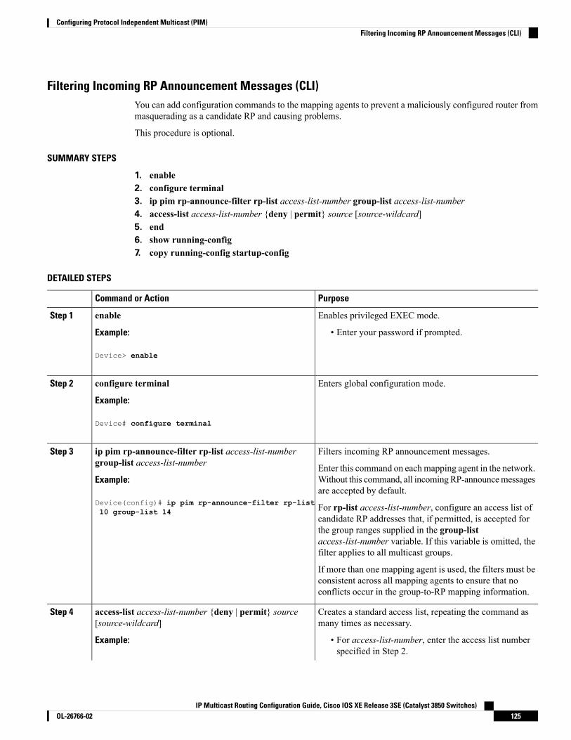
Filtering Incoming RP Announcement Messages (CLI)You can add configuration commands to the mapping agents to prevent a maliciously configured router frommasquerading as a candidate RP and causing problems.
This procedure is optional.
SUMMARY STEPS
1. enable2. configure terminal3. ip pim rp-announce-filter rp-list access-list-number group-list access-list-number4. access-list access-list-number {deny | permit} source [source-wildcard]5. end6. show running-config7. copy running-config startup-config
DETAILED STEPS
PurposeCommand or Action
Enables privileged EXEC mode.enableStep 1
Example: • Enter your password if prompted.
Device> enable
Enters global configuration mode.configure terminal
Example:
Step 2
Device# configure terminal
Filters incoming RP announcement messages.ip pim rp-announce-filter rp-list access-list-numbergroup-list access-list-number
Step 3
Enter this command on eachmapping agent in the network.Without this command, all incomingRP-announcemessagesare accepted by default.
Example:
Device(config)# ip pim rp-announce-filter rp-list For rp-list access-list-number, configure an access list ofcandidate RP addresses that, if permitted, is accepted for
10 group-list 14
the group ranges supplied in the group-listaccess-list-number variable. If this variable is omitted, thefilter applies to all multicast groups.
If more than one mapping agent is used, the filters must beconsistent across all mapping agents to ensure that noconflicts occur in the group-to-RP mapping information.
Creates a standard access list, repeating the command asmany times as necessary.
access-list access-list-number {deny | permit} source[source-wildcard]
Step 4
Example: • For access-list-number, enter the access list numberspecified in Step 2.
IP Multicast Routing Configuration Guide, Cisco IOS XE Release 3SE (Catalyst 3850 Switches)125OL-26766-02
Configuring Protocol Independent Multicast (PIM)Filtering Incoming RP Announcement Messages (CLI)

PurposeCommand or Action
Device(config)# access-list 10 permit 10.8.1.0• The deny keyword denies access if the conditions arematched.
255.255.224.0
• The permit keyword permits access if the conditionsare matched.
• Create an access list that specifies from which routersand multilayer devices the mapping agent acceptscandidate RP announcements (rp-list ACL).
• Create an access list that specifies the range ofmulticast groups from which to accept or deny(group-list ACL).
• For source, enter the multicast group address rangefor which the RP should be used.
• (Optional) For source-wildcard, enter the wildcardbits in dotted decimal notation to be applied to thesource. Place ones in the bit positions that you wantto ignore.
The access list is always terminated by an implicit denystatement for everything.
Returns to privileged EXEC mode.end
Example:
Step 5
Device(config)# end
Verifies your entries.show running-config
Example:
Step 6
Device# show running-config
(Optional) Saves your entries in the configuration file.copy running-config startup-config
Example:
Step 7
Device# copy running-config startup-config
Related TopicsExample: Filtering Incoming RP Announcement Messages, on page 146
Configuring PIMv2 BSRThe process for configuring PIMv2 BSR may involve the following optional tasks:
• Defining the PIM domain border
IP Multicast Routing Configuration Guide, Cisco IOS XE Release 3SE (Catalyst 3850 Switches)OL-26766-02126
Configuring Protocol Independent Multicast (PIM)Configuring PIMv2 BSR

• Defining the IP multicast boundary
• Configuring candidate BSRs
• Configuring candidate RPs
Defining the PIM Domain Border (CLI)Perform the following steps to configure the PIM domain border. This procedure is optional.
SUMMARY STEPS
1. enable2. configure terminal3. interface interface-id4. ip pim bsr-border5. end6. show running-config7. copy running-config startup-config
DETAILED STEPS
PurposeCommand or Action
Enables privileged EXEC mode.enableStep 1
Example: • Enter your password if prompted.
Device> enable
Enters global configuration mode.configure terminal
Example:
Step 2
Device# configure terminal
Specifies the interface to be configured, and enters interfaceconfiguration mode.
interface interface-id
Example:
Step 3
The specified interface must be one of the following:Device(config)# interface gigabitethernet 1/0/1 • A routed port—A physical port that has been
configured as a Layer 3 port by entering the noswitchport interface configuration command.
You will also need to enable IP PIMsparse-dense-mode on the interface, and join theinterface as a statically connected member to an IGMPstatic group.
• An SVI—A VLAN interface created by using theinterface vlan vlan-id global configuration command.
IP Multicast Routing Configuration Guide, Cisco IOS XE Release 3SE (Catalyst 3850 Switches)127OL-26766-02
Configuring Protocol Independent Multicast (PIM)Defining the PIM Domain Border (CLI)

PurposeCommand or Action
You will also need to enable IP PIMsparse-dense-mode on the VLAN, join the VLAN asa statically connectedmember to an IGMP static group,and then enable IGMP snooping on the VLAN, theIGMP static group, and physical interface.
These interfaces must have IP addresses assigned to them.
Defines a PIM bootstrap message boundary for the PIMdomain.
ip pim bsr-border
Example:
Step 4
Enter this command on each interface that connects to otherbordering PIM domains. This command instructs the deviceDevice(config-if)# ip pim bsr-border
to neither send nor receive PIMv2 BSR messages on thisinterface.
To remove the PIM border, use the no ip pimbsr-border interface configuration command.
Note
Returns to privileged EXEC mode.end
Example:
Step 5
Device(config)# end
Verifies your entries.show running-config
Example:
Step 6
Device# show running-config
(Optional) Saves your entries in the configuration file.copy running-config startup-config
Example:
Step 7
Device# copy running-config startup-config
Defining the IP Multicast Boundary (CLI)You define a multicast boundary to prevent Auto-RP messages from entering the PIM domain. You createan access list to deny packets destined for 224.0.1.39 and 224.0.1.40, which carry Auto-RP information.
This procedure is optional.
SUMMARY STEPS
1. enable2. configure terminal3. access-list access-list-number deny source [source-wildcard]4. interface interface-id
IP Multicast Routing Configuration Guide, Cisco IOS XE Release 3SE (Catalyst 3850 Switches)OL-26766-02128
Configuring Protocol Independent Multicast (PIM)Defining the IP Multicast Boundary (CLI)

5. ip multicast boundary access-list-number6. end7. show running-config8. copy running-config startup-config
DETAILED STEPS
PurposeCommand or Action
Enables privileged EXEC mode.enableStep 1
Example: • Enter your password if prompted.
Device> enable
Enters global configuration mode.configure terminal
Example:
Step 2
Device# configure terminal
Creates a standard access list, repeating the command asmany times as necessary.
access-list access-list-number deny source[source-wildcard]
Step 3
Example: • For access-list-number, the range is 1 to 99.Device(config)#access-list 12 deny 224.0.1.39 • The deny keyword denies access if the conditions are
matched.access-list 12 deny 224.0.1.40
• For source, enter multicast addresses 224.0.1.39 and224.0.1.40, which carry Auto-RP information.
• (Optional) For source-wildcard, enter the wildcardbits in dotted decimal notation to be applied to thesource. Place ones in the bit positions that you wantto ignore.
The access list is always terminated by an implicit denystatement for everything.
Specifies the interface to be configured, and enters interfaceconfiguration mode.
interface interface-id
Example:
Step 4
The specified interface must be one of the following:Device(config)# interface gigabitethernet 1/0/1 • A routed port—A physical port that has been
configured as a Layer 3 port by entering the noswitchport interface configuration command.
You will also need to enable IP PIMsparse-dense-mode on the interface, and join theinterface as a statically connected member to an IGMPstatic group.
IP Multicast Routing Configuration Guide, Cisco IOS XE Release 3SE (Catalyst 3850 Switches)129OL-26766-02
Configuring Protocol Independent Multicast (PIM)Defining the IP Multicast Boundary (CLI)

PurposeCommand or Action
• An SVI—A VLAN interface created by using theinterface vlan vlan-id global configuration command.
You will also need to enable IP PIMsparse-dense-mode on the VLAN, join the VLAN asa statically connectedmember to an IGMP static group,and then enable IGMP snooping on the VLAN, theIGMP static group, and physical interface.
These interfaces must have IP addresses assigned to them.
Configures the boundary, specifying the access list youcreated in Step 2.
ip multicast boundary access-list-number
Example:
Step 5
Device(config-if)# ip multicast boundary 12
Returns to privileged EXEC mode.end
Example:
Step 6
Device(config)# end
Verifies your entries.show running-config
Example:
Step 7
Device# show running-config
(Optional) Saves your entries in the configuration file.copy running-config startup-config
Example:
Step 8
Device# copy running-config startup-config
Related TopicsExample: Defining the IP Multicast Boundary to Deny Auto-RP Information, on page 146
Configuring Candidate BSRs (CLI)You can configure one or more candidate BSRs. The devices serving as candidate BSRs should have goodconnectivity to other devices and be in the backbone portion of the network.
This procedure is optional.
SUMMARY STEPS
1. enable2. configure terminal3. ip pim bsr-candidate interface-id hash-mask-length [priority]
IP Multicast Routing Configuration Guide, Cisco IOS XE Release 3SE (Catalyst 3850 Switches)OL-26766-02130
Configuring Protocol Independent Multicast (PIM)Configuring Candidate BSRs (CLI)

4. end5. show running-config6. copy running-config startup-config
DETAILED STEPS
PurposeCommand or Action
Enables privileged EXEC mode.enableStep 1
Example: • Enter your password if prompted.
Device> enable
Enters global configuration mode.configure terminal
Example:
Step 2
Device# configure terminal
Configures your device to be a candidate BSR.ip pim bsr-candidate interface-id hash-mask-length[priority]
Step 3
• For interface-id, enter the interface on this device fromwhich the BSR address is derived to make it aExample:candidate. This interface must be enabled with PIM.
Device(config)# ip pim bsr-candidate Valid interfaces include physical ports, port channels,and VLANs.gigabitethernet 1/0/3 28 100
• For hash-mask-length, specify the mask length (32 bitsmaximum) that is to be ANDedwith the group addressbefore the hash function is called. All groups with thesame seed hash correspond to the same RP. Forexample, if this value is 24, only the first 24 bits of thegroup addresses matter.
• (Optional) For priority, enter a number from 0 to 255.The BSR with the larger priority is preferred. If thepriority values are the same, the device with the highestIP address is selected as the BSR. The default is 0.
Returns to privileged EXEC mode.end
Example:
Step 4
Device(config)# end
Verifies your entries.show running-config
Example:
Step 5
Device# show running-config
IP Multicast Routing Configuration Guide, Cisco IOS XE Release 3SE (Catalyst 3850 Switches)131OL-26766-02
Configuring Protocol Independent Multicast (PIM)Configuring Candidate BSRs (CLI)

PurposeCommand or Action
(Optional) Saves your entries in the configuration file.copy running-config startup-config
Example:
Step 6
Device# copy running-config startup-config
Related TopicsPIMv2 Bootstrap Router, on page 110Example: Configuring Candidate BSRs, on page 147
Configuring the Candidate RPs (CLI)You can configure one or more candidate RPs. Similar to BSRs, the RPs should also have good connectivityto other devices and be in the backbone portion of the network. An RP can serve the entire IP multicast addressspace or a portion of it. Candidate RPs send candidate RP advertisements to the BSR.
This procedure is optional.
Before you begin
When deciding which devices should be RPs, consider these options:
• In a network of Cisco routers and multilayer devices where only Auto-RP is used, any device can beconfigured as an RP.
• In a network that includes only Cisco PIMv2 routers and multilayer devices and with routers from othervendors, any device can be used as an RP.
• In a network of Cisco PIMv1 routers, Cisco PIMv2 routers, and routers from other vendors, configureonly Cisco PIMv2 routers and multilayer devices as RPs.
SUMMARY STEPS
1. enable2. configure terminal3. ip pim rp-candidate interface-id [group-list access-list-number]4. access-list access-list-number {deny | permit} source [source-wildcard]5. end6. show running-config7. copy running-config startup-config
DETAILED STEPS
PurposeCommand or Action
Enables privileged EXEC mode.enableStep 1
Example: • Enter your password if prompted.
Device> enable
IP Multicast Routing Configuration Guide, Cisco IOS XE Release 3SE (Catalyst 3850 Switches)OL-26766-02132
Configuring Protocol Independent Multicast (PIM)Configuring the Candidate RPs (CLI)

PurposeCommand or Action
Enters global configuration mode.configure terminal
Example:
Step 2
Device# configure terminal
Configures your device to be a candidate RP.ip pim rp-candidate interface-id [group-listaccess-list-number]
Step 3
• For interface-id, specify the interface whose associatedIP address is advertised as a candidate RP address.Example:Valid interfaces include physical ports, port channels,and VLANs.Device(config)# ip pim rp-candidate gigabitethernet
1/0/5 group-list 10• (Optional) For group-list access-list-number, enter anIP standard access list number from 1 to 99. If nogroup-list is specified, the device is a candidate RP forall groups.
Creates a standard access list, repeating the command asmany times as necessary.
access-list access-list-number {deny | permit} source[source-wildcard]
Step 4
Example: • For access-list-number, enter the access list numberspecified in Step 2.
Device(config)# access-list 10 permit 239.0.0.0• The deny keyword denies access if the conditions arematched. The permit keyword permits access if theconditions are matched.
0.255.255.255
• For source, enter the number of the network or hostfrom which the packet is being sent.
• (Optional) For source-wildcard, enter the wildcardbits in dotted decimal notation to be applied to thesource. Place ones in the bit positions that you wantto ignore.
The access list is always terminated by an implicit denystatement for everything.
Returns to privileged EXEC mode.end
Example:
Step 5
Device(config)# end
Verifies your entries.show running-config
Example:
Step 6
Device# show running-config
IP Multicast Routing Configuration Guide, Cisco IOS XE Release 3SE (Catalyst 3850 Switches)133OL-26766-02
Configuring Protocol Independent Multicast (PIM)Configuring the Candidate RPs (CLI)
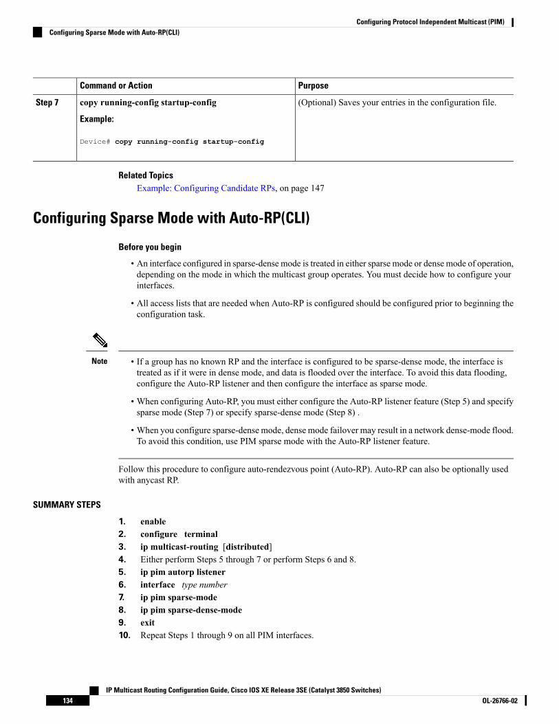
PurposeCommand or Action
(Optional) Saves your entries in the configuration file.copy running-config startup-config
Example:
Step 7
Device# copy running-config startup-config
Related TopicsExample: Configuring Candidate RPs, on page 147
Configuring Sparse Mode with Auto-RP(CLI)
Before you begin
• An interface configured in sparse-dense mode is treated in either sparse mode or dense mode of operation,depending on the mode in which the multicast group operates. You must decide how to configure yourinterfaces.
• All access lists that are needed when Auto-RP is configured should be configured prior to beginning theconfiguration task.
• If a group has no known RP and the interface is configured to be sparse-dense mode, the interface istreated as if it were in dense mode, and data is flooded over the interface. To avoid this data flooding,configure the Auto-RP listener and then configure the interface as sparse mode.
• When configuring Auto-RP, you must either configure the Auto-RP listener feature (Step 5) and specifysparse mode (Step 7) or specify sparse-dense mode (Step 8) .
• When you configure sparse-dense mode, dense mode failover may result in a network dense-mode flood.To avoid this condition, use PIM sparse mode with the Auto-RP listener feature.
Note
Follow this procedure to configure auto-rendezvous point (Auto-RP). Auto-RP can also be optionally usedwith anycast RP.
SUMMARY STEPS
1. enable2. configure terminal3. ip multicast-routing [distributed]4. Either perform Steps 5 through 7 or perform Steps 6 and 8.5. ip pim autorp listener6. interface type number7. ip pim sparse-mode8. ip pim sparse-dense-mode9. exit10. Repeat Steps 1 through 9 on all PIM interfaces.
IP Multicast Routing Configuration Guide, Cisco IOS XE Release 3SE (Catalyst 3850 Switches)OL-26766-02134
Configuring Protocol Independent Multicast (PIM)Configuring Sparse Mode with Auto-RP(CLI)

11. ip pim send-rp-announce {interface-type interface-number | ip-address} scope ttl-value [group-listaccess-list] [interval seconds] [bidir]
12. ip pim send-rp-discovery [interface-type interface-number] scope ttl-value [interval seconds]13. ip pim rp-announce-filter rp-list access-list group-list access-list14. no ip pim dm-fallback15. interface type number16. ip multicast boundary access-list [filter-autorp]17. end18. show ip pim autorp19. show ip pim rp [mapping] [rp-address]20. show ip igmp groups [group-name | group-address| interface-type interface-number] [detail]21. show ip mroute [group-address | group-name] [source-address | source-name] [interface-type
interface-number] [summary] [count] [active kbps]
DETAILED STEPS
PurposeCommand or Action
Enables privileged EXEC mode.enableStep 1
Example: • Enter your password if prompted.
Device> enable
Enters global configuration mode.configure terminal
Example:
Step 2
Device# configure terminal
Enables IP multicast routing.ip multicast-routing [distributed]Step 3
Example: • Use the distributed keyword to enabled MulticastDistributed Switching.
Device(config)# ip multicast-routing
--Either perform Steps 5 through 7 or perform Steps 6 and8.
Step 4
Causes IP multicast traffic for the two Auto-RP groups209.165.201.1 and 209.165.201.22 to be PIM dense modeflooded across interfaces operating in PIM sparse mode.
ip pim autorp listener
Example:
Device(config)# ip pim autorp listener
Step 5
• Skip this step if you are configuring sparse-densemode in Step 8.
Selects an interface that is connected to hosts on whichPIM can be enabled.
interface type number
Example:
Step 6
Device(config)# interface Gigabitethernet 1/0/0
IP Multicast Routing Configuration Guide, Cisco IOS XE Release 3SE (Catalyst 3850 Switches)135OL-26766-02
Configuring Protocol Independent Multicast (PIM)Configuring Sparse Mode with Auto-RP(CLI)

PurposeCommand or Action
Enables PIM sparse mode on an interface. Whenconfiguring Auto-RP in sparse mode, you must alsoconfigure the Auto-RP listener in the next step.
ip pim sparse-mode
Example:
Device(config-if)# ip pim sparse-mode
Step 7
• Skip this step if you are configuring sparse-densemode in Step 8.
Enables PIM sparse-dense mode on an interface.ip pim sparse-dense-modeStep 8
Example: • Skip this step if you configured sparse mode in Step7.
Device(config-if)# ip pim sparse-dense-mode
Exits interface configuration mode and returns to globalconfiguration mode.
exit
Example:
Step 9
Device(config-if)# exit
--Repeat Steps 1 through 9 on all PIM interfaces.Step 10
Sends RP announcements out all PIM-enabled interfaces.ip pim send-rp-announce {interface-typeinterface-number | ip-address} scope ttl-value [group-listaccess-list] [interval seconds] [bidir]
Step 11
• Perform this step on the RP device only.
Example: • Use the interface-typeand interface-number argumentsto define which IP address is to be used as the RPaddress.Device(config)# ip pim send-rp-announce loopback0
scope 31 group-list 5 • Use the ip-address argument to specify a directlyconnected IP address as the RP address.
If the ip-address argument is configured for thiscommand, the RP-announce message will besourced by the interface to which this IP addressis connected (that is, the source address in theIP header of the RP-announce message is theIP address of that interface).
Note
• This example shows that the interface is enabled witha maximum of 31 hops. The IP address by which thedevice wants to be identified as RP is the IP addressassociated with loopback interface 0. Access list 5describes the groups for which this device serves asRP.
Configures the device to be an RP mapping agent.ip pim send-rp-discovery [interface-typeinterface-number] scope ttl-value [interval seconds]
Step 12
• Perform this step on RP mapping agent devices or oncombined RP/RP mapping agent devices.Example:
Device(config)# ip pim send-rp-discovery loopback1 scope 31
IP Multicast Routing Configuration Guide, Cisco IOS XE Release 3SE (Catalyst 3850 Switches)OL-26766-02136
Configuring Protocol Independent Multicast (PIM)Configuring Sparse Mode with Auto-RP(CLI)
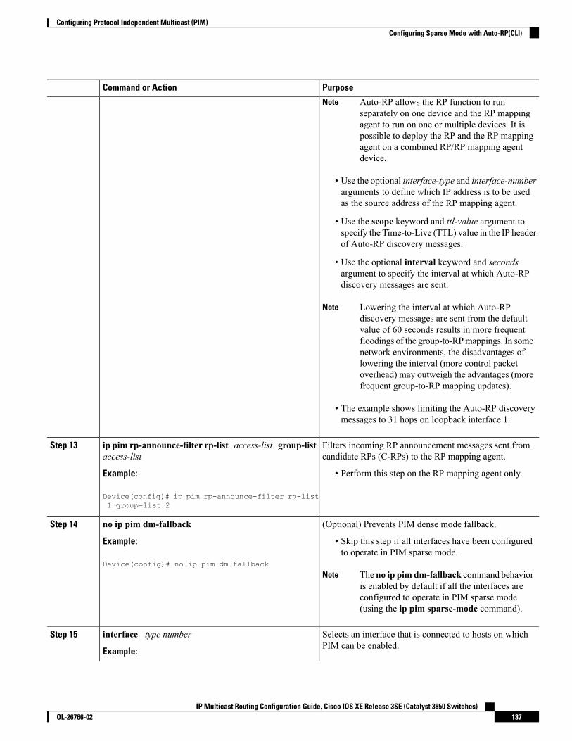
PurposeCommand or Action
Auto-RP allows the RP function to runseparately on one device and the RP mappingagent to run on one or multiple devices. It ispossible to deploy the RP and the RP mappingagent on a combined RP/RP mapping agentdevice.
Note
• Use the optional interface-type and interface-numberarguments to define which IP address is to be usedas the source address of the RP mapping agent.
• Use the scope keyword and ttl-value argument tospecify the Time-to-Live (TTL) value in the IP headerof Auto-RP discovery messages.
• Use the optional interval keyword and secondsargument to specify the interval at which Auto-RPdiscovery messages are sent.
Lowering the interval at which Auto-RPdiscovery messages are sent from the defaultvalue of 60 seconds results in more frequentfloodings of the group-to-RPmappings. In somenetwork environments, the disadvantages oflowering the interval (more control packetoverhead) may outweigh the advantages (morefrequent group-to-RP mapping updates).
Note
• The example shows limiting the Auto-RP discoverymessages to 31 hops on loopback interface 1.
Filters incoming RP announcement messages sent fromcandidate RPs (C-RPs) to the RP mapping agent.
ip pim rp-announce-filter rp-list access-list group-listaccess-list
Step 13
Example: • Perform this step on the RP mapping agent only.
Device(config)# ip pim rp-announce-filter rp-list1 group-list 2
(Optional) Prevents PIM dense mode fallback.no ip pim dm-fallbackStep 14
Example: • Skip this step if all interfaces have been configuredto operate in PIM sparse mode.
Device(config)# no ip pim dm-fallback
The no ip pim dm-fallback command behavioris enabled by default if all the interfaces areconfigured to operate in PIM sparse mode(using the ip pim sparse-mode command).
Note
Selects an interface that is connected to hosts on whichPIM can be enabled.
interface type number
Example:
Step 15
IP Multicast Routing Configuration Guide, Cisco IOS XE Release 3SE (Catalyst 3850 Switches)137OL-26766-02
Configuring Protocol Independent Multicast (PIM)Configuring Sparse Mode with Auto-RP(CLI)

PurposeCommand or Action
Device(config)# interface gigabitethernet 1/0/0
Configures an administratively scoped boundary.ip multicast boundary access-list [filter-autorp]Step 16
Example: • Perform this step on the interfaces that are boundariesto other devices.
Device(config-if)# ip multicast boundary 10filter-autorp • The access list is not shown in this task.
• An access list entry that uses the deny keywordcreates a multicast boundary for packets that matchthat entry.
Returns to global configuration mode.end
Example:
Step 17
Device(config-if)# end
(Optional) Displays the Auto-RP information.show ip pim autorp
Example:
Step 18
Device# show ip pim autorp
(Optional) Displays RPs known in the network and showshow the device learned about each RP.
show ip pim rp [mapping] [rp-address]
Example:
Step 19
Device# show ip pim rp mapping
(Optional) Displays the multicast groups having receiversthat are directly connected to the device and that were
show ip igmp groups [group-name | group-address|interface-type interface-number] [detail]
Step 20
learned through Internet Group Management Protocol(IGMP).Example:
Device# show ip igmp groups • A receiver must be active on the network at the timethat this command is issued in order for receiverinformation to be present on the resulting display.
(Optional) Displays the contents of the IPmulticast routing(mroute) table.
show ip mroute [group-address | group-name][source-address | source-name] [interface-typeinterface-number] [summary] [count] [active kbps]
Step 21
Example:
Device# show ip mroute cbone-audio
Related TopicsThe Role of Auto-RP in a PIM Network, on page 108Example: Sparse Mode with Auto-RP , on page 145
IP Multicast Routing Configuration Guide, Cisco IOS XE Release 3SE (Catalyst 3850 Switches)OL-26766-02138
Configuring Protocol Independent Multicast (PIM)Configuring Sparse Mode with Auto-RP(CLI)

Delaying the Use of PIM Shortest-Path Tree (CLI)Perform these steps to configure a traffic rate threshold that must be reached before multicast routing isswitched from the source tree to the shortest-path tree.
This procedure is optional.
SUMMARY STEPS
1. enable2. configure terminal3. access-list access-list-number {deny | permit} source [source-wildcard]4. ip pim spt-threshold {kbps | infinity} [group-list access-list-number]5. end6. show running-config7. copy running-config startup-config
DETAILED STEPS
PurposeCommand or Action
Enables privileged EXEC mode.enableStep 1
Example: • Enter your password if prompted.
Device> enable
Enters global configuration mode.configure terminal
Example:
Step 2
Device# configure terminal
Creates a standard access list.access-list access-list-number {deny | permit} source[source-wildcard]
Step 3
• For access-list-number, the range is 1 to 99.Example:
• The deny keyword denies access if the conditions arematched.Device(config)# access-list 16 permit 225.0.0.0
0.255.255.255 • The permit keyword permits access if the conditionsare matched.
• For source, specify the multicast group to which thethreshold will apply.
• (Optional) For source-wildcard, enter the wildcardbits in dotted decimal notation to be applied to thesource. Place ones in the bit positions that you wantto ignore.
The access list is always terminated by an implicit denystatement for everything.
IP Multicast Routing Configuration Guide, Cisco IOS XE Release 3SE (Catalyst 3850 Switches)139OL-26766-02
Configuring Protocol Independent Multicast (PIM)Delaying the Use of PIM Shortest-Path Tree (CLI)

PurposeCommand or Action
Specifies the threshold that must be reached before movingto shortest-path tree (spt).
ip pim spt-threshold {kbps | infinity} [group-listaccess-list-number]
Step 4
Example: • For kbps, specify the traffic rate in kilobits per second.The default is 0 kbps.
Device(config)# ip pim spt-threshold Because of device hardware limitations, 0kbps is the only valid entry even though therange is 0 to 4294967.
Noteinfinity group-list 16
• Specify infinity if you want all sources for thespecified group to use the shared tree, never switchingto the source tree.
• (Optional) For group-list access-list-number, specifythe access list created in Step 2. If the value is 0 or ifthe group list is not used, the threshold applies to allgroups.
Returns to privileged EXEC mode.end
Example:
Step 5
Device(config)# end
Verifies your entries.show running-config
Example:
Step 6
Device# show running-config
(Optional) Saves your entries in the configuration file.copy running-config startup-config
Example:
Step 7
Device# copy running-config startup-config
Modifying the PIM Router-Query Message Interval (CLI)PIM routers andmultilayer devices send PIM router-querymessages to find which device will be the designatedrouter (DR) for each LAN segment (subnet). The DR is responsible for sending IGMP host-query messagesto all hosts on the directly connected LAN.
With PIM DM operation, the DR has meaning only if IGMPv1 is in use. IGMPv1 does not have an IGMPquerier election process, so the elected DR functions as the IGMP querier. With PIM-SM operation, the DRis the device that is directly connected to the multicast source. It sends PIM register messages to notify theRP that multicast traffic from a source needs to be forwarded down the shared tree. In this case, the DR is thedevice with the highest IP address.
This procedure is optional.
IP Multicast Routing Configuration Guide, Cisco IOS XE Release 3SE (Catalyst 3850 Switches)OL-26766-02140
Configuring Protocol Independent Multicast (PIM)Modifying the PIM Router-Query Message Interval (CLI)

SUMMARY STEPS
1. enable2. configure terminal3. interface interface-id4. ip pim query-interval seconds5. end6. show ip igmp interface [interface-id]7. copy running-config startup-config
DETAILED STEPS
PurposeCommand or Action
Enables privileged EXEC mode.enableStep 1
Example: • Enter your password if prompted.
Device> enable
Enters global configuration mode.configure terminal
Example:
Step 2
Device# configure terminal
Specifies the interface to be configured, and enters interfaceconfiguration mode.
interface interface-id
Example:
Step 3
The specified interface must be one of the following:Device(config)# interface • A routed port—A physical port that has been
configured as a Layer 3 port by entering the noswitchport interface configuration command.
gigabitethernet 1/0/1
You will also need to enable IP PIMsparse-dense-mode on the interface, and join theinterface as a statically connected member to an IGMPstatic group.
• An SVI—A VLAN interface created by using theinterface vlan vlan-id global configuration command.
You will also need to enable IP PIMsparse-dense-mode on the VLAN, join the VLAN asa statically connectedmember to an IGMP static group,and then enable IGMP snooping on the VLAN, theIGMP static group, and physical interface.
These interfaces must have IP addresses assigned to them.
Configures the frequency at which the device sends PIMrouter-query messages.
ip pim query-interval seconds
Example:
Step 4
IP Multicast Routing Configuration Guide, Cisco IOS XE Release 3SE (Catalyst 3850 Switches)141OL-26766-02
Configuring Protocol Independent Multicast (PIM)Modifying the PIM Router-Query Message Interval (CLI)

PurposeCommand or Action
The default is 30 seconds. The range is 1 to 65535.Device(config-if)# ip pimquery-interval 45
Returns to privileged EXEC mode.end
Example:
Step 5
Device(config)# end
Verifies your entries.show ip igmp interface [interface-id]
Example:
Step 6
Device# show ip igmp interface
(Optional) Saves your entries in the configuration file.copy running-config startup-config
Example:
Step 7
Device# copy running-config startup-config
Monitoring PIM InformationUse the privileged EXEC commands in the following table to monitor your PIM configurations.
Table 16: PIM Monitoring Commands
PurposeCommand
Displays all VRFs.show ip pim all-vrfs tunnel [tunnel tunnel_number| verbose]
Displays global auto-RP information.show ip pim autorp
Displays information about mroutes filtered byadministratively scoped IPv4 multicast boundariesconfigured on an interface.
show ip pim boundary
Displays information about interfaces configured forProtocol Independent Multicast (PIM).
show ip pim interface
Displays the PIM neighbor information.show ip pim neighbor
Displays RP routers associated with a sparse-modemulticast group. This command is available in allsoftware images.
show ip pim rp[group-name | group-address]
IP Multicast Routing Configuration Guide, Cisco IOS XE Release 3SE (Catalyst 3850 Switches)OL-26766-02142
Configuring Protocol Independent Multicast (PIM)Monitoring PIM Information

PurposeCommand
Displays information about Protocol IndependentMulticast (PIM) tunnel interfaces
show ip pim tunnel [tunnel | verbose]
Displays the VPN routing/forwarding instance.show ip pim vrf { word { all-vrfs | autorp |boundary | bsr-router | interface |mdt | neighbor| rp | rp-hash | tunnel } }
Displays the interested clients that have joined thespecific multicast source group.
show ip igmp groups detail
Monitoring the RP Mapping and BSR InformationUse the privileged EXEC mode in the following table to verify the consistency of group-to-RP mappings:
Table 17: RP Mapping Monitoring Commands
PurposeCommand
Displays all available RPmappings and metrics. This tells youhow the device learns of the RP (through the BSR or theAuto-RP mechanism).
• (Optional) For the hostname, specify the IP name of thegroup about which to display RPs.
• (Optional) For the IP address, specify the IP address ofthe group about which to display RPs.
• (Optional) Use themapping keyword to display allgroup-to-RPmappings of which the Cisco device is aware(either configured or learned from Auto-RP).
• (Optional) Use themetric keyword to display the RPRPF metric.
show ip pim rp [ hostname or IP address |mapping [ hostname or IP address | elected| in-use ] |metric [ hostname or IP address] ]
Displays the RP that was selected for the specified group. Thatis, on a PIMv2 router or multilayer device, confirms that thesame RP is the one that a PIMv1 system chooses. For group,enter the group address for which to display RP information.
show ip pim rp-hash group
Use the privileged EXEC commands in the following table to monitor BSR information:
Table 18: BSR Monitoring Commands
PurposeCommand
Displays information about the elected BSR.show ip pim bsr
Displays information about the BSRv2.show ip pim bsr-router
IP Multicast Routing Configuration Guide, Cisco IOS XE Release 3SE (Catalyst 3850 Switches)143OL-26766-02
Configuring Protocol Independent Multicast (PIM)Monitoring the RP Mapping and BSR Information
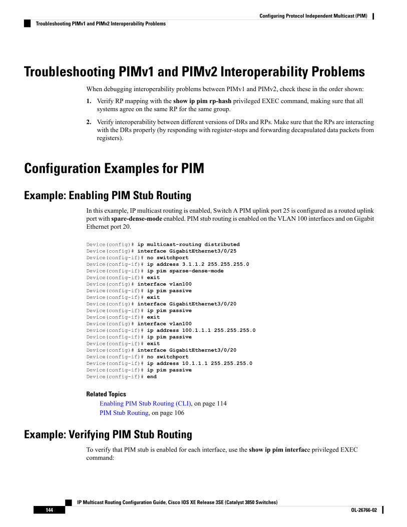
Troubleshooting PIMv1 and PIMv2 Interoperability ProblemsWhen debugging interoperability problems between PIMv1 and PIMv2, check these in the order shown:
1. Verify RP mapping with the show ip pim rp-hash privileged EXEC command, making sure that allsystems agree on the same RP for the same group.
2. Verify interoperability between different versions of DRs and RPs. Make sure that the RPs are interactingwith the DRs properly (by responding with register-stops and forwarding decapsulated data packets fromregisters).
Configuration Examples for PIM
Example: Enabling PIM Stub RoutingIn this example, IP multicast routing is enabled, Switch A PIM uplink port 25 is configured as a routed uplinkport with spare-dense-mode enabled. PIM stub routing is enabled on the VLAN 100 interfaces and on GigabitEthernet port 20.
Device(config)# ip multicast-routing distributedDevice(config)# interface GigabitEthernet3/0/25Device(config-if)# no switchportDevice(config-if)# ip address 3.1.1.2 255.255.255.0Device(config-if)# ip pim sparse-dense-modeDevice(config-if)# exitDevice(config)# interface vlan100Device(config-if)# ip pim passiveDevice(config-if)# exitDevice(config)# interface GigabitEthernet3/0/20Device(config-if)# ip pim passiveDevice(config-if)# exitDevice(config)# interface vlan100Device(config-if)# ip address 100.1.1.1 255.255.255.0Device(config-if)# ip pim passiveDevice(config-if)# exitDevice(config)# interface GigabitEthernet3/0/20Device(config-if)# no switchportDevice(config-if)# ip address 10.1.1.1 255.255.255.0Device(config-if)# ip pim passiveDevice(config-if)# end
Related TopicsEnabling PIM Stub Routing (CLI), on page 114PIM Stub Routing, on page 106
Example: Verifying PIM Stub RoutingTo verify that PIM stub is enabled for each interface, use the show ip pim interface privileged EXECcommand:
IP Multicast Routing Configuration Guide, Cisco IOS XE Release 3SE (Catalyst 3850 Switches)OL-26766-02144
Configuring Protocol Independent Multicast (PIM)Troubleshooting PIMv1 and PIMv2 Interoperability Problems

Device# show ip pim interfaceAddress Interface Ver/ Nbr Query DR DRMode Count Intvl Prior3.1.1.2 GigabitEthernet3/0/25 v2/SD 1 30 1 3.1.1.2100.1.1.1 Vlan100 v2/P 0 30 1 100.1.1.110.1.1.1 GigabitEthernet3/0/20 v2/P 0 30 1 10.1.1.1
Example: Manually Assigning an RP to Multicast GroupsThis example shows how to configure the address of the RP to 147.106.6.22 for multicast group 225.2.2.2only:
Device(config)# access-list 1 permit 225.2.2.2 0.0.0.0Device(config)# ip pim rp-address 147.106.6.22 1
Example: Configuring Auto-RPThis example shows how to send RP announcements out all PIM-enabled interfaces for a maximum of 31hops. The IP address of port 1 is the RP. Access list 5 describes the group for which this device serves as RP:
Device(config)# ip pim send-rp-announce gigabitethernet1/0/1 scope 31 group-list 5Device(config)# access-list 5 permit 224.0.0.0 15.255.255.255
Related TopicsSetting Up Auto-RP in a New Internetwork (CLI), on page 119Auto-RP, on page 107
Example: Sparse Mode with Auto-RPThe following example configures sparse mode with Auto-RP:
ip multicast-routingip pim autorp listenerip pim send-rp-announce Loopback0 scope 16 group-list 1ip pim send-rp-discovery Loopback1 scope 16no ip pim dm-fallbackaccess-list 1 permit 239.254.2.0 0.0.0.255access-list 1 permit 239.254.3.0 0.0.0.255...access-list 10 permit 224.0.1.39access-list 10 permit 224.0.1.40access-list 10 permit 239.254.2.0 0.0.0.255access-list 10 permit 239.254.3.0 0.0.0.255
Related TopicsThe Role of Auto-RP in a PIM Network, on page 108Configuring Sparse Mode with Auto-RP(CLI), on page 134
IP Multicast Routing Configuration Guide, Cisco IOS XE Release 3SE (Catalyst 3850 Switches)145OL-26766-02
Configuring Protocol Independent Multicast (PIM)Example: Manually Assigning an RP to Multicast Groups

Example: Defining the IP Multicast Boundary to Deny Auto-RP InformationThis example shows a portion of an IP multicast boundary configuration that denies Auto-RP information:
Device(config)# access-list 1 deny 224.0.1.39Device(config)# access-list 1 deny 224.0.1.40Device(config)# access-list 1 permit allDevice(config)# interface gigabitethernet1/0/1Device(config-if)# ip multicast boundary 1
Related TopicsDefining the IP Multicast Boundary (CLI), on page 128
Example: Filtering Incoming RP Announcement MessagesThis example shows a sample configuration on an Auto-RP mapping agent that is used to prevent candidateRP announcements from being accepted from unauthorized candidate RPs:
Device(config)# ip pim rp-announce-filter rp-list 10 group-list 20Device(config)# access-list 10 permit host 172.16.5.1Device(config)# access-list 10 permit host 172.16.2.1Device(config)# access-list 20 deny 239.0.0.0 0.0.255.255Device(config)# access-list 20 permit 224.0.0.0 15.255.255.255
The mapping agent accepts candidate RP announcements from only two devices, 172.16.5.1 and 172.16.2.1.The mapping agent accepts candidate RP announcements from these two devices only for multicast groupsthat fall in the group range of 224.0.0.0 to 239.255.255.255. The mapping agent does not accept candidateRP announcements from any other devices in the network. Furthermore, the mapping agent does not acceptcandidate RP announcements from 172.16.5.1 or 172.16.2.1 if the announcements are for any groups in the239.0.0.0 through 239.255.255.255 range. This range is the administratively scoped address range.
Related TopicsFiltering Incoming RP Announcement Messages (CLI), on page 125
Example: Preventing Join Messages to False RPsIf all interfaces are in sparse mode, use a default-configured RP to support the two well-knowngroups 224.0.1.39 and 224.0.1.40. Auto-RP uses these two well-known groups to collect and distributeRP-mapping information. When this is the case and the ip pim accept-rp auto-rp command is configured,another ip pim accept-rp command accepting the RP must be configured as follows:
Device(config)# ip pim accept-rp 172.10.20.1 1Device(config)# access-list 1 permit 224.0.1.39Device(config)# access-list 1 permit 224.0.1.40
Related TopicsPreventing Join Messages to False RPs (CLI), on page 124
IP Multicast Routing Configuration Guide, Cisco IOS XE Release 3SE (Catalyst 3850 Switches)OL-26766-02146
Configuring Protocol Independent Multicast (PIM)Example: Defining the IP Multicast Boundary to Deny Auto-RP Information

Example: Configuring Candidate BSRsThis example shows how to configure a candidate BSR, which uses the IP address 172.21.24.18 on a port asthe advertised BSR address, uses 30 bits as the hash-mask-length, and has a priority of 10.
Device(config)# interface gigabitethernet1/0/2Device(config-if)# ip address 172.21.24.18 255.255.255.0Device(config-if)# ip pim sparse-modeDevice(config-if)# ip pim bsr-candidate gigabitethernet1/0/2 30 10
Related TopicsConfiguring Candidate BSRs (CLI), on page 130PIMv2 Bootstrap Router, on page 110
Example: Configuring Candidate RPsThis example shows how to configure the device to advertise itself as a candidate RP to the BSR in its PIMdomain. Standard access list number 4 specifies the group prefix associated with the RP that has the addressidentified by a port. That RP is responsible for the groups with the prefix 239.
Device(config)# ip pim rp-candidate gigabitethernet1/0/2 group-list 4Device(config)# access-list 4 permit 239.0.0.0 0.255.255.255
Related TopicsConfiguring the Candidate RPs (CLI), on page 132
Where to Go Next for PIMYou can configure the following:
• IGMP
• Wireless Multicast
• SSM
• IP Multicast Routing
• Service Discovery Gateway
You can also review the following IP Multicast Optimization processes for your configuration:
• Optimizing PIM Sparse Mode in a Large IP Multicast Deployment
• Multicast Subsecond Convergence
• IP Multicast Load Splitting across Equal-Cost Paths
• SSM Channel Based Filtering for Multicast
• PIM Dense Mode State Refresh
• IGMP State Limit
IP Multicast Routing Configuration Guide, Cisco IOS XE Release 3SE (Catalyst 3850 Switches)147OL-26766-02
Configuring Protocol Independent Multicast (PIM)Example: Configuring Candidate BSRs

Additional ReferencesRelated Documents
Document TitleRelated Topic
• Protocol Independent Multicast (PIM): Motivation andArchitecture
• Protocol Independent Multicast (PIM), Dense ModeProtocol Specification
• Protocol Independent Multicast (PIM), Sparse ModeProtocol Specification
• draft-ietf-idmr-igmp-v2-06.txt, Internet GroupManagement Protocol, Version 2
• draft-ietf-pim-v2-dm-03.txt, PIM Version 2 Dense Mode
PIM is defined in RFC 4601 and in theseInternet Engineering Task Force (IETF)Internet drafts.
IP Multicast Routing Command Reference (Catalyst 3850Switches) Command Reference (Catalyst 9500 Series Switches)Command Reference (Catalyst 9300 Series Switches)
For complete syntax and usage informationfor the commands used in this chapter.
IP Multicast Routing Command Reference (Catalyst 3850Switches)
IGMP Helper command syntax and usageinformation.
IP Routing: Protocol-Independent Configuration Guide, CiscoIOS XE Release 3SE (Catalyst 3850 Switches)
Multicast SourceDiscovery Protocol (MSDP)
IP Routing: EIGRP Configuration Guide, Cisco IOS XERelease 3SE (Catalyst 3850 Switches)
Enhanced Interior Gateway Routing Protocol(EIGRP) stub routing
IP Routing: OSPF Configuration Guide, Cisco IOS XE 3SE(Catalyst 3850 Switches)
Open Shortest Path First (OSPF) stub routing
Cisco IOS Master Commands List, All ReleasesCisco IOS commands
Cisco IOS IP Multicast Command ReferenceCisco IOS IP SLAs commands
“ IP Multicast Technology Overview ” moduleOverview of the IP multicast technology area
“ Configuring a Basic IP Multicast Network ” moduleConcepts, tasks, and examples for configuringan IP multicast network using PIM
Error Message Decoder
LinkDescription
https://www.cisco.com/cgi-bin/Support/Errordecoder/index.cgiTo help you research and resolve systemerror messages in this release, use the ErrorMessage Decoder tool.
IP Multicast Routing Configuration Guide, Cisco IOS XE Release 3SE (Catalyst 3850 Switches)OL-26766-02148
Configuring Protocol Independent Multicast (PIM)Additional References

Standards and RFCs
TitleStandard/RFC
Protocol-Independent Multicast-Sparse Mode (PIM-SM): Protocol SpecificationRFC 4601
MIBs
MIBs LinkMIB
To locate and downloadMIBs for selected platforms, Cisco IOS releases,and feature sets, use Cisco MIB Locator found at the following URL:
http://www.cisco.com/go/mibs
All the supported MIBs for thisrelease.
Technical Assistance
LinkDescription
http://www.cisco.com/supportThe Cisco Support website provides extensive online resources, includingdocumentation and tools for troubleshooting and resolving technical issueswith Cisco products and technologies.
To receive security and technical information about your products, you cansubscribe to various services, such as the Product Alert Tool (accessed fromField Notices), the Cisco Technical Services Newsletter, and Really SimpleSyndication (RSS) Feeds.
Access to most tools on the Cisco Support website requires a Cisco.com userID and password.
Feature History and Information for PIMModificationRelease
This feature was introduced.Cisco IOS XE 3.2SE
IP Multicast Routing Configuration Guide, Cisco IOS XE Release 3SE (Catalyst 3850 Switches)149OL-26766-02
Configuring Protocol Independent Multicast (PIM)Feature History and Information for PIM

IP Multicast Routing Configuration Guide, Cisco IOS XE Release 3SE (Catalyst 3850 Switches)OL-26766-02150
Configuring Protocol Independent Multicast (PIM)Feature History and Information for PIM
C H A P T E R 7Configuring PIM MIB Extension for IP Multicast
• Finding Feature Information, on page 151• Information About PIM MIB Extension for IP Multicast, on page 151• How to Configure PIM MIB Extension for IP Multicast, on page 152• Configuration Examples for PIM MIB Extensions, on page 154• Additional References, on page 154
Finding Feature InformationYour software release may not support all the features documented in this module. For the latest caveats andfeature information, see Bug Search Tool and the release notes for your platform and software release. Tofind information about the features documented in this module, and to see a list of the releases in which eachfeature is supported, see the feature information table at the end of this module.
Use Cisco Feature Navigator to find information about platform support and Cisco software image support.To access Cisco Feature Navigator, go to http://www.cisco.com/go/cfn. An account on Cisco.com is notrequired.
Information About PIM MIB Extension for IP Multicast
PIM MIB Extensions for SNMP Traps for IP MulticastProtocol Independent Multicast (PIM) is an IP multicast routing protocol used for routing multicast datapackets to multicast groups. RFC 2934 defines the PIM MIB for IPv4, which describes managed objects thatenable users to remotely monitor and configure PIM using Simple Network Management Protocol (SNMP).
PIM MIB extensions introduce the following new classes of PIM notifications:
• neighbor-change--This notification results from the following conditions:
• A router’s PIM interface is disabled or enabled (using the ip pim command in interface configurationmode)
• A router's PIM neighbor adjacency expires (defined in RFC 2934)
• rp-mapping-change--This notification results from a change in the rendezvous point (RP) mappinginformation due to either Auto-RP messages or bootstrap router (BSR) messages.
IP Multicast Routing Configuration Guide, Cisco IOS XE Release 3SE (Catalyst 3850 Switches)151OL-26766-02

• invalid-pim-message--This notification results from the following conditions:
• An invalid (*, G) Join or Prune message is received by the device (for example, when a routerreceives a Join or Prune message for which the RP specified in the packet is not the RP for themulticast group)
• An invalid PIM register message is received by the device (for example, when a router receives aregister message from a multicast group for which it is not the RP)
Related TopicsEnabling PIM MIB Extensions for IP Multicast, on page 152Example Enabling PIM MIB Extensions for IP Multicast, on page 154
Benefits of PIM MIB ExtensionsPIM MIB extensions:
• Allow users to identify changes in the multicast topology of their network by detecting changes in theRP mapping.
• Provide traps to monitor the PIM protocol on PIM-enabled interfaces.
• Help users identify routing issues when multicast neighbor adjacencies expire on a multicast interface.
• Enable users to monitor RP configuration errors (for example, errors due to flapping in dynamic RPallocation protocols like Auto-RP).
How to Configure PIM MIB Extension for IP Multicast
Enabling PIM MIB Extensions for IP MulticastPerform this task to enable PIM MIB extensions for IP multicast.
• The pimInterfaceVersion object was removed from RFC 2934 and, therefore, is no longer supported insoftware.
• The following MIB tables are not supported in Cisco software:
• pimIpMRouteTable• pimIpMRouteNextHopTable
Note
SUMMARY STEPS
1. enable2. configure terminal3. snmp-server enable traps pim [neighbor-change | rp-mapping-change | invalid-pim-message]4. snmp-server host host-address [traps | informs] community-string pim
IP Multicast Routing Configuration Guide, Cisco IOS XE Release 3SE (Catalyst 3850 Switches)OL-26766-02152
Configuring PIM MIB Extension for IP MulticastBenefits of PIM MIB Extensions

DETAILED STEPS
PurposeCommand or Action
Enables privileged EXEC mode.enableStep 1
Example: • Enter your password if prompted.
Device> enable
Enters global configuration mode.configure terminal
Example:
Step 2
Device# configure terminal
Enables a device to send PIM notifications.snmp-server enable traps pim [neighbor-change |rp-mapping-change | invalid-pim-message]
Step 3
• neighbor-change --This keyword enables notificationsindicating when a device’s PIM interface is disabledExample:or enabled, or when a device’s PIM neighbor adjacencyexpires.Device(config)# snmp-server enable traps pim
neighbor-change• rp-mapping-change --This keyword enablesnotifications indicating a change in RP mappinginformation due to either Auto-RP messages or BSRmessages.
• invalid-pim-message --This keyword enablesnotifications for monitoring invalid PIM protocoloperations (for example, when a device receives a joinor prune message for which the RP specified in thepacket is not the RP for the multicast group or whena device receives a register message from a multicastgroup for which it is not the RP).
Specifies the recipient of a PIM SNMP notificationoperation.
snmp-server host host-address [traps | informs]community-string pim
Example:
Step 4
Device(config)# snmp-server host 10.10.10.10 trapspublic pim
Related TopicsPIM MIB Extensions for SNMP Traps for IP Multicast, on page 151Example Enabling PIM MIB Extensions for IP Multicast, on page 154
IP Multicast Routing Configuration Guide, Cisco IOS XE Release 3SE (Catalyst 3850 Switches)153OL-26766-02
Configuring PIM MIB Extension for IP MulticastEnabling PIM MIB Extensions for IP Multicast

Configuration Examples for PIM MIB Extensions
Example Enabling PIM MIB Extensions for IP MulticastThe following example shows how to configure a router to generate notifications indicating that a PIM interfaceof the router has been enabled. The first line configures PIM traps to be sent as SNMP v2c traps to the hostwith IP address 10.0.0.1. The second line configures the router to send the neighbor-change class of trapnotification to the host.
snmp-server host 10.0.0.1 traps version 2c public pimsnmp-server enable traps pim neighbor-changeinterface ethernet0/0ip pim sparse-mode
Related TopicsEnabling PIM MIB Extensions for IP Multicast, on page 152PIM MIB Extensions for SNMP Traps for IP Multicast, on page 151
Additional ReferencesRelated Documents
Document TitleRelated Topic
Cisco IOSMaster Commands List, All ReleasesCisco IOS commands
Cisco IOS IP Multicast Command ReferenceIPmulticast commands
Standards and RFCs
TitleStandard/RFC
A New Proposal for Bi-directional PIMdraft-kouvelas-pim-bidir-new-00.txt
Host Extensions for IP MulticastingRFC 1112
Address Allocation for Private InternetsRFC 1918
GLOP Addressing in 233/8RFC 2770
An Overview of Source-Specific Multicast (SSM)RFC 3569
IP Multicast Routing Configuration Guide, Cisco IOS XE Release 3SE (Catalyst 3850 Switches)OL-26766-02154
Configuring PIM MIB Extension for IP MulticastConfiguration Examples for PIM MIB Extensions

MIBs
MIBs LinkMIB
To locate and downloadMIBs for selected platforms, Ciscosoftware releases, and feature sets, use CiscoMIB Locatorfound at the following URL:
http://www.cisco.com/go/mibs
No new or modified MIBs are supported by thisfeature, and support for existing MIBs has notbeen modified by this feature.
Technical Assistance
LinkDescription
http://www.cisco.com/cisco/web/support/index.htmlTheCisco Support andDocumentationwebsite providesonline resources to download documentation, software,and tools. Use these resources to install and configurethe software and to troubleshoot and resolve technicalissues with Cisco products and technologies. Access tomost tools on the Cisco Support and Documentationwebsite requires a Cisco.com user ID and password.
IP Multicast Routing Configuration Guide, Cisco IOS XE Release 3SE (Catalyst 3850 Switches)155OL-26766-02
Configuring PIM MIB Extension for IP MulticastAdditional References

IP Multicast Routing Configuration Guide, Cisco IOS XE Release 3SE (Catalyst 3850 Switches)OL-26766-02156
Configuring PIM MIB Extension for IP MulticastAdditional References

C H A P T E R 8Configuring MSDP
• Finding Feature Information, on page 157• , on page 157• Information About Using MSDP to Interconnect Multiple PIM-SM Domains, on page 157• How to Use MSDP to Interconnect Multiple PIM-SM Domains, on page 171• Configuration Examples for Using MSDP to Interconnect Multiple PIM-SM Domains, on page 192• Where to Go Next for MSDP, on page 195• Additional References, on page 196• Feature History and Information for Multicast Source Discovery Protocol, on page 197
Finding Feature InformationYour software release may not support all the features documented in this module. For the latest caveats andfeature information, see Bug Search Tool and the release notes for your platform and software release. Tofind information about the features documented in this module, and to see a list of the releases in which eachfeature is supported, see the feature information table at the end of this module.
Use Cisco Feature Navigator to find information about platform support and Cisco software image support.To access Cisco Feature Navigator, go to http://www.cisco.com/go/cfn. An account on Cisco.com is notrequired.
Information About Using MSDP to Interconnect MultiplePIM-SM Domains
Benefits of Using MSDP to Interconnect Multiple PIM-SM Domains• Allows a rendezvous point (RP) to dynamically discover active sources outside of its domain.
• Introduces a more manageable approach for building multicast distribution trees between multipledomains.
IP Multicast Routing Configuration Guide, Cisco IOS XE Release 3SE (Catalyst 3850 Switches)157OL-26766-02

MSDP is a mechanism to connect multiple PIM-SM domains. The purpose of MSDP is to discover multicastsources in other PIM domains. Themain advantage ofMSDP is that it reduces the complexity of interconnectingmultiple PIM-SM domains by allowing PIM-SM domains to use an interdomain source tree (rather than acommon shared tree). When MSDP is configured in a network, RPs exchange source information with RPsin other domains. An RP can join the interdomain source tree for sources that are sending to groups for whichit has receivers. The RP can do that because it is the root of the shared tree within its domain, which hasbranches to all points in the domain where there are active receivers. When a last-hop device learns of a newsource outside the PIM-SM domain (through the arrival of a multicast packet from the source down the sharedtree), it then can send a join toward the source and join the interdomain source tree.
If the RP either has no shared tree for a particular group or a shared tree whose outgoing interface list is null,it does not send a join to the source in another domain.
Note
When MSDP is enabled, an RP in a PIM-SM domain maintains MSDP peering relationships withMSDP-enabled devices in other domains. This peering relationship occurs over a TCP connection, whereprimarily a list of sources sending to multicast groups is exchanged.MSDP uses TCP (port 639) for its peeringconnections. As with BGP, using point-to-point TCP peeringmeans that each peer must be explicitly configured.The TCP connections between RPs, moreover, are achieved by the underlying routing system. The receivingRP uses the source lists to establish a source path. If the multicast sources are of interest to a domain that hasreceivers, multicast data is delivered over the normal, source-tree building mechanism provided by PIM-SM.MSDP is also used to announce sources sending to a group. These announcements must originate at the RPof the domain.
The figure illustratesMSDP operating between twoMSDP peers. PIM usesMSDP as the standardmechanismto register a source with the RP of a domain.
Although the following illustration and example uses routers in the configuration, any device (router or switch)can be used.
Note
IP Multicast Routing Configuration Guide, Cisco IOS XE Release 3SE (Catalyst 3850 Switches)OL-26766-02158
Configuring MSDP

Figure 7: MSDP Running Between RP Peers
When MSDP is implemented, the following sequence of events occurs:
1. When a PIM designated device (DR) registers a source with its RP as illustrated in the figure, the RPsends a Source-Active (SA) message to all of its MSDP peers.
The DR sends the encapsulated data to the RP only once per source (when the source goes active). If thesource times out, this process happens again when it goes active again. This situation is different from theperiodic SA message that contains all sources that are registered to the originating RP. Those SA messagesare MSDP control packets, and, thus, do not contain encapsulated data from active sources.
Note
1. The SA message identifies the source address, the group that the source is sending to, and the address orthe originator ID of the RP, if configured.
2. EachMSDP peer that receives the SAmessage floods the SAmessage to all of its peers downstream fromthe originator. In some cases (such as the case with the RPs in PIM-SM domains B and C in the figure),an RP may receive a copy of an SA message from more than one MSDP peer. To prevent looping, theRP consults the BGP next-hop database to determine the next hop toward the originator of the SAmessage.If both MBGP and unicast BGP are configured, MBGP is checked first, and then unicast BGP. Thatnext-hop neighbor is the RPF-peer for the originator. SA messages that are received from the originatoron any interface other than the interface to the RPF peer are dropped. The SA message flooding process,therefore, is referred to as peer-RPF flooding. Because of the peer-RPF flooding mechanism, BGP orMBGP must be running in conjunction with MSDP.
IP Multicast Routing Configuration Guide, Cisco IOS XE Release 3SE (Catalyst 3850 Switches)159OL-26766-02
Configuring MSDP

1. When an RP receives an SA message, it checks to see whether there are any members of the advertisedgroups in its domain by checking to see whether there are interfaces on the group’s (*, G) outgoinginterface list. If there are no group members, the RP does nothing. If there are group members, the RPsends an (S, G) join toward the source. As a result, a branch of the interdomain source tree is constructedacross autonomous system boundaries to the RP. As multicast packets arrive at the RP, they are thenforwarded down its own shared tree to the group members in the RP’s domain. The members’ DRs thenhave the option of joining the rendezvous point tree (RPT) to the source using standard PIM-SMprocedures.
2. The originating RP continues to send periodic SA messages for the (S, G) state every 60 seconds for aslong as the source is sending packets to the group. When an RP receives an SA message, it caches the SAmessage. Suppose, for example, that an RP receives an SA message for (172.16.5.4, 228.1.2.3) fromoriginating RP 10.5.4.3. The RP consults its mroute table and finds that there are no active members forgroup 228.1.2.3, so it passes the SA message to its peers downstream of 10.5.4.3. If a host in the domainthen sends a join to the RP for group 228.1.2.3, the RP adds the interface toward the host to the outgoinginterface list of its (*, 224.1.2.3) entry. Because the RP caches SAmessages, the device will have an entryfor (172.16.5.4, 228.1.2.3) and can join the source tree as soon as a host requests a join.
In all current and supported software releases, caching of MSDP SA messages is mandatory and cannot bemanually enabled or disabled. By default, when anMSDP peer is configured, the ip multicast cache-sa-statecommand will automatically be added to the running configuration.
Note
MSDP Message TypesThere are four basic MSDP message types, each encoded in their own Type, Length, and Value (TLV) dataformat.
SA MessagesSA messages are used to advertise active sources in a domain. In addition, these SA messages may containthe initial multicast data packet that was sent by the source.
SA messages contain the IP address of the originating RP and one or more (S, G) pairs being advertised. Inaddition, the SA message may contain an encapsulated data packet.
For more information about SA messages, see the SA Message Origination Receipt and Processing, on page161 section.
Note
SA Request MessagesSA request messages are used to request a list of active sources for a specific group. These messages are sentto an MSDP SA cache that maintains a list of active (S, G) pairs in its SA cache. Join latency can be reducedby using SA request messages to request the list of active sources for a group instead of having to wait up to60 seconds for all active sources in the group to be readvertised by originating RPs.
IP Multicast Routing Configuration Guide, Cisco IOS XE Release 3SE (Catalyst 3850 Switches)OL-26766-02160
Configuring MSDPMSDP Message Types

SA Response MessagesSA responsemessages are sent by theMSDP peer in response to an SA request message. SA responsemessagescontain the IP address of the originating RP and one or more (S, G) pairs of the active sources in the originatingRP’s domain that are stored in the cache.
Keepalive MessagesKeepalive messages are sent every 60 seconds in order to keep the MSDP session active. If no keepalivemessages or SA messages are received for 75 seconds, the MSDP session is reset.
SA Message Origination Receipt and ProcessingThe section describes SA message origination, receipt, and processing in detail.
SA Message OriginationSAmessages are triggered by an RP (assumingMSDP is configured) when any new source goes active withina local PIM-SM domain. A local source is a source that is directly connected to the RP or is the first-hop DRthat has registered with it. An RP originates SA messages only for local sources in its PIM-SM domain; thatis, for local sources that register with it.
A local source is denoted by the A flag being set in the (S, G) mroute entry on the RP (which can be viewedin the output of the show ip mroute command). This flag indicates that the source is a candidate foradvertisement by the RP to other MSDP peers.
Note
When a source is in the local PIM-SM domain, it causes the creation of (S, G) state in the RP. New sourcesare detected by the RP either by the receipt of a register message or the arrival of the first (S, G) packet froma directly connected source. The initial multicast packet sent by the source (either encapsulated in the registermessage or received from a directly connected source) is encapsulated in the initial SA message.
SA Message ReceiptSA messages are only accepted from the MSDP RPF peer that is in the best path back toward the originator.The same SA message arriving from other MSDP peers must be ignored or SA loops can occur.Deterministically selecting theMSDP RPF peer for an arriving SAmessage requires knowledge of theMSDPtopology. However, MSDP does not distribute topology information in the form of routing updates. MSDPinfers this information by using (M)BGP routing data as the best approximation of the MSDP topology forthe SA RPF check mechanism. An MSDP topology, therefore, must follow the same general topology as theBGP peer topology. Besides a few exceptions (such as default MSDP peers and MSDP peers in MSDP meshgroups), MSDP peers, in general should also be (M)BGP peers.
How RPF Check Rules Are Applied to SA Messages
The rules that apply to RPF checks for SA messages are dependent on the BGP peerings between the MSDPpeers:
• Rule 1: Applied when the sending MSDP peer is also an interior (M)BGP peer.
• Rule 2: Applied when the sending MSDP peer is also an exterior (M)BGP peer.
IP Multicast Routing Configuration Guide, Cisco IOS XE Release 3SE (Catalyst 3850 Switches)161OL-26766-02
Configuring MSDPSA Response Messages

• Rule 3: Applied when the sending MSDP peer is not an (M)BGP peer.
RPF checks are not performed in the following cases:
• If the sending MSDP peer is the only MSDP peer, which would be the case if only a single MSDP peeror a default MSDP peer is configured.
• If the sending MSDP peer is a member of a mesh group.
• If the sending MSDP peer address is the RP address contained in the SA message.
How the Software Determines the Rule to Apply to RPF Checks
The software uses the following logic to determine which RPF rule to apply to RPF checks:
• Find the (M)BGP neighbor that has the same IP address as the sending MSDP peer.
• If the matching (M)BGP neighbor is an internal BGP (iBGP) peer, apply Rule 1.• If the matching (M)BGP neighbor is an external BGP (eBGP) peer, apply Rule 2.• If no match is found, apply Rule 3.
The implication of the RPF check rule selection is as follows: The IP address used to configure an MSDPpeer on a device must match the IP address used to configure the (M)BGP peer on the same device.
Rule 1 of RPF Checking of SA Messages in MSDP
Rule 1 of RPF checking in MSDP is applied when the sending MSDP peer is also an i(M)BGP peer. WhenRule 1 is applied, the RPF check proceeds as follows:
1. The peer searches the BGP Multicast Routing Information Base (MRIB) for the best path to the RP thatoriginated the SA message. If a path is not found in the MRIB, the peer then searches the Unicast RoutingInformation Base (URIB). If a path is still not found, the RPF check fails.
2. If the previous search succeeds (that is, the best path is found), the peer then determines the address ofthe BGP neighbor for this best path, which will be the address of the BGP neighbor that sent the peer thepath in BGP update messages.
The BGP neighbor address is not the same as the next-hop address in the path. Because i(M)BGP peers donot update the next-hop attribute of a path, the next-hop address usually is not the same as the address of theBGP peer that sent us the path.
Note
The BGP neighbor address is not necessarily the same as the BGP ID of the peer that sent the peer the path.Note
1. If the IP address of the sending MSDP peer is the same as the BGP neighbor address (that is, the addressof the BGP peer that sent the peer the path), then the RPF check succeeds; otherwise it fails.
Implications of Rule 1 of RPF Checking on MSDP
The MSDP topology must mirror the (M)BGP topology. In general, wherever there is an i(M)BGP peerconnection between two devices, an MSDP peer connection should be configured. More specifically, the IP
IP Multicast Routing Configuration Guide, Cisco IOS XE Release 3SE (Catalyst 3850 Switches)OL-26766-02162
Configuring MSDPHow the Software Determines the Rule to Apply to RPF Checks

address of the far-end MSDP peer connection must be the same as the far-end i(M)BGP peer connection. Theaddresses must be the same because the BGP topology between i(M)BGP peers inside an autonomous systemis not described by the AS path. If it were always the case that i(M)BGP peers updated the next-hop addressin the path when sending an update to another i(M)BGP peer, then the peer could rely on the next-hop addressto describe the i(M)BGP topology (and hence the MSDP topology). However, because the default behaviorfor i(M)BGP peers is to not update the next-hop address, the peer cannot rely on the next-hop address todescribe the (M)BGP topology (MSDP topology). Instead, the i(M)BGP peer uses the address of the i(M)BGPpeer that sent the path to describe the i(M)BGP topology (MSDP topology) inside the autonomous system.
Care should be taken when configuring the MSDP peer addresses to make sure that the same address is usedfor both i(M)BGP and MSDP peer addresses.
Tip
Rule 2 of RPF Checking of SA Messages in MSDP
Rule 2 of RPF checking in MSDP is applied when the sending MSDP peer is also an e(M)BGP peer. WhenRule 2 is applied, the RPF check proceeds as follows:
1. The peer searches the BGP MRIB for the best path to the RP that originated the SA message. If a path isnot found in the MRIB, the peer then searches the URIB. If a path is still not found, the RPF check fails.
2. If the previous search succeeds (that is, the best path is found), the peer then examines the path. If thefirst autonomous system in the best path to the RP is the same as the autonomous system of the e(M)BGPpeer (which is also the sending MSDP peer), then the RPF check succeeds; otherwise it fails.
Implications of Rule 2 of RPF Checking on MSDP
The MSDP topology must mirror the (M)BGP topology. In general, wherever there is an e(M)BGP peerconnection between two devices, an MSDP peer connection should be configured. As opposed to Rule 1, theIP address of the far-end MSDP peer connection does not have to be the same as the far-end e(M)BGP peerconnection.The reason that the addresses do not have to be identical is that BGP topology between twoe(M)BGP peers is not described by the AS path.
Rule 3 of RPF Checking of SA Messages in MSDP
Rule 3 of RPF checking is applied when the sending MSDP peer is not a (M)BGP peer at all. When Rule 3is applied, the RPF check proceeds as follows:
1. The peer searches the BGP MRIB for the best path to the RP that originated the SA message. If a path isnot found in the MRIB, the peer then searches the URIB. If a path is still not found, the RPF check fails.
2. If the previous search succeeds (that is, the best path to the RP that originated the SA message is found),the peer then searches the BGP MRIB for the best path to the MSDP peer that sent the SA message. If apath is not found in the MRIB, the peer then searches the URIB. If a path is still not found, the RPF checkfails.
The autonomous system of the MSDP peer that sent the SA is the origin autonomous system, which is thelast autonomous system in the AS path to the MSDP peer.
Note
1. If the first autonomous system in the best path to the RP is the same as the autonomous system of thesending MSDP peer, then the RPF check succeeds; otherwise it fails.
IP Multicast Routing Configuration Guide, Cisco IOS XE Release 3SE (Catalyst 3850 Switches)163OL-26766-02
Configuring MSDPRule 2 of RPF Checking of SA Messages in MSDP

SA Message ProcessingThe following steps are taken by an MSDP peer whenever it processes an SA message:
1. Using the group address G of the (S, G) pair in the SA message, the peer locates the associated (*, G)entry in the mroute table. If the (*, G) entry is found and its outgoing interface list is not null, then thereare active receivers in the PIM-SM domain for the source advertised in the SA message.
2. The MSDP peer then creates an (S, G) entry for the advertised source.
3. If the (S, G) entry did not already exist, the MSDP peer immediately triggers an (S, G) join toward thesource in order to join the source tree.
4. The peer then floods the SA message to all other MSDP peers with the exception of:
• The MSDP peer from which the SA message was received.• Any MSDP peers that are in the same MSDP mesh group as this device (if the peer is a member ofa mesh group).
SA messages are stored locally in the device’s SA cache.Note
MSDP PeersLike BGP,MSDP establishes neighbor relationships with other MSDP peers. MSDP peers connect using TCPport 639. The lower IP address peer takes the active role of opening the TCP connection. The higher IP addresspeer waits in LISTEN state for the other to make the connection. MSDP peers send keepalive messages every60 seconds. The arrival of data performs the same function as the keepalive message and keeps the sessionfrom timing out. If no keepalive messages or data is received for 75 seconds, the TCP connection is reset.
Related TopicsConfiguring an MSDP Peer, on page 171Shutting Down an MSDP Peer, on page 172Example: Configuring an MSDP Peer, on page 192
MSDP MD5 Password AuthenticationThe MSDP MD5 password authentication feature is an enhancement to support Message Digest 5 (MD5)signature protection on a TCP connection between two MSDP peers. This feature provides added security byprotecting MSDP against the threat of spoofed TCP segments being introduced into the TCP connectionstream.
Related TopicsConfiguring MSDP MD5 Password Authentication Between MSDP Peers, on page 173Example: Configuring MSDP MD5 Password Authentication, on page 192
How MSDP MD5 Password Authentication WorksDeveloped in accordance with RFC 2385, the MSDP MD5 password authentication feature is used to verifyeach segment sent on the TCP connection between MSDP peers. The ip msdp password peer command isused to enableMD5 authentication for TCP connections between twoMSDP peers.WhenMD5 authentication
IP Multicast Routing Configuration Guide, Cisco IOS XE Release 3SE (Catalyst 3850 Switches)OL-26766-02164
Configuring MSDPSA Message Processing

is enabled between two MSDP peers, each segment sent on the TCP connection between the peers is verified.MD5 authenticationmust be configuredwith the same password on bothMSDP peers; otherwise, the connectionbetween them will not be made. Configuring MD5 authentication causes the Cisco IOS software to generateand verify the MD5 digest of every segment sent on the TCP connection.
Benefits of MSDP MD5 Password Authentication• Protects MSDP against the threat of spoofed TCP segments being introduced into the TCP connectionstream.
• Uses the industry-standard MD5 algorithm for improved reliability and security.
SA Message LimitsThe ip msdp sa-limit command is used to limit the overall number of SA messages that a device can acceptfrom specified MSDP peers. When the ip msdp sa-limit command is configured, the device maintains aper-peer count of SA messages stored in the SA cache and will ignore new messages from a peer if theconfigured SA message limit for that peer has been reached.
The ip msdp sa-limit command was introduced as a means to protect an MSDP-enabled device from denialof service (DoS) attacks. We recommended that you configure SA message limits for all MSDP peerings onthe device. An appropriately low SA limit should be configured on peerings with a stub MSDP region (forexample, a peer that may have some further downstream peers but that will not act as a transit for SAmessagesacross the rest of the Internet). A high SA limit should be configured for all MSDP peerings that act as transitsfor SA messages across the Internet.
MSDP Keepalive and Hold-Time IntervalsThe ip msdp keepalive command is used to adjust the interval at which an MSDP peer will send keepalivemessages and the interval at which the MSDP peer will wait for keepalive messages from other peers beforedeclaring them down.
Once an MSDP peering session is established, each side of the connection sends a keepalive message andsets a keepalive timer. If the keepalive timer expires, the local MSDP peer sends a keepalive message andrestarts its keepalive timer; this interval is referred to as the keepalive interval. The keepalive-intervalargumentis used to adjust the interval for which keepalive messages will be sent. The keepalive timer is set to the valuespecified for the keepalive-intervalargument when the peer comes up. The keepalive timer is reset to the valueof the keepalive-interval argument whenever an MSDP keepalive message is sent to the peer and reset whenthe timer expires. The keepalive timer is deleted when an MSDP peering session is closed. By default, thekeepalive timer is set to 60 seconds.
The value specified for the keepalive-interval argument must be less than the value specified for theholdtime-intervalargument and must be at least one second.
Note
The hold-time timer is initialized to the value of the hold-time-interval argument whenever an MSDP peeringconnection is established, and is reset to the value of the hold-time-intervalargument whenever an MSDPkeepalive message is received. The hold-time timer is deleted whenever an MSDP peering connection isclosed. By default, the hold-time interval is set to 75 seconds.
IP Multicast Routing Configuration Guide, Cisco IOS XE Release 3SE (Catalyst 3850 Switches)165OL-26766-02
Configuring MSDPBenefits of MSDP MD5 Password Authentication

Use the hold-time-interval argument to adjust the interval at which the MSDP peer will wait for keepalivemessages from other peers before declaring them down.
MSDP Connection-Retry IntervalYou can adjust the interval at which all MSDP peers will wait after peering sessions are reset before attemptingto reestablish the peering sessions. This interval is referred to as the connection-retry interval. By default,MSDP peers will wait 30 seconds after the session is reset before attempting to reestablish sessions with otherpeers. The modified configured connection-retry interval applies to all MSDP peering sessions on the device.
Default MSDP PeersA stub autonomous system also might want to have MSDP peerings with more than one RP for the sake ofredundancy. For example, SA messages cannot just be accepted from multiple default peers, because there isno RPF check mechanism. Instead, SA messages are accepted from only one peer. If that peer fails, SAmessages are then accepted from the other peer. The underlying assumption here, of course, is that both defaultpeers are sending the same SA messages.
The figure illustrates a scenario where default MSDP peers might be used. In the figure, a customer that ownsDevice B is connected to the Internet through two Internet service providers (ISPs), one that owns Device Aand the other that owns Device C. They are not running BGP orMBGP between them. In order for the customerto learn about sources in the ISP domain or in other domains, Device B identifies Device A as its defaultMSDP peer. Device B advertises SA messages to both Device A and Device C, but accepts SA messageseither from Device A only or Device C only. If Device A is the first default peer in the configuration, it willbe used if it is up and running. Only if Device A is not running will Device B accept SAmessages fromDeviceC.
The ISP will also likely use a prefix list to define which prefixes it will accept from the customer device. Thecustomer will define multiple default peers, each having one or more prefixes associated with it.
The customer has two ISPs to use. The customer defines both ISPs as default peers. As long as the first defaultpeer identified in the configuration is up and running, it will be the default peer and the customer will acceptall SA messages it receives from that peer.
Although the following illustration and example uses routers in the configuration, any device (router or switch)can be used.
Note
IP Multicast Routing Configuration Guide, Cisco IOS XE Release 3SE (Catalyst 3850 Switches)OL-26766-02166
Configuring MSDPMSDP Connection-Retry Interval

Figure 8: Default MSDP Peer Scenario
Device B advertises SAs to Device A andDevice C, but uses only Device A or Device C to accept SAmessages.If Device A is first in the configuration, it will be used if it is up and running. Only when Device A is notrunning will Device B accept SAs from Device C. This is the behavior without a prefix list.
If you specify a prefix list, the peer will be a default peer only for the prefixes in the list. You can have multipleactive default peers when you have a prefix list associated with each. When you do not have any prefix lists,you can configure multiple default peers, but only the first one is the active default peer as long as the devicehas connectivity to this peer and the peer is alive. If the first configured peer goes down or the connectivityto this peer goes down, the second configured peer becomes the active default, and so on.
Related TopicsConfiguring a Default MSDP Peer, on page 178Example: Configuring a Default MSDP Peer, on page 193
MSDP Mesh GroupsAnMSDP mesh group is a group of MSDP speakers that have fully meshed MSDP connectivity between oneanother. In other words, each of theMSDP peers in the groupmust have anMSDP peering relationship (MSDPconnection) to every other MSDP peer in the group. When an MSDP mesh group is configured between agroup of MSDP peers, SA message flooding is reduced. Because when an MSDP peer in the group receivesan SA message from another MSDP peer in the group, it assumes that this SA message was sent to all theother MSDP peers in the group. As a result, it is not necessary for the receiving MSDP peer to flood the SAmessage to the other MSDP peers in the group.
Related TopicsConfiguring an MSDP Mesh Group, on page 179Example: Configuring MSDP Mesh Groups, on page 195
Benefits of MSDP Mesh Groups• Optimizes SA flooding--MSDP mesh groups are particularly useful for optimizing SA flooding whentwo or more peers are in a group.
IP Multicast Routing Configuration Guide, Cisco IOS XE Release 3SE (Catalyst 3850 Switches)167OL-26766-02
Configuring MSDPMSDP Mesh Groups

• Reduces the amount of SA traffic across the Internet--When MSDP mesh groups are used, SA messagesare not flooded to other mesh group peers.
• Eliminates RPF checks on arriving SAmessages--When anMSDPmesh group is configured, SAmessagesare always accepted from mesh group peers.
SA Origination FiltersBy default, an RP that is configured to run MSDP will originate SA messages for all local sources for whichit is the RP. Local sources that register with an RP, therefore, will be advertised in SA messages, which insome cases is not desirable. For example, if sources inside a PIM-SM domain are using private addresses (forexample, network 10.0.0.0/8), you should configure an SA origination filter to restrict those addresses frombeing advertised to other MSDP peers across the Internet.
To control what sources are advertised in SA messages, you can configure SA origination filters on an RP.By creating SA origination filters, you can control the sources advertised in SA messages as follows:
• You can configure an RP to prevent the device from advertising local sources in SAmessages. The devicewill still forward SA messages from other MSDP peers in the normal fashion; it will just not originateany SA messages for local sources.
• You can configure the device to only originate SA messages for local sources sending to specific groupsthat match (S, G) pairs defined in the extended access list. All other local sources will not be advertisedin SA messages.
• You can configure the device to only originate SA messages for local sources sending to specific groupsthat the match AS paths defined in an AS-path access list. All other local sources will not be advertisedin SA messages.
• You can configure the device to only originate SA messages for local sources that match the criteriadefined in the route map. All other local sources will not be advertised in SA messages.
• You configure an SA origination filter that includes an extended access list, an AS-path access list, androute map, or a combination thereof. In this case, all conditions must be true before any local sourcesare advertised in SA messages.
Use of Outgoing Filter Lists in MSDPBy default, anMSDP-enabled device forwards all SAmessages it receives to all of its MSDP peers. However,you can prevent SAmessages from being forwarded toMSDP peers by creating outgoing filter lists. Outgoingfilter lists apply to all SA messages, whether locally originated or received from another MSDP peer, whereasSA origination filters apply only to locally originated SA messages. For more information about enabling afilter for MSDP SA messages originated by the local device, see the Controlling SA Messages Originated byan RP for Local Sources section.
By creating an outgoing filter list, you can control the SAmessages that a device forwards to a peer as follows:
• You can filter all outgoing SA messages forwarded to a specified MSDP peer by configuring the deviceto stop forwarding its SA messages to the MSDP peer.
• You can filter a subset of outgoing SA messages forwarded to a specified MSDP peer based on (S, G)pairs defined in an extended access list by configuring the device to only forward SA messages to the
IP Multicast Routing Configuration Guide, Cisco IOS XE Release 3SE (Catalyst 3850 Switches)OL-26766-02168
Configuring MSDPSA Origination Filters

MSDP peer that match the (S, G) pairs permitted in an extended access list. The forwarding of all otherSA messages to the MSDP peer will be stopped.
• You can filter a subset of outgoing SA messages forwarded to a specified MSDP peer based on matchcriteria defined in a route map by configuring the device to only forward SA messages that match thecriteria defined in the route map. The forwarding of all other SA messages to the MSDP peer will bestopped.
• You can filter a subset of outgoing SA messages from a specified peer based on the announcing RPaddress contained in the SA message by configuring the device to filter outgoing SA messages based ontheir origin, even after an SA message has been transmitted across one or more MSDP peers. Theforwarding of all other SA messages to the MSDP peer will be stopped.
• You can configure an outgoing filter list that includes an extended access list, a route map, and either anRP access list or an RP route map. In this case, all conditions must be true for the MSDP peer to forwardthe outgoing SA message.
Arbitrary filtering of SA messages can result in downstream MSDP peers being starved of SA messages forlegitimate active sources. Care, therefore, should be taken when using these sorts of filters. Normally, outgoingfilter lists are used only to reject undesirable sources, such as sources using private addresses.
Caution
Use of Incoming Filter Lists in MSDPBy default, an MSDP-enabled device receives all SA messages sent to it from its MSDP peers. However, youcan control the source information that a device receives from its MSDP peers by creating incoming filterlists.
By creating incoming filter lists, you can control the incoming SA messages that a device receives from itspeers as follows:
• You can filter all incoming SAmessages from a specifiedMSDP peer by configuring the device to ignoreall SA messages sent to it from the specified MSDP peer.
• You can filter a subset of incoming SA messages from a specified peer based on (S, G) pairs defined inan extended access list by configuring the device to only receive SA messages from the MSDP peer thatmatch the (S, G) pairs defined in the extended access list. All other incoming SA messages from theMSDP peer will be ignored.
• You can filter a subset of incoming SA request messages from a specified peer based on match criteriadefined in a route map by configuring the device to only receive SA messages that match the criteriadefined in the route map. All other incoming SA messages from the MSDP peer will be ignored.
• You can filter a subset of incoming SAmessages from a specified peer based on both (S, G) pairs definedin an extended access list and on match criteria defined in a route map by configuring the device to onlyreceive incoming SA messages that both match the (S, G) pairs defined in the extended access list andmatch the criteria defined in the route map. All other incoming SA messages from the MSDP peer willbe ignored.
• You can filter a subset of incoming SA messages from a specified peer based on the announcing RPaddress contained in the SA message by configuring the device to filter incoming SA messages basedon their origin, even after the SA message may have already been transmitted across one or more MSDPpeers.
IP Multicast Routing Configuration Guide, Cisco IOS XE Release 3SE (Catalyst 3850 Switches)169OL-26766-02
Configuring MSDPUse of Incoming Filter Lists in MSDP

• You can configure an incoming filter list that includes an extended access list, a route map, and eitheran RP access list or an RP route map. In this case, all conditions must be true for the MSDP peer toreceive the incoming SA message.
Arbitrary filtering of SA messages can result in downstream MSDP peers being starved of SA messages forlegitimate active sources. Care, therefore, should be taken when using these sorts of filters. Normally, incomingfilter lists are used only to reject undesirable sources, such as sources using private addresses.
Caution
TTL Thresholds in MSDPThe time-to-live (TTL) value provides a means to limit the number of hops a packet can take before beingdropped. The ipmulticast ttl-threshold command is used to specify a TTL for data-encapsulated SAmessagessent to specified MSDP peers. By default, multicast data packets in SA messages are sent to an MSDP peer,provided the TTL value of the packet is greater than 0, which is standard TTL behavior.
In general, a TTL-threshold problem can be introduced by the encapsulation of a source’s initial multicastpacket in an SA message. Because the multicast packet is encapsulated inside of the unicast SA message(whose TTL is 255), its TTL is not decremented as the SA message travels to the MSDP peer. Furthermore,the total number of hops that the SA message traverses can be drastically different than a normal multicastpacket because multicast and unicast traffic may follow completely different paths to the MSDP peer andhence the remote PIM-SM domain. As a result, encapsulated packets can end up violating TTL thresholds.The solution to this problem is to configure a TTL threshold that is associated with any multicast packet thatis encapsulated in an SAmessage sent to a particularMSDP peer using the ipmulticast ttl-threshold command.The ip msdp ttl-threshold command prevents any multicast packet whose TTL in the IP header is less thanthe TTL value specified for the ttl-valueargument from being encapsulated in SA messages sent to that peer.
SA Request MessagesYou can configure a noncaching device to send SA request messages to one or more specified MSDP peers.
If an noncaching RP has an MSDP peer that is caching SAs, you can reduce the join latency for a noncachingpeer by enabling the noncaching peer to send SA request messages. When a host requests a join to a particulargroup, the noncaching RP sends an SA request message to its caching peers. If a peer has cached sourceinformation for the group in question, it sends the information to the requesting RP with an SA responsemessage. The requesting RP uses the information in the SA response but does not forward the message to anyother peers. If a noncaching RP receives an SA request, it sends an error message back to the requestor.
In all current and supported software releases, caching of MSDP SA messages is mandatory and cannot bemanually enabled or disabled. By default, when an MSDP peer is configured, the configured commands areautomatically added to the running configuration.
Note
SA Request FiltersBy default, a device honors all outgoing SA request messages from its MSDP peers; that is, it sends cachedsource information to requesting MSDP peers in SA response messages. You can control the outgoing SA
IP Multicast Routing Configuration Guide, Cisco IOS XE Release 3SE (Catalyst 3850 Switches)OL-26766-02170
Configuring MSDPTTL Thresholds in MSDP

request messages that a device will honor from specified peers by creating an SA request filter. An SA requestfilter controls the outgoing SA requests that the device will honor from MSDP peers as follows:
• You can filter all SA request messages from a specified peer by configuring the device to ignore all SArequests from the specified MSDP peer.
• You can filter a subset of SA request messages from a specified peer based on groups defined in a standardaccess list by configuring the device to honor only SA request messages from the MSDP peer that matchthe groups defined in a standard access list. SA request messages from the specified peer for other groupswill be ignored.
How to Use MSDP to Interconnect Multiple PIM-SM DomainsThe first task is required; all other tasks are optional.
Configuring an MSDP Peer
By enabling an MSDP peer, you implicitly enable MSDP.Note
Before you begin
• IP multicast routing must be enabled and PIM-SM must be configured.
• With the exception of a single MSDP peer, default MSDP peer, and MSDP mesh group scenarios, allMSDP peers must be configured to run BGP prior to being configured for MSDP.
SUMMARY STEPS
1. enable2. configure terminal3. ip msdp peer {peer-name| peer-address} [connect-source type number] [remote-as as-number]4. ip msdp description {peer-name| peer-address} text5. end
DETAILED STEPS
PurposeCommand or Action
Enables privileged EXEC mode.enableStep 1
Example: • Enter your password if prompted.
Device> enable
Enters global configuration mode.configure terminal
Example:
Step 2
IP Multicast Routing Configuration Guide, Cisco IOS XE Release 3SE (Catalyst 3850 Switches)171OL-26766-02
Configuring MSDPHow to Use MSDP to Interconnect Multiple PIM-SM Domains

PurposeCommand or Action
Device# configure terminal
Enables MSDP and configures an MSDP peer as specifiedby the DNS name or IP address.
ip msdp peer {peer-name| peer-address} [connect-sourcetype number] [remote-as as-number]
Step 3
Example: The device that is selected to be configured asan MSDP peer is also usually a BGP neighbor.If it is not, see the Configuring a Default MSDPPeer, on page 178 section or the Configuring anMSDP Mesh Group, on page 179 section.
Note
Device(config)# ip msdp peer 192.168.1.2connect-source loopback0
• If you specify the connect-sourcekeyword, the primaryaddress of the specified local interface type and numbervalues are used as the source IP address for the TCPconnection. The connect-sourcekeyword isrecommended, especially forMSDP peers on a borderthat peer with a device inside of a remote domain.
(Optional) Configures a description for a specified peer tomake it easier to identify in a configuration or in showcommand output.
ip msdp description {peer-name| peer-address} text
Example:
Device(config)# ip msdp description 192.168.1.2router at customer a
Step 4
Exits global configuration mode and returns to privilegedEXEC mode.
end
Example:
Step 5
Device(config)# end
Related TopicsMSDP Peers, on page 164Example: Configuring an MSDP Peer, on page 192
Shutting Down an MSDP PeerPerform this optional task to shut down an MSDP peer.
If you are configuring several MSDP peers and you do not want any of the peers to go active until you havefinished configuring all of them, you can shut down each peer, configure each peer, and later bring each peerup. You might also want to shut down an MSDP session without losing the configuration for that MSDP peer.
When anMSDP peer is shut down, the TCP connection is terminated and not restarted until the peer is broughtback up using the no ip msdp shutdown command (for the specified peer).
Note
IP Multicast Routing Configuration Guide, Cisco IOS XE Release 3SE (Catalyst 3850 Switches)OL-26766-02172
Configuring MSDPShutting Down an MSDP Peer

Before you begin
MSDP is running and the MSDP peers must be configured.
SUMMARY STEPS
1. enable2. configure terminal3. ip msdp shutdown {peer-name | peer-address}4. Repeat Step 3 to shut down additional MSDP peers.5. end
DETAILED STEPS
PurposeCommand or Action
Enables privileged EXEC mode.enableStep 1
Example: • Enter your password if prompted.
Device> enable
Enters global configuration mode.configure terminal
Example:
Step 2
Device# configure terminal
Administratively shuts down the specified MSDP peer.ip msdp shutdown {peer-name | peer-address}
Example:
Step 3
Device(config)# ip msdp shutdown 192.168.1.3
--Repeat Step 3 to shut down additional MSDP peers.Step 4
Exits global configuration mode and returns to privilegedEXEC mode.
end
Example:
Step 5
Device(config)# end
Related TopicsMSDP Peers, on page 164Example: Configuring an MSDP Peer, on page 192
Configuring MSDP MD5 Password Authentication Between MSDP PeersPerform this optional task to configure MSDP MD5 password authentication between MSDP peers.
SUMMARY STEPS
1. enable2. configure terminal
IP Multicast Routing Configuration Guide, Cisco IOS XE Release 3SE (Catalyst 3850 Switches)173OL-26766-02
Configuring MSDPConfiguring MSDP MD5 Password Authentication Between MSDP Peers

3. ip msdp password peer {peer-name | peer-address} [encryption-type] string4. exit5. show ip msdp peer [peer-address | peer-name]
DETAILED STEPS
PurposeCommand or Action
Enables privileged EXEC mode.enableStep 1
Example: • Enter your password if prompted.
Device> enable
Enters global configuration mode.configure terminal
Example:
Step 2
Device# configure terminal
Enables MD5 password encryption for a TCP connectionbetween two MSDP peers.
ip msdp password peer {peer-name | peer-address}[encryption-type] string
Step 3
Example: MD5 authenticationmust be configured with thesame password on bothMSDP peers; otherwise,the connection between them will not be made.
Note
Device(config)# ip msdp password peer 10.32.43.1440 test
• If you configure or change the password or key, whichis used for MD5 authentication between two MSDPpeers, the local device does not disconnect the existingsession after you configure the password. You mustmanually disconnect the session to activate the newor changed password.
Exits global configuration mode and returns to privilegedEXEC mode.
exit
Example:
Step 4
Device(config)# exit
(Optional) Displays detailed information aboutMSDP peers.show ip msdp peer [peer-address | peer-name]Step 5
Example: Use this command to verify whether MD5password authentication is enabled on anMSDPpeer.
Note
Device# show ip msdp peer
Related TopicsMSDP MD5 Password Authentication, on page 164Example: Configuring MSDP MD5 Password Authentication, on page 192
IP Multicast Routing Configuration Guide, Cisco IOS XE Release 3SE (Catalyst 3850 Switches)OL-26766-02174
Configuring MSDPConfiguring MSDP MD5 Password Authentication Between MSDP Peers

Troubleshooting TipsIf a device has a password configured for an MSDP peer but the MSDP peer does not, a message such as thefollowing will appear on the console while the devices attempt to establish an MSDP session between them:
%TCP-6-BADAUTH: No MD5 digest from [peer's IP address]:11003 to [local router'sIP address]:179
Similarly, if the two devices have different passwords configured, a message such as the following will appearon the console:
%TCP-6-BADAUTH: Invalid MD5 digest from [peer's IP address]:11004 to [local router'sIP address]:179
The debug ip tcp transactions command is used to display information on significant TCP transactions suchas state changes, retransmissions, and duplicate packets. In the context of monitoring or troubleshootingMSDPMD5 password authentication, use the debug ip tcp transactions command to verify that the MD5 passwordis enabled and that the keepalive message is received by the MSDP peer.
Preventing DoS Attacks by Limiting the Number of SA Messages Allowed inthe SA Cache from Specified MSDP Peers
Perform this optional (but highly recommended) task to limit the overall number of SA messages that thedevice can accept from specified MSDP peers. Performing this task protects an MSDP-enabled device fromdistributed denial-of-service (DoS) attacks.
We recommend that you perform this task for all MSDP peerings on the device.Note
SUMMARY STEPS
1. enable2. configure terminal3. ip msdp sa-limit {peer-address | peer-name} sa-limit4. Repeat Step 3 to configure SA limits for additional MSDP peers.5. exit6. show ip msdp count [as-number]7. show ip msdp peer [peer-address | peer-name]8. show ip msdp summary
DETAILED STEPS
PurposeCommand or Action
Enables privileged EXEC mode.enableStep 1
Example: • Enter your password if prompted.
Device> enable
IP Multicast Routing Configuration Guide, Cisco IOS XE Release 3SE (Catalyst 3850 Switches)175OL-26766-02
Configuring MSDPTroubleshooting Tips

PurposeCommand or Action
Enters global configuration mode.configure terminal
Example:
Step 2
Device# configure terminal
Limits the number of SAmessages allowed in the SA cachefrom the specified MSDP.
ip msdp sa-limit {peer-address | peer-name} sa-limit
Example:
Step 3
Device(config)# ip msdp sa-limit 192.168.10.1 100
--Repeat Step 3 to configure SA limits for additional MSDPpeers.
Step 4
Exits global configuration mode and returns to privilegedEXEC mode.
exit
Example:
Step 5
Device(config)# exit
(Optional) Displays the number of sources and groupsoriginated in MSDP SA messages and the number of SAmessages from an MSDP peer in the SA cache.
show ip msdp count [as-number]
Example:
Device# show ip msdp count
Step 6
(Optional) Displays detailed information aboutMSDP peers.show ip msdp peer [peer-address | peer-name]Step 7
Example: The output of this command displays the numberof SAmessages received fromMSDP peers thatare stored in the cache.
Note
Device# show ip msdp peer
(Optional) Displays MSDP peer status.show ip msdp summaryStep 8
Example: The output of this command displays a per-peer“SA Count” field that displays the number ofSAs stored in the cache.
Note
Device# show ip msdp summary
Adjusting the MSDP Keepalive and Hold-Time IntervalsPerform this optional task to adjust the interval at which an MSDP peer will send keepalive messages and theinterval at which the MSDP peer will wait for keepalive messages from other peers before declaring themdown. By default, it may take as long as 75 seconds for an MSDP peer to detect that a peering session withanother MSDP peer has gone down. In network environments with redundant MSDP peers, decreasing thehold-time interval can expedite the reconvergence time of MSDP peers in the event that an MSDP peer fails.
IP Multicast Routing Configuration Guide, Cisco IOS XE Release 3SE (Catalyst 3850 Switches)OL-26766-02176
Configuring MSDPAdjusting the MSDP Keepalive and Hold-Time Intervals

We recommend that you do not change the command defaults for the ip msdp keepalive command, becausethe command defaults are in accordance with RFC 3618,Multicast Source Discovery Protocol. If your networkenvironment requires that you modify the defaults, you must configure the same time values for thekeepalive-interval and hold-time-interval arguments on both ends of the MSDP peering session.
Note
SUMMARY STEPS
1. enable2. configure terminal3. ip msdp keepalive {peer-address | peer-name} keepalive-interval hold-time-interval4. Repeat Step 3 to adjust the keepalive message interval for additional MSDP peers.5. exit
DETAILED STEPS
PurposeCommand or Action
Enables privileged EXEC mode.enableStep 1
Example: • Enter your password if prompted.
Device> enable
Enters global configuration mode.configure terminal
Example:
Step 2
Device# configure terminal
Configures the interval at which an MSDP peer will sendkeepalive messages and the interval at which the MSDP
ip msdp keepalive {peer-address | peer-name}keepalive-interval hold-time-interval
Step 3
peer will wait for keepalive messages from other peersbefore declaring them down.Example:
Device(config)# ip msdp keepalive 10.1.1.3 40 55
--Repeat Step 3 to adjust the keepalive message interval foradditional MSDP peers.
Step 4
Exits global configuration mode and returns to privilegedEXEC mode.
exit
Example:
Step 5
Device(config)# exit
Adjusting the MSDP Connection-Retry IntervalPerform this optional task to adjust the interval at which MSDP peers will wait after peering sessions are resetbefore attempting to reestablish the peering sessions. In network environments where fast recovery of SAmessages is required, such as in trading floor network environments, you may want to decrease theconnection-retry interval to a time value less than the default value of 30 seconds.
IP Multicast Routing Configuration Guide, Cisco IOS XE Release 3SE (Catalyst 3850 Switches)177OL-26766-02
Configuring MSDPAdjusting the MSDP Connection-Retry Interval

SUMMARY STEPS
1. enable2. configure terminal3. ip msdp timer connection-retry-interval4. exit
DETAILED STEPS
PurposeCommand or Action
Enables privileged EXEC mode.enableStep 1
Example: • Enter your password if prompted.
Device> enable
Enters global configuration mode.configure terminal
Example:
Step 2
Device# configure terminal
Configures the interval at whichMSDP peers will wait afterpeering sessions are reset before attempting to reestablishthe peering sessions.
ip msdp timer connection-retry-interval
Example:
Device# ip msdp timer 45
Step 3
Exits global configuration mode and returns to privilegedEXEC mode.
exit
Example:
Step 4
Device(config)# exit
Configuring a Default MSDP PeerPerform this optional task to configure a default MSDP peer.
Before you begin
An MSDP default peer must be a previously configured MSDP peer. Before configuring a default MSDPpeer, you must first configure an MSDP peer.
SUMMARY STEPS
1. enable2. configure terminal3. ip msdp default-peer {peer-address | peer-name} [prefix-list list]4. exit
IP Multicast Routing Configuration Guide, Cisco IOS XE Release 3SE (Catalyst 3850 Switches)OL-26766-02178
Configuring MSDPConfiguring a Default MSDP Peer

DETAILED STEPS
PurposeCommand or Action
Enables privileged EXEC mode.enableStep 1
Example: • Enter your password if prompted.
Device> enable
Enters global configuration mode.configure terminal
Example:
Step 2
Device# configure terminal
Configures a default peer from which to accept all MSDPSA messages
ip msdp default-peer {peer-address | peer-name}[prefix-list list]
Example:
Step 3
Device(config)# ip msdp default-peer 192.168.1.3
Exits global configuration mode and returns to privilegedEXEC mode.
exit
Example:
Step 4
Device(config)# exit
Related TopicsDefault MSDP Peers, on page 166Example: Configuring a Default MSDP Peer, on page 193
Configuring an MSDP Mesh GroupPerform this optional task to configure an MSDP mesh group.
You can configure multiple mesh groups per device.Note
SUMMARY STEPS
1. enable2. configure terminal3. ip msdp mesh-group mesh-name {peer-address | peer-name}4. Repeat Step 3 to add MSDP peers as members of the mesh group.5. exit
IP Multicast Routing Configuration Guide, Cisco IOS XE Release 3SE (Catalyst 3850 Switches)179OL-26766-02
Configuring MSDPConfiguring an MSDP Mesh Group

DETAILED STEPS
PurposeCommand or Action
Enables privileged EXEC mode.enableStep 1
Example: • Enter your password if prompted.
Device> enable
Enters global configuration mode.configure terminal
Example:
Step 2
Device# configure terminal
Configures an MSDP mesh group and indicates that anMSDP peer belongs to that mesh group.
ip msdp mesh-group mesh-name {peer-address |peer-name}
Step 3
Example: All MSDP peers on a device that participate ina mesh groupmust be fully meshed with all otherMSDP peers in the group. Each MSDP peer oneach device must be configured as a peer usingthe ip msdp peer command and also as amember of the mesh group using the ip msdpmesh-group command.
Note
Device(config)# ip msdp mesh-group peermesh
--Repeat Step 3 to add MSDP peers as members of the meshgroup.
Step 4
Exits global configuration mode and returns to privilegedEXEC mode.
exit
Example:
Step 5
Device(config)# exit
Related TopicsMSDP Mesh Groups, on page 167Example: Configuring MSDP Mesh Groups, on page 195
Controlling SA Messages Originated by an RP for Local SourcesPerform this task to control SA messages originated by an RP by enabling a filter to restrict which registeredsources are advertised in SA messages.
For best practice information related to configuring MSDP SA message filters, see the Multicast SourceDiscovery Protocol SA Filter Recommendations tech note.
Note
SUMMARY STEPS
1. enable
IP Multicast Routing Configuration Guide, Cisco IOS XE Release 3SE (Catalyst 3850 Switches)OL-26766-02180
Configuring MSDPControlling SA Messages Originated by an RP for Local Sources

2. configure terminal3. ip msdp redistribute [list access-list] [asn as-access-list] [route-map map-name]4. exit
DETAILED STEPS
PurposeCommand or Action
Enables privileged EXEC mode.enableStep 1
Example: • Enter your password if prompted.
Device> enable
Enters global configuration mode.configure terminal
Example:
Step 2
Device# configure terminal
Enables a filter for MSDP SA messages originated by thelocal device.
ip msdp redistribute [list access-list] [asn as-access-list][route-map map-name]
Step 3
Example: The ip msdp redistribute command can also beused to advertise sources that are known to theRP but not registered. However, it is stronglyrecommended that you not originateadvertisements for sources that have notregistered with the RP.
Note
Device(config)# ip msdp redistribute route-mapcustomer-sources
Exits global configuration mode and returns to privilegedEXEC mode.
exit
Example:
Step 4
Device(config)# exit
Controlling the Forwarding of SA Messages to MSDP Peers Using OutgoingFilter Lists
Perform this optional task to control the forwarding of SA messages to MSDP peers by configuring outgoingfilter lists.
For best practice information related to configuring MSDP SA message filters, see the Multicast SourceDiscovery Protocol SA Filter Recommendations tech note.
Note
SUMMARY STEPS
1. enable2. configure terminal
IP Multicast Routing Configuration Guide, Cisco IOS XE Release 3SE (Catalyst 3850 Switches)181OL-26766-02
Configuring MSDPControlling the Forwarding of SA Messages to MSDP Peers Using Outgoing Filter Lists

3. ip msdp sa-filter out {peer-address | peer-name} [list access-list] [route-map map-name] [rp-listaccess-list | rp-route-map map-name]
4. Repeat Step 3 to configure outgoing filter lists for additional MSDP peers.5. exit
DETAILED STEPS
PurposeCommand or Action
Enables privileged EXEC mode.enableStep 1
Example: • Enter your password if prompted.
Device> enable
Enters global configuration mode.configure terminal
Example:
Step 2
Device# configure terminal
Enables a filter for outgoing MSDP messages.ip msdp sa-filter out {peer-address | peer-name} [listaccess-list] [route-map map-name] [rp-list access-list |rp-route-map map-name]
Step 3
Example:
Device(config)# ip msdp sa-filter out 192.168.1.5peerone
--Repeat Step 3 to configure outgoing filter lists for additionalMSDP peers.
Step 4
Exits global configuration mode and returns to privilegedEXEC mode.
exit
Example:
Step 5
Device(config)# exit
Controlling the Receipt of SA Messages from MSDP Peers Using IncomingFilter Lists
Perform this optional task to control the receipt of incoming SA messages from MSDP peers.
For best practice information related to configuring MSDP SA message filters, see the Multicast SourceDiscovery Protocol SA Filter Recommendations tech note.
Note
SUMMARY STEPS
1. enable2. configure terminal
IP Multicast Routing Configuration Guide, Cisco IOS XE Release 3SE (Catalyst 3850 Switches)OL-26766-02182
Configuring MSDPControlling the Receipt of SA Messages from MSDP Peers Using Incoming Filter Lists

3. ip msdp sa-filter in {peer-address | peer-name} [list access-list] [route-map map-name] [rp-listaccess-list | rp-route-map map-name]
4. Repeat Step 3 to configure incoming filter lists for additional MSDP peers.5. exit
DETAILED STEPS
PurposeCommand or Action
Enables privileged EXEC mode.enableStep 1
Example: • Enter your password if prompted.
Device> enable
Enters global configuration mode.configure terminal
Example:
Step 2
Device# configure terminal
Enables a filter for incoming MSDP SA messages.ip msdp sa-filter in {peer-address | peer-name} [listaccess-list] [route-map map-name] [rp-list access-list |rp-route-map map-name]
Step 3
Example:
Device(config)# ip msdp sa-filter in 192.168.1.3
--Repeat Step 3 to configure incoming filter lists for additionalMSDP peers.
Step 4
Exits global configuration mode and returns to privilegedEXEC mode.
exit
Example:
Step 5
Device(config)# exit
Using TTL Thresholds to Limit the Multicast Data Sent in SA MessagesPerform this optional task to establish a time to live (TTL) threshold to limit the multicast data sent in SAmessages.
SUMMARY STEPS
1. enable2. configure terminal3. ip msdp ttl-threshold {peer-address | peer-name} ttl-value4. exit
IP Multicast Routing Configuration Guide, Cisco IOS XE Release 3SE (Catalyst 3850 Switches)183OL-26766-02
Configuring MSDPUsing TTL Thresholds to Limit the Multicast Data Sent in SA Messages

DETAILED STEPS
PurposeCommand or Action
Enables privileged EXEC mode.enableStep 1
Example: • Enter your password if prompted.
Device> enable
Enters global configuration mode.configure terminal
Example:
Step 2
Device# configure terminal
Sets a TTL value for MSDP messages originated by thelocal device.
ipmsdp ttl-threshold {peer-address | peer-name} ttl-value
Example:
Step 3
• By default, multicast data packets in SA messages aresent to an MSDP peer, provided the TTL value of the
Example: packet is greater than 0, which is standard TTLbehavior.
Device(config)# ip msdp ttl-threshold 192.168.1.58
Exits global configuration mode and returns to privilegedEXEC mode.
exit
Example:
Step 4
Device(config)# exit
Controlling the Response to Outgoing SA Request Messages from MSDP PeersUsing SA Request Filters
Perform this optional task to control the outgoing SA request messages that the device will honor fromMSDPpeers.
SUMMARY STEPS
1. enable2. configure terminal3. ip msdp filter-sa-request {peer-address | peer-name} [list access-list]4. Repeat Step 3 to configure SA request filters for additional MSDP peers.5. exit
DETAILED STEPS
PurposeCommand or Action
Enables privileged EXEC mode.enableStep 1
Example: • Enter your password if prompted.
IP Multicast Routing Configuration Guide, Cisco IOS XE Release 3SE (Catalyst 3850 Switches)OL-26766-02184
Configuring MSDPControlling the Response to Outgoing SA Request Messages from MSDP Peers Using SA Request Filters

PurposeCommand or Action
Device> enable
Enters global configuration mode.configure terminal
Example:
Step 2
Device# configure terminal
Enables a filter for outgoing SA request messages.ip msdp filter-sa-request {peer-address | peer-name} [listaccess-list]
Step 3
Only one SA request filter can be configured perMSDP peer.
NoteExample:
Device(config)# ip msdp filter sa-request172.31.2.2 list 1
--Repeat Step 3 to configure SA request filters for additionalMSDP peers.
Step 4
Exits global configuration mode and returns to privilegedEXEC mode.
exit
Example:
Step 5
Device(config)# exit
Including a Bordering PIM Dense Mode Region in MSDPPerform this optional task to configure a border device to send SAmessages for sources active in a PIM densemode (PIM-DM) region.
You can have a device that borders a PIM-SM region and a PIM-DM region. By default, sources in thePIM-DM domain are not included in MSDP. You can configure this border device to send SA messages forsources active in the PIM-DM domain. If you do so, it is very important to also configure the ip msdpredistribute command to control what local sources from the PIM-DMdomain are advertised. Not configuringthis command can result in the (S, G) state remaining long after a source in the PIM-DM domain has stoppedsending. For configuration information, see the Controlling SA Messages Originated by an RP for LocalSources, on page 180 section.
SUMMARY STEPS
1. enable2. configure terminal3. ip msdp border sa-address type number4. exit
DETAILED STEPS
PurposeCommand or Action
Enables privileged EXEC mode.enableStep 1
Example: • Enter your password if prompted.
IP Multicast Routing Configuration Guide, Cisco IOS XE Release 3SE (Catalyst 3850 Switches)185OL-26766-02
Configuring MSDPIncluding a Bordering PIM Dense Mode Region in MSDP
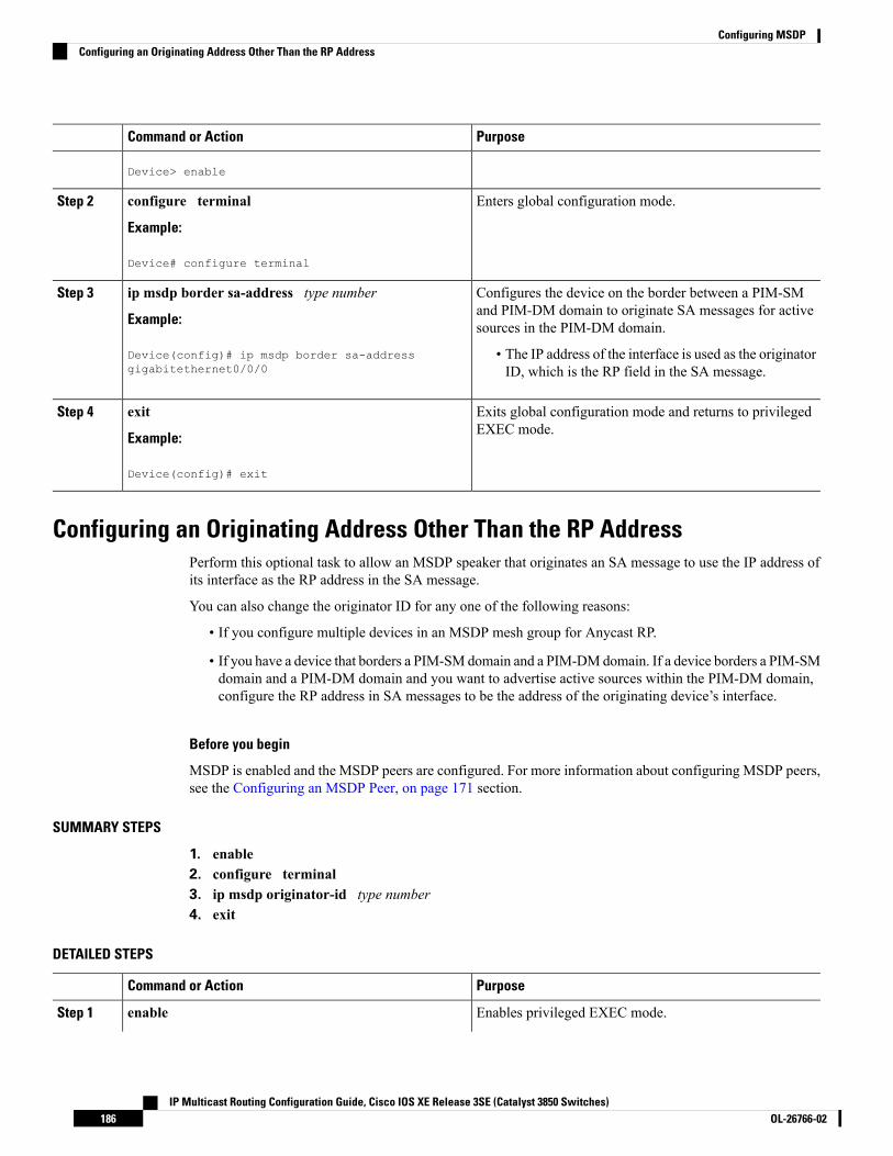
PurposeCommand or Action
Device> enable
Enters global configuration mode.configure terminal
Example:
Step 2
Device# configure terminal
Configures the device on the border between a PIM-SMand PIM-DM domain to originate SA messages for activesources in the PIM-DM domain.
ip msdp border sa-address type number
Example:
Device(config)# ip msdp border sa-addressgigabitethernet0/0/0
Step 3
• The IP address of the interface is used as the originatorID, which is the RP field in the SA message.
Exits global configuration mode and returns to privilegedEXEC mode.
exit
Example:
Step 4
Device(config)# exit
Configuring an Originating Address Other Than the RP AddressPerform this optional task to allow an MSDP speaker that originates an SA message to use the IP address ofits interface as the RP address in the SA message.
You can also change the originator ID for any one of the following reasons:
• If you configure multiple devices in an MSDP mesh group for Anycast RP.
• If you have a device that borders a PIM-SM domain and a PIM-DMdomain. If a device borders a PIM-SMdomain and a PIM-DM domain and you want to advertise active sources within the PIM-DM domain,configure the RP address in SA messages to be the address of the originating device’s interface.
Before you begin
MSDP is enabled and the MSDP peers are configured. For more information about configuring MSDP peers,see the Configuring an MSDP Peer, on page 171 section.
SUMMARY STEPS
1. enable2. configure terminal3. ip msdp originator-id type number4. exit
DETAILED STEPS
PurposeCommand or Action
Enables privileged EXEC mode.enableStep 1
IP Multicast Routing Configuration Guide, Cisco IOS XE Release 3SE (Catalyst 3850 Switches)OL-26766-02186
Configuring MSDPConfiguring an Originating Address Other Than the RP Address

PurposeCommand or Action
Example: • Enter your password if prompted.
Device> enable
Enters global configuration mode.configure terminal
Example:
Step 2
Device# configure terminal
Configures the RP address in SAmessages to be the addressof the originating device’s interface.
ip msdp originator-id type number
Example:
Step 3
Device(config)# ip msdp originator-id ethernet 1
Exits global configuration mode and returns to privilegedEXEC mode.
exit
Example:
Step 4
Device(config)# exit
Monitoring MSDPPerform this optional task to monitor MSDP SA messages, peers, state, and peer status.
SUMMARY STEPS
1. enable2. debug ip msdp [peer-address | peer-name] [detail] [routes]3. debug ip msdp resets4. show ip msdp count [as-number]5. show ip msdp peer [peer-address | peer-name]6. show ip msdp sa-cache [group-address | source-address | group-name | source-name] [as-number]7. show ip msdp summary
DETAILED STEPS
Step 1 enable
Example:
Device# enable
Enables privileged EXEC mode.
• Enter your password if prompted.
Step 2 debug ip msdp [peer-address | peer-name] [detail] [routes]
Use this command to debug MSDP activity.
IP Multicast Routing Configuration Guide, Cisco IOS XE Release 3SE (Catalyst 3850 Switches)187OL-26766-02
Configuring MSDPMonitoring MSDP

Use the optional peer-address or peer-name argument to specify for which peer debug events are logged.
The following is sample output from the debug ip msdp command:
Example:
Device# debug ip msdpMSDP debugging is onDevice#MSDP: 224.150.44.254: Received 1388-byte message from peerMSDP: 224.150.44.254: SA TLV, len: 1388, ec: 115, RP: 172.31.3.92MSDP: 224.150.44.254: Peer RPF check passed for 172.31.3.92, used EMBGP peerMSDP: 224.150.44.250: Forward 1388-byte SA to peerMSDP: 224.150.44.254: Received 1028-byte message from peerMSDP: 224.150.44.254: SA TLV, len: 1028, ec: 85, RP: 172.31.3.92MSDP: 224.150.44.254: Peer RPF check passed for 172.31.3.92, used EMBGP peerMSDP: 224.150.44.250: Forward 1028-byte SA to peerMSDP: 224.150.44.254: Received 1388-byte message from peerMSDP: 224.150.44.254: SA TLV, len: 1388, ec: 115, RP: 172.31.3.111MSDP: 224.150.44.254: Peer RPF check passed for 172.31.3.111, used EMBGP peerMSDP: 224.150.44.250: Forward 1388-byte SA to peerMSDP: 224.150.44.250: Received 56-byte message from peerMSDP: 224.150.44.250: SA TLV, len: 56, ec: 4, RP: 192.168.76.241MSDP: 224.150.44.250: Peer RPF check passed for 192.168.76.241, used EMBGP peerMSDP: 224.150.44.254: Forward 56-byte SA to peerMSDP: 224.150.44.254: Received 116-byte message from peerMSDP: 224.150.44.254: SA TLV, len: 116, ec: 9, RP: 172.31.3.111MSDP: 224.150.44.254: Peer RPF check passed for 172.31.3.111, used EMBGP peerMSDP: 224.150.44.250: Forward 116-byte SA to peerMSDP: 224.150.44.254: Received 32-byte message from peerMSDP: 224.150.44.254: SA TLV, len: 32, ec: 2, RP: 172.31.3.78MSDP: 224.150.44.254: Peer RPF check passed for 172.31.3.78, used EMBGP peerMSDP: 224.150.44.250: Forward 32-byte SA to peer
Step 3 debug ip msdp resets
Use this command to debug MSDP peer reset reasons.
Example:
Device# debug ip msdp resets
Step 4 show ip msdp count [as-number]
Use this command to display the number of sources and groups originated in MSDP SA messages and the number of SAmessages from an MSDP peer in the SA cache. The ip msdp cache-sa-state command must be configured for thiscommand to produce any output.
The following is sample output from the show ip msdp countcommand:
Example:
Device# show ip msdp countSA State per Peer Counters, <Peer>: <# SA learned>
192.168.4.4: 8SA State per ASN Counters, <asn>: <# sources>/<# groups>
Total entries: 8?: 8/8
Step 5 show ip msdp peer [peer-address | peer-name]
Use this command to display detailed information about MSDP peers.
IP Multicast Routing Configuration Guide, Cisco IOS XE Release 3SE (Catalyst 3850 Switches)OL-26766-02188
Configuring MSDPMonitoring MSDP

Use the optional peer-address or peer-name argument to display information about a particular peer.
The following is sample output from the show ip msdp peercommand:
Example:
Device# show ip msdp peer 192.168.4.4MSDP Peer 192.168.4.4 (?), AS 64512 (configured AS)Connection status:State: Up, Resets: 0, Connection source: Loopback0 (2.2.2.2)Uptime(Downtime): 00:07:55, Messages sent/received: 8/18Output messages discarded: 0Connection and counters cleared 00:08:55 ago
SA Filtering:Input (S,G) filter: none, route-map: noneInput RP filter: none, route-map: noneOutput (S,G) filter: none, route-map: noneOutput RP filter: none, route-map: none
SA-Requests:Input filter: none
Peer ttl threshold: 0SAs learned from this peer: 8Input queue size: 0, Output queue size: 0MD5 signature protection on MSDP TCP connection: not enabled
Step 6 show ip msdp sa-cache [group-address | source-address | group-name | source-name] [as-number]
Use this command to display the (S, G) state learned from MSDP peers.
The following is sample output from the show ip msdp sa-cachecommand:
Example:
Device# show ip msdp sa-cacheMSDP Source-Active Cache - 8 entries(10.44.44.5, 239.232.1.0), RP 192.168.4.4, BGP/AS 64512, 00:01:20/00:05:32, Peer 192.168.4.4(10.44.44.5, 239.232.1.1), RP 192.168.4.4, BGP/AS 64512, 00:01:20/00:05:32, Peer 192.168.4.4(10.44.44.5, 239.232.1.2), RP 192.168.4.4, BGP/AS 64512, 00:01:19/00:05:32, Peer 192.168.4.4(10.44.44.5, 239.232.1.3), RP 192.168.4.4, BGP/AS 64512, 00:01:19/00:05:32, Peer 192.168.4.4(10.44.44.5, 239.232.1.4), RP 192.168.4.4, BGP/AS 64512, 00:01:19/00:05:32, Peer 192.168.4.4(10.44.44.5, 239.232.1.5), RP 192.168.4.4, BGP/AS 64512, 00:01:19/00:05:32, Peer 192.168.4.4(10.44.44.5, 239.232.1.6), RP 192.168.4.4, BGP/AS 64512, 00:01:19/00:05:32, Peer 192.168.4.4(10.44.44.5, 239.232.1.7), RP 192.168.4.4, BGP/AS 64512, 00:01:19/00:05:32, Peer 192.168.4.4
Step 7 show ip msdp summary
Use this command to display MSDP peer status.
The following is sample output from the show ip msdp summary command:
Example:
Device# show ip msdp summaryMSDP Peer Status SummaryPeer Address AS State Uptime/ Reset SA Peer Name
Downtime Count Count192.168.4.4 4 Up 00:08:05 0 8 ?
IP Multicast Routing Configuration Guide, Cisco IOS XE Release 3SE (Catalyst 3850 Switches)189OL-26766-02
Configuring MSDPMonitoring MSDP

Clearing MSDP Connections Statistics and SA Cache EntriesPerform this optional task to clear MSDP connections, statistics, and SA cache entries.
SUMMARY STEPS
1. enable2. clear ip msdp peer [peer-address | peer-name]3. clear ip msdp statistics [peer-address | peer-name]4. clear ip msdp sa-cache [group-address]
DETAILED STEPS
PurposeCommand or Action
Enables privileged EXEC mode.enableStep 1
Example: • Enter your password if prompted.
Device> enable
Clears the TCP connection to the specifiedMSDP peer andresets all MSDP message counters.
clear ip msdp peer [peer-address | peer-name]
Example:
Step 2
Device# clear ip msdp peer
Clears the statistics counters for the specified MSDP peerand resets all MSDP message counters.
clear ip msdp statistics [peer-address | peer-name]
Example:
Step 3
Device# clear ip msdp statistics
Clears SA cache entries.clear ip msdp sa-cache [group-address]Step 4
Example: • If the clear ip msdp sa-cache is specified with theoptional group-address argument or
Device# clear ip msdp sa-cache source-addressargument, all SA cache entries arecleared.
• Use the optional group-address argument to clear allSA cache entries associated with a specific group.
Enabling SNMP Monitoring of MSDPPerform this optional task to enable Simple Network Management Protocol (SNMP) monitoring of MSDP.
Before you begin
• SNMP and MSDP is configured on your devices.
• In each PIM-SM domain there should be a device that is configured as the MSDP speaker. This devicemust have SNMP and the MSDP MIB enabled.
IP Multicast Routing Configuration Guide, Cisco IOS XE Release 3SE (Catalyst 3850 Switches)OL-26766-02190
Configuring MSDPClearing MSDP Connections Statistics and SA Cache Entries

• All MSDP-MIB objects are implemented as read-only.• The Requests table is not supported in Cisco’s implementation of the MSDP MIB.• The msdpEstablished notification is not supported in Cisco’s implementation of the MSDP MIB.
Note
SUMMARY STEPS
1. enable2. snmp-server enable traps msdp3. snmp-server host host [traps | informs] [version {1 | 2c | 3 [auth| priv | noauth]}] community-string
[udp-port port-number] msdp4. exit
DETAILED STEPS
PurposeCommand or Action
Enables privileged EXEC mode.enableStep 1
Example: • Enter your password if prompted.
Device> enable
Enables the sending of MSDP notifications for use withSNMP.
snmp-server enable traps msdp
Example:
Step 2
The snmp-server enable trapsmsdp commandenables both traps and informs.
NoteDevice# snmp-server enable traps msdp
Specifies the recipient (host) for MSDP traps or informs.snmp-server host host [traps | informs] [version {1 |2c | 3 [auth| priv | noauth]}] community-string [udp-portport-number] msdp
Step 3
Example:
Device# snmp-server host examplehost msdp
Exits global configuration mode and returns to privilegedEXEC mode.
exit
Example:
Step 4
Device(config)# exit
Troubleshooting TipsYou can compare the results of MSDP MIB notifications to the output from the software by using the showip msdp summary and show ip msdp peer commands on the appropriate device. You can also compare theresults of these commands to the results from SNMP Get operations. You can verify SA cache table entriesusing the show ipmsdp sa-cache command. Additional troubleshooting information, such as the local addressof the connection, the local port, and the remote port, can be obtained using the output from the debug ipmsdp command.
IP Multicast Routing Configuration Guide, Cisco IOS XE Release 3SE (Catalyst 3850 Switches)191OL-26766-02
Configuring MSDPTroubleshooting Tips
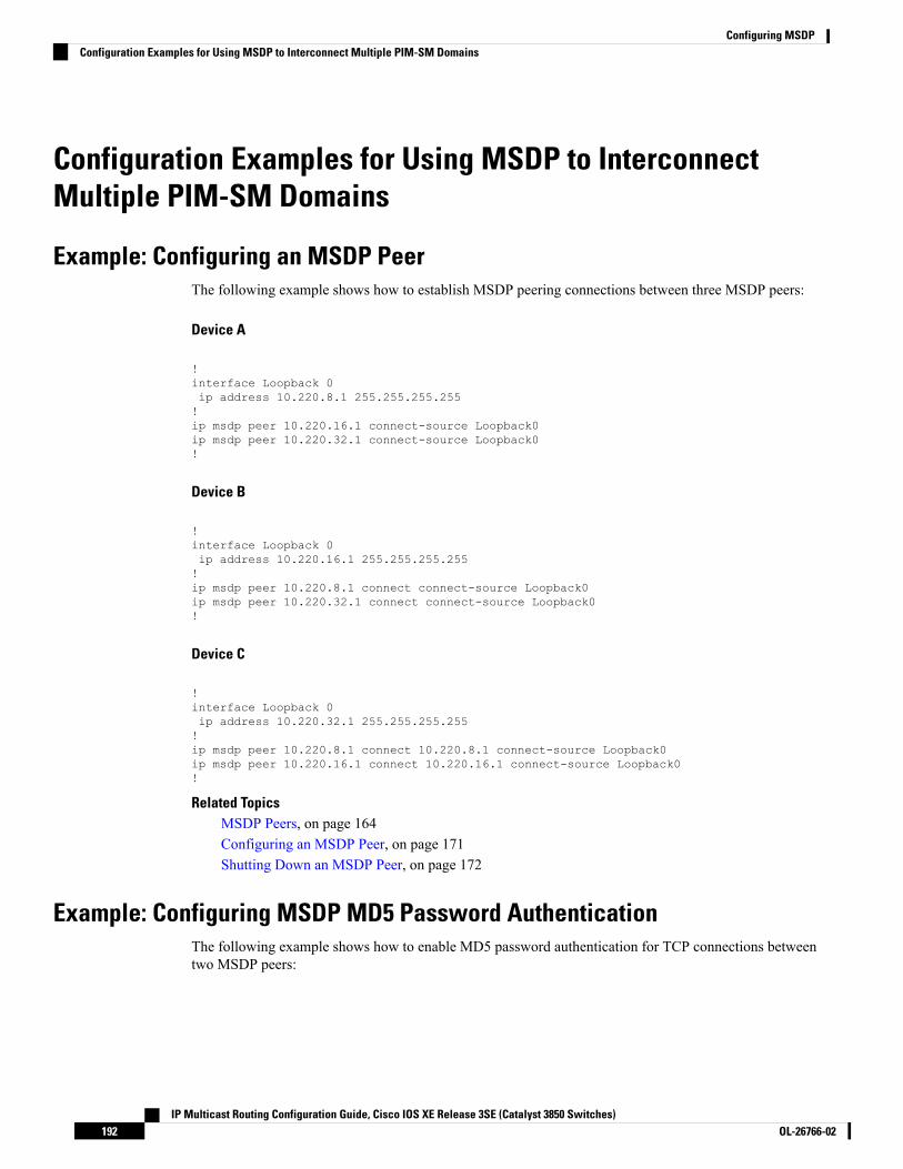
Configuration Examples for Using MSDP to InterconnectMultiple PIM-SM Domains
Example: Configuring an MSDP PeerThe following example shows how to establish MSDP peering connections between three MSDP peers:
Device A
!interface Loopback 0ip address 10.220.8.1 255.255.255.255!ip msdp peer 10.220.16.1 connect-source Loopback0ip msdp peer 10.220.32.1 connect-source Loopback0!
Device B
!interface Loopback 0ip address 10.220.16.1 255.255.255.255!ip msdp peer 10.220.8.1 connect connect-source Loopback0ip msdp peer 10.220.32.1 connect connect-source Loopback0!
Device C
!interface Loopback 0ip address 10.220.32.1 255.255.255.255!ip msdp peer 10.220.8.1 connect 10.220.8.1 connect-source Loopback0ip msdp peer 10.220.16.1 connect 10.220.16.1 connect-source Loopback0!
Related TopicsMSDP Peers, on page 164Configuring an MSDP Peer, on page 171Shutting Down an MSDP Peer, on page 172
Example: Configuring MSDP MD5 Password AuthenticationThe following example shows how to enable MD5 password authentication for TCP connections betweentwo MSDP peers:
IP Multicast Routing Configuration Guide, Cisco IOS XE Release 3SE (Catalyst 3850 Switches)OL-26766-02192
Configuring MSDPConfiguration Examples for Using MSDP to Interconnect Multiple PIM-SM Domains

Device A
!ip msdp peer 10.3.32.154ip msdp password peer 10.3.32.154 0 test!
Device B
!ip msdp peer 10.3.32.153ip msdp password peer 10.3.32.153 0 test!
Related TopicsConfiguring MSDP MD5 Password Authentication Between MSDP Peers, on page 173MSDP MD5 Password Authentication, on page 164
Example: Configuring a Default MSDP PeerThe figure illustrates a scenario where default MSDP peers might be used. In the figure, a customer that ownsDevice B is connected to the internet through two ISPs, one that owns Device A and the other that ownsDevice C. They are not running (M)BGP between them. In order for the customer to learn about sources inthe ISP domain or in other domains, Device B identifies Device A as its default MSDP peer. Device Badvertises SA messages to both Device A and Device C, but accepts SA messages either from Device A onlyor Device C only. If Device A is the first default peer in the configuration, it will be used if it is up and running.Only if Device A is not running will Device B accept SA messages from Device C.
The ISP will also likely use a prefix list to define which prefixes it will accept from the customer device. Thecustomer will define multiple default peers, each having one or more prefixes associated with it.
The customer has two ISPs to use. The customer defines both ISPs as default peers. As long as the first defaultpeer identified in the configuration is up and running, it will be the default peer and the customer will acceptall SA messages it receives from that peer.
Although the following illustration and example uses routers in the configuration, any device (router or switch)can be used.
Note
IP Multicast Routing Configuration Guide, Cisco IOS XE Release 3SE (Catalyst 3850 Switches)193OL-26766-02
Configuring MSDPExample: Configuring a Default MSDP Peer

Figure 9: Default MSDP Peer Scenario
Device B advertises SAs to Device A andDevice C, but uses only Device A or Device C to accept SAmessages.If Device A is first in the configuration file, it will be used if it is up and running. Only when Device A is notrunning will Device B accept SAs from Device C. This is the behavior without a prefix list.
If you specify a prefix list, the peer will be a default peer only for the prefixes in the list. You can have multipleactive default peers when you have a prefix list associated with each. When you do not have any prefix lists,you can configure multiple default peers, but only the first one is the active default peer as long as the devicehas connectivity to this peer and the peer is alive. If the first configured peer goes down or the connectivityto this peer goes down, the second configured peer becomes the active default, and so on.
The following example shows a partial configuration of Device A and Device C in the figure. Each of theseISPs may have more than one customer using default peering, like the customer in the figure. In that case,they may have similar configurations. That is, they will only accept SAs from a default peer if the SA ispermitted by the corresponding prefix list.
Device A Configuration
ip msdp default-peer 10.1.1.1ip msdp default-peer 10.1.1.1 prefix-list site-b ge 32ip prefix-list site-b permit 10.0.0.0/8
Device C Configuration
ip msdp default-peer 10.1.1.1 prefix-list site-b ge 32ip prefix-list site-b permit 10.0.0.0/8
Related TopicsConfiguring a Default MSDP Peer, on page 178Default MSDP Peers, on page 166
IP Multicast Routing Configuration Guide, Cisco IOS XE Release 3SE (Catalyst 3850 Switches)OL-26766-02194
Configuring MSDPExample: Configuring a Default MSDP Peer

Example: Configuring MSDP Mesh GroupsThe following example shows how to configure three devices to be fully meshed members of an MSDP meshgroup:
Device A Configuration
ip msdp peer 10.2.2.2ip msdp peer 10.3.3.3ip msdp mesh-group test-mesh-group 10.2.2.2ip msdp mesh-group test-mesh-group 10.3.3.3
Device B Configuration
ip msdp peer 10.1.1.1ip msdp peer 10.3.3.3ip msdp mesh-group test-mesh-group 10.1.1.1ip msdp mesh-group test-mesh-group 10.3.3.3
Device C Configuration
ip msdp peer 10.1.1.1ip msdp peer 10.2.2.2ip msdp mesh-group test-mesh-group 10.1.1.1ip msdp mesh-group test-mesh-group 10.2.2.2
Related TopicsConfiguring an MSDP Mesh Group, on page 179MSDP Mesh Groups, on page 167
Where to Go Next for MSDPYou can configure the following:
• IGMP
• PIM
• SSM
• IP Multicast Routing
• Service Discovery Gateway
You can also review the following IP Multicast Optimization processes for your configuration:
• Optimizing PIM Sparse Mode in a Large IP Multicast Deployment
• Multicast Subsecond Convergence
• IP Multicast Load Splitting across Equal-Cost Paths
• SSM Channel Based Filtering for Multicast
• PIM Dense Mode State Refresh
IP Multicast Routing Configuration Guide, Cisco IOS XE Release 3SE (Catalyst 3850 Switches)195OL-26766-02
Configuring MSDPExample: Configuring MSDP Mesh Groups

• IGMP State Limit
Additional ReferencesRelated Documents
Document TitleRelated Topic
IPv6 Configuration GuideIPv6 addressing and connectivity
Cisco IOSMaster Commands List, All ReleasesCisco IOS commands
Cisco IOS IP Multicast Command ReferenceIP multicast commands
Cisco IOS IPv6 Command ReferenceIPv6 commands
Cisco IOS IPv6 Feature MappingCisco IOS IPv6 features
Standards and RFCs
TitleStandard/RFC
IPv6RFCs
RFCs forIPv6
MIBs
MIBs LinkMIB
To locate and download MIBs for selected platforms, Cisco IOS releases, and feature sets, use CiscoMIB Locator found at the following URL:
http://www.cisco.com/go/mibs
Technical Assistance
LinkDescription
http://www.cisco.com/cisco/web/support/index.htmlTheCisco Support andDocumentationwebsite providesonline resources to download documentation, software,and tools. Use these resources to install and configurethe software and to troubleshoot and resolve technicalissues with Cisco products and technologies. Access tomost tools on the Cisco Support and Documentationwebsite requires a Cisco.com user ID and password.
IP Multicast Routing Configuration Guide, Cisco IOS XE Release 3SE (Catalyst 3850 Switches)OL-26766-02196
Configuring MSDPAdditional References

Feature History and Information for Multicast Source DiscoveryProtocol
ModificationRelease
This feature was introduced.Cisco IOS XE 3.2SE
IP Multicast Routing Configuration Guide, Cisco IOS XE Release 3SE (Catalyst 3850 Switches)197OL-26766-02
Configuring MSDPFeature History and Information for Multicast Source Discovery Protocol

IP Multicast Routing Configuration Guide, Cisco IOS XE Release 3SE (Catalyst 3850 Switches)OL-26766-02198
Configuring MSDPFeature History and Information for Multicast Source Discovery Protocol

C H A P T E R 9Configuring Wireless Multicast
• Finding Feature Information, on page 199• Prerequisites for Configuring Wireless Multicast, on page 199• Restrictions on Configuring Wireless Multicast, on page 200• Information About Wireless Multicast, on page 200• How to Configure Wireless Multicast, on page 204• Verifying Wireless Multicast, on page 212• Where to Go Next for Wireless Multicast, on page 212• Additional References, on page 213
Finding Feature InformationYour software release may not support all the features documented in this module. For the latest caveats andfeature information, see Bug Search Tool and the release notes for your platform and software release. Tofind information about the features documented in this module, and to see a list of the releases in which eachfeature is supported, see the feature information table at the end of this module.
Use Cisco Feature Navigator to find information about platform support and Cisco software image support.To access Cisco Feature Navigator, go to http://www.cisco.com/go/cfn. An account on Cisco.com is notrequired.
Prerequisites for Configuring Wireless Multicast• IP multicast routingmust be enabled and the PIM version and PIMmodemust be configured. The defaultroutes should be available in the device. After performing these tasks, the device can forward multicastpackets and populate its multicast routing table.
• To participate in IP multicasting, the multicast hosts, routers, and multilayer switches must have IGMPoperating.
• When enabling multicast mode on the device, a CAPWAP multicast group address should also beconfigured. Access points listen to the CAPWAP multicast group using IGMP.
IP Multicast Routing Configuration Guide, Cisco IOS XE Release 3SE (Catalyst 3850 Switches)199OL-26766-02

Restrictions on Configuring Wireless MulticastThe following are the restrictions for configuring IP multicast routing:
• Access points in monitor mode, sniffer mode, or rogue-detector mode do not join the CAPWAPmulticastgroup address.
• The CAPWAPmulticast group configured on the controllers should be different for different controllers.
• Multicast routing should not be enabled for the management interface.
Restrictions for IPv6 SnoopingThe IPv6 snooping feature is not supported on Etherchannel ports.
Restrictions for IPv6 RA Guard• The IPv6 RA Guard feature does not offer protection in environments where IPv6 traffic is tunneled.
• This feature is supported only in hardware when the ternary content addressable memory (TCAM) isprogrammed.
• This feature can be configured on a switch port interface in the ingress direction.
• This feature supports host mode and router mode.
• This feature is supported only in the ingress direction; it is not supported in the egress direction.
• This feature is not supported on EtherChannel and EtherChannel port members.
• This feature is not supported on trunk ports with merge mode.
• This feature is supported on auxiliary VLANs and private VLANs (PVLANs). In the case of PVLANs,primary VLAN features are inherited and merged with port features.
• Packets dropped by the IPv6 RA Guard feature can be spanned.
• If the platform ipv6 acl icmp optimize neighbor-discovery command is configured, the IPv6 RAGuard feature cannot be configured and an error message will be displayed. This command adds defaultglobal Internet Control Message Protocol (ICMP) entries that will override the RA guard ICMP entries.
Information About Wireless MulticastIf the network supports packet multicasting, the multicast method that the device uses can be configured. Thedevice performs multicasting in two modes:
• Unicast mode—The device unicasts every multicast packet to every access point associated to the device.This mode is inefficient, but is required on networks that do not support multicasting.
IP Multicast Routing Configuration Guide, Cisco IOS XE Release 3SE (Catalyst 3850 Switches)OL-26766-02200
Configuring Wireless MulticastRestrictions on Configuring Wireless Multicast
• Multicast mode—The device sendsmulticast packets to a CAPWAPmulticast group. This method reducesthe overhead on the device processor and shifts the work of packet replication to the network, which ismuch more efficient than the unicast method.
The flexconnect mode has two submodes: local switching and central switching. In local switching mode, thedata traffic is switched at the AP level and the controller does not see anymulticast traffic. In central switchingmode, the multicast traffic reaches the controller. However, IGMP snooping takes place at the AP.
When the multicast mode is enabled and the device receives a multicast packet from the wired LAN, thedevice encapsulates the packet using CAPWAP and forwards the packet to the CAPWAP multicast groupaddress. The device always uses the management VLAN for sending multicast packets. Access points in themulticast group receive the packet and forward it to all the BSSIDs mapped to the VLAN on which clientsreceive multicast traffic.
The device supports all the capabilities of IGMP v1, including Multicast Listener Discovery (MLD) v1snooping, but the IGMP v2 and IGMP v3 capabilities are limited. This feature keeps track of and deliversIPv6 multicast flows to the clients that request them. To support IPv6 multicast, global multicast mode shouldbe enabled.
Internet GroupManagement Protocol (IGMP) snooping is introduced to better direct multicast packets. Whenthis feature is enabled, the device snooping gathers IGMP reports from the clients, processes them, createsunique multicast group IDs (MGIDs) based on the Layer 3 multicast address and the VLAN number, andsends the IGMP reports to the IGMP querier. The device then updates the access-point MGID table on thecorresponding access point with the client MAC address. When the device receives multicast traffic for aparticular multicast group, it forwards it to all the access points, but only those access points that have activeclients listening or subscribed to that multicast group send multicast traffic on that particular WLAN. IPpackets are forwarded with an MGID that is unique for an ingress VLAN and the destination multicast group.Layer 2 multicast packets are forwarded with an MGID that is unique for the ingress VLAN.
MGID is a 14-bit value filled in the 16-bit reserved field of wireless information in the CAPWAP header.The remaining two bits should be set to zero.
Related TopicsConfiguring Wireless Multicast-MCMC Mode (CLI), on page 204Configuring Wireless Multicast-MCUC Mode (CLI), on page 205
Multicast OptimizationMulticast used to be based on the group of the multicast addresses and the VLAN as one entity, MGID. Withthe VLAN group, duplicate packets might increase. Using the VLAN group feature, every client listens tothe multicast stream on a different VLAN. As a result, the device creates different MGIDs for each multicastaddress and the VLAN. Therefore, the upstream router sends a copy for each VLAN, which results in as manycopies as the number of VLANs in the group. Because theWLAN remains the same for all the clients, multiplecopies of the multicast packet are sent over the wireless network. To suppress the duplication of a multicaststream on the wireless medium between the device and the access points, the multicast optimization featurecan be used.
Multicast optimization enables you to create a multicast VLAN that can be used for multicast traffic. One ofthe VLANs in the device can be configured as a multicast VLAN where multicast groups are registered. Theclients are allowed to listen to a multicast stream on the multicast VLAN. The MGID is generated using themulicast VLAN and multicast IP addresses. If multiple clients on different VLANs of the same WLAN arelistening to a single multicast IP address, a single MGID is generated. The device makes sure that all themulticast streams from the clients on this VLAN group always go out on the multicast VLAN to ensure that
IP Multicast Routing Configuration Guide, Cisco IOS XE Release 3SE (Catalyst 3850 Switches)201OL-26766-02
Configuring Wireless MulticastMulticast Optimization

the upstream router has one entry for all the VLANs of the VLAN group. Only one multicast stream hits theVLAN group even if the clients are on different VLANs. Therefore, the multicast packets that are sent outover the network is just one stream.
Related TopicsConfiguring IP Multicast VLAN for WLAN (CLI), on page 211
IPv6 Global PoliciesIPv6 global policies provide storage and access policy database services. IPv6 ND inspection and IPv6 RAguard are IPv6 global policies features. Every time an ND inspection or RA guard is configured globally, thepolicy attributes are stored in the software policy database. The policy is then applied to an interface, and thesoftware policy database entry is updated to include this interface to which the policy is applied.
IPv6 RA GuardThe IPv6 RAGuard feature provides support for allowing the network administrator to block or reject unwantedor rogue RA guard messages that arrive at the network device platform. RAs are used by devices to announcethemselves on the link. The IPv6 RA Guard feature analyzes these RAs and filters out RAs that are sent byunauthorized devices. In host mode, all RA and router redirect messages are disallowed on the port. The RAguard feature compares configuration information on the Layer 2 (L2) device with the information found inthe received RA frame. Once the L2 device has validated the content of the RA frame and router redirectframe against the configuration, it forwards the RA to its unicast or multicast destination. If the RA framecontent is not validated, the RA is dropped.
In the wireless deployment RAs coming on wireless ports are dropped as routers cannot reside on theseinterfaces.
Information About IPv6 Snooping
IPv6 Neighbor Discovery InspectionThe IPv6 Neighbor Discovery Inspection, or IPv6 "snooping," feature bundles several Layer 2 IPv6 first-hopsecurity features, including IPv6 Address Glean and IPv6 Device Tracking. IPv6 neighbor discovery (ND)inspection operates at Layer 2, or between Layer 2 and Layer 3, and provides IPv6 features with security andscalability. This feature mitigates some of the inherent vulnerabilities for the neighbor discovery mechanism,such as attacks on duplicate address detection (DAD), address resolution, device discovery, and the neighborcache.
IPv6 ND inspection learns and secures bindings for stateless autoconfiguration addresses in Layer 2 neighbortables and analyzes NDmessages in order to build a trusted binding table. IPv6 NDmessages that do not havevalid bindings are dropped. AnNDmessage is considered trustworthy if its IPv6-to-MACmapping is verifiable.This feature mitigates some of the inherent vulnerabilities for the neighbor discovery mechanism, such asattacks on duplicate address detection (DAD), address resolution, device discovery, and the neighbor cache.
When IPv6 ND inspection is configured on a target (which varies depending on platform target support andmay include device ports, switch ports, Layer 2 interfaces, Layer 3 interfaces, and VLANs), capture instructionsare downloaded to the hardware to redirect the ND protocol and Dynamic Host Configuration Protocol (DHCP)for IPv6 traffic up to the switch integrated security features (SISF) infrastructure in the routing device. ForND traffic, messages such as NS, NA, RS, RA, and REDIRECT are directed to SISF. For DHCP, UDPmessages sourced from port 546 or 547 are redirected.
IP Multicast Routing Configuration Guide, Cisco IOS XE Release 3SE (Catalyst 3850 Switches)OL-26766-02202
Configuring Wireless MulticastIPv6 Global Policies

IPv6 ND inspection registers its "capture rules" to the classifier, which aggregates all rules from all featureson a given target and installs the corresponding ACL down into the platform-dependent modules. Uponreceiving redirected traffic, the classifier calls all entry points from any registered feature (for the target onwhich the traffic is being received), including the IPv6 ND inspection entry point. This entry point is the lastto be called, so any decision (such as drop) made by another feature supersedes the IPv6 ND inspectiondecision.
IPv6 ND Inspection
IPv6 ND inspection learns and secures bindings for stateless autoconfiguration addresses in Layer 2 neighbortables. IPv6 ND inspection analyzes neighbor discovery messages in order to build a trusted binding tabledatabase, and IPv6 neighbor discovery messages that do not have valid bindings are dropped. A neighbordiscovery message is considered trustworthy if its IPv6-to-MAC mapping is verifiable.
This feature mitigates some of the inherent vulnerabilities for the neighbor discovery mechanism, such asattacks on duplicate address detection (DAD), address resolution, device discovery, and the neighbor cache.
IPv6 Device Tracking
IPv6 device tracking provides IPv6 host liveness tracking so that a neighbor table can be immediately updatedwhen an IPv6 host disappears.
IPv6 First-Hop Security Binding Table
The IPv6 First-Hop Security Binding Table recovery mechanism feature enables the binding table to recoverin the event of a device reboot. A database table of IPv6 neighbors connected to the device is created frominformation sources such as ND snooping. This database, or binding, table is used by various IPv6 guardfeatures to validate the link-layer address (LLA), the IPv4 or IPv6 address, and prefix binding of the neighborsto prevent spoofing and redirect attacks.
This mechanism enables the binding table to recover in the event of a device reboot. The recovery mechanismwill block any data traffic sourced from an unknown source; that is, a source not already specified in thebinding table and previously learned through ND or DHCP gleaning. This feature recovers the missing bindingtable entries when the resolution for a destination address fails in the destination guard.When a failure occurs,a binding table entry is recovered by querying the DHCP server or the destination host, depending on theconfiguration.
Recovery Protocols and Prefix Lists
The IPv6 First-Hop Security Binding Table Recovery Mechanism feature introduces the capability to providea prefix list that is matched before the recovery is attempted for both DHCP and NDP.
If an address does not match the prefix list associated with the protocol, then the recovery of the binding tableentry will not be attempted with that protocol. The prefix list should correspond to the prefixes that are validfor address assignment in the Layer 2 domain using the protocol. The default is that there is no prefix list, inwhich case the recovery is attempted for all addresses. The command to associate a prefix list to a protocolis protocol {dhcp | ndp} [prefix-list prefix-list-name].
IPv6 Device Tracking
IPv6 device tracking provides IPv6 host liveness tracking so that a neighbor table can be immediately updatedwhen an IPv6 host disappears.
IP Multicast Routing Configuration Guide, Cisco IOS XE Release 3SE (Catalyst 3850 Switches)203OL-26766-02
Configuring Wireless MulticastIPv6 ND Inspection

IPv6 Address Glean
IPv6 address glean is the foundation for many other IPv6 features that depend on an accurate binding table.It inspects ND and DHCP messages on a link to glean addresses, and then populates the binding table withthese addresses. This feature also enforces address ownership and limits the number of addresses any givennode is allowed to claim.
The following figure shows how IPv6 address glean works.Figure 10: IPv6 Address Glean
How to Configure Wireless Multicast
Configuring Wireless Multicast-MCMC Mode (CLI)
SUMMARY STEPS
1. enable
IP Multicast Routing Configuration Guide, Cisco IOS XE Release 3SE (Catalyst 3850 Switches)OL-26766-02204
Configuring Wireless MulticastIPv6 Address Glean

2. configure terminal3. wireless multicast4. end
DETAILED STEPS
PurposeCommand or Action
Enables privileged EXEC mode.enableStep 1
Example: Enter your password, if prompted.
Device> enable
Enters global configuration mode.configure terminal
Example:
Step 2
Device# configure terminal
Enables multicast traffic for wireless clients. By default,multicast traffic is in disabled state. Use the no form of thiscommand to disable the multicast traffic for wireless clients.
wireless multicast
Example:Device(config)# wireless multicast
Device(config)# no wireless multicast
Step 3
Exits configuration mode. Alternatively, press Ctrl-Z toexit configuration mode.
end
Example:
Step 4
Device(config)# end
Related TopicsInformation About Wireless Multicast, on page 200
Configuring Wireless Multicast-MCUC Mode (CLI)
SUMMARY STEPS
1. enable2. configure terminal3. wireless multicast4. end
DETAILED STEPS
PurposeCommand or Action
Enables privileged EXEC mode.enableStep 1
Example: Enter your password, if prompted.
IP Multicast Routing Configuration Guide, Cisco IOS XE Release 3SE (Catalyst 3850 Switches)205OL-26766-02
Configuring Wireless MulticastConfiguring Wireless Multicast-MCUC Mode (CLI)
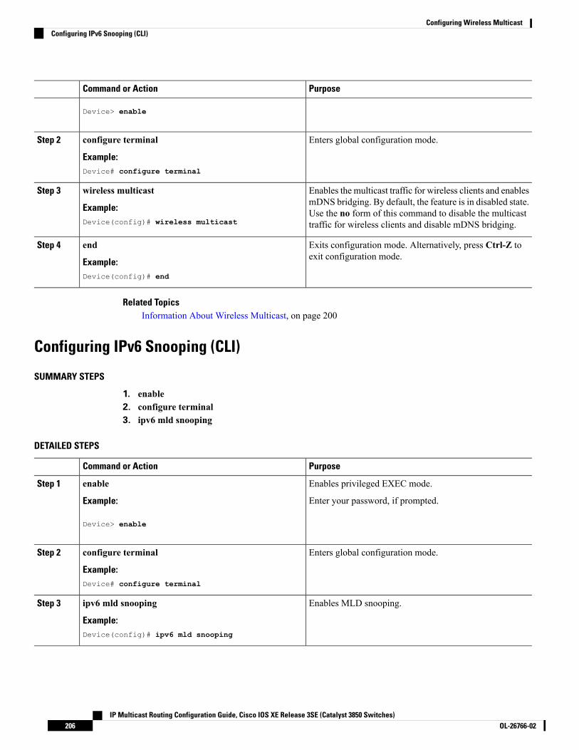
PurposeCommand or Action
Device> enable
Enters global configuration mode.configure terminal
Example:
Step 2
Device# configure terminal
Enables the multicast traffic for wireless clients and enablesmDNS bridging. By default, the feature is in disabled state.
wireless multicast
Example:
Step 3
Use the no form of this command to disable the multicasttraffic for wireless clients and disable mDNS bridging.Device(config)# wireless multicast
Exits configuration mode. Alternatively, press Ctrl-Z toexit configuration mode.
end
Example:
Step 4
Device(config)# end
Related TopicsInformation About Wireless Multicast, on page 200
Configuring IPv6 Snooping (CLI)
SUMMARY STEPS
1. enable2. configure terminal3. ipv6 mld snooping
DETAILED STEPS
PurposeCommand or Action
Enables privileged EXEC mode.enableStep 1
Example: Enter your password, if prompted.
Device> enable
Enters global configuration mode.configure terminal
Example:
Step 2
Device# configure terminal
Enables MLD snooping.ipv6 mld snooping
Example:
Step 3
Device(config)# ipv6 mld snooping
IP Multicast Routing Configuration Guide, Cisco IOS XE Release 3SE (Catalyst 3850 Switches)OL-26766-02206
Configuring Wireless MulticastConfiguring IPv6 Snooping (CLI)

Configuring IPv6 Snooping Policy (CLI)
SUMMARY STEPS
1. enable2. configure terminal3. ipv6 snooping policy policy-name4. security-level guard5. device-role node6. protocol {dhcp | ndp}
DETAILED STEPS
PurposeCommand or Action
Enables privileged EXEC mode.enableStep 1
Example: Enter your password, if prompted.
Device> enable
Enters global configuration mode.configure terminal
Example:
Step 2
Device# configure terminal
Configures an IPv6 snooping policy with a name.ipv6 snooping policy policy-name
Example:
Step 3
Device(config)# ipv6 snooping policy mypolicy
Configures the security level to inspect and dropunauthorized messages, if any.
security-level guard
Example:
Step 4
Device(config-ipv6-snooping)# security-level guard
Configures the role of the device, which is a node, to theattached port.
device-role node
Example:
Step 5
Device(config-ipv6-snooping)# device-role node
Sets the protocol to glean addresses in either the DHCP orthe NDP packets.
protocol {dhcp | ndp}
Example:
Step 6
Device(config-ipv6-snooping)# protocol ndp
Configuring Layer 2 Port as Multicast Router Port (CLI)
SUMMARY STEPS
1. enable
IP Multicast Routing Configuration Guide, Cisco IOS XE Release 3SE (Catalyst 3850 Switches)207OL-26766-02
Configuring Wireless MulticastConfiguring IPv6 Snooping Policy (CLI)

2. configure terminal3. ipv6 mld snooping vlan vlan-idmrouter interface Port-channel port-channel-interface-number
DETAILED STEPS
PurposeCommand or Action
Enables privileged EXEC mode.enableStep 1
Example: Enter your password, if prompted.
Device> enable
Enters global configuration mode.configure terminal
Example:
Step 2
Device# configure terminal
Configures a Layer 2 port as a Multicast router port. TheVLAN is the client VLAN.
ipv6 mld snooping vlan vlan-idmrouter interfacePort-channel port-channel-interface-number
Example:
Step 3
Device(config)# ipv6 mld snooping vlan 2 mrouterinterface Port-channel 22
Configuring IPv6 RA Guard (CLI)
SUMMARY STEPS
1. enable2. configure terminal3. ipv6 nd raguard policy policy-name4. trusted-port5. device-role {host |monitor | router | switch}
DETAILED STEPS
PurposeCommand or Action
Enables privileged EXEC mode.enableStep 1
Example: Enter your password, if prompted.
Device> enable
Enters global configuration mode.configure terminal
Example:
Step 2
Device# configure terminal
IP Multicast Routing Configuration Guide, Cisco IOS XE Release 3SE (Catalyst 3850 Switches)OL-26766-02208
Configuring Wireless MulticastConfiguring IPv6 RA Guard (CLI)

PurposeCommand or Action
Configures a policy for RA guard.ipv6 nd raguard policy policy-name
Example:
Step 3
Device(config)# ipv6 nd raguard policymyraguardpolicy
Sets up a trusted port.trusted-port
Example:
Step 4
Device(config-nd-raguard)# trusted-port
Sets the role of the device attached to the port.device-role {host |monitor | router | switch}
Example:
Step 5
Device(config-nd-raguard)# device-role router
Configuring Non-IP Wireless Multicast (CLI)
SUMMARY STEPS
1. enable2. configure terminal3. wireless multicast non-ip4. wireless multicast non-ip vlan vlanid5. end
DETAILED STEPS
PurposeCommand or Action
Enables privileged EXEC mode.enableStep 1
Example: Enter your password, if prompted.
Device> enable
Enters global configuration mode.configure terminal
Example:
Step 2
Device# configure terminal
Enables non-IP multicast in all the VLANs. By default, thenon-IP multicast in all the VLANs is in Disabled state.
wireless multicast non-ip
Example:
Step 3
Wireless multicast must be enabled for the traffic to pass.Device(config)# wireless multicast non-ip
Device(config)# no wireless multicast non-ip
Use the no form of this command to disable non-IPmulticast in all the VLANs.
Enables non-IP multicast per VLAN. By default, non-IPmulticast per VLAN is in Disabled state. Both wireless
wireless multicast non-ip vlan vlanid
Example:
Step 4
multicast and wireless multicast non-IP must be enabled
IP Multicast Routing Configuration Guide, Cisco IOS XE Release 3SE (Catalyst 3850 Switches)209OL-26766-02
Configuring Wireless MulticastConfiguring Non-IP Wireless Multicast (CLI)

PurposeCommand or ActionDevice(config)# wireless multicast non-ip vlan 5 for traffic to pass. Use the no form of this command to
disable non-IP multicast per VLAN.Device(config)# no wireless multicast non-ip vlan5
Exits configuration mode. Alternatively, press Ctrl-Z toexit configuration mode.
end
Example:
Step 5
Device(config)# end
Configuring Wireless Broadcast (CLI)
SUMMARY STEPS
1. enable2. configure terminal3. wireless broadcast4. wireless broadcast vlan vlanid5. end
DETAILED STEPS
PurposeCommand or Action
Enables privileged EXEC mode.enableStep 1
Example: Enter your password, if prompted.
Device> enable
Enters global configuration mode.configure terminal
Example:
Step 2
Device# configure terminal
Enables broadcast packets for wireless clients. By default,the broadcast packets for wireless clients is in Disabled
wireless broadcast
Example:
Step 3
state. Enablingwireless broadcast enables broadcast trafficDevice(config)# wireless broadcast
Device(config)# no wireless broadcast
for eachVLAN.Use the no form of this command to disablebroadcasting packets.
Enables broadcast packets for single VLAN. By default,the Broadcast Packets for a Single VLAN feature is in
wireless broadcast vlan vlanid
Example:
Step 4
Disabled state. Wireless broadcast must be enabled forDevice(config)# wireless broadcast vlan 3
Device(config)# no wireless broadcast vlan 3
broadcasting. Use the no form of this command to disablebroadcast traffic for each VLAN.
Exits configuration mode. Alternatively, press Ctrl-Z toexit configuration mode.
end
Example:
Step 5
IP Multicast Routing Configuration Guide, Cisco IOS XE Release 3SE (Catalyst 3850 Switches)OL-26766-02210
Configuring Wireless MulticastConfiguring Wireless Broadcast (CLI)

PurposeCommand or ActionDevice(config)# end
Configuring IP Multicast VLAN for WLAN (CLI)
SUMMARY STEPS
1. enable2. configure terminal3. wlan wlan_name4. shutdown5. ip multicast vlan {vlan_name vlan_id}6. no shutdown7. end
DETAILED STEPS
PurposeCommand or Action
Enables privileged EXEC mode.enableStep 1
Example: Enter your password, if prompted.
Device> enable
Enters global configuration mode.configure terminal
Example:
Step 2
Device# configure terminal
Enters configuration mode to configure various parametersin the WLAN.
wlan wlan_name
Example:
Step 3
Device(config)# wlan test 1
Disables WLAN.shutdown
Example:
Step 4
Device(config-wlan)# shutdown
Configures multicast VLAN for WLAN. Use the no formof this command to disable themulticast VLAN forWLAN.
ip multicast vlan {vlan_name vlan_id}
Example:
Step 5
Device(config-wlan)# ip multicast vlan 5
Device(config-wlan)# no ip multicast vlan 5
Enables the disabled WLAN.no shutdown
Example:
Step 6
IP Multicast Routing Configuration Guide, Cisco IOS XE Release 3SE (Catalyst 3850 Switches)211OL-26766-02
Configuring Wireless MulticastConfiguring IP Multicast VLAN for WLAN (CLI)

PurposeCommand or Action
Device(config-wlan)# no shutdown
Exits configuration mode. Alternatively, press Ctrl-Z toexit configuration mode.
end
Example:
Step 7
Device(config)# end
Related TopicsMulticast Optimization, on page 201
Verifying Wireless MulticastTable 19: Commands for Verifying Wireless Multicast
DescriptionCommand
Displays the multicast status and IP multicast mode, and eachVLAN's broadcast and non-IP multicast status. Also displaysthe Multicast Domain Name System (mDNS) bridging state.
show wireless multicast
Displays all (Group and VLAN) lists and the correspondingMGID values.
show wireless multicast group summary
Displays details of the specified (S,G,V) and shows all theclients associated with and their MC2UC status.
show wireless multicast [source source]group group vlan vlanid
Displays statistics of the number of multicast SPIs per MGIDsent between IOS and the Wireless Controller Module.
show ip igmp snooping wirelessmcast-spi-count
Displays the MGID mappings.show ip igmp snooping wireless mgid
Displays the client-to-SGV mappings and the SGV-to-clientmappings.
show ip igmp snooping igmpv2-tracking
Displays the IGMP querier information for the specifiedVLAN.
show ip igmp snooping querier vlan vlanid
Displays the detailed IGMP querier information of all theVLANs.
show ip igmp snooping querier detail
Displays theMLDquerier information for the specifiedVLAN.show ipv6 mld snooping querier vlanvlanid
Displays MGIDs for the IPv6 multicast group.show ipv6 mld snooping wireless mgid
Where to Go Next for Wireless MulticastYou can configure the following:
IP Multicast Routing Configuration Guide, Cisco IOS XE Release 3SE (Catalyst 3850 Switches)OL-26766-02212
Configuring Wireless MulticastVerifying Wireless Multicast

• IGMP
• PIM
• SSM
• IP Multicast Routing
• Service Discovery Gateway
You can also review the following IP Multicast Optimization processes for your configuration:
• Optimizing PIM Sparse Mode in a Large IP Multicast Deployment
• Multicast Subsecond Convergence
• IP Multicast Load Splitting across Equal-Cost Paths
• SSM Channel Based Filtering for Multicast
• PIM Dense Mode State Refresh
• IGMP State Limit
Additional ReferencesRelated Documents
Document TitleRelated Topic
IPMulticast Routing Command Reference (Catalyst3850 Switches)
For complete syntax and usage information for thecommands used in this chapter.
Error Message Decoder
LinkDescription
https://www.cisco.com/cgi-bin/Support/Errordecoder/index.cgiTo help you research and resolve systemerror messages in this release, use the ErrorMessage Decoder tool.
Standards and RFCs
TitleStandard/RFC
—
IP Multicast Routing Configuration Guide, Cisco IOS XE Release 3SE (Catalyst 3850 Switches)213OL-26766-02
Configuring Wireless MulticastAdditional References

MIBs
MIBs LinkMIB
To locate and downloadMIBs for selected platforms, Cisco IOS releases,and feature sets, use Cisco MIB Locator found at the following URL:
http://www.cisco.com/go/mibs
All the supported MIBs for thisrelease.
Technical Assistance
LinkDescription
http://www.cisco.com/supportThe Cisco Support website provides extensive online resources, includingdocumentation and tools for troubleshooting and resolving technical issueswith Cisco products and technologies.
To receive security and technical information about your products, you cansubscribe to various services, such as the Product Alert Tool (accessed fromField Notices), the Cisco Technical Services Newsletter, and Really SimpleSyndication (RSS) Feeds.
Access to most tools on the Cisco Support website requires a Cisco.com userID and password.
IP Multicast Routing Configuration Guide, Cisco IOS XE Release 3SE (Catalyst 3850 Switches)OL-26766-02214
Configuring Wireless MulticastAdditional References

C H A P T E R 10Configuring SSM
• Finding Feature Information, on page 215• Prerequisites for Configuring SSM, on page 215• Restrictions for Configuring SSM, on page 216• Information About SSM, on page 217• How to Configure SSM, on page 221• Monitoring SSM, on page 229• Configuration Examples for Source Specific Multicast, on page 230• Where to Go Next for SSM, on page 230• Additional References, on page 231• Feature History and Information for SSM, on page 232
Finding Feature InformationYour software release may not support all the features documented in this module. For the latest caveats andfeature information, see Bug Search Tool and the release notes for your platform and software release. Tofind information about the features documented in this module, and to see a list of the releases in which eachfeature is supported, see the feature information table at the end of this module.
Use Cisco Feature Navigator to find information about platform support and Cisco software image support.To access Cisco Feature Navigator, go to http://www.cisco.com/go/cfn. An account on Cisco.com is notrequired.
Prerequisites for Configuring SSMThe following are the prerequisites for configuring source-specific multicast (SSM) and SSM mapping:
• Before you configure SSM mapping, you must perform the following tasks:
• Enable IP multicast routing.
• Enable PIM sparse mode.
• Configure SSM.
• Before you configure static SSM mapping, you must configure access control lists (ACLs) that definethe group ranges to be mapped to source addresses.
IP Multicast Routing Configuration Guide, Cisco IOS XE Release 3SE (Catalyst 3850 Switches)215OL-26766-02

• Before you can configure and use SSMmapping with DNS lookups, you need to add records to a runningDNS server. If you do not already have a DNS server running, you need to install one.
You can use a product such asCisco Network Registrar to add records to a runningDNS server.
Note
Related TopicsConfiguring Basic IP Multicast Routing (CLI), on page 238Configuring Source Specific Multicast, on page 221
Restrictions for Configuring SSMThe following are the restrictions for configuring SSM:
• To run SSMwith IGMPv3, SSMmust be supported in the Cisco IOS router, the host where the applicationis running, and the application itself.
• Existing applications in a network predating SSM will not work within the SSM range unless they aremodified to support (S, G) channel subscriptions. Therefore, enabling SSM in a network may causeproblems for existing applications if they use addresses within the designated SSM range.
• IGMP Snooping—IGMPv3 uses newmembership report messages that might not be correctly recognizedby older IGMP snooping devices.
• Address management is still necessary to some degree when SSM is used with Layer 2 switchingmechanisms. Cisco Group Management Protocol (CGMP), IGMP snooping, or Router-Port GroupManagement Protocol (RGMP) support only group-specific filtering, not (S, G) channel-specific filtering.If different receivers in a switched network request different (S, G) channels sharing the same group,they do not benefit from these existing mechanisms. Instead, both receivers receive all (S, G) channeltraffic and filter out the unwanted traffic on input. Because SSM can re-use the group addresses in theSSM range for many independent applications, this situation can lead to decreased traffic filtering in aswitched network. For this reason, it is important to use random IP addresses from the SSM range foran application to minimize the chance for re-use of a single address within the SSM range betweendifferent applications. For example, an application service providing a set of television channels should,even with SSM, use a different group for each television (S, G) channel. This setup guarantees thatmultiple receivers to different channels within the same application service never experience trafficaliasing in networks that include Layer 2 devices.
• In PIM-SSM, the last hop router will continue to periodically send (S, G) join messages if appropriate(S, G) subscriptions are on the interfaces. Therefore, as long as receivers send (S, G) subscriptions, theshortest path tree (SPT) state from the receivers to the source will be maintained, even if the source isnot sending traffic for longer periods of time (or even never).
The opposite situation occurs with PIM-SM, where (S, G) state is maintained only if the source is sendingtraffic and receivers are joining the group. If a source stops sending traffic for more than 3 minutes inPIM-SM, the (S, G) state is deleted and only reestablished after packets from the source arrive againthrough the RPT (rendezvous point tree). Because no mechanism in PIM-SSM notifies a receiver that asource is active, the networkmust maintain the (S, G) state in PIM-SSM as long as receivers are requestingreceipt of that channel.
IP Multicast Routing Configuration Guide, Cisco IOS XE Release 3SE (Catalyst 3850 Switches)OL-26766-02216
Configuring SSMRestrictions for Configuring SSM

The following are the restrictions for configuring SSM mapping:
• The SSM Mapping feature does not share the benefit of full SSM. SSM mapping takes a group G joinfrom a host and identifies this group with an application associated with one or more sources, therefore,it can only support one such application per group G. Nevertheless, full SSM applications may still sharethe same group also used in SSM mapping.
• Enable IGMPv3 with care on the last hop router when you rely solely on SSM mapping as a transitionsolution for full SSM. When you enable both SSM mapping and IGMPv3 and the hosts already supportIGMPv3 (but not SSM), the hosts send IGMPv3 group reports. SSM mapping does not support theseIGMPv3 group reports, and the router does not correctly associate sources with these reports.
Information About SSMThe source-specific multicast (SSM) feature is an extension of IP multicast in which datagram traffic isforwarded to receivers from only those multicast sources that the receivers have explicitly joined. For multicastgroups configured for SSM, only SSM distribution trees (no shared trees) are created.
This section describes how to configure source-specific multicast (SSM). For a complete description of theSSM commands in this section, refer to the IP Multicast Command Reference. To locate documentation forother commands that appear in this chapter, use the command reference master index, or search online.
SSM Components OverviewSSM is a datagram delivery model that best supports one-to-many applications, also known as broadcastapplications. SSM is a core networking technology for the Cisco implementation of IP multicast solutionstargeted for audio and video broadcast application environments. The device supports the following componentsthat support SSM implementation:
• Protocol independent multicast source-specific mode (PIM-SSM)
PIM-SSM is the routing protocol that supports the implementation of SSM and is derived from PIMsparse mode (PIM-SM).
• Internet Group Management Protocol version 3 (IGMPv3)
Related TopicsConfiguring Source Specific Multicast, on page 221SSM with IGMPv3 Example, on page 230
How SSM Differs from Internet Standard MulticastThe standard IP multicast infrastructure in the Internet and many enterprise intranets is based on the PIM-SMprotocol and Multicast Source Discovery Protocol (MSDP). These protocols have proved to be reliable,extensive, and efficient. However, they are bound to the complexity and functionality limitations of the InternetStandardMulticast (ISM) service model. For example, with ISM, the network must maintain knowledge aboutwhich hosts in the network are actively sending multicast traffic. With SSM, this information is provided byreceivers through the source addresses relayed to the last-hop devices by IGMPv3. SSM is an incrementalresponse to the issues associated with ISM and is intended to coexist in the network with the protocolsdeveloped for ISM. In general, SSM provides IP multicast service for applications that utilize SSM.
IP Multicast Routing Configuration Guide, Cisco IOS XE Release 3SE (Catalyst 3850 Switches)217OL-26766-02
Configuring SSMInformation About SSM

ISM service is described in RFC 1112. This service consists of the delivery of IP datagrams from any sourceto a group of receivers called the multicast host group. The datagram traffic for the multicast host groupconsists of datagrams with an arbitrary IP unicast source address S and the multicast group address G as theIP destination address. Systems will receive this traffic by becoming members of the host group. Membershipin a host group simply requires signaling the host group through IGMP Version 1, 2, or 3.
In SSM, delivery of datagrams is based on (S, G) channels. Traffic for one (S, G) channel consists of datagramswith an IP unicast source address S and the multicast group address G as the IP destination address. Systemswill receive this traffic by becoming members of the (S, G) channel. In both SSM and ISM, no signaling isrequired to become a source. However, in SSM, receivers must subscribe or unsubscribe to (S, G) channelsto receive or not receive traffic from specific sources. In other words, receivers can receive traffic only from(S, G) channels to which they are subscribed, whereas in ISM, receivers need not know the IP addresses ofsources from which they receive their traffic. The proposed standard approach for channel subscriptionsignaling utilizes IGMP INCLUDE mode membership reports, which are supported only in IGMP Version3.
SSM OperationsAn established network, in which IP multicast service is based on PIM-SM, can support SSM services. SSMcan also be deployed alone in a network without the full range of protocols required for interdomain PIM-SM(for example, MSDP, Auto-RP, or bootstrap router [BSR]) if only SSM service is needed.
If SSM is deployed in a network already configured for PIM-SM, only the last-hop routers support SSM.Routers that are not directly connected to receivers do not require support for SSM. In general, these not-last-hoprouters must only run PIM-SM in the SSM range and might need additional access control configuration tosuppress MSDP signalling, registering, or PIM-SM shared tree operations from occurring within the SSMrange.
Use the ip pim ssm global configuration command to configure the SSM range and to enable SSM. Thisconfiguration has the following effects:
• For groupswithin the SSM range, (S, G) channel subscriptions are accepted through IGMPv3 include-modemembership reports.
• PIM operations within the SSM range of addresses change to PIM-SSM, a mode derived from PIM-SM.In this mode, only PIM (S, G) join and prune messages are generated by the router, and no (S, G)rendezvous point tree (RPT) or (*, G) RPT messages are generated. Incoming messages related to RPToperations are ignored or rejected, and incoming PIM register messages are immediately answered withregister-stop messages. PIM-SSM is backward-compatible with PIM-SM unless a router is a last-hoprouter. Therefore, routers that are not last-hop routers can run PIM-SM for SSM groups (for example, ifthey do not yet support SSM).
• No MSDP source-active (SA) messages within the SSM range are accepted, generated, or forwarded.
Benefits of SSM
IP Multicast Address Management Not Required
In the ISM service, applications must acquire a unique IP multicast group address because traffic distributionis based only on the IP multicast group address used. If two applications with different sources and receiversuse the same IP multicast group address, then receivers of both applications will receive traffic from the
IP Multicast Routing Configuration Guide, Cisco IOS XE Release 3SE (Catalyst 3850 Switches)OL-26766-02218
Configuring SSMSSM Operations

senders of both applications. Even though the receivers, if programmed appropriately, can filter out theunwanted traffic, this situation would cause generally unacceptable levels of unwanted traffic.
Allocating a unique IPmulticast group address for an application is still a problem.Most short-lived applicationsuse mechanisms like Session Description Protocol (SDP) and Session Announcement Protocol (SAP) to geta random address, a solution that does not work well with a rising number of applications in the Internet. Thebest current solution for long-lived applications is described in RFC 2770, but this solution suffers from therestriction that each autonomous system is limited to only 255 usable IP multicast addresses.
In SSM, traffic from each source is forwarded between routers in the network independent of traffic fromother sources. Thus different sources can reuse multicast group addresses in the SSM range.
Denial of Service Attacks from Unwanted Sources Inhibited
In SSM, multicast traffic from each individual source will be transported across the network only if it wasrequested (through IGMPv3, IGMP v3lite, or URD memberships) from a receiver. In contrast, ISM forwardstraffic from any active source sending to a multicast group to all receivers requesting that multicast group. InInternet broadcast applications, this ISM behavior is highly undesirable because it allows unwanted sourcesto easily disturb the actual Internet broadcast source by simply sending traffic to the same multicast group.This situation depletes bandwidth at the receiver side with unwanted traffic and thus disrupts the undisturbedreception of the Internet broadcast. In SSM, this type of denial of service (DoS) attack cannot be made bysimply sending traffic to a multicast group.
Easy to Install and Manage
SSM is easy to install and provision in a network because it does not require the network to maintain whichactive sources are sending to multicast groups. This requirement exists in ISM (with IGMPv1, IGMPv2, orIGMPv3).
The current standard solutions for ISM service are PIM-SM and MSDP. Rendezvous point (RP) managementin PIM-SM (including the necessity for Auto-RP or BSR) andMSDP is required only for the network to learnabout active sources. This management is not necessary in SSM, which makes SSM easier than ISM to installandmanage, and therefore easier than ISM to operationally scale in deployment. Another factor that contributesto the ease of installation of SSM is the fact that it can leverage preexisting PIM-SM networks and requiresonly the upgrade of last hop routers to support IGMPv3, IGMP v3lite, or URD.
Ideal for Internet Broadcast Applications
The three benefits previously described make SSM ideal for Internet broadcast-style applications for thefollowing reasons:
• The ability to provide Internet broadcast services through SSM without the need for unique IP multicastaddresses allows content providers to easily offer their service (IP multicast address allocation has beena serious problem for content providers in the past).
• The prevention against DoS attacks is an important factor for Internet broadcast services because, withtheir exposure to a large number of receivers, they are the most common targets for such attacks.
• The ease of installation and operation of SSM makes it ideal for network operators, especially in thosecases where content needs to be forwarded between multiple independent PIM domains (because thereis no need to manage MSDP for SSM between PIM domains).
IP Multicast Routing Configuration Guide, Cisco IOS XE Release 3SE (Catalyst 3850 Switches)219OL-26766-02
Configuring SSMBenefits of SSM

SSM MappingIn a typical set-top box (STB) deployment, each TV channel uses one separate IP multicast group and hasone active server host sending the TV channel. A single server can send multiple TV channels, but each to adifferent group. In this network environment, if a router receives an IGMPv1 or IGMPv2 membership reportfor a particular group, the report addresses the well-known TV server for the TV channel associated with themulticast group.
When SSM mapping is configured, if a router receives an IGMPv1 or IGMPv2 membership report for aparticular group, the router translates this report into one or more channel memberships for the well-knownsources associated with this group.
When the router receives an IGMPv1 or IGMPv2membership report for a group, the router uses SSMmappingto determine one or more source IP addresses for the group. SSM mapping then translates the membershipreport as an IGMPv3 report and continues as if it had received an IGMPv3 report. The router then sends PIMjoins and continues to be joined to these groups as long as it continues to receive the IGMPv1 or IGMPv2membership reports, and the SSM mapping for the group remains the same.
SSM mapping enables the last hop router to determine the source addresses either by a statically configuredtable on the router or through a DNS server. When the statically configured table or the DNSmapping changes,the router leaves the current sources associated with the joined groups.
Static SSM MappingWith static SSM mapping, you can configure the last hop router to use a static map to determine the sourcesthat are sending to groups. Static SSM mapping requires that you configure ACLs to define group ranges.After configuring the ACLs to define group ranges, you can then map the groups permitted by those ACLsto sources by using the ip igmp ssm-map static global configuration command.
You can configure static SSM mapping in smaller networks when a DNS is not needed or to locally overrideDNS mappings. When configured, static SSM mappings take precedence over DNS mappings.
DNS-Based SSM MappingYou can use DNS-based SSM mapping to configure the last hop router to perform a reverse DNS lookup todetermine sources sending to groups. When DNS-based SSM mapping is configured, the router constructs adomain name that includes the group address and performs a reverse lookup into the DNS. The router looksup IP address resource records and uses them as the source addresses associated with this group. SSMmappingsupports up to 20 sources for each group. The router joins all sources configured for a group.
IP Multicast Routing Configuration Guide, Cisco IOS XE Release 3SE (Catalyst 3850 Switches)OL-26766-02220
Configuring SSMSSM Mapping

Figure 11: DNS-Based SSM Mapping
The following figure displays DNS-based SSM
mapping.
The SSMmapping mechanism that enables the last hop router to join multiple sources for a group can providesource redundancy for a TV broadcast. In this context, the last hop router provides redundancy using SSMmapping to simultaneously join two video sources for the same TV channel. However, to prevent the last hoprouter from duplicating the video traffic, the video sources must use a server-side switchover mechanism.One video source is active, and the other backup video source is passive. The passive source waits until anactive source failure is detected before sending the video traffic for the TV channel. Thus, the server-sideswitchover mechanism ensures that only one of the servers is actively sending video traffic for the TV channel.
To look up one or more source addresses for a group that includes G1, G2, G3, and G4, you must configurethese DNS records on the DNS server:
G4.G3.G2.G1 [multicast-domain] [timeout] IN A source-address-1IN A source-address-2IN A source-address-n
See your DNS server documentation for more information about configuring DNS resource records.
How to Configure SSMFor a complete description of the source-specific multicast (SSM) commands in this section, see the IPMulticast Command Reference, Cisco IOS XE Release 3SE (Catalyst 3850 Switches). To locate documentationfor other commands that appear in this chapter, use the command reference master index, or search online.
Configuring Source Specific MulticastFollow these steps to configure SSM:
IP Multicast Routing Configuration Guide, Cisco IOS XE Release 3SE (Catalyst 3850 Switches)221OL-26766-02
Configuring SSMHow to Configure SSM

Before you begin
If you want to use an access list to define the Source Specific Multicast (SSM) range, configure the accesslist before you reference the access list in the ip pim ssm command.
SUMMARY STEPS
1. configure terminal2. ip multicast-routing [distributed]3. ip pim ssm {default | range access-list}4. interface type number5. ip pim sparse-mode6. Repeat Steps 1 through 6 on every interface that uses IP multicast.7. ip igmp version 38. Repeat Step 8 on all host-facing interfaces.9. end10. show ip igmp groups [group-name | group-address| interface-type interface-number] [detail]11. show ip mroute
DETAILED STEPS
PurposeCommand or Action
Enters global configuration mode.configure terminal
Example:
Step 1
device# configure terminal
Enables IP multicast routing.ip multicast-routing [distributed]Step 2
Example: • Use the distributed keyword to enable MulticastDistributed Switching.
device(config)# ip multicast-routing
Configures SSM service.ip pim ssm {default | range access-list}Step 3
Example: • The default keyword defines the SSM range accesslist as 232/8.
device(config)# ip pim ssm default• The range keyword specifies the standard IP accesslist number or name that defines the SSM range.
Selects an interface that is connected to hosts on whichIGMPv3 can be enabled.
interface type number
Example:
Step 4
device(config)# interface gigabitethernet 1/0/0
Enables PIM on an interface. You must use sparse mode.ip pim sparse-mode
Example:
Step 5
device(config-if)# ip pim sparse-mode
IP Multicast Routing Configuration Guide, Cisco IOS XE Release 3SE (Catalyst 3850 Switches)OL-26766-02222
Configuring SSMConfiguring Source Specific Multicast

PurposeCommand or Action
--Repeat Steps 1 through 6 on every interface that uses IPmulticast.
Step 6
Enables IGMPv3 on this interface. The default version ofIGMP is set to Version 2. Version 3 is required by SSM.
ip igmp version 3
Example:
Step 7
device(config-if)# ip igmp version 3
--Repeat Step 8 on all host-facing interfaces.Step 8
Ends the current configuration session and returns toprivileged EXEC mode.
end
Example:
Step 9
device(config-if)# end
(Optional) Displays the multicast groups having receiversthat are directly connected to the device and that werelearned through IGMP.
show ip igmp groups [group-name | group-address|interface-type interface-number] [detail]
Example:
Step 10
• A receiver must be active on the network at the timethat this command is issued in order for receiverinformation to be present on the resulting display.
device# show ip igmp groups
(Optional) Displays the contents of the IP mroute table.show ip mrouteStep 11
Example: • This command displays whether a multicast group isconfigured for SSM service or a source-specific hostreport has been received.device# show ip mroute
Related TopicsPrerequisites for Configuring SSM, on page 215SSM Components Overview, on page 217SSM with IGMPv3 Example, on page 230
Configuring Source Specific Multicast MappingThe Source Specific Multicast (SSM) mapping feature supports SSM transition when supporting SSM on theend system is impossible or unwanted due to administrative or technical reasons. You can use SSM mappingto leverage SSM for video delivery to legacy STBs that do not support IGMPv3 or for applications that donot use the IGMPv3 host stack.
Configuring Static SSM Mapping (CLI)Follow these steps to configure static SSM Mapping:
For additional information on SSM mapping, see the IP Multicast CG Library, Cisco IOS XE Release 3SE(Catalyst 3850 Switches).
IP Multicast Routing Configuration Guide, Cisco IOS XE Release 3SE (Catalyst 3850 Switches)223OL-26766-02
Configuring SSMConfiguring Source Specific Multicast Mapping

SUMMARY STEPS
1. enable2. configure terminal3. ip igmp ssm-map enable4. no ip igmp ssm-map query dns5. ip igmp ssm-map static access-list source-address6. end7. show running-config8. copy running-config startup-config
DETAILED STEPS
PurposeCommand or Action
Enables privileged EXEC mode.enableStep 1
Example: • Enter your password if prompted.
Device> enable
Enters global configuration mode.configure terminal
Example:
Step 2
Device# configure terminal
Enables SSM mapping for groups in the configured SSMrange.
ip igmp ssm-map enable
Example:
Step 3
By default, this command enables DNS-basedSSM mapping.
NoteDevice(config)# ip igmp ssm-map enable
(Optional) Disables DNS-based SSM mapping.no ip igmp ssm-map query dnsStep 4
Example: Disable DNS-based SSM mapping if you onlywant to rely on static SSMmapping. By default,the ip igmp ssm-map command enablesDNS-based SSM mapping.
Note
Device(config)# no ip igmp ssm-map query dns
Configures static SSM mapping.ip igmp ssm-map static access-list source-addressStep 5
Example: • The ACL supplied for the access-list argument definesthe groups to be mapped to the source IP addressentered for the source-address argument.Device(config)# ip igmp ssm-map static 11
172.16.8.11
IP Multicast Routing Configuration Guide, Cisco IOS XE Release 3SE (Catalyst 3850 Switches)OL-26766-02224
Configuring SSMConfiguring Static SSM Mapping (CLI)

PurposeCommand or Action
You can configure additional static SSMmappings. If additional SSM mappings areconfigured and the router receives an IGMPv1or IGMPv2 membership report for a group inthe SSM range, the device determines the sourceaddresses associated with the group by walkingeach configured ip igmp ssm-map staticcommand. The device associates up to 20 sourcesper group.
Note
Repeat Step to configure additional static SSM mappings,if required.
Returns to privileged EXEC mode.end
Example:
Step 6
Device(config)# end
Verifies your entries.show running-config
Example:
Step 7
Device# show running-config
(Optional) Saves your entries in the configuration file.copy running-config startup-config
Example:
Step 8
Device# copy running-config startup-config
Related TopicsConfiguring Static SSM Mapping (CLI), on page 223Configuring Static SSM Mapping (CLI), on page 223
Configuring DNS-Based SSM Mapping (CLI)To configure DNS-based SSM mapping, you need to create a DNS server zone or add records to an existingzone. If the routers that are using DNS-based SSMmapping are also using DNS for other purposes, you shoulduse a normally configured DNS server. If DNS-based SSM mapping is the only DNS implementation beingused on the router, you can configure a false DNS setup with an empty root zone or a root zone that pointsback to itself.
SUMMARY STEPS
1. enable2. configure terminal3. ip igmp ssm-map enable4. ip igmp ssm-map query dns
IP Multicast Routing Configuration Guide, Cisco IOS XE Release 3SE (Catalyst 3850 Switches)225OL-26766-02
Configuring SSMConfiguring DNS-Based SSM Mapping (CLI)

5. ip domain multicast domain-prefix6. ip name-server server-address1 [server-address2...server-address6]7. Repeat Step 6 to configure additional DNS servers for redundancy, if required.8. end9. show running-config10. copy running-config startup-config
DETAILED STEPS
PurposeCommand or Action
Enables privileged EXEC mode.enableStep 1
Example: • Enter your password if prompted.
Device> enable
Enters global configuration mode.configure terminal
Example:
Step 2
Device# configure terminal
Enables SSM mapping for groups in a configured SSMrange.
ip igmp ssm-map enable
Example:
Step 3
Device(config)# ip igmp ssm-map enable
(Optional) Enables DNS-based SSM mapping.ip igmp ssm-map query dnsStep 4
Example: • By default, the ip igmp ssm-map command enablesDNS-based SSM mapping. Only the no form of thiscommand is saved to the running configuration.Device(config)# ip igmp ssm-map query dns
Use this command to reenable DNS-based SSMmapping if DNS-based SSM mapping isdisabled.
Note
(Optional) Changes the domain prefix used for DNS-basedSSM mapping.
ip domain multicast domain-prefix
Example:
Step 5
• By default, the software uses the ip-addr.arpa domainprefix.Device(config)# ip domain multicast
ssm-map.cisco.com
Specifies the address of one or more name servers to usefor name and address resolution.
ip name-server server-address1[server-address2...server-address6]
Example:
Step 6
Device(config)# ip name-server 10.48.81.21
IP Multicast Routing Configuration Guide, Cisco IOS XE Release 3SE (Catalyst 3850 Switches)OL-26766-02226
Configuring SSMConfiguring DNS-Based SSM Mapping (CLI)

PurposeCommand or Action
Repeat Step 6 to configure additional DNS servers forredundancy, if required.
Step 7
Returns to privileged EXEC mode.end
Example:
Step 8
Device(config)# end
Verifies your entries.show running-config
Example:
Step 9
Device# show running-config
(Optional) Saves your entries in the configuration file.copy running-config startup-config
Example:
Step 10
Device# copy running-config startup-config
Related TopicsConfiguring DNS-Based SSM Mapping (CLI), on page 225Configuring DNS-Based SSM Mapping (CLI), on page 225Configuring Static Traffic Forwarding with SSM Mapping (CLI), on page 227
Configuring Static Traffic Forwarding with SSM Mapping (CLI)Follow these steps to configure static traffic forwarding with SSM mapping on the last hop router:
SUMMARY STEPS
1. enable2. configure terminal3. interface interface-id4. ip igmp static-group group-address source ssm-map5. end6. show running-config7. copy running-config startup-config
DETAILED STEPS
PurposeCommand or Action
Enables privileged EXEC mode.enableStep 1
Example: • Enter your password if prompted.
IP Multicast Routing Configuration Guide, Cisco IOS XE Release 3SE (Catalyst 3850 Switches)227OL-26766-02
Configuring SSMConfiguring Static Traffic Forwarding with SSM Mapping (CLI)

PurposeCommand or Action
Device> enable
Enters global configuration mode.configure terminal
Example:
Step 2
Device# configure terminal
Selects an interface on which to statically forward trafficfor a multicast group using SSM mapping, and entersinterface configuration mode.
interface interface-id
Example:
Device(config)# interface
Step 3
The specified interface must be one of the following:gigabitethernet 1/0/1
• A routed port—A physical port that has beenconfigured as a Layer 3 port by entering the noswitchport interface configuration command.
You will also need to enable IP PIMsparse-dense-mode on the interface, and join theinterface as a statically connected member to an IGMPstatic group.
• An SVI—A VLAN interface created by using theinterface vlan vlan-id global configuration command.
You will also need to enable IP PIMsparse-dense-mode on the VLAN, join the VLAN asa statically connectedmember to an IGMP static group,and then enable IGMP snooping on the VLAN, theIGMP static group, and physical interface.
These interfaces must have IP addresses assigned to them.
Static forwarding of traffic with SSM mappingworks with either DNS-based SSM mapping orstatically configured SSM mapping.
Note
Configures SSM mapping to statically forward a (S, G)channel from the interface.
ip igmp static-group group-address source ssm-map
Example:
Step 4
Use this command if you want to statically forward SSMtraffic for certain groups. Use DNS-based SSM mappingto determine the source addresses of the channels.
Device(config-if)# ip igmpstatic-group 239.1.2.1 sourcessm-map
Returns to privileged EXEC mode.end
Example:
Step 5
Device(config)# end
IP Multicast Routing Configuration Guide, Cisco IOS XE Release 3SE (Catalyst 3850 Switches)OL-26766-02228
Configuring SSMConfiguring Static Traffic Forwarding with SSM Mapping (CLI)

PurposeCommand or Action
Verifies your entries.show running-config
Example:
Step 6
Device# show running-config
(Optional) Saves your entries in the configuration file.copy running-config startup-config
Example:
Step 7
Device# copy running-config startup-config
Related TopicsConfiguring DNS-Based SSM Mapping (CLI), on page 225
Monitoring SSMUse the privileged EXEC commands in the following table to monitor SSM.
Table 20: Commands for Monitoring SSM
PurposeCommand
Displays the (S, G) channel subscription throughIGMPv3.
show ip igmp groups detail
Displays whether a multicast group supports SSMservice or whether a source-specific host report wasreceived.
show ip mroute
Monitoring SSM MappingUse the privileged EXEC commands in the following table to monitor SSM mapping.
Table 21: SSM Mapping Monitoring Commands
PurposeCommand
Displays information about SSM mapping.Device# show ip igmp ssm-mapping
Displays the sources that SSM mapping uses for aparticular group.
Device#show ip igmp ssm-mapping group-address
Displays the multicast groups with receivers that aredirectly connected to the router and that were learnedthrough IGMP.
Device#show ip igmp groups [group-name |group-address | interface-type interface-number][detail]
IP Multicast Routing Configuration Guide, Cisco IOS XE Release 3SE (Catalyst 3850 Switches)229OL-26766-02
Configuring SSMMonitoring SSM

PurposeCommand
Displays the default domain name, the style of namelookup service, a list of name server hosts, and thecached list of hostnames and addresses.
Device#show host
Displays the IGMP packets received and sent andIGMP host-related events.
Device#debug ip igmp group-address
Configuration Examples for Source Specific Multicast
SSM with IGMPv3 ExampleThe following example shows how to configure a router (running IGMPv3) for SSM:
ip multicast-routing!interface GigabitEthernet3/1/0ip address 172.21.200.203 255.255.255.0description backbone interfaceip pim sparse-mode!interface GigabitEthernet3/2/0ip address 131.108.1.2 255.255.255.0ip pim sparse-modedescription ethernet connected to hostsip igmp version 3!ip pim ssm default
Related TopicsSSM Components Overview, on page 217Configuring Source Specific Multicast, on page 221
Where to Go Next for SSMYou can configure the following:
• IGMP
• PIM
• IP Multicast Routing
• Service Discovery Gateway
You can also review the following IP Multicast Optimization processes for your configuration:
• Optimizing PIM Sparse Mode in a Large IP Multicast Deployment
• Multicast Subsecond Convergence
IP Multicast Routing Configuration Guide, Cisco IOS XE Release 3SE (Catalyst 3850 Switches)OL-26766-02230
Configuring SSMConfiguration Examples for Source Specific Multicast

• IP Multicast Load Splitting across Equal-Cost Paths
• SSM Channel Based Filtering for Multicast
• PIM Dense Mode State Refresh
• IGMP State Limit
Additional ReferencesRelated Documents
Document TitleRelated Topic
IP Multicast Routing Command Reference (Catalyst 3850 Switches)Command Reference (Catalyst 9500 Series Switches) CommandReference (Catalyst 9300 Series Switches)
For complete syntax and usageinformation for the commands usedin this chapter.
• IP Multicast: PIM Configuration Guide, Cisco IOS XE Release3SE (Catalyst 3850 Switches)
• IPMulticast: IGMPConfigurationGuide, Cisco IOS XERelease3SE (Catalyst 3850 Switches)
• IPMulticast:Multicast Optimization ConfigurationGuide, CiscoIOS XE Release 3SE (Catalyst 3850 Switches)
Platform-independent configurationinformation
Cisco IOS Master Commands List, All ReleasesCisco IOS commands
Error Message Decoder
LinkDescription
https://www.cisco.com/cgi-bin/Support/Errordecoder/index.cgiTo help you research and resolve systemerror messages in this release, use the ErrorMessage Decoder tool.
Standards and RFCs
TitleStandard/RFC
Protocol-Independent Multicast-Sparse Mode (PIM-SM): Protocol SpecificationRFC 4601
MIBs
MIBs LinkMIB
To locate and downloadMIBs for selected platforms, Cisco IOS releases,and feature sets, use Cisco MIB Locator found at the following URL:
http://www.cisco.com/go/mibs
All the supported MIBs for thisrelease.
IP Multicast Routing Configuration Guide, Cisco IOS XE Release 3SE (Catalyst 3850 Switches)231OL-26766-02
Configuring SSMAdditional References
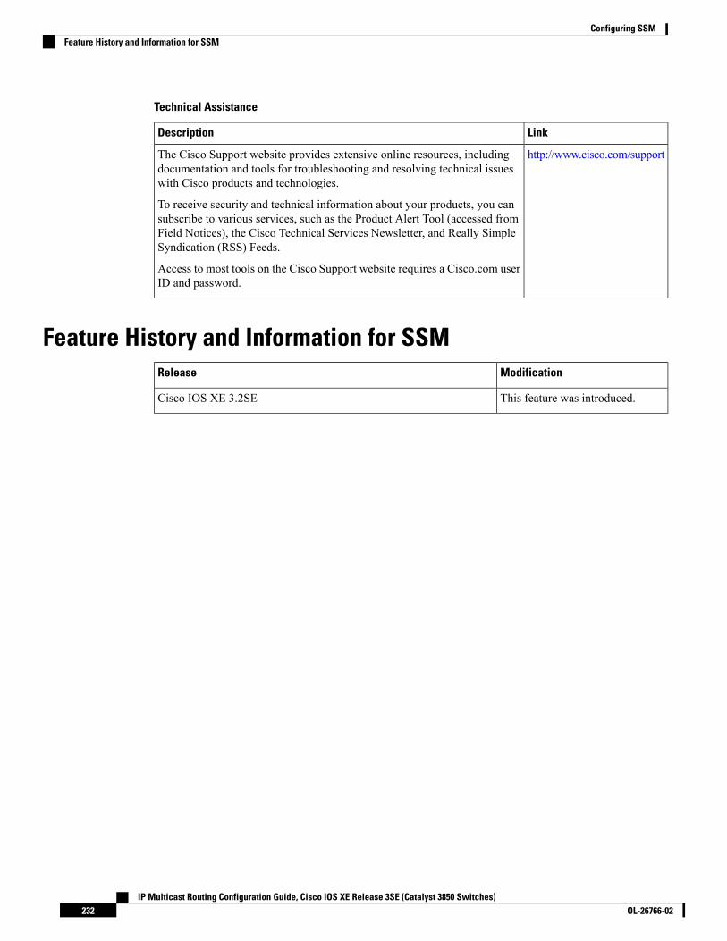
Technical Assistance
LinkDescription
http://www.cisco.com/supportThe Cisco Support website provides extensive online resources, includingdocumentation and tools for troubleshooting and resolving technical issueswith Cisco products and technologies.
To receive security and technical information about your products, you cansubscribe to various services, such as the Product Alert Tool (accessed fromField Notices), the Cisco Technical Services Newsletter, and Really SimpleSyndication (RSS) Feeds.
Access to most tools on the Cisco Support website requires a Cisco.com userID and password.
Feature History and Information for SSMModificationRelease
This feature was introduced.Cisco IOS XE 3.2SE
IP Multicast Routing Configuration Guide, Cisco IOS XE Release 3SE (Catalyst 3850 Switches)OL-26766-02232
Configuring SSMFeature History and Information for SSM

C H A P T E R 11Configuring Basic IP Multicast Routing
• Finding Feature Information, on page 233• Prerequisites for Configuring IP Multicast Routing, on page 233• Restrictions for Configuring IP Multicast Routing, on page 234• Information About Basic IP Multicast Routing, on page 234• How to Configure Basic IP Multicast Routing, on page 238• Monitoring and Maintaining Basic IP Multicast Routing, on page 249• Configuration Examples for IP Multicast Routing, on page 252• Where to Go Next for IP Multicast, on page 253• Additional References, on page 254• Feature History and Information for IP Multicast, on page 255
Finding Feature InformationYour software release may not support all the features documented in this module. For the latest caveats andfeature information, see Bug Search Tool and the release notes for your platform and software release. Tofind information about the features documented in this module, and to see a list of the releases in which eachfeature is supported, see the feature information table at the end of this module.
Use Cisco Feature Navigator to find information about platform support and Cisco software image support.To access Cisco Feature Navigator, go to http://www.cisco.com/go/cfn. An account on Cisco.com is notrequired.
Prerequisites for Configuring IP Multicast RoutingThe following are the prerequisites for configuring IP multicast routing:
• To use the IP multicast routing feature on the device, the device or active device must be running the IPServices feature set.
• You must enable IP multicast routing and configure the PIM version and PIM mode on the device. Afterperforming these tasks, the device can then forward multicast packets and can populate its multicastrouting table.
• To participate in IP multicasting, the multicast hosts, routers, and multilayer device must have IGMPoperating.
IP Multicast Routing Configuration Guide, Cisco IOS XE Release 3SE (Catalyst 3850 Switches)233OL-26766-02

Restrictions for Configuring IP Multicast RoutingThe following are the restrictions for configuring IP multicast routing:
• IP multicast routing is not supported on devices running the LAN Base feature set.
• Layer 3 IPv6 multicast routing is not supported on the device.
• High-availability support for Layer 3 multicast routing is not supported.
• You cannot have a device stack containing a mix of Catalyst 3850 and Catalyst 3650 devices.
Information About Basic IP Multicast RoutingIP multicasting is an efficient way to use network resources, especially for bandwidth-intensive services suchas audio and video. IP multicast routing enables a host (source) to send packets to a group of hosts (receivers)anywhere within the IP network by using a special form of IP address called the IP multicast group address.
The sending host inserts the multicast group address into the IP destination address field of the packet, andIP multicast routers and multilayer devices forward incoming IP multicast packets out all interfaces that leadto members of the multicast group. Any host, regardless of whether it is a member of a group, can send to agroup. However, only the members of a group receive the message.
For complete syntax and usage information for the commands used in this chapter, see the IP MulticastCommand Reference, Cisco IOS XE Release 3SE (Catalyst 3850 Switches). For information on configuringthe Multicast Source Discovery Protocol (MSDP), see the Catalyst 3850 Routing Configuration Guide.
Note
Cisco’s Implementation of IP Multicast RoutingCisco IOS software supports the following protocols to implement IP multicast routing:
• Internet Group Management Protocol (IGMP) is used among hosts on a LAN and the routers (andmultilayer devices) on that LAN to track the multicast groups of which hosts are members. To participatein IP multicasting, multicast hosts, routers, and multilayer devices must have the Internet GroupManagement Protocol (IGMP) operating.
• Protocol-Independent Multicast (PIM) protocol is used among routers and multilayer devices to trackwhich multicast packets to forward to each other and to their directly connected LANs.
The device does not support the Distance Vector Multicast Routing Protocol (DVMRP) nor the Cisco GroupManagement Protocol (CGMP).
Note
IP Multicast Routing Configuration Guide, Cisco IOS XE Release 3SE (Catalyst 3850 Switches)OL-26766-02234
Configuring Basic IP Multicast RoutingRestrictions for Configuring IP Multicast Routing

Figure 12: IP Multicast Routing Protocols
The following figure shows where the Cisco-supported protocols for the device operate within the IP multicast
environment.
According to IPv4 multicast standards, the MAC destination multicast address begins with 0100:5e and isappended by the last 23 bits of the IP address. For example, if the IP destination address is 239.1.1.39, theMAC destination address is 0100:5e01:0127.
A multicast packet is unmatched when the destination IPv4 address does not match the destination MACaddress. The device forwards the unmatched packet in hardware based upon the MAC address table. If thedestination MAC address is not in the MAC address table, the device floods the packet to the all port in thesame VLAN as the receiving port.
Related TopicsConfiguring Basic IP Multicast Routing (CLI), on page 238
Multicast Forwarding Information Base OverviewThe device uses the Multicast Forwarding Information Base (MFIB) architecture and the Multicast RoutingInformation Base (MRIB) for IP multicast.
TheMFIB architecture provides both modularity and separation between the multicast control plane (ProtocolIndependentMulticast [PIM] and Internet GroupManagement Protocol [IGMP]) and the multicast forwardingplane (MFIB). This architecture is used in Cisco IOS IPv6 multicast implementations.
MFIB itself is a multicast routing protocol independent forwarding engine; that is, it does not depend on PIMor any other multicast routing protocol. It is responsible for:
• Forwarding multicast packets
• Registering with the MRIB to learn the entry and interface flags set by the control plane
• Handling data-driven events that must be sent to the control plane
• Maintaining counts, rates, and bytes of received, dropped, and forwarded multicast packets
The MRIB is the communication channel between MRIB clients. Examples of MRIB clients are PIM, IGMP,the multicast routing (mroute) table, and the MFIB.
IP Multicast Routing Configuration Guide, Cisco IOS XE Release 3SE (Catalyst 3850 Switches)235OL-26766-02
Configuring Basic IP Multicast RoutingMulticast Forwarding Information Base Overview

Related TopicsConfiguring IP Multicast Forwarding (CLI), on page 240
Multicast Group ConceptMulticast is based on the concept of a group. An arbitrary group of receivers expresses an interest in receivinga particular data stream. This group does not have any physical or geographical boundaries. The hosts can belocated anywhere on the Internet. Hosts that are interested in receiving data flowing to a particular group mustjoin the group using IGMP. Hosts must be a member of the group to receive the data stream.
Related TopicsConfiguring an IP Multicast Boundary (CLI), on page 246Example: Configuring an IP Multicast Boundary, on page 252
Multicast BoundariesAdministratively-scoped boundaries can be used to limit the forwarding of multicast traffic outside of a domainor subdomain. This approach uses a special range of multicast addresses, called administratively-scopedaddresses, as the boundary mechanism. If you configure an administratively-scoped boundary on a routedinterface, multicast traffic whose multicast group addresses fall in this range cannot enter or exit this interface,which provides a firewall for multicast traffic in this address range.
Multicast boundaries and TTL thresholds control the scoping of multicast domains; however, TTL thresholdsare not supported by the device. You should use multicast boundaries instead of TTL thresholds to limit theforwarding of multicast traffic outside of a domain or a subdomain.
Note
Figure 13: Administratively-Scoped Boundaries
The following figure shows that Company XYZ has an administratively-scoped boundary set for the multicastaddress range 239.0.0.0/8 on all routed interfaces at the perimeter of its network. This boundary prevents anymulticast traffic in the range 239.0.0.0 through 239.255.255.255 from entering or leaving the network. Similarly,the engineering and marketing departments have an administratively-scoped boundary of 239.128.0.0/16around the perimeter of their networks. This boundary prevents multicast traffic in the range of 239.128.0.0through 239.128.255.255 from entering or leaving their respective networks.
You can define an administratively-scoped boundary on a routed interface for multicast group addresses. Astandard access list defines the range of addresses affected. When a boundary is defined, no multicast data
IP Multicast Routing Configuration Guide, Cisco IOS XE Release 3SE (Catalyst 3850 Switches)OL-26766-02236
Configuring Basic IP Multicast RoutingMulticast Group Concept

packets are allowed to flow across the boundary from either direction. The boundary allows the samemulticastgroup address to be reused in different administrative domains.
The IANA has designated the multicast address range 239.0.0.0 to 239.255.255.255 as theadministratively-scoped addresses. This range of addresses can then be reused in domains administered bydifferent organizations. The addresses would be considered local, not globally unique.
You can configure the filter-autorp keyword to examine and filter Auto-RP discovery and announcementmessages at the administratively scoped boundary. Any Auto-RP group range announcements from theAuto-RP packets that are denied by the boundary access control list (ACL) are removed. An Auto-RP grouprange announcement is permitted and passed by the boundary only if all addresses in the Auto-RP group rangeare permitted by the boundary ACL. If any address is not permitted, the entire group range is filtered andremoved from the Auto-RP message before the Auto-RP message is forwarded.
Related TopicsConfiguring an IP Multicast Boundary (CLI), on page 246Example: Configuring an IP Multicast Boundary, on page 252
Multicast Routing and Device StacksFor all multicast routing protocols, the entire stack appears as a single router to the network and operates asa single multicast router.
In a device stack, the active device performs these functions:
• It is responsible for completing the IP multicast routing functions of the stack. It fully initializes and runsthe IP multicast routing protocols.
• It builds and maintains the multicast routing table for the entire stack.
• It is responsible for distributing the multicast routing table to all stack members.
The stack members perform these functions:
• They act as multicast routing standby devices and are ready to take over if there is a active device failure.
If the active device fails, all stack members delete their multicast routing tables. The newly elected activedevice starts building the routing tables and distributes them to the stack members.
• They do not build multicast routing tables. Instead, they use the multicast routing table that is distributedby the active device.
Default Multicast Routing ConfigurationThis table describes the default multicast routing configuration for the device.
Table 22: Default Multicast Routing Configuration
Default SettingFeature
Disabled on all interfaces.Multicast routing
IP Multicast Routing Configuration Guide, Cisco IOS XE Release 3SE (Catalyst 3850 Switches)237OL-26766-02
Configuring Basic IP Multicast RoutingMulticast Routing and Device Stacks

How to Configure Basic IP Multicast Routing
Configuring Basic IP Multicast Routing (CLI)You must enable IP multicast routing and configure the PIM version and mode. After performing these tasks,the software can then forward multicast packets, and the device can populate its multicast routing table.
You can configure an interface to be in PIM dense mode, sparse mode, or sparse-dense mode. The devicepopulates its multicast routing table and forwards multicast packets it receives from its directly connectedLANs according to the mode setting. You must enable PIM in one of these modes for an interface to performIP multicast routing.
Enabling PIM on an interface also enables IGMP operation on that interface.
If you enable PIM on multiple interfaces, when most of these interfaces are not on the outgoing interface list,and IGMP snooping is disabled, the outgoing interface might not be able to sustain line rate for multicasttraffic because of the extra replication.
Note
In populating the multicast routing table, dense-mode interfaces are always added to the table. Sparse-modeinterfaces are added to the table only when periodic join messages are received from downstream devices orwhen there is a directly connected member on the interface.
When forwarding from a LAN, sparse-mode operation occurs if there is a rendezvous point (RP) known forthe group. An RP acts as the meeting place for sources and receivers of multicast data. If an RP exists, thepackets are encapsulated and sent toward the RP.When no RP is known, the packet is flooded in a dense-modefashion. If the multicast traffic from a specific source is sufficient, the receiver’s first-hop router might sendjoin messages toward the source to build a source-based distribution tree.
By default, multicast routing is disabled, and there is no default mode setting.
This procedure is required.
SUMMARY STEPS
1. enable2. configure terminal3. ip multicast-routing4. interface interface-id5. ip pim {dense-mode | sparse-mode | sparse-dense-mode}6. end7. show running-config8. copy running-config startup-config
DETAILED STEPS
PurposeCommand or Action
Enables privileged EXEC mode.enableStep 1
IP Multicast Routing Configuration Guide, Cisco IOS XE Release 3SE (Catalyst 3850 Switches)OL-26766-02238
Configuring Basic IP Multicast RoutingHow to Configure Basic IP Multicast Routing

PurposeCommand or Action
Example: Enter your password, if prompted.
Device> enable
Enters global configuration mode.configure terminal
Example:
Step 2
Device# configure terminal
Enables IP multicast routing.ip multicast-routingStep 3
Example: IP multicast routing is supported withMulticast ForwardingInformation Base (MFIB) and Multicast RoutingInformation Base (MRIB).Device(config)# ip multicast-routing
Specifies the Layer 3 interface on which you want to enablemulticast routing, and enters interface configuration mode.
interface interface-id
Example:
Step 4
The specified interface must be one of the following:Device(config)# interface • A routed port—A physical port that has been
configured as a Layer 3 port by entering the nogigabitethernet 1/0/1
switchport interface configuration command. Youwill also need to enable IP PIM sparse-dense-mode onthe interface, and join the interface as a staticallyconnected member to an IGMP static group. For aconfiguration example, see Example: InterfaceConfiguration as a Routed Port, on page 77
• An SVI—A VLAN interface created by using theinterface vlan vlan-id global configuration command.You will also need to enable IP PIMsparse-dense-mode on the VLAN, join the VLAN asa statically connectedmember to an IGMP static group,and then enable IGMP snooping on the VLAN, theIGMP static group, and physical interface. For aconfiguration example, see Example: InterfaceConfiguration as an SVI, on page 78
These interfaces must have IP addresses assigned to them.
Enables a PIM mode on the interface.ip pim {dense-mode | sparse-mode | sparse-dense-mode}Step 5
Example: By default, no mode is configured.
Device(config-if)# ip pimThe keywords have these meanings:
sparse-dense-mode • dense-mode—Enables dense mode of operation.
IP Multicast Routing Configuration Guide, Cisco IOS XE Release 3SE (Catalyst 3850 Switches)239OL-26766-02
Configuring Basic IP Multicast RoutingConfiguring Basic IP Multicast Routing (CLI)

PurposeCommand or Action
• sparse-mode—Enables sparse mode of operation. Ifyou configure sparse mode, you must also configurean RP.
• sparse-dense-mode—Causes the interface to be treatedin the mode in which the group belongs. Sparse-densemode is the recommended setting.
• state-refresh—PM dense mode state-refreshconfiguration.
Returns to privileged EXEC mode.end
Example:
Step 6
Device(config-if)# end
Verifies your entries.show running-config
Example:
Step 7
Device# show running-config
(Optional) Saves your entries in the configuration file.copy running-config startup-config
Example:
Step 8
Device# copy running-configstartup-config
Related TopicsPrerequisites for Configuring SSM, on page 215Cisco’s Implementation of IP Multicast Routing, on page 234
Configuring IP Multicast Forwarding (CLI)You can use the following procedure to configure IPv4 Multicast Forwarding Information Base (MFIB)interrupt-level IP multicast forwarding of incoming packets or outgoing packets on the device.
After you have enabled IP multicast routing by using the ip multicast-routing command, IPv4 multicastforwarding is enabled. Because IPv4 multicast forwarding is enabled by default, you can use the no form ofthe ip mfib command to disable IPv4 multicast forwarding.
Note
SUMMARY STEPS
1. enable
IP Multicast Routing Configuration Guide, Cisco IOS XE Release 3SE (Catalyst 3850 Switches)OL-26766-02240
Configuring Basic IP Multicast RoutingConfiguring IP Multicast Forwarding (CLI)
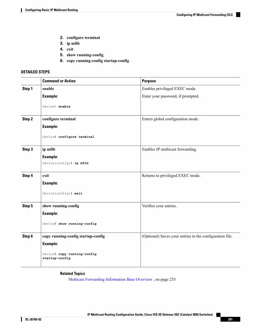
2. configure terminal3. ip mfib4. exit5. show running-config6. copy running-config startup-config
DETAILED STEPS
PurposeCommand or Action
Enables privileged EXEC mode.enableStep 1
Example: Enter your password, if prompted.
Device> enable
Enters global configuration mode.configure terminal
Example:
Step 2
Device# configure terminal
Enables IP multicast forwarding.ip mfib
Example:
Step 3
Device(config)# ip mfib
Returns to privileged EXEC mode.exit
Example:
Step 4
Device(config)# exit
Verifies your entries.show running-config
Example:
Step 5
Device# show running-config
(Optional) Saves your entries in the configuration file.copy running-config startup-config
Example:
Step 6
Device# copy running-configstartup-config
Related TopicsMulticast Forwarding Information Base Overview , on page 235
IP Multicast Routing Configuration Guide, Cisco IOS XE Release 3SE (Catalyst 3850 Switches)241OL-26766-02
Configuring Basic IP Multicast RoutingConfiguring IP Multicast Forwarding (CLI)

Configuring a Static Multicast Route (mroute) (CLI)You can use the following procedure to configure static mroutes. Static mroutes are similar to unicast staticroutes but differ in the following ways:
• Static mroutes are used to calculate RPF information, not to forward traffic.
• Static mroutes cannot be redistributed.
Static mroutes are strictly local to the device on which they are defined. Because Protocol IndependentMulticast(PIM) does not have its own routing protocol, there is no mechanism to distribute static mroutes throughoutthe network. Consequently, the administration of static mroutes tends to be more complicated than theadministration of unicast static routes.
When static mroutes are configured, they are stored on the device in a separate table referred to as the staticmroute table. When configured, the ip mroute command enters a static mroute into the static mroute tablefor the source address or source address range specified for the source-address and mask arguments. Sourcesthat match the source address or that fall in the source address range specified for the source-address argumentwill RPF to either the interface associated with the IP address specified for the rpf-address argument or thelocal interface on the device specified for the interface-type and interface-number arguments. If an IP addressis specified for the rpf-address argument, a recursive lookup is done from the unicast routing table on thisaddress to find the directly connected neighbor.
If there are multiple static mroutes configured, the device performs a longest-match lookup of the mroutetable. When the mroute with the longest match (of the source-address) is found, the search terminates and theinformation in the matching static mroute is used. The order in which the static mroutes are configured is notimportant.
The administrative distance of an mroute may be specified for the optional distance argument. If a value isnot specified for the distance argument, the distance of the mroute defaults to zero. If the static mroute hasthe same distance as another RPF source, the static mroute will take precedence. There are only two exceptionsto this rule: directly connected routes and the default unicast route.
SUMMARY STEPS
1. enable2. configure terminal3. ip mroute [vrf vrf-name] source-address mask { fallback-lookup {global | vrf vrf-name }[ protocol ]
{rpf-address | interface-type interface-number}} [distance]4. exit5. show running-config6. copy running-config startup-config
DETAILED STEPS
PurposeCommand or Action
Enables privileged EXEC mode.enableStep 1
Example: Enter your password, if prompted.
Device> enable
IP Multicast Routing Configuration Guide, Cisco IOS XE Release 3SE (Catalyst 3850 Switches)OL-26766-02242
Configuring Basic IP Multicast RoutingConfiguring a Static Multicast Route (mroute) (CLI)

PurposeCommand or Action
Enters global configuration mode.configure terminal
Example:
Step 2
Device# configure terminal
The source IP address 10.1.1.1 is configured to be reachablethrough the interface associated with IP address 10.2.2.2.
ip mroute [vrf vrf-name] source-address mask {fallback-lookup {global | vrf vrf-name }[ protocol ]{rpf-address | interface-type interface-number}} [distance]
Step 3
Example:Device(configure)# ip mroute 10.1.1.1255.255.255.255 10.2.2.2
Returns to privileged EXEC mode.exit
Example:
Step 4
Device(config)# exit
(Optional) Verifies your entries.show running-config
Example:
Step 5
Device# show running-config
(Optional) Saves your entries in the configuration file.copy running-config startup-config
Example:
Step 6
Device# copy running-configstartup-config
Configuring sdr Listener SupportTheMBONE is the small subset of Internet routers and hosts that are interconnected and capable of forwardingIP multicast traffic. Other multimedia content is often broadcast over the MBONE. Before you can join amultimedia session, you need to know what multicast group address and port are being used for the session,when the session is going to be active, and what sort of applications (audio, video, and so forth) are requiredon your workstation. The MBONE Session Directory Version 2 (sdr) tool provides this information. Thisfreeware application can be downloaded from several sites on the World Wide Web, one of which ishttp://www.video.ja.net/mice/index.html.
SDR is a multicast application that listens to a well-known multicast group address and port for SessionAnnouncement Protocol (SAP) multicast packets from SAP clients, which announce their conference sessions.These SAP packets contain a session description, the time the session is active, its IP multicast group addresses,media format, contact person, and other information about the advertised multimedia session. The informationin the SAP packet is displayed in the SDR Session Announcement window.
IP Multicast Routing Configuration Guide, Cisco IOS XE Release 3SE (Catalyst 3850 Switches)243OL-26766-02
Configuring Basic IP Multicast RoutingConfiguring sdr Listener Support

Enabling sdr Listener Support (CLI)By default, the device does not listen to session directory advertisements.
This procedure is optional.
SUMMARY STEPS
1. enable2. configure terminal3. interface interface-id4. ip sap listen5. end6. show running-config7. copy running-config startup-config
DETAILED STEPS
PurposeCommand or Action
Enables privileged EXEC mode.enableStep 1
Example: Enter your password, if prompted.
Device> enable
Enters global configuration mode.configure terminal
Example:
Step 2
Device# configure terminal
Specifies the interface to be enabled for sdr, and entersinterface configuration mode.
interface interface-id
Example:
Step 3
The specified interface must be one of the following:Device(config)# interface • A routed port—A physical port that has been
configured as a Layer 3 port by entering the nogigabitethernet 1/0/1
switchport interface configuration command. Youwill also need to enable IP PIM sparse-dense-mode onthe interface, and join the interface as a staticallyconnected member to an IGMP static group. For aconfiguration example, see Example: InterfaceConfiguration as a Routed Port, on page 77
• An SVI—A VLAN interface created by using theinterface vlan vlan-id global configuration command.You will also need to enable IP PIMsparse-dense-mode on the VLAN, join the VLAN asa statically connectedmember to an IGMP static group,and then enable IGMP snooping on the VLAN, theIGMP static group, and physical interface. For a
IP Multicast Routing Configuration Guide, Cisco IOS XE Release 3SE (Catalyst 3850 Switches)OL-26766-02244
Configuring Basic IP Multicast RoutingEnabling sdr Listener Support (CLI)

PurposeCommand or Action
configuration example, see Example: InterfaceConfiguration as an SVI, on page 78
These interfaces must have IP addresses assigned to them.
Enables the device software to listen to session directoryannouncements.
ip sap listen
Example:
Step 4
Device(config-if)# ip sap listen
Returns to privileged EXEC mode.end
Example:
Step 5
Device(config-if)# end
Verifies your entries.show running-config
Example:
Step 6
Device# show running-config
(Optional) Saves your entries in the configuration file.copy running-config startup-config
Example:
Step 7
Device# copy running-configstartup-config
Limiting How Long an sdr Cache Entry Exists (CLI)By default, entries are never deleted from the sdr cache. You can limit how long the entry remains active sothat if a source stops advertising SAP information, old advertisements are not unnecessarily kept.
This procedure is optional.
SUMMARY STEPS
1. enable2. configure terminal3. ip sap cache-timeout minutes4. end5. show running-config6. show ip sap7. copy running-config startup-config
IP Multicast Routing Configuration Guide, Cisco IOS XE Release 3SE (Catalyst 3850 Switches)245OL-26766-02
Configuring Basic IP Multicast RoutingLimiting How Long an sdr Cache Entry Exists (CLI)

DETAILED STEPS
PurposeCommand or Action
Enables privileged EXEC mode.enableStep 1
Example: Enter your password, if prompted.
Device> enable
Enters global configuration mode.configure terminal
Example:
Step 2
Device# configure terminal
Limits how long a Session Announcement Protocol (SAP)cache entry stays active in the cache.
ip sap cache-timeout minutes
Example:
Step 3
By default, entries are never deleted from the cache.Device(config)# ip sap cache-timeout 30 For minutes, the range is 1 to 1440 minutes (24 hours).
Returns to privileged EXEC mode.end
Example:
Step 4
Device(config)# end
Verifies your entries.show running-config
Example:
Step 5
Device# show running-config
Displays the SAP cache.show ip sap
Example:
Step 6
Device# show ip sap
(Optional) Saves your entries in the configuration file.copy running-config startup-config
Example:
Step 7
Device# copy running-configstartup-config
Configuring an IP Multicast Boundary (CLI)This procedure is optional.
IP Multicast Routing Configuration Guide, Cisco IOS XE Release 3SE (Catalyst 3850 Switches)OL-26766-02246
Configuring Basic IP Multicast RoutingConfiguring an IP Multicast Boundary (CLI)

SUMMARY STEPS
1. enable2. configure terminal3. access-list {access-list-number 1-99 | access-list-number 100-199 | access-list-number 1300-1999
|access-list-number 2000-2699 | dynamic-extended | rate-limit}4. interface interface-id5. ip multicast boundary access-list-number6. end7. show running-config8. copy running-config startup-config
DETAILED STEPS
PurposeCommand or Action
Enables privileged EXEC mode.enableStep 1
Example: Enter your password, if prompted.
Device> enable
Enters global configuration mode.configure terminal
Example:
Step 2
Device# configure terminal
Creates a standard access list, repeating the command asmany times as necessary.
access-list {access-list-number 1-99 | access-list-number100-199 | access-list-number 1300-1999
Step 3
|access-list-number 2000-2699 | dynamic-extended |rate-limit} • For access-list-number, the ranges are as follows:
• access-list-number 1—99 (IP standard access list)Example:
• access-list-number 100—199 ( IP extended accesslist)Device(config)# access-list 99 permit any
• access-list-number 1300—1999 (IP standardaccess list - expanded range)
• access-list-number 2000—2699 (IP extendedaccess list - expanded range)
• The dynamic-extended keyword extends the dynamicACL absolute timer.
• The rate-limit keyword permits a simple rate-limitspecific access list.
The access list is always terminated by an implicit denystatement for everything.
IP Multicast Routing Configuration Guide, Cisco IOS XE Release 3SE (Catalyst 3850 Switches)247OL-26766-02
Configuring Basic IP Multicast RoutingConfiguring an IP Multicast Boundary (CLI)

PurposeCommand or Action
Specifies the interface to be configured, and enters interfaceconfiguration mode.
interface interface-id
Example:
Step 4
The specified interface must be one of the following:Device(config)# interface gigabitEthernet1/0/1 • A routed port—A physical port that has been
configured as a Layer 3 port by entering the noswitchport interface configuration command. Youwill also need to enable IP PIM sparse-dense-mode onthe interface, and join the interface as a staticallyconnected member to an IGMP static group. For aconfiguration example, see Example: InterfaceConfiguration as a Routed Port, on page 77
• An SVI—A VLAN interface created by using theinterface vlan vlan-id global configuration command.You will also need to enable IP PIMsparse-dense-mode on the VLAN, join the VLAN asa statically connectedmember to an IGMP static group,and then enable IGMP snooping on the VLAN, theIGMP static group, and physical interface. For aconfiguration example, see Example: InterfaceConfiguration as an SVI, on page 78
These interfaces must have IP addresses assigned to them.
Configures the boundary, specifying the access list youcreated in Step 2.
ip multicast boundary access-list-number
Example:
Step 5
Additional command options include:Device(config-if)# ip multicast boundary 99 • For access-list-number, the ranges are as follows:
• access-list-number 1—99 (IP standard access list)
• access-list-number 100—199 ( IP extended accesslist)
• access-list-number 1300—1999 (IP standardaccess list - expanded range)
• access-list-number 2000—2699 (IP extendedaccess list - expanded range)
• Word—IP named access list.
• filter-autorp—Filter AutoRP packet contents.
• in—Restrict (s,g) creation when this interface is theRPF.
• out—Restrict interface addition to outgoing list.
IP Multicast Routing Configuration Guide, Cisco IOS XE Release 3SE (Catalyst 3850 Switches)OL-26766-02248
Configuring Basic IP Multicast RoutingConfiguring an IP Multicast Boundary (CLI)

PurposeCommand or Action
Returns to privileged EXEC mode.end
Example:
Step 6
Device(config-if)# end
Verifies your entries.show running-config
Example:
Step 7
Device# show running-config
(Optional) Saves your entries in the configuration file.copy running-config startup-config
Example:
Step 8
Device# copy running-configstartup-config
What to do next
Proceed to the other supported IP multicast routing procedures.
Related TopicsMulticast Boundaries, on page 236Multicast Group Concept, on page 236Example: Configuring an IP Multicast Boundary, on page 252
Monitoring and Maintaining Basic IP Multicast Routing
Clearing Caches, Tables, and DatabasesYou can remove all contents of a particular cache, table, or database. Clearing a cache, table, or databasemight be necessary when the contents of the particular structure are or suspected to be invalid.
You can use any of the privileged EXEC commands in the following table to clear IP multicast caches, tables,and databases.
Table 23: Commands for Clearing Caches, Tables, and Databases
PurposeCommand
Deletes entries from the IGMP cache.clear ip igmp group {group [ hostname | IP address]| vrf name group [ hostname | IP address] }
Clears all active IPv4 Multicast ForwardingInformation Base (MFIB) traffic counters.
clear ip mfib { counters [group | source] | globalcounters [group | source] | vrf * }
IP Multicast Routing Configuration Guide, Cisco IOS XE Release 3SE (Catalyst 3850 Switches)249OL-26766-02
Configuring Basic IP Multicast RoutingMonitoring and Maintaining Basic IP Multicast Routing

PurposeCommand
IP multicast routing clear commands.clear ip mrm {status-report [ source ] }
Deletes entries from the IP multicast routing table.clear ip mroute { * | [hostname | IP address] | vrfname group [ hostname | IP address] }
Clears the Multicast Source Discovery Protocol(MSDP) cache.
clear ip msdp { peer | sa-cache | statistics | vrf }
Clears the IP multicast information.clear ip multicast { limit | redundancy statistics }
Clears the PIM cache.clear ip pim { df [ int | rp rp address ] | interface |rp-mapping [rp address] | vrf vpn name { df |interface | rp-mapping }
Deletes the Session Directory Protocol Version 2cache or an sdr cache entry.
clear ip sap [group-address | “session-name”]
Displaying System and Network StatisticsYou can display specific statistics, such as the contents of IP routing tables, caches, and databases.
This release does not support per-route statistics.Note
You can display information to learn resource usage and solve network problems. You can also displayinformation about node reachability and discover the routing path that packets of your device are takingthrough the network.
You can use any of the privileged EXEC commands in the following table to display various routing statistics.
Table 24: Commands for Displaying System and Network Statistics
PurposeCommand
Sends an ICMP Echo Request to a multicast groupaddress.
ping [group-name | group-address]
Displays IGMP filter information.show ip igmp filter
Displays the multicast groups that are directlyconnected to the device and that were learned throughIGMP.
show ip igmp groups [type-number | detail ]
Displays multicast-related information about aninterface.
show ip igmp interface [type number]
Displays IGMP membership information forforwarding.
show ip igmp membership [ name/group address |all | tracked ]
Displays IGMP profile information.show ip igmp profile [ profile_number]
IP Multicast Routing Configuration Guide, Cisco IOS XE Release 3SE (Catalyst 3850 Switches)OL-26766-02250
Configuring Basic IP Multicast RoutingDisplaying System and Network Statistics

PurposeCommand
Displays IGMP SSM mapping information.show ip igmp ssm-mapping [ hostname/IP address]
Displays static group information.show ip igmp static-group {class-map [ interface[ type ] ]
Displays the selected VPN Routing/Forwardinginstance by name.
show ip igmp vrf
Displays the IPmulticast forwarding information base.show ip mfib [ type number ]
Displays the multicast routing information base.show ip mrib { client | route | vrf }
Displays the IPmulticast routingmonitor information.show ip mrm { interface |manager | status-report}
Displays the contents of the IP multicast routing table.show ip mroute [group-name | group-address][source] [ count | interface | proxy | pruned |summary | verbose]
Displays the Multicast Source Discovery Protocol(MSDP) information.
show ip msdp { count | peer | rpf-peer | sa-cache |summary | vrf }
Displays global multicast information.show ip multicast [ interface | limit |mpls |redundancy | vrf ]
Displays information about interfaces configured forPIM. This command is available in all softwareimages.
show ip pim interface [type number] [count | detail| df | stats ]
Display all VRFs.show ip pim all-vrfs { tunnel }
Display global auto-RP information.show ip pim autorp
Displays boundary information.show ip pim boundary [ type number ]
Display bootstrap router information (version 2).show ip pim bsr-router
Displays PIM interface information.show ip pim interface [ type number ]
Displays multicast tunnel information.show ip pim mdt [ bgp ]
Lists the PIM neighbors discovered by the device.This command is available in all software images.
show ip pim neighbor [type number]
Displays the RP routers associated with a sparse-modemulticast group. This command is available in allsoftware images.
show ip pim rp [group-name | group-address]
Displays the RP to be chosen based upon the groupselected.
show ip pim rp-hash [group-name | group-address]
Displays the registered tunnels.show ip pim tunnel [ tunnel | verbose ]
IP Multicast Routing Configuration Guide, Cisco IOS XE Release 3SE (Catalyst 3850 Switches)251OL-26766-02
Configuring Basic IP Multicast RoutingDisplaying System and Network Statistics

PurposeCommand
Displays VPN routing and forwarding instances.show ip pim vrf name
Displays how the device is doing Reverse-PathForwarding (that is, from the unicast routing table,DVMRP routing table, or static mroutes).
Command parameters include:
• Host name or IP address—IP name or groupaddress.
• Select—Group-based VRF select information.
• vrf—Selects VPNRouting/Forwarding instance.
show ip rpf {source-address | name}
Displays the Session Announcement Protocol (SAP)Version 2 cache.
Command parameters include:
• A.B.C.D—IP group address.
• WORD—Session name (in double quotes).
• detail—Session details.
show ip sap [group | “session-name” | detail]
Monitoring IP Multicast RoutingYou can use the privileged EXEC commands in the following table to monitor IP multicast routers, packets,and paths.
Table 25: Commands for Monitoring IP Multicast Routing
PurposeCommand
Queries a multicast router or multilayer device aboutwhich neighboring multicast devices are peering withit.
mrinfo { [hostname | address] | vrf }
Displays IPmulticast packet rate and loss information.mstat { [hostname | address] | vrf }
Traces the path from a source to a destination branchfor a multicast distribution tree for a given group.
mtrace { [hostname | address] | vrf }
Configuration Examples for IP Multicast Routing
Example: Configuring an IP Multicast BoundaryThis example shows how to set up a boundary for all administratively-scoped addresses:
IP Multicast Routing Configuration Guide, Cisco IOS XE Release 3SE (Catalyst 3850 Switches)OL-26766-02252
Configuring Basic IP Multicast RoutingMonitoring IP Multicast Routing

Device(config)# access-list 1 deny 239.0.0.0 0.255.255.255Device(config)# access-list 1 permit 224.0.0.0 15.255.255.255Device(config)# interface gigabitethernet1/0/1Device(config-if)# ip multicast boundary 1
Related TopicsConfiguring an IP Multicast Boundary (CLI), on page 246Multicast Boundaries, on page 236Multicast Group Concept, on page 236
Example: Responding to mrinfo RequestsThe software answers mrinfo requests sent by mrouted systems and Cisco routers and multilayer devices. Thesoftware returns information about neighbors through DVMRP tunnels and all the routed interfaces. Thisinformation includes the metric (always set to 1), the configured TTL threshold, the status of the interface,and various flags. You can also use themrinfo privileged EXEC command to query the router or device itself,as in this example:
Device# mrinfo171.69.214.27 (mm1-7kd.cisco.com) [version cisco 11.1] [flags: PMS]:171.69.214.27 -> 171.69.214.26 (mm1-r7kb.cisco.com) [1/0/pim/querier]171.69.214.27 -> 171.69.214.25 (mm1-45a.cisco.com) [1/0/pim/querier]171.69.214.33 -> 171.69.214.34 (mm1-45c.cisco.com) [1/0/pim]171.69.214.137 -> 0.0.0.0 [1/0/pim/querier/down/leaf]171.69.214.203 -> 0.0.0.0 [1/0/pim/querier/down/leaf]171.69.214.18 -> 171.69.214.20 (mm1-45e.cisco.com) [1/0/pim]171.69.214.18 -> 171.69.214.19 (mm1-45c.cisco.com) [1/0/pim]171.69.214.18 -> 171.69.214.17 (mm1-45a.cisco.com) [1/0/pim]
Where to Go Next for IP MulticastYou can configure the following:
• IGMP
• Wireless Multicast
• PIM
• SSM
• Service Discovery Gateway
You can also review the following IP Multicast Optimization processes for your configuration:
• Optimizing PIM Sparse Mode in a Large IP Multicast Deployment
• Multicast Subsecond Convergence
• IP Multicast Load Splitting across Equal-Cost Paths
• SSM Channel Based Filtering for Multicast
IP Multicast Routing Configuration Guide, Cisco IOS XE Release 3SE (Catalyst 3850 Switches)253OL-26766-02
Configuring Basic IP Multicast RoutingExample: Responding to mrinfo Requests

• PIM Dense Mode State Refresh
• IGMP State Limit
Additional ReferencesRelated Documents
Document TitleRelated Topic
IP Multicast Routing Command Reference(Catalyst 3850 Switches)
For complete syntax and usage information for thecommands used in this chapter.
Routing Command Reference (Catalyst 3850Switches)
For information on configuring the Multicast SourceDiscovery Protocol (MSDP).
Error Message Decoder
LinkDescription
https://www.cisco.com/cgi-bin/Support/Errordecoder/index.cgiTo help you research and resolve systemerror messages in this release, use the ErrorMessage Decoder tool.
Standards and RFCs
TitleStandard/RFC
Host Extensions for IP MulticastingRFC 1112
Internet Group Management Protocol, Version 2RFC 2236
Protocol-Independent Multicast-Sparse Mode (PIM-SM): Protocol SpecificationRFC 4601
MIBs
MIBs LinkMIB
To locate and downloadMIBs for selected platforms, Cisco IOS releases,and feature sets, use Cisco MIB Locator found at the following URL:
http://www.cisco.com/go/mibs
All the supported MIBs for thisrelease.
IP Multicast Routing Configuration Guide, Cisco IOS XE Release 3SE (Catalyst 3850 Switches)OL-26766-02254
Configuring Basic IP Multicast RoutingAdditional References

Technical Assistance
LinkDescription
http://www.cisco.com/supportThe Cisco Support website provides extensive online resources, includingdocumentation and tools for troubleshooting and resolving technical issueswith Cisco products and technologies.
To receive security and technical information about your products, you cansubscribe to various services, such as the Product Alert Tool (accessed fromField Notices), the Cisco Technical Services Newsletter, and Really SimpleSyndication (RSS) Feeds.
Access to most tools on the Cisco Support website requires a Cisco.com userID and password.
Feature History and Information for IP MulticastModificationRelease
This feature was introduced.Cisco IOS XE 3.2SE
IP Multicast Routing Configuration Guide, Cisco IOS XE Release 3SE (Catalyst 3850 Switches)255OL-26766-02
Configuring Basic IP Multicast RoutingFeature History and Information for IP Multicast

IP Multicast Routing Configuration Guide, Cisco IOS XE Release 3SE (Catalyst 3850 Switches)OL-26766-02256
Configuring Basic IP Multicast RoutingFeature History and Information for IP Multicast

C H A P T E R 12Configuring the Service Discovery Gateway
• Finding Feature Information, on page 257• Restrictions for Configuring the Service Discovery Gateway, on page 257• Information about the Service Discovery Gateway and mDNS, on page 258• How to Configure the Service Discovery Gateway, on page 261• Monitoring Service Discovery Gateway, on page 268• Configuration Examples, on page 268• Monitoring Service Cache (GUI), on page 270• Monitoring Static Service Cache (GUI), on page 271• Where to Go Next for Configuring Services Discovery Gateway, on page 272• Additional References, on page 272• Feature History and Information for Services Discovery Gateway, on page 273
Finding Feature InformationYour software release may not support all the features documented in this module. For the latest caveats andfeature information, see Bug Search Tool and the release notes for your platform and software release. Tofind information about the features documented in this module, and to see a list of the releases in which eachfeature is supported, see the feature information table at the end of this module.
Use Cisco Feature Navigator to find information about platform support and Cisco software image support.To access Cisco Feature Navigator, go to http://www.cisco.com/go/cfn. An account on Cisco.com is notrequired.
Restrictions for Configuring the Service Discovery GatewayThe following are restrictions for configuring the Service Discovery Gateway:
• The Service Discovery Gateway does not support topologies with multiple hops. All network segmentsmust be connected directly to it. The Service Discovery Gateway can learn services from all connectedsegments to build its cache and respond to requests acting as a proxy.
• The use of third-party mDNS servers or applications are not supported with this feature.
• On a Cat4500sup8e MC (3.7 ) running mDNS, iphone and ipads running iOS7.0 might have problemsin accessing print services through mDNS.
IP Multicast Routing Configuration Guide, Cisco IOS XE Release 3SE (Catalyst 3850 Switches)257OL-26766-02

Information about the Service Discovery Gateway and mDNS
mDNSmDNS was defined to achieve zero configuration, with zero configuration being defined as providing thefollowing features:
• Addressing—Allocating IP addresses to hosts
• Naming—Using names to refer to hosts instead of IP addresses
• Service discovery—Finding services automatically on the network
With mDNS, network users no longer have to assign IP addresses, assign host names, or type in names toaccess services on the network. Users only need to ask to see what network services are available, and choosefrom a list.
With mDNS, addressing is accomplished through the use of DHCP/DHCPv6 or IPv4 and IPv6 Link Localscoped addresses. The benefit of zero-configuration occurs when no infrastructure services such as DHCP orDNS are present and self-assigned link-local addressing can be used. The client can then select a random IPv4address in the link-local range (169.254.0.0/24) or use its IPv6 link-local address (FE80::/10) for communication.
With mDNS, naming (name-to-address translation on a local network using mDNS) queries are sent over thelocal network using link-local scoped IP multicast. Because these DNS queries are sent to a multicast address(IPv4 address 224.0.0.251 or IPv6 address FF02::FB), no single DNS server with global knowledge is requiredto answer the queries. When a service or device sees a query for any service it is aware of, it provides a DNSresponse with the information from its cache.
With mDNS, service discovery is accomplished by browsing. An mDNS query is sent out for a given servicetype and domain, and any device that is aware of matching services replies with service information. Theresult is a list of available services for the user to choose from.
The mDNS protocol (mDNS-RFC), together with DNS Service Discovery (DNS-SD-RFC) achieves thezero-configuration addressing, naming, and service discovery.
mDNS-SDMulticast DNS Service Discovery (mDNS-SD) uses DNS protocol semantics and multicast over well-knownmulticast addresses to achieve zero configuration service discovery. DNS packets are sent to and received onport 5353 using a multicast address of 224.0.0.251 and its IPv6 equivalent FF02::FB.
Because mDNS uses a link-local multicast address, its scope is limited to a single physical or logical LAN.If the networking reach needs to be extended to a distributed campus or to a wide-area environment consistingof many different networking technologies, mDNS gateway is implemented. An mDNS gateway provides atransport for mDNS packets across Layer 3 boundaries by filtering, caching, and redistributing services fromone Layer 3 domain to another.
mDNS-SD Considerations for Wireless Clients
• mDNS packets can be sent out of Layer 3 interfaces that might not have an IP address.
• Packets with mDNS multicast IP and multicast MAC are sent on a multicast CAPWAP tunnel, ifmulticast-multicast mode is enabled. A multicast CAPWAP tunnel is a special CAPWAP tunnel used
IP Multicast Routing Configuration Guide, Cisco IOS XE Release 3SE (Catalyst 3850 Switches)OL-26766-02258
Configuring the Service Discovery GatewayInformation about the Service Discovery Gateway and mDNS

for reducing the number of copies of multicast packet that are required to be generated for each APCAPWAP tunnel. Sending packets on the multicast CAPWAP tunnel requires the outer IP header to bedestined to the multicast CAPWAP tunnel's address, which all APs are subscribed to.
• All mDNS packet handling is done at a foreign switch for roamed clients. A foreign switch is the newswitch that a roamed wireless client is actually attached to, which is called the point of attachment.
Service Discovery GatewayThe Service Discovery Gateway feature enables multicast Domain Name System (mDNS) to operate acrossLayer 3 boundaries (different subnets). An mDNS gateway provides transport for service discovery acrossLayer 3 boundaries by filtering, caching, and redistributing services from one Layer 3 domain (subnet) toanother. Prior to implementation of this feature, mDNS was limited in scope to within a subnet because ofthe use of link-local scoped multicast addresses. This feature enhances Bring Your Own Device (BYOD).
Related TopicsConfiguring the Service List (CLI), on page 261Example: Creating a Service-List, Applying a Filter and Configuring Parameters, on page 269Enabling mDNS Gateway and Redistributing Services (CLI), on page 264Example: Specify Alternative Source Interface for Outgoing mDNS Packets, on page 268Example: Redistribute Service Announcements, on page 268Example: Disable Bridging of mDNS Packets to Wireless Clients, on page 269Example: Enabling mDNS Gateway and Redistributing Services, on page 269Example: Global mDNS Configuration, on page 270Example: Interface mDNS Configuration, on page 270
mDNS Gateway and SubnetsYou need to enable an mDNS gateway for service discovery to operate across subnets. You can enable mDNSgateway for a device or for an interface.
You need to configure service routing globally before configuring at the interface level.Note
After the device or interface is enabled, you can redistribute service discovery information across subnets.You can create service policies and apply filters on either incoming service discovery information (calledIN-bound filtering) or outgoing service discovery information (called OUT-bound filtering).
If redistribution is enabled globally, global configuration is given higher priority than interface configuration.Note
Figure 14: Sample Networking Scenario
For example, if the mDNS gateway functionality is enabled on the router in this figure, then service informationcan be sent from one subnet to another and vice-versa. For example, the printer and fax service informationbeing advertised in the network with IP address 192.0.2.6 are redistributed to the network with IP address198.51.100.4. The printer and fax service information in the network with IP address 192.0.2.6 is learned by
IP Multicast Routing Configuration Guide, Cisco IOS XE Release 3SE (Catalyst 3850 Switches)259OL-26766-02
Configuring the Service Discovery GatewayService Discovery Gateway

mDNS-enabled hosts and devices in the other network.
FilteringAfter configuring the mDNS gateway and subnets, you can filter services that you want to redistribute. Whilecreating a service list, the permit or deny command options are used:
• The permit command option allows you to permit or transport specific service list information.
• The deny option allows you to deny service list information that is available to be transported to othersubnets.
You need to include a sequence number when using the permit or deny command option. The same servicelist name can be associated with multiple sequence numbers and each sequence number will be mapped to arule.
If no filters are configured, then the default action is to deny service list information to be transported throughthe device or interface.
Note
Query is another option provided when creating service lists. You can create queries using a service list. Ifyou want to browse for a service, then active queries can be used. This function is helpful to keep the recordsrefreshed in the cache.
Active queries can only be used globally and cannot be used at the interface level.Note
A service end-point (such as a printer or fax) sends unsolicited announcements when a service starts up. Afterthat, it sends unsolicited announcements whenever a network change event occurs (such as an interface comingup or going down). The device always respond to queries.
IP Multicast Routing Configuration Guide, Cisco IOS XE Release 3SE (Catalyst 3850 Switches)OL-26766-02260
Configuring the Service Discovery GatewayFiltering

After creating a service list and using the permit or deny command options, you can filter using matchstatements (commands) based on service-instance, service-type, or message-type (announcement or query).
Related TopicsConfiguring the Service List (CLI), on page 261Example: Creating a Service-List, Applying a Filter and Configuring Parameters, on page 269Enabling mDNS Gateway and Redistributing Services (CLI), on page 264Example: Specify Alternative Source Interface for Outgoing mDNS Packets, on page 268Example: Redistribute Service Announcements, on page 268Example: Disable Bridging of mDNS Packets to Wireless Clients, on page 269Example: Enabling mDNS Gateway and Redistributing Services, on page 269Example: Global mDNS Configuration, on page 270Example: Interface mDNS Configuration, on page 270
How to Configure the Service Discovery Gateway
Configuring the Service List (CLI)This procedure describes how to create a service list, apply a filter for the service list, and configure parametersfor the service list name.
SUMMARY STEPS
1. enable2. configure terminal3. service-list mdns-sd service-list-name {deny sequence-number | permit sequence-number | query}4. match message-type {announcement | any | query}5. match service-instance { LINE }6. match service-type {LINE }7. end
DETAILED STEPS
PurposeCommand or Action
Enables privileged EXEC mode.enableStep 1
Example: Enter your password, if prompted.
Device> enable
Enters global configuration mode.configure terminal
Example:
Step 2
Device# configure terminal
IP Multicast Routing Configuration Guide, Cisco IOS XE Release 3SE (Catalyst 3850 Switches)261OL-26766-02
Configuring the Service Discovery GatewayHow to Configure the Service Discovery Gateway

PurposeCommand or Action
Enters mDNS service discovery service list mode. In thismode, you can:
service-list mdns-sd service-list-name {denysequence-number | permit sequence-number | query}
Example:
Step 3
• Create a service list and apply a filter on the servicelist according to the permit or deny option applied tothe sequence number.Device(config)# service-list mdns-sd sl1 permit 3
• Create a service list and associate a query for theservice list name if the query option is used.Device(config)# service-list mdns-sd sl4 query
The sequence number sets the priority of the rule.A rule with a lower sequence number is selectedfirst and the service announcement or query isallowed or denied accordingly. You define thesequence number as per your networkrequirements.
Note
(Optional) Sets the message type to match. You can matchthe following message types:
match message-type {announcement | any | query}
Example:
Step 4
• announcementDevice(config-mdns-sd-sl)# match message-type
• anyannouncement
• query
These commands configure the parameters for the servicelist name that is created in step 2.
If thematch message-type is an announcement, then theservice list rule only allows service advertisements orannouncements for the device. If thematch message-typeis a query, then only a query from the client for a certainservice in the network is allowed.
Multiple service maps of the same name with differentsequence numbers can be created and the evaluation of thefilters will be ordered on the sequence number. Service listsare an ordered sequence of individual statements, each onehas a permit or deny result. Evaluation of service listconsists of a list scan, in a predetermined order, and anevaluation of the criteria of each statement that matches. Alist scan is stopped once the first statement match is foundand an action permit/deny associated with the statementmatch is performed. The default action after scanningthrough the entire list is to deny.
You cannot use thematch command if you haveused the query option in the previous step. Thematch command can be used only for the permitor deny option.
Note
IP Multicast Routing Configuration Guide, Cisco IOS XE Release 3SE (Catalyst 3850 Switches)OL-26766-02262
Configuring the Service Discovery GatewayConfiguring the Service List (CLI)

PurposeCommand or Action
(Optional) Sets the service instance to match.match service-instance { LINE }Step 5
Example: This command configures the parameters for the servicelist name that is created in step 2.
Device(config-mdns-sd-sl)## match service-instance You cannot use thematch command if you haveused the query option in the previous step. Thematch command can be used only for the permitor deny option.
NoteservInst 1
(Optional) Sets the value of the mDNS service type stringto match.
match service-type {LINE }
Example:
Step 6
This command configures the parameters for the servicelist name that is created in step 2.Device(config-mdns-sd-sl)# match service-type
_ipp._tcpYou cannot use thematch command if you haveused the query option in the previous step. Thematch command can be used only for the permitor deny option.
Note
Returns to privileged EXEC mode.end
Example:
Step 7
Device(config-mdns-sd-sl)# end
What to do next
Proceed to enable the mDNS gateway and redistribution of services.
Related TopicsService Discovery Gateway , on page 259Filtering, on page 260Example: Creating a Service-List, Applying a Filter and Configuring Parameters, on page 269
Configuring the Service List (GUI)
Step 1 Choose Configuration > Controller >mDNS > Static Service.Step 2 Click Create Service.
The Service List > Create Service page is displayed.Step 3 In the Service List Name text box, enter the service list name.Step 4 From the Service rule drop-down list, choose from the following options:
• permit—permits the service list.• deny—denies the service list.
Step 5 In the Sequence number text box, enter the priority of the rule.
IP Multicast Routing Configuration Guide, Cisco IOS XE Release 3SE (Catalyst 3850 Switches)263OL-26766-02
Configuring the Service Discovery GatewayConfiguring the Service List (GUI)

A rule with a lower sequence number is selected first and the service announcement or query is allowed or deniedaccordingly. You define the sequence number as per your network requirements.
Step 6 From theMessage type drop-down list, choose the message type to match from the following options:
• announcement—The service list rule allows only service advertisements or announcements for the device.• query—The service list rule allows only a query from the client for a service in the network.• any—The service list rule allows any type of message.
Multiple service maps of the same name with different sequence numbers can be created and the evaluation of thefilters will be ordered on the sequence number. Service lists are an ordered sequence of individual statements, each onehas a permit or deny result. Evaluation of service list consists of a list scan, in a predetermined order, and an evaluationof the criteria of each statement that matches. A list scan is stopped once the first statement match is found and anaction permit/deny associated with the statement match is performed. The default action after scanning through theentire list is to deny.
Step 7 In the Service instance text box, enter the service instance to match.Step 8 In the Custom text box, enter the mDNS service type string to match.
The Learned Service box shows the services that are added after enabling the learned service type configured bynavigating to Configuration > Controller >mDNS > Global. For example, _roap._tcp.local.The Selected Service box shows the learned service that you have selected for an mDNS service.
Step 9 Click Apply.Step 10 Click Save Configuration.
What to do next
Proceed to enable the mDNS gateway and redistribution of services.
Enabling mDNS Gateway and Redistributing Services (CLI)After enabling mDNS gateway for a device, you can apply filters (apply IN-bound filtering or OUT-boundfiltering) and active queries by using service-policy and service-policy-query commands, respectively. Youcan redistribute services and service announcements using the redistribute mdns-sd command, and set somepart of the system memory for cache using the cache-memory-max command.
By default, mDNS gateway is disabled on all interfaces.Note
SUMMARY STEPS
1. enable2. configure terminal3. service-routing mdns-sd4. service-policy service-policy-name {IN | OUT}5. redistribute mdns-sd6. cache-memory-max cache-config-percentage7. service-policy-query service-list-query-name service-list-query-periodicity
IP Multicast Routing Configuration Guide, Cisco IOS XE Release 3SE (Catalyst 3850 Switches)OL-26766-02264
Configuring the Service Discovery GatewayEnabling mDNS Gateway and Redistributing Services (CLI)

8. exit9. wireless multicast10. no wireless mdns-bridging11. end
DETAILED STEPS
PurposeCommand or Action
Enables privileged EXEC mode.enableStep 1
Example: Enter your password, if prompted.
Device> enable
Enters global configuration mode.configure terminal
Example:
Step 2
Device# configure terminal
Enables mDNS gateway functionality for a device andenters multicast DNS configuration (config-mdns) mode.
service-routing mdns-sd
Example:
Step 3
This command enables the mDNS functionglobally.
NoteDevice (config)# service-routing mdns-sd
Enter the service-routing mdns-sdsource-interface if-name command in eitherglobal-config or interface-config mode, tospecify an alternate source interface foroutgoing mDNS packets, so its IP address canbe used when there is none configured on theoutgoing interface.
Note
(Optional) For a service list, applies a filter on incomingservice discovery information (IN-bound filtering) or
service-policy service-policy-name {IN | OUT}
Example:
Step 4
outgoing service discovery information (OUT-boundfiltering).
Device (config-mdns)# service-policy serv-pol1 IN
(Optional) Redistributes services or service announcementsacross subnets.
redistribute mdns-sd
Example:
Step 5
If redistribution is enabled globally, globalconfiguration is given higher priority thaninterface configuration.
NoteDevice (config-mdns)# redistribute mdns-sd
(Optional) Sets some part of the system memory (inpercentage) for cache.
cache-memory-max cache-config-percentage
Example:
Step 6
IP Multicast Routing Configuration Guide, Cisco IOS XE Release 3SE (Catalyst 3850 Switches)265OL-26766-02
Configuring the Service Discovery GatewayEnabling mDNS Gateway and Redistributing Services (CLI)

PurposeCommand or Action
Device (config-mdns)# cache-memory-max 20By default, 10 percent of the system memoryis set aside for cache. You can override thedefault value by using this command.
Note
(Optional) Configures service list-query periodicity.service-policy-query service-list-query-nameservice-list-query-periodicity
Step 7
Example:
Device (config-mdns)# service-policy-querysl-query1 100
(Optional) Returns to global configuration mode.exit
Example:
Step 8
Device (config-mdns)#exit
(Optional) Enables wireless Ethernet multicast support.wireless multicast
Example:
Step 9
Device (config)# wireless multicast
(Optional) Disables bridging of mDNS packets to wirelessclients.
no wireless mdns-bridging
Example:
Step 10
Device (config)# no wireless mdns-bridging
Returns to privileged EXEC mode.end
Example:
Step 11
Device(config)# end
Related TopicsService Discovery Gateway , on page 259Filtering, on page 260Example: Specify Alternative Source Interface for Outgoing mDNS Packets, on page 268Example: Redistribute Service Announcements, on page 268Example: Disable Bridging of mDNS Packets to Wireless Clients, on page 269Example: Enabling mDNS Gateway and Redistributing Services, on page 269Example: Global mDNS Configuration, on page 270Example: Interface mDNS Configuration, on page 270
IP Multicast Routing Configuration Guide, Cisco IOS XE Release 3SE (Catalyst 3850 Switches)OL-26766-02266
Configuring the Service Discovery GatewayEnabling mDNS Gateway and Redistributing Services (CLI)

Configuring Interface Service Rules (GUI)
Step 1 Choose Configuration > Controller >mDNS > Interface.Step 2 Click an interface name.
The Interface Service Rules page is displayed.
Step 3 From the Service Policy IN drop-down list, choose the service policy that should be applied for incomingmDNSmessages.Step 4 From the Service Policy OUT drop-down list, choose the service policy that should be applied for outgoing mDNS
messages.Step 5 Select or unselect the Redistribution check box to enable or disable redistribution of service announcements received
on one interface over all the interfaces or over a specific interface.Step 6 Click Apply.Step 7 Click Save Configuration.
Configuring mDNS Global Rules (GUI)
Step 1 Choose Configuration > Controller >mDNS > Global.Step 2 Select themDNS gateway check box.Step 3 Follow these steps to configure the device as designated gateway and apply proximity rules:
a) Click the Advanced tab.b) Select or unselect the Self Designated Gateway check box.c) Under Proximity, in theMax Services Option box, enter the maximum number of devices supported with a particular
service type that are in proximity. The valid range is between 1 and 100.d) From the Service List Active Query drop-down list, choose the services that are filtered for proximity.
You can create a custom service list, by choosing Create New and then specifying the service list name.e) Click New to add a service type, and from the Service Type drop-down list, choose the service type to be added, and
click OK.See the online help for detailed descriptions of the fields.
Step 4 From the Learn Service drop-down list, choose from the following options:
• Enable—Allows the device to learn all the announced services. It is used to learn services by enabling allannouncement/queries by using Service Policy IN of type GUI-permit-all and in Service Policy OUT of typeGUI-deny-all.
• Disable—Denies all the traffics IN and OUT. It is used to deny services by disabling all announcement/queries byusing Service Policy IN of type GUI-deny-all and in Service Policy OUT of type GUI-deny-all.
• Custom—You can set your own IN and OUT policy. It allows you to define a custom service list.
Step 5 Click Apply.Step 6 Click Save Configuration.
IP Multicast Routing Configuration Guide, Cisco IOS XE Release 3SE (Catalyst 3850 Switches)267OL-26766-02
Configuring the Service Discovery GatewayConfiguring Interface Service Rules (GUI)

Monitoring Service Discovery GatewayTable 26: Monitoring Service Discovery Gateway
PurposeCommand
This command displays information for outstandingmDNS requests, including record name and recordtype information.
show mdns requests [detail | name record-name|type record-type [ name record-name]]
This command displays mDNS cache information.show mdns cache [interface type number | namerecord-name [type record-type]| type record-type]
This command displays mDNS statistics.show mdns statistics {all | service-list list-name |service-policy {all | interface type number }}
Configuration Examples
Example: Specify Alternative Source Interface for Outgoing mDNS PacketsThe following example displays how to specify an alternate source interface for outgoing mDNS packets, soits IP address can be used when there is none configured on the outgoing interface.
Device(config)# service-routing mdns-sdDevice(config-mdns)# source-interface if-name
Related TopicsEnabling mDNS Gateway and Redistributing Services (CLI), on page 264Service Discovery Gateway , on page 259Filtering, on page 260
Example: Redistribute Service AnnouncementsThe following example displays how to redistribute service announcements received on one interface overall the interfaces or over a specific interface.
Device(config)# service-routing mdns-sdDevice(config-mdns)# Redistribute mdns-sd if-name
Related TopicsEnabling mDNS Gateway and Redistributing Services (CLI), on page 264Service Discovery Gateway , on page 259Filtering, on page 260
IP Multicast Routing Configuration Guide, Cisco IOS XE Release 3SE (Catalyst 3850 Switches)OL-26766-02268
Configuring the Service Discovery GatewayMonitoring Service Discovery Gateway

Example: Disable Bridging of mDNS Packets to Wireless ClientsThe following example displays how to disable bridging of mDNS packets to wireless clients.
Device(config)# wireless multicastDevice(config)# no wireless mdns-bridging
Related TopicsEnabling mDNS Gateway and Redistributing Services (CLI), on page 264Service Discovery Gateway , on page 259Filtering, on page 260
Example: Creating aService-List, Applying aFilter and Configuring ParametersThe following example shows the creation of a service-list sl1. The permit command option is being appliedon sequence number 3 and all services with message-type announcement are filtered and available for transportacross various subnets associated with the device.
Device# configure terminalDevice(config)# service-list mdns-sd sl1 permit 3Device(config-mdns-sd-sl)#match message-type announcementDevice(config-mdns)# exit
Related TopicsConfiguring the Service List (CLI), on page 261Service Discovery Gateway , on page 259Filtering, on page 260
Example: Enabling mDNS Gateway and Redistributing ServicesThe following example shows how to enable an mDNS gateway for a device and enable redistribution ofservices across subnets. IN-bound filtering is applied on the service-list serv-pol1. Twenty percent of systemmemory is made available for cache and service-list-query periodicity is configured at 100 seconds.
Device# configure terminalDevice# service-routing mdns-sdDevice(config-mdns)# service-policy serv-pol1 INDevice(config-mdns)# redistribute mdns-sdDevice(config-mdns)# cache-memory-max 20Device(config-mdns)# service-policy-query sl-query1 100Device(config-mdns)# exit
Related TopicsEnabling mDNS Gateway and Redistributing Services (CLI), on page 264Service Discovery Gateway , on page 259Filtering, on page 260
IP Multicast Routing Configuration Guide, Cisco IOS XE Release 3SE (Catalyst 3850 Switches)269OL-26766-02
Configuring the Service Discovery GatewayExample: Disable Bridging of mDNS Packets to Wireless Clients

Example: Global mDNS ConfigurationThe following example displays how to globally configure mDNS.
Device# configure terminalDevice(config)# service-list mdns-sd mypermit-all permit 10Device(config-mdns-sd-s1)# exitDevice(config)# service-list mdns-sd querier queryDevice(config-mdns-sd-s1)# service-type _dns._udpDevice(config-mdns-sd-s1)# endDevice# configure terminalDevice(config)# service-routing mdns-sdDevice(config-mdns)# service-policy mypermit-all INDevice(config-mdns)# service-policy mypermit-all OUT
Related TopicsEnabling mDNS Gateway and Redistributing Services (CLI), on page 264Service Discovery Gateway , on page 259Filtering, on page 260
Example: Interface mDNS ConfigurationThe following example displays how to configure mDNS for an interface.
Device(config)#interface Vlan136Device(config-if)# description *** Mgmt VLAN ***Device(config-if)# ip address 9.7.136.10 255.255.255.0Device(config-if)# ip helper-address 9.1.0.100Device(config-if)# service-routing mdns-sdDevice(config-if-mdns-sd)# service-policy mypermit-all INDevice(config-if-mdns-sd)# service-policy mypermit-all OUTDevice(config-if-mdns-sd)# service-policy-query querier 60
Related TopicsEnabling mDNS Gateway and Redistributing Services (CLI), on page 264Service Discovery Gateway , on page 259Filtering, on page 260
Monitoring Service Cache (GUI)ClickMonitor > Controller >mDNS > Service Cache to view domain names and other details of the serviceproviders.
Each service advertisement contains a record that maps the domain name of the service provider to the IPaddress. The details of the following parameters is displayed:
Displays the hostname assigned to each serviceprovider machine.
Name
Displays the VLAN ID of the service provider.VLAN ID
IP Multicast Routing Configuration Guide, Cisco IOS XE Release 3SE (Catalyst 3850 Switches)OL-26766-02270
Configuring the Service Discovery GatewayExample: Global mDNS Configuration

Displays the MAC address of the service providermachine.
MAC ID
Displays the Time to Live (TTL) value in secondsthat determines the validity of the service offered bythe service provider. The service provider is removedfrom the Devicewhen the TTL expires.
TTL
Displays the time left in seconds before the serviceprovider is removed from the Device.
Remaining
Displays the service type record. Values are as follow:
• PTR• TXT• SRV
Type
Displays IP addresses, service names of the announcedservices.
RR Record Data
Monitoring Static Service Cache (GUI)ClickMonitor > Controller > mDNS > Static Service Cache to view domain names and other details ofthe service providers.
Each service advertisement contains a record that maps the domain name of the service provider to the IPaddress. The details of the following parameters is displayed:
Displays the hostname assigned to each serviceprovider machine.
Name
Displays the VLAN ID of the service provider.VLAN ID
Displays the MAC address of the service providermachine.
MAC ID
Displays the Time to Live (TTL) value in secondsthat determines the validity of the service offered bythe service provider. The service provider is removedfrom the Devicewhen the TTL expires.
TTL
Displays the time left in seconds before the serviceprovider is removed from the Device.
Remaining
Displays the service type record. Values are as follow:
• PTR• TXT• SRV
Type
Displays IP addresses, service names of the announcedservices.
RR Record Data
IP Multicast Routing Configuration Guide, Cisco IOS XE Release 3SE (Catalyst 3850 Switches)271OL-26766-02
Configuring the Service Discovery GatewayMonitoring Static Service Cache (GUI)

Where to Go Next for Configuring Services Discovery GatewayYou can configure the following:
• IGMP
• Wireless Multicast
• PIM
• SSM
• IP Multicast Routing
You can also review the following IP Multicast Optimization processes for your configuration:
• Optimizing PIM Sparse Mode in a Large IP Multicast Deployment
• Multicast Subsecond Convergence
• IP Multicast Load Splitting across Equal-Cost Paths
• SSM Channel Based Filtering for Multicast
• PIM Dense Mode State Refresh
• IGMP State Limit
Additional ReferencesRelated Documents
Document TitleRelated Topic
IP Addressing: DNS Configuration Guide, Cisco IOS XE Release3SE
Configuring DNS
'Information About DNS' section in IP Addressing: DNSConfiguration Guide, Cisco IOS XE Release 3SE
DNS conceptual information
IP Addressing: DNS Configuration Guide, Cisco IOS XE Release3SE
Platform-independent configurationinformation
Error Message Decoder
LinkDescription
https://www.cisco.com/cgi-bin/Support/Errordecoder/index.cgiTo help you research and resolve systemerror messages in this release, use the ErrorMessage Decoder tool.
IP Multicast Routing Configuration Guide, Cisco IOS XE Release 3SE (Catalyst 3850 Switches)OL-26766-02272
Configuring the Service Discovery GatewayWhere to Go Next for Configuring Services Discovery Gateway

Standards and RFCs
TitleStandard/RFC
DNS-Based Service DiscoveryRFC 6763
MulticastMulticast DNS Internet-Draft
MIBs
MIBs LinkMIB
To locate and downloadMIBs for selected platforms, Cisco IOS releases,and feature sets, use Cisco MIB Locator found at the following URL:
http://www.cisco.com/go/mibs
All the supported MIBs for thisrelease.
Technical Assistance
LinkDescription
http://www.cisco.com/supportThe Cisco Support website provides extensive online resources, includingdocumentation and tools for troubleshooting and resolving technical issueswith Cisco products and technologies.
To receive security and technical information about your products, you cansubscribe to various services, such as the Product Alert Tool (accessed fromField Notices), the Cisco Technical Services Newsletter, and Really SimpleSyndication (RSS) Feeds.
Access to most tools on the Cisco Support website requires a Cisco.com userID and password.
FeatureHistoryandInformationforServicesDiscoveryGatewayModificationRelease
This feature was introduced.Cisco IOS XE 3.2SE
IP Multicast Routing Configuration Guide, Cisco IOS XE Release 3SE (Catalyst 3850 Switches)273OL-26766-02
Configuring the Service Discovery GatewayFeature History and Information for Services Discovery Gateway

IP Multicast Routing Configuration Guide, Cisco IOS XE Release 3SE (Catalyst 3850 Switches)OL-26766-02274
Configuring the Service Discovery GatewayFeature History and Information for Services Discovery Gateway

C H A P T E R 13IP Multicast Optimization: Optimizing PIM SparseMode in a Large IP Multicast Deployment
• Finding Feature Information, on page 275• Prerequisites for Optimizing PIM Sparse Mode in a Large IP Multicast Deployment, on page 275• Information About Optimizing PIM Sparse Mode in a Large IP Multicast Deployment, on page 276• How to Optimize PIM Sparse Mode in a Large IP Multicast Deployment, on page 279• Configuration Examples for Optimizing PIM Sparse Mode in a Large Multicast Deployment, on page281
• Additional References, on page 281• Feature History and Information for Optimizing PIM Sparse Mode in a Large IP Multicast Deployment,on page 282
Finding Feature InformationYour software release may not support all the features documented in this module. For the latest caveats andfeature information, see Bug Search Tool and the release notes for your platform and software release. Tofind information about the features documented in this module, and to see a list of the releases in which eachfeature is supported, see the feature information table at the end of this module.
Use Cisco Feature Navigator to find information about platform support and Cisco software image support.To access Cisco Feature Navigator, go to http://www.cisco.com/go/cfn. An account on Cisco.com is notrequired.
Prerequisites for Optimizing PIM Sparse Mode in a Large IPMulticast Deployment
• You must have PIM sparse mode running in your network.
• If you plan to use a group list to control to which groups the shortest-path tree (SPT) threshold applies,you must have configured your access list before performing the task.
IP Multicast Routing Configuration Guide, Cisco IOS XE Release 3SE (Catalyst 3850 Switches)275OL-26766-02

Information About Optimizing PIM Sparse Mode in a Large IPMulticast Deployment
PIM Registering ProcessIP multicast sources do not use a signaling mechanism to announce their presence. Sources just send theirdata into the attached network, as opposed to receivers that use Internet Group Management Protocol (IGMP)to announce their presence. If a source sends traffic to a multicast group configured in PIM sparse mode(PIM-SM), the Designated Router (DR) leading toward the source must inform the rendezvous point (RP)about the presence of this source. If the RP has downstream receivers that want to receive the multicast traffic(natively) from this source and has not joined the shortest path leading toward the source, then the DR mustsend the traffic from the source to the RP. The PIM registering process, which is individually run for each (S,G) entry, accomplishes these tasks between the DR and RP.
The registering process begins when a DR creates a new (S, G) state. The DR encapsulates all the data packetsthat match the (S, G) state into PIM register messages and unicasts those register messages to the RP.
If an RP has downstream receivers that want to receive register messages from a new source, the RP can eithercontinue to receive the register messages through the DR or join the shortest path leading toward the source.By default, the RP will join the shortest path, because delivery of native multicast traffic provides the highestthroughput. Upon receipt of the first packet that arrives natively through the shortest path, the RP will senda register-stop message back to the DR. When the DR receives this register-stop message, it will stop sendingregister messages to the RP.
If an RP has no downstream receivers that want to receive register messages from a new source, the RP willnot join the shortest path. Instead, the RPwill immediately send a register-stopmessage back to the DR.Whenthe DR receives this register-stop message, it will stop sending register messages to the RP.
Once a routing entry is established for a source, a periodic reregistering takes place between the DR and RP.One minute before the multicast routing table state times out, the DR will send one dataless register messageto the RP each second that the source is active until the DR receives a register-stop message from the RP.This action restarts the timeout time of the multicast routing table entry, typically resulting in one reregisteringexchange every 2 minutes. Reregistering is necessary to maintain state, to recover from lost state, and to keeptrack of sources on the RP. It will take place independently of the RP joining the shortest path.
PIM Version 1 CompatibilityIf an RP is running PIM Version 1, it will not understand dataless register messages. In this case, the DR willnot send dataless register messages to the RP. Instead, approximately every 3 minutes after receipt of aregister-stop message from the RP, the DR encapsulates the incoming data packets from the source into registermessages and sends them to the RP. The DR continues to send register messages until it receives anotherregister-stop message from the RP. The same behavior occurs if the DR is running PIM Version 1.
When a DR running PIM Version 1 encapsulates data packets into register messages for a specific (S, G)entry, the entry is process-switched, not fast-switched or hardware-switched. On platforms that support thesefaster paths, the PIM registering process for an RP or DR running PIM Version 1 may lead to periodicout-of-order packet delivery. For this reason, we recommend upgrading your network from PIM Version 1to PIM Version 2.
IP Multicast Routing Configuration Guide, Cisco IOS XE Release 3SE (Catalyst 3850 Switches)OL-26766-02276
IP Multicast Optimization: Optimizing PIM Sparse Mode in a Large IP Multicast DeploymentInformation About Optimizing PIM Sparse Mode in a Large IP Multicast Deployment

PIM Designated RouterDevices configured for IP multicast send PIM hello messages to determine which device will be the designatedrouter (DR) for each LAN segment (subnet). The hello messages contain the device’s IP address, and thedevice with the highest IP address becomes the DR.
The DR sends Internet Group Management Protocol (IGMP) host query messages to all hosts on the directlyconnected LAN.When operating in sparse mode, the DR sends source registration messages to the rendezvouspoint (RP).
By default, multicast devices send PIM router query messages every 30 seconds. By enabling a device to sendPIM hello messages more often, the device can discover unresponsive neighbors more quickly. As a result,the device can implement failover or recovery procedures more efficiently. It is appropriate to make thischange only on redundant devices on the edge of the network.
PIM Sparse-Mode Register MessagesDataless register messages are sent at a rate of one message per second. Continuous high rates of registermessages might occur if a DR is registering bursty sources (sources with high data rates) and if the RP is notrunning PIM Version 2.
By default, PIM sparse-mode register messages are sent without limiting their rate. Limiting the rate of registermessages will limit the load on the DR and RP, at the expense of dropping those register messages that exceedthe set limit. Receivers may experience data packet loss within the first second in which packets are sent frombursty sources.
Preventing Use of Shortest-Path Tree to Reduce Memory RequirementUnderstanding PIM shared tree and source tree will help you understand how preventing the use of theshortest-path tree can reduce memory requirements.
PIM Shared Tree and Source Tree - Shortest-Path TreeBy default, members of a multicast group receive data from senders to the group across a single data distributiontree rooted at the rendezvous point (RP). This type of distribution tree is called shared tree, as shown in thefigure. Data from senders is delivered to the RP for distribution to group members joined to the shared tree.
IP Multicast Routing Configuration Guide, Cisco IOS XE Release 3SE (Catalyst 3850 Switches)277OL-26766-02
IP Multicast Optimization: Optimizing PIM Sparse Mode in a Large IP Multicast DeploymentPIM Designated Router

Figure 15: Shared Tree versus Source Tree (Shortest-Path Tree)
If the data rate warrants, leaf routers on the shared tree may initiate a switch to the data distribution tree rootedat the source. This type of distribution tree is called a shortest-path tree (SPT) or source tree. By default, thesoftware switches to a source tree upon receiving the first data packet from a source.
The following process describes the move from shared tree to source tree in more detail:
1. Receiver joins a group; leaf Router C sends a Join message toward the RP.
2. The RP puts the link to Router C in its outgoing interface list.
3. Source sends data; Router A encapsulates data in a register message and sends it to the RP.
4. The RP forwards data down the shared tree to Router C and sends a Join message toward the source. Atthis point, data may arrive twice at Router C, once encapsulated and once natively.
5. When data arrives natively (through multicast) at the RP, the RP sends a register-stop message to RouterA.
6. By default, reception of the first data packet prompts Router C to send a Join message toward the source.
7. When Router C receives data on (S, G), it sends a Prune message for the source up the shared tree.
8. The RP deletes the link to Router C from the outgoing interface of (S, G). The RP triggers a Prune messagetoward the source.
Join and Prune messages are sent for sources and RPs. They are sent hop-by-hop and are processed by eachPIM router along the path to the source or RP. Register and register-stop messages are not sent hop-by-hop.They are sent by the designated router that is directly connected to a source and are received by the RP forthe group.
Multiple sources sending to groups use the shared tree.
IP Multicast Routing Configuration Guide, Cisco IOS XE Release 3SE (Catalyst 3850 Switches)OL-26766-02278
IP Multicast Optimization: Optimizing PIM Sparse Mode in a Large IP Multicast DeploymentPIM Shared Tree and Source Tree - Shortest-Path Tree

Benefit of Preventing or Delaying the Use of the Shortest-Path TreeThe switch from shared to source tree happens upon the arrival of the first data packet at the last hop device(Router C in PIM Shared Tree and Source Tree - Shortest-Path Tree, on page 277). This switch occurs becausethe ip pim spt-threshold command controls that timing, and its default setting is 0 kbps.
The shortest-path tree requires more memory than the shared tree, but reduces delay. You might want toprevent or delay its use to reduce memory requirements. Instead of allowing the leaf device to move to theshortest-path tree immediately, you can prevent use of the SPT or specify that the traffic must first reach athreshold.
You can configure when a PIM leaf device should join the shortest-path tree for a specified group. If a sourcesends at a rate greater than or equal to the specified kbps rate, the device triggers a PIM Join message towardthe source to construct a source tree (shortest-path tree). If the infinity keyword is specified, all sources forthe specified group use the shared tree, never switching to the source tree.
How to Optimize PIM Sparse Mode in a Large IP MulticastDeployment
Optimizing PIM Sparse Mode in a Large DeploymentConsider performing this task if your deployment of IP multicast is large.
Steps 3, 5, and 6 in this task are independent of each other and are therefore considered optional. Any one ofthese steps will help optimize PIM sparse mode. If you are going to perform Step 5 or 6, you must performStep 4. Step 6 applies only to a designated router; changing the PIM query interval is only appropriate onredundant routers on the edge of the PIM domain.
SUMMARY STEPS
1. enable2. configure terminal3. ip pim register-rate-limit rate4. ip pim spt-threshold {kbps| infinity}[group-list access-list]5. interface type number6. ip pim query-interval period [msec]
DETAILED STEPS
PurposeCommand or Action
Enables privileged EXEC mode.enableStep 1
Example: • Enter your password if prompted.
Router> enable
Enters global configuration mode.configure terminal
Example:
Step 2
IP Multicast Routing Configuration Guide, Cisco IOS XE Release 3SE (Catalyst 3850 Switches)279OL-26766-02
IP Multicast Optimization: Optimizing PIM Sparse Mode in a Large IP Multicast DeploymentBenefit of Preventing or Delaying the Use of the Shortest-Path Tree

PurposeCommand or Action
Router# configure terminal
(Optional) Sets a limit on the maximum number of PIMsparse mode register messages sent per second for each (S,G) routing entry.
ip pim register-rate-limit rate
Example:
Router(config)# ip pim register-rate-limit 10
Step 3
• Use this command to limit the number of registermessages that the designated router (DR) will allowfor each (S, G) entry.
• By default, there is no maximum rate set.
• Configuring this command will limit the load on theDR and RP at the expense of dropping those registermessages that exceed the set limit.
• Receivers may experience data packet loss within thefirst second in which register messages are sent frombursty sources.
(Optional) Specifies the threshold that must be reachedbefore moving to the shortest-path tree.
ip pim spt-threshold {kbps| infinity}[group-listaccess-list]
Step 4
Example: • The default value is 0, which causes the router to jointhe SPT immediately upon the first data packet itreceives.Router(config)# ip pim spt-threshold infinity
group-list 5• Specifying the infinity keyword causes the routernever to move to the shortest-path tree; it remains onthe shared tree. This keyword applies to a multicastenvironment of “many-to-many” communication.
• The group list is a standard access list that controlswhich groups the SPT threshold applies to. If a valueof 0 is specified or the group list is not used, thethreshold applies to all groups.
• In the example, group-list 5 is already configured topermit the multicast groups 239.254.2.0 and239.254.3.0: access-list 5 permit 239.254.2.0 0.0.0.255access-list 5 permit 239.254.3.0 0.0.0.255
Configures an interface.interface type numberStep 5
Example: • If you do not want to change the default values of thePIM SPT threshold or the PIM query interval, do notperform this step; you are done with this task.Router(config)# interface ethernet 0
(Optional) Configures the frequency at which multicastrouters send PIM router query messages.
ip pim query-interval period [msec]
Example:
Step 6
• Perform this step only on redundant routers on theedge of a PIM domain.Router(config-if)# ip pim query-interval 1
IP Multicast Routing Configuration Guide, Cisco IOS XE Release 3SE (Catalyst 3850 Switches)OL-26766-02280
IP Multicast Optimization: Optimizing PIM Sparse Mode in a Large IP Multicast DeploymentOptimizing PIM Sparse Mode in a Large Deployment

PurposeCommand or Action
• The default query interval is 30 seconds.
• The period argument is in seconds unless themseckeyword is specified.
• Set the query interval to a smaller number of secondsfor faster convergence, but keep in mind the trade-offbetween faster convergence and higher CPU andbandwidth usage.
Related TopicsOptimizing PIM Sparse Mode in a Large IP Multicast Deployment Example, on page 281
Configuration Examples for Optimizing PIM Sparse Mode in aLarge Multicast Deployment
Optimizing PIM Sparse Mode in a Large IP Multicast Deployment ExampleThe following example shows how to:
• Set the query interval to 1 second for faster convergence.
• Configure the router to never move to the SPT but to remain on the shared tree.
• Set a limit of 10 PIM sparse mode register messages sent per second for each (S, G) routing entry.
interface ethernet 0ip pim query-interval 1...!ip pim spt-threshold infinityip pim register-rate-limit 10!
Related TopicsOptimizing PIM Sparse Mode in a Large Deployment, on page 279
Additional ReferencesRelated Documents
Document TitleRelated Topic
Cisco IOS Master Commands List, All ReleasesCisco IOS commands
IP Multicast Routing Configuration Guide, Cisco IOS XE Release 3SE (Catalyst 3850 Switches)281OL-26766-02
IP Multicast Optimization: Optimizing PIM Sparse Mode in a Large IP Multicast DeploymentConfiguration Examples for Optimizing PIM Sparse Mode in a Large Multicast Deployment

Document TitleRelated Topic
Cisco IOS IP Multicast Command ReferenceCisco IOS IP SLAs commands
“Configuring Basic IPMulticast” module or “Configuring IPMulticast in IPv6 Networks” module
PIM SparseMode concepts and configuration
MIBs
MIBs LinkMIB
To locate and downloadMIBs for selected platforms, CiscoIOS XE releases, and feature sets, use Cisco MIB Locatorfound at the following URL:
http://www.cisco.com/go/mibs
No new or modifiedMIBs are supported by thesefeatures, and support for existing MIBs has notbeen modified by these features.
Technical Assistance
LinkDescription
http://www.cisco.com/cisco/web/support/index.htmlTheCisco Support andDocumentationwebsite providesonline resources to download documentation, software,and tools. Use these resources to install and configurethe software and to troubleshoot and resolve technicalissues with Cisco products and technologies. Access tomost tools on the Cisco Support and Documentationwebsite requires a Cisco.com user ID and password.
FeatureHistoryandInformationforOptimizingPIMSparseModein a Large IP Multicast Deployment
ModificationRelease
This feature was introduced.Cisco IOS XE 3.2SE
IP Multicast Routing Configuration Guide, Cisco IOS XE Release 3SE (Catalyst 3850 Switches)OL-26766-02282
IP Multicast Optimization: Optimizing PIM Sparse Mode in a Large IP Multicast DeploymentFeature History and Information for Optimizing PIM Sparse Mode in a Large IP Multicast Deployment

C H A P T E R 14IP Multicast Optimization: Multicast SubsecondConvergence
• Finding Feature Information, on page 283• Prerequisites for Multicast Subsecond Convergence, on page 283• Restrictions for Multicast Subsecond Convergence, on page 283• Information About Multicast Subsecond Convergence, on page 284• How to Configure Multicast Subsecond Convergence, on page 286• Configuration Examples for Multicast Subsecond Convergence, on page 289• Additional References, on page 291• Feature History and Information for Multicast Subsecond Convergence, on page 291
Finding Feature InformationYour software release may not support all the features documented in this module. For the latest caveats andfeature information, see Bug Search Tool and the release notes for your platform and software release. Tofind information about the features documented in this module, and to see a list of the releases in which eachfeature is supported, see the feature information table at the end of this module.
Use Cisco Feature Navigator to find information about platform support and Cisco software image support.To access Cisco Feature Navigator, go to http://www.cisco.com/go/cfn. An account on Cisco.com is notrequired.
Prerequisites for Multicast Subsecond ConvergenceService providers must have a multicast-enabled core in order to use the Cisco Multicast SubsecondConvergence feature.
Restrictions for Multicast Subsecond ConvergenceDevices that use the subsecond designated router (DR) failover enhancement must be able to process hellointerval information arriving in milliseconds. Devices that are congested or do not have enough CPU cyclesto process the hello interval can assume that the Protocol IndependentMulticast (PIM) neighbor is disconnected,although this may not be the case.
IP Multicast Routing Configuration Guide, Cisco IOS XE Release 3SE (Catalyst 3850 Switches)283OL-26766-02

Information About Multicast Subsecond Convergence
Benefits of Multicast Subsecond Convergence• The scalability components improve on the efficiency of handling increases (or decreases) in serviceusers (receivers) and service load (sources or content).
• New algorithms and processes (such as aggregated join messages, which deliver up to 1000 individualmessages in a single packet) reduce the time to reach convergence by a factor of 10.
• Multicast subsecond convergence improves service availability for large multicast networks.
• Multicast users such as financial services firms and brokerages receive better quality of service (QoS),because multicast functionality is restored in a fraction of the time previously required.
Multicast Subsecond Convergence Scalability EnhancementsTheMulticast Subsecond Convergence feature provides scalability enhancements that improve on the efficiencyof handling increases (or decreases) in service users (receivers) and service load (sources or content). Scalabilityenhancements in this release include the following:
• Improved Internet Group Management Protocol (IGMP) and PIM state maintenance through new timermanagement techniques
• Improved scaling of the Multicast Source Discovery Protocol (MSDP) Source-Active (SA) cache
The scalability enhancements provide the following benefits:
• Increased potential PIM multicast route (mroute), IGMP, and MSDP SA cache state capacity
• Decreased CPU usage
PIM Router Query MessagesMulticast subsecond convergence allows you to send PIM router query messages (PIM hellos) every fewmilliseconds. The PIM hello message is used to locate neighboring PIM devices. Before the introduction ofthis feature, the device could send the PIM hellos only every few seconds. By enabling a device to send PIMhello messages more often, this feature allows the device to discover unresponsive neighbors more quickly.As a result, the device can implement failover or recovery procedures more efficiently.
Related TopicsModifying the PIM Router Query Message Interval, on page 287Modifying the PIM Router Query Message Interval Example, on page 290
Reverse Path ForwardingUnicast Reverse Path Forwarding (RPF) helps to mitigate problems caused by the introduction of malformedor forged IP source addresses into a network by discarding IP packets that lack a verifiable IP source address.
IP Multicast Routing Configuration Guide, Cisco IOS XE Release 3SE (Catalyst 3850 Switches)OL-26766-02284
IP Multicast Optimization: Multicast Subsecond ConvergenceInformation About Multicast Subsecond Convergence

Malformed or forged source addresses can indicate denial-of-service (DoS) attacks based on source IP addressspoofing.
RPF uses access control lists (ACLs) in determining whether to drop or forward data packets that havemalformed or forged IP source addresses. An option in the ACL commands allows system administrators tolog information about dropped or forwarded packets. Logging information about forged packets can help inuncovering information about possible network attacks.
Per-interface statistics can help system administrators quickly discover the interface serving as the entry pointfor an attack on the network.
RPF ChecksPIM is designed to forward IP multicast traffic using the standard unicast routing table. PIM uses the unicastrouting table to decide if the source of the IP multicast packet has arrived on the optimal path from the source.This process, the RPF check, is protocol-independent because it is based on the contents of the unicast routingtable and not on any particular routing protocol.
Related TopicsModifying the Periodic RPF Check Interval, on page 286Example Modifying the Periodic RPF Check Interval, on page 289
Triggered RPF ChecksMulticast subsecond convergence provides the ability to trigger a check of RPF changes for mroute states.This check is triggered by unicast routing changes. By performing a triggered RPF check, users can set theperiodic RPF check to a relatively high value (for example, 10 seconds) and still fail over quickly.
The triggered RPF check enhancement reduces the time needed for service to be restored after disruption,such as for single service events (for example, in a situation with one source and one receiver) or as the servicescales along any parameter (for example, many sources, many receivers, and many interfaces). Thisenhancement decreases in time-to-converge PIM (mroute), IGMP, and MSDP (SA cache) states.
RPF FailoverIn an unstable unicast routing environment that uses triggered RPF checks, the environment could be constantlytriggering RPF checks, which places a burden on the resources of the device. To avoid this problem, use theip multicast rpf backoff command to prevent a second triggered RPF check from occurring for the lengthof time configured. That is, the PIM “backs off” from another triggered RPF check for a minimum amountof milliseconds as configured by the user.
If the backoff period expires without further routing table changes, PIM then scans for routing changes andaccordingly establishes multicast RPF changes. However, if more routing changes occur during the backoffperiod, PIM doubles the backoff period to avoid overloading the device with PIM RPF changes while therouting table is still converging.
Related TopicsConfiguring PIM RPF Failover Intervals, on page 287Example Configuring PIM RPF Failover Intervals, on page 290
IP Multicast Routing Configuration Guide, Cisco IOS XE Release 3SE (Catalyst 3850 Switches)285OL-26766-02
IP Multicast Optimization: Multicast Subsecond ConvergenceRPF Checks

Topology Changes and Multicast Routing RecoveryThe Multicast Subsecond Convergence feature set enhances both enterprise and service provider networkbackbones by providing almost instantaneous recovery of multicast paths after unicast routing recovery.
Because PIM relies on the unicast routing table to calculate its RPF when a change in the network topologyoccurs, unicast protocols first need to calculate options for the best paths for traffic, and then multicast candetermine the best path.
Multicast subsecond convergence allows multicast protocol calculations to finish almost immediately afterthe unicast calculations are completed. As a result, multicast traffic forwarding is restored substantially fasterafter a topology change.
How to Configure Multicast Subsecond Convergence
Modifying the Periodic RPF Check IntervalPerform this optional task to modify the intervals at which periodic RPF checks occur.
Cisco recommends that you do not change the default values for the ip rpf intervalcommand. The defaultvalues allow subsecond RPF failover. The default interval at which periodic RPF checks occur is 10 seconds.
Note
SUMMARY STEPS
1. enable2. configure terminal3. ip multicast rpf interval seconds [list access-list | route-map route-map]
DETAILED STEPS
PurposeCommand or Action
Enables privileged EXEC mode.enableStep 1
Example: • Enter your password if prompted.
Device> enable
Enters global configuration mode.configure terminal
Example:
Step 2
Device# configure terminal
Configures the periodic RPF check intervals to occur at aspecified interval, in seconds.
ip multicast rpf interval seconds [list access-list |route-map route-map]
Example:
Step 3
Device(config)# ip multicast rpf interval 10
IP Multicast Routing Configuration Guide, Cisco IOS XE Release 3SE (Catalyst 3850 Switches)OL-26766-02286
IP Multicast Optimization: Multicast Subsecond ConvergenceTopology Changes and Multicast Routing Recovery

Related TopicsRPF Checks, on page 285Example Modifying the Periodic RPF Check Interval, on page 289
Configuring PIM RPF Failover IntervalsPerform this optional task to configure the intervals at which PIM RPF failover will be triggered by changesin the routing tables.
Cisco recommends that you do notmodify the default values for the ip multicast rpf backoff command. Thedefault values allow subsecond RPF failover.
Note
SUMMARY STEPS
1. enable2. configure terminal3. ip multicast rpf backoff minimum maximum [disable]
DETAILED STEPS
PurposeCommand or Action
Enables privileged EXEC mode.enableStep 1
Example: • Enter your password if prompted.
Device> enable
Enters global configuration mode.configure terminal
Example:
Step 2
Device# configure terminal
Configures the minimum and the maximum backoffintervals.
ip multicast rpf backoff minimum maximum [disable]
Example:
Step 3
Device(config)# ip multicast rpf backoff 100 2500
Related TopicsRPF Failover, on page 285Example Configuring PIM RPF Failover Intervals, on page 290
Modifying the PIM Router Query Message IntervalPerform this task to modify the PIM router query message interval.
IP Multicast Routing Configuration Guide, Cisco IOS XE Release 3SE (Catalyst 3850 Switches)287OL-26766-02
IP Multicast Optimization: Multicast Subsecond ConvergenceConfiguring PIM RPF Failover Intervals

SUMMARY STEPS
1. enable2. configure terminal3. interface type slot / subslot / port4. ip pim query-interval period [msec]
DETAILED STEPS
PurposeCommand or Action
Enables privileged EXEC mode.enableStep 1
Example: • Enter your password if prompted.
Device> enable
Enters global configuration mode.configure terminal
Example:
Step 2
Device# configure terminal
Specifies the interface and enters interface configurationmode.
interface type slot / subslot / port
Example:
Step 3
Device(config)# interface gigabitethernet 1/0/0
Configures the frequency at which multicast routers sendPIM router query messages.
ip pim query-interval period [msec]
Example:
Step 4
Device(config-if)# ip pim query-interval 45
Related TopicsPIM Router Query Messages, on page 284Modifying the PIM Router Query Message Interval Example, on page 290
Verifying Multicast Subsecond Convergence ConfigurationsPerform this task to display detailed information about and to verify information regarding the MulticastSubsecond Convergence feature.
SUMMARY STEPS
1. enable2. show ip pim interface type number3. show ip pim neighbor
IP Multicast Routing Configuration Guide, Cisco IOS XE Release 3SE (Catalyst 3850 Switches)OL-26766-02288
IP Multicast Optimization: Multicast Subsecond ConvergenceVerifying Multicast Subsecond Convergence Configurations

DETAILED STEPS
Step 1 enable
Example:
Device> enable
Enables privileged EXEC mode.
• Enter your password if prompted.
Step 2 show ip pim interface type number
Use this command to display information about interfaces configured for PIM.
The following is sample output from the show ip pim interface command:
Example:Device# show ip pim interface GigabitEthernet 1/0/0Address Interface Ver/ Nbr Query DR DR
Mode Count Intvl Prior172.16.1.4 GigabitEthernet1/0/0 v2/S 1 100 ms 1 172.16.1.4
Step 3 show ip pim neighbor
Use this command to display the PIM neighbors discovered by the Cisco IOS XE software.
The following is sample output from the show ip pim neighbor command:
Example:Device# show ip pim neighborPIM Neighbor TableNeighbor Interface Uptime/Expires Ver DRAddress Prio/Mode172.16.1.3 GigabitEthernet1/0/0 00:03:41/250 msec v2 1 / S
Configuration Examples for Multicast Subsecond Convergence
Example Modifying the Periodic RPF Check IntervalIn the following example, the ip multicast rpf interval has been set to 10 seconds. This command does notshow up in show running-config output unless the interval value has been configured to be the nondefaultvalue.
!ip multicast-routingip multicast rpf interval 10...interface Ethernet0/0ip address 172.16.2.1 255.255.255.0
IP Multicast Routing Configuration Guide, Cisco IOS XE Release 3SE (Catalyst 3850 Switches)289OL-26766-02
IP Multicast Optimization: Multicast Subsecond ConvergenceConfiguration Examples for Multicast Subsecond Convergence

.
.
.ip pim sparse-mode!
Related TopicsModifying the Periodic RPF Check Interval, on page 286RPF Checks, on page 285
Example Configuring PIM RPF Failover IntervalsIn the following example, the ip multicast rpf backoff command has been configured with a minimumbackoff interval value of 100 and a maximum backoff interval value of 2500. This command does not showup in show running-config command output unless the interval value has been configured to be the nondefaultvalue.
!ip multicast-routing...ip multicast rpf backoff 100 2500!!interface Ethernet0/0ip address 172.16.2.1 255.255.255.0...ip pim sparse-mode!
Related TopicsConfiguring PIM RPF Failover Intervals, on page 287RPF Failover, on page 285
Modifying the PIM Router Query Message Interval ExampleIn the following example, the ip pim query-interval command has been set to 100milliseconds. This commanddoes not show up in show running-config command output unless the interval value has been configured tobe the nondefault value.
!interface gigabitethernet0/0/1ip address 172.16.2.1 255.255.255.0ip pim query-interval 100 msecip pim sparse-mode
Related TopicsModifying the PIM Router Query Message Interval, on page 287PIM Router Query Messages, on page 284
IP Multicast Routing Configuration Guide, Cisco IOS XE Release 3SE (Catalyst 3850 Switches)OL-26766-02290
IP Multicast Optimization: Multicast Subsecond ConvergenceExample Configuring PIM RPF Failover Intervals

Additional ReferencesRelated Documents
Document TitleRelated Topic
Cisco IOS Master Commands List, All ReleasesCisco IOS commands
Cisco IOS IP Multicast Command ReferenceCisco IOS IP SLAs commands
“Configuring Basic IPMulticast” module or “Configuring IPMulticast in IPv6 Networks” module
PIM SparseMode concepts and configuration
MIBs
MIBs LinkMIB
To locate and downloadMIBs for selected platforms, CiscoIOS XE releases, and feature sets, use Cisco MIB Locatorfound at the following URL:
http://www.cisco.com/go/mibs
No new or modifiedMIBs are supported by thesefeatures, and support for existing MIBs has notbeen modified by these features.
Technical Assistance
LinkDescription
http://www.cisco.com/cisco/web/support/index.htmlTheCisco Support andDocumentationwebsite providesonline resources to download documentation, software,and tools. Use these resources to install and configurethe software and to troubleshoot and resolve technicalissues with Cisco products and technologies. Access tomost tools on the Cisco Support and Documentationwebsite requires a Cisco.com user ID and password.
Feature History and Information for Multicast SubsecondConvergence
ModificationRelease
This feature was introduced.Cisco IOS XE 3.2SE
IP Multicast Routing Configuration Guide, Cisco IOS XE Release 3SE (Catalyst 3850 Switches)291OL-26766-02
IP Multicast Optimization: Multicast Subsecond ConvergenceAdditional References

IP Multicast Routing Configuration Guide, Cisco IOS XE Release 3SE (Catalyst 3850 Switches)OL-26766-02292
IP Multicast Optimization: Multicast Subsecond ConvergenceFeature History and Information for Multicast Subsecond Convergence

C H A P T E R 15IP Multicast Optimization: IP Multicast LoadSplitting across Equal-Cost Paths
• Finding Feature Information, on page 293• Prerequisites for IP Multicast Load Splitting across Equal-Cost Paths, on page 293• Information About IP Multicast Load Splitting across Equal-Cost Paths, on page 294• How to Load Split IP Multicast Traffic over ECMP, on page 303• Configuration Examples for Load Splitting IP Multicast Traffic over ECMP, on page 310• Additional References, on page 311• Feature History and Information for Load Splitting IP Multicast Traffic over ECMP, on page 312
Finding Feature InformationYour software release may not support all the features documented in this module. For the latest caveats andfeature information, see Bug Search Tool and the release notes for your platform and software release. Tofind information about the features documented in this module, and to see a list of the releases in which eachfeature is supported, see the feature information table at the end of this module.
Use Cisco Feature Navigator to find information about platform support and Cisco software image support.To access Cisco Feature Navigator, go to http://www.cisco.com/go/cfn. An account on Cisco.com is notrequired.
Prerequisites for IP Multicast Load Splitting across Equal-CostPaths
IP multicast is enabled on the device using the tasks described in the “Configuring Basic IPMulticast” moduleof the IP Multicast: PIM Configuration Guide.
IP Multicast Routing Configuration Guide, Cisco IOS XE Release 3SE (Catalyst 3850 Switches)293OL-26766-02
InformationAbout IPMulticastLoadSplittingacrossEqual-CostPaths
Load Splitting Versus Load BalancingLoad splitting and load balancing are not the same. Load splitting provides a means to randomly distribute(*, G) and (S, G) traffic streams across multiple equal-cost reverse path forwarding (RPF) paths, which doesnot necessarily result in a balanced IP multicast traffic load on those equal-cost RPF paths. By randomlydistributing (*, G) and (S, G) traffic streams, the methods used for load splitting IP multicast traffic attemptto distribute an equal amount of traffic flows on each of the available RPF paths not by counting the flows,but, rather, by making a pseudorandom decision. These methods are collectively referred to as equal-costmultipath (ECMP) multicast load splitting methods and result in better load-sharing in networks where thereare many traffic streams that utilize approximately the same amount of bandwidth.
If there are just a few (S, G) or (*, G) states flowing across a set of equal-cost links, the chance that they arewell balanced is quite low. To overcome this limitation, precalculated source addresses--for (S, G) states orrendezvous point (RP) addresses for (*, G) states, can be used to achieve a reasonable form of load balancing.This limitation applies equally to the per-flow load splitting in Cisco Express Forwarding (CEF) or withEtherChannels: As long as there are only a few flows, those methods of load splitting will not result in goodload distribution without some form of manual engineering.
Default Behavior for IP Multicast When Multiple Equal-Cost Paths ExistBy default, for Protocol IndependentMulticast sparse mode (PIM-SM), Source SpecificMulticast (PIM-SSM),bidirectional PIM (bidir-PIM), and PIM dense mode (PIM-DM) groups, if multiple equal-cost paths areavailable, Reverse Path Forwarding (RPF) for IPv4 multicast traffic is based on the PIM neighbor with thehighest IP address. This method is referred to as the highest PIM neighbor behavior. This behavior is inaccordance with RFC 2362 for PIM-SM, but also applies to PIM-SSM, PIM-DM, and bidir-PIM.
The figure illustrates a sample topology that is used in this section to explain the default behavior for IPmulticast when multiple equal-cost paths exist.
Although the following illustration and example uses routers in the configuration, any device (router or switch)can be used.
Note
IP Multicast Routing Configuration Guide, Cisco IOS XE Release 3SE (Catalyst 3850 Switches)OL-26766-02294
IP Multicast Optimization: IP Multicast Load Splitting across Equal-Cost PathsInformation About IP Multicast Load Splitting across Equal-Cost Paths

Figure 16: Default Behavior for IP Multicast When Multiple Equal-Cost Paths Exist
In the figure, two sources, S1 and S2, are sending traffic to IPv4multicast groups, G1 and G2. Either PIM-SM,PIM-SSM, or PIM-DM can be used in this topology. If PIM-SM is used, assume that the default of 0 for theip pim spt-threshold command is being used on Device 2, that an Interior Gateway Protocol (IGP) is beingrun, and that the output of the show ip route command for S1 and for S2 (when entered on Device 2) displaysserial interface 0 and serial interface 1 on Device 1 as equal-cost next-hop PIM neighbors of Device 2.
Without further configuration, IPv4 multicast traffic in the topology illustrated in the figure would alwaysflow across one serial interface (either serial interface 0 or serial interface 1), depending on which interfacehas the higher IP address. For example, suppose that the IP addresses configured on serial interface 0 andserial interface 1 on Device 1 are 10.1.1.1 and 10.1.2.1, respectively. Given that scenario, in the case ofPIM-SM and PIM-SSM, Device 2 would always send PIM join messages towards 10.1.2.1 and would alwaysreceive IPv4 multicast traffic on serial interface 1 for all sources and groups shown in the figure. In the caseof PIM-DM, Device 2 would always receive IP multicast traffic on serial Interface 1, only that in this case,PIM join messages are not used in PIM-DM; instead Device 2 would prune the IP multicast traffic acrossserial interface 0 and would receive it through serial interface 1 because that interface has the higher IP addresson Device 1.
IPv4 RPF lookups are performed by intermediate multicast device to determine the RPF interface and RPFneighbor for IPv4 (*,G) and (S, G) multicast routes (trees). An RPF lookup consists of RPF route-selectionand route-path-selection. RPF route-selection operates solely on the IP unicast address to identify the root ofthe multicast tree. For (*, G) routes (PIM-SM and Bidir-PIM), the root of the multicast tree is the RP addressfor the group G; for (S, G) trees (PIM-SM, PIM-SSM and PIM-DM), the root of the multicast tree is the sourceS. RPF route-selection finds the best route towards the RP or source in the routing information base (RIB),and, if configured (or available), the Distance Vector Multicast Routing Protocol (DVMRP) routing table,theMultiprotocol Border Gateway Protocol (MBGP) routing table or configured static mroutes. If the resultingroute has only one available path, then the RPF lookup is complete, and the next-hop device and interface ofthe route become the RPF neighbor and RPF interface of this multicast tree. If the route has more than onepath available, then route-path-selection is used to determine which path to choose.
For IP multicast, the following route-path-selection methods are available:
All methods but the default method of route-path-selection available in IP multicast enable some form ofECMP multicast load splitting.
Note
• Highest PIM neighbor--This is the default method; thus, no configuration is required. If multiple equal-costpaths are available, RPF for IPv4 multicast traffic is based on the PIM neighbor with the highest IPaddress; as a result, without configuration, ECMP multicast load splitting is disabled by default.
IP Multicast Routing Configuration Guide, Cisco IOS XE Release 3SE (Catalyst 3850 Switches)295OL-26766-02
IP Multicast Optimization: IP Multicast Load Splitting across Equal-Cost PathsDefault Behavior for IP Multicast When Multiple Equal-Cost Paths Exist

• ECMP multicast load splitting method based on source address--You can configure ECMP multicastload splitting using the ipmulticastmultipath command. Entering this form of the ipmulticastmultipathcommand enables ECMP multicast load splitting based on source address using the S-hash algorithm.For more information, see the ECMPMulticast Load Splitting Based on Source Address Using the S-HashAlgorithm, on page 296 section.
• ECMP multicast load splitting method based on source and group address--You can configure ECMPmulticast load splitting using the ipmulticastmultipath commandwith the s-g-hash and basic keywords.Entering this form of the ip multicast multipath command enables ECMPmulticast load splitting basedon source and group address using the basic S-G-hash algorithm. For more information, see the ECMPMulticast Load Splitting Based on Source and Group Address Using the Basic S-G-Hash Algorithm, onpage 297 section.
• ECMPmulticast load splitting method based on source, group, and next-hop address--You can configureECMP multicast load splitting using the ip multicast multipath command with the s-g-hash andnext-hop-based keywords. Entering this form of the command enables ECMP multicast load splittingbased on source, group, and next-hop address using the next-hop-based S-G-hash algorithm. For moreinformation, see the ECMPMulticast Load Splitting Based on Source Group and Next-Hop Address, onpage 298 section.
The default behavior (the highest PIM neighbor behavior) does not result in any form of ECMP load-splittingin IP multicast, but instead selects the PIM neighbor that has the highest IP address among the next-hop PIMneighbors for the available paths. A next hop is considered to be a PIM neighbor when it displays in the outputof the show ip pim neighbor command, which is the case when PIM hello messages have been received fromit and have not timed out. If none of the available next hops are PIM neighbors, then simply the next hop withthe highest IP address is chosen.
Methods to Load Split IP Multicast TrafficIn general, the following methods are available to load split IP multicast traffic:
• You can enable ECMP multicast load splitting based on source address, based on source and groupaddress, or based on source, group, and next-hop address. After the equal-cost paths are recognized,ECMP multicast load splitting operates on a per (S, G) basis, rather than a per packet basis as in unicasttraffic.
• Alternative methods to load split IP multicast are to consolidate two or more equal-cost paths into ageneric routing encapsulation (GRE) tunnel and allow the unicast routing protocol to perform the loadsplitting, or to load split across bundle interfaces, such as Fast or Gigabit EtherChannel interfaces,Multilink PPP (MLPPP) link bundles, or Multilink Frame Relay (FR.16) link bundles.
Overview of ECMP Multicast Load SplittingBy default, ECMPmulticast load splitting of IPv4 multicast traffic is disabled. ECMPmulticast load splittingcan be enabled using the ip multicast multipath command.
ECMP Multicast Load Splitting Based on Source Address Using the S-Hash AlgorithmECMP multicast load splitting traffic based on source address uses the S-hash algorithm, enabling the RPFinterface for each (*, G) or (S, G) state to be selected among the available equal-cost paths, depending on the
IP Multicast Routing Configuration Guide, Cisco IOS XE Release 3SE (Catalyst 3850 Switches)OL-26766-02296
IP Multicast Optimization: IP Multicast Load Splitting across Equal-Cost PathsMethods to Load Split IP Multicast Traffic

RPF address to which the state resolves. For an (S, G) state, the RPF address is the source address of the state;for a (*, G) state, the RPF address is the address of the RP associated with the group address of the state.
When ECMP multicast load splitting based on source address is configured, multicast traffic for differentstates can be received across more than just one of the equal-cost interfaces. The method applied by IPv4multicast is quite similar in principle to the default per-flow load splitting in IPv4 CEF or the load splittingused with Fast and Gigabit EtherChannels. This method of ECMPmulticast load splitting, however, is subjectto polarization.
Related TopicsEnabling ECMP Multicast Load Splitting Based on Source Address, on page 304Example Enabling ECMP Multicast Load Splitting Based on Source Address, on page 310
ECMP Multicast Load Splitting Based on Source and Group Address Using the Basic S-G-HashAlgorithm
ECMP multicast load splitting based on source and group address uses a simple hash, referred to as the basicS-G-hash algorithm, which is based on source and group address. The basic S-G-hash algorithm is predictablebecause no randomization is used in coming up with the hash value. The S-G-hash mechanism, however, issubject to polarization because for a given source and group, the same hash is always picked irrespective ofthe device this hash is being calculated on.
The basic S-G-hash algorithm ignores bidir-PIM groups.Note
Related TopicsEnabling ECMP Multicast Load Splitting Based on Source and Group Address, on page 306Example Enabling ECMP Multicast Load Splitting Based on Source and Group Address, on page 310
Predictability As a By-Product of Using the S-Hash and Basic S-G-Hash AlgorithmsThe method used by ECMP multicast load splitting in IPv4 multicast allows for consistent load splitting in anetwork where the same number of equal-cost paths are present in multiple places in a topology. If an RPaddress or source addresses are calculated once to have flows split across N paths, then they will be splitacross those N paths in the same way in all places in the topology. Consistent load splitting allows forpredictability, which, in turn, enables load splitting of IPv4 multicast traffic to be manually engineered.
Polarization As a By-Product of Using the S-Hash and Basic S-G-Hash AlgorithmsThe hash mechanism used in IPv4 multicast to load split multicast traffic by source address or by source andgroup address is subject to a problem usually referred to as polarization. A by-product of ECMP multicastload splitting based on source address or on source and group address, polarization is a problem that preventsrouters in some topologies from effectively utilizing all available paths for load splitting.
The figure illustrates a sample topology that is used in this section to explain the problem of polarization whenconfiguring ECMP multicast load splitting based on source address or on source and group address.
Although the following illustration and example uses routers in the configuration, any device (router or switch)can be used.
Note
IP Multicast Routing Configuration Guide, Cisco IOS XE Release 3SE (Catalyst 3850 Switches)297OL-26766-02
IP Multicast Optimization: IP Multicast Load Splitting across Equal-Cost PathsECMP Multicast Load Splitting Based on Source and Group Address Using the Basic S-G-Hash Algorithm

Figure 17: Polarization Topology
In the topology illustrated in the figure, notice that Router 7 has two equal-cost paths towards the sources, S1to S10, through Router 5 and Router 6. For this topology, suppose that ECMP multicast load splitting isenabled with the ip multicast multipath command on all routers in the topology. In that scenario, Router 7would apply equal-cost load splitting to the 10 (S, G) states. The problem of polarization in this scenariowould affect Router 7 because that router would end up choosing serial interface 0 on Router 5 for sourcesS1 to S5 and serial interface 1 on Router 6 for sources S6 to S10. The problem of polarization, furthermore,would also affect Router 5 and Router 6 in this topology. Router 5 has two equal-cost paths for S1 to S5through serial interface 0 on Router 1 and serial interface 1 on Router 2. Because Router 5 would apply thesame hash algorithm to select which of the two paths to use, it would end up using just one of these twoupstream paths for sources S1 to S5; that is, either all the traffic would flow across Router 1 and Router 5 oracross Router 2 and Router 5. It would be impossible in this topology to utilize Router 1 and Router 5 andRouter 2 and Router 5 for load splitting. Likewise, the polarization problem would apply to Router 3 andRouter 6 and Router 4 and Router 6; that is, it would be impossible in this topology to utilize both Router 3and Router 6 and Router 4 and Router 6 for load splitting.
ECMP Multicast Load Splitting Based on Source Group and Next-Hop AddressConfiguring ECMP multicast load splitting based on source, group, and next-hop address enables a morecomplex hash, the next-hop-based S-G-hash algorithm, which is based on source, group, and next-hop address.The next-hop-based S-G-hash algorithm is predictable because no randomization is used in calculating thehash value. Unlike the S-hash and basic S-G-hash algorithms, the hash mechanism used by the next-hop-basedS-G-hash algorithm is not subject to polarization.
The next-hop-based S-G-hash algorithm in IPv4multicast is the same algorithm used in IPv6 ECMPmulticastload splitting, which, in turn, utilizes the same hash function used for PIM-SM bootstrap device (BSR).
Note
The next-hop-based hash mechanism does not produce polarization and also maintains better RPF stabilitywhen paths fail. These benefits come at the cost that the source or RP IP addresses cannot be used to reliablypredict and engineer the outcome of load splitting when the next-hop-based S-G-hash algorithm is used.Becausemany customer networks have implemented equal-cost multipath topologies, the manual engineeringof load splitting, thus, is not a requirement in many cases. Rather, it is more of a requirement that the defaultbehavior of IP multicast be similar to IP unicast; that is, it is expected that IP multicast use multiple equal-costpaths on a best-effort basis. Load splitting for IPv4 multicast, therefore, could not be enabled by defaultbecause of the anomaly of polarization.
IP Multicast Routing Configuration Guide, Cisco IOS XE Release 3SE (Catalyst 3850 Switches)OL-26766-02298
IP Multicast Optimization: IP Multicast Load Splitting across Equal-Cost PathsECMP Multicast Load Splitting Based on Source Group and Next-Hop Address

Load splitting for CEF unicast also uses a method that does not exhibit polarization and likewise cannot beused to predict the results of load splitting or engineer the outcome of load splitting.
Note
The next-hop-based hash function avoids polarization because it introduces the actual next-hop IP address ofPIM neighbors into the calculation, so the hash results are different for each device, and in effect, there is noproblem of polarization. In addition to avoiding polarization, this hash mechanism also increases stability ofthe RPF paths chosen in the face of path failures. Consider a device with four equal-cost paths and a largenumber of states that are load split across these paths. Suppose that one of these paths fails, leaving only threeavailable paths. With the hash mechanism used by the polarizing hash mechanisms (the hash mechanism usedby the S-hash and basic S-G-hash algorithms), the RPF paths of all states would likely reconverge and thuschange between those three paths, especially those paths that were already using one of those three paths.These states, therefore, may unnecessarily change their RPF interface and next-hop neighbor. This problemexists simply because the chosen path is determined by taking the total number of paths available intoconsideration by the algorithm, so once a path changes, the RPF selection for all states is subject to changetoo. For the next-hop-based hash mechanism, only the states that were using the changed path for RPF wouldneed to reconverge onto one of the three remaining paths. The states that were already using one of thosepaths would not change. If the fourth path came back up, the states that initially used it would immediatelyreconverge back to that path without affecting the other states.
The next-hop-based S-G-hash algorithm ignores bidir-PIM groups.Note
Related TopicsEnabling ECMP Multicast Load Splitting Based on Source Group and Next-Hop Address, on page 308Example Enabling ECMP Multicast Load Splitting Based on Source Group and Next-Hop Address, onpage 310
Effect of ECMP Multicast Load Splitting on PIM Neighbor Query and Hello Messages for RPF PathSelection
If load splitting of IP multicast traffic over ECMP is not enabled and there are multiple equal-cost pathstowards an RP or a source, IPv4multicast will first elect the highest IP address PIM neighbor. A PIM neighboris a device from which PIM hello (or PIMv1 query) messages are received. For example, consider a devicethat has two equal-cost paths learned by an IGP or configured through two static routes. The next hops ofthese two paths are 10.1.1.1 and 10.1.2.1. If both of these next-hop devices send PIM hello messages, then10.1.2.1 would be selected as the highest IP address PIM neighbor. If only 10.1.1.1 sends PIM hello messages,then 10.1.1.1 would be selected. If neither of these devices sends PIM hello messages, then 10.1.2.1 wouldbe selected. This deference to PIM hello messages allows the construction of certain types of dynamic failoverscenarios with only static multicast routes (mroutes); it is otherwise not very useful.
For more information about configuring static mroutes, see the Configuring Multiple Static Mroutes in CiscoIOS configuration note on the Cisco IOS IP multicast FTP site, which is available at:ftp://ftpeng.cisco.com/ipmulticast /config-notes/static-mroutes.txt.
Note
When load splitting of IP multicast traffic over ECMP is enabled, the presence of PIM hello message fromneighbors is not considered; that is, the chosen RPF neighbor does not depend on whether or not PIM hello
IP Multicast Routing Configuration Guide, Cisco IOS XE Release 3SE (Catalyst 3850 Switches)299OL-26766-02
IP Multicast Optimization: IP Multicast Load Splitting across Equal-Cost PathsEffect of ECMP Multicast Load Splitting on PIM Neighbor Query and Hello Messages for RPF Path Selection

messages are received from that neighbor--it only depends on the presence or absence of an equal-cost routeentry.
Effect of ECMP Multicast Loading Splitting on Assert Processing in PIM-DM and DF Election inBidir-PIM
The ip multicast multipath command only changes the RPF selection on the downstream device; it does nothave an effect on designated forwarder (DF) election in bidir-PIM or the assert processing on upstream devicesin PIM-DM.
The figure illustrates a sample topology that is used in this section to explain the effect of ECMP multicastload splitting on assert processing in PIM-DM and DF election in bidir-PIM.
Although the following illustration and example uses routers in the configuration, any device (router or switch)can be used.
Note
Figure 18: ECMP Multicast Load Splitting and Assert Processing in PIM-DM and DF Election in Bidir-PIM
In the figure, Device 2 has two equal-cost paths to S1 and S2 and the RP addresses on Device 1. Both pathsare across Gigabit Ethernet interface 1/0/0: one path towards Device 3 and one path towards Device 4. ForPIM-SM and PIM-SSM (*, G) and (S, G) RPF selection, there is no difference in the behavior of Device 2in this topology versus Device 2 in the topology illustrated in the figure. There is, however, a difference whenusing PIM-DM or bidir-PIM.
If PIM-DM is used in the topology illustrated in the figure, Device 3 and Device 4 would start flooding trafficfor the states onto Gigabit Ethernet interface 1/0/0 and would use the PIM assert process to elect one deviceamong them to forward the traffic and to avoid traffic duplication. As both Device 3 and Device 4 would havethe same route cost, the device with the higher IP address on Gigabit Ethernet interface 1/0/0 would alwayswin the assert process. As a result, if PIM-DM is used in this topology, traffic would not be load split acrossDevice 3 and Device 4.
If bidir-PIM is used in the topology illustrated in the figure, a process called DF election would take placebetween Device 2, Device 3, and Device 4 on Gigabit Ethernet interface 1/0/0. The process of DF electionwould elect one device for each RP to forward traffic across Gigabit Ethernet interface 1/0/0 for any groupsusing that particular RP, based on the device with the highest IP address configured for that interface. Evenif multiple RPs are used (for example one for G1 and another one for G2), the DF election for those RPswould always be won by the device that has the higher IP address configured on Gigabit Ethernet interface1/0/0 (either Device 3 or Device 4 in this topology). The election rules used for DF election are virtually thesame as the election rules used for the PIM assert process, only the protocol mechanisms to negotiate them
IP Multicast Routing Configuration Guide, Cisco IOS XE Release 3SE (Catalyst 3850 Switches)OL-26766-02300
IP Multicast Optimization: IP Multicast Load Splitting across Equal-Cost PathsEffect of ECMP Multicast Loading Splitting on Assert Processing in PIM-DM and DF Election in Bidir-PIM

are more refined for DF election (in order to return the results more expediently). As a result, when bidir-PIMis used in this topology, load splitting would always occur across Gigabit Ethernet interface 1/0/0.
The reason that ECMP multicast load splitting does influence the RPF selection but not the assert process inPIM-DM or DF election in bidir-PIM is because both the assert process and DF election are cooperativeprocesses that need to be implemented consistently between participating devices. Changing them wouldrequire some form of protocol change that would also need to be agreed upon by the participating devices.RPF selection is a purely device local policy and, thus, can be enabled or disabled without protocol changesindividually on each device.
For PIM-DM and bidir-PIM, configuring ECMP multicast load splitting with the ip multicast multipathcommand is only effective in topologies where the equal-cost paths are not upstream PIM neighbors on thesame LAN, but rather neighbors on different LANs or point-to-point links.
Effect of ECMP Multicast Load Splitting on the PIM Assert Process in PIM-SM and PIM-SSMThere are also cases where ECMP multicast load splitting with the ip multicast multipath command canbecome ineffective due to the PIM assert process taking over, even when using PIM-SM with (*, G) or (S,G) forwarding or PIM-SSM with (S, G) forwarding.
The figure illustrates a sample topology that is used in this section to explain the effect of ECMP multicastload splitting on the PIM assert process in PIM-SM and PIM-SSM.
Although the following illustration and example uses routers in the configuration, any device (router or switch)can be used.
Note
Figure 19: ECMP Multicast Load Splitting and the PIM Assert Process in PIM-SM and PIM-SSM
In the topology illustrated in the figure, if both Device 2 and Device 5 are Cisco devices and are consistentlyconfigured for ECMP multicast load splitting with the ip multicast multipath command, then load splittingwould continue to work as expected; that is, both devices would have Device 3 and Device 4 as equal-costnext hops and would sort the list of equal-cost paths in the same way (by IP address). When applying themultipath hash function, for each (S, G) or (*, G) state, they would choose the same RPF neighbor (eitherDevice 3 or Device 4) and send their PIM joins to this neighbor.
If Device 5 and Device 2 are inconsistently configured with the ip multicast multipath command, or if Device5 is a third-party device, then Device 2 and Device 5 may choose different RPF neighbors for some (*, G) or(S, G) states. For example Device 2 could choose Device 3 for a particular (S, G) state or Device 5 couldchoose Device 4 for a particular (S, G) state. In this scenario, Device 3 and Device 4 would both start toforward traffic for that state onto Gigabit Ethernet interface 1/0/0, see each other’s forwarded traffic, and--to
IP Multicast Routing Configuration Guide, Cisco IOS XE Release 3SE (Catalyst 3850 Switches)301OL-26766-02
IP Multicast Optimization: IP Multicast Load Splitting across Equal-Cost PathsEffect of ECMP Multicast Load Splitting on the PIM Assert Process in PIM-SM and PIM-SSM

avoid traffic duplication--start the assert process. As a result, for that (S, G) state, the device with the higherIP address for Gigabit Ethernet interface 1/0/0 would forward the traffic. However, both Device 2 and Device5 would be tracking the winner of the assert election and would send their PIM joins for that state to this assertwinner, even if this assert winner is not the same device as the one that they calculated in their RPF selection.For PIM-SM and PIM-SSM, therefore, the operation of ECMPmulticast load splitting can only be guaranteedwhen all downstream devices on a LAN are consistently configured Cisco devices.
ECMP Multicast Load Splitting and Reconvergence When Unicast Routing ChangesWhen unicast routing changes, all IP multicast routing states reconverge immediately based on the availableunicast routing information. Specifically, if one path goes down, the remaining paths reconverge immediately,and if the path comes up again, multicast forwarding will subsequently reconverge to the same RPF pathsthat were used before the path failed. Reconvergence occurs whether load splitting of IP multicast traffic overECMP is configured or not.
Use of BGP with ECMP Multicast Load SplittingECMP multicast load splitting works with RPF information learned through BGP in the same way as withRPF information learned from other protocols: It chooses one path out of the multiple paths installed by theprotocol. The main difference with BGP is that it only installs a single path, by default. For example, whena BGP speaker learns two identical external BGP (eBGP) paths for a prefix, it will choose the path with thelowest device ID as the best path. The best path is then installed in the IP routing table. If BGP multipathsupport is enabled and the eBGP paths are learned from the same neighboring AS, instead of picking thesingle best path, BGP installs multiple paths in the IP routing table. By default, BGP will install only one pathto the IP routing table.
To leverage ECMP multicast load splitting for BGP learned prefixes, you must enable BGP multipath. Onceconfigured, when BGP installs the remote next-hop information, RPF lookups will execute recursively to findthe best next hop towards that BGP next hop (as in unicast). If for example there is only a single BGP pathfor a given prefix, but there are two IGP paths to reach that BGP next hop, then multicast RPF will correctlyload split between the two different IGP paths.
Use of ECMP Multicast Load Splitting with Static MroutesIf it is not possible to use an IGP to install equal cost routes for certain sources or RPs, static routes can beconfigured to specify the equal-cost paths for load splitting. You cannot use static mroutes to configureequal-cost paths because the software does not support the configuration of one static mroute per prefix. Thereare some workarounds for this limitation using recursive route lookups but the workarounds cannot be appliedto equal-cost multipath routing.
For more information about configuring static mroutes, see the Configuring Multiple Static Mroutes in CiscoIOS configuration note on the Cisco IOS IP multicast FTP site atftp://ftpeng.cisco.com/ipmulticast/config-notes/static-mroutes.txt.
Note
You can specify only static mroutes for equal-cost multipaths in IPv4 multicast; however, those static mrouteswould only apply to multicast, or you can specify that the equal-cost multipaths apply to both unicast andmulticast routing. In IPv6multicast, there is no such restriction. Equal-cost multipathmroutes can be configuredfor static IPv6 mroutes that apply to only unicast routing, only multicast routing, or both unicast and multicastrouting.
IP Multicast Routing Configuration Guide, Cisco IOS XE Release 3SE (Catalyst 3850 Switches)OL-26766-02302
IP Multicast Optimization: IP Multicast Load Splitting across Equal-Cost PathsECMP Multicast Load Splitting and Reconvergence When Unicast Routing Changes

Alternative Methods of Load Splitting IP Multicast TrafficLoad splitting of IP multicast traffic can also be achieved by consolidating multiple parallel links into a singletunnel over which the multicast traffic is then routed. This method of load splitting is more complex to configurethan ECMP multicast load splitting. One such case where configuring load splitting across equal-cost pathsusing GRE links can be beneficial is the case where the total number of (S, G) or (*, G) states is so small andthe bandwidth carried by each state so variable that even the manual engineering of the source or RP addressescannot guarantee the appropriate load splitting of the traffic.
With the availability of ECMP multicast load splitting, tunnels typically only need to be used if per-packetload sharing is required.
Note
IP multicast traffic can also be used to load split across bundle interfaces, such as Fast or Gigabit EtherChannelinterfaces, MLPPP link bundles or Multilink Frame Relay (FRF.16) bundles. GRE or other type of tunnelscan also constitute such forms of Layer 2 link bundles. Before using such an Layer 2 mechanism, it is necessaryto understand how unicast and multicast traffic is load split.
Before load splitting IP multicast traffic across equal-cost paths over a tunnel, you must configure CEFper-packet load balancing or else the GRE packets will not be load balanced per packet.
How to Load Split IP Multicast Traffic over ECMP
Enabling ECMP Multicast Load SplittingPerform the following tasks to load split IP multicast traffic across multiple equal-cost paths, based on sourceaddress.
If two or more equal-cost paths from a source are available, unicast traffic will be load split across those paths.However, by default, multicast traffic is not load split across multiple equal-cost paths. In general, multicasttraffic flows down from the RPF neighbor. According to PIM specifications, this neighbor must have thehighest IP address if more than one neighbor has the same metric.
Configuring load splitting with the ip multicast multipath command causes the system to load split multicasttraffic across multiple equal-cost paths based on source address using the S-hash algorithm. When the ipmulticast multipath command is configured and multiple equal-cost paths exist, the path in which multicasttraffic will travel is selected based on the source IP address. Multicast traffic from different sources will beload split across the different equal-cost paths. Load splitting will not occur across equal-cost paths for multicasttraffic from the same source sent to different multicast groups.
The ip multicast multipathcommand load splits the traffic and does not load balance the traffic. Traffic froma source will use only one path, even if the traffic far outweighs traffic from other sources.
Note
Prerequisites for IP Multicast Load Splitting - ECMP• Youmust have an adequate number of sources (at least more than two sources) to enable ECMPmulticastload splitting based on source address.
IP Multicast Routing Configuration Guide, Cisco IOS XE Release 3SE (Catalyst 3850 Switches)303OL-26766-02
IP Multicast Optimization: IP Multicast Load Splitting across Equal-Cost PathsAlternative Methods of Load Splitting IP Multicast Traffic

• You must have multiple paths available to the RP to configure ECMP multicast load splitting.
Use the show ip route command with either the IP address of the source for theip-addressargument or the IP address of the RP to validate that there are multiplepaths available to the source or RP, respectively. If you do not see multiple pathsin the output of the command, you will not be able to configure ECMP multicastload splitting.
Note
• When using PIM-SM with shortest path tree (SPT) forwarding, the T-bit mus be set for the forwardingof all (S, G) states.
• Before configuring ECMP multicast load splitting, it is best practice to use the show ip rpf commandto validate whether sources can take advantage of IP multicast multipath capabilities.
• BGP does not install multiple equal-cost paths by default. Use themaximum-paths command to configuremultipath (for example in BGP). For more information, see the Use of BGP with ECMP Multicast LoadSplitting section.
Restrictions• If two or more equal-cost paths from a source are available, unicast traffic will be load split across thosepaths. However, by default, multicast traffic is not load split across multiple equal-cost paths. In general,multicast traffic flows down from the RPF neighbor. According to PIM specifications, this neighbormust have the highest IP address if more than one neighbor has the same metric.
• The ip multicast multipath command does not support configurations in which the same PIM neighborIP address is reachable through multiple equal-cost paths. This situation typically occurs if unnumberedinterfaces are used. Use different IP addresses for all interfaces when configuring the ip multicastmultipath command.
• The ip multicast multipath command load splits the traffic and does not load balance the traffic. Trafficfrom a source will use only one path, even if the traffic far outweighs traffic from other sources.
Enabling ECMP Multicast Load Splitting Based on Source AddressPerform this task to enable ECMP multicast load splitting of multicast traffic based on source address (usingthe S-hash algorithm) to take advantage of multiple paths through the network. The S-hash algorithm ispredictable because no randomization is used in calculating the hash value. The S-hash algorithm, however,is subject to polarization because for a given source, the same hash is always picked irrespective of the deviceon which the hash is being calculated.
Enable ECMP multicast load splitting on the device that is to be the receiver for traffic from more than oneincoming interfaces, which is opposite to unicast routing. From the perspective of unicast, multicast is activeon the sending device connecting to more than one outgoing interfaces.
Note
IP Multicast Routing Configuration Guide, Cisco IOS XE Release 3SE (Catalyst 3850 Switches)OL-26766-02304
IP Multicast Optimization: IP Multicast Load Splitting across Equal-Cost PathsRestrictions

Before you begin
• Youmust have an adequate number of sources (at least more than two sources) to enable ECMPmulticastload splitting based on source address.
• You must have multiple paths available to the RP to configure ECMP multicast load splitting.
Use the show ip route command with either the IP address of the source for theip-addressargument or the IP address of the RP to validate that there are multiplepaths available to the source or RP, respectively. If you do not see multiple pathsin the output of the command, you will not be able to configure ECMP multicastload splitting.
Note
• When using PIM-SM with shortest path tree (SPT) forwarding, the T-bit mus be set for the forwardingof all (S, G) states.
• Before configuring ECMP multicast load splitting, it is best practice to use the show ip rpf commandto validate whether sources can take advantage of IP multicast multipath capabilities.
• BGP does not install multiple equal-cost paths by default. Use themaximum-paths command to configuremultipath (for example in BGP). For more information, see the Use of BGP with ECMPMulticast LoadSplitting, on page 302 section.
SUMMARY STEPS
1. enable2. configure terminal3. ip multicast multipath4. Repeat step 3 on all the devices in a redundant topology.5. exit6. show ip rpf source-address [group-address]7. show ip route ip-address
DETAILED STEPS
PurposeCommand or Action
Enables privileged EXEC mode.enableStep 1
Example: • Enter your password if prompted.
Device> enable
Enters global configuration mode.configure terminal
Example:
Step 2
Device# configure terminal
Enables ECMP multicast load splitting based on sourceaddress using the S-hash algorithm.
ip multicast multipath
Example:
Step 3
IP Multicast Routing Configuration Guide, Cisco IOS XE Release 3SE (Catalyst 3850 Switches)305OL-26766-02
IP Multicast Optimization: IP Multicast Load Splitting across Equal-Cost PathsEnabling ECMP Multicast Load Splitting Based on Source Address
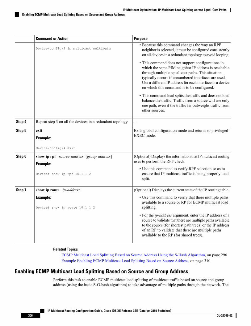
PurposeCommand or Action
Device(config)# ip multicast multipath• Because this command changes the way an RPFneighbor is selected, it must be configured consistentlyon all devices in a redundant topology to avoid looping.
• This command does not support configurations inwhich the same PIM neighbor IP address is reachablethrough multiple equal-cost paths. This situationtypically occurs if unnumbered interfaces are used.Use a different IP address for each interface in a deviceon which this command is to be configured.
• This command load splits the traffic and does not loadbalance the traffic. Traffic from a source will use onlyone path, even if the traffic far outweighs traffic fromother sources.
--Repeat step 3 on all the devices in a redundant topology.Step 4
Exits global configuration mode and returns to privilegedEXEC mode.
exit
Example:
Step 5
Device(config)# exit
(Optional) Displays the information that IPmulticast routinguses to perform the RPF check.
show ip rpf source-address [group-address]
Example:
Step 6
• Use this command to verify RPF selection so as toensure that IP multicast traffic is being properly loadsplit.
Device# show ip rpf 10.1.1.2
(Optional) Displays the current state of the IP routing table.show ip route ip-addressStep 7
Example: • Use this command to verify that there multiple pathsavailable to a source or RP for ECMP multicast loadsplitting.Device# show ip route 10.1.1.2
• For the ip-address argument, enter the IP address of asource to validate that there are multiple paths availableto the source (for shortest path trees) or the IP addressof an RP to validate that there are multiple pathsavailable to the RP (for shared trees).
Related TopicsECMP Multicast Load Splitting Based on Source Address Using the S-Hash Algorithm, on page 296Example Enabling ECMP Multicast Load Splitting Based on Source Address, on page 310
Enabling ECMP Multicast Load Splitting Based on Source and Group AddressPerform this task to enable ECMP multicast load splitting of multicast traffic based on source and groupaddress (using the basic S-G-hash algorithm) to take advantage of multiple paths through the network. The
IP Multicast Routing Configuration Guide, Cisco IOS XE Release 3SE (Catalyst 3850 Switches)OL-26766-02306
IP Multicast Optimization: IP Multicast Load Splitting across Equal-Cost PathsEnabling ECMP Multicast Load Splitting Based on Source and Group Address

basic S-G-hash algorithm is predictable because no randomization is used in calculating the hash value.Thebasic S-G-hash algorithm, however, is subject to polarization because for a given source and group, the samehash is always picked irrespective of the device on which the hash is being calculated.
The basic S-G-hash algorithm provides more flexible support for ECMP multicast load splitting than the theS-hash algorithm. Using the basic S-G-hash algorithm for load splitting, in particular, enables multicast trafficfrom devices that send many streams to groups or that broadcast many channels, such as IPTV servers orMPEG video servers, to be more effectively load split across equal-cost paths.
Enable ECMP multicast load splitting on the device that is to be the receiver for traffic from more than oneincoming interfaces, which is opposite to unicast routing. From the perspective of unicast, multicast is activeon the sending device connecting to more than one outgoing interfaces.
Note
SUMMARY STEPS
1. enable2. configure terminal3. ip multicast multipath s-g-hash basic4. Repeat Step 3 on all the devices in a redundant topology.5. exit6. show ip rpf source-address [group-address]7. show ip route ip-address
DETAILED STEPS
PurposeCommand or Action
Enables privileged EXEC mode.enableStep 1
Example: • Enter your password if prompted.
Device> enable
Enters global configuration mode.configure terminal
Example:
Step 2
Device# configure terminal
Enables ECMPmulticast load splitting based on source andgroup address using the basic S-G-hash algorithm.
ip multicast multipath s-g-hash basic
Example:
Step 3
• Because this command changes the way an RPFneighbor is selected, it must be configured consistentlyon all devices in a redundant topology to avoid looping.
Device(config)# ip multicast multipath s-g-hashbasic
--Repeat Step 3 on all the devices in a redundant topology.Step 4
Exits global configuration mode and returns to privilegedEXEC mode.
exit
Example:
Step 5
IP Multicast Routing Configuration Guide, Cisco IOS XE Release 3SE (Catalyst 3850 Switches)307OL-26766-02
IP Multicast Optimization: IP Multicast Load Splitting across Equal-Cost PathsEnabling ECMP Multicast Load Splitting Based on Source and Group Address

PurposeCommand or Action
Device(config)# exit
(Optional) Displays the information that IPmulticast routinguses to perform the RPF check.
show ip rpf source-address [group-address]
Example:
Step 6
• Use this command to verify RPF selection so as toensure that IP multicast traffic is being properly loadsplit.
Device# show ip rpf 10.1.1.2
(Optional) Displays the current state of the IP routing table.show ip route ip-addressStep 7
Example: • Use this command to verify that there multiple pathsavailable to a source or RP for ECMP multicast loadsplitting.Device# show ip route 10.1.1.2
• For the ip-address argument, enter the IP address of asource to validate that there are multiple paths availableto the source (for shortest path trees) or the IP addressof an RP to validate that there are multiple pathsavailable to the RP (for shared trees).
Related TopicsECMPMulticast Load Splitting Based on Source andGroupAddress Using the Basic S-G-HashAlgorithm,on page 297Example Enabling ECMP Multicast Load Splitting Based on Source and Group Address, on page 310
Enabling ECMP Multicast Load Splitting Based on Source Group and Next-Hop AddressPerform this task to enable ECMP multicast load splitting of multicast traffic based on source, group, andnext-hop address (using the next-hop-based S-G-hash algorithm) to take advantage of multiple paths throughthe network. The next-hop-based S-G-hash algorithm is predictable because no randomization is used incalculating the hash value. Unlike the S-hash and basic S-G-hash algorithms, the hash mechanism used bythe next-hop-based S-G-hash algorithm is not subject to polarization.
The next-hop-based S-G-hash algorithm provides more flexible support for ECMP multicast load splittingthan S-hash algorithm and eliminates the polarization problem. Using the next-hop-based S-G-hash algorithmfor ECMP multicast load splitting enables multicast traffic from devices that send many streams to groups orthat broadcast many channels, such as IPTV servers or MPEG video servers, to be more effectively load splitacross equal-cost paths.
SUMMARY STEPS
1. enable2. configure terminal3. ip multicast multipath s-g-hash next-hop-based4. Repeat Steps 1 through 3 on all the routers in a redundant topology.5. end6. show ip rpf source-address [group-address]7. show ip route ip-address
IP Multicast Routing Configuration Guide, Cisco IOS XE Release 3SE (Catalyst 3850 Switches)OL-26766-02308
IP Multicast Optimization: IP Multicast Load Splitting across Equal-Cost PathsEnabling ECMP Multicast Load Splitting Based on Source Group and Next-Hop Address

DETAILED STEPS
PurposeCommand or Action
Enables privileged EXEC mode.enableStep 1
Example: • Enter your password if prompted.
Router> enable
Enters global configuration mode.configure terminal
Example:
Step 2
Router# configure terminal
Enables ECMP multicast load splitting based on source,group, and next-hop-address using the next-hop-basedS-G-hash algorithm.
ip multicast multipath s-g-hash next-hop-based
Example:
Router(config)# ip multicast multipath s-g-hashnext-hop-based
Step 3
• Because this command changes the way an RPFneighbor is selected, it must be configured consistentlyon all routers in a redundant topology to avoid looping.
Be sure to enable the ip multicast multipathcommand on the router that is supposed to bethe receiver for traffic from more than oneincoming interfaces, which is opposite to unicastrouting. From the perspective of unicast,multicast is active on the sending routerconnecting to more than one outgoing interfaces.
Note
--Repeat Steps 1 through 3 on all the routers in a redundanttopology.
Step 4
Exits global configuration mode and returns to privilegedEXEC mode.
end
Example:
Step 5
Router(config)# end
(Optional) Displays the information that IPmulticast routinguses to perform the RPF check.
show ip rpf source-address [group-address]
Example:
Step 6
• Use this command to verify RPF selection so as toensure that IP multicast traffic is being properly loadsplit.
Router# show ip rpf 10.1.1.2
(Optional) Displays the current state of the IP routing table.show ip route ip-addressStep 7
Example: • Use this command to verify that there multiple pathsavailable to a source or RP for ECMP multicast loadsplitting.Router# show ip route 10.1.1.2
• For the ip-address argument, enter the IP address of asource to validate that there are multiple paths available
IP Multicast Routing Configuration Guide, Cisco IOS XE Release 3SE (Catalyst 3850 Switches)309OL-26766-02
IP Multicast Optimization: IP Multicast Load Splitting across Equal-Cost PathsEnabling ECMP Multicast Load Splitting Based on Source Group and Next-Hop Address
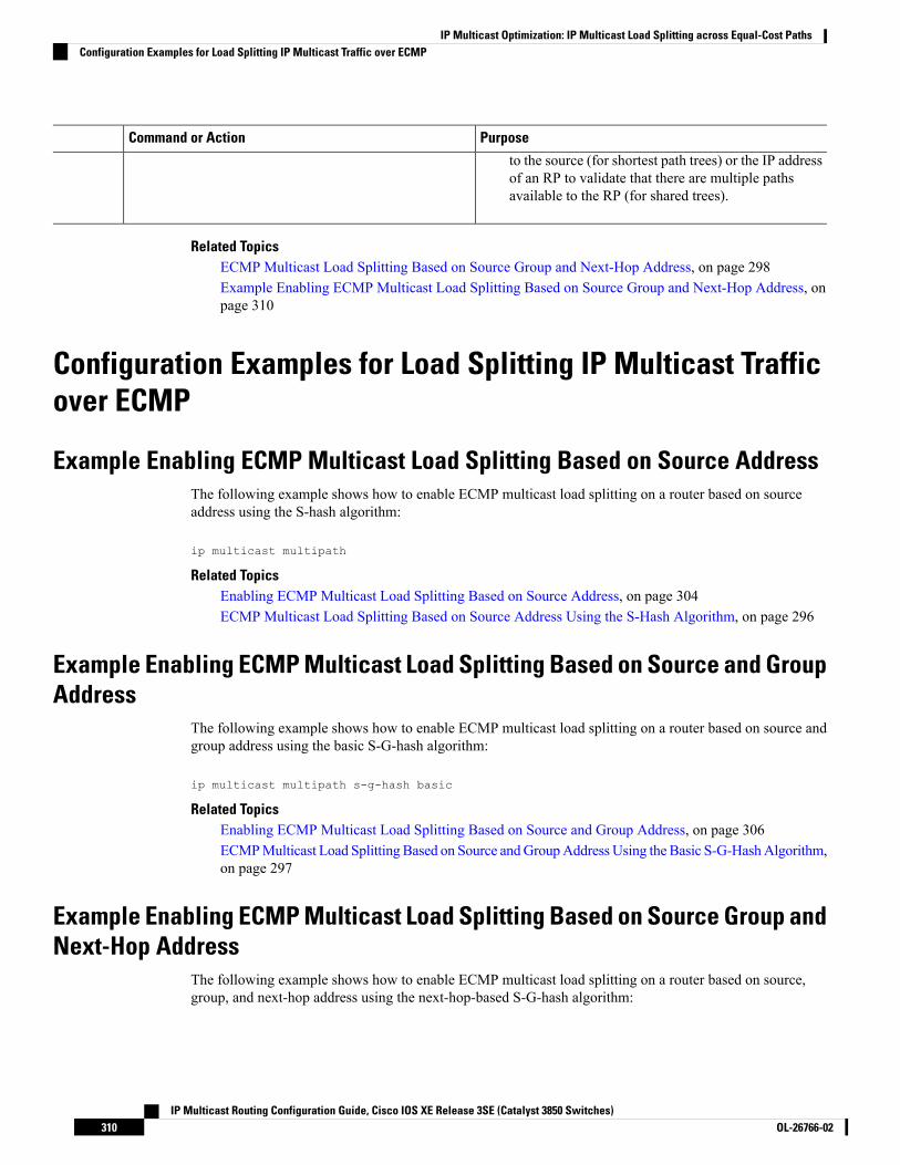
PurposeCommand or Action
to the source (for shortest path trees) or the IP addressof an RP to validate that there are multiple pathsavailable to the RP (for shared trees).
Related TopicsECMP Multicast Load Splitting Based on Source Group and Next-Hop Address, on page 298Example Enabling ECMP Multicast Load Splitting Based on Source Group and Next-Hop Address, onpage 310
Configuration Examples for Load Splitting IP Multicast Trafficover ECMP
Example Enabling ECMP Multicast Load Splitting Based on Source AddressThe following example shows how to enable ECMP multicast load splitting on a router based on sourceaddress using the S-hash algorithm:
ip multicast multipath
Related TopicsEnabling ECMP Multicast Load Splitting Based on Source Address, on page 304ECMP Multicast Load Splitting Based on Source Address Using the S-Hash Algorithm, on page 296
Example Enabling ECMP Multicast Load Splitting Based on Source and GroupAddress
The following example shows how to enable ECMP multicast load splitting on a router based on source andgroup address using the basic S-G-hash algorithm:
ip multicast multipath s-g-hash basic
Related TopicsEnabling ECMP Multicast Load Splitting Based on Source and Group Address, on page 306ECMPMulticast Load Splitting Based on Source andGroupAddress Using the Basic S-G-HashAlgorithm,on page 297
Example Enabling ECMP Multicast Load Splitting Based on Source Group andNext-Hop Address
The following example shows how to enable ECMP multicast load splitting on a router based on source,group, and next-hop address using the next-hop-based S-G-hash algorithm:
IP Multicast Routing Configuration Guide, Cisco IOS XE Release 3SE (Catalyst 3850 Switches)OL-26766-02310
IP Multicast Optimization: IP Multicast Load Splitting across Equal-Cost PathsConfiguration Examples for Load Splitting IP Multicast Traffic over ECMP
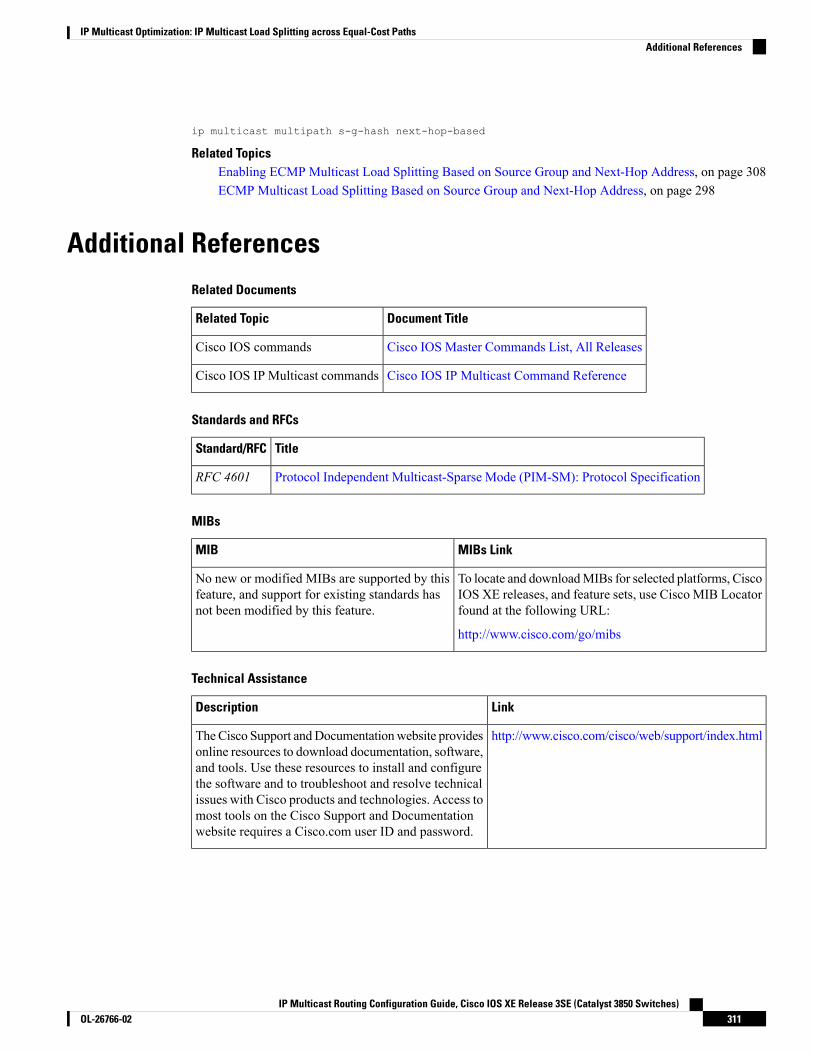
ip multicast multipath s-g-hash next-hop-based
Related TopicsEnabling ECMP Multicast Load Splitting Based on Source Group and Next-Hop Address, on page 308ECMP Multicast Load Splitting Based on Source Group and Next-Hop Address, on page 298
Additional ReferencesRelated Documents
Document TitleRelated Topic
Cisco IOS Master Commands List, All ReleasesCisco IOS commands
Cisco IOS IP Multicast Command ReferenceCisco IOS IP Multicast commands
Standards and RFCs
TitleStandard/RFC
Protocol Independent Multicast-Sparse Mode (PIM-SM): Protocol SpecificationRFC 4601
MIBs
MIBs LinkMIB
To locate and downloadMIBs for selected platforms, CiscoIOS XE releases, and feature sets, use Cisco MIB Locatorfound at the following URL:
http://www.cisco.com/go/mibs
No new or modified MIBs are supported by thisfeature, and support for existing standards hasnot been modified by this feature.
Technical Assistance
LinkDescription
http://www.cisco.com/cisco/web/support/index.htmlTheCisco Support andDocumentationwebsite providesonline resources to download documentation, software,and tools. Use these resources to install and configurethe software and to troubleshoot and resolve technicalissues with Cisco products and technologies. Access tomost tools on the Cisco Support and Documentationwebsite requires a Cisco.com user ID and password.
IP Multicast Routing Configuration Guide, Cisco IOS XE Release 3SE (Catalyst 3850 Switches)311OL-26766-02
IP Multicast Optimization: IP Multicast Load Splitting across Equal-Cost PathsAdditional References

Feature History and Information for Load Splitting IP MulticastTraffic over ECMP
ModificationRelease
This feature was introduced.Cisco IOS XE 3.2SE
IP Multicast Routing Configuration Guide, Cisco IOS XE Release 3SE (Catalyst 3850 Switches)OL-26766-02312
IP Multicast Optimization: IP Multicast Load Splitting across Equal-Cost PathsFeature History and Information for Load Splitting IP Multicast Traffic over ECMP

C H A P T E R 16IP Multicast Optimization: SSM Channel BasedFiltering for Multicast
• Finding Feature Information, on page 313• Finding Feature Information, on page 313• Prerequisites for SSM Channel Based Filtering for Multicast Boundaries, on page 314• Information About the SSM Channel Based Filtering for Multicast Boundaries Feature, on page 314• How to Configure SSM Channel Based Filtering for Multicast Boundaries, on page 315• Configuration Examples for SSM Channel Based Filtering for Multicast Boundaries, on page 316• Additional References, on page 317• Feature History and Information for SSM Channel Based Filtering for Multicast Boundaries, on page318
Finding Feature InformationYour software release may not support all the features documented in this module. For the latest caveats andfeature information, see Bug Search Tool and the release notes for your platform and software release. Tofind information about the features documented in this module, and to see a list of the releases in which eachfeature is supported, see the feature information table at the end of this module.
Use Cisco Feature Navigator to find information about platform support and Cisco software image support.To access Cisco Feature Navigator, go to http://www.cisco.com/go/cfn. An account on Cisco.com is notrequired.
Finding Feature InformationYour software release may not support all the features documented in this module. For the latest caveats andfeature information, see Bug Search Tool and the release notes for your platform and software release. Tofind information about the features documented in this module, and to see a list of the releases in which eachfeature is supported, see the feature information table.
Use Cisco Feature Navigator to find information about platform support and Cisco software image support.To access Cisco Feature Navigator, go to www.cisco.com/go/cfn. An account on Cisco.com is not required.
IP Multicast Routing Configuration Guide, Cisco IOS XE Release 3SE (Catalyst 3850 Switches)313OL-26766-02

Prerequisites for SSM Channel Based Filtering for MulticastBoundaries
IP multicast is enabled on the device using the tasks described in the "Configuring Basic IPMulticast" moduleof the IP Multicast: PIM Configuration Guide.
Information About the SSM Channel Based Filtering forMulticast Boundaries Feature
Rules for Multicast BoundariesThe SSM Channel Based Filtering for Multicast Boundaries feature expands the ip multicast boundarycommand for control plane filtering support. More than one ip multicast boundary command can be appliedto an interface.
The following rules govern the ip multicast boundary command:
• One instance of the in and out keywords can be configured on an interface.
• The in and out keywords can be used for standard or extended access lists.
• Only standard access lists are permitted with the use of the filter-autorp keyword or no keyword.
• A maximum of three instances of a command will be allowed on an interface: one instance of in, oneinstance of out, and one instance of filter-autorp or no keyword.
• Whenmultiple instances of the command are used, the filtering will be cumulative. If a boundary statementwith no keyword exists with a boundary statement with the inkeyword, both access lists will be appliedon the in direction and a match on either one will be sufficient.
• All instances of the command apply to both control and data plane traffic.
• Protocol information on the extended access list is parsed to allow reuse and filtering for consistency.An (S,G) operation will be filtered by an extended access list under all conditions stated above forkeywords if the access list filters (S,G) traffic for all protocols.
Related TopicsConfiguring Multicast Boundaries, on page 315Configuring the Multicast Boundaries Permitting and Denying Traffic Example, on page 316Configuring the Multicast Boundaries Permitting Traffic Example, on page 316Configuring the Multicast Boundaries Denying Traffic Example, on page 317
Benefits of SSM Channel Based Filtering for Multicast Boundaries• This feature allows input on the source interface.
• The access control capabilities are the same for SSM and Any Source Multicast (ASM).
IP Multicast Routing Configuration Guide, Cisco IOS XE Release 3SE (Catalyst 3850 Switches)OL-26766-02314
IP Multicast Optimization: SSM Channel Based Filtering for MulticastPrerequisites for SSM Channel Based Filtering for Multicast Boundaries

How to Configure SSM Channel Based Filtering for MulticastBoundaries
Configuring Multicast Boundaries
SUMMARY STEPS
1. enable2. configure terminal3. ip access-list {standard| extended} access-list-name4. permit protocol host address host address5. deny protocol host address host address6. Repeat Step 4 or Step 5 as needed.7. interface type interface-number port -number8. ip multicast boundary access-list-name [in| out | filter-autorp]
DETAILED STEPS
PurposeCommand or Action
Enables privileged EXEC mode.enable
Example:
Step 1
Device> enable
Enters global configuration mode.configure terminal
Example:
Step 2
Device# configure terminal
Configures the standard or extended access list.ip access-list {standard| extended} access-list-name
Example:
Step 3
Device(config)# ip access-list 101
Permits specified ip host traffic.permit protocol host address host address
Example:
Step 4
Device(config-ext-nacl)# permit ip host 181.1.2.201host 232.1.1.11
Denies specified multicast ip group and source traffic.deny protocol host address host address
Example:
Step 5
Device(config-acl-nacl)# deny ip host 181.1.2.203host 232.1.1.1
IP Multicast Routing Configuration Guide, Cisco IOS XE Release 3SE (Catalyst 3850 Switches)315OL-26766-02
IP Multicast Optimization: SSM Channel Based Filtering for MulticastHow to Configure SSM Channel Based Filtering for Multicast Boundaries

PurposeCommand or Action
Permits and denies specified host and source traffic.Repeat Step 4 or Step 5 as needed.Step 6
Enables interface configuration mode.interface type interface-number port -number
Example:
Step 7
Device(config)# interface gigabitethernet 2/3/0
Configures the multicast boundary.ip multicast boundary access-list-name [in| out |filter-autorp]
Step 8
The filter-autorp keyword does not supportextended access lists.
NoteExample:
Device(config-if)# ip multicast boundary acc_grp1out
Related TopicsRules for Multicast Boundaries, on page 314Configuring the Multicast Boundaries Permitting and Denying Traffic Example, on page 316Configuring the Multicast Boundaries Permitting Traffic Example, on page 316Configuring the Multicast Boundaries Denying Traffic Example, on page 317
Configuration Examples for SSM Channel Based Filtering forMulticast Boundaries
Configuring the Multicast Boundaries Permitting and Denying Traffic ExampleThe following example permits outgoing traffic for (181.1.2.201, 232.1.1.1) and (181.1.2.202, 232.1.1.1) anddenies all other (S,G)s.
configure terminalip access-list extended acc_grp1permit ip host 0.0.0.0 232.1.1.1 0.0.0.255permit ip host 181.1.2.201 host 232.1.1.1permit udp host 181.1.2.202 host 232.1.1.1permit ip host 181.1.2.202 host 232.1.1.1deny igmp host 181.2.3.303 host 232.1.1.1interface gigabitethernet 2/3/0ip multicast boundary acc_grp1 out
Related TopicsConfiguring Multicast Boundaries, on page 315Rules for Multicast Boundaries, on page 314
Configuring the Multicast Boundaries Permitting Traffic ExampleThe following example permits outgoing traffic for (192.168.2.201, 232.1.1.5) and 192.168.2.202, 232.1.1.5).
IP Multicast Routing Configuration Guide, Cisco IOS XE Release 3SE (Catalyst 3850 Switches)OL-26766-02316
IP Multicast Optimization: SSM Channel Based Filtering for MulticastConfiguration Examples for SSM Channel Based Filtering for Multicast Boundaries

configure terminalip access-list extended acc_grp6permit ip host 0.0.0.0 232.1.1.1 5.0.0.255deny udp host 192.168.2.201 host 232.1.1.5permit ip host 192.168.2.201 host 232.1.1.5deny pim host 192.168.2.201 host 232.1.1.5permit ip host 192.168.2.202 host 232.1.1.5deny igmp host 192.2.3.303 host 232.1.1.1interface gigabitethernet 2/3/0ip multicast boundary acc_grp6 out
Related TopicsConfiguring Multicast Boundaries, on page 315Rules for Multicast Boundaries, on page 314
Configuring the Multicast Boundaries Denying Traffic ExampleThe following example denies a group-range that is announced by the candidate RP. Because the group rangeis denied, no pim auto-rp mappings are created.
configure terminalip access-list standard acc_grp10deny 225.0.0.0 0.255.255.255permit anyaccess-list extended acc_grp12permit pim host 181.1.2.201 host 232.1.1.8deny udp host 181.1.2.201 host 232.1.1.8permit pim host 181.1.2.203 0.0.0.255 host 227.7.7.7permit ip host 0.0.0.0 host 227.7.7.7permit ip 181.1.2.203 0.0.0.255 host 227.7.7.7permit ip host 181.1.2.201 host 232.1.1.7ip access-list extended acc_grp13deny ip host 181.1.2.201 host 232.1.1.8permit ip any anyinterface gigabitethernet 2/3/0ip multicast boundary acc_grp10 filter-autorpip multicast boundary acc_grp12 outip multicast boundary acc_grp13 in
Related TopicsConfiguring Multicast Boundaries, on page 315Rules for Multicast Boundaries, on page 314
Additional ReferencesRelated Documents
Document TitleRelated Topic
Cisco IOS Master Commands List, All ReleasesCisco IOS commands
Cisco IOS IP Multicast Command ReferenceCisco IOS IP Multicast commands
IP Multicast Routing Configuration Guide, Cisco IOS XE Release 3SE (Catalyst 3850 Switches)317OL-26766-02
IP Multicast Optimization: SSM Channel Based Filtering for MulticastConfiguring the Multicast Boundaries Denying Traffic Example
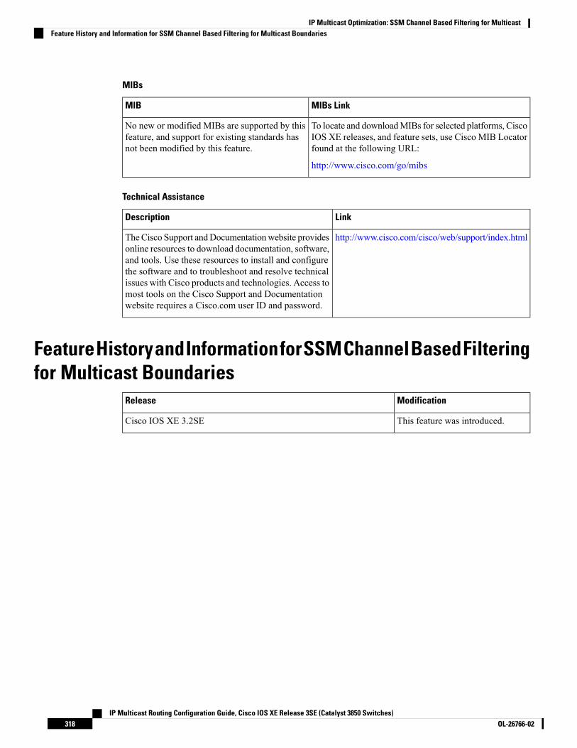
MIBs
MIBs LinkMIB
To locate and downloadMIBs for selected platforms, CiscoIOS XE releases, and feature sets, use Cisco MIB Locatorfound at the following URL:
http://www.cisco.com/go/mibs
No new or modified MIBs are supported by thisfeature, and support for existing standards hasnot been modified by this feature.
Technical Assistance
LinkDescription
http://www.cisco.com/cisco/web/support/index.htmlTheCisco Support andDocumentationwebsite providesonline resources to download documentation, software,and tools. Use these resources to install and configurethe software and to troubleshoot and resolve technicalissues with Cisco products and technologies. Access tomost tools on the Cisco Support and Documentationwebsite requires a Cisco.com user ID and password.
FeatureHistoryandInformationforSSMChannelBasedFilteringfor Multicast Boundaries
ModificationRelease
This feature was introduced.Cisco IOS XE 3.2SE
IP Multicast Routing Configuration Guide, Cisco IOS XE Release 3SE (Catalyst 3850 Switches)OL-26766-02318
IP Multicast Optimization: SSM Channel Based Filtering for MulticastFeature History and Information for SSM Channel Based Filtering for Multicast Boundaries
C H A P T E R 17IP Multicast Optimization: PIM Dense Mode StateRefresh
• Finding Feature Information, on page 319• Prerequisite for PIM Dense Mode State Refresh, on page 319• Restrictions on PIM Dense Mode State Refresh, on page 319• Information About PIM Dense Mode State Refresh, on page 320• How to Configure PIM Dense Mode State Refresh, on page 320• Configuration Examples for PIM Dense Mode State Refresh, on page 322• Additional References, on page 323• Feature History and Information for PIM Dense Mode State Refresh, on page 324
Finding Feature InformationYour software release may not support all the features documented in this module. For the latest caveats andfeature information, see Bug Search Tool and the release notes for your platform and software release. Tofind information about the features documented in this module, and to see a list of the releases in which eachfeature is supported, see the feature information table at the end of this module.
Use Cisco Feature Navigator to find information about platform support and Cisco software image support.To access Cisco Feature Navigator, go to http://www.cisco.com/go/cfn. An account on Cisco.com is notrequired.
Prerequisite for PIM Dense Mode State Refresh• You must have PIM dense mode enabled on an interface before configuring the PIM Dense Mode StateRefresh feature.
Restrictions on PIM Dense Mode State Refresh• All routers in a PIM dense mode network must run a software release that supports the PIM Dense ModeState Refresh feature to process and forward state refresh control messages.
IP Multicast Routing Configuration Guide, Cisco IOS XE Release 3SE (Catalyst 3850 Switches)319OL-26766-02

• The origination interval for the state refresh control message must be the same for all PIM routers on thesame LAN. Specifically, the same origination interval must be configured on each router interface thatis directly connected to the LAN.
Information About PIM Dense Mode State Refresh
PIM Dense Mode State Refresh OverviewThe PIMDenseMode State Refresh feature is an extension of the PIMVersion 2 multicast routing architecture.
PIM dense mode builds source-based multicast distribution trees that operate on a flood and prune principle.Multicast packets from a source are flooded to all areas of a PIM dense mode network. PIM routers that receivemulticast packets and have no directly connected multicast group members or PIM neighbors send a prunemessage back up the source-based distribution tree toward the source of the packets. As a result, subsequentmulticast packets are not flooded to pruned branches of the distribution tree. However, the pruned state inPIM dense mode times out approximately every 3 minutes and the entire PIM dense mode network is refloodedwith multicast packets and prune messages. This reflooding of unwanted traffic throughout the PIM densemode network consumes network bandwidth.
The PIM Dense Mode State Refresh feature keeps the pruned state in PIM dense mode from timing out byperiodically forwarding a control message down the source-based distribution tree. The control messagerefreshes the prune state on the outgoing interfaces of each router in the distribution tree.
Related TopicsConfiguring PIM Dense Mode State Refresh, on page 320Originating Processing and Forwarding PIM Dense Mode State Refresh Control Messages Example, onpage 322Processing and Forwarding PIM Dense Mode State Refresh Control Messages Example, on page 323
Benefits of PIM Dense Mode State RefreshThe PIMDenseMode State Refresh feature keeps the pruned state in PIM dense mode from timing out, whichsaves network bandwidth by greatly reducing the reflooding of unwanted multicast traffic to pruned branchesof the PIM dense mode network. This feature also enables PIM routers in a PIM dense mode multicast networkto recognize topology changes (sources joining or leaving a multicast group) before the default 3-minute staterefresh timeout period.
How to Configure PIM Dense Mode State Refresh
Configuring PIM Dense Mode State RefreshThere are no configuration tasks for enabling the PIM Dense Mode State Refresh feature. By default, all PIMrouters that are running a Cisco IOS XE software release that supports the PIM Dense Mode State Refreshfeature automatically process and forward state refresh control messages.
IP Multicast Routing Configuration Guide, Cisco IOS XE Release 3SE (Catalyst 3850 Switches)OL-26766-02320
IP Multicast Optimization: PIM Dense Mode State RefreshInformation About PIM Dense Mode State Refresh

To disable the processing and forwarding of state refresh control messages on a PIM router, use the ip pimstate-refresh disableglobal configuration command. To enable state refresh again if it has been disabled, usethe no ip pim state-refresh disableglobal configuration command.
The origination of state refresh control messages is disabled by default. To configure the origination of thecontrol messages on a PIM router, use the following commands beginning in global configuration mode:
PurposeCommand
Specifies an interface and places the router in interface configurationmode.Router(config)# interface type
number
Configures the origination of the PIM Dense Mode State Refreshcontrol message. Optionally, you can configure the number ofseconds between control messages by using the interval argument.The default interval is 60 seconds. The interval range is 1 secondto 100 seconds.
Router(config-if)# ip pimstate-refreshorigination-interval[interval]
Related TopicsPIM Dense Mode State Refresh Overview, on page 320Originating Processing and Forwarding PIM Dense Mode State Refresh Control Messages Example, onpage 322Processing and Forwarding PIM Dense Mode State Refresh Control Messages Example, on page 323
Verifying PIM Dense Mode State Refresh ConfigurationUse the show ip pim interface [type number] detail and the show ip pim neighbor [interface] commandsto verify that the PIM Dense Mode State Refresh feature is configured correctly. The following output of theshow ip pim interface [type number] detail command indicates that processing, forwarding, and originationof state refresh control messages is enabled.
Router# show ip pim interface fastethernet 0/1/0 detailFastEthernet0/1/0 is up, line protocol is upInternet address is 172.16.8.1/24Multicast switching:processMulticast packets in/out:0/0Multicast boundary:not setMulticast TTL threshold:0PIM:enabledPIM version:2, mode:densePIM DR:172.16.8.1 (this system)PIM neighbor count:0PIM Hello/Query interval:30 seconds
PIM State-Refresh processing:enabledPIM State-Refresh origination:enabled, interval:60 seconds
PIM NBMA mode:disabledPIM ATM multipoint signalling:disabledPIM domain border:disabled
Multicast Tagswitching:disabled
The S in the Mode field of the following show ip pim neighbor [interface] command output indicates thatthe neighbor has the PIM Dense Mode State Refresh feature configured.
Router# show ip pim neighborPIM Neighbor Table
IP Multicast Routing Configuration Guide, Cisco IOS XE Release 3SE (Catalyst 3850 Switches)321OL-26766-02
IP Multicast Optimization: PIM Dense Mode State RefreshVerifying PIM Dense Mode State Refresh Configuration
Neighbor Interface Uptime/Expires Ver DRAddress Priority/Mode172.16.5.1 Ethernet1/1 00:09:03/00:01:41 v2 1 / B S
Monitoring and Maintaining PIM DM State RefreshFollowing are the PIMDenseMode State Refresh control messages that are sent and received by a PIM routerafter the debug ip pim privileged EXEC command is configured for multicast group 239.0.0.1:
Router# debug ip pim 239.0.0.1*Mar 1 00:25:10.416:PIM:Originating refresh message for(172.16.8.3,239.0.0.1)*Mar 1 00:25:10.416:PIM:Send SR on GigabitEthernet1/1/0 for (172.16.8.3,239.0.0.1)TTL=9
The following output from the show ip mroute command displays are the resulting prune timer changes forGigabitEthernet interface1/0/0 and multicast group 239.0.0.1. (The following output assumes that the debugip pim privileged EXEC command has already been configured on the router.) In the first output from theshow ip mroute command, the prune timer reads 00:02:06. The debug messages indicate that a PIM DenseMode State Refresh control message is received and sent on Ethernet interface 1/0, and that other PIM DenseMode State Refresh routers were discovered. In the second output from the show ip mroute command, theprune timer has been reset to 00:02:55.
Router# show ip mroute 239.0.0.1(172.16.8.3, 239.0.0.1), 00:09:50/00:02:06, flags:PTIncoming interface:GigabitEthernet1/1/0, RPF nbr 172.16.5.2Outgoing interface list:GigabitEthernet1/0/0, Prune/Dense, 00:09:43/00:02:06Router#*Mar 1 00:32:06.657:PIM:SR on iif from 172.16.5.2 orig 172.16.8.1 for(172.16.8.3,239.0.0.1)*Mar 1 00:32:06.661: flags:prune-indicator*Mar 1 00:32:06.661:PIM:Cached metric is [0/0]*Mar 1 00:32:06.661:PIM:Keep RPF nbr 172.16.5.2*Mar 1 00:32:06.661:PIM:Send SR on Ethernet1/0 for (172.16.8.3,239.0.0.1)TTL=8*Mar 1 00:32:06.661: flags:prune-indicatorRouter# show ip mroute 239.0.0.1(172.16.8.3, 239.0.0.1), 00:10:01/00:02:55, flags:PTIncoming interface:GigabitEthernet1/1/0, RPF nbr 172.16.5.2Outgoing interface list:GigabitEthernet1/0/0, Prune/Dense, 00:09:55/00:02:55
Configuration Examples for PIM Dense Mode State Refresh
OriginatingProcessingandForwardingPIMDenseModeStateRefreshControlMessages Example
The following example is for a PIM router that is originating, processing, and forwarding PIM Dense ModeState Refresh control messages on Fast Ethernet interface 0/1/0 every 60 seconds:
ip multicast-routing distributedinterface FastEthernet0/1/0
IP Multicast Routing Configuration Guide, Cisco IOS XE Release 3SE (Catalyst 3850 Switches)OL-26766-02322
IP Multicast Optimization: PIM Dense Mode State RefreshMonitoring and Maintaining PIM DM State Refresh
ip address 172.16.8.1 255.255.255.0ip pim state-refresh origination-interval 60ip pim dense-mode
Related TopicsConfiguring PIM Dense Mode State Refresh, on page 320PIM Dense Mode State Refresh Overview, on page 320
Processing and Forwarding PIM Dense Mode State Refresh Control MessagesExample
The following example is for a PIM router that is just processing and forwarding PIM Dense Mode StateRefresh control messages on Fast Ethernet interface 1/1/0:
ip multicast-routinginterface FastEthernet1/1/0ip address 172.16.7.3 255.255.255.0ip pim dense-mode
Related TopicsConfiguring PIM Dense Mode State Refresh, on page 320PIM Dense Mode State Refresh Overview, on page 320
Additional ReferencesRelated Documents
Document TitleRelated Topic
“Configuring Basic IPMulticast” moduleThe PIM Dense Mode State Refresh feature is an extension ofthe PIM Version 2 multicast routing architecture
Cisco IOS IP Multicast CommandReference
IP multicast commands: complete command syntax, commandmode, defaults, command history, usage guidelines, and examples
Standards
TitleStandard
--No new or modified standards are supported by this feature, and support for existing standards has notbeen modified by this feature.
IP Multicast Routing Configuration Guide, Cisco IOS XE Release 3SE (Catalyst 3850 Switches)323OL-26766-02
IP Multicast Optimization: PIM Dense Mode State RefreshProcessing and Forwarding PIM Dense Mode State Refresh Control Messages Example

MIBs
MIBs LinkMIB
To locate and downloadMIBs for selected platforms, CiscoIOS releases, and feature sets, use Cisco MIB Locatorfound at the following URL:
http://www.cisco.com/go/mibs
No new or modified MIBs are supported by thisfeature, and support for existing standards hasnot been modified by this feature.
RFCs
TitleRFC
--No new or modified RFCs are supported by this feature, and support for existing standards has notbeen modified by this feature.
Technical Assistance
LinkDescription
http://www.cisco.com/techsupportThe Cisco Support website provides extensive online resources, includingdocumentation and tools for troubleshooting and resolving technical issueswith Cisco products and technologies.
To receive security and technical information about your products, youcan subscribe to various services, such as the Product Alert Tool (accessedfrom Field Notices), the Cisco Technical Services Newsletter, and ReallySimple Syndication (RSS) Feeds.
Access to most tools on the Cisco Support website requires a Cisco.comuser ID and password.
Feature History and Information for PIM Dense Mode StateRefresh
ModificationRelease
This feature was introduced.Cisco IOS XE 3.2SE
IP Multicast Routing Configuration Guide, Cisco IOS XE Release 3SE (Catalyst 3850 Switches)OL-26766-02324
IP Multicast Optimization: PIM Dense Mode State RefreshFeature History and Information for PIM Dense Mode State Refresh

C H A P T E R 18IP Multicast Optimization: IGMP State Limit
• Finding Feature Information, on page 325• Prerequisites for IGMP State Limit, on page 325• Restrictions for IGMP State Limit, on page 325• Information About IGMP State Limit, on page 326• How to Configure IGMP State Limit, on page 327• Configuration examples for IGMP State Limit, on page 329• Additional References, on page 331• Feature History and Information for IGMP State Limit, on page 331
Finding Feature InformationYour software release may not support all the features documented in this module. For the latest caveats andfeature information, see Bug Search Tool and the release notes for your platform and software release. Tofind information about the features documented in this module, and to see a list of the releases in which eachfeature is supported, see the feature information table at the end of this module.
Use Cisco Feature Navigator to find information about platform support and Cisco software image support.To access Cisco Feature Navigator, go to http://www.cisco.com/go/cfn. An account on Cisco.com is notrequired.
Prerequisites for IGMP State Limit• IP multicast is enabled and the Protocol Independent Multicast (PIM) interfaces are configured usingthe tasks described in the "Configuring Basic IPMulticast" module of the IPMulticast: PIMConfigurationGuide.
• ALLACLsmust be configured. For information, see the see the " Creating an IP Access List and ApplyingIt to an Interface " module of the Security Configuration Guide: Access Control Lists guide.
Restrictions for IGMP State LimitYou can configure only one global limit per device and one limit per interface.
IP Multicast Routing Configuration Guide, Cisco IOS XE Release 3SE (Catalyst 3850 Switches)325OL-26766-02

Information About IGMP State Limit
IGMP State LimitThe IGMP State Limit feature allows for the configuration of IGMP state limiters, which impose limits onmroute states resulting from IGMP membership reports (IGMP joins) on a global or per interface basis.Membership reports exceeding the configured limits are not entered into the IGMP cache. This feature canbe used to prevent DoS attacks or to provide a multicast CAC mechanism in network environments where allthe multicast flows roughly utilize the same amount of bandwidth.
IGMP state limiters impose limits on the number of mroute states resulting from IGMP, IGMP v3lite, andURL Rendezvous Directory (URD) membership reports on a global or per interface basis.
Note
Related TopicsConfiguring Global IGMP State Limiters, on page 327Configuring IGMP State Limiters Example, on page 329
IGMP State Limit Feature Design• Configuring IGMP state limiters in global configuration mode specifies a global limit on the number ofIGMP membership reports that can be cached.
• Configuring IGMP state limiters in interface configuration mode specifies a limit on the number of IGMPmembership reports on a per interface basis.
• Use ACLs to prevent groups or channels from being counted against the interface limit. A standard oran extended ACL can be specified. A standard ACL can be used to define the (*, G) state to be excludedfrom the limit on an interface. An extended ACLs can be used to define the (S, G) state to be excludedfrom the limit on an interface. An extended ACL also can be used to define the (*, G) state to be excludedfrom the limit on an interface, by specifying 0.0.0.0 for the source address and source wildcard--referredto as (0, G)--in the permit or deny statements that compose the extended access list.
• You can only configure one global limit per device and one limit per interface.
Mechanics of IGMP State LimitersThe mechanics of IGMP state limiters are as follows:
• Each time a router receives an IGMPmembership report for a particular group or channel, the Cisco IOSsoftware checks to see if either the limit for the global IGMP state limiter or the limit for the per interfaceIGMP state limiter has been reached.
• If only a global IGMP state limiter has been configured and the limit has not been reached, IGMPmembership reports are honored. When the configured limit has been reached, subsequent IGMPmembership reports are then ignored (dropped) and a warning message in one of the following formatsis generated:
IP Multicast Routing Configuration Guide, Cisco IOS XE Release 3SE (Catalyst 3850 Switches)OL-26766-02326
IP Multicast Optimization: IGMP State LimitInformation About IGMP State Limit

•%IGMP-6-IGMP_GROUP_LIMIT: IGMP limit exceeded for <group (*, group address)> on<interface type number> by host <ip address>
•%IGMP-6-IGMP_CHANNEL_LIMIT: IGMP limit exceeded for <channel (source address, groupaddress)> on <interface type number> by host <ip address>
• If only per interface IGMP state limiters are configured, then each limit is only counted against theinterface on which it was configured.
• If both a global IGMP state limiter and per interface IGMP state limiters are configured, the limitsconfigured for the per interface IGMP state limiters are still enforced but are constrained by the globallimit.
How to Configure IGMP State Limit
Configuring IGMP State Limiters
IGMP state limiters impose limits on the number of mroute states resulting from IGMP, IGMP v3lite, andURD membership reports on a global or per interface basis.
Note
Configuring Global IGMP State LimitersPerform this optional task to configure one global IGMP state limiter per device.
SUMMARY STEPS
1. enable2. configure terminal3. ip igmp limit number4. end5. show ip igmp groups
DETAILED STEPS
PurposeCommand or Action
Enables privileged EXEC mode.enableStep 1
Example: • Enter your password if prompted.
Device> enable
Enters global configuration mode.configure terminal
Example:
Step 2
IP Multicast Routing Configuration Guide, Cisco IOS XE Release 3SE (Catalyst 3850 Switches)327OL-26766-02
IP Multicast Optimization: IGMP State LimitHow to Configure IGMP State Limit

PurposeCommand or Action
Device# configure terminal
Configures a global limit on the number of mroute statesresulting from IGMP membership reports (IGMP joins).
ip igmp limit number
Example:
Step 3
Device(config)# ip igmp limit 150
Ends the current configuration session and returns toprivileged EXEC mode.
end
Example:
Step 4
Device(config-if)# end
(Optional) Displays the multicast groups with receivers thatare directly connected to the device and that were learnedthrough IGMP.
show ip igmp groups
Example:
Device# show ip igmp groups
Step 5
Related TopicsIGMP State Limit, on page 326Configuring IGMP State Limiters Example, on page 329
Configuring Per Interface IGMP State LimitersPerform this optional task to configure a per interface IGMP state limiter.
SUMMARY STEPS
1. enable2. configure terminal3. interface type number4. ip igmp limit number [except access-list]5. Do one of the following:
• exit• end
6. show ip igmp interface [type number]7. show ip igmp groups
DETAILED STEPS
PurposeCommand or Action
Enables privileged EXEC mode.enableStep 1
Example: • Enter your password if prompted.
Device> enable
IP Multicast Routing Configuration Guide, Cisco IOS XE Release 3SE (Catalyst 3850 Switches)OL-26766-02328
IP Multicast Optimization: IGMP State LimitConfiguring Per Interface IGMP State Limiters

PurposeCommand or Action
Enters global configuration mode.configure terminal
Example:
Step 2
Device# configure terminal
Enters interface configuration mode.interface type numberStep 3
Example: • Specify an interface that is connected to hosts.
Device(config)# interface GigabitEthernet0/0
Configures a per interface limit on the number of mroutesstates created as a result of IGMP membership reports(IGMP joins).
ip igmp limit number [except access-list]
Example:
Device(config-if)# ip igmp limit 100
Step 4
Do one of the following:Step 5 • (Optional) Ends the current configuration session andreturns to global configuration mode. Repeat steps 3• exit and 4 to configure a per interface limiter on anotherinterface.• end
Example: • Ends the current configuration session and returns toprivileged EXEC mode.Device(config-if)# exit
Device(config-if)# end
(Optional) Displays information about the status andconfiguration of IGMP and multicast routing on interfaces.
show ip igmp interface [type number]
Example:
Step 6
Device# show ip igmp interface
(Optional) Displays the multicast groups with receivers thatare directly connected to the device and that were learnedthrough IGMP.
show ip igmp groups
Example:
Device# show ip igmp groups
Step 7
Configuration examples for IGMP State Limit
Configuring IGMP State Limiters ExampleThe following example shows how to configure IGMP state limiters to provide multicast CAC in a networkenvironment where all the multicast flows roughly utilize the same amount of bandwidth.
This example uses the topology illustrated in the figure.
IP Multicast Routing Configuration Guide, Cisco IOS XE Release 3SE (Catalyst 3850 Switches)329OL-26766-02
IP Multicast Optimization: IGMP State LimitConfiguration examples for IGMP State Limit

Although the following illustration and example uses routers in the configuration, any device (router or switch)can be used.
Note
Figure 20: IGMP State Limit Example Topology
In this example, a service provider is offering 300 Standard Definition (SD) TV channels. Each SD channelutilizes approximately 4 Mbps.
The service provider must provision the Gigabit Ethernet interfaces on the PE router connected to the DigitalSubscriber Line Access Multiplexers (DSLAMs) as follows: 50% of the link’s bandwidth (500 Mbps) mustbe available to subscribers of the Internet, voice, and video on demand (VoD) service offerings while theremaining 50% (500 Mbps) of the link’s bandwidth must be available to subscribers of the SD channelofferings.
Because each SD channel utilizes the same amount of bandwidth (4 Mbps), per interface IGMP state limiterscan be used to provide the necessary CAC to provision the services being offered by the service provider. Todetermine the required CAC needed per interface, the total number of channels is divided by 4 (because eachchannel utilizes 4 Mbps of bandwidth). The required CAC needed per interface, therefore, is as follows:
500Mbps / 4Mbps = 125 mroutes
Once the required CAC is determined, the service provider uses the results to configure the per IGMP statelimiters required to provision the Gigabit Ethernet interfaces on the PE router. Based on the network’s CACrequirements, the service provider must limit the SD channels that can be transmitted out a Gigabit Ethernetinterface (at any given time) to 125. Configuring a per interface IGMP state limit of 125 for the SD channelsprovisions the interface for 500 Mbps of bandwidth, the 50% of the link’s bandwidth that must always beavailable (but never exceeded) for the SD channel offerings.
The following configuration shows how the service provider uses a per interface mroute state limiter toprovision interface Gigabit Ethernet 0/0/0 for the SD channels and Internet, Voice, and VoD services beingoffered to subscribers:
interface GigabitEthernet0/0/0description --- Interface towards the DSLAM ---
IP Multicast Routing Configuration Guide, Cisco IOS XE Release 3SE (Catalyst 3850 Switches)OL-26766-02330
IP Multicast Optimization: IGMP State LimitConfiguring IGMP State Limiters Example

.
.
.ip igmp limit 125
Related TopicsConfiguring Global IGMP State Limiters, on page 327IGMP State Limit, on page 326
Additional ReferencesRelated Documents
Document TitleRelated Topic
Cisco IOS Master Commands List, All ReleasesCisco IOS commands
Cisco IOS IP Multicast Command ReferenceCisco IOS IP Multicast commands
MIBs
MIBs LinkMIB
To locate and downloadMIBs for selected platforms, CiscoIOS XE releases, and feature sets, use Cisco MIB Locatorfound at the following URL:
http://www.cisco.com/go/mibs
No new or modified MIBs are supported by thisfeature, and support for existing standards hasnot been modified by this feature.
Technical Assistance
LinkDescription
http://www.cisco.com/cisco/web/support/index.htmlTheCisco Support andDocumentationwebsite providesonline resources to download documentation, software,and tools. Use these resources to install and configurethe software and to troubleshoot and resolve technicalissues with Cisco products and technologies. Access tomost tools on the Cisco Support and Documentationwebsite requires a Cisco.com user ID and password.
Feature History and Information for IGMP State LimitModificationRelease
This feature was introduced.Cisco IOS XE 3.2SE
IP Multicast Routing Configuration Guide, Cisco IOS XE Release 3SE (Catalyst 3850 Switches)331OL-26766-02
IP Multicast Optimization: IGMP State LimitAdditional References

IP Multicast Routing Configuration Guide, Cisco IOS XE Release 3SE (Catalyst 3850 Switches)OL-26766-02332
IP Multicast Optimization: IGMP State LimitFeature History and Information for IGMP State Limit

I N D E X
A
address aliasing 27addresses 22
multicast 22group address range 22
Auto-RP 109, 119benefits 109
B
BIP multicast routing 234bootstrap router (BSR), described 110BSRs 130
candidate 130
C
CGMP 94CGMP (example) 98Cisco Group Management Protocol 234
See CGMP 234clearing 249
caches 249databases 249tables 249
configurable leave timer, IGMP 30
D
default configuration 31, 32, 113, 237IGMP 31IGMP filtering 32IGMP snooping 32IGMP throttling 32IP multicast routing 237PIM 113
designated router (DR) 277Distance Vector Multicast Routing Protocol 234
See DVMRP 234DNS-based SSM mapping 220DVMRP 253
mrinfo requests, responding to 253
DVMRP (continued)neighbors 253
displaying information 253tunnels 253
displaying neighbor information 253
F
false RPs 124feature information 82, 149, 232, 255
IGMP 82IP Multicast 255PIM 149SSM 232
G
global leave, IGMP 67
H
host signalling 25
I
IGMP 22, 23, 26, 27, 28, 29, 30, 31, 33, 37, 38, 40, 42, 61, 64, 66, 67, 68, 71configurable last member query count 64
enabling 64configurable leave timer 30, 61
described 30enabling 61
configuring the switch 33, 42as a member of a group 33statically connected member 42
default configuration 31flooded multicast traffic 66, 67, 68
controlling the length of time 66disabling on an interface 68global leave 67recovering from flood mode 67
host-query interval, modifying 37join messages 27join process 26leave process 26
IP Multicast Routing Configuration Guide, Cisco IOS XE Release 3SE (Catalyst 3850 Switches)IN-1OL-26766-02

IGMP (continued)leaving multicast group 29maximum query response time value 40multicast reachability 33pruning groups 40queries 28query timeout 38
query timeout 38report suppression 30, 71
described 30disabling 71
supported versions 23Version 1 23Version 2 23Version 3 23version differences 23
IGMP filtering 30, 32default configuration 32described 30
IGMP groups 47, 48configuring filtering 48setting the maximum number 47
IGMP Helper 107IGMP Immediate Leave 60
enabling 60IGMP profile 44, 46
applying 46configuration mode 44
IGMP proxy (example) 90IGMP robustness-variable 63IGMP snooping 23, 27, 29, 30, 32, 54, 55, 56, 69, 73, 95
and address aliasing 27and stack changes 30default configuration 32definition 27enabling and disabling 54global configuration 54Immediate Leave 29in the switch stack 30method 56monitoring 73querier 69
configuring 69supported versions 23VLAN configuration 55
IGMP throttling 30, 32, 48, 75configuring 48default configuration 32described 30displaying action 75
IGMPv3 25Immediate Leave, IGMP 29
described 29Internet Group Management Protocol 234
See IGMP 234IP multicast boundaries 236
IP multicast boundary 128, 246IP multicast group addresses 22IP multicast routing 22, 23, 104, 107, 110, 126, 143, 234, 237, 238, 239,
240, 242, 243, 244, 245, 250addresses 22, 23
all-hosts 22all-multicast-routers 23host group address range 22
bootstrap router 110overview 110
configuring 238, 240, 242basic multicast routing 238IP multicast forwarding 240IP static multicast route 242
default configuration 237enabling 239
PIM mode 239group-to-RP mappings 107, 110
Auto-RP 107BSR 110
MBONE 243, 244, 245described 243enabling sdr listener support 244limiting sdr cache entry lifetime 245SAP packets for conference session announcement 243
multicast forwarding, described 110PIMv1 and PIMv2 interoperability 104protocol interaction 234RP 126, 143
configuring PIMv2 BSR 126monitoring mapping information 143
stacking 237active switch functions 237stack member functions 237
statistics, displaying system and network 250ip pim state-refresh origination-interval command 320
J
join messages, IGMP 27
L
Layer 2 switches 94
M
MBONE 243mDNS 258mDNS gateway 259mDNS Gateway 259mDNS-SD 258mDNS-SD, wireless 258MFIB 235
IP Multicast Routing Configuration Guide, Cisco IOS XE Release 3SE (Catalyst 3850 Switches)OL-26766-02IN-2
INDEX
monitoring 73, 74, 143, 229, 249, 252BSR information 143IGMP 73
snooping 73IP 249
multicast routing 249IP multicast routing 252multicast router interfaces 74RP mapping information 143SSM mapping 229
MSDP 106multicast forwarding 110Multicast group concept 236multicast groups 27, 29, 59
joining 27leaving 29static joins 59
multicast router interfaces, monitoring 74multicast router ports, adding 58Multicast Source Discovery Protocol 106
P
PIM 103, 104, 105, 106, 111, 112, 113, 139, 140, 142, 144, 239default configuration 113dense mode 111
RPF lookups 111enabling a mode 239monitoring 142router-query message interval, modifying 140shortest path tree, delaying the use of 139sparse mode 105, 106, 112
join messages and shared tree 105prune messages 106RPF lookups 112
versions 104, 144interoperability 104troubleshooting interoperability problems 144v2 improvements 104
PIM Dense Mode State Refresh 319, 320, 322benefits 320configuration examples 322configuration tasks 320monitoring and maintaining 322overview 320prerequisites 319related features and technologies 320restrictions 319
PIM DM 105PIM domain border 110, 127PIM registering process 276PIM shared tree 112PIM source tree 112PIM stub routing 106, 114
prerequisites 101, 215, 233IP multicast routing 233PIM 101SSM 215
Protocol-Independent Multicast Protocol 234See PIM 234
Q
queries, IGMP 28
R
rendezvous point 116report suppression, IGMP 30, 71
described 30disabling 71
restrictions 21, 102, 216, 234Auto-RP 102IGMP 21IP multicast routing 234PIM 102SSM 216
reverse path check 110RFC 27
1112, IP multicast and IGMP 27RGMP 95RGMP (example) 99Router-Port Group Management Protocol 95
See RGMP 95RP 116, 121
sparse-mode cloud 121RP announcement messages 125RPs 132
candidate 132
S
sdr 243Service Discovery Gateway 260
filtering 260query 260service list 260
service list 261shared tree versus source tree (figure) 277shortest path tree 277shortest-path tree, preventing 277Source Specific Multicast 221
See SSM 221Source-specific multicast 221
See SSM 221sparse-mode register messages 277SSM 217, 229
IGMPv3 217monitoring 229
IP Multicast Routing Configuration Guide, Cisco IOS XE Release 3SE (Catalyst 3850 Switches)IN-3OL-26766-02
INDEX

SSM (continued)PIM 217
SSM (Source Specific Multicast) 217differences from ISM 217
SSM mapping 220, 223, 225, 227, 229DNS-based 220, 225monitoring 229static traffic forwarding 227
SSM Mapping 220SSM operations 218stack changes, effects on 30, 237
IGMP snooping 30multicast routing 237
stacks, switch 237multicast routing, active switch and member roles 237
static SSM mapping 220statistics 250
IP multicast routing 250subnets 259
T
troubleshooting 144PIMv1 and PIMv2 interoperability problems 144
IP Multicast Routing Configuration Guide, Cisco IOS XE Release 3SE (Catalyst 3850 Switches)OL-26766-02IN-4
INDEX