Cisco Unified Border Element?Fundamentals and Basic Setup ...
50
Cisco Unified Border Element Fundamentals and Basic Setup Configuration Guide, Cisco IOS Release 12.4T Americas Headquarters Cisco Systems, Inc. 170 West Tasman Drive San Jose, CA 95134-1706 USA http://www.cisco.com Tel: 408 526-4000 800 553-NETS (6387) Fax: 408 527-0883
-
Upload
khangminh22 -
Category
Documents
-
view
3 -
download
0
Transcript of Cisco Unified Border Element?Fundamentals and Basic Setup ...
Cisco Unified BorderElement Fundamentals and Basic SetupConfiguration Guide, Cisco IOS Release12.4T
Americas HeadquartersCisco Systems, Inc.170 West Tasman DriveSan Jose, CA 95134-1706USAhttp://www.cisco.comTel: 408 526-4000 800 553-NETS (6387)Fax: 408 527-0883
THE SPECIFICATIONS AND INFORMATION REGARDING THE PRODUCTS IN THIS MANUAL ARE SUBJECT TO CHANGE WITHOUT NOTICE. ALL STATEMENTS,INFORMATION, AND RECOMMENDATIONS IN THIS MANUAL ARE BELIEVED TO BE ACCURATE BUT ARE PRESENTED WITHOUT WARRANTY OF ANY KIND,EXPRESS OR IMPLIED. USERS MUST TAKE FULL RESPONSIBILITY FOR THEIR APPLICATION OF ANY PRODUCTS.
THE SOFTWARE LICENSE AND LIMITED WARRANTY FOR THE ACCOMPANYING PRODUCT ARE SET FORTH IN THE INFORMATION PACKET THAT SHIPPEDWITH THE PRODUCT AND ARE INCORPORATED HEREIN BY THIS REFERENCE. IF YOU ARE UNABLE TO LOCATE THE SOFTWARE LICENSE OR LIMITEDWARRANTY, CONTACT YOUR CISCO REPRESENTATIVE FOR A COPY.
The Cisco implementation of TCP header compression is an adaptation of a program developed by the University of California, Berkeley (UCB) as part of UCB’s public domain versionof the UNIX operating system. All rights reserved. Copyright © 1981, Regents of the University of California.
NOTWITHSTANDING ANY OTHER WARRANTY HEREIN, ALL DOCUMENT FILES AND SOFTWARE OF THESE SUPPLIERS ARE PROVIDED “AS IS” WITH ALLFAULTS. CISCO AND THE ABOVE-NAMED SUPPLIERS DISCLAIM ALL WARRANTIES, EXPRESSED OR IMPLIED, INCLUDING, WITHOUT LIMITATION, THOSE OFMERCHANTABILITY, FITNESS FOR A PARTICULAR PURPOSE AND NONINFRINGEMENT OR ARISING FROM A COURSE OF DEALING, USAGE, OR TRADEPRACTICE.
IN NO EVENT SHALL CISCO OR ITS SUPPLIERS BE LIABLE FOR ANY INDIRECT, SPECIAL, CONSEQUENTIAL, OR INCIDENTAL DAMAGES, INCLUDING,WITHOUT LIMITATION, LOST PROFITS OR LOSS OR DAMAGE TO DATA ARISING OUT OF THE USE OR INABILITY TO USE THIS MANUAL, EVEN IF CISCO ORITS SUPPLIERS HAVE BEEN ADVISED OF THE POSSIBILITY OF SUCH DAMAGES.
Cisco and the Cisco logo are trademarks or registered trademarks of Cisco and/or its affiliates in the U.S. and other countries. To view a list of Cisco trademarks, go to this URL: www.cisco.com/go/trademarks. Third-party trademarks mentioned are the property of their respective owners. The use of the word partner does not imply a partnership relationshipbetween Cisco and any other company. (1110R)
Any Internet Protocol (IP) addresses and phone numbers used in this document are not intended to be actual addresses and phone numbers. Any examples, command display output,network topology diagrams, and other figures included in the document are shown for illustrative purposes only. Any use of actual IP addresses or phone numbers in illustrative contentis unintentional and coincidental.
© 2011 Cisco Systems, Inc. All rights reserved.

C O N T E N T S
Cisco Unified Border Element Fundamentals and Basic Setup 1
Finding Feature Information 1
Getting Started with Important Concepts 1
Prerequisites for Cisco Unified Border Element 2
Restrictions for Cisco Unified Border Element 2
Information About Cisco Unified Border Element 2
Gateway Functionality 3
Cisco Unified Border Element Network Topology 3
Lawful Intercept Support 5
Basic SIP-to-SIP Set-up and Functionality Features 5
Configuring Call Rate Monitoring 6
IP-to-IP Gateway SIP-to-SIP Basic Functionality 9
Finding Feature Information 9
Prerequisites for IP-to-IP Gateway SIP-to-SIP Basic Functionality 10
Restrictions for IP-to-IP Gateway SIP-to-SIP Basic Functionality 10
How to Configure SIP-to-SIP Connections in a Cisco Unified Border Element Enterprise 10
Feature Information for IP-to-IP Gateway SIP-to-SIP Basic Functionality 11
SIP-to-SIP Extended Feature Functionality for Session Border Controllers 13
Finding Feature Information 13
Prerequisites for SIP-to-SIP Extended Feature Functionality for Session Border Controllers 14
Modem Passthrough over VoIP 14
Prerequisites for the Modem Passthrough over VoIP Feature 15
Restrictions for the Modem Passthrough over VoIP Feature 16
How to Configure Modem Passthrough over VoIP 16
Configuring Modem Passthrough over VoIP Globally 17
Configuring Modem Passthrough over VoIP for a Specific Dial Peer 18
Verifying Modem Passthrough over VoIP 20
Troubleshooting Tips 21
Monitoring and Maintaining Modem Passthrough over VoIP 21
Cisco Unified Border Element Fundamentals and Basic Setup Configuration Guide, Cisco IOS Release 12.4T iii

Configuration Examples 21
Feature Information for SIP-to-SIP Extended Feature Functionality for Session Border
Controllers 23
SIP Gateway Support for the bind Command 25
Finding Feature Information 25
Prerequisites for SIP Gateway Support for the bind Command 25
Information About SIP Gateway Support for the bind Command 26
How to Configure SIP Gateway Support for the bind Command 27
Setting the Bind Address 27
Setting a Source IP Address for Signaling and Media Packets 28
Verifying and Troubleshooting Tips 31
Verifying a Bound IP Address 31
Verifying Bind Status 31
Configuration Examples for SIP Gateway Support for the bind Command 32
SIP Gateway Support for the bind Command Example 32
Feature Information for SIP Gateway Support for the bind Command 32
SIP Video Calls with Flow Around Media 35
Finding Feature Information 35
Prerequisites for SIP Video Calls with Flow Around Media 35
Restrictions for SIP Video Calls with Flow Around Media 35
How to Configure Support for SIP Video Calls with Flow Around Media 36
Feature Information for Support for SIP Video Calls with Flow Around Media 36
Additional References 39
Related Documents 39
Standards 40
MIBs 40
RFCs 41
Technical Assistance 42
Glossary 43
Contents
Cisco Unified Border Element Fundamentals and Basic Setup Configuration Guide, Cisco IOS Release 12.4Tiv
Cisco Unified Border Element Fundamentalsand Basic Setup
This Cisco Unified Border Element is a special Cisco IOS software image that provides a network-to-network interface point for billing, security, call admission control, quality of service, and signalinginterworking. This chapter describes basic gateway functionality, software images, topology, andsummarizes supported features.
Cisco Product Authorization Key (PAK)--A Product Authorization Key (PAK) is required to configuresome of the features described in this guide. Before you start the configuration process, please registeryour products and activate your PAK at the following URL http://www.cisco.com/go/license.
• Finding Feature Information, page 1• Getting Started with Important Concepts, page 1• Basic SIP-to-SIP Set-up and Functionality Features, page 5• Configuring Call Rate Monitoring, page 6
Finding Feature InformationYour software release may not support all the features documented in this module. For the latest featureinformation and caveats, see the release notes for your platform and software release. To find informationabout the features documented in this module, and to see a list of the releases in which each feature issupported, see the Feature Information Table at the end of this document.
Use Cisco Feature Navigator to find information about platform support and Cisco software image support.To access Cisco Feature Navigator, go to www.cisco.com/go/cfn. An account on Cisco.com is not required.
Getting Started with Important Concepts• Prerequisites for Cisco Unified Border Element, page 2
• Restrictions for Cisco Unified Border Element, page 2
• Information About Cisco Unified Border Element, page 2
• Lawful Intercept Support, page 5
Cisco Unified Border Element Fundamentals and Basic Setup Configuration Guide, Cisco IOS Release 12.4T 1
Prerequisites for Cisco Unified Border Element
Cisco Unified Border Element Hardware
• Install the routers that will serve as session border controllers in your VoIP network.
Cisco Unified Border Element Software
• Obtain the appropriate feature license for each router on which you will install an image that supportsthe Unified Border Element feature. Additional information on obtaining a feature license can befound at: http://www.cisco.com/en/US/products/sw/voicesw/ps5640/products_data_sheet09186a00801da698.html
• Cisco Product Authorization Key (PAK)--A Product Authorization Key (PAK) is required to configuresome of the features described in this guide. Before you start the configuration process, please registeryour products and activate your PAK at the following URL http://www.cisco.com/go/license .
• Install the appropriate Cisco IOS image on each router and configure a working VoIP network.
Use Cisco Feature Navigator to find information about platform support and software image support. CiscoFeature Navigator enables you to determine which Cisco IOS and Catalyst OS software images support aspecific software release, feature set, or platform. To access Cisco Feature Navigator, go to http://www.cisco.com/go/cfn . An account on Cisco.com is not required.
Restrictions for Cisco Unified Border Element• Cisco Unified Border Elements that require the Registration, Admission, and Status (RAS) protocol
must have a via-zone-enabled gatekeeper or equivalent.• Cisco fax relay is reported as a voice call on an Cisco Unified Border Element. Fax relay is enabled by
default for all systems. No further configuration is needed.• Cisco Unified Border Element supports T.38 fax relay (H.323 Annex D). However, endpoints
configured with Named Signaling Events (NSE) may result in reduced fax transmission quality and arenot supported.
• Codec filtering must be based on codec types; filtering based on byte size is not supported.• When a Tcl script is running on an Cisco Unified Border Element, the Cisco Unified Border Element
does not support ringback tone generation.• Transcoding is not supported.
Information About Cisco Unified Border ElementWhen you configure SIP on a router, the ports on all its interfaces are open by default. This makes therouter vulnerable to malicious attackers who can execute toll fraud across the gateway if the router has apublic IP address and a public switched telephone network (PSTN) connection. To eliminate the threat, youshould bind an interface to private IP address that is not accessible by untrusted hosts. In addition, youshould protect any public or untrusted interface by configuring a firewall or an access control list (ACL) toprevent unwanted traffic from traversing the router.A Cisco Unified Border Element facilitates connectivitybetween independent VoIP networks by enabling SIP and H.323 VoIP and videoconferencing calls fromone IP network to another. This gateway performs most of the same functions of a PSTN-to-IP gateway,but typically joins two IP call legs, rather than a PSTN and an IP call leg. Media packets can flow eitherthrough the gateway (thus hiding the networks from each other) or around the border element, if soconfigured.
Prerequisites for Cisco Unified Border Element Getting Started with Important Concepts
Cisco Unified Border Element Fundamentals and Basic Setup Configuration Guide, Cisco IOS Release 12.4T2
Cisco Unified Border Element is a special Cisco IOS software image that runs on the Cisco AS1000platform. It provides a network-to-network interface point for billing, security, call admission control,quality of service, and signaling interworking.
Cisco UBE is designed to meet the interconnection needs of Internet telephony service providers (ITSPs)and of enterprises. One set of images provides basic interconnection and a second set providesinterconnection through an Open Settlement Protocol (OSP) provider, enabling ITSPs to gain the benefitsof the Cisco Unified Border Element while making use of the routing, billing, and settlement capabilitiesoffered by OSP-based clearinghouses.
Feature benefits include the following:
• Capacity control and improved call routing control using carrier-based routing with the Cisco UnifiedBorder Element feature and routing traffic through the gateways.
• Improved billing and settlement capabilities.• Provides key services at the edge of the network for scalability.
• Gateway Functionality, page 3• Cisco Unified Border Element Network Topology, page 3
Gateway FunctionalityGateways are responsible for the following tasks.
• Media stream handling and speech path integrity• DTMF relay• Fax relay and passthrough• Digit translation and call processing• Dial peers and codec filtering• Carrier ID handling• Gateway-based billing• Termination and re-origination of signaling and media
Cisco Unified Border Element Network TopologyIn the current VoIP market, ITSPs who provide wholesale VoIP services use their own IP-to-TDMgateways to exchange calls with the PSTN. Problems occur when a wholesaler receives a call from anoriginating ITSP and decides to terminate the call to another ITSP. Because it does not own the PSTNgateways, the wholesaler does not receive call setup or release information and therefore cannot bill for thecall. Wholesalers are forced either to forbid these connections, thereby foregoing a potential revenuesource, or to set up the call through a combination of back-to-back IP-to-TDM gateways. This solutionresults in reduced quality due to double media coding and decoding, and it wastes TDM port resources.
Cisco Unified Border Element allows the wholesaler to terminate the call from the originating ITSP andthen reoriginate it, thereby providing a point at which accurate call detail records (CDRs) can be collectedfor billing.
The superior interconnect capability provided by the Cisco Unified Border Element enables serviceproviders to conceal their internal network and business relationships while improving call admissioncontrol, flexible routing, and protocol interworking capabilities.
The Cisco Unified Border Element includes the following changes to gateways and gatekeepers to allowCisco UBE call legs:
• Support for H.323-to-H.323, H.323-to-SIP, and SIP-to-SIP connection types
Cisco Unified Border Element Fundamentals and Basic SetupGateway Functionality
Cisco Unified Border Element Fundamentals and Basic Setup Configuration Guide, Cisco IOS Release 12.4T 3

• Support for transparent codec on H.323-to-H.323 connection types• Support for H.323 call capacities• Introduction of gatekeeper via-zones. Via-zone is a Cisco term for a zone that contains Cisco Unified
Border Elements and via-zone-enabled gatekeepers. A via-zone-enabled gatekeeper is capable ofrecognizing via-zones and sending traffic to via-zone gateways. Cisco via-zone-enabled gatekeepersinclude a via-zone command-line interface (CLI) command.
Via-zones are usually located on the edge of an ITSP network and are like a VoIP transfer point, or tandemzone, where traffic passes through on the way to the remote zone destination. Gateways in this zoneterminate requested calls and reoriginate traffic to its final destination. Via-zone gatekeepers operate asusual for applications that are not Cisco UBE gatekeepers in via-zones support resource management (forexample, gateway selection and load balancing) using the Capacities field in the H.323 Version 4 RASmessages.
The figure below shows a simple topology example of the Cisco Unified Border Element using via-zonegatekeepers.
Figure 1 Cisco Unified Border Element Feature Sample Topology
The gatekeeper in Domain A and the gatekeeper in Domain B are connected to the via-zone gatekeeper.GK408 and the via-zone gatekeeper exchange Registration, Admission, and Status (RAS) messages for theoriginating side. Then the connection is made between the originating gateway and the Cisco UnifiedBorder Element. The via-zone gatekeeper exchanges RAS messages with GK919 for the terminating side.If the call is accepted, the Cisco Unified Border Element completes the connection from GW408 toGW919, and the media flows through the Cisco Unified Border Element.
In a basic call scenario, on receiving a location request (LRQ) message from the originating gatekeeper(GK408), the via-zone-enabled gatekeeper (GKVIA) processes the message and determines that the callshould be set up using the Cisco Unified Border Element. After the originating gateway receives itsadmission confirmation (ACF) message, it sets up the call.
With the Cisco Unified Border Element feature, instead of the originating gateway signaling theterminating gateway directly, the Cisco Unified Border Element controls the call set-up both the signaling
Cisco Unified Border Element Fundamentals and Basic Setup Cisco Unified Border Element Network Topology
Cisco Unified Border Element Fundamentals and Basic Setup Configuration Guide, Cisco IOS Release 12.4T4

and media channel. The Cisco Unified Border Element is terminating the signaling and media channels, butthe information associated with the media is propagated through to the opposite call leg. This processallows the endpoints to determine what media channel capabilities to use for the call. When the call isestablished, the audio stream flows through the Cisco Unified Border Element, meaning that the gatewayterminates the audio channel on one call leg and then reorginates it to the other leg.
The following scenario illustrates a basic call from the originating gateway to the terminating gateway,using the Cisco Unified Border Element and gatekeepers.
1 GW408 (the originating gateway) calls someone in the 919 area code, which is serviced by GW919 (theterminating gateway).
2 GW408 sends an ARQ with the called number having the 919 area code to a gatekeeper in its zone(GK408).
3 GK408 resolves 919 to belong to a via-zone gatekeeper (GKVIA). GK408 then sends an LRQ toGKVIA.
4 GKVIA receives the LRQ for the 919 number. GKVIA resolves the 919 prefix to belong to the CiscoUnified Border Element. GKVIA is configured to route requests for 919 prefix calls through its CiscoUnified Border Element. GKVIA sends an LCF to GK408.
5 GK408 returns an ACF specifying Cisco Unified Border Element to GW408.6 GW408 sends a SETUP message to Cisco Unified Border Element for the 919 number.7 Cisco Unified Border Element consults GKVIA with an ARQ message with the answerCall=true
parameter to admit the incoming call.8 GKVIA responds with an ACF to admit the call. From the perspective of the gatekeeper, the first call
leg has been established.9 Cisco Unified Border Element has a dial peer specifying that RAS messages should be sent to GKVIA
for all prefixes. Cisco Unified Border Element initiates the resending of the call by sending the ARQmessage with the answerCall parameter set to, false to GKVIA for 919.
10 GKVIA knows that prefix 919 belongs to GK919, and since the source zone is the via-zone, theGKVIA sends an LRQ to GK919.
11 GK919 sees prefix 919 as a local zone and sends an LCF pointing to GW919.12 GKVIA returns an ACF specifying GW919.13 Cisco Unified Border Element sends a SETUP message to GW919 for the 919 call.14 GW919 sends an ARQ to GK919 to request admission for the call.15 GK919 sends an ACF with the answerCall=true parameter.
All other messages (for example, Proceeding, Alerting, and Connect) are created as two legs betweenGW408, and GW919, with the Cisco Unified Border Element acting as an intermediate gateway.
Lawful Intercept SupportLawful Intercept (LI) is the term used to describe the process by which law enforcement agencies conductelectronic surveillance of circuit communications as authorized by judicial or administrative order. CiscoService Independent Intercept (SII) supports voice and data intercept and intercept requests are initiated byMD using SNMPv3.
Basic SIP-to-SIP Set-up and Functionality FeaturesSIP-to-SIP Set-up
• SIP-to-SIP Basic Functionality
Lawful Intercept SupportBasic SIP-to-SIP Set-up and Functionality Features
Cisco Unified Border Element Fundamentals and Basic Setup Configuration Guide, Cisco IOS Release 12.4T 5

• Transport Control Protocol (TCP) and User Datagram Protocol (UDP) interworking• Transport Control Protocol (TCP) and User Datagram Protocol (UDP)
http://www.cisco.com/en/US/docs/ios/voice/command/reference/vr_t3.html#wp1625679
• Cisco Unified Border Element and Cisco Unified Communications Manager Express Support forUniversal Packaging
http://www.cisco.com/en/US/docs/ios/voice/command/reference/vr_m3.html#wp1396382
IP Addressing
• SIP--Gateway Support for the bind Command• Configuring an Inbound Dial-peer to Match the URI on SIP Calls• Configuring Media Flow Through and Flow Around
Basic Dial Plan Management
• Dial Peer Configuration on Voice Gateway Routers
http://www.cisco.com/en/US/docs/ios/12_3/vvf_c/dial_peer/dpeer_c.html
Basic Protocol and DTMF Interworking
• Supported Protocol Interworking
http://www.cisco.com/en/US/docs/ios/voice/cube/configuration/guide/vb-gw-overview_ps5640_TSD_Products_Configuration_Guide_Chapter.html#wp1168393
Configuring Call Rate MonitoringPerform this task to enable voice call rate monitoring on Cisco UBE.
SUMMARY STEPS
1. enable
2. configure terminal
3. voice service voip
4. voice call rate monitor
5. end
6. show voice call rate
DETAILED STEPS
Command or Action Purpose
Step 1 enable
Example:Router> enable
Enables privileged EXEC mode.
• Enter your password if prompted.
Cisco Unified Border Element Fundamentals and Basic Setup Configuring Call Rate Monitoring
Cisco Unified Border Element Fundamentals and Basic Setup Configuration Guide, Cisco IOS Release 12.4T6

Command or Action Purpose
Step 2 configure terminal
Example:Router# configure terminal
Enters global configuration mode.
Step 3 voice service voip
Example:Router(config)# voice service voip
Enters voice service configuration mode.
Step 4 voice call rate monitor
Example:Router(conf-voi-serv)# voice call rate monitor
Enables voice call rate monitoring.
Step 5 end
Example:Router(conf-voi-serv)# end
Exits voice service configuration mode and enters privilegedEXEC mode.
Step 6 show voice call rate
Example:Router# show voice call rate
(Optional) Displays the voice call rate information.
Cisco and the Cisco logo are trademarks or registered trademarks of Cisco and/or its affiliates in the U.S.and other countries. To view a list of Cisco trademarks, go to this URL: www.cisco.com/go/trademarks.Third-party trademarks mentioned are the property of their respective owners. The use of the word partnerdoes not imply a partnership relationship between Cisco and any other company. (1110R)
Any Internet Protocol (IP) addresses and phone numbers used in this document are not intended to beactual addresses and phone numbers. Any examples, command display output, network topology diagrams,and other figures included in the document are shown for illustrative purposes only. Any use of actual IPaddresses or phone numbers in illustrative content is unintentional and coincidental.
Cisco Unified Border Element Fundamentals and Basic Setup
Cisco Unified Border Element Fundamentals and Basic Setup Configuration Guide, Cisco IOS Release 12.4T 7
Lawful Intercept Support
Cisco Unified Border Element Fundamentals and Basic Setup Configuration Guide, Cisco IOS Release 12.4T8
IP-to-IP Gateway SIP-to-SIP BasicFunctionality
SIP-to-SIP Basic Functionality for Cisco Unified Border Element (Cisco UBE) and Cisco Unified BorderElement (Enterprise) (Cisco UBE (Enterprise)) provides termination and reorigination of both signalingand media between VoIP and video networks using SIP signaling in conformance with RFC3261. TheSIP-to-SIP protocol interworking capabilities support the following:
• Basic voice calls (Supported audio codecs include: G.711, G.729, G.728, G.726, G.723, G.722,gsmamr nb, AAC_LD, iLBC. Video codecs: H.263, and H.264)
• Calling/called name and number• DTMF relay interworking
◦ SIP RFC 2833 <-> SIP RFC 2833◦ SIP Notify <-> SIP Notify
• Interworking between SIP early-media and SIP early-media signaling• Interworking between SIP delayed-media and SIP delayed-media signaling• RADIUS call-accounting records• RSVP synchronized with call signaling• SIP-to-SIP Video calls• TCL IVR 2.0 for SIP, including media playout and digit collection (RFC 2833 DTMF relay)• T.38 fax relay and Cisco fax relay• UDP and TCP transport
• Finding Feature Information, page 9• Prerequisites for IP-to-IP Gateway SIP-to-SIP Basic Functionality, page 10• Restrictions for IP-to-IP Gateway SIP-to-SIP Basic Functionality, page 10• How to Configure SIP-to-SIP Connections in a Cisco Unified Border Element Enterprise, page 10• Feature Information for IP-to-IP Gateway SIP-to-SIP Basic Functionality, page 11
Finding Feature InformationYour software release may not support all the features documented in this module. For the latest featureinformation and caveats, see the release notes for your platform and software release. To find informationabout the features documented in this module, and to see a list of the releases in which each feature issupported, see the Feature Information Table at the end of this document.
Use Cisco Feature Navigator to find information about platform support and Cisco software image support.To access Cisco Feature Navigator, go to www.cisco.com/go/cfn. An account on Cisco.com is not required.
Cisco Unified Border Element Fundamentals and Basic Setup Configuration Guide, Cisco IOS Release 12.4T 9
Prerequisites for IP-to-IP Gateway SIP-to-SIP BasicFunctionality
Cisco Unified Border Element
• Cisco IOS Release 12.2(13)T3 or a later release must be installed and running on your Cisco UnifiedBorder Element.
Cisco Unified Border Element (Enterprise)
• Cisco IOS XE Release 2.5 or a later release must be installed and running on your Cisco ASR 1000Series Router.
Restrictions for IP-to-IP Gateway SIP-to-SIP BasicFunctionality
• Connections are disabled by default in Cisco IOS images that support the Cisco UBE (Enterprise).
How to Configure SIP-to-SIP Connections in a Cisco UnifiedBorder Element Enterprise
To configure SIP-to-SIP connection types, perform the steps in this section.
SUMMARY STEPS
1. enable
2. configure terminal
3. voice service voip
4. allow-connections from-type to to-type
5. exit
DETAILED STEPS
Command or Action Purpose
Step 1 enable
Example:
Router> enable
Enables privileged EXEC mode.
• Enter your password if prompted.
IP-to-IP Gateway SIP-to-SIP Basic Functionality Prerequisites for IP-to-IP Gateway SIP-to-SIP Basic Functionality
Cisco Unified Border Element Fundamentals and Basic Setup Configuration Guide, Cisco IOS Release 12.4T10

Command or Action Purpose
Step 2 configure terminal
Example:
Router# configure terminal
Enters global configuration mode.
Step 3 voice service voip
Example:
Router(config)# voice service voip
Enters VoIP voice-service configuration mode.
Step 4 allow-connections from-type to to-type
Example:
Router(config-voi-serv)# allow-connections sip to sip
Allows connections between specific types of endpoints in an CiscoUBE. Arguments are as follows:
• from-type --Type of connection. Valid values: h323, sip.• to-type --Type of connection. Valid values: h323, sip.
Note H.323-to-H.323: By default, H.323-to-H.323 connections aredisabled and POTS-to-any and any-to-POTS connections areenabled.
Step 5 exit
Example:
Router(config-voi-serv)# exit
Exits the current mode.
Feature Information for IP-to-IP Gateway SIP-to-SIP BasicFunctionality
The following table provides release information about the feature or features described in this module.This table lists only the software release that introduced support for a given feature in a given softwarerelease train. Unless noted otherwise, subsequent releases of that software release train also support thatfeature.
Use Cisco Feature Navigator to find information about platform support and Cisco software image support.To access Cisco Feature Navigator, go to www.cisco.com/go/cfn. An account on Cisco.com is not required.
Cisco Unified Border Element Feature History Information.
IP-to-IP Gateway SIP-to-SIP Basic FunctionalityFeature Information for IP-to-IP Gateway SIP-to-SIP Basic Functionality
Cisco Unified Border Element Fundamentals and Basic Setup Configuration Guide, Cisco IOS Release 12.4T 11

Table 1 Feature Information for SIP-to-SIP Connections in a Cisco Unified Border Element
Feature Name Releases Feature Information
SIP-to-SIP Basic Functionality 12.2(13)T3 12.3(7)T This feature provides terminationand reorigination of bothsignaling and media betweenVoIP and video networks usingSIP signaling in conformancewith RFC3261.
The following commands wereintroduced or modified: allow-connections
Cisco Unified Border Element (Enterprise) Feature History Information.
Table 2 Feature Information for SIP-to-SIP Connections in a Cisco Unified Border Element (Enterprise)
Feature Name Releases Feature Information
SIP-to-SIP Basic Functionality Cisco IOS XE Release 2.5 This feature provides terminationand reorigination of bothsignaling and media betweenVoIP and video networks usingSIP signaling in conformancewith RFC3261.
The following commands wereintroduced or modified: allow-connections
Cisco and the Cisco logo are trademarks or registered trademarks of Cisco and/or its affiliates in the U.S.and other countries. To view a list of Cisco trademarks, go to this URL: www.cisco.com/go/trademarks.Third-party trademarks mentioned are the property of their respective owners. The use of the word partnerdoes not imply a partnership relationship between Cisco and any other company. (1110R)
Any Internet Protocol (IP) addresses and phone numbers used in this document are not intended to beactual addresses and phone numbers. Any examples, command display output, network topology diagrams,and other figures included in the document are shown for illustrative purposes only. Any use of actual IPaddresses or phone numbers in illustrative content is unintentional and coincidental.
IP-to-IP Gateway SIP-to-SIP Basic Functionality
Cisco Unified Border Element Fundamentals and Basic Setup Configuration Guide, Cisco IOS Release 12.4T12

SIP-to-SIP Extended Feature Functionality forSession Border Controllers
The SIP-to-SIP Extended Feature Functionality for Session Border Controllers (SBCs) enables the SIP-to-SIP functionality to conform with RFC 3261 to interoperate with SIP User Agents (UAs). The SIP-to-SIPExtended Feature Functionality includes:
• Call Admission Control (based on CPU, memory, and total calls)• Delayed Media Call• ENUM support• Configuring SIP Error Message Pass Through• Interoperability with Cisco Unified Communications Manager 5.0 and BroadSoft• Lawful Intercept• Media Inactivity• Modem Passthrough over VoIP, page 14• TCP and UDP interworking• Tcl scripts with SIP NOTIFY VoiceXML with SIP-to-SIP• Transport Layer Security (TLS)
• Finding Feature Information, page 13• Prerequisites for SIP-to-SIP Extended Feature Functionality for Session Border Controllers, page
14• Modem Passthrough over VoIP, page 14• Feature Information for SIP-to-SIP Extended Feature Functionality for Session Border Controllers,
page 23
Finding Feature InformationYour software release may not support all the features documented in this module. For the latest featureinformation and caveats, see the release notes for your platform and software release. To find informationabout the features documented in this module, and to see a list of the releases in which each feature issupported, see the Feature Information Table at the end of this document.
Use Cisco Feature Navigator to find information about platform support and Cisco software image support.To access Cisco Feature Navigator, go to www.cisco.com/go/cfn. An account on Cisco.com is not required.
Cisco Unified Border Element Fundamentals and Basic Setup Configuration Guide, Cisco IOS Release 12.4T 13
Prerequisites for SIP-to-SIP Extended Feature Functionalityfor Session Border Controllers
Cisco Unified Border Element
• Cisco IOS Release 12.4(6)T or a later release must be installed and running on your Cisco UnifiedBorder Element.
Cisco Unified Border Element (Enterprise)
• Cisco IOS XE Release 3.1S or a later release must be installed and running on your Cisco ASR 1000Series Router.
Modem Passthrough over VoIPThe Modem Passthrough over VoIP feature provides the transport of modem signals through a packetnetwork by using pulse code modulation (PCM) encoded packets.
The Modem Passthrough over VoIP feature performs the following functions:
• Represses processing functions like compression, echo cancellation, high-pass filter, and voice activitydetection (VAD).
• Issues redundant packets to protect against random packet drops.• Provides static jitter buffers of 200 milliseconds to protect against clock skew.• Discriminates modem signals from voice and fax signals, indicating the detection of the modem signal
across the connection, and placing the connection in a state that transports the signal across thenetwork with the least amount of distortion.
• Reliably maintains a modem connection across the packet network for a long duration under normalnetwork conditions.
For further details, the functions of the Modem Passthrough over VoIP feature are described in thefollowing sections.
Modem Tone Detection
The gateway is able to detect modems at speeds up to V.90.
Passthrough Switchover
When the gateway detects a data modem, both the originating gateway and the terminating gateway rollover to G.711. The roll over to G.711 disables the high-pass filter, disables echo cancellation, and disablesVAD. At the end of the modem call, the voice ports revert to the prior configuration and the digital signalprocessor (DSP) goes back to the state before switchover. You can configure the codec by selecting theg711alaw or g711ulaw option of the codec command.
See also the How to Configure Modem Passthrough over VoIP, page 16 section in this document.
SIP-to-SIP Extended Feature Functionality for Session Border Controllers Prerequisites for SIP-to-SIP Extended Feature Functionality for Session Border Controllers
Cisco Unified Border Element Fundamentals and Basic Setup Configuration Guide, Cisco IOS Release 12.4T14
Controlled Redundancy
You can enable payload redundancy so that the Modem Passthrough over VoIP switchover causes thegateway to emit redundant packets.
Packet Size
When redundancy is enabled, 10-ms sample-sized packets are sent. When redundancy is disabled, 20-mssample-sized packets are sent.
Clock Slip Buffer Management
When the gateway detects a data modem, both the originating gateway and the terminating gateway switchfrom dynamic jitter buffers to static jitter buffers of 200-ms depth. The switch from dynamic to static is tocompensate for Public Switched Telephone Network (PSTN) clocking differences at the originatinggateway and the terminating gateway. At the conclusion of the modem call, the voice ports revert todynamic jitter buffers.
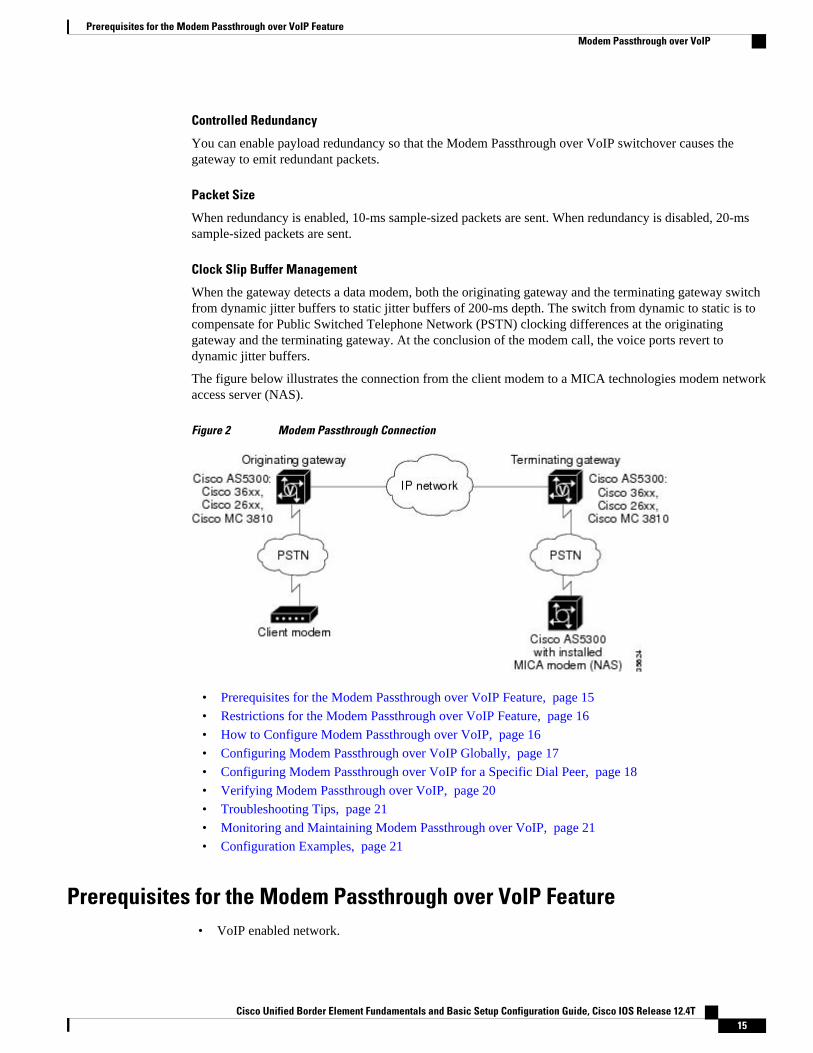
The figure below illustrates the connection from the client modem to a MICA technologies modem networkaccess server (NAS).
Figure 2 Modem Passthrough Connection
• Prerequisites for the Modem Passthrough over VoIP Feature, page 15
• Restrictions for the Modem Passthrough over VoIP Feature, page 16
• How to Configure Modem Passthrough over VoIP, page 16
• Configuring Modem Passthrough over VoIP Globally, page 17
• Configuring Modem Passthrough over VoIP for a Specific Dial Peer, page 18
• Verifying Modem Passthrough over VoIP, page 20
• Troubleshooting Tips, page 21
• Monitoring and Maintaining Modem Passthrough over VoIP, page 21
• Configuration Examples, page 21
Prerequisites for the Modem Passthrough over VoIP Feature• VoIP enabled network.
Prerequisites for the Modem Passthrough over VoIP FeatureModem Passthrough over VoIP
Cisco Unified Border Element Fundamentals and Basic Setup Configuration Guide, Cisco IOS Release 12.4T 15
• Cisco IOS Release 12.1(3)T must run on the gateways for the Modem Passthrough over VoIP featureto work.
• Network suitability to pass modem traffic. The key attributes are packet loss, delay, and jitter. Thesecharacteristics of the network can be determined by using the Cisco IOS feature Service AssuranceAgent.
Cisco Unified Border Element
• Cisco IOS Release 12.4(6)T or a later release must be installed and running on your Cisco UnifiedBorder Element.
Cisco Unified Border Element (Enterprise)
• Cisco IOS XE Release 3.3S or a later release must be installed and running on your Cisco ASR 1000Series Router.
Restrictions for the Modem Passthrough over VoIP Feature
Cisco Unified Border Element (Enterprise)
• If call started as g729, upon modem tone (2100Hz) detection both the outgoing gateway (OGW) andthe trunking gateway (TGW) will genearate NSE packets towards peer side and up speed to g711 asCisco UBE(Enterprise) passes these packets to the peer side.
Note That OGW and TGW display the new codec, but the Cisco UBE (Enterprise) continues to show the originalcodec g729 in the show commands.
How to Configure Modem Passthrough over VoIPBy default, modem passthrough over VoIP capability and redundancy are disabled.
Tip You need to configure modem passthrough in both the originating gateway and the terminating gateway forthe Modem Passthrough over VoIP feature to operate. If you configure only one of the gateways in a pair,the modem call will not connect successfully.
Redundancy can be enabled in one or both of the gateways. When only a single gateway is configured forredundancy, the other gateway receives the packets correctly, but does not produce redundant packets.
See the following sections for the Modem Passthrough over VoIP feature. The two configuration tasks canconfigure separately or together. If both are configured, the dial-peer configuration takes precedence overthe global configuration. Consequently, a call matching a particular dial-peer will first try to apply themodem passthrough configuration on the dial-peer. Then, if a specific dial-peer is not configured, the routerwill use the global configuration:
Restrictions for the Modem Passthrough over VoIP Feature Modem Passthrough over VoIP
Cisco Unified Border Element Fundamentals and Basic Setup Configuration Guide, Cisco IOS Release 12.4T16

Configuring Modem Passthrough over VoIP GloballyFor the Modem Passthrough over VoIP feature to operate, you need to configure modem passthrough inboth the originating gateway and the terminating gateway so that the modem call matches a voip dial-peeron the gateway.
When using the voice service voip and modem passthrough nse commands on a terminating gateway toglobally set up fax or modem passthrough with NSEs, you must also ensure that each incoming call will beassociated with a VoIP dial peer to retrieve the global fax or modem configuration. You associate calls withdial peers by using the incoming called-number command to specify a sequence of digits that incomingcalls can match.
To configure the Modem Passthrough over VoIP feature for all the connections of a gateway, use thefollowing commands beginning in global configuration mode:
SUMMARY STEPS
1. enable
2. voice service voip
3. modem passthrough nse [payload-type number] codec {g711ulaw | g711alaw} [redundancy][maximum-sessions value]
4. exit
5. exit
DETAILED STEPS
Command or Action Purpose
Step 1 enable
Example:
Router> enable
Enables privileged EXEC mode.
• Enter your password if prompted.
Step 2 voice service voip
Example:
Router(config)# voice service voip
Enters voice-service configuration mode.
Configures voice service for all the connections for the gateways.
Configuring Modem Passthrough over VoIP GloballyModem Passthrough over VoIP
Cisco Unified Border Element Fundamentals and Basic Setup Configuration Guide, Cisco IOS Release 12.4T 17
Command or Action Purpose
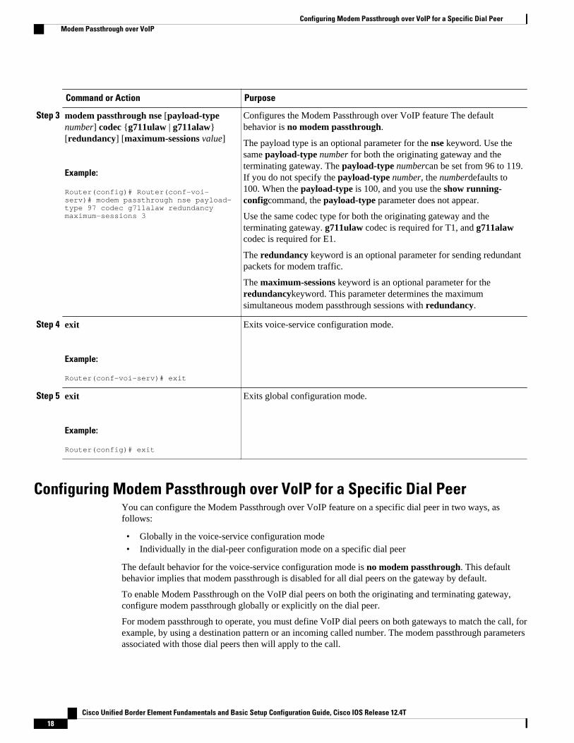
Step 3 modem passthrough nse [payload-typenumber] codec {g711ulaw | g711alaw}[redundancy] [maximum-sessions value]
Example:
Router(config)# Router(conf-voi-serv)# modem passthrough nse payload-type 97 codec g711alaw redundancy maximum-sessions 3
Configures the Modem Passthrough over VoIP feature The defaultbehavior is no modem passthrough.
The payload type is an optional parameter for the nse keyword. Use thesame payload-type number for both the originating gateway and theterminating gateway. The payload-type numbercan be set from 96 to 119.If you do not specify the payload-type number, the numberdefaults to100. When the payload-type is 100, and you use the show running-configcommand, the payload-type parameter does not appear.
Use the same codec type for both the originating gateway and theterminating gateway. g711ulaw codec is required for T1, and g711alawcodec is required for E1.
The redundancy keyword is an optional parameter for sending redundantpackets for modem traffic.
The maximum-sessions keyword is an optional parameter for theredundancykeyword. This parameter determines the maximumsimultaneous modem passthrough sessions with redundancy.
Step 4 exit
Example:
Router(conf-voi-serv)# exit
Exits voice-service configuration mode.
Step 5 exit
Example:
Router(config)# exit
Exits global configuration mode.
Configuring Modem Passthrough over VoIP for a Specific Dial PeerYou can configure the Modem Passthrough over VoIP feature on a specific dial peer in two ways, asfollows:
• Globally in the voice-service configuration mode• Individually in the dial-peer configuration mode on a specific dial peer
The default behavior for the voice-service configuration mode is no modem passthrough. This defaultbehavior implies that modem passthrough is disabled for all dial peers on the gateway by default.
To enable Modem Passthrough on the VoIP dial peers on both the originating and terminating gateway,configure modem passthrough globally or explicitly on the dial peer.
For modem passthrough to operate, you must define VoIP dial peers on both gateways to match the call, forexample, by using a destination pattern or an incoming called number. The modem passthrough parametersassociated with those dial peers then will apply to the call.
Configuring Modem Passthrough over VoIP for a Specific Dial Peer Modem Passthrough over VoIP
Cisco Unified Border Element Fundamentals and Basic Setup Configuration Guide, Cisco IOS Release 12.4T18

Note When modem passthrough is configured individually for a specific dial peer, that configuration for thespecific dial peer takes precedence over the global configuration.
To configure the Modem Passthrough over VoIP feature for a specific dial peer, use the followingcommands beginning in global configuration mode:
SUMMARY STEPS
1. enable
2. dial-peer voice number voip
3. modem passthrough {system | nse [payload-type number] codec {g711ulaw | g711alaw}[redundancy]}
4. exit
5. exit
DETAILED STEPS
Command or Action Purpose
Step 1 enable
Example:
Router> enable
Enables privileged EXEC mode.
• Enter your password if prompted.
Step 2 dial-peer voice number voip
Example:
Router(config)# dial-peer voice 5 voip
Enters dial-peer configuration mode.
Configures a specific dial peer in dial-peer configuration mode.
SIP-to-SIP Extended Feature Functionality for Session Border ControllersModem Passthrough over VoIP
Cisco Unified Border Element Fundamentals and Basic Setup Configuration Guide, Cisco IOS Release 12.4T 19

Command or Action Purpose
Step 3 modem passthrough {system | nse[payload-type number] codec {g711ulaw |g711alaw}[redundancy]}
Example:
Router(config-dial-peer)# modem passthrough nse payload-type 97 codec g711alaw redundancy
Configures the Modem Passthrough over VoIP feature for a specific dialpeer. The default behavior for the Modem Passthrough for VoIP feature indial-peer configuration mode is modem passthrough system. As required,the gateway defaults to no modem passthrough.
When the system keyword is enabled, the following parameters are notavailable: nse, payload-type, codec, and redundancy. Instead the valuesfrom the global configuration are used.
The payload type is an optional parameter for the nse keyword. Use thesame payload-type number for both the originating gateway and theterminating gateway. The payload-type numbercan be set from 96 to 119.If you do not specify the payload-type number, the numberdefaults to 100.When the payload-type is 100, and you use the show running-configcommand, the payload-type parameter does not appear.
Use the same codec type for both the originating gateway and theterminating gateway. g711ulaw codec is required for T1, and g711alawcodec is required for E1.
The redundancy keyword is an optional parameter for sending redundantpackets for modem traffic.
Step 4 exit
Example:
Router(config-dial-peer)# exit
Exits dial-peer configuration mode and returns to the global configurationmode.
Step 5 exit
Example:
Router(config)# exit
Exits global configuration mode.
Verifying Modem Passthrough over VoIPTo verify that the Modem Passthrough over VoIP feature is enabled, perform the following steps:
SUMMARY STEPS
1. Enter the show runcommand to verify the configuration.
2. Enter the show dial-peer voice command to verify that Modem Passthrough over VoIP is enabled.
DETAILED STEPS
Step 1 Enter the show runcommand to verify the configuration.
Step 2 Enter the show dial-peer voice command to verify that Modem Passthrough over VoIP is enabled.
Verifying Modem Passthrough over VoIP Modem Passthrough over VoIP
Cisco Unified Border Element Fundamentals and Basic Setup Configuration Guide, Cisco IOS Release 12.4T20
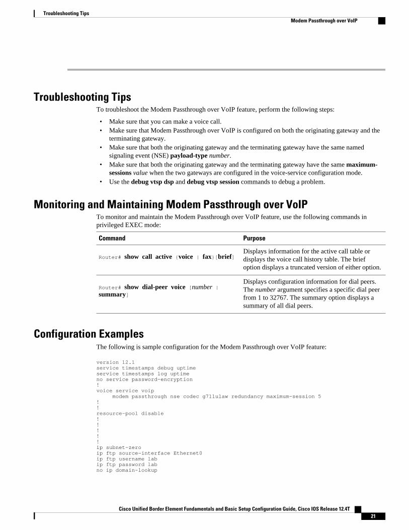
Troubleshooting TipsTo troubleshoot the Modem Passthrough over VoIP feature, perform the following steps:
• Make sure that you can make a voice call.• Make sure that Modem Passthrough over VoIP is configured on both the originating gateway and the
terminating gateway.• Make sure that both the originating gateway and the terminating gateway have the same named
signaling event (NSE) payload-type number.• Make sure that both the originating gateway and the terminating gateway have the same maximum-
sessions value when the two gateways are configured in the voice-service configuration mode.• Use the debug vtsp dsp and debug vtsp session commands to debug a problem.
Monitoring and Maintaining Modem Passthrough over VoIPTo monitor and maintain the Modem Passthrough over VoIP feature, use the following commands inprivileged EXEC mode:
Command Purpose
Router# show call active {voice | fax}[brief]Displays information for the active call table ordisplays the voice call history table. The briefoption displays a truncated version of either option.
Router# show dial-peer voice [number | summary]
Displays configuration information for dial peers.The number argument specifies a specific dial peerfrom 1 to 32767. The summary option displays asummary of all dial peers.
Configuration ExamplesThe following is sample configuration for the Modem Passthrough over VoIP feature:
version 12.1service timestamps debug uptimeservice timestamps log uptimeno service password-encryption!voice service voip modem passthrough nse codec g711ulaw redundancy maximum-session 5!!resource-pool disable!!!!!ip subnet-zeroip ftp source-interface Ethernet0ip ftp username labip ftp password labno ip domain-lookup
Troubleshooting TipsModem Passthrough over VoIP
Cisco Unified Border Element Fundamentals and Basic Setup Configuration Guide, Cisco IOS Release 12.4T 21

!isdn switch-type primary-5esscns event-service server!!!!!mta receive maximum-recipients 0!!controller T1 0 framing esf clock source line primary linecode b8zs pri-group timeslots 1-24!controller T1 1 shutdown clock source line secondary 1!controller T1 2 shutdown !controller T1 3 shutdown!!!interface Ethernet0 ip address 1.1.2.2 255.0.0.0 no ip route-cache no ip mroute-cache!interface Serial0:23 no ip address encapsulation ppp ip mroute-cache no logging event link-status isdn switch-type primary-5ess isdn incoming-voice modem no peer default ip address no fair-queue no cdp enable no ppp lcp fast-start! interface FastEthernet0 ip address 26.0.0.1 255.0.0.0 no ip route-cache no ip mroute-cache load-interval 30 duplex full speed auto no cdp enable!ip classlessip route 17.18.0.0 255.255.0.0 1.1.1.1no ip http server!!!!voice-port 0:D!dial-peer voice 1 pots incoming called-number 55511.. destination-pattern 020.. direct-inward-dial port 0:D prefix 020!dial-peer voice 2 voip incoming called-number 020..
SIP-to-SIP Extended Feature Functionality for Session Border Controllers Modem Passthrough over VoIP
Cisco Unified Border Element Fundamentals and Basic Setup Configuration Guide, Cisco IOS Release 12.4T22

destination-pattern 55511.. modem passthrough nse codec g711ulaw redundancy session target ipv4:26.0.0.2!!line con 0 exec-timeout 0 0 transport input noneline aux 0line vty 0 4 login!!end
Feature Information for SIP-to-SIP Extended FeatureFunctionality for Session Border Controllers
The following table provides release information about the feature or features described in this module.This table lists only the software release that introduced support for a given feature in a given softwarerelease train. Unless noted otherwise, subsequent releases of that software release train also support thatfeature.
Use Cisco Feature Navigator to find information about platform support and Cisco software image support.To access Cisco Feature Navigator, go to www.cisco.com/go/cfn. An account on Cisco.com is not required.
Table 3 Feature Information for Configuring SIP-to-SIP Extended Feature Functionality for Session BorderControllers for the Cisco Unified Border Element.
Feature Name Releases Feature Information
SIP-to-SIP Extended FeatureFunctionality for Session BorderControllers
12.4(6)T The SIP-to-SIP Extended FeatureFunctionality for Session BorderControllers (SBCs) enables theSIP-to-SIP functionality toconform with RFC 3261 tointeroperate with SIP UserAgents (UAs).
The following commands wereintroduced or modified: modempassthrough (dial-peer);modem passthrough (voice-service); show call active voicevoice; show call history voicevoice; show dial-peer voice;voice service.
SIP-to-SIP Extended Feature Functionality for Session Border ControllersFeature Information for SIP-to-SIP Extended Feature Functionality for Session Border Controllers
Cisco Unified Border Element Fundamentals and Basic Setup Configuration Guide, Cisco IOS Release 12.4T 23

Table 4 Feature Information for Configuring SIP-to-SIP Extended Feature Functionality for Session BorderControllers for the Cisco Unified Border Element (Enterprise).
Feature Name Releases Feature Information
SIP-to-SIP Extended FeatureFunctionality for Session BorderControllers
Cisco IOS XE Release 3.1S,
Cisco IOS XE Release 3.3S
The SIP-to-SIP Extended FeatureFunctionality for Session BorderControllers (SBCs) enables theSIP-to-SIP functionality toconform with RFC 3261 tointeroperate with SIP UserAgents (UAs).
The following commands wereintroduced or modified: modempassthrough (dial-peer);modem passthrough (voice-service); show call active voicevoice; show call history voicevoice; show dial-peer voice;voice service.
Cisco and the Cisco logo are trademarks or registered trademarks of Cisco and/or its affiliates in the U.S.and other countries. To view a list of Cisco trademarks, go to this URL: www.cisco.com/go/trademarks.Third-party trademarks mentioned are the property of their respective owners. The use of the word partnerdoes not imply a partnership relationship between Cisco and any other company. (1110R)
Any Internet Protocol (IP) addresses and phone numbers used in this document are not intended to beactual addresses and phone numbers. Any examples, command display output, network topology diagrams,and other figures included in the document are shown for illustrative purposes only. Any use of actual IPaddresses or phone numbers in illustrative content is unintentional and coincidental.
SIP-to-SIP Extended Feature Functionality for Session Border Controllers
Cisco Unified Border Element Fundamentals and Basic Setup Configuration Guide, Cisco IOS Release 12.4T24
SIP Gateway Support for the bind Command
The Gateway Support for the bind Command feature introduces the bind command, which allows you toconfigure the source IP address of signaling packets or both signaling and media packets. Befor thisfeature was introduced the source address of a packet going out of a Cisco IOS gateway is notdeterministic. The session protocols and VoIP layers depended on the IP layer to give the best localaddress and then used the address for the source address in signaling or media or both, even if multipleinterfaces can support a route to the destination address.
• Finding Feature Information, page 25• Prerequisites for SIP Gateway Support for the bind Command, page 25• Information About SIP Gateway Support for the bind Command, page 26• How to Configure SIP Gateway Support for the bind Command, page 27• Verifying and Troubleshooting Tips, page 31• Configuration Examples for SIP Gateway Support for the bind Command, page 32• Feature Information for SIP Gateway Support for the bind Command, page 32
Finding Feature InformationYour software release may not support all the features documented in this module. For the latest featureinformation and caveats, see the release notes for your platform and software release. To find informationabout the features documented in this module, and to see a list of the releases in which each feature issupported, see the Feature Information Table at the end of this document.
Use Cisco Feature Navigator to find information about platform support and Cisco software image support.To access Cisco Feature Navigator, go to www.cisco.com/go/cfn. An account on Cisco.com is not required.
Prerequisites for SIP Gateway Support for the bind CommandCisco Unified Border Element
• Cisco IOS Release 12.2(8)T or a later release must be installed and running on your Cisco UnifiedBorder Element.
Cisco Unified Border Element (Enterprise)
• Cisco IOS XE Release 2.5 or a later release must be installed and running on your Cisco ASR 1000Series Router.
Cisco Unified Border Element Fundamentals and Basic Setup Configuration Guide, Cisco IOS Release 12.4T 25
Information About SIP Gateway Support for the bindCommand
Prior to the Gateway Support for the bind Command feature the source address of a packet going out of thegateway was never deterministic. That is, the session protocols and VoIP layers always depended on the IPlayer to give the best local address . The best local address was then used as the source address (the addressshowing where the SIP request came from) for signaling and media packets. Using this nondeterministicaddress occasionally caused confusion for firewall applications, because a firewall could not be configuredwith an exact address and would take action on several different source address packets.
The bind interface command allows you to configure a specific interface’s IP address as the source IPaddress of signaling and media packets. The address that goes out on the packet is bound to the IP addressof the interface specified with the bind command. Packets that are not destined to the bound address arediscarded.
When you do not specify a bind address, or if the interface is down, the IP layer still provides the best localaddress.
With the bind command, SIP signaling and media paths can advertise the same source IP address on thegateway for certain applications, even if the paths use different addresses to reach the source. Thiseliminates confusion for firewall applications that, Without the binding, may have taken action on severaldifferent source address packets.
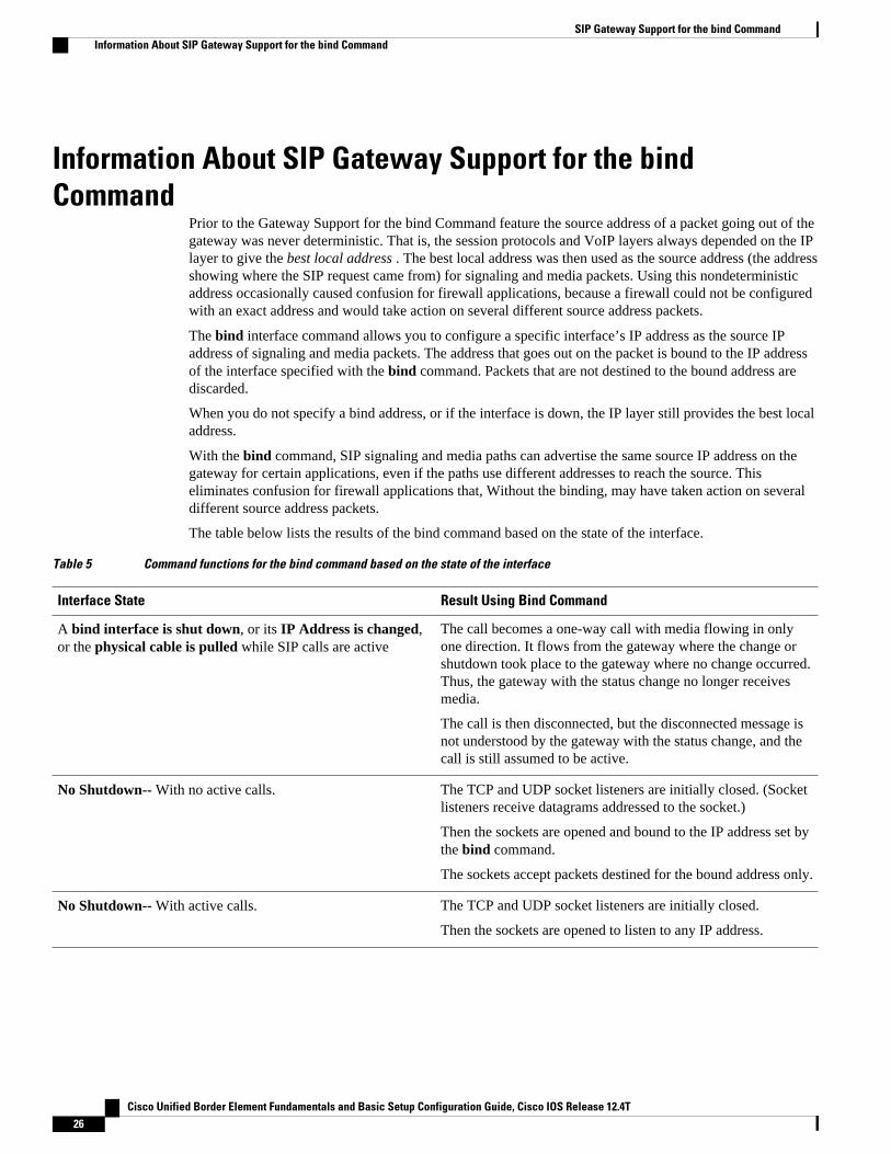
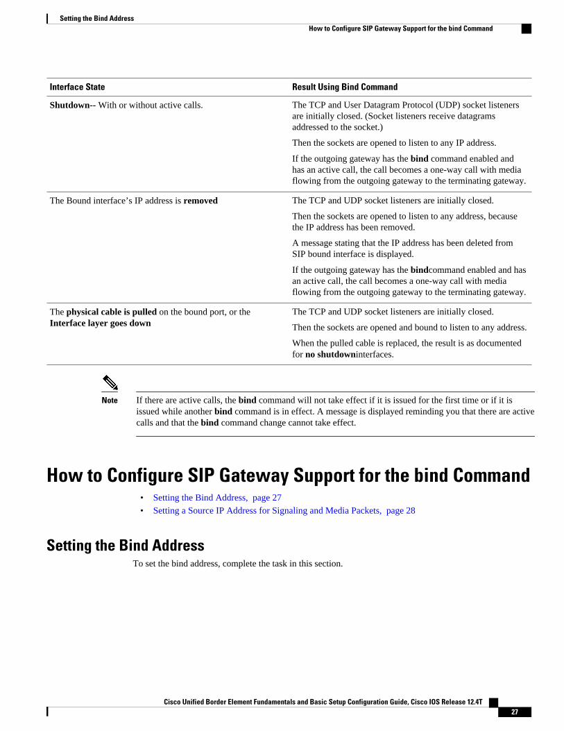
The table below lists the results of the bind command based on the state of the interface.
Table 5 Command functions for the bind command based on the state of the interface
Interface State Result Using Bind Command
A bind interface is shut down, or its IP Address is changed,or the physical cable is pulled while SIP calls are active
The call becomes a one-way call with media flowing in onlyone direction. It flows from the gateway where the change orshutdown took place to the gateway where no change occurred.Thus, the gateway with the status change no longer receivesmedia.
The call is then disconnected, but the disconnected message isnot understood by the gateway with the status change, and thecall is still assumed to be active.
No Shutdown-- With no active calls. The TCP and UDP socket listeners are initially closed. (Socketlisteners receive datagrams addressed to the socket.)
Then the sockets are opened and bound to the IP address set bythe bind command.
The sockets accept packets destined for the bound address only.
No Shutdown-- With active calls. The TCP and UDP socket listeners are initially closed.
Then the sockets are opened to listen to any IP address.
SIP Gateway Support for the bind Command Information About SIP Gateway Support for the bind Command
Cisco Unified Border Element Fundamentals and Basic Setup Configuration Guide, Cisco IOS Release 12.4T26
Interface State Result Using Bind Command
Shutdown-- With or without active calls. The TCP and User Datagram Protocol (UDP) socket listenersare initially closed. (Socket listeners receive datagramsaddressed to the socket.)
Then the sockets are opened to listen to any IP address.
If the outgoing gateway has the bind command enabled andhas an active call, the call becomes a one-way call with mediaflowing from the outgoing gateway to the terminating gateway.
The Bound interface’s IP address is removed The TCP and UDP socket listeners are initially closed.
Then the sockets are opened to listen to any address, becausethe IP address has been removed.
A message stating that the IP address has been deleted fromSIP bound interface is displayed.
If the outgoing gateway has the bindcommand enabled and hasan active call, the call becomes a one-way call with mediaflowing from the outgoing gateway to the terminating gateway.
The physical cable is pulled on the bound port, or theInterface layer goes down
The TCP and UDP socket listeners are initially closed.
Then the sockets are opened and bound to listen to any address.
When the pulled cable is replaced, the result is as documentedfor no shutdowninterfaces.
Note If there are active calls, the bind command will not take effect if it is issued for the first time or if it isissued while another bind command is in effect. A message is displayed reminding you that there are activecalls and that the bind command change cannot take effect.
How to Configure SIP Gateway Support for the bind Command• Setting the Bind Address, page 27
• Setting a Source IP Address for Signaling and Media Packets, page 28
Setting the Bind AddressTo set the bind address, complete the task in this section.
Setting the Bind AddressHow to Configure SIP Gateway Support for the bind Command
Cisco Unified Border Element Fundamentals and Basic Setup Configuration Guide, Cisco IOS Release 12.4T 27

SUMMARY STEPS
1. enable
2. configure terminal
3. dial-peer voice number voip
4. session target ipv4: destination-address
5. exit
DETAILED STEPS
Command or Action Purpose
Step 1 enable
Example:
Router> enable
Enables privileged EXEC mode.
• Enter your password if prompted.
Step 2 configure terminal
Example:
Router# configure terminal
Enters global configuration mode.
Step 3 dial-peer voice number voip
Example:
Router(config)# dial-peer voice 2 voip
Enters dial peer configuration mode to configure a VoIP dial-peer.
Step 4 session target ipv4: destination-address
Example:
Router(config-dial-peer)# session target ipv4: 172.16.43.3
Specifies a network-specific address for a dial peer.
• This command must be set to the bind address of the receivinggateway before using the bind command.
• ipv4 :destination-address: Sets the IP address of the dial peer. Avalid IP address is in this format: xxx.xxx.xxx.xxx.
Step 5 exit
Example:
Router(config-dial-peer)# exit
Exits dial peer voice configuration mode.
Setting a Source IP Address for Signaling and Media PacketsSIP configuration mode starts from voice-service VoIP configuration mode. When the router is in SIPconfiguration mode, several options are available, including the bind command. To enable this feature,review the prerequisites to make sure your network is compliant, and then complete the task in this section.
Setting a Source IP Address for Signaling and Media Packets How to Configure SIP Gateway Support for the bind Command
Cisco Unified Border Element Fundamentals and Basic Setup Configuration Guide, Cisco IOS Release 12.4T28

• Endure you have Cisco IOS XE Release 2.5 or a later release installed and running on your Cisco ASR1000 Series Router.
• Ensure that the gateway has voice functionality that is configurable for SIP.• Establish a working IP network.• Configure VoIP.• Set the bind address prior to using the bind command.
SUMMARY STEPS
1. enable
2. configure terminal
3. voice service voip
4. sip
5. session transport {udp | tcp}
6. bind {control | all} source-interface interface-id
7. default {bind|rel1xx|session-transport|url}
8. exit
DETAILED STEPS
Command or Action Purpose
Step 1 enable
Example:
Router> enable
Enables privileged EXEC mode.
• Enter your password if prompted.
Step 2 configure terminal
Example:
Router# configure terminal
Enters global configuration mode.
Step 3 voice service voip
Example:
Router(config)# voice service voip
Enters voice-service configuration mode
Step 4 sip
Example:
Router(config-voi-srv)# sip
Enters the SIP configuration mode.
SIP Gateway Support for the bind CommandHow to Configure SIP Gateway Support for the bind Command
Cisco Unified Border Element Fundamentals and Basic Setup Configuration Guide, Cisco IOS Release 12.4T 29
Command or Action Purpose
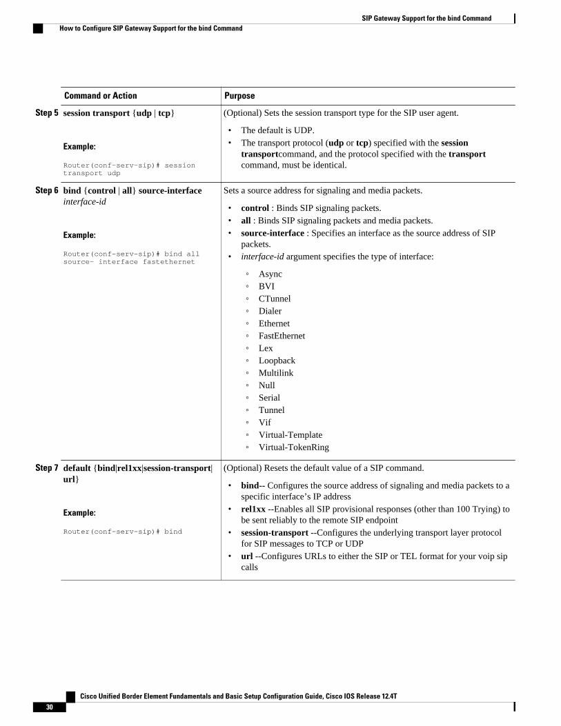
Step 5 session transport {udp | tcp}
Example:
Router(conf-serv-sip)# session transport udp
(Optional) Sets the session transport type for the SIP user agent.
• The default is UDP.• The transport protocol (udp or tcp) specified with the session
transportcommand, and the protocol specified with the transportcommand, must be identical.
Step 6 bind {control | all} source-interfaceinterface-id
Example:
Router(conf-serv-sip)# bind all source- interface fastethernet
Sets a source address for signaling and media packets.
• control : Binds SIP signaling packets.• all : Binds SIP signaling packets and media packets.• source-interface : Specifies an interface as the source address of SIP
packets.• interface-id argument specifies the type of interface:
◦ Async◦ BVI◦ CTunnel◦ Dialer◦ Ethernet◦ FastEthernet◦ Lex◦ Loopback◦ Multilink◦ Null◦ Serial◦ Tunnel◦ Vif◦ Virtual-Template◦ Virtual-TokenRing
Step 7 default {bind|rel1xx|session-transport|url}
Example:
Router(conf-serv-sip)# bind
(Optional) Resets the default value of a SIP command.
• bind-- Configures the source address of signaling and media packets to aspecific interface’s IP address
• rel1xx --Enables all SIP provisional responses (other than 100 Trying) tobe sent reliably to the remote SIP endpoint
• session-transport --Configures the underlying transport layer protocolfor SIP messages to TCP or UDP
• url --Configures URLs to either the SIP or TEL format for your voip sipcalls
SIP Gateway Support for the bind Command How to Configure SIP Gateway Support for the bind Command
Cisco Unified Border Element Fundamentals and Basic Setup Configuration Guide, Cisco IOS Release 12.4T30
Command or Action Purpose
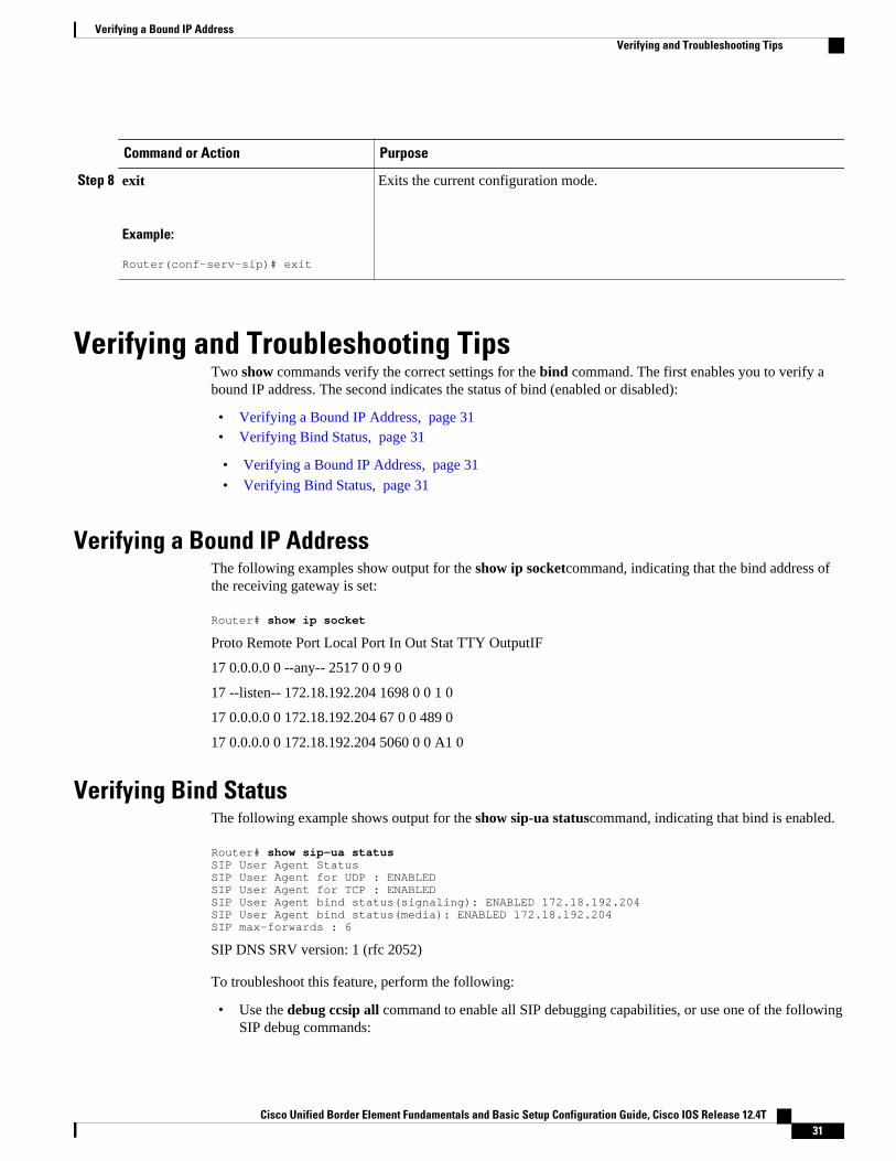
Step 8 exit
Example:
Router(conf-serv-sip)# exit
Exits the current configuration mode.
Verifying and Troubleshooting TipsTwo show commands verify the correct settings for the bind command. The first enables you to verify abound IP address. The second indicates the status of bind (enabled or disabled):
• Verifying a Bound IP Address, page 31• Verifying Bind Status, page 31
• Verifying a Bound IP Address, page 31
• Verifying Bind Status, page 31
Verifying a Bound IP AddressThe following examples show output for the show ip socketcommand, indicating that the bind address ofthe receiving gateway is set:
Router# show ip socket
Proto Remote Port Local Port In Out Stat TTY OutputIF
17 0.0.0.0 0 --any-- 2517 0 0 9 0
17 --listen-- 172.18.192.204 1698 0 0 1 0
17 0.0.0.0 0 172.18.192.204 67 0 0 489 0
17 0.0.0.0 0 172.18.192.204 5060 0 0 A1 0
Verifying Bind StatusThe following example shows output for the show sip-ua statuscommand, indicating that bind is enabled.
Router# show sip-ua statusSIP User Agent Status SIP User Agent for UDP : ENABLED SIP User Agent for TCP : ENABLED SIP User Agent bind status(signaling): ENABLED 172.18.192.204SIP User Agent bind status(media): ENABLED 172.18.192.204SIP max-forwards : 6
SIP DNS SRV version: 1 (rfc 2052)
To troubleshoot this feature, perform the following:
• Use the debug ccsip all command to enable all SIP debugging capabilities, or use one of the followingSIP debug commands:
Verifying a Bound IP AddressVerifying and Troubleshooting Tips
Cisco Unified Border Element Fundamentals and Basic Setup Configuration Guide, Cisco IOS Release 12.4T 31
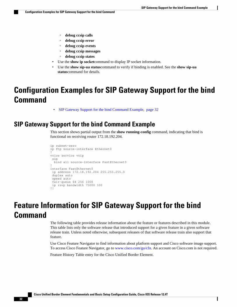
◦ debug ccsip calls◦ debug ccsip error◦ debug ccsip events◦ debug ccsip messages◦ debug ccsip states
• Use the show ip socketcommand to display IP socket information.• Use the show sip-ua statuscommand to verify if binding is enabled. See the show sip-ua
statuscommand for details.
Configuration Examples for SIP Gateway Support for the bindCommand
• SIP Gateway Support for the bind Command Example, page 32
SIP Gateway Support for the bind Command ExampleThis section shows partial output from the show running-config command, indicating that bind isfunctional on receiving router 172.18.192.204.
ip subnet-zeroip ftp source-interface Ethernet0!voice service voip sip bind all source-interface FastEthernet0!interface FastEthernet0 ip address 172.18.192.204 255.255.255.0 duplex auto speed auto fair-queue 64 256 1000 ip rsvp bandwidth 75000 100!!
Feature Information for SIP Gateway Support for the bindCommand
The following table provides release information about the feature or features described in this module.This table lists only the software release that introduced support for a given feature in a given softwarerelease train. Unless noted otherwise, subsequent releases of that software release train also support thatfeature.
Use Cisco Feature Navigator to find information about platform support and Cisco software image support.To access Cisco Feature Navigator, go to www.cisco.com/go/cfn. An account on Cisco.com is not required.
Feature History Table entry for the Cisco Unified Border Element.
SIP Gateway Support for the bind Command Example Configuration Examples for SIP Gateway Support for the bind Command
Cisco Unified Border Element Fundamentals and Basic Setup Configuration Guide, Cisco IOS Release 12.4T32

Table 6 Feature Information for SIP: Gateway Support for the bind Command
Feature Name Releases Feature Information
SIP: Gateway Support for thebind Command
12.2(8)T, 12.3(2)T, 12.2(11)T,12.2(15)T
In Cisco IOS XE Release 2.5,This feature was introduced onthe Cisco ASR 1000 SeriesRouters.
The following commands wereintroduced or modified: bindandsip.
Feature History Table entry for the Cisco Unified Border Element (Enterprise) .
Table 7 Feature Information for SIP: Gateway Support for the bind Command
Feature Name Releases Feature Information
SIP: Gateway Support for thebind Command
Cisco IOS XE Release 2.5 In Cisco IOS XE Release 2.5,This feature was introduced onthe Cisco ASR 1000 SeriesRouters.
The following commands wereintroduced or modified: bindandsip.
Cisco and the Cisco logo are trademarks or registered trademarks of Cisco and/or its affiliates in the U.S.and other countries. To view a list of Cisco trademarks, go to this URL: www.cisco.com/go/trademarks.Third-party trademarks mentioned are the property of their respective owners. The use of the word partnerdoes not imply a partnership relationship between Cisco and any other company. (1110R)
Any Internet Protocol (IP) addresses and phone numbers used in this document are not intended to beactual addresses and phone numbers. Any examples, command display output, network topology diagrams,and other figures included in the document are shown for illustrative purposes only. Any use of actual IPaddresses or phone numbers in illustrative content is unintentional and coincidental.
SIP Gateway Support for the bind Command
Cisco Unified Border Element Fundamentals and Basic Setup Configuration Guide, Cisco IOS Release 12.4T 33
SIP Gateway Support for the bind Command Example
Cisco Unified Border Element Fundamentals and Basic Setup Configuration Guide, Cisco IOS Release 12.4T34

SIP Video Calls with Flow Around Media
The SIP Video Calls with Flow Around Media feature provides the ability to have a SIP video call wherethe media flows around the Cisco Unified Border Element (Cisco UBE) and the Cisco Unified BorderElement (Enterprise) platform. Previous support was only for call scenarios where the media flowedthrough the Cisco UBE.
• Finding Feature Information, page 35• Prerequisites for SIP Video Calls with Flow Around Media, page 35• Restrictions for SIP Video Calls with Flow Around Media, page 35• How to Configure Support for SIP Video Calls with Flow Around Media, page 36• Feature Information for Support for SIP Video Calls with Flow Around Media, page 36
Finding Feature InformationYour software release may not support all the features documented in this module. For the latest featureinformation and caveats, see the release notes for your platform and software release. To find informationabout the features documented in this module, and to see a list of the releases in which each feature issupported, see the Feature Information Table at the end of this document.
Use Cisco Feature Navigator to find information about platform support and Cisco software image support.To access Cisco Feature Navigator, go to www.cisco.com/go/cfn. An account on Cisco.com is not required.
Prerequisites for SIP Video Calls with Flow Around MediaCisco Unified Border Element
• Cisco IOS Release 12.4(15)XZ or a later release must be installed and running on your Cisco UnifiedBorder Element.
Cisco Unified Border Element (Enterprise)
• Cisco IOS XE Release 3.1S or a later release must be installed and running on your Cisco ASR 1000Series Router.
Restrictions for SIP Video Calls with Flow Around Media• Media flow-around for Delayed-Offer to Early-Offer audio and video calls is not supported.
Cisco Unified Border Element Fundamentals and Basic Setup Configuration Guide, Cisco IOS Release 12.4T 35

How to Configure Support for SIP Video Calls with FlowAround Media
To enable this feature use the mediacommand in dial peer, voice class, or voice service configurationmode. For detailed information on the use of this command, see the Cisco IOS Voice Command Referenceat the following URL: http://www.cisco.com/en/US/docs/ios/voice/command/reference/vr_book.html
Feature Information for Support for SIP Video Calls with FlowAround Media
The following table provides release information about the feature or features described in this module.This table lists only the software release that introduced support for a given feature in a given softwarerelease train. Unless noted otherwise, subsequent releases of that software release train also support thatfeature.
Use Cisco Feature Navigator to find information about platform support and Cisco software image support.To access Cisco Feature Navigator, go to www.cisco.com/go/cfn. An account on Cisco.com is not required.
Feature History Table entry for the Cisco Unified Border Element.
Table 8 Feature Information for SIP Video Calls with Flow Around Media
Feature Name Releases Feature Information
SIP Video Calls with FlowAround Media
12.4(15)XZ 12.4(20)T This feature provides thecapability for media packets topass directly between endpointswithout the intervention of theCisco UBE.
The following command wasmodified by this feature: media
Feature History Table entry for the Cisco Unified Border Element (Enterprise).
Table 9 Feature Information for SIP Video Calls with Flow Around Media
Feature Name Releases Feature Information
SIP Video Calls with FlowAround Media
Cisco IOS XE Release 3.1S This feature provides thecapability for media packets topass directly between endpointswithout the intervention of theCisco UBE.
The following command wasmodified by this feature: media
SIP Video Calls with Flow Around Media How to Configure Support for SIP Video Calls with Flow Around Media
Cisco Unified Border Element Fundamentals and Basic Setup Configuration Guide, Cisco IOS Release 12.4T36
Cisco and the Cisco logo are trademarks or registered trademarks of Cisco and/or its affiliates in the U.S.and other countries. To view a list of Cisco trademarks, go to this URL: www.cisco.com/go/trademarks.Third-party trademarks mentioned are the property of their respective owners. The use of the word partnerdoes not imply a partnership relationship between Cisco and any other company. (1110R)
Any Internet Protocol (IP) addresses and phone numbers used in this document are not intended to beactual addresses and phone numbers. Any examples, command display output, network topology diagrams,and other figures included in the document are shown for illustrative purposes only. Any use of actual IPaddresses or phone numbers in illustrative content is unintentional and coincidental.
SIP Video Calls with Flow Around Media
Cisco Unified Border Element Fundamentals and Basic Setup Configuration Guide, Cisco IOS Release 12.4T 37

SIP Video Calls with Flow Around Media
Cisco Unified Border Element Fundamentals and Basic Setup Configuration Guide, Cisco IOS Release 12.4T38

Additional References
The following sections provide references related to the Cisco Unified Border Element (Enterprise)Configuration Guide.
• Related Documents, page 39• Standards, page 40• MIBs, page 40• RFCs, page 41• Technical Assistance, page 42
Related DocumentsRelated Topic Document Title
Cisco IOS commands Cisco IOS Master Commands List, All Releases
Cisco IOS Voice commands Cisco IOS Voice Command Reference
Cisco IOS Voice Configuration Library For more information about Cisco IOS voicefeatures, including feature documents, andtroubleshooting information--at
http://www.cisco.com/en/US/docs/ios/12_3/vvf_c/cisco_ios_voice_configuration_library_glossary/vcl.htm
Cisco IOS Release 15.0 Cisco IOS Release 15.0 Configuration Guides
Cisco IOS Release 12.2 Cisco IOS Voice, Video, and Fax ConfigurationGuide, Release 12.2
Cisco Unified Border Element Fundamentals and Basic Setup Configuration Guide, Cisco IOS Release 12.4T 39
Related Topic Document Title
internet Low Bitrate Codec (iLBC) Documents • Codecs section of the Dial Peer Configurationon Voice Gateway Routers Guide
http://www.cisco.com/en/US/docs/ios/12_3/vvf_c/dial_peer/ dp_ovrvw.html
• Dial Peer Features and Configuration sectionof the Dial Peer Configuration on VoiceGateway Routers Guide
http://www.cisco.com/en/US/docs/ios/12_3/vvf_c/dial_peer/ dp_confg.html
Related Application Guides • Cisco Unified Communications Manager andCisco IOS Interoperability Guide
• Cisco IOS SIP Configuration Guide• Cisco Unified Communications Manager
(CallManager) Programming Guides
Troubleshooting and Debugging guides • Cisco IOS Debug Command Reference,Release 12.4 at
http://www.cisco.com/en/US/docs/ios/debug/command/reference/db_book.html
• Troubleshooting and Debugging VoIP CallBasics at http://www.cisco.com/en/US/tech/tk1077/technologies_tech_note09186a0080094045.shtml
• VoIP Debug Commands at
http://www.cisco.com/en/US/docs/routers/access/1700/1750/software/configuration/guide/debug.html
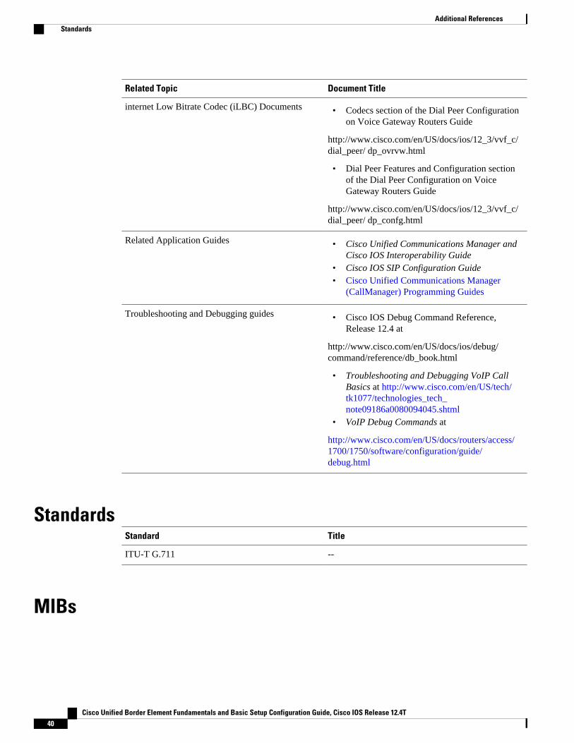
StandardsStandard Title
ITU-T G.711 --
MIBs
Additional References Standards
Cisco Unified Border Element Fundamentals and Basic Setup Configuration Guide, Cisco IOS Release 12.4T40
http://www.cisco.com/en/US/products/sw/voicesw/ps556/products_programming_reference_guides_list.html
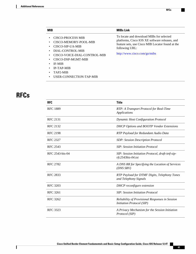
MIB MIBs Link
• CISCO-PROCESS MIB• CISCO-MEMORY-POOL-MIB• CISCO-SIP-UA-MIB• DIAL-CONTROL-MIB• CISCO-VOICE-DIAL-CONTROL-MIB• CISCO-DSP-MGMT-MIB• IF-MIB• IP-TAP-MIB• TAP2-MIB• USER-CONNECTION-TAP-MIB
To locate and download MIBs for selectedplatforms, Cisco IOS XE software releases, andfeature sets, use Cisco MIB Locator found at thefollowing URL:
http://www.cisco.com/go/mibs
RFCsRFC Title
RFC 1889 RTP: A Transport Protocol for Real-TimeApplications
RFC 2131 Dynamic Host Configuration Protocol
RFC 2132 DHCP Options and BOOTP Vendor Extensions
RFC 2198 RTP Payload for Redundant Audio Data
RFC 2327 SDP: Session Description Protocol
RFC 2543 SIP: Session Initiation Protocol
RFC 2543-bis-04 SIP: Session Initiation Protocol, draft-ietf-sip-rfc2543bis-04.txt
RFC 2782 A DNS RR for Specifying the Location of Services(DNS SRV)
RFC 2833 RTP Payload for DTMF Digits, Telephony Tonesand Telephony Signals
RFC 3203 DHCP reconfigure extension
RFC 3261 SIP: Session Initiation Protocol
RFC 3262 Reliability of Provisional Responses in SessionInitiation Protocol (SIP)
RFC 3323 A Privacy Mechanism for the Session InitiationProtocol (SIP)
Additional ReferencesRFCs
Cisco Unified Border Element Fundamentals and Basic Setup Configuration Guide, Cisco IOS Release 12.4T 41

RFC Title
RFC 3325 Private Extensions to the Session InitiationProtocol (SIP) for Asserted Identity within TrustedNetworks
RFC 3515 The Session Initiation Protocol (SIP) Refer Method
RFC 3361 Dynamic Host Configuration Protocol (DHCP-for-IPv4) Option for Session Initiation Protocol (SIP)Servers
RFC 3455 Private Header (P-Header) Extensions to theSession Initiation Protocol (SIP) for the 3rd-Generation Partnership Project (3GPP)
RFC 3608 Session Initiation Protocol (SIP) Extension HeaderField for Service Route Discovery DuringRegistration
RFC 3711 The Secure Real-time Transport Protocol (SRTP)
RFC 3925 Vendor-Identifying Vendor Options for DynamicHost Configuration Protocol version 4 (DHCPv4)
Technical AssistanceDescription Link
The Cisco Support website provides extensiveonline resources, including documentation and toolsfor troubleshooting and resolving technical issueswith Cisco products and technologies.
To receive security and technical information aboutyour products, you can subscribe to variousservices, such as the Product Alert Tool (accessedfrom Field Notices), the Cisco Technical ServicesNewsletter, and Really Simple Syndication (RSS)Feeds.
Access to most tools on the Cisco Support websiterequires a Cisco.com user ID and password.
http://www.cisco.com/cisco/web/support/index.html
Additional References Technical Assistance
Cisco Unified Border Element Fundamentals and Basic Setup Configuration Guide, Cisco IOS Release 12.4T42

Glossary
AMR-NB --Adaptive Multi Rate codec - Narrow Band.
Allow header --Lists the set of methods supported by the UA generating the message.
bind -- In SIP, configuring the source address for signaling and media packets to the IP address of aspecific interface.
call --In SIP, a call consists of all participants in a conference invited by a common source. A SIP call isidentified by a globally unique call identifier. A point-to-point IP telephony conversation maps into asingle SIP call.
call leg --A logical connection between the router and another endpoint.
CLI --command-line interface.
Content-Type header --Specifies the media type of the message body.
CSeq header --Serves as a way to identify and order transactions. It consists of a sequence number and amethod. It uniquely identifies transactions and differentiates between new requests and requestretransmissions.
delta --An incremental value. In this case, the delta is the difference between the current time and the timewhen the response occurred. dial peer--An addressable call endpoint.
dial peer --An addressable call endpoint.
DNS --Domain Name System. Used to translate H.323 IDs, URLs, or e-mail IDs to IP addresses. DNS isalso used to assist in locating remote gatekeepers and to reverse-map raw IP addresses to host names ofadministrative domains.
DNS SRV --Domain Name System Server. Used to locate servers for a given service.
DSP --Digital Signal Processor.
DTMF --dual-tone multifrequency. Use of two simultaneous voice-band tones for dialing (such as touch-tone).
EFXS --IP phone virtual voice ports.
FQDN --fully qualified domain name. Complete domain name including the host portion; for example,serverA.companyA.com .
FXS --analog telephone voice ports.
gateway --A gateway allows SIP or H.323 terminals to communicate with terminals configured to otherprotocols by converting protocols. A gateway is the point where a circuit-switched call is encoded andrepackaged into IP packets.
H.323 --An International Telecommunication Union (ITU-T) standard that describes packet-based video,audio, and data conferencing. H.323 is an umbrella standard that describes the architecture of the
Cisco Unified Border Element Fundamentals and Basic Setup Configuration Guide, Cisco IOS Release 12.4T 43

conferencing system and refers to a set of other standards (H.245, H.225.0, and Q.931) to describe itsactual protocol.
iLBC --internet Low Bitrate Codec.
INVITE--A SIP message that initiates a SIP session. It indicates that a user is invited to participate,provides a session description, indicates the type of media, and provides insight regarding the capabilitiesof the called and calling parties.
IP-- Internet Protocol. A connectionless protocol that operates at the network layer (Layer 3) of the OSImodel. IP provides features for addressing, type-of-service specification, fragmentation and reassemble,and security. Defined in RFC 791. This protocol works with TCP and is usually identified as TCP/IP. SeeTCP/IP.
ISDN --Integrated Services Digital Network.
Minimum Timer --Configured minimum value for session interval accepted by SIP elements (proxy,UAC, UAS). This value helps minimize the processing load from numerous INVITE requests.
Min-SE --Minimum Session Expiration. The minimum value for session expiration.
multicast --A process of transmitting PDUs from one source to many destinations. The actual mechanism(that is, IP multicast, multi-unicast, and so forth) for this process might be different for LAN technologies.
originator --User agent that initiates the transfer or Refer request with the recipient.
PDU --protocol data units. Used by bridges to transfer connectivity information.
PER --Packed Encoding Rule.
proxy --A SIP UAC or UAS that forwards requests and responses on behalf of another SIP UAC or UAS.
proxy server --An intermediary program that acts as both a server and a client for the purpose of makingrequests on behalf of other clients. Requests are serviced internally or by passing them on, possibly aftertranslation, to other servers. A proxy interprets and, if necessary, rewrites a request message beforeforwarding it.
recipient --User agent that receives the Refer request from the originator and is transferred to the finalrecipient.
redirect server --A server that accepts a SIP request, maps the address into zero or more new addresses,and returns these addresses to the client. It does not initiate its own SIP request or accept calls.
re-INVITE --An INVITE request sent during an active call leg.
Request URI --Request Uniform Resource Identifier. It can be a SIP or general URL and indicates theuser or service to which the request is being addressed.
RFC --Request For Comments.
RTP --Real-Time Transport Protocol (RFC 1889)
SCCP --Skinny Client Control Protocol.
SDP--Session Description Protocol. Messages containing capabilities information that are exchangedbetween gateways.
session --A SIP session is a set of multimedia senders and receivers and the data streams flowing betweenthe senders and receivers. A SIP multimedia conference is an example of a session. The called party canbe invited several times by different calls to the same session.
session expiration --The time at which an element considers the call timed out if no successful INVITEtransaction occurs first.
session interval --The largest amount of time that can occur between INVITE requests in a call before acall is timed out. The session interval is conveyed in the Session-Expires header. The UAS obtains this
Glossary
Cisco Unified Border Element Fundamentals and Basic Setup Configuration Guide, Cisco IOS Release 12.4T44

value from the Session-Expires header of a 2xx INVITE response that it sends. Proxies and UACsdetermine this value from the Session-Expires header in a 2xx INVITE response they receive.
SIP --Session Initiation Protocol. An application-layer protocol originally developed by the MultipartyMultimedia Session Control (MMUSIC) working group of the Internet Engineering Task Force (IETF).Their goal was to equip platforms to signal the setup of voice and multimedia calls over IP networks. SIPfeatures are compliant with IETF RFC 2543, published in March 1999.
SIP URL --Session Initiation Protocol Uniform Resource Locator. Used in SIP messages to indicate theoriginator, recipient, and destination of the SIP request. Takes the basic form of user@host , where user isa name or telephone number, and host is a domain name or network address.
SPI --service provider interface.
socket listener -- Software provided by a socket client to receives datagrams addressed to the socket.
stateful proxy --A proxy in keepalive mode that remembers incoming and outgoing requests.
TCP --Transmission Control Protocol. Connection-oriented transport layer protocol that provides reliablefull-duplex data transmissions. TCP is part of the TCP/IP protocol stack. See also TCP/IP and IP.
TDM --time-division multiplexing.
UA --user agent. A combination of UAS and UAC that initiates and receives calls. See UASand UAC.
UAC --user agent client. A client application that initiates a SIP request.
UAS --user agent server. A server application that contacts the user when a SIP request is received andthen returns a response on behalf of the user. The response accepts, rejects, or redirects the request.
UDP -- User Datagram Protocol. Connectionless transport layer protocol in the TCP/IP protocol stack.UDP is a simple protocol that exchanges datagrams without acknowledgments or guaranteed delivery,requiring that error processing and retransmission be handled by other protocols. UDP is defined inRFC-768.
URI --Uniform Resource Identifier. Takes a form similar to an e-mail address. It indicates the user’s SIPidentity and is used for redirection of SIP messages.
URL --Universal Resource Locator. Standard address of any resource on the Internet that is part of theWorld Wide Web (WWW).
User Agent --A combination of UAS and UAC that initiates and receives calls. See UAS and UAC.
VFC --Voice Feature Card.
VoIP --Voice over IP. The ability to carry normal telephone-style voice over an IP-based Internet withPOTS-like functionality, reliability, and voice quality. VoIP is a blanket term that generally refers to theCisco standards-based approach (for example, H.323) to IP voice traffic.
Glossary
Cisco Unified Border Element Fundamentals and Basic Setup Configuration Guide, Cisco IOS Release 12.4T 45

Glossary
Cisco Unified Border Element Fundamentals and Basic Setup Configuration Guide, Cisco IOS Release 12.4T46