Machine Controller System - SETUP MANUAL
293
Machine Controller System Machine Controller MP2000 Series SETUP MANUAL MANUAL NO. SIEP C880732 14A 1 2 3 4 5 6 System Configuration Installation and Connections Machine Controller Setup Creating User Programs Debugging Programs Security Controller Specifications Motion Parameters AppB AppA MP2200 MBU-01 POWER CPU-01 SVB-01 218F-01 LIO-02 LIO-01 LIO-01 217F-01 EXIOIF 260F-01 YASKAWA MBU-03 CPU-01 MP2200 MBU-03 CPU-01 100M Ethernet LINK SW2 E-INIT E-TEST MECHATROLINK ON BATTERY DC 0 DC24 M-I/II RUN ERR BAT SW1 RDY ALM MTX STOP SUP INIT CNFG MON TEST ON IP TRX MP2310 YASKAWA
-
Upload
khangminh22 -
Category
Documents
-
view
1 -
download
0
Transcript of Machine Controller System - SETUP MANUAL

Machine Controller SystemMachine Controller MP2000 Series
SETUP MANUAL
MANUAL NO. SIEP C880732 14A
1
2
3
4
5
6
System Configuration
Installation and Connections
Machine Controller Setup
Creating User Programs
Debugging Programs
Security
Controller Specifications
Motion Parameters AppB
AppA
MP2200 MBU-01POWER
CPU-01 SVB-01218F-01 LIO-02LIO-01LIO-01 217F-01 EXIOIF260F-01
YASKAWA
MBU-03CPU-01MP2200
MBU-03CPU-01
100M
EthernetLINK
SW2E-INITE-TEST
MECHATROLINK
ON
BATTERY
POWER
DC 0
DC24M-I/II
RUN
ERR
BAT
SW1
RDY
ALM
MTX
STOPSUPINIT
CNFGMON
TESTON
IPTRX
MP2310YASKAWA

Copyright © 2015 YASKAWA ELECTRIC CORPORATION
All rights reserved. No part of this publication may be reproduced, stored in a retrieval system, or transmitted, in any form, or by any means, mechanical, elec-tronic, photocopying, recording, or otherwise, without the prior written permission of Yaskawa. No patent liability is assumed with respect to the use of the informa-tion contained herein. Moreover, because Yaskawa is constantly striving to improve its high-quality products, the information contained in this manual is sub-ject to change without notice. Every precaution has been taken in the preparation of this manual. Nevertheless, Yaskawa assumes no responsibility for errors or omissions. Neither is any liability assumed for damages resulting from the use of the information contained in this publication.

iii
About this Manual
This manual describes the procedures that are required to use the Machine Controller, from instal-lation and connections to programming, trial operation, and debugging. Read this manual carefully to ensure the correct usage of the Machine Controller and apply the Machine Controller to control your manufacturing system. Keep this manual in a safe place so that it can be referred to whenever necessary.
Using this Manual
Basic TermsUnless otherwise specified, the following definitions are used:
Basic Terms Meaning
Machine ControllerA generic name for the following MP2000 Machine Controllers: MP2200, MP2300, MP2310, MP2300S, and MP2400. (The MP2200 and MP2310 are used as typical examples in this manual.)
MPE720 The Engineering Tool or a personal computer running the Engineering Tool
PLC A Programmable Logic Controller
Motion Control Function Modules The Function Modules in the Motion Modules and the Function Modules in the SVA-01, SVB/SVB-01, or SVC-01 built into the CPU Modules.
Communications Function Mod-ules
The Function Modules in the Communications Modules and the Function Mod-ules in the 218IFD built into the CPU Modules.

iv
Manual ConfigurationThis manual is structured according to the following flow of setup procedures.
Tuning
Debugging the Programs
Creating User Programs
Test Run
Setting the System Configuration
Placing the MPE720 Online
Self Configuration
Creating a Project File
Installing the MPE720
Connecting Devices
Installing the Machine Controller2.1 Machine Controller Installation
2.2 Connecting Devices
3.2 MPE720 Installation
3.3 Creating a Project File
3.4 Self Configuration
3.6 Device-specific Settings
3.7 Test Run
4.2 Creating Ladder Programs
4.3 Creating Motion Programs
4.4 Creating a Sequence Program
4.5 Transferring Data with the MPE720
4.6 Data Transfer without Using the MPE720
5.1 Debugging Ladder Programs
5.2 Debugging a Motion or a Sequence Program
5.3 Monitoring Machine Operation
3.5 Placing the MPE720 Online

v
MPE720 Engineering Tool Version NumberIn this manual, the operation of MPE720 is described using screen captures of MPE720 version 7. For this reason, the screen captures and some descriptions may differ for MPE720 version 6.
Indication of Reverse SignalsIn this manual, the names of reverse signals (ones that are valid when low) are written with a for-ward slash (/) before the signal name, as shown in the following example:Notation Examples• S-ON = /S-ON• P-CON = /P-CON
Terms Used to Describe “Torque”Although the term “torque” is commonly used when describing rotary Servomotors and “force” is used when describing linear Servomotors, this manual uses “torque” when describing either one (excluding parameter names).
Copyrights• MECHATROLINK is a trademark of the MECHATROLINK Members Association.• DeviceNet is a registered trademark of the ODVA (Open DeviceNet Venders Association).• PROFIBUS is a trademark of the PROFIBUS User Organization.• Ethernet is a registered trademark of the Xerox Corporation.• Other product names and company names are the trademarks or registered trademarks of the
respective company. “TM” and the ® mark do not appear with product or company names in this manual.
Visual AidsThe following aids are used to indicate certain types of information for easier reference.
Indicates precautions or restrictions that must be observed. Indicates alarm displays and other precautions that will not result in machine dam-age.
Indicates items for which caution is required or precautions to prevent operating mis-takes.
Indicates operating or setting examples.
Indicates supplemental information to deepen understanding or useful information.
Indicates definitions of difficult terms or terms that have not been previously explained in this manual.
Important
Note
Example
Information
Term

vi
Related Manuals
The following table lists the manuals that are related to the MP2000-series Machine Controllers. Refer to these manuals as required.Be aware of all product specifications and restrictions to product application before you attempt to use any product.
Category Manual Name Manual Number Contents
Basic func-tionality
Machine Controller MP2000 Series Machine Controller System Setup Manual
SIEP C880732 14 (This manual)
Describes the functions of the MP2000-series Machine Controllers and the procedures that are required to use the Machine Controller, from instal-lation and connections to settings, pro-gramming, trial operation, and debugging.
Machine Controller MP2100/MP2100M User’s Manual, Design and Maintenance SIEP C880700 01
Describes the functions, specifica-tions, setup procedures, and operating methods of the MP2100/MP2100M.
Machine Controller MP2300 Basic Module User’s Manual SIEP C880700 03
Describes the functions, specifica-tions, setup procedures, and operating methods of the MP2300.
Machine Controller MP2300S Basic Module User’s Manual SIEP C880732 00
Describes the functions, specifica-tions, setup procedures, and operating methods of the MP2300S.
Machine Controller MP2310 Basic Module User’s Manual SIEP C880732 01
Describes the functions, specifica-tions, setup procedures, and operating methods of the MP2310.
Machine Controller MP2400 User’s Manual SIEP C880742 00
Describes the functions, specifica-tions, setup procedures, and operating methods of the MP2400.
Machine Controller MP2500/MP2500M/ MP2500D/MP2500MD User’s Manual SIEP C880752 00
Describes how to use the MP2500, MP2500M, MP2500D, and MP2500MD Machine Controllers.
Machine Controller MP2000 Series Troubleshooting Manual
SIEP C880700 40(currently in pro-duction)
Describes troubleshooting an MP2000-series Machine Controller.
Communica-tions func-tionality
Machine Controller MP2000 Series Communication Module User’s Manual SIEP C880700 04
Provides information on the Communi-cations Modules that can be connected to an MP2000-series Machine Control-ler and describes the communications methods.
Machine Controller MP2300S/MP2310/MP2400 Basic Module Supplement for Ethernet Communica-tions
SIEP C880700 37
Describes a specific method of com-munications between the MP2300S, MP2310, or MP2400 Machine Control-lers and Ethernet-connected remote equipment, such as PLCs and Win-dows computers.
Machine Controller MP2000 Series 262IF-01 FL-net Communication Module User’s Manual
SIEP C880700 36
Describes the specifications and com-munications methods for the FL-net Communications Module that can be connected to an MP2000-series Machine Controller.
Machine Controller MP2000 Series 263IF-01 EtherNet/IP Communication Module User’s Manual
SIEP C880700 39
Describes the specifications and com-munications methods for the EtherNet/IP Communications Module that can be connected to an MP2000-series Machine Controller.
Continued on next page.

vii
Motion con-trol function-ality
Machine Controller MP2000 Series SVA-01 Motion Module User’s Manual SIEP C880700 32
Describes the functions, specifica-tions, and operating methods of the MP2000-series SVA-01 Motion Mod-ule.
Machine Controller MP2000 Series Built-in SVB/SVB-01 Motion Module User’s Manual
SIEP C880700 33
Describes the functions, specifica-tions, and operating methods of the MP2000-series Motion Module (built-in Function Modules: SVB, SVB-01, and SVR).
Machine Controller MP2000 Series SVC-01 Motion Module User’s Manual SIEP C880700 41
Describes the functions, specifica-tions, and operating methods of the MP2000-series SVC-01 Motion Mod-ule.
Machine Controller MP2000 Series Pulse Output Motion Module PO-01 User’s Manual
SIEP C880700 28Describes the functions, specifica-tions, and operating methods of the MP2000-series PO-01 Motion Module.
Program-ming
Machine Controller MP900/MP2000 Series User’s Manual, Ladder Program-ming
SIEZ-C887-1.2 Describes the instructions used in MP2000 ladder programming.
Machine Controller MP2000 Series User’s Manual for Motion Programming SIEP C880700 38 Describes the instructions used in
MP2000 motion programming.
Machine Controller MP900/MP2000 Series New Ladder Editor Programming Manual
SIEZ-C887-13.1
Describes the programming instruc-tions of the New Ladder Editor, which assists MP900/MP2000-series design and maintenance.
Machine Controller MP900/MP2000 Series New Ladder Editor User’s Manual SIEZ-C887-13.2
Describes the operating methods of the New Ladder Editor, which assists MP900/MP2000-series design and maintenance.
Engineering Tool
Machine Controller MP2000/MP3000 Series MPLoader Version 4 User’s Man-ual
SIEP C880761 01 Describes how to install and operate the MPLoader.
Machine Controller MP2000/MP3000 Series MPLoad Maker Version 4 User’s Manual
SIEP C880761 02 Describes how to install and operate the MPLoad Maker.
Machine Controller MP2000/MP3000 Series Engineering Tool MPE720 Version 7 User’s Manual
SIEP C880761 03 Describes how to operate MPE720 ver-sion 7.
I/O Modules
Machine Controller MP2000 Series I/O Module User’s Manual SIEP C880700 34
Describes the functions, specifica-tions, and operating methods of the LIO-01, LIO-02, LIO-04, LIO-05, LIO-06, and DO-01 I/O Modules for MP2000-series Machine Controllers.
Machine Controller MP2000 Series Analog Input/Analog Output Module AI-01/AO-01 User’s Manual
SIEP C880700 26
Describes the functions, specifica-tions, and operating methods of the AI-01 and AO-01 I/O Modules for MP2000-series Machine Controllers.
Machine Controller MP2000 Series Counter Module CNTR-01 User’s Manual SIEP C880700 27
Describes the functions, specifica-tions, and operating methods of the CNTR-01 Counter Module for MP2000-series Machine Controllers.
MECHA-TROLINK I/O
MECHATROLINK-III Compatible I/O Module User’s Manual SIEP C880781 04
Describes the functions, specifica-tions, operating methods, and MECHA-TROLINK-III communications for the Remote I/O Modules for MP2000/MP3000-series Machine Controllers.
Machine Controller MP900/MP2000 Series Distributed I/O Module User’s Manual, MECHATROLINK System
SIE-C887-5.1Describes MECHATROLINK distrib-uted I/O for MP900/MP2000-series Machine Controllers.
Continued from previous page.
Category Manual Name Manual Number Contents

viii
Safety Precautions
The following signal words and marks are used to indicate safety precautions in this manual.
Information marked as shown below is important for safety. Always read this information and heed the precautions that are provided.
The following precautions are for storage, transportation, installation, wiring, operation, mainte-nance, inspection, and disposal. These precautions are important and must be observed.
General Precautions
Indicates precautions that, if not heeded, could possibly result in loss of life or serious injury.
Indicates precautions that, if not heeded, could result in relatively serious or minor injury, or property damage.If not heeded, even precautions classified as cautions ( ) can lead to serious results depending on circumstances.
Indicates prohibited actions. For example, indicates prohibition of open flame.
Indicates mandatory actions. For example, indicates that grounding is required.
WARNING The installation must be suitable and it must be performed only by an experienced technician.
There is a risk of electrical shock or injury. Before connecting the machine and starting operation, make sure that an emergency stop pro-
cedure has been provided and is working correctly.There is a risk of injury.
Do not approach the machine after a momentary interruption to the power supply. When power is restored, the Machine Controller and the device connected to it may start operation suddenly. Provide safety measures in advance to ensure human safety when operation restarts.There is a risk of injury.
Do not touch anything inside the Machine Controller.There is a risk of electrical shock.
Do not remove the front cover, cables, connector, or options while power is being supplied.There is a risk of electrical shock, malfunction, or damage.
Do not damage, pull on, apply excessive force to, place heavy objects on, or pinch the cables.There is a risk of electrical shock, operational failure of the Machine Controller, or burning.
Do not attempt to modify the Machine Controller in any way.There is a risk of injury or device damage.
WARNING
CAUTIONCAUTION
PROHIBITED
MANDATORY

ix
Storage and Transportation
CAUTION Do not store the Machine Controller in any of the following locations.
• Locations that are subject to direct sunlight• Locations that are subject to ambient temperatures that exceed the storage conditions• Locations that are subject to ambient humidity that exceeds the storage conditions• Locations that are subject to rapid temperature changes and condensation• Locations that are subject to corrosive or inflammable gas• Locations that are subject to excessive dust, dirt, salt, or metallic powder• Locations that are subject to water, oil, or chemicals• Locations that are subject to vibration or shockThere is a risk of fire, electrical shock, or device damage.
Hold onto the main body of the Machine Controller when transporting it.Holding the cables or connectors may damage them or result in injury.
Do not overload the Machine Controller during transportation. (Follow all instructions.)There is a risk of injury or an accident.
Never subject the Machine Controller to an atmosphere containing halogen (fluorine, chlorine, bromine, or iodine) during transportation.There is a risk of malfunction or damage.
If disinfectants or insecticides must be used to treat packing materials such as wooden frames, pallets, or plywood, the packing materials must be treated before the product is packaged, and methods other than fumigation must be used.Example: Heat treatment, where materials are kiln-dried to a core temperature of 56°C for 30 min-utes or more.If the electronic products, which include stand-alone products and products installed in machines, are packed with fumigated wooden materials, the electrical components may be greatly damaged by the gases or fumes resulting from the fumigation process. In particular, disinfectants containing halogen, which includes chlorine, fluorine, bromine, or iodine can contribute to the erosion of the capacitors.

x
Installation
CAUTION Do not install the Machine Controller in any of the following locations.
• Locations that are subject to direct sunlight• Locations that are subject to ambient temperatures that exceed the operating conditions• Locations that are subject to ambient humidity that exceeds the operating conditions• Locations that are subject to rapid temperature changes and condensation• Locations that are subject to corrosive or inflammable gas• Locations that are subject to excessive dust, dirt, salt, or metallic powder• Locations that are subject to water, oil, or chemicals• Locations that are subject to vibration or shockThere is a risk of fire, electrical shock, or device damage.
Never install the Machine Controller in an atmosphere containing halogen (fluorine, chlorine, bromine, or iodine).There is a risk of malfunction or damage.
Do not step on the Machine Controller or place heavy objects on the Machine Controller.There is a risk of injury or an accident.
Do not block the air exhaust ports on the Machine Controller. Do not allow foreign objects to enter the Machine Controller.There is a risk of internal element deterioration, malfunction, or fire.
Always mount the Machine Controller in the specified orientation.There is a risk of malfunction.
Leave the specified amount of space between the Machine Controller, and the interior surface of the control panel and other devices.There is a risk of fire or malfunction.
Do not subject the Machine Controller to strong shock.There is a risk of malfunction.
Suitable battery installation must be performed and it must be performed only by an experi-enced technician.There is a risk of electrical shock, injury, or device damage.
Do not touch the electrodes when installing the Battery.Static electricity may damage the electrodes.

xi
Wiring
CAUTION Check the wiring to be sure it has been performed correctly.
There is a risk of motor run-away, injury, or accidents. Always use a power supply of the specified voltage.
There is a risk of fire or accident. In places with poor power supply conditions, ensure that the input power is supplied within the
specified voltage range.There is a risk of device damage.
Install breakers and other safety measures to provide protection against shorts in external wir-ing.There is a risk of fire.
Provide sufficient shielding when using the Machine Controller in the following locations.• Locations that are subject to noise, such as from static electricity• Locations that are subject to strong electromagnetic or magnetic fields• Locations that are subject to radiation• Locations that are near power linesThere is a risk of device damage.
Configure the circuits to turn ON the power supply to the CPU Module before the 24-V I/O power supply. Refer to the following manual for details on circuits.
MP2200/MP23/MP2400 Safety Precautions (Manual No.: TOBP C880700 02)
If the power supply to the CPU Module is turned ON after the external power supply, e.g., the 24-V I/O power supply, the outputs from the CPU Module may momentarily turn ON when the power supply to the CPU Module turns ON. This can result in unexpected operation that may cause injury or device damage.
Provide emergency stop circuits, interlock circuits, limit circuits, and any other required safety measures in control circuits outside of the Machine Controller.There is a risk of injury or device damage.
If you use MECHATROLINK I/O Modules, use the establishment of MECHATROLINK communi-cations as an interlock output condition.There is a risk of device damage.
Connect the Battery with the correct polarity.There is a risk of battery damage or explosion.
Select the I/O signal wires for external wiring to connect the Machine Controller to external devices based on the following criteria:• Mechanical strength• Noise interference• Wiring distance• Signal voltage
Separate the I/O signal cables for control circuits from the power cables both inside and outside the control panel to reduce the influence of noise from the power cables.If the I/O signal lines and power lines are not separated properly, malfunction may occur.
Example of Separated Cables
Power cable I/O signal cables in
control circuits
Steel separator

xii
Operation
CAUTION Follow the procedures and instructions in the user’s manuals for the relevant Machine Control-
lers to perform normal operation and trial operation.Operating mistakes while the Servomotor and machine are connected may damage the machine or even cause accidents resulting in injury or death.
Implement interlock signals and other safety circuits external to the Machine Controller to ensure safety in the overall system even if the following conditions occur.• Machine Controller failure or errors caused by external factors• Shutdown of operation due to Machine Controller detection of an error in self-diagnosis and the sub-
sequent turning OFF or holding of output signals• Holding of the ON or OFF status of outputs from the Machine Controller due to fusing or burning of
output relays or damage to output transistors• Voltage drops from overloads or short-circuits in the 24-V output from the Machine Controller and the
subsequent inability to output signals• Unexpected outputs due to errors in the power supply, I/O, or memory that cannot be detected by
the Machine Controller through self-diagnosis.There is a risk of injury, device damage, or burning.
Observe the setting methods that are given in the manual for the following parameters.• Parameters for absolute position detection when the axis type is set to a finite-length axis• Parameters for simple absolute infinite-length position control when the axis type is set to an infinite-
length axisMP2000 Series SVA-01 Motion Module User’s Manual (Manual No.: SIEP C880700 32)
MP2000 Series Built-in SVB/SVB-01 User’s Manual (Manual No.: SIEP C880700 33)
MP2000 Series SVC-01 Motion Module User’s Manual (Manual No.: SIEP C880700 41)
If any other methods are used, offset in the current position when the power supply is turned OFF and ON again may result in device damage.
OL48 (Zero Point Position Offset in Machine Coordinate System) is always valid when the axis type is set to a finite-length axis. Do not change the setting of OL48 while the Machine Controller is operating.There is a risk of machine damage or an accident.

xiii
Always check to confirm the paths of axes when any of the following axis movement instruc-tions are used in programs to ensure that the system operates safely.• Positioning (MOV)• Linear Interpolation (MVS)• Circular Interpolation (MCC or MCW)• Helical Interpolation (MCC or MCW)• Set-time Positioning (MVT)• Linear Interpolation with Skip Function (SKP)• Zero Point Return (ZRN)• External Positioning (EXM)
There is a risk of injury or device damage. The same coordinate word will create a completely different travel operation in Absolute Mode
and in Incremental Mode. Make sure that the ABS and INC instructions are used correctly before you start operation.There is a risk of injury or device damage.
The travel path for the Positioning (MOV) instructions will not necessarily be a straight line. Check to confirm the paths of the axis when this instruction is used in programs to ensure that the system operates safely.There is a risk of injury or device damage.
The Linear Interpolation (MVS) instruction can be used on both linear axes and rotary axes. However, if a rotary axis is included, the linear interpolation path will not necessarily be a straight line. Check to confirm the paths of the axis when this instruction is used in programs to ensure that the system operates safely.There is a risk of injury or device damage.
The linear interpolation for the Helical Interpolation (MCW and MCC) instructions can be used for both linear axes and rotary axes. However, depending on how the linear axis is taken, the path of helical interpolation will not be a helix. Check to confirm the paths of the axis when this instruction is used in programs to ensure that the system operates safely.There is a risk of injury or device damage.
CAUTION
Example
Axis 1
Axis 2
Axis 3
Each axis is moved independently at rapid traverse speed.
Current position
Positioning operation
End position
Axis 2
Axis 1
Axis 3
Example of Basic Path for Positioning (MOV) Instruction
xiv
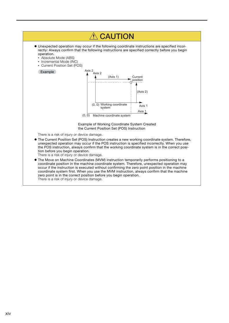
Unexpected operation may occur if the following coordinate instructions are specified incor-rectly: Always confirm that the following instructions are specified correctly before you begin operation.• Absolute Mode (ABS)• Incremental Mode (INC)• Current Position Set (POS)
There is a risk of injury or device damage. The Current Position Set (POS) Instruction creates a new working coordinate system. Therefore,
unexpected operation may occur if the POS instruction is specified incorrectly. When you use the POS instruction, always confirm that the working coordinate system is in the correct posi-tion before you begin operation.There is a risk of injury or device damage.
The Move on Machine Coordinates (MVM) instruction temporarily performs positioning to a coordinate position in the machine coordinate system. Therefore, unexpected operation may occur if the instruction is executed without confirming the zero point position in the machine coordinate system first. When you use the MVM instruction, always confirm that the machine zero point is in the correct position before you begin operation.There is a risk of injury or device damage.
CAUTION
ExampleCurrent position
Working coordinate system
Machine coordinate system
(Axis 1)
(Axis 2)
Axis 1
Axis 1
Axis 2 Axis 2
(0, 0)
(0, 0)
Example of Working Coordinate System Created the Current Position Set (POS) Instruction

xv
Maintenance and Inspection
Disposal
Other General Precautions
CAUTION Do not attempt to disassemble or repair the Machine Controller.
There is a risk of electrical shock, injury, or device damage. Do not change any wiring while power is being supplied.
There is a risk of electrical shock, injury, or device damage. Suitable battery replacement must be performed and it must be performed only by an experi-
enced technician.There is a risk of electrical shock, injury, or device damage.
Replace the Battery only while power is supplied to the Basic Module.Replacing the Battery while the power supply to the Basic Module is turned OFF may result in loss of the data stored in memory in the Module.
Replace the Battery only while power is supplied to the Machine Controller.Replacing the Battery while the power supply to the Machine Controller is turned OFF may result in loss of the data stored in memory in the Machine Controller.
Do not touch the electrodes when replacing the Battery.Static electricity may damage the electrodes.
Do not forget to perform the following tasks when you replace the CPU Module:• Back up all programs and parameters from the CPU Module that is being replaced.• Transfer all saved programs and parameters to the new CPU Module.If you operate the CPU Module without transferring this data, unexpected operation may occur. There is a risk of injury or device damage.
Do not touch the heat sink on the CPU Module while the power supply is turned ON or for a suf-ficient period of time after the power supply is turned OFF.The heat sink may be very hot, and there is a risk of burn injury.
CAUTION Dispose of the Machine Controller as general industrial waste. Observe all local laws and ordinances when you dispose of used Batteries.
Observe the following general precautions to ensure safe application.
The products shown in the illustrations in this manual are sometimes shown without covers or protective guards. Always replace the cover or protective guard as specified first, and then operate the products in accordance with the manual.
The illustrations that are presented in this manual are typical examples and may not match the product you received.
If the manual must be ordered due to loss or damage, inform your nearest Yaskawa representa-tive or one of the offices listed on the back of this manual.

xvi
Warranty
Details of Warranty
Warranty Period
The warranty period for a product that was purchased (hereinafter called “delivered product”) is one year from the time of delivery to the location specified by the customer or 18 months from the time of shipment from the Yaskawa factory, whichever is sooner.
Warranty Scope
Yaskawa shall replace or repair a defective product free of charge if a defect attributable to Yaskawa occurs during the warranty period above. This warranty does not cover defects caused by the delivered product reaching the end of its service life and replacement of parts that require replacement or that have a limited service life.This warranty does not cover failures that result from any of the following causes.• Improper handling, abuse, or use in unsuitable conditions or in environments not described in
product catalogs or manuals, or in any separately agreed-upon specifications• Causes not attributable to the delivered product itself• Modifications or repairs not performed by Yaskawa• Abuse of the delivered product in a manner in which it was not originally intended• Causes that were not foreseeable with the scientific and technological understanding at the time
of shipment from Yaskawa• Events for which Yaskawa is not responsible, such as natural or human-made disasters
Limitations of Liability• Yaskawa shall in no event be responsible for any damage or loss of opportunity to the customer
that arises due to failure of the delivered product.• Yaskawa shall not be responsible for any programs (including parameter settings) or the results of
program execution of the programs provided by the user or by a third party for use with program-mable Yaskawa products.
• The information described in product catalogs or manuals is provided for the purpose of the cus-tomer purchasing the appropriate product for the intended application. The use thereof does not guarantee that there are no infringements of intellectual property rights or other proprietary rights of Yaskawa or third parties, nor does it construe a license.
• Yaskawa shall not be responsible for any damage arising from infringements of intellectual prop-erty rights or other proprietary rights of third parties as a result of using the information described in catalogs or manuals.

xvii
Suitability for Use• It is the customer’s responsibility to confirm conformity with any standards, codes, or regulations
that apply if the Yaskawa product is used in combination with any other products.• The customer must confirm that the Yaskawa product is suitable for the systems, machines, and
equipment used by the customer.• Consult with Yaskawa to determine whether use in the following applications is acceptable. If use
in the application is acceptable, use the product with extra allowance in ratings and specifica-tions, and provide safety measures to minimize hazards in the event of failure.
• Outdoor use, use involving potential chemical contamination or electrical interference, or use in conditions or environments not described in product catalogs or manuals
• Nuclear energy control systems, combustion systems, railroad systems, aviation systems, vehicle systems, medical equipment, amusement machines, and installations subject to separate industry or government regulations
• Systems, machines, and equipment that may present a risk to life or property• Systems that require a high degree of reliability, such as systems that supply gas, water, or electricity, or
systems that operate continuously 24 hours a day• Other systems that require a similar high degree of safety
• Never use the product for an application involving serious risk to life or property without first ensuring that the system is designed to secure the required level of safety with risk warnings and redundancy, and that the Yaskawa product is properly rated and installed.
• The circuit examples and other application examples described in product catalogs and manuals are for reference. Check the functionality and safety of the actual devices and equipment to be used before using the product.
• Read and understand all use prohibitions and precautions, and operate the Yaskawa product correctly to prevent accidental harm to third parties.
Specifications ChangeThe names, specifications, appearance, and accessories of products in product catalogs and manuals may be changed at any time based on improvements and other reasons. The next edi-tions of the revised catalogs or manuals will be published with updated code numbers. Consult with your Yaskawa representative to confirm the actual specifications before purchasing a product.

xviii
ContentsAbout this Manual . . . . . . . . . . . . . . . . . . . . . . . . . . . . . . . . . . . . . . . . . . . . . . . . iiiUsing this Manual . . . . . . . . . . . . . . . . . . . . . . . . . . . . . . . . . . . . . . . . . . . . . . . . iiiRelated Manuals . . . . . . . . . . . . . . . . . . . . . . . . . . . . . . . . . . . . . . . . . . . . . . . . . viSafety Precautions . . . . . . . . . . . . . . . . . . . . . . . . . . . . . . . . . . . . . . . . . . . . . . viiiWarranty . . . . . . . . . . . . . . . . . . . . . . . . . . . . . . . . . . . . . . . . . . . . . . . . . . . . . . xvi
System Configuration1
1.1 Combinations of MP2000-series Products . . . . . . . . . . . . . . . . 1-2
1.2 System Configuration Examples . . . . . . . . . . . . . . . . . . . . . . . . 1-41.2.1 Using the MP2200 . . . . . . . . . . . . . . . . . . . . . . . . . . . . . . . . . . . . . . . . . . . .1-41.2.2 Using the MP2310 . . . . . . . . . . . . . . . . . . . . . . . . . . . . . . . . . . . . . . . . . . . .1-6
Installation and Connections2
2.1 Machine Controller Installation . . . . . . . . . . . . . . . . . . . . . . . . . 2-22.1.1 Screw Mounting . . . . . . . . . . . . . . . . . . . . . . . . . . . . . . . . . . . . . . . . . . . . . .2-22.1.2 DIN Rail Mounting . . . . . . . . . . . . . . . . . . . . . . . . . . . . . . . . . . . . . . . . . . . .2-32.1.3 Installing Optional Modules . . . . . . . . . . . . . . . . . . . . . . . . . . . . . . . . . . . . .2-62.1.4 Replacing and Adding Optional Modules . . . . . . . . . . . . . . . . . . . . . . . . . . .2-72.1.5 Installing and Replacing the Battery in the Basic Module . . . . . . . . . . . . . .2-102.1.6 EXIOIF Module Connections. . . . . . . . . . . . . . . . . . . . . . . . . . . . . . . . . . . .2-13
2.2 Connecting Devices . . . . . . . . . . . . . . . . . . . . . . . . . . . . . . . . . 2-162.2.1 Part Names and Functions . . . . . . . . . . . . . . . . . . . . . . . . . . . . . . . . . . . . .2-162.2.2 Connecting the Power Supply Connector . . . . . . . . . . . . . . . . . . . . . . . . . .2-212.2.3 MECHATROLINK Connectors . . . . . . . . . . . . . . . . . . . . . . . . . . . . . . . . . . .2-242.2.4 Connecting the RLY OUT Connector (MP2300 and MP2400) . . . . . . . . . . .2-262.2.5 Connecting the Power Supply and Other Devices . . . . . . . . . . . . . . . . . . .2-27
Machine Controller Setup3
3.1 The Flow of the Setup . . . . . . . . . . . . . . . . . . . . . . . . . . . . . . . . 3-3
3.2 MPE720 Installation . . . . . . . . . . . . . . . . . . . . . . . . . . . . . . . . . . 3-4
3.3 Creating a Project File . . . . . . . . . . . . . . . . . . . . . . . . . . . . . . . . 3-73.3.1 Project Files . . . . . . . . . . . . . . . . . . . . . . . . . . . . . . . . . . . . . . . . . . . . . . . . .3-73.3.2 Creating a Project File . . . . . . . . . . . . . . . . . . . . . . . . . . . . . . . . . . . . . . . . .3-83.3.3 Setting a Project Password . . . . . . . . . . . . . . . . . . . . . . . . . . . . . . . . . . . . .3-9
3.4 Self Configuration. . . . . . . . . . . . . . . . . . . . . . . . . . . . . . . . . . . 3-103.4.1 Self Configuration Using the DIP Switch. . . . . . . . . . . . . . . . . . . . . . . . . . .3-103.4.2 Self Configuration Using the MPE720. . . . . . . . . . . . . . . . . . . . . . . . . . . . .3-11

xix
3.5 Placing the MPE720 Online . . . . . . . . . . . . . . . . . . . . . . . . . . . 3-133.5.1 Preparing the Ethernet Connection . . . . . . . . . . . . . . . . . . . . . . . . . . . . . . 3-133.5.2 Going Online . . . . . . . . . . . . . . . . . . . . . . . . . . . . . . . . . . . . . . . . . . . . . . . 3-153.5.3 Project Link Connection . . . . . . . . . . . . . . . . . . . . . . . . . . . . . . . . . . . . . . 3-17
3.6 Device-specific Settings . . . . . . . . . . . . . . . . . . . . . . . . . . . . . 3-183.6.1 Data That Is Automatically Updated during Self Configuration . . . . . . . . . 3-183.6.2 Detailed Module Settings . . . . . . . . . . . . . . . . . . . . . . . . . . . . . . . . . . . . . 3-213.6.3 Parameters Written during Self Configuration . . . . . . . . . . . . . . . . . . . . . . 3-323.6.4 Setting Machine-specific Motion Parameters . . . . . . . . . . . . . . . . . . . . . . 3-343.6.5 Setting the Scan Times . . . . . . . . . . . . . . . . . . . . . . . . . . . . . . . . . . . . . . . 3-45
3.7 Test Run . . . . . . . . . . . . . . . . . . . . . . . . . . . . . . . . . . . . . . . . . . 3-473.7.1 Test Run . . . . . . . . . . . . . . . . . . . . . . . . . . . . . . . . . . . . . . . . . . . . . . . . . . 3-473.7.2 Starting the Test Run and Selecting the Axis . . . . . . . . . . . . . . . . . . . . . . . 3-483.7.3 Test Run Dialog Box Details . . . . . . . . . . . . . . . . . . . . . . . . . . . . . . . . . . . 3-50
Creating User Programs4
4.1 User Program Types and Execution Timing . . . . . . . . . . . . . . . . 4-34.1.1 Ladder Programs. . . . . . . . . . . . . . . . . . . . . . . . . . . . . . . . . . . . . . . . . . . . . 4-34.1.2 Motion Programs . . . . . . . . . . . . . . . . . . . . . . . . . . . . . . . . . . . . . . . . . . . . 4-124.1.3 Sequence Programs . . . . . . . . . . . . . . . . . . . . . . . . . . . . . . . . . . . . . . . . . 4-244.1.4 The M-EXECUTOR . . . . . . . . . . . . . . . . . . . . . . . . . . . . . . . . . . . . . . . . . . 4-264.1.5 Registers . . . . . . . . . . . . . . . . . . . . . . . . . . . . . . . . . . . . . . . . . . . . . . . . . . 4-41
4.2 Creating Ladder Programs . . . . . . . . . . . . . . . . . . . . . . . . . . . . 4-51
4.3 Creating Motion Programs . . . . . . . . . . . . . . . . . . . . . . . . . . . . 4-554.3.1 Creating a Group Definition . . . . . . . . . . . . . . . . . . . . . . . . . . . . . . . . . . . . 4-554.3.2 Creating a Motion Main Program . . . . . . . . . . . . . . . . . . . . . . . . . . . . . . . . 4-564.3.3 Creating a Motion Subprogram . . . . . . . . . . . . . . . . . . . . . . . . . . . . . . . . . 4-58
4.4 Creating a Sequence Program . . . . . . . . . . . . . . . . . . . . . . . . . 4-604.4.1 Creating a Sequence Main Program . . . . . . . . . . . . . . . . . . . . . . . . . . . . . 4-604.4.2 Creating a Sequence Subprogram. . . . . . . . . . . . . . . . . . . . . . . . . . . . . . . 4-61
4.5 Transferring Data with the MPE720 . . . . . . . . . . . . . . . . . . . . . 4-634.5.1 Writing Parameters to the Machine Controller . . . . . . . . . . . . . . . . . . . . . . 4-644.5.2 Writing into a Project File. . . . . . . . . . . . . . . . . . . . . . . . . . . . . . . . . . . . . . 4-654.5.3 Reading from the Machine Controller . . . . . . . . . . . . . . . . . . . . . . . . . . . . 4-664.5.4 Reading from a Project File . . . . . . . . . . . . . . . . . . . . . . . . . . . . . . . . . . . . 4-674.5.5 Saving to Flash Memory . . . . . . . . . . . . . . . . . . . . . . . . . . . . . . . . . . . . . . 4-684.5.6 Using a CF Card (MP2200 Only) . . . . . . . . . . . . . . . . . . . . . . . . . . . . . . . . 4-694.5.7 Comparing to the Machine Controller . . . . . . . . . . . . . . . . . . . . . . . . . . . . 4-714.5.8 Comparing Flash Memory and RAM Data . . . . . . . . . . . . . . . . . . . . . . . . . 4-714.5.9 Comparing to a Project File . . . . . . . . . . . . . . . . . . . . . . . . . . . . . . . . . . . . 4-714.5.10 Comparing to a CF Card . . . . . . . . . . . . . . . . . . . . . . . . . . . . . . . . . . . . . . 4-71
4.6 Data Transfer without Using the MPE720 . . . . . . . . . . . . . . . . 4-724.6.1 Using a CF Card (MP2200 Only) . . . . . . . . . . . . . . . . . . . . . . . . . . . . . . . . 4-724.6.2 Using the MPLoader . . . . . . . . . . . . . . . . . . . . . . . . . . . . . . . . . . . . . . . . . 4-754.6.3 Using the MPLoad Maker . . . . . . . . . . . . . . . . . . . . . . . . . . . . . . . . . . . . . 4-77

xx
Debugging Programs5
5.1 Debugging Ladder Programs . . . . . . . . . . . . . . . . . . . . . . . . . . . 5-35.1.1 Ladder Program Runtime Monitoring . . . . . . . . . . . . . . . . . . . . . . . . . . . . . .5-35.1.2 Register List Panes. . . . . . . . . . . . . . . . . . . . . . . . . . . . . . . . . . . . . . . . . . . .5-45.1.3 Watch Panes . . . . . . . . . . . . . . . . . . . . . . . . . . . . . . . . . . . . . . . . . . . . . . . .5-75.1.4 Searching and Replacing in Programs . . . . . . . . . . . . . . . . . . . . . . . . . . . . .5-85.1.5 Searching and Replacing in Project Files . . . . . . . . . . . . . . . . . . . . . . . . . .5-115.1.6 Cross Reference Panes . . . . . . . . . . . . . . . . . . . . . . . . . . . . . . . . . . . . . . .5-135.1.7 Checking for Multiple Coils. . . . . . . . . . . . . . . . . . . . . . . . . . . . . . . . . . . . .5-165.1.8 Forcing Coils ON and OFF . . . . . . . . . . . . . . . . . . . . . . . . . . . . . . . . . . . . .5-175.1.9 Viewing a Called Program. . . . . . . . . . . . . . . . . . . . . . . . . . . . . . . . . . . . . .5-205.1.10 Enabling and Disabling a Program . . . . . . . . . . . . . . . . . . . . . . . . . . . . . . .5-20
5.2 Debugging a Motion or a Sequence Program . . . . . . . . . . . . . 5-215.2.1 Tab Page Items. . . . . . . . . . . . . . . . . . . . . . . . . . . . . . . . . . . . . . . . . . . . . .5-225.2.2 Monitoring Program Execution . . . . . . . . . . . . . . . . . . . . . . . . . . . . . . . . . .5-235.2.3 Register List Panes. . . . . . . . . . . . . . . . . . . . . . . . . . . . . . . . . . . . . . . . . . .5-255.2.4 Watch Panes . . . . . . . . . . . . . . . . . . . . . . . . . . . . . . . . . . . . . . . . . . . . . . .5-255.2.5 Searching and Replacing in Programs . . . . . . . . . . . . . . . . . . . . . . . . . . . .5-255.2.6 Searching and Replacing in Project Files . . . . . . . . . . . . . . . . . . . . . . . . . .5-255.2.7 Viewing a Motion Subprogram . . . . . . . . . . . . . . . . . . . . . . . . . . . . . . . . . .5-255.2.8 Cross Reference Searches . . . . . . . . . . . . . . . . . . . . . . . . . . . . . . . . . . . . .5-255.2.9 Alarm Monitor . . . . . . . . . . . . . . . . . . . . . . . . . . . . . . . . . . . . . . . . . . . . . . .5-265.2.10 Alarm Code Details. . . . . . . . . . . . . . . . . . . . . . . . . . . . . . . . . . . . . . . . . . .5-30
5.3 Monitoring Machine Operation. . . . . . . . . . . . . . . . . . . . . . . . . 5-335.3.1 Axis Monitor . . . . . . . . . . . . . . . . . . . . . . . . . . . . . . . . . . . . . . . . . . . . . . . .5-335.3.2 Alarm Monitor . . . . . . . . . . . . . . . . . . . . . . . . . . . . . . . . . . . . . . . . . . . . . . .5-375.3.3 Realtime Tracing . . . . . . . . . . . . . . . . . . . . . . . . . . . . . . . . . . . . . . . . . . . . .5-415.3.4 XY Trace . . . . . . . . . . . . . . . . . . . . . . . . . . . . . . . . . . . . . . . . . . . . . . . . . . .5-64
5.4 Tuning . . . . . . . . . . . . . . . . . . . . . . . . . . . . . . . . . . . . . . . . . . . . 5-685.4.1 Using SigmaWin+ (When Using a Servo) . . . . . . . . . . . . . . . . . . . . . . . . . .5-685.4.2 Using DriveWizard Plus (When Using an Inverter) . . . . . . . . . . . . . . . . . . . .5-68
Security6
6.1 Project File Security . . . . . . . . . . . . . . . . . . . . . . . . . . . . . . . . . . 6-26.1.1 Setting a Project Password . . . . . . . . . . . . . . . . . . . . . . . . . . . . . . . . . . . . .6-26.1.2 Creating or Changing a Password . . . . . . . . . . . . . . . . . . . . . . . . . . . . . . . .6-26.1.3 Deleting a Password. . . . . . . . . . . . . . . . . . . . . . . . . . . . . . . . . . . . . . . . . . .6-36.1.4 Setting the Default User . . . . . . . . . . . . . . . . . . . . . . . . . . . . . . . . . . . . . . . .6-46.1.5 User Management . . . . . . . . . . . . . . . . . . . . . . . . . . . . . . . . . . . . . . . . . . . .6-4
6.2 Program Security . . . . . . . . . . . . . . . . . . . . . . . . . . . . . . . . . . . . 6-76.2.1 Setting the Password . . . . . . . . . . . . . . . . . . . . . . . . . . . . . . . . . . . . . . . . . .6-76.2.2 Changing a Password. . . . . . . . . . . . . . . . . . . . . . . . . . . . . . . . . . . . . . . . . .6-86.2.3 Deleting a Password. . . . . . . . . . . . . . . . . . . . . . . . . . . . . . . . . . . . . . . . . . .6-86.2.4 Opening a Password-Protected Ladder Program . . . . . . . . . . . . . . . . . . . . .6-9
6.3 Online Security . . . . . . . . . . . . . . . . . . . . . . . . . . . . . . . . . . . . . 6-106.3.1 Setting Online Security . . . . . . . . . . . . . . . . . . . . . . . . . . . . . . . . . . . . . . . .6-116.3.2 Changing Online Security . . . . . . . . . . . . . . . . . . . . . . . . . . . . . . . . . . . . . .6-126.3.3 Deleting Online Security . . . . . . . . . . . . . . . . . . . . . . . . . . . . . . . . . . . . . . .6-13

xxi
6.3.4 Changing the Security Key . . . . . . . . . . . . . . . . . . . . . . . . . . . . . . . . . . . . 6-146.3.5 Unlocking Online Security Temporarily . . . . . . . . . . . . . . . . . . . . . . . . . . . 6-15
Controller SpecificationsAppendixA
A.1 Installation and Usage Conditions . . . . . . . . . . . . . . . . . . . . . . . A-2
A.2 Control Panel Cooling Method . . . . . . . . . . . . . . . . . . . . . . . . . . A-3
Motion ParametersAppendixB
B.1 Fixed Parameters . . . . . . . . . . . . . . . . . . . . . . . . . . . . . . . . . . . . B-2
B.2 Setting Parameters. . . . . . . . . . . . . . . . . . . . . . . . . . . . . . . . . . . B-5
B.3 Monitor Parameters . . . . . . . . . . . . . . . . . . . . . . . . . . . . . . . . . B-13
Index
Revision History

This chapter describes the combinations of Units and Mod-ules in MP2000-series Machine Controllers and provides system configuration examples.
1.1 Combinations of MP2000-series Products . . .1-2
1.2 System Configuration Examples . . . . . . . . . . .1-41.2.1 Using the MP2200 . . . . . . . . . . . . . . . . . . . . . . . 1-41.2.2 Using the MP2310 . . . . . . . . . . . . . . . . . . . . . . . 1-6
System Configuration 1

1.1 Combinations of MP2000-series Products
1-2
1.1 Combinations of MP2000-series Products
The following table shows the combinations of Units and Modules in MP2000-series Machine Controllers.
Product Name Abbreviation Description MP2200MP2300,MP2310,MP2300S
CPU
CPU-01 CPU ×
CPU-02 CPU+USB+CFIF ×
CPU-03 CPU+Ethernet+CFIF ×CPU-04 CPU+Ethernet ×
MPU-01 CPU+SVC-01 Ver. 2.73 or higher
Ver. 2.73 or higher (MP2300
is not supported)
Expansion EXIOIF Expansion ×
Communica-tions
217IF-01 Serial
218IF-01 Ethernet
218IF-02 Ethernet Ver. 2.60 or higher
Ver. 2.60 or higher
260IF-01 DeviceNet
261IF-01 PROFIBUS
262IF-01 FL-net Ver. 2.63 or higher
Ver. 2.63 or higher
263IF-01 EtherNet/IP Ver. 2.64 or higher
Ver. 2.64 or higher
264IF-01 EtherCAT Ver. 2.73 or higher
Ver. 2.73 or higher
265IF-01 CompoNet Ver. 2.74 or higher
Ver. 2.74 or higher
266IF-01 PROFINET Master Ver. 2.81 or higher
Ver. 2.81 or higher
266IF-02 PROFINET Slave Ver. 2.82 or higher
Ver. 2.82 or higher
215AIF-01CP-215
Ver. 2.41 or higher
Ver. 2.41 or higherMPLINK
Motion
SVB-01 MECHATROLINK-II Ver. 2.02 or higher
Ver. 2.02 or higher
SVC-01 MECHATROLINK-III Ver. 2.70 or higher
Ver. 2.70 or higher
SVA-01 Analog outputs Ver. 2.20 or higher
Ver. 2.20 or higher
PO-01 Pulse outputs Ver. 2.44 or higher
Ver. 2.44 or higher
Continued on next page.
Opt
iona
l Mod
ules

1.1 Combinations of MP2000-series Products
1-3
1S
yste
m C
onfig
urat
ion
I/O
LIO-01 16 inputs, 16 sinking out-puts, and 1 pulse input channel
LIO-0216 inputs, 16 sourcing outputs, and 1 channel pulse input
LIO-04 32 inputs and 32 sinking outputs
Ver. 2.20 or higher
Ver. 2.20 or higher
LIO-05 32 inputs and 32 sourcing outputs
Ver. 2.32 or higher
Ver. 2.32 or higher
LIO-06
8 digital inputs, 8 digital sinking outputs, 1 analog input channel, 1 analog output channel, and 1 pulse counter chan-nel
Ver. 2.63 or higher
Ver. 2.63 or higher
DO-01 64 sinking outputs Ver. 2.32 or higher
Ver. 2.32 or higher
AI-01 Analog input Ver. 2.40 or higher
Ver. 2.40 or higher
AO-01 Analog output Ver. 2.44 or higher
Ver. 2.44 or higher
CNTR-01 Counter Ver. 2.44 or higher
Ver. 2.44 or higher
AFMP-01 AnyWire-DB master∗1 Ver. 2.02 or higher
Ver. 2.02 or higher
AFMP-02-C CC-Link interface board∗1 Ver. 2.51 or higher
Ver. 2.51 or higher
AFMP-02-CA
AnyWire-DB interface board with CC-Link∗1
Ver. 2.51 or higher
Ver. 2.51 or higher
MPALN00-0 A-net/A-Link master unit∗2 Ver. 2.46 or higher
Ver. 2.46 or higher
MPCUNET-0 CUnet Master Unit∗2 Ver. 2.81 or higher
Ver. 2.81 or higher
*1. AnyWire Co., Ltd.*2. Algo System Co., Ltd.
Continued from previous page.
Product Name Abbreviation Description MP2200MP2300,MP2310,MP2300S
Opt
iona
l Mod
ules

1.2 System Configuration Examples
1.2.1 Using the MP2200
1-4
1.2 System Configuration Examples
Configuration examples are provided below for the MP2000 Series.
1.2.1 Using the MP2200
One-Rack Configuration
Note: 1. Use the connecting cables and connectors recommended by Yaskawa. Always check the device to be used and select the correct cable for the device.
2. 24-VDC power supply is not provided by Yaskawa.
FG
MPE720
MECHATROLINK-II
Ethernet
Ethernet HUB
I/O
YASKAWA SERVOPACK 200V
SGDS-01A12A
SW1
CHARGE
CN3
A/B
CN1
CN2
CN4
L1L2
L2C
L1C
B1/B2
U
V
W
CN6
YASKAWA SERVOPACK 200V
SGDS-01A12A
SW1
CHARGE
CN3
A/B
CN1
CN2
CN4
L1L2
L2C
L1C
B1/B2
U
V
W
CN6
JEPMC-IO2310
VS mini V7
MP2200 MBU-02POWER
CPU-01 SVB-01218F-01
DC
LIO
-01
LIO
-02
LIO
-04
LIO
-05
DO
-01
AI-0
1
AO
-01
LIO
-06
215A
IF-0
1
216A
IF-0
1
217I
F-01
218I
F-01
260I
F-01
261I
F-01
SVA
-01
SV
B-0
1
PO
-01
AFM
P-0
1
MPA
NL0
0-0
RS-232C
Ethernet
DeviceNet
PROFIBUS
RS422/485
AnyWire
A-net/A-link
AFM
P-0
2
CC-Link
CN
TR-0
1
SV
C-0
1
262I
F-01
263I
F-01
218I
F-02
FL-net
EtherNet/IP
MPA
LL00
-0
MPA
L000
-0
MPA
N00
0-0
EXIOIF Module
EX
IOIF
Communication module
Motion control module
Other module such as other company's module
External Output
External Input
Servoamplifier
Optional moduleI/O module
Max. 21 stations including I/O.(Max. 16 stations servo can be included.)
Host PLC
InverterServo Servo ServoRepeater
Terminating resistor 130 W
24 VDC
215 communication
216 communication
MP2200 Expansion Rack
SGDH-04AE NS115

1.2 System Configuration Examples
1.2.1 Using the MP2200
1-5
1S
yste
m C
onfig
urat
ion
Four-Rack Configuration
* Use an EXIOIF cable that has a maximum length of 6.0 m.
LIO
-01
LIO
-02
LIO
-04
LIO
-05
DO
-01
AI-
01
AO
-01
LIO
-06
215A
IF-0
1
216A
IF-0
1
217I
F-01
218I
F-01
260I
F-01
261I
F-01
SV
A-0
1
SV
B-0
1
PO
-01
Motion control modules
AFM
P-0
1
MP
AN
L00-
0
RS-232C
Ethernet
DeviceNe t
PROFIBUS
RS422/485
AnyWir e
A-net/A-link
AFM
P-0
2
CC-Link
CN
TR
-01
SV
C-0
1
262I
F-01
263I
F-01
218I
F-02
FL-net
EtherNet/I PM
PA
LL00
-0
MP
AL0
00-0
MP
AN
000-
0
EXIOIF module
EXI
OIF
External I/O modules
Communication modules
Optional modules
External input
External output
24 VDCor
100/200VAC
Slot 8Slot 0 (always CPU module)
Slot 1 Slot 9
Slot 1 Slot 9
Slot 1Slot 9
Servoamplifier
215 communication
216 communication
MP2200 Expansion Rack
Other module such as other company's module
*
MP2200 MBU-01POWER
CPU-01EXIOIF
MP2200 MBU-01POWER
SVB-01EXIOIF
Y ASKA
MP2200 MBU-01POWER
SVB-01EXIOIF
Y ASKA
MP2200 MBU-01POWER
SVB-01EXIOIF
Y ASKA

1.2 System Configuration Examples
1.2.2 Using the MP2310
1-6
1.2.2 Using the MP2310
215 Communications
Up to 21 stations, including I/O (Up to 16 stations can be Servos.)
InverterServomotorRepeaterServomotorServomotor
Other Modules (including those from other manufacturers)
Host PLC
Opt
iona
l Mod
ules
Opt
iona
l Mod
ules
Opt
iona
l Mod
ules
Communications Modules
Motion Modules
SERVOPACKs
I/O ModulesOptional Modules
External inputs
External outputs
24 VDC
FG
MPE720
MECHATROLINK-II
Ethernet
Ethernet HUB
SGDH-04AE NS115
I/O
YASKAWA SERVOPACK 200V
SGDS-01A12A
SW1
CHARGE
CN3
A/B
CN1
CN2
CN4
L1L2
L2C
L1C
B1/B2
U
V
W
CN6
YASKAWA SERVOPACK 200V
SGDS-01A12A
SW1
CHARGE
CN3
A/B
CN1
CN2
CN4
L1L2
L2C
L1C
B1/B2
U
V
W
CN6
VS mini V7
215A
IF-0
1
217I
F-01
218I
F-01
218I
F-02
260I
F-01
261I
F-01
262I
F-01
263I
F-01
264I
F-01
265I
F-01
SVA
-01
SV
B-0
1P
O-0
1
SV
C-0
1M
PU
-01
MPA
LL00
-0
MPA
L000
-0
AFM
P-0
1
MPA
NL00
-0AF
MP-02
-C/-C
A
MPA
N000
-0
RS-232C
Ethernet
DeviceNet
PROFIBUS
RS422/485
AnyWire
A-net/A-link
CC-Link
LIO
-01
LIO
-02
LIO
-04
LIO
-05
DO
-01
LIO
-06
AI-0
1A
O-0
1CN
TR-0
1
Terminating resistor130 Ω
100M
EthernetLINK
SW2E-INITE-TEST
MECHATROLINK
ON
BATTERY
POWER
DC 0
DC24M-I/II
RUN
ERR
BAT
SW1
RDY
ALM
MTX
STOPSUPINIT
CNFGMON
TESTON
IPTRX
MP2310
YASKAWA
JEPMC-IO2310

This chapter describes the installation and connections of Machine Controllers.
2.1 Machine Controller Installation . . . . . . . . . . 2-22.1.1 Screw Mounting . . . . . . . . . . . . . . . . . . . . . . . . . 2-22.1.2 DIN Rail Mounting . . . . . . . . . . . . . . . . . . . . . . . . 2-32.1.3 Installing Optional Modules . . . . . . . . . . . . . . . . . 2-62.1.4 Replacing and Adding Optional Modules . . . . . . 2-72.1.5 Installing and Replacing the Battery
in the Basic Module . . . . . . . . . . . . . . . . . . . . . 2-102.1.6 EXIOIF Module Connections . . . . . . . . . . . . . . . 2-13
2.2 Connecting Devices . . . . . . . . . . . . . . . . . 2-162.2.1 Part Names and Functions . . . . . . . . . . . . . . . . 2-162.2.2 Connecting the Power Supply Connector . . . . . 2-212.2.3 MECHATROLINK Connectors . . . . . . . . . . . . . . 2-242.2.4 Connecting the RLY OUT Connector (MP2300 and
MP2400) . . . . . . . . . . . . . . . . . . . . . . . . . . . . . . 2-262.2.5 Connecting the Power Supply and
Other Devices . . . . . . . . . . . . . . . . . . . . . . . . . . 2-27
Installation and Connections 2

2.1 Machine Controller Installation
2.1.1 Screw Mounting
2-2
2.1 Machine Controller Installation
You can use either of the following methods to install a Machine Controller.• Screw mounting• DIN rail mountingRefer to the following appendix for more information on the installation and application require-ments.
A.1 Installation and Usage Conditions on page A-2
2.1.1 Screw MountingPress the Machine Controller against the mounting surface, and use the four mounting screws to firmly secure it.
Note: Install the Controller perpendicularly to the wall, as shown in the above figure.
100M
EthernetLINK
RUN
ERR
BAT
SW1
SW2
RDY
ALM
MTX
STOPSUPINIT
CNFGMON
TEST
E-INITE-TEST
MECHATROLINK
ON
ONBATTERY
POWER
DC 0V
DC24VM-I/II
IPTRX
MP2310YASKAWA
Use a screwdriver with a shaft that is at least 10 cm long.
Mounting screws (M4, Phillips screw)

2.1 Machine Controller Installation
2.1.2 DIN Rail Mounting
2-3
2
Inst
alla
tion
and
Con
nect
ions
2.1.2 DIN Rail MountingThis section describes how to install the Controller by mounting it on DIN rail.
DIN Rail Types and the SpacerVarious types of DIN rails are available with a 7-mm to 15-mm gap from the mounting surface as shown on the left in the following figure. If you mount a Machine Controller using a DIN rail with a 10-mm or larger gap, install a spacer on the back of and near the bottom of the Machine Controller, as shown on the right side of the following figure, to protect it from vibration and shock.
DIN rail
Installation plate
Distance from mounting surface: 7.5 to 15 mm
Spacer
DIN rail
DIN Rail with a 10-mm Gap

2.1 Machine Controller Installation
2.1.2 DIN Rail Mounting
2-4
Procedure for Mounting to a DIN Rail1. Attach the DIN rail to the control panel and secure it in place.
2. Insert the DIN Rail Mounting Clips in the two slots on the back of the Machine Control-ler, and press them in until they reach the dotted line shown in the following figure.
Note: The Mounting Clips have a front and a back surface. Insert each Clip so that its front surface faces outward.
Securing the DIN RailSecure the DIN rail at a pitch of 300 mm or less, as shown in the following figure.
Important
300 mm max.300 mm max.
Mounting Clips (position after
insertion)
Installation locationsMounting Clips (Model: JEPMC-OP300)
Back of the MP2310
BackFront

2.1 Machine Controller Installation
2.1.2 DIN Rail Mounting
2-5
2
Inst
alla
tion
and
Con
nect
ions
3. Pull the DIN Rail Mounting Clips down to release them.
4. Hook the Machine Controller to the top of the DIN rail (a in the figure), and then press the Controller toward the mounting surface (b in the figure) to secure it in place.
5. Press in the DIN Rail Mounting Clips to lock them in place.
100M
EthernetLINK
RUN
ERR
BAT
SW1
SW2
RDY
ALM
MTX
STOPSUPINIT
CNFGMON
TEST
E-INITE-TEST
MECHATROLINK
ON
ONBATTERY
M-I/II
IPTRX
MP2310YASKAWA
POWER
DC 0V
DC24V
Clip
a
b
100M
EthernetLINK
RUN
ERR
BAT
SW1
SW2
RDY
ALM
MTX
STOPSUPINIT
CNFGMON
TEST
E-INITE-TEST
MECHATROLINK
ON
ONBATTERY
POWER
DC 0V
DC24VM-I/II
IPTRX
MP2310YASKAWA
Clip

2.1 Machine Controller Installation
2.1.3 Installing Optional Modules
2-6
6. Place end plates on both sides of the Machine Controller to secure it to the DIN rail.
This completes the installation procedure.
2.1.3 Installing Optional ModulesUse the following procedure to install Optional Modules.
1. Hold the top and bottom of the Optional Module to be installed, line up the Module with the left side of the guide rail inside the option slot, and then insert the Module straight in.
2. After the Optional Module is completely inserted, place your hand on the front of the Optional Module and press the Optional Module firmly until it mates with the Mounting Base connectors in the Unit. The front of the Optional Module and the tabs will be aligned if the Optional Module has been installed properly.
You can remove the Controller by reversing the order of the mounting procedure.
Refer to the manual for the MP2100 or MP2500 for more information on installation.
100M
EthernetLINK
RUN
ERR
BAT
SW1
SW2
RDY
ALM
MTX
STOPSUPINIT
CNFGMON
TEST
E-INITE-TEST
MECHATROLINK
ON
ONBATTERY
POWER
DC 0V
DC24VM-I/II
IPTRX
MP2310YASKAWA
End plate
DIN rail
Note
Information
The FG bar inside and on the bottom may be damaged if the Module is not inserted along the guide rail.
Note
123456
SW1
IP
BAT
ERR
YASKAWAMP
2310
RUN
ON
SW2
ON
INIT
CNFG
STOP
LD8
TRX
MTX
ALM
RDY
SUP
MON
TEST
E-TESTE-I
NIT
Ethern
et
LINK
M-I/II
100M
POWER
BATTERY
DC24V
DC0V

2.1 Machine Controller Installation
2.1.4 Replacing and Adding Optional Modules
2-7
2
Inst
alla
tion
and
Con
nect
ions
3. Place the hole on the bottom of the panel of the Optional Module onto the tab on the bottom of the Unit. Next, hook the hole at the top of the panel of the Optional Module onto the tab on the Unit.
This completes the installation procedure.
2.1.4 Replacing and Adding Optional ModulesUse the following procedure to replace or add Optional Modules.
1. Turn OFF the power supply and disconnect all cables from the Machine Controller.
2. Pull the notch on the side toward you to remove the battery cover.
Always use Option Covers (model: JEPMC-OP2300) to cover unused slots.
12345
6
SW1
IP
TRX
MTX
ALM
RDY
RUN
ERR
BAT
STOP
MODE
LD4
LD3
LD2
LD1
LD8
LD7
LD6
LD5
SUP
INIT
CNFG
MON
TEST
ON
I/O
MODE
LD8
LD7
LD6
LD5RUN
I/O
1234
SW2
ONE-IN
IT
E-TEST
BATTER
Y
YASKAW
AMP2
310
LIO-0
LIO-
O-02
POWER
DC24V
100M
ULTRA
Ethern
et
LINK
LITHIUM BATTERYL
ER3V/BV
M-I/II
DCOV
CN2
CN1
Note
Always create a backup before replacing or adding Optional Modules. Back up the program from the Machine Controller to the PC using the MPE720.
Important
12345
6
SW1
IP
STOP
MODE
LD4
CN1
LD3 LD8
LD7
SUP
INIT
CNFG
MON
TEST
ON
I/O
MODE
LD4
LD3 LD8
LD7LD2
LD6
LD5
FU
RUN
I/O
1234
SW2
ONE-IN
IT
E-TEST
BATTER
Y
DC24V
Ethern
et
LINK
M-I/II
DCOV
2.1 Machine Controller Installation
2.1.4 Replacing and Adding Optional Modules
2-8
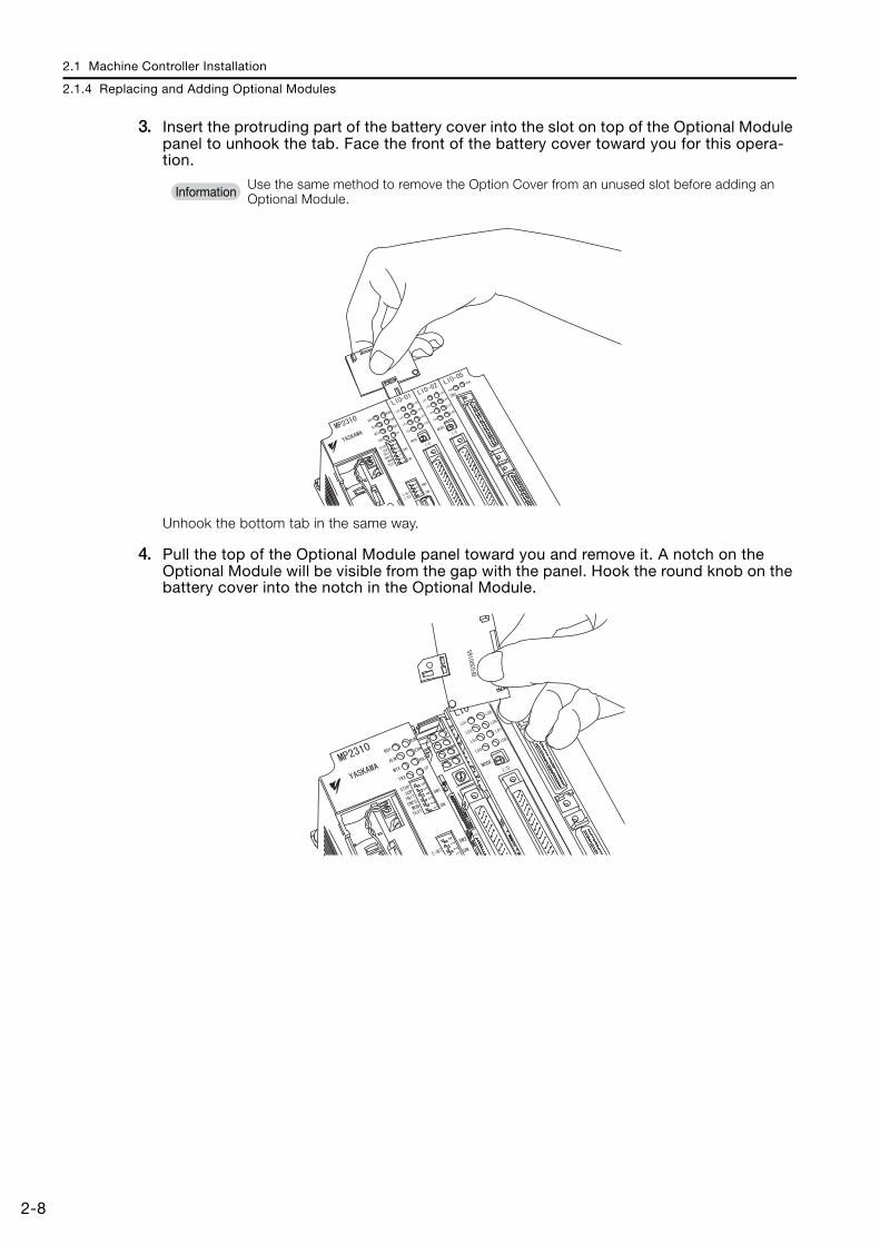
3. Insert the protruding part of the battery cover into the slot on top of the Optional Module panel to unhook the tab. Face the front of the battery cover toward you for this opera-tion.
Unhook the bottom tab in the same way.
4. Pull the top of the Optional Module panel toward you and remove it. A notch on the Optional Module will be visible from the gap with the panel. Hook the round knob on the battery cover into the notch in the Optional Module.
Use the same method to remove the Option Cover from an unused slot before adding an Optional Module.Information

2.1 Machine Controller Installation
2.1.4 Replacing and Adding Optional Modules
2-9
2
Inst
alla
tion
and
Con
nect
ions
5. Hold the center of the battery cover, and turn it around the round knob while pushing it toward the back to disconnect the Module from the Mounting Base connectors. Then, pull the Module forward.
6. Hold the Optional Module at the top and bottom and pull it straight out. Hold the edges of the Module and avoid touching the components on the Module.
Note: Put the Module that you removed into the bag that was supplied when you purchased it and store the Module in this bag.

2.1 Machine Controller Installation
2.1.5 Installing and Replacing the Battery in the Basic Module
2-10
2.1.5 Installing and Replacing the Battery in the Basic ModuleThe Battery in the Basic Module backs up the data that is saved by the Basic Module in the event of a power failure or when the power to the Basic Module is turned OFF. The Battery pro-vides backup power for the following data.• M registers• S registers• Trace memory• Alarm history• Table data
Battery Appearance
Note: This Battery is not available on the retail market. Order the Battery from Yaskawa Controls Co., Ltd. (The model number is JZSP-BA01.)
Battery Installation
• The Basic Module comes with one Battery. The Battery is not connected when the Module is delivered.
• The Battery can provide backup power for the memory for a total power OFF time of 1 year. However, this depends on the actual operating conditions, such as the ambient temperature.
• When the total power OFF times reaches 1 year, the voltage of the Battery will drop, and the BAT indicator on the Basic Module will light. When this occurs, always replace the Battery with a new one within two weeks.Delayed replacement of the Battery will result in loss of the data stored in the memory of the Basic Module.
• The Battery is warranted for 5 years.
JZSP-BA01 Battery Specifications
Type Lithium primary cell
Battery Model ER3VC
Manufacturer Toshiba Home Appliance Corp.
Nominal Voltage 3.6 V
Nominal Capacity 1000 mAh
Lithium Content 0.3 g
Number of Batteries Used 1
The Basic Module comes with one Battery. The Battery is not connected when the Module is delivered.
Important
LiTHIUM
Red lead Black lead
Important
CAUTION Suitable battery installation must be performed and it must be performed only by an
experienced technician.There is a risk of electrical shock, injury, or device damage.
Do not touch the electrodes when installing the Battery.Static electricity may damage the electrodes.

2.1 Machine Controller Installation
2.1.5 Installing and Replacing the Battery in the Basic Module
2-11
2
Inst
alla
tion
and
Con
nect
ions
1. Confirm that the power supply to the Basic Module is turned OFF.
2. Open the battery cover on the front of the Module.
3. Securely connect the lead connector of the Battery to the connector in the Basic Mod-ule, and insert the Battery into the battery holder.
4. Close the battery cover and turn ON the Basic Module.
5. Installation of the Battery is complete when the RDY indicator on the Basic Module goes out.
Battery Replacement
CAUTION Suitable battery replacement must be performed and it must be performed only by an
experienced technician.There is a risk of electrical shock, injury, or device damage.
Replace the Battery only while power is supplied to the Basic Module.Replacing the Battery while the power supply to the Basic Module is turned OFF may result in loss of the data stored in memory in the Module.
Do not touch the electrodes when replacing the Battery.Static electricity may damage the electrodes.
Observe all local laws and ordinances when you dispose of used Batteries.

2.1 Machine Controller Installation
2.1.5 Installing and Replacing the Battery in the Basic Module
2-12
1. Back up the programs and data stored in the Basic Module.Note: The backup can be used to recover the data if the data accidentally gets deleted during Battery replace-
ment. Refer to the following manual for details on backing up the data.4.5 Transferring Data with the MPE720 - 4.5.3 Reading from the Machine Controller on page 4-66
2. Confirm that the RDY indicator on the Basic Module is lit.
3. Open the battery cover on the front of the Unit.
4. Disconnect the lead connector of the Battery from the connector on the Basic Module, and remove the Battery from the battery holder.
5. Securely connect the lead connector of the Replacement Battery to the connector on the Basic Module, and insert the Replacement Battery into the battery holder.
6. Confirm that the BAT indicator of the Basic Module is not lit.
7. Close the cover. This concludes the Battery replacement procedure.

2.1 Machine Controller Installation
2.1.6 EXIOIF Module Connections
2-13
2
Inst
alla
tion
and
Con
nect
ions
2.1.6 EXIOIF Module ConnectionsAn EXIOIF Module is mounted to an MP2200 Base Unit (MBU-01, MBU-02, or MBU-03). You can use the Module to add up to four Expansion Racks.
ConnectorsThe connectors on the EXIOIF Module are shown in the following figure.
These connectors are used to add MP2200 Base Units (MBU-01, MBU-02, or MBU-03).Use the standard cables. Refer to the following section for information on the standard cables.
Standard Cables (page 2-14)
CN2OUT
CN1IN
EXIOIFExternal input connector
External output connector

2.1 Machine Controller Installation
2.1.6 EXIOIF Module Connections
2-14
The connection method for the external I/O connectors is shown in the following figure.
Note: Attach the enclosed dust caps to the unused connectors ( in the above figure).
Standard Cables
Note: 1. Do not exceed 6.0 m for the total cable length when you add Racks.2. Make all connections on a 1:1 basis.
Name Model Length Description
Cables with Connectors on Both Ends
JEPMC-W2091-A5 0.5 m Shielded cables, equivalent to UL 20276, 0.08 mm2 (AWG28), two ferrite cores attached
JEPMC-W2091-01 1.0 m
JEPMC-W2091-2A5 2.5 m
JEPMC-W2094-A5 0.5 m Shielded cables, equivalent to UL 20276, 0.05 mm2 (AWG30), four ferrite cores attached
JEPMC-W2094-01 1.0 m
JEPMC-W2094-2A5 2.5 m
EXIOIF
EXIOIF
EXIOIF
EXIOIF
Rack 1
Rack 2
Rack 3
Rack 4
CN1IN
CN2OUT
CN1IN
CN2OUT
CN1IN
CN2OUT
CN1IN
CN2OUT
�
�

2.1 Machine Controller Installation
2.1.6 EXIOIF Module Connections
2-15
2
Inst
alla
tion
and
Con
nect
ions
Standard Cable Appearance
JEPMC-W2091-
JEPMC-W2094-

2.2 Connecting Devices
2.2.1 Part Names and Functions
2-16
2.2 Connecting Devices
This section explains how to connect devices to the Machine Controllers.
2.2.1 Part Names and FunctionsThe following figure shows the names and functions of the parts of the Machine Controller and the Servo Drive.
MP2200 (When Using the MBU-01 and CPU-01)
MP2200 MBU-01POWER
CPU-01
YASKAWAConnects the power supply.
3-pin connector (power supply)
Battery Cover
This DIP switch is used to set the startup operating conditions of the Machine Controller.
DIP Switch (6 Pins)
These indicators show the status of the Machine Controller.
Indicators

2.2 Connecting Devices
2.2.1 Part Names and Functions
2-17
2
Inst
alla
tion
and
Con
nect
ions
MP2310
MP2300S
Some Controllers have two MECHATROLINK-II connectors. If only one of these connectors is connected to a MECHATROLINK Communications Cable, then you must connect a Terminator to the other connector.
100M
EthernetLINK
SW2E-INITE-TEST
MECHATROLINK
ON
BATTERY
POWER
DC 0
DC24M-I/II
RUN
ERR
BAT
SW1
RDY
ALM
MTX
STOPSUPINIT
CNFGMON
TESTON
IPTRX
MP2310YASKAWA
Connects to an Ethernet cable. The indicator shows the connection status.
Ethernet Connector (with Indicator)
Connects the 24-VDC power supply.
3-pin connector (24-V power supply)
Connect a MECHATROLINK-II Communications Cable or a Terminator here.
MECHATROLINK-II Connector (One Line with One Port)
Battery Cover
This DIP switch is used to set the operating conditions of the Ethernet port.
DIP Switch (4 Pins)
This DIP switch is used to set the startup operating conditions of the Machine Controller.
DIP Switch (6 Pins)
These eight indicators show the status of the Machine Controller.
Indicators
Note
MP
EthernetLINK
0023 S
0V
M-I/II
Connects to an Ethernet cable. The indicator shows the connection status.
Ethernet Connector (with Indicator)
Connects the 24-VDC power supply.
3-pin connector (24-V power supply)
Connect a MECHATROLINK-II Communications Cable or a Terminator here.
MECHATROLINK-II Connector (One Line with Two Ports)
Battery Cover
This DIP switch is used to set the operating conditions of the Ethernet port.
DIP Switch (4 Pins)
This DIP switch is used to set the startup operating conditions of the Machine Controller.
DIP Switch (6 Pins)
These eight indicators show the status of the Machine Controller.
Indicators
RLY OUT connector

2.2 Connecting Devices
2.2.1 Part Names and Functions
2-18
MP2400
100M
EthernetLINK
DC
DC
24V
RLYOUT
0V
TEST
RDY
ALM
MTX
TRX
RUN
ERR
BAT
IP
SW1
SW2
ON
ON
CNFGINTSUP
MON
STOP
M-I/II
EETESTINT
Connects to an Ethernet cable. The indicator shows the connection status.
Ethernet Connector (with Indicator)
Connects the 24-VDC power supply.
3-pin connector (24-V power supply)
Connect a MECHATROLINK-II Communications Cable or a Terminator here.
MECHATROLINK-II Connector (One Line with One Port)
Battery Cover
This DIP switch is used to set the operating conditions of the Ethernet port.
DIP Switch (4 Pins)
This DIP switch is used to set the startup operating conditions of the Machine Controller.
DIP Switch (6 Pins)
These eight indicators show the status of the Machine Controller.
Indicators
RLY OUT connector

2.2 Connecting Devices
2.2.1 Part Names and Functions
2-19
2
Inst
alla
tion
and
Con
nect
ions
Servo Drive
SGDV-series SERVOPACK
Reference-type SERVOPACK with MECHATROLINK-II Communications
The ground terminal helps prevent electric shock. Always connect it.Ground Terminal
Note:
This connector is used to connect the encoder built into the Servomotor.Encoder Connector (CN2)
These terminals are used to connect the main circuit cable (power line) to the Servomotor.
Servomotor Terminals (U, V, W)
These terminals input the control power supply.Control Power Supply Terminals (L1C, L2C or 24 V, 0 V)
These terminals input the main circuit power supply.Main Circuit Power Supply Terminals (L1, L2, L3)
These connectors are used to connect devices that are compatible with the MECHATROLINK-II system.
MECHATROLINK-II Communications Connectors (CN6A, CN6B)
This DIP switch is used to set parameters for MECHATROLINK-II communications.
DIP Switch (SW2)
This seven-segment display indicates the status of the Servo.
Panel Display
This rotary switch is used to set the MECHATROLINK-II station address.
Rotary switch (SW1)
SERVOPACK with the Front Cover Open

2.2 Connecting Devices
2.2.1 Part Names and Functions
2-20
Reference-type SERVOPACK with MECHATROLINK-III Communications
SGMAV-series Servomotor
Note: The ground terminal helps prevent electric shock. Always connect it.Ground Terminal
This connector is used to connect the encoder built into the Servomotor.Encoder Connector (CN2)
These terminals are used to connect the main circuit cable (power line) to the Servomotor.
Servomotor Terminals (U, V, W)
These terminals input the control power supply.Control Power Supply Terminals (L1C, L2C or 24 V, 0 V)
These terminals input the main circuit power supply.Main Circuit Power Supply Terminals (L1, L2, L3)
These connectors are used to connect devices that are compatible with the MECHATROLINK-III system.
MECHATROLINK-III Communications Connectors (CN6A, CN6B)
This seven-segment display indicates the status of the Servo.
Panel Display
These switches are used to set the MECHATROLINK station address.
Rotary switches (S1, S2)
SERVOPACK with the Front Cover Open
This connector is used to connect the encoder cable.
Encoder Cable Connector
This connector is used to connect the motor cable.
Motor Cable Connector

2.2 Connecting Devices
2.2.2 Connecting the Power Supply Connector
2-21
2
Inst
alla
tion
and
Con
nect
ions
2.2.2 Connecting the Power Supply ConnectorThis section describes how to connect the power supply connector.
Power Connector Specifications, Pin Assignments, and Connection Method
100/200-VAC Power SupplyThe power supply for the Machine Controller is 100/200 VAC. Refer to the following figure for the connection methods.
NameConnector
LabelNumber of
pinsConnector Models
Module Side Cable Side Manufacturer
Power Connector POWER 3 721-863 721-203/026 WAGO Company of
JAPAN
Pin No.Signal Label
Description
3 AC AC input
2 AC AC input
1 FG Connects to the frame ground. (Ground to 100 Ω max.)
ACAC
POWER
POWER
721-863
721-203/026
FG
AC input
Machine Controller

2.2 Connecting Devices
2.2.2 Connecting the Power Supply Connector
2-22
Procedure to Make a 100/200-VAC Power CableThe power supply pins are contained in a removable connector. Use the following procedure to wire the power supply connector. Use a twisted-pair cable with a wire size of AWG16 to AWG13 (1.5 to 2.5 mm2) to connect the 100/200-VAC power supply to the power supply con-nector on the Controller. Use the following procedure to make the cable.
1. Strip the wires.Strip the wires for a length of 8 to 9 mm from the end to expose the conductors.
2. Clamp the wires.Insert the conductors into the back of the plug and clamp them securely.
8 to 9 mm

2.2 Connecting Devices
2.2.2 Connecting the Power Supply Connector
2-23
2
Inst
alla
tion
and
Con
nect
ions
Cable for a 24-VDC Power SupplyThe power supply for the Machine Controller is 24 VDC. Refer to the following figure for the connection methods.
Note: Use an isolating 24-VDC power supply, and install the power supply switch on the AC side of the power supply. If the switch is installed on the 24-VDC side, the inrush current may reach approx. 40 A when the power is turned ON.
Procedure to Make a 24-VDC Power CableThe power supply pins are contained in a removable connector. Use the following procedure to wire the power supply connector. Use a twisted-pair cable with a wire size of AWG18 to AWG13 (0.8 to 2.6 mm2) to connect the 24-VDC power supply to the power supply connector on the Controller.The procedure to make the cable is the same as for the 100/200-VAC power supply cable.
Procedure to Make a 100/200-VAC Power Cable (page 2-22)
NameConnector
LabelNumber of
pinsConnector Models
Module Side Cable Side Manufacturer
Power Connector POWER 3 721-863 721-203/026 WAGO Company of
JAPAN
Pin No.Signal Label
Description
3 24 VDC Power input wire for 24 VDC
2 0 VDC Power input wire for 0 VDC
1 FG Connects to the frame ground. (Ground to 100 Ω max.)
24 VDC0 VDC
POWER
0 V
POWER
FG
721-863
721-203/026
FG
24-VDC power supply
AC input
24 VDC
Machine Controller

2.2 Connecting Devices
2.2.3 MECHATROLINK Connectors
2-24
2.2.3 MECHATROLINK ConnectorsMECHATROLINK connector is used to connect the Machine Controller to the SERVOPACKs and distributed I/O via MECHATROLINK cables.
Specifications and Pin Arrangement
Name Connector Name
No. of Pins
Connector Model
Module Cable Manufacturer
MECHATROLINK Connector M-I/II 4 1903814-1 2040305-1 Tyco Electronics
Japan G.K.
No. Signal Name Description
1 (NC) Not used
2 /DATA Signal –
3 DATA Signal +
4 SH Not used
Shell Shield Connect a shielded wire.
M-I/II

2.2 Connecting Devices
2.2.3 MECHATROLINK Connectors
2-25
2
Inst
alla
tion
and
Con
nect
ions
CablesName and Specification Model Number Length
MECHATROLINK CableMECHATROLINK Connector – MECHATROLINK Connector
JEPMC-W6002-A5 0.5 m
JEPMC-W6002-01 1 m
JEPMC-W6002-03 3 m
JEPMC-W6002-05 5 m
JEPMC-W6002-10 10 m
JEPMC-W6002-20 20 m
JEPMC-W6002-30 30 m
JEPMC-W6002-40 40 m
JEPMC-W6002-50 50 m
MECHATROLINK CableMECHATROLINK Connector – MECHATROLINK Connector (with Ferrite Core)
JEPMC-W6003-A5 0.5 m
JEPMC-W6003-01 1 m
JEPMC-W6003-03 3 m
JEPMC-W6003-05 5 m
JEPMC-W6003-10 10 m
JEPMC-W6003-20 20 m
JEPMC-W6003-30 30 m
JEPMC-W6003-40 40 m
JEPMC-W6003-50 50 m
MECHATROLINK CableMECHATROLINK Connector – Loose Wire
JEPMC-W6011-A5 0.5m
JEPMC-W6011-01 1 m
JEPMC-W6011-03 3 m
JEPMC-W6011-05 5 m
JEPMC-W6011-10 10 m
JEPMC-W6011-20 20 m
JEPMC-W6011-30 30 m
JEPMC-W6011-40 40 m
JEPMC-W6011-50 50 m
Terminator
JEPMC-W6022 −

2.2 Connecting Devices
2.2.4 Connecting the RLY OUT Connector (MP2300 and MP2400)
2-26
2.2.4 Connecting the RLY OUT Connector (MP2300 and MP2400)The RLY OUT connector connects the status output terminal. It is an NO contact relay output. The RLY OUT connector is linked to the operation of the RDY indicator: The contacts close when the indicator lights, and they open when the indicator goes out.
RLY OUT Connector SpecificationsThe operation of the RLY OUT connector is linked to the operation of the RDY indicator on the CPU Module.RDY indicator lit: Circuit closedRDY indicator not lit: Circuit open
Contact Ratings
RLY OUT Connector Connection CableTo connect the RLY OUT connector, use a cable with a wire size of AWG28 to AWG14 (0.08 to 2.0 mm2) and a maximum outer diameter of 3.4 mm. The procedure to make the RLY OUT connector cable is the same as for the 24-VDC power supply cable.
When the RDY indicator is lit, the Controller is operating normally. It does not necessarily mean that the user programs are being executed.
Input Voltage
Current Capacity
24 VDC 0.5 A (resistive load)0.25 A (inductive load)
125 VAC 0.4 A (resistive load)0.2 A (inductive load)
You can use the RLY connector only on the Rack to which the CPU Module is mounted. On Racks without the CPU Module, the power supply circuit is always open.
Note
Note

2.2 Connecting Devices
2.2.5 Connecting the Power Supply and Other Devices
2-27
2
Inst
alla
tion
and
Con
nect
ions
RLY OUT Connector Connection ExampleRefer to the following figure for an example of connecting the RLY OUT connector.
2.2.5 Connecting the Power Supply and Other DevicesUse the following procedure to connect the power cables that you made to the system devices.
1. Connect the SERVOPACK to the Servomotor.Connect the motor cable, the encoder cable, and the ground terminals.
2. Wire the power supply to the Machine Controller and the SERVOPACK.Refer to the following section for more information on wiring the power supply to the Machine Con-troller.
2.2.2 Connecting the Power Supply Connector on page 2-21
Note: Refer to the relevant manuals for information on wiring the SERVOPACK power supply.
3. After wiring the power supply, turn ON the power, and confirm that power is being sup-plied.After confirmation, turn OFF the power supply.
RLY OUT
24 VDC
0 VDC
POWER
Ground to 100 Ω max.
24-VDC power supply
Power supply
Error: OFFNormal operation: ON
RLY OUT output
100M
EthernetLINK
RUN
ERR
BAT
SW1
SW2
RDY
ALM
MTX
STOPSUPINIT
CNFGMON
TEST
E-INITE-TEST
MECHATROLINK
ON
ONBATTERY
POWER
DC 0V
DC24VM-I/II
IPTRX
MP2310YASKAWA
Confirm that the panel indicator on the SERVOPACK is lit.
Confirm that the indicators on the Machine Controller are lit.

2.2 Connecting Devices
2.2.5 Connecting the Power Supply and Other Devices
2-28
4. Connect the devices using the MECHATROLINK-II or MECHATROLINK-III cables.
5. Set the station addresses of the SERVOPACKs.
• A MECHATROLINK-II Terminator is not required for using the MP2300, MP2310, or MP2400 Machine Controller.
• If more than one SERVOPACK is connected with MECHATROLINK-II Communications Cables, install a Terminator on the last SERVOPACK.
• If more than one SERVOPACK is connected with MECHATROLINK-III Communications Cables, a Terminator is not required on the last SERVOPACK.
If there is more than one Servo Drive, connect them in the same way. You can use either cascade connections or star configurations. The following figure shows an example of cascade connections. Refer to the following manual for details.
MECHATROLINK-III I/O Module User’s Manual (Manual No.: SIEP C880781 04)
The following is an example of the station address settings.MECHATROLINK-II: The figures show the settings when the address of axis 1 is 1, and the address of axis 2 is 2.MECHATROLINK-III: The figures show the settings when the address of axis 1 is 3, and the address of axis 2 is 4.
Note: For MECHATROLINK-III, start setting the station addresses from 3.
MECHATROLINK-II cables
To prevent communications errors, confirm that the connectors are properly inserted.
100M
EthernetLINK
RUN
ERR
BAT
SW1
SW2
RDY
ALM
MTX
STOPSUPINIT
CNFGMON
TEST
E-INITE-TEST
MECHATROLINK
ON
ONBATTERY
POWER
DC 0V
DC24VM-I/II
IPTRX
MP2310
YASKAWA
Note
Note
Example

2.2 Connecting Devices
2.2.5 Connecting the Power Supply and Other Devices
2-29
2
Inst
alla
tion
and
Con
nect
ions
SERVOPACK MECHATROLINK-II MECHATROLINK-III
Axi
s 1
SW2 S3
SW1 S1
− − S2
Axi
s 2
SW2 S3
SW1 S1
− − S2
ON
OFF
1 2 3 4 1 2 3 4
ON
OFF
43 52 61 7
C
80F 9E AD B
43
5
2
6
1
7
C
8
0F
9
E
A
D
B
43
5
2
6
1
7
C
8
0F
9
E
A
D
B
ON
OFF
1 2 3 4 1 2 3 4
ON
OFF
43 52 61 7
C
80F 9E AD B
43
5
2
6
1
7
C
8
0F
9
E
A
D
B
43
5
2
6
1
7
C
8
0F
9
E
A
D
B

This chapter provides the procedures for setting up a Machine Controller using the MPE720.
3.1 The Flow of the Setup . . . . . . . . . . . . . . . . . 3-3
3.2 MPE720 Installation . . . . . . . . . . . . . . . . . . 3-4
3.3 Creating a Project File . . . . . . . . . . . . . . . . . 3-73.3.1 Project Files . . . . . . . . . . . . . . . . . . . . . . . . . . . . 3-73.3.2 Creating a Project File . . . . . . . . . . . . . . . . . . . . . 3-83.3.3 Setting a Project Password . . . . . . . . . . . . . . . . . 3-9
3.4 Self Configuration . . . . . . . . . . . . . . . . . . . 3-103.4.1 Self Configuration Using the DIP Switch . . . . . . 3-103.4.2 Self Configuration Using the MPE720 . . . . . . . . 3-11
3.5 Placing the MPE720 Online . . . . . . . . . . . . 3-133.5.1 Preparing the Ethernet Connection . . . . . . . . . . 3-133.5.2 Going Online . . . . . . . . . . . . . . . . . . . . . . . . . . . 3-153.5.3 Project Link Connection . . . . . . . . . . . . . . . . . . 3-17
3.6 Device-specific Settings . . . . . . . . . . . . . . 3-183.6.1 Data That Is Automatically Updated during Self
Configuration . . . . . . . . . . . . . . . . . . . . . . . . . . . . . . . 3-183.6.2 Detailed Module Settings . . . . . . . . . . . . . . . . . 3-213.6.3 Parameters Written during Self Configuration . . 3-323.6.4 Setting Machine-specific Motion Parameters . . 3-343.6.5 Setting the Scan Times . . . . . . . . . . . . . . . . . . . 3-45
Machine Controller Setup 3

3.7 Test Run . . . . . . . . . . . . . . . . . . . . . . . . . . . 3-473.7.1 Test Run . . . . . . . . . . . . . . . . . . . . . . . . . . . . . . .3-473.7.2 Starting the Test Run and Selecting the Axis . . .3-483.7.3 Test Run Dialog Box Details . . . . . . . . . . . . . . . .3-50

3.1 The Flow of the Setup
3-3
3
Mac
hine
Con
trolle
r Set
up
3.1 The Flow of the Setup
The following flowchart shows the setup procedures.
3.2 MPE720 Installation on page 3-4
3.3 Creating a Project File on page 3-7
3.4 Self Configuration on page 3-10
3.5 Placing the MPE720 Online on page 3-13
3.6 Device-specific Settings on page 3-18
3.7 Test Run on page 3-47
Creating a Project File
Placing the MPE720 Online
Device-specific Settings
Test Run
Self Configuration
MPE720 Installation

3.2 MPE720 Installation
3-4
3.2 MPE720 Installation
Use the following procedure to install the MPE720.Refer to the following brochure or the catalog for details on the system requirements of the MPE720.
MP2000-series Machine Controller (Manual No.: KAEP C880700 15)
1. Insert the MPE720 DVD-ROM into the PC. The installer will start.
2. Click the Install Button. The following dialog box will be displayed.
3. Click the Next Button.
What Is the MPE720?It is the Engineering Tool that you use to design and maintain Machine Controller applications. It provides an environment to design applications by dragging and copying, as well as to share, reuse, and save data efficiently.
If the software does not start automatically, execute the SETUP.EXE file in the root directory of the DVD-ROM.
Term
Note

3.2 MPE720 Installation
3-5
3
Mac
hine
Con
trolle
r Set
up
4. The License Agreement will be displayed. Read the agreement, select the I accept the terms of the license agreement Option, and then click the Next Button.
5. Enter the user name, company name and serial number (on the DVD-ROM package), and then click the Next Button.
6. Specify the destination for the MPE720 installation. To use the default path, click the Next Button.

3.2 MPE720 Installation
3-6
7. Click the Install Button.
8. When the MPE720 installation is completed, the following dialog box will be displayed.

3.3 Creating a Project File
3.3.1 Project Files
3-7
3
Mac
hine
Con
trolle
r Set
up
3.3 Creating a Project File
This section gives the procedure for creating a project file.
3.3.1 Project FilesA project file is the application file for MPE720 version 7. It includes the following information.
The project file includes files for all of the above information but allows you to handle them as a single file in Windows. The project file extension is .YMW.Opening a project file enables editing all of these files.
Only one project file can be opened in a single window with MPE720 version 7. The same proj-ect file cannot be opened in more than one window with MPE720 version 7. If you try to open a project file that is already open, the window that contains the open project file will move to the front.
System configura-tion
• System definitions• Scan time definitions• Module configuration definitions• Data tracing information
Programs
• Ladder programs (high-speed, low-speed, start, inter-rupt, and function programs)
• Motion programs (main program, subprograms, and group definitions)
• Table data• Variables (axis, I/O, global, constant, and user-defined
structure variables)• Comments (I/O, global, and constant comments)
Registers
• M (data registers)• D (internal registers)• C (constant registers)• S (system registers)• I (input registers)• O (output registers)
To prevent data loss in case of a CPU Module failure, always store a backup copy of the project file. We recommend saving a copy of the project file before making any modifications to it (changing the module configuration definitions, the ladder programs, the motion programs, etc.).
Information

3.3 Creating a Project File
3.3.2 Creating a Project File
3-8
3.3.2 Creating a Project FileUse the following procedure to create a project file.
1. Start creating a project file with either of the following two methods.• Select New from the Project Menu in the Start Tab Page.• Select File − Create New Project from the menu bar.
2. Open the target folder, enter the file name, select the file type, and specify the Machine Controller to use.
If a project file was being edited, a dialog box will be displayed asking whether to compile and save the project file. The buttons perform the following actions:
Yes Button: The current project will be compiled and saved by overwriting the previ-ously version, and editing will be ended.No Button: Editing will be ended without compilation and saving any changes.Cancel Button: Creating a project will be canceled and you can continue to edit the current project.
File nameEnter the name of the project file to create.
Note: The file name cannot contain any of the following characters: / \ :* " < > |
Save as type Select the file extension (.YMW) for the project file from the list of possible extensions.
Series Select the series of the Machine Controller to use.
Controller Select the model of the CPU Module.
Information

3.3 Creating a Project File
3.3.3 Setting a Project Password
3-9
3
Mac
hine
Con
trolle
r Set
up
3. Click the Create Button.After the Create/Open Project File message is displayed, the project file is created in the specified folder and the created project file is displayed in the System Pane.
After you create a project file, you can perform program file operation in the Ladder and Motion Panes.
3.3.3 Setting a Project PasswordYou can set a password for the project file that is currently open.Refer to the following chapter for details.
Chapter 6 Security
Make the following settings after you create a project file.• Communications settings• Module configuration settings
3.6 Device-specific Settings on page 3-18
• System settings• Scan settings
Setting the Scan Times (page 3-45)
• Opening an Existing Project FileYou can open an existing project files by dragging its icon to the window of MPE720 ver-sion 7. Alternatively, select File − Open Project from the menu bar to display the Open Project Dialog Box, and then select and open the project file from there.
Note: If another project file is already open in the same window, and there were changes made to it, then performing the operation above will display a dialog box asking whether to save the changes to the project file.
• Saving a Project FileA project file can be saved so that it overwrites the previous version. Select File − Save Project from the menu bar. A message will be displayed asking you to wait while the project file is being saved. The edited project file is saved by overwriting the previous ver-sion of it. To save the project file with a different name, select File − Save as a New Project from the menu bar.
• Closing a Project FileTo close a project file, select File − Close Project from the menu bar. Alternatively, select Close from the Project Menu on the Start Tab Page.
Note
Information
If you forget the password that you set, there is no way to recover it, and it will be impossible to open the password-protected project file. Therefore, if you set a password, make sure you do not forget it.
Important

3.4 Self Configuration
3.4.1 Self Configuration Using the DIP Switch
3-10
3.4 Self Configuration
This section gives the self configuration procedures. Self configuration is a feature that automatically recognizes all the Optional Modules that are installed in the Machine Controller and all the slave devices that are connected via the MECHA-TROLINK connector (such as Servo Drives), and creates the module configuration definition files based on that information.
3.4.1 Self Configuration Using the DIP SwitchThis section describes the self configuration procedure using the DIP switch. The following procedure performs a new self configuration of all Modules, and creates new definition files. Before performing this procedure, turn ON the power supply to the SERVOPACKs and other devices, and open the project file that you created.
1. Turn OFF the power supply to the Machine Controller.
2. Insert the Optional Modules into the slots.
3. Turn ON the INIT and CNFG pins on the DIP switch (SW1) on the Machine Controller.
4. Turn ON the power supply to the Machine Controller.
5. Confirm that the indicators on the Machine Controller change in the following way:• RDY: Goes out, and then lights.• RUN: Goes out, flashes, and then lights.
1. Refer to the following section when you perform self configuration for the first time after con-necting the devices.
Self Configuration Using the DIP Switch (page 3-10)
2. If the Machine Controller and the MPE720 are already connected, the self configuration can be performed by using the MPE720.
Self Configuration Using the MPE720 (page 3-11)
Important
This procedure will delete the following data from the Machine Controller, and all definition files will be newly created.• All definition files• All user programs• All registers• SERVOPACK parameters
Important
STOP
SUP
INIT
CNFG
MON
TEST

3.4 Self Configuration
3.4.2 Self Configuration Using the MPE720
3-11
3
Mac
hine
Con
trolle
r Set
up
6. Turn OFF the INIT and CNFG pins on the DIP switch (SW1) on the Machine Controller.
3.4.2 Self Configuration Using the MPE720After going online, the MPE720 can perform self configuration of all Modules, or self configura-tion of only specified Modules. When the self configuration is performed from the MPE720, it will create the definitions for the axes newly detected via the MECHATROLINK connections. The definitions of previously allo-cated axes will not change. Use the following procedure to perform self configuration of all Modules.
1. Double-click Module configuration in the System Pane.
The MC-Configurator Window will be opened, and the Module Configuration Tab Page will be dis-played.
STOP
SUP
INIT
CNFG
MON
TEST
Before performing this procedure, turn ON the power supply to the connected devices, such as the SERVOPACKs.
Important

3.4 Self Configuration
3.4.2 Self Configuration Using the MPE720
3-12
2. Click the All modules Icon under Self Configuration to perform the self configuration.
Refer to the following manual for details and for the rest of the procedure.MP2000/MP3000 Series Engineering Tool MPE720 Version 7 User’s Manual (Manual No.: SIEP C880761 03)
Refer to the above manual for the procedure to perform self configuration for only specified Modules.

3.5 Placing the MPE720 Online
3.5.1 Preparing the Ethernet Connection
3-13
3
Mac
hine
Con
trolle
r Set
up
3.5 Placing the MPE720 Online
This section describes how to go online.
3.5.1 Preparing the Ethernet ConnectionUse the following procedure to prepare the Ethernet connection.
1. Use an Ethernet cable to connect the Ethernet connector on the Machine Controller to the LAN connector on the PC.
2. On the PC, select Control Panel − Network Connection − Local Area Connection − Properties from the Windows Start Menu.
3. Double-click Internet Protocol (TCP/IP) in the list.
Going online refers to connecting the MPE720 to the Machine Controller.
Term
Use a cross cable for the Machine Controller if you connect the Machine Controller directly to the PC.
Note

3.5 Placing the MPE720 Online
3.5.1 Preparing the Ethernet Connection
3-14
4. Select the Use the following IP address Option, and enter the following data.IP address =192.168.1.2Subnet mask = 255.255.255.0
5. This concludes setting the IP address.Click the OK Button to close the dialog box.
Do not use the same IP address as the IP address of the Machine Controller. The default IP address of the Controller is 192.168.1.1. Therefore, the IP address of the MPE720 must be set to 192.168.1.* (where * is a value between 2 and 254).
Note

3.5 Placing the MPE720 Online
3.5.2 Going Online
3-15
3
Mac
hine
Con
trolle
r Set
up
3.5.2 Going OnlineUse the following procedure to go online.
1. Double-click the MPE720 Icon on the desktop.
2. After the MPE720 starts, select Communications Setting.
3. Select the IP address that is set for the PC, such as Ethernet (IP:192.168.1.2), from the list of communications ports.
4. Click the Search Button, select the Controller, and then click the Connection Button.
If there is no icon on the Desktop, then select All Programs − YE_Applications − MPE720 Ver.7 from the Windows Start Menu.
Note

3.5 Placing the MPE720 Online
3.5.2 Going Online
3-16
5. The connection was successfully established if the MPE720 window appears with “Online” displayed in it.
You can also connect by using a serial port. Refer to the manuals of the Machine Controller for details.
Verify going online here.
Information
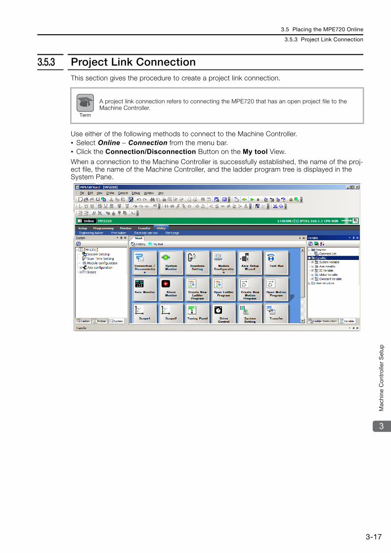
3.5 Placing the MPE720 Online
3.5.3 Project Link Connection
3-17
3
Mac
hine
Con
trolle
r Set
up
3.5.3 Project Link ConnectionThis section gives the procedure to create a project link connection.
Use either of the following methods to connect to the Machine Controller.• Select Online − Connection from the menu bar.• Click the Connection/Disconnection Button on the My tool View.When a connection to the Machine Controller is successfully established, the name of the proj-ect file, the name of the Machine Controller, and the ladder program tree is displayed in the System Pane.
A project link connection refers to connecting the MPE720 that has an open project file to the Machine Controller.
Term

3.6 Device-specific Settings
3.6.1 Data That Is Automatically Updated during Self Configuration
3-18
3.6 Device-specific Settings
This section describes the data that is automatically updated during self configuration, and the data that is changed by the user.
3.6.1 Data That Is Automatically Updated during Self Configu-rationUse the following procedure to confirm the results of self configuration to make sure that the Modules are properly assigned to the slots.
1. Open the project file.
2. Click Module configuration under Setup.
The Module Configuration Tab Page will be displayed as shown below.

3.6 Device-specific Settings
3.6.1 Data That Is Automatically Updated during Self Configuration
3-19
3
Mac
hine
Con
trolle
r Set
up
Module Configuration Definition Tab Page DetailsThe following table describes the items that are displayed in the Module Configuration Defini-tion Tab Page.
* Set I/O registers so that the same registers are not used by more than one Function Module.
No. Item Display/Setting Item Setting Range/Settings Editing
Module Displays the Module that is set for the slot. Any Module Possi-
ble
Function Module/Slave
Displays the Function Modules and slaves that are used by the Module. Any Function Module or slave Possi-
ble
Status
In Online Mode, displays the status of the Function Modules and the com-munications status of MECHA-TROLINK slave devices.
Refer to the following sec-tion.
Status Display Contents on page 3-20
Not possible
Circuit No./Axis Address
Start Displays the first circuit number that is assigned to the Module. Circuit No. 1 to 16 Possi-
ble
Occu-pied cir-cuits
Displays the number of circuits that are assigned to the Module. 1 to 2 Possi-
ble
Motion Register Displays the first and last register numbers of the motion parameters.
The parameter is automati-cally set based on the circuit numbers.
Not possible
Register (Input/Output)
Disabled Used to disable inputs or outputs by selecting the check boxes. Selected or not selected Possi-
ble
Start - End
Displays the range of registers that is used as an I/O area by the Function Module. For the SVB, the first and last registers of the I/O Modules that are connected to MECHATROLINK are displayed.
Start: 0000 to 7FFF hex, End: 10000 to 17FFF hex, 800 hex words max.∗
Possi-ble
Size Displays the number of words in the I/O area.
The size depends on the function of the Module.
Possi-ble
Scan Displays the scan in which the I/O ser-vice is performed for the I/O device. High or Low Possi-
ble
Comment Displays the user comment.
You can enter up to 16 char-acters for a Function Module. You can enter up to 32 char-acters for a MECHA-TROLINK slave.
Possi-ble

3.6 Device-specific Settings
3.6.1 Data That Is Automatically Updated during Self Configuration
3-20
Status Display ContentsThe items displayed in the Status Column are listed below.
Function Module StatusThe following status is displayed for Function Modules.
Precautions When Setting the Parameters• Always save all settings to the flash memory after changing them.• When changing the settings, be careful not to set register numbers that overlap with other
Modules.• Set I/O start and end registers even if a I/O Module is not connected to the MECHATROLINK
network.
Display Description
−−−− The Function Module is not defined.
Empty The Function Module is defined, but it is not operating correctly.
Driving The Function Module is operating normally.
Failure An error was detected in the Function Module.
× A Function Module is operating, but it is not the Function Module that was defined.
Initializing The Function Module is defined, but there is no Detailed Function Module Defini-tion.
Driving Stop The CPU Module is stopped (The user programs are stopped).
Note

3.6 Device-specific Settings
3.6.2 Detailed Module Settings
3-21
3
Mac
hine
Con
trolle
r Set
up
3.6.2 Detailed Module SettingsThis section describes the following settings:• Communications settings• MECHATROLINK communications settings• Motion control settings
Communications SettingsDouble-click slot 2 to display details on the Module.
Connecting to the Host DeviceWe recommend that you use an Ethernet connection to connect the Machine Controller to the host device.
The following section describes how to easily connect to the host device with the MPE720.
The host device is a generic term for another Controller, a PLC made by another manufacturer, a touch panel, or any other similar device.
Term

3.6 Device-specific Settings
3.6.2 Detailed Module Settings
3-22
Using the MPE720 for Easy Connection
1. Click slot 2 on the Module Configuration Tab Page.
2. The following dialog box will be displayed. Click the Easy setting Button in the Mes-sage Communication Area.

3.6 Device-specific Settings
3.6.2 Detailed Module Settings
3-23
3
Mac
hine
Con
trolle
r Set
up
3. The following dialog box will be displayed.
4. Select the communications protocol type from the list, and click the OK Button.
This concludes the setting procedure.Refer to the following manual for details.
MP2000 Series Ethernet Communications Troubleshooting Manual (Manual No.: SIEP C880700 45)
MP2300S/MP2310/MP2400 Basic Module Supplement for Ethernet Communications (Manual No.: SIEP C880700 37)

3.6 Device-specific Settings
3.6.2 Detailed Module Settings
3-24
MECHATROLINK Communications SettingsDouble-click SVB at slot 3 to display the MECHATROLINK Communications Definition Dialog Box. The MECHATROLINK Communications Definition Dialog Box has four tabs: Transmission Parameters, Link Assignment, I/O Map, and Status. Click a tab to view the tab page.
Transmission Parameters Tab PageThis tab page displays the parameters required to use the MECHATROLINK communications system.
The items on the Transmission Parameters Tab Page are described in the following table.
Item Description Precautions and Settings
Master/SlaveDisplays whether the selected SVB Module is used as a master station or a slave station.
Select either Master or Slave.The built-in SVB (in slot 00) is always the master.
My station address
Displays the address of the local station.
For a master station, the setting is always 0. For a slave station, set the address to between 1 and the number of slave stations.
Communication Cycle Displays the communications cycle.
This setting is enabled only for the master station. Select from the following: 125 μs, 250 μs, 500 μs, 1 ms, 1.5 ms, 2 ms, and 3 ms.
Enabled mes-sage communi-cation
If the check box is selected, mes-sage communications are enabled.
This setting is enabled only for the master station. This check box is linked to the setting of the Number of retry to slaves Box. If the retry count is 0, it will change to 1 when the Enabled message communi-cation check box is selected. If a value that is higher than 1 is set for the retry count, this check box will be selected automatically.
Number of retry to slaves
Displays the maximum number of retries executed within one commu-nications cycle.
This setting is enabled only for the master station.
Number of con-nection
Displays the number of slave sta-tions that are connected.
This setting is enabled only for the master station. You can set the number of connected stations here.
Message Box This box displays precautions on the high-speed scan time setting.
This box is enabled only for the master station. For a slave station, this box is empty.
For editable items, the settings can be changed. Always save all settings to the flash memory after changing them.
Note

3.6 Device-specific Settings
3.6.2 Detailed Module Settings
3-25
3
Mac
hine
Con
trolle
r Set
up
Slave Synchronization Settings (Slave CPU Synchronization)Slave CPU synchronization is used for configurations with one SVB or SVC (MECHATROLINK master) and more than one SVB or SVC (MECHATROLINK slaves) to synchronize the high-speed scan cycle of the Machine Controller with the master SVB with the high-speed scan cycles of the Machine Controllers with the slave SVBs. This enables synchronization between slave CPU Modules, so if more than one SVB or SVC are connected as slaves, the applica-tion programming can be distributed. The following schematic diagram illustrates the syn-chronization of slave CPU Modules using SVBs.
This diagram shows that the MECHATROLINK-II communications are delayed until the appli-cation programming in the master sends references to the slaves. The delay time is constant, so the application programming can manage the timing between the master and the slaves. There is no need to manage the timing between the slave CPU Modules, because their timing is synchronized with no delay. Refer to the manuals of the Machine Controller for details.
Information
MP
2200
MP
2200
MECHATROLINK-MECHATROLINK-llll
MECHATROLINK-MECHATROLINK-llll MECHATROLINK-MECHATROLINK-llll
SV
B-0
1S
VB
-01
CP
U
SV
B-0
1S
VB
-01
MP
2300
SM
P23
00S
SV
B-0
1S
VB
-01
MP
2300
SM
P23
00S
SV
B-0
1S
VB
-01
MP
2300
SM
P23
00S
SE
RV
OPA
CK
SE
RV
OPA
CK
SE
RV
OPA
CK
SE
RV
OPA
CK
SE
RV
OPA
CK
SE
RV
OPA
CK

3.6 Device-specific Settings
3.6.2 Detailed Module Settings
3-26
Link Assignment Tab PageThe Link Assignment Tab Page displays the assignment settings for all slave devices that were detected during self-configuration (MECHATROLINK-connected devices, such as SERVO-PACKs or distributed I/O).
Displayed ItemsThe following table lists the items that are displayed on the Link Assignment Tab Page.For the valid setting ranges and setting precautions, refer to the descriptions of the items on the following pages.
Item DetailsThis section provides details on the items that are displayed on the Link Assignment Parame-ters Tab Page.
ST #This is the station number.The number of rows that is displayed corresponds to the number of slave stations that is set on the Transmission Parameters Tab Page.Use the same setting of the rotary switch.
No. Item Description
ST # Displays the station number.
TYPE Sets the slave model.
D Enables or disables the I/O registers.
INPUT Sets the first register address of the input area.
SIZE Sets the input or output size in words.
OUTPUT Sets the first register address of the output area.
SCAN Sets the scan in which the input or output is performed.
Comment Used to enter a comment of up to 32 characters.
Always save all settings to the flash memory after changing them.
Note

3.6 Device-specific Settings
3.6.2 Detailed Module Settings
3-27
3
Mac
hine
Con
trolle
r Set
up
TYPESet the slave model.
• Link Assignment Model DetailsThe relationship between the model displayed under TYPE and its corresponding profile is shown below.If you manually assign a link, be sure that the actual device connected to the SVC Module is the same as the one that is displayed under TYPE on the Link Assignment Tab Page.
DEnable or disable the I/O registers.• Settings: Enable or Disable
: Enabled : Disabled
INPUTSet the first register address of the input area. The number of registers is automatically set to the maximum value.• Setting range: The range of the Module’s I/O registers
SIZESet the input and output sizes in words.• Setting range: 0 to 32
OUTPUTSet the first register address of the output area. The number of registers is automatically set to the maximum value.• Setting range: The range of the Module’s I/O registers
SCANSet the scan in which the input and output is performed.• Settings: High or Low
TYPE
Communications Specifications
Corresponding Profile
Number of Trans-mission Bytes
Minimum Communications
Cycle
Maximum Communications
Cycle
SGDV−∗∗∗∗2∗∗ Standard Servo 48 125 μs 4 ms
JAPMC-MC2320-E Standard I/O 16, 32, 48, 64 250 μs 32 ms
JEPMC-MTD2310-E Standard I/O 16 250 μs 8 ms
JEPMC−MTA2900−E Standard I/O 32 125 μs 8 ms
JEPMC−MTA2910−E Standard I/O 16 125 μs 8 ms
JEPMC−MTP2900−E Standard I/O 64 125 μs 8 ms
JEPMC−MTP2910−E Standard I/O 64 125 μs 8 ms
WildCard DeviceStandard Servo 48 Depends on the
actual device.Depends on the actual device.
Standard I/O 16, 32, 48, 64 Depends on the actual device.
Depends on the actual device.

3.6 Device-specific Settings
3.6.2 Detailed Module Settings
3-28
CommentEnter a comment of up to 32 characters if required.
Deleting Station AssignmentsYou can delete the items on the Link Assignment Tab Page for a station.
Click any cell in the row for the station to delete, and then select Edit − Assignment Delete from the menu bar.
Motion Control SettingsUse the following procedure to display the SVC Definition Tab Page.
1. Select View − Work Space from the menu bar.
The Work Space Pane is displayed on the left side of the window.
Deleted station assignments cannot be restored.
Note

3.6 Device-specific Settings
3.6.2 Detailed Module Settings
3-29
3
Mac
hine
Con
trolle
r Set
up
2. Click the Expand [+] Button beside each item in the Work Space Pane to display motion parameters as shown below.
3. Double-click the motion parameter to set or monitor.The Axis Display Selection Dialog Box (“Display in axis selected”) will be displayed.
4. Select the axis to set or monitor, and then click the OK Button.
The SVC Definition Tab Page for the selected motion parameters will be displayed.
To change which motion parameters are displayed, double-click the required motion parameters in the Work Space Pane.Information

3.6 Device-specific Settings
3.6.2 Detailed Module Settings
3-30
Setting the Fixed ParametersThe values of the fixed parameters depend on the Servomotor that is controlled by the Control-ler, and also on the machine that is driven by the Servomotor. These settings cannot be changed from a ladder program.
The actual values to set will depend on the Servomotor and the machine.
Setting the Setting ParametersThe values of these parameters are normally set from a ladder program. However, values for setting parameters that do not need to be set from a ladder program can be specified on this tab page and saved from here. These values will be used when the system is started.
Viewing the Motion Monitor Parameters

3.6 Device-specific Settings
3.6.2 Detailed Module Settings
3-31
3
Mac
hine
Con
trolle
r Set
up
Setting the SERVOPACK ParametersThe settings of the parameters can be prepared inside the CPU Unit of the Controller while it is offline. When the Controller and the SERVOPACK are connected, you can transfer these values to the SERVOPACK in one batch.
• The default settings are used without any changes.• Never modify the values of parameters that are given as reserved parameters.
Important

3.6 Device-specific Settings
3.6.3 Parameters Written during Self Configuration
3-32
3.6.3 Parameters Written during Self ConfigurationThe fixed values in the Machine Controller are written to the SERVOPACK EEPROM or RAM during self-configuration as shown below. The SERVOPACK parameters are also written to the Machine Controller's setting parameters.
Writing Parameters to the SERVOPACKThe following settings are written regardless of the setting of bit A (SERVOPACK Parameter Auto-Write) in fixed parameter No. 1.
SERVOPACK parameters and Machine Controller parameters may be overwritten when self con-figuration is executed.
Parameter No. Name Set Value
Pn50A.3Input Signal Selections 1, P-OT Signal Mapping
7: Prohibit forward drive.
Pn50B.0Input Signal Selections 2, N-OT Signal Mapping
7: Prohibit reverse drive
Pn801.0Application Function Selections 6, Software Limit Selection
3: Disable both software limits.
Pn20E Electronic Gear Ratio Numerator 1
Pn210 Electronic Gear Ratio Denominator 1
Pn511.0Input Signal Selections 5, Zero Point Deceleration LS Signal Mapping (/DEC)
SGDV-J11: CN1-41 input terminal
SGDV-E1 Not changed.
Other SGDV models 3: CN1-9 input terminal
Pn511.1Input Signal Selections 5, External Latch Signal Mapping (/EXT1)
SGDV-J14: CN1-44 input terminal
SGDV-E1 Not changed.
Other SGDV models4: CN1-10 input terminal
Pn511.2Input Signal Selections 5, External Latch 2 Signal Mapping (/EXT2)
SGDV-J15: CN1-45 input terminal
SGDV-E1 Not changed.
Other SGDV models5: CN1-11 input terminal
Pn511.3Input Signal Selections 5, External Latch 3 Signal Mapping (/EXT3)
SGDV-J16: CN1-46 input terminal
SGDV-E1 Not changed.
Other SGDV models6: CN1-12 input terminal
Pn002.0Application Function Selections 2, MECHATROLINK Command Position and Speed Control Option
1: Use P_TLIM and N_TLIM as torque limits.
Pn002.1Application Function Selections 2, Torque Control Option
1: Use the speed limit (VLIM) for torque control as the speed limit.
Pn822 Reverse Latching AreaThe setting of Pn820 (Forward Latching Area) is copied.
Pn81F.1Command Data Allocations, Position Control Command TFF/TLIM Allocation
1: Enable allocation.
Pn833.0Motion Settings, Linear Acceleration/Deceleration Constant Selection
1: Use Pn834 to Pn840.
Pn520 Position Deviation Overflow Alarm Level 230−1
Pn51E Position Deviation Overflow Warning Level 100
Note

3.6 Device-specific Settings
3.6.3 Parameters Written during Self Configuration
3-33
3
Mac
hine
Con
trolle
r Set
up
Writing Parameters to the Machine ControllerThe following settings are written when bit A (SERVOPACK Parameter Auto-Write) in fixed parameter No. 1 is set to 0 (Enable).
* The motor type is written to the Motor Type Box at the upper right of the SVB Definitions Dialog Box.
• Axes that were previously set in the Module configuration settings will not be changed.• The settings of Pn520 and Pn51E are written to RAM in the SERVOPACK.
The settings of parameters other than Pn520 and Pn51E are written to EEPROM in the SER-VOPACK.
Parameter Parameter Name Parameter No.
Fixe
d P
aram
eter
s
Rot
ary
− Motor Type* ←
According to the Servomotor that is connected.
30 Encoder Selection ←
34 Rated Motor Speed ←
36 Number of Pulses per Motor Rotation ←
38Maximum Number of Absolute Encoder Rotations
← Pn205: Multiturn Limit Setting
Line
ar
− Motor Type* ←
According to the Servomotor that is connected.
6 Linear Scale Pitch ←
30 Encoder Selection ←
34 Rated Speed ←
36 Number of Pulses per Linear Scale Pitch ←
Set
up P
aram
eter
s OW2E Position Loop Gain ← Pn102: Position Loop Gain
OW2F Speed Loop Gain ← Pn100: Speed Loop Gain
OW30 Speed Feedforward Compensation ← Pn109: Feedforward
OW32 Position Loop Integral Time Constant ← Pn11F: Position Integral Time Constant
OW34 Speed Loop Integration Time Constant ← Pn101: Speed Loop Integral Time Constant
OW3A Filter Time Constant ← Pn812: Movement Average Time
• Axes that were previously set in the Module configuration settings will not be changed.• The default settings will be written for all other parameters.
Note
Note

3.6 Device-specific Settings
3.6.4 Setting Machine-specific Motion Parameters
3-34
3.6.4 Setting Machine-specific Motion ParametersSet the following eight motion parameters according to the machine’s specifications to ensure correct motion control.• Reference Unit• Electronic Gear• Axis Selection• Position Reference• Speed Reference• Acceleration/Deceleration Settings• Acceleration/Deceleration Filter Settings• Linear Scale Pitch/Rated Speed (when using a linear motor)
The following section describes how to use the Axis Setup Wizard to set these parameters.
Axis Setup WizardThis wizard makes it easy to set up SERVOPACKs that are connected via a MECHATROLINK network. It provides an easy solution to set up the axes, including setting the SERVOPACK parameters, tuning, setting the Machine Controller according to the machine’s specifications, and backing up data.
Starting the Axis Setup WizardTo start the Axis Setup Wizard, double-click Axis Setup Wizard under Axis configuration in the System Pane. Alternatively, you can click the Axis Setup Wizard Button on the Start Tab Page.
The following conditions must be met to use the Axis Setup Wizard.• Ethernet must be used for the communications port.• The Machine Controller must be online.• The MECHATROLINK SERVOPACKs must be in the Σ-V Series.• SigmaWin+ version 5.11 or later must be installed.
If SigmaWin+ version 5.11 or later is not installed, it can be downloaded for free from the Internet (product and technical information website).Use the following URL: http://www.e-mechatronics.com/support/tool/ (Japanese only)
Note

3.6 Device-specific Settings
3.6.4 Setting Machine-specific Motion Parameters
3-35
3
Mac
hine
Con
trolle
r Set
up
Axis Setup Wizard Details
Axis Setup WizardThis wizard sets up individual axes for SERVOPACKs that are connected to a MECHATROLINK network.
No. Item Description
Tool Bar
Axis Monitor Displays the Axis Monitor Dialog Box.
Alarm Monitor Displays the Alarm Monitor Dialog Box.
Alarms/Warn-ings Displays the Alarms/Warnings Dialog Box.
Axis Selection Displays the Axis Selection Dialog Box to select the axis to set up.
Axis Display Displays the selected axis.
SERVOPACK Parameter Set-ting
Starts the SigmaWin+ Setup Wizard to set the SERVOPACK param-eters.
Fixed Parameter Setting Displays the Fixed Parameter Dialog Box to set the fixed parameters according to the machine specifications.
Tuning Starts SigmaWin+ tuning to perform optimal tuning for the axis.
Reflect SERVOPACK Parame-ter in Setting Parameter
Loads the parameters that are automatically applied from the SER-VOPACK, applies them to the setting parameters in the Machine Controller, and then saves them.
Backup Save of SERVO-PACK Parameter
Loads the current values of the SERVOPACK parameters and back them up in the SERVOPACK parameters in the Machine Controller.
Close Closes the Axis Setup Wizard Dialog Box.

3.6 Device-specific Settings
3.6.4 Setting Machine-specific Motion Parameters
3-36
Axis SelectionThe information that is assigned in the Module configuration definition will be displayed. Select the axis to set up.
Only the selected single axis can be used in the Axis Setup Wizard. To set up other axes, click the Axis Button and select the axis in the Axis Selection Dialog Box. Repeat this for each axis.
Information

3.6 Device-specific Settings
3.6.4 Setting Machine-specific Motion Parameters
3-37
3
Mac
hine
Con
trolle
r Set
up
Fixed Parameter SettingThe fixed parameters of the Machine Controller are set according to the machine.
No. Item Description
Tool Bar Refer to Tool Bar (1) in the Axis Setup Wizard Dialog Box.
Axis... This button is disabled.
Axis Display Displays the selected axis.
Reference Unit and Electronic Gear Setting
Displays the Reference Unit/Electronic Gear Dialog Box to set the reference unit and the electronic gear.
Axis Type Setting Displays the Axis Type Setting Dialog Box to set the motor type and the axis type.
Absolute Position Detection Set-ting
Displays the Absolute Position Detection Setting Dialog Box to set the simple absolute infinite axis position management and maximum number of absolute encoder rotations.
Fixed Parameter Saving Displays the Fixed Parameter Saving Dialog Box to save the modified values of the fixed parameters.
Close Closes the Fixed Parameter Setting Dialog Box.
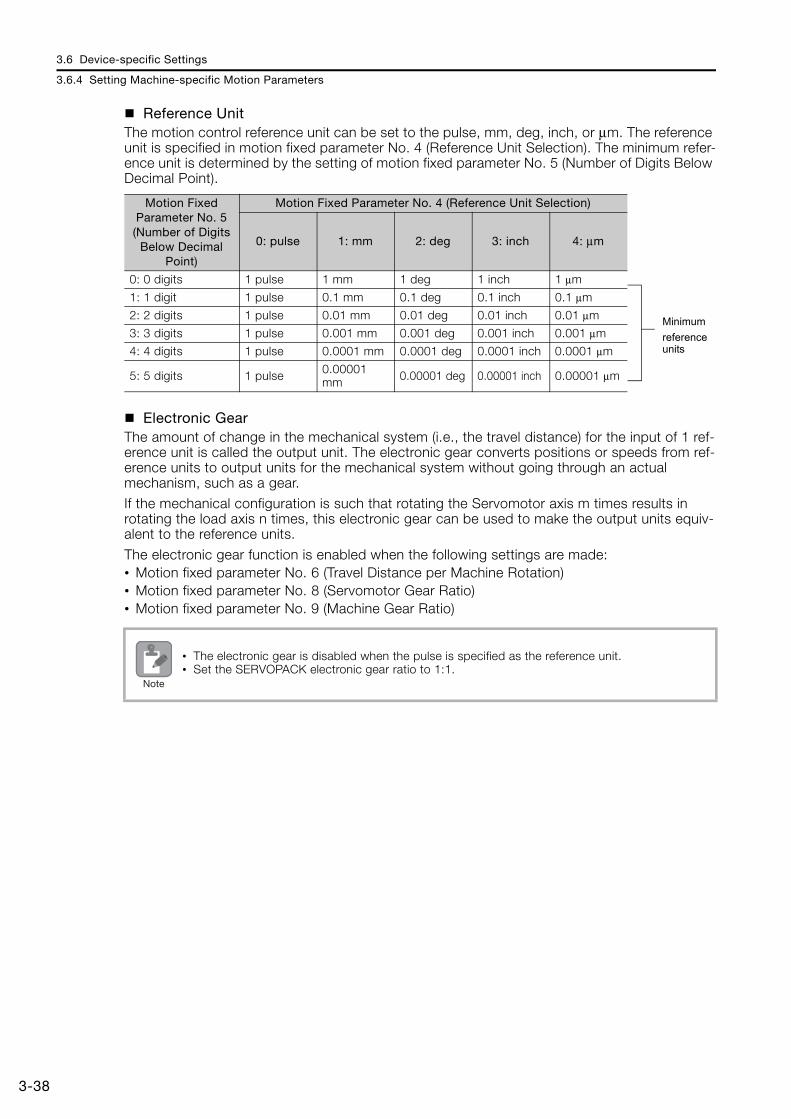
3.6 Device-specific Settings
3.6.4 Setting Machine-specific Motion Parameters
3-38
Reference UnitThe motion control reference unit can be set to the pulse, mm, deg, inch, or μm. The reference unit is specified in motion fixed parameter No. 4 (Reference Unit Selection). The minimum refer-ence unit is determined by the setting of motion fixed parameter No. 5 (Number of Digits Below Decimal Point).
Electronic GearThe amount of change in the mechanical system (i.e., the travel distance) for the input of 1 ref-erence unit is called the output unit. The electronic gear converts positions or speeds from ref-erence units to output units for the mechanical system without going through an actual mechanism, such as a gear.If the mechanical configuration is such that rotating the Servomotor axis m times results in rotating the load axis n times, this electronic gear can be used to make the output units equiv-alent to the reference units.
The electronic gear function is enabled when the following settings are made:• Motion fixed parameter No. 6 (Travel Distance per Machine Rotation)• Motion fixed parameter No. 8 (Servomotor Gear Ratio)• Motion fixed parameter No. 9 (Machine Gear Ratio)
Motion Fixed Parameter No. 5 (Number of Digits
Below Decimal Point)
Motion Fixed Parameter No. 4 (Reference Unit Selection)
0: pulse 1: mm 2: deg 3: inch 4: μm
0: 0 digits 1 pulse 1 mm 1 deg 1 inch 1 μm
1: 1 digit 1 pulse 0.1 mm 0.1 deg 0.1 inch 0.1 μm
2: 2 digits 1 pulse 0.01 mm 0.01 deg 0.01 inch 0.01 μm
3: 3 digits 1 pulse 0.001 mm 0.001 deg 0.001 inch 0.001 μm
4: 4 digits 1 pulse 0.0001 mm 0.0001 deg 0.0001 inch 0.0001 μm
5: 5 digits 1 pulse 0.00001 mm 0.00001 deg 0.00001 inch 0.00001 μm
• The electronic gear is disabled when the pulse is specified as the reference unit.• Set the SERVOPACK electronic gear ratio to 1:1.
Minimumreferenceunits
Note

3.6 Device-specific Settings
3.6.4 Setting Machine-specific Motion Parameters
3-39
3
Mac
hine
Con
trolle
r Set
up
The following examples show the settings for a ball screw and rotary table as loads.
• Ball Screw
• Rotary Table

3.6 Device-specific Settings
3.6.4 Setting Machine-specific Motion Parameters
3-40
• Belt and Pulley
No. Item Description
Reference unit selection
Select one of the following five reference units.0: pulse, 1: mm, 2: deg, 3: inch, or 4: μmWhen the Reference Unit Selection parameter is set to 0 (pulse), the settings from (2) onward are disabled.
Number of digits below decimal point
Select the number of decimal digits from the following six settings.0: None, 1: 0.1, 2: 0.12, 3: 0.123, 4: 0.1234, or 5: 0.12345
Mechanical
Select the mechanical configuration from the following three settings.a: Ball Screwb: Rotary Tablec: Belt and Pulley
Pitch P Set the travel distance per revolution of the ball screw.
Load axis revolu-tions Set the number of load axis revolutions for the gear ratio.
Servomotor axis revolutions Set the number of Servomotor axis revolutions for the gear ratio.
Set Click this button to set the reference unit and electronic gear and return to the Fixed Parameter Setting Dialog Box.
Cancel Click this button to return to the Fixed Parameter Setting Dialog Box without setting the reference unit and electronic gear.
Per rotation Set the travel distance per revolution of the rotary table.
Pitch P Set the travel distance per revolution of the pulley.
Pulley Diameter Set the diameter of the pulley.
11
11

3.6 Device-specific Settings
3.6.4 Setting Machine-specific Motion Parameters
3-41
3
Mac
hine
Con
trolle
r Set
up
Axis Type SettingThis dialog box is used to set the motor type and the axis type.There are two types of position control: finite-length axis position control for round-trip opera-tion and other tasks that are performed only within a specified range, and infinite-length axis position control that is used for rotation in one direction only. Infinite-length axis position control can work in one of two ways: It can be used to reset the position data to 0 after one rotation, e.g., for belt conveyors, or to simply rotate in one direction only, without resetting the position after one rotation.The following parameters can be set after you set the axis type.
No. Fixed Parameter
No. 1, bit 0 Axis Selection
No.10 Infinite-length Axis Reset Position (POSMAX)
No.30 Encoder Selection
No. Item Description
Encoder Selection
Select the encoder from the following three settings.0: Incremental encoder1: Absolute encoder2: Absolute encoder (Incremental encoder is used.)
Axis Type Select the axis type from the following two settings.0: Finite-length axis, 1: Infinite-length axis
Infinite-length Axis Setting
Set the reset position of the infinite-length axis.This setting is enabled if an infinite-length axis is selected for the axis type (2).
Set Click this button to set the axis type and return to the Fixed Parameter Set-ting Dialog Box.
Cancel Click this button to return to the Fixed Parameter Setting Dialog Box without setting the axis type.

3.6 Device-specific Settings
3.6.4 Setting Machine-specific Motion Parameters
3-42
Absolute Position Detection SettingSet the maximum number of absolute encoder rotations for simple absolute infinite axis posi-tion management. The following parameters can be set after you set absolute position detection.
* The following formula is used for the automatic calculation:
No. Fixed Parameter
No. 1, bit 9 Simple Absolute Infinite Axis Position Management
No.38 Maximum Number of Absolute Encoder Rotations
The values that are set here are also saved in Pn205 (Multiturn Limit Setting).
No. Item Description
Simple Absolute Infinite Axis Posi-tion Management
Enable or disable simple absolute infinite axis position manage-ment.This selection is enabled if an infinite-length axis is selected for the axis type (2) in the Axis Type Setting Dialog Box.
Auto*
Automatically calculates the maximum number of absolute encoder rotations.This button is enabled if the Managed Option was selected at (1).
Maximum rotation amount of abso-lute encoder (Maximum Number of Absolute Encoder Rotations)
Set the maximum number of absolute encoder rotations.If a finite-length axis is selected as the axis type (2) in the Axis Type Setting Dialog Box, then this value can be set to a maximum of 65,535. If an infinite-length axis is selected, the maximum setting will be 65,534.
Set Click this button to set the absolute position detection and return to the Fixed Parameter Setting Dialog Box.
Cancel Click this button to return to the Fixed Parameter Setting Dialog Box without setting the absolute position detection.
Note

3.6 Device-specific Settings
3.6.4 Setting Machine-specific Motion Parameters
3-43
3
Mac
hine
Con
trolle
r Set
up
The following formulas give the value of the reset rotations. The formula depends on whether the reference unit is set to the pulse or to one of the following: mm, deg, or inch.
(Fixed parameter No. 38: Maximum Number of Absolute Encoder Rotations +1) = Integer (Remainder = 0)
Reset rotations
• When the Reference Unit Is PulseNo. 10: Infinite-length Axis Reset Position
No. 36: Numbers of Pulses Per Servomotor Rotation
• When the Reference Unit Is mm, Deg, or InchNo. 10: Infinite-length Axis Reset Position × No. 8: Servomotor Gear Ratio
No. 6: Travel Distance per Machine Rotation × No. 9: Machine Gear Ratio

3.6 Device-specific Settings
3.6.4 Setting Machine-specific Motion Parameters
3-44
Fixed Parameter SavingThis section describes how to save the fixed parameter settings.
1. Click the Axis Setup Wizard Button, click the Fixed Parameter Setting Button, and then click the Fixed Parameter Saving Button to display the following dialog box.
2. Next, the Reflect SERVOPACK Parameter Dialog Box will be displayed.Click the Check button to check whether the saved fixed parameters match the SERVOPACK parameter settings.
3. Checked parameters will be marked with a , and the results of the check will be dis-played.If the fixed parameter and the SERVOPACK parameter match: EqualIf the fixed parameter and the SERVOPACK parameter do not match: Not equal
Fixed Parameter SERVOPACK parameter
No. 38 (Maximum Number of Absolute Encoder Rotations) Pn205 (Multiturn Limit Setting)
No. 30 (Encoder Selection) Pn002.2 (Absolute Encoder Usage)

3.6 Device-specific Settings
3.6.5 Setting the Scan Times
3-45
3
Mac
hine
Con
trolle
r Set
up
3.6.5 Setting the Scan TimesThis section describes how to set the scan times for the high-speed and low-speed scans.Select Setup and then Scan Time Setting from the item tree of the Environment Setting Dia-log Box. Alternatively, select the Setup and then click the Scan Time Setting Icon in the Launcher. The following dialog box will be displayed.
High-speed (H) ScanThis section describes how to set the scan time of a high-speed processing program (H, Hxx, Hxx.xx) in milliseconds.The set value that is set here will determine the reference pulse distribution cycle (accuracy).
I/O ProcessingThe following figures show the timing results for these settings.
Example: High-speed Scan = 0.5 ms
* The purpose of this system service register is to determine from a ladder program whether the MP2000 option service is being scanned.
The default high-speed scan time is 4.0 ms.Information
0.5 ms
Reference issued at (3)Reference issued at (2)Reference issued at (1)
System service register SB000008 *
MP2000 Optional Module
Basic cycle (0.5 ms)
High-speed scan

3.6 Device-specific Settings
3.6.5 Setting the Scan Times
3-46
Low-speed (L) ScanThis section describes how to set the scan time of a low-speed processing program (L, Lxx, Lxx.xx) in milliseconds. This example shows set values for a control cycle of pushbuttons and similar controls. The possible set values for the low-speed scan time are 2.0 to 300.0 ms (in 0.5-ms incre-ments).
I/O ProcessingDuring the low-speed scan, the I/O service (I/O processing) is performed every scan, regard-less of the set value.
The default low-speed scan time is 200.0 ms.Information

3.7 Test Run
3.7.1 Test Run
3-47
3
Mac
hine
Con
trolle
r Set
up
3.7 Test Run
This section describes the features of the test run.
3.7.1 Test RunThe test run checks whether the references issued by the Machine Controller correctly drive the SERVOPACK axis.
You can perform the following operations for a test run from the Test Run Dialog Box.• Axis Servo ON and OFF: You can turn the servo ON and OFF for the specified SERVOPACK
axis.• Jog: You can rotate the specified SERVOPACK axis in one direction at a fixed speed.• Step: You can rotate the specified SERVOPACK axis from the current position to the speci-
fied position. There are two ways to monitor the test run.• Axis Monitor: Monitors the operating status of each axis.• Alarm Monitor: You can monitor the alarm information of all axes on one dialog box.
• The test run can be used only if the Motion Module (SVC-01, SVB-01, SVB-01 Inverter, SVA-01, SVR, or PO-01) of the tested axis meets the conditions listed in the following table. If the conditions are not met, you will not be able to perform the test run.
Note: For an Inverter, use the Operation Enabled bit instead of the Motion Operation Ready bit, and use the Inverter Ready bit instead of the Servo Ready bit.
• Correct operation of the test run requires that no ladder program, motion program, or sequence program is being executed at the same time.
Important
AxisMotion Opera-
tion ReadyServo Ready
Motion Command Response Code
SVC-01 ON ON No Operation
Built-in SVB/SVB-01
Servo ON ON No Operation
Inverter – ON No Operation
SVA-01 ON ON No Operation
SVR ON – No Operation
PO-01 ON – No Operation

3.7 Test Run
3.7.2 Starting the Test Run and Selecting the Axis
3-48
3.7.2 Starting the Test Run and Selecting the AxisOpen the Test Run Dialog Box and specify the SERVOPACK axis to test. Use the following pro-cedure to set the axis.
1. Double-click Test run under Axis configuration in the System Pane. Alternatively, click the Test Run Button on the Start Tab Page.
The Test Run Warning Dialog Box will be displayed.
2. Check the contents of the Warnings Dialog Box, and then click the Agree Button.Next, the Test Run Dialog Box and the Axis Selection Dialog Box will be displayed.
3. Select the axis you want to test from the axis configuration tree in the Axis Selection Dialog Box, then click the OK Button.
The information assigned in the Module configuration definition will be displayed in the Axis Selection Dialog Box.
Information

3.7 Test Run
3.7.2 Starting the Test Run and Selecting the Axis
3-49
3
Mac
hine
Con
trolle
r Set
up
The following message will be displayed.
4. Click the Yes Button. The label of the selected axis will be displayed on the right of the Axis... Button in the Test Run Dialog Box.
The Test Run can be performed only on the selected axis. To set up other axes, click the Axis Button and select the axis in the Axis Selection Dialog Box. Repeat this for each axis.
Note

3.7 Test Run
3.7.3 Test Run Dialog Box Details
3-50
3.7.3 Test Run Dialog Box DetailsThis section provides a detailed description of the Test Run Dialog Box. You can select jogging or stepping by clicking the tabs. Jogging Stepping
No. Item Function
Tool Bar
Axis Monitor Displays the Axis Monitor Tab Page in the Main Window.
Alarm Monitor Displays the Alarm Monitor Tab Page in the Main Window.
Refresh Updates the test run information.
Axis Displays the Axis Selection Dialog Box.
Axis Display Displays the selected axis.
Status Displays the operating status of the axis and any alarms that occurred.
Enable Turns ON the axis servo.
Disable Turns OFF the axis servo.
Monitor Displays the Alarm/Warning Dialog Box.
Speed Reference Displays the Speed Reference Setting Dialog Box. Set the speed (speed reference value) for axis rotation.
Forward While this button is pressed, the axis rotates in the positive direc-tion.
Reverse While this button is pressed, the axis rotates in the negative direc-tion.
Step Distance Displays the Step Distance Setting Dialog Box. Set the step dis-tance for the axis.
Direction Setting Displays the Direction Setting Dialog Box. Set the starting direction and the number of rotations for the step operation.
Forward/Reverse Status The mark indicates the current step direction.
Repetition Counter Status Displays the repetition status as the current repetition count/set repetition count.
Run Performs stepping in the direction that was specified in the Direc-tion Setting Dialog Box.
Stop Stops the stepping operation.
11
12
13
15 16
14
11
12
13
14
15
16

This chapter describes the types of user programs and describes how to create and write them to the Controller.
4.1 User Program Types and Execution Timing . . . . 4-34.1.1 Ladder Programs . . . . . . . . . . . . . . . . . . . . . . . . 4-34.1.2 Motion Programs . . . . . . . . . . . . . . . . . . . . . . . 4-124.1.3 Sequence Programs . . . . . . . . . . . . . . . . . . . . . 4-244.1.4 The M-EXECUTOR . . . . . . . . . . . . . . . . . . . . . . 4-264.1.5 Registers . . . . . . . . . . . . . . . . . . . . . . . . . . . . . . 4-41
4.2 Creating Ladder Programs . . . . . . . . . . . . 4-51
4.3 Creating Motion Programs . . . . . . . . . . . . 4-554.3.1 Creating a Group Definition . . . . . . . . . . . . . . . . 4-554.3.2 Creating a Motion Main Program . . . . . . . . . . . 4-564.3.3 Creating a Motion Subprogram . . . . . . . . . . . . . 4-58
4.4 Creating a Sequence Program . . . . . . . . . 4-604.4.1 Creating a Sequence Main Program . . . . . . . . . 4-604.4.2 Creating a Sequence Subprogram . . . . . . . . . . 4-61
4.5 Transferring Data with the MPE720 . . . . . . 4-634.5.1 Writing Parameters to the Machine Controller . . 4-644.5.2 Writing into a Project File . . . . . . . . . . . . . . . . . 4-654.5.3 Reading from the Machine Controller . . . . . . . . 4-664.5.4 Reading from a Project File . . . . . . . . . . . . . . . . 4-674.5.5 Saving to Flash Memory . . . . . . . . . . . . . . . . . . 4-684.5.6 Using a CF Card (MP2200 Only) . . . . . . . . . . . . 4-694.5.7 Comparing to the Machine Controller . . . . . . . . 4-714.5.8 Comparing Flash Memory and RAM Data . . . . . 4-714.5.9 Comparing to a Project File . . . . . . . . . . . . . . . . 4-714.5.10 Comparing to a CF Card . . . . . . . . . . . . . . . . . . 4-71
Creating User Programs 4

4.6 Data Transfer without Using the MPE720 . . . 4-724.6.1 Using a CF Card (MP2200 Only) . . . . . . . . . . . .4-724.6.2 Using the MPLoader . . . . . . . . . . . . . . . . . . . . .4-754.6.3 Using the MPLoad Maker . . . . . . . . . . . . . . . . . .4-77

4.1 User Program Types and Execution Timing
4.1.1 Ladder Programs
4-3
4
Cre
atin
g U
ser P
rogr
ams
4.1 User Program Types and Execution Timing
There are three types of user programs:• Ladder programs• Motion programs• Sequence programsThis section describes these programs.
4.1.1 Ladder ProgramsLadder programs are managed as drawings (ladder diagrams) that are identified by their draw-ing numbers (DWG numbers). The ladder drawings form the basis of the ladder programs.
Drawing Types and Hierarchical ConfigurationThis section describes the types of ladder drawings and their hierarchical configuration.
TypesLadder drawings are divided into four different types based on their purpose.• DWG.A (Startup Drawings)
This type of ladder drawing is used to set register data. These ladder drawings are executed before high-speed scan process drawings and low-speed scan process drawings.
• DWG.I (Interrupt Drawings)This type of ladder drawing is used to perform processing with priority given to signals input from an Optional Module. These ladder drawings are executed with higher priority than high-speed scan process drawings regardless of the scan cycle.
• DWG.H (High-speed Scan Process Drawings)This type of ladder drawing is used to perform motion control or high-speed I/O control.
• DWG.L (Low-speed Scan Process Drawings)This type of ladder drawing is used for communications with HMIs and external devices as well as for standard I/O control.
The following table lists the priority, execution conditions, and maximum number of drawings for each type of ladder drawing.
* Drawings with lower numbers have higher priority.
Drawing Type Priority* Execution ConditionMaximum Number of
Drawings
DWG.A (Startup Drawings) 1 Power ON (These drawings are executed once when the power supply is turned ON.) 64
DWG.I (Interrupt Drawings) 2
External interrupt (These drawings are exe-cuted when a DI interrupt or counter match interrupt is received from an Option Mod-ule.)
64
DWG.H (High-speed Scan Process Drawings) 3 Started at fixed intervals. (These drawings
are executed once every high-speed scan.) 200
DWG.L (Low-speed Scan Process Drawings) 4 Started at fixed intervals. (These drawings
are executed once every low-speed scan.) 500

4.1 User Program Types and Execution Timing
4.1.1 Ladder Programs
4-4
Hierarchical ConfigurationThere are four types of ladder drawings: parent drawings, child drawings, grandchild drawings, and operation error drawings.• Parent Drawings
These drawings are automatically executed by the system program when the execution con-ditions are met.
• Child DrawingsThese drawings are executed when they are called from a parent drawing with a SEE instruc-tion.
• Grandchild DrawingsThese drawings are executed when they are called from a child drawing with a SEE instruc-tion.
• Operation Error DrawingsThese drawings are automatically executed by the system program when an operation error occurs.
A parent drawing cannot call a child drawing from a different type of drawing. Similarly, a child drawing cannot call a grandchild drawing from a different type of drawing. A parent drawing cannot call a grandchild drawing directly. The parent drawing first must call the child drawing, and then the child drawing must call the grandchild drawing. This is called the hierarchical con-figuration of drawings.The following figure shows the parent-child-grandchild structure in which a program is created.
User FunctionsGrandchild Drawings
Child Drawings
Parent Drawing
Note 1: � = A, I, H, or L
DWG.� DWG.�01
DWG.�nn
DWG.�01.01
DWG.�01.02 FUNC-001
FUNC-006
FUNC-032
FUNC-064
DWG.�01.03
DWG notation:
Grandchild drawing number
Parent drawing type (A, I, H, or L)
Child drawing number
Note 2: The following notation is used for operation error drawings.
Parent drawing type (A, I, H, or L) of the drawing where the error occurs
Fixed value (00)
DWG.� � . �
DWG.� 00

4.1 User Program Types and Execution Timing
4.1.1 Ladder Programs
4-5
4
Cre
atin
g U
ser P
rogr
ams
The breakdown of the number of ladder drawings in each category is given in the following table.
Controlling the Execution of DrawingsDrawings are executed based on their priorities, as shown in the following figure.
*1. DWG.A drawings are executed immediately after the power supply is turned ON.*2. When an interrupt signal is input, execution of the DWG.I drawing is given priority even if execution of a DWG.H
or DWG.L drawing is currently in progress.
Note: The parent drawing of each drawing is automatically called and executed by the system.
DrawingsNumber of Drawings
DWG.A DWG.I DWG.H DWG.L
Parent Drawings 1 1 1 1
Operation Error Drawings 1 1 1 1
Child DrawingsTotal of 62 max. Total of 62 max. Total of 198 max. Total of 498 max.Grandchild Draw-
ings
There are separate functions that can be called from the drawings as required. Functions are executed when they are called from a parent, child, or grandchild drawing with the FUNC instruction. You can create up to 500 functions.
Information
Power ON
DWG.A (Startup Drawings)
Interrupt signal
DWG.I (interrupt drawing)
Execution is continued from the point before the interrupt.
Every low-speed scan
Batch output
Batch input
DWG.L (low-speed scan process drawing)
Every high-speed scan
Batch output
Batch input
DWG.H (high-speed scan process drawing)
*1
*2

4.1 User Program Types and Execution Timing
4.1.1 Ladder Programs
4-6
Execution Processing of DrawingsThe drawings are executed by calling them from the top to the bottom, following the hierarchy of the drawings. The following figure illustrates the execution processing of a high-speed scan drawing (DWG.H).
Note: 1. The parent drawing is automatically called and executed by the system. Child drawings and grandchild drawings are executed by calling them from a parent drawing or a child drawing using the SEE instruction.
2. You can call functions from any drawing. You can also call functions from other functions.3. If an operation error occurs, the operation error drawing for the drawing type will be started automatically.4. Always specify 00 as the drawing number for operation error drawings.
DWG.H DWG.H01
H02
H00
DWG.H01.01
FUNC 01
SEEH01
SEEH02
END END
END
END
END
END
SEEH01.H01
FUNC01
Functions
Execution is started by the system program when the execution condition is met.
Parent Drawing Child Drawings Grandchild Drawings
Execution is automatically started by the system.An operation
error occurs.

4.1 User Program Types and Execution Timing
4.1.1 Ladder Programs
4-7
4
Cre
atin
g U
ser P
rogr
ams
Scheduling the Execution of High-speed and Low-speed Scan Process Drawings
High-speed scan process drawings (DWG.H) and low-speed scan process drawings (DWG.L) cannot be executed at the same time. DWG.L drawings are executed during the idle time of DWG.H drawings.The period during which DWG.H drawings are executed is called the high-speed scan time. The period during which DWG.L drawings are executed is called the low-speed scan time.
* Background processing is used to execute internal system processing, such as communications processing.
Setting the High-speed and Low-speed Scan TimesUse MPE720 version 7 and perform the procedure given below to set the high-speed and low-speed scan times.
1. Stop the CPU Module.
2. Select File − Environment Setting from the menu bar. Alternatively, click the System Setting Icon on the Start Tab Page.The Environment Setting Dialog Box will be displayed.
3. Select Setup − Scan Time Setting.The following dialog box will be displayed.
Low-speed scan time
High-speed scan time
High-speed scan time
High-speed scan time
High-speed scan time
DWG.H (high-speed scan process drawing) DWG.L (low-speed scan process drawing)
Background processing*
: Actual processing time during the scan

4.1 User Program Types and Execution Timing
4.1.1 Ladder Programs
4-8
Setting Value: Enter the scan time settings.Current Value: A value of 0.0 ms is displayed when the MPE720 is offline. Otherwise, the actual
processing times for the scans are displayed.Maximum Value: The maximum processing time for the scan is displayed. You can set the maximum
value. The setting is retained until it is exceeded.
4. Enter the high-speed scan time in the Setting Value Box under High-speed Scan. Enter the low-speed scan time in the Setting Value Box under Low-speed Scan.The following table shows the possible set values and default values for each scan time.
Note: The possible set values and default values depend on the model. Refer to the user’s manual for the Mod-ule you are using for details.
5. Click the OK Button.The settings will be saved and the Environment Setting Dialog Box will close.
Item Possible Set Values Default
High-speed Scan Time 0.5 to 32.0 ms (in 0.5-ms increments) 4.0 ms
Low-speed Scan Time 2.0 to 300.0 ms (in 0.5-ms increments) 200.0 ms
Observe the following precautions when setting the high-speed scan time and low-speed scan time.1. Set the scan set value so that it is 1.25 times greater than the maximum value.
If the scan set value is too close to the maximum value, the refresh rate of the MPE720 window will noticeably drop and can cause communications timeout errors to occur. If the maximum value exceeds the scan set value, a watchdog error may occur and cause the Machine Con-troller system to shut down.
2. If you are using MECHATROLINK-II or MECHATROLINK-III, set values that are an integral mul-tiple of the communications cycle. If you change the communications cycle, check the scan time set values.
3. Do not change the scan set value while the Servo is ON. Never change the scan set value while an axis is in motion (i.e., while the motor is rotating). Doing so may cause the motor to rotate out of control.
4. After changing or setting a scan time, always save the data to flash memory.
Important

4.1 User Program Types and Execution Timing
4.1.1 Ladder Programs
4-9
4
Cre
atin
g U
ser P
rogr
ams
High-speed Drawing Operation Mode SettingsThe high-speed drawing operation mode is the mode that is set for DWG.H drawings.If no DWG.I drawings are used, select the high-speed mode. This optimizes the processing of DWG.H drawings. If DWG.I drawings are used, select the normal mode.If the high-speed mode is selected, DWG.I drawings will not be executed.
• DWG.A, DWG.I, and DWG.L drawings do not have operation mode settings.• The more often the following instructions are used, the greater the effect that the optimiza-
tion will have on DWG.H processing.
DWG.H DWG.H DWG.H
DWG.H DWG.H DWG.H
When the high-speed operation mode is set:
The current high-speed scan time decreases. (The scan overhead is reduced.)
The current high-speed scan time decreases. (The scan overhead is reduced.)
The current high-speed scan time decreases. (The scan overhead is reduced.)
High-speed scan processing
High-speed scan cycle (SW00014)
High-speed scan cycle (SW00014)
High-speed scan processing
Current high-speed scan time (SW00008)
High-speed scan cycle (SW00014)
High-speed scan cycle (SW00014)
Current high-speed scan time (SW00008)
Information
Type Function
Relay Circuit Instructions
Rising-edge NO Contact
Falling-edge NO Contact
Rising-edge NC Contact
Falling-edge NC Contact
Rising-edge Pulse
Falling-edge Pulse
Coil
Reverse Coil
Rising-edge Detection Coil
Falling-edge Detection Coil
Set Coil
Reset Coil
Numeric Operation Instructions
Increment
Decrement

4.1 User Program Types and Execution Timing
4.1.1 Ladder Programs
4-10
Perform the following procedure with MPE720 version 7 to set the high-speed drawing opera-tion mode.
1. Select File − Environment Settings from the menu bar. Alternatively, click the System Setting Icon on the My Tool View of the Start Tab Page. The Environment Setting Dialog Box is displayed.
2. Select Setup − System Setting. The following dialog box will be displayed.
3. Select High-speed or Normal for the High-speed Drawing Operation Mode.

4.1 User Program Types and Execution Timing
4.1.1 Ladder Programs
4-11
4
Cre
atin
g U
ser P
rogr
ams
FunctionsFunctions are executed when they are called from a parent, child, or grandchild drawing with the FUNC instruction.Functions can be freely called from any drawing. The same function can be called simultane-ously from different types of drawings or different levels of drawings. You can also call functions from other functions that you have created.
The use of functions provides the following merits:• Easy user program modularization• Easy user program creation and maintenanceYou can use standard functions that are provided by the system, and you can define user func-tions.
Standard System FunctionsThe following functions for communications and other purposes are provided as standard func-tions in the system. You cannot change the system functions.
User FunctionsYou can freely program the body of a user function and program the user function definitions. The maximum number of user functions is 500 drawings.Note: Refer to the following manuals for details on how to define functions.
MP900/MP2000 Series User’s Manual, Ladder Programming (Manual No.: SIEZ-C887-1.2)
MP2000 Series User’s Manual for Motion Programming (Manual No.: SIEP C880700 38)
MP900/MP2000 Series New Ladder Editor Programming Manual (Manual No.: SIEZ-C887-13.1)
MP900/MP2000 Series New Ladder Editor User’s Manual (Manual No.: SIEZ-C887-13.2)
Symbol Function
COUNTER Counter
FINFOUT First-in First-out
TRACE Trace
DTRC-RD Read Data Trace
MSG-SND Send Message
MSG-RCV Receive Message
MOTREG-W Write Motion Register
MOTREG-R Read Motion Register

4.1 User Program Types and Execution Timing
4.1.2 Motion Programs
4-12
4.1.2 Motion ProgramsA motion program is a program that is written in a text-based motion language.There are two types of motion programs.
Note: There are cases when the M-EXECUTOR cannot be used. Refer to the following section for details.The M-EXECUTOR (page 4-26)
TypeDesignation
MethodFeatures Number of Programs
Main programs MPM(=1 to 256)
• Main programs are called from a DWG.H drawing.
• Main programs are called from the M-EXECUTOR pro-gram execution definitions.
You can create up to 256 motion programs, including the following programs:• Motion main programs• Motion subprograms• Sequence main programs• Sequence subprogramsSubprograms MPS
(=1 to 256)Subprograms are called from a main program.
1. The same numbers are used to manage the motion programs and sequence programs. Use a unique number for each program.• Motion program numbers are given in the form MPM or MPS.• Sequence program numbers are given in the form SPM or SPS.
2. The number of motion programs that can be executed simultaneously depends on the model of the Machine Controller. If the number of simultaneously executable programs is exceeded, an alarm will occur (No System Work Available Error).• The No System Work Available Error is indicated by bit E in the Status Flags of the motion
program.
Motion SubprogramsSubprograms are created to perform common operations. They help minimizing the number of program steps and allow efficient use of memory.
Important
Term
MPM001 MPM002 MPM003
MPS010
Main program
Call (MSEE)
Call (MSEE)
Call (MSEE)
Subprogram
The common process is
written as a subprogram.
Main programMain program

4.1 User Program Types and Execution Timing
4.1.2 Motion Programs
4-13
4
Cre
atin
g U
ser P
rogr
ams
Motion Program ExecutionMotion programs are called with an MSEE instruction from a ladder program in an H drawing.
After you create the motion program, place a Call Motion Program (MSEE) instruction in the ladder program of an H drawing. Motion programs can be called from any H drawing, regard-less of whether it is a parent, child, or grandchild drawing.The following figure shows an execution example.
The ladder instruction in the H drawing is executed every high-speed scan cycle according to the hierarchical organization of parent-child-grandchild drawings.The above programming only prepares for execution of the motion program. The motion pro-gram is not executed when the MSEE instruction is inserted. To start the motion program after inserting the MSEE instruction, use a control signal to turn ON the Request for Start of Program Operation.
The motion program is executed in the scan cycle, but unlike ladder programs, the entire pro-gram is not executed in a single scan. Execution of motion programs is controlled by the sys-tem.
You can also register the motion program in the M-EXECUTOR (Motion Executor) to call it. Refer to the following section for details.
The M-EXECUTOR (page 4-26)
The following points must be taken into consideration when executing motion programs.• Motion programs that are registered in the M-EXECUTOR cannot be executed with MSEE
instructions.• More than one instance of the same motion program (i.e., the same program number) cannot
be executed with MSEE instructions.• Subprograms (MPS) cannot be executed with MSEE instructions in a ladder program.
You can call subprograms only from motion programs and motion subprograms (MPM and MPS).
• You cannot call the same subprogram more than once at the same time.• Sequence programs (SPM and SPS) cannot be called with MSEE instructions from
a ladder program for the MP2300, CPU-01, or CPU-03.
Note
MSEEMPM001
DWG.H
SEEH01
DEND
DWG.H01
SEE H01.01
ENDDEND
END
RETEND
DEND
MPM003MPS101
DWG.H01.01 MPM001
MPM002MSEE
MPM002
MSEEMPM003
MSEEMPS101
VEL [a1]5000 [b1]..FMX T10000000;IAC T25;IDC T30;MOV [a1]300. [b1]..MVS [a1]200. [b1]..
. . .
Execution is started by the system program when the execution condition is met.
Grandchild drawing Motion programs
Subprogram
Child drawingParent drawing
Note

4.1 User Program Types and Execution Timing
4.1.2 Motion Programs
4-14
Specifying Motion ProgramsThere are two methods that you can use to specify motion programs.• Calling the motion program by specifying it directly• Calling the motion program by specifying it indirectlyThese two methods are described below.
Calling the Motion Program by Specifying It DirectlyDirect designation is used to call a motion program by specifying its program number (MPM) directly.
To call the motion program from a ladder program with the MSEE instruction, specify the pro-gram number in the Program Number operand of the MSEE instruction.
Calling the Motion Program by Specifying It IndirectlyIndirect designation is used to call a motion program by specifying its number in a register.
In this method, the program (MPM) whose number is the same as the value that is stored in the register is called.
To call the motion program from a ladder program with an MSEE instruction, use the Program Number operand of the MSEE instruction to specify the M or D register that indirectly desig-nates the motion program.
ABS;
MOV[X] _ [Y] _
MOV[X] _ [Y] _
MVS[X] _ [Y] _ F
IOW MB0001
. .
.
MPM001
Call Motion Program Instruction
MPM number
Ladder Program Motion Program
0 3 ABS;
IOW MB0001
. . .
MOV[X] _ [Y] _
MOV[X] _ [Y] _
MVS[X] _ [Y] _ F
(MW00200 = 3)
MPM003
Setting device
Register address
Ladder Program Motion Program
Call Motion Program Instruction
The value is stored in the MW00200 register.

4.1 User Program Types and Execution Timing
4.1.2 Motion Programs
4-15
4
Cre
atin
g U
ser P
rogr
ams
Work RegistersWork registers are used to set and monitor motion programs.The first work register for a motion program that is called with an MSEE instruction is specified in the MSEE instruction in the ladder program. The following figure shows the structure of the work registers.
Motion Program Status FlagsThe Motion Program Status Flags give the execution condition of the motion program. The fol-lowing table describes the meanings of the Status Flags.
Note: If a program alarm occurs, motion program error information is provided in the Motion Alarm Dialog Box and in the S registers.
Bit No. Status
0 Program is being executed.
1 Program is paused.
2 Program is stopped due to a stop request (for system use).
3 Reserved for system.
4 Program single-block execution is stopped.
5 Reserved for system.
6 Reserved for system.
7 Reserved for system.
8 There is a program alarm.
9 Execution is stopped at a breakpoint.
A Reserved for system.
B The program is in Debug Mode (EWS debugging).
C Program Type, 0: Motion program
D Start Request History
E No System Work Available ErrorExecution Scan Error
F Main Program Number Limit Exceeded Error
First work register (M register or D register)
Work Register Contents
1st register Motion Program Status Flags2nd register Motion Program Control Signals3rd register Interpolation Override4th register System Work Number

4.1 User Program Types and Execution Timing
4.1.2 Motion Programs
4-16
Control SignalsTo control the execution of a motion program, you must input program control signals (Request for Start of Program Operation, or Request for Stop of Program, etc.). The following table describes the control signals for motion programs.
*1. System Work Number Setting• When the Motion Program Is Registered in M-EXECUTOR:
The system work number cannot be specified. The system will use the definition number as the system work number.
• When a Motion Program Is Called from a Ladder Program with an MSEE Instruction:OFF: The system will use an automatically acquired system work number. The system work number will be different each time.ON: The work number that is specified by the system will be used. However, if the work number is assigned to the M-EXECUTOR, a No System Work Available Error (Status Flag Bit E) is reported.
*2. Interpolation Override Setting OFF: The interpolation override is always 100%. ON: The interpolation override in the parameter setting is used.
Note: 1. Use the specified signal types for the ladder program inputs.2. If the Request for Start of Program Operation control signal is ON when the power supply is turned ON, the
motion program with the specified program number will be executed.
Bit No. Signal Name Signal Type
0 Request for Start of Program Operation Differential or NO contact input
1 Request for Pause of Program NO contact
2 Request for Stop of Program NO contact
3 Program Single-block Mode Selection NO contact
4 Program Single-block Start Request Differential or NO contact input
5 Alarm Reset Request NO contact
6 Request for Start of Continuous Program Opera-tion Differential or NO contact input
7 Reserved for system. −8 Skip 1 Information NO contact
9 Skip 2 Information NO contact
A Reserved for system. −B Reserved for system. −C Reserved for system. −D System Work Number Setting*1 NO contact
E Interpolation Override Setting*2 NO contact
F Reserved for system. −

4.1 User Program Types and Execution Timing
4.1.2 Motion Programs
4-17
4
Cre
atin
g U
ser P
rogr
ams
Motion Program Control Signals Timing ChartTiming chart examples for axis operations and status flags after a control signal is input are provided below.
• Request for Start of Program Operation
• Request for Pause
* Status flags related to control signal input are updated after one scan.
• Request for Stop
* Status flags related to control signal input are updated after one scan.
Control signal: Request for Start of Program Operation
Status flag: Program Executing
Axis operation: Pulse distribution
Control signal: Request for Start of Program Operation
Status flag: Program Executing
Axis operation: Pulse distribution
Control signal: Request for Pause of Program
Status flag: Program Paused
1 scan*
Control signal: Request for Start of Program Operation
Status flag: Program Executing
Axis operation: Pulse distribution for Positioning instruction
Control signal: Request for Stop of Program
Axis operation: Pulse distribution for Zero Point Return instruction
Axis operation: Pulse distribution for Interpolation instruction
Status flag: Program Stopped for Stop Request
Status flag: Program Alarm
Control signal: Program Reset and Alarm Reset Request
1 scan*
1 scan

4.1 User Program Types and Execution Timing
4.1.2 Motion Programs
4-18
• If a Motion Program Alarm Occurs
* Status flags related to control signal input are updated after one scan.
Interpolation OverrideThe interpolation override is used to change the output ratio of the axis movement speed refer-ence for interpolation motion language instructions.
Set the override value to use when executing interpolation instructions (MVS, MCW, MCC, or SKP).
The interpolation override is valid only when bit E (Interpolation Override Setting) in the control signals is ON.
The setting range of the interpolation override is 0 to 32,767.Unit: 1 = 0.01%
System Work NumbersWhen you call a motion program from a ladder program with the MSEE instruction, set the sys-tem work number to use to call the motion program. This system work number is valid only when bit D (System Work Number Setting) of the control signals is ON.Setting range: 1 to 16
1. If the Request for Stop of Program control signal is turned ON while the axis is being con-trolled for a motion language instruction, an alarm will occur.
2. If the Request for Stop of Program control signal is turned ON while the axis is being con-trolled for an interpolation motion language instruction, the axes will stop immediately. To per-form a deceleration stop, use the Request for Pause of Operation control signal.
3. The Request for Pause of Program control signal is not acknowledged while a Zero Point Return (ZRN) instruction is being executed. To stop the operation, use the Request for Stop of Program control signal.
4. If a motion program alarm occurs while an axis is in motion, the axis stops immediately.
When using MSEE instructions in ladder programs along with the M-EXECUTOR, do not specify the system work numbers that are for the M-EXECUTOR in the MSEE instructions in the ladder programs. If you specify one, a No System Work Available Error will occur.System work numbers for the M-EXECUTOR: 0 to the set value of the number of program defini-tions
You cannot set the system work numbers when you use the M-EXECUTOR. The system will use system work numbers that are the same as the definition numbers.
Control signal: Request for Start of Program Operation
Status flag: Program Alarm
Status flag: Program Executing
Axis operation: Pulse distribution for Interpolation instruction
Control signal: Program Reset and Alarm Reset Request
Axis operation: Pulse distribution for Positioning instruction
Axis operation: Pulse distribution for Zero Point Return instruction
1 scan*
Important
Important
Information

4.1 User Program Types and Execution Timing
4.1.2 Motion Programs
4-19
4
Cre
atin
g U
ser P
rogr
ams
Using the Work RegistersThe work registers for motion program are used differently depending on whether the motion program is called from a ladder program using an MSEE instruction, or the motion program is registered in the M-EXECUTOR program execution definitions.
This section describes these two methods.
When the Motion Program Is Called from the Ladder Program with an MSEE Instruction
When a motion program is called from the ladder program with an MSEE instruction, the motion program is controlled by either a sequence program or a ladder program.To use this method, include the MSEE instruction in a ladder H drawing. In this case, the MSEE work registers are used to set and monitor the motion program.The following figure shows a setting example.
The next page shows an example of a ladder program that controls the motion program.
DWG.H
END
MPM001
END
.
.
.
.
.
.
.
.
VEL [a1] 5000 [b1]..FMX T10000000;IAC T25;
IDC T30;MOV [a1] 300. [b1]..MVS [a1] 200. [b1]..
.
.
.
.
DAxxxxxDAxxxxx+1DAxxxxx+2DAxxxxx+3
External Ladder Control Signals
• Start operation• Pause• Stop Etc.
Ladder diagram that controls the motion program
Ladder Program
StatusControl Signals
Interpolation OverrideSystem Work Number
Execution Control with Motion Management
Motion Program
x: Decimal number
Accessing the MSEE work registers
Address of first MSEE work register
Motion program number
MSEE work register address

4.1 User Program Types and Execution Timing
4.1.2 Motion Programs
4-20
Ladder Program Example

4.1 User Program Types and Execution Timing
4.1.2 Motion Programs
4-21
4
Cre
atin
g U
ser P
rogr
ams
Monitoring the Execution Information on the Motion Pro-gram with S RegistersYou can monitor execution information on the motion program with the S registers (SW03200 to SW05119 and SW08192 to SW09215).The execution information is monitored differently, depending on whether the motion program is called from a ladder program with an MSEE instruction, or the motion program is registered in the M-EXECUTOR program execution definitions.
This section describes these two monitoring methods.
When the Motion Program Is Called from the Ladder Program with an MSEE Instruction
When a motion program is called from the ladder program with an MSEE instruction, the moni-toring method depends on the setting of bit D (System Work Number Setting) in the Motion Program Control Signals.
When Bit D (System Work Number Setting) in the Motion Program Control Signal Is ON
The execution information is reported in the Work n Program Information registers (SW03264 to SW05119 and SW08192 to SW09215).
For example, if the system work number is 1, you can monitor the execution information of the motion program with the Work 1 Program Information registers (SW03264 to SW03321).
When Bit D (System Work Number Setting) in the Motion Program Control Signal Is OFF
The system automatically determines the system work number to use. You can check the work numbers that are in use in the Active Program Numbers registers (SW03200 to SW03215).
For example, to monitor the MPM001 motion program and SW03202 is 001, that means the system number is 3. You can therefore monitor the execution information of the MPM001 motion program using the Work 3 Program Information registers (SW03380 to SW03437).
When the Motion Program Is Registered in M-EXECUTOR Program Execution Definitions:
When the motion program is registered in the M-EXECUTOR program execution definitions, the system work number will be the same as the definition number.
For example, if the motion program is registered with definition number 3, system work number 3 will be used. In this case, you can monitor the execution information of the motion program with the Work 3 Program Information registers (SW03380 to SW03437).Refer to the following section for the register ranges for the motion program execution informa-tion.

4.1 User Program Types and Execution Timing
4.1.2 Motion Programs
4-22
Register Ranges for Motion Program Execution Information
16 W
16 W
16 W
16 W
58 W
58 W
58 W
58 W
58 W
58 W
58 W
58 W
58 W
58 W
58 W
58 W
58 W
58 W
58 W
58 W
928 W
64 W
SW03200
SW03216
SW03232
SW03248
SW03264
SW03322
SW03380
SW03438
SW03496
SW03554
SW03612
SW03670
SW03728
SW03786
SW03844
SW03902
SW03960
SW04018
SW04076
SW04134
SW04192
SW05120
MP 016(Bit F) to MP 001(Bit 0)
MP 032(Bit F) to MP 017(Bit 0)
MP 048(Bit F) to MP 033(Bit 0)
MP 054(Bit F) to MP 049(Bit 0)
MP 080(Bit F) to MP 055(Bit 0)
MP 096(Bit F) to MP 081(Bit 0)
MP 112(Bit F) to MP 097(Bit 0)
MP 128(Bit F) to MP 113(Bit 0)
MP 144(Bit F) to MP 129(Bit 0)
MP 160(Bit F) to MP 145(Bit 0)
MP 176(Bit F) to MP 161(Bit 0)
MP 192(Bit F) to MP 177(Bit 0)
MP 208(Bit F) to MP 193(Bit 0)
MP 224(Bit F) to MP 209(Bit 0)
MP 240(Bit F) to MP 225(Bit 0)
MP 256(Bit F) to MP 241(Bit 0)
SW03236
SW03201
SW03202
SW03203
SW03204
SW03205
SW03206
SW03207
SW03200
SW03212
SW03213
SW03214
SW03215
SW03239
SW03237
SW03238
SW03240
SW03241
SW03242
SW03243
SW03244
SW03245
SW03246
SW03247
SW03208
SW03209
SW03210
SW03232
SW03233
SW03234
SW03235
SW03211
Motion Program Execution Information Active Program Numbers
Number of Program Using Work Number 1
Number of Program Using Work Number 2
Number of Program Using Work Number 3
Number of Program Using Work Number 4
Number of Program Using Work Number 5
Number of Program Using Work Number 6
Number of Program Using Work Number 7
Number of Program Using Work Number 8
Number of Program Using Work Number 9
Number of Program Using Work Number 10
Number of Program Using Work Number 11
Number of Program Using Work Number 12
Number of Program Using Work Number 13
Number of Program Using Work Number 14
Number of Program Using Work Number 15
Number of Program Using Work Number 16
Program Execution Bits
Note: is M or S.
Active Program Numbers (the numbers of the currently
executing main programs)
Reserved for system.
Program Execution Bits (ON if execution is in progress.)
Reserved for system.
Work 1 Program Information
Work 2 Program Information
Work 3 Program Information
Work 4 Program Information
Work 5 Program Information
Work 6 Program Information
Work 7 Program Information
Work 8 Program Information
Work 9 Program Information
Work 10 Program Information
Work 11 Program Information
Work 12 Program Information
Work 13 Program Information
Work 14 Program Information
Work 15 Program Information
Work 16 Program Information
Reserved for system.
Reserved for system.

4.1 User Program Types and Execution Timing
4.1.2 Motion Programs
4-23
4
Cre
atin
g U
ser P
rogr
ams
Contents of Work n Program Information
+1
+2
+5
+8
+11
+14
+17
+20
+23
+26
+0
+28
+30
+32
+34
+36
+38
+40
+42
+44
+46
+48
+50
+52
+54
+56
3 W
3 W
3 W
3 W
3 W
3 W
3 W
3 W
2 W
2 W
2 W
2 W
2 W
2 W
2 W
2 W
2 W
2 W
2 W
2 W
2 W
2 W
2 W
2 W
Work n Program Information
Active Program Numbers
Current Block Number
Alarm Code
Program Status
Program Control Signals
Parallel Fork 0 Information
Parallel Fork 1 Information
Parallel Fork 2 Information
Parallel Fork 3 Information
Parallel Fork 4 Information
Parallel Fork 5 Information
Parallel Fork 6 Information
Parallel Fork 7 Information
Logical Axis 1 Program Current Position
Logical Axis 2 Program Current Position
Logical Axis 3 Program Current Position
Logical Axis 4 Program Current Position
Logical Axis 5 Program Current Position
Logical Axis 6 Program Current Position
Logical Axis 7 Program Current Position
Logical Axis 8 Program Current Position
Logical Axis 9 Program Current Position
Logical Axis 10 Program Current Position
Logical Axis 11 Program Current Position
Logical Axis 12 Program Current Position
Logical Axis 13 Program Current Position
Logical Axis 14 Program Current Position
Logical Axis 15 Program Current Position
Logical Axis 16 Program Current Position

4.1 User Program Types and Execution Timing
4.1.3 Sequence Programs
4-24
4.1.3 Sequence ProgramsA sequence program is written in a text-based motion language.There are two types of sequence programs.
Sequence Program ExecutionA sequence program is executed by registering it in the M-EXECUTOR execution definitions.The sequence programs are executed in ascending order.The following figure shows an execution example.
If the execution type is set to an H-scan sequence program or L-scan sequence program, then the program will be executed as soon as the definition is saved. If the execution type is set to a startup sequence program, then the program will be executed the next time when the power supply is turned ON.
TypeDesignation
MethodFeatures Number of Programs
Main programs SPM(=1 to 256)
Main programs are called from the M-EXECUTOR program execution definitions.
You can create up to 256 motion programs, including the following programs:• Motion main programs• Motion subprograms• Sequence main programs• Sequence subprograms
Subprograms SPS (=1 to 256)
Subprograms are called from a main program.
The same numbers are used to manage the sequence programs and motion programs.Use a unique number for each program.• Motion program numbers are given in the form MPM or MPS.• Sequence program numbers are given in the form SPM or SPS.Important
END
END
RETEND
SPM003SPS101
SPM001
SPM002
SSEESPS101
IF MW000<32767;MW000=MW000+1;ELSE;MW000;IEND;
M-EXECUTOR Program Execution Definitions
Sequence Programs
Subprogram

4.1 User Program Types and Execution Timing
4.1.3 Sequence Programs
4-25
4
Cre
atin
g U
ser P
rogr
ams
Specifying Sequence ProgramsSequence programs must be specified directly. Indirect designations cannot be used.Specify the program number of the sequence program to execute (SPM).
Work RegistersWork registers are used to monitor sequence programs.
The work registers have Status Flags inside the M-EXECUTOR control registers, in the same way as motion programs that are registered in the M-EXECUTOR.
Sequence Program Status FlagsThe Sequence Program Status Flags give the execution condition of the sequence program.The following table describes the meanings of the Status Flags.
Bit No. Status
0 Program is being executed.
1 Reserved for system.
2 Reserved for system.
3 Reserved for system.
4 Reserved for system.
5 Reserved for system.
6 Reserved for system.
7 Reserved for system.
8 There is a program alarm.
9 Execution is stopped at a breakpoint.
A Reserved for system.
B The program is in Debug Mode (EWS debugging).
C Program Type, 1: Sequence program
D Start Request History
E Reserved for system.
F Reserved for system.
Sequence Program AlarmsIf an error is detected when a sequence subprogram is called with an SSEE instruction, bit 8 (Program Alarm) turns ON. When the error is removed, this bit turns OFF.The following errors can occur.• The called program is not registered.• The called program is not a sequence program.• The called program is not a subprogram (a main program was called).• Called Program Number Limit Exceeded Error• Too Many Nesting Levels Error
SPM001
IF MW000<32767;MW000=MW000+1;ELSE;MW000;IEND;
M-EXECUTOR Program Execution Definitions
Sequence Program
Note

4.1 User Program Types and Execution Timing
4.1.4 The M-EXECUTOR
4-26
4.1.4 The M-EXECUTORThis section describes the functionality of the M-EXECUTOR Motion Executor and the contents of its various displays.
IntroductionThe M-EXECUTOR provides the following merits:• Motion programs can be executed without using a ladder program.
Motion programs can be executed without placing MSEE instructions in the ladder programs.
• Motion programs can be controlled without using the ladder programs.Motion programs can be controlled directly from a host PLC.
• Sequence control can be written in motion language.A sequence program can be used in place of a ladder program.Refer to the following manuals for instructions that can be used in sequence programs.
MP2000 Series User’s Manual for Motion Programming (Manual No.: SIEP C880700 38)
Specifications
Programs That Can Be Registered in the M-EXECUTORThe following programs can be registered in the M-EXECUTOR:
* Total: 16 programs
The M-EXECUTOR is a software module that executes motion and sequence programs.
The M-EXECUTOR software module that executes motion and sequence programs cannot be used with the following Machine Controllers and CPU Modules:• MP2300 Basic Module• CPU-01 and CPU-02 ModulesRefer to the following manual for details.
MP2200 User’s Manual (Manual No.: SIEP C880700 14)
It is still possible to use MSEE instructions in the ladder programs.
The execution of a sequence program is completed in one scan.Sequence programs are written using the same text-based language as motion programs.
Program Type Number of Registered Programs
Motion programs 16*
Sequence programs
Startup 1
Interrupt Not possible
H scan 16*L scan 16*
Term
Note
Information
Information

4.1 User Program Types and Execution Timing
4.1.4 The M-EXECUTOR
4-27
4
Cre
atin
g U
ser P
rogr
ams
Program Control MethodsYou can use the following control methods for the programs that are registered in the M-EXEC-UTOR:
Using the M-EXECUTOR
Item Motion Programs Sequence Programs
Execution method Sequential executionStartup: Event executionH scan: Scan executionL scan: Scan execution
System work The same number is used for the definition number and system work number (the number of program definitions is set on the MPE720).
Program designation method Direct designation or indirect desig-nation Direct designation
Program execution method Register the program in the defini-tions or turn ON the start signal.
Execution is started when the pro-gram is registered in the definitions.
Interpolation Override Setting Supported. Not supported.
I/O link definitions Supported. Not supported.
Motion program status reporting in S registers Supported.
Number of parallel forks 1 to 8 (main: 4 forks, sub: 2 forks) 1
Error diagram execution when an operation error occurs Supported.
Set the M-EXECUTOR (enable the M-EXECUTOR).
Set the detailed settings for the M-EXECUTOR.
Create the motion programs.
Register program execution.
Programs are executed.
Initializing the M-EXECUTOR (page 4-28)
M-EXECUTOR Detail Settings (page 4-32)
Creating Motion Programs (page 4-37)
Registering Program Execution (page 4-38)

4.1 User Program Types and Execution Timing
4.1.4 The M-EXECUTOR
4-28
Initializing the M-EXECUTORUse the following procedure to initialize the M-EXECUTOR.
1. Click the Module Configuration Icon from the Start Tab Page.
The Module Configuration Tab Page will be displayed as shown below.

4.1 User Program Types and Execution Timing
4.1.4 The M-EXECUTOR
4-29
4
Cre
atin
g U
ser P
rogr
ams
2. Double-click the UNDEFINED cell in row 05 of the Function Module/Slave Column.
The Function Module Dialog Box will be displayed.
3. Select M-EXECUTOR and click the OK Button.

4.1 User Program Types and Execution Timing
4.1.4 The M-EXECUTOR
4-30
4. Verify that M-EXECUTOR is displayed in row 05, and double-click M-EXECUTOR.
The M-EXECUTOR Definition Dialog Box will be displayed.
If M-EXECUTOR is displayed, then the M-EXECUTOR is properly assigned.Information

4.1 User Program Types and Execution Timing
4.1.4 The M-EXECUTOR
4-31
4
Cre
atin
g U
ser P
rogr
ams
5. Click the OK Button.The Detail Definition Dialog Box will be displayed.
6. Select File - Save from the toolbar.The M-EXECUTOR definitions will be saved.
7. Verify that Driving is displayed in the Status cell of the M-EXECUTOR row in the Module Configuration Definition Tab Page.
If Driving is displayed, the M-EXECUTOR is enabled.Information

4.1 User Program Types and Execution Timing
4.1.4 The M-EXECUTOR
4-32
M-EXECUTOR Detail SettingsThe detailed settings for the M-EXECUTOR are performed on the Module Configuration Tab Page and the Detail Definition Dialog Box.This section provides the procedures to display this tab page and dialog box, and describes their contents.
Module Configuration Definition Tab PageUse the following procedure to display the Module Configuration Definition Tab Page.• Click the Module Configuration Icon from the Start Tab Page.The information on the M-EXECUTOR is displayed in row 05 of the Function Module/Slave Col-umn.
The following table describes the M-EXECUTOR items that are displayed on the Module Con-figuration Definition Tab Page.
No. Item Display/Setting Item Editing
Function Module/SlaveDisplays whether the M-EXECUTOR is enabled.• UNDEFINED: Disabled• M-EXECUTOR: Enabled
Possible
Status Displays the status of the M-EXECUTOR. Possible
Circuit No./Axis Address Not used. “----” is always displayed.
Not possi-ble
Motion Register Not used. “----” is always displayed.
Not possi-ble
Continued on next page.

4.1 User Program Types and Execution Timing
4.1.4 The M-EXECUTOR
4-33
4
Cre
atin
g U
ser P
rogr
ams
Details on the I/O RegistersThe I/O registers that are assigned to the M-EXECUTOR are used to execute motion and sequence programs, as well as to monitor sequence programs.The following tables give the contents of the M-EXECUTOR I/O registers.
Detail Definition Dialog BoxThe Detail Definition Dialog Box has two tab pages, the Program Definition Tab Page and the Allocation Control Register Tab Page. Use the following procedure to display the Detail Definition Dialog Box.
1. Click the Module Configuration Icon from the Start Tab Page.
2. Double-click row 05 of the Function Module/Slave Column.
Register (Input/Output)
Disabled Not used. “----” is always displayed.
Not possi-ble
Start - End
Displays the range of registers that is used as the I/O area.• Setting range: 00000 to 07FFF hexRefer to the following section for details.
Details on the I/O Registers on page 4-33
Possible
Size
Displays the number of words in the I/O area.• Setting range: 64 to 128Four words each of input registers and output registers are required to register a single motion program or sequence program in the M-EXECUTOR. If you need to register more than 16 programs, set the size with four additional words for each program to add. A maximum of 32 programs can be registered (maximum number of program definitions).
Possible
Scan Not used. “----” is always displayed.
Not possi-ble
Comment Displays the user comment. Enter a comment of up to 16 characters. Possible
M-EXECUTOR Input Registers M-EXECUTOR Output Registers
M-EXECUTOR Input Register
ItemM-EXECUTOR
Output RegisterItem
IW + 0
Definition No. 1
Status OW + 0
Definition No. 1
Program Num-ber
IW + 1 Reserved. OW + 1 Control Signals
IW + 2 Reserved. OW + 2 Override
IW + 3 Reserved. OW + 3 Reserved.
IW + 4
Definition No. 2
Status OW + 4
Definition No. 2
Program Num-ber
IW + 5 Reserved. OW + 5 Control Signals
IW + 6 Reserved. OW + 6 Override
IW + 7 Reserved. OW + 7 Reserved.
IW + 3C
Definition No. 16
Status OW + 3C
Definition No. 16
Program Num-ber
IW + 3D Reserved. OW + 3D Control Signals
IW + 3E Reserved. OW + 3E Override
IW + 3F Reserved. OW + 3F Reserved.
Continued from previous page.
No. Item Display/Setting Item Editing
· · ·
· · ·
· · ·
· · ·
· · ·
· · ·

4.1 User Program Types and Execution Timing
4.1.4 The M-EXECUTOR
4-34
Program Definition Tab PageRegister the motion or sequence programs to execute. This section describes the items that are displayed on the Program Definition Tab Page.
Individual Display ButtonClick this button to display the M-EXECUTOR in a separate window.
Program Definition NumberSet the number of program definitions that can be registered in the M-EXECUTOR.• Setting range: 0 to 32• Default value: 8
No.The execution order of the programs is displayed. Programs are executed in the scans in ascending order of their numbers.
DEnable or disable the definitions.• Not selected: Definition is enabled.• Selected: Definition is disabled.
Execution TypeSet the execution type of the program.
Execution Type Support Programs Execution Condition
---------- Not supported. −Startup sequence pro-gram
Sequence programs
Startup (These programs are executed once when the power supply is turned ON.)
L-scan sequence pro-grams
Started at a fixed interval. (These drawings are executed once every low-speed scan cycle.)
H-scan sequence pro-grams
Started at a fixed interval. (These drawings are executed once every high-speed scan cycle.)
Motion programs Motion programs
Request for Start of Program Operation con-trol signal (The program is executed when the Request for Start of Program Operation is turned ON.)

4.1 User Program Types and Execution Timing
4.1.4 The M-EXECUTOR
4-35
4
Cre
atin
g U
ser P
rogr
ams
SettingSet the program designation method. The designation method can be different for each program.
ProgramSet the program number.
Execution Monitor Registers (S Registers)If the execution type is set to a motion program, the range of the execution monitor registers (S registers) will be displayed. Refer to the following manuals for details on the execution monitor registers.
MP2000 Series User’s Manual for Motion Programming (Manual No.: SIEP C880700 38)
Designation Method
Motion Programs
Sequence Programs
Description
Direct designation Supported. Supported. The program is specified with the program number.Examples: MPM001 or SPM002
Indirect designation Supported. Not sup-ported.
The program is specified by specifying a register that contains the program number.Example: OW0C0C (If 1 is stored in OW0C0C, MPM001 will be called.)
Execution Type Description
Sequence programs (Startup, L-scan, or H-scan)
If you enter 1 and press the Enter Key, SPM001 will be set automatically. You can specify a program that is not registered or leave the program number empty. In either case, no program will be executed.
Motion programs
Direct designation: If you enter 1 and press the Enter Key, MPM001 will be set automatically.
You can specify a program that is not registered or leave the program number empty. In either case, no program will be executed.
Indirect designation: The O register of the M-EXECUTOR Module will be set automatically.
Only the system can set this.

4.1 User Program Types and Execution Timing
4.1.4 The M-EXECUTOR
4-36
Allocation Control Register Tab PageThis tab page is used to assign registers.This section describes the items that are displayed on the Allocation Control Register Tab Page.
M-EXECUTOR Control RegisterThis column displays the I/O registers that are assigned to the M-EXECUTOR.The M-EXECUTOR control registers are used to control or monitor the motion programs.
Allocation DisableUse these check boxes to enable or disable the assigned registers.• Not selected: Definition is enabled.• Selected: Definition is disabled.
DirectionThis column displays the data I/O directions.
Allocation RegisterThe data of the assigned registers and the M-EXECUTOR control registers will move in the direction that is given in .You can assign any register numbers.
Note: You can set word-type I, O, or M registers (except motion registers) in the Allocation register Column.
Allocation Contact InterlockThis contact controls the movement of data between the assigned registers and the M-EXECUTOR control registers. When the assigned interlock contact is ON, the data in the assigned registers and the M-EXECUTOR control registers will move in the direction that is given in .Any register bit number can be assigned as the interlock contact.
Note: You can set bit-type I, O, S, M, or C registers (except motion registers) in the Allocation Contact interlock Column.
M-EXECUTOR Control Register Application
Program Number Sets the program number.This register is only used for indirect designation.
Status Monitors the program execution status.
Control Signals Controls the program.
Override Sets the override value to use when executing interpolation motion instructions.

4.1 User Program Types and Execution Timing
4.1.4 The M-EXECUTOR
4-37
4
Cre
atin
g U
ser P
rogr
ams
Status and Control Signal DetailsDouble-click the Status or the Control signal cell to display the Detail Dialog Box.This dialog box is used to verify the status and the control signals.• Status
• Control Signals
Creating Motion ProgramsRefer to the following section and manual for details.
4.3 Creating Motion Programs on page 4-55
MP2000 Series User’s Manual for Motion Programming (Manual No.: SIEP C880700 38)
The allocated interlock contact is used to interlock motion program operation.If you assign a register, always assign an interlock contact.
Note

4.1 User Program Types and Execution Timing
4.1.4 The M-EXECUTOR
4-38
Registering Program ExecutionThis section gives the procedure to register the execution of programs.
1. Display the program to register for execution.
2. Click the Task Allocation ( ) Icon.
The Task Allocation Dialog Box will be displayed.
3. Check that the settings match the contents of the Allocation Control Register Tab Page, and then click the Set Button.The registered contents will be saved.
Refer to the following section for details on the Allocation Control Register Tab Page. Allocation Control Register Tab Page on page 4-36
You can also use the Task Allocation Dialog Box to change the settings. Refer to the following manuals for details.
MP2000 Series User’s Manual for Motion Programming (Manual No.: SIEP C880700 38)
Information

4.1 User Program Types and Execution Timing
4.1.4 The M-EXECUTOR
4-39
4
Cre
atin
g U
ser P
rogr
ams
Execution SchedulingPrograms that are registered in the M-EXECUTOR are executed in the order of their priority lev-els (execution types).Programs that are registered in the M-EXECUTOR are executed immediately before processing the ladder programs.
Power turned ON.
Startup sequence programs
DWG.A (startup drawings)
Every high-speed scan Every low-speed scan
Batch outputs
Batch inputs
L-scan sequence programs
The execution order follows the definitions in the M-EXECUTOR.
DWG.L (low-speed scan
process drawings)
Batch outputs
Batch inputs
H-scan sequence programsMotion programs
The execution order follows the definitions in the M-EXECUTOR.
DWG.H (high-speed scan process drawings)

4.1 User Program Types and Execution Timing
4.1.4 The M-EXECUTOR
4-40
The following is an execution example.• M-EXECUTOR Program Execution Definitions
Execution TimingThis section describes the execution timing of programs in the above example. The following figure shows how program and drawing execution is based on the order of regis-tration in the M-EXECUTOR program definitions.
Sequence Program Execution ExampleThe following figure shows an example of the sequence programs registered in the M-EXECUTOR.
Example
SPM003 MPM004 SPM005 DWG.H
SPM001 DWG.A
DWG.L
SPM003 MPM004
SPM002
SPM005 DWG.H
DWG.
SPM002
Startup
High-speed scan
High-speed scan cycle High-speed scan cycle
Low-speed scan cycle
Low-speed scan
This shows that the higher priority processing is interrupting lower
priority processing.
: Ladder processing

4.1 User Program Types and Execution Timing
4.1.5 Registers
4-41
4
Cre
atin
g U
ser P
rogr
ams
4.1.5 RegistersRegisters are areas that store data within the Machine Controller. Variables are registers with labels (variable names).
There are two kinds of registers: global registers that are shared between all programs, and local registered that are used only by a specific program.
Global RegistersGlobal registers are shared by ladder programs, user functions, motion programs, and sequence programs. Memory space for global registers is reserved by the system for each reg-ister type.
Ladder programs
Global registers
S registers
8,192 words
M registers
65,536 words
I registers
32,768 wordsInput data +
Monitor parameters
O registers
32,768 wordsOutput data +
Setting parameters
C registers
16,384 words
User functions
Motion programs/sequence programs

4.1 User Program Types and Execution Timing
4.1.5 Registers
4-42
Local RegistersLocal registers can be used within each specific drawing. These registers cannot be shared by other drawings. Local registers are stored in the program memory for each drawing.Ladder Program Conceptual Diagram
Motion Program Conceptual Diagram
Structure of Register Addresses
You can also use index registers or array registers as variables to address specific registers. Refer to the following sections for details.
Index Registers (i, j) (page 4-48)
Array Registers ([ ]) on page 4-49
H01 FUNC01 FUNC02HParent drawing
# registers
Child drawing
# registers
User function
X registers
User function
X registersD registers D registers Y registers
Z registers# registersD registers
Y registersZ registers# registersD registersThese registers cannot be shared between
different drawings.
These registers cannot be shared between different drawings.
Motion program (MPM001)
MSEE MPS002;
D registers (DW00000
to DW00031)
Subprogram (MPS002)
D registers (DW00000
to DW00031)
Sequence program (SPM003)
D registers (DW00000
to DW00031)
Subprogram (SPS004)
D registers (DW00000
to DW00031)
SSEE SPS004;
D registers cannot be shared between different drawings.
D registers cannot be shared between different drawings.
Register address = S W 00000Range (The number of digits depends on the register type and data type.)
Data type
Register type
Information

4.1 User Program Types and Execution Timing
4.1.5 Registers
4-43
4
Cre
atin
g U
ser P
rogr
ams
Register TypesThis section describes global and local registers.
Global RegistersGlobal registers are shared by ladder programs, user functions, motion programs, and sequence programs. In other words, the operation results of a ladder program can be used by other user functions, motion programs, or sequence programs.
Note: n: decimal digit, h: hexadecimal digit
Local RegistersLocal registers are valid within only one specific program. The local registers in other programs cannot be accessed.
You specify the usable range from the MPE720.
Type NameDesignation
Methods
Usable Range (MP3000-series
Controller)Description
S System registers (S registers)
SBnnnnnh, SWnnnnn, SLnnnnn, SFnnnnn, SAnnnnn
SW00000 to SW8192
These registers are prepared by the system. They report the status of the Machine Con-troller and other information. The system clears the registers from SW00000 to SW00049 to 0 at startup. They have a battery backup.
M Data registers (M registers)
MBnnnnnnnh, MWnnnnnnn, MLnnnnnnn, MFnnnnnnn, MAnnnnnnn
MW0000000 to MW65536
These registers are used as interfaces between programs.They have a battery backup.
I Input registers (I registers)
IBhhhhhh, IWhhhhh, ILhhhhh, IFhhhhh, IAhhhhh
IW00000 to IW07FFF These registers are used for input data.
IW08000 to IW0FFFF
These registers store the motion monitor parameters.These registers are used for Motion Mod-ules.
O Output registers (O registers)
OBhhhhhh, OWhhhhh, OLhhhhh, OFhhhhh, OAhhhhh
OW00000 to OW07FFF These registers are used for output data.
OW08000 to OW0FFFF
These store the motion setting parameters.These registers are used for Motion Mod-ules.
C Constant regis-ters (C registers)
CBnnnnnh, CWnnnnn, CLnnnnn, CFnnnnn, CAnnnnn
CW00000 to CW16383
These registers can be read in programs but they cannot be written.The values are set from the MPE720.
Type NameDesignation
MethodsDescription Features
# # registers
#Bnnnnnh, #Wnnnnn, #Lnnnnn, #Fnnnnn, #Annnnn
These registers can be read in programs but they cannot be written.The values are set from the MPE720.
Pro-gram-
specific
D D registers
DBnnnnnh, DWnnnnn, DLnnnnn, DFnnnnn, DAnnnnn
These registers can be used for general purposes within a program.By default, 32 words are reserved for each pro-gram.The default value after startup depends on the set-ting of the D Register Clear when Start option.Refer to the following section for details.
Setting the D Register Clear When Start Option (page 4-45)
Continued on next page.

4.1 User Program Types and Execution Timing
4.1.5 Registers
4-44
Note: n: decimal digit, h: hexadecimal digit
Local Registers within a User FunctionIn addition to # registers and D registers, there are local registers that can be used only within individual user functions.
Note: n: decimal digit, h: hexadecimal digit
X Function input registers
XBnnnnnh, XWnnnnn, XLnnnnn, XFnnnnn,
These registers are used for inputs to functions.• Bit inputs: XB000000 to XB00000F• Integer inputs: XW00001 to XW00016• Double-length integers: XL00001 to XL00015• Real numbers: XF00001 to XF00015
Function-specific
Y Function output registers
YBnnnnnh, YWnnnnn, YLnnnnn, YFnnnnn,
These registers are used for outputs from func-tions.• Bit outputs: YB000000 to YB00000F• Integer outputs: YW00001 to YW00016• Double-length integers: YL00001 to YL00015• Real numbers: YF00001 to YF00015
Z Function internal registers
ZBnnnnnh, ZWnnnnn, ZLnnnnn, ZFnnnnn,
These are internal registers that are unique within each function. You can use them for internal pro-cessing in functions.• Bits: ZB000000 to ZB00063F• Integers: ZW00000 to ZW00063• Double-length integers: ZL00000 to ZL00062• Real numbers: ZF00000 to ZF00062
A Function external registers
ABnnnnnh, AWnnnnn, ALnnnnn, AFnnnnn,
These are external registers that use the address input value as the base address.When the address input value of an M or D register is provided by the source of the function call, then the registers of the source of the function call can be accessed from inside the function by using that address as the base.
Type Name Designation Methods Description
X Function input registers
XBnnnnnh, XWnnnnn, XLnnnnn, XFnnnnn,
These registers are used for inputs to functions.• Bit inputs: XB000000 to XB00000F• Integer inputs: XW00001 to XW00016• Double-length integers: XL00001 to XL00015• Real numbers: XF00001 to XF00015
Y Function output registers
YBnnnnnh, YWnnnnn, YLnnnnn, YFnnnnn,
These registers are used for outputs from functions.• Bit outputs: YB000000 to YB00000F• Integer outputs: YW00001 to YW00016• Double-length integers: YL00001 to YL00015• Real numbers: YF00001 to YF00015
Z Function internal registers
ZBnnnnnh, ZWnnnnn, ZLnnnnn, ZFnnnnn,
These are internal registers that are unique within each function. You can use them for internal processing in functions.
A Function exter-nal registers
ABnnnnnh, AWnnnnn, ALnnnnn, AFnnnnn,
These are external registers that use the address input value as the base address.When the address input value of an M or D register is pro-vided by the source of the function call, then the registers of the source of the function call can be accessed from inside the function by using that address as the base.
User functions can be called from any programs, any number of times.
Continued from previous page.
Type NameDesignation
MethodsDescription Features
Important

4.1 User Program Types and Execution Timing
4.1.5 Registers
4-45
4
Cre
atin
g U
ser P
rogr
ams
Precautions When Using Local Registers within a User FunctionWhen you call a user function, consider what values could be in the local registers, and perform initialization as needed.
• Setting the D Register Clear When Start Option
1. Select File - Environment Setting from the MPE720 Version 7 Window.
2. Select Setup - System Setting.
3. Select Enable or Disable for the D Register Clear when Start option.Disable: The initial values will be uncertain.Enable: The initial values will be 0.
Name Precautions
X registers (function input registers)
If input values are not set, the values will be uncertain.Do not use X registers that are outside of the range that is specified in the input defi-nitions.
Y registers (function output registers)
If output values are not set, the values will be uncertain.Always set the values of the range of Y registers that is specified in the output defini-tions.
Z registers (function internal registers)
When the function is called, the previously set values will be lost and the values will be uncertain.These registers are not appropriate for instructions if the previous value must be retained.Use them only after initializing them within the function.
# registers These are constant registers. Their values cannot be changed.
D registers
When the function is called, the previously set values are preserved.If a previous value is not necessary, initialize the value, or use a Z register instead.D registers retain the data until the power is turned OFF.The default value after startup depends on the setting of the D Register Clear when Start option. Refer to the following section for details.
Setting the D Register Clear When Start Option (page 4-45)

4.1 User Program Types and Execution Timing
4.1.5 Registers
4-46
Data TypesThere are different data types that you can use depending on the purpose of the application: bit, integer, double-length integer, real number, and address.
* Conforms to IEEE754 standards.
Symbol Data Type Range of Values Data Size Description
B Bit 1 (ON) or 0 (OFF) − Used in relay circuits and to deter-mine ON/OFF status.
W Integer -32,768 to 32,767 (8000 to 7FFF hex) 1 word
Used for numeric operations. The values in parentheses on the left are for logical operations.
L Double-length integer
-2,147,483,648 to 2,147,483,647 (80000000 to 7FFFFFFF hex)
2 wordsUsed for numeric operations. The values in parentheses on the left are for logical operations.
F Real number ± (1.175E-38 to 3.402E+38) or 0 2 words Used for advanced numeric oper-ations.*
A Address 0 to 32,767 − Used only as pointers for address-ing.
The MP2000-series Machine Controller does not have separate registers for each data type. As shown in the following figure, the same address will access the same register even if the data type is different. For example, MB001003, a bit address, and the MW00100, an integer address, have different data types, but they both access the same register, MW00100.
Pointer DesignationWhen an address is passed to a function as a parameter, this is referred to as pointer designa-tion. When pointer designation is used, the continuous data area starting from the address of the specified register number can be used in internal processing for functions with all data types.
Important
[MW00100]
[MW00101]
[MW00102]
[MW00103]
[ML00100][MF00100]
[ML00102][MF00102]
0 1 2 3 4 5 6 7 8 9 A B C D E F
[MA00101]
……
[MB001003]
[MB00103B]
Data Types and Register Designations
Integer data Bit data
Address data
An extra digit that specifies the bit (3) is appended to the end of the register address (00100).One word is allocated for each register address.
Double-length integer or real number data type
Bit data
If MA00101 is specified as a pointer, it addresses a continuous data area with the specified register address (00101) as the starting address. This data area can be used with all data types in internal processing for functions.
The addressed register (00102) and the following register (00103) are combined as a 2-word area. Therefore, the register addresses are specified at intervals of 2.
Term

4.1 User Program Types and Execution Timing
4.1.5 Registers
4-47
4
Cre
atin
g U
ser P
rogr
ams
Precautions for Operations Using Different Data TypesIf you perform an operation using different data types, be aware that the results will be different depending on the data type of the storage register, as described below.• Storing Real Number Data in an Integer Register
MW00100 = MF00200; the real number is stored after it is converted to an integer. (00001) (1.234)
Note: There may be rounding error due to storing a real number in an integer register. Whether numbers are rounded or truncated when converting a real number to an integer can be set in the properties of the drawing.
Setting for Real Number Casting on page 4-47
MW00100 = MF00200 + MF00202 (0124) (123.48) (0.02) The result of the operation may be different depending on the value of the variable. (0123) (123.49) (0.01)
• Storing Real Number Data in a Double-length Integer RegisterML00100 = MF00200; the real number is stored after it is converted to an integer. (65432) (65432.1)
• Storing Double-length Integer Data in an Integer RegisterMW00100 = ML00200; the lower 16 bits of the double-length integer are stored without change. (-00001) (65535)
• Storing Integer Data in a Double-length Integer RegisterML00100 = MW00200; the integer is stored after it is converted to double-length integer data.(0001234) (1234)
Setting for Real Number CastingThe casting method (truncating or rounding) can be set in the detailed definitions in the Pro-gram Property Dialog Box.The method to use for real number casting is set for each drawing.
Use the following procedure to display the Program Property Dialog Box.
1. In the Ladder Pane, select the ladder program for which to view the properties.
2. Right-click the selected program and select Property from the pop-up menu.The Program Property Dialog Box will be displayed.

4.1 User Program Types and Execution Timing
4.1.5 Registers
4-48
Index Registers (i, j)There are two special registers, i and j, that are used to modify relay and register addresses. The functions of i and j are identical. They are used to handle register addresses in registers.The indices i and j can be expressed in decimal when specified as variables.
We will describe this with examples for each register data type.
Attaching an Index to a Bit RegisterUsing an index is the same as adding the value of i or j to the register address.For example, if i = 2, MB000000i is the same as MB000002.
Attaching an Index to an Integer RegisterUsing an index is the same as adding the value of i or j to the register address.
For example, if j = 30, MW00001j is the same as MW00031.
The data is little endian, as shown in the following example.• MB001006
• MW00100 = 1234 hex
• ML00100 = 12345678 hex
Information
F E D C B A 9 8 7 6 5 4 3 2 1 0Bit
MB001006
MW00100
MW00100 1234 hex
ML00100MW00100 5678 hex
MW00101 1234 hex
i = 2;
DB000000 = MB000000i; DB000000 = MB000002;Equivalent
DW00000 = MW00031;DW00000 = MW00001j;
j = 30; Equivalent

4.1 User Program Types and Execution Timing
4.1.5 Registers
4-49
4
Cre
atin
g U
ser P
rogr
ams
Attaching an Index to a Double-length Integer or a Real Number RegisterUsing an index is the same as adding the value of i or j to the register address.For example, if j = 1, ML00000j is the same as ML00001. Similarly, if j = 1, MF00000j is the same as MF00001.
Array Registers ([ ])Array registers are used to modify register addresses.They are used to handle register addresses as variables.As with indices, an offset can be added to the register address.
Attaching an Array Register to a Bit RegisterUsing an array register is the same as adding the value of the array register to the register address.
For example, if DW00000 = 2, MB000000[DW00000] is the same as MB000002.
Attaching an Array Register to a Register Other Than a Bit RegisterUsing an array register is the same as adding the word size of the data type of the array register times the value of the array register to the register address.
For example, if DW00000 = 30, ML00002[DW00000] is the same as ML00062.DL00002 = ML00000 (30 × 2 + 2) = ML0000062
Double-length integers and real numbers use a region that is 2 words in size. For example, when using ML00000j with both j = 0 and j = 1, the one-word area of MW00001 will overlap. Be careful of overlapping areas when indexing double-length integer or real number register addresses.
If j = 0, ML00000j is ML00000.
If j = 1, ML00000j is ML00001.
Double-length Integer Upper WordMW00001
Lower WordMW00000
If j = 0, MF00000j is MF00000.
If j = 1, MF00000j is MF00001.
Real Number Upper WordMW00001
Lower WordMW00000
MW00002 MW00001
MW00002 MW00001
Note
DW00000 = 2;
DB000020 = MB000000[DW00000]; DB000020 = MB000002;
Equivalent
DW00000 = 30;
DL00002 = ML00002[DW00000]; DL00002 = ML00062;Equivalent

4.1 User Program Types and Execution Timing
4.1.5 Registers
4-50
FormatThis section describes the formats of array registers.
Programming ExampleIn the following example, an array register is used to calculate the total amount of 50 registers from ML0000100 to ML0000198. That amount is then stored in ML0000200.
Contents Use Usable Registers
Array name All registers with any data type (excluding # and C registers)
Array elements
• All registers with integer and double-length integer data types (excluding # and C registers)
• Constants• Index registers
MOV[A1]ML00000[MW00100];� �
ML0000200 = 0;DW00000 = 0;WHILE DW00000 < 50; ML0000200 = ML0000200 + ML0000100[DW00000]; DW00000 = DW00000 + 1;WEND;
END;

4.2 Creating Ladder Programs
4-51
4
Cre
atin
g U
ser P
rogr
ams
4.2 Creating Ladder Programs
Use the following procedure to create a ladder program.
1. Select Programming - Ladder program in the Launcher.The Ladder Pane will be displayed.
2. Right-click High-speed under Ladder program, and select New.
The Create New Program Dialog Box will be displayed.
3. Click the OK Button.
The Ladder Editor will start.
The following example shows how to create a high-speed program, but low-speed and startup programs can be created in essentially the same way.
Note
Right-click.

4.2 Creating Ladder Programs
4-52
4. Enter the ladder program.Ladder programs are entered by inserting rungs, then instructions, and finally parameters for the instructions. Refer to the following section for details.
Ladder Program Creation Example (page 4-52)
5. While displaying the ladder program, select Compile − Compile from the menu bar to compile the program.When the compilation is finished, the ladder program will be saved automatically.
Ladder Program Creation ExampleThe following example shows how to insert an NO Contact instruction.
1. Right-click the tab with the row number, and select Insert Rung.
A rung will be inserted.
2. Create an NO Contact instruction with one of the following methods.• Drag NO Contact under RELAY in the Task Pane to the rung.
If an error is displayed in the Output Pane during compilation, the ladder program will not be saved.
Important
Right-click
Drag.

4.2 Creating Ladder Programs
4-53
4
Cre
atin
g U
ser P
rogr
ams
• Double-click at the location at which to insert the NO Contact instruction, and select A: NO Contact from the list.
• Select the location at which to insert the NO Contact instruction, and click the NO Contact Button.
3. Double-click the box with a question mark.
The Edit Parameter Dialog Box will be displayed.
4. Enter MB000000 in the Variable/Register Box and click the OK Button.
MB000000 will be displayed for the NO Contact instruction.
Note: The type of register and data you can use depend on the actual instruction. Refer to the following manual for details on each instruction.
MP900/MP2000 Series User’s Manual Ladder Programming (Manual No.: SIEZ-C887-1.2)

4.2 Creating Ladder Programs
4-54
5. Repeat steps 1 to 4 until you have entered the entire ladder program. The following example shows a ladder program and its timing chart.
Note: The ladder program example that is shown above uses M registers for switches and lamps.When you enter a ladder program for an actual system, use the appropriate I and O registers.
To insert a comment, right-click the tab with the row number, and select Insert Rung Comment.
Information
<Ladder Program Exam-
5 s
ON
OFF
ON
OFF
SW1 (MB00000) ON
OFF
SW2 (MB00001)
Lamp 1 (MB00010)
AND Circuit Operation
SW3 (MB00002)ON
OFF
Timer Circuit Operation
Timer (DW00000)
Lamp 2 (MB00011) ON
OFF
5
0
<Timing Chart Example>

4.3 Creating Motion Programs
4.3.1 Creating a Group Definition
4-55
4
Cre
atin
g U
ser P
rogr
ams
4.3 Creating Motion Programs
This section describes how to create motion main programs and motion subprograms.
4.3.1 Creating a Group DefinitionBefore creating a motion program, we have to group the axes together as required by the machine configuration.
1. Click the Motion Tab in the Programming Pane to display Motion program in the Motion Pane.
2. Right-click Motion program, and select Group Definition.
Motion program is dis-played.
Right-click

4.3 Creating Motion Programs
4.3.2 Creating a Motion Main Program
4-56
3. Click the OK Button.Refer to the following manuals for details on group definitions.
MP2000 Series User’s Manual for Motion Programming (Manual No.: SIEP C880700 38)
4.3.2 Creating a Motion Main ProgramUse the following procedure to create a motion main program.
1. Start the Motion Editor.
2. Expand the tree structure in the Motion Pane. Right-click Main program and select New.
3. Click the OK Button.

4.3 Creating Motion Programs
4.3.2 Creating a Motion Main Program
4-57
4
Cre
atin
g U
ser P
rogr
ams
4. Edit the motion program.Use the instruction input assistance feature to insert an INC instruction and a MOV instruction into the motion program.The motion instruction assistance feature is used by right-clicking on the Motion Editor Tab Page.• Calling the Instruction Input Assistance Feature (Select Motion Command Assist.)
• Inserting an INC Instruction • Inserting a MOV Instruction

4.3 Creating Motion Programs
4.3.3 Creating a Motion Subprogram
4-58
5. Select Compile - Compile from the menu bar to compile the program.When the compilation is finished, the motion program will be saved automatically.
4.3.3 Creating a Motion SubprogramUse the following procedure to create a motion subprogram.
1. Start the Motion Editor.
2. Expand the tree structure in the Motion Pane. Right-click Sub program, and select New.
3. Click the OK Button.
If an error occurs during compilation, the motion program will not be saved.
Important

4.3 Creating Motion Programs
4.3.3 Creating a Motion Subprogram
4-59
4
Cre
atin
g U
ser P
rogr
ams
4. Enter the motion program.
5. Select Compile - Compile from the menu bar to compile the program.When the compilation is completed, the motion program is saved automatically.
If an error was displayed in the Error List Dialog Box during compilation, the motion program will not be saved.
Important

4.4 Creating a Sequence Program
4.4.1 Creating a Sequence Main Program
4-60
4.4 Creating a Sequence Program
This section describes how to create sequence main programs and sequence subprograms.
4.4.1 Creating a Sequence Main ProgramUse the following procedure to create a sequence main program.
1. Start the Motion Editor.
2. Expand the tree structure in the Motion Pane. Right-click Main program and select New.
3. Click the OK Button.
4. Enter the motion program.

4.4 Creating a Sequence Program
4.4.2 Creating a Sequence Subprogram
4-61
4
Cre
atin
g U
ser P
rogr
ams
5. Select Compile - Compile from the menu bar to compile the program.When the compilation is finished, the motion program will be saved automatically.
4.4.2 Creating a Sequence SubprogramUse the following procedure to create a sequence subprogram.
1. Start the Motion Editor.
2. Expand the tree structure in the Motion Pane. Right-click Sub program, and select New.
3. Click the OK Button.
If an error occurs during compilation, the motion program will not be saved.
Important

4.4 Creating a Sequence Program
4.4.2 Creating a Sequence Subprogram
4-62
4. Enter the sequence program.
5. Click the Save Icon ( ) in the Motion Editor to compile the program. When the com-pilation is finished, the sequence program will be saved automatically.
If an error was displayed in the Error List Dialog Box during compilation, the sequence program will not be saved.
Important

4.5 Transferring Data with the MPE720
4-63
4
Cre
atin
g U
ser P
rogr
ams
4.5 Transferring Data with the MPE720
You can transfer data to read, write, and compare data between the external memory (MPE720 or CF card) and the Machine Controller, and save the RAM data in the Machine Controller to flash memory.
You can transfer the following data.• System Configuration
• System definitions• Scan time definitions• Module configuration definitions• Trace data
• Programs• Ladder programs (high-speed, low-speed, startup, and interrupt programs, and functions)• Motion programs (main program, subprograms, and group definitions)• Table data• Variables (axis, I/O, global, constant, and user-defined structure variables)• Comments (I/O, global, and constant comments)
• RegistersM (data), D (internal), C (constant), S* (system), I* (input), O* (output), and G (G) registers
* The contents of these registers cannot be changed.
The type of data transfer is selected in the Transfer Dialog Box. Display this dialog box by selecting Online - Transfer from the menu bar.
Note: 1. In the above dialog box, all icons are shown as enabled for the purpose of this description.2. To transfer data from the main menu, select Online - Write into Controller, Read from Controller or Save to
Flash.3. You can also transfer data by selecting the Transfer Icon in the Launcher, then select Write into Controller,
Read from Controller, or Save to Flash.

4.5 Transferring Data with the MPE720
4.5.1 Writing Parameters to the Machine Controller
4-64
The following figure illustrates data transfers for MPE720 version 7.
<Data Transfer Conceptual Diagram>
The following sections provide the data transfer procedures.
4.5.1 Writing Parameters to the Machine ControllerThe operation depends on whether a project file is currently open.• When a project file is open (i.e., when you are online), the current project file data will be
transferred to the Machine Controller.Go online with the Machine Controller before performing the transfer.
• When a project file is opened and a connection is established (i.e., when a project link con-nection is made), the Transfer Program Dialog Box is displayed when you select the operation from the Transfer Dialog Box.
• When a connection is established without opening a project file (i.e., when a direct connec-tion is made), you select the transfer source project file and then transfer the data to the Machine Controller.
MPE720
Writing into the Machine Controller and Saving to Flash
Reading from the Machine Controller
Application data in the Machine Controller RAM
Machine Controller RAM
Project fileAnother project file
Project file transfer data
Project file Another project file
Machine Controller RAM
Machine Controller
flash
When you perform a Write into Controller operation from the Transfer Dialog Box, the data of the open project fie (or of another project file that you specified) will be written to the RAM of the Machine Controller. If you perform a Save to Flash operation, the data that is stored in the RAM of the Machine Controller will be written to the flash mem-ory of the Machine Controller.
When you perform a Read from Controller operation from the Transfer Dialog Box, the data in the RAM of the Machine Controller will be loaded into the MPE720 and written to the open project fie (or to another project file that you specified).

4.5 Transferring Data with the MPE720
4.5.2 Writing into a Project File
4-65
4
Cre
atin
g U
ser P
rogr
ams
4.5.2 Writing into a Project FileYou can write the data from the currently open project to another project file.
Use the following procedure to write the data.
1. Select Online - Transfer from the menu bar, and then click the Write into Project But-ton in the Transfer Dialog Box.The Open Project Dialog Box will be displayed.
2. Select the project file to which to write the data, and then click the Save Button.
The Transfer Program - Write into Project Dialog Box will be displayed.
3. Click the Batch Button or the Individual Button.If you click the Batch Button, use the check boxes to indicate the data to transfer: System Configura-tion, Program, Register, and/or Comment.If you click the Individual Button, use the check boxes to indicate the data to transfer: System Config-uration, Program, Register, and/or Comment. You can then specify the individual data to transfer.
4. Click the Start Button to start writing to the project file.
You can write to a project file only when the Machine Controller is not connected (i.e., when offline).
Important

4.5 Transferring Data with the MPE720
4.5.3 Reading from the Machine Controller
4-66
When the Project File Is Open and the Machine Controller Is OnlineSelect Online - Write into Controller from the menu bar.Alternatively, you can select Transfer - Write into Controller from the Launcher.The Transfer Program - Write into Controller Dialog Box will be displayed.
4.5.3 Reading from the Machine ControllerThe operation depends on whether a project file is currently open.• When a Project File Is Open:
The RAM data of the Machine Controller will be transferred to the current project file. If the Machine Controller is offline, a connection to the Machine Controller is established before performing the transfer.
• When a Connection Is Established without Opening a Project File:The data in the Machine Controller will be transferred to the target project file after the file is selected.
When the Project File Is Open and the Machine Controller Is OnlineSelect Online - Read from Controller from the menu bar.Alternatively, you can select Transfer - Read from Controller from the Launcher.The Transfer Program - Read from Controller Dialog Box will be displayed.

4.5 Transferring Data with the MPE720
4.5.4 Reading from a Project File
4-67
4
Cre
atin
g U
ser P
rogr
ams
4.5.4 Reading from a Project FileYou can read data from another project file into the currently open project. You can write to a project file only when the Machine Controller is not connected (i.e., when offline).
Use the following procedure to read the data.
1. Select Online - Transfer from the menu bar, and then click the Read from Project But-ton in the Transfer Dialog Box.The Open Project Dialog Box will be displayed.
2. Select the project file from which to read the data, and click the Open Button.
The Transfer Program - Read from Project Dialog Box will be displayed.
3. Click the Batch Button or the Individual Button, and then the Start Button.If you click the Batch Button, use the check boxes to indicate the data to transfer: System Configura-tion, Program, Register, and/or Comment.If you click the Individual Button, use the check boxes to indicate the data to transfer: System Config-uration, Program, Register, and/or Comment. You can then specify the individual data to transfer.

4.5 Transferring Data with the MPE720
4.5.5 Saving to Flash Memory
4-68
4.5.5 Saving to Flash MemoryYou can save the Machine Controller RAM data to the flash memory of the Machine Controller.
Use the following procedure to save the data.
1. Select Online - Save to Flash from the menu bar.The Transfer Program - Save to Flash Dialog Box will be displayed.
2. Click the Start Button.
If the CPU Module is running, the following message will be displayed. Click either the Yes or the No Button to save the data to the flash memory.
You can save the data to flash memory only when the Machine Controller is connected (online).
Important

4.5 Transferring Data with the MPE720
4.5.6 Using a CF Card (MP2200 Only)
4-69
4
Cre
atin
g U
ser P
rogr
ams
4.5.6 Using a CF Card (MP2200 Only)You can use a CF card to write or read data only with the MP2200 (CPU-02 or CPU-03). This section provides the procedures.
Writing to a CF CardYou can write data to a CF card. The operation depends on whether the project file is currently open.• When a Project File Is Open:
The data in the current project file will be transferred to the CF card.• When a Connection Is Established without Opening a Project File:
The Machine Controller (MP2200 CPU-02) RAM data will be transferred to the CF card installed in the PC.
Use the following procedure.
1. Select Online - Transfer from the menu bar, then click the Write into CF Card (Media) Button in the Transfer Dialog Box.The Select Drive Dialog Box will be displayed.
2. Select the drive to use and click the OK Button.
The Transfer Program - Write into CF Card (Media) Dialog Box will be displayed.
3. Click the Start Button.
Writing to the CF card will start.

4.5 Transferring Data with the MPE720
4.5.6 Using a CF Card (MP2200 Only)
4-70
Reading from a CF CardYou can read data from a CF card.The operation depends on whether the project file is currently open.• When a Project File Is Open:
The data on the CF card will be transferred to the current project file. If the Machine Controller is offline, a connection to the Machine Controller (MP2200 CPU-02 or CPU-03) is established before performing the transfer.
• When a Connection Is Established without Opening a Project File:The data on the CF card will be transferred to the Machine Controller (MP2200 CPU-02 or CPU-03).
Use the following procedure.
1. Select Online - Transfer from the menu bar, then click the Read from CF Card (Media) Button in the Transfer Dialog Box.The Select Drive Dialog Box will be displayed.
2. Select the drive to use and click the OK Button.
The Transfer Program - Read from CF Card (Media) Dialog Box will be displayed.
3. Click the Start Button.
Reading from the CF card will start.

4.5 Transferring Data with the MPE720
4.5.7 Comparing to the Machine Controller
4-71
4
Cre
atin
g U
ser P
rogr
ams
4.5.7 Comparing to the Machine ControllerThe operation depends on whether a project file on the PC is currently open (offline) or whether the Machine Controller is online.• Offline
After a connection to the Machine Controller is established, the currently open project file data and the Machine Controller RAM data will be compared, and the results will be dis-played in the Transfer Pane.
• OnlineWhen you specify (or create) a project file to compare, the project file data and the Machine Controller RAM data will be compared, and the results will be displayed in the Transfer Pane.
4.5.8 Comparing Flash Memory and RAM DataThe Machine Controller RAM data and the flash memory data will be compared, and the results will be displayed in the Transfer Pane. You can save the data to flash memory only when the Machine Controller is connected (online).
4.5.9 Comparing to a Project FileThe currently open project file data and the data in another project file will be compared, and the results will be displayed in the Transfer Pane. This comparison can be executed only when the Machine Controller is offline.
4.5.10 Comparing to a CF CardYou can compare the data on the CF card to the data in the Machine Controller or in a project file.The operation depends on whether a project file on the PC is currently open (offline) or whether the Machine Controller is online.• When a Project File Is Open:
The current project file data and the data on the CF card will be compared, and the results will be displayed in the Transfer Pane.
• When Connected to the Machine Controller (MP2200 CPU-02 or CPU-03)The Machine Controller (MP2200 CPU-02 or CPU-03) RAM data and the CF card data will be compared, and the results will be displayed in the Transfer Pane.

4.6 Data Transfer without Using the MPE720
4.6.1 Using a CF Card (MP2200 Only)
4-72
4.6 Data Transfer without Using the MPE720
This section describes how to transfer project file data without using the MPE720.
4.6.1 Using a CF Card (MP2200 Only)You can use a CF card to write or read data only with the MP2200 (CPU-02 or CPU-03). This section provides the procedures.
SpecificationsThe following table gives the Compact Flash interface specifications.
Function SpecificationsThe following table gives the functional specifications of the Compact Flash interface.
Method Reference
Using a CF Card (MP2200 only) Using a CF Card (MP2200 Only) (page 4-72)
Using the MPLoader Using the MPLoader (page 4-75)
Using the MPLoad Maker Using the MPLoad Maker (page 4-77)
Item Specifications Description
Slot standard Compact Flash Type I 50 pins
Number of slots 1 −Interface PC Card ATA True IDE is not supported.
Supported media Compact Flash Type I −
Media memory capacity 32 MB, 64 MB, 128 MB,256 MB, 512 MB −
Partitioning Not supported. −
Applicable FAT FAT12, FAT16, FAT32, or VFAT (long names)
When using VFAT, the maximum file name length is 256 characters. However, in practice it is only 246 characters max., due to full path designation.
Maximum number of nested directories 10 −
File information Last update timestamp supported. Uses the calendar in the Controller.
Maximum length for file name and directory names 256 characters Total characters in the file name and directory
names
Current directory function Not supported. −Maximum number of simul-taneously opened files 16 −
Item Specification Description
Operation switches Uses 3 pins on SW2.
CARD: Enables/disables the use of the media.LOAD: Performs batch loading when the power is turned ON.SAVE: Performs batch saving when switched from OFF to ON.
Batch load CF card to CPU Module (flash memory)
• Controls the operation based on the settings of the above operation switches.
• User applications and registers are transferred.Batch save CPU Module (SDRAM) to CF card

4.6 Data Transfer without Using the MPE720
4.6.1 Using a CF Card (MP2200 Only)
4-73
4
Cre
atin
g U
ser P
rogr
ams
Writing to a CF CardYou can use a DIP switch to write the user application data that is stored in the RAM to the CF card without using the MPE720.
Note: 1. If there is already data on the CF card, it will be overwritten.2. If motion registers are used in the trace definitions and the appropriate Motion Module is not defined or not
mounted, the data will not be written.3. CPU versions 2.41 or lower do not have a security function for the CF program transfer.
Use the following procedure to write the data to the CF card when using the CPU-02.
1. Confirm that the CARD, LOAD, and SAVE pins on the SW2 switch of the CPU-02 Module are OFF.
2. While the power supply is ON, insert a formatted CF card into the CF slot of the CPU-02 Module.
3. Turn ON the CARD pin.The PWON indicator will light.
4. Turn ON the SAVE pin.Writing will start, and the CARD indicator will light. When saving is completed, the CARD indicator will go out.Note: If saving fails, the ALM indicator will light, and error information will be reported in the SW00658 system
register.The ALM indicator will go out if you redo the batch saving operation or if you restart the MP2200.
You can read the application data that you wrote to the CF card from the MPE720.
It is possible to write application data from the MPE720 to the CF card, but the data is limited to a batch dump of the application data from the Controller. A writing error may occur if the applica-tion data that you try to write into the CF card was created or edited offline.Refer to the following section for information on writing application data to the CF card from the MPE720.
4.5 Transferring Data with the MPE720 − Using a CF Card (MP2200 Only) − Writing to a CF Card (page 4-69)
CPU-02/CPU-03
RAM
CF card
\MP_BKUP\BACKUP folder
User application User application
Flash memory
User application
SW2OFF ON
CARDLOADSAVEUSB1
Information
Note

4.6 Data Transfer without Using the MPE720
4.6.1 Using a CF Card (MP2200 Only)
4-74
Reading from a CF CardYou can use a DIP switch to read the user application data that is stored in the CF card into the RAM, and then save it to the flash memory.
Use the following procedure to read data from the CF card when using a CPU-02.
1. While the power supply is OFF, insert the CF card that contains the application data backup into the CF slot of the CPU-02 Module.
2. Turn ON the CARD and LOAD pins of the SW2 switch on the CPU-02 Module.
3. Turn ON the power supply to the MP2200-series Machine Controller.The PWON indicator will light and reading will start. The CARD indicator will light, and the RUN indi-cator will flash.When reading from the CF card is completed, the CARD indicator will go out.When saving is completed, the RUN and the PWON indicators will go out.Note: If loading fails, the ALM indicator will light, and error information will be reported in the SW00658 system
register.The ALM indicator will go out when the MP2200 is restarted.
4. Turn OFF the power supply to the MP2200-series Machine Controller.
5. Turn OFF the CARD, LOAD and INIT pins, and then turn ON the power and restart the MP2200 (a flash startup).
Refer to the following manual for details.MP2200 User’s Manual (Manual No.: SIEP C880700 14)
CPU-02/CPU-03
RAM
CF card
User application User application
Flash memory
User application
\MP_BKUP\BACKUP folder
SW2OFF ON
CARDLOADSAVEUSB1

4.6 Data Transfer without Using the MPE720
4.6.2 Using the MPLoader
4-75
4
Cre
atin
g U
ser P
rogr
ams
4.6.2 Using the MPLoaderThe MPLoader software was developed to provide an easy way for users to modify the internal definition files, application programs, and register data in a Machine Controller without using the MPE720. The following table lists the various models of this product.The model depends on the number of PCs that the software can be installed on.
Function
Loading Application Data• MPLoader version 3.00 and higher can load MPE720 version 7 project files (YMW files) into
the Machine Controller.• The folder containing all of the data for one Machine Controller in the MPE720 can be loaded
into the Machine Controller in a batch operation.• You can make setting when creating the data that is loaded into the Machine Controller to
also back up the application that is already loaded into the Machine Controller.
Saving to Flash MemoryThe MPL700 Client can save data to flash memory.
System RequirementsThe following table gives the system requirements.
Applicable Models and Communications InterfacesThe following models and communications interfaces can be used with the MPL700 Client:• Model: MP900/MP2000-series Machine Controller (except MP910)• Communications: Serial (RS-232C), Ethernet (except relay and duplex), PCI bus (for MP2100,
MP2100M, MP2101, MP2101M, MP2101T, or MP2101TM), or USB (for MP2200-02)
Name Model Description
MPL700 Client
CPMC-MPL700C Single license
CPMC-MPL700C-10 10 licenses
CPMC-MPL700C-20 20 licenses
Item Specification
CPU Pentium II, 400 MHz min.
RAM 128 MB min.
HD Space is required for software installation.MPL700C software installation: 30 MB
Display resolution 800 × 600 min.
OS Windows 2000, Windows XP, Windows Vista, Windows 7

4.6 Data Transfer without Using the MPE720
4.6.2 Using the MPLoader
4-76
MPL700 FeaturesThe MPL700 provides an easy way to load updated applications to the end-user systems with-out using the MPE720. Therefore, unlike the MPE720, it does not have functions for system configuration definitions, programming, monitoring, and other operations.
The application provider sends the compressed application file to the user. The end user can specify the received compressed file in the MPL700 to load the application into the Machine Controller.
Overall WorkflowThe following figure shows the dataflow until the updated application is loaded into the end-user system (CPU Module) using the MPL700 Client.
: Create the compressed file for sending with the compressed sending function of the MPE720 (version 5.10 or higher).This is the same function as the one supported by the MPL700 Server.
MPLoader version 3.00 or higher can also be used to send MPE720 version 7 project files (YMW files).
: Load the compressed file that was provided into the Machine Controller with the MPL700 Client.
indicates transfer via a network, removable disk, or other methods that are not automatically supported by this software.Refer to the following manual for details on the features and operation of the MPLoader.
MP900/MP2000-series MPLoader Client User’s Manual (Manual No.: SIEZ-C887-12.2)
MPL700Client
Application Provider End User
Controller
MPE720 (version 5.10 or higher)
Create compressed file to send.Send it as an email attachment.Extract the application environment.Load into the Controller.

4.6 Data Transfer without Using the MPE720
4.6.3 Using the MPLoad Maker
4-77
4
Cre
atin
g U
ser P
rogr
ams
4.6.3 Using the MPLoad MakerThe MPLoad Maker is used to create automatically startup files (Auto_MPL) from a Machine Controller applications that were created on a development PC. The Auto_MPL file that is cre-ated with the MPLoader Maker is written onto a CD-ROM. The CD-ROM (hereafter Auto_M-PLCD) is inserted into the target PC that is located in the system of the Machine Controller, and serves the purpose of transferring applications. The Auto_MPL automatically extracts the appli-cation and transfers it into the target Machine Controller.Instead of using a CD-ROM, a .BAT file, that can start up from the HDD can also be created.
The following figure outlines the transfer process.
Note: The MPLoad Maker does not have the functionality to write a CD-ROM. Use a specific device and driver to write the CD-ROM.
MPLoad Maker Features• Applications can be transferred even if there is no application transfer software (MPE720 or
MPLoader) installed on the target PC.• One Auto_MPLCD can be used to transfer the application into more than one Machine Con-
troller.The functionality of the Auto_MPL is limited to extracting and transferring applications. This eliminates the risk of the application being accidentally edited on the target PC.
MP2000-series Machine Controller
Auto_MPLCD
(MPLoadMaker)
Development PC
Write the Auto_MPL to the CD-ROM.
Write onto a generic memory card (USB memory).
Create the Auto_MPL (automatic transfer file) from the MP2000 application.
Insert into the drive.Auto_MPL automatically starts and transfers the application.
Target PC
Copy.Communications via RS-232C, Ethernet, or USB
MP2300YASKAWA RDY
ALM
TX
RUN
ERR
BAT
BATTERY
SW1
OFF ON
M-I/II
CPU I/O
POWER
DC24V
DC 0V
STOPSUPINIT
CNFGMON
TEST
MP2200 MBU- 01POWER
YASKAWA

4.6 Data Transfer without Using the MPE720
4.6.3 Using the MPLoad Maker
4-78
MPLoad Maker Product SpecificationsThe following table lists the product specifications of the MPLoad Maker.
*1. Relay settings are not supported.*2. More space may be required depending on the size of the transferred application.
Refer to the following manual for details on the features and operation of the MPLoad Maker.MP2000/MP3000-series MPLoad Maker Version 4 User’s Manual Auto Transfer File Creation Tool (Manual No.: SIEP C880761 02)
Item Development PC (MPLoad Maker) Target PC
Applicable Machine Control-lers
MP2100, MP2100M, MP2101, MP2101M, MP2101T, MP2101TM, MP2200 (CPU-01/02/03/04), MP2300, MP2310, MP2300S, MP2400, MPU-01
CPU Pentium II, 400 MHz min.
RAM 128 MB min. −Display resolution 800 × 600 min. −
Applicable OS
Windows 2000 (English or Japanese), Windows XP (English or Japanese), Windows Vista (English or Japanese), or Windows 7 (English or Japanese)
Windows 2000 (English or Japanese), Windows XP (English or Japanese), Windows Vista (English or Japanese), or Windows 7 (English or Japanese)
Applicable communication interfaces and correspond-ing Communications Mod-ules
−
Serial Communications Interface 217IF-01∗1
218IF-01∗1
260IF-01 261IF-01 215AIF-01Ethernet Communications Interface 218IF-01∗1
218IFA∗1
218IFB∗1
218IFC∗1
USBI/F MP2200 (CPU-02)MP2100I/F MP2100 MP2100M MP2101 MP2101M MP2101T MP2101TM
Transferable files .YMW files
Consecutive application transfers − Supported.
Installation size 30MB Installation is not required.
Available HDD space for exe-cution 25 MB*2 (for one Auto_MPL) 1MB*2 (released when the transfer is
completed)

This chapter describes how to debug programs and how to adjust the operation of the machine.
5.1 Debugging Ladder Programs . . . . . . . . . . . 5-35.1.1 Ladder Program Runtime Monitoring . . . . . . . . . 5-35.1.2 Register List Panes . . . . . . . . . . . . . . . . . . . . . . . 5-45.1.3 Watch Panes . . . . . . . . . . . . . . . . . . . . . . . . . . . . 5-75.1.4 Searching and Replacing in Programs . . . . . . . . 5-85.1.5 Searching and Replacing in Project Files . . . . . 5-115.1.6 Cross Reference Panes . . . . . . . . . . . . . . . . . . . 5-135.1.7 Checking for Multiple Coils . . . . . . . . . . . . . . . . 5-165.1.8 Forcing Coils ON and OFF . . . . . . . . . . . . . . . . 5-175.1.9 Viewing a Called Program . . . . . . . . . . . . . . . . . 5-205.1.10 Enabling and Disabling a Program . . . . . . . . . . 5-20
5.2 Debugging a Motion or a Sequence Program . 5-215.2.1 Tab Page Items . . . . . . . . . . . . . . . . . . . . . . . . . 5-225.2.2 Monitoring Program Execution . . . . . . . . . . . . . 5-235.2.3 Register List Panes . . . . . . . . . . . . . . . . . . . . . . 5-255.2.4 Watch Panes . . . . . . . . . . . . . . . . . . . . . . . . . . . 5-255.2.5 Searching and Replacing in Programs . . . . . . . 5-255.2.6 Searching and Replacing in Project Files . . . . . 5-255.2.7 Viewing a Motion Subprogram . . . . . . . . . . . . . 5-255.2.8 Cross Reference Searches . . . . . . . . . . . . . . . . 5-255.2.9 Alarm Monitor . . . . . . . . . . . . . . . . . . . . . . . . . . 5-265.2.10 Alarm Code Details . . . . . . . . . . . . . . . . . . . . . . 5-30
5.3 Monitoring Machine Operation . . . . . . . . . 5-335.3.1 Axis Monitor . . . . . . . . . . . . . . . . . . . . . . . . . . . 5-335.3.2 Alarm Monitor . . . . . . . . . . . . . . . . . . . . . . . . . . 5-375.3.3 Realtime Tracing . . . . . . . . . . . . . . . . . . . . . . . . 5-415.3.4 XY Trace . . . . . . . . . . . . . . . . . . . . . . . . . . . . . . 5-64
Debugging Programs 5

5.4 Tuning . . . . . . . . . . . . . . . . . . . . . . . . . . . . 5-685.4.1 Using SigmaWin+ (When Using a Servo) . . . . . .5-685.4.2 Using DriveWizard Plus
(When Using an Inverter) . . . . . . . . . . . . . . . . . .5-68

5.1 Debugging Ladder Programs
5.1.1 Ladder Program Runtime Monitoring
5-3
5
Deb
uggi
ng P
rogr
ams
5.1 Debugging Ladder Programs
This section describes debugging with MPE 720 version 7.
5.1.1 Ladder Program Runtime MonitoringYou can monitor the execution status of each instruction. Using runtime monitoring requires a connection to the Machine Controller.
Instructions where the relay output is ON are displayed in blue.The current values of the parameter registers of the instructions that are being executed are also displayed.
ON coils are displayed in blue.
Current values of registers are displayed.

5.1 Debugging Ladder Programs
5.1.2 Register List Panes
5-4
5.1.2 Register List PanesYou can monitor the current values of the registers in a continuous area (register map) on any of the Register List 1, 2, and 3 Panes. Realtime monitoring is possible if the Machine Controller is connected. You can edit the values.
Displaying the Register MapThe following table gives the meaning of the background colors in the register map.
Use the following procedure to display the register map.
1. Click one of the tabs for the Register List 1, 2 or 3 Panes.Select Monitor − Register List from the Launcher. The Register List 1 Pane will be displayed.Note: You can show or hide the Register List 1, 2, and 3 Panes by selecting View − Register List − Register
List 1, View − Register List 2, or View − Register List 3 from the menu bar.
2. Enter the address of the register to display in the Register Box. When displaying a list of D registers, enter the program number as shown below.
3. When you press the Enter Key, the register map will be displayed.The specified register will be displayed in the top row.
Example of Displaying the D Register Map and Balloon
• If you use a project link connection, the data in the Machine Controller is accessed. When the register map is displayed, the displayed results do not always match the project file of the linked project. If you display the register map when using a project link connection, first always transfer the data to the project file by reading the data from the Machine Controller.
• The register list can display S, I, O, M, C , D, and G registers. However, C registers are read-only. They can be read but not written.
Green Indicates a register that is used in a ladder program.
Red Indicates a redundant register (i.e., a register that is used for more than one data type).
Note
Number of registers displayed in one row
Switching Buttons

5.1 Debugging Ladder Programs
5.1.2 Register List Panes
5-5
5
Deb
uggi
ng P
rogr
ams
Example of an M Register Map
Switching the Register Map DisplayYou can change the number of registers that is displayed in one row. You can use the five but-tons on the top right to switch the displayed contents of the register map.
Number of Registers Displayed in One RowYou can set the number of registers displayed in a row to between 1 and 16 either by direct numeric input or by selection from a list. For bit registers, the number is always 16 and cannot be changed. If you select Automatic, the number of displayed registers will be set automati-cally based on the size of the Register List Pane.
Monitor ON ( )/OFF ( ) ButtonThis button is enabled only in Online Mode. Click this button to turn monitoring ON and OFF.When monitoring is ON, the register data will be updated and displayed continuously. When monitoring is OFF, the data will not be updated.
Register Map Show ( )/Hide ( ) ButtonClick this button show and hide the register map.
Show mode: Registers that are used in the ladder program are displayed with a green back-ground, and registers that are used for more than one data type are displayed with a red background.
Hide mode: All registers are displayed with a white background.
• If you move the cursor over the register map, a balloon will show the register and the status of the register at the cursor position.
• You can change the number of registers displayed in one row. The five buttons on the top right of the pane are used to switch the displayed contents.
• If you right-click the register list, you can select Decimal, Hex, Binary, or ASCII from the pop-up menu to change the data type of the values. However, the B and F data types cannot be changed.
• The display color alternate between blue and black for every other row.• The Monitor Icon is enabled only when the Machine Controller is online.
Note
Number of registers displayed in one row

5.1 Debugging Ladder Programs
5.1.2 Register List Panes
5-6
Register Map Refresh Button ( )Click this button to refresh the values in the register map.
Redundant Register Search Button ( / )This button searches for and displays redundant registers. The [↑] Button searches for redun-dant registers upward, and the [↓] Button searches downward.The results will be displayed on the register map. If a redundant register was found, it will be displayed with a blue background.
Editing DataYou can perform the following editing operations by selecting cells on the register map.• Directly entering data• Deleting data (setting the data to 0)• Copying and pasting data
If the Machine Controller is online, any changes in the data immediately affect the operation of the Machine Controller.
This button is disabled when the Register Map Show/Hide Button is in Hide ( ) status.
This button is disabled when the Register Map Show/Hide Button is in Hide ( ) status.
Note
Note

5.1 Debugging Ladder Programs
5.1.3 Watch Panes
5-7
5
Deb
uggi
ng P
rogr
ams
5.1.3 Watch PanesYou can monitor the values and comments of the specified S, I, O, M, C, D, and G registers on the Watch 1, 2, and 3 Panes. Realtime monitoring is possible if the Machine Controller is con-nected. You can edit the values.
Displaying Watch Data1. Click one of the tabs for the Watch 1, 2 or 3 Panes.
Select Monitor − Watch from the Launcher. The Watch 1 Pane will be displayed.Note: You can show or hide the Watch 1, 2, and 3 Panes by selecting View − Watch − Watch 1, View −
Watch − Watch 2, or View − Watch − Watch 3 from the menu bar.
2. Double-click the Variable Column or press F2 to show the text cursor, and then enter the register or variable register to monitor.Note: 1. You can also drag or copy registers from the ladder program or from the Variables Pane.
2. When monitoring D registers, enter the program number as shown below.
3. Press the Enter Key.The contents of the specified register will be displayed.
If you right-click a row, you can select Decimal, Hex, Binary, or ASCII from the pop-up menu to change the data type of the Value Column.
When a project link is used, the data registered in the Watch Pane is saved only to the Machine Controller. To apply the watch data to the project file, transfer all of the data from the Machine Controller.
Note

5.1 Debugging Ladder Programs
5.1.4 Searching and Replacing in Programs
5-8
Editing the Value ColumnDouble-click the Value Column or press F2 to show the text cursor. You can enter the value directly or paste a value.
After entering the data, press the Enter Key to confirm the change.
5.1.4 Searching and Replacing in ProgramsYou can search for variables, instructions, and comments in a specified program. You can also search for and replace registers and register comments.The following section describes how to search for and replace text in programs.
Searching in Programs1. Bring the program to search to the front in the Ladder Editor, and then select Edit − Find
from the menu bar.The Search Dialog Box will be displayed.
2. Click the Variable, Instruction or Comment Tab to set the search criteria.
Variable Tab Page: Allows you to search for variables and registers. You can also enter the variable by copying it from the Variables Pane.
You cannot edit the comments of the system registers.
If the Machine Controller is online, any changes in the data immediately affect the operation of the Machine Controller.
Note
Note

5.1 Debugging Ladder Programs
5.1.4 Searching and Replacing in Programs
5-9
5
Deb
uggi
ng P
rogr
ams
Instruction Tab Page: Enter the name of the instruction or the assigned instruction key in the Instruc-tion Box.The Variable Box is displayed when an instruction is entered in the Instruction Box. If the SEE instruction is entered in the Instruction Box, Variable changes to Program Name. You can also enter the variable by copying it from the Vari-ables Pane.
Comment Tab Page:Allows you to search for object comments, rung comments, program com-ments, and expression comments.
• Use wild cards Check Box: Select this check box to use wildcard characters (∗ and ?) in the search string.
• Find whole items only Check Box: Select this check box to search for comments where the string in the comment box is exactly the same as the search string. However, case matching is con-trolled by the Match case Check Box.
• Match case Check Box: Select this check box to differentiate between uppercase and lowercase characters.
• Register compensation Check Box: Select this check box to convert search strings that are rec-ognized as registers into register notation.
• Output log at Search 2 Check Box: Select this check box to display the search results in the Search 2 Pane without changing the contents of the Search 1 Pane. If you clear the selection of the check box, the search results will be displayed in the Search 1 Pane.
• Select Range Check Box: If you select this check box, you can specify the search range by setting the start and end rungs.
3. Click the Search Button or the Search All Button to start searching.If you click the Search Button, the instruction object that was found will be selected.If you click the Search All Button, the search results will be displayed in the Search 1 or Search 2 Panes.

5.1 Debugging Ladder Programs
5.1.4 Searching and Replacing in Programs
5-10
Replacing Text in Programs1. Bring the program in which to search and replace to the front of the Ladder Editor, and
then select Edit − Replace from the menu bar.The Replace Dialog Box will be displayed.
2. Click the Register or Comment Tab to set the search criteria and the replacement string.
Register Tab Page: Allows you to search for and replace registers.
Comment Tab Page: Allows you to search for object comments, rung comments, program com-ments, and expression comments.• Use wild cards Check Box: Select this check box to use wildcard characters (∗ and ?) in the
search string.
Note: If you enter an ∗ or a ? character in the Replace Register or Replace Object Box, they will not be handled as wildcards, but as regular characters.
• Select Range Check Box: If you select this check box, you can specify the search range by setting the start and end rungs.However, range selection is disabled on the Comment Tab Page.
3. Start the search/replace operation.Click the Search Button. The instruction object that was found will be selected. If you click the Replace Button, the object will be replaced by the contents of the Replace Register or Replace Object Box.If you click the Replace All Button on the Register Tab Page, the registers that are found will be replaced, and the replacement results will be displayed in the Output Pane.

5.1 Debugging Ladder Programs
5.1.5 Searching and Replacing in Project Files
5-11
5
Deb
uggi
ng P
rogr
ams
5.1.5 Searching and Replacing in Project FilesYou can search for variables in all ladder programs, motion programs, and sequence programs, or in only the specified programs of a project file. You can also search for and replace registers and addresses.
The following section describes how to search for and replace text in a project file.
Searching in Project Files1. Select Edit − Search in Project from the menu bar.
The Search in Project Dialog Box will be displayed.
2. Specify the address of the variable to search for and the name of the program to search.
Note: 1. You can also enter the variable by copying it from the Variables Pane.2. Use commas and spaces to specify more than one program in the Target Program Box. The follow-
ing wildcard (∗) combinations can also be used in the Target Program Box: ∗, H∗, L∗, I∗, A∗, F∗ (all functions), MPM∗, MPS∗, SPM∗, and SPS∗. Other uses, such as “H01.*”, are not allowed.
3. Output log at Search 2 Check Box: Select this check box to display the search results in the Search 2 Pane without changing the contents of the Search 1 Pane. If you clear the selection of the check box, the search results will be displayed in the Search 1 Pane.
3. Start the search operation.Click the Search All Button. A progress bar will be displayed, and the search results will appear in the Search Pane.
You can search the project file only when the Machine Controller is offline.
Note

5.1 Debugging Ladder Programs
5.1.5 Searching and Replacing in Project Files
5-12
Replacing in Project Files
1. Bring the program to search to the front of the Ladder Editor, and then select Edit − Replace in the project from the menu bar.The Replace in the Project Dialog Box will be displayed.
2. Specify the address of the variable to search for and the name of the program to search.Note: 1. You can also enter the variable by copying it from the Variables Pane.
2. Use commas and spaces to specify more than one program in the Target Program Box. The follow-ing wildcard (∗) combinations can also be used in the Target Program Box: ∗, H∗, L∗, I∗, A∗, F∗ (all functions), MPM∗, MPS∗, SPM∗, and SPS∗. Other uses, such as “H01.∗”, are not allowed.
3. Click the Register or Address Tab to set the search criteria and the replacement value.
Register Tab Page: Allows you to replace registers.
Address Tab Page: Allows you to replace registers that meet the specified criteria.Note: The following wildcard (∗) combinations can also be used in the Target Program Box:
∗, H∗, L∗, I∗, A∗, F∗, MPM∗, and MPS∗.
4. Start the search/replace operation.Click the Replace All Button. The replacement results will be displayed in the Output Pane.
Note: If an error occurs during compilation of a program, the replacements will not be completed.After the replacement operation, the variables and addresses of the registers that were replaced will be displayed.
After you perform a replace operation on a project file, the project file will be compiled and saved, and there will be no way to return to the previous version. Always create a backup before per-forming replacements on important files.
Note

5.1 Debugging Ladder Programs
5.1.6 Cross Reference Panes
5-13
5
Deb
uggi
ng P
rogr
ams
5.1.6 Cross Reference PanesCross referencing allows you to check whether a register is used in a program, and where it is used.
The search results indicate output registers in red, input registers in blue.
If the value of a register is different from its set value, it means that the value of the register may have been overwritten somewhere in the program. In this case, you can search for the registers using cross references. Check the registers displayed in red, and locate the program that is overwriting them.
The following cross-reference criteria can be set. The following tables describe the check boxes.
The following section describes the search operation on arrays.1. Register[Register] Arrays
2. Register[Constant] Arrays
3. Register[Constant], LONG Arrays
Check box Search Method
Selected. A search is made for local registers (D registers) in the active drawing in the MPE720 Window.
Not selected. A search is made for local registers (D registers) in the specified drawing.
Cross referencing executed.
Search Results Display
Red: Output registersBlue: Input registers
Example
→ MW00000 and MW00001 are subject to searching.
→ MW00000 and MW00005 are subject to searching.
ML00000 and ML00010 are subject to searching.→

5.1 Debugging Ladder Programs
5.1.6 Cross Reference Panes
5-14
Check box Search Method
Selected.
A search is made for registers that are the same as the register that was found.Select this check box to display the results in a list when you search the following instructions for a variable of MW00000.
Not selected.
A search is not made for the same register and data type as the register that was found.Clear the selection of this check box to not display the results in a list when you search the following instructions for a variable of MW00000.
Check box Search Method
Selected.
Searches for redundant addresses.Select this check box to display the results in a list when you search the following instructions with a variable with a different data type, such as ML00000.
Not selected.
A search is not performed for redundant addresses.Clear the selection of this check box to not display the results in a list when you search the following instructions for a variable with a different data type, such as ML00000.

5.1 Debugging Ladder Programs
5.1.6 Cross Reference Panes
5-15
5
Deb
uggi
ng P
rogr
ams
Check box Search Method
Selected.
When you perform cross referencing from the Cross Reference Pane, the results will be displayed in a separate pane. Cross reference results can be displayed in up to 3 panes.
Not selected.
When you perform cross referencing from a Cross Reference Pane, the results will be displayed by updating the data in the same pane.
Cross Reference 1 Pane
Pane changed.
Cross Reference 2 Pane
Pane changed.
Cross Reference 3 Pane
Pane changed.
Cross Reference 1 Pane
Page updated.

5.1 Debugging Ladder Programs
5.1.7 Checking for Multiple Coils
5-16
5.1.7 Checking for Multiple CoilsYou can check for multiple coils (different coils that use the same register) in the entire ladder program, and display the search results.
Select Debug − Check for Multiple Coils from the menu bar.
Searching for multiple coils will start, and the results will be displayed in the Check for Multiple Coils Pane.
When you use a project link connection, the data in the project file is used. Sometimes the dis-played results do not match the data in the linked Machine Controller.When you check for multiple coils and use a project link connection, first always read the data to the project file from the Controller.
If the Enable to Multiple Coil Check Check Box is selected in the compile options, a search for multiple coils will be performed during compilation and the results will be displayed as warnings in the Output Pane.
Note
Multiple coils are displayed.
Note

5.1 Debugging Ladder Programs
5.1.8 Forcing Coils ON and OFF
5-17
5
Deb
uggi
ng P
rogr
ams
5.1.8 Forcing Coils ON and OFFThis section describes how to force coils ON and OFF, and how to change the forced status.
Forcing Coils ON or OFF from a Ladder ProgramYou can monitor a program by forcing specified coil objects ON or OFF in the Ladder Editor.
1. Select the coil to force ON or OFF.
2. Select Debug − Force OFF from the menu bar.The selected coil will be forced ON or OFF.
Changing the Forced ON/OFF Status from the Force Coil List PaneThe Force Coil List Pane lists the ON/OFF status of the forced coils in the ladder program.You can also change and cancel the ON, OFF, or cancelled status of the forced coils in the entire ladder program.
Searching for Forced Coils in the Force Coil List Pane
1. Display the Force Coil List Pane.Note: You can show and hide the Force Coil List Pane by selecting View − Other Windows − Force Coil List
from the menu bar.
2. Select Debug − Force Coil List from the menu bar.Note: In the above case, all programs will be searched for forced coils. To specify a program for the search,
press the Force Coil Condition Setting Button ( ) to display the Force Coil Condition Setting Dialog Box.
The search results will be displayed in the Force Coil List Pane.
Select Debug − Disable Force from the menu bar to cancel forced ON or forced OFF status.
Coil is forced ON.
Information

5.1 Debugging Ladder Programs
5.1.8 Forcing Coils ON and OFF
5-18
3. Select the check boxes for the coils to force ON or OFF.
Names and Descriptions of the Force Coil List Pane ItemsThe Force Coil List Pane consists of a list where the forced coils are displayed, and a toolbar that is used to search and repeat searches for forced coils, and to change the forced status of coils.
1. If you right-click in the Force Coil List Pane, you can use the pop-up menu to select Check All or Uncheck All to select or clear the selections of the all of the Forcing Check Boxes.
2. If you select or double-click a search result row in the Force Coil List Pane, you can jump to the corresponding coil in the ladder program. Alternatively, you can right-click in the list in the Force Coil List Pane, and select Jump from the pop-up menu. If the program is not open, it will be opened automatically and the display will jump to the corresponding coil in the pro-gram.
3. If you right-click in the Force Coil List Pane and select Cross Reference from the pop-up menu, or select Debug − Cross Reference from the menu bar, the register that is set for the coil will be checked for cross references and the results will be displayed in the Cross Refer-ence Pane.
4. If you edit the ladder program while the search results are displayed, the coils in the edited program will be displayed in gray.
Note
Tool Bar
List

5.1 Debugging Ladder Programs
5.1.8 Forcing Coils ON and OFF
5-19
5
Deb
uggi
ng P
rogr
ams
Tool Bar
• Force Coil Condition Setting Button ( )Click this button to display the Force Coil Condition Setting Dialog Box. Specify the program to search for forced coils.
• Repeat Search Button ( )Click this button to repeat the forced coil search in the program that was specified in the Force Coil Condition Setting Dialog Box.
• Cancel Forcing Button ( )Click this button to cancel the forced status of the selected coils.
• Force ON Button ( )Click this button to force ON the selected coils.
• Force OFF Button ( )Click this button to force OFF the selected coils.
• Variable Display Switch Button ( )Click this button to switch the display of the register that is used by the coil between a regis-ter or a variable.
List Forcing Status
This column displays the forced ON or OFF status of the coils that were found.
CoilThis column displays the coils that were found.There are six types of coils.
ProgramsThis column displays the names of the programs where the coils were found.
VariableThis column displays the variables or registers that are set for the coils that were found.
CommentThis column displays the comments of the variables.
Execution StepThis column displays the execution step numbers of the coils that were found.
Check BoxesThe coils with selected check boxes will be subject to forcing operations (ON, OFF, or Can-cel). You can use the toolbar buttons and also the pop-up menu to force the status of all selected coils to ON, OFF, or cancelled.
Coil TypeCoil Symbol
ON OFF
Coil −/ (ON)− −/ (OFF)−Set Coil −/ (S ON)− −/ (S OFF)−Reset Coil −/ (R ON)− −/ (R OFF)−

5.1 Debugging Ladder Programs
5.1.9 Viewing a Called Program
5-20
5.1.9 Viewing a Called ProgramYou can open a drawing that is called with a Call Program (SEE) instruction or a User Function (FUNC) instruction.
Select the SEE instruction object or FUNC instruction object for the program to view, and select Debug − Open Program from the menu bar.
5.1.10 Enabling and Disabling a ProgramA program drawing can be disabled to temporarily prevent the program from being executed.Right-click the Program Icon in the Ladder Pane, and select Enable or Disable.
Calling instruction
Called drawing: H01 Drawing

5.2 Debugging a Motion or a Sequence Program
5-21
5
Deb
uggi
ng P
rogr
ams
5.2 Debugging a Motion or a Sequence Program
This section describes how to execute programs in Debug Operation Mode.The Debug Operation Mode allows you to monitor the line of the motion or sequence program that is current being executed. This makes it easier to find bugs in the program.You can pause the execution of a program, set breakpoints, perform single-step execution (sin-gle-block execution), and perform other operations to ensure proper operation of the program that you developed.In Debug Operation Mode, the program line that is being executed is displayed at the top of the tab page as shown below.
To start Debug Operation Mode, first connect to the Controller, then click the icon on the Motion Editor Tab Page.In Debug Operation Mode, the program line that is being executed is highlighted at the top of the tab page.
You must register the program for execution before you can start Debug Operation Mode.
Normal Operation Debug Operation Mode
Highlighted display
Note

5.2 Debugging a Motion or a Sequence Program
5.2.1 Tab Page Items
5-22
5.2.1 Tab Page Items
Current Program LineThe program line that is currently being executed is displayed in blue.If an alarm has occurred in the motion program, the line will be displayed in red. Refer to the following manuals for details on motion program alarms.
MP2000 Series User’s Manual for Motion Programming (Manual No.: SIEP C880700 38)
MP2000 Series Troubleshooting Manual (Manual No.: SIEP C880700 40) (currently in production)
Toolbar Icons and Function KeysThe following table describes the icons and function keys that are used in Debug Operation Mode.
Note:: Possible, ×: Not possible.
Function IconKey
OperationDescription
Motion Programs
Sequence Programs
Debug Opera-tion Mode F1 Starts Debug Operation Mode.
Normal Opera-tion Mode F11
Ends Debug Operation Mode and starts the continuous execution of the pro-gram in Normal Operation Mode.
Move Start Point F6 Moves the start point for execution.
Breakpoint Set/Remove F7 Sets or removes a breakpoint. Displays
the breakpoints in the program.
Step In F4Executes one block. For an MSEE or SSEE instruction, debugging will move to the first line of the subprogram.
Step Over F5
Executes one block. For an MSEE or SSEE instruction, the subprogram will be executed and debugging will con-tinue at the next block after the MSEE or SSEE instruction.
Execute F8 Continuously executes a motion pro-gram in Debug Operation Mode.
Break F10 Pauses the execution of a motion pro-gram in Debug Operation Mode.
End F2 Ends execution of the motion program. ×
Update Current Position − Updates the current position coordi-
nates. ×
Set Motion Task − Sets the fork number, level number, and task of the selected program.
Breakpoint Enable/Disable − −
Enables or disables breakpoints.Use the Debug Menu or the pop-up menu for this setting.

5.2 Debugging a Motion or a Sequence Program
5.2.2 Monitoring Program Execution
5-23
5
Deb
uggi
ng P
rogr
ams
5.2.2 Monitoring Program ExecutionYou can monitor the lines of the program that are currently being executed to debug the pro-gram more easily.
You can use the Drive Control Panel to monitor the execution and debug the program.
There are two modes for debugging and monitoring: Debug Operation Mode and Normal Oper-ation Mode.
Debug Operation ModeThis mode executes the program one line at a time. While in Debug Operation Mode, you can check the operation status of the program in the Drive Control Panel.
Normal Operation ModeThis mode executes the program continuously from the beginning to the end. You can monitor the block lines one by one.

5.2 Debugging a Motion or a Sequence Program
5.2.2 Monitoring Program Execution
5-24
Block Monitor Tab PageThe line that is currently being executed is highlighted.
Monitoring SubprogramsYou must set a motion task for the subprogram in advance.You cannot monitor a subprogram without a motion task setting.
Monitoring Sequence ProgramsThe Block Monitor Tab Page is displayed for sequence programs only if they are executed in Debug Operation Mode.
Monitoring Programs That Are Being EditedIf you edit the program while it is executed in monitoring mode, the Block Monitor Tab Page will change in the following way:• If you edit the program, the Block Monitor Tab Page will disappear.• After you edit and compile the program, the Block Monitor Tab Page will be displayed.
Alarm IndicationsIf an alarm occurs in the motion program during execution, the line that is being executed will be displayed in red.

5.2 Debugging a Motion or a Sequence Program
5.2.3 Register List Panes
5-25
5
Deb
uggi
ng P
rogr
ams
5.2.3 Register List PanesYou can display a register list in the same way as you can when you debug a ladder program.Refer to the following section for details.
5.1 Debugging Ladder Programs − Register List Panes (page 5-4)
5.2.4 Watch PanesYou can monitor the values and comments of the specified S, I, O, M, C, D, and G registers in the Watch 1, 2, and 3 Panes. Refer to the following section for details.
5.1 Debugging Ladder Programs − Watch Panes (page 5-7)
5.2.5 Searching and Replacing in ProgramsYou can search and replace text in the same way as you can for ladder programs.Refer to the following section for details.
5.1 Debugging Ladder Programs − Searching and Replacing in Programs (page 5-8)
5.2.6 Searching and Replacing in Project FilesYou can search and replace text in the same way as you can for ladder programs. Refer to the following section for details.
5.1 Debugging Ladder Programs − Searching and Replacing in Project Files (page 5-11)
5.2.7 Viewing a Motion SubprogramYou can open and view a program that is called with an MSEE instruction.
1. Select the MSEE instruction for the drawing with the program to view, then select Debug − Refer from the menu bar.
2. The called program will be displayed in the Edit Tab Page.
5.2.8 Cross Reference SearchesYou can search and replace text in the same way as you can for ladder programs. Refer to the following section for details.
5.1 Debugging Ladder Programs − Cross Reference Panes (page 5-13)

5.2 Debugging a Motion or a Sequence Program
5.2.9 Alarm Monitor
5-26
5.2.9 Alarm MonitorUse this dialog box to check any alarms that occur during motion program execution.
No. Name Description
Task Displays the task numbers.
Program name Displays the program numbers.
Block number Displays the block numbers where the alarms occurred.
Axis number Displays the axis numbers where the alarms occurred.
Status (alarm name) Displays the names of the alarms.
Alarm Contents This box displays a description of the alarm.
Corrective Action This box displays information on correcting the condition that caused the alarm.
OK The OK Button closes the Motion Alarm Dialog Box and returns to the Motion Editor Tab Page.

5.2 Debugging a Motion or a Sequence Program
5.2.9 Alarm Monitor
5-27
5
Deb
uggi
ng P
rogr
ams
Checking Alarm CodesWhen a motion program alarm occurs (i.e., when status bit 8 (Active Program Alarm) turns ON), the cause of the alarm is reported in the alarm code.The motion program alarm codes can be checked using the Error Information Dialog Box or the S registers.
Error Information Dialog BoxClick the Display Button next to Display in the Drive Control Panel to display the Error Infor-mation Dialog Box.
The Error Information Dialog Box will be displayed.
To open the Error Information Dialog Box from the Motion Editor, right-click and select Motion Alarm ··· from the pop-up menu.
Information

5.2 Debugging a Motion or a Sequence Program
5.2.9 Alarm Monitor
5-28
Registry NumberIf the alarm occurred in a motion program that was registered for execution in the M-EXECU-TOR, then this box will show the M-EXECUTOR registration number.If the alarm occurred in a motion program that was called from a ladder program with an MSEE instruction, then this box will show ---.
Registry ProgramIf the alarm occurred in a motion program that was registered for execution in the M-EXECU-TOR, then this box will show the name of the program registered in the M-EXECUTOR.If the alarm occurred in a motion program that was called from a ladder program with an MSEE instruction, then this box will show ---.
ParallelWhen parallel execution (PFORK) is used in a motion program, sometimes more than one alarm will occur at the same time. Refer to the following manuals for details on parallel exe-cution.
MP2000 Series User’s Manual for Motion Programming (Manual No.: SIEP C880700 38)
Alarm CodeThis column displays the alarm codes.
Alarm NameThis column displays the names of the alarms.
Program NumberThis column displays the names of the programs where the alarms occurred.

5.2 Debugging a Motion or a Sequence Program
5.2.9 Alarm Monitor
5-29
5
Deb
uggi
ng P
rogr
ams
Block NumberThis column displays the numbers of the blocks where the alarms occurred.Double-click the block number to jump to the program where the alarms occurred.The block numbers are displayed in the Motion Editor Tab Page.
Alarm ContentsThis box displays a description of the alarm.
Corrective ActionThis box displays instructions to correct the error that caused the alarm to occur.
S RegistersRefer to the following manuals for information on checking the alarm codes in the S registers.
MP2000 Series User’s Manual for Motion Programming (Manual No.: SIEP C880700 38)
MP2000 Series Troubleshooting Manual (Manual No.: SIEP C880700 40) (currently in production)
Block number

5.2 Debugging a Motion or a Sequence Program
5.2.10 Alarm Code Details
5-30
5.2.10 Alarm Code DetailsThis section describes the alarm codes that are used in motion programs.
Structure of Motion Program AlarmsThe following figure shows the structure of the alarm codes.
Motion Program Alarm CodesThe following table lists the alarm codes for motion programs.
Alarm Code
Alarm Name Alarm Description Corrective Action
02 hex Division error The data was divided by 0. Correct the motion program.
10 hex Turn specified instead of radius
A number of turns (T) was specified instead of a radius for a circular or helical interpolation instruction.
• Convert the radius setting to a center point coordinate setting to execute the circular or helical interpolation instruction.
• Do not specify a number of turns.
11 hex Interpolation feed speed over limit
The interpolation feed speed setting exceeded the setting range of the FMX instruction.
Correct the feed speed setting of the interpolation instruction.
12 hex No interpolation feed speed setting
The interpolation feed speed has never been set. (If you set it once, fur-ther settings can be omitted within the same program.)
Set the feed speed using the inter-polation instruction.
13 hex
Range exceeded after acceleration parameter conver-sion
The indirectly designated acceleration parameter exceeded the setting range.
Change the value of the register that is used for the indirect desig-nation.
14 hexCircular arc length exceeded LONG_-MAX
The circular arc length that was spec-ified for a circular or helical interpola-tion instruction exceeded the setting range.
Correct the circular arc length set-ting for the circular or helical inter-polation instruction.
15 hexNo vertical axis set for the circular arc plane
The vertical axis was not set for a cir-cular or helical interpolation instruc-tion.
Set the axis with the PLN instruc-tion.
16 hexNo horizontal axis set for the circular arc plane
The horizontal axis was not set for a circular or helical interpolation instruc-tion.
Set the axis with the PLN instruc-tion.
17 hex Number of axes over limit
The number of specified axes exceeds the limit of a circular interpo-lation instruction (2 axes max.) or a helical interpolation instruction (3 axes max.).
Correct the axis setting of the cir-cular or helical interpolation instruc-tion.
18 hex Number of turns over limit
The number of turns that was speci-fied for a circular or helical interpola-tion instruction exceeded the setting range.
Correct the number of turns setting of the circular or helical interpola-tion instruction.
19 hex Radius exceeded LONG_MAX
The radius that was specified for a circular or helical interpolation instruc-tion exceeded the setting range.
Correct the radius setting for the circular or helical interpolation instruction.
Continued on next page.
Bit F Bit C Bit 8 Bit 7 Bit 0
Alarm Axis Information (1 to 32) Alarm Code (Axis alarm when bit 7 is ON.)

5.2 Debugging a Motion or a Sequence Program
5.2.10 Alarm Code Details
5-31
5
Deb
uggi
ng P
rogr
ams
1A hex Center point set-ting error
The correct point was not set for a circular or helical interpolation instruc-tion.
Specify a correct center point for the circular or helical interpolation instruction.
1B hex Emergency stopThe axis movement instruction was stopped due to a Request for Stop of Program.
Turn OFF the Request for Stop of Program motion program control signal, and turn ON the Alarm Reset Request.
1C hex
Linear interpolation travel distance exceeded LONG_-MAX
The travel distance that was specified for a linear interpolation instruction exceeded the setting range.
Correct the travel distance for the linear interpolation instruction.
1D hex FMX is not definedThere was no FMX instruction exe-cuted in a motion program that includes an interpolation instruction.
Execute an FMX instruction. An FMX instruction is required for each program that contains an interpola-tion instruction.
1E hex T address out of range
The address setting in an IAC/IDC/FMX instruction exceeds the setting range.
Correct the setting in the IAC/IDC/FMX instruction.
1F hex P address out of range
The address setting in an IFP instruc-tion exceeds the setting range.
Correct the setting in the IFP instruction.
21 hex PFORK execution error
Motion instructions were executed at the same time in the second fork of the PFORK instruction in the calling motion program and the second fork of the PFORK instruction in the sub-program.
Correct the motion program or the subprogram.
22 hexIndirect designa-tion register range error
The specified register address exceeds the range of the register size.
Correct the motion program.
23 hex Travel distance out of range
The decimal-format axis travel dis-tance specified in an axis movement instruction exceeds the allowed range.
Correct the axis travel distance.
24 hex Interpolation over-ride out of range
The interpolation override setting exceeded the setting range.
Correct the Interpolation Override Setting.
26 hex PFORK number of parallel forks error
The number of parallel forks exceeded the number set for the par-allel mode.
• Correct the motion program.• Correct the parallel mode setting.
80 hex Logical axis use prohibited
More than one motion instruction was executed for the same axis. Correct the motion program.
81 hexThe infinite length axis setting exceeded POSMAX
The travel distance setting for infinite length axis exceeded the POSMAX setting.
• Set the Infinite Length Axis Reset Position fixed parameter.
• Correct the motion program.
82 hexThe axis travel dis-tance exceeded LONG_MAX
The axis travel distance setting exceeded the allowed range. Correct the motion program.
84 hex Duplicated motion command
More than one instruction was exe-cuted for the same axis.
Check to see if a reference for the same axis is being issued from any other program. If it is, correct the program.
Continued on next page.
Continued from previous page.
Alarm Code
Alarm Name Alarm Description Corrective Action

5.2 Debugging a Motion or a Sequence Program
5.2.10 Alarm Code Details
5-32
85 hex Motion command response error
A response for a different motion command was reported by the Motion Module when a motion instruction was executed.
• Remove the cause of the alarm at the target axis.
• If the Servo is not ON, turn ON the Servo.
• Check to see if a reference for the same axis is being issued from any other program. If it is, correct the program.
87 hex VEL setting out of range
The setting in the VEL instruction exceeds the allowed range. Correct the VEL instruction.
88 hex INP setting out of range
The setting in the INP instruction exceeds the allowed range. Correct the INP instruction.
89 hex ACC/SCC/DCC setting out of range
The setting in the ACC/SCC/DCC instruction exceeds the allowed range.
Correct the ACC/SCC/DCC instruction.
8A hex No time setting in MVT instruction
The T setting in the MVT instruction is zero. Correct the MVT instruction.
8B hex Command cannot be executed
The specified motion instruction can-not be executed on the target Motion Module.
Correct the motion program.
8C hex Distribution incom-plete
A motion instruction was executed when the Motion Module has not completed distribution for a previous instruction.
Correct the motion program so that the motion instruction is executed when the Distribution Completed Bit is ON.
8D hex Motion command error termination
The Motion Module is in Command Error status.
• Clear the error at the target axis.• Correct the motion program.
Continued from previous page.
Alarm Code
Alarm Name Alarm Description Corrective Action

5.3 Monitoring Machine Operation
5.3.1 Axis Monitor
5-33
5
Deb
uggi
ng P
rogr
ams
5.3 Monitoring Machine Operation
This section describes how to monitor a machine that is connected to the Machine Controller.
5.3.1 Axis MonitorYou can monitor the operating status for each axis that is connected to the Machine Controller. You can display the operating status of the axes and the data of other monitor parameters.
Starting the Axis MonitorDouble-click Axis configuration − Axis Monitor in the System Pane of MPE720 version 7.Alternatively, click the Axis Monitor Button in the My Tool Tab Page.
You can use the Axis Monitor Tab Page to check the Ready/Servo ON status (“Ready/Servo Enable”), the Alarm/Warning status, the Distribution/Positioning Completed (“Prof. Comp/In Position”) status, and the motion command.
Information

5.3 Monitoring Machine Operation
5.3.1 Axis Monitor
5-34
Names and Functions of the Axis Monitor Tab Page ItemsThe following figure shows the items that are displayed on the Axis Monitor Tab Page.
The following section gives detailed information on each item.
Tool BarThe toolbar contains icons for selecting the circuit, changing the monitoring speed, and con-trolling the display.
No. Item Function
Tool Bar Use the toolbar to update the display or stop the monitor.
Circuit and axis display Displays the circuit number and the axis name.
Axis operating status display Displays the operating status of the axis.
Monitor parameter display Displays the names and current values of the monitor parame-ters.
The following axes can be displayed for the given Modules. SVC or SVC32: The axes connected to the MECHATROLINK SVC-01: The axes connected to the MECHATROLINK SVB Module: The axes connected to the MECHATROLINK SVA-01: 2 axes SVR: 16 axes PO-01: 4 axes
Icon Name Function
Circuit selection Selects the circuit to monitor.
Monitor type
Selects the monitoring frequency from the fol-lowing three options:• High-speed monitor• Normal-speed monitor• Low-speed monitor
Stop monitorStart monitor
Stop monitor: Stops the monitor.Monitoring: The monitor is operating.
Alarm Monitor Display the Alarm Monitor.
Refresh Updates the information on the Axis Monitor Tab Page.
Note

5.3 Monitoring Machine Operation
5.3.1 Axis Monitor
5-35
5
Deb
uggi
ng P
rogr
ams
Circuit and Axis DisplayThis area displays the circuit number of the Module that is connected to the Machine Controller, the name of the Motion Module (SVA-01, SVB/SVB-01, or SVC-01), and the name of the axis connected to the Motion Module.
You can select a Module from the list to display the Axis Monitor for another Module.
Axis DisplayThis area displays the axis number, the axis type, and the comment (if there is one) for the axis.
Displaying the Operating Status of the AxisThis area displays the operating status of the axis. You can use this area to check the Ready/Servo ON status (“Ready/Servo Enable”), the Alarm/Warning status, the Distribution/Position-ing Completed (“Prof. Comp/In Position”) status, and the motion command.
• Ready/Servo ON (“Ready/Servo Enable”)This row displays whether the axis is in ready status and whether it is in Servo ON (“Enabled”) status.
• Alarms/WarningsThis row is displayed if an alarm or warning has occurred.
To see details on the alarm or warning, click the status indicator to display the Alarm/Warning Dialog Box.When the alarm/warning condition has been corrected, the status will change in the following way:
• Distribution/Positioning Completed (“Prof. Comp/In Position”)This row displays the status of the Distribution Completed and Positioning Completed bits in the Position Management Status parameter. A blue background indicates that the status bit is ON.
• Motion CommandThis row displays the status of the motion command response code. The background is blue whenever there is a command of any type.
Icon Name Function
Ready
Ready: Preparations for axis operation have been com-pleted.Not Ready: Preparations for axis operation have not been completed.
Enabled Enabled: The Servo is ON.Disabled: The Servo is OFF.
Icon Name Function
Alarm An alarm has occurred.
Warning A warning has occurred.
Icon Name Function
No Alarm There is no alarm or warning.
Icon Name Function
Pulse Distribution Com-pleted (“Prof. Comp”)
This box displays the status of the Distribution Completed bit.
Positioning This box displays the status of the Positioning Completed bit.

5.3 Monitoring Machine Operation
5.3.1 Axis Monitor
5-36
Setting and Displaying Monitor ParametersYou can check the contents of the monitor parameters that are displayed in the Module Config-uration Definition.You can monitor up to eight monitor parameters at the same time.You can set the parameters to monitor by selecting them from the list, or by entering I/O motion registers directly.You can also change the previously set monitor parameters.
Use the following procedure to select the monitor parameters.
1. Click a monitor parameter that is already displayed, or click the Parameter Selection
( ) Button. The Motion Parameter Dialog Box will be displayed.
2. Select the parameters to monitor from the list, or enter I/O motion registers directly.
The following monitor parameters are displayed in the box list:
The monitor parameters that you set are saved as setting information, so when you reopen the Axis Monitor Tab Page the next time, the previously set monitor parameters will be dis-played.
Monitor Parameter Register Unit
Machine Coordinate System Target Position (TPOS) IL0E Reference units
Machine Coordinate System Calculated Position (CPOS) IL10 Reference units
Machine Coordinate System Reference Position (MPOS) IL12 Reference units
Machine Coordinate System Feedback Position (APOS) IL16 Reference units
Machine Coordinate System Latch Position (LPOS) IL18 Reference units
Position Deviation (PERR) IL1A Reference units
Number of POSMAX Turns IL1E rev
Speed Reference Output Monitor IL20 pulses/s (“pulse/sec”)
Feedback Speed IL40 Speed Unit Selection
Torque/Force Reference Monitor IL42 Torque Unit Selection
Information

5.3 Monitoring Machine Operation
5.3.2 Alarm Monitor
5-37
5
Deb
uggi
ng P
rogr
ams
5.3.2 Alarm MonitorThe Alarm Monitor monitors all axes that are connected to the Machine Controller. This tab page displays the alarm and warning status of each axis.
Starting the Alarm MonitorDouble-click Axis configuration − Alarm Monitor in the System Pane of MPE720 version 7.Alternatively, click the Axis Monitor Button on the My Tool Tab Page, or click the Alarm Mon-itor Button in the Axis Monitor Tab Page.

5.3 Monitoring Machine Operation
5.3.2 Alarm Monitor
5-38
Names and Functions of the Alarm Monitor Tab Page ItemsThis tab page displays the warning and alarm status by circuit. The Alarm Monitor Tab Page can display up to eight axes in one horizontal row.
Tool BarThe toolbar contains icons to manually change the display contents, and to stop and start monitoring.
Circuit Number and Module NameThis box displays the circuit number and the name of the Motion Module.Click the Circuit Number Box to display or hide the monitor data for that circuits. This allows you to display only the required axis data.
• When a Circuit Is DisplayedThe alarm and warning data for that circuit will be displayed.
• When a Circuit Is HiddenThe alarm and warning data for that circuit will be hidden.
In offline mode, all monitor data are displayed as -----.
Icon Name Function
Manually refreshUse this button to update the alarm and warning information of the Alarm Monitor Tab Page.The Alarm Monitor Tab Page is not updated automatically.
Stop monitorStart monitor
Stop monitor: Stops the monitor.Monitoring: The monitor is operating.
Note

5.3 Monitoring Machine Operation
5.3.2 Alarm Monitor
5-39
5
Deb
uggi
ng P
rogr
ams
StatusIf an alarm or a warning occurs, the alarm or warning status will be shown on the Alarm Monitor Tab Page in the following way:
Displaying Alarms and WarningsIf an alarm or a warning occurs, double-click the axis where the alarm or warning occurred to display the Alarm/Warning Dialog Box.
Troubleshooting Alarms and WarningsWhen an alarm occurs, the status will change to . When a warning occurs, the sta-tus will change to . Click the status indicator to display the Alarm/Warning Dialog Box to see details on the alarm or warning.This section uses a SERVOPACK Communications Error as an example to describe what to do when an alarm or warning occurs.
Icon Name Function
No Alarm No alarm or warning has occurred.
Occurred An alarm has occurred.
Occurred A warning has occurred.
No. Item Function
Axis name This row displays the name of the axis. The display takes the fol-lowing format: Assigned axis number : Comment : Type.
Alarm Clear This button clears the alarm.
HelpThis button displays the manual related to the alarm that occurred: MP2000 Series Troubleshooting Manual (Manual No.: SIEP C880700 40) (currently in production).
Refresh This button updates the contents of the Alarm/Warning Dialog Box.
Alarms/warnings displayDisplays the parameter name, the bit number, and the status.This area shows the alarm and warning information bit by bit for each Motion Module.
Close This button closes the Alarm/Warning Dialog Box.

5.3 Monitoring Machine Operation
5.3.2 Alarm Monitor
5-40
1. Click the status indicator in the Alarm Monitor.The Alarm/Warning Dialog Box will be displayed.
2. Select the name of the alarm or warning where the status indicator shows Occurred, and click the Help Button.
The MP2000 Series Troubleshooting Manual (Manual No.: SIEP C880700 40) (currently in production) will be opened and the information on the selected alarm or warning will be displayed.
3. Check details on the alarm, and follow the instructions in the manual to correct it.
4. Click the Alarm Clear Button.If there are no other alarms or warnings, the status indicator will change to .
If both an alarm and a warning occurred, the manual related to the alarm will be dis-played.
If there are other alarms or warnings, repeat the procedure from step 1.
Information
Note

5.3 Monitoring Machine Operation
5.3.3 Realtime Tracing
5-41
5
Deb
uggi
ng P
rogr
ams
5.3.3 Realtime TracingRealtime tracing gets the register data from the Machine Controller and displays it in a graph. The results can be used to analyze the data movements and the timing scan by scan. There are various register data that you can get from the Machine Controller, including speed and torque data, and bit information.
Starting the Realtime TracingDouble-click Scope 1, Scope 2, Scope 3, or Scope 4 in the System Pane of MPE720 version 7, and then click the Real-Time Trace Button in the Trace Type Dialog Box.Alternatively, click Monitor − Scope in the Launcher, and then click the Real-Time Trace But-ton in the Trace Type Dialog Box.
MPE720 version 7 supports data tracing as a monitoring function. Data tracing get the I/O data of the Machine Controller when it is online, and calculates and draws a graph. You can use data tracing to monitor the operating status of the program and for debugging.
Another method for starting is to click the Scope 1, Scope 2, Scope 3, or Scope 4 Button that was registered in the My Tool Tab Page, and then click the Real-Time Trace Button in the Trace Type Dialog Box.
Information
Information

5.3 Monitoring Machine Operation
5.3.3 Realtime Tracing
5-42
The Trace Type Dialog Box contains the following items:
No. Item Description
Real-Time Trace This button displays up to 64 points of trace data in realtime.
Trace Manager This button displays up to 64 points of trace data in a graph.
XY Trace This button displays the position data of two orthogonal axes in a 2-dimensional graph.
Open This button starts the selected type of trace.
Cancel This button returns you to the main window without starting the selected type of trace.

5.3 Monitoring Machine Operation
5.3.3 Realtime Tracing
5-43
5
Deb
uggi
ng P
rogr
ams
Names and Functions of the Real-time Trace Tab Page Items
Graph ToolbarThe following table gives details on the icons.
Icon Function
Click the Select Icon, and then double-click the target area to enlarge the display.
Click the Scroll Icon to move the target area. Double-click the target area to enlarge the dis-play.
Click the Zoom In Icon, and then drag or double-click the target area to enlarge the display.
Click the Reset Icon to return to the original display of the graph.
Click the Split Graph Display Icon to display the graphs separately.
Click the Cursor A Icon to display cursor A, and then move it on the graph to display the val-ues.
Click the Cursor B Icon to display cursor B, and then move it on the graph to display the val-ues.
Click the Cursor C Icon to display cursor C, and then move it on the graph to display the val-ues.
Continued on next page.
Graph ToolbarPpage 5-43
The Graph Toolbar contains buttons to analyze the trace data. Trace Execution Toolbar
Ppage 5-44
This toolbar contains the Trace Data Setting, the Sampling & Trigger Set-ting, and the Start Trace Buttons to perform these operations in this order.
Trace ListPpage 5-53
The Trace List Area dis-plays the trace data, and the file and history data.
Trend GraphPpage 5-50
This graph displays the trace data. You can use the Graph Toolbar, the sliders, and the cursors to analyze the trace data in realtime.

5.3 Monitoring Machine Operation
5.3.3 Realtime Tracing
5-44
Trace Execution Toolbar
Trace Data SettingsSetting the Registers to Trace
Click the Cursor D Icon to display cursor D, and then move it on the graph to display the val-ues.
Click the Cursor AB Link Icon to lock the horizontal distance between cursors A and B.
Click the Cursor CD Link Icon to lock the vertical distance between cursors C and D.
Click the List Icon to display the Trace List.
Click the Copy Graph Icon to place a screen capture of the graph on the clipboard.
No. Item Description
Trace Target List
Displays a list of the registers that will be traced.Right-click in the Trace Target List to display the pop-up menu to select or deselect registers.Add to Trace adds the selected register to the Trace Target List.Clear deselects multiple registers that were selected by using the Shift or the Ctrl Keys.Select All selects all registers shown on the tab page.
Continued on next page.
Continued from previous page.Icon Function
Click the Trace Data Setting Button to display the following dialog box:

5.3 Monitoring Machine Operation
5.3.3 Realtime Tracing
5-45
5
Deb
uggi
ng P
rogr
ams
Sampling and Trigger Settings
Add Button Use this button to add registers to the Trace Target List.
Delete Button Use this button to delete the selected registers from the Trace Target List.
Trace Target
Displays the trace target registers. You can select the registers from the Trace Target List, or you can also enter the registers directly.Right-click in the Trace Target List to display the pop-up menu to edit the Trace Target List.Insert the Line inserts a blank row.Delete the Line deletes a row. If a trace target setting was added, then it will be deleted.
OK The OK Button sets the Trace Target, and enables the Sampling & Trigger Setting Button.
Cancel The Cancel Button returns you to the Real-Time Trace Dialog Box without setting the trace target.
No. Item Description
Trace Name Use this box to specify a name or comment for the trace. You can use up to 32 characters.
Sampling Setting Use these options to set the data sampling conditions.The recommended maximum measurement time will be displayed.
Continued on next page.
Continued from previous page.
No. Item Description
This dialog box is used to set the trace name, the sampling settings, and the trig-ger setting parameters.Click the Sampling & Trigger Setting Button to display the following dialog box:

5.3 Monitoring Machine Operation
5.3.3 Realtime Tracing
5-46
• Trigger Setting DetailsThese settings specify the conditions for starting the trace. There are four methods to start the data sampling.
• No TriggerUse this option to start and stop the sampling manually.
Trigger SettingThese settings specify the method for starting the trace data sampling.Refer to the following section for details.
Trigger Setting Details (page 5-46)
OK Click the OK Button to set the sampling and trigger settings, and to enable the Start Trace Button.
Cancel Click the Cancel Button to return to the Real-Time Trace Dialog Box with-out setting the sampling and trigger settings.
Continued from previous page.
No. Item Description

5.3 Monitoring Machine Operation
5.3.3 Realtime Tracing
5-47
5
Deb
uggi
ng P
rogr
ams
• Edge ON or Edge OFFUse these options to sample the data before and after a specified bit changes from OFF to ON or from ON to OFF.
Edge ON: Edge OFF:
No. Item Description
Edge ON Use these options to sample the data before and after a specified bit changes from OFF to ON or from ON to OFF.
Target register (Bit type) Use this box to enter the target register.
Drag this icon to set the trigger position.
% Select the numeric value to set for the trigger position.
ms The maximum measurement time after the trigger is displayed in this box.
Edge OFF Use this method to sample the data before and after a specified bit changed status from ON to OFF.

5.3 Monitoring Machine Operation
5.3.3 Realtime Tracing
5-48
• DetailsUse the Details Option to specify a register for triggering the trace.
No. Item Description
Details Use this option to specify the register (Bit, Word, Float, or Long) to use to trigger the trace. You can freely create the desired combination of conditions to start and stop the trace.
Initiate Enter any register and value to start the trace.If the initiate trigger is not specified, tracing will start at the same time as the sampling.
Condition
Select from the following operators:
Opera-tor Trigger
><=<>>=
<=
A trigger occurs when the register value is greater than the comparison value.A trigger occurs when the register value is less than the comparison value.A trigger occurs when the register value is equal to the comparison value.A trigger occurs when the register value is not equal to the comparison value.A trigger occurs when the register value is greater than or equal to the compari-son value.A trigger occurs when the register value is less than or equal to the comparison value.
Terminate Enter any register and value to start the trace.If a terminate trigger is not specified, tracing will continue until the sampling stops.
No. of Delays
Set the number of samplings to execute after the terminate trigger condition has been met and before the trace is stopped.

5.3 Monitoring Machine Operation
5.3.3 Realtime Tracing
5-49
5
Deb
uggi
ng P
rogr
ams
Starting and Stopping Traces
Read Again
Function Description
Start Trace
Use this button to start the trace. The data that is sampled will be displayed in real-time.If the Program Option was selected in the Sampling & Trigger Setting Dialog Box, the trace cannot be started manually. You can use only the Read Again Button.
Real Time DisplaySelect the Real Time Display Check Box to display the trace data moving in realtime.If more than one Trace Tab Page is open, you can use a realtime display for only one of them.
Stop Trace Use this button to stop the trace. When you press the Stop Button, all trace buffer data will be collected and displayed.
The Read Again Button re-reads the trace data from the Machine Controller.

5.3 Monitoring Machine Operation
5.3.3 Realtime Tracing
5-50
Trend Graph
Graph UnitThe unit of the parameter that was selected for the trace target will be displayed on the graph.
Cursors
No. Display Function
These boxes display the values of the cursor positions.
− This box displays the horizontal distance between the positions of cursor A and cursor B.
− This box displays the vertical distance between the positions of cursor C and cur-sor D.
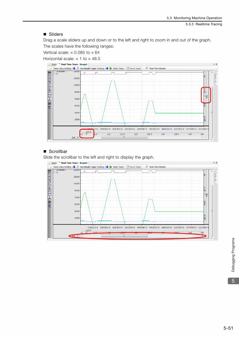
5.3 Monitoring Machine Operation
5.3.3 Realtime Tracing
5-51
5
Deb
uggi
ng P
rogr
ams
SlidersDrag a scale sliders up and down or to the left and right to zoom in and out of the graph.The scales have the following ranges:
Vertical scale: × 0.085 to × 64Horizontal scale: × 1 to × 48.5
ScrollbarSlide the scrollbar to the left and right to display the graph.

5.3 Monitoring Machine Operation
5.3.3 Realtime Tracing
5-52
Split Graph DisplaysYou can group the trace data by data type and assign a separate graph for each group, creat-ing a split display.The trace data consist of the group that is on the Trace Target List Tab Page, and the group of other registers.You can switch between the split display and the combined display.
Changing the Graph UnitIf the trace data has more than one unit, you can change the unit for the vertical axis of the graph.
When you do that, the scale of the vertical axis will change according to the axis information (unit and decimal digits), and the waveforms will be displayed accordingly.
1. The available units depend on the axis information.2. The axis unit can be changed regardless of the graph display method. It works for the split dis-
play as well as for the combined display. When you change the unit, the color of the trace lines that have a different unit will be dimmed.Note
No Unit: Millimeters (mm):

5.3 Monitoring Machine Operation
5.3.3 Realtime Tracing
5-53
5
Deb
uggi
ng P
rogr
ams
Trace ListThe Trace List displays the traced data, the trace data that was read from external files, and a history of the trace data.You can use this information to check the waveforms, the displayed graphs, and details on the traced data.Use the check boxes to show or hide the waveforms on the graph display.
No. Display Function
Trace Data Displays the trace data of the traced targets.
Trace name Displays the name of the trace.
Trace group nameThe trace data is displayed in groups, where one group consists of the data that was included in the Trace Target List Tab Page of the Trace Data Setting Dialog Box, and the other group consists of other data.
Registers Displays the registers that were traced.The register names are displayed in the same color as their trace lines.
File & History Data Displays a list of trace targets that were registered for tracing, and trace data that was read from external files.
Trace nameDisplays the name of trace data that was registered for tracing, and trace data that was read from external files.You can save up to five backups of the file and history data.
RegistersDisplays the names of trace data that was registered for tracing, and traced registers that were read from external files.The register names are displayed in the same color as their trace lines.

5.3 Monitoring Machine Operation
5.3.3 Realtime Tracing
5-54
Displaying Measurement InformationYou can view the trace definition information of monitor data and history data that you set as sampling and trigger setting information.This allows you to view and reuse the trace definitions from past measurements.Select Trace Data − Sampling & Trigger Setting Information from the MPE720 version 7 menu bar to display the Sampling & Trigger Setting Information Dialog Box.Alternatively, right-click Trace Data or File & History Data in the Trace List Pane, and select Sampling & Trigger Setting Information from the pop-up menu.

5.3 Monitoring Machine Operation
5.3.3 Realtime Tracing
5-55
5
Deb
uggi
ng P
rogr
ams
Editing the Trace DataYou can enlarge or reduce the waveform of the trace data, or move its position. Changing the size or position helps you compare the waveform to other lines for analysis.
Select Trace Data − Offset/Scale Edit of Waveform from MPE720 version 7 menu bar to display the Offset/Scale Edit of Waveform Dialog Box.Alternatively, right-click Trace Data or File & History Data in the Trace List Pane, and select Offset/Scale Edit of Waveform from the pop-up menu.
When the trace data is refreshed, the size and position will be reset.
If you display the pop-up menu by right-clicking on a group name, you can edit the wave-forms of the entire group.
Note
Information

5.3 Monitoring Machine Operation
5.3.3 Realtime Tracing
5-56
The Offset/Scale Edit of Waveform Dialog Box contains the following items:
No. Display Function
Trace name This box displays the name of the trace and the file.
Offset move buttons Use these buttons to move the waveforms of the specified trace data.
Scale adjustment slider Use this slider to increase/decrease the amplitude of waveforms of the specified trace data.
Default Click this button to return the trace data to the default settings.
Close Click this button to close the Offset/Scale Edit of Waveform Dialog Box.

5.3 Monitoring Machine Operation
5.3.3 Realtime Tracing
5-57
5
Deb
uggi
ng P
rogr
ams
Analyzing the Trace DataYou can use the trace data editing and zooming features to analyze the trace data.
Analyzing the I/O Registers and the M RegistersThis section describes how to analyze the differences between set values and actual values.
1. Display the trace data to analyze on the graph.
2. Select Trace Data − File & History Data from the menu bar. Alternatively, right-click Trace Data or File & History Data in the Trace List Pane, and select Edit Trace Data from the pop-up menu.
3. Use the arrow buttons to move to the location to use for comparison.
4. Click the Cursor A and Cursor B Icons or the Cursor C and Cursor D Icons on the Graph Toolbar to display the cursors, and align them on the registers to analyze.
5. The difference between the waveform of the set register values and the waveform of the actual output values of the register is analyzed.

5.3 Monitoring Machine Operation
5.3.3 Realtime Tracing
5-58
Comparison to Data Sampled in the PastThis section describes how to compare trace data that was read from the Machine Controller to trace data that was sampled in the past.
1. If you read trace data from an external file into the File & History Data in the Trace List Pane, the trace data waveform will be displayed as shown in the following figure.Note: If the trace data has already been loaded, then select the check box at the trace definition.
2. Select Trace Data − Offset/Scale Edit of Waveform from the menu bar. Alternatively, right-click Trace Data or File & History Data in the Trace List Pane, and select Offset/Scale Edit of Waveform from the pop-up menu. The Offset/Scale Edit of Waveform Dialog Box will be displayed.
3. Use the arrow buttons to move the start position of the data to the desired location.
4. Use the editing functions, such as zoom in, zoom out, or the slider, to compare the data to the past trace data.

5.3 Monitoring Machine Operation
5.3.3 Realtime Tracing
5-59
5
Deb
uggi
ng P
rogr
ams
Reading Trace DataThis section describes how to read saved trace data. Trace definition files (.dat) and CSV files (.csv) can be read.Select File − Open External File from the menu bar. The Open Dialog Box will be displayed. Select the saved CSV file or trace definition file to open.

5.3 Monitoring Machine Operation
5.3.3 Realtime Tracing
5-60
Saving the Trace DataThis section describes how to save the trace data into a CSV file or a trace definition file.Data can be analyzed if it is saved into a CSV or a trace definition file.
Select File − Save in External File from the menu bar. Select a CSV or a trace definition file, specify a name, and save it.
You can also display a list and copy from the trace list to an Excel file.Information

5.3 Monitoring Machine Operation
5.3.3 Realtime Tracing
5-61
5
Deb
uggi
ng P
rogr
ams
List ViewYou can display the graph data in a list.You can display the trace data and the history data in a list.
Select Trace Data − List View from the menu bar. When you select List View, the trace data that is displayed in the graph will be displayed as a list.

5.3 Monitoring Machine Operation
5.3.3 Realtime Tracing
5-62

5.3 Monitoring Machine Operation
5.3.3 Realtime Tracing
5-63
5
Deb
uggi
ng P
rogr
ams
Copying a GraphYou can place a screen capture of the graph on the clipboard.Select Graph − Copy Graph from the menu bar. Alternatively, click the Copy Graph Icon on the Graph Toolbar. The screen capture of the graph will be placed on the clipboard.

5.3 Monitoring Machine Operation
5.3.4 XY Trace
5-64
5.3.4 XY TraceAn XY trace gets the position data (target position and feedback position) of the X and Y axes in every scan and displays them on a 2-dimensional plane graph, allowing for visual analysis of the paths that the two axes take.
Starting the XY TraceDouble-click Scope 1, Scope 2, Scope 3, or Scope 4 in the System Pane of MPE720 version 7, and then click the XY Trace Button in the Trace Type Dialog Box.Alternatively, click the Scope 1, Scope 2, Scope 3, or Scope 4 Button in the My Tool Tab Page, and then click the XY Trace Button in the Trace Type Dialog Box.You can also start it from the Launcher by selecting Monitor − Trace, and then clicking the XY Trace Button in the Trace Type Dialog Box.
By default, only the Scope 1 and Scope 2 Buttons are displayed in the My Tool Tab Page.Information

5.3 Monitoring Machine Operation
5.3.4 XY Trace
5-65
5
Deb
uggi
ng P
rogr
ams
The following dialog box will be displayed.
No. Item Description
Trace Manager This button displays up to 16 points of trace data in a graph.
XY Trace This button displays the position data of two orthogonal axes in a 2-dimensional graph.
Open This button starts the selected type of trace.
Cancel This button returns you to the main window without starting the selected trace type.

5.3 Monitoring Machine Operation
5.3.4 XY Trace
5-66
Names and Functions of the XY Trace Tab Page Items
Graph ToolbarThe following table gives details on the icons.
Icon Function
Click the Select Icon, and then double-click the target area to enlarge the display.
Click the Scroll Icon to move the target area. Double-click the target area to enlarge the display.
Click the Zoom In Icon, and then drag or double-click the target area to enlarge the display.
Click the Reset Icon to return to the original display of the graph.
Click the Cursor A Icon to display cursor A, and then move it on the graph to display the X and Y values.
Click the Cursor B Icon to display cursor B, and then move it on the graph to display the X and Y values.
Click the Cursor AB Link Icon to lock the horizontal distance between cursors A and B, and to move them together at a fixed width.
Click the Open External File Icon to display the Open Dialog Box and read the trace data from a file.
Click the Save Icon to display the Save Dialog Box so that you can save the file with a specified name.
Click the List Icon to display the Trace List.
Click the Copy Graph Icon to place a screen capture of the graph on the clipboard.
XY GraphThis graph displays the trace data.You can use the Graph Toolbar,
Graph ToolbarThe Graph Toolbar contains buttons to analyze the trace data.
Trace Execution ToolbarThis toolbar contains the Trace Data Setting, the Sampling & Trigger Setting, and the Start

5.3 Monitoring Machine Operation
5.3.4 XY Trace
5-67
5
Deb
uggi
ng P
rogr
ams
Trace Execution Toolbar
Trace Data SettingsUse this button to select the axes and the trace targets.
Sampling and Trigger SettingsThis dialog box is used to set the trace name, the sampling settings, and the trigger setting parameters.Refer to the following section for details on sampling and trigger settings.
Realtime Tracing− Sampling and Trigger Settings on page 5-45
Starting and Stopping Traces
No. Item Description
X-Y Axis Specification Use these boxes to specify the X and Y axes.
Trace Target
Use these check boxes to specify the trace targets. You can select the following two motion parameters:ILxx10: Machine Coordinate System Calculated Position (ILxx10)ILxx16: Machine Coordinate System Feedback Position (ILxx16)
OK The OK Button sets the X-Y axes and the trace targets, and enables the Sampling & Trigger Setting Button.
Cancel The Cancel Button returns you to the XY Trace Dialog Box without set-ting the X-Y axes and the trace targets.
Function Description
Start Trace Use this button to start the trace. The data that is sampled will be displayed in real-time.
Real Time DisplaySelect the Real Time Display Check Box to display the axes moving in realtime.If more than one Trace Tab Page is open, you can use a realtime display for only one of them.
Stop Trace Use this button to stop the trace. When the trace stops, all trace buffer data will be collected and displayed.
Click the Trace Data Setting Button to display the following dialog box:

5.4 Tuning
5.4.1 Using SigmaWin+ (When Using a Servo)
5-68
5.4 Tuning
This section describes how to perform tuning for the machine that is connected to the Machine Controller.
5.4.1 Using SigmaWin+ (When Using a Servo)The Servo can be tuned by connecting it to the SigmaWin+ via the Controller.
Refer to the following manual for details.SigmaWin+ Online Manual (Manual No.: SIEP S800000 67)
5.4.2 Using DriveWizard Plus (When Using an Inverter)The Inverter can be tuned by connecting it to the DriveWizard Plus via the Controller.Refer to the following manual for details.
DriveWizard Plus Online Manual (Manual No.: TOEP C730600 20)

This chapter describes the security features.
6.1 Project File Security . . . . . . . . . . . . . . . . . . 6-26.1.1 Setting a Project Password . . . . . . . . . . . . . . . . . 6-26.1.2 Creating or Changing a Password . . . . . . . . . . . . 6-26.1.3 Deleting a Password . . . . . . . . . . . . . . . . . . . . . . 6-36.1.4 Setting the Default User . . . . . . . . . . . . . . . . . . . 6-46.1.5 User Management . . . . . . . . . . . . . . . . . . . . . . . . 6-4
6.2 Program Security . . . . . . . . . . . . . . . . . . . . . 6-76.2.1 Setting the Password . . . . . . . . . . . . . . . . . . . . . 6-76.2.2 Changing a Password . . . . . . . . . . . . . . . . . . . . . 6-86.2.3 Deleting a Password . . . . . . . . . . . . . . . . . . . . . . 6-86.2.4 Opening a Password-Protected
Ladder Program . . . . . . . . . . . . . . . . . . . . . . . . . 6-9
6.3 Online Security . . . . . . . . . . . . . . . . . . . . . 6-106.3.1 Setting Online Security . . . . . . . . . . . . . . . . . . . 6-116.3.2 Changing Online Security . . . . . . . . . . . . . . . . . 6-126.3.3 Deleting Online Security . . . . . . . . . . . . . . . . . . 6-136.3.4 Changing the Security Key . . . . . . . . . . . . . . . . 6-146.3.5 Unlocking Online Security Temporarily . . . . . . . 6-15
Security 6

6.1 Project File Security
6.1.1 Setting a Project Password
6-2
6.1 Project File Security
This section describes the security features for project files.
6.1.1 Setting a Project PasswordYou can set a password for the project file that is currently open.
6.1.2 Creating or Changing a Password1. Select Security and then Project Password from the tree structure in the Environment
Setting Dialog Box. The following view will be displayed.
2. Select the When the project is opened, the password is input Check Box on the Proj-ect Password View. The following dialog box will be displayed. Enter each item, and then click the OK Button.
If you forget the password that you set, there is no way to recover it and it will be impossible to open the password-protected project file.
Important
Item Description
Password Enter from 1 to 16 alphanumeric characters. The password is not case sensi-tive.
Password (confirm)Enter the same password one more time, and then click the OK Button.
Note: The OK Button will be enabled when one or more characters are entered in the Password (confirm) Box.

6.1 Project File Security
6.1.3 Deleting a Password
6-3
6
Sec
urity
6.1.3 Deleting a PasswordClear the selection of the When the project is opened, the password is input Check Box on the Project Password View of the Environment Setting Dialog Box to delete the password that you set previously.
Enter the project password, and then click the OK Button to open the project file.
When you try to open a password-protected project file, the Security Dialog Box will be dis-played.
Information

6.1 Project File Security
6.1.4 Setting the Default User
6-4
6.1.4 Setting the Default UserSelect Security and then Default User Setting from the tree structure in the Environment Setting Dialog Box. The Default User Setting View will be displayed.
Select the Select the default user Check Box to enable accessing the project file (or the Machine Controller) with the default user account. If the specified user name is not among the registered users, the Logon Dialog Box will be displayed.Enter from 1 to 16 alphanumeric characters into the Default User Name and Default Pass-word Boxes.
6.1.5 User ManagementYou can register and change the name of users who can open a project file.You can make this setting when the project file is open, or when the Machine Controller is online. If the setting is performed while the Machine Controller is online, the setting will provide access and writing privileges to the Machine Controller.
If you forget the password that you set, there is no way to recover it and it will be impossible for the user to open the password-protected project file.
Important

6.1 Project File Security
6.1.5 User Management
6-5
6
Sec
urity
Select Security and then User Registration from the tree structure in the Environment Set-ting Dialog Box. The User Registration View will be displayed.
Registering a New UserClick the New Button on the User Registration View. The User Registration Dialog Box will be displayed. Enter each item, and then click the OK Button.
User Name Enter from 1 to 16 alphanumeric characters.
Password Enter from 1 to 16 alphanumeric characters.
User Privilege Select the reading and writing privilege levels for the user from 0 to 7.Higher numbers represent higher levels of privileges.
Default Privilege In these boxes, set the default levels of privileges when a user creates a program.
Reading and Writing PrivilegesReading and writing privilege levels are set to maintain the security of the programs. To open a program, the user must have at least the same reading level privilege as was set for that program. Similarly, to edit and save a program, the user must have at least the same writing level privilege as was set for that program.
Note

6.1 Project File Security
6.1.5 User Management
6-6
Changing Registration InformationSelect the user whose information you want to change in the User Registration Pane of the Environment Setting Dialog Box. The User Registration Dialog Box will be displayed. Set the items as needed, and then click the OK Button to change the user information.
Deleting a Registered UserSelect the user whose information you want to delete in the User Registration View of the Envi-ronment Setting Dialog Box. The following dialog box will be displayed. Click the OK Button to delete the selected user.
If the selected user is the default user, only the default privileges can be changed.Refer to the following section for information on specifying the default user.
Setting the Default User (page 6-4)Note

6.2 Program Security
6.2.1 Setting the Password
6-7
6
Sec
urity
6.2 Program Security
You can set separate passwords for ladder programs and motion programs. A lock mark is dis-played for each password-protected program. To edit a password-protected program, you must first enter the password.
The purpose of this password is to control access for editing. It does not affect the manage-ment of program files (copying, cutting, pasting, deleting, or enable/disable settings).
This section describes the security that is provided, using a ladder program as an example.
6.2.1 Setting the Password1. In the Ladder Pane, right-click on the program for which you want to set a password.
Select Set the Password from the pop-up menu.The Program Password Dialog Box will be displayed.
2. Enter 1 to 8 characters in the New Password Box. Enter the same password again in the Password (Confirm) Box, and then click the OK Button.Note: 1. The OK Button will be enabled when one or more characters are entered in the Password (Con-
firm) Box.2. The password is not case sensitive.
The Program Password Dialog Box will be closed, and a padlock icon will be displayed next to the ladder program that was selected in Step 1. If the program was displayed in the main window, it will be closed.
If you forget the password that you set, there is no way to recover it, and it will be impossible to open the password-protected program.
Important

6.2 Program Security
6.2.2 Changing a Password
6-8
6.2.2 Changing a Password1. In the Ladder Pane, right-click on the program for which you want to change the pass-
word. Select Set the Password from the pop-up menu.The Program Password Dialog Box will be displayed.
2. Enter the current password in the Current Password Box.Enter 1 to 8 characters in the New Password Box. Enter the same password again in the Password (Confirm) Box, and then click the OK Button.Note: The OK Button will be enabled when one or more characters are entered in the Password (Confirm)
Box.
The password will be changed and the Program Password Dialog Box will be closed.
6.2.3 Deleting a Password1. In the Ladder Pane, right-click on the program from which you want to delete the pass-
word. Select Cancel the Password from the pop-up menu.The Program Password Dialog Box will be displayed.
2. Enter the current password in the Program Password Box, and then click the OK But-ton.Note: The OK Button will be enabled when one or more characters are entered in the Program Password
Box.
The padlock icon will be removed from the ladder program that was selected in step 1, and the Pro-gram Password Dialog Box will be closed.

6.2 Program Security
6.2.4 Opening a Password-Protected Ladder Program
6-9
6
Sec
urity
6.2.4 Opening a Password-Protected Ladder Program1. When you attempt to open a password-protected ladder program (i.e., one with a pad-
lock icon next to its name), the Program Password Dialog Box will be displayed.
2. Enter the current password in the Program Password Box, and then click the OK But-ton.Note: The OK Button will be enabled when one or more characters are entered in the Program Password
Box.
The selected ladder program will be opened in the main window.

6.3 Online Security
6-10
6.3 Online Security
Online security refers to limiting the ability to read data from the Machine Controller.You can set security key (i.e., a password) and privilege levels for programs to restrict the ability to read the program data from the Machine Controller or to open the programs to users who have at least the specified level of file reading privilege.
Item Description
Status This area displays the current status of the security setting.
Apply File Reading Restriction
Select this check box to apply a reading restriction. This check box can be used to set file reading restrictions for ladder programs, motion programs, and C pro-grams.
Note: If a value is entered in the Security Key Box without selecting the Apply File Reading Restriction Check Box, only the security key will be set. The file reading restriction will not be set.
Restriction Privilege
Use this box to set the privilege level to restrict the group of users who can read the files.
Note: The user must have a privilege level at least as high as the specified privi-lege to read the files.
Security Key and Security Key Confirmation
Enter the password that will be required to set online security. Enter from 1 to 8 alphanumeric characters. The password is case sensitive.
Change the Security Key Button Click this button to change the security key.
Set Button Click this button to set the file reading restriction.
Set to None Button Click this button to delete the current security key setting.
Unlock Button
Click this button to temporarily unlock the current online security.Even if you save the settings to the flash memory while the security key is tem-porarily unlocked, the temporary unlocked status will not be saved, and the online security setting will be maintained.The temporary unlock will be valid until you turn OFF the power supply to the Controller, disconnect the MPE720 from the Controller, or press the Lock Button on the Security Setting Dialog Box.
Close Button Click this button to close the Security Setting Dialog Box.
1. If the reading privilege is set to 4, then programs with a reading privilege of 4 or higher cannot be opened.To manage program security, the current user must have a writing privilege level of 7.
2. Even if the Apply File Reading Restriction Check Box is selected while the CARD and SAVE pins of the DIP switch on the MP2200 Machine Controller with the CPU-02 are set to ON, the restriction will not be saved to the CF card. Refer to the following manual on the MP2200 Machine Controller.
MP2200 User’s Manual (Manual No.: SIEP C880700 14)
Important

6.3 Online Security
6.3.1 Setting Online Security
6-11
6
Sec
urity
6.3.1 Setting Online SecurityThis section describes how to set restrictions on reading the data from the Machine Controller.Use the following procedure to set online security.
1. With the Machine Controller online, select Online − Security Setting from the menu bar.The Security Setting Dialog Box will be displayed.
2. Select the Apply File Reading Restriction Check Box, and then select the value of the Restriction Privilege Box from the list.
3. Enter the password in the Security Key Box. Enter the same password again in the Security Key Confirmation Box, and then click the Set Button. The Set Button will be enabled when one or more characters of text are entered in the Security Key Box.The file reading restriction and the security key will be changed, and the following message will be displayed to ask for confirmation.
4. Click the OK Button.Click the Close Button to close the Security Setting Dialog Box.Save to flash memory, if necessary.

6.3 Online Security
6.3.2 Changing Online Security
6-12
6.3.2 Changing Online SecurityThis section describes how to change the online security settings.Use the following procedure to change the current file reading restriction and restriction privi-lege settings.
1. With the Machine Controller online, select Online − Security Setting from the menu bar.The Security Setting Dialog Box will be displayed.
2. Select or clear the Apply File Reading Restriction Check Box, and then change the value of the Restriction Privilege Box.
3. Enter the current security key in the Security Key Box, and then click the Set Button.The following confirmation message will be displayed.
4. Click the OK Button.Click the Close Button to close the Security Setting Dialog Box.Save to flash memory, if necessary.

6.3 Online Security
6.3.3 Deleting Online Security
6-13
6
Sec
urity
6.3.3 Deleting Online SecurityThis section describes how to delete the online security settings.Use the following procedure to delete the security that was set for the Machine Controller.
1. With the Machine Controller online, select Online − Security Setting from the menu bar.The Security Setting Dialog Box will be displayed.
2. Enter the current security key in the Security Key Box, and then click the Unlock But-ton.The following confirmation message will be displayed.
3. Click the OK Button.Click the Close Button to close the Security Setting Dialog Box.Save to flash memory, if necessary.

6.3 Online Security
6.3.4 Changing the Security Key
6-14
6.3.4 Changing the Security KeyThis section describes how to change the security key of the online security.Use the following procedure to change the security key.
1. With the Machine Controller online, select Online − Security Setting from the menu bar.The Security Setting Dialog Box will be displayed.
2. Click the Change the Security Key Button.The Security Key Change Dialog Box will be displayed.
3. Enter the current password in the Current Security Key Box, and then enter the new password in the New Security Key Box. Enter the same new password in the New Security Key Confirmation Box, and then click the OK Button.The following confirmation message will be displayed.
4. Click the OK Button.Click the Close Button to close the Security Setting Dialog Box.Save to flash memory, if necessary.

6.3 Online Security
6.3.5 Unlocking Online Security Temporarily
6-15
6
Sec
urity
6.3.5 Unlocking Online Security TemporarilyThis section describes how to temporarily unlock the online security settings.Use the following procedure to temporarily unlock the security that was set for the Machine Controller.
1. With the Machine Controller online, select Online − Security Setting from the menu bar.The Security Setting Dialog Box will be displayed.
2. Enter the current security key in the Security Key Box, and then click the Unlock But-ton.The following confirmation message will be displayed.
3. Click the OK Button.Click the Close Button to close the Security Setting Dialog Box.Even if you save the settings to the flash memory, the temporary unlocked status will not be saved, and the online security setting will be maintained.

Appendix
This chapter describes conditions when the MP2000-series Machine Controllers are used.
A.1 Installation and Usage Conditions . . . . . . . A-2
A.2 Control Panel Cooling Method . . . . . . . . . . A-3
Controller Specifications
A

A.1 Installation and Usage Conditions
A-2
A.1 Installation and Usage Conditions
The installation and usage conditions for the MP2000-series Machine Controllers are given in the following table.
Environmental Conditions
Mechanical Operating Conditions
Electrical Operating Conditions
Installation Conditions
Item Specification
Ambient Operating Temperature 0 to 55°C (CPU-03: 0 to 50°C)
Ambient Storage Temperature −25 to 85°C
Ambient Operating Humidity 30% to 95% RH (with no condensation)
Ambient Storage Humidity 5% to 95% RH (with no condensation)
Pollution Degree Conforms to JIS B 3502 Pollution Degree 2.
Corrosive Gases There must be no combustible or corrosive gases.
Operating Altitude 2,000 m max.
Item Specification
Vibration Resistance
Conforms to JIS B 3502.Vibration amplitude and acceleration:
10 Hz ≤ f < 57 Hz with vibration amplitude of 0.075 mm57 Hz ≤ f ≤ 150 Hz with fixed acceleration of 9.8 m/s2
10 sweeps each in X, Y, Z directions (sweep: 1 octave/min)
Shock ResistanceConforms to JIS B 3502.Peak acceleration of 147 m/s2 twice for 11 ms each in the X, Y, and Z directions
Item Specification
Noise ResistanceConforms to EN 61000-6-2 and EN 55011 (Group 1 Class A).Power supply noise (FT noise): ±2 kV min. for 1 minuteRadiation noise (FT noise): ±1 kV min. for 1 minute
Item Specification
Ground Ground to 100 Ω max.
Cooling Method Natural cooling

A.2 Control Panel Cooling Method
A-3
AppA
Con
trolle
r Spe
cific
atio
ns
A.2 Control Panel Cooling Method
The components that are used in the Machine Controller require the ambient operating tem-perature to be between 0 and 55°C. Use the following methods to ensure adequate cooling in the control panel.
Control Panels with Natural Cooling• Do not mount the Machine Controller at the top of the control panel, where the hot air that is
generated inside the panel collects.• Leave sufficient space above and below the Units, and maintain adequate distances from
other devices, cable ducts, and other objects to ensure suitable air circulation.• Do not mount the Controller in any direction other than the specified direction.• Do not mount the Controller on top of any device that generates a significant amount of heat.• Do not subject the Controller to direct sunlight.
Appendix
This appendix lists the motion parameters.
B.1 Fixed Parameters . . . . . . . . . . . . . . . . . . . .B-2
B.2 Setting Parameters . . . . . . . . . . . . . . . . . . .B-5
B.3 Monitor Parameters . . . . . . . . . . . . . . . . . .B-13
Motion ParametersB

B.1 Fixed Parameters
B-2
B.1 Fixed Parameters
The following table lists the SVB, SVC, and SVR fixed parameters.Refer to the following manual for details on individual fixed parameters.
MP2000 Series SVA-01 Motion Module User’s Manual (Manual No.: SIEP C880700 32)MP2000 Series Built-in SVB/SVB-01 Motion Module User’s Manual (Manual No.: SIEP C880700 33)MP2000 Series SVC-01 Motion Module User’s Manual (Manual No.: SIEP C880700 41)
No. Name Description SVB SVC SVR
0 Operation Mode Selection
0: Normal Operation Mode √ √ √1: Unused Axis (Axis unused) √ √ √2: Simulation Mode √ √ −3: SERVOPACK Transmission Reference Mode √ √ −4 and 5: Reserved for system. − − −
1 Function Selection Flags 1
Bit 0: Axis Selection0: Finite-length axis, 1: Infinite-length axis*1 √ √ √
Bit 1: Enable Positive Software Limit (Soft limit (positive direction) enable/disable)0: Disabled, 1: Enabled
√ √ −
Bit 2: Enable Negative Software Limit (Soft limit (negative direction) enable/disable)0: Disabled, 1: Enabled
√ √ −
Bit 3: Enable Positive Overtravel (Overtravel positive direction enable/disable)0: Disabled, 1: Enabled
√ √ −
Bit 4: Enable Negative Overtravel (Overtravel negative direction enable/disable)0: Disabled, 1: Enabled
√ √ −
Bits 5 to 7: Reserved for system. − − −Bit 8: Interpolation Segment Distribution Pro-cessing0: Enabled, 1: Disabled
√ √ −
Bit 9: Simple Absolute Infinite Axis PositionManagement (Simple ABS rotary Pos. mode)0: Disabled, 1: Enabled
√ √ −
Bit A: SERVOPACK Parameter Auto-Write (User constants self-writing function)0: Enabled, 1: Disabled
√ √ −
Bit B: User-specified SERVOPACK Parameter Auto-Write (User select User constants self-writing function)0: Disabled, 1: Enabled
√ √ −
Bit C: Software Limit Parameter Selection (Soft limit parameter selection)0: Fixed parameter, 1: Setting parameter
√ √ −
Bits D to F: Reserved for system. − − −Continued on next page.
*1. Always set this parameter to 0 for linear motors.

B.1 Fixed Parameters
B-3
AppB
Mot
ion
Par
amet
ers
2 Function Selection Flags 2
Bit 0: Mask Communications Error Detection(Communication abnormality detection mask)0: Disabled, 1: Enabled
√ √ −
Bit 1: Mask Watchdog Error Detection(WDT abnormality detection mask)0: Disabled, 1: Enabled
√ √ −
Bits 2 to F: Reserved for system. − − −3 − Reserved for system. − − −
4Reference Unit Selec-tion*2
0: Pulses1: mm2: Degrees3: Inches4: μm
√ √ √
5 Number of Digits Below Decimal Point 1 = 1 digit √ √ √
6
Travel Distance per Machine Rotation (Rotary Motor)
1 = 1 reference unit √ √ √
Linear Scale Pitch (Linear Motor) 1 = 1 reference unit √ √ √
8Servomotor Gear Ratio Term*3 1 = 1 revolution √ √ √
9Machine Gear Ratio Term*3 1 = 1 revolution √ √ √
10Infinite-length Axis Reset Position (POS-MAX)*3
1 = 1 reference unit √ √ √
12Positive Software Limit 1 = 1 reference unit √ √ −
14Negative Software Limit 1 = 1 reference unit √ √ −
16 to 28 − Reserved for system. − − −
29 Motor Type Selection 0: Rotary motor1: Linear motor √ √ √
30 Encoder Selection
0: Incremental encoder1: Absolute encoder2: Absolute encoder used as incremental encoder(Absolute encoder (Incremental encoder is used))3: Reserved for system.
√ √ −
31 to 33 − Reserved for system. − − −
Continued on next page.*2. For linear motors, you can use 0 (pulses), 1 (mm), or 4 (μm). If 2 (degrees) or 3 (inches) is selected, the unit is
converted to mm.*3. This parameter is not valid for linear motors.
Continued from previous page.
No. Name Description SVB SVC SVR

B.1 Fixed Parameters
B-4
*4. This parameter is not valid for linear motors.*5. Set this parameter to 0 when a direct-drive motor is used.
34
Rated Motor Speed (Rotary Motor) 1 = 1 min-1 √ √ √
Rated Speed (Linear Motor) 1 = 0.1 m/s √ √ √
36
Number of Pulses Per Motor Rotation (Rotary Motor)
1 = 1 pulse/rev √ √ √
Number of Pulses Per Linear Scale Pitch (Linear Motor)
1 = 1 pulse/scale pitch √ √ √
38Maximum Number of Absolute Encoder Rotations*4*5
1 = 1 revolution √ √ −
40 to 41 − Reserved for system. − − −
42Feedback Speed Movement Averaging Time Constant
1 = 1 ms √ √ √
43 − Reserved for system. − − −
44User-specified SER-VOPACK Parameter Number
Specifies the SERVOPACK parameter number to apply automatically. √ √ −
45User-specified SER-VOPACK Parameter Size
Specifies the data size of the above SERVO-PACK parameter.1 = 1 W
√ √ −
Continued from previous page.
No. Name Description SVB SVC SVR

B.2 Setting Parameters
B-5
AppB
Mot
ion
Par
amet
ers
B.2 Setting Parameters
The following table lists the SVB, SVC, and SVR setting parameters.Refer to the following manual for details on individual setting parameters.
MP2000 Series SVA-01 Motion Module User’s Manual (Manual No.: SIEP C880700 32)MP2000 Series Built-in SVB/SVB-01 Motion Module User’s Manual (Manual No.: SIEP C880700 33)MP2000 Series SVC-01 Motion Module User’s Manual (Manual No.: SIEP C880700 41)
Register Address
Name Description SVB SVC SVR
OW00 Operation Com-mand Settings
Bit 0: Servo ON 0: OFF, 1: ON √ √ √
Bit 1: Machine lock0: Machine lock mode released1: Machine lock mode
√ √ −
Bits 2 to 3: Reserved for system. − − −Bit 4: Latch Detection Request (Latch detection demand) 0: OFF, 1: ON
√ √ −
Bit 5: Reserved for system. − − −Bit 6: Number of POSMAX Turns Preset Request (POSMAX turn number presetting demand)0: OFF, 1: ON*1
√ √ √
Bit 7: Absolute Infinite-length Position Infor-mation Load Request (Request ABS rotary pos. load)0: OFF, 1: ON*1
√ √ −
Bit 8: Positive External Torque/Force Limit Input (Forward outside limiting torque/thrust input)0: OFF, 1: ON
√ √ −
Bit 9: Negative External Torque/Force Limit Input(Reverse outside limiting torque/thrust input)0: OFF, 1: ON
√ √ −
Bit A: Reserved for system. − − −Bit B: Reset Integration (Integration reset)0: OFF, 1: ON √ √ −
Bit C: Reset Network (Network reset)0: OFF, 1: ON √ √ −
Bit D: Latch Completed Status Clear Request(Latch completion status clear request)0: OFF, 1: ON
√ √ −
Bit E: Reset Communications (Communica-tion reset)0: OFF, 1: ON
√ √ −
Bit F: Clear Alarm (Alarm clear)0: OFF, 1: ON √ √ √
Continued on next page.*1. Always set this parameter to 0 for linear motors.

B.2 Setting Parameters
B-6
OW01 Mode Settings 1
Bit 0: Excessive Deviation Error Level Setting0: Alarm, 1: Warning √ √ −
Bits 1 to 2: Reserved for system. − − −Bit 3: Speed Loop P/PI Switch0: PI control, 1: P control √ √ −
Bit 4: Switch Gain (Gain switch)0: OFF, 1: ON √ √ −
Bit 5: Switch Gain 2*2 (Gain switch 2)0: OFF, 1: ON
√ √ −
Bits 6 to F: Reserved for system. − − −
OW02 Mode Settings 2
Bits 0 to 7: Reserved for system. − − −Bits 8 to F: Stop Mode Selection0: Stop according to the Linear Deceleration Rate/Deceleration Time Constant parameter (Decelerate to a stop according to the linear deceleration time constant).1: Stop immediately. (Stop reference output.)
√ √ −
OW03 Function Set-tings 1
Bits 0 to 3: Speed Unit Selection0: Reference units/s (Reference unit/sec)1: 10n reference units/min2: Percentage of rated speed (1 = 0.01%)3: Percentage of rated speed (1 = 0.0001%)
√ √ √
Bits 4 to 7: Acceleration/Deceleration Rate Unit Selection0: Reference units/s2
1: ms
√ √ √
Bits 8 to B: Filter Type Selection0: No filter (Filter none)1: Exponential acceleration/deceleration filter2: Moving average filter
√ √ √
Bits C to F: Torque Unit Selection0: Percentage of rated torque (1 = 0.01%)1: Percentage of rated torque (1 = 0.0001%)
√ √ √
OW04 Function Set-tings 2
Bits 0 to 3: Latch Detection Signal Selection √ √ −0: − − − −1: − − − −2: Phase-C pulse input signal √ √ −3: /EXT1 √ √ −4: /EXT2 √ √ −5: /EXT3 √ √ −Bits 4 to 7: External Positioning Signal Set-ting √ √ −
0: − − − −1: − − − −2: Phase-C pulse input signal √ √ −3: /EXT1 √ √ −4: /EXT2 √ √ −5: /EXT3 √ √ −Bits 8 to F: Reserved for system. − − −
Continued on next page.*2. Currently under development.
Continued from previous page.
Register Address
Name Description SVB SVC SVR

B.2 Setting Parameters
B-7
AppB
Mot
ion
Par
amet
ers
OW05 Function Set-tings 3
Bit 0: Reserved for system. − − −Bit 1: Disable Phase Reference Calculation0: Enabled, 1: Disabled √ √ −
Bits 2 to A: Reserved for system. − − −Bit B: Zero Point Return Input Signal0: OFF, 1: ON √ √ −
Bits C to F: Reserved for system. − − −
OW06
M-III Vendor-specific Servo Command Out-put Signal
This parameter is used as a vendor-specific output area. √ √ −
OW07 − Reserved for system. − − −
OW08 (Continued on
next page.)
Motion Com-mands
0: NOP (No Operation) (No command) √ √ √1: POSING (Positioning) √ √ √2: EX_POSING (External Positioning) √ √ √3: ZRET (Zero Point Return) √ √ √4: INTERPOLATE (Interpolation) √ √ √5: ENDOF_INTERPOLATE (Last Interpolation Segment) (Reserved for system use.) √ √ √
6: LATCH (Latch) (Interpolation mode with latch input) √ √ √
7: FEED (Jog) (Jog mode) √ √ √8: STEP (STEP Operation) (Relative position mode) √ √ √
9: ZSET (Set Zero Point) √ √ √10: ACC (Change Acceleration Time) √ √ √11: DCC (Change Deceleration Time) √ √ √12: SCC (Change Filter Time Constant) √ √ √13: CHG_FILTER (Change Filter Type) √ √ √14: KVS (Change Speed Loop Gain) √ √ −15: KPS (Change Position Loop Gain) √ √ −16: KFS (Change Feedforward) √ √ −17: PRM_RD (Read Parameter)(Read user constant) √ √ −
18: PRM_WR (Write Parameter) (Write user constant) √ √ −
19: ALM_MON (Monitor Alarms) (Alarm monitor) √ √ −
20: ALM_HIST (Monitor Alarm History) (Alarm history monitor) √ √ −
21: ALMHIST_CLR (Clear Alarm History) √ √ −22: Reserved for system. − − −23: VELO (Issue Speed Reference) (Speed reference) √ √ √
Continued on next page.
Continued from previous page.
Register Address
Name Description SVB SVC SVR
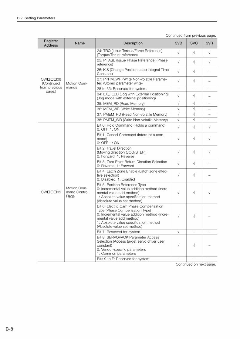
B.2 Setting Parameters
B-8
OW08 (Continued
from previous page.)
Motion Com-mands
24: TRQ (Issue Torque/Force Reference) (Torque/Thrust reference) √ √ √
25: PHASE (Issue Phase Reference) (Phase reference) √ √ √
26: KIS (Change Position Loop Integral Time Constant) √ √ −
27: PPRM_WR (Write Non-volatile Parame-ter) (Stored parameter write) √ √ −
28 to 33: Reserved for system. − − −34: EX_FEED (Jog with External Positioning)(Jog mode with external positioning) √ √ −
35: MEM_RD (Read Memory) √ √ −36: MEM_WR (Write Memory) √ √ −37: PMEM_RD (Read Non-volatile Memory) √ √ −38: PMEM_WR (Write Non-volatile Memory) √ √ −
OW09Motion Com-mand Control Flags
Bit 0: Hold Command (Holds a command) 0: OFF, 1: ON √ √ √
Bit 1: Cancel Command (Interrupt a com-mand) 0: OFF, 1: ON
√ √ √
Bit 2: Travel Direction (Moving direction (JOG/STEP))0: Forward, 1: Reverse
√ √ √
Bit 3: Zero Point Return Direction Selection 0: Reverse, 1: Forward √ √ −
Bit 4: Latch Zone Enable (Latch zone effec-tive selection)0: Disabled, 1: Enabled
√ √ −
Bit 5: Position Reference Type0: Incremental value addition method (Incre-mental value add method)1: Absolute value specification method (Absolute value set method)
√ √ √
Bit 6: Electric Cam Phase Compensation Type (Phase Compensation Type)0: Incremental value addition method (Incre-mental value add method)1: Absolute value specification method (Absolute value set method)
√ √ −
Bit 7: Reserved for system. √ − −Bit 8: SERVOPACK Parameter Access Selection (Access target servo driver user constant)0: Vendor-specific parameters1: Common parameters
√ √ −
Bits 9 to F: Reserved for system. − − −Continued on next page.
Continued from previous page.
Register Address
Name Description SVB SVC SVR

B.2 Setting Parameters
B-9
AppB
Mot
ion
Par
amet
ers
OW0A Motion Subcom-mands
0: NOP (No Operation) √ √ √1: PRM_RD (Read Parameter)(Read user constant) √ √ −
2: PRM_WR (Write Parameter)(Write user constant) √ √ −
3: INF_RD (Read Device Information) √ √ −4: SMON (Monitor Status) √ √ −5: FIXPRM_RD (Read Fixed Parameter) √ √ √6: FIXPRM_CHG (Change Fixed Parameter)(Write fixed parameter) √ √ −
OW0B − Reserved for system. − − −
OL0C
Torque/Force Reference Set-ting or Torque Feedforward Compensation
The unit is set in bits C to F (Torque Unit Selection) of OW03. √ √ √
OW0ESpeed Limit for Torque/Force Reference
1 = 0.01% (percentage of rated speed) √ √ −
OW0F − Reserved for system. − − −
OL10 Speed Reference Setting
The unit is set in bits 0 to 3 (Speed Unit Selection) of OW03. √ √ √
OW12 Speed Limit 1 = 0.01% (percentage of rated speed) − √ −OW13 − Reserved for system. − − −
OL14 Torque/Force Limit
The unit is set in bits C to F (Torque Unit Selection) of OW03. √ √ −
OL16 Second Speed Compensation
The unit is set in bits 0 to 3 (Speed Unit Selection) of OW03. √ √ √
OW18 Override 1 = 0.01% √ √ −OW19
to OW1B
− Reserved for system. − − −
OL1C Position Refer-ence Setting 1 = 1 reference unit √ √ √
OL1E Positioning Com-pletion Width 1 = 1 reference unit √ √ −
OL20 NEAR Signal Output Width 1 = 1 reference unit √ √ −
OL22Excessive Devia-tion Detection Value
1 = 1 reference unit √ √ −
OL24 − Reserved for system. − − −
OW26Positioning Com-pletion Check Time
1 = 1 ms √ √ −
OW27 − Reserved for system. − − −
OL28 Phase Compen-sation Setting 1 = 1 reference unit √ √ −
OL2ALatch Zone Lower Limit Set-ting
1 = 1 reference unit √ √ −
OL2CLatch Zone Upper Limit Set-ting
1 = 1 reference unit √ √ −
OW2E Position Loop Gain 1 = 0.1 /s √ √ −
Continued on next page.
Continued from previous page.
Register Address
Name Description SVB SVC SVR

B.2 Setting Parameters
B-10
OW2F Speed Loop Gain 1 = 1Hz √ √ −
OW30Speed Feedfor-ward Compen-sation
1 = 0.01% (percentage of distribution seg-ment) √ √ −
OW31 Speed Compen-sation 1 = 0.01% (percentage of rated speed) √ √ √
OW32Position Loop Integral Time Constant
1 = 1 ms √ √ −
OW33 − Reserved for system. − − −
OW34Speed Loop Integral Time Constant
1 = 0.01 ms √ √ −
OW35 − Reserved for system. − − −
OL36
Linear Accelera-tion Rate/Accel-eration Time Constant
The unit is set in bits 4 to 7 (Acceleration/Deceleration Rate Unit Selection) of OW03.
√ √ √
OL38
Linear Decelera-tion Rate/Decel-eration Time Constant
The unit is set in bits 4 to 7 (Acceleration/Deceleration Rate Unit Selection) of OW03.
√ √ √
OW3A Filter Time Con-stant 1 = 0.1 ms √ √ √
OW3B
Bias Speed for Indexed Deceler-ation/Accelera-tion Filter
The unit is set in bits 0 to 3 (Speed Unit Selection) of OW03. √ − √
OW3C Zero Point Return Method
0: DEC1 + C pulse1: ZERO signal2: DEC1 + ZERO signal3: C pulse4 to 10: Reserved for system.11: C pulse only12: P-OT + C pulse13: P-OT only14: HOME LS + C pulse15: HOME only16: N-OT + C pulse17: N-OT only18: INPUT + C pulse19: INPUT only
√ √ −
OW3DZero Point Posi-tion Output Width
1 = 1 reference unit √ √ √
OL3E Approach Speed The unit is set in bits 0 to 3 (Speed Unit Selection) of OW03. √ √ −
OL40 Creep Speed The unit is set in bits 0 to 3 (Speed Unit Selection) of OW03. √ √ −
OL42Zero Point Return Travel Distance
1 = 1 reference unit √ √ −
OL44 STEP Travel Dis-tance 1 = 1 reference unit √ √ √
OL46External Posi-tioning Final Travel Distance
1 = 1 reference unit √ √ −
Continued on next page.
Continued from previous page.
Register Address
Name Description SVB SVC SVR

B.2 Setting Parameters
B-11
AppB
Mot
ion
Par
amet
ers
OL48
Zero Point Posi-tion Offset in Machine Coordi-nate System
1 = 1 reference unit √ √ √
OL4AWorking Coordi-nate System Off-set
1 = 1 reference unit √ √ √
OL4C*3Number of POS-MAX Turns Pre-set Data
1 = 1 revolution √ √ √
OW4ESERVOPACK User Monitor Setting
Bits 0 to 3: Monitor 1 (Cannot be set.)Bits 4 to 7: Monitor 2Bits 8 to B: Monitor 3 (Cannot be set.)Bits C to F: Monitor 4
√ √ −
OW4FSERVOPACK Alarm Monitor Number
Sets the number of the alarm to monitor. √ √ −
OW50SERVOPACK Parameter Num-ber
Sets the SERVOPACK parameter number. √ √ −
OW51 SERVOPACK Parameter Size
Sets the size of the SERVOPACK parameter in words. √ √ −
OL52SERVOPACK Parameter Set Value
Sets the set value for the SERVOPACK parameter. √ √ −
OW54Auxiliary SERVO-PACK Parame-ter Number
Sets the SERVOPACK parameter number. √ √ −
OW55Auxiliary SERVO-PACK Parame-ter Size
Sets the size of the SERVOPACK parameter in words. √ √ −
OL56Auxiliary SERVO-PACK Parame-ter Set Value
Sets the set value for the SERVOPACK parameter. √ √ −
OL58 Address SettingSets the target address for the MEM_RD, MEM_WR, PMEM_RD, and PMEM_WR motion commands.
√ √ −
OW5A − Reserved for system. − − −
OW5BDevice Informa-tion Selection Code
00 hex: Disabled01 hex: Vendor ID code02 hex: Device code03 hex: Device version04 hex: Device information file version05 hex: Serial number
√ √ −
OW5C Fixed Parameter Number
Sets the number of the fixed parameter to read with the FIXPRM_RD motion subcom-mand.
√ √ √
OW5D − Reserved for system. − − −
OL5E*4
Power OFF Encoder Posi-tion (Encoder position when power is off) (Lower 2 Words)
1 = 1 pulse √ √ −
Continued on next page.*3. This parameter is not valid for linear motors.
Continued from previous page.
Register Address
Name Description SVB SVC SVR

B.2 Setting Parameters
B-12
OL60*4
Power OFF Encoder Posi-tion (Encoder position when power is off) (Upper 2 Words)
1 = 1 pulse √ √ −
OL62*4
Power OFF Pulse Position (Pulse position when power is off) (Lower 2 Words)
1 = 1 pulse √ √ −
OL64*4
Power OFF Pulse Position (Pulse position when power is off) (Upper 2 Words)
1 = 1 pulse √ √ −
OL66 Positive Software Limit 1 = 1 reference unit √ √ −
OL68 Negative Soft-ware Limit 1 = 1 reference unit √ √ −
OL6E Reserved for system. Reserved for system. − − −
OL70
User-specified SERVOPACK Parameter Set Value
Enter the value to set for the SERVOPACK parameter that is set with fixed parameter No. 44.
√ √ −
OW68 to OW7F*5
Command Buf-fers for SERVO-PACK Transmission Reference Mode
This area is used for command data when MECHATROLINK Servo commands are specified directly.
√ √ −
*4. Do not set this parameter for linear motors.*5. These parameters are used in SERVOPACK Transmission Reference Mode only.
Continued from previous page.
Register Address
Name Description SVB SVC SVR

B.3 Monitor Parameters
B-13
AppB
Mot
ion
Par
amet
ers
B.3 Monitor Parameters
The following table lists the SVB, SVC, and SVR monitor parameters.Refer to the following manual for details on individual monitor parameters.
MP2000 Series SVA-01 Motion Module User’s Manual (Manual No.: SIEP C880700 32)MP2000 Series Built-in SVB/SVB-01 Motion Module User’s Manual (Manual No.: SIEP C880700 33)MP2000 Series SVC-01 Motion Module User’s Manual (Manual No.: SIEP C880700 41)
Register Address
Name Description SVB SVC SVR
IW00 RUN Status
Bit 0: Motion Operation Ready (Motion controller operation ready)0: Motion operation not ready1: Motion operation ready
√ √ √
Bit 1: Running with Servo ON (Running (At servo on))0: Stopped, 1: Running with Servo ON √ √ √
Bit 2: System Busy0: System not busy, 1: System busy √ √ −
Bit 3: Servo Ready0: Servo not ready, 1: Servo ready √ √ −
Bit 4: Latch Mode0: Latch detection request not received1: Latch detection request received
√ √ −
Bits 5 to F: Reserved for system. − − −
IW01Out-of-range Parameter Number
Setting parameter: 0 and higherFixed parameter: 1000 and higher √ √ √
IL02
Warnings
Bit 0: Excessive Deviation0: In normal deviation range1: Excessive deviation detected
√ √ −
Bit 1: Setting Parameter Error (Set parameter error)0: In setting range, 1: Outside setting range √ √ √
Bit 2: Fixed Parameter Error0: In setting range, 1: Outside setting range √ √ √
Bit 3: SERVOPACK Error0: No warning, 1: Warning √ √ −
Bit 4: Motion Command Setting Error (Motion com-mand set error)0: No command setting error1: Command setting error
√ √ √
Bit 5: Reserved for system. √ − −Bit 6: Positive Overtravel (Positive direction over-travel)0: No positive overtravel1: Positive overtravel occurred
√ √ −
Bit 7: Negative Overtravel (Negative direction over-travel)0: No negative overtravel1: Negative overtravel occurred
√ √ −
Warnings
Bit 8: Servo ON Incomplete0: Servo ON, 1: Servo ON incomplete √ √ −
Bit 9: SERVOPACK Communications Warning0: Communications normal1: Communications error detected
√ √ −
Bit A: SERVOPACK Stop Signal Active0: There is no stop signal input1: There is a stop signal input
√ √ −
Bits B to 1F: Reserved for system. − − −Continued on next page.

B.3 Monitor Parameters
B-14
IL04 (Continued
on next page.)
Alarms
Bit 0: SERVOPACK Error0: No SERVOPACK alarm1: SERVOPACK alarm occurred
√ √ −
Bit 1: Positive Overtravel (Positive direction over-travel)0: No positive overtravel1: Positive overtravel occurred
√ √ −
Bit 2: Negative Overtravel (Negative direction over-travel)0: No negative overtravel1: Negative overtravel occurred
√ √ −
Bit 3: Positive Software Limit (Positive direction soft-ware limit)0: Positive software limit not exceeded1: Positive software limit exceeded
√ √ −
Bit 4: Negative Software Limit (Negative direction software limit)0: Negative software limit not exceeded1: Negative software limit exceeded
√ √ −
Bit 5: Servo OFF0: Servo ON, 1: Servo OFF √ √ √
Bit 6: Positioning Time Exceeded (Positioning time over)0: No timeout, 1: Timeout occurred
√ √ −
Bit 7: Excessive Positioning Travel Distance(Excessive positioning moving amount)0: Normal travel distance1: Excessive travel distance
√ √ −
Bit 8: Excessive Speed0: Normal speed, 1: Excessive speed √ √ −
Bit 9: Excessive Deviation0: Normal following deviation1: Excessive deviation
√ √ −
Bit A: Filter Type Change Error0: No change error, 1: Change error occurred √ √ −
Bit B: Filter Time Constant Change Error0: No change error, 1: Change error occurred √ √ −
Bit C: Reserved for system. − − −
Bit D: Zero Point Unset*1 (Zero point unsetting)0: Zero point is not set1: Zero point unset error occurred
√ √ −
Bits E and F: Reserved for system. − − −Bit 10: SERVOPACK Synchronized Communications Error (Servo Driver Synch. Comm. error)0: No synchronized communications error1: Synchronized communications error occurred
√ √ −
Bit 11: SERVOPACK Communications Error0: No consecutive synchronized communications errors1: Consecutive synchronized communications errors occurred
√ √ −
Bit 12: SERVOPACK Communications Timeout Error0: SERVOPACK command completed within the specified time1: SERVOPACK command not completed within the specified time
√ √ −
Continued on next page.
Continued from previous page.
Register Address
Name Description SVB SVC SVR

B.3 Monitor Parameters
B-15
AppB
Mot
ion
Par
amet
ers
IL04 (Continued from previ-ous page.)
Alarms
Bit 13: Excessive Absolute Encoder Rotations*1
(Excessive ABS encoder rotations)0: In valid range, 1: Outside valid range
√ √ −
Bits 14 and 15: Reserved for system. − − −Bit 16: Scan Setting Error0: No scan setting error, 1: Scan setting error occurred
√ √ −
Bits 17 to 1B: Reserved for system. − − −Bit 1C: Cyclic Communications Initialization Incom-plete0: Initialization completed (default)1: Initialization not completed
√ √ −
Bit 1D: Detected SERVOPACK Model Error0: Match, 1: Mismatch √ √ −
Bit 1E: Motor Type Setting Error0: Match, 1: Mismatch √ √ −
Bit 1F: Connected Encoder Model Error0: Match, 1: Mismatch √ √ −
IL06 − Reserved for system. − − −
IW08
Motion Com-mand Response Code
Same as OW08 (motion commands). √ √ √
IW09 Motion Com-mand Status
Bit 0: Command Execution Flag (BUSY)0: READY (Completed), 1: BUSY (Processing) √ √ √
Bit 1: Command Hold Completed (HOLDL)0: Command hold not completed1: Command hold completed
√ √ √
Bit 2: Reserved for system. − − −Bit 3: Command Error End (FAIL) (Command error completed status)0: Completed normally, 1: Completed with an error
√ √ √
Bits 4 to 7: Reserved for system. − − −Bit 8: Command Execution Completed (COMPLETE)0: Normal execution not completed1: Normal execution completed
√ √ √
Bits 9 to F: Reserved for system. − − −
IW0A
Motion Sub-command Response Code
Same as OW0A (Motion Subcommands). √ √ √
IW0BMotion Sub-command Status
Bit 0: Command Execution Flag0: READY (Completed), 1: BUSY (Processing) √ √ √
Bits 1 to 2: Reserved for system. − − −Bit 3: Command Error End (Command error com-pleted status)0: Completed normally, 1: Completed with an error
√ √ √
Bits 4 to 7: Reserved for system. − − −Bit 8: Command Execution Completed0: Normal execution not completed1: Normal execution completed
√ √ √
Bits 9 to F: Reserved for system. − − −Continued on next page.
*1. This parameter is not valid for linear motors.
Continued from previous page.
Register Address
Name Description SVB SVC SVR

B.3 Monitor Parameters
B-16
IW0CPosition Man-agement Sta-tus
Bit 0: Distribution Completed (DEN) (Discharging completed)0: Distributing pulses, 1: Distribution completed
√ √ √
Bit 1: Positioning Completed (POSCOMP)0: Outside positioning completed range1: Within positioning completed range
√ √ √
Bit 2: Latch Completed (LCOMP)0: Latch not complete, 1: Latch completed √ √ −
Bit 3: Near Position (NEAR)0: Outside near position range1: Within near position range
√ √ √
Bit 4: Zero Point Position (ZERO)0: Outside zero point position range1: Within zero point position range
√ √ √
Bit 5: Zero Point Return/Setting Completed (ZRNC)(Zero point return [setting] completed)0: Zero point return/setting not completed1: Zero point return/setting completed
√ √ √
Bit 6: Machine Locked (MLKL) (During machine lock)0: Machine Lock Mode released, 1: Machine locked √ √ −
Bit 7: Reserved for system. − − −Bit 8: Absolute Infinite-length Position Information Load Completed (ABSLDE) (ABS rotary pos. LOAD complete)0: Load not complete, 1: Load completed
√ √ −
Bit 9: POSMAX Turn Preset Completed (TPRSE)*1
(POSMAX turn preset complete)0: Preset not completed, 1: Preset completed
√ √ √
Bits A to F: Reserved for system. − − −IW0D − Reserved for system. − − −
IL0E
Machine Coordinate System Tar-get Position (TPOS)
1 = 1 reference unit √ √ √
IL10
Machine Coordinate System Cal-culated Posi-tion (CPOS)
1 = 1 reference unit √ √ √
IL12
Machine Coordinate System Refer-ence Position (MPOS)
1 = 1 reference unit √ √ √
IL14 32-bit DPOS (DPOS) 1 = 1 reference unit √ √ √
IL16
Machine Coordinate System Feed-back Position (APOS)
1 = 1 reference unit √ √ √
IL18
Machine Coordinate System Latch Position (LPOS)
1 = 1 reference unit √ √ −
Continued on next page.*1. This bit is not valid for linear motors.
Continued from previous page.
Register Address
Name Description SVB SVC SVR

B.3 Monitor Parameters
B-17
AppB
Mot
ion
Par
amet
ers
IL1A Position Devi-ation (PERR) 1 = 1 reference unit √ √ −
IL1C
Target Posi-tion Incre-ment Monitor (PDV)(Target posi-tion differ-ence monitor)
1 = 1 reference unit − − √
IL1E*1Number of POSMAX Turns
1 = 1 turn √ √ √
IL20Speed Refer-ence Output Monitor
pulse/s √ √ −
IL22 to
IL27− Reserved for system. − − −
IL28
M-III Servo Command Input Signal Monitor
Reports the signal information that is input to the MECHATROLINK-III. √ √ −
IL2AM-III Servo Command Status
Reports the Servo command information that is input to MECHATROLINK-III. √ √ −
IW2C M-III Com-mand Status
Bit 0: Drive Alarm (D_ALM) (Drive Alarm Occurrence)Bit 1: Drive Warning (D_WAR) (Drive Warning Occur-rence)Bit 2: Command Ready (CMDRDY)Bit 3: Alarm Clear Execution Completed (ALM_CL-R_CMP) (Alarm Clear Execution Completion)Bits 4 and 5: Reserved for system.Bits 6 and 7: Echo-back of Command ID (RCMD_ID)Bits 8 to B: Command Error Status (CMD_ALM)(Command Error)Bits C to F: Communications Error Status (COM-M_ALM)
√ √ −
IW2D SERVOPACK Alarm Code Reports the alarm code from the SERVOPACK. √ √ −
IW2E − Reserved for system. − − −
IW2FSERVOPACK User Monitor Information
Bits 0 to 3: Monitor 1 (Cannot be set.)Bits 4 to 7: Monitor 2Bits 8 to B: Monitor 3 (Cannot be set.)Bits C to F: Monitor 4
√ √ −
IL30SERVOPACK User Monitor 2
Reports the result of the selected monitor item. √ √ −
IL32SERVOPACK User Monitor 3
Reserved for system. − − −
IL34SERVOPACK User Monitor 4
Reports the result of the selected monitor item. √ √ −
IW36SERVOPACK Parameter Number
Reports the number of the target parameter. √ √ −
IW37
Auxiliary SER-VOPACK Parameter Number
Reports the number of the target parameter. √ √ −
Continued on next page.*1. This parameter is not valid for linear motors.
Continued from previous page.
Register Address
Name Description SVB SVC SVR

B.3 Monitor Parameters
B-18
IL38SERVOPACK Parameter Read Data
Reports the setting of the read parameter. √ √ −
IL3A
Auxiliary SER-VOPACK Parameter Read Data
Reports the setting of the read parameter. √ √ −
IW3C to
IW3E− Reserved for system. − − −
IW3F Motor Type Reports the type of the connected motor.0: Rotary motor, 1: Linear motor √ √ −
IL40 Feedback Speed
The unit is set in bits 0 to 3 (Speed Unit Selection) of OW03. √ √ √
IL42Torque/Force Reference Monitor
The unit is set in bits C to F (Torque Unit Selection) of OW03. √ √ √
IW44 to
IW55− Reserved for system. − − −
IL56 Fixed Parame-ter Monitor
Stores the execution results of the FIXPRM_RD motion subcommand. √ √ √
IW58 to
IW5A− Reserved for system. − − −
IW5BDevice Infor-mation Moni-tor Code
00 hex: Disabled01 hex: Vendor ID code02 hex: Device code03 hex: Device version04 hex: Device information file version05 hex: Serial number
√ √ −
IL5C − Reserved for system. − − −
IL5E
Power OFF Encoder Posi-tion (Encoder position when power is off) (Lower 2 Words)
1 = 1 pulse √ √ −
IL60
Power OFF Encoder Posi-tion (Encoder position when power is off) (Upper 2 Words)
1 = 1 pulse √ √ −
IL62
Power OFF Pulse Posi-tion (Pulse position when power is off) (Lower 2 Words)
1 = 1 pulse √ √ −
IL64
Power OFF Pulse Posi-tion (Pulse position when power is off) (Upper 2 Words)
1 = 1 pulse √ √ −
Continued on next page.
Continued from previous page.
Register Address
Name Description SVB SVC SVR

B.3 Monitor Parameters
B-19
AppB
Mot
ion
Par
amet
ers
*2. These parameters are used in SERVOPACK Transmission Reference Mode only.
IW66 to
IW6F− Reserved for system. − − −
IW70 to
IW7F
Device Infor-mation Moni-tor Data
Reports the information that was read with the INF_RD subcommand. √ √ −
IW68 to
IW7F*2
Response Buffers for SERVOPACK Transmission Reference Mode
Stores MECHATROLINK Servo responses. √ √ −
Continued from previous page.
Register Address
Name Description SVB SVC SVR

Index
Index-1
IndexA
alarm code details - - - - - - - - - - - - - - - - - - - - - 5-30alarm monitor - - - - - - - - - - - - - - - - - - - - - - - - 5-26
Bbackground - - - - - - - - - - - - - - - - - - - - - - - - - - 4-7
Battery Installation - - - - - - - - - - - - - - - - - - - - - 2-10Battery replacement - - - - - - - - - - - - - - - - - - - - 2-11
Cchecking for multiple coils - - - - - - - - - - - - - - - - - 5-16combinations
MP2000-series products - - - - - - - - - - - - - - - - 1-2connection
connecting the power supply and other devices - - 2-27connecting the power supply connector- - - - - - - 2-21connecting the RLY OUT connector - - - - - - - - - 2-26going online - - - - - - - - - - - - - - - - - - - - - - - 3-15project link connection- - - - - - - - - - - - - - - - - 3-17
creating a group definition - - - - - - - - - - - - - - - - - 4-55creating programs
ladder programs - - - - - - - - - - - - - - - - - - - - 4-51motion main programs- - - - - - - - - - - - - - - - - 4-56motion subprogram - - - - - - - - - - - - - - - - - - 4-58sequence main program- - - - - - - - - - - - - - - - 4-60sequence subprogram - - - - - - - - - - - - - - - - - 4-61
cross referenceladder program - - - - - - - - - - - - - - - - - - - - - 5-13motion and sequence programs - - - - - - - - - - - 5-25
Ddata transfer
with the MPE720 - - - - - - - - - - - - - - - - - - - - 4-63without the MPE720 - - - - - - - - - - - - - - - - - - 4-72
debuggingladder programs - - - - - - - - - - - - - - - - - - - - - 5-3motion program - - - - - - - - - - - - - - - - - - - - 5-21sequence program - - - - - - - - - - - - - - - - - - - 5-21
DWG.A- - - - - - - - - - - - - - - - - - - - - - - - - - - - - 4-5DWG.H- - - - - - - - - - - - - - - - - - - - - - - - - - - - - 4-5DWG.I - - - - - - - - - - - - - - - - - - - - - - - - - - - - - 4-5
DWG.L - - - - - - - - - - - - - - - - - - - - - - - - - - - - - 4-5
Eenabling and disabling a program- - - - - - - - - - - - - 5-20Ethernet connection preparation - - - - - - - - - - - - - 3-13
Fforcing coils ON and OFF - - - - - - - - - - - - - - - - - 5-17
Ggoing online- - - - - - - - - - - - - - - - - - - - - - - - - - 3-15
Iinstallation
DIN rail mounting - - - - - - - - - - - - - - - - - - - - -2-3screw mounting - - - - - - - - - - - - - - - - - - - - - -2-2
Lladder programs - - - - - - - - - - - - - - - - - - - - - - - -4-3
creating - - - - - - - - - - - - - - - - - - - - - - - - - - 4-51debugging - - - - - - - - - - - - - - - - - - - - - - - - -5-3
list of fixed parameters - - - - - - - - - - - - - - - - - - - B-2list of monitor parameters - - - - - - - - - - - - - - - - - -B-13
list of setting parameters - - - - - - - - - - - - - - - - - - B-5
MM-EXECUTOR functionality - - - - - - - - - - - - - - - - - 4-26monitoring
axis alarm monitor - - - - - - - - - - - - - - - - - - - - 5-37axis monitor - - - - - - - - - - - - - - - - - - - - - - - 5-33realtime tracing- - - - - - - - - - - - - - - - - - - - - - 5-41XY trace- - - - - - - - - - - - - - - - - - - - - - - - - - 5-64
motion parameters
list of fixed parameters - - - - - - - - - - - - - - - - - B-2list of monitor parameters- - - - - - - - - - - - - - - -B-13list of setting parameters - - - - - - - - - - - - - - - - B-5
motion programs - - - - - - - - - - - - - - - - - - - - - - - 4-12creating - - - - - - - - - - - - - - - - - - - - - - - - - - 4-55debugging - - - - - - - - - - - - - - - - - - - - - - - - 5-21
MPE720 Ver. 7
going online - - - - - - - - - - - - - - - - - - - - - - - 3-15installation - - - - - - - - - - - - - - - - - - - - - - - - -3-4project link connection - - - - - - - - - - - - - - - - - 3-17transferring data - - - - - - - - - - - - - - - - - - - - - 4-63
Oonline security - - - - - - - - - - - - - - - - - - - - - - - - 6-10
changing - - - - - - - - - - - - - - - - - - - - - - - - - 6-12changing the security key - - - - - - - - - - - - - - - - 6-14deleting - - - - - - - - - - - - - - - - - - - - - - - - - - 6-13setting- - - - - - - - - - - - - - - - - - - - - - - - - - - 6-11
Optional Modulesinstallation - - - - - - - - - - - - - - - - - - - - - - - - -2-6replacing and adding - - - - - - - - - - - - - - - - - - -2-7
Pprogram security - - - - - - - - - - - - - - - - - - - - - - - -6-7
changing a password - - - - - - - - - - - - - - - - - - -6-8deleting a password - - - - - - - - - - - - - - - - - - - -6-8setting a password - - - - - - - - - - - - - - - - - - - -6-7
project filecreating a project file - - - - - - - - - - - - - - - - - - -3-8setting a project password - - - - - - - - - - - - - - - -3-9
project file security - - - - - - - - - - - - - - - - - - - - - - -6-2

Index
Index-2
creating or changing a password - - - - - - - - - - - 6-2deleting a password - - - - - - - - - - - - - - - - - - - 6-3setting a project password - - - - - - - - - - - - - - - 6-2setting the default user - - - - - - - - - - - - - - - - - 6-4user management - - - - - - - - - - - - - - - - - - - - 6-4
project link connection- - - - - - - - - - - - - - - - - - - -3-17
Rreading
from a project file- - - - - - - - - - - - - - - - - - - - -4-67from the Machine Controller - - - - - - - - - - - - - -4-66
register list- - - - - - - - - - - - - - - - - - - - - - - - - - - 5-4
registers - - - - - - - - - - - - - - - - - - - - - - - - - - - -4-41
Ssaving to flash memory - - - - - - - - - - - - - - - - - - -4-68scan time setting - - - - - - - - - - - - - - - - - - - - - - -3-45scheduling the execution of high-speed and low-speed scan process drawings - - - - - - - - - - - - - - - - - - - 4-7searching and replacing in programs
ladder programs - - - - - - - - - - - - - - - - - - - - - 5-8motion and sequence programs - - - - - - - - - - - -5-25
searching and replacing in project filesladder programs - - - - - - - - - - - - - - - - - - - - -5-11motion and sequence programs - - - - - - - - - - - -5-25
securityonline security - - - - - - - - - - - - - - - - - - - - - -6-10program security - - - - - - - - - - - - - - - - - - - - - 6-7project file security - - - - - - - - - - - - - - - - - - - - 6-2
self configurationdata that is updated automatically during self configuration - - - - - - - - - - - - - - - - - - - - - - -3-18parameters written during self configuration - - - - -3-32using the DIP switch - - - - - - - - - - - - - - - - - - -3-10using the MPE720 - - - - - - - - - - - - - - - - - - - -3-11
sequence programs - - - - - - - - - - - - - - - - - - - - -4-24creating - - - - - - - - - - - - - - - - - - - - - - - - - -4-60debugging - - - - - - - - - - - - - - - - - - - - - - - -5-21
setting the high-speed and low-speed times - - - - - - - 4-7
setup flow - - - - - - - - - - - - - - - - - - - - - - - - - - - 3-3system configuration - - - - - - - - - - - - - - - - - - - - - 1-4
Ttest run - - - - - - - - - - - - - - - - - - - - - - - - - - - -3-47tuning - - - - - - - - - - - - - - - - - - - - - - - - - - - - -5-68
using DriveWizard Plus (when using an Inverter) - - -5-68using SigmaWin+ (when using a Servo) - - - - - - - -5-68
Uuser program types - - - - - - - - - - - - - - - - - - - - - 4-3
ladder programs - - - - - - - - - - - - - - - - - - - - - 4-3motion programs - - - - - - - - - - - - - - - - - - - - -4-12sequence programs - - - - - - - - - - - - - - - - - - -4-24
using a CF card (MP2200 only)with the MPE720- - - - - - - - - - - - - - - - - - - - -4-69
without the MPE720 - - - - - - - - - - - - - - - - - - 4-72using the MPLoad Marker - - - - - - - - - - - - - - - - - 4-77using the MPLoader - - - - - - - - - - - - - - - - - - - - - 4-75
Vviewing a called program - - - - - - - - - - - - - - - - - - 5-20
viewing a motion subprogram - - - - - - - - - - - - - - - 5-25
Wwatch - - - - - - - - - - - - - - - - - - - - - - - - - - 5-7, 5-25writing
to a project file - - - - - - - - - - - - - - - - - - - - - - 4-65to the Machine Controller - - - - - - - - - - - - - - - - 4-64

Revision History-1
Revision History
The revision dates and numbers of the revised manuals are given on the bottom of the back cover.
Date of Publication Rev. No. WEB
Rev. No. Section Revised Contents
April 2016 <0> 1 Front cover Revision: Format
2.2.5 Revision: Procedure to set MECHATROLINK-III station address
Back cover Revision: Address and format
January 2015 – – – First edition
MANUAL NO. SIEP C880732 14A <0>-1
Published in Japan April 2016
Date of publication
Revision numberWEB revision number

IRUMA BUSINESS CENTER (SOLUTION CENTER)480, Kamifujisawa, Iruma, Saitama, 358-8555, JapanPhone 81-4-2962-5151 Fax 81-4-2962-6138http://www.yaskawa.co.jp
YASKAWA AMERICA, INC.2121, Norman Drive South, Waukegan, IL 60085, U.S.A.Phone 1-800-YASKAWA (927-5292) or 1-847-887-7000 Fax 1-847-887-7310http://www.yaskawa.com
YASKAWA ELÉTRICO DO BRASIL LTDA.777, Avenida Piraporinha, Diadema, São Paulo, 09950-000, Brasil Phone 55-11-3585-1100 Fax 55-11-3585-1187http://www.yaskawa.com.br
YASKAWA EUROPE GmbH185, Hauptstraβe, Eschborn, 65760, GermanyPhone 49-6196-569-300 Fax 49-6196-569-398http://www.yaskawa.eu.com
YASKAWA ELECTRIC KOREA CORPORATION9F, Kyobo Securities Bldg. 26-4, Yeouido-dong, Yeongdeungpo-gu, Seoul, 150-737, KoreaPhone 82-2-784-7844 Fax 82-2-784-8495http://www.yaskawa.co.kr
YASKAWA ELECTRIC (SINGAPORE) PTE. LTD.151, Lorong Chuan, #04-02A, New Tech Park, 556741, SingaporePhone 65-6282-3003 Fax 65-6289-3003http://www.yaskawa.com.sg
YASKAWA ELECTRIC (THAILAND) CO., LTD.59, 1st-5th Floor, Flourish Building, Soi Ratchadapisek 18, Ratchadapisek Road, Huaykwang, Bangkok, 10310, ThailandPhone 66-2-017-0099 Fax 66-2-017-0799http://www.yaskawa.co.th
YASKAWA ELECTRIC (CHINA) CO., LTD.22F, One Corporate Avenue, No.222, Hubin Road, Shanghai, 200021, ChinaPhone 86-21-5385-2200 Fax 86-21-5385-3299http://www.yaskawa.com.cn
YASKAWA ELECTRIC (CHINA) CO., LTD. BEIJING OFFICERoom 1011, Tower W3 Oriental Plaza, No.1, East Chang An Ave.,Dong Cheng District, Beijing, 100738, ChinaPhone 86-10-8518-4086 Fax 86-10-8518-4082
YASKAWA ELECTRIC TAIWAN CORPORATION9F, 16, Nanking E. Rd., Sec. 3, Taipei, 104, TaiwanPhone 886-2-2502-5003 Fax 886-2-2505-1280
In the event that the end user of this product is to be the military and said product is to be employed in any weapons systems or the manufacture thereof, the export will fall under the relevant regulations as stipulated in the Foreign Exchange and Foreign Trade Regulations. Therefore, be sure to follow all procedures and submit all relevant documentation according to any and all rules, regulations and laws that may apply.
Specifications are subject to change without notice for ongoing product modifications and improvements.
© 2015-2016 YASKAWA ELECTRIC CORPORATION
Published in Japan April 2016
MANUAL NO. SIEP C880732 14A <0>-1
15-8-11
Machine Controller SystemMachine Controller MP2000 Series
SETUP MANUAL