Holonic machine controller: a study and implementation of holonic behaviour to current NC controller
11
ELSEVIER Computers in Industry 33 (1997) 323-333 Holonic machine controller: A study and implementation of holonic behaviour to current NC controller l?rianggada Indra Tanaya * , Jan Detand, Jean-Pierre Kruth Kutholieke Uniuersite;t Leuuen, Faculty uf Applied Science, Department of Mechanicul Engineering, Dioision of Production Engineering, Machine Design, and Automation, Celestijnenlaan 3OOB, 3001 Lawen, Belgium Abstract This paper describes ongoing research and development of a Holonic Machine Controller. The characteristics of this new prototype controller will be more flexible and open in comparison with present NC technology. PC based software has been developed on a Windows 16-bit platform that embeds the full functionality of the Machine Control Unit (MCU) of a five axis milling machine. The input to the MCU should be a feature based part description. The new controller is intended to autonomously generate machining NC sequences that are stepwise downloaded and executed by the original NC controller, using the LSV-2 communication protocol. The protocol is conceived as a device-driver. A device-driver can process NIOs (Non-Interruptable Operations) for machining, process gauging, etc. Holonic behaviour will be supported by advanced planning, execution, and monitoring (PEM) actions. 0 1997 Elsevier Science B.V. Keywords: NC controller; Holonic behaviour; Manufacturing-feature: Communication protocol: Non-Interruptable Operation (NIO) 1. Introduction 1.1. Historical background Numerical Control, abbreviated as NC, is gener- ally accepted as the second industrial revolution on the manufacturing scene. It was introduced by John T. Parson around 1954. The first NC machines oper- ated according to a program on a paper tape. Later, the tape code became standardised and known as G-code. G-code was computer technology based on of early 1950s. In the early 1960, APT3 (Automatic Programming Tosols, Version 3) was developed through the joint efforts of the Aerospace Industries * Corresponding author. Tel.: + 32.16.32.24.80; fax: + 32.16.32.29.87; e-mail: [email protected] ven.ac.be. Association members, MIT, and the US Air Force, as described by Baughman [2]. In Germany, EXAPT was developed by Reckziegel [14], around 1967. In the early seventies, geometric computation was de- veloped in the form of CAD/CAM systems. CAD/CAM systems allow to produce parts by graphically generating part programs. This is a far more intuitive approach. Up to now, the NC con- troller technology is still evolving, amongst others, from the point of view of control system principles and a part programming methodology, standardisa- tion, etc. In the nineties, many researchers have been study- ing and developing new types of NC controller. Pritschow et al. [12] outlines the modular software and hardware design principles of an open architec- ture CNC system. Altintas and Munasinghe [ll pro- pose a hierarchical open-architecture CNC system 0166-3615/97/$17IKl 0 1997 Elsevier Science B.V. All rights reserved. PII SOl66-3615(9;)00037-7
Transcript of Holonic machine controller: a study and implementation of holonic behaviour to current NC controller

ELSEVIER Computers in Industry 33 (1997) 323-333
Holonic machine controller: A study and implementation of holonic behaviour to current NC controller
l?rianggada Indra Tanaya * , Jan Detand, Jean-Pierre Kruth Kutholieke Uniuersite;t Leuuen, Faculty uf Applied Science, Department of Mechanicul Engineering, Dioision of Production Engineering,
Machine Design, and Automation, Celestijnenlaan 3OOB, 3001 Lawen, Belgium
Abstract
This paper describes ongoing research and development of a Holonic Machine Controller. The characteristics of this new prototype controller will be more flexible and open in comparison with present NC technology. PC based software has been developed on a Windows 16-bit platform that embeds the full functionality of the Machine Control Unit (MCU) of a five axis milling machine. The input to the MCU should be a feature based part description. The new controller is intended to autonomously generate machining NC sequences that are stepwise downloaded and executed by the original NC controller, using the LSV-2 communication protocol. The protocol is conceived as a device-driver. A device-driver can process NIOs (Non-Interruptable Operations) for machining, process gauging, etc. Holonic behaviour will be supported by advanced planning, execution, and monitoring (PEM) actions. 0 1997 Elsevier Science B.V.
Keywords: NC controller; Holonic behaviour; Manufacturing-feature: Communication protocol: Non-Interruptable Operation (NIO)
1. Introduction
1.1. Historical background
Numerical Control, abbreviated as NC, is gener- ally accepted as the second industrial revolution on the manufacturing scene. It was introduced by John T. Parson around 1954. The first NC machines oper- ated according to a program on a paper tape. Later, the tape code became standardised and known as G-code. G-code was computer technology based on of early 1950s. In the early 1960, APT3 (Automatic Programming Tosols, Version 3) was developed through the joint efforts of the Aerospace Industries
* Corresponding author. Tel.: + 32.16.32.24.80; fax:
+ 32.16.32.29.87; e-mail: [email protected] ven.ac.be.
Association members, MIT, and the US Air Force, as described by Baughman [2]. In Germany, EXAPT was developed by Reckziegel [14], around 1967. In the early seventies, geometric computation was de- veloped in the form of CAD/CAM systems. CAD/CAM systems allow to produce parts by graphically generating part programs. This is a far more intuitive approach. Up to now, the NC con- troller technology is still evolving, amongst others, from the point of view of control system principles and a part programming methodology, standardisa- tion, etc.
In the nineties, many researchers have been study- ing and developing new types of NC controller. Pritschow et al. [12] outlines the modular software and hardware design principles of an open architec- ture CNC system. Altintas and Munasinghe [ll pro- pose a hierarchical open-architecture CNC system
0166-3615/97/$17IKl 0 1997 Elsevier Science B.V. All rights reserved. PII SOl66-3615(9;)00037-7

324 P.I. Tanaya et al. / Computers in Industry 33 (19971323-333
(HOAC-CNC) which provides an open platform for implementing machining algorithms. Luscombe et al. [l l] propose a revision of the hardware architecture of machine controllers that could be integrated easily in CIM environment.
Today, an NC program is still executed as a ‘monolithic’ block. The controller processes the part program in one block while co-ordinating the move-
ment of cutting-tool, machine axes, spindle rotation, and any miscellaneous functions such as to turn
cooling on/off, to turn spindle cw/ccw, to move the
cutter from/to tool magazine, etc. The contents of a part program represents either
statements of IS0 code (ISO-4343, ISO-3592) or its macro code. The part programs are stored in the controller’s bubble RAM memory and the machine operator can start the machining operation by assign- ing the part program (ID) number. The NC controller executes the part program statement by statement
and may also perform constant monitoring and con- trol. Part programs may be also generated off-line, then downloaded from remote devices (e.g. a PC, a handy-file, etc.) by using any file transfer software
with/without communication protocol through a communication port (e.g. RS232C) as described by
Vissenberg [22].
1.2. PMA approach
At the division PMA, the study and development of a prototype NC controller is introduced in the
framework of research carried out on holonic manu- facturing systems (HMS) as described by Van Brus- se1 and Kruth [20]. The prototype development will embed a holonic behaviour (refer to Section 2). By
implementing this behaviour, the prototype NC con- troller will have ability to manufacture autonomously a part described by features, to do process selection (e.g. ball-cut milling, end-milling, facing, etc.), to select machining strategy (e.g. zigzag), to select an appropriate cutting-tool, to determine cutting param- eters, to generate a toolpath, to do in-process cycle gauging, and to mediate and recover from unex- pected disturbances based on sensor feedback infor- mation. The development of this prototype is based on the experiences gathered from implementation of feature-technology for process planning as described by Detand [5], and device-driver and Non-Intetrupta-
ble Operation (NIO) concepts as described by Valck- enaers [ 171. The use of device-driver and NIO con- cepts are intended to remedy the rigidity of present NC technology, that can be expressed as its difficul-
ties to negotiate and communicate to the external world limiting part programs to be downloaded and executed in batch. This concept has been success-
fully implemented on FACCS (Flexible Assembly Cell Control Systems). Above mentioned concepts will be explained in the manuscript as a foundation
to realise holonic behaviour for NC controller.
2. Holonic manufacturing systems
Holonic manufacturing is a paradigm developed in the framework of the Intelligent Manufacturing Systems (IMS) program. The goal of IMS is the creation of manufacturing science that can meet the needs of the next century. In a feasibility study
reported by Valckenaers et al. [19], six test cases were considered, one of which was ‘holonic manu- facturing systems: system components of au- tonomous modules and their distributed control’. In
compliance with IMS goals, the HMS project aims at a better understanding of the requirements for future generation manufacturing systems and at ways to build systems satisfying there requirements. Below, the concept of ‘holonic systems’ is described by Valckenaers et al. [19] to clarify some terminology used in this manuscript.
2.1. Historical background
Some 25 years ago, Arthur Koestler [9] proposed the word ‘hoEon’. It is a combination from the Greek word bolos (whole) and the suffix on which, as in proton or neutron, suggests a particle or part.
Two observations compelled Koestler to propose the word holon. The first comes from Simon [15], a Nobel prize winner, and is based on his ‘parable of the two watchmakers’. From this parable, Simon concludes that complex systems will evolve from simple systems much more rapidly if there are stable intermediate forms than if there are not; the resulting complex systems in the former case will be hierar- chical.

P.I. Tanaya et al./ Computers in Industry 33 (1997) 323-333 325
The second observation, made by Koestler while analysing hierarchies and stable intermediate forms in living organisms and social organisation, is that-although it is easy to identify subwholes or parts-‘wholes’ and ‘parts’ in an absolute sense do not exist anywhere. This made Koestler propose the word holon to describe the hybrid nature of sub-
wholes/parts in real-life systems; holons simultane- ously are self-contained wholes to their subordinated
parts, and dependent parts when seen from the in- verse direction.
Koestler also establishes the link between holons and the watchmakers’ parable from professor Simon. He points out that the sub-wholes/holons are au- tonomous self-reliant units, which have a degree of independence and handle contingencies without ask- ing higher authori ties for instructions. Simultane- ously, holons are subject to control from (multiple) higher authorities. The first property ensures that
holons are stable forms, which survive disturbances. The latter property signifies that they are intermedi- ate forms, which provide the proper functionality for
the bigger whole. Finally, Koestler defines a holarchy as a hierarchy
of self-regulating holons which function (a) as au- tonomous wholes in supra-ordination to their parts, (b) as dependent p.arts in sub-ordination to controls on higher levels, (c) in co-ordination with their local environment.
2.2. The concept of holonic manufacturing systems
The HMS consortium translated the concepts that
Koestler developed for social organisations and liv- ing organisms into a set of appropriate concepts for manufacturing industries. The goal of this work is to attain in manufacturing the benefits that holonic organisation provides to living organisms and soci- eties, e.g. stabi& with respect to disturbances, adaptability and jlexibility with respect to change, and efJicient use of available resources.
The HMS concept combines the best features of hierarchical and heterarchical organisational struc- tures: see Diits, Boyd, and Whorms [6]. This concept can preserve the stability of hierarchy while provid- ing the dynamic flexibility of heterarchies.
The HMS consortium developed the following list
of definitions (among others) to help understand and guide the translation of holonic concepts into a man- ufacturing setting: * Holon: An autonomous and co-operative building
block of a manufacturing system for transform- ing, transporting, storing and/or validating infor-
mation and physical objects. The holon consists of an information processing part and often a physical processing part. A holon can be part of
another holon. - Autonomy: The capability of an entity to create
and control the execution of its own plans and/or
strategies. - Co-operation: A process whereby a set of entities
develops mutually acceptable plans and executes these plans.
- HoZarchy: A system of holons that can co-operate to achieve a goal or objective. The holarchy defines the basic rules for co-operation of the holons and thereby limits their autonomy.
* Holonic Manufacturing System (HMS): A hol-
archy that integrates the entire range of manufac- turing activities from order booking through de- sign, production, and marketing to realise the agile manufacturing enterprise.
- Holonic Attributes: The attributes of an entity that make it a holon. The minimum set is autonomy and co-operativeness. Using some concepts above, we are currently
developing a holon, namely, a holonic NC controller. The preliminary result presented in this manuscript may be considered as an application. This applica- tion should be justified as a temporal implementation
where the primary objectives is to quickly evaluate and validate the holonic reference architecture and design methodology by performing holonic be- haviour. This behaviour could be expressed as a self-assertive tendency and an integrative ten- dency, as described by Van Brussel and Kruth [20], and Van Brussel [21].
The self-assertive tendency of manufacturing holons is expressed by their degree of autonomy to execute a given task. Self-diagnostics, self-repair, and self-learning are desirable derived features, nec- essary to safeguard the holon’s autonomy. The inte- grative tendency is expressed by properties like goal-orientation, self-organisation, flexibility, and extendibility.

326 P.I. Tanaya et al. /Computers in Industq 33 (1997) 323-333
Since present NC technology is rigid, the applica- tion encapsulates the controller executive functions to ensure the system performs the following tasks; step wise execution of manufacturing tasks, status
inquiries at any time: e.g. tool in magazine, tool in spindle, end of part program execution, etc., self-
configuration, and self-diagnosis.
3. Research on holonic NC controller
At the division PMA, research on holonic manu- facturing was amongst others initiated through a GOA project. The project will develop holonic man- ufacturing systems starting from a reference architec- ture and design methodology until the detailed reali- sation of a holonic system (a holarchy) and sub-sys- tems (holons). A study and development of a holonic
sub-system, namely, a holonic machine controller, is assigned in three phases, as follows: 1. The study and development of the architecture of
a machining holon. 2. The development of a prototype feature-based NC
controller. 3. The development of a holonic NC controller with
appropriate hardware. This paper describes the present state of develop-
ment of the holonic NC controller of phase 2 and small portion of phase 1, and the result of these phases will be implemented directly into the hard-
ware at phase 3. To avoid that the test-bed NC machines would not
be operational for a long term period during the study and development, a drastic change to the origi- nal NC controller was not advisable. The test-bed machine should be able to work in its original con- figuration with/without attaching the application. Therefore, a PC is connected to the NC controller and a communication protocol software is developed. This manuscript will report on the design require- ments, and some concept to realise this application.
3.1. Design requirements
Van Brussel and Kruth [20] have specified the main features of a holonic machine controller. The architecture is based on two concepts related to the autonomy of the controller, namely, downstream
autonomy (toward the machine holon) and up- stream autonomy (toward higher level holons).
To realise the downstream autonomy, a concept of device-driver has been introduced. The concept
has been highlighted for other manufacturing system equipment, e.g. robot controllers, in Valckenaers and
Van Brussel [18]. The adoption and modification of the underlying concept of device-driver for NC con- troller is also reported by Indra Tanaya [8]. The device-driver concept is intended to remedy to the rigidity of the original NC controller technology where intervention and communication with external world in not possible. The realisation of such
device-driver will also enlarge the openness of the holonic NC controller by its independence of ISO- code to co-ordinate the machining operation. Section
4.1 gives further explanation about this concept reali- sation.
A feature-based concept is used to realise the
upstream autonomy. This means that the application will be fed with a part description consisting of manufacturing features, rather than being fed with a ready-to-execute part programs. A concise imple- mentation of manufacturing features has been done by Detand [5] for process planning and will be used at this level. At this autonomy level, the application has to decide autonomously about the sequence of operations to machine features, the tool to be used, the cutting parameters, and the tool path to be fol-
lowed. The upstream autonomy level description will be started when function described in the paragraph above have been fully tested.
3.2. Test-bed configuration
The test-bed is a Maho MH6OOC machine tool with Philips CNC432 controller. The machine tool is a knee type mining machine with simultaneously controlled movement on its axes; 3 translation; X, Y, Z, and 2 rotation; A, B (see Fig. 1) that capable to machine complex surfaces. The machine has a maga- zine with storage capacity for 25 cutting-tools.
To implement the holonic controller without dras- tic changes to the original NC controller, a PC has been connected to the original NC controller and a communication protocol software has been devel- oped.

P.I. Tanaya et al./ Computers in Industry 33 (1997) 323-333 327
Fig. 1. Touch-trigger probe integration.
3.3. Communication protocol ouerview
The original m,schine tool controller supports a communication protocol, called LSV/2. This com- munication protocol has functions to perform file management, monitoring, and control. The LSV/2 functions are available in 2 mode, namely, a local and remote mode. The ‘remote’ mode gives more function access flexibility compared with the ‘local’ one.
A protocol function is composed of various se-
quences of meta-control. A meta-control code con- sists of four ASCII characters. Each meta-control code performs among other the progress of transac- tion, error messages, etc. Fig. 2 shows an example of a meta-control transaction to perform reading opera- tion of the part program, with identification (ID), located in the NC static RAM memory which initi- ated from a remote platform (a PC).
CNC
Fig. 2. Reading NC program from NC static RAM memory.
RC
PR
:;
M-
T-
R-
Remote Control (PC) RR Ready to Receive
Program file Receive NR bad NumbeR
Memory Model of user program NP Not Possible
user program (id) number NB Next Block
Misc. command BD Break Down
Transfer control FD end of transfer
Receive data OK function OK
Before meta-controls are exchanged, serial com- munication is performed, e.g. through acknowledge- ment (ACK) or not-acknowledgement (NAK). Vis- senberg [22], explains concisely the protocol transac- tion type, and Campbell [4] the serial communication transaction.
3.4. Diagnostic by sensor based task control
One important characteristic in a holonic manu- facturing environment is the notion of self-diagnos-
tics and self-repair. This behaviour will also be introduced in the holonic NC controller through sen-
sor based task control actions. Two modes of diag- nostics can be implemented: (1) off-line sensing
tasks that are performed between two machining tasks, and (2) in-process sensing and on-line control corrections. The first type of diagnostics will be implemented through a touch-trigger probe. The sec- ond type through temperature sensors, accelerome- ters, and dynamometers.

328 P.I. Tanaya et al. / Computers in Industry 33 (1997) 323-333
For a first prototype implementation, we have chosen to focus on the first diagnostic tasks. Ray- makers and Roosen [ 131 have developed an interface between a standard gauging probe and the Philips
CNC controller (see Fig. 1). They also developed a device-driver which allows to communicate gauging
tasks and measuring results between the machine controller and a PC. This device-driver was first implemented in DOS but has now been ported to the Windows 16-bit environment.
This gauging device-driver is used to perform single and multiple feature measurement, to identify the stock workpiece location on the machine clamp-
ing table, and to align reference planes to the ma- chine reference co-ordinate system.
This information can be used as a self-diagnostic tool to improve the autonomy of the NC controller.
For instance, the feature dimensions could be checked after roughing to get an estimate of the tool-length after a certain amount of wear. This compensated tool-length can then be used to perform a more accurate finishing process. Section 4 will further explain the sensor driven task control algorithm that is based on the concept of NIOs (Non-Interruptable Operations).
4. Preliminary realisation of holonic NC con- troller
This section describes the various fundamental aspects that allow to obtain a ‘holonic’ NC con- troller: i.e. the device-driver and NIO concept first
Manufacturing
Disturbances
Fig. 3. Schematic diagram of holonic NC controller.
introduced by Valckenaers [17] to control various types of robot controllers, and currently modified for NC control.
4.1. Deuice-driver
Valckenaers [ 171 introduced the device-driver concept to control several robots in flexible assembly cell control system. This implementation was aiming to solve the problem originated from huge variety of off-line programming language for robots, whereas every robot manufacturer has their own special lan- guage, which neither is similar nor compatible. Simi- larly, NC controller manufacturers have their own part program syntax and rules: even if a standard already exists (ISO-4343, ISO-3592), some differ-
ences can be found. To change a part program from one NC controller (Fig. 3) to another may not be possible without repostprocessing the CL-DATA
(Cutter Location DATA). Since post-processing is performed as a single ‘monolithic task, this ap- proach greatly contributes to shop floor inflexibili- ties.
4.1.1. System configuration
First, the original NC controller is still capable to execute part programs composed from ‘monolithic’ G-code block. This feature is kept unchanged be- cause the original NC controller should still be able
to perform in its original way and any controller surgery is not advisable. Second, a computer plat- form is needed to develop the device-driver concept, and to create some holonic behaviour that will be
Final
P.I. Tanaya et al. / Computers in Industry 33 (1997) 323-333 329
Fig. 4. System hardware configuration.
introduced further: refer to Van Brussel and Kruth
[20], and Kruth, Detand, and Indra Tanaya [IO]. A communication link between peers in the system completes the hardware configuration. This commu- nication link is an asynchronous serial line with parameters as shown in Fig. 4.
4.1.2. Communication link
Valckenaers [17] distinguishes several tasks or construction methodology for device-drivers, amongst others establishing a communication link and identify device-driver functions. The holonic NC
application has adopted these methods with some modifications. The subsequent paragraphs will ex- plain the different tasks.
4.1.2.1. Establishing communication link. Establish- ing a link between peers, has been done by executing LSV/2 functions to reset the original controller and put him as a server. This function execution is necessary because the NC controller broadcasts error notifications announcing that a connection is not
established. The LW/2 protocol functions used to
perform this task are Reset_Protocol, Clear_Con-
tro 1, Clear_Error_Message, and
Setting-Status-Mask. The purpose to establish a communication link is, among other, used to config- ure the NC controller from local to remote mode. This can also be done by key emulation of the control MD1 (Manual Data Input) panel.
4.1.2.2. IdentificatiNon of the device-driver functions.
Valckenaers [17] distinguishes three classes to per- form this function. ‘They are the obseruation capabil-
ity class, the immediate actions class, and the mode
control class. The description and modification of this construction method for the application are as follows:
Obseruation capability class. Example: observa- tion capability classes are tasks that observe the spindle speed and feedrate, and the status broad-
casted by the original NC controller task, to observe the current position of part program execution, etc. All of these features has been realised for the appli-
cation. The immediate actions class. The immediate ac-
tions class contains action commands to perform
machining operation or to react on disturbances. This class allows the implementation of the NIO (Non-In-
terruptable Operation) concept. In case of disturbances which may influence the
quality of machining processes, immediate action is an important requirement. A novel idea to implement this type construction method class is by adopting Brooks’ [3] work on a robust layered control system
for a mobile robot. The control system known as
subsumption architecture. The subsumption archi- tecture for machining operation has been described by Wright and Boume (1988). Its applicability to
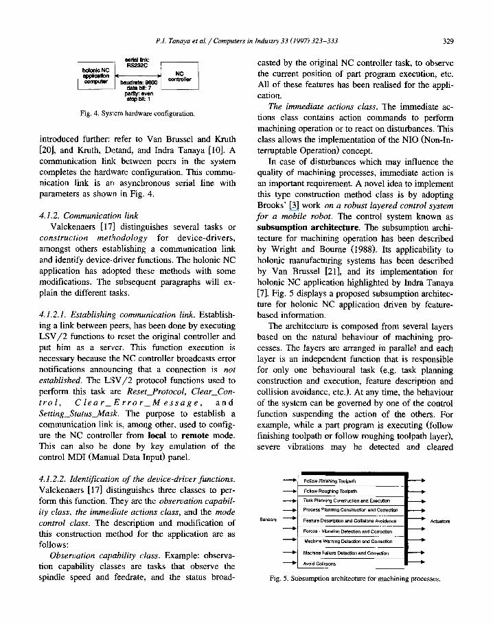
holonic manufacturing systems has been described by Van Brussel [21], and its implementation for holonic NC application highlighted by Indra Tanaya [7]. Fig. 5 displays a proposed subsumption architec- ture for holonic NC application driven by feature- based information.
The architecture is composed from several layers based on the natural behaviour of machining pro- cesses. The layers are arranged in parallel and each layer is an independent function that is responsible for only one behavioural task (e.g. task planning construction and execution, feature description and
collision avoidance, etc.). At any time, the behaviour of the system can be governed by one of the control
function suspending the action of the others. For example, while a part program is executing (follow finishing toolpath or follow roughing toolpath layer), severe vibrations may be detected and cleared
Fig. 5. Subsumption architecture for machining processes.

330 P.I. Tanaya et al. / Computers in Industry 33 (19971323-333
(force-vibration detection and correction layer), in-
terrupting the part program (follow finishing toolpath layer). If the vibration is caused by cutting-tool failure, a new tool may be required, and the part
program should be resumed at the last position of the feature being machined (task planning construction and execution, and follow finishing toolpath layer). Then, based on the valid process planning (process planning construction and correction layer), the re- lated control function should generate and execute the task to continue machining operation (task plan- ning construction and execution, follow finish tool-
path layer). The mode control function class. Examples of this
class are changing spindle speed and feedrate to compensate severe cutting force or vibration de- tected, constructing cZearance plane as an intermedi- ate position for the cutting tool to retract, starting a part program, etc. In depth study to implement this control function class will be conducted later.
As an example, changing feedrate and spindle speed can be done by sending messages to push the MD1 key panel (override). Suppose that this MD1 override might be used, the machining activity might stop because MD1 emulation command from remote platform is only valid in local mode operation in-
stead of remote one. To change from local to remote operation mode, the controller stops and some
LSV/2 functions become inaccessible. Therefore, a compromise to design this device-driver concept for holonic application should be done further.
4.2. Non-interruptable operation
A non-interruptable operation (NIO) is an atomic function, i.e. atomic to the controller, to perform machining or non-machining operation within a bounded amount of time. When the application starts a NIO, it relinquishes control of the necessary equip- ment to the NIO. Similar to the device-driver con- cept, the NIO concept is adopted and modified from work reported by Valckenaers [17] on FACCS. For the holonic NC application, NIOs are implemented as three classes: loading and unloading functions, protocol functions, and machining or primitive func- tions.
A machining NIO performs either the primitive cutting or gauging functions (Section 3.4). This type
of NIO consists of roughing, semi-finishing, and finishing NIOs. The type of operation can be divided
as single-pass and multi-pass and are constructed as one or more NIOs. For example, a machining opera-
tion for a pocket could be done by multi-pass rough- ing, and single-pass finishing. By using multi-pass roughing NIO, the system tells that during this activ- ity any interruption is ignored. Interruption will be processed between NIOs.
Some protocol functions might also be defined
as NIOs. For example, to download and to upload part programs, to start the part programs from the remote platform, etc. Anyway, not every protocol functions will be suitable for NIO. This is depending
on its function interrupt priority that is described by the group of exchange where the protocol function
belong. The groups are Normal, Direct, Status, and Exception. Exception exchange group has the highest
interrupt priority compare to other exchange groups. The functions belong to Normal exchange group are interruptable when other functions from Status group is broadcasted. Vissenberg [22] describes concisely for this exchange priority. As an example, the origi- nal NC controller sends LSV/2 Auto_Status_Re-
port (Status group) functions anytime that interrupt present transaction activities. This LSV/2 function has higher priority to be responded by the original
NC controller compare to other functions. For exam- ple, if the functions of Normal or Direct group declared as NIOs, the application will not react immediately when the Status group function message broadcasted. The application will reply the message after the NIO execution is finished.
Loading and unloading NIOs includes of cutting-tools, touch-trigger probe, workpiece, and fixtures manipulations. For the time being, the appli-
cation uses the human holon (machine operator) to perform this class. For example, to load/unload a cutting-tool into the magazine, human operator per- forms this operation by interrupting the controller from its MD1 panel.
Fig. 6 displays a sequence of NIOs to be executed and the response to disturbances during NIO opera- tion. During machining operation, disturbances may be present anytime, e.g. severe cutting-forces or vibration, that could affect the quality of the work- piece. To be able to react immediately to distur- bances, a construction of machining NIO may not be

P.I. Tanaya et al. /Computers in Industry 33 (1997) 323-333 331
Assumed normal cperation (machining tasks)
NIO sequer~ce in a list final workpiece ?.
planned
Iu”EYP’
a NIO to be inserted un-controllable
due to planned inhwrupt emergency-stop
s=500 S=lOOO dmin rimin
NIO-1 already ,’ processed severe force, vibration
(in-process Interrupt) MDI keypad emulation
List after un-control interrupt
Fig. 6. NIO sequence and interrupt respond operation.
too long. A long execution of NIOs can delay the response of disturbances that feedback to the applica- tion through sensors. The application notices the sensor feedback and waits until the current NIO execution has been finished to stop the machining processes. The application recovers from the distur- bances by taking into consideration the feedback occurred in the preceding machining NT0 in order to take decisions on the succeeding machining NIO. To
realise this behaviour, some process planning func- tions will have to be introduced in the controller. At this point, much work will be adopted from work reported by Detand [5].
4.3. Feature-based technology
4.3. I. Manufacturing feature
Requirements o-F product data exchange between holons in HMS could be supported by using feature technology. Each holon of the system has the flexi- bility to use the appropriate type of features. For example, design holon, scheduling holon, process planning holon, and machining holon uses different level of feature data abstraction whereas from generic point of view this means there are different format for exchanging information about the same entity (product), as described by Tiinshoff, Winkler, and Aurich [16]. The use of features contribute to the simplicity to perform co-operative characteristic in HMS.
Features can also be used for process planning, or
part programming. Such features are called manu- facturing features. They represent isolated pieces of
volumetric geometry, that are associated to one or more operation steps of the manufacturing process. A concise implementation of manufacturing feature has been elaborated by Detand [5] for non-linear process planning. Based on this experiences, a simi- lar concept is planned to be used for holonic NC
controller, as described by Kruth, Detand, and Indra Tanaya [lo]. This concept aims, first, to reduce the rigidity of current NC controller technology where intervention or communication to the external world is impossible when the part program is being exe- cuted. Secondly, the input source of the NC con-
troller becomes more generic compared to ready-to- execute part program expressed by G-code while
part program incompatibility between controller manufacturers is anticipated.
4.3.2. Task decomposition
Fig. 7 shows a simple workpiece with three fea- tures and Fig. 8 shows a possible task decomposition that was produced by the holonic NC controller. Based on the feature information, a part program for feature number 1 is generated off-line on a remote platform, and downloaded to the NC static RAM.
This part program block is executed remotely by using device-driver commands as described in Sec- tion 4.1. During its execution, the application waits before moving forward to the next feature type, while monitoring the part program completion. The sequence of this operation may be performed as shown in Fig. 8 until the final workpiece shape is achieved.
feature1 s&t&
$3
69
feature 4
finished wort&ce
Fig. 7. Simple workpiece consisting of the features.

332 P.I. Tanaya et al. / Computers in Industry 33 (1997) 323-333
Fig. 8. Machining sequence.
Machining operations are performed based on the feature information. A machining operation may con- tain several tasks that will be executed. And, a task consists of a list of device-driver commands that may contain several LSV/2 protocol functions. A device-driver task is described as an event on the
application module. Each event correspond to a C + + object-oriented method. The application has been programmed as an event-driven or message-based execution to be able to use the advantages of using Windows platform. A concise description of the task decomposition is described by Indra Tanaya 181.
5. Conclusions and future work
The implementation of device-driver concept has been realised by using some communication protocol functions. NIOs (Non-Interruptable Operations) en- capsulate the functionality of appropriate communi- cation protocol commands written as C + + object- oriented methods. Due to this, the NC controller may communicate and negotiate with external world in a more easy way. The task execution is event-driven or message-based. The application waits for event noti- fication, then accesses appropriate C + + method to perform the task.
Primitive functions to recognise single and multi-
ple features on the machine table have been imple- mented and tested in a prototype software module. Those functions exhibit, among other, self-configura- tion and self-repair behaviour for the holonic NC applications. The application knows the location of the workpiece reference point, the dimension of the form-features, etc. based on touch-trigger scanning results. The full implementation of the touch-trigger probe could be used to decide on the next machining sequences, whereas the application can decide, for
example, how much material should be removed for last finishing step.
By using the device-driver concept, downstream autonomy of the application becomes more generic. The original NC controller is treated in a similar way as other computer peripherals (e.g. printers, plotters, etc.). In the near future, process planning and part programming modules based on features technology will be worked out.
Acknowledgements
This manuscript presents current research results obtained through work sponsored by GOA/95/2
project (GOA = Geconcerteerde Onderzoeksactie) on Holonic Manufacturing Systems (HMS) from the Belgian Ministry of Scientific Administration
(Vlaamse Ministerie van Wetenschapsbeleid) and the programme on Interuniversity Poles of Attraction (IUAP-50) initiated by the Belgian State, Prime Min- ister’s Office, Science Policy Programming. The first author received scholarship from PT Industri Pe- sawat Terbang Nusantara (PT IPTN), Bandung, In- donesia. He would like to express his gratitude to J. Dehaes for the useful discussions while building the software under Windows platform. The scientific
responsibility is assumed by its authors.
References
111
121
Y. Altintas, W.K. Munasinghe, A hierarchical open-architec-
ture CNC system for machine tools, Ann. CIRP 43 (1)
(1994) 349-354.
J.A. Baughman, Multi-axis machining with APT, in: W.H.P.
Leslie (Ed.), Numerical Control User’s Handbook, McGraw-
Hill, London, 1970, pp. 271-298.

P.I. Tanaya et al. /Computers in Industry 33 (1997) 323-333 333
[3] R.A. Brooks, A robust layered control system for mobile
robots, IEEE J. Robotics Autom. RA-2 (1986) 14-23.
[4] J. Campbell, C Programmers Guide to Serial Communica-
tions, Howard & W. Sams Co., Carmel, Indiana.
[5] J. Detand, A computer aided process planning system gener-
ating non-linear pmcess plans, Doctorate thesis 93D4, KU
Leuven Department of Mechanical Engineering Div. of PMA,
Leuven, 1993.
[6] D.M. Dilts, N.P. :Boyd, H.H. Whorms, The evolution of
control architectures for automated manufacturing system,
Journal of Manufacturing Systems 10 (1) (1991) 79-93.
[7] P. Indra Tanaya, Holonic NC system: study and problems
situation, Int. Rep. 95R25, KU Leuven Dept. of Mechanical
Engineering Div. uf PMA, Leuven, 1995a.
[8] P. Indra Tanaya, Holonic NC System: study and develop-
ment of device-driver concept, Int. Rep. 95R26, KU Leuven
Dept. of Mechanical Engineering Div. of PMA, Leuven,
1995b.
[9] A. Koestler, The ‘Ghost in The Machine, Arkana Books,
London, 1967.
[lo] J.P. Kruth, J. Det,md, P. Indra Tanaya, A prototype NC
controller driven by feature-based part description, in: Pacific
Conference on Manufacturing, Conference Proceedings, De-
cember, Jakarta, 1994, pp. 535-544.
[ll] A.M. Luscombe, D.J. Toncich, W. Thompson, R. Dluzniak,
A new type of machine control system to replace traditional
CNC, International Journal of Advanced Manufacturing
Technology 9 (6) (1994) 369-374.
[12] G. Pritschow, Ch. Daniel, G. Junghans, W. Sperling, Open
system controllers--a challenge for the future of the machine
tool industry, Ann. CIRP 42 (1) (1993) 449-452.
[13] D. Raymakers, J. Roosen, Ontwerp en Ontwikkelen van een
Tastersysteem vocr Off-Line Compensatie van Gereed-
schapsslijtage en Positioneerfouten, Burgerlijk Ingenieur the-
sis 95EP31, Departement Werktuigkunde Afd. PMA, Leu-
ven, 1995.
[14] D. Reckziegel, ‘EXAPT l’, Numerical Control User’s Hand-
book, in: W.H.P. Leslie (Ed.), McGraw-Hill, London, 1970,
pp. 159-196.
[15] H.A. Simon, The Science of The Artificial, 2nd edn., MIT
Press, Cambridge, MA, 1990.
[16] H.K. Tijnshoff, M. Winkler, J.C. Aurich, Product modelling
for holonic manufacturing systems, in: Computer Integrated
Manufacturing and Automation Technology, Conference Pro-
ceedings, October 10-12, IEEE Computer Society Press, Los
Alamitos, CA, 1994, pp. 121-127.
[17] P. Valckenaers, Flexibility for integrated production automa-
tion, Doctorate thesis 93D1, KU Leuven Department of
Mechanical Engineering Div. of PMA, Leuven, 1993.
[18] P. Valckenaers, H. van Brussel, A theoretical model to
preserve flexibility in flexible manufacturing systems, in:
Shimon Y. Nof (Ed.), Information and Collaboration Models
of Integration, Series E: Applied Sciences, Vol. 259, NATO
AS1 Series, 1993, pp. 89-104.
[19] P. Valckenaers, H. van Brussel, F. Bonneville, L. Bongaerts,
J. Wyns, IMS Test Case 5: Holonic manufacturing systems,
in: IFAC Workshop on Intelligent Manufacturing Systems,
June, 1994 (preprint of IMS’94, Vienna, 13-15 June 1994).
[20] H. van Brussel, J.P. Kruth, Holonic Manufacturing Systems,
Project Proposal to The Belgian Ministry Scientific Adminis-
tration, KU Leuven Dept. of Mechanical Engineering Div. of
PMA, September, Leuven, 1993.
[21] H. van Brussel, Holonic manufacturing systems-the vision
matching the problem, in: 1st European Conference on
Holonic Manufacturing Systems, University of Hannover,
Hannover.
[22] C.J.M. Vissenberg, Specification Data Communication,
Philips Machine Tools Control CNC M700 900315, 1990.