Self-organized and evolvable holonic architecture for ...
199
HAL Id: tel-01137643 https://tel.archives-ouvertes.fr/tel-01137643v2 Submitted on 18 Feb 2016 HAL is a multi-disciplinary open access archive for the deposit and dissemination of sci- entific research documents, whether they are pub- lished or not. The documents may come from teaching and research institutions in France or abroad, or from public or private research centers. L’archive ouverte pluridisciplinaire HAL, est destinée au dépôt et à la diffusion de documents scientifiques de niveau recherche, publiés ou non, émanant des établissements d’enseignement et de recherche français ou étrangers, des laboratoires publics ou privés. Self-organized and evolvable holonic architecture for manufacturing control José Barbosa To cite this version: José Barbosa. Self-organized and evolvable holonic architecture for manufacturing control. Chemical and Process Engineering. Université de Valenciennes et du Hainaut-Cambresis, 2015. English. NNT: 2015VALE0008. tel-01137643v2
-
Upload
khangminh22 -
Category
Documents
-
view
1 -
download
0
Transcript of Self-organized and evolvable holonic architecture for ...

HAL Id: tel-01137643https://tel.archives-ouvertes.fr/tel-01137643v2
Submitted on 18 Feb 2016
HAL is a multi-disciplinary open accessarchive for the deposit and dissemination of sci-entific research documents, whether they are pub-lished or not. The documents may come fromteaching and research institutions in France orabroad, or from public or private research centers.
L’archive ouverte pluridisciplinaire HAL, estdestinée au dépôt et à la diffusion de documentsscientifiques de niveau recherche, publiés ou non,émanant des établissements d’enseignement et derecherche français ou étrangers, des laboratoirespublics ou privés.
Self-organized and evolvable holonic architecture formanufacturing control
José Barbosa
To cite this version:José Barbosa. Self-organized and evolvable holonic architecture for manufacturing control. Chemicaland Process Engineering. Université de Valenciennes et du Hainaut-Cambresis, 2015. English. �NNT :2015VALE0008�. �tel-01137643v2�

Thèse de doctorat Pour obtenir le grade de Docteur de l’Université de
VALENCIENNES ET DU HAINAUT CAMBRÉSIS
Spécialité Automatique et Génie Informatique
Présentée et soutenue par José BARBOSA.
Le 19/02/2015, à Valenciennes
Ecole doctorale
Sciences Pour l’Ingénieur (SPI)
Laboratoire
Laboratoire d’Automatique, de Mécanique, et d’Informatique industrielle et Humaine (LAMIH)
Proposition d’une architecture holonique auto-organisée et évolutive pour le
pilotage des systèmes de production
JURY
Président du jury
PIERREVAL, Henri, Professeur, Professeur à l’Institut Français de Mécanique Avancée,Clermont-Ferrand, France.
RapporteursMcFARLANE, Duncan, Professeur à l’Université de Cambridge, Angleterre.BOISSIER, Olivier, Professeur à l’Ecole des Mines de St-Etienne, France.
ExaminateursBARATA, José, Professeur à l’Nouvelle Université de Lisbonne (UNL), Portugal.
Directeur de thèseTRENTESAUX, Damien, Professeur à l’Université de Valenciennes et du HainautCambrésis.
Co-directeur de thèseLEITÃO, Paulo, Professeur à l’Institut Polytechnique de Bragança.
Co-encadrant de thèseADAM, Emmanuel, Maître de Conférences à l’Université de Valenciennes et du HainautCambrésis.

ii

Thesis submitted for the degree of Doctor from Université de
VALENCIENNES ET DU HAINAUT CAMBRÉSIS
Specialty in Automation and Computer Science
Submitted and Defended by José BARBOSA.
February 19th 2015, Valenciennes, FRANCE
Doctoral School
Sciences Pour l’Ingénieur (SPI)
Laboratory
Laboratoire d’Automatique, de Mécanique, et d’Informatique industrielle et Humaine (LAMIH)
Self-organized and evolvable holonic architecture for manufacturing control
DEFENSE COMMITTEE
President of the Defense CommitteePIERREVAL, Henri, Professor at Institut Français de Mécanique Avancée, Clermont-Ferrand,France.
ReviewersMcFARLANE, Duncan, Professor at University of Cambridge, England.BOISSIER, Olivier, Professor at Ecole des Mines de St-Etienne, France.
ExaminersBARATA, José, Professor at New University of Lisbon, Portugal.
Dissertation AdvisorTRENTESAUX, Damien, Professor at Université de Valenciennes et du Hainaut Cambrésis.
Dissertation Co-AdvisorLEITÃO, Paulo, Professor at Polytechnic Institute of Bragança.
Dissertation Co-supervisorADAM, Emmanuel, Professor associate at Université de Valenciennes et du HainautCambrésis.

ii
José Fernando Lopes Barbosa
Department of Electrical Engineering
Polytechnic Institute of Bragança
Quinta Santa Apolónia
5300-253 Bragança
Portugal
[w] www.ipb.pt/~jbarbosa
Laboratory Association
UVHC, TEMPO research center EA4542,
F-59313 Valenciennes, France

ii

To Inês, Mariana and Gonçalo.

iv

Acknowledgements
During the work developed in this thesis I had the pleasure of meeting and interact
with very interesting people, allowing me to grow not only scientifically but as well as a
person. In this way, I consider that this document is the appropriate place to express my
most sincere acknowledgements.
I would like to start by giving my most grateful acknowledgements to Prof. Damien
Trentesaux, Prof. Emmanuel Adam and Prof. Paulo Leitão that welcomed me and allo-
wed me to finish this work, guiding me through this long journey, encouraging me in the
difficult times and having the necessary patience whenever I was more occupied with
aside work.
My sincere thanks to all the members of the jury, Prof. Duncan McFarlane, Prof. Oli-
vier Boissier, Prof. Henri Pierreval and Prof. José Barata that had decisively contribute to
this thesis with their comments and incentive. I’m really very grateful to have had such
an internationally well recognized jury.
My most sincere gratitude to the University of Valenciennes and Hainaut-Cambresis
that has accepted me for the elaboration of this work. A special thank to my research
group in France that always received me with arms wide open and helped me whenever
necessary.
I would like to express my gratitude to the Polytechnic Institute of Bragança, more
particularly to the Escola Superior de Tecnologia e de Gestão, that had received me and,
always when I needed, has given support.
An additional gratitude to the Polytechnic Institute of Bragança for the granted re-
search scholarship under the supervision of Prof. Paulo Leitão without which this work
was not possible.
I also wish to express my gratitude to all the colleagues of the Polytechnic Institute
of Bragança, specially to those that in a daily basis had to bear with my good and bad
moments. A special thank to the lab colleagues Adriano Ferreira, Arnaldo Pereira, Filipe
Fernandes and Nelson Rodrigues and more recently to Jonas Queiroz and José Dias. Also
a special thank to Ana Isabel Pereira, José Lima and José Augusto.
Last, but not least, a special thank to my family that never gave up on me and always
v

vi
helped me on the good and bad moments. Thank you for simply being there. Particularly
to my wife Inês, that during the time that I needed to finish this endeavour was able to
understand and had the necessary patience. Only with her support I was able to drive
this until the end. Finally, to the two most important persons in my life, Mariana and
Gonçalo, to whom I promise that from now on I will dedicate more time to them.

Abstract
The manufacturing world is being deeply challenged with a set of ever demanding
constraints where from one side, the costumers are requiring products to be more cus-
tomizable, with higher quality at lower prices, and on other side, companies have to deal
on a daily basis with internal disturbances that range from machine breakdown to worker
absence and from demand fluctuation to frequent production changes. This dissertation
proposes a manufacturing control architecture, following the holonic principles devel-
oped in the ADAptive holonic COntrol aRchitecture (ADACOR) and extending it taking
inspiration in evolutionary theories and making use of self- organization mechanisms.
The use of evolutionary theories enrich the proposed control architecture by allowing
evolution in two distinct ways, responding accordingly to the type and degree of the
disturbance that appears. The first component, named behavioural self- organization, al-
lows each system’s entity to dynamically adapt its internal behaviour, addressing small
disturbances. The second component, named structural self-organization, addresses big-
ger disturbances by allowing the system entities to re-arrange their rela- tionships, and
consequently changing the system in a structural manner. The proposed self-organized
holonic manufacturing control architecture was validated at a AIP-PRIMECA flexible
manufacturing cell. The achieved experimental results have also shown an improvement
of the key performance indicators over the hierarchical and heterarchical control archi-
tecture.
Keywords: holonic manufacturing control architecture, self-organization, multi-agent
systems
vii

viii

Resumé
Le monde des entreprises est profondément soumis à un ensemble de contraintes
toujours plus exigeantes provenant d’une part des clients, exigeant des produits plus per-
sonnalisables, de qualité supérieure et à faible coût, et d’autre part des aléas internes aux
entreprises, comprenant les pannes machines, les défaillances humaines, la fluctuation de
la demande, les fréquentes variations de production. Cette thèse propose une architecture
de contrôle de systèmes de production, basée sur les principes holoniques développées
dans l’architecture ADACOR (ADAptive holonic COntrol aRchitecture), et l’étendant en
s’inspirant des théories de l’évolution et en utilisant des mécanismes d’auto-organisation.
L’utilisation des théories de l’évolution enrichit l’architecture de contrôle en permettant
l’évolution de deux manières distinctes, en réponse au type et au degré de la perturba-
tion apparue. Le premier mode d’adaptation, appelé auto-organisation comportemen-
tale, permet à chaque entité qui compose le système d’adapter dynamiquement leur
comportement interne, gérant de cette façon de petites perturbations. Le second mode,
nommé auto-organisation structurelle, traite de plus grandes perturbations, en permet-
tant aux entités du système de ré-organiser leurs relations, et par conséquent modifier
structurellement le système. L’architecture holonique auto-organisée de contrôle de sys-
tèmes de production proposée dans cette thèse a été validée sur une cellule de production
flexible AIP-PRIMECA. Les résultats ont montré une amélioration des indicateurs clés de
performance par rapport aux architectures de contrôle hiérarchiques et hétérarchiques.
Mots-clés: Architecture holonique, contrôle de systèmes de production, auto-
organisation, systèmes multi-agents
ix

x

Resumo
O mundo da manufactura é constantemente desafiado com um conjunto cada vez
mais exigente de perturbações, onde de um lado, os clientes exigem produtos mais per-
sonalizados, com maior qualidade e a preços mais baixos, e no outro lado, as empresas
têm de lidar diariamente com perturbações internas que variam desde a avaria de má-
quinas à ausência da trabalhadores e da flutuação da procura às mudanças frequentes na
produção.
Tradicionalmente, as empresas de manufactura operavam com unidades processa-
mento centralizadas e monolíticas que apresentam altos níveis de optimização sob rígidas
condições de trabalho, mas não são capazes de responder apropriadamente, com rapidez
e agilidade, quando imposta pelas perturbações e exigências acima mencionadas.
Mais recentemente, uma mudança de paradigma nos sistemas de controlo de fabrico
tem sido notada, promovendo o aumento da capacidade de resposta e agilidade, favo-
recendo a descentralização e distribuição da capacidade de processamento por várias
entidades pequenas e autónomas, sendo capazes de tomar decisões localmente, mas com
a necessidade de cooperar para alcançar os objetivos globais do sistema. Apesar dos
benefícios introduzidos por esta descentralização, estes sistemas nunca foram capazes
de alcançar os níveis de desempenho alcançados pelas abordagens clássicas em condi-
ções normais de funcionamento. Além disso, técnicas e mecanismos de auto-organização
nunca foram verdadeiramente embebidos e explorados nestas abordagens.
O presente trabalho propõe uma arquitetura de controlo de fabrico, seguindo os prin-
cípios holónicos apresentadas e desenvolvidas na arquitetura conhecida por ADAptive
holonic COntrol aRchitecture (ADACOR), estendendo-a com a inspiração em teorias evo-
lucionárias e fazendo uso de mecanismos de auto-organização. O uso de teorias evolucio-
nárias visam enriquecer a arquitetura proposta, permitindo a evolução de duas maneiras
distintas, respondendo de acordo com o tipo e grau de perturbação. A primeira com-
ponente, chamada de auto-organização comportamental, permite a que cada entidade
xi

xii
se adapte dinamicamente o seu comportamento interno, abordando pequenas perturba-
ções. A segunda componente, chamada auto-organização estrutural, trata perturbações
maiores, permitindo que as entidades do sistema reorganizem as suas relações, e, conse-
quentemente, alterar o sistema de uma forma estrutural.
Atuando no comportamento interno do holon, ou seja, no micro nível, cada holon é
capaz de lidar localmente com pequenas perturbações ou para melhorar individualmente
o seu desempenho interno, sendo considerado como uma evolução suave ou adaptação.
Atuando ao nível das relações, ou seja, a um macro nível, o sistema é capaz de responder
drasticamente a perturbações maiores, impondo uma reorganização estrutural, sendo
considerado uma evolução drástica.
O arquitetura holônica de controlo de produção auto-organizada proposta foi vali-
dado na célula de manufatura flexível AIP-PRIMECA localizada na Université de Va-
lenciennes et du Hainaut-Cambrésis. Os resultados experimentais obtidos mostraram
também uma melhoria dos indicadores-chave de desempenho através de diversas arqui-
teturas de controlo, nomeadamente a hierárquica, heterárquica e o ADACOR.
Palavras-chave: arquitetura holônica de controle de fabrico, auto-organização, sistemas
multiagentes

Extended Abstract
The manufacturing world is being deeply challenged with a set of ever demanding
constraints where from one side, the costumers are requiring products to be more cus-
tomizable, with higher quality at lower prices, and on other side, companies have to
deal on a daily basis with internal disturbances that range from machine breakdown to
worker absence and from demand fluctuation to frequent production changes.
Traditionally, manufacturing companies rely on centralized and monolithic process-
ing units which were capable to introduce high levels of optimization under rigid work-
ing conditions, but are not able to respond the responsiveness and agility imposed by the
aforementioned disturbances and demands.
More recently, a shift in the manufacturing control systems paradigm has been no-
ticed, promoting to increase the responsiveness and agility, through the decentralization
and distribution of the processing capacity throughout several small and autonomous
entities, which are able to take decisions locally, but needing to cooperate to achieve the
overall system goals. Despite of the benefits introduced by this decentralization, these
newer systems were never able to reach the performance levels achieved by the classi-
cal approaches during normal functioning conditions, and also never implemented truly
self-organization concepts to support condition changes.
This dissertation proposes a manufacturing control architecture, following the
holonic principles developed in the ADAptive holonic COntrol aRchitecture (ADACOR)
and extending it taking inspiration in evolutionary theories and making use of self-
organization mechanisms. The use of evolutionary theories enrich the proposed archi-
tecture by allowing evolution in two distinct ways, responding accordingly to the type
and degree of the disturbance that appears. The first component, named behavioural self-
organization, allows each system’s entity to dynamically adapt its internal behaviour, ad-
dressing small disturbances. The second component, named structural self-organization,
addresses bigger disturbances by allowing the system entities to re-arrange their rela-
tionships, and consequently changing the system in a structural manner.
xiii
xiv
Acting at the holon internal behaviour, i.e. at the micro level, each holon is able to
handle locally small disturbances or to improve individually its internal performance,
being considered as a smooth evolution or adaptation. Acting at the relations level, i.e.
at a macro level, the system is able to drastically respond to more drastic disturbances by
imposing a structural re-organization, being considered a drastic evolution.
The proposed self-organized holonic manufacturing control architecture was vali-
dated at the AIP-PRIMECA flexible manufacturing cell located at the Université de Valen-
ciennes et du Hainaut-Cambrésis. The achieved experimental results have also shown an
improvement of the key performance indicators over the hierarchical, heterarchical and
the ADACOR control architecture.
Keywords: holonic manufacturing control architecture, self-organization, multi-agent
systems

Resumé Étendu
Le monde des entreprises est profondément soumis à un ensemble de contraintes
toujours plus exigeantes provenant d’une part des clients, exigeant des produits plus
personnalisables, de qualité supérieure et à faible coût, et d’autre part des aléas internes
aux entreprises, comprenant les pannes machines, les défaillances humaines, la fluctua-
tion de la demande, les fréquentes variations de production.
Traditionnellement, les industries manufacturières reposent sur des unités de pro-
ductions centralisées et monolithiques qui sont capables d’obtenir des niveaux élevés de
l’optimisation, sous réserve de conditions de travail rigides, mais ne sont pas en mesure
de répondre de la réactivité et l’agilité imposée par les perturbations et les exigences ac-
tuelles.
Plus récemment, afin d’accroître la réactivité et l’agilité, le contrôle des systèmes de
production ont connu un changement de paradigme, permettant la décentralisation et
la distribution de la capacité de traitement au sein de multiples entités autonomes ca-
pable de prendre des décisions au niveau local, mais capable également de coopérer afin
d’atteindre les objectifs globaux du système.
Malgré les avantages introduits par cette décentralisation, ces nouveaux systèmes
n’étaient en fait jamais réellement en mesure d’atteindre les niveaux de performance ob-
tenus par les approches classiques, sous conditions de fonctionnement normales, et de
plus, les concepts d’auto-organisation n’ont jamais vraiment été mis en œuvre pour faire
face aux changements de condition.
Cette thèse propose une architecture de contrôle de systèmes de production, basée
sur les principes holoniques développé és dans l’architecture ADACOR (ADAptive ho-
lonic COntrol aRchitecture), et l’étendant en s’inspirant des théories de l’évolution et en
utilisant des mécanismes d’auto-organisation.
xv

xvi
L’utilisation des théories de l’évolution enrichit l’architecture ADACOR en permet-
tant l’évolution de deux manières distinctes, en réponse au type et au degré de la per-
turbation apparue. Le premier mode d’adaptation, appelé auto-organisation comporte-
mentale, permet à chaque entité qui compose le système d’adapter dynamiquement leur
comportement interne, gérant de cette façon de petites perturbations. Le second mode,
nommé auto-organisation structurelle, traite de plus grandes perturbations, en permet-
tant aux entités du système de ré-organiser leurs relations, et par conséquent modifier
structurellement le système.
Agir sur le comportement interne du holon, c’est-à-dire au niveau micro, permet à
chaque holon de gérer localement de petites perturbations ou d’améliorer individuelle-
ment la performance interne, et est considéré comme une légère évolution ou adaptation.
Agir au niveau des relations, c’est-à-dire au un niveau macro, permet au système de ré-
pondre à des perturbations plus profondes en imposant une réorganisation structurelle,
et est considéré comme une forte évolution.
L’architecture holonique auto-organisée de contrôle de systèmes de production pro-
posée dans cette thèse a été validée sur la cellule de production flexible AIP-PRIMECA
située à l’Université de Valenciennes et du Hainaut-Cambrésis. Les résultats ont mon-
tré une amélioration des indicateurs clés de performance par rapport aux architectures
de contrôle hiérarchiques, hétérarchiques et également par rapport à l’architecture ADA-
COR initiale.
Mots-clés: Architecture holonique, contrôle de systèmes de production, auto-
organisation, systèmes multi-agents

Contents
Abstract vii
Resumé ix
Resumo xi
Extended Abstract xiii
Resumé Étendu xv
List of Figures xxi
List of Tables xxv
List of Acronyms xxvii
List of Symbols xxxi
1 Introduction 1
1.1 Research Problem . . . . . . . . . . . . . . . . . . . . . . . . . . . . . . . . . 1
1.2 Objectives and Contributions . . . . . . . . . . . . . . . . . . . . . . . . . . 4
1.3 Dissertation Organization . . . . . . . . . . . . . . . . . . . . . . . . . . . . 5
2 Manufacturing Control Paradigms 9
2.1 Production and Manufacturing Control . . . . . . . . . . . . . . . . . . . . 9
2.2 Production and Manufacturing Control Approaches . . . . . . . . . . . . . 12
2.2.1 Multi-Agent System Applications to Manufacturing . . . . . . . . . 14
2.2.2 Holonic Manufacturing System Applications . . . . . . . . . . . . . 18
2.2.3 Other Distributed Manufacturing Control Approaches . . . . . . . 19
2.3 An Adaptive Holonic Control Architecture: ADACOR . . . . . . . . . . . 20
2.4 Limitations and Challenges of the Existing Approaches . . . . . . . . . . . 23
xvii
xviii CONTENTS
2.5 Summary . . . . . . . . . . . . . . . . . . . . . . . . . . . . . . . . . . . . . . 23
3 Biological Inspiration to Solve Complex Problems 25
3.1 Swarm Intelligence . . . . . . . . . . . . . . . . . . . . . . . . . . . . . . . . 25
3.2 Evolution and Self-Organization . . . . . . . . . . . . . . . . . . . . . . . . 28
3.3 Survey of Bio-Inspired Applications for Solving Complex Problems . . . . 29
3.3.1 Applied to Engineering Problems . . . . . . . . . . . . . . . . . . . 29
3.3.2 Applied to Manufacturing Problems . . . . . . . . . . . . . . . . . . 32
3.4 Enriching MAS Based Application with Bio-inspiration . . . . . . . . . . . 32
3.5 How to Achieve an Evolvable System . . . . . . . . . . . . . . . . . . . . . 36
3.5.1 Being Prepared for the Unexpected . . . . . . . . . . . . . . . . . . 37
3.5.2 Hierarchy: a way to Achieve Stabilization and Optimization . . . . 38
3.5.3 Self-Organization and Emergence as the Main Driver . . . . . . . . 38
3.5.4 Controlled Randomness . . . . . . . . . . . . . . . . . . . . . . . . . 39
3.5.5 Be Aware with Chaos . . . . . . . . . . . . . . . . . . . . . . . . . . 40
3.6 Summary . . . . . . . . . . . . . . . . . . . . . . . . . . . . . . . . . . . . . . 41
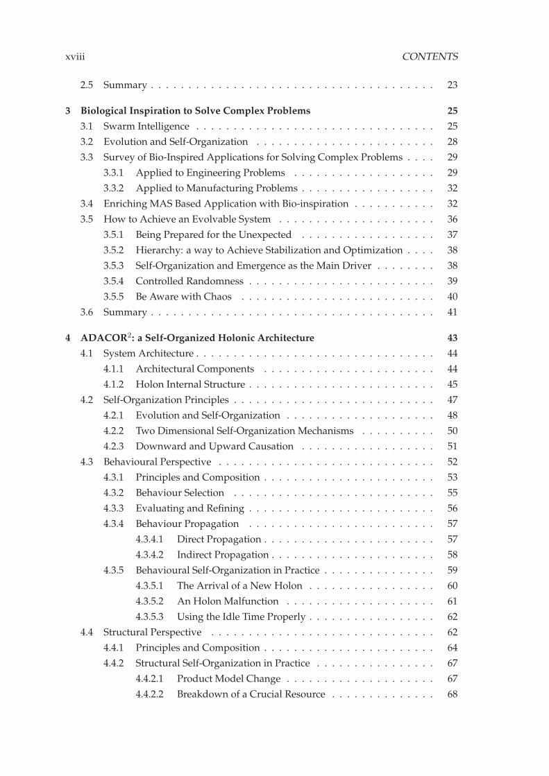
4 ADACOR2: a Self-Organized Holonic Architecture 43
4.1 System Architecture . . . . . . . . . . . . . . . . . . . . . . . . . . . . . . . . 44
4.1.1 Architectural Components . . . . . . . . . . . . . . . . . . . . . . . 44
4.1.2 Holon Internal Structure . . . . . . . . . . . . . . . . . . . . . . . . . 45
4.2 Self-Organization Principles . . . . . . . . . . . . . . . . . . . . . . . . . . . 47
4.2.1 Evolution and Self-Organization . . . . . . . . . . . . . . . . . . . . 48
4.2.2 Two Dimensional Self-Organization Mechanisms . . . . . . . . . . 50
4.2.3 Downward and Upward Causation . . . . . . . . . . . . . . . . . . 51
4.3 Behavioural Perspective . . . . . . . . . . . . . . . . . . . . . . . . . . . . . 52
4.3.1 Principles and Composition . . . . . . . . . . . . . . . . . . . . . . . 53
4.3.2 Behaviour Selection . . . . . . . . . . . . . . . . . . . . . . . . . . . 55
4.3.3 Evaluating and Refining . . . . . . . . . . . . . . . . . . . . . . . . . 56
4.3.4 Behaviour Propagation . . . . . . . . . . . . . . . . . . . . . . . . . 57
4.3.4.1 Direct Propagation . . . . . . . . . . . . . . . . . . . . . . . 57
4.3.4.2 Indirect Propagation . . . . . . . . . . . . . . . . . . . . . . 58
4.3.5 Behavioural Self-Organization in Practice . . . . . . . . . . . . . . . 59
4.3.5.1 The Arrival of a New Holon . . . . . . . . . . . . . . . . . 60
4.3.5.2 An Holon Malfunction . . . . . . . . . . . . . . . . . . . . 61
4.3.5.3 Using the Idle Time Properly . . . . . . . . . . . . . . . . . 62
4.4 Structural Perspective . . . . . . . . . . . . . . . . . . . . . . . . . . . . . . 62
4.4.1 Principles and Composition . . . . . . . . . . . . . . . . . . . . . . . 64
4.4.2 Structural Self-Organization in Practice . . . . . . . . . . . . . . . . 67
4.4.2.1 Product Model Change . . . . . . . . . . . . . . . . . . . . 67
4.4.2.2 Breakdown of a Crucial Resource . . . . . . . . . . . . . . 68

CONTENTS xix
4.4.2.3 Holarchy Division Based on Specialization . . . . . . . . . 69
4.5 Controlling Nervousness . . . . . . . . . . . . . . . . . . . . . . . . . . . . . 70
4.6 Summary . . . . . . . . . . . . . . . . . . . . . . . . . . . . . . . . . . . . . . 73
5 Self-Organization Regulating Mechanisms in ADACOR2 75
5.1 Mechanisms for the Behavioural Self-Organization . . . . . . . . . . . . . . 75
5.1.1 Market-Based Approach . . . . . . . . . . . . . . . . . . . . . . . . . 77
5.1.2 Potential Fields . . . . . . . . . . . . . . . . . . . . . . . . . . . . . . 78
5.1.2.1 Attractive Potential Field Calculation . . . . . . . . . . . . 80
5.1.2.2 Attenuation of the Attractive Potential Field . . . . . . . . 81
5.1.2.3 Decision and Selection . . . . . . . . . . . . . . . . . . . . 82
5.1.3 Stigmergy . . . . . . . . . . . . . . . . . . . . . . . . . . . . . . . . . 82
5.1.3.1 Deposition and Reinforcement . . . . . . . . . . . . . . . . 83
5.1.3.2 Evaporation Process . . . . . . . . . . . . . . . . . . . . . . 85
5.1.3.3 Next Destination Selection . . . . . . . . . . . . . . . . . . 85
5.2 Mechanisms for Structural Self-Organization . . . . . . . . . . . . . . . . . 86
5.2.1 Structural Re-Arrangement by Means of Birds Behaviour . . . . . . 87
5.2.2 Structural Re-Arrangement by Means of Ants Food Foraging Be-
haviour . . . . . . . . . . . . . . . . . . . . . . . . . . . . . . . . . . . 89
5.3 Learning and Reasoning . . . . . . . . . . . . . . . . . . . . . . . . . . . . . 90
5.4 Nervousness Stabilizer: Controlling Chaos in Dynamic Self-Organized
Systems . . . . . . . . . . . . . . . . . . . . . . . . . . . . . . . . . . . . . . . 92
5.5 Summary . . . . . . . . . . . . . . . . . . . . . . . . . . . . . . . . . . . . . . 96
6 Practical Implementation and Validation 97
6.1 Description of the Case Study and System Implementation . . . . . . . . . 97
6.1.1 The Real AIP-PRIMECA FMS . . . . . . . . . . . . . . . . . . . . . . 98
6.1.2 A More Flexible AIP-PRIMECA FMS . . . . . . . . . . . . . . . . . 101
6.2 Manufacturing Control Assessment Metrics . . . . . . . . . . . . . . . . . . 102
6.3 Mapping ADACOR2 Holons to the Case Study . . . . . . . . . . . . . . . . 103
6.4 Assessment of ADACOR2 . . . . . . . . . . . . . . . . . . . . . . . . . . . . 104
6.4.1 Behavioural Self-Organization Using the AIP-PRIMECA . . . . . . 105
6.4.2 Structural Self-Organization Using the Futuristic AIP-PRIMECA . 110
6.5 Summary . . . . . . . . . . . . . . . . . . . . . . . . . . . . . . . . . . . . . . 113
7 Conclusions and Future Work 115
7.1 Conclusions . . . . . . . . . . . . . . . . . . . . . . . . . . . . . . . . . . . . 115
7.2 Work Validation . . . . . . . . . . . . . . . . . . . . . . . . . . . . . . . . . . 116
7.3 Future Work . . . . . . . . . . . . . . . . . . . . . . . . . . . . . . . . . . . . 118
A Making Simulations 147

xx CONTENTS
B Potential Fields Behaviour 155
C Operation Holons Structural Self-Organization 159
D Supervisor Holon Scheduling Algorithm 161

List of Figures
1.1 Performance Behaviour of Different Classical Control Structures . . . . . . 3
1.2 Organization Structure of the Dissertation . . . . . . . . . . . . . . . . . . . 5
2.1 The ANSI/ISA 95 Standard . . . . . . . . . . . . . . . . . . . . . . . . . . . 10
2.2 Distribution of Decisional Capabilities from Centralised Control Systems
to Non-Centralised Control Systems (Trentesaux, 2009) . . . . . . . . . . . 11
2.3 Multi-Agent System Example . . . . . . . . . . . . . . . . . . . . . . . . . . 13
2.4 Holonic Manufacturing System Example . . . . . . . . . . . . . . . . . . . 14
2.5 ADACOR Holon Classes . . . . . . . . . . . . . . . . . . . . . . . . . . . . . 21
2.6 Adaptation Mechanism in ADACOR Supporting a Hybrid Control Archi-
tecture . . . . . . . . . . . . . . . . . . . . . . . . . . . . . . . . . . . . . . . 22
3.1 Indirect Communication in Insect Swarms: a) the Deposition and Sensing
of Pheromones by Ants [adapted from (Parunak et al., 2003)]; b) the Wag-
gle Dance Used by Bees . . . . . . . . . . . . . . . . . . . . . . . . . . . . . 26
3.2 Requirements for a Truly Evolvable System . . . . . . . . . . . . . . . . . . 37
4.1 ADACOR2: an Extension of ADACOR . . . . . . . . . . . . . . . . . . . . . 44
4.2 Mapping ADACOR2 Holons Into Real System . . . . . . . . . . . . . . . . 45
4.3 Holon Internal Structure . . . . . . . . . . . . . . . . . . . . . . . . . . . . . 46
4.4 Darwin’s and Punctuated Evolution Theories . . . . . . . . . . . . . . . . . 49
4.5 Evolution by Means of the Self-Organization Mechanism . . . . . . . . . . 50
4.6 Emergence in Action . . . . . . . . . . . . . . . . . . . . . . . . . . . . . . . 51
4.7 Coleman’s Boat View in ADACOR2 . . . . . . . . . . . . . . . . . . . . . . 52
4.8 Behavioural Self-Organization . . . . . . . . . . . . . . . . . . . . . . . . . . 53
4.9 Composition of a Generic Behaviour . . . . . . . . . . . . . . . . . . . . . . 54
4.10 Behavioural Perspective Block Diagram . . . . . . . . . . . . . . . . . . . . 55
4.11 Evaluating and Refining the Holon Behaviour . . . . . . . . . . . . . . . . 56
4.12 Indirect Behaviour Propagation . . . . . . . . . . . . . . . . . . . . . . . . . 59
xxi

xxii LIST OF FIGURES
4.13 Behavioural Self-Organization in Practice: Detection of a New Holon . . . 60
4.14 Evolution by Means the Behavioural Self-Organization: Detection of a
New Holon . . . . . . . . . . . . . . . . . . . . . . . . . . . . . . . . . . . . . 61
4.15 Behavioural Self-Organization in Practice: Holon Malfunction . . . . . . . 61
4.16 Structural Self-Organization by Group Decomposition . . . . . . . . . . . . 64
4.17 Composition of a Structure Procedure . . . . . . . . . . . . . . . . . . . . . 65
4.18 Bottom-Up and Top-Down Approaches for the Structural Self-Organization 66
4.19 Huge Batch Order Arrival and New Structure Propagation . . . . . . . . . 68
4.20 Structural Self-Organization by OH Change . . . . . . . . . . . . . . . . . . 68
4.21 Structural Self-Organization by Resource Sharing . . . . . . . . . . . . . . 69
4.22 Detection of a Crucial Operation as Trigger to Structural Self-Organization 69
4.23 Structural Self-Organization by Clustering . . . . . . . . . . . . . . . . . . 70
4.24 Stabilization Mechanism Embedded in ADACOR2 Holons . . . . . . . . . 71
4.25 Nervousness Controller System Dynamics . . . . . . . . . . . . . . . . . . . 72
5.1 Contract-Net Protocol Approach in ADACOR2 . . . . . . . . . . . . . . . . 78
5.2 Potential Fields Concept . . . . . . . . . . . . . . . . . . . . . . . . . . . . . 79
5.3 Attenuation Curves Profiles . . . . . . . . . . . . . . . . . . . . . . . . . . . 81
5.4 Stigmergic Behaviour Concept . . . . . . . . . . . . . . . . . . . . . . . . . 83
5.5 Different Solutions Found During the Structural Self-Organization . . . . 89
5.6 Ants Food Foraging Structural Self-Organization . . . . . . . . . . . . . . . 90
5.7 Nervousness control mechanism based on PID controllers . . . . . . . . . 93
6.1 View of the AIP-PRIMECA Cell . . . . . . . . . . . . . . . . . . . . . . . . . 98
6.2 Layout of the AIP-PRIMECA Cell . . . . . . . . . . . . . . . . . . . . . . . . 99
6.3 AIP-PRIMECA Shuttle and Switching Gate Detail . . . . . . . . . . . . . . 99
6.4 Product Catalogue . . . . . . . . . . . . . . . . . . . . . . . . . . . . . . . . 100
6.5 A Futuristic AIP-PRIMECA Cell . . . . . . . . . . . . . . . . . . . . . . . . 101
6.6 Conveyor System Holon GUI . . . . . . . . . . . . . . . . . . . . . . . . . . 104
6.7 Cmax for the Normal Scenarios . . . . . . . . . . . . . . . . . . . . . . . . . 106
6.8 Cmax for the Disturbances Scenario . . . . . . . . . . . . . . . . . . . . . . 107
6.9 Analysis of Impact with the Occurrence of Disturbances . . . . . . . . . . . 107
6.10 Throughput for Normal Scenarios . . . . . . . . . . . . . . . . . . . . . . . 108
6.11 Throughput for the Disturbance Scenarios . . . . . . . . . . . . . . . . . . . 109
6.12 Predictability of the Manufacturing Control Approaches . . . . . . . . . . 109
6.13 Structural Self-Organization in Practice . . . . . . . . . . . . . . . . . . . . 111
6.14 Cmax for the Structural Self-Organization . . . . . . . . . . . . . . . . . . . 111
6.15 Throughput for the Structural Self-Organization . . . . . . . . . . . . . . . 112
6.16 Analysis of the Impact of the Control Approaches . . . . . . . . . . . . . . 112
6.17 Predictability of the Manufacturing Control Approaches . . . . . . . . . . 113
7.1 Performance Behaviour of the Evaluated Control Structures . . . . . . . . 117

LIST OF FIGURES xxiii
A.1 Product Catalogue . . . . . . . . . . . . . . . . . . . . . . . . . . . . . . . . 148
B.1 AUML PF Propagation . . . . . . . . . . . . . . . . . . . . . . . . . . . . . . 155
B.2 Shop-Floor Representation Graph . . . . . . . . . . . . . . . . . . . . . . . . 156
B.3 AUML Diagram of TH Querying for PF Values . . . . . . . . . . . . . . . . 157
C.1 AUML Diagram Used in the Structural Self-Organization . . . . . . . . . . 160
D.1 Calculation Time Plus the Output Results . . . . . . . . . . . . . . . . . . . 162

xxiv LIST OF FIGURES

List of Tables
3.1 Bio-Inspired Applications to Solve Engineering Problems . . . . . . . . . . 31
3.2 Bio-Inspired Applications to Solve Manufacturing Problems . . . . . . . . 33
5.1 Blackboard Table Example . . . . . . . . . . . . . . . . . . . . . . . . . . . . 84
6.1 Transportation Times Between Nodes . . . . . . . . . . . . . . . . . . . . . 99
6.2 Process Plans for the Catalogue of Products . . . . . . . . . . . . . . . . . . 100
6.3 Machine Skills and Processing Times . . . . . . . . . . . . . . . . . . . . . . 100
6.4 Behavioural Scenarios Description . . . . . . . . . . . . . . . . . . . . . . . 105
6.5 Structural Scenarios Description . . . . . . . . . . . . . . . . . . . . . . . . 110
xxv

xxvi LIST OF TABLES

List of Acronyms
AARIA Autonomous Agents at Rock Island Arsenal.
ABAS Actor-Based Assembly Systems.
ABC Artificial Bee Colony.
ABM Agent-Based Modelling.
ACIN Automation and Control Institute.
ACO Ant Colony Optimization.
ADACOR ADAptive holonic COntrol aRchitecture.
AGV Automated Guided Vehicles.
AIP Atelier Inter-établissement de Productique.
ARUM Adaptive Production Management.
AUML Agent Unified Modeling Language.
BMS Bionic Manufacturing Systems.
CFP Call For Proposals.
CIM Computer-Integrated Manufacturing.
CIMOSA Computer Integrated Manufacturing Open System Architecture.
CNC Computer Numerical Control.
CNP Contract-Net Protocol.
CoBASA Coalition Based Approach for Shopfloor Agility.
CPS Cyber-Physical Systems.
CSH Conveyor System Holon.
DB Data Base.
DCS Distributed Control System.
xxvii

xxviii List of Acronyms
DIAL Distributed Information and Automation Laboratory.
DML Dedicated Manufacturing Lines.
EAS Evolvable Assembly Systems.
EPS Evolvable Production Systems.
ERP Enterprise Resource Planning.
FIPA Foundation for Intelligent Physical Agents.
FMS Flexible Manufacturing System.
GA Genetic Algorithm.
GRACE inteGration of pRocess and quAlity Control using multi-agEnt technology.
GUI Graphical User Interface.
HCBA Holonic Component Based Architecture.
HMS Holonic Manufacturing System.
HPC High Performance Computing.
IDEAS Instantly Deployable Evolvable Assembly Systems.
iESB inteligent Enterprise Service Bus.
IMC-AESOP ArchitecturE for Service-Oriented Process - Monitoring and Control.
JADE Java Agent DEvelopment Framework.
JESS Java Expert System Shell.
KB Knowledge Base.
KPI Key Performance Indicator.
MAS Multi-Agent System.
MAST Manufacturing Agent Simulation Tool.
MES Manufacturing Execution System.
OH Operational Holon.
OPC-UA OLE for process control - Unified Architecture.
ORCA dynamic Architecture for an Optimized and Reactive Control.
PABADIS Plant Automation Based on DIStributed systems.
PF Potential Fields.
PH Product Holon.

List of Acronyms xxix
PID Proportional, Integral and Derivative.
PLC Programmable Logical Controller.
PRIME Plug and PRoduce Intelligent Multi Agent Environment.
PRIMECA Pôle de Ressources Informatique pour la Mécanique.
PROSA Product-Resource-Order-Staff Architecture.
PSO Particle Swarm Optimization.
RFID Radio Frequency IDentifier.
RMS Reconfigurable Manufacturing System.
SCADA Supervisory Control And Data Acquisition.
SD System Dynamics.
SH Supervisor Holon.
SoA Service Oriented Architecture.
SOCRADES Service-Oriented Cross-layer Infrastructure for Distributed smart Embed-
ded devices.
TH Task Holon.
UAV Uninhabited Aerial Vehicles.
VR Virtual Resource.
WIP Work In Progress.
XML EXtensible Markup Language.
YAMS Yet Another Manufacturing System.

xxx List of Acronyms

List of Symbols
α Weight desirability of follow the local pheromone information.
β Weight desirability of follow the global pheromone information.
Bh Set of behavioural mechanisms.
δ Nervousness time window.
e Pheromone evaporation value.
ǫ Number of behavioural or structural changes.
γ Learning update rate.
Hσh Holon internal nervousness level.
Kd Nervousness controller derivative parameter.
Ki Nervousness controller integral parameter.
Kp Nervousness controller proportional parameter.
OHPFoh Set of potential fields of a given Operational Holon.
P ti Pheromone deposition value.
ψ Potential field back-propagation stop threshold.
Rh Set of structural mechanisms.
st Holarchy structural performance indicator.
τ Re-establishment time (from a disturbance).
tm AGVs moving time in structural self-organization.
tp Resource processing time.
xxxi

xxxii List of Symbols
tt Transportation time between resources.
ζ Threshold value for an increase of performance of the holons’ internal behaviour to
consider a behavioural change.

1Introduction
Our greatest weakness lies in giving up. The most certain way to succeed is always to try
just one more time.
Thomas A. Edison
One of the main pillars of the world’s economy is the manufacturing sector that, par-
ticularly in the recent years, has suffer a revolution from the client side, being pushed by
an ever increasing demand for higher products customization, quality standards and by
the decrease of the product life-cycle, passing by significant fluctuations in market de-
mands, just to name a few (ElMaraghy et al., 2012). On an internal side, and in order to
face these constraints, manufacturing has seen an unprecedented process of automation
re-configuration, leading to a possible production increase and higher product quality
but also to, in some part, leaving the shop-floor vulnerable to more disturbances, such as
machine failures.
1.1 Research Problem
Traditionally, manufacturing control systems use hierarchical control structures
which concentrate the processing power of the shop-floor control under one central node.
This increases the system performance and optimization but sacrifices other key features,
such as the responsiveness to handle disturbances and scalability possibilities. These
1

1.1. Research Problem
monolithic, rigid control structures are insufficient to meet the current requirements im-
posed by manufacturing environments which demand flexibility, robustness, reconfig-
urability and responsiveness, which are pointed out as research topics by the National
Research Council for the year of 2020 (Council, 1998). New manufacturing paradigms
have thus emerged with the common denominator of the decentralization and distribu-
tion of processing power over several entities providing a better capability to adapt and
respond to condition changes but with a decrease in the system performance regarding
the optimization process. This decentralization is also aligned with recent trends and ini-
tiatives, such as the Internet of Things, CPS (Cyber-Physical Systems) and Industrie 4.0
program.
Several examples of paradigms promoting this decentralization can be found in the
literature, being the most known the MAS (Multi-Agent System) (Ferber, 1999), BMS
(Bionic Manufacturing Systems), HMS (Holonic Manufacturing System) (Deen, 2003),
and more recently, EPS (Evolvable Production Systems) (Onori et al., 2006).
A MAS (Ferber, 1999; Wooldridge, 2002) is both a paradigm and technology that advo-
cates the design of systems based on societies of decentralized, distributed, autonomous
and intelligent entities, called agents. In such systems, each agent has a partial view of
the surrounding world and must therefore cooperate with others to achieve the global
objectives. The behaviour of the global system emerges from the cooperation between
individual agents.
An HMS (Deen, 2003) is a paradigm that translates the concepts of living organisms
and social organizations developed by A. Koestler (Koestler, 1969) to the manufacturing
world. A holon, as Koestler coined the term, is an identifiable part of a system that has
a unique identity, yet is made up of sub-ordinate parts and is in turn part of a larger
whole. Koestler also defines the term holarchy as a hierarchically organized system pop-
ulated with self-regulating holons, and the system goals are achieved by the cooperation
between holons. An HMS is the encapsulation of the entire manufacturing system in a
holarchy. The holons can represent physical resources and logic entities.
The BMS uses the underlying mechanisms and the structural organization found in
biological systems (Tharumarajah, 1996). These systems exhibit many of the features
needed for the current manufacturing paradigms such as autonomy, spontaneous be-
haviour social harmony with hierarchy structure.
EAS (Evolvable Assembly Systems) proposes a new design approach by advocating
the system to be built by a swarm-like of interconnect modules that possess a more lim-
ited set of skills, i.e. more task specific, enabling the system a continuous evolution (Onori
et al., 2006). Additionally, EAS also proposes a new approach on the design cycle of the
products, which are deeply influenced by the available set of modules present within a
given system.
These paradigms promote the decentralization of the control power among several
entities. Despite the existence of central nodes, in the hierarchical approaches, that con-
trol the low-level entities constitute a drawback, in the sense that if it fails the whole
2

1. INTRODUCTION
system may fail, they are able to reach high optimization levels under stable conditions.
On the other hand, decentralized systems, such as those elaborated using MAS and HMS
concepts, respond better to perturbations where the failure of an isolated entity only
affects part of the system, while the other parts can continue operating with no major im-
pact. Despite the benefits shown, decentralized systems do not attain optimization levels
as high as those depicted by hierarchical solutions. As illustrated in Figure 1.1, under nor-
mal conditions, the system performance of hierarchical architectures hi(t) is better than
heterarchical architectures he(t). However, in case of unexpected situations, e.g., due to a
resource malfunction or a rush order, the heterarchical architectures behave better since
they are able to respond promptly to perturbations.
100%(optimal)
0%(stoppage)
time
performance
gapnew gap
he(t)
hi(t)
dirturbances
new
dir
ha(t)
hi(t): hierarchical
he(t): heterarchical
ha(t): hybrid (e.g., ADACOR)
Figure 1.1 – Performance Behaviour of Different Classical Control Structures
Essentially, the challenge is to combine the best of both worlds, where a system dis-
plays the optimization levels of hierarchical systems under normal conditions and be-
haves like heterarchical approaches in unexpected situations. An approach like this
brings hierarchical features to distributed entities whilst retaining their autonomy. For
this purpose, some hybrid solutions have been developed exhibiting the ha(t) behaviour
illustrated in Figure 1.1.
Several approaches relying on these emergent paradigms with the objective to ad-
dress this challenge can be found in the literature and particularly, the ADACOR (ADAp-
tive holonic COntrol aRchitecture) (Leitão and Restivo, 2006) holonic control architecture
is a well-known example of such approach since it considers an adaptive production
control mechanism that balances between two states: a hierarchical stationary state and a
heterarchical transient state. In spite of the important progress made in this domain, there
is still the need to further development to achieve a truly dynamic and evolvable system
that is able to cope with system constraints, without significantly affecting its operation,
i.e. minimizing the overall gap to the optimal behaviour in Figure 1.1.
Biology and nature, as well as evolutionary theories, are suitable sources of inspira-
tion to design and develop solutions for solving complex, large-scale problems, and par-
ticularly manufacturing control systems, aiming to increase their potential by embedding
3
1.2. Objectives and Contributions
emergent concepts (Leitão et al., 2012). One example is the use of self-organization princi-
ples, which can be described as the ability of a system to arrange itself autonomously and
spontaneously, mainly due to internal interactions, and without the need to use a central
authority (Camazine et al., 2001). Other well-known biological sources of inspiration are
the food foraging of ants (Deneubourg et al., 1990) or food foraging of bees (Frisch, 1967),
as well as fish schooling or birds flying patterns (Eberhart and Kennedy, 1995).
Some approaches have already tried to use self-organization concepts as a way to
cope with the complexity and unpredictability associated with disturbances that may
appear in the system. Some examples are found in the literature, embedding these con-
cepts, namely the PROSA (Product-Resource-Order-Staff Architecture) architecture that
was extended by using the food foraging behaviour of ants as a forecasting methodology
(Hadeli et al., 2004), the P2000+ (Bussmann and Schild, 2000) that used a virtual buffer
mechanism in machines that acts as the self-organization regulator, and the ADACOR
that use a pheromone spreading technique to propagate the perturbation as a warning
signal among entities, which can assess the impact of the perturbation on themselves
(Leitão and Restivo, 2006).
Despite this, these biologically inspired mechanisms are considered very superficial,
lacking truly evolutionary concepts as a way to handle complex systems properly, mini-
mizing the impact of disturbances and boosting the optimization of the system behaviour.
1.2 Objectives and Contributions
This thesis addresses the challenge of study and present an innovative manufacturing
control architecture, by proposing an evolution to the ADACOR holonic manufacturing
control architecture, by taking knowledge of biology and evolutionary theories into con-
sideration. This knowledge aims primarily to unleash the two predefined working states
of its predecessor by allowing the system to dynamically evolve using self-organization
principles.
The thesis sustained in this research work can be summarized in the following state-
ment:
The development of a manufacturing control architecture, where the ADACOR principles are
reused, mainly the holonic concepts and the adaptive production control, enhanced with a two-
dimensional self-organization model and a nervousness control, allowing that intelligent complex
systems to smoothly or dramatically respond to new system constraints in such a way that the
overall performance is degraded as less as possible.
The aforementioned statement is supported by the development of the following re-
search pillars:
— Holonic principles, as also defined in the ADACOR architecture, making use of co-
operative holons and hierarchical organizations, where the robustness, modularity,
agility, flexibility and scalability are presented by the cooperative holons, while op-
timization is introduced by the high level entities in the hierarchical organization.
4

1. INTRODUCTION
— Use of biological principles found in societies of species, namely self-organization,
and of evolutionary theories, enhancing the system capability of adaptation and
evolution.
— Enhancing the holons internal behavioural composition, allowing to act at a micro
level aiming a dynamic adaptation of the holons to disturbances.
— Acting at a macro level, re-arranging dynamically the holons relations, and conse-
quently re-shaping the holarchies constitution aiming a dynamic system evolution.
— Embedding a nervousness controller into the holon’s internal structure, lowering
the holon and consequently the system nervousness level, usually present in self-
organized systems.
1.3 Dissertation Organization
The dissertation organization, see Figure 1.2, is described in this subsection. This
document is divided in seven chapters, starting by the present chapter that contextualizes
the research work and points out the thesis to be developed.
State of the art on
manufacturing
control
State of the art on
biological
inspiration
opportunitieslacks(+ADACOR)
2 3
Architecture
Self-organization
mechanisms
ADACOR2
4
5
6Validation
Figure 1.2 – Organization Structure of the Dissertation
Chapter 2, entitled "Manufacturing control paradigms", describes the current ap-
proaches to tackle the manufacturing control problem. Particularly, a special attention
will be devoted to the distributed paradigms, with the analysis of the weaknesses or
lacks of current approaches in order to detect possible improvements. In this chapter, the
ADACOR manufacturing control architecture is also described since it is the ground base
for the current work.
Chapter 3, entitled "Biological Inspiration to Solve Complex Problems", describes and
praises the importance of using mechanisms and techniques often found in biological
5
1.3. Dissertation Organization
systems as inspiration for the development of a new generation of manufacturing con-
trol systems. Particularly, the swarm intelligence phenomena found in insects societies,
the evolutionary concepts and self-organization mechanisms receive a particular focus.
Additionally, two surveys of applications that use biological inspiration in several scien-
tific domains, such as finance, image processing, military, robotics and manufacturing,
illustrates the benefits of using such mechanisms in nowadays problem solving. An ex-
trapolation of the manufacturing areas that can benefit from the usage of those biological
concepts is also made. Finally, this chapter ends by pinpointing key features that a truly
evolvable manufacturing control architecture must address.
Chapter 4, entitled "ADACOR2: a Self-organized Holonic Architecture", starts by design-
ing the architectural components that compose the ADACOR2 manufacturing control ar-
chitecture, namely its holons, particularly the description of the holons internal structure.
The chapter continues by describing the purpose behind the use of the two self-organized
vectors, depicting their interdependences using the concept of Coleman’s boat. Both vec-
tors are detailed in this chapter, starting with the behavioural description and followed
by the structural self-organization. Both descriptions have possible application examples
in order to make more clear their usage. Finally, the chapter ends by describing the ner-
vousness controller principles in order to control the holons instability that may arise in
self-organized systems.
Chapter 5, entitled "Self-organization Regulating Mechanisms in ADACOR2", instanti-
ates some mechanisms that were used during the development of the ADACOR2 man-
ufacturing control architecture. This chapter starts by describing three behavioural self-
organization techniques, one following marked-based rules, another using the physical
effect of magnetic bodies and the last one using the food foraging behaviour of ant so-
cieties. Secondly, a bird inspired mechanism is also described as the way for the holons
to self-organize structurally. Last, the chapter ends by proposing a nervousness con-
troller inspired in the feedback mechanism known as Proportional, Integral and Deriva-
tive (PID) found in the classical control systems theory.
The description of the case study and the assessment of the proposed manufacturing
control architecture is presented in chapter 6, named "Pratical Implementation and Valida-
tion". The chapter starts by making a description of the Flexible Manufacturing Cell used
in the case study. Next, the assessment metrics used later in the approach validation are
described, being followed by a mapping of the ADACOR2 holons with the system com-
ponents. The assessment is achieved in two different phases. First, a simulation of the
real use case is used to assess the behavioural self-organization component, while a mod-
ified version of the use case is used to assess the structural self-organization component.
Finally, the thesis is round up by the "Conclusions and Future Work" where macro con-
clusions and major contributions of this research work are presented. This chapter is
ended by outlining future research branches that can be followed to continue the started
work.
6

1. INTRODUCTION
Additionally, four appendixes are also available providing details of developed sup-
port work. The Appendix A describes the simulation technique and procedures. On
the Appendix B, the implementation of a potential fields based mechanism is described,
while on the Appendix C the implementation of a fish schooling self-organization mech-
anism is depicted. Finally, the Appendix D describes the implementation details of the
scheduling algorithm used by the supervisor holon.
7

1.3. Dissertation Organization
8

2Manufacturing Control Paradigms
Simplicity is the ultimate sophistication.
Leonardo da Vinci
The present chapter will draw the current state of the art regarding the production
and manufacturing control paradigms. The most traditional and more recent paradigms
characteristics and approaches will be analysed, as well a deeper explanation of the ADA-
COR manufacturing control architecture, followed by the discussion of the remaining
problems and challenges in this area.
2.1 Production and Manufacturing Control
Each industrial facility is built upon a complex system of systems, where raw ma-
terials, or semi-finished products, are processed and combined using a set of internal
resources, and are delivered as finished goods. To this subject, the ANSI/ISA-95 (as also
the IEC 62264) standard divides this complexity into four layers (see Figure 2.1), defin-
ing where and how manufacturing decisions are made. These four layers comprise the
control (Level 1 and 2), operations (Level 3) and business (Level 4).
The objective of level 1 and 2 is the control of equipment which leads to the execu-
tion of the production process aiming the production of the products, comprising e.g.,
PLC (Programmable Logical Controller)s, resources, CNC (Computer Numerical Con-
trol) and SCADA (Supervisory Control And Data Acquisition). Level 3, also named the
MES (Manufacturing Execution System) layer activities, comprises several preparation
9

2.1. Production and Manufacturing Control
Level 0
Level 1
Level 2
Level 3
Level 4
Continuous
Control
Batch
Control
Discrete
Control
The production process
Sensing the production process,
acting on the production process
Manufacturing
Operations ManagementDispatching Production, Detailed Production,
Scheduling, Reliability Assurance, ...
Business Planning & LogisticsPlant Production Scheduling, Operational
Management, ...
Monitoring, supervisory control and
automated control of the production
process
Hours, minutes, seconds, subseconds
Work flow / recipe control, stepping the
process through states to produce the
desired end products. Maintaining records
and optimizing the production process.
Days, shifts, hours, minutes, seconds
Establishing the basic plant schedule –
production, material use, delivery and
shipping. Determining inventory levels.
Months, weeks, days
Figure 2.1 – The ANSI/ISA 95 Standard
activities, such as detailed scheduling, quality management and maintenance that are
undertaken to prepare, monitor and complete the production process that is executed at
the lower levels. Level 4 is the highest level, also named the ERP (Enterprise Resource
Planning) layer, being related to the layer where strategic decisions are taken, such as
financial and logistics. As an example, long term planning, marketing and procurement
activities take place at this layer.
Focusing on the layer distribution made by the ANSI/ISA-95, the subject of this thesis
is to propose a manufacturing control architecture that covers, at least partially, the levels
2 and 3.
According to the Figure 2.2, adapted from (Trentesaux, 2009), a manufacturing control
architecture falls into one of four typological classes, classified from Class 0 to Class III.
Classically, manufacturing control architectures rely on a pure centralized control system,
where one central decisional entity governs the full spectrum of the operation system
(e.g., machines and transportation). The Class I divides the massive processing needs
found in Class 0 by placing one decision entity into each of the (sub)systems to control
and by clustering those into higher level recurring to the sub-division, but following a
fully hierarchical approach.
Class II clusters the control architectures that proposes an hybrid manufacturing con-
trol merging the optimization of hierarchical system with the flexibility of heterarchical
ones. Lastly, Class III control systems propose a fully decentralized control, distributing
the processing capabilities among a set of individual and autonomous entities.
10
2. MANUFACTURING CONTROL PARADIGMS
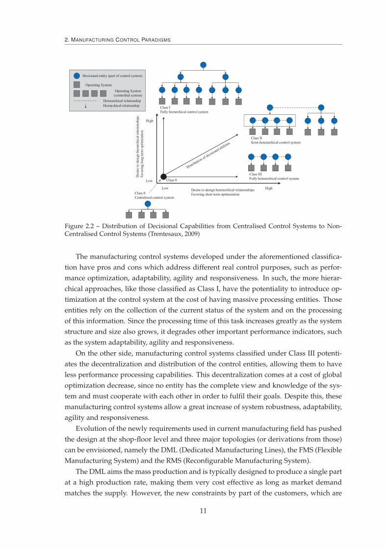
Figure 2.2 – Distribution of Decisional Capabilities from Centralised Control Systems to Non-Centralised Control Systems (Trentesaux, 2009)
The manufacturing control systems developed under the aforementioned classifica-
tion have pros and cons which address different real control purposes, such as perfor-
mance optimization, adaptability, agility and responsiveness. In such, the more hierar-
chical approaches, like those classified as Class I, have the potentiality to introduce op-
timization at the control system at the cost of having massive processing entities. Those
entities rely on the collection of the current status of the system and on the processing
of this information. Since the processing time of this task increases greatly as the system
structure and size also grows, it degrades other important performance indicators, such
as the system adaptability, agility and responsiveness.
On the other side, manufacturing control systems classified under Class III potenti-
ates the decentralization and distribution of the control entities, allowing them to have
less performance processing capabilities. This decentralization comes at a cost of global
optimization decrease, since no entity has the complete view and knowledge of the sys-
tem and must cooperate with each other in order to fulfil their goals. Despite this, these
manufacturing control systems allow a great increase of system robustness, adaptability,
agility and responsiveness.
Evolution of the newly requirements used in current manufacturing field has pushed
the design at the shop-floor level and three major topologies (or derivations from those)
can be envisioned, namely the DML (Dedicated Manufacturing Lines), the FMS (Flexible
Manufacturing System) and the RMS (Reconfigurable Manufacturing System).
The DML aims the mass production and is typically designed to produce a single part
at a high production rate, making them very cost effective as long as market demand
matches the supply. However, the new constraints by part of the customers, which are
11

2.2. Production and Manufacturing Control Approaches
demanding a higher variety of customized products with shorter life-cycle, is imposing
a strong pressure into this rigid line design, which is naturally in a decay situation (only
for particular cases).
The FMS can be sub-divided into several categories regarding the introduced flexi-
bility part, namely the machine, the process, the product, the routing, the volume, the
expansion and the production (Jha, 1991). Depicting the ones where a manufacturing
control architecture may influence, the machine flexibility can be seen as the way that
machines can adapt to production changes (making use, e.g., of CNC machines). The sec-
ond flexibility degree is the routing and here the system shop-floor is designed in such a
way that more than one routing alternative is available for the transportation of products
into the processing machines. Despite of these flexibilities degrees, the installation cost
regarding the FMS is a general drawback for its implementation.
The last paradigm tries to bring the best of both worlds, by combining the high
throughput provided by the DML with the flexibility of the FMS (but with a lower price).
This paradigm, named RMS, is a concept that suggests the rapid change in the factory’s
structure using changes in hardware and/or software to adjust the production capacity
and functionality (ElMaraghy, 2006). A RMS system should exhibit the following charac-
teristics (Koren et al., 1999): modularity, integrability, customization, convertibility and
diagonalisability.
Despite this, an appropriate control strategy of the aforementioned paradigms is of
crucial importance, where scheduling, optimization and dispatching rules are applied as
middle layer control which operationalize the higher level orders coming from the ERP
systems.
2.2 Production and Manufacturing Control Approaches
Hierarchical control architectures were among the first to be developed in the manu-
facturing control field. The most successful of those was the CIM (Computer-Integrated
Manufacturing) (Waldner, 1992) based architecture, which promoted the computeriza-
tion of all the production life-cycle from the early stages of the design phase until the
final product production. In the European region, the CIMOSA (Computer Integrated
Manufacturing Open System Architecture) architecture aimed at the development of an
open framework to help companies for enterprise modelling and integration into the CIM
approaches by proposing a reference architecture from which the particular architectures
were developed from (ESPRIT Consortium AMICE., 1993).
Despite the promotion of the integration of several technologies, the CIM approach
wasn’t able to achieve the desired results mainly because of the heterogeneity of the in-
volved tools, the installation and maintenance complexity and its centralized approach
that limited to scale the system.
Recently, manufacturing control architectures are assuming the decentralization of
the processing capabilities and following a distribution of the decisional nodes bringing
12
2. MANUFACTURING CONTROL PARADIGMS
them more closer to where they are needed. This new trend will probably gain an extra
momentum by the promotion of the Industrie 4.0 (Drath and Horch, 2014) and Indus-
trial Internet (Evans and Annunziata, 2012) initiatives, being the first one seen as the 4th
industrial revolution.
For this purpose, some design trends have emerged over the past years, being the
most promising the ones developed under the HMS, MAS and the SoA (Service Oriented
Architecture) paradigms.
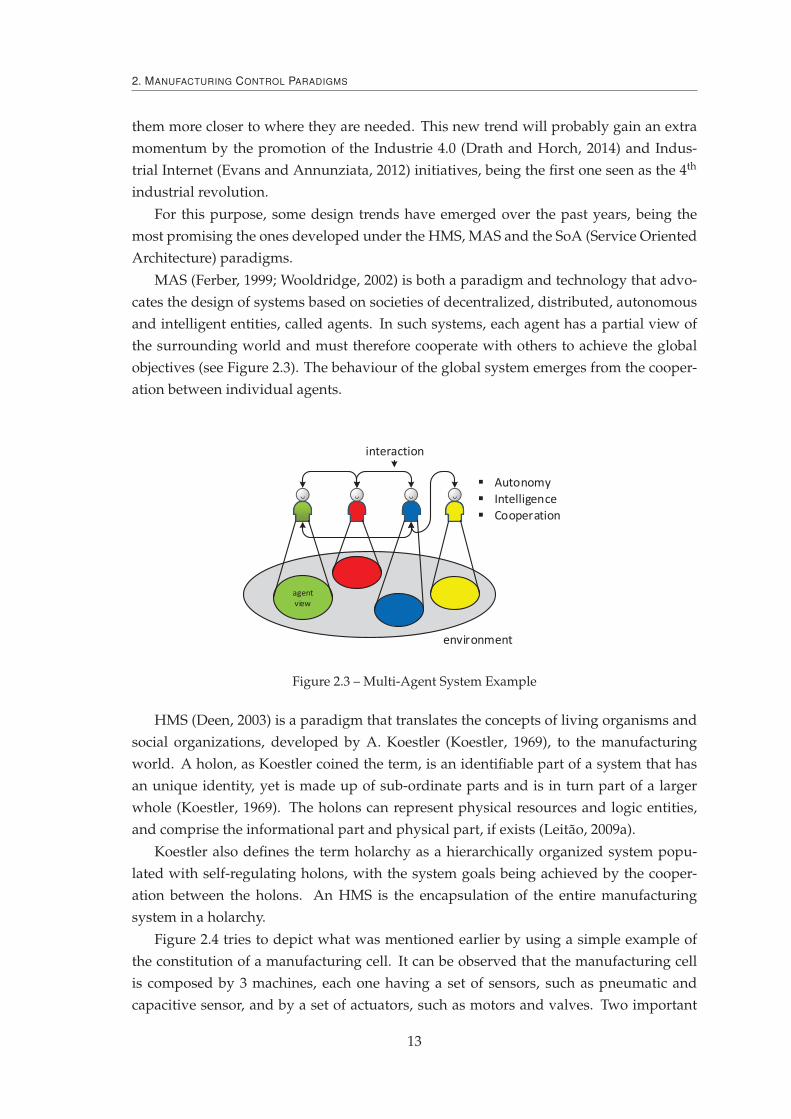
MAS (Ferber, 1999; Wooldridge, 2002) is both a paradigm and technology that advo-
cates the design of systems based on societies of decentralized, distributed, autonomous
and intelligent entities, called agents. In such systems, each agent has a partial view of
the surrounding world and must therefore cooperate with others to achieve the global
objectives (see Figure 2.3). The behaviour of the global system emerges from the cooper-
ation between individual agents.
Autonomy
Intelligence
Cooperation
interaction
environment
agent
view
Figure 2.3 – Multi-Agent System Example
HMS (Deen, 2003) is a paradigm that translates the concepts of living organisms and
social organizations, developed by A. Koestler (Koestler, 1969), to the manufacturing
world. A holon, as Koestler coined the term, is an identifiable part of a system that has
an unique identity, yet is made up of sub-ordinate parts and is in turn part of a larger
whole (Koestler, 1969). The holons can represent physical resources and logic entities,
and comprise the informational part and physical part, if exists (Leitão, 2009a).
Koestler also defines the term holarchy as a hierarchically organized system popu-
lated with self-regulating holons, with the system goals being achieved by the cooper-
ation between the holons. An HMS is the encapsulation of the entire manufacturing
system in a holarchy.
Figure 2.4 tries to depict what was mentioned earlier by using a simple example of
the constitution of a manufacturing cell. It can be observed that the manufacturing cell
is composed by 3 machines, each one having a set of sensors, such as pneumatic and
capacitive sensor, and by a set of actuators, such as motors and valves. Two important
13

2.2. Production and Manufacturing Control Approaches
features found in the holonic systems can be observed, namely the holon sharing, seen in
the pneumatic sensor, that is being shared by machines 2 and 3, and hierarchy, creating
intermediary stable states, in the way that all the machines are controlled by a higher
level controller and the overall cell by one additional controller.
Figure 2.4 – Holonic Manufacturing System Example
Lastly, another very important feature found in HMS is the recursivity, due to the frac-
tal composition of the holons. This feature can be seen in the Figure 2.4 where machine
1 uses other machine to be built with, resembling the Janus effect of having authority by
its own and to depend/belong to others.
MAS technology and/or HMS concepts have been successfully developed and ap-
plied to different domains (see for example the reviews (Leitão et al., 2012; Monostori
et al., 2006)).
2.2.1 Multi-Agent System Applications to Manufacturing
YAMS (Yet Another Manufacturing System) (Parunak, 1985) is one of the first known
implementations (probably the very first) applying agent-based principles to control a
manufacturing system. In this case, an agent is applied to each node of the control hi-
erarchy, being one machine, a workstation, a cell or a factory. A CNP (Contract-Net
Protocol) procedure was applied to this hierarchical model as the mean for negotiation.
In this hierarchical approach, the upper level agent uses the CNP (Smith, 1980) procedure
to identify the lower level agent that’s under its control.
At the same time, Duffie and Piper were among the first ones to discuss an heter-
archical control approach. In their work, agents represent physical resources, parts and
human operators. Additionally, a part focused scheduling mechanism is applied (Duffie
and Piper, 1986).
A contract net based approach was used to simulate 35 workstations of a job shop that
produced parts for steam turbines that belong to the General Electric Power Generation
14

2. MANUFACTURING CONTROL PARADIGMS
(Baker, 1991). In the case study, 491 orders, belonging to 184 unique products, each one
having on average 8.2 operations per product are used. In the proposed approach, each
workstation, either automated or a human, was represented by an agent (Baker, 1991).
Briefly, the customers request a bid for a final product that will then trigger, from the
agents that are able to deliver that product, a chain reaction from the agents that are
needed to deliver parts or assemblies. This process is repeated by all the agents along the
supply chain and the result is sent back to the customer, returning cost per unit, which is
a function based on delivery time and lot size.
MetaMorph (Maturana et al., 1999) and its successor MetaMorph II (Shen et al., 2000)
were projects that firstly aimed to provide an agent-based approach for the creation and
management of agent communities in distributed manufacturing environments, and sec-
ondly to integrate cross-enterprise activities, such as design, planning and scheduling.
AARIA (Autonomous Agents at Rock Island Arsenal) was developed in the early
years of agent-based architectures for military production, with the particularity of using
internet as a means of communication between agents (Parunak et al., 2001).
The Explantech, developed at the Czech Technical University, aims the long-term pro-
duction planning process (Pechoucek et al., 2005). This approach was deployed at an au-
tomotive related company (LIAZ Pattern Shop company) (Pechoucek et al., 2002) and at
the SKODA Auto for the scheduling of the engine assembly workshop.
The CoBASA (Coalition Based Approach for Shopfloor Agility) architecture uses
a multi-agent system to support the re-engineering at the shop floor (Barata and
Camarinha-Matos, 2003). In this way, CoBASA uses contracts to govern the relationships
between coalition members and defines a new methodology on which the re-engineering
process is included within the life-cycle.
The previous approaches stayed more either at an academic level development stage,
tested by building demonstrators, or in the brief deployment in the real industrial facili-
ties. Despite this, some examples can be given that had accomplished a deeper industrial
penetration.
One of the first multi-agent approach deployed into a real production system was
named as P2000+ and was installed at a Daimler Chrysler factory that produced en-
gine cylinder heads (Bussmann and Schild, 2001). This multi-agent system followed a
late commitment strategy applied to the parts routing in a conveyor system. A self-
organization mechanism is also used, adding to the machine a virtual buffer that acts
like the bidding manager allowing the machine to bid to a request from a part need-
ing to be processed (Schild and Bussmann, 2007). Being this an industrial case, a final
assessment of the use of multi-agents comparing with the previous control strategy was
conducted and it was concluded that a 20% gain in productivity was achieved (Bussmann
and Sieverding, 2001).
A multi-agent approach was also developed and applied at the NovaFlex manufac-
turing system at Uninova, Portugal (Cândido and Barata, 2007). The system is composed
of two assembly robots, an automatic warehouse and a transport system that connects
15
2.2. Production and Manufacturing Control Approaches
all the modules and each component that composes the system is agentified (i.e. each
component has one agent associated to it) following some guidelines developed under
the CoBASA architecture.
The iShopFloor (Shen et al., 2005) addresses the newly demands from the manufactur-
ing global competition by promoting the usage of internet, web and agent technologies.
The proposed approach promotes a framework for the components belonging to the sys-
tem to work together aside of being disjoint. Additionally, the information architecture
is specified and the methodologies for the integration are also provided.
Rockwell Automation developed a multi-agent based system to manage the set of
components (plumbing, controls, communication and electric) of a U.S. Navy’s Reduced
Scale Advance Demonstrator, where the goal was the control of the liquid flow through-
out the ship in a different set of regimes, such as cruise and battle (Maturana et al., 2005).
A multi-agent system enhanced with the ants food foraging behaviour is used in
(Sallez et al., 2009) as the way for the products to dynamically route over the FMS. The
proposed architecture is composed by two levels, named virtual and physical level. The
first one is composed by the virtual active products (VAP) which represents the physical
active products (PAP) that acts on the real level. Since time in the virtual level can be
fast-forward, several VAPs can be used to test different routing alternatives, allowing to
act on real-time on the PAP.
Albadawi et al. (2006) describes the implementation of an agent-based control archi-
tecture applied to two continuous manufacturing process, first to a tuneable model for
the plastic thermoforming process and secondly to a rule-based model for the metal pow-
der grinding process (Albadawi et al., 2006).
Rockwell Automation developed its first industrial agent approach to increase the
machine utilization of the steel rod bar mill of the Australian company BHP Billiton
(Marík et al., 2005). As it was a real use case, and despite the developed MAS performed
well in all the tests, it was only considered to be on the decision making layer and sup-
port the human operator in charge of the actual control. In this case, each cooling box
was mapped with an agent which based on a bidding process would allow the heated
steel to be cooled there.
Agent-based systems are also useful in manufacturing to provide simulation tools
which allow an assessment and debugging at early design stages. One of such tools, is
the MAST (Manufacturing Agent Simulation Tool) (Vrba, 2003) system and with basic
components, such as conveyor belts, diverters and AGV (Automated Guided Vehicles)s,
are used to design and simulate the desired system. The MAST system has also been used
to simulate real test-beds, such as the DIAL (Distributed Information and Automation
Laboratory) packing cell at the University of Cambridge and at the ACIN (Automation
and Control Institute) located at the Vienna University of Technology (Vrba and Marik,
2010).
A second example of an agent based simulation tool is the ABAS (Actor-Based Assem-
bly Systems), developed by the Tampere university of Technology and Schneider Electric,
16
2. MANUFACTURING CONTROL PARADIGMS
for the simulation and visualization of the robot operation in a 3D manufacturing space
(Lastra and Colombo, 2006).
Scheduling is also one of the main topics of research using agent-based technology,
since it is one key feature in the control layer of a manufacturing process. Kouiss et al.
use dedicated agents to work centres to select dynamically the most suitable dispatching
rule (Kouiss et al., 1997). In this work, agents select the dispatching rule based on their
local and global states, such as the availability of machines and on the their performance
objectives.
Other example is given in (Erol et al., 2012) where feasible scheduling solutions for an
AGVs system is accomplished by agents negotiation/bidding process. A multi objective
optimization on the basis of ratio analysis technique under a fuzzy multi criteria decision
making considering several attributes was used as the scheduling prioritization on the
agent based holonic manufacturing system proposed by (Jana et al., 2013). For this case, a
CNP is used as the negotiation and cooperation procedure for the task allocation process.
Companies are already using multi-agent technology as the mean to develop intelli-
gent scheduling tools. One example of such company is the Russian Smart Solutions that
applies its scheduling solutions to transportation, such as taxi fleets or petrol tanks, or to
manufacturing (Skobelev, 2011).
Additionally, several research funding projects, particularly in Europe have been or
are being undertaken.
The EU FP7 GRACE (inteGration of pRocess and quAlity Control using multi-agEnt
technology) (Leitão and Rodrigues, 2011) aimed the development of a multi-agent based
monitoring system that combines the production and quality data for allowing the prod-
uct customization. The developed GRACE multi-agent system was deployed to a real
washing machine production line, where agents are collecting and analysing individual
washing machine production data and correlating it with overall global key performance
indicators, improving the final washing machine quality, making it individually unique.
The EU FP7 ARUM (Adaptive Production Management) aims at improving the ramp-
up phase of small lot and highly customizable products, such as air planes (e.g., the Air-
bus A350). This is achieved by developing a set of scheduling (Leitão and Barbosa, 2014)
and planning tools (Leitão et al., 2013) using multi-agent systems. The developed sys-
tem is integrated using the SoA principles by recurring to an iESB (inteligent Enterprise
Service Bus) that allows the seamless communication between all the tools present at the
architecture (Marin et al., 2013).
The EU FP7 PRIME (Plug and PRoduce Intelligent Multi Agent Environment) is de-
veloping a plug and produce solution based on an intelligent multi-agent system en-
vironment using standard technology. The objective is to develop a flexible, standard,
reusable, adaptable, reconfigurable, customisable and cost effective solution to deploy
and maintain complex assembly systems. (Rocha et al., 2014).
The EU FP7 IDEAS (Instantly Deployable Evolvable Assembly Systems) applied
17

2.2. Production and Manufacturing Control Approaches
the concepts developed under the EAS paradigm and proposed self-configuring, self-
diagnosis and process-oriented components aiming a complex, flexible and multi-
propose system (Onori et al., 2012).
2.2.2 Holonic Manufacturing System Applications
The beginnings of the development of MAS have risen in the middle of the 80s and
since then have given raise to several applications using its concepts and visions.
One of the most remarkable HMS architectures is the PROSA (Product-Resource-
Order-Staff Architecture) reference architecture that defines the main guidelines for de-
veloping a generic manufacturing control system (Van Brussel et al., 1998). The HCBA
(Holonic Component Based Architecture) architecture defines two major types of holons,
namely the product and resource, which are responsible to e.g., manage the operations
execution, make the product decision making process and possess the product informa-
tion (Chirn and McFarlane, 2000). The holonic system is built through the association of
these holon types using nested structures of those holons.
A manufacturing control system for a packing cell at the assembly cell of University
of Cambridge was developed following an holonic approach, namely using the PROSA
architecture, and implemented using the MAS technology (Fletcher et al., 2003). This
system is responsible to assembly GilleteTMpackages into personalised gift boxes. This
full-scale real cell uses a set of robots and a conveyor system to route the products. The
designed agent-based system integrates RFID (Radio Frequency IDentifier) technology,
enabling a dynamic and unique identification of the products therein. In this approach, a
collaboration was formed between order and resource holons to accommodate the clients’
demands. Order holons use negotiation techniques to ensure the fast and reliable produc-
tion and are also responsible for tracking the production progress. On the other hand, the
main aim of resource holons is to maximize the return on the execution of their services,
and finally, product holons deal with the buying and selling of goods.
The ADACOR (ADAptive holonic COntrol aRchitecture) (Leitão and Restivo, 2006),
which will be deeper detailed in section 2.3, is a holonic architecture that proposes an
adaptive production control approach that balances between a stationary state and a tran-
sient state, in normal and unexpected conditions, respectively, combining the benefits of
hierarchical and heterarchical control structures using an adaptive mechanism.
The PABADIS (Plant Automation Based on DIStributed systems) architecture aims
the construction of a MES using a set of autonomous production agents. Briefly, ev-
ery process starts by the conventional manufacturing order being processed at the ERP,
comprising the set of required production steps, which is then sent to a block named
Agency, which is responsible to create a set of the necessary agents to execute the manu-
facturing order (Lüder et al., 2004). To accomplish this, a set of agents were responsible
to interface and interact with the different set of components, named as Co-operative
Manufacturing Units (CMU). A continuation of this project was developed, named as
18

2. MANUFACTURING CONTROL PARADIGMS
PABADIS-PROMISE (Ferrarini et al., 2006), which has lowering the ANSI/ISA-95 action
to the physical layers.
HMS concepts have also been applied to manufacturing control of continuous pro-
cesses, namely to a steel rod mill spray cooling line. Within the proposed holonic ar-
chitecture (McFarlane, 1995), a set of holons were specified, which are responsible for
managing processing tasks, negotiation procedures, scheduling activities and diagnosis
features (McFarlane et al., 1995).
As already happened in the MAS field, the scheduling is also one of the key applica-
tions being developed following the HMS paradigm.
Sousa and Ramos (1999) propose a dynamic scheduling system supported by a
holonic approach, using forward and backward influence in the negotiation, leading to
the task allocation, to handle the temporal constraints and to solve conflicts. The archi-
tecture is composed by holons to represent resources, tasks, planning systems, etc (Sousa
and Ramos, 1999).
More recently the EU FP7 ARUM is also applying an holonic swarm of scheduling
and planning tools, using an agent-based approach, to combine the strategic planning
tools, that are producing capacity planning schedule, with the dynammic alloaction of
tasks to machines at the shop-floor (Leitão and Barbosa, 2014).
The aforementioned state-of-the-art description allows to verify what is being devel-
oped in this field and further reading regarding the MAS and HMS production and man-
ufacturing control can be made using the following references: (Shen and Norrie, 1999),
(Monostori et al., 2006), (Shen et al., 2006), (Trentesaux, 2009), (Leitão, 2009b), (Vrba et al.,
2011), (Leitao et al., 2012) and (Laszlo, 2014).
2.2.3 Other Distributed Manufacturing Control Approaches
Not only MAS and HMS are used to design and develop distributed manufacturing
control architectures. SoA, for example, has taken the attention in the past years pro-
moting the distributed control and the seamless communication between all the players
within the ANSI/ISA 95.
A SoA based architecture is proposed by (Candido et al., 2010) where transparent
interoperability between devices is the major requirement. The SoA approach is used to
enhance the EAS traditional architectures abstracting the implementation details under a
service interface.
European projects are also using the SoA principles and technologies. Two ex-
amples are the EU FP6 SOCRADES (Service-Oriented Cross-layer Infrastructure for
Distributed smart Embedded devices) and the EU FP7 IMC-AESOP (ArchitecturE for
Service-Oriented Process - Monitoring and Control). SOCRADES proposes a design, exe-
cution and management platform for the next-generation industrial automation systems
at the device and at the application level. In this way, SOCRADES creates new method-
ologies, technologies and tools for modeling, design, implement and for the operation of
19
2.3. An Adaptive Holonic Control Architecture: ADACOR
a network of smart embedded devices (Cannata et al., 2008).
The IMC-AESOP consortium developed a SoA and cloud based architecture, integrat-
ing the SCADA and the DCS (Distributed Control System) in a seamless manner, which
is able to monitor and control all the information flow in large and complex industrial
systems. (Karnouskos et al., 2014).
A distributed control example can also be found in the hybrid manufacturing control
architecture named ORCA (dynamic Architecture for an Optimized and Reactive Con-
trol) (Pach et al., 2014). This architecture is divided in three layers, namely the physical
system (PS) layer, the local control (LC) and the global control (GC). The GC has a global
view of the system and guarantees the good performance of the system by having a
global view of it and being composed by a global optimizer. Each PS has associated a LC
that is responsible to react properly, accordingly with the associated PS state. The ORCA
architecture is a dual-mode architecture, where under normal mode the GC transmits the
orders to the LC. If a disturbance is detected by the LC, it will switch to the disturbance
mode, being responsible to optimize the PS under its control.
Zambrano Rey et al. (2014) propose a semi-heterarchical architecture composed by
a supervisor (S) and subordinate decisional entities (E). In this approach, simulation-
optimization mechanisms are used to reduce the subordinates’ myopic behaviour.
2.3 An Adaptive Holonic Control Architecture: ADACOR
The ADACOR adaptive holonic architecture intends to combine the best practices of
hierarchical and heterarchical control approaches, being as centralised as possible and as
decentralized as necessary, i.e. using a centralised approach when the objective is the op-
timisation, and a more heterarchical approach in the presence of unexpected events and
modifications (Leitão and Restivo, 2006). In these circumstances, ADACOR proposes
the decomposition of manufacturing control functions into a community of autonomous
and cooperative holons, taking advantage of modularity, decentralisation, agility, flexi-
bility, robustness and scalability. To achieve this, ADACOR proposes four types of holons
(Leitão, 2004):
— PH (Product Holon), representing the products available in the factory plant cata-
logue and the knowledge to produce them.
— TH (Task Holon), responsible for managing the real-time execution of production
orders on the shop floor.
— OH (Operational Holon), representing the system resources, e.g., robots and oper-
ators, responsible for governing its own agenda as well as managing the physical
connection with the real resource.
— SH (Supervisor Holon), responsible for introducing optimization into the system.
ADACOR clearly defines the behaviour of individual holons using the Petri Nets
formalism and also the interaction patterns between them using AUML (Agent Unified
20

2. MANUFACTURING CONTROL PARADIGMS
Figure 2.5 – ADACOR Holon Classes
Modeling Language) sequence diagrams (Leitão and Restivo, 2006). This is of great im-
portance in the way that ADACOR proposes a binary-state balance for the adaptive pro-
duction control depending on the system perturbation level, combining the benefits of
hierarchical and heterarchical control structures using an adaptive mechanism.
As illustrated in Figure 2.6, in stationary state, the holons are organized in a hierarchi-
cal structure, with supervisor holons playing the role of coordination and optimizing the
schedules of their subordinates organized in clusters. The system runs in this configura-
tion until a perturbation is detected. The operational holon that detects the disturbance
(in this case OH1) tries to recover locally by carrying out a self-diagnosis. If recovery
from the failure is unsuccessful, its autonomy factor is increased and a propagation of
the need for re-organisation to the other holons in the system is sent. The propagation
mechanism involves depositing a pheromone on the neighbouring supervisor holon and
its subsequent spread to other SHs.
The other holons that sense the pheromone from supervisor holons, increase their au-
tonomy factors according to the pheromone’s intensity and their local knowledge, and
propagate the emergent re-organization to the neighbouring supervisor holons. The in-
tensity of the odour associated with the pheromone decreases as the levels of supervisor
holons increases (it is similar to the distance in the original pheromone techniques), ac-
cording to a defined flow field gradient. Each individual holon, taking its autonomy fac-
tor, learning capabilities and pheromone intensity into consideration, decides if it should
re-organize or not. In Figure 2.6, the holons OH1 to OH5 choose to re-organize, while
holons OH6 and OH7 do not re-organize as the pheromone’s intensity is not high enough,
i.e. the epicentre of the disturbance is far away and the impact is too low or zero.
In this transitory state, the task holons interact directly with the operational holons
to achieve an alternative schedule in a short time, gaining in responsiveness. During
21

2.3. An Adaptive Holonic Control Architecture: ADACOR
Figure 2.6 – Adaptation Mechanism in ADACOR Supporting a Hybrid Control Architecture
this state, the supervisor holons continue elaborating optimized schedules, but now only
the holons with low autonomy factors will accept the proposals. The holons remain in
transient state during the re-establishment time, τ , which is typically a short period of
time. Once this time has elapsed, they verify if the pheromone odour has dissipated or
is still active. If the pheromone is still active, the holons stay in transient state for an
additional re-establishment time, until the pheromone has dissipated.
Once the pheromone has dissipated, each individual holon reduces its autonomy fac-
tor again and returns to a hierarchical control structure, going back to a stationary state,
since they accept the schedules once more from their SH. At this moment, the supervisor
holons collect the updated individual schedules, achieved during the transient state, and
proceed with the synchronization and posterior optimization of the existing schedule.
The reschedule is sent to the operational holons, which accept the advised schedule since
they have a low autonomy factor again.
This powerful mechanism allows the system to respond quickly to perturbations and
balance back to a stationary state after its dissipation, fulfilling the challenge of devel-
oping a hybrid control system, i.e. the ha(t) curve in Figure 1.1. Despite the potential
and innovation introduced by embedding this self-organization mechanism, the control
system only balances between two predefined states and is not able to evolve to other
22
2. MANUFACTURING CONTROL PARADIGMS
pre-defined or new control structures, supporting a truly evolvable and reconfigurable
system. This challenge is aligned with the current demanding of an additional step taking
the knowledge of biology, the chaos theory and the evolutionary theory into considera-
tion to achieve the dynamic evolution and adaptation of manufacturing systems.
2.4 Limitations and Challenges of the Existing Approaches
Centralized and monolithic control architectures have design, maintenance and scala-
bility problems. Despite these important and limiting issues, these approaches, generally,
display optimal results under well defined and known functioning conditions. Addi-
tionally, due to its complexity and information centralization, these approaches behave
poorly when disturbance appear, losing responsiveness.
Decentralized approaches, such as MAS and HMS, address better the disturbances
situations but don’t achieve the optimization performance displayed in the centralized
approaches. Additionally, the design and maintenance of decentralized systems tend to
be simpler due to its Lego-like construction, e.g., promoting the re-utilization of devel-
oped code (although debugging could be more time consuming).
Having this in mind, it can be concluded that combining the strong points of each
architectural approach can bring benefits in the design of a better manufacturing control
architecture. A good example of such combination is found in the ADACOR architecture
that combines the optimization power of centralized systems with the responsiveness of
decentralization.
However, analysing the current state-of-the-art of the decentralized architectures it
can be found that design schemes tend to keep the entities behaviour static, in the sense
that the change of behaviours is not handled.
On the other hand, more recently, research started to consider self-organization mech-
anisms to simplify and optimize some of the processes in the decentralized systems.
Despite this, the use of self-organized approaches have prove to be very punctual and
limited, needing to be further explored and potentiated.
In this sense, a manufacturing control architecture that combines the optimisation
levels found in centralized systems with the responsiveness of the decentralized architec-
tures enhanced with the real use of self-organization principles is missing in the current
panorama.
2.5 Summary
This chapter overviews the current state-of-the-art concerning the manufacturing
control architectures and approaches. The different system configurations were depicted
and analysed, enhancing their benefits and disadvantages. The ANSI/ISA-95 standard
was introduced, contextualizing the position of this thesis contribution.
23

2.5. Summary
The overview of the state-of-the-art included the most renowned manufacturing con-
trol architectures, being given particular emphasis to those that follow the MAS and HMS
paradigms. A brief detail of each of the studied architectures was given, as well further
references, providing a more detailed description of those.
This study provided valuable info about the strengths and weaknesses of these man-
ufacturing control architectures. It was not found an architecture that allows the entities
to dynamically adapt its internal behaviour and the majority of them use a rigid struc-
ture where agents interact with the same peers and where the structure is fixed or slightly
adapts. Additionally, some of them make use of self-organization concepts but only in a
superficial manner.
Lastly, a particular focus was given to the ADACOR manufacturing control architec-
ture, since it will be used as the ground-base for the development of this thesis work. It
was described the system architecture, and particularly the adaptive control mechanism
that allows to balance between a hierarchical and heterarchical structure, combining op-
timization and responsiveness.
The next chapter will describe some concepts and mechanisms that can be found in
biological system, such as swarm intelligence, evolution and self-organization that can be
used as source of inspiration. Two surveys depicting applications that use bio-inspired
mechanisms on their problem solving are also given, being the first one related to generic
engineering problems while the second focus more on the manufacturing world domain.
Then, the benefits that the biological inspiration can bring to the MAS is also pointed
out, being given special focus to the self-configuration, self-optimization and self-healing
aspects of the MAS. Additionally, this biological inspiration contribution to manufactur-
ing is also depicted, stating where, why and how its usage can be beneficial.
Finally, the main guidelines needed to achieve a truly evolvable system are drawn
and analysed.
24

3Biological Inspiration to Solve
Complex Problems
I have called this principle, by which each slight variation, if useful, is preserved, by the term
of Natural Selection.
Charles Darwin
Nature offers plenty of powerful mechanisms, refined by millions of years of evo-
lution, to handle emergent and evolvable environments (Leitão, 2009c), constituting a
promising source of inspiration to enrich distributed systems with the capability to face
emergence and condition changes in a quite naturally manner. This section describes
how complex things behave simply in nature and biology, introducing the concepts of
swarm intelligence, evolution and self-organization.
3.1 Swarm Intelligence
In biology, complex systems are based on entities that exhibit simple behaviours,
made of a small set of simple rules, with reduced cognitive abilities. The global system
behaviour emerges from a multiplicity of non-linear interactions among the individual
entities. In such systems, the emergent behaviour occurs without a pre-defined plan, is
not driven by a central entity, and occurs only when the resultant behaviour of the whole
is greater and much more complex than the sum of the behaviours of its parts (Holland,
25

3.1. Swarm Intelligence
1999). Some illustrative examples of this kind of emergent behaviour can be found in the
ant and bee societies. In fact, everybody knows that "a single ant or bee isn’t smart, but their
colonies are" (Miller, 2007), being capable of displaying surprisingly complex behaviours.
Swarm intelligence, found in colonies of insects, can be defined as "the emergent collec-
tive intelligence of groups of simple and single entities" (Bonabeau et al., 1999), thus reflecting
the emergent phenomenon. Swarm intelligence offers an alternative way of designing
intelligent, complex systems, in which the traditional centralized control is replaced by
distributed operations where the interactions between individuals lead to the emergence
of "intelligent" global behaviour, previously unknown (Bonabeau et al., 1999). Examples
of swarm intelligence include ant colonies, bird flocking, fish schooling and bacterial
growth (Miller, 2007).
In such colonies, individuals possess a partial view of the world and require some
way of communicating with others to achieve global objectives. However, the individu-
als in these colonies usually do not have the ability to communicate directly each other
(e.g., like humans) and thus use an indirect form of communication that establishes a
channel of information sharing. For example, ants communicate by using an indirect co-
ordination mechanism known as stigmergy, derived from the Greek words stigma, which
means mark or sign, and ergon, which means work or action (Grassé, 1959). In stigmergy,
the trace left in the environment stimulates the execution of a subsequent action, by the
same or different entity. In this mechanism, ants use a chemical substance known as
pheromone, which acts like a trigger that individuals from the same specie can sense
and/or use in favour of the swarm (e.g., guidance when foraging for food) (Bonabeau
et al., 1999) (see Figure 3.1a).
pheromone
Perception
Action
(deposit/
reinforcement)
Action
(deposit/
reinforcement)
Perception
Figure 3.1 – Indirect Communication in Insect Swarms: a) the Deposition and Sensing ofPheromones by Ants [adapted from (Parunak et al., 2003)]; b) the Waggle Dance Used by Bees
After finding a food site, ants walk back to the nest and lay down a pheromone
trail to share information. Other ants foraging for food can sense the odour diffused by
pheromones, and may lay a trail reinforcing the existing pheromones. The pheromones
deposited in the nature suffer a natural process of evaporation, resulting in a reduction of
the intensity of the odour; the reduction is directly proportional to the time elapsed from
26

3. BIOLOGICAL INSPIRATION TO SOLVE COMPLEX PROBLEMS
the nest to the food source (i.e. the more intense, the shorter distance travelled). If sev-
eral ants make different trips to the same source of food, there will be several trips to the
same source. The optimal solution (i.e. the shortest one) will be the trail that has more in-
tense pheromones. After a while, gradually, the trails that have less intense pheromones
are abandoned by the ants because the pheromones are not reinforced. Naturally, these
trails are no longer considered as options. Sometimes, ants can walk randomly instead of
choosing a pheromone trail, which is a good way to find new paths that have appeared
in the mean time (Bonabeau et al., 1999).
The double-bridge experiment conducted by (Deneubourg et al., 1990) reinforces the
idea that ants can indeed find the shortest paths to goals. In their experiments, if two
equal paths from the nest to a food source, each path is chosen 50% of the time; in each
experiment, the ants tend to choose only one path. On the other hand, if one path is
significantly longer than the other, the ants chose the shortest one (Goss et al., 1989).
Another illustrative example of indirect communication supporting swarm intelli-
gence is related to the waggle dance used by honey bees to share information about the
direction and distance to patches of flowers yielding nectar and pollen. After scouting
an area for a food source, honey bees return to the hive and inform other bees about
the food source, performing a dance known as the "waggle dance", as shown in Figure
3.1b. This dance provides the following information to the other bees: 1) the rotation
angle of the dance, in relation to the sun, states the direction in which the food source
can be found and 2) the duration of the dance represents the travel distance to the food
source (Bonabeau et al., 1999; Frisch, 1967). Other researchers suggest that this dance
also provides a third kind of information related to the quality and quantity of the food
source. This last information is shared by releasing a pheromone-type odour (Dornhaus
and Chittka, 2004).
Swarm intelligence can be achieved more from coordinating activities of individuals
and less from using decision-making mechanisms. A well-known example is the move-
ment of flock of birds (e.g., the typical V formation), where individuals coordinate their
movements in relation to the movement of the others (Reynolds, 1987). For this purpose,
simple feedback mechanisms are used to regulate the individual behaviour (Camazine
et al., 2001):
— in case of positive feedback, the system responds to the perturbation in the same
direction as the change (i.e. towards the amplification of the perturbation), and
— in case of negative feedback, the system responds to the perturbation in the oppo-
site direction (i.e. towards the stabilization of the perturbation).
By combining both positive and negative feedbacks, the system can be maintained
under control but pushed to its limits (Camazine et al., 2001). For example, the simple
rule "I nest where other similar individuals nest unless there are too many fishes" (Camazine et
al., 2001), used to describe fish nesting, combines positive and negative feedback: the first
27

3.2. Evolution and Self-Organization
part uses positive feedback, allowing the aggregation of fishes in the same place to be in-
creased, and the second part uses negative feedback, thus avoiding a high concentration
of fishes in the same place.
Other similar coordination mechanisms are found in other areas of science and nature,
namely market laws (Márkus et al., 1996) and potential fields (Vaario and Ueda, 1996),
based on regulating the expectations of individuals with conflicts of interest.
3.2 Evolution and Self-Organization
The Darwinian theory of evolution (Darwin, 2007) is a form of adaptation to the dy-
namic environmental evolution. Darwin stated that nature is in a permanent transfor-
mation state in which the species would change from generation to generation, evolving
to better suit their environment. Basically, Darwin saw the evolution as a result of en-
vironmental selection acting on a population of organisms competing for resources. In
this evolutionary process, the selection is natural in the sense that it is purely sponta-
neous without a pre-defined plan. In other words, species tend to evolve to overcome
their limitations and to adapt to external natural conditions. For example, a specie can
perform small spontaneous changes within their chromosomes, which provokes some
physiological changes after a few generations.
Self-organization is another form of adaptation to the dynamic environmental evo-
lution. Several distinct, not necessarily contradictory, definitions can be found in the
literature, namely (Massotte, 1995; Thamarajah, 1998; Bousbia and Trentesaux, 2002; Pi-
card et al., 2009). However, the base definition (it will be further detailed in sub-section
4.2.1) used in this work is:
"The ability of an entity/system to adapt dynamically its behaviour to external changing con-
ditions without external intervention" (Leitão, 2008).
Self-organizing systems don’t follow a rigid structure but instead evolve through a
dynamic, non-linear process with a constant optimization of the individuals’ behaviour.
Examples of self-organization principals can be found in several domains, namely:
— Physics: In thermodynamics, the 2nd law states that everything in the universe
tends to move from a state of order towards a state of chaos (introducing the con-
cept of entropy), which explains that hot bodies tend to get colder with an external
cold source (e.g., a refrigerator). Another example is found on the Bernard rolls phe-
nomenon (Getling, 1998) in which the hot and cold molecules self-organize them-
selves in order to create a flow.
— Chemistry: As example, molecules exhibit self-assembly properties, which drives
the molecular structure to self-organization (Whitesides et al., 1991). Another ex-
ample is the Belousov-Zhabotinsky chemical oscillator, which is composed of a re-
action sequence that forms a loop (Shanks, 2001).
— Nature: The stigmergy phenomenon is used to achieve self-organization in ant
28

3. BIOLOGICAL INSPIRATION TO SOLVE COMPLEX PROBLEMS
colonies.
The coordination mechanisms found in colonies of ants and bees, besides allowing
members of these species to communicate, allow the whole community to achieve and
display self-organization behaviour. Bonabeau et al. suggest that the basic ingredients to
achieve a self-organized system are the positive feedback, negative feedback and fluctu-
ations (e.g., random walks and errors). They also suggest that self-organization relies on
the multiple interactions between the individuals.
3.3 Survey of Bio-Inspired Applications for Solving Complex
Problems
Several researchers are using biological inspiration (e.g., those found in colonies of
insects) to solve complex engineering problems. In this section, bio-inspired techniques
and methods in engineering are briefly reviewed, with special attention to their applica-
bility in manufacturing.
3.3.1 Applied to Engineering Problems
The insights inherited from the swarm intelligence principles led researchers to de-
sign optimization evolutionary algorithms, namely the ACO (Ant Colony Optimization),
the ABC (Artificial Bee Colony) algorithm, and the PSO (Particle Swarm Optimization).
Dorigo introduced the ACO technique (Dorigo, 1992), inspired by the food foraging
behaviour of ants, to solve problems that need to find optimal paths to some goal. In
ACO, agents acting as ants, travel randomly over a weighted graph leaving marks (i.e.
pheromones) wherever they go. After an initial phase, the "ants" make their decisions
according to the pheromone level, instead of making decisions randomly. Over the time,
the pheromone trail becomes weaker in the less used paths, making the most used path
(i.e. the most optimized path) prevail.
The ACO algorithm has been used to solve diverse engineering problems from dif-
ferent application domains. In fact, in the financial domain, the ACO algorithm has been
used to classify firms as to the different levels of credit risk (Marinakis et al., 2008a) and, in
the medical field, to distinguish cancer from non-cancerous diseases, by helping with the
evaluation of proteomic patterns (Meng, 2006). In the engineering world, the ACO algo-
rithm has been used to determine the optimal values for the components in an electronics
power circuit (J. Zhang et al., 2008), to achieve an optimal image threshold by separating
the object from its background (Malisia and Tizhoosh, 2006), and to update the telecom-
munications routing tables dynamically and adaptively (Di Caro and Dorigo, 1998). In
the army, this algorithm has been applied for the dynamic re-planning of UAV (Uninhab-
ited Aerial Vehicles) (Duan et al., 2009) and for the cooperation among swarm robots to
accomplish a complex task (Nouyan et al., 2009). In the industrial domain, Air Liquide
has used an ant-based strategy to manage the truck routes for delivering industrial and
29
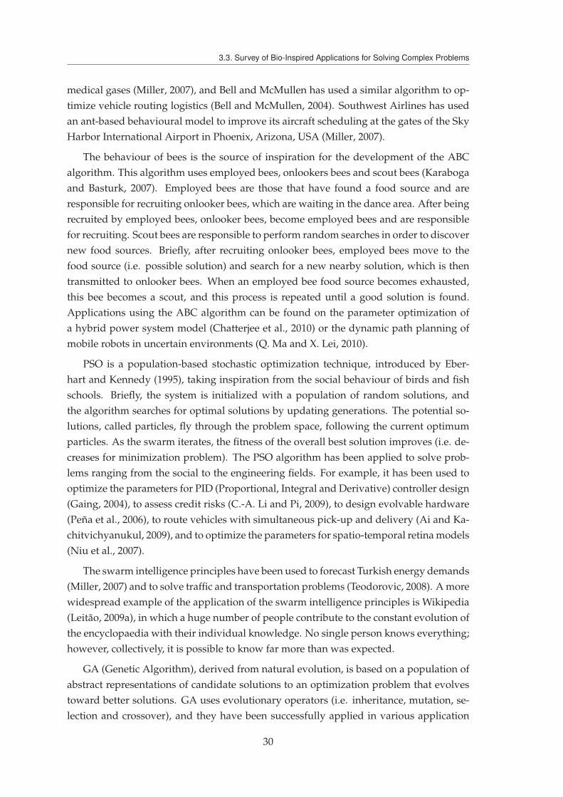
3.3. Survey of Bio-Inspired Applications for Solving Complex Problems
medical gases (Miller, 2007), and Bell and McMullen has used a similar algorithm to op-
timize vehicle routing logistics (Bell and McMullen, 2004). Southwest Airlines has used
an ant-based behavioural model to improve its aircraft scheduling at the gates of the Sky
Harbor International Airport in Phoenix, Arizona, USA (Miller, 2007).
The behaviour of bees is the source of inspiration for the development of the ABC
algorithm. This algorithm uses employed bees, onlookers bees and scout bees (Karaboga
and Basturk, 2007). Employed bees are those that have found a food source and are
responsible for recruiting onlooker bees, which are waiting in the dance area. After being
recruited by employed bees, onlooker bees, become employed bees and are responsible
for recruiting. Scout bees are responsible to perform random searches in order to discover
new food sources. Briefly, after recruiting onlooker bees, employed bees move to the
food source (i.e. possible solution) and search for a new nearby solution, which is then
transmitted to onlooker bees. When an employed bee food source becomes exhausted,
this bee becomes a scout, and this process is repeated until a good solution is found.
Applications using the ABC algorithm can be found on the parameter optimization of
a hybrid power system model (Chatterjee et al., 2010) or the dynamic path planning of
mobile robots in uncertain environments (Q. Ma and X. Lei, 2010).
PSO is a population-based stochastic optimization technique, introduced by Eber-
hart and Kennedy (1995), taking inspiration from the social behaviour of birds and fish
schools. Briefly, the system is initialized with a population of random solutions, and
the algorithm searches for optimal solutions by updating generations. The potential so-
lutions, called particles, fly through the problem space, following the current optimum
particles. As the swarm iterates, the fitness of the overall best solution improves (i.e. de-
creases for minimization problem). The PSO algorithm has been applied to solve prob-
lems ranging from the social to the engineering fields. For example, it has been used to
optimize the parameters for PID (Proportional, Integral and Derivative) controller design
(Gaing, 2004), to assess credit risks (C.-A. Li and Pi, 2009), to design evolvable hardware
(Peña et al., 2006), to route vehicles with simultaneous pick-up and delivery (Ai and Ka-
chitvichyanukul, 2009), and to optimize the parameters for spatio-temporal retina models
(Niu et al., 2007).
The swarm intelligence principles have been used to forecast Turkish energy demands
(Miller, 2007) and to solve traffic and transportation problems (Teodorovic, 2008). A more
widespread example of the application of the swarm intelligence principles is Wikipedia
(Leitão, 2009a), in which a huge number of people contribute to the constant evolution of
the encyclopaedia with their individual knowledge. No single person knows everything;
however, collectively, it is possible to know far more than was expected.
GA (Genetic Algorithm), derived from natural evolution, is based on a population of
abstract representations of candidate solutions to an optimization problem that evolves
toward better solutions. GA uses evolutionary operators (i.e. inheritance, mutation, se-
lection and crossover), and they have been successfully applied in various application
30

3. BIOLOGICAL INSPIRATION TO SOLVE COMPLEX PROBLEMS
domains: power distribution (Ramirez-Rosado and Bernal-Agustin, 1998), image seg-
mentation (Peng et al., 2000) and scheduling and route selection for military land moves
(Montana et al., 1999).
Table 3.1 provides a summary of some applications that use insights from biology
and nature to solve complex engineering problems. In this table, the problem domain
can range from finance to energy. This table does not intend to be exhaustive but instead
to demonstrate the many domains that are already using bio-inspired solutions.
Table 3.1 – Bio-Inspired Applications to Solve Engineering Problems
ProblemDomain
Existing ACO-inspiredsolutions
Existing PSO-inspiredsolutions
Existing GA-inspiredsolutions
Communicationnetworks
(Di Caro and Dorigo,1998),(D. Zhao et al.,
2009),(Sim andW. H. Sun, 2002)
(Dongming et al., 2008),(T. Li et al., 2008)
(Lima et al., 2007),(J.-H. Lee et al., 1997)
Control
(Van Ast et al., 2009),(Boubertakh et al., 2009),
(Q. Zhang andX.-h. Wang, 2008)
(Gaing, 2004), (Jalilvandet al., 2008), (Hu et al.,
2005)
(Wai and Su, 2006),(Toderici et al., 2010),
(Bae et al., 2001)
Finance
(Fang and Bai, 2009),(Yuan and Zou, 2009),
(Hong et al., 2007),(Marinakis et al., 2008c),
(Kumar et al., 2009)
(C.-A. Li and Pi, 2009),(Majhi et al., 2008),
(A.-P. Chen et al., 2009)(Badawy et al., 2005)
Hardwaredesign
(J. Zhang et al., 2008),(Abd-El-Barr et al.,
2003), (Sethuram andParashar, 2006)
(Peña et al., 2006),(Goudos et al., 2008),
(Ren and L. Cheng, 2009)
(Tsai and Chou, 2006),(Regue et al., 2001)
ImageProcessing
(Malisia and Tizhoosh,2006), (Tian et al., 2008),(X.-N. Wang et al., 2005)
(Y.-W. Chen et al., 2009),(Chandramouli and
Izquierdo, 2006), (M. Maet al., 2008)
(Peng et al., 2000),(Katayama et al., 2006)
Medicine(Meng, 2006), (Y. Lee
et al., 2009), (Logeswariand Karnan, 2010), ()
(Niu et al., 2007), (Meng,2006), (Marinakis et al.,
2008b)
(Maulik, 2009), (Das andBhattacharya, 2009),(Tohka et al., 2007)
Military(Duan et al., 2009),
(C.-T. Cheng et al., 2009),(Munirajan et al., 2004)
(Matlock et al., 2009),(Cui and Potok, 2007),(Thangaraj et al., 2009)
(Moore and Sinclair,1999), (Montana et al.,
1999), (H. Liu et al., 2005)
Power energy
(K. Lee andVlachogiannis, 2005),(Z. Liu et al., 2009),(Colson et al., 2009)
(H. Liu and Ge, 2008),(B. Zhang et al., 2008),
(Leeton et al., 2010)
(Ramirez-Rosado andBernal-Agustin, 1998)
Robotics (Nouyan et al., 2009)(Zhengxiong andXinsheng, 2010)
(Tohka et al., 2007),(Karlra and Prakash,2003), (Pessin et al.,
2009), (Albert et al., 2009)
Sensornetworks
(Camilo et al., 2006),(Muraleedharan and
Osadciw, 2009)
(Aziz et al., 2007) ,(Tewolde et al., 2008),(Z. Li and L. Lei, 2009)
(Jiang et al., 2009),(Brown and McShane,2004), (Khanna et al.,
2006)
Vehiclerouting/traffic
control
(Miller, 2007), (Bell andMcMullen, 2004)
(Ai andKachitvichyanukul,
2009), (J. Wu and Tan,2009)
(Tong et al., 2004), (Jun,2009), (Tunjongsirigul
and Pongchairerks, 2010)
31

3.4. Enriching MAS Based Application with Bio-inspiration
3.3.2 Applied to Manufacturing Problems
A similar analysis of the applicability of bio-inspired techniques can be performed for
manufacturing. In the manufacturing domain, algorithms based on the ant behaviour
have been used to optimize machine layouts (Corry and Kozan, 2004), schedule contin-
uous casting aluminium in a Quebec factory (Gravel et al., 2002), and coordinate adap-
tive manufacturing control systems (Hadeli et al., 2004). The food-foraging behaviour of
honey bees is the source of inspiration for solving job scheduling problems (Pham et al.,
2007b) and optimizing the manufacturing layout formation (Pham et al., 2007a). The be-
haviour of wasps has been used for task allocation (Cicirello and S. F. Smith, 2004) and
factory routing and scheduling (Cicirello and S. F. Smith, 2001).
In addition, the PSO technique has been applied to machinery fault detection
(Samanta and Nataraj, 2009), job shop scheduling (Xia and Z. Wu, 2005), machine load
balance as part of a job shop manufacturing system (F. Zhao et al., 2006), and manufac-
turing cells layout and robot transport allocation optimisation (Yamada et al., 2003). GAs
have been used to generate and evaluate assembly plans (Lazzerini et al., 1999), to design
optimized layouts (G. Wang et al., 2008), and to generate schedules for flexible job-shop
production systems (Qiu et al., 2009).
Self-organization principles have been used to solve complex adaptive problems: in
holonic manufacturing control (Leitão and Restivo, 2006), in dynamic resource allocation
of a Daimler Chrysler plant (Bussmann et al., 2004), in the development of self-organized
and self-assembled bio-inspired robots (Moudada et al., 2004), and in manufacturing
scheduling (Thamarajah, 1998). A stigmergic approach has also been used as the routing
mechanism in a flexible manufacturing system (Sallez et al., 2009).
The potential fields have been used to solve some manufacturing problems. In spite
of being a concept usually found in physics, in this work, it is included in the bio-inspired
world. This concept has been used to allocate products within a group of resources
(Vaario and Ueda, 1996) and to guide AGVs in a manufacturing site (Weyns et al., 2008).
In addition, potential fields were used for dynamic task allocation and product routing
(Zbib et al., 2010). Table 3.2 summarises some of the existing bio-inspired applications
found in the manufacturing field.
3.4 Enriching MAS Based Application with Bio-inspiration
The analysis in the previous section shows the tremendous potential of using of bio-
inspired systems to solve complex engineering problems. This section discusses the ap-
plicability and benefits of combining bio-inspired techniques with MAS in the manufac-
turing domain in order to address the current challenges. The MAS paradigm has already
inherited some biological insights (Barbosa and Leitão, 2010):
— Distributed nature: MAS are based on a set of distributed, autonomous and co-
operative agents, and the functioning of the whole system is determined by the
32

3. BIOLOGICAL INSPIRATION TO SOLVE COMPLEX PROBLEMS
Table 3.2 – Bio-Inspired Applications to Solve Manufacturing Problems
ProblemDomain
Existing solutionsinspired by ant and bee
behaviour
Existing solutionsinspired by
self-organization or GA
Other existingbio-inspired solutions
Assembly/disassembly
(Shan et al., 2007),(S. Sharma et al., 2009),
(Lu et al., 2008)
(Lazzerini et al., 1999),(Gao and W. D. Chen,
2008)
(Lv and Lu, 2009),(Dong et al., 2007)
Layoutoptimization
(Jain and P. Sharma,2005), (Z.-G. Sun andTeng, 2002), (G. Chen
and Rogers, 2009),(Corry and Kozan, 2004)
(G. Wang et al., 2008),(Kulkarni and Shanker,
2007)
(Ning et al., 2004),(Ohmori et al., 2010),
(J. Lei et al., 2003),(Pham et al., 2007a),(Yamada et al., 2003)
Manufacturingscheduling
(Arnaout et al., 2008),(R.-M. Chen et al., 2008),(Xu et al., 2009), (Blum
and Sampels, 2004),(Gravel et al., 2002)
(Qiu et al., 2009),(Aggoune et al., 2001),
(Thamarajah, 1998)
(Shi et al., 2009),(R. Zhang and C. Wu,
2008), (Pham et al.,2007b), (Cicirello and
S. F. Smith, 2001),(Cicirello and
S. F. Smith, 2004), (Xiaand Z. Wu, 2005),
(D. Zhao et al., 2009)
Productioncontrol
(Hadeli et al., 2004)
(Leitão and Restivo,2006), (Bussmann andSchild, 2000), (Sallez
et al., 2009)
(Vaario and Ueda, 1996),(Ueda et al., 2001),
(Weyns et al., 2008),(Zbib et al., 2010)
Supply chain(Suva et al., 2004),
(R. Sun et al., 2008),(Caldeira et al., 2007)
(Elmahi et al., 2004),(Kaijun et al., 2010),
(Jianhua and Xianfeng,2010)
(Sinha et al., 2009)
interaction among these individuals.
— Division of labour: MAS define different types of agents with distinct roles, objec-
tives, behaviours and skills; when a social group reaches a sufficient size, "the divi-
sion of labour" appears naturally, like in insect colonies where an individual usually
does not perform all tasks but rather specializes in one set of tasks (Bonabeau et al.,
1999).
— Emergence from collective simple behaviour: The obtained behaviour of the
whole system cannot be summarized to the simple sum of the behaviours of its
parts (Holland, 1999).
Recalling the vision described in the previous chapter, the MAS applications that ful-
fils the aforementioned insights offers an alternative way of designing intelligent, robust
and adaptive systems that replace traditional centralized control. As previously seen,
these approaches provide robustness, since the system is not dependent on a centralized
entity and has the ability to continue working even if some entities fail when performing
their tasks, and flexibility, since the members of the society can dynamically be plugged
in, plugged out or modified to face changing environments on the fly.
33
3.4. Enriching MAS Based Application with Bio-inspiration
Generally, the application of MAS principles usually allows the appearance of a emer-
gent global behaviour, guaranteeing the fulfilment of flexible and robustness require-
ments. These systems must have the capacity to evolve, that is related to the way the
system can adapt quickly and efficiently to the environmental volatility, thus addressing
the responsiveness property.
To face this challenge, biology and nature can provide useful insights, especially the
self-organization phenomenon. Self-organization applied to MAS allows the implemen-
tation of several self-* properties (Leitão, 2008):
— Self-configuration, i.e. the capacity to dynamically adapt to changing conditions by
modifying the system’s own organization structure, thus permitting the addition/
removal/modification of entities on the fly, without disrupting the service.
— Self-optimization, i.e. the system’s capacity to adjust itself pro-actively to respond
to environmental stimuli anticipating future state of the environment.
— Self-healing, i.e. the capacity to diagnose deviations due to unexpected conditions
and act pro-actively to normalize these deviations, thus avoiding service disrup-
tions.
The self-* properties are crucial for developing highly adaptive, evolvable systems,
addressing the current requirements, and supporting reconfigurability in a quite natural
manner.
Bio-inspired techniques to enhance MAS can be analysed from another perspective.
Manufacturing and automation cover a wide range of application domains, presenting
different requirements and constraints, which can benefit more or less from using such
bio-inspired techniques. Based on the accumulated experience, the use of bio-inspired
techniques combined with MAS can help to design more intelligent, modular, flexible
and adaptive systems, especially in the following manufacturing domains (Leitão et al.,
2012):
— Supply chains and virtual organizations, which require the frequent re-organization
of partners to achieve optimization and responsiveness;
— Shop floor layout, which requires optimizing the shop floor layout in order to min-
imize transport time and to minimize transport distances, in situations where shop
floor resources move physically.
— Product demand, in which the manufacturing system re-organizes itself to adapt to
the changes in the product demand (i.e. faced with the mass customization trend),
increasing/reducing the number of resources or modifying their capabilities, based
on the forecast production demands.
— Planning and scheduling, in which the goal is to find the most current optimized
plans and schedules, while taking the product demands and the capabilities of the
shop floor resources into consideration.
34
3. BIOLOGICAL INSPIRATION TO SOLVE COMPLEX PROBLEMS
— Adaptive control, in which the goal is to identify an adaptive, dynamic production
control strategy based on the dynamic on-line schedule, which is adapted in cases
of unexpected disturbances.
— Predictive maintenance, in which predicting machinery failures is essential for tol-
erating disturbances and malfunctions, which helps to develop an adaptive pro-
duction system.
— Diagnosis, in which distributed entities are able to cooperate to achieve a dynamic,
reliable and clear diagnosis of the detected symptoms.
— Adaptive processes and equipment, in which developing new sensors, actuators
and controllers will help to design and implement more adaptive manufacturing
equipment.
Despite the enormous potential of the bio-inspired insights, special care must be taken
when translating them into the real-world problem-solving. If the biological behaviours
are simply copied, the system may not work as expected. Mimicking behaviours can
drive the system into danger states (e.g., the circular mill in army ants (Anderson and
Bartholdi, 2000)). Based on this observation, the idea is not to copy the entire behavioural
aspect of the biological mechanism, but instead translate and adapt the insights in order
to match the system’s objectives. This translation/adaptation requires collaboration be-
tween experts in biology and experts in engineering, which may lead to new insights
from a different point of view.
This observation may provoke a question related to the fact that, in manufacturing,
there is little space for testing, e.g., to send physical entities (e.g., products or trucks) on
a random walk to explore alternative routes. It is important to remember that a multi-
agent manufacturing system is composed of two components: the virtual agents and the
physical resources (i.e. products and machines). Naturally, the product cannot be sent on
a test trip, but agents, running bio-inspired algorithms, can use virtual ants (i.e. agents)
to explore the best solutions in order to route products.
These bio-inspired solutions can be more useful when the environment in which they
operate is unpredictable. The other issue that must be taken into account is applying
these mechanisms may not be advantageous in cases where strong real-time constraints
are needed. Special care must be taken, and the right mechanisms applied, in order to
not affect the system performance.
In spite of the promising prospects that bio-inspired principles can bring to engineer-
ing systems, especially in the manufacturing domain, these principles have been adopted
less than expected in industrial situations. The major problem is that industry demands
proven technology, without wanting to be the first ones to try it in their production pro-
cesses. The maturity of the technology and the proofs of its real applicability and merits
will solve this problem. Furthermore, industry is usually afraid of using emergent ter-
minology associated to these new technologies, such as self-organization, emergence,
distributed thinking and learning.
35
3.5. How to Achieve an Evolvable System
The challenge for engineers developing bio-inspired solutions for manufacturing is to
convince people from industry of the real advantages of using distributed systems based
on the behaviour of simple, effective and adaptive entities regulated by simple coordi-
nation mechanisms, such as those occurring in nature. For this purpose, it is important
to develop demonstrators and real case studies to be used as a proof of concept. Simula-
tion platforms simplify the design, testing and debugging of these bio-inspired applica-
tions, ensuring a framework to simulate/validate strategies to support decision-making.
Several computational platforms are currently available for the simulation/validation of
bio-inspired models (e.g., SWARM, RePast, NetLogo, Gama and MadKit), in which the
behaviours of biological entities (e.g., ants and bees) are usually implemented using soft-
ware agents (more information related to ABM (Agent-Based Modelling) tools can be
found in (Railsback et al., 2006) and (Arunachalam et al., 2008)).
An interesting example is using the NetLogo platform to simulate the dynamic de-
termination of the best path to route the products in situations with disturbances (Sallez
et al., 2009). The idea here is to simulate the manufacturing system taking into account
the real conditions (e.g., the equipment status). In this way, the model gets real infor-
mation, performs the simulation, and sends the commands to the real environment. The
system operates in a bidirectional manner: the real environment provides fault inputs
to the modelling system, and the modelling system gives scheduling orders to the real
environment.
3.5 How to Achieve an Evolvable System
The achievement of truly evolvable systems requires the fulfilment of a certain
plethora of requirements. The system, particularly a manufacturing control system in
this work, should withstand the loss or addition of entities and continue to work in a
seamless way. Disturbances must be accommodated in a transparent way and handled
as smoothly as possible to mitigate their impacts. During the disturbance phase and after
it, the system must constantly try to be as optimized as possible. This optimization phase
might pass by acting on the internal functioning of the entities or by re-arranging the
system structure, i.e. the relation among the entities. Additionally, this optimization, can
also be achieved through the introduction of a high level entity (with a broader view), by
applying self-organization principles or by the combination of both.
Figure 3.2 depicts the identified requirements that the proposed system must exhibit
to be truly evolvable. Among them, it is possible to identify features such as control of
randomness, being prepared for the unexpected, the appearance of an emergent feature,
the usage of chaos control, self-organization mechanisms and the introduction of hierar-
chy. These features will be detailed in the following sub-sections.
36

3. BIOLOGICAL INSPIRATION TO SOLVE COMPLEX PROBLEMS
Figure 3.2 – Requirements for a Truly Evolvable System
3.5.1 Being Prepared for the Unexpected
Very large-scale and complex systems, like those found in manufacturing, have dif-
ferent types of disturbances that can affect the system with assorted degrees of impact.
As example, in manufacturing, a disturbance, who classically is a perturbation that dis-
rupts/affects the normal functioning of the system, can be a rush order, a delay, a worker
absenteeism or a resource breakdown, which may have a negative impact on the system.
Notably, a disturbance can even have a positive impact on the system, such as the in-
troduction of a new resource or an upgrade on a existing one, in the sense that broader
possibilities are presented. In the same line, the restructuring of the conveyor system or
the re-arrangement of the shop-floor can deeply determine the performance of the sys-
tem. All the aforementioned situations should be considered has a disturbance, their
impacts measured and the system acting accordingly to cope with them. Regarding the
impact level of the disturbance, a two level classification can be envisioned, namely:
Low level: the system can overcome it with less effort. Disturbances are classified as low
when their impact in the system is restrained within some tight boundaries and
when the system is able to resolve it locally, i.e. using minor mitigation strategies.
High level: the system, to overcome the perturbation, must undergo with major
changes. Perturbations are classified as high when their impact in the system over-
passes the focal point of perturbation. In this situation, the system must make
changes that not only involve the affected area.
37

3.5. How to Achieve an Evolvable System
To this subject, a truly evolvable system must consider this wider set of different dis-
turbances, learn on-the-fly as they appear, and manage them in a proper way. It is also
desirable to embed in the system entities, or in the design process, methods, forecasting
techniques and simulations to predict the unexpected (Valckenaers et al., 2011).
Having this in mind, it can be understood that the system must be able to accomplish
two different things. Firstly, the disturbance must be eliminated and accommodated into
the normal functioning of the system. This is, from a certain point, the disturbance must
be considered has a natural part of the system as it is absorbed by the system. The sec-
ond requirement, is that the degradation of the system performance during and after the
occurrence of the disturbance must be as less as possible, and for this purpose, different
disturbances can be mitigated using distinct strategies. So, a truly evolvable system must
have different ways to overcome the unexpected.
3.5.2 Hierarchy: a way to Achieve Stabilization and Optimization
Optimization can be defined as the way that a given entity has to be in a state where,
under the same conditions, it can extract the most out of it. Hierarchy is one of the
most used ways to achieve system optimization (Dilts et al., 1991). In such approach,
the entity uses the global information to have a wider knowledge of the system, making
the decision process more efficient, i.e. more optimized. These high level entities uses
their wider knowledge to consider a wider set of solutions for the same conditions and
consequently provide low level orders to their subordinates.
A. Koestler, based on the Herbert Simon’s observations, stated that a complex system
will evolve more rapidly in the presence of stable intermediary states than if they were
not present (Koestler, 1969). During his observations, Simon describes the parable of the
two Swiss watchmakers 1 to conclude that "Complex systems will evolve from simple systems
much more rapidly if there are stable intermediate forms that if there are not." (Koestler, 1969).
As conclusion, hierarchy is a way to achieve optimization and stabilization in complex
systems since higher level entities that govern the hierarchy have a wider knowledge of
the current system status.
3.5.3 Self-Organization and Emergence as the Main Driver
Self-organization can be found in many complex and well structured systems (Kauff-
man, 1993). Many times, regulated by several local interactions, systems display desired
1. Two watchmakers produced high quality watches and were very requested. Both watches were sim-ilar in number of parts needed to build them, but each one used a different building approach. The firstwatchmaker, named Mekhos, would build watches piece by piece without clustering in groups. This pro-cess implies that every time Mekhos was interrupted, all the watch needed to be re-built from the beginning,since all the parts would disaggregate from each other. The other watchmaker, known as Bios, followeda different strategy, making groups of parts, which are then assembled in a hierarchical manner. In otherwords, Bios assembled groups of parts that are sub-assemblies of higher levels groups. In this approach,every time Bios was interrupted, the maximum he had to re-build was the sub-group he was working on atthe moment of interruption.
38
3. BIOLOGICAL INSPIRATION TO SOLVE COMPLEX PROBLEMS
features, such as adaptability to face the perturbations and system equilibrium. This is,
often, driven by the use of indirect communication between the entities that compose the
system.
Self-organization can be used to enhance the autonomy of the entities in distributed
systems, managing and organizing their internal tasks and work.
As also seen in species societies, self-organization also enables the system to improve
responsiveness and to overcome any disturbance that may appear along the way, mainly
in large and dynamic systems. Optimization is another expected feature that can be
extracted from self-organized systems. Recall the ant double bridge experience where,
without any previously knowledge or any central authority, the shortest path was pre-
ferred over the longest one.
One underlying key feature of self-organization is found on the simplicity of the use
of coordination and communication mechanisms. A notable usage of this is the odour
pheromone deposition made by the ants during food foraging that indicates the quality
and distance to the food source or the waggle dance performed by scouting bees, indi-
cating to others the quality, distance and orientation to food sources.
Lastly, and since the goal is to have an evolvable system, self-organization can also
respond properly to this since environmental influences and disturbances, generally, do
not affect the self-organization mechanism, making the system to dynamically evolve, by
either maintaining a stable form or displaying a transient phenomena (Bonabeau et al.,
1999).
On the other hand, emergence appears due to the multitude of non-linear and dy-
namic interactions between all the system’s entities. This emergent behaviour appears
without the need to have a central authority in charge where the outcome is greater than
the simple sum of the contributions of all the entities.
In fact, among the different types of emergence (Deguet et al., 2006), one definition
that can be used is the one related to the simulation, where: "A true emergent phenomenon
is one for which the optimal means of prediction is simulation." (Darley, 1994).
Accordingly, self-organization principles must be at the core centre of every truly
evolvable system.
3.5.4 Controlled Randomness
Randomness is a feature that appear in biology to allow the identification/discovery
of probabilities to evolve. As an example, ants during the food foraging process usually
decide to make random walks exploring the neighbour space, allowing them to discover
new routing possibilities, which until that point were unknown to them. The finding of
new places in the state space is afterwords evaluated to see their viability, being discarded
in case of worst results or non-benefits.
Random movements have also proved to be extremely effective and desirable in na-
ture, in situations where the predators are, somehow, expecting for preys and naturally,
39

3.5. How to Achieve an Evolvable System
desires to catch them. The serengeti wildebeest, as example, during the annual migration
movement, moves in herds and purposely makes random movements between years in
order for predators to not be able to find them as easily as they would otherwise (Kava-
liers and Choleris, 2001).
In an truly evolvable system, randomness is a "must have" feature in the sense that it
allows the addition or removal of entities and also the change of the state space where the
system operates, detecting new system configurations and new entities relations. This is
a very important feature in dynamic systems where, e.g., layouts change and entities
providing new services are appearing and disappearing.
The pertinent question is how to embed this randomness into the control system with-
out affecting the normal functioning of it or without degrading its performance. It must
be always kept in mind that the mechanisms to be used in control systems cannot nega-
tively affect the same system operation, e.g., one entity responsible for processing a task
cannot just be sent intentionally in a random walk to search for new places in the state
space. This search for changes in the state space must be made by using non-invasive
techniques, i.e. those that not affect or have less impact on the normal functioning of the
system.
An example of the use of exploratory entities can be seen in the PROSA+ANTS ar-
chitecture (Karuna et al., 2005), where the authors have specified an entity named ex-
ploratory ants that is responsible for searching routing possibilities (representing the best
manufacturing processing sequence possible). A second example of such technique can
be seen in (Zbib et al., 2010) where similar concepts are also used.
Having a system without a certain degree of randomness can reduce its capability
to detect changes in an appropriate way and constraint the system to evolve. Note for
instance the work in (Barbosa et al., 2012a), where it is shown that having no random
capabilities, the entities will not be able to overcome disturbances in a changing system.
In the same work it is also shown that the opposite is also undesirable, i.e. having a large
randomness feature, where the system would not display the most desired behaviour.
As conclusion, the ultimate solution is to have a controlled randomness, allowing the
entities within the system to have random features but not too much that will make them
to fall into chaotic behaviour.
3.5.5 Be Aware with Chaos
Chaos can be directly related with the degree of randomness once if the level of the
entity randomness is too high, the system will fall into a chaotic behaviour. Although
some degree of chaos is desirable, which can drive the system to discover new func-
tioning points, it becomes undesired when it grows beyond a certain point. The chaotic
behaviour is one of the last effects that a system can or desire to have since chaos can
rapidly drive the system into a non-return situation where it becomes uncontrollable or
falls into a pitfall.
40

3. BIOLOGICAL INSPIRATION TO SOLVE COMPLEX PROBLEMS
The trigger for the last example is pertinent to be discovered and eliminated in order
to avoid this undesired behaviour. To this concern, a special attention to the impact of
decisions must be made. Recall for example the butterfly effect, where a small change
at a given point in time can produce, in a non-linear system, a huge impact later on.
Additionally, the conditions on which the change is made can also influence the way the
system evolve.
Despite the drawbacks of chaos, one can also benefit from a certain degree of it. Lets
recall that some studies state that the human brain is a in a constant state near of chaotic
behaviour, i.e. it is critically self-organized (Kitzbichler et al., 2009), and in this situation
the human beings tend to extract more from their brain activity. Additionally, accord-
ing to (Kauffman, 1993), complex adaptive systems reside on the edge of chaos between
equilibrium and chaotic activity.
Having this in mind, a truly self-organized system should be at the edge of chaos,
pushed into its limits but maintaining its stability.
3.6 Summary
This chapter has given a picture of some insights, mechanisms and techniques, that bi-
ology has to offer. Swarm intelligence concept was introduced and explained and within
this, the behaviour of insects societies is briefly explained. Despite not displaying indi-
vidually intelligent behaviour, ants and bees as a group are capable of performing amaz-
ingly complex behaviours.
The evolution and self-organization concepts were briefly described, presenting an
interesting way to design systems that in a non-controlled way are able to evolve in dy-
namic environments.
Two surveys are also presented as the way to, in an exemplified manner, depict some
applications that already inhered biologically inspired techniques into their approaches,
such as in finance, image processing or even in manufacturing production control. Some
guidelines to derive the aforementioned insights into the manufacturing world are also
depicted.
Finally, key features that a manufacturing control system must possess in order to be
truly evolvable are described, namely being prepared to the unexpected, the introduction
of optimization through hierarchy or the use of self-organization principles figure among
them.
The next chapter will describe the basic principles of the proposed self-organized
holonic architecture, acting at the micro- and macro-level, i.e. at holon internal level
and at the structural level. The proposed architecture extends the ADACOR approach
with self-organization concepts to address a truly self-organized holonic manufacturing
control.
41

3.6. Summary
42

4ADACOR2: a Self-Organized
Holonic Architecture
Look deep into nature, and then you will understand everything better.
Albert Einstein
As seen in the previous chapters, the existing manufacturing control approaches lack
to achieve a truly evolvable system in the aspect that they are not able to dynamically
evolve to find better functioning points, or if they have this capability, only a few degrees
of freedom are considered. This requires a manufacturing control system architecture
that is able to evolve in a natural manner, properly coping with different types and levels
of disturbances, minimizing their impact into the system performance.
This chapter describes the architectural principles of the proposed self-organized
holonic approach, named ADACOR2, since it is based on the established ADACOR
holonic architecture (Leitão and Restivo, 2006). ADACOR2 holonic architecture aims
to enhance the existing ADACOR holonic architecture through self-organization capa-
bilities to achieve truly evolvable and reconfigurable manufacturing systems, which are
able to cope with unexpected condition changes, pushing the system into its limits but
remaining under stable states. For this purpose, it is proposed a self-organization holonic
architecture that evolves through multiple configurations on which the system can oper-
ate, unleashing the two pre-defined states defined in ADACOR, as illustrated in Figure
4.1 (Barbosa et al., 2012b).
43

4.1. System Architecture
...
ADACOR
ADACOR + Self-organization
Figure 4.1 – ADACOR2: an Extension of ADACOR
In the next sections, the system architecture and the self-organization principles will
be described in detail (Barbosa et al., 2015).
4.1 System Architecture
The proposed architecture follows the ADACOR holonic architecture, being consti-
tuted by an ecosystem populated by several holons that interact with each other to
achieve the system’s goals.
4.1.1 Architectural Components
The control level proposed by the ADACOR2 holonic system is composed by a finite
set of entities, known as holons (Hh), each one representing physical or logical compo-
nents, processes and information belonging to the system.
Following its predecessor ADACOR, the ADACOR2 architecture considers four types
of holons, that are able to represent all the entities within a manufacturing system,
namely PH, TH, OH and SH. There is a direct mapping of the set of holons and the
set of logical and physical manufacturing components, as illustrated in Figure 4.2, where
the ADACOR2 system is represented as a pool of holons with their mappings to a real
world representation. Note that a SH doesn’t have a direct representation with the real
world since it is an entity that aims to introduce optimization into the system.
In this way, the ADACOR2 pool of entities can be represented by:
ADACOR2 = {PHph, THth, OHoh, SHsh} (4.1)
The set of products that can be produced in the shop-floor, i.e. the product catalogue
for a given manufacturing company, is represented by PH. Product holons comprise the
knowledge about the product and the process model, which are transmitted to the THs.
Additionally, the PH also takes pro-active actions in situations where deviations from
initial plans are detected that could affect the created THs.
44
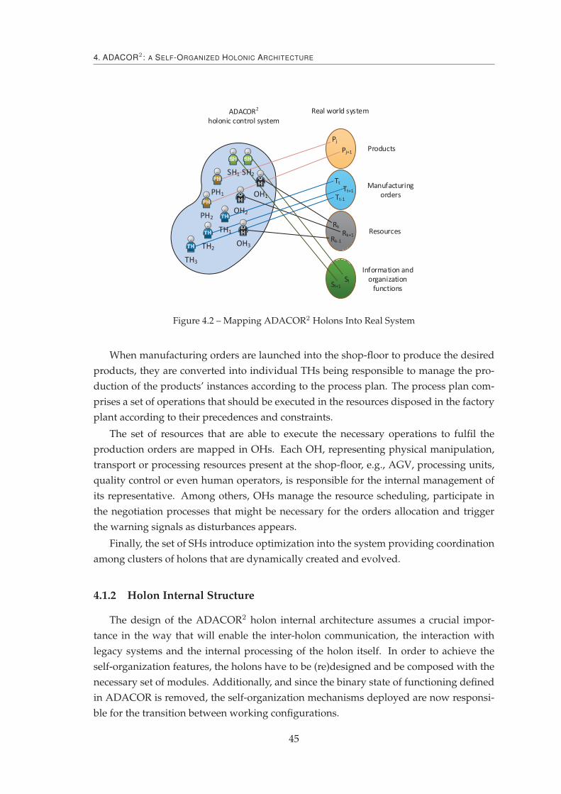
4. ADACOR2 : A SELF-ORGANIZED HOLONIC ARCHITECTURE
Products
Resources
Pj+1
Pj
Rk
Rk+1Rk-1
ADACOR2
holonic control system
PH2
Real world system
Manufacturing
ordersTt+1
Tt
Tt-1
Sl
Information and
organization
functionsSl+1
SH1 SH2
PH1
OH2
OH3TH2
TH3
TH1
OH1
Figure 4.2 – Mapping ADACOR2 Holons Into Real System
When manufacturing orders are launched into the shop-floor to produce the desired
products, they are converted into individual THs being responsible to manage the pro-
duction of the products’ instances according to the process plan. The process plan com-
prises a set of operations that should be executed in the resources disposed in the factory
plant according to their precedences and constraints.
The set of resources that are able to execute the necessary operations to fulfil the
production orders are mapped in OHs. Each OH, representing physical manipulation,
transport or processing resources present at the shop-floor, e.g., AGV, processing units,
quality control or even human operators, is responsible for the internal management of
its representative. Among others, OHs manage the resource scheduling, participate in
the negotiation processes that might be necessary for the orders allocation and trigger
the warning signals as disturbances appears.
Finally, the set of SHs introduce optimization into the system providing coordination
among clusters of holons that are dynamically created and evolved.
4.1.2 Holon Internal Structure
The design of the ADACOR2 holon internal architecture assumes a crucial impor-
tance in the way that will enable the inter-holon communication, the interaction with
legacy systems and the internal processing of the holon itself. In order to achieve the
self-organization features, the holons have to be (re)designed and be composed with the
necessary set of modules. Additionally, and since the binary state of functioning defined
in ADACOR is removed, the self-organization mechanisms deployed are now responsi-
ble for the transition between working configurations.
45

4.1. System Architecture
As illustrated in Figure 4.3, the holon can be divided into two major parts (Leitão
and Restivo, 2006): information and physical part. The information part relates to the
processing capacity of the holon itself and regulates the internal and external communi-
cation. The physical part represents the "real world", mapping different physical system
components, such as resources and products.
Figure 4.3 – Holon Internal Structure
The information part of the holon comprises several modules organized in three ma-
jor blocks, namely communication, interface and decision.
The communication module provides the communication capabilities to the holon,
comprising two sub-modules that allow a direct communication with other holons and
with the environment.
The interface module provides, when needed, a connection to the physical devices,
legacy systems and/or displays information to the users using a friendly GUI (Graph-
ical User Interface), which allows a real time monitoring of the holon state and at the
same time the interaction with the user. With this interface, each holon is able to repre-
sent physical systems, like robots or machines, and interface with legacy systems of the
company, such as MES or ERP.
The main core part of the holon internal structure is the decision module, which is
further decomposed in sub-modules responsible to monitor and discover events, to take
control actions, to manage self-organization, and control nervousness.
The holon internal processing engine is responsible for managing the information
flow within the holon and for trigger the holons’ internal actions, such as read the envi-
ronment, send messages and supervise the holon’s behaviour. Basically, the processing
engine is responsible for managing the holon’ internal agenda.
The monitoring module is responsible for gathering information about the state of
46
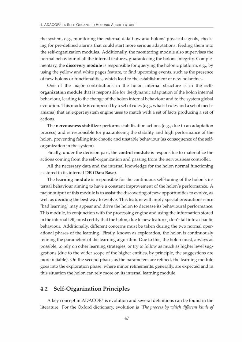
4. ADACOR2 : A SELF-ORGANIZED HOLONIC ARCHITECTURE
the system, e.g., monitoring the external data flow and holons’ physical signals, check-
ing for pre-defined alarms that could start more serious adaptations, feeding them into
the self-organization modules. Additionally, the monitoring module also supervises the
normal behaviour of all the internal features, guaranteeing the holons integrity. Comple-
mentary, the discovery module is responsible for querying the holonic platform, e.g., by
using the yellow and white pages feature, to find upcoming events, such as the presence
of new holons or functionalities, which lead to the establishment of new holarchies.
One of the major contributions in the holon internal structure is in the self-
organization module that is responsible for the dynamic adaptation of the holon internal
behaviour, leading to the change of the holon internal behaviour and to the system global
evolution. This module is composed by a set of rules (e.g., what-if rules and a set of mech-
anisms) that an expert system engine uses to match with a set of facts producing a set of
actions.
The nervousness stabilizer performs stabilization actions (e.g., due to an adaptation
process) and is responsible for guaranteeing the stability and high performance of the
holon, preventing falling into chaotic and unstable behaviour (as consequence of the self-
organization in the system).
Finally, under the decision part, the control module is responsible to materialize the
actions coming from the self-organization and passing from the nervousness controller.
All the necessary data and the internal knowledge for the holon normal functioning
is stored in its internal DB (Data Base).
The learning module is responsible for the continuous self-tuning of the holon’s in-
ternal behaviour aiming to have a constant improvement of the holon’s performance. A
major output of this module is to assist the discovering of new opportunities to evolve, as
well as deciding the best way to evolve. This feature will imply special precautions since
"bad learning" may appear and drive the holon to decrease its behavioural performance.
This module, in conjunction with the processing engine and using the information stored
in the internal DB, must certify that the holon, due to new features, don’t fall into a chaotic
behaviour. Additionally, different concerns must be taken during the two normal oper-
ational phases of the learning. Firstly, known as exploration, the holon is continuously
refining the parameters of the learning algorithm. Due to this, the holon must, always as
possible, to rely on other learning strategies, or try to follow as much as higher level sug-
gestions (due to the wider scope of the higher entities, by principle, the suggestions are
more reliable). On the second phase, as the parameters are refined, the learning module
goes into the exploration phase, where minor refinements, generally, are expected and in
this situation the holon can rely more on its internal learning module.
4.2 Self-Organization Principles
A key concept in ADACOR2 is evolution and several definitions can be found in the
literature. For the Oxford dictionary, evolution is "The process by which different kinds of
47

4.2. Self-Organization Principles
living organism are believed to have developed from earlier forms during the history of the earth"
or simply, "The gradual development of something" 1. Additionally, according to The Free
Dictionary, evolution is: "A gradual process in which something changes into a different and
usually more complex or better form." 2.
4.2.1 Evolution and Self-Organization
Evolution in ADACOR2, as shown in Definition 1, is defined by relating the capabil-
ity to dynamically find new configurations points, under given conditions, allowing the
system to work in a stable state with the best performance possible.
Definition 1 (Evolution) The process by which, overtime, the system or entity, in an organized
way, adapts into new internal or external situations, handling this way disturbances by finding
better working configurations. In can be seen as the sum of self-organization and adaptation over
time. It is also characterized by allowing a continuous or punctuated evolution between stable
states towards a goal or objective.
To this respect, evolutionary theories provide several answers, where a multitude of
theories are presented with some with significant opposite visions. Probably the most
renowned evolutionary theory was developed by Charles Darwin and were published
in the book entitled "On the origin of species" (Darwin, 2007). In this book, Darwin
states that overtime species tend to make small internal changes in order to adapt to
their environment, phenomenon also known as the survival of the fittest. Having this in
mind, one can anticipate that depending on its position on the system, each entity must
adapt itself to its local surroundings and overtime can have different "feel and look". This
behaviour is shown in Figure 4.4b), where a smooth evolution of the system over time
can be observed. In ADACOR2, this is translated into the entities internal evolution by
allowing them to add, remove or refine their behaviours.
In an opposite direction, the punctuated equilibrium theory (Eldredge and Gould,
1972) states that species tend to be in a stable state for long periods of time and suddenly
make a drastic change, as it is illustrated in Figure 4.4a). In this theory, systems would
make a more drastic change into itself.
Similar concepts can be found in the manufacturing world where the kaizen philos-
ophy states that the system can be improved through small continuous changes while
the kaikaku philosophy considers that drastic changes improve the system performance
(Kettunen, 2010).
These two opposite theories has then been merged, as shown in Figure 4.4c), and are
the working base behind the insights to develop the ADACOR2 manufacturing control
architecture.
These two dramatically different approaches, found either in evolutionary theories
or manufacturing strategies, offer insights to respond to unexpected events in an agile
1. www.oxforddictionaries.com/definition/english/evolution2. www.thefreedictionary.com/evolution
48

4. ADACOR2 : A SELF-ORGANIZED HOLONIC ARCHITECTURE
Ev
olu
tio
n
a)
b)
c)
a) drastic change
b) smooth evolution
c) desired behaviour (ADACOR2)
Figure 4.4 – Darwin’s and Punctuated Evolution Theories
manner. Having this in mind, ADACOR2 proposes a two-dimensional self-organization
model that considers mechanisms at micro and macro level, unleashing the two pre-
defined states as defined in ADACOR. In this way, the combination of smooth and drastic
system evolution will enable the discovery of a multitude of configurations on which the
system can operate, as illustrated in Figure 4.1. The opportunity to work on a multitude
of configurations is probably the major difference between the two versions of ADACOR
architecture. On one side, the system can be on a stationary or in a transient way, on the
other, the system can dynamically adapt itself either by introducing a smooth or a drastic
evolution.
The self-organization can be achieved through the interactions between all the differ-
ent entities present in the system. This type of self-organization is observed throughout
the nature and has proved to be very effective in swarms for problem solving. To support
the dynamic evolution of the proposed architecture a two way self-organization will be
deployed in the system.
At this point, it is crucial to define the meaning given to self-organization in this
document.
Definition 2 (Self-Organization) A set of processes by which an entity or system has the abil-
ity, in an autonomous and spontaneous way to re-arrange itself by means of multiple interactions
and feedback mechanisms. This arrangement always aims at performance increment and system
stability.
These interactions, by following nature-inspired mechanisms, aim to be as simple as
possible and with the least necessary communication overload. For each type of neces-
sity (e.g., disturbance or need for reconfiguration), each designated entity will embed a
set of mechanisms that will allow the system to overcome and evolve into a more opti-
mized and stable functioning. To support these ideas, all the entities will be supported
by learning mechanisms.
49
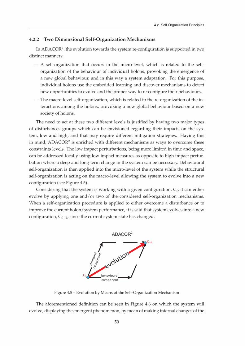
4.2. Self-Organization Principles
4.2.2 Two Dimensional Self-Organization Mechanisms
In ADACOR2, the evolution towards the system re-configuration is supported in two
distinct manners:
— A self-organization that occurs in the micro-level, which is related to the self-
organization of the behaviour of individual holons, provoking the emergence of
a new global behaviour, and in this way a system adaptation. For this purpose,
individual holons use the embedded learning and discover mechanisms to detect
new opportunities to evolve and the proper way to re-configure their behaviours.
— The macro-level self-organization, which is related to the re-organization of the in-
teractions among the holons, provoking a new global behaviour based on a new
society of holons.
The need to act at these two different levels is justified by having two major types
of disturbances groups which can be envisioned regarding their impacts on the sys-
tem, low and high, and that may require different mitigation strategies. Having this
in mind, ADACOR2 is enriched with different mechanisms as ways to overcome these
constraints levels. The low impact perturbations, being more limited in time and space,
can be addressed locally using low impact measures as opposite to high impact pertur-
bation where a deep and long term change in the system can be necessary. Behavioural
self-organization is then applied into the micro-level of the system while the structural
self-organization is acting on the macro-level allowing the system to evolve into a new
configuration (see Figure 4.5).
Considering that the system is working with a given configuration, Ci, it can either
evolve by applying one and/or two of the considered self-organization mechanisms.
When a self-organization procedure is applied to either overcome a disturbance or to
improve the current holon/system performance, it is said that system evolves into a new
configuration, Ci+1, since the current system state has changed.
ADACOR2
Figure 4.5 – Evolution by Means of the Self-Organization Mechanism
The aforementioned definition can be seen in Figure 4.6 on which the system will
evolve, displaying the emergent phenomenon, by mean of making internal changes of the
50
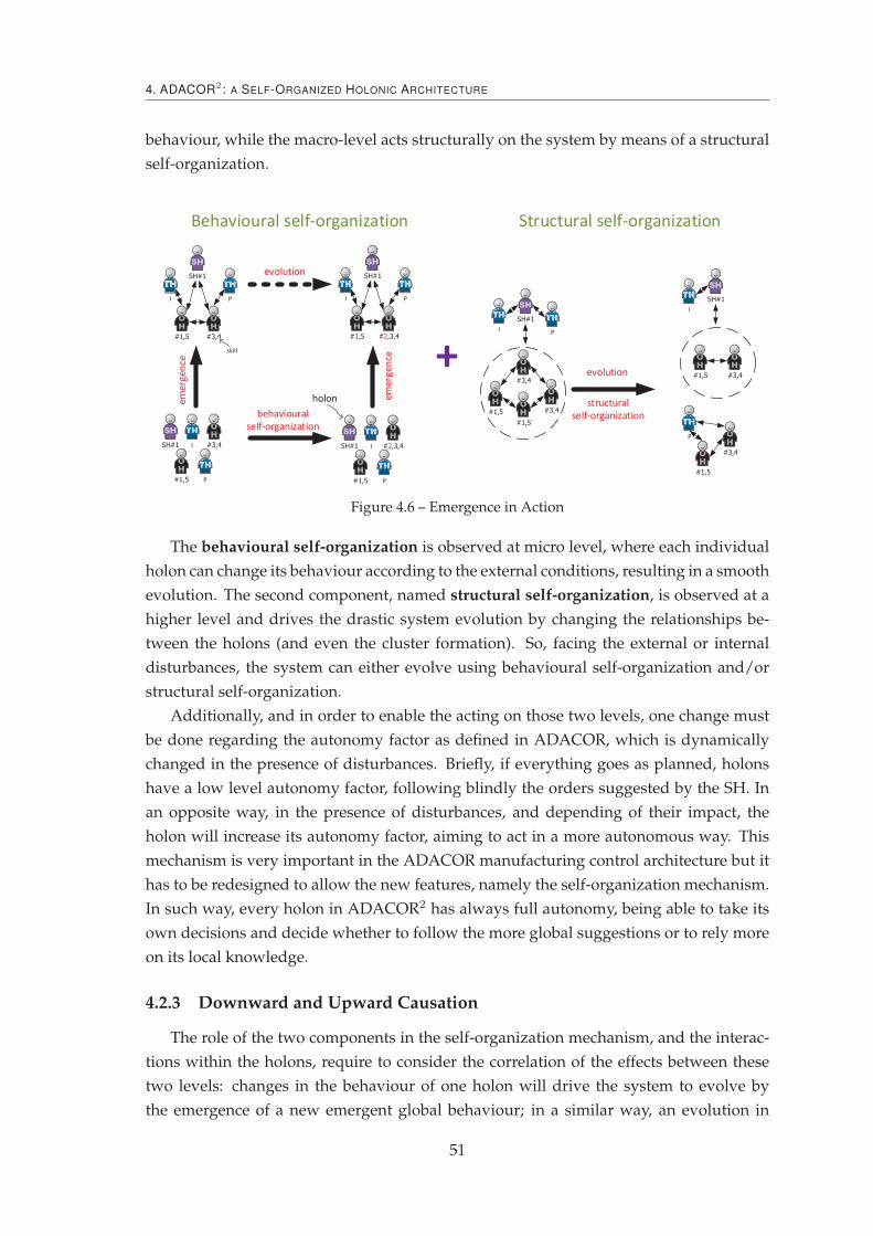
4. ADACOR2 : A SELF-ORGANIZED HOLONIC ARCHITECTURE
behaviour, while the macro-level acts structurally on the system by means of a structural
self-organization.
Figure 4.6 – Emergence in Action
The behavioural self-organization is observed at micro level, where each individual
holon can change its behaviour according to the external conditions, resulting in a smooth
evolution. The second component, named structural self-organization, is observed at a
higher level and drives the drastic system evolution by changing the relationships be-
tween the holons (and even the cluster formation). So, facing the external or internal
disturbances, the system can either evolve using behavioural self-organization and/or
structural self-organization.
Additionally, and in order to enable the acting on those two levels, one change must
be done regarding the autonomy factor as defined in ADACOR, which is dynamically
changed in the presence of disturbances. Briefly, if everything goes as planned, holons
have a low level autonomy factor, following blindly the orders suggested by the SH. In
an opposite way, in the presence of disturbances, and depending of their impact, the
holon will increase its autonomy factor, aiming to act in a more autonomous way. This
mechanism is very important in the ADACOR manufacturing control architecture but it
has to be redesigned to allow the new features, namely the self-organization mechanism.
In such way, every holon in ADACOR2 has always full autonomy, being able to take its
own decisions and decide whether to follow the more global suggestions or to rely more
on its local knowledge.
4.2.3 Downward and Upward Causation
The role of the two components in the self-organization mechanism, and the interac-
tions within the holons, require to consider the correlation of the effects between these
two levels: changes in the behaviour of one holon will drive the system to evolve by
the emergence of a new emergent global behaviour; in a similar way, an evolution in
51

4.3. Behavioural Perspective
the holons behaviour will occur after a structural self-organization. A graphical explana-
tion is presented in Figure 4.7 using the Coleman’s boat analogy (Coleman, 1994), which
explains these interrelations in detail.
Figure 4.7 – Coleman’s Boat View in ADACOR2
A change in the structural relations between holons implies a downward causation
that will change the behaviour of individual holons making them to adapt themselves
to optimize their individual behaviour to face the new organization. On the other side,
a change in the behaviour of holons at the micro-level may imply an upward causation
that affects the structure of the relations between holons.
The following chapters will describe the two self-organization components, namely
behavioural and structural.
4.3 Behavioural Perspective
The behavioural self-organization contributes at micro level to the global self-
organization found in the ADACOR2 architecture (Barbosa et al., 2013a). This self-
organization component, seen as the way to achieve the smooth evolution of the sys-
tem facing unexpected changes in normal conditions, is achieved by the selection of the
proper behaviour, from a catalogue of behaviours, using a behaviour selection engine.
Every holon is aware of its surrounding environment, and when a disturbance is de-
tected, it starts the behavioural self-organization process that will culminate with the
selection of the most appropriate behaviour for the new working conditions, as shown in
Figure 4.8.
For this purpose, each holon is continuously monitoring its state and its environment,
seeking an opportunity to evolve, as well as being aware of any external evolution trigger.
Depending on the trigger type, the holon self-organizes by selecting the right behaviour
from the set of known behaviours Bh ={
Bh1 , B
h2 , ..., B
hb
}
.
52

4. ADACOR2 : A SELF-ORGANIZED HOLONIC ARCHITECTURE
Figure 4.8 – Behavioural Self-Organization
This selection is accomplished when the adequate behaviour is used at the exact mo-
ment with the lowest impact on the overall system. This type of self-organization will
push the system to a new operating point, i.e. a new configuration, produced by internal
changes to cope with new constraints. In this sense, the behavioural self-organization of
ADACOR2 is defined as:
Definition 3 The change in the internal state of the holon using a set of internal rules and mech-
anisms, triggered in response to a plan deviation or a new evolution opportunity, with the aim of
re-establishing normal functioning or improving performance.
From a behavioural self-organization perspective, a plan deviation is detected or an
evolution opportunity is discovered by the processing engine embedded in the holon,
e.g., matching a set of rules with the available data or facts.
4.3.1 Principles and Composition
Generically, a behaviour is constituted by a set of input data, a set of rules and the
output data (as shown in Figure 4.9).
The input data defines the necessary data for the proper function of the behaviour,
without which it cannot be executed. The core of the behaviour composition is its set
of rules that processes the input data to produce an output. On its turn, the output
is decomposed into three groups of data: KPI (Key Performance Indicator), measures
and post-processing actions. The KPI is the expected performance indicator, while the
measures are the set of procedures necessary to implement the behaviour. Finally, the
post-processing actions relates to possible procedures taken after the application of the
behaviour.
These actions include propagation policies used to warn other holons about the
change of the behaviour, data policies used to update possible environment parameters
53

4.3. Behavioural Perspective
Input data
Ouput data
RulesAuxiliary
functionsParameters
KPI
Post-processing actions
Measures
Figure 4.9 – Composition of a Generic Behaviour
used in the behaviour and feedback policies used as input to the learning module to give
a real KPI to the behaviour. The later is used to refine the parameters of the rules/process.
The behavioural module proposes a change every time a given behaviour produces
an improvement of the actual holon KPI. Additionally, the input or the output data may
have auxiliary functions to support gathering or generating the needed data.
Figure 4.10 extends the holon internal structure (see Figure 4.3) and depicts the self-
organization module regarding the behaviour perspective. There, it can be observed
that low level events, those that came from the physical system, and high level events,
those coming from the holonic infra-structure, are being constantly monitored and stored
into its internal DB. These events or facts act like trigger signals to the behavioural self-
organization, which are then feed into the decision making engine that matches them
with the known behaviour rules.
The decision making process is accomplished using global data from ADACOR2 high
level holons, namely SHs, and local data from the holons’ local knowledge. In this way,
the detection of plan deviations, using the monitoring module, is sustained by means of
access to global and local information. The access to the global information, related to
the most optimized functioning, guarantees that behavioural decisions take into account
broader, long-term solutions, thus decreasing the need for a new behavioural adaptation
in the short term. On the other hand, local information supports the system reactivity by
allowing the entity to access local data that at the moment of decision is more accurate,
i.e. more up-to-date. Despite the faster refresh rate of this data, it suffers from myopia in
the sense that it represents a local, partial view of a smaller area of action (Barbosa et al.,
2011), and so global data must be used whenever possible.
All this process is supported by the learning module, which is responsible to gather
and accumulate knowledge from the holon internal DB or from the feedback information
about behaviours and create new knowledge by adding, removing or changing rules
54
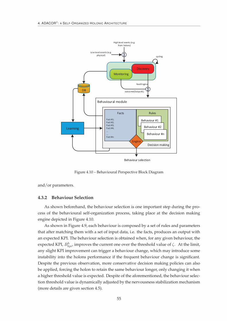
4. ADACOR2 : A SELF-ORGANIZED HOLONIC ARCHITECTURE
Figure 4.10 – Behavioural Perspective Block Diagram
and/or parameters.
4.3.2 Behaviour Selection
As shown beforehand, the behaviour selection is one important step during the pro-
cess of the behavioural self-organization process, taking place at the decision making
engine depicted in Figure 4.10.
As shown in Figure 4.9, each behaviour is composed by a set of rules and parameters
that after matching them with a set of input data, i.e. the facts, produces an output with
an expected KPI. The behaviour selection is obtained when, for any given behaviour, the
expected KPI, Bhkpi, improves the current one over the threshold value of ζ. At the limit,
any slight KPI improvement can trigger a behaviour change, which may introduce some
instability into the holons performance if the frequent behaviour change is significant.
Despite the previous observation, more conservative decision making policies can also
be applied, forcing the holon to retain the same behaviour longer, only changing it when
a higher threshold value is expected. Despite of the aforementioned, the behaviour selec-
tion threshold value is dynamically adjusted by the nervousness stabilization mechanism
(more details are given section 4.5).
55

4.3. Behavioural Perspective
When more that one behaviour is eligible to be use, i.e. when an improvement over
the current holon KPI is expected, the behaviour that produces the higher improvement
is considered. Alternatively, a multi-criteria function can be considered by combining
multiple parameters in the behaviour selection. A good example in the manufacturing
domain can be the selection of the behaviour that combined produces the higher im-
provement with the less impact in the system. Note that, for the example, some mech-
anisms to infer the impact of the behaviour change in the system must be embedded in
the holon internal structure.
At the end of this process, the selected behaviour is sent to the nervousness controller
that will enable its application.
4.3.3 Evaluating and Refining
The evaluation post-processing action is triggered each time the holon ends a self-
organization procedure that produced a change in the holon behaviour.
Each time the holon interacts with other holons, as illustrated in Figure 4.11, it will
gather the performance indicator which is then evaluated. In the case of the existence of
a deviation from the initial plan, an internal trigger will be issued to the behavioural self-
organization module, which will check the performance indicators for plan deviations in
order to have a behavioural change or keep the current behaviour. In the case this plan
deviation exceeds a pre-determined trigger the holon will propagate this event into the
affected holons allowing them to deeply analyse and take pro-active measures.
Figure 4.11 – Evaluating and Refining the Holon Behaviour
At the end of the holon life-cycle, i.e. when the holon has fulfilled all of its purposes,
all the gathered knowledge will be sent, if possible, to the correspondent high level holon
56

4. ADACOR2 : A SELF-ORGANIZED HOLONIC ARCHITECTURE
(in the example of figure 4.11, the TH sends to the PH). This enables a behavioural refine-
ment in future holons, e.g., the PH learning module will refine the behaviour parameters
for future holons.
4.3.4 Behaviour Propagation
A basic rule to obtain a self-organized system relies in the interactions between en-
tities and the information exchanged among them. In the same way, ADACOR2 holons
follow a sociable or genetic paradigm of knowledge sharing. This sharing allows the en-
tities to exchange information about behavioural techniques and to, in a distributed or
centralized way, to classify them by its usefulness. This information propagation can be
done in a direct way, i.e. when it is transmitted from holon to holon, or using indirect
transmission, using the environment as the mean to share the behaviour.
These behaviour propagation methods will also serve as a way for the holons to assess
the data relevance. Some parameters are used to measure the behaviour usefulness, such
as the number of holons that have used it, its success rate or improvement rate. The set
of parameters used to assess the behaviours are described as follows:
— Count: number of times that holons have used this behaviour.
— Success rate: number of times an holon has used this behaviour and it has been
beneficial for the holon.
— Success trend: depicts the trend of success of the last n times the behaviour was
used.
— Information freshness: how far away in time was made the last information update.
— Location: place where the behaviour code is stored.
— Improvement rate: states the improvement on the holons performance by selecting
this behaviour.
— Improvement trend: indicates the trend of the improvement on the last n times the
behaviour was used.
— Variance: indicates how spread are the improvement rates.
The use of the aforementioned parameters allows the holons to assess the usefulness
of each behaviour. In this way, the number of holons that have used the behaviour is the
first one, once as greater this number, the higher is the relevance of the data, since more
holons have contribute to its creation. Secondly, the success rate of the behaviour usage
informs about the beneficial of usage of it.
4.3.4.1 Direct Propagation
This behavioural propagation sets foundation in two distinct phenomena that can
be observed in nature. The first is the phenomena where animals are changing their
57

4.3. Behavioural Perspective
behaviour by mimicking others from the same species. Recalling the parable of the blue-
tit birds and the milk bottles described in (Koestler, 1969), where, by the promotion of
randomness, some blue-tit birds discover that the milkman put bottles of milk at the
clients doorstep and discover how to open those. After some time, the knowledge of the
milkman habit and the process of how to open the bottles is propagated to other blue-
tit birds. The second phenomena is that, on a second generation of blue-tit birds, this
behaviour is already engraved into the genetic property of them and is naturally part of
their behaviour.
In such way, the direct propagation of behaviour can be seen in two different ways.
A vertical way, where the behaviour is transmitted downward from a high level entity to
a lower one, similarly to the genetic engraving of the behaviour. And, the second way,
or horizontally, the behaviour is transmitted between peers at the same decisional level
inside the same holarchy.
The vertical behaviour propagation is relatively easy to achieve, since the high level
holon is aware of its subordinates and can send them the new behaviours or simply
inform them of parameters updates on those that they already possess. Additionally, this
process can be done in the time of the creation of new generation entities by embedding
the new behaviours.
The horizontal propagation is achieved by being aware of the existence of other
holons at the same level and send them the information update of the behaviour pa-
rameters or the information of how to access a new behaviour. In this way, each holon
will send behaviour information to other peers when it allows to achieve good results.
The receiving holons evaluate the information received and can request the behaviour
details in order to acquire it.
4.3.4.2 Indirect Propagation
The indirect behaviour propagation is considered to be holon driven in the sense that
it is the own holon that is in search for behaviour alternatives that explores it. In this
way, the holons may have the possibility to store and to manage behaviour related in-
formation. Figure 4.12 depicts an example involving the TH and the OH. So, every time
THs interact with one OH, they will inquiry it for the known behaviour list and their
parameters. The TH uses this enquiry to assess the most reliable behaviours feeding this
information into the learning module for internal parameters refining. Additionally, if
the TH receives an unknown behaviour, it will evaluate it based on the provided infor-
mation, i.e. if the new behaviour has similar or better KPIs of the known behaviours, and
will acquire it for future consideration.
On the opposite side, if the TH possess an unknown behaviour for the OH, it will
transmit this information in conjunction with the KPIs.
Higher level entities, such as SHs, are cyclically searching for the behaviours evolu-
tion at the low level entities. By querying the low level entities, they are aware of the
58
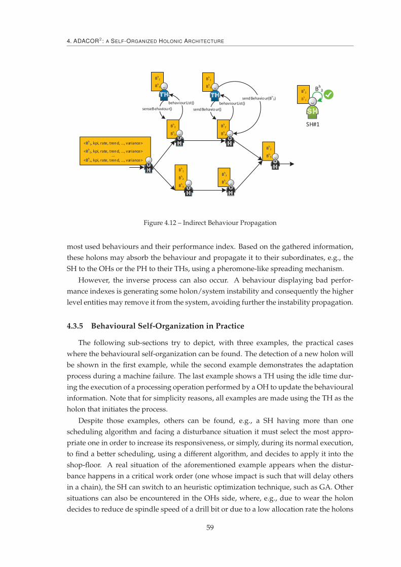
4. ADACOR2 : A SELF-ORGANIZED HOLONIC ARCHITECTURE
Figure 4.12 – Indirect Behaviour Propagation
most used behaviours and their performance index. Based on the gathered information,
these holons may absorb the behaviour and propagate it to their subordinates, e.g., the
SH to the OHs or the PH to their THs, using a pheromone-like spreading mechanism.
However, the inverse process can also occur. A behaviour displaying bad perfor-
mance indexes is generating some holon/system instability and consequently the higher
level entities may remove it from the system, avoiding further the instability propagation.
4.3.5 Behavioural Self-Organization in Practice
The following sub-sections try to depict, with three examples, the practical cases
where the behavioural self-organization can be found. The detection of a new holon will
be shown in the first example, while the second example demonstrates the adaptation
process during a machine failure. The last example shows a TH using the idle time dur-
ing the execution of a processing operation performed by a OH to update the behavioural
information. Note that for simplicity reasons, all examples are made using the TH as the
holon that initiates the process.
Despite those examples, others can be found, e.g., a SH having more than one
scheduling algorithm and facing a disturbance situation it must select the most appro-
priate one in order to increase its responsiveness, or simply, during its normal execution,
to find a better scheduling, using a different algorithm, and decides to apply it into the
shop-floor. A real situation of the aforementioned example appears when the distur-
bance happens in a critical work order (one whose impact is such that will delay others
in a chain), the SH can switch to an heuristic optimization technique, such as GA. Other
situations can also be encountered in the OHs side, where, e.g., due to wear the holon
decides to reduce de spindle speed of a drill bit or due to a low allocation rate the holons
59

4.3. Behavioural Perspective
decides to have a more competitive behaviour, e.g., by changing the bidding functions.
4.3.5.1 The Arrival of a New Holon
A first practical example of behavioural self-organization is related to the appearance
of a new holon in the system, as illustrated in Figure 4.13 (note that this also implies a
change in the holarchy structure which is not focused on this description). Lets suppose
that a given TH has all the work orders in its schedule assigned and that this TH has
subscribed to be alerted to possible additions or removals of services that can be useful
for it. In other words, the TH has subscribed to all the services that are still needed to
fulfil the remaining work orders until the completeness of the process.
At a given point in time, a OH registers three services, namely #2, 3#, #4 (marked with
yellow in Figure 4.13).
Figure 4.13 – Behavioural Self-Organization in Practice: Detection of a New Holon
The arrival of the new holon is detected by the discovery module, present in the
holon, feeding the behavioural module with this information. Thereafter, the TH starts
the self-organization procedure, running all the known behaviours, collecting the most
advantage situation, deciding either to keep the current stable behaviour or changing
into a more reactive behaviour and re-schedule considering the new OH. The output of
this procedure is then evaluated by the nervousness stabilizer (see section 4.5) to guar-
antee that the achieved KPIs, e.g., the reduction on production time or maximization of
resource utilization, are worthy of the change.
Finally, and if the change is approved by the nervousness mechanism, the holon ap-
plies all the necessary measures for its implementation, as shown in Figure 4.14. In the
present case, two OHs are informed of cancelled operations and the new arrived holon of
an allocation. Note that, for simplicity reasons, possible negotiation process are omitted
60
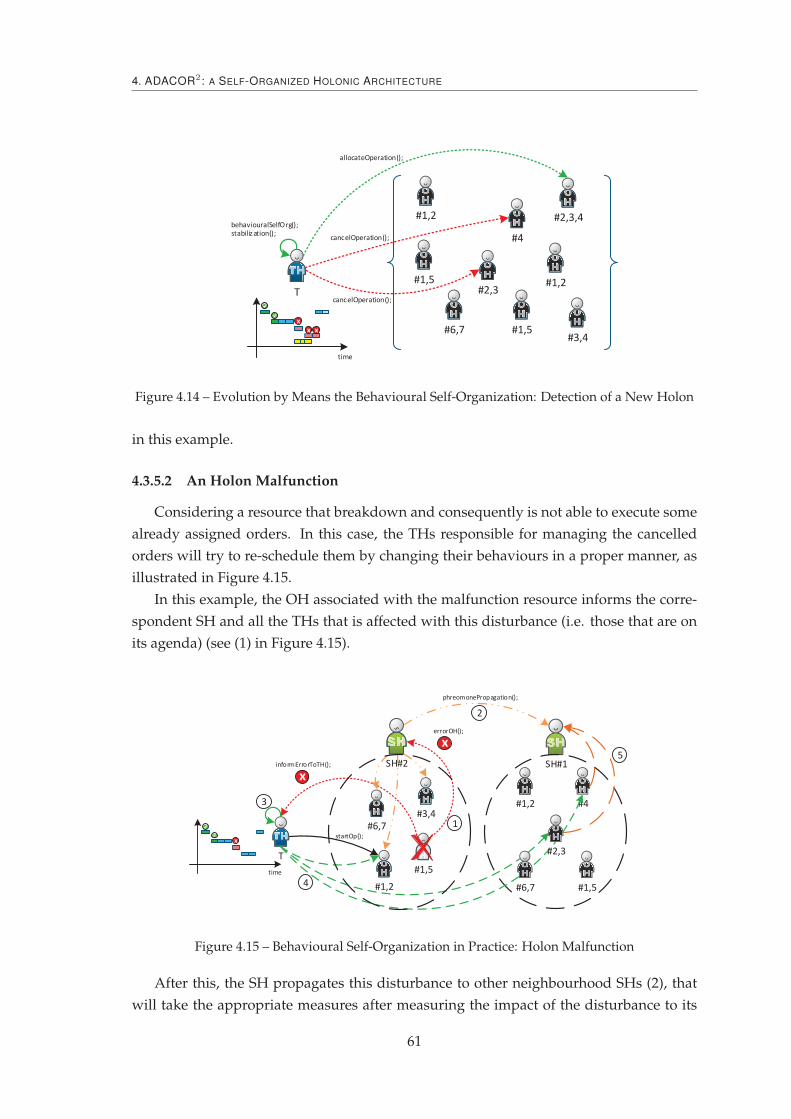
4. ADACOR2 : A SELF-ORGANIZED HOLONIC ARCHITECTURE
Figure 4.14 – Evolution by Means the Behavioural Self-Organization: Detection of a New Holon
in this example.
4.3.5.2 An Holon Malfunction
Considering a resource that breakdown and consequently is not able to execute some
already assigned orders. In this case, the THs responsible for managing the cancelled
orders will try to re-schedule them by changing their behaviours in a proper manner, as
illustrated in Figure 4.15.
In this example, the OH associated with the malfunction resource informs the corre-
spondent SH and all the THs that is affected with this disturbance (i.e. those that are on
its agenda) (see (1) in Figure 4.15).
Figure 4.15 – Behavioural Self-Organization in Practice: Holon Malfunction
After this, the SH propagates this disturbance to other neighbourhood SHs (2), that
will take the appropriate measures after measuring the impact of the disturbance to its
61

4.4. Structural Perspective
internal normal functioning, and to all the OHs that belong to its hierarchy. Similarly to
already happen with ADACOR, the low level holons are now more reactive, increasing
their responsiveness and now can react by selecting the most appropriate behaviour.
Meanwhile, the affected THs realize (3) that this disturbance may imply a decrease of
the holon KPIs, e.g., a delay in the delivery due date. In response to this, the TH changes
its behaviour by changing from a more steady one (i.e. one taking into consideration the
accumulated knowledge from the SH or global data) into a more reactive one, e.g., to one
relying more on local information.
In the present example, some work orders are re-assigned to the available OHs, being
some assigned to OHs under the SH1 hierarchy while others are kept assigned to the OH
(4).
After the direct negotiation process, the OHs send their schedules to their SHs (5),
which will be responsible to synchronize the achieved schedules and check whether there
is any further possibility of optimization.
4.3.5.3 Using the Idle Time Properly
The TH can assume one of two approaches: passive or active. In the first one, the TH
representing an instance of a product to be produced receives the processing information
and follows it in a "blind" manner, i.e. it is not able to change it during its life-cycle. As
opposite, in the second situation, the TH assumes an active participation in the manufac-
turing process, by influencing the decision taken during the life-cycle. The last paradigm
is becoming immensely popular and is known as Intelligent Product (McFarlane et al.,
2003; Meyer et al., 2009; Sallez et al., 2009) and is being used in the TH to increase its
potentialities.
Particularly to the described previously, every time that the TH has to take a decision
and regardless of any trigger event, it initiates, in an active manner, the behavioural self-
organization module. This process is executed during the idle time, i.e. when the TH
is waiting for a processing finish, and involves an update of the behaviour information
related with the holons’ behaviour. This information is stored in the OHs which the TH
is interacting with.
In this case, and based on the new informations the TH might decide to keep the
current behaviour or change it, which could culminate in a more reactive behaviour.
4.4 Structural Perspective
The structural self-organization presents a means of drastic evolution, re-arranging
the relationships between the holons and/or their organization (Barbosa et al., 2013b).
This change of relations can be limited within a group or take broader impact, imposing
a relationship change in a wider system range. In this way, each holon has embedded a
set of mechanisms, Rh ={
Rh1 , R
h2 , ..., R
hr
}
that allows the re-arrangement of its relations
62

4. ADACOR2 : A SELF-ORGANIZED HOLONIC ARCHITECTURE
group. Formally, in this work, structural self-organization can be defined as:
Definition 4 The change in the relationships between holons, and consequently the change in the
holarchy structure, which is triggered in response to a deep impact plan deviation, thus promoting
a drastic response that aims to re-establish normal system functioning or improve its performance.
Going back to the interdependencies between the behavioural and structural self-
organization, one can foresee that the change in the behaviour of one holon can drive the
change in its relations and consequently in its nearby structure. Additionally, the change
of the structure of the system can also be triggered as consequence of any disturbance that
appear in the system, such as a plan deviation and an add/removal of a resource. The
need for the structural self-organization must be evaluated by the holon internal mech-
anisms and decided based on the current facts, on the structural output KPI mechanism
and on the impact of the necessary implementation measures.
Finally, this self-organization vector can also have impacts on a real change at physical
level, i.e. the reorganization at the holarchical level must be translated in the physical
layer, e.g., by imposing a resource layout change. This means that a logical change in
the holarchy would imply a real change in the physical or logical entities that the holons
represent.
In such set of possibilities, this type of reorganization is divided into three dif-
ferent levels, relating with the behavioural self-organization or pure structural self-
organization.
— Level 0 (emergence): relations between holons are changed as a consequence of
the behavioural self-organization. This happen when the result of the behavioural
self-organization implies a change in its relations, such as the selection of a new
resource for processing a previously allocated operation. This level of structural
change is classified as weak since it is not directly driven by the need.
— Level 1 (logical structural self-organization): each holon is constantly trying to opti-
mize its place within the holarchy structure. This constant optimization may drive
the holon to change the holarchy, to participate in several holarchies at the same
time or to act as a freelancer to work completely autonomously. This change only
has implications at the logical control layer.
— Level 2 (physical structural re-organization): similar to the level 1, but additionally
the holons, e.g., OHs, can physically change their place, changing not only their
relations and positions in the holarchy but also their physical position.
Particularly, the last two levels, i.e. levels 1 and 2, are related to the concepts envi-
sioned by the RMS paradigm of rapid change at the shop-floor level. In fact, at level 1,
one can assist to the logical re-organization on the control layer, which is mapped into
the software change of the RMS paradigm, and at level 2, a hardware change is achieved
by the physical re-arrangement of the resources present at the shop-floor.
63

4.4. Structural Perspective
4.4.1 Principles and Composition
The stimulus that can trigger a structural self-organization depends on the impact
on the system and can be of any type, i.e. a disturbance that disrupts or deviates the
predicted execution of the system or that allows the improvement its the current per-
formance. Examples of triggers that can start a structural self-organization can be the
appearance of an important manufacturing order, which would change the order priori-
tization, a rush order, an order cancellation, a production quality issue that could imply
a drastic change on the resource allocation process, a supply shortage, or a resource mal-
function.
Figure 4.16 depicts the evolutionary process idea behind the structural self-
organization. At a given configuration functioning point, the system is constituted by
a set of OHs within a single SH. In reaction to a disturbance, for this case the production
of two distinct products, the system re-arranges itself by cloning the SH and splitting of
the OH between these two SHs.
Figure 4.16 – Structural Self-Organization by Group Decomposition
The structural self-organization component, part of the self-organization module
found in Figure 4.3, is similar to the behavioural module. In such way, when the moni-
toring and discovery modules detect a plan deviation or opportunity to evolve, the struc-
tural self-organization process starts by launching all the known re-arrangement proce-
dures (note that those can, in the limit, be named as behaviours). Similarly, these pro-
cedures match a set of known facts with a set of necessary rules of each procedure. The
output result of this process is then evaluated by the nervousness controller (see section
4.5) that will allow (or not) the application of the structural self-organization.
Generically, each structural self-organization procedure is similar to what is found in
the behaviour composition and is constituted by a set of input data, the structural rules
64
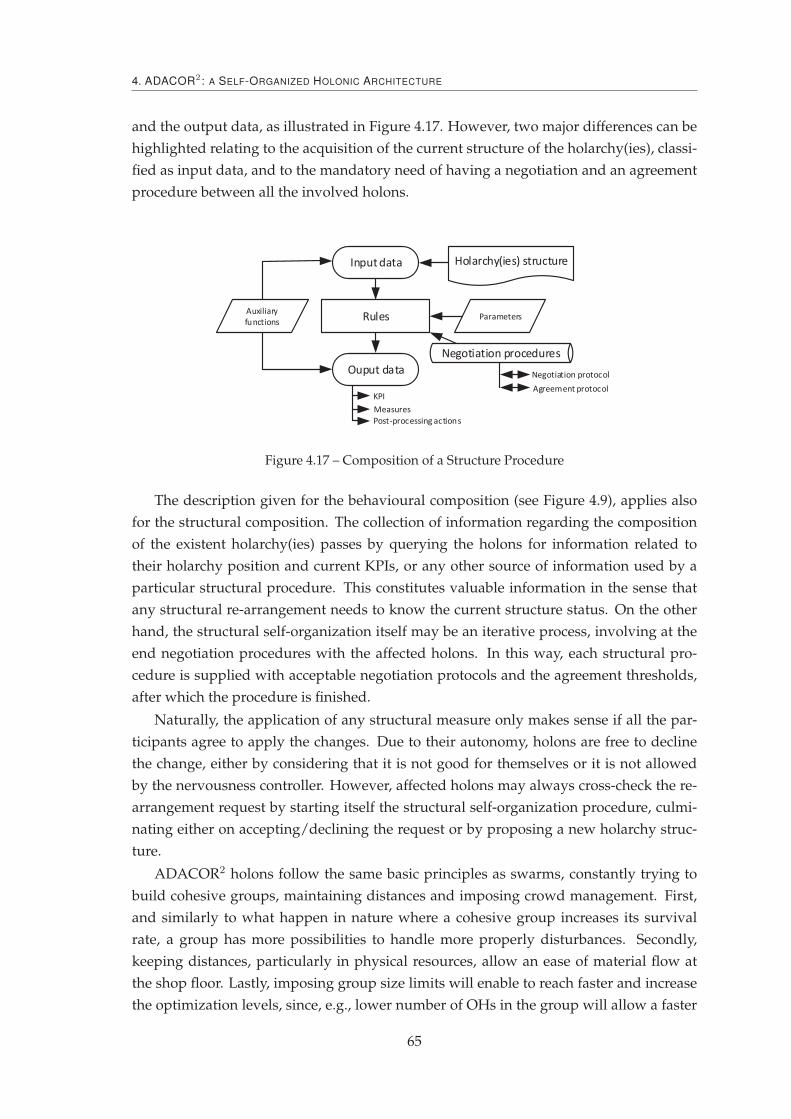
4. ADACOR2 : A SELF-ORGANIZED HOLONIC ARCHITECTURE
and the output data, as illustrated in Figure 4.17. However, two major differences can be
highlighted relating to the acquisition of the current structure of the holarchy(ies), classi-
fied as input data, and to the mandatory need of having a negotiation and an agreement
procedure between all the involved holons.
Input data
Ouput data
RulesAuxiliary
functionsParameters
KPI
Post-processing actions
Measures
Negotiation procedures
Holarchy(ies) structure
Negotiation protocol
Agreement protocol
Figure 4.17 – Composition of a Structure Procedure
The description given for the behavioural composition (see Figure 4.9), applies also
for the structural composition. The collection of information regarding the composition
of the existent holarchy(ies) passes by querying the holons for information related to
their holarchy position and current KPIs, or any other source of information used by a
particular structural procedure. This constitutes valuable information in the sense that
any structural re-arrangement needs to know the current structure status. On the other
hand, the structural self-organization itself may be an iterative process, involving at the
end negotiation procedures with the affected holons. In this way, each structural pro-
cedure is supplied with acceptable negotiation protocols and the agreement thresholds,
after which the procedure is finished.
Naturally, the application of any structural measure only makes sense if all the par-
ticipants agree to apply the changes. Due to their autonomy, holons are free to decline
the change, either by considering that it is not good for themselves or it is not allowed
by the nervousness controller. However, affected holons may always cross-check the re-
arrangement request by starting itself the structural self-organization procedure, culmi-
nating either on accepting/declining the request or by proposing a new holarchy struc-
ture.
ADACOR2 holons follow the same basic principles as swarms, constantly trying to
build cohesive groups, maintaining distances and imposing crowd management. First,
and similarly to what happen in nature where a cohesive group increases its survival
rate, a group has more possibilities to handle more properly disturbances. Secondly,
keeping distances, particularly in physical resources, allow an ease of material flow at
the shop floor. Lastly, imposing group size limits will enable to reach faster and increase
the optimization levels, since, e.g., lower number of OHs in the group will allow a faster
65
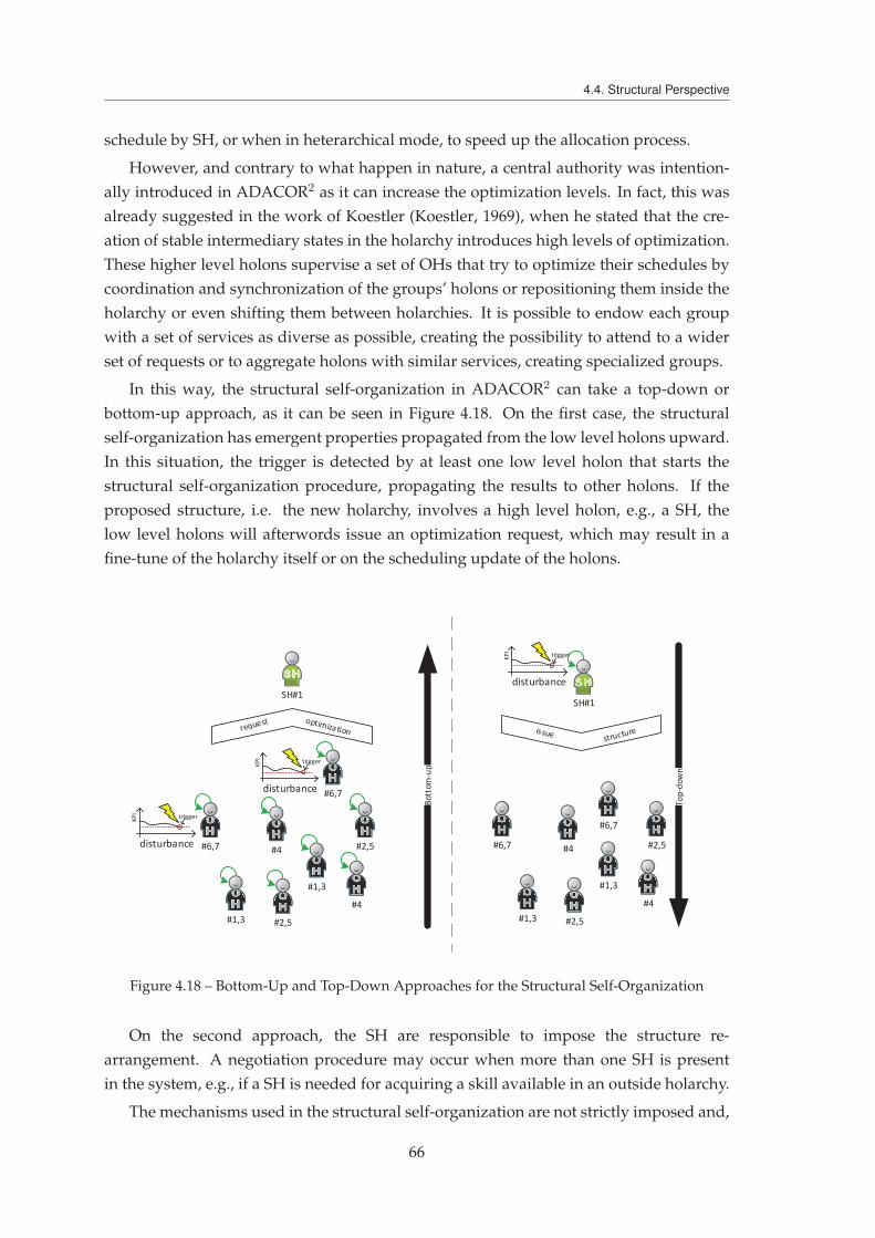
4.4. Structural Perspective
schedule by SH, or when in heterarchical mode, to speed up the allocation process.
However, and contrary to what happen in nature, a central authority was intention-
ally introduced in ADACOR2 as it can increase the optimization levels. In fact, this was
already suggested in the work of Koestler (Koestler, 1969), when he stated that the cre-
ation of stable intermediary states in the holarchy introduces high levels of optimization.
These higher level holons supervise a set of OHs that try to optimize their schedules by
coordination and synchronization of the groups’ holons or repositioning them inside the
holarchy or even shifting them between holarchies. It is possible to endow each group
with a set of services as diverse as possible, creating the possibility to attend to a wider
set of requests or to aggregate holons with similar services, creating specialized groups.
In this way, the structural self-organization in ADACOR2 can take a top-down or
bottom-up approach, as it can be seen in Figure 4.18. On the first case, the structural
self-organization has emergent properties propagated from the low level holons upward.
In this situation, the trigger is detected by at least one low level holon that starts the
structural self-organization procedure, propagating the results to other holons. If the
proposed structure, i.e. the new holarchy, involves a high level holon, e.g., a SH, the
low level holons will afterwords issue an optimization request, which may result in a
fine-tune of the holarchy itself or on the scheduling update of the holons.
Figure 4.18 – Bottom-Up and Top-Down Approaches for the Structural Self-Organization
On the second approach, the SH are responsible to impose the structure re-
arrangement. A negotiation procedure may occur when more than one SH is present
in the system, e.g., if a SH is needed for acquiring a skill available in an outside holarchy.
The mechanisms used in the structural self-organization are not strictly imposed and,
66
4. ADACOR2 : A SELF-ORGANIZED HOLONIC ARCHITECTURE
in principle, can be any that allows the system to perform such task. Despite this, cur-
rently the ADACOR2 holons draw inspiration from the social behaviour of schools of
fishes and flocks of birds since it is concluded that they work very well as a group, main-
taining the system equilibrium and e.g., avoiding predators (Leitão et al., 2012), which in
this case are external system disturbances.
Another concern to be tackled is related to the fact that this self-organization process
can be very time-consuming, which can be of major importance in large-scale systems in
which the amount of available information increases exponentially. This important con-
straint is solved by taking a system snapshot, i.e. the current system state, whenever there
is a disruptive event. This context-aware feature is complemented, at the end of the self-
organization process, with the actions taken and the achieved results (i.e. performance
indicators), allowing the decision assessment afterwards. Additionally, this process can
be enriched with data processing, e.g., data mining, to facilitate future processing by al-
lowing the system to find the best measures taken for similar events and start a warm
self-organization process, i.e. it is not necessary to discover a new configuration, only to
adapt a known one.
4.4.2 Structural Self-Organization in Practice
In order to illustrate the structural self-organization in practice, three examples are
provided in which a structural self-organization could be useful. The first is the intro-
duction of a big batch order, the second is a resource sharing due to a malfunction on a
similar one, while in the third case the creation of a new holarchy would introduce an
optimization on a given KPI .
4.4.2.1 Product Model Change
Lets assume that the system is functioning in a stable state with a given configuration,
and that a very large order arrives at a given point in time. After realizing this, the
system either through the SH holons due to a high demand in variation requests or by the
individual OHs due to a high number of variation proposals, will launch all the known
structural self-organization procedures (marked with number 1 in Figure 4.19).
In this example, all the holons, namely the OHs and SHs, start their structural self-
organization and in this case the SH2 detects a re-arrangement possibility (see the number
2 in Figure 4.19). After this, the SH2 holon informs its counterpart SH1, proposing the
new configuration. Once this process is finished, the SHs will inform their subordinates
of the necessary measures that need to be taken. In this example, the necessary measures
pass by applying a level 1 structural self-organization, since only a re-organization at the
logical level is imposed, as seen in Figure 4.20.
Two different re-organization situations can also be envisioned. First, in cases where
a pool of workers is available for disturbance situations, the new system configuration
67

4.4. Structural Perspective
P PP PI II I
SH#1
#1,2 #4
#6,7
#2,3
#1,5
SH#2
#1,2
#3,4
#6,7
#1,5
BE
L T
hugh batch
A AA A
time
time
...
~~
foundBetterStructure();sendStructureProposal();
agreeOnStructure();
1
2
Figure 4.19 – Huge Batch Order Arrival and New Structure Propagation
could imply the integration of one resource from the pool into one of the existing hol-
archy. Secondly, worker training and machine upgrade can also be possibilities by giving
those assets new skills.
SH#1
#1,2
#4
#6,7
#2,3
#1,5
SH#2
#1,2 #3,4
#6,7#1,5
P PP PI II I
BE
L T
A AA A
time
time
...
~~
Optimization of the overall
performance, e.g. Cmax reduction.
Figure 4.20 – Structural Self-Organization by OH Change
The process culminates with the exchange of holons between both groups, each su-
pervised by a SH and managing a batch of orders, i.e. the current and the new one.
4.4.2.2 Breakdown of a Crucial Resource
In this example, a crucial resource becomes unavailable, as illustrated in Figure 4.21.
The holon representing the physical resource informs its SH that will start a search,
through structural self-organization, for possibilities to mitigate this disturbance.
After the detection of the existence of other holon with the necessary skills, the SH1
negotiates a resource sharing with SH2 that checks with the affected holon for its avail-
ability to be shared. Once all counterparts agree, the re-organization is finished by allow-
ing both SHs to manage the OH agenda.
The shared holon is now under the supervision of the two SHs that must always
negotiate the processing time slots. In this way, every time a SH wants to perform an
68

4. ADACOR2 : A SELF-ORGANIZED HOLONIC ARCHITECTURE
Figure 4.21 – Structural Self-Organization by Resource Sharing
optimization in its holarchy, involving the shared OH, it must first gather the consent of
the other SH. In the same direction, every time some event happens with the OH, e.g., a
processing delay or breakdown, the OH informs both SHs, which will together find the
best compromising solution.
4.4.2.3 Holarchy Division Based on Specialization
This last example depicts a situation where the specialized work occurs often at shop-
floor, e.g., preparatory work common to all manufacturing orders.
In this way, in Figure 4.22, the skills #1 and #5 are the ones needed in all the man-
ufacturing orders. Those are considered to be crucial and the introduction of schedule
optimization into those resources could bring an increase of production performance.
Realizing this, SH1 informs SH2 about those facts.
SH#1
#3,4#4
#6,7
#2,3
#1,5
SH#2
#1,2 #3,4
#6,7#1,5
P PP PI II I
BEL T
A AA A
time
time
...
~~
foundCrucialOperation();
sendStructureProposal();
agreeOnStructure();
Figure 4.22 – Detection of a Crucial Operation as Trigger to Structural Self-Organization
After this, SH1 (the initiator) creates a new SH, transferring into it the new OHs (see
Figure 4.23). To finalize, the accumulated knowledge related to the transferred OHs of
69

4.5. Controlling Nervousness
both SHs is sent into the new one.
SH#1
#3,4 #4
#6,7
#2,3
#1,5
SH#2
#1,2
#3,4
#6,7
#1,5
P PP PI II I
BE
L T
A AA A
time
time
...
~~
Optimization of the overall
performance, e.g. Cmax reduction.
SH#11
knowledgeTransfer();
Figure 4.23 – Structural Self-Organization by Clustering
At this point, this specialized set of operations can then be prepared in a more opti-
mized way since a dedicated SH introduces improvements in the OHs scheduling.
4.5 Controlling Nervousness
One of the main problems that could appear in self-organized distributed au-
tonomous systems is instability due to the holons continuous behaviour change or con-
tinuous cycle of constant evolution/adaptation.
Besides how to know if a new solution brings better results than the previous one, it
is important to know if it will negatively affect the system performance. In such way, it
becomes important to bring this phenomenon into the system design allowing to push it
to its limits keeping it under control.
Parunak et al. (2003) use two mechanisms to calm hyperactive agents (Parunak et
al., 2003). The first one is related to what is classified as “on-going operations", iden-
tifying two agent’s characteristics: agents should be able to detect when their activities
are outside the scope and acknowledge when they can re-enter the system due to new
requirements. The described solution uses the stigmergy found in societies of insects,
allowing to merge multiple local data in order to take decisions in a more supported ba-
sis. The second mechanism delineates a way to divide exploration and exploitation times
relating them to the imposed deadline.
On the other hand, K. Hadeli et al. (2005) state that in case an agent wants to change
the initial ideas it is necessary to make a quality measurement of the new solution and
only if it is significantly better than the previous one the agent can change its intentions
70

4. ADACOR2 : A SELF-ORGANIZED HOLONIC ARCHITECTURE
(K. Hadeli et al., 2005). Additionally, the authors limit the frequency of changing the ini-
tial intentions, restringing the agent continuous willing to change. Another example can
be found in (Zbib et al., 2010) where the inspiration from magnetic fields helps products
to choose the most adequate route. In this mechanism, as resources are being occupied,
the attraction power emitted (designated by potential field) is reduced allowing products
to be routed in a decisive manner.
A reward based mechanism was proposed by (Hogg and Huberman, 1991) as the way
to freeze out the chaotic behaviour in distributed systems. Despite of not directly related
to the nervousness feature of individual entities, using the same principles might turn
out to be advantageous in the way that an excess of the individual nervousness levels of
entities can drive the system to display chaotic behaviour.
To cope with the nervousness issue, each individual ADACOR2 holon has a built-in
stabilization mechanism, comparable to car shock absorbers, to avoid instability first at
the holons level and secondly at the system level (Barbosa et al., 2012a). By introducing
these stabilizers, the system operates in such manner that it is pushed to its limits by
enhancing the self-organization principles, remaining always under control.
A two-layer approach is used, as illustrated in Figure 4.24, where the first one regu-
lates the changing will imposed by each self-organization module while the second level
assess the previous two nervousness controllers (one for each self-organization module),
deciding which emergent self-organization procedure will produce the most valuable ac-
tion.
Figure 4.24 – Stabilization Mechanism Embedded in ADACOR2 Holons
At each nervousness control process, the output of the decision is stored into a KB
(Knowledge Base), which later is used by the learning module to refine the parameters
of the nervousness stabilizer.
71

4.5. Controlling Nervousness
In order to or not allow the holon to change its actions, the nervousness stabilizer
must be aware of the current internal and external context on which the changes are to
be made. First, the holon must be aware of its internal nervousness level, Hσh , given by
the quotient between the number of changes (either behavioural or structural), ǫ, within
a time window, δ.
Hσh =
ǫ
δ(4.2)
Additionally, the number of changes, ǫ, is evaluated by the success of the past changes.
This is, the holon is allowed to change more often its behaviour or structure, if in the past
changes led to an increase of the performance. In this way, ǫ is calculated by:
ǫ =∑
n
akpi
pkpi(4.3)
where,
— n represents the number of last changes.
— akpi is the achieved KPI for the change n.
— pkpi is the previous KPI for the change n.
The assigned performance ranges from 0 to 1, being 0 for non-success and 1 to a
complete goal fulfil.
The external context, named SD (System Dynamics), allows to gather information
about how the system behaves, regarding, e.g., the work order arrival rate, disturbances
rate or even allocation rate to OHs. Each holon estimates the SD either by querying a
more global entity, namely the SH, or locally through querying cyclically the neighbours
holons.
Having this, the two level nervousness control model described previously are used
within the context of the Figure 4.25. In the figure, two control loops can be seen, be-
ing the internal one based on the holons’ nervousness level, with the one found on its
neighbours, while the outer correlates the nervousness level with the SD.
Figure 4.25 – Nervousness Controller System Dynamics
In the inner loop, the holon is able to compare its internal nervousness level with
the holons located at its neighbourhood. Using this comparison, each holon can see if it
is below or above the neighbourhood average nervousness level, deciding if its internal
level can be further increased or needs to be lowered, respectively. On the other hand,
72

4. ADACOR2 : A SELF-ORGANIZED HOLONIC ARCHITECTURE
the outer loop has broader information of the system nervousness levels and is an picture
of the dynamics present at the system, driving also the holons’ nervousness level limits.
Note that in order to react properly in higher system dynamics the holon could be more
nervous than what would be if the system dynamics are lower.
Despite all the aforementioned nervousness control loops, holons have a safeguard
mechanism, that ensures that if the majority of the holons participating on the change
decide that it is beneficial for the system, the holon(s) that are not allowed to change,
will change altogether. A tentative threshold value for this could be to use qualified
majority rules, such as the two-quarters or three-quarters (used for instance in many
countries to approve constitutions changes). In this case, if 2/3 or 3/4 of the holons
decide a change favourably, the rest will not block the system evolution and will also
implement the necessary changes.
4.6 Summary
This chapter describes the ideas and the main guidelines behind the ADACOR2 man-
ufacturing control architecture.
ADACOR2 takes inspiration in Darwin and punctuated equilibrium evolutionary the-
ories to propose a bi-dimensional self-organized holonic control architecture that better
addresses the reaction and responsiveness to condition changes without degrading the
system optimization. In this way, a smooth evolution, by means of constant adapta-
tion, is embedded into internal behaviour of the holons and is named behavioural self-
organization. Secondly, a more disruptive evolution is possible due to the re-arrangement
of the holons relations, named structural self-organization.
Both self-organization vectors were described as also some common underlying
mechanisms, such as the downward and upward causation effects.
Also, the nervousness phenomena inherent to the self-organized systems was dis-
cussed, being detailed a proper mechanism that takes into consideration the system dy-
namics.
The next chapter instantiates the self-organization mechanisms, proposing some prac-
tical implementations for behavioural and structural levels. These illustrative examples
were used during the assessment tests and intend to demonstrate the applicability of the
proposed approach.
73

4.6. Summary
74

5Self-Organization Regulating
Mechanisms in ADACOR2
Somewhere, something incredible is waiting to be known.
Carl Sagan
The previous chapter introduced the main architectural principles of the proposed
self-organized holonic manufacturing control system, taking inspiration from biology to
design a bi-dimensional self-organization approach that addresses the achievement of a
truly evolvable system.
This chapter depicts the instantiation of the behavioural and the structural self-
organization mechanisms, as well the reasoning and learning capabilities to properly
support the execution of such models. A nervousness control mechanism, inspired in
the PID technique used in the traditional control theory, is also proposed to regulated the
system dynamics under this evolvable system.
These instantiated mechanisms will be lately implemented and tested, and serve as
example for the implementation of the proposed approach.
5.1 Mechanisms for the Behavioural Self-Organization
Generically, the procedure of the block identified as behavioural module can be de-
composed into the Algorithm 1. As input, the module requires the facts that lead to the
75

5.1. Mechanisms for the Behavioural Self-Organization
event and also the current behaviour KPIs. The holon will collect the known behaviours
and launch all of them, collecting at the end the expected KPIs. After this collection, the
behaviour that offers the best KPI is selected. At this stage, if the obtained KPI improves
the current one, the module will send this information (i.e. these facts) to the nervous-
ness stabilizer, which will enable/disable the application of the changes, guaranteeing
the stability of the holon.
Algorithm 1 Behavioural Self-Organization
Require: facts, currentBehaviourKPIEnsure: Selection of the Holons’ proper behaviour
1: procedure BEHAVIOURALSELFORGANIZATION(facts)2: Behaviours← List of Behaviours
3: nBehaviours← count(Behaviours)4: for i = 0 to nBehaviours do5: launch Behaviour(i) ⊲ Launch all the known behaviours procedures6: end for7: i = 08: while (all behaviour output not received) || (timeelapsed ≤ maxTime) do9: if behaviourReceived then
10: output(i)← OutputBehaviour(i)11: i = i+ 112: end if13: end while14: bestBehaviourKPI ← currentBehaviourKPI
15: newBehaviourFound = false
16: for i = 0 to count(output) do17: if output(i).getKPI > bestBehaviourKPI then18: bestBehaviourKPI ← output(i).getKPI19: newBestBehaviour ← output(i).getBehaviour20: newBehaviourFound = true
21: end if22: end for23: if newBehaviourFound then24: Send result to nervousness stabilizer25: end if26: end procedure
Additionally, the learning module, not shown in the pseudo-code, is used as the mean
to adjust the operating parameters in the behaviours or in the selection mechanism of
those. This module will be detailed later in section 5.3.
In the present work, some behavioural mechanisms were used in order to implement
this level of self-organization supporting the resource allocation procedure. The first
behavioural mechanism is related to market-based approaches, using the well known
CNP (Smith, 1980), that allows a set of, or even only one, entity to negotiate the allocation
of a process. The second one, known as PF (Potential Fields), is based on the magnetic
fields concept (Morrish, 2001), and on its attractive and repulsive fields. The last one,
76

5. SELF-ORGANIZATION REGULATING MECHANISMS IN ADACOR2
relates to the ants food foraging behaviour, known as stigmergy. The next subsections
details the theory behind these mechanisms and their instantiation in ADACOR2.
5.1.1 Market-Based Approach
It is a common practice in the world daily life that people and machines have to
negotiate in order to achieve the exchange of products and information or any other
material or immaterial good. Generically, this is a negotiation process that follows some
kind of market-based approach.
The process, usually started by the need of acquiring something, on which the buyer
searches for someone, seller, that offers the request need can assume a multitude of ap-
proaches.
Auctions, are one good example of such approach, where the buyer goes to common
places to bid to the seller offers. Two major auctions types, primary and secondary, are
found in the literature, being the most classical ones the Dutch and English auctions.
Dutch auction starts by a high asking price from the seller, which lowers it down until a
buyer is willing to accept it. On the other side, the English auction starts by a lower bound
price and higher prices are announced by the seller or offered by the buyer. The auction
finishes when no buyer is willing to increase the offered price. Lastly, in the sealed bid
auction, which is commonly used in public contracts, all bids are placed in a sealed way
(i.e. secret bids) that are opened when the defined auction duration ends. After this, all
bids are opened, wining the auction the one with highest value.
Other example, similar to an auction, but more closely related to the one followed in
this section, starts by the buyer to announce what is desired, followed by a set of selling
proposals from the sellers, which after this are evaluated by the buyer deciding who to
buy from. Naturally, this process can be further detailed, where more negotiation phases
are introduced into this loop, but very basically this was the main driver to design a well
known negotiation technique used in distributed systems, known as CNP (Smith, 1980).
The use of CNP is simple and effective but can impose an overwhelming communication
process between entities due to its intrinsic negotiation process.
This process is used in the ADACOR2 as one procedure to allocate the production
tasks needed by the TH to the available OHs. The process starts with the needed TH
searching for the set of OHs that possess the required skills to execute the task. After
this initial search, the negotiation process, described in Figure 5.1, starts with the TH
preparing the CFP (Call For Proposals) that comprises the description of the needed task,
associated skills and required processing time, and the list of recipients, i.e. the OHs. Af-
ter receiving the CFP each OH analyses it and prepares, based on its internal constraints
(e.g., its availability), a reply comprising the conditions on which they will execute the
task, i.e. the start and end processing times and the cost. A refuse can also be replied for
the cases where the OH is not available to execute the requested task, e.g., due to non-
availability. The negotiation phase finishes when the TH receives all the replies, analyses
77

5.1. Mechanisms for the Behavioural Self-Organization
them and issues the acceptance and rejection messages to the OHs.
The CNP ends when the winning OH informs the TH of the (un)success of the devel-
oped task.
ADACOR2 Contract Net Protocol
TH OH's
cfp
refuse
propose
reject-proposal
accept-proposal
failure
inform-result: inform
inform-done: inform
Prepare
CFP
Prepare
reply
Analyse
proposals
Execute
task
Analyse
CFP
Figure 5.1 – Contract-Net Protocol Approach in ADACOR2
The bid price calculation and the selection threshold used in this work is the same as
defined in the ADACOR implementation example (Leitão, 2004). The bid price calcula-
tion takes into consideration parameters, such as the setup time and cost, acquisition of
new tools cost, execution costs, resource investment cost and level of assigned work. As
for the selection threshold, parameters such as the given bidding price, the distance for
the resource and proposed due date are taken into consideration.
5.1.2 Potential Fields
Magnetism or the concept of PF is a technique that gets inspiration from the physics
(Morrish, 2001), and particularly in attractive and repulsive forces on certain types of
bodies found in nature. In magnetism, bodies can have positive or negative charge and
two bodies with the same charge tend to repulse each other while bodies with different
charges, sense attractive forces. The exerted force is stronger near the body where it is
emitted and gets weaker while moving away from it.
78

5. SELF-ORGANIZATION REGULATING MECHANISMS IN ADACOR2
This technique has been used in different areas such as in game development (Hagel-
bäck and Johansson, 2009), robots motion planning (Dolgov et al., 2010) and even in
manufacturing control (Zbib et al., 2010).
Since this approach is more reactive (i.e. focusing a short time range), it is a good
candidate to be used as an alternative behaviour for very reactive environments in spite
of losing some optimization. In such way, an algorithm based on this concept was devel-
oped and deployed in ADACOR2 holons.
Operational holons, representing the set of available resources at the shop-floor, emit
a set of potential fields based on the set of services, pf , that they are able to perform, as
shown in Figure 5.2 and notated in 5.1.
OHPFoh =
{
OHPF1
oh , OHPF2
oh , ..., OHPFpf
oh
}
(5.1)
For simplicity purposes, Figure 5.2 is built of 3 OHs, mapping resources, each one emit-
ting the PF for the offered skills, namely OH1 and OH2 offer the service yellow while OH3
offers red and purple. Now, lets assume that it is possible to route from one resource to the
other accordingly to the thick straight arrow, e.g., it is possible to route from OH1 to OH2.
In such way, OH2 back-propagates the yellow PF value to OH1, which then calculates its
value reflected on it. Notice also that in this case, a propagation of the OH2 PF value is
also relayed back since it is possible to convey from OH3 to OH1.
Figure 5.2 – Potential Fields Concept
The PF values are stored using a blackboard system (Engelmore and Morgan, 1988)
that every OH is responsible to manage. The repository of PF values is accessible to the
79
5.1. Mechanisms for the Behavioural Self-Organization
holons that need to use this behaviour, e.g., THs searching for a processing resource.
In this way, in short, the overall behaviour procedure can be summarized as follows.
Each holon that is able to provide the execution of a given service, e.g., a processing or
a transportation task, emits an attractive field calculated using the equation 5.2. This
attractive field is then propagated to its adjacent nodes (i.e. other OHs) that, based on
an attenuation profile, calculate the field value there. After this, these OHs check if the
calculated value is in condition to be further propagated, i.e. if it is above the designated
threshold ψ.
On the other side, the holons that require the execution of a given service, e.g., a TH
that needs a processing task, will check in the current OH for the attractive fields of the
desired service.
5.1.2.1 Attractive Potential Field Calculation
Since each resource has a map of their neighbour connections, it is easy to implement
the back-propagation mechanism, unburdening this way the OH of the creation of the
connections map in order to propagate its PF value.
Several resource parameters can be used to calculate the intensity of each PF for a
given service, namely the resource workload (based on its own agenda and/or with the
orders waiting it its buffer), the service processing times, the quality and the scheduled
maintenance. In this way, every time a given parameter considered for the calculation
changes, the correspondent OH is responsible to re-calculate the intensity of the PF,
OHPFpf
oh , according to the equation (5.2), and to send it to its adjacent nodes (i.e. to its
adjacent OHs).
OHPFpf
i =∑
WP × PP (5.2)
where,
— WP is the weight given to parameter p.
— PP is the value of the parameter.
Particularly, for the algorithm developed in the current work, the equation 5.2 is in-
stantiated by using as parameters the resource queue and its state, meaning that longer
queues decrease the emitted PF. The resource state is considered in the equation, where
situations representing its availability will increase the PF value while the failure or out-
of-service situations will decrease it. As an example, if the resource is on an execution
state, a neutral value to the PF will be awarded, counting only its queue for calculating
the PF to emit.
The OHs relay back this information to its precedent nodes and so-backward, guaran-
teeing that the service power of the PF will reach all the relevant nodes. This propagation,
as it happens in the physical process, is affected by an attenuation factor, decreasing its
intensity as it gets farther from its epicentre.
80

5. SELF-ORGANIZATION REGULATING MECHANISMS IN ADACOR2
5.1.2.2 Attenuation of the Attractive Potential Field
As for the attenuation factor, some profiles can be used, which range from a simple at-
tenuation based on the distance to more complex ones, based on a mixture of parameters
of influence, such as the distance with traffic and route quality. Based on the distance,
one of three atomic attenuation profiles can be envisioned (as shown in Figure 5.3): con-
stant (a), crescent (b) and exponential (c). In the first one, the attenuation is fixed and
independent of the distance, i.e. the power of the PF is equal in all the nodes and are
divided by a constant. In the crescent pattern, as longer the node is from the source, as
more attenuated it is by a constant factor. The last one is similar to the previous one,
but in this case, the attenuation factor is exponential, introducing faster attenuation for
further nodes.
Figure 5.3 – Attenuation Curves Profiles
The value of the PF for the service pf on the destination OH, depending on the curve
profile, can then be calculated using,
OHPFpf
i |OHj=OH
PFpf
oh
profile(5.3)
where,
— OHPFpf
oh is the emitted PF value by resource oh.
— profile is the used attenuation curve.
In the particular case of the current specification, the crescent profile was selected,
being directly proportional with the distance, i.e. as farther it is the node, the more the
PF is attenuated.
The criteria for stop relaying back information is meet when the calculated power at
the present node is lower than the parameter ψ, which is a constant value that defines the
lower bound of considerable power.
OHPFpf
i |OHj≥ ψ, propagates
OHPFpf
i |OHj< ψ, don’t propagate
(5.4)
81

5.1. Mechanisms for the Behavioural Self-Organization
Note that adjusting ψ will define the distance sensitivity where services can be sensed
from others.
5.1.2.3 Decision and Selection
Finally, when a decision/selection needs to be made e.g., by a TH that needs a pro-
cessing operation, it follows the maximum potential field available at the node where it
is at for the desired service, expressed in equation 5.5.
OHPFs
oh+1 = max{
OHPFs
1 , OHPFs
2 , ..., OHPFs
oh
}
(5.5)
This is a very reactive behaviour in the way that the TH only selects the next service
to be executed, suffering this way from myopia. Even if the TH scans for the next services
to come, the conditions taken for the decision could not be the same in the time where
the operation will be executed due to the behaviour dynamics. By abstracting itself from
the generation of the attractive field and on the propagation process, and avoiding a
negotiation procedure, like the one found in the CNP, the TH can rapidly select the next
OH.
Additionally, a self-organized feature is introduced in the system where, in a non-
controlled manner, the system is able to organize itself.
5.1.3 Stigmergy
The ants food foraging behaviour mechanism, described in section 3.1, was the source
of inspiration for the development of several bio-inspired mechanisms, such as the ACO
(as shown in Chapter 3), which is often used as optimization technique or in robotics path
planning. This type of source of inspiration can be deployed into the internal behaviour
of holons and used as a way to make decisions based on long-term distributed local
learning.
Similarly to the PF behaviour, each OH (representing the resources) stores on a black-
board the stigmergy values of the known services for its adjacent nodes. The main dif-
ference between the two approaches is that the stigmergy values are now updated not by
the OHs themselves but by the THs, according to the acquired knowledge during their
life-cycle. Another particular difference from the PF behaviour is that the update rate is
longer in the way that it is only updated at the end of the TH life-cycle.
The overall process can then be summarized into three procedures: reinforcement of
the values by the THs, pheromone evaporation by the OHs and node decision by the THs.
A graphical description is also made in Figure 5.4. The reinforcement part is achieved
through the deposition of pheromone values in the system, namely in the OHs. THs are
responsible for this process, in the way they are responsible to manage the execution of
the tasks. Through their life-cycle, THs gather information about the execution of the
process and evaluates the decisions taken with their goals. Based on this evaluation,
the THs reinforce the path taken (mapped in the OHs). The second part guarantees the
82

5. SELF-ORGANIZATION REGULATING MECHANISMS IN ADACOR2
elimination of the worst paths. This is achieved through an evaporation process (decrease
of the stigmergic values), where each OH cyclically reduces the pheromone values stored
locally. Lastly, having this distributed information, the THs can use it in order to take
future decisions.
Figure 5.4 – Stigmergic Behaviour Concept
These three steps will be further detailed in the following points.
5.1.3.1 Deposition and Reinforcement
The deposition/reinforcement mechanism can be seen as a kind of reward to the best
paths and resources or to the best combination of resources to produce a given product.
In the proposed model, two different types of pheromone values are stored in each node
(i.e. in each OH). Both are related to the pheromone regarding the services available on
the posterior nodes, residing the difference between them in the deposition permissions.
While on the first one, all THs may update the pheromone of the service used, on the
second one, each type of TH (i.e. from different products) may only update the corre-
spondent pheromone value for the used service.
Two different types of information can then be extracted from this deposition con-
cept. On the first and since all the THs update on the same service pheromone value,
the information is more refined, i.e. it is built from a wider set of entities. On the other
hand, the product dedicated pheromone has a more focused information related to the
83

5.1. Mechanisms for the Behavioural Self-Organization
best decision taken for that particular product. In such way, the OHs have several black-
boards, one related to the global pheromone information for the next service while the
others relates to the particular product decision.
An example of the blackboard, extracted from OH1 of Figure 5.4, representing the
pheromone information related to the adjacent services is presented in Table 5.1.
Table 5.1 – Blackboard Table Example
OH1 OH2 OH3 OH4
Yellow 0 -1 0 -1Red 0 8 12 -1
Purple 0 -1 -1 4
The pheromone values of the same resource are marked with the value 0 since other
OHs have the values to link to this OH. Connections that are not possible to be made
are marked with the value -1, while the other values represent the intensity to reach a
particular service, e.g., from this point the red service has a higher value for the OH3, i.e.
(12).
The described deposition mechanism is still decomposed in two stages. The first stage
depends only on the time taken to reach the desired goal and it is updated immediately
after reach it. The amount of pheromone to deposit, r1, for service i, is shown in Equation
5.6 and is simply the sum of the previous values with the division of r1 with the time
taken, tt, to reach the goal.
P ti = P t−1
i +r1
tt(5.6)
The second deposit stage (see Equation 5.7) is related to the fulfilment of the objectives
by the resource. This can contribute to increase the amount of pheromones if the goals
are accomplished successfully, or to reduce it in case of failure or delay in accomplishing
the task execution. In the latest, the amount of pheromone deposited in stage one is also
withdraw.
P ti = P t−1
i + r2 , if sucess
P ti = P t−1
i − r1tt− r2 ×
T imeTakenT imeExpected
, otherwise(5.7)
where,
— r2 is the amount of value to deposit/withdraw.
— T imeTaken is the time taken in the operation.
— T imeExpected is the time expected for the operation.
The second type of pheromone, i.e. the one related with the overall TH process, is
reinforced when an entity fulfils all of its services during the execution of the process.
The amount of pheromones to deposit is weighted by the time taken, Cmax, compared
84
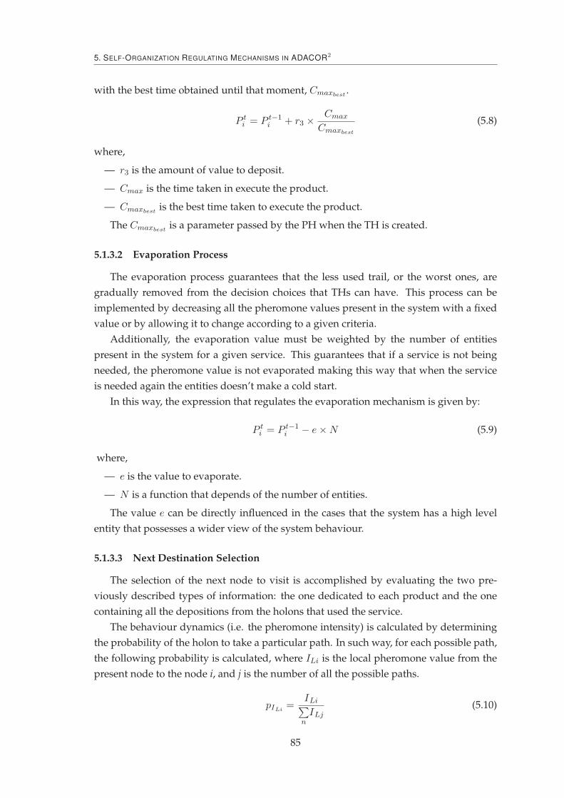
5. SELF-ORGANIZATION REGULATING MECHANISMS IN ADACOR2
with the best time obtained until that moment, Cmaxbest.
P ti = P t−1
i + r3 ×Cmax
Cmaxbest
(5.8)
where,
— r3 is the amount of value to deposit.
— Cmax is the time taken in execute the product.
— Cmaxbestis the best time taken to execute the product.
The Cmaxbestis a parameter passed by the PH when the TH is created.
5.1.3.2 Evaporation Process
The evaporation process guarantees that the less used trail, or the worst ones, are
gradually removed from the decision choices that THs can have. This process can be
implemented by decreasing all the pheromone values present in the system with a fixed
value or by allowing it to change according to a given criteria.
Additionally, the evaporation value must be weighted by the number of entities
present in the system for a given service. This guarantees that if a service is not being
needed, the pheromone value is not evaporated making this way that when the service
is needed again the entities doesn’t make a cold start.
In this way, the expression that regulates the evaporation mechanism is given by:
P ti = P t−1
i − e×N (5.9)
where,
— e is the value to evaporate.
— N is a function that depends of the number of entities.
The value e can be directly influenced in the cases that the system has a high level
entity that possesses a wider view of the system behaviour.
5.1.3.3 Next Destination Selection
The selection of the next node to visit is accomplished by evaluating the two pre-
viously described types of information: the one dedicated to each product and the one
containing all the depositions from the holons that used the service.
The behaviour dynamics (i.e. the pheromone intensity) is calculated by determining
the probability of the holon to take a particular path. In such way, for each possible path,
the following probability is calculated, where ILi is the local pheromone value from the
present node to the node i, and j is the number of all the possible paths.
pILi=
ILi∑
n
ILj(5.10)
85

5.2. Mechanisms for Structural Self-Organization
In that way, the highest pheromone values are most likely to be selected to be the next
route to take.
The same exercise is made for the information related to the overall process for a
particular TH, i.e. a product to be processed. Expression 5.11 gives the next route to take,
making the overall route selection less myopic.
pIGi=
IGi∑
n
IGj
(5.11)
The decision is achieved by selecting the maximum value obtained of the aforemen-
tioned equations. An additional parameter is introduced into the selection equation that
guarantees a certain degree of randomness.
nextNode = max (αILi, βIGi) (5.12)
where,
— ILi represents the path traced, by the use of pheromone deposition/evaporation, to
the next resource.
— IGi represents the traced optimized plan.
— α ≥ 0 weights the desirability of follow the local pheromone information.
— β ≥ 0 weights the desirability of follow the global information.
The local and global desirability can be complementary by considering β = 1 − α.
Despite that, the independent control of these variables displays advantages in the cases
where no balance between the local and global information is required.
5.2 Mechanisms for Structural Self-Organization
Changing the relation of holons is a crucial part of the ADACOR2 architecture, al-
lowing them to re-organize e.g., to create new groups. The previous section has shown
3 techniques that are able to change the behaviour of an holon and consequently may
change the holons relations (recall the Level 0 emergence definition of the structural self-
organization).
This section will depict two techniques that can be used as a way to achieve a struc-
tural self-organization. In this way and generically, the structural self-organization pro-
cedure can be described using the Algorithm 2.
After the detection of an opportunity to evolve (process not described) the holon
launches all the known procedures to find a new system working configuration. When
all the results of the procedures are collected, or ultimately when a maximum time has
elapsed, the structural self-organization module will evaluate them searching for the one
that improves the current KPIs. In the case of finding a better reorganization, the module
will send this result to the nervousness module that will analyse the possibility to apply
the necessary measures.
86

5. SELF-ORGANIZATION REGULATING MECHANISMS IN ADACOR2
Algorithm 2 Structural Self-Organization
Require: facts, currentStructuralKPIEnsure: Selection of the holons’ proper structural organization
1: procedure STRUCTURALSELFORGANIZATION(facts)2: Structures← List of Structures
3: nStructures← count(Structures)4: for i = 0 to nStructures do5: launch Structural(i) ⊲ Launch all the known structural procedures6: end for7: i = 08: while (all structural output not received) || (timeelapsed ≤ maxTime) do9: output(i)← OutputStructural(i)
10: newStructureFound = false
11: end while12: bestStructuralKPI ← currentStructuralKPI
13: for i = 0 to count(output) do14: if output(i).getKPI > bestStructuralKPI then15: bestStructuralKPI ← output(i).getKPI16: newBestStructural← output(i).getStructural17: newStructureFound = true
18: end if19: end for20: if newStructureFound then21: Send result to nervousness stabilizer22: end if23: end procedure
One notably difference from this process to the behavioural self-organization is the
fact that in this case other holons are affected by the application of the necessary mea-
sures, e.g., change of the holarchy of an OH or, as seen in the general example of Figure
4.16, the creation of a second SH and the division of the OHs.
In this way, all the holons that have started a structural procedure will send the ex-
pected KPIs for the new structure which will be evaluated by the participants which will
submit them to their internal nervousness controllers who will analyse the proposals.
5.2.1 Structural Re-Arrangement by Means of Birds Behaviour
Getting inspiration from the birds flocks or the fish schooling, one can assist to the
basic behaviour of each individual entity. Among those, three can be highlighted: i)
entities, in the group, tend to follow the leader; ii) entities also tend to maintain distances
to other elements in the groups and finally, iii) the group size regulation is also made.
The first rule is important in the sense that, e.g., if one entity is more agitated and
makes a sudden move, maybe it is because it has cognition of important information to
the group. The second rule tries to avoid collision within the group and makes the vision
field more clear. The last one, regulating the group size, is important because either too
87
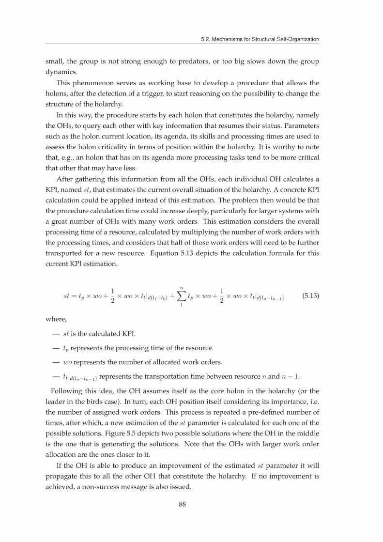
5.2. Mechanisms for Structural Self-Organization
small, the group is not strong enough to predators, or too big slows down the group
dynamics.
This phenomenon serves as working base to develop a procedure that allows the
holons, after the detection of a trigger, to start reasoning on the possibility to change the
structure of the holarchy.
In this way, the procedure starts by each holon that constitutes the holarchy, namely
the OHs, to query each other with key information that resumes their status. Parameters
such as the holon current location, its agenda, its skills and processing times are used to
assess the holon criticality in terms of position within the holarchy. It is worthy to note
that, e.g., an holon that has on its agenda more processing tasks tend to be more critical
that other that may have less.
After gathering this information from all the OHs, each individual OH calculates a
KPI, named st, that estimates the current overall situation of the holarchy. A concrete KPI
calculation could be applied instead of this estimation. The problem then would be that
the procedure calculation time could increase deeply, particularly for larger systems with
a great number of OHs with many work orders. This estimation considers the overall
processing time of a resource, calculated by multiplying the number of work orders with
the processing times, and considers that half of those work orders will need to be further
transported for a new resource. Equation 5.13 depicts the calculation formula for this
current KPI estimation.
st = tp × wo+1
2× wo× tt|d(l1−l0) +
n∑
1
tp × wo+1
2× wo× tt|d(ln−ln−1) (5.13)
where,
— st is the calculated KPI.
— tp represents the processing time of the resource.
— wo represents the number of allocated work orders.
— tt|d(ln−ln−1) represents the transportation time between resource n and n− 1.
Following this idea, the OH assumes itself as the core holon in the holarchy (or the
leader in the birds case). In turn, each OH position itself considering its importance, i.e.
the number of assigned work orders. This process is repeated a pre-defined number of
times, after which, a new estimation of the st parameter is calculated for each one of the
possible solutions. Figure 5.5 depicts two possible solutions where the OH in the middle
is the one that is generating the solutions. Note that the OHs with larger work order
allocation are the ones closer to it.
If the OH is able to produce an improvement of the estimated st parameter it will
propagate this to all the other OH that constitute the holarchy. If no improvement is
achieved, a non-success message is also issued.
88

5. SELF-ORGANIZATION REGULATING MECHANISMS IN ADACOR2
Solution B
wo: 23 wo: 23wo: 50
wo:12 wo: 5
wo: 5
wo: 23wo: 23 wo: 50
wo:12 wo: 5wo: 5
Solution A
Figure 5.5 – Different Solutions Found During the Structural Self-Organization
After receiving all the results or after a time-out period, each OH will implement the
solution that guarantees the best estimated st parameter.
5.2.2 Structural Re-Arrangement by Means of Ants Food Foraging Behaviour
A second bio-inspired structural self-organization mechanism uses the pheromone
concept to, in a distributed manner, re-organized the OHs inside the holarchy and dis-
place them physically in the shop-floor.
The mechanism is based on a two-step approach where first the holons, that possess
the production knowledge, i.e. the PHs, make a pheromone map based on the needed
skills and secondly, the OHs place themselves based on their interests.
In order to facilitate the description of the mechanism, let’s assume that a given shop-
floor is divided into sections (see round markings in Figure 5.6), named working places,
where any type of processing machine can be placed. Additionally, each of those working
places have stored within a pheromone matrix where tuples of {skill, value} are used to
represent the pheromone intensity to a given skill. Naturally, the matrix size depends on
the number of skills needed to produce the catalogue of products present at the system.
The first stage of the mechanism starts by each of the PHs to send a given number,
ℵ, of scouting ants that are responsible to deposit a pheromone mark at the shop-floor.
In this way, a given PH with the processing plan {skill1, skill2, ..., skilln} will send ℵ
scouting ants for each of the needed skill.
The deposition value depends of several parameters, namely one pre-defined value,
the skill pheromone value on the working position and the pheromone on the neighbour
working positions (e.g., their average). This local and neighbour analysis is made by the
skill in deposition and for the skills needed in the precedent and subsequent operations
(like depicted in notation 5.14).
{local, neighbour} × {current, precedent, subsequent} skill (5.14)
At the end of this process a mesh-like pheromone distribution is achieved for each of
the present skills, having different pheromone intensities in the shop-floor.
89

5.3. Learning and Reasoning
B
{skill1, skill2, …, skilln}
AC
1st
phase 2nd
phase
Figure 5.6 – Ants Food Foraging Structural Self-Organization
The second phase is started after the creation of this mesh of pheromone values where
the OHs start actively finding its new place within the holarchy and, if a level 2 structural
self-organization is on place, their physical move in the shop-floor. At this stage, each OH
positions itself on the maximum pheromone value of a working place at the shop-floor. In
the cases where the OH offers more than one skill it will position itself on the geometrical
average between the maximum pheromone values obtained for each of the offered skills.
Some parameter may influence the pheromone mesh creation, such as the neighbour-
hood size, the pheromone value to deposit or the number of scouting ants. Additionally,
the positioning technique that the OHs use in the second phase also influences the re-
organization and aside of each OH position itself on the pheromone maximum, it can
do it on the overall average maximum and prioritization of the OH position can also be
added (e.g., by positioning first the most overloaded holons).
5.3 Learning and Reasoning
The reasoning and learning capabilities modules play a crucial role in the self-
organization model, supporting the generation, removal or adaptation of knowledge.
In particular, learning is important in two distinct phases of self-organization:
1. Identification of opportunities to evolve, refining the thresholds on which the self-
organization mechanisms are triggered.
2. Defining how to evolve, adapting the internal self-organization mechanisms pa-
rameters along the time.
Different constraints impose different types of learning techniques and for this pur-
pose, ADACOR2 uses social learning for the propagation of new behaviours among the
holons and for the propagation of accumulated knowledge from PHs to THs using a
pheromone-like mechanism, as defined in the ADACOR architecture (Leitão and Restivo,
2006). This exchange of knowledge allows the receiving holons to have access to more
aggregated information from the past peers experiences.
90

5. SELF-ORGANIZATION REGULATING MECHANISMS IN ADACOR2
Social learning is also used to provide the direct query between holons, asking for past
decisions and their outcomes. In this case, holons acquire information about the good and
bad decisions of others and the context on which they were taken, allowing in this way
for these holons to incorporate this into their internal decisional engine. Ultimately, this
procedure culminates by creating new rules (or adapting similar ones) used later in the
decision support by the reasoning engine.
A practical example can be given when TH2 queries TH1 and receives the information
that changing from behaviour Bha to Bh
b , when the system is above a given overload level
combined with offline status of OH5, produces a decrease on the KPI.
A reward based learning technique, e.g., reinforcement-based mechanism, is used as
a means to evaluate past evolution decisions. In this way, bad decisions performed in the
past will have a negative impact on the future selection for the same decision, contrary to
a good result that will have a positive impact. In this way, this learning technique is used
throughout the holon life-cycle as a parameter fine tuning, such as to increase or decrease
the confidence on using a given behaviour. It is also used by higher level holons, such as
the SHs or the PHs, to collect accumulated knowledge from several holons.
Generalizing the learning mechanism, a given parameter, p, would have a value in-
crease in the case of an improvement of the expected holon performance while it de-
creases in situations of obtaining a performance degradation. In this way, the new value
of the parameter can be written by:
pt+1 = pt + γ ×KPIfinal −KPIexpected
KPIfinal(5.15)
where,
— pt represents the previous parameter value.
— γ is a value between [0..1] that defines the update rate.
— KPIfinal is the obtained KPI considered in the parameter calculation.
— KPIexpected is the expected KPI considered in the parameter calculation.
It is important to note that the learning mechanisms to be embedded in individual holons
should be kept as simple as possible, as it is in biology. Nevertheless, more complex learn-
ing mechanisms can be deployed, which can potentiate even more the learning module,
knowing beforehand that more computational power could be a requisite in this situa-
tion.
The reasoning module is complementary to the learning module and is constantly
matching the known facts with, e.g., the thresholds defined by the learning algorithms.
Naturally, all sort of reasoning techniques, such as inductive, deductive, analogical or
case-based reasoning can be embedded into the ADACOR2 holons. Despite this, in the
current work of ADACOR2, a rule based reasoning technique was considered and imple-
mented using an expert system.
91
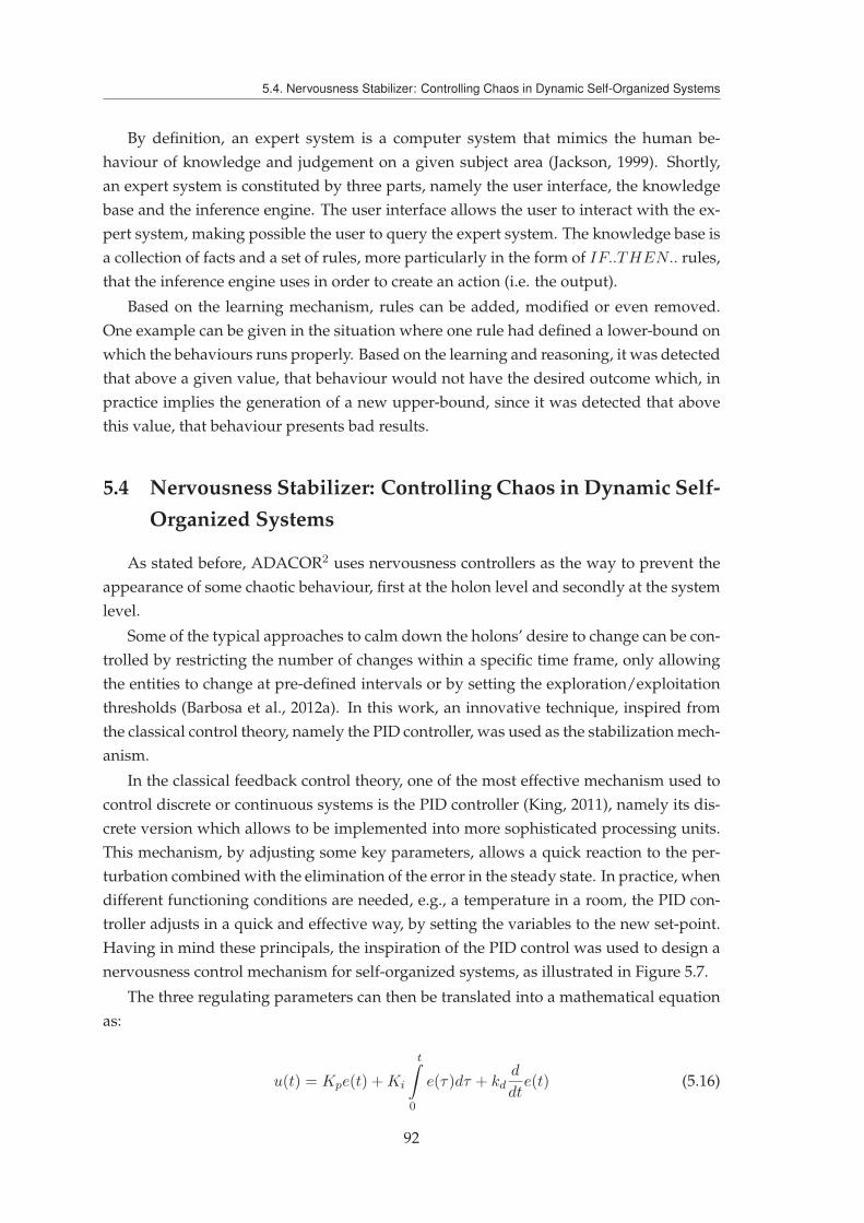
5.4. Nervousness Stabilizer: Controlling Chaos in Dynamic Self-Organized Systems
By definition, an expert system is a computer system that mimics the human be-
haviour of knowledge and judgement on a given subject area (Jackson, 1999). Shortly,
an expert system is constituted by three parts, namely the user interface, the knowledge
base and the inference engine. The user interface allows the user to interact with the ex-
pert system, making possible the user to query the expert system. The knowledge base is
a collection of facts and a set of rules, more particularly in the form of IF..THEN.. rules,
that the inference engine uses in order to create an action (i.e. the output).
Based on the learning mechanism, rules can be added, modified or even removed.
One example can be given in the situation where one rule had defined a lower-bound on
which the behaviours runs properly. Based on the learning and reasoning, it was detected
that above a given value, that behaviour would not have the desired outcome which, in
practice implies the generation of a new upper-bound, since it was detected that above
this value, that behaviour presents bad results.
5.4 Nervousness Stabilizer: Controlling Chaos in Dynamic Self-
Organized Systems
As stated before, ADACOR2 uses nervousness controllers as the way to prevent the
appearance of some chaotic behaviour, first at the holon level and secondly at the system
level.
Some of the typical approaches to calm down the holons’ desire to change can be con-
trolled by restricting the number of changes within a specific time frame, only allowing
the entities to change at pre-defined intervals or by setting the exploration/exploitation
thresholds (Barbosa et al., 2012a). In this work, an innovative technique, inspired from
the classical control theory, namely the PID controller, was used as the stabilization mech-
anism.
In the classical feedback control theory, one of the most effective mechanism used to
control discrete or continuous systems is the PID controller (King, 2011), namely its dis-
crete version which allows to be implemented into more sophisticated processing units.
This mechanism, by adjusting some key parameters, allows a quick reaction to the per-
turbation combined with the elimination of the error in the steady state. In practice, when
different functioning conditions are needed, e.g., a temperature in a room, the PID con-
troller adjusts in a quick and effective way, by setting the variables to the new set-point.
Having in mind these principals, the inspiration of the PID control was used to design a
nervousness control mechanism for self-organized systems, as illustrated in Figure 5.7.
The three regulating parameters can then be translated into a mathematical equation
as:
u(t) = Kpe(t) +Ki
t∫
0
e(τ)dτ + kdd
dte(t) (5.16)
92

5. SELF-ORGANIZATION REGULATING MECHANISMS IN ADACOR2
Figure 5.7 – Nervousness control mechanism based on PID controllers
In such mechanisms, the proportional part Kp adjusts the reaction time to the pertur-
bation trigger, the integrative part Ki regulates the accepted error of the desired goal, and
the derivative part Kd sets the responsiveness to reach the goal. Similarly, in ADACOR2
these three parameters regulate the self-control of holons. The e(t) represents the error
that needs to be eliminated and is calculated by the difference between the system out-
put and the desired goal.
Firstly, the Kp defines the time from which the holons start to react to trigger events,
allowing them to overcome momentary perturbations or to gather more information
about the perturbation, starting the self-organization mechanism only after the whole
set of new allocation requests has been collected. In the PID controller analogy, a high
value of Kp will drive the system to respond faster to perturbations, which could lead the
system to behave in an unstable manner, while a low value will not enable the system to
reach the desired goal. The same cautions must also be taken into account when selecting
the time after which the holons will react to plan deviations. A high value may drive the
holons to be constantly in an adaptation mode while a low value might drive them to
never react.
Secondly, Ki describes the minimum acceptable improvement of the solution found
(by each self-organization mechanism) that can be considered as enough to permit the
use of the changes. In the PID analogy, the Ki, or the integrative part, is responsible for
the elimination of the error in steady state, i.e. going as close as possible to the desired
goal. Since the goal of the ADACOR2 holons is to improve themselves always as possible,
they are considered as moving a goal, which is a maximization function. In such way, the
Ki parameter acts as the minimum acceptable improvement of the actual goal.
Lastly, Kd defines how fast the solution must be found, acting as a limit to find solu-
tions, after which the most acceptable ones are considered. In the PID analogy, the Kd
parameter helps to improve the settling time and increases system stability. Mimicking
this to the nervousness controller, one will find that this parameter acts like the time lim-
iter for a given holon to adapt. After this time, the holons will stop adapting and thus
calm down its behaviour. The cautions to set this parameter regards the fact that a high
value will enable a long adaptation time while a low value might not enable the holon to
reach an acceptable goal value.
93

5.4. Nervousness Stabilizer: Controlling Chaos in Dynamic Self-Organized Systems
In this way, the SD defined in section 4.5 plays a major role in the dynamic parameter
adaptation since for faster dynamics, the kp must lower down to allow quicker responses
to plan deviations. In an opposite way, the kd must also be increased to guarantee a faster
convergence to the expected performance. Obviously, this adjustment increases the risk
of obtaining holons instability and must be counterbalanced with an appropriate reac-
tion time. The ki for this case must also lower down, compromising bigger performance
improvements by allowing more changes in the holon decision through smaller steps.
Each one of the aforementioned parameters are dynamically adjusted taking into con-
sideration the learning mechanism defined in the previous section. This dynamic ad-
justment aims to contribute to a more robust usage of the controller with respect to its
exterior, namely to the SD.
As depicted in Figure 4.24 a two level stabilization mechanism is used. Recalling, the
first level controls each self-organization mechanism while the second selects the most
appropriate one to use (in the cases where both self-organization procedures produce a
valid output).
Algorithm 3 depicts the behavioural nervousness control using the PID approach.
Algorithm 3 Behavioural Nervousness Control
Require: facts, holonBehaviouralNervousnessLevelEnsure: Behavioural nervousness stabilization of holon
1: startT ime← disturbanceT ime||improvementT ime2: procedure BEHAVIOURALNERVOUSNESSSTABILIZATION(facts, behavioursKPI, e(t)B)3: expectedBehaviourKPI ← currentBehaviourKPI
4: currentBehaviourKPI ← newBehaviourKPI
5: kpiDeviationT ime← startT ime− currentT ime6: behaviourAllowed← False
7: if kpiDeviationT ime ≤ kd and e(t)B ≥ behaviourThreshold then8: if (kpiDeviationT ime− currentT ime) ≥ kp then9: if (expectedBehaviourKPI − currentBehaviourKPI) ≥ ki then
10: Change holon behaviour11: behaviourAllowed← True
12: else13: KPI improvement not sufficient.14: end if15: else16: Need to wait a little longer before react.17: end if18: else19: No more adaptation allowed. Adaptation time overpassed.20: end if21: end procedure
The behavioural nervousness control starts by checking if the adaptation phase is
still valid, i.e. if the maximum adaptation time has not yet elapsed, and if the current
behaviour error (or deviation) is higher than the minimum behaviour threshold (making
94
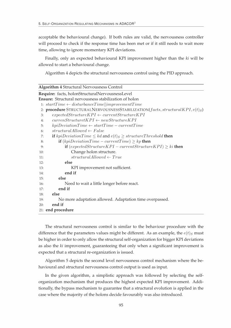
5. SELF-ORGANIZATION REGULATING MECHANISMS IN ADACOR2
acceptable the behavioural change). If both rules are valid, the nervousness controller
will proceed to check if the response time has been met or if it still needs to wait more
time, allowing to ignore momentary KPI deviations.
Finally, only an expected behavioural KPI improvement higher than the ki will be
allowed to start a behavioural change.
Algorithm 4 depicts the structural nervousness control using the PID approach.
Algorithm 4 Structural Nervousness Control
Require: facts, holonStructuralNervousnessLevelEnsure: Structural nervousness stabilization of holon
1: startT ime← disturbanceT ime||improvementT ime2: procedure STRUCTURALNERVOUSNESSSTABILIZATION(facts, structuralKPI, e(t)S)3: expectedStructureKPI ← currentStructureKPI
4: currenStructuretKPI ← newStructureKPI
5: kpiDeviationT ime← startT ime− currentT ime6: structuralAllowed← False
7: if kpiDeviationT ime ≤ kd and e(t)S ≥ structureThreshold then8: if (kpiDeviationT ime− currentT ime) ≥ kp then9: if (expectedStructureKPI − currentStructureKPI) ≥ ki then
10: Change holon structure.11: structuralAllowed← True
12: else13: KPI improvement not sufficient.14: end if15: else16: Need to wait a little longer before react.17: end if18: else19: No more adaptation allowed. Adaptation time overpassed.20: end if21: end procedure
The structural nervousness control is similar to the behaviour procedure with the
difference that the parameters values might be different. As an example, the e(t)S must
be higher in order to only allow the structural self-organization for bigger KPI deviations
as also the ki improvement, guaranteeing that only when a significant improvement is
expected that a structural re-organization is issued.
Algorithm 5 depicts the second level nervousness control mechanism where the be-
havioural and structural nervousness control output is used as input.
In the given algorithm, a simplistic approach was followed by selecting the self-
organization mechanism that produces the highest expected KPI improvement. Addi-
tionally, the bypass mechanism to guarantee that a structural evolution is applied in the
case where the majority of the holons decide favourably was also introduced.
95

5.5. Summary
Algorithm 5 Second Level Nervousness Control
Require: facts, holonNervousnessLevelEnsure: Nervousness stabilization of holon
1: procedure SECONDLEVELNERVOUSNESSSTABILIZATION(facts)2: if behaviourAllowed||structuralAllowed then3: Apply highest expected KPI.4: end if5: if majorityRule then6: Apply requested structural change. ⊲ Structural bypass by the majority rule.7: end if8: end procedure
5.5 Summary
This chapter presents some of the self-organization related mechanisms that were
developed and implemented in the ADACOR2 architecture, which will be used in the
following chapter as the assessment ground-base of the architecture.
Shortly, three mechanisms were used in the holons behavioural catalogue to allow
them to respond properly to changes in the system conditions, based on current condi-
tions. The first mechanism relies on negotiation techniques used on market-based ap-
proaches while the second one uses the concepts of magnetism to create a very dynamic
behaviour, aiming to introduce responsiveness. Finally, the last technique is based upon
the ant food foraging behaviour.
Two mechanisms for the structural self-organization were also introduced where the
inspiration from the bird group formation and the pheromone deposition used by ants
during the food foraging are used to allow the holons to re-arrange themselves in order
to optimize the production according to the current product demand.
Social and reinforcement learning examples and techniques were also described, al-
lowing the holons to dynamically perform the parameters adjustment. A rule based rea-
soning engine, using an expert system, was also described.
Finally, an instantiation of the holon’s nervousness controller is depicted, taking in-
spiration in the classical feedback control, to regulate the dynamics of the holons in such
self-organized environment.
In the next chapter, the case study used to validate and assess the proposed architec-
ture is described as well the implementation of the prototype solution. The experiment
trials are also presented and the achieved results are analysed.
96
6Practical Implementation and
Validation
The present is theirs; the future, for which I really worked, is mine.
Nikola Tesla
This chapter intends to validate the proposed manufacturing control architecture. The
used case study, based on a real FMS, is presented and the holons mapping between the
ADACOR2 and the described system is made.
Additionally, two experimental scenarios were developed to assess the two proposed
self-organization vectors. The behavioural self-organization is validated using a simu-
lation of the real AIP (Atelier Inter-établissement de Productique)-PRIMECA (Pôle de
Ressources Informatique pour la Mécanique) FMS located at the Université de Valenci-
ennes et du Hainaut-Cambrésis, and the structural self-organization, due to its partic-
ularities, is validated using a modified version of the AIP-PRIMECA FMS, where the
rigidity of the machines’ position was removed and the conveyor system was replaced
by an AGV.
6.1 Description of the Case Study and System Implementation
The case study used to test the presented work is based on the AIP FMS located at
the Université de Valenciennes et du Hainaut-Cambrésis, which is described in detail in
(Trentesaux et al., 2013). A visual aspect of the FMS is provided in Figure 6.1.
97

6.1. Description of the Case Study and System Implementation
Figure 6.1 – View of the AIP-PRIMECA Cell
This FMS cell was selected since it introduces a high level of flexibility, mainly on the
production and transport sides, introducing several alternatives for the same goal.
The following sub-sections will give a deeper insight of the AIP-PRIMECA cell.
6.1.1 The Real AIP-PRIMECA FMS
The FMS is composed of 7 machines linked by a conveyor system, as illustrated in
Figure 6.2.
Four robots, being three from KUKA and one from Stäubli, a loading/unloading sta-
tion, an automated inspection unit and a manual recovery unit constitute the set of ma-
chines present in the system. The movement of the product to be processed in the pre-
vious machines is achieved by means of a shuttle, which moves on the rack system. For
visual clarity, an image of the conveyor system and of the shuttle is shown in Figure 6.3a.
The change between tracks is achieved by means of a switching gate system, as shown in
Figure 6.3b.
The routing within the FMS has a great importance since the decisions made in this
respect can have major impact on the production of a given product and on the overall
system performance. To this respect, transportation times between subsequent nodes/
machines are provided in Table 6.1 (note that the composite times are derived combining
two or more paths).
A set of sub-products are able to be produced within this FMS, namely the letters b,
e, l, t, a, i, p and t. Combining the previous sub-products, one is able to produce the final
products BELT, AIP and LATE. A visual perspective of the aforementioned sub-products
98
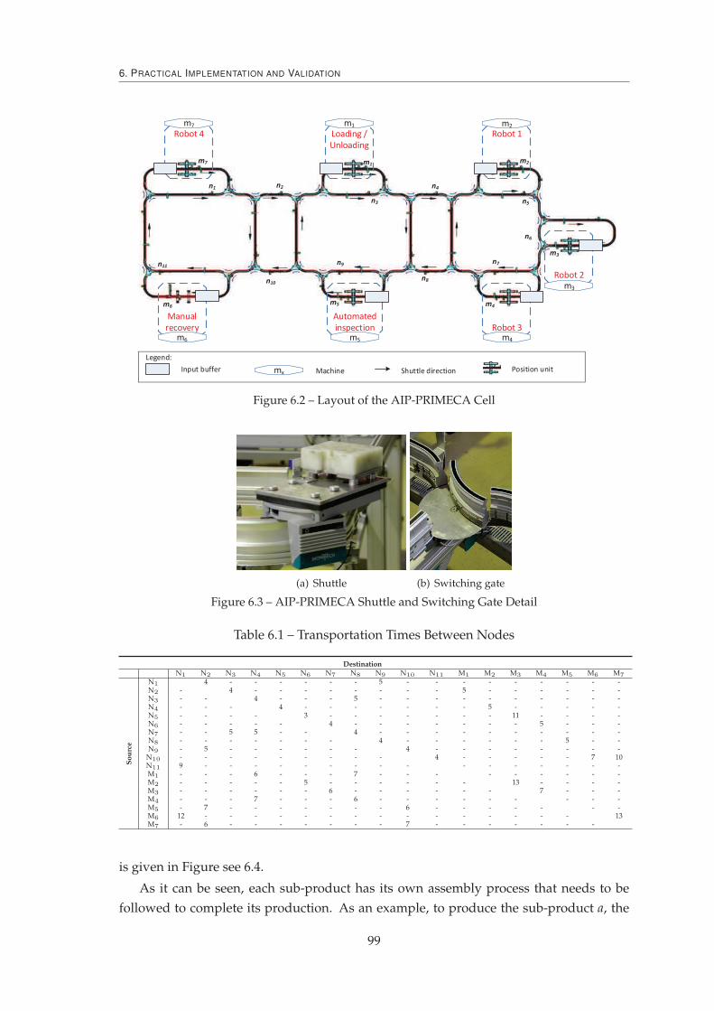
6. PRACTICAL IMPLEMENTATION AND VALIDATION
Robot 4 Loading /
Unloading
Robot 1
Robot 2
Robot 3
Automated
inspection
Manual
recovery
m7 m1 m2
m3
m4m5m6
mxInput buffer Machine Shuttle direction Position unit
Legend:
Figure 6.2 – Layout of the AIP-PRIMECA Cell
(a) Shuttle (b) Switching gate
Figure 6.3 – AIP-PRIMECA Shuttle and Switching Gate Detail
Table 6.1 – Transportation Times Between Nodes
DestinationN1 N2 N3 N4 N5 N6 N7 N8 N9 N10 N11 M1 M2 M3 M4 M5 M6 M7
Sou
rce
N1 4 - - - - - - 5 - - - - - - - - -N2 - 4 - - - - - - - - 5 - - - - - -N3 - - 4 - - - 5 - - - - - - - - - -N4 - - - 4 - - - - - - - 5 - - - - -N5 - - - - 3 - - - - - - - 11 - - - -N6 - - - - - 4 - - - - - - - 5 - - -N7 - - 5 5 - - 4 - - - - - - - - - -N8 - - - - - - - 4 - - - - - - 5 - -N9 - 5 - - - - - - 4 - - - - - - - -
N10 - - - - - - - - - 4 - - - - - 7 10N11 9 - - - - - - - - - - - - - - - -M1 - - - 6 - - - 7 - - - - - - - - -M2 - - - - - 5 - - - - - - 13 - - - -M3 - - - - - - 6 - - - - - - 7 - - -M4 - - - 7 - - - 6 - - - - - - - - -M5 - 7 - - - - - - - 6 - - - - - - -M6 12 - - - - - - - - - - - - - - - 13M7 - 6 - - - - - - - 7 - - - - - - -
is given in Figure see 6.4.
As it can be seen, each sub-product has its own assembly process that needs to be
followed to complete its production. As an example, to produce the sub-product a, the
99

6.1. Description of the Case Study and System Implementation
ComponentsMatrix Pallet
B-Product E-Product L-Product T-Product A-Product I-Product P-Product
Figure 6.4 – Product Catalogue
assembly base plate must be loaded into the shuttle, followed by three axis components,
one r, L and I component and is ended by a screw assembly and the unloading procedure.
The remaining process plans for all sub-products are mapped in Table 6.2.
Table 6.2 – Process Plans for the Catalogue of Products
Sequence B E L T A I P#1 Loading Loading Loading Loading Loading Loading Loading#2 Axis Axis Axis Axis Axis Axis Axis#3 Axis Axis Axis Axis Axis Axis Axis#4 Axis Axis Axis Rcomp Axis Icomp Rcomp#5 Rcomp Rcomp Icomp Lcomp Rcomp Screw Lcomp#6 Rcomp Rcomp Icomp Inspection Lcomp Inspection Inspection#7 Icomp Lcomp Screw Unloading Icomp Unloading Unloading#8 Screw Inspection Screw Screw#9 Inspection Unloading Inspection Inspection#10 Unloading Unloading Unloading
Naturally, the assembly procedures mentioned before are processed by the available
machines at the shop-floor. The sub-set of machines that are able to perform a required
operation is illustrated in 6.3. The values depicted in the table represent the processing
times that each machine offers to perform that given operation.
Table 6.3 – Machine Skills and Processing Times
Operation M1 M2 M3 M4 M5
Loading 10Unloading 10
Axis 20 20 20Rcomp 20 20 20Icomp 20Lcomp 20 20Screw 20 20
Inspection 5
As an example, the “Loading” operation can be executed by machine M1 while the
“Axis” operation can be executed by machines M2 and M3, both with a processing time
of 20s. Particularly here, a slight change was introduced, regarding what is described in
(Trentesaux et al., 2013), to increase the flexibility of the FMS. This change is achieved
100

6. PRACTICAL IMPLEMENTATION AND VALIDATION
by the increasing the number of skills, namely in machine M4 with "Axis" and "Rcomp".
Note that before this change, a breakdown in any of the machines that offer processing
skills, namely M2, M3 and M4, only one other machine was able to offer the skill, limiting
the decision making process of the manufacturing control architecture.
6.1.2 A More Flexible AIP-PRIMECA FMS
Although the real AIP-PRIMECA FMS cell allows to assess the proposed manufac-
turing control architecture, it still has limitations to assess the structural self-organization
vector in ADACOR2, due to the relatively limited size of machines and the rigid nature of
the FMS (e.g., machines have rigid working places and shuttles have fixed transportation
paths).
In this way, please recall that the structural self-organization will change the relations
between the holons present in the system. Naturally, this could only be tested briefly in
the current real version of the AIP-PRIMECA FMS cell, where, e.g., clustering of orders
from the same client could be done. But for instance, a deeper structural self-organization
is not possible, e.g., machine dynamic grouping.
Increasing the flexibility degrees where the control decisions could be greatly poten-
tiated, aiming to have a more dynamic cell, is then achieved by replacing the transporta-
tion rack system with a more flexible one. This can be achieved by the introduction of
an AGV transportation system. Secondly, the fixed working positions of the machines
can also be eliminated, allowing them to be repositioned, minimizing the need for longer
transportation times. This last feature is in-line with more recent manufacturing trends,
such as the ones found in Festo AG & Co. KG.
Concretizing the previous features, a completely new manufacturing shop-floor is
presented in Figure 6.5. Attention was paid to get a closer behaviour as with the real AIP
cell. In such way, machines are placed in the same positions and transportation times
between them are similar. To achieve this, the AGV takes 3 seconds to move between
positions (represented as dots in the figure).
AGV
Figure 6.5 – A Futuristic AIP-PRIMECA Cell
101

6.2. Manufacturing Control Assessment Metrics
Machines can now shift the working position, only possible in the purple places,
which have all vital needs for a machine to work properly, e.g., electrical power and
hydraulics. The AGV, on the other hand, can move on all positions but this can only be
made in an horizontal or/and vertical way, i.e. AGVs cannot travel in a diagonal line.
Using the previous adaptations, it is now possible to assess deeply the structural self-
organization of ADACOR2, since level 2 can be tested. Particularly, it is possible, for
instance, to test the self-organization of the machines in order to minimize the amount of
time needed to produce a given order.
6.2 Manufacturing Control Assessment Metrics
Measuring the efficiency of a manufacturing control architecture is always difficult.
Despite this, a proper assessment of the proposed control architecture requires the mea-
surement and evaluation of a set of different metrics, or KPIs (Brennan and Norrie, 2003),
as well as proper benchmarks (Trentesaux et al., 2013).
Two different types of KPIs are generally used for this assessment, namely quantita-
tive and qualitative. The first is used when the KPI measurement is possible, giving a nu-
merical value to it. KPIs such as the resource utilization, the WIP (Work In Progress), the
tardiness or the makespan are among the most used to assess quantitatively a manufac-
turing control architecture. On the other hand, qualitative assessment is more deductive
in the sense that assigning a numerical value to a given KPI is harder, e.g., measuring the
agility or reconfigurability of the system. Despite this, some works have been conducted
in the past were metrics and methodologies are described, namely (Brennan and Norrie,
2003; Leitão, 2004; Trentesaux et al., 2013).
In the present work, a quantitative approach was selected in order to assess the man-
ufacturing control architecture. The main influential decision for this choice is the help
on the ease of comparison between the several control structures.
One of the most used quantitative KPIs is known as makespan, or Cmax, which is
denoted by the total amount of time that a given manufacturing order needs to be pro-
cessed. In other words, Cmax is related to the time of the last operation of the whole
manufacturing order. In this way, the objective function of this KPI is the minimization
of it, i.e. as lower is the Cmax the better the manufacturing control architecture is.
The throughput can be defined as the total amount of parts that the system is able to
produce per unit of time. This parameter depicts the production system capacity and, in
this work, is calculated by counting the number of products produced during one hour.
Measuring the impact, i, that disturbances have in manufacturing control architec-
tures is also important, particularly in the current work, since one of the main goals of the
proposed manufacturing control architecture is to have as less impact as possible when
disturbances appear into the system. In this work, the impact KPI is calculated by the
difference of the makespan of a given architecture, Carchimax , in relation to the best KPI of all
architectures, Coverallmax . This value is still normalized in relation with the best overall KPI.
102

6. PRACTICAL IMPLEMENTATION AND VALIDATION
Finally, this can be represented as: i = Carchimax −Coverall
max
Coverallmax
. The previous equation can even
be further developed in the case where a percentage value is required by multiplying it
with the number 100.
Lastly, the control predictability is also important, particularly in non-linear systems
and when several runs are executed in order to obtain the metrics for the architecture
assessment. In the way, as higher this is the more reliable the output result is expected
to be. Indirectly, the predictability can be also considered as the confidence level of the
produced output of a given architecture.
6.3 Mapping ADACOR2 Holons to the Case Study
The proposed self-organized holonic system used the multi-agent technology, and
more particularly, the JADE (Java Agent DEvelopment Framework) (Bellifemine et al.,
2007) to develop the agent-based infra-structure, namely the behaviour of each individ-
ual ADACOR2 holon and the designed cooperation patterns. More recently appeared
the JaCaMo approach, that combines both the dimension organization (important in this
case as an holonic organization is used that have to follow the agents), the dimension
agent and the dimension environment, presenting an interesting and promising solution
(Boissier et al., 2013). The selection of JADE framework over others, such as A-Globe
(Rehák et al., 2005), Jason (Bordini, 2007) or Cougaar (Kleinmann et al., 2003), relies basi-
cally under three facts. First, JADE always had a steady and stable development, which
makes future evolutions more reliable. One example of the importance of this feature
is the present work, which has extended the previous work of ADACOR. Secondly, the
community that uses JADE doesn’t stop to grow and also has a very good documenta-
tion. Finally, and although the current state of FIPA (Foundation for Intelligent Physical
Agents) development, being FIPA compliant, JADE follows the standards in the field and
permits a more concrete interaction with other agents frameworks.
The holon’s intelligence, as already happened in the first version of ADACOR, was
embedded using a rule engine implemented with the JESS (Java Expert System Shell)
platform (Friedman-Hill, 2003).
In the real AIP-PRIMECA scenario, a particular holon type, named CSH (Conveyor
System Holon), instantiated from an OH, was developed to manage the routing and gate
switching inside the conveyor system, providing some specific functions, such as serving
as an intermediary to manage the dispatching of the transportation orders to the available
shuttles. The CSH used the Jung tool (O’Madadhain et al., 2002) to support an ease and
dynamical parameter calculation in the nodes and also to display the provided function-
alities. The CSH GUI, illustrated in Figure 6.6, provides real-time information regarding
the location of the shuttles and the state of the machines, according to a colour-based
diagram.
Additionally, all the defined ADACOR2 holons are used. When a higher holon is
necessary in the system, one SH is used to introduce optimization into the lower level
103
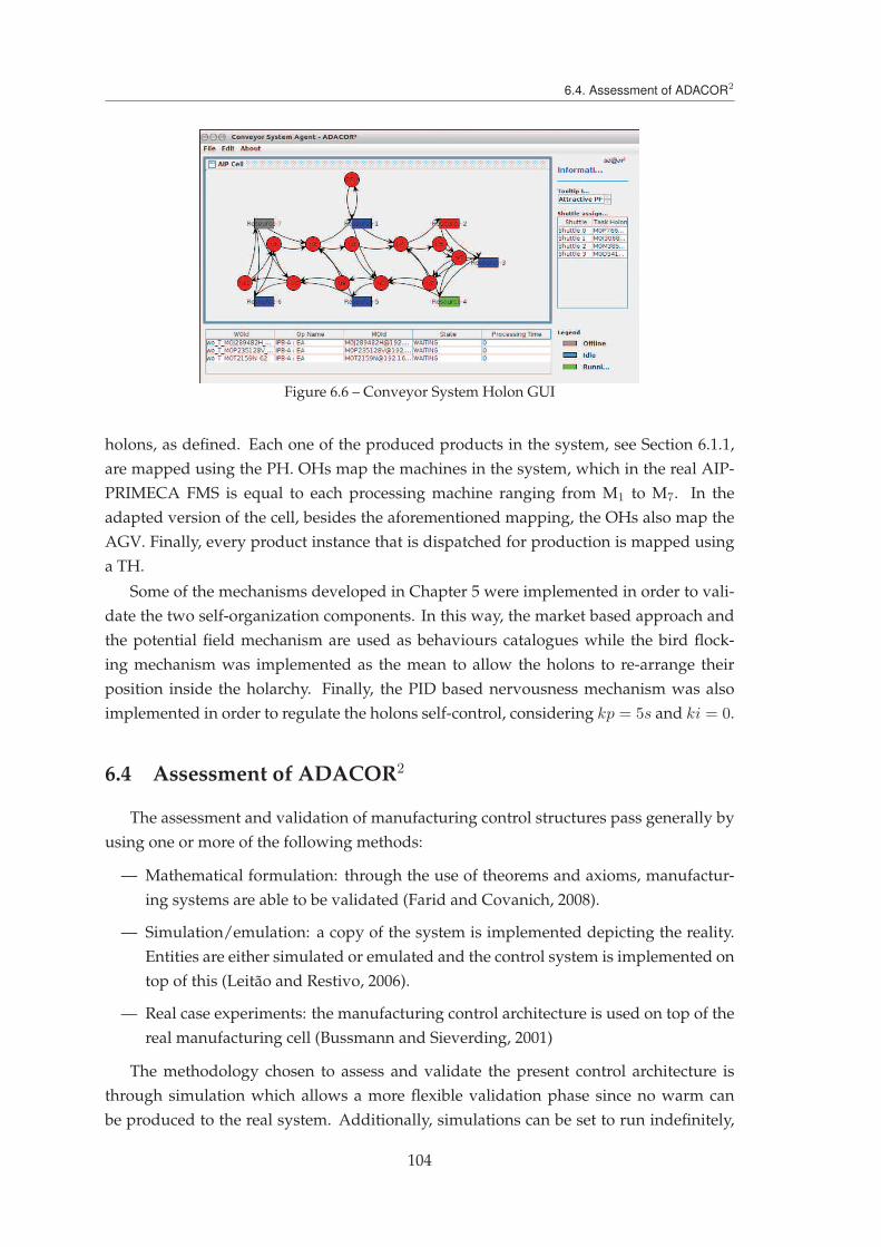
6.4. Assessment of ADACOR2
Figure 6.6 – Conveyor System Holon GUI
holons, as defined. Each one of the produced products in the system, see Section 6.1.1,
are mapped using the PH. OHs map the machines in the system, which in the real AIP-
PRIMECA FMS is equal to each processing machine ranging from M1 to M7. In the
adapted version of the cell, besides the aforementioned mapping, the OHs also map the
AGV. Finally, every product instance that is dispatched for production is mapped using
a TH.
Some of the mechanisms developed in Chapter 5 were implemented in order to vali-
date the two self-organization components. In this way, the market based approach and
the potential field mechanism are used as behaviours catalogues while the bird flock-
ing mechanism was implemented as the mean to allow the holons to re-arrange their
position inside the holarchy. Finally, the PID based nervousness mechanism was also
implemented in order to regulate the holons self-control, considering kp = 5s and ki = 0.
6.4 Assessment of ADACOR2
The assessment and validation of manufacturing control structures pass generally by
using one or more of the following methods:
— Mathematical formulation: through the use of theorems and axioms, manufactur-
ing systems are able to be validated (Farid and Covanich, 2008).
— Simulation/emulation: a copy of the system is implemented depicting the reality.
Entities are either simulated or emulated and the control system is implemented on
top of this (Leitão and Restivo, 2006).
— Real case experiments: the manufacturing control architecture is used on top of the
real manufacturing cell (Bussmann and Sieverding, 2001)
The methodology chosen to assess and validate the present control architecture is
through simulation which allows a more flexible validation phase since no warm can
be produced to the real system. Additionally, simulations can be set to run indefinitely,
104

6. PRACTICAL IMPLEMENTATION AND VALIDATION
introducing disturbances scenarios and testing properly the ADACOR2 holonic architec-
ture. To achieve this, a set of procedures were developed, as described in Appendix A.
6.4.1 Behavioural Self-Organization Using the AIP-PRIMECA
The behavioural part of the ADACOR2 holonic architecture was validated using a
simulated version of the AIP-PRIMECA. Several scenarios from the Bench4Star bench-
mark are used, namely those ranging from A0 to E0 (Trentesaux et al., 2013), which al-
lows to test different sets of manufacturing orders sizes and shuttles number. Table 6.4
shows a brief description of the scenarios configurations.
Table 6.4 – Behavioural Scenarios Description
Scenario Number of shuttles Transportation timesClient order
Order ProductsBELT AIP LATE
A0 10 Table 6.1#1 1 - -#2 - 1 -
B0 10 Table 6.1 #1 - 2 -
C0 4 Table 6.1#1 1 - -#2 - 1 -
D0 10 Table 6.1#1 1 - -#2 2 1 -
E0 10Table 6.1
#1 2 1 -#2 - 2 1#3 - - 2
The differences between the Bench4Star benchmark and the number of shuttles are
encountered in the situations where infinite number of shuttles were envisioned. The
transportation times were also added in the cases where they were neglected.
Scenarios without and with disturbances, namely the #PS12 (Trentesaux et al., 2013)
that introduces a 60s breakdown in M2 at the end of processing 4 jobs, are used to assess
the manufacturing control architectures impact.
Four manufacturing control architectures are compared in both situations. First, a
completely hierarchical approach is used, where the SH is always optimizing the OHs
scheduling. A completely heterarchical approach is also used, where THs have to directly
negotiate with the OHs in order to be processed. In this approach, the SH is removed.
In order to compare if the ADACOR2 manufacturing control architecture improves the
ADACOR architecture, both are tested. In these simulations, the ADACOR, when no dis-
turbances are present in the system uses a SH to introduce schedule optimization while
in disturbances situations it uses its switching mechanism, balancing between the hier-
archical and heterarchical structure. On the other hand, ADACOR2 assumes the same
hierarchical form in non-disturbance situations, while it uses the proposed behavioural
self-organization mechanisms to handle disturbances. In this case, THs aiming to re-
spond to disturbances, execute the market-based and PF mechanisms and select the one
that reduces more the overall work order execution.
105

6.4. Assessment of ADACOR2
As shown previously, a system will be as much desirable as faster it is able to produce
the same amount of work. This KPI, named as Cmax, or makespan, allows to assess this
feature. First, every one of the four manufacturing control approaches are tested for
a scenario where all parameters are well known and controlled, i.e. a system without
disturbances. Experimental results for all the non-disturbance situations are shown in
Figure 6.7.
Figure 6.7 – Cmax for the Normal Scenarios
As it can be seen, the hierarchical approach along side with ADACOR and ADACOR2
present the most optimized solution. This is due to the fact that using these approaches,
the SH is introducing optimization into the scheduling of the OHs. As everything is pre-
dictable and under control, this holon schedules when the manufacturing order arrives,
sending afterword the processing plans to OHs and THs.
The heterarchical approach presents the worst results since the THs are interacting
directly with the OHs and in this way, myopic phenomena appears. Note that the CNP
market based approach is used as the negotiation technique.
ADACOR2 insights could also be used to enhance the heterarchical approach by em-
bedding new negotiation, i.e. behaviours, into the THs. Despite this potentiality, that
could enhance the heterarchical mode, this was not extensively tested. Nevertheless,
preliminary tests have shown improvements on the pure heterarchical approach when
converted into an ADACOR2 architecture (without a centralized holon).
As mentioned before, having solely a system without disturbances is not real and so
any manufacturing control architecture must be tested within these hard working condi-
tions in order to asses its viability. In such way, the PS#12 scenario defined in Trentesaux
et al. (2013) is used. The experimental results for the Cmax KPI are shown in Figure 6.8.
Analysing the graph, it is observed that under these conditions ADACOR2 is the one
that achieves better performance, allowing to produce the same amount of work in less
time. Additionally, and as already shown in (Leitão and Restivo, 2006) the ADACOR
control architecture surpasses the hierarchical and heterarchical control solutions.
Quantitatively, the ADACOR2 control architecture is able to reduce, on average, the
106
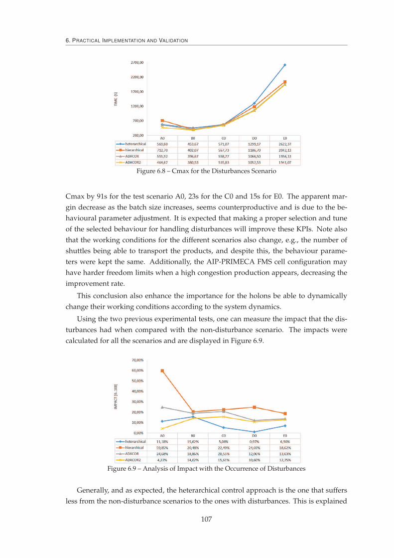
6. PRACTICAL IMPLEMENTATION AND VALIDATION
Figure 6.8 – Cmax for the Disturbances Scenario
Cmax by 91s for the test scenario A0, 23s for the C0 and 15s for E0. The apparent mar-
gin decrease as the batch size increases, seems counterproductive and is due to the be-
havioural parameter adjustment. It is expected that making a proper selection and tune
of the selected behaviour for handling disturbances will improve these KPIs. Note also
that the working conditions for the different scenarios also change, e.g., the number of
shuttles being able to transport the products, and despite this, the behaviour parame-
ters were kept the same. Additionally, the AIP-PRIMECA FMS cell configuration may
have harder freedom limits when a high congestion production appears, decreasing the
improvement rate.
This conclusion also enhance the importance for the holons be able to dynamically
change their working conditions according to the system dynamics.
Using the two previous experimental tests, one can measure the impact that the dis-
turbances had when compared with the non-disturbance scenario. The impacts were
calculated for all the scenarios and are displayed in Figure 6.9.
Figure 6.9 – Analysis of Impact with the Occurrence of Disturbances
Generally, and as expected, the heterarchical control approach is the one that suffers
less from the non-disturbance scenarios to the ones with disturbances. This is explained
107

6.4. Assessment of ADACOR2
by the fact that this control structure is completely dependent of local interactions. De-
spite this result, the impact must always be accompanied with other KPIs for contextual-
ization, such as the Cmax.
Considering all the other approaches, ADACOR2 is the one that less impact suffer
when disturbances appear at the shop-floor, having on average, for all the tested scenar-
ios, the best Cmax results.
Having an idea of how much products can be produced in a given amount of time
(i.e. the throughput), it is also very important to assess a production system, an partic-
ularly the control architecture on top of it. Regarding this, and as expected, in the sce-
narios without disturbances, see Figure 6.10, the heterarchical approach is the one that
presents the worst throughput value. Since all the other approaches follow an hierarchi-
cal structure in non-disturbance scenarios, they all present the same throughput values.
Comparatively, for the scenario A0, the heterarchical approach produces, on average less
6.87 products per hour. If the same analysis is made for the scenario C0, it can be seen
that 7.88 products per hour are less produced and for scenario E0, 17.58 products.
Figure 6.10 – Throughput for Normal Scenarios
Additionally, it is possible to be observed a margin gain after scenario C0, where the
heterarchical approach throughput degrades while the others have an improvement.
Introducing disturbances and making the same exercise, now all the control archi-
tectures have different behaviours (see Figure 6.11). Being this already expected, it is
possible to analyse that, on average the heterarchical approach is the one that presents
the worst results, while the ADACOR2 is the one that displays higher values of through-
put. Comparing the ADACOR2 with the heterarchical approach, it can be seen that, for
the scenario A0, ADACOR2 produces more 9.67 products per hour and for scenario C0,
2.81. Note that for scenario C0 all the approaches have a decrease of throughput, which
is explained by being the scenario with the lower number of shuttles to transport the
products, i.e. only 4 shuttles. Similarly to what happened for the scenarios without dis-
turbances, from scenario C0 on, there is an increase of throughput for ADACOR2, while
there is a decrease of throughput for the heterarchical approach, being the difference for
scenario E0 of 13.76 products per hour.
108
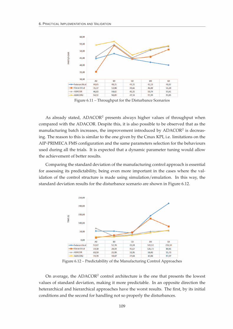
6. PRACTICAL IMPLEMENTATION AND VALIDATION
Figure 6.11 – Throughput for the Disturbance Scenarios
As already stated, ADACOR2 presents always higher values of throughput when
compared with the ADACOR. Despite this, it is also possible to be observed that as the
manufacturing batch increases, the improvement introduced by ADACOR2 is decreas-
ing. The reason to this is similar to the one given by the Cmax KPI, i.e. limitations on the
AIP-PRIMECA FMS configuration and the same parameters selection for the behaviours
used during all the trials. It is expected that a dynamic parameter tuning would allow
the achievement of better results.
Comparing the standard deviation of the manufacturing control approach is essential
for assessing its predictability, being even more important in the cases where the val-
idation of the control structure is made using simulation/emulation. In this way, the
standard deviation results for the disturbance scenario are shown in Figure 6.12.
Figure 6.12 – Predictability of the Manufacturing Control Approaches
On average, the ADACOR2 control architecture is the one that presents the lowest
values of standard deviation, making it more predictable. In an opposite direction the
heterarchical and hierarchical approaches have the worst results. The first, by its initial
conditions and the second for handling not so properly the disturbances.
109

6.4. Assessment of ADACOR2
6.4.2 Structural Self-Organization Using the Futuristic AIP-PRIMECA
The structural part of the ADACOR2 holonic architecture is validated, as stated pre-
viously, using the level 2 of the structural self-organization.
The structural self-organization mechanism is triggered when a batch of orders is al-
located to a OH. Briefly, after receiving a batch of orders, the OH will start an information
gathering from other OHs, where the resource queue, allocated work-orders, processing
times and actual location, are exchanged. The implemented procedure follows the mech-
anism described in section 5.2.1. After finishing the allocation of all OHs, each OH sends
the information of either better or worst solution achieved, from actual resources disposi-
tion. In the case of a better solution, the OH sends the KPI and the new allocation places
to all the OHs. The overall best solution, found in each OH, is automatically assumed
and used.
Several test scenarios were designed with different batch sizes, as illustrated in Table
6.5. Each scenario is composed by two orders being the second one launched after a given
time from the first one. As an example, sC0 starts by launching 2 BELT and after 120s is
launched 5 BELT and 10 LATE. In this example, the transport of orders is achieved by the
use of 10 AGVs.
Table 6.5 – Structural Scenarios Description
Number of AGVs Time launching (s)Client order
Order ProductsBELT AIP LATE
sA0 10 120#1 2 - -#2 - 3 -
sB0 10 120#1 2 - -#2 - 10 -
sC0 10 120#1 2 - -#2 5 - 10
sD0 10120
#1 2 - 2#2 - - 15
A visual result of the structural self-organization can be seen in Figure 6.13. The
scenario sC0 is used in this example and it can be seen that after the arrival of order #2,
the machines, after applying the structural self-organization, shifted into new working
positions. Machine M6 has been requested to change place, since it had no allocation of
tasks and its position needed to be used in the present re-organization.
Similarly to the behavioural self-organization tests, the structural self-organization
was also tested considering four manufacturing control approaches, namely the heterar-
chical, hierarchical, ADACOR and ADACOR2. In this case, the ADACOR manufactur-
ing control architecture follows the hierarchical approach and so the results are the same.
This is explained by the limited re-organization capabilities of the ADACOR that only
switches between the two pre-defined states. The ADACOR2 uses the SH but the struc-
tural self-organization happens in an emergent way, since the re-organization is deployed
110

6. PRACTICAL IMPLEMENTATION AND VALIDATION
M1 M2
M6 M5 M4
M3
2xAIP 10xLATE
5xBELT
structural
self-organization
M6
M3 M2 M4 M5M1
Figure 6.13 – Structural Self-Organization in Practice
by the OHs.
In reality, the physical re-organization, or the machines shifting place, takes a given
amount of time. In the present simulations, and in order to simulate a more real machine
moving, machines also spend a given amount of time to be shifted. This time is propor-
tional with the travelling distance (d) and with twice the setup time (ts) (unplugging from
original place and plugging in the final working position). Naturally, the used times are
not real, but are realistic and proportional with the designed dataset sizes. In this way,
the necessary amount of time to move, tm, between working positions is given by:
tm = d× k + 2× ts (6.1)
where k is a constant representing the travelling time between consecutive working po-
sitions. In the current simulation k is 2 seconds and ts is 5 seconds.
Additionally, if the holons detect that the structural change is not beneficial for the
system, i.e. it doesn’t bring an KPI improvement, the re-arrangement will not happen.
The experimental results for the Cmax KPI are depicted in Figure 6.14.
Figure 6.14 – Cmax for the Structural Self-Organization
Analysing the results, it can be noticed that for all the scenarios, the heterarchical ap-
proach is the one that produces the worst results, i.e. the highest Cmax. The structural
111

6.4. Assessment of ADACOR2
self-organization in ADACOR2, for scenarios sA0 and SB0, didn’t produce any improve-
ments and so the holons didn’t apply it, reaching the same results as hierarchical and
ADACOR. For the scenarios sC0 and sD0, the ADACOR2 approach was applied the struc-
tural self-organization procedure which has produced improvements and consequently
they were taken into consideration, improving the Cmax, on average, by 23.98s.
Converting the previous results in terms of throughput, as shown in Figure 6.15, it is
possible to observe that for scenarios sC0 and sD0 the ADACOR2 is able to produce more
0.76 and 0.28 parts per hour, respectively.
Figure 6.15 – Throughput for the Structural Self-Organization
Comparing all the control approaches with the hierarchical one, it can be observed,
see Figure 6.16, that the heterarchical control approach has on average 18,53% of KPI
degradation. Despite this overall value, it is also noticeable that for the largest dataset,
i.e. for scenario sD0, this degradation is reduced to 4,28%.
Figure 6.16 – Analysis of the Impact of the Control Approaches
As already seen in the Cmax analysis, in the first two scenarios, the ADACOR2 hasn’t
produced any improvement since due its low batch size won’t justify the structural self-
organization. On the other two, it has improved the best control approach, by 0.88% for
the sC0 and 0.33% for sD0. Despite the apparent low improvement, it must be noticed
that several assumptions were made that could limit it. First, tm and its variables were
112

6. PRACTICAL IMPLEMENTATION AND VALIDATION
obtained in an empirical manner in order to balance between moving time and batch
sizes, giving a comparatively realistic simulation. Secondly, the batch sizes are, proba-
bly, too small to properly extract the real capabilities of the structural self-organization.
Lastly, the potential field based mechanism might not be the most appropriate for this
case. Despite of all the aforementioned constraints, the purpose of the designed scenar-
ios was achieved by passing the information about the structural self-organization.
Lastly, the predictability is also an important assessment metric and in this KPI, as
expected, the heterarchical control approach produces the most variable results. On
the other hand, and due to the structural self-organization process embedded in the
ADACOR2, it produces, on average, the second most unpredictable. Despite this, it is
worthy to be noticed that this is not a major issue, since the difference is not relevant.
Figure 6.17 – Predictability of the Manufacturing Control Approaches
The achieved experimental results show the merits of the structural self-organization
approach to face severe changing conditions. However, the experiments also showed
new possibilities to improve the proposed algorithm, e.g., by considering the optimiza-
tion in the re-configuration of the resources during the structural self-organization pro-
cess.
6.5 Summary
The present chapter has described the two use cases used to assess the proposed
ADACOR2 manufacturing control architecture. The two use cases are based on the AIP-
PRIMECA FMS, using the first one to validate the behavioural self-organization vector.
A modified version of the AIP-PRIMECA, where the shuttle transportation system is re-
placed by AGVs and machines are also empowered with moving capabilities, was used
to test the structural self-organization.
Several simulation runs were conducted and by analysing them one can conclude that
ADACOR2 brings significant advantages in fulfilling the requirements needed to achieve
a truly evolvable and self-organized system.
113

6.5. Summary
114

7Conclusions and Future Work
Success is not final, failure is not fatal: it is the courage to continue that counts.
Winston Churchill
The manufacturing world is constantly pushed into their limits. To face the current
challenges imposed to the manufacturing world, an innovative manufacturing control
architecture was proposed.
7.1 Conclusions
The ever growing demanding requirements by customers are imposing the need to
develop more flexible, agile, robust and responsive manufacturing control architectures.
Requirements such as product customization, shorter life-cycles, higher quality demand
or, at an internal level, resources breakdown, worker absence, rush orders or problems in
the supply management layer, can also impose pressure into the manufacturing compa-
nies.
To cope with the aforementioned requirements, the focus of the research trend has
shifted from more hierarchical manufacturing control architectures into distributed and
decentralized control, assuming a more heterarchical structure. Despite this, the latest
has never been able to reach the optimization performances displayed by the first ones
when the system is operating under stable conditions. In recent years, the combination of
115

7.2. Work Validation
hierarchical and heterarchical structures have also taken the researchers attention, com-
bining the system optimization given by the hierarchical structure with the responsive-
ness provided by the heterarchical approaches.
One of the most prominent manufacturing control architectures that proposed the
use of this approach is the well known ADACOR holonic architecture which works on a
binary state that switches from a stationary state into a transient state when disturbances
hit the shop-floor and switches back to the stationary state after the disturbance recovery.
Despite the good results displayed by ADACOR, a step further was still needed to reach
a truly evolvable system, possibility by eliminating the fixed binary state on which it
operates.
In order to overcome the ADACOR main limitation, inspiration was drawn from evo-
lutionary theories and self-organization principles found in societies of species, such as
ant food foraging behaviour and fish schooling, or in natural processes such as the mag-
netic field concepts.
Two evolutionary theories are on the basis of the developed work of this thesis. The
first one, and by far the most known, is the Darwin evolutionary theory. On his studies,
Darwin stated that species tend to be in a constant state of evolution by making small
internal adaptations in order to better fit the external environment on which they operate.
On the other hand, the punctuated equilibrium theory, states that species are mostly in
a stable state and suddenly can make drastic changes in order to overcome the imposed
external constraints.
The first evolutionary theory is translated into the ADACOR2 manufacturing con-
trol architecture by allowing the individual holons to change/adapt their internal be-
haviour. This is named behavioural self-organization and allows the overall system to
smoothly evolve into a new working configuration. The second evolutionary theory is
incorporated into the ADACOR2 manufacturing control architecture by allowing a re-
arrangement in the holarchy structure. This more drastic change, named structural self-
organization, will allow the system to overcome disturbances with higher impact levels
and will also allow the system to evolve into a new working configuration.
During the presented work, a new internal model of the holon was also proposed,
with a special emphasis to the two referred self-organization components: the be-
havioural and the structural. A special attention is also given to handle the nervous-
ness aspect that can appear in those distributed and self-organized systems. This can
be also seen in the holon internal structure by detailing and specifying the nervousness
controller.
7.2 Work Validation
In order to validate the proposed manufacturing control architecture, an instantiation
of the ADACOR2 holons was implemented using the MAS technology. The implemented
116

7. CONCLUSIONS AND FUTURE WORK
system was tested using an emulated version of the real AIP-PRIMECA FMS and the sce-
narios contained in this work were defined taking into consideration the ones specified in
the Bench4star benchmark (Trentesaux et al., 2013). The aforementioned use case allowed
the validation of the behavioural self-organization vector while a modified version of the
refereed benchmark was needed to test and validate the structural self-organization vec-
tor. In this adaptation of the real use case, the resources have moving capabilities and the
transportation of the products at the shop-floor is accomplished by using AGVs, which
may imply a physical structural re-organization at the shop-floor level. This last feature
is also aligned with the recent trends being developed by the system integrators, e.g., as
Festo AG & Co. KG.
At the end of this thesis and based on the achieved experimental results, some out-
comes can be highlighted:
— ADACOR2 can smoothly or drastically evolve into a better working configuration,
responding properly to disturbances.
— A nervousness controller is a must have in distributed self-organized systems in
order to prevent chaotic behaviour and push the system to its limits.
— ADACOR2 outreaches its predecessor ADACOR as also the hierarchical and heter-
archical approaches.
At the beginning of this thesis, it was depicted that one of the main goals of this work
was the specification of a manufacturing control architecture that was able to improve
the current state-of-the-art approaches, reducing the gap between these and an optimal
situation (recall Figure 1.1). This was achieved by introducing dynamics associated to the
two self-organization dimensions and the nervousness controller. This gap is illustrated
in Figure 7.1, considering the real values extracted from the experimental results, and
particularly in this case those from behavioural self-organization and scenario A0.
Figure 7.1 – Performance Behaviour of the Evaluated Control Structures
117
7.3. Future Work
The experimental results show that the performance obtained by the ADACOR2 ar-
chitecture outperforms all the other tested approaches. If it is assumed that the super-
visor holon scheduling mechanism is optimal, i.e. it introduces an optimal plan to be
executed (which for the case is not that important, being just a matter of implementation
and boundaries definition), the hierarchical, the ADACOR and the ADACOR2 architec-
ture have optimal performance levels in non-disturbance situations. When disturbances
are introduced into the system, all the approaches must react by handling them in the best
possible way. In this situation, the hierarchical approach suffers the highest impact in the
sense that is the one that performs worst of the four approaches. It is also possible to
observe that the ADACOR2 approach is the one that has less impact when disturbances
are introduced.
This analysis sustains that the "vision" introduced in the Figure 1.1 is achieved during
the development of this work by allowing the holons to dynamically change their internal
behaviour or to dynamically re-arrange the holarchy structure.
7.3 Future Work
At the end of this work, several research developments could be identified as future
work that will enhance the current achievements.
Firstly, the developed agents must be integrated in embedded control devices, allow-
ing the practical development of the intelligent products concept and the CPS paradigm.
Although some experiments were conducted during this work, serving as a proof of con-
cept by deploying some of the ADACOR2 agents into the RaspberryPi 1 platform, the
results are not shown in this thesis.
Secondly, another major development branch can be foreseen in the use of the stan-
dard de-facto OPC-UA (OLE for process control - Unified Architecture) as a major enabler
to integrate the ADACOR2 holons in the existing/future system designs. The integration
with the OPC-UA guarantees several important features, standard access to data sources
across shop-floor and seamless device integration, since all major vendors are adopting
its usage.
Cloud computing is a nowadays reality. To this extend, the development of the SH
using the cloud resources, combined with the processing power of the HPC (High Per-
formance Computing), enables to run massive simulations to identify in an early stage
possible bottlenecks that would not be foreseen in another way. A practical result of this
could be the prediction with more accuracy of possible plan deviations that would later
be feed to the THs. On the opposite side there is the fog computing that promises to
bring into the end nodes the cloud computation power. This is also aligned with the CPS
paradigm and can be used to empower the OHs with more processing capabilities allow-
ing a better decision making on that side, e.g., turning machines more responsiveness
and better decision makers.
1. http://www.raspberrypi.org/
118

7. CONCLUSIONS AND FUTURE WORK
The introduced nervousness stabilizer is also a major research trend in the way that
the correct development of this mechanism enables the ADACOR2 holons, and even
other distributed entities developed within other architectures, to be pushed to perfor-
mance levels not seen before maintaining the overall system under control.
Additionally, a deeper study on the structural self-organization focusing on when and
how to re-organize the holarchy structurally assumes also a crucial importance. In this
scope, previous work of (Farid and McFarlane, 2008) and (Farid and Covanich, 2008) can
be used as ground-base to further explore this.
Future work will also be devoted to consider SoA principles in the ADACOR2 archi-
tecture, which will enable a seamless integration within the vertical layers of the ISA-95
standard.
A final research trend, just to name a few, is devoted to the ADACOR2 generalization
issues considering that the developed work can/may be applied into other architectures
than ADACOR.
119

7. CONCLUSIONS AND FUTURE WORK
120

Bibliography
Abd-El-Barr, M., S.M. Sait, and B.A.B. Sarif. 2003. « Ant colony algorithm for evolution-
ary design of arithmetic circuits ». Proceedings of the 15th International Conference on
Microelectronics, 2003. ICM 2003. 198–201. doi:10.1109/ICM.2003.1287767.
Aggoune, Riad, A.H. Mahdi, and M.-C. Portmann. 2001. « Genetic algorithms for the flow
shop scheduling problem with availability constraints ». Proceedgins of the IEEE Inter-
national Conference on Systems, Man, and Cybernetics, 2001 4:2546–2551 vol.4. doi:10.
1109/ICSMC.2001.972941.
Ai, The Jin, and Voratas Kachitvichyanukul. 2009. « A Particle Swarm Optimization for
the Vehicle Routing Problem with Simultaneous Pickup and Delivery ». Computers &
Operations Research 36:1693–1702.
Albadawi, Zahir, Benoit Boulet, Robert DiRaddo, Patrick Girard, Alexandre Rail, and Vin-
cent Thomson. 2006. « Agent-based control of manufacturing processes » [inlangen].
International Journal of Manufacturing Research 1 (4): 466. Visited on 11/18/2014.
doi:10.1504/IJMR.2006.012256.
Albert, F.Y.C., S.P. Koh, C.P. Chen, C.K. Loo, and S.K. Tiong. 2009. « Path control of dex-
terous robotic hand using Genetic Algorithm ». Proceedings of the 4th International Con-
ference on Autonomous Robots and Agents, 2009. ICARA 2009. 502–506. doi:10.1109/
ICARA.2000.4804002.
Anderson, Carl, and John Bartholdi. 2000. « Centralized versus decentralized control in
manufacturing: lessons from social insects », 91–105.
Arnaout, J.-P., R. Musa, and G. Rabadi. 2008. « Ant colony optimization algorithm to par-
allel machine scheduling problem with setups ». Proceeding of the IEEE International
Conference on Automation Science and Engineering, 2008. CASE 2008: 578–582. doi:10.
1109/COASE.2008.4626566.
Arunachalam, S., R. Zalila-Wenkstern, and R. Steiner. 2008. « Environment Mediated
Multi Agent Simulation Tools – A Comparison », 43–48. IEEE. Visited on
05/26/2014. doi:10.1109/SASOW.2008.44.
121

BIBLIOGRAPHY
Aziz, N.A.B.A., A.W. Mohemmed, and B.S. Daya Sagar. 2007. « Particle Swarm Optimiza-
tion and Voronoi diagram for Wireless Sensor Networks coverage optimization ». Pro-
ceeding of the International Conference on Intelligent and Advanced Systems, 2007. ICIAS
2007: 961–965. doi:10.1109/ICIAS.2007.4658528.
Badawy, F.A., H.Y. Abdelazim, and M.G. Darwish. 2005. « Genetic Algorithms for Pre-
dicting the Egyptian Stock Market ». Proceeding ot the Enabling Technologies for the New
Knowledge Society: ITI 3rd International Conference on Information and Communications
Technology, 2005: 109–122. doi:10.1109/ITICT.2005.1609619.
Bae, Jong Il, Dong Cheol Lee, Doo Sung Ahn, Jong Moon Lee, Kang Eon Kim, and Moon
Soo Kim. 2001. « Speed control of fork lift vehicle using a genetic algorithm ». Proceed-
ings of the IEEE International Symposium on Industrial Electronics, 2001. Proceedings. ISIE
2001. 3:1839–1844 vol.3. doi:10.1109/ISIE.2001.931990.
Baker, Albert D. 1991. « Manufacturing Control with a Market-Driven Contract Net ».
Ph.D., Rensselaer Polytechnic Institute.
Barata, Jose, and Luis M. Camarinha-Matos. 2003. « Coalitions of manufacturing compo-
nents for shop floor agility - the CoBASA architecture » [inlangen]. International Jour-
nal of Networking and Virtual Organisations 2 (1): 50. Visited on 11/18/2014. doi:10.
1504/IJNVO.2003.003518.
Barbosa, José, and Paulo Leitão. 2010. « Modelling and Simulating Self-Organizing
Agent-based Manufacturing Systems ». to appear in the Proceedings of the 36th An-
nual Conference of the IEEE Industrial Electronics Society (IECON’10) Arizona, US, 8-10
November.
Barbosa, Jose, Paulo Leitao, Emmanuel Adam, and Damien Trentesaux. 2013a. « Self-
Organized Holonic Multi-agent Manufacturing System: The Behavioural Perspec-
tive ». 2013 IEEE International Conference on Systems, Man, and Cybernetics: 3829–3834.
doi:10.1109/SMC.2013.654.
Barbosa, José, Paulo Leitão, Emmanuel Adam, and Damien Trentesaux. 2015. « Dynamic
self-organization in holonic multi-agent manufacturing systems: The ADACOR evo-
lution » [inlangen]. Computers in Industry 66 (): 99–111. Visited on 12/12/2014.
doi:10.1016/j.compind.2014.10.011.
— . 2012a. « Nervousness in Dynamic Self-organized Holonic Multi-agent Systems ». In
Highlights on Pratical Applications of Agents and Multi-agent Systems, 9–17. Advances in
Intelligent and Soft Computing.
— . 2012b. « Self-organized holonic manufacturing systems combining adaptation and
performance optimization ». In Technological Innovation for Value Creation, 163–170.
Springer.
122
BIBLIOGRAPHY
— . 2013b. « Structural Self-organized Holonic Multi-Agent Manufacturing Systems ».
In Industrial Applications of Holonic and Multi-Agent Systems, ed. by David Hutchison,
Takeo Kanade, Josef Kittler, Jon M. Kleinberg, Friedemann Mattern, John C. Mitchell,
Moni Naor, Oscar Nierstrasz, C. Pandu Rangan, Bernhard Steffen, Madhu Sudan,
Demetri Terzopoulos, Doug Tygar, Moshe Y. Vardi, Gerhard Weikum, Vladimír
Marík, Jose L. Martinez Lastra, and Petr Skobelev, 8062:59–70. Berlin, Heidelberg:
Springer Berlin Heidelberg. Visited on 10/28/2013.
Barbosa, Jose, Paulo Leitao, and Ana I. Pereira. 2011. « Combining adaptation and opti-
mization in bio-inspired multi-agent manufacturing systems ». In IEEE International
Symposium on Industrial Electronics, 1773–1778. Visited on 05/30/2013. doi:10.1109/
ISIE.2011.5984425.
Bell, J. E., and P. R. McMullen. 2004. « Ant Colony Optimization Techniques for the Vehi-
cle Routing Problem ». Advanced Engineering Informatics 18:41–48.
Bellifemine, Fabio Luigi, Giovanni Caire, and Dominic Greenwood. 2007. Developing
Multi-Agent Systems with JADE (Wiley Series in Agent Technology). John Wiley & Sons.
Blum, C., and M. Sampels. 2004. « An Ant Colony Optimization Algorithm for Shop
Scheduling Problems ». Journal of Mathematical Modelling and Algorithms 3:285–308.
Boissier, Olivier, Rafael H. Bordini, Jomi F. Hübner, Alessandro Ricci, and Andrea Santi.
2013. « Multi-agent oriented programming with JaCaMo ». Special section: The Pro-
gramming Languages track at the 26th {ACM} Symposium on Applied Comput-
ing (SAC 2011) & Special section on Agent-oriented Design Methods and Pro-
gramming Techniques for Distributed Computing in Dynamic and Complex Envi-
ronments, Science of Computer Programming 78 (6): 747–761. doi:http://dx.doi.
org/10.1016/j.scico.2011.10.004.
Bonabeau, Eric, Marco Dorigo, and Guy Theraulaz. 1999. Swarm Intelligence: From Natural
to Artificial Systems. New York, NY, USA: Oxford University Press, Inc.
Bonabeau, Eric, Guy Theraulaz, Jean-Louls Deneubourg, Serge Aron, and Scott Ca-
mazine. 1997. « Self-organization in social insects » [inlangen]. Trends in Ecology & Evo-
lution 12, no. 5 (): 188–193. Visited on 05/23/2014. doi:10.1016/S0169-5347(97)
01048-3.
Bordini, Rafael H. 2007. Programming multi-agent systems in AgentSpeak using Jason. Chich-
ester, West Sussex, England ; Hoboken, NJ: J. Wiley.
Boubertakh, H., M. Tadjine, P.-Y. Glorennec, and S. Labiod. 2009. « Tuning fuzzy PID
controllers using ant colony optimization ». Proceeding of the 17th Mediterranean Con-
ference on Control and Automation, 2009. MED ’09. 13–18. doi:10.1109/MED.2009.
5164507.
Bousbia, Salah, and Damien Trentesaux. 2002. « Self-organization in Distributed Manu-
facturing Control: State-of-the-art and Future Trends ». Proceeding of the IEEE Interna-
tional Conference on Systems, Man and Cybernetics 5.
123
BIBLIOGRAPHY
Brennan, Robert W., and Douglas H. Norrie. 2003. « Metrics for evaluating distributed
manufacturing control systems » [inlangen]. Computers in Industry 51, no. 2 (): 225–
235. Visited on 09/03/2014. doi:10.1016/S0166-3615(03)00038-1.
Brown, J.Q., and M.J. McShane. 2004. « Optimal design of nanoengineered implantable
optical sensors using a genetic algorithm ». Proceedings of the 26th Annual International
Conference of the IEEE Engineering in Medicine and Biology Society, 2004. IEMBS ’04.
1:2105–2108. doi:10.1109/IEMBS.2004.1403618.
Bussmann, Stefan, Nicholas R Jennings, and Michael Wooldridge. 2004. Multiagent Sys-
tems for Manufacturing Control A Design Methodology [inlangEnglish]. Berlin, Heidel-
berg: Springer Berlin Heidelberg. Visited on 05/26/2014.
Bussmann, Stefan, and Klaus Schild. 2001. « An agent-based approach to the control of
flexible production systems », 2:481–488. IEEE. Visited on 11/19/2014. doi:10.1109/
ETFA.2001.997722.
— . 2000. « Self-Organizing Manufacturing Control: An Industrial Application of Agent
Technology ». In Proceedings of the Fourth International Conference on MultiAgent Systems
(ICMAS-2000), 87–94. ICMAS ’00. Washington, DC, USA: IEEE Computer Society.
Bussmann, Stefan, and Jörg Sieverding. 2001. « Holonic Control of an Engine Assembly
Plant - An Industrial Evaluation ». Proceedings of the IEEE International Conference on
Systems, Man and Cybernetics: 169–174.
Caldeira, J.L., R.C. Azevedo, C.A. Silva, and J.M.C. Sousa. 2007. « Supply-Chain Manage-
ment Using ACO and Beam-ACO Algorithms ». Proceedings of the IEEE International
Fuzzy Systems Conference, 2007. FUZZ-IEEE 2007. 1–6. doi:10.1109/FUZZY.2007.
4295615.
Camazine, Scott, Jean L. Deneubourg, Nigel R. Franks, James Sneyd, Guy Theraulaz,
and Eric Bonabeau. 2001. Self-Organization in Biological Systems. Princeton University
Press.
Camilo, T., C. Carreto, J. S. Silva, and F. Boavida. 2006. « An Energy-Efficient Ant-Based
Routing Algorithm for Wireless Sensor Networks ». ANTS Workshop: 49–59.
Cândido, Gonçalo, and José Barata. 2007. « A Multiagent Control System for Shop Floor
Assembly » [inlangen]. In Holonic and Multi-Agent Systems for Manufacturing, ed. by
Vladimír Marík, Valeriy Vyatkin, and Armando W. Colombo, 4659:293–302. Berlin,
Heidelberg: Springer Berlin Heidelberg. Visited on 11/18/2014.
Candido, Goncalo, Jose Barata, Armando W. Colomboy, and Francois Jammesz. 2010.
« Service-oriented Architecture at device level to support Evolvable Production Sys-
tems », 2669–2674. IEEE. Visited on 11/23/2014. doi:10 . 1109 / ISIE . 2010 .
5637527.
124
BIBLIOGRAPHY
Cannata, A, M Gerosa, and M Taisch. 2008. « SOCRADES: A framework for developing
intelligent systems in manufacturing ». In Industrial Engineering and Engineering Man-
agement, 2008. IEEM 2008. IEEE International Conference on, 1904–1908. doi:10.1109/
IEEM.2008.4738203.
Chandramouli, K., and E. Izquierdo. 2006. « Image Classification using Chaotic Particle
Swarm Optimization ». Proceedings of the IEEE International Conference on Image Pro-
cessing, 2006: 3001–3004. doi:10.1109/ICIP.2006.312968.
Chatterjee, A., S.P. Ghoshal, and V. Mukherjee. 2010. « Artificial Bee Colony Algorithm for
Transient Performance Augmentation of Grid Connected Distributed Generation ». In
Swarm, Evolutionary, and Memetic Computing, ed. by BijayaKetan Panigrahi, Swagatam
Das, PonnuthuraiNagaratnam Suganthan, and SubhransuSekhar Dash, 6466:559–566.
Lecture Notes in Computer Science. Springer Berlin Heidelberg.
Chen, G.Y., and K.J. Rogers. 2009. « Proposition of two multiple criteria models applied
to Dynamic Multi-objective Facility Layout Problem based on Ant Colony Optimiza-
tion ». Proceedgins of the IEEE International Conference on Industrial Engineering and En-
gineering Management, 2009. IEEM 2009. 1553–1557. doi:10 . 1109 / IEEM . 2009 .
5373095.
Chen, An-Pin, Chien-Hsun Huang, and Yu-Chia Hsu. 2009. « A novel modified particle
swarm optimization for forecasting financial time series ». Proceedings of the IEEE In-
ternational Conference on Intelligent Computing and Intelligent Systems, 2009. ICIS 2009.
1:683–687. doi:10.1109/ICICISYS.2009.5357771.
Chen, Ruey-Maw, Shih-Tang Lo, Chung-Lun Wu, and Tsung-Hung Lin. 2008. « An effec-
tive ant colony optimization-based algorithm for flow shop scheduling ». Proceedgins
of the IEEE Conference onSoft Computing in Industrial Applications, 2008. SMCia ’08. 101–
106. doi:10.1109/SMCIA.2008.5045943.
Chen, Yen-Wei, A. Mimori, and Chen-Lun Lin. 2009. « Hybrid particle swarm optimiza-
tion for 3-D image registration ». Proceedings of the 16th IEEE International Conference
on Image Processing (ICIP), 2009: 1753–1756. doi:10.1109/ICIP.2009.5414613.
Cheng, Chi-Tsun, K. Fallahi, H. Leung, and C.K. Tse. 2009. « Cooperative path planner
for UAVs using ACO algorithm with Gaussian distribution functions ». Proceedings of
the IEEE International Symposium on Circuits and Systems, 2009. ISCAS 2009. 173–176.
doi:10.1109/ISCAS.2009.5117713.
Chirn, Jin-Lung, and Duncan McFarlane. 2000. « A holonic component-based approach
to reconfigurable manufacturing control architecture », 219–223. IEEE Comput. Soc.
Visited on 11/18/2014. doi:10.1109/DEXA.2000.875030.
Cicirello, Vincent A., and Stephen F. Smith. 2001. « Wasp nests for self-configurable facto-
ries », 473–480. ACM Press. Visited on 01/15/2014. doi:10.1145/375735.376420.
125

BIBLIOGRAPHY
— . 2004. « Wasp-like Agents for Distributed Factory Coordination ». Autonomous Agents
and Multi-Agent Systems 8, no. 3 (): 237–266. Visited on 01/15/2014. doi:10.1023/B:
AGNT.0000018807.12771.60.
Coleman, James S. 1994. Foundations of social theory [inlangEnglish]. Cambridge, Mass.
[u.a.: Belknap Press of Harvard Univ. Press.
Colson, C.M., M.H. Nehrir, and C. Wang. 2009. « Ant colony optimization for microgrid
multi-objective power management ». Proceedings of the IEEE/PES Power Systems Con-
ference and Exposition, 2009. PSCE ’09. 1–7. doi:10.1109/PSCE.2009.4840070.
Corry, P., and E. Kozan. 2004. « Ant Colony Optimisation for Machine Layout Problems ».
Computational Optimization and Applications 28:287–310.
Council, National Research. 1998. Visionary manufacturing challenges for 2020. Washington,
D.C: National Academy Press.
Cui, Xiaohui, and T.E. Potok. 2007. « A Particle Swarm Social Model for Multi-Agent
Based Insurgency Warfare Simulation ». Proceedings of the 5th ACIS International Con-
ference on Software Engineering Research, Management Applications, 2007. SERA 2007.
177–183. doi:10.1109/SERA.2007.21.
Darley, Vince. 1994. « Emergent phenomena and complexity ». Artificial Life 4:411–416.
Darwin, Charles. 2007. On the origin of species by means of natural selection, or, The preserva-
tion of favored races in the struggle for life [inlangEnglish]. New York: Cosimo Classics.
Das, A., and M. Bhattacharya. 2009. « A Study on Prognosis of Brain Tumors Using Fuzzy
Logic and Genetic Algorithm Based Techniques ». Proceedgins of the International Joint
Conference on Bioinformatics, Systems Biology and Intelligent Computing, 2009. IJCBS ’09.
348–351. doi:10.1109/IJCBS.2009.129.
Deen, S. M. 2003. Agent based manufacturing: advances in holonic approach. Advanced infor-
mation processing. New York: Springer.
Deguet, Joris, Yves Demazeau, and Laurent Magnin. 2006. « Elements about the emer-
gence issue: A survey of emergence definitions ». ComPlexUs 3 (1-3): 24–31.
Deneubourg, S. Aron, S. Goss, and J. M. Pasteels. 1990. « The self-organizing exploratory
pattern of the argentine ant ». Journal of Insect Behavior 3 (2): 159–168. doi:10.1007/
BF01417909.
Di Caro, Gianni, and Marco Dorigo. 1998. « AntNet: Distributed Stigmergetic Control for
Communications Networks ». Journal of Artificial Intelligence Research 9:317–365.
Dijkstra, E. W. 1959. « A note on two problems in connexion with graphs » [inlangen].
Numerische Mathematik 1, no. 1 (): 269–271. Visited on 12/05/2014. doi:10.1007/
BF01386390.
Dilts, D.M., N.P. Boyd, and H.H. Whorms. 1991. « The evolution of control architectures
for automated manufacturing systems ». Journal of Manufacturing Systems 10, no. 1 ():
79–93. Visited on 02/05/2014. doi:10.1016/0278-6125(91)90049-8.
126

BIBLIOGRAPHY
Dolgov, D., S. Thrun, M. Montemerlo, and J. Diebel. 2010. « Path Planning for Au-
tonomous Vehicles in Unknown Semi-structured Environments ». The International
Journal of Robotics Research 29, no. 5 (): 485–501. Visited on 01/17/2014. doi:10.1177/
0278364909359210.
Dong, Qiaoying, Shulin Kan, Ling Qin, and Zhihui Huang. 2007. « Sequencing Mixed
Model Assembly Lines Based on a Modified Particle Swarm Optimization Multi-
objective Algorithm ». Proceedings of the IEEE International Conference on Automation
and Logistics, 2007: 2818–2823. doi:10.1109/ICAL.2007.4339061.
Dongming, Zhao, Xia Kewen, Wang Baozhu, and Gao Jinyong. 2008. « An Approach to
Mobile IP Routing Based on QPSO Algorithm ». Proceedings of the Pacific-Asia Workshop
on Computational Intelligence and Industrial Application, 2008. PACIIA ’08. 1:667–671.
doi:10.1109/PACIIA.2008.17.
Dorigo, M. 1992. « Optimization, Learning and Natural Algorithms (in Italian) ». PhD
thesis, Dipartimento di Elettronica, Politecnico di Milano, Milan, Italy.
Dornhaus, Anna, and Lars Chittka. 2004. « Information flow and regulation of forag-
ing activity in bumble bees ». Apidologie 35, no. 2 (): 183–192. Visited on 05/23/2014.
doi:10.1051/apido:2004002.
Drath, Rainer, and Alexander Horch. 2014. « Industrie 4.0: Hit or Hype? [Industry Fo-
rum] ». IEEE Industrial Electronics Magazine 8, no. 2 (): 56–58. Visited on 11/22/2014.
doi:10.1109/MIE.2014.2312079.
Duan, H., X. Zhang, J. Wu, and G. Ma. 2009. « Max-Min Adaptive Ant Colony Optimiza-
tion Approach to Multi-UAVs Coordinated Trajectory Replanning in Dynamic and
Uncertain Environments ». Journal of Bionic Engineering 6:161–173.
Duffie, Neil A., and Rex S. Piper. 1986. « Nonhierarchical control of manufacturing
systems » [inlangen]. Journal of Manufacturing Systems 5, no. 2 (): 141. Visited on
11/18/2014. doi:10.1016/0278-6125(86)90036-1.
Eberhart, R. C., and J. Kennedy. 1995. « A new optimizer using particle swarm theory. »
Proceedings of the Sixth International Symposium on Micromachine and Human Science:
39–43.
Eldredge, Niles, and Stephen J. Gould. 1972. « Punctuated Equilibria: An Alternative to
Phyletic Gradualism ». Ed. by Thomas J. M. Schopf. Models in Paleobiology: 82–115.
Elmahi, I., S. Merzouk, O. Grunder, and A. Elmoudni. 2004. « A genetic algorithm ap-
proach for the batches delivery optimization in a supply chain ». Proceedings of the
IEEE International Conference on Networking, Sensing and Control, 2004 1:299–304 Vol.1.
doi:10.1109/ICNSC.2004.1297452.
ElMaraghy, H. 2006. « Flexible and Reconfigurable Manufacturing Systems Paradigms ».
Proceedings of the International Journal of Flexible Manufacturing System 17:261–271.
127

BIBLIOGRAPHY
ElMaraghy, H., T. AlGeddawy, A. Azab, and W. ElMaraghy. 2012. « Change in Manufac-
turing – Research and Industrial Challenges ». In Enabling Manufacturing Competitive-
ness and Economic Sustainability, ed. by Hoda A. ElMaraghy, 2–9. Berlin, Heidelberg:
Springer Berlin Heidelberg. Visited on 05/21/2013.
Engelmore, Robert, and A. J. Morgan, eds. 1988. Blackboard systems. The Insight series in
artificial intelligence. Wokingham, England ; Reading, Mass: Addison-Wesley.
Erol, Rizvan, Cenk Sahin, Adil Baykasoglu, and Vahit Kaplanoglu. 2012. « A multi-agent
based approach to dynamic scheduling of machines and automated guided vehicles
in manufacturing systems » [inlangen]. Applied Soft Computing 12, no. 6 (): 1720–1732.
Visited on 11/20/2014. doi:10.1016/j.asoc.2012.02.001.
ESPRIT Consortium AMICE. 1993. CIMOSA: Open System Architecture for CIM
[inlangEnglish]. Berlin, Heidelberg: Springer Berlin Heidelberg. Visited on
11/26/2014.
Evans, Peter C, and Marco Annunziata. 2012. « Industrial Internet: Pushing the Bound-
aries ».
Fang, X., and T. Bai. 2009. « Share Price Prediction Using Wavelet Transform and Ant
Colony Algorithm for Parameters Optimization ». SVM, WRI Global Congress on Intel-
ligent Systems 3:288–292.
Farid, Amro, and Wuttiphat Covanich. 2008. « Measuring the effort of a reconfigura-
tion process », 1137–1144. IEEE. Visited on 06/20/2014. doi:10.1109/ETFA.2008.
4638540.
Farid, Amro, and Duncan McFarlane. 2008. « Production degrees of freedom as manu-
facturing system reconfiguration potential measures ». Proceedings of the Institution of
Mechanical Engineers, Part B: Journal of Engineering Manufacture 222, no. 10 (): 1301–
1314. Visited on 12/16/2014. doi:10.1243/09544054JEM1056.
Ferber, J. 1999. Multi-Agent System: An Introduction to Distributed Artificial Intelligence.
Addison-Wesley Professional.
Ferrarini, L., C. Veber, A. Luder, J. Peschke, A. Kalogeras, J. Gialelis, J. Rode, D. Wun-
sch, and V. Chapurlat. 2006. « Control Architecture for Reconfigurable Manufacturing
Systems: the PABADIS’PROMISE approach », 545–552. IEEE. Visited on 11/18/2014.
doi:10.1109/ETFA.2006.355427.
Fletcher, Martyn, Duncan McFarlane, Andrew Lucas, James Brusey, and Dennis Jarvis.
2003. « The Cambridge Packing Cell — A Holonic Enterprise Demonstrator ». In
Multi-Agent Systems and Applications III, ed. by Vladimír Marík, Michal Pechoucek,
and Jörg Müller, 2691:533–543. Berlin, Heidelberg: Springer Berlin Heidelberg. Vis-
ited on 07/23/2013.
Friedman-Hill, Ernest. 2003. Jess in action: rule-based systems in Java. Greenwich, CT: Man-
ning.
128

BIBLIOGRAPHY
Frisch, Karl von. 1967. The Dance Language and Orientation of Bees. Cambridge, Mass.: The
Belknap Press of Harvard University Press.
Gaing, Z.-L. 2004. « A Particle Swarm Optimization Approach for Optimum Design of
PID Controller in AVR System » [inlangen]. IEEE Transactions on Energy Conversion
19, no. 2 (): 384–391. Visited on 05/23/2014. doi:10.1109/TEC.2003.821821.
Gao, Nan, and Wei Da Chen. 2008. « A genetic algorithm for disassembly scheduling with
assembly product structure ». Proceedings of the IEEE International Conference on Service
Operations and Logistics, and Informatics, 2008. IEEE/SOLI 2008. 2:2238–2243. doi:10.
1109/SOLI.2008.4682907.
Getling, A. V. 1998. Rayleigh-Bénard convection: structures and dynamics. Advanced series
in nonlinear dynamics v. 11. Singapore ; River Edge, NJ: World Scientific.
Goss, S., S. Aron, J. Deneubourg, and J. Pasteels. 1989. « Self-organized shortcuts in the
Argentine ant ». Naturwissenschaften 76 (12): 579–581. doi:10.1007/BF00462870.
Goudos, S.K., I.T. Rekanos, and J.N. Sahalos. 2008. « EMI Reduction and ICs Optimal
Arrangement Inside High-Speed Networking Equipment Using Particle Swarm Op-
timization ». Proceedings of the IEEE Transactions on Electromagnetic Compatibility 50 (3):
586–596. doi:10.1109/TEMC.2008.924389.
Grassé, P. P. 1959. « La Reconstruction du nid et les Coordinations Inter-Individuelles
chez Bel-licositermes Natalensis et Cubitermes sp. La théorie de la Stigmergie: Es-
sai d’interpréta-tion du Comportement des Termites Constructeurs ». Insectes Sociaux
6:41–84.
Gravel, M., W.L. Price, and C. Gagné. 2002. « Scheduling Continuous Casting of Alu-
minum using a Multiple Objective Ant Colony Optimization Metaheuristic ». Euro-
pean Journal of Operational Research 143:218–229.
Hadeli, Karuna, Paul Valckenaers, Paul Verstraete, Bart Saint Germain, and Hendrik Van
Brussel. 2005. « A Study of System Nervousness in Multi-agent Manufacturing Con-
trol System ». In Engineering Self-Organising Systems’05, 232–243.
Hadeli, P. Valckenaers, M. Kollingbaum, and H. Van Brussel. 2004. « Multi-agent Coordi-
nation and Control using Stimergy ». Computers in Industry 53:75–96.
Hagelbäck, Johan, and Stefan J. Johansson. 2009. « A Multiagent Potential Field-Based
Bot for Real-Time Strategy Games ». International Journal of Computer Games Technology
2009:1–10. Visited on 01/17/2014. doi:10.1155/2009/910819.
Hogg, Tad, and Bernardo A. Huberman. 1991. « Controlling chaos in distributed sys-
tems ». IEEE Transactions on Systems, Man, and Cybernetics 21:1325–1332.
Holland, John H. 1999. Emergence: From Chaos to Order. Perseus Publishing.
129

BIBLIOGRAPHY
Hong, Wei-Chiang, Yu-Fen Chen, Peng-Wen Chen, and Yi-Hsuan Yeh. 2007. « Continu-
ous ant colony optimization algorithms in a support vector regression based financial
forecasting model ». Proceedings of the Third International Conference on Natural Compu-
tation, 2007. ICNC 2007. 1:548–552. doi:10.1109/ICNC.2007.315.
Hu, Haibing, Qingbo Hu, Zhengyu Lu, and Dehong Xu. 2005. « Optimal PID controller
design in PMSM servo system via particle swarm optimization ». Proceedings of the
31st Annual Conference of IEEE Industrial Electronics Society, 2005. IECON 2005. 5 pp.
doi:10.1109/IECON.2005.1568882.
Jackson, Peter. 1999. Introduction to expert systems. 3rd ed. International computer science
series. Harlow, England ; Reading, Mass: Addison-Wesley.
Jain, P.K., and P.K. Sharma. 2005. « Solving job shop layout problem using ant colony
optimization technique ». Proceedings of the IEEE International Conference on Systems,
Man and Cybernetics, 2005 1:288–292 Vol. 1. doi:10.1109/ICSMC.2005.1571160.
Jalilvand, A., A. Kimiyaghalam, A. Ashouri, and M. Mahdavi. 2008. « Advanced particle
swarm optimization-based PID controller parameters tuning ». Proceedings of the IEEE
International Multitopic Conference, 2008. INMIC 2008. 429–435. doi:10.1109/INMIC.
2008.4777776.
Jana, Tarun Kanti, Bipradas Bairagi, Soumen Paul, Bijan Sarkar, and Jyotirmoy Saha.
2013. « Dynamic schedule execution in an agent based holonic manufacturing sys-
tem » [inlangen]. Journal of Manufacturing Systems 32, no. 4 (): 801–816. Visited on
11/20/2014. doi:10.1016/j.jmsy.2013.07.004.
Jha, Nand K., ed. 1991. Handbook of flexible manufacturing systems. San Diego: Academic
Press.
Jiang, Bing, Wei Zhang, and Pan Zhang. 2009. « Research on an Improved Genetic Al-
gorithm Which Can Improve the Node Positioning Optimized Solution of Wireless
Sensor Networks ». Proceedgins of the International Conference on Computational Science
and Engineering, 2009. CSE ’09. 2:949–954. doi:10.1109/CSE.2009.101.
Jianhua, Wang, and Huang Xianfeng. 2010. « A hybrid genetic algorithm for agile sup-
ply chain scheduling optimization ». Proceedings of the 2nd International Conference on
Future Computer and Communication (ICFCC), 2010 1:396–400. doi:10.1109/ICFCC.
2010.5497760.
Jun, Li. 2009. « A Genetic Algorithm to Logistics Distribution Vehicle Routing Problem
with Fuzzy Due Time ». Proceedings of the Sixth International Conference on Fuzzy Sys-
tems and Knowledge Discovery, 2009. FSKD ’09. 6:33–39. doi:10.1109/FSKD.2009.
594.
Kaijun, Leng, Cui Nanfang, and Wang Yuxia. 2010. « Genetic optimization of retailer se-
lection in supply chain management ». Proceedings of the 2nd IEEE International Con-
ference on Information Management and Engineering (ICIME), 2010: 124–127. doi:10.
1109/ICIME.2010.5477709.
130
BIBLIOGRAPHY
Karaboga, Dervis, and Bahriye Basturk. 2007. « A powerful and efficient algorithm for
numerical function optimization: artificial bee colony (ABC) algorithm » [inlangen].
Journal of Global Optimization 39, no. 3 (): 459–471. Visited on 05/23/2014. doi:10.
1007/s10898-007-9149-x.
Karlra, P., and N.R. Prakash. 2003. « A neuro-genetic algorithm approach for solving
the inverse kinematics of robotic manipulators ». Proceedgins of the IEEE International
Conference on Systems, Man and Cybernetics, 2003. 2:1979–1984 vol.2. doi:10.1109/
ICSMC.2003.1244702.
Karnouskos, Stamatis, Armando W. Colombo, Thomas Bangemann, Keijo Manninen,
Roberto Camp, Marcel Tilly, Marek Sikora, François Jammes, Jerker Delsing, Jens
Eliasson, Philippe Nappey, Ji Hu, and Mario Graf. 2014. « The IMC-AESOP Archi-
tecture for Cloud-Based Industrial Cyber-Physical Systems » [inlangen]. In Industrial
Cloud-Based Cyber-Physical Systems, ed. by Armando W. Colombo, Thomas Bange-
mann, Stamatis Karnouskos, Jerker Delsing, Petr Stluka, Robert Harrison, Francois
Jammes, and Jose L. Lastra, 49–88. Cham: Springer International Publishing. Visited
on 11/24/2014.
Karuna, Hadeli, Paul Valckenaers, Bart Saint-Germain, Paul Verstraete, Constantin
Bala Zamfirescu, and Hendrik Brussel. 2005. « Emergent Forecasting Using a Stig-
mergy Approach in Manufacturing Coordination and Control ». In Engineering Self-
Organising Systems, ed. by David Hutchison, Takeo Kanade, Josef Kittler, Jon M. Klein-
berg, Friedemann Mattern, John C. Mitchell, Moni Naor, Oscar Nierstrasz, C. Pandu
Rangan, Bernhard Steffen, Madhu Sudan, Demetri Terzopoulos, Dough Tygar, Moshe
Y. Vardi, Gerhard Weikum, Sven A. Brueckner, Giovanna Marzo Serugendo, Anthony
Karageorgos, and Radhika Nagpal, 3464:210–226. Berlin, Heidelberg: Springer Berlin
Heidelberg. Visited on 02/07/2014.
Katayama, Kei, K.J. Mackin, K. Matsushita, and E. Nunohiro. 2006. « Applying Brightness
Information in Satellite Image Data Search using Distributed Genetic Algorithm ».
Proceedings of the International Conference on Hybrid Information Technology, 2006. ICHIT
’06. 2:84–89. doi:10.1109/ICHIT.2006.253594.
Kauffman, Stuart A. 1993. The Origins of Order: Self-Organization and Selection in Evolution.
1st ed. Published: Paperback. Oxford University Press, USA.
Kavaliers, Martin, and Elena Choleris. 2001. « Antipredator responses and defensive be-
havior: ecological and ethological approaches for the neurosciences » [inlangen]. Neu-
roscience & Biobehavioral Reviews 25, numbers 7-8 (): 577–586. Visited on 09/08/2014.
doi:10.1016/S0149-7634(01)00042-2.
Kettunen, Petri. 2010. « A Tentative Framework for Lean Software Enterprise Research
and Development ». In Lean Enterprise Software and Systems, ed. by Will Aalst, John
131

BIBLIOGRAPHY
Mylopoulos, Norman M. Sadeh, Michael J. Shaw, Clemens Szyperski, Pekka Abra-
hamsson, and Nilay Oza, 65:60–71. Berlin, Heidelberg: Springer Berlin Heidelberg.
Visited on 05/23/2013.
Khanna, R., Huaping Liu, and Hsiao-Hwa Chen. 2006. « Self-Organization of Sensor Net-
works Using Genetic Algorithms ». Proceedings of the IEEE International Conference on
Communications, 2006. ICC ’06. 8:3377–3382. doi:10.1109/ICC.2006.255594.
King, Michael. 2011. Process control: a practical approach. Chicester, West Sussex: Wiley.
Kitzbichler, Manfred G., Marie L. Smith, Søren R. Christensen, and Ed Bullmore. 2009.
« Broadband Criticality of Human Brain Network Synchronization ». Ed. by Tim
Behrens. PLoS Computational Biology 5, no. 3 (): e1000314. Visited on 01/05/2014.
doi:10.1371/journal.pcbi.1000314.
Kleinmann, K., R. Lazarus, and R. Tomlinson. 2003. « An infrastructure for adaptive con-
trol of multi-agent systems », 230–236. IEEE. Visited on 11/24/2014. doi:10.1109/
KIMAS.2003.1245050.
Koestler, A. 1969. The Ghost in the Machine. Arkana Books.
Koren, Y., F. Jovane, U. Heisel, T. Moriwaki, Pritschow G, Ulsoy AG, and VanBrussel H.
1999. « Reconfigurable Manufacturing Systems ». CIRP Annals 48, No. 2:6–12.
Kouiss, Khalid, Henri Pierreval, and Nasser Mebarki. 1997. « Using multi-agent architec-
ture in FMS for dynamic scheduling » [inlangEnglish]. Journal of Intelligent Manufac-
turing 8 (1): 41–47. doi:10.1023/A:1018540317470.
Kulkarni, P.C., and K. Shanker. 2007. « A genetic algorithm for layout problems in cellular
manufacturing systems ». Proceedings of the IEEE International Conference on Industrial
Engineering and Engineering Management, 2007: 694–698. doi:10.1109/IEEM.2007.
4419279.
Kumar, Sameer, Gitika Chadha, Ruppa K. Thulasiram, and Parimala Thulasiraman. 2009.
« Ant Colony Optimization to price exotic options », 2366–2373. IEEE. Visited on
05/26/2014. doi:10.1109/CEC.2009.4983236.
Lastra, Jose L., and Armando W. Colombo. 2006. « Engineering framework for agent-
based manufacturing control » [inlangen]. Engineering Applications of Artificial Intel-
ligence 19, no. 6 (): 625–640. Visited on 11/18/2014. doi:10.1016/j.engappai.
2005.12.015.
Laszlo, Monostori. 2014. « Cooperative Control in Production and Logistics », ed. by Boje
Edward, 4246–4265. Visited on 11/19/2014. doi:10.3182/20140824-6-ZA-1003.
01026.
Lazzerini, B., F. Marcelloni, G. Dini, and F. Failli. 1999. « Assembly planning based on ge-
netic algorithms ». Proceedings of the 18th International Conference of the North American
Fuzzy Information Processing Society, 1999. NAFIPS. 482–486. doi:10.1109/NAFIPS.
1999.781740.
132

BIBLIOGRAPHY
Lee, Ju-Hyun, Yanghee Choi, Byoung-Tak Zhang, and Chong Sang Kim. 1997. « Using a
genetic algorithm for communication link partitioning ». Proceedings of the IEEE Inter-
national Conference on Evolutionary Computation, 1997. 581–584. doi:10.1109/ICEC.
1997.592377.
Lee, K.Y., and J.G. Vlachogiannis. 2005. « Optimization of Power Systems based on Ant
Colony System Algorithms: An Overview ». Proceedings of the 13th International Con-
ference on Intelligent Systems Application to Power Systems, 2005. 22–35. doi:10.1109/
ISAP.2005.1599237.
Lee, Yun, Shyi-Chyi Cheng, Chin-Chun Chang, and Chi-Han Chuang. 2009. « An Ant
Colony Optimization Algorithm for DNA Copy Number Analysis in Array CGH
Data ». Proceedings of the International Conference on Complex, Intelligent and Software
Intensive Systems, 2009. CISIS ’09. 842–847. doi:10.1109/CISIS.2009.201.
Leeton, Uthen, Tossaphol Ratniyomchai, and Thanatchai Kulworawanichpong. 2010.
« Optimal reactive power flow with distributed generating plants in electric power
distribution systems ». Proceedings of the International Conference on Advances in Energy
Engineering (ICAEE), 2010: 166–169. doi:10.1109/ICAEE.2010.5557590.
Lei, J., Y. Yamada, and Y. Komura. 2003. « Layout optimization of manufacturing cells
using particle swarm optimization ». Proceedings of the SICE 2003 Annual Conference
1:392–396 Vol.1. doi:10.1109/SICE.2003.1323378.
Leitao, P., V. Marik, and P. Vrba. 2012. Past, Present, and Future of Industrial Agent Applica-
tions.
Leitão, Paulo. 2004. « ADAptive holonic COntrol aRchitecture for distributed manufac-
turing systems ». PhD thesis, University of Porto.
— . 2009a. « Agent-based distributed manufacturing control: A state-of-the-art sur-
vey ». Engineering Applications of Artificial Intelligence 22, no. 7 (): 979–991. Visited on
06/25/2013. doi:10.1016/j.engappai.2008.09.005.
— . 2009b. « Agent-based distributed manufacturing control: A state-of-the-art survey ».
Eng. Appl. Artif. Intell. 22 (7): 979–991. doi:10.1016/j.engappai.2008.09.005.
— . 2009c. « Holonic Rationale and Self-Organization on Design of Complex Evolvable
Systems ». Proceedings of the 4th Int’l. Conf. on Industrial Applications of Holonic and
Multi-Agent Systems, LNAI 5696, Springer: 13–24.
— . 2008. « Self-Organization in Manufacturing Systems: Challenges and Opportuni-
ties ». Proceedings of th Second IEEE International Conference on Self-Adaptive and Self-
Organizing Systems Workshops, 2008. SASOW 2008. 174–179. doi:10.1109/SASOW.
2008.40.
Leitão, Paulo, and Jose Barbosa. 2014. « Adaptive scheduling based on self-organized
holonic swarm of schedulers », 1706–1711. IEEE. Visited on 11/19/2014. doi:10 .
1109/ISIE.2014.6864872.
133
BIBLIOGRAPHY
Leitão, Paulo, José Barbosa, and Damien Trentesaux. 2012. « Bio-inspired multi-agent sys-
tems for reconfigurable manufacturing systems ». Engineering Applications of Artificial
Intelligence 25 (5): 934–944. Visited on 07/24/2013. doi:10.1016/j.engappai.
2011.09.025.
Leitão, Paulo, Jose Barbosa, Pavel Vrba, Petr Skobelev, Alexander Tsarev, and Daria
Kazanskaia. 2013. « Multi-agent System Approach for the Strategic Planning in Ramp-
Up Production of Small Lots », 4743–4748. IEEE. Visited on 11/19/2014. doi:10 .
1109/SMC.2013.807.
Leitão, Paulo, and Francisco Restivo. 2006. « ADACOR: a holonic architecture for agile
and adaptive manufacturing control ». Comput. Ind. 57 (2): 121–130. doi:10.1016/j.
compind.2005.05.005.
Leitão, Paulo, and Nelson Rodrigues. 2011. « Multi-Agent System for On-demand Pro-
duction Integrating Production and Quality Control ». In Holonic and Multi-Agent
Systems for Manufacturing, ed. by David Hutchison, Takeo Kanade, Josef Kittler, Jon
M. Kleinberg, Friedemann Mattern, John C. Mitchell, Moni Naor, Oscar Nierstrasz,
C. Pandu Rangan, Bernhard Steffen, Madhu Sudan, Demetri Terzopoulos, Doug Ty-
gar, Moshe Y. Vardi, Gerhard Weikum, Vladimír Marík, Pavel Vrba, and Paulo Leitão,
6867:84–93. Berlin, Heidelberg: Springer Berlin Heidelberg. Visited on 11/18/2014.
Li, Cheng-An, and You-Guo Pi. 2009. « A Hybrid of Particle Swarm Optimization and En-
semble Learning for Credit Risk Assessment ». Proc. of the Int’l. Conf. on Computational
Intelligence and Software Engineering: 1–4.
Li, Taoshen, Ming Yang, Songqiao Chen, Zhigang Zhao, and Zhihui Ge. 2008. « On QoS
Anycast Routing Algorithm based on Particle Swarm Optimization ». Proceedings of
the 9th International Conference for Young Computer Scientists, 2008. ICYCS 2008. 386–
391. doi:10.1109/ICYCS.2008.287.
Li, Zhiming, and Lin Lei. 2009. « Sensor node deployment in wireless sensor networks
based on improved particle swarm optimization ». Proceedings of the International Con-
ference on Applied Superconductivity and Electromagnetic Devices, 2009. ASEMD 2009.
215–217. doi:10.1109/ASEMD.2009.5306655.
Lima, M.A.C., A.F.R. Araujo, and A.C. Cesar. 2007. « Adaptive Genetic Algorithms for
Dynamic Channel Assignment in Mobile Cellular Communication Systems ». Proceed-
ings of the IEEE Transactions on Vehicular Technology 56 (5): 2685–2696. doi:10.1109/
TVT.2007.898411.
Liu, Hong, and Shaoyun Ge. 2008. « Reactive power optimization based on improved
particle swarm optimization algorithm with boundary restriction ». Proceedings of
the Third International Conference on Electric Utility Deregulation and Restructuring and
Power Technologies, 2008. DRPT 2008. 1365–1370. doi:10 . 1109 / DRPT . 2008 .
4523618.
134

BIBLIOGRAPHY
Liu, Hongbo, Zhanguo Xu, and Ajith Abraham. 2005. « Hybrid fuzzy-genetic algorithm
approach for crew grouping ». Proceedings of the 5th International Conference on Intelli-
gent Systems Design and Applications, 2005. ISDA ’05. 332–337. doi:10.1109/ISDA.
2005.51.
Liu, Zhe, Dongmei Zhao, Xu Zhang, Baotao Dan, and Fenghua Guan. 2009. « Reactive
power optimization in power system based on chaos ant colony algorithm ». Pro-
ceedings of the International Conference on Sustainable Power Generation and Supply, 2009.
SUPERGEN ’09. 1–4. doi:10.1109/SUPERGEN.2009.5348366.
Logeswari, T., and M. Karnan. 2010. « An Improved Implementation of Brain Tumor
Detection Using Soft Computing ». Proceedings of the Second International Conference
on Communication Software and Networks, 2010. ICCSN ’10. 147–151. doi:10.1109/
ICCSN.2010.10.
Lu, C., H.Z. Huang, B. Zheng, J.Y.H. Fuh, and Y.S. Wong. 2008. « An Ant Colony Op-
timization Approach to Disassembly Planning ». Proceedings of the International Con-
ference on Apperceiving Computing and Intelligence Analysis, 2008. ICACIA 2008. 81–84.
doi:10.1109/ICACIA.2008.4769976.
Lüder, Arndt, Jörn Peschke, Thilo Sauter, Steffen Deter, and Daniel Diep. 2004.
« Distributed intelligence for plant automation based on multi-agent systems: the
PABADIS approach » [inlangen]. Production Planning & Control 15, no. 2 (): 201–212.
Visited on 11/18/2014. doi:10.1080/09537280410001667484.
Lv, Hongguang, and Cong Lu. 2009. « A discrete particle swarm optimization algorithm
for assembly sequence planning ». Proceedings of the 8th International Conference on
Reliability, Maintainability and Safety, 2009. ICRMS 2009. 1119–1122. doi:10.1109/
ICRMS.2009.5270057.
Ma, Miao, Yanning Zhang, Hongpeng Tian, and Yanjing Lu. 2008. « A Fast SAR Image
Segmentation Algorithm Based on Particle Swarm Optimization and Grey Entropy ».
Proceedings of the Fourth International Conference on Natural Computation, 2008. ICNC
’08. 4:8–12. doi:10.1109/ICNC.2008.577.
Ma, Qianzhi, and Xiujuan Lei. 2010. « Dynamic Path Planning of Mobile Robots Based
on ABC Algorithm ». In Artificial Intelligence and Computational Intelligence, ed. by
FuLee Wang, Hepu Deng, Yang Gao, and Jingsheng Lei, 6320:267–274. Lecture Notes
in Computer Science. Springer Berlin Heidelberg.
Majhi, R., G. Panda, G. Sahoo, A. Panda, and A. Choubey. 2008. « Prediction of S&P 500
and DJIA stock indices using Particle Swarm Optimization technique ». Proceedings of
the IEEE Congress on Evolutionary Computation, 2008. CEC 2008. (IEEE World Congress
on Computational Intelligence). 1276–1282. doi:10.1109/CEC.2008.4630960.
Malisia, A.R., and H.R. Tizhoosh. 2006. « Image Thresholding Using Ant Colony Opti-
mization », 26–26. IEEE. Visited on 05/23/2014. doi:10.1109/CRV.2006.42.
135
BIBLIOGRAPHY
Marík, Vladimír, Pavel Vrba, Ken H. Hall, and Francisco P. Maturana. 2005. « Rock-
well automation agents for manufacturing » [inlangen], 107. ACM Press. Visited on
11/23/2014. doi:10.1145/1082473.1082812.
Marin, Cesar A., Lars Monch, Paulo Leitao, Pavel Vrba, Daria Kazanskaia, Vadim Chepe-
gin, Liwei Liu, and Nikolay Mehandjiev. 2013. « A Conceptual Architecture Based on
Intelligent Services for Manufacturing Support Systems », 4749–4754. IEEE. Visited
on 11/22/2014. doi:10.1109/SMC.2013.808.
Marinakis, Yannis, Magdalene Marinaki, Michael Doumpos, Nikolaos Matsatsinis, and
Constantin Zopounidis. 2008a. « Optimization of nearest neighbor classifiers via
metaheuristic algorithms for credit risk assessment » [inlangen]. Journal of Global Op-
timization 42, no. 2 (): 279–293. Visited on 05/23/2014. doi:10.1007/s10898-007-
9242-1.
Marinakis, Yannis, Magdalene Marinaki, and Georgios Dounias. 2008b. « Particle swarm
optimization for pap-smear diagnosis » [inlangen]. Expert Systems with Applications
35, no. 4 (): 1645–1656. Visited on 05/26/2014. doi:10.1016/j.eswa.2007.08.
089.
Marinakis, Yannis, Magdalene Marinaki, and Constantin Zopounidis. 2008c. « Applica-
tion Of Ant Colony Optimization To Credit Risk Assessment ». New Mathematics and
Natural Computation (NMNC) 4 (01): 107–122.
Márkus, A., T. Kis Váncza, and L. Monostori. 1996. « A Market Approach to Holonic
Manufacturing ». CIRP Annals - Manufacturing Technology 45 (1): 433–436. doi:DOI:
10.1016/S0007-8506(07)63096-0.
Massotte, P. 1995. « Self-organization: A New Approach to Improve the Reactivity of the
Production Systems ». Proc. of the IEEE International Conference on Emergent Technologies
for Factory Automation: 23–32.
Matlock, A., R. Holsapple, C. Schumacher, J. Hansen, and A. Girard. 2009. « Cooperative
defensive surveillance using Unmanned Aerial Vehicles ». Proceedings of the American
Control Conference, 2009. ACC ’09. 2612–2617. doi:10.1109/ACC.2009.5160051.
Maturana, Francisco, W. Shen, and D.H. Norrie. 1999. « MetaMorph: An adaptive
agent-based architecture for intelligent manufacturing ». International Journal of Pro-
duction Research 37, no. 10 (): 2159–2173. Visited on 06/26/2013. doi:10 . 1080 /
002075499190699.
Maturana, Francisco, Raymond Staron, Kenwood Hall, Pavel Tichý, Petr Šlechta, and
Vladimír Marík. 2005. « An Intelligent Agent Validation Architecture for Distributed
Manufacturing Organizations » [inlangen]. In Emerging Solutions for Future Manufac-
turing Systems, ed. by Luis M. Camarinha-Matos, 159:81–90. Boston: Kluwer Aca-
demic Publishers. Visited on 11/20/2014.
136
BIBLIOGRAPHY
Maulik, U. 2009. « Medical Image Segmentation Using Genetic Algorithms ». Proceedings
of the IEEE Transactions on Information Technology in Biomedicine 13 (2): 166–173. doi:10.
1109/TITB.2008.2007301.
McFarlane, D., B. Marett, G. Elsley, and D. Jarvis. 1995. « Application of holonic method-
ologies to problem diagnosis in a steel rod mill », 1:940–945. IEEE. Visited on
11/18/2014. doi:10.1109/ICSMC.1995.537888.
McFarlane, Duncan. 1995. « Holonic manufacturing systems in continuous processing:
concepts and control requirements ». In ASI. Lisbon.
McFarlane, Duncan, Sanjay Sarma, Jin Lung Chirn, C.Y Wong, and Kevin Ashton. 2003.
« Auto ID systems and intelligent manufacturing control ». Engineering Applications
of Artificial Intelligence 16, no. 4 (): 365–376. Visited on 02/23/2014. doi:10.1016/
S0952-1976(03)00077-0.
Meng, Yan. 2006. « A Swarm Intelligence Based Algorithm for Proteomic Pattern Detec-
tion of Ovarian Cancer ». Proceedgins of the IEEE Symposium on Computational Intelli-
gence and Bioinformatics and Computational Biology, 2006. CIBCB ’06. 1–7. doi:10.1109/
CIBCB.2006.331010.
Meyer, Gerben G., Kary Främling, and Jan Holmström. 2009. « Intelligent Products: A
survey ». Computers in Industry 60, no. 3 (): 137–148. Visited on 02/23/2014. doi:10.
1016/j.compind.2008.12.005.
Miller, P. 2007. « The Genius of Swarms ». National Geographic.
Monostori, L., J. Váncza, and S.R.T. Kumara. 2006. « Agent-Based Systems for Manu-
facturing ». CIRP Annals - Manufacturing Technology 55, no. 2 (): 697–720. Visited on
06/25/2013. doi:10.1016/j.cirp.2006.10.004.
Montana, D., G. Bidwell, G. Vidaver, and J. Herrero. 1999. « Scheduling and route se-
lection for military land moves using genetic algorithms ». Proceedings of the 1999
Congress on Evolutionary Computation, 1999. CEC 99. 2:1123 Vol. 2. doi:10.1109/CEC.
1999.782548.
Moore, S.J., and M.C. Sinclair. 1999. « Design of routing tables for a survivable military
communications network using genetic algorithms ». Proceedings of the 1999 Congress
on Evolutionary Computation, 1999. CEC 99. 3:1795 Vol. 3. doi:10.1109/CEC.1999.
785491.
Morrish, Allan H. 2001. The physical principles of magnetism. New York: IEEE Press.
Moudada, F., M. Bonani, Magnenat S, A. Guignard, and D. Floreano. 2004. « Physical
Connections and Cooperation in Swarm Robotics ». Proceedings of the 8th Conf. on In-
telligent Autonomous Systems: 53–60.
137
BIBLIOGRAPHY
Munirajan, V.K., F. Sahin, and E. Cole. 2004. « Ant colony optimization based swarms:
implementation for the mine detection application ». Proceedings of the IEEE Interna-
tional Conference on Systems, Man and Cybernetics, 2004 1:716–721 vol.1. doi:10.1109/
ICSMC.2004.1398386.
Muraleedharan, R., and L.A. Osadciw. 2009. « An intrusion detection framework for sen-
sor networks using ant colony ». Proceedings of the Conference Record of the Forty-Third
Asilomar Conference on Signals, Systems and Computers, 2009: 275–278. doi:10.1109/
ACSSC.2009.5470103.
Ning, Li, Liu Fei, Sun Debao, and Huang Chang. 2004. « Particle Swarm Optimization
for Constrained Layout Optimization ». Proceedings of the Fifth World Congress on In-
telligent Control and Automation, 2004. WCICA 2004. 3:2214–2218 Vol.3. doi:10.1109/
WCICA.2004.1341981.
Niu, X., Y. Qiu, and S. Tong. 2007. « Application of Particle Swarm System as a Novel
Parameter Optimization Technique on Spatiotemporal Retina Model ». Proc. of the 29th
Annual Int’l. Conf. of the IEEE Engineering in Medicine and Biology Society: 5794–5797.
Nouyan, S., R. Gross, M. Bonani, F. Mondada, and M. Dorigo. 2009. « Teamwork in Self-
Organized Robot Colonies ». Proceedings of the IEEE Transactions on Evolutionary Com-
putation 13:695–711.
Ohmori, Shunichi, Kazuho Yoshimoto, and Kenshu Ogawa. 2010. « Solving Facility
Layout Problem via Particle Swarm Optimization ». Proceedings of the Third Interna-
tional Joint Conference on Computational Science and Optimization (CSO), 2010 1:409–413.
doi:10.1109/CSO.2010.242.
O’Madadhain, Joshua, Danyel Fisher, Padhraic Smyth, Scott White, and Yan-Biao Boey.
2002. « Analysis and Visualization of Network Data using JUNG ». Journal of Statistical
Software.
Onori, Mauro, José Barata, and Regina Frei. 2006. « Evolvable Assembly Systems Basic
Principles ». In Information Technology For Balanced Manufacturing Systems, 220:317–
328. Boston, MA: Springer US. Visited on 05/23/2013.
Onori, Mauro, Niels Lohse, José Barata, and Christoph Hanisch. 2012. « The IDEAS
project: plug & produce at shopfloor level » [inlangen]. Assembly Automation 32, no. 2
(): 124–134. Visited on 11/20/2014. doi:10.1108/01445151211212280.
Pach, Cyrille, Thierry Berger, Thérèse Bonte, and Damien Trentesaux. 2014. « ORCA-
FMS: a dynamic architecture for the optimized and reactive control of flexible manu-
facturing scheduling » [inlangen]. Computers in Industry 65, no. 4 (): 706–720. Visited
on 11/23/2014. doi:10.1016/j.compind.2014.02.005.
Parunak, H. Van Dyke. 1985. « Fractal actors for distributed manufacturing control ». The
engineering of knowledge-based systems: 653–660.
138
BIBLIOGRAPHY
Parunak, H. Van Dyke, Albert D. Baker, and Steven J. Clark. 2001. « The AARIA agent
architecture: From manufacturing requirements to agent-based system design ». Inte-
grated Computer-Aided Engineering 8 (1): 45–58.
Parunak, H. Van Dyke, Sven A. Brueckner, Robert Matthews, and John Sauter. 2003.
« How to calm hyperactive agents ». In Proceedings of the second international joint
conference on Autonomous agents and multiagent systems, 1092–1093. AAMAS ’03. Mel-
bourne, Australia: ACM. doi:http://doi.acm.org/10.1145/860575.860811.
Pechoucek, M., J. Vokrinek, and P. Becvar. 2005. « ExPlanTech: Multiagent Support for
Manufacturing Decision Making » [inlangen]. IEEE Intelligent Systems 20, no. 1 (): 67–
74. Visited on 11/18/2014. doi:10.1109/MIS.2005.6.
Pechoucek, Michal, Ales Riha, Jiri Vokrinek, Vladimir Marik, and Vojtech Prazma. 2002.
« ExPlanTech: Applying multi-agent systems in production planning » [inlangen].
International Journal of Production Research 40, no. 15 (): 3681–3692. Visited on
11/19/2014. doi:10.1080/00207540210140086.
Peña, J., A. Upegui, and E. Sanchez. 2006. « Particle Swarm Optimization with Dis-
crete Recombination: An Online Optimizer for Evolvable Hardware ». Proc. of the 1st
NASA/ESA Conf. on Adaptive Hardware and Systems: 163–170.
Peng, Hanchuan, Fuhui Long, Zheru Chi, and Wanchi Su. 2000. « A hierarchical dis-
tributed genetic algorithm for image segmentation ». Proceedings of the 2000 Congress
on Evolutionary Computation, 2000. 1:272–276 vol.1. doi:10 . 1109 / CEC . 2000 .
870306.
Pessin, G., F. Osorio, D.F. Wolf, and M.A. Dias. 2009. « Genetic Algorithm Applied to
Robotic Squad Coordination ». Proceedings of the Electronics, Robotics and Automotive
Mechanics Conference, 2009. CERMA ’09. 169–174. doi:10.1109/CERMA.2009.17.
Pham, D., Afify A, and E. Koc. 2007a. « Manufacturing Cell Formation using the Bees
Algorithm ». Proc. of the IPROMS Innovative Production Machines and Systems Virtual
Conference.
Pham, D., E. Koc, J. Y. Lee, and J. Phrueksanant. 2007b. « Using the Bees Algorithm to
Schedule Jobs for a Machine ». Proc. of the 8th Int’l. Conf. on Laser Metrology, CMM and
Machine Tool Performance: 430–439.
Picard, Gauthier, Jomi Fred Hübner, Olivier Boissier, and Marie-Pierre Gleizes. 2009.
« Reorganisation and Self-organisation in Multi-Agent Systems ». In International
Workshop on Organizational Modeling (OrgMod’09), 66–80. Http://www.emse.fr/ pi-
card/publications/picard09orgmod.pdf. Paris, France.
Qiu, Hongze, Wanli Zhou, and Hailong Wang. 2009. « A Genetic Algorithm-Based Ap-
proach to Flexible Job-Shop Scheduling Problem ». Natural Computation, 2009. ICNC
’09. Fifth International Conference on 4:81–85. doi:10.1109/ICNC.2009.609.
139

BIBLIOGRAPHY
Railsback, Steven F., Steven L. Lytinen, and Stephen K. Jackson. 2006. « Agent-based Sim-
ulation Platforms: Review and Development Recommendations ». SIMULATION 82
(9): 609–623. doi:10.1177/0037549706073695.
Ramirez-Rosado, I.J., and J.L. Bernal-Agustin. 1998. « Genetic algorithms applied to the
design of large power distribution systems ». Proceedings of the IEEE Transactions on
Power Systems 13 (2): 696–703. doi:10.1109/59.667402.
Regue, J.-R., M. Ribo, J.-M. Garrell, and A. Martin. 2001. « A genetic algorithm based
method for source identification and far-field radiated emissions prediction from
near-field measurements for PCB characterization ». Proceedings of the IEEE Transac-
tions on Electromagnetic Compatibility 43 (4): 520–530. doi:10.1109/15.974631.
Rehák, Martin, Michal Pechoucek, and Milan Rollo. 2005. « A-globe: Agent development
platform with inaccessibility and mobility support ». In Software Agent-Based Applica-
tions, Platforms and Development Kits, 21–46. Birkhauser Verlag.
Ren, Bin, and Lianglun Cheng. 2009. « SMT Automatic Optical Inspection Path Planning
Based on MDSPSO Algorithm ». Proceedings of the International Conference on Compu-
tational Intelligence and Natural Computing, 2009. CINC ’09. 2:134–137. doi:10.1109/
CINC.2009.190.
Reynolds, Craig W. 1987. « Flocks, herds and schools: A distributed behavioral model »
[inlangen], 25–34. ACM Press. Visited on 05/23/2014. doi:10.1145/37401.37406.
Rocha, Andre, Giovanni Di Orio, Jose Barata, Nikolas Antzoulatos, Elkin Castro, Daniele
Scrimieri, Svetan Ratchev, and Luis Ribeiro. 2014. « An agent based framework to
support plug and produce », 504–510. IEEE. Visited on 11/23/2014. doi:10.1109/
INDIN.2014.6945565.
Sallez, Y., T. Berger, and D. Trentesaux. 2009. « A Stigmergic Approach for Dynamic Rout-
ing of Active Products in FMS ». Computers in Industry 60:204–216.
Samanta, B., and C. Nataraj. 2009. « Application of Particle Swarm Optimization and
Proximal Support Vector Machines for Fault Detection ». Swarm Intelligence 3, n. 4:303–
325.
Schild, Klaus, and Stefan Bussmann. 2007. « Self-organization in manufacturing op-
erations » [inlangen]. Communications of the ACM 50, no. 12 (): 74–79. Visited on
11/19/2014. doi:10.1145/1323688.1323698.
Sethuram, R., and M. Parashar. 2006. « Ant Colony Optimization and its Application
to Boolean Satisfiability for Digital VLSI Circuits ». Proceedings of the International
Conference on Advanced Computing and Communications, 2006. ADCOM 2006. 507–512.
doi:10.1109/ADCOM.2006.4289945.
140

BIBLIOGRAPHY
Shan, Hongbo, Shuxia Li, Jing Huang, Zhimin Gao, and Wei Li. 2007. « Ant Colony Opti-
mization Algorithm-Based Disassembly Sequence Planning ». Proceedings of the Inter-
national Conference on Mechatronics and Automation, 2007. ICMA 2007. 867–872. doi:10.
1109/ICMA.2007.4303659.
Shanks, Niall. 2001. « Modeling Biological Systems: The Belousov–Zhabotinsky Reac-
tion » [inlangEnglish]. Foundations of Chemistry 3 (1): 33–53. doi:10 . 1023 / A :
1011434929814.
Sharma, S., R.N. Mohapatra, B.B. Biswal, and B.B. Choudhury. 2009. « Generation of
robotic assembly sequence using ant colony optimization ». Industrial and Information
Systems (ICIIS), 2009 International Conference on: 520–525. doi:10.1109/ICIINFS.
2009.5429805.
Shen, W., S.Y.T. Lang, and L. Wang. 2005. « iShopFloor : An Internet-Enabled Agent-Based
Intelligent Shop Floor » [inlangen]. IEEE Transactions on Systems, Man and Cybernetics,
Part C (Applications and Reviews) 35, no. 3 (): 371–381. Visited on 11/18/2014. doi:10.
1109/TSMCC.2004.843224.
Shen, W., F. Maturana, and D.H. Norrie. 2000. « MetaMorph II: an agent-based ar-
chitecture for distributed intelligent design and manufacturing ». Journal of Intelli-
gent Manufacturing 11, no. 3 (): 237–251. Visited on 06/26/2013. doi:10.1023/A:
1008915208259.
Shen, Weiming, Qi Hao, Hyun Joong Yoon, and Douglas H. Norrie. 2006. « Applications
of agent-based systems in intelligent manufacturing: An updated review » [inlangen].
Advanced Engineering Informatics 20, no. 4 (): 415–431. Visited on 11/19/2014. doi:10.
1016/j.aei.2006.05.004.
Shen, Weiming, and Douglas H. Norrie. 1999. « Agent-Based Systems for Intelligent Man-
ufacturing: A State-of-the-Art Survey » [inlangen]. Knowledge and Information Systems
1, no. 2 (): 129–156. Visited on 09/06/2014. doi:10.1007/BF03325096.
Shi, Dejia, Jing He, and Li Wang. 2009. « Job Shop Scheduling Problem with a Novel
Particle Swarm Optimization Based on Tabu Search ». Proceedgins of the International
Conference on Artificial Intelligence and Computational Intelligence, 2009. AICI ’09. 2:97–
100. doi:10.1109/AICI.2009.389.
Sim, Kwang Mong, and Weng Hong Sun. 2002. « Multiple ant-colony optimization for
network routing ». Proceedgins of the First International Symposium on Cyber Worlds,
2002. Proceedings. 277–281. doi:10.1109/CW.2002.1180890.
Sinha, A.K., H.K. Aditya, M.K. Tiwari, and F. Chan. 2009. « Multi-agent based petroleum
supply chain coordination: A Co-evolutionary Particle Swarm Optimization ap-
proach ». Proceedings of the World Congress on Nature Biologically Inspired Computing,
2009. NaBIC 2009. 1349–1354. doi:10.1109/NABIC.2009.5393741.
141
BIBLIOGRAPHY
Skobelev, Petr. 2011. « Multi-Agent Systems for Real Time Resource Allocation, Schedul-
ing, Optimization and Controlling: Industrial Applications ». In Holonic and Multi-
Agent Systems for Manufacturing, ed. by David Hutchison, Takeo Kanade, Josef Kit-
tler, Jon M. Kleinberg, Friedemann Mattern, John C. Mitchell, Moni Naor, Oscar
Nierstrasz, C. Pandu Rangan, Bernhard Steffen, Madhu Sudan, Demetri Terzopou-
los, Doug Tygar, Moshe Y. Vardi, Gerhard Weikum, Vladimír Marík, Pavel Vrba, and
Paulo Leitão, 6867:1–14. Berlin, Heidelberg: Springer Berlin Heidelberg. Visited on
11/20/2014.
Smith. 1980. « The Contract Net Protocol: High-Level Communication and Control in a
Distributed Problem Solver ». IEEE Transactions on Computers C-29, no. 12 (): 1104–
1113. Visited on 01/17/2014. doi:10.1109/TC.1980.1675516.
Sousa, Paulo, and Carlos Ramos. 1999. « A distributed architecture and negotiation pro-
tocol for scheduling in manufacturing systems » [inlangen]. Computers in Industry 38,
no. 2 (): 103–113. Visited on 11/18/2014. doi:10.1016/S0166-3615(98)00112-2.
Sun, Ruoying, Xingfen Wang, and Gang Zhao. 2008. « An Ant Colony Optimization Ap-
proach to Multi-Objective Supply Chain Model ». Proceedings of the Second International
Conference on Secure System Integration and Reliability Improvement, 2008. SSIRI ’08. 193–
194. doi:10.1109/SSIRI.2008.35.
Sun, Zhi-Guo, and Hong-Fei Teng. 2002. « An ant colony optimization based layout op-
timization algorithm ». Proceedings of the 2002 IEEE Region 10 Conference on Computers,
Communications, Control and Power Engineering TENCON ’02. 1:675–678 vol.1.
Suva, C.A., I.M.C. Sousa, J.M.G. Sa da Costa, and T.A. Runkler. 2004. « A multi-agent
approach for supply chain management using ant colony optimization ». Proceeddings
of the IEEE International Conference on Systems, Man and Cybernetics, 2004 2:1938–1943
vol.2. doi:10.1109/ICSMC.2004.1399970.
Teodorovic, D. 2008. « Swarm Intelligence Systems for Transportation Engineering: Prin-
ciples and Applications ». Transportation Research - Part C 16:651–667.
Tewolde, G.S., D.M. Hanna, and R.E. Haskell. 2008. « Hardware PSO for sensor network
applications ». Proceedings of the Swarm Intelligence Symposium, 2008. SIS 2008. IEEE:
1–8. doi:10.1109/SIS.2008.4668308.
Thamarajah, A. 1998. « A Self-organizing Model for Scheduling Distributed Autonomous
Manufacturing Systems ». Cybernetics Systems 29 (5):461–480.
Thangaraj, R., M. Pant, and A.K. Nagar. 2009. « Maximization of Expected Target Dam-
age Value Using Quantum Particle Swarm Optimization ». Proceedings of the Second
International Conference on Developments in eSystems Engineering (DESE), 2009: 329–334.
doi:10.1109/DeSE.2009.48.
Tharumarajah, A. 1996. « Comparison of the bionic, fractal and holonic manufacturing
system concepts » [inlangen]. International Journal of Computer Integrated Manufactur-
ing 9, no. 3 (): 217–226. Visited on 09/12/2014. doi:10.1080/095119296131670.
142

BIBLIOGRAPHY
Tian, Jing, Weiyu Yu, and Shengli Xie. 2008. « An ant colony optimization algorithm for
image edge detection ». Proceedings of the IEEE Congress on Evolutionary Computation,
2008. CEC 2008. (IEEE World Congress on Computational Intelligence). 751–756. doi:10.
1109/CEC.2008.4630880.
Toderici, M., S. Toderici, and M. Imecs. 2010. « Optimization of induction motor con-
trol using genetic algorithms ». Proceedings of the 2010 IEEE International Conference on
Automation Quality and Testing Robotics (AQTR), 3:1–6. doi:10.1109/AQTR.2010.
5520749.
Tohka, J., E. Krestyannikov, I.D. Dinov, A.M. Graham, D.W. Shattuck, U. Ruotsalainen,
and A.W. Toga. 2007. « Genetic Algorithms for Finite Mixture Model Based Voxel
Classification in Neuroimaging ». Proceedings of the IEEE Transactions on Medical Imag-
ing 26 (5): 696–711. doi:10.1109/TMI.2007.895453.
Tong, Zou, Li Ning, and Sun Debao. 2004. « Genetic algorithm for vehicle routing prob-
lem with time window with uncertain vehicle number ». Proceedings of the Fifth World
Congress on Intelligent Control and Automation, 2004. WCICA 2004. 4:2846–2849 Vol.4.
doi:10.1109/WCICA.2004.1343033.
Trentesaux, Damien. 2009. « Distributed control of production systems » [inlangen]. Engi-
neering Applications of Artificial Intelligence 22, no. 7 (): 971–978. Visited on 09/06/2014.
doi:10.1016/j.engappai.2009.05.001.
Trentesaux, Damien, Cyrille Pach, Abdelghani Bekrar, Yves Sallez, Thierry Berger,
Thérèse Bonte, Paulo Leitão, and José Barbosa. 2013. « Benchmarking flexible job-
shop scheduling and control systems ». Control Engineering Practice 21 (9): 1204–1225.
doi:http://dx.doi.org/10.1016/j.conengprac.2013.05.004.
Tsai, Jinn-Tsong, and Jyh-Horng Chou. 2006. « Circuit Tolerance Design Using an Im-
proved Genetic Algorithm ». Proceedings of the 9th International Conference on Control,
Automation, Robotics and Vision, 2006. ICARCV ’06. 1–6. doi:10 . 1109 / ICARCV .
2006.345168.
Tunjongsirigul, B., and P. Pongchairerks. 2010. « A Genetic algorithm for a vehicle rout-
ing problem on a real application of Bakery delivery ». Proceedings of the 2010 Inter-
national Conference on Electronic Computer Technology (ICECT): 214–217. doi:10.1109/
ICECTECH.2010.5479956.
Ueda, K., I. Hatono, N. Fujii, and J. Vaario. 2001. « Line-less Production System Using
Self-Organization: A Case Study for BMS » [inlangen]. CIRP Annals - Manufactur-
ing Technology 50, no. 1 (): 319–322. Visited on 05/26/2014. doi:10.1016/S0007-
8506(07)62130-1.
Vaario, J., and K. Ueda. 1996. « Self-Organisation in Manufacturing Systems ». Proceedings
of the Japan- USA Symposium on Flexible Automation, Boston, US: 1481–1484.
143
BIBLIOGRAPHY
Valckenaers, Paul, Hendrik Van Brussel, Herman Bruyninckx, Bart Saint Germain, Jan
Van Belle, and Johan Philips. 2011. « Predicting the unexpected » [inlangen]. Com-
puters in Industry 62, no. 6 (): 623–637. Visited on 09/08/2014. doi:10.1016/j.
compind.2011.04.011.
Van Ast, J., R. Babuska, and B. De Schutter. 2009. « Fuzzy Ant Colony Optimization for
optimal control ». Proceedings of the American Control Conference, 2009. ACC ’09. 1003–
1008. doi:10.1109/ACC.2009.5160327.
Van Brussel, Hendrik, Jo Wyns, Paul Valckenaers, Luc Bongaerts, and Patrick Peeters.
1998. « Reference architecture for holonic manufacturing systems: PROSA ». Comput-
ers in Industry 37, no. 3 (): 255–274. Visited on 06/24/2013. doi:10.1016/S0166-
3615(98)00102-X.
Vrba, P. 2003. « MAST: manufacturing agent simulation tool », 1:282–287. IEEE. Visited
on 11/20/2014. doi:10.1109/ETFA.2003.1247718.
Vrba, Pavel, and Vladimír Marik. 2010. « Capabilities of Dynamic Reconfiguration of
Multiagent-Based Industrial Control Systems ». IEEE Transactions on Systems, Man,
and Cybernetics - Part A: Systems and Humans 40, no. 2 (): 213–223. Visited on
11/20/2014. doi:10.1109/TSMCA.2009.2034863.
Vrba, Pavel, Pavel Tichý, Vladimír Marík, Kenwood H. Hall, Raymond J. Staron, Fran-
cisco P. Maturana, and Petr Kadera. 2011. « Rockwell Automation’s Holonic and Mul-
tiagent Control Systems Compendium ». IEEE Transactions on Systems, Man, and Cy-
bernetics, Part C (Applications and Reviews) 41, no. 1 (): 14–30. Visited on 05/05/2014.
doi:10.1109/TSMCC.2010.2055852.
Wai, Rong-Jong, and Kuo-Ho Su. 2006. « Supervisory control for linear piezoelectric ce-
ramic motor drive using genetic algorithm ». Proceedings of the IEEE Transactions on
Industrial Electronics 53 (2): 657–673. doi:10.1109/TIE.2006.870661.
Waldner, Jean-Baptiste. 1992. CIM, principles of computer-integrated manufacturing. Chich-
ester, West Susssex, England ; New York: Wiley.
Wang, G., Y. Yan, X. Zhang, J. Shangguan, and Y. Xiao. 2008. « A Simulation Optimiza-
tion Approach for Facility Layout Problem ». Proc. of the IEEE Int’l. Conf. on Industrial
Engineering and Engineering Management: 734–738.
Wang, Xiao-Nian, Yuan-Jing Feng, and Zu-Ren Feng. 2005. « Ant colony optimization for
image segmentation ». Proceedings of the International Conference on Machine Learning
and Cybernetics, 2005. 9:5355–5360 Vol. 9. doi:10.1109/ICMLC.2005.1527890.
Weyns, Danny, Nelis Boucké, and Tom Holvoet. 2008. « A field-based versus a protocol-
based approach for adaptive task assignment » [inlangen]. Autonomous Agents and
Multi-Agent Systems 17, no. 2 (): 288–319. Visited on 05/26/2014. doi:10 . 1007 /
s10458-008-9037-x.
144
BIBLIOGRAPHY
Whitesides, G., J. Mathias, and C. Seto. 1991. « Molecular self-assembly and nanochem-
istry: a chemical strategy for the synthesis of nanostructures » [inlangen]. Science 254,
no. 5036 (): 1312–1319. Visited on 05/23/2014. doi:10.1126/science.1962191.
Wooldridge, Michael. 2002. Introduction to Multiagent Systems. Vol. 30. New York, NY,
USA: John Wiley and; Sons, Inc.
Wu, Jianjun, and Yubo Tan. 2009. « A particle swarm optimization algorithm for grain
logistics vehicle routing problem ». Proceedings of the ISECS International Colloquium
on Computing, Communication, Control, and Management, 2009. CCCM 2009. 3:364–367.
doi:10.1109/CCCM.2009.5267915.
Xia, W., and Z. Wu. 2005. « A Hybrid Particle Swarm Optimization Approach for Job-shop
Scheduling Problem ». The International Journal of Advanced Manufacturing Technology:
360–366.
Xu, Dong-Sheng, Xiao-Yan Ai, and Li-Ning Xing. 2009. « An Improved Ant Colony Opti-
mization for Flexible Job Shop Scheduling Problems ». Proceedings of the International
Joint Conference on Computational Sciences and Optimization, 2009. CSO 2009. 1:517–519.
doi:10.1109/CSO.2009.225.
Yamada, Y., K. Ookoudo, and Y. Komura. 2003. « Layout Optimization of Manufacturing
Cells and Allocation Optimization of Transport Robots in Reconfigurable Manufac-
turing Systems using Particle Swarm Optimization ». Proc. of the Int’l. Conf. on Intelli-
gent Robots and Systems.
Yuan, Xiu-e, and Yu Zou. 2009. « Technology Program Financial Forecast Model Based
on CACO-SVM ». Proceedings of the International Workshop onIntelligent Systems and
Applications, 2009. ISA 2009. 1–4. doi:10.1109/IWISA.2009.5073158.
Zambrano Rey, Gabriel, Thérèse Bonte, Vittaldas Prabhu, and Damien Trentesaux.
2014. « Reducing myopic behavior in FMS control: A semi-heterarchical simula-
tion–optimization approach » [inlangen]. Simulation Modelling Practice and Theory 46
(): 53–75. Visited on 11/23/2014. doi:10.1016/j.simpat.2014.01.005.
Zbib, N., C. Pach, Y. Sallez, and D. Trentesaux. 2010. « Heterarchical production control
in manufacturing systems using the potential fields concept ». Journal of Intelligent
Manufacturing. doi:10.1007/s10845-010-0467-3.
Zhang, Boquan, Yimin Yang, and Lu Gan. 2008. « Dynamic control of wind/photovoltaic
hybrid power systems based on an advanced particle swarm optimization ». Proceed-
ings of the IEEE International Conference on Industrial Technology, 2008. ICIT 2008. 1–6.
doi:10.1109/ICIT.2008.4608443.
Zhang, Jun, H.S.H. Chung, A.W.L. Lo, and Tao Huang. 2008. « Optimization of Power
Electronic Circuits Using Ant Colony System ». Proceedings of the IEEE Transactions on
Power Electronics 24:147–162.
145

BIBLIOGRAPHY
Zhang, Qin, and Xiong-hai Wang. 2008. « Region Water Supply System Optimization
Based on Binary and Continuous Ant Colony Algorithms ». Proceedings of the Inter-
national Conference on Intelligent Computation Technology and Automation (ICICTA), 2008
1:130–134. doi:10.1109/ICICTA.2008.125.
Zhang, Rui, and Cheng Wu. 2008. « An effective immune particle swarm optimization al-
gorithm for scheduling job shops ». Proceedings of the 3rd IEEE Conference on Industrial
Electronics and Applications, 2008. ICIEA 2008. 758–763. doi:10.1109/ICIEA.2008.
4582617.
Zhao, Dongming, Liang Luo, and Kai Zhang. 2009. « An improved ant colony optimiza-
tion for communication network routing problem ». Proceedings of the Fourth Inter-
national Conference on Bio-Inspired Computing, 2009. BIC-TA ’09. 1–4. doi:10.1109/
BICTA.2009.5338074.
Zhao, Fuqing, Aihong Zhu, Zongyi Ren, and Yahong Yang. 2006. « Integration of Process
Planning and Production Scheduling Based on A Hybrid PSO and SA Algorithm »,
2290–2295. IEEE. Visited on 05/23/2014. doi:10.1109/ICMA.2006.257669.
Zhengxiong, Guo, and Ge Xinsheng. 2010. « A particle swarm optimization for the mo-
tion planning of wheeled mobile robot ». Proceedings of the 8th World Congress on In-
telligent Control and Automation (WCICA), 2010: 2410–2414. doi:10.1109/WCICA.
2010.5554396.
146

AMaking Simulations
Making a huge number of simulations is mandatory for the assessment of the pro-
posed control architecture. In this way, the ease of the simulation process assumes a
crucial issue, being only possible in an automated process. The developed simulation
procedure, depicted in Figure A.1, comprises several components and is divided in sev-
eral layers.
The upper layer is denominated by Simulation Control and is composed by a set of
XML (EXtensible Markup Language) files describing the simulations and the simulation
scenarios, and by an agent denominated ADACOR2 System Manager. This agent is re-
sponsible to manage the creation of the system and is only necessary to manage the sim-
ulation. In normal operation mode, i.e. when the agents are processing the orders and
interacting each other, this agent is not necessary.
The simulation process starts by selecting a XML file that describes the simulation
to be processed (marked with the number 1 in Figure A.1). This XML file describes
the number of times and the scenario to be processed as shown in the Listing A.1. In
the given example it can be observed that two scenarios are to be processed. The first,
named scenario-template-heterarchical will be processed 30 times, as well as the second,
named scenario-template-heterarchical-Failure#PS12. As information, and as the scenario
names suggest, the first will run the agents in a heterarchical mode while the second
will introduce the #PS12 failure (as described in the Bench4star) in the same heterarchical
approach.
The scenarios also use a XML file, which define the constitution of the system to be
tested. Listing A.2 shows one example of such file and in it one can see that the agents,
particularly those defined in the ADACOR2 architecture, and their configuration param-
eters.
147

A. MAKING SIMULATIONS
VR
M1
A
VR
M2
VR
Mn
...
Co
ntr
ol
lay
er
Vir
tua
l R
eso
urc
es
P
I
VR
M3
...SH#1
RMA DF AMS
failure: #PS12
...
emulates
Ph
ys
ica
l
lay
er
get simulation1
XML scenario
DBget xml file2
Sim
ula
tio
n c
on
tro
l
create the system3
reportStatus();
JAD
E F
ram
ew
ork
<?xml version="1.0" encoding="UTF-8" standalone="yes"?>
<simulation>
</description>
<scenario>
<name>scenarioA0-ADACOR2-Failure#PS12</name>
<runs>30</runs>
</scenario>
</sceneList>
</simulation>
Figure A.1 – Product Catalogue
Listing A.1 – Simulation File
<?xml version="1.0" encoding="UTF-8" standalone="yes"?>
<simulation>
<!--The description to appear in the list for the user to know
what the
scenario is about. -->
<description>This simulation will make xxx times the scene yyy.
</description>
<!--Specify the resources available in the shop-floor. -->
<sceneList>
<!--Specify the scene. -->
<scenario>
<!-- The name of the scenario to simulate. Must
match the name of the
.xml file. -->
<name>scenario-template-heterarchical</name>
<!-- The number of times that this scenario will be
simulated -->
<number>30</number>
</scenario>
<scenario>
<!-- The name of the scenario to simulate. Must
match the name of the
148

A. MAKING SIMULATIONS
.xml file. -->
<name>scenario-template-heterarchical-Failure#PS12</name>
<!-- The number of times that this scenario will be
simulated -->
<number>30</number>
</scenario>
</sceneList>
</simulation>
The control layer is composed by the ADACOR2 agents itself, namely the SH, PH, TH
and OH. Those agents operate according with what is defined in the simulation file and
with the behaviours described in this thesis.
Listing A.2 – Scene File
<?xml version="1.0" encoding="UTF-8" standalone="yes"?>
<scenario>
<!--The description to appear in the list for the user to know
what the
scenario is about. -->
<description>This scenario is the basic and has the following:
SupA, No
behavioural, No ...
</description>
<!--Specify the list of Supervisor Holons present in the system.
-->
<supervisorList>
<!--Specify the parameters of the Supervisor Holon (as is
in the .xml file). -->
<supervisor>
<!--Specify the name of the Supervisor Holon (as is
in the .xml file). -->
<name>ManControl-A-Ho</name>
<!--Specify the configuration file that contains the
resources that belong
to the Supervisor Holon. To be removed when a
truly self-organization is
implemented. -->
<configurationFile>FactoryPlant</configurationFile>
</supervisor>
</supervisorList>
<!--Specify the resources available in the shop-floor. -->
<resourceList>
<!--Specify the resources. -->
<resource>
<!-- The name of the resource. Must match the name
of the .xml file. -->
149
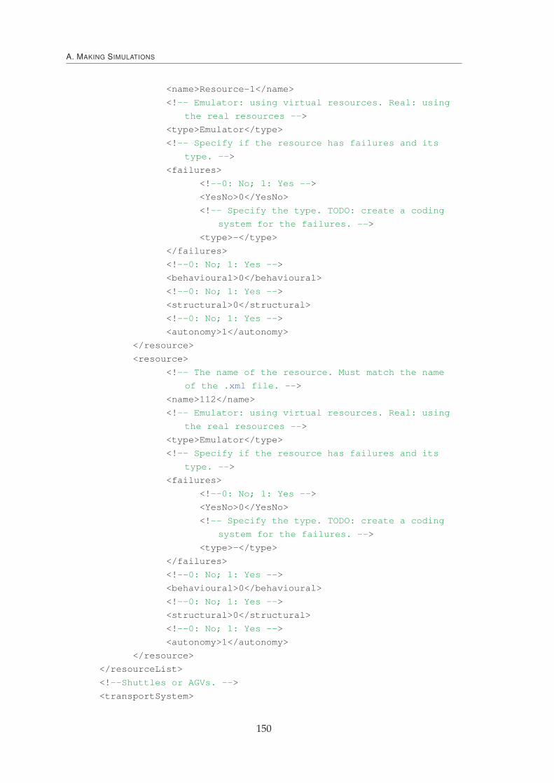
A. MAKING SIMULATIONS
<name>Resource-1</name>
<!-- Emulator: using virtual resources. Real: using
the real resources -->
<type>Emulator</type>
<!-- Specify if the resource has failures and its
type. -->
<failures>
<!--0: No; 1: Yes -->
<YesNo>0</YesNo>
<!-- Specify the type. TODO: create a coding
system for the failures. -->
<type>-</type>
</failures>
<!--0: No; 1: Yes -->
<behavioural>0</behavioural>
<!--0: No; 1: Yes -->
<structural>0</structural>
<!--0: No; 1: Yes -->
<autonomy>1</autonomy>
</resource>
<resource>
<!-- The name of the resource. Must match the name
of the .xml file. -->
<name>112</name>
<!-- Emulator: using virtual resources. Real: using
the real resources -->
<type>Emulator</type>
<!-- Specify if the resource has failures and its
type. -->
<failures>
<!--0: No; 1: Yes -->
<YesNo>0</YesNo>
<!-- Specify the type. TODO: create a coding
system for the failures. -->
<type>-</type>
</failures>
<!--0: No; 1: Yes -->
<behavioural>0</behavioural>
<!--0: No; 1: Yes -->
<structural>0</structural>
<!--0: No; 1: Yes -->
<autonomy>1</autonomy>
</resource>
</resourceList>
<!--Shuttles or AGVs. -->
<transportSystem>
150

A. MAKING SIMULATIONS
<type>AIP</type>
<quantity>10</quantity>
<size>normal</size>
</transportSystem>
<!--Specify the list of Supervisor Holons present in the system.
-->
<!--Specify the batch of orders and their launch time. -->
<batch>
<package>
<!--Specify the owner of the batch. Used later for
something. -->
<owner>clientA</owner>
<!--Specify the product to be produced. -->
<product>product_B_letter</product>
<!--Specify the due date of the batch. -->
<dueDate>325</dueDate>
<!--Specify the quantity to produce. -->
<quantity>1</quantity>
<!--0: No; 1: Yes -->
<behavioural>1</behavioural>
<!--0: No; 1: Yes -->
<structural>0</structural>
<!--Specify the start time. -->
<startTime>0</startTime>
</package>
<package>
<!--Specify the owner of the batch. Used later for
something. -->
<owner>clientB</owner>
<!--Specify the product to be produced. -->
<product>product_P_letter</product>
<!--Specify the due date of the batch. -->
<dueDate>209</dueDate>
<!--Specify the quantity to produce. -->
<quantity>1</quantity>
<!--0: No; 1: Yes -->
<behavioural>1</behavioural>
<!--0: No; 1: Yes -->
<structural>0</structural>
<!--Specify the start time. -->
<startTime>0</startTime>
</package>
</batch>
</scenario>
151

A. MAKING SIMULATIONS
For each scenario described in the previous XML file, one result file is created, con-
taining the achieved results, which can later be processed and analysed.
Listing A.3 – Results File
<?xml version="1.0" encoding="UTF-8" standalone="yes"?>
<simulationList>
<simulation id="1">
<ManufacturingOrder>
<AgentLocalName>MO552636</AgentLocalName>
<MLTotal>157</MLTotal>
<MLT>156</MLT>
<MOTard>0</MOTard>
<Ptproc>65</Ptproc>
<Pttransp>32</Pttransp>
</ManufacturingOrder>
<ManufacturingOrder>
<AgentLocalName>MO574317</AgentLocalName>
<MLTotal>291</MLTotal>
<MLT>291</MLT>
<MOTard>0</MOTard>
<Ptproc>35</Ptproc>
<Pttransp>15</Pttransp>
</ManufacturingOrder>
</simulation>
<simulation id="2">
<ManufacturingOrder>
<AgentLocalName>MO184125</AgentLocalName>
<MLTotal>217</MLTotal>
<MLT>216</MLT>
<MOTard>0</MOTard>
<Ptproc>74</Ptproc>
<Pttransp>23</Pttransp>
</ManufacturingOrder>
<ManufacturingOrder>
<AgentLocalName>MO358396</AgentLocalName>
<MLTotal>257</MLTotal>
<MLT>256</MLT>
<MOTard>0</MOTard>
<Ptproc>39</Ptproc>
<Pttransp>19</Pttransp>
</ManufacturingOrder>
</simulation>
</simulationList>
VR (Virtual Resource)s are responsible to create a layer that emulates the real physical
machines behaviour. In this way, the VRs receive commands that allows them to execute
152

A. MAKING SIMULATIONS
a set of procedures and reply back a set of status signals that allow the OH in charge
to take the appropriate measures, e.g., knowing that a processing task has started or
finished. Disturbances are also generated in this layer, allowing to test the disturbances
scenarios defined in the Bench4star (Trentesaux et al., 2013).
153

A. MAKING SIMULATIONS
154

BPotential Fields Behaviour
The PF behavioural self-organization mechanism developed in 5.1.2 was imple-
mented and embedded into the MAS. Three different types of agents, each one playing
a different role, are used throughout the process. Two are needed for the information
creation about the PF while the third one changes its behaviour based on the created
information.
First, the OHs are emitting a set of PFs, one for each of the possessed skills, based
on their current status considering a pre-defined maximum value subtracted by the ma-
chine’s schedule size. The value of the emitted PF is updated each time the machines’
condition change, i.e. when a new work order is allocated or finished the processing.
The OH informs the CSH of the PF value by sending an FIPA INFORM message type, as
seen the in AUML of Figure B.1.
FIPA.inform
Calculate
PF
Update PF
on graph
Figure B.1 – AUML PF Propagation
155

B. POTENTIAL FIELDS BEHAVIOUR
Based on the received PFs status the CSH constructs a graph map of the current sys-
tem PF situation. This information is displayed using a graph based approach that is
also used as the mean to calculate the PF propagation. The toolbox used to developed
this was the JUNG tool and has built in graph related algorithms, such as the Dijkstra’s
shortest path (Dijkstra, 1959).
The shop-floor organization is represented in the graph, see Figure B.2, by using the
nodes to map the OH (represented as rectangles) and the transportation times between
the machines are mapped using the graph arcs.
Figure B.2 – Shop-Floor Representation Graph
The nodes have information about its representative, namely its status (i.e. offline,
online, processing, ...) and is used to store the PF information, as shown in Listing B.1.
Listing B.1 – Node Class Definition
public class MyNode {
private int processing;
private String name;
private String shape;
private Double[][] attractivePF;
private String state;
private int buffer;
private String location;
}
As it can be seen, basic information such as name, state and location is stored but also
a table with the PF information of all the system.
The arcs, representing the links between all the nodes have also associated with it
information (as seen in Listing B.2), namely its id and the transportation time.
Listing B.2 – Link Class Definition
public class MyLink {
private Double time;
int id;
}
156
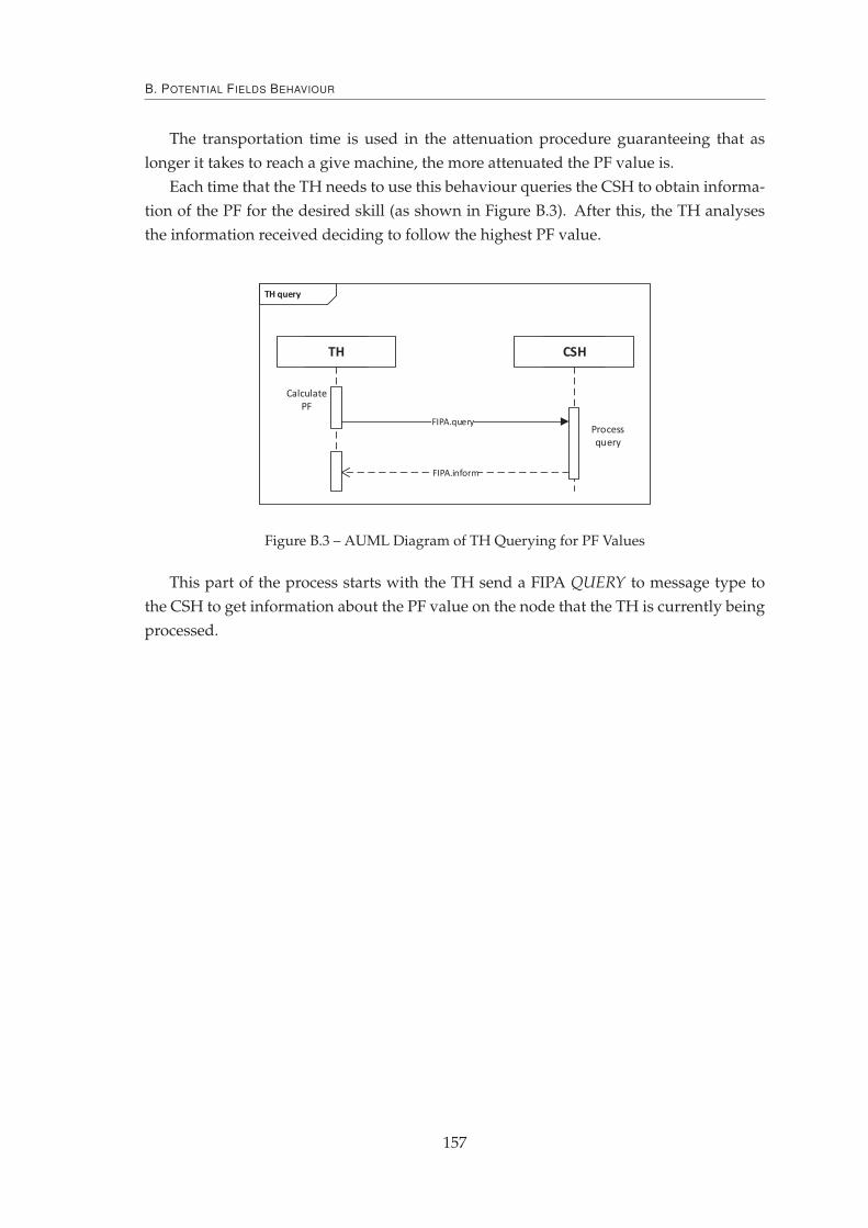
B. POTENTIAL FIELDS BEHAVIOUR
The transportation time is used in the attenuation procedure guaranteeing that as
longer it takes to reach a give machine, the more attenuated the PF value is.
Each time that the TH needs to use this behaviour queries the CSH to obtain informa-
tion of the PF for the desired skill (as shown in Figure B.3). After this, the TH analyses
the information received deciding to follow the highest PF value.
FIPA.query
Calculate
PF
Process
query
FIPA.inform
Figure B.3 – AUML Diagram of TH Querying for PF Values
This part of the process starts with the TH send a FIPA QUERY to message type to
the CSH to get information about the PF value on the node that the TH is currently being
processed.
157

B. POTENTIAL FIELDS BEHAVIOUR
158

COperation Holons Structural
Self-Organization
The structural self-organization by means of the birds behaviour protocol is described
in Figure C.1 and involves all the OHs that compose a given holarchy. On the left side of
the figure it is represented one OH that behaves like all the others that are represented on
the right side.
After the acknowledge of the appearance of a huge manufacturing order, every OH
will start this protocol in order to assess the current holarchy structure and proceed to
find a new structural organization that, face with this new constraint, is able to better
address it.
The protocol starts by querying all the other OHs with their current informational
status like its name, location, schedule size and processing times. This information allows
to have a global perspective of the holarchy status and based on this, to calculate the
current structure KPI (as defined in Equation 5.13 described in Section 5.2.1).
The re-organization procedure takes as inspiration some of the behaviours found in
the birds flocking. In this way, the OH that is making the re-organization positions itself
as the leader and fixes its current position. After this it places closer to its position the
other OHs by schedule size (considering this to be), creating a group of OHs around it.
This new re-organization is then assessed by applying the Equation 5.13. In the case
where the re-organizations predicts a KPI improvement, the OH will propagate the new
holarchy structure alongside with the predicted KPI. On contrary to that, the OH will
also propagate a message informing of a worst re-organization found, i.e. the OH wasn’t
able to discover a structural improvement.
159

C. OPERATION HOLONS STRUCTURAL SELF-ORGANIZATION
FIPA.query
FIPA.inform (better solution)
FIPA.inform (worst solution)
FIPA.inform (better solution)
FIPA.inform (worst solution)
FIPA.inform
Name
Location
WO list
Processing timesWait for all
informs’
Re-organization
Re-organization
Take
actions
Figure C.1 – AUML Diagram Used in the Structural Self-Organization
When all the OHs have executed the re-organization procedure and propagated the
results, each OH will accept and implement the overall best solution, i.e. the one with the
best expected KPI.
160

DSupervisor Holon Scheduling
Algorithm
In the presented architecture, the SH assumes a crucial role in the sense that it can
introduce schedule optimization, increasing the throughput of the system, and so its
profitability. The first version of the scheduling mechanism was based on a simple but
non-optimal algorithm and the develop of a new one which is able to achieve better opti-
mization results, namely the Cmax, without compromising the sum of calculation speed
with the output result.
For this purpose, the SH was enriched with a GA based algorithm. The algorithm
pseudo-code, shown in Algorithm 6, requires as input the set of work orders to be man-
ufactured and the available workstations.
Algorithm 6 Genetic Algorithm Pseudo-Code
Require: workOrders, workStationsEnsure: Scheduling of work orders to the workstations
1: procedure GA(workOrders, workStations, population)2: InitialPopulationGeneration(); ⊲ Generates random schedule allocation3: n← population
4: for i = 0 to n do5: addRealTimeToSchedules(); ⊲ Adds real time to schedule6: orderSolutionsByFitness();7: CrossOver();8: end for9: addRealTimeToSchedules();
10: orderSolutionsByFitness();11: end procedure
161

D. SUPERVISOR HOLON SCHEDULING ALGORITHM
The process starts by generating a set of random scheduling solutions of size
population each one having already the allocation of the work orders to workstations.
Having this set of initial possible solutions, the algorithm will start a iterative process
that starts discarding the worst half solutions, followed by a set of crossover operations
that will scramble allocated work orders from two random sets of solutions. A random
selection of the allocated work orders within these solutions is also used to crossover.
After repeating this process n times, the best solution will be selected as the one to be
dispatched to the shop-floor.
A set of production scenarios and system configurations were designed to bench-
mark manufacturing control architectures or scheduling algorithms (Trentesaux et al.,
2013) and the designed scenarios involve variations on the batch sizes, shuttles number
or constraints on the workstation buffer capacity.
A proper test for the designed GA algorithm, to assess the calculation speed and the
output results, imposes the comparison with the previous scheduling algorithm (Leitão
and Restivo, 2006) and the use of different batch sizes (in this case the scenarios ranging
from A0 to F0 of (Trentesaux et al., 2013)). Given this, only the population parameter is
still missing in order to fully characterize the input data for the algorithm. In the present
case, a value of 6 was used, meaning that initially 6 scheduling solutions are generated
and that the algorithm runs iteratively 6 times.
The experimental results of running the existing scheduling algorithm (named "old"
in the legend) and the GA approach are shown in Figure D.1.
Figure D.1 – Calculation Time Plus the Output Results
It is possible to analyse that for all the testing scenarios, the GA approach obtains
better results. As example, for the scenario C0, despite the existing scheduling algorithm
needs 17ms to compute and the GA 11195ms, the GA overall time, considering calcula-
tion time with the output result, improves the previous scheduling by 24,81%. Addition-
ally, it is still possible to observe that as the batch order increases, the GA improvement
also rises, being of 34,77% for scenario F0.
162