169390-1CD CONTROLLER SETUP AND OPERATION ...
210
Part Number: 169390-1CD Revision: 7 MANUAL NO. 7 169390-1CD CONTROLLER SETUP AND OPERATION MANUAL FOR: DX100 CONTROLLER DX200 CONTROLLER Upon receipt of the product and prior to initial operation, read these instructions thoroughly, and retain for future reference. YASKAWA INSTRUCTIONS CONTROLLER INSTRUCTIONS OPERATOR’S MANUAL MAINTENANCE MANUAL The operator’s manual above corresponds to specific usage. Be sure to use the appropriate manual. 1 of 210
-
Upload
khangminh22 -
Category
Documents
-
view
2 -
download
0
Transcript of 169390-1CD CONTROLLER SETUP AND OPERATION ...

Part Number: 169390-1CDRevision: 7
MANUAL NO.
7169390-1CD
CONTROLLER SETUP AND OPERATION MANUALFOR: DX100 CONTROLLER
DX200 CONTROLLER
Upon receipt of the product and prior to initial operation, read these instructions thoroughly, and retain for future reference.
YASKAWA INSTRUCTIONS
CONTROLLER INSTRUCTIONSOPERATOR’S MANUALMAINTENANCE MANUAL
The operator’s manual above corresponds to specific usage. Be sure to use the appropriate manual.
1 of 210

ii
169390-1CD
169390-1CD
PalletSolver
Copyright © 2017, 2016, 2015, YASKAWA America, Inc.
Terms of Use and Copyright Notice
All rights reserved. This manual is freely available as a service to YASKAWA customers to assist in the operation of Motoman robots, related equipment and software This manual is copyrighted property of YASKAWA and may not be sold or redistributed in any way. You are welcome to copy this document to your computer or mobile device for easy access but you may not copy the PDF files to another website, blog, cloud storage site or any other means of storing or distributing Online content.
Printed in the United States of America
First Printing, 2015
YASKAWA America, Inc. Motoman Robotics Division 100 Automation Way Miamisburg, OH 45342 Phone: 937-847-6200
www.motoman.com
2 of 210

iii
169390-1CD
169390-1CD
PalletSolver
MANDATORY
• This manual explains the error recovery function. Read this manual carefully and be sure to understand its contents before operation.
• General items related to safety are listed in Section 1: Safety, in the Controller Instructions. To ensure correct and safe operation, carefully read the Controller Instructions before reading this manual.
• For detailed instructions regarding additional equipment including controller, manipulator, or other components, refer to the specific equipment manuals included with your documentation package
CAUTION
• Some drawings in this manual are shown with the protective covers or shields removed for clarity. Be sure all covers and shields are replaced before operating this product.
• The drawings and photos in this manual are representative examples and differences may exist between them and the delivered product.
• YASKAWA may modify this model without notice when necessary due to product improvements, modifications, or changes in specifications. If such modification is made, the manual number will also be revised.
• If your copy of the manual is damaged or lost, contact a YASKAWA representative to order a new copy. The representatives are listed on the back cover. Be sure to tell the representative the manual number listed on the front cover.
• YASKAWA is not responsible for incidents arising from unauthorized modification of its products. Unauthorized modification voids your product's warranty.
• Software described in this manual is supplied against licensee only, with permission to use or copy under the conditions stated in the license. No part of this manual may be copied or reproduced in any form without written consent of YASKAWA.
3 of 210

iv
169390-1CD
169390-1CD
PalletSolver
We suggest that you obtain and review a copy of the ANSI/RIA National Safety Standard for Industrial Robots and Robot Systems (ANSI/RIA R15.06-2012). You can obtain this document from the Robotic Industries Association (RIA) at the following address:
Robotic Industries Association900 Victors WayP.O. Box 3724
Ann Arbor, Michigan 48106TEL: (734) 994-6088FAX: (734) 994-3338
www.roboticsonline.com
Ultimately, well-trained personnel are the best safeguard against accidents and damage that can result from improper operation of the equipment. The customer is responsible for providing adequately trained personnel to operate, program, and maintain the equipment. NEVER ALLOW UNTRAINED PERSONNEL TO OPERATE, PROGRAM, OR REPAIR THE EQUIPMENT!
We recommend approved YASKAWA training courses for all personnel involved with the operation, programming, or repair of the equipment.
This equipment has been tested and found to comply with the limits for a Class A digital device, pursuant to part 15 of the FCC rules. These limits are designed to provide reasonable protection against harmful interference when the equipment is operated in a commercial environment. This equipment generates, uses, and can radiate radio frequency energy and, if not installed and used in accordance with the instruction manual, may cause harmful interference to radio communications.
4 of 210

v
169390-1CD
169390-1CD
PalletSolver Notes for Safe Operation
Notes for Safe OperationBefore using this product, read this manual and all the other related documents carefully to ensure knowledge about the product and safety, including all the cautions.
In this manual, the Notes for Safe Operation are classified as “WARNING”, “CAUTION”, “MANDATORY”, or “PROHIBITED”.
Even items described as “CAUTION” may result in a serious accident in some situations.
At any rate, be sure to follow these important items
WARNINGIndicates a potentially hazardous situation which, if not avoided, could result in death or serious injury to personnel.
CAUTIONIndicates a potentially hazardous situation which, if not avoided, could result in minor or moderate injury to personnel and damage to equipment. It may also be used to alert against unsafe practices.
MANDATORYAlways be sure to follow explicitly the items listed under this heading.
PROHIBITED Must never be performed.
NOTETo ensure safe and efficient operation at all times, be sure to follow all instructions, even if not designated as “CAUTION” and “WARNING”.
5 of 210

Notes for Safe Operation
vi
169390-1CD
169390-1CD
PalletSolver
WARNING• Before operating the manipulator, check that servo power is turned
OFF pressing the [Emergency Stop] buttons on the front door of the controller and the programming pendant. When the servo power is turned OFF, the SERVO ON LED on the programming pendant is turned OFF.
Injury or damage to machinery may result if the emergency stop circuit cannot stop the manipulator during an emergency. The manipulator should not be used if the [Emergency Stop] buttons do not function.
Figure 1: Emergency Stop Button
• Once the [Emergency Stop] button is released, clear the cell of all items which could interfere with the operation of the manipulator. Then turn the servo power ON.
Injury may result from unintentional or unexpected manipulator motion.
Figure 2: Release of Emergency Stop
TURN
• Observe the following precautions when performing teaching operations within the P-point maximum envelope of the manipulator:
– View the manipulator from the front whenever possible.
– Always follow the predetermined operating procedure.
– Ensure that you have a safe place to retreat in case of emergency.
Improper or unintended manipulator operation may result in injury.
• Confirm that no person is present in the P-point maximum envelope of the manipulator and that you are in a safe location before:
– Turning on the power for the controller.
– Moving the manipulator with the programming pendant.
– Running the system in the check mode.
– Performing automatic operations.
Injury may result if anyone enters the P-point maximum envelope of the manipulator during operation. Always press an [Emergency Stop] button immediately if there is a problem.
The [Emergency Stop] buttons are located on the right of front door of the controller and the programming pendant.
6 of 210

vii
169390-1CD
169390-1CD
PalletSolver Notation for Menus and Buttons
Notation for Menus and ButtonsDescriptions of the programming pendant, buttons, and displays are shown as follows:
Description of the Operation ProcedureIn the explanation of the operation procedure, the expression “Select • • •” means the following operations:
• To move the cursor to the object item and left-click on it with the mouse.
• To pick out the object item by the tab key and press the Enter key.
(In case of selecting a menu, use arrow keys instead of the tab key to pick out the object item, then press the Enter key.)
Registered TrademarkIn this manual, names of companies, corporations, or products are trademarks, registered trademarks, or brand names for each company or corporation. The indications of (R) and TM are omitted.
CAUTION
• Perform the following inspection procedures prior to conducting manipulator teaching. If problems are found, repair them immediately, and be sure that all other necessary processing has been performed.
– Check for problems in manipulator movement.
– Check for damage to insulation and sheathing of external wires.
• Always return the programming pendant to the hook on the cabinet of the controller after use.
The programming pendant can be damaged if it is left in the manipulator's work area, on the floor, or near fixtures.
• Read and understand the Explanation of Warning Labels in the Controller Instructions before operating the manipulator:
Item Manual Designation
Menu The menus displayed on screen are denoted with { }. ex. {TOOL}.
Button The buttons, check boxes, radio buttons displayed on screen are denoted with [ ].ex. [Close]; [Sync] check box; [Fast] radio button.
7 of 210

Table of Contents
viii
169390-1CD
169390-1CD
PalletSolver
Table of Contents
1 Introduction .....................................................................................................................................1-1
1.1 Overview............................................................................................................................1-1
1.1.1 Operation Areas.................................................................................................... 1-2
1.1.2 Modules ................................................................................................................1-2
1.2 Features.............................................................................................................................1-3
1.2.1 PalletSolver- PC Pattern Generation Tool ............................................................1-3
1.2.2 PalletSolver-Controller.......................................................................................... 1-3
1.3 System Requirements........................................................................................................ 1-4
1.3.1 PalletSolver PC Minimum Requirements.............................................................. 1-4
1.3.2 Controller Requirements....................................................................................... 1-4
1.4 About this Document.......................................................................................................... 1-5
1.5 Learning PalletSolver.........................................................................................................1-6
1.6 Reference to Other Documentation ...................................................................................1-6
1.7 Customer Support Information........................................................................................... 1-7
2 PalletSolver System Definitions ......................................................................................................2-1
2.1 Cell Identification................................................................................................................2-1
2.2 Station and Gripper Identification....................................................................................... 2-2
2.2.1 Station Definition...................................................................................................2-3
2.2.1.1 Station Frame.......................................................................................... 2-3
2.2.1.2 Station Interference Boundary................................................................. 2-4
2.3 Forkable Conveyors........................................................................................................... 2-7
2.4 Conveyor End Stops .........................................................................................................2-8
2.5 Package Definition .............................................................................................................2-9
2.5.1 Package Frame and Dimensions.......................................................................... 2-9
2.5.2 Label Position ....................................................................................................... 2-9
2.5.3 Package Coordinates ........................................................................................... 2-9
2.5.3.1 Package Orientation on the Infeed........................................................ 2-10
2.5.3.2 Package Orientation on the Build Station.............................................. 2-11
2.6 Gripper Definition ............................................................................................................. 2-12
2.6.1 Vacuum Gripper.................................................................................................. 2-12
2.6.2 Clamp Grippers................................................................................................... 2-12
2.6.2.1 Clamp Fixed Edge.................................................................................2-13
2.6.2.2 Clamp Moving Edge ..............................................................................2-13
8 of 210

ix
169390-1CD
169390-1CD
PalletSolver Table of Contents
2.6.3 Fork grippers ...................................................................................................... 2-14
2.6.4 Bag Grippers ...................................................................................................... 2-15
2.6.5 Gripper Orientation on Infeed Conveyor............................................................. 2-15
2.6.6 Gripper Orientation on Build Station................................................................... 2-16
2.6.7 Physical Gripping and Sensing Areas ................................................................ 2-17
2.6.8 Virtual Gripper .................................................................................................... 2-18
2.6.9 Gripper I/O Signal Mapping............................................................................... 2-18
3 Flow of Operations.......................................................................................................................... 3-1
3.1 Setup ................................................................................................................................. 3-2
4 Controller PalletSolver Setup Application ....................................................................................... 4-1
4.1 Cell Setup Operational Sequence ..................................................................................... 4-1
4.1.1 Robot Controller/ Gripper Interfaces..................................................................... 4-3
4.1.1.1 Background ............................................................................................. 4-3
4.1.1.2 Overview ................................................................................................. 4-5
4.1.1.3 Pre-engineered Universal Outputs .......................................................... 4-6
4.1.1.4 Pre-engineered Universal Inputs............................................................. 4-7
4.2 Station Setup ..................................................................................................................... 4-9
4.2.1 User Frames....................................................................................................... 4-10
4.2.1.1 User Frame Locations ........................................................................... 4-10
4.2.1.2 Required User Frames Number ............................................................ 4-10
4.2.1.3 User Frame Offsets ............................................................................... 4-11
4.2.2 Clearance Z........................................................................................................ 4-12
4.2.3 Dispenser Types................................................................................................. 4-12
4.3 Cell Setup Applications’ Use of External Memory Devices.............................................. 4-13
4.4 PalletSolver Setup Application......................................................................................... 4-16
4.4.1 Start PalletSolver Setup Application................................................................... 4-16
4.4.2 Open an Existing Setup File ............................................................................... 4-17
4.4.3 Defining a New Cell ............................................................................................ 4-18
4.4.4 PalletSolver Editor .............................................................................................. 4-19
4.4.5 Cell Editor ........................................................................................................... 4-19
4.4.5.1 Station Selection ................................................................................... 4-19
4.4.5.2 Add New Stations.................................................................................. 4-20
4.4.5.3 Delete Station........................................................................................ 4-20
4.4.5.4 Edit Station............................................................................................ 4-22
9 of 210

Table of Contents
x
169390-1CD
169390-1CD
PalletSolver
4.4.6 Gripper Definition................................................................................................ 4-22
4.4.6.1 Define Gripper Types ............................................................................ 4-22
4.4.6.2 Set Gripper ID .......................................................................................4-25
4.4.6.3 Set Tool Center Point Number (TCP)....................................................4-25
4.4.6.4 Grip Areas .............................................................................................4-26
4.4.6.5 Gripper Motion Setup ............................................................................ 4-27
4.4.6.6 Gripper Operation.................................................................................. 4-29
4.4.7 Station Definition.................................................................................................4-30
4.4.7.1 Dispenser Stations Types...................................................................... 4-31
4.4.7.2 Optional Station Sensors.......................................................................4-32
4.4.8 Pattern Setup...................................................................................................... 4-35
4.4.9 Network Option ................................................................................................... 4-36
4.4.9.1 Pattern File Naming Convention............................................................ 4-37
4.4.9.2 Network Folder Usage........................................................................... 4-38
4.4.10 System Control .................................................................................................4-39
4.4.11 Write Cell Setup Job......................................................................................... 4-39
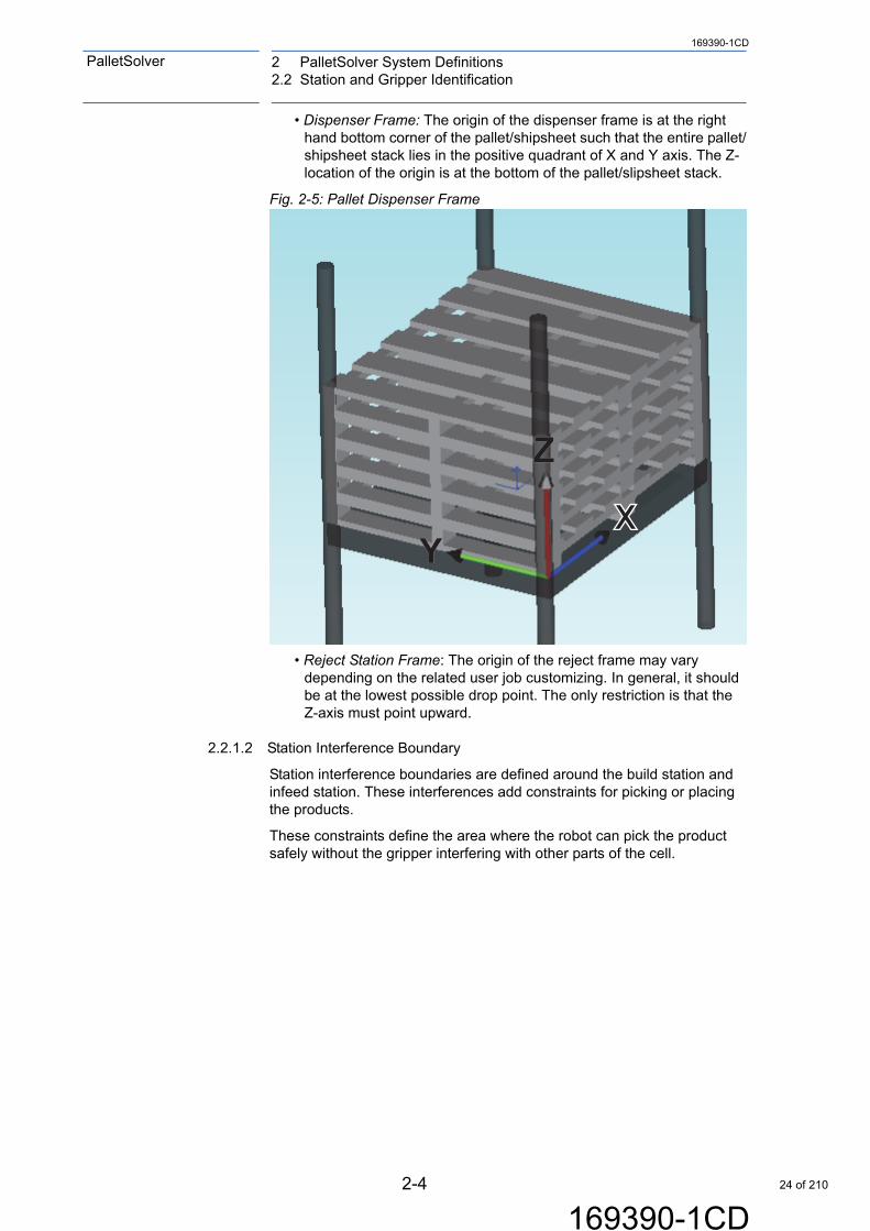
4.4.12 Close Button ..................................................................................................... 4-40
5 PalletSolver PC Pattern Generation Tool........................................................................................ 5-1
5.1 Build Pattern Files.............................................................................................................. 5-1
5.1.1 MotoPlus Pattern File Importer Application .......................................................... 5-1
5.1.2 Initiating Build Pattern Conversion........................................................................ 5-1
6 Controller Jobs and Concurrent I/O Program..................................................................................6-1
6.1 Structure ........................................................................................................................... 6-1
6.2 Jobs ................................................................................................................................... 6-2
6.2.1 System Jobs .........................................................................................................6-2
6.2.1.1 System_PLC_Messaging ........................................................................ 6-2
6.2.1.2 System_Machine_State........................................................................... 6-2
6.2.2 Standard Jobs ......................................................................................................6-3
6.2.2.1 PalletSolver_Master_Job.........................................................................6-3
6.2.2.2 PalletSolver_Planner: .............................................................................. 6-3
6.2.2.3 PalletSolver_Motion................................................................................. 6-4
6.2.2.4 PalletSolver_Cell_Setup.......................................................................... 6-4
6.2.2.5 PATTERN_#............................................................................................6-4
6.2.3 User Jobs..............................................................................................................6-4
6.2.3.1 USER_ADJUSTMENTS.......................................................................... 6-5
6.2.3.2 USER_CONTROL_TASK...................................................................... 6-13
6.2.3.3 USER_MOVE_REJECT........................................................................ 6-14
6.2.3.4 USER_GRIPPER_ON........................................................................... 6-15
6.2.3.5 USER_GRIPPER_OFF ......................................................................... 6-15
6.2.3.6 USER_DISPERSER_GRIPPER_CONTROL........................................ 6-15
10 of 210

xi
169390-1CD
169390-1CD
PalletSolver Table of Contents
6.2.3.7 USER_CLEAR_IO................................................................................. 6-16
6.2.3.8 USER AUTO_DISPENSE ..................................................................... 6-16
6.3 Concurrent I/O ................................................................................................................. 6-17
6.3.1 Overview ............................................................................................................ 6-17
6.3.2 Gripper Setup Introduction ................................................................................. 6-17
6.3.2.1 Gripper Setup........................................................................................ 6-18
6.3.3 Gripper Setup Examples .................................................................................... 6-29
6.3.3.1 Vacuum Gripper .................................................................................... 6-29
6.3.3.2 Zone Clamp Gripper.............................................................................. 6-36
6.3.3.3 Variable Stroke Fork Gripper................................................................. 6-38
6.3.3.4 Gripper Testing ..................................................................................... 6-42
7 DX100 & DX200 Operation Monitor and Control Interface ............................................................. 7-1
7.1 Functions ........................................................................................................................... 7-1
7.2 Interface: Direct I/O Signals............................................................................................... 7-2
7.2.1 System Signals..................................................................................................... 7-2
7.2.1.1 System Start/Stop ................................................................................... 7-2
7.2.1.2 Palletizing Stop/Start ............................................................................... 7-3
7.2.1.3 PLC Controlled System........................................................................... 7-3
7.2.1.4 Fieldbus Heartbeat .................................................................................. 7-3
7.2.1.5 Set Next Infeed Pick................................................................................ 7-4
7.2.1.6 Safety Speed........................................................................................... 7-4
7.2.1.7 Speed Override ....................................................................................... 7-4
7.2.1.8 Battery Warning ...................................................................................... 7-4
7.2.1.9 Motion Sequence .................................................................................... 7-5
7.2.2 Warning and Error Handling................................................................................. 7-5
7.2.2.1 PalletSolver Job Warning ........................................................................ 7-6
7.2.2.2 Pick/Place Error....................................................................................... 7-6
7.2.2.3 System Job Running ............................................................................... 7-8
7.2.3 All Stations ........................................................................................................... 7-8
7.2.3.1 Station Exists .......................................................................................... 7-8
7.2.3.2 Station Active .......................................................................................... 7-8
7.2.3.3 Station Lock/Unlock ................................................................................ 7-8
7.2.3.4 Station Pick/Place Error .......................................................................... 7-9
7.2.4 Reject Station ..................................................................................................... 7-10
7.2.4.1 At Reject Drop....................................................................................... 7-10
7.2.4.2 Reject Full ............................................................................................. 7-10
7.2.4.3 Gripper Package Release ..................................................................... 7-10
7.2.4.4 Goto Reject Station ............................................................................... 7-11
7.2.5 Build Stations ..................................................................................................... 7-11
7.2.5.1 Build Pattern Assigned.......................................................................... 7-11
7.2.5.2 Build Pallet Present ............................................................................... 7-11
7.2.5.3 Normal Build Done and Eject ................................................................ 7-11
11 of 210

Table of Contents
xii
169390-1CD
169390-1CD
PalletSolver
7.2.5.4 Build Station Forced Done and Eject....................................................7-12
7.2.5.5 Build Station Lock after Build is Done ...................................................7-12
7.2.5.6 Build Station Verify Layer ...................................................................... 7-12
7.2.6 Infeed Stations....................................................................................................7-13
7.2.6.1 Infeed Package Request .......................................................................7-13
7.2.6.2 Purge Infeed..........................................................................................7-13
7.2.7 Dispenser Stations..............................................................................................7-14
7.2.7.1 Dispenser Reset Search Height ............................................................ 7-14
7.2.7.2 Dispenser Low Stack.............................................................................7-14
7.2.7.3 Dispenser Empty ................................................................................... 7-14
7.3 Interface: Message Communication ................................................................................7-15
7.3.1 PLC to Robot Message Structure .......................................................................7-15
7.3.2 Handshaking.......................................................................................................7-17
7.3.3 Functions ............................................................................................................ 7-19
7.3.3.1 Reset Message Transaction ID .............................................................7-19
7.3.3.2 Build Station Assign/Unassign Pattern.................................................. 7-20
7.3.3.3 Station Package Info .............................................................................7-21
7.3.3.4 Build Station Request Pattern Info ........................................................ 7-22
7.3.3.5 Build Station Request Build Status........................................................ 7-23
7.3.3.6 Build Station Request Associated Stations ........................................... 7-25
7.3.3.7 Select Sequencing Mode ...................................................................... 7-25
7.3.3.8 Infeed Ratio ........................................................................................... 7-28
7.3.3.9 Infeed Priority ........................................................................................ 7-30
7.3.3.10 Package Height Adjustment ................................................................7-32
7.3.3.11 Station Frame Adjustment ................................................................... 7-33
7.3.3.12 Build Station Maximum Layer.............................................................. 7-35
7.3.3.13 Infeed Station Row Data ..................................................................... 7-36
8 Operation Monitor and Control Pendant Application....................................................................... 8-1
8.1 Function .............................................................................................................................8-1
8.2 Starting the PalletSolver HMI............................................................................................. 8-1
8.3 Interface.............................................................................................................................8-3
8.3.1 System Overview Screen ..................................................................................... 8-3
8.3.2 Monitor Mode Overview........................................................................................ 8-4
8.3.3 Controller Screen.................................................................................................. 8-4
8.3.4 Build Station Screen ............................................................................................. 8-6
8.3.5 Infeed Station Screen ........................................................................................... 8-8
8.3.6 Dispenser Station Screen: .................................................................................. 8-10
8.3.7 Settings and Optimization Screen ...................................................................... 8-12
8.3.8 Sequencing Screen ............................................................................................ 8-13
12 of 210

xiii
169390-1CD
169390-1CD
PalletSolver Table of Contents
8.3.9 Frame and Product Adjustment Screen ............................................................. 8-14
8.3.10 Speed Adjustment Screen................................................................................ 8-15
8.3.10.1 Adjusting the Speed ............................................................................ 8-15
8.3.11 Gripper Testing................................................................................................. 8-16
8.3.11.1 Grip Output Control ............................................................................. 8-16
8.3.11.2 Gripper Part Sensors........................................................................... 8-17
8.3.11.3 Gripper Open and Close Sensors ....................................................... 8-18
8.3.12 Security Check ................................................................................................. 8-19
8.3.13 Reject Station Screen....................................................................................... 8-21
8.3.13.1 Reject Station Controls........................................................................ 8-21
8.3.13.2 Gripper Controls .................................................................................. 8-21
8.3.13.3 Station Lock ........................................................................................ 8-21
Appendix A .......................................................................................................................................A-1
A.1 Monitor and Control Direct I/O Mapping............................................................................A-1
A.1.1 Controller Outputs (PLC Inputs)...........................................................................A-2
A.1.2 Controller Inputs (PLC Outputs)...........................................................................A-9
A.2 Error and Warning Lists...................................................................................................A-16
A.2.1 Messaging Error List ..........................................................................................A-16
A.2.2 Job Warning List ................................................................................................A-18
A.2.3 Controller Error and Warning List.......................................................................A-21
A.3 PLC Messaging Example ................................................................................................A-22
A.3.1 Example: Get Sequencing Mode (Command 5) ...............................................A-22
A.3.2 Example: Request Build Pattern Associated Station Info (Command 3) ...........A-25
13 of 210

1 Introduction1.1 Overview
1-1
169390-1CD
169390-1CD
PalletSolver
1 Introduction
1.1 Overview
The PalletSolver Software Suite provides a turn-key, easy to use system for integrators to develop a palletizing system faster and with ease. This suite also allows the end user to create new palletizing patterns and add new products with ease on a PC and then to quickly transfer the generated pattern to the system controller.
Fig. 1-1: Overview of the Easy Pallet Software Suite
14 of 210

1-2
169390-1CD
169390-1CD
PalletSolver 1 Introduction1.1 Overview
1.1.1 Operation Areas
There are two main operational areas of the PalletSolver Software Suite and they are:
• PC Windows Application: The PC component consist of a Pattern Generation tool that will run on a Windows base PC. This applications purpose is to generate patterns.
• Controller Application: The controller components consist of the controller jobs, Concurrent I/O program, pendant applications, and MotoPlus applications which are executing in the controller without the need of an external PC. An external PLC I/O interface is available monitor and control the system. The Online components will provide the following major functions:
– System Initial Setup - cell layout, I/O mapping, user-frame definition…
– System Monitor and Controller - system status, build status, pattern selection…
– Pattern File Import - import information from pattern file generated by the PalletSolver - PC Pattern Generation Tool
– Run Time Execution - job and concurrent jobs executing the pallet builds)
– PLC Interface - enables an external PLC/HMI to Monitor and Control the system
1.1.2 Modules
Modules included with the Pallet Software Suite work to together through interface using the Pattern Files (Pattern XML Files), Controller Variables and I/O Tables, and Configuration Jobs (Palletizing Cell Project.JBI and Pattern.JBI). This suite is composed of the following modules:
• PalletSolver - Cell Setup Pendant Application
• PalletSolver - PC Pattern Generation Application
• Pattern File Importer MotoPlus Application
• Controller Job and Concurrent I/O Program
• Operator Monitor and Control Interface
• PalletSolver - HMI Pendant Application
NOTEThough this application takes into account physical restrictions of a system (physical interferences, gripper dimensions), it is basically independent of the specifics of the system (robot type, cell layout, I/O configuration.)
15 of 210

1 Introduction1.2 Features
1-3
169390-1CD
169390-1CD
PalletSolver
1.2 Features
1.2.1 PalletSolver- PC Pattern Generation Tool
• Intuitive user interface with guided pallet recipe generation
• Interference constraints per station to ensure quick change over without halting production
• Import pallet patterns generated by TOPS or CAPE software
• Virtually unlimited SKUs supported
• Support for multiple-cells
• Dynamic gripper zone configuration to suit modular gripper design
• Support for the following grippers:
– Vacuum Grippers
– Clamp Grippers
– Fork Grippers
– Bag Grippers
1.2.2 PalletSolver-Controller
• System Configuration - Maximum: 8 infeed x 8 build stations, 2 pallet dispensing stations, 2 slipsheet dispensing stations
• Dynamic robot path adjustment to ensure optimum production rate
• Pre-Mapped I/O to communicate with PLC/supervisory control for status and monitoring
• PLC- Robot Messaging interface for operations control
• Intuitive guided setup and configuration using robot pendant HMI
• PLC-less operation in the case where the robot controller is the only controller in the system
• Network enabled for importing of Pattern (recipe) files generated by PalletSolver- PC
• Granular control over Palletizing operations
– Controlling infeed pick sequence (Round robin, priority, relative ratio, PLC controlled)
• Automatic reject of parts
• Conveyor/Pallet lock-out for maintenance or failures
• End of production handling
• Adjusting pick-place depth as package changes due to environmental conditions
• Integration Customization Library: customize applications for unique gripper handling, error handling or customizing pick-place handling
16 of 210

1-4
169390-1CD
169390-1CD
PalletSolver 1 Introduction1.3 System Requirements
1.3 System Requirements
1.3.1 PalletSolver PC Minimum Requirements
• Compatible with Microsoft Windows XP Service Pack 2.0 and Microsoft Windows 7
• Microsoft.NET Framework 3.5
• 400 megahertz (MHz), Recommended 1 gigahertz (GHz)
• 128 megabytes (MB), Recommended 256 megabytes (MB)
• 30 MB Hard Disk Space
• Monitor Resolution of 1280 x 1024 dots per inch (dpi)
• Hardware Key provided with the Pallet Software Suite
1.3.2 Controller Requirements
• Controller
– DX100 controller with DS3.91 - 14 or later Controller Software with MotoPlus support.
– DX200 controller with DN1.54 or later Controller Software.
• Programming Pendant
• Industrial Grade Memory Compact Flash Card (CF Flash) or a USB Flash Drive with 256 MB of available space or more
17 of 210

1 Introduction1.4 About this Document
1-5
169390-1CD
169390-1CD
PalletSolver
1.4 About this Document
This manual is intended as an introduction and overview for personnel who are familiar with the operation of their YASKAWA Motoman robot model and Microsoft® Windows®/PC usage.
This manual provides an overview of the YASKAWA Motoman PalletSolver system.
This manual contains the following sections:
• Chapter 1 "Introduction"
• Chapter 2 "PalletSolver System Definitions"
• Chapter 3 "Flow of Operations"
• Chapter 4 "Controller PalletSolver Setup Application"
• Chapter 5 "PalletSolver PC Pattern Generation Tool"
• Chapter 6 "Controller Jobs and Concurrent I/O Program"
• Chapter 7 "DX100 & DX200 Operation Monitor and Control Interface"
• Chapter 8 "Operation Monitor and Control Pendant Application"
• Appendix A
18 of 210

1-6
169390-1CD
169390-1CD
PalletSolver 1 Introduction1.5 Learning PalletSolver
1.5 Learning PalletSolver
YASKAWA has created this product with keeping with our proven track record of delivering industry leading quality, innovation and customer satisfaction. With that said if training is still needed a variety of options are available to help you learn the PalletSolver, including training and technical support. For more information on available training classes for the PalletSolver Suite, please contact our training department at: [email protected] or visit our website at: www.motoman.com.
Also be sure to try the Online training course at: http://info.motoman.com/palletsolver-download This course allows you to download and practice creating pallet patterns with the PalletSolver - PC Pattern Generation Tool.
1.6 Reference to Other Documentation
For additional information refer to the following:
• YASKAWA Controller Manual
• YASKAWA Maintenance Manual
• YASKAWA Operator's Manual for General
• YASKAWA Operator's Manual for Handling
• YASKAWA Concurrent I/O Parameter Manual
• YASKAWA INFORM User’s Manual
• YASKAWA Inform Extension Function Structured Program Language Manual
• YASKAWA PalletSolver PC Pattern Generation Tool Manual
• YASKAWA Search Function Manual
• YASKAWA Speed Override Function Manual
• YASKAWA TCP Function Manual
• YASKAWA Standard I/O Signal Assignment Manual
• Vendor manuals for system components not manufactured by YASKAWA
19 of 210

1 Introduction1.7 Customer Support Information
1-7
169390-1CD
169390-1CD
PalletSolver
1.7 Customer Support Information
If you need assistance with any aspect of your PalletSolver system, please contact YASKAWA Customer Support at our 24-hour telephone number:
For routine technical inquiries, you can also contact YASKAWA Customer Support at the following e-mail address:
When using e-mail to contact YASKAWA Customer Support, please provide a detailed description of your issue, along with complete contact information. Please allow approximately 24 to 36 hours for a response to your inquiry.
Please have the following information ready before calling:
NOTEPlease use e-mail for routine inquiries only. If an urgent or emergency need for service, replacement parts, or information, contact YASKAWA Customer Support at the telephone number shown above.
System PalletSolver
Robots
Software Version Access this information on the Programming Pendant’s LCD display screen by selecting {MAIN MENU} - {SYSTEM INFO} - {VERSION}
Robot Serial Number Located on the robot data plate
Robot Sales Order Number Located on the controller data plate
(937) 847-3200
20 of 210

2-1
169390-1CD
169390-1CD
PalletSolver 2 PalletSolver System Definitions2.1 Cell Identification
2 PalletSolver System Definitions
The system definition establishes conventions to identify and define components in both the controller and windows software. These conventions must be followed on both sides inorder for the system to operate properly. This definition only needs to be done once during the initial setup of a new cell.
2.1 Cell Identification
Each cell is identified by a unique user-defined number, the cell ID. This number is entered in both the PalletSolver PC Pattern Generation Tool application and the controller PalletSolver Cell Setup pendant application. During operation, when the XML pattern files generated in the PalletSolver PC the cell ID of the XML pattern file is checked against the cell ID of the controller system to confirm the Offline validation (gripper, interference zone….) of the pattern was done with the data corresponding to the proper physical cell.
21 of 210

2 PalletSolver System Definitions2.2 Station and Gripper Identification
2-2
169390-1CD
169390-1CD
PalletSolver
2.2 Station and Gripper Identification
During the initial definition of the cell, it is important the components identified in PalletSolver PC application matches the physical identification of the controller system. Each station within a cell should be identified by type: infeed (conveyor), build station (outfeed conveyor), pallet dispenser, slipsheet dispenser; and an ID number starting at 1 to the number of stations of that type.
Grippers are also have a unique identification number (GripperID) identifying a physical gripper of a specific type, dimension and configuration. If multiple cells have identical grippers, they should share the same GripperID and data.
Fig. 2-2: Station Identification Example
Build Station 1
Slipsheet Dispenser 1
Infeed Station 1
Infeed Station 2
Build Station 2
Pallet Dispenser 1
22 of 210

2-3
169390-1CD
169390-1CD
PalletSolver 2 PalletSolver System Definitions2.2 Station and Gripper Identification
2.2.1 Station Definition
2.2.1.1 Station Frame
All frames (coordinate systems) used in the calculations follow the Right-Hand-Thumb rule for frames.
• Infeed Conveyor Frame: The origin of conveyor frame is at the right hand corner at the front of the conveyor such that X-axis of the frame is pointing against the flow of the conveyor. The X-axis is aligned with the right side of a right justified box and the Y-axis is aligned with the front the first box.
Fig. 2-3: Infeed Conveyor Frame
• Build Station Frame (Pallet/Outfeed Frame): The origin of the pallet frame is at the right hand bottom corner of the pallet such that the entire pallet lies in the positive quadrant of X and Y axis. The Z-location of the origin is at the bottom of the pallet.
Fig. 2-4: Build Station Frame
XXY
Z
XXY
Z
23 of 210
2 PalletSolver System Definitions2.2 Station and Gripper Identification
2-4
169390-1CD
169390-1CD
PalletSolver
• Dispenser Frame: The origin of the dispenser frame is at the right hand bottom corner of the pallet/shipsheet such that the entire pallet/shipsheet stack lies in the positive quadrant of X and Y axis. The Z-location of the origin is at the bottom of the pallet/slipsheet stack.
Fig. 2-5: Pallet Dispenser Frame
• Reject Station Frame: The origin of the reject frame may vary depending on the related user job customizing. In general, it should be at the lowest possible drop point. The only restriction is that the Z-axis must point upward.
2.2.1.2 Station Interference Boundary
Station interference boundaries are defined around the build station and infeed station. These interferences add constraints for picking or placing the products.
These constraints define the area where the robot can pick the product safely without the gripper interfering with other parts of the cell.
XXY
Z
24 of 210

2-5
169390-1CD
169390-1CD
PalletSolver 2 PalletSolver System Definitions2.2 Station and Gripper Identification
Fig. 2-6: Station Interference
The interference constraints are defined with respect to the origin of the infeed or build station and distances in the positive and negative direction of the frame orientation axes.
Fig. 2-7: Infeed Station Interference Boundary
25 of 210

2 PalletSolver System Definitions2.2 Station and Gripper Identification
2-6
169390-1CD
169390-1CD
PalletSolver
Fig. 2-8: Build Station Interference Boundary
26 of 210

2-7
169390-1CD
169390-1CD
PalletSolver 2 PalletSolver System Definitions2.3 Forkable Conveyors
2.3 Forkable Conveyors
Fork and bag grippers have to move between the conveyor roller and beneath the product during the pickup sequence. The PalletSolver - PC Pattern Generation Tool is responsible for ensuring the conveyor is forkable with each associated Fork Gripper.
Fig. 2-9(a): Moving Between Rollers and Under Product
Fig. 2-9(b): Balancing Loads on Grippers
27 of 210

2 PalletSolver System Definitions2.4 Conveyor End Stops
2-8
169390-1CD
169390-1CD
PalletSolver
2.4 Conveyor End Stops
Infeed Conveyors can be equipped with optional End stops. These stops are mainly used with Fork style grippers. They are typically used to help center the products on the fork gripper. Each time the product size changes this stop might need adjusting. This information is set in PalletSolver - PC Pattern Generation Tool.
Fig. 2-10: Conveyor End Stops
28 of 210

2-9
169390-1CD
169390-1CD
PalletSolver 2 PalletSolver System Definitions2.5 Package Definition
2.5 Package Definition
2.5.1 Package Frame and Dimensions
The package frame is in the middle of the top surface of the package.
Fig. 2-11: Package Frame
2.5.2 Label Position
Labels can be defined on one or more sides of a box package relative to the package frame.
2.5.3 Package Coordinates
The package X and Y coordinates define the position and orientation of the center in relation to conveyor/pallet frame and are defined in the pattern files.
The orientation is the Z rotation angle of the box X-axis relative to the conveyor/pallet frame.
X: LengthY: WidthZ: Height
NOTEThe package coordinates do not directly correspond to the robot coordinates. The robot coordinates are based on the gripper coordinates.
29 of 210

2 PalletSolver System Definitions2.5 Package Definition
2-10
169390-1CD
169390-1CD
PalletSolver
2.5.3.1 Package Orientation on the Infeed
The package orientation is defined relative to the infeed conveyor frame.
Fig. 2-12: Package Orientation on Infeed
30 of 210

2-11
169390-1CD
169390-1CD
PalletSolver 2 PalletSolver System Definitions2.5 Package Definition
2.5.3.2 Package Orientation on the Build Station
The package orientation is defined relative to the build station (outfeed conveyor) frame.
Fig. 2-13: Package Orientation on Build Station
The pallet itself is considered as a package and has an orientation relative to the build station frame. The pallet can be defined as “Length on X” or “Length on Y”.
Fig. 2-14: Pallet Orientation
31 of 210

2 PalletSolver System Definitions2.6 Gripper Definition
2-12
169390-1CD
169390-1CD
PalletSolver
2.6 Gripper Definition
The tool control point (TCP) defined on the robot controller must match the gripper frame that defines the position of the gripper relative to the station frame in the PalletSolver PC Pattern Generation Tool. To do so, conventions are based on the gripper type.
2.6.1 Vacuum Gripper
The vacuum gripper or suction cup gripper frame is usually defined in the center of suction cups at the bottom of the suction cups. There is some flexibility on the X, and Y positioning of the TCP. For the Z position, it MUST be at the bottom of the cups where a box would be before applying vacuum to grip it. The X axis is along the length of the gripper and the Z axis toward the bottom of the gripper. The Y axis is perpendicular to the other two axes following the right-hand rule.
The gripper interference (body) constraints are defined with respect to the frame (TCP) and distances in the positive and negative direction of the frame orientation axes.
Fig. 2-15: Gripper Tool Definition
2.6.2 Clamp Grippers
Clamp grippers are classified by the number of moving clamps as defined below:
• Clamp Fixed Edge
• Camp Moving Edge
32 of 210

2-13
169390-1CD
169390-1CD
PalletSolver 2 PalletSolver System Definitions2.6 Gripper Definition
2.6.2.1 Clamp Fixed Edge
These grippers have one fixed edge and one moving edge. See the Fixed Edge Clamp Gripper picture below. The TCP in this type of gripper is defined at the bottom inside edge of the fixed clamp or paddle with the (+Y) axis pointing away from the gripper and the (-Y) axis point towards the movable clamp. The Z axis points down, away from the end of the paddle.
The X axis origin can be in the center or the end of the fixed clamp edge. The X axis is pointing along the edge of the clamp.
Fig. 2-16: Fixed Edge Clamp Gripper
2.6.2.2 Clamp Moving Edge
TCPs are similar to the Fixed Edge clamp TCPs but with the Y axis origin in the middle of the two moving paddles. See the figure below.
Fig. 2-17: Moving Edge Clamp Gripper
33 of 210

2 PalletSolver System Definitions2.6 Gripper Definition
2-14
169390-1CD
169390-1CD
PalletSolver
2.6.3 Fork grippers
Fork grippers come in two types called:
• Retractable Fork Grippers
• Variable Stroke Fork Grippers
Retractable Fork Grippers have only two fork positions: fully open and fully closed.
Fig. 2-18: Retractable Fork Grippers
Variable stroke grippers can close and open a set number of distances between the fully open and fully closed position.
Fig. 2-19: Variable Stroke Fork Grippers
The TCPs setup is the same for all fork grippers. The origin of the TCP is usually set at the inside edge of the fixed wall. The (+Y) axis is pointing towards the retracted fork. The origin of the Z axis is at the top surface of the fork. The (+Z) axis must be pointing towards the bottom of the gripper fork. The (-Y) axis is pointing in the direction that the fork moves when it is closing. The X axis is pointing towards the fork tines, with the origin usually in the center of the tines or at the edge of the first tine.
34 of 210

2-15
169390-1CD
169390-1CD
PalletSolver 2 PalletSolver System Definitions2.6 Gripper Definition
2.6.4 Bag Grippers
The bag gripper frame is defined on the surface formed by the fork tines in the closed position. The Z axis points down. The X-Y origin is usually at the center of the gripper. The X axis is pointing to the other fork tines and the Y axis in the fork open and close motion. Fig.2-20 "Bag Gripper" shows the frame of a bag gripper.
Fig. 2-20: Bag Gripper
2.6.5 Gripper Orientation on Infeed Conveyor
The gripper orientation is defined relative to the infeed conveyor frame. Only two orientations are supported:
Fig. 2-21: Gripper Orientation on Infeed Conveyor
35 of 210

2 PalletSolver System Definitions2.6 Gripper Definition
2-16
169390-1CD
169390-1CD
PalletSolver
2.6.6 Gripper Orientation on Build Station
The gripper orientation is defined relative to the build station frame.
Fig. 2-22: Gripper Orientation on Build Station
36 of 210

2-17
169390-1CD
169390-1CD
PalletSolver 2 PalletSolver System Definitions2.6 Gripper Definition
2.6.7 Physical Gripping and Sensing Areas
The physical gripping and sensing zones define the center location (X, Y) and dimension (Length_X and Width_Y) of the effective area of each GripAreaID or SensorID. Each GripAreaID or SensorID should have its own set of I/O signals on the Online side. There is a maximum of 32 GripAreaID and 32 Sensor ID.
A GripAreaID identify one or more suction cups or actuators that will always be activated together. For example, there would a single GripAreaID, if a single vacuum generator is connected to four suction cups and the effective area would cover all four suction cups. In the case of vacuum, the effective area should be the minimum area that needs to be completely covered by the packages in order for the vacuum to be made.
Fig.2-16 Gripping and Sensing Area Examples shows two examples. In the first, each suction cup is independently controller and has its own sensor (vacuum confirmation). In the second, the vacuum gripper has four gripping areas (composed of four suction cups physically connected together) and two sensor areas.
Fig. 2-23: Gripping and Sensing Area Examples
A SensorID identifies the sensing area of a single sensor. The effective area is defined as the area where the sensor will turn on if a package is partially in the area.
37 of 210

2 PalletSolver System Definitions2.6 Gripper Definition
2-18
169390-1CD
169390-1CD
PalletSolver
2.6.8 Virtual Gripper
A physical gripper may have multiple virtual grippers define as needed based on the package size by the person making the palletizing pattern. The purpose is to combine gripping areas and sensor areas together into a logical zone that matches the package size to facilitate the pattern building process on the PC side. This is particularly useful for flexible vacuum grippers that can accommodate various box sizes by having individual control for each suction cup. Using virtual grippers the operator doesn't have to activate a large number of individual grip area to pick-up a single large box, he can define virtual zone that groups the smaller physical areas into larger zones.
For example in the following figure a virtual gripper with two zones is defined to pick-up larger boxes. Zone 1 is composed of grip area 1 to 4 and 9 to 12 plus the sensor area 1, and Zone 2 of grip area 5 to 8 and 13 to 16 plus the sensor zone 2.
Fig. 2-24: Virtual Zone Definitions
The use of virtual gripper and gripping and sensing areas also allows abstracting from the PC Pattern Generation Tool application the details of the I/O signals required to grip or release boxes and detected their presence.
2.6.9 Gripper I/O Signal Mapping
On the controller side, there is a maximum of 32 GripAreaIDs (grip areas) and 32 Sensor IDs (sensor areas) available. Each GripAreaID and SensorID have assigned auxiliary relays that need to be mapped to external signal. Please refer to Section 6.3 “Concurrent I/O” on page 6-17 for details for mapping the gripper I/Os.
38 of 210

3-1
169390-1CD
169390-1CD
PalletSolver 3 Flow of Operations
3 Flow of Operations
While installation of the software is performed by a YASKAWA technician, on the controller there are other procedures that must be complete, before you can use the palletizing system.
Fig. 3-1: PalletSolver Setup Flow Chart
CAUTION
The customer is responsible for providing trained operators to run the equipment. The customer is also responsible for making sure that all equipment is operated in accordance with the ANSI/RIA R15.06-2012 Robot Safety standard, as well as any other required standards.
39 of 210

3 Flow of Operations3.1 Setup
3-2
169390-1CD
169390-1CD
PalletSolver
3.1 Setup
The setup process is described in the following paragraphs.
The PalletSolver Cell Setup Pendant Tool is a Wizard type interface to help guide the user in the initial definition and setup of the system. It will generate a palletizing cell project file that can be store on the local storage device (USB Drive or CF Card) of the controller pendant and also generate a corresponding Cell Configuration Job that sets the appropriate variables defining the system on the controller. This job file is called before starting operation to make sure that system is always reset to its proper definition before starting.
The PalletSolver PC Pattern Generation Application runs on a PC and generates pattern files in XML format that is stored on a storage device. The storage device is used to store multiple pattern files for various products, patterns and build stations. It can be a Network storage location or a local storage device (USB Drive or CF Card) on the pendant.
When a pattern change command is issued, the Pattern File Importer MotoPlus Application will retrieve the requested pattern file for a build station from the network or local storage device and convert it to a job format.
During operation, the controller's standard software runs a set of standard palletizing jobs and the Concurrent I/O program written for the PalletSolver system. A master job calls subroutines take care of resetting the system, control the sequence, pick and place package, etc. The job makes reference to various variables and I/O signals to control the various aspect of the operation. The patterns generated by the PalletSolver PC and imported in jobs are called at each cycle to populate variables defining required information for the next pick and place cycle of the pattern. The monitoring and controller operation can be done by reading and writing to the various variables and I/O signals.
The monitoring and control of the palletizing operation can be done through the PalletSolver HMI Application. This application can read variables and I/O to get the status of the system or write to them to modify the behavior of the system. It will also enable the operator to assign pattern to build station.
In a similar fashion as the pendant application, the Monitor and Control Interface can be used to make a user customized interface with a PLC/HMI. A set range of I/O is dedicated to allow a PLC/HMI to send commands and retrieve information.
40 of 210

4-1
169390-1CD
169390-1CD
PalletSolver 4 Controller PalletSolver Setup Application4.1 Cell Setup Operational Sequence
4 Controller PalletSolver Setup Application
This application is used to define the robotic palletizing cell. The cell is defined by setting various gripper parameters and the palletizing station types and key variables that are used in the robot cell.
The setup definition is stored in a Setup *.xml file and in a robot controller job called 'PalletSolver_Cell_Setup.JBI. The setup job is called by the main PalletSolver master job.
The setup job must be created and loaded into the controller before the cell can properly operate.
PalletSolver Setup allows gripper and station types listed below:
• Gripper 1
• Gripper Types
• Vacuum Gripper
• Clamp Gripper
• Fork Gripper
• Bag Gripper
• Infeed Stations 1 to 8
• Build Station 1 to 8
• Slipsheet Dispenser 0 to 2
• Pallet Dispenser 0 to 2
• Reject Station 0 to 1
4.1 Cell Setup Operational Sequence
PalletSolver cell setup works with and supplements the partial setup information that is captured in the PC based application. While the PC information focuses more on general setup data, some information between the two systems overlaps. The main purpose of this application is to define the robot specific variables required for the gripper and each station to operate.
For example, when defining a gripper, the PC system defines the basic gripper type and functional use (how many boxes will be moved and in what orientation.) While the gripper type and gripper ID numbers are defined in both systems, the pendant application is more concerned with very specific gripper issues such as wiring, number, type of control points and IO required to make the gripper function.
Additionally, the cell setup can be an iterative process that is performed a number of times as the system definition is modified and goes from initial design to actual operation. The Setup application is designed to accommodate this process and allows stations to be modified, deleted, or added as needed. Each time the cell changes the user can recreate the cell setup job.
41 of 210

4 Controller PalletSolver Setup Application4.1 Cell Setup Operational Sequence
4-2
169390-1CD
169390-1CD
PalletSolver
Fig. 4-1: Gripper Installation Flow
42 of 210

4-3
169390-1CD
169390-1CD
PalletSolver 4 Controller PalletSolver Setup Application4.1 Cell Setup Operational Sequence
4.1.1 Robot Controller/ Gripper Interfaces
4.1.1.1 Background
All Grippers are controlled by a combination of robot variables, universal inputs and outputs, M Registers, and external Inputs and Outputs. Robot/Gripper control requires both PalletSolver pre-engineered controller jobs, customized User modified jobs, pre-engineered CIO ladder and user customized CIO ladder additions.
Fig.4-2 "Gripper I/O Mapping Flowchart" is a simplified view of this process. This drawing shows the robot controller as a large green block and the gripper as a yellow block. In this drawing the objects shown in brown are pre-engineered and are provided as part of the PalletSolver system. The objects in light blue are tasks that must be completed by the user. They include:
• Mapping Auxiliary Relays to External Input and outputs
• Modifying CIO ladder with these custom mappings
• Modifying User jobs
• Wiring the Gripper to the External Inputs and Outputs
• Gripper Testing
43 of 210

4 Controller PalletSolver Setup Application4.1 Cell Setup Operational Sequence
4-4
169390-1CD
169390-1CD
PalletSolver
Fig. 4-2: Gripper I/O Mapping Flowchart
Depending upon the gripper type and options, the user may also have to Map some Universal outputs and inputs into external inputs and outputs. These modifications are required when a gripper function must be controlled in the User Jobs.
44 of 210

4-5
169390-1CD
169390-1CD
PalletSolver 4 Controller PalletSolver Setup Application4.1 Cell Setup Operational Sequence
4.1.1.2 Overview
This section will trace through the process of picking and placing product at a very high level.
The process starts off line in the PalletSolver - PC Pattern Generation Tool. Here a pattern is defined in a robotic cell, with desired product pattern and gripper models. The PatternX.XML file is read into the robot controller where it is converted to a job (Pattern_X.JBIs.)
The Pattern_X.JBI defines the virtual gripper states required for each pick and place operation. (See section 2.6.7 "Physical Gripping and Sensing Areas” on page 2-17 for an explanation of Virtual Grippers and sensing areas.)
When the pattern is read into the controller, these states are mapped to a variables. When the robot is picking and placing the next product set for that pattern, the appropriate values are past as argument to the gripper related user jobs.
During box picking, the 32 grippers on/off states are transferred from two I variables (GripArea1-16 and GripArea17-32) to M registers M110 and M111. When the Universal output Grip_ON is set to true or “on”, the M110 and M111 are simultaneously transferred to external outputs via the User defined Auxiliary Relay to External Output Mapping and with the User modified CIO ladder.
When product is picked up, it may be verified with a number of sensors. These sensors include part present sensors and gripper state sensors such as gripper on/fork close/clamp close.
The feedback sensors require the user defined External Inputs to Auxiliary Relay and user modified CIO ladder functions.
Product placement is similar to product pickups. Here the Grip Off/Clamp Open/Fork retract and possibly the Blow Off signals are used.
The following figure shows the PalletSolver major motion jobs. The jobs filled with pink are pre-engineered. The USER_GRIPPER_ON.JBI, USER_GRIPPER_OFF.JBI and USER_DISPENSER_GRIPPER_CONTROL.JBI may need to be modified by the user. These jobs are shown in light blue.
As Fig. 4-3 shows, gripper control for product picking is done in the USER_GRIPPER_ON.JBI job, and gripper control for product placing is done in the USER_GRIPPER_OFF.JBI job. However gripper control for both pallet and slipsheet dispensers and for both picking and placing is done in one job: USER_DISPENSER_GRIPPER_CONTROL.JBI.
45 of 210

4 Controller PalletSolver Setup Application4.1 Cell Setup Operational Sequence
4-6
169390-1CD
169390-1CD
PalletSolver
Fig. 4-3: Pick Place Motion Flowchart
4.1.1.3 Pre-engineered Universal Outputs
The following outputs are ready to use in any User Modified Jobs. The signal names and definitions are show in the tables below. The gripper can be controlled with standard inform I/O commands such as;
• PULSE OT#(Grip_ON)
• DOUT OT#(Grip_ON) OFF
Table 4-1: Pre-engineered Universal Outputs
Universal Output Conc. I/O Address Name Description
OT#(1593) #12000 Griper_HasPart Indicate that the gripper is carrying parts.NOTE: This signal is based on pick/place sequence tracking and not on sensor feedback.
OT#(1596) #12003 DispGripSensIgn Temporarily turn ON to disregard (turn ON) the dispenser part present of the gripper.
OT#(1601) #12010 Grip_ON Turn on the GripOn Relays (and turns off the GripOff relays) specified by the registers M110 and M111.
OT#(1602) #12011 Grip_OFF Turn off the GripOn Relays (and turns on the GripOff relays) specified by the registers M112 and M113. Also, turn on the corresponding BlowOff relays for the amount of time specified by register M122.
OT#(1605) #12014 PartSensor_ON Add the PartSensor Relays specified by the registers M114 and M115 to the verification list.
OT#(1606) #12015 PartSensor_OFFRemove the PartSensor Relays specified by the registers M116 and M117 to the verification list.
46 of 210

4-7
169390-1CD
169390-1CD
PalletSolver 4 Controller PalletSolver Setup Application4.1 Cell Setup Operational Sequence
4.1.1.4 Pre-engineered Universal Inputs
The following inputs are ready to use in any User modified Jobs. The signal names and definitions are show in the table below. The gripper can be controlled with standard inform I/O commands such as WAIT IN#(GripOpened_OK!)=ON.
Table 4-2: Pre-engineered Universal Inputs
Universal Input Conc. I/O Address Name Description
IN#(1597) #02004 Pal1_Grip_SensIndicate that the gripper is carrying parts. Note that this signal is based on pick/place sequence tracking and not on sensor feedback.
IN#(1598) #02005 Pal2_Grip_SensConfirms that the gripper sensor(s) detecting a pallet from dispenser 2 is ON
IN#(1599) #02006 Slp1_Grip_SensConfirms that the gripper sensor(s) detecting a slipsheet from dispenser 1 is ON
IN#(1600) #02007 Slp2_Grip_SensConfirms that the gripper sensor(s) detecting a slipsheet from dispenser 2 is ON
IN#(1606) #02015 GripSensors_OK!Confirms that the part sensors enabled for part present verification are all ON
IN#(1607) #02016 GripOpened_OK!Confirms that the sensors verifying that a grip area is open are ON for all the grip areas that are currently OFF.
IN#(1608) #02017 GripClosed_OK!Confirms that the sensors verifying that a grip area is closed are ON for all the grip areas that are currently ON.
IN#(1609) #02020 Pal1_HiSrchSensConfirms that the gripper sensor(s) detecting the top of pallet dispenser 1 stack is ON
IN#(1610) #02021 Pal2_HiSrchSensConfirms that the gripper sensor(s) detecting the top of pallet dispenser 2 stack is ON
IN#(1611) #02022 Slp1_HiSrchSensConfirms that the gripper sensor(s) detecting the top of slipsheet dispenser 1 stack is ON
IN#(1612) #02023 Slp2_HiSrchSensConfirms that the gripper sensor(s) detecting the top of slipsheet dispenser 2 stack is ON
IN#(1613) #02024 Pal1_LoSrchSensConfirms that the gripper sensor(s) detecting the top of pallet dispenser 1 stack is ON
IN#(1614) #02025 Pal2_LoSrchSensConfirms that the gripper sensor(s) detecting the top of pallet dispenser 2 stack is ON
IN#(1615) #02026 Slp1_LoSrchSensConfirms that the gripper sensor(s) detecting the top of slipsheet dispenser 1 stack is ON
IN#(1616) #02027 Slp2_LoSrchSensConfirms that the gripper sensor(s) detecting the top of slipsheet dispenser 2 stack is ON
47 of 210

4 Controller PalletSolver Setup Application4.1 Cell Setup Operational Sequence
4-8
169390-1CD
169390-1CD
PalletSolver
In the PalletSolver application, control of the gripper is programmed in the concurrent I/O using Registers and Auxiliary relays. A Double variable is decomposed into two Integer variables that are then used to set two Registers. A universal output is then pulsed to apply the change to the auxiliary relays.
Table 4-3: 4 Sets of Outputs
Table 4-4: 5 Set of Inputs
The specific external inputs and outputs of the gripper will need to be mapped in the concurrent I/O to these auxiliary relays in the Concurrent I/O for each specific system. The signals are resolved and generated for all 32 bits of each set but only the required signals need to be mapped to the external inputs and outputs.
Output Set Auxiliary Relays Description
GripOn 71030 to 71067 GripOn outputs are the main actuator to grip a package and should always be used.
GripOff 71070 to 71107 The GripOff outputs are to be used when a secondary signals is required to ungrip a package. They are always the opposite of the GripOn signal.
BlowOff 71110 to 71147 The BlowOff outputs are automatically triggered to match GripOn signals that are being turned off. The signal is held for the amount time set in register M122.
VariableStroke 71310 to 71327 The VariableStroke outputs correspond to the binary representation of the value set in the VariableStroke register M109. The combination the GripOn signals and the VariableStroke signals can be combined to control the actuators of a grip area into intermediate position based on the package width.
Input Set Auxiliary Relays Description
Part Present Sensor
71150 to 71187 Signals from the gripper sensors
Gripper Open Sensor
71190 to 71227 Signals from the gripper actuators confirming that the grip areas that are OFF are fully open.
Gripper Close Sensor
71230 to 71267 Signals from the gripper actuators confirming that the grip areas that are ON are closed.
Dispenser Part Present Sensor
71280 to 71284Signals from the gripper sensor when a pallet or slip-sheet is present in the gripper
Dispenser Part Search Sensor
71290 to 71297
Signals from the gripper sensor used when searching for the top pallet or slip-sheet of a stack. Each dispenser has a high speed and low speed search sensor. (See Gripper Handling of Dispenser Part for details)
48 of 210

4-9
169390-1CD
169390-1CD
PalletSolver 4 Controller PalletSolver Setup Application4.2 Station Setup
4.2 Station Setup
All stations have two variables, User Frame Offset and Clearance Height. Pallet and Slip-Sheet Dispensers also have Station Types that must be defined.
Fig. 4-4: Station Setup Flowchart
49 of 210

4 Controller PalletSolver Setup Application4.2 Station Setup
4-10
169390-1CD
169390-1CD
PalletSolver
4.2.1 User Frames
The robot knows the location of each station via a user frame. Section 2.2 “Station and Gripper Identification” on page 2-2 defines how the station numbers are assigned.
4.2.1.1 User Frame Locations
Section 2.2.1 “Station and Gripper Identification” on page 2-3 shows user frame location for the various station types.
4.2.1.2 Required User Frames Number
PalletSolver User frames numbers are fixed and cannot be changed. The table below shows the Stations and their required User Frame Numbers.
Table 4-5: User Frame #Station Required User Frame
Build Station 1 1
Build Station 2 2
Build Station 3 3
Build Station 4 4
Build Station 5 5
Build Station 6 6
Build Station 7 7
Build Station 8 8
Infeed Station 1 11
Infeed Station 2 12
Infeed Station 3 13
Infeed Station 4 14
Infeed Station 5 15
Infeed Station 6 16
Infeed Station 7 17
Infeed Station 8 18
Pallet Dispenser 1 21
Pallet Dispenser 2 22
Slipsheet Dispenser 1 31
Slipsheet Dispenser 2 32
Reject Station 1 41
Pick Stationa)
a) The Pick Station and Place Station user frames are dynamically recalculated each cycle by combining the currently selected pick and place station user frame and their associated frame offsets (see Section 4.2.1.3 “User Frame Offsets”).
62
Place Stationa) 63
50 of 210

4-11
169390-1CD
169390-1CD
PalletSolver 4 Controller PalletSolver Setup Application4.2 Station Setup
4.2.1.3 User Frame Offsets
Sometimes the robot cannot reach the required user frame location on all stations. (See Fig. 4-5) In this figure the robot reach is shown in yellow. Location (1) is the desired user frame location. However the robot cannot reach this point.
In these cases, the user can set the station user frame to a known location such as the front left edge of the outfeed conveyor or position (2). A measurable offset such as the width of the outfeed conveyor (3) can be added to position (2).
Position (2) becomes the user frame. Position (3) is the offset from Position (2).
When possible, the user frame should be set directly on the station, position (1) and the offset (x,y, and z) should be set to 0.0
Fig. 4-5: Offset Reach
51 of 210

4 Controller PalletSolver Setup Application4.2 Station Setup
4-12
169390-1CD
169390-1CD
PalletSolver
4.2.2 Clearance Z
Each Station has a clearance height called Clearance Z. Clearance Z is the height about the station user frame that will allow the robot to safely transition over it. Clearance Z does not take into consideration product on the station.
Some stations, such as Slipsheet stations, have a clearance height that is larger than the station plus it’s associated product stack height. Other stations such as some infeed conveyors have a clearance height that is lower than the conveyor with typical product on it.
Fig. 4-6: Clearance Z
4.2.3 Dispenser Types
Dispensers hold a stack of Pallets or Slip-sheets. They can be Fixed Level (the bottom product is pushed to a set pickup location) or Searchable (varying stack height whose top of stack is determined by robot gripper). Optional Station Level sensors can also be set to determine when the stacks are low or empty.
Fig. 4-7: Pallet Dispensers
Clearance Z for Roller Conveyor Clearance Z for a Slipsheet Station
Fixed Level Pallet Dispenser Searchable Pallet Dispenser
52 of 210

4-13
169390-1CD
169390-1CD
PalletSolver 4 Controller PalletSolver Setup Application4.3 Cell Setup Applications’ Use of External Memory Devices
4.3 Cell Setup Applications’ Use of External Memory Devices
As described earlier in the chapter, the Setup application reads and writes project files (*.pcs). These files are used for permanent storage of cell setup information. It also writes a 'PalletSolver_Cell_Setup.JBI that captures the same setup options in a job or *.jbi format. It is called from the PalletSolver master job and the system will not run without a valid setup job loaded on the controller.
The Cell Setup Application uses external memory (CF or USB format) as described below:
1.0 Open Project File Command -- Reads the *.pcs project file from CF/USB Memory
2.0 Write Cell Setup Job command
2.1 Writes *.pcs file to external CF/USB memory
2.2 Writes 'PalletSolver_Cell_Setup.JBI to CF/USB memory
2.3 Automatically moves the 'PalletSolver_Cell_Setup.JBI from CF/USB memory to robot controller memory
The figure below shows this process graphically.
Fig. 4-8: Cell Setup using External Memory Device
53 of 210

4 Controller PalletSolver Setup Application4.3 Cell Setup Applications’ Use of External Memory Devices
4-14
169390-1CD
169390-1CD
PalletSolver
If the application is started without the CF Card or USB Flash Drive that contains the correct support files, the Setup application will display a message box, as shown in Fig. 4-9:
Fig. 4-9: No Storage Device Available Message Box
NOTE
1. Failure to have a CF/USB memory device will cause errors during read and write operations,
2. You can have multiple *.pcs project files
(For example you may create a project file that has only one infeed and build station during initial setup or testing and then later create a project with three infeeds and three build stations as your system become or complete.)
3. You can only have one setup file named 'PalletSolver_Cell_Setup.JBI. Each time the Write Cell Setup command is executed, it creates and overwrites the old one.
4. Both the *.pcs files and the 'PalletSolver_Cell_Setup.JBI are stored in the base directory of the USB/CF memory device.
54 of 210

4-15
169390-1CD
169390-1CD
PalletSolver 4 Controller PalletSolver Setup Application4.3 Cell Setup Applications’ Use of External Memory Devices
To open an existing project, the user must insert a CF Card or USB Flash Drive with a valid project file.
Alternatively, create a new project file without an external memory, but a CF/USB memory is required before saving.
Fig. 4-10: Correcting No Storage Device Available Message Box
55 of 210

4 Controller PalletSolver Setup Application4.4 PalletSolver Setup Application
4-16
169390-1CD
169390-1CD
PalletSolver
4.4 PalletSolver Setup Application
4.4.1 Start PalletSolver Setup Application
With the Pendant Key, place the Controller in the Teach Mode. Set the security level to Management.
Below the {Main Menu} (1) press the right [►] button. Press the (2) [APPLICATION] button and then select the (3) [PalletSolver Setup].
Fig. 4-11: Starting PalletSolver Setup Application Actions
NOTE The controller must be in Teach Mode and Management Mode to display the PalletSolver Setup pendant button.
56 of 210

4-17
169390-1CD
169390-1CD
PalletSolver 4 Controller PalletSolver Setup Application4.4 PalletSolver Setup Application
The PalletSolver Setup Screen appears see Fig. 4-12
Fig. 4-12: PalletSolver Setup Screen
4.4.2 Open an Existing Setup File
To open an existing Setup File, the user needs to select the desired Setup File (1) and press the (2) [Open] button. The file will be read in and the Setup Application will automatically open the Setup Editing form.
Fig. 4-13: Process of Opening an Existing File
57 of 210

4 Controller PalletSolver Setup Application4.4 PalletSolver Setup Application
4-18
169390-1CD
169390-1CD
PalletSolver
4.4.3 Defining a New Cell
To define a new cell, (1) press the New Button. The screen will be replaced with a large Keyboard. (2) Type in the desired cell and (3) press “Enter.”
Fig. 4-14(a): Process of Defining a New Cell
Fig. 4-14(b): Process of Defining a New Cell
When a new cell is created, the application automatically defines a minimum cell of one gripper, one infeed, and one build station. The three elements are created with default values. Actual values should be entered to replace the default data.
58 of 210

4-19
169390-1CD
169390-1CD
PalletSolver 4 Controller PalletSolver Setup Application4.4 PalletSolver Setup Application
4.4.4 PalletSolver Editor
This is the page where most work is done. This page:
• Uses the station editor to add, delete and modify gripper and palletizing stations
• Sets the control mode to PLC or Robot (local control)
• Defines the source of the XML Pattern files
• Writes the robot setup job: PalletSolverCellSetup.JBI
Fig. 4-15: PalletSolver Editor Screen
4.4.5 Cell Editor
The editor allows you to add new stations, and to delete and edit existing stations and the gripper tool.
The Gripper is shown at the top of the cell editor window and all of the stations are show below the gripper in the list box named Station List.
4.4.5.1 Station Selection
To select a station highlight the desired station in the Station List using the mouse and then press the [Done] button.
59 of 210

4 Controller PalletSolver Setup Application4.4 PalletSolver Setup Application
4-20
169390-1CD
169390-1CD
PalletSolver
4.4.5.2 Add New Stations
To add a new station, the user presses the [Add] button see Fig. 4-15. A form similar to Fig. 4-16 displays. Chose the type of station (1) by selecting the Station Type and (2) press the [OK] button.
Fig. 4-16: Adding a New Station
The user will be lead through a series of wizard forms that guide them through the setup options for each station type. Once all options have been entered, the Editor form (Fig. 4-15) will reappear with the new station type selected in the Station List.
4.4.5.3 Delete Station
To delete a station, select the last station of its type and press the [Delete] button. If the station is deleted successfully a message box displays (Fig. 4-17).
Fig. 4-17: Delete Message Box
60 of 210

4-21
169390-1CD
169390-1CD
PalletSolver 4 Controller PalletSolver Setup Application4.4 PalletSolver Setup Application
If you attempt to delete a station that is not the last of it's type, a delete error will occur.
In the following example, the user has selected Feed Conveyor 2 to be deleted.
Fig. 4-18: Example of Selecting Feed Conveyor 2 for Deletion.
When pressing the [Delete] button, the message screen in Fig. 4-19 displays and the last station of it’s type is highlighted.
Fig. 4-19: Delete Station Error
NOTE Do to FeedConv_3 being the last station of a type it is highlighted automatically and can be deleted successfully.
61 of 210

4 Controller PalletSolver Setup Application4.4 PalletSolver Setup Application
4-22
169390-1CD
169390-1CD
PalletSolver
4.4.5.4 Edit Station
To edit a station, select it and press the [Edit] button. Each Station Wizard Page displays and can be edited as explained in the following sections.
4.4.6 Gripper Definition
The major steps, required to define a gripper, are shown below.
4.4.6.1 Define Gripper Types
This release supports the following types of grippers:
• Vacuum
• Clamp
• Fork
• Bag
To select the desired gripper type from the {Gripper Sub Type} Menu shown below:
Fig. 4-20: Defining Gripper Type
Vacuum Grippers Vacuum Grippers use suction to hold the boxes on the robot gripper. They attach to the product tops and are generally the most flexible grippers to work with. They are the most flexible and support the most number of pallet patterns.
Clamp Grippers These grippers attach to a product's sides. The carry the product by closing the paddles until they apply sufficient force to securely hold it. Clamp Grippers come with a variety of gripper paddles, paddle covering and paddle lengths.
These grippers are further divided by the number of paddles that move as explained below:
• Clamp Fixed Edge This gripper has one fixed paddle and one moving paddle.
62 of 210

4-23
169390-1CD
169390-1CD
PalletSolver 4 Controller PalletSolver Setup Application4.4 PalletSolver Setup Application
• Clamp Moving EdgeIt has two moving paddles.
• Clamp Tool Parameters
– Max. Insertion - This is the maximum amount that the product should be inserted into the clamp paddle. This distance must be less than the gripper clamp paddle length. This parameter is entered in millimeters.
– Min. Clearance - This defines a minimum distance between the end of the clamp paddle and the conveyor or pickup surface. It is entered in millimeters.
– Max. Y Opening - This the size of the clamp gripper when all clamp paddles are open. The product width must be smaller than this. It is entered in millimeters.
Fig. 4-21: Determining Clamp Gripper Type
Clamp Fixed Edge
Clamp Moving Edge
63 of 210

4 Controller PalletSolver Setup Application4.4 PalletSolver Setup Application
4-24
169390-1CD
169390-1CD
PalletSolver
Fork Retractable Fork Grippers carry the product on top of the gripper fork. They pick up the product by going beneath the product (generally by having the fork tine's go between the conveyor rollers) and then moving upward. They release the product by retracting the gripper fork when the product is in the desired location.
They are very reliable and are able to carry heavy products whose cases cannot be gripped from the top or sides.
• Fork Gripper Retractable ZonesFork grippers are further divided by the number of retractable fork lengths. Fork grippers with more than one retractable length are called “Fork Variable” grippers while fork grippers with only one retractable length are called “Fork Retractable”. PalletSolver supports fork grippers with 1 to 3 retractable lengths or zones.
• Fork Gripper Parameters
– Fork Thickness - User must measure and enter the thickness of the fork tines.
– Fork Length - Distance from the tip of the fork tine when fully extended to the side wall against which the box rests. This is the area that is available for the product to ride on.
Fig. 4-22: Determining Fork Type
Fork Retractable
Fork Variable
64 of 210

4-25
169390-1CD
169390-1CD
PalletSolver 4 Controller PalletSolver Setup Application4.4 PalletSolver Setup Application
Bag GripperBag Grippers are used to move bag products. They operate like a claim shell, having two closeable forks. The open forks pass between the conveyor's rollers and go beneath and around the ends of the bag product. The forks close and the robot moves the gripper up with the gripper supporting the bag product from underneath.
Bag Grippers generally hold one product at a time. Bag palletizing is performed very quickly. Many times the grippers forks are opening and closing during robot motions and gives the appearance that the robot is tossing the product onto the pallet.
• Z Open Clearance This is the Z distance between the tip of the open fork and the top of the closed fork surface where the bag product is held. This value is required for proper gripper pick and place operation.
The figure below show the Z Open Clearance value that must be entered.
Fig. 4-23: Bag Gripper Parameters for Z Open Clearance
4.4.6.2 Set Gripper ID
The gripper ID is set in this application and in the PalletSolver PC Pattern Generation Tool. These IDs are how the system determines the same gripper is being referenced for both systems.
4.4.6.3 Set Tool Center Point Number (TCP)
This form sets the tool number for use with:
• standard robot box pick and place operations
• empty pallet pick and place operations from a Pallet Dispenser Station
• slipsheet pick and place operations from a Slip Sheet Dispenser Station
Each tool number can be set to a value between 0 and 63.
65 of 210

4 Controller PalletSolver Setup Application4.4 PalletSolver Setup Application
4-26
169390-1CD
169390-1CD
PalletSolver
4.4.6.4 Grip Areas
This section only applies to Clamp, Fork, and Bag grippers. It will not be visible when vacuum grippers are selected.
For Clamp and Fork Grippers, please check the following boxes if the clamp/fork devices have sensors that are set when the clamp/fork is set to the commanded position:
• Grip Areas have Close Sensors
• Grip Areas have Open Sensors
The number of grip areas must also be entered. For example the gripper below has 3 grip areas.
Fig. 4-24: 3 Grip Area Clamp Gripper
Fig. 4-25: Wizard TCP Screen
66 of 210

4-27
169390-1CD
169390-1CD
PalletSolver 4 Controller PalletSolver Setup Application4.4 PalletSolver Setup Application
4.4.6.5 Gripper Motion Setup
Some grippers have motion related setup variables. The figures show these the parameters required for each gripper type. In the figures below, the relative motion is shown via blue vectors.
Fork Gripper Motion Parameters This gripper has three motion related parameters.
• Y Approach Clears the side of the product as the gripper is moving down into position. After the gripper is at the correct height, the gripper moves in the Y direction until the stationary gripper product support moves so that it touches the product side. The Y approach is typically in the 50 to 100 mm range.
• Z Below ApproachMoves the top of the forks below the box by a small distance (generally between 10 and 50 mm.) If this value is set too low or too high, the gripper could collide with parts of the infeed conveyor. Once reaching this position, the gripper forks extend beneath the product.
• Z Check HeightMoves the gripper up so that it clears the infeed conveyor surface and that the gripper top clamp (not shown below) is closed. Gripper securely holds the product at this point. This parameter is generally in the 50 to 100 mm range.
Bag Gripper Motion ParametersThis gripper has two motion related parameters.
• Z Below ApproachMoves the top of the fork below the bag by a small distance (generally between 10 and 50 mm.) If this value is set too low or too high, the gripper could collide with parts of the infeed conveyor or the bag. Once reaching this position, the gripper forks close beneath the product.
• Z Check Height Moves the gripper up so that it clears the infeed conveyor surface and that the gripper top clamp (not shown below) is closed. The gripper holds the product securely at this point. This parameter is generally in the 50 to 100 mm range.
Other Gripper Motion ParametersOther grippers (Clamp and Vacuum Grippers) do not have any motion parameters included in the Cell Setup application. When these gripper types are selected a “No Motion Parameters Required for This Gripper Type” message displays.
67 of 210

4 Controller PalletSolver Setup Application4.4 PalletSolver Setup Application
4-28
169390-1CD
169390-1CD
PalletSolver
Fig. 4-26: Gripper Motion Parameters
Fork Gripper Motion Parameters
Bag Gripper Motion Parameters
Other Grippers Not Requiring Motion Parameters
68 of 210

4-29
169390-1CD
169390-1CD
PalletSolver 4 Controller PalletSolver Setup Application4.4 PalletSolver Setup Application
4.4.6.6 Gripper Operation
Gripper operation is controlled via CIO Ladder modifications. See section 4.1.1 "Robot Controller/ Gripper Interfaces” on page 4-3 and section 6.3.2 "Gripper Setup Introduction” on page 6-17 for more details.
To setup the Gripper Sensor and to robot input mapping:
(1) Select the starting input number. It is recommended to set it to 73 (see section 4.1.1 "Robot Controller/ Gripper Interfaces” on page 4-3 and section 6.3.2 "Gripper Setup Introduction” on page 6-17.)
69 of 210

4 Controller PalletSolver Setup Application4.4 PalletSolver Setup Application
4-30
169390-1CD
169390-1CD
PalletSolver
4.4.7 Station Definition
Pallet Solver stations consist of:
• Build Stations
• Infeed Stations
• Reject Station
• Pallet Dispenser
• Slip-Sheet Dispenser
Station Setup consists of defining the following parameters for all stations:
• User Frame Offsets
• Clearance Z Heights
Fig. 4-27: Defining Station Flowchart
70 of 210

4-31
169390-1CD
169390-1CD
PalletSolver 4 Controller PalletSolver Setup Application4.4 PalletSolver Setup Application
4.4.7.1 Dispenser Stations Types
Dispenser stations also have subtypes as described below.
Two types of dispenser stations are supported. These include stations that dispense product to a set location and are referred to as “Fixed Level” dispensers, and searchable dispensers called “Searching Stack” dispensers. Searching Stack dispensers use the gripper and it's sensors to define the current stack height. These station types are shown below:
Fig. 4-28: Selecting Type of Dispenser
Fixed Level Dispenser
Searchable Dispenser
71 of 210

4 Controller PalletSolver Setup Application4.4 PalletSolver Setup Application
4-32
169390-1CD
169390-1CD
PalletSolver
4.4.7.2 Optional Station Sensors
Station Sensors may also be added to each dispenser station. These sensors constantly monitor the height of the dispenser stack and can give a warning when the stack goes below a desired level (Low Height Sensor) or an alarm when the stack is empty. These sensors can be used on both Fixed Level and Searchable Stations as seen below.
Fig. 4-29: Selecting Optional Level Sensors
Fixed Level Dispenser with Optional Station Level Sensors
Searchable Dispenser with Optional Station Level Sensors
72 of 210

4-33
169390-1CD
169390-1CD
PalletSolver 4 Controller PalletSolver Setup Application4.4 PalletSolver Setup Application
The following forms are the same for each of the station types. The only thing that changes is the picture of the station type.
Fig. 4-30: Station Wizard
Fig. 4-31: User Frame Wizard
Enter any user frame offsets in the X, Y, and Z boxes below. User Frame Offsets are defined earlier in this section.
73 of 210

4 Controller PalletSolver Setup Application4.4 PalletSolver Setup Application
4-34
169390-1CD
169390-1CD
PalletSolver
Fig. 4-32: Clearance Z Wizard
Enter the clearance Z value in the form below. Remember that the Clearance Z is the safe transition height over the empty station.
74 of 210

4-35
169390-1CD
169390-1CD
PalletSolver 4 Controller PalletSolver Setup Application4.4 PalletSolver Setup Application
4.4.8 Pattern Setup
The PalletSolver PC creates one pattern file for each pallet solution. These pattern files can be opened from one of three possible sources:
• Compact Flash Card
• USB Flash Drive
• Via Network (Ethernet)
The Pattern Setup section allows the user to select and store this information in the Setup files (XML and Job formats.) This source of the pattern files is chosen from the “Select Pattern File Source” drop down box.
Fig. 4-33: Pattern Setup from USB or CF Card
75 of 210

4 Controller PalletSolver Setup Application4.4 PalletSolver Setup Application
4-36
169390-1CD
169390-1CD
PalletSolver
4.4.9 Network Option
The Network option allows the controller to retrieve pattern files by accessing a FTP Server on an Ethernet network.
As Fig. 4-34 shows, when the “Network” option is chosen, additional information must be entered. This information includes:
• FTP User Name
• FTP Password
• IP Address and
• Network Directory
The FTP User Name and/or Password may be left bank. These options maybe required for FTP Anonymous operation.
Fig. 4-34: Setting Network
76 of 210

4-37
169390-1CD
169390-1CD
PalletSolver 4 Controller PalletSolver Setup Application4.4 PalletSolver Setup Application
4.4.9.1 Pattern File Naming Convention
Pattern files are created with the following naming convention:
<ProductID>,<PatternID>,<CellID>,<StnID>.xml
The following example shows a number of pattern file names and their meanings:
• 111,1,1,1.xml - Where
• ProductID = 111
• PatternID = 1
• CellID = 1
• StnID (Build Station ID) = 1
• 123,2,2,3.xml = where
• Product ID = 123
• Pattern ID = 2
• Cell ID = 2
• Stn ID (Build Station ID) = 3
77 of 210

4 Controller PalletSolver Setup Application4.4 PalletSolver Setup Application
4-38
169390-1CD
169390-1CD
PalletSolver
4.4.9.2 Network Folder Usage
FTP Servers may set their Home directory to essentially any directory they prefer. All external references refer to subdirectories under the Home directory. The Network Directory must be setup this way and is further explained below:
<FTP Server Home Dir.>/<Network_Dir.>/Cell#/filename.xml
At the deepest folder level, the .xml pattern file must be in a subdirectory titled “Cell#” where # is the Cell ID number. This corresponds to the folder structure enforced by the PalletSolver - PC Pattern Generation Tool when creating the pattern files.
The Network_Dir should always be specified with a leading “/” character. This corresponds to the “Home Directory” or root of the FTP Server.
The following table gives six example pattern files names and directories. It shows three possible FTP Server Home Dir. Settings and the correct or required Network Directory settings.
Table 4-6: Pattern File and directory on FTP Server
Pattern File and directory on FTP Server Example FTP Server Home Dir. Setting
Required Network_Dir Setting
C:\Data\PatternLibrary\Cell1\ 111,1,1,1.xm C:\ “/Data/PatternLibrary
C:\Data “/PatternLibrary
C:\Data\PatternLibrary “” or (blank)
C:\Data\PatternLibrary\Cell1\123,2,1,1.xml C:\ “/Data/PatternLibrary
C:\Data “/PatternLibrary
C:\Data\PatternLibrary “” or (blank)
C:\Data\PatternLibrary\Cell1\199,2,1,2.xm C:\ “/Data/PatternLibrary
C:\Data “/PatternLibrary
C:\Data\PatternLibrary “” or (blank)
C:\Data\PatternLibrary\Cell2\ 111,1,2,1.xml C:\ “/Data/PatternLibrary
C:\Data “/PatternLibrary
C:\Data\PatternLibrary “” or (blank)
C:\Data\PatternLibrary\Cell2\ 123,1,2,1.xml C:\ “/Data/PatternLibrary
C:\Data “/PatternLibrary
C:\Data\PatternLibrary “” or (blank)
C:\Data\PatternLibrary\Cell2\ 199,1,2,1.xml C:\ “/Data/PatternLibrary
C:\Data “/PatternLibrary
C:\Data\PatternLibrary “” or (blank)
78 of 210

4-39
169390-1CD
169390-1CD
PalletSolver 4 Controller PalletSolver Setup Application4.4 PalletSolver Setup Application
4.4.10 System Control
The PalletSolver can run with or without a PLC. If the Robot is controlling the system then the user would select Robot option of System Control. If a PLC is controlling the system simply set the PLC Radio button.
4.4.11 Write Cell Setup Job
Pressing this button will attempt to write both the cell setup *.xml project file and the 'PalletSolver_Cell_Setup.JBI as described in detail in Section 4.3 “Cell Setup Applications’ Use of External Memory Devices”.
When the tasks are successfully completed, a Message box is displayed (see Fig. 4-35.)
Fig. 4-35: Setup Job Successfully Written Message Box
NOTE
• The PLC control and monitor signals are covered in Chapter 7 "DX100 & DX200 Operation Monitor and Control Interface". Appendix A has a list of pre-mapped robot controller inputs and outputs that can be used by the PLC to control the robotic palletizing system.
• During PLC control, the Monitor and Control Pendant Application is limited to Monitoring only. See section 8.3.1 "System Overview Screen” on page 8-3 for more details.
79 of 210
4 Controller PalletSolver Setup Application4.4 PalletSolver Setup Application
4-40
169390-1CD
169390-1CD
PalletSolver
4.4.12 Close Button
If edits have been made and the user presses the [Close] button, a Message Box is displayed. It warns the user that the edits made will be lost if the file is not saved.
Fig. 4-36: Project File Modified Message Box
80 of 210

5-1
169390-1CD
169390-1CD
PalletSolver 5 PalletSolver PC Pattern Generation Tool5.1 Build Pattern Files
5 PalletSolver PC Pattern Generation Tool
PalletSolver PC Pattern Generation Tool optimizes the time required to create pallet build patterns by allowing the user to develop the build pattern on a PC without requiring the physical system. Each Pallet Build Pattern is exported from the PC application as a single XML file. See the PalletSolver PC Pattern Generation Tool Manual for specific information on the pallet build pattern work flow.
5.1 Build Pattern Files
These XML- formatted build patterns can be imported from one of three storage devices:
• USB Flash Drive
• CF Card
• Connecting the robot controller to an Ethernet FTP site.
For details on setting the XML Build Pattern source, refer to Section 4.4.8 “PalletSolver Setup Application” on page 4-35 for more details.
5.1.1 MotoPlus Pattern File Importer Application
When changing build patterns, the MotoPlus Pattern File Importer Application retrieves the XML formatted build pattern file, from the specified source, and converts the file to a robot controller job or *.jbi.
The MotoPlus application:
• is started automatically when the robot controller is powered up,
• is always running and ready to convert a build pattern into a robot job,
• has little or no direct user interface,
• can only assign one build pattern to each build station
• can unassign a build pattern and thus make the build station offline or in a locked state,
• checks the build station's state to ensure that the build pattern can be changed.
5.1.2 Initiating Build Pattern Conversion
While the MotoPlus application does the actual XML to robot job conversion, the conversion process can be initiated by using the Build Station Assign/Unassign command describe in Section 7.3 “Interface: Message Communication” on page 7-15.
An operator can also assign and unassign patterns using the “Build Station Screen” of the PalletSolver - HMI pendant application described in Chapter 8 "Operation Monitor and Control Pendant Application".
81 of 210

6 Controller Jobs and Concurrent I/O Program6.1 Structure
6-1
169390-1CD
169390-1CD
PalletSolver
6 Controller Jobs and Concurrent I/O Program
During operation, the controller's standard software will playback a set of standard palletizing jobs and run the Concurrent I/O program written for this palletizing system. A master job will call subroutines that will take care of resetting the system, controller the sequence, pick and place package, etc.
6.1 Structure
82 of 210

6-2
169390-1CD
169390-1CD
PalletSolver 6 Controller Jobs and Concurrent I/O Program6.2 Jobs
6.2 Jobs
The jobs are the robot controller programs or scripts that run the palletizing system. In PalletSolver, the jobs are divided into three categories: System Jobs, Standard Job and User Jobs.
6.2.1 System Jobs
System jobs are jobs that are automatically started once the controller completes its boot sequence. They run in the background even when the controller is not playing back the jobs. They are not accessible to the user under normal circumstances.
6.2.1.1 System_PLC_Messaging
The system PLC messaging job allows the controller to maintain message communication with the PLC even if the MasterJob is not running. This allows the PLC to send command message and get reply back from the controller as long as the controller is powered up. Note that for some commands, the data may not be up to date if the Master Job is not running.
6.2.1.2 System_Machine_State
The system machine state job keeps some of the I/O and variables representing the state of each station up to date base on changing input or command received.
CAUTION
Only use signals and variables for the purpose that they are intended. The PalletSolver jobs interface is done using fixed assignment of variables and I/O signals. Those variables and I/O signals are pre-assigned and labeled in the system.
Modifying the signals and variables to purpose other than they are intended may cause damage to equipment.
CAUTION
Do not edit these jobs. If modifications are required, contact your YASKAWA representative for assistance
Editing these jobs can cause damage to equipment.
83 of 210

6 Controller Jobs and Concurrent I/O Program6.2 Jobs
6-3
169390-1CD
169390-1CD
PalletSolver
6.2.2 Standard Jobs
The job structure breaks down the job functions into main jobs that run as separate tasks. Those main jobs may then call on several sub jobs. Some variables and I/O signals are used to handshake between the tasks running in parallel and synchronize them when necessary.
6.2.2.1 PalletSolver_Master_Job
Initialize the system and start the other tasks. The main initialization steps are:
• Call the USER_ADJUSTMENT job (section 6.2.3.1 “USER_ADJUSTMENTS”)
• Safely move the robot back to the home position
• Clear required I/O signals and variables
• Load the cell setup generated by the PalletSolver-Cell Setup pendant application
• Set the Gripper mapping
• Calculate the stations position around the robot
• Start task:
• PalletSolver_Planner (section 6.2.2.2 “PalletSolver_Planner:”)
• PalletSolver_Motion: (section 6.2.2.3 “PalletSolver_Motion”)
• USER_CONTROL_TASK (section 6.2.3.2 “USER_CONTROL_TASK”)
6.2.2.2 PalletSolver_Planner:
Based on the sequencing mode and the station current state, this task selects the next build pattern and then set the required information for its next pick and place cycle. This task handshakes with the PalletSolver_Motion task to coordinate the timing at which the planning is ready for the motion and when the next cycle planning can be started.
CAUTION
Do not edit jobs. If modifications are required, contact your YASKAWA representative for assistance.
Editing jobs can cause damage to equipment.
84 of 210

6-4
169390-1CD
169390-1CD
PalletSolver 6 Controller Jobs and Concurrent I/O Program6.2 Jobs
6.2.2.3 PalletSolver_Motion
This is the only task that moves the robot. It moves the robot through the path determined by the palletizing planner. The product's pick and place sequence are executed by this standard job. For dispensers and reject station, customizable user jobs are called so that they can be adapted to the various devices and setups. See section 6.2.3 “User Jobs” on page 6-4 for details.
6.2.2.4 PalletSolver_Cell_Setup
The “PalletSolver - Cell Setup” pendant application generates a job that will set system definition variables when it is executed at the beginning of the master job. This ensures that the system is reset properly every time the system restarts.
6.2.2.5 PATTERN_#
The “XML Pattern File Importer” MotoPlus Application also converts the XML pattern file generated by the “PalletSolver-PC: Pattern Generation Tool” application to job files that will set pattern definition variables for the appropriate build station. Note that pattern file information is usually too large to be completely loaded into variable memory. So, after the initial load of the general information (used stations, virtual gripper definitions…), the pattern job is repeatedly called at each pick/place cycle to set the variables related to the pick/place with the current cycle data.
6.2.3 User Jobs
User jobs are jobs that are intended to be modified as needed to adapt the PalletSolver system to the user specific needs and devices. The default template job supplied with the system should provide a good starting point for most systems. Most of the changes should be minimal for example setting some I/O points address or adjusting a key position. User jobs have a capitalized name starting with “USER_”.
85 of 210

6 Controller Jobs and Concurrent I/O Program6.2 Jobs
6-5
169390-1CD
169390-1CD
PalletSolver
6.2.3.1 USER_ADJUSTMENTS
The “USER_ADJUSTMENTS” job contains variables such as clearance heights, search heights, timers etc. that can be adjusted by the user to fit their system specific needs. Please refer to the comments in the job for details on each adjustment.
Home PositionThe Home_User_Set variable (P700) is the position where the robot returns to when the system is not palletizing. This position is defined in pulse coordinates so that it is not affected by tool changes. To prevent an accidental change of this position, the position is set in the USER_ADJUSTMENTS job. To set the values, the operator can move the robot to the desired position and display the robot current position and write down the values, then enter those values as the last argument of the SETE instruction.
Fig. 6-1: Setting Home Position in USER-ADJUSTMENTS JOB
NOTE
Whenever the system is reset the robot will move directly up to clear all stations, move backward or forward to be on the same radius as the Home position, and then swivel around to the Home position. Pay attention when defining the Home position so that it is on a radius that allows moving around the whole cell without hitting any obstacles or fences.
86 of 210

6-6
169390-1CD
169390-1CD
PalletSolver 6 Controller Jobs and Concurrent I/O Program6.2 Jobs
Once the home position is determined, the Interference Area 64 should be defined in Axis Interference method (pulses) so the Home Position is inside the Interference Area 64. Please refer to the Controller Instructions Manual for further detail on defining the Interference Areas.
Fig. 6-2: Defining Interface Area 64
Ready PositionThe Ready_Position variable (P743) is the position where the robot returns to when the system is idle because no stations are ready. It is recommended to place the Ready position close to the infeeds to improve cycle time.
To use this position, set the output #248 Ready_Exists to ON in the USER_ADJUSTMENT job. The usrIdleTimeLimit (R756) can be set to adjust the time in second to wait in idle before sending the robot to the Ready Position.
In the same way as the Home position, the Ready position is defined in pulse coordinates so that it is not affected by tool changes. To prevent an accidental change of this position, the position is set in the USER_ADJUSTMENTS job. To set the values, the operator can move the robot to the desired position and display the robot current position and write down the values, then enter those values as the last argument of the SETE instruction.
Once the Ready Position is determined, the Interference Area 1 should be defined in either Cubic or Axis Interference method so that the Ready is inside the Interference Area 1. Please refer to the Controller Instructions Manual for further detail on defining Interference Areas.
87 of 210

6 Controller Jobs and Concurrent I/O Program6.2 Jobs
6-7
169390-1CD
169390-1CD
PalletSolver
Via-PointsThe standard robot motion between stations consist of radial motion. In some irregular shaped cell layout, this may cause collision with fencing or some other components in the cell. Via-points can be define to modify the path of the robot between stations.
Fig. 6-3(a): Via-point Example
When a via-point is define between stations, the robot path will be modified so that the package Grip TCP of the gripper passes by the via-point X, Y coordinates with the set Rz rotation. The Z coordinate will be the same or above the define via-point.
Up to 6 via-points can be defined in the USER_ADJUSTMENT job. Via-points are considered defined when the X or Y value of a via-point is non-zero. Via points define the robot base frame (X, Y, Z, Rz) using the package Grip TCP.
To set the appropriate values, set the current tool to the package grip TCP and move the robot in the desired position. Display the robot current position in the Base frame and record the values. Then go to the USER_ADJUSTMENT job and modify the values set for the via point to those recorded. All the digits should be entered but without the decimal points because the values of the SETE instructions are in microns (0.001 mm) or 0.0001 degrees.
Fig. 6-3(b): Setting Via-point in USER_ADJUSTMENT job
88 of 210

6-8
169390-1CD
169390-1CD
PalletSolver 6 Controller Jobs and Concurrent I/O Program6.2 Jobs
T-axis Motion Control (DX100 only)For the DX100, the T_PulseMax (D757) and T_PulseMin (D758) variables are used to define the range within which the T-axis can move while preventing the gripper cables from winding around the T-axis and getting pulled too tightly. Move the gripper by pressing the T+ key until the desired maximum (leaving some of play in the cables) is reach. Look at the T-axis current position in pulses and enter the value on the SET T_PulseMax instruction. Repeat the same process in pressing the T- key and enter the value for the SET T_PulseMin instruction.
Minimum Clearance HeightThe All_Clear_By_um variable (D759) is the minimum clearance to have between the package in the gripper and the stations clearance when moving above stations. The minimum value is 25 mm. Adjust this value to take into account motion cornering and to keep a comfortable distance between the gripper and the top of stations.
Look AheadThe LookAheadOn variable (D757) enable the planning of an extra cycle ahead of time. When set to 1, it will populate extra information about the infeed next cycle required quantity. This information can be retrieved by using the “Get Infeed Lookahead Row Data” message (see Table 7-26 "Get Infeed Lookahead Row Data" on page 7-38 for details). Note that enabling Lookahead variable will slightly increase the cycle planning time.
Smart Conveyor ModeThe smart conveyor mode can be enable for a single row, UsrSmartOneRow (B758) or multiple row conveyor configuration, UsrSmartMultirow (B759). When the Smart Conveyor mode is enable, orientation of the box on a row is added to the quantity of boxes.
Bits 0-5 contains the quantity 1-63 and bits 6-7 the orientation:
Table 6-1: Byte Locations
NOTE
• If the standard T-axis software limits are made too restrictive, conversion errors may occur during playback. In such case, open up the standard software limits. The T_PulseMax (D757) and T_PulseMin (D758) variables will take care of controlling the T-axis proper motion during normal playback of PalletSolver jobs.
• For the DX200, the T-axis motion is controlled by setting parameter S2C430 to 4 and adjusting the soft limits to the desired range of motion.
Bit 7 6 5 4 3 2 1 0
Usage Orientation Number of boxes 1-63
89 of 210

6 Controller Jobs and Concurrent I/O Program6.2 Jobs
6-9
169390-1CD
169390-1CD
PalletSolver
For multiple row conveyor, this information can be retrieved by using the “Get Infeed Row Data” message (see Table 7-25 "Set Station Maximum Layer" on page 7-37 for details).
Approach VectorThe approach vector variables are set globally for all build stations. There are two options:
• Set vector magnitude as a (%) relative to the height of the box.
• Set an absolute value in mm.
Table 6-3: Approach Vector Variables
Fig. 6-4: Approach Vector Diagram
Table 6-2: Bits 6 and 7 Sets The Orientation
Orientation Bit 7 Bit 6
0 degrees 0 0
90 degrees 0 1
180 degrees 1 0
270 degrees 1 1
NOTE For absolute values to be considered the relative % value must be set to 0%.
Station Relative % of box height Absolute value in mmName Variable Name Variable
XY Approach Usr_XY_vect_% I750 Usr_XY_vect_mm I753Z-High Approach Usr_Z_Hi_vect_% I751 Usr_Z_Hi_vect_mm I754Z-Low Approach Usr_Z_Lo_vect_% I752 Usr_Z_Lo_vect_mm I755
NOTE
During the pattern generation on the PC, the pattern is validated for a Maximum Approach Vector. If the set approach vector exceed the pattern Maximum Approach Vector, the build station will lock and job warning 36 will be generated.
90 of 210

6-10
169390-1CD
169390-1CD
PalletSolver 6 Controller Jobs and Concurrent I/O Program6.2 Jobs
Motion SpeedThe motion speed variables set the default speed and acceleration. Different values can be set when the gripper is empty and when it is holding boxes (loaded), a pallet or a slipsheet. The Air Motion Velocity % is the speed value that will be used for MOVJ VJ=<Air Motion Velocity %>. The Approach Motion Velocity % will be multiplied by the robot maximum linear velocity (usually 1500 mm/s) and used for MOVL V=<Approach Motion Velocity %> x <Robot Maximum Linear Velocity>. The acceleration is used with motion argument ACCEL=<Acceleration %> and DECEL=<Acceleration %>. All these percentages need to be between 1% and 100%. Note that the loaded values will also be multiplied by a product specific speed and acceleration ratio as define in the pattern file generated by the PalletSolver - PC Pattern Generation Tool.
Table 6-4(a): Motion Speed Variables for Empty Gripper and Loaded with Boxes
Table 6-4(b): Motion Speed Variables for Loaded with Pallets and Loaded with Slipsheet
Empty Gripper Loaded with BoxesName Variable Name Variable
Air Motion Velocity %
UsrEmptyAirVel% B750 UsrLoadedAirVel% B753
Approach Motion Velocity %
UsrEmptyApprVel% B751 UsrLoadApprVel% B754
Acceleration and Deceleration %
UsrEmptyAcc% B752 UsrLoadedAcc% B755
Loaded with Pallet Loaded with SlipsheetName Variable Name Variable
Air Motion Velocity %
UsrPalletAirVel% B774 UsrSlipAirVel% B777
Approach Motion Velocity %
UsrPaletApprVel% B775 UsrSlipApprVel% B778
Acceleration and Deceleration %
UsrPalletAcc% B776 UsrSlipAcc% B779
91 of 210

6 Controller Jobs and Concurrent I/O Program6.2 Jobs
6-11
169390-1CD
169390-1CD
PalletSolver
• Stack Dispenser MotionFor pallet and slipsheet dispensers where the robot picks from a stack, the main settings are available through the pendant Cell Setup application, but extra adjustments are also available as USER ADJUSTMENT for finer control. The figures below show the various settings and whether they can be adjusted in the Cell Setup application or the USER_ADJUSTMENT job.
Fig. 6-5: Stack Dispenser Downward Motion
Fig. 6-6: Stack Dispenser Upward Motion
92 of 210

6-12
169390-1CD
169390-1CD
PalletSolver 6 Controller Jobs and Concurrent I/O Program6.2 Jobs
After a first search has been done, the starting point of the next search is set to the position where the last product was found. If cases where the product is fairly thin (slipsheet), this might take the robot at fairly high speed to close to the product before the search is initiated. The Next Search Offset value is added to the last found position (height) and can be adjusted to start the next search from a higher point.
Table 6-4(c): Pallet and Slipsheet Next Search Offset Variables
Speed and distance can be specified for the upward motion after picking from the stack. This is useful to make adjustment to allow proper separation between stacked slipsheets (or pallets). The speed value is specified in mm/s. If the speed is not specified (set to 0) then normal approach linear motion is used. The distance is specified in mm from the pick point. The upward motion is capped so that it does not exceed the defined stack maximum start search height.
Table 6-4(d): Pallet and Slipsheet Dispenser Variables For Upward Motion
Pick/Place TimerThe Pick/Place timer variables are time delay after the gripper I/O has been signal and before the next motion starts. The value is in units of 0.01 second. So a value of 50 is equivalent to 0.50 second. They are defined for each station:
Table 6-5: Pick/Place Timer Variables
Station Name VariablePallet Dispenser 1 pd1NxtSrchOffset I605Pallet Dispenser 2 pd2NxtSrchOffset I630Slipsheet Dispenser 1 sd1NxtSrchOffset I655Slipsheet Dispenser 2 sd2NxtSrchOffset I680
Station Name VariablePallet Dispenser 1 pd1MoveUpDist D607
pd1MovUpSpeed D608Pallet Dispenser 2 pd2MoveUpDist D632
pd2MovUpSpeed D633Slipsheet Dispenser 1 sd1MoveUpDist D657
sd1MovUpSpeed D658Slipsheet Dispenser 2 sd2MoveUpDist D682
sd2MovUpSpeed D683
Station Pick PlaceName Variable Name Variable
Infeed Conveyor 1 fd1Pick_Time I121 fdPlace_Time I122Infeed Conveyor 2 fd2Pick_Time I146 fd2Place _Time I147Infeed Conveyor 3 fd3Pick_Time I171 fd3Place _Time I172Infeed Conveyor 4 fd4Pick_Time I196 fd4Place _Time I197Infeed Conveyor 5 fd5Pick_Time I221 fd5Place _Time I222Infeed Conveyor 6 fd6Pick_Time I246 fd6Place _Time I247Infeed Conveyor 7 fd7Pick_Time I271 fd7Place _Time I272Infeed Conveyor 8 fd8Pick_Time I296 fd8Place _Time I297Pallet Dispenser 1 pd1Pick_Time I601 pdPlace_Time I602Pallet Dispenser 2 pd2Pick_Time I626 pd2Place _Time I627Slipsheet Dispenser 1
sd1Pick_Time I651 sdPlace_Time I652
Slipsheet Dispenser 2
sd2Pick_Time I676 sd2Place _Time I677
93 of 210

6 Controller Jobs and Concurrent I/O Program6.2 Jobs
6-13
169390-1CD
169390-1CD
PalletSolver
Blow Off TimerThe UsrBlowOffTimer (I759) variable is used with vacuum gripper to set the duration of the blow off. The value is in units of 0.01 second. So a value of 50 is equivalent to 0.50 second.
Network DelayThe setting “Network_Delay” is the delay in milliseconds that the robot controller will wait before retrying to re-read a packet of data when an error occurs retrieving a pattern file from a network. The default value is 50 milliseconds, but results may be fine-tuned on a particular network. If there are many errors occurring when trying to retrieve a pattern file across the network, try increasing this value.
6.2.3.2 USER_CONTROL_TASK
This job runs as an independent task that only starts if the system control is set as "Robot" in the PalletSolver Setup pendant application and is mainly for when the robot controller is controlling the number of box on the infeed conveyor and the removal of the pallet on the build station.
If the infeed conveyors control signals are wired directly to the robot controller rather than a PLC, then the System Integrator will need to modify job to evaluate the quantity needed, control the conveyor to obtain that quantity, and send back a ready signal.
For pallet removal, jobs are customizable by removing a pallet by interacting with a conveyor or an operator doing a manual removal.
The default “USER_CONTROL_TASK” only contains a loop with a timer inside. The user code should be inserted inside the loop.
The job programming can be done to complete handshake that would normally be done by a PLC. To this end, the outputs and inputs intended for the PLC have been also been mapped to a block of user I/O that can be used by user job to emulate PLC logic in a job. To emulate the inputs that would normally be coming from a PLC, the output signals starting at 993 have been combined with an OR instruction with the PLC and Network signals to trigger input starting at IN#193. So any input from IN#193 to IN#480 can be triggered by changing the state of the output corresponding to the input number plus 800. For example, to turn ON input #254, turn ON output #1054 (254 + 800). In a similar way, controller output signals intended for the PLC which start at OT#193 can be checked by looking at signals starting at input IN#993.
Refer to Chapter 7 "DX100 & DX200 Operation Monitor and Control Interface" for details about the various I/O handshake.
CAUTION
The timer inside the loop of the “USER_CONTROL_TASK” must not be removed otherwise this task will use too much system resources and affect the system overall performance.
NOTE
To avoid conflicts between multiple points of control, the user job outputs and Pendant HMI Network signals are only considered when the system is defined as ROBOT controlled. The PLC outputs are only considered when the system is defined as PLC controlled.
94 of 210

6-14
169390-1CD
169390-1CD
PalletSolver 6 Controller Jobs and Concurrent I/O Program6.2 Jobs
6.2.3.3 USER_MOVE_REJECT
This job is called whenever the system aborted a sequence and needs to safely drop off any package held by the gripper before continuing with the next cycle. The user should program a path clear of any potential collision from the “Home” position to the reject position and then back to the home position. Interaction can be programmed at the drop position using the reject station I/O signals: “Force Gripper Release”, “At Reject Drop”, “Reject Drop Acknowledge”.
For more elaborate reject sequence where the exact product in the gripper need to be considered, the package in the gripper can be identified by looking up the source if the package which is stored in variables Grip_PickStnType (B840) and Grip_PickStnID (B841). User should consider if the system can reject pallet or slipsheet. For example the following code segment would enable the user to get the package height to adjust the drop height:
…
Get the package height
and handling speed for
package in gripper
IFTHEN Grip_PickStnType=2
Infeed Conveyor
SET Variable_Offset EXPRESS ( Grip_PickStnID - 1 ) * 25
SET PackHeight_adr EXPRESS 123 + Variable_Offset
SET GripPackHeight D[PackHeight_adr]
ELSEIF Grip_PickStnType=3 ORIF Grip_PickStnType=4
Pallet or Slipsheet Dispenser
SET Variable_Offset EXPRESS ( Grip_PickStnType - 3 ) * 50 + ( Grip_PickStnID - 1 ) * 25
SET PackHeight_adr EXPRESS 603 + Variable_Offset
SET GripPackHeight D[PackHeight_adr]
ELSE
SETUALM 8007 “INVALID PICK STATION TYPE” Grip_PickStnType
Unknown source of package
currently in gripper
PAUSE
ENDIF
…
Please refer to comments in the template job and Chapter 7 "DX100 & DX200 Operation Monitor and Control Interface" for details about the reject station signals.
95 of 210

6 Controller Jobs and Concurrent I/O Program6.2 Jobs
6-15
169390-1CD
169390-1CD
PalletSolver
6.2.3.4 USER_GRIPPER_ON
The “USER_GRIPPER_ON” job is called to grab boxes on one of the infeed by turning on vacuum, closing clamps, extending forks. There four arguments passed to this job: Grip 1 to 16, Grip17 to 32, Sensor 1 to 16 and Sensor 17 to 32, which are the values defined by the Pattern file to grab the boxes in the required gripper zone.
The default “USER_GRIPPER_ON” job assigns those values to the proper registers and pulses the corresponding output to apply the command to the gripper. Modification of the job should only be required if secondary actuators need to be activated after the primary actuator is turned on. For example on a fork gripper, if clamp down mechanism needs to be activated after the forks are extended.
For further details on gripper operation and examples, please refer to the Gripper Control section.
6.2.3.5 USER_GRIPPER_OFF
The “USER_GRIPPER_OFF” job is called to release boxes by turning off vacuum, opening clamps, retracting forks. There four arguments passed to this job: Grip 1 to 16, Grip 17 to 32, Sensor 1 to 16 and Sensor 17 to 32, which are the values defined by the Pattern file to release the boxes in the required gripper zone.
The default “USER_GRIPPER_OFF” job assigns those values to the proper registers and pulses the corresponding output to apply the command to the gripper. Modification of the job should only be required if secondary actuators need to be activated after the primary actuator is turned on. For example on a fork gripper, if clamp down mechanism needs to be raised before the forks are retracted.
For further details on gripper operation and examples, please refer to the Gripper Control section.
6.2.3.6 USER_DISPERSER_GRIPPER_CONTROL
This jobs is used to control the robot gripper during the handling of pallets and slip-sheets.
It is called from the following jobs:
• Motion_Pick_Dispenser_Fix.JBI,
• Motion_Pick_Dispenser_Stack.JBI, and the
• Motion_Place_Dispenser.JBIs
The jobs is supplied with 3 major inputs which are:
• Station Type (Pallet or Slipsheet Dispenser)
• Station ID and
• Action
– PREPICK
– ON or CLOSE
– OFF or OPEN
– POSTPLACE
96 of 210

6-16
169390-1CD
169390-1CD
PalletSolver 6 Controller Jobs and Concurrent I/O Program6.2 Jobs
The PREPICK and POSTPLACE commands are optional. They can be used to prepare the gripper for picking pallets and/ or slip-sheets or for restoring the gripper after the product has been placed. One example of how a PREPICK command could be used would be to lower vacuum cups on a fork or clamp gripper. The POSTPLACE would then be used to restore the vacuum cups to their normal location after the placement is complete.
The Following example shows how the user would turn on the first 3 grip areas and the first 3 sensor areas during a pallet or slip-sheet Pick up operation.
IF Action=”ON” ORIF Action=”CLOSE”' Turn on grip area 1,2,3' Binairy value of 7 SETREG MREG#(110) 7
‘zones 17 to 32 not used SETREG MREG#(111) 0 PULSE OT#(Grip_ON)' turn on Sensors' Set sensor feedback SETREG MREG#(114) 7 SETREG MREG#(115) 0 PULSE OT#(Sensor_ON)
ENDIF
For further details on gripper operation and examples, please refer to the Gripper Control section.
It is also possible to include checks in this routine to confirm proper grasping of pallet or slipsheet. Error handling routine can be customized and calls to the MOTION_PICK_PLACE_ERROR routine made to generate Job Warning and get recovery response such as ignore/retry/abort. On a successful dispenser operation, the USER_DISPERSER_GRIPPER_CONTROL job should return 0, on a failure returning a value of -1 will cause the calling routine to abort the sequence.
6.2.3.7 USER_CLEAR_IO
This job is call whenever the system is restarted from the Top of the Master Job. It allows the user to reset the user control output (OG#125 to 160 or OT#993 to 1280). The default “USER_CLEAR_IO” resets all the user control output back to the OFF state except for the “Speed Override” output group (OG#132).
6.2.3.8 USER AUTO_DISPENSE
This job signals an external device to dispense a product to a build station and wait until completion to increment the next layer.
It is used to complete signaling when control mode is robot and when the robot is not handling the empty pallets from the pallet dispenser.
97 of 210

6 Controller Jobs and Concurrent I/O Program6.3 Concurrent I/O
6-17
169390-1CD
169390-1CD
PalletSolver
6.3 Concurrent I/O
6.3.1 Overview
The PalletSolver Interface between the operator/PLC is done through I/O signals. The controller concurrent I/O program maps the jobs universal I/O and other system I/O to external and network I/O that can be accessed by PLC and Pendant Applications to monitor and control the system. The concurrent I/O also controls the gripper operation.
PalletSolver uses a modified concurrent I/O program in the controller. There modifications are essential for proper and safe operation of the system.
Only Concurrent I/O changes to allow for gripper control are allowed. Making other changes to the concurrent I/O ladder are not allowed and could cause unpredictable behavior of the system.
6.3.2 Gripper Setup Introduction
Section 4.2.2 “Robot Controller/ Gripper Interfaces” on page 4-3 gives a general overview of the communications between the robot controller and the Gripper. Please see this section for background information.
This section gives detailed instructions for the users on how to setup various types of grippers to work in the PalletSolver system. In general, the vast majority of gripper setup work is generic and does not have to be changed.
The following functions must be completed by the user:
• Mapping External Outputs - Mapping concurrent I/O auxiliary relays outputs to robot controller external outputs (mappings go into the concurrent IO file) for:
– Grip On/ Clamp Close/ Fork Close
– Grip Off/ Clamp Open / Fork Open
– Blow Off
– Variable Stroke
• Mapping External Inputs - Mapping concurrent I/O auxiliary relay inputs to robot controller external inputs for:
– Gripper Part Present Sensor Inputs
– Gripper Open Sensor Inputs
– Gripper Closed Sensor Inputs
– Gripper Pallet part present (from Pallet dispenser #1 and #2)
– Gripper Slipsheet part present (from Slipsheet dispenser #1 and #2)
CAUTION
PalletSolver concurrent I/O program modifications may cause damage to equipment. Only make gripper control modifications to the concurrent I/O.
98 of 210

6-18
169390-1CD
169390-1CD
PalletSolver 6 Controller Jobs and Concurrent I/O Program6.3 Concurrent I/O
• Mapping Universal Outputs to User External Outputs
– This mapping only applies in the case that the user has extra signals that are not covered by the PalletSolver pre-engineered signals.
– These are outputs that are controlled in jobs via DOUT instructions
– Requires both CIO edits and User Job modification to turn the signals on and off
• Mapping User External Inputs to Universal Inputs
– This mapping only applies in the case that the user has extra signals that are not covered by the PalletSolver pre-engineered signals.
– These are inputs that can be used in jobs via WAIT, IF instructions.
– Requires both CIO edits and User Job modification to check the signals on and off state
• Update Concurrent IO (CIO.LST)
• Update User Jobs as required
6.3.2.1 Gripper Setup
Available Robot Outputs and Inputs
CAUTION
Modifications of Universal Inputs or Outputs and External Inputs or Outputs used by PalletSolver may cause unpredictable behavior and damage to the equipment!
Please use the recommended I/O range listed below for user needs. Do not modify the I/O range listed below.
Robot ControllerRecommended Range for User
PalletSolver Range(Do Not Use)
Universal Input 0010 to 00237 00250 to 00787
01250 to 01607
01990 to 02207
Universal Output 10010 to 10237 10250 to 10787
11250 to 11607
11990 to 12207
External Input 20030 to 20257 20270 to 20807
External Output 30030 to 30257 30270 to 30807
99 of 210

6 Controller Jobs and Concurrent I/O Program6.3 Concurrent I/O
6-19
169390-1CD
169390-1CD
PalletSolver
Robot Controller Auxiliary Relay Output to External Output MappingPalletSolver supports 32 outputs for each of the following gripper valve (or control) types listed below.
• Vacuum On or Clamp Close
– Auxiliary Relay to External Output Mapping
– Maximum of 32 outputs
– Vacuum Grippers have control valves that turn on vacuum to an area of the gripper.
– Clamp Grippers use this digital control to close the clamp until it squeezes the product with sufficient force that it may be moved by the robot and gripper system.
– Simple Fork grippers (Fork Retractable system grippers) have a close command that causes the fork to be completely extended.
– More complicated fork grippers (Fork Variable style grippers) have the ability to close to a number of different distances. Generally one to three distances are defined. These are used for narrow, medium and wide boxes.
• Vacuum Off or Clamp Open
– Auxiliary Relay to External Output Mapping
– Maximum of 32 outputs
– Required if a separate valve is required to un-grip (vacuum off, clamp open or fork retract) and release the product.
• Blow Off
– Auxiliary Relay to External Output Mapping
– Maximum of 32 outputs
– Used by Vacuum Grippers to help blow off or brake the seal between the vacuum cups and the product.
• Variable Stroke
– Auxiliary Relay to External Output Mapping
– Maximum of 16 outputs
– Used by Fork Grippers to move the fork in or out.
Table 6-6 "Auxiliary Relay to External Outputs Mapping Work Sheet" can be copied and used when wiring in your gripper to the PalletSolver system.
The concurrent I/O already has auxiliary relays assigned to each of the defined control above. These auxiliary relays should not be used for any other purpose. Do not modify existing rungs that uses these auxiliary relays.
100 of 210

6-20
169390-1CD
169390-1CD
PalletSolver 6 Controller Jobs and Concurrent I/O Program6.3 Concurrent I/O
Robot Controller Aux. Relay to External Output Mapping Procedure
1. Determine the number of Gripper On or Gripper Close Valves
a) # of Gripper On/Close Valves = ____________
2. Determine if separate grip Off Valves are required by the Gripper
a) If Yes then number of grip off valves = number of grip On Valves
b) If No, then number of grip off valves = 0
c) # of Grip Off Valves = _____________
3. Determine if the gripper has Blow Off Valves
a) If Yes then number of Blow off valves = number of grip On Valves
b) If No, then number of Blow off valves = 0
c) # of Blow Off Valves = _____________
4. Complete Table 6-6 "Auxiliary Relay to External Outputs Mapping Work Sheet"
• This step is used to determine how to wire up the robot controller outputs to the gripper inputs for the Grip On/ Grip Close, Grip Off/ Grip Open and Blow Off control signals.
a) Assign a CIO Auxiliary relay output to each of the grip On, grip Off and Blow off valves
• Example CIO instructions
i) Example - Assign 1 bit
• STR #71030
• OUT #30030
ii) Example - Assign 8 consecutive bits to 8 consecutive outputs
• GSTR #71030
• GOUT #30030
b) Record each gripper Aux. Relay to robot External Output assignment in the worksheet
c) Wire each gripper valve to the robot External Output in the worksheet
d) Use available outputs between 30030 and 30257
e) Any wiring order is okay as long as it matches the physical gripper wiring
101 of 210

6 Controller Jobs and Concurrent I/O Program6.3 Concurrent I/O
6-21
169390-1CD
169390-1CD
PalletSolver
Table 6-6: Auxiliary Relay to External Outputs Mapping Work Sheet
Control Valve #
Gripper On Gripper Off Blow Off Variable StrokeAuxiliary Relay #
External Output #
Auxiliary Relay #
External Output #
Auxiliary Relay #
External Output #
Auxiliary Relay #
External Output #
1 71030 71070 71110 71310
2 71031 71071 71111 71311
3 71032 71072 71112 71312
4 71033 71073 71113 71313
5 71034 71074 71114 71314
6 71035 71075 71115 71315
7 71036 71076 71116 71316
8 71037 71077 71117 71317
9 71040 71080 71120 71320
10 71040 71081 71121 71321
11 71041 71082 71122 71322
12 71042 71083 71123 71323
13 71043 71084 71124 71324
14 71044 71085 71125 71325
15 71046 71086 71126 71326
16 71047 71087 71127 71327
17 71050 71090 71130
18 71049 71091 71131
19 71050 71092 71132
20 71052 71093 71133
21 71053 71094 71134
22 71054 71095 71135
23 71055 71096 71136
24 71056 71097 71137
25 71057 71100 71140
26 71060 71101 71141
27 71061 71102 71142
28 71062 71103 71143
29 71063 71104 71144
30 71064 71105 71145
31 71066 71106 71146
32 71067 71107 71147
102 of 210

6-22
169390-1CD
169390-1CD
PalletSolver 6 Controller Jobs and Concurrent I/O Program6.3 Concurrent I/O
5. If you need signals that must be controlled in a user job, then map it to an available Universal Output.
a) Complete Table 6-7 "Universal Outputs to External Outputs Work Sheet"
b) Assign a Universal output to each required External Output
• Example CIO instructions
i) Example - Assign 1 bit
• STR #10010
• OUT #30030
c) Record each Universal output to robot External Output assignment in the worksheet
d) Wire each gripper valve to the robot External Output in the worksheet
e) Use available outputs between 30030 and 30257
f) Any wiring order is okay as long as it matches the physical gripper wiring
g) Modify the required USER Job
i) Add DOUT instructions as required
Table 6-7: Universal Outputs to External Outputs Work Sheet
Universal Output # External Output #
Name Job Usage Example
JBI # Internal Controller #
1 10010 DOUT OT#(1) ON
2 10011 DOUT OT#(2) ON
3 10012 DOUT OT#(3) ON
4 10013 DOUT OT#(4) ON
5 10014 DOUT OT#(5) ON
6 10015 DOUT OT#(6) ON
7 10016 DOUT OT#(7) ON
8 10017 DOUT OT#(8) ON
103 of 210

6 Controller Jobs and Concurrent I/O Program6.3 Concurrent I/O
6-23
169390-1CD
169390-1CD
PalletSolver
Robot Controller External Input OverviewPalletSolver supports the following types of external inputs from the gripper:
• Part Present Sensors (maximum of 32 Inputs)
– Part Present Sensors, generally one per grip area or zone
– Used to confirm that a product is held in the associated sensor area
• Dispenser Part Present Sensors (1 for each dispenser station to - 4 maximum)
– Used to determine if a dispenser pallet or slipsheet is held by the gripper
– May have up to one Dispenser Part Present Sensor for each dispenser station
– Generally the same sensor will be used for all dispenser stations or for dispensers of the same type (Pallet or Slipsheet)
– May use one of the 32 standard product part sensors listed above
• Dispenser Part Search - High Speed (1 per dispenser station -4 maximum)
– Used when the gripper is performing a high speed search for the top of the dispenser stack and rapid input are not used.
– Generally the same sensor will be used for all dispenser stations or for dispensers of the same type (Pallet or Slipsheet)
– If the same external sensor is used for multiple stations or for both low and high speed searches, map each one of the auxiliary input with the same external input.
– Required setup for Normal IO Searches only - Rapid Input setup is performed in Cell Setup, see section 4.4.7 “Station Definition” on page 4-30
• Dispenser Part Search - Low Speed (1 per dispenser station - 4 maximum)
– Used when the gripper is performing a low speed search for the top of the dispenser stack and rapid input are not used.
– Generally the same sensor will be used for all dispenser stations or for dispensers of the same type (Pallet or Slip-Sheet)
– If the same external sensor is used for multiple stations or for both low and high speed searches, map each one of the auxiliary input with the same external input.
– Required setup for Normal IO Search only - Rapid Input setup is performed in Cell Setup, see section 4.4.7 “Station Definition” on page 4-30
• Gripper Open Sensors (maximum of 32 inputs)
– Signals form the gripper confirming that the associated grip area that have been turned OFF, are either OFF (vacuum gripper) or are fully open (clamp and fork gripper)
– Used as feedback to determine that the gripper is in the commanded state
104 of 210

6-24
169390-1CD
169390-1CD
PalletSolver 6 Controller Jobs and Concurrent I/O Program6.3 Concurrent I/O
• Gripper Closed Sensors (maximum of 32 robot inputs)
– Signals form the gripper confirming that the associated grip area that have been turned ON, are either ON (vacuum gripper) or are fully closed (clamp and fork gripper)
– Used as feedback to determine that the gripper is in the commanded state
The concurrent I/O already has auxiliary relays assigned to each of the defined control above. These auxiliary relays should not be used for any other purpose. Do not modify existing rungs that uses these auxiliary relays.
Table 6-8 "Robot Controller External Input Mapping Worksheet" can be copied and used when wiring in your gripper to the PalletSolver system.
Robot Controller External Inputs (From Gripper) Mapping Procedure
1. Determine the number of part present sensors.
a) # of part present sensors= _______________
2. Determine the number of Gripper Open External Inputs
a) # of Gripper Open Inputs= ____________
3. Determine the number of Gripper Closed External Inputs
a) # of Gripper Closed External Inputs= ____________
4. Complete Table 6-8 "Robot Controller External Input Mapping Worksheet".
• This step is used to determine how to wire up the robot controller external inputs to the gripper outputs of part present, gripper open and gripper close signals.
a) Assign a CIO Auxiliary relay input to each of the of the controls
b) Record each gripper CIO valve to robot external input assignment in the worksheet
c) Wire each gripper sensor to the robot External Input in the worksheet
d) Use available external inputs between 20030 to 20257
e) Any wiring order is okay as long as it matches the physical gripper wiring
105 of 210

6 Controller Jobs and Concurrent I/O Program6.3 Concurrent I/O
6-25
169390-1CD
169390-1CD
PalletSolver
Table 6-8: Robot Controller External Input Mapping Worksheet
Control Valve #
Part Present Inputs
Gripper Open Inputs
Gripper Closed Inputs
External Input #
Auxiliary Input #
External Input #
Auxiliary Input #
External Input #
Auxiliary Input #
1 71150 71190 71230
2 71151 71191 71231
3 71152 71192 71232
4 71153 71193 71233
5 71154 71194 71234
6 71155 71195 71235
7 71156 71196 71236
8 71157 71197 71237
9 71160 71200 71240
10 71161 71201 71241
11 71162 71202 71242
12 71163 71203 71243
13 71164 71204 71244
14 71165 71205 71245
15 71166 71206 71246
16 71167 71207 71247
17 71170 71210 71250
18 71171 71211 71251
19 71172 71212 71252
20 71173 71213 71253
21 71174 71214 71254
22 71175 71215 71255
23 71176 71216 71256
24 71177 71217 71257
25 71180 71220 71260
26 71181 71221 71261
27 71182 71222 71262
28 71183 71223 71263
29 71184 71224 71264
30 71185 71225 71265
31 71186 71226 71266
32 71187 71227 71267
106 of 210

6-26
169390-1CD
169390-1CD
PalletSolver 6 Controller Jobs and Concurrent I/O Program6.3 Concurrent I/O
5. Dispenser Part Present MappingIn this procedure we will determine how to wire the robot controller to gripper dispenser part present sensors. The following flowchart and table serves as guides during this process.
The light blue boxes, in the flow chart shows the 4 different choices for wiring the Pallet Present Sensors and the Slipsheet present sensors. These choices are:
a) No mapping required - no dispenser part present sensors are being used
This is usually the case when the pallets or slipsheets are not being handled by the robot.
b) Map both slipsheet/pallet dispenser part present sensors to one standard part present sensor. One that is tied to part present sensor # X where X is 1 to 32.
This is the most likely scenario since the gripper cannot simultaneously hold product, pallets and slip sheets. Here a standard part present sensor is used for dispenser and part presence.
In this case use the same external input # for all four table entries.
c) Map both slipsheet/pallet dispenser part present sensors to the same external input
In this case one or more new (do not use a part present sensor) external Inputs must be used.
• Use the same input # if all dispenser stations are using the same dispenser part present
• Use a different input number for pallet and slipsheet dispenser stations when the two types of dispensers require a different part present sensors
107 of 210

6 Controller Jobs and Concurrent I/O Program6.3 Concurrent I/O
6-27
169390-1CD
169390-1CD
PalletSolver
Fig. 6-7: Dispensing Part Present Flowchart
Table 6-9: Dispenser Part Present - External Inputs Mapping Work Sheet
Dispenser Type Dispenser Index External Input # Auxiliary Relay Input #
Pallet 1 71280
Pallet 2 71281
Slipsheet 1 71282
Slipsheet 2 71283
108 of 210

6-28
169390-1CD
169390-1CD
PalletSolver 6 Controller Jobs and Concurrent I/O Program6.3 Concurrent I/O
6. Dispenser Stack Search Mapping
The gripper is used to search to find the current dispenser stack height or top of stack. PalletSolver supports both a low speed and a high speed sensor for each dispenser station or a total of eight dispenser search sensors are shown in the table below.
In cases where there are no dispenser stations or where the dispenser types are fixed height, no dispenser search sensors are required and no wiring is required.
In most cases only one high speed and one low speed search sensor is required since the same sensors can be used on all dispenser stations. In this case the high speed sensor would be mapped to all four high speed external inputs in the table. Similarly, one low speed search sensor (one external input) is mapped to all four low speed sensor entries in the table.
Sometimes users may want to use a different high speed and low speed sensor for slipsheet dispensers and pallet dispensers. When this is the case the table would have a unique input for all eight search sensors.
Table 6-10: Gripper Search for Dispenser Top of Stack - External Inputs to Auxiliary Relay Mapping Worksheet
• CIO EditingEach external input or output that is mapped into CIO auxiliary relays, must be identified in the CIO.LST file.
– Adding an External Output to the CIO Ladder
STR 7XXXXOUT 30YYY where 7XXXX is the auxiliary relay # 30YYY is the external output
– Adding an External Input to the CIO Ladder
STR 20XXXOUT 7YYYY where 20XXX is the external Input #
7YYYYY is the auxiliary relay #
Dispenser Type
Dispenser Index
Sensor Type External Input #
Auxiliary Relay Input #
Pallet 1 High Speed 71290
Pallet 2 High Speed 71291
Slipsheet 1 High Speed 71292
Slipsheet 2 High Speed 71293
Pallet 1 Low Speed 71294
Pallet 2 Low Speed 71295
Slipsheet 1 Low Speed 71296
Slipsheet 2 Low Speed 71297
109 of 210

6 Controller Jobs and Concurrent I/O Program6.3 Concurrent I/O
6-29
169390-1CD
169390-1CD
PalletSolver
6.3.3 Gripper Setup Examples
6.3.3.1 Vacuum Gripper
Fig.6-7 "Dispensing Part Present Flowchart" is an example of the vacuum gripper is composed of eight suction cups controlled individually with vacuum. This gripper uses eight blow off valves but does not use a separate gripper off signals.
All eight vacuum cups have sensor feedbacks to determine if a part is present.
The gripper has a set of mechanical jaws to grip and convey the empty pallets among stations. These jaws are controlled in the PalletSolver User modified jobs with a Universal Output.
The pallet dispenser is a searchable stack height type of dispenser. The gripper will use both a high and low speed sensor when finding the stack top.
Fig. 6-8: Example Vacuum Gripper with Pallet Clamp
1. Map Grip On and BlowOff Signals
• The first step is to assign external outputs to the Gripper On and BlowOff On signals. The tables below shows these assignments.
Table 6-11: External Output Assignments
Valve #
Gripper On
NameControl Valve #
Blow Off
NameAuxiliary Relay #
External Output #
Auxiliary Relay #
External Output #
1 71030 30010 Vacuum 1 On 1 71110 30020 BlowOff 1 On
2 71031 30011 Vacuum 2 On 2 71111 30021 BlowOff 2 On
3 71032 30012 Vacuum 3 On 3 71112 30022 BlowOff 3 On
4 71033 30013 Vacuum 4 On 4 71113 30023 BlowOff 4 On
5 71034 30014 Vacuum 5 On 5 71114 30024 BlowOff 5 On
6 71035 30015 Vacuum 6 On 6 71115 30025 BlowOff 6 On
7 71036 30016 Vacuum 7 On 7 71116 30026 BlowOff 7 On
8 71037 30017 Vacuum 8 On 8 71117 30027 BlowOff 8 On
110 of 210

6-30
169390-1CD
169390-1CD
PalletSolver 6 Controller Jobs and Concurrent I/O Program6.3 Concurrent I/O
2. Add Grip ON and BlowOff Signals to CIO
• The next two lines connect the Auxiliary relay 71030 to 70137 to the group of external outputs 30010 to 30017 (Vacuum on signals.) Lines three and four do the same functions for the BlowOff signals.
GSTR #71030 // Auxiliary Relay Grip OnGOUT #30010 // to External Grip On outputsGSTR #71110 // Auxiliary Relay Blow Off On to GOUT #30020 // to External BlowOff On outputs
3. Map Clamp Open and Clamp Close Signals
• The pallet clamps are independently controlled by two valves (Clamp Open and Clamp Close). These controls must be accessed in the USER_DISPENSER_GRIPPER_CONTROL job. Therefore we need to assign the Clamp Open and Clamp Close to External Outputs and then to Universal outputs. In the following table Clamp Open is assigned to external output 30030. It is also mapped to universal output 10010 (or OT#(1)). It can be set and cleared in PalletSolver jobs by the DOUT Inform instruction.
Table 6-12: Universal to External Output Mapping
4. Add Clamp Open and Clamp Close Signals to CIO
STR #10010 // Universal output 1OUT #30030 // Open ClampSTR #10011 // Universal output 2OUT #30031 // Close Clamp
Universal Output
External Output #
Name CIO ModificationExample Use in Job
1 10010 30030Clamp Open
STR #10010 // Univ. output 1 DOUT OT#(1) ON
OUT #30030 // Open Clamp DOUT OT#(1) OFF
2 10011 30031Clamp Close
STR #10011 // Univ. output 1 DOUT OT#(2) ON
OUT #30031 // Clamp Close DOUT OT#(2) OFF
3 10012
4 10013
5 10014
6 10015
7 10016
8 10017
111 of 210

6 Controller Jobs and Concurrent I/O Program6.3 Concurrent I/O
6-31
169390-1CD
169390-1CD
PalletSolver
5. Map Part Present Inputs to External Inputs
Table 6-13: Robot Controller External Input Mapping
6. Add Part Present Inputs to CIO
• GSTR and GOUT store 8 bits in one operation
GSTR #20010 // External Vacuum SensorGOUT #71150 // Auxiliary Part Present Sensor
7. Map Gripper High and Low speed External Inputs
Table 6-14: Dispenser Search Sensor Inputs
8. Add Gripper Search Inputs to CIO
STR #20032 // Long Range SensorOUT #71290 // Pallet 1 High Speed Search SensorSTR #20033 // Short Range SensorOUT #71294 // Pallet 1 Low Speed Search Sensor
9. Modification for picking boxes:The vacuum sensors are used to detect the part present. Each suction cup has a signal to turn on the vacuum and one to control blow off.
Job Modification:In “USER_ADJUSTMENT.JBI” Timer for the duration of the blowoff (0.01s)SET UsrBlowOffTimer 50
Control Valve #
Part Present Inputs
Name External Auxiliary Input #
1 Vacuum 1 Sensor 20010 71150
2 Vacuum 2 Sensor 20011 71151
3 Vacuum 3 Sensor 20012 71152
4 Vacuum 4 Sensor 20013 71153
5 Vacuum 5 Sensor 20014 71154
6 Vacuum 6 Sensor 20015 71155
7 Vacuum 7 Sensor 20016 71156
8 Vacuum 8 Sensor 20017 71157
Dispenser Type
Dispenser Index
Sensor Type
External Input #
Auxiliary Relay #
Pallet 1 High Speed 20032 71290
Pallet 1 Low Speed 20033 71294
112 of 210

6-32
169390-1CD
169390-1CD
PalletSolver 6 Controller Jobs and Concurrent I/O Program6.3 Concurrent I/O
10. Modification for picking a pallet with independent clamp mechanism:
• The pallet presence is confirmed when the clamp is closed but the actuator close sensor is not reached (because the pallet is blocking the way). The pallet search is done using two sensors: a long range sensor for faster search and a short range sensor for slower search.
STR-NOT #30030 // Signal to Open Clamp is OffAND #30031 // Signal to Close Clamp is OnAND-NOT #20030 // Clamp Open Sensor OffAND-NOT #20031 // Clamp Close Sensor Off
11. Job Modification For pallet picking with independent clamp mechanism:
In “USER_DISPENSER_GRIPPER_CONTROL.JBI”…----------------- Pallet Handling-----------------IFTHEN StationType=3
IFTHEN Action=”PREPICK”
Called before going down for the pallet pick. Open the gripper DOUT OT#(1) ONDOUT OT#(2) OFFWAIT IN#(1)=ON
ELSEIF Action=”ON” ORIF Action=”CLOSE” Called to grap pallet Close the gripperoutput #30030
DOUT OT#(1) OFF
DOUT OT#(2) ONWAIT IN#(1)=OFFTIMER T=1.0
ELSEIF Action=”OFF” ORIF Action=”OPEN” Called to release pallet Open the gripper DOUT OT#(1) ONDOUT OT#(2) OFFWAIT IN#(1)=ON
ELSEIF Action=”POSTPLACE” Called after releasing pallet and moving up No Action
ELSESETUALM 8005 “UNHANDLED GRIPPER ACTION TYPE” 0PAUSERET -1
ENDIF
113 of 210

6 Controller Jobs and Concurrent I/O Program6.3 Concurrent I/O
6-33
169390-1CD
169390-1CD
PalletSolver
12. In “USER_ADJUSTMENT.JBI”… and Place timers for handling the products of each dispenser. unit of 0.01 sSET pd1Place_Time 25SET pd1Pick_Time 25
Search speed for dispenser stack search in 0.1 mm/sSET pd1Srch_HiSpeed 500SET pd1Srch_LoSpeed 500…
The modification is done for Pallet Dispenser 1 and should be repeated if a second pallet dispenser is available.
13. Modification for picking a slipsheet with vacuum:
• Since the vacuum control is already maps for the box handling, we can map the pick box signals back to the slipsheet signals and manually control the vacuum through the USER_DISPENSER_GRIPPER_CONTROL.JBI.
– Concurrent I/O Modification:
STR #02015 // Grip Sensor OKOUT #02006 // SlipSheet 1 Presence in Gripper STR #02015 // Grip Sensor OKOUT #02022 // SlipSheet 1 High Speed Search SensorSTR #02015 // Grip Sensor OKOUT #02026 // SlipSheet 1 Low Speed Search Sensor
– Job Modification:
In “USER_DISPENSER_GRIPPER_CONTROL.JBI”…-------------------- Handling--------------------ELSEIF StationType=4
If different I/O controlis required between stationsuse StationID to create separate cases
114 of 210

6-34
169390-1CD
169390-1CD
PalletSolver 6 Controller Jobs and Concurrent I/O Program6.3 Concurrent I/O
IFTHEN Action=”PREPICK”Called before going downfor the slipsheet pick.Set Gripper I/O
Example Vacuum on to Searchturn on vacuum before startingsearch.Turn on grip area 1,2,3,4Binairy value of 15 SETREG MREG#(110) 15 SETREG MREG#(111) 0 PULSE OT#(Grip_ON) Set sensor feedback SETREG MREG#(114) 15 SETREG MREG#(115) 0 PULSE OT#(Sensor_ON)
ELSEIF Action=”ON” ORIF Action=”CLOSE”Called to grap slipsheet
Example Turn OnTurn on grip area 1,2,3,4Binairy value of 15
SETREG MREG#(110) 15 SETREG MREG#(111) 0 PULSE OT#(Grip_ON) Set sensor feedback
SETREG MREG#(114) 15 SETREG MREG#(115) 0 PULSE OT#(Sensor_ON)
ELSEIF Action=”OFF” ORIF Action=”OPEN” Called to release slipsheet
Example turn off vacuum Turn off grip and sensor area 1,2,3,4 equivalant to binairy value of 15 Disable sensor check SETREG MREG#(116) 15 SETREG MREG#(117) 0 PULSE OT#(Sensor_OFF) Release vacuum SETREG MREG#(112) 15 SETREG MREG#(113) 0 PULSE OT#(Grip_OFF) Timer TIMER T=0.1
115 of 210

6 Controller Jobs and Concurrent I/O Program6.3 Concurrent I/O
6-35
169390-1CD
169390-1CD
PalletSolver
ELSEIF Action=”POSTPLACE”' Called after releasing' slipsheet and moving up'' Example: No Action'
ELSESETUALM 8005 “UNHANDLED GRIPPER ACTION TYPE” 0PAUSERET -1
ENDIF'--------------------…
In “USER_ADJUSTMENT.JBI”…' Set Pick and Place timers' for handling the products' of each dispenser.' unit of 0.01 s
SET sd1Place_Time 25SET sd1Pick_Time 25
' Search speed for dispenser' stack search in 0.1 mm/s
SET sd1Srch_HiSpeed 500SET sd1Srch_LoSpeed 500
116 of 210

6-36
169390-1CD
169390-1CD
PalletSolver 6 Controller Jobs and Concurrent I/O Program6.3 Concurrent I/O
6.3.3.2 Zone Clamp Gripper
Fig.6-8 "Example Vacuum Gripper with Pallet Clamp" is a standard three zone clamp gripper. The open and close signals can be mapped directly to the corresponding Clamp Close and Clamp Open signals.
If there are no separate part present sensors, the open and close signals can be used instead. The part is considered present when the clamp is closed but the actuator close sensor is not reached (because the box is preventing reaching the end of the stroke).
Fig. 6-9: Zone Clamp Gripper
1. Map Clamp Close and Clamp Open Signals
Table 6-15: Gripper On / Clamp Close / Fork Close
Table 6-16: Gripper Off / Clamp Open / Fork Retract
2. Map Clamp Close and Clamp Open Signals to the CIO file
STR #71030 // GripOn1 OUT#30011 // Close Clamp 1STR #71031 // GripOn2 OUT#30013 // Close Clamp 2STR #71032 // GripOn3 OUT#30015 // Close Clamp 3
STR #71070 // GripOff1 OUT#30010 // Open Clamp 1STR #71071 // GripOff2 OUT#30012 // Open Clamp 2STR #71072 // GripOff3 OUT#30014 // Close Clamp 3
Valve # Auxiliary Relay # External Output # Name
1 71030 30011 Clamp 1 Close
2 71031 30013 Clamp 2 Close
3 71032 30015 Clamp 3 Close
Control Valve #
Auxiliary Relay # External Output # Name
1 71070 30010 Clamp 1 Open
2 71071 30012 Clamp 2 Open
3 71072 30014 Clamp 3 Open
117 of 210

6 Controller Jobs and Concurrent I/O Program6.3 Concurrent I/O
6-37
169390-1CD
169390-1CD
PalletSolver
3. Map Part Present Inputs to External Inputs
Table 6-17: Robot Controller External Input Mapping
4. Add Part Present Inputs to CIO
STR #20010 // Clamp 1 Open SensorOUT #71190 // OpenSensor1 Auxiliary RelaySTR #20012 // Clamp 2 Open SensorOUT #71191 // OpenSensor2 Auxiliary RelaySTR #20014 // Clamp 3 Open SensorOUT #71192 // OpenSensor3 Auxiliary RelaySTR #20011 // Clamp 1 Close SensorOUT #71230 // CloseSensor1 Auxiliary RelaySTR #20013 // Clamp 2 Close SensorOUT #71231 // CloseSensor2 Auxiliary RelaySTR #20015 // Clamp 3 Close SensorOUT #71232 // CloseSensor3 Auxiliary Relay
The following is special CIO logic to allow the clamp open and close feedback to also be used as part present feedback.
STR-NOT #30010 // Signal to Open Clamp 1 is offAND #30031 // Signal to Close Clamp 1 is onAND-NOT #20010 // Clamp 1 Open Sensor OffAND-NOT #20011 // Clamp 1 Close Sensor OffOUT #71150 // Clamp 1 Part Presence Auxiliary Relay STR-NOT #30012 // Signal to Open Clamp 2 is offAND #30033 // Signal to Close Clamp 2 is onAND-NOT #20012 // Clamp 2 Open Sensor OffAND-NOT #20013 // Clamp 2 Close Sensor OffOUT #71151 // Clamp 2 Part Presence Auxiliary Relay STR-NOT #30014 // Signal to Open Clamp 3 is offAND #30035 // Signal to Close Clamp 3 is onAND-NOT #20014 // Clamp 3 Open Sensor OffAND-NOT #20015 // Clamp 3 Close Sensor OffOUT #71152 // Clamp 3 Part Presence Auxiliary Relay
Control Valve #
Gripper/Clamp Open Inputs Gripper/Clamp Close Inputs
Name External Input #
Auxiliary Input #
Name External Input #
Auxiliary Input #
1 Clamp Open Sensor 20010 71190 Clamp 1 Close Sensor 20011 71230
2 Clamp Open Sensor 20012 71791 Clamp 2 Close Sensor 20013 71231
3 Clamp Close Sensor 20014 71792 Clamp 3 Close Sensor 20015 71232
118 of 210

6-38
169390-1CD
169390-1CD
PalletSolver 6 Controller Jobs and Concurrent I/O Program6.3 Concurrent I/O
6.3.3.3 Variable Stroke Fork Gripper
Fig.6-10 "Example with Variable Stroke Fork Gripper" is an example for a variable stroke fork gripper with a single grip area and a top clamp that can move down to hold the part while moving.
The forks are moved by a short and a long actuator placed in series so that four positions (retracted, short, medium and long) can be obtained. This is required so that the fork gripper can be used to move products of different widths. The variable closing distances allows the fork tip to stay under the product and keeps if from damaging products that are already on the pallet.
There are sensors mounted on the fork slide to confirm each position.
This gripper does not have any dispenser search sensors and will not be used to carry empty pallet or slipsheets between stations.
Fig. 6-10: Example with Variable Stroke Fork Gripper
1. Map Output Signals
Table 6-18: Gripper Output Signals
Valve # Auxiliary Relay # External Output #
Name
1 71070 (GripOff1) OR NOT71310 (VarStroke1)
30010 Short Actuator Retract
2 71030 (GripOn1) AND71310 (VarStroke1)
30011 Short Actuator Extend
3 71070 (GripOff1) OR NOT71311 (VarStroke2)
30012 Long Actuator Retract
4 71030 (GripOn1) AND71311 (VarStroke2)
30013 Long Actuator Extend
5 71090 (GripOffAux1) 30014 Clamp Actuator Retract
6 71050 (GripOnAux1) 30015 Clamp Acturator Extend
119 of 210

6 Controller Jobs and Concurrent I/O Program6.3 Concurrent I/O
6-39
169390-1CD
169390-1CD
PalletSolver
2. Gripper CIO modifications for Fork and Clamp open and close signals
STR #71070 // GripOff1 OR-NOT #71310 // Variable Stroke 1OUT #30010 // Short Actuator Retract
STR #71030 // GripOn1AND #71310 // Variable Stroke 1OUT#30011 // Short Actuator Extend
STR #71070 // GripOff1OR-NOT #71311 // Variable Stroke 2OUT #30012 // Long Actuator Retract
STR #71030 // GripOn1AND #71311 // Variable Stroke 2OUT#30013 // Long Actuator Extend
STR #71090 // GripOffAux1 (GripOff17)OUT#30014 // Clamp Retract (Up)
STR #71050 // GripOnAux1 (GripOn17)OUT#30015 // Clamp Extend (Down)
3. Map Sensors
In this example, sensors mount directly on the fork rail to confirm the fork position. The variable stroke outputs combined with the fork position sensors confirm the “close” position. For the clamp sensor, the “close” position does not have a sensor because in most cases, the close position will vary based on the product height therefore we simply check that the “open” sensor turns off.
Table 6-19: Gripper Inputs
Signal # Name External Ouput # Auxiliary Relay #
1 Fork Retracted Sensor 20010 71190 (Open Sensor 1)
2 Fork Short Stroke Sensor 20011 71230 (Close Sensor)3 Fork Medium Stroke Sensor 20012
4 Fork Long Stroke Sensor 200135 Clamp Up Sensor 20014 71210
(Open Aux1 Sensor)
120 of 210

6-40
169390-1CD
169390-1CD
PalletSolver 6 Controller Jobs and Concurrent I/O Program6.3 Concurrent I/O
4. Add Part Present Inputs to CIO
STR #20010 // Fork Retracted SensorOUT #71190 // Fork Open Sensor
STR #20011 // Fork Short Stroke SensorAND #71310 // Variable Stroke 1 ONAND-NOT #71311 // Variable Stroke 2 OFFSTR #20012 // Fork Medium Stroke SensorAND-NOT #71310 // Variable Stroke 1 OFFAND #71311 // Variable Stroke 2 ONSTR #20013 // Fork Long Stroke SensorAND #71310 // Variable Stroke 1 ONAND #71311 // Variable Stroke 2 ONOR-STROUT #71230 // Close Sensor
STR #20014 // Clamp Open SensorOUT #71210 // Open Sensor 17STR-NOT #20014 // Clamp Close SensorOUT #71250 // Close Sensor 17
121 of 210

6 Controller Jobs and Concurrent I/O Program6.3 Concurrent I/O
6-41
169390-1CD
169390-1CD
PalletSolver
Modify User Job
In the case of the fork gripper, the “USER_GRIPPER_ON” job is called twice. The first time, the Grip1to16 argument is set and should be used to extend the forks. Based in the product width, the M109 register is set to set the variable stroke value.
The second time, the Grip17to32 and the Sensor1to16 is set and should be used to activate the clamp down of the product and enable the part present sensor.
By default the CellSetup application doesn't account for grip area 17 to 32 being used for auxiliary actuators. So the use of open and close sensors for auxiliary actuators need to be manually set. Those sensors check can be added by setting the registers M119: Open Sensor Used and M121 Close Sensor User for grip areas 17 to 32. These values are bitwise values, bit 1 being for grip area 17 (auxiliary actuator 1), bit 2 for grip area 18 (auxiliary actuator 2) and so forth. So in our particular example, we should set M119 and M121 to 1 in the USER_GRIPPER jobs.
In “USER_GRIPPER_ON.JBI”:NOPGETARG Grip1to16 IARG#(1)GETARG Grip17to32 IARG#(2)GETARG Sensor1to16 IARG#(3)GETARG Sensor17to32 IARG#(4)'' Set use of open/close sensor' for GripArea17 (Aux Actuator 1)SETREG MREG#(119) 1SETREG MREG#(121) 1' ' Set Fork Variable Stroke' based on product width ' in microns.
SET ProdWidth_adr EXPRESS 120 + ( Pik_PickStnID - 1 ) * 25IFTHEN D[ProdWidth_adr]>450000SETREG MREG#(109) 3ELSEIF D[ProdWidth_adr]>300000
SETREG MREG#(109) 2 ELSE
SETREG MREG#(109) 1ENDIF'' Extend forks
' Set grip area to turn ONSETREG MREG#(110) Grip1to16SETREG MREG#(111) Grip17to32PULSE OT#(Grip_ON)'' Set part present feedback' based on clamp down feedbackSETREG MREG#(114) Sensor1to16SETREG MREG#(115) 0' PULSE OT#(Sensor_ON)'DOUT OT#(Griper_HasParts) ONEND
122 of 210

6-42
169390-1CD
169390-1CD
PalletSolver 6 Controller Jobs and Concurrent I/O Program6.3 Concurrent I/O
In "USER_GRIPPER_OFF.JBI":NOPGETARG Grip1to16 IARG#(1)GETARG Grip17to32 IARG#(2)GETARG Sensor1to16 IARG#(3)GETARG Sensor17to32 IARG#(4)'' Set use of open/close sensor' for GripArea17 (Aux Actuator 1)SETREG MREG#(119) 1SETREG MREG#(121) 1'' Set Grip AreaSETREG MREG#(112) Grip1to16SETREG MREG#(113) Grip17to32'' Set Sensor AreaSETREG MREG#(116) Sensor1to16SETREG MREG#(117) Sensor17to32' ' Apply new settingsPULSE OT#(Sensor_OFF)PULSE OT#(Grip_OFF)' END
6.3.3.4 Gripper Testing
After the gripper integration with the robot controller is complete, the basic gripper functionality can be tested with the Gripper HMI application. See section 6.3.2.1 “Gripper Setup” for details on gripper test capabilities in the PalletSolver HMI application.
123 of 210

7 DX100 & DX200 Operation Monitor and Control Interface7.1 Functions
7-1
169390-1CD
169390-1CD
PalletSolver
7 DX100 & DX200 Operation Monitor and Control Interface
7.1 Functions
The PalletSolver system is design to offer a flexible user interface to monitor and control the system. All the functions describes in this section are I/O based and can be access through various user interface such as a pendant application, a PLC with an HMI, a PC-HMI… It is up to the integrator or end-user to define the desired user interface and required functionality.
The functionality is accessible through a 54 byte I/O block. The block is split in two sections. The bytes 0 through 35 are direct I/O signals which are explicitly mapped to specific signals. The bytes 36 through 53 are I/O used to implement Message Communication which allows reusing the same block of I/O to exchange various information through messages. This will allow to expand functionality as needed in the future.
For a PLC, an I/O block is mapped between the controller and the PLC through a standard communication board such as: DeviceNet, EtherNet/IP, Profibus… On the controller side, the PLC I/O block is 54 bytes long. It is mapped to the external I/O signal starting the address 20270 for inputs and 30270 for outputs.
For Pendant Application or other applications using standard YASKAWA protocol such as Motocom or High-Speed Ethernet Server, Network addresses can be used to write Inputs. Outputs can be accessed directly. The ladder has Network address 25270 (DX100 Controller) or 27270 (DX200 Controller) combined with 20270 by an OR operation to generate the Universal Input.
It is also possible to control some of the peripheral devices such as infeeds and outfeeds through user defined jobs when a PLC is not included in the system. In such case, User Control Job signals are mapped between the controller job input and output. (Refer to Section 6.2.3 “User Jobs” on page 6-4 for more details.)
Refer to Chapter 8 "Operation Monitor and Control Pendant Application" for an example of the Monitor and Control interface usage.
NOTE
To avoid conflicts between multiple points of control, the user job outputs and Pendant HMI Network signals are only considered when the system is defined as ROBOT controlled. The PLC outputs are only considered when the system is defined as PLC controlled.
124 of 210

7-2
169390-1CD
169390-1CD
PalletSolver 7 DX100 & DX200 Operation Monitor and Control Interface7.2 Interface: Direct I/O Signals
7.2 Interface: Direct I/O Signals
The Direct I/O signals are the first 36 bytes of the Monitor and Control I/O block. They are signals that are explicitly mapped in the controller.
For the complete listing of the direct I/O mapping and their corresponding PLC, Network, and User signals, refer to Appendix A.
7.2.1 System Signals
7.2.1.1 System Start/Stop
Start and stop controller playback using standard signals such as: Select MasterJob, Ext. Servo On, Ext. Start, Ext. Hold, etc. For further details on the standard signal, please refer to the Controller Concurrent I/O manual.
The pre-start sequence:• Check that “Operating” is OFF; if ON abort the sequence the system
is already started.
• Check that “Remote Selected” is ON; if OFF, display message to user.
• Check that “In Hold” is OFF; if ON, you may attempt to turn it off by turning OFF the “External Hold” signal. If it doesn't turn OFF, the hold is from another source, display message to user.
• Check that “E-Stop External”, “E-Stop Pendant”, and Safety Gate” are ON; if OFF, display message to user.
• Check that “In Warning” is OFF; if ON, you may attempt to reset it by turning ON the “Warning Reset” signal until the “In Warning” signal turns OFF. If it doesn't turn OFF, display message to user.
• Check that “Play Selected” is ON; if OFF, you may attempt to select it by turning ON the “Play Mode Select” signal until the “Play Selected” is ON. If it doesn't turn ON, display message to user.
• Check that “Servo On” is ON; if OFF, you may attempt to turn them on by turning ON the “Servo On Request” signal until the “Servo On” signal turns ON. If it doesn't turn ON, display message to user.
• Turn ON either the “Home Request”, if the system is to return (or stay at) “Home” or the “Build Request” signal to start palletizing.
Start-Resume sequence:• Check that the “Resume Allowed” signal is ON. If OFF, it isn't safe to
resume, the system should be restarted from the top of the Master Job (see the following sequence).
• Turn ON the “External Start” signal until the “Operating” signal turns ON to confirm that the system started.
Start-Master Job sequence:• Turn ON the “Call Master Job” signal until the “Top of Master Job”
signal turns ON.
• Turn ON the “External Start” signal until the “Operating” signal turns “ON” to confirm that the system started.
125 of 210

7 DX100 & DX200 Operation Monitor and Control Interface7.2 Interface: Direct I/O Signals
7-3
169390-1CD
169390-1CD
PalletSolver
Stop sequence:• Turn ON the “External Hold” signal until the “Operating” signal turns
OFF. Note that for a normal stop of the system, it is recommended to stop palletizing before stopping the system (see Section 7.2.1.2 “Palletizing Stop/Start” on page 7-3).
7.2.1.2 Palletizing Stop/Start
Signal to stop/start palletizing. On a stop, the robot completes the current pick/place cycle and then the robot returns back to home position and waits. This shouldn't stop the execution of other tasks that handles concurrent I/O and PLC communication. On a start, the robot resumes palletizing with the next pick/place cycle.
Handshaking: • Signal “Home_Request” should be held ON until acknowledged by
signal “At_Home”. Signal “In_Home_Cube” should also be checked to verify the robot is at the home position.
• Signal “Build_Request” must be held ON to enable any motion cycle other than going home. If the job is running properly, even if not actively moving, “Build_Request” will be acknowledged by “Building”.
7.2.1.3 PLC Controlled System
The “PLC Controlled System” signal indicates if the system was setup by the “PalletSolver Cell Setup” pendant application to operate with the PLC. Slight modifications on the system behavior are based on this signal. For example, the “Fieldbus Heartbeat” check is only enabled when the system is “PLC Controlled”. So if a PLC is used, the PLC should check that this signal is ON.
7.2.1.4 Fieldbus Heartbeat
The “Fieldbus Heartbeat” signal is used to determined health of the network from the controller perspective. The controller will shut down via a user Warning, if the robot is operating and does not see a transition of this signal. The following PLC modification is required for functionality:
Sequence:The PLC input must turn on the PLC output.
If this rung is not created the controller will cause a warning and not run in play mode.
NOTEThe “Fieldbus Heartbeat” is only enabled when the system is setup for “PLC Controlled” in the “PalletSolver Cell Setup” pendant application.
126 of 210

7-4
169390-1CD
169390-1CD
PalletSolver 7 DX100 & DX200 Operation Monitor and Control Interface7.2 Interface: Direct I/O Signals
7.2.1.5 Set Next Infeed Pick
The “Next Infeed (bit 0 to 3)” signals represent a bitwise value that indicates the infeed station ID that should be picked from on the next cycle. The controller will go to that station regardless of the station “Pick Ready” signal, but will wait for the check for “Infeed# Pick Ready” over the infeed and initiate a “Infeed# Pick Error” event if not ON.
Handshake:• The “Next Infeed (bit 0 to 3)” value must be held ON until
acknowledged by the signals “Next Infeed Echo (bit 0 to 3)” value matches the requested value.
7.2.1.6 Safety Speed
When the “Safety Speed Select” signal is on, the playback operating speed is limited by in-guard safe operation speed.
Handshake:• The “Safety Speed Select” is turned ON and HELD to limit the
maximum speed of the system.
• The “Safety Speed” signal can be monitored to confirm that the safety speed is enabled.
7.2.1.7 Speed Override
The “Speed Override % (bit 0 to 7)” signals represent a bitwise value that indicates a global speed override applied to all programmed speeds. The value must be set between 1 and 100%. A value of 0% disables the function and the system will run at a 100% of the programmed speeds.
7.2.1.8 Battery Warning
The “Battery Warning” signal is turned ON to indicate that batteries need replacement when voltage drops in the memory protection battery and the absolute encoder memory retention battery. Loss of data in memory due to a weak battery can cause significant damage.
NOTEThis setting is only valid when the sequencing mode is set to “PLC Mode”. (Refer to Section 7.3.3.7 “Select Sequencing Mode” on page 7-25 for details.)
NOTEThe system is capable of planning one cycle ahead, so as soon as a pick cycle is initiated the next infeed can be set. So if the current cycle is aborted, both the current cycle and the next planned one are canceled.
127 of 210

7 DX100 & DX200 Operation Monitor and Control Interface7.2 Interface: Direct I/O Signals
7-5
169390-1CD
169390-1CD
PalletSolver
7.2.1.9 Motion Sequence
The “Picking Sequence” signal turns ON to indicate that the robot is currently in the motion sequence to pick a package. This included moving from the current position to the pick station.
The “Placing Sequence” signal turns ON to indicate that the robot is currently in the motion sequence to place a package. This includes moving from the infeed or dispenser station to the build station.
The “Placing Boxes Sequence” signal turns ON to indicate that the robot started placing the boxes on the build station. The “Placing Sequence” signal remains ON while this signal is ON.
7.2.2 Warning and Error Handling
There are various types of Warning and errors that can be generated by the system.
• Controller Errors and Warnings are generated by the controller and are not specific to the PalletSolver system. When occurring, the system “In Warning” signal will turn ON and the Warning or error information will display on the controller pendant. Further details about those Warnings and errors can be found in the Controller Maintenance Manual.
• PalletSolver Job Warnings are generated by the PalletSolver jobs. These alarm details are in Section 7.2.2.1 “PalletSolver Job Warning” on page 7-6 and in Appendix A.2.2 “Job Warning List” on page A-18.
• PalletSolver Controller Alarms - Controller alarms in the 8000 range are generated in the jobs with the instruction SETUALM. They are mostly introduced to detect job program errors such as trying to address a Pallet Build Station that does not exist.
Controller Alarms in the 9000 range are generated in the concurrent I/O ladder.
See Appendix A.2.3 “Controller Error and Warning List” on page A-21 for a complete list of 8000 and 9000 errors.
• Pick/Place Errors are generated when there is a mismatch between the expected packages on the gripper and the gripper part present sensor feedback. Details are in Section 7.2.2.2 “Pick/Place Error” below and in Section 7.2.3.4 “Station Pick/Place Error” on page 7-9.
• Message Communication Errors are part of the reply message to a command send by the PLC. Details are in Section 7.3 “Interface: Message Communication” on page 7-15 and in the Appendix A.2.1 “Messaging Error List” on page A-16.
128 of 210

7-6
169390-1CD
169390-1CD
PalletSolver 7 DX100 & DX200 Operation Monitor and Control Interface7.2 Interface: Direct I/O Signals
7.2.2.1 PalletSolver Job Warning
The “Job Warning” signals are warnings generated when the PalletSolver job detects an unusual condition in the state of the system. In general, when such condition is detected, the related station will be locked and a Job Warning message is issued. Operation will continue for other stations. The condition should then be resolved before unlocking the station. The nature of the warning is indicated by a “Job Warning Code (bit 0 to 7)” and the “Job Warning Parameter (bit 0 to 7)”. For details on the Job Warning codes, please refer to Appendix A.2.2 “Job Warning List” on page A-18. The “Job Warning Param” meaning may vary based on the nature of the warning code but in most cases it should indicate the ID of the station on which the condition occurred.
Handshake:• The signals “Job Warning Code (bit 0 to 7)” and “Job Warning
Parameter (bit 0 to 7)” will be set.
• The “Job Warning” signal will be maintained until acknowledge by a matching “Job Warning Reset”.
• The PLC would then need to unlock the station after taking any corrective action needed to correct the condition causing the warning.
7.2.2.2 Pick/Place Error
The Pick/Place Error signal indicates that an error was detected while picking (on infeed or dispenser) or placing (on a build station). The error is usually related to the gripper part present sensors not returning the expected signal. The system will signal the fault and then wait on an “Ignore”, “Retry” or “Abort” signal.
The same signal is also available on a per station base. See Section 7.2.3.4 “Station Pick/Place Error” on page 7-9 for details.
Error Response SignalsThe “Error Responses” signals work in conjunction with the stations “Pick/Place” errors.
• “Error Response Ignore” signal is used to ignore an error and proceed as if the error hadn't occurred. This might be used in the case where a pick error occurs because the part present sensor isn't detecting the package but the package was in fact pick-up and the operator want to proceed with the normal cycle.
NOTE
If a warning has already been issued and the PLC or HMI does not acknowledge and reset the warning within reasonable time, any new warning will be discarded. If a station is locked and the warning for it is has been discarded, unlocking the station should cause the sequence to repeat. The station will re-lock and the warning will be reissued.
NOTE Error Response signals can only be used when there is an active Pick/Place Error
129 of 210

7 DX100 & DX200 Operation Monitor and Control Interface7.2 Interface: Direct I/O Signals
7-7
169390-1CD
169390-1CD
PalletSolver
• “Error Response Retry” signal is used to repeat a sequence that caused an error. This might be used in the case where the slipsheet wasn't picked up and the operator wants the system to retry picking it again.
• “Error Response Abort” signal is used to cancel a sequence. This might be used in the case where a box is drop between the pick and place sequence, so the place sequence should be canceled.
• When the abort is done during the Placing sequence, the abort mode can be specified by turning on one of the following signal before sending the “Error Response Abort” signal:
–Abort and Repeat Cycle: The cycle that was aborted will be repeated.
–Abort and Go to Next Cycle: The cycle that was aborted is considered completed and the build will continue with the next cycle.
–Abort and Clear Layer: The current layer is considered to have been cleared and the build will restart at the first cycle of the current layer.
–Abort and Go to Next Layer: The current layer is considered to have been completed and the build will restart at the first cycle of the next layer.
• If no mode is selected, the default abort mode are:
–To repeat the cycle, if the place error occurred before starting to place boxes on the build station.
–To clear the layer, if the place error occurred after starting to place boxes on the build station.
Handshaking:The “Error Response” signal should be maintained until the corresponding “Error Response Acknowledge” comes on. The original Pick/Place Error signal to the PLC will be cleared after the “Error Response”/“Error Response Acknowledge” handshake is complete.
NOTE
• When aborting, the station involved will automatically be locked. Proper verification that the station is in working order should be done before unlocking the station.
• In the case of a build station (place error), the “Verify Layer Request” signal will also be turned on. This signal will prevent accidentally unlocking the station until the “Layer Verified” signal has been sent.
• When aborting a sequence, if there are any chances of package being on the gripper, the robot will be sent to the reject station where the package can be drop or removed by the operator before resuming normal operation.
130 of 210

7-8
169390-1CD
169390-1CD
PalletSolver 7 DX100 & DX200 Operation Monitor and Control Interface7.2 Interface: Direct I/O Signals
7.2.2.3 System Job Running
The “System Job Running” signal should always be ON. It confirms that system jobs that handle the PLC messaging and control the system state are actively running. If the “System Job Running” signal is OFF, the system should be stopped and the controller power should be cycled.
System Jobs could stop running following some controller alarm or if they were not setup properly to automatically start when the controller is powered on.
Handshaking:If the “System Job Running” signal is OFF, stop operations and instruct operator to cycle power on the controller.
7.2.3 All Stations
7.2.3.1 Station Exists
The “Station Exists” signals to indicate that the station is defined in the cell. This can be useful to create a user interface that can be used on multiple cells and adapt itself to represent the proper number stations in the cell.
Available “Station Exists” signals: Build# Exists, Infeed# Exists, Pallet Disp# Exists, Slipsheet Disp# Exists, Reject Exists (where the symbol # represents the station ID).
Handshake: “Station Exists” is set from the Cell Setup Pendant application, and must be ON to use the station.
7.2.3.2 Station Active
The “Station Active” signal indicates that a station is currently being used in the current pick/place cycle. The build station active signal will be ON for the full duration of the Pick/Place cycle. For the other station, the active signal is ON only for the duration of the pick cycle.
Available Station Active SignalsAvailable “Station Active” signals: Build# Active, Infeed# Active, Pallet Disp# Active, Slipsheet Disp# Active, Reject Active (where the symbol # represents the station ID).
Handshake:“Station Active” is ON if the current pick / place cycle is for the station.
7.2.3.3 Station Lock/Unlock
The station lock prevents any further pick or place to the station.
Station Lock/Unlock Signals• “Station Lock Request” signal enables the operator/PLC to lock a
station. If the station is currently active, the station will only be locked once the current pick/place cycle is completed.
• “Station Unlock Request” signal enables the operator/PLC to unlock a station.
131 of 210

7 DX100 & DX200 Operation Monitor and Control Interface7.2 Interface: Direct I/O Signals
7-9
169390-1CD
169390-1CD
PalletSolver
• “Station Locked” signal reflects the current lock state of the station.
Available Station signals• “Station Lock Request” signals: Build# Lock Request, Infeed# Lock
Request, Pallet Disp# Lock Request, Slipsheet Disp# Lock Request, Reject Lock Request (where the symbol # represents the station ID).
• “Station Unlock Request” signals: Build# Unlock Request, Infeed# Unlock Request, Pallet Disp# Unlock Request, Slipsheet Disp# Unlock Request, Reject Unlock Request (where the symbol # represents the station ID).
• “Station Locked” signals: Build# Locked Request, Infeed# Locked Request, Pallet Disp# Locked Request, Slipsheet Disp# Locked Request, Reject Locked Request (where the symbol # represents the station ID).
Handshake: The “Station Lock Request” or “Station Unlock Request” signals should be held ON until acknowledged by the state change of the corresponding “Station Locked” signal.
7.2.3.4 Station Pick/Place Error
The “Station Pick/Place Error” signal indicates that an error was detected while picking (on infeed or dispenser) or placing (on a build station). The error is usually related to the gripper part present sensors not returning the expected signal. The system will signal the fault and then wait on an “Ignore”, “Retry” or “Abort” signal (Refer to Section 7.2.2 “Warning and Error Handling” on page 7-5 for details).
The “Error Response” signal should help ON until the signal “Station Pick/Place Error” turns is OFF.
Available Station signals“Station Pick/Place Error” signals: Build# Place Error, Infeed# Pick Error, Pallet Disp# Pick Error, Slipsheet Disp# Pick Error (where the symbol # represents the station ID).
Handshake: The “Station Pick/Place Error” indicates that an error occurred during the pick/place cycle for this station and will suspend palletizing until it receives an “Ignore, Retry or Abort Error Response” signal.
NOTE
• When a build station is locked, it should prevent any pick to an associated station feeding it package.
• Palletizing job may also lock a station because of a pick or place error.
132 of 210

7-10
169390-1CD
169390-1CD
PalletSolver 7 DX100 & DX200 Operation Monitor and Control Interface7.2 Interface: Direct I/O Signals
7.2.4 Reject Station
The reject station is a defined location in the system where the robot should go to when it detects that packages are in the gripper when it shouldn't. This usually occurs following when a pick/place cycle is aborted. The reject station could take various shapes, from a simple maintenance location that give the operator easy access to the gripper to an outfeed conveyor. The exact sequence can be customized through a user job.
7.2.4.1 At Reject Drop
The “At Reject Drop” indicates that the robot has stopped at the reject drop point. Depending on the reject user job structure, this could be before or after the gripper releases the package. The reject sequence will resume when the “Reject Drop Acknowledge” signal turns ON.
Handshake:• “At Reject Drop” indicates that the robot has reached the product
drop position and must be acknowledged by “Reject Drop Acknowledge” before the robot will continue.
• “Reject Drop Acknowledge” should be turned OFF once the “At Reject Drop” signal turns OFF.
7.2.4.2 Reject Full
The “Reject Full” signal is intended to relay a sensor signal that would indicate that packages are already present at the reject station.
• “Reject_Full” indicates that the Reject station is full and cannot be used at this time.
Handshake:• If “Reject Full” is ON, the robot should stop and wait for the signal to
turn OFF before going to the final drop position.
7.2.4.3 Gripper Package Release
The “Need Gripper Clear” signal indicates that the robot is in a position where packages on the gripper can be release safely. When ON, it enables the “Force Gripper Release” function that allows the release of all the package on the gripper when the “Force Gripper Release” signal is turned ON.
Handshake:• “Need Gripper Clear” indicates that the packages a ready to be
released at reject station.
• Turn ON the “Force Gripper Release” to release the packages until the “Need Gripper Clear” signal turns OFF.
133 of 210

7 DX100 & DX200 Operation Monitor and Control Interface7.2 Interface: Direct I/O Signals
7-11
169390-1CD
169390-1CD
PalletSolver
7.2.4.4 Goto Reject Station
The “Reject Goto Request” signal indicates that the operator is requesting for the robot to go to the reject station. This signal essentially calls the “USER_MOVE_REJECT” job where the use can program custom path to send to the robot to reject or maintenance position.
Handshake:• Pulse the “Goto Reject Request” to latch the signal and send the
robot to the reject sequence after completing the next cycle.
• The “Goto Reject Request” turns OFF when the “Reject Active” signal turns ON.
7.2.5 Build Stations
The following functions are specific to the build station. The corresponding I/O signals are repeated for each station.
7.2.5.1 Build Pattern Assigned
The “Build# Pattern Assigned” signal indicates that a valid pattern is assigned to the build station. To assign or unassign patterns the Message Communication is used, refer to section “Build Station Assign/Unassign Pattern”.
Handshaking:“Build# Pattern Assigned” indicates that the build station has a Pattern assigned to it. This signal must be ON in order to use the station.
7.2.5.2 Build Pallet Present
The “Build# Pallet Present” is a signal to send a Pallet Present sensor to the robot. For any cycle other than the robot placing the first layer pallet, this signal must be ON to initiate the cycle.
Handshaking:“Build# Pallet Present” must be ON to initiate any cycle other than the robot placing the first layer pallet.
7.2.5.3 Normal Build Done and Eject
The “Build# Done” signal is turn on when the pattern was completed normally by reaching the total number of layer and place. At this point the PLC should eject the pallet and respond with “Build# Cleared” signal. Counters are reset and the build station is ready to start a new build using the same pattern. If the pallet removal is manual, the operator would generate the “Build# Cleared” input by pressing a button after removing the pallet.
If the pallet is automatically removed by conveyors controlled by a PLC, the PLC would generate the “Build# Cleared” input once the pallet is cleared of the build station.
If the pallet is automatically removed by conveyors controlled by a robot controller, the robot controller would turn on the “UserRdyNxt_Bld_#” output in the job once the pallet is cleared of the build station. That signal is internally then feedback to the “Build# Cleared” input.
Handshake:The “Build# Done” signal is held ON until acknowledged by signal “Build# Cleared”.
134 of 210

7-12
169390-1CD
169390-1CD
PalletSolver 7 DX100 & DX200 Operation Monitor and Control Interface7.2 Interface: Direct I/O Signals
7.2.5.4 Build Station Forced Done and Eject
The “Build# Done Request” signal is used when the operator/PLC wants to stop the current build and eject the pallet before the build is completed. If a pick/place cycle is currently active on the station, the cycle completes normally before the build is stop and ejected. No further pick/place cycle will be performed on this build station until the pallet is removed and the build station is reset.
Handshake: “The “Build# Done Request” signal should be held ON until acknowledged by signal “Build#_ Done”.
7.2.5.5 Build Station Lock after Build is Done
The “Build# Lock After Done” signal requests that the specified station be locked after the current pallet build on the station is completed. This allows an operator/PLC to lock a build station after the build is complete so that he may for example change the pattern before resuming operation.
Refer to the Section 7.2.3.3 “Station Lock/Unlock” on page 7-8 for further details.
Handshake: The “Build# Lock After Done” signal should be held ON until acknowledged by signals “Build# Done” and “Build# Locked”.
7.2.5.6 Build Station Verify Layer
The “Build# Verify Layer Request” signal indicates that before continuing the build, the packages on the current layer need to be verified and if necessary manually adjusted to match the current layer package count and positions defined by the completed cycles. This Verify Layer Request usually occurs when the number of boxes on the layer is unclear following a place error occurrence.
The “Build# Layer Verified Confirm” signal is used to confirm to the system that the packages of the current layer are matching the current build state and that the build can be resumed. The station still needs to be unlocked before the build actually continues.
135 of 210

7 DX100 & DX200 Operation Monitor and Control Interface7.2 Interface: Direct I/O Signals
7-13
169390-1CD
169390-1CD
PalletSolver
7.2.6 Infeed Stations
The following functions are specific to the infeed conveyor station. The corresponding I/O signals are repeated for each station.
7.2.6.1 Infeed Package Request
The “Infeed#_BoxNeed” signals represent a bitwise value of the number of packages required on the infeed for the next pick cycle.
Sequence: • Normal: The robot controller sets “Infeed# BoxNeeded” value to the
quantity of boxes needed for the next pick, then turns ON “Infeed# Pick Request”. The signals will be held ON until the packages have been successfully picked from the conveyor. The robot will not plan a cycle to pick from the conveyor until the PLC (or User Job) sets the “Infeed# Pick Ready” to ON.
• The “Infeed# Pick Ready” should be held ON until the corresponding “Infeed# Pick Request” turns OFF.
• Abnormal: Certain conditions (aborted picks, ending a build early, cycle power, etc…) may cause the quantity requested value to be recalculated. In such condition, the “Infeed# Pick Request” will turn OFF. A new request will not be made until PLC turns off the “Infeed# Pick Ready” signal. It is possible that the new requested quantity differ from previous one, it is up to the user to program the logic to make sure that the quantity on the infeed matched the new “Infeed# BoxNeeded” value before turning ON the “Infeed# Pick Ready”.
7.2.6.2 Purge Infeed
The “Infeed# Purge” signal indicates that an infeed line is done receiving more product and that the robot should run one last pick-place cycle to this infeed even if the expected number of packages hasn't been reached. Package present sensors will be ignored during the cycle in order to complete the pick/place cycle without errors. Once the last cycle is complete, the associated build station pallet is mark as complete.
Handshake: The “Infeed# Purge” signal should be held ON until acknowledged by signal “Infeed# Purge Request Acknowledge”.
136 of 210

7-14
169390-1CD
169390-1CD
PalletSolver 7 DX100 & DX200 Operation Monitor and Control Interface7.2 Interface: Direct I/O Signals
7.2.7 Dispenser Stations
The following functions are specific to the both pallet and dispenser station. The pallet dispenser signals have the prefix “Pdisp” and the slipsheet dispensers “Sdisp”. The corresponding I/O signals are repeated for each station.
7.2.7.1 Dispenser Reset Search Height
The “Dispenser# Reset Search” signal of a dispenser invalidates this dispenser (pallet or slipsheet) previous search result. This forces the system to initiate a search from the top of the dispenser on the next pick cycle on this dispenser.
Handshake: The “Dispenser# Reset Search” should be held ON until acknowledged by signal “Dispenser# Reset Search Acknowledge”.
7.2.7.2 Dispenser Low Stack
The “Dispenser# Low Stack” signal indicates that a comparison of the height the last search end point and a variable setting in job “USER_ADJUSTMENTS” shows that the dispenser is low in pallets or slipsheets.
Handshake:The “Dispenser# Low Stack” will be held ON until reset by signal “Dispenser# Search Reset Acknowledge”.
Alternatives: A sensor may be used in place of the search height evaluation. In this case, copy the sensor signal to the robot at “Dispenser# Low Stack Sensor”. To eliminate the robot signal “Dispenser# Low Stack”, set the variable to a value below what would ever be reached.
7.2.7.3 Dispenser Empty
The “Dispenser#_Empty” or “Dispenser#_Empty” signal indicates that a comparison of the height the last search end point and a variable setting in job “USER_ADJUSTMENTS” shows that the dispenser is out of pallets or slipsheets. When this signal is on, the station will automatically be locked and prevent further pick from it. Once the station is refilled, the operator/PLC must unlock the station, and Reset the Search Height.
Handshake: The “Dispenser#_Empty” will be held ON until reset by signal “Dispenser# Search Reset Acknowledge”.
Alternatives: A sensor may be used in addition to the search height evaluation. In this case, copy the sensor signal to the robot at “Dispenser# Empty Sensor”. To eliminate the robot signal “Dispenser# Empty”, set the variable to a value below what would ever be reached. Either “Dispenser#_Empty” or “Dispenser# Empty Sensor” will keep the robot from attempting to pick at the station.
NOTE
• This signal should be automatically set whenever a possible access to the dispenser to reload it is detected.
• This signal will reset the “Dispenser# Low Stack” and “Dispenser#_Empty” signals.
137 of 210

7 DX100 & DX200 Operation Monitor and Control Interface7.3 Interface: Message Communication
7-15
169390-1CD
169390-1CD
PalletSolver
7.3 Interface: Message Communication
The other mode of communication is through a block of I/O signals that are reserved to send command with arguments and receive information in a reply block. The same I/O block can then be reused to send and retrieved various information between the PLC and controller.
Proper code must be developed on both side to implement the protocol and process the command and reply. On the controller side, a PLC dedicated system job handles the PLC communication.
7.3.1 PLC to Robot Message Structure
Fig. 7-1: PLC and Controller Data Flow Diagram
When the PLC wants to command to robot to perform a task, the PLC generates a message to the robot through direct access of its memory. The memory locations (registers) vary by specific PLC manufacturer, but the communication structure remains the same.
The following table defines of all I/O locations of a message and their functions. Note that the PLC byte number identification is relative to the starting position of the I/O block.
NOTESome of the PLC/Controller communication requires the controller to be running the master job in order to update the system variables and return the proper values.
138 of 210

7-16
169390-1CD
169390-1CD
PalletSolver 7 DX100 & DX200 Operation Monitor and Control Interface7.3 Interface: Message Communication
Table 7-1: Command (PLC to Controller):
Table 7-2: Reply (Controller to PLC)
PLC Output
DX
Input
Name Value Description
Byte 36 IG#61 TransactionID / Handshaking
Byte Cycles 1-99 to indicate a new command (bit 1 to 7) Handshaking (bit 8)
Byte 37 IG#62 CommandID Byte See sections below for specific Command IDs and layouts
Byte 38 IG#63 Param1 Integer Varies based on Command ID
Byte 39 IG#64
Byte 40 IG#65 Param2
Integer Varies based on Command ID
Byte 41 IG#66
Byte 42 IG#67 Param3
Integer Varies based on Command ID
Byte 43 IG#68
Byte 44 IG#69 Param4 Integer Varies based on Command ID Byte 45 IG#70
PLC Input
DX Output
Name Value Description
Byte 36 OG#61 Reply TransactionID / Handshaking
Byte Cycles 1-99 to indicate the reply id which should match the command ID (bit 1 to 7).
Handshaking (bit 8)
Byte 37 OG#62 CommandID (Echo) Byte See sections below for specific Command IDs and layouts
Byte 38 OG#63 Param1
(Echo)
Integer Varies based on Command ID
Byte 39 OG#64
Byte 40 OG#65 Param2
(Echo)
Integer Varies based on Command ID
Byte 41 OG#66
Byte 42 OG#67 Param3
(Echo)
Integer Varies based on Command ID
Byte 43 OG#68
Byte 44 OG#69 Param4
(Echo)
Integer Varies based on Command ID
Byte 45 OG#70
Byte 46 OG#71 Data1 Integer Varies based on Command ID
Byte 47 OG#72
Byte 48 OG#73 Data2 Integer Varies based on Command ID
Byte 49 OG#74
Byte 50 OG#75 Data3 Integer Varies based on Command ID
Byte 51 OG#76
Byte 52 OG#77 ErrorCode Integer 0: Success; >0 Failure (see error code list) Byte 53 OG#78
139 of 210

7 DX100 & DX200 Operation Monitor and Control Interface7.3 Interface: Message Communication
7-17
169390-1CD
169390-1CD
PalletSolver
7.3.2 Handshaking
The handshaking will be done through the Transaction ID group. The transaction ID is a number between 1 and 99 that is used to confirm that the commands and reply don't get out of sync. For each transaction the transaction ID is incremented by 1 until it reaches 99 and then it is reset to 1. The transaction ID uses the first 7 bits of the Transaction ID byte. This leaves the 8th bit as an independent signal to indicate that a new transaction is ready. The sequence is as follows:
Table 7-3: PLC and Robot Controller Handshake
PLC (or PP App) Robot Controller (JOB)
Increments the command transaction ID (first 7 bit of byte 36) leaving the handshaking bit (8th bit of output byte 36). If the transaction ID reaches 100, reset to 1.
Wait for the command handshaking bit (8th bit IG#61) to turn on.
Sets the command ID and parameters (1-4).
Turn on the command handshaking bit (8th bit of output byte 36)
Wait for the reply handshaking bit (8th bit input byte 36) to turn on.
Increments the reply transaction ID (first 7 bit of OG#61) leaving the handshaking bit (8th bit of OG#61). If the transaction ID reaches 100, reset to 1. Check that it matches the command transaction ID.
Process the command and set command echo and the reply data (1-3) and error blocks.
Turn on the reply handshaking bit (8th bit of OG#61)
Check that the reply transaction ID (first 7 bit of input byte 36) matches the command transaction ID
Wait for the command handshaking bit (8th bit IG#61) to turn off.
Check the echo fields matches the command fields (optional)
Process the reply
Turn off the command handshaking bit (8th bit of output byte 36)
Wait for the reply handshaking bit (8th bit input byte 36) to turn off.
Turn off the reply handshaking bit (8th bit of OG#61)
140 of 210

7-18
169390-1CD
169390-1CD
PalletSolver 7 DX100 & DX200 Operation Monitor and Control Interface7.3 Interface: Message Communication
In the case the transaction ID between the command and the reply transaction ID are out of sync. The robot controller returns the appropriate error code and doesn't process the command.
To reset the transaction ID and resync the PLC and controller transaction ID together, the transaction ID should be set to 0 and the command ID to 0 for no command. If a valid command ID is send with a Transaction ID set to 0, it will processed normally. So if an integrator doesn't want to implement transaction ID verification, the transaction ID could always be kept at zero.
An example of the PLC program for the messaging handling can be found in the appendix.
141 of 210

7 DX100 & DX200 Operation Monitor and Control Interface7.3 Interface: Message Communication
7-19
169390-1CD
169390-1CD
PalletSolver
7.3.3 Functions
The functions described in this section are predefined functions included in the standard system. However the objective of the message communication is to allow the capability to expanded functionality as needed. So it is possible to add functions based on the customer requests.
7.3.3.1 Reset Message Transaction ID
The “Reset Message Transaction ID” is used to initialize the message communication or to reset a Transaction ID mismatch error.
Table 7-4: Reset Message Transaction ID
Signal Name Values Purpose
Send Command: PLC --> Controller
CommandTransactionID 0 Cycles 1-99 to indicate a new command
CommandID 0 Assign Build Pattern Parameter 1 0 Unused
Parameter 2 0 Unused
Parameter 3 0 Unused
Parameter 4 0 Unused
Command Reply: Controller --> PLC
Send Command See above Echo of the SendCommand
Data 1 0 Unused
Data 2 0 Unused
Data 3 0 Unused
Error Code – Low byte 0 0: Success; >0 Failure (see error code list)
Error Code – High byte 0 SubCode (see error code list)
142 of 210

7-20
169390-1CD
169390-1CD
PalletSolver 7 DX100 & DX200 Operation Monitor and Control Interface7.3 Interface: Message Communication
7.3.3.2 Build Station Assign/Unassign Pattern
The “Assign Pallet Pattern” command is used to assign a new combination of ProductID and PatternID to the specified build station. This command may only be executed if the robot is at the Home Position (In_Home_Cube: PLC Input byte 2 bit 1 is ON) and not palletizing (Home Request: PLC Output byte 1 bit 0 is ON; or Build Request: PLC Output byte 2 bit 2 is OFF). To “Unassign Pallet Pattern” the same command is used but both ProductID and PatternID need to be set to 0. So a 0 value cannot be used has a valid ProductID or PatternID. It is not required to “Unassign” before making a new “Assignment”. If the station has either a partial build or a completed pallet when it is assigned or unassigned it will flag the station with “Bld#_Build_Done”, and force the clearing of the station.
Table 7-5: Build Station Command
NOTEEach build station has a signal “Bld#Patrn_Asignd” which indicates whether it has a pattern set (refer to Section 7.2 “Interface: Direct I/O Signals” on page 7-2 for details).
Signal Name Values Purpose
Send Command: PLC --> Controller
CommandTransactionID 1-99 Cycles 1-99 to indicate a new command
CommandID 1 Assign Build Pattern Parameter 1 – Low byte 1 Station Type: 1-Build Parameter 1 – High byte 1-8 Station ID
Parameter 2 INT16 Product ID > 0
Parameter 3 INT16 Pattern ID > 0
Parameter 4 0 Unused
Command Reply: Controller --> PLC
Send Command See above Echo of the SendCommand
Data 1 0 Unused
Data 2 0 Unused
Data 3 0 Unused
Error Code – Low byte Varies 0: Success; >0 Failure (see error code list)
Error Code – High byte Varies SubCode (see error code list)
143 of 210

7 DX100 & DX200 Operation Monitor and Control Interface7.3 Interface: Message Communication
7-21
169390-1CD
169390-1CD
PalletSolver
7.3.3.3 Station Package Info
The “Request Station Package Info” command retrieves the package ID associated with the specified station. This can be used to confirm that the selection on the controller matches the one on the PLC.
In the case of a build station, the ProductID and PatternID are returned. The product ID is the ID of the product (box) being palletized.
Table 7-6: Station Package Information
Signal Name Values Purpose
Send Command: PLC --> Controller CommandTransactionID 1-99 Cycles 1-99 to indicate a new command CommandID 4 Request Station PackageID Parameter 1 – Low byte
1-4 Station Type: 1:Build, 2:Infeed 3:Pallet Dispenser, 4:SlipSheet Dispenser
Parameter 1 – High byte 1-8 Station ID
Parameter 2 0 Unused
Parameter 3 0 Unused
Parameter 4 0 Unused
Command Reply: Controller --> PLC Send Command See above Echo of the SendCommand Data 1 INT16 Package ID >= 0
Data 2 INT16 Pattern ID >= 0 (Build Station Only)
Data 3 0 Unused
Error Code – Low byte Varies 0: Success; >0 Failure (see error code list)
Error Code – High byte Varies SubCode (see error code list)
144 of 210

7-22
169390-1CD
169390-1CD
PalletSolver 7 DX100 & DX200 Operation Monitor and Control Interface7.3 Interface: Message Communication
7.3.3.4 Build Station Request Pattern Info
The “Request Build Pattern Info” command request the ProductID, PatternID and Maximum Number of Layer currently assigned to the specified build station. This is to enable the PLC/HMI to confirm the current pattern selection and ProductID is assigned.
Table 7-7: Build Station Pattern Information
Signal Name Values Purpose
Send Command: PLC --> Controller CommandTransactionID 1-99 Cycles 1-99 to indicate a new command CommandID 2 Request Build Pattern Info Parameter 1 – Low byte 1 Station Type: 1-Build Parameter 1 – High byte 1-8 Station ID
Parameter 2 0 Unused
Parameter 3 0 Unused
Parameter 4 0 Unused
Command Reply: Controller --> PLC Send Command See above Echo of the SendCommand Data 1 INT16 Product ID >= 0
Data 2 INT16 Pattern ID >= 0
Data 3 1-100 Maximum Number of Layers > 0
Error Code – Low byte Varies 0: Success; >0 Failure (see error code list)
Error Code – High byte Varies SubCode (see error code list)
145 of 210

7 DX100 & DX200 Operation Monitor and Control Interface7.3 Interface: Message Communication
7-23
169390-1CD
169390-1CD
PalletSolver
7.3.3.5 Build Station Request Build Status
The “Request Build Status” command retrieves information about the progress of the pattern being build at the specified station.
The “Request Build Status1” command retrieves the current layer, current pick/place cycle and maximum number of cycle on that layer.
The “Request Build Status 2” command retrieves the current box layer (excludes pallet and slipsheet layer), number of placed package and maximum number of package on the current layer.
Table 7-8: Build Station Build Status 1 (Layer and Cycles)
Signal Name Values Purpose
Send Command: PLC --> Controller CommandTransactionID 1-99 Cycles 1-99 to indicate a new command CommandID 13 Request Build Status 1 Parameter 1 – Low byte 1 Station Type: 1-Build Parameter 1 – High byte 1-8 Station ID
Parameter 2 0 Unused
Parameter 3 0 Unused
Parameter 4 0 Unused
Command Reply: Controller --> PLC Send Command See above Echo of the SendCommand Data 1 >=0 Current Layer Data 2 >=0 Current Cycle Data 3 >=0 Maximum number of cycle on current layer. Error Code – Low byte Varies 0: Success; >0 Failure (see error code list)
Error Code – High byte Varies SubCode (see error code list)
146 of 210

7-24
169390-1CD
169390-1CD
PalletSolver 7 DX100 & DX200 Operation Monitor and Control Interface7.3 Interface: Message Communication
Table 7-9: Build Station Build Status 2 (Box Layer and Packages)
Signal Name Values Purpose
Send Command: PLC --> Controller CommandTransactionID 1-99 Cycles 1-99 to indicate a new command CommandID 14 Request Build Status 2 Parameter 1 – Low byte 1 Station Type: 1-Build Parameter 1 – High byte 1-8 Station ID
Parameter 2 0 Unused
Parameter 3 0 Unused
Parameter 4 0 Unused
Command Reply: Controller --> PLC Send Command See above Echo of the SendCommand Data 1 >=0 Current layer of boxes Data 2 >=0 Current number of package placed Data 3 >=0 Maximum number of package on current layer. Error Code – Low byte Varies 0: Success; >0 Failure (see error code list)
Error Code – High byte Varies SubCode (see error code list)
147 of 210

7 DX100 & DX200 Operation Monitor and Control Interface7.3 Interface: Message Communication
7-25
169390-1CD
169390-1CD
PalletSolver
7.3.3.6 Build Station Request Associated Stations
The “Request Build Pattern Associated Station Info” command is used to retrieve the station ID of the infeed and dispenser stations associated with a specific build station current pattern.
Table 7-10: Build Station Associated Stations
7.3.3.7 Select Sequencing Mode
The “Get/Set Sequencing Mode” command allows to monitor and control the algorithm to select which infeed/build station should be selected for the next pick/place cycle.
The possible modes are:
• Round Robin: Sequentially check which infeed is ready. When a ready infeed is found, the robot picks and place from it and then the search resumes with the following infeed.
Signal Name Values Purpose
Send Command: PLC --> Controller CommandTransactionID 1-99 Cycles 1-99 to indicate a new command CommandID 3 Request Build Pattern Associated Station Info Parameter 1 – Low byte 1 Station Type: 1-Build Parameter 1 – High byte 1-8 Station ID
Parameter 2 – Low byte 2, 3, 4
Associated Station Type: 2:Infeed, 3:Pallet Dispenser, 4:SlipSheet Dispenser
Parameter 2 – High byte 0 Unused
Parameter 3 0 Unused
Parameter 4 0 Unused
Command Reply: Controller --> PLC Send Command See above Echo of the SendCommand Data 1 – Low byte 0, 2, 3, 4 Specified Station Type Data 1 – High byte 0-8 Station ID
Data 2 – Low byte 0, 2, 3, 4 Specified Station Type Data 2 – High byte 0-8 Station ID
Data 3 – Low byte 0, 2, 3, 4 Specified Station Type Data 3 – High byte 0-8 Station ID
Error Code – Low byte Varies 0: Success; >0 Failure (see error code list)
Error Code – High byte Varies SubCode (see error code list)
148 of 210

7-26
169390-1CD
169390-1CD
PalletSolver 7 DX100 & DX200 Operation Monitor and Control Interface7.3 Interface: Message Communication
• Ratio: A ratio is given to each infeed and the system will select pick to try to maintain that ratio. The system will only pick from infeed that have a ready signal, so the ratio are only met as long as the infeeds ready signal keep pace. The ratio represents the number of pick to that infeed relative to the overall number of pick. For example, if a 3 infeeds system has ratios set to 1, 2, 1 this gives an overall number of 4 picks (1+2+1), so infeed 1 and 3 will each be picked 25% (1/4) of the time and infeed 2 will be picked 50% (2/4) of the time.
• Priority (Highest Priority First): At each cycle, the search starts with the infeed with the highest priority setting (1 being the highest). If it is not ready, then it goes to the next highest priority and so on until a ready infeed is found.
• PLC Control: PLC explicitly tells the robot to which infeed to go next, regardless if the infeed is ready or not. For details on selecting the next infeed pick please refer to Section 7.2.1.5 “Set Next Infeed Pick” on page 7-4.
Table 7-11: Get Sequencing Mode
NOTE
Actual infeed ratios are calculated overtime and the algorithm tries to make them converge toward the set (desired) ratios. The actual ratios will be reset every time the sequencing mode or infeed ratio is set. So if an infeed is stopped for a long time, it might be necessary to reset the actual ratios, otherwise, once the infeed is back, the system will favor it in order to catch-up to the set ratio.
Signal Name Values Purpose
Send Command: PLC --> Controller CommandTransactionID 1-99 Cycles 1-99 to indicate a new command CommandID 5 Get Sequencing ModeParameter 1 0 Unused
Parameter 2 0 Unused
Parameter 3 0 Unused
Parameter 4 0 Unused
Command Reply: Controller --> PLCSend Command See above Echo of the SendCommand Data 1 1-4 Current Mode: 1-RoundRobin, 2-Ratio, 3-Priority, 4-PLC
Data 2 0 Unused
Data 3 0 Unused
Error Code – Low byte Varies 0: Success; >0 Failure (see error code list)
Error Code – High byte Varies SubCode (see error code list)
149 of 210

7 DX100 & DX200 Operation Monitor and Control Interface7.3 Interface: Message Communication
7-27
169390-1CD
169390-1CD
PalletSolver
Table 7-12: Set Sequencing Mode
Signal Name Values Purpose
Send Command: PLC --> Controller CommandTransactionID 1-99 Cycles 1-99 to indicate a new command CommandID 6 Set Sequencing Mode Parameter 1 1-4 Current Mode: 1-RoundRobin, 2-Ratio, 3-Priority, 4-PLC Parameter 2 0 Unused
Parameter 3 0 Unused
Parameter 4 0 Unused
Command Reply: Controller --> PLC Send Command See above Echo of the SendCommand Data 1 1-4 Current Mode: 1-RoundRobin, 2-Ratio, 3-Priority, 4-PLC
Data 2 0 Unused
Data 3 0 Unused
Error Code – Low byte Varies 0: Success; >0 Failure (see error code list)
Error Code – High byte Varies SubCode (see error code list)
150 of 210

7-28
169390-1CD
169390-1CD
PalletSolver 7 DX100 & DX200 Operation Monitor and Control Interface7.3 Interface: Message Communication
7.3.3.8 Infeed Ratio
The “Set Infeed Ratio” command enables to set a picking ratio between the infeeds when multiple infeeds are ready for picking.
The “Get Infeed Ratio” command returns the priority level currently set for the specified infeed.
The ratio represents the number of pick to that infeed relative to the overall number of pick. For example, if a 3 infeeds system has ratios set to 1, 2, 1 this give an overall number of 4 picks (1+2+1), so infeed 1 and 3 will each be pick 25% (1/4) of the time and infeed 2 will be pick 50% (2/4) of the time.
Table 7-13: Get Infeed Ratio:
NOTE This setting is only valid when the sequencing mode is set to “Ratio Mode”.
Signal Name Values Purpose
Send Command: PLC --> Controller CommandTransactionID 1-99 Cycles 1-99 to indicate a new command CommandID 15 Get Infeed Ratio Parameter 1 – Low byte 2 Station Type: 2:Infeed
Parameter 1 – High byte 1-8 Station ID
Parameter 2 0 Unused
Parameter 3 0 Unused
Parameter 4 0 Unused
Command Reply: Controller --> PLC Send Command See above Echo of the SendCommand Data 1 INT16 Current Ratio > 0
Data 2 0 Unused
Data 3 0 Unused
Error Code – Low byte Varies 0: Success; >0 Failure (see error code list)
Error Code – High byte Varies SubCode (see error code list)
151 of 210

7 DX100 & DX200 Operation Monitor and Control Interface7.3 Interface: Message Communication
7-29
169390-1CD
169390-1CD
PalletSolver
Table 7-14: Set Infeed Ratio
Signal Name Values Purpose
Send Command: PLC --> Controller CommandTransactionID 1-99 Cycles 1-99 to indicate a new command CommandID 16 Set Infeed Ratio Parameter 1 – Low byte 1 Station Type: 1:Infeed
Parameter 1 – High byte 1-8 Station ID
Parameter 2 INT16 Requested Ratio > 0
Parameter 3 0 Unused
Parameter 4 0 Unused
Command Reply: Controller --> PLC Send Command See above Echo of the SendCommand Data 1 INT16 Current Ratio > 0
Data 2 0 Unused
Data 3 0 Unused
Error Code – Low byte Varies 0: Success; >0 Failure (see error code list)
Error Code – High byte Varies SubCode (see error code list)
152 of 210

7-30
169390-1CD
169390-1CD
PalletSolver 7 DX100 & DX200 Operation Monitor and Control Interface7.3 Interface: Message Communication
7.3.3.9 Infeed Priority
The “Set Infeed Priority” command enables to set a higher priority on picking certain infeeds over other ones when multiple infeeds are ready for picking.
The “Get Infeed Priority” command returns the priority level currently set for the specified infeed.
The highest priority is 1. The lowest priority is 8. The higher the number is, the lower the priority. In the event of multiple stations having the same priority, a round robin approach will be used to schedule the stations with identical priorities.
Table 7-15: Get Infeed Priority:
NOTE This setting is only valid when the sequencing mode is set to “Priority Mode”.
Signal Name Values Purpose
Send Command: PLC --> Controller CommandTransactionID 1-99 Cycles 1-99 to indicate a new command CommandID 7 Get Infeed Priority Parameter 1 – Low byte 2 Station Type: 2:Infeed
Parameter 1 – High byte 1-8 Station ID
Parameter 2 0 Unused
Parameter 3 0 Unused
Parameter 4 0 Unused
Command Reply: Controller --> PLC Send Command See above Echo of the SendCommand Data 1 INT16 Current Priority > 0
Data 2 0 Unused
Data 3 0 Unused
Error Code – Low byte Varies 0: Success; >0 Failure (see error code list)
Error Code – High byte Varies SubCode (see error code list)
153 of 210

7 DX100 & DX200 Operation Monitor and Control Interface7.3 Interface: Message Communication
7-31
169390-1CD
169390-1CD
PalletSolver
Table 7-16: Set Infeed Priority
Signal Name Values Purpose
Send Command: PLC --> Controller CommandTransactionID 1-99 Cycles 1-99 to indicate a new command CommandID 8 Set Infeed Priority Parameter 1 – Low byte 1 Station Type: 1:Infeed
Parameter 1 – High byte 1-8 Station ID
Parameter 2 INT16 Requested Priority > 0
Parameter 3 0 Unused
Parameter 4 0 Unused
Command Reply: Controller --> PLC Send Command See above Echo of the SendCommand Data 1 INT16 Current Priority > 0
Data 2 0 Unused
Data 3 0 Unused
Error Code – Low byte Varies 0: Success; >0 Failure (see error code list)
Error Code – High byte Varies SubCode (see error code list)
154 of 210

7-32
169390-1CD
169390-1CD
PalletSolver 7 DX100 & DX200 Operation Monitor and Control Interface7.3 Interface: Message Communication
7.3.3.10 Package Height Adjustment
The “Get/Set Package Height” allows the operator to make a small temporary adjustment to the height of a package associated on an infeed line to adjust the pick and place position for each infeed line and its associated build station. The adjustment is automatically reset after a pattern change.
Table 7-17: Get Package Height Adjustment:
Table 7-18: Set Package Height Adjustment
Signal Name Values Purpose
Send Command: PLC --> Controller CommandTransactionID 1-99 Cycles 1-99 to indicate a new command CommandID 9 Get Package Height Adjustment Parameter 1 – Low byte
2, 3, 4 Station Type: 2:Infeed, 3:Pallet Dispenser, 4:SlipSheet Dispenser
Parameter 1 – High byte 1-8 Station ID
Parameter 2 0 Unused
Parameter 3 0 Unused
Parameter 4 0 Unused
Command Reply: Controller --> PLC Send Command See above Echo of the SendCommand Data 1
INT16 Current Height Adjustment in 0.1 mm; Range -250 to +250 (-25.0 to 25.0 mm)
Data 2 0 Unused
Data 3 0 Unused
Error Code – Low byte Varies 0: Success; >0 Failure (see error code list)
Error Code – High byte Varies SubCode (see error code list)
Signal Name Values Purpose
Send Command: PLC --> Controller CommandTransactionID 1-99 Cycles 1-99 to indicate a new command CommandID 10 Set Package Height Adjustment Parameter 1 – Low byte
2, 3, 4 Station Type: 2:Infeed, 3:Pallet Dispenser, 4:SlipSheet Dispenser
Parameter 1 – High byte 1-8 Station ID
Parameter 2 INT16
Requested Height Adjustment in 0.1 mm; Range -250 to +250 (-25.0 to 25.0 mm)
Parameter 3 0 Unused
Parameter 4 0 Unused
Command Reply: Controller --> PLC Send Command See above Echo of the SendCommand Data 1
INT16 Current Height Adjustment in 0.1 mm; Range -250 to +250 (-25.0 to 25.0 mm)
Data 2 0 Unused
Data 3 0 Unused
Error Code – Low byte Varies 0: Success; >0 Failure (see error code list)
Error Code – High byte Varies SubCode (see error code list)
155 of 210

7 DX100 & DX200 Operation Monitor and Control Interface7.3 Interface: Message Communication
7-33
169390-1CD
169390-1CD
PalletSolver
7.3.3.11 Station Frame Adjustment
The “Get/Set Station Frame Adjustment” allows the operator to make small adjustments to the station reference frame. The adjustment only affects the specified station and is not reset after a pattern change.
Table 7-19: Get Station Frame Adjustment:
Signal Name Values Purpose
Send Command: PLC --> Controller CommandTransactionID 1-99 Cycles 1-99 to indicate a new command CommandID 11 Get Station Frame Adjustment Parameter 1 – Low byte
1-4 Station Type: 1:Build, 2:Infeed 3:Pallet Dispenser, 4:SlipSheet Dispenser
Parameter 1 – High byte 1-8 Station ID
Parameter 2 0 Unused
Parameter 3 0 Unused
Parameter 4 0 Unused
Command Reply: Controller --> PLC Send Command See above Echo of the SendCommand Data 1
INT16 Current X Adjustment in 0.1 mm; Range -250 to +250 (-25.0 to 25.0 mm)
Data 2 INT16
Current Y Adjustment in 0.1 mm; Range -250 to +250 (-25.0 to 25.0 mm)
Data 3 INT16
Current Z Adjustment in 0.1 mm; Range -250 to +250 (-25.0 to 25.0 mm)
Error Code – Low byte Varies 0: Success; >0 Failure (see error code list)
Error Code – High byte Varies SubCode (see error code list)
156 of 210

7-34
169390-1CD
169390-1CD
PalletSolver 7 DX100 & DX200 Operation Monitor and Control Interface7.3 Interface: Message Communication
Table 7-20: Set Station Frame Adjustment
Signal Name Values Purpose
Send Command: PLC --> Controller CommandTransactionID 1-99 Cycles 1-99 to indicate a new command CommandID 12 Set Station Maximum Layer Parameter 1 – Low byte 1-4 Station Type: 1:Build
Parameter 1 – High byte 1-8 Station ID
Parameter 2 INT16
Requested X Adjustment in 0.1 mm; Range -250 to +250 (-25.0 to 25.0 mm)
Parameter 3 INT16
Requested Y Adjustment in 0.1 mm; Range -250 to +250 (-25.0 to 25.0 mm)
Parameter 4 INT16
Requested Z Adjustment in 0.1 mm; Range -250 to +250 (-25.0 to 25.0 mm)
Command Reply: Controller --> PLC Send Command See above Echo of the SendCommand Data 1
INT16 Current X Adjustment in 0.1 mm; Range -250 to +250 (-25.0 to 25.0 mm)
Data 2 INT16
Current Y Adjustment in 0.1 mm; Range -250 to +250 (-25.0 to 25.0 mm)
Data 3 INT16
Current Z Adjustment in 0.1 mm; Range -250 to +250 (-25.0 to 25.0 mm)
Error Code – Low byte Varies 0: Success; >0 Failure (see error code list)
Error Code – High byte Varies SubCode (see error code list)
157 of 210

7 DX100 & DX200 Operation Monitor and Control Interface7.3 Interface: Message Communication
7-35
169390-1CD
169390-1CD
PalletSolver
7.3.3.12 Build Station Maximum Layer
The “Get/Set Station Maximum Layer” allows the operator to adjustments the number of box layers on a build station. For example a pattern with 6 layers of boxes could be temporarily reduce to 3 layers without having to use a different patterns. The maximum number of layers is automatically reset to the pattern maximum whenever a pattern is assigned to the
station.
Table 7-21: Get Station Maximum Layer
Signal Name Values Purpose
Send Command: PLC --> Controller CommandTransactionID 1-99 Cycles 1-99 to indicate a new command CommandID 19 Set Station Maximum Layer Parameter 1 – Low byte 1 Station Type: 1:Build
Parameter 1 – High byte 1-8 Station ID
Parameter 2 0 Unused
Parameter 3 0 Unused
Parameter 4 0 Unused
Command Reply: Controller --> PLC Send Command See above Echo of the SendCommand Data 1 >0 Maximum number of box layers
Data 2 >0 Pattern Number of box layer
Data 3 >0 Pattern number of layer (including pallet and slipsheets.)
Error Code – Low byte Varies 0: Success; >0 Failure (see error code list)
Error Code – High byte Varies SubCode (see error code list)
158 of 210

7-36
169390-1CD
169390-1CD
PalletSolver 7 DX100 & DX200 Operation Monitor and Control Interface7.3 Interface: Message Communication
Table 7-22: Set Station Maximum Layer
7.3.3.13 Infeed Station Row Data
The “Get Infeed Row Data” and “Get Infeed Lookahead Row Data” messages allow to retrieve the row information for the specified infeed station. The smart conveyor mode (B758 or B759) must be enabled for the data to be valid. In the case of the “Get Infeed Lookahead Row Data”, the lookahead mode (B757) must also be enabled. Row data is encoded in a byte, so the information for two row is encoded in each word, one in the lower byte and one in the higher byte. Each byte contains the quantity of boxes in bit 0-5 (0 to 63 boxes) and the boxes orientation in bit 6-7.
Table 7-23: Byte Locations
Signal Name Values Purpose
Send Command: PLC --> Controller CommandTransactionID 1-99 Cycles 1-99 to indicate a new command CommandID 20 Set Station Maximum Layer Parameter 1 – Low byte 1 Station Type: 1:Build
Parameter 1 – High byte 1-8 Station ID
Parameter 2 >0 Maximum number of box layers
Parameter 3 0 Unused
Parameter 4 0 Unused
Command Reply: Controller --> PLC Send Command See above Echo of the SendCommand Data 1 >0 Maximum number of box layers
Data 2 >0 Pattern number of box layer
Data 3 >0 Pattern number of layer (including pallet and slipsheets.)
Error Code – Low byte Varies 0: Success; >0 Failure (see error code list)
Error Code – High byte Varies SubCode (see error code list)
Bit 7 6 5 4 3 2 1 0
Usage Orientation Number of boxes 1-63
Table 7-24: Bits 6 and 7 Sets The Orientation
Orientation Bit 7 Bit 6
0 degrees 0 0
90 degrees 0 1
180 degrees 1 0
270 degrees 1 1
159 of 210

7 DX100 & DX200 Operation Monitor and Control Interface7.3 Interface: Message Communication
7-37
169390-1CD
169390-1CD
PalletSolver
Table 7-25: Set Station Maximum Layer
Signal Name Values Purpose
Send Command: PLC --> Controller CommandTransactionID 1-99 Cycles 1-99 to indicate a new command CommandID 21 Set Station Maximum Layer Parameter 1 – Low byte 2 Station Type: 1:Build
Parameter 1 – High byte 1-8 Station ID
Parameter 2 0 Unused
Parameter 3 0 Unused
Parameter 4 0 Unused
Command Reply: Controller --> PLC Send Command See above Echo of the SendCommand Data 1 – Low Byte >0 Row1 Data: Bit 0-5 = Qty; Bit 6-7 = Orientation
Data 1 – High Byte >=0 Row2 Data: Bit 0-5 = Qty; Bit 6-7 = Orientation
Data 2 – Low Byte >=0 Row3 Data: Bit 0-5 = Qty; Bit 6-7 = Orientation
Data 2 – High Byte >=0 Row4 Data: Bit 0-5 = Qty; Bit 6-7 = Orientation
Data 3 – Low Byte >=0 Row5 Data: Bit 0-5 = Qty; Bit 6-7 = Orientation
Data 3 – High Byte >=0 Row6 Data: Bit 0-5 = Qty; Bit 6-7 = Orientation
Error Code – Low byte Varies 0: Success; >0 Failure (see error code list)
Error Code – High byte Varies SubCode (see error code list)
160 of 210

7-38
169390-1CD
169390-1CD
PalletSolver 7 DX100 & DX200 Operation Monitor and Control Interface7.3 Interface: Message Communication
Table 7-26: Get Infeed Lookahead Row Data
Signal Name Values Purpose
Send Command: PLC --> Controller CommandTransactionID 1-99 Cycles 1-99 to indicate a new command CommandID 22 Get Infeed Lookahead Row Data Parameter 1 – Low byte 2 Station Type: 1:Build
Parameter 1 – High byte 1-8 Station ID
Parameter 2 0 Unused
Parameter 3 0 Unused
Parameter 4 0 Unused
Command Reply: Controller --> PLC Send Command See above Echo of the SendCommandData 1 – Low Byte >0 Row1 Data: Bit 0-5 = Qty; Bit 6-7 = Orientation
Data 1 – High Byte >=0 Row2 Data: Bit 0-5 = Qty; Bit 6-7 = Orientation
Data 2 – Low Byte >=0 Row3 Data: Bit 0-5 = Qty; Bit 6-7 = Orientation
Data 2 – High Byte >=0 Row4 Data: Bit 0-5 = Qty; Bit 6-7 = Orientation
Data 3 – Low Byte >=0 Row5 Data: Bit 0-5 = Qty; Bit 6-7 = Orientation
Data 3 – High Byte >=0 Row6 Data: Bit 0-5 = Qty; Bit 6-7 = Orientation
Error Code – Low byte Varies 0: Success; >0 Failure (see error code list)
Error Code – High byte Varies SubCode (see error code list)
161 of 210

8 Operation Monitor and Control Pendant Application8.1 Function
8-1
169390-1CD
169390-1CD
PalletSolver
8 Operation Monitor and Control Pendant Application
8.1 Function
The monitoring and control of the palletizing operation can be done through the Operator Monitor and Control Pendant Application. This application can read variables and I/O to get the status of the system or write to them to modify the behavior the system. It will also enable the operator to assign a pattern to a build station.
This pendant application accesses the data in a fashion similar to a PLC or HMI. It is intended as an HMI example of Operator Monitor and Control Interface and could potentially be used on a system that doesn't have a PLC/HMI interface.
8.2 Starting the PalletSolver HMI
To open the pendant application, either select the [PalletSolver HMI] button from the Application button on the left menu of the pendant display (Fig.8-1 "[PalletSolver HMI] button"), or press the [PalletSolver] button in the lower right corner of the display (Fig.8-2 "[PalletSolver] button").
Fig. 8-1: [PalletSolver HMI] button
162 of 210

8-2
169390-1CD
169390-1CD
PalletSolver 8 Operation Monitor and Control Pendant Application8.2 Starting the PalletSolver HMI
Fig. 8-2: [PalletSolver] button
163 of 210

8 Operation Monitor and Control Pendant Application8.3 Interface
8-3
169390-1CD
169390-1CD
PalletSolver
8.3 Interface
8.3.1 System Overview Screen
Fig. 8-3: System Overview Screen of the System
The System Overview screen is the entry screen into the PalletSolver Monitor & Control application. Each station in the cell is represented with a button that shows the basic status of that station via its color, and when the button is pressed, it will open a more detailed monitor and control screen dedicated to that station.
One status indicator shows if the system is Running (jobs running). The other status indicator shows if the system is at Home, or actively Palletizing.
The [Controller] button will lead to a screen with a more detailed controller monitor and control functionality.
The [Settings] button will lead to other settings that may be user adjusted.
• Monitor System
– Running
– Palletizing
• Control System
– Start/Stop System
– Start/Stop Palletizing
• Palletizing Overview
– Button for each station: Displays station details when pressed.
– Station Status: Changes button background color: gray = ready; blue = active; yellow = requires attention.
• [Controller] button: Displays the Controller screen.
• [Settings] button: Displays the system settings and optimization screens.
• [Exit] button: Exits the application.
164 of 210

8-4
169390-1CD
169390-1CD
PalletSolver 8 Operation Monitor and Control Pendant Application8.3 Interface
8.3.2 Monitor Mode Overview
When the palletizing cell is in the PLC control Mode, the HMI will morph into a Monitor only interface so that the PLC can be the single point of control.
When the cell is controlled by the robot the HMI has both monitoring and control capabilities.
The following sections will presents all the screen and controls when operation in normal mode. In the Monitor mode, some of the controls will not be available and will be either disabled or hidden.
8.3.3 Controller Screen
Fig. 8-4: Controller Screen
The Controller screen allows for a more detailed display of indicators describing the state of the system, including the status indicators listed below.
Additionally, the system may be Started or Stopped from this screen.
• Monitor System Indicators
– Running: If green, indicates the system is running.
– Remote Mode: If green, indicates the controller pendant key switch is in Remote mode, which is required.
– Servo On: If green, indicates the controller servo is on.
– Allow Resume: If green, indicates that the robot was not manipulated since it was stopped so that the system may resume from its present position without a requirement to move home first.
– Robot at Home: This indicator is green when the robot is at the home position.
165 of 210

8 Operation Monitor and Control Pendant Application8.3 Interface
8-5
169390-1CD
169390-1CD
PalletSolver
– Home Requested: When green, indicates that there is a request for the robot to be at home. This also means the robot is not actively palletizing at this time. If the system is palletizing (i.e. if the Palletizing indicator on the System Overview screen is green), the Home Requested indicator will be off.
– Safety Gate Open: This indicator will turn red when the safety gate is open.
– Hold: The Hold indicator will turn red when the system is in an active Hold state (while the physical [HOLD] button on the pendant is depressed).
– E-Stop: The E-Stop indicator will turn red when the system is E-Stopped.
– Alarm: The Alarm indicator will turn red when the system has an alarm
• [Start] button
– Press the Start button to begin operation. Decide if to “Resume Build” or merely Home the robot.
Fig. 8-5: Resume Build Screen
• [Stop] button
– Stops execution of all jobs
• [Clear Msg] button
– Clears any messages that may remain in the message area at the bottom of the Controller screen.
• [Return] button: Return to the “System Overview” screen.
166 of 210

8-6
169390-1CD
169390-1CD
PalletSolver 8 Operation Monitor and Control Pendant Application8.3 Interface
8.3.4 Build Station Screen
Fig. 8-6: Build Station Screen
Each Build Station will have a screen dedicated to it to provide detailed monitoring information and user interaction. The Build Station screen may be reached by pressing the related [Build Station] button on the main System Overview screen. The various indicators and controls are described below:
• Active indicator: Turns blue when the build station is targeted for a placement
• Associated Stations buttons:
– These serve as both indicators (that may turn yellow, indicating the associated station needs attention), and as links. Pushing a button will open the screen dedicated to that station, the same as it would if pressed from the main overview screen.
• Build Pattern:
– Product ID: Desired or current build pattern
– Pattern ID: Desired or current build pattern
– Assigned indicator: Green if pattern is currently assigned
– [Assign/Unassign] button: Used to change the pattern. If there is a pattern assigned the Product ID and Pattern ID fields will be disabled and display the IDs of the currently assigned pattern.
• To Change Pattern:
– The station must be locked using the [Lock] button to enable the [Assign/Unassign] button will be enabled.
– To Unassign the pattern, click the [Unassign] button. This will enable and blank the Product ID and Pattern ID fields.
– To assign a pattern, enter the desired Product and Pattern IDs by typing in numeric value from keypad, or by pressing the [Edit] button to display the alphanumeric keyboard. When pattern files are stored on CF Card or USB drive, selection can be made from the drop-down list. After entering the desired IDs, click the [Assign] button to assign the pattern to the build station.
167 of 210

8 Operation Monitor and Control Pendant Application8.3 Interface
8-7
169390-1CD
169390-1CD
PalletSolver
• Current Build Status:
– Build: Number of builds complete since the last counter reset.
– Layer: Current Layer number and maximum number of layers.
– Package: Number of placed package and maximum number of package on the current layer
– Complete indicator: When a build pattern completes, this indicator will turn yellow.
– [Force Complete] button: Provides a way to force the station to a complete state prior to placing all layers and packages specified by the current pattern.
– [Build Clear] button: Is enabled when a build is completed (and the complete indicator is yellow). The user should press this button after the completed build is physically removed from the cell to tell the system that the build area is clear and ready for the next build to proceed.
– Pallet Present indicator: Turns green when the pallet present signal is on.
• Station Lock:
– Lock indicator: Turns red when the station becomes locked (unavailable for building) either due to a place error, or through the user manually locking the station by pressing the [Lock] button.
– [Lock/Unlock] button: When the station is locked press this button to unlock the station and make it available for building.Conversely, if the station is building and it is desired to stop or pause the build process, the station may be locked by pressing this button.
– [Lock After Done] button: Pressing this button will force the station to become locked when the build completes.
• Place Error:
– Place Error indicator: Turns red if there is an error when the robot attempts a placement. (The lock indicator will also turn red)
– [Ignore] button: Press the [Ignore] button following a place error if it is determined it is safe and desirable to continue the build as if there were no error.
– [Abort] button: Following a place error, press this button if it is determined the placement should not continue. When pressed, the robot will assume there are unplaced packages on the gripper, and will move safely to home, and then to the Reject Station where the packages will be dropped off.
– Clear Layer Requested indicator: Following an aborted placement, the system will turn this indicator red, indicating that the current layer should be physically cleared by the user so that the robot can start the layer from the beginning.
– [Layer Clear] button: Press this button following a Clear Layer Request to tell the system the layer has been physically cleared and it is safe to continue from the beginning of the layer.
168 of 210

8-8
169390-1CD
169390-1CD
PalletSolver 8 Operation Monitor and Control Pendant Application8.3 Interface
8.3.5 Infeed Station Screen
Fig. 8-7: Infeed Station Screen
Each Conveyor Infeed Station has a screen dedicated to it to provide detailed monitoring information and user interaction. The Infeed Station screen may be reached by pressing the related [Infeed Station] button on either the main System Overview screen, or on the associated Build Station screen. The various indicators and controls are described below:
• Active indicator: turns blue when the infeed station is targeted for a pick
• Pick Request:
– Requested indicator: Turns green when a pick is requested by the system.
– Package Requested numeric indicator: Displays the number of packages requested when a pick is requested.
– Ready indicator: Turns green when the infeed package sensor(s) is/are made and the requested number of packages are present.
– [Purge] button: Press the [Purge] button to purge the remaining packages on the infeed conveyor... even if there are a different number of packages available on the conveyor than requested.
• Station Lock:
– Lock indicator: Turns red when the station becomes locked (unavailable for building) either due to a pick error, or through the user manually locking the station by pressing the [Lock] button.
– [Lock/Unlock] button: When the station is locked press this button to unlock the station and make it available for infeed.Conversely, if the station is in use and it is desired to stop or pause the pick process, the station may be locked by pressing this button.
169 of 210

8 Operation Monitor and Control Pendant Application8.3 Interface
8-9
169390-1CD
169390-1CD
PalletSolver
• Pick Error:
– Pick Error indicator: Turns red if there is an error when the robot attempts to pick. (The lock indicator will also turn red)
– [Ignore] button: Press following a pick error if it is determined it is safe and desirable to continue the build as if there were no error.
– [Retry] button Press this button following a pick error to allow the system to retry the pick.
– [Abort] button: Following a pick error, press this button if it is determined the placement should not continue. When pressed, the robot will assume there are unplaced packages on the gripper, and will move safely to home, and then to the Reject Station where the packages will be dropped off.
170 of 210

8-10
169390-1CD
169390-1CD
PalletSolver 8 Operation Monitor and Control Pendant Application8.3 Interface
8.3.6 Dispenser Station Screen:
Fig. 8-8: Dispenser Station Screen
Each Dispenser station (both Pallet and Slipsheet dispenser(s)) will have a screen dedicated to it to provide detailed monitoring information and user interaction. The Dispenser screen may be reached by pressing the related [Dispenser Station] button on either the main System Overview screen, or on the associated Build Station screen. The various indicators and controls are described below:
• Active indicator turns blue when the dispenser station is targeted for a pick
• Dispenser Status:
– Low or Empty indicators: Turns red when a dispenser is determined to be low or empty due to either a sensor indication, or a search height limit.
– [Ht Reset] button: Press to reset the low or empty indicators after the dispenser has been refilled
• Station Lock:
– Lock indicator: Turns red when the station becomes locked (unavailable for building) either due to a pick error, or through the user manually locking the station by pressing the [Lock] button.
– [Lock/Unlock] button: When the station is locked press this button to unlock the station and make it available for dispensing.Conversely, if the station is in use and it is desired to stop or pause the pick process, the station may be locked by pressing this button.
171 of 210

8 Operation Monitor and Control Pendant Application8.3 Interface
8-11
169390-1CD
169390-1CD
PalletSolver
• Pick Error:
– Pick Error indicator: Turns red if there is an error when the robot attempts to pick. (The lock indicator will also turn red)
– [Ignore] button: Press following a pick error if it is determined it is safe and desirable to continue the build as if there were no error.
– [Retry] button: Press following a pick error to allow the system to retry the pick.
– [Abort] button: Following a pick error, press this button if it is determined the pick should not continue. The system will lock the station.
172 of 210

8-12
169390-1CD
169390-1CD
PalletSolver 8 Operation Monitor and Control Pendant Application8.3 Interface
8.3.7 Settings and Optimization Screen
Fig. 8-9: Settings and Optimization Screen
The Settings and Optimization Screen serves as a gateway to various other settings and optimization screens. Press the appropriate button as described here:
• [Test Gripper] button: Displays the Test Gripper screen.
• [Speed Adj] button: Displays the Speed Adjustment screen.
• [Password] button: Displays the Security Check screen
• [Sequencing] button: Displays the Sequencing screen
• [Frame Adj] button: Displays the Frame and Product Adjustment screen.
173 of 210

8 Operation Monitor and Control Pendant Application8.3 Interface
8-13
169390-1CD
169390-1CD
PalletSolver
8.3.8 Sequencing Screen
Fig. 8-10: Sequencing Screen
The Sequencing screen is dedicated to displaying the current sequencing mode and allowing it to be changed as described below:
• {Sequencing Mode} section:
– Radio: Displays current setting as starting value
• RoundRobin: Specifies that infeed stations are picked sequentially in order if they are ready. If not ready, they are skipped until next time around.
• Ratio: Specifies that infeed stations will be picked according to the specified ratios. If a station is not ready, the system will skip to the station that is furthest behind its desired ratio.
• Priority: Specifies that the system will pick from the highest priority (lowest priority numbered) station that is ready. If there are two or more highest priority stations ready with the same priority, the system will alternate between the two.
• PLC: Specifies that the PLC will determine which infeed is the next to be picked from.
• [Apply] button:
– If mode is Ratio, applies the selected ratios for each infeed.
– If mode is Priority, applies the selected priority for each infeed.
– Sets Round Robin or PLC as the sequencing mode if indicated.
• [Return] button: Go back to the Settings and Optimization screen.
174 of 210

8-14
169390-1CD
169390-1CD
PalletSolver 8 Operation Monitor and Control Pendant Application8.3 Interface
8.3.9 Frame and Product Adjustment Screen
Fig. 8-11: Frame and Product Adjustment Screen
The Frame & Product Adjustment screen displays and allows changing the Package Height Adjustment (in Z) and Frame Adjustments (in X, Y, Z) for all stations:
• Package Height Adjustment section:
a) Select desired Station Type and Station ID from the respective droplists. (It is not possible to adjust package height for Build Stations).
b) Set Height Adjustment spin button to desired value and click Apply.
• Frame Adjustment section:
a) Select desired Station Type and Station ID from the respective droplists.
b) Set X, Y, and/or Z Frame Adjustment spin button(s) to desired value(s) and click Apply.
• [Return] button: Go back to the Settings and Optimization screen
175 of 210

8 Operation Monitor and Control Pendant Application8.3 Interface
8-15
169390-1CD
169390-1CD
PalletSolver
8.3.10 Speed Adjustment Screen
Fig. 8-12: Speed Adjustment Screen
This screen will come up showing the current speed control. The default is 100% speed.
8.3.10.1 Adjusting the Speed
1. Check the Speed Control% check box.
2. Change the speed control value by increasing or decreasing the speed percentage.
3. Press the [Apply] button to apply the change, or press the [Return] button to leave the screen without saving any change.
176 of 210

8-16
169390-1CD
169390-1CD
PalletSolver 8 Operation Monitor and Control Pendant Application8.3 Interface
8.3.11 Gripper Testing
Gripper testing maybe preformed the pressing the [Gripper Test] button on the Settings and Optimization screen.
The Test Gripper Signals screen is shown below: This screen can be used for testing the initial gripper operation and wiring. Additionally it can be used during crash recovery and during system resets to allow the user to manually grip or un-grip products.
8.3.11.1 Grip Output Control
These signals control the Vacuum On/Off, Clamp in and out and Fork open and close signals. See Chapter 6 "Controller Jobs and Concurrent I/O Program" for details on wiring a gripper.
To turn the gripper on or off, select the “Grip” radio button and press the associated [All On] or [All Off] buttons.
To turn on or off individual gripper valves, select the “Grip” radio button followed by the valve number. It will toggle between the on (green) or off (red) states.
Fig. 8-13: Test Gripper Signal Screen
177 of 210

8 Operation Monitor and Control Pendant Application8.3 Interface
8-17
169390-1CD
169390-1CD
PalletSolver
8.3.11.2 Gripper Part Sensors
Gripper Part Sensors inputs can be checked by pressing the Part Sensor radio button and the All On button.
If a part is on the gripper that input will be green. Sensors that have no parts will be red.
Fig. 8-14: Sensor Signal ON with a Sensor Error
178 of 210

8-18
169390-1CD
169390-1CD
PalletSolver 8 Operation Monitor and Control Pendant Application8.3 Interface
8.3.11.3 Gripper Open and Close Sensors
For Gripper controls that have open and close states, such as Clamp or Fork Grippers, Open and Closed state Sensors can be wired into the controller and monitored.
The following screen captures show the open and closed state of each clamp or fork gripper. Closed Sensors are shown in green and open senors are shown in red.
Also note that Closed and Open Sensors are complimentary.
Fig. 8-15(a): Test Gripper Open States
Fig. 8-15(b): Test Gripper Close Sensors
179 of 210

8 Operation Monitor and Control Pendant Application8.3 Interface
8-19
169390-1CD
169390-1CD
PalletSolver
8.3.12 Security Check
The Security Check screen allows to limit access to certain screens by requiring a password to be entered.
Fig. 8-16: Password Management
• “Enabled Password Check” checkbox: The password check functionality is enable when checked. Other controls will be disabled if the unchecked.
• Password textbox: Displays the current password and allows to change the password. The Keyboard button next to the textbox can be press to display a keyboard and enter an alphanumeric password.
• Password required to access area: List all the buttons/screens that can be protected by the password. When pressed, checked buttons will be required the user to enter the password before being allowed to access the corresponding screen.
– The "Exit PalletSolver" checkbox will require the user to enter the password in order to get out of PalletSolver and have access to the normal pendant interface.
– Checking the "Settings" checkbox will automatically disable all the individual checkbox for the buttons underneath the "Settings" screen.
• [Apply] button: Save the password setting changes and return to the "Settings" screen.
• [Return] button: Cancel all changes and return the to "Settings" screen.
180 of 210

8-20
169390-1CD
169390-1CD
PalletSolver 8 Operation Monitor and Control Pendant Application8.3 Interface
When the user is required to enter the Password, the follow screen appears.
Fig. 8-17: Password Screen
The operator can enter a numeric password on the pendant keypad and press [ENTER] or press the {Keyboard} button to display the on-screen keyboard to enter an alphanumeric password.
• [Return] button: Return the to previous screen
• [Continue] button: Continue to next screen if the valid password was entered.
181 of 210

8 Operation Monitor and Control Pendant Application8.3 Interface
8-21
169390-1CD
169390-1CD
PalletSolver
8.3.13 Reject Station Screen
Fig. 8-18: Reject Station Screen
The Reject Station has a screen dedicated to it that provides basic feedback and control:
• Active indicator: Turns blue when the reject station is targeted for a place
• [Return] button: Go back to the previous screen
8.3.13.1 Reject Station Controls
• [Goto] button: Request the robot to goto to the reject station after completing the next cycle.
• [Reject Clr] indicator: The reject area is cleared of packages.
• [At Rej Drop] indicator: The robot is in position to drop packages.
• [Continue] button: Resumes the palletizing after being at drop position.
8.3.13.2 Gripper Controls
• [Clr Gripper] indicator: The gripper has packages that need to be removed.
• [Release] button: Release all packages from the gripper.
8.3.13.3 Station Lock
• [Lock/Unlock] indicator: Will turn red when the station becomes locked (unavailable for drop) through the user manually locking the station by pressing the [Lock] button.
• [Lock/Unlock] button: When the station is locked press this button to unlock the station and make it available for dropping package at reject station. Conversely, if the station is in use and it is desired to prevent going to the reject station, the station may be locked by pressing this button.
182 of 210

A-1
169390-1CD
169390-1CD
PalletSolver Appendix A A.1 Monitor and Control Direct I/O Mapping
Appendix A
A.1 Monitor and Control Direct I/O Mapping
The following tables present the direct I/O mapping of the controller. The controller signals used in the jobs are identified above each signal (OUT# or IN#). The corresponding PLC signals are identified by combining the byte number of the row with the bit number of the column.
Network Signals are addresses that can be accessed by a Pendant Application or other application using standard YASKAWA protocol such as MotoCom or High-Speed Ethernet Server. The network address value is found be taking the address of the row and replacing the “x” of that address with the bit of the column.
183 of 210

Appendix A PalletSolver A.1 Monitor and Control Direct I/O Mapping
A-2
169390-1CD
169390-1CD
A.1
.1C
on
tro
lle
r O
utp
uts
(P
LC
In
pu
ts)
Tab
le A
-1:
Con
trol
ler
Ou
tpu
ts (
PLC
Inp
uts)
PL
CIn
pu
t B
yte
Net
wo
rk
Sig
nal
A
dd
ress
Bit
7B
it 6
Bit
5B
it 4
Bit
3B
it 2
Bit
1B
it 0
Sec
tio
n
0#3
027x
OU
T#2
00
OU
T#1
99
OU
T#1
98
OU
T#1
97
OU
T#1
96
OU
T#1
95
OU
T#1
94O
UT
#193
Sys
tem
Teac
h S
ele
cted
Pla
y S
ele
cted
Rem
ote
Sel
ecte
dIn
War
nin
gTo
p of
Mas
ter
Job
Ser
vo O
ffS
ervo
On
Op
erat
ing
1#3
028x
OU
T#2
08
OU
T#2
07
OU
T#2
06
OU
T#2
05
OU
T#2
04
OU
T#2
03
OU
T#2
02O
UT
#201
Sys
tem
Fie
ldbu
s H
eart
bea
tB
atte
ry
Wa
rnin
gE
-Sto
p P
enda
ntE
-Sto
p E
xter
nal
Saf
ety
Gat
e
Ope
nS
afet
y S
pee
dIn
Ho
ldA
t Hom
e
2#3
029x
OU
T#2
16
OU
T#2
15
OU
T#2
14
OU
T#2
13
OU
T#2
12
OU
T#2
11O
UT
#210
OU
T#2
09S
yste
m
Nex
t Inf
eed
Ech
o (b
it 3
)
Nex
t Inf
eed
Ech
o (b
it 2
)
Nex
t Inf
eed
Ech
o (b
it 1
)
Nex
t Inf
eed
Ech
o (b
it 0)
PLC
Con
trol
led
Sys
tem
Bui
ldin
gIn
Ho
me
Cub
eR
esum
e A
llow
ed
3#3
030x
OU
T#2
24
OU
T#2
23
OU
T#2
22
OU
T#2
21
OU
T#2
20
OU
T#2
19
OU
T#2
18O
UT
#217
Err
or
Han
dlin
gE
rror
R
espo
nse
Ab
ort
Ack
now
lege
Err
or
Res
pons
e R
etry
A
ckno
wle
ge
Err
or
Res
pons
e Ig
nore
A
ckn
owle
ge
Sys
tem
Job
R
unn
ing
Mo
toP
lus
App
R
unn
ing
Pic
k/P
lace
E
rror
JobC
om
Loc
kJo
b W
arni
ng
4#3
031x
OU
T#2
32
OU
T#2
31
OU
T#2
30
OU
T#2
29
OU
T#2
28
OU
T#2
27
OU
T#2
26O
UT
#225
Err
or
Han
dlin
gJo
b W
arni
ng
Cod
e
(bit
7)
Job
War
nin
g C
ode
(b
it 6
)
Job
War
nin
g C
ode
(b
it 5
)
Job
War
nin
g C
ode
(b
it 4)
Job
War
nin
g C
ode
(b
it 3)
Job
War
nin
g C
ode
(b
it 2)
Job
War
nin
g C
ode
(b
it 1)
Job
War
nin
g C
ode
(bit
0)
184 of 210

Appendix A PalletSolver A.1 Monitor and Control Direct I/O Mapping
A-3
169390-1CD
169390-1CD
5#3
032x
OU
T#2
40
OU
T#2
39
OU
T#2
38
OU
T#2
37
OU
T#2
36
OU
T#2
35
OU
T#2
34O
UT
#233
Err
or
Han
dlin
gJo
b W
arni
ng
Pa
ram
(b
it 7
)
Job
War
nin
g P
ara
m
(bit
6)
Job
War
nin
g P
aram
(b
it 5
)
Job
War
nin
g P
aram
(b
it 4)
Job
War
nin
g P
aram
(b
it 3)
Job
War
nin
g P
aram
(b
it 2)
Job
War
nin
g P
aram
(b
it 1)
Job
War
nin
g P
aram
(b
it 0)
6#3
033x
OU
T#2
48
OU
T#2
47
OU
T#2
46
OU
T#2
45
OU
T#2
44
OU
T#2
43
OU
T#2
42O
UT
#241
Oth
er
Rea
dy
Exi
sts
In R
ead
y C
ube
Pla
cin
g B
oxe
s S
eque
nce
Pla
cin
g S
equ
ence
Pic
king
S
equ
ence
7#3
034x
OU
T#2
56
OU
T#2
55
OU
T#2
54
OU
T#2
53
OU
T#2
52
OU
T#2
51
OU
T#2
50O
UT
#249
Rej
ect
Rej
ect
Exi
sts
Rej
ect
Act
ive
Rej
ect
Loc
ked
At R
ejec
t Dro
pN
eed
Grip
per
C
lea
r
8#3
035x
OU
T#2
64
OU
T#2
63
OU
T#2
62
OU
T#2
61
OU
T#2
60
OU
T#2
59
OU
T#2
58O
UT
#257
Bu
ild
Bu
ild1
Exi
sts
Bu
ild1
Ver
ify
Laye
r R
eque
stB
uild
1 P
lace
E
rror
Bui
ld1
Pla
ce
Act
ive
Bui
ld1
Lock
edB
uild
1 P
atte
rn
Ass
igne
d
Bui
ld1
Don
e
9#3
036x
OU
T#2
72
OU
T#2
71
OU
T#2
70
OU
T#2
69
OU
T#2
68
OU
T#2
67
OU
T#2
66O
UT
#265
Bu
ild
Bu
ild2
Exi
sts
Bu
ild2
Ver
ify
Laye
r R
eque
stB
uild
2 P
lace
E
rror
Bui
ld2
Pla
ce
Act
ive
Bui
ld2
Lock
edB
uild
2 P
atte
rn
Ass
igne
dB
uild
2 D
one
10#3
037x
OU
T#2
80
OU
T#2
79
OU
T#2
78
OU
T#2
77
OU
T#2
76
OU
T#2
75
OU
T#2
74O
UT
#273
Bu
ild
Bu
ild3
Exi
sts
Bu
ild3
Ver
ify
Laye
r R
eque
stB
uild
3 P
lace
E
rror
Bui
ld3
Pla
ce
Act
ive
Bui
ld3
Lock
edB
uild
3 P
atte
rn
Ass
igne
dB
uild
3 D
one
PL
CIn
pu
t B
yte
Net
wo
rk
Sig
nal
A
dd
ress
Bit
7B
it 6
Bit
5B
it 4
Bit
3B
it 2
Bit
1B
it 0
Sec
tio
n
185 of 210

Appendix A PalletSolver A.1 Monitor and Control Direct I/O Mapping
A-4
169390-1CD
169390-1CD
11#3
038x
OU
T#2
88
OU
T#2
87
OU
T#2
86
OU
T#2
85
OU
T#2
84
OU
T#2
83
OU
T#2
82O
UT
#281
Bu
ild
Bu
ild4
Exi
sts
Bu
ild4
Ver
ify
Laye
r R
eque
stB
uild
4 P
lace
E
rror
Bui
ld4
Pla
ce
Act
ive
Bui
ld4
Lock
edB
uild
4 P
atte
rn
Ass
igne
dB
uild
4 D
one
12#3
039x
OU
T#2
96
OU
T#2
95
OU
T#2
94
OU
T#2
93
OU
T#2
92
OU
T#2
91
OU
T#2
90O
UT
#289
Bu
ild
Bu
ild5
Exi
sts
Bu
ild5
Ver
ify
Laye
r R
eque
stB
uild
5 P
lace
E
rror
Bui
ld5
Pla
ce
Act
ive
Bui
ld5
Lock
edB
uild
5 P
atte
rn
Ass
igne
dB
uild
5 D
one
13#3
040x
OU
T#3
04
OU
T#3
03
OU
T#3
02
OU
T#3
01
OU
T#3
00
OU
T#2
99
OU
T#2
98O
UT
#297
Bu
ild
Bu
ild6
Exi
sts
Bu
ild6
Ver
ify
Laye
r R
eque
stB
uild
6 P
lace
E
rror
Bui
ld6
Pla
ce
Act
ive
Bui
ld6
Lock
edB
uild
6 P
atte
rn
Ass
igne
dB
uild
6 D
one
14#3
041x
OU
T#3
12
OU
T#3
11O
UT
#31
0O
UT
#30
9O
UT
#30
8O
UT
#30
7O
UT
#306
OU
T#3
05B
uild
Bu
ild7
Exi
sts
Bu
ild7
Ver
ify
Laye
r R
eque
stB
uild
7 P
lace
E
rror
Bui
ld7
Pla
ce
Act
ive
Bui
ld7
Lock
edB
uild
7 P
atte
rn
Ass
igne
dB
uild
7 D
one
15#3
042x
OU
T#3
20
OU
T#3
19
OU
T#3
18
OU
T#3
17
OU
T#3
16
OU
T#3
15
OU
T#3
14O
UT
#313
Bu
ild
Bu
ild8
Exi
sts
Bu
ild8
Ver
ify
Laye
r R
eque
stB
uild
8 P
lace
E
rror
Bui
ld8
Pla
ce
Act
ive
Bui
ld8
Lock
edB
uild
8 P
atte
rn
Ass
igne
dB
uild
8 D
one
16#3
043x
OU
T#3
28
OU
T#3
27
OU
T#3
26
OU
T#3
25
OU
T#3
24
OU
T#3
23
OU
T#3
22O
UT
#321
Infe
ed
Infe
ed1
Exi
sts
Infe
ed1
Pur
ge
Req
ues
t A
ckn
owle
d
Infe
ed1
Pic
k A
ctiv
eIn
feed
1 Lo
cked
Infe
ed1
Pic
k E
rro
rIn
feed
1 P
ick
Req
ues
t
PL
CIn
pu
t B
yte
Net
wo
rk
Sig
nal
A
dd
ress
Bit
7B
it 6
Bit
5B
it 4
Bit
3B
it 2
Bit
1B
it 0
Sec
tio
n
186 of 210

Appendix A PalletSolver A.1 Monitor and Control Direct I/O Mapping
A-5
169390-1CD
169390-1CD
17#3
044x
OU
T#3
36
OU
T#3
35
OU
T#3
34
OU
T#3
33
OU
T#3
32
OU
T#3
31
OU
T#3
30O
UT
#329
Infe
ed
Infe
ed1
B
ox
Ne
ede
d (b
it 7
)
Infe
ed1
B
ox
Ne
ede
d (b
it 6
)
Infe
ed1
B
ox N
eed
ed
(bit
5)
Infe
ed1
B
ox N
eede
d (b
it 4)
Infe
ed1
Box
Nee
ded
(bit
3)
Infe
ed1
Box
Nee
ded
(bit
2)
Infe
ed1
Box
Nee
ded
(bit
1)
Infe
ed1
Box
Nee
ded
(b
it 0)
18#3
045x
OU
T#3
44
OU
T#3
43
OU
T#3
42
OU
T#3
41
OU
T#3
40
OU
T#3
39
OU
T#3
38O
UT
#337
Infe
ed
Infe
ed2
Exi
sts
Infe
ed2
Pur
ge
Req
ues
t A
ckn
owle
d
Infe
ed2
Pic
k A
ctiv
eIn
feed
2 Lo
cked
Infe
ed2
Pic
k E
rro
rIn
feed
2 P
ick
Req
ues
t
19#3
046x
OU
T#3
52
OU
T#3
51
OU
T#3
50
OU
T#3
49
OU
T#3
48
OU
T#3
47
OU
T#3
46O
UT
#345
Infe
ed
Infe
ed2
B
ox
Ne
ede
d (b
it 7
)
Infe
ed2
B
ox
Ne
ede
d (b
it 6
)
Infe
ed2
B
ox N
eed
ed
(bit
5)
Infe
ed2
B
ox N
eede
d (b
it 4)
Infe
ed2
Box
Nee
ded
(bit
3)
Infe
ed2
Box
Nee
ded
(bit
2)
Infe
ed2
Box
Nee
ded
(bit
1)
Infe
ed2
Box
Nee
ded
(b
it 0)
20#3
047x
OU
T#3
60
OU
T#3
59
OU
T#3
58
OU
T#3
57
OU
T#3
56
OU
T#3
55
OU
T#3
54O
UT
#353
Infe
ed
Infe
ed3
Exi
sts
Infe
ed3
Pur
ge
Req
ues
t A
ckn
owle
d
Infe
ed3
Pic
k A
ctiv
eIn
feed
3 Lo
cked
Infe
ed3
Pic
k E
rro
rIn
feed
3 P
ick
Req
ues
t
21#3
048x
OU
T#3
68
OU
T#3
67
OU
T#3
66
OU
T#3
65
OU
T#3
64
OU
T#3
63
OU
T#3
62O
UT
#361
Infe
ed
Infe
ed3
B
ox
Ne
ede
d (b
it 7
)
Infe
ed3
B
ox
Ne
ede
d (b
it 6
)
Infe
ed3
B
ox N
eed
ed
(bit
5)
Infe
ed3
B
ox N
eede
d (b
it 4)
Infe
ed3
Box
Nee
ded
(bit
3)
Infe
ed3
Box
Nee
ded
(bit
2)
Infe
ed3
Box
Nee
ded
(bit
1)
Infe
ed3
Box
Nee
ded
(b
it 0)
22#3
049
OU
T#3
76
OU
T#3
75
OU
T#3
74
OU
T#3
73
OU
T#3
72
OU
T#3
71
OU
T#3
70O
UT
#369
Infe
ed
Infe
ed4
Exi
sts
Infe
ed4
Pur
ge
Req
ues
t A
ckn
owle
d
Infe
ed4
Pic
k A
ctiv
eIn
feed
4 Lo
cked
Infe
ed4
Pic
k E
rro
rIn
feed
4 P
ick
Req
ues
t
PL
CIn
pu
t B
yte
Net
wo
rk
Sig
nal
A
dd
ress
Bit
7B
it 6
Bit
5B
it 4
Bit
3B
it 2
Bit
1B
it 0
Sec
tio
n
187 of 210

Appendix A PalletSolver A.1 Monitor and Control Direct I/O Mapping
A-6
169390-1CD
169390-1CD
23#3
050x
OU
T#3
84
OU
T#3
83
OU
T#3
82
OU
T#3
81
OU
T#3
80
OU
T#3
79
OU
T#3
78O
UT
#377
Infe
ed
Infe
ed4
B
ox
Ne
ede
d (b
it 7
)
Infe
ed4
B
ox
Ne
ede
d (b
it 6
)
Infe
ed4
B
ox N
eed
ed
(bit
5)
Infe
ed4
B
ox N
eede
d (b
it 4)
Infe
ed4
Box
Nee
ded
(bit
3)
Infe
ed4
Box
Nee
ded
(bit
2)
Infe
ed4
Box
Nee
ded
(bit
1)
Infe
ed4
Box
Nee
ded
(b
it 0)
24#3
051x
OU
T#3
92
OU
T#3
91
OU
T#3
90
OU
T#3
89
OU
T#3
88
OU
T#3
87
OU
T#3
86O
UT
#385
Infe
ed
Infe
ed5
Exi
sts
Infe
ed5
Pur
ge
Req
ues
t A
ckn
owle
d
Infe
ed5
Pic
k A
ctiv
eIn
feed
5 Lo
cked
Infe
ed5
Pic
k E
rro
rIn
feed
5 P
ick
Req
ues
t
25#3
052x
OU
T#4
00
OU
T#3
99
OU
T#3
98
OU
T#3
97
OU
T#3
96
OU
T#3
95
OU
T#3
94O
UT
#393
Infe
ed
Infe
ed5
B
ox
Ne
ede
d (b
it 7
)
Infe
ed5
B
ox
Ne
ede
d (b
it 6
)
Infe
ed5
B
ox N
eed
ed
(bit
5)
Infe
ed5
B
ox N
eede
d (b
it 4)
Infe
ed5
Box
Nee
ded
(bit
3)
Infe
ed5
Box
Nee
ded
(bit
2)
Infe
ed5
Box
Nee
ded
(bit
1)
Infe
ed5
Box
Nee
ded
(b
it 0)
26#3
053x
OU
T#4
08
OU
T#4
07
OU
T#4
06
OU
T#4
05
OU
T#4
04
OU
T#4
03
OU
T#4
02O
UT
#401
Infe
ed
Infe
ed6
Exi
sts
Infe
ed6
Pur
ge
Req
ues
t A
ckn
owle
d
Infe
ed6
Pic
k A
ctiv
eIn
feed
6 Lo
cked
Infe
ed6
Pic
k E
rro
rIn
feed
6 P
ick
Req
ues
t
27#3
054x
OU
T#4
16
OU
T#4
15
OU
T#4
14
OU
T#4
13
OU
T#4
12
OU
T#4
11O
UT
#410
OU
T#4
09In
feed
Infe
ed6
B
ox
Ne
ede
d (b
it 7
)
Infe
ed6
B
ox
Ne
ede
d (b
it 6
)
Infe
ed6
B
ox N
eed
ed
(bit
5)
Infe
ed6
B
ox N
eede
d (b
it 4)
Infe
ed6
Box
Nee
ded
(bit
3)
Infe
ed6
Box
Nee
ded
(bit
2)
Infe
ed6
Box
Nee
ded
(bit
1)
Infe
ed6
Box
Nee
ded
(b
it 0)
28#3
055x
OU
T#4
24
OU
T#4
23
OU
T#4
22
OU
T#4
21
OU
T#4
20
OU
T#4
19
OU
T#4
18O
UT
#417
Infe
ed
Infe
ed7
Exi
sts
Infe
ed7
Pur
ge
Req
ues
t A
ckn
owle
d
Infe
ed7
Pic
k A
ctiv
eIn
feed
7 Lo
cked
Infe
ed7
Pic
k E
rro
rIn
feed
7 P
ick
Req
ues
t
PL
CIn
pu
t B
yte
Net
wo
rk
Sig
nal
A
dd
ress
Bit
7B
it 6
Bit
5B
it 4
Bit
3B
it 2
Bit
1B
it 0
Sec
tio
n
188 of 210

Appendix A PalletSolver A.1 Monitor and Control Direct I/O Mapping
A-7
169390-1CD
169390-1CD
29#3
056x
OU
T#4
32
OU
T#4
31
OU
T#4
30
OU
T#4
29
OU
T#4
28
OU
T#4
27
OU
T#4
26O
UT
#425
Infe
ed
Infe
ed7
B
ox
Ne
ede
d (b
it 7
)
Infe
ed7
B
ox
Ne
ede
d (b
it 6
)
Infe
ed7
B
ox N
eed
ed
(bit
5)
Infe
ed7
B
ox N
eede
d (b
it 4)
Infe
ed7
Box
Nee
ded
(bit
3)
Infe
ed7
Box
Nee
ded
(bit
2)
Infe
ed7
Box
Nee
ded
(bit
1)
Infe
ed7
Box
Nee
ded
(b
it 0)
30#3
057x
OU
T#4
40
OU
T#4
39
OU
T#4
38
OU
T#4
37
OU
T#4
36
OU
T#4
35
OU
T#4
34O
UT
#433
Infe
ed
Infe
ed8
Exi
sts
Infe
ed8
Pur
ge
Req
ues
t A
ckn
owle
d
Infe
ed8
Pic
k A
ctiv
eIn
feed
8 Lo
cked
Infe
ed8
Pic
k E
rro
rIn
feed
8 P
ick
Req
ues
t
31#3
058x
OU
T#4
48
OU
T#4
47
OU
T#4
46
OU
T#4
45
OU
T#4
44
OU
T#4
43
OU
T#4
42O
UT
#441
Infe
ed
Infe
ed8
B
ox
Ne
ede
d (b
it 7
)
Infe
ed8
B
ox
Ne
ede
d (b
it 6
)
Infe
ed8
B
ox N
eed
ed
(bit
5)
Infe
ed8
B
ox N
eede
d (b
it 4)
Infe
ed8
Box
Nee
ded
(bit
3)
Infe
ed8
Box
Nee
ded
(bit
2)
Infe
ed8
Box
Nee
ded
(bit
1)
Infe
ed8
Box
Nee
ded
(b
it 0)
32#3
059x
OU
T#4
56
OU
T#4
55
OU
T#4
54
OU
T#4
53
OU
T#4
52
OU
T#4
51
OU
T#4
50O
UT
#449
Pal
let
Dis
pe
ns
erP
alle
t Dis
p1
Exi
sts
Pal
let D
isp1
P
ick
Err
orP
alle
t Dis
p1
Em
pty
Pal
let D
isp
1 Lo
w S
tack
Pal
let D
isp
1 P
ick
Act
ive
Pal
let D
isp
1 Lo
cked
Pal
let D
isp
1 S
earc
h R
eset
A
ck
33#3
060x
OU
T#4
64
OU
T#4
63
OU
T#4
62
OU
T#4
61
OU
T#4
60
OU
T#4
59
OU
T#4
58O
UT
#457
Pal
let
Dis
pe
ns
erP
alle
t Dis
p2
Exi
sts
Pal
let D
isp2
P
ick
Err
orP
alle
t Dis
p2
Em
pty
Pal
let D
isp
2 Lo
w S
tack
Pal
let D
isp
2 P
ick
Act
ive
Pal
let D
isp
2 Lo
cked
Pal
let D
isp
2 S
earc
h R
eset
A
ck
34#3
061x
OU
T#4
72
OU
T#4
71
OU
T#4
70
OU
T#4
69
OU
T#4
68
OU
T#4
67
OU
T#4
66O
UT
#465
Slip
shee
t D
isp
en
ser
Slip
she
et
Dis
p1 E
xist
sS
lipsh
eet
D
isp1
Pic
k E
rror
Slip
she
et
Dis
p1 E
mpt
yS
lipsh
eet
D
isp1
Lo
w
Sta
ck
Slip
she
et
Dis
p1 P
ick
Act
ive
Slip
shee
t D
isp1
Loc
ked
Slip
shee
t D
isp1
Sea
rch
Res
et A
ck
PL
CIn
pu
t B
yte
Net
wo
rk
Sig
nal
A
dd
ress
Bit
7B
it 6
Bit
5B
it 4
Bit
3B
it 2
Bit
1B
it 0
Sec
tio
n
189 of 210

Appendix A PalletSolver A.1 Monitor and Control Direct I/O Mapping
A-8
169390-1CD
169390-1CD
35#3
062x
OU
T#4
80
OU
T#4
79
OU
T#4
78
OU
T#4
77
OU
T#4
76
OU
T#4
75
OU
T#4
74O
UT
#473
Slip
shee
t D
isp
en
ser
Slip
she
et
Dis
p2 E
xist
sS
lipsh
eet
D
isp2
Pic
k E
rror
Slip
she
et
Dis
p2 E
mpt
yS
lipsh
eet
D
isp2
Lo
w
Sta
ck
Slip
she
et
Dis
p2 P
ick
Act
ive
Slip
shee
t D
isp2
Loc
ked
Slip
shee
t D
isp2
Sea
rch
Res
et A
ck
PL
CIn
pu
t B
yte
Net
wo
rk
Sig
nal
A
dd
ress
Bit
7B
it 6
Bit
5B
it 4
Bit
3B
it 2
Bit
1B
it 0
Sec
tio
n
190 of 210

Appendix A PalletSolver A.1 Monitor and Control Direct I/O Mapping
A-9
169390-1CD
169390-1CD
A.1
.2C
on
tro
lle
r In
pu
ts (
PL
C O
utp
uts
)
Tab
le A
-2:
Con
trol
ler
Inpu
ts (
PL
C O
utp
uts)
PL
CO
utp
ut
Byt
e
Ne
two
rk
Sig
nal
A
dd
ress
Bit
7B
it 6
Bit
5B
it 4
Bit
3B
it 2
Bit
1B
it 0
Sec
tio
n
0D
X1
00:
#25
27x
DX
200
:#
2727
x
IN#2
00
IN#1
99
IN#1
98
IN#1
97
IN#1
96
IN#1
95
IN#1
94IN
#193
Sys
tem
Teac
h M
ode
Sel
ect
Pla
y M
ode
S
elec
tW
arni
ng R
eset
Ca
ll M
ast
er
Job
Re
ques
t Ser
vo
Off
Re
ques
t Ser
vo
On
Ext
erna
l Sta
rt
1D
X1
00:
#25
28x
DX
200
:#
2728
x
IN#2
08
IN#2
07
IN#2
06
IN#2
05
IN#2
04
IN#2
03
IN#2
02IN
#201
Sys
tem
Fie
ldbu
s H
eart
Saf
e S
peed
S
elec
tE
xter
nal H
old
Ho
me
Re
que
st
2D
X1
00:
#25
29x
DX
200
:#
2729
x
IN#2
16
IN#2
15
IN#2
14
IN#2
13
IN#2
12
IN#2
11IN
#210
IN#2
09S
yste
m
Nex
t In
feed
(b
it 3)
Nex
t In
fee
d (b
it 2)
Nex
t In
fee
d (b
it 1)
Nex
t In
feed
(b
it 0)
Bui
ld R
equ
est
3D
X1
00:
#25
30x
DX
200
:#
2730
x
IN#2
24
IN#2
23
IN#2
22
IN#2
21
IN#2
20
IN#2
19
IN#2
18IN
#217
Err
or
Ha
nd
ling
Err
or
Res
pon
se
Abo
rt
Err
or
Res
pon
se
Ret
ry
Err
or
Res
pon
se
Igno
re
Job
War
nin
g R
eset
4D
X1
00:
#25
31x
DX
200
:#
2731
x
IN#2
32
IN#2
31
IN#2
30
IN#2
29
IN#2
28
IN#2
27
IN#2
26IN
#225
Err
or
Ha
nd
ling
Abo
rt N
ext
Laye
rA
bort
Cle
ar
Cyc
leA
bort
Nex
t C
ycle
Abo
rt R
epea
t C
ycle
191 of 210

Appendix A PalletSolver A.1 Monitor and Control Direct I/O Mapping
A-10
169390-1CD
169390-1CD
5D
X1
00:
#25
32x
DX
200
:#
2732
x
IN#2
40
IN#2
39
IN#2
38
IN#2
37
IN#2
36
IN#2
35
IN#2
34IN
#233
No
t U
sed
6D
X1
00:
#25
33x
DX
200
:#
2733
x
IN#2
48
IN#2
47
IN#2
46
IN#2
45
IN#2
44
IN#2
43
IN#2
42IN
#241
Sys
tem
Spe
ed
Ove
rrid
e%(b
it 7)
Spe
ed
Ove
rrid
e%(b
it 6)
Spe
ed
Ove
rrid
e%(b
it 5)
Spe
ed
Ove
rrid
e%(b
it 4)
Spe
ed
Ove
rrid
e%(b
it 3)
Spe
ed
Ove
rrid
e%(b
it 2)
Spe
ed
Ove
rrid
e%(b
it 1)
Spe
ed
Ove
rrid
e%(b
it 0)
7D
X1
00:
#25
34x
DX
200
:#
2734
x
IN#2
56
IN#2
55
IN#2
54
IN#2
53
IN#2
52
IN#2
51
IN#2
50IN
#249
Re
ject
Rej
ect G
oto
Req
uest
Rej
ect F
ull
Re
ject
Un
lock
R
equ
est
Rej
ect L
ock
Re
ques
tR
eje
ct D
rop
Ack
now
ledg
eF
orce
Grip
per
Re
leas
e
8D
X1
00:
#25
35x
DX
200
:#
2735
x
IN#2
64
IN#2
63
IN#2
62
IN#2
61
IN#2
60
IN#2
59
IN#2
58IN
#257
Bu
ild
Bui
ld1
Laye
r V
erifi
ed
Con
firm
Bui
ld1
Pal
let
Pre
sen
tB
uild
1 C
lear
edB
uild
1 U
nloc
k R
equ
est
Bui
ld1
Lock
R
equ
est
Bui
ld1
Lock
A
fter
Don
eB
uild
1 D
one
R
equ
est
9D
X1
00:
#25
36x
DX
200
:#
2736
x
IN#2
72
IN#2
71
IN#2
70
IN#2
69
IN#2
68
IN#2
67
IN#2
66IN
#265
Bu
ild
Bui
ld2
Laye
r V
erifi
ed
Con
firm
Bui
ld2
Pal
let
Pre
sen
tB
uild
2 C
lear
edB
uild
2 U
nloc
k R
equ
est
Bui
ld2
Lock
R
equ
est
Bui
ld2
Lock
A
fter
Don
eB
uild
2 D
one
R
equ
est
PL
CO
utp
ut
Byt
e
Ne
two
rk
Sig
nal
A
dd
ress
Bit
7B
it 6
Bit
5B
it 4
Bit
3B
it 2
Bit
1B
it 0
Sec
tio
n
192 of 210

Appendix A PalletSolver A.1 Monitor and Control Direct I/O Mapping
A-11
169390-1CD
169390-1CD
10D
X1
00:
#25
37x
DX
200
:#
2737
x
IN#2
80
IN#2
79
IN#2
78
IN#2
77
IN#2
76
IN#2
75
IN#2
74IN
#273
Bu
ild
Bui
ld3
Laye
r V
erifi
ed
Con
firm
Bui
ld3
Pal
let
Pre
sen
tB
uild
3 C
lear
edB
uild
3 U
nloc
k R
equ
est
Bui
ld3
Lock
R
equ
est
Bui
ld3
Lock
A
fter
Don
eB
uild
3 D
one
R
equ
est
11D
X1
00:
#25
38x
DX
200
:#
2738
x
IN#2
88
IN#2
87
IN#2
86
IN#2
85
IN#2
84
IN#2
83
IN#2
82IN
#281
Bu
ild
B
uild
4 La
yer
Ver
ified
C
onfir
m
Bui
ld4
Pal
let
Pre
sen
tB
uild
4 C
lear
edB
uild
4 U
nloc
k R
equ
est
Bui
ld4
Lock
R
equ
est
Bui
ld4
Lock
A
fter
Don
eB
uild
4 D
one
R
equ
est
12D
X1
00:
#25
39x
DX
200
:#
2739
x
IN#2
96
IN#2
95
IN#2
94
IN#2
93
IN#2
92
IN#2
91
IN#2
90IN
#289
Bu
ild
B
uild
5 La
yer
Ver
ified
C
onfir
m
Bui
ld5
Pal
let
Pre
sen
tB
uild
5 C
lear
edB
uild
5 U
nloc
k R
equ
est
Bui
ld5
Lock
R
equ
est
Bui
ld5
Lock
A
fter
Don
eB
uild
5 D
one
R
equ
est
13D
X1
00:
#25
40x
DX
200
:#
2740
x
IN#3
04
IN#3
03
IN#3
02
IN#3
01
IN#3
00
IN#2
99
IN#2
98IN
#297
Bu
ild
B
uild
6 La
yer
Ver
ified
C
onfir
m
Bui
ld6
Pal
let
Pre
sen
tB
uild
6 C
lear
edB
uild
6 U
nloc
k R
equ
est
Bui
ld6
Lock
R
equ
est
Bui
ld6
Lock
A
fter
Don
eB
uild
6 D
one
R
equ
est
14D
X1
00:
#25
41x
DX
200
:#
2741
x
IN#3
12
IN#3
11IN
#31
0IN
#30
9IN
#30
8IN
#30
7IN
#306
IN#3
05B
uild
Bui
ld7
Laye
r V
erifi
ed
Con
firm
Bui
ld7
Pal
let
Pre
sen
tB
uild
7 C
lear
edB
uild
7 U
nloc
k R
equ
est
Bui
ld7
Lock
R
equ
est
Bui
ld7
Lock
A
fter
Don
eB
uild
7 D
one
R
equ
est
PL
CO
utp
ut
Byt
e
Ne
two
rk
Sig
nal
A
dd
ress
Bit
7B
it 6
Bit
5B
it 4
Bit
3B
it 2
Bit
1B
it 0
Sec
tio
n
193 of 210

Appendix A PalletSolver A.1 Monitor and Control Direct I/O Mapping
A-12
169390-1CD
169390-1CD
15D
X1
00:
#25
42x
DX
200
:#
2742
x
IN#3
20
IN#3
19
IN#3
18
IN#3
17
IN#3
16
IN#3
15
IN#3
14IN
#313
Bu
ild
B
uild
8 La
yer
Ver
ified
C
onfir
m
Bui
ld8
Pal
let
Pre
sen
tB
uild
8 C
lear
edB
uild
8 U
nloc
k R
equ
est
Bui
ld8
Lock
R
equ
est
Bui
ld8
Lock
A
fter
Don
eB
uild
8 D
one
R
equ
est
16D
X1
00:
#25
43x
DX
200
:#
2743
x
IN#3
28
IN#3
27
IN#3
26
IN#3
25
IN#3
24
IN#3
23
IN#3
22IN
#321
Infe
ed
Infe
ed1
Unl
ock
R
equ
est
Infe
ed1
Loc
k R
equ
est
Infe
ed1
Pu
rge
Infe
ed1
Pic
k R
ead
y
17D
X1
00:
#25
44x
DX
200
:#
2744
x
IN#3
36
IN#3
35
IN#3
34
IN#3
33
IN#3
32
IN#3
31
IN#3
30IN
#329
Infe
ed
18D
X1
00:
#25
45x
DX
200
:#
2745
x
IN#3
44
IN#3
43
IN#3
42
IN#3
41
IN#3
40
IN#3
39
IN#3
38IN
#337
Infe
ed
Infe
ed2
Unl
ock
R
equ
est
Infe
ed2
Loc
k R
equ
est
Infe
ed2
Pu
rge
Infe
ed2
Pic
k R
ead
y
19D
X1
00:
#25
46x
DX
200
:#
2746
x
IN#3
52
IN#3
51
IN#3
50
IN#3
49
IN#3
48
IN#3
47
IN#3
46IN
#345
Infe
ed
PL
CO
utp
ut
Byt
e
Ne
two
rk
Sig
nal
A
dd
ress
Bit
7B
it 6
Bit
5B
it 4
Bit
3B
it 2
Bit
1B
it 0
Sec
tio
n
194 of 210

Appendix A PalletSolver A.1 Monitor and Control Direct I/O Mapping
A-13
169390-1CD
169390-1CD
20D
X1
00:
#25
47x
DX
200
:#
2747
x
IN#3
60
IN#3
59
IN#3
58
IN#3
57
IN#3
56
IN#3
55
IN#3
54IN
#353
Infe
ed
Infe
ed3
Unl
ock
R
equ
est
Infe
ed3
Loc
k R
equ
est
Infe
ed3
Pu
rge
Infe
ed3
Pic
k R
ead
y
21D
X1
00:
#25
48x
DX
200
:#
2748
x
IN#3
68
IN#3
67
IN#3
66
IN#3
65
IN#3
64
IN#3
63
IN#3
62IN
#361
Infe
ed
22D
X1
00:
#25
49
DX
200
:#
2749
x
IN#3
76
IN#3
75
IN#3
74
IN#3
73
IN#3
72
IN#3
71
IN#3
70IN
#369
Infe
ed
Infe
ed4
Unl
ock
R
equ
est
Infe
ed4
Loc
k R
equ
est
Infe
ed4
Pu
rge
Infe
ed4
Pic
k R
ead
y
23D
X1
00:
#25
50x
DX
200
:#
2750
x
IN#3
84
IN#3
83
IN#3
82
IN#3
81
IN#3
80
IN#3
79
IN#3
78IN
#377
Infe
ed
24D
X1
00:
#25
51x
DX
200
:#
2751
x
IN#3
92
IN#3
91
IN#3
90
IN#3
89
IN#3
88
IN#3
87
IN#3
86IN
#385
Infe
ed
Infe
ed5
Unl
ock
R
equ
est
Infe
ed5
Loc
k R
equ
est
Infe
ed5
Pu
rge
Infe
ed5
Pic
k R
ead
y
PL
CO
utp
ut
Byt
e
Ne
two
rk
Sig
nal
A
dd
ress
Bit
7B
it 6
Bit
5B
it 4
Bit
3B
it 2
Bit
1B
it 0
Sec
tio
n
195 of 210

Appendix A PalletSolver A.1 Monitor and Control Direct I/O Mapping
A-14
169390-1CD
169390-1CD
25D
X1
00:
#25
52x
DX
200
:#
2752
x
IN#4
00
IN#3
99
IN#3
98
IN#3
97
IN#3
96
IN#3
95
IN#3
94IN
#393
Infe
ed
26D
X1
00:
#25
53x
DX
200
:#
2753
x
IN#4
08
IN#4
07
IN#4
06
IN#4
05
IN#4
04
IN#4
03
IN#4
02IN
#401
Infe
ed
Infe
ed6
Unl
ock
R
equ
est
Infe
ed6
Loc
k R
equ
est
Infe
ed6
Pu
rge
Infe
ed6
Pic
k R
ead
y
27D
X1
00:
#25
54x
DX
200
:#
2754
x
IN#4
16
IN#4
15
IN#4
14
IN#4
13
IN#4
12
IN#4
11IN
#410
IN#4
09In
feed
28D
X1
00:
#25
55x
DX
200
:#
2755
x
IN#4
24
IN#4
23
IN#4
22
IN#4
21
IN#4
20
IN#4
19
IN#4
18IN
#417
Infe
ed
Infe
ed7
Unl
ock
R
equ
est
Infe
ed7
Loc
k R
equ
est
Infe
ed7
Pu
rge
Infe
ed7
Pic
k R
ead
y
29D
X1
00:
#25
56x
DX
200
:#
2756
x
IN#4
32
IN#4
31
IN#4
30
IN#4
29
IN#4
28
IN#4
27
IN#4
26IN
#425
Infe
ed
PL
CO
utp
ut
Byt
e
Ne
two
rk
Sig
nal
A
dd
ress
Bit
7B
it 6
Bit
5B
it 4
Bit
3B
it 2
Bit
1B
it 0
Sec
tio
n
196 of 210

Appendix A PalletSolver A.1 Monitor and Control Direct I/O Mapping
A-15
169390-1CD
169390-1CD
30D
X1
00:
#25
57x
DX
200
:#
2757
x
IN#4
40
IN#4
39
IN#4
38
IN#4
37
IN#4
36
IN#4
35
IN#4
34IN
#433
Infe
ed
Infe
ed8
Unl
ock
R
equ
est
Infe
ed8
Loc
k R
equ
est
Infe
ed8
Pu
rge
Infe
ed8
Pic
k R
ead
y
31D
X1
00:
#25
58x
DX
200
:#
2758
x
IN#4
48
IN#4
47
IN#4
46
IN#4
45
IN#4
44
IN#4
43
IN#4
42IN
#441
Infe
ed
32D
X1
00:
#25
59x
DX
200
:#
2759
x
IN#4
56
IN#4
55
IN#4
54
IN#4
53
IN#4
52
IN#4
51
IN#4
50IN
#449
Pal
let
Dis
pen
ser
Pal
let D
isp1
E
mpt
y S
enso
rP
alle
t Dis
p1
Low
Sta
ck
Sen
sor
Pal
let D
isp1
U
nlo
ck
Re
ques
t
Pal
let D
isp1
Lo
ck R
equ
est
Pal
let D
isp1
S
earc
h R
eset
33D
X1
00:
#25
60x
DX
200
:#
2760
x
IN#4
64
IN#4
63
IN#4
62
IN#4
61
IN#4
60
IN#4
59
IN#4
58IN
#457
Pal
let
Dis
pen
ser
Pal
let D
isp2
E
mpt
y S
enso
rP
alle
t Dis
p2
Low
Sta
ck
Sen
sor
Pal
let D
isp2
U
nlo
ck
Re
ques
t
Pal
let D
isp2
Lo
ck R
equ
est
Pal
let D
isp2
S
earc
h R
eset
34D
X1
00:
#25
61x
DX
200
:#
2761
x
IN#4
72
IN#4
71
IN#4
70
IN#4
69
IN#4
68
IN#4
67
IN#4
66IN
#465
Slip
shee
t D
isp
ense
rS
lipsh
eet
Dis
p1
Em
pty
S
enso
r
Slip
shee
t D
isp
1 Lo
w
Sta
ck S
enso
r
Slip
shee
t D
isp
1 U
nlo
ck
Re
ques
t
Slip
shee
t D
isp
1 Lo
ck
Re
ques
t
Slip
shee
t D
isp
1 S
earc
h R
eset
35D
X1
00:
#25
62x
DX
200
:#
2762
x
IN#4
80
IN#4
79
IN#4
78
IN#4
77
IN#4
76
IN#4
75
IN#4
74IN
#473
Slip
shee
t D
isp
ense
rS
lipsh
eet
Dis
p2
Em
pty
S
enso
r
Slip
shee
t D
isp
2 Lo
w
Sta
ck S
enso
r
Slip
shee
t D
isp
2 U
nlo
ck
Re
ques
t
Slip
shee
t D
isp
2 Lo
ck
Re
ques
t
Slip
shee
t D
isp
2 S
earc
h R
eset
PL
CO
utp
ut
Byt
e
Ne
two
rk
Sig
nal
A
dd
ress
Bit
7B
it 6
Bit
5B
it 4
Bit
3B
it 2
Bit
1B
it 0
Sec
tio
n
197 of 210

Appendix A A.2 Error and Warning Lists
A-16
169390-1CD
169390-1CD
PalletSolver
A.2 Error and Warning Lists
A.2.1 Messaging Error List
Table A-3: Main Code
Table A-4: Error 5: Pattern Assign Error Subcodes
Error Code Meaning
0 Successful
1 Transaction ID out of sync.
2 Command ID unknown
3 Command Parameter Invalid
Subcode: Parameter #
4 Value Out-Of-Range
Subcode: Parameter #
5 Pattern Assign Error
Subcode: MotoPlus Application Error Code
Subcode Meaning
1 ROBOT_NOT_IN_ASSIGNMENT_STATE
10 NO_PATTERN_INFORMATION_ELEMENT
11 CELLID_IN_PATTERNFILE_DOES_NOT_MATCH_CELL
12 PATTERNFILE_DOES_NOT_HAVE_ONE_STATIONS_INFORMATION
13 PATTERNFILE_NO_NUMBEROFSTATIONS
14 PATTERNFILE_INVALID_NUMBEROFSTATIONS
15 INFEED_IN_PATTERNFILE_DOES_NOT_MATCH_CELL
16 BUILDSTATION_IN_PATTERNFILE_DOES_NOT_MATCH_CELL
17 NO_INFEED_IN_PATTERNFILE
18 NO_BUILDSTATION_IN_PATTERNFILE
19 PALLETDISPENSER_IN_PATTERNFILE_DOES_NOT_MATCH_CELL
20 SLIPSHEETDISPENSER_IN_PATTERNFILE_DOES_NOT_MATCH_CELL
21 PATTERNFILE_CONTAINS_STATION_WITH_UNDEFINED_TYPE
22 ILLEGAL_PALLETDISPENSER_ID_IN_PATTERNFILE
23 ILLEGAL_SLIPSHEETDISPENSER_ID_IN_PATTERNFILE
24 INVALID_CELLID_IN_PATTERNFILE
25 PATTERNFILE_INVALID_GRIPPER
26 GRIPPERID_IN_PATTERNFILE_DOES_NOT_MATCH_CELL
27 PATTERNFILE_NOT_FOUND_OR_ILLEGAL_FORMAT
28 PATTERNFILE_HAS_ILLEGAL_FORMAT
29 PATTERNFILE_CANNOT_FIND_NUMBEROFVIRTUALGRIPPERS
30 PATTERNFILE_NUMBEROFVIRTUALGRIPPERS_IS_WRONG
31 NOT_ENOUGH_MEMORY_FOR_VGRIPPERS
32 PATTERNFILE_HAS_BAD_VIRTUALGRIPPER
33 PATTERNFILE_CONTAINS_NON_ZONE_SUBELEMENT_OF_ZONES
34 PATTERNFILE_BAD_NUMBER_OF_ZONES
35 PATTERNFILE_BAD_NUMBER_OF_GRIPAREA_IDS
36 PATTERNFILE_CONTAINS_NON_ID_SUBELEMENT_OF_GRIPAREAS
198 of 210

A-17
169390-1CD
169390-1CD
PalletSolver Appendix A A.2 Error and Warning Lists
37 PATTERNFILE_CONTAINS_NON_ID_SUBELEMENT_OF_PARTPRESENTSENORS
38 NUMBEROFLAYERS_NOT_FOUND
39 INCORRECT_NUMBER_OF_LAYER_ELEMENTS
40 PATTERNFILE_CONTAINS_NON_LAYER_SUBELEMENT_OF_LAYERS
41 PATTERNFILE_LAYER_MUST_HAVE_TWO_SUBELEMENTS
42 PATTERNFILE_BAD_SUBELEMENT_OF_LAYER
43 NUMBEROFLAYERSTYLES_NOT_FOUND
44 INCORRECT_NUMBER_OF_LAYERSTYLE_ELEMENTS
45 PATTERNFILE_CONTAINS_NON_LAYERSTYLE_SUBELEMENT_OF_LAYERSTYLES
46 PATTERNFILE_LAYERSTYLE_MUST_HAVE_FIVE_SUBELEMENTS
47 PATTERNFILE_BAD_SUBELEMENT_OF_LAYERSTYLE
48 PATTERNFILE_CYCLE_MUST_HAVE_FOUR_SUBELEMENTS
49 PATTERNFILE_BAD_NUMBER_OF_CYCLE_ELEMENTS
50 PATTERNFILE_BAD_NUMBEROFCYCLES_ELEMENT
51 MEMORY_ALLOCATION_FAILED
52 PATTERNFILE_PICKINFORMATION_BAD_NUMBER_OF_SUBELEMENTS
53 PATTERNFILE_BAD_NUMBER_OF_PACKAGES
54 PATTERNFILE_PICKCOORDS_BAD_NUMBER_OF_SUBELEMENTS
55 PATTERNFILE_PACKAGES_BAD_NUMBER_OF_SUBELEMENTS
56 PATTERNFILE_PACKAGES_CONTAINS_NON_PACKAGE_SUBELEMENT
57 PATTERNFILE_PACKAGE_BAD_NUMBER_OF_SUBELEMENTS
58 PATTERNFILE_PACKAGECOORDS_BAD_NUMBER_OF_SUBELEMENTS
59 PATTERNFILE_PLACEMENTINFO_MUST_HAVE_TWO_SUBELEMENTS
60 PATTERNFILE_INVALID_NUMBEROFPLACEMENTS
61 PATTERNFILE_PLACEMENTS_BAD_NUMBER_OF_SUBELEMENTS
62 PATTERNFILE_NONPLACEMENT_SUBELEMENT_OF_PLACEMENTS
63 PATTERNFILE_PLACEMENT_MUST_HAVE_FIVE_SUBELEMENTS
64 PATTERNFILE_PLACEMENTCOORDS_BAD_NUMBER_OF_SUBELEMENTS
65 PATTERNFILE_APPROACHVECTOR_BAD_NUMBER_OF_SUBELEMENTS
66 PATTERNFILE_BAD_BUILDSTATIONID_VALUE
67 INCORRECT_NUMBER_OF_PACKAGESINFORMATION_ELEMENTS
68 PATTERNFILE_NO_NUMBEROFPACKAGES
69 PATTERNFILE_INVALID_NUMBEROFPACKAGES
70 PATTERNFILE_CANT_FIND_VGRIPPER
71 PROBLEM_WRITING_TO_JBI_FILE
72 BAD_SYSTEM_TIME
73 UNABLE_TO_GET_MAXLINEARSPEED
74 UNABLE_TO_GET_XMLFILE_INFO
75 UNABLE_TO_DELETE_JBI_FILE
76 UNABLE_TO_WRITE_STATIC_PART_OF_JBI_FILE
77 UNABLE_TO_WRITE_1ST_PART_OF_JBI_FILE
78 UNABLE_TO_WRITE_2ND_PART_OF_JBI_FILE
79 UNABLE_TO_WRITE_3RD_PART_OF_JBI_FILE
80 UNABLE_TO_WRITE_4TH_PART_OF_JBI_FILE
81 UNABLE_TO_WRITE_5TH_PART_OF_JBI_FILE
82 UNABLE_TO_WRITE_END_PART_OF_JBI_FILE
Subcode Meaning
199 of 210

Appendix A A.2 Error and Warning Lists
A-18
169390-1CD
169390-1CD
PalletSolver
A.2.2 Job Warning List
Table A-5: Job Warning List
83 UNABLE_TO_READ_PATTERNFILE
84 UNABLE_TO_GET_REMOTE_PATTERNFILE_SIZE
85 PATTERNFILE_NOT_ENOUGH_MEMORY
86 BUILD_NOT_DONE
87 BUILD_NOT_LOCKED
88 NON_ORTHOGONAL_PACKAGE_ORIENTATION
89 PATTERNFILE_CANT_FIND_PACKAGE_LAYERSTYLE
90 UNABLE_TO_CREATE_JOB_FILE
91 INFEEDSTATIONID_IS_ALREADY_IN_USE
92 UNABLE_TO_LOAD_JOB_FILE
93 PATTERNFILE_BAD_NUMBER_OF_ROWS
94 PATTERNFILE_ROWS_CONTAINS_NON_ROW_SUBELEMENT
95 PATTERNFILE_ROW_BAD_NUMBER_OF_SUBELEMENTS
96 PATTERNFILE_BAD_ROWPACKAGEINDEX
100 UNABLE_TO_READ_VARIABLE_FROM_CONTROLLER
101 UNABLE_TO_READ_IO_FROM_CONTROLLER
Subcode Meaning
Warning Code
Warning Parameter
Meaning Remedy
0 0 No Warning
1 Infeed Station ID
Requested Pick Quantity Mismatch: The number of boxes set on the infeed doesn't match the number of boxes requested by the system.
- Remove the boxes from the infeed and then clear the box count echo.- Unlock the station after correcting the issue.
2 Build Station ID
Pallet Present signal is missing: The system is attempting to place packages on a build station that doesn't have a pallet in place.
- Check that a pallet is on the build station.- Check that the pallet present sensor is operating properly.- Unlock the station after correcting the issue.
3 Build Station ID
Pallet is already present: The system is attempting to place the bottom pallet on a build station but the pallet present signal is indicating that a pallet is already present.
- Remove the pallet on the build station. - Check that the pallet present sensor is operating properly.- Unlock the station after correcting the issue.
4 Infeed Station ID
Infeed Station Not Ready: The planner sent the robot at the infeed but once the robot got to the infeed the station is not ready for the pick.
- Set the Pick Ready signal for the Infeed.- Select to Ignore (Error Response Ignore), Retry (Error Response Retry) or Abort (Error Response Abort).
5 0 Home Position Is Not In Home Cube: The robot moved to the home position but the I/O signal indicating that the robot is in the Home Cube didn't turn on.
- Verify Home Position- Verify Home Cube (64) Definition
6 Build Station ID
Motion vs Planning Mismatch: The planned pick cycle doesn't match the build station current state.
- This situation will automatically be recovered by resetting the motion and planner.- This warning should not occur under normal operations. If it does, please report it to YASKAWA technical support.
200 of 210

A-19
169390-1CD
169390-1CD
PalletSolver Appendix A A.2 Error and Warning Lists
7 Build Station ID
Motion vs Planning Mismatch: The planned place cycle doesn't match the build station current state.
- This situation will automatically be recovered by resetting the motion and planner.- This warning should not occur under normal operations. If it does, please report it to YASKAWA technical support.
8 Build Station ID
Zero Height Layer: The pattern is adding a layer that no handled by the robot and has a height of zero.
- If the system is not using pallets and a virtual pallet of height 0 is used only to define the palletizing area, then remove this check from the USER_AUTO_DISPENSER job. - Check the product definition in the PalletSolver - PC Pattern Generation Tool and make sure that the proper height has been entered.
9 Build Station ID
“Layer Verified Confirmed” Signal is already ON before the “Verify Layer Request” has been set.
Turn off the “Layer Verified Confirmed” signal of the specified build station.
10 0 Ready Position Is Not In Ready Cube: The robot moved to the ready position but the I/O signal indicating that the robot is in the Ready Cube didn't turn on.
- Verify Ready Position- Verify Ready Cube (1) Definition
11 0 No Schedule Mode Selected: A valid schedule mode hasn't been assigned.
Select a valid schedule mode.
12 Infeed Station ID
No Ratio Set: In Ratio sequencing mode, none of the station have a ratio assigned to it.
Assign a ratio to at least one of the station.
13 Infeed Station ID
PLC Selected Station Doesn't Exist: In PLC sequencing mode, the PLC is requesting a station that doesn't exist for the next pick cycle.
- Verify PLC sequencing program.- Verify PLC sequence handshaking I/O signals.- Verify cell setup station configuration.
14 Infeed Station ID
PLC Selected Station is Locked: In PLC sequencing mode, the PLC is requesting a station that is currently locked for the next pick cycle.
- Unlock the requested station if conditions permit.- Have the PLC select a different station- Verify PLC sequencing program.
15 Infeed Station ID
PLC Selected Station is Not Ready: In PLC sequencing mode, the PLC is requesting an infeed station associated with a build station that isn't ready.
- Check infeed associated build station status.- Have the PLC select a different station- Verify PLC sequencing program.
16 Infeed Station ID
PLC Selected Station is Invalid: In PLC sequencing mode, the PLC is requesting a station number that isn't valid. Station number should be between 0 and 8.
- Verify PLC sequencing program.- Verify PLC sequence handshaking I/O signals.
17 Infeed Station ID
Can't set PLC Selected Station because next box request is not set.
- Verify that the Pick Ready signal when the Pick Request turns off.- Verify PLC sequencing program.- Verify PLC sequence handshaking I/O signals
20 Build Station ID
PatternFile Build Station ID Mismatch: The build station ID in the pattern file doesn't match assigned build station ID.
Use the PalletSolver - PC Pattern Generation Tool to generate the Pattern for the correct build station.
21 Build Station ID
Pattern File Infeed Station Already Assigned: The pattern file is defining two infeeds for the same build station.
Use the PalletSolver - PC Pattern Generation Tool to generate the Pattern using a single infeed station.
22 Build Station ID
Pattern File Infeed Station Already In Use: The infeed station identified in the pattern file is already being used by another build station.
- Unassign the other build station currently using the desired infeed.- Assign a different pattern file that uses an infeed currently available.
Warning Code
Warning Parameter
Meaning Remedy
201 of 210

Appendix A A.2 Error and Warning Lists
A-20
169390-1CD
169390-1CD
PalletSolver
23 Build Station ID
Pattern File Too Many Dispenser: The pattern file is defining more than two pallet dispensers or two slipsheet dispensers.
Use the PalletSolver - PC Pattern Generation Tool to generate the Pattern using a maximum of two dispensers of each type.
24 Build Station ID
Pattern File Invalid Station Type: The pattern file is defining a station type that is not supported by this system.
Use the PalletSolver - PC Pattern Generation Tool to generate the Pattern using supported station types.
25 Build Station ID
Pattern File Undefined Infeed Station: The pattern file is not defining the infeed station.
Use the PalletSolver - PC Pattern Generation Tool to generate the Pattern using one infeed station.
26 Build Station ID
Invalid Pallet Height: The define pallet height for the auto dispensing has a height of 0 or smaller.
- Verify the Pallet height defined in the PalletSolver - PC application.
30 Sensor ID Pick/Place Error: The specified sensor ID did not detect the package presence.
- Confirm product present or put product in position.- Select to Ignore (Error Response Ignore), Retry (Error Response Retry) or Abort (Error Response Abort).
31 Infeed Station ID
Package Too Larger for Clamp Gripper: The package width on the infeed is larger than the clamp gripper maximum opening.
- Verify product selection.- Verify gripper definition in Setup application.- Change product.
32 Infeed Station ID
Pick/Place Error: Waiting for gripper open confirmation
- Check the gripper open sensor signal- Verify gripper mapping in Concurrent I/O program.
33 Infeed Station ID
Pick/Place Error: Waiting for gripper close confirmation
- Check the gripper close sensor signal- Verify gripper mapping in Concurrent I/O program.
34 Pallet Dispenser Station ID
Pick/Place Error: The pallet present sensor on the gripper did not detect the pallet presence.
- Confirm product present or put product in position.- Select to Ignore (Error Response Ignore, Retry (Error Response Retry) or Abort (Error Response Abort).
35 Slipsheet Dispenser Station ID
Pick/Place Error: The slipsheet present sensor on the gripper didn't detect the slipsheet presence.
- Confirm product present or put product in position.- Select to Ignore (Error Response Ignore), Retry (Error Response Retry) or Abort (Error Response Abort).
36 Build Station ID
XY Approach Above Maximum: XY Approach Vector is larger than the validated maximum approach vector defined by the pattern file.
- Reduce approach vector setting in the USER_ADJUSTMENT job.- Increase the maximum approach vector of the pattern using the PalletSolver-PC Pattern Generation Tool software.
37 0 Gripper has packages that need to be removed but the reject station is locked.
- Unlock the reject station- Manually remove the package from the gripper
38 Build Station ID
Pick/Place Error: Place cycle was interrupted before completing.
Send Abort signal for the specified build station.
39 Build Station ID
Pick/Place Error: Error cannot be ignored or retried.
Send Abort signal for the specified build station.
Warning Code
Warning Parameter
Meaning Remedy
202 of 210

A-21
169390-1CD
169390-1CD
PalletSolver Appendix A A.2 Error and Warning Lists
A.2.3 Controller Error and Warning List
Table A-6: Controller User Warning List
Job Warning Code
Meaning
9064 FIELDBUS HEARTBEAT FAILURE: Communication between the controller and the PLC was lost.
9065 SYSTEM STATE JOB HEARTBEAT FAILURE: The PalletSolver SYSTEM_STATE_MACHINE system jobs is either not set to run automatically on start-up or an alarm caused it to stop. Check proper setting and cycle power to restart the system jobs.NOTE: Setting the job cycle mode to “STEP” will stop the continuous execution of the system jobs. To resume execution, return to normal “CYCLE” mode and restart the system job manually or by cycling power to the controller.
9066 MOTOPLUS IMPORT APP. FAILURE: The MotoPlus application that is used to import and assign pattern files is either not installed or has stopped running. Check proper setting and cycle power to restart the application.
9067 SYSTEM PLC JOB HEARTBEAT FAIL: The PalletSolver SYSTEM_PLC_MESSAGING system job is either not set to run automatically on start-up or an alarm caused it to stop. Check proper setting and cycle power to restart the system jobs. NOTE: Setting the job cycle mode to “STEP” will stop the continuous execution of the system jobs. To resume execution, return to normal “CYCLE” mode and restart the system job manually or by cycling power to the controller.
NOTEFor the complete list of the controller standard error and Job Warning lists please refer to the appropriate Controller Maintenance Manual.
203 of 210

Appendix A A.3 PLC Messaging Example
A-22
169390-1CD
169390-1CD
PalletSolver
A.3 PLC Messaging Example
There are various message communication formats described earlier in section 7.3 of this manual. This section shows two examples of how to create or implement the ladder logic within the Rockwell software environment. The approach can easily be ported to other PLC manufacturers. The two examples below is not intended to capture all available messaging formats.
A.3.1 Example: Get Sequencing Mode (Command 5)
This approach uses four 16-bit data types to hold the data, prior to sending it to the robot controller over EtherNet/IP. The data received from the robot controller is also stored in three, 16-bit data types.
204 of 210

A-23
169390-1CD
169390-1CD
PalletSolver Appendix A A.3 PLC Messaging Example
205 of 210

Appendix A A.3 PLC Messaging Example
A-24
169390-1CD
169390-1CD
PalletSolver
Table A-7: Variable / Type Definition for Ladder Segment Above
Variable Name Data Type Bit
Transaction_ID SINT (8 bit)
Command_ID SINT (8 bit)
Parameter1_Value INT (16 bit)
Parameter2_Value INT (16 bit)
Parameter3_Value INT (16 bit)
Parameter4_Value INT (16 bit)
Data1_from_DX100 INT (16 bit)
Data2_from_DX100 INT (16 bit)
Data3_from_DX100 INT (16 bit)
ErrorCode INT (16 bit)
206 of 210

A-25
169390-1CD
169390-1CD
PalletSolver Appendix A A.3 PLC Messaging Example
A.3.2 Example: Request Build Pattern Associated Station Info(Command 3)
This approach uses eight 8-bit data types to hold the data, prior to sending it to the robot controller over EtherNet/IP. The data received from the robot controller is also stored in six, 8-bit data types. In this approach, the Error Code data is also broken up into 2 variables for easier analysis.
207 of 210

Appendix A A.3 PLC Messaging Example
A-26
169390-1CD
169390-1CD
PalletSolver
208 of 210

A-27
169390-1CD
169390-1CD
PalletSolver Appendix A A.3 PLC Messaging Example
Table A-8: Variable / Type Definition for Ladder Segment
Variable Name Data Type Bit
Transaction_ID SINT (8 bit)
Command_ID SINT (8 bit)
Parameter1_Low_Value SINT (8 bit)
Parameter1_High_Value SINT (8 bit)
Parameter2_Low_Value SINT (8 bit)
Parameter2_High_Value SINT (8 bit)
Parameter3_Low_Value SINT (8 bit)
Parameter3_High_Value SINT (8 bit)
Parameter4_Low_Value SINT (8 bit)
Parameter4_High_Value SINT (8 bit)
Data1_from_DX100_LowByte SINT (8 bit)
Data1_from_DX100_HighByte SINT (8 bit)
Data2_from_DX100_LowByte SINT (8 bit)
Data2_from_DX100_HighByte SINT (8 bit)
Data3_from_DX100_LowByte SINT (8 bit)
Data3_from_DX100_HighByte SINT (8 bit)
ErrorCode_Low SINT (8 bit)
ErrorCode_High SINT (8 bit)
209 of 210

HEAD OFFICE2-1 Kurosakishiroishi, Yahatanishi-ku, Kitakyushu 806-0004, JapanPhone +81-93-645-7703 Fax +81-93-645-7802
100 Automation Way, Miamisburg, OH 45342, U.S.A. Phone +1-937-847-6200 Fax +1-937-847-6277
YASKAWA America Inc. (Motoman Robotics Division)
Bredbandet 1 vån. 3 varvsholmen 392 30 Kalmar, SwedenPhone +46-480-417-800 Fax +46-480-417-999
YASKAWA Nordic AB
Yaskawastrasse 1, 85391 Allershausen, GermanyPhone +49-8166-90-100 Fax +49-8166-90-103
YASKAWA Europe GmbH Robotics Divsion )
9F, Kyobo Securities Bldg., 26-4, Yeouido-dong, Yeongdeungpo-gu, Seoul 150-737, KoreaPhone +82-2-784-7844 Fax +82-2-784-8495
YASKAWA Electric Korea Co., Ltd
151 Lorong Chuan, #04-02A, New Tech Park, Singapore 556741Phone +65-6282-3003 Fax +65-6289-3003
YASKAWA Electric (Singapore) PTE Ltd.
No7 Yongchang North Road, Beijing E&T Development Area China 100176Phone +86-10-6788-2858 Fax +86-10-6788-2878
YASKAWA SHOUGANG ROBOT Co. Ltd.
#426, Udyog Vihar, Phase- IV, Gurgaon, Haryana, IndiaFax +91-124-475-8542Phone +91-124-475-8500
YASKAWA India Private Ltd. (Robotics Division)
YASKAWA Electric (China) Co., Ltd.22/F One Corporate Avenue No.222, Hubin Road, Huangpu District, Shanghai 200021, ChinaPhone +86-21-5385-2200 Fax 86-21-5385-3299
YASKAWA Electric (Thailand) Co., Ltd.252/125-126 27th Floor, Tower B Muang Thai-Phatra Complex Building,Rachadaphisek Road Huaykwang, Bangkok 10320, ThailandPhone +66-2693-2200 Fax +66-2693-4200
12F, No.207, Sec. 3, Beishin Rd., Shindian District, New Taipei City 23143, TaiwanFax +886-2-8913-1513Phone +886-2-8913-1333
YASKAWA Electric Taiwan Corporation
Secure Building-Gedung B Lantai Dasar & Lantai 1 JI. Raya Protokol Halim Perdanakusuma, Jakarta 13610, Indonesia
Fax +62-21-2982-6741Phone +62-21-2982-6470
PT. YASKAWA Electric Indonesia
Specifications are subject to change without noticefor ongoing product modifications and improvements.
MANUAL NO.
7169390-1CD
CONTROLLER SETUP AND OPERATION MANUALFOR: DX100 CONTROLLER
DX200 CONTROLLER
210 of 210