SC200 System Controller Operation Handbook
133
SC200 System Controller Operation Handbook Issue: IPN 997-00012-50F Issue Date: September 2009 Eaton Corporation Telecommunications Power Solutions www.eaton.com/telecompower [email protected]
-
Upload
khangminh22 -
Category
Documents
-
view
1 -
download
0
Transcript of SC200 System Controller Operation Handbook

SC200 System Controller Operation Handbook
Issue: IPN 997-00012-50F
Issue Date: September 2009
Eaton Corporation Telecommunications Power Solutions
www.eaton.com/telecompower [email protected]

Eaton Corporation disclaims any liability for direct, indirect, incidental, special or consequential damages arising out of the application or use of any information contained in this document. The foregoing disclaimer applies to damages or personal injury, property damage, loss of operation, loss of profits, loss of product or loss of time, whether incurred by the purchaser, the purchaser’s employees or third party. Information in this document does not constitute a warranty, representation or guarantee concerning the suitability or performance of Eaton products. No such warranty, representation or guarantee is expressed or implied. Information contained in this document is subject to change without further notice. Subject to the right to use its equipment, Eaton Corporation does not convey any right, title or interest in its intellectual property, including, without limitation, its patents, copyrights and know-how. No part of this document may be reproduced or transmitted in any form, by any means or for any purpose other than the Purchaser’s personal use, without the express written permission of Eaton Corporation. Eaton®, Powerware®, IntergyTM, CellSureTM, SiteSureTM, PowerManagerIITM and DCToolsTM are trade names, trademarks, and/or service marks of Eaton Corporation or its subsidiaries and affiliates. Unless otherwise noted, brands, product names, trademarks or registered trademarks are the property of their respective holders. Copyright © 2007-2009 Eaton Corporation. All Rights Reserved.

About This Guide
Copyright © 2007-2009 Eaton Corporation. All Rights Reserved.
IPN 997-00012-50F September 2009 i
About This Guide
Scope This guide covers operation of the SC200 system controller with embedded software Version 3.0 or later.
See SC200 Identity Information on page 16 to determine the version of the embedded software.
Audience This guide is intended for use by: • Installers competent in:
• installing and commissioning dc power systems • safe working practices for ac and dc powered equipment • the relevant local electrical safety regulations and wiring standards
• Operators and maintenance staff competent in: • operation of dc power systems • safe working practices for ac and dc powered equipment
Related Information • PowerManagerII Online Help • DCTools Online Help • SiteSure-3G Installation and Operation Guide – IPN 997-00012-51 • CellSure Installation Guide – IPN 997-00012-20
Reporting Problems with this Guide Please use this email address to report any problems you find in this guide: Eaton DC Product Marketing Communications EMAIL: [email protected]
For Further Information and Technical Assistance For further information and technical assistance see Worldwide Support on page 119.

SC200 Handbook
ii Copyright © 2007-2009 Eaton Corporation. All Rights Reserved.
IPN 997-00012-50F September 2009
Table of Contents
Copyright © 2007-2009 Eaton Corporation. All Rights Reserved.
IPN 997-00012-50F September 2009 iii
Table of Contents
About This Guide Scope............................................................................................................................................i Audience .....................................................................................................................................i Related Information...................................................................................................................i Reporting Problems with this Guide ......................................................................................i For Further Information and Technical Assistance...............................................................i
Chapter 1 General Description Overview.................................................................................................................................... 1 SC200 System Controller ......................................................................................................... 2 Input/Output Board ................................................................................................................ 2 Connections ............................................................................................................................... 4 Compatible Software................................................................................................................ 5
Chapter 2 SC200 Operation Overview.................................................................................................................................... 7 Starting the SC200..................................................................................................................... 8
Main Screen Shortcut Keys .............................................................................................................8 SC200 Operation using the Keypad and Screen................................................................... 9
Soft Keys............................................................................................................................................9 Navigation Keys...............................................................................................................................9 Main Menu Navigation.................................................................................................................10 Sub-menu Tabs...............................................................................................................................11 Changing a Configuration Setting using the Keypad ...............................................................12 Keypad Access Security ................................................................................................................12 Display Settings..............................................................................................................................13 Main Screen Parameters................................................................................................................13 Display Time-out ...........................................................................................................................14 Alarm Indicators ............................................................................................................................14
SC200 Operation Using a PC/Laptop.................................................................................. 14 SC200 Identity Information ...................................................................................................16 SC200 Internal Clock .............................................................................................................. 16 Language Options .................................................................................................................. 18
Language selection ........................................................................................................................18 SC200 Firmware Upgrade ..................................................................................................... 19 Configuration File................................................................................................................... 19 Backup and Restore................................................................................................................ 20
SC200 Handbook
iv Copyright © 2007-2009 Eaton Corporation. All Rights Reserved.
IPN 997-00012-50F September 2009
Chapter 3 System Operation Overview.................................................................................................................................. 21 Voltage Control ....................................................................................................................... 22
Float Voltage...................................................................................................................................22 Active Voltage Control (AVC) .....................................................................................................23 Battery Current Limit (BCL).........................................................................................................23 Battery Test .....................................................................................................................................25 Equalize...........................................................................................................................................26 Fast Charge .....................................................................................................................................27 Temperature Compensation.........................................................................................................29
Rectifiers................................................................................................................................... 31 Identify a Rectifier..........................................................................................................................32 Rectifier Comms Lost Alarm ........................................................................................................33 Rectifier Shutdown ........................................................................................................................33
Low Voltage Disconnect (LVD) ............................................................................................ 35 Typical LVD Arrangements..........................................................................................................36 LVD Operation...............................................................................................................................37 LVD Setup.......................................................................................................................................38 Smart Alarm Disconnect ...............................................................................................................41
Alarms...................................................................................................................................... 42 Types of Alarms .............................................................................................................................42 Active Alarm Indications ..............................................................................................................43 Common Alarm Parameters.........................................................................................................44 System Alarm Configuration........................................................................................................44 System Overload Alarm................................................................................................................45 Smart Alarms..................................................................................................................................47
Batteries.................................................................................................................................... 52 Batteries Configuration .................................................................................................................53 Battery Mid-point Monitoring (MPM) ........................................................................................53 Battery Time Remaining ...............................................................................................................56 Reverse Battery Detection.............................................................................................................60
Generator Control Option ..................................................................................................... 61 Configuration .................................................................................................................................63
Input/Output (I/O) ............................................................................................................... 63 Identify an I/O Board....................................................................................................................64 Analog System Values...................................................................................................................64 Analog Inputs.................................................................................................................................65 System States ..................................................................................................................................67 Digital Inputs..................................................................................................................................67 Digital Outputs...............................................................................................................................68
Data Logging........................................................................................................................... 70 Event Log ........................................................................................................................................70 Data Log..........................................................................................................................................71 PC Log .............................................................................................................................................72

Table of Contents
Copyright © 2007-2009 Eaton Corporation. All Rights Reserved.
IPN 997-00012-50F September 2009 v
Chapter 4 Communications Overview.................................................................................................................................. 73 Communications Options......................................................................................................74 Direct (USB) Communications.............................................................................................. 74 Ethernet Communications..................................................................................................... 74
DCTools or PowerManagerII Communications Setup (if required) .......................................75 Communication via Web Browser...............................................................................................76 Communication via a Network Management System using SNMP.......................................77 Modbus-TCP Communications....................................................................................................79
Serial (RS232) Communications............................................................................................80 PSTN Modem Communications ..................................................................................................81 GSM Modem Communications....................................................................................................83 Serial Server ....................................................................................................................................86
Communications Security ..................................................................................................... 87 Serial Communications (USB/RS232/Ethernet) Security ........................................................87 Web Access Security ......................................................................................................................88
CSP............................................................................................................................................ 89 Chapter 5 Maintenance
Overview.................................................................................................................................. 91 Troubleshooting...................................................................................................................... 92 Replacing the System Controller .......................................................................................... 96 Replacing the Input/Output Board ..................................................................................... 96
Appendix A Specifications SC200 system controller......................................................................................................... 97 IOBGP-00, -01 I/O Board....................................................................................................... 97
Appendix B Alarm Descriptions Appendix C Connector Pin-outs
System Controller Connector Pin-outs .............................................................................. 105 I/O Board (IOBGP-00, -01) Connector Pin-outs ............................................................... 107
Appendix D System Event Types Appendix E SC200 Mappings
I/O Board Mapping ............................................................................................................. 113 Digital Output (Relay) Activation ...................................................................................... 115
Equipment Incident Report Worldwide Support Index

SC200 Handbook
vi Copyright © 2007-2009 Eaton Corporation. All Rights Reserved.
IPN 997-00012-50F September 2009
Chapter 1
General Description
Copyright © 2007-2009 Eaton Corporation. All Rights Reserved.
IPN 997-00012-50F September 2009 1
C h a p t e r 1 General Description
Overview
Topic Page
SC200 System Controller 2
Input/Output Board 2
Connections 4
Compatible Software 5

SC200 Handbook
2 Copyright © 2007-2009 Eaton Corporation. All Rights Reserved.
IPN 997-00012-50F September 2009
SC200 System Controller The SC200 system controller is an advanced control and monitoring solution which provides a full suite of communications options, including built-in Ethernet interface, Web server, and SNMP agent.
Alarm notifications may be by SNMP traps, SMS text messaging, dial-out to PowerManagerII remote monitoring software, or relay contact closures.
Power on LED (green)
Minor alarm LED (yellow)
Critical/Major alarm LED (red)
Color LCD display
Soft keys (2)
Navigation keys (4)
USB 1.1 connector (12Mb/s)
Retaining screw
Power and system communications connector
RS232 connector
Ethernet connector and status LEDs
The SC200 is supplied pre-configured with either a default configuration file, or with one factory customized for a particular application. Some configuration file changes can be made with the keypad, or all settings can be changed via a PC connected to the USB interface (see details on page 19).
For connector pin-outs see details on page 105. See Troubleshooting on page 92 for details of SC200 alarm LEDs.
Input/Output Board The input/output (I/O) board provides the I/O interfaces and connections for the SC200 system controller. The I/O board includes a range of sense inputs for dc power system control and monitoring. It also allows real time data collection from building services and other external devices, and relay outputs for alarm signals or control of external devices.
General Description
Copyright © 2007-2009 Eaton Corporation. All Rights Reserved.
IPN 997-00012-50F September 2009 3
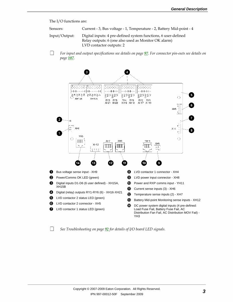
The I/O functions are:
Sensors: Current - 3, Bus voltage - 1, Temperature - 2, Battery Mid-point - 4
Input/Output: Digital inputs: 4 pre-defined system functions, 6 user-defined Relay outputs: 6 (one also used as Monitor OK alarm) LVD contactor outputs: 2
For input and output specifications see details on page 97. For connector pin-outs see details on page 107.
Bus voltage sense input - XH9
Power/Comms OK LED (green)
Digital inputs D1-D6 (6 user defined) - XH15A, XH15B
Digital (relay) outputs RY1-RY6 (6) - XH16-XH21
LVD contactor 2 status LED (green)
LVD contactor 2 connector - XH5
LVD contactor 1 status LED (green)
LVD contactor 1 connector - XH4
LVD power input connector - XH8
Power and RXP comms input - YH11
Current sense inputs (3) - XH6
Temperature sense inputs (2) - XH7
Battery Mid-point Monitoring sense inputs - XH12
DC power system digital inputs (4 pre-defined: Load Fuse Fail, Battery Fuse Fail, AC Distribution Fan Fail, AC Distribution MOV Fail) - YH3
See Troubleshooting on page 92 for details of I/O board LED signals.
SC200 Handbook
4 Copyright © 2007-2009 Eaton Corporation. All Rights Reserved.
IPN 997-00012-50F September 2009
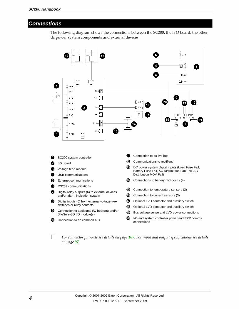
Connections The following diagram shows the connections between the SC200, the I/O board, the other dc power system components and external devices.
SC200 system controller
I/O board
Voltage feed module
USB communications
Ethernet communications
RS232 communications
Digital relay outputs (6) to external devices and/or alarm indication system
Digital inputs (6) from external voltage-free switches or relay contacts
Connection to additional I/O board(s) and/or SiteSure-3G I/O module(s)
Connection to dc common bus
Connection to dc live bus
Communications to rectifiers
DC power system digital inputs (Load Fuse Fail, Battery Fuse Fail, AC Distribution Fan Fail, AC Distribution MOV Fail)
Connections to battery mid-points (4)
Connection to temperature sensors (2)
Connection to current sensors (3)
Optional LVD contactor and auxiliary switch
Optional LVD contactor and auxiliary switch
Bus voltage sense and LVD power connections
I/O and system controller power and RXP comms connections
For connector pin-outs see details on page 107. For input and output specifications see details on page 97.

General Description
Copyright © 2007-2009 Eaton Corporation. All Rights Reserved.
IPN 997-00012-50F September 2009 5
Compatible Software The following software is compatible with the SC200 system controller: • DCTools Configuration Software. Latest version is available free from
www.powerquality.eaton.com/downloads. • PowerManagerII Remote Control and Monitoring Software. Contact your Eaton dc
product supplier for further information (see Worldwide Support on page 119). • Recommended web browsers: Microsoft Internet Explorer 8 (IE6 is compatible but with
reduced performance), Mozilla Firefox 3.0.

SC200 Handbook
6 Copyright © 2007-2009 Eaton Corporation. All Rights Reserved.
IPN 997-00012-50F September 2009
Chapter 2
SC200 Operation
Copyright © 2007-2009 Eaton Corporation. All Rights Reserved.
IPN 997-00012-50F September 2009 7
C h a p t e r 2 SC200 Operation
Overview
Topic Page
Starting the SC200 8
SC200 Operation using the Keypad and Screen 9
SC200 Operation Using a PC/Laptop 14
SC200 Identity Information 16
SC200 Internal Clock 16
Language Options 18
SC200 Firmware Upgrade 19
Configuration File 19
Backup and Restore 20
SC200 Handbook
8 Copyright © 2007-2009 Eaton Corporation. All Rights Reserved.
IPN 997-00012-50F September 2009
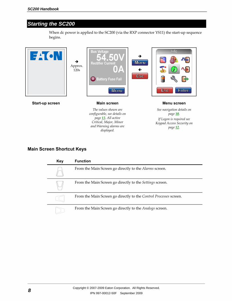
Starting the SC200 When dc power is applied to the SC200 (via the RXP connector YS11) the start-up sequence begins.
Approx.
120s
Start-up screen Main screen Menu screen The values shown are
configurable, see details on page 13. All active
Critical, Major, Minor and Warning alarms are
displayed.
See navigation details on page 10.
If Logon is required see Keypad Access Security on
page 12.
Main Screen Shortcut Keys
Key Function
From the Main Screen go directly to the Alarms screen.
From the Main Screen go directly to the Settings screen.
From the Main Screen go directly to the Control Processes screen.
From the Main Screen go directly to the Analogs screen.

SC200 Operation
Copyright © 2007-2009 Eaton Corporation. All Rights Reserved.
IPN 997-00012-50F September 2009 9
SC200 Operation using the Keypad and Screen
LCD display
Soft key 1 label
Soft key 1
Navigation keys (Up - Down - Left - Right)
Soft key 2
Soft key 2 label
Soft Keys The function of the soft keys is indicated by the corresponding labels on the LCD screen. The following table shows the most common labels and key functions.
Label Key function
Go to menu screen. See details on page 10.
Go back to parent menu screen.
Go to sub-menu or configuration screen*.
Save a new configuration setting*.
Ignore a new configuration setting*.
* See Changing a Configuration Setting on page 12.
Navigation Keys
Key Function
• Move up/down in the menu screen. See details on page 10. • Move up/down in a list (hold to go to the top or bottom of the list). • Select options in a configuration screen. • Increase/decrease a value in a configuration screen.
• Move left/right in the menu screen. See details on page 10. • Move left/right between tabs in Rectifiers, Alarms, Battery or Settings
menus. • Move left/right between segments of a multiple segment value in a
configuration screen.
SC200 Handbook
10 Copyright © 2007-2009 Eaton Corporation. All Rights Reserved.
IPN 997-00012-50F September 2009
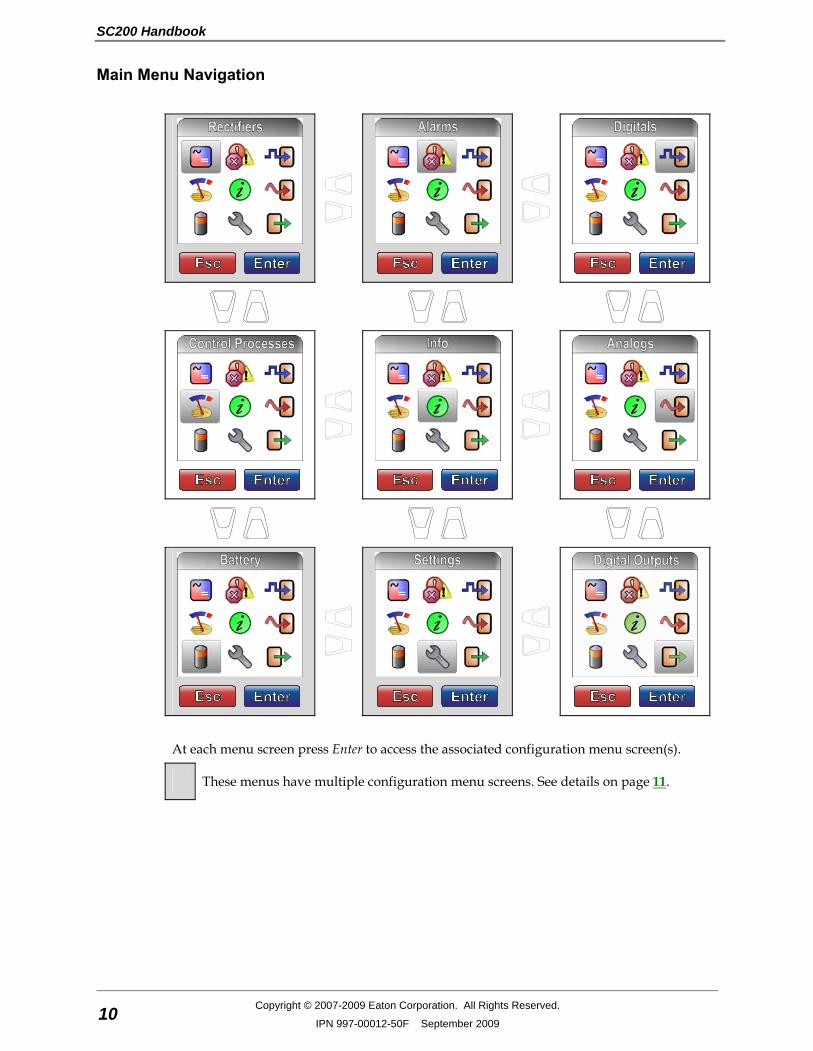
Main Menu Navigation
At each menu screen press Enter to access the associated configuration menu screen(s).
These menus have multiple configuration menu screens. See details on page 11.
SC200 Operation
Copyright © 2007-2009 Eaton Corporation. All Rights Reserved.
IPN 997-00012-50F September 2009 11
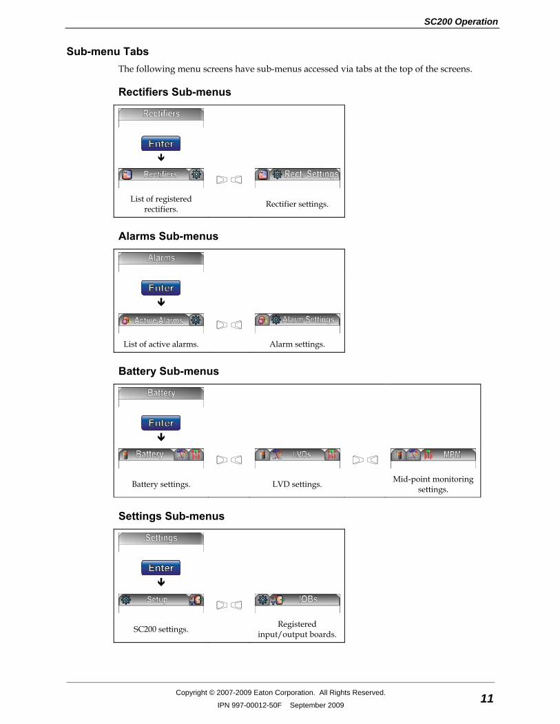
Sub-menu Tabs The following menu screens have sub-menus accessed via tabs at the top of the screens.
Rectifiers Sub-menus
List of registered rectifiers. Rectifier settings.
Alarms Sub-menus
List of active alarms. Alarm settings.
Battery Sub-menus
Battery settings. LVD settings. Mid-point monitoring settings.
Settings Sub-menus
SC200 settings. Registered input/output boards.
SC200 Handbook
12 Copyright © 2007-2009 Eaton Corporation. All Rights Reserved.
IPN 997-00012-50F September 2009
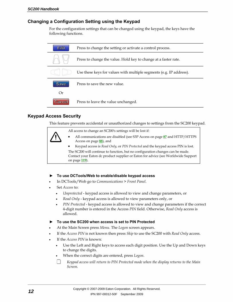
Changing a Configuration Setting using the Keypad For the configuration settings that can be changed using the keypad, the keys have the following functions.
Press to change the setting or activate a control process.
Press to change the value. Hold key to change at a faster rate.
Use these keys for values with multiple segments (e.g. IP address).
Press to save the new value.
Or
Press to leave the value unchanged.
Keypad Access Security This feature prevents accidental or unauthorized changes to settings from the SC200 keypad.
All access to change an SC200's settings will be lost if:
• All communications are disabled (see S3P Access on page 87 and HTTP/HTTPS Access on page 88), and
• Keypad access is Read Only, or PIN Protected and the keypad access PIN is lost. The SC200 will continue to function, but no configuration changes can be made. Contact your Eaton dc product supplier or Eaton for advice (see Worldwide Support on page 119).
► To use DCTools/Web to enable/disable keypad access • In DCTools/Web go to Communications > Front Panel. • Set Access to:
• Unprotected - keypad access is allowed to view and change parameters, or • Read Only - keypad access is allowed to view parameters only, or • PIN Protected - keypad access is allowed to view and change parameters if the correct
4-digit number is entered in the Access PIN field. Otherwise, Read Only access is allowed.
► To use the SC200 when access is set to PIN Protected • At the Main Screen press Menu. The Logon screen appears. • If the Access PIN is not known then press Skip to use the SC200 with Read Only access. • If the Access PIN is known:
• Use the Left and Right keys to access each digit position. Use the Up and Down keys to change the digits.
• When the correct digits are entered, press Logon.
Keypad access will return to PIN Protected mode when the display returns to the Main Screen.
SC200 Operation
Copyright © 2007-2009 Eaton Corporation. All Rights Reserved.
IPN 997-00012-50F September 2009 13
Display Settings ► To change the display contrast • Use the keypad to go to: Settings > Setup > Contrast > Edit.
► To change the display language • See Language Options on page 18.
► To change the display orientation (horizontal/vertical) Either: • Use the keypad to go to: Settings > Setup > Orientation > Edit. • Select the required orientation (vertical, horizontal-left or horizontal-right). Press Save. Or: • In DCTools/Web go to: Configuration > Communications > Front Panel. • Select the required orientation (vertical, horizontal-left or horizontal-right). Click Save
Changes.
The functions of the navigations keys also change to suit the new display orientation.
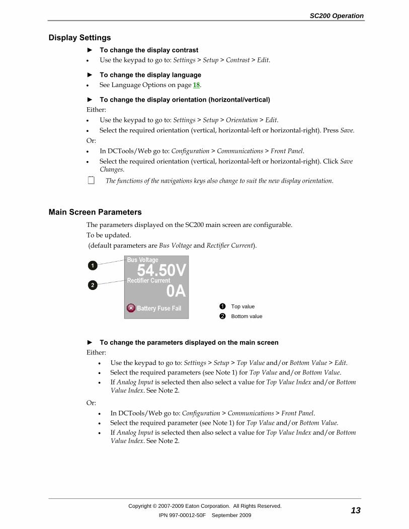
Main Screen Parameters The parameters displayed on the SC200 main screen are configurable. To be updated. (default parameters are Bus Voltage and Rectifier Current).
Top value
Bottom value
► To change the parameters displayed on the main screen Either:
• Use the keypad to go to: Settings > Setup > Top Value and/or Bottom Value > Edit. • Select the required parameters (see Note 1) for Top Value and/or Bottom Value. • If Analog Input is selected then also select a value for Top Value Index and/or Bottom
Value Index. See Note 2.
Or: • In DCTools/Web go to: Configuration > Communications > Front Panel. • Select the required parameter (see Note 1) for Top Value and/or Bottom Value. • If Analog Input is selected then also select a value for Top Value Index and/or Bottom
Value Index. See Note 2.

SC200 Handbook
14 Copyright © 2007-2009 Eaton Corporation. All Rights Reserved.
IPN 997-00012-50F September 2009
Notes: 1 The parameters available are: Bus Voltage, Rectifier Current, Load Current, Battery Current,
Battery Temperature, Load Power, System Power, or Analog Input. 2 If Analog Input is selected then also select a value for Top Value Index and/or Bottom Value
Index. This value is the number of the AI from the Analog Inputs table. To view the table in DCTools/Web go to: Analog Inputs.
Display Time-out If there is no keypad activity for 60 seconds the display will go back to the main screen.
Alarm Indicators
Visual indicators
Power on LED (green)
Minor Alarm LED (yellow)
Critical/Major Alarm LED (red)
??? The system value cannot be displayed because of a failed, disconnected or unconfigured sensor.
Audible indicator • One beep – indicates an invalid key press • Three beeps every 2 seconds – refer to the alert message on the SC200 display • One beep every 2 seconds – Minor alarm is active • Continuous sound – Critical/Major alarm is active
Critical/Major alarms always override Minor alarms.
► To stop the audible indicator • Press any key
The audible indicator will restart at the next active alarm or alert message.
► To enable/disable the audible alarm indicator Either:
• Use the keypad to go to Alarms > Alarm Settings > Audible Alarms > Edit. Or:
• In DCTools/Web go to: Configuration > Communications > Front Panel.
When Disabled, the audible indicator will still indicate an invalid key press.
SC200 Operation Using a PC/Laptop DCTools is configuration software for editing a system controller's configuration file (on-line) and monitoring the operation of Eaton's dc power systems. It is available free from www.powerquality.eaton.com/downloads.
SC200 Operation
Copyright © 2007-2009 Eaton Corporation. All Rights Reserved.
IPN 997-00012-50F September 2009 15
DCTools can be run on a PC/laptop connected to the SC200's USB port.
DCTools can also be run on a remote PC/laptop connected to the SC200's RS232 serial port (via a modem) or Ethernet port. For remote PC/laptop connection details see Communications Options on page 74.
Before you start you will need: • The latest version of DCTools available from www.powerquality.eaton.com/downloads. • A PC/laptop with USB port and USB A/B cable (RadioShack 55010997, Jaycar WC7700,
or equivalent).
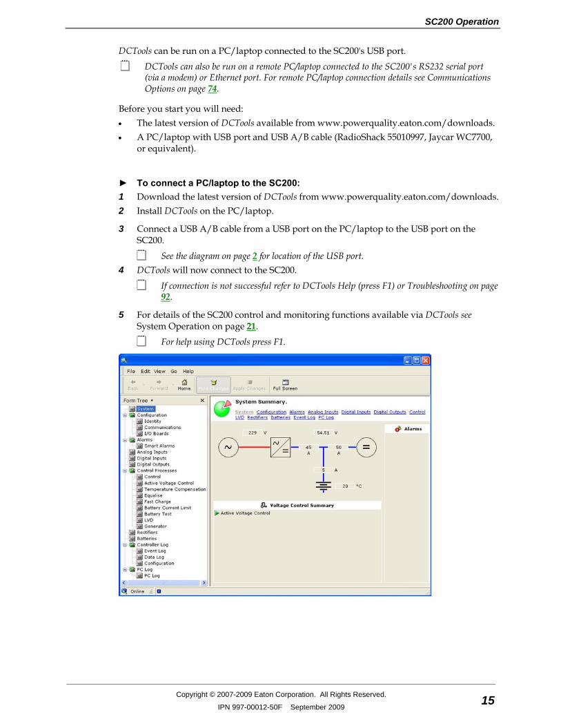
► To connect a PC/laptop to the SC200: 1 Download the latest version of DCTools from www.powerquality.eaton.com/downloads. 2 Install DCTools on the PC/laptop.
3 Connect a USB A/B cable from a USB port on the PC/laptop to the USB port on the SC200.
See the diagram on page 2 for location of the USB port. 4 DCTools will now connect to the SC200.
If connection is not successful refer to DCTools Help (press F1) or Troubleshooting on page 92.
5 For details of the SC200 control and monitoring functions available via DCTools see System Operation on page 21.
For help using DCTools press F1.
SC200 Handbook
16 Copyright © 2007-2009 Eaton Corporation. All Rights Reserved.
IPN 997-00012-50F September 2009
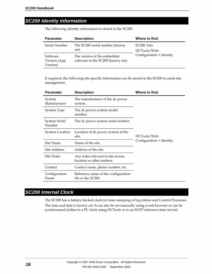
SC200 Identity Information The following identity information is stored in the SC200.
Parameter Description Where to find:
Serial Number The SC200 serial number (factory set).
Software Version (App Version)
The version of the embedded software in the SC200 (factory set).
SC200: Info DCTools/Web: Configuration > Identity
If required, the following site specific information can be stored in the SC200 to assist site management.
Parameter Description Where to find:
System Manufacturer
The manufacturer of the dc power system.
System Type The dc power system model number.
System Serial Number
The dc power system serial number.
System Location Location of dc power system at the site.
Site Name Name of the site.
Site Address Address of the site.
Site Notes Any notes relevant to site access, location or other matters.
Contact Contact name, phone number, etc.
Configuration Name
Reference name of the configuration file in the SC200.
DCTools/Web: Configuration > Identity
SC200 Internal Clock The SC200 has a battery-backed clock for time stamping of log entries and Control Processes. The time and date is factory set. It can also be set manually using a web browser or can be synchronized (either to a PC clock using DCTools or to an SNTP reference time server).
SC200 Operation
Copyright © 2007-2009 Eaton Corporation. All Rights Reserved.
IPN 997-00012-50F September 2009 17
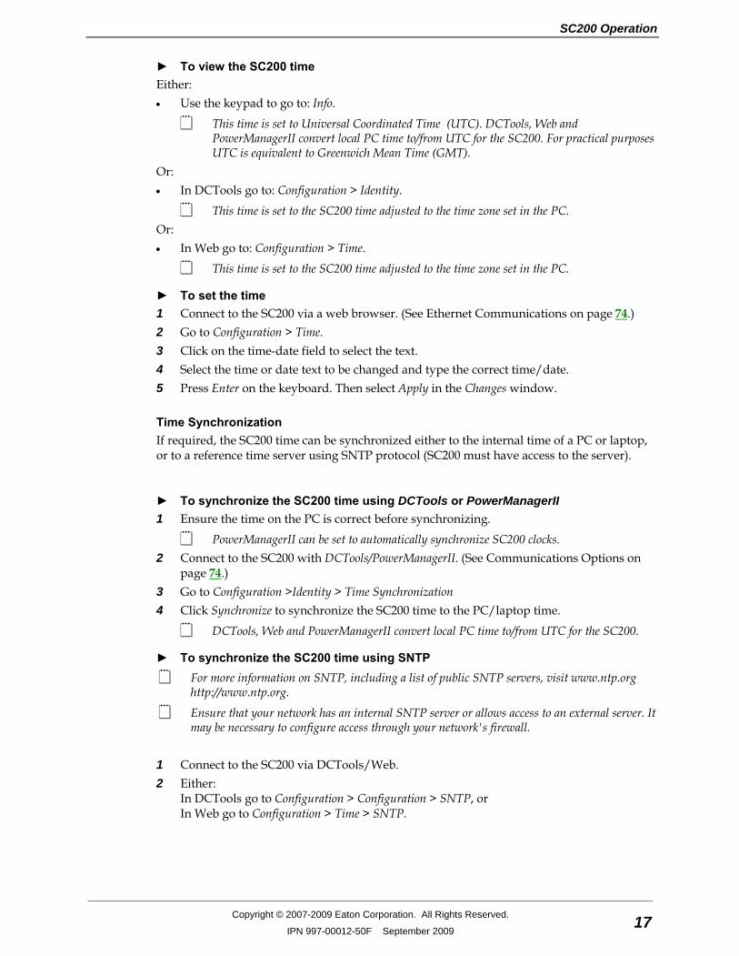
► To view the SC200 time Either: • Use the keypad to go to: Info.
This time is set to Universal Coordinated Time (UTC). DCTools, Web and PowerManagerII convert local PC time to/from UTC for the SC200. For practical purposes UTC is equivalent to Greenwich Mean Time (GMT).
Or: • In DCTools go to: Configuration > Identity.
This time is set to the SC200 time adjusted to the time zone set in the PC. Or: • In Web go to: Configuration > Time.
This time is set to the SC200 time adjusted to the time zone set in the PC.
► To set the time 1 Connect to the SC200 via a web browser. (See Ethernet Communications on page 74.) 2 Go to Configuration > Time. 3 Click on the time-date field to select the text. 4 Select the time or date text to be changed and type the correct time/date. 5 Press Enter on the keyboard. Then select Apply in the Changes window.
Time Synchronization If required, the SC200 time can be synchronized either to the internal time of a PC or laptop, or to a reference time server using SNTP protocol (SC200 must have access to the server).
► To synchronize the SC200 time using DCTools or PowerManagerII 1 Ensure the time on the PC is correct before synchronizing.
PowerManagerII can be set to automatically synchronize SC200 clocks. 2 Connect to the SC200 with DCTools/PowerManagerII. (See Communications Options on
page 74.) 3 Go to Configuration >Identity > Time Synchronization 4 Click Synchronize to synchronize the SC200 time to the PC/laptop time.
DCTools, Web and PowerManagerII convert local PC time to/from UTC for the SC200.
► To synchronize the SC200 time using SNTP For more information on SNTP, including a list of public SNTP servers, visit www.ntp.org
http://www.ntp.org.
Ensure that your network has an internal SNTP server or allows access to an external server. It may be necessary to configure access through your network's firewall.
1 Connect to the SC200 via DCTools/Web. 2 Either:
In DCTools go to Configuration > Configuration > SNTP, or In Web go to Configuration > Time > SNTP.

SC200 Handbook
18 Copyright © 2007-2009 Eaton Corporation. All Rights Reserved.
IPN 997-00012-50F September 2009
3 Set the following parameters:
Primary Address IP address of primary SNTP server.
Backup Address IP address of backup SNTP server.
UDP Port Assigned by the time server administrator.
Poll Interval The time between synchronizations.
The time will update a few seconds after any SNTP parameter change.
Language Options The SC200 system controller language default is English. Text on the LCD display and web pages (see details on page 76) can be shown in other languages by loading the appropriate Translation File (SC200-xx-Vyyy.icp) into the SC200. Contact Eaton for available Translation Files (see Worldwide Support on page 119).
This process does not change the language in DCTools.
► To add a new SC200 display/web page language: 1 Obtain the appropriate Translation File (SC200-xx-Vyyy.icp) from Eaton. 2 Save the file. 3 Connect to the SC200 via an Ethernet connection. See Communications Options on page
74. 4 Open a web browser and browse to the SC200 IP address. 5 Go to Tools > Firmware Upgrade. 6 Click on Browse and select the Translation File (SC200-xx-Vyyy.icp). 7 Click on Next then follow the prompts to add the language.
Language selection An SC200 can hold multiple language files and any of these can be selected for the LCD display and Web pages.
► To see which languages are loaded into an SC200 Either:
• On the SC200 keypad go to: Settings > Language > Edit. Or:
• Connect to the SC200 via an Ethernet connection. See Communications Options on page 74.
• On the Log On web page, a flag icon is shown for each language option available.
► To select a new language for the Web pages • On the Log On web page, click on the required language flag icon. • The web pages will change to the required language.
SC200 Operation
Copyright © 2007-2009 Eaton Corporation. All Rights Reserved.
IPN 997-00012-50F September 2009 19
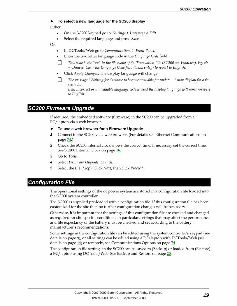
► To select a new language for the SC200 display Either:
• On the SC200 keypad go to: Settings > Language > Edit. • Select the required language and press Save.
Or: • In DCTools/Web go to Communications > Front Panel. • Enter the two letter language code in the Language Code field.
This code is the "xx" in the file name of the Translation File (SC200-xx-Vyyy.icp). Eg: zh = Chinese. Clear the Language Code field (blank entry) to revert to English.
• Click Apply Changes. The display language will change.
The message "Waiting for database to become available for update ..." may display for a few seconds. If an incorrect or unavailable language code is used the display language will remain/revert to English.
SC200 Firmware Upgrade If required, the embedded software (firmware) in the SC200 can be upgraded from a PC/laptop via a web browser.
► To use a web browser for a Firmware Upgrade 1 Connect to the SC200 via a web browser. (For details see Ethernet Communications on
page 74.) 2 Check the SC200 internal clock shows the correct time. If necessary set the correct time.
See SC200 Internal Clock on page 16. 3 Go to Tools. 4 Select Firmware Upgrade: Launch. 5 Select the file (*.icp). Click Next, then click Proceed.
Configuration File The operational settings of the dc power system are stored in a configuration file loaded into the SC200 system controller. The SC200 is supplied pre-loaded with a configuration file. If this configuration file has been customized for the site then no further configuration changes will be necessary. Otherwise, it is important that the settings of this configuration file are checked and changed as required for site-specific conditions. In particular, settings that may affect the performance and life expectancy of the battery must be checked and set according to the battery manufacturer’s recommendations. Some settings in the configuration file can be edited using the system controller's keypad (see details on page 9), or all settings can be edited using a PC/laptop with DCTools/Web (see details on page 14) or remotely, see Communications Options on page 74. The configuration file settings in the SC200 can be saved to (Backup) or loaded from (Restore) a PC/laptop using DCTools/Web. See Backup and Restore on page 20.

SC200 Handbook
20 Copyright © 2007-2009 Eaton Corporation. All Rights Reserved.
IPN 997-00012-50F September 2009
Backup and Restore The configuration file settings in the SC200 can be saved to (Backup) or loaded from (Restore) a PC/laptop using DCTools/Web. Backup and Restore can be used to: • Load a standard (master) configuration file into an SC200 for customization. • Copy a customized configuration file from one SC200 to others (at similar sites). • Save a copy of a customized configuration file. This is recommended in case the SC200
has to be replaced.
► To use DCTools for Backup and Restore 1 Connect to the SC200 with DCTools. See details on page 14 or see Communications
Options on page 74. 2 In DCTools go to File > ICE Backup/Restore and follow the prompts.
The saved file does not include site specific settings including Site Identity, IP Address, S3P Address, battery characterization data.
► To use a web browser for Backup 1 Connect to the SC200 via a web browser. For details see Ethernet Communications on
page 74. 2 Go to Tools. 3 Select Backup Tool. 4 Select the file type:
• System Snapshot (*.dcs): Configuration file including site specific settings. • Configuration (*.dcc): Configuration file without site specific settings - Site Identity,
IP Address, S3P Address, battery characterization data). 5 Click Proceed to Backup the configuration.
► To use a web browser for Restore 1 Connect to the SC200 via a web browser. For details see Ethernet Communications on
page 74. 2 Go to Tools. 3 Select Restore Tool. 4 Select the file type:
• System Snapshot (*.dcs): Configuration file including site specific settings. • Configuration (*.dcc): Configuration file without site specific settings - Site Identity,
IP Address, S3P Address, battery characterization data). • Fragment (*.dcf): Restore part of a configuration file (such as battery characterization
data). 5 Click Next, then select a file name to Restore a configuration.
Chapter 3
System Operation
Copyright © 2007-2009 Eaton Corporation. All Rights Reserved.
IPN 997-00012-50F September 2009 21
C h a p t e r 3 System Operation
Overview
Topic Page
Voltage Control 22
Rectifiers 31
Low Voltage Disconnect (LVD) 35
Alarms 42
Batteries 52
Generator Control Option 61
Input/Output (I/O) 63
Data Logging 70
SC200 Handbook
22 Copyright © 2007-2009 Eaton Corporation. All Rights Reserved.
IPN 997-00012-50F September 2009
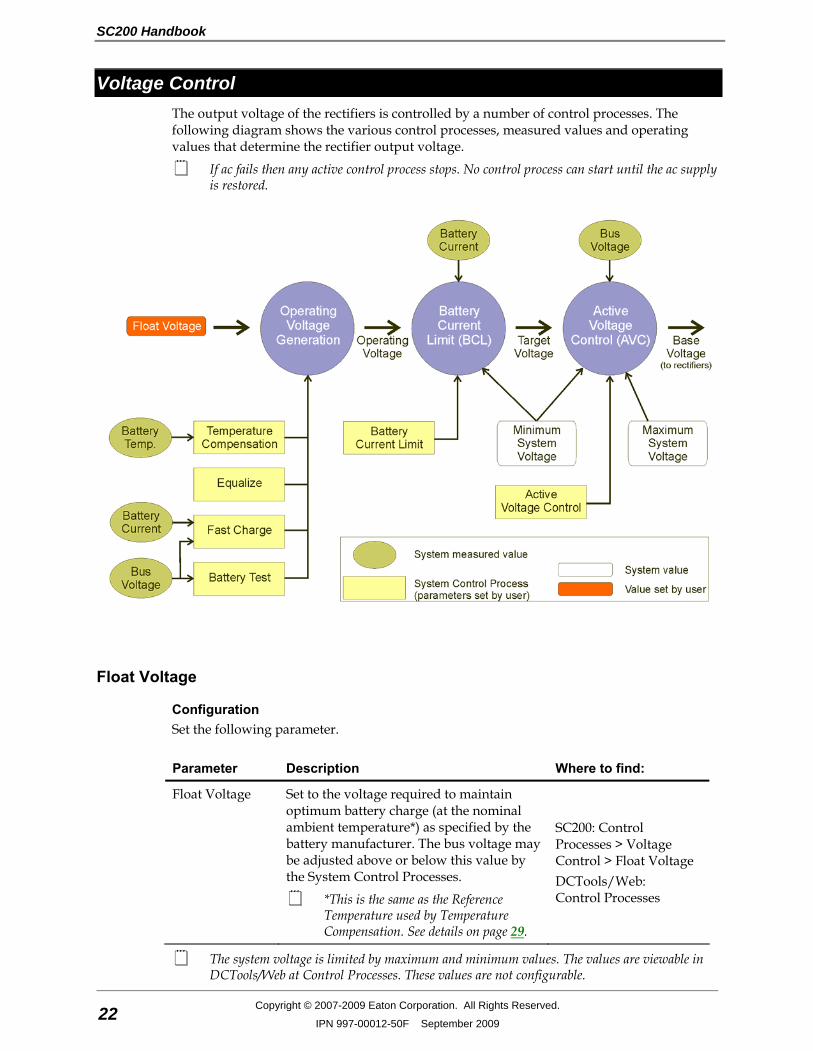
Voltage Control The output voltage of the rectifiers is controlled by a number of control processes. The following diagram shows the various control processes, measured values and operating values that determine the rectifier output voltage.
If ac fails then any active control process stops. No control process can start until the ac supply is restored.
Float Voltage
Configuration Set the following parameter.
Parameter Description Where to find:
Float Voltage Set to the voltage required to maintain optimum battery charge (at the nominal ambient temperature*) as specified by the battery manufacturer. The bus voltage may be adjusted above or below this value by the System Control Processes.
*This is the same as the Reference Temperature used by Temperature Compensation. See details on page 29.
SC200: Control Processes > Voltage Control > Float Voltage DCTools/Web: Control Processes
The system voltage is limited by maximum and minimum values. The values are viewable in DCTools/Web at Control Processes. These values are not configurable.
System Operation
Copyright © 2007-2009 Eaton Corporation. All Rights Reserved.
IPN 997-00012-50F September 2009 23
Active Voltage Control (AVC) Active Voltage Control maintains a constant float voltage under varying load current by monitoring the bus voltage and adjusting the rectifier output voltage to compensate for any voltage drop. This prevents undercharging the batteries during high load demand.
► To enable Active Voltage Control • Use the SC200 keypad to go to: Control Processes > Voltage Control > AVC. • Or, in DCTools/Web go to: Control Processes > Voltage Control > Active Voltage
Control.
Active Voltage Control is normally enabled. Only disable if there are particular reasons.
Information The following information is available about AVC.
Parameter Description Where to find:
State Indicates if AVC is active or inactive.
Target Voltage AVC will set the Base Voltage to attempt to maintain the bus voltage to this value.
Voltage Offset The difference between the Base Voltage and the Target Voltage.
DCTools/Web: Control Processes > Active Voltage Control
Battery Current Limit (BCL) Battery Current Limit automatically limits the battery recharge current to: • Prevent excessive battery charge current in under-loaded systems • Minimize gas release in VRLA batteries • Reduce the load on a standby generator. Two current limit values can be set (both are a percentage of the C10 rating of the battery):
Battery Current Limit: BCL value for use when utility ac is available.
Engine Run Limit (optional): BCL value for use when ac is supplied by a standby generator. This reduces the load on the generator and allows a smaller generator to be used.
Engine Run Limit is activated by a signal from an ac standby generator.
► To enable BCL • Use the SC200 keypad to go to: Control Processes > Battery Current Limit. • Or, in DCTools/Web go to: Control Processes > Battery Current Limit.
SC200 Handbook
24 Copyright © 2007-2009 Eaton Corporation. All Rights Reserved.
IPN 997-00012-50F September 2009
► To activate Engine Run BCL • Connect a voltage free relay contact (that will operate when the standby generator starts)
to a Digital Input. • In DCTools/Web go to Digital Inputs. • Configure the selected Digital Input and set Function to Engine Run. • In DCTools/Web go to Control Processes > Battery Current Limit and set the Engine Run
Limit.
Information The following information is available about BCL.
Parameter Description Where to find:
State Indicates if BCL is active or inactive. SC200: Control Processes > Battery Current Limit. DCTools/Web: Control Processes > Battery Current Limit
Engine Run State Indicates if Engine Run BCL is active.
Voltage Offset The bus voltage adjustment made by Battery Current Limit is applied to the Operating Voltage to produce the Target Voltage. Target Voltage is used as the input to the AVC function.
DCTools/Web: Control Processes > Battery Current Limit
Configuration Set the following parameters.
Parameter Description Where to find:
Battery Capacity Set to the rated 10 hour capacity of the installed battery strings. Zero means no battery is installed.
SC200: Battery > Battery > Battery Capacity DCTools/Web: Batteries
Current Limit BCL maintains the battery current below this value, which is a percentage of the installed C10 Battery Capacity.
Engine Run Limit The Battery Current Limit setting when Engine Run is active. BCL maintains the battery current below this value when the engine run digital input is active (engine run is enabled). This limit is expressed as a percentage of the installed C10 Battery Capacity.
DCTools/Web: Control Processes > Battery Current Limit

System Operation
Copyright © 2007-2009 Eaton Corporation. All Rights Reserved.
IPN 997-00012-50F September 2009 25
Battery Test Battery Test is a preventative maintenance tool that monitors the discharge capabilities to ensure that the condition of the battery has not deteriorated over time. The SC200 temporarily reduces the output voltage of the rectifiers to just below the bus voltage for a set duration. The battery then supplies power to the load. A battery test passes if the battery voltage remains above a predetermined level for the duration of the test. Battery Tests can be scheduled to occur at regular intervals, and/or can be started/stopped manually, and/or can be started by an external relay contact or switch.
Battery Test does NOT function during a Fast Charge or Equalize, or during the first 48 hours after an ac supply failure (the lock-out period).
If a Digital Input has the function "Start Battery Test" then a Battery Test will start when the Digital Input becomes active.
► To enable Battery Test (or to start or stop a test manually) • Use the SC200 keypad to go to: Control Processes > Battery Test. • Or, in DCTools/Web go to: Control Processes > Battery Test
► To use an external relay contact to activate a Battery Test (optional) • Connect a voltage free relay contact or switch to any Digital Input. • In DCTools/Web go to Digital Inputs. • Configure the selected Digital Input and set Function to Start Battery Test.
Information The following information is available about Battery Test.
Parameter Description Where to find:
State Indicates if Battery Test is disabled, locked-out, active or inactive.
Next Start Time The start time of the next scheduled Battery Test.
Time shown on SC200 is UTC. Time on PC running DCTools/Web is local time. See SC200 Internal Clock on page 16.
Remaining Time The time to the end of the currently active Battery Test.
Battery Test Lockout Remaining
The time remaining until a Battery Test can be started. Battery Tests cannot be started within 48 hours of an ac supply failure.
Voltage Offset The adjustment to the bus voltage being applied due to the Battery Test. While a Battery Test is running, the rectifiers are turned down to force the battery to carry the load.
SC200: Control Processes > Battery Test DCTools/Web: Control Processes > Battery Test
SC200 Handbook
26 Copyright © 2007-2009 Eaton Corporation. All Rights Reserved.
IPN 997-00012-50F September 2009
Configuration Set the following parameters.
Parameter Description Where to find:
First Start Time The date and time that the first battery test cycle will occur. Subsequent tests will occur at every Battery Test Interval after that.
Interval The time between scheduled battery tests. The interval period begins at the start of a battery test. Zero disables scheduled battery tests. Zero also disables the 48 hour lockout following an ac supply failure, allowing an immediate manual test.
Test Duration The maximum time a Battery Test process will be active. The battery test will pass if the bus voltage remains above the Battery Test Termination Voltage for the duration of the test.
Termination Voltage
If the bus voltages drops below this value during a Battery Test, then the test fails.
SC200: Control Processes > Battery Test DCTools/Web: Control Processes > Battery Test
Equalize Equalize charges batteries at a higher voltage after they have been fully charged to ensure that all individual cell voltages are the same, that electrolyte is distributed evenly, and that sulfate crystal buildup on the plates is reduced. Equalize can be scheduled to occur at regular intervals and/or can be started/stopped manually.
Refer to the battery manufacturer's instructions before using Equalize.
If a Digital Input has the function "Start Equalize" then a manual equalize cycle will start when the Digital Input becomes active.
If Equalize cannot start at the scheduled time (for example when there is no ac supply) then its state will be Pending and it will start as soon as conditions allow. Use Stop Equalize to cancel a Pending Equalize.
► To enable Equalize (or to start or stop Equalize manually) • Use the SC200 keypad to go to: Control Processes > Equalize. • Or, in DCTools/Web go to: Control Processes > Equalize.
► To use an external relay contact to activate an Equalize (optional) • Connect a voltage free relay contact or switch to any Digital Input. • In DCTools/Web go to: Digital Inputs. • Configure the selected Digital Input and set Function to Start Equalize.

System Operation
Copyright © 2007-2009 Eaton Corporation. All Rights Reserved.
IPN 997-00012-50F September 2009 27
Information The following information is available about Equalize.
Parameter Description Where to find:
State Indicates if Equalize is Disabled, Active, Inactive or Pending.
Next Start Time The start time of the next scheduled Equalize.
Time shown on SC200 is UTC. Time on PC running DCTools/Web is local time. See SC200 Internal Clock on page 16.
Remaining Time The time to the end of the currently active Equalize.
Voltage Offset The adjustment to the bus voltage being applied due to the Equalize.
SC200: Control Processes > Equalize DCTools/Web: Control Processes > Equalize
Configuration Set the following parameters.
Parameter Description Where to find:
First Start Time The date and time that the first scheduled Equalize will occur. Subsequent Equalize will occur at every Equalize Interval after that.
Interval The time between scheduled Equalize. The interval period begins at the start of an Equalize. Zero disables scheduled Equalizes.
Duration The duration of a scheduled Equalize.
Equalize Voltage The bus voltage maintained during an Equalize cycle as recommended by the battery manufacturer. The bus voltage is further adjusted by Temperature Compensation.
SC200: Control Processes > Equalize DCTools/Web: Control Processes > Equalize
Equalize may also be used to trigger the Generator Enable alarm. See details on page 61.
Fast Charge After an ac supply failure, Fast Charge automatically increases the float voltage of the power system to recharge the batteries as quickly as possible. Enable Fast Charge if the site experiences frequent ac supply failures.
Fast Charge does NOT function during a Battery Test, Equalize or if the battery current sensor fails.
If Fast Charge is used then Battery Current Limit (BCL) should also be used. See Battery Current Limit on page 23 for details.
If Fast Charge cannot start at the scheduled time (for example when there is no ac supply) then its state will be Pending and it will start as soon as conditions allow. Use Stop Fast Charge to cancel a Pending Fast Charge.
► To enable Fast Charge (or to stop Fast Charge manually) • Use the SC200 keypad to go to: Control Processes > Fast Charge. • Or, in DCTools/Web go to: Control Processes > Fast Charge.

SC200 Handbook
28 Copyright © 2007-2009 Eaton Corporation. All Rights Reserved.
IPN 997-00012-50F September 2009
Information The following information is available about Fast Charge.
Parameter Description Where to find:
State Indicates if Fast Charge is Disabled, Active, Inactive or Pending.
Ah Discharged The current level of battery discharge. A Fast Charge cycle is started if this value is above the Ah Threshold.
See also Reset Battery State on page 29.
Maximum Time Remaining
The maximum time to the end of the currently active Fast Charge.
Voltage Offset The adjustment to the bus voltage being applied due to the Fast Charge.
SC200: Control Processes > Fast Charge DCTools/Web: Control Processes > Fast Charge
Configuration Set the following parameters.
Parameter Description Where to find:
Voltage Threshold If the bus voltage drops below this value during an ac supply failure then Fast Charge starts when the ac supply is restored. Fast charge can also be started based on the Ah Threshold.
Ah Threshold If Ah Discharged exceeds this value during an ac supply failure, then Fast Charge starts when the ac supply is restored. The threshold is given as a percentage of installed C10 battery capacity. Fast charge can also be started based on the Fast Charge Voltage Threshold.
Maximum Duration
The maximum duration of a Fast Charge as recommended by the battery manufacturer.
Recharge Percentage (%)
The ratio of ampere-hours recharged to the ampere-hours discharged. Fast Charge stops either when the Ah recharged equals the Ah discharged x Fast Charge Recharge Percentage, or after Maximum Duration.
Fast Charge Voltage
The bus voltage maintained during a Fast Charge.
SC200: Control Processes > Fast Charge DCTools/Web: Control Processes > Fast Charge
Battery Capacity The rated 10 hour capacity of the installed battery strings. Zero means no battery is installed.
SC200: Battery > Battery > Battery Capacity DCTools/Web: Batteries
Fast Charge may also be used to trigger the Generator Enable alarm. See details on page 61.

System Operation
Copyright © 2007-2009 Eaton Corporation. All Rights Reserved.
IPN 997-00012-50F September 2009 29
Reset Battery State The SC200 monitors battery discharge and maintains a value called Ah Discharged. In a new SC200 Ah Discharged is set to zero. During operation of the dc power system the value is increased as the battery is discharged, and reduced as the battery is recharged. The value of Ah Discharged is used to start the Fast Charge control process. See details on page 27.
► To view current value of Ah Discharged • Use the SC200 keypad to go to: Battery > Battery > Ah Discharged • In DCTools/Web go to: Batteries.
If a battery or the SC200 is changed then reset the value of Ah Discharged to zero (when the battery is fully charged).
► To set the value of Ah Discharged back to zero • Use the SC200 keypad to go to: Battery > Battery > Reset State > Enter > Reset. • In DCTools/Web go to: Batteries. Click Reset Battery State.
Any active or pending Fast Charge or Equalize will be cancelled.
Temperature Compensation As the ambient temperature of a battery drops (or rises) the voltage required to maintain full charge increases (or decreases). Temperature Compensation automatically varies the float voltage to cancel the effects of changing temperature. Enable Temperature Compensation for optimum battery life and battery capacity over a wider temperature range.
Temperature Compensation does NOT function during a Battery Test.
► To enable Temperature Compensation • Use the SC200 keypad to go to: Control Processes > Temperature Compensation > Enabled. • Or, in DCTools/Web go to: Control Processes > Temperature Compensation.
Information The following information is available about Temperature Compensation.
Parameter Description Where to find:
State Indicates if Temperature Compensation is active or inactive.
Voltage Offset The adjustment to the bus voltage being applied due to the Temperature Compensation. Offset is zero when the battery temperature equals the reference temperature.
SC200: Control Processes > Temperature Compensation > Enabled DCTools/Web: Control Processes > Temperature Compensation
Battery Temperature
The temperature measured by the battery temperature sensor.
SC200: Analogs > Battery Temperature DCTools/Web: Batteries
SC200 Handbook
30 Copyright © 2007-2009 Eaton Corporation. All Rights Reserved.
IPN 997-00012-50F September 2009
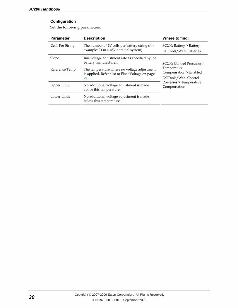
Configuration Set the following parameters.
Parameter Description Where to find:
Cells Per String The number of 2V cells per battery string (for example: 24 in a 48V nominal system).
SC200: Battery > Battery DCTools/Web: Batteries
Slope Bus voltage adjustment rate as specified by the battery manufacturer.
Reference Temp The temperature where no voltage adjustment is applied. Refer also to Float Voltage on page 22.
Upper Limit No additional voltage adjustment is made above this temperature.
Lower Limit No additional voltage adjustment is made below this temperature.
SC200: Control Processes > Temperature Compensation > Enabled DCTools/Web: Control Processes > Temperature Compensation
System Operation
Copyright © 2007-2009 Eaton Corporation. All Rights Reserved.
IPN 997-00012-50F September 2009 31
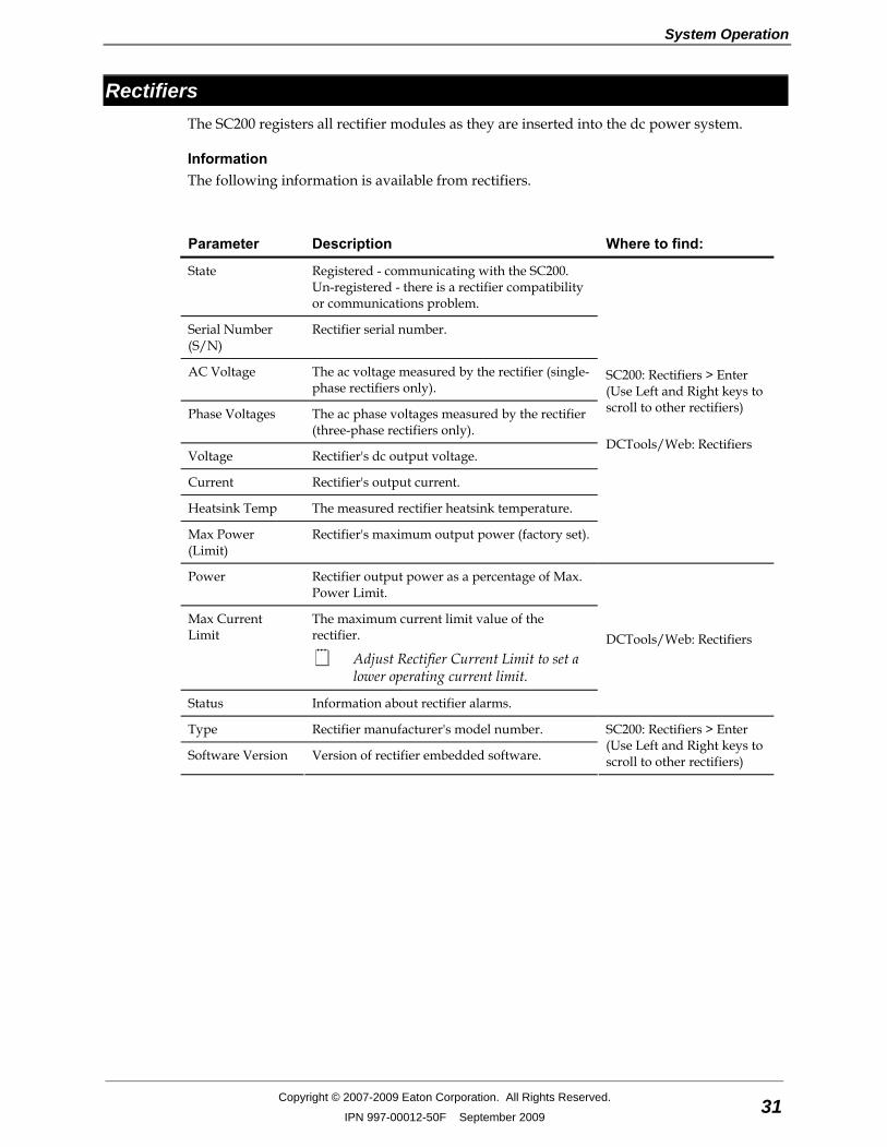
Rectifiers The SC200 registers all rectifier modules as they are inserted into the dc power system.
Information The following information is available from rectifiers.
Parameter Description Where to find:
State Registered - communicating with the SC200. Un-registered - there is a rectifier compatibility or communications problem.
Serial Number (S/N)
Rectifier serial number.
AC Voltage The ac voltage measured by the rectifier (single-phase rectifiers only).
Phase Voltages The ac phase voltages measured by the rectifier (three-phase rectifiers only).
Voltage Rectifier's dc output voltage.
Current Rectifier's output current.
Heatsink Temp The measured rectifier heatsink temperature.
Max Power (Limit)
Rectifier's maximum output power (factory set).
SC200: Rectifiers > Enter (Use Left and Right keys to scroll to other rectifiers) DCTools/Web: Rectifiers
Power Rectifier output power as a percentage of Max. Power Limit.
Max Current Limit
The maximum current limit value of the rectifier.
Adjust Rectifier Current Limit to set a lower operating current limit.
Status Information about rectifier alarms.
DCTools/Web: Rectifiers
Type Rectifier manufacturer's model number.
Software Version Version of rectifier embedded software.
SC200: Rectifiers > Enter (Use Left and Right keys to scroll to other rectifiers)
SC200 Handbook
32 Copyright © 2007-2009 Eaton Corporation. All Rights Reserved.
IPN 997-00012-50F September 2009
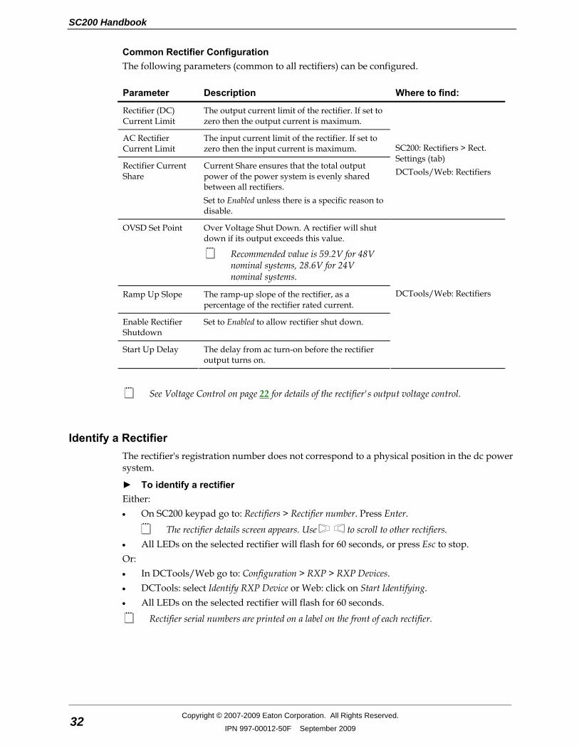
Common Rectifier Configuration The following parameters (common to all rectifiers) can be configured.
Parameter Description Where to find:
Rectifier (DC) Current Limit
The output current limit of the rectifier. If set to zero then the output current is maximum.
AC Rectifier Current Limit
The input current limit of the rectifier. If set to zero then the input current is maximum.
Rectifier Current Share
Current Share ensures that the total output power of the power system is evenly shared between all rectifiers. Set to Enabled unless there is a specific reason to disable.
SC200: Rectifiers > Rect. Settings (tab) DCTools/Web: Rectifiers
OVSD Set Point Over Voltage Shut Down. A rectifier will shut down if its output exceeds this value.
Recommended value is 59.2V for 48V nominal systems, 28.6V for 24V nominal systems.
Ramp Up Slope The ramp-up slope of the rectifier, as a percentage of the rectifier rated current.
Enable Rectifier Shutdown
Set to Enabled to allow rectifier shut down.
Start Up Delay The delay from ac turn-on before the rectifier output turns on.
DCTools/Web: Rectifiers
See Voltage Control on page 22 for details of the rectifier's output voltage control.
Identify a Rectifier The rectifier's registration number does not correspond to a physical position in the dc power system.
► To identify a rectifier Either: • On SC200 keypad go to: Rectifiers > Rectifier number. Press Enter.
The rectifier details screen appears. Use to scroll to other rectifiers. • All LEDs on the selected rectifier will flash for 60 seconds, or press Esc to stop. Or: • In DCTools/Web go to: Configuration > RXP > RXP Devices. • DCTools: select Identify RXP Device or Web: click on Start Identifying. • All LEDs on the selected rectifier will flash for 60 seconds.
Rectifier serial numbers are printed on a label on the front of each rectifier.
System Operation
Copyright © 2007-2009 Eaton Corporation. All Rights Reserved.
IPN 997-00012-50F September 2009 33
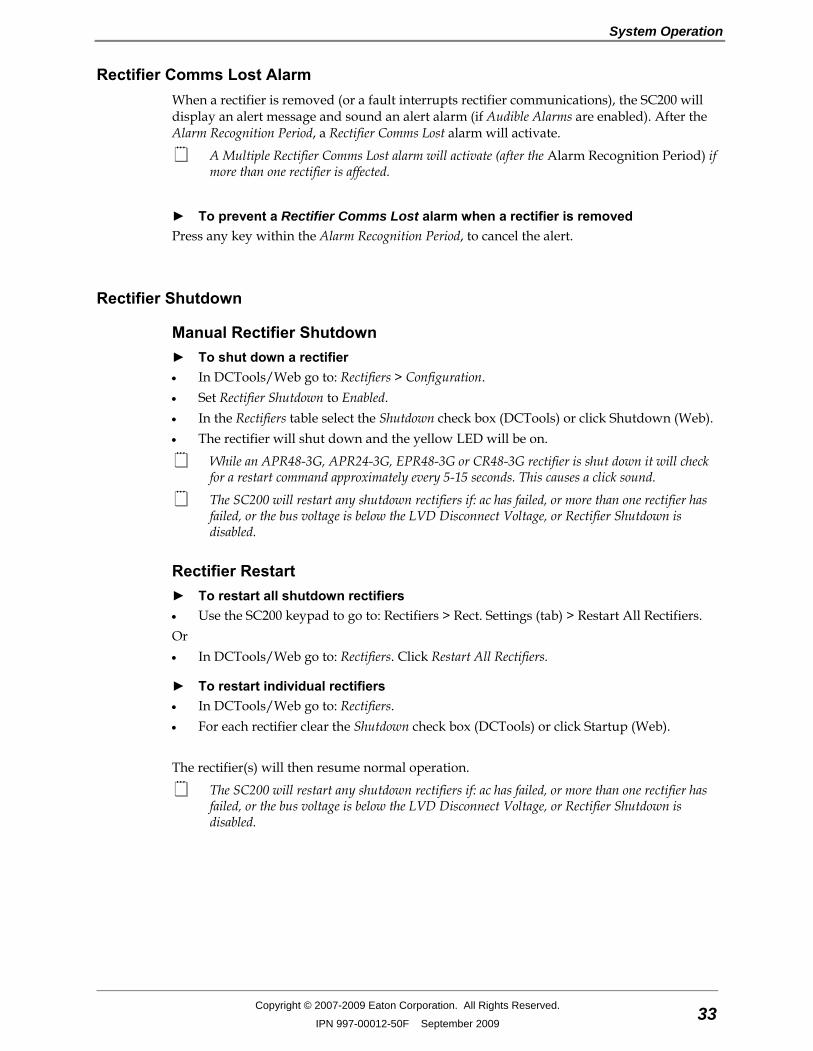
Rectifier Comms Lost Alarm When a rectifier is removed (or a fault interrupts rectifier communications), the SC200 will display an alert message and sound an alert alarm (if Audible Alarms are enabled). After the Alarm Recognition Period, a Rectifier Comms Lost alarm will activate.
A Multiple Rectifier Comms Lost alarm will activate (after the Alarm Recognition Period) if more than one rectifier is affected.
► To prevent a Rectifier Comms Lost alarm when a rectifier is removed Press any key within the Alarm Recognition Period, to cancel the alert.
Rectifier Shutdown
Manual Rectifier Shutdown ► To shut down a rectifier • In DCTools/Web go to: Rectifiers > Configuration. • Set Rectifier Shutdown to Enabled. • In the Rectifiers table select the Shutdown check box (DCTools) or click Shutdown (Web). • The rectifier will shut down and the yellow LED will be on.
While an APR48-3G, APR24-3G, EPR48-3G or CR48-3G rectifier is shut down it will check for a restart command approximately every 5-15 seconds. This causes a click sound.
The SC200 will restart any shutdown rectifiers if: ac has failed, or more than one rectifier has failed, or the bus voltage is below the LVD Disconnect Voltage, or Rectifier Shutdown is disabled.
Rectifier Restart ► To restart all shutdown rectifiers • Use the SC200 keypad to go to: Rectifiers > Rect. Settings (tab) > Restart All Rectifiers. Or • In DCTools/Web go to: Rectifiers. Click Restart All Rectifiers.
► To restart individual rectifiers • In DCTools/Web go to: Rectifiers. • For each rectifier clear the Shutdown check box (DCTools) or click Startup (Web). The rectifier(s) will then resume normal operation.
The SC200 will restart any shutdown rectifiers if: ac has failed, or more than one rectifier has failed, or the bus voltage is below the LVD Disconnect Voltage, or Rectifier Shutdown is disabled.
SC200 Handbook
34 Copyright © 2007-2009 Eaton Corporation. All Rights Reserved.
IPN 997-00012-50F September 2009
Load Based Rectifier Shutdown If Load Based Rectifier Shutdown (LBRS) is enabled then the SC200 automatically shuts down rectifiers when the total load current is significantly less than the total rectifier capacity. This raises the average load on the remaining rectifiers which will then operate at a higher efficiency. This results in a decrease in system power consumption. The run time of all rectifiers is recorded and balanced to ensure even aging. The SC200 will progressively restart rectifiers if the load increases.
Rectifiers shut down by LBRS will have the yellow LED on and will check for a restart command approximately every 5-15 seconds. This causes a click sound in APR48-3G, APR24-3G and EPR48-3G rectifiers.
At least two rectifiers will always be on to maintain N+1 rectifier redundancy. Therefore, LBRS has no effect in dc power systems with only one or two rectifiers.
The SC200 will automatically restart all rectifiers if ac supply has failed, or more than one rectifier has failed, or Battery Test / Equalize / Fast Charge is active, or the bus voltage is below the LVD Disconnect Voltage.
► To enable Load Based Rectifier Shutdown • Use the SC200 keypad to go to: Control Processes > Load Based Rectifier Shutdown. • Or, in DCTools/Web go to: Rectifiers > Load Based Rectifier Shutdown
Ensure that Rectifier Start Up Delay is less than 30 seconds. See information on page 31. LBRS will not function correctly if the start up delay is more than 30 seconds.
Information The following information is available about Load Based Rectifier Shutdown.
Parameter Description Where to find:
State Indicates if LBRS is Enabled or Disabled. SC200: Control Processes > LBRS DCTools/Web: Rectifiers > Load Based Rectifier Shutdown
Run Time The run time of each rectifier DCTools/Web: Rectifiers

System Operation
Copyright © 2007-2009 Eaton Corporation. All Rights Reserved.
IPN 997-00012-50F September 2009 35
Configuration The following parameters must be configured to set Load Based Rectifier Shutdown.
Parameter Description Where to find:
Reset Run Time Sets the run time of all rectifiers to zero.
High Threshold LBRS restarts all rectifiers if the load is more than this percentage of the total rectifier capacity. Typical: 80%.
Low Threshold LBRS shuts down rectifiers if the load is less than this percentage of the total rectifier capacity. Typical: 60%.
Interval The time interval in minutes that the SC200 will cycle rectifiers when the LBRS process is active.
Restart All Rectifiers
Press to temporarily restart all rectifiers shut down by LBRS.
Disable LBRS to permanently restart all rectifiers.
SC200: Control Processes > LBRS DCTools/Web: Rectifiers > Load Based Rectifier Shutdown
Low Voltage Disconnect (LVD) Low Voltage Disconnects may be connected either as load disconnect or battery disconnect depending on the dc power system model. They have two purposes: • to protect a VRLA battery from deep discharge and premature failure, and/or • to reduce the load on a battery under discharge so that high priority equipment operates
for a longer time after an ac supply failure.
The SC200 has 16 independent LVD control channels (LVD 1 to LVD 16). Each channel can control one or more of up to 16 contactors, with coil voltages from 12V to 48V nominal.
There are two contactor connectors on an IOBGP input/output board. Additional contactors are controlled by additional IOBGP-01 input/output boards. If required, refer to the dc power system Installation and Operation Guide for details on how to connect additional IOBGP-01 input/output boards to the SC200.
LVD Disconnect Modes The LVD control channels can have any combination of the following modes of operation: 1 Voltage Based Disconnect: The LVD control channel will disconnect its contactor(s)
based on the bus voltage. 2 AC Timer Based Disconnect: The LVD control channel will disconnect its contactor(s)
after a specified period of ac supply failure. 3 Smart Alarm Disconnect: The LVD control channel will disconnect its contactor(s)
according to the state of a specified Smart Alarm. See Smart Alarm Disconnect on page 41.
CAUTION: An unnecessary LVD disconnection may occur if the Smart Alarm uses a sensor or other input device which becomes faulty or disconnected.
SC200 Handbook
36 Copyright © 2007-2009 Eaton Corporation. All Rights Reserved.
IPN 997-00012-50F September 2009
If Chained to Previous is enabled, the LVD control channel will only disconnect its contactor(s) if one of its disconnect conditions is True, and the preceding control channel has been disconnected for the Recognition Time.
Chained to Previous does not apply to LVD 1.
LVD Default and Custom Configuration If factory-fitted in the dc power system, the LVD contactors will be characterized and the LVD control channels will have default configuration settings for Voltage Based Disconnect. Custom configuration will only be necessary if: • contactors are connected to the dc power system on site (see LVD Characterization on
page 37 and LVD Setup on page 38) • different disconnect conditions are required (see LVD Configuration on page 40).
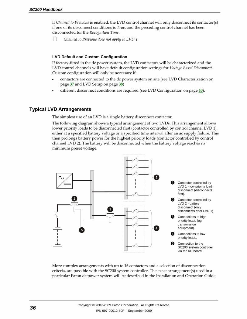
Typical LVD Arrangements The simplest use of an LVD is a single battery disconnect contactor. The following diagram shows a typical arrangement of two LVDs. This arrangement allows lower priority loads to be disconnected first (contactor controlled by control channel LVD 1), either at a specified battery voltage or a specified time interval after an ac supply failure. This then prolongs battery power for the highest priority loads (contactor controlled by control channel LVD 2). The battery will be disconnected when the battery voltage reaches its minimum preset voltage.
Contactor controlled by LVD 1 - low priority load disconnect (disconnects first).
Contactor controlled by LVD 2 - battery disconnect (only disconnects after LVD 1)
Connections to high priority loads (eg transmission equipment).
Connections to low priority loads.
Connection to the SC200 system controller via the I/O board.
More complex arrangements with up to 16 contactors and a selection of disconnection criteria, are possible with the SC200 system controller. The exact arrangement(s) used in a particular Eaton dc power system will be described in the Installation and Operation Guide.
System Operation
Copyright © 2007-2009 Eaton Corporation. All Rights Reserved.
IPN 997-00012-50F September 2009 37
Characterization The contactor characterization process determines the optimum operating voltages to suit the contactor(s) coil voltage. These values are stored in the SC200 and on the I/O board. An LVD Characterization Error alarm will be activated if the SC200 detects that the characterization values stored in the SC200 and on the I/O board are different. This happens when: • The SC200 is replaced. To clear the alarm, on the SC200 select Use IOB Values. • The I/O Board is replaced. To clear the alarm, on the SC200 select Use SC Values. • Both the SC200 and the I/O Board are replaced. In this case, re-characterize the
contactor(s).
When a contactor is re-characterized it will disconnect and re-connect several times. Refer to Maintenance in the dc power system Installation and Operation Guide for full instructions.
Factory-fitted contactors will be characterized at the factory. If an existing contactor is replaced, characterize the new contactor from the SC200.
In this case, there will be no LVD Characterization Error alarm.
LVD Operation ► To allow access to LVD functions from the SC200 keypad • In DCTools/Web go to: Control Processes > LVD. • Select the Allow Front Panel LVD Control check box.
If the check box is cleared LVD functions can only be accessed using DCTools/Web.
► To manually connect or disconnect an LVD control channel • Use the SC200 keypad to go to: Battery > LVDs > LVD 1 - LVD 16 > Details > Manual
Control. • Select Connect or Disconnect to connect or disconnect the channel (and all mapped
contactors).
The contactor(s) will remain in the selected state until another state or Auto is selected. • Select Auto to return the LVD control channel to automatic operation.
SC200 Handbook
38 Copyright © 2007-2009 Eaton Corporation. All Rights Reserved.
IPN 997-00012-50F September 2009
Information The following information is available about LVD control channels and contactors.
Parameter Description Where to find:
LVD Control Channel State
Connected: all of the channel's disconnect conditions are false. All mapped contactors are connected (contacts closed). Disconnected: one of the channel's disconnect conditions is true. All mapped contactors are disconnected (contacts open). Manual: The LVD is under manual control from the SC200 keypad (see previous section). No Contactors: there are no contactors mapped to this channel. Idle: The LVD has not yet connected or disconnected.
LVD Control Channel Inhibited
Indicates if the LVD cannot change state due to the Inhibit Period.
Contactor State Disabled: contactor cannot be operated Connected: contactor is connected (contacts closed) Disconnected: contactor is disconnected (contacts open) Failed: contactor is not connected to the I/O board or is faulty. Conflict: two contactors are mapped to the same I/O board connector. Not Characterized: the contactor must be characterized (see details on page 37).
SC200: Battery > LVDs DCTools/Web: Control Processes > LVD
LVD Setup Use the following procedures to enable or add an LVD control channel.
For SC200s upgraded from software v2.57 or earlier only: The software upgrade preserves the original LVD1 and LVD2 alarms (for backwards compatibility). However, these alarms will not operate with LVD 3 or higher. Before adding LVD 3, 4 etc., enable and configure the generic LVD alarms (LVD Manual, LVD Fail, LVD Disconnected, LVD Characterization) and disable the specific LVD1 and LVD2 alarms.

System Operation
Copyright © 2007-2009 Eaton Corporation. All Rights Reserved.
IPN 997-00012-50F September 2009 39
► To Enable (Add) an LVD control channel using the SC200 keypad Control and configuration of LVDs and contactors is only available from the SC200 keypad if
Allow Front Panel LVD Control is TRUE. See LVD Operation on page 37. 1 Go to: Battery > LVDs. 2 If there are no LVD control channels (LVD 1, LVD 2, ...) listed then go to Step 4. 3 For each LVD control channel select Details. Note the contactors operated by each
channel.
The contactor numbers (1-1, 1-2, ...) indicate the existing IOB Number - IOB Connector Number combinations.
4 Go to: Battery > LVDs > Add LVD. 5 From the list of registered I/O boards, select a board connected to a contactor to be
operated by this LVD control channel. Select Next. 6 For IOBGP I/O boards (see Input/Output Board on page 2) select:
• 1, if the contactor is connected to XH4 • 2, if the contactor is connected to XH5. Warning: Do not select an existing IOB Number - IOB Connector Number combination (see Step 3). This will cause a conflict.
7 Select Next. 8 Select contactor type:
• Normally Open if contacts are open when coil voltage is zero. • Normally Closed if contacts are closed when coil voltage is zero.
9 Characterize the contactor (see LVD Characterization on page 37). 10 To add additional contactors to the LVD control channel, go to Battery > LVDs > LVD x >
Add Contactor. Repeat Steps 5-9.
► To Enable an LVD control channel using DCTools/Web 1 In DCTools/Web go to: Control Processes > LVD. Expand the Logical LVDs table: 2 Select a spare LVD control channel and configure as required. See LVD Configuration on
page 40. 3 Expand the Physical Contactors table. 4 Select and configure the contactor(s) to be operated by the LVD control channel. See
Contactor Configuration on page 41.
General Configuration Settings
Parameter Description Where to find:
Inhibit Period The minimum time an LVD stays connected or disconnected before it can change state. Does not apply to manual operation.
SC200: Battery > LVDs DCTools/Web: Control Processes > LVD
Allow Front Panel LVD Control
Disables LVD control from the system controller front panel.
DCTools/Web: Control Processes > LVD
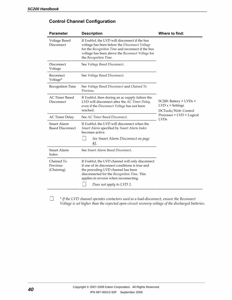
SC200 Handbook
40 Copyright © 2007-2009 Eaton Corporation. All Rights Reserved.
IPN 997-00012-50F September 2009
Control Channel Configuration
Parameter Description Where to find:
Voltage Based Disconnect
If Enabled, the LVD will disconnect if the bus voltage has been below the Disconnect Voltage for the Recognition Time and reconnect if the bus voltage has been above the Reconnect Voltage for the Recognition Time.
Disconnect Voltage
See Voltage Based Disconnect.
Reconnect Voltage*
See Voltage Based Disconnect.
Recognition Time See Voltage Based Disconnect and Chained To Previous.
AC Timer Based Disconnect
If Enabled, then during an ac supply failure the LVD will disconnect after the AC Timer Delay, even if the Disconnect Voltage has not been reached.
AC Timer Delay See AC Timer Based Disconnect.
Smart Alarm Based Disconnect
If Enabled, the LVD will disconnect when the Smart Alarm specified by Smart Alarm Index becomes active.
See Smart Alarm Disconnect on page 41.
Smart Alarm Index
See Smart Alarm Based Disconnect.
Chained To Previous (Chaining)
If Enabled, the LVD channel will only disconnect if one of its disconnect conditions is true and the preceding LVD channel has been disconnected for the Recognition Time. This applies in reverse when reconnecting.
Does not apply to LVD 1.
SC200: Battery > LVDs > LVD x > Settings DCTools/Web: Control Processes > LVD > Logical LVDs
* If the LVD channel operates contactors used as a load-disconnect, ensure the Reconnect Voltage is set higher than the expected open-circuit recovery voltage of the discharged batteries.
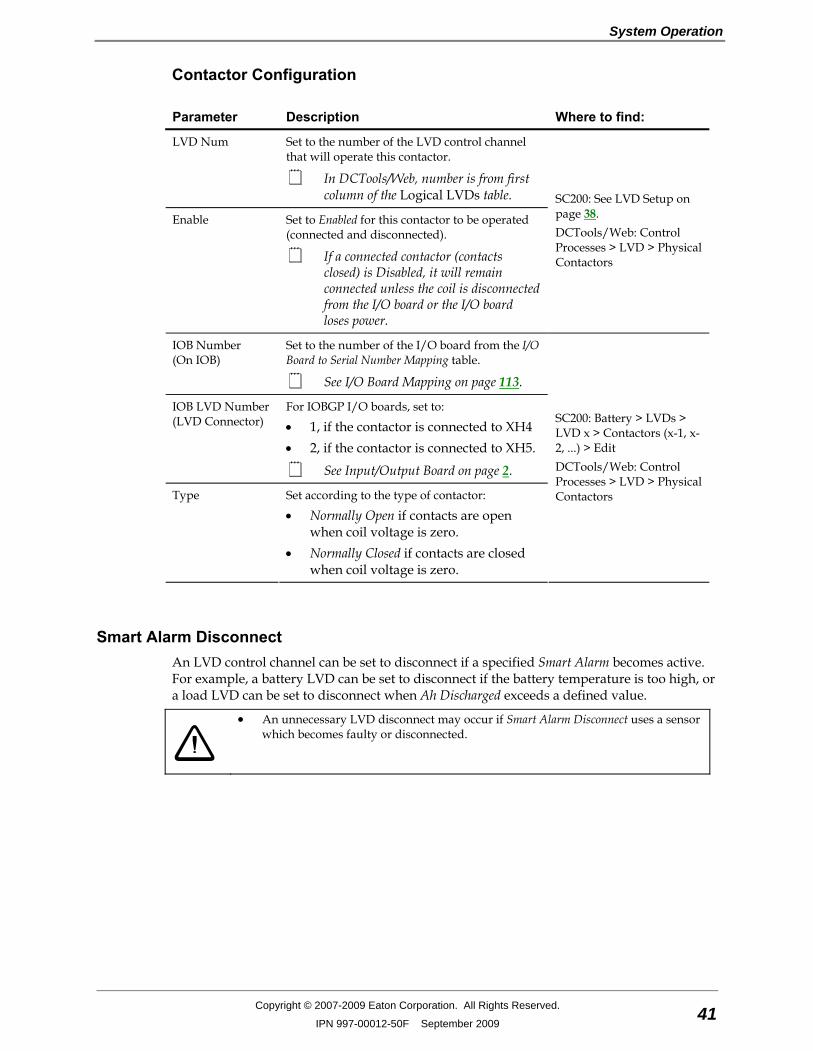
System Operation
Copyright © 2007-2009 Eaton Corporation. All Rights Reserved.
IPN 997-00012-50F September 2009 41
Contactor Configuration
Parameter Description Where to find:
LVD Num Set to the number of the LVD control channel that will operate this contactor.
In DCTools/Web, number is from first column of the Logical LVDs table.
Enable Set to Enabled for this contactor to be operated (connected and disconnected).
If a connected contactor (contacts closed) is Disabled, it will remain connected unless the coil is disconnected from the I/O board or the I/O board loses power.
SC200: See LVD Setup on page 38. DCTools/Web: Control Processes > LVD > Physical Contactors
IOB Number (On IOB)
Set to the number of the I/O board from the I/O Board to Serial Number Mapping table.
See I/O Board Mapping on page 113.
IOB LVD Number (LVD Connector)
For IOBGP I/O boards, set to:
• 1, if the contactor is connected to XH4 • 2, if the contactor is connected to XH5.
See Input/Output Board on page 2.
Type Set according to the type of contactor:
• Normally Open if contacts are open when coil voltage is zero.
• Normally Closed if contacts are closed when coil voltage is zero.
SC200: Battery > LVDs > LVD x > Contactors (x-1, x-2, ...) > Edit DCTools/Web: Control Processes > LVD > Physical Contactors
Smart Alarm Disconnect An LVD control channel can be set to disconnect if a specified Smart Alarm becomes active. For example, a battery LVD can be set to disconnect if the battery temperature is too high, or a load LVD can be set to disconnect when Ah Discharged exceeds a defined value.
• An unnecessary LVD disconnect may occur if Smart Alarm Disconnect uses a sensor which becomes faulty or disconnected.
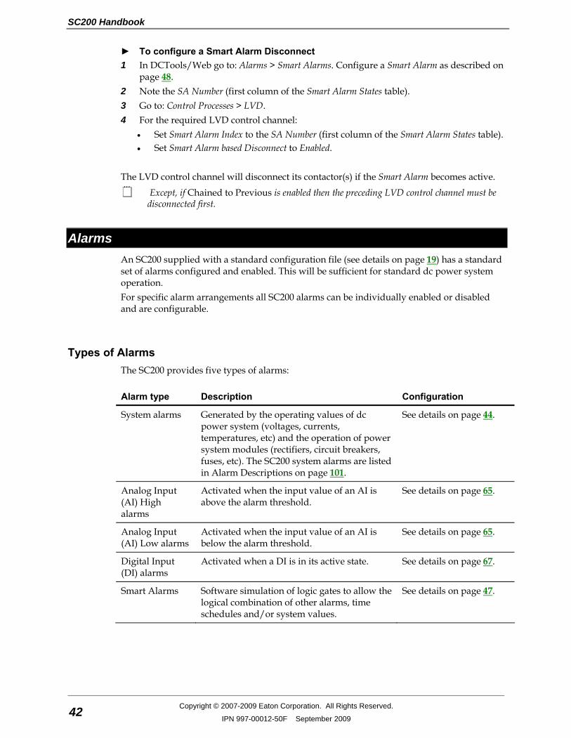
SC200 Handbook
42 Copyright © 2007-2009 Eaton Corporation. All Rights Reserved.
IPN 997-00012-50F September 2009
► To configure a Smart Alarm Disconnect 1 In DCTools/Web go to: Alarms > Smart Alarms. Configure a Smart Alarm as described on
page 48. 2 Note the SA Number (first column of the Smart Alarm States table). 3 Go to: Control Processes > LVD. 4 For the required LVD control channel:
• Set Smart Alarm Index to the SA Number (first column of the Smart Alarm States table). • Set Smart Alarm based Disconnect to Enabled.
The LVD control channel will disconnect its contactor(s) if the Smart Alarm becomes active.
Except, if Chained to Previous is enabled then the preceding LVD control channel must be disconnected first.
Alarms An SC200 supplied with a standard configuration file (see details on page 19) has a standard set of alarms configured and enabled. This will be sufficient for standard dc power system operation. For specific alarm arrangements all SC200 alarms can be individually enabled or disabled and are configurable.
Types of Alarms The SC200 provides five types of alarms:
Alarm type Description Configuration
System alarms Generated by the operating values of dc power system (voltages, currents, temperatures, etc) and the operation of power system modules (rectifiers, circuit breakers, fuses, etc). The SC200 system alarms are listed in Alarm Descriptions on page 101.
See details on page 44.
Analog Input (AI) High alarms
Activated when the input value of an AI is above the alarm threshold.
See details on page 65.
Analog Input (AI) Low alarms
Activated when the input value of an AI is below the alarm threshold.
See details on page 65.
Digital Input (DI) alarms
Activated when a DI is in its active state. See details on page 67.
Smart Alarms Software simulation of logic gates to allow the logical combination of other alarms, time schedules and/or system values.
See details on page 47.

System Operation
Copyright © 2007-2009 Eaton Corporation. All Rights Reserved.
IPN 997-00012-50F September 2009 43
Active Alarm Indications All alarms have a configured Severity:
Critical Major Minor Warning Control The Severity determines how an active alarm is indicated:
Severity Alarm indications Details
SC200 Major alarm LED will turn on. See details on page 14.
SC200 Minor alarm LED will turn on. See details on page 14.
If the SC200 audible indicator is enabled, it will sound until a key is pressed.
See details on page 14.
The alarm name and severity icon will be displayed on the SC200 main screen.
See details on page 8.
The Event Log will record the alarm activation. See details on page 70.
In DCTools/Web (if connected), the alarm name and severity icon will be displayed in the Alarms list on the System page.
See DCTools screen on page 15, Web screen on page 76.
If configured, an SMS text message will be sent to one or more cell phones.
See details on page 85.
If configured, PowerManagerII control and monitoring software will be notified by modem callback. PowerManagerII can initiate various actions when it receives an alarm notification.
Refer to the PowerManagerII online Help.
If configured, an SNMP Trap will be sent to a network management system (NMS).
See details on page 77.
If configured, a note will be displayed on the SC200 and included in the SNMP trap (if used).
Refer to the alarm’s configuration details.
If configured, one or two digital outputs (relays) will be operated.
Refer to the alarm’s configuration details.
► To view a list of active alarms • Use the SC200 keypad to go to: Alarms. • Or, in DCTools/Web go to System.
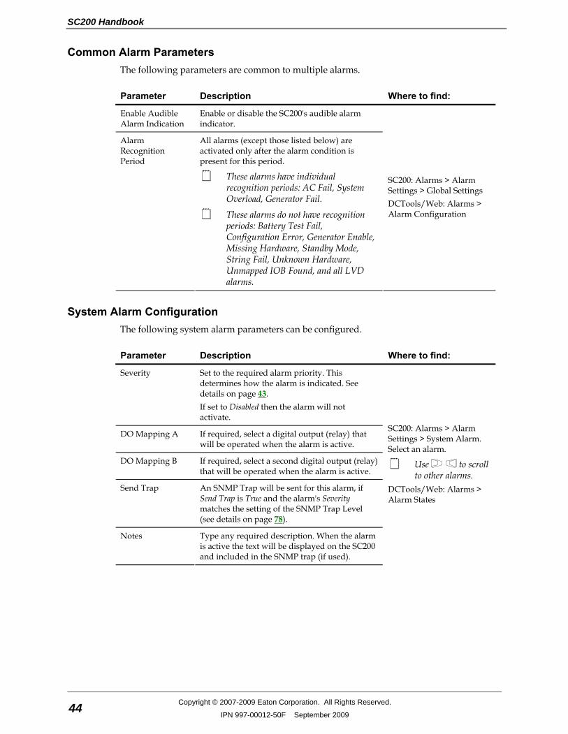
SC200 Handbook
44 Copyright © 2007-2009 Eaton Corporation. All Rights Reserved.
IPN 997-00012-50F September 2009
Common Alarm Parameters The following parameters are common to multiple alarms.
Parameter Description Where to find:
Enable Audible Alarm Indication
Enable or disable the SC200's audible alarm indicator.
Alarm Recognition Period
All alarms (except those listed below) are activated only after the alarm condition is present for this period.
These alarms have individual recognition periods: AC Fail, System Overload, Generator Fail.
These alarms do not have recognition periods: Battery Test Fail, Configuration Error, Generator Enable, Missing Hardware, Standby Mode, String Fail, Unknown Hardware, Unmapped IOB Found, and all LVD alarms.
SC200: Alarms > Alarm Settings > Global Settings DCTools/Web: Alarms > Alarm Configuration
System Alarm Configuration The following system alarm parameters can be configured.
Parameter Description Where to find:
Severity Set to the required alarm priority. This determines how the alarm is indicated. See details on page 43. If set to Disabled then the alarm will not activate.
DO Mapping A If required, select a digital output (relay) that will be operated when the alarm is active.
DO Mapping B If required, select a second digital output (relay) that will be operated when the alarm is active.
Send Trap An SNMP Trap will be sent for this alarm, if Send Trap is True and the alarm's Severity matches the setting of the SNMP Trap Level (see details on page 78).
Notes Type any required description. When the alarm is active the text will be displayed on the SC200 and included in the SNMP trap (if used).
SC200: Alarms > Alarm Settings > System Alarm. Select an alarm.
Use to scroll to other alarms.
DCTools/Web: Alarms > Alarm States
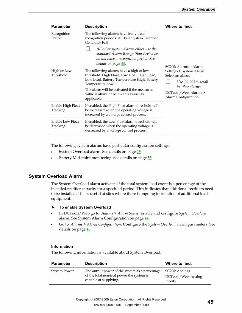
System Operation
Copyright © 2007-2009 Eaton Corporation. All Rights Reserved.
IPN 997-00012-50F September 2009 45
Parameter Description Where to find:
Recognition Period
The following alarms have individual recognition periods: AC Fail, System Overload, Generator Fail.
All other system alarms either use the standard Alarm Recognition Period or do not have a recognition period. See details on page 44.
High or Low Threshold
The following alarms have a high or low threshold: High Float, Low Float, High Load, Low Load, Battery Temperature High, Battery Temperature Low. The alarm will be activated if the measured value is above or below this value, as applicable.
Enable High Float Tracking
If enabled, the High Float alarm threshold will be increased when the operating voltage is increased by a voltage control process.
Enable Low Float Tracking
If enabled, the Low Float alarm threshold will be decreased when the operating voltage is decreased by a voltage control process.
SC200: Alarms > Alarm Settings > System Alarm. Select an alarm.
Use to scroll to other alarms.
DCTools/Web: Alarms > Alarm Configuration
The following system alarms have particular configuration settings: • System Overload alarm. See details on page 45. • Battery Mid-point monitoring. See details on page 53.
System Overload Alarm The System Overload alarm activates if the total system load exceeds a percentage of the installed rectifier capacity for a specified period. This indicates that additional rectifiers need to be installed. This is useful at sites where there is ongoing installation of additional load equipment.
► To enable System Overload • In DCTools/Web go to: Alarms > Alarm States. Enable and configure System Overload
alarm. See System Alarm Configuration on page 44. • Go to: Alarms > Alarm Configuration. Configure the System Overload alarm parameters. See
details on page 46.
Information The following information is available about System Overload.
Parameter Description Where to find:
System Power The output power of the system as a percentage of the total nominal power the system is capable of supplying.
SC200: Analogs DCTools/Web: Analog Inputs
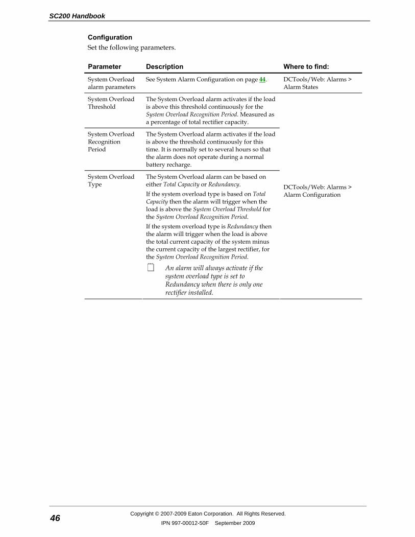
SC200 Handbook
46 Copyright © 2007-2009 Eaton Corporation. All Rights Reserved.
IPN 997-00012-50F September 2009
Configuration Set the following parameters.
Parameter Description Where to find:
System Overload alarm parameters
See System Alarm Configuration on page 44. DCTools/Web: Alarms > Alarm States
System Overload Threshold
The System Overload alarm activates if the load is above this threshold continuously for the System Overload Recognition Period. Measured as a percentage of total rectifier capacity.
System Overload Recognition Period
The System Overload alarm activates if the load is above the threshold continuously for this time. It is normally set to several hours so that the alarm does not operate during a normal battery recharge.
System Overload Type
The System Overload alarm can be based on either Total Capacity or Redundancy. If the system overload type is based on Total Capacity then the alarm will trigger when the load is above the System Overload Threshold for the System Overload Recognition Period. If the system overload type is Redundancy then the alarm will trigger when the load is above the total current capacity of the system minus the current capacity of the largest rectifier, for the System Overload Recognition Period.
An alarm will always activate if the system overload type is set to Redundancy when there is only one rectifier installed.
DCTools/Web: Alarms > Alarm Configuration
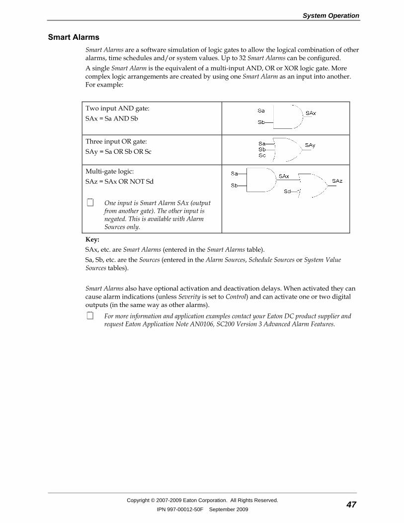
System Operation
Copyright © 2007-2009 Eaton Corporation. All Rights Reserved.
IPN 997-00012-50F September 2009 47
Smart Alarms Smart Alarms are a software simulation of logic gates to allow the logical combination of other alarms, time schedules and/or system values. Up to 32 Smart Alarms can be configured. A single Smart Alarm is the equivalent of a multi-input AND, OR or XOR logic gate. More complex logic arrangements are created by using one Smart Alarm as an input into another. For example:
Two input AND gate: SAx = Sa AND Sb
Three input OR gate: SAy = Sa OR Sb OR Sc
Multi-gate logic: SAz = SAx OR NOT Sd
One input is Smart Alarm SAx (output from another gate). The other input is negated. This is available with Alarm Sources only.
Key: SAx, etc. are Smart Alarms (entered in the Smart Alarms table). Sa, Sb, etc. are the Sources (entered in the Alarm Sources, Schedule Sources or System Value Sources tables). Smart Alarms also have optional activation and deactivation delays. When activated they can cause alarm indications (unless Severity is set to Control) and can activate one or two digital outputs (in the same way as other alarms).
For more information and application examples contact your Eaton DC product supplier and request Eaton Application Note AN0106, SC200 Version 3 Advanced Alarm Features.
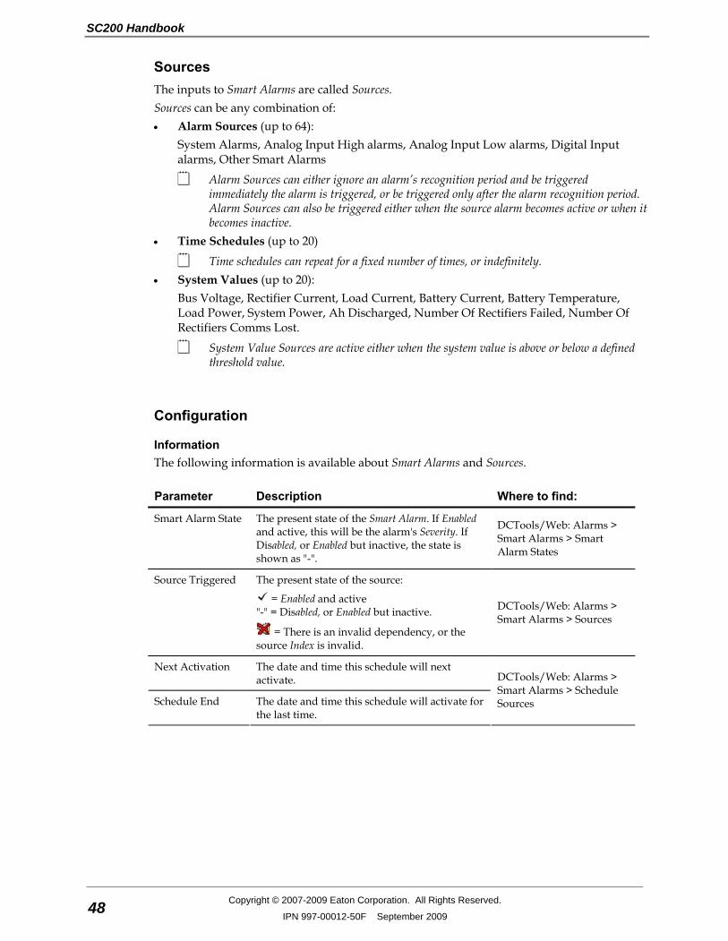
SC200 Handbook
48 Copyright © 2007-2009 Eaton Corporation. All Rights Reserved.
IPN 997-00012-50F September 2009
Sources The inputs to Smart Alarms are called Sources. Sources can be any combination of: • Alarm Sources (up to 64):
System Alarms, Analog Input High alarms, Analog Input Low alarms, Digital Input alarms, Other Smart Alarms
Alarm Sources can either ignore an alarm’s recognition period and be triggered immediately the alarm is triggered, or be triggered only after the alarm recognition period. Alarm Sources can also be triggered either when the source alarm becomes active or when it becomes inactive.
• Time Schedules (up to 20)
Time schedules can repeat for a fixed number of times, or indefinitely. • System Values (up to 20):
Bus Voltage, Rectifier Current, Load Current, Battery Current, Battery Temperature, Load Power, System Power, Ah Discharged, Number Of Rectifiers Failed, Number Of Rectifiers Comms Lost.
System Value Sources are active either when the system value is above or below a defined threshold value.
Configuration
Information The following information is available about Smart Alarms and Sources.
Parameter Description Where to find:
Smart Alarm State The present state of the Smart Alarm. If Enabled and active, this will be the alarm's Severity. If Disabled, or Enabled but inactive, the state is shown as "-".
DCTools/Web: Alarms > Smart Alarms > Smart Alarm States
Source Triggered The present state of the source:
= Enabled and active "-" = Disabled, or Enabled but inactive.
= There is an invalid dependency, or the source Index is invalid.
DCTools/Web: Alarms > Smart Alarms > Sources
Next Activation The date and time this schedule will next activate.
Schedule End The date and time this schedule will activate for the last time.
DCTools/Web: Alarms > Smart Alarms > Schedule Sources
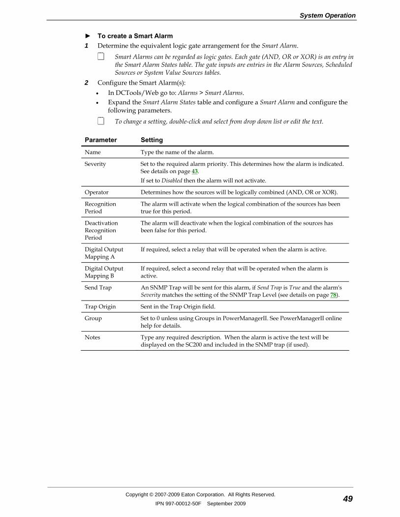
System Operation
Copyright © 2007-2009 Eaton Corporation. All Rights Reserved.
IPN 997-00012-50F September 2009 49
► To create a Smart Alarm 1 Determine the equivalent logic gate arrangement for the Smart Alarm.
Smart Alarms can be regarded as logic gates. Each gate (AND, OR or XOR) is an entry in the Smart Alarm States table. The gate inputs are entries in the Alarm Sources, Scheduled Sources or System Value Sources tables.
2 Configure the Smart Alarm(s): • In DCTools/Web go to: Alarms > Smart Alarms. • Expand the Smart Alarm States table and configure a Smart Alarm and configure the
following parameters.
To change a setting, double-click and select from drop down list or edit the text.
Parameter Setting
Name Type the name of the alarm.
Severity Set to the required alarm priority. This determines how the alarm is indicated. See details on page 43. If set to Disabled then the alarm will not activate.
Operator Determines how the sources will be logically combined (AND, OR or XOR).
Recognition Period
The alarm will activate when the logical combination of the sources has been true for this period.
Deactivation Recognition Period
The alarm will deactivate when the logical combination of the sources has been false for this period.
Digital Output Mapping A
If required, select a relay that will be operated when the alarm is active.
Digital Output Mapping B
If required, select a second relay that will be operated when the alarm is active.
Send Trap An SNMP Trap will be sent for this alarm, if Send Trap is True and the alarm's Severity matches the setting of the SNMP Trap Level (see details on page 78).
Trap Origin Sent in the Trap Origin field.
Group Set to 0 unless using Groups in PowerManagerII. See PowerManagerII online help for details.
Notes Type any required description. When the alarm is active the text will be displayed on the SC200 and included in the SNMP trap (if used).
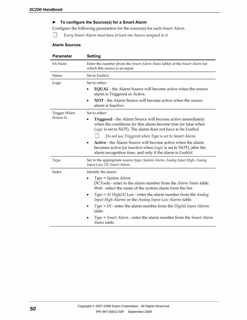
SC200 Handbook
50 Copyright © 2007-2009 Eaton Corporation. All Rights Reserved.
IPN 997-00012-50F September 2009
► To configure the Source(s) for a Smart Alarm Configure the following parameters for the source(s) for each Smart Alarm.
Every Smart Alarm must have at least one Source assigned to it.
Alarm Sources
Parameter Setting
SA Num Enter the number (from the Smart Alarm States table) of the Smart Alarm for which this source is an input.
Status Set to Enabled.
Logic Set to either:
• EQUAL - the Alarm Source will become active when the source alarm is Triggered or Active.
• NOT - the Alarm Source will become active when the source alarm is Inactive.
Trigger When Source Is
Set to either:
• Triggered - the Alarm Source will become active immediately when the conditions for this alarm become true (or false when Logic is set to NOT). The alarm does not have to be Enabled.
Do not use Triggered when Type is set to Smart Alarm. • Active - the Alarm Source will become active when the alarm
becomes active (or inactive when Logic is set to NOT), after the alarm recognition time, and only if the alarm is Enabled.
Type Set to the appropriate source type: System Alarm, Analog Input High, Analog Input Low, DI, Smart Alarm.
Index Identify the alarm:
• Type = System Alarm: DCTools - enter to the alarm number from the Alarm States table. Web - select the name of the system alarm from the list.
• Type = AI High/AI Low - enter the alarm number from the Analog Input High Alarms or the Analog Input Low Alarms table.
• Type = DI - enter the alarm number from the Digital Input Alarms table.
• Type = Smart Alarm - enter the alarm number from the Smart Alarm States table.
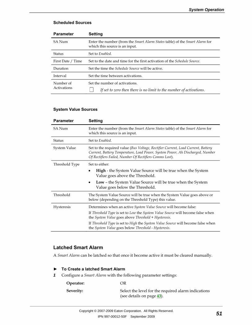
System Operation
Copyright © 2007-2009 Eaton Corporation. All Rights Reserved.
IPN 997-00012-50F September 2009 51
Scheduled Sources
Parameter Setting
SA Num Enter the number (from the Smart Alarm States table) of the Smart Alarm for which this source is an input.
Status Set to Enabled.
First Date / Time Set to the date and time for the first activation of the Schedule Source.
Duration Set the time the Schedule Source will be active.
Interval Set the time between activations.
Number of Activations
Set the number of activations.
If set to zero then there is no limit to the number of activations.
System Value Sources
Parameter Setting
SA Num Enter the number (from the Smart Alarm States table) of the Smart Alarm for which this source is an input.
Status Set to Enabled.
System Value Set to the required value (Bus Voltage, Rectifier Current, Load Current, Battery Current, Battery Temperature, Load Power, System Power, Ah Discharged, Number Of Rectifiers Failed, Number Of Rectifiers Comms Lost).
Threshold Type Set to either:
• High - the System Value Source will be true when the System Value goes above the Threshold.
• Low – the System Value Source will be true when the System Value goes below the Threshold.
Threshold The System Value Source will be true when the System Value goes above or below (depending on the Threshold Type) this value.
Hysteresis Determines when an active System Value Source will become false: If Threshold Type is set to Low the System Value Source will become false when the System Value goes above Threshold + Hysteresis. If Threshold Type is set to High the System Value Source will become false when the System Value goes below Threshold - Hysteresis.
Latched Smart Alarm A Smart Alarm can be latched so that once it become active it must be cleared manually.
► To Create a latched Smart Alarm 1 Configure a Smart Alarm with the following parameter settings:
Operator: OR
Severity: Select the level for the required alarm indications (see details on page 43).
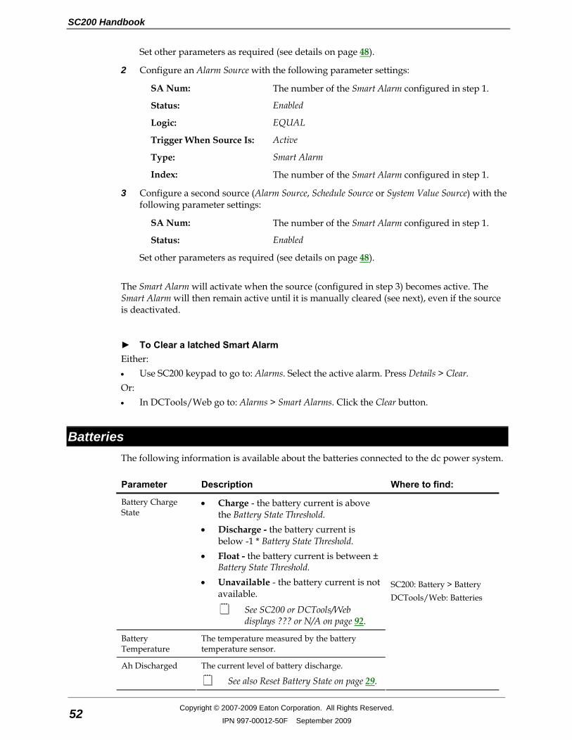
SC200 Handbook
52 Copyright © 2007-2009 Eaton Corporation. All Rights Reserved.
IPN 997-00012-50F September 2009
Set other parameters as required (see details on page 48).
2 Configure an Alarm Source with the following parameter settings:
SA Num: The number of the Smart Alarm configured in step 1.
Status: Enabled
Logic: EQUAL
Trigger When Source Is: Active
Type: Smart Alarm
Index: The number of the Smart Alarm configured in step 1.
3 Configure a second source (Alarm Source, Schedule Source or System Value Source) with the following parameter settings:
SA Num: The number of the Smart Alarm configured in step 1.
Status: Enabled
Set other parameters as required (see details on page 48). The Smart Alarm will activate when the source (configured in step 3) becomes active. The Smart Alarm will then remain active until it is manually cleared (see next), even if the source is deactivated.
► To Clear a latched Smart Alarm Either: • Use SC200 keypad to go to: Alarms. Select the active alarm. Press Details > Clear. Or: • In DCTools/Web go to: Alarms > Smart Alarms. Click the Clear button.
Batteries The following information is available about the batteries connected to the dc power system.
Parameter Description Where to find:
Battery Charge State
• Charge - the battery current is above the Battery State Threshold.
• Discharge - the battery current is below -1 * Battery State Threshold.
• Float - the battery current is between ± Battery State Threshold.
• Unavailable - the battery current is not available.
See SC200 or DCTools/Web displays ??? or N/A on page 92.
Battery Temperature
The temperature measured by the battery temperature sensor.
Ah Discharged The current level of battery discharge.
See also Reset Battery State on page 29.
SC200: Battery > Battery DCTools/Web: Batteries

System Operation
Copyright © 2007-2009 Eaton Corporation. All Rights Reserved.
IPN 997-00012-50F September 2009 53
Batteries Configuration The following battery parameters must be configured.
Parameter Description Where to find:
Cells Per String The number of 2V cells per battery string (for example: 24 in a 48V nominal system).
Battery Capacity Set to the rated 10 hour capacity of the installed battery strings.
SC200: Battery > Battery (tab) DCTools/Web: Batteries
Battery State Threshold
Used to determine the Battery Charge State. See Battery Charge State on page 52.
Battery Type An optional text field for the name or type of battery.
Battery Current Sensor Fail Recognition Period
An optional battery current sensor fail delay. Set if momentary battery current sensor fail conditions stop battery related control processes.
DCTools/Web: Batteries
Battery Mid-point Monitoring (MPM) Battery Mid-point Monitoring provides a cost-effective method for the early detection of internal battery faults. The voltages of the two halves of a battery string are measured and the system controller generates an alarm signal if a voltage imbalance is detected. A voltage imbalance is an indication that one or more cells has an internal fault. Further investigation can then isolate the faulty cell(s) and action can be taken to correct the problem and prevent a total battery failure. To connect the Battery Mid-point Monitoring option see details in the DC power system installation guide. If a String Fail alarm is generated see Troubleshooting on page 92. To ensure reliable operation Mid-point Monitoring operates only when the battery is in float charge and after a configurable lockout period since the last battery discharge, Fast Charge, Equalize or Battery Test.

SC200 Handbook
54 Copyright © 2007-2009 Eaton Corporation. All Rights Reserved.
IPN 997-00012-50F September 2009
► To enable Battery Mid-point Monitoring (MPM) If any of the mid-point monitoring analog inputs are used for Reverse Battery Detection (see
details on page 60) then they are not available for MPM. 1 Connect the mid-point monitoring sense wires to the batteries. Refer to the dc power
system Installation and Operation Guide.
There are four mid-point monitoring analog inputs on an IOBGP input/output board (for four battery strings). Up to 20 additional battery strings can be monitored if additional IOBGP input/output boards are connected. Refer to the dc power system Installation and Operation Guide for details on how to connect additional IOBGP input/output boards to the SC200.
2 In DCTools/Web go to Batteries. 3 Set Cells Per String to the number of 2V cells per string (for example: 24 for 48V nominal
system). 4 Expand the Mid-point Monitoring table. 5 Set MPM Enable to Enabled and check the configuration settings (see details on page 56). 6 Go to Analog Inputs and Enable the mid-point monitoring analog inputs (one per battery
string) as required.
Battery strings 1-4 will be connected to IOB Number 1, IOB AI Numbers 2-5. Battery strings 5-8 will be connected to IOB Number 2, IOB AI Numbers 2-5. And so on, as required up to string 24.
7 Go to Alarms > Alarm States. Enable and configure the String Fail alarm. See System Alarm Configuration on page 44.
► To clear a String Fail alarm 1 In DCTools/Web go to Batteries > Mid-point Battery Monitoring (expand the table). 2 Click on Clear String Fail.
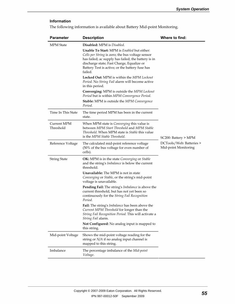
System Operation
Copyright © 2007-2009 Eaton Corporation. All Rights Reserved.
IPN 997-00012-50F September 2009 55
Information The following information is available about Battery Mid-point Monitoring.
Parameter Description Where to find:
MPM State Disabled: MPM is Disabled. Unable To Start: MPM is Enabled but either: Cells per String is zero; the bus voltage sensor has failed; ac supply has failed; the battery is in discharge state; Fast Charge, Equalize or Battery Test is active; or the battery fuse has failed. Locked Out: MPM is within the MPM Lockout Period. No String Fail alarm will become active in this period. Converging: MPM is outside the MPM Lockout Period but is within MPM Convergence Period. Stable: MPM is outside the MPM Convergence Period.
Time In This State The time period MPM has been in the current state.
Current MPM Threshold
When MPM state is Converging this value is between MPM Start Threshold and MPM Stable Threshold. When MPM state is Stable this value is the MPM Stable Threshold.
Reference Voltage The calculated mid-point reference voltage (50% of the bus voltage for even number of cells).
String State OK: MPM is in the state Converging or Stable and the string's Imbalance is below the current threshold. Unavailable: The MPM is not in state Converging or Stable, or the string's mid-point voltage is unavailable. Pending Fail: The string's Imbalance is above the current threshold, but has not yet been so continuously for the String Fail Recognition Period. Fail: The string's Imbalance has been above the Current MPM Threshold for longer than the String Fail Recognition Period. This will activate a String Fail alarm. Not Configured: No analog input is mapped to this string.
Mid-point Voltage Shows the mid-point voltage reading for the string or N/A if no analog input channel is mapped to this string.
Imbalance The percentage imbalance of the Mid-point Voltage.
SC200: Battery > MPM DCTools/Web: Batteries > Mid-point Monitoring
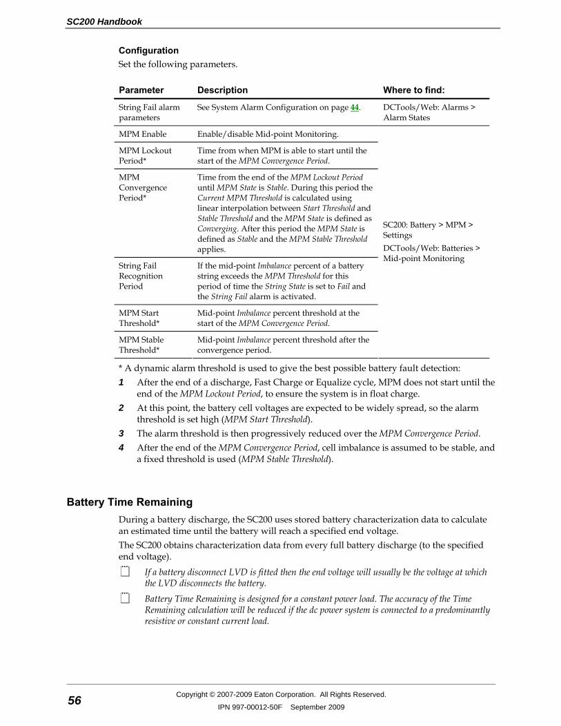
SC200 Handbook
56 Copyright © 2007-2009 Eaton Corporation. All Rights Reserved.
IPN 997-00012-50F September 2009
Configuration Set the following parameters.
Parameter Description Where to find:
String Fail alarm parameters
See System Alarm Configuration on page 44. DCTools/Web: Alarms > Alarm States
MPM Enable Enable/disable Mid-point Monitoring.
MPM Lockout Period*
Time from when MPM is able to start until the start of the MPM Convergence Period.
MPM Convergence Period*
Time from the end of the MPM Lockout Period until MPM State is Stable. During this period the Current MPM Threshold is calculated using linear interpolation between Start Threshold and Stable Threshold and the MPM State is defined as Converging. After this period the MPM State is defined as Stable and the MPM Stable Threshold applies.
String Fail Recognition Period
If the mid-point Imbalance percent of a battery string exceeds the MPM Threshold for this period of time the String State is set to Fail and the String Fail alarm is activated.
MPM Start Threshold*
Mid-point Imbalance percent threshold at the start of the MPM Convergence Period.
MPM Stable Threshold*
Mid-point Imbalance percent threshold after the convergence period.
SC200: Battery > MPM > Settings DCTools/Web: Batteries > Mid-point Monitoring
* A dynamic alarm threshold is used to give the best possible battery fault detection: 1 After the end of a discharge, Fast Charge or Equalize cycle, MPM does not start until the
end of the MPM Lockout Period, to ensure the system is in float charge. 2 At this point, the battery cell voltages are expected to be widely spread, so the alarm
threshold is set high (MPM Start Threshold). 3 The alarm threshold is then progressively reduced over the MPM Convergence Period. 4 After the end of the MPM Convergence Period, cell imbalance is assumed to be stable, and
a fixed threshold is used (MPM Stable Threshold).
Battery Time Remaining During a battery discharge, the SC200 uses stored battery characterization data to calculate an estimated time until the battery will reach a specified end voltage. The SC200 obtains characterization data from every full battery discharge (to the specified end voltage).
If a battery disconnect LVD is fitted then the end voltage will usually be the voltage at which the LVD disconnects the battery.
Battery Time Remaining is designed for a constant power load. The accuracy of the Time Remaining calculation will be reduced if the dc power system is connected to a predominantly resistive or constant current load.
System Operation
Copyright © 2007-2009 Eaton Corporation. All Rights Reserved.
IPN 997-00012-50F September 2009 57
Configuration
• It will take at least 10 hours to characterize a battery. • When a battery is characterized it is discharged. The bus voltage will gradually
reduce to the battery end voltage. Ensure that this will not affect the operation of any equipment connected to the dc power system.
Use the following procedure to configure Battery Time Remaining for the first time, or if a previously characterized battery is changed.
Battery Characterization is not necessary if a previously saved battery characterization data file is available. Refer to Characterization Data Management on page 60. Only use characterization data for an identical type and size of battery.
► To configure Battery Time Remaining 1 Check that all battery strings are connected and all LVD contactors (if any) are
connected.
During a battery characterization, LVD contactor disconnection is inhibited. If any LVD contactor is configured to connect during a battery discharge then set it to Manual Connect to prevent operation during the battery characterization.
2 Check that all battery strings are fully charged.
When a battery is fully charged, the Battery Charge State will be Float and Ah Discharged will be zero. See Batteries on page 52.
3 Check that all battery parameters are set to the correct values. See Batteries Configuration on page 53.
4 Check that the load current is at least 2% of the C10 capacity of the batteries (Battery Capacity) and 150% of the Battery State Threshold. See Batteries Configuration on page 53.
If the load current is less than 10% of the C10 capacity of the batteries, then Battery Characterization will take longer than 10 hours.
5 Either, in DCTools/Web go to Batteries > Battery Time Remaining, or use the SC200 keypad to go to Battery. Set End Voltage to the voltage per cell when the battery is regarded as fully discharged.
In general set the end voltage to the same value as for the LVD Disconnect Voltage (see LVD Configuration on page 40). End Voltage must be at least 0.02V/Cell above the Minimum System Voltage (per cell). The Minimum System Voltage is viewable in DCTools/Web at Control Processes. It is not configurable.
6 Enable Battery Current Limit (see details on page 23).
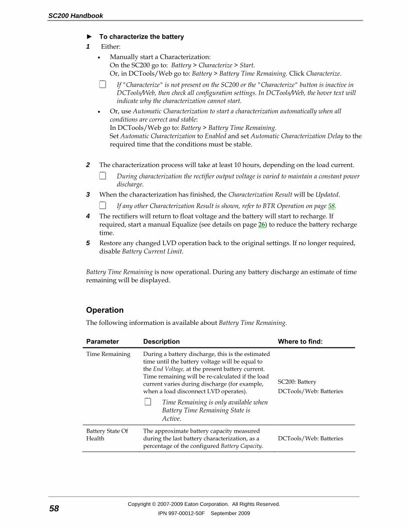
SC200 Handbook
58 Copyright © 2007-2009 Eaton Corporation. All Rights Reserved.
IPN 997-00012-50F September 2009
► To characterize the battery 1 Either:
• Manually start a Characterization: On the SC200 go to: Battery > Characterize > Start. Or, in DCTools/Web go to: Battery > Battery Time Remaining. Click Characterize.
If "Characterize" is not present on the SC200 or the "Characterize" button is inactive in DCTools/Web, then check all configuration settings. In DCTools/Web, the hover text will indicate why the characterization cannot start.
• Or, use Automatic Characterization to start a characterization automatically when all conditions are correct and stable: In DCTools/Web go to: Battery > Battery Time Remaining. Set Automatic Characterization to Enabled and set Automatic Characterization Delay to the required time that the conditions must be stable.
2 The characterization process will take at least 10 hours, depending on the load current.
During characterization the rectifier output voltage is varied to maintain a constant power discharge.
3 When the characterization has finished, the Characterization Result will be Updated.
If any other Characterization Result is shown, refer to BTR Operation on page 58. 4 The rectifiers will return to float voltage and the battery will start to recharge. If
required, start a manual Equalize (see details on page 26) to reduce the battery recharge time.
5 Restore any changed LVD operation back to the original settings. If no longer required, disable Battery Current Limit.
Battery Time Remaining is now operational. During any battery discharge an estimate of time remaining will be displayed.
Operation The following information is available about Battery Time Remaining.
Parameter Description Where to find:
Time Remaining During a battery discharge, this is the estimated time until the battery voltage will be equal to the End Voltage, at the present battery current. Time remaining will be re-calculated if the load current varies during discharge (for example, when a load disconnect LVD operates).
Time Remaining is only available when Battery Time Remaining State is Active.
SC200: Battery DCTools/Web: Batteries
Battery State Of Health
The approximate battery capacity measured during the last battery characterization, as a percentage of the configured Battery Capacity.
DCTools/Web: Batteries
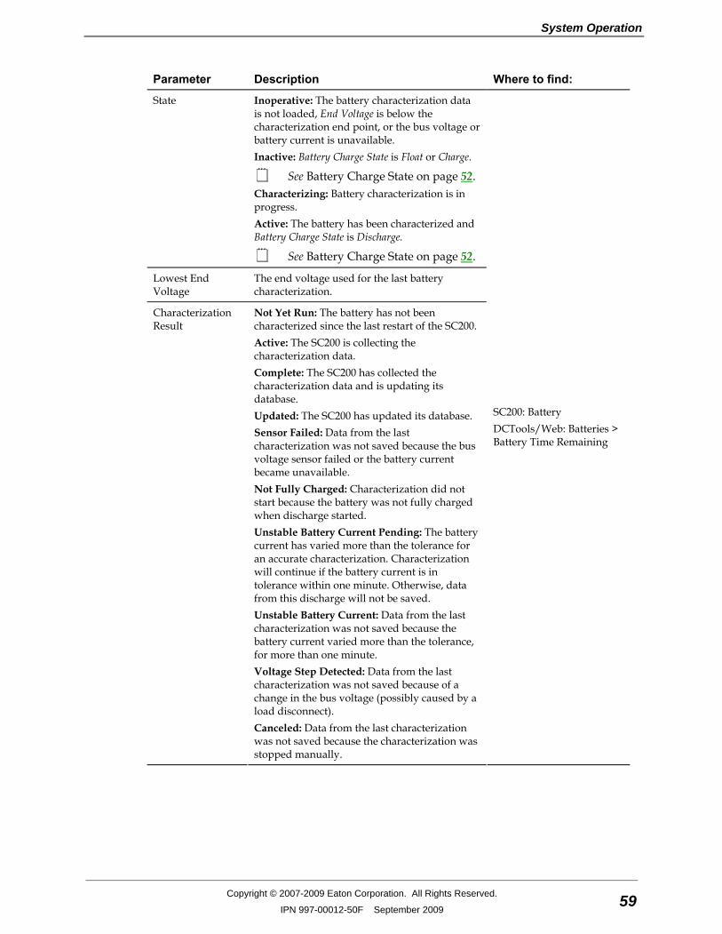
System Operation
Copyright © 2007-2009 Eaton Corporation. All Rights Reserved.
IPN 997-00012-50F September 2009 59
Parameter Description Where to find:
State Inoperative: The battery characterization data is not loaded, End Voltage is below the characterization end point, or the bus voltage or battery current is unavailable. Inactive: Battery Charge State is Float or Charge.
See Battery Charge State on page 52. Characterizing: Battery characterization is in progress. Active: The battery has been characterized and Battery Charge State is Discharge.
See Battery Charge State on page 52.
Lowest End Voltage
The end voltage used for the last battery characterization.
Characterization Result
Not Yet Run: The battery has not been characterized since the last restart of the SC200. Active: The SC200 is collecting the characterization data. Complete: The SC200 has collected the characterization data and is updating its database. Updated: The SC200 has updated its database. Sensor Failed: Data from the last characterization was not saved because the bus voltage sensor failed or the battery current became unavailable. Not Fully Charged: Characterization did not start because the battery was not fully charged when discharge started. Unstable Battery Current Pending: The battery current has varied more than the tolerance for an accurate characterization. Characterization will continue if the battery current is in tolerance within one minute. Otherwise, data from this discharge will not be saved. Unstable Battery Current: Data from the last characterization was not saved because the battery current varied more than the tolerance, for more than one minute. Voltage Step Detected: Data from the last characterization was not saved because of a change in the bus voltage (possibly caused by a load disconnect). Canceled: Data from the last characterization was not saved because the characterization was stopped manually.
SC200: Battery DCTools/Web: Batteries > Battery Time Remaining
SC200 Handbook
60 Copyright © 2007-2009 Eaton Corporation. All Rights Reserved.
IPN 997-00012-50F September 2009
Characterization Data Management Battery characterization data can be saved to file for later use. This is useful if several sites use batteries of the same type and size. However, characterization of each battery will provide the most accurate estimate of Time Remaining.
► To save characterization data to a file 1 In Web go to Batteries > Battery Time Remaining. 2 When the battery characterization is completed, click on Characterization Data: Download. 3 Click Save. Enter a file name (*.dcf) and browse to the required location. Click Save.
► To load battery characterization data into the SC200 Use Web to restore the *.dcf (configuration fragment) file previously saved. Refer to Backup and Restore on page 20.
Reverse Battery Detection If Reverse Battery Detection is enabled and a battery is connected with the incorrect polarity, the SC200 will: • activate a Wrong Battery Polarity alarm, and • prevent any LVD from connecting.
Reverse Battery Detection uses the battery mid-point monitoring (MPM) analog inputs on an IOBGP input/output board. Any of the mid-point monitoring analog inputs used for Reverse Battery Detection are not available for MPM (see details on page 53).
► To enable Reverse Battery Detection 1 Before the batteries are connected to the dc power system, connect the mid-point
monitoring sense wires to the battery sides of the battery fuses/disconnect devices (leave the fuses/disconnect devices open). Refer to the dc power system Installation and Operation Guide.
There are four mid-point monitoring analog inputs on an IOBGP input/output board (for four battery fuses/disconnect devices). Up to 20 additional battery fuses/disconnect devices can be connected if additional IOBGP-01 input/output boards are connected. Refer to the dc power system Installation and Operation Guide for details on how to connect additional IOBGP-01 input/output boards to the SC200.

System Operation
Copyright © 2007-2009 Eaton Corporation. All Rights Reserved.
IPN 997-00012-50F September 2009 61
2 In DCTools/Web go to Analog Inputs and for each mid-point monitoring analog inputs used (one per battery fuses/disconnect devices) set the following parameters.
To change a setting, double-click and select from drop down list or edit the text.
Parameter Setting
Status Set to Enable.
Name Set to: Battery Polarity Detect 1, Battery Polarity Detect 2, ...
Function Set to Reverse Battery Detection.
Units Set to Volts.
IOB Number Set to 1 for battery fuses/disconnect devices 1-4. Set to 2 for battery fuses/disconnect devices 5-8. ...
IOB AI Number Set to 2 for battery fuses/disconnect devices 1, 5, 9 ... Set to 3 for battery fuses/disconnect devices 2, 6, 10 ... ...
Gain Set to 1.
Offset Set to 0.
Group Set to 0 unless using Groups in PowerManagerII. See PowerManagerII online help for details.
Wrong Battery Polarity Alarm If Reverse Battery Detection is connected and enabled, the SC200 will activate a Wrong Battery Polarity alarm if it detects that one or more of the batteries are connected with the wrong polarity.
Generator Control Option Generator Control is used to delay the start of standby ac generators until the batteries are partially discharged (rather than immediately after the ac supply fails). This can save fuel by preventing generators running during short ac supply failures. Generator Control uses a digital output (relay) which is connected in series with the generator run signal of the generator controller. The relay is controlled by the Generator Enable alarm. The relay contacts interrupt the generator run signal until the Generator Enable alarm is active. The Generator Enable alarm is activated when the ac supply fails and either the Fast Charge or Equalize control process starts (depending on the setting of the Generator Start Trigger). The Generator Enable alarm stays active (and the generator running) until the ampere-hours recharged is enough for the battery to be fully charged, or until the maximum fast charge duration is reached. A Generator Fail alarm is activated if the SC200 does not detect that the ac supply is present (rectifiers have turned on) after the Generator Fail Alarm Recognition Period following Generator Enable becoming active.
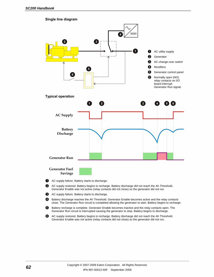
SC200 Handbook
62 Copyright © 2007-2009 Eaton Corporation. All Rights Reserved.
IPN 997-00012-50F September 2009
Single line diagram
AC utility supply
Generator
AC change-over switch
Rectifiers
Generator control panel
Normally open (NO) relay contacts on I/O board interrupt Generator Run signal.
Typical operation
AC Supply
Battery
Discharge
Generator Run
Generator Fuel Savings
AC supply failure. Battery starts to discharge.
AC supply restored. Battery begins to recharge. Battery discharge did not reach the Ah Threshold. Generator Enable was not active (relay contacts did not close) so the generator did not run.
AC supply failure. Battery starts to discharge.
Battery discharge reaches the Ah Threshold. Generator Enable becomes active and the relay contacts close. The Generator Run circuit is completed allowing the generator to start. Battery begins to recharge.
Battery recharge is complete. Generator Enable becomes inactive and the relay contacts open. The Generator Run circuit is interrupted causing the generator to stop. Battery begins to discharge.
AC supply restored. Battery begins to recharge. Battery discharge did not reach the Ah Threshold. Generator Enable was not active (relay contacts did not close) so the generator did not run.
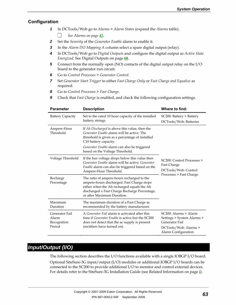
System Operation
Copyright © 2007-2009 Eaton Corporation. All Rights Reserved.
IPN 997-00012-50F September 2009 63
Configuration 1 In DCTools/Web go to Alarms > Alarm States (expand the Alarms table).
See Alarms on page 42. 2 Set the Severity of the Generator Enable alarm to enable it. 3 In the Alarm DO Mapping A column select a spare digital output (relay). 4 In DCTools/Web go to Digital Outputs and configure the digital output as Active State
Energized. See Digital Outputs on page 68. 5 Connect from the normally open (NO) contacts of the digital output relay on the I/O
board to the generator run circuit. 6 Go to Control Processes > Generator Control. 7 Set Generator Start Trigger to either Fast Charge Only or Fast Charge and Equalize as
required. 8 Go to Control Processes > Fast Charge. 9 Check that Fast Charge is enabled, and check the following configuration settings.
Parameter Description Where to find:
Battery Capacity Set to the rated 10 hour capacity of the installed battery strings.
SC200: Battery > Battery DCTools/Web: Batteries
Ampere-Hour Threshold
If Ah Discharged is above this value, then the Generator Enable alarm will be active. The threshold is given as a percentage of installed C10 battery capacity. Generator Enable alarm can also be triggered based on the Voltage Threshold.
Voltage Threshold If the bus voltage drops below this value then Generator Enable alarm will be active. Generator Enable alarm can also be triggered based on the Ampere-Hour Threshold.
Recharge Percentage
The ratio of ampere-hours recharged to the ampere-hours discharged. Fast Charge stops either when the Ah recharged equals the Ah discharged x Fast Charge Recharge Percentage, or after Maximum Duration.
Maximum Duration
The maximum duration of a Fast Charge as recommended by the battery manufacturer.
SC200: Control Processes > Fast Charge DCTools/Web: Control Processes > Fast Charge
Generator Fail Alarm Recognition Period
A Generator Fail alarm is activated after this time if Generator Enable is active but the SC200 does not detect that the ac supply is present (rectifiers have turned on).
SC200: Alarms > Alarm Settings > System Alarms > Generator Fail DCTools/Web: Alarms > Alarm Configuration
Input/Output (I/O) The following section describes the I/O functions available with a single IOBGP I/O board. Optional SiteSure-3G input/output (I/O) modules or additional IOBGP I/O boards can be connected to the SC200 to provide additional I/O to monitor and control external devices. For details refer to the SiteSure-3G Installation Guide (see Related Information on page i).
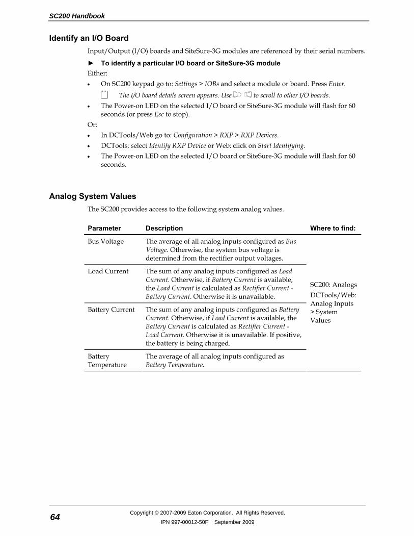
SC200 Handbook
64 Copyright © 2007-2009 Eaton Corporation. All Rights Reserved.
IPN 997-00012-50F September 2009
Identify an I/O Board Input/Output (I/O) boards and SiteSure-3G modules are referenced by their serial numbers.
► To identify a particular I/O board or SiteSure-3G module Either: • On SC200 keypad go to: Settings > IOBs and select a module or board. Press Enter.
The I/O board details screen appears. Use to scroll to other I/O boards. • The Power-on LED on the selected I/O board or SiteSure-3G module will flash for 60
seconds (or press Esc to stop). Or: • In DCTools/Web go to: Configuration > RXP > RXP Devices. • DCTools: select Identify RXP Device or Web: click on Start Identifying. • The Power-on LED on the selected I/O board or SiteSure-3G module will flash for 60
seconds.
Analog System Values The SC200 provides access to the following system analog values.
Parameter Description Where to find:
Bus Voltage The average of all analog inputs configured as Bus Voltage. Otherwise, the system bus voltage is determined from the rectifier output voltages.
Load Current The sum of any analog inputs configured as Load Current. Otherwise, if Battery Current is available, the Load Current is calculated as Rectifier Current - Battery Current. Otherwise it is unavailable.
Battery Current The sum of any analog inputs configured as Battery Current. Otherwise, if Load Current is available, the Battery Current is calculated as Rectifier Current - Load Current. Otherwise it is unavailable. If positive, the battery is being charged.
Battery Temperature
The average of all analog inputs configured as Battery Temperature.
SC200: Analogs DCTools/Web: Analog Inputs > System Values
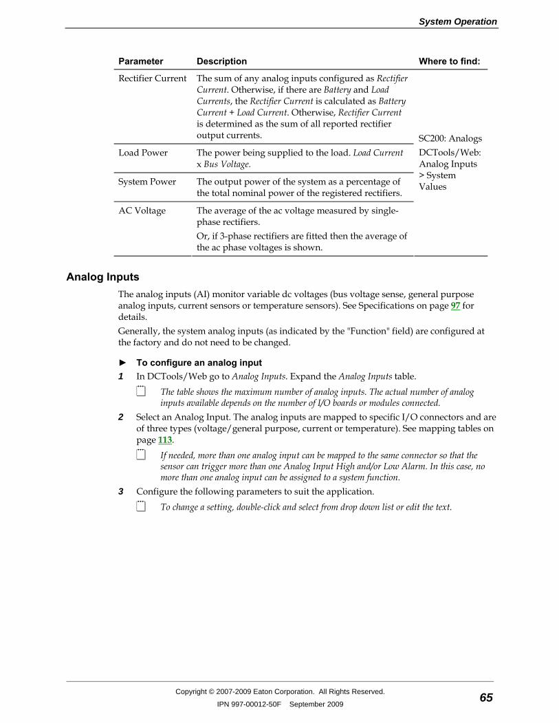
System Operation
Copyright © 2007-2009 Eaton Corporation. All Rights Reserved.
IPN 997-00012-50F September 2009 65
Parameter Description Where to find:
Rectifier Current The sum of any analog inputs configured as Rectifier Current. Otherwise, if there are Battery and Load Currents, the Rectifier Current is calculated as Battery Current + Load Current. Otherwise, Rectifier Current is determined as the sum of all reported rectifier output currents.
Load Power The power being supplied to the load. Load Current x Bus Voltage.
System Power The output power of the system as a percentage of the total nominal power of the registered rectifiers.
AC Voltage The average of the ac voltage measured by single-phase rectifiers. Or, if 3-phase rectifiers are fitted then the average of the ac phase voltages is shown.
SC200: Analogs DCTools/Web: Analog Inputs > System Values
Analog Inputs The analog inputs (AI) monitor variable dc voltages (bus voltage sense, general purpose analog inputs, current sensors or temperature sensors). See Specifications on page 97 for details. Generally, the system analog inputs (as indicated by the "Function" field) are configured at the factory and do not need to be changed.
► To configure an analog input 1 In DCTools/Web go to Analog Inputs. Expand the Analog Inputs table.
The table shows the maximum number of analog inputs. The actual number of analog inputs available depends on the number of I/O boards or modules connected.
2 Select an Analog Input. The analog inputs are mapped to specific I/O connectors and are of three types (voltage/general purpose, current or temperature). See mapping tables on page 113.
If needed, more than one analog input can be mapped to the same connector so that the sensor can trigger more than one Analog Input High and/or Low Alarm. In this case, no more than one analog input can be assigned to a system function.
3 Configure the following parameters to suit the application.
To change a setting, double-click and select from drop down list or edit the text.
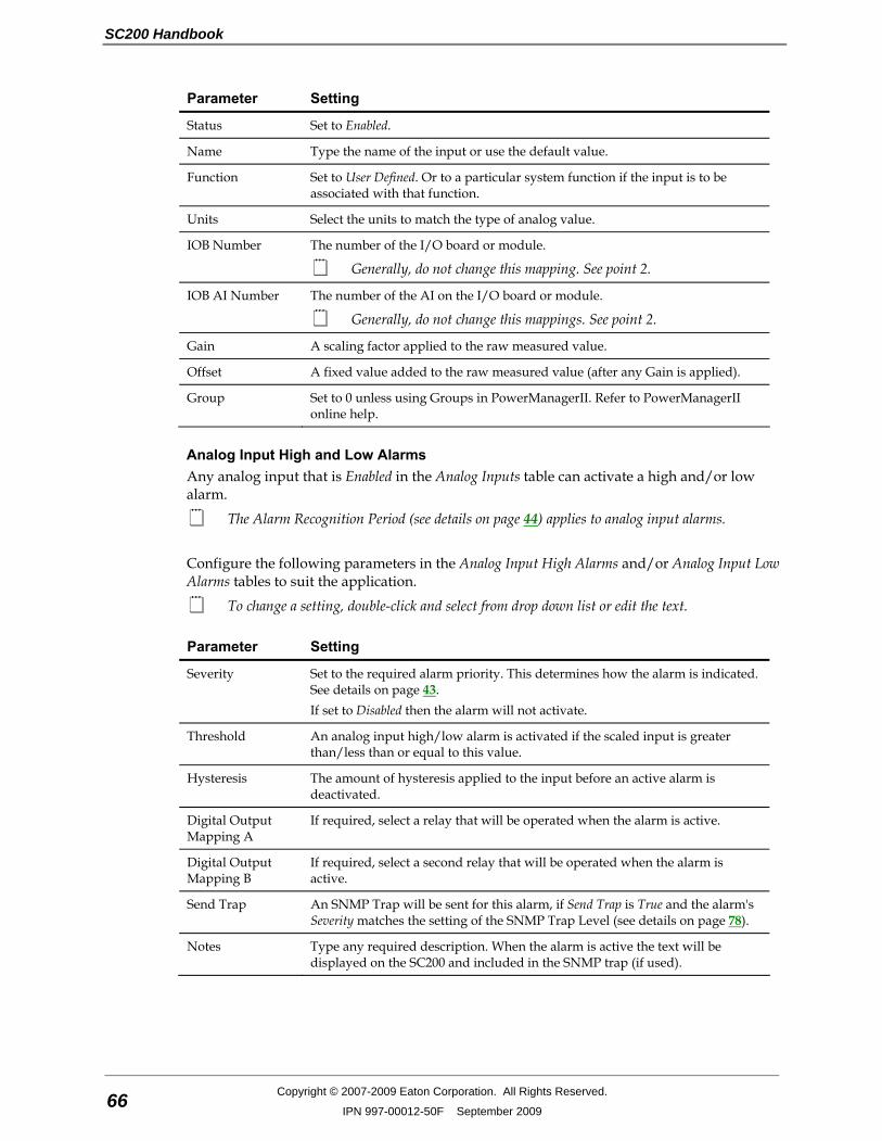
SC200 Handbook
66 Copyright © 2007-2009 Eaton Corporation. All Rights Reserved.
IPN 997-00012-50F September 2009
Parameter Setting
Status Set to Enabled.
Name Type the name of the input or use the default value.
Function Set to User Defined. Or to a particular system function if the input is to be associated with that function.
Units Select the units to match the type of analog value.
IOB Number The number of the I/O board or module.
Generally, do not change this mapping. See point 2.
IOB AI Number The number of the AI on the I/O board or module.
Generally, do not change this mappings. See point 2.
Gain A scaling factor applied to the raw measured value.
Offset A fixed value added to the raw measured value (after any Gain is applied).
Group Set to 0 unless using Groups in PowerManagerII. Refer to PowerManagerII online help.
Analog Input High and Low Alarms Any analog input that is Enabled in the Analog Inputs table can activate a high and/or low alarm.
The Alarm Recognition Period (see details on page 44) applies to analog input alarms. Configure the following parameters in the Analog Input High Alarms and/or Analog Input Low Alarms tables to suit the application.
To change a setting, double-click and select from drop down list or edit the text.
Parameter Setting
Severity Set to the required alarm priority. This determines how the alarm is indicated. See details on page 43. If set to Disabled then the alarm will not activate.
Threshold An analog input high/low alarm is activated if the scaled input is greater than/less than or equal to this value.
Hysteresis The amount of hysteresis applied to the input before an active alarm is deactivated.
Digital Output Mapping A
If required, select a relay that will be operated when the alarm is active.
Digital Output Mapping B
If required, select a second relay that will be operated when the alarm is active.
Send Trap An SNMP Trap will be sent for this alarm, if Send Trap is True and the alarm's Severity matches the setting of the SNMP Trap Level (see details on page 78).
Notes Type any required description. When the alarm is active the text will be displayed on the SC200 and included in the SNMP trap (if used).

System Operation
Copyright © 2007-2009 Eaton Corporation. All Rights Reserved.
IPN 997-00012-50F September 2009 67
System States The SC200 monitors the following system states to provide an overview of the dc power system's operation. States displayed will depend on the dc power system model.
Name Description Where to find:
Fan Indicates if any digital input with Function set to "ACD Fan Fail" is active (only used in systems with ac distribution fans).
Cabinet Fan Indicates if any digital input with Function set to "Cabinet Fan Fail" is active (only used in systems with cabinet fans).
Mains Fail Indicates if any digital input with Function set to "AC Fail" is active.
MOV Fail Indicates if any digital input with Function set to "MOV Fail" is active (only used in systems with MOV surge protection).
Load Fuse Fail Indicates if any digital input with Function set to "Load Fuse Fail" is active.
Battery Fuse Fail Indicates if any digital input with Function set to "Battery Fuse Fail" is active.
Phase Fail Indicates if any digital input with Function set to "Phase Fail" is active.
SC200: Digitals DCTools/Web: Digital Inputs
Notes: 1 See the related Alarm Descriptions on page 101. 2 A value of Unavailable indicates that a System State is not configured for this dc power
system. 3 A value of Missing indicates that the I/O board has been disconnected or is faulty, or the
connector mapping is incorrect.
Digital Inputs The input/output (I/O) board is fitted with a number of configurable digital inputs (DI) which can monitor external voltage-free relay contacts or switches. See Input/Output Board on page 2 for details.
► To configure a digital input 1 In DCTools/Web go to Digital Inputs. Expand the Digital Inputs table. 2 Digital Input 1-6 are available for configuration.
Digital Input 7-10 (on I/O board 1) are used for system alarms.
If additional I/O boards and/or SiteSure-3G modules are connected there will be more configurable Digital Inputs. See details in the DC power system installation guide.
The last four digital inputs are the pre-assigned Digital System States (see details on page 67). Do not change these settings.
3 Select a configurable Digital Input. 4 Configure the following parameters to suit the application.
To change a setting, double-click and select from drop down list or edit the text.
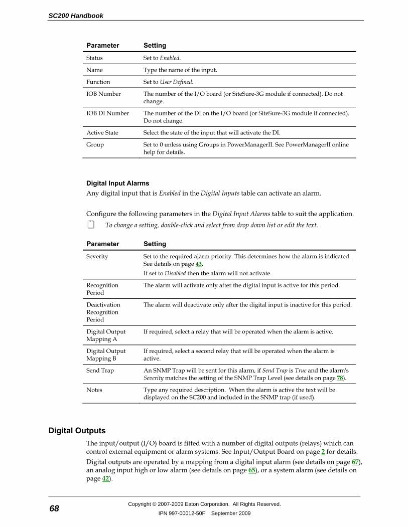
SC200 Handbook
68 Copyright © 2007-2009 Eaton Corporation. All Rights Reserved.
IPN 997-00012-50F September 2009
Parameter Setting
Status Set to Enabled.
Name Type the name of the input.
Function Set to User Defined.
IOB Number The number of the I/O board (or SiteSure-3G module if connected). Do not change.
IOB DI Number The number of the DI on the I/O board (or SiteSure-3G module if connected). Do not change.
Active State Select the state of the input that will activate the DI.
Group Set to 0 unless using Groups in PowerManagerII. See PowerManagerII online help for details.
Digital Input Alarms Any digital input that is Enabled in the Digital Inputs table can activate an alarm. Configure the following parameters in the Digital Input Alarms table to suit the application.
To change a setting, double-click and select from drop down list or edit the text.
Parameter Setting
Severity Set to the required alarm priority. This determines how the alarm is indicated. See details on page 43. If set to Disabled then the alarm will not activate.
Recognition Period
The alarm will activate only after the digital input is active for this period.
Deactivation Recognition Period
The alarm will deactivate only after the digital input is inactive for this period.
Digital Output Mapping A
If required, select a relay that will be operated when the alarm is active.
Digital Output Mapping B
If required, select a second relay that will be operated when the alarm is active.
Send Trap An SNMP Trap will be sent for this alarm, if Send Trap is True and the alarm's Severity matches the setting of the SNMP Trap Level (see details on page 78).
Notes Type any required description. When the alarm is active the text will be displayed on the SC200 and included in the SNMP trap (if used).
Digital Outputs The input/output (I/O) board is fitted with a number of digital outputs (relays) which can control external equipment or alarm systems. See Input/Output Board on page 2 for details. Digital outputs are operated by a mapping from a digital input alarm (see details on page 67), an analog input high or low alarm (see details on page 65), or a system alarm (see details on page 42).

System Operation
Copyright © 2007-2009 Eaton Corporation. All Rights Reserved.
IPN 997-00012-50F September 2009 69
► To manually control a digital output Either: • In DCTools/Web go to Digital Outputs:
• Expand the Digital Outputs table. • In the Control State column of the required digital output, select Active or Inactive.
• Or, use the SC200 keypad to go to Digital Outputs: • Select the required digital output. Press Edit. • Select Active or Inactive. Press Save.
• The DO Manual alarm (if enabled) will activate. • The corresponding digital output will Energize or De-Energize, as selected in the Active
State column of the Digital Outputs table.
While Active or Inactive is selected, the DO will not be operated by any active alarms mapped to it. Set Control State back to Automatic to allow mapped alarms to operate the digital output.
► To set the state of a digital output from PowerManagerII • In DCTools, set the Group of one or more digital outputs to a non-zero value.
Only digital outputs with a non-zero Group are visible in PowerManagerII • In PowerManagerII select the SiteManager group item. • Click on the Realtime tab. • From the drop down list beside the digital output select Active Manual or Inactive Manual. • The DO Manual alarm (if enabled) will activate. • The corresponding digital output will Energize or De-Energize, according to its Active
State.
While Active Manual or Inactive Manual is selected, the DO will not be operated by any active alarms mapped to it. Set Control State back to Automatic to allow mapped alarms to operate the digital output.
► To configure a digital output 1 In DCTools/Web go to Digital Outputs. Expand the Digital Outputs table. 2 Select a Digital Output (1-6).
Other Digital Outputs will be available if additional I/O boards and/or SiteSure-3G modules are connected. See details in the DC power system installation guide.
3 Configure the following parameters to suit the application.
To change a setting, double-click and select from drop down list or edit the text.
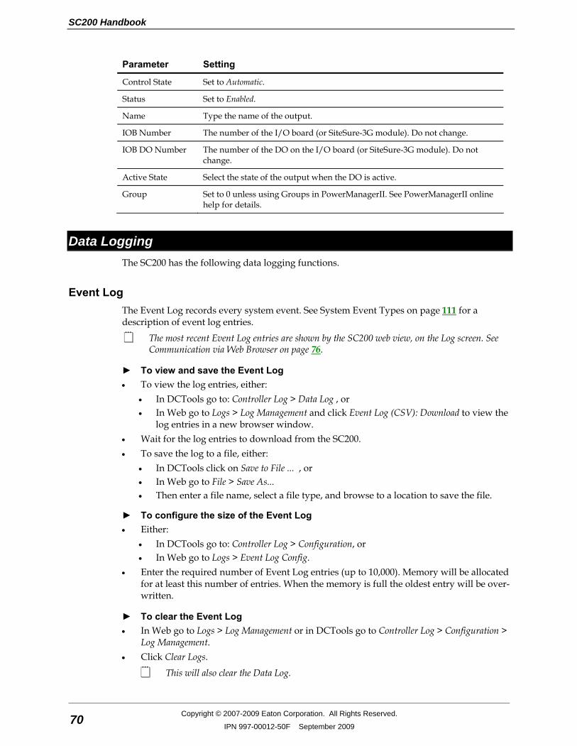
SC200 Handbook
70 Copyright © 2007-2009 Eaton Corporation. All Rights Reserved.
IPN 997-00012-50F September 2009
Parameter Setting
Control State Set to Automatic.
Status Set to Enabled.
Name Type the name of the output.
IOB Number The number of the I/O board (or SiteSure-3G module). Do not change.
IOB DO Number The number of the DO on the I/O board (or SiteSure-3G module). Do not change.
Active State Select the state of the output when the DO is active.
Group Set to 0 unless using Groups in PowerManagerII. See PowerManagerII online help for details.
Data Logging The SC200 has the following data logging functions.
Event Log The Event Log records every system event. See System Event Types on page 111 for a description of event log entries.
The most recent Event Log entries are shown by the SC200 web view, on the Log screen. See Communication via Web Browser on page 76.
► To view and save the Event Log • To view the log entries, either:
• In DCTools go to: Controller Log > Data Log , or • In Web go to Logs > Log Management and click Event Log (CSV): Download to view the
log entries in a new browser window. • Wait for the log entries to download from the SC200. • To save the log to a file, either:
• In DCTools click on Save to File ... , or • In Web go to File > Save As... • Then enter a file name, select a file type, and browse to a location to save the file.
► To configure the size of the Event Log • Either:
• In DCTools go to: Controller Log > Configuration, or • In Web go to Logs > Event Log Config.
• Enter the required number of Event Log entries (up to 10,000). Memory will be allocated for at least this number of entries. When the memory is full the oldest entry will be over-written.
► To clear the Event Log • In Web go to Logs > Log Management or in DCTools go to Controller Log > Configuration >
Log Management. • Click Clear Logs.
This will also clear the Data Log.
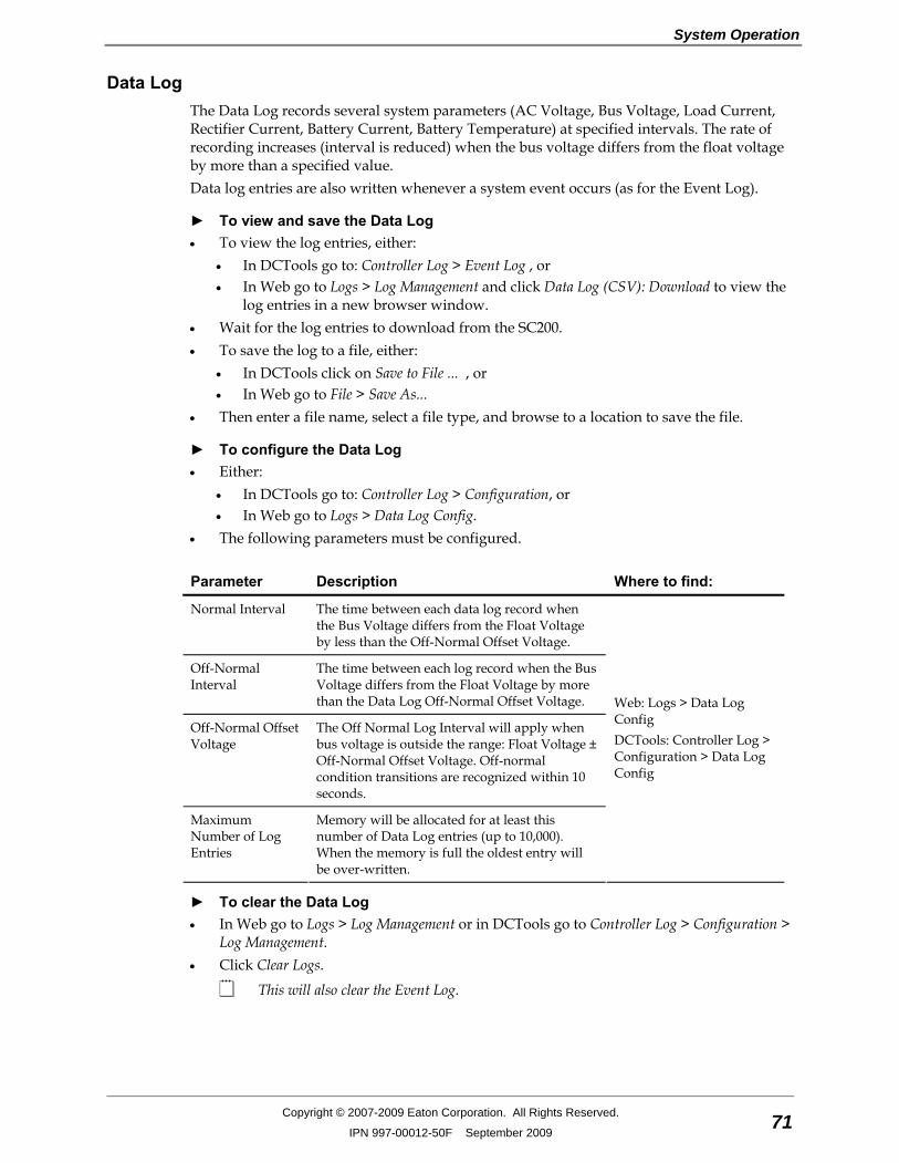
System Operation
Copyright © 2007-2009 Eaton Corporation. All Rights Reserved.
IPN 997-00012-50F September 2009 71
Data Log The Data Log records several system parameters (AC Voltage, Bus Voltage, Load Current, Rectifier Current, Battery Current, Battery Temperature) at specified intervals. The rate of recording increases (interval is reduced) when the bus voltage differs from the float voltage by more than a specified value. Data log entries are also written whenever a system event occurs (as for the Event Log).
► To view and save the Data Log • To view the log entries, either:
• In DCTools go to: Controller Log > Event Log , or • In Web go to Logs > Log Management and click Data Log (CSV): Download to view the
log entries in a new browser window. • Wait for the log entries to download from the SC200. • To save the log to a file, either:
• In DCTools click on Save to File ... , or • In Web go to File > Save As...
• Then enter a file name, select a file type, and browse to a location to save the file.
► To configure the Data Log • Either:
• In DCTools go to: Controller Log > Configuration, or • In Web go to Logs > Data Log Config.
• The following parameters must be configured.
Parameter Description Where to find:
Normal Interval The time between each data log record when the Bus Voltage differs from the Float Voltage by less than the Off-Normal Offset Voltage.
Off-Normal Interval
The time between each log record when the Bus Voltage differs from the Float Voltage by more than the Data Log Off-Normal Offset Voltage.
Off-Normal Offset Voltage
The Off Normal Log Interval will apply when bus voltage is outside the range: Float Voltage ± Off-Normal Offset Voltage. Off-normal condition transitions are recognized within 10 seconds.
Maximum Number of Log Entries
Memory will be allocated for at least this number of Data Log entries (up to 10,000). When the memory is full the oldest entry will be over-written.
Web: Logs > Data Log Config DCTools: Controller Log > Configuration > Data Log Config
► To clear the Data Log • In Web go to Logs > Log Management or in DCTools go to Controller Log > Configuration >
Log Management. • Click Clear Logs.
This will also clear the Event Log.

SC200 Handbook
72 Copyright © 2007-2009 Eaton Corporation. All Rights Reserved.
IPN 997-00012-50F September 2009
PC Log The PC Log allows a continuous streaming of system data (Bus Voltage, Load Current, Battery Current, Battery Temperature, Rectifier Current, Load Power, System Power) from the SC200 directly into a specified file.
► To configure and activate the PC Log 1 In DCTools go to PC Log. 2 At File Name click on the button to enter a file name, select a file type, and browse to a
location to save the file. 3 Select the required interval between log entries (from 5s to 60 minutes). 4 Click on Start to begin the log. 5 Click on Stop to end the log.
Chapter 4
Communications
Copyright © 2007-2009 Eaton Corporation. All Rights Reserved.
IPN 997-00012-50F September 2009 73
C h a p t e r 4 Communications
Overview
Topic Page
Communications Options 74
Direct (USB) Communications 74
Ethernet Communications 74
Serial (RS232) Communications 80
Communications Security 87
CSP 89
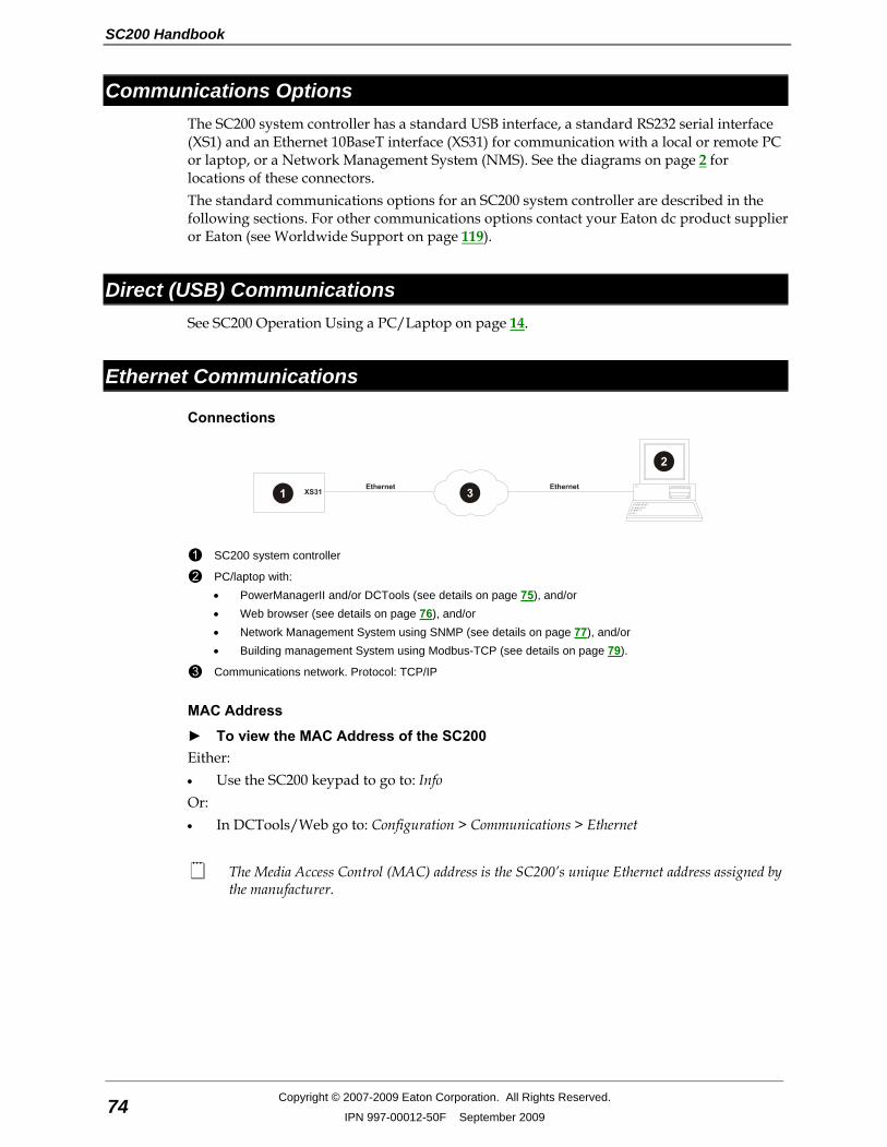
SC200 Handbook
74 Copyright © 2007-2009 Eaton Corporation. All Rights Reserved.
IPN 997-00012-50F September 2009
Communications Options The SC200 system controller has a standard USB interface, a standard RS232 serial interface (XS1) and an Ethernet 10BaseT interface (XS31) for communication with a local or remote PC or laptop, or a Network Management System (NMS). See the diagrams on page 2 for locations of these connectors. The standard communications options for an SC200 system controller are described in the following sections. For other communications options contact your Eaton dc product supplier or Eaton (see Worldwide Support on page 119).
Direct (USB) Communications See SC200 Operation Using a PC/Laptop on page 14.
Ethernet Communications
Connections
SC200 system controller
PC/laptop with: • PowerManagerII and/or DCTools (see details on page 75), and/or • Web browser (see details on page 76), and/or • Network Management System using SNMP (see details on page 77), and/or • Building management System using Modbus-TCP (see details on page 79).
Communications network. Protocol: TCP/IP
MAC Address
► To view the MAC Address of the SC200 Either: • Use the SC200 keypad to go to: Info Or: • In DCTools/Web go to: Configuration > Communications > Ethernet
The Media Access Control (MAC) address is the SC200’s unique Ethernet address assigned by the manufacturer.
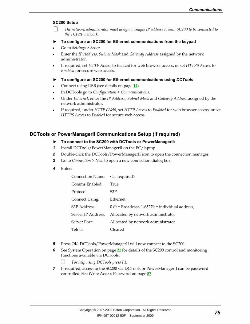
Communications
Copyright © 2007-2009 Eaton Corporation. All Rights Reserved.
IPN 997-00012-50F September 2009 75
SC200 Setup The network administrator must assign a unique IP address to each SC200 to be connected to
the TCP/IP network.
► To configure an SC200 for Ethernet communications from the keypad • Go to Settings > Setup • Enter the IP Address, Subnet Mask and Gateway Address assigned by the network
administrator. • If required, set HTTP Access to Enabled for web browser access, or set HTTPS Access to
Enabled for secure web access.
► To configure an SC200 for Ethernet communications using DCTools • Connect using USB (see details on page 14). • In DCTools go to Configuration > Communications. • Under Ethernet, enter the IP Address, Subnet Mask and Gateway Address assigned by the
network administrator. • If required, under HTTP (Web), set HTTP Access to Enabled for web browser access, or set
HTTPS Access to Enabled for secure web access.
DCTools or PowerManagerII Communications Setup (if required) ► To connect to the SC200 with DCTools or PowerManagerII: 1 Install DCTools/PowerManagerII on the PC/laptop. 2 Double-click the DCTools/PowerManagerII icon to open the connection manager. 3 Go to Connection > New to open a new connection dialog box.
4 Enter:
Connection Name: <as required>
Comms Enabled: True
Protocol: S3P
Connect Using: Ethernet
S3P Address: 0 (0 = Broadcast, 1-65279 = individual address)
Server IP Address: Allocated by network administrator
Server Port: Allocated by network administrator
Telnet Cleared
5 Press OK. DCTools/PowerManagerII will now connect to the SC200. 6 See System Operation on page 21 for details of the SC200 control and monitoring
functions available via DCTools.
For help using DCTools press F1. 7 If required, access to the SC200 via DCTools or PowerManagerII can be password
controlled. See Write Access Password on page 87.
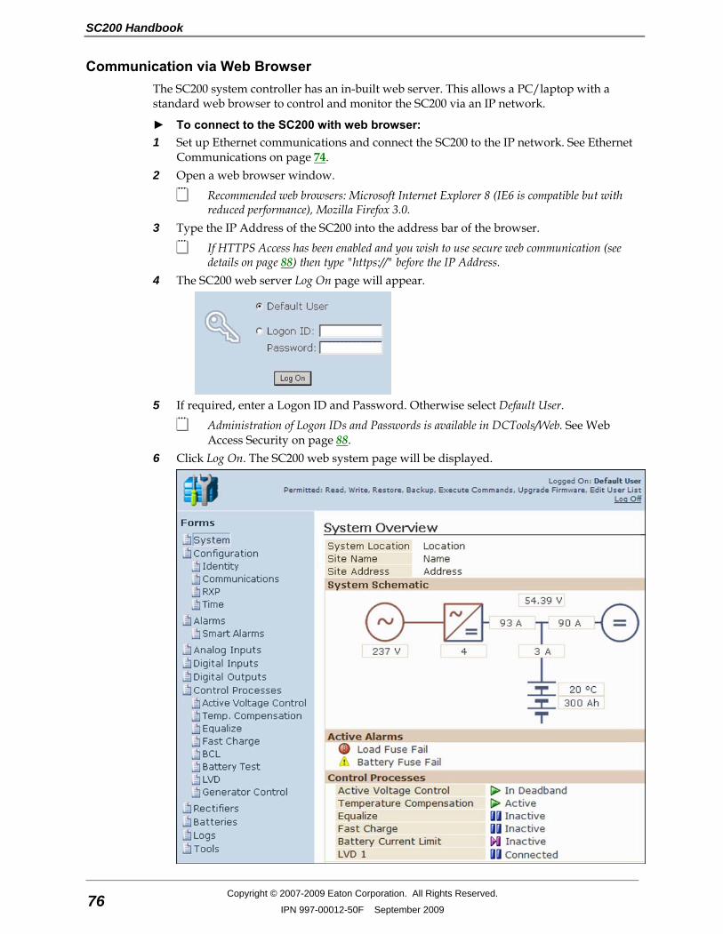
SC200 Handbook
76 Copyright © 2007-2009 Eaton Corporation. All Rights Reserved.
IPN 997-00012-50F September 2009
Communication via Web Browser The SC200 system controller has an in-built web server. This allows a PC/laptop with a standard web browser to control and monitor the SC200 via an IP network.
► To connect to the SC200 with web browser: 1 Set up Ethernet communications and connect the SC200 to the IP network. See Ethernet
Communications on page 74. 2 Open a web browser window.
Recommended web browsers: Microsoft Internet Explorer 8 (IE6 is compatible but with reduced performance), Mozilla Firefox 3.0.
3 Type the IP Address of the SC200 into the address bar of the browser.
If HTTPS Access has been enabled and you wish to use secure web communication (see details on page 88) then type "https://" before the IP Address.
4 The SC200 web server Log On page will appear.
5 If required, enter a Logon ID and Password. Otherwise select Default User.
Administration of Logon IDs and Passwords is available in DCTools/Web. See Web Access Security on page 88.
6 Click Log On. The SC200 web system page will be displayed.
Communications
Copyright © 2007-2009 Eaton Corporation. All Rights Reserved.
IPN 997-00012-50F September 2009 77
7 Go to the Forms for details of the SC200 control and monitoring functions available via the web.
8 To change a setting click the text field, type the new value, then press Enter on the PC keyboard. Then click Apply in the Changes window.
Hold the mouse pointer over any field for help. 9 Click Log Off (top right of window) to log out.
Communication via a Network Management System using SNMP The SC200 system controller can be configured to allow access by a Network Management System (NMS), and/or to send alarms as SNMP traps to up to eight different SNMP trap receivers on an NMS.
► To allow NMS access to the SC200 1 Set up Ethernet Communications (see details on page 74). 2 In DCTools/Web go to Configuration > Communications > SNMP. 3 Set the following parameters:
SNMP Access: Disabled: NMS access to the SC200 is not allowed. All: the NMS has full access to the SC200. Read Only: the NMS has read only access to the SC200. V3 Only: SNMP v3 access is allowed.
Read Community, Write Community:
Do not change the default settings unless requested by the network administrator.
Authentication Password (SHA):
Only used with SNMP v3. Set if the NMS requires an authentication password.
Privacy Password (DES): Only used with SNMP v3 and if an authentication password is set. Set if the NMS uses encryption.
System Object ID: This is a unique Object Identifier that allows the NMS to identify the type of device (in this case a power system) on the network. Objects are named in the iso.org.dod.internet.private.enterprises (1.3.6.1.4.1) sub-tree for enterprise-specific objects. The default Object Identifier for an SC200-based dc power system is: 1.3.6.1.4.1.1918.2.13 A network administrator can specify a new Object Identifier within the (1.3.6.1.4.1) sub-tree, if required. Do not enter the sub-tree integers 1.3.6.1.4.1 into the System Object ID field.
► To send alarms as SNMP traps 1 Set up Ethernet Communications (see details on page 74). 2 In DCTools go to Configuration > Communications > SNMP.
SC200 Handbook
78 Copyright © 2007-2009 Eaton Corporation. All Rights Reserved.
IPN 997-00012-50F September 2009
3 Set the following parameters:
System Object ID: See: To Allow NMS Access to a SC200 on page 77.
Trap Version: Set to SNMP V1, V2, V3 as required.
Trap Format: Set to Eaton or X.733 as appropriate . "Eaton" format uses different trap numbers according to the alarm source. X.733 format uses a single trap number for all alarm sources.
Enable Generic Traps, Trap Repeat and Trap Repeat Rate
Configure as appropriate.
4 For each SNMP trap receiver (up to 8) , configure the following parameters.
Parameter Configuration Guidelines
Name Enter the name of the SNMP trap receiver (20 bytes maximum).
This allows 20 ASCII characters, but less for languages with multi-byte characters.
Level SNMP Trap Level – controls reporting of specific events for each receiver: • Select All Alarms And Warnings to receive Critical, Major and Minor
alarms, and Warnings. (Typically Warnings are status messages such as Equalize Active.)
• Select Minor And Above to receive Critical, Major and Minor alarms. • Select Major And Above to receive only Critical and Major alarms. • Select Critical Only to receive only Critical alarms. • Select Disabled to disable notifications to the receiver.
To prevent an SNMP Trap for an individual alarm, set Send Trap to False in the alarm's configuration.
IP Address IP address of the trap receiver assigned by the network administrator.
Port The default setting is 162. Do not change this setting, unless requested by the network administrator.
Trap Community
A form of password. Use public, unless the network administrator has assigned a new password.
Mode Select: • Normal Traps for sending traps to any network management system,
except PowerManagerII • Acknowledged Summary Trap for sending traps to PowerManagerII
only
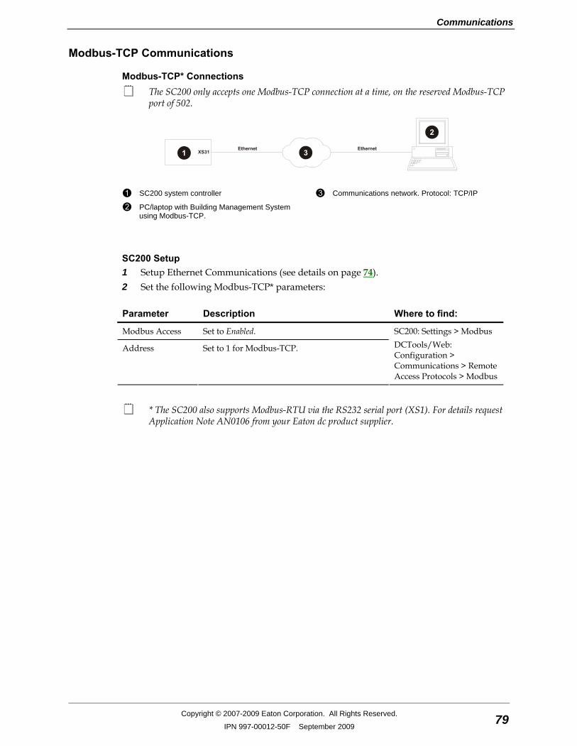
Communications
Copyright © 2007-2009 Eaton Corporation. All Rights Reserved.
IPN 997-00012-50F September 2009 79
Modbus-TCP Communications
Modbus-TCP* Connections The SC200 only accepts one Modbus-TCP connection at a time, on the reserved Modbus-TCP
port of 502.
SC200 system controller
PC/laptop with Building Management System using Modbus-TCP.
Communications network. Protocol: TCP/IP
SC200 Setup 1 Setup Ethernet Communications (see details on page 74). 2 Set the following Modbus-TCP* parameters:
Parameter Description Where to find:
Modbus Access Set to Enabled.
Address Set to 1 for Modbus-TCP.
SC200: Settings > Modbus DCTools/Web: Configuration > Communications > Remote Access Protocols > Modbus
* The SC200 also supports Modbus-RTU via the RS232 serial port (XS1). For details request Application Note AN0106 from your Eaton dc product supplier.
SC200 Handbook
80 Copyright © 2007-2009 Eaton Corporation. All Rights Reserved.
IPN 997-00012-50F September 2009
Diagnostics The following diagnostic information is available.
Parameter Description Where to find:
Bus Message Count
Number of messages. Does not include messages with bad CRC.
Bus Communication Error Count
Number of CRC errors.
Slave Exception Error Count
Number of exception errors.
Slave Message Count
Number of messages to the SC200.
Slave No Response Count
Number of messages received for which no response was sent.
Bus Character Overrun Count
Number of messages received with more than 256 characters.
DCTools/Web: Communications > Modbus > Diagnostics
All counts are since the last SC200 restart or since counter was reset.
Serial (RS232) Communications The parameters of the RS232 serial port can be configured, if required for a specific RS232 device. However, for most applications use the default settings.
Parameter Description Where to find:
Baud Rate Default: 19200
Parity Default: None
Stop Bits Default: One
SC200: Settings > Serial Port Settings DCTools/Web: Configuration > Communications > Serial > Port Settings
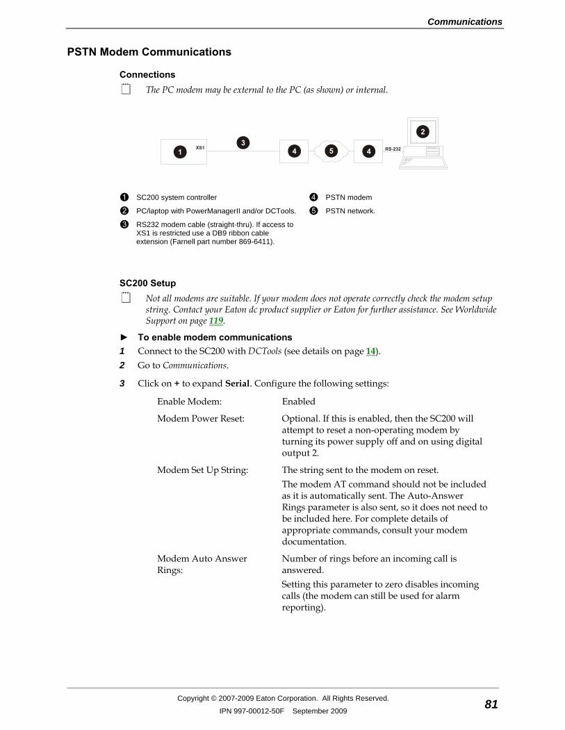
Communications
Copyright © 2007-2009 Eaton Corporation. All Rights Reserved.
IPN 997-00012-50F September 2009 81
PSTN Modem Communications
Connections The PC modem may be external to the PC (as shown) or internal.
SC200 system controller
PC/laptop with PowerManagerII and/or DCTools.
RS232 modem cable (straight-thru). If access to XS1 is restricted use a DB9 ribbon cable extension (Farnell part number 869-6411).
PSTN modem
PSTN network.
SC200 Setup Not all modems are suitable. If your modem does not operate correctly check the modem setup
string. Contact your Eaton dc product supplier or Eaton for further assistance. See Worldwide Support on page 119.
► To enable modem communications 1 Connect to the SC200 with DCTools (see details on page 14). 2 Go to Communications.
3 Click on + to expand Serial. Configure the following settings:
Enable Modem: Enabled
Modem Power Reset: Optional. If this is enabled, then the SC200 will attempt to reset a non-operating modem by turning its power supply off and on using digital output 2.
Modem Set Up String: The string sent to the modem on reset. The modem AT command should not be included as it is automatically sent. The Auto-Answer Rings parameter is also sent, so it does not need to be included here. For complete details of appropriate commands, consult your modem documentation.
Modem Auto Answer Rings:
Number of rings before an incoming call is answered. Setting this parameter to zero disables incoming calls (the modem can still be used for alarm reporting).
SC200 Handbook
82 Copyright © 2007-2009 Eaton Corporation. All Rights Reserved.
IPN 997-00012-50F September 2009
4 If the SC200 is to report alarms to PowerManagerII then click on + to expand PowerManager Callback. Configure the following settings:
Alarm Report: Select the type of event(s) that will initiate the dial-out process.
Report Maximum Retries: Set to the number of times the SC200 is to try to connect with a remote modem, if the first attempt fails. After this number of retries the SC200 will try the next number in the Dial Out Numbers table.
Dialing will stop if none of the numbers in the Dial Out Number Table connect.
Report Retry Interval: Set to the required interval between retries.
Dial Out Number(s): Enter the telephone number(s) to be called.
Consult the modem documentation for appropriate dial modifiers.
DCTools or PowerManagerII Communications Setup
► To connect to the SC200 with DCTools or PowerManagerII: 1 If not already installed, install the PC modem (hardware and software) according to the
manufacturer's instructions. 2 Install DCTools/PowerManagerII on the PC/laptop. 3 Double-click the DCTools/PowerManagerII icon to open the Connection Manager window. 4 Go to Connection > New to open a new connection dialog box.
5 Enter:
Connection Name: <as required>
Comms Enabled: True
Protocol: S3P
Connect Using: Select the COM port used by the modem (if external) or the modem name.
S3P Address: 0 (0 = Broadcast, 1-65279 = individual address)
Phone Number: The number of the PSTN line used by the modem.
Modem Logon: Clear if a logon script is not required for the modem. Select if a logon script is required. Click Logon Script to define. For more details, see DCTools/PowerManagerII online help (press F1).
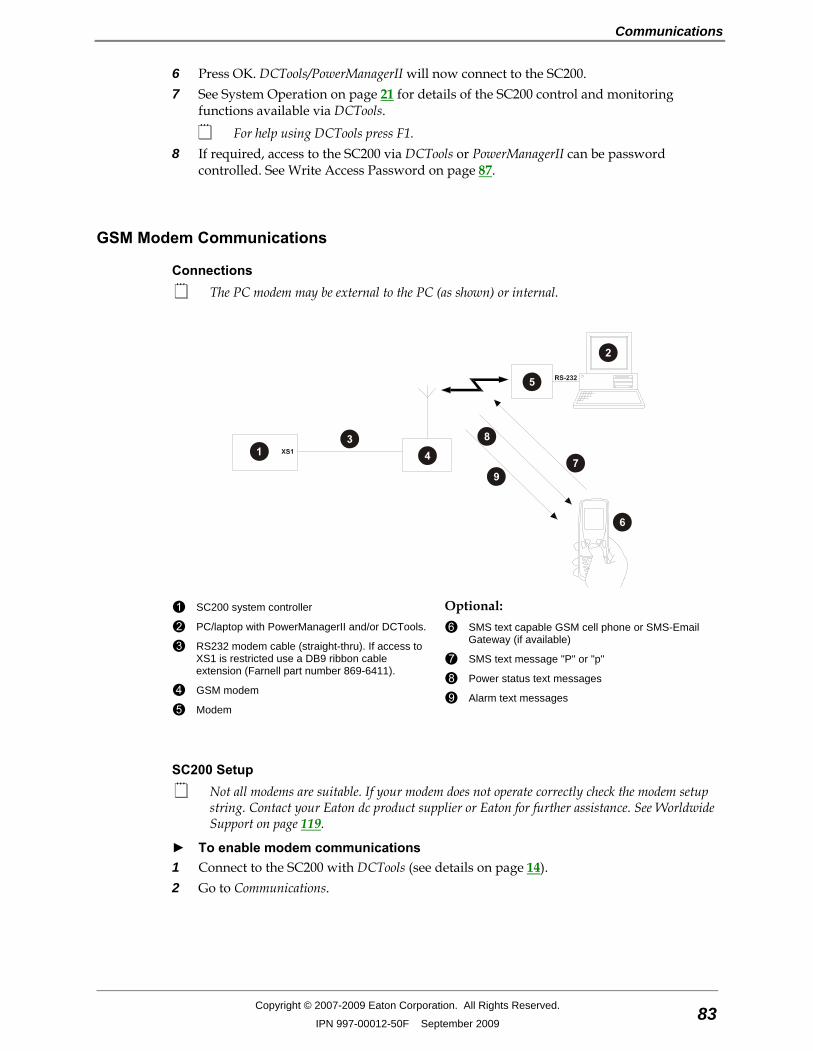
Communications
Copyright © 2007-2009 Eaton Corporation. All Rights Reserved.
IPN 997-00012-50F September 2009 83
6 Press OK. DCTools/PowerManagerII will now connect to the SC200. 7 See System Operation on page 21 for details of the SC200 control and monitoring
functions available via DCTools.
For help using DCTools press F1. 8 If required, access to the SC200 via DCTools or PowerManagerII can be password
controlled. See Write Access Password on page 87.
GSM Modem Communications
Connections The PC modem may be external to the PC (as shown) or internal.
SC200 system controller
PC/laptop with PowerManagerII and/or DCTools.
RS232 modem cable (straight-thru). If access to XS1 is restricted use a DB9 ribbon cable extension (Farnell part number 869-6411).
GSM modem
Modem
Optional:
SMS text capable GSM cell phone or SMS-Email Gateway (if available)
SMS text message "P" or "p"
Power status text messages
Alarm text messages
SC200 Setup Not all modems are suitable. If your modem does not operate correctly check the modem setup
string. Contact your Eaton dc product supplier or Eaton for further assistance. See Worldwide Support on page 119.
► To enable modem communications 1 Connect to the SC200 with DCTools (see details on page 14). 2 Go to Communications.

SC200 Handbook
84 Copyright © 2007-2009 Eaton Corporation. All Rights Reserved.
IPN 997-00012-50F September 2009
3 Click on + to expand Serial. Configure the following settings:
Enable Modem: Enabled
Modem Power Reset: Optional. If this is enabled, then the SC200 will attempt to reset a non-operating modem by turning its power supply off and on using digital output 2.
Modem Set Up String: The string sent to the modem on reset. The modem AT command should not be included as it is automatically sent. The Auto-Answer Rings parameter is also sent, so it does not need to be included here. For complete details of appropriate commands, consult your modem documentation.
Modem Auto Answer Rings:
Number of rings before an incoming call is answered. Setting this parameter to zero disables incoming calls (the modem can still be used for alarm reporting).
4 If the SC200 is to report alarms to PowerManagerII then click on + to expand PowerManager Callback. Configure the following settings:
Alarm Report: Select the type of event(s) that will initiate the dial-out process.
Report Maximum Retries: Set to the number of times the SC200 is to try to connect with a remote modem, if the first attempt fails. After this number of retries the SC200 will try the next number in the Dial Out Numbers table.
Dialing will stop if none of the numbers in the Dial Out Number Table connect.
Report Retry Interval: Set to the required interval between retries.
Dial Out Number(s): Enter the telephone number(s) to be called.
Consult the modem documentation for appropriate dial modifiers.
DCTools or PowerManagerII Communications Setup
► To connect to the SC200 with DCTools or PowerManagerII: 1 If not already installed, install the PC modem (hardware and software) according to the
manufacturer's instructions. 2 Install DCTools/PowerManagerII on the PC/laptop. 3 Double-click the DCTools/PowerManagerII icon to open the Connection Manager window. 4 Go to Connection > New to open a new connection dialog box.
Communications
Copyright © 2007-2009 Eaton Corporation. All Rights Reserved.
IPN 997-00012-50F September 2009 85
5 Enter:
Connection Name: <as required>
Comms Enabled: True
Protocol: S3P
Connect Using: Select the COM port used by the modem (if external) or the modem name.
S3P Address: 0 (0 = Broadcast, 1-65279 = individual address)
Phone Number: The number of the PSTN line used by the modem.
Modem Logon: Clear if a logon script is not required for the modem. Select if a logon script is required. Click Logon Script to define. For more details, see DCTools/PowerManagerII online help (press F1).
6 Press OK. DCTools/PowerManagerII will now connect to the SC200. 7 See System Operation on page 21 for details of the SC200 control and monitoring
functions available via DCTools.
For help using DCTools press F1. 8 If required, access to the SC200 via DCTools or PowerManagerII can be password
controlled. See Write Access Password on page 87.
SMS Text Messaging Setup (if required) For additional information see Application Note AN0024. To receive application notes see
Worldwide Support on page 119.
► To enable SMS alarm messages 1 Connect to the SC200 with DCTools/Web. 2 Go to Configuration > Communications > Serial. 3 Click on to expand SMS Notifications. 4 For each cellphone to receive SMS alarm messages set the Phone Number and other details
as required. 5 Enter the required Prefix string if alarm messages are to be sent to an email address.
This requires a GSM-Email Gateway connected to the GSM network. Contact the GSM network operator for details of the Prefix string required at the beginning of the SMS message.
SC200 Handbook
86 Copyright © 2007-2009 Eaton Corporation. All Rights Reserved.
IPN 997-00012-50F September 2009
► To check the dc power system status using SMS 1 From any cellphone write a SMS (text) message starting with "P" or "p" (any following
characters are ignored). 2 Send the message to the SC200 GSM modem telephone number. The SC200 will reply with a dc power system status message. This will include: Number of active alarms, bus voltage, load current, ac voltage, battery current, battery temperature, battery time remaining (if available).
Serial Server Serial Server allows any software to communicate (via Ethernet) with a device connected to the SC200's RS232 port.
For example, use Serial Server to connect DCTools or PowerManagerII to a CellSure Battery Controller (CBC) connected to the SC200. For information refer to the CellSure Installation Guide (see Related Information on page i).
► SC200 Setup 1 Configure the SC200 for Ethernet communications. See details on page 74. 2 Either:
• On the SC200 keypad go to Settings > Setup > Serial Server. Select Enabled. Or:
• Use DCTools/Web to go to Configuration > Communications > Remote Access Protocols > Serial Server.
• Set Access to Enabled.
DCTools or PowerManagerII Setup Use similar settings for other software.
1 Install DCTools/PowerManagerII on the PC/laptop. 2 Double-click the DCTools/PowerManagerII icon to open the connection manager. 3 Go to Connection > New to open a new connection dialog box.
4 Enter:
Connection Name: <as required>
Comms Enabled: True
Protocol: S3P
Connect Using: Local Network
S3P Address: 0 (0 = Broadcast, 1-65279 = individual address)
Server IP Address: The IP Address of the SC200. Allocated by network administrator.
Server Port: 15000
Telnet Cleared
5 Press OK. DCTools/PowerManagerII will now connect to the device connected to the SC200's RS232 port.
Communications
Copyright © 2007-2009 Eaton Corporation. All Rights Reserved.
IPN 997-00012-50F September 2009 87
Communications Security
SC200 settings cannot be changed if:
• All communications are disabled (see S3P Access on page 87 and HTTP/HTTPS Access on page 88), and
• Keypad access (see details on page 12) is Read Only, or PIN Protected and the keypad access PIN is lost.
In this situation the SC200 will continue to function, but no configuration changes can be made. Contact your Eaton dc product supplier or Eaton for advice (see Worldwide Support on page 119).
Serial Communications (USB/RS232/Ethernet) Security
S3P Access S3P is the serial communications protocol used by the SC200 to communicate with DCTools or PowerManagerII via the USB, RS232 or Ethernet port.
S3P Protocol is not used by the web server.
► To Enable/Disable S3P access • On the SC200 keypad go to Settings > Setup > S3P. Select Enabled or Disabled.
Or: 1 Connect to the SC200 with a web browser (see details on page 74). 2 Go to Configuration > Communications > Remote Access Protocols > S3P. 3 Set Access to Enabled or Disabled.
Write Access Password The Write Access Password prevents unauthorized changes to the SC200 configuration (using DCTools or PowerManagerII).
When a Write Access Password is set serial communications access to the SC200 (using DCTools or PowerManagerII) is read only. The password must be entered before any setting can be changed.
If a Write Access Password is lost, clear it from the SC200 keypad and enter a new password in DCTools, or change it via the Web.
► To set a Write Access Password 1 Connect to the SC200 with DCTools/Web (see details on page 74). 2 Go to Configuration > Communications > Remote Access Protocols > S3P 3 Type a password into the Write Access Password field.
Passwords are case sensitive, maximum 32 characters. 4 Click the Apply Changes button.
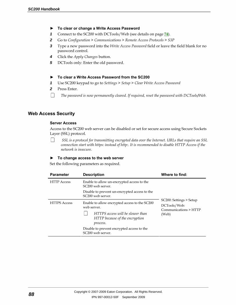
SC200 Handbook
88 Copyright © 2007-2009 Eaton Corporation. All Rights Reserved.
IPN 997-00012-50F September 2009
► To clear or change a Write Access Password 1 Connect to the SC200 with DCTools/Web (see details on page 74). 2 Go to Configuration > Communications > Remote Access Protocols > S3P 3 Type a new password into the Write Access Password field or leave the field blank for no
password control. 4 Click the Apply Changes button. 5 DCTools only: Enter the old password.
► To clear a Write Access Password from the SC200 1 Use SC200 keypad to go to Settings > Setup > Clear Write Access Password 2 Press Enter.
The password is now permanently cleared. If required, reset the password with DCTools/Web.
Web Access Security
Server Access Access to the SC200 web server can be disabled or set for secure access using Secure Sockets Layer (SSL) protocol.
SSL is a protocol for transmitting encrypted data over the Internet. URLs that require an SSL connection start with https: instead of http:. It is recommended to disable HTTP Access if the network is insecure.
► To change access to the web server Set the following parameters as required.
Parameter Description Where to find:
HTTP Access Enable to allow un-encrypted access to the SC200 web server. Disable to prevent un-encrypted access to the SC200 web server.
HTTPS Access Enable to allow encrypted access to the SC200 web server.
HTTPS access will be slower than HTTP because of the encryption process.
Disable to prevent encrypted access to the SC200 web server.
SC200: Settings > Setup DCTools/Web: Communications > HTTP (Web)
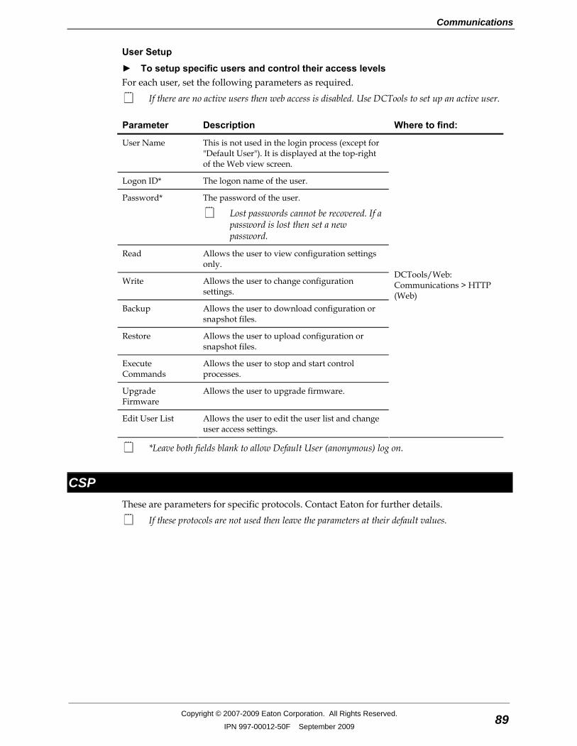
Communications
Copyright © 2007-2009 Eaton Corporation. All Rights Reserved.
IPN 997-00012-50F September 2009 89
User Setup
► To setup specific users and control their access levels For each user, set the following parameters as required.
If there are no active users then web access is disabled. Use DCTools to set up an active user.
Parameter Description Where to find:
User Name This is not used in the login process (except for "Default User"). It is displayed at the top-right of the Web view screen.
Logon ID* The logon name of the user.
Password* The password of the user.
Lost passwords cannot be recovered. If a password is lost then set a new password.
Read Allows the user to view configuration settings only.
Write Allows the user to change configuration settings.
Backup Allows the user to download configuration or snapshot files.
Restore Allows the user to upload configuration or snapshot files.
Execute Commands
Allows the user to stop and start control processes.
Upgrade Firmware
Allows the user to upgrade firmware.
Edit User List Allows the user to edit the user list and change user access settings.
DCTools/Web: Communications > HTTP (Web)
*Leave both fields blank to allow Default User (anonymous) log on.
CSP These are parameters for specific protocols. Contact Eaton for further details.
If these protocols are not used then leave the parameters at their default values.

SC200 Handbook
90 Copyright © 2007-2009 Eaton Corporation. All Rights Reserved.
IPN 997-00012-50F September 2009
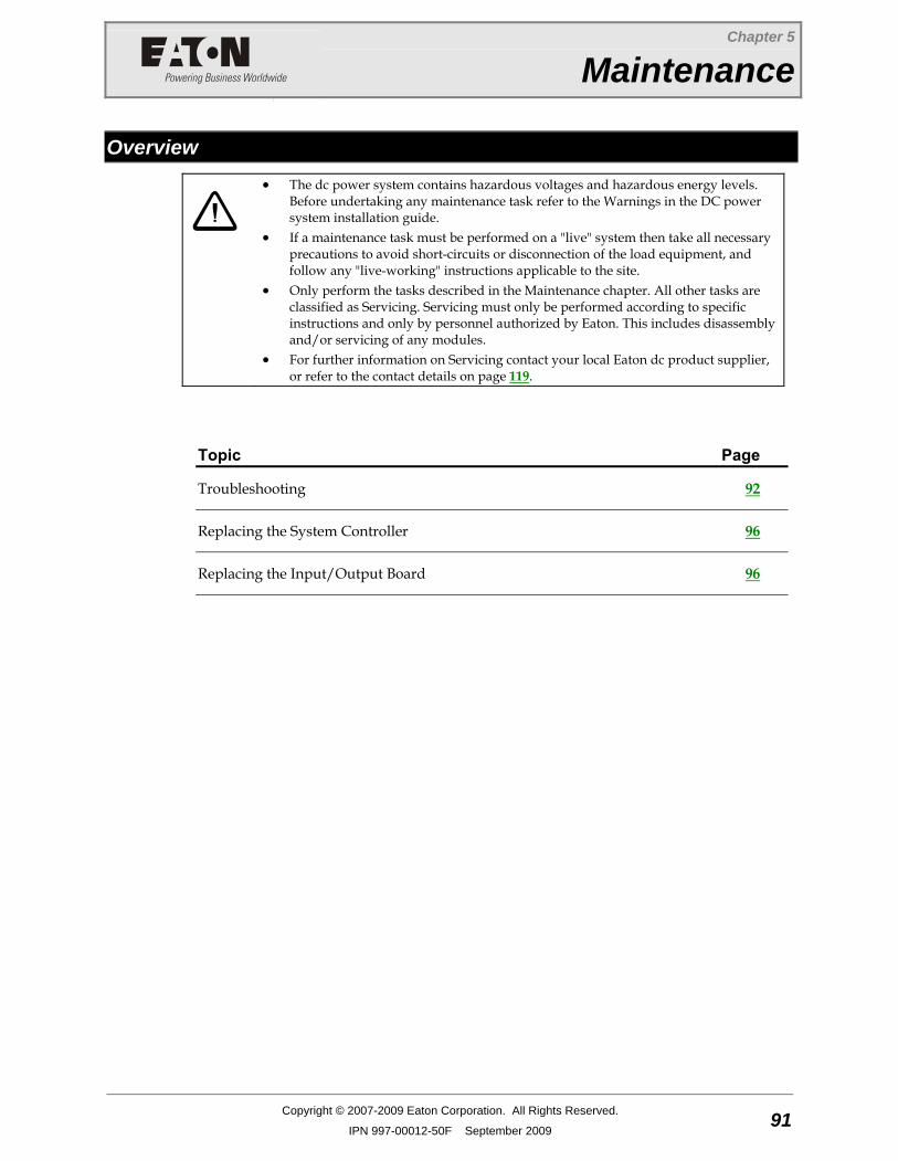
Chapter 5
Maintenance
Copyright © 2007-2009 Eaton Corporation. All Rights Reserved.
IPN 997-00012-50F September 2009 91
C h a p t e r 5 Maintenance
Overview
• The dc power system contains hazardous voltages and hazardous energy levels. Before undertaking any maintenance task refer to the Warnings in the DC power system installation guide.
• If a maintenance task must be performed on a "live" system then take all necessary precautions to avoid short-circuits or disconnection of the load equipment, and follow any "live-working" instructions applicable to the site.
• Only perform the tasks described in the Maintenance chapter. All other tasks are classified as Servicing. Servicing must only be performed according to specific instructions and only by personnel authorized by Eaton. This includes disassembly and/or servicing of any modules.
• For further information on Servicing contact your local Eaton dc product supplier, or refer to the contact details on page 119.
Topic Page
Troubleshooting 92
Replacing the System Controller 96
Replacing the Input/Output Board 96
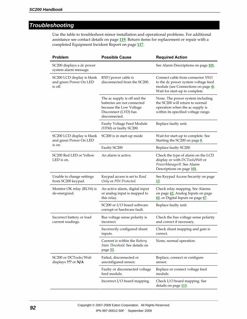
SC200 Handbook
92 Copyright © 2007-2009 Eaton Corporation. All Rights Reserved.
IPN 997-00012-50F September 2009
Troubleshooting Use the table to troubleshoot minor installation and operational problems. For additional assistance see contact details on page 119. Return items for replacement or repair with a completed Equipment Incident Report on page 117.
Problem Possible Cause Required Action
SC200 displays a dc power system alarm message.
See Alarm Descriptions on page 101.
RXP/power cable is disconnected from the SC200.
Connect cable from connector YS11 to the dc power system voltage feed module (see Connections on page 4). Wait for start-up to complete.
The ac supply is off and the batteries are not connected because the Low Voltage Disconnect (LVD) has disconnected.
None. The power system including the SC200 will return to normal operation when the ac supply is within its specified voltage range.
SC200 LCD display is blank and green Power On LED is off.
Faulty Voltage Feed Module (VFM) or faulty SC200.
Replace faulty unit.
SC200 is in start-up mode Wait for start-up to complete. See Starting the SC200 on page 8.
SC200 LCD display is blank and green Power On LED is on.
Faulty SC200 Replace faulty SC200.
SC200 Red LED or Yellow LED is on.
An alarm is active. Check the type of alarm on the LCD display or with DCTools/Web or PowerManagerII. See Alarm Descriptions on page 101.
Unable to change settings from SC200 keypad.
Keypad access is set to Read Only or PIN Protected.
See Keypad Access Security on page 12.
An active alarm, digital input or analog input is mapped to this relay.
Check relay mapping. See Alarms on page 42, Analog Inputs on page 65, or Digital Inputs on page 67.
Monitor OK relay (RLY6) is de-energized.
SC200 or I/O board software corrupt or hardware fault.
Replace faulty unit.
Bus voltage sense polarity is incorrect.
Check the bus voltage sense polarity and correct if necessary.
Incorrectly configured shunt inputs.
Check shunt mapping and gain is correct.
Incorrect battery or load current readings.
Current is within the Battery State Threshold. See details on page 53.
None, normal operation.
Failed, disconnected or unconfigured sensor.
Replace, connect or configure sensor.
Faulty or disconnected voltage feed module.
Replace or connect voltage feed module.
SC200 or DCTools/Web displays ??? or N/A
Incorrect I/O board mapping. Check I/O board mapping. See details on page 113.
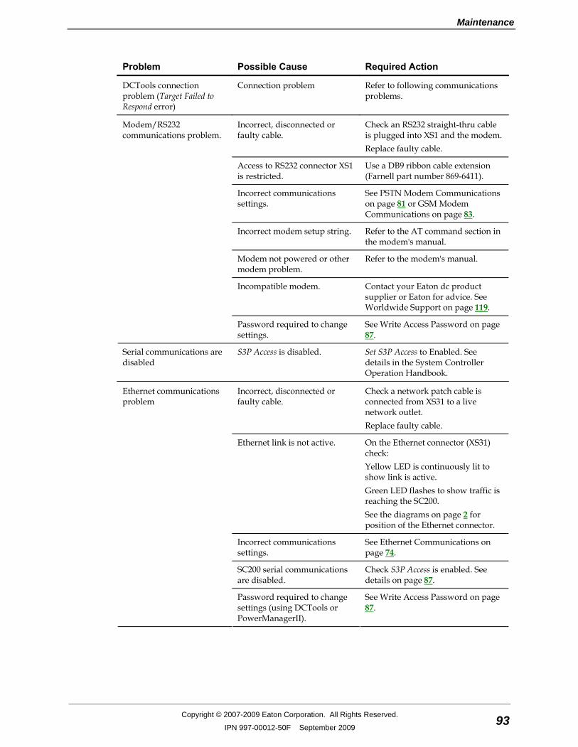
Maintenance
Copyright © 2007-2009 Eaton Corporation. All Rights Reserved.
IPN 997-00012-50F September 2009 93
Problem Possible Cause Required Action
DCTools connection problem (Target Failed to Respond error)
Connection problem Refer to following communications problems.
Incorrect, disconnected or faulty cable.
Check an RS232 straight-thru cable is plugged into XS1 and the modem. Replace faulty cable.
Access to RS232 connector XS1 is restricted.
Use a DB9 ribbon cable extension (Farnell part number 869-6411).
Incorrect communications settings.
See PSTN Modem Communications on page 81 or GSM Modem Communications on page 83.
Incorrect modem setup string. Refer to the AT command section in the modem's manual.
Modem not powered or other modem problem.
Refer to the modem's manual.
Incompatible modem. Contact your Eaton dc product supplier or Eaton for advice. See Worldwide Support on page 119.
Modem/RS232 communications problem.
Password required to change settings.
See Write Access Password on page 87.
Serial communications are disabled
S3P Access is disabled. Set S3P Access to Enabled. See details in the System Controller Operation Handbook.
Incorrect, disconnected or faulty cable.
Check a network patch cable is connected from XS31 to a live network outlet. Replace faulty cable.
Ethernet link is not active. On the Ethernet connector (XS31) check: Yellow LED is continuously lit to show link is active. Green LED flashes to show traffic is reaching the SC200. See the diagrams on page 2 for position of the Ethernet connector.
Incorrect communications settings.
See Ethernet Communications on page 74.
SC200 serial communications are disabled.
Check S3P Access is enabled. See details on page 87.
Ethernet communications problem
Password required to change settings (using DCTools or PowerManagerII).
See Write Access Password on page 87.
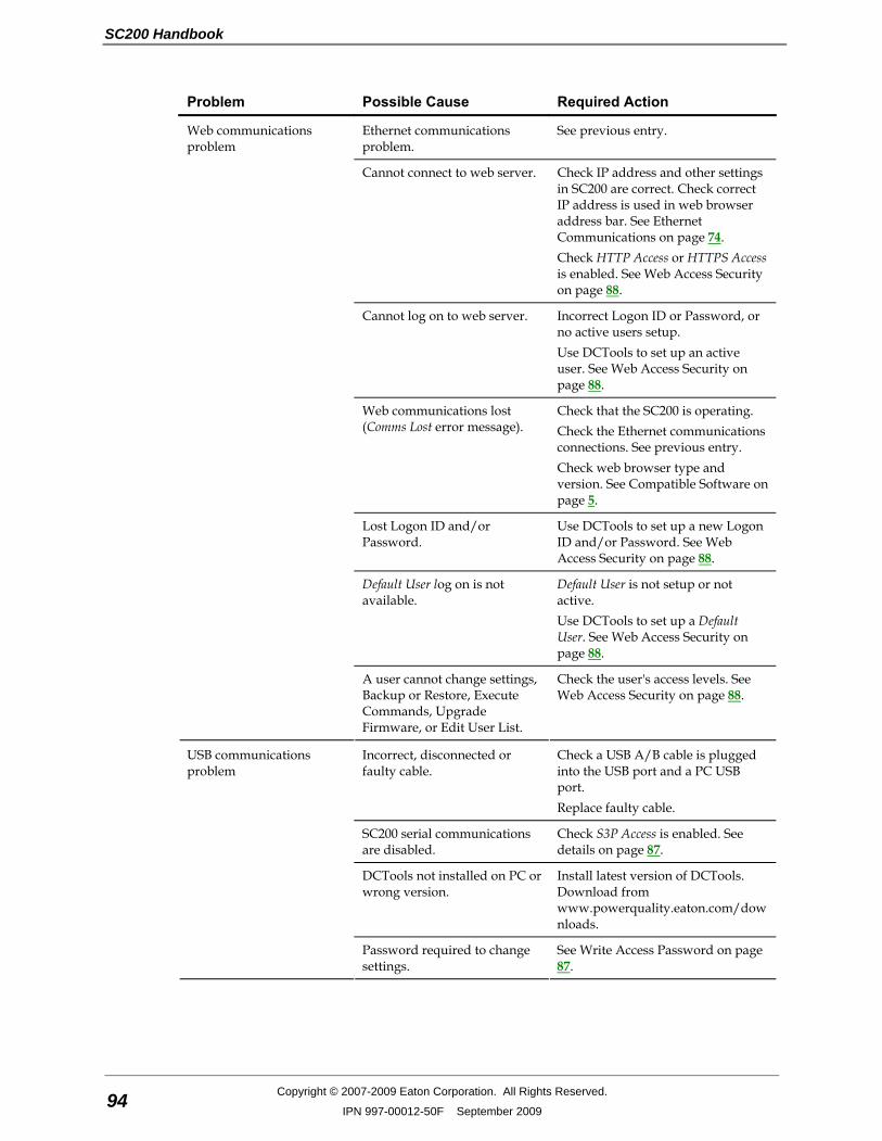
SC200 Handbook
94 Copyright © 2007-2009 Eaton Corporation. All Rights Reserved.
IPN 997-00012-50F September 2009
Problem Possible Cause Required Action
Ethernet communications problem.
See previous entry.
Cannot connect to web server. Check IP address and other settings in SC200 are correct. Check correct IP address is used in web browser address bar. See Ethernet Communications on page 74. Check HTTP Access or HTTPS Access is enabled. See Web Access Security on page 88.
Cannot log on to web server. Incorrect Logon ID or Password, or no active users setup. Use DCTools to set up an active user. See Web Access Security on page 88.
Web communications lost (Comms Lost error message).
Check that the SC200 is operating. Check the Ethernet communications connections. See previous entry. Check web browser type and version. See Compatible Software on page 5.
Lost Logon ID and/or Password.
Use DCTools to set up a new Logon ID and/or Password. See Web Access Security on page 88.
Default User log on is not available.
Default User is not setup or not active. Use DCTools to set up a Default User. See Web Access Security on page 88.
Web communications problem
A user cannot change settings, Backup or Restore, Execute Commands, Upgrade Firmware, or Edit User List.
Check the user's access levels. See Web Access Security on page 88.
Incorrect, disconnected or faulty cable.
Check a USB A/B cable is plugged into the USB port and a PC USB port. Replace faulty cable.
SC200 serial communications are disabled.
Check S3P Access is enabled. See details on page 87.
DCTools not installed on PC or wrong version.
Install latest version of DCTools. Download from www.powerquality.eaton.com/downloads.
USB communications problem
Password required to change settings.
See Write Access Password on page 87.
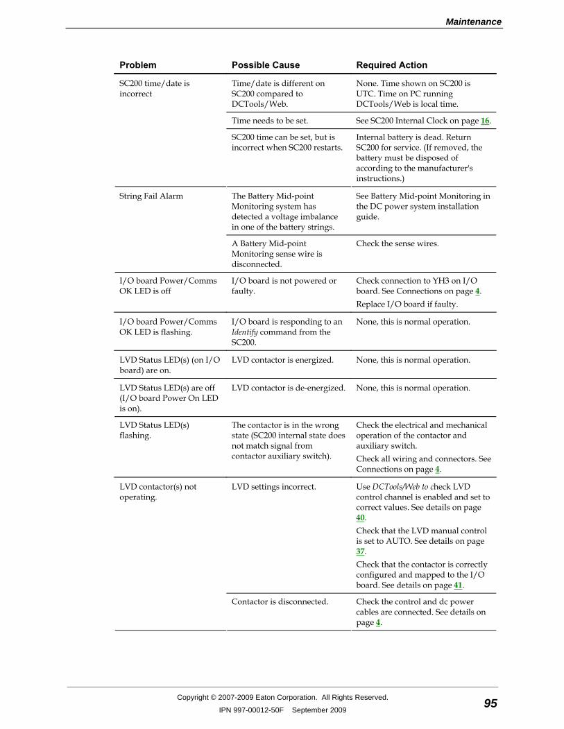
Maintenance
Copyright © 2007-2009 Eaton Corporation. All Rights Reserved.
IPN 997-00012-50F September 2009 95
Problem Possible Cause Required Action
Time/date is different on SC200 compared to DCTools/Web.
None. Time shown on SC200 is UTC. Time on PC running DCTools/Web is local time.
Time needs to be set. See SC200 Internal Clock on page 16.
SC200 time/date is incorrect
SC200 time can be set, but is incorrect when SC200 restarts.
Internal battery is dead. Return SC200 for service. (If removed, the battery must be disposed of according to the manufacturer's instructions.)
The Battery Mid-point Monitoring system has detected a voltage imbalance in one of the battery strings.
See Battery Mid-point Monitoring in the DC power system installation guide.
String Fail Alarm
A Battery Mid-point Monitoring sense wire is disconnected.
Check the sense wires.
I/O board Power/Comms OK LED is off
I/O board is not powered or faulty.
Check connection to YH3 on I/O board. See Connections on page 4. Replace I/O board if faulty.
I/O board Power/Comms OK LED is flashing.
I/O board is responding to an Identify command from the SC200.
None, this is normal operation.
LVD Status LED(s) (on I/O board) are on.
LVD contactor is energized. None, this is normal operation.
LVD Status LED(s) are off (I/O board Power On LED is on).
LVD contactor is de-energized. None, this is normal operation.
LVD Status LED(s) flashing.
The contactor is in the wrong state (SC200 internal state does not match signal from contactor auxiliary switch).
Check the electrical and mechanical operation of the contactor and auxiliary switch. Check all wiring and connectors. See Connections on page 4.
LVD settings incorrect. Use DCTools/Web to check LVD control channel is enabled and set to correct values. See details on page 40. Check that the LVD manual control is set to AUTO. See details on page 37. Check that the contactor is correctly configured and mapped to the I/O board. See details on page 41.
LVD contactor(s) not operating.
Contactor is disconnected. Check the control and dc power cables are connected. See details on page 4.
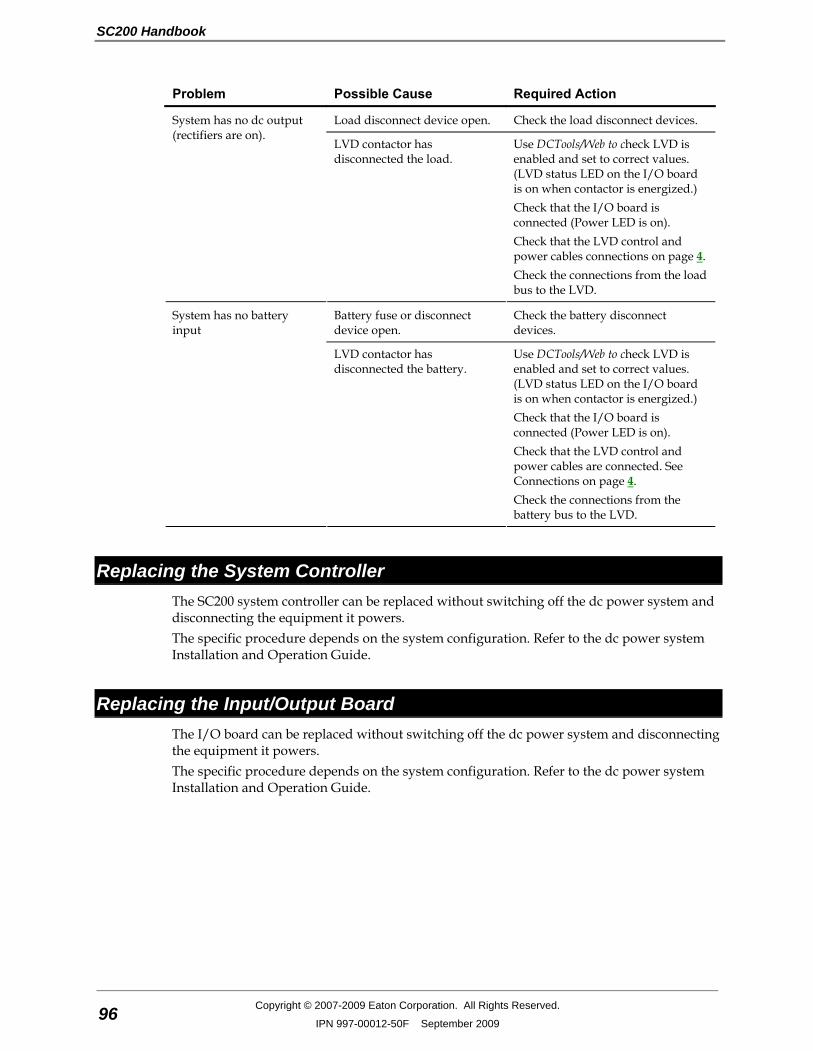
SC200 Handbook
96 Copyright © 2007-2009 Eaton Corporation. All Rights Reserved.
IPN 997-00012-50F September 2009
Problem Possible Cause Required Action
Load disconnect device open. Check the load disconnect devices. System has no dc output (rectifiers are on).
LVD contactor has disconnected the load.
Use DCTools/Web to check LVD is enabled and set to correct values. (LVD status LED on the I/O board is on when contactor is energized.) Check that the I/O board is connected (Power LED is on). Check that the LVD control and power cables connections on page 4. Check the connections from the load bus to the LVD.
Battery fuse or disconnect device open.
Check the battery disconnect devices.
System has no battery input
LVD contactor has disconnected the battery.
Use DCTools/Web to check LVD is enabled and set to correct values. (LVD status LED on the I/O board is on when contactor is energized.) Check that the I/O board is connected (Power LED is on). Check that the LVD control and power cables are connected. See Connections on page 4. Check the connections from the battery bus to the LVD.
Replacing the System Controller The SC200 system controller can be replaced without switching off the dc power system and disconnecting the equipment it powers. The specific procedure depends on the system configuration. Refer to the dc power system Installation and Operation Guide.
Replacing the Input/Output Board The I/O board can be replaced without switching off the dc power system and disconnecting the equipment it powers. The specific procedure depends on the system configuration. Refer to the dc power system Installation and Operation Guide.
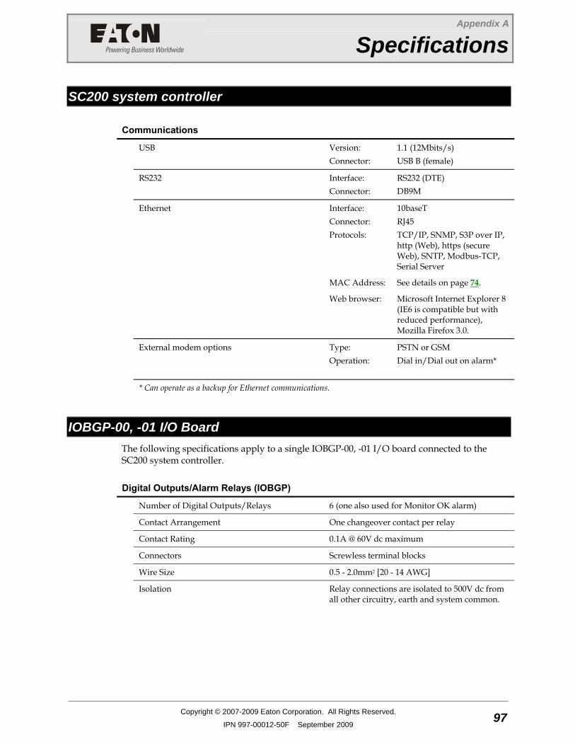
Appendix A
Specifications
Copyright © 2007-2009 Eaton Corporation. All Rights Reserved.
IPN 997-00012-50F September 2009 97
A p p e n d i x A Specifications
SC200 system controller
Communications
USB Version:
Connector: 1.1 (12Mbits/s) USB B (female)
RS232 Interface:
Connector: RS232 (DTE) DB9M
Ethernet Interface: Connector: Protocols:
10baseT RJ45 TCP/IP, SNMP, S3P over IP, http (Web), https (secure Web), SNTP, Modbus-TCP, Serial Server
MAC Address: See details on page 74.
Web browser: Microsoft Internet Explorer 8 (IE6 is compatible but with reduced performance), Mozilla Firefox 3.0.
External modem options Type:
Operation:
PSTN or GSM Dial in/Dial out on alarm*
* Can operate as a backup for Ethernet communications.
IOBGP-00, -01 I/O Board The following specifications apply to a single IOBGP-00, -01 I/O board connected to the SC200 system controller.
Digital Outputs/Alarm Relays (IOBGP)
Number of Digital Outputs/Relays 6 (one also used for Monitor OK alarm)
Contact Arrangement One changeover contact per relay
Contact Rating 0.1A @ 60V dc maximum
Connectors Screwless terminal blocks
Wire Size 0.5 - 2.0mm2 [20 - 14 AWG]
Isolation Relay connections are isolated to 500V dc from all other circuitry, earth and system common.
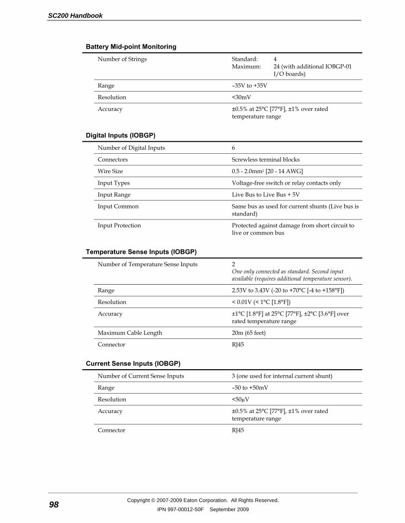
SC200 Handbook
98 Copyright © 2007-2009 Eaton Corporation. All Rights Reserved.
IPN 997-00012-50F September 2009
Battery Mid-point Monitoring
Number of Strings Standard:
Maximum: 4 24 (with additional IOBGP-01 I/O boards)
Range –35V to +35V
Resolution <30mV
Accuracy ±0.5% at 25°C [77°F], ±1% over rated temperature range
Digital Inputs (IOBGP)
Number of Digital Inputs 6
Connectors Screwless terminal blocks
Wire Size 0.5 - 2.0mm2 [20 - 14 AWG]
Input Types Voltage-free switch or relay contacts only
Input Range Live Bus to Live Bus + 5V
Input Common Same bus as used for current shunts (Live bus is standard)
Input Protection Protected against damage from short circuit to live or common bus
Temperature Sense Inputs (IOBGP)
Number of Temperature Sense Inputs 2
One only connected as standard. Second input available (requires additional temperature sensor).
Range 2.53V to 3.43V (-20 to +70°C [-4 to +158°F])
Resolution < 0.01V (< 1°C [1.8°F])
Accuracy ±1°C [1.8°F] at 25°C [77°F], ±2°C [3.6°F] over rated temperature range
Maximum Cable Length 20m (65 feet)
Connector RJ45
Current Sense Inputs (IOBGP)
Number of Current Sense Inputs 3 (one used for internal current shunt)
Range –50 to +50mV
Resolution <50µV
Accuracy ±0.5% at 25°C [77°F], ±1% over rated temperature range
Connector RJ45

Specifications
Copyright © 2007-2009 Eaton Corporation. All Rights Reserved.
IPN 997-00012-50F September 2009 99
Bus Voltage Sense Input (IOBGP)
Number of Bus Voltage Sense Inputs 1
Range –60V to +60V
Resolution 30mV
Accuracy ±0.5% at 25°C [77°F], ±1% over rated temperature range
Connector MTA156 (2-way)

SC200 Handbook
100 Copyright © 2007-2009 Eaton Corporation. All Rights Reserved.
IPN 997-00012-50F September 2009
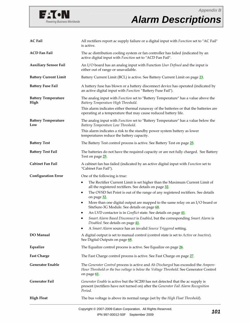
Appendix B
Alarm Descriptions
Copyright © 2007-2009 Eaton Corporation. All Rights Reserved.
IPN 997-00012-50F September 2009 101
A p p e n d i x B Alarm Descriptions
AC Fail All rectifiers report ac supply failure or a digital input with Function set to "AC Fail" is active.
ACD Fan Fail The ac distribution cooling system or fan controller has failed (indicated by an active digital input with Function set to "ACD Fan Fail".
Auxiliary Sensor Fail An I/O board has an analog input with Function User Defined and the input is either out of range or unavailable.
Battery Current Limit Battery Current Limit (BCL) is active. See Battery Current Limit on page 23.
Battery Fuse Fail A battery fuse has blown or a battery disconnect device has operated (indicated by an active digital input with Function "Battery Fuse Fail").
Battery Temperature High
The analog input with Function set to "Battery Temperature" has a value above the Battery Temperature High Threshold. This alarm indicates either thermal runaway of the batteries or that the batteries are operating at a temperature that may cause reduced battery life.
Battery Temperature Low
The analog input with Function set to "Battery Temperature" has a value below the Battery Temperature Low Threshold. This alarm indicates a risk to the standby power system battery as lower temperatures reduce the battery capacity.
Battery Test The Battery Test control process is active. See Battery Test on page 25.
Battery Test Fail The batteries do not have the required capacity or are not fully charged. See Battery Test on page 25.
Cabinet Fan Fail A cabinet fan has failed (indicated by an active digital input with Function set to "Cabinet Fan Fail").
Configuration Error One of the following is true:
• The Rectifier Current Limit is set higher than the Maximum Current Limit of all the registered rectifiers. See details on page 32.
• The OVSD Set Point is out of the range of any registered rectifiers. See details on page 32.
• More than one digital output are mapped to the same relay on an I/O board or SiteSure-3G Module. See details on page 68.
• An LVD contactor is in Conflict state. See details on page 41. • Smart Alarm Based Disconnect is Enabled, but the corresponding Smart Alarm is
Disabled. See details on page 41. • A Smart Alarm source has an invalid Source Triggered setting.
DO Manual A digital output is set to manual control (control state is set to Active or Inactive). See Digital Outputs on page 68.
Equalize The Equalize control process is active. See Equalize on page 26.
Fast Charge The Fast Charge control process is active. See Fast Charge on page 27.
Generator Enable The Generator Control process is active and Ah Discharged has exceeded the Ampere-Hour Threshold or the bus voltage is below the Voltage Threshold. See Generator Control on page 61.
Generator Fail Generator Enable is active but the SC200 has not detected that the ac supply is present (rectifiers have not turned on) after the Generator Fail Alarm Recognition Period.
High Float The bus voltage is above its normal range (set by the High Float Threshold).

SC200 Handbook
102 Copyright © 2007-2009 Eaton Corporation. All Rights Reserved.
IPN 997-00012-50F September 2009
High Load The bus voltage is higher than the safe range for the load and/or battery (set by the High Load Threshold).
In Discharge Battery Charge State is Discharge (see details on page 52).
Load Fuse Fail A load fuse has blown or a load disconnect device has operated (indicated by an active digital input with Function "Load Fuse Fail").
Low Float The bus voltage is below its normal range (set by the Low Float Threshold).
Low Load The bus voltage is lower than the safe range for the load and/or battery (set by the Low Load Threshold).
LVD Characterization Error An LVD contactor must be characterized. See Low Voltage Disconnect on page 37.
LVD Disconnected An LVD contactor has disconnected the battery or load. See Low Voltage Disconnect on page 37.
LVD Fail An LVD contactor is faulty or the control cable from the I/O board is disconnected. See Low Voltage Disconnect on page 37.
LVD Manual An LVD is set to MANUAL CONNECT or MANUAL DISCONNECT. See Low Voltage Disconnect on page 37.
Missing Hardware The SC200 has lost communication with a mapped I/O board or SiteSure-3G module. Or, an input or output is mapped to an invalid I/O board or SiteSure-3G module. See I/O Board Mapping on page 113.
MOV Fail One or more MOV cartridges have failed and must be replaced (indicated by an active digital input with Function set to "MOV Fail").
Multiple Rectifier Comms Lost
More than one rectifier has lost communications. See also Rectifier Comms Lost on page 102.
Multiple Rectifier Fail Multiple rectifiers are faulty or their ac supply has failed without causing partial or total ac supply failure.
Partial AC Fail A digital input with Function set to "Phase Fail" is active, or more than 20% of single-phase rectifiers are reporting ac supply failure, or all 3-phase rectifiers are reporting loss of the same phase.
Rectifier Comms Lost Normally this alarm indicates that a rectifier has been removed during routine maintenance. However, faulty rectifier communications or losing the rectifier communications bus can also trigger this alarm. If removing multiple rectifiers triggers this alarm, reset it from the keypad before it triggers an external alarm.
Rectifier Current Limit Rectifier(s) in current limit.
Rectifier Fail A rectifier is faulty or its ac supply has failed without causing partial or total ac supply failure.
Rectifier No Load The total rectifier current is less than 2% of the maximum system output current or is less than 2A.
Rectifier Over Temperature
Rectifier(s) operating in temperature turndown mode, because of high ambient temperature or low ac supply voltage.
Sensor Fail The current, temperature or voltage sensing system is faulty, or the I/O board mapping is incorrect.
Standby Mode The SC200 is on but inactive. Another SC200 controls the dc power system. If the other SC200 fails or is disconnected then the SC200 in Standby Mode will become active (after a short delay).
String Fail There is a voltage imbalance in one of the battery strings. See Battery Mid-point Monitoring on page 53.

Alarm Descriptions
Copyright © 2007-2009 Eaton Corporation. All Rights Reserved.
IPN 997-00012-50F September 2009 103
System Overload The power system is operating close to its maximum capacity and more rectifiers are needed. The System Overload threshold is configurable. See System Overload Alarm on page 45.
Unknown Hardware The SC200 has detected an unknown type of device on the RXP bus. Contact your Eaton DC product supplier for advice.
Unmapped IOB Found An I/O board or SiteSure-3G module is connected to the SC200, but its serial number is not in the I/O Board to Serial Number Mapping table. See I/O Board Mapping on page 113.
Wrong Battery Polarity An analog input with Function set to "Reverse Battery Detect" has a value above the Bus Voltage. This alarm indicates the battery is connected with wrong polarity. See Reverse Battery Detection on page 60.

SC200 Handbook
104 Copyright © 2007-2009 Eaton Corporation. All Rights Reserved.
IPN 997-00012-50F September 2009
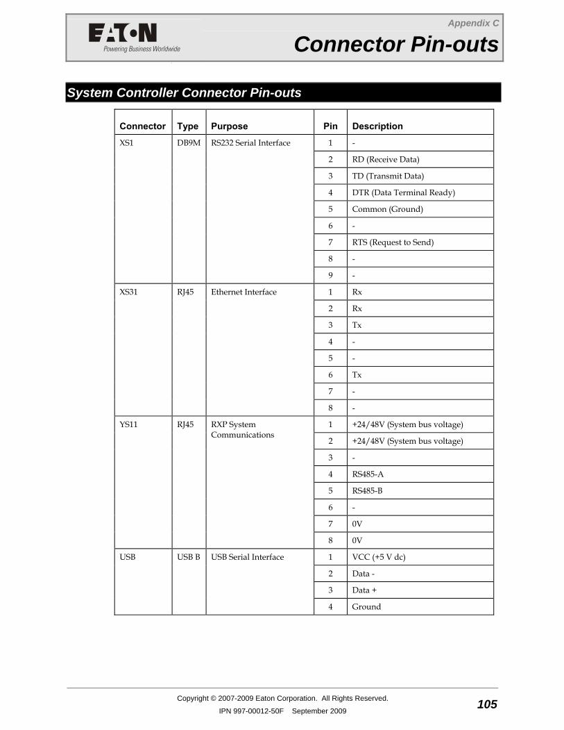
Appendix C
Connector Pin-outs
Copyright © 2007-2009 Eaton Corporation. All Rights Reserved.
IPN 997-00012-50F September 2009 105
A p p e n d i x C Connector Pin-outs
System Controller Connector Pin-outs
Connector Type Purpose Pin Description
1 -
2 RD (Receive Data)
3 TD (Transmit Data)
4 DTR (Data Terminal Ready)
5 Common (Ground)
6 -
7 RTS (Request to Send)
8 -
XS1 DB9M RS232 Serial Interface
9 -
1 Rx
2 Rx
3 Tx
4 -
5 -
6 Tx
7 -
XS31
RJ45 Ethernet Interface
8 -
1 +24/48V (System bus voltage)
2 +24/48V (System bus voltage)
3 -
4 RS485-A
5 RS485-B
6 -
7 0V
YS11 RJ45 RXP System Communications
8 0V
1 VCC (+5 V dc)
2 Data -
3 Data +
USB
USB B USB Serial Interface
4 Ground
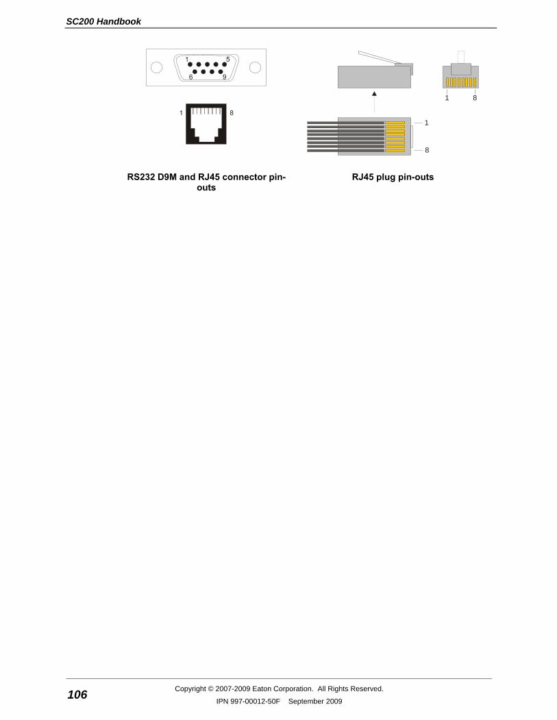
SC200 Handbook
106 Copyright © 2007-2009 Eaton Corporation. All Rights Reserved.
IPN 997-00012-50F September 2009
8
1
1 8
RS232 D9M and RJ45 connector pin-outs
RJ45 plug pin-outs
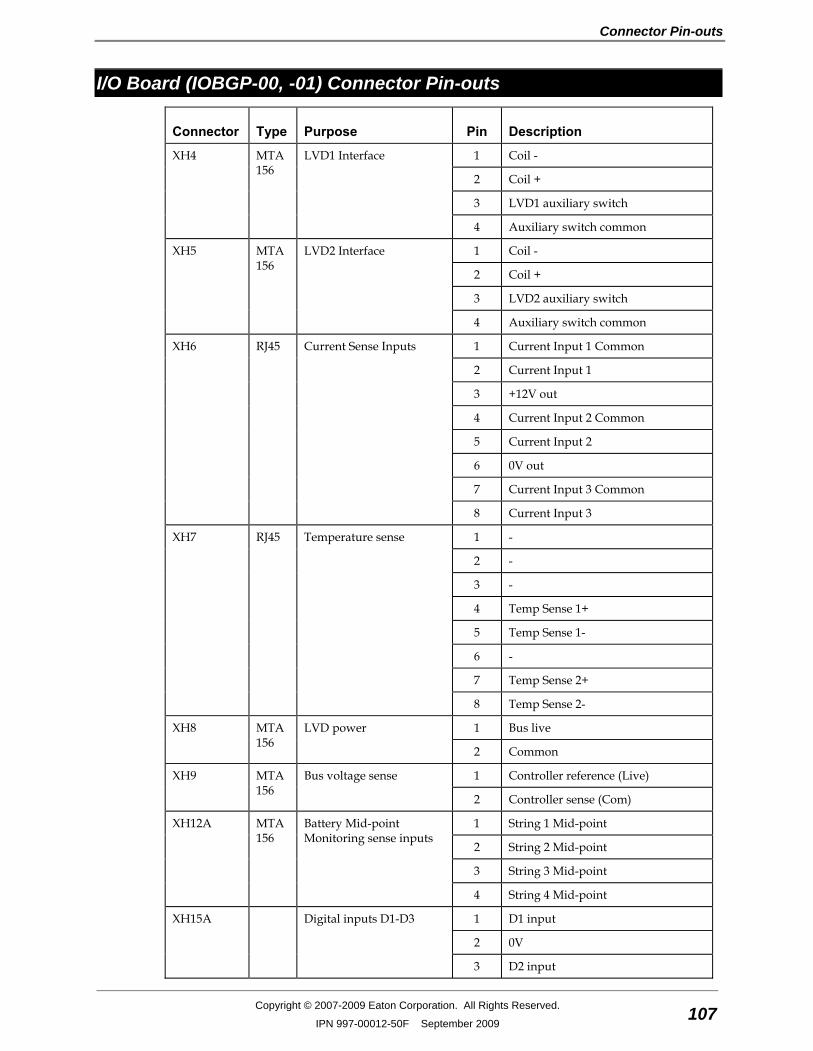
Connector Pin-outs
Copyright © 2007-2009 Eaton Corporation. All Rights Reserved.
IPN 997-00012-50F September 2009 107
I/O Board (IOBGP-00, -01) Connector Pin-outs
Connector Type Purpose Pin Description
1 Coil -
2 Coil +
3 LVD1 auxiliary switch
XH4 MTA 156
LVD1 Interface
4 Auxiliary switch common
1 Coil -
2 Coil +
3 LVD2 auxiliary switch
XH5 MTA 156
LVD2 Interface
4 Auxiliary switch common
1 Current Input 1 Common
2 Current Input 1
3 +12V out
4 Current Input 2 Common
5 Current Input 2
6 0V out
7 Current Input 3 Common
XH6 RJ45 Current Sense Inputs
8 Current Input 3
1 -
2 -
3 -
4 Temp Sense 1+
5 Temp Sense 1-
6 -
7 Temp Sense 2+
XH7 RJ45 Temperature sense
8 Temp Sense 2-
1 Bus live XH8 MTA 156
LVD power
2 Common
1 Controller reference (Live) XH9 MTA 156
Bus voltage sense
2 Controller sense (Com)
1 String 1 Mid-point
2 String 2 Mid-point
3 String 3 Mid-point
XH12A MTA 156
Battery Mid-point Monitoring sense inputs
4 String 4 Mid-point
1 D1 input
2 0V
XH15A Digital inputs D1-D3
3 D2 input

SC200 Handbook
108 Copyright © 2007-2009 Eaton Corporation. All Rights Reserved.
IPN 997-00012-50F September 2009
Connector Type Purpose Pin Description
4 0V
5 D3 input
6 0V
1 D4 input
2 0V
3 D5 input
4 0V
5 D6 input
XH15B Digital inputs D4-D6
6 0V
1 Relay 1 normally closed (NC)
2 Relay 1 normally open (NO)
3 Relay 1 Common (COM)
4 Relay 2 normally closed (NC)
5 Relay 2 normally open (NO)
XH16/XH17 Digital relay outputs 1-2
6 Relay 2 Common (COM)
1 Relay 3 normally closed (NC)
2 Relay 3 normally open (NO)
3 Relay 3 Common (COM)
4 Relay 4 normally closed (NC)
5 Relay 4 normally open (NO)
XH18/XH19 Digital relay outputs 3-4
6 Relay 4 Common (COM)
1 Relay 5 normally closed (NC)
2 Relay 5 normally open (NO)
3 Relay 5 Common (COM)
4 Relay 6 normally closed (NC)
5 Relay 6 normally open (NO)
XH20/XH21 Digital relay outputs 5-6
6 Relay 6 Common (COM)
1 Load Fuse Fail
2 Battery Fuse Fail
3 +12V out
4 AC Distribution Fan Fail
5 AC Distribution MOV Fail
6 0V out (system live - protected)
7 -
YH3 RJ45 DC power system digital inputs
8 System common - protected
1 +24/48V (System bus voltage) YH11 RJ45 RXP System Communications
2 +24/48V (System bus voltage)
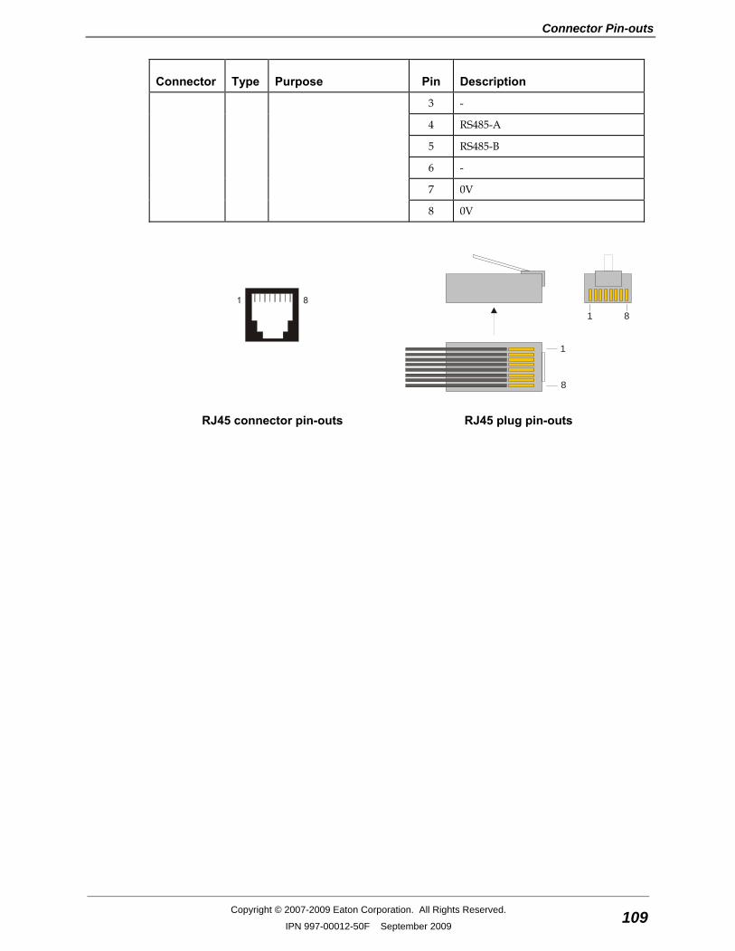
Connector Pin-outs
Copyright © 2007-2009 Eaton Corporation. All Rights Reserved.
IPN 997-00012-50F September 2009 109
Connector Type Purpose Pin Description
3 -
4 RS485-A
5 RS485-B
6 -
7 0V
8 0V
8
1
1 8
RJ45 connector pin-outs RJ45 plug pin-outs

SC200 Handbook
110 Copyright © 2007-2009 Eaton Corporation. All Rights Reserved.
IPN 997-00012-50F September 2009
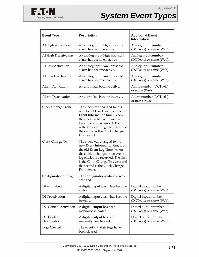
Appendix D
System Event Types
Copyright © 2007-2009 Eaton Corporation. All Rights Reserved.
IPN 997-00012-50F September 2009 111
A p p e n d i x D System Event Types
Event Type Description Additional Event Information
AI High Activation An analog input high threshold alarm has become active.
Analog input number (DCTools) or name (Web).
AI High Deactivation An analog input high threshold alarm has become inactive.
Analog input number (DCTools) or name (Web).
AI Low Activation An analog input low threshold alarm has become active.
Analog input number (DCTools) or name (Web).
AI Low Deactivation An analog input low threshold alarm has become inactive.
Analog input number (DCTools) or name (Web).
Alarm Activation An alarm has become active. Alarm number (DCTools) or name (Web).
Alarm Deactivation An alarm has become inactive. Alarm number (DCTools) or name (Web).
Clock Change From
The clock was changed to this new Event Log Time from the old Event Information time. When the clock is changed, two event log entries are recorded. The first is the Clock Change To event and the second is the Clock Change From event.
Clock Change To
The clock was changed to the new Event Information time from the old Event Log Time. When the clock is changed, two event log entries are recorded. The first is the Clock Change To event and the second is the Clock Change From event.
Configuration Change The configuration database was changed.
DI Activation A digital input alarm has become active.
Digital input number (DCTools) or name (Web).
DI Deactivation A digital input alarm has become inactive.
Digital input number (DCTools) or name (Web).
DO Control Activation A digital output has been manually activated.
Digital output number (DCTools) or name (Web).
DO Control Deactivation
A digital output has been manually deactivated.
Digital output number (DCTools) or name (Web).
Logs Cleared The event and data logs have been cleared.
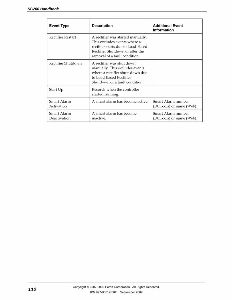
SC200 Handbook
112 Copyright © 2007-2009 Eaton Corporation. All Rights Reserved.
IPN 997-00012-50F September 2009
Event Type Description Additional Event Information
Rectifier Restart A rectifier was started manually. This excludes events where a rectifier starts due to Load-Based Rectifier Shutdown or after the removal of a fault condition.
Rectifier Shutdown A rectifier was shut down manually. This excludes events where a rectifier shuts down due to Load-Based Rectifier Shutdown or a fault condition.
Start Up Records when the controller started running.
Smart Alarm Activation
A smart alarm has become active. Smart Alarm number (DCTools) or name (Web).
Smart Alarm Deactivation
A smart alarm has become inactive.
Smart Alarm number (DCTools) or name (Web).
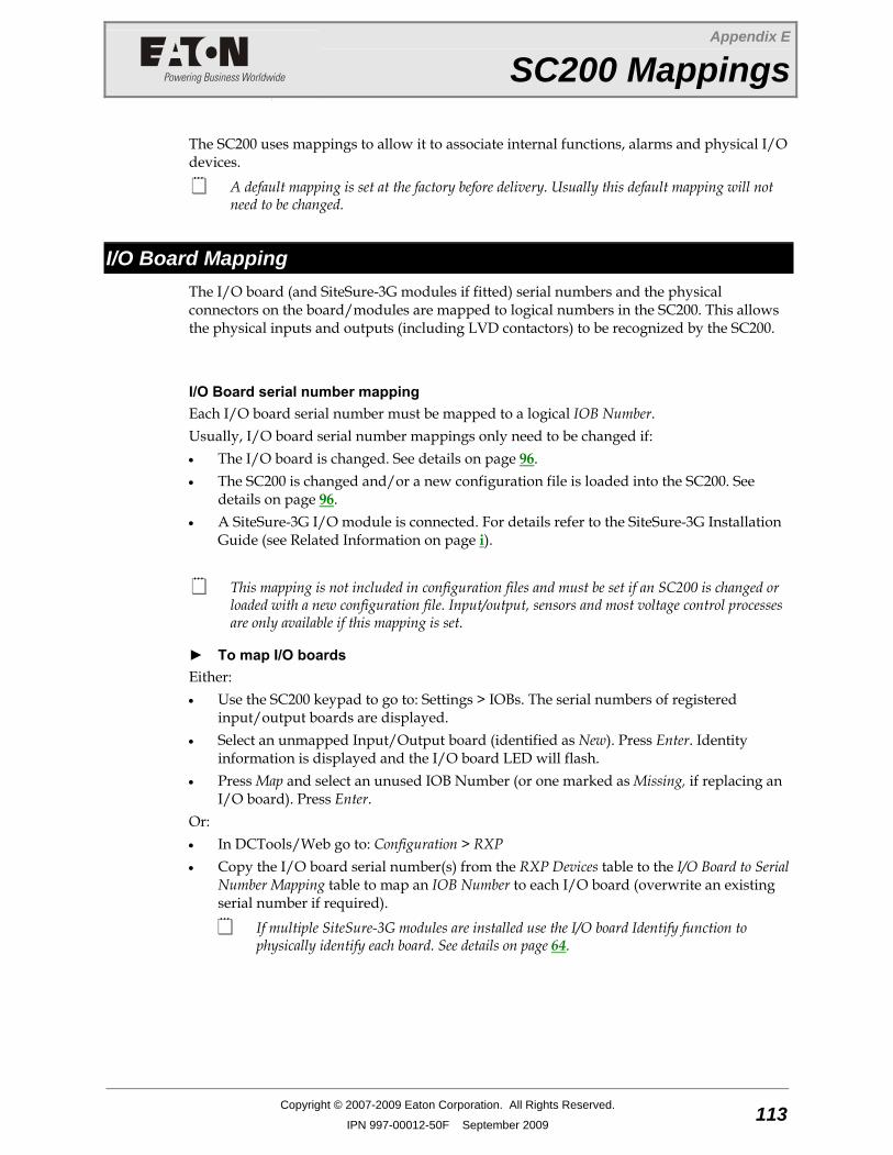
Appendix E
SC200 Mappings
Copyright © 2007-2009 Eaton Corporation. All Rights Reserved.
IPN 997-00012-50F September 2009 113
A p p e n d i x E SC200 Mappings
The SC200 uses mappings to allow it to associate internal functions, alarms and physical I/O devices.
A default mapping is set at the factory before delivery. Usually this default mapping will not need to be changed.
I/O Board Mapping The I/O board (and SiteSure-3G modules if fitted) serial numbers and the physical connectors on the board/modules are mapped to logical numbers in the SC200. This allows the physical inputs and outputs (including LVD contactors) to be recognized by the SC200.
I/O Board serial number mapping Each I/O board serial number must be mapped to a logical IOB Number. Usually, I/O board serial number mappings only need to be changed if: • The I/O board is changed. See details on page 96. • The SC200 is changed and/or a new configuration file is loaded into the SC200. See
details on page 96. • A SiteSure-3G I/O module is connected. For details refer to the SiteSure-3G Installation
Guide (see Related Information on page i).
This mapping is not included in configuration files and must be set if an SC200 is changed or loaded with a new configuration file. Input/output, sensors and most voltage control processes are only available if this mapping is set.
► To map I/O boards Either: • Use the SC200 keypad to go to: Settings > IOBs. The serial numbers of registered
input/output boards are displayed. • Select an unmapped Input/Output board (identified as New). Press Enter. Identity
information is displayed and the I/O board LED will flash. • Press Map and select an unused IOB Number (or one marked as Missing, if replacing an
I/O board). Press Enter. Or: • In DCTools/Web go to: Configuration > RXP • Copy the I/O board serial number(s) from the RXP Devices table to the I/O Board to Serial
Number Mapping table to map an IOB Number to each I/O board (overwrite an existing serial number if required).
If multiple SiteSure-3G modules are installed use the I/O board Identify function to physically identify each board. See details on page 64.

SC200 Handbook
114 Copyright © 2007-2009 Eaton Corporation. All Rights Reserved.
IPN 997-00012-50F September 2009
I/O connector mapping Each I/O connector (analog input, digital input and digital output) on an I/O board must be mapped to a logical IOB Number and IOB AI, IOB DI or IOB DO Number.
► To map I/O connectors See Analog Inputs on page 65, Digital Inputs on page 67 and Digital Outputs on page 68.
The following tables show the default connector mappings:
Analog Input
Name Function* IOB Number
IOB AI Number
Connector
1 IOBGP 1 Bus Voltage Bus Voltage 1 1 XH9
2 IOBGP 1 Mid-point 1 Battery Mid-point 1 2 XH12A
3 IOBGP 1 Mid-point 2 Battery Mid-point 1 3 XH12A
4 IOBGP 1 Mid-point 3 Battery Mid-point 1 4 XH12A
5 IOBGP 1 Mid-point 4 Battery Mid-point 1 5 XH12A
6 Battery Current Battery Current 1 6 XH6
7 Current 2 User Defined 1 7 XH6
8 Current 3 User Defined 1 8 XH6
9 Battery Temperature Battery Temperature
1 9 XH7
10 Temperature 2 User Defined 1 10 XH7
Digital Input
Name Function* IOB Number
IOB DI Number
Connector
1 Digital Input 1 User Defined 1 1 XH15A
2 Digital Input 2 User Defined 1 2 XH15A
3 Digital Input 3 User Defined 1 3 XH15A
4 Digital Input 4 User Defined 1 4 XH15B
5 Digital Input 5 User Defined 1 5 XH15B
6 Digital Input 6 User Defined 1 6 XH15B
7 Load Fuse Fail Load Fuse Fail 1 7 YH3
8 Battery Fuse Fail Battery Fuse Fail 1 8 YH3
9 ACD Fan Fail ACD Fan Fail 1 9 YH3
10 MOV Fail MOV Fail 1 10 YH3
* Function is an internal analog or digital input value used by the SC200 for voltage control processes, and/or to generate System States, and/or to generate system alarms.
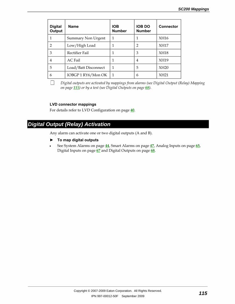
SC200 Mappings
Copyright © 2007-2009 Eaton Corporation. All Rights Reserved.
IPN 997-00012-50F September 2009 115
Digital Output
Name IOB Number
IOB DO Number
Connector
1 Summary Non Urgent 1 1 XH16
2 Low/High Load 1 2 XH17
3 Rectifier Fail 1 3 XH18
4 AC Fail 1 4 XH19
5 Load/Batt Disconnect 1 5 XH20
6 IOBGP 1 RY6/Mon OK 1 6 XH21
Digital outputs are activated by mappings from alarms (see Digital Output (Relay) Mapping on page 115) or by a test (see Digital Outputs on page 68).
LVD connector mappings For details refer to LVD Configuration on page 40.
Digital Output (Relay) Activation Any alarm can activate one or two digital outputs (A and B).
► To map digital outputs • See System Alarms on page 44, Smart Alarms on page 47, Analog Inputs on page 65,
Digital Inputs on page 67 and Digital Outputs on page 68.

SC200 Handbook
116 Copyright © 2007-2009 Eaton Corporation. All Rights Reserved.
IPN 997-00012-50F September 2009

Copyright © 2007-2009 Eaton Corporation. All Rights Reserved.
IPN 997-00012-50F September 2009 117
Equipment Incident Report
EQUIPMENT INCIDENT REPORT
Please enter as much information as you can. Send the completed form, together with the item for repair to your nearest authorized service agent. NOTE: Only one fault to be recorded per form. For further information contact your local Eaton dc product supplier or Eaton (see contact details on page 119). Or email: [email protected]
Date:
Customer Information
Company:
Postal Address:
Return Address: (Not PO Box)
Telephone: Fax: Email:
Contact Name:
Location of Failure
Product code: Serial number: Document number:
System type installed in: Serial number:
Site name or location:
Fault discovered Delivery Unpacking Installation
Initial test Operation after _____ years Other ___________
Failure source Design Manufacturing Documentation
Transportation Installation Handling
___________
Effect on system operation None Minor Major _________________
INFORMATION (fault details, circumstances, consequences, actions)
Internal use only. Reference No: __________ RMA: __________ NCR: __________ Signature: _________________ Date: __________

118 Copyright © 2007-2009 Eaton Corporation. All Rights Reserved.
IPN 997-00012-50F September 2009
INFORMATION continued (fault details, circumstances, consequences, actions)
SG/03 ISS06

Worldwide Support
Copyright © 2007-2009 Eaton Corporation. All Rights Reserved.
IPN 997-00012-50F September 2009 119
Worldwide Support
For product information and a complete listing of worldwide sales offices, visit Eaton's website at: www.eaton.com/telecompower or email: [email protected] For technical support contact either your local Eaton dc product representative, the closest office from the following list, telephone (+64) 3 343-7448, or email [email protected]
Australia 1300 877 359
Canada 1-800-461-9166
Central America +52 55 9000 5252
China +86-571-8848-0166
Europe / Middle East / Africa +44-1243-810-500
Hong Kong / Korea / Japan +852-2745-6682
India +91-11-4223-2325
New Zealand 0800 DC Power (327-693)
Singapore / South East Asia +65 6825 1668
South America +54-11-4124-4000
South Pacific +64-3-343-7448
Taiwan +886-2-6600-6688 or free call 0800-038-168
United States of America (Toll Free)
1-800-843-9433

SC200 Handbook
120 Copyright © 2007-2009 Eaton Corporation. All Rights Reserved.
IPN 997-00012-50F September 2009
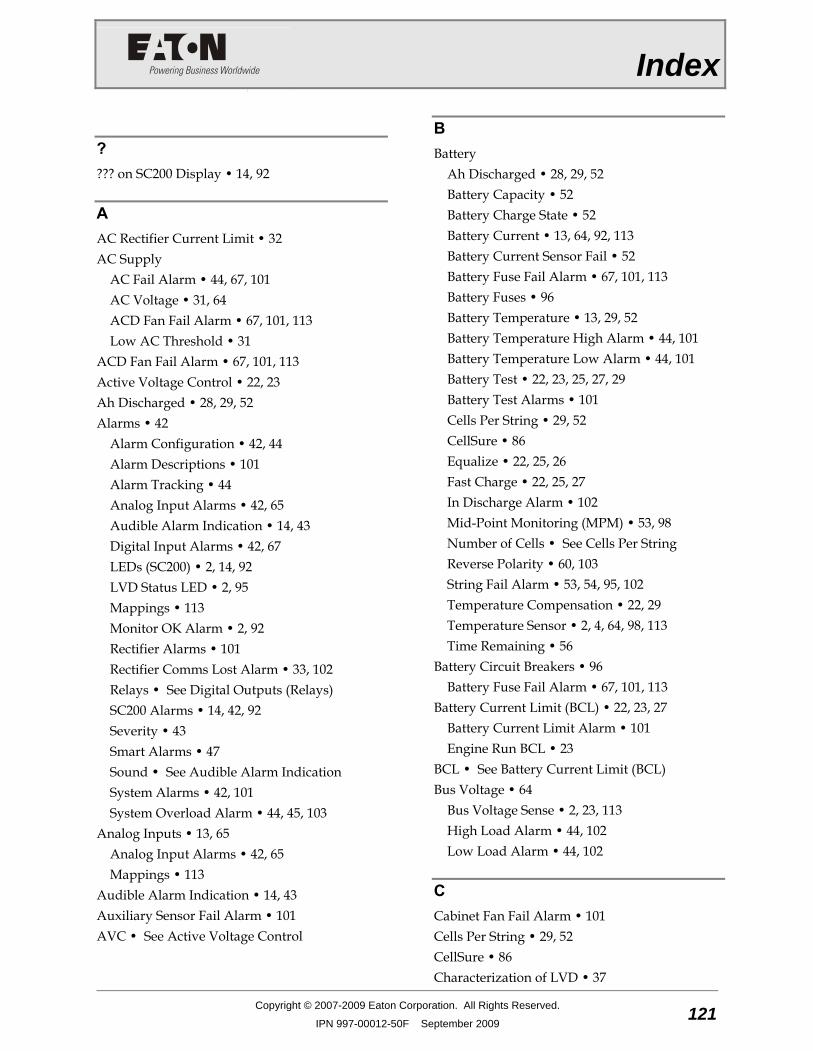
Index
Copyright © 2007-2009 Eaton Corporation. All Rights Reserved.
IPN 997-00012-50F September 2009 121
Index
? ??? on SC200 Display • 14, 92
A AC Rectifier Current Limit • 32 AC Supply
AC Fail Alarm • 44, 67, 101 AC Voltage • 31, 64 ACD Fan Fail Alarm • 67, 101, 113 Low AC Threshold • 31
ACD Fan Fail Alarm • 67, 101, 113 Active Voltage Control • 22, 23 Ah Discharged • 28, 29, 52 Alarms • 42
Alarm Configuration • 42, 44 Alarm Descriptions • 101 Alarm Tracking • 44 Analog Input Alarms • 42, 65 Audible Alarm Indication • 14, 43 Digital Input Alarms • 42, 67 LEDs (SC200) • 2, 14, 92 LVD Status LED • 2, 95 Mappings • 113 Monitor OK Alarm • 2, 92 Rectifier Alarms • 101 Rectifier Comms Lost Alarm • 33, 102 Relays • See Digital Outputs (Relays) SC200 Alarms • 14, 42, 92 Severity • 43 Smart Alarms • 47 Sound • See Audible Alarm Indication System Alarms • 42, 101 System Overload Alarm • 44, 45, 103
Analog Inputs • 13, 65 Analog Input Alarms • 42, 65 Mappings • 113
Audible Alarm Indication • 14, 43 Auxiliary Sensor Fail Alarm • 101 AVC • See Active Voltage Control
B Battery
Ah Discharged • 28, 29, 52 Battery Capacity • 52 Battery Charge State • 52 Battery Current • 13, 64, 92, 113 Battery Current Sensor Fail • 52 Battery Fuse Fail Alarm • 67, 101, 113 Battery Fuses • 96 Battery Temperature • 13, 29, 52 Battery Temperature High Alarm • 44, 101 Battery Temperature Low Alarm • 44, 101 Battery Test • 22, 23, 25, 27, 29 Battery Test Alarms • 101 Cells Per String • 29, 52 CellSure • 86 Equalize • 22, 25, 26 Fast Charge • 22, 25, 27 In Discharge Alarm • 102 Mid-Point Monitoring (MPM) • 53, 98 Number of Cells • See Cells Per String Reverse Polarity • 60, 103 String Fail Alarm • 53, 54, 95, 102 Temperature Compensation • 22, 29 Temperature Sensor • 2, 4, 64, 98, 113 Time Remaining • 56
Battery Circuit Breakers • 96 Battery Fuse Fail Alarm • 67, 101, 113
Battery Current Limit (BCL) • 22, 23, 27 Battery Current Limit Alarm • 101 Engine Run BCL • 23
BCL • See Battery Current Limit (BCL) Bus Voltage • 64
Bus Voltage Sense • 2, 23, 113 High Load Alarm • 44, 102 Low Load Alarm • 44, 102
C Cabinet Fan Fail Alarm • 101 Cells Per String • 29, 52 CellSure • 86 Characterization of LVD • 37

SC200 Handbook
122 Copyright © 2007-2009 Eaton Corporation. All Rights Reserved.
IPN 997-00012-50F September 2009
Circuit Breakers Battery Fuse Fail Alarm • 67, 101, 113 Load Fuse Fail Alarm • 67, 102, 113
Communications • 74, 97 Communications Options • 74 Connector • 2, 4 CSP • 89 DCTools • 5 Ethernet Communications • 74, 93 GSM Modem Communications • 83, 93 HTTP/HTTPS • 88 Loss of Communications • 87 MAC Address • 74 Modbus • 79 Problems • See Troubleshooting PSTN Modem Communications • 81, 93 Security • 87 Serial Server • 86 SNMP • 77 USB Communications • 14, 94 Web Access Security • 88, 94 Web Browsers (recommended) • 5 Web Server • 76, 94 Write Access Password • 87, 93
Configuration File • 19, 42 Backup and Restore • 20 Changing a Configuration Setting • 12
Contrast • See Display Settings Control • See Voltage Control CSP • 89 Current
Battery Current • 13, 64, 92, 113 Load Current • 13, 64, 92 No Load Alarm • 102 Rectifier Current • 8, 13, 64
Current Limit Battery Current Limit (BCL) • 22, 23, 27 Rectifier Current Limit • 32
Current Sense • 2, 4, 64, 98, 113
D Data Logging • 70
Data Log • 71 Event Log • 70 PC Log • 72
System Event Types • 111 DCTools • 5
N/A (in DCTools/Web) • 92 Software Versions • 5 Target Failed to Respond Error • 93 Write Access Password • 87, 93
Digital Inputs • 67, 98, 113 Connectors • 2, 4, 107 Digital Input Alarms • 42, 67 Mappings • 113 System States • 67
Digital Outputs (Relays) • 43, 68, 97 Connectors • 2, 4, 107 Relay Mapping • 44, 67, 68, 115 Remote Control State • 68 Test Digital Outputs • 68
Display Settings • 13 Language • 18
E Email Alarm Messages • 85 Engine Run BCL • 23 Equalize • 22, 25, 26
Equalize Active Alarm • 101 Ethernet
Connector • 2, 4 Ethernet Communications • 74, 93 MAC Address • 74 Problems • See Troubleshooting
Event Log • 70 System Event Types • 111
F Fast Charge • 22, 25, 27
Fast Charge Active Alarm • 101 Float Voltage • 22, 31
High Float Alarm • 44, 101 Low Batt Temp Alarm • 44, 102
Function • 67 Fuse
Battery Fuses • 96 Load Fuses • 96
Index
Copyright © 2007-2009 Eaton Corporation. All Rights Reserved.
IPN 997-00012-50F September 2009 123
G Generator
Generator Control Option • 61 Generator Enable Alarm • 101 Generator Fail Alarm • 44, 61, 101
GSM Modem Communications • 83, 93
H Heatsink Temperature • 31 High Float Alarm • 44, 101 High Load Alarm • 44, 102 Horizontal/Vertical Setting of Display • See
Display Settings HTTP/HTTPS • 88
I Identify a Rectifier • 32 Identify an I/O Board • 64 Identity Information • 16 In Discharge Alarm • 102 Input/Output (I/O) Board
Additional I/O • See SiteSure-3G I/O module
Analog Inputs • 13, 65 Connections to other system components • 4 Connector Pin-outs • 107 Description • 2 Digital Inputs • 67, 98, 113 I/O Board Mapping • 113 Identify an I/O Board • 64 LVD Status LED • 2, 95 Power On LED • 2, 95 Repair and Return • 117 Replacing the Input/Output Board • 96
Internal Clock • 16, 95
K Keypad
Keypad Access Security • 12, 92
L Language • 18 LCD Display • 9, 92
Display Settings • 13
Language • 18 LEDs
LEDs (SC200) • 2, 14, 92 LVD Status LED • 2, 95 Power On LED • 2, 95 Troubleshooting • 92
Load Circuit Breakers • 96 Load Fuse Fail Alarm • 67, 102, 113
Load Current • 13, 64, 92 Load Fuse Fail Alarm • 67, 102, 113 Load Fuses • 96 Load Power • 13, 64 Load-Based Rectifier Shutdown • 34 Locate Rectifier • See Identify a Rectifier Log • See Data Logging Logon (SC200) • 12 Logon ID (Web) • 88 Low AC Threshold • 31 Low Batt Temp Alarm • 44, 102 Low Load Alarm • 44, 102 Low Voltage Disconnect (LVD) • 37
Characterization of LVD • 37 Connectors • 2, 4, 107 LVD Alarms • 102, See Troubleshooting LVD Status LED • 2, 95 Mappings • 113 Problems • 95
LVD • See Low Voltage Disconnect (LVD)
M MAC Address • 74 Main Screen • 8, 13
Main Screen Items • 13 Mains Fail Alarm • See AC Fail Alarm Mappings • 113 Mid-Point Monitoring (MPM) • 53, 98
String Fail Alarm • 53, 54, 95, 102 Missing Hardware Alarm • 102 Modbus • 79 Modem (PSTN, GSM) • See Communications Monitor OK Alarm • 2, 92 MOVs
MOV Fail Alarm • 67, 102, 113 MPM • See Mid-Point Monitoring (MPM) Multiple Rectifier Comms Lost Alarm • 102
SC200 Handbook
124 Copyright © 2007-2009 Eaton Corporation. All Rights Reserved.
IPN 997-00012-50F September 2009
Multiple Rectifier Fail Alarm • 102
N N/A (in DCTools/Web) • 92 Network Management System (NMS) • See
SNMP No Load Alarm • 102 Number of Cells • See Cells Per String
O Output Voltage and Current • 22, 31, 64 Over Voltage Shut Down (OVSD) • 32
P Partial AC Fail Alarm • 102 Password
Web Access Security • 88, 94 Write Access Password • 87, 93
PC Log • 72 PC/Laptop (Connection via USB) • See USB
Communications Polarity
Reverse Polarity • 60, 103 Power
Load Power • 13, 64 System Power • 13, 64
PowerManagerII • 5, 43 Problems • See Troubleshooting Protection • See Security PSTN Modem Communications • 81, 93
R Ramp Up Slope • 32 Rectifiers
AC Rectifier Current Limit • 32 Heatsink Temperature • 31 Identify a Rectifier • 32 Load Power • 13, 64 Load-Based Rectifier Shutdown • 34 Locate Rectifier • See Identify a Rectifier Output Voltage and Current • 22, 31, 64 Over Voltage Shut Down (OVSD) • 32 Problems • See Troubleshooting Ramp Up Slope • 32 Rectifier Alarms • 101
Rectifier Comms Lost Alarm • 33, 102 Rectifier Current • 8, 13, 64 Rectifier Current Limit • 32 Registration • 31 Repair and Return • 117 Restart Rectifier(s) • 33 Serial Number • 31, 32 Shutdown • 32, 33 Start Up Delay • 32 System Overload Alarm • 44, 45, 103 System Power • 13, 64 Voltage Control • 22
Relays • See Digital Outputs (Relays) Monitor OK Alarm • 2, 92 Relay Mapping • 44, 67, 68, 115
Remote Control State • 68 Repair and Return • 117 Restart Rectifier(s) • 33 Reverse Polarity • 60, 103 RS232 • 80
Connector • 2, 4 Modem (PSTN, GSM) • See Communications Serial Server • 86
S SC200 system controller
??? on SC200 Display • 14, 92 Alarm Descriptions • 101 Changing a Configuration Setting • 12 Configuration File • 19, 42 Connections to other system components • 4 Connector Pin-outs • 105, 107 Description • 2 Display Settings • 13 Firmware Upgrade • 19 Identity Information • 16 Internal Clock • 16, 95 Keypad • 9, 92 Language • 18 LEDs (SC200) • 2, 14, 92 Main Menu • 10 Main Screen • 8, 13 Mappings • 113 N/A (in DCTools/Web) • 92 Problems • See Troubleshooting
Index
Copyright © 2007-2009 Eaton Corporation. All Rights Reserved.
IPN 997-00012-50F September 2009 125
Repair and Return • 117 Replacing the System Controller • 96 SC200 Alarms • 14, 42, 92 Security • See Keypad Access Security Startup • 8
Security • 87 Keypad Access Security • 12, 92 Web Access Security • 88, 94 Write Access Password • 87, 93
Sensor Fail Alarm • 102 Auxiliary Sensor Fail Alarm • 101
Serial Server • 86 Servicing • 117, 119 Severity • 43 Shutdown • 32, 33
Load-Based Rectifier Shutdown • 34 Over Voltage Shut Down (OVSD) • 32 Restart Rectifier(s) • 33
SiteSure-3G I/O module • 63 Smart Alarms • 47 SMS Text Messaging • See GSM Modem
Communications SNMP • 77 SNTP • See Internal Clock Software Versions • 5 Sound • See Audible Alarm Indication Specifications • 97 Standby Mode • 102 Start Up Delay • 32 String Fail Alarm • 53, 54, 95, 102 System Alarms • 42, 101
System Overload Alarm • 44, 45, 103 System Power • 13, 64 System States • 67
T Target Failed to Respond Error • 93 Technical Assistance • 119 Temperature
Battery Temperature • 13, 29, 52 Battery Temperature High Alarm • 44, 101 Battery Temperature Low Alarm • 44, 101 Heatsink Temperature • 31 Temperature Compensation • 22, 29 Temperature Sensor • 2, 4, 64, 98, 113
Test Digital Outputs • 68 Text Messaging (SMS) • See GSM Modem
Communications Time • See Internal Clock Time Remaining • 56 Transient Voltage Protection
MOV Fail Alarm • 67, 102, 113 Translation • 18 Troubleshooting • 92
Repair and Return • 117 Servicing • 117, 119 Technical Assistance • 119
U Unknown Hardware Alarm • 103 USB
Connector • 2, 4 Problems • See Troubleshooting USB Cable • 15 USB Communications • 14, 94
V Vertical/Horizontal Setting of Display • See
Display Settings Voltage (Bus) • 64, See Bus Voltage Sense Voltage Control • 22
Active Voltage Control • 22, 23 Bus Voltage Sense • 2, 23, 113
Voltage Feed Module • 4
W Web
Language • 18 Web Access Security • 88, 94 Web Browsers (recommended) • 5 Web Server • 76, 94
Web Browsers (recommended) • 5 Write Access Password • 87, 93