Access Controller M3 - Tenda.cz
65
Access Controller M3 User Manual
-
Upload
khangminh22 -
Category
Documents
-
view
1 -
download
0
Transcript of Access Controller M3 - Tenda.cz

Access Controller M3
User Manual

i
Copyright Statement
© 2018 Shenzhen Tenda Technology Co., Ltd. All rights reserved.
is a registered trademark legally held by Shenzhen Tenda Technology Co., Ltd. Other brand and
product names mentioned herein are trademarks or registered trademarks of their respective holders. Copyright
of the whole product as integration, including its accessories and software, belongs to Shenzhen Tenda
Technology Co., Ltd. No part of this publication can be reproduced, transmitted, transcribed, stored in a retrieval
system, or translated into any language in any form or by any means without the prior written permission of
Shenzhen Tenda Technology Co., Ltd.
Disclaimer
Pictures, images and product specifications herein are for references only. To improve internal design,
operational function, and/or reliability, Tenda reserves the right to make changes to the products without
obligation to notify any person or organization of such revisions or changes. Tenda does not assume any liability
that may occur due to the use or application of the product described herein. Every effort has been made in the
preparation of this document to ensure accuracy of the contents, but all statements, information and
recommendations in this document do not constitute the warranty of any kind, express or implied.

ii
Preface
Thank you for choosing Tenda! Please read this user guide before you start with M3.
Conventions
If not specifically indicated, “AC”, “this device” or “this product” mentioned in this User Guide stands for this AC.
In this User Guide, we assume that all settings on this device are kept in default factory settings.
Typographical conventions in this User Guide:
Item Presentation Example
Cascading Menus > Click Status > Device Status
Parameter and value Bold Set User Name to Tom.
UI control Bold On the Policy page, click the OK button.
Variable Italic Format: XX:XX:XX:XX:XX:XX
Message “ ” The “Success” message appears.
Symbols in this User Guide:
Item Meaning
This format is used to highlight information of importance or special interest. Ignoring this type of note may result in ineffective configurations, loss of data or damage to device.
This format is used to highlight a procedure that will save time or resources.
Acronyms and Abbreviations
Acronym or
Abbreviation Full Spelling
AC Access Controller
AP Access Point
DHCP Dynamic Host Configuration Protocol
DNS Domain Name System
ISP Internet Service Provider

iii
Acronym or
Abbreviation Full Spelling
SSID Service Set Identifier
VLAN Virtual Local Area Network
Technical Support
If you need more help, contact us by any of the following means. We will be glad to assist you as soon as
possible.
Hotline
Canada: 1-888-998-8966
Hong Kong: 00852-81931998
Website
http://www.tendacn.com
Skype
tendasz

iv
Contents 1 Know Your Device .............................................................................................................................................. 1
1.1 Overview ...................................................................................................................................................... 1
1.2 Apperance .................................................................................................................................................... 1
1.2.1 Front Panel ........................................................................................................................................ 1
1.2.2 Rear Panel ......................................................................................................................................... 2
1.2.3 Label .................................................................................................................................................. 2
1.3 Application Topology ................................................................................................................................... 3
2 Web Login .......................................................................................................................................................... 4
2.1 Web Login .................................................................................................................................................... 4
2.2 Web Logout .................................................................................................................................................. 6
2.3 Layout of Web UI ......................................................................................................................................... 6
2.4 Commonly Used Elements on UI ................................................................................................................. 7
3 Function Descriptions ........................................................................................................................................ 8
3.1 Discover AP .................................................................................................................................................. 8
3.1.1 Discover AP ....................................................................................................................................... 9
3.1.2 Discover SSID .................................................................................................................................. 10
3.1.3 Export the scanned SSID information ............................................................................................. 11
3.1.4 Deleting offline APs ......................................................................................................................... 11
3.2 Manage Policy ............................................................................................................................................ 12
3.2.1 SSID Policy ....................................................................................................................................... 12
3.2.2 Radio Policy ..................................................................................................................................... 15

v
3.2.3 VLAN policy ..................................................................................................................................... 18
3.2.4 Maintain Policy ............................................................................................................................... 20
3.3 Manage AP ................................................................................................................................................. 27
3.3.1 AP Group Modify ............................................................................................................................ 27
3.3.2 AP Modify ....................................................................................................................................... 32
3.4 User Status ................................................................................................................................................. 39
3.5 System Tools .............................................................................................................................................. 40
3.5.1 System Status .................................................................................................................................. 40
3.5.2 Network Setting .............................................................................................................................. 42
3.5.3 DHCP List For AP ............................................................................................................................. 48
3.5.4 Maintain .......................................................................................................................................... 49
3.5.5 Date&Time ...................................................................................................................................... 52
3.5.6 System Log ...................................................................................................................................... 55
3.5.7 Network Diagnosis .......................................................................................................................... 55
Appendix .................................................................................................................................................................. 58
A.1 Troubleshooting ......................................................................................................................................... 58
A.2 Default Factory Settings ............................................................................................................................ 59

1
1 Know Your Device
1.1 Overview
Tenda M3 is a multifunctional access controller. It supports a maximum of 64 Tenda APs to be managed in a
centralized manner, providing managemable and high-stable wireless network solutions to
small-to-medium-sized enterprises, higher education institutions and hotels.
1.2 Apperance
1.2.1 Front Panel
The front panel contains the following parts: LEDs, LAN port and RESET button.
LED indicators
LED
Indicator Color Status Description
POWER Green
Solid Proper connection to power supply.
Off Improper connection to power supply or malfunction occurs.
SYS Green
Solid The system is starting.
Blinking The system is functioning normally.
Link Orange
Solid A valid link has been established over the corresponding port.
Off No link is established over the corresponding port or malfunction occurs.
Act Green
Blinking Data is transmitted over the corresponding port.
Off No data is transmitted over the corresponding port.

2
LAN port
Five 10/100/1000 Mbps auto-negotiation RJ45 ports. Each RJ45 port has its corresponding Link/Act LED.
RESET button
When the AC is functioning properly, press it with a needle for about 6 seconds and then release; about 45
seconds later, this device will be restored to factory settings.
1.2.2 Rear Panel
Power Interface
Used to connect to the included power adapter for power supply.
1.2.3 Label
1 Default login IP address used to log in to this AC’s web UI.
2 Default login user name and password for web access.
3 This AC’s power specification.
4 S/N: If there goes something wrong with your device and you need to send it to our technical staff for repair,
you will need this sequence number.
1
3
4
2

3
1.3 Application Topology
See the following figure below.
For simple networks with few APs, you can connect the PoE switch directly to M3.
AP
Router
Core Switch AC
PoE Swicth
AP AP
Smartphone Tablet Laptop

4
2 Web Login
2.1 Web Login
The first time you use this AC, you can access its web UI with the following default login information:
Login information Default settings
User Name admin
Password admin
IP Address 192.168.10.1
Step 1 Connect your PC to a LAN port of the AC directly, or to the switch connected to the AC.
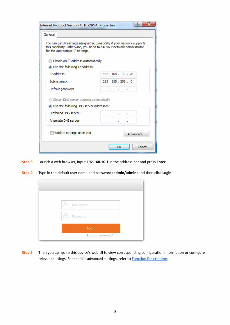
Step 2 Set your PC to an IP address within the following range: 192.168.10.X (2-254), which is 192.168.10.26
in this example, and with the subnet mask of 255.255.255.0.
AC
PC
5
Step 3 Launch a web browser, input 192.168.10.1 in the address bar and press Enter.
Step 4 Type in the default user name and password (admin/admin) and then click Login.
Step 5 Then you can go to this device’s web UI to view corresponding configuration information or configure
relevant settings. For specific advanced settings, refer to Function Descriptions.

6
----End
2.2 Web Logout
You can safely exit this AC’s web UI by directly closing your web browser or clicking Logout in the upper right
corner of the web UI.
2.3 Layout of Web UI
The Web page can be divided into three parts: navigation bar and the configuration section.
Sequence
Number Name Description
❶ Level-1 navigation
bar The navigation bar presents web administration functions to you in the form of
navigation tree. This section allows you to select function menus here.
❷ Level-2 navigation
bar
❸ Configuration
Section This section allows you to configure and view settings here.
❷
❶
❸

7
If features or parameters on the web UI display grey, they are not configurable.
2.4 Commonly Used Elements on UI
Port Graphical Status Overview:
Commonly Used Elements Description
Indicates no link is established over the corresponding port.
Indicates a link has been established over the corresponding port.
Commonly Used Buttons:
Commonly Used Elements Description
Save Used to save your current configurations.
Cancel Used to save your current configurations which haven’t been saved.

8
3 Function Descriptions
3.1 Discover AP
This section gives you an overview of the information of connected APs, including online and offline APs.
Button Description:
Button Description
Used to scan the Aps in the network.
Used to scan the enabled SSID information of online APs.
Used to scan and saving results of Discover AP displayed on the page to your local computer as an
excel spreadsheet.
Used to delete the selected offline APs.

9
3.1.1 Discover AP
Click Discover AP to enter the page below:
Parameter Description:
Parameter Description
Model The model number of the AP.
Remark The comment of the AP. By default, it indicates the model number of the AP. When the AP is
online, click it to modify.
You are recommended to remark the AP using its location, so as to help you precisiely locate the
AP that works improperly using the log or alert record.
IP IP address of the AP.When the AP connects to the controller for the first time, the DHCP server
on the controller will automatically assign an IP address to the AP.
MAC MAC address of the AP.
Online User The amount of online users connected to the WiFi network of the AP.
SSID Wireless network name of the AP.
Channel The wireless operating channel of the AP.
Version The firmware version number of the AP.
Status AP’s connection status:
Online: The AP has been connected to the AC successfully and the AC can manage the AP.
Offline: The AP has not been connected to the AC. The AC can’t manage the AP.
When the AP is offline, it still retains the previous configuration sent by the AC, and you can
normally connect to its WiFi network, unless it is reset.

10
3.1.2 Discover SSID
To scan SSIDs on your network, click Discover SSID, the scanned information will be displayed on the page.
Parameter Description:
Parameter Description
Model The model number of the AP.
Remark The comment information of the AP. By default, it indicates the model number of the AP. When
the AP is online, click it to modify.
SSID NO The order of the SSID. The format is xx:xx--a, xx:xx indicates the last four characters of the MAC
address of the AP, and a is a digit number which represents the order of the SSID. For example,
EA:60--6 means the sixth SSID of the AP with the MAC address ending with EA:60.
SSID The paimary wireless network name of the AP.
MAC MAC address of the AP.
Online/Limits Online indicates the amount of clients currentlty connected to the primary SSID, while Limits
indicates the maximum amount allowed to connect to the primary SSID.
Channel The wireless operating channel of the AP.
Status AP’s connection status:
Online: The AP has been connected to the AC successfully and the AC can manage the AP.
Offline: The AP has not been connected to the AC. The AC can’t manage the AP.
When the AP is offline, it still retains the previous configuration sent by the AC, and you can
normally connect to its WiFi network, unless it is reset.

11
3.1.3 Export the scanned SSID information To export the scanned SSID information, click Export, the following window pops up, clikc OK, an Excel file is downloaded to your local computer.
3.1.4 Deleting offline APs
Select the offline AP you wan to delete, click Delete.

12
3.2 Manage Policy
This section helps you create SSID Policy, Radio Policy, VLAN Policy, and Maintain Policy.
3.2.1 SSID Policy
Here you can view the basic information of SSID policies. SSID parameters include SSID, Security key, VLAN ID,
and so on.
To create an SSID policy, click Manage Policy > SSID Policy to enter the page below.
Button Description:
Button Description
Used to add a new SSID policy.
Used to delete the selected SSID policies in Not Used status.
It is the action button used to modify parameters excluding Policy name.
13
Button Description
You are not recommended to modify the Used policies.
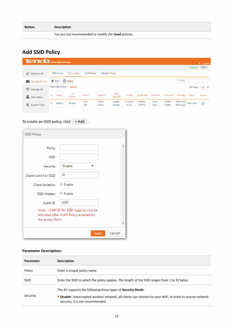
Add SSID Policy
To create an SSID policy, click + Add .
Parameter Description:
Parameter Description
Policy Enter a unique policy name.
SSID Enter the SSID to which the policy applies. The length of the SSID ranges from 1 to 32 bytes.
Security
The AC supports the following three types of Security Mode:
Disable: Unencrypted wireless network, all clients can connect to your WiFi. In order to ensure network
security, it is not recommended.

14
Parameter Description
WPA-PSK: The security mode of the wireless network is WPA-PSK.
WPA2-PSK: The security mode of the wireless network is WPA2-PSK.
WPA-Enterprise: The security mode of the wireless network is WPA-Enterprise.
WPA2-Enterprise: The security mode of the wireless network is WPA2-Enterprise.
Encryption
It is available only when Security is enabled.
The AC supports the following three types of encryption:
AES: AES is short for Advanced Encryption Standard. This encryption algorithm ensures a higher
wireless rate.
TKIP: TKIP is short for Temporal Key Integrity Protocol. Wireless rate can only reach 54 Mbps with this
algorithm.
TKIP&AES: Compatible with TKIP and AES. The wireless client can use either AES or TKIP algorithm to
connect to the WiFi.
Security Key
It is available only when security is enabled.
Wireless clients need to enter this security key to connect to a corresponding AP.
The range of length is 8-63 characters.
Key interval
It is available only when security is enabled.
Configure the key update interval for encrypting WPA data. Theoretically, the shorter the key interval is,
the more secure the WPA data will be. If set to 0, the key will not be updated.
Client Limit For
SSID
Used to specify the upper limit allowed to connect to the corresponding SSID. Value range: 1-64.
Client Isolation
Enable/Disable client isolation.
Enable: Wireless clients that connect to the SSID cannot communicate with each other.
Disable: Wireless clients that connect to the SSID can communicate with each other.
SSID Hidden
Enable/Disable SSID Hidden function.
Enable: With this function enabled, the SSID will not be broadcasted so that the SSIDs can not be found
in the clients' available network list. Users need to manually enter the SSID to their clients connect to
the wireless network.
Disable: The SSID will be broadcasted and will be discovered by adjacent devices.
VLAN ID
Set VLAN ID of the SSID and all packets from connected clients will be tagged with this VLAN ID.
VLAN ID is not effective unless VLAN Policy is delivered.
Status Display whether the policy is used or not.
Action
Modify the parameters except policy name.
You are not recommended to modify the Used policies.

15
3.2.2 Radio Policy
Here you can view the basic information of Radio policies including 5G Prority, Radio, Mode, Bandwidth, Channel,
Time Age, and so on.
To create a radio policy, click Manage Policy > Radio Policy to enter the page below.
Button Description:
Button Description
Used to add radio policy.
Used to delete the selected Radio plicies in Not Used status.
Used to modify the parameters except policy name.
You are not recommended to modify the Used policies.
Add Radio Policy
To add a radio policy, click + Add .

16
Parameter Description:
Parameter Description
Policy Enter a unique policy name.
Radio
Supports 2.4 GHz and 5 GHz bands. Different radio provides different signal strength and quality over
different distance ranges. 2.4 GHz offers long distance data transmission, while the 5 GHz offers
high-speed data transmission.
WiFi Enable/disable 2.4 GHz or 5 GHz radio frequency.
Airtime scheduling
It is recommended to enable this function.
Dynamic airtime scheduling gives equal airtime rather than frame transmission opportunity to clients,
thereby allowing high-speed clients to achieve much higher throughput without significantly impacting
the slow-speed clients.
Country It specifies country or region where this device is located. You can select the country or region to ensure
that this device complies with the channel regulations of the country or region.

17
Parameter Description
Network Mode
Select a Network Mode. 2.4 GHz band includes 11b, 11g, 11b/g and 11b/g/n, while 5 GHz band includes
11a, 11ac and 11a/n. Descriptions are as follows.
11b: Works in 2.4 GHz band and supports up to 11 Mbps.
11g: Works in 2.4 GHz band and supports up to 54 Mbps.
11b/g: If you select this option, wireless clients supporting 802.11b or 802.11g can connect to the WiFi.
11b/g/n: If you select this option, wireless clients supporting 802.11b, 802.11g or 802.11n can connect
to the WiFi.
11a: Works in 5 GHz band and supports up to 54 Mbps.
11ac: Works in 5 GHz band and supports up to 1732Mbps. It is a newer standard that uses wider
channels, QAM and spatial streams for higher throughput.
11a/n: Works in 5 GHz band and supports up to 600Mbps, compatible with 11n.
Bandwidth
Select the wireless bandwidth.
20: 20MHZ channel bandwidth.
40: 40MHZ channel bandwidth.
80: 80MHZ channel bandwidth.
Auto: Automatically adjust the channel bandwidth to 20MHZ or 40MHZ based on surrounding
environment.
Channel Select the wireless channel. Channel range differs from country and radio band.
Extension Channel When bandwidth is 40 or Auto, this is used to determine the channel range of AP.
TX power AP’s wireless transmission power. If this value is greater than the maximum supported power of an AP,
the maximum supported power takes effect after the policy is delivered.
RSSI Threshold
RSSI is short for Received Signal Strength Indication.
If a wireless client’s signal is lower than this value, the client can not connect to the AP, which helps the
client connect to an AP with stronger signal.
WMM
Wi-Fi Multimedia (WMM) provides basic Quality of Service (QoS) features to IEEE 802.11 networks. The
WMM mechanism divides WLAN traffic by priority in descending order into the AC-VO (voice stream),
AC-VI (video stream), AC-BE (best effort), and AC-BK (background) access categories. The access category
uses queues with different priorities to send packets.
The WMM mechanism ensures that packets in queues with higher priorities have more opportunities to
access channels.
SSID Isolation
Enable/Disable SSID isolation.
When enabled, wireless clients that connect to different SSID of the AP cannot communicate with each
other.
APSD
APSD is short for Automatic Power Save Delivery. If it is enabled, the power consumption of this device is
reduced after a specified period during which no traffic is transmitted or received. By default, it is
disabled. By allowing your mobile devices to enter standby or sleep mode, it conserves energy. It is only
effective when you enable WMM.
Time Age For Client After a client connects to the AP, if there is no data transmission within the specified time period, AP will
actively disconnect the client.
5G Priority 5G priority refers to a scenario when a dual band client connects to a dual band AP, the AP makes it

18
Parameter Description
connect to 5 GHz band in higher prority, which helps the AP to reduce interference and workload in 2.4
GHz band and hence improve user experience.
Status Display whether the Policy is used or not.
Action
Use for modifying the parameters except Policy name.
You are not recommended to modify the Used policies.
3.2.3 VLAN policy
Here you can view the basic information of VLAN policies. VLAN policy includes AP's PVID, management VLAN,
trunk ports, and so on.
To create a VLAN policy, click Manage Policy > VLAN Policy to enter the page below.
Button Description:
Button Description
Used to add VLAN policy.
Used to delete the selected VLAN plicies in Not Used status.
Used to modify the parameters except Policy name.
You are not recommended to modify the Used policies.
Add VLAN policy
To add a VLAN policy, go to Manage Policy > VLAN Policy, and click + Add .

19
Parameter Description:
Parameter Description
Policy Enter a unique VLAN Policy name.
AP VLAN
Enable/disable AP's 802.1Q VLAN feature.
After this feature is enabled and this VLAN policy is delivered to AP, "VLAN ID" in Manage Policy > SSID
policy takes effect.
PVID Enter the VLAN ID of AP’s Trunk port. The default value is 1.
Manage Vlan
AP's Management VLAN ID.
If a policy with this value modified is sent to the AP, the AC cannot mange the AP any more. To recover
this function, choose System Tools > Network setting > VLAN Settings, and set the VLAN ID same as that
of the AC.
A management computer can access the AP’s Web UI only when it is in the same VLAN with the AP.
Trunk Mode
Select wired LAN port as a trunk port which allows all VLAN packets to pass.
If AP has only one LAN port, select LAN0.
Access Mode Display the port(s) in access mode. If a port has been set to a trunk port, it cannot be an access port.
LAN 0
LAN 1 Set up the Access port's VLAN ID.
Status Display whether the Policy is used or not.
Action Modify the parameters except Policy name.

20
Parameter Description
You are not recommended to modify the Used policies.
3.2.4 Maintain Policy
Here you can view the information of maintain policies.
To create a maintain policy, alert policy, admin policy or deployment policy, click Manage Policy > Maintain
Policy to enter the page below.
Button Description:
Button Description
Used to add a new maintain policy.
Used to add a new alert policy.
Used to add a new admin policy.
Used to add a new deployment policy.
Used to delete the selecting policies in Not Used status.
Parameter Description:
Parameter Description
Policy Display the unique name of a policy.
LED If the policy is a maintain policy, it indicates the LED indicator status either enable or disable.
Otherwise, it displays ----.
Maintain/Alert/Admin
Policy Display corresponding information of a maintain/alert/admin policy.

21
Parameter Description
Signal Transmission Signal interference between APs can be effectively reduced by adjusting the transmit power of AP. If it
is a capacity-oriented network, please select High Density. Otherwise, select Coverage.
Signal Reception
Select a Signal Reception Method based on different scenarios.
Coverage: It is used in a coverage-oriented network to ensure a higher WiFi coverage.
High Density: It is used in a capacity-oriented network to ensure a better signal quality.
Default: The signal reception is between coverage and high density.
Status Display whether the policy is used or not.
Action
Modify the parameters except policy name.
You are not recommended to modify the Used policies.
Maintain Policy
This section helps you configure the maintain policy, including LED status and auto maintain.
Click + Maintain Policy to add a maintain policy.

22
Parameter Description:
Parameter Description
Policy Enter a unique policy name. Duplicated names are not allowed.
LED Use to turn on or off the AP’s LED indicators.
Auto Maintain Enable/Disable AP’s auto reboot feature. If enabled, the AP will automatically reboot at a specified time
(recommended in leisure time) to ensure AP’s performance.
Maintain Type
Select AP reboot type.
Circularly: The AP will automatically reboot periodically at a specified interval.
Schedule: The AP will automatically reboot at specified date and time.
Maintain Time Specify AP reboot time.
Everyday, Mon,
Tue, Wed, Thu, Fri,
Sat, Sun
Specify AP reboot date when Schedule is selected.
Alert Policy
This section helps you configure AP alert policies, including Software alert, Email alert configurations.
Click + Alert Policy to add an alert policy.

23
Parameter Description:
Parameter Description
Policy Enter a unique policy name. Duplicated names are not allowed.
Software Alert
Enable/Disable the software alert function.
When enabled, please enter the IP address of the host used to receive alert logs, and the AC will send
alert logs directly to the alert client program running on the host.
For the description of alert client program, please refer to Running Alert Client.
Email Alert Enable/Disable Email alert function. With this function enabled, the AC will reqularly send alert logs to
the email you entered here.
Email Server Port Enter the server port of the sending email.
E-mail password Enter the password of the email used to receive alters.
Alert Interval It specifies at which interval the alter email is sent.
AP Failure Alert Enable/Disable AP failure alert function. If enabled, the AC will send alert logs, such as AP reboot, AP
online or offline, and so on.
AP Traffic Alert Enable/Disable AP Traffic Alert. If enabled, the AC will send alert logs when AP traffic reaches its limit.

24
Parameter Description
Traffic Limit When AP Traffic Alert is enabled, the AC will send alert logs when AP traffic reaches this limit.
AP Client Alert Enable/Disable AP Client Alert. The AC will send alert logs when the number of connected clients
reaches its limit.
Client Limit When AP Client Alert is enable, the AC will send alert logs when AP's connected clients reach this
number.
Running Alert Client: (Take Windows 7 for example)
Step 1 Go to the official website www.tendacn.com to download the corresponding alert client software to
the local PC.
Step 2 Save the software to your local computer.
Step 3 Double-click the icon .
Step 4 If the "Do you want to allow the following program from unknown Publisher to make changes to this
computer" dialogue prompts, click Yes .
---End
After a successful installation, the system will generate the following two files in the folder:
The network administrator can view AP's alert logs on the alert client program. Do as follows.
Step 1 Double-click the alert client icon.
Step 2 View AP alert logs on the pop-up page. Click Refresh to view the latest alert logs.
The AC will send AP's alert logs to this file on the host. This file cannot be deleted.
This is the system temporary file, which can be ignored.

25
---End
Admin Policy
This section helps you configure login account and password of AP.
Click + Admin Policy to add an admin policy.
Parameter Description:
Parameter Description
Policy Enter a unique policy name. Duplicated names are not allowed.
User name Set up AP's login account.
Password Set up AP's login password.
Confirm Password Repeat the password.

26
Deployment Policy
This section helps you configure deployment policies, including Signal Transmission, Signal Reception, and
Ethernet Mode.
Click + Deployment Policy to add a deployment policy.
Parameter Description:
Parameter Description
Policy Enter a unique SSID deployment policy name. Duplicated names are not allowed.
Signal Transmission Signal interference between APs can be effectively reduced by adjusting the transmit power of AP. If it
is a capacity-oriented network, please select High Density. Otherwise, select Coverage.
Signal Reception
Select a Signal Reception Method based on different scenarios.
Coverage: It is used in a coverage-oriented network to ensure a higher WiFi coverage.
High Density: It is used in a capacity-oriented network to ensure a better signal quality.
Default: The signal reception is between coverage and high density.
Ethernet mode
Select AP LAN port's Ethernet mode. The default option is 10M Half-Duplex. This mode can transmit in
a longer distance with lower speed. When the distance between AP and the other device are more
than 100 meters, please select 10M half-duplex to make signal travels further. You must ensure that
the other device works in auto negotiation mode, or AP LAN port can't send and receive data.

27
3.3 Manage AP
This section helps you deliver the configured policies to appropriate APs and manage the APs. It includes two
parts, AP Group Modify and AP Modify.
3.3.1 AP Group Modify
Here you can view the basic information and policy of the connected APs. To deliver SSID policy, radio policy,
VLAN policy and maintain policy to APs, click Manage AP > AP Group Modify to enter the page below.
Button Description:
Button Description
Used to deliver an SSID Policy to selected online APs.
Used to deliver a Radio Policy to selected online APs.
Used to deliver a VLAN Policy to selected online APs.
Used to deliver a maintain/alert/admin/deployment policy to selected online APs.
Used to restore the maintain policy and alert policy of the selected online APs to factory settings.
Used to delete the selected offline APs.
Parameter Description:
Parameter Description
Model The model number of the AP.
Remark The comment of AP. In order to manage different AP easily, it is recommended to set up the Remark
name as AP’s branch name or location.
MAC AP MAC address.

28
Parameter Description
SSID AP’s SSID(s). If more than one SSID is delivered to AP, it displays all SSIDs when the cursor is hovering
over.
Radio Policy The delivered radio policy name.
VLAN policy The delivered VLAN policy name.
Maintain Policy The delivered maintain policy name.
Alert Policy The delivered alert policy name.
Admin Policy The delivered admin policy name.
Deployment Policy The delivered deployment policy name.
Status
AP’s connection status:
Online: The AP has been connected to the AC successfully and the AC can manage the AP.
Offline: The AP has not been connected to the AC. The AC can’t configure the AP. In this status,
settings on the AP are saved and you can still connect to it wirelessly if you do not reset your AP.
If the AP is offline, it keeps configuration delivered before. Users can still use their wireless network
unless the AP is restored to factory settings.

29
SSID Setting
To deliver SSID policies to online APs:
Step 1 Log in to the web UI of AC, click Manage AP > AP Group Modify.
Step 2 Select online APs.
Step 3 Click SSID Setting.
Step 4 From the drop-down list, select the SSID policy name.
Step 5 Click Save.
----End
The SSID policies will be delivered to the selected APs.
If an AP does not support 5 GHz band, the 5 GHz band will not be configured.
Only policies compliant with the band of the AP can be sent to the AP successfully.
If an AP supports a maximum of 2 SSIDs, extra selected SSIDs will not be sent to the AP.
RF Setting
To deliver a RF policy to online APs:
Step 1 Log in to the web UI of AC, click Manage AP > AP Group Modify.

30
Step 2 Select online APs.
Step 3 Click RF Setting.
Step 4 From the drop-down list, select the policy name.
Step 5 Click Save.
----End
The RF policy will be delivered to the selected online APs.
VLAN Settings
To deliver a VLAN policy to online APs:
Step 1 Log in to the web UI of AC, click Manage AP > AP Group Modify.
Step 2 Select online APs.
Step 3 Click VLAN Settings.
Step 4 From the drop-down list, select the policy name.
Step 5 Click Save.
----End
The VLAN policy will be delivered to the selected APs.
Maintain Setting
To deliver maintain policies to online APs:

31
Step 1 Log in to the web UI of AC, click Manage AP > AP Group Modify.
Step 2 Select online APs.
Step 3 Click Maintain Policy.
Step 4 From the drop-down list, select the corresponding policy name.
Step 5 Click Save.
----End
The maintain policies will be delivered to the selected APs.
Clear Settings
To restore maintain policy and alert policy of the selected online APs to default factory settings:
Step 1 Log in to the web UI of AC, click Manage AP > AP Group Modify.
Step 2 Select online APs.
Step 3 Click Clear Settings.
----End
The maintain policy here does not include alert policy, admin policy or deployment policy.
Delete
To delete offline APs:
Step 1 Log in to the web UI of AC, click Manage AP > AP Group Modify.

32
Step 2 Select the offline APs to be deleted.
Step 3 Click Delete.
----End
Online APs will not be deleted even if you select them.
3.3.2 AP Modify
To reboot, upgrade and reset selected online APs, to delete selected offline APs or to change RF settings of an AP,
click Manage AP > AP Modify to enter the page below.
Button Description:
Button Description
Used to reboot the selected online APs.
Used to upgrade a firmware for the selected online APs.
Used to restore the selected online APs to factory settings.
Used to delete the selected offline APs.
Parameter Description:
Parameter Description
Model The model number of the AP.
Remark The comment of AP. In order to manage different AP easily, it is recommended to set up the Remark
name as AP’s branch name or location.
MAC AP MAC address.

33
Parameter Description
Radio AP's frequency band. It may be 2.4 GHz or 5 GHz or 2.4 GHz and 5 GHz.
SSID AP’s SSID(s). If more than one SSID is delivered to AP, it displays all SSIDs when the cursor is hovering
over.
Online Users The amount of online users which connect to the AP.
TX Power AP's wireless transmission power. If this value is greater than the maximum supported power of an AP,
the maximum supported power takes effect after the policy is delivered.
Channel AP’s channel.
RSSI
RSSI is short for Received Signal Strength Indication.
If a wireless client’s signal is lower than this value, the client can not connect to the AP, which helps the
client to connect to an AP with stronger signal.
5G Priority
5G priority refers to a scenario when a dual band client connects to a dual band AP, the AP makes it
connect to 5 GHz band in higher prority, which helps the AP to reduce interference and workload in 2.4
GHz band and hence improve user experience.
Version The firmware version of the AP.
Status
AP’s connection status:
Online: The AP has been connected to the AC successfully and the AC can manage the AP.
Offline: The AP has not been connected to the AC. The AC cannot configure the AP. In this status,
settings on the AP are saved and you can still connect to it wirelessly if you do not reset your AP.
If the AP is offline, it keeps configuration delivered before. Users can still use their wireless network unless
the AP is restored to factory settings.
Action Used to modify the AP’s RF settings.
If Status and Action does not appear in this page, please zoom in the page, e.g. 125%, and then drag the slider at the
bottom of the page so that you can view the AP’s status and click in Actions field to modify AP parameters.

34
Reboot
To reboot online APs:
Step 1 Log in to the web UI of AC, click Manage AP > AP Modify.
Step 2 Select online APs to be rebooted.
Step 3 Click Reboot.
----End
Upgrade
To upgrade for online APs:
Step 1 Log in to the web UI of AC, click Manage AP > AP Modify.
Step 2 Select online APs to be upgraded.
Step 3 Click Upgrade.
Step 4 Follow on-screen instructions to finish firmware upgrade.

35
----End
When an AP firmware is upgrading, please DO NOT power off the AP, otherwise it may cause damage to the AP! If a sudden power failure occurs, please upgrade again. If you cannot log in to AP's Web UI after a sudden power failure, please contact our technical support.
Reset
To reset online APs to default factory settings:
Step 1 Log in to the web UI of AC, click Manage AP > AP Modify.
Step 2 Select online APs to be reset.
Step 3 Click Reset.
----End
Delete
To delete offline APs:
Step 1 Log in to the web UI of AC, click Manage AP > AP Modify.
Step 2 Select offline APs to be deleted.
Step 3 Click Delete.
----End
If the AP is offline, it keeps configuration delivered before. Users can still use their wireless network unless the AP is
restored to factory settings.
36
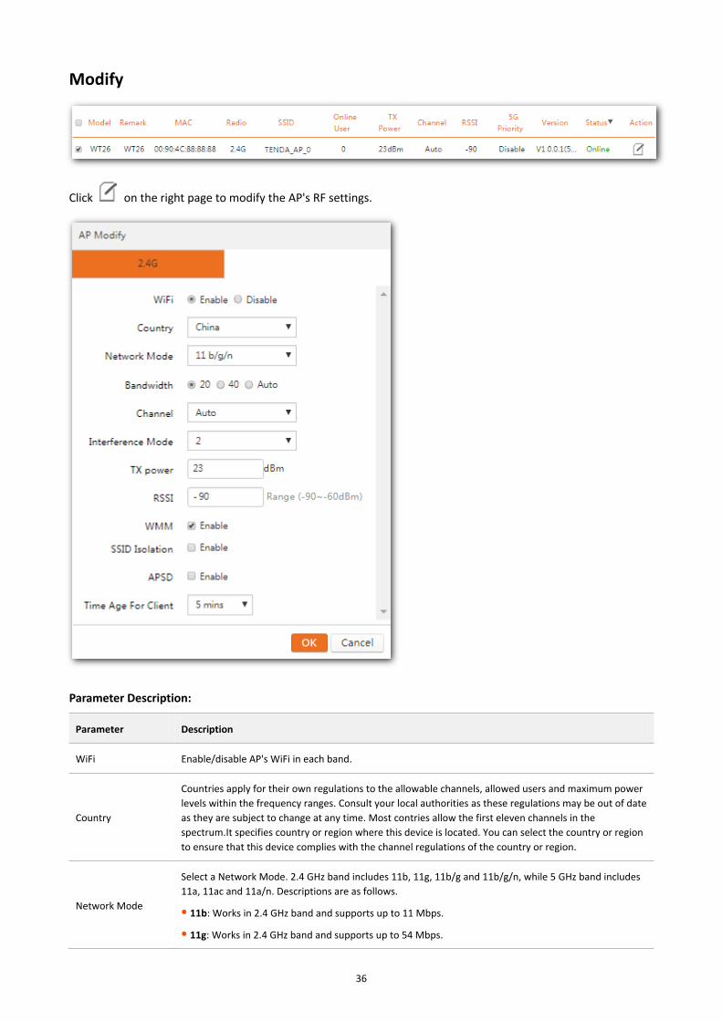
Modify
Click on the right page to modify the AP's RF settings.
Parameter Description:
Parameter Description
WiFi Enable/disable AP's WiFi in each band.
Country
Countries apply for their own regulations to the allowable channels, allowed users and maximum power
levels within the frequency ranges. Consult your local authorities as these regulations may be out of date
as they are subject to change at any time. Most contries allow the first eleven channels in the
spectrum.It specifies country or region where this device is located. You can select the country or region
to ensure that this device complies with the channel regulations of the country or region.
Network Mode
Select a Network Mode. 2.4 GHz band includes 11b, 11g, 11b/g and 11b/g/n, while 5 GHz band includes
11a, 11ac and 11a/n. Descriptions are as follows.
11b: Works in 2.4 GHz band and supports up to 11 Mbps.
11g: Works in 2.4 GHz band and supports up to 54 Mbps.

37
Parameter Description
11b/g: If you select this option, wireless clients supporting 802.11b or 802.11g can connect to the
WiFi.
11b/g/n: If you select this option, wireless clients supporting 802.11b, 802.11g or 802.11n can connect
to the WiFi.
11a: Works in 5 GHz band and supports up to 54 Mbps.
11ac: Works in 5 GHz band and supports up to 1732Mbps. It is a newer standard that uses wider
channels, QAM and spatial streams for higher throughput
11a/n: Works in 5 GHz band and supports up to 600Mbps, compatible with 11n.
Bandwidth
Select the wireless bandwidth.
20: 20MHZ channel bandwidth.
40: 40MHZ channel bandwidth.
80: 80MHZ channel bandwidth.
Auto: Automatically adjust the channel bandwidth to 20MHZ or 40MHZ based on surrounding
environment.
Channel Select the wireless channel. Channel range differs from country and radio band.
Extension Channel When bandwidth is 40 or Auto, this is used to determine the channel range of AP.
Interference Mode
Configure Interference mode. Value range: 0 – 4.
0: Disable all interference immunity.
1: Enable the same frequency interference immunity.
2: Force to enable radio interference immunity.
3: Automatically enable radio interference immunity.
4: Automatically enable radio interference immunity and noise reduction.
Different AP models have different recommended interference mode. Please contact Tenda technical
support for help.
TX power AP’s wireless transmission power. If this value is greater than the maximum supported power of an AP,
the maximum supported power takes effect after the policy is delivered.
RSSI
RSSI is short for Received Signal Strength Indication.
If a wireless client’s signal is lower than this value, the client can not connect to the AP, which helps the
client to connect to an AP with stronger signal.
WMM
Wi-Fi Multimedia (WMM) provides basic Quality of Service (QoS) features to IEEE 802.11 networks.
WMM prioritizes traffic according to four Access Categories (AC) - voice, video, best effort, and
background. However, it does not provide guaranteed throughput. It is suitable for well defined
applications that require QoS, such as Voice over IP (VoIP) on Wi-Fi phones (VoWLAN).
SSID Isolation
Enable/Disable SSID isolation.
When enabled, wireless clients that connect to different SSID of the AP cannot communicate with each
other.
APSD APSD is short for Automatic Power Save Delivery. It is basically a feature mode that allows your mobile
devices to save more battery while connect to your WiFi network. By allowing your mobile devices to

38
Parameter Description
enter standby or sleep mode, it conserves energy. It is only effective when you enable WMM.
Time Age For Client
After a client connects to the AP:
If there is no data transmission within the time period, AP will actively disconnect the client.
If data transmission is detected within the time period, AP will recalculate the time age.

39
3.4 User Status
This section gives you an overview of client information connected to the network. Click User Status to enter the
page below.
To export and save the client information to your local computer, click Export, and then click OK on the pop-up
window.
Parameter Description:
Parameter Description
Remark The comment of AP. In order to manage different APs easily, it is recommended to set up the
Remark name as AP’s model number or location.
Model The model number of the AP.
SSID AP’s SSID which the user’s device connects to.
Radio AP’s radio band which the user connects to.
Client's IP The user device’s IP address.
Client's MAC The user device's MAC address.
Download The user's total download traffic.
RSSI The user’s RSSI.
RSSI is short for Received Signal Strength Indication.
Online Time The authorized online period of the user.
Status Whether the user is online or offline.
Online: The user has successfully authorized to the AP currently.

40
Parameter Description
Offline: The user does not authorize to the AP currently.
3.5 System Tools
This section helps you manage this AC in a safe and effective manner, and get to know the real-time running
status. Here are the following 7 parts:
System Status: View interface information, system status and network information.
Network Setting: View and modify LAN settings, DHCP settings and and 802.1 QVLAN settings.
DHCP List For AP: View and export DHCP list.
Maintain: View license information, modify the user name and password to manage the AC, upgrade
firmware, backup/restore the AC configuration and restore the device to default factory settings.
Date&Time: View and set the system of the AC.
System Log: View the AC system logs, and get to know the AP connection status as well as its warning info.
Network Diagnosis: Detect network connection status of the AC
3.5.1 System Status
Here you can view Interface, System Status, and Network Information. Click System Tools > System Status to
enter the page below.

41
Interface
It displays the current connection status of each LAN port of the AC.
System Status
It displays how many APs are managed by the AC, offline AP numbers, connected client numbers, run time and
CPU/memory usage of the AC.

42
Parameter Description:
Parameter Description
Managed APs It indicates how many APs are managed by the AC currently.
Offline APs It indicates how many APs are offline currently.
Connected Clients It indicates how many wireless clients are connected to online APs currently.
Run Time It indicates the time elapsed since the AC is rebooted last time.
CPU Usage It indicates how much the CPU of the AC is utilized in percenteage.
Memory Usage It indicates how much the memory of the AC is utilized in percenteage.
Network Information
It displays the IP address, subnet mask, MAC address, and firmware version of the AC.
3.5.2 Network Setting
Here you can set up IP information to connect to the internet, and set up VLAN information. Click System Tools >

43
Network Setting to enter the page below.
LAN Settings
It allows you to set IP address, subnet mask, gateway, preferred DNS and alternate DNS.

44
Parameter Description:
Parameter Description
IP Address
It specifies the IP address of this AC. Users in LAN can access the web UI of this AP using this IP
address. The default IP is 192.168.10.1.
If you change LAN IP, you still need to change the IP address on your computer to be the same
segment of the new IP address. And use the new IP address to login to the web UI of the AC.
Subnet Mask The subnet mask of the AC, default value is 255.255.255.0.
Gateway The gateway of the AC, default value is 192.168.10.254.
Preferred DNS The DNS server address of this AC. It is a required field and the default is 192.168.10.254.
Alternative DNS The alternative DNS server address of this AC. It is an optional field and it is left blank by default.
DHCP Settings
It allows you to enable/disable DHCP server and modify IP address.

45
Parameter Description:
Parameter Description
Start IP Enter the start IP address of DHCP address pool.
End IP
Enter the end IP address of DHCP address pool.
Start IP and end IP must be on the same IP segment.
Lease Time Lease time is the assigned IP address’s effective time period. When lease time is due, the online APs can
renewal the lease time.
VLAN Settings
It allows you to add one or more VLAN rules to manage AP across VLANs.
Configuration steps:
Step 1 Log in to the web UI of AC, click System Tools > Network Setting > VLAN Settings.

46
Step 2 Port Isolation: Set Port Isolation to Enable.
Step 3 VLAN ID: Set VLAN ID, such as 3-10, or 12. One port can only be set with one VLAN ID, but can be
grouped into different VLANs.
The hyphen (-) means “consective”, and the comma (,) means “and”. For example, 3-10, 12 includes 9 VLAN IDs through
VLAN3 to VLAN10, as well as VLAN12.
Step 4 LAN port: Select LAN port corresponding to the VLAN ID.
Step 5 Click Add, the added rule shows in the VLAN list.
----End
To delete a VLAN rule, click corresponding to the rule. You cannot modify a rule but delete it and then add
again.
You need to reboot the device to activate the settings after settings modified.
After adding a VLAN rule, PVID serves as VLAN 1, a port to receive any data.

47
An example of configuring VLAN settings
Network Topology
Topology description: (here takes F1226P as an example)
Create 3 802.1Q VLAN rules on the switch, VLAN IDs and corresponding ports are as below:
− VLAN2: Interface 2, port link type is Access;
− VLAN3: Interface 3, port link type is Access;
− VLAN4: Interface 4, port link type is Access;
Set 2 trunk ports, details is as below:
− Interface 7: Trunk port, PVID=1, all VLANs are allowed;
− Interface 8: Trunk port, PVID=1, all VLANs are allowed;
Configuration steps:
Step 1 Log in to the web UI of AC, click System Tools > Network Setting > VLAN Settings.
Tablet
Port3:VLAN3
Port5
Router
F1226 PoE Switch AC
PC AP AP AP
Smartphone Laptop
Port2:VLAN2 Port4:VLAN4
Port1:VLAN2,3,4 Port8
Port7
WAN LAN

48
Step 2 Port Isolation: Set Port Isolation to Enable.
Step 3 VLAN ID: Set VLAN ID to 1-4.
Step 4 LAN port: Set LAN port to LAN1.
Step 5 Click Add.
----End
Then click System Tools > Maintain to reboot this device to activate your settings.
3.5.3 DHCP List For AP
Here you can view AP’s IP address obtained from AP’s DHCP server, and AP’s MAC address. Click System Tools >
DHCP List For AP to enter the page below.
Parameter Description:
Parameter Description
ID The ID of the AP.
IP Address The IP address of the AP.
MAC Address The MAC address of the AP.

49
3.5.4 Maintain
Here you can view license information, modify user management information and maintain the AC. Click System
Tools > Maintain to enter the page below.

50
License
The AC is licensed by default, and can manage up to 128 APs.
User Management
In order to prevent other person from modifying settings on your AC, it is advisable to modify your login user
name and password.
After modifying your login user name and password, it will automatically skip to the login page and you need to
use the new user name and password to re-access its web UI.
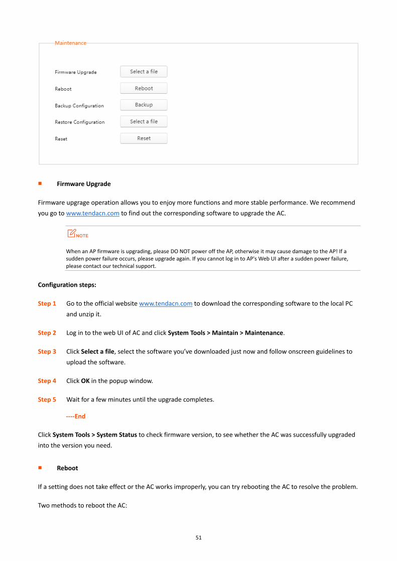
Maintenance
Here you can upgrade, reboot, backup, restore and reset AC.
51
Firmware Upgrade
Firmware upgrage operation allows you to enjoy more functions and more stable performance. We recommend
you go to www.tendacn.com to find out the corresponding software to upgrade the AC.
When an AP firmware is upgrading, please DO NOT power off the AP, otherwise it may cause damage to the AP! If a sudden power failure occurs, please upgrade again. If you cannot log in to AP's Web UI after a sudden power failure, please contact our technical support.
Configuration steps:
Step 1 Go to the official website www.tendacn.com to download the corresponding software to the local PC
and unzip it.
Step 2 Log in to the web UI of AC and click System Tools > Maintain > Maintenance.
Step 3 Click Select a file, select the software you’ve downloaded just now and follow onscreen guidelines to
upload the software.
Step 4 Click OK in the popup window.
Step 5 Wait for a few minutes until the upgrade completes.
----End
Click System Tools > System Status to check firmware version, to see whether the AC was successfully upgraded
into the version you need.
Reboot
If a setting does not take effect or the AC works improperly, you can try rebooting the AC to resolve the problem.
Two methods to reboot the AC:

52
Method 1: Log in to the web UI of the AC, click System Tools > Maintain > Maintenance, and then click Reboot.
Method 2: Disconnect the AC from power supply and then reconnect the AC to power supply.
Backup Configuration
If you have configured many settings on this device, which will make this device work in good status and suitable
environment, it is suggested to backup settings for this device, which will be convenient for troubleshooting and
saving time for next time configuration. Click Backup then follow onscreen instructions.
Restore Configuration
If you happen to do some configurations, only to find that reduces the AC’s performance, in this case, you can
restore the device to its previous configurations. Click Select a file corresponding to Restore Configuration,
select your former configuration file and then follow onscreen instructions.
Reset
If you need to log in to the AC’s web UI, but forget the login user name or login IP; or you have some trouble in
surfing the Internet but unable to find where the problem is, it is advisable to restore this device to default
factory settings.
Here are two methods to restore the AC to default factory settings:
Method 1: Reset by pressing the RESET button for at least 6 seconds, and then wait for about 45 seconds.
Method 2: Reset by clicking Reset on the System Tools > Maintain page.
After restoring this device to factory settings, you need to use the default IP address (192.168.10.1) and login user name
and password (admin/admin) to relog in to the management webpage. For other default settings, see Default Factory
Settings.
3.5.5 Date&Time
Here you can set your AC's system time and Web expired time. Click System tools > Date&Time to enter the page
below.

53
Time configuration will be lost if the AC is powered off. But if you enable “NTP Network Time”, the AC will synchronize
time with Internet after reboot. And then time-related functions will perform correctly.
Parameter Description:
Item Description
System time The AC's current time.
Synchronize with PC
time
When clicked Synchronize with PC time, the AC will synchronize time with your computer. Ensure that
your PC’s time is correct.
Time Zone GMT time zone where the AC is deployed.
NTP network time When enabled, the AC’s time will synchronize with Internet time server periodically at a specific time
interval.
Sync Interval How often the AC will synchronize with Internet time server. Default option is 30 minutes.
Expired Time If the user has no operation in the Web UI within the expired time, the system logs you out. Default
value: 5 minutes.
NTP Network Time
When NTP Network Time function is enabled, the AC will synchronize with Internet time server periodically at a
specific time interval.
NTP Network Time requires a successful Internet connection. (To connect to Internet, please refer to LAN
Settings)
To configure NTP Network Time:
Step 1 Log in to the web UI of AC, click System Tools > Date&Time.
Step 2 Time Zone: Choose standard GMT Time Zone where your AC is deployed, e.g. "(GMT-10:00) Hawaii ".
Step 3 NTP Network Time: Set it to Enable.

54
Step 4 Sync Interval: Select a Sync Interval. It is recommended to keep the default value 30 minutes.
Step 5 Click OK.
----End
Synchronize with PC time
When you click Synchronize with PC time, the AC will synchronize time with your computer. And you must
ensure that your PC’s time is correct.
To synchronize with PC time:
Step 1 Log in to the web UI of AC, click System Tools > Date&Time.
Step 2 Click Synchronize with PC time.
Step 3 NTP Network Time: Disable this function.
Step 4 Click OK.
----End

55
3.5.6 System Log
The log system can record and classify information such as AP connections and alarms, and help network
administrators to monitor network operation and diagnose network faults.
The most recent logs are displayed at first. A maximum of 3000 logs are allowed. If exceeded, old logs will be
replaced with new ones.
Click System Tools > System Log to enter the page below:
For the convenience of monitoring real-time network status and troubleshooting networking problems, you need to
ensure that the AC acquires the correct time. Refer to Date&Time.
To view the latest log information, click Refresh; To export and save the AC's logs to your local computer, click
Export Logs; To clear all current log information, click Clear Logs.
Restarting the AC will lose recorded log information.
Actions, like re-powering up the device after disconnecting its power supply, modifying its LAN IP address, backuping/restoring settings, resetting, upgrading this device, etc. will restart the device itself.
3.5.7 Network Diagnosis
Here you can detect network connection status of the AC. Click System Tools > Network Diagnosis to enter the
page below.

56
This AC provides Ping and Traceroute diagnosis tools.
Ping
Ping is a commonly used diagnosis and troubleshooting command. It consists of ICMP request and response
packets. If the network works normally, the target device will return response packets.
Parameter Description:
Parameter Description
Destination
IP/Domain The target IP address or domain name, e.g. www.google.com.

57
Parameter Description
Packet Number The number of request packets.
Packet Size The size of request packets.
Traceroute
Traceroute is computer network diagnostic tool for displaying the route (path) and measuring transit delays of
packets across an Internet Protocol (IP) network.
Appendix
A.1 Troubleshooting
Q: I enter the device’s LAN IP address in the web browser but cannot access this device’s web UI. What should
I do?
− Check the TCP/IP settings on your PC and verify that IP address is 192.168.10.X (2-254);
− Clear the browser cache or try another web browser.
− Restart your PC or close your PC’s firewall.
− Ensure the management IP 192.168.10.1 is not used by other devices in the LAN.
− Ensure that there is no other device with IP address 192.168.10.1, and try again.
Q: I’ve forgotten the login user name and password. What should I do?
− Try to access its web UI with the default user name and password.
− If you are still unable to log in, restore your device to default factory settings and then use the default login IP address and password to try again. To reset the AC, press the RESET button for at least 6 seconds with the AC powered on, and then wait for about 45 seconds, this device will be restored to factory settings.
After restoring this device to factory settings, all your current configurations will be lost and you need to re-configure your device.
Q: Wireless clients can’t connect to the managed AP or it displays “Limited” or “No Internet Access”, and my
PC’s IP address is shown as 169.254.X.X. What should I do?
The AP DHCP server on this AC only assigns IP addresses to its managed APs. Thus, if you want wireless clients
(connected to these APs) to get Internet access by obtaining IP addresses automatically, you have to set up a
DHCP server in the LAN to assign IP addresses to these wireless clients.

A.2 Default Factory Settings
Parameter Default Setting
Login Information
Login Method HTTP (web UI)
Login IP 192.168.10.1
Login User name/Password admin/admin
Web Logout 5 minutes
Policy Configuration /
LAN Settings
IP Address 192.168.10.1
Subnet Mask 255.255.255.0
Gateway 192.168.10.254
Preferred DNS 192.168.10.254
Alternative DNS /
DHCP Setting
Status Enabled
Start IP 192.168.10.100
End IP 192.168.10.200
Lease Time 1 week
VLAN Settings /
License
Status Licensed
Max Managed APs 128
Time Settings
NTP Network Time Enable
Time Interval 30 minutes
Time Zone (GMT+08:00) Beijing, Chongqing, Hong Kong,Urumuqi
Expired Time 5 minutes