
Study of morphological hysteresis in partially immiscible polymers
Upload
independentCategory
view
7download
0
This article has been accepted for inclusion in a future issue of this journal. Content is final as presented, with the exception of pagination.
IEEE TRANSACTIONS ON ENERGY CONVERSION 1
Hysteresis-Controller-Based Energy HarvestingScheme for Microbial Fuel Cells With Parallel
Operation CapabilityJae-Do Park, Member, IEEE, and Zhiyong Ren
Abstract—Microbial fuel cell (MFC) is an emerging technologyfor sustainable energy production. An MFC employs indigenousmicroorganisms as biocatalysts and can theoretically convert anybiodegradable substrate into electricity, making the technologya viable solution for sustainable waste treatment or autonomouspower supply. However, the electric energy currently generatedfrom MFCs is not directly usable due to the low voltage and cur-rent output. Moreover, the output power can fluctuate significantlyaccording to the operating conditions, which makes stable harvestof energy difficult. This paper presents an MFC energy harvestingscheme using a hysteresis controller and two layers of DC/DC con-verters. The proposed energy harvesting system can capture theenergy from multiple MFCs at individually controlled operatingpoint and at the same time form the energy into a usable shape.
Index Terms—DC/DC converter, energy harvesting, microbialfuel cell (MFC).
I. INTRODUCTION
THE finite resource of fossil fuels and environmental pol-lution derived from their use are driving the search for
renewable and clean energy alternatives. This replacement offossil fuels will require the utilization of many energy sourcessuited to meet different end uses. Microbial fuel cell (MFC)technology has been intensively researched in recent years asa novel technology, because it offers a solution for environ-mentally sustainable energy by treating waste and recoveringelectricity simultaneously. MFCs use active bacteria to gener-ate electrical energy from the environment electrochemically.MFCs offer a simple, direct method for converting environ-mentally available biomass into electricity and are very suit-able for clean, distributed, and renewable energy source, forexample, powering the remote sensors [1], [2]. However, likeother microenergy sources such as ambient heat, vibrations, andlights, MFC reactors generate very low power and energy due tothermodynamic limitations and it has been reported that largerpower production cannot be easily achieved by just building
Manuscript received November 5, 2011; revised January 26, 2012; acceptedMarch 19, 2012. Paper no. TEC-00591-2011.
J.-D. Park is with the Department of Electrical Engineering, University ofColorado Denver, Denver, CO 80204 USA (e-mail: [email protected]).
Z. Ren is with the Department of Civil Engineering, University of ColoradoDenver, Denver, CO 80204 USA (e-mail: [email protected]).
Color versions of one or more of the figures in this paper are available onlineat http://ieeexplore.ieee.org.
Digital Object Identifier 10.1109/TEC.2012.2196044
larger MFCs or simply connecting them in series or in parallel,because of the nonlinear nature of MFCs [3]–[5].
The power density from MFCs has increased by orders ofmagnitude in less than a decade of research. The reported maxi-mum power density from lab scale air-cathode MFCs increasedfrom less than 1 mW/m2 to 6.9 W/m2 [5]–[7]. This improvementcan mainly be attributed to relieving physical and chemical con-straints through electrode material and reactor architecture im-provement, as well as optimization of operational conditions [2],[8]. However, the reported power output from many MFC stud-ies is based on the power dissipated on a static external resistanceinstead of the actual attainable power in a usable form [1]–[4],[7], [9]–[15], which indicates one crucial missing part before thetechnology can be commercialized—how to efficiently convertthe theoretical potential into a practically meaningful poweroutput. A few energy harvesting systems for sediment MFCshave been reported [16], [17]: they can capture energy from theMFC and convert it into applicable voltage and current levels.However, a control scheme that actively harvests energy at anoptimal operating point especially from multiple MFCs has notbeen researched extensively.
In this paper, an efficient MFC energy harvesting system usingtwo layers of dc/dc converters is presented [34]. The proposedsystem can capture the energy from multiple MFCs at individu-ally controlled operating points and at the same time forms theenergy into a usable shape.
II. MFCS
A. Characterization of MFC
MFCs use electrochemically active bacteria at the anode tocatalyze the conversion of chemical energy stored in biodegrad-able substrate into electricity. In a typical two-chamber systemin Fig. 1, the anode and cathode compartments separated byan ion-exchange membrane. Electrochemically active anaero-bic or facultative bacteria extracts electrons from the electrondonor and transfers them to the anode electrode. These elec-trons flow from the anode through an external circuit to thecathode, where they reduce an electron acceptor such as oxy-gen or ferricyanide. Protons are exchanged from the anode tothe cathode and participate in the oxidant reduction [2]. In asingle-chamber air-cathode MFC, the ion exchange membranehas been removed and constructs a cathode structure for openair diffusion [9]. Lab-scale MFC reactors are shown in Fig. 2.
An MFC can be treated as a weak voltage source because theoutput voltage does not remain constant as the current output
0885-8969/$31.00 © 2012 IEEE

This article has been accepted for inclusion in a future issue of this journal. Content is final as presented, with the exception of pagination.
2 IEEE TRANSACTIONS ON ENERGY CONVERSION
Fig. 1. Schematic of a two chamber MFC using O2 as electron acceptor.
Fig. 2. Lab scale two-chamber MFC using ferricyanide as electron acceptor(MFC#1, left) and single-chamber MFC using air as electron acceptor (MFC#2,right).
Fig. 3. Equivalent circuit of an MFC.
increases. It can be electrically modeled as a voltage source and aresistance as can be seen in Fig. 3. The MFC internal resistanceRint is the sum of system ohmic resistance, charge transferresistance, and activation resistance. It has been reported that theinternal resistance is reasonably constant in the ohmic region forgiven reactor parameters [6], [8]. The thermodynamic voltagevint can vary nonlinearly as MFC condition changes. Possiblecauses include instantaneous output power level, accumulatedextracted energy, bacteria community and activity shifts, andenvironmental condition changes.
The potential difference between anode and cathode when thecircuit is open is called open-circuit voltage (OCV). The OCVof an air-cathode MFC is generally less than 0.8 V, because theMFC anode potential is around−0.3 V (versus normal hydrogenelectrode), which is set by the respiratory enzymes of bacteria,and the working cathode potential is around +0.5 V when oxygen
Fig. 4. Polarization curves of MFCs used in the experiment. MFC#1 andMFC#2 denote two-chamber ferricyanide cathode MFC and single-chamber aircathode MFC, respectively. Points A and B are the operating points determinedby hysteresis controller. Double arrows denote MFC voltage, current, and powerin harvesting operation band.
is used as the terminal electron acceptor. The anode potential ofthe two-chamber MFCs with ferricyanide cathodes is same asthat of single-chamber MFCs. Typically, the working potentialof ferricyanide cathode is +0.6 V and it is determined by theredox potential of ferricynaide. The thermodynamic limitationdetermines the voltage generally less than 0.8 V and the currentoutput in the range of a few milliamperes, which cannot be useddirectly in most real-world applications [10].
The typical method for static characterization of MFC powerproduction is operating the MFC with a series of external resistorRext between the anode and cathode, and monitoring voltageacross the resistor continuously to obtain a polarization data.The interval to change the Rext is 5–30 min depending onMFC condition. This could be done either manually or using apotentiostat controller. The MFC reactors under test have showna clear activation characteristics but the voltage has not droppedmuch in concentration region. It can be seen that the MFC outputvoltage in the ohmic region is practically inversely proportionalto the output current. The maximum power point (MPP) can bedefined by respective voltage and current, where the maximumpower is delivered by the MFC system. It can be shown thatthis operating point occurs when Rext equals Rint [12], [15].Although the OCV of an MFC can reach as high as 0.8 V,the actual voltage at MPP is much lower as can be seen inFig. 4, which makes the direct use of MFC voltage output moredifficult. Fig. 4 shows the polarization curves for the MFCs usedfor energy harvesting experiment in this paper.
The dynamic response of MFC reactor has also been testedwith MFC#1 reactor. The output terminal of the reactor has beenshort-circuited by a MOSFET switch with a constant 50% dutyratio. The MFC generates its maximum current that the reactorcondition permits. It turned out that the instantaneous voltageand current response is quite fast, as can be seen in Fig. 5. Thecurrent output has about 2-μs delay, 4-μs rising and falling timefor step-wise energy extraction and recovery, and 3 × 10⁻⁶ timeconstant τi for steady state. The test has been performed with

This article has been accepted for inclusion in a future issue of this journal. Content is final as presented, with the exception of pagination.
PARK AND REN: HYSTERESIS-CONTROLLER-BASED ENERGY HARVESTING SCHEME FOR MICROBIAL FUEL CELLS 3
Fig. 5. MFC#1 output voltage and current to step-wise energy extraction with50% duty ratio and 12.5-kHz switching. From top, MOSFET switch state (0:OFF, 1: ON), MFC voltage, and MFC current.
Fig. 6. MFC#1 output voltage and current to step-wise energy extractionwith 50% duty ratio with 10-kHz switching. From top, MFC voltage and MFCcurrent.
different switching frequencies and slightly different reactorconditions, and results were similar. Because the time constantis small enough, the output dynamics of MFC itself is negligibleso that it can be modeled as resistive circuit. The instantaneousMFC output current in generation mode can be given as follows:
iMFC(t) = IMFC(t)(1 − e−t/τi ) ≈ IMFC(t) (1)
where IMFC is the current magnitude determined by the instanta-neous thermodynamic voltage and internal/external impedance.
When the MOSFET is OFF, the MFC terminals are openand the voltage across terminals represents the OCV, which isthe thermodynamic voltage. It can be seen in Fig. 5 that thevoltage recovers instantaneously, but the amplitude is slightlysmaller than before extraction. Fig. 6 shows the MFC voltage
TABLE IPOLARIZATION TEST DATA OF MFC#1 AND ESTIMATED INTERNAL RESISTANCE
Rint AT THERMODYNAMIC VOLTAGE vint AROUND MPP
recovered after energy extraction decreases as microbial systemcontinuously generates power, which in turn reduces the outputcurrent. The time constant for this voltage decrease is consider-ably slower compared to the current dynamics. For continuouspower extraction, the average thermodynamic voltage of MFCcan be given as follows, where Vint0 is the initial thermodynamicvoltage and τv (t) is a time constant for decaying voltage:
vint(t) = Vint0(e−t/τv (t)). (2)
The time constant τv is a function of biochemical factors andelectrical load as well as the thermodynamic voltage vint .
B. Electricity Generation Using MFC
The instantaneous power output of an MFC reactor Po , whichcan be measured across Rext , is inversely proportional to thetotal system resistance squared as follows:
Po(t) =vint(t)2Rext
(Rint + Rext)2 (3)
where vint is the thermodynamic voltage of the MFC. The outputpower is also in proportion to the square of the thermodynamicvoltage, which is slowly varying according to load and reactorconditions. The internal resistance Rint at the MPP can be esti-mated from the polarization curve using the fact that for a givenvoltage, the maximum power is generated when Rint and Rextis same. The thermodynamic voltage vint at the MPP can alsobe estimated using Rint and measured current Io . The internalresistance in other operating points can be roughly estimatedusing the slope on the polarization curve or measured accu-rately using electrochemical analysis, such as electrochemicalimpedance spectroscopy [8], [18]. Estimated values of Rint andvint from the MFC#1 polarization test data are shown in Table I.
The power measurement on static Rext on MFC output cansimulate the MFC power output to a load, but the generatedpower is dissipated as heat instead of being utilized to support theload. Although the resistors make it straightforward to measurethe MFC’s power generation, this scheme cannot be used forpractical purpose. For efficient harvesting and usage of the MFCenergy, a power conversion circuitry is indispensable to capturethe electrical energy from MFCs and shape it into a usable form.DC/DC switching converters can be used and this can be definedas “active” harvesting compared to the power dissipation onresistance because the power converters actively extract energyfrom MFC by high-frequency switching action.

This article has been accepted for inclusion in a future issue of this journal. Content is final as presented, with the exception of pagination.
4 IEEE TRANSACTIONS ON ENERGY CONVERSION
Fig. 7. Block diagram of the proposed MFC energy harvesting system.
In order to make the MFC technology more applicable, fol-lowing challenges need to be addressed:
1) an efficient real-time control scheme without using staticresistance to capture and provide the usable energy fromMFCs using power electronics converters;
2) flexible parallel operation of harvesting systems for mul-tiple MFCs to overcome the difficulty of increasing powerand energy with stacked MFCs;
3) a real-time controller to maintain the operation of MFC atan optimal operating point.
In this paper, the first two challenges have been addressed.The proposed scheme can harvest energy from multiple MFCsat individually controlled operating point (e.g., MPP) and shapethe harvesting energy to a usable form. The MPP tracking ca-pability has not been included in this paper, but can be readilyintegrated into the proposed harvesting controller [19].
III. MFC ENERGY HARVESTING TECHNIQUES
A. Current Techniques
Research on MFC energy harvesting has been focused on thefollowing areas:
1) increasing output voltage and power capacity;2) optimizing external resistance Rext to find and keep the
operating point at the MPP;3) development of energy management system to utilize en-
ergy harvested from MFCs for devices such as remotesensors and transmitters.
Some researchers tried to achieve a larger power from biggerMFC or multiple interconnected MFCs. However, the amountof energy generated by MFCs is not a linear function of theirsize; thus, the power density will not remain constant with theincreased electrode surface area. Stacks of MFCs are not op-erating as same as batteries, and the performance of the stackis limited by the worst performing unit because of the voltagereversal [3], [20].
Popular maximum power point tracking (MPPT) techniquessuch as perturbation and observation or gradient method forphotovoltaic systems and hydrogen fuel cells have been intro-duced to MFC systems to find the optimal value of externalresistance [11], [12]. Although it is important to identify thesteady-state operating condition for maximum power output,
the external resistance should be removed in order to practicallyutilize the generated energy.
Energy management systems have been developed especiallyfor ocean sediment MFCs to power remote sensors and wire-less transmitters for naval applications [17], [21], [22]. Giventhe low energy output from sediment MFCs, intermittent opera-tion rather than continuous harvesting has been suggested [17].Although the reported systems have supported actual electricalloads, mostly they used passive harvesting techniques to har-vest the energy from MFCs using capacitors or charge pumps.Those passive devices do not have proper control over the op-erating point of MFCs. Hence, the system performance can beimproved if MFCs can be controlled to operate at the most ef-ficient operating point. Moreover, an effective way to increasethe power/energy capacity of MFC system has not been inves-tigated.
Other proposed approaches include multiunit optimizationand detailed mathematical model-based approach [13], [14].
B. Proposed Harvesting System
A harvesting system for maximizing energy recovery frommultiple MFCs is proposed in this paper. The system consistsof two layers of DC/DC converters. The first converter harveststhe energy from an MFC and charges the storage capacitor, andthe second layer converter boosts the voltage to an appropriatelevel for the connected load. Instead of a capacitor-based chargepump that is not designed for linear voltage regulation [23],[24], an inductor-based converter has been utilized for morecontrollability on MFC operation. Compared to a single-layersystem, which uses a single converter for capturing energy andsupporting the load, this double-layer configuration can achievebetter performance by doing energy harvesting and load supportin separate subsystems. Fig. 7 shows the block diagram of theoverall system.
The MFC operation voltage can be determined by the polar-ization curve assuming reasonably stable condition. Once theoperating point is determined, the proposed real-time operatingpoint controller keeps the MFC output voltage in the determinedoperating voltage band. The MFC thermodynamic voltage thathas been explained in Section II-A determines the dynamics ofMFC output voltage and current, i.e., rate of change, with the

This article has been accepted for inclusion in a future issue of this journal. Content is final as presented, with the exception of pagination.
PARK AND REN: HYSTERESIS-CONTROLLER-BASED ENERGY HARVESTING SCHEME FOR MICROBIAL FUEL CELLS 5
inductance in the power interface circuit. And, these dv/dt anddi/dt determines the switching period and duty ratio.
The hysteresis-controller-based energy harvesting systemcontrols the operating voltage by switching the harvesting con-verter MOSFET Q1 . Unlike the standard boost converter thatcontrols the output voltage, the proposed control scheme con-trols the power extraction at input side, i.e., the Q1 switchingfrequency and duty ratio, according to the MFC’s condition tomaintain the MFC voltage at a predefined range and ensuresenough recovery time of the MFC reactor. This scheme is ef-fective especially when the MFC thermodynamic voltage dropssignificantly as output current increases. The second layer has astandard DC/DC boost converter that amplifies the output volt-age to an appropriate level for powering the external electronicdevice(s).
The inductance can be determined with following equation[25], assuming stiff response of MFC generation and edge ofcontinuous conduction:
L1 =VMFCTsD
2IMFC(4)
where VMFC is the average MFC output voltage in the hysteresisvoltage band, IMFC is the average output current, and Ts andD are the average switching period and duty ratio, respectively.However, it should be noted that the switching period will varyas the MFC condition changes as well as the duty ratio. Forexample, the harvesting system does not switch to CHARGEmode from DISCHARGE if the MFC voltage does not recoverto the upper threshold voltage due to reduced substrate concen-tration or microbial activity. This will decrease the switchingfrequency and duty ratio. The diode is reverse biased and theconverter operates in discontinuous conduction mode in thiscase. Fast recovery by strong microbial activity will increaseswitching frequency and duty ratio. The mode changes fromCHARGE to DISCHARGE similarly.
The harvesting controller in the first layer captures the energyfrom MFC in power mode; in other words, it injects the current tothe reservoir capacitor C1 ; hence the C1 voltage is not controlledand it is a function of harvested power and load power. Largercapacitance can be used for longer power supply for the energystorage capacitor, but it takes longer to charge it up. On the otherhand, smaller capacitors are charged faster, but they cannot standlonger. The voltage on C1 affects the efficiency of first andsecond layer converters because too high boost ratio reducesthe boost conversion efficiency [25]. Hence, the selection ofcapacitor C1 should be application dependent and the tradeoffbetween charge time, support time, and converter efficiencyneeds to be considered.
The design of the secondary boost controller can follow thestandard design procedure [25].
C. Operation of the Proposed Harvesting System
The operation of the energy harvester in the first layer con-sists of two modes, CHARGE and DISCHARGE, according tothe energy flow on the inductor connected to the MFC. The op-eration can be explained with the polarization curve in Fig. 4.The CHARGE mode starts when the MFC reaches the operating
point A. The MOSFET is ON and the MFC voltage decreasesas current increases. As the MFC voltage decreases to the oper-ating point B, MOSFET turns OFF and the inductor energy isdischarged to capacitor. In this DISCHARGE mode, the voltageincreases to operating point A as current decrease. It can beseen that the voltage is confined between points A and B andthe MFC can operate around the MPP as shown with doublearrows.
During the CHARGE mode, the harvesting converter’s MOS-FET Q1 is ON, and the energy is extracted from the MFC andstored in the inductor L1 . The MFC terminal voltage vMFCin this mode decreases due to the increasing current. Assum-ing negligible inductor resistance and constant thermodynamicvoltage Vint , the instantaneous MFC output voltage and currentin a CHARGE period can be given as follows, where IoC is theinitial inductor current when MOSFET Q1 is closed:
vMFC(t) = vint(t) − RintiMFC(t) (5)
iMFC(t) =1L1
∫vMFC(t)dt (6)
=(
IoC − Vint
Rint
)e−
R in tL 1
t +Vint
Rint. (7)
It can be seen that the current would be increasing to a leveldetermined by the thermodynamic voltage and the resistance,which is the maximum generatable current in the polarizationcurve in Fig. 4. However, the energy harvesting controller keepsthe current at the level of the specified operating point. Theexternal inductance and the internal resistance determine thechanging rate of voltage and current, which in turn determinesthe energy extracting frequency.
During the DISCHARGE mode, the MOSFET switch Q1 isOFF, and the energy stored in the external inductor L1 is dis-charged to the storage capacitor C1 . The MFC voltage increasesin this mode as current decreases. The MFC output current andthe storage capacitor voltage in the DISCHARGE mode can begiven as follows:
iMFC(t) =1L1
∫(vint(t) − Rinti(t) − vo1(t))dt (8)
=(
IoD − Vint − vo1(t)Rint
)e−
R in tL 1
t +Vint − vo1(t)
Rint
(9)
vo1(t) =1C1
∫(i1(t) − i2(t))dt. (10)
In (8) and (9), IoD and i2 is the inductor current when MOS-FET Q1 is open and the load current drawn from the storagecapacitor C1 by the second layer voltage boost converter, respec-tively. The MFC output voltage in the DISCHARGE mode canbe given as same as (6). The instantaneous current is a functionof thermodynamic voltage, internal resistance, external induc-tance, external capacitance, and load current in DISCHARGEmode.
The hysteresis controller turns OFF the MOSFET Q1 auto-matically when the MFC voltage reaches lower threshold in the

This article has been accepted for inclusion in a future issue of this journal. Content is final as presented, with the exception of pagination.
6 IEEE TRANSACTIONS ON ENERGY CONVERSION
Fig. 8. Schematic of the proposed harvesting converter controller.
Fig. 9. Simulation: MFC#1 operation at measured MPP.
CHARGE mode and turns it back ON when the MFC voltagereaches the upper threshold in DISCHARGE mode. Becausethe MOSFET is ON when the output voltage is lower than theCHARGE threshold VthH and OFF when it is higher than theDISCHARGE threshold VthL , a logic inverter is added to thecomparator-based hysteresis controller. The threshold voltagetoggles as operating mode changes. The upper and lower volt-age thresholds can be determined as follows and easily changedusing potentiometers:
VthH = Vcc ×R2
R2 + (R1//R3)(11)
VthL = Vcc ×R2//R3
R1 + (R2//R3). (12)
The duty ratio and switching frequency can be controlled bythe hysteresis voltage band, VthH − VthL , and they will varydepending on the generating capacity and recovery time of theoperating MFC. The schematic of the proposed hysteresis har-vesting controller is shown in Fig. 8. Simulated MFC outputvoltage and current using the proposed hysteresis controller canbe seen in Fig. 9.
D. Efficiency Calculation
The efficiency of the energy harvester can be given as
η =Po
Pin=
Pin − Ploss
Pin. (13)
From Fig. 7, the power loss in CHARGE and DISCHARGEmode are as follows:
PlossC = (PlossL + PlossQ1) ×TCHG
TSW(14)
PlossD = (PlossL + PlossD1 + PlossCap) × TDISCHG
TSW(15)
where PlossC and PlossD are loss in CHARGE and DISCHARGEmodes, respectively. And PlossL , PlossQ1 , PlossD1 , and PlossCapare loss on inductors, Q1 and D1 . TCHG , TDISCHG , and TSW arethe time periods for CHARGE, DISCHARGE, and a switchingcycle, respectively.
Efficiency can be calculated using this loss model:
η =VMPPIMPP − PlossC − PlossD − Punmodeled
VMPPIMPP(16)
where VMPP and IMPP are average MFC voltage and currentat MPP, respectively, and Punmodeled is a unmodeled miscella-neous losses including switching loss.
E. Parallel Operation
Parallel operation will be a viable option to increase thecapacity of MFC-based power system because the direct se-ries/parallel connection has difficulties in increasing power andenergy capacity. Although there are number of MFC applica-tions that can be readily operated in parallel for larger power andenergy capacity, harvesting systems to provide flexible controlover such systems have not been investigated. In this paper, amultiple-input converter topology is used. The multiple-inputconverters have recently been used for applications such as hy-brid vehicles, photovoltaics, and wind power systems [26]–[28],but it has not been applied to MFC energy harvesting systems.
The advantage of the proposed scheme is apparent withmultiple-reactor operation. The number of converters will beN + 1 because N reactors can share one boost converter in thesecond layer. The proposed scheme can achieve better harvest-ing efficiency because it actively extracts the energy contin-uously at individually controlled operating points, while it isdifficult to continuously harvest the energy and maintain outputvoltage at the same time with single converter configuration.Typically, a capacitor or a charge pump is used for single con-verter system, but the operating point changes as capacitor volt-age changes because they just passively takes the power fromMFC, which leads to a low harvesting efficiency.
It is straightforward to operate multiple MFCs in parallel us-ing the proposed controller. As can be seen in the block diagramin Fig. 10, only the harvesting controllers will be added formultiple MFCs in parallel operation. Each harvesting controlleroperates independently with separate voltage thresholds basedon its MFC’s maximum power operating point. The harvestingcontrollers share a storage capacitor to put captured energy into
This article has been accepted for inclusion in a future issue of this journal. Content is final as presented, with the exception of pagination.
PARK AND REN: HYSTERESIS-CONTROLLER-BASED ENERGY HARVESTING SCHEME FOR MICROBIAL FUEL CELLS 7
Fig. 10. Parallel operation with multiple MFCs and a boost converter.
and a single boost converter generates increased voltage to sup-port the load. The output of the second layer boost converter canbe given as
vo2 = vo1 ×1
1 − DQ2(17)
where DQ2 is the duty ratio of MOSFET Q2 .
IV. EXPERIMENTAL RESULT
A. Energy Harvesting From Multiple MFCs
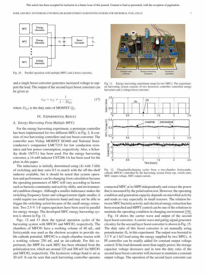
For the energy harvesting experiment, a prototype controllerhas been implemented for two different MFCs in Fig. 2. It con-sists of two harvesting controllers and one boost converter. Thecontroller uses Vishay MOSFET SI3460 and National Semi-conductor’s comparator LMC7215 for low conduction resis-tance and low power consumption, respectively. Also, a Schot-tky diode 1N5711 has been used. For the energy harvestingconverter, a 14-mH inductor CST206-1A has been used for theplots in this paper.
The inductance is initially determined using (4) with 3 kHzof switching and duty ratio 0.5 to match with the off-the-shelfinductor available, but it should be noted that system opera-tion and performance can be changing from calculation becausethe operating parameters of MFC will vary according to factorssuch as bacteria community and activity shifts, and environmen-tal condition changes. Although a smaller inductance makes theswitching frequency faster and voltage/current ripple smaller, itcould require too small hysteresis band and may not be able totrigger the switching action because of the small energy extrac-tion. Two 2.5-V 1-F supercapacitors have been used in parallelfor energy storage. The developed MFC energy harvesting sys-tem is shown in Fig. 11.
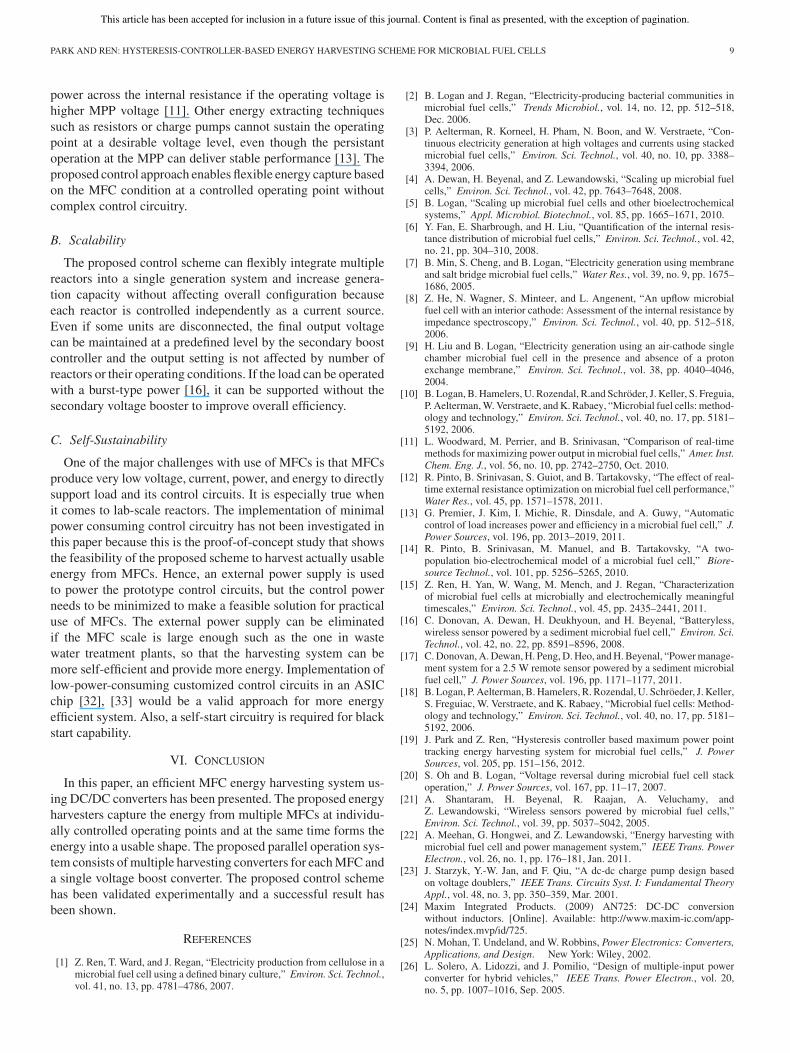
Figs. 12 and 13 show the typical operation cycles of theharvesting system with MFC#1 and MFC#2, respectively. Thechambers of MFC#1 have a working volume of 48 mL, andferricyanide was used as the electron acceptor to provide sta-ble cathode potential. MFC#2 is a single-chamber reactor witha working volume 250 mL and an air-cathode. For this ex-periment, the MPP for each MFC has been obtained from thepolarization test, which are around 325 and 300 mV for MFC#1and MFC#2, respectively. The hysteresis voltage band is set as20 mV. It can be seen that each harvesting controller operates
Fig. 11. Energy harvesting experiment setup for two MFCs. The experimen-tal harvesting system consists of two hysteresis controller controlled energyharvesters and a voltage boost converter.
Fig. 12. Charging/discharging cycles from a two-chamber ferricyanide-cathode MFC#1 controlled by the harvesting system From top, switch state,MFC output voltage, MFC output current.
connected MFC at its MPP independently and extract the powerthat is measured by the polarization test. However, the operatingcondition and generation capacity depends on microbial activityand tends to vary especially in small reactors. The relation be-tween MFC bacteria activity and electrical energy extraction hasbeen researched and MPPT control can be one of the solutions tomaintain the operating condition in changing environment [19].
Fig. 14 shows the carrier wave and output of the secondlayer boost converter. A carrier wave and gating signal generatorcircuitry for the second layer boost converter is shown in Fig. 15.The duty ratio of this boost converter is set manually usingpotentiometer R6 in this experiment. The output was boosted to3.3 V at 1-kΩ load using the energy supplied by two MFCs. API controller can be readily added for constant output voltagecontrol. If the load demands more than supply power, the storagecapacitor voltage decreases and in turn the duty ratio of thesecond layer boost converter will increase to maintain a constantoutput voltage. The operation of the second layer converter can

This article has been accepted for inclusion in a future issue of this journal. Content is final as presented, with the exception of pagination.
8 IEEE TRANSACTIONS ON ENERGY CONVERSION
Fig. 13. Charging/discharging cycles from a single-chamber air-cathodeMFC#2 controlled by the harvesting system. From top, switch state, MFCoutput voltage, MFC output current.
Fig. 14. Secondary layer DC/DC operation. From top, carrier wave, switchingstate, input and output voltage of the converter.
be paused in this case because the efficiency drops significantlywith high boost ratio.
B. Efficiency
The energy harvesting controller has been tested for efficiencyby charging a 3-F capacitor from 0 to 500 mV. It took 36 minwith one MFC#1 type two-chamber reactor. The average switch-ing frequency and duty ratio of the switch Q1 depends on theMFC’s generation response and voltage recovery in conjunctionwith the external power interface. The measured efficiency ofthe harvesting system is 45.21% and breakdown of the loss cal-culated using the data from the polarization test and datasheetof the parts used in the control system are shown in Table II.It can be seen that the power loss due to diode forward dropis dominant (93%) in overall loss and causes low efficiency.
Fig. 15. Carrier wave and reference signal generator for second layer DC/DCconverter.
TABLE IIEFFICIENCY CALCULATION DATA AND LOSS BREAKDOWN
Apparently, the diode drop is too high for such a low-voltage,low-power application. However, the synchronous rectificationtechnique can improve the efficiency by replacing the diode witha low on-loss MOSFET, although the control circuitry has to becarefully designed for the issues such as reverse power flow pre-vention and floating gate drive [29]–[31]. Also selecting lowerloss components, e.g., ones with lower RDS(on) , dc resistance,and equivalent series resistance, and implementing circuitry inlow-power application-specified integrated circuit (ASIC) [32],[33] would be feasible ways to improve efficiency.
V. DISCUSSION
The result of the experiments in this paper have confirmedthe following:
1) MFC operating point control capability for energy captureusing a simple hysteresis controller;
2) parallel operation of multiple MFC reactors in powermode;
3) output voltage boost to a practically usable level using theharvested energy.
A. Controllability
The control approach proposed in this paper enables the op-erating point control. MFCs lost more than 50% of produced
This article has been accepted for inclusion in a future issue of this journal. Content is final as presented, with the exception of pagination.
PARK AND REN: HYSTERESIS-CONTROLLER-BASED ENERGY HARVESTING SCHEME FOR MICROBIAL FUEL CELLS 9
power across the internal resistance if the operating voltage ishigher MPP voltage [11]. Other energy extracting techniquessuch as resistors or charge pumps cannot sustain the operatingpoint at a desirable voltage level, even though the persistantoperation at the MPP can deliver stable performance [13]. Theproposed control approach enables flexible energy capture basedon the MFC condition at a controlled operating point withoutcomplex control circuitry.
B. Scalability
The proposed control scheme can flexibly integrate multiplereactors into a single generation system and increase genera-tion capacity without affecting overall configuration becauseeach reactor is controlled independently as a current source.Even if some units are disconnected, the final output voltagecan be maintained at a predefined level by the secondary boostcontroller and the output setting is not affected by number ofreactors or their operating conditions. If the load can be operatedwith a burst-type power [16], it can be supported without thesecondary voltage booster to improve overall efficiency.
C. Self-Sustainability
One of the major challenges with use of MFCs is that MFCsproduce very low voltage, current, power, and energy to directlysupport load and its control circuits. It is especially true whenit comes to lab-scale reactors. The implementation of minimalpower consuming control circuitry has not been investigated inthis paper because this is the proof-of-concept study that showsthe feasibility of the proposed scheme to harvest actually usableenergy from MFCs. Hence, an external power supply is usedto power the prototype control circuits, but the control powerneeds to be minimized to make a feasible solution for practicaluse of MFCs. The external power supply can be eliminatedif the MFC scale is large enough such as the one in wastewater treatment plants, so that the harvesting system can bemore self-efficient and provide more energy. Implementation oflow-power-consuming customized control circuits in an ASICchip [32], [33] would be a valid approach for more energyefficient system. Also, a self-start circuitry is required for blackstart capability.
VI. CONCLUSION
In this paper, an efficient MFC energy harvesting system us-ing DC/DC converters has been presented. The proposed energyharvesters capture the energy from multiple MFCs at individu-ally controlled operating points and at the same time forms theenergy into a usable shape. The proposed parallel operation sys-tem consists of multiple harvesting converters for each MFC anda single voltage boost converter. The proposed control schemehas been validated experimentally and a successful result hasbeen shown.
REFERENCES
[1] Z. Ren, T. Ward, and J. Regan, “Electricity production from cellulose in amicrobial fuel cell using a defined binary culture,” Environ. Sci. Technol.,vol. 41, no. 13, pp. 4781–4786, 2007.
[2] B. Logan and J. Regan, “Electricity-producing bacterial communities inmicrobial fuel cells,” Trends Microbiol., vol. 14, no. 12, pp. 512–518,Dec. 2006.
[3] P. Aelterman, R. Korneel, H. Pham, N. Boon, and W. Verstraete, “Con-tinuous electricity generation at high voltages and currents using stackedmicrobial fuel cells,” Environ. Sci. Technol., vol. 40, no. 10, pp. 3388–3394, 2006.
[4] A. Dewan, H. Beyenal, and Z. Lewandowski, “Scaling up microbial fuelcells,” Environ. Sci. Technol., vol. 42, pp. 7643–7648, 2008.
[5] B. Logan, “Scaling up microbial fuel cells and other bioelectrochemicalsystems,” Appl. Microbiol. Biotechnol., vol. 85, pp. 1665–1671, 2010.
[6] Y. Fan, E. Sharbrough, and H. Liu, “Quantification of the internal resis-tance distribution of microbial fuel cells,” Environ. Sci. Technol., vol. 42,no. 21, pp. 304–310, 2008.
[7] B. Min, S. Cheng, and B. Logan, “Electricity generation using membraneand salt bridge microbial fuel cells,” Water Res., vol. 39, no. 9, pp. 1675–1686, 2005.
[8] Z. He, N. Wagner, S. Minteer, and L. Angenent, “An upflow microbialfuel cell with an interior cathode: Assessment of the internal resistance byimpedance spectroscopy,” Environ. Sci. Technol., vol. 40, pp. 512–518,2006.
[9] H. Liu and B. Logan, “Electricity generation using an air-cathode singlechamber microbial fuel cell in the presence and absence of a protonexchange membrane,” Environ. Sci. Technol., vol. 38, pp. 4040–4046,2004.
[10] B. Logan, B. Hamelers, U. Rozendal, R.and Schroder, J. Keller, S. Freguia,P. Aelterman, W. Verstraete, and K. Rabaey, “Microbial fuel cells: method-ology and technology,” Environ. Sci. Technol., vol. 40, no. 17, pp. 5181–5192, 2006.
[11] L. Woodward, M. Perrier, and B. Srinivasan, “Comparison of real-timemethods for maximizing power output in microbial fuel cells,” Amer. Inst.Chem. Eng. J., vol. 56, no. 10, pp. 2742–2750, Oct. 2010.
[12] R. Pinto, B. Srinivasan, S. Guiot, and B. Tartakovsky, “The effect of real-time external resistance optimization on microbial fuel cell performance,”Water Res., vol. 45, pp. 1571–1578, 2011.
[13] G. Premier, J. Kim, I. Michie, R. Dinsdale, and A. Guwy, “Automaticcontrol of load increases power and efficiency in a microbial fuel cell,” J.Power Sources, vol. 196, pp. 2013–2019, 2011.
[14] R. Pinto, B. Srinivasan, M. Manuel, and B. Tartakovsky, “A two-population bio-electrochemical model of a microbial fuel cell,” Biore-source Technol., vol. 101, pp. 5256–5265, 2010.
[15] Z. Ren, H. Yan, W. Wang, M. Mench, and J. Regan, “Characterizationof microbial fuel cells at microbially and electrochemically meaningfultimescales,” Environ. Sci. Technol., vol. 45, pp. 2435–2441, 2011.
[16] C. Donovan, A. Dewan, H. Deukhyoun, and H. Beyenal, “Batteryless,wireless sensor powered by a sediment microbial fuel cell,” Environ. Sci.Technol., vol. 42, no. 22, pp. 8591–8596, 2008.
[17] C. Donovan, A. Dewan, H. Peng, D. Heo, and H. Beyenal, “Power manage-ment system for a 2.5 W remote sensor powered by a sediment microbialfuel cell,” J. Power Sources, vol. 196, pp. 1171–1177, 2011.
[18] B. Logan, P. Aelterman, B. Hamelers, R. Rozendal, U. Schroeder, J. Keller,S. Freguiac, W. Verstraete, and K. Rabaey, “Microbial fuel cells: Method-ology and technology,” Environ. Sci. Technol., vol. 40, no. 17, pp. 5181–5192, 2006.
[19] J. Park and Z. Ren, “Hysteresis controller based maximum power pointtracking energy harvesting system for microbial fuel cells,” J. PowerSources, vol. 205, pp. 151–156, 2012.
[20] S. Oh and B. Logan, “Voltage reversal during microbial fuel cell stackoperation,” J. Power Sources, vol. 167, pp. 11–17, 2007.
[21] A. Shantaram, H. Beyenal, R. Raajan, A. Veluchamy, andZ. Lewandowski, “Wireless sensors powered by microbial fuel cells,”Environ. Sci. Technol., vol. 39, pp. 5037–5042, 2005.
[22] A. Meehan, G. Hongwei, and Z. Lewandowski, “Energy harvesting withmicrobial fuel cell and power management system,” IEEE Trans. PowerElectron., vol. 26, no. 1, pp. 176–181, Jan. 2011.
[23] J. Starzyk, Y.-W. Jan, and F. Qiu, “A dc-dc charge pump design basedon voltage doublers,” IEEE Trans. Circuits Syst. I: Fundamental TheoryAppl., vol. 48, no. 3, pp. 350–359, Mar. 2001.
[24] Maxim Integrated Products. (2009) AN725: DC-DC conversionwithout inductors. [Online]. Available: http://www.maxim-ic.com/app-notes/index.mvp/id/725.
[25] N. Mohan, T. Undeland, and W. Robbins, Power Electronics: Converters,Applications, and Design. New York: Wiley, 2002.
[26] L. Solero, A. Lidozzi, and J. Pomilio, “Design of multiple-input powerconverter for hybrid vehicles,” IEEE Trans. Power Electron., vol. 20,no. 5, pp. 1007–1016, Sep. 2005.

This article has been accepted for inclusion in a future issue of this journal. Content is final as presented, with the exception of pagination.
10 IEEE TRANSACTIONS ON ENERGY CONVERSION
[27] F. Boico and B. Lehman, “Mutliple-input maximum power point trackingalgorithm for solar panels with reduced sensing circuitry for portableapplications,” Solar Energy, vol. 86, pp. 463–475, 2012.
[28] Y.-C. Liu and Y.-M. Chen, “A systematic approach to synthesizing multi-input DC-DC converters,” IEEE Trans. Power Electron., vol. 24, no. 1,pp. 116–127, Jan. 2009.
[29] E. Carlson, K. Strunz, and B. Otis, “A 20 mV input boost converter withefficient digital control for thermoelectric energy harvesting,” IEEE J.Solid-State Circuits, vol. 45, no. 4, pp. 741–750, Apr. 2010.
[30] B. Acker, C. Sullivan, and S. Sanders, “Synchronous rectification withadaptive timing control,” in Proc. 26th IEEE Power Electron. Spec. Conf.,Jun, 1995, vol. 1, pp. 88–95.
[31] J. Park and Z. Ren, “High efficiency energy harvesting from microbial fuelcells using a synchronous boost converter,” J. Power Sources, vol. 208,pp. 322–327, 2012.
[32] H. Lhermet, C. Condemine, M. Plissonnier, R. Salot, P. Audebert, andM. Rosset, “Efficient power management circuit: From thermal energyharvesting to above-ic microbattery energy storage,” IEEE J. Solid-StateCircuits, vol. 43, no. 1, pp. 246–255, Jan. 2008.
[33] A. Richelli, L. Colalongo, S. Tonoli, and Z. Kovacs-Vajna, “A 0.2VDC/DC boost converter for power harvesting applications,” IEEE Trans.Power Electron., vol. 24, no. 6, pp. 1541–1546, Jun 2009.
[34] J. Park and Z. Ren, “Efficient energy harvester for microbial fuel cells usingDC/DC converters,” in Proc. IEEE Energy Convers. Congress Expo., Sep.2011, pp. 3852–3858.
Jae-Do Park (M’07) received the Ph.D. degree fromthe Pennsylvania State University, University Park,in 2007.
He is currently an Assistant Professor of electri-cal engineering at the University of Colorado Denver,Denver. Prior to his arrival at the University of Col-orado Denver, he was with Pentadyne Power Corpo-ration, Chatsworth, CA, as a Manager of Software andControls, where he took charge of control algorithmdesign and software development for the high-speedflywheel energy storage system. His research inter-
ests include various energy and power system research and education includingelectric machines and drives, energy storage and harvesting systems, renewableenergy sources, grid-interactive distributed generation, microturbine control,and microgrid systems.
Zhiyong Ren received the Ph.D. degree from thePennsylvania State University, University Park, in2008.
He is currently an Assistant Professor of civil en-gineering at the University of Colorado Denver, Den-ver, where he also directs the Environmental Biotech-nology Laboratory. His lab uses bioelectrochemicalsystems and fermentation technology to directly con-vert cellulosic biomass and waste water into H2 andelectricity, and he uses molecular microbiology toolsand electrochemical analyses to understand the fun-
damental determinant factors of those systems so as to enhance design, op-eration, and monitoring in concert with traditional approaches. His researchfocuses on bioenergy production during waste treatment processes, with thegoal of expanding environmental engineering from pollution clean-up to sus-tainable development of energy and environmental systems.
Copyright © 2022 FDOKUMEN