Integrated Dell Remote Access Controller 9 User's Guide - Icecat
Upload
khangminh22Category
view
4download
0
Programmable Controller
User's Manual(Utility Operation, Programming)
C Controller ModuleQ12DCCPU-V, Q06CCPU-V,
Q06CCPU-V-B, SW3PVC-CCPU-E
MITSUBISHI ELECTRIC
MITSUBISHI ELECTRIC
04012010SH(NA)-080767Version B
INDUSTRIAL AUTOMATION


SAFETY PRECAUTIONS(Read these precautions before using this product.)
Before using this product, please read this manual and the relevant manuals carefully and pay full attention to safety to handle the product correctly.The instructions given in this manual are concerned with this product only. For the safety instructions of the programmable controller system, please read the CPU module user's manual.In this manual, the safety precautions are classified into two levels: "DANGER" and "CAUTION".
Under some circumstances, failure to observe the precautions given under " " may lead to serious consequences.Observe the precautions of both levels because they are important for personal and system safety.
Make sure that the end users read this manual and then keep the manual in a safe place for future reference.
[Design Precautions]DANGER
Configure safety circuits external to the C Controller module to ensure that the entire systemoperates safely even when a fault occurs in the external power supply or the C Controller module.For the following controls, configure an interlock circuit in the user program to ensure that the entiresystem will always operate safely.(1) Changing data of the running C Controller module from the development environment (personal
computer) connected(2) Changing the operating status(3) Operating from the development environment (personal computer)Especially, in the case of control from an external device to a remote C Controller module, immediateaction cannot be taken for a problem on the C Controller module due to a communication failure.To prevent this, configure an interlock circuit in the user program, and determine corrective actions tobe taken between the external device and C Controller module in case of a communication failure.
DANGER
CAUTION
Indicates that incorrect handling may cause hazardous conditions,
resulting in death or severe injury.
Indicates that incorrect handling may cause hazardous conditions,
resulting in minor or moderate injury or property damage.
A - 1

[Setup and Maintenance Precautions]DANGER
Configure safety circuits external to the C Controller module to ensure that the entire systemoperates safely even when a fault occurs in the external power supply or the C Controller module.For the following controls, configure an interlock circuit in the user program to ensure that the entiresystem will always operate safely.(1) Changing data of the running C Controller module from the development environment (personal
computer) connected(2) Changing the operating status(3) Operating from the development environment (personal computer)Especially, in the case of control from an external device to a remote C Controller module, immediateaction cannot be taken for a problem on the C Controller module due to a failure of datacommunication.To prevent this, configure an interlock circuit in the user program, and determine corrective actions tobe taken between the external device and C Controller module in case of a failure of datacommunication.
CAUTIONBefore performing online operations (especially, program modification, forced output, and operationstatus change) for the running C Controller module from the peripheral connected, read relevantmanuals carefully and ensure the safety.Improper operation may damage machines or cause accidents.
A - 2
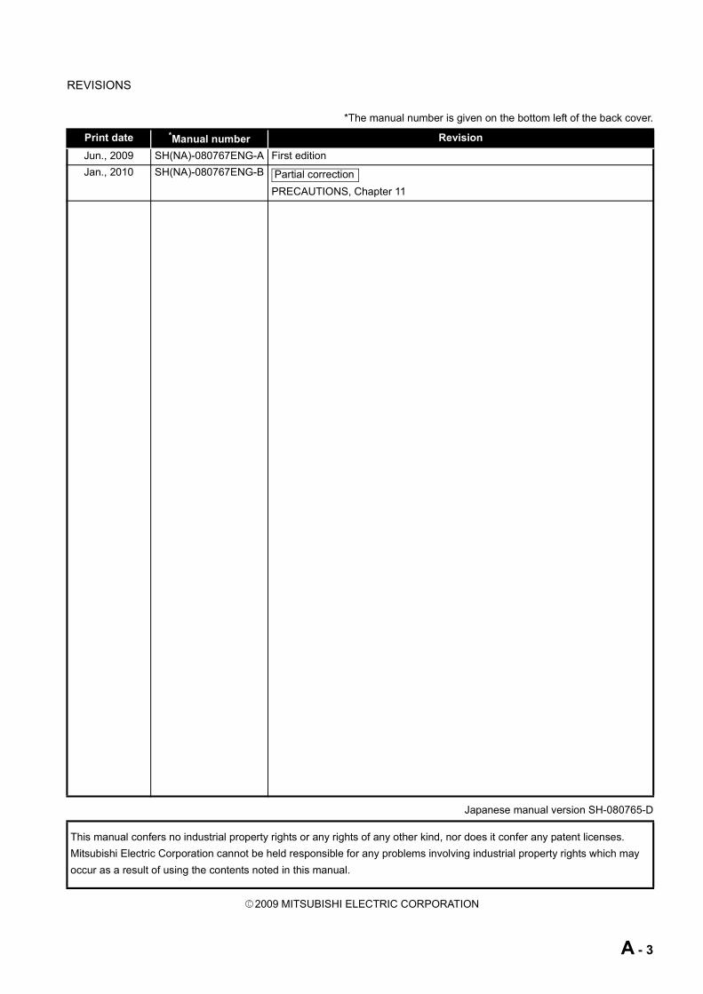
REVISIONS
*The manual number is given on the bottom left of the back cover.
Japanese manual version SH-080765-D
2009 MITSUBISHI ELECTRIC CORPORATION
Print date *Manual number RevisionJun., 2009 SH(NA)-080767ENG-A First editionJan., 2010 SH(NA)-080767ENG-B
PRECAUTIONS, Chapter 11
This manual confers no industrial property rights or any rights of any other kind, nor does it confer any patent licenses.Mitsubishi Electric Corporation cannot be held responsible for any problems involving industrial property rights which may occur as a result of using the contents noted in this manual.
Partial correction
A - 3

PRECAUTIONS
The following precautions are given in this section.
(1) Precautions for installation and uninstallation
(a) Installation by overwriting • When installing utility by overwriting, the same folder where the existing one
is installed must be used.Any other folders cannot be used.
• Installation by overwriting is available only onto the same version of SW PVC-CCPU.To install another version of utility, uninstall existing one before installation.
(b) UninstallationDo not terminate uninstallation during processing.If terminated, redo the uninstallation all over again.If the uninstallation fails after terminating the uninstallation, reinstall the software and then uninstall it again.
(2) Precautions for utility
(a) Communication error of utilityWhen the line is congested, communication errors (time out errors) are more likely to occur (monitoring stops if running) in each utility.If a utility communication error has occurred, set the connection target again in Connection setting.
(b) Connection during script file processingConnection from utility to a C Controller module may not be available during processing a script file (while the RUN LED is flashing).Finish the script file processing before connecting utility to a C Controller module.If the RUN LED remains flashing, refer to the C Controller Module User's Manual (Hardware Design, Function Explanation) and troubleshoot the problem.
(c) Terminating Microsoft WindowsDo not terminate Microsoft Windows while utility other than Device monitoring utility is running.Terminate all the running utility (other than Device monitoring utility) first and then Microsoft Windows .
Precautions Reference pageFor installation, uninstallation Page A-4For each utility Page A-4For programming Page A-5For debugging a program Page A-9For using FTP Page A-14For the Wind River Systems product Page A-14
A - 4

(d) ParametersParameters written from utility other than Device monitoring utility to a C Controller module will take effect when the C Controller module is powered off and then on or is reset.Written parameters will not take effect by changing the C Controller module status from STOP to RUN by remote operation or by a switch.
(3) Precautions for programming
(a) Restrictions on the bus interface functions and MELSEC data link functions
1) Endian format (memory layout)There are two models of the Q06CCPU-V(-B), which are in little endian format (memory layout) and in big endian format.Create user programs in either little or big endian that is appropriate to the model used.(Set the compiler by selecting "A toolchain" when creating a project on Tornado. ( Page 9-16, Section 9.4.2))
2) User program executionExecute a user program by starting a task from the script file.( Page 9-50, Section 9.9)The system may malfunction if the user program is executed without a task being started.
3) Execution type prioritySet the priority of a task for executing the FTP user program as described below.
[When access is not made via FTP during user program execution]Set the priority of the user program task to 100 or more (100 to 255). If the priority is set within 0 to 99, the system may not operate properly.
[When access is made via FTP during user program execution]The actual FTP processing (task) of the C Controller module is performed at the priority of 200.When accessing via FTP during executing a user program, perform programming as described below.
• Set the priority of the user program task within 201 to 255. • When setting the priority of the user program task within 100 to 200, insert
a wait processing (such as taskDalay) in the user program to let the actual FTP processing operate.
A - 5
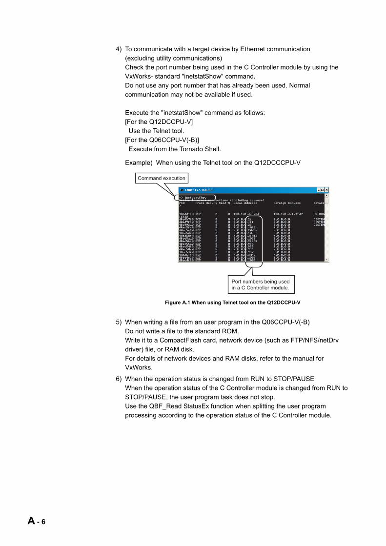
4) To communicate with a target device by Ethernet communication(excluding utility communications)Check the port number being used in the C Controller module by using the VxWorks- standard "inetstatShow" command.Do not use any port number that has already been used. Normal communication may not be available if used.
Execute the "inetstatShow" command as follows:[For the Q12DCCPU-V] Use the Telnet tool.[For the Q06CCPU-V(-B)] Execute from the Tornado Shell.
Example) When using the Telnet tool on the Q12DCCCPU-V
5) When writing a file from an user program in the Q06CCPU-V(-B)Do not write a file to the standard ROM.Write it to a CompactFlash card, network device (such as FTP/NFS/netDrv driver) file, or RAM disk.For details of network devices and RAM disks, refer to the manual for VxWorks.
6) When the operation status is changed from RUN to STOP/PAUSEWhen the operation status of the C Controller module is changed from RUN to STOP/PAUSE, the user program task does not stop.Use the QBF_Read StatusEx function when splitting the user program processing according to the operation status of the C Controller module.
Figure A.1 When using Telnet tool on the Q12DCCPU-V
Port numbers being used
in a C Controller module.
Command execution
A - 6

7) Relationships between Workbench/Tornado and system watchdog timer and user watchdog timerWhen using the following functions on Workbench or Tornado, provide sufficient time for the system watchdog timer( Page 4-30, Section 4.7) and user watchdog timer settings.( Page 9-3, Section 9.2)
Since the above functions activate tasks with high CPU utilization, a system watchdog timer error and user watchdog timer error are more likely to occur.
8) Common restrictionsFor restrictions common to the bus interface functions and MELSEC data link functions, refer to the following.
Page 9-25, "9.6 Precautions for Functions"
(b) Restrictions on the bus interface function
1) Clock settingDo not set the clock of the C Controller module while the QBF_WaitEvent function or the QBF_WaitUnitEvent function is in process.
2) Execution results of remote STOP/PAUSE and the bus interface functionWhen the operation status of the C Controller module is either the remote STOP or remote PAUSE, the following execution results will be an error during STOP/PAUSE.
• Output (Y) (QBF_Y_OutBitEx function, QBF_Y_OutWordEx function) • Writing to buffer memory (QBF_ToBuf function)
The Y output and writing to buffer memory can be executed from the <<Module monitoring>> tab of the C Controller setting utility.
3) Restrictions on the bus interface functionRefer to the following.
Page 9-22, "9.5 Programming Flow for Bus Interface Functions"
(c) Precautions on MELSEC data link functionsOpening and closing of a communication line (mdOpen and mdClose functions) is allowed only once each at the start (task start) and the end (task end) of each user program.Repeating opening/closing in every communication degrades communication performance.For the Q06CCPU-V-B, the MELSEC data link functions cannot be used.For restrictions on MELSEC data link functions, refer to the following.
Page 10-5, "10.5 MELSEC Data Link Function Programming Flow"
Environment FunctionWorkbench Wind River System Viewer etc.
Tornado•SpyChart function of Browser•WindPower tools (such as WindView)
A - 7

(d) Login user
1) Default accountTo prevent illegal access, delete the default account (User name and password) using the loginUserDelete function.
2) Retaining login user settingThe login user settings are cleared and return to default when the C Controller module is powered off or is reset.To retain the login user settings, describe a registration (adding/deleting) of the settings in a script file.Describe either of the following in the script file.
• Directly describe the login user operation commands (loginUserAdd function or loginUserDelete function).
• Provide a description that starts the user program task for login user operation.
For login user settings, refer to the C Controller Module User's Manual (Hardware Design, Function Explanation).
(e) Power off and reset during writing an user file Data corruption or file system error may occur if the C Controller system is powered of or is reset (including remote RESET) during writing data to an user file in the standard RAM, standard ROM, or CompactFlash card.To power off or reset the C Controller system during writing data to an user file in the standard RAM, standard ROM, or CompactFlash card, perform the following first.
1) When writing data to a file in the standard RAM or standard ROMClose the file where data are being written. (Program example Page 12-1, CHAPTER 12)
2) When writing data to a file in a CompactFlash cardClose the file where data are being written, and unmount the CompactFlash card. (Program example Page 12-1, CHAPTER 12)
For the stop processing of the CompactFlash card, refer to the C Controller Module User's Manual (Hardware Design, Function Explanation).
(f) Watchdog timerAn user watchdog timer error occurs when the user watchdog timer cannot be reset due to some reasons such as user program runaway.When an user watchdog timer occurs, perform the following.
• Increase the WDT time set by the QBF_StartWDT function. • Lower the CPU utilization of tasks that require high utilization.
Or set them not to operate. • Review user programs.
After the above operations, reset the C Controller system.For resetting, refer to the C Controller Module User's Manual (Hardware Design, Function Explanation).
(g) IP addressThe IP address of the C Controller module cannot be set from an user program.Set in the <<Online operation>> tab of C Controller setting utility.
A - 8

(h) Script file "STARTUP.CMD"In the script file, describe commands for setting a login user (adding/deleting) and user program startups as necessary.
• Setting a login user C Controller Module User's Manual (Hardware Design, Function
Explanation) • Creating a script file
Page 9-50, "9.9 Creating a Script File "STARTUP.CMD""
(4) Precautions for program debugging
(a) VxWorks image fileWhen debugging an user program, specify the VxWorks image file same as the one in the C Controller module to Workbench or to Tornado.The serial No. and function version of the file to be specified must be identical with those of the C Controller module. (Example for Q12DCCPU-V: Q12DCCPU-V_10121-B) ( Page 9-30, Section 9.7)
1) When VxWorks image files are not identicalWhen the VxWorks image file in the development environment (personal computer) and in the C Controller module are not identical, copy the image file in the C Controller module into the development environment (personal computer). ( Page 9-45, Section 9.8)The image file of the C Controller is stored in the system drive (/SYSTEMROM/OS_IMAGEFILE).
2) When connected with the different VxWorks image file specifiedWhen the VxWorks image file in the C Controller module and in Workbench or Tornado are not identical, a system watchdog timer error may occur in the C Controller module.In addition, debugging cannot be performed normally. ( Page 9-30, Section 9.7)
A - 9

(b) Precautions for Telnet connectionIf the line is disconnected during use of Telnet, it cannot be reconnected until TCP connection including the Telnet on the C Controller module side is timed out.If this occurs, reconnect it after timeout.
The timeout time for the C Controller module side Telnet (TCP) connection can be changed by setting the values in the calculation formula by the following setting methods.
[Calculation formula for the Q12DCCPU-V]The timeout time is determined by the following calculation formula.
* 1 The number of retries cannot be changed.
[Setting method for the Q12DCCPU-V]The following explains how to set the initial value to 30 seconds.
• Setting while the C Controller module is in operation
• Setting at the timing of starting C Controller module
Timeout time = net.inet.tcp.keepidle
+ (net.inet.tcp.keepintvl 8 (number of retries)*1) [ms]
Initial value for C Controller module: 30000 (30 seconds) Initial value for VxWorks: 7800000 (2 hours and 10 minutes)
net.inet.tcp.keepidle: Time from line disconnection to the first retry (ms)Initial value for C Controller module: 22000Initial value for VxWorks: 7200000
net.inet.tcp.keepintvl: Retry interval (ms)Initial value for C Controller module: 1000Initial value of VxWorks: 75000
1) Connect the line to the C Controller module with the Telnet tool.2) Execute the following two Sysct1() commands with the Telnet tool to set
the timeout time to the initial value.Sysctl("net.inet.tcp.keepidle = 22000")Sysctl("net.inet.tcp.keepintvl = 1000")
3) Close the Telnet connection.
1) Describe the following two Sysct1() commands on the script file,"STARTUP.CMD".
Sysctl("net.inet.tcp.keepidle = 22000")Sysctl("net.inet.tcp.keepintvl = 1000")
2) Write the above script file, "STARTUP.CMD" to a CompactFlash card,and insert it into the C Controller module.
3) Upon start of the C Controller module, the timeout time is set to theinitial value.
A - 10

[Calculation for the Q06CCPU-V(-B)]The timeout time is determined by the following calculation formula.
[Settings methods for the Q06CCPU-V(-B)]The following explains how to set the initial value to 4 hours and 10 minutes.
• Setting while the C Controller module is in operation
• Setting at the timing of starting the C Controller module
Timeout time = tcp_keepidle + (tcp_keepintvl 2 tcp_keepcnt) [s]
Initial value: 15000 (4 hours and 10 minutes)
tcp_keepidle: Time from line disconnection to the first retry (s) Initial value: 14400
tcp_keepintvl: Retry interval (in 0.5s units) Initial value: 150
tcp_keepcnt: Number of retries Initial value: 8
1) Connect the line to the C Controller module with the Telnet tool.2) Set the following three external variables with the Telnet tool to change
the timeout time to the initial value.tcp_keepidle = 14400tcp_keepintvl = 150tcp_keepcnt = 8
3) Close the Telnet connection.
1) Describe the following three external variable settings on the script file,"STARTUP.CMD".
tcp_keepidle = 14400tcp_keepintvl = 150tcp_keepcnt = 8
2) Write the above script file, "STARTUP.CMD" to a CompactFlash card,and insert it into the C Controller module.
3) Upon start of the C Controller module, the timeout time is set to theinitial value.
A - 11

(c) Precautions for executing the Shell command from Workbench Shell or Tornado Shell, or the Telnet tool
1) When executing the Shell command from Workbench Shell or Tornado ShellPay attention to the following since the entered Shell commands operate on the task of priority 1 in the C Controller module.
• Some commands (example: a command that occupies CPU processing) may cause a system error or stop (such as a system watchdog timer error).Pay full attention to the command when entering it. ( Page 9-30, Section 9.7)
• Some commands (example: the status-indicating Show command) may disable an interrupt for a long time.During the time, processing called from an interrupt routine (example: bus interface function for ISR) is not executed.Interrupts that are expected to occur at fixed intervals, such as multiple CPU synchronous interrupt, may delay. When executing a command, pay attention to the above.
A VxWorks message may appear on Shell during connecting from Shell to the C Controller module.For messages of VxWorks, refer to the manual for VxWorks, Workbench, or Tornado.
2) The number of Telnet tools connectable at the same timeWhen executing a Shell command from the Telnet tool, make one-to-one connection between the Telnet tool and the C Controller module.Connection cannot be made from multiple Telnet tools to the same C Controller module.When exchanging the Telnet tool with another, first close the connection with the currently used Telnet tool, and then connect the line to the C Controller module from another Telnet tool.For Telnet functions, refer to C Controller Module User's Manual (Hardware Design, Function Explanation).
A - 12
3) Priority of Shell commands executed from the Telnet toolThe Shell commands entered by the Telnet tool of the development environment (personal computer) operate on the task of the following priorities in the C Controller module.
When using Shell commands, pay attention to the following: • Some commands (example: a command that occupies CPU processing)
may cause a system error or stop (such as system watchdog timer error).Pay full attention to the command when entering it. ( Page 9-30, Section 9.7)
• Some commands (example: the status-indicating Show command) may disable an interrupt for a long time.Interrupts that are expected to occur at fixed intervals, such as multiple CPU synchronous interrupt, may delay. When executing a command, pay attention to the above.
A VxWorks message may appear on the Telnet tool screen during a Telnet connection to the C Controller module.For messages of VxWorks, refer to the manual for VxWorks, Workbench, or Tornado.
4) Execution of VxWorks reboot commandDo not reboot VxWorks by executing the reboot function or pressing the CTRL + X keys.If VxWorks is rebooted, the C Controller module does not start properly.Reset it in the C Controller module.For resetting, refer to the C Controller Module User's Manual (Hardware Design, Function Explanation).
5) Execution of command without argument specifiedIf a command that requires an argument is executed without an argument specified, 0 is substituted for the argument. Some commands causes a system error or stop (such as a system watchdog timer error) in the C Controller module.Before executing a command, confirm the specifications and specified argument of the command.
• Example)Do not execute the "close" command without an argument. If executed, the resource reserved in the VxWorks system will be closed.
C Controller module PriorityQ12DCCPU-V 1Q06CCPU-V(-B) 2
A - 13

(5) Precautions for use of FTP
(a) When reading out files from the C Controller moduleA 426 (Data connection error) occurs if many files are read (downloaded) by using FTP.In that case, take following actions and read files again.
• Decrease the number of files to read • Read the files in several batches.
(6) Precautions for the Wind River Systems productThe C Controller module has an embedded real-time operating system, VxWorks, made and sold by Wind River Systems, Inc. in the United State.We, Mitsubishi, make no warranty for the Wind River Systems product and will not be liable for any problems and damages caused by the Wind River Systems product during use of the C Controller module.For the problems or specifications of the Wind River Systems product, refer to the corresponding manual or consult Wind River Systems, Inc.Contact information is available on the following website.http://www.windriver.com/
A - 14

SAFETY PRECAUTIONS•••••••••••••••••••••••••••••••••••••••••••••••••••••••••••••••••••••••••••••••••••••••••••••••••••••• A - 1
REVISIONS••••••••••••••••••••••••••••••••••••••••••••••••••••••••••••••••••••••••••••••••••••••••••••••••••••••••••••••••••••••• A - 3
PRECAUTIONS•••••••••••••••••••••••••••••••••••••••••••••••••••••••••••••••••••••••••••••••••••••••••••••••••••••••••••••••••• A - 4
INTRODUCTION ••••••••••••••••••••••••••••••••••••••••••••••••••••••••••••••••••••••••••••••••••••••••••••••••••••••••••••••• A - 15
CONTENTS•••••••••••••••••••••••••••••••••••••••••••••••••••••••••••••••••••••••••••••••••••••••••••••••••••••••••••••••••••••• A - 15
ABOUT MANUALS••••••••••••••••••••••••••••••••••••••••••••••••••••••••••••••••••••••••••••••••••••••••••••••••••••••••••••• A - 25
MANUAL PAGE ORGANIZATION •••••••••••••••••••••••••••••••••••••••••••••••••••••••••••••••••••••••••••••••••••••••••• A - 26
HOW TO USE THIS MANUAL••••••••••••••••••••••••••••••••••••••••••••••••••••••••••••••••••••••••••••••••••••••••••••••• A - 27
GENERIC TERMS AND ABBREVIATIONS••••••••••••••••••••••••••••••••••••••••••••••••••••••••••••••••••••••••••••••• A - 28
GLOSSARY•••••••••••••••••••••••••••••••••••••••••••••••••••••••••••••••••••••••••••••••••••••••••••••••••••••••••••••••••••••• A - 32
PACKING LIST•••••••••••••••••••••••••••••••••••••••••••••••••••••••••••••••••••••••••••••••••••••••••••••••••••••••••••••••••• A - 33
CHAPTER 1 OVERVIEW 1 - 1 to 1 - 41.1 Features ••••••••••••••••••••••••••••••••••••••••••••••••••••••••••••••••••••••••••••••••••••••••••••••••••••••••••••••1 - 3
CHAPTER 2 INSTALLATION AND UNINSTALLATION OF SOFTWARE PACKAGE2 - 1 to 2 - 7
2.1 Development Environment ••••••••••••••••••••••••••••••••••••••••••••••••••••••••••••••••••••••••••••••••••••••••2 - 1
2.2 Installation••••••••••••••••••••••••••••••••••••••••••••••••••••••••••••••••••••••••••••••••••••••••••••••••••••••••••••2 - 3
2.3 Uninstallation ••••••••••••••••••••••••••••••••••••••••••••••••••••••••••••••••••••••••••••••••••••••••••••••••••••••••2 - 6
CHAPTER 3 COMMON UTILITY OPERATIONS 3 - 1 to 3 - 143.1 Utility List •••••••••••••••••••••••••••••••••••••••••••••••••••••••••••••••••••••••••••••••••••••••••••••••••••••••••••••3 - 1
3.2 Activating Utility •••••••••••••••••••••••••••••••••••••••••••••••••••••••••••••••••••••••••••••••••••••••••••••••••••••3 - 2
3.3 Exiting Utility •••••••••••••••••••••••••••••••••••••••••••••••••••••••••••••••••••••••••••••••••••••••••••••••••••••••••3 - 3
3.4 Specifying CPU Type ••••••••••••••••••••••••••••••••••••••••••••••••••••••••••••••••••••••••••••••••••••••••••••••3 - 4
3.5 Setting Connection Target ••••••••••••••••••••••••••••••••••••••••••••••••••••••••••••••••••••••••••••••••••••••••3 - 5
3.6 Displaying the Help Screen •••••••••••••••••••••••••••••••••••••••••••••••••••••••••••••••••••••••••••••••••••••••3 - 9
3.7 Checking Version ••••••••••••••••••••••••••••••••••••••••••••••••••••••••••••••••••••••••••••••••••••••••••••••••• 3 - 11
3.8 Parameter Setting File ••••••••••••••••••••••••••••••••••••••••••••••••••••••••••••••••••••••••••••••••••••••••••• 3 - 12
INTRODUCTION
Thank you for purchasing the C Controller module.Before using this product, please read this manual carefully and develop familiarity with the functions and performance of the C Controller module to handle the product correctly.
CONTENTS
A - 15

3.9 Displays on the Title Bar and Status Bar ••••••••••••••••••••••••••••••••••••••••••••••••••••••••••••••••••••• 3 - 14
CHAPTER 4 C CONTROLLER SETTING UTILITY 4 - 1 to 4 - 474.1 C Controller Setting Utility Function List ••••••••••••••••••••••••••••••••••••••••••••••••••••••••••••••••••••••••4 - 1
4.2 Module Information Tab •••••••••••••••••••••••••••••••••••••••••••••••••••••••••••••••••••••••••••••••••••••••••••4 - 2
4.3 Event History Tab•••••••••••••••••••••••••••••••••••••••••••••••••••••••••••••••••••••••••••••••••••••••••••••••••••4 - 4
4.4 SRAM Monitoring Tab •••••••••••••••••••••••••••••••••••••••••••••••••••••••••••••••••••••••••••••••••••••••••••••4 - 9
4.5 Module Monitoring Tab •••••••••••••••••••••••••••••••••••••••••••••••••••••••••••••••••••••••••••••••••••••••••• 4 - 13
4.6 Online Operation Tab •••••••••••••••••••••••••••••••••••••••••••••••••••••••••••••••••••••••••••••••••••••••••••• 4 - 21
4.7 System Settings Tab ••••••••••••••••••••••••••••••••••••••••••••••••••••••••••••••••••••••••••••••••••••••••••••• 4 - 30
4.8 I/O Assignment Settings Tab ••••••••••••••••••••••••••••••••••••••••••••••••••••••••••••••••••••••••••••••••••• 4 - 34
4.9 Multiple CPU Settings Tab •••••••••••••••••••••••••••••••••••••••••••••••••••••••••••••••••••••••••••••••••••••• 4 - 38
4.10 Communication Diagnostics Tab •••••••••••••••••••••••••••••••••••••••••••••••••••••••••••••••••••••••••••••• 4 - 42
4.11 System Menu •••••••••••••••••••••••••••••••••••••••••••••••••••••••••••••••••••••••••••••••••••••••••••••••••••••• 4 - 43
4.12 Reading Initial Setting File and Importing Multiple CPU Parameters ••••••••••••••••••••••••••••••••••• 4 - 45
4.13 Precautions •••••••••••••••••••••••••••••••••••••••••••••••••••••••••••••••••••••••••••••••••••••••••••••••••••••••• 4 - 47
CHAPTER 5 CC-LINK UTILITY 5 - 1 to 5 - 215.1 CC-Link Utility Function List ••••••••••••••••••••••••••••••••••••••••••••••••••••••••••••••••••••••••••••••••••••••5 - 1
5.2 Module Information Tab •••••••••••••••••••••••••••••••••••••••••••••••••••••••••••••••••••••••••••••••••••••••••••5 - 2
5.3 Other Station Monitoring Tab•••••••••••••••••••••••••••••••••••••••••••••••••••••••••••••••••••••••••••••••••••••5 - 6
5.4 Online Operation Tab ••••••••••••••••••••••••••••••••••••••••••••••••••••••••••••••••••••••••••••••••••••••••••••••5 - 9
5.5 Parameter Settings Tab ••••••••••••••••••••••••••••••••••••••••••••••••••••••••••••••••••••••••••••••••••••••••• 5 - 10
5.6 Target Settings Tab •••••••••••••••••••••••••••••••••••••••••••••••••••••••••••••••••••••••••••••••••••••••••••••• 5 - 14
5.7 Test Tab •••••••••••••••••••••••••••••••••••••••••••••••••••••••••••••••••••••••••••••••••••••••••••••••••••••••••••• 5 - 17
5.8 System Menu •••••••••••••••••••••••••••••••••••••••••••••••••••••••••••••••••••••••••••••••••••••••••••••••••••••• 5 - 20
5.9 Precautions •••••••••••••••••••••••••••••••••••••••••••••••••••••••••••••••••••••••••••••••••••••••••••••••••••••••• 5 - 21
CHAPTER 6 MELSECNET/H UTILITY 6 - 1 to 6 - 426.1 MELSECNET/H Utility Function List ••••••••••••••••••••••••••••••••••••••••••••••••••••••••••••••••••••••••••••6 - 1
6.2 Module Information Tab •••••••••••••••••••••••••••••••••••••••••••••••••••••••••••••••••••••••••••••••••••••••••••6 - 2
6.3 Error History Monitoring Tab••••••••••••••••••••••••••••••••••••••••••••••••••••••••••••••••••••••••••••••••••••••6 - 9
6.4 Other Station Monitoring Tab••••••••••••••••••••••••••••••••••••••••••••••••••••••••••••••••••••••••••••••••••• 6 - 14
6.5 Online Operation Tab •••••••••••••••••••••••••••••••••••••••••••••••••••••••••••••••••••••••••••••••••••••••••••• 6 - 25
6.6 Parameter Settings Tab ••••••••••••••••••••••••••••••••••••••••••••••••••••••••••••••••••••••••••••••••••••••••• 6 - 26
6.7 Target Settings Tab •••••••••••••••••••••••••••••••••••••••••••••••••••••••••••••••••••••••••••••••••••••••••••••• 6 - 38
6.8 System menu •••••••••••••••••••••••••••••••••••••••••••••••••••••••••••••••••••••••••••••••••••••••••••••••••••••• 6 - 41
6.9 Precautions •••••••••••••••••••••••••••••••••••••••••••••••••••••••••••••••••••••••••••••••••••••••••••••••••••••••• 6 - 42
A - 16

CHAPTER 7 CC IE CONTROL UTILITY 7 - 1 to 7 - 377.1 CC IE Control Utility Function List •••••••••••••••••••••••••••••••••••••••••••••••••••••••••••••••••••••••••••••••7 - 1
7.2 Module Information Tab •••••••••••••••••••••••••••••••••••••••••••••••••••••••••••••••••••••••••••••••••••••••••••7 - 2
7.3 Diagnostics Result Screen ••••••••••••••••••••••••••••••••••••••••••••••••••••••••••••••••••••••••••••••••••••••••7 - 5
7.4 Online Operation Tab •••••••••••••••••••••••••••••••••••••••••••••••••••••••••••••••••••••••••••••••••••••••••••• 7 - 20
7.5 Parameter Settings Tab ••••••••••••••••••••••••••••••••••••••••••••••••••••••••••••••••••••••••••••••••••••••••• 7 - 22
7.6 Target Settings Tab •••••••••••••••••••••••••••••••••••••••••••••••••••••••••••••••••••••••••••••••••••••••••••••• 7 - 33
7.7 System Menu •••••••••••••••••••••••••••••••••••••••••••••••••••••••••••••••••••••••••••••••••••••••••••••••••••••• 7 - 36
7.8 Precautions •••••••••••••••••••••••••••••••••••••••••••••••••••••••••••••••••••••••••••••••••••••••••••••••••••••••• 7 - 37
CHAPTER 8 DEVICE MONITORING UTILITY 8 - 1 to 8 - 198.1 Device Monitoring Utility Function List ••••••••••••••••••••••••••••••••••••••••••••••••••••••••••••••••••••••••••8 - 1
8.2 Batch Monitoring ••••••••••••••••••••••••••••••••••••••••••••••••••••••••••••••••••••••••••••••••••••••••••••••••••••8 - 2
8.3 16-Point Register Monitoring •••••••••••••••••••••••••••••••••••••••••••••••••••••••••••••••••••••••••••••••••••••8 - 4
8.4 Setting Monitoring Target •••••••••••••••••••••••••••••••••••••••••••••••••••••••••••••••••••••••••••••••••••••••••8 - 6
8.5 Setting Device to Be Monitored ••••••••••••••••••••••••••••••••••••••••••••••••••••••••••••••••••••••••••••••••••8 - 7
8.6 Changing Word Device Values•••••••••••••••••••••••••••••••••••••••••••••••••••••••••••••••••••••••••••••••••••8 - 8
8.7 Continuously Changing Word Device Values ••••••••••••••••••••••••••••••••••••••••••••••••••••••••••••••• 8 - 10
8.8 Tuning On and Off Bit Device •••••••••••••••••••••••••••••••••••••••••••••••••••••••••••••••••••••••••••••••••• 8 - 12
8.9 Changing the Display Format••••••••••••••••••••••••••••••••••••••••••••••••••••••••••••••••••••••••••••••••••• 8 - 14
8.10 Start and Stop Monitoring ••••••••••••••••••••••••••••••••••••••••••••••••••••••••••••••••••••••••••••••••••••••• 8 - 15
8.11 Numerical Pad••••••••••••••••••••••••••••••••••••••••••••••••••••••••••••••••••••••••••••••••••••••••••••••••••••• 8 - 16
8.12 Other Operations•••••••••••••••••••••••••••••••••••••••••••••••••••••••••••••••••••••••••••••••••••••••••••••••••• 8 - 17
8.13 Precautions •••••••••••••••••••••••••••••••••••••••••••••••••••••••••••••••••••••••••••••••••••••••••••••••••••••••• 8 - 19
CHAPTER 9 PROGRAMMING BUS INTERFACE FUNCTION 9 - 1 to 9 - 579.1 Outline of Bus Interface Function ••••••••••••••••••••••••••••••••••••••••••••••••••••••••••••••••••••••••••••••••9 - 1
9.2 Bus Interface Function List••••••••••••••••••••••••••••••••••••••••••••••••••••••••••••••••••••••••••••••••••••••••9 - 3
9.3 Programming Procedure ••••••••••••••••••••••••••••••••••••••••••••••••••••••••••••••••••••••••••••••••••••••••••9 - 7
9.4 Creating and Compiling a New Project of User Program •••••••••••••••••••••••••••••••••••••••••••••••••••9 - 89.4.1 For the Q12DCCPU-V••••••••••••••••••••••••••••••••••••••••••••••••••••••••••••••••••••••••••••••••••••••••9 - 89.4.2 For the Q06CCPU-V(-B) ••••••••••••••••••••••••••••••••••••••••••••••••••••••••••••••••••••••••••••••••••• 9 - 16
9.5 Programming Flow for Bus Interface Functions••••••••••••••••••••••••••••••••••••••••••••••••••••••••••••• 9 - 22
9.6 Precautions for Functions ••••••••••••••••••••••••••••••••••••••••••••••••••••••••••••••••••••••••••••••••••••••• 9 - 25
9.7 Precautions for Program Debugging •••••••••••••••••••••••••••••••••••••••••••••••••••••••••••••••••••••••••• 9 - 309.7.1 For Q12DCCPU-V •••••••••••••••••••••••••••••••••••••••••••••••••••••••••••••••••••••••••••••••••••••••••• 9 - 309.7.2 For the Q06CCPU-V(-B) ••••••••••••••••••••••••••••••••••••••••••••••••••••••••••••••••••••••••••••••••••• 9 - 37
9.8 Program Registration••••••••••••••••••••••••••••••••••••••••••••••••••••••••••••••••••••••••••••••••••••••••••••• 9 - 45
9.9 Creating a Script File "STARTUP.CMD" ••••••••••••••••••••••••••••••••••••••••••••••••••••••••••••••••••••• 9 - 50
A - 17

9.10 Device Types for Bus Interface Functions ••••••••••••••••••••••••••••••••••••••••••••••••••••••••••••••••••• 9 - 55
CHAPTER 10 PROGRAMMING USING MELSEC DATA LINK FUNCTIONS 10 - 1 to 10 - 3910.1 Outline of MELSEC Data Link Functions••••••••••••••••••••••••••••••••••••••••••••••••••••••••••••••••••••• 10 - 1
10.2 MELSEC Data Link Function List •••••••••••••••••••••••••••••••••••••••••••••••••••••••••••••••••••••••••••••• 10 - 4
10.3 Programming Procedure •••••••••••••••••••••••••••••••••••••••••••••••••••••••••••••••••••••••••••••••••••••••• 10 - 4
10.4 Creating a New Project of User Program and Compiling ••••••••••••••••••••••••••••••••••••••••••••••••• 10 - 5
10.5 MELSEC Data Link Function Programming Flow •••••••••••••••••••••••••••••••••••••••••••••••••••••••••• 10 - 5
10.6 Precautions for the MELSEC Data Link Function •••••••••••••••••••••••••••••••••••••••••••••••••••••••••• 10 - 9
10.7 Precautions for Program Debugging •••••••••••••••••••••••••••••••••••••••••••••••••••••••••••••••••••••••••• 10 - 9
10.8 Program Registration••••••••••••••••••••••••••••••••••••••••••••••••••••••••••••••••••••••••••••••••••••••••••••• 10 - 9
10.9 Creating a Script File "STARTUP.CMD" ••••••••••••••••••••••••••••••••••••••••••••••••••••••••••••••••••••• 10 - 9
10.10 Channel ••••••••••••••••••••••••••••••••••••••••••••••••••••••••••••••••••••••••••••••••••••••••••••••••••••••••••••• 10 - 9
10.11 Station No. Setting for MELSEC Data Link Functions ••••••••••••••••••••••••••••••••••••••••••••••••••••10 - 10
10.12 Device Types for the MELSEC Data Link Function •••••••••••••••••••••••••••••••••••••••••••••••••••••••10 - 12
10.13 Accessible Ranges and Devices of the MELSEC Data Link Function•••••••••••••••••••••••••••••••••10 - 1710.13.1 Access to a multiple CPU system•••••••••••••••••••••••••••••••••••••••••••••••••••••••••••••••••••••••10 - 1710.13.2 Access via CC-Link ••••••••••••••••••••••••••••••••••••••••••••••••••••••••••••••••••••••••••••••••••••••••10 - 2110.13.3 Access via MELSECNET/H ••••••••••••••••••••••••••••••••••••••••••••••••••••••••••••••••••••••••••••••10 - 2710.13.4 Access via CC-Link IE controller network •••••••••••••••••••••••••••••••••••••••••••••••••••••••••••••10 - 34
CHAPTER 11 PROGRAMMING USING VxWorks API FUNCTIONS 11 - 1 to 11 - 2
CHAPTER 12 SAMPLE PROGRAMS 12 - 1 to 12 - 3
CHAPTER 13 EVENT NUMBER LIST 13 - 1 to 13 - 8
APPENDICES App - 1 to App - 18
Appendix 1 VxWorks Component List •••••••••••••••••••••••••••••••••••••••••••••••••••••••••••••••••••••••••••• App - 1Appendix 2 Comparison of Software Packages••••••••••••••••••••••••••••••••••••••••••••••••••••••••••••••••App - 17
Appendix 2.1 Precautions for replacing programs•••••••••••••••••••••••••••••••••••••••••••••••••••••••••App - 17
INDEX Index - 1 to Index - 2
A - 18

(Relevant manual): C Controller Module User's Manual (Hardware Design, Function Explanation)
CONTENTS
CHAPTER 1 OVERVIEW1.1 Features
CHAPTER 2 SYSTEM CONFIGURATION2.1 System Configuration
2.1.1 Devices used for each base unit2.1.2 Connection with a development environment2.1.3 Connection with peripheral devices2.1.4 System configuration overview2.1.5 Precautions for system configuration
2.2 Applicable Modules2.2.1 Applicable I/O modules and intelligent function modules2.2.2 Precautions for using I/O modules and intelligent function modules
2.3 Software Packages
2.4 Applicable Devices
2.5 Checking Function Version, Serial No., and Software Version2.5.1 Checking the function version and serial No. of the C Controller module2.5.2 Checking the software version of software package
CHAPTER 3 SPECIFICATIONS3.1 General Specifications
3.2 Performance Specifications
3.3 RS-232 Connector Specifications3.3.1 RS-232 connector specifications for the Q12DCCPU-V3.3.2 RS-232 connector specifications for the Q06CCPU-V(-B)
3.4 Operation Processing3.4.1 Initial processing3.4.2 I/O access timing3.4.3 RUN, STOP and PAUSE status operation processing3.4.4 Operation processing during momentary power failure
CHAPTER 4 FUNCTIONS4.1 Function List
4.2 I/O Module and Intelligent Function Module Access Function
4.3 Remote Operation Function4.3.1 Remote RUN/STOP4.3.2 Remote PAUSE4.3.3 Remote RESET4.3.4 Relation between remote operation and RUN/STOP status
A - 19

4.4 Self-Diagnostic Function
4.5 Output (Y) Status Setting for Switching STOP to RUN
4.6 Clock Function4.6.1 Multiple CPU Clock Synchronization Function
4.7 Input Response Time Selection (I/O Response Time)
4.8 Error Time Output Mode Setting
4.9 Hardware Error Time CPU Operation Mode Setting
4.10 Switch Settings for I/O and Intelligent Function Modules
4.11 Watchdog Timer (WDT)
4.12 Interrupt from Intelligent Function Module
4.13 Connection Between C Controller Module and GOT (Microcomputer Connection)
4.14 Telnet Function
CHAPTER 5 ACCESS VIA NETWORK MODULES5.1 Network Module Access Function List
5.2 CC-Link Module Access Function5.2.1 Block data assurance per station
5.3 MELSECNET/H Module Access Function5.3.1 Message communication5.3.2 Link device access5.3.3 Parameter settings5.3.4 Link device refresh setting5.3.5 Link data transfer processing time specifications
5.4 CC-Link IE Controller Network Module Access Function5.4.1 Message communication5.4.2 Link device access5.4.3 Parameter settings5.4.4 Link device refresh setting5.4.5 Link data transfer processing time specifications
CHAPTER 6 PREPARATORY PROCEDURES AND SETTING6.1 Handling Precautions
6.2 Fail-Safe Circuit
6.3 Preparatory Procedure and Setting
6.4 Part Names and Functions6.4.1 Part names and functions of the Q12DCCPU-V6.4.2 Part names and functions of the Q06CCPU-V(-B)
6.5 Cable Connection6.5.1 Compliance of the C Controller module with the EMC Directive
6.6 Network Settings for 1:1 Connection
6.7 Specifications, Installation, and Replacement of the Battery6.7.1 Battery specifications6.7.2 Battery installation
A - 20

6.7.3 Battery replacement6.7.4 When the module has been operated without battery6.7.5 Removing a battery before storage
6.8 Inserting/Removing a CompactFlash Card and Access Stop6.8.1 Inserting/removing the CompactFlash card6.8.2 Stopping access to the CompactFlash card6.8.3 Unmounting the CompactFlash card by the RESET/SELECT switch6.8.4 Measures against static electricity for commercially available CompactFlash cards in compliance
with the EMC directives
6.9 Checking the Number of Erasures on the Standard ROM
6.10 Setting the C Controller Module to the Initialized or Factory-Set Status6.10.1 Setting the Q12DCCPU-V to the initialized status6.10.2 Setting the Q06CCPU-V(-B) back to the factory-set status
6.11 Login User Setting and Restriction6.11.1 Functions that can be restricted by login user setting6.11.2 Setting a login user
6.12 Maintenance and Inspection6.12.1 Daily inspection6.12.2 Periodical inspection
CHAPTER 7 I/O NUMBER ASSIGNMENT7.1 Number of Base Units and Number of Slots
7.2 Connecting Extension Base Units and Setting the Number of Stages
7.3 Base Unit Assignment (Base Mode)
7.4 What is I/O Number?
7.5 I/O Number Assignment7.5.1 I/O numbers of a base unit
7.6 I/O Assignment by C Controller Setting Utility7.6.1 Purposes of I/O assignment by C Controller setting utility7.6.2 Details of I/O assignment by C Controller setting utility
7.7 I/O Assignment Example
7.8 Checking I/O Numbers
CHAPTER 8 MEMORIES AND FILES8.1 Memories of the C Controller Module
8.1.1 User memories8.1.2 System memory
8.2 File Operation and Handling Precautions8.2.1 File operation8.2.2 Precautions for handling files
CHAPTER 9 MULTIPLE CPU SYSTEM OVERVIEW9.1 What is the Multiple CPU System?
A - 21

CHAPTER 10 MULTIPLE CPU SYSTEM CONFIGURATION10.1 System Configuration
10.1.1 Devices used for each base unit10.1.2 Connection with a development environment10.1.3 Connection with peripheral devices10.1.4 System configuration overview (when CPU No.1 is a C Controller module)
10.2 Applicable Modules10.2.1 Applicable CPU modules10.2.2 Precautions for using I/O modules and intelligent function modules
10.3 Precautions for System Configuration
CHAPTER 11 CONCEPT OF MULTIPLE CPU SYSTEM11.1 Mounting Positions of CPU Modules
11.2 CPU No. of CPU Module
11.3 I/O Number Assignment11.3.1 I/O number assignment for the module11.3.2 I/O number of each CPU module
11.4 Access Ranges Between a CPU Module and Other Modules11.4.1 Access to controlled modules11.4.2 Access to non-controlled modules
11.5 Access to Link Devices
11.6 Resetting CPU Modules
11.7 When a CPU Module Stop Error Occurs
CHAPTER 12 COMMUNICATIONS BETWEEN CPU MODULES12.1 Data Communications by MELSEC Data Link Functions
12.2 Event Notification Function12.2.1 Multiple CPU synchronous interrupt function
12.3 Data Communications Using CPU Shared Memory12.3.1 CPU shared memory structure12.3.2 Data communications using auto refresh12.3.3 Communication using the multiple CPU high speed transmission area and auto refresh12.3.4 Data communications without using auto refresh
12.4 Programmable Controller Remote Control Function
12.5 Sequence Program Control Function
12.6 Interrupt Issue to Motion CPU
12.7 Motion CPU Control Instruction
12.8 Motion CPU Device Access
12.9 Multiple CPU Synchronized Boot-Up
CHAPTER 13 PARAMETERS ADDED FOR MULTIPLE CPU SYSTEMS13.1 Parameter List
A - 22

13.1.1 Setting the number of CPUs (required)13.1.2 Operation mode setting (optional)13.1.3 Online module change (optional)13.1.4 I/O sharing when using Multiple CPUs (optional)13.1.5 Communication area setting (refresh setting) (optional)13.1.6 Control CPU settings (required)13.1.7 Multiple CPU synchronous startup setting (optional)13.1.8 Multiple CPU high speed transmission area setting (required)
CHAPTER 14 STARTING A MULTIPLE CPU SYSTEM14.1 Flowchart for Starting a Multiple CPU System
14.2 Setting Parameters Added for Multiple CPU Systems14.2.1 System configuration14.2.2 Parameters required for the multiple CPU system14.2.3 When creating a new system14.2.4 Importing existing multiple CPU parameters
CHAPTER 15 TROUBLESHOOTING15.1 Troubleshooting Basics
15.2 Troubleshooting15.2.1 When the POWER LED on the power supply module turned off15.2.2 When the MODE LED is not lit green15.2.3 When the ERR. LED is on or flashing15.2.4 When the RUN LED remains flashing15.2.5 When UNIT VERIFY ERR. occurred15.2.6 When CONTROL-BUS.ERR. occurred15.2.7 When no communication is available between the development environment (personal computer)
and C Controller module15.2.8 When a file (program) cannot be written15.2.9 When an error occurs in function execution15.2.10 When a file system error occurred15.2.11 When no LED on an output module turn on15.2.12 When an output load device of an output module does not turn on15.2.13 When operation is not normal due to script file execution15.2.14 When an error occurred during user program download or ld command execution15.2.15 When unable to read from or write to the specified device15.2.16 When an error occurred during reading from or writing to the standard RAM, standard ROM,
CompactFlash card, or RAM disk using FTP15.2.17 When unable to make a Telnet connection15.2.18 When unable to make an FTP connection
15.3 Actions to be Taken When the ERR. LED is On or Flashing
15.4 Error Code List15.4.1 Actions by error code generated in function execution
15.5 Hardware Self-Diagnostic Function15.5.1 Hardware self-diagnostic function and initialization setting for the Q12DCCPU-V15.5.2 Hardware self-diagnostic function and initialization setting for the Q06CCPU-V(-B)
15.6 Diagnostics and Restoration of the Standard RAM, Standard ROM, and CompactFlash Card Drives
A - 23

APPENDICES
Appendix 1 Function Processing TimeAppendix 2 External Dimensions
Appendix 2.1 Q12DCCPU-VAppendix 2.2 Q06CCPU-VAppendix 2.3 Q06CCPU-V-B
Appendix 3 Transportation PrecautionsAppendix 3.1 Regulated modelsAppendix 3.2 Handling for transportation
Appendix 4 Handling of Batteries and Devices with Built-in Batteries in EU Member StatesAppendix 4.1 Disposal precautionsAppendix 4.2 Exportation precautions
Appendix 5 Characters Applicable to User Names and PasswordsAppendix 6 Parameter Number ListAppendix 7 Specification Comparison Between the Q06CCPU-V and Q06CCPU-V-H01Appendix 8 Functions Added by Version Upgrade
INDEX
A - 24
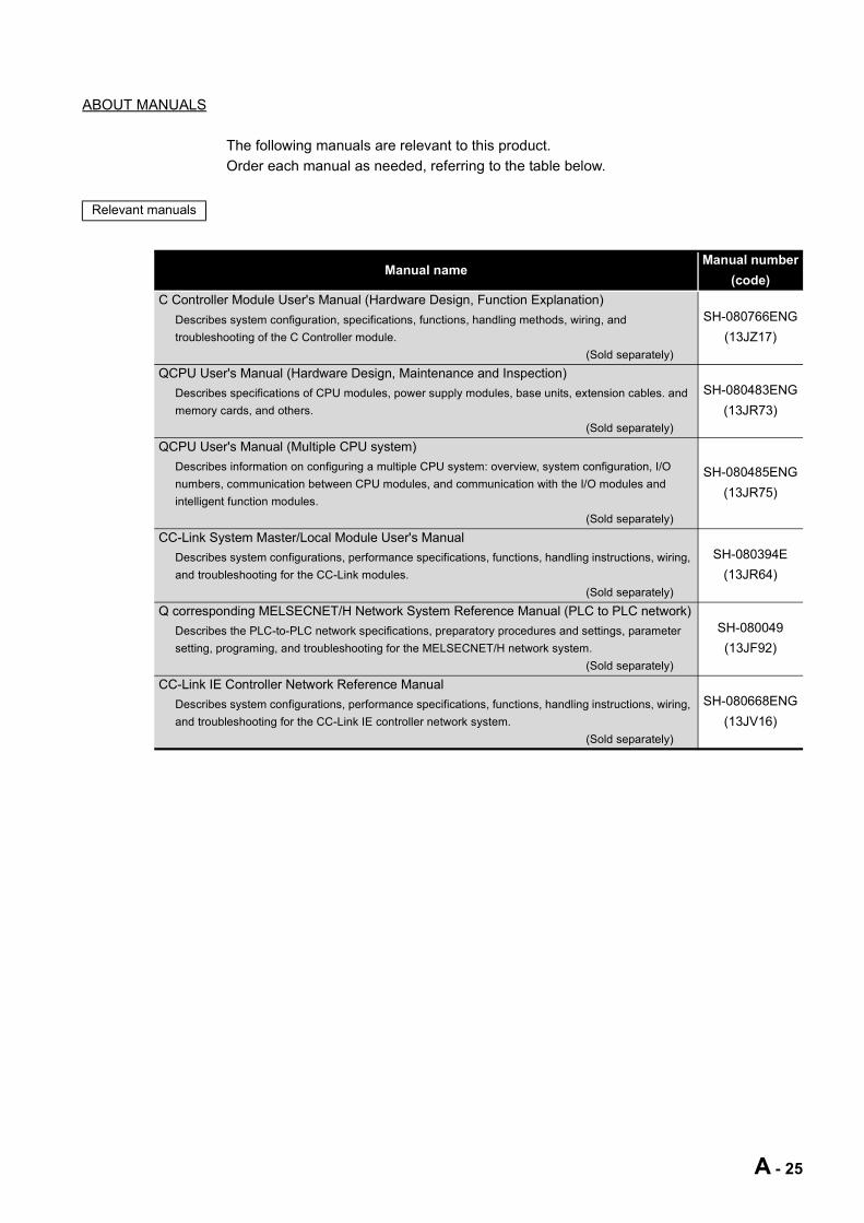
ABOUT MANUALS
The following manuals are relevant to this product.Order each manual as needed, referring to the table below.
Relevant manuals
Manual nameManual number
(code)C Controller Module User's Manual (Hardware Design, Function Explanation)
Describes system configuration, specifications, functions, handling methods, wiring, and troubleshooting of the C Controller module.
(Sold separately)
SH-080766ENG(13JZ17)
QCPU User's Manual (Hardware Design, Maintenance and Inspection)Describes specifications of CPU modules, power supply modules, base units, extension cables. and memory cards, and others.
(Sold separately)
SH-080483ENG(13JR73)
QCPU User's Manual (Multiple CPU system)Describes information on configuring a multiple CPU system: overview, system configuration, I/O numbers, communication between CPU modules, and communication with the I/O modules and intelligent function modules.
(Sold separately)
SH-080485ENG(13JR75)
CC-Link System Master/Local Module User's ManualDescribes system configurations, performance specifications, functions, handling instructions, wiring, and troubleshooting for the CC-Link modules.
(Sold separately)
SH-080394E(13JR64)
Q corresponding MELSECNET/H Network System Reference Manual (PLC to PLC network)Describes the PLC-to-PLC network specifications, preparatory procedures and settings, parameter setting, programing, and troubleshooting for the MELSECNET/H network system.
(Sold separately)
SH-080049(13JF92)
CC-Link IE Controller Network Reference ManualDescribes system configurations, performance specifications, functions, handling instructions, wiring, and troubleshooting for the CC-Link IE controller network system.
(Sold separately)
SH-080668ENG(13JV16)
A - 25
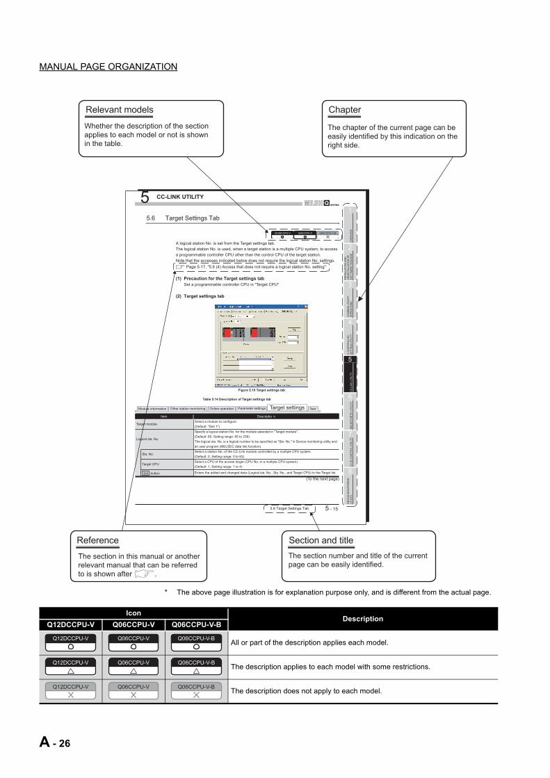
MANUAL PAGE ORGANIZATION
* The above page illustration is for explanation purpose only, and is different from the actual page.
IconDescription
Q12DCCPU-V Q06CCPU-V Q06CCPU-V-B
All or part of the description applies each model.
The description applies to each model with some restrictions.
The description does not apply to each model.
5 CC-LINK UTILITY
5.6 Target Settings Tab 5 - 15
1
OV
ER
VIE
W
2
INS
TA
LLA
TIO
N A
ND
U
NIN
STA
LL
AT
ION
OF
S
OF
TW
AR
E P
AC
KA
GE
3
CO
MM
ON
UT
ILIT
Y
OP
ER
AT
ION
S
4
C C
ON
TR
OLLE
R
SE
TT
ING
UT
ILIT
Y
5
CC
-LIN
K U
TIL
ITY
6
ME
LS
EC
NE
T/H
UT
ILIT
Y
7
CC
IE
CO
NT
RO
L U
TIL
ITY
8
DE
VIC
E M
ON
ITO
RIN
G
UT
ILIT
Y
A logical station No. is set from the Target settings tab.
The logical station No. is used, when a target station is a multiple CPU system, to access
a programmable controller CPU other than the control CPU of the target station.
Note that the accesses indicated below does not require the logical station No. settings.
Page 5-17, "5.6 (4) Access that does not require a logical station No. setting"
(1) Precaution for the Target settings tab
Set a programmable controller CPU in "Target CPU"
(2) Target settings tab
(To the next page)
Table 5.14 Description of Target settings tab
Item Descriptio n
Target moduleSelect a module to configure.
(Default: "Slot 1")
Logical sta. No.
Specify a logical station No. for the module selected in "Target module".
(Default: 65, Setting range: 65 to 239)
The logical sta. No. is a logical number to be specified as "Sta. No." in Device monitoring utility and
an user program (MELSEC data link function).
Sta. No.Select a station No. of the CC-Link module controlled by a multiple CPU system.
(Default: 0, Setting range: 0 to 63)
Target CPUSelect a CPU of the access target (CPU No. in a multiple CPU system).
(Default: 1, Setting range: 1 to 4)
button Enters the added and changed data (Logical sta. No., Sta. No., and Target CPU) to the Target list.
Q12DCCPU-V Q06CCPU-V Q06CCPU-V-B
Module information Other station monitoring Online operation Parameter settings Target settings Test
Set
5.6 Target Settings Tab
Figure 5.10 Target settings tab
The section in this manual or another
relevant manual that can be referred
to is shown after .
Reference
Relevant models
Whether the description of the section
applies to each model or not is shown
in the table.
Chapter
The chapter of the current page can be
easily identified by this indication on the
right side.
The section number and title of the current
page can be easily identified.
Section and title
Q12DCCPU-V Q06CCPU-V Q06CCPU-V-B
Q12DCCPU-V Q06CCPU-V Q06CCPU-V-B
Q12DCCPU-V Q06CCPU-V Q06CCPU-V-B
A - 26

HOW TO USE THIS MANUAL
This manual is used to develop familiarity with parameter settings, monitoring, and programming required for using the C Controller module.Refer to the following list when using this manual.
Remark
This manual does not explain the features, system configurations, specifications, handling instructions, wiring, or troubleshooting of the C Controller module.For details of the above, refer to C Controller Module User's Manual (Hardware Design, Function Explanation).
Chapter DescriptionCHAPTER 1 Features of SW PVC-CCPUCHAPTER 2 Operating environment, installing, uninstalling of SW PVC-CCPU
CHAPTER 3 to CHAPTER 8
Parameter settings and monitoring using utility
CHAPTER 9 to CHAPTER 12
Programming of the C Controller module
CHAPTER 13 Event numbers of the C Controller module
A - 27

GENERIC TERMS AND ABBREVIATIONS
Unless otherwise specified, this manual uses the following generic terms and abbreviations to explain the C Controller module.
(1) C Controller module and SW PVC-CCPU
(2) CPU modules
(To the next page)
Generic term/abbreviation DescriptionQ12DCCPU-V Abbreviation for the Q12DCCPU-V C Controller moduleQ06CCPU-V Abbreviation for the Q06CCPU-V C Controller moduleQ06CCPU-V-B Abbreviation for the Q06CCPU-V-B C Controller moduleQ06CCPU-V(-B) Generic term for the Q06CCPU-V and Q06CCPU-V-BC Controller module Generic term for the Q12DCCPU-V, Q06CCPU-V, and Q06CCPU-V-B
SW PVC-CCPU
Abbreviation for VxWorks-based C Controller module setting/monitoring tool
(SW PVC-CCPU-E)
indicates the version.
Generic term/abbreviation Description
ACPU
Generic term for the 1NCPU, A0J2HCPU, A1SCPU, A1SHCPU, A1SJCPU, A1SJHCPU, A2CCPU, A2CJCPU, A2NCPU, A2NCPU-S1, A2SCPU, A2SHCPU, A2ACPU, A2ACPU-S1, A2UCPU, A2UCPU-S1, A2USCPU, A2USCPU-S1, A2USHCPU-S1, A3NCPU, A3ACPU, A3UCPU, and A4UCPU
QnACPUGeneric term for the Q2ACPU, Q2ACPU-S1, Q2ASCPU, Q2ASCPU-S1, Q2ASHCPU, Q2ASHCPU-S1, Q3ACPU, Q4ACPU, and Q4ARCPU
QCPU (A mode) Generic term for the Q02CPU-A, Q02HCPU-A, and Q06HCPU-ABasic model QCPU Generic term for the Q00CPU and Q01CPUHigh Performance model QCPU Generic term for the Q02CPU, Q02HCPU, Q06HCPU, Q12HCPU, and Q25HCPUProcess CPU Generic term for the Q02PHCPU, Q06PHCPU, Q12PHCPU, and Q25PHCPURedundant CPU Generic term for the Q12PRHCPU and Q25PRHCPU
Universal model QCPU
Generic term for the Q00UJCPU, Q00UCPU, Q01UCPU, Q02UCPU, Q03UDCPU, Q04UDHCPU, Q06UDHCPU, Q10UDHCPU, Q13UDHCPU, Q20UDHCPU, Q26UDHCPU, Q03UDECPU, Q04UDEHCPU, Q06UDEHCPU, Q10UDEHCPU, Q13UDEHCPU, Q20UDEHCPU, and Q26UDEHCPU
QCPU (Q mode)Generic term for the Basic model QCPU, High Performance model QCPU, Process CPU, Redundant CPU, and Universal model QCPU
Motion CPUGeneric term for the Q172CPUN, Q172CPUN-T, Q172HCPU, Q172HCPU-T, Q173CPUN, Q173CPUN-T, Q173HCPU, Q173HCPU-T, Q172DCPU and Q173DCPU
CPU module Generic term for the C Controller module, QCPU(Q mode), and Motion CPUSingle CPU system Control system where the C Controller module is mounted in the CPU slotMultiple CPU system Control system where multiple CPU modules are mounted on a main base unit
A - 28

(3) Network modules and PC boards
Generic term/abbreviation Description
Control CPU
CPU module that controls I/O modules and intelligent function modules mounted on the main base unit and extension base units.Example: When CPU No. 2 controls a module mounted in Slot 3, CPU No.2 is the control CPU of the module in Slot 3.
Controlled moduleI/O module and intelligent function module controlled by a control CPU.Example: When CPU No.2 controls a module mounted in Slot 3, the module in Slot 3 is the controlled module of CPU No.2.
Non-controlled module(Non-group module)
I/O module and intelligent function module other than controlled modules.Example: When CPU No. 2 controls a module mounted in Slot 3, the module in the Slot 3 is the non-controlled module of CPU No.1 and 3.
Non-control CPUCPU module that is not a control CPU.Example: When CPU No. 2 controls the module mounted in Slot 3, the module in Slot 3 is a non-control CPU of CPUs No.1 and No.3.
Battery Generic term for the Q6BAT and Q7BAT batteries for CPU module
PC CPU moduleAbbreviation for the MELSEC-Q series PC CPU module manufactured by CONTEC Co., Ltd
Generic term/abbreviation DescriptionCC-Link module Generic term for the QJ61BT11 and QJ61BT11NCC-Link/LT module Generic term for the QJ61CL12
CC-Link boardGeneric term for the Q81BD-J61BT11 and Q80BD-J61BT11N CC-Link system master/local interface boards, A80BD-J61BT11 CC-Link system master/local interface board, and A80BD-J61BT13 CC-Link interface board
CC-Link IE controller network module
Generic term for the QJ71GP21-SX and QJ71GP21S-SX
CC-Link IE controller network interface board
Generic term for the Q80BD-J71GP21-SX and Q80BD-J71GP21S-SX CC-Link IE controller network interface boards
MELSECNET/H moduleGeneric term for the QJ71LP21-25, QJ71LP21S-25, QJ71LP21G, QJ71LP21GE, QJ72LP25-25, QJ72LP25G, QJ72LP25GE, QJ71BR11, QJ72BR15, and QJ71NT11B
MELSECNET/H interface boardGeneric term for the Q81BD-J71LP21-25, Q80BD-J71LP21-25, Q80BD-J71LP21G, Q80BD-J71LP21S-25, and Q80BD-J71BR11 MELSECNET/H interface boards
A - 29

(4) Power supply modules and base units
Generic term/abbreviation Description
Q3 BGeneric term for the Q33B, Q35B, Q38B, and Q312B main base units on which the CPU modules, Q series power supply module, Q series I/O modules, and intelligent function modules can be mounted
Q3 SB
Generic term for the Q32SB, Q33SB, and Q35SB slim type main base units on which the C Controller module, Basic model QCPU, High Performance model QCPU, Universal model QCPU, slim type power supply module, Q series I/O modules, and intelligent function modules can be mounted
Q3 RBGeneric term for the Q38RB main base unit for redundant power supply system on which the CPU modules, redundant power supply module, Q series I/O modules, and intelligent function modules can be mounted
Q3 DBGeneric term for the Q38DB and Q312DB multiple CPU high speed main base unit on which the CPU modules, Q series power supply module, Q series I/O modules, and intelligent function modules can be mounted
Q5 BGeneric term for the Q52B and Q55B extension base units on which the Q series I/O modules and intelligent function modules can be mounted
Q6 BGeneric term for the Q63B, Q65B, Q68B, and Q612B extension base units on which the Q series power supply modules, Q series I/O modules, and intelligent function modules can be mounted
Q6 RBGeneric term for the Q68RB extension base unit for redundant power supply system on which the redundant power supply modules, Q series I/O modules, and intelligent function modules can be mounted
QA1S6 BGeneric term for the QA1S65B and QA1S68B extension base units on which the AnS series power supply modules, AnS series I/O modules, and special function modules can be mounted
Main base unit Generic term for the Q3 B, Q3 SB, Q3 RB, and Q3 DBExtension base unit Generic term for the Q5 B, Q6 B, Q6 RB, and QA1S6 BSlim type main base unit Generic term for the Q3 SBRedundant power main base unit Generic term for the Q3 RBRedundant power extension base unit
Generic term for the Q6 RB
Multiple CPU high speed main base unit
Generic term for the Q3 DB
Base unitGeneric term for the main base unit, extension base unit, slim type main base unit, redundant power main base unit, redundant power extension base unit, and multiple CPU high speed main base unit
Redundant power supply base unit
Generic term for the redundant power main base unit and redundant power extension base unit
Q series power supply moduleGeneric term for the Q61P-A1, Q61P-A2, Q61P, Q61P-D, Q62P, Q63P, Q64P, and Q64PN power supply modules
Slim type power supply module Generic term for the Q61SP slim type power supply module
Redundant power supply moduleGeneric term for the Q63RP, Q64RP power supply module for redundant power supply system
Power supply moduleGeneric term for the Q series power supply module, slim type power supply module, and redundant power supply module
Extension cableGeneric term for the QC05B, QC06B, QC12B, QC30B, QC50B, and QC100B extension cables
CPU slot The slot on the right side of the power supply module on the main base unit
A - 30

(5) Others
Generic term/abbreviation DescriptionQ series Abbreviation for the Mitsubishi programmable controllers, MELSEC-Q seriesAnS series Abbreviation for the Mitsubishi programmable controllers, compact MELSEC-A seriesCC-Link Abbreviation for Control & Communication LinkEthernet Generic term for the 100BASE-TX and 10BASE-T network systemsMELSECNET/H Generic term for the Q series MELSECNET/H network systemGOT Abbreviation for the Mitsubishi Graphic Operation Terminal
GX DeveloperProduct name of the SW D5C-GPPW GPP function software package for Q series systems
indicates the version.
Windows Vista
Generic term for:
Microsoft Windows Vista Home Basic Operating System,
Microsoft Windows Vista Home Premium Operating System,
Microsoft Windows Vista Business Operating System,
Microsoft Windows Vista Ultimate Operating System, and
Microsoft Windows Vista Enterprise Operating System
Windows XP
Generic term for:
Microsoft Windows XP Professional Operating System and
Microsoft Windows XP Home Edition Operating System
WorkbenchAbbreviation for Workbench 2.6.1 Update manufactured by Wind River Systems, Inc.For specifications and inquiries of Workbench, visit the website of Wind River Systems, Inc.: http://www.windriver.com/
Tornado
Abbreviation for Tornado 2.1.0 for Hitachi SuperH Cumulative patch 1 manufactured by Wind River Systems, Inc.For specifications and inquiries of Tornado, visit the website of Wind River Systems, Inc.: http://www.windriver.com/
A - 31

GLOSSARY
Definitions of the terms used in this manual are explained below.
Term DescriptionFTP FTP is an abbreviation for File Transfer Protocol, which is used to transfer data files.Telnet Network protocol, or virtual terminal software, that enables remote login in TCP/IP networks.
CompactFlash (CF) CardStorage card stipulated in the "CF+ and CompactFlash Specification" issued by CompactFlash Association
Bus interface functionsFunctions offered by SW PVC-CCPUThese functions allow input/output controls of the I/O modules controlled by C Controller modules and access to intelligent function module's buffer memories.
MELSEC data link function
Functions offered by SW PVC-CCPUThese functions allow access to a programmable controller CPU in the system where the C Controller module is installed, and access to another station's programmable controller CPU via any of the following network that is controlled by the C Controller module.•CC-Link IE controller network•MELSECNET/H•CC-Link
A - 32

PACKING LIST
The following is the product line of the C Controller module.
Model name Product name Quantity
Q12DCCPU-VQ12DCCPU-V C Controller module (Endian format (memory layout): Little endian)
1
Battery (Q6BAT) 1
Q06CCPU-VQ06CCPU-V C Controller module (Endian format (memory layout): Big endian) 1Battery (Q6BAT) 1
Q06CCPU-V-BQ06CCPU-V-B C Controller module (Endian format (memory layout): Big endian) 1Battery (Q6BAT) 1
SW PVC-CCPU-E
VxWorks-based setting/monitoring tools for the C Controller module(Volume license product)
(CD-ROM)1
Software License Agreement 1Software Registration Form 1License Agreement 1Industrial development tool purchasing form (Workbench)
1Industrial development tool purchasing form (Tornado)
A - 33

1 OVERVIEW
CHAPTER 1 OVERVIEW
This manual explains the parameter setting, monitoring, and programming required for operation of the C Controller module.
For the features, system configuration, specifications, handling, wiring, and troubleshooting of the C Controller module, refer to the C Controller Module User's Manual (Hardware Design, Function Explanation).
(1) Manuals relevant to the C Controller moduleThe following list shows the manuals relevant to the C Controller module.For details such as a manual No, refer to "ABOUT MANUALS" section in this manual. ( Page A-25)
(To the next page)
Table 1.1 Manuals relevant to the C Controller module
Purpose
C Controller Module User's
Manual (Hardware)
C Controller Module User's
Manual (Hardware
Design, Function Explanation)
C Controller Module User's Manual (Utility
Operation, Programming)
QCPU User's Manual
(Hardware Design,
Maintenance and Inspection)
QCPU User's Manual (Multiple
CPU System)
Checking the part names and specifications of the C Controller module
Checking the specifications and method of selecting, mounting, and installing the power supply module and base units
Checking the connecting methods of the power supply module, base units, and I/O module
Checking the functions of the C Controller module
Configuring a single CPU system (Start-up procedure and I/O No. assignment)
Configuring a multiple CPU system (Start-up procedure and I/O No. assignment)
Hardware
(Packed)
Hardware
Design
Utility
Operation
Maintenance
and
Inspection
Multiple CPU
System
OutlineDetails
Details
OutlineDetails
Details
Details
OutlineDetails
1 - 1
1 OVERVIEW
1
OV
ERVI
EW
2
INS
TALL
ATIO
N A
ND
U
NIN
STA
LLAT
ION
OF
SO
FTW
ARE
PA
CKA
GE
3
CO
MM
ON
UTI
LITY
O
PER
ATIO
NS
4
C C
ON
TRO
LLE
R
SET
TIN
G U
TILI
TY
5
CC
-LIN
K U
TILI
TY
6
MEL
SEC
NET
/H U
TILI
TY
7
CC
IE C
ON
TRO
L U
TILI
TY
8
DE
VIC
E M
ON
ITO
RIN
G
UTI
LITY
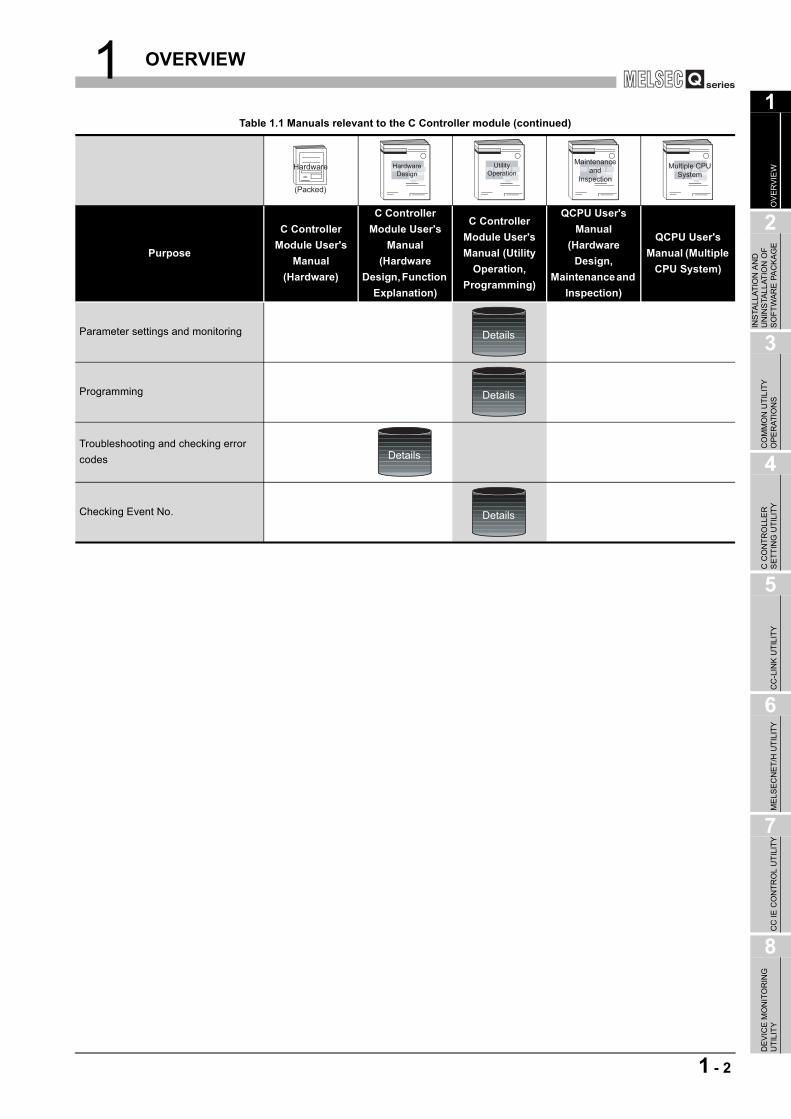
Table 1.1 Manuals relevant to the C Controller module (continued)
Purpose
C Controller Module User's
Manual (Hardware)
C Controller Module User's
Manual (Hardware
Design, Function Explanation)
C Controller Module User's Manual (Utility
Operation, Programming)
QCPU User's Manual
(Hardware Design,
Maintenance and Inspection)
QCPU User's Manual (Multiple
CPU System)
Parameter settings and monitoring
Programming
Troubleshooting and checking error codes
Checking Event No.
Hardware
(Packed)
Hardware
Design
Utility
Operation
Maintenance
and
Inspection
Multiple CPU
System
Details
Details
Details
Details
1 - 2

1 OVERVIEW
1.1 Features
(1) Easy setting with utilitiesVarious settings, such as parameter setting for the C Controller module and multiple CPU setting, can be easily configured by using C Controller setting utility.Also, parameters for the following modules can be set, and device monitoring of an access target can be configured and executed.
• CC-Link modules • MELSECNET/H modules • CC-Link IE controller network modules
The setting items and functionalities vary depending on the model of the C Controller module.For the functions of each utility, refer to the following.
Page 3-1, "3.1 Utility List"
Figure 1.1 Utility screens
1 - 3 1.1 Features

1 OVERVIEW
1
OV
ERVI
EW
2
INS
TALL
ATIO
N A
ND
U
NIN
STA
LLAT
ION
OF
SO
FTW
ARE
PA
CKA
GE
3
CO
MM
ON
UTI
LITY
O
PER
ATIO
NS
4
C C
ON
TRO
LLE
R
SET
TIN
G U
TILI
TY
5
CC
-LIN
K U
TILI
TY
6
MEL
SEC
NET
/H U
TILI
TY
7
CC
IE C
ON
TRO
L U
TILI
TY
8
DE
VIC
E M
ON
ITO
RIN
G
UTI
LITY
(2) Efficient development of user programs with integrated development environment
(a) For the Q12DCCPU-VWorkbench, an integrated development environment, provides efficient development of user programs with C or C++ language.Providing a development group that covers all the developing processes from "software development", "system diagnostics", "testing", to "manufacturing", Workbench allows users to shorten development period and improve the quality.ICE is not required since debugging is available from a development environment (personal computer) by connecting it to the C Controller module by Ethernet.
(b) For the Q06CCPU-V(-B)Tornado, an integrated development environment, provides efficient development of user programs by using C or C++ language.ICE is not required since debugging is available from a development environment (personal computer) by connecting it to the C Controller module by Ethernet.
Figure 1.2 Development with Workbench
Development environment (personal computer)
C Controller module
Efficient development with an integrated development
environment (Workbench)
1.1 Features 1 - 4

2 INSTALLATION AND UNINSTALLATION OF SOFTWARE PACKAGE
CHAPTER 2 INSTALLATION AND UNINSTALLATION OF SOFTWARE PACKAGE
2.1 Development Environment
Table 2.1 Product requirements for SW PVC-CCPU
Item Description
Personal computerPC-AT compatible machine running the following operating systemsFor writing user programs into a CompactFlash card, a personal computer supporting CompactFlash card is required.
CPU Page 2-1, "Table 2.2 Requirements for operating system and personal computer"Memory
Operating system
Microsoft Windows 2000 Professional Operating System (English version) Service Pack4 or later
Microsoft Windows XP Professional Operating System (English version) Service Pack2 or later
Microsoft Windows Vista Home Basic Operating System (English version)
Microsoft Windows Vista Home Premium Operating System (English version)
Microsoft Windows Vista Business Operating System (English version)
Microsoft Windows Vista Ultimate Operating System (English version)
Microsoft Windows Vista Enterprise Operating System (English version)Development tool
Q12DCCPU-VWind River Workbench 2.6.1 UpdateFor product requirements for Workbench, refer to the manual of Workbench.
Q06CCPU-V, Q06CCPU-V-B
Tornado 2.1.0 for Hitachi SuperH Cumulative patch 1For product requirements for Tornado, refer to the manual of Tornado.
Display Resolution 1024 768 dots or moreDisk space 250MB or more
Disk drive CD-ROM disk drive (DVD-ROM disk drive for Windows Vista )Ethernet card, board 10BASE-T, 100BASE-TX
Table 2.2 Requirements for operating system and personal computer
Operating systemPersonal computer
CPU Memory
Windows 2000 Professional Pentium 1GHz or more 256MB or more
Windows XP Professional Pentium 1GHz or more 256MB or more
Windows Vista Home Basic Pentium 1GHz or more 512MB or more
Windows Vista Home Premium Pentium 1GHz or more 512MB or more
Windows Vista Business Pentium 1GHz or more 512MB or more
Windows Vista Ultimate Pentium 1GHz or more 512MB or more
Windows Vista Enterprise Pentium 1GHz or more 512MB or more
2 - 1 2.1 Development Environment
2 INSTALLATION AND UNINSTALLATION OF SOFTWARE PACKAGE
1
OV
ERVI
EW
2
INS
TALL
ATIO
N A
ND
U
NIN
STA
LLAT
ION
OF
SO
FTW
ARE
PA
CKA
GE
3
CO
MM
ON
UTI
LITY
O
PER
ATIO
NS
4
C C
ON
TRO
LLE
R
SET
TIN
G U
TILI
TY
5
CC
-LIN
K U
TILI
TY
6
MEL
SEC
NET
/H U
TILI
TY
7
CC
IE C
ON
TRO
L U
TILI
TY
8
DE
VIC
E M
ON
ITO
RIN
G
UTI
LITY
POINT1. When installing or uninstalling SW PVC-CCPU and when operating utility,
logon as an user with Administrator attribute.2. When using Windows 2000 Professional, large fonts (detailed setting in the
screen properties) cannot be used.If used, this product may not operate properly.
3. When using Windows XP or Windows Vista , the following functions cannot be used and if any of the following functions is used, this product may not operate properly.
• Application startup in Windows Compatibility Mode • Fast User Switching • Remote Desktop • Large fonts (detailed setting in the screen properties)
Also, 64-bit versions of Windows XP and Windows Vista are not supported.
2.1 Development Environment 2 - 2

2 INSTALLATION AND UNINSTALLATION OF SOFTWARE PACKAGE
2.2 Installation
(1) Preparation for installationBefore installation, perform the following.
1) Logon as an user with Administrator attribute.
2) Remove all the applications in the start up, restart Windows , and logon again as an user with Administrator attribute.
3) Change settings not to allow any update program of OS, such as Windows Update, or other manufacturer's software, such as Java, to start automatically.The installer may not operate normally if an update program is activated.
POINT1. Installation of SW PVC-CCPU by overwriting is available only onto the same
version.When installing any other version, uninstall the existing one before installation.
2. When installing SW PVC-CCPU by overwriting, file backups are not necessary for the files stored by utility including a parameter setting file.Files stored in the "C:\MELSEC\CCPU\Param" folder will not be removed when installing SW PVC-CCPU by overwriting.
2 - 3 2.2 Installation

2 INSTALLATION AND UNINSTALLATION OF SOFTWARE PACKAGE
1
OV
ERVI
EW
2
INS
TALL
ATIO
N A
ND
U
NIN
STA
LLAT
ION
OF
SO
FTW
ARE
PA
CKA
GE
3
CO
MM
ON
UTI
LITY
O
PER
ATIO
NS
4
C C
ON
TRO
LLE
R
SET
TIN
G U
TILI
TY
5
CC
-LIN
K U
TILI
TY
6
MEL
SEC
NET
/H U
TILI
TY
7
CC
IE C
ON
TRO
L U
TILI
TY
8
DE
VIC
E M
ON
ITO
RIN
G
UTI
LITY
(2) Installation procedure1) Insert a CD-ROM, this product, to the CD-ROM drive.
2) Double-click "Setup.exe" in the CD-ROM folder to start the installer of SW PVC-CCPU.
3) Proceed the installation following the instructions provided by the installer.For the setting selection, refer to the following instruction.
4) After installation, enable Windows Firewall so that an development environment (personal computer) and the C Controller module can be connected.
Page 2-5, "2.2 (3) Operation after installation"
User Account Control (For Windows Vista )
Click "Allow".
Selecting installation destination
Specify the folder of installation destination.
•When installation destination is "C:\MELSEC", click the button.
•When installation destination is other than "C:\MELSEC", click the button and specify the folder of installation destination.
End of InstallShield Wizard
Restart Windows at the end of the installation.(1) Eject the CD-ROM from the CD-ROM drive.
(2) Select "Yes, I want to restart my computer now." and click the
button. Windows is restarted and now SW PVC-CCPU is operable.
Next>
Browse
Finish
2.2 Installation 2 - 4

2 INSTALLATION AND UNINSTALLATION OF SOFTWARE PACKAGE
(3) Operation after installationEnable Windows Firewall to connect the development environment (personal computer) and the C Controller module.
1 Open the Control Panel of Windows , click Security Center, and then click Windows Firewall.
2 Display the <<Exceptions>> tab and click the
button.
3 Select one of the utilities of SW PVC-CCPU and click the
button.Repeat the procedure until all the required utilities of SW PVC-CCPU are added.
4 Confirm that all the utilities of SW PVC-CCPU are
selected, and click the button.
(Completed)
Add Program
OK
OK
2 - 5 2.2 Installation

2 INSTALLATION AND UNINSTALLATION OF SOFTWARE PACKAGE
1
OV
ERVI
EW
2
INS
TALL
ATIO
N A
ND
U
NIN
STA
LLAT
ION
OF
SO
FTW
ARE
PA
CKA
GE
3
CO
MM
ON
UTI
LITY
O
PER
ATIO
NS
4
C C
ON
TRO
LLE
R
SET
TIN
G U
TILI
TY
5
CC
-LIN
K U
TILI
TY
6
MEL
SEC
NET
/H U
TILI
TY
7
CC
IE C
ON
TRO
L U
TILI
TY
8
DE
VIC
E M
ON
ITO
RIN
G
UTI
LITY
2.3 Uninstallation
(1) Preparation for uninstallationPerform the following before uninstallation.
1) Logon as an user with Administrator attribute.
2) Terminate all the running utilities.
POINT1. If uninstallation cannot be performed, check if the following file names are
displayed as image names in the process of task manager.If displayed as image names, terminate the process before uninstalling again.
• CCIECUtl.exe • CClnkUtl.exe • CCpuUtl.exe • MnethUtl.exe • RtDvmonUtl.exe
2. Uninstallation must be started from Control Panel.3. To reinstall SW PVC-CCPU, uninstall it, restart Windows , and then
reinstall.4. Do not terminate uninstallation during processing.
If terminated, redo the uninstallation all over again.If the uninstallation fails after terminating the uninstallation, reinstall the software and then uninstall it again.
Q12DCCPU-V Q06CCPU-V Q06CCPU-V-B
2.3 Uninstallation 2 - 6
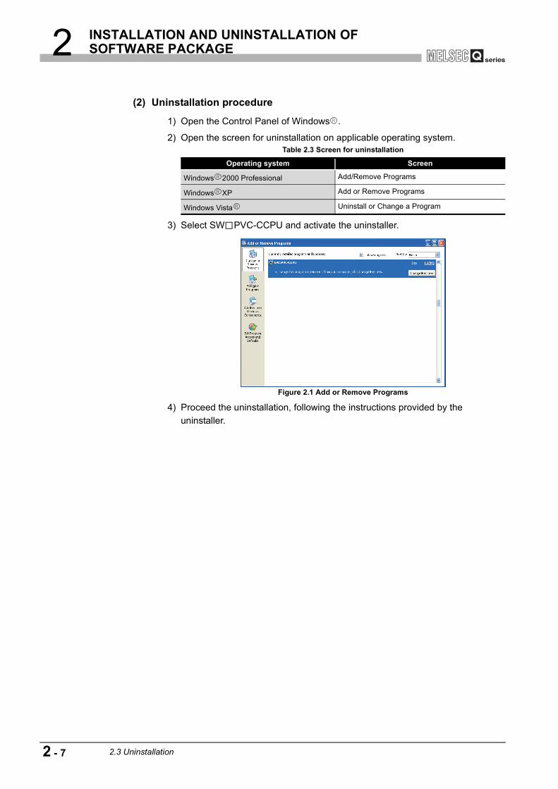
2 INSTALLATION AND UNINSTALLATION OF SOFTWARE PACKAGE
(2) Uninstallation procedure
1) Open the Control Panel of Windows .
2) Open the screen for uninstallation on applicable operating system.
3) Select SW PVC-CCPU and activate the uninstaller.
4) Proceed the uninstallation, following the instructions provided by the uninstaller.
Table 2.3 Screen for uninstallation
Operating system Screen
Windows 2000 Professional Add/Remove Programs
Windows XP Add or Remove Programs
Windows Vista Uninstall or Change a Program
Figure 2.1 Add or Remove Programs
2 - 7 2.3 Uninstallation

3 COMMON UTILITY OPERATIONS
1
OV
ERVI
EW
2
INS
TALL
ATIO
N A
ND
U
NIN
STA
LLAT
ION
OF
SO
FTW
ARE
PA
CKA
GE
3
CO
MM
ON
UTI
LITY
O
PER
ATIO
NS
4
C C
ON
TRO
LLE
R
SET
TIN
G U
TILI
TY
5
CC
-LIN
K U
TILI
TY
6
MEL
SEC
NET
/H U
TILI
TY
7
CC
IE C
ON
TRO
L U
TILI
TY
8
DE
VIC
E M
ON
ITO
RIN
G
UTI
LITY
CHAPTER 3 COMMON UTILITY OPERATIONS
3.1 Utility List
: Available, : Available but partially restricted, : N/A
Remark
For functions added to the C Controller module and SW PVC-CCPU and function versions and serial No.s of the CPU module that support the added functions, refer to the C Controller Module User's Manual (Hardware Design, Function Explanation).
Table 3.1 Utilities in SW PVC-CCPU
Utility DescriptionAvailability
Reference page
Q12DCCPU-V
Q06CCPU-V
Q06CCPU-V-B
C Controller setting utility
Functions of C Controller setting utility are as follows.•Displays the module information (LED status, switch status, and error information and others) of a C Controller module
•Displays event history•Monitors states (input, output, and buffer memories) of each module mounted with the C Controller module
•Sets parameters•Operates the C Controller module online
Page 4-1
CC-Link utilityPerforms parameter setting, network monitoring, etc. of the CC-Link module controlled by the C Controller module.
Page 5-1
MELSECNET/H utilityPerforms parameter setting, network monitoring, etc. of the MELSECNET/H module controlled by the C Controller module.
Page 6-1
CC IE Control utilityPerforms parameter setting, network monitoring, etc. of the CC-Link IE controller network module controlled by the C Controller module.
Page 7-1
Device monitoring utility
Monitors and tests device data of the programmable controller CPU.
Page 8-1
Q12DCCPU-V Q06CCPU-V Q06CCPU-V-B
3.1 Utility List 3 - 1

3 COMMON UTILITY OPERATIONS
3.2 Activating Utility
To activate utility, select [Start] [All Programs] [MELSEC] [C Controller], and click a desired item from the following menu.
Figure 3.1 Items added to the Start menu
Q12DCCPU-V Q06CCPU-V Q06CCPU-V-B
Activates MELSECNET/H utility
Activates MELSEC Data Link Function HELP
Activates Device monitoring utility
Activates CC-Link utility
Activates CC IE Control utility
Activates C Controller setting utility
Activates Bus Interface Function HELP
3 - 2 3.2 Activating Utility

3 COMMON UTILITY OPERATIONS
1
OV
ERVI
EW
2
INS
TALL
ATIO
N A
ND
U
NIN
STA
LLAT
ION
OF
SO
FTW
ARE
PA
CKA
GE
3
CO
MM
ON
UTI
LITY
O
PER
ATIO
NS
4
C C
ON
TRO
LLE
R
SET
TIN
G U
TILI
TY
5
CC
-LIN
K U
TILI
TY
6
MEL
SEC
NET
/H U
TILI
TY
7
CC
IE C
ON
TRO
L U
TILI
TY
8
DE
VIC
E M
ON
ITO
RIN
G
UTI
LITY
3.3 Exiting Utility
(1) Utility other than Device monitoring utilityTo exit utility other than Device monitoring utility, click the button at the bottom right of the screen.
(2) Device monitoring utilityTo exit Device monitoring utility, select [Menu] [Exit] on the menu bar.
As a dialog box appears, click the button.
Figure 3.2 Exiting C Controller setting utility
Figure 3.3 Exiting Device monitoring utility
Q12DCCPU-V Q06CCPU-V Q06CCPU-V-B
Exit
Click.
Yes
Click.
3.3 Exiting Utility 3 - 3

3 COMMON UTILITY OPERATIONS
3.4 Specifying CPU Type
Select the C Controller module for parameter setting and monitoring in utility other than Device monitoring utility.
Remark
1. Changing CPU typeSelect [Specify CPU type] from the system menu and change the CPU type. ( Page 4-43, Section 4.11, Page 5-20, Section 5.8, Page 6-41, Section 6.8, Page 7-36, Section 7.7)
2. When writing parameters or performing communication processing such as monitoring to any other CPU type, change the CPU type on this screen in advance.For the following communication processing, CPU type change is available in the processing.
• Connection target settings • Parameter read
Figure 3.4 Specify CPU type screen
Table 3.2 Description of the Specify CPU type screen
Item Description
CPU typeSpecifies a C Controller module to which parameters are set or to be monitored.(Default: "Q12DCCPU-V")
CPU type fixed
The specified CPU type is fixed and this screen will not be displayed on and after next utility operation.To set back to the default (CPU type not fixed), select [Specify CPU type] in the system menu to open this screen and deselect the check box.(Default: Deselected (CPU type not fixed))
button Sets the selected C Controller module as the CPU type and closes this screen.
button Closes this screen without changing the CPU type.
Q12DCCPU-V Q06CCPU-V Q06CCPU-V-B
OK
Cancel
3 - 4 3.4 Specifying CPU Type

3 COMMON UTILITY OPERATIONS
1
OV
ERVI
EW
2
INS
TALL
ATIO
N A
ND
U
NIN
STA
LLAT
ION
OF
SO
FTW
ARE
PA
CKA
GE
3
CO
MM
ON
UTI
LITY
O
PER
ATIO
NS
4
C C
ON
TRO
LLE
R
SET
TIN
G U
TILI
TY
5
CC
-LIN
K U
TILI
TY
6
MEL
SEC
NET
/H U
TILI
TY
7
CC
IE C
ON
TRO
L U
TILI
TY
8
DE
VIC
E M
ON
ITO
RIN
G
UTI
LITY
3.5 Setting Connection Target
Connect an development environment (personal computer) and the C Controller module.
(1) Operating procedure
Remark
If a utility communication error occurred after connecting, restart monitoring by
clicking the button or set the connection target again in Connection settings.
1 Select "192.168.3.3 (Default)" in "Target module".When the IP address of the C Controller module has been changed, enter the IP address or host name currently set.
2 Select the "Write authority" check box and enter the following.User name: targetPassword: passwordWhen the account of the C Controller module has been changed, enter the user name and password currently set to the account.
3 Check the connectivity with the C Controller by clicking the
button.Note that in startup or after reset of the C Controller module, the timing to click the button differs according to the script file "STARTUP.CMD" usage.
The timing to click the button;When executing "STARTUP.CMD": After the RUN LED finished flashingWhen not executing "STARTUP.CMD": 15 seconds after the startup or reset of the module.
4 Clicking the button establishes a connection with the C Controller module, and the screen shown on the left appears.
Click the button when reading out parameters from the C Controller module.
(Completed)
Q12DCCPU-V Q06CCPU-V Q06CCPU-V-B
Test
Test
Connect
Yes
Start monitoring
3.5 Setting Connection Target 3 - 5

3 COMMON UTILITY OPERATIONS
(2) Connection settings screen
Figure 3.5 Connection settings screen
Table 3.3 Description of the Connection settings screen
Item Description
Target module
Enter the IP address or host name of the C Controller module to be connected.
Click to allow selection from the following.•Connection target history (Up to 8 data, common to all utilities)•"192.168.3.3 (Default)"•"Offline" (other than Device monitoring utility)When entering a host name, do not set multiple IP addresses under the same host name. (If set, a communication is performed with the host whose IP address is last acquired.)
Write authoritySelect the checkbox when writing parameters to the C Controller module.For "User name" and "password", enter the user name and password set to the account of the C Controller.Parameters cannot be written to the C Controller module if these are not set.These items cannot be set when:•"Offline" is selected for "Target module" or•This screen has been opened from Device monitoring utility.For restrictions on accessing to a login user, refer to the C Controller Module User's Manual (Hardware Design, Function Explanation).
User name
Password
button Checks the connectivity with the C Controller module specified in "Target module".
button Clears the connection target log of "Target module".
button Opens the Detailed settings screen. ( Page 3-7, Section 3.5 (2) (a))
buttonEstablishes a connection with the C Controller module specified in "Target module".When "Write authority" is selected, the C Controller module authenticates the account.
button Closes the Connection settings screen without changing the connection target.
Test
Clear history
Detailed settings
Connect
Exit
3 - 6 3.5 Setting Connection Target

3 COMMON UTILITY OPERATIONS
1
OV
ERVI
EW
2
INS
TALL
ATIO
N A
ND
U
NIN
STA
LLAT
ION
OF
SO
FTW
ARE
PA
CKA
GE
3
CO
MM
ON
UTI
LITY
O
PER
ATIO
NS
4
C C
ON
TRO
LLE
R
SET
TIN
G U
TILI
TY
5
CC
-LIN
K U
TILI
TY
6
MEL
SEC
NET
/H U
TILI
TY
7
CC
IE C
ON
TRO
L U
TILI
TY
8
DE
VIC
E M
ON
ITO
RIN
G
UTI
LITY
(a) Detailed settings screenEnter values in "Communication check time" and "Retry count" used in Ethernet communication between a development environment (personal computer) and the C Controller module.
POINTCommunication errors may occur in Ethernet communication between the development environment (personal computer) and the C Controller module depending on the line status. When a communication error has occurred, increase the setting value for "Communication check time" and/or "Retry count".
Figure 3.6 Detailed settings screen
Table 3.4 Description of the Detailed settings screen
Item Description
Communication check time
Set a communication check time in Ethernet communication between the development environment (personal computer) and C Controller module. (Unit: seconds)(Default: 10, Setting range: 1 to 360)
Retry count
Set the number of retries in Ethernet communication between the development environment (personal computer) and C Controller module.(Default: 2, Setting range: 0 to 9)
button Enables the current settings and closes the Detailed settings screen.
button Closes the Detailed settings screen without enabling the settings.
buttonSets the values entered in "Communication check time" and "Retry count" back to default.
OK
Cancel
Default
3.5 Setting Connection Target 3 - 7

3 COMMON UTILITY OPERATIONS
Remark
1. Offline operationParameters can be written to each utility offline.When writing parameters, a connection must be established with the C Controller module.
2. Changing connection targetTo connect with other target, open the "Connection settings" screen with the following operations and change the IP address or host name.
• For other than Device monitoring utility
Click the button at the bottom left of the screen. • For Device monitoring utility
Select [Setting] [Connection settings] from the menu bar.3. The connection target when other utility is started from the system menu.
Connection is established with the same C Controller module.4. How to check the connection target and user name
Check on the title bar and status bar. ( Page 3-14, Section 3.9)5. When the C Controller module specified in the CPU type on utility (other than
Device monitoring utility) and the connection target C Controller module are not the same type.Change the setting to the C Controller module that is to be connected as the CPU type, and then set it in Connection settings.For changing the CPU type, refer to the following.
Page 3-4, "3.4 Specifying CPU Type"
Connection settings
3 - 8 3.5 Setting Connection Target

3 COMMON UTILITY OPERATIONS
1
OV
ERVI
EW
2
INS
TALL
ATIO
N A
ND
U
NIN
STA
LLAT
ION
OF
SO
FTW
ARE
PA
CKA
GE
3
CO
MM
ON
UTI
LITY
O
PER
ATIO
NS
4
C C
ON
TRO
LLE
R
SET
TIN
G U
TILI
TY
5
CC
-LIN
K U
TILI
TY
6
MEL
SEC
NET
/H U
TILI
TY
7
CC
IE C
ON
TRO
L U
TILI
TY
8
DE
VIC
E M
ON
ITO
RIN
G
UTI
LITY
3.6 Displaying the Help Screen
(1) Utilities other than Device monitoring utilityTo display the Help screen of utilities other than Device monitoring utility, click the
button at the bottom right of the screen.
Alternatively, press the key while the utility is active.
(2) Device monitoring utilityTo display the Help screen of Device monitoring utility, select [Help] [Help] from the menu bar.Alternatively, press the key while the utility is active.
Figure 3.7 Starting Help of C Controller setting utility
Figure 3.8 Starting Help of Device monitoring utility
Q12DCCPU-V Q06CCPU-V Q06CCPU-V-B
Help
F1
Click.
F1
Click.
3.6 Displaying the Help Screen 3 - 9

3 COMMON UTILITY OPERATIONS
(3) Windows VistaWhen using Windows Vista , the screen below may appear instead of the Help screen.
(a) When a development environment (personal computer) is connectable to the internet:
1) Click the link shown on the screen above to display Microsoft Help and Support article ID No.917607 on the web browser.
2) Install WinHlp32.exe according to the instruction provided in the article ID No. 917607.
(b) When a development environment (personal computer) is not connectable to the internet:
1) Use another personal computer connectable to the internet and go to the address below on the web browser to display Microsoft Help and Support article ID No.917607.http://support.microsoft.com/kb/917607
2) Install WinHlp32.exe according to the instruction in the article ID No. 917607.
3) Transfer WinHlp32.exe to the development environment (personal computer) and install it.
Remark
1. The Help screens in SW PVC-CCPU cannot be displayed simultaneously.Display one screen at a time.If another Help screen is started while a Help screen is being displayed, the first one is closed to display the one last opened.
2. If an error occurs in the C Controller module (host CPU), the Help screen can be displayed from the System information screen of the C Controller setting utility. ( Page 4-17, Section 4.5 (3))
Figure 3.9 When the Help screen does not appear on Windows Vista
Link
3 - 10 3.6 Displaying the Help Screen

3 COMMON UTILITY OPERATIONS
1
OV
ERVI
EW
2
INS
TALL
ATIO
N A
ND
U
NIN
STA
LLAT
ION
OF
SO
FTW
ARE
PA
CKA
GE
3
CO
MM
ON
UTI
LITY
O
PER
ATIO
NS
4
C C
ON
TRO
LLE
R
SET
TIN
G U
TILI
TY
5
CC
-LIN
K U
TILI
TY
6
MEL
SEC
NET
/H U
TILI
TY
7
CC
IE C
ON
TRO
L U
TILI
TY
8
DE
VIC
E M
ON
ITO
RIN
G
UTI
LITY
3.7 Checking Version
(1) Utilities other than Device monitoring utilityTo check the version of utilities other than Device monitoring utility, select [Version information] in the system menu.C Controller setting utility .... Page 4-43, Section 4.11CC-Link utility ...................... Page 5-20, Section 5.8MELSECNET/H utility ......... Page 6-41, Section 6.8CC IE Control utility ............. Page 7-36, Section 7.7
(2) Device monitoring utilityTo check the version of Device monitoring utility:
(a) OperationClick [Help] [Version] from the menu bar to open the Version information screen.
(b) Version information screen
Figure 3.10 Checking version
Figure 3.11 Version information screen
Table 3.5 Version information
Item DescriptionDevice monitoring utility Displays the update date of Device monitoring utility.
button Closes the version information screen.
Q12DCCPU-V Q06CCPU-V Q06CCPU-V-B
Click.
OK
3.7 Checking Version 3 - 11
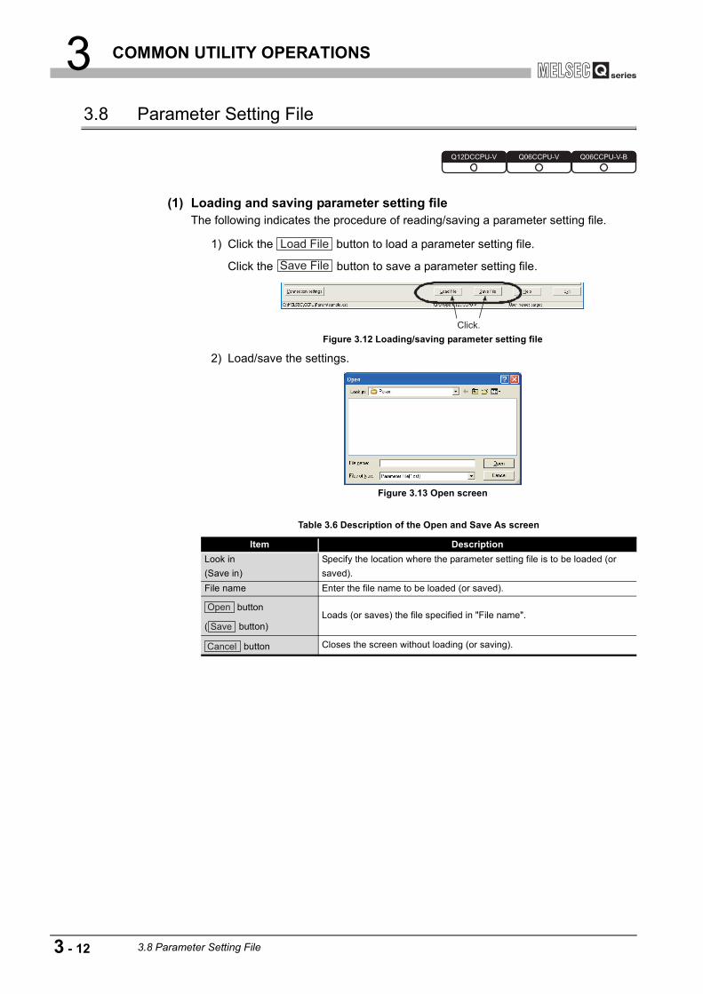
3 COMMON UTILITY OPERATIONS
3.8 Parameter Setting File
(1) Loading and saving parameter setting fileThe following indicates the procedure of reading/saving a parameter setting file.
1) Click the button to load a parameter setting file.
Click the button to save a parameter setting file.
2) Load/save the settings.
Figure 3.12 Loading/saving parameter setting file
Figure 3.13 Open screen
Table 3.6 Description of the Open and Save As screen
Item DescriptionLook in(Save in)
Specify the location where the parameter setting file is to be loaded (or saved).
File name Enter the file name to be loaded (or saved).
button
( button)Loads (or saves) the file specified in "File name".
button Closes the screen without loading (or saving).
Q12DCCPU-V Q06CCPU-V Q06CCPU-V-B
Load File
Save File
Click.
Open
Save
Cancel
3 - 12 3.8 Parameter Setting File

3 COMMON UTILITY OPERATIONS
1
OV
ERVI
EW
2
INS
TALL
ATIO
N A
ND
U
NIN
STA
LLAT
ION
OF
SO
FTW
ARE
PA
CKA
GE
3
CO
MM
ON
UTI
LITY
O
PER
ATIO
NS
4
C C
ON
TRO
LLE
R
SET
TIN
G U
TILI
TY
5
CC
-LIN
K U
TILI
TY
6
MEL
SEC
NET
/H U
TILI
TY
7
CC
IE C
ON
TRO
L U
TILI
TY
8
DE
VIC
E M
ON
ITO
RIN
G
UTI
LITY
Remark
1. The name of the parameter setting file currently used is displayed on the status bar in utilities other than Device monitoring utility.
2. The following table lists the extensions for parameter setting files.
3. The standard directory, where utilities other than Device monitoring utility save parameter setting files, is "C:\MELSEC\CCPU\Param". (When SW PVC-CCPU has been installed in "C:\MELSEC")
4. Double-clicking any saved parameter setting file (*.cst, *.ccl, *.mnh, or *.mng) starts the corresponding utility with the saved parameter setting loaded.
5. When a parameter setting file is loaded, utility will be in the following status.
(2) Utilizing existing parameter settings in the parameter setting fileMultiple modules can be used under the same parameter setting by loading a existing parameter file into multiple development environments (personal computers).
Remark
Parameter settings can be utilized without a parameter setting file with the following procedure.
1. Set parameters in utility other than Device monitoring utility.2. Open the Connection settings screen and connect to the module where the
parameters are written.
3. Write the parameters to the C Controller module by clicking the button in the <<Online operation>> tab of each utility.
4. By repeating steps 2 and 3, the same parameter setting can be set to multiple modules.
Table 3.7 Extensions for parameter setting file
Utility Extension for parameter setting fileC Controller setting utility cstCC-Link utility cclMELSECNET/H utility mnhCC IE Control utility mng
Table 3.8 Utility status
Item Status
CPU typeChanged back to the one set when the parameter setting file was saved.
Connection
Disconnected and monitoring is stopped.
To restart monitoring, click the button or set data again in Connection settings.
Start monitoring
Write
3.8 Parameter Setting File 3 - 13

3 COMMON UTILITY OPERATIONS
3.9 Displays on the Title Bar and Status Bar
Figure 3.14 Title bar and status bar
Table 3.9 Display on the title bar and status bar
No. Display
Utility name
IP address or host address of the connection target C Controller module"Offiline" is displayed when in offline.Name of a parameter setting file"New" is displayed when no parameter setting file has been loaded or saved.
CPU type specified in the Specify CPU type screen.
User name who has been logged in to the C Controller module.
Q12DCCPU-V Q06CCPU-V Q06CCPU-V-B
543
21
1
2
3
4
5
3 - 14 3.9 Displays on the Title Bar and Status Bar
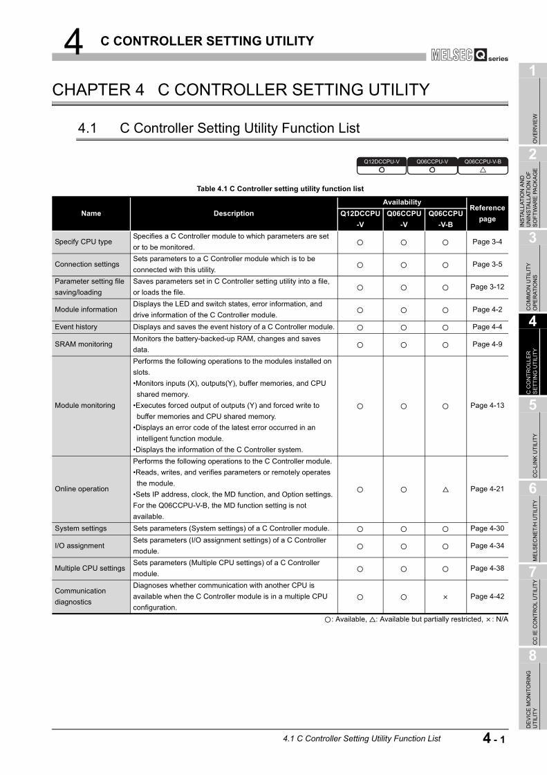
4 C CONTROLLER SETTING UTILITY
1
OV
ERVI
EW
2
INS
TALL
ATIO
N A
ND
U
NIN
STA
LLAT
ION
OF
SO
FTW
ARE
PA
CKA
GE
3
CO
MM
ON
UTI
LITY
O
PER
ATIO
NS
4
C C
ON
TRO
LLE
R
SET
TIN
G U
TILI
TY
5
CC
-LIN
K U
TILI
TY
6
MEL
SEC
NET
/H U
TILI
TY
7
CC
IE C
ON
TRO
L U
TILI
TY
8
DE
VIC
E M
ON
ITO
RIN
G
UTI
LITY
CHAPTER 4 C CONTROLLER SETTING UTILITY
4.1 C Controller Setting Utility Function List
: Available, : Available but partially restricted, : N/A
Table 4.1 C Controller setting utility function list
Name DescriptionAvailability
Reference page
Q12DCCPU-V
Q06CCPU-V
Q06CCPU-V-B
Specify CPU typeSpecifies a C Controller module to which parameters are set or to be monitored.
Page 3-4
Connection settingsSets parameters to a C Controller module which is to be connected with this utility.
Page 3-5
Parameter setting file saving/loading
Saves parameters set in C Controller setting utility into a file, or loads the file.
Page 3-12
Module informationDisplays the LED and switch states, error information, and drive information of the C Controller module.
Page 4-2
Event history Displays and saves the event history of a C Controller module. Page 4-4
SRAM monitoringMonitors the battery-backed-up RAM, changes and saves data.
Page 4-9
Module monitoring
Performs the following operations to the modules installed on slots.•Monitors inputs (X), outputs(Y), buffer memories, and CPU shared memory.
•Executes forced output of outputs (Y) and forced write to buffer memories and CPU shared memory.
•Displays an error code of the latest error occurred in an intelligent function module.
•Displays the information of the C Controller system.
Page 4-13
Online operation
Performs the following operations to the C Controller module.•Reads, writes, and verifies parameters or remotely operates the module.
•Sets IP address, clock, the MD function, and Option settings. For the Q06CCPU-V-B, the MD function setting is not available.
Page 4-21
System settings Sets parameters (System settings) of a C Controller module. Page 4-30
I/O assignmentSets parameters (I/O assignment settings) of a C Controller module.
Page 4-34
Multiple CPU settingsSets parameters (Multiple CPU settings) of a C Controller module.
Page 4-38
Communication diagnostics
Diagnoses whether communication with another CPU is available when the C Controller module is in a multiple CPU configuration.
Page 4-42
Q12DCCPU-V Q06CCPU-V Q06CCPU-V-B
4.1 C Controller Setting Utility Function List 4 - 1

4 C CONTROLLER SETTING UTILITY
4.2 Module Information Tab
The Module information tab displays the LED status, switch status, error information, and drive information of the C Controller module.
(1) Precautions for the Module information tab
(a) Switching a tab during monitoringMonitoring stops when a tab is switched to another during monitoring. Monitoring resumes when the <<Module monitoring>> tab is opened next time.
(b) When a utility communication error has occurredWhen a utility communication error has occurred during connection, click the
button or set the connection target again in the Connection settings so that the communication can be restarted.
(c) During resetCommunications are not available while the C Controller module is being reset.Start communications after the reset is complete.
(2) Module information tab
* 1 For part names and functions of the C Controller module, refer to the C Controller Module User's Manual (Hardware Design, Function Explanation)
(To the next page)
Q12DCCPU-V Q06CCPU-V Q06CCPU-V-B
Figure 4.1 Module information tab
Table 4.2 Description of the Module information tab
Item DescriptionReference
pageModule information Displays the information of the C Controller module.
LED informationDisplays the LED states of the C Controller module.Note that the CH3 SD/RD indication for the Q12DCCPU-V and the CH2 SD/RD indication for the Q06CCPU-V(-B) are disabled.
*1
Q12DCCPU-V Q06CCPU-V Q06CCPU-V-B
Start monitoring
Module information Event history SRAM monitoring Module monitoring Online operation
4 - 2 4.2 Module Information Tab

4 C CONTROLLER SETTING UTILITY
1
OV
ERVI
EW
2
INS
TALL
ATIO
N A
ND
U
NIN
STA
LLAT
ION
OF
SO
FTW
ARE
PA
CKA
GE
3
CO
MM
ON
UTI
LITY
O
PER
ATIO
NS
4
C C
ON
TRO
LLE
R
SET
TIN
G U
TILI
TY
5
CC
-LIN
K U
TILI
TY
6
MEL
SEC
NET
/H U
TILI
TY
7
CC
IE C
ON
TRO
L U
TILI
TY
8
DE
VIC
E M
ON
ITO
RIN
G
UTI
LITY
* 1 For part names and functions of the C Controller module, refer to the C Controller Module User's Manual (Hardware Design, Function Explanation).
* 2 For corrective actions for errors, refer to the C Controller Module User's Manual (Hardware Design, Function Explanation).
* 3 "Used space" indication of the "Standard RAM information", "Standard ROM information", and "CF card information" includes the space used by the file system.
* 4 For data and size that can be stored, refer to the C Controller Module User's Manual (Hardware Design, Function Explanation).
Table 4.2 Description of the Module information tab (continued)
Item DescriptionReference
pageModule information
Toggle switch informationDisplays the RUN/STOP/MODE switch and RESET/SELECT switch states of the C Controller module.
*1
7-segment LED informationDisplays the 7-segment LED status of the C Controller module.For the Q06CCPU-V(-B), this indication is disabled.
*1
CPU operating statusDisplays the operating status ("RUN", "STOP", "PAUSE") of the C Controller module, including remote operation.
*1
Error code Displays the latest error code among stop/continue errors currently occurring.Help in this
utility
Error information
When a stop or continue error has occurred in the C Controller module,
corresponding error item for stop or continue error changes from (white) to
(red).
*2
or
button
Starts or stops monitoring the C Controller module."*" flashes in the upper right of the button during monitoring. These buttons are disabled in the offline status.
Drive information Displays drive information of the C Controller module.
Standard RAM information Displays its size, used space, and free space of a standard ROM.*3
For the Q06CCPU-V(-B), this information is not displayed.*4
Standard ROM information Displays its size, used space, and free space of a standard ROM.*3
For the Q12DCCPU-V, this information is not displayed.*4
CF card information
When a CompactFlash card is installed, entire space, used space, and free space
of the CompactFlash card are displayed.*3
"Empty" is displayed for the following cases.•A CompactFlash card is not installed when the Q12DCCPU-V or Q06CCPU-V is used.
•When the Q06CCPU-V-B is used.
*4
buttonUpdates either of the "Standard RAM information" or "Standard ROM information", and "CF card information".
Module information Event history SRAM monitoring Module monitoring Online operation
Start monitoring
Stop monitoring
Update
4.2 Module Information Tab 4 - 3

4 C CONTROLLER SETTING UTILITY
4.3 Event History Tab
(1) Precautions for the Event history tab
(a) Event history update timingEvent history is updated by acquiring the data from the C Controller module when a connection is established to the C Controller module in Connection settings or
when the button is clicked.
(b) Event history displays the data registered by QBF_RegistEventLog functionThe event history displays the data registered by QBF_RegistEventLog function.( Page 9-3, Section 9.2)
(c) When a utility communication error has occurredWhen a utility communication error has occurred during connection, set the connection target again in the Connection settings so that the communication can be restarted.
(d) During resetCommunications are not available while the C Controller module is being reset.Start communications after the reset is complete.
(e) Precautions for using QBF_RegistEventLog functionIf the same data as in "source flag" ( Page 4-8, "Table 4.5 Source flag") is specified into the argument SrcStr[] of the QBF_RegistEventLog function, it will be difficult to differentiate the data in the <<Event history>> tab.Do not specify the same character string as in "source flag".
The event occurrence can be located in the following ways. • Checking "Event type" of the Detailed event information screen
Page 4-7, "4.3 (3) Detailed event information screen" • Checking the event history file
Page 4-8, "4.3 (4) Specifications of the Event history file"
Q12DCCPU-V Q06CCPU-V Q06CCPU-V-B
Update
4 - 4 4.3 Event History Tab

4 C CONTROLLER SETTING UTILITY
1
OV
ERVI
EW
2
INS
TALL
ATIO
N A
ND
U
NIN
STA
LLAT
ION
OF
SO
FTW
ARE
PA
CKA
GE
3
CO
MM
ON
UTI
LITY
O
PER
ATIO
NS
4
C C
ON
TRO
LLE
R
SET
TIN
G U
TILI
TY
5
CC
-LIN
K U
TILI
TY
6
MEL
SEC
NET
/H U
TILI
TY
7
CC
IE C
ON
TRO
L U
TILI
TY
8
DE
VIC
E M
ON
ITO
RIN
G
UTI
LITY
(f) Date and time of AC/DC DOWNWhen AC/DC DOWN (Event No. 0xC0000201) has occurred, two kinds of date and time data are displayed as shown below.To confirm the actual date and time of AC/DC DOWN, look at the data 2).
1) The date and time when the C Controller module was powered on after AC/DC DOWN. 2) The date and time when AC/DC DOWN occurred (when the C Controller module was powered
off).Figure 4.2 Date and time of AC/DC DOWN
1)
2)
4.3 Event History Tab 4 - 5

4 C CONTROLLER SETTING UTILITY
(2) Event history tabThe events occurred in the C Controller module are displayed or saved in this tab.
* 1 Displaying all event information at once may not be available when too many events occurred.To check all data of the event information, double-click the event to display the Detailed event information screen and confirm the information.
Figure 4.3 Event history tab
Table 4.3 Description of the Event history tab
Item DescriptionReference
page
button Acquires and displays the latest event history in the C Controller module.
button Deletes the event history in the C Controller module.
button Saves the displayed event history into a CSV format file. Page 4-8
Event history
Displays the history up to 512 events occurred in the C Controller module.If 513 or more events have occurred, a new event is inserted by deleting the oldest one.The event history is displayed in reverse chronological order.Double-clicking an event opens the Detailed event information screen.
Page 4-7Page 13-1
Date Displays the date of event occurrence. Page 13-1Time Displays the time of event occurrence. Page 13-1
SourceDisplays the source of event occurrence. (Example "MQbfDrv" is displayed when a event occurred in the bus interface drive (bus part).)
Page 13-1
Event No. Displays the No. of event occurred. Page 13-1
Event information*1 Displays event information of the event occurred. Page 13-1
Module information Event history SRAM monitoring Module monitoring Online operation
Update
Clear
Save event history
4 - 6 4.3 Event History Tab

4 C CONTROLLER SETTING UTILITY
1
OV
ERVI
EW
2
INS
TALL
ATIO
N A
ND
U
NIN
STA
LLAT
ION
OF
SO
FTW
ARE
PA
CKA
GE
3
CO
MM
ON
UTI
LITY
O
PER
ATIO
NS
4
C C
ON
TRO
LLE
R
SET
TIN
G U
TILI
TY
5
CC
-LIN
K U
TILI
TY
6
MEL
SEC
NET
/H U
TILI
TY
7
CC
IE C
ON
TRO
L U
TILI
TY
8
DE
VIC
E M
ON
ITO
RIN
G
UTI
LITY
(3) Detailed event information screenThe detailed information of the event that is double-clicked on the Event history tab is displayed. ( Page 4-6).
Figure 4.4 Detailed information screenTable 4.4 Description of the Detailed information screen
Item DescriptionReference
pageDate, Time, Source, Event No., Event info
Displays the Detailed event information.Page 4-6
Page 13-1
Event type
Displays the type of the event.
Page 13-1
Indication DescriptionSystem (Err.) The event is a C Controller system error.System (Warning) The event is a C Controller system warning.System (Info) The event is a C Controller system information.
ApplicationThe event is registered from an user program (QBF_RegistEventLog function).
button Displays the Detailed event information screen.
button
Displays the next latest detailed event information than the currently displayed one.
Clicking the button while the latest detailed event information is displayed, a message appears and the oldest detailed event information is displayed.
button
Displays the next oldest detailed event information than the currently displayed one.
Clicking the button while the oldest detailed event information is displayed, a message appears and the latest detailed event information is displayed.
button Starts a Help of C Controller setting utility and displays the information of the event.
OK
PreviousPrevious
NextNext
Help
4.3 Event History Tab 4 - 7

4 C CONTROLLER SETTING UTILITY
(4) Specifications of the Event history fileA file format can be selected in "Files of type" on the following screen.
To use the text data of the Event history file in an user program etc., select "EventLog File(*.csv)" when saving.To use them on Microsoft Excel etc., select "EventLog File[Form2](*.csv)" when saving.
(a) Source flagThe source file (the third column) of the event history file indicates the following information.
* 1 Corresponding to "Source" in the Event history tab.
Remark
The folder to save the event history file is "C:\MELSEC\CCPU\Param" by default (when SW PVC-CCPU has been installed in "C:\MELSEC").
Figure 4.5 Save As screen
When "EventLog File(*.csv)" is selected When "EventLog File[Form2](*.csv)" is selected
Figure 4.6 Example of Event history files
Table 4.5 Source flag
Source flag Source*1 Data type
0000Character string specified by the QBF_RegistEventLog function.
An event registered from QBF_RegistEventLog function.
0001 MQbfDrv Bus interface driver (bus part) related0002 MXwdkDrv Bus interface driver (system part) related
0003 MUtlIfQbfUtility communication interface (bus interface part) related
0004 MUtlIfMdUtility communication interface (MELSEC communication part) related
0005 MUtlIfComUtility communication interface (common part) related
0006 MMain C Controller module main body part related0007 MFDrv Flash ROM and standard RAM related0008 MCfDrv CompactFlash card related0009 MEtherDrv Ethernet related
4 - 8 4.3 Event History Tab
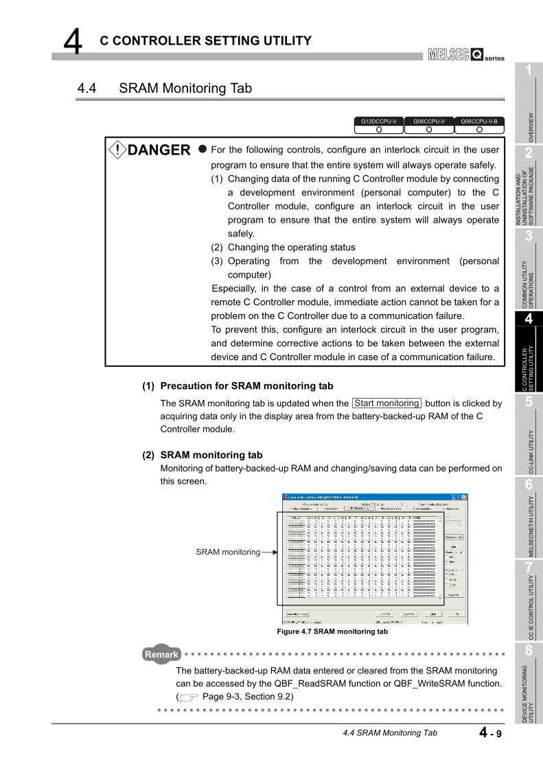
4 C CONTROLLER SETTING UTILITY
1
OV
ERVI
EW
2
INS
TALL
ATIO
N A
ND
U
NIN
STA
LLAT
ION
OF
SO
FTW
ARE
PA
CKA
GE
3
CO
MM
ON
UTI
LITY
O
PER
ATIO
NS
4
C C
ON
TRO
LLE
R
SET
TIN
G U
TILI
TY
5
CC
-LIN
K U
TILI
TY
6
MEL
SEC
NET
/H U
TILI
TY
7
CC
IE C
ON
TRO
L U
TILI
TY
8
DE
VIC
E M
ON
ITO
RIN
G
UTI
LITY
4.4 SRAM Monitoring Tab
(1) Precaution for SRAM monitoring tabThe SRAM monitoring tab is updated when the button is clicked by acquiring data only in the display area from the battery-backed-up RAM of the C Controller module.
(2) SRAM monitoring tabMonitoring of battery-backed-up RAM and changing/saving data can be performed on this screen.
Remark
The battery-backed-up RAM data entered or cleared from the SRAM monitoring can be accessed by the QBF_ReadSRAM function or QBF_WriteSRAM function. ( Page 9-3, Section 9.2)
DANGER For the following controls, configure an interlock circuit in the userprogram to ensure that the entire system will always operate safely.(1) Changing data of the running C Controller module by connecting
a development environment (personal computer) to the CController module, configure an interlock circuit in the userprogram to ensure that the entire system will always operatesafely.
(2) Changing the operating status(3) Operating from the development environment (personal
computer) Especially, in the case of a control from an external device to a
remote C Controller module, immediate action cannot be taken for aproblem on the C Controller due to a communication failure.To prevent this, configure an interlock circuit in the user program,and determine corrective actions to be taken between the externaldevice and C Controller module in case of a communication failure.
Figure 4.7 SRAM monitoring tab
Q12DCCPU-V Q06CCPU-V Q06CCPU-V-B
Start monitoring
SRAM monitoring
4.4 SRAM Monitoring Tab 4 - 9

4 C CONTROLLER SETTING UTILITY
* 1 Endian format (memory layout) of the C Controller module is applied when "16 bits" or "32 bits" is selected.Example) Display format when "32 bits" is selected
Table 4.6 Description of the SRAM monitoring tab
Item DescriptionReference
page
SRAM monitoring
Monitors battery-backed-up RAM data.Double-click one of the data being monitored, or select one and then press the
[Enter] key to enter data. ( Page 4-11)
Offset
Set the start address of the data to be monitored. (In increments of 0x10)When a value is set other than in increments of 0x10, the fraction is dropped at the start of monitoring.When a value outside the setting range is set, it will automatically be corrected to a value within the range, at the start of monitoring.(Default: 0, Setting range: 0 to 1FFFF)
or
button
Starts or stops monitoring the C Controller module."*" flashes in the upper right of the button during monitoring.These buttons are disabled in the offline status.
button Changes all battery-backed-up RAM data to 0.
Numeric format Select a value format to display in the SRAM monitoring. (Default: "HEX.")
Display format Select a display format of SRAM monitoring.*1(Default: "8 bits")
button
Saves all battery-backed-up RAM data.
Monitoring stops from when the button is clicked until all data are saved.
Page 4-12
Figure 4.8 Display example when "32 bits" is selected
SRAM monitoring Module monitoring Online operationEvent historyModule information
Start monitoring
Stop monitoring
Clear
Save data Save data
Memory status SRAM monitoring screen display
78
+00
56 34 12
Address
Display data12 34 56 78
+00 +01 +02 +03Address
Display data 12
+00
34 56 78
For the
Q12DCCPU-V
and Q06CCPU-V
For the
Q06CCPU-V-B
4 - 10 4.4 SRAM Monitoring Tab

4 C CONTROLLER SETTING UTILITY
1
OV
ERVI
EW
2
INS
TALL
ATIO
N A
ND
U
NIN
STA
LLAT
ION
OF
SO
FTW
ARE
PA
CKA
GE
3
CO
MM
ON
UTI
LITY
O
PER
ATIO
NS
4
C C
ON
TRO
LLE
R
SET
TIN
G U
TILI
TY
5
CC
-LIN
K U
TILI
TY
6
MEL
SEC
NET
/H U
TILI
TY
7
CC
IE C
ON
TRO
L U
TILI
TY
8
DE
VIC
E M
ON
ITO
RIN
G
UTI
LITY
(3) Data setting screenData can be entered into the battery-backed-up RAM from this screen.
Figure 4.9 Data settings screenTable 4.7 Description of the Data settings screen
Item DescriptionReference
page
Input formatSelect a format of the value to be entered in "Input data".(Default: "Numeric format" of the screen which opened this screen.)
Target addressDisplays the address of the battery-backed-up RAM where the data are to be entered.
Input data Enter data to be entered into the battery-backed-up RAM.
button Writes data entered in "Input data" to the battery-backed-up RAM.
buttonCloses the Data settings screen without writing the input data to the battery-backed-up RAM.
Target address Input data
OK
Cancel
4.4 SRAM Monitoring Tab 4 - 11

4 C CONTROLLER SETTING UTILITY
(4) Specifications of the Battery-backed-up RAM data save fileBattery-backed-up RAM data can be saved either in the CSV or binary format.A file format can be selected in "Files of type" on the following screen.
(a) Specifications of the CSV formatTo use the text data of the Battery-backed-up RAM data save file in an user program etc, select "SRAM Data File(*.csv)" when saving.To use them on Microsoft Excel etc., select "SRAM Data File[Form2](*.csv)" when saving.
(b) Specifications of the binary format • The extension is "bin". • When data are saved in the binary format, the battery-backed-up RAM data
are saved as is.
Remark
The standard directory to store the battery-backed-up RAM data is "C:\MELSEC\CCPU\Param" by default (when SW PVC-CCPU has been installed in "C:\MELSEC").
Figure 4.10 Save As screen
When "SRAM Data File(*.csv)" is selected When "SRAM Data File[Form2](*.csv)" is selected
Figure 4.11 Example of save files
4 - 12 4.4 SRAM Monitoring Tab

4 C CONTROLLER SETTING UTILITY
1
OV
ERVI
EW
2
INS
TALL
ATIO
N A
ND
U
NIN
STA
LLAT
ION
OF
SO
FTW
ARE
PA
CKA
GE
3
CO
MM
ON
UTI
LITY
O
PER
ATIO
NS
4
C C
ON
TRO
LLE
R
SET
TIN
G U
TILI
TY
5
CC
-LIN
K U
TILI
TY
6
MEL
SEC
NET
/H U
TILI
TY
7
CC
IE C
ON
TRO
L U
TILI
TY
8
DE
VIC
E M
ON
ITO
RIN
G
UTI
LITY
4.5 Module Monitoring Tab
(1) Precautions for Module monitoring tab
(a) Switching a tab during monitoringMonitoring stops when the tab is switched to another during monitoring.Monitoring resumes when the <<Module monitoring>> tab is opened next time.
(b) When a utility communication error has occurredWhen a utility communication error has occurred during connection, click the
button or set the connection target again in the Connection settings so that the communication can be restarted.
(c) During resetCommunications are not available while the C Controller module is being reset.Start communications after the reset is complete.
DANGER For the following controls, configure an interlock circuit in the userprogram to ensure that the entire system will always operate safely.(1) Changing data of the running C Controller module by connecting
a development environment (personal computer) to the CController module, configure an interlock circuit in the userprogram to ensure that the entire system will always operatesafely.
(2) Changing the operating status(3) Operating from the development environment (personal
computer) Especially, in the case of a control from an external device to a
remote C Controller module, immediate action cannot be taken for aproblem on the C Controller due to a communication failure.To prevent this, configure an interlock circuit in the user program,and determine corrective actions to be taken between the externaldevice and C Controller module in case of a communication failure.
Q12DCCPU-V Q06CCPU-V Q06CCPU-V-B
Start monitoring
4.5 Module Monitoring Tab 4 - 13

4 C CONTROLLER SETTING UTILITY
(d) Monitoring and testModule monitoring and tests (forced output of output (Y), forced write to buffer memory and CPU shared memory) on this tab are executed to the module that is installed in the "Slot No." specified on this tab.The setting in the "Type" field of Parameter settings (I/O assignment settings) does not affect the target.Note that tests are available only to the modules controlled by the C Controller module.
When monitoring or forced write to buffer memory has been performed to the CC-Link module where the block data assurance per station function is enabled, cyclic data will be automatically refreshed.
Note that data are automatically refreshed only when the monitoring or forced write to buffer memory has been performed to the link refresh device (buffer memory) range corresponding to the stations set in the CC-Link master station parameters (Station information setting). (For details of the range, refer to "Slave station offset, size information" (buffer memory address:3E0H to 5DFH) in the buffer memory list for the CC-Link module.)For details of the block data assurance per station function, refer to the C Controller Module User's Manual (Hardware Design, Function Explanation).
The following area will not be refreshed when monitoring or forced write to buffer memory has been performed.
• The write (send) area of link refresh devices (buffer memory) will not be refreshed when monitoring has been performed.
• The read (receive) area of link refresh devices (buffer memory) will not be refreshed when forced write to buffer memory has been performed.
(e) Precautions for changing module configurationWhen module configuration is changed after starting C Controller setting utility, any of the following operation updates the module configuration information.
• Set the Connection settings.
• Click the button in the <<Module monitoring >> tab.
• Click the button in the <<Module monitoring >> tab.
Start monitoring
System info
4 - 14 4.5 Module Monitoring Tab

4 C CONTROLLER SETTING UTILITY
1
OV
ERVI
EW
2
INS
TALL
ATIO
N A
ND
U
NIN
STA
LLAT
ION
OF
SO
FTW
ARE
PA
CKA
GE
3
CO
MM
ON
UTI
LITY
O
PER
ATIO
NS
4
C C
ON
TRO
LLE
R
SET
TIN
G U
TILI
TY
5
CC
-LIN
K U
TILI
TY
6
MEL
SEC
NET
/H U
TILI
TY
7
CC
IE C
ON
TRO
L U
TILI
TY
8
DE
VIC
E M
ON
ITO
RIN
G
UTI
LITY
(2) Module monitoring tabThe status of input (X), output (Y), and buffer memory of the module installed to the selected slot are monitored on this tab. The forced output of the output (Y) and forced write to the buffer memory are allowed.
(To the next page)
Figure 4.12 Module monitoring tab
Table 4.8 Description of the Module monitoring tab
Item DescriptionReference
page
Slot No.
Specify a slot No. to be monitored.This item cannot be changed during monitoring. Stop monitoring for changing.In a multiple CPU system, the CPU shared memory can be monitored by setting the slot No. where a CPU module is mounted."CPU" can be set only in a multiple CPU system configuration.(Default: 0, Setting range: "CPU", 0 to 63)
Start I/O No. Displays the start I/O No. of the module installed to the slot specified in "Slot No.".
Control CPU
Displays the CPU No. that controls a module installed in the slot specified in "Slot No.".Displays " " (blank) when the slot where a CPU module is installed, or the slot to which "CPU (Empty)" is set as I/O assignment, is specified in "Slot No.". ("*" appears on the right side of the CPU No. of the C Controller module when it is connected with C Controller setting utility and is a control CPU.)
Type
Displays the I/O points and type of the module if the slot where other than a CPU module is installed is specified in "Slot No.". Within parentheses, the value set in "points" in Parameter settings (I/O assignment settings) is displayed.Displays CPU No. and "connected CPU" when the slot where a CPU module (own station) is mounted is specified in "Slot No.".Displays CPU No. when the slot where a CPU module (another CPU) is mounted is specified in "Slot No.".Displays "CPU (Empty)" when the slot to which "CPU (Empty)" is set as I/O assignment is specified in "Slot No.".
Module information Event history SRAM monitoring Module monitoring Online operation
4.5 Module Monitoring Tab 4 - 15
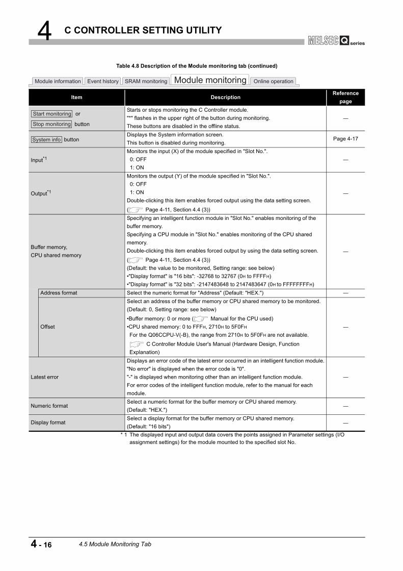
4 C CONTROLLER SETTING UTILITY
* 1 The displayed input and output data covers the points assigned in Parameter settings (I/O assignment settings) for the module mounted to the specified slot No.
Table 4.8 Description of the Module monitoring tab (continued)
Item DescriptionReference
page
or
button
Starts or stops monitoring the C Controller module."*" flashes in the upper right of the button during monitoring.These buttons are disabled in the offline status.
buttonDisplays the System information screen.This button is disabled during monitoring.
Page 4-17
Input*1Monitors the input (X) of the module specified in "Slot No.". 0: OFF 1: ON
Output*1
Monitors the output (Y) of the module specified in "Slot No.". 0: OFF 1: ONDouble-clicking this item enables forced output using the data setting screen.
( Page 4-11, Section 4.4 (3))
Buffer memory, CPU shared memory
Specifying an intelligent function module in "Slot No." enables monitoring of the buffer memory.Specifying a CPU module in "Slot No." enables monitoring of the CPU shared memory.Double-clicking this item enables forced output by using the data setting screen.
( Page 4-11, Section 4.4 (3))(Default: the value to be monitored, Setting range: see below)•"Display format" is "16 bits": -32768 to 32767 (0H to FFFFH)•"Display format" is "32 bits": -2147483648 to 2147483647 (0H to FFFFFFFFH)
Address format Select the numeric format for "Address" (Default: "HEX.")
Offset
Select an address of the buffer memory or CPU shared memory to be monitored.(Default: 0, Setting range: see below)
•Buffer memory: 0 or more ( Manual for the CPU used)•CPU shared memory: 0 to FFFH, 2710H to 5F0FH
For the Q06CCPU-V(-B), the range from 2710H to 5F0FH are not available.
C Controller Module User's Manual (Hardware Design, Function Explanation)
Latest error
Displays an error code of the latest error occurred in an intelligent function module."No error" is displayed when the error code is "0"."-" is displayed when monitoring other than an intelligent function module.For error codes of the intelligent function module, refer to the manual for each module.
Numeric formatSelect a numeric format for the buffer memory or CPU shared memory.(Default: "HEX.")
Display formatSelect a display format for the buffer memory or CPU shared memory.(Default: "16 bits")
Module information Event history SRAM monitoring Module monitoring Online operation
Start monitoring
Stop monitoring
System info
4 - 16 4.5 Module Monitoring Tab

4 C CONTROLLER SETTING UTILITY
1
OV
ERVI
EW
2
INS
TALL
ATIO
N A
ND
U
NIN
STA
LLAT
ION
OF
SO
FTW
ARE
PA
CKA
GE
3
CO
MM
ON
UTI
LITY
O
PER
ATIO
NS
4
C C
ON
TRO
LLE
R
SET
TIN
G U
TILI
TY
5
CC
-LIN
K U
TILI
TY
6
MEL
SEC
NET
/H U
TILI
TY
7
CC
IE C
ON
TRO
L U
TILI
TY
8
DE
VIC
E M
ON
ITO
RIN
G
UTI
LITY
(3) System information screenInformation of the C Controller system can be displayed on this screen.
(To the next page)
Figure 4.13 System information screenTable 4.9 Description of the System information screen
Item DescriptionReference
manual
CPU status
Displays the status of CPU modules that configure the C Controller system.Double-clicking the C Controller module or programmable controller CPU with an
error opens the Error details screen. ( Page 4-19, Section 4.5 (3) (a))
CPU moduleDisplays CPU No. of the CPU module. "Empty" is displayed when no CPU module is mounted.(Display: "No.1" to "No.4", "Empty")
StatusDisplays the operation status of the CPU module.(Display: "RUN", "STOP", "PAUSE", and "RESET")
SwitchDisplays the switch status of the CPU module.(Display: "RUN", "STOP", and "RESET")
Error code
Displays an error code of the first stop error and continuous error occurred in the CPU module.
The other errors can be confirmed on the Module information tab ( Page 4-2,
Section 4.2) or the Event history tab ( Page 4-4, Section 4.3).Present error Displays an message corresponding to the "Error code"Date Displays the date of the error occurrence.Time Displays the time of the error occurrence.
System
configuration
4.5 Module Monitoring Tab 4 - 17

4 C CONTROLLER SETTING UTILITY
Remark
The information displayed on the System information screen is based on the configuration when the screen was opened.To update the information, close and reopen the System information screen.
Table 4.9 Description of the System information screen (continued)
Item DescriptionReference
pageCPU status
button
Selecting a C Controller module (own station) and clicking the button starts Help of C Controller setting utility, which displays help information of a current error.This button is available only when the C Controller module (own station) is selected.For errors of programmable controller CPU(s), refer to the manual for the programmable controller CPU used.
System configuration
Displays the information of CPU modules that configure the C Controller system.Double-clicking a module (or selecting a module and pressing the [Enter] key) updates the display to information of the selected module, and closes the System information screen. Note that CPU module selection is not allowed for a single CPU system.
SlotDisplays the "slot No." of the module. In the parenthesis, module's base No. and mounting position in the base unit are displayed.
TypeDisplays the module type.(Display: "Empty", "Input", "Hi.Input", "Output", "I/O mix", "Intelli.", "Interrupt", and "CPU")
SeriesDisplays the series name of the module.(Display: "Q" (fixed))
Model name Displays the model name of the module.
PointsDisplays the I/O points of the module.(Display: 0, 16, 32, 48, 64, 128, 256, 512, 1024)
Start I/O No.Displays the I/O No. of the module.(Display: 0000 to 0FF0, 3E00 to 3E30)
Control CPUDisplays the CPU No. of the control CPU of the module.(Display: "No.1" to "No.4")
Serial No. Displays the serial No. of the module.Ver. Displays the function version of the module.
Product No.Displays the product No. of the C Controller module.When the model does not have product No. indication, "-" is displayed.For the Q06CCPU-V(-B), this item is not displayed.
buttonSaves the displayed information of the C Controller system into the system information file.
Page 4-20
buttonSelecting a module and clicking the button changes the display to information of the selected module, and closes the System information screen.
Page 4-15
button Closes the System information screen.
Error code help
Error code help
Save system information
SelectSelect
Exit
4 - 18 4.5 Module Monitoring Tab

4 C CONTROLLER SETTING UTILITY
1
OV
ERVI
EW
2
INS
TALL
ATIO
N A
ND
U
NIN
STA
LLAT
ION
OF
SO
FTW
ARE
PA
CKA
GE
3
CO
MM
ON
UTI
LITY
O
PER
ATIO
NS
4
C C
ON
TRO
LLE
R
SET
TIN
G U
TILI
TY
5
CC
-LIN
K U
TILI
TY
6
MEL
SEC
NET
/H U
TILI
TY
7
CC
IE C
ON
TRO
L U
TILI
TY
8
DE
VIC
E M
ON
ITO
RIN
G
UTI
LITY
(a) Error details screen
* 1 For errors of the C Controller module, refer to the C Controller Module User's Manual (Hardware Design, Function Explanation).For errors of the programmable controller CPU, refer to the manual for the programmable controller CPU used.
Figure 4.14 Error details screenTable 4.10 Description of the Error details screen
Item Description Reference Common error information Displays common information corresponding to the error code. *1Individual error information Displays individual information corresponding to the error code. *1
4.5 Module Monitoring Tab 4 - 19

4 C CONTROLLER SETTING UTILITY
(4) Specifications of the system information save fileA file format can be selected in "Files of type" on the following screen.
To use the text data of the system information save file in an user program etc, select "System Info File(*.csv)" when saving.To use them on Microsoft Excel etc., select "System Info File[Form2](*.csv)" when saving.
Remark
The standard directory of the system information save file is "C:\MELSEC\CCPU\Param" (when SW PVC-CCPU has been installed in "C:\MELSEC").
Figure 4.15 Save As screen
When "System Info File(*.csv)" is selected When "System Info File[Form2](*.csv)" is selected
Figure 4.16 Example of system information save files
4 - 20 4.5 Module Monitoring Tab

4 C CONTROLLER SETTING UTILITY
1
OV
ERVI
EW
2
INS
TALL
ATIO
N A
ND
U
NIN
STA
LLAT
ION
OF
SO
FTW
ARE
PA
CKA
GE
3
CO
MM
ON
UTI
LITY
O
PER
ATIO
NS
4
C C
ON
TRO
LLE
R
SET
TIN
G U
TILI
TY
5
CC
-LIN
K U
TILI
TY
6
MEL
SEC
NET
/H U
TILI
TY
7
CC
IE C
ON
TRO
L U
TILI
TY
8
DE
VIC
E M
ON
ITO
RIN
G
UTI
LITY
4.6 Online Operation Tab
(1) Precautions for the Online operation tab
(a) When a utility communication error has occurredWhen a utility communication error has occurred during connection, set the connection target again in the Connection settings so that the communication can be restarted.
(b) During resetCommunications are not available while the C Controller module is being reset.Start communications after the reset is complete.
(2) Online operation tabRead, write, and verification of parameters, and remote operation, clock setting, and IP address setting for the C Controller module are available in this tab.
(To the next page)
Figure 4.17 Online operation tab
Table 4.11 Description of the Online operation tab
Item DescriptionReference
pageRead parameters
buttonReads parameters from the C Controller module.
Q12DCCPU-V Q06CCPU-V Q06CCPU-V-B
Operation
Target CPU
Module information Event history SRAM monitoring Module monitoring Online operation
Read
4.6 Online Operation Tab 4 - 21

4 C CONTROLLER SETTING UTILITY
* 1 For remote operation, refer to the C Controller Module User's Manual (Hardware Design, Function Explanation).
Table 4.11 Description of the Online operation tab (continued)
Item DescriptionReference
page
Write parameters
button
Writes parameters set in C Controller setting utility into the C Controller module.The written parameters take effect when the C Controller module is powered off and then on or is reset.Parameters can be written only when "Write authority" is selected in Connection settings. If "Write authority" is not selected, select it in the Connection settings
screen before writing parameters. ( Page 3-5, Section 3.5)
"Clear all parameters before writing." check box
Clicking the button with this box checked clears all parameters (parameters for the CC-Link module, MELSECNET/H module, CC-Link IE controller network module, and intelligent function module) before writing the parameters.
Verify parameters
button
Cross-check the parameters set in the C Controller module and in C Controller setting utility.The result is displayed in a message box.
Remote operation Remotely controls a C Controller module or programmable controller CPU. *1
OperationSelect a remote operation.(Default: "RUN")
*1
Target CPU
Select a CPU that is remote operation target.To remotely operate a own station in a multiple CPU system configuration, select "connected CPU". Selecting a CPU No. causes an error.(Default: "connected CPU")
*1
button
Executes a specified remote operation.For precautions for the remote RESET operation during writing an user file, refer to the C Controller Module User's Manual (Hardware Design, Function Explanation).
*1
button
Opens the Detailed settings screen.Sets the IP address, clock, MD function, and Option settings.Detailed settings is available only when "Write authority" is checked in Connection settings. If "Write authority" is not checked, check it in Connection settings and
then set the Detailed settings. ( Page 3-5, Section 3.5)For the Q06CCPU-V-B, the MD function setting is not available.
Page 4-23
Module information Event history SRAM monitoring Module monitoring Online operation
Write
Write
Verify
Execute
Detail
4 - 22 4.6 Online Operation Tab

4 C CONTROLLER SETTING UTILITY
1
OV
ERVI
EW
2
INS
TALL
ATIO
N A
ND
U
NIN
STA
LLAT
ION
OF
SO
FTW
ARE
PA
CKA
GE
3
CO
MM
ON
UTI
LITY
O
PER
ATIO
NS
4
C C
ON
TRO
LLE
R
SET
TIN
G U
TILI
TY
5
CC
-LIN
K U
TILI
TY
6
MEL
SEC
NET
/H U
TILI
TY
7
CC
IE C
ON
TRO
L U
TILI
TY
8
DE
VIC
E M
ON
ITO
RIN
G
UTI
LITY
(3) Detailed settings screenThe IP address, clock, MD function and Option for the C Controller module can be set on this screen.For the Q06CCPU-V-B, the MD function setting is not available.
Figure 4.18 Detailed settings screen
Table 4.12 Description of the Detailed settings screen
Item DescriptionReference
page<<IP address>> tab Set the IP address for the C Controller module. Page 4-24<<Clock>> tab Set the clock of the C Controller module. Page 4-27
<<MD function>> tabSet the timeout value of the communications made by the MELSEC data link function.For the Q06CCPU-V-B, this item is not available.
Page 4-28
<<Option>> tab Set priority of the processing for communications with the C Controller module. Page 4-28
button Closes the Detailed settings screen.
IP address Clock MD function Option
Exit
4.6 Online Operation Tab 4 - 23

4 C CONTROLLER SETTING UTILITY
(a) IP address tabThe IP address for the C Controller module can be set in this tab.
Figure 4.19 IP address tab
Table 4.13 Description of the IP address tab
Item DescriptionReference
page
IP address settings CH1Set whether to enable or disable the 10BASE-T/100BASE-TX interface of CH1.CH1 and CH2 cannot be set to blank (disable) simultaneously.(Default: checked (enable))
IP addressSet the IP address for the 10BASE-T/100BASE-TX interface of CH1.
(Default: 192.168.3.3, Setting range: Page 4-25, Section 4.6 (3) (a) 1))
Subnet maskSet the subnet mask for the 10BASE-T/100BASE-TX interface of CH1.
(Default: 255.255.255.0, Setting range: Page 4-25, Section 4.6 (3) (a) 1))
Default gateway
Set the IP address of the default gateway for the 10BASE-T/100BASE-TX interface of CH1.
(Default: blank, Setting range: Page 4-25, Section 4.6 (3) (a) 1))
IP address settings CH2
Set whether to enable or disable the 10BASE-T/100BASE-TX interface for CH2.For the Q06CCPU-V(-B), this item is not available.CH1 and CH2 cannot be set to blank (disable) simultaneously.(Default: not checked (enable))
IP addressSet the IP address for the 10BASE-T/100BASE-TX interface of CH2.
(Default: blank, Setting range: Page 4-25, Section 4.6 (3) (a) 1))
Subnet mask
Set the IP address for the default gateway for the 10BASE-T/100BASE-TX interface of CH2.
(Default: blank, Setting range: Page 4-25, Section 4.6 (3) (a) 1))
Default gateway
Set the IP address for the default gateway for the 10BASE-T/100BASE-TX interface of CH2.
(Default: blank, Setting range: Page 4-25, Section 4.6 (3) (a) 1))
buttonWrites the settings of "IP address settings CH1" and "IP address settings CH2" into the C Controller module.
IP address Clock MD function Option
Set
4 - 24 4.6 Online Operation Tab

4 C CONTROLLER SETTING UTILITY
1
OV
ERVI
EW
2
INS
TALL
ATIO
N A
ND
U
NIN
STA
LLAT
ION
OF
SO
FTW
ARE
PA
CKA
GE
3
CO
MM
ON
UTI
LITY
O
PER
ATIO
NS
4
C C
ON
TRO
LLE
R
SET
TIN
G U
TILI
TY
5
CC
-LIN
K U
TILI
TY
6
MEL
SEC
NET
/H U
TILI
TY
7
CC
IE C
ON
TRO
L U
TILI
TY
8
DE
VIC
E M
ON
ITO
RIN
G
UTI
LITY
1) IP address setting • IP address setting range
The following table indicates the IP addresses settable to the C Controller module.For the IP address setting, consult your network administrator (network planner or person in charge of IP addresses)
Note that the IP address must satisfy all the conditions indicated in the following table.
• Subnet mask setting rangeNote that the subnet mask must satisfy all the conditions indicated in the following table.
• Update of the settingsThe settings made in this tab are displayed by reading out from the C Controller module when this tab is opened. If failed to read out the settings, an error message appears and the settings will be back to default.
• Setting IP address back to the initialization status or factory settingTo set the IP address of the C Controller module back to the initialization status or factory setting, execute the "Default IP setting" mode by the hardware self-diagnostic function. For details of the hardware self-diagnostic function, refer to the C Controller Module User's Manual (Hardware Design, Function Explanation).
Table 4.14 IP address setting range
Class High-order bits of IP address IP address rangeA 0 0.0.0.0 to 126.255.255.255 (excluding 0.x.x.x)B 10 128.0.0.0 to 191.255.255.255C 110 192.0.0.0 to 223.255.255.255
Table 4.15 Conditions of the IP address
Conditions
•Bits in the network address portion(*1) are not set with only 0s or only 1s.
•Bits in the host portion(*1) are not set with only 0s or only 1s.•Network address of CH1 and CH2 are different. * 1 The network address portion is the potion where the subnet mask is corresponding to
bit 1 in a IP address.The host portion is the potion where the subnet mask is corresponding to bit 0 in a IP address.Example)
Network address portionHost
portionIP address 192. 168. 3. 3Subnet mask (Binary) 11111111. 11111111. 11111111. 00000000
Table 4.16 Conditions of the subnet mask
Conditions Setting example•Set with only 1s including the most significant bit.0 is not inserted between 1s.
•The least significant bit is 0.255.255.0.0
4.6 Online Operation Tab 4 - 25

4 C CONTROLLER SETTING UTILITY
• To enable the settingsThe entered IP address takes effect when the C Controller module is powered off and then on or is reset.When the IP address is changed, set the connection target with the new IP address in Connection setting.
4 - 26 4.6 Online Operation Tab

4 C CONTROLLER SETTING UTILITY
1
OV
ERVI
EW
2
INS
TALL
ATIO
N A
ND
U
NIN
STA
LLAT
ION
OF
SO
FTW
ARE
PA
CKA
GE
3
CO
MM
ON
UTI
LITY
O
PER
ATIO
NS
4
C C
ON
TRO
LLE
R
SET
TIN
G U
TILI
TY
5
CC
-LIN
K U
TILI
TY
6
MEL
SEC
NET
/H U
TILI
TY
7
CC
IE C
ON
TRO
L U
TILI
TY
8
DE
VIC
E M
ON
ITO
RIN
G
UTI
LITY
(b) Clock tabClock data of the C Controller can be set in this tab.
* 1 The clock data are displayed by reading from the C Controller module when this tab is opened.When failed to read the data, an error message appears and the clock data of a personal computer is displayed.
* 2 For the clock function, refer to the C Controller Module User's Manual (Hardware Design, Function Explanation).
1) Precautions for the clock settingWhen "Synchronize clock with CPU No.1" is disabled (deselected), power off and then on or reset the C Controller module before setting "Date" and "Time".Set "Date" and "Time" after powering off and then on or resetting the C Controller module.
Figure 4.20 Clock tab
Table 4.17 Description of the Clock tab
Item DescriptionReference
page
Date*1Set the clock of the C Controller module and displays it.This setting is disabled when "Synchronize clock with CPU No.1" is checked.(Setting range:2000/1/1 to 2099/12/31)
*2
Time*1Set the clock of the C Controller module and displays it.This setting is disabled when "Synchronize clock with CPU No.1" is checked.(Setting range: 00:00:00 to 23:59:59)
*2
Clock synchronization functionSet the multiple CPU clock synchronization function of the C Controller module.For the Q06CCPU-V(-B), this setting is not available.
Synchronize clock with CPU No.1
Set whether to enable or disable the multiple CPU clock synchronization function of the C Controller module.When the checkbox is checked, the clock of the C Controller module synchronizes with the CPU No.1 in the multiple CPU system. This item cannot be set when the connected C Controller module is in a single CPU system or is CPU No. 1 in a multiple CPU system.The setting takes effect when the C Controller module is powered off and then on or is reset.(Default: Selected (synchronized))
*2
button Writes the "Date" and "Clock" data into the C Controller module.
IP address Clock MD function Option
Set
4.6 Online Operation Tab 4 - 27

4 C CONTROLLER SETTING UTILITY
(c) MD function tabThe timeout value used in the MELSEC data link function can be set in this tab.For the Q06CCPU-V-B, this setting is not available.
Figure 4.21 MD function tab
Table 4.18 Description of the MD function tab
Item DescriptionReference
page
MD function timeout value
Set the timeout value for the communication made by the MELSEC data link function.Default value is recommended to use unless any problem, such as too late response from the MD function, is concerned.Change the timeout time value from the default in the above case.For details of precautions for the MELSEC data link function, refer to the following.
Page 10-5, Section 10.5
Q series bus interface (Channel No.12)
Set the timeout value for the communication on the Q series bus interface (Channel No.12). (In units of seconds)(Default: 15, Setting range: 1 to 360)
MELSECNET/H (Channel No. 51 to 54)
Set the timeout value for the communication on the MELSECNET/H (Channel No.51 to 54). (In units of seconds)(Default: 15, Setting range: 1 to 360)
CC-Link (Channel No.81 to 88)Set the timeout value for the communication on the CC-Link (Channel No.81 to 88). (In units of seconds)(Default: 30, Setting range: 1 to 360)
CC-Link IE Controller Network (Channel No. 151 to 154)
Set the timeout value for the communication on the CC-Link IE controller network (Channel No. 151 to 154). (In units of seconds)(Default: 15, Setting range: 1 to 360)
button Change the settings back to default.
button
Write the "MD function timeout value" data into the C Controller module.The timeout value takes effect after powering off and on or resetting the C Controller module.
IP address Clock MD function Option
Default
Set
4 - 28 4.6 Online Operation Tab

4 C CONTROLLER SETTING UTILITY
1
OV
ERVI
EW
2
INS
TALL
ATIO
N A
ND
U
NIN
STA
LLAT
ION
OF
SO
FTW
ARE
PA
CKA
GE
3
CO
MM
ON
UTI
LITY
O
PER
ATIO
NS
4
C C
ON
TRO
LLE
R
SET
TIN
G U
TILI
TY
5
CC
-LIN
K U
TILI
TY
6
MEL
SEC
NET
/H U
TILI
TY
7
CC
IE C
ON
TRO
L U
TILI
TY
8
DE
VIC
E M
ON
ITO
RIN
G
UTI
LITY
(d) Option tabThe priority of processing for communications with the C Controller module can be set in this tab.
1) "Priority" for "SWnPVC-CCPU communication setting" • The default setting can be used for normal system operation. • Change the "Priority" value when the default value may affect the behavior
of user programs.Note that changing "Priority" value may cause timeout in a communication between utility and the C Controller module.
Figure 4.22 Option tab
Table 4.19 Description of the Option tab
Item DescriptionReference
pageSWnPVC-CCPU communication setting
Set the processing priority for communications with the C Controller module.The smaller the value, the higher the priority. Conversely, the larger the value, the lower the priority."Priority" setting may affect the communication between each utility and a C Controller module or behavior of the user program.
•Priority for utility........ Page 4-29, Section 4.6 (3) (d) 1)
•Priority for user program... Page 9-25, Section 9.6(Default: 99, Setting range: 99 to 255)
Priority
button Changed the settings back to default.
button
Write the "Priority" data into the C Controller module.The "Priority" takes effect after powering off and on or resetting the C Controller module.
IP address Clock MD function Option
Default
Set
4.6 Online Operation Tab 4 - 29

4 C CONTROLLER SETTING UTILITY
4.7 System Settings Tab
Parameters (system settings) of the C Controller module and system-related parameters can be set in this tab.
(1) Precautions for the System settings tab
(a) Multiple CPU system configurationSet the multiple CPU parameters on the CPU No. 1.For the CPU module No.2 and later, utilize the parameters set on the CPU No.1.For the multiple CPU parameter, refer to the C Controller Module User's Manual (Hardware Design, Function Explanation).
(2) System settings tab
(To the next page)
Figure 4.23 System settings tab
Table 4.20 Description of the System settings tab
Item DescriptionReference
page
Points occupied by empty slotSet the points to each empty slot of the main base unit and extension base unit.In a multiple CPU, the settings for each CPU module must be identical.(Default: 16 points)
Remote resetSet whether to allow remote reset of the C Controller module.(Default: not checked (not allowed))
Q12DCCPU-V Q06CCPU-V Q06CCPU-V-B
System settings I/O assignment settings Multiple CPU settings Communication diagnostics
4 - 30 4.7 System Settings Tab

4 C CONTROLLER SETTING UTILITY
1
OV
ERVI
EW
2
INS
TALL
ATIO
N A
ND
U
NIN
STA
LLAT
ION
OF
SO
FTW
ARE
PA
CKA
GE
3
CO
MM
ON
UTI
LITY
O
PER
ATIO
NS
4
C C
ON
TRO
LLE
R
SET
TIN
G U
TILI
TY
5
CC
-LIN
K U
TILI
TY
6
MEL
SEC
NET
/H U
TILI
TY
7
CC
IE C
ON
TRO
L U
TILI
TY
8
DE
VIC
E M
ON
ITO
RIN
G
UTI
LITY
* 1 For the system watchdog timer, refer to the C Controller Module User's Manual (Hardware Design, Function Explanation).
Table 4.20 Description of the System settings tab (continued)
Item DescriptionReference
page
Output mode at STOP to RUNSelect the output (Y) status in the case where the C Controller module is switched from STOP to RUN, either from "Previous state" or "Reset output (Y)".(Default: "Previous state")
Intelligent function module settings Clicking the button opens the Intelligent function module interrupt event settings screen.
Page 4-32
WDT (Watchdog timer) settingSet the time of the system watchdog timer.(Default: 1000, Setting range: 20 to 2000)
Error check
Select desired error detection."Battery check""Fuse blown check""Module verification"(Default: all checked (detect errors))
Operation mode at the time of errorSet whether to continue or stop operation of the C Controller when an error is detected in "Fuse blown" or "Module verify error"(Default: Stop)
Module synchronization
Set whether to synchronize the startup of the bus interface driver with that of the intelligent function module.Check the checkbox when making the startup of the C Controller module synchronized with that of the intelligent function module (positioning module).When not setting "Module synchronization", interlocks must be provided between the C Controller module and intelligent function module.(Default: checked (synchronize))
Initial settings of intelligent function module
Reads the Initial settings of intelligent function module.The Initial settings are written to the C Controller module along with other parameters. Subsequently, they are written to the buffer memory of the intelligent function module when the bus interface driver starts up.
buttonLoads the Initial settings of intelligent function module from a project file of GX Developer.
Page 4-45
Setting listDisplays "I/O address", "Module name", and "Initial setting" loaded by clicking the
button.
button Deletes the information displayed in the setting list.
button Change the settings back to default.
System settings I/O assignment settings Multiple CPU settings Communication diagnostics
Interrupt event setting
Load initial setting file
Load initial setting file
Clear
Default
4.7 System Settings Tab 4 - 31

4 C CONTROLLER SETTING UTILITY
(3) Intelligent function module interrupt event settings screenInterrupt event data of an intelligent function module can be set on this screen.The interrupt event is an event for interrupt notification that occurs in response to an interrupt from an intelligent function module.For interrupt events from the intelligent function module, refer to the C Controller Module User's Manual (Hardware Design, Function Explanation).
Figure 4.24 Intelligent function module interrupt event settings screen
Table 4.21 Description of the Intelligent function module interrupt event settings screen
Item DescriptionReference
page
Interrupt event start No.Set the start No. of the interrupt event.(Default: blank, Setting range: 50 to 255)
Number of interrupt eventsSet the No. of the interrupt events.(Default: blank, Setting range: 1 to 16)
Start I/O No.Set the start I/O No. of the intelligent function module.(Default: blank, Setting range: 0000 to 0FF, 3E00 to 3E30)
Start SI No.Set the SI No. (Interrupt event No. Page 4-33, Section 4.7 (3) (a)) of the intelligent function module.(Default: blank, Setting range: 0 to 15)
button Checks whether the settings are correct.
buttonSaves the settings and closes the Intelligent function module interrupt event settings screen.
buttonCloses the Intelligent function module interrupt event settings screen without saving the settings.
Check
End
Cancel
4 - 32 4.7 System Settings Tab

4 C CONTROLLER SETTING UTILITY
1
OV
ERVI
EW
2
INS
TALL
ATIO
N A
ND
U
NIN
STA
LLAT
ION
OF
SO
FTW
ARE
PA
CKA
GE
3
CO
MM
ON
UTI
LITY
O
PER
ATIO
NS
4
C C
ON
TRO
LLE
R
SET
TIN
G U
TILI
TY
5
CC
-LIN
K U
TILI
TY
6
MEL
SEC
NET
/H U
TILI
TY
7
CC
IE C
ON
TRO
L U
TILI
TY
8
DE
VIC
E M
ON
ITO
RIN
G
UTI
LITY
(a) List for No. and factors of interrupt event
Table 4.22 List for Event No. and factor of event
Interrupt event No. Interrupt factor0
Interrupt by QI60
1st point1 2nd point2 3rd point3 4th point4 5th point5 6th point6 7th point7 8th point8 9th point9 10th point10 11th point11 12th point12 13th point13 14th point14 15th point15 16th point
16 to 49 Not used
50 to 255 Intelligent function module interruptUsing parameters, set which intelligent function module uses the No.
4.7 System Settings Tab 4 - 33

4 C CONTROLLER SETTING UTILITY
4.8 I/O Assignment Settings Tab
Parameters (I/O assignment) of the C Controller module can be set in this tab.Assign I/O to slots and set parameters related to the base units where modules are installed.For the I/O assignment, refer to the C Controller Module User's Manual (Hardware Design, Function Explanation).
(1) Precautions for the I/O assignment settings tab
(a) Multiple CPU system configurationSet the multiple CPU parameter on the CPU No. 1.For the CPU module No.2 and later, utilize the parameters set on the CPU No.1.For the multiple CPU parameter, refer to the C Controller Module User's Manual (Hardware Design, Function Explanation).
(2) I/O assignment settings tab
(To the next page)
Figure 4.25 I/O assignment settings tab
Table 4.23 Description of the I/O assignment settings tab
Item DescriptionReference
page
I/O assignmentI/O assignment setting.In a multiple CPU system, the settings for each CPU module must be identical.
SlotDisplays "slot No." of the module. In the parenthesis, module's base No. and mounting position in the base unit are displayed.
Q12DCCPU-V Q06CCPU-V Q06CCPU-V-B
System settings I/O assignment settings Multiple CPU settings Communication diagnostics
4 - 34 4.8 I/O Assignment Settings Tab

4 C CONTROLLER SETTING UTILITY
1
OV
ERVI
EW
2
INS
TALL
ATIO
N A
ND
U
NIN
STA
LLAT
ION
OF
SO
FTW
ARE
PA
CKA
GE
3
CO
MM
ON
UTI
LITY
O
PER
ATIO
NS
4
C C
ON
TRO
LLE
R
SET
TIN
G U
TILI
TY
5
CC
-LIN
K U
TILI
TY
6
MEL
SEC
NET
/H U
TILI
TY
7
CC
IE C
ON
TRO
L U
TILI
TY
8
DE
VIC
E M
ON
ITO
RIN
G
UTI
LITY
Table 4.23 Description of the I/O assignment settings tab (continued)
Item DescriptionReference
pageI/O assignment
Type
Select the type of the mounted module.In a multiple CPU system, no error will be displayed when "CPU (Empty)" is set to the position where the C Controller module does not support.Check for incorrect setting.(Default: " "(blank))
Model name Enter the model name of the mounted module.
PointsWhen changing I/O points, select the I/O points of the slot.(Default: " "(blank))
Start X/Y When changing I/O No., select the I/O No. of the slot.
button Opens the Switch settings for I/O and intelligent function module screen. Page 4-36
button Opens the Intelligent function module detailed settings screen. Page 4-37
Base settingBase unit setting.In a multiple CPU system, the settings for each CPU module must be identical.
Base model Enter the model name of the base unit.Power model Enter the model name of the power supply module.Extension cable Enter the model name of the extension cable.
SlotsSelect the number of slots of the base unit.(Default: none)
Base modeSelect Base mode either from "Auto" or "Detail"(Default: "Auto")
, button
Batch-sets the base unit to the specified number of slots.
button
Reads out multiple CPU parameters either from the following file.•Project file created with GX Developer•Parameter setting file created with C Controller setting utility.
Page 4-45
button Changes the settings back to default.
System settings I/O assignment settings Multiple CPU settings Communication diagnostics
Switch settings
Detailed settings
8 slot default 12 slot default
Import multiple CPU parameters
Default
4.8 I/O Assignment Settings Tab 4 - 35

4 C CONTROLLER SETTING UTILITY
(3) Switch settings for I/O and intelligent function module screenSwitch settings for I/O and intelligent function module can be set on this screen.For the switch settings, refer to the C Controller Module User's Manual (Hardware Design, Function Explanation).
Figure 4.26 Switch settings for I/O and intelligent function module screenTable 4.24 Description of the Switch settings for I/O and intelligent function module screen
Item DescriptionReference
pageInput format Select the numerical input format. (Default: "HEX.")Slot, Type, Model name Displays the "Slot", "Type", and "Model" set on the I/O assignment screen. Page 4-34
Switch 1 to Switch 5
Set the switches of the programmable controller CPU or intelligent function module.In a multiple CPU system, the settings for each CPU module must be identical.Switch settings of the programmable controller CPU is available only in the 12DCCPU-V.
buttonSaves the settings and closes the Switch settings for I/O and intelligent function module screen.
buttonCloses the Switch settings for I/O and intelligent function module screen without saving the settings.
End
Cancel
4 - 36 4.8 I/O Assignment Settings Tab

4 C CONTROLLER SETTING UTILITY
1
OV
ERVI
EW
2
INS
TALL
ATIO
N A
ND
U
NIN
STA
LLAT
ION
OF
SO
FTW
ARE
PA
CKA
GE
3
CO
MM
ON
UTI
LITY
O
PER
ATIO
NS
4
C C
ON
TRO
LLE
R
SET
TIN
G U
TILI
TY
5
CC
-LIN
K U
TILI
TY
6
MEL
SEC
NET
/H U
TILI
TY
7
CC
IE C
ON
TRO
L U
TILI
TY
8
DE
VIC
E M
ON
ITO
RIN
G
UTI
LITY
(4) Intelligent function module detailed settings screenDetailed settings for I/O modules and intelligent function modules can be set on this screen.For setting items on this screen, refer to the C Controller Module User's Manual (Hardware Design, Function Explanation).
Figure 4.27 Intelligent function module detailed settings screen
Table 4.25 Description of the Intelligent function module detailed settings screen
Item DescriptionReference
pageSlot, Type, Model name Displays the "Slot", "Type", and "Model" set on the I/O assignment screen. Page 4-34
Error time output modeSelect the output mode for error detection.(Default: "Clear")
H/W error time CPU operation modeSelect the operation mode of the C Controller module for H/W error detection.(Default: "Stop")
I/O response time
Set the I/O response time.Mounted module Default
High-speed input module, interrupt module
0.2
Input module, I/O combined module 10(In increments of ms)
Control CPUSet the control CPUIn a multiple CPU system, the settings for each CPU module must be identical.(Default: "No.1")
buttonSaves the settings and closes the Intelligent function module detailed settings screen.
buttonCloses the Intelligent function module detailed settings screen without saving the settings.
End
Cancel
4.8 I/O Assignment Settings Tab 4 - 37
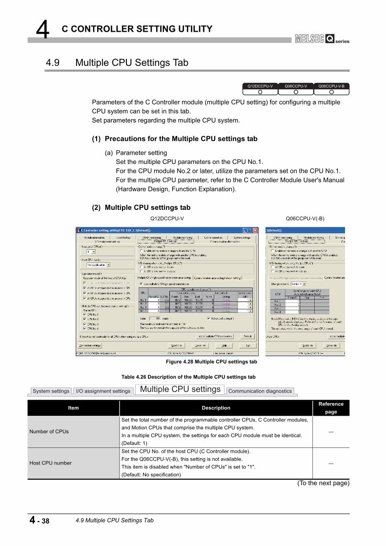
4 C CONTROLLER SETTING UTILITY
4.9 Multiple CPU Settings Tab
Parameters of the C Controller module (multiple CPU setting) for configuring a multiple CPU system can be set in this tab.Set parameters regarding the multiple CPU system.
(1) Precautions for the Multiple CPU settings tab
(a) Parameter settingSet the multiple CPU parameters on the CPU No.1.For the CPU module No.2 or later, utilize the parameters set on the CPU No.1.For the multiple CPU parameter, refer to the C Controller Module User's Manual (Hardware Design, Function Explanation).
(2) Multiple CPU settings tab
(To the next page)
Q12DCCPU-V Q06CCPU-V(-B)
Figure 4.28 Multiple CPU settings tab
Table 4.26 Description of the Multiple CPU settings tab
Item DescriptionReference
page
Number of CPUs
Set the total number of the programmable controller CPUs, C Controller modules, and Motion CPUs that comprise the multiple CPU system.In a multiple CPU system, the settings for each CPU module must be identical.(Default: 1)
Host CPU number
Set the CPU No. of the host CPU (C Controller module).For the Q06CCPU-V(-B), this setting is not available.This item is disabled when "Number of CPUs" is set to "1".(Default: No specification)
Q12DCCPU-V Q06CCPU-V Q06CCPU-V-B
System settings I/O assignment settings Multiple CPU settings Communication diagnostics
4 - 38 4.9 Multiple CPU Settings Tab

4 C CONTROLLER SETTING UTILITY
1
OV
ERVI
EW
2
INS
TALL
ATIO
N A
ND
U
NIN
STA
LLAT
ION
OF
SO
FTW
ARE
PA
CKA
GE
3
CO
MM
ON
UTI
LITY
O
PER
ATIO
NS
4
C C
ON
TRO
LLE
R
SET
TIN
G U
TILI
TY
5
CC
-LIN
K U
TILI
TY
6
MEL
SEC
NET
/H U
TILI
TY
7
CC
IE C
ON
TRO
L U
TILI
TY
8
DE
VIC
E M
ON
ITO
RIN
G
UTI
LITY
(To the next page)
Table 4.26 Description of the Multiple CPU settings tab (continued)
Item DescriptionReference
page
Operation mode
Set the operation mode for a CPU stop error on each programmable controller CPU.In a multiple CPU system, the settings for each CPU module must be identical.This item is disabled when "Number of CPUs" is set to "1".(Default: checked (all CPUs are to be stopped for an error on each CPU module))
Multiple CPU synchronous startup setting
Check the target CPU module(s) of the multiple CPU synchronized boot-up.For the Q06CCPU-V(-B), this setting is not available.In a multiple CPU system, the settings for each CPU module must be identical.This item is disabled when "Number of CPUs" is set to "1".(Default: checked (Multiple CPU synchronized boot-up is enabled))
Online module changeSet whether to allow online change on the Process CPU.In a multiple CPU system, the settings for each CPU module must be identical.This item is disabled when "Number of CPUs" is set to "1".
I/O sharing when using Multiple CPUs
Set whether to import the non-group input and/or output states.In a multiple CPU system, the settings for each CPU module must be identical.This item is disabled when "Number of CPUs" is set to "1".(Default: not checked (not import the input and output states)
Multiple CPU high speed transmission area setting
Set the Multiple CPU high speed transmission area.For the Q06CCPU-V(-B), this item is disabled.In a multiple CPU system, the settings for each CPU module must be identical.This item is disabled when "Number of CPUs" is set to "1".
Use multiple CPU high speed transmission
Set when using multiple CPU high-speed transmission.(Default: checked (the function is enabled))
CPU specific send range
Set the points to the multiple CPU high-speed transmission area where each CPU module uses to send data.(Default: see below, Setting range: 12 to 14 points or less (Note that total 16 points or less including the system area))Setting of "Number of
CPUs"Send range for each CPU
CPU No.1 CPU No.2 CPU No.3 CPU No.42 7 73 7 3 34 3 3 3 3
User setting area Displays usable range in the user setting area.
Auto refresh
Displays the points of the multiple CPU high-speed transmission area where each CPU module performs auto refresh.For setting the multiple CPU high-speed transmission area, open the Auto refresh
settings screen by clicking the button. ( Page 4-41, Section 4.9 (3))
system area
Set size for the system area that is used as the multiple CPU high-speed transmission area.This item is disabled when "Advanced settings" is not checked.(Default: 1)
Advanced settingsCheck when using the system area.(Default: not checked (not use))
System settings I/O assignment settings Multiple CPU settings Communication diagnostics
Setting
4.9 Multiple CPU Settings Tab 4 - 39

4 C CONTROLLER SETTING UTILITY
* 1 The following dialog box appears when switching this screen to another without setting the number smaller than the refresh setting.
Clicking the button moves up the preset refresh setting to an empty area with the smaller No.
POINTPoints for the system area used for dedicated instructions can be changed to 2K by selecting "Advanced settings" which increases the number of dedicated instructions to be simultaneously executed.For dedicated instructions, refer to the manual for the Motion CPU used.
Table 4.26 Description of the Multiple CPU settings tab (continued)
Item DescriptionReference
pageCommunication area setting (refresh
setting)*1Set the auto refresh area within CPU modules
Change screensSelect any of registered refresh setting.(Default: "Setting1")
Send range for each CPUSet the points of a shared memory by which each CPU module use to send data.Points for "Start" and "End" are automatically calculated and displayed.(Default: 0, Setting range: 0 to 2048)
button
Reads out multiple CPU parameters either from the following file.•Project file created with GX Developer•Parameter setting file created with C Controller setting utility.
Page 4-45
button Changes the settings back to default.
Figure 4.29 Dialog box
Figure 4.30 Refresh settings example
System settings I/O assignment settings Multiple CPU settings Communication diagnostics
Import multiple CPU parameters
Default
OK
No setting
Setting ASetting 1
Setting 2
Setting 3
Setting 4
Setting 1
Setting 2
Setting 3
Setting 4
No setting
Setting B No setting
Setting A
No setting
Setting B
<At setup> <After screen chanExample)
4 - 40 4.9 Multiple CPU Settings Tab

4 C CONTROLLER SETTING UTILITY
1
OV
ERVI
EW
2
INS
TALL
ATIO
N A
ND
U
NIN
STA
LLAT
ION
OF
SO
FTW
ARE
PA
CKA
GE
3
CO
MM
ON
UTI
LITY
O
PER
ATIO
NS
4
C C
ON
TRO
LLE
R
SET
TIN
G U
TILI
TY
5
CC
-LIN
K U
TILI
TY
6
MEL
SEC
NET
/H U
TILI
TY
7
CC
IE C
ON
TRO
L U
TILI
TY
8
DE
VIC
E M
ON
ITO
RIN
G
UTI
LITY
(3) Auto refresh settings screenPoints of the Multiple CPU high speed transmission area to which each CPU module performs auto refresh can be set on this screen.
Figure 4.31 Auto refresh settings screen
Table 4.27 Description of the Auto refresh settings screen
Item Description
<<CPU No.1>> tab to <<CPU No.4>> tab
Select the CPU module to be configured.Either "(Send)" or "(Receive)" is displayed with a tab name when "No.1" to "No.4" are selected for "Host CPU number"."(Send)" and "(Receive)" indicates whether respective CPU data are sent to or received from the C Controller module.
CPU specific send range Set the points to the Multiple CPU high speed transmission area where each CPU module performs auto refresh.(Default: " "(blank), Setting range: up to "Max. points")points
Start Displays the Multiple CPU high speed transmission area set in "Auto refresh" by address.The C Controller module calculates the value to display.End
Total points Displays total of the points set in "Auto refresh".Settable points Displays the maximum points that can be set in "Auto refresh".
button Check for incorrect setting.
button Saves the settings and closes the Auto refresh settings screen.
buttonCloses the Auto refresh settings screen without saving the settings.
Check
End
Cancel
4.9 Multiple CPU Settings Tab 4 - 41

4 C CONTROLLER SETTING UTILITY
4.10 Communication Diagnostics Tab
Whether access from the C Controller module in a multiple CPU system to another CPU is available or not can be checked in this tab.
(1) Precautions for the Communication diagnositcs tab
(a) When a utility communication error has occurredWhen a utility communication error has occurred during diagnosing, set the connection target again in the Connection settings so that the communication can be restarted.
(2) Communication diagnositcs tab
Figure 4.32 Communication diagnositcs tab
Table 4.28 Description of the Communication diagnositcs tab
Item DescriptionReference
pageCommunication diagnostics Performs communication diagnostics
Target CPU
Select the CPU to diagnose.Selecting the host CPU displays the error code "19203".Selecting an empty slot displays the error code "19200".(Default: "No.1")
Repeat countSpecify the number of times that communication diagnostics is performed.(Default: 5, Setting range 1 to 32767)
or button Executes or stops the communication diagnostics.
Execution count Displays the number of times that communication diagnostics has been executed.
Result"Normal" appears when the execution result is normal."Error" appears when the execution was resulted in an error."Diagnosing" appears during diagnosing.
Mean time to communicate Displays the mean time required for communication.
Error codeDisplays an error code of communication diagnostics.For details of error codes, refer to HELP of the MELSEC data link function.
Q12DCCPU-V Q06CCPU-V Q06CCPU-V-B
System settings I/O assignment settings Multiple CPU settings Communication diagnostics
Start Stop
4 - 42 4.10 Communication Diagnostics Tab

4 C CONTROLLER SETTING UTILITY
1
OV
ERVI
EW
2
INS
TALL
ATIO
N A
ND
U
NIN
STA
LLAT
ION
OF
SO
FTW
ARE
PA
CKA
GE
3
CO
MM
ON
UTI
LITY
O
PER
ATIO
NS
4
C C
ON
TRO
LLE
R
SET
TIN
G U
TILI
TY
5
CC
-LIN
K U
TILI
TY
6
MEL
SEC
NET
/H U
TILI
TY
7
CC
IE C
ON
TRO
L U
TILI
TY
8
DE
VIC
E M
ON
ITO
RIN
G
UTI
LITY
4.11 System Menu
(1) System menuSystem menu in C Controller setting utility can be accessed either in the following three way.
• Right-click on the title bar. • Click the ( ) icon on the title bar. • Press the [Alt] key and then the [ ] key.
Figure 4.33 System menuTable 4.29 Description of the System menu
Item DescriptionReference
page
Move, Minimize, Close Refer to manuals for Microsoft Windows .
Specify CPU typeSpecifies a C Controller module to which parameters are set or to be monitored.This item cannot be selected during monitoring.
Page 3-4
CC-Link utilityStarts CC-Link utility.When C Controller setting utility is connected online, this utility is started with the same connection target connected.
Page 5-1
MELSECNET/H utilityStarts MELSECNET/H utility.When C Controller setting utility is connected online, this utility is started with the same connection target connected.
Page 6-1
CC IE Control utility
Starts CC IE Control utility.When C Controller setting utility is connected online, this utility is started with the same connection target connected.For the Q06CCPU-V-B, this utility cannot be used.
Page 7-1
Device monitoring utility
Starts Device monitoring utility.When C Controller setting utility is connected online, this utility is started with the same connection target connected.For the Q06CCPU-V-B, this utility cannot be used.
Page 8-1
Version information Opens the version information screen. Page 4-44
Q12DCCPU-V Q06CCPU-V Q06CCPU-V-B
4.11 System Menu 4 - 43

4 C CONTROLLER SETTING UTILITY
(2) Version information screenVersion information of C Controller setting utility can be checked on this screen.
Figure 4.34 Version information screen (Example: Version 3.03D)Table 4.30 Description of the version information screen
Item DescriptionReference
pageSoftware package
SW PVC-CCPU-E Displays the version of SW PVC-CCPU.C Controller setting utility Displays the update date of C Controller setting utility.
Product information Displays the product information of the C Controller module (Model name, Serial No., and product No.) when this utility is connected to the module online.The System information screen also displays the same information.This information cannot be displayed offline.In a multiple CPU system, the information can also be confirmed in the system monitor (product information list) of GX Developer.For the Q06CCPU-V(-B), "-" appears for the product No.
Model name
Serial No.
Function version
Product No.
button Closes the version information screen.OK
4 - 44 4.11 System Menu
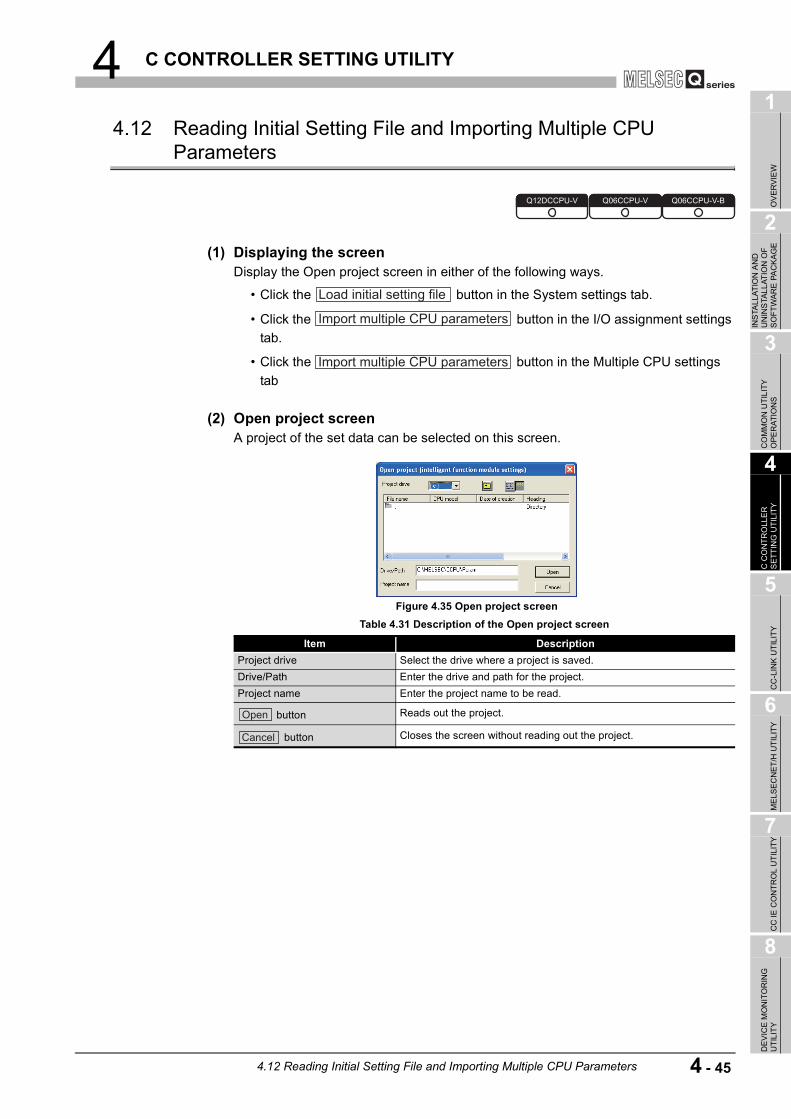
4 C CONTROLLER SETTING UTILITY
1
OV
ERVI
EW
2
INS
TALL
ATIO
N A
ND
U
NIN
STA
LLAT
ION
OF
SO
FTW
ARE
PA
CKA
GE
3
CO
MM
ON
UTI
LITY
O
PER
ATIO
NS
4
C C
ON
TRO
LLE
R
SET
TIN
G U
TILI
TY
5
CC
-LIN
K U
TILI
TY
6
MEL
SEC
NET
/H U
TILI
TY
7
CC
IE C
ON
TRO
L U
TILI
TY
8
DE
VIC
E M
ON
ITO
RIN
G
UTI
LITY
4.12 Reading Initial Setting File and Importing Multiple CPU Parameters
(1) Displaying the screenDisplay the Open project screen in either of the following ways.
• Click the button in the System settings tab.
• Click the button in the I/O assignment settings tab.
• Click the button in the Multiple CPU settings tab
(2) Open project screenA project of the set data can be selected on this screen.
Figure 4.35 Open project screenTable 4.31 Description of the Open project screen
Item DescriptionProject drive Select the drive where a project is saved.Drive/Path Enter the drive and path for the project.Project name Enter the project name to be read.
button Reads out the project.
button Closes the screen without reading out the project.
Q12DCCPU-V Q06CCPU-V Q06CCPU-V-B
Load initial setting file
Import multiple CPU parameters
Import multiple CPU parameters
Open
Cancel
4.12 Reading Initial Setting File and Importing Multiple CPU Parameters 4 - 45

4 C CONTROLLER SETTING UTILITY
(3) Precautions for utilizing set data
(a) Initial setting file of intelligent function modules and multiple CPU parameters can be imported from the following files.
(b) When transferring data of GX Developer set by another personal computer, to a development environment (personal computer), transfer the project folder of GX Developer.The project cannot be specified if only file was transferred.
(c) When multiple CPU parameters are utilized between different CPU types, ( Page 3-4, Section 3.4) default values will be displayed for the parameters not supported by the CPU type.
(d) Reading out a project file of GX DeveloperOn the C Controller module, the Initial settings of intelligent function module can be read out through a project file of GX Developer.Note that only the initial settings made by GX Configurator can be read out.
: Read available, : Read N/A
Table 4.32 Files to import
Item Description
Initial setting file of intelligent function module Project file in GX Developer ( Page 4-46, Section 4.12 (3) (d))
Multiple CPU parameters•Project file in GX Developer•Parameter setting file in C Controller setting utility
Table 4.33 Availability of intelligent function module parameter read
Name Availability Measures for unreadable GX ConfiguratorGX Configurator-AD
GX Configurator-DA
GX Configurator-SCWrite each parameter of the serial communication module to the buffer memory using the Bus interface function (QBF_ToBuf).
GX Configurator-CT
GX Configurator-TC
GX Configurator-TI
GX Configurator-FL
GX Configurator-PT
GX Configurator-AS
GX Configurator-QP
•For the Q12DCCPU-VTo write parameters to a positioning module, connect a development environment (personal computer) and the C Controller module with a USB, and use GX Configurator-QP Version 2.30G or later.
GX Configurator-QP Version 2 Operating Manual•For the Q06CCPU-V(-B)Write parameters to a positioning module to the buffer memory using the Bus interface function (QBF_ToBuf).By using the sample program (QPParamSet.c), the parameter file created with GX
Configurator-QP can be transferred to the positioning module. ( Page 12-1, CHAPTER 12)
GX Configurator-CC Set parameters for the CC-Link module using CC-Link utility of SW PVC-CCPU.
4 - 46 4.12 Reading Initial Setting File and Importing Multiple CPU Parameters

4 C CONTROLLER SETTING UTILITY
1
OV
ERVI
EW
2
INS
TALL
ATIO
N A
ND
U
NIN
STA
LLAT
ION
OF
SO
FTW
ARE
PA
CKA
GE
3
CO
MM
ON
UTI
LITY
O
PER
ATIO
NS
4
C C
ON
TRO
LLE
R
SET
TIN
G U
TILI
TY
5
CC
-LIN
K U
TILI
TY
6
MEL
SEC
NET
/H U
TILI
TY
7
CC
IE C
ON
TRO
L U
TILI
TY
8
DE
VIC
E M
ON
ITO
RIN
G
UTI
LITY
4.13 Precautions
(1) Simultaneous use of utilityUp to eight C Controller setting utilities can be simultaneously activated.
(2) Written parametersParameters written to the C Controller module take effect when the C Controller module is powered off and then on or is reset.
(3) Tabs available to operate offlineWhen C Controller setting utility connection is offline, data can be set only in the System settings tab, I/O assignment settings tab, and Multiple CPU settings tab.
(4) Terminating Microsoft WindowsDo not terminate Microsoft Windows while C Controller setting utility is running.Terminate C Controller setting utility first and then Microsoft Windows .
(5) Connection during script file processingConnection from utility to a C Controller module may not be available during processing a script file (while the RUN LED is flashing).If the RUN LED remains flashing, refer to the C Controller Module User's Manual (Hardware Design, Function Explanation) and troubleshoot the problem.
(6) Time required for connection from each utility to the C Controller moduleThe following time is required for the C Controller module to connect to each utility after power-on or reset.
• When executing a script file, "STARTUP.CMD":Upon completion of the RUN LED flashing.
• When not executing a script file, "STARTUP.CMD":Fifteen (15) seconds after completion of start or reset
Do not attempt a connection before the above time has elapsed after completion of power-on or reset.Changing "Priority" to a larger value in the Option tab of C Controller setting utility increases the time after which the C Controller module can be connected.
Q12DCCPU-V Q06CCPU-V Q06CCPU-V-B
4.13 Precautions 4 - 47

5 CC-LINK UTILITY
CHAPTER 5 CC-LINK UTILITY
5.1 CC-Link Utility Function List
: Available, : Available but partially restricted, : N/A
Table 5.1 CC-Link utility function list
Name DescriptionAvailability
Reference page
Q12DCCPU-V
Q06CCPU-V
Q06CCPU-V-B
Specify CPU typeSpecifies a C Controller module to which parameters are set or to be monitored.
Page 3-4
Connection settingsSets parameters to a C Controller module which is to be connected with this utility.
Page 3-5
Parameter setting file saving/loading
Saves parameters set in C Controller setting utility into a file or loads the file.
Page 3-12
Module information display
Displays information of the CC-Link module (own station) controlled by the connected C Controller module.
Page 5-2
Other station monitoring
Displays line states of other stations (CC-Link network stations).
Page 5-6
Online operation Reads, writes, verifies the CC-Link parameter. Page 5-9
Parameter settings Sets parameters for the CC-Link modules. Page 5-10
Target settingsSets a logical station number for access to a CPU module in a multiple CPU system where a CC-Link module is mounted.
Page 5-14
Test Tests the mounted CC-Link modules. Page 5-17
Q12DCCPU-V Q06CCPU-V Q06CCPU-V-B
5 - 1 5.1 CC-Link Utility Function List
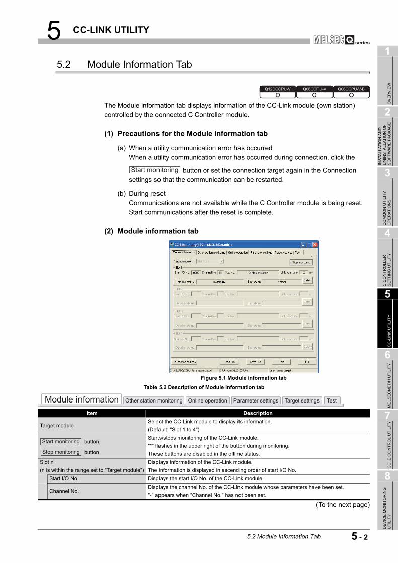
5 CC-LINK UTILITY
1
OV
ERVI
EW
2
INS
TALL
ATIO
N A
ND
U
NIN
STA
LLAT
ION
OF
SO
FTW
ARE
PA
CKA
GE
3
CO
MM
ON
UTI
LITY
O
PER
ATIO
NS
4
C C
ON
TRO
LLE
R
SET
TIN
G U
TILI
TY
5
CC
-LIN
K U
TILI
TY
6
MEL
SEC
NET
/H U
TILI
TY
7
CC
IE C
ON
TRO
L U
TILI
TY
8
DE
VIC
E M
ON
ITO
RIN
G
UTI
LITY
5.2 Module Information Tab
The Module information tab displays information of the CC-Link module (own station) controlled by the connected C Controller module.
(1) Precautions for the Module information tab
(a) When a utility communication error has occurredWhen a utility communication error has occurred during connection, click the
button or set the connection target again in the Connection settings so that the communication can be restarted.
(b) During resetCommunications are not available while the C Controller module is being reset.Start communications after the reset is complete.
(2) Module information tab
(To the next page)
Figure 5.1 Module information tab
Table 5.2 Description of Module information tab
Item Description
Target moduleSelect the CC-Link module to display its information.(Default: "Slot 1 to 4")
button,
button
Starts/stops monitoring of the CC-Link module."*" flashes in the upper right of the button during monitoring.These buttons are disabled in the offline status.
Slot n(n is within the range set to "Target module")
Displays information of the CC-Link module.The information is displayed in ascending order of start I/O No.
Start I/O No. Displays the start I/O No. of the CC-Link module.
Channel No.Displays the channel No. of the CC-Link module whose parameters have been set."-" appears when "Channel No." has not been set.
Q12DCCPU-V Q06CCPU-V Q06CCPU-V-B
Start monitoring
Module information Other station monitoring Online operation Parameter settings Target settings Test
Start monitoring
Stop monitoring
5.2 Module Information Tab 5 - 2

5 CC-LINK UTILITY
(a) Operation modeThe following indicates details of the Operation mode.
(b) Data link statusThe following indicates details of the Data link status.
Table 5.2 Description of Module information tab (continued)
Item DescriptionSlot n
Sta. No.
Displays the station No., Station type, and Operation mode.(Display example: "0: Master station (Ver.2 mode)", "1: Local station")For details of operation mode, refer to the following.
Page 5-3, Section 5.2 (2) (a)
Link scan time Displays current link scan time of the CC-Link module. (In increments of ms)
Data link status Displays data link status of the CC-Link module. ( Page 5-3, Section 5.2 (2) (b))
Error status Displays error status of the CC-Link module. ( Page 5-4, Section 5.2 (2) (c))
buttonOpens the Detailed module information screen. ( Page 5-4, Section 5.2 (3))This button is disabled during monitoring.
Table 5.3 Details of Operation mode
Display Description
No displayCyclic transmission data size has not been increased.Remote net(Ver.1 mode)
(Additional mode)Both the CC-link module supporting/not supporting the cyclic transmission data size increase exist.Remote net(Add. mode)
(Ver.2 mode)Cyclic transmission data size has been increased.Remote net(Ver.2 mode)
Table 5.4 Details of Data link status
Display DescriptionIn data link Data link is being performed.Suspended data link Data link is suspended.Initial status In initial status (before parameter update)Waiting for receiving parameters Parameters have not been received.
Disconnecting (no request polling)Disconnected from data link network due to no request from the master station.
Disconnecting (Link error) Disconnected from data link network due to a line error.Disconnecting (Other) Disconnected from data link network due to any other factor.Performing line test Line test is in process.Performing parameter setting test Parameter setting test is in process from the master station.
Performing auto-returnProcessing for automatically returning to data link network is being performed.
Resetting CC-Link module is being reset.
Module information Other station monitoring Online operation Parameter settings Target settings Test
Details
5 - 3 5.2 Module Information Tab

5 CC-LINK UTILITY
1
OV
ERVI
EW
2
INS
TALL
ATIO
N A
ND
U
NIN
STA
LLAT
ION
OF
SO
FTW
ARE
PA
CKA
GE
3
CO
MM
ON
UTI
LITY
O
PER
ATIO
NS
4
C C
ON
TRO
LLE
R
SET
TIN
G U
TILI
TY
5
CC
-LIN
K U
TILI
TY
6
MEL
SEC
NET
/H U
TILI
TY
7
CC
IE C
ON
TRO
L U
TILI
TY
8
DE
VIC
E M
ON
ITO
RIN
G
UTI
LITY
(c) Error statusThe following indicates details of the Error status.
(3) Detailed module information screenDetailed information of the CC-Link module are displayed on this screen.
Remark
The information displayed on the Detailed module information screen is based on the setting when the screen was opened.To update the information, close and reopen the Detailed module information screen.
Table 5.5 Details of error status
Display DescriptionNormal Normal status.Transport error Transmission channel error was detected.Parameter error Parameter error was detected.CRC error CRC error was detected.Timeout error Timeout error was detected.Abort error CC-Link module (gate array) error was detected.Setting error Setting error was detected.
Other errorAny other error was detected.Refer to the manual for the CC-Link module and troubleshoot the problem.
Figure 5.2 Detailed module information screen
Table 5.6 Description of Detailed module information screen
Item Description
Start I/O No., Channel No., Sta. No. Displays detailed information of the CC-Link module. ( Page 5-2, Section 5.2 (2))
Mode switch status Displays the mode switch status of the CC-Link module. ( Page 5-5, Section 5.2 (3) (a))
Data link status Displays data link status of the CC-Link module. ( Page 5-3, Section 5.2 (2) (b))
Error status Displays error status of the CC-Link module. ( Page 5-4, Section 5.2 (2) (c))Model name Displays the model name of the CC-Link module.Product information Displays the product information (serial No. and function version) of the CC-Link module.
Link scan time (ms)Displays the maximum, minimum, and current scan time of the CC-Link module. (In increments of ms)
button Closes the Detailed module information screen.
buttonSaves the link special relay (SB) and link special register (SW) data of the CC-Link module into a
CSV format file. ( Page 5-5, Section 5.2 (4))
OK
Save SB/SW
5.2 Module Information Tab 5 - 4

5 CC-LINK UTILITY
(a) Mode switch statusThe following indicates details of the Mode switch states.
(4) Specifications of the SB/SW save fileA file format can be selected in "Save as" on the following screen.
To use the text data of the SB/SW save file in an user program etc., select "SBSWSave File(*.csv)" when saving.To use them on Microsoft Excel etc., select "SBSWSave File[Form2](*.csv)" when saving.
Remark
The folder of the SB/SW save file is stored in "C:\MELSEC\CCPU\Param" by default. (When SW PVC-CCPU has been installed in "C:\MELSEC").
Table 5.7 Details of Mode switch states
DisplayTransmission
speedMode
0: 156kbps (Online) 156Kbps
Online1: 625kbps (Online) 625Kbps2: 2.5Mbps (Online) 2.5Mbps3: 5Mbps (Online) 5Mbps4: 10Mbps (Online) 10Mbps
5: 156kbps (Line test ) 156Kbps
Line test
When =1, station No. is 0.
When =2, station No. is 1 to 64.
6: 625kbps (Line test ) 625Kbps
7: 2.5Mbps (Line test ) 2.5Mbps
8: 5Mbps (Line test ) 5Mbps
9: 10Mbps (Line test ) 10Mbps
A: 156kbps (Hardware test) 156Kbps
Hardware testB: 625kbps (Hardware test) 625KbpsC: 2.5Mbps (Hardware test) 2.5MbpsD: 5Mbps (Hardware test) 5MbpsE: 10Mbps (Hardware test) 10MbpsF: Not available
Figure 5.3 Save As screen
When "SBSWSave File(*.csv)" is selected When "SBSWSave File[Form2](*.csv)" is selected
Figure 5.4 Examples of SB/SW save files
5 - 5 5.2 Module Information Tab

5 CC-LINK UTILITY
1
OV
ERVI
EW
2
INS
TALL
ATIO
N A
ND
U
NIN
STA
LLAT
ION
OF
SO
FTW
ARE
PA
CKA
GE
3
CO
MM
ON
UTI
LITY
O
PER
ATIO
NS
4
C C
ON
TRO
LLE
R
SET
TIN
G U
TILI
TY
5
CC
-LIN
K U
TILI
TY
6
MEL
SEC
NET
/H U
TILI
TY
7
CC
IE C
ON
TRO
L U
TILI
TY
8
DE
VIC
E M
ON
ITO
RIN
G
UTI
LITY
5.3 Other Station Monitoring Tab
This tab displays the line states of other stations (CC-Link network stations).
(1) Precautions for the Other station monitoring tab
(a) Monitoring statusMonitoring is stopped while CC-Link utility is being started.
To start monitoring, click the button.
(b) When a utility communication error has occurredWhen a utility communication error has occurred during connection, click the
button or set the connection target again in the Connection settings so that the communication can be restarted.
(c) During resetCommunications are not available the C Controller module is reset. Start communications after the reset is complete.
(2) Other station monitoring tab
(To the next page)
Figure 5.5 Other station monitoring
Table 5.8 Description of the Other station monitoring tab
Item Description
Target moduleSelect the module to monitor as other station monitoring.(Default: "Slot 1", Setting range: "Slot 1" to "Slot 8")
Start I/O No. Displays the start I/O No. of the CC-Link module selected in "Target module".
Own station informationDisplays the station No., station type, and operation mode.For details of operation mode, refer to the following.
Page 5-3, Section 5.2 (2) (a)
button Opens the View all stations screen. ( Page 5-8, Section 5.3 (3))
No. Displays the connection number.
Q12DCCPU-V Q06CCPU-V Q06CCPU-V-B
Start monitoring
Start monitoring
Module information Other station monitoring Online operation Parameter settings Target settings Test
View all stations
5.3 Other Station Monitoring Tab 5 - 6

5 CC-LINK UTILITY
(a) StatesDetails of states are given below.
Table 5.8 Description of the Other station monitoring tab (continued)
Item DescriptionTarget module
Sta. No. Displays the station No.Reserved station information Displays the reserved station.Error invalid station information Displays the error invalid station.
Station type Displays the error invalid station.
Occupied number Displays the number of occupied stations.
Status Displays the status of each station module. ( Page 5-7, Section 5.3 (2) (a))
Transient error Displays the transient error of each module.
Expanded cyclic settingDisplays the expanded cyclic setting.This item are not displayed when the status of the target module is "Remote net(Ver.1 mode).
Remote station pointsDisplays the number of remote station points.This item are not displayed when the status of the target module is "Remote net(Ver.1 mode).
, or
button
Starts or stops monitoring the CC-Link module."*" flashes in the upper right of the button during monitoring.These buttons are disabled in the offline status.
Table 5.9 Details of states
Display DescriptionNormal NormalTemporary error invalidity status Temporary error is invalid.Data link error Link status is in error.WDT error Watchdog timer error has occurred.Blown fuse confirmation error There is a station that has a fuse blow.Station No. duplication Station number is duplicated.Switch changing Switch setting was changed.
Module information Other station monitoring Online operation Parameter settings Target settings Test
Start monitoring
Stop monitoring
5 - 7 5.3 Other Station Monitoring Tab

5 CC-LINK UTILITY
1
OV
ERVI
EW
2
INS
TALL
ATIO
N A
ND
U
NIN
STA
LLAT
ION
OF
SO
FTW
ARE
PA
CKA
GE
3
CO
MM
ON
UTI
LITY
O
PER
ATIO
NS
4
C C
ON
TRO
LLE
R
SET
TIN
G U
TILI
TY
5
CC
-LIN
K U
TILI
TY
6
MEL
SEC
NET
/H U
TILI
TY
7
CC
IE C
ON
TRO
L U
TILI
TY
8
DE
VIC
E M
ON
ITO
RIN
G
UTI
LITY
(3) View all stations screenThe following indicates communication states of other stations.
Figure 5.6 View all stations screen
Table 5.10 Description of View all stations screen
Item Description
Status of each station
Communication status of each station is coded in color as follows. White: Normal communication Red: Error station Green: Error invalid station Blue: Reserved station Yellow: Temporary error invalid stationThe information displayed on the screen is based on the communication status when the screen was opened.Any changes on the communication status after opening the screen does not take effect to the display.
button Closes the View all stations screen.OK
5.3 Other Station Monitoring Tab 5 - 8

5 CC-LINK UTILITY
5.4 Online Operation Tab
The CC-Link parameters can be read, written, or verified from this tab.
(1) Precautions for the Online operation tab
(a) When a utility communication error has occurredWhen a utility communication error has occurred during connection, set the connection target again in the Connection settings so that the communication can be restarted.
(b) During resetCommunications are not available while the C Controller module is being reset.Start communications after the reset is completes.
(2) Online operation tab
Remark
To read, write, or verify parameters, connect the C Controller module and the development environment (personal computer) online.
Figure 5.7 Online operation tab
Table 5.11 Description of Online operation tab
Item DescriptionRead parameters
buttonReads out the CC-Link parameter from the C Controller module.
Write parameters
button
Writes the CC-Link parameter to the C Controller module.The written parameters take effect when the C Controller module is powered off and then on or is reset.Parameters can be written only when "Write authority" is selected in Connection settings. If "Write authority" is not selected, select it in the Connection settings screen before writing parameters.
( Page 3-5, Section 3.5)
Verify parameters
button
Verifies the CC-Link parameters set in the C Controller module and in CC-Link utility.The verification result is displayed in a message box.
Q12DCCPU-V Q06CCPU-V Q06CCPU-V-B
Module information Other station monitoring Online operation Parameter settings Target settings Test
Read
Write
Verify
5 - 9 5.4 Online Operation Tab

5 CC-LINK UTILITY
1
OV
ERVI
EW
2
INS
TALL
ATIO
N A
ND
U
NIN
STA
LLAT
ION
OF
SO
FTW
ARE
PA
CKA
GE
3
CO
MM
ON
UTI
LITY
O
PER
ATIO
NS
4
C C
ON
TRO
LLE
R
SET
TIN
G U
TILI
TY
5
CC
-LIN
K U
TILI
TY
6
MEL
SEC
NET
/H U
TILI
TY
7
CC
IE C
ON
TRO
L U
TILI
TY
8
DE
VIC
E M
ON
ITO
RIN
G
UTI
LITY
5.5 Parameter Settings Tab
Set the CC-Link module parameter in the Parameter settings tab.
(1) Parameter settings tab
(To the next page)
Figure 5.8 Parameter settings tabTable 5.12 Description of Parameter settings tab
Item Description
Number of modulesSet the number of CC-Link modules that are to be controlled by the C Controller module.Selecting "(Blank)" means no setting (Setting cleared).(Default: "(Blank)")
Target moduleSelect a module to configure. (Default: 1)The numbers for this item will be automatically rearranged in ascending order of start I/O numbers when saving the parameter setting file or when switching the tab.
Start I/O No.Set a start I/O No. of a CC-Link IE controller network module.(Setting range: 0 to FE0H (The set value must be unique, and not duplicated with the one for another CC-Link IE controller network module.))
Channel No.
Set a channel No. of a CC-Link IE controller network module.The set value is used to open the channel from Device monitoring utility or an user program (MELSEC data link functions).For the Q06CCPU-V-B, this setting is not available.Channel No. must be unique, and not duplicated with the one for another CC-Link IE controller network module.
button Sets the parameters for Operation settings and Station information settings back to default.
button Checks for any setting error.
Q12DCCPU-V Q06CCPU-V Q06CCPU-V-B
Module information Other station monitoring Online operation Parameter settings Target settings Test
Default
Check
5.5 Parameter Settings Tab 5 - 10

5 CC-LINK UTILITY
(To the next page)
Table 5.12 Description of Parameter settings tab (continued)
Item DescriptionOperation settings Set the operation mode of the CC-Link module.
TypeSelect a type of the CC-Link module.(Default: "Master station")
ModeSelect a mode of the CC-Link module.(Default: "Remote net(Ver.1 mode"))
Expanded cyclic setting
Select the expanded cyclic setting of the CC-Link module.This setting is available only when "Local station" is set in "Type" and other than "Remote net(Ver.1 mode)" is specified in "Mode".(Default: "Single")
Error event: input data statusSet how the input data be handled in the event of data link error.(Default: "Clear")
CPU stop: data link status
Set how the link data to be handled in the event of CPU stop.This setting is available for the J61BT11N.For the QJ61BT11, the "Refresh" is applied regardless of the setting on this tab.(Default: "Refresh")
Occupied numberSet the number of occupied stations of the CC-Link module (local station).This setting is available only when "Local station" is set in "Type".(Default: "Exclusive station 1")
button Opens the "Other settings" screen. ( Page 5-13, Section 5.5 (2))
Station information settings
Set the total of connected modules and each CC-Link module station information.This setting is available only when "Master station" is set in "Type", and any of the following is set in "Mode".•Remote net(Ver.1 mode)•Remote net(Ver.2 mode)•Remote net(Add. mode)
All connect countSet the number of modules that are to be connected to the CC-Link module.(Default: 64)
Station Type
Select a type of the station.Default values are given below.•When "Remote net(Ver.1 mode)" is set in "Mode": "Remote I/O station"•When "Remote net(Ver.2 mode)" or "Remote net(Add. mode)" is set in "Mode": "Ver.1 Remote I/O station"
Expanded cyclic setting
Select a expanded cyclic points of the CC-Link module.(Default: "Single")This setting is available only when the following conditions are satisfied.•When "Remote net(Ver.2 mode)" or "Remote net(Add. mode)" is set in "Mode".•When "Ver.2 Remote device station" or "Ver.2 Intelligent device station" is set in "Type".
Occupied numberSelect the number of occupied stations.(Default: "Exclusive station 1")
Remote station pointsSelect the points of remote station.This setting is available only when "Remote net(Ver.2 mode)" is set in "Mode". For defaults and setting range, refer to the CC-Link System Master/Local Module User's Manual.
Module information Other station monitoring Online operation Parameter settings Target settings Test
Other settings
5 - 11 5.5 Parameter Settings Tab

5 CC-LINK UTILITY
1
OV
ERVI
EW
2
INS
TALL
ATIO
N A
ND
U
NIN
STA
LLAT
ION
OF
SO
FTW
ARE
PA
CKA
GE
3
CO
MM
ON
UTI
LITY
O
PER
ATIO
NS
4
C C
ON
TRO
LLE
R
SET
TIN
G U
TILI
TY
5
CC
-LIN
K U
TILI
TY
6
MEL
SEC
NET
/H U
TILI
TY
7
CC
IE C
ON
TRO
L U
TILI
TY
8
DE
VIC
E M
ON
ITO
RIN
G
UTI
LITY
Table 5.12 Description of Parameter settings tab (continued)
Item DescriptionStation information settings
Reserve/invalid station selectSet the CC-Link module as a reserved or invalid station.(Default: "No setting")
Intelligent buffer select (word)
This setting is available when any of the following is set in "Type".•Intelligent device station•Ver.1 Intelligent device station•Ver.2 Intelligent device station
SendSpecify the send area. (In increments of words)(Default: 64, Setting range: 0, 64 to 4096)
ReceiveSpecify the receive area. (In increments of words)(Default: 64, Setting range: 0, 64 to 4096)
AutomaticSpecify the automatic update area. (In increments of words)(Default: 128, Setting range: 0, 128 to 4096)
button Clears parameters set in "Station information setting" and set defeat values instead.
Module information Other station monitoring Online operation Parameter settings Target settings Test
Clear
5.5 Parameter Settings Tab 5 - 12

5 CC-LINK UTILITY
(2) Other settings screen
* 1 This setting is available when "Master station" is set in "Type", and any of the following is set in "Mode".
Figure 5.9 Other settings screen
Table 5.13 Description of Other settings screen
Item Description
Retry count*1Set the number of retries in the case of a communication error (transient transmission error occurrence)(Default: 3, Setting range: 1 to 7)
Auto return station count*1Set the number of modules that can be automatically reconnected in one link scan.(Default: 1, Setting range: 1 to 10)
Standby master station No.*1Set a station No. of the standby master station.(Default: 0 (no setting), Setting range: 0 to 64)
CPU down: data link status*1 Set the data link status when an error occurs in the C Controller module.(Default: "Stop")
Delay information setting*1 Set "0".
Block data assurance per stationSet whether to use the block data assurance per station function.(Default: unchecked (not use))
button Applies the settings and closes the Other settings screen.
button Closes the Other settings screen without applying the settings.
•Remote net(Ver.1 mode)•Remote net(Ver.2 mode)•Remote net(Add mode)
Set
Cancel
5 - 13 5.5 Parameter Settings Tab

5 CC-LINK UTILITY
1
OV
ERVI
EW
2
INS
TALL
ATIO
N A
ND
U
NIN
STA
LLAT
ION
OF
SO
FTW
ARE
PA
CKA
GE
3
CO
MM
ON
UTI
LITY
O
PER
ATIO
NS
4
C C
ON
TRO
LLE
R
SET
TIN
G U
TILI
TY
5
CC
-LIN
K U
TILI
TY
6
MEL
SEC
NET
/H U
TILI
TY
7
CC
IE C
ON
TRO
L U
TILI
TY
8
DE
VIC
E M
ON
ITO
RIN
G
UTI
LITY
5.6 Target Settings Tab
A logical station No. is set from the Target settings tab.The logical station No. is used, when a target station is a multiple CPU system, to access a programmable controller CPU other than the control CPU of the target station.Note that the accesses indicated below does not require the logical station No. settings.
Page 5-16, "5.6 (4) Access that does not require a logical station No. setting"
(1) Precaution for the Target settings tabSet a programmable controller CPU in "Target CPU"
(2) Target settings tab
(To the next page)
Figure 5.10 Target settings tab
Table 5.14 Description of Target settings tab
Item Description
Target moduleSelect a module to configure.(Default: "Slot 1")
Logical sta. No.
Specify a logical station No. for the module selected in "Target module".(Default: 65, Setting range: 65 to 239)The logical sta. No. is a logical number to be specified as "Sta. No." in Device monitoring utility and an user program (MELSEC data link function).
Sta. No.Select a station No. of the CC-Link module controlled by a multiple CPU system.(Default: 0, Setting range: 0 to 63)
Target CPUSelect a CPU of the access target (CPU No. in a multiple CPU system).(Default: 1, Setting range: 1 to 4)
button Enters the added and changed data (Logical sta. No., Sta. No., and Target CPU) to the Target list.
Q12DCCPU-V Q06CCPU-V Q06CCPU-V-B
Module information Other station monitoring Online operation Parameter settings Target settings Test
Set
5.6 Target Settings Tab 5 - 14
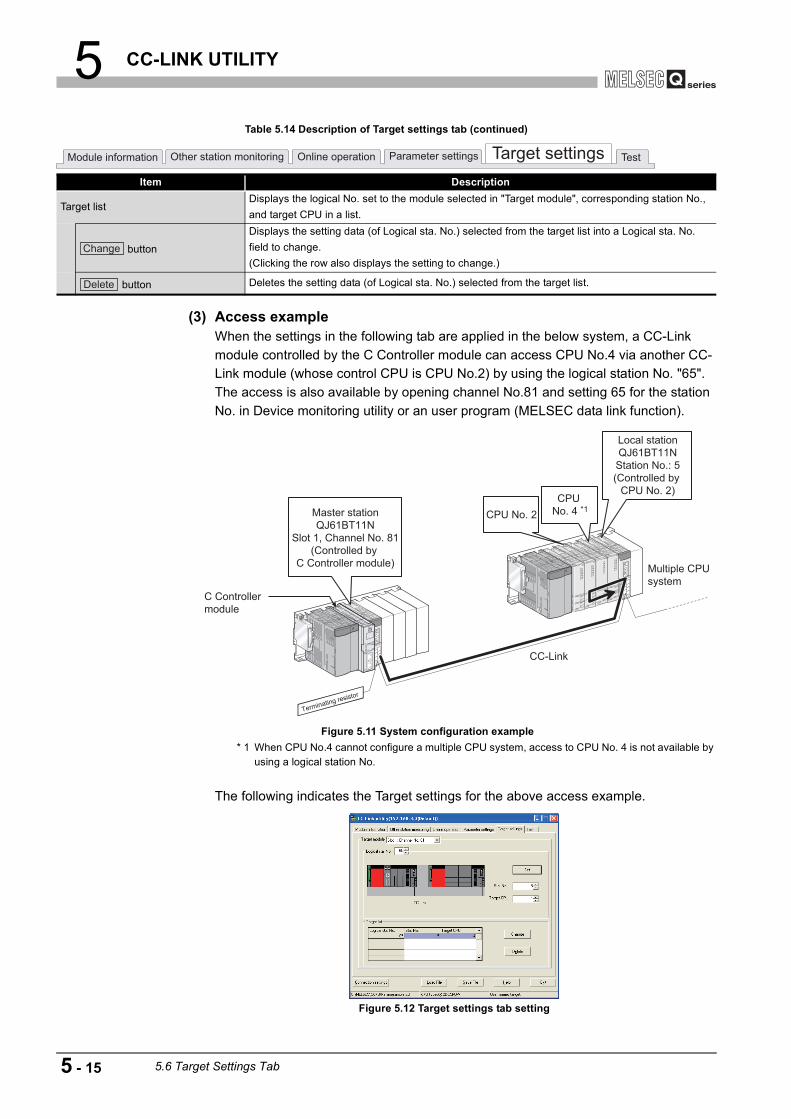
5 CC-LINK UTILITY
(3) Access exampleWhen the settings in the following tab are applied in the below system, a CC-Link module controlled by the C Controller module can access CPU No.4 via another CC-Link module (whose control CPU is CPU No.2) by using the logical station No. "65".The access is also available by opening channel No.81 and setting 65 for the station No. in Device monitoring utility or an user program (MELSEC data link function).
* 1 When CPU No.4 cannot configure a multiple CPU system, access to CPU No. 4 is not available by using a logical station No.
The following indicates the Target settings for the above access example.
Table 5.14 Description of Target settings tab (continued)
Item Description
Target listDisplays the logical No. set to the module selected in "Target module", corresponding station No., and target CPU in a list.
button
Displays the setting data (of Logical sta. No.) selected from the target list into a Logical sta. No. field to change.(Clicking the row also displays the setting to change.)
button Deletes the setting data (of Logical sta. No.) selected from the target list.
Figure 5.11 System configuration example
Figure 5.12 Target settings tab setting
Module information Other station monitoring Online operation Parameter settings Target settings Test
Change
Delete
Multiple CPU
system
Terminating resistor
Master station
QJ61BT11N
Slot 1, Channel No. 81
(Controlled by
C Controller module)
Local station
QJ61BT11N
Station No.: 5
(Controlled by
CPU No. 2)
CPU No. 2
C Controller
module
CC-Link
CPU
No. 4 *1
5 - 15 5.6 Target Settings Tab

5 CC-LINK UTILITY
1
OV
ERVI
EW
2
INS
TALL
ATIO
N A
ND
U
NIN
STA
LLAT
ION
OF
SO
FTW
ARE
PA
CKA
GE
3
CO
MM
ON
UTI
LITY
O
PER
ATIO
NS
4
C C
ON
TRO
LLE
R
SET
TIN
G U
TILI
TY
5
CC
-LIN
K U
TILI
TY
6
MEL
SEC
NET
/H U
TILI
TY
7
CC
IE C
ON
TRO
L U
TILI
TY
8
DE
VIC
E M
ON
ITO
RIN
G
UTI
LITY
(4) Access that does not require a logical station No. settingIn the following access, use the station No. of a CC-Link module on other station.The logical station No. setting is not required.
Figure 5.13 Access that does not require a logical station No. setting
Other station CC-Link module
C Controller module
CC-Link
Terminating resistor
Control CPU of other station CC-Link module
C Controller module
CC-Link
Terminating resistor
5.6 Target Settings Tab 5 - 16

5 CC-LINK UTILITY
5.7 Test Tab
A network test and line test for the mounted CC-Link module can be executed from this tab.
(1) Precautions for the Test tab
(a) Connection status for testingThe network and line test can be executed while the CC-Link module is online.While in offline, the both tests cannot be executed.
(b) Line testSelect station(s) to be tested by selecting either "All stations (1 to 64)" or "Selected station" as necessary and then conduct the test. ( Page 5-18, Section 5.7 (3))
(c) When an communication error has occurredTo restart the communication, set data again in the Connection settings.
(2) Test tab
(To the next page)
Figure 5.14 Test tab
Table 5.15 Description of the Test tab
Item Description
Target moduleSelect a module for testing.(Default: "1" slot)
Start I/O No. Displays the start I/O No. of the CC-Link module.
Q12DCCPU-V Q06CCPU-V Q06CCPU-V-B
Module information Other station monitoring Online operation Parameter settings Target settings Test
5 - 17 5.7 Test Tab

5 CC-LINK UTILITY
1
OV
ERVI
EW
2
INS
TALL
ATIO
N A
ND
U
NIN
STA
LLAT
ION
OF
SO
FTW
ARE
PA
CKA
GE
3
CO
MM
ON
UTI
LITY
O
PER
ATIO
NS
4
C C
ON
TRO
LLE
R
SET
TIN
G U
TILI
TY
5
CC
-LIN
K U
TILI
TY
6
MEL
SEC
NET
/H U
TILI
TY
7
CC
IE C
ON
TRO
L U
TILI
TY
8
DE
VIC
E M
ON
ITO
RIN
G
UTI
LITY
(3) Testing procedure
(a) Line testThe line test can be conducted only when the data link status of the CC-Link module ( Page 5-2, Section 5.2) is "In data link" or "Perform auto-return".When the line test for "All stations (1 to 64)" resulted in error, which indicates possible error station, conduct the line test again selecting "Selected station".
1) Setting
Select the target station of the line test and click the button to start the test.
2) Results
For details of error codes, refer to Help of the bus interface function.
Table 5.15 Description of the Test tab (continued)
Item DescriptionTarget module
Own station information
Displays a station No., type of the station, and operation mode.For details of the operation mode, refer to the following.
Page 5-3, Section 5.2 (2) (a)
Test item
Select the test to conduct.Display Description
Line testTests the connected station for connectivity with a data link. (Selectable for the Master station only)
Network test Tests a data link start and stop.
button
Conduct a test selected in the above "Test item".
Line test........... Page 5-18, Section 5.7 (3) (a)
Network test.... Page 5-19, Section 5.7 (3) (b)
Figure 5.15 Line test screen
For "All stations (1 to 64)" For "Selected station"
Figure 5.16 Result screen
Module information Other station monitoring Online operation Parameter settings Target settings Test
Start
OK
5.7 Test Tab 5 - 18
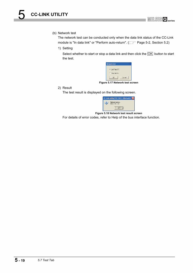
5 CC-LINK UTILITY
(b) Network testThe network test can be conducted only when the data link status of the CC-Link module is "In data link" or "Perform auto-return". ( Page 5-2, Section 5.2)
1) Setting
Select whether to start or stop a data link and then click the button to start the test.
2) ResultThe test result is displayed on the following screen.
For details of error codes, refer to Help of the bus interface function.
Figure 5.17 Network test screen
Figure 5.18 Network test result screen
OK
5 - 19 5.7 Test Tab

5 CC-LINK UTILITY
1
OV
ERVI
EW
2
INS
TALL
ATIO
N A
ND
U
NIN
STA
LLAT
ION
OF
SO
FTW
ARE
PA
CKA
GE
3
CO
MM
ON
UTI
LITY
O
PER
ATIO
NS
4
C C
ON
TRO
LLE
R
SET
TIN
G U
TILI
TY
5
CC
-LIN
K U
TILI
TY
6
MEL
SEC
NET
/H U
TILI
TY
7
CC
IE C
ON
TRO
L U
TILI
TY
8
DE
VIC
E M
ON
ITO
RIN
G
UTI
LITY
5.8 System Menu
(1) System menuSystem menu in CC-Link utility can be accessed either in the following three way for operation.
• Right-click on the title bar.
• Click the ( ) icon on the title bar. • Press the [Alt] key and then the [ ] key.
(2) Version information screenVersion information of CC-Link utility can be checked on this screen.
Figure 5.19 System menu
Table 5.16 Description of System menu
Item Description
Move, Minimize, Close Refer to manuals for Microsoft Windows .
Specify CPU typeSpecifies a C Controller module to which parameters are set or to be monitored. ( Page 3-4, Section 3.4)This item is disabled during monitoring.
C Controller setting utilityStarts C Controller setting utility. ( Page 4-1, CHAPTER 4)When CC-Link utility is connected online, this utility is started with the same connection target connected.
Device monitoring utility
Starts Device monitoring utility. ( Page 8-1, CHAPTER 8)When CC-Link utility is connected online, this utility is started with the same connection target connected.For the Q06CCPU-V-B, this utility cannot be used.
Version information Opens the Version information screen. ( Page 5-20, Section 5.8 (2))
Figure 5.20 Version information screen (Example: Version 3.01B)
Table 5.17 Description of Version information screen
Item DescriptionSoftware package
SW PVC-CCPU-E Displays the version of SW PVC-CCPU.
CC-Link utility Displays the update date of CC-Link utility.
button Closes the Version information screen.
Q12DCCPU-V Q06CCPU-V Q06CCPU-V-B
OK
5.8 System Menu 5 - 20

5 CC-LINK UTILITY
5.9 Precautions
(1) Parameter detailsFor details of respective parameters, refer to CC-Link System Master/Local Module User's Manual.
(2) Simultaneous use of utilitiesUp to eight CC-Link setting utilities can be used simultaneously.
(3) Written parametersParameters written to the C Controller module take effect when the C Controller is powered off and then on or is reset.
(4) Tabs available to operate offlineWhen CC-Link utility connection is offline, data can be set only in the Parameter settings tab and the Target settings tab.For the Q06CCPU-V-B, only parameters shown in the Target settings tab can be set.
(5) Terminating Microsoft WindowsDo not terminate Microsoft Windows while CC-Link utility is running.Terminate CC-Link utility first and then Microsoft Windows .
(6) Connection during script file processingConnection from utility to a C Controller module may not be available during processing a script file (while the RUN LED is flashing).If the RUN LED remains flashing, refer to the C Controller Module User's Manual (Hardware Design, Function Explanation) and troubleshoot the problem.
(7) Time required for connection from each utility to the C Controller moduleThe following time is required for the C Controller module to connect to each utility after power-on or reset.
• When executing a script file, "STARTUP.CMD":Upon completion of the RUN LED flashing.
• When not executing a script file, "STARTUP.CMD":Fifteen (15) seconds after completion of start or reset
Do not attempt a connection before the above time has elapsed after completion of power-on or reset.Changing "Priority" to a larger value in the Option tab of C Controller setting utility increases the time after which the C Controller module can be connected.
Q12DCCPU-V Q06CCPU-V Q06CCPU-V-B
5 - 21 5.9 Precautions

6 MELSECNET/H UTILITY
1
OV
ERVI
EW
2
INS
TALL
ATIO
N A
ND
U
NIN
STA
LLAT
ION
OF
SO
FTW
ARE
PA
CKA
GE
3
CO
MM
ON
UTI
LITY
O
PER
ATIO
NS
4
C C
ON
TRO
LLE
R
SET
TIN
G U
TILI
TY
5
CC
-LIN
K U
TILI
TY
6
MEL
SEC
NET
/H U
TILI
TY
7
CC
IE C
ON
TRO
L U
TILI
TY
8
DE
VIC
E M
ON
ITO
RIN
G
UTI
LITY
CHAPTER 6 MELSECNET/H UTILITY
6.1 MELSECNET/H Utility Function List
: Available, : Available but partially restricted, : N/A
Table 6.1 MELSECNET/H Utility function list
Item DescriptionAvailability
Reference page
Q12DCCPU-V
Q06CCPU-V
Q06CCPU-V-B
Specify CPU typeSpecifies a C Controller module to which parameters are set or to be monitored.
Page 3-4
Connection settingsSets parameters to a C Controller module which is to be connected with this utility.
Page 3-5
Parameter setting file saving/loading
Saves parameters set in MELSECNET/H utility into a file or loads the file.
Page 3-12
Module informationDisplays information of the MELSECNET/H (host station) controlled by the connected C Controller module.
Page 6-2
Error history monitoring
Displays the history of errors that occurred in the MELSECNET/H module.
Page 6-9
Other station monitoring
Displays line states of other stations (MELSECNET/H network stations).
Page 6-14
Online operation Reads, writes, verifies the MELSECNET/H parameter. Page 6-25
Parameter settings Sets parameters for the MELSECNET/H modules. Page 6-26
Target settingsSets a logical station number for access to a CPU module in a multiple CPU system where a MELSECNET/H module is mounted.
Page 6-38
Q12DCCPU-V Q06CCPU-V Q06CCPU-V-B
6.1 MELSECNET/H Utility Function List 6 - 1

6 MELSECNET/H UTILITY
6.2 Module Information Tab
The Module information tab displays information of the MELSECNET/H module (host station) controlled by the connected C Controller module.
(1) Precautions for the Module information tab
(a) When a utility communication error has occurredWhen a utility communication error has occurred during connection, click the
button or set the connection target again in the Connection settings so that the communication can be restarted.
(b) During resetCommunications are not available while the C Controller module is being reset.Start communication after the reset is complete.
(2) Module information tab
(To the next page)
Figure 6.1 Module information tab
Table 6.2 Description of the Module information tab
Item DescriptionCorresponding
SBCorresponding
SW
Link device refresh timeDisplays total link device refresh time required to refresh the MELSECNET/H and CC-Link IE controller network controlled by the C Controller module (host CPU). (In increments of ms)
Max.
Displays the maximum total link device refresh time in the past record.
"-" appears when Link device refresh cycle ( Page 6-26, Section 6.6) is 0ms.
Min.
Displays the minimum total link device refresh time in the past record.
"-" appears when Link device refresh cycle ( Page 6-26, Section 6.6) is 0ms.
Q12DCCPU-V Q06CCPU-V Q06CCPU-V-B
Start monitoring
Module information Error history monitoring Other station monitoring
6 - 2 6.2 Module Information Tab

6 MELSECNET/H UTILITY
1
OV
ERVI
EW
2
INS
TALL
ATIO
N A
ND
U
NIN
STA
LLAT
ION
OF
SO
FTW
ARE
PA
CKA
GE
3
CO
MM
ON
UTI
LITY
O
PER
ATIO
NS
4
C C
ON
TRO
LLE
R
SET
TIN
G U
TILI
TY
5
CC
-LIN
K U
TILI
TY
6
MEL
SEC
NET
/H U
TILI
TY
7
CC
IE C
ON
TRO
L U
TILI
TY
8
DE
VIC
E M
ON
ITO
RIN
G
UTI
LITY
(a) Communication statusDetails of communication states are given below.
Table 6.2 Description of the Module information tab (continued)
Item DescriptionCorresponding
SBCorresponding
SWLink device refresh time
Current
Displays current total link device refresh time.
"-" appears when Link device refresh cycle ( Page 6-26, Section 6.6) is 0ms.
or
button
Starts or stops monitoring of the MELSECNET/H module."*" flashes in the upper right of the button during monitoring.These buttons are disabled in the offline status.
1 Slot to 4 SlotDisplays information of the CC-Link module.The information is displayed in ascending order of start I/O No.
Start I/O No. Displays the start I/O No. of the MELSECNET/H module.
Channel No.
Displays the channel No. of the MELSECNET/H module.
"-" appears when "Channel No." has not been set. ( Page 6-26, Section 6.6)
Network No.
Displays the network No. of the MELSECNET/H module.
"-" appears when "Network No." has not been set. ( Page 6-26, Section 6.6)
SW0040
Group No.
Displays the group No. of the MELSECNET/H module.
"-" appears when "Group No." has not been set. ( Page 6-26, Section 6.6)
SW0041
Sta. No. Displays the station No. of the MELSECNET/H module. SW0042Type Displays the type of the MELSECNET/H module. SB0044
StatusDisplays the communication status of the MELSECNET/H module.
( Page 6-3, Section 6.2 (2) (a))SW0047
Link scan timeDisplays the scan time of the MELSECNET/H module.(In increments of ms)
buttonOpens the Module information tab. ( Page 6-4, Section 6.2 (3))This button is disabled during monitoring.
Table 6.3 Details of communication states
Display DescriptionIn data link Data link is being performed.
Suspend data link (Other)Cyclic transmission was stopped from the other station.
Suspend data link (Hostself) Cyclic transmission was stopped by the host station.Baton pass (No area) No B/W transmission assignment to the host station.
Baton pass (Parameter Halt)An error has detected in any of the host station parameter.
Baton pass (No Receive) Common parameters have not been received.Disconnecting (no baton) Station No. duplication, or cable not connected.Disconnecting (Link error) Cable not connected.Testing Online or offline test is being conducted.Resetting Hardware error.
Module information Error history monitoring Other station monitoring
Start monitoring
Stop monitoring
Details
6.2 Module Information Tab 6 - 3

6 MELSECNET/H UTILITY
(3) Detailed module information screen.Detailed information of the MELSECNET/H module are displayed on this screen.
(To the next page)
Figure 6.2 Detailed module information screen
Table 6.4 Description of the Detailed module information screen
Item DescriptionCorresponding
SBCorresponding
SWModel name Displays the model name of the MELSECNET/H module.
Product informationDisplays the product information (serial No. and version) of the MELSECNET/H module.
button Closes the Detailed module information screen.
button
Saves the link special relay (SB) and link special register (SW) information of the MELSECNET/H module into a CSV format file.
( Page 6-8, Section 6.2 (4))Own station information Displays the own station information of the MELSECNET/H module.
Start I/O No. Displays the start I/O No. of the own station.Network No. Displays the network to of the own station. SW0040Group No. Displays the group No. of the own station. SW0041Sta. No. Displays the station No. of the own station. SW0042
NetworkDisplays the network to which the MELSECNET/H module is connected.
SB0057, SB005A
SW0046
Type Displays the type of the own station. SB0044
OK
Save SB/SW
6 - 4 6.2 Module Information Tab

6 MELSECNET/H UTILITY
1
OV
ERVI
EW
2
INS
TALL
ATIO
N A
ND
U
NIN
STA
LLAT
ION
OF
SO
FTW
ARE
PA
CKA
GE
3
CO
MM
ON
UTI
LITY
O
PER
ATIO
NS
4
C C
ON
TRO
LLE
R
SET
TIN
G U
TILI
TY
5
CC
-LIN
K U
TILI
TY
6
MEL
SEC
NET
/H U
TILI
TY
7
CC
IE C
ON
TRO
L U
TILI
TY
8
DE
VIC
E M
ON
ITO
RIN
G
UTI
LITY
(To the next page)
Table 6.4 Description of the Detailed module information screen (continued)
Item DescriptionCorresponding
SBCorresponding
SWOwn station information Displays operation setting status of the own station.
Parameter setting
Displays the parameter setting status of the host station with any of the following.•Common parameter•Common + Specific parameter•Default parameter•Default + Specific
SB0054 SW0054
Reserved station setting Displays whether a reserved station exists in the network. SB0064
Transmission modeDisplays the transmission mode of the own station. (Display: "Normal mode", "Constant scan XX ms" (XX represents the constant link scan setting time))
SW0068
Duplex transmission setting
Displays the multiplex transmission setting of the own station."-" is displayed in the case of a coaxial bus system.(Display: "Normal transmission", "Multiplex transmission")
SB0069
Duplex transmission status
Displays the multiplex transmission status of the own station."-" is displayed in the case of a coaxial bus system.(Display: "Normal transmission", "Multiplex transmission", "-")
SB006A
Transmission speedDisplays the transmission speed of the own station. (Display: "10Mbps", "25Mbps")
Control station informationDisplays the control station information of the MELSECNET/H network system.
Assign control stationDisplays the specified control station in the MELSECNET/H network system."0" appears when the control station is faulty.
SW0057
Present control stationDisplays the current control station in the MELSECNET/H network system."0" appears when the control station is faulty.
SW0056
Transmission information
Displays the transmission information of the MELSECNET/H network system.(Display: "Control station communication", "Sub control station transmission")
SB0056
Sub control station transmission
Displays the sub control station transmission status of the MELSECNET/H network system.(Display: "Yes", "No")
SB0058
Remote I/O station number
Displays the station No. of the remote I/O master station for each block.
Block 1 Displays the station No. of the remote I/O master station of Block 1. SW005CBlock 2 Displays the station No. of the remote I/O master station of Block 2. SW005D
6.2 Module Information Tab 6 - 5

6 MELSECNET/H UTILITY
Remark
The information displayed on the Detailed module information screen is based on the information when the screen was opened.To display the updated information, close and reopen the Detailed module information screen.
Table 6.4 Description of the Detailed module information screen (continued)
Item DescriptionCorresponding
SBCorresponding
SWLink information Displays the network status
ModeDisplays the operation mode of the own station.(Display: "Online", "Offline", "Loop test")
SW0043
F loop statusDisplays the forward loop status."-" is displayed in the case of a coaxial bus system.(Display: "Normal", "Loopback transmission", "Data link disable", "-")
SB0091, SB0099
Loopback station
Displays the No. of the station that is performing loopback on the forward loop side."-" is displayed in the case of a coaxial bus system.The field goes blank when data link is not available.(Display: 1 to 64, "Not performed", "-", "(blank)")
SW0099
R loop statusDisplays the reverse loop status."-" is displayed in the case of a coaxial bus system.(Display: "Normal", "Loopback transmission", "-")
SB0095, SB009A
Loopback station
Displays the No. of the station that is performing loopback on the reverse loop side."-" is displayed in the case of a coaxial bus system.The field goes blank when data link is not available.(Display: 1 to 64, "Not performed", "-", "(blank)")
SW009A
Link scan time Displays link scan time. (In increments of ms)
Max.Displays the maximum link scan time in the past record.The field goes blank when data link is not available.
SW006B
Min.Displays the minimum link scan time in the past record.The field goes blank when data link is not available.
SW006C
CurrentDisplays the current link scan time.The field goes blank when data link is not available.
SW006D
Data link information Displays the data link status of the MELSECNET/H.Total number of link stations
Displays the total number of linked stations on MELSECNET/H. SW0059
Station of maximum normal transmission
Displays the maximum number of stations that are communicating normally.
SW005A
Station of maximum data link
Displays the maximum number of data link stations on MELSECNET/H. SW005B
Transmission statusDisplays the transmission status of MELSECNET/H.
( Page 6-3, Section 6.2 (2) (a))SW0047
Reason for transmission interruption
Displays the reason for transmission interruption on MELSECNET/H.
( Page 6-7, Section 6.2 (3) (a))SW0048
Reason for transmission stop
Displays the reason for transmission stop on MELSECNET/H.
( Page 6-7, Section 6.2 (3) (b))SW0049
6 - 6 6.2 Module Information Tab
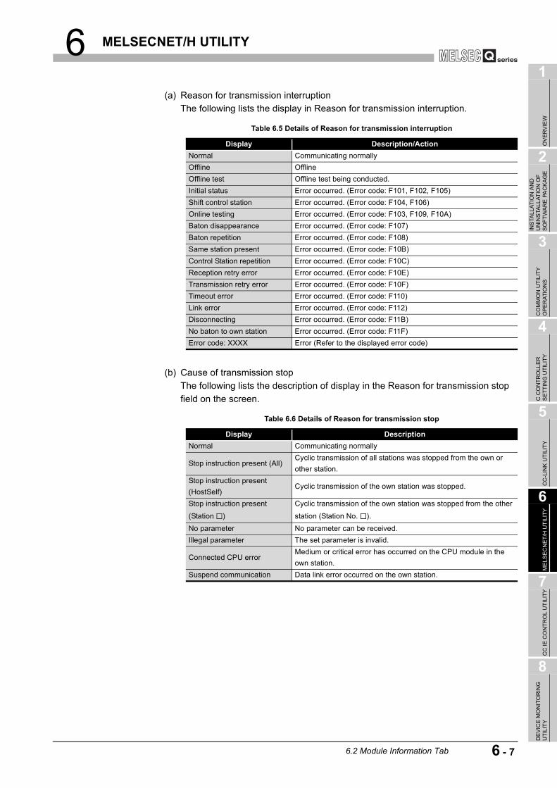
6 MELSECNET/H UTILITY
1
OV
ERVI
EW
2
INS
TALL
ATIO
N A
ND
U
NIN
STA
LLAT
ION
OF
SO
FTW
ARE
PA
CKA
GE
3
CO
MM
ON
UTI
LITY
O
PER
ATIO
NS
4
C C
ON
TRO
LLE
R
SET
TIN
G U
TILI
TY
5
CC
-LIN
K U
TILI
TY
6
MEL
SEC
NET
/H U
TILI
TY
7
CC
IE C
ON
TRO
L U
TILI
TY
8
DE
VIC
E M
ON
ITO
RIN
G
UTI
LITY
(a) Reason for transmission interruptionThe following lists the display in Reason for transmission interruption.
(b) Cause of transmission stopThe following lists the description of display in the Reason for transmission stop field on the screen.
Table 6.5 Details of Reason for transmission interruption
Display Description/ActionNormal Communicating normallyOffline OfflineOffline test Offline test being conducted.Initial status Error occurred. (Error code: F101, F102, F105)Shift control station Error occurred. (Error code: F104, F106)Online testing Error occurred. (Error code: F103, F109, F10A)Baton disappearance Error occurred. (Error code: F107)Baton repetition Error occurred. (Error code: F108)Same station present Error occurred. (Error code: F10B)Control Station repetition Error occurred. (Error code: F10C)Reception retry error Error occurred. (Error code: F10E)Transmission retry error Error occurred. (Error code: F10F)Timeout error Error occurred. (Error code: F110)Link error Error occurred. (Error code: F112)Disconnecting Error occurred. (Error code: F11B)No baton to own station Error occurred. (Error code: F11F)Error code: XXXX Error (Refer to the displayed error code)
Table 6.6 Details of Reason for transmission stop
Display DescriptionNormal Communicating normally
Stop instruction present (All)Cyclic transmission of all stations was stopped from the own or other station.
Stop instruction present (HostSelf)
Cyclic transmission of the own station was stopped.
Stop instruction present
(Station )
Cyclic transmission of the own station was stopped from the other
station (Station No. ).
No parameter No parameter can be received.Illegal parameter The set parameter is invalid.
Connected CPU errorMedium or critical error has occurred on the CPU module in the own station.
Suspend communication Data link error occurred on the own station.
6.2 Module Information Tab 6 - 7

6 MELSECNET/H UTILITY
(4) Specifications of the SB/SW save fileA file format can be selected in "Save as" on the following screen.
To use the text data of the SB/SW save file in an user program etc, select "SBSWSave File(*.csv)" when saving.To use them on Microsoft Excel etc., select "SBSWSave File[Form2](*.csv)" when saving.
Remark
The folder of the SB/SW save file is "C:\MELSEC\CCPU\Param" by default. (When SW PVC-CCPU has been installed in "C:\MELSEC").
Figure 6.3 Save As screen
When "SBSWSave File(*.csv)" is selected When "SBSWSave File[Form2](*.csv)" is selected
Figure 6.4 Example of the SB/SW save file
6 - 8 6.2 Module Information Tab

6 MELSECNET/H UTILITY
1
OV
ERVI
EW
2
INS
TALL
ATIO
N A
ND
U
NIN
STA
LLAT
ION
OF
SO
FTW
ARE
PA
CKA
GE
3
CO
MM
ON
UTI
LITY
O
PER
ATIO
NS
4
C C
ON
TRO
LLE
R
SET
TIN
G U
TILI
TY
5
CC
-LIN
K U
TILI
TY
6
MEL
SEC
NET
/H U
TILI
TY
7
CC
IE C
ON
TRO
L U
TILI
TY
8
DE
VIC
E M
ON
ITO
RIN
G
UTI
LITY
6.3 Error History Monitoring Tab
The Error history monitoring tab displays the historical data of loop errors, communication errors, and transient transmission errors.
(1) Precautions for the Error history monitoring tab
(a) Number of historical dataUp to 16 loop switching or transient transmission errors are stored.When the number of stored data reaches to 16, the next error will be stored by deleting the oldest. (No.1 (oldest) to No. 16 (newest))
(b) Transient transmission errorFor the error codes and error types displayed in the Transient transmission errors, refer to the Q Corresponding MELSECNET/H Network System Reference Manual (PLC to PLC network)
(2) Error history monitoring tab
(To the next page)
Figure 6.5 Error history monitoring tab
Table 6.7 Description of the Error history monitoring tab
Item DescriptionCorresponding
SBCorresponding
SW
Target moduleSpecify a MELSECNET/H for error history monitoring.(Default: 1)
buttonOpens the Clear error history screen. ( Page 6-12, Section 6.3 (3))
, or
button
Starts or stops monitoring MELSECNET/H module."*" flashes in the upper right of the button during monitoring.These buttons are disabled in the offline status.
Q12DCCPU-V Q06CCPU-V Q06CCPU-V-B
Module information Error history monitoring Other station monitoring
Clear error history
Start monitoring
Stop monitoring
6.3 Error History Monitoring Tab 6 - 9

6 MELSECNET/H UTILITY
(To the next page)
Table 6.7 Description of the Error history monitoring tab (continued)
Item DescriptionCorresponding
SBCorresponding
SW
Own station informationDisplays the own station information of the MELSECNET/H module.
Start I/O No. Displays the start I/O No. of the own station.Network No. Displays the network No. of the own station. SW0040Group No. Displays the group No. of the own station. SW0041Sta.No. Displays the station No. of the own station. SW0042
NetworkDisplays the network to which the MELSECNET/H module is connected.
SB0057, SB005A
SW0046
Type Displays the type of the own station. SB0044
Loop switchingDisplays the factor of loop switching and the status after the switching.(For optical loop only)
Sta. No.Displays the number of the station that requested loop switching or loopback.
SW00E0 to SW00E7
Factor Displays the factor of loop switching or loopback.SW00D0 to SW00DF
Switched status Displays the data link status after loop switching.SW00D0 to SW00DF
Transient transmission errors
Displays error codes for transient transmission errors that occurred on the own station.For details of errors, refer to the Q Corresponding MELSECNET/H Network System Reference Manual (PLC to PLC network).
Err. codeDisplays error codes that are reported during transient transmission.
SW00F0 to SW00FF
Error typeDisplays types of errors that occurred during transient transmission.
Module information Error history monitoring Other station monitoring
6 - 10 6.3 Error History Monitoring Tab

6 MELSECNET/H UTILITY
1
OV
ERVI
EW
2
INS
TALL
ATIO
N A
ND
U
NIN
STA
LLAT
ION
OF
SO
FTW
ARE
PA
CKA
GE
3
CO
MM
ON
UTI
LITY
O
PER
ATIO
NS
4
C C
ON
TRO
LLE
R
SET
TIN
G U
TILI
TY
5
CC
-LIN
K U
TILI
TY
6
MEL
SEC
NET
/H U
TILI
TY
7
CC
IE C
ON
TRO
L U
TILI
TY
8
DE
VIC
E M
ON
ITO
RIN
G
UTI
LITY
Table 6.7 Description of the Error history monitoring tab
Item DescriptionCorresponding
SBCorresponding
SW
Number of error occurrences
Displays the number of error occurrences.For details of factors and corrective actions, refer to the following.
Page 6-13, Section 6.3 (4)
Loop switchingDisplays the number of times that loop switching and loopback has been executed."-" is displayed in the case of a coaxial bus system.
SW00CE
Transient transmission errorsDisplays the number of transient transmission errors that has been occurred.
SW00EE
Retry Displays the number of retries (for transmission errors).SW00C8, SW00C9
Line trouble "-" is displayed in the case of a coaxial bus system.SW00CC, SW00CD
Communication error
UNDER Displays the number of UNDER errors that has been occurred.SW00B8, SW00C0
CRC Displays the number of CRC errors that has been occurred.SW00B9, SW00C1
OVER Displays the number of OVER errors that has been occurred.SW00BA, SW00C2
SHORTFRAMEDisplays the number of short frame (too short data message) errors that has been occurred.
SW00BB, SW00C3
ABORT Displays the number of AB.IF errors that has been occurred.SW00BC, SW00C4
TIMEOUT Displays the number of timeout errors that has been occurred.SW00BD, SW00C5
Exceeded 2KBDisplays the number of errors exceeding 2k bytes that has been occurred.
SW00BE, SW00C6
DPLL ERRORDisplays the number of DPLL (data not properly recognized in synchronization/modulation) errors.
SW00BF, SW00C7
Module information Error history monitoring Other station monitoring
6.3 Error History Monitoring Tab 6 - 11
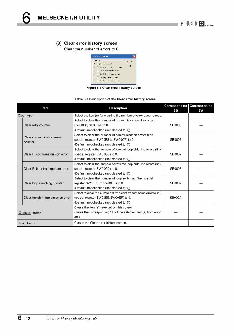
6 MELSECNET/H UTILITY
(3) Clear error history screenClear the number of errors to 0.
Figure 6.6 Clear error history screen
Table 6.8 Description of the Clear error history screen
Item DescriptionCorresponding
SBCorresponding
SWClear type Select the item(s) for clearing the number of error occurrences.
Clear retry counterSelect to clear the number of retries (link special register SW00C8, SE00C9) to 0.(Default: not checked (not cleared to 0))
SB0005
Clear communication error counter
Select to clear the number of communication errors (link special register SW00B8 to SW00C7) to 0.(Default: not checked (not cleared to 0))
SB0006
Clear F. loop transmission errorSelect to clear the number of forward loop side line errors (link special register SW00CC) to 0.(Default: not checked (not cleared to 0))
SB0007
Clear R. loop transmission errorSelect to clear the number of reverse loop side line errors (link special register SW00CD) to 0.(Default: not checked (not cleared to 0))
SB0008
Clear loop switching counterSelect to clear the number of loop switching (link special register SW00CE to SW00E7) to 0.(Default: not checked (not cleared to 0))
SB0009
Clear transient transmission errorSelect to clear the number of transient transmission errors (link special register SW00EE,SW00EF) to 0.(Default: not checked (not cleared to 0))
SB000A
button
Clears the item(s) selected on this screen.(Turns the corresponding SB of the selected item(s) from on to off.)
button Closes the Clear error history screen.
Execute
Exit
6 - 12 6.3 Error History Monitoring Tab

6 MELSECNET/H UTILITY
1
OV
ERVI
EW
2
INS
TALL
ATIO
N A
ND
U
NIN
STA
LLAT
ION
OF
SO
FTW
ARE
PA
CKA
GE
3
CO
MM
ON
UTI
LITY
O
PER
ATIO
NS
4
C C
ON
TRO
LLE
R
SET
TIN
G U
TILI
TY
5
CC
-LIN
K U
TILI
TY
6
MEL
SEC
NET
/H U
TILI
TY
7
CC
IE C
ON
TRO
L U
TILI
TY
8
DE
VIC
E M
ON
ITO
RIN
G
UTI
LITY
(4) Factors and actionsThe following table shows factors and corrective actions for each error.The information can also be checked from the following link special registers (SW) as well as on the Error history monitoring tab.For details of special registers (SW), refer to the Q Corresponding MELSECNET/H Network System Reference Manual (PLC to PLC network).
(a) Errors other than transient transmission errorsUnless the error count frequently increases during operation, no specific action is required.Take the following corrective actions if the error count frequently increases.
1) Check the status (on/off) of power supply for the own and other stations.
2) Check cables and connectors (for disconnection, loose connectors, broken cables, and improper cable lengths).
3) Conduct a self-loopback test, internal self-loopback test, and hardware test.
4) Conduct a station-to-station test and forward/reverse loop test.
5) Review its wiring, referring to the manuals for the network module and/or MELSECNET/H board used.Or, reinstall the system, referring to the user's manual for the CPU module used.
Table 6.9 Error factors and corrective actions
Item Link special register Factor Corrective action
Loop switching SW00CE Station's power on/off, cable fault, noise, etc. Page 6-13, Section 6.3 (4) (a)
Transient transmission errors
SW00EETarget station's power off, target station's CPU failure, cable fault, noise, etc.
Check the error code of the transient transmission error, and take corrective actions.
Retry SW00C8, SW00C9 Station's power on/off, cable fault, noise, etc.
Page 6-13, Section 6.3 (4) (a)
Line trouble SW00CC, SW00CDAdjacent station's power off, cable fault, noise, etc.
UNDER SW00B8, SW00C0Adjacent station's power on off, cable fault, etc.
CRC SW00B9, SW00C1Source station of data transmission was disconnected, cable fault, hardware fault, noise, etc.
OVER SW00BA, SW00C2Cable fault, hardware fault, noise, etc.
SHORTFRAME SW00BB, SW00C3
ABORT SW00BC, SW00C4Source station of data transmission was disconnected, cable fault, hardware fault, noise, etc.
TIMEOUT SW00BD, SW00C5Too-short data link monitoring time, cable fault, noise, etc.
Exceeded 2KB SW00BE, SW00C6Cable fault, hardware fault, noise, etc.
DPLL ERROR SW00BF, SW00C7
6.3 Error History Monitoring Tab 6 - 13
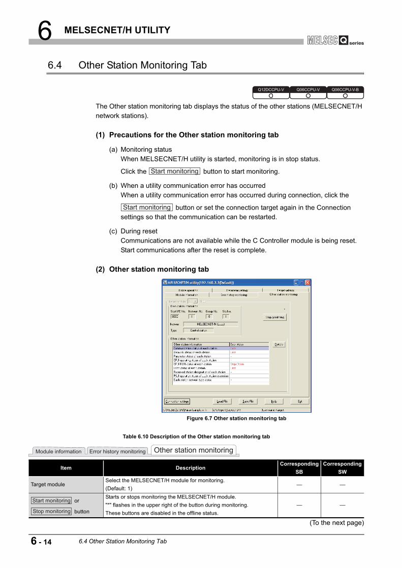
6 MELSECNET/H UTILITY
6.4 Other Station Monitoring Tab
The Other station monitoring tab displays the status of the other stations (MELSECNET/H network stations).
(1) Precautions for the Other station monitoring tab
(a) Monitoring statusWhen MELSECNET/H utility is started, monitoring is in stop status.
Click the button to start monitoring.
(b) When a utility communication error has occurredWhen a utility communication error has occurred during connection, click the
button or set the connection target again in the Connection settings so that the communication can be restarted.
(c) During resetCommunications are not available while the C Controller module is being reset.Start communications after the reset is complete.
(2) Other station monitoring tab
(To the next page)
Figure 6.7 Other station monitoring tab
Table 6.10 Description of the Other station monitoring tab
Item DescriptionCorresponding
SBCorresponding
SW
Target moduleSelect the MELSECNET/H module for monitoring.(Default: 1)
or
button
Starts or stops monitoring the MELSECNET/H module."*" flashes in the upper right of the button during monitoring.These buttons are disabled in the offline status.
Q12DCCPU-V Q06CCPU-V Q06CCPU-V-B
Start monitoring
Start monitoring
Module information Error history monitoring Other station monitoring
Start monitoring
Stop monitoring
6 - 14 6.4 Other Station Monitoring Tab

6 MELSECNET/H UTILITY
1
OV
ERVI
EW
2
INS
TALL
ATIO
N A
ND
U
NIN
STA
LLAT
ION
OF
SO
FTW
ARE
PA
CKA
GE
3
CO
MM
ON
UTI
LITY
O
PER
ATIO
NS
4
C C
ON
TRO
LLE
R
SET
TIN
G U
TILI
TY
5
CC
-LIN
K U
TILI
TY
6
MEL
SEC
NET
/H U
TILI
TY
7
CC
IE C
ON
TRO
L U
TILI
TY
8
DE
VIC
E M
ON
ITO
RIN
G
UTI
LITY
(3) Details screensDetailed information of the item selected on the Other station monitoring tab are displayed on each screen below.The following lists the details screen corresponding to each item selected on the Other station monitoring tab.
Remark
The information on the Details screens is based on the information when the screen was opened.To display the updated information, close and reopen the Details screen.
Table 6.10 Description of the Other station monitoring tab (continued)
Item DescriptionCorresponding
SBCorresponding
SWOwn station information Displays the own station information of the MELSECNET/H module.
Start I/O No. Displays the start I/O No. of the own station.Network No. Displays the network No. of the own station. SW0040Group No. Displays the group No. of the own station. SW0041Sta.No. Displays the station No. of the own station. SW0042
NetworkDisplays the network to which the MELSECNET/H module is connected.
SB0057, SB005A
SW0046
Type Displays the type of the own station. SB0044
Other station information
Displays the error occurrence of the other stations. ( Page 6-15, Section 6.4 (3))Double-clicking an item opens the Details screen that displays the detailed information of the item.
buttonOpens the Details screen to display the detailed information of the
selected item. ( Page 6-15, Section 6.4 (3))
Other station information Displays errors in "Error status" when an error corresponding to the item in "Other station information" has occurred.Error status
Table 6.11 Other station monitoring tab selection and corresponding Details screen
Selection on the Other station monitoring tab
Corresponding Details screen Reference page
Communication status of each station
Communication status of each station screen
Page 6-16, Section 6.4 (3) (a)
Data link status of each station Data link status of each station screen Page 6-17, Section 6.4 (3) (b)Parameter status of each station
Parameter status of each station screen Page 6-18, Section 6.4 (3) (c)
CPU operating status of each station
CPU operating status of each station screen
Page 6-19, Section 6.4 (3) (d)
CPU RUN status of each station CPU RUN status of each station screen Page 6-20, Section 6.4 (3) (e)Loop status of each station Loop status of each station screen Page 6-21, Section 6.4 (3) (f)Reserved station designation of each station
Reserved station designation of each station screen
Page 6-22, Section 6.4 (3) (g)
PSU operation states of each station extension
PSU operation states of each station extension screen
Page 6-23, Section 6.4 (3) (h)
Each station network type status
Each station network type status screen Page 6-24, Section 6.4 (3) (i)
Module information Error history monitoring Other station monitoring
Details
6.4 Other Station Monitoring Tab 6 - 15

6 MELSECNET/H UTILITY
(a) Communication status of each status screenDisplays the baton pass status. (Availability of transient transmission)Displayed number of the stations is based on the "Total stations" set on the Parameter settings tab.
Figure 6.8 Communication status of each status screen
Table 6.12 Description of the Communication status of each status screen
Item DescriptionCorresponding
SBCorresponding
SW
button Closes the Communication status of each station screen.
Own station information
Displays the own station information of the MELSECNET/H module.
( Page 6-14, Section 6.4 (2))
SB0044, SB0057, SB005A
SW0040, SW0041, SW0042, SW0046
Communication status of each station
Displays baton pass status (Availability of transient transmission) in the following color code.Light blue: Normally communicating station or reserved stationRed: Communication error status (disconnected)
SW0070 to SW0073
OK
6 - 16 6.4 Other Station Monitoring Tab

6 MELSECNET/H UTILITY
1
OV
ERVI
EW
2
INS
TALL
ATIO
N A
ND
U
NIN
STA
LLAT
ION
OF
SO
FTW
ARE
PA
CKA
GE
3
CO
MM
ON
UTI
LITY
O
PER
ATIO
NS
4
C C
ON
TRO
LLE
R
SET
TIN
G U
TILI
TY
5
CC
-LIN
K U
TILI
TY
6
MEL
SEC
NET
/H U
TILI
TY
7
CC
IE C
ON
TRO
L U
TILI
TY
8
DE
VIC
E M
ON
ITO
RIN
G
UTI
LITY
(b) Data link status of each station screenDisplays the cyclic transmission status.The number of displayed stations is based on the "Total stations" set in the Parameter settings tab.
Figure 6.9 Data link status of each station screen
Table 6.13 Description of the Data link status of each station screen
Item DescriptionCorresponding
SBCorresponding
SW
button Closes the Data link status of each station screen.
Own station information
Displays the own station information of the MELSECNET/H module.
( Page 6-14, Section 6.4 (2))
SB0044, SB0057, SB005A
SW0040, SW0041, SW0042, SW0046
Data link status of each station
Displays the cyclic transmission status in the following color code.Light blue: Normal or reserved stationRed: Error station (Data link not performed)
SW0074 to SW0077
OK
6.4 Other Station Monitoring Tab 6 - 17

6 MELSECNET/H UTILITY
(c) Parameter status of each station screenDisplays the parameter communication status and parameter error status of each station.The number of displayed stations is based on the "Total stations" set in the Parameter settings tab.
Figure 6.10 Communication status of each station screen
Table 6.14 Description of the Communication status of each station screen
Item DescriptionCorresponding
SBCorresponding
SW
button Closes the Communication status of each station screen.
Own station information
Displays the own station information of the MELSECNET/H module.
( Page 6-14, Section 6.4 (2))
SB0044, SB0057, SB005A
SW0040, SW0041, SW0042, SW0046
Communication status of each station parameter
Displays the parameter communication status of each station in the following color code.Light blue: Status other than "communicating with parameters", reserved station, or unconnected stationRed: Communicating with parameters
SW0078 to SW007B
Error status of each station parameter
Displays the parameter error status of each station in the following color code.Light blue: Parameters normal, reserved station, or unconnected stationRed: Parameter error
SW007C to SW007F
OK
6 - 18 6.4 Other Station Monitoring Tab

6 MELSECNET/H UTILITY
1
OV
ERVI
EW
2
INS
TALL
ATIO
N A
ND
U
NIN
STA
LLAT
ION
OF
SO
FTW
ARE
PA
CKA
GE
3
CO
MM
ON
UTI
LITY
O
PER
ATIO
NS
4
C C
ON
TRO
LLE
R
SET
TIN
G U
TILI
TY
5
CC
-LIN
K U
TILI
TY
6
MEL
SEC
NET
/H U
TILI
TY
7
CC
IE C
ON
TRO
L U
TILI
TY
8
DE
VIC
E M
ON
ITO
RIN
G
UTI
LITY
(d) CPU operation status of each station screenDisplays the CPU operation status.The number of displayed stations is based on the "Total stations" set in the Parameter settings tab.
Figure 6.11 CPU operation status of each station screen
Table 6.15 Description of the CPU operation status of each station screen
Item DescriptionCorresponding
SBCorresponding
SW
button Closes the "CPU operation status of each station" screen.
Own station information
Displays the own station information of the MELSECNET/H module.
( Page 6-14, Section 6.4 (2))
SB0044, SB0057, SB005A
SW0040, SW0041, SW0042, SW0046
CPU operation status of each station
Displays the CPU operation status in the following color code.Light blue: CPU normal, reserved station, unconnected stationRed: CPU fault Medium error (WDT error, etc.) or, critical error (Hardware error, etc.)Yellow: CPU fault minor error
SW0080 to SW0083,
SW0088 to SW008B
OK
6.4 Other Station Monitoring Tab 6 - 19

6 MELSECNET/H UTILITY
(e) CPU RUN status of each station screenDisplays the RUN/STOP states of the CPUs.The number of displayed stations is based on the "Total stations" set in the Parameter settings tab.
Figure 6.12 CPU RUN status of each station screen
Table 6.16 CPU RUN status of each station screen
Item DescriptionCorresponding
SBCorresponding
SW
button Closes the CPU RUN status of each station screen.
Own station information
Displays the own station information of the MELSECNET/H module.
( Page 6-14, Section 6.4 (2))
SB0044, SB0057, SB005A
SW0040, SW0041, SW0042, SW0046
CPU status
Displays the RUN/STOP status of each CPU.RUN: RUN, STEP RUNSTOP: STOP, PAUSEDOWN: ERROR, or unconnected stationReserved Sta.: Reserved station
SW0084 to SW0087
OK
6 - 20 6.4 Other Station Monitoring Tab

6 MELSECNET/H UTILITY
1
OV
ERVI
EW
2
INS
TALL
ATIO
N A
ND
U
NIN
STA
LLAT
ION
OF
SO
FTW
ARE
PA
CKA
GE
3
CO
MM
ON
UTI
LITY
O
PER
ATIO
NS
4
C C
ON
TRO
LLE
R
SET
TIN
G U
TILI
TY
5
CC
-LIN
K U
TILI
TY
6
MEL
SEC
NET
/H U
TILI
TY
7
CC
IE C
ON
TRO
L U
TILI
TY
8
DE
VIC
E M
ON
ITO
RIN
G
UTI
LITY
(f) Loop status of each station screenIn the case of the optical loop system, this screen displays the forward and reverse loop states.The number of displayed stations is based on the "Total stations" set in the Parameter settings tab.
Figure 6.13 Loop status of each station screen
Table 6.17 Description of the Loop status of each station screen
Item DescriptionCorresponding
SBCorresponding
SW
button Closes the Loop status of each station screen.
Own station information
Displays the own station information of the MELSECNET/H module.
( Page 6-14, Section 6.4 (2))
SB0044, SB0057, SB005A
SW0040, SW0041, SW0042, SW0046
F. loop status of each station
Displays the forward loop status in the optical loop system in the following color code.Light blue: Normal, reserved station, or unconnected stationRed: Error station
SW0091 to SW0094
R. loop status of each station
Displays the reverse loop status in the optical loop system in the following color code.Light blue: Normal, reserved station, or unconnected stationRed: Error station
SW0095 to SW0098
OK
6.4 Other Station Monitoring Tab 6 - 21

6 MELSECNET/H UTILITY
(g) Reserved station designation of each station screenDisplays the setting status of the reserved status.The number of displayed stations is based on the "Total stations" set in the Parameter settings tab.
Figure 6.14 Reserved station designation of each station screen
Table 6.18 Description of the Reserved station designation of each station screen
Item DescriptionCorresponding
SBCorresponding
SW
buttonCloses the Reserved station designation of each station screen.
Own station information
Displays the own station information of the MELSECNET/H module.
( Page 6-14, Section 6.4 (2))
SB0044, SB0057, SB005A
SW0040, SW0041, SW0042, SW0046
Reserved station designation of each station
Displays the reserved station setting status in the following color code.Light blue: Non-reserved stationBlue: Reserved station
SW0064 to SW0067
OK
6 - 22 6.4 Other Station Monitoring Tab
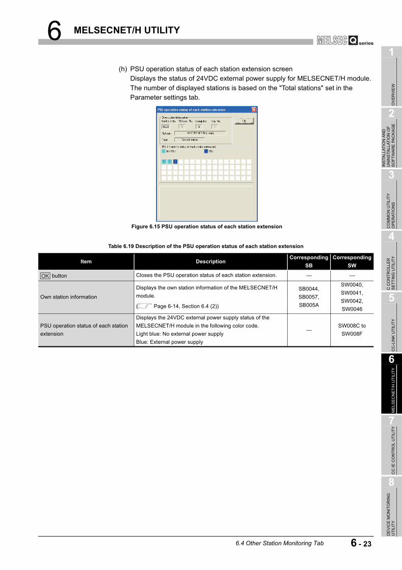
6 MELSECNET/H UTILITY
1
OV
ERVI
EW
2
INS
TALL
ATIO
N A
ND
U
NIN
STA
LLAT
ION
OF
SO
FTW
ARE
PA
CKA
GE
3
CO
MM
ON
UTI
LITY
O
PER
ATIO
NS
4
C C
ON
TRO
LLE
R
SET
TIN
G U
TILI
TY
5
CC
-LIN
K U
TILI
TY
6
MEL
SEC
NET
/H U
TILI
TY
7
CC
IE C
ON
TRO
L U
TILI
TY
8
DE
VIC
E M
ON
ITO
RIN
G
UTI
LITY
(h) PSU operation status of each station extension screenDisplays the status of 24VDC external power supply for MELSECNET/H module.The number of displayed stations is based on the "Total stations" set in the Parameter settings tab.
Figure 6.15 PSU operation status of each station extension
Table 6.19 Description of the PSU operation status of each station extension
Item DescriptionCorresponding
SBCorresponding
SW
button Closes the PSU operation status of each station extension.
Own station information
Displays the own station information of the MELSECNET/H module.
( Page 6-14, Section 6.4 (2))
SB0044, SB0057, SB005A
SW0040, SW0041, SW0042, SW0046
PSU operation status of each station extension
Displays the 24VDC external power supply status of the MELSECNET/H module in the following color code.Light blue: No external power supplyBlue: External power supply
SW008C to SW008F
OK
6.4 Other Station Monitoring Tab 6 - 23

6 MELSECNET/H UTILITY
(i) Each station network type status screenDisplays consistency of the network types that are set in the control station and in the normal station.The number of displayed stations is based on the "Total stations" set in the Parameter settings tab.
Figure 6.16 Each station network type status screen
Table 6.20 Description of the Each station network type status screen
Item DescriptionCorresponding
SBCorresponding
SW
button Closes the Each station network type status screen.
Own station information
Displays the own station information of the MELSECNET/H module.
( Page 6-14, Section 6.4 (2))
SB0044, SB0057, SB005A
SW0040, SW0041, SW0042, SW0046
Each station network type status
Displays the consistency of the network types set in the control station and in the normal station in the following color code.Light blue: Normal, reserved, or communication error station whose network type is the same as that of the control station.Red: Normal station whose network type is different from that of the control station.
SW01E0 to SW01E3
OK
6 - 24 6.4 Other Station Monitoring Tab

6 MELSECNET/H UTILITY
1
OV
ERVI
EW
2
INS
TALL
ATIO
N A
ND
U
NIN
STA
LLAT
ION
OF
SO
FTW
ARE
PA
CKA
GE
3
CO
MM
ON
UTI
LITY
O
PER
ATIO
NS
4
C C
ON
TRO
LLE
R
SET
TIN
G U
TILI
TY
5
CC
-LIN
K U
TILI
TY
6
MEL
SEC
NET
/H U
TILI
TY
7
CC
IE C
ON
TRO
L U
TILI
TY
8
DE
VIC
E M
ON
ITO
RIN
G
UTI
LITY
6.5 Online Operation Tab
MELSECNET/H parameters can be read, written, or verified from this tab.
(1) Precautions for the Online operation tab
(a) When a utility communication error has occurredWhen a utility communication error has occurred during connection, set the connection target again in the Connection settings so that the communication can be restarted.
(b) During resetCommunications are not available while the C Controller module is being reset.Start communications after the reset is complete.
(2) Online operation tab
Remark
Reading, writing, and verification of parameters can be performed only when the C Controller module and a development environment (personal computer) is connected online.
Figure 6.17 Online operation tab
Table 6.21 Description of the Online operation tab
Item DescriptionRead parameters
buttonReads out MELSECNET/H parameters from the C Controller module.
Write parameters
button
Writes MELSECNET/H parameters to the C Controller module.The written parameters take effect when the C Controller module is powered off and then on or is reset.Parameters can be written only when "Write authority" is selected on the Connection settings screen. If "Write
authority" is not selected, select it in the Connection settings screen before writing parameters. ( Page 3-5, Section 3.5)
Verify parameters
button
Compares the MELSECNET/H parameters of the C Controller module with those of the MELSECNET/H utility.The results are displayed in a message box.
Q12DCCPU-V Q06CCPU-V Q06CCPU-V-B
Parameter settings Target settingsOnline operation
Read
Write
Verify
6.5 Online Operation Tab 6 - 25

6 MELSECNET/H UTILITY
6.6 Parameter Settings Tab
Parameters of the MELSECNET/H module can be set in this tab.
(1) Precautions for the Parameter settings tab
(a) Link device refresh cycle and Routing parameter"Link device refresh cycle" and "Routing parameter" are parameters common to CC-Link IE controller networks.When the defined parameters written from CC IE Control utility differs from that in
this utility, the following dialog box appears after clicking the button in the <<Online operation>> tab.
(2) Parameter settings tab
(To the next page)
Figure 6.18 Dialog box
Figure 6.19 Parameter setting tab
Table 6.22 Description of the Parameter setting tab
Item Description
Number of modulesSet the number of MELSECNET/H modules controlled by the C Controller module.Selecting "(blank)" is regarded as no setting (setting clear).(Default: "(blank)")
Q12DCCPU-V Q06CCPU-V Q06CCPU-V-B
Write
Target settingsOnline operation Parameter settings
6 - 26 6.6 Parameter Settings Tab

6 MELSECNET/H UTILITY
1
OV
ERVI
EW
2
INS
TALL
ATIO
N A
ND
U
NIN
STA
LLAT
ION
OF
SO
FTW
ARE
PA
CKA
GE
3
CO
MM
ON
UTI
LITY
O
PER
ATIO
NS
4
C C
ON
TRO
LLE
R
SET
TIN
G U
TILI
TY
5
CC
-LIN
K U
TILI
TY
6
MEL
SEC
NET
/H U
TILI
TY
7
CC
IE C
ON
TRO
L U
TILI
TY
8
DE
VIC
E M
ON
ITO
RIN
G
UTI
LITY
(To the next page)
Table 6.22 Description of the Parameter setting tab (continued)
Item Description
Link device refresh cycle
Set the refresh cycle of the link device. (In increments of ms)When using both the CC-Link IE controller network and MELSECNET/H, set the same value as the value set in CC IE Control utility.
When enabling Block data assurance per station ( Page 6-36, Section 6.6 (6)), set 10 or more to the "Link device refresh cycle" and set "Refresh parameters".If 0 is set, refresh is not performed, all the settings for the refresh are cleared, and the
button is disabled.(Default: 100, Setting range: 0, 10 to 1000)For details of the link device refresh cycle, refer to the C Controller Module User's (Hardware Design, Function Explanation).
button Displays the Routing parameter settings screen. ( Page 6-30, Section 6.6 (3))
Target moduleSelect a module to configure. (Default: 1)The numbers for this item will be automatically rearranged in ascending order of start I/O numbers when saving the parameter setting file or when switching the tab.
Start I/O No.Set the start I/O No. of the MELSECNET/H module.(Setting range: 0 to FE0H (Note that the number must be unique and cannot be duplicated with the start I/O No. of other MELSECNET/H module.)
Channel No.
Set the channel No. of the MELSECNET/H module.Use this value when opening the channel from Device monitoring utility or an user program (MELSEC data link function). For the Q06CCPU-V-B, this setting is not available.The channel No. must be unique and cannot be duplicated with a channel No. of other MELSECNET/H modules.
button
Displays the Refresh parameter setting screen. ( Page 6-32, Section 6.6 (4))
When enabling Block data assurance per station, ( Page 6-36, Section 6.6 (6)), set 10 or more to the "Link device refresh cycle" and set "Refresh parameters".
button Checks for any setting error.
button Set the operation settings, network range assignments, and refresh parameters back to default.
Operation settings Operation settings for the MELSECNET/H module.
Network No.Set the network No. of the MELSECNET/H module.(Default: 1, Setting range: 1 to 239)
Group No.Set the group No. of the MELSECNET/H module.(Default: 0, Setting range: 0 to 32)
Network typeSet the type of the MELSECNET/H module. (Default: "MNET/H mode (Control station)")
Mode Set the mode of the MELSECNET/H module. (Default: "Online")
Return
Return setting of the control station.This setting is available when any of the following is selected for "Network type".•MNET/H mode (Control station)•MNET/10 mode (Control station)•MNET/H Ext. mode (Control station)(Default: "Return as control station")
Target settingsOnline operation Parameter settings
Refresh parameters
Routing parameter
Refresh parameters
Check
Default
6.6 Parameter Settings Tab 6 - 27

6 MELSECNET/H UTILITY
Table 6.22 Description of the Parameter setting tab (continued)
Item Description
Network range assignment
Assign network ranges.•MNET/H mode (Control station)•MNET/10 mode (Control station)•MNET/H Ext. mode (Control station)
Total stationsSet a total number of stations (including the control station) to the target network.(Default: 2)
Assignment methodSwitches the device range input method between Points/Start and Start/End.(Default: "Start/End")
Monitoring timeSet the monitoring time for the link scan time. (In increments of 10ms)(Default: 200, Setting range: 1 to 200)
Switch screens
Select the link device to which network range is to be assigned."Low speed LB" and "Low speed LW" can be set when MNET/H mode (Control station) or MNET/H Ext. mode (Control station) is selected for "Network type".(Default: "LB/LW settings")
Points
Set the No. of the link device points assigned to the target station.This setting is available when "Point/Start" is selected for "Assignment method".
(Default: "(blank)", Setting range: Page 6-29, Section 6.6 (2) (a))
StartSet the start No. of the link device assigned to the target station.
(Default: "(blank)", Setting range: Page 6-29, Section 6.6 (2) (a))
End
Set the end No. of the link device assigned to the target station. This setting is available when "Start/End" is selected for "Assignment method".
(Default: "(blank)", Setting range: Page 6-29, Section 6.6 (2) (a))
button
Sets the selected station as an I/O master station of the link device (LX/LY), or cancels the setting.This button is enabled when "(LX/LY) settings (1)" or "(LX/LY) settings (2)" is selected for "Switch screens".
button Sets the selected station as a reserved station, or cancels the setting.
button Displays the Equal assignment screen. ( Page 6-34, Section 6.6 (5))
button Displays the Supplementary settings screen. ( Page 6-36, Section 6.6 (6))
buttonClears the "Points", "Start", and "End" settings and then sets the "Total stations" and "Monitoring time" settings back to default.
Target settingsOnline operation Parameter settings
Specify I/O master Sta.
Specify reserved Sta.
Equal assignment
Supplementary settings
Clear
6 - 28 6.6 Parameter Settings Tab

6 MELSECNET/H UTILITY
1
OV
ERVI
EW
2
INS
TALL
ATIO
N A
ND
U
NIN
STA
LLAT
ION
OF
SO
FTW
ARE
PA
CKA
GE
3
CO
MM
ON
UTI
LITY
O
PER
ATIO
NS
4
C C
ON
TRO
LLE
R
SET
TIN
G U
TILI
TY
5
CC
-LIN
K U
TILI
TY
6
MEL
SEC
NET
/H U
TILI
TY
7
CC
IE C
ON
TRO
L U
TILI
TY
8
DE
VIC
E M
ON
ITO
RIN
G
UTI
LITY
(a) Network range assignmentThe following table indicates the setting ranges of network assignment.
* 1 Only a multiple of 16 can be set to "Points" and "Start" of LX, LY, and LB. * 2 Only a (multiple of 16 minus 1) can be set to "End" of LX, LY, and LB. * 3 Set the "Network type" in the Parameter settings tab.
( Page 6-26, Section 6.6 (2))
Table 6.23 Setting ranges of network range assignment
Device Points/Start/End Setting range
LX
Points 16 to 8192*1
Start 0000 to 1FF0*1
End 000F to 1FFF*2
LY
Points 16 to 8192*1
Start 0000 to 1FF0*1
End 000F to 1FFF*2
When "Network type"*3 is either of the following•MNET/H mode (Control station)•MNET/H Ext. mode (Control station)
LB
Points 16 to 16384*1
Start 0000 to 3FF0*1
End 000F to 3FFF*2
LWPoints 1 to 16384Start 0000 to 3FFFEnd 0000 to 3FFF
Low-speed LB
Points 16 to 8192*1
Start 2000 to 3FF0*1
End 200F to 3FFF*2
Low-speed LW
Points 1 to 8192Start 2000 to 3FFFEnd 2000 to 3FFF
When "Network type"*3 is "MNET/10 mode (Control station)
LB
Points 16 to 8192*1
Start 0000 to 1FF0*1
End 000F to 1FFF*2
LWPoints 1 to 8192Start 0000 to 1FFFEnd 0000 to 1FFF
6.6 Parameter Settings Tab 6 - 29

6 MELSECNET/H UTILITY
(3) Routing parameter settings screenTransfer destination, relay network No., and relay station No. are set on this screen.
POINT1. The MELSECNET/H module controlled by the C Controller module cannot be
used a relay station which operates as a bridge.For a relay station, use the MELSECNET/H module that is controlled by a programmable controller CPU which is capable of configuring multiple network systems.
2. Routing parameters are common in the following channels.Different parameters cannot be set for each channel No.
• MELSECNET/H (Channel No.51 to 54) • CC-Link IE controller network (Channel No.151 to 154)
(To the next page)
Figure 6.20 Routing parameter settings screen
Table 6.24 Description of the Routing parameter settings screen
Item Description
Transfer target network No.Set the transfer target network No.(Default: "(blank)", Setting range: 1 to 239)
Relay network No.Set the relay network No.(Default: "(blank)", Setting range: 1 to 239)
Relay station No.Set the relay station No.(Default: "(blank)", Setting range: 1 to 120)
6 - 30 6.6 Parameter Settings Tab

6 MELSECNET/H UTILITY
1
OV
ERVI
EW
2
INS
TALL
ATIO
N A
ND
U
NIN
STA
LLAT
ION
OF
SO
FTW
ARE
PA
CKA
GE
3
CO
MM
ON
UTI
LITY
O
PER
ATIO
NS
4
C C
ON
TRO
LLE
R
SET
TIN
G U
TILI
TY
5
CC
-LIN
K U
TILI
TY
6
MEL
SEC
NET
/H U
TILI
TY
7
CC
IE C
ON
TRO
L U
TILI
TY
8
DE
VIC
E M
ON
ITO
RIN
G
UTI
LITY
Table 6.24 Description of the Routing parameter settings screen (continued)
Item DescriptionMax. size of transient transmission via other network No.
For each channel No., set the maximum transmission size of data sent by transient transmission from an user program via another network (No.).
Channel No.51 to Channel No.54
For each channel No., set the maximum transmission size for the case where data are sent by transient transmission to another network (No.) via a MELSECNET/H module.Only when the relay stations and target stations of transient transmission are the MELSEC-Q series network modules, select 960 words.When the relay stations and target stations of transient transmission are other than the MELSEC-Q series network modules, select 480 words. If 960 words is set for this case, data may be cut off, resulting in incorrect transient transmission.(Default: 480 words)
button Clears the "Transfer target network No.", "Relay network No.", and "Relay station No." settings.
button Checks the "Transfer target network No.", "Relay network No.", and "Relay station No." settings.
button Saves the settings and closes the Routing parameter settings screen.
button Closes the Routing parameter settings screen without saving the settings.
Clear
Check
End
Cancel
6.6 Parameter Settings Tab 6 - 31

6 MELSECNET/H UTILITY
(4) Refresh parameter settings screenSet refresh parameters.
Figure 6.21 Refresh parameter settings screen
Table 6.25 Description of the Refresh parameter settings screen
Item Description
Assignment methodThe device range input method can be switched between Points/Start and Start/End.(Default: "Start/End")
Link sideSet the refresh parameters of the target module selected on the Parameter settings tab.Up to 64 refresh parameters can be set.Set an unique value for each device. Duplicated devices are not allowed.
Device nameSet the name of the link device to be refreshed.
(Default: Page 6-33, Section 6.6 (4) (a), Setting range: Page 6-33, Section 6.6 (4) (b))
PointsSet the points of the link device to be refreshed.
(Default: Page 6-33, Section 6.6 (4) (a), Setting range: Page 6-33, Section 6.6 (4) (c))
StartSet the start No. of the link device to be refreshed.
(Default: Page 6-33, Section 6.6 (4) (a), Setting range: Page 6-33, Section 6.6 (4) (c))
EndSet the end No. of the link device to be refreshed.
(Default: Page 6-33, Section 6.6 (4) (a), Setting range: Page 6-33, Section 6.6 (4) (c))
CPU sideDisplays refresh parameters of the CPU module.Displayed data are corresponding to each setting in "Link side".
Device nameDisplays the name of the device to be refreshed on the CPU module.
(Display: Page 6-33, Section 6.6 (4) (b))
PointsDisplays the points of the device to be refreshed on the CPU module.Displays the same start No. as the one in "Points" in the "Link side" field.
StartDisplays the start No. of the device to be refreshed on the CPU module.Displays the same start No. as the one in "Start" in the "Link side" field.
EndDisplays the start No. of the device to be refreshed on the CPU module.Displays the same start No. as the one in "End" in the "Link side" field.
button Set the "Link side" and "CPU side" settings back to default.
button Checks the "Link side" and "CPU side" settings for error.
button Saves the settings and closes the Refresh parameter settings screen.
button Closes the Refresh parameter settings screen without saving the settings.
Default
Check
End
Cancel
6 - 32 6.6 Parameter Settings Tab

6 MELSECNET/H UTILITY
1
OV
ERVI
EW
2
INS
TALL
ATIO
N A
ND
U
NIN
STA
LLAT
ION
OF
SO
FTW
ARE
PA
CKA
GE
3
CO
MM
ON
UTI
LITY
O
PER
ATIO
NS
4
C C
ON
TRO
LLE
R
SET
TIN
G U
TILI
TY
5
CC
-LIN
K U
TILI
TY
6
MEL
SEC
NET
/H U
TILI
TY
7
CC
IE C
ON
TRO
L U
TILI
TY
8
DE
VIC
E M
ON
ITO
RIN
G
UTI
LITY
(a) DefaultThe following indicates the default for "Device name", "Points", "Start", and "End".
(b) Device namesThe following indicates the setting ranges of the "Device names" on the "Link side", and the display of the "Device names" on the "CPU side".
(c) Setting range on the link sideThe following indicates the setting ranges of the link side "Points", "Start", and "End".(The same setting ranges are applied to "Trans.1" to "Trans.64".)
* 1 Only a multiple of 16 can be set to "Points" and "Start" of LX, LY, and LB. * 2 Only a (multiple of 16 minus 1) can be set to "End" of LX, LY, and LB.
Table 6.26 Default for "Device name", "Points", "Start", and "End"
Setting item Device name Points Start EndTrans.1 LB 8192 0000 1FFFTrans.2 LW 8192 0000 1FFFTrans.3 to Trans.64
"(Blank)"
Table 6.27 "Device names" on "Link side" and "CPU side"
"Link side" setting range "CPU side" displayLX LX bufferLY LY bufferLB LB bufferLW LW buffer
Table 6.28 Setting ranges of link side "Points", "Start", and "End"
Device name Points/Start/End Setting range
LX
Points 16 to 8192*1
Start 0000 to 1FF0*1
End 000F to 1FFF*2
LY
Points 16 to 8192*1
Start 0000 to 1FF0*1
End 000F to 1FFF*2
LB
Points 16 to 16384*1
Start 0000 to 3FF0*1
End 000F to 3FFF*2
LWPoints 1 to 16384Start 0000 to 3FFFEnd 0000 to 3FFF
6.6 Parameter Settings Tab 6 - 33

6 MELSECNET/H UTILITY
(5) Equal assignment screenThe link device points of all stations can be equally assigned on this screen.For the start and end stations, set values within the number of the stations for equal assignment target, which can be calculated in the following expression:(Total link stations - (Start station No. - 1))
(a) When "LB/LW settings" is set for "Switch screens" in the Parameter settings tab.
Figure 6.22 Equal assignment screen (for LB/LW settings)
Table 6.29 Description of the Equal assignment screen (for LB/LW settings)
Item Description
Identical point assignmentEqually assigns entered points to the link devices of each station. (In increments of 16)(Default "(Blank)", Setting range: 16 or more)
buttonValidates the equal assignment setting according to entered values and closes the Equal assignment screen.
button Discard the settings and closes the Equal assignment screen.
Equal assignment Equally divides the entered points and assigns them to the link devices of each station.LB equal assignment Set the method for equal assignment to LB
Start station
Set the first of the stations to which equal assignment will be performed.(Default "(Blank)", Setting range: 1 to (Value set in "Total stations"))The value for "Total stations" can be set in the "Network range assignment" in the Parameter
settings tab. ( Page 6-26, Section 6.6 (2))
End station
Set the last of the stations to which equal assignment will be performed.(Default "(Blank)", Setting range: (Value set in "Start station" to "Total stations"))The value for "Total stations" can be set on the "Network range assignment" in the Parameter
settings tab. ( Page 6-26, Section 6.6 (2))
Start No.Set the start No. of the link device to be equally assigned.
(Default "(Blank)", Setting range: Page 6-29, Section 6.6 (2) (a))
Total points assignedSet the total points of the link devices to be equally assigned.
(Default "(Blank)", Setting range: Page 6-29, Section 6.6 (2) (a))
LW equal assignmentSet the method for equal assignment to LW.Set each item the same as for "LB equal assignment"
Low speed LB equal assignmentSet the method for equal assignment to low-speed LB.Setting method is the same as for "LB equal assignment" described above.
Low speed LW equal assignmentSet the method for equal assignment to low-speed LW.Setting method is the same as for "LB equal assignment" described above.
OK
Cancel
6 - 34 6.6 Parameter Settings Tab
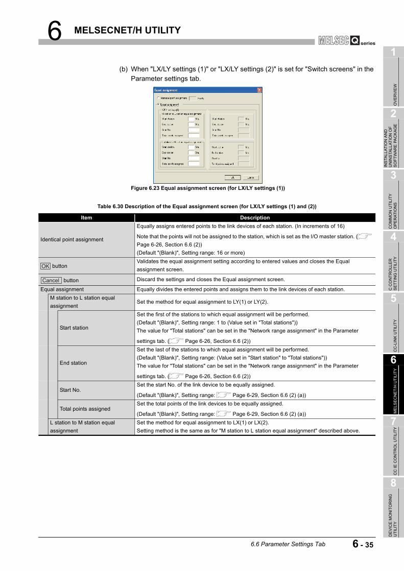
6 MELSECNET/H UTILITY
1
OV
ERVI
EW
2
INS
TALL
ATIO
N A
ND
U
NIN
STA
LLAT
ION
OF
SO
FTW
ARE
PA
CKA
GE
3
CO
MM
ON
UTI
LITY
O
PER
ATIO
NS
4
C C
ON
TRO
LLE
R
SET
TIN
G U
TILI
TY
5
CC
-LIN
K U
TILI
TY
6
MEL
SEC
NET
/H U
TILI
TY
7
CC
IE C
ON
TRO
L U
TILI
TY
8
DE
VIC
E M
ON
ITO
RIN
G
UTI
LITY
(b) When "LX/LY settings (1)" or "LX/LY settings (2)" is set for "Switch screens" in the Parameter settings tab.
Figure 6.23 Equal assignment screen (for LX/LY settings (1))
Table 6.30 Description of the Equal assignment screen (for LX/LY settings (1) and (2))
Item Description
Identical point assignment
Equally assigns entered points to the link devices of each station. (In increments of 16)
Note that the points will not be assigned to the station, which is set as the I/O master station. ( Page 6-26, Section 6.6 (2))(Default "(Blank)", Setting range: 16 or more)
buttonValidates the equal assignment setting according to entered values and closes the Equal assignment screen.
button Discard the settings and closes the Equal assignment screen.
Equal assignment Equally divides the entered points and assigns them to the link devices of each station.M station to L station equal assignment
Set the method for equal assignment to LY(1) or LY(2).
Start station
Set the first of the stations to which equal assignment will be performed.(Default "(Blank)", Setting range: 1 to (Value set in "Total stations"))The value for "Total stations" can be set in the "Network range assignment" in the Parameter
settings tab. ( Page 6-26, Section 6.6 (2))
End station
Set the last of the stations to which equal assignment will be performed.(Default "(Blank)", Setting range: (Value set in "Start station" to "Total stations"))The value for "Total stations" can be set in the "Network range assignment" in the Parameter
settings tab. ( Page 6-26, Section 6.6 (2))
Start No.Set the start No. of the link device to be equally assigned.
(Default "(Blank)", Setting range: Page 6-29, Section 6.6 (2) (a))
Total points assignedSet the total points of the link devices to be equally assigned.
(Default "(Blank)", Setting range: Page 6-29, Section 6.6 (2) (a))L station to M station equal assignment
Set the method for equal assignment to LX(1) or LX(2).Setting method is the same as for "M station to L station equal assignment" described above.
OK
Cancel
6.6 Parameter Settings Tab 6 - 35

6 MELSECNET/H UTILITY
(6) Supplementary settings screenThe supplementary settings is used for advanced settings.Default values can be applied for normal usage.
* 1 Securing consistency means preventing 2-word (32 bits) link data, such as the current value of the positioning module, from being divided into new and old data in units of 1 word (16 bits) due to cyclic transmission timing.The link device refresh processing between the C Controller module and MELSECNET/H module
can be set in the "Refresh parameter settings" tab. ( Page 6-32, Section 6.6 (4)).(To the next page)
Figure 6.24 Supplementary settings screen
Table 6.31 Description of the Supplementary settings screen
Item Description
Constant scanConstant scan is used to maintain the link scan time at a constant time.Set a value to prevent fluctuation of the link scan time. (Unit: ms)(Default: "(Blank)"), Setting range: 1 to 500
Max. number of returned stations per scan
Set the number of communication error stations that can return during one link scan.(Default: 2, Setting range: 1 to 64 ("Total stations" setting))"Total station" can be set in the "Network range assignment" field in the Parameter settings tab.
( Page 6-26, Section 6.6 (2))
With multiplex transmission
Select this when executing the multiplex transmission function.Multiplex transmission is used in the optical loop system to increase the transmission speed by using both the forward and reverse loops simultaneously when they are in a normal condition.This setting is available only when "Total stations" is set to 4 or more."Total station" can be set in the "Network range assignment" field in the Parameter settings tab.
( Page 6-26, Section 6.6 (2))(Default: Not selected (Not execute))
There is a data link thorough the sub-controlling station when the controlling station is down.
Select this when allowing another normal station on the network to continue communication (the control station switch function) as a alternate station (sub-control station) when the specified control station is disconnected due to some fault.(Default: Selected (Enable the control station switch function))
Block send data assurance per station
Select this when securing consistency*1 of link data for each station in cyclic transmission.This enables to handle multiple word data without providing interlocks in the program.
Note that this function*1 can be used only for the link device refresh processing between the C Controller module and MELSECNET/H module.Set the following parameters when selecting any of these items for assuring data per station.•"Link device refresh cycle" in the "Parameter settings" tab.
( Page 6-26, Section 6.6 (2))•Refresh parameters in the "Refresh parameter settings" tab.
( Page 6-32, Section 6.6 (4))
(Default: Page 6-37, Section 6.6 (6) (a))
Block receive data assurance per station
6 - 36 6.6 Parameter Settings Tab

6 MELSECNET/H UTILITY
1
OV
ERVI
EW
2
INS
TALL
ATIO
N A
ND
U
NIN
STA
LLAT
ION
OF
SO
FTW
ARE
PA
CKA
GE
3
CO
MM
ON
UTI
LITY
O
PER
ATIO
NS
4
C C
ON
TRO
LLE
R
SET
TIN
G U
TILI
TY
5
CC
-LIN
K U
TILI
TY
6
MEL
SEC
NET
/H U
TILI
TY
7
CC
IE C
ON
TRO
L U
TILI
TY
8
DE
VIC
E M
ON
ITO
RIN
G
UTI
LITY
(a) "Block send data assurance per station" "Block receive data assurance per station"Default settings differ depending on the network type as follows. ( Page 6-26, Section 6.6 (2))
Table 6.31 Description of the Supplementary settings screen (continued)
Item DescriptionTransient settings Determine the conditions for transient transmission.
Max. number of transients per scan
Enter the number of transient transmissions (total of entire network) that can be performed by one network during one scan.(Default: 2, Setting range: 1 to 255)
Max. number of transients per station
Enter the number of transient transmissions that can be performed by one station during one scan.(Default: 2, Setting range: 1 to 10 ("Max. number of transients per scan" setting)
Low speed cyclic transmission settings
Set the execution conditions when sending link data (LB, LW) in slow cycles (low speed cyclic transmission) in addition to the normal cyclic transmission.This setting is available only when "Low speed LB" and "Low speed LW" of "Network range assignment" are set on the "Parameter settings" tab.
Transmit data of one station per scan
Select this when collectively sending data to another station per link scan.
Interval of fixed cycleLow-speed cyclic transmission is performed at specified intervals.(Default: "(Blank)", Setting range: 1 to 65535 (Unit: Sec.))
Timer settings
Low-speed cyclic transmission is performed at specified time.Any of "Hour", "Min.", and "Sec." settings cannot be skipped.When no value are set to "Year", "Month", and "Day", the transmission is executed at specified time every day.When no value are set to "Year" and "Month", the transmission is executed at specified time every month.When no value is set to "Year", the transmission is executed at specified time every year.(Default: "(Blank)", Setting range: 00:00:00, January 1, 2000 to 23:59:59, December 31, 2099)
button Saves the settings and closes the Supplementary setting screen.
button Closes the Supplementary setting screen without saving the settings.
Table 6.32 Network types and default
Network type DefaultMNET/H mode (Control station)
Send and receive both deselectedMNET/10 mode (Control station)MNET/H Extended mode (Control station) Send and receive both selected
End
Cancel
6.6 Parameter Settings Tab 6 - 37

6 MELSECNET/H UTILITY
6.7 Target Settings Tab
Logical station numbers are set on this tab.Logical station numbers are used when the target station is a multiple CPU system to access the programmable controller other than control CPU in the target station.Note that the logical station number setting is not required for the following access.
Page 6-40, "6.7 (4) Access that does not require a logical station No. setting"
(1) Precaution for the Target settings tabSelect a programmable controller CPU for the "Target module".
(2) The Target settings tab
(To the next page)
Figure 6.25 Target settings tab
Table 6.33 Description of the Target settings tab
Item Description
Target moduleSelect the module to be configured.(Default: "Slot 1")
Logical Sta. No.
Specify the logical station No. of the module selected in "Target module".(Default: 65, Setting range: 65 to 239)The logical station No. is logical numbers to be set in "Sta. No." in Device monitoring utility and MELSEC data link function (MELSECNET data link function).
Network No.Set the network No. of the CC-Link IE controller network module and MELSECNET/H module controlled by the multiple CPU system.(Default: 1, Setting range: 1 to 239)
Sta. No.Set the station No. of the CC-Link IE controller network module and MELSECNET/H module controlled by the multiple CPU system.(Default: 1, Setting range: 1 to 120)
Target CPUSet the CPU (CPU No. used in the multiple CPU system) to be accessed.(Default: 1, Setting range: 1 to 4)
button Registers the settings (Logical Sta. No., Network No., Sta. No., and Target CPU) to the Target list.
Q12DCCPU-V Q06CCPU-V Q06CCPU-V-B
Online operation Parameter settings Target settings
Set
6 - 38 6.7 Target Settings Tab

6 MELSECNET/H UTILITY
1
OV
ERVI
EW
2
INS
TALL
ATIO
N A
ND
U
NIN
STA
LLAT
ION
OF
SO
FTW
ARE
PA
CKA
GE
3
CO
MM
ON
UTI
LITY
O
PER
ATIO
NS
4
C C
ON
TRO
LLE
R
SET
TIN
G U
TILI
TY
5
CC
-LIN
K U
TILI
TY
6
MEL
SEC
NET
/H U
TILI
TY
7
CC
IE C
ON
TRO
L U
TILI
TY
8
DE
VIC
E M
ON
ITO
RIN
G
UTI
LITY
(3) Access exampleWhen the settings in the following screen are applied in the below system, a MELSECNET/H module controlled by the C Controller module can access to the CPU No.4 via the MELSECNET/H module (controlled by CPU No. 2, network No. 1) by using the logical station No. "65".The access is also available by opening channel No. 51 and setting 65 for the station No. in Device monitoring utility or an user program (MELSEC data link function).
* 1 When CPU No. 4 cannot configure a multiple CPU system, access to the CPU No. 4 is not available by using the logical station number.
The target settings for the above access is shown below.
Table 6.33 Description of the Target settings tab (continued)
Item Description
Target listDisplays a list of the Logical Sta. No. set to the module selected in "Target module" and the corresponding network No., station No., and target CPUs
buttonDisplays the data of the selected row (Logical sta. No.) in the Target list.(Setting for the logical sta. No. can also be changed by double-clicking the row.)
button Deletes the line (Logical sta. No.) selected in the Target list area.
Figure 6.26 System configuration
Figure 6.27 Target settings tab
Online operation Parameter settings Target settings
Change
Delete
Multiple CPU system
Control station
QJ71LP21G
Slot 1, Channel No.51
(Controlled by
C Controller module)
C Controller
module
Normal station
QJ71LP21G
Station No.: 5
(Controlled by CPU No.2)
CPU
No.4 *1
MELSECNET/H
Network No.1
CPU
No.2
6.7 Target Settings Tab 6 - 39

6 MELSECNET/H UTILITY
(4) Access that does not require a logical station No. settingIn the following access, use the station No. of a MELSECNET/H module on other station.The logical station number setting is not required.
Figure 6.28 Access that does not require a logical station No. setting
Other station MELSECNET/H module
C Controller module
MELSECNET/H
Control CPU of other station MELSECNET/H module
C Controller module
MELSECNET/H
6 - 40 6.7 Target Settings Tab

6 MELSECNET/H UTILITY
1
OV
ERVI
EW
2
INS
TALL
ATIO
N A
ND
U
NIN
STA
LLAT
ION
OF
SO
FTW
ARE
PA
CKA
GE
3
CO
MM
ON
UTI
LITY
O
PER
ATIO
NS
4
C C
ON
TRO
LLE
R
SET
TIN
G U
TILI
TY
5
CC
-LIN
K U
TILI
TY
6
MEL
SEC
NET
/H U
TILI
TY
7
CC
IE C
ON
TRO
L U
TILI
TY
8
DE
VIC
E M
ON
ITO
RIN
G
UTI
LITY
6.8 System menu
(1) System menuOpen the system menu of MELSECNET/H utility in any of the following three methods.
• Right-click on the title bar.
• Click the ( ) icon on the title bar. • Press the [Alt] key and then the [ ] key.
(2) Version information screenDisplays the version information of MELSECNET/H utility.
Figure 6.29 System menu
Table 6.34 Description of the System menu
Item Description
Move, Minimize, Close Refer to the Microsoft Windows manual.
Specify CPU typeSpecifies a C Controller module to which parameters are set or to be monitored. ( Page 3-4, Section 3.4)This item is not selectable during monitoring.
C Controller setting utilityStarts C Controller setting utility. ( Page 4-1, CHAPTER 4)While online, check that C Controller setting utility is connected to the same target device as for MELSECNET/H utility.
Device monitoring utility
Starts Device monitoring utility. ( Page 8-1, CHAPTER 8)While online, check that Device monitoring utility is connected to the same target device as for MELSECNET/H utility.For the Q06CCPU-V-B, Device monitoring utility is not available.
Version information Opens the Version information screen. ( Page 6-41, Section 6.8 (2))
Figure 6.30 Version information screen (Example: Version 3.01B)
Table 6.35 Description of the Version information screen
Item DescriptionSoftware package
SW PVC-CCPU-E Displays the version of SW PVC-CCPU.MELSECNET/H utility Displays the update date of MELSECNET/H utility.
button Closes the Version information screen.
Q12DCCPU-V Q06CCPU-V Q06CCPU-V-B
OK
6.8 System menu 6 - 41

6 MELSECNET/H UTILITY
6.9 Precautions
(1) Parameter detailsFor details of each parameter, refer to Q Corresponding MELSECNET/H Network System Reference Manual (PLC to PLC network).
(2) Simultaneous use of utilityUp to eight MELSECNET/H utilities can be simultaneously activated.
(3) Written parametersParameters written to the C Controller module take effect when the C Controller module is powered off and then on or is reset.
(4) Tabs available to operate offlineWhen MELSECNET/H utility connection is offline, data can be set only in the Parameter settings tab and the Target settings tab.For the Q06CCPU-V-B, only parameters shown in the Target settings tab can be set.
(5) Terminating Microsoft WindowsDo not terminate Microsoft Windows while MELSECNET/H utility is running.Terminate MELSECNET/H utility first and then Microsoft Windows .
(6) Connection during script file processing Connection from utility to a C Controller module may not be available during processing a script file (while the RUN LED is flashing).If the RUN LED remains flashing, refer to the C Controller Module User's Manual (Hardware Design, Function Explanation) and troubleshoot the problem.
(7) Time required for connection from each utility to the C Controller moduleThe following time is required for the C Controller module to connect to each utility after power-on or reset.
• When executing a script file, "STARTUP.CMD":Upon completion of the RUN LED flashing.
• When not executing a script file, "STARTUP.CMD":Fifteen (15) seconds after completion of start or reset
Do not attempt a connection before the above time has elapsed after completion of power-on or reset.Changing "Priority" to a larger value in the Option tab of C Controller setting utility increases the time after which the C Controller module can be connected.
Q12DCCPU-V Q06CCPU-V Q06CCPU-V-B
6 - 42 6.9 Precautions

7 CC IE CONTROL UTILITY
1
OV
ERVI
EW
2
INS
TALL
ATIO
N A
ND
U
NIN
STA
LLAT
ION
OF
SO
FTW
ARE
PA
CKA
GE
3
CO
MM
ON
UTI
LITY
O
PER
ATIO
NS
4
C C
ON
TRO
LLE
R
SET
TIN
G U
TILI
TY
5
CC
-LIN
K U
TILI
TY
6
MEL
SEC
NET
/H U
TILI
TY
7
CC
IE C
ON
TRO
L U
TILI
TY
8
DE
VIC
E M
ON
ITO
RIN
G
UTI
LITY
CHAPTER 7 CC IE CONTROL UTILITY
7.1 CC IE Control Utility Function List
: Applicable, : Applicable but partially restricted, : N/A
Table 7.1 CC IE Control utility function list
Name DescriptionApplicability
Reference page
Q12DCCPU-V
Q06CCPU-V
Specify CPU type Specifies a C Controller module for parameter setting and monitoring. Page 3-4
Connection settingsSets the C Controller module to which CC IE Control utility is to be connected.
Page 3-5
Parameter setting file saving/loading
Saves parameters set in CC IE Control utility into a file or loads the file. Page 3-12
Module information display
Displays information on the CC-Link IE controller network module (own station) that is controlled by the connected C Controller module.
Page 7-2
Online operation Reads, writes, or verifies CC-Link IE controller network parameters. Page 7-20
Parameter settings Sets parameters for the CC-Link IE controller network modules. Page 7-22
Target settingsSets a logical station number for access to a CPU module in a multiple CPU system when a CC-Link IE controller network module is mounted in the system.
Page 7-33
Q12DCCPU-V Q06CCPU-V Q06CCPU-V-B
7.1 CC IE Control Utility Function List 7 - 1
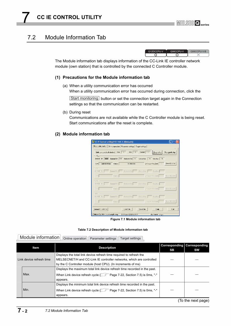
7 CC IE CONTROL UTILITY
7.2 Module Information Tab
The Module information tab displays information of the CC-Link IE controller network module (own station) that is controlled by the connected C Controller module.
(1) Precautions for the Module information tab
(a) When a utility communication error has occurredWhen a utility communication error has occurred during connection, click the
button or set the connection target again in the Connection settings so that the communication can be restarted.
(b) During resetCommunications are not available while the C Controller module is being reset. Start communications after the reset is complete.
(2) Module information tab
(To the next page)
Figure 7.1 Module information tab
Table 7.2 Description of Module information tab
Item DescriptionCorresponding
SBCorresponding
SW
Link device refresh timeDisplays the total link device refresh time required to refresh the MELSECNET/H and CC-Link IE controller networks, which are controlled by the C Controller module (host CPU). (In increments of ms)
Max.
Displays the maximum total link device refresh time recorded in the past.
When Link device refresh cycle ( Page 7-22, Section 7.5) is 0ms, "-" appears.
Min.
Displays the minimum total link device refresh time recorded in the past.
When Link device refresh cycle ( Page 7-22, Section 7.5) is 0ms, "-" appears.
Q12DCCPU-V Q06CCPU-V Q06CCPU-V-B
Start monitoring
Online operation Parameter settingsModule information Target settings
7 - 2 7.2 Module Information Tab

7 CC IE CONTROL UTILITY
1
OV
ERVI
EW
2
INS
TALL
ATIO
N A
ND
U
NIN
STA
LLAT
ION
OF
SO
FTW
ARE
PA
CKA
GE
3
CO
MM
ON
UTI
LITY
O
PER
ATIO
NS
4
C C
ON
TRO
LLE
R
SET
TIN
G U
TILI
TY
5
CC
-LIN
K U
TILI
TY
6
MEL
SEC
NET
/H U
TILI
TY
7
CC
IE C
ON
TRO
L U
TILI
TY
8
DE
VIC
E M
ON
ITO
RIN
G
UTI
LITY
Table 7.2 Description of Module information tab (continued)
Item DescriptionCorresponding
SBCorresponding
SWLink device refresh time
Current
Displays the current total link device refresh time.
When Link device refresh cycle ( Page 7-22, Section 7.5) is 0ms, "-" appears.
button
Displays the "CC IE Control Network diagnostics result" screen.
( Page 7-5, Section 7.3)This button cannot be clicked in the offline status.
or
button
Starts or stops monitoring the CC-Link IE controller network module."*" flashes in the upper right of the button during monitoring.These buttons are disabled in the offline status.
1 Slot to 4 SlotDisplays CC-Link IE controller network module information in order of start I/O No.
Start I/O No. Displays the start I/O No. of the CC-Link IE controller network module.
Channel No.
Displays the channel No. of the CC-Link IE controller network module.
When the "Channel No." parameter is not specified ( Page 7-22, Section 7.5), "-" appears.
Network No.
Displays the network No. of the CC-Link IE controller network module.
When the "Network No." parameter is not specified ( Page 7-22, Section 7.5), "-" appears.
SW0040
Group No.
Displays the group No. of the CC-Link IE controller network module.
When the "Group No." parameter is not specified ( Page 7-22, Section 7.5), "-" appears.)
SW0041
Sta. No. Displays the station No. of the CC-Link IE controller network module. SW0042Type Displays the type of the CC-Link IE controller network module. SB0044
Status
Displays the communication status of the CC-Link IE controller network module as one of the following.• In data link • Suspend data link• Baton passing• Suspend baton pass• Offline testing• Offline
SW0047
Link scan timeDisplays the link scan time of the CC-Link IE controller network module. (In increments of ms)
button
Saves information of the CC-Link IE controller network module's link
special relay (SB) and link special register (SW) into a CSV file. ( Page 7-4, Section 7.2 (3))
Online operation Parameter settingsModule information Target settings
Diagnostics
Start monitoring
Stop monitoring
Save SB/SW
7.2 Module Information Tab 7 - 3
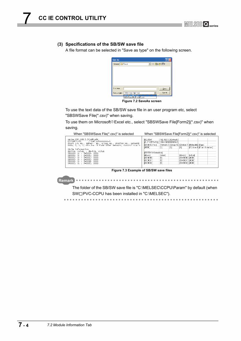
7 CC IE CONTROL UTILITY
(3) Specifications of the SB/SW save fileA file format can be selected in "Save as type" on the following screen.
To use the text data of the SB/SW save file in an user program etc, select "SBSWSave File(*.csv)" when saving.To use them on Microsoft Excel etc., select "SBSWSave File[Form2](*.csv)" when saving.
Remark
The folder of the SB/SW save file is "C:\MELSEC\CCPU\Param" by default (when SW PVC-CCPU has been installed in "C:\MELSEC").
Figure 7.2 SaveAs screen
When "SBSWSave File(*.csv)" is selected When "SBSWSave File[Form2](*.csv)" is selected
Figure 7.3 Example of SB/SW save files
7 - 4 7.2 Module Information Tab

7 CC IE CONTROL UTILITY
1
OV
ERVI
EW
2
INS
TALL
ATIO
N A
ND
U
NIN
STA
LLAT
ION
OF
SO
FTW
ARE
PA
CKA
GE
3
CO
MM
ON
UTI
LITY
O
PER
ATIO
NS
4
C C
ON
TRO
LLE
R
SET
TIN
G U
TILI
TY
5
CC
-LIN
K U
TILI
TY
6
MEL
SEC
NET
/H U
TILI
TY
7
CC
IE C
ON
TRO
L U
TILI
TY
8
DE
VIC
E M
ON
ITO
RIN
G
UTI
LITY
7.3 Diagnostics Result Screen
Clicking the button in the <<Module information>> tab displays this screen.
POINTWhen there are two or more CC-Link IE controller network modules that are controlled by the C Controller module, the following "Select diagnostics destination" window is displayed prior to "CC IE Control Network diagnostics result".
Select a network to be diagnosed and click the button.
Figure 7.4 CC IE Control Network diagnostics result screen
Figure 7.5 Select diagnostics destination screen
Q12DCCPU-V Q06CCPU-V Q06CCPU-V-B
Diagnostics
OK
7.3 Diagnostics Result Screen 7 - 5
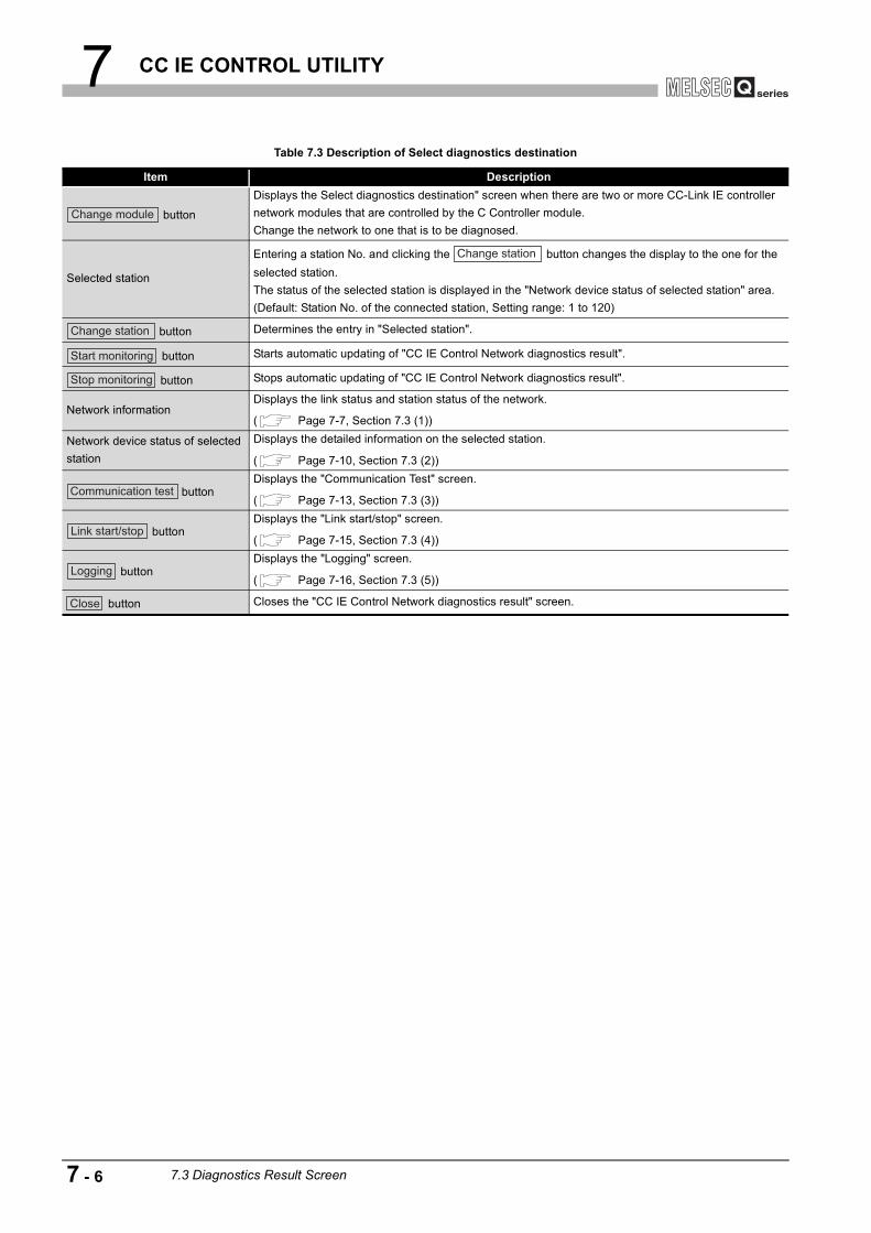
7 CC IE CONTROL UTILITY
Table 7.3 Description of Select diagnostics destination
Item Description
button
Displays the Select diagnostics destination" screen when there are two or more CC-Link IE controller network modules that are controlled by the C Controller module.Change the network to one that is to be diagnosed.
Selected station
Entering a station No. and clicking the button changes the display to the one for the selected station.The status of the selected station is displayed in the "Network device status of selected station" area.(Default: Station No. of the connected station, Setting range: 1 to 120)
button Determines the entry in "Selected station".
button Starts automatic updating of "CC IE Control Network diagnostics result".
button Stops automatic updating of "CC IE Control Network diagnostics result".
Network informationDisplays the link status and station status of the network.
( Page 7-7, Section 7.3 (1))
Network device status of selected station
Displays the detailed information on the selected station.
( Page 7-10, Section 7.3 (2))
buttonDisplays the "Communication Test" screen.
( Page 7-13, Section 7.3 (3))
buttonDisplays the "Link start/stop" screen.
( Page 7-15, Section 7.3 (4))
buttonDisplays the "Logging" screen.
( Page 7-16, Section 7.3 (5))
button Closes the "CC IE Control Network diagnostics result" screen.
Change module
Change station
Change station
Start monitoring
Stop monitoring
Communication test
Link start/stop
Logging
Close
7 - 6 7.3 Diagnostics Result Screen
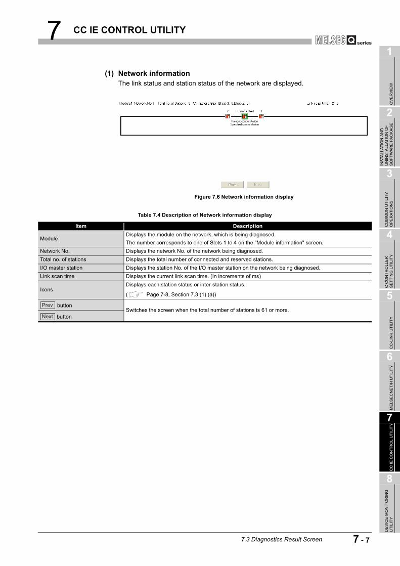
7 CC IE CONTROL UTILITY
1
OV
ERVI
EW
2
INS
TALL
ATIO
N A
ND
U
NIN
STA
LLAT
ION
OF
SO
FTW
ARE
PA
CKA
GE
3
CO
MM
ON
UTI
LITY
O
PER
ATIO
NS
4
C C
ON
TRO
LLE
R
SET
TIN
G U
TILI
TY
5
CC
-LIN
K U
TILI
TY
6
MEL
SEC
NET
/H U
TILI
TY
7
CC
IE C
ON
TRO
L U
TILI
TY
8
DE
VIC
E M
ON
ITO
RIN
G
UTI
LITY
(1) Network informationThe link status and station status of the network are displayed.
Figure 7.6 Network information display
Table 7.4 Description of Network information display
Item Description
ModuleDisplays the module on the network, which is being diagnosed.The number corresponds to one of Slots 1 to 4 on the "Module information" screen.
Network No. Displays the network No. of the network being diagnosed.Total no. of stations Displays the total number of connected and reserved stations.I/O master station Displays the station No. of the I/O master station on the network being diagnosed.Link scan time Displays the current link scan time. (In increments of ms)
IconsDisplays each station status or inter-station status.
( Page 7-8, Section 7.3 (1) (a))
buttonSwitches the screen when the total number of stations is 61 or more.
button
Prev
Next
7.3 Diagnostics Result Screen 7 - 7

7 CC IE CONTROL UTILITY
(a) IconsEach icon represents its station status or inter-station status.
1) Station No.Station No. of each CC-Link IE controller network module is displayed.
2) ConnectedThis word is shown for the station connected to the CC IE Control utility (own station).
3) IconsThe meanings of the icons are listed below.
4) Present control station and Specified control stationPresent control station: Station that is actually operating as a control stationSpecified control station: Control station that is set with a parameter
Figure 7.7 Displaying each station status and inter-station status
Table 7.5 Descriptions of icons
Icon Description
Normally operating station
Faulty stationAlthough cyclic transmission is performed, a fault has occurred on any of the following:•CC-Link IE controller network module•CC-Link IE controller network interface board•Cable
Faulty station (Cyclic station is stopped.)
Disconnected station (black)
Reserved station (gray)
Selected station (an icon in a green frame)•To select, click a station icon, or move the focus with the left and right arrow keys and press the space key.
•The detailed information is displayed in "Network device status of selected station".•Disconnected or reserved stations are not selectable.Being focused (an icon in a dotted line frame)•To make it selected, press the space key.•Disconnected or reserved stations are not selectable.Communication error•Selecting the station next to a faulty station will display the detailed information in the "Network device status of selected station" area.
1)
2)
3)
4)
7 - 8 7.3 Diagnostics Result Screen
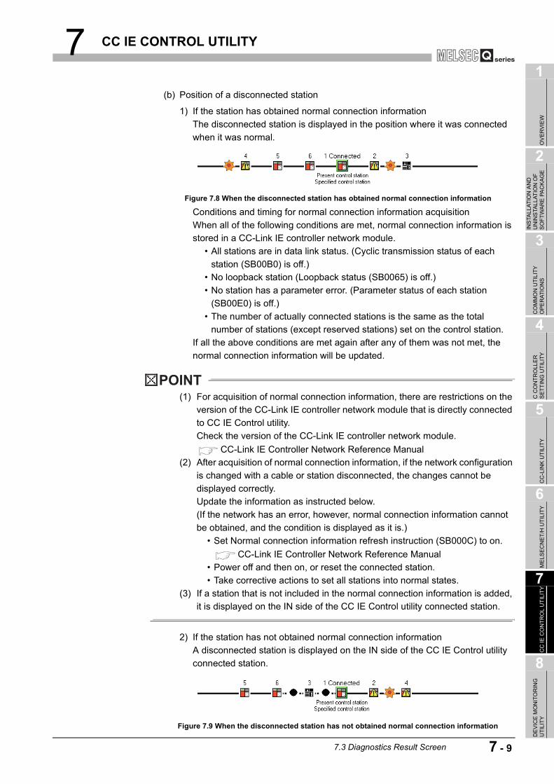
7 CC IE CONTROL UTILITY
1
OV
ERVI
EW
2
INS
TALL
ATIO
N A
ND
U
NIN
STA
LLAT
ION
OF
SO
FTW
ARE
PA
CKA
GE
3
CO
MM
ON
UTI
LITY
O
PER
ATIO
NS
4
C C
ON
TRO
LLE
R
SET
TIN
G U
TILI
TY
5
CC
-LIN
K U
TILI
TY
6
MEL
SEC
NET
/H U
TILI
TY
7
CC
IE C
ON
TRO
L U
TILI
TY
8
DE
VIC
E M
ON
ITO
RIN
G
UTI
LITY
(b) Position of a disconnected station
1) If the station has obtained normal connection informationThe disconnected station is displayed in the position where it was connected when it was normal.
Conditions and timing for normal connection information acquisitionWhen all of the following conditions are met, normal connection information is stored in a CC-Link IE controller network module.
• All stations are in data link status. (Cyclic transmission status of each station (SB00B0) is off.)
• No loopback station (Loopback status (SB0065) is off.) • No station has a parameter error. (Parameter status of each station
(SB00E0) is off.) • The number of actually connected stations is the same as the total
number of stations (except reserved stations) set on the control station.If all the above conditions are met again after any of them was not met, the normal connection information will be updated.
POINT(1) For acquisition of normal connection information, there are restrictions on the
version of the CC-Link IE controller network module that is directly connected to CC IE Control utility.Check the version of the CC-Link IE controller network module.
CC-Link IE Controller Network Reference Manual(2) After acquisition of normal connection information, if the network configuration
is changed with a cable or station disconnected, the changes cannot be displayed correctly.Update the information as instructed below.(If the network has an error, however, normal connection information cannot be obtained, and the condition is displayed as it is.)
• Set Normal connection information refresh instruction (SB000C) to on.CC-Link IE Controller Network Reference Manual
• Power off and then on, or reset the connected station. • Take corrective actions to set all stations into normal states.
(3) If a station that is not included in the normal connection information is added, it is displayed on the IN side of the CC IE Control utility connected station.
2) If the station has not obtained normal connection informationA disconnected station is displayed on the IN side of the CC IE Control utility connected station.
Figure 7.8 When the disconnected station has obtained normal connection information
Figure 7.9 When the disconnected station has not obtained normal connection information
7.3 Diagnostics Result Screen 7 - 9

7 CC IE CONTROL UTILITY
(2) Network device status of selected stationThe detailed information of a selected station is displayed.
Figure 7.10 Network device status of selected station
Table 7.6 Description of Network device status of selected station
Item Display Description
Group No.Displays the group No. of the selected station.(Range: 0 to 32)
ModeDisplays the mode of the selected station.(Display item: "Online", "Line test")
Operating status
Normal operation
Error (data link continued) (yellow)
Error (data link stopped) (red)
LEDs of selected station network device
Displays the operating status of the selected station.
( Page 7-11, Section 7.3 (2) (a))
Communication status
In data link
Cable disconnection
Communication error (other than cable disconnection)
Module error (CC-Link IE controller network parameter error or transient transmission error)
Error details button , etc.Displayed in the faulty area.
( Page 7-12, Section 7.3 (2) (b))
7 - 10 7.3 Diagnostics Result Screen

7 CC IE CONTROL UTILITY
1
OV
ERVI
EW
2
INS
TALL
ATIO
N A
ND
U
NIN
STA
LLAT
ION
OF
SO
FTW
ARE
PA
CKA
GE
3
CO
MM
ON
UTI
LITY
O
PER
ATIO
NS
4
C C
ON
TRO
LLE
R
SET
TIN
G U
TILI
TY
5
CC
-LIN
K U
TILI
TY
6
MEL
SEC
NET
/H U
TILI
TY
7
CC
IE C
ON
TRO
L U
TILI
TY
8
DE
VIC
E M
ON
ITO
RIN
G
UTI
LITY
(a) LEDs of the selected station network deviceThe operating status of the selected station is displayed.
* 1 Displayed only when the module is equipped with an external power supply.
Figure 7.11 LEDs of the selected station network device
Table 7.7 Description of LEDs of the selected station network device
LED LED status Description
RUNOn, green In normal operationOff Hardware fault or watchdog timer error
MODEOn, green Online modeFlashing, green Test modeOff Offline mode
SDOn, green Sending dataOff Not yet sending data
ERR.On, red
•Received data are erroneous. (Receive frame error)•A certain level frame error has occurred between stations.•Control station or station No. is duplicated.•Cables are disconnected or incorrectly connected between OUT and IN.•Network parameters are corrupted, or some settings (reserved station setting, total number of stations, network No., etc.) are inconsistent between control and normal stations.
Off Normal status
PRMOn, green Operating as a control stationOff Operating as a normal station
D LINKOn, green In data link (cyclic transmission operated)Flashing, green In data link (cyclic transmission stopped)Off Not yet in data link (being disconnected)
RDOn, green Receiving dataOff Not yet receiving data
EXT.PW*1 On, green External power is being suppliedOff External power not yet supplied
7.3 Diagnostics Result Screen 7 - 11

7 CC IE CONTROL UTILITY
(b) Error details buttonClicking the button displays the "Error details" screen.The detailed information, error factor, and troubleshooting tips are displayed.
Figure 7.12 Error details screen
7 - 12 7.3 Diagnostics Result Screen

7 CC IE CONTROL UTILITY
1
OV
ERVI
EW
2
INS
TALL
ATIO
N A
ND
U
NIN
STA
LLAT
ION
OF
SO
FTW
ARE
PA
CKA
GE
3
CO
MM
ON
UTI
LITY
O
PER
ATIO
NS
4
C C
ON
TRO
LLE
R
SET
TIN
G U
TILI
TY
5
CC
-LIN
K U
TILI
TY
6
MEL
SEC
NET
/H U
TILI
TY
7
CC
IE C
ON
TRO
L U
TILI
TY
8
DE
VIC
E M
ON
ITO
RIN
G
UTI
LITY
(3) Communication Test screenThe route from the own station to the specified destination is displayed on this screen, and whether transient transmissions can be performed correctly or not is checked.Upon completion of the communication test, the test result is displayed.If an error occurs, take actions according to the error message.
(To the next page)
Figure 7.13 Communication Test screen
Table 7.8 Description of Communication Test screen
Item DescriptionCommunication test details Set the destination and communication data.
Network No.Set a network No. of the destination.(Default:1, Setting range: 1 to 239)
Station No.Set a station No. of the destination.(Default: 1, Setting range: 0 (I/O master station), 1 to 120 (control/normal station))
LengthSet a communication data length.(Default: 100, Setting range: 1 to 900)
Communication countSpecify how many times the communication is to be made.(Default: 1, Setting range: 1 to 100)
W.D.T.Set a timeout time for the communication test (in units of seconds).(Default: 5, Setting range: 1 to 100)
button Executes the communication test.
Communication test result Displays the destination and communication data.
<<Outward>> tabDisplays the numbers of the networks and stations that are on the route from the source station (connected station) to the specified destination.
<<Inward>> tabDisplays the numbers of the networks and stations that are on the route back from the specified destination to the source station (connected station).
Network No.Displays the network No. of the turn-around point on the way from the source station (connected station) to the specified destination.(Range: 1 to 239)
Station No.Displays the station No. of the turn-around point on the way from the source station (connected station) to the specified destination).(Range: 0 to 120)
Execute test
7.3 Diagnostics Result Screen 7 - 13

7 CC IE CONTROL UTILITY
Remark
On the default screen, only the communication test setting area is displayed as below.
Table 7.8 Description of Communication Test screen (continued)
Item DescriptionOwn station Displays the information on the own (connected) station.
Network No. Displays the network No. of the own (connected) station.Station No. Displays the station No. of the own (connected9 station.
Communication information Displays the communication information.
Communication countDisplays how many times the communication has been made.(Range: 1 to 100)
Communication timeDisplays the communication time. (In increments of 100ms)(Range: 0 or greater)
Destination Displays the information on the destination.Network No. Displays the network No. that was entered in the Target settings.Station No. Displays the station No. that was entered in the Target settings.
button Closes the "Communication Test" screen.
Figure 7.14 Default Communication Test screen
Close
7 - 14 7.3 Diagnostics Result Screen

7 CC IE CONTROL UTILITY
1
OV
ERVI
EW
2
INS
TALL
ATIO
N A
ND
U
NIN
STA
LLAT
ION
OF
SO
FTW
ARE
PA
CKA
GE
3
CO
MM
ON
UTI
LITY
O
PER
ATIO
NS
4
C C
ON
TRO
LLE
R
SET
TIN
G U
TILI
TY
5
CC
-LIN
K U
TILI
TY
6
MEL
SEC
NET
/H U
TILI
TY
7
CC
IE C
ON
TRO
L U
TILI
TY
8
DE
VIC
E M
ON
ITO
RIN
G
UTI
LITY
(4) Link start/stop screenFrom this screen, data link of the specified station can be started or stopped.
Figure 7.15 Link start/stop screen
Table 7.9 Description of Link start/stop screen
Item DescriptionNetwork information Displays the information on the selected network (own station).
NetworkDisplays the name of the selected network (own station).(Display item: "CC IE Control" (fixed))
TypeDisplayed the station type of the selected network (own station).(Display item: "Controller network control station", "Controller network normal station")
Network No. Displays the network No. of the selected network (own station).Group No. Displays the group No. of the selected network (own station).Station No. Displays the station No. of the selected network (own station).
Status of all stations Displays the information on each station that is connected to the selected network (own station).
Selected/non-selected
Select a station to start or stop the link.By right-clicking on each information area in "Status of all stations", a pop-up menu appears.From the pop-up menu, the displayed status can be changed.(Default: Not checked (Link start or stop))
Station No.Displays station No. on the specified network.Reserved station numbers are not displayed.(Range: 1 to 120)
Link statusDisplays the link status of a station on the specified network.(Display item: "Linking (blue)", "Suspended (red)")
GroupDisplays the group No. of a station on the specified network.(Range: 0 to 32)
TypeDisplays the type of a station on the specified network.(Display item: "Control station", "Normal station")
Link start/stopSpecify the link start or stop.When "Forced start" is selected, the link can be started from a station other than the stop-requested station.(Default: "Start")
button Executes the operation selected in the Link start/stop setting for the selected station.
button Closes the "Link start/stop" screen.
Execute
Close
7.3 Diagnostics Result Screen 7 - 15

7 CC IE CONTROL UTILITY
(5) Logging screenTransmission pass switching and transient transmission error logs can be monitored, and error information can be cleared.
(To the next page)
<<Monitoring details>> tab <<Clear error>> tab
Figure 7.16 Logging screen
Table 7.10 Description of Logging screen
Item DescriptionConnected station Displays the information on the connected stations.
Network No.Displays the network No. of the connected station.(Range: 1 to 239)
Group No.Displays the group No. of the connected station.(Range: 0 to 32)
Station No.Displays the station No. of the connected station.(Range: 1 to 120)
7 - 16 7.3 Diagnostics Result Screen

7 CC IE CONTROL UTILITY
1
OV
ERVI
EW
2
INS
TALL
ATIO
N A
ND
U
NIN
STA
LLAT
ION
OF
SO
FTW
ARE
PA
CKA
GE
3
CO
MM
ON
UTI
LITY
O
PER
ATIO
NS
4
C C
ON
TRO
LLE
R
SET
TIN
G U
TILI
TY
5
CC
-LIN
K U
TILI
TY
6
MEL
SEC
NET
/H U
TILI
TY
7
CC
IE C
ON
TRO
L U
TILI
TY
8
DE
VIC
E M
ON
ITO
RIN
G
UTI
LITY
(To the next page)
Table 7.10 Description of Logging screen (continued)
Item Description<<Monitoring details>> tab Displays logs in the Transmission path switch and Transient transmission error areas.
Transmission path switchUp to 100 transmission path switch logs can be displayed.If more than 100 logs have occurred, the oldest log will be deleted to record the latest log.
Loop statusDisplays the information on the transmission lines on the entire network.(Display item: "Normal", "Loopback", "Error in all stations")
Loopback station IN Displays the station No. of the station where an IN-side loopback has occurred.(Range: 1 to 120)
Loopback station OUTDisplays the station No. of the station where an OUT-side loopback has occurred.(Range: 1 to 120)
Date/time Displays the date and time at which the transmission path was switched.
Transient transmission errorDisplays up to 100 transient transmission error logs.If more than 100 logs have occurred, the oldest log will be deleted to record the latest log.
Error codeDisplays error codes.For details of the error codes, refer to the CC-Link IE Controller Network Reference Manual.
Target networkWhen a transient transmission error has occurred, the network No. of the error-detected station is displayed.(Range: 1 to 239)
Target station No.When a transient transmission error has occurred, the station No. of the error-detected station is displayed.(Range: 1 to 120)
Date/time Displays the date and time at which the transient transmission error occurred.
button
Saves the <<Monitoring details>> tab data to a CSV file.
Select a CSV file format by clicking the button.
( Page 7-19, Section 7.3 (6))
•Drive/Path: Specify where the CSV file is saved.•File name: Specify a name for the CSV file to be saved.(*.csv)
button
button
Starts or stops the on-screen Logging monitoring.
During monitoring, the button is enabled.
While monitoring is stopped, the button is enabled.
When a utility communication error has occurred, the and buttons will be disabled.
Save error log
Browse
Start monitoring
Stop monitoring
Start monitoring
Start monitoring
Start monitoring Stop monitoring
7.3 Diagnostics Result Screen 7 - 17

7 CC IE CONTROL UTILITY
Table 7.10 Description of Logging screen (continued)
Item Description<<Clear error>> tab Clears the errors.
Clear communication error counterThe communication error counter can be cleared to zeros.(Default: Checked (Clears to 0))
Clear IN side transmission error counter
The areas for detected IN-side line errors (SW0068, SW0069, SB006E, SB0140, SW0074, and SW0140 to SW0147) can be cleared to zeros.(Default: Checked (Clears to 0))
Clear OUT side transmission error counter
The areas for detected OUT-side line errors (SB006F, SB0150, SW006A, SW006B, SW0084, and SW0150 to SW0157) can be cleared to zeros.(Default: Checked (Clears to 0))
Clear loop switching counterThe areas for path switch detection of the own station (SB008E, SB0160, SW006E, and SW0160 to SW0167) can be cleared to zeros.(Default: Checked (Clears to 0))
Clear transient transmission errorThe areas for transient transmission errors of the own station (SB008F, SB0170, SW006F, and SW0170 to SW0177) cam be cleared to zeros.(Default: Checked (Clears to 0))
button Clears the selected information.
button
Closes the "Logging" screen.The 17th and later logs displayed are deleted when this screen is closed.To save all of the displayed logs, click the "Save error log" button.
Clear error info.
Close
7 - 18 7.3 Diagnostics Result Screen
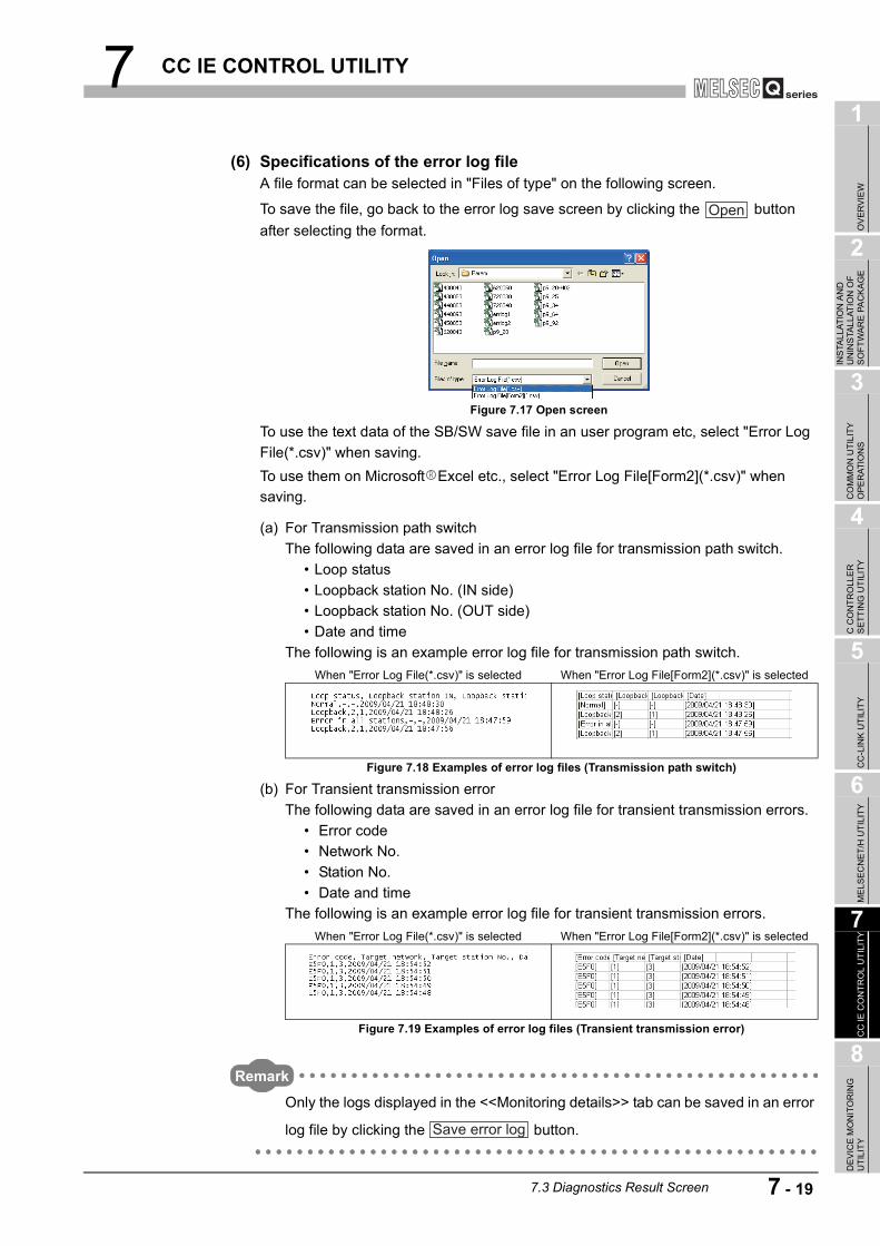
7 CC IE CONTROL UTILITY
1
OV
ERVI
EW
2
INS
TALL
ATIO
N A
ND
U
NIN
STA
LLAT
ION
OF
SO
FTW
ARE
PA
CKA
GE
3
CO
MM
ON
UTI
LITY
O
PER
ATIO
NS
4
C C
ON
TRO
LLE
R
SET
TIN
G U
TILI
TY
5
CC
-LIN
K U
TILI
TY
6
MEL
SEC
NET
/H U
TILI
TY
7
CC
IE C
ON
TRO
L U
TILI
TY
8
DE
VIC
E M
ON
ITO
RIN
G
UTI
LITY
(6) Specifications of the error log fileA file format can be selected in "Files of type" on the following screen.
To save the file, go back to the error log save screen by clicking the button after selecting the format.
To use the text data of the SB/SW save file in an user program etc, select "Error Log File(*.csv)" when saving.To use them on Microsoft Excel etc., select "Error Log File[Form2](*.csv)" when saving.
(a) For Transmission path switchThe following data are saved in an error log file for transmission path switch.
• Loop status • Loopback station No. (IN side) • Loopback station No. (OUT side) • Date and time
The following is an example error log file for transmission path switch.
(b) For Transient transmission errorThe following data are saved in an error log file for transient transmission errors.
• Error code • Network No. • Station No. • Date and time
The following is an example error log file for transient transmission errors.
Remark
Only the logs displayed in the <<Monitoring details>> tab can be saved in an error
log file by clicking the button.
Figure 7.17 Open screen
When "Error Log File(*.csv)" is selected When "Error Log File[Form2](*.csv)" is selected
Figure 7.18 Examples of error log files (Transmission path switch)
When "Error Log File(*.csv)" is selected When "Error Log File[Form2](*.csv)" is selected
Figure 7.19 Examples of error log files (Transient transmission error)
Open
Save error log
7.3 Diagnostics Result Screen 7 - 19

7 CC IE CONTROL UTILITY
7.4 Online Operation Tab
The CC-Link IE controller network parameters can be read, written, or verified from this tab.
(1) Precautions for the Online operation tab
(a) When a utility communication error has occurredWhen a utility communication error has occurred during connection, set the connection target again in the Connection settings so that the communication can be restarted.
(b) During resetCommunications are not available while the C Controller module is being reset.Start communications after the reset is complete.
(2) Online operation tab
Figure 7.20 Online operation tab
Table 7.11 Description of Online operation tab
Item DescriptionRead parameters
buttonReads CC-Link IE controller network parameters from the C Controller module.
Write parameters
button
Writes CC-Link IE controller network parameters to the C Controller module.The written parameters take effect when the C Controller module is powered off and then on or is reset.Parameters can be written only when "Write authority" is selected in Connection settings. If "Write authority" is not selected, select it in the Connection settings screen before writing parameters.
( Page 3-5, Section 3.5)
Verify parameters
button
Check for consistency between the CC-Link IE controller network parameters of the C Controller module and those set in CC IE Control utility.The verification results are shown in a message box.If a mismatch is found, a message appears and prompts the user to save the results to a file.
( Page 7-21, Section 7.4 (3))
Q12DCCPU-V Q06CCPU-V Q06CCPU-V-B
Parameter settings Target settingsOnline operationModule information
Read
Write
Verify
7 - 20 7.4 Online Operation Tab

7 CC IE CONTROL UTILITY
1
OV
ERVI
EW
2
INS
TALL
ATIO
N A
ND
U
NIN
STA
LLAT
ION
OF
SO
FTW
ARE
PA
CKA
GE
3
CO
MM
ON
UTI
LITY
O
PER
ATIO
NS
4
C C
ON
TRO
LLE
R
SET
TIN
G U
TILI
TY
5
CC
-LIN
K U
TILI
TY
6
MEL
SEC
NET
/H U
TILI
TY
7
CC
IE C
ON
TRO
L U
TILI
TY
8
DE
VIC
E M
ON
ITO
RIN
G
UTI
LITY
Remark
Reading, writing, and verification are available while the C Controller module is connected online to the development environment (personal computer).
(3) Verification results fileIf a mismatch is found, a message appears and prompts the user to save the results to a file.
To save a verification results file, click the button and enter appropriate data on the following screen.The verification results file is saved in text format.For "Save as" operations, refer to the following.
Page 3-12, Section 3.8
The following is an example of a verification results file.
Remark
The default directory for saving a verification results file is "C:\MELSEC\CCPU\Param" (when SW PVC-CCPU has been installed in "C:\MELSEC").
Figure 7.21 Save As screen
Yes
7.4 Online Operation Tab 7 - 21

7 CC IE CONTROL UTILITY
7.5 Parameter Settings Tab
Parameters of the CC-Link IE controller network module can be set in this tab.
(1) Precautions for the Parameter settings tab
(a) Link device refresh cycle and Routing parameter"Link device refresh cycle" and "Routing parameter" are parameters common to MELSECNET/H.When some of the set values written from MELSECNET/H utility are different from
those set in this utility, clicking the button in <<Online operation>> will display the following dialog box.
(2) Parameter settings tab
(To the next page)
Figure 7.22 Dialog box
Figure 7.23 Parameter settings tab
Table 7.12 Description of Parameter settings tab
Item Description
Number of modules
Set the number of CC-Link IE controller network modules that are to be controlled by the C Controller module.Selecting "(Blank)" means no setting (Setting cleared).(Default: "(Blank)")
Q12DCCPU-V Q06CCPU-V Q06CCPU-V-B
Write
Target settingsOnline operation Parameter settingsModule information
7 - 22 7.5 Parameter Settings Tab

7 CC IE CONTROL UTILITY
1
OV
ERVI
EW
2
INS
TALL
ATIO
N A
ND
U
NIN
STA
LLAT
ION
OF
SO
FTW
ARE
PA
CKA
GE
3
CO
MM
ON
UTI
LITY
O
PER
ATIO
NS
4
C C
ON
TRO
LLE
R
SET
TIN
G U
TILI
TY
5
CC
-LIN
K U
TILI
TY
6
MEL
SEC
NET
/H U
TILI
TY
7
CC
IE C
ON
TRO
L U
TILI
TY
8
DE
VIC
E M
ON
ITO
RIN
G
UTI
LITY
Table 7.12 Description of Parameter settings tab (continued)
Item Description
Link device refresh cycle
Set a refresh cycle for link devices. (In increments of ms)When using both the CC-Link IE controller network and MELSECNET/H network, set the same value as the value set in MELSECNET/H utility.
To enable the "Block data assurance per station" setting ( Page 7-32, Section 7.5 (7)), enter 10ms or more for "Link device refresh cycle", and set refresh parameters.Setting 0 for "Link device refresh cycle" disables any refresh with all refresh parameter settings
deleted, and disables the button.(Default: 100, Setting range: 0, 10 to 1000)For further details, refer to the C Controller Module User's Manual (Hardware Design, Function Explanation).
button Displays the "Routing parameter settings" screen. ( Page 7-24, Section 7.5 (3))
Target moduleSelect a module to configure. (Default: 1)The numbers for this item will be automatically rearranged in ascending order of start I/O numbers when saving the parameter setting file or when switching the tab.
Start I/O No.Set a start I/O No. of a CC-Link IE controller network module.(Setting range: 0 to FE0H (The set value must be unique, and not duplicated with the one for another CC-Link IE controller network module.))
Channel No.
Set a channel No. of a CC-Link IE controller network module.The set value is used to open the channel from Device monitoring utility or an user program (MELSEC data link functions).Channel No. must be unique, and not duplicated with the one for another CC-Link IE controller network module.
button Sets the operation settings, network range assignments, and refresh parameters to default values.
button Checks for any setting error.
button
Displays the "Refresh parameter settings" screen. ( Page 7-26, Section 7.5 (4))
To enable the Block data assurance per station" setting ( Page 7-32, Section 7.5 (7)), enter 10ms or more for "Link device refresh cycle", and set refresh parameters.
buttonDisplays the "Network range assignment" screen. ( Page 7-28, Section 7.5 (5))When "CC IE Control (Control station)" is selected for "Network type", this button is enabled.
Operation settings Specify the CC-Link IE controller network module operation.
Network typeSet a type of the CC-Link IE controller network module.(Default: "CC IE Control (Control station)")
ModeSet a mode of the CC-Link IE controller network module."Line test" can be set when "CC IE Control (Control station)" is selected for "Network type".(Default: "Online")
Network No.Set a network No. of the CC-Link IE controller network module.(Default: 1, Setting range: 1 to 239)
Group No.Set a group No. of the CC-Link IE controller network module.(Default: 0, Setting range: 0 to 32)
Station No.Set a station No. of the CC-Link IE controller network module.(Default: 1, Setting range: 1 to 120)
Target settingsOnline operation Parameter settingsModule information
Refresh parameters
Routing parameter
Default
Check
Refresh parameters
Network range assignment
7.5 Parameter Settings Tab 7 - 23

7 CC IE CONTROL UTILITY
(3) Routing parameter settings screenThe transfer target network, relay network, and relay station can be specified on this screen.
POINT1. The CC-Link IE controller network module controlled by a C Controller
module cannot be a relay station that is supposed to act as a bridge. As a relay station, use a CC-Link IE controller network module controlled by a programmable controller CPU with which multiple network systems can be constructed.
2. Common routing parameters must be used for the following channels.Different settings for each channel No. are not allowed.
• CC-Link IE controller network (Channel No.151 to 154) • MELSECNET/H (Channel No.51 to 54)
(To the next page)
Figure 7.24 Routing parameter settings screen
Table 7.13 Description of Routing parameter settings screen
Item Description
Transfer target network No.Set a transfer target network No.(Default: "(Blank)", Setting range: 1 to 239)
Relay network No.Set a relay network No.(Default: "(Blank)", Setting range: 1 to 239)
Relay station No.Set a relay station No.(Default: "(Blank)", Setting range: 1 to 120)
7 - 24 7.5 Parameter Settings Tab

7 CC IE CONTROL UTILITY
1
OV
ERVI
EW
2
INS
TALL
ATIO
N A
ND
U
NIN
STA
LLAT
ION
OF
SO
FTW
ARE
PA
CKA
GE
3
CO
MM
ON
UTI
LITY
O
PER
ATIO
NS
4
C C
ON
TRO
LLE
R
SET
TIN
G U
TILI
TY
5
CC
-LIN
K U
TILI
TY
6
MEL
SEC
NET
/H U
TILI
TY
7
CC
IE C
ON
TRO
L U
TILI
TY
8
DE
VIC
E M
ON
ITO
RIN
G
UTI
LITY
Table 7.13 Description of Routing parameter settings screen (continued)
Item DescriptionMax. size of transient transmission via other network No.
For each channel No, set the maximum size of transient transmission data sent from an user program via another network (No.)
Channel No.151 toChannel No.154
For each channel, set the maximum size of transient transmission data sent to another network (No.) via a CC-Link IE controller network module.Only when all of the relay and target stations of the transient transmission are MELSEC-Q series network modules, select 960 words.Select 480 words if a module other than the MELSEC-Q series network modules is included in the relay and target stations. Setting 960 words in this case may truncate some of the data, disabling normal transient transmission.(Default: 480 words)
button Clears the "Transfer target network No.", "Relay network No.", and "Relay station No." settings.
button Checks the "Transfer target network No.", "Relay network No.", and "Relay station No." settings.
button Saves the settings and closes the "Routing parameter settings" screen.
button Closes the "Routing parameters settings" screen without saving the settings.
Clear
Check
End
Cancel
7.5 Parameter Settings Tab 7 - 25

7 CC IE CONTROL UTILITY
(4) Refresh parameter settings screenRefresh parameters are set on this screen.
Figure 7.25 Refresh parameter settings screen
Table 7.14 Description of Refresh parameter settings screen
Item Description
Assignment methodHow to enter the device range data can be switched between Points/Start and Start/End styles. (Default: "Start/End")
Link sideSet refresh parameters of the module selected on the "Parameter settings" tab.Up to 64 refresh parameters can be set.Since duplicated device setting is not allowed, prevent any overlapped settings.
Device nameSet a link device name to be refreshed.
(Default: Page 7-27, Section 7.5 (4) (a), Setting range: Page 7-27, Section 7.5 (4) (b))
PointsSet points of the link device to be refreshed.
(Default: Page 7-27, Section 7.5 (4) (a), Setting range: Page 7-27, Section 7.5 (4) (c))
StartSet the start No. of the link device to be refreshed.
(Default: Page 7-27, Section 7.5 (4) (a), Setting range: Page 7-27, Section 7.5 (4) (c))
EndSet the end No. of the link device to be refreshed.
(Default: Page 7-27, Section 7.5 (4) (a), Setting range: Page 7-27, Section 7.5 (4) (c))
CPU sideDisplays refresh parameters of the CPU module.Data corresponding to respective "Link side" settings are shown.
Device nameDisplays the name of the device whose data are refreshed onto the CPU module.
(Range: Page 7-27, Section 7.5 (4) (b))
PointsDisplays the points of the device whose data are refreshed onto the CPU module.The points is the same as those shown in "Points" of "Link side".
StartDisplays the start No. of the device whose data are refreshed onto the CPU module.The start No. is the same as that shown in "Start" of "Link side".
EndDisplays the end No. of the device whose data are refreshed onto the CPU module.The end No. is the same as that shown in "END" of "Link side".
button Resets the "Link side" and "CPU side" settings back to defaults.
button Checks the "Link side" and "CPU side" settings for errors.
button Saves the settings and closes the "Refresh parameter settings" screen.
button Closes the "Refresh parameter settings" screen without saving the settings.
Default
Check
End
Cancel
7 - 26 7.5 Parameter Settings Tab

7 CC IE CONTROL UTILITY
1
OV
ERVI
EW
2
INS
TALL
ATIO
N A
ND
U
NIN
STA
LLAT
ION
OF
SO
FTW
ARE
PA
CKA
GE
3
CO
MM
ON
UTI
LITY
O
PER
ATIO
NS
4
C C
ON
TRO
LLE
R
SET
TIN
G U
TILI
TY
5
CC
-LIN
K U
TILI
TY
6
MEL
SEC
NET
/H U
TILI
TY
7
CC
IE C
ON
TRO
L U
TILI
TY
8
DE
VIC
E M
ON
ITO
RIN
G
UTI
LITY
(a) Default values for "Device name", "Points", "Start", and "End"The following table lists the default values for "Device name", "Points", "Start", and "End".
(b) "Device names" on "Link side" and "CPU side"The following table lists the setting range for "Device name" of "Link side" and "CPU side" "Device name" displays.
(c) Setting ranges for the link side "Points", "Start", and "End"The following table lists the setting ranges for the link side "Points", "Start", and "End".(These setting ranges apply to all of "Trans.1" to "Trans.64".)
* 1 Only a multiple of 16 can be set for "Points" and "Start" of LX, LY, and LB. * 2 Only (a multiple of 16 minus 1) can be set for "End" of LX, LY, and LB.
Table 7.15 Default values for "Device name", "Points", "Start", and "End"
Setting item Device name Points Start EndTrans.1 LB 32768 0000 7FFFTrans.2 LW 131072 00000 1FFFFTrans.3 to Trans.64
"(blank)"
Table 7.16 "Device names" on "Link side" and "CPU side"
"Link side" setting range "CPU side" displayLX LX bufferLY LY bufferLB LB bufferLW LW buffer
Table 7.17 Setting ranges for the link side "Points", "Start", and "End"
Device name Points/Start/End Setting range
LX
Points 16 to 8192*1
Start 0000 to 1FF0*1
End 000F to 1FFF*2
LY
Points 16 to 8192*1
Start 0000 to 1FF0*1
End 000F to 1FFF*2
LB
Points 16 to 32768*1
Start 0000 to 7FF0*1
End 000F to 7FFF*2
LWPoints 1 to 131072Start 00000 to 1FFFFEnd 00000 to 1FFFF
7.5 Parameter Settings Tab 7 - 27

7 CC IE CONTROL UTILITY
(5) Network range assignment screenFor each station, set cyclic transmission ranges of LB, LW, LX, and LY.
Figure 7.26 Network range assignment screen
Table 7.18 Description of Network range assignment screen
Item Description
Total stationsSet the total number of stations (including control stations) on the network.(Default: 2)
Assignment methodHow to enter the device range data can be switched between Points/Start and Start/End styles.(Default: "Start/End")
Monitoring timeSet a monitoring time for the link scan time. (In increments of ms)(Default: 2000, Setting range: 5 to 2000)
Switch screensSelect a link device for which network ranges are assigned.(Default: "LB/LW settings (1)")
Points
Set the number of link device points assigned to the target station.This setting is available when "Points/Start" is selected for "Assignment method".
(Default: "(Blank)", Setting range: Page 7-29, Section 7.5 (5) (a))
StartSet the start No. of the link device, which is assigned to the target station.
(Default: "(Blank)", Setting range: Page 7-29, Section 7.5 (5) (a))
End
Set the end No. of the link device, which is assigned to the target station.This setting is available when "Start/End" is selected for "Assignment method".
(Default: "(Blank)", Setting range: Page 7-29, Section 7.5 (5) (a))
button
Specifies the selected station as an I/O master station of the link device (LX/LY), or cancels the setting.This button can be used when "LX/LY settings (1)" or "LX/LY settings (2)" is selected for "Switch screens".
button
Specifies the selected station as a reserved station, or cancels the setting.
button Displays the "Equal assignment" screen. ( Page 7-30, Section 7.5 (6))
button Displays the "Supplementary settings" screen. ( Page 7-32, Section 7.5 (7))
buttonErases the "Points", "Start", and "End" settings, and sets "Total stations" and "Monitoring time" back to defaults.
button Checks the "Points", "Start", "End", "Total stations", and "Monitoring time" settings for errors.
button Saves the settings and closes the "Network range assignment" screen.
button Closes the "Network range assignment" screen without saving the settings.
Specify I/O master station
Specify reserved station
Equal assignment
Supplementary settings
Clear
Check
End
Cancel
7 - 28 7.5 Parameter Settings Tab

7 CC IE CONTROL UTILITY
1
OV
ERVI
EW
2
INS
TALL
ATIO
N A
ND
U
NIN
STA
LLAT
ION
OF
SO
FTW
ARE
PA
CKA
GE
3
CO
MM
ON
UTI
LITY
O
PER
ATIO
NS
4
C C
ON
TRO
LLE
R
SET
TIN
G U
TILI
TY
5
CC
-LIN
K U
TILI
TY
6
MEL
SEC
NET
/H U
TILI
TY
7
CC
IE C
ON
TRO
L U
TILI
TY
8
DE
VIC
E M
ON
ITO
RIN
G
UTI
LITY
(a) Setting ranges for Network range assignmentThe following are the setting ranges for Network range assignment.
* 1 Only a multiple of 16 can be set for "Points" and "Start" of LX, LY, and LB. * 2 Only (a multiple of 16 minus 1) can be set for "End" of LX, LY, and LB.
Table 7.19 Setting ranges for Network range assignment
Device name Points/Start/End Setting range
LX
Points 16 to 8192 *1
Start 0000 to 1FF0 *1
End 000F to 1FFF*2
LY
Points 16 to 8192 *1
Start 0000 to 1FF0*1
End 000F to 1FFF*2
LB
Points 16 to 32768*1
Start 0000 to 7FF0 *1
End 000F to 7FFF *2
LWPoints 1 to 131072Start 00000 to 1FFFFEnd 00000 to 1FFFF
7.5 Parameter Settings Tab 7 - 29

7 CC IE CONTROL UTILITY
(6) Equal assignment screenThe link device points of all stations can be equally assigned to each station.The Start and End stations for equal assignment can be set within (Total link stations - (Start station No. - 1)).
(a) When "LB/LW settings (1)" or "LB/LW settings (2)" is set for "Switch screens" in "Network range assignment"
Figure 7.27 Equal assignment screen (for LB/LW settings (1))
Table 7.20 Description of Equal assignment screen (for LB/LW settings (1) or LB/LW settings (2))
Item Description
Identical point assignmentEqually assigns the entered points to link devices of each station. (In increments of 16 points)(Default: "(Blank)", Setting range: 16 or greater)
button Executes equal assignment according to the settings, and closes the "Equal assignment" screen.
button Closes the "Equal assignment" screen without executing equal assignment.
Equal assignment Equally divides the entered points and assigns them to link devices of each station.LB equal assignment Set data for equal assignment of LB (1) or LB (2).
Start station
Specify the start station.(Default: "(Blank)", Setting range: 1 to ("Total stations" setting))
"Total stations" is set on the "Network range assignment" screen. ( Page 7-28, Section 7.5 (5))
End station
Specify the end station.(Default: "(Blank)", Setting range: (Start station" setting) to ("Total stations" setting))
"Total stations" is set on the "Network range assignment" screen. ( Page 7-28, Section 7.5 (5))
Start No.Set the start No. of the link device.
(Default: "(Blank)", Setting range: Page 7-29, Section 7.5 (5) (a))
Total points assignedSet the total link device points.
(Default: "(Blank)", Setting range: Page 7-29, Section 7.5 (5) (a))
LW equal assignmentSet data for equal assignment of LW (1) or LW (2).Set respective items as in "LB equal assignment".
OK
Cancel
7 - 30 7.5 Parameter Settings Tab

7 CC IE CONTROL UTILITY
1
OV
ERVI
EW
2
INS
TALL
ATIO
N A
ND
U
NIN
STA
LLAT
ION
OF
SO
FTW
ARE
PA
CKA
GE
3
CO
MM
ON
UTI
LITY
O
PER
ATIO
NS
4
C C
ON
TRO
LLE
R
SET
TIN
G U
TILI
TY
5
CC
-LIN
K U
TILI
TY
6
MEL
SEC
NET
/H U
TILI
TY
7
CC
IE C
ON
TRO
L U
TILI
TY
8
DE
VIC
E M
ON
ITO
RIN
G
UTI
LITY
(b) When "LX/LY settings (1)" or "LX/LY settings (2)" is set for "Switch screens" in "Network range assignment"
Figure 7.28 Equal assignment screen (for LX/LY settings (1))
Table 7.21 Description of Equal assignment screen (for LX/LY settings (1) or LX/LY settings (2))
Item Description
Identical point assignment
Equally assigns the entered points to link devices of each station. (In increments of 16 points)
Note that no points are assigned to any I/O master station. ( Page 7-28, Section 7.5 (5))(Default: "(Blank)", Setting range: 16 or greater)
button Executes equal assignment according to the settings, and closes the "Equal assignment" screen.
button Closes the "Equal assignment" screen without executing equal assignment.
Equal assignment Equally divides the entered points and assigns them to link devices of each station.M station to L station equal assignment
Set data for equal assignment of LY (1) or LY (2).
Start station
Specify the start station.(Default: "(Blank)", Setting range: 1 to ("Total stations" setting))
"Total stations" is set on the "Network range assignment" screen. ( Page 7-28, Section 7.5 (5))
End station
Specify the end station.(Default: "(Blank)", Setting range: ("Start station" setting) to ("Total stations" setting))
"Total stations" is set on the "Network range assignment" screen. ( Page 7-28, Section 7.5 (5))
Start No.Set the start No. of the link device.
(Default: "(Blank)", Setting range: Page 7-29, Section 7.5 (5) (a))
Total points assignedSet the total link device points.
(Default: "(Blank)", Setting range: Page 7-29, Section 7.5 (5) (a))L station to M station equal assignment
Set data for equal assignment of LX (1) or LX (2).Set respective items as in "M station to L station equal assignment".
OK
Cancel
7.5 Parameter Settings Tab 7 - 31

7 CC IE CONTROL UTILITY
(7) Supplementary settings screenThe Supplementary settings screen is useful for advanced applications.Use the default settings normally.
* 1 A two-word (32-bit) link data, such as a present value of a positioning module, may be divided into two one-word data (new 16-bit data and old 16-bit data) at a timing of cyclic transmission. This function prevents this situation from occurring.Set link device refresh processing between a C Controller module and a CC-Link IE controller
network module on the "Refresh parameter settings" screen. ( Page 7-26, Section 7.5 (4))
(a) Link scan operations by the Constant scan time assurance setting
Figure 7.29 Supplementary settings screen
Table 7.22 Description of Supplementary settings screen
Item Description
Constant scanConstant scan is a feature provided for keeping a fixed link scan time.Set a value if variation in link scan time undesirable. (In increments of ms)(Default: "(Blank)", Setting range: 1 to 500, "(Blank)")
Block data assurance per station
Select this to assure the station-based link data consistency in cyclic transmissions.*1
No interlock program is needed for operation of multiple word data if this item is selected.
Note that this function*1 is available only for link device refresh processing between a C Controller module and a CC-Link IE controller network module.When selecting this item, make sure the following parameters are set.•"Link device refresh cycle" on the "Parameter settings" tab
( Page 7-22, Section 7.5 (2))•Refresh parameters on the "Refresh parameter settings" tab
( Page 7-26, Section 7.5 (4))(Default: Checked (Allow))
Transient settings Set execution conditions for transient transmissions.
Constant scan time assurance Set whether or not to assure the constant scan time. ( Page 7-32, Section 7.5 (7) (a))(Default: Checked (Enabled))
Max. number of transients per station
Set the number of transient transmissions that one station can execute during one link scan. (Default: 2, Setting range: 1 to 10)
button Saves the settings and closes the "Supplementary settings" screen.
button Closes the "Supplementary settings" screen without saving the settings.
Table 7.23 Link scan operations by Constant scan time assurance setting
Constant scan time assurance Link scan operation
Selected
•Link scan time is kept constant.•Link scan time is longer compared with the deselected setting.•The larger the "Max. number of transients per station" value is, the longer the link scan time will become.
Deselect•Link scan time varies when a transient transmission is requested.•The larger the "Max. number of transients per station" value is, the larger the link scan time variation will become.
End
Cancel
7 - 32 7.5 Parameter Settings Tab

7 CC IE CONTROL UTILITY
1
OV
ERVI
EW
2
INS
TALL
ATIO
N A
ND
U
NIN
STA
LLAT
ION
OF
SO
FTW
ARE
PA
CKA
GE
3
CO
MM
ON
UTI
LITY
O
PER
ATIO
NS
4
C C
ON
TRO
LLE
R
SET
TIN
G U
TILI
TY
5
CC
-LIN
K U
TILI
TY
6
MEL
SEC
NET
/H U
TILI
TY
7
CC
IE C
ON
TRO
L U
TILI
TY
8
DE
VIC
E M
ON
ITO
RIN
G
UTI
LITY
7.6 Target Settings Tab
Logical station No. can be set on this tab.When the target station is on a multiple CPU system, a logical station No. is used for accessing a programmable controller CPU that is controlled by another CPU.For the access in the following section, however, the logical station No. setting is not required.
Page 7-35, "7.6 (4) Access that does not require a logical station No. setting"
(1) Precautions for the Target settings tabSet a programmable controller CPU for "Target CPU".
(2) Target settings tab
(To the next page)
Figure 7.30 Target settings tab
Table 7.24 Description of Target settings tab
Item Description
Target moduleSelect a module to configure.(Default: "Slot 1")
Logical station No.
Specify a logical station No. of the module selected for "Target module".(Default: 65, Setting range: 65 to 239)Logical station No. is a logical number that is specified as "station No." in Device monitoring utility or user programs (MELSEC data link functions).
Network No.Set a network No. of a CC-Link IE controller network module or MELSECNET/H module that is controlled by a multiple CPU system.(Default: 1, Setting range: 1 to 239)
Station No.Set a station No. of a CC-Link IE controller network module or MELSECNET/H module that is controlled by a multiple CPU system.(Default: 1, Setting range: 1 to 120)
Target CPUSet an access target CPU (CPU No. used in the multiple CPU system).(Default: 1, Setting range: 1 to 4)
buttonRegisters the set or modified data (Logical station No., Network No., Station No., and Target CPU) to the Target list.
Q12DCCPU-V Q06CCPU-V Q06CCPU-V-B
Online operation Parameter settings Target settingsModule information
Set
7.6 Target Settings Tab 7 - 33

7 CC IE CONTROL UTILITY
(3) Access exampleWhen the settings in the following screen are applied in the below system, a CC-Link IE controller network module controlled by a C Controller module can access CPU No. 4 via another CC-Link IE controller network module (controlled by CPU No.2, network No.1) by using logical station No."65".The access is also available by opening channel No.151 and setting 65 for the station No. in Device monitoring utility or an user program (MELSEC data link functions).
* 1 When CPU No.4 cannot configure a multiple CPU system, access to CPU No. 4 is not available by using the logical No.
The following is the target setting for the above access.
Table 7.24 Description of Target settings tab (continued)
Item Description
Target listDisplays the logical station No. set for the selected "Target module", the relevant network No. and station No., and the target CPU in the list.
button
Updates a setting change (logical station No.) of a row selected in the Target list into the above Logical station No. box.(Logical No. setting can be also changed by double-clicking the row.)
button Deletes the selected row (logical station No.) from the Target list.
Figure 7.31 System configuration
Figure 7.32 Target settings tab setting
Online operation Parameter settings Target settingsModule information
Change
Delete
Multiple CPU system
Control station
QJ71GP21-SX
Slot 1, Channel No.151
(Controlled by
C Controller module)
Normal station
QJ71GP21-SX
Station No.: 5
(Controlled by CPU No.2)
CPU
No.4 *1
CC-Link IE controller network
Network No.1
C Controller
module
CPU
No.2
7 - 34 7.6 Target Settings Tab

7 CC IE CONTROL UTILITY
1
OV
ERVI
EW
2
INS
TALL
ATIO
N A
ND
U
NIN
STA
LLAT
ION
OF
SO
FTW
ARE
PA
CKA
GE
3
CO
MM
ON
UTI
LITY
O
PER
ATIO
NS
4
C C
ON
TRO
LLE
R
SET
TIN
G U
TILI
TY
5
CC
-LIN
K U
TILI
TY
6
MEL
SEC
NET
/H U
TILI
TY
7
CC
IE C
ON
TRO
L U
TILI
TY
8
DE
VIC
E M
ON
ITO
RIN
G
UTI
LITY
(4) Access that does not require a logical station No. settingIn the following cases, use the station No. of a CC-Link IE controller network module on other station.The logical station number setting is not required
Figure 7.33 Access that does not require a logical station No. setting
Other station CC-Link IE controller network module
CC-Link IE controller network
C Controller module
Control CPU of other station
CC-Link IE controller network module
C Controller module
CC-Link IE controller network
7.6 Target Settings Tab 7 - 35

7 CC IE CONTROL UTILITY
7.7 System Menu
(1) System menuTo open the system menu of CC IE Control utility, use any of the following three methods:
• Right-click on the title bar.
• Click the ( ) icon on the title bar. • Press the [Alt] key and then the [ ] key.
(2) Version information screenVersion information of the CC IE Control utility is displayed.
Figure 7.34 System menu
Table 7.25 Description of System menu
Item Description
Move, Minimize, and Close Refer to the Microsoft Windows manual.
Specify CPU typeSpecifies a C Controller module to which parameters are set or to be monitored. ( Page 3-4, Section 3.4)This item is not selectable while monitoring is active.
C Controller setting utilityStarts C Controller setting utility. ( Page 4-1, CHAPTER 4)If CC IE Control utility is connected online, this utility is started with the same target being connected.
Device monitoring utilityStarts Device monitoring utility. ( Page 8-1, CHAPTER 8)If CC IE Control utility is connected online, this utility is started with the same target being connected.
Version information Opens the "Version information" screen. ( Page 7-36, Section 7.7 (2))
Figure 7.35 Version information screen (Example: Version 3.02C)
Table 7.26 Description of Version information screen
Item DescriptionSoftware package
SW PVC-CCPU-E Displays the version of SW PVC-CCPU.CC IE Control utility Displays the update date of the CC IE Control utility.
button Closes the "Version information" screen.
Q12DCCPU-V Q06CCPU-V Q06CCPU-V-B
OK
7 - 36 7.7 System Menu

7 CC IE CONTROL UTILITY
1
OV
ERVI
EW
2
INS
TALL
ATIO
N A
ND
U
NIN
STA
LLAT
ION
OF
SO
FTW
ARE
PA
CKA
GE
3
CO
MM
ON
UTI
LITY
O
PER
ATIO
NS
4
C C
ON
TRO
LLE
R
SET
TIN
G U
TILI
TY
5
CC
-LIN
K U
TILI
TY
6
MEL
SEC
NET
/H U
TILI
TY
7
CC
IE C
ON
TRO
L U
TILI
TY
8
DE
VIC
E M
ON
ITO
RIN
G
UTI
LITY
7.8 Precautions
(1) Parameter detailsFor details of respective parameters, refer to the CC-Link IE Controller Network Reference Manual.
(2) Simultaneous use of utilitiesUp to eight CC IE Control utilities can be used simultaneously.
(3) Written parametersParameters written to the C Controller module take effect when the C Controller module is powered off and then on or is reset.
(4) Tabs available to operate offlineWhen CC IE Control utility connection is offline, data can be set only in the Parameter settings and the Target settings tab.
(5) Terminating Microsoft WindowsDo not terminate Microsoft Windows while CC IE Control utility is running.Terminate CC IE Control utility first and then Microsoft Windows .
(6) Connection during script file processingConnection from utility to a C Controller module may not be available during processing a script file (while the RUN LED is flashing).If the RUN LED remains flashing, refer to the C Controller Module User's Manual (Hardware Design, Function Explanation) and troubleshoot the problem.
(7) Time required for connection from each utility to the C Controller moduleThe following time is required for the C Controller module to connect to each utility after power-on or reset.
• When executing a script file, "STARTUP.CMD":Upon completion of the RUN LED flashing.
• When not executing a script file, "STARTUP.CMD":Fifteen (15) seconds after completion of start or reset
Do not attempt a connection before the above time has elapsed after completion of power-on or reset.Changing "Priority" to a larger value in the Option tab of C Controller setting utility increases the time after which the C Controller module can be connected.
Q12DCCPU-V Q06CCPU-V Q06CCPU-V-B
7.8 Precautions 7 - 37

8 DEVICE MONITORING UTILITY
CHAPTER 8 DEVICE MONITORING UTILITY
8.1 Device Monitoring Utility Function List
: Applicable, : Applicable but partially restricted, : N/A
Table 8.1 Device monitoring utility function list
Name DescriptionApplicability Reference
pageQ12DCCPU-V Q06CCPU-VConnection setting Sets the connection target of Device monitoring utility. Page 3-5
Batch monitoring Monitors only one specified device. Page 8-216-point register monitoring
Monitors up to five bit devices and one word device at the same time. Page 8-4
Setting monitoring target
Sets a network for which Device monitoring utility is used. Page 8-6
Setting device to be monitored
Sets the device(s) to be monitored. Page 8-7
Word device value change
Changes the specified word device data. Page 8-8
Continuous word device value change
Changes the specified points of word device data to the specified data. Page 8-10
ON/OFF of bit device Turns on or off the specified bit device. Page 8-12
Changing the format Changes the display format for device monitoring. Page 8-14
Start/stop monitoring Starts or stops monitoring by Device monitoring utility. Page 8-15
Numerical pad Enters numerical data by a mouse. Page 8-16
Q12DCCPU-V Q06CCPU-V Q06CCPU-V-B
8 - 1 8.1 Device Monitoring Utility Function List

8 DEVICE MONITORING UTILITY
1
OV
ERVI
EW
2
INS
TALL
ATIO
N A
ND
U
NIN
STA
LLAT
ION
OF
SO
FTW
ARE
PA
CKA
GE
3
CO
MM
ON
UTI
LITY
O
PER
ATIO
NS
4
C C
ON
TRO
LLE
R
SET
TIN
G U
TILI
TY
5
CC
-LIN
K U
TILI
TY
6
MEL
SEC
NET
/H U
TILI
TY
7
CC
IE C
ON
TRO
L U
TILI
TY
8
DE
VIC
E M
ON
ITO
RIN
G
UTI
LITY
8.2 Batch Monitoring
Only one specified device can be monitored.
(1) Precautions for batch monitoring
(a) When a utility communication error has occurredWhen a utility communication error has occurred during connection, set the connection target again in the Connection settings so that the communication can be restarted.
(b) CC-Link module monitoringWhen monitoring has been performed to the CC-Link module (specified as own station) where the block data assurance per station is enabled, cyclic data are will be automatically refreshed.
Note that this automatic refresh is performed only when monitoring has been performed to the link refresh device ranges (buffer memory) that correspond to the stations specified with parameters (station information settings) on the CC-Link master station. (For details, refer to "Slave station offset, size information" (buffer memory address: 3E0H to 5DFH) in the buffer memory list for the CC-link module.)For details of the block data assurance per station, refer to the C Controller Module User's Manual (Hardware Design, Function Explanation).
Note also that the write (send) area of the link refresh devices (the buffer memory) will not be refreshed when monitoring has been performed.
Q12DCCPU-V Q06CCPU-V Q06CCPU-V-B
8.2 Batch Monitoring 8 - 2

8 DEVICE MONITORING UTILITY
(2) Selected menu itemsFrom the menu bar, select [Menu] [Batch monitoring].(The above procedure is available only when 16-point register monitoring is active. Batch monitoring is displayed immediately after start of Device monitoring utility.)Select [Setting] [Device settings] and set the device to be monitored. ( Page 8-7, Section 8.5)
(3) Display screen
Figure 8.1 Batch monitoring
Table 8.2 Description of Batch monitoring screen
Item Description
1) Device informationDisplays the current device status.
Changing display format ( Page 8-14, Section 8.9)
2) Network statusDisplays the status of the currently specified network.
Network setting ( Page 8-6, Section 8.4)
3) Display format
Displays the device type (word device or bit device) and display format.
Changing device type ( Page 8-7, Section 8.5)
Changing display format ( Page 8-14, Section 8.9)
1)
2) 3)
8 - 3 8.2 Batch Monitoring

8 DEVICE MONITORING UTILITY
1
OV
ERVI
EW
2
INS
TALL
ATIO
N A
ND
U
NIN
STA
LLAT
ION
OF
SO
FTW
ARE
PA
CKA
GE
3
CO
MM
ON
UTI
LITY
O
PER
ATIO
NS
4
C C
ON
TRO
LLE
R
SET
TIN
G U
TILI
TY
5
CC
-LIN
K U
TILI
TY
6
MEL
SEC
NET
/H U
TILI
TY
7
CC
IE C
ON
TRO
L U
TILI
TY
8
DE
VIC
E M
ON
ITO
RIN
G
UTI
LITY
8.3 16-Point Register Monitoring
Up to five bit devices and one word device can be monitored at the same time.
(1) Precautions for 16-point register monitoring
(a) When a utility communication error has occurredWhen a utility communication error has occurred during connection, set the connection target again in the Connection settings so that the communication can be restarted.
(b) CC-Link module monitoringWhen monitoring has been performed to the CC-Link module (specified as own station) where the block data assurance per station is enabled, cyclic data will be automatically refreshed.
Note that this automatic refresh is performed only when monitoring has been performed to the link refresh device ranges (the buffer memory) that correspond to the stations specified with parameters (station information settings) on the CC-Link master station. (For details, refer to "Slave station offset, size information" (buffer memory address: 3E0H to 5DFH) in the buffer memory list for the CC-link module.)For details of the block data assurance per station, refer to the C Controller Module User's Manual (Hardware Design, Function Explanation).
Note also that the write (send) area of the link refresh devices (the buffer memory) will not be refreshed when monitoring has been performed.
Q12DCCPU-V Q06CCPU-V Q06CCPU-V-B
8.3 16-Point Register Monitoring 8 - 4

8 DEVICE MONITORING UTILITY
(2) Selected menu itemsFrom the menu bar, select [Menu] [16-point monitoring].(The above procedure is available only when batch monitoring is active.)Select [Setting] [Device settings] and set the device to be monitored. ( Page 8-7, Section 8.5)
(3) Display screen
Figure 8.2 16-point register monitoring
Table 8.3 Description of 16-point register monitoring
Item Description
1) Device informationDisplays the current device status.
Changing display format ( Page 8-14, Section 8.9)
2) Network statusDisplays the status of the currently specified network.
Network setting ( Page 8-6, Section 8.4)
3) Display format
Displays the device type (word device or bit device) and display format.
Changing device type ( Page 8-7, Section 8.5)
Changing display format ( Page 8-14, Section 8.9)
1)
2) 3)
8 - 5 8.3 16-Point Register Monitoring

8 DEVICE MONITORING UTILITY
1
OV
ERVI
EW
2
INS
TALL
ATIO
N A
ND
U
NIN
STA
LLAT
ION
OF
SO
FTW
ARE
PA
CKA
GE
3
CO
MM
ON
UTI
LITY
O
PER
ATIO
NS
4
C C
ON
TRO
LLE
R
SET
TIN
G U
TILI
TY
5
CC
-LIN
K U
TILI
TY
6
MEL
SEC
NET
/H U
TILI
TY
7
CC
IE C
ON
TRO
L U
TILI
TY
8
DE
VIC
E M
ON
ITO
RIN
G
UTI
LITY
8.4 Setting Monitoring Target
Set a network for which Device monitoring utility is used.Set the network at startup of Device monitoring utility.
(1) Precautions for network settingWhen the own station is selected in "Network settings", network No."0" and station No."255" are displayed in the network status area.
(2) Selected menu itemsFrom the menu bar, select [Setting] [Network settings].
(3) Dialog box
Figure 8.3 Network settings dialog box
Table 8.4 Description of Network settings dialog box
Item Description
ChannelSelect a channel.
( Page 10-1, Section 10.1, Page 10-9, Section 10.10)
Network settingsSelect Own or Other station, and set network No. and station No.
( Page 10-1, Section 10.1, Page 10-10, Section 10.11)
Q12DCCPU-V Q06CCPU-V Q06CCPU-V-B
8.4 Setting Monitoring Target 8 - 6

8 DEVICE MONITORING UTILITY
8.5 Setting Device to Be Monitored
Set the device to be monitored.
(1) Precautions for device setting
(a) Devices available for 16-point register monitoringOnly the randomly accessible devices can be monitored by 16-point register monitoring.If random access is not allowed for the specified device, a device type error (-3) will occur.For random accessibility of each device, refer to the following.
Page 10-17, Section 10.13
(2) Selected menu itemsFrom the menu bar, select [Setting] [Device settings].
(3) Dialog box
Figure 8.4 Device settings dialog boxTable 8.5 Description of Device settings dialog box
Item Description
Device type Set the type ( Page 10-12, Section 10.12), block No., and network No. of the device to be monitored.
Device No.Set the start No. of the device to be monitored.(HEX: Hexadecimal, DEC: Decimal, OCT: Octal)
Register device list Lists the registered devices.
buttonRegisters the device type and device No. settings, and adds the information in the Register device list.
button Changes the registered data of the selected device.
button Deletes the registered data of the selected device from the Register device list.
Q12DCCPU-V Q06CCPU-V Q06CCPU-V-B
Batch monitoring 16-point register monitoring
Set
Change
Delete
8 - 7 8.5 Setting Device to Be Monitored

8 DEVICE MONITORING UTILITY
1
OV
ERVI
EW
2
INS
TALL
ATIO
N A
ND
U
NIN
STA
LLAT
ION
OF
SO
FTW
ARE
PA
CKA
GE
3
CO
MM
ON
UTI
LITY
O
PER
ATIO
NS
4
C C
ON
TRO
LLE
R
SET
TIN
G U
TILI
TY
5
CC
-LIN
K U
TILI
TY
6
MEL
SEC
NET
/H U
TILI
TY
7
CC
IE C
ON
TRO
L U
TILI
TY
8
DE
VIC
E M
ON
ITO
RIN
G
UTI
LITY
8.6 Changing Word Device Values
Data of the specified word device can be changed.
(1) Precautions for changing word device values
(a) When a utility communication error has occurredWhen a utility communication error has occurred during connection, set the connection target again in the Connection settings so that the communication can be restarted.
(b) CC-Link module monitoringWhen devices has been written to a CC-Link module (specified as own station) where the block data assurance per station is enabled, cyclic data will be automatically refreshed.
Note that this automatic refresh is performed only when devices have been written to the link refresh device ranges (in the buffer memory) that correspond to the stations specified with parameters (station information settings) on the CC-Link master station. (For details, refer to "Slave station offset, size information" (buffer memory address: 3E0H to 5DFH) in the buffer memory list for the CC-link module.)For details of the block data assurance per station, refer to the C Controller Module User's Manual (Hardware Design, Function Explanation).
Note also that the read (receive) area of the link refresh devices (the buffer memory) will not be refreshed when devices have been written.
DANGER Configure safety circuits external to the C Controller module toensure that the entire system operates safely even when a faultoccurs in the external power supply or the C Controller module.For the following controls, configure an interlock circuit in theuser program to ensure that the entire system will alwaysoperate safely.(1) Changing data of the running C Controller module from the
development environment (personal computer) connected(2) Changing the operating status(3) Operating from the development environment (personal
computer)Especially, in the case of a control from an external device to aremote C Controller module, immediate action cannot be takenfor a problem on the C Controller module due to acommunication failure.To prevent this, configure an interlock circuit in the userprogram, and determine corrective actions to be taken betweenthe external device and C Controller module in case of acommunication failure.
Q12DCCPU-V Q06CCPU-V Q06CCPU-V-B
8.6 Changing Word Device Values 8 - 8
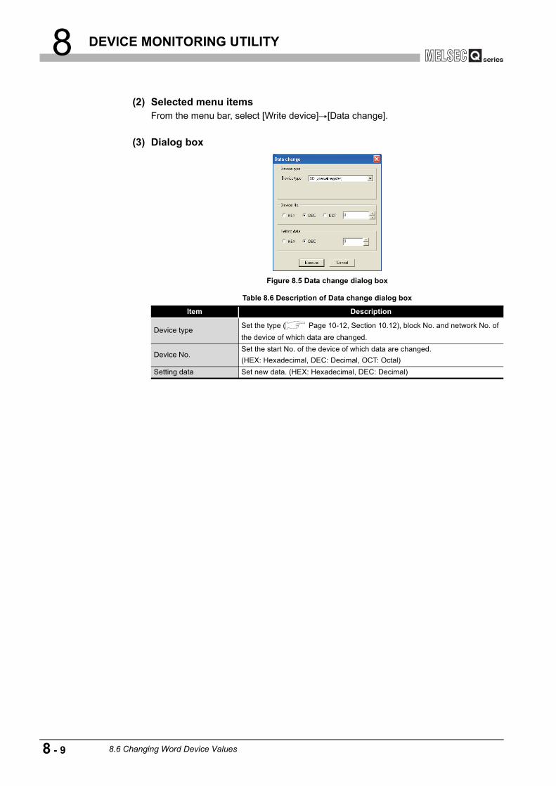
8 DEVICE MONITORING UTILITY
(2) Selected menu itemsFrom the menu bar, select [Write device] [Data change].
(3) Dialog box
Figure 8.5 Data change dialog box
Table 8.6 Description of Data change dialog box
Item Description
Device type Set the type ( Page 10-12, Section 10.12), block No. and network No. of the device of which data are changed.
Device No.Set the start No. of the device of which data are changed.(HEX: Hexadecimal, DEC: Decimal, OCT: Octal)
Setting data Set new data. (HEX: Hexadecimal, DEC: Decimal)
8 - 9 8.6 Changing Word Device Values

8 DEVICE MONITORING UTILITY
1
OV
ERVI
EW
2
INS
TALL
ATIO
N A
ND
U
NIN
STA
LLAT
ION
OF
SO
FTW
ARE
PA
CKA
GE
3
CO
MM
ON
UTI
LITY
O
PER
ATIO
NS
4
C C
ON
TRO
LLE
R
SET
TIN
G U
TILI
TY
5
CC
-LIN
K U
TILI
TY
6
MEL
SEC
NET
/H U
TILI
TY
7
CC
IE C
ON
TRO
L U
TILI
TY
8
DE
VIC
E M
ON
ITO
RIN
G
UTI
LITY
8.7 Continuously Changing Word Device Values
The specified points of word device data can be changed to the specified data.
(1) Precautions for continuous change of word device values
(a) When a utility communication error has occurredWhen a utility communication error has occurred during connection, set the connection target again in the Connection settings so that the communication can be restarted.
(b) CC-Link module monitoringWhen devices have been written to a CC-Link module (specified as own station) where the block data assurance per station is enabled, cyclic data will be automatically refreshed.
Note that this automatic refresh is performed only when devices have been written to the link refresh device ranges (in the buffer memory) that correspond to the stations specified with parameters (station information settings) on the CC-Link master station. (For details, refer to "Slave station offset, size information" (buffer memory address: 3E0H to 5DFH) in the buffer memory list for the CC-link module.)For details of the block data assurance per station, refer to the C Controller Module User's Manual (Hardware Design, Function Explanation).
Note also that the read (receive) area of the link refresh devices (the buffer memory) will not be refreshed when devices have been written.
DANGER Configure safety circuits external to the C Controller module toensure that the entire system operates safely even when a faultoccurs in the external power supply or the C Controller module.For the following controls, configure an interlock circuit in theuser program to ensure that the entire system will alwaysoperate safely.(1) Changing data of the running C Controller module from the
development environment (personal computer) connected(2) Changing the operating status(3) Operating from the development environment (personal
computer)Especially, in the case of a control from an external device to aremote C Controller module, immediate action cannot be takenfor a problem on the C Controller module due to acommunication failure.To prevent this, configure an interlock circuit in the userprogram, and determine corrective actions to be taken betweenthe external device and C Controller module in case of acommunication failure.
Q12DCCPU-V Q06CCPU-V Q06CCPU-V-B
8.7 Continuously Changing Word Device Values 8 - 10
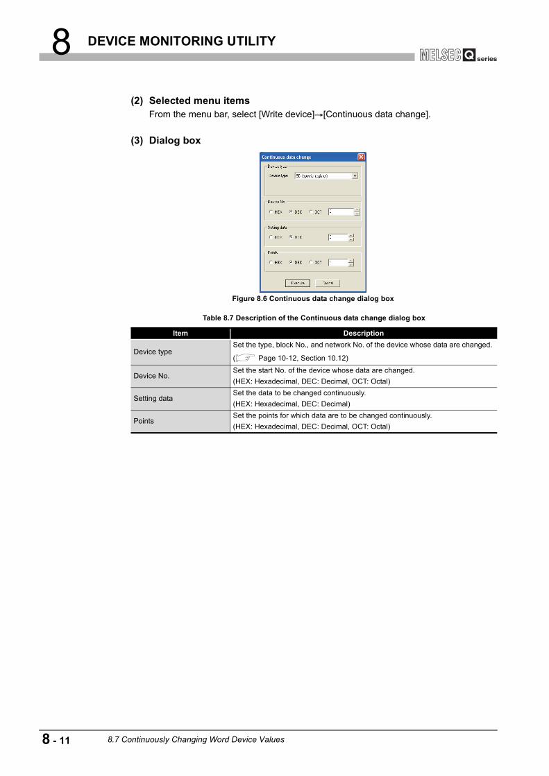
8 DEVICE MONITORING UTILITY
(2) Selected menu itemsFrom the menu bar, select [Write device] [Continuous data change].
(3) Dialog box
Figure 8.6 Continuous data change dialog box
Table 8.7 Description of the Continuous data change dialog box
Item Description
Device typeSet the type, block No., and network No. of the device whose data are changed.
( Page 10-12, Section 10.12)
Device No.Set the start No. of the device whose data are changed.(HEX: Hexadecimal, DEC: Decimal, OCT: Octal)
Setting dataSet the data to be changed continuously.(HEX: Hexadecimal, DEC: Decimal)
PointsSet the points for which data are to be changed continuously.(HEX: Hexadecimal, DEC: Decimal, OCT: Octal)
8 - 11 8.7 Continuously Changing Word Device Values

8 DEVICE MONITORING UTILITY
1
OV
ERVI
EW
2
INS
TALL
ATIO
N A
ND
U
NIN
STA
LLAT
ION
OF
SO
FTW
ARE
PA
CKA
GE
3
CO
MM
ON
UTI
LITY
O
PER
ATIO
NS
4
C C
ON
TRO
LLE
R
SET
TIN
G U
TILI
TY
5
CC
-LIN
K U
TILI
TY
6
MEL
SEC
NET
/H U
TILI
TY
7
CC
IE C
ON
TRO
L U
TILI
TY
8
DE
VIC
E M
ON
ITO
RIN
G
UTI
LITY
8.8 Tuning On and Off Bit Device
The specified bit device can be turned on and off.
(1) Precaution for turning on and off the bit device
(a) When a utility communication error has occurredWhen a utility communication error has occurred during connection, set the connection target again in the Connection settings so that the communication can be restarted.
(b) CC-Link module monitoringWhen devices have been written to a CC-Link module (specified as own station) where the block data assurance per station is enabled, cyclic data will be automatically refreshed.
Note that this automatic refresh is performed only when devices have been written to the link refresh device ranges (in the buffer memory) that correspond to the stations specified with parameters (station information settings) on the CC-Link master station. (For details, refer to "Slave station offset, size information" (buffer memory address: 3E0H to 5DFH) in the buffer memory list for the CC-link module.)For details of the block data assurance per station, refer to the C Controller Module User's Manual (Hardware Design, Function Explanation).
Note also that the read (receive) area of the link refresh devices (the buffer memory) will not be refreshed when devices have been written.
DANGER Configure safety circuits external to the C Controller module toensure that the entire system operates safely even when a faultoccurs in the external power supply or the C Controller module.For the following controls, configure an interlock circuit in theuser program to ensure that the entire system will alwaysoperate safely.(1) Changing data of the running C Controller module from the
development environment (personal computer) connected(2) Changing the operating status(3) Operating from the development environment (personal
computer)Especially, in the case of a control from an external device to aremote C Controller module, immediate action cannot be takenfor a problem on the C Controller module due to acommunication failure.To prevent this, configure an interlock circuit in the userprogram, and determine corrective actions to be taken betweenthe external device and C Controller module in case of acommunication failure.
Q12DCCPU-V Q06CCPU-V Q06CCPU-V-B
8.8 Tuning On and Off Bit Device 8 - 12

8 DEVICE MONITORING UTILITY
(2) Selected menuFrom the menu bar, select [Write device] [Set (Reset) bit device].
(3) Dialog box
Figure 8.7 Set bit device dialog box
Table 8.8 Description of the Set (reset) bit device dialog box
Item Description
Device typeSet the type, block No., and network No. of the device to be turned on or off.
( Page 10-12, Section 10.12)
Device No.Set the bit device No. of the device to be turned on or off.(HEX: Hexadecimal, DEC: Decimal, OCT: Octal)
8 - 13 8.8 Tuning On and Off Bit Device

8 DEVICE MONITORING UTILITY
1
OV
ERVI
EW
2
INS
TALL
ATIO
N A
ND
U
NIN
STA
LLAT
ION
OF
SO
FTW
ARE
PA
CKA
GE
3
CO
MM
ON
UTI
LITY
O
PER
ATIO
NS
4
C C
ON
TRO
LLE
R
SET
TIN
G U
TILI
TY
5
CC
-LIN
K U
TILI
TY
6
MEL
SEC
NET
/H U
TILI
TY
7
CC
IE C
ON
TRO
L U
TILI
TY
8
DE
VIC
E M
ON
ITO
RIN
G
UTI
LITY
8.9 Changing the Display Format
The display format in device monitoring can be changed.Note that the menu options for Batch monitoring and 16-point register monitoring are different.
(1) Selected menuFrom the menu bar, select [Data Format] [Word (Bit) device].
Figure 8.8 Data Format menu
Q12DCCPU-V Q06CCPU-V Q06CCPU-V-B
8.9 Changing the Display Format 8 - 14

8 DEVICE MONITORING UTILITY
8.10 Start and Stop Monitoring
The and buttons of Device monitoring utility are operated on this screen.
The and buttons become operable after completing the Device setting.
(1) OperationMonitoring can be started and stopped by using the and
buttons.
(2) Screen
Figure 8.9 Screen for monitoring start and stop
Table 8.9 Description of buttons
Item Description
button and
button
Starts or stops monitoring."*" flashes in the bottom right of the button during monitoring.These buttons are disabled in the offline status.
Q12DCCPU-V Q06CCPU-V Q06CCPU-V-B
Start monitoring Stop monitoring
Start monitoring Stop monitoring
Start monitoring
Stop monitoring
Start monitoring
Stop monitoring
8 - 15 8.10 Start and Stop Monitoring

8 DEVICE MONITORING UTILITY
1
OV
ERVI
EW
2
INS
TALL
ATIO
N A
ND
U
NIN
STA
LLAT
ION
OF
SO
FTW
ARE
PA
CKA
GE
3
CO
MM
ON
UTI
LITY
O
PER
ATIO
NS
4
C C
ON
TRO
LLE
R
SET
TIN
G U
TILI
TY
5
CC
-LIN
K U
TILI
TY
6
MEL
SEC
NET
/H U
TILI
TY
7
CC
IE C
ON
TRO
L U
TILI
TY
8
DE
VIC
E M
ON
ITO
RIN
G
UTI
LITY
8.11 Numerical Pad
From the menu bar, select [Option] [Numerical pad] so that device values can be entered using the Numerical pad.
1 Click the "Device No." entry field.
2 As the Numerical pad appears, enter a numerical value using buttons.
Then click the button.
3 The numerical value is entered.
Q12DCCPU-V Q06CCPU-V Q06CCPU-V-B
OK
8.11 Numerical Pad 8 - 16

8 DEVICE MONITORING UTILITY
8.12 Other Operations
Double-clicking the device No. on the screen during monitoring enables to change word device data and to turn on and off bit devices.
(1) Precautions for changing the word device and bit device
(a) When a utility communication error has occurredWhen a utility communication error has occurred during connection, set the connection target again in the Connection settings so that the communication can be restarted.
(b) CC-Link module monitoringWhen devices have been written to a CC-Link module (specified as own station) where the block data assurance per station is enabled, cyclic data will be automatically refreshed.
Note that this automatic refresh is performed only when devices have been written to the link refresh device ranges (in the buffer memory) that correspond to the stations specified with parameters (station information settings) on the CC-Link master station. (For details, refer to "Slave station offset, size information" (buffer memory address: 3E0H to 5DFH) in the buffer memory list for the CC-link module.)For details of the block data assurance per station, refer to the C Controller Module User's Manual (Hardware Design, Function Explanation).
Note also that the read (receive) area of the link refresh devices (the buffer memory)will not be refreshed when devices have been written.
DANGER Configure safety circuits external to the C Controller module toensure that the entire system operates safely even when a faultoccurs in the external power supply or the C Controller module.For the following controls, configure an interlock circuit in theuser program to ensure that the entire system will alwaysoperate safely.(1) Changing data of the running C Controller module from the
development environment (personal computer) connected(2) Changing the operating status(3) Operating from the development environment (personal
computer)Especially, in the case of a control from an external device to aremote C Controller module, immediate action cannot be takenfor a problem on the C Controller module due to acommunication failure.To prevent this, configure an interlock circuit in the userprogram, and determine corrective actions to be taken betweenthe external device and C Controller module in case of acommunication failure.
Q12DCCPU-V Q06CCPU-V Q06CCPU-V-B
8 - 17 8.12 Other Operations

8 DEVICE MONITORING UTILITY
1
OV
ERVI
EW
2
INS
TALL
ATIO
N A
ND
U
NIN
STA
LLAT
ION
OF
SO
FTW
ARE
PA
CKA
GE
3
CO
MM
ON
UTI
LITY
O
PER
ATIO
NS
4
C C
ON
TRO
LLE
R
SET
TIN
G U
TILI
TY
5
CC
-LIN
K U
TILI
TY
6
MEL
SEC
NET
/H U
TILI
TY
7
CC
IE C
ON
TRO
L U
TILI
TY
8
DE
VIC
E M
ON
ITO
RIN
G
UTI
LITY
(2) Changing a word deviceThe following describes how to change a word device.
(3) Changing a bit deviceThe following describes how to turn on and off a bit device.Note that this operation is available only when the display format is set to "Vertical".
1 Double-click the word device No. of which value is to be changed.
2 As the dialog box shown on the left appears, enter any given values.
Click the button.
3 To accept the change, click the button in the dialog box shown on the left.
To cancel the change, click the button.
1 Double-click the bit device No. of which value is to be changed.
2 To accept the change, click the button in the dialog box shown on the left.
To cancel the change, click the button.
Execute
Yes
No
Yes
No
8.12 Other Operations 8 - 18

8 DEVICE MONITORING UTILITY
8.13 Precautions
(1) Connection during script file processingConnection from utility to a C Controller module may not be available during processing a script file (while the RUN LED is flashing).If the RUN LED remains flashing, refer to the C Controller Module User's Manual (Hardware Design, Function Explanation) and troubleshoot the problem.
(2) Time required for connection from each utility to the C Controller moduleThe following time is required for the C Controller module to connect to each utility after power-on or reset.
• When executing the script file, "STARTUP.CMD":Upon completion of the RUN LED flashing.
• When not executing the script file, "STARTUP.CMD":Fifteen (15) seconds after completion of start or reset
Do not attempt a connection before the above time has elapsed after completion of power-on or reset.Changing "Priority" to a larger value in the Option tab of C Controller setting utility increases the time after which the C Controller module can be connected.
Q12DCCPU-V Q06CCPU-V Q06CCPU-V-B
8 - 19 8.13 Precautions

9 PROGRAMMING BUS INTERFACE FUNCTION
9
PR
OG
RAM
MIN
G B
US
IN
TER
FAC
E FU
NC
TIO
N
10
PR
OG
RAM
MIN
G U
SIN
G
MEL
SEC
DAT
A L
INK
FU
NC
TIO
NS
11
PR
OG
RAM
MIN
G U
SIN
G
VxW
orks
AP
I FU
NC
TIO
NS
12
SAM
PLE
PR
OG
RAM
S
13
EVEN
T N
UM
BER
LIS
TAP
PEN
DIC
ESIN
DEX
CHAPTER 9 PROGRAMMING BUS INTERFACE FUNCTION
When applying program examples introduced in this chapter into actual systems, fully examine the applicability, and confirm that they will not cause system control problems.
9.1 Outline of Bus Interface Function
To access and control programmable controllers and each module in an user program, functions provided by SW PVC-CCPU must be used.
(1) The following indicates features of bus interface functions.1) Input and output control of I/O modules controlled by the C Controller module.
2) Access to the buffer memories of intelligent function modules controlled by the C Controller module.(X/Y access, buffer memory access, and wait for interrupt event from a intelligent function module/QI60 are available)
3) Linkage between the programmable controller CPU and the Motion CPU that are in the same system as the C Controller module.
4) Message exchange with the following modules or personal computers via CC-Link IE controller network module(s) or MELSECNET/H module(s) controlled by the C Controller module.
• C Controller module (another station) • Programmable controller CPU (another station) • Personal computer equipped with MELSECNET/H board (only via
MELSECNET/H module(s))
5) Access to link devices of the CC-Link IE controller network module or MELSECNET/H module controlled by the C Controller module.
6) Start of a routine from the user watchdog timer error interrupt.
7) Remote RUN/STOP/PAUSE control of the C Controller module.
8) Registration of the event log to the event history file.
9) Mounting and unmounting of the CompactFlash card.
10)Shutdown of the standard ROM.
11)Setting and reading of the clock data.
12)Writing data to or reading data from the battery-backed-up RAM
Q12DCCPU-V Q06CCPU-V Q06CCPU-V-B
Q12DCCPU-V Q06CCPU-V Q06CCPU-V-B
9.1 Outline of Bus Interface Function 9 - 1

9 PROGRAMMING BUS INTERFACE FUNCTION
The system illustration below represents a system image based on the features described on the previous page.
Figure 9.1 Bus interface function image
Table 9.1 Access targets of bus interface functions
Arrow Access targetNo. given
aboveRemarks
Input module/output module 1)•Input(X): Reading enabled•Output(Y): Reading and writing enabled
Intelligent function module 2) Reading from and writing to buffer memory enabled
Programmable controller CPU/MotionCPU 3)
CC-Link IE controller network module (another station), or MELSECNET/H module (another station)
4)
CC-Link IE controller network module (own station), or MELSECNET/H module(host station)
5)
C Controller module 6) to 12)
The following operations are available.•Remote RUN/STOP/PAUSE•Setting and reading clock data•Reading from and writing to battery-backed-up RAM.
4)3)
1) 2)5)
I/O module
C Controller module
Motion CPU
Programmable controller CPU
Intelligent function module
Programmable controller CPU
CC-Link IE controller network module or
MELSECNET/H module
CC-Link IE controller network or
MELSECNET/H
CC-Link module
6) to 12)
9 - 2 9.1 Outline of Bus Interface Function

9 PROGRAMMING BUS INTERFACE FUNCTION
9
PR
OG
RAM
MIN
G B
US
IN
TER
FAC
E FU
NC
TIO
N
10
PR
OG
RAM
MIN
G U
SIN
G
MEL
SEC
DAT
A L
INK
FU
NC
TIO
NS
11
PR
OG
RAM
MIN
G U
SIN
G
VxW
orks
AP
I FU
NC
TIO
NS
12
SAM
PLE
PR
OG
RAM
S
13
EVEN
T N
UM
BER
LIS
TAP
PEN
DIC
ESIN
DEX
9.2 Bus Interface Function List
(1) Bus interface function list
: Available, : N/A
(To the next page)
Table 9.2 Bus interface function list
1)Q12DCCPU-V 2)Q06CCPU-V 3)Q06CCPU-V-B
Category Function name FunctionAvailability
1) 2) 3)
Open/closeQBF_Open Opens a bus.QBF_Close Closes a bus.
I/O access
QBF_X_In_BitEx Reads a single point in the input signal (X).QBF_X_In_WordEx Reads input signal (X) in 1-word units.QBF_Y_Out_BitEx Outputs a single point in the output signal (Y).QBF_Y_Out_WordEx Outputs output signal (Y) in 1-word units.QBF_Y_In_BitEx Reads a single point in the output signal (Y).QBF_Y_In_WordEx Reads output signal (Y) in 1-word units.
CPU shared memory/buffer memory access
QBF_ToBufWrites data to the CPU shared memory of the specified module and the buffer memory of the intelligent function module (To instruction).
QBF_FromBufReads data from the CPU shared memory of the specified module and the buffer memory of the intelligent function module (From instruction).
Link device refresh
QBF_RefreshLinkDevice Refreshes the CC-Link module link device.
Link device access
QBF_WriteLinkDeviceWrites data to link devices of a CC-Link IE controller network module (own station) or MELSECNET/H module (own station).
QBF_ReadLinkDeviceReads data from link devices of a CC-Link IE controller network module (own station) or MELSECNET/H module (own station).
Message communication
QBF_SEND
Sends messages to another station via CC-Link IE controller network module or MELSECNET/H module.(Equivalent to SEND instruction of CC-Link IE controller network module or MELSECNET/H module.)
QBF_RECV
Receives messages from another station via CC-Link IE controller network module or MELSECNET/H module.(Equivalent to RECV instruction of CC-Link IE controller network module or MELSECNET/H module.)
Acquisition of module information
QBF_UnitInfo Reads module configuration information.
WDT control
QBF_StartWDT Sets an interval of WDT and starts up the user WDT.QBF_ResetWDT Resets the user WDT.QBF_StopWDT Stops the user WDT.QBF_EntryWDTInt Registers a routine for the user WDT error interrupt.
Q12DCCPU-V Q06CCPU-V Q06CCPU-V-B
9.2 Bus Interface Function List 9 - 3
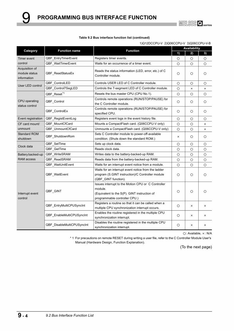
9 PROGRAMMING BUS INTERFACE FUNCTION
: Available, : N/A * 1 For precautions on remote RESET during writing a user file, refer to the C Controller Module User's
Manual (Hardware Design, Function Explanation).(To the next page)
Table 9.2 Bus interface function list (continued)
1)Q12DCCPU-V 2)Q06CCPU-V 3)Q06CCPU-V-B
Category Function name FunctionAvailability
1) 2) 3)Timer event control
QBF_EntryTimerEvent Registers timer events.
QBF_WaitTimerEvent Waits for an occurrence of a timer event.Acquisition of module status information
QBF_ReadStatusExReads the status information (LED, error, etc.) of C Controller module.
User LED controlQBF_ControlLED Controls USER LED of C Controller module.
QBF_Control7SegLED Controls the 7-segment LED of C Controller module.
CPU operating status control
QBF_Reset*1 Resets the bus master CPU (CPU No.1).
QBF_ControlControls remote operations (RUN/STOP/PAUSE) for the C Controller module.
QBF_ControlExControls remote operations (RUN/STOP/PAUSE) for specified CPU.
Event registration QBF_RegistEventLog Registers event logs in the event history file.
CF card mount/unmount
QBF_MountCfCard Mounts a CompactFlash card. (Q06CCPU-V only)
QBF_UnmountCfCard Unmounts a CompactFlash card. (Q06CCPU-V only)Standard ROM shutdown
QBF_ShutdownRomSets C Controller module to power-off-available condition. (Shuts down the standard ROM.)
Clock dataQBF_SetTime Sets up clock data.
QBF_GetTime Reads clock data.
Battery backed-up RAM access
QBF_WriteSRAM Writes data to the battery-backed-up RAM.
QBF_ReadSRAM Reads data from the battery-backed-up RAM.
Interrupt event control
QBF_WaitUnitEvent Waits for an interrupt event notice from a module.
QBF_WaitEventWaits for an interrupt event notice from the ladder program (S.GINT instruction)/C Controller module (QBF_GINT function).
QBF_GINT
Issues interrupt to the Motion CPU or C Controller module.(Equivalent to the S(P). GINT instruction of programmable controller CPU.)
QBF_EntryMultiCPUSyncIntRegisters a routine so that it can be called when a multiple CPU synchronization interrupt occurs.
QBF_EnableMultiCPUSyncIntEnables the routine registered in the multiple CPU synchronization interrupt.
QBF_DisableMultiCPUSyncIntDisables the routine registered in the multiple CPU synchronization interrupt.
9 - 4 9.2 Bus Interface Function List

9 PROGRAMMING BUS INTERFACE FUNCTION
9
PR
OG
RAM
MIN
G B
US
IN
TER
FAC
E FU
NC
TIO
N
10
PR
OG
RAM
MIN
G U
SIN
G
MEL
SEC
DAT
A L
INK
FU
NC
TIO
NS
11
PR
OG
RAM
MIN
G U
SIN
G
VxW
orks
AP
I FU
NC
TIO
NS
12
SAM
PLE
PR
OG
RAM
S
13
EVEN
T N
UM
BER
LIS
TAP
PEN
DIC
ESIN
DEX
: Available, : N/A
POINTFor details of the bus interface functions, refer to the Bus Interface Function HELP of SW PVC-CCPU.
Table 9.2 Bus interface function list (continued)
1)Q12DCCPU-V 2)Q06CCPU-V 3)Q06CCPU-V-B
Category Function name FunctionAvailability
1) 2) 3)Ladder program control
QBF_ControlProgram Controls execution type of a ladder program.
Motion CPU control (program start)
QBF_MotionSFCSRequests to start the specified Motion SFC program.(Equivalent to S(P).SFCS instruction of programmable controller CPU.)
Motion CPU control (operations)
QBF_MotionSVSTRequests to start the specified servo program.(Equivalent to S(P).SVST instruction of programmable controller CPU.)
QBF_MotionCHGA
Requests to change the current value of the specified axis.(Equivalent to S(P).CHGA instruction of programmable controller CPU.)
QBF_MotionCHGVRequests to change the speed of the specified axis.(Equivalent to S(P).CHGV instruction of programmable controller CPU.)
QBF_MotionCHGT
Requests to change the torque limit value of the specified axis.(Equivalent to S(P).CHGT instruction of programmable controller CPU.)
Motion device access
QBF_MotionDDWRWrites data to the Motion CPU devices.(Equivalent to S(P).DDWR instruction or D(P).DDWR instruction of programmable controller CPU.)
QBF_MotionDDRDReads data from the Motion CPU devices.(Equivalent to S(P).DDRD instruction or D(P).DDRD instruction of programmable controller CPU.)
9.2 Bus Interface Function List 9 - 5
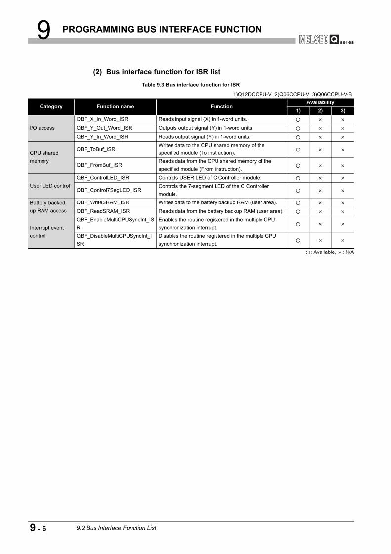
9 PROGRAMMING BUS INTERFACE FUNCTION
(2) Bus interface function for ISR list
: Available, : N/A
Table 9.3 Bus interface function for ISR
1)Q12DCCPU-V 2)Q06CCPU-V 3)Q06CCPU-V-B
Category Function name FunctionAvailability
1) 2) 3)
I/O access
QBF_X_In_Word_ISR Reads input signal (X) in 1-word units.
QBF_Y_Out_Word_ISR Outputs output signal (Y) in 1-word units.
QBF_Y_In_Word_ISR Reads output signal (Y) in 1-word units.
CPU shared memory
QBF_ToBuf_ISRWrites data to the CPU shared memory of the specified module (To instruction).
QBF_FromBuf_ISRReads data from the CPU shared memory of the specified module (From instruction).
User LED controlQBF_ControlLED_ISR Controls USER LED of C Controller module.
QBF_Control7SegLED_ISRControls the 7-segment LED of the C Controller module.
Battery-backed-up RAM access
QBF_WriteSRAM_ISR Writes data to the battery backup RAM (user area).
QBF_ReadSRAM_ISR Reads data from the battery backup RAM (user area).
Interrupt event control
QBF_EnableMultiCPUSyncInt_ISR
Enables the routine registered in the multiple CPU synchronization interrupt.
QBF_DisableMultiCPUSyncInt_ISR
Disables the routine registered in the multiple CPU synchronization interrupt.
9 - 6 9.2 Bus Interface Function List

9 PROGRAMMING BUS INTERFACE FUNCTION
9
PR
OG
RAM
MIN
G B
US
IN
TER
FAC
E FU
NC
TIO
N
10
PR
OG
RAM
MIN
G U
SIN
G
MEL
SEC
DAT
A L
INK
FU
NC
TIO
NS
11
PR
OG
RAM
MIN
G U
SIN
G
VxW
orks
AP
I FU
NC
TIO
NS
12
SAM
PLE
PR
OG
RAM
S
13
EVEN
T N
UM
BER
LIS
TAP
PEN
DIC
ESIN
DEX
9.3 Programming Procedure
This section provides the procedure for programming using the bus interface functions or MELSEC data link functions.
Figure 9.2 Programming procedure
Q12DCCPU-V Q06CCPU-V Q06CCPU-V-B
No
Yes
Complete the settings of a C Controller module.
Check that the image file in the system memory of the
development environment (personal computer)
matches with that of the C Controller module.
Install Workbench or Tornado into the development
environment (personal computer).
Activate Workbench or Tornado on the development
environment (personal computer), and create a
project of the user program.
Is debugging completed?
End
Start
Complete the settings for bus interface functions and
MELSEC data link functions.
Create an user program using the bus interface
functions and MELSEC data link functions.
Debug the user program with Workbench or Tornado
Write the user program created into the standard RAM,
standard ROM, or CompactFlash card.
Create the script file "STARTUP.CMD", and write it into
the standard RAM, standard ROM, or CompactFlash
card.
For the Q12DCCPU-V, back up the file in the standard
RAM since the file may be cleared when the battery life
has expired.
Error codes of bus interface
functions and MELSEC
data link functions
Manual for Workbench or Tornado
C Controller Module User's Manual
(Hardware Design, Function Explanation)
Page 9-30, Section 9.7
Page 9-8, Section 9.4
Page 9-8, Section 9.4
Page 9-22, Section 9.5, Page 9-25, Section 9.6, Page 10-5, Section 10.5, Page 10-9, Section 10.6
HELP for each function
Page 9-45, Section 9.8
Page 9-50, Section 9.9
Page 9-30, Section 9.7
Page 9-45, Section 9.8, Page 12-1, CHAPTER 12
9.3 Programming Procedure 9 - 7

9 PROGRAMMING BUS INTERFACE FUNCTION
9.4 Creating and Compiling a New Project of User Program
9.4.1 For the Q12DCCPU-V
This section explains: • How to create a new project ( Page 9-8, Section 9.4 (1)) • How to compile ( Page 9-12, Section 9.4 (2)) • How to check the endian format (memory layout) of the execution file ( Page
9-15, Section 9.4 (3))
(1) How to create a new project
1 Select [File] [New] [VxWorks Downloadable Kernel Module Project] from the menu bar.
2 Enter a project name in "Project name" and click the button.
3 Click the button. (No setting is necessary.)
(To the next page)
Q12DCCPU-V Q06CCPU-V Q06CCPU-V-B
Next>
Next>
9 - 8 9.4 Creating and Compiling a New Project of User Program9.4.1 For the Q12DCCPU-V

9 PROGRAMMING BUS INTERFACE FUNCTION
9
PR
OG
RAM
MIN
G B
US
IN
TER
FAC
E FU
NC
TIO
N
10
PR
OG
RAM
MIN
G U
SIN
G
MEL
SEC
DAT
A L
INK
FU
NC
TIO
NS
11
PR
OG
RAM
MIN
G U
SIN
G
VxW
orks
AP
I FU
NC
TIO
NS
12
SAM
PLE
PR
OG
RAM
S
13
EVEN
T N
UM
BER
LIS
TAP
PEN
DIC
ESIN
DEX
(From the previous page)
4 Click the button. (No setting is necessary.)
5 Select "SH7750gnule" and click the button.
To set the release mode, deselect "Debug Mode".
(To the next page)
Next>
Finish
REFERENCE
9.4 Creating and Compiling a New Project of User Program9.4.1 For the Q12DCCPU-V
9 - 9

9 PROGRAMMING BUS INTERFACE FUNCTION
(From the previous page)
6 Right-click on the created project on the "Project Navigator" window and select [Properties] from the menu.
7 Open the <<Build Paths>> tab by selecting "Build Properties" in the tree on the left side of the screen.Add the settings of the include files for each function to "Include paths:" and click the button.
Use "/" for separating characters of the directory. "\" cannot be used. Add "-IC:/MELSEC/CCPU/DVx/Include" to the setting of the include file. (When SW PVC-CCPU is installed to "C:\MELSEC")
8 Select [File] [New] [File] from the menu bar.
(To the next page)
OK
REFERENCE
9 - 10 9.4 Creating and Compiling a New Project of User Program9.4.1 For the Q12DCCPU-V
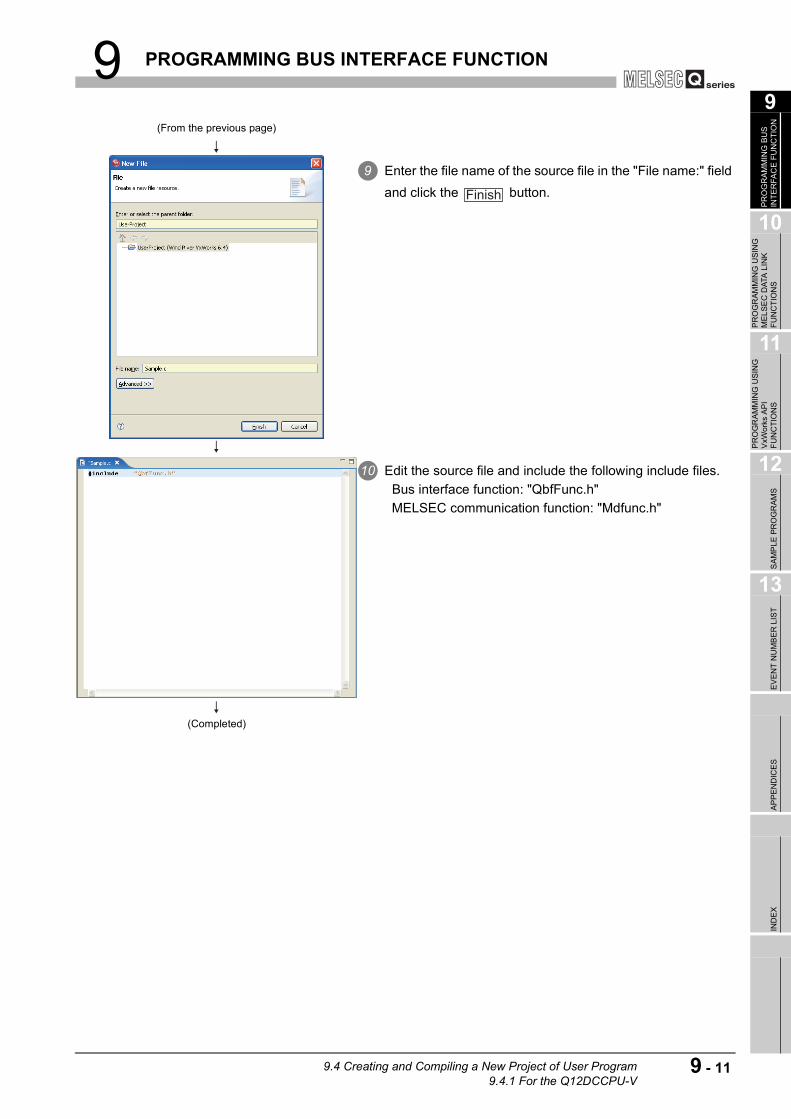
9 PROGRAMMING BUS INTERFACE FUNCTION
9
PR
OG
RAM
MIN
G B
US
IN
TER
FAC
E FU
NC
TIO
N
10
PR
OG
RAM
MIN
G U
SIN
G
MEL
SEC
DAT
A L
INK
FU
NC
TIO
NS
11
PR
OG
RAM
MIN
G U
SIN
G
VxW
orks
AP
I FU
NC
TIO
NS
12
SAM
PLE
PR
OG
RAM
S
13
EVEN
T N
UM
BER
LIS
TAP
PEN
DIC
ESIN
DEX
(From the previous page)
9 Enter the file name of the source file in the "File name:" field and click the button.
10 Edit the source file and include the following include files. Bus interface function: "QbfFunc.h" MELSEC communication function: "Mdfunc.h"
(Completed)
Finish
9.4 Creating and Compiling a New Project of User Program9.4.1 For the Q12DCCPU-V
9 - 11

9 PROGRAMMING BUS INTERFACE FUNCTION
(2) How to compile
POINTThe following operations are required for compiling.
1 Right-click on the source file to be compiled on the "Project Navigator" window and select [Refresh] from the menu.
2 Right-click on the project to be compiled on the "Project Navigator" window and select [Rebuild Project] from the menu.
(To the next page)
9 - 12 9.4 Creating and Compiling a New Project of User Program9.4.1 For the Q12DCCPU-V

9 PROGRAMMING BUS INTERFACE FUNCTION
9
PR
OG
RAM
MIN
G B
US
IN
TER
FAC
E FU
NC
TIO
N
10
PR
OG
RAM
MIN
G U
SIN
G
MEL
SEC
DAT
A L
INK
FU
NC
TIO
NS
11
PR
OG
RAM
MIN
G U
SIN
G
VxW
orks
AP
I FU
NC
TIO
NS
12
SAM
PLE
PR
OG
RAM
S
13
EVEN
T N
UM
BER
LIS
TAP
PEN
DIC
ESIN
DEX
(From the previous page)
3 Click the button.
4 Click the button. (No setting is necessary.)
5 Click the button. (No setting is necessary.)
(To the next page)
Generate Includes
Next>
Next>
9.4 Creating and Compiling a New Project of User Program9.4.1 For the Q12DCCPU-V
9 - 13

9 PROGRAMMING BUS INTERFACE FUNCTION
(From the previous page)
6 Select only "SH7750gnule" to "Modify include search paths for selected build specs:" and click the button.
7 Compiling process appears on the "Build Console" window as shown on the left.
8 When compiling is finished, user programs that are executable in the C Controller module are generated.The user programs are not generated if an error occurred during compiling.The user programs are saved in the following directory under the following file name.Directory: <Project saving directory> \SH7750gnule_DEBUGFile name: <Project name>.out
In the release mode, the user programs are saved in the project saving directory.
(Completed)
Finish
REFERENCE
9 - 14 9.4 Creating and Compiling a New Project of User Program9.4.1 For the Q12DCCPU-V

9 PROGRAMMING BUS INTERFACE FUNCTION
9
PR
OG
RAM
MIN
G B
US
IN
TER
FAC
E FU
NC
TIO
N
10
PR
OG
RAM
MIN
G U
SIN
G
MEL
SEC
DAT
A L
INK
FU
NC
TIO
NS
11
PR
OG
RAM
MIN
G U
SIN
G
VxW
orks
AP
I FU
NC
TIO
NS
12
SAM
PLE
PR
OG
RAM
S
13
EVEN
T N
UM
BER
LIS
TAP
PEN
DIC
ESIN
DEX
(3) How to check the endian format (memory layout) of the execution file
(a) Checking methodThe endian format of the execution file can be checked by the abjdumpsh command of VxWorks.Execute the objdumpsh command on the VxWorks Development Shell from the
development environment (personal computer) as follows:*1
objdumpsh -p Execution file name [Enter]
* 1 Start the VxWorks Development Shell by selecting [Start] [All Programs] [Wind River] [VxWorks 6.4 and General Purpose Technologies] [VxWorks Development Shell].
(b) Checking resultThe checking result is indicated as below.
: Big endian: Little endianelf32-shl
elf32-sh
Execution file name: file format elf32-shl
9.4 Creating and Compiling a New Project of User Program9.4.1 For the Q12DCCPU-V
9 - 15
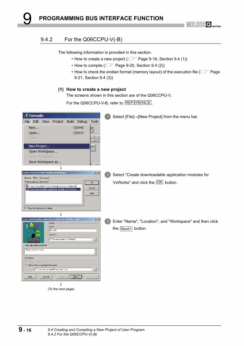
9 PROGRAMMING BUS INTERFACE FUNCTION
9.4.2 For the Q06CCPU-V(-B)
The following information is provided in this section. • How to create a new project ( Page 9-16, Section 9.4 (1)) • How to compile ( Page 9-20, Section 9.4 (2)) • How to check the endian format (memory layout) of the execution file ( Page
9-21, Section 9.4 (3))
(1) How to create a new projectThe screens shown in this section are of the Q06CCPU-V.
For the Q06CCPU-V-B, refer to .
1 Select [File] [New Project] from the menu bar.
2 Select "Create downloadable application modules for
VxWorks" and click the button.
3 Enter "Name", "Location", and "Workspace" and then click
the button.
(To the next page)
REFERENCE
OK
Next>
9 - 16 9.4 Creating and Compiling a New Project of User Program9.4.2 For the Q06CCPU-V(-B)

9 PROGRAMMING BUS INTERFACE FUNCTION
9
PR
OG
RAM
MIN
G B
US
IN
TER
FAC
E FU
NC
TIO
N
10
PR
OG
RAM
MIN
G U
SIN
G
MEL
SEC
DAT
A L
INK
FU
NC
TIO
NS
11
PR
OG
RAM
MIN
G U
SIN
G
VxW
orks
AP
I FU
NC
TIO
NS
12
SAM
PLE
PR
OG
RAM
S
13
EVEN
T N
UM
BER
LIS
TAP
PEN
DIC
ESIN
DEX
(From the previous page)
4 Select "A toolchain" and select the setting corresponding to the modules below in the pull-down menu and click the
button. Q06CCPU-V: SH7750gnule (Little endian)Q06CCPU-V-B: SH7750gnu (Big endian)
This setting defines the endian format. The program does not run if the setting with a different endian format is selected.
5 Check that the settings of "Workspace" and "Tool Chain" are
valid and then click the button.
6 Open the <<Builds>> tab on the "Workspace" window.
(To the next page)
Next>
REFERENCE
Finish
9.4 Creating and Compiling a New Project of User Program9.4.2 For the Q06CCPU-V(-B)
9 - 17

9 PROGRAMMING BUS INTERFACE FUNCTION
(From the previous page)
7 Double-click the ( ) icon to display the lower item.
8 Right-click "SH7750gnule" and select [Properties] from the menu.
For the Q06CCPU-V-B, right-click "SH7750gnu" and select [Properties] from the menu bar.
(To the next page)
REFERENCE
9 - 18 9.4 Creating and Compiling a New Project of User Program9.4.2 For the Q06CCPU-V(-B)
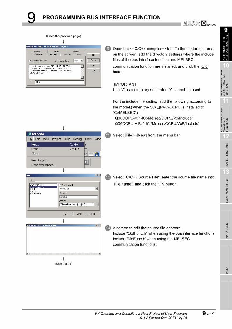
9 PROGRAMMING BUS INTERFACE FUNCTION
9
PR
OG
RAM
MIN
G B
US
IN
TER
FAC
E FU
NC
TIO
N
10
PR
OG
RAM
MIN
G U
SIN
G
MEL
SEC
DAT
A L
INK
FU
NC
TIO
NS
11
PR
OG
RAM
MIN
G U
SIN
G
VxW
orks
AP
I FU
NC
TIO
NS
12
SAM
PLE
PR
OG
RAM
S
13
EVEN
T N
UM
BER
LIS
TAP
PEN
DIC
ESIN
DEX
(From the previous page)
9 Open the <<C/C++ compiler>> tab. To the center text area on the screen, add the directory settings where the include files of the bus interface function and MELSEC
communication function are installed, and click the button.
Use "/" as a directory separator. "\" cannot be used. 10
For the include file setting, add the following according to the model.(When the SW PVC-CCPU is installed to "C:\MELSEC") Q06CCPU-V: "-IC:/Melsec/CCPU/Vx/Include" Q06CCPU-V-B: "-IC:/Melsec/CCPU/VxB/Include"
11 Select [File] [New] from the menu bar.
12 Select "C/C++ Source File", enter the source file name into
"File name", and click the button.
13 A screen to edit the source file appears.Include "QbfFunc.h" when using the bus interface functions.Include "MdFunc.h"when using the MELSEC communication functions.
(Completed)
OK
IMPORTANT
OK
9.4 Creating and Compiling a New Project of User Program9.4.2 For the Q06CCPU-V(-B)
9 - 19

9 PROGRAMMING BUS INTERFACE FUNCTION
(2) How to compile
POINTThe following operations are required for compiling.
1 In the <<Files>> tab on the "Workspace" window, right-click on the source file name to be compiled, and select [Dependencies] from the menu.
2 Check the source file name to be compiled, and click the
button.
3 Select [Build] [Rebuild All] from the menu bar.
(To the next page)
OK
9 - 20 9.4 Creating and Compiling a New Project of User Program9.4.2 For the Q06CCPU-V(-B)

9 PROGRAMMING BUS INTERFACE FUNCTION
9
PR
OG
RAM
MIN
G B
US
IN
TER
FAC
E FU
NC
TIO
N
10
PR
OG
RAM
MIN
G U
SIN
G
MEL
SEC
DAT
A L
INK
FU
NC
TIO
NS
11
PR
OG
RAM
MIN
G U
SIN
G
VxW
orks
AP
I FU
NC
TIO
NS
12
SAM
PLE
PR
OG
RAM
S
13
EVEN
T N
UM
BER
LIS
TAP
PEN
DIC
ESIN
DEX
(3) How to check the endian format (memory layout) of the execution file
(a) Checking methodThe endian format of the execution file can be checked by the objdumpsh command of VxWorks.Execute the objdumpsh command on the command prompt from the development environment (personal computer) as follows:*1
objdumpsh -p Execution file name [Enter]
* 1 To use the objdumpsh command, execute the following file and set environment variable.<Tornado InstallDir> \host\x86-win32\bin\torVars.bat(<Tornado InstallDir> is a folder where Tornado has been installed.)
(b) Checking resultThe checking result is indicated as below.
(From the previous page)
4 Compiling process appears on the screen as shown on the left.
5 When compiling is finished, user programs that can be executed in the C Controller module are generated.
6 The user programs are not generated if an error occurred during compiling.
78 The user programs are saved in the following directory
under the following file name.9 Directory: <Project saving directory\SH7750gnule10 File name: <Project name>.out
For the Q06CCPU-V-B, user programs are generated in the "SH7750gnu" directory.
(Completed)
REFERENCE
: Big endian: Little endianelf32-shl
elf32-sh
Execution file name: file format elf32-shl
9.4 Creating and Compiling a New Project of User Program9.4.2 For the Q06CCPU-V(-B)
9 - 21

9 PROGRAMMING BUS INTERFACE FUNCTION
9.5 Programming Flow for Bus Interface Functions
(1) Programming flowThe following flowchart shows the procedure for programming using the bus interface functions.
Figure 9.3 Bus interface function programming flow
Q12DCCPU-V Q06CCPU-V Q06CCPU-V-B
Register a routine to the user watchdog
timer error interrupt.
(QBF_EntryWDTInt function)
Open the bus. (QBF_Open function)
Task start
Has error occurred?
No (Normal)
Yes (Error occurrence)
Set and start the watchdog timer.
(QBF_StartWDT function)
Control the module by using bus interface
functions.
Acquire the information of the C Controller
module. (QBF_ReadStatusEx function)
Reset the watchdog timer.
(QBF_ResetWDT function)
Set the watchdog timer for the user program
to monitor the hardware, user program
runaway, and processing overtime.
This process can be skipped when
monitoring is not necessary.
*1
Error notification
Task end
Stop the watchdog timer.
(QBF_StopWDT function)
Deregister the routine of the user watchdog
timer error interrupt.
(QBF_EntryWDTInt function)
Close the bus. (QBF_Close function)
*1
*1
*1
*1
9 - 22 9.5 Programming Flow for Bus Interface Functions

9 PROGRAMMING BUS INTERFACE FUNCTION
9
PR
OG
RAM
MIN
G B
US
IN
TER
FAC
E FU
NC
TIO
N
10
PR
OG
RAM
MIN
G U
SIN
G
MEL
SEC
DAT
A L
INK
FU
NC
TIO
NS
11
PR
OG
RAM
MIN
G U
SIN
G
VxW
orks
AP
I FU
NC
TIO
NS
12
SAM
PLE
PR
OG
RAM
S
13
EVEN
T N
UM
BER
LIS
TAP
PEN
DIC
ESIN
DEX
The following flowchart shows the outline in the case of an user watchdog timer error interrupt.
(2) Precautions for using the bus interface functions
(a) Programming precautions
1) Open/close processingPerform the bus open and close processing (QBF_Open function/QBF_Close functions) only once at the beginning and end of the program respectively.Communication performance will decrease if open/close is repeated at each communication.
2) Simultaneous processing of bus interface functionsBus interface functions are serialized in the C Controller module for processing.When the MELSEC data link function are requested simultaneously in multiple tasks, one of the task starts its processing and the other tasks will have to wait until the processing is complete.
3) User watchdog timer error interruptWhen using the bus interface functions on multiple tasks, register the routine for the user watchdog timer error interrupt from one of the tasks.
4) Clock settingWhen setting the clock of the C Controller module, confirm that both the QBF_WaitEvent and QBF_WaitUnitEvent functions are not in process.
5) Remote STOP/PAUSE and bus interface function execution resultWhen the operation status of the C Controller module is remote STOP or remote PAUSE, the execution result of the following operations by the user program will be STOP/PAUSE error.
• Output (Y) (QBF_Y_OutBitExfunction, QBF_Y_OutWordEx function) • Buffer memory writing (QBF_ToBuf function)
Y output and buffer memory writing can be executed from the <<Module monitoring>> tab of the C Controller setting utility.
6) The sequence program control function (QBF_ControlProgram function) can be executed only to the High Performance model QCPU.
Figure 9.4 User watchdog timer error interrupt programming outline
Interrupt routine start
*2 *2
*2
Access the SRAM data.
(QBF_WriteSRAM/QBF_ReadSRAM function)
Register the event history.
(QBF_RegistEventLog function)
Interrupt routine end
Interrupt routine (Specify "1"(ISR) for the
argument flg of the function since it is
executed from ISR.)
9.5 Programming Flow for Bus Interface Functions 9 - 23

9 PROGRAMMING BUS INTERFACE FUNCTION
(b) Precautions for own station device access via CC-Link moduleWhen accessing via a CC-Link module, create an user program that provides interlocks to enable write to/read from the own station device.Data become effective only when the following conditions are satisfied.
• Module error (Xn0) is off (normal) • Module ready (XnF) is on (operable) • Own data link status (Xn1) is on (in data link)
Write to/read from the own station is terminated normally irrespective of the above conditions.
(c) Precautions for host station device access via MELSECNET/H moduleWhen accessing via MELSECNET/H module, create an user program that provides interlocks to enable writing to/reading from the host station device.Data become valid only when the following conditions are satisfied.
• Module status (SB20) is off (normal) • Baton pass status of host station (SB47) is off (normal) • Data link status of host station (SB49) is off (in data link)
Write to/read from the host station is terminated normally irrespective of the above conditions.
(d) Precautions for own station device access via CC-Link IE controller network moduleWhen accessing via CC-Link IE controller network module, create an user program that provides interlocks to enable write to/read from the own station device.Data become effective only when the following conditions are satisfied.
• Data link status of own station (SB49) is off (in data link) • Data link status (the bit corresponding to the communication targets in SWB0
to B7 which is read from the own station) is off (normal)
Write to/read from the own station is terminated normally irrespective of the above conditions.
9 - 24 9.5 Programming Flow for Bus Interface Functions

9 PROGRAMMING BUS INTERFACE FUNCTION
9
PR
OG
RAM
MIN
G B
US
IN
TER
FAC
E FU
NC
TIO
N
10
PR
OG
RAM
MIN
G U
SIN
G
MEL
SEC
DAT
A L
INK
FU
NC
TIO
NS
11
PR
OG
RAM
MIN
G U
SIN
G
VxW
orks
AP
I FU
NC
TIO
NS
12
SAM
PLE
PR
OG
RAM
S
13
EVEN
T N
UM
BER
LIS
TAP
PEN
DIC
ESIN
DEX
9.6 Precautions for Functions
This section provides precautions for the bus interface function and MELSEC data link function.
(1) Endian format (Memory layout)There are two types of models for the Q06CCPU-V(-B), which are in little endian format (memory layout) and in big endian format.Create user programs in either little or big endian that is appropriate to the model used.(Set the compiler by selecting "A toolchain" when creating a project on Tornado. ( Page 9-16, Section 9.4.2)
(2) Execution type prioritySet the priority of a task for executing the FTP user program as described below.
(a) When access is not made via FTP during user program executionSet the priority of the user program task to 100 or more (100 to 255).If the priority is set within 0 to 99, the system may not operate properly.
(b) When access is made via FTP during user program executionThe actual FTP processing (task) of the C Controller module is performed at the priority of 200.When accessing via FTP during user program execution, perform programming as described below.
• Set the priority of the user program task within 201 to 255. • When setting the priority of the user program task within 100 to 200, insert
wait processing (such as taskDalay) in the user program to enable the actual FTP processing.
(3) User program executionExecute an user program by starting a task from the script file.( Page 9-50, Section 9.9)The system may malfunction if the user program is executed without a task being started.
(4) When communicating from utility while an user program is runningIf a communication from utility may affect the user program, lower the task priority of utility communication than that of the user program.
Q12DCCPU-V Q06CCPU-V Q06CCPU-V-B
9.6 Precautions for Functions 9 - 25

9 PROGRAMMING BUS INTERFACE FUNCTION
(5) To communicate with a target device by Ethernet communication(excluding utility communications)Check the port number being used in the C Controller module by using the VxWorks- standard "inetstatShow" command.Do not use any port number that has already been used. Normal communication may not be available if used.
Execute the "inetstatShow" command as follows:[For the Q12DCCPU-V] Use the Telnet tool.[For the Q06CCPU-V(-B)] Execute from the Tornado Shell.
Example) When using the Telnet tool on the Q12DCCCPU-V
(6) When writing a file from the user program by the Q06CCPU-V(-B)Do not write a file to the standard ROM.Write it to a CompactFlash card, network device (such as FTP/NFS/netDrv driver) file, or RAM disk.For details of network devices and RAM disks, refer to the manual for VxWorks.
(7) CompactFlash card replacementRefer to the C Controller Module User's Manual (Hardware Design, Function Explanation) when replacing the CompactFlash card while the power is on.Close all the files being written if any. (Program example Page 12-1, CHAPTER 12)
Figure 9.5 When using Telnet tool on the Q12DCCPU-V
Port numbers being used
in a C Controller module.
Command execution
9 - 26 9.6 Precautions for Functions

9 PROGRAMMING BUS INTERFACE FUNCTION
9
PR
OG
RAM
MIN
G B
US
IN
TER
FAC
E FU
NC
TIO
N
10
PR
OG
RAM
MIN
G U
SIN
G
MEL
SEC
DAT
A L
INK
FU
NC
TIO
NS
11
PR
OG
RAM
MIN
G U
SIN
G
VxW
orks
AP
I FU
NC
TIO
NS
12
SAM
PLE
PR
OG
RAM
S
13
EVEN
T N
UM
BER
LIS
TAP
PEN
DIC
ESIN
DEX
(8) When the operation status is changed from RUN to STOP/PAUSEWhen the operation status of the C Controller module is changed from RUN to STOP/PAUSE, the user program task does not stop.Use the QBF_Read StatusEx function when splitting the user program processing according to the operation status of the C Controller module.
(9) When an user watchdog timer cannot be resetAn user watchdog timer error occurs when the user watchdog timer cannot be reset due to some reasons such as user program runaway.When an user watchdog timer has occurred, perform the following.
• Increase the WDT time set by the QBF_StartWDT function. • Lower the CPU utilization of tasks that require high utilization.
Or set them not to operate. • Review the user program.
After the above operations, reset the C Controller system.For resetting, refer to the C Controller Module User's Manual (Hardware Design, Function Explanation).
(10)Relationships between Workbench/Tornado and system watchdog timer and user watchdog timerWhen using the following functions on Workbench or Tornado, provide sufficient setting time for the system watchdog timer ( Page 4-30, Section 4.7) and user watchdog timer. ( Page 9-3, Section 9.2)
Since the above functions activate tasks with high CPU utilization, a system watchdog timer error and user watchdog timer error are more likely to occur.
(11)IP address settingThe IP address of the C Controller module cannot be set from the user program.Set it in the <<Online operation>> tab of C Controller setting utility.
Table 9.4 Functions with high CPU utilization
Environment FunctionWorkbench Wind River System Viewer etc.
Tornado•Spy Chart function of Browser•Wind Power tools (WindView etc.)
9.6 Precautions for Functions 9 - 27

9 PROGRAMMING BUS INTERFACE FUNCTION
(12)Power off and reset during writing an user fileData corruption or file system error may occur if the C Controller system is powered of or is reset (including remote RESET) during writing data to the user file in the standard RAM, standard ROM, or CompactFlash card.To power off or reset the C Controller system, perform the following first.
(a) When writing data to a file in the standard RAM or standard ROMClose the file where data are being written. (Program example Page 12-1, CHAPTER 12)
(b) When writing data to a file in a CompactFlash cardClose the file where data are being written, and unmount the CompactFlash card. (Program example Page 12-1, CHAPTER 12)
For halting the CompactFlash card processing, refer to the C Controller Module User's Manual (Hardware Design, Function Explanation)
(13)Login userThe login user settings are cleared and return to default when the C Controller module is powered off or is reset.To retain the login user settings, describe a registration (adding/deleting) of the settings in a script file.
Describe either of the following in the script file.
• Directly describe the login user operation commands (loginUserAdd function or loginUserDelete function).
• Provide a description that starts the user program task for login user operation.For login user settings, refer to the C Controller Module User's Manual (Hardware Design, Function Explanation).
(14)User program created with VxWorks Real Time Process (RTP)Bus interface functions and MELSEC data link functions cannot be used from the user program created with VxWorks Real Time Process (RTP).
9 - 28 9.6 Precautions for Functions

9 PROGRAMMING BUS INTERFACE FUNCTION
9
PR
OG
RAM
MIN
G B
US
IN
TER
FAC
E FU
NC
TIO
N
10
PR
OG
RAM
MIN
G U
SIN
G
MEL
SEC
DAT
A L
INK
FU
NC
TIO
NS
11
PR
OG
RAM
MIN
G U
SIN
G
VxW
orks
AP
I FU
NC
TIO
NS
12
SAM
PLE
PR
OG
RAM
S
13
EVEN
T N
UM
BER
LIS
TAP
PEN
DIC
ESIN
DEX
(15)Functions that can be used in the interrupt routine of the Q12DCCPU-VThe following functions can be used in the interrupt routine of the Q12DCCPU-V.
• Bus interface function for ISR • QBF_RegistEventLog • QBF_WriteSRAM • QBF_ReadSRAM
Do not use bus interface functions other than above or MELSEC data link functions in the interrupt routine. Using those functions may cause OS runaway.When using OS-standard functions, understand the restrictions on Interrupt Service Routine of VxWorks 6.4.For restrictions on Interrupt Service Routine of VxWorks 6.4, refer to VxWorks Kernel Programmer's Guide 6.4.
(16)Functions that can be used in the interrupt routine registered by the QBF_EntryWDTInt function when using the Q06CCPU-V(-B)The following functions can be used in the interrupt routine registered by the QBF_EntryWDTInt function when using the Q06CCPU-V(-B).
• QBF_RegistEventLog • QBF_WriteSRAM • QBF_ReadSRAM
Do not use bus interface functions other than above or MELSEC data link functions in the interrupt routine. Using those functions may cause OS to runaway.When using OS-standard functions, understand the restrictions on Interrupt Service Code of VxWorks 5.4.For restrictions on Interrupt Service Code of VxWorks5.4, refer to VxWorks Kernel Programmer's Guide 5.4.
9.6 Precautions for Functions 9 - 29

9 PROGRAMMING BUS INTERFACE FUNCTION
9.7 Precautions for Program Debugging
9.7.1 For Q12DCCPU-V
(1) Specifying a VxWorks image file and IP addressTo debug the user program, specify the following for Workbench.
• IP address of the C Controller module • The same VxWorks image file as that of the C Controller module
(a) Specifying method
1) Check that the VxWorks image file in the system memory of the development environment (personal computer) is identical with that of the C Controller module.( Page 9-32, Section 9.7.1 (1) (b))
2) Start Workbench.
3) Right-click on the "Target Manager" window.Select [New] [Connection] to open the "New Connection" dialog box.
4) Select "Wind River VxWorks 6.x Target Server Connection" and click the button.
Q12DCCPU-V Q06CCPU-V Q06CCPU-V-B
VxWorks
image fileVxWorks
image file
Must
match !
Development environment
(personal computer) C Controller module
Next>
9 - 30 9.7 Precautions for Program Debugging9.7.1 For Q12DCCPU-V

9 PROGRAMMING BUS INTERFACE FUNCTION
9
PR
OG
RAM
MIN
G B
US
IN
TER
FAC
E FU
NC
TIO
N
10
PR
OG
RAM
MIN
G U
SIN
G
MEL
SEC
DAT
A L
INK
FU
NC
TIO
NS
11
PR
OG
RAM
MIN
G U
SIN
G
VxW
orks
AP
I FU
NC
TIO
NS
12
SAM
PLE
PR
OG
RAM
S
13
EVEN
T N
UM
BER
LIS
TAP
PEN
DIC
ESIN
DEX
5) Set "Backend settings" as follows.
6) Select the "File" radio button in the "Kernel image" field and click the button.
7) Select "*" in "Files of type" to select the VxWorks image file and click the
button.
For the folder where the VxWorks image file is stored, refer to the following. Page 9-32, "9.7 (1) (b) VxWorks image file"
Table 9.5 Backend settings
Item ValueBackend: wdbrpcCpu: SH-4A
Target name / IP address:192.168.3.3(If the IP address of the C Controller module has been changed, enter the latest one.)
Port: " " blank
Browse
Finish
9.7 Precautions for Program Debugging9.7.1 For Q12DCCPU-V
9 - 31

9 PROGRAMMING BUS INTERFACE FUNCTION
(b) VxWorks image file
1) VxWorks image file storage locationWhen SW PVC-CCPU has been installed to "C:\MELSEC", the VxWorks image file corresponding to the following models is stored.
* 1 XXXXX: First five digits of the serial No. of the C Controller moduleY : Function version of the C Controller moduleFor the checking method of the serial No. and function version, refer to the C Controller Module User's Manual (Hardware Design, Function Explanation).
2) When VxWorks image files are not identicalWhen the VxWorks image file of the development environment (personal computer) is not identical with that of the C Controller module, copy the image file from the C Controller module to the development environment (personal computer) via FTP. ( Page 9-45, Section 9.8)The Image file of the C Controller module is stored in the system drive (/SYSTEMROM/OS_IMAGEFILE).
POINTWhen the VxWorks image files in the C Controller module and in Workbench are not identical, a system watchdog timer error may occur in the C Controller module.In addition, debugging cannot be performed normally.
Remark
For other debugging methods, refer to the manual for Workbench.
Table 9.6 VxWorks image file storage location
Model FileQ12DCCPU-V C:\MELSEC\CCPU\DVx\Tools\Q12DCCPU-V_XXXXX-Y*1
9 - 32 9.7 Precautions for Program Debugging9.7.1 For Q12DCCPU-V

9 PROGRAMMING BUS INTERFACE FUNCTION
9
PR
OG
RAM
MIN
G B
US
IN
TER
FAC
E FU
NC
TIO
N
10
PR
OG
RAM
MIN
G U
SIN
G
MEL
SEC
DAT
A L
INK
FU
NC
TIO
NS
11
PR
OG
RAM
MIN
G U
SIN
G
VxW
orks
AP
I FU
NC
TIO
NS
12
SAM
PLE
PR
OG
RAM
S
13
EVEN
T N
UM
BER
LIS
TAP
PEN
DIC
ESIN
DEX
(2) Precautions for Telnet connectionIf the line is disconnected during use of Telnet, it cannot be reconnected until TCP connection including the Telnet on the C Controller module side is timed out.If this occurs, reconnect it after timeout.
The timeout time for the C Controller module side Telnet (TCP) connection can be changed by setting the values in the calculation formula by the following setting methods.
[Calculation formula]Timeout time is determined by the following calculation formula.
* 1 The number of retries cannot be changed.
[Setting method]The following explains how to set the initial value to 30 seconds.
• Setting while the C Controller module is in operation
• Setting at the timing of starting C Controller module
Timeout time = net.inet.tcp.keepidle
+ (net.inet.tcp.keepintvl 8 (Retry count)*1) [ms]
Default value of the C Controller module: 30000 (30 sec.) Default value of VxWorks: 7800000 (2 hr. 10 min.)
net.inet.tcp.keepidle: Time from line disconnection to the first retry (ms) Initial value for C Controller module: 22000 Initial value for VxWorks: 7200000
net.inet.tcp.keepintvl: Retry interval (ms) Initial value for C Controller module: 1000 Initial value for VxWorks: 75000
1) Connect the line to the C Controller module with the Telnet tool.2) Execute the following two Sysct1() commands with the Telnet tool to set the
timeout time to the initial value.Sysctl("net.inet.tcp.keepidle = 22000")Sysctl("net.inet.tcp.keepintvl = 1000")
3) Close the Telnet connection.
1) Describe the following two Sysct1() commands on the script file,"STARTUP.CMD".
Sysctl("net.inet.tcp.keepidle = 22000")Sysctl("net.inet.tcp.keepintvl = 1000")
2) Write the above script file, "STARTUP.CMD" to a CompactFlash card, andinsert it into the C Controller module.
3) Upon start of the C Controller module, the timeout time is set to the initialvalue.
9.7 Precautions for Program Debugging9.7.1 For Q12DCCPU-V
9 - 33

9 PROGRAMMING BUS INTERFACE FUNCTION
(3) Precautions for executing a Shell command from Workbench Shell or the Telnet tool
1) When executing a Shell command from Workbench ShellWhen executing a Shell command from Workbench Shell, pay attention to the following since the entered Shell commands operate on the task of priority 1 in the C Controller module.
• Some commands (example: a command that occupies CPU processing) may cause a system error or stop (such as a system watchdog timer error).Pay full attention when entering it.
• Some commands (example: the status-indicating Show command) may disable an interrupt for a long time.During the time, processing called from an interrupt routine (example: bus interface functions for ISR) is not executed.Interrupts that are expected to occur at fixed intervals, such as multiple CPU synchronous interrupt, may delay. When executing a command, pay attention to the above.
A VxWorks message may appear on Shell during connecting from Shell to the C Controller module.For messages of VxWorks, refer to the manual for VxWorks or Workbench.
2) The number of Telnet tools connectable at the same timeMake one to one connection between the Telnet tool and the C Controller module.Connection cannot be made from multiple Telnet tools to the same C Controller module.When exchanging the Telnet tool with another, first close the connection with the currently used Telnet tool, and then connect the line to the C Controller module from another Telnet tool.
9 - 34 9.7 Precautions for Program Debugging9.7.1 For Q12DCCPU-V

9 PROGRAMMING BUS INTERFACE FUNCTION
9
PR
OG
RAM
MIN
G B
US
IN
TER
FAC
E FU
NC
TIO
N
10
PR
OG
RAM
MIN
G U
SIN
G
MEL
SEC
DAT
A L
INK
FU
NC
TIO
NS
11
PR
OG
RAM
MIN
G U
SIN
G
VxW
orks
AP
I FU
NC
TIO
NS
12
SAM
PLE
PR
OG
RAM
S
13
EVEN
T N
UM
BER
LIS
TAP
PEN
DIC
ESIN
DEX
3) Priority of Shell commands executed from the Telnet toolThe Shell commands entered by the Telnet tool of the development environment (personal computer) operate on the task of priority 1 in the C Controller module.Pay full attention to the command when entering it.
When using a Shell command, pay attention to the following. • Some commands (example: a command that occupies CPU processing)
may cause a system error or stop (such as a system watchdog timer error).
• Some commands (example: the status-indicating Show command) may disable an interrupt for a long time.During the time, processing called from an interrupt routine (example: bus interface functions for ISR) is not executed.Interrupts that are expected to occur at fixed intervals, such as multiple CPU synchronous interrupt, may delay. When executing a command, pay attention to the above.
A VxWorks message may appear on the Telnet tool screen during a Telnet connection to the C Controller module.For messages of VxWorks, refer to the manual for VxWorks or Workbench.
4) Execution of VxWorks reboot commandDo not reboot VxWorks by executing the reboot function or pressing the CTRL + X keys.If VxWorks is rebooted, the C Controller module does not start properly.Reset it in the C Controller module.For resetting, refer to the C Controller Module User's Manual (Hardware Design, Function Explanation).
5) Execution of command without argument specifiedIf a command that requires an argument is executed without any argument specified, 0 is substituted for the argument. A system error or stop (such as a system watchdog timer error) may occur in the C Controller module depending on the command (example: command that occupies CPU processing).Before executing a command, confirm the specifications and specified argument of the command.
• Example)Do not execute the "close" command without an argument. If executed, the resource reserved in the VxWorks system will be closed.
9.7 Precautions for Program Debugging9.7.1 For Q12DCCPU-V
9 - 35

9 PROGRAMMING BUS INTERFACE FUNCTION
(4) Precautions for remote debugging from Workbench
(a) When downloading by specifying the user program from WorkbenchA system error or stop (such as a system watchdog timer error) may occur in the C Controller module during downloading if the program is too large.When a system error or stop (such as a system watchdog timer error) has occurred, take either of the following measures.
• Increase the value of "WDT (watchdog timer) setting" on the System settings tab of the C Controller setting utility.
• Load the program in the C Controller module before debugging.
An interrupt to the C Controller module may be disabled during remote debugging.During the time, processing called from an interrupt routine (example: bus interface functions for ISR) is not executed.Interrupts that are expected to occur at fixed intervals, such as multiple CPU synchronous interrupt, may delay. For remote debugging from Workbench, pay attention to the above.
(b) When restarting the C Controller moduleBefore restarting the C Controller module, disconnect the connection with Workbench.Failure to do so may cause an error in the C Controller module.
9 - 36 9.7 Precautions for Program Debugging9.7.1 For Q12DCCPU-V

9 PROGRAMMING BUS INTERFACE FUNCTION
9
PR
OG
RAM
MIN
G B
US
IN
TER
FAC
E FU
NC
TIO
N
10
PR
OG
RAM
MIN
G U
SIN
G
MEL
SEC
DAT
A L
INK
FU
NC
TIO
NS
11
PR
OG
RAM
MIN
G U
SIN
G
VxW
orks
AP
I FU
NC
TIO
NS
12
SAM
PLE
PR
OG
RAM
S
13
EVEN
T N
UM
BER
LIS
TAP
PEN
DIC
ESIN
DEX
9.7.2 For the Q06CCPU-V(-B)
(1) Specifying a VxWorks image fileTo debug the user program, specify the same VxWorks image file as that of the C Controller module for Tornado.
(a) Specifying method of VxWorks image file
1) Check that the VxWorks image file in the system memory of the development environment (personal computer) is identical with that of the C Controller module.( Page 9-38, Section 9.7.2 (1) (b))
2) Start Tornado.
3) Select [Tools] [Target Server] [Configure] to open the "Configure Target Servers" dialog box.
4) Select "Core File and Symbols" in the "Target Server Properties" pull-down menu.
5) Select the "File" radio button and specify the storage location of the VxWorks image file to the text box.When SW PVC-CCPU has been installed to "C:\MELSEC", the VxWorks image file corresponding to either of the following models is stored. ( Page 9-38, Section 9.7.2 (1) (b))
6) Click the button.
Table 9.7 VxWorks image file storage location
Model FileQ06CCPU-V C:\MELSEC\CCPU\Vx\Tools\Q06CCPU-V_XXXXX-YQ06CCPU-V-B C:\MELSEC\CCPU\VxB\Tools\Q06CCPU-V-B_XXXXX-Y
VxWorks
image fileVxWorks
image file
Must
match !
Development environment
(personal computer) C Controller module
OK
9.7 Precautions for Program Debugging9.7.2 For the Q06CCPU-V(-B)
9 - 37

9 PROGRAMMING BUS INTERFACE FUNCTION
The following screen provides an example of specifying the VxWorks image file whose serial No. (first five digits) and the function version is "09051" and "B" respectively.
(b) VxWorks image file
1) VxWorks image file storage locationWhen SW PVC-CCPU has been installed to "C:\MELSEC", the VxWorks image file corresponding to either of the following models is stored.
* 1 XXXXX: First five digits of the serial No. of the C Controller moduleY : Function version of the C Controller moduleFor the checking method of the serial No. and function version, refer to the C Controller Module User's Manual (Hardware Design, Function Explanation).
2) When VxWorks image files are not identicalWhen the VxWorks image file in the development environment (personal computer) is not identical with that of the C Controller module, copy the image file from the C Controller module to the development environment (personal computer) via FTP. ( Page 9-45, Section 9.8)The Image file of the C Controller module is stored in the system drive (/SYSTEMROM/OS_IMAGEFILE).
POINTWhen the VxWorks image files in the C Controller module and in Workbench are not identical, a system watchdog timer error may occur in the C Controller module.In addition, debugging cannot be performed normally.
Figure 9.6 VxWorks image file specification
Table 9.8 VxWorks storage location
Model FileQ06CCPU-V C:\MELSEC\CCPU\Vx\Tools\Q06CCPU-V_XXXXX-Y*1
Q06CCPU-V-B C:\MELSEC\CCPU\VxB\Tools\Q06CCPU-V-B_XXXXX-Y*1
4)
5)
9 - 38 9.7 Precautions for Program Debugging9.7.2 For the Q06CCPU-V(-B)

9 PROGRAMMING BUS INTERFACE FUNCTION
9
PR
OG
RAM
MIN
G B
US
IN
TER
FAC
E FU
NC
TIO
N
10
PR
OG
RAM
MIN
G U
SIN
G
MEL
SEC
DAT
A L
INK
FU
NC
TIO
NS
11
PR
OG
RAM
MIN
G U
SIN
G
VxW
orks
AP
I FU
NC
TIO
NS
12
SAM
PLE
PR
OG
RAM
S
13
EVEN
T N
UM
BER
LIS
TAP
PEN
DIC
ESIN
DEX
Remark
For other debugging methods, refer to the manual for Tornado.
(2) IP address setting of C Controller moduleTo debug the user program by connecting the development environment (personal computer) with the C Controller module in Ethernet, specify the IP address of the C Controller module to Tornado.
1) Start Tornado.
2) Select [Tools] [Target Server] [Configure] from the menu bar to open the "Configure Target Servers" dialog box.
3) Select "Back End" in the "Target Server Properties" pull-down menu.
4) Select "wdbrpc" from the "Available Back Ends" list.
5) In "Target Name/IP Address", set the IP address of the C Controller module to be connected.As the IP address for the C Controller module, set the same value as in "IP address" in the <<Online operation>> tab of the C Controller setting utility.
6) Click the button.
Remark
For other debugging methods, refer to the manual for Tornado.
Figure 9.7 IP address setting of the C Controller module
OK
3)
4)
5)
9.7 Precautions for Program Debugging9.7.2 For the Q06CCPU-V(-B)
9 - 39

9 PROGRAMMING BUS INTERFACE FUNCTION
(3) Symbol information synchronization settingTo debug the user program, the symbol information of the C Controller module and that of the development environment (personal computer) must be synchronized.
1) Start Tornado.
2) Select [Tools] [Target Server] [Configure] to open the "Configure Target Servers" dialog box.
3) Select "Core File and Symbols" in the "Target Server Properties" pull-down menu.
4) Check the "Synchronize Target/Host Symbol Tables" checkbox.
5) Click the button.
6) Select [Tools] [Options] from the menu bar to open the "Options" dialog box, and select the "Tornado Registry" tab.
7) Select the "Remote registry" radio button and specify the IP address or host name of the development environment (personal computer).
8) Click the button.
Figure 9.8 Symbol information synchronization setting
Figure 9.9 Development environment (personal computer) IP address setting
OK
3)
4)
OK
7)
9 - 40 9.7 Precautions for Program Debugging9.7.2 For the Q06CCPU-V(-B)

9 PROGRAMMING BUS INTERFACE FUNCTION
9
PR
OG
RAM
MIN
G B
US
IN
TER
FAC
E FU
NC
TIO
N
10
PR
OG
RAM
MIN
G U
SIN
G
MEL
SEC
DAT
A L
INK
FU
NC
TIO
NS
11
PR
OG
RAM
MIN
G U
SIN
G
VxW
orks
AP
I FU
NC
TIO
NS
12
SAM
PLE
PR
OG
RAM
S
13
EVEN
T N
UM
BER
LIS
TAP
PEN
DIC
ESIN
DEX
Remark
For other debugging methods, refer to the manual for Tornado.
(4) Shell display settingTo display output information (such as printf) from each task of the C Controller module, the following setting is required.Without the following setting, only the output information on the Shell task is displayed.
1) Start Tornado.
2) Select [Tools] [Target Server] [Configure] to open the "Configure Target Servers" dialog box.
3) Select "Console and Redirection" in the "Target Server Properties" pull-down menu.
4) Check the "Redirect Target IO" checkbox.
5) Click the button.
Remark
For other debugging methods, refer to the manual for Tornado.
Figure 9.10 Shell display setting
OK
3)
4)
9.7 Precautions for Program Debugging9.7.2 For the Q06CCPU-V(-B)
9 - 41

9 PROGRAMMING BUS INTERFACE FUNCTION
(5) Precautions for Telnet connectionIf the line is disconnected during use of Telnet, it cannot be reconnected until TCP connection including the Telnet on the C Controller module side is timed out.If this occurs, reconnect it after timeout.
The timeout time for the C Controller module side Telnet (TCP) connection can be changed by setting the values in the calculation formula by the following setting methods.
[Calculation formula]The timeout time is determined by the following calculation formula.
[Setting method]The following explains how to set the initial value to 4 hours and 10 minutes.
• Setting while the C Controller module is in operation
• Setting at the timing of starting C Controller module
Timeout time = tcp_keepidle + (tcp_keepintvl 2 tcp_keepcnt) [s]
Initial value: 15000 (4 hours and 10 minutes)
tcp_keepidle: Time from disconnection to the first retry (s) Initial value: 14400
tcp_keepintvl: Retry interval (in 0.5s units) Initial value: 150
tcp_keepcnt: Number of retries Initial value: 8
1) Connect the line to the C Controller module with the Telnet tool.2) Set the following three external variables with the Telnet tool to change the
timeout time to the initial value.tcp_keepidle = 14400tcp_keepintvl = 150tcp_keepcnt = 8
3) Close the Telnet connection.
1) Describe the following three external variable settings on the script file,"STARTUP.CMD".
tcp_keepidle = 14400tcp_keepintvl = 150tcp_keepcnt = 8
2) Write the above script file, "STARTUP.CMD" to a CompactFlash card, andinsert it into the C Controller module.
3) Upon start of the C Controller module, the timeout time is set to the initialvalue.
9 - 42 9.7 Precautions for Program Debugging9.7.2 For the Q06CCPU-V(-B)

9 PROGRAMMING BUS INTERFACE FUNCTION
9
PR
OG
RAM
MIN
G B
US
IN
TER
FAC
E FU
NC
TIO
N
10
PR
OG
RAM
MIN
G U
SIN
G
MEL
SEC
DAT
A L
INK
FU
NC
TIO
NS
11
PR
OG
RAM
MIN
G U
SIN
G
VxW
orks
AP
I FU
NC
TIO
NS
12
SAM
PLE
PR
OG
RAM
S
13
EVEN
T N
UM
BER
LIS
TAP
PEN
DIC
ESIN
DEX
(6) Precautions for executing Shell commands from Tornado Shell or the Telnet tool
1) When executing the Shell command from Tornado Shell, pay attention to the following since the entered Shell commands operate on the task of priority 1 in the C Controller module.
• Some commands (example: a command that occupies CPU processing) may cause a system error or stop (such as a system watchdog timer error).Pay full attention to the command when entering it.
A VxWorks message may appear on the Telnet tool screen during a Telnet connection to the C Controller module.For messages of VxWorks, refer to the manual for VxWorks or Tornado.
2) The number of Telnet tools connectable at the same timeMake one-to-one connection between the Telnet tool and the C Controller module.Connection cannot be made from multiple Telnet tools to the same C Controller module.When exchanging the Telnet tool with another, first close the connection with the currently used Telnet tool, and then connect the line to the C Controller module from another Telnet tool.
3) Priority of Shell commands executed from the Telnet toolPay attention to the following since the Shell commands entered by the Telnet tool of the development environment (personal computer) operate on the task of priority 2 in the C Controller module.
When using Shell commands, pay attention to the following. • Some commands (example: a command that occupies CPU processing)
may cause a system error or stop (such as a system watchdog timer error).Pay full attention to the command when entering it.
A VxWorks message may appear on the Telnet tool screen during a Telnet connection to the C Controller module.For messages of VxWorks, refer to the manual for VxWorks or Tornado.
9.7 Precautions for Program Debugging9.7.2 For the Q06CCPU-V(-B)
9 - 43

9 PROGRAMMING BUS INTERFACE FUNCTION
4) Execution of VxWorks reboot commandDo not reboot VxWorks by executing the reboot function or pressing the CTRL + X keys.If VxWorks is rebooted, the C Controller module does not start properly. Reset it in the C Controller module.For resetting, refer to the C Controller Module User's Manual (Hardware Design, Function Explanation).
5) Execution of command without argument specifiedIf a command that requires an argument is executed without any argument specified, 0 is substituted for the argument. Some commands may cause a system error or stop (such as a system watchdog timer error) in the C Controller module. Before executing a command, confirm the specifications and specified argument of the command.
• Example)Do not execute the "close" command without the argument specified. If executed, the resource reserved in the VxWorks system will be closed.
9 - 44 9.7 Precautions for Program Debugging9.7.2 For the Q06CCPU-V(-B)

9 PROGRAMMING BUS INTERFACE FUNCTION
9
PR
OG
RAM
MIN
G B
US
IN
TER
FAC
E FU
NC
TIO
N
10
PR
OG
RAM
MIN
G U
SIN
G
MEL
SEC
DAT
A L
INK
FU
NC
TIO
NS
11
PR
OG
RAM
MIN
G U
SIN
G
VxW
orks
AP
I FU
NC
TIO
NS
12
SAM
PLE
PR
OG
RAM
S
13
EVEN
T N
UM
BER
LIS
TAP
PEN
DIC
ESIN
DEX
9.8 Program Registration
To register respective file to the C Controller module, write the file to a standard RAM or standard ROM of the C Controller module or a CompactFlash card.
: Available, : N/A
POINTBefore registering a file to the standard RAM, standard ROM, or a CompactFlash card, close all the tasks running on the C Controller module.
(1) Registration via FTPThis section explains file registration to the C Controller module via FTP.
(a) Drives and operations allowed via FTPThe following table indicates the drive names and operations allowed for registration via FTP.
* 1 This drive name is for the sample program (MakeRAMDisk.c).Do not use "/RAM", "/ROM", "/CF", or "/SYSTEMROM" for a drive name of a RAM disk. The system may not operate properly if any of the above name is used.
Table 9.9 How to write to each drive
Writing method
Program storage location
Standard RAM
Standard ROM
CompactFlash card
RAM disk(When creating
a RAM disk)Registration via FTP
Copy registration from CompactFlash cardCopy registration from development environment (personal computer) to CompactFlash card
Table 9.10 Drives available for FTP
Drive Drive name OperationStandard RAM /RAM Write/read availableStandard ROM /ROM Write/read availableCompactFlash card /CF Write/read availableSystem drive /SYSTEMROM Only read available
RAM disk (When creating a RAM disk) /RAMDISK*1 Write/read available
Q12DCCPU-V Q06CCPU-V Q06CCPU-V-B
9.8 Program Registration 9 - 45

9 PROGRAMMING BUS INTERFACE FUNCTION
(b) Login user when using FTPThe following indicates the login user data (user name, password) when using FTP.
For addition or change of the login user etc. other than above, refer to the C Controller Module User's Manual (Hardware Design, Function Explanation).
(c) Precautions for program registration via FTP
1) Login user settingThe user login setting of the C Controller module is for limiting users and setting operation of the C Controller module. It does not completely prevent illegal access from the outside.
2) When security against illegal access from the outside is neededTake measures at user's discretion when it is necessary to secure the safety of the C Controller system against illegal access from the outside.( C Controller Module User's Manual (Hardware Design, Function Explanation)
3) When registering by overwriting using FTPBefore registering a file of the C Controller module by overwriting using FTP, close the file being opened by an user program.If the registering the file by overwriting without closing them, the registration may fail.
4) Number of FTP tools that are simultaneously connectableUp to 10 FTP tools can be simultaneously connected to the C Controller module.Connection may become unavailable if the FTP tool is repeatedly used since Windows Explorer does not immediately disconnect the connection when terminated.When a connection is not available in Explorer, perform either of the following.
• Terminate Explorer from Windows Task Manager. • Reconnect 200 seconds after terminating Explorer. • Use the FTP tool other than in Explorer.
Table 9.11 Login user defaults
Item ValueUser name "target"Password "password"
9 - 46 9.8 Program Registration
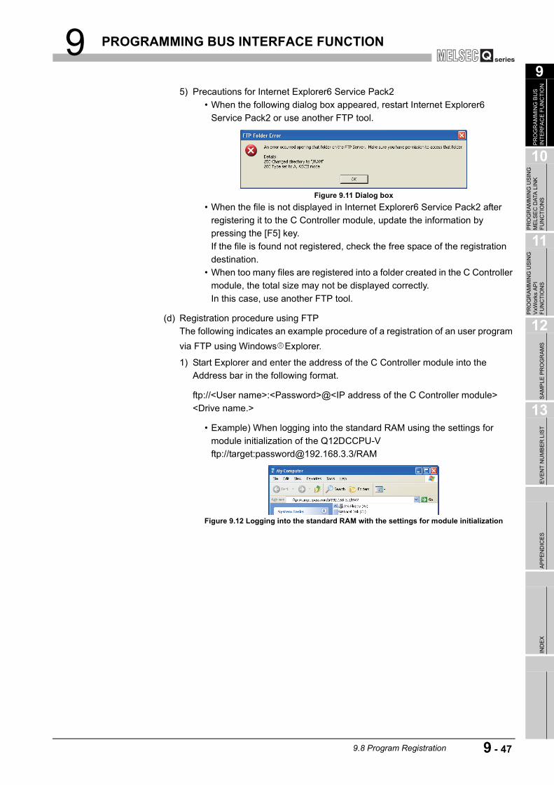
9 PROGRAMMING BUS INTERFACE FUNCTION
9
PR
OG
RAM
MIN
G B
US
IN
TER
FAC
E FU
NC
TIO
N
10
PR
OG
RAM
MIN
G U
SIN
G
MEL
SEC
DAT
A L
INK
FU
NC
TIO
NS
11
PR
OG
RAM
MIN
G U
SIN
G
VxW
orks
AP
I FU
NC
TIO
NS
12
SAM
PLE
PR
OG
RAM
S
13
EVEN
T N
UM
BER
LIS
TAP
PEN
DIC
ESIN
DEX
5) Precautions for Internet Explorer6 Service Pack2 • When the following dialog box appeared, restart Internet Explorer6
Service Pack2 or use another FTP tool.
• When the file is not displayed in Internet Explorer6 Service Pack2 after registering it to the C Controller module, update the information by pressing the [F5] key.If the file is found not registered, check the free space of the registration destination.
• When too many files are registered into a folder created in the C Controller module, the total size may not be displayed correctly.In this case, use another FTP tool.
(d) Registration procedure using FTPThe following indicates an example procedure of a registration of an user program via FTP using Windows Explorer.
1) Start Explorer and enter the address of the C Controller module into the Address bar in the following format.
ftp://<User name>:<Password>@<IP address of the C Controller module> <Drive name.>
• Example) When logging into the standard RAM using the settings for module initialization of the Q12DCCPU-Vftp://target:[email protected]/RAM
Figure 9.11 Dialog box
Figure 9.12 Logging into the standard RAM with the settings for module initialization
9.8 Program Registration 9 - 47

9 PROGRAMMING BUS INTERFACE FUNCTION
2) The screen display after logging in to the C Controller module is as follows.
3) After logging in to the C Controller module, perform write and read just as normal file operations in Explorer.
POINT1. Other than Explorer, registration via FTP is available by Internet Explorer and
the FTP command which is started up from command prompt.(For error messages of Internet Explorer, go to Microsoft Help and Support, enter keyword such as "Internet Explorer" and "FTP", and check the information.)
2. If registration by FTP fails when using Internet Explorer7, use other FTP tools such as Explorer.
Figure 9.13 Connection via FTP
Figure 9.14 File operation
*1*1
Drag & drop to transfer a file.
9 - 48 9.8 Program Registration

9 PROGRAMMING BUS INTERFACE FUNCTION
9
PR
OG
RAM
MIN
G B
US
IN
TER
FAC
E FU
NC
TIO
N
10
PR
OG
RAM
MIN
G U
SIN
G
MEL
SEC
DAT
A L
INK
FU
NC
TIO
NS
11
PR
OG
RAM
MIN
G U
SIN
G
VxW
orks
AP
I FU
NC
TIO
NS
12
SAM
PLE
PR
OG
RAM
S
13
EVEN
T N
UM
BER
LIS
TAP
PEN
DIC
ESIN
DEX
(2) Copy registration from a CompactFlash card to the standard RAMThe following explains copy registration of the files in the CompactFlash card to the standard RAM of the C Controller module.This operation is not available on the Q06CCPU-V(-B).This operation allows to easily register the same user programs to multiple C Controller modules.In the following copy registration procedure, an example with "STARTUP.CMD" is used as a script file for installation into the standard RAM.
(a) Copy registration procedure from CompactFlash card to standard RAM
1) Install the CompactFlash card into the development environment (personal computer) and write the following files to it.
2) Remove CompactFlash card from the development environment (personal computer), and install it in the C Controller module.
3) Power on the C Controller module.
4) The installation script file "STARTUP.CMD" in the CompactFlash card is started and each file in the CompactFlash card is copied to the standard RAM of the C Controller module.
5) When copying is completed, the "sysLedSet" command is executed, and "FF" is displayed in the 7-segment LED.
6) After confirming that "FF" is displayed in the 7-segment LED, power off the C Controller module and remove the CompactFlash card.
7) When the C Controller module is powered on, the script file copied into the standard RAM is started and an user program is executed.
(b) Program example of script file for installation into standard RAM
Table 9.12 Written file list
File name DescriptionSTARTUP.CMD Script file for installation into the standard RAMSTARTUP.RAM Script file to be used in the standard RAM********.out User program to be used in the standard RAM
Figure 9.15 Program example of a script file for installation
copy "/CF/project.out", "/RAM/project.out"
copy "/CF/STARTUP.RAM", "/RAM/STARTUP.CMD"
STARTUP.CMD
sysLedSet(OxFF)
Describe the command "sysLedSet(0xFF)" at the end of the
installation script file for confirmation of the completion of the copy.
The script file for standard RAM "STARTUP.ROM" in the
CompactFlash card is copied as the script file "STARTUP.CMD" of
the standard RAM.
The user program "project.out" in the CompactFlash card is copied as
the user program "project.out" of the standard RAM.
3)
2)
1)
3)
2)
1)
9.8 Program Registration 9 - 49
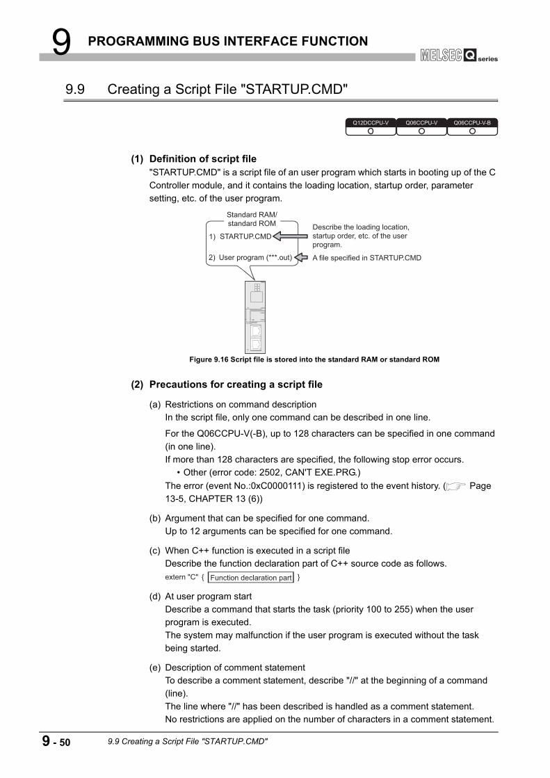
9 PROGRAMMING BUS INTERFACE FUNCTION
9.9 Creating a Script File "STARTUP.CMD"
(1) Definition of script file"STARTUP.CMD" is a script file of an user program which starts in booting up of the C Controller module, and it contains the loading location, startup order, parameter setting, etc. of the user program.
(2) Precautions for creating a script file
(a) Restrictions on command descriptionIn the script file, only one command can be described in one line.
For the Q06CCPU-V(-B), up to 128 characters can be specified in one command (in one line).If more than 128 characters are specified, the following stop error occurs.
• Other (error code: 2502, CAN'T EXE.PRG.)The error (event No.:0xC0000111) is registered to the event history. ( Page 13-5, CHAPTER 13 (6))
(b) Argument that can be specified for one command.Up to 12 arguments can be specified for one command.
(c) When C++ function is executed in a script fileDescribe the function declaration part of C++ source code as follows.
(d) At user program startDescribe a command that starts the task (priority 100 to 255) when the user program is executed.The system may malfunction if the user program is executed without the task being started.
(e) Description of comment statementTo describe a comment statement, describe "//" at the beginning of a command (line).The line where "//" has been described is handled as a comment statement.No restrictions are applied on the number of characters in a comment statement.
Figure 9.16 Script file is stored into the standard RAM or standard ROM
Q12DCCPU-V Q06CCPU-V Q06CCPU-V-B
STARTUP.CMD
Standard RAM/
standard ROM
User program (***.out)
1)
2)
Describe the loading location,
startup order, etc. of the user
program.
A file specified in STARTUP.CMD
extern "C" { }Function declaration part
9 - 50 9.9 Creating a Script File "STARTUP.CMD"

9 PROGRAMMING BUS INTERFACE FUNCTION
9
PR
OG
RAM
MIN
G B
US
IN
TER
FAC
E FU
NC
TIO
N
10
PR
OG
RAM
MIN
G U
SIN
G
MEL
SEC
DAT
A L
INK
FU
NC
TIO
NS
11
PR
OG
RAM
MIN
G U
SIN
G
VxW
orks
AP
I FU
NC
TIO
NS
12
SAM
PLE
PR
OG
RAM
S
13
EVEN
T N
UM
BER
LIS
TAP
PEN
DIC
ESIN
DEX
Remark
1. Depending on the description in the script file, the following operation can be performed from the CompactFlash card to the standard RAM or standard ROM (excluding the Q06CCPU-V-B).
• Copy registration of a program to the standard RAM or standard ROM ( Page 9-45, Section 9.8)
• Standard RAM and standard ROM formatting ( C Controller Module User's Manual (Hardware Design, Function Explanation))
2. Commands described in a script file are identical with those described in the startup script file for VxWorks. ( Manual for VxWorks)
3. The RUN LED of the C Controller module flashes while the script file (command) is in process.
4. For precautions for the user program, refer to the following. Page 9-22, "9.5 Programming Flow for Bus Interface Functions" Page 9-25, "9.6 Precautions for Functions" Page 10-5, "10.5 MELSEC Data Link Function Programming Flow"
In the script file, describe commands used for login user setting (addition/change) and user program task start as necessary.For login user, refer to the C Controller Module User's Manual (Hardware Design, Function Explanation).
6. For the sample program of the script file, refer to the following. Page 12-1, "CHAPTER 12 SAMPLE PROGRAMS"
9.9 Creating a Script File "STARTUP.CMD" 9 - 51

9 PROGRAMMING BUS INTERFACE FUNCTION
(3) Script file storage locationThe script file can be stored into the standard RAM, standard ROM, and CompactFlash card.
(a) Script file storage locationStore the script file in the root directory.
• Standard RAMRoot directory of standard RAM("/RAM")
• Standard ROMRoot directory of standard ROM("/ROM")
• CompactFlash cardRoot directory of CompactFlash card ("/CF")
(b) When a script file is stored into either the standard RAM or standard ROM and CompactFlash cardWhen a script file is stored into either the standard RAM or standard ROM and CompactFlash card, the one in the CompactFlash card is started by priority. (The script file in the standard RAM or standard ROM is ignored.)
For example, the script file used for maintenance can be processed by installing the Compact Flash card with a maintenance script file stored, even when the script file in the standard RAM or standard ROM is used for system operation.
Figure 9.17 Example of the use when script files are stored in both locations
STARTUP.CMD (For system operation)
Install !
Standard RAM/standard ROM
STARTUP.CMD (For maintenance)
CompactFlash card
Script file of CompactFlash card is started with priority!
9 - 52 9.9 Creating a Script File "STARTUP.CMD"

9 PROGRAMMING BUS INTERFACE FUNCTION
9
PR
OG
RAM
MIN
G B
US
IN
TER
FAC
E FU
NC
TIO
N
10
PR
OG
RAM
MIN
G U
SIN
G
MEL
SEC
DAT
A L
INK
FU
NC
TIO
NS
11
PR
OG
RAM
MIN
G U
SIN
G
VxW
orks
AP
I FU
NC
TIO
NS
12
SAM
PLE
PR
OG
RAM
S
13
EVEN
T N
UM
BER
LIS
TAP
PEN
DIC
ESIN
DEX
(4) Example of script file descriptionThe following provides an example of describing the script file to start user programs on the Q12DCCPU-V.
(a) When loading the user program from the script file in the standard RAMThe following is an example of loading an user program ("fileA.out", "fileB.out") in the standard RAM from the script file in the standard RAM.
POINTSince the maximum number of arguments to be specified for one command is 12, up to seven arguments can be given to the function entry specified in taskSpawn (funcB in the above example).The task will not start if eight or more arguments are specified for the function entry specified in task Spawn (funcB in the above example).
Figure 9.18 Example of script file description (loaded from standard RAM)
1 Default: 100 funcA /RAM/DirA/fileA.out
2 taskB 120 5000 funcB /RAM/DirB/fileB.out
ld (1, 0, "/RAM/DirA/fileA.out")
ld (1, 0, "/RAM/DirB/fileB.out")
sp (funcA, 0, 0, 0, 0, 0, 0, 0, 0, 0)
taskSpawn ("taskB", 120, 0, 5000, funcB,10, 0, 0, 0, 0, 0, 0)
1)
2)
3)
4)
/RAM
/DirB
"STARTUP.CMD"
"fileB.out" *2
/DirA "fileA.out" *1
Files in standard RAM
<Stored files>
*1 "funcA" function already included in fileA.out
*2 "funcB" function already included in fileB.out
C Controller module
<Task settings>
Startup order Task name Priority Stack size (byte)
Function name Argument specification File storage location
Default: tN (N=1, 2, ...) Default: 20000 None
Specified (First argument: 10)
<Example of script file description >
1) The "fileA.out" file is loaded from the standard RAM "DirA" directory.
2) The "fileB.out" file is loaded from the standard RAM "DirB" directory.
3) The "funcA" function is generated under the default task name (t1).
4) The "funcB" function is generated under the task name "taskB".
9.9 Creating a Script File "STARTUP.CMD" 9 - 53

9 PROGRAMMING BUS INTERFACE FUNCTION
(b) When loading the user program from the script file in CompactFlash cardThe following provides an example of loading user programs ("fileA.out", "fileB.out") in the standard RAM and CompactFlash card from the script file in the CompactFlash card.
POINTSince the maximum number of arguments to be specified for one command is 12, up to seven arguments can be given to the function entry specified in taskSpawn (funcB in the above example).The task will not start if eight or more arguments are specified for the function entry specified in task Spawn (funcB in the above example).
Figure 9.19 Example of script file description (loaded from CompactFlash card)
ld (1, 0, "/CF/DirA/fileA.out")
ld (1, 0, "/RAM/DirB/fileB.out")
sp (funcA, 0, 0, 0, 0, 0, 0, 0, 0, 0)
taskSpawn ("taskB", 120, 0, 5000, funcB,10, 0, 0, 0, 0, 0, 0)
/RAM
/DirB "fileB.out" *2
/CF "STARTUP.CMD"
/ DirA "fileA.out" *1 *1 "funcA" function already included in fileA.out
*2 "funcB" function already included in fileB.out
1) The "fileA.out" file is loaded from the CompactFlash card "DirA" directory.
2) The "fileB.out" file is loaded from the standard RAM "DirB" directory.
3) The "funcA" function is generated under the default task name (t1).
4) The "funcB" function is generated under the task name "taskB".
<Stored files>
File in standard RAM
C Controller module
<Script file description example>
File in CompactFlash card
1)
2)
3)
4)
1 Default: 100 funcA /CF/DirA/fileA.out
2 taskB 120 5000 funcB /RAM/DirB/fileB.out
<Task settings>
Startup order Task name Priority Stack size (byte)
Function name Argument specification File storage location
Default: tN (N=1, 2, ...) Default: 20000 None
Specified (First argument: 10)
9 - 54 9.9 Creating a Script File "STARTUP.CMD"

9 PROGRAMMING BUS INTERFACE FUNCTION
9
PR
OG
RAM
MIN
G B
US
IN
TER
FAC
E FU
NC
TIO
N
10
PR
OG
RAM
MIN
G U
SIN
G
MEL
SEC
DAT
A L
INK
FU
NC
TIO
NS
11
PR
OG
RAM
MIN
G U
SIN
G
VxW
orks
AP
I FU
NC
TIO
NS
12
SAM
PLE
PR
OG
RAM
S
13
EVEN
T N
UM
BER
LIS
TAP
PEN
DIC
ESIN
DEX
9.10 Device Types for Bus Interface Functions
The device types used for the bus interface functions can be specified either by the code number or device name indicated in this section.
(1) Motion CPU dedicated device typesThe motion CPU dedicated device types can be specified in the argument sDevType of the QBF_MotionDDWR, QBF_MotionDDRD function.
* 1 The device name specification (macro) is defined in the include file "QbfFunc.h" of the bus
interface function. ( Page 9-8, Section 9.4) * 2 For the Q172DCPU and Q173DCPU, L (latch relay) cannot be used. * 3 When SM (special relay) is specified in sDevType, the ulDevNo specification is as follows.
[When using the Q172DCPU or Q173DCPU]0 to 1999 (SM2000 to SM2255 are SM compatibility areas in the Motion CPU other than the Q172DCPU and Q173DCPU.)[When using the Motion CPU other than the Q172DCPU and Q173DCPU]0 and higher (corresponds to M9000 and higher areas in the Motion CPU)
* 4 When SD (special register) is specified in sDevType, the ulDevNo specification is as follows.[When using the Q172DCPU or Q173DCPU]0 to 1999 (SD2000 to SD2255 are SD compatibility areas in the Motion CPU other than the Q172DCPU and Q173DCPU.)[When using the Motion CPU other than the Q172DCPU and Q173DCPU]0 and higher (corresponds to M9000 and higher areas in the Motion CPU)
Table 9.13 Motion CPU dedicated device types
Device type
DeviceCode specification Device name
specification*1Dec. Hex.
1 1H QBFDev_MCPU_X Input (X)2 2H QBFDev_MCPU_Y Output (Y)
3 3H QBFDev_MCPU_L Latch relay (L)*2
4 4H QBFDev_MCPU_M Internal relay (M)
5 5H QBFDev_MCPU_SM Special relay (SM)*3
6 6H QBFDev_MCPU_F Annunciator (F)13 DH QBFDev_MCPU_D Data register (D)
14 EH QBFDev_MCPU_SD Special register (SD)*4
23 17H QBFDev_MCPU_B Link relay (B)24 18H QBFDev_MCPU_W Link register (W)61 3DH QBFDev_MCPU_MR Motion register (#)
Q12DCCPU-V Q06CCPU-V Q06CCPU-V-B
9.10 Device Types for Bus Interface Functions 9 - 55

9 PROGRAMMING BUS INTERFACE FUNCTION
(2) Device types for accessing CC-Link IE controller network modules or MELSECNET/H modulesSpecify the device type for accessing a CC-Link IE controller network module or MELSECNET/H module with the argument QBF_WriteLinkDevice or QBF_ReadLinkDevice function.In the user program, either of the following two link device accessing methods can be selected by specifying the device.
(a) Internal buffer access
* 1 The device name specification (macro) is defined in the include file "QbfFunc.h" of the bus
interface function. ( Page 9-8, Section 9.4)
(b) Direct access
* 1 The device name specification (macro) is defined in the include file "QbfFunc.h" of the bus
interface function. ( Page 9-8, Section 9.4) * 2 Only CC-Link IE controller network modules can access to the areas of LB4000 and higher and
LW4000 and higher.
Table 9.14 Device types for internal buffer access
Device type
DeviceCode specification Device name
specification*1Dec. Hex.
1 1H QBFDev_LXBuf Link input internal buffer (LX buffer)2 2H QBFDev_LYBuf Link output internal buffer (LY buffer)23 17H QBFDev_LBBuf Link relay internal buffer (LB buffer)24 18H QBFDev_LWBuf Link register internal buffer (LW buffer)
Table 9.15 Device types for internal direct access
Device type
DeviceCode specification Device name
specification*1Dec. Hex.
1000 3E8H QBFDev_LX Direct link input (LX)2000 7D0H QBFDev_LY Direct link output (LY)
23000 59D8H QBFDev_LB Direct link relay (LB)*2
24000 5DC0H QBFDev_LW Direct link register (LW)*2
25000 61A8H QBFDev_LSB Direct link special relay (SB)28000 6D60H QBFDev_LSW Direct link special register (SW)
9 - 56 9.10 Device Types for Bus Interface Functions
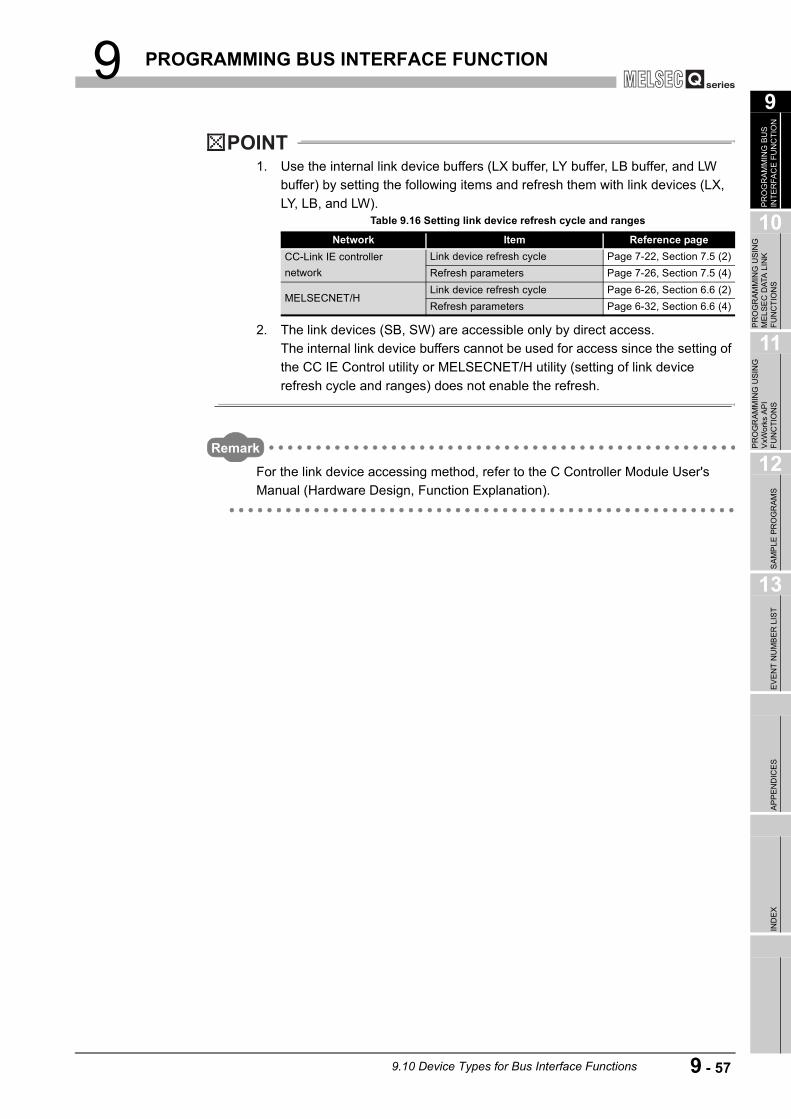
9 PROGRAMMING BUS INTERFACE FUNCTION
9
PR
OG
RAM
MIN
G B
US
IN
TER
FAC
E FU
NC
TIO
N
10
PR
OG
RAM
MIN
G U
SIN
G
MEL
SEC
DAT
A L
INK
FU
NC
TIO
NS
11
PR
OG
RAM
MIN
G U
SIN
G
VxW
orks
AP
I FU
NC
TIO
NS
12
SAM
PLE
PR
OG
RAM
S
13
EVEN
T N
UM
BER
LIS
TAP
PEN
DIC
ESIN
DEX
POINT1. Use the internal link device buffers (LX buffer, LY buffer, LB buffer, and LW
buffer) by setting the following items and refresh them with link devices (LX, LY, LB, and LW).
2. The link devices (SB, SW) are accessible only by direct access.The internal link device buffers cannot be used for access since the setting of the CC IE Control utility or MELSECNET/H utility (setting of link device refresh cycle and ranges) does not enable the refresh.
Remark
For the link device accessing method, refer to the C Controller Module User's Manual (Hardware Design, Function Explanation).
Table 9.16 Setting link device refresh cycle and ranges
Network Item Reference pageCC-Link IE controller network
Link device refresh cycle Page 7-22, Section 7.5 (2)Refresh parameters Page 7-26, Section 7.5 (4)
MELSECNET/HLink device refresh cycle Page 6-26, Section 6.6 (2)Refresh parameters Page 6-32, Section 6.6 (4)
9.10 Device Types for Bus Interface Functions 9 - 57

10 PROGRAMMING USING MELSEC DATA LINK FUNCTIONS
CHAPTER 10 PROGRAMMING USING MELSEC DATA LINK FUNCTIONS
When applying program examples introduced in this chapter into actual systems, fully examine the applicability, and confirm that they do not cause system control problems.
10.1 Outline of MELSEC Data Link Functions
To access and control a programmable controller CPU and each module in an user program, the functions provided by SW PVC-CCPU must be used.
(1) The following indicates features of bus interface functions.1) Access to the programmable controller CPU that is in the same system as the
C Controller module.
2) Access to the programmable controller on another station via CC-Link module(s) controlled by the C Controller module.
3) Access to the programmable controller on another station via CC-Link module(s) or MELSECNET/H module(s) controlled by the C Controller module.
4) Message exchange with the following modules or personal computers via CC-Link IE controller network module(s) or MELSECNET/H module(s) controlled by the C Controller module.
• C Controller module (another station) • Programmable controller (another station) • Personal computer equipped with MELSECNET/H board (only via
MELSECNET/H module(s))
Q12DCCPU-V Q06CCPU-V Q06CCPU-V-B
Q12DCCPU-V Q06CCPU-V Q06CCPU-V-B
10 - 1 10.1 Outline of MELSEC Data Link Functions
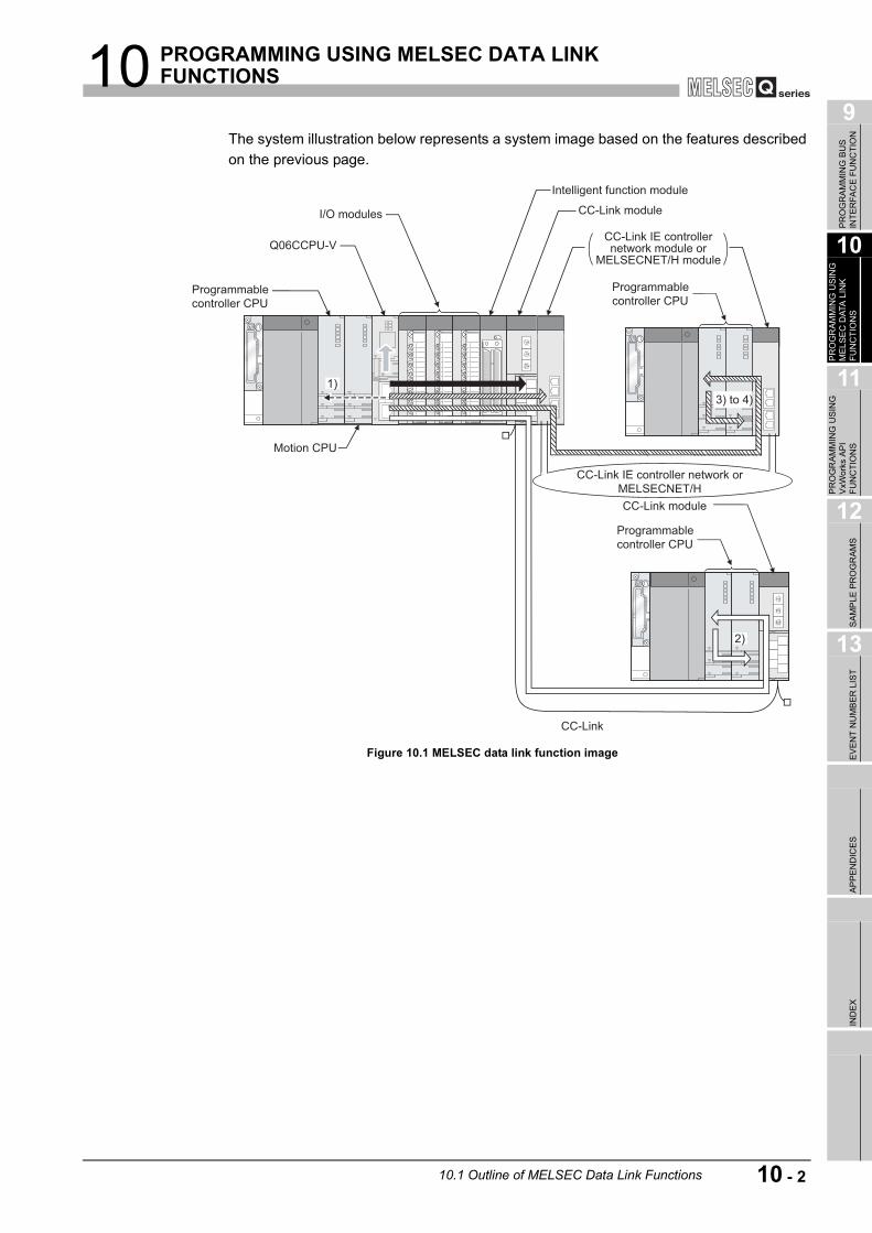
10 PROGRAMMING USING MELSEC DATA LINK FUNCTIONS
9
PR
OG
RAM
MIN
G B
US
IN
TER
FAC
E FU
NC
TIO
N
10
PR
OG
RAM
MIN
G U
SIN
G
MEL
SEC
DAT
A L
INK
FU
NC
TIO
NS
11
PR
OG
RAM
MIN
G U
SIN
G
VxW
orks
AP
I FU
NC
TIO
NS
12
SAM
PLE
PR
OG
RAM
S
13
EVEN
T N
UM
BER
LIS
TAP
PEN
DIC
ESIN
DEX
The system illustration below represents a system image based on the features described on the previous page.
Figure 10.1 MELSEC data link function image
CC-Link IE controller network or
MELSECNET/H
Programmable
controller CPU
CC-Link module
1)
2)
I/O modules
Q06CCPU-V
Motion CPU
Programmable
controller CPU
Intelligent function module
CC-Link module
Programmable
controller CPU
3) to 4)
CC-Link
CC-Link IE controller network module or
MELSECNET/H module
10.1 Outline of MELSEC Data Link Functions 10 - 2

10 PROGRAMMING USING MELSEC DATA LINK FUNCTIONS
* 1 "n" indicates the last digit of the channel No. set in the CC-Link utility. * 2 The logical station No. must be set in the <<Target settings>> tab of the CC-Link utility to access
the CPU that does not control other station CC-Link module. * 3 "n" indicates the last digit of the channel No. set in the MELSECNET/H utility. * 4 "n" indicates the last digit of the channel No. set in the CC IE Control utility. * 5 The logical station No. must be set in the <<Target settings>> tab of the MELSECNET/H utility to
access the CPU that does not control the other station MELSECNET/H module. * 6 The logical station No. must be set in the <<Target settings>> tab of the CC IE Control utility to
access the CPU that does not control the other station CC-Link IE controller network module.
Table 10.1 Access targets of MELSEC data link functions
Arrow Access targetNo.
given above
Communication path
Setting of Device monitoring utility Remarks
Channel name StationProgrammable controller CPU
1)Q seriesbus
12: Q series bus interfaceOther sta.
C Controller moduleQseriesbus
12: Q series bus interfaceOwn sta.
Only CPU shared memory accessible
CC-Link module (own station)
CC-Link8n: CC-Link
(Channel No.8n)*1Own sta.
Programmable controller CPU(other station)
2) CC-Link8n: CC-Link
(Channel No.8n)*1Other sta.
Station No.: 0 to 63 (access to control CPU of other station CC-Link module)
Programmable controller CPU(other station in multiple CPU system)
2) CC-Link8n: CC-Link
(Channel No.8n)*1Other sta.
Station No.: 65 to 239*2
(access to CPU that does not control other station CC-Link module)
MELSECNET/Hmodule (host station)
MELSECNET/H5n: MELSECNET/H
(Channel No.5n)*3Own sta.CC-Link IE controller
network module (own station)
CC-Link IE controller network
15n: CC-Link IE controller network
(Channel No.15n)*4
Programmable controller (other station)
3), 4)
MELSECNET/H5n: MELSECNET/
H(Channel No.5n)*3
Other sta.
Station No.: 1 to 64(access to control CPU of other station MELSECNET/H module)
CC-Link IE controller network
15n: CC-Link IE controller network
(Channel No.15n)*4
Station No.: 1 to 120(access to control CPU of other station CC-Link IE controller network module)
Programmable controller CPU (other station in multiple CPU system)
3), 4)
MELSECNET/H5n: MELSECNET/H
(Channel No.5n)*3
Other sta.
Station No.: 65 to 239*5 (access to CPU that does not control other station MELSECNET/H module)
CC-Link IE controller network
15n: CC-Link IE controller network
(Channel No.15n)*4
Station No.: 65 to 239*6 (access to CPU that does not control other station CC-Link IE controller network)
10 - 3 10.1 Outline of MELSEC Data Link Functions

10 PROGRAMMING USING MELSEC DATA LINK FUNCTIONS
9
PR
OG
RAM
MIN
G B
US
IN
TER
FAC
E FU
NC
TIO
N
10
PR
OG
RAM
MIN
G U
SIN
G
MEL
SEC
DAT
A L
INK
FU
NC
TIO
NS
11
PR
OG
RAM
MIN
G U
SIN
G
VxW
orks
AP
I FU
NC
TIO
NS
12
SAM
PLE
PR
OG
RAM
S
13
EVEN
T N
UM
BER
LIS
TAP
PEN
DIC
ESIN
DEX
10.2 MELSEC Data Link Function List
: Available, : N/A
POINTFor details of the MELSEC data link functions, refer to the MELSEC data link function HELP of SW PVC-CCPU.
10.3 Programming Procedure
For details of programming procedures, refer to the following. Page 9-7, "9.3 Programming Procedure"
Table 10.2 MELSEC data link function list
1)Q12DCCPU-V 2)Q06CCPU-V
Category Function name DescriptionAvailability1) 2)
Open/closemdOpen Opens a communication line.
mdClose Closes a communication line.
Remote control mdControlRemote operations (RUN/STOP/PAUSE) of the programmable controller CPU.
CPU model read mdTypeRead Reads the model name of the programmable controller CPU.
Device access
mdSend•Batch writes devices.•Sends messages (SEND function)
mdSendEx Batch writes devices. (Extended function)
mdReceive•Batch reads devices.•Receives messages. (RECV function)
mdReceiveEx Batch reads devices. (Extended function)
mdDevSet Sets bit devices.
mdDevSetEx Sets bit devices. (Extended function)
mdDevRst Resets bit devices.
mdDevRstEx Resets bit devices. (Extended function)
mdRandR Reads devices randomly.
mdRandREx Reads devices randomly. (Extended function)
mdRandW Writes devices randomly.
mdRandWEx Writes devices randomly. (Extended function)
Initialize mdInit Refreshes the programmable controller device address table.
Q12DCCPU-V Q06CCPU-V Q06CCPU-V-B
Q12DCCPU-V Q06CCPU-V Q06CCPU-V-B
10.2 MELSEC Data Link Function List 10 - 4

10 PROGRAMMING USING MELSEC DATA LINK FUNCTIONS
10.4 Creating a New Project of User Program and Compiling
For details of creating a new project of user program and compiling, refer to the following. Page 9-8, "9.4 Creating and Compiling a New Project of User Program"
10.5 MELSEC Data Link Function Programming Flow
(1) Programming flowThe following flowchart shows the procedure for programming using the MELSEC data link functions.
For details of precautions for each process, refer to the following.
Page 10-6, "10.5 (2) (a) Precautions for programming"
Figure 10.2 Programming using MELSEC data link functions
Q12DCCPU-V Q06CCPU-V Q06CCPU-V-B
Q12DCCPU-V Q06CCPU-V Q06CCPU-V-B
No
Yes
1)
2)
4), 5)
1)
3)
Task start
Opens a communication line. (mdOpen function)
Makes dummy access (reading a device, a model
name, etc.) to each access target.
Using a MELSEC data link function, accesses the target
(Programmable controller CPU, CC-Link IE controller
network module, MELSECNET/H module, CC-Link
module, etc.).
Terminate the program (task)?
Closes the communication line. (mdClose function)
Task end
1
2
3
4
1
10 - 5 10.4 Creating a New Project of User Program and Compiling

10 PROGRAMMING USING MELSEC DATA LINK FUNCTIONS
9
PR
OG
RAM
MIN
G B
US
IN
TER
FAC
E FU
NC
TIO
N
10
PR
OG
RAM
MIN
G U
SIN
G
MEL
SEC
DAT
A L
INK
FU
NC
TIO
NS
11
PR
OG
RAM
MIN
G U
SIN
G
VxW
orks
AP
I FU
NC
TIO
NS
12
SAM
PLE
PR
OG
RAM
S
13
EVEN
T N
UM
BER
LIS
TAP
PEN
DIC
ESIN
DEX
(2) Precautions for using MELSEC data link functions
(a) Precautions for programming
1) Opening and closing of communication lines ( )Opening and closing of a communication line (mdOpen and mdClose functions) is allowed only once each at the start (task start) and the end (task end) of the user program task.Repeating opening and closing for every communication degrades communication performance.
2) Execution time for initial execution ( )When a device is added, the function collects information of the programmable controller in detail at first execution, which increases the execution time.To avoid the increase, make dummy access to each target in advance.
3) MELSEC data link function execution in multiple tasks ( )The MELSEC data link functions cannot be simultaneously processed in multiple tasks within the C Controller module.When processing by the MELSEC data link function are requested simultaneously in multiple tasks, one of the tasks starts its processing and the other tasks will be in waiting status since the processing is performed one at a time.
Create a program that completes all preparatory processing ( ) first and
then execute the main processing( ).
4) Accessing to other station ( )When accessing other station from the C Controller module via any of the following, one of the communication processing starts and the others will be in the waiting status.
• Q series bus interface • CC-Link IE controller network module • MELSECNET/H module • CC-Link module
Note that if one communication processing times out, the other communication processing may time out.
1
2
3
3
4
4
10.5 MELSEC Data Link Function Programming Flow 10 - 6

10 PROGRAMMING USING MELSEC DATA LINK FUNCTIONS
(b) Precautions for accessing to CC-Link module own station devices and other station programmable controller devices.When accessing via CC-Link module, provide interlocks according to the link states of the own and other stations.
1) Access to own station deviceCreate an user program that provides interlocks to enable write to/read from the own station device.Data take effect only when the following conditions are satisfied.
• Module error (Xn0) is off (normal) • Own station link status (Xn1) is off (in data link) • Module ready (XnF) is on (operable)
Write to/read from the own station is terminated normally irrespective of the above conditions.
2) Transient access to other stations (other station programmable controller CPU remote operation and device access) Create an user program that allows to access under the following conditions, in addition to the interlocks for own station device access.
• Data link status of the access target station (Bits corresponding to a communication target station of SW80 to 83, which are read from the own station) is off (normal communication).
(c) Precautions for access to MELSECNET/H module host station devices and other station programmable controller devicesWhen accessing via MELSECNET/H module, provide interlocks according to the link status of the host station.
1) Access to host station deviceCreate an user program that provides interlocks to enable write to/read from the host station devices.Data take effect only when the following conditions are satisfied.
• Module status (SB20) is off (normal) • Baton pass status of the host station (SB47) is off (normal) • Data link status of the host station (SB49) is off (in data link)
Write to/read from the host station is terminated normally irrespective of the above conditions.
2) Transient access to other stations (other station programmable controller CPU remote operation and device access)Create an user program that makes access when any of the following conditions is satisfied, in addition to the interlocks for the host station device access.
• Baton pass status of the access target station (Bits corresponding to a communication target station of SW70 to 73, which are read from the host station) is off (normal communication).
• Data link status (Bits corresponding to the communication target station of SW74 to 77, which are read from the host station) is off (normal communication).
10 - 7 10.5 MELSEC Data Link Function Programming Flow

10 PROGRAMMING USING MELSEC DATA LINK FUNCTIONS
9
PR
OG
RAM
MIN
G B
US
IN
TER
FAC
E FU
NC
TIO
N
10
PR
OG
RAM
MIN
G U
SIN
G
MEL
SEC
DAT
A L
INK
FU
NC
TIO
NS
11
PR
OG
RAM
MIN
G U
SIN
G
VxW
orks
AP
I FU
NC
TIO
NS
12
SAM
PLE
PR
OG
RAM
S
13
EVEN
T N
UM
BER
LIS
TAP
PEN
DIC
ESIN
DEX
(d) Precautions for access to CC-Link IE controller network module own station devices and other station programmable controller devicesWhen accessing via a CC-Link IE controller network module, provide interlocks according to the link status of the own station.
1) Access to own station devicesCreate an user program that provides interlocks to enable write to/read from the own station device.Data take effect only when the following conditions are satisfied.
• Data link status of own station (SB49) is off (in data link) • Data link status (Bits corresponding to the communication target station of
SWB0 to B7, which are read from the own station) is off (normal communication).
Write to/read from the own station is terminated normally irrespective of the above conditions.
2) Transient access to other stations (other station programmable controller CPU remote operation and device access)Create an user program that allows to access under the following conditions, in addition to the interlocks for own station device access.
• Baton pass status of own station (SB47) is off (normal) • Baton pass status of the access target station (Bits corresponding to the
communication target station of SWA0 to A7, which are read from the own station) is off (normal communication)
(e) Other precautions
1) Time out value setting for MELSEC data link functionWhen either of the following problems occur, change the communication timeout value for the MELSEC data link function in C Controller setting utility. ( Page 4-28, Section 4.6 (3) (c))
• Frequent communication timeouts due to line congestion. Increase the timeout value
• To allow communication timeout at shorter timing Decrease the timeout value
When the above problems do not occur, operate by default setting.
Figure 10.3 MD function communication timeout value setting screen
10.5 MELSEC Data Link Function Programming Flow 10 - 8

10 PROGRAMMING USING MELSEC DATA LINK FUNCTIONS
10.6 Precautions for the MELSEC Data Link Function
For details of precautions for the MELSEC data link function, refer to the following. Page 9-25, "9.6 Precautions for Functions"
10.7 Precautions for Program Debugging
For details of precautions for program debugging, refer to the following. Page 9-30, "9.7 Precautions for Program Debugging"
10.8 Program Registration
For details of program registration, refer to the following. Page 9-45, "9.8 Program Registration"
10.9 Creating a Script File "STARTUP.CMD"
For details of creating a script file "STARTUP.CMD", refer to the following. Page 9-50, "9.9 Creating a Script File "STARTUP.CMD""
10.10 Channel
Table 10.3 Channels used for MELSEC data link functions
No. Channel name Description12 Q series bus interface Used when communication is performed via a bus.
51 to 54MELSECNET/H(Channel No.51 to 54)
Used when communication is performed via a MELSECNET/H module controlled by the C Controller module.Channel No. is set for each target module in the <<Parameter settings>> tab of
MELSECNET/H utility. ( Page 6-26, Section 6.6)
81 to 88CC-Link(Channel No.81 to 88)
Used when communication is performed via CC-Link module controlled by the C Controller module.Channel No. is set for each target module in the <<Parameter settings>> tab of CC-Link
utility. ( Page 5-10, Section 5.5)
151 to 154CC-Link IE controller network(Channel No.151 to 154)
Used when communication is performed via CC-Link IE controller network module controlled by the C Controller module.Channel No. is set for each target module in the <<Parameter settings>> tab of CC IE
Control utility. ( Page 7-22, Section 7.5)
Q12DCCPU-V Q06CCPU-V Q06CCPU-V-B
Q12DCCPU-V Q06CCPU-V Q06CCPU-V-B
Q12DCCPU-V Q06CCPU-V Q06CCPU-V-B
Q12DCCPU-V Q06CCPU-V Q06CCPU-V-B
Q12DCCPU-V Q06CCPU-V Q06CCPU-V-B
10 - 9 10.6 Precautions for the MELSEC Data Link Function
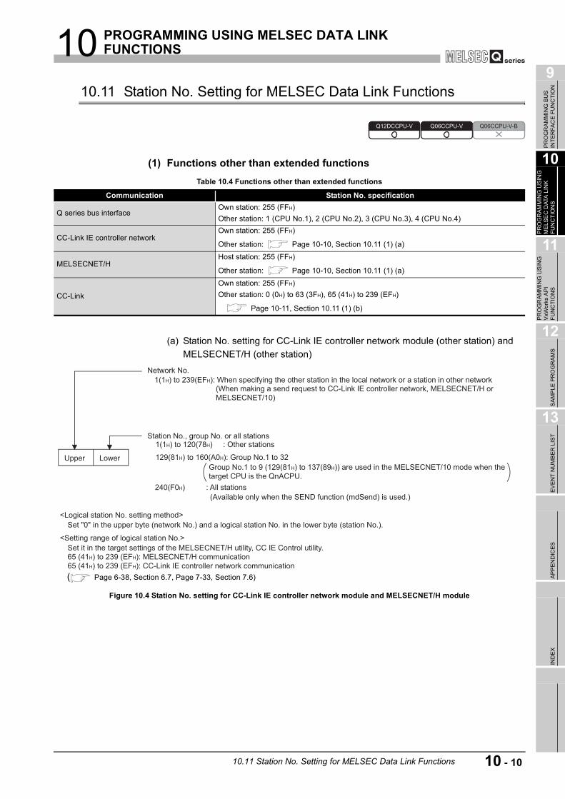
10 PROGRAMMING USING MELSEC DATA LINK FUNCTIONS
9
PR
OG
RAM
MIN
G B
US
IN
TER
FAC
E FU
NC
TIO
N
10
PR
OG
RAM
MIN
G U
SIN
G
MEL
SEC
DAT
A L
INK
FU
NC
TIO
NS
11
PR
OG
RAM
MIN
G U
SIN
G
VxW
orks
AP
I FU
NC
TIO
NS
12
SAM
PLE
PR
OG
RAM
S
13
EVEN
T N
UM
BER
LIS
TAP
PEN
DIC
ESIN
DEX
10.11 Station No. Setting for MELSEC Data Link Functions
(1) Functions other than extended functions
(a) Station No. setting for CC-Link IE controller network module (other station) and MELSECNET/H (other station)
Table 10.4 Functions other than extended functions
Communication Station No. specification
Q series bus interfaceOwn station: 255 (FFH)Other station: 1 (CPU No.1), 2 (CPU No.2), 3 (CPU No.3), 4 (CPU No.4)
CC-Link IE controller networkOwn station: 255 (FFH)
Other station: Page 10-10, Section 10.11 (1) (a)
MELSECNET/HHost station: 255 (FFH)
Other station: Page 10-10, Section 10.11 (1) (a)
CC-Link
Own station: 255 (FFH)Other station: 0 (0H) to 63 (3FH), 65 (41H) to 239 (EFH)
Page 10-11, Section 10.11 (1) (b)
Figure 10.4 Station No. setting for CC-Link IE controller network module and MELSECNET/H module
Q12DCCPU-V Q06CCPU-V Q06CCPU-V-B
Upper Lower
<Logical station No. setting method>
<Setting range of logical station No.>
Set "0" in the upper byte (network No.) and a logical station No. in the lower byte (station No.).
Set it in the target settings of the MELSECNET/H utility, CC IE Control utility.
65 (41H) to 239 (EFH): MELSECNET/H communication
65 (41H) to 239 (EFH): CC-Link IE controller network communication
Network No.
(When making a send request to CC-Link IE controller network, MELSECNET/H or
MELSECNET/10)
1(1H) to 239(EFH): When specifying the other station in the local network or a station in other network
Station No., group No. or all stations
(Available only when the SEND function (mdSend) is used.)
240(F0H) : All stations
Group No.1 to 9 (129(81H) to 137(89H)) are used in the MELSECNET/10 mode when the
target CPU is the QnACPU.
129(81H) to 160(A0H): Group No.1 to 32
1(1H) to 120(78H) : Other stations
( Page 6-38, Section 6.7, Page 7-33, Section 7.6)
10.11 Station No. Setting for MELSEC Data Link Functions 10 - 10

10 PROGRAMMING USING MELSEC DATA LINK FUNCTIONS
(b) Station No. setting for CC-Link module (other station)
Station No. 64 cannot be specified for the CC-Link (other station).When the own station No. is 64, the other station cannot be specified. (Access is allowed only to the own station.)Specify the station No. other than 64.
(2) Extended functions
* 1 65(41H) to 120(78H) can be specified for other station on a CC-Link IE controller network.
* 2 Logical station No. is set in the <<Target settings>> tab of CC IE Control utility ( Page 7-33),
MELSECNET/H utility ( Page 6-38), or CC-Link utility ( Page 5-14). * 3 For CC-Link (other station), station No. 64 cannot be specified.
When the own station No. is 64, other station cannot be specified. (Access is allowed only to the own station.)Specify the station No. other than 64.
Figure 10.5 Station No. setting for CC-Link module
Table 10.5 Extended function
Communication Network No. specification Station No. specification
Q series bus interface 0(0H)Own station: 255(FFH)Other station: 1 (CPU No.1), 2 (CPU No.2), 3 (CPU No.3), 4 (CPU No.4)
CC-Link IE controller network, or MELSECNET/HOwn (host) station: 0(0H)Other station: 1(1H) to 239(EFH)Logical station: 0(0H)
Own (Host) station: 255(FFH)
Other station: 1(1H) to 120(78H)*1
Logical station: 65(41H) to 239(EFH)*2
CC-Link 0(0H)
Own station: 255(FFH)
Other station: 0(0H) to 63(3FH)*3
Logical station: 65(41H) to 239(EFH)*2
<Logical station No. setting method>
<The setting range of logical station No.>
Set "0" in the upper byte (network No.) and a logical station No. in
the lower byte (station No.).
Set it in the target settings of the CC-Link utility.
65 (41H) to 239 (EFH): CC-Link communication
( )
0(0H) to 63(3FH) : Other station
Station No.
0: CC-Link
Network No.
LowerUpper
Page 5-14, Section 5.6
10 - 11 10.11 Station No. Setting for MELSEC Data Link Functions

10 PROGRAMMING USING MELSEC DATA LINK FUNCTIONS
9
PR
OG
RAM
MIN
G B
US
IN
TER
FAC
E FU
NC
TIO
N
10
PR
OG
RAM
MIN
G U
SIN
G
MEL
SEC
DAT
A L
INK
FU
NC
TIO
NS
11
PR
OG
RAM
MIN
G U
SIN
G
VxW
orks
AP
I FU
NC
TIO
NS
12
SAM
PLE
PR
OG
RAM
S
13
EVEN
T N
UM
BER
LIS
TAP
PEN
DIC
ESIN
DEX
10.12 Device Types for the MELSEC Data Link Function
Device type used for the MELSEC data link functions can be specified either by code numbers or device names.
(1) Common device types
* 1 The device name specification (macro) is defined in this function's include file "MdFunc.h". ( Page 9-8, Section 9.4)
* 2 Even if a non-existing device is specified in mdRandR or mdRandREx functions, they complete normally. (The read data is "-1".)
(To the next page)
Table 10.6 Common device types of MELSEC data link functions
Device typeDeviceCode
Device name*1DEC. HEX.
1 1H DevX X2 2H DevY Y3 3H DevL L4 4H DevM M
5 5H DevSMSM(special relay), SB(link special relay for MELSECNET/H, CC-Link IE controller network, and CC-Link)
6 6H DevF F7 7H DevTT T (contact)8 8H DevTC T (coil)9 9H DevCT C (contact)10 AH DevCC C (coil)11 BH DevTN T (current value)12 CH DevCN C (current value)13 DH DevD D
14 EH DevSDSD (special register), SW(link special register for MELSECNET/H, CC-Link IE controller network, and CC-Link)
15 FH DevTM T (main setting)16 10H DevTS T (sub setting 1)
16002 3E82H DevTS2 T (sub setting 2)16003 3E83H DevTS3 T (sub setting 3)
17 11H DevCM C (main setting)18 12H DevCS C (sub setting 1)
18002 4652H DevCS2 C (sub setting 2)18003 4653H DevCS3 C (sub setting 3)
19 13H DevA A20 14H DevZ Z21 15H DevV V (index register)22 16H DevR R (file register)
220 00DCH DevZR ZR (file register)
22000 to 22256 55F0H to 56F0HDevER(0) to DevER(256)
ER (extended file register)
Argument value of device name (0 to 256*2) is Block No.23 17H DevB B24 18H DevW W25 19H DevQSB Q/QnA link special relay (within Q/QnACPU)26 1AH DevSTT Retentive timer (contact)27 1BH DevSTC Retentive timer (coil)
Q12DCCPU-V Q06CCPU-V Q06CCPU-V-B
10.12 Device Types for the MELSEC Data Link Function 10 - 12

10 PROGRAMMING USING MELSEC DATA LINK FUNCTIONS
* 1 The device name specification (macro) is defined in this function's include file "MdFunc.h". ( Page 9-8, Section 9.4)
* 2 Even if a non-existing device is specified in mdRandR or mdRandREx functions, they complete normally. (The read data is "-1".)
* 3 This device is the CC-Link (own station) module's buffer memory. * 4 Available for accessing other station's personal computers. (Only when the communication target
is on Microsoft Windows NT Workstation 4.0 where MX Links (SW2D5F-CSKP or later) is running).
* 5 Access is not allowed to LW8000 or higher.
Table 10.6 Common device types of MELSEC data link functions (continued)
Device typeDeviceCode
Device name*1DEC. HEX.
28 1CH DevQSW Q/QnA link special register (within Q/QnACPU)30 1EH DevQV Q/QnA edge relay (within Q/QnACPU)
33 21H DevMRB Own station random access buffer*3
35 23H DevSTN Retentive timer (current value)
36 24H DevWw Own station link register (for sending)*3
37 25H DevWr Own station link register (for receiving)*3
50 32H DevSPB Own station buffer memory*3
101 65H DevMAIL Q/QnA SEND function (with arrival confirmation) and RECV function102 66H DevMAILNC Q/QnA SEND function (no arrival confirmation)
1001 to 1255 3E9H to 4E7HDevLX(1) to DevLX(255)
Direct link input (other station side)
Argument value of device name (1 to 255*2) is Network No.
2001 to 2255 7D1H to 8CFHDevLY(1) to DevLY(255)
Direct link output (other station side)
Argument value of device name (1 to 255*2) is Network No.
23001 to 2325559D9H to 5AD7H
DevLB(1) to DevLB(255)
Direct link relay (other station side)
Argument value of device name (1 to 255*2) is Network No.
24001 to 242555DC1H to
5EBFH
DevLW(1) to DevLW(255)
Direct link register (other station side)*5
Argument value of device name (1 to 255*2) is Network No.
25001 to 25255 61A9H to 62A7HDevLSB(1) to DevLSB(255)
Direct link special relay (other station side)
Argument value of device name (1 to 255*2) is Network No.
28001 to 28255 6D61H to 6E5FHDevLSW(1) to DevLSW(255)
Direct link special register (other station side)
Argument value of device name (1 to 255*2) is Network No.
29000 to 29255 7148H to 7247HDevSPG(0) to DevSPG(255)
Special direct buffer register
Argument value of device name (1 to 255*2) is start I/O No. divided by 16
31000 to 31255 7918H to 7A17HDevEM(0) to DevEM(255)
EM (shared device)*4
Argument value of device name (0 to 255*2) is Block No.
32000 to 322557D00H to 7DFFH
DevED(0) to DevED(255)
ED (shared device)*4
Argument value of device name (0 to 255*2) is Block No.
R R
10 - 13 10.12 Device Types for the MELSEC Data Link Function

10 PROGRAMMING USING MELSEC DATA LINK FUNCTIONS
9
PR
OG
RAM
MIN
G B
US
IN
TER
FAC
E FU
NC
TIO
N
10
PR
OG
RAM
MIN
G U
SIN
G
MEL
SEC
DAT
A L
INK
FU
NC
TIO
NS
11
PR
OG
RAM
MIN
G U
SIN
G
VxW
orks
AP
I FU
NC
TIO
NS
12
SAM
PLE
PR
OG
RAM
S
13
EVEN
T N
UM
BER
LIS
TAP
PEN
DIC
ESIN
DEX
(2) Dedicated device types for Q series bus interface
* 1 The device name specification (macro) is defined in this function's include file "MdFunc.h". ( Page 9-8, Section 9.4)
* 2 The device cannot be used in the mdRandR, mdRandREx, mdRandW, mdRandWEx, mdDevSet, mdDevSetEx, mdDevRst, or mdDevRstEx function.
(3) Device types for accessing the CC-Link modules
* 1 The device name specification (macro) is defined in this function's include file "MdFunc.h". ( Page 9-8, Section 9.4)
* 2 The device cannot be used in the mdRandR, mdRandREx, mdRandW, mdRandWEx, mdDevSet, mdDevSetEx, mdDevRst, or mdDevRstEx functions.
* 3 These (DevSM, DevQSB) are the same device. * 4 These (DevSD, DevQSW) are the same device. * 5 Note that maximum of one scan time may delay when the block data assurance per station
function is enabled and the link device is continuously accessed (mdSend, mdSendEx(1), mdReceive(1), mdReceiveEx, mdDevSet, mdDevSetEx, mdDevRst, mdDevRstEx). (This is the same behavior when the auto refresh method is selected as CC-Link refreshing method in the QBF_ToBuf and QBF_FromBuf functions.)Moreover, block data assurance per station cannot be used in dReadR, mdRandREx, mdReadW, and mdRandWEx functions.For details, refer to the following.For block data assurance per station, refer to the C Controller Module User's Manual (Hardware Design, Function Explanation).For the MELSEC data link functions, refer to the HELP of the MELSEC data link function.
(To the next page)
Table 10.7 Q series bus interface dedicated device types
Device typesDeviceCode
Device name*1DEC. HEX.501 1F5H DevSPB1 CPU shared memory (area for CPU No.1)*2
502 1F6H DevSPB2 CPU shared memory (area for CPU No.2)*2
503 1F7H DevSPB3 CPU shared memory (area for CPU No.3)*2
504 1F8H DevSPB4 CPU shared memory (area for CPU No.4)*2
Table 10.8 Device types for accessing CC-Link module
Device typeDeviceCode
Device name*1DEC. HEX.
1 1H DevX Own station RX*5
2 2H DevY Own station RY*5
5 5H DevSM Own station SB (link special relay for CC-Link)*3
14 EH DevSD Own station SW (link special register for CC-Link)*4
25 19H DevQSB Own station SB (link special relay for CC-Link)*3
28 1CH DevQSW Own station SW (link special register for CC-Link)*4
33 21H DevMRB Own station random access buffer
36 24H DevWw Own station link register (for sending)*5
37 25H DevWr Own station link register (for receiving)*5
50 32H DevSPB Own station buffer memory*5
-32768 8000H DevRBM Other station buffer memory*2
-32736 8020H DevRAB Other station random access buffer*2
10.12 Device Types for the MELSEC Data Link Function 10 - 14
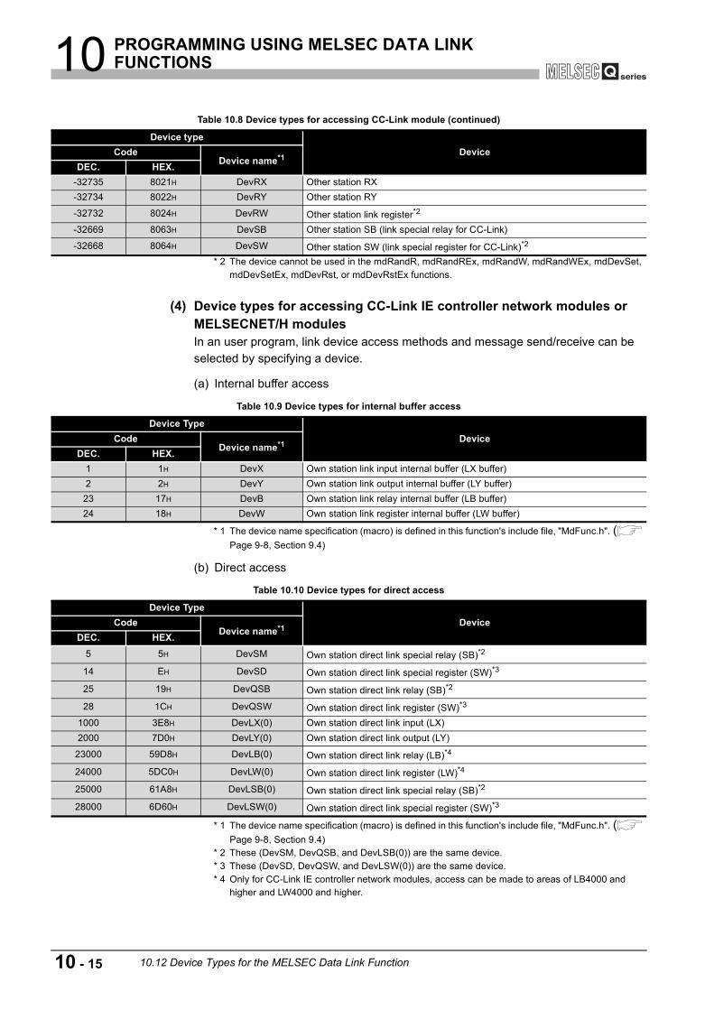
10 PROGRAMMING USING MELSEC DATA LINK FUNCTIONS
* 2 The device cannot be used in the mdRandR, mdRandREx, mdRandW, mdRandWEx, mdDevSet, mdDevSetEx, mdDevRst, or mdDevRstEx functions.
(4) Device types for accessing CC-Link IE controller network modules or MELSECNET/H modulesIn an user program, link device access methods and message send/receive can be selected by specifying a device.
(a) Internal buffer access
* 1 The device name specification (macro) is defined in this function's include file, "MdFunc.h". ( Page 9-8, Section 9.4)
(b) Direct access
* 1 The device name specification (macro) is defined in this function's include file, "MdFunc.h". ( Page 9-8, Section 9.4)
* 2 These (DevSM, DevQSB, and DevLSB(0)) are the same device. * 3 These (DevSD, DevQSW, and DevLSW(0)) are the same device. * 4 Only for CC-Link IE controller network modules, access can be made to areas of LB4000 and
higher and LW4000 and higher.
Table 10.8 Device types for accessing CC-Link module (continued)
Device typeDeviceCode
Device name*1DEC. HEX.
-32735 8021H DevRX Other station RX-32734 8022H DevRY Other station RY
-32732 8024H DevRW Other station link register*2
-32669 8063H DevSB Other station SB (link special relay for CC-Link)
-32668 8064H DevSW Other station SW (link special register for CC-Link)*2
Table 10.9 Device types for internal buffer access
Device TypeDeviceCode
Device name*1DEC. HEX.
1 1H DevX Own station link input internal buffer (LX buffer)2 2H DevY Own station link output internal buffer (LY buffer)23 17H DevB Own station link relay internal buffer (LB buffer)24 18H DevW Own station link register internal buffer (LW buffer)
Table 10.10 Device types for direct access
Device TypeDeviceCode
Device name*1DEC. HEX.
5 5H DevSM Own station direct link special relay (SB)*2
14 EH DevSD Own station direct link special register (SW)*3
25 19H DevQSB Own station direct link relay (SB)*2
28 1CH DevQSW Own station direct link register (SW)*3
1000 3E8H DevLX(0) Own station direct link input (LX)2000 7D0H DevLY(0) Own station direct link output (LY)
23000 59D8H DevLB(0) Own station direct link relay (LB)*4
24000 5DC0H DevLW(0) Own station direct link register (LW)*4
25000 61A8H DevLSB(0) Own station direct link special relay (SB)*2
28000 6D60H DevLSW(0) Own station direct link special register (SW)*3
10 - 15 10.12 Device Types for the MELSEC Data Link Function

10 PROGRAMMING USING MELSEC DATA LINK FUNCTIONS
9
PR
OG
RAM
MIN
G B
US
IN
TER
FAC
E FU
NC
TIO
N
10
PR
OG
RAM
MIN
G U
SIN
G
MEL
SEC
DAT
A L
INK
FU
NC
TIO
NS
11
PR
OG
RAM
MIN
G U
SIN
G
VxW
orks
AP
I FU
NC
TIO
NS
12
SAM
PLE
PR
OG
RAM
S
13
EVEN
T N
UM
BER
LIS
TAP
PEN
DIC
ESIN
DEX
(c) Message send/receive
* 1 The device name specification (macro) is defined in this function's include file, "MdFunc.h". ( Page 9-8, Section 9.4)
POINT1. Use the internal link device buffers (LX buffer, LY buffer, LB buffer, and LW
buffer) by setting the following items and refresh them with link devices (LX, LY, LB, and LW).
2. The link devices (SB and SW) are accessible only by direct access.Access by using internal link device buffers cannot be made since the settings (link device refresh cycle and ranges) of the CC IE Control utility and MELSECNET/H utility cannot perform link device refresh.
Remark
For the link device accessing method, refer to the C Controller Module User's Manual (Hardware Design, Function Explanation).
Table 10.11 Device types for message send receive
Device typeDeviceCode
Device name*1DEC. HEX.101 65H DevMAIL Q/QnA SEND function (with arrival confirmation) and RECV function102 66H DevMAILNC Q/QnA SEND function (no arrival confirmation)
Table 10.12 Setting link device refresh cycle and ranges
Network Item Reference pageCC-Link IE controller network
Link device refresh cycle Page 7-22, Section 7.5 (2)Refresh parameters Page 7-26, Section 7.5 (4)
MELSECNET/HLink device refresh cycle Page 6-26, Section 6.6 (2)Refresh parameters Page 6-32, Section 6.6 (4)
10.12 Device Types for the MELSEC Data Link Function 10 - 16
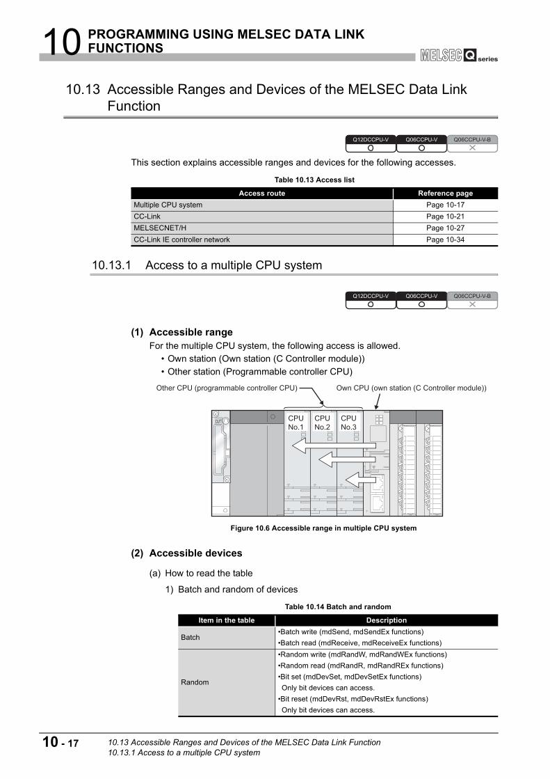
10 PROGRAMMING USING MELSEC DATA LINK FUNCTIONS
10.13 Accessible Ranges and Devices of the MELSEC Data Link Function
This section explains accessible ranges and devices for the following accesses.
10.13.1 Access to a multiple CPU system
(1) Accessible rangeFor the multiple CPU system, the following access is allowed.
• Own station (Own station (C Controller module)) • Other station (Programmable controller CPU)
(2) Accessible devices
(a) How to read the table
1) Batch and random of devices
Table 10.13 Access list
Access route Reference pageMultiple CPU system Page 10-17CC-Link Page 10-21MELSECNET/H Page 10-27CC-Link IE controller network Page 10-34
Figure 10.6 Accessible range in multiple CPU system
Table 10.14 Batch and random
Item in the table Description
Batch•Batch write (mdSend, mdSendEx functions)•Batch read (mdReceive, mdReceiveEx functions)
Random
•Random write (mdRandW, mdRandWEx functions)•Random read (mdRandR, mdRandREx functions)•Bit set (mdDevSet, mdDevSetEx functions)Only bit devices can access.
•Bit reset (mdDevRst, mdDevRstEx functions)Only bit devices can access.
Q12DCCPU-V Q06CCPU-V Q06CCPU-V-B
Q12DCCPU-V Q06CCPU-V Q06CCPU-V-B
Other CPU (programmable controller CPU) Own CPU (own station (C Controller module))
CPU
No.1
CPU
No.2
CPU
No.3
10 - 17 10.13 Accessible Ranges and Devices of the MELSEC Data Link Function10.13.1 Access to a multiple CPU system
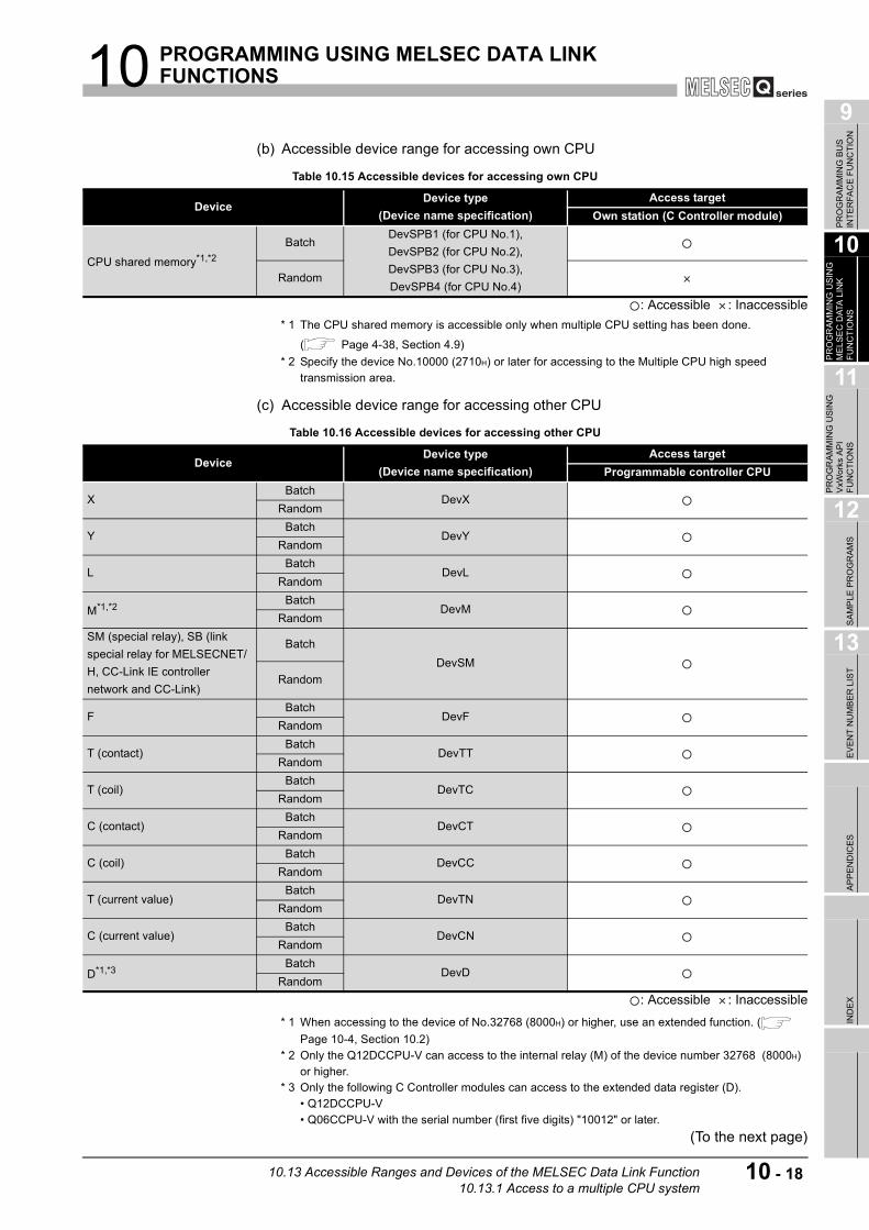
10 PROGRAMMING USING MELSEC DATA LINK FUNCTIONS
9
PR
OG
RAM
MIN
G B
US
IN
TER
FAC
E FU
NC
TIO
N
10
PR
OG
RAM
MIN
G U
SIN
G
MEL
SEC
DAT
A L
INK
FU
NC
TIO
NS
11
PR
OG
RAM
MIN
G U
SIN
G
VxW
orks
AP
I FU
NC
TIO
NS
12
SAM
PLE
PR
OG
RAM
S
13
EVEN
T N
UM
BER
LIS
TAP
PEN
DIC
ESIN
DEX
(b) Accessible device range for accessing own CPU
: Accessible : Inaccessible * 1 The CPU shared memory is accessible only when multiple CPU setting has been done.
( Page 4-38, Section 4.9) * 2 Specify the device No.10000 (2710H) or later for accessing to the Multiple CPU high speed
transmission area.
(c) Accessible device range for accessing other CPU
: Accessible : Inaccessible
* 1 When accessing to the device of No.32768 (8000H) or higher, use an extended function. ( Page 10-4, Section 10.2)
* 2 Only the Q12DCCPU-V can access to the internal relay (M) of the device number 32768 (8000H) or higher.
* 3 Only the following C Controller modules can access to the extended data register (D).• Q12DCCPU-V• Q06CCPU-V with the serial number (first five digits) "10012" or later.
(To the next page)
Table 10.15 Accessible devices for accessing own CPU
DeviceDevice type
(Device name specification)Access target
Own station (C Controller module)
CPU shared memory*1,*2Batch
DevSPB1 (for CPU No.1),DevSPB2 (for CPU No.2), DevSPB3 (for CPU No.3), DevSPB4 (for CPU No.4)
Random
Table 10.16 Accessible devices for accessing other CPU
DeviceDevice type
(Device name specification)Access target
Programmable controller CPU
XBatch
DevXRandom
YBatch
DevYRandom
LBatch
DevLRandom
M*1,*2 BatchDevM
RandomSM (special relay), SB (link special relay for MELSECNET/H, CC-Link IE controller network and CC-Link)
BatchDevSM
Random
FBatch
DevFRandom
T (contact)Batch
DevTTRandom
T (coil)Batch
DevTCRandom
C (contact)Batch
DevCTRandom
C (coil)Batch
DevCCRandom
T (current value)Batch
DevTNRandom
C (current value)Batch
DevCNRandom
D*1,*3 BatchDevD
Random
10.13 Accessible Ranges and Devices of the MELSEC Data Link Function10.13.1 Access to a multiple CPU system
10 - 18
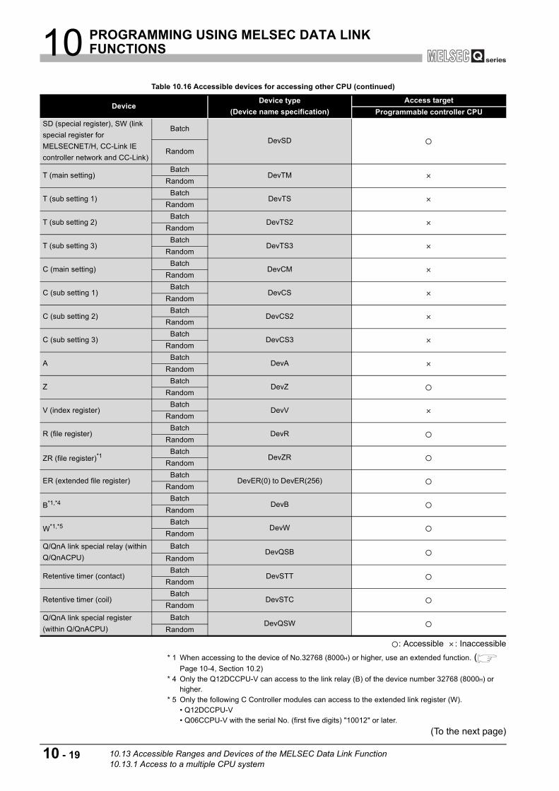
10 PROGRAMMING USING MELSEC DATA LINK FUNCTIONS
: Accessible : Inaccessible * 1 When accessing to the device of No.32768 (8000H) or higher, use an extended function. (
Page 10-4, Section 10.2) * 4 Only the Q12DCCPU-V can access to the link relay (B) of the device number 32768 (8000H) or
higher. * 5 Only the following C Controller modules can access to the extended link register (W).
• Q12DCCPU-V• Q06CCPU-V with the serial No. (first five digits) "10012" or later.
(To the next page)
Table 10.16 Accessible devices for accessing other CPU (continued)
DeviceDevice type
(Device name specification)Access target
Programmable controller CPUSD (special register), SW (link special register for MELSECNET/H, CC-Link IE controller network and CC-Link)
BatchDevSD
Random
T (main setting)Batch
DevTMRandom
T (sub setting 1)Batch
DevTSRandom
T (sub setting 2)Batch
DevTS2Random
T (sub setting 3)Batch
DevTS3Random
C (main setting)Batch
DevCMRandom
C (sub setting 1)Batch
DevCSRandom
C (sub setting 2)Batch
DevCS2Random
C (sub setting 3)Batch
DevCS3Random
ABatch
DevARandom
ZBatch
DevZRandom
V (index register)Batch
DevVRandom
R (file register)Batch
DevRRandom
ZR (file register)*1Batch
DevZRRandom
ER (extended file register)Batch
DevER(0) to DevER(256)Random
B*1,*4 BatchDevB
Random
W*1,*5 BatchDevW
Random
Q/QnA link special relay (within Q/QnACPU)
BatchDevQSB
Random
Retentive timer (contact)Batch
DevSTTRandom
Retentive timer (coil)Batch
DevSTCRandom
Q/QnA link special register (within Q/QnACPU)
BatchDevQSW
Random
10 - 19 10.13 Accessible Ranges and Devices of the MELSEC Data Link Function10.13.1 Access to a multiple CPU system
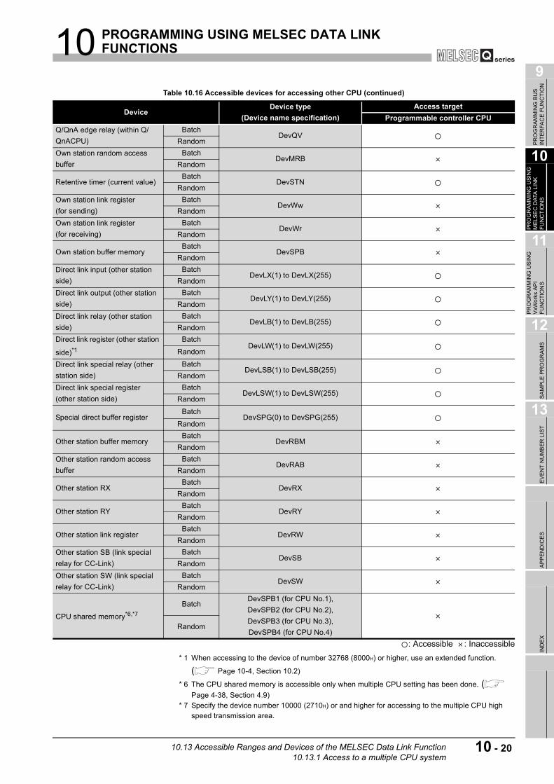
10 PROGRAMMING USING MELSEC DATA LINK FUNCTIONS
9
PR
OG
RAM
MIN
G B
US
IN
TER
FAC
E FU
NC
TIO
N
10
PR
OG
RAM
MIN
G U
SIN
G
MEL
SEC
DAT
A L
INK
FU
NC
TIO
NS
11
PR
OG
RAM
MIN
G U
SIN
G
VxW
orks
AP
I FU
NC
TIO
NS
12
SAM
PLE
PR
OG
RAM
S
13
EVEN
T N
UM
BER
LIS
TAP
PEN
DIC
ESIN
DEX
: Accessible : Inaccessible* 1 When accessing to the device of number 32768 (8000H) or higher, use an extended function. ( Page 10-4, Section 10.2)
* 6 The CPU shared memory is accessible only when multiple CPU setting has been done. ( Page 4-38, Section 4.9)
* 7 Specify the device number 10000 (2710H) or and higher for accessing to the multiple CPU high speed transmission area.
Table 10.16 Accessible devices for accessing other CPU (continued)
DeviceDevice type
(Device name specification)Access target
Programmable controller CPUQ/QnA edge relay (within Q/QnACPU)
BatchDevQV
RandomOwn station random access buffer
BatchDevMRB
Random
Retentive timer (current value)Batch
DevSTNRandom
Own station link register(for sending)
BatchDevWw
RandomOwn station link register (for receiving)
BatchDevWr
Random
Own station buffer memoryBatch
DevSPBRandom
Direct link input (other station side)
BatchDevLX(1) to DevLX(255)
RandomDirect link output (other station side)
BatchDevLY(1) to DevLY(255)
RandomDirect link relay (other station side)
BatchDevLB(1) to DevLB(255)
RandomDirect link register (other station
side)*1Batch
DevLW(1) to DevLW(255)Random
Direct link special relay (other station side)
BatchDevLSB(1) to DevLSB(255)
RandomDirect link special register (other station side)
BatchDevLSW(1) to DevLSW(255)
Random
Special direct buffer registerBatch
DevSPG(0) to DevSPG(255)Random
Other station buffer memoryBatch
DevRBMRandom
Other station random access buffer
BatchDevRAB
Random
Other station RXBatch
DevRXRandom
Other station RYBatch
DevRYRandom
Other station link registerBatch
DevRWRandom
Other station SB (link special relay for CC-Link)
BatchDevSB
RandomOther station SW (link special relay for CC-Link)
BatchDevSW
Random
CPU shared memory*6,*7Batch
DevSPB1 (for CPU No.1), DevSPB2 (for CPU No.2), DevSPB3 (for CPU No.3), DevSPB4 (for CPU No.4)
Random
10.13 Accessible Ranges and Devices of the MELSEC Data Link Function10.13.1 Access to a multiple CPU system
10 - 20

10 PROGRAMMING USING MELSEC DATA LINK FUNCTIONS
10.13.2 Access via CC-Link
(1) Accessible rangeThe following accesses are allowed via CC-Link.
• Master station where the CC-Link module is connected • Local station where the CC-Link module is connected • C Controller module • PC CPU module • Intelligent device station of CC-Link • Personal computer with the CC-Link board is installed
POINTWhen the own station is station No.64, access to another station is not allowed.Access is allowed only to the own station.
Figure 10.7 Accessible range for access via CC-Link
Q12DCCPU-V Q06CCPU-V Q06CCPU-V-B
Own station (master or local station
controlled by C Controller module) Other station programmable controller CPU,
C Controller module, PC CPU module
(master or local station)
Intelligent device
station
CC-Link board
(personal computer)
10 - 21 10.13 Accessible Ranges and Devices of the MELSEC Data Link Function10.13.2 Access via CC-Link
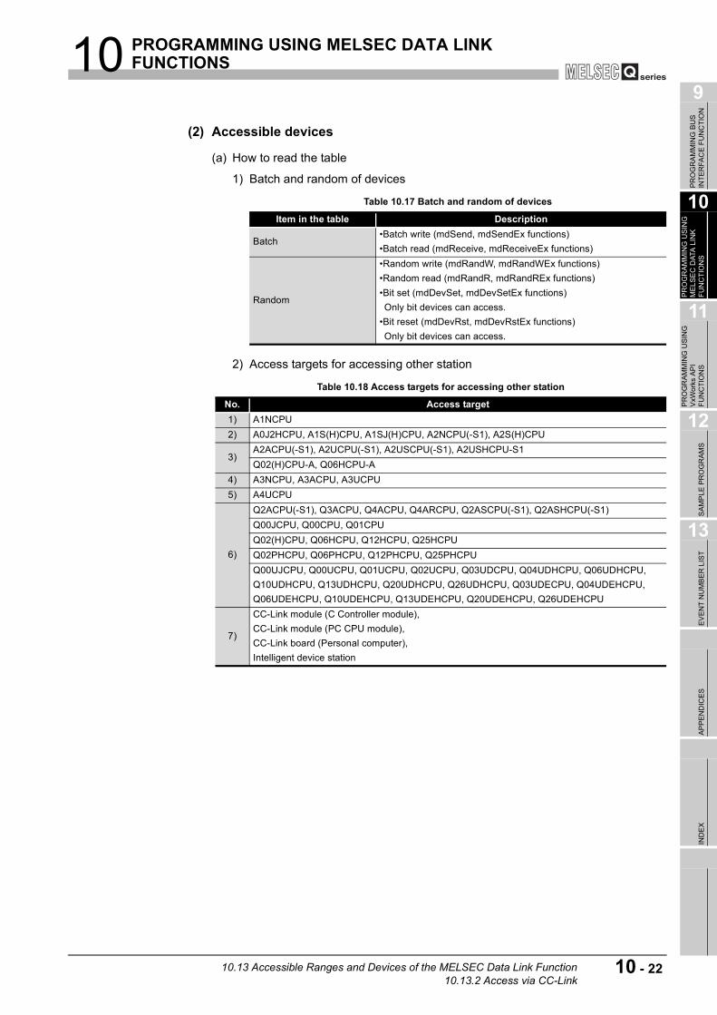
10 PROGRAMMING USING MELSEC DATA LINK FUNCTIONS
9
PR
OG
RAM
MIN
G B
US
IN
TER
FAC
E FU
NC
TIO
N
10
PR
OG
RAM
MIN
G U
SIN
G
MEL
SEC
DAT
A L
INK
FU
NC
TIO
NS
11
PR
OG
RAM
MIN
G U
SIN
G
VxW
orks
AP
I FU
NC
TIO
NS
12
SAM
PLE
PR
OG
RAM
S
13
EVEN
T N
UM
BER
LIS
TAP
PEN
DIC
ESIN
DEX
(2) Accessible devices
(a) How to read the table
1) Batch and random of devices
2) Access targets for accessing other station
Table 10.17 Batch and random of devices
Item in the table Description
Batch•Batch write (mdSend, mdSendEx functions)•Batch read (mdReceive, mdReceiveEx functions)
Random
•Random write (mdRandW, mdRandWEx functions)•Random read (mdRandR, mdRandREx functions)•Bit set (mdDevSet, mdDevSetEx functions)Only bit devices can access.
•Bit reset (mdDevRst, mdDevRstEx functions)Only bit devices can access.
Table 10.18 Access targets for accessing other station
No. Access target1) A1NCPU2) A0J2HCPU, A1S(H)CPU, A1SJ(H)CPU, A2NCPU(-S1), A2S(H)CPU
3)A2ACPU(-S1), A2UCPU(-S1), A2USCPU(-S1), A2USHCPU-S1Q02(H)CPU-A, Q06HCPU-A
4) A3NCPU, A3ACPU, A3UCPU5) A4UCPU
6)
Q2ACPU(-S1), Q3ACPU, Q4ACPU, Q4ARCPU, Q2ASCPU(-S1), Q2ASHCPU(-S1)Q00JCPU, Q00CPU, Q01CPUQ02(H)CPU, Q06HCPU, Q12HCPU, Q25HCPUQ02PHCPU, Q06PHCPU, Q12PHCPU, Q25PHCPUQ00UJCPU, Q00UCPU, Q01UCPU, Q02UCPU, Q03UDCPU, Q04UDHCPU, Q06UDHCPU, Q10UDHCPU, Q13UDHCPU, Q20UDHCPU, Q26UDHCPU, Q03UDECPU, Q04UDEHCPU, Q06UDEHCPU, Q10UDEHCPU, Q13UDEHCPU, Q20UDEHCPU, Q26UDEHCPU
7)
CC-Link module (C Controller module),CC-Link module (PC CPU module),CC-Link board (Personal computer),Intelligent device station
10.13 Accessible Ranges and Devices of the MELSEC Data Link Function10.13.2 Access via CC-Link
10 - 22

10 PROGRAMMING USING MELSEC DATA LINK FUNCTIONS
(b) Accessible devices for accessing own station
: Accessible : Inaccessible
(c) Accessible devices for accessing other station
: Accessible : Inaccessible * 1 When accessing to the device of No.32768 (8000H) or higher, use an extended function. (
Page 10-4, Section 10.2) * 2 Only the Q12DCCPU-V can access to the internal link relay (M) of the device number 32768
(8000H) or higher.(To the next page)
Table 10.19 Accessible devices for accessing own station
DeviceDevice type
(Device name specification)Accessibility
Own station RXBatch
DevXRandom
Own station RYBatch
DevYRandom
Own station SB (link special relay for CC-Link)
BatchDevSM
RandomOwn station SW (link special register for CC-Link)
BatchDevSD
RandomOwn station link register (for sending)
BatchDevWw
RandomOwn station link register (for receiving)
BatchDevWr
Random
Own station buffer memoryBatch
DevSPBRandom
Own station random access buffer
BatchDevMRB
Random
Table 10.20 Accessible devices for accessing other station
DeviceDevice type
(Device name specification)Access target
1) 2) 3) 4) 5) 6) 7)
XBatch
DevXRandom
YBatch
DevYRandom
LBatch
DevLRandom
M*1,*2 BatchDevM
RandomSM (special relay), SB (link special relay for MELSEC/H, CC-Link IE controller network, and CC-Link)
BatchDevSM
Random
FBatch
DevFRandom
T (contact)Batch
DevTTRandom
T (coil)Batch
DevTCRandom
C (contact)Batch
DevCTRandom
C (coil)Batch
DevCCRandom
T (current value)Batch
DevTNRandom
10 - 23 10.13 Accessible Ranges and Devices of the MELSEC Data Link Function10.13.2 Access via CC-Link

10 PROGRAMMING USING MELSEC DATA LINK FUNCTIONS
9
PR
OG
RAM
MIN
G B
US
IN
TER
FAC
E FU
NC
TIO
N
10
PR
OG
RAM
MIN
G U
SIN
G
MEL
SEC
DAT
A L
INK
FU
NC
TIO
NS
11
PR
OG
RAM
MIN
G U
SIN
G
VxW
orks
AP
I FU
NC
TIO
NS
12
SAM
PLE
PR
OG
RAM
S
13
EVEN
T N
UM
BER
LIS
TAP
PEN
DIC
ESIN
DEX
: Accessible : Inaccessible * 1 When accessing to the device of No.32768 (8000H) or higher, use an extended function. (
Page 10-4, Section 10.2) * 3 Only the following C Controller modules can access to the extended data register (D).
• Q12DCCPU-V• Q06CCPU-V with the serial number (first five digits) "10012" or later.
* 4 Access is not allowed for the A2ACPU(-S1). * 5 Access is not allowed for the Q00JCPU.
(To the next page)
Table 10.20Accessible devices for accessing other station (continued)
DeviceDevice type
(Device name specification)Access target
1) 2) 3) 4) 5) 6) 7)
C (current value)Batch
DevCNRandom
D*1,*3 BatchDevD
RandomSD (special register), SW (link special register for MELSECNET/H and CC-Link)
BatchDevSD
Random
T (main setting)Batch
DevTMRandom
T (sub setting 1)Batch
DevTS*4
Random
T (sub setting 2)Batch
DevTS2Random
T (sub setting 3)Batch
DevTS3Random
C (main setting)Batch
DevCMRandom
C (sub setting 1)Batch
DevCS*4
Random
C (sub setting 2)Batch
DevCS2Random
C (sub setting 3)Batch
DevCS3Random
ABatch
DevARandom
ZBatch
DevZRandom
V (index register)Batch
DevVRandom
R (file register)Batch
DevR *5Random
ZR (file register)*1Batch
DevZR *5Random
ER (extended register)Batch
DevER(0) to DevER(256) *5Random
10.13 Accessible Ranges and Devices of the MELSEC Data Link Function10.13.2 Access via CC-Link
10 - 24

10 PROGRAMMING USING MELSEC DATA LINK FUNCTIONS
: Accessible : Inaccessible
* 1 When accessing to the device of number 32768 (8000H) or higher, use an extended function. ( Page 10-4, Section 10.2)
* 6 Only the Q12DCCPU-V can access to the link relay (B) of the device number 32768 (8000H) or higher.
* 7 Only the following C Controller modules can access to the extended link register (W). • Q12DCCPU-V• Q06CCPU-V with the serial number (first five digits) "10012" or later.
(To the next page)
Table 10.20 Accessible devices for accessing other station (continued)
DeviceDevice type
(Device name specification)Access target
1) 2) 3) 4) 5) 6) 7)
B*1,*6 BatchDevB
Random
W*1,*7 BatchDevW
RandomQ/QnA link special relay (within Q/QnACPU)
BatchDevQSB
Random
Retentive timer (contact)Batch
DevSTTRandom
Retentive timer (coil)Batch
DevSTCRandom
Q/QnA link special register (within Q/QnACPU)
BatchDevQSW
RandomQ/QnA edge relay (within Q/QnACPU)
BatchDevQV
RandomOwn station random access buffer
BatchDevMRB
Random
Retentive timer (current value)Batch
DevSTNRandom
Own station link register (for sending)
BatchDevWw
RandomOwn station link register (for receiving)
BatchDevWr
Random
Own station buffer memoryBatch
DevSPBRandom
Q/QnA SEND function (with arrival confirmation)
BatchDevMAIL
RandomQ/QnA SEND function (no arrival confirmation)
BatchDevMAILNC
Random
10 - 25 10.13 Accessible Ranges and Devices of the MELSEC Data Link Function10.13.2 Access via CC-Link

10 PROGRAMMING USING MELSEC DATA LINK FUNCTIONS
9
PR
OG
RAM
MIN
G B
US
IN
TER
FAC
E FU
NC
TIO
N
10
PR
OG
RAM
MIN
G U
SIN
G
MEL
SEC
DAT
A L
INK
FU
NC
TIO
NS
11
PR
OG
RAM
MIN
G U
SIN
G
VxW
orks
AP
I FU
NC
TIO
NS
12
SAM
PLE
PR
OG
RAM
S
13
EVEN
T N
UM
BER
LIS
TAP
PEN
DIC
ESIN
DEX
: Accessible : Inaccessible
* 1 When accessing to the device of number 32768 (8000H) or higher, use an extended function. ( Page 10-4, Section 10.2)
* 8 Indicates the access to the buffer memory of a CC-Link module (intelligent device station) installed with each CPU module.Access is not allowed to multiple CPU systems (when the logical station number is specified).
Table 10.20 Accessible devices for accessing other station (continued)
DeviceDevice type
(Device name specification)Access target
1) 2) 3) 4) 5) 6) 7)Direct link input (Other station side)
BatchDevLX(1) to DevLX(255)
RandomDirect link output (Other station side)
BatchDevLY(1) to DevLY(255)
RandomDirect link relay (Other station side)
BatchDevLB(1) to DevLB(255)
RandomDirect link register (Other
station side)*1Batch
DevLW(1) to DevLW(255)Random
Direct link special relay (Other station side)
BatchDevLSB(1) to DevLSB(255)
Random
Direct link special register (Other station side)
BatchDevLSW(1) to DevLSW(255)
Random
Special direct buffer registerBatch
DevSPG(0) to DevSPG(255)Random
Other station buffer memory*8Batch
DevRBMRandom
Other station random access
buffer*8Batch
DevRABRandom
Other station RX*8Batch
DevRXRandom
Other station RY*8Batch
DevRYRandom
Other station link register*8Batch
DevRWRandom
Other station SB (Link special
relay for CC-Link) *8Batch
DevSBRandom
Other station SW (Link special
register for CC-Link)*8Batch
DevSWRandom
10.13 Accessible Ranges and Devices of the MELSEC Data Link Function10.13.2 Access via CC-Link
10 - 26

10 PROGRAMMING USING MELSEC DATA LINK FUNCTIONS
10.13.3 Access via MELSECNET/H
(1) Accessible range
(a) How to read the tableThe items from [1.Connected network] to [4.Target CPU] in Table 10.22 correspond to the numbers indicated in the figure below.
The numbers in the [4.Target CPU] column indicate the modules or boards for personal computer as in the table below.
Figure 10.8 Accessible range via MELSECNET/H
Table 10.21 Routing target CPU
No. CPU type1) C Controller module, PC CPU module2) MELSECNET/H board (personal computer)3) CC-Link IE controller network interface board (personal computer)
Q12DCCPU-V Q06CCPU-V Q06CCPU-V-B
1
2
3
4
C Controller module Connected network
Connected
station CPUConnected
module
Relayed
module
Target
CPU
Destination
module
Relayed network
10 - 27 10.13 Accessible Ranges and Devices of the MELSEC Data Link Function10.13.3 Access via MELSECNET/H

10 PROGRAMMING USING MELSEC DATA LINK FUNCTIONS
9
PR
OG
RAM
MIN
G B
US
IN
TER
FAC
E FU
NC
TIO
N
10
PR
OG
RAM
MIN
G U
SIN
G
MEL
SEC
DAT
A L
INK
FU
NC
TIO
NS
11
PR
OG
RAM
MIN
G U
SIN
G
VxW
orks
AP
I FU
NC
TIO
NS
12
SAM
PLE
PR
OG
RAM
S
13
EVEN
T N
UM
BER
LIS
TAP
PEN
DIC
ESIN
DEX
(b) Accessible range for own station and [2.Connected station CPU]The own station and [2.Connected station CPU] are all accessible.
(c) Accessible range for [4.Target CPU]
: Accessible : Inaccessible * 1 Only when all the CPU module connected and relay stations are Universal model QCPU, a CC-
Link IE controller network module of station number 65 or higher can be accessed. * 2 Access is allowed when the MELSECNET/H module of the connected station is in the MELSECNET/
H mode. * 3 Access is allowed when the MELSECNET/H module of the connected station is in the MELSECNET/
10 mode. * 4 Only the following C Controller modules can access to the C Controller module of the [4.Target
CPU].
* 5 Access is not allowed to PC CPU modules.
Table 10.22 Accessibility table
1.Connected network
2.Connected station CPU
3.Relayed network
4.Target CPU
QCPUQnACPU ACPU 1)
Board for personal computer
Q mode A mode 2) 3)
MELSECNET/H QCPU (Q mode)
CC-Link IE controller
network*1*4,*5
MELSECNET/H*2
MELSECNET/10*3
MELSECNET(II)
Ethernet
Computer linkCC-Link
MELSECNET/10
QCPU (Q mode)
CC-Link IE controller
network*1*4,*5
MELSECNET/H *5
MELSECNET/10 *5
MELSECNET(II)
Ethernet
Computer linkCC-Link
QnACPU
CC-Link IE controller networkMELSECNET/H
MELSECNET/10 *5
MELSECNET(II)
Ethernet
Computer linkCC-Link
QCPU (A mode), ACPU
CC-Link IE controller networkMELSECNET/H
MELSECNET/10 *5
MELSECNET(II)EthernetComputer linkCC-Link
•Q12DCCPU-V•Q06CCPU-V with the serial number (first five digits) "10012" or later.
10.13 Accessible Ranges and Devices of the MELSEC Data Link Function10.13.3 Access via MELSECNET/H
10 - 28

10 PROGRAMMING USING MELSEC DATA LINK FUNCTIONS
(2) Accessible devices
(a) How to read the table
1) Batch and random of devices
2) Access target for accessing other station
Table 10.23 Batch and random of devices
Item in the table Description
Batch•Batch write (mdSend, mdSendEx functions)•Batch read (mdReceive, mdReceiveEx functions)
Random
•Random write(mdRandW, mdRandWEx functions)•Random read(mdRandR, mdRandREx functions)•Bit set(mdDevSet, mdDevSetEx functions)Only bit devices can access.
•Bit reset(mdDevRst, mdDevRstEx functions)Only bit devices can access.
Table 10.24 Access target for accessing other station
No. Access target1) A1NCPU2) A0J2HCPU, A1S(H)CPU, A1SJ(H)CPU, A2NCPU(-S1), A2S(H)CPU
3)A2ACPU(-S1), A2UCPU(-S1), A2USCPU(-S1), A2USHCPU-S1Q02(H)CPU-A, Q06HCPU-A
4) A3NCPU, A3ACPU, A3UCPU5) A4UCPU
6)
Q2ACPU(-S1), Q3ACPU, Q4ACPU, Q4ARCPU, Q2ASCPU(-S1), Q2ASHCPU(-S1)Q00JCPU, Q00CPU, Q01CPUQ02(H)CPU, Q06HCPU, Q12HCPU, Q25HCPUQ02PHCPU, Q06PHCPU, Q12PHCPU, Q25PHCPUQ00UJCPU, Q00UCPU, Q01UCPU, Q02UCPU, Q03UDCPU, Q04UDHCPU, Q06UDHCPU, Q10UDHCPU, Q13UDHCPU, Q20UDHCPU, Q26UDHCPU, Q03UDECPU, Q04UDEHCPU, Q06UDEHCPU, Q10UDEHCPU, Q13UDEHCPU, Q20UDEHCPU, Q26UDEHCPU
7)
CC-Link IE controller network module (C Controller module),MELSECNET/H module (C Controller module),MELSECNET/H module (PC CPU module),CC-Link IE controller network interface board (personal computer),MELSECNET/H board (personal computer)
10 - 29 10.13 Accessible Ranges and Devices of the MELSEC Data Link Function10.13.3 Access via MELSECNET/H

10 PROGRAMMING USING MELSEC DATA LINK FUNCTIONS
9
PR
OG
RAM
MIN
G B
US
IN
TER
FAC
E FU
NC
TIO
N
10
PR
OG
RAM
MIN
G U
SIN
G
MEL
SEC
DAT
A L
INK
FU
NC
TIO
NS
11
PR
OG
RAM
MIN
G U
SIN
G
VxW
orks
AP
I FU
NC
TIO
NS
12
SAM
PLE
PR
OG
RAM
S
13
EVEN
T N
UM
BER
LIS
TAP
PEN
DIC
ESIN
DEX
(b) Accessible devices for accessing own station
: Accessible : Inaccessible
Table 10.25 Accessible devices for accessing own station
DeviceDevice type (Device name
specification)Accessibility
Own station input internal buffer (LX buffer)
BatchDevX
RandomOwn station output internal buffer (LY buffer)
BatchDevY
RandomOwn station link relay internal buffer (LB buffer)
BatchDevB
RandomOwn station link register internal buffer (LW buffer)
BatchDevW
Random
Q/QnA RECV functionBatch
DevMAILRandom
Own station direct link input (LX)
BatchDevLX(0)
RandomOwn station direct link output (LY)
BatchDevLY(0)
RandomOwn station direct link relay (LB)
BatchDevLB(0)
RandomOwn station direct link register (LW)
BatchDevLW(0)
RandomOwn station direct link special relay (SB)
BatchDevSB(0)
RandomOwn station direct link special register (SW)
BatchDevSW(0)
Random
10.13 Accessible Ranges and Devices of the MELSEC Data Link Function10.13.3 Access via MELSECNET/H
10 - 30

10 PROGRAMMING USING MELSEC DATA LINK FUNCTIONS
(c) Accessible devices for accessing other station
: Accessible : Inaccessible * 1 When accessing to the device of number 32768 (8000H) or higher, use an extended function.
( Page 10-4, Section 10.2) * 2 Only the Q12DCCPU-V can access to the internal link relay (M) of the device number 32768
(8000H) or higher. * 3 Only the following C Controller modules can access to the extended data register (D).
* 4 Access is not allowed for the A2ACPU(-S1).(To the next page)
Table 10.26 Accessible devices for accessing other station
DeviceDevice type
(Device name specification)Access target
1) 2) 3) 4) 5) 6) 7)
XBatch
DevXRandom
YBatch
DevYRandom
LBatch
DevLRandom
M*1,*2 BatchDevM
RandomSM (special relay), SB (link special relay for MELSECNET/H, CC-Link IE controller network and CC-Link)
BatchDevSM
Random
FBatch
DevFRandom
T (contact)Batch
DevTTRandom
T (coil)Batch
DevTCRandom
C (contact)Batch
DevCTRandom
C (coil)Batch
DevCCRandom
T (current value)Batch
DevTNRandom
C (current value)Batch
DevCNRandom
D*1,*3 BatchDevD
RandomSD (special register), SW (link special register for MELSECNET/H, CC-Link IE controller network and CC-Link)
Batch
DevSDRandom
T (main setting)Batch
DevTMRandom
T (sub setting 1)Batch
DevTS*4
Random
T (sub setting 2)Batch
DevTS2Random
T (sub setting 3)Batch
DevTS3Random
C (main setting)Batch
DevCMRandom
•Q12DCCPU-V•Q06CCPU-V with the serial number (first five digits) "10012" or later.
10 - 31 10.13 Accessible Ranges and Devices of the MELSEC Data Link Function10.13.3 Access via MELSECNET/H

10 PROGRAMMING USING MELSEC DATA LINK FUNCTIONS
9
PR
OG
RAM
MIN
G B
US
IN
TER
FAC
E FU
NC
TIO
N
10
PR
OG
RAM
MIN
G U
SIN
G
MEL
SEC
DAT
A L
INK
FU
NC
TIO
NS
11
PR
OG
RAM
MIN
G U
SIN
G
VxW
orks
AP
I FU
NC
TIO
NS
12
SAM
PLE
PR
OG
RAM
S
13
EVEN
T N
UM
BER
LIS
TAP
PEN
DIC
ESIN
DEX
: Accessible : Inaccessible
* 1 When accessing to the device of number 32768 (8000H) or higher, use an extended function. ( Page 10-4, Section 10.2)
* 4 Access is not allowed for the A2ACPU(-S1). * 5 Access is not allowed for the Q00JCPU. * 6 Only the Q12DCCPU-V can access to the internal link relay (M) of the device number 32768
(8000H) or higher. * 7 Only the following C Controller modules can access to the extended link register (W).
(To the next page)
Table 10.26 Accessible devices for accessing other station (continued)
DeviceDevice type
(Device name specification)Access target
1) 2) 3) 4) 5) 6) 7)
C (sub setting 1)Batch
DevCS*4
Random
C (sub setting 2)Batch
DevCS2Random
C (sub setting 3)Batch
DevCS3Random
ABatch
DevARandom
ZBatch
DevZRandom
V (index register)Batch
DevVRandom
R (file register)Batch
DevR *5Random
ZR (file register)*1Batch
DevZR *5Random
ER (extended file register)Batch
DevER(0) to DevER(256) *5Random
B*1,*6 BatchDevB
Random
W*1,*7 BatchDevW
RandomQ/QnA link special relay (within Q/QnACPU)
BatchDevQSB
Random
Retentive timer (contact)Batch
DevSTTRandom
Retentive timer (coil)Batch
DevSTCRandom
Q/QnA link special register (within Q/QnACPU)
BatchDevQSW
RandomQ/QnA edge relay (within Q/QnACPU)
BatchDevQV
RandomOwn station random access buffer
BatchDevMRB
Random
Retentive timer (current value)Batch
DevSTNRandom
Own station link register (for sending)
BatchDevWw
RandomOwn station link register (for receiving)
BatchDevWr
Random
•Q12DCCPU-V•Q06CCPU-V with the serial number (first five digits) "10012" or later.
10.13 Accessible Ranges and Devices of the MELSEC Data Link Function10.13.3 Access via MELSECNET/H
10 - 32

10 PROGRAMMING USING MELSEC DATA LINK FUNCTIONS
: Accessible : Inaccessible
* 1 When accessing to the device of number 32768 (8000H) or higher, use an extended function. ( Page 10-4, Section 10.2)
* 8 This function is used to send messages to a network module on the other station via a MELSECNET/H module.Access is not allowed to a multiple CPU system (when the logical station numbers are specified).
* 9 Access is not allowed for MELSECNET/H modules (PC CPU modules) and CC-Link IE controller network interface boards (personal computers).
Table 10.26 Accessible devices for accessing other station (continued)
DeviceDevice type
(Device name specification)Access target
1) 2) 3) 4) 5) 6) 7)
Own station buffer memoryBatch
DevSPBRandom
Q/QnA SEND function (with
arrival confirmation)*8Batch
DevMAIL*9
Random
Q/QnA SEND function (no
arrival confirmation)*8Batch
DevMAILNC*9
Random
Direct link input (other station side)
BatchDevLX(1) to DevLX(255)
RandomDirect link output (other station side)
BatchDevLY(1) to DevLY(255)
RandomDirect link relay (other station side)
BatchDevLB(1) to DevLB(255)
RandomDirect link register (other station
side)*1Batch
DevLW(1) to DevLW(255)Random
Direct link special relay (other station side)
BatchDevLSB(1) to DevLSB(255)
Random
Direct link special register (other station side)
BatchDevLSW(1) to DevLSW(255)
Random
Special direct buffer registerBatch
DevSPG(0) to DevSPG(255)Random
Other station buffer memoryBatch
DevRBMRandom
Other station random access buffer
BatchDevRAB
Random
Other station RXBatch
DevRXRandom
Other station RYBatch
DevRYRandom
Other station link registerBatch
DevRWRandom
Other station SB (link special relay for CC-Link)
BatchDevSB
RandomOther station SW (link special register for CC-Link)
BatchDevSW
Random
10 - 33 10.13 Accessible Ranges and Devices of the MELSEC Data Link Function10.13.3 Access via MELSECNET/H

10 PROGRAMMING USING MELSEC DATA LINK FUNCTIONS
9
PR
OG
RAM
MIN
G B
US
IN
TER
FAC
E FU
NC
TIO
N
10
PR
OG
RAM
MIN
G U
SIN
G
MEL
SEC
DAT
A L
INK
FU
NC
TIO
NS
11
PR
OG
RAM
MIN
G U
SIN
G
VxW
orks
AP
I FU
NC
TIO
NS
12
SAM
PLE
PR
OG
RAM
S
13
EVEN
T N
UM
BER
LIS
TAP
PEN
DIC
ESIN
DEX
10.13.4 Access via CC-Link IE controller network
(1) Accessible range
(a) How to read the tableThe items from [1.Connected network] to [4.Target CPU] in the Accessibility table correspond to the numbers indicated in the figure below.
The numbers in the [4.Target CPU] column indicate the modules or boards for personal computer as in the table below.
(b) Accessible range for own station and [2.Connected station CPU]The own station and [2.Connected station CPU] are all accessible.
(c) Accessible range for [4.Target CPU]
: Accessible : Inaccessible * 1 Only when all the CPU module on the connected and relay stations are Universal model QCPU, a
CC-Link IE controller network module of station number 65 or higher can be accessed. * 2 Access is not allowed when the connected station CPU is the Q00CPU or Q01CPU. * 3 Only the following C Controller modules can access to the C Controller module of the [4.Target
CPU].
* 4 Access is not allowed to the PC CPU modules.
Figure 10.9 Accessible range via CC-Link IE controller network
Table 10.27 Routing target CPU
No. CPU type1) C Controller module, PC CPU module2) MELSECNET/H board (personal computer)3) CC-Link IE controller network interface board (personal computer)
Table 10.28 Accessibility table
1.Connected network
2.Connected station CPU
3.Relayed network
4.Target CPU
QCPUQnACPU ACPU 1)
Board for personal computer
Q mode A mode 2) 3)
CC-Link IE controller network
QCPU (Q mode)
CC-Link IE controller network
*1,*2 *3,*4
MELSECNET/H *2 *4
MELSECNET/10 *2 *4
MELSECNET(II)
Ethernet
Computer linkCC-Link
•Q12DCCPU-V•Q06CCPU-V with the serial number (first five digits) "10012" or later.
Q12DCCPU-V Q06CCPU-V Q06CCPU-V-B
1
2
3
4
C Controller module Connected network
Connected
station CPUConnected
module
Relayed
module
Target
CPU
Destination
module
Relayed network
10.13 Accessible Ranges and Devices of the MELSEC Data Link Function10.13.4 Access via CC-Link IE controller network
10 - 34
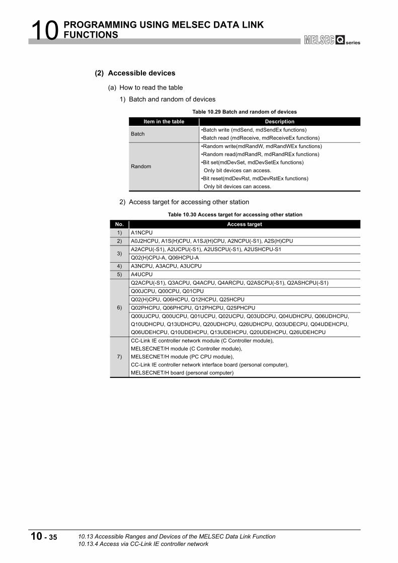
10 PROGRAMMING USING MELSEC DATA LINK FUNCTIONS
(2) Accessible devices
(a) How to read the table
1) Batch and random of devices
2) Access target for accessing other station
Table 10.29 Batch and random of devices
Item in the table Description
Batch•Batch write (mdSend, mdSendEx functions)•Batch read (mdReceive, mdReceiveEx functions)
Random
•Random write(mdRandW, mdRandWEx functions)•Random read(mdRandR, mdRandREx functions)•Bit set(mdDevSet, mdDevSetEx functions)Only bit devices can access.
•Bit reset(mdDevRst, mdDevRstEx functions)Only bit devices can access.
Table 10.30 Access target for accessing other station
No. Access target1) A1NCPU2) A0J2HCPU, A1S(H)CPU, A1SJ(H)CPU, A2NCPU(-S1), A2S(H)CPU
3)A2ACPU(-S1), A2UCPU(-S1), A2USCPU(-S1), A2USHCPU-S1Q02(H)CPU-A, Q06HCPU-A
4) A3NCPU, A3ACPU, A3UCPU5) A4UCPU
6)
Q2ACPU(-S1), Q3ACPU, Q4ACPU, Q4ARCPU, Q2ASCPU(-S1), Q2ASHCPU(-S1)Q00JCPU, Q00CPU, Q01CPUQ02(H)CPU, Q06HCPU, Q12HCPU, Q25HCPUQ02PHCPU, Q06PHCPU, Q12PHCPU, Q25PHCPUQ00UJCPU, Q00UCPU, Q01UCPU, Q02UCPU, Q03UDCPU, Q04UDHCPU, Q06UDHCPU, Q10UDHCPU, Q13UDHCPU, Q20UDHCPU, Q26UDHCPU, Q03UDECPU, Q04UDEHCPU, Q06UDEHCPU, Q10UDEHCPU, Q13UDEHCPU, Q20UDEHCPU, Q26UDEHCPU
7)
CC-Link IE controller network module (C Controller module),MELSECNET/H module (C Controller module),MELSECNET/H module (PC CPU module),CC-Link IE controller network interface board (personal computer),MELSECNET/H board (personal computer)
10 - 35 10.13 Accessible Ranges and Devices of the MELSEC Data Link Function10.13.4 Access via CC-Link IE controller network

10 PROGRAMMING USING MELSEC DATA LINK FUNCTIONS
9
PR
OG
RAM
MIN
G B
US
IN
TER
FAC
E FU
NC
TIO
N
10
PR
OG
RAM
MIN
G U
SIN
G
MEL
SEC
DAT
A L
INK
FU
NC
TIO
NS
11
PR
OG
RAM
MIN
G U
SIN
G
VxW
orks
AP
I FU
NC
TIO
NS
12
SAM
PLE
PR
OG
RAM
S
13
EVEN
T N
UM
BER
LIS
TAP
PEN
DIC
ESIN
DEX
(b) Accessible devices for accessing own station
: Accessible : Inaccessible * 1 When accessing to the device of number 32768 (8000H) or higher, use an extended function.
( Page 10-4, Section 10.2)
Table 10.31 Accessible devices for accessing own station
DeviceDevice type (Device name
specification)Accessibility
Own station input internal buffer (LX buffer)
BatchDevX
RandomOwn station output internal buffer (LY buffer)
BatchDevY
RandomOwn station link relay internal buffer (LB buffer)
BatchDevB
RandomOwn station link register internal buffer (LW buffer)
BatchDevW
Random
Q/QnA RECV functionBatch
DevMAILRandom
Own station direct link input (LX)
BatchDevLX(0)
RandomOwn station direct link output (LY)
BatchDevLY(0)
RandomOwn station direct link relay (LB)
BatchDevLB(0)
RandomOwn station direct link register
(LW)*1Batch
DevLW(0)Random
Own station direct link special relay (SB)
BatchDevSB(0)
RandomOwn station direct link special register (SW)
BatchDevSW(0)
Random
10.13 Accessible Ranges and Devices of the MELSEC Data Link Function10.13.4 Access via CC-Link IE controller network
10 - 36

10 PROGRAMMING USING MELSEC DATA LINK FUNCTIONS
(c) Accessible devices for accessing other station
: Accessible : Inaccessible * 1 When accessing to the device of number 32768 (8000H) or higher, use an extended function.
( Page 10-4, Section 10.2) * 2 Only the Q12DCCPU-V can access to the internal link relay (M) of the device number 32768
(8000H) or higher. * 3 Only the following C Controller modules can access to the extended data register (D).
* 4 Access is not allowed for the A2ACPU(-S1).(To the next page)
Table 10.32 Accessible devices for accessing other station
DeviceDevice type
(Device name specification)Access target
1) 2) 3) 4) 5) 6) 7)
XBatch
DevXRandom
YBatch
DevYRandom
LBatch
DevLRandom
M*1,*2 BatchDevM
RandomSM(special relay),SB(link special relay for MELSECNET/H, CC-Link IE controller network and CC-Link)
BatchDevSM
Random
FBatch
DevFRandom
T (contact)Batch
DevTTRandom
T (coil)Batch
DevTCRandom
C (contact)Batch
DevCTRandom
C (coil)Batch
DevCCRandom
T (current value)Batch
DevTNRandom
C (current value)Batch
DevCNRandom
D*1,*3 BatchDevD
RandomSD(special register), SW (link special register for MELSECNET/H, CC-Link IE controller network and CC-Link)
Batch
DevSDRandom
T (main setting)Batch
DevTMRandom
T (sub setting 1)Batch
DevTS*4
Random
T (sub setting 2)Batch
DevTS2Random
T (sub setting 3)Batch
DevTS3Random
C (main setting)Batch
DevCMRandom
•Q12DCCPU-V•Q06CCPU-V with the serial number (first five digits) "10012" or later.
10 - 37 10.13 Accessible Ranges and Devices of the MELSEC Data Link Function10.13.4 Access via CC-Link IE controller network

10 PROGRAMMING USING MELSEC DATA LINK FUNCTIONS
9
PR
OG
RAM
MIN
G B
US
IN
TER
FAC
E FU
NC
TIO
N
10
PR
OG
RAM
MIN
G U
SIN
G
MEL
SEC
DAT
A L
INK
FU
NC
TIO
NS
11
PR
OG
RAM
MIN
G U
SIN
G
VxW
orks
AP
I FU
NC
TIO
NS
12
SAM
PLE
PR
OG
RAM
S
13
EVEN
T N
UM
BER
LIS
TAP
PEN
DIC
ESIN
DEX
: Accessible : Inaccessible
* 1 When accessing to the device of number 32768 (8000H) or higher, use an extended function.
( Page 10-4, Section 10.2) * 4 Access is not allowed for the A2ACPU(-S1). * 5 Access is not allowed for the Q00JCPU. * 6 Only the Q12DCCPU-V can access to the internal link relay (B) of the device number 32768
(8000H) or higher. * 7 Only the following C Controller modules can access to the extended link register (W).
(To the next page)
Table 10.32 Accessible devices for accessing other station (continued)
DeviceDevice type
(Device name specification)Access target
1) 2) 3) 4) 5) 6) 7)
C (sub setting 1)Batch
DevCS*4
Random
C (sub setting 2)Batch
DevCS2Random
C (sub setting 3)Batch
DevCS3Random
ABatch
DevARandom
ZBatch
DevZRandom
V (index register)Batch
DevVRandom
R (file register)Batch
DevR *5Random
ZR (file register)*1Batch
DevZR *5Random
ER (extended file register)Batch
DevER(0) to DevER(256) *5Random
B*1, *6 BatchDevB
Random
W*1, *7 BatchDevW
RandomQ/QnA link special relay (within Q/QnACPU)
BatchDevQSB
Random
Retentive timer (contact)Batch
DevSTTRandom
Retentive timer (coil)Batch
DevSTCRandom
Q/QnAlink special register (within Q/QnACPU)
BatchDevQSW
RandomQ/QnA edge relay (within Q/QnACPU)
BatchDevQV
RandomOwn station random access buffer
BatchDevMRB
Random
Retentive timer (current value)Batch
DevSTNRandom
Own station link register (for sending)
BatchDevWw
RandomOwn station link register (for receiving)
BatchDevWr
Random
•Q12DCCPU-V•Q06CCPU-V with the serial number (first five digits) "10012" or later.
10.13 Accessible Ranges and Devices of the MELSEC Data Link Function10.13.4 Access via CC-Link IE controller network
10 - 38
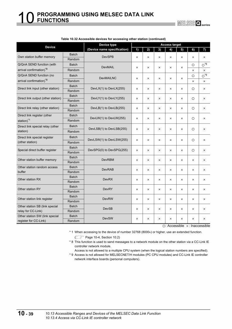
10 PROGRAMMING USING MELSEC DATA LINK FUNCTIONS
: Accessible : Inaccessible
* 1 When accessing to the device of number 32768 (8000H) or higher, use an extended function.
( Page 10-4, Section 10.2) * 8 This function is used to send messages to a network module on the other station via a CC-Link IE
controller network module.Access is not allowed to a multiple CPU system (when the logical station numbers are specified).
* 9 Access is not allowed for MELSECNET/H modules (PC CPU modules) and CC-Link IE controller network interface boards (personal computers).
Table 10.32 Accessible devices for accessing other station (continued)
DeviceDevice type
(Device name specification)Access target
1) 2) 3) 4) 5) 6) 7)
Own station buffer memoryBatch
DevSPBRandom
Q/QnA SEND function (with
arrival confirmation)*8Batch
DevMAIL*9
Random
Q/QnA SEND function (no
arrival confirmation)*8Batch
DevMAILNC*9
Random
Direct link input (other station)Batch
DevLX(1) to DevLX(255)Random
Direct link output (other station)Batch
DevLY(1) to DevLY(255)Random
Direct link relay (other station)Batch
DevLB(1) to DevLB(255)Random
Direct link register (other
station)*1Batch
DevLW(1) to DevLW(255)Random
Direct link special relay (other station)
BatchDevLSB(1) to DevLSB(255)
Random
Direct link special register (other station)
BatchDevLSW(1) to DevLSW(255)
Random
Special direct buffer registerBatch
DevSPG(0) to DevSPG(255)Random
Other station buffer memoryBatch
DevRBMRandom
Other station random access buffer
BatchDevRAB
Random
Other station RXBatch
DevRXRandom
Other station RYBatch
DevRYRandom
Other station link registerBatch
DevRWRandom
Other station SB (link special relay for CC-Link)
BatchDevSB
RandomOther station SW (link special register for CC-Link)
BatchDevSW
Random
10 - 39 10.13 Accessible Ranges and Devices of the MELSEC Data Link Function10.13.4 Access via CC-Link IE controller network

11 PROGRAMMING USING VxWorks API FUNCTIONS
9
PR
OG
RAM
MIN
G B
US
IN
TER
FAC
E FU
NC
TIO
N
10
PR
OG
RAM
MIN
G U
SIN
G
MEL
SEC
DAT
A L
INK
FU
NC
TIO
NS
11
PR
OG
RAM
MIN
G U
SIN
G
VxW
orks
AP
I FU
NC
TIO
NS
12
SAM
PLE
PR
OG
RAM
S
13
EVEN
T N
UM
BER
LIS
TAP
PEN
DIC
ESIN
DEX
CHAPTER 11 PROGRAMMING USING VxWorks API FUNCTIONS
For the component list and information checking method of the VxWorks component implemented in the C Controller module, refer to the following.
Page App-1, "Appendix 1 VxWorks Component List"
For each component functionality and VxWorks API functions, refer to the manual for VxWorks.
(1) Sample program using VxWorks functionsInstalling SW PVC-CCPU registers the sample programs of the following functions. ( Page 12-1, CHAPTER 12)
• The Connect function between C Controller module and GOT (Microcomputer connection)
• The RAM disk function
(2) Precautions for using VxWorks API functions
(a) Changing the system clock rateThe C Controller module supports system clock rate of 60 to 1000. (Default: 60)When changing the system clock rate, use the sysClkRateSet function.For setting and changing the system clock rate, refer to the manual for VxWorks.
(3) Precautions for the Wind River Systems productWe, Mitsubishi, make no warranty for the Wind River Systems product and will not be liable for any problems and damages caused by the Wind River Systems product during use of the C Controller module. For the problems or specifications of the Wind River Systems product, refer to the corresponding manual or consult Wind River Systems, Inc.Contact information is available on the following website.http://www.windriver.com/
Q12DCCPU-V Q06CCPU-V Q06CCPU-V-B
11 - 1

11 PROGRAMMING USING VxWorks API FUNCTIONS
Memo
11 - 2

12 SAMPLE PROGRAMS
9
PR
OG
RAM
MIN
G B
US
IN
TER
FAC
E FU
NC
TIO
N
10
PR
OG
RAM
MIN
G U
SIN
G
MEL
SEC
DAT
A L
INK
FU
NC
TIO
NS
11
PR
OG
RAM
MIN
G U
SIN
G
VxW
orks
AP
I FU
NC
TIO
NS
12
SAM
PLE
PR
OG
RAM
S
13
EVEN
T N
UM
BER
LIS
TAP
PEN
DIC
ESIN
DEX
CHAPTER 12 SAMPLE PROGRAMS
Sample programs are provided as a reference used in creating user programs.Please use the sample programs at user's own discretion.
(1) Sample programs for the Q12DCCPU-VSample programs for the Q12DCCPU-V are installed in "C:\MELSEC\CCPU\CCPUTOOL\Sample\DVx" (When SW PVC-CCPU has been installed in "C:\MELSEC".).
(To the next page)
Table 12.1 Registered sample programs
Folder name File name Description of sample programGOTtest GOTtest.c For connection to GOT.
MDtest DevAccess
DevAccessChanCCIEC.c
For access to the following modules using MELSEC data link functions•A CC-Link IE controller network module (own station) controlled by the C Controller module.
•CC-Link IE controller network modules or programmable controller CPUs on other stations via a CC-Link IE controller network module controlled by the C Controller module.
DevAccessChanCCL.c
For access to the following modules using MELSEC data link functions•A CC-Link module (own station) controlled by the C Controller module.•CC-Link modules or programmable controller CPUs on other stations via a CC-Link module controlled by the C Controller module.
DevAccessChanMNH.c
For access to the following modules using MELSEC data link functions•A MELSECNET/H module (host station) controlled by the C Controller module.•MELSECNET/H modules or programmable controller CPUs on other stations via a MELSECNET/H module controlled by the C Controller module.
DevAccessChanQBF.c
For access to the following module using MELSEC data link functions•CPU No.1 mounted together with the C Controller module in a multiple CPU system.
Others
CFTaskPrioritySet.c
For priority (default: 50) change of the system task (XBD service task) which operates when accessing to a CompactFlash card.
FTPGet.c For FTP communicationsMakeRAMDisk.c For RAM disk creation
QD75Status.cFor 1-shot monitoring of the positioning module status (current feed value, axis error No., and axis warning No.)
QPParamSet.cFor automatic transfer of the parameter file created in GX Configurator-QP to a positioning module
SntpTimeSet.c For setting clock data by acquiring the data from the SNTP server computer
Q12DCCPU-V Q06CCPU-V Q06CCPU-V-B
12 - 1

12 SAMPLE PROGRAMS
(2) Sample programs for the Q06CCPU-V(-B)Sample programs for the Q06CCPU-V(-B) are installed in "C:\MELSEC\CCPU\CCPUTOOL\Sample\Vx" (When SW PVC-CCPU has been installed in "C:\MELSEC".).
(To the next page)
Table 12.1 Registered sample programs (continued)
Folder name File name Description of sample program
QBFtest
CFChange CFChange.c For unmounting a CompactFlash card when X0 turns onEntryWDTInt EntryWDTInt.c For user watchdog timer error interrupt registration
MotionLinkMotionLink.c The linkage with the Motion CPU is utilized for this sample program.
MotionSyncInt.cFor execution of the interrupt process synchronizing with the multiple CPU high speed transmission with either the Q172DCPU or Q173DCPU.
QBFMessage QBFMessage.c For sending messages via MELSECNET/H
Script
LoginUserRegist STARTUP.CMD Sample script file for login user registrationParamBackUp STARTUP.CMD Sample script file for parameter backupParamRestore STARTUP.CMD Sample script file for parameter restorationRAMFormat STARTUP.CMD Sample script file for standard RAM formatting
Table 12.2 Registered sample programs
Folder name File name Description of sample programGOTtest GOTtest.c For connection to GOT
MDtest DevAccess
DevAccessChanCCIEC.c
For access to the following modules using MELSEC data link functionsFor the Q06CCPU-V-B, this sample program cannot be used.•A CC-Link IE controller network module (own station) controlled by the C Controller module.
•CC-Link IE controller network modules or programmable controller CPUs on other stations via a CC-Link IE controller network module controlled by the C Controller module.
DevAccessChanCCL.c
For access to the following modules using MELSEC data link functionsFor the Q06CCPU-V-B, this sample program cannot be used.•A CC-Link module (own station) controlled by the C Controller module.•CC-Link modules and programmable controller CPUs on other stations via a CC-Link module controlled by the C Controller module.
DevAccessChanMNH.c
For access to the following modules using MELSEC data link functionsFor the Q06CCPU-V-B, this sample program cannot be used.•A MELSECNET/H module (host station) controlled by the C Controller module.•MELSECNET/H modules and programmable controller CPUs on other stations via a MELSECNET/H module controlled by the C Controller module.
DevAccessChanQBF.c
For access to the following module using MELSEC data link functionsFor the Q06CCPU-V-B, this sample program cannot be used.•CPU No.1 configuring a multiple CPU system with the C Controller module.
12 - 2

12 SAMPLE PROGRAMS
9
PR
OG
RAM
MIN
G B
US
IN
TER
FAC
E FU
NC
TIO
N
10
PR
OG
RAM
MIN
G U
SIN
G
MEL
SEC
DAT
A L
INK
FU
NC
TIO
NS
11
PR
OG
RAM
MIN
G U
SIN
G
VxW
orks
AP
I FU
NC
TIO
NS
12
SAM
PLE
PR
OG
RAM
S
13
EVEN
T N
UM
BER
LIS
TAP
PEN
DIC
ESIN
DEX
Remark
Sample programs which cannot be used in the C Controller module contain the notification message as shown below.
Table 12.2 Registered sample programs (continued)
Folder name File name Description of sample program
Others
FTPGet.c For FTP communicationMakeRAMDisk.c For RAM disk creation
QD75Status.cFor 1-shot monitoring of the positioning module status (current feed value, axis error No., and axis warning No.)
QPParamSet.cFor automatic transfer of the parameter file created in GX Configurator-QP to a positioning module
SntpTimeSet.c For setting clock data by acquiring the data from the SNTP server computer
QBFtest
CFChange CFChange.cFor unmounting a CompactFlash card when X0 turns onFor the Q06CCPU-V-B, this sample program cannot be used.
EntryWDTInt EntryWDTInt.c For user watchdog timer error interrupt registrationMotionLink MotionLink.c The linkage with the Motion CPU is used for this sample program.QBFMessage QBFMessage.c For sending messages via MELSECNET/HShutdown ROMShutdown.c For shutting down the standard ROM when X0 turns on
Script
LoginUserRegist STARTUP.CMD Sample script file for login user registrationParamBackUp STARTUP.CMD Sample script file for parameter backupParamRestore STARTUP.CMD Sample script file for parameter restorationROMFormat STARTUP.CMD Sample script file for standard ROM formatting
Figure 12.1 A sample program which cannot be used in the Q06CCPU-V-B
/**************************************************************************/
/* */
/* */
/* */
/* */
/* */
/* */
/* */
/* */
Sample program
When X0 is ON, unmount the CF card.
Note)
This sample program cannot be used because
Q06CCPU-V-B does not support CF card interface.
If the following functions are executed, unsupported
communications path error (19203 [0x4B03]) will be
returned.
12 - 3

13 EVENT NUMBER LIST
CHAPTER 13 EVENT NUMBER LIST
When an event such as an error occurs in the C Controller system, information required to correct errors such as an event No. is displayed on the Event history tab. When an event has occurred, check the event No. in the following procedure and take corrective actions.
POINTWhen more than one event occur, take corrective actions for each event in chronological order.
1) Open the "Detailed event information" screen by double-clicking on a event to correct on the history screen of C Controller setting utility. ( Page 4-7, Section 4.3 (3))
2) When "Application" is shown in the "Event type" field, it indicates that the event was registered by the user program (QBF_RegistEventLog function). Take corrective actions determined by user.
3) The following "Event type" indicate that the event has occurred in the C Controller system.
• System (Info.) • System (Warning) • System (Err.)
Check "source" and "event No." on the Detailed event information screen, and take corrective actions referring to the following table.
Figure 13.1 Detailed event information screen
Table 13.1 Source list
Source Data typeReference
pageMQbfDrv Bus interface driver (bus part) related Page 13-2MXwdkDrv Bus interface driver (system part) related Page 13-3MUtlIfQbf Utility communication interface (bus interface part) related Page 13-3
MUtlIfMdUtility communication interface (MELSEC communication part) related
Page 13-4
MUtlIfCom Utility communication interface (common part) related Page 13-4MMain C Controller module main part related Page 13-5MFDrv Flash ROM and standard RAM related Page 13-5MCfDrv CompactFlash card related Page 13-7MEtherDrv Ethernet related Page 13-8
Q12DCCPU-V Q06CCPU-V Q06CCPU-V-B
13 - 1

13 EVENT NUMBER LIST
9
PR
OG
RAM
MIN
G B
US
IN
TER
FAC
E FU
NC
TIO
N
10
PR
OG
RAM
MIN
G U
SIN
G
MEL
SEC
DAT
A L
INK
FU
NC
TIO
NS
11
PR
OG
RAM
MIN
G U
SIN
G
VxW
orks
AP
I FU
NC
TIO
NS
12
SAM
PLE
PR
OG
RAM
S
13
EVEN
T N
UM
BER
LIS
TAP
PEN
DIC
ESIN
DEX
(1) When the source is "MQbfDrv"When taking corrective actions of corresponding error code, refer to HELP of C Controller setting utility.
Table 13.2 Corrective actions
Event No. Event Corrective action
C000011EH Failed to allocate memory required for the driver start-up.Increase the system memory.Reduce the memory usage of other programs.
C0000127H SYSTEM WDT ERROR occurred. Take corrective actions for error code 5000.C0000131H USER WDT ERROR occurred. Take corrective actions for error code 5001.C0000201H AC/DC DOWN occurred. Take corrective actions for error code 5001.
C0000202H CONTROL-BUS.ERR. occurred.Take corrective actions for error code 1413, 1414, 1415, and 1416.
C0000204H UNIT VERIFY ERR. occurred. Take corrective actions for error code 2000.
C0000206H FUSE BREAK OFF occurred. Take corrective actions for error code 1300.
C0000207H SP.UNIT DOWN occurred.Take corrective actions for error code 1401 and 1403.
C0000208H CONTROL-BUS.ERR. occurred. Take corrective actions for error code 1412.
C0000209H SP.UNIT LAY ERR. occurred.Take corrective actions for error code 2100, 2103, 2106, 2107, 2108, 2120, 2121, 2122, 2124, 2125, 2126, and 2150.
C000020AH PARAMETER ERROR occurred.Take corrective actions for error code 3000, 3001, 3010, 3012, 3014, 3015, and 3016.
C000020BHAn error occurred during module initialization.(Only the first error is displayed.)
Take corrective actions corresponding to the error code displayed in the event information.
C000020EH A CPU module built-in battery error occurred. Take corrective actions for error code 1600.
C0000210H MULTI CPU DOWN occurred.Take corrective actions for error code 7000 and 7002.
C0000211H MULTI EXE.ERROR occurred.Take corrective actions for error code 7010, 7011, and 7013.
C0000212H MULTI CPU ERROR occurred. Take corrective actions for error code 7020.
C0000213H SP.PARAMETER ERROR occurred.Take corrective actions for error code 3300, 3301, 3302, and 3303.
C0000214H LINK PARAMETER ERROR occurred.Take corrective actions for error code 3100, 3101, 3102, 3103, 3104, 3105, and 3107.
C0000215H I/O INT.ERROR occurred. Take corrective actions for error code 1310.
C0000216H MAIN CPU DOWN occurred.Take corrective actions for error code 1000 and 1009.
C0000217H A momentary stop occurred. Take corrective actions for error code 1500.C0000218H LINK REFRESH TIME OVER occurred. Take corrective actions for error code 5012.C0000219H SINGLE PS.DOWN occurred. Take corrective actions for error code 1510.C000021AH SINGLE PS.ERROR occurred. Take corrective actions for error code 1520.
C000021BH MULTI-C.BUS.ERR. occurred.Take corrective actions for error code 1430, 1431, 1432, 1433, 1434, 1435, 1436, 1437, and 1439.
C000021CH CPU LAY ERROR occurred. Take corrective actions for error code 7036.
13 - 2

13 EVENT NUMBER LIST
(2) When the source is "MXwdkDrv"
(3) When source is "MUtlIfQbf"
Table 13.3 Corrective action
Event No. Event Corrective action
40000000H
The clock data of the C Controller module has been set.This event occurs when:•Clock data are set by executing the QBF_SetTime function.•Clock data are set by C Controller setting utility.
C0000001H An exceptional error occurred.
Reexamine the user program by checking the event detail information (such as error details, task names, and program counters). Check the operation methods of Workbench or Tornado as well.Please consult your local Mitsubishi service center or representative, explaining the details of the problem.
40000002H
The clock data were corrected by the clock synchronization function.This event is registered when a clock data difference from a CPU No. 1 is detected after enabling the Clock synchronization function.
Table 13.4 Corrective action
Event No. Event Corrective action
C0000000H An illegal packet error occurred.Check the port No. used and change it if necessary.Change the IP address.
C0000001H An instruction error occurred.Check the utility and the C Controller module versions.
C0000002H An socket generation error occurred.
Restart the C Controller module.Please consult your local Mitsubishi service center or representative, explaining the details of the problem.
C0000003H An port acquisition error occurred.Check the port No. used.Check for overlap between the C Controller module ports.
C0000004H A bind error occurred.
Restart the C Controller module.Please consult your local Mitsubishi service center or representative, explaining the details of the problem.
13 - 3

13 EVENT NUMBER LIST
9
PR
OG
RAM
MIN
G B
US
IN
TER
FAC
E FU
NC
TIO
N
10
PR
OG
RAM
MIN
G U
SIN
G
MEL
SEC
DAT
A L
INK
FU
NC
TIO
NS
11
PR
OG
RAM
MIN
G U
SIN
G
VxW
orks
AP
I FU
NC
TIO
NS
12
SAM
PLE
PR
OG
RAM
S
13
EVEN
T N
UM
BER
LIS
TAP
PEN
DIC
ESIN
DEX
(4) When source is "MUtlIfMd"
(5) When the source is "MUtlIfCom"
Table 13.5 Corrective action
Event No. Event Corrective action
C0000000H An illegal packet error occurred.Check the port No. used and change it if necessary.Change the IP address.
C0000001H An instruction error occurred.Check the utility and C Controller module versions.
C0000002H A socket generation error occurred.
Restart the C Controller module.Please consult your local Mitsubishi service center or representative, explaining the details of the problem.A port acquisition error occurred.
C0000003H A port acquisition error occurred.Check the port No. used.Check for overlap between the C Controller module ports.
C0000004H A bind error occurred.
Restart the C Controller module.Please consult your local Mitsubishi service center or representative, explaining the details of the problem.
Table 13.6 Corrective action
Event No. Event Corrective action
C0000000H An illegal packet error occurred.Check the port No. used and change it if necessary.Change the IP address.
C0000001H An instruction error occurred.Check the utility and C Controller module versions.
C0000002H A socket generation error occurred.
Restart the C Controller module.Please consult your local Mitsubishi service center or representative, explaining the details of the problem.
C0000003H A port acquisition error occurred.Check the port No. used.Check for overlap between the C Controller module ports.
C0000004H A bind error occurred.
Restart the C Controller module.Please consult your local Mitsubishi service center or representative, explaining the details of the problem.
13 - 4

13 EVENT NUMBER LIST
(6) When the source is "MMain"When taking corrective actions for an error code, refer to HELP of C Controller setting utility.
(7) When the source is "MFDrv"When taking corrective actions for an error code, refer to HELP of C Controller setting utility.
(To the next page)
Table 13.7 Corrective action
Event No. Event Corrective action
C0000110H A script execution error occurred.
A system error in the C Controller module is possible.Please consult your local Mitsubishi service center or representative, explaining the details of the problem.
C0000111H
One of commands (lines) in the script file has more than 129 characters. (A stop error occurs in the C Controller module [CPU error code 2502] and the module stops execution of the script command.)
Correct or delete the description of the script file where the error occurred, and restart the C Controller module.(Take corrective actions for error code 2502.)
C0000330H Failed to access LAN.
The parameter file (IP address setting area) does not exist. Using the C Controller setting utility, set the IP address or write the parameters.A system error in the C Controller is possible cause.Please consult your local Mitsubishi service center or representative, explaining the details of the problem.
Table 13.8 Corrective action
Event No. Event Corrective action
80000000H
•Q12DCCPU-VAn illegal access was occurred in standard ROM drive.
•Q06CCPU-V(-B)The number of standard ROM drive "/ROM" deletions exceeded 100 thousand times.
•Q12DCCPU-VIt might be a breakdown of the C Controller module.Please consult your local Mitsubishi service center or representative, explaining the details of the problem.
•Q06CCPU-V(-B)Change the writing media from the standard ROM drive to the CompactFlash card (/CF), or replace the C Controller module.
C0000400H A standard ROM drive "/ROM" format error occurred. Reformat the standard ROM drive (/ROM).
C0000401H Usage of the buttery backed-up RAM exceeded the capacity.
A system error in the C Controller is possible cause.Please consult your local Mitsubishi service center or representative, explaining the details of the problem.
13 - 5

13 EVENT NUMBER LIST
9
PR
OG
RAM
MIN
G B
US
IN
TER
FAC
E FU
NC
TIO
N
10
PR
OG
RAM
MIN
G U
SIN
G
MEL
SEC
DAT
A L
INK
FU
NC
TIO
NS
11
PR
OG
RAM
MIN
G U
SIN
G
VxW
orks
AP
I FU
NC
TIO
NS
12
SAM
PLE
PR
OG
RAM
S
13
EVEN
T N
UM
BER
LIS
TAP
PEN
DIC
ESIN
DEX
Table 13.8 Corrective action (continued)
Event No. Event Corrective action
80000406HA timeout occurred during writing to file in the standard ROM drive "/ROM".
Write the file again if the file was not written correctly.If this event occurs frequently, reexamine the user program (processing, task priority, etc.) that runs on the C Controller module.
C0000408H Abnormality of battery backup RAM was detected.
A system error in the C Controller module is probable. Please consult your local Mitsubishi service center or representative, explaining the details of the problem.
C0000409HAbnormality of internal ROM ("/ROM","/SYSTEMROM") was detected.
A system error in the C Controller module is probable. Please consult your local Mitsubishi service center or representative, explaining the details of the problem.
C000040AH MAIN CPU DOWN was occurred. It refers to the Error Code 1000.
C0000410H A standard RAM drive "/RAM" format error occurred.
Reformat the standard RAM drive (/RAM).When this event is generated even if it formats it again, it might be a breakdown of the C Controller module. Please consult your local Mitsubishi service center or representative, explaining the details of the problem.
C0000416H Abnormality of the standard RAM drive "/RAM" was detected. It refers to the Error Code 1106.C0000417H RAM ERROR was occurred. It refers to the Error Code 1106.
13 - 6

13 EVENT NUMBER LIST
(8) When the source is "MCfDrv"Table 13.9 Corrective action
Event No. Event Corrective action
C0000480H CF card is not responding.The CompactFlash Card is pulled out once, and it inserts it again.Replace the CompactFlash card.
C0000481H An error occurred during acquiring the CF drive information.The CompactFlash Card is pulled out once, and it inserts it again.Replace the CompactFlash card.
C0000482H An error occurred during reading master boot record (MBR).
The CompactFlash Card is pulled out once, and it inserts it again.Reformat the CompactFlash card on a personal computer, etc.Replace the CompactFlash card.
C0000483H The master boot record (MBR) cannot be recognized in this format.Reformat the CompactFlash card on a personal computer, etc.Replace the CompactFlash card.
C0000490H A resource shortage error occurred.Check the utilization of the memory, provide a free space, and execute again.
C0000491H A CF driver initialization error occurred.
A system error in the C Controller is possible cause.Please consult your local Mitsubishi service center or representative, explaining the details of the problem.
C0000492H A device name registration error occurred.
A system error in the C Controller is possible cause.Please consult your local Mitsubishi service center or representative, explaining the details of the problem.
C0000493H A block No. error occurred.
A system error in the C Controller is possible cause.Please consult your local Mitsubishi service center or representative, explaining the details of the problem.
13 - 7

13 EVENT NUMBER LIST
9
PR
OG
RAM
MIN
G B
US
IN
TER
FAC
E FU
NC
TIO
N
10
PR
OG
RAM
MIN
G U
SIN
G
MEL
SEC
DAT
A L
INK
FU
NC
TIO
NS
11
PR
OG
RAM
MIN
G U
SIN
G
VxW
orks
AP
I FU
NC
TIO
NS
12
SAM
PLE
PR
OG
RAM
S
13
EVEN
T N
UM
BER
LIS
TAP
PEN
DIC
ESIN
DEX
(9) When the source is "MEtherDrv"Table 13.10 Corrective action
Event No. Event Corrective action
C0000200H An initialization parameter error occurred.
A system error in the C Controller is possible cause.Please consult your local Mitsubishi service center or representative, explaining the details of the problem.
C0000201H A resource shortage error occurred.
A system error in the C Controller is possible cause.Please consult your local Mitsubishi service center or representative, explaining the details of the problem.
C0000202H An END or MIB-II structure initialization error occurred.
A system error in the C Controller is possible cause.Please consult your local Mitsubishi service center or representative, explaining the details of the problem.
C0000203H An interrupt registration error occurred.
A system error in the C Controller is possible cause.Please consult your local Mitsubishi service center or representative, explaining the details of the problem.
C0000210H An MII clock stop was detected.
A system error in the C Controller is possible cause.Please consult your local Mitsubishi service center or representative, explaining the details of the problem.
13 - 8
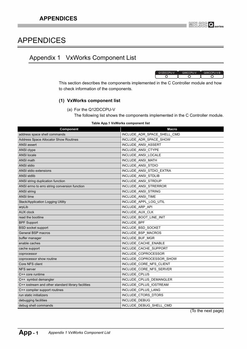
APPENDICES
APPENDICES
Appendix 1 VxWorks Component List
This section describes the components implemented in the C Controller module and how to check information of the components.
(1) VxWorks component list
(a) For the Q12DCCPU-VThe following list shows the components implemented in the C Controller module.
(To the next page)
Table App.1 VxWorks component list
Component Macroaddress space shell commands INCLUDE_ADR_SPACE_SHELL_CMDAddress Space Allocator Show Routines INCLUDE_ADR_SPACE_SHOWANSI assert INCLUDE_ANSI_ASSERTANSI ctype INCLUDE_ANSI_CTYPEANSI locale INCLUDE_ANSI_LOCALEANSI math INCLUDE_ANSI_MATHANSI stdio INCLUDE_ANSI_STDIOANSI stdio extensions INCLUDE_ANSI_STDIO_EXTRAANSI stdlib INCLUDE_ANSI_STDLIBANSI string duplication function INCLUDE_ANSI_STRDUPANSI errno to erro string conversion function INCLUDE_ANSI_STRERRORANSI string INCLUDE_ANSI_STRINGANSI time INCLUDE_ANSI_TIMEStack/Application Logging Utility INCLUDE_APPL_LOG_UTILarpLib INCLUDE_ARP_APIAUX clock INCLUDE_AUX_CLKread the bootline INCLUDE_BOOT_LINE_INITBPF Support INCLUDE_BPFBSD socket support INCLUDE_BSD_SOCKETGeneral BSP macros INCLUDE_BSP_MACROSbuffer manager INCLUDE_BUF_MGRenable caches INCLUDE_CACHE_ENABLEcache support INCLUDE_CACHE_SUPPORTcoprocessor INCLUDE_COPROCESSORcoprocessor show routine INCLUDE_COPROCESSOR_SHOWCore NFS client INCLUDE_CORE_NFS_CLIENTNFS server INCLUDE_CORE_NFS_SERVERC++ core runtime INCLUDE_CPLUSC++ symbol demangler INCLUDE_CPLUS_DEMANGLERC++ iostream and other standard library facilities INCLUDE_CPLUS_IOSTREAMC++ compiler support routines INCLUDE_CPLUS_LANGrun static initializers INCLUDE_CTORS_DTORSdebugging facilities INCLUDE_DEBUGdebug shell commands INCLUDE_DEBUG_SHELL_CMD
Q12DCCPU-V Q06CCPU-V Q06CCPU-V-B
App - 1 Appendix 1 VxWorks Component List

APPENDICES
9
PR
OG
RAM
MIN
G B
US
IN
TER
FAC
E FU
NC
TIO
N
10
PR
OG
RAM
MIN
G U
SIN
G
MEL
SEC
DAT
A L
INK
FU
NC
TIO
NS
11
PR
OG
RAM
MIN
G U
SIN
G
VxW
orks
AP
I FU
NC
TIO
NS
12
SAM
PLE
PR
OG
RAM
S
13
EVEN
T N
UM
BER
LIS
TAP
PEN
DIC
ESIN
DEX
(To the next page)
Table App.1 VxWorks component list (continued)
Component MacroDevice Manager INCLUDE_DEVICE_MANAGERDHCP Core files INCLUDE_DHCP_COREDHCPv4 runtime client INCLUDE_DHCPCDHCPv4 boot-time client INCLUDE_DHCPC_BOOTDHCP client timestamp setup INCLUDE_DHCPC_LEASE_GETDHCPv4 client timestamp storage INCLUDE_DHCPC_LEASE_SAVEDHCPv4 Client Lease Verification/Assignment INCLUDE_DHCPC_LEASE_TESTDHCPv4 client common library INCLUDE_DHCPC_SHAREDHCP client show routines INCLUDE_DHCPC_SHOWFile System and Disk Utilities INCLUDE_DISK_UTILfile system shell commands INCLUDE_DISK_UTIL_SHELL_CMDdoubly linked lists INCLUDE_DLLDNS resolver INCLUDE_DNS_RESOLVERDNS resolver debug output INCLUDE_DNS_RESOLVER_DEBUGuipc_domain INCLUDE_DOMAIN_INITDOS filesystem backward-compatibility INCLUDE_DOSFSDOS File System Consistency Checker INCLUDE_DOSFS_CHKDSKDOS File System Old Directory Format Handler INCLUDE_DOSFS_DIR_FIXEDDOS File System VFAT Directory Handler INCLUDE_DOSFS_DIR_VFATDOS File System FAT12/16/32 Handler INCLUDE_DOSFS_FATDOS File System Volume Fomatter Module INCLUDE_DOSFS_FMTdosfs File System Main Module (dosFs2) INCLUDE_DOSFS_MAINpersistent error log INCLUDE_EDR_ERRLOGpersistent memory INCLUDE_EDR_PMED&R shell commands INCLUDE_EDR_SHELL_CMDED&R show routines INCLUDE_EDR_SHOWsystem debug flag INCLUDE_EDR_SYSDBG_FLAGEND interface support INCLUDE_ENDEND driver polled statistics support INCLUDE_END_POLLED_STATSunix compatible environment variables INCLUDE_ENV_VARSEvent Reporting Framework INCLUDE_ERFEthernet interface support INCLUDE_ETHERNETexception handling INCLUDE_EXC_HANDLINGexception show routines INCLUDE_EXC_SHOWexception task INCLUDE_EXC_TASKfpp formatting for printf INCLUDE_FLOATING_POINTformatted IO INCLUDE_FORMATTED_IOformatted output routines INCLUDE_FORMATTED_OUT_BASICFile System Event Utilities INCLUDE_FS_EVNET_UTILFile System Monitor INCLUDE_FS_MONITORFTP client INCLUDE_FTPget name info INCLUDE_GETNAMEINFOget serv by name INCLUDE_GETSERVBYNAMEGNU compiler support routines INCLUDE_GNU_INTRINSICSGTF support INCLUDE_GTFgtf_timer_start INCLUDE_GTF_TIMER_STARThandle show routines INCLUDE_HANDLE_SHOWhash library INCLUDE_HASHhost table INCLUDE_HOST_TBL
Appendix 1 VxWorks Component List App - 2

APPENDICES
(To the next page)
Table App.1 VxWorks component list (continued)
Component MacroHighly Reliable File System INCLUDE_HRFShardware fpp support INCLUDE_HW_FPICMP v4 INCLUDE_ICMPV4IF INCLUDE_IFifIndex Initialization INCLUDE_IFINDEXIPv4 interface address library INCLUDE_IFLIBIGMP v2/v3 INCLUDE_IGMPinetLib INCLUDE_INETLIBIO system INCLUDE_IO_SYSTEMAttach END to IPv4 INCLUDE_IPATTACHIP v4 INCLUDE_IPV4Job Queue support INCLUDE_JOB_QUEUEjob task INCLUDE_JOB_TASKrandom INCLUDE_KERN_RANDOMkernel INCLUDE_KERNELlink BufPool INCLUDE_LINKBUFPOOLtarget loader INCLUDE_LOADERmessage logging INCLUDE_LOGGINGloopback interface support INCLUDE_LOOPBACKlinked list library INCLUDE_LSTLIBShow routines for memory mapped objects INCLUDE_MAPPED_FILES_SHOWmapped files shell commands INCLUDE_MAPPED_FILES_SHOW_SHELL_CMDbasic memory allocator INCLUDE_MEM_MGR_BASICfull featured memory allocator INCLUDE_MEM_MGR_FULLmemory allocator info routines INCLUDE_MEM_MGR_INFOmemory show routine INCLUDE_MEM_SHOWBSP Memory Configuration INCLUDE_MEMORY_CONFIGmessage queues INCLUDE_MESSAGE_Qmessage queue creation and deletion library INCLUDE_MESSAGE_Q_CREATE_DELETEmessage queue info routines INCLUDE_MESSAGE_Q_INFOMIB2 ICMP Management APIs INCLUDE_MIB2_ICMPMIB2 IF Counter Instrumentation INCLUDE_MIB2_IFMIB2 TCP Management APIs INCLUDE_MIB2_TCPMIB2 UDP Management APIs INCLUDE_MIB2_UDPbasic MMU INCLUDE_MMU_BASICMMU global map INCLUDE_MMU_GLOBAL_MAPmodule manager INCLUDE_MODULE_MANAGERtarget loader shell command INCLUDE_MODULE_SHELL_CMDmessage queue show routine INCLUDE_MSG_Q_SHOWMUX support INCLUDE_MUXnon-blocking message logging INCLUDE_NBIO_LOGBoot parameter process INCLUDE_NET_BOOTnetwork boot device configuration INCLUDE_NET_BOOT_CONFIGNetwork Daemon Support INCLUDE_NET_DAEMONNetDrv for remote IO INCLUDE_NET_DRVNetwork function binding INCLUDE_NET_FUNCBINDpublic hostname setup INCLUDE_NET_HOST_SETUPNetwork interface show routines INCLUDE_NET_IF_SHOWnetwork init INCLUDE_NET_INIT
App - 3 Appendix 1 VxWorks Component List

APPENDICES
9
PR
OG
RAM
MIN
G B
US
IN
TER
FAC
E FU
NC
TIO
N
10
PR
OG
RAM
MIN
G U
SIN
G
MEL
SEC
DAT
A L
INK
FU
NC
TIO
NS
11
PR
OG
RAM
MIN
G U
SIN
G
VxW
orks
AP
I FU
NC
TIO
NS
12
SAM
PLE
PR
OG
RAM
S
13
EVEN
T N
UM
BER
LIS
TAP
PEN
DIC
ESIN
DEX
(To the next page)
Table App.1 VxWorks component list (continued)
Component Macromd5 INCLUDE_NET_MD5Network Stack Memory Pool Configuration INCLUDE_NET_POOLnetwork remote I/O access INCLUDE_NET_REM_IONetwork route show routines INCLUDE_NET_ROUTE_SHOWNetwork route show snprintf buffering INCLUDE_NET_ROUTE_SHOW_SNPRINTFNETWORK SYSCTL INCLUDE_NET_SYSCTLnetBufLib INCLUDE_NETBUFLIBnetBufPool INCLUDE_NETBUFPOOLnetwork device netmask setup INCLUDE_NETMASK_GETnetstat INCLUDE_NETSTATnetstat for IPv4 INCLUDE_NETSTAT_IPV4basic network support INCLUDE_NETWORKNFS client All INCLUDE_NFS_CLIENT_ALLNFS server All INCLUDE_NFS_SERVER_ALLNFS v2 client INCLUDE_NFS2_CLIENTNFS server V2 INCLUDE_NFS2_SERVERNFS v3 client INCLUDE_NFS3_CLIENTNFS server V3 INCLUDE_NFS3_SERVERobject management INCLUDE_OBJ_LIBextended object library INCLUDE_OBJ_OPENobject management ownership INCLUDE_OBJ_OWNERSHIPold route INCLUDE_OLDROUTEPING client INCLUDE_PINGpipes INCLUDE_PIPESpool allocation library INCLUDE_POOLPOSIX advisory file locking INCLUDE_POSIX_ADVISORY_FILE_LOCKINGPOSIX asynchronous IO INCLUDE_POSIX_AIOPOSIX AIO driver INCLUDE_POSIX_AIO_SYSDRVPOSIX clocks INCLUDE_POSIX_CLOCKSPOSIX directory utilities INCLUDE_POSIX_DIRLIBPOSIX ftruncate INCLUDE_POSIX_FTRUNCPOSIX Memory Mapped Files for RTPs INCLUDE_POSIX_MAPPED_FILESPOSIX mman INCLUDE_POSIX_MEMPOSIX message queues INCLUDE_POSIX_MQPOSIX message queue show routine INCLUDE_POSIX_MQ_SHOWPOSIX thread scheduler in RTPs INCLUDE_POSIX_PTHREAD_SCHEDULERPOSIX threads INCLUDE_POSIX_PTHREADSPOSIX process scheduling INCLUDE_POSIX_SCHEDPOSIX semaphore INCLUDE_POSIX_SEMPOSIX semaphore show routine INCLUDE_POSIX_SEM_SHOWPOSIX Shared Memory Objects INCLUDE_POSIX_SHMPOSIX signal INCLUDE_POSIX_SIGNALSPOSIX thread CPU-time clock INCLUDE_POSIX_THREAD_CPUTIMEPOSIX timers INCLUDE_POSIX_TIMERSenable guard pages for kernel task stacks INCLUDE_PROTECT_TASK_STACKPseudo terminal driver INCLUDE_PTYDRVPOSIX scheduling policies SCHED_FIFO/SCHED_RR/SCHED_OTHER support in RTPs
INCLUDE_PX_SCHED_DEF_PLICIES
RAM Disk INCLUDE_RAM_DISK
Appendix 1 VxWorks Component List App - 4
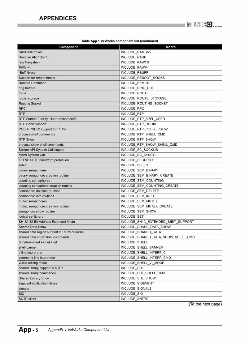
APPENDICES
(To the next page)
Table App.1 VxWorks component list (continued)
Component MacroRAM disk driver INCLUDE_RAMDRVReverse ARP client INCLUDE_RARPraw filesystem INCLUDE_RAWFSRAW v4 INCLUDE_RAWV4rBuff library INCLUDE_RBUFFSupport for reboot hooks INCLUDE_REBOOT_HOOKSRemote Command INCLUDE_REMLIBring buffers INCLUDE_RING_BUFroute INCLUDE_ROUTEroute_storage INCLUDE_ROUTE_STORAGERouting Socket INCLUDE_ROUTING_SOCKETRPC INCLUDE_RPCRTP INCLUDE_RTPRTP Startup Facility: User-defined code INCLUDE_RTP_APPL_USERRTP Hook Support INCLUDE_RTP_HOOKSPOSIX PSE52 support for RTPs INCLUDE_RTP_POSIX_PSE52process shell commands INCLUDE_RTP_SHELL_CMDRTP Show INCLUDE_RTP_SHOWprocess show shell commands INCLUDE_RTP_SHOW_SHELL_CMDSocket API System Call support INCLUDE_SC_SOCKLIBsysctl System Call INCLUDE_SC_SYSCTLTELNET/FTP password protection INCLUDE_SECURITYselect INCLUDE_SELECTbinary semaphores INCLUDE_SEM_BINARYbinary semaphore creation routine INCLUDE_SEM_BINARY_CREATEcounting semaphores INCLUDE_SEM_COUNTINGcounting semaphore creation routine INCLUDE_SEM_COUNTING_CREATEsemaphore deletion routines INCLUDE_SEM_DELETEsemaphore info routines INCLUDE_SEM_INFOmutex semaphores INCLUDE_SEM_MUTEXmutex semaphore creation routine INCLUDE_SEM_MUTEX_CREATEsemaphore show routine INCLUDE_SEM_SHOWlogical set library INCLUDE_SETSH-4A 32-Bit Address Extended Mode INCLUDE_SH4A_EXTENDED_32BIT_SUPPORTShared Data Show INCLUDE_SHARE_DATA_SHOWshared data region support in RTPs or kernel INCLUDE_SHARED_DATAshared data show shell commands INCLUDE_SHARED_DATA_SHOW_SHELL_CMDtarget-resident kernel shell INCLUDE_SHELLshell banner INCLUDE_SHELL_BANNERc line interpreter INCLUDE_SHELL_INTERP_Ccommand line interpreter INCLUDE_SHELL_INTERP_CMDvi-like editing mode INCLUDE_SHELL_VI_MODEshared library support in RTPs INCLUDE_SHLshared library commands INCLUDE_SHL_SHELL_CMDShared Library Show INCLUDE_SHL_SHOWsigevent notification library INCLUDE_SIGEVENTsignals INCLUDE_SIGNALSSIO INCLUDE_SIOSNTP client INCLUDE_SNTPC
App - 5 Appendix 1 VxWorks Component List

APPENDICES
9
PR
OG
RAM
MIN
G B
US
IN
TER
FAC
E FU
NC
TIO
N
10
PR
OG
RAM
MIN
G U
SIN
G
MEL
SEC
DAT
A L
INK
FU
NC
TIO
NS
11
PR
OG
RAM
MIN
G U
SIN
G
VxW
orks
AP
I FU
NC
TIO
NS
12
SAM
PLE
PR
OG
RAM
S
13
EVEN
T N
UM
BER
LIS
TAP
PEN
DIC
ESIN
DEX
(To the next page)
Table App.1 VxWorks component list (continued)
Component MacroSocket API INCLUDE_SOCKLIBspy INCLUDE_SPYbuilt-in symbol table INCLUDE_STANDALONE_SYM_TBLerror status table INCLUDE_STAT_SYM_TBLstdio INCLUDE_STDIOstricmp INCLUDE_STRICMPstrnicmp INCLUDE_STRNICMPsymbol shell commands INCLUDE_SYM_SHELL_CMDtarget symbol table INCLUDE_SYM_TBLinitialize system symbol table INCLUDE_SYM_TBL_INITsymbol table show routine INCLUDE_SYM_TBL_SHOWsystem-defined timestamping INCLUDE_SYS_TIMESTAMPSystem Call Hook Support INCLUDE_SYSCALL_HOOKSSystem clock INCLUDE_SYSCLK_INITSYSCTL INCLUDE_SYSCTLSYSCTL CLI INCLUDE_SYSCTL_CLItask hooks INCLUDE_TASK_HOOKStask hook show routine INCLUDE_TASK_HOOKS_SHOWtask shell commands INCLUDE_TASK_SHELL_CMDtask show routine INCLUDE_TASK_SHOWenable non-executable kernel task stacks INCLUDE_TASK_STACK_NO_EXECtask variables INCLUDE_TASK_VARSTCP v4 INCLUDE_TCPV4Telnet server INCLUDE_TELNETTFTP client INCLUDE_TFTP_CLIENThigh resolution timestamping INCLUDE_TIMESTAMPtimex INCLUDE_TIMEXterminal driver INCLUDE_TTY_DEVterminal driver support INCLUDE_TYLIBUDP v4 INCLUDE_UDPV4target unloader INCLUDE_UNLOADERunloader shell command INCLUDE_UNLOADER_SHELL_CMDapplication initialization INCLUDE_USER_APPLVM library show routine INCLUDE_VM_SHOWvirtual memory show shell commands INCLUDE_VM_SHOW_SHELL_CMDVirtual Root File Sytem INCLUDE_VRFSVxWorks events INCLUDE_VXEVENTSwatchdog timers INCLUDE_WATCHDOGSwatchdog timers creation and deletion library INCLUDE_WATCHDOGS_CREATE_DELETEWDB agent INCLUDE_WDBWDB banner INCLUDE_WDB_BANNERWDB breakpoints INCLUDE_WDB_BPHost/target breakpoint synchronization INCLUDE_WDB_BP_SYNCWDB network connection INCLUDE_WDB_COMM_NETWORKWDB tasks INCLUDE_WDB_CTXTWDB callouts INCLUDE_WDB_DIRECT_CALLWDB eventpoints INCLUDE_WDB_EVENTPOINTSWDB events INCLUDE_WDB_EVENTSWDB exception notification INCLUDE_WDB_EXC_NOTIFY
Appendix 1 VxWorks Component List App - 6

APPENDICES
Table App.1 VxWorks component list (continued)
Component MacroWDB task exit notification INCLUDE_WDB_EXIT_NOTIFYWDB call functions INCLUDE_WDB_FUNC_CALLWDB gopher INCLUDE_WDB_GOPHERhost/target modules and symbols synchronization INCLUDE_WDB_MDL_SYM_SYNCWDB memory access INCLUDE_WDB_MEMWDB post kernel initialization INCLUDE_WDB_POST_KERNEL_INITWDB register access INCLUDE_WDB_REGWDB RTP support INCLUDE_WDB_RTPWDB RTP breakpoints INCLUDE_WDB_RTP_BPWDB RTP control support INCLUDE_WDB_RTP_CONTROLWDB task creation INCLUDE_WDB_START_NOTIFYWDB task debugging INCLUDE_WDB_TASKWDB task breakpoints INCLUDE_WDB_TASK_BPWDB task hooks INCLUDE_WDB_TASK_HOOKSWDB task registers INCLUDE_WDB_TASK_REGWDB target server file system INCLUDE_WDB_TSFSWDB user event INCLUDE_WDB_USER_EVENTVIO driver INCLUDE_WDB_VIOWDB virtual I/O library INCLUDE_WDB_VIO_LIBfloating point show routine INCLUDE_WH_FP_SHOWSystem Viewer library INCLUDE_WINDVIEWSystem Viewer class instrumentation INCLUDE_WINDVIEW_CLASSfile upload path initialization INCLUDE_WVUPLOAD_FILETSFS upload path initialization INCLUDE_WVUPLOAD_TSFSSOCKExtended Block Device INCLUDE_XBDXBD Block Device INCLUDE_XBD_BLK_DEVXBD Disk Partition Handler INCLUDE_XBD_PART_LIBXBD Ram Drive INCLUDE_XBD_RAMDRVXDR INCLUDE_XDR
App - 7 Appendix 1 VxWorks Component List

APPENDICES
9
PR
OG
RAM
MIN
G B
US
IN
TER
FAC
E FU
NC
TIO
N
10
PR
OG
RAM
MIN
G U
SIN
G
MEL
SEC
DAT
A L
INK
FU
NC
TIO
NS
11
PR
OG
RAM
MIN
G U
SIN
G
VxW
orks
AP
I FU
NC
TIO
NS
12
SAM
PLE
PR
OG
RAM
S
13
EVEN
T N
UM
BER
LIS
TAP
PEN
DIC
ESIN
DEX
(b) For the Q06CCPU-V(-B)The following list shows the components implemented in the C Controller module.
(To the next page)
Table App.2 VxWorks component list
Component MacroANSI assert INCLUDE_ANSI_ASSERTANSI ctype INCLUDE_ANSI_CTYPEANSI locale INCLUDE_ANSI_LOCALEANSI math INCLUDE_ANSI_MATHANSI stdio INCLUDE_ANSI_STDIOANSI stdio extensions INCLUDE_ANSI_STDIO_EXTRAANSI stdlib INCLUDE_ANSI_STDLIBANSI string INCLUDE_ANSI_STRINGANSI time INCLUDE_ANSI_TIMEAPI to ARP tables INCLUDE_ARP_APIapplication initialization INCLUDE_USER_APPLbasic C++ iostreams INCLUDE_CPLUS_IOSTREAMSbasic network support INCLUDE_NETWORKbinary semaphores INCLUDE_SEM_BINARYBOOT protocol client library INCLUDE_BOOTPBSD 4.4 TCPv4 INCLUDE_TCPBSD 4.4. UDPv4 INCLUDE_UDPBSD SOCKET INCLUDE_BSD_SOCKETBSP hardware initialization INCLUDE_SYSHW_INITBSP Memory Configuration INCLUDE_MEMORY_CONFIGbuffer manager INCLUDE_BUF_MGRbuilt-in symbol table INCLUDE_STANDALONE_SYM_TBLC++ runtime support INCLUDE_CPLUSC++ standard template library INCLUDE_CPLUS_STLC++ string i/o INCLUDE_CPLUS_STRING_IOC++ string type INCLUDE_CPLUS_STRINGC++ symbol demangler INCLUDE_CPLUS_DEMANGLERcache support INCLUDE_CACHE_SUPPORTCBIO (Cached Block I/O) Support, cbioLib INCLUDE_CBIOconfigure the network boot device INCLUDE_NETDEV_CONFIGcounting semaphores INCLUDE_SEM_COUNTINGDHCP client timestamp removal INCLUDE_DHCPC_LEASE_CLEANDisk Cache Handler INCLUDE_DISK_CACHEDisk Partition Handler INCLUDE_DISK_PARTDNS resolver INCLUDE_DNS_RESOLVERDOS File System Consistency Checker INCLUDE_DOSFS_CHKDSKDOS File System FAT12/16/32 Handler INCLUDE_DOSFS_FAT
Appendix 1 VxWorks Component List App - 8

APPENDICES
(To the next page)
Table App.2 VxWorks component list (continued)
Component MacroDOS File System Old Directory Format Handler INCLUDE_DOSFS_DIR_FIXEDDOS File System VFAT Directory Handler INCLUDE_DOSFS_DIR_VFATDOS File System Volume Formatter INCLUDE_DOSFS_FMTDOSFS2 File System Primary Module INCLUDE_DOSFS_MAINdoubly linked lists INCLUDE_DLLenable caches INCLUDE_CACHE_ENABLEEND attach interface INCLUDE_END_BOOTEND interface support INCLUDE_ENDenvironment variables INCLUDE_ENV_VARSexception handling INCLUDE_EXC_HANDLINGexception task INCLUDE_EXC_TASKfile upload path initialization INCLUDE_WVUPLOAD_FILEfloating point show routine INCLUDE_HW_FP_SHOWformatted IO INCLUDE_FORMATTED_IOfpp formatting for printf INCLUDE_FLOATING_POINTfull C++ iostreams INCLUDE_CPLUS_IOSTREAMS_FULLfull featured memory allocator INCLUDE_MEM_MGR_FULLhardware fpp support INCLUDE_HW_FPhash library INCLUDE_HASHHOST TBL INCLUDE_HOST_TBLICMPv4 INCLUDE_ICMPIGMPv4 INCLUDE_IGMPinitialize network at boot time INCLUDE_NET_INITinitialize symbol table INCLUDE_SYM_TBL_INITIO system INCLUDE_IO_SYSTEMIPv4 INCLUDE_IPkernel INCLUDE_KERNELloopback driver INCLUDE_LOOPBACKmessage logging INCLUDE_LOGGINGmessage queue show routine INCLUDE_MSG_Q_SHOWmessage queues INCLUDE_MSG_Qminimal memory allocator INCLUDE_MEM_MGR_BASICmodule manager INCLUDE_MODULE_MANAGERmutex semaphores INCLUDE_SEM_MUTEXnetwork buffer initialization INCLUDE_NET_SETUPnetwork device name selection INCLUDE_NETDEV_NAMEGETnetwork device netmask setup INCLUDE_NETMASK_GETnetwork host setup INCLUDE_NET_HOST_SETUPnetwork library support INCLUDE_NET_LIBnetwork mux initialization INCLUDE_MUXnetwork remote I/O access INCLUDE_NET_REM_IONFS client INCLUDE_NFSNFS mount all INCLUDE_NFS_MOUNT_ALLNFS server INCLUDE_NFS_SERVERPING client INCLUDE_PINGpipes INCLUDE_PIPESPOSIX AIO driver INCLUDE_POSIX_AIO_SYSDRVPOSIX asynchronous IO INCLUDE_POSIX_AIOPOSIX clocks INCLUDE_POSIX_CLOCKSPOSIX ftruncate INCLUDE_POSIX_FTRUNCPOSIX message queues INCLUDE_POSIX_MQ
App - 9 Appendix 1 VxWorks Component List

APPENDICES
9
PR
OG
RAM
MIN
G B
US
IN
TER
FAC
E FU
NC
TIO
N
10
PR
OG
RAM
MIN
G U
SIN
G
MEL
SEC
DAT
A L
INK
FU
NC
TIO
NS
11
PR
OG
RAM
MIN
G U
SIN
G
VxW
orks
AP
I FU
NC
TIO
NS
12
SAM
PLE
PR
OG
RAM
S
13
EVEN
T N
UM
BER
LIS
TAP
PEN
DIC
ESIN
DEX
(To the next page)
Table App.2 VxWorks component list (continued)
Component MacroPOSIX mman INCLUDE_POSIX_MEMPOSIX scheduler INCLUDE_POSIX_SCHEDPOSIX semaphores INCLUDE_POSIX_SEMPOSIX signals INCLUDE_POSIX_SIGNALSPOSIX timers INCLUDE_POSIX_TIMERSRAM disk driver INCLUDE_RAMDRVrBuff library INCLUDE_RBUFFread the bootline INCLUDE_BOOT_LINE_INITRemote Procedure Call system INCLUDE_RPCring buffers INCLUDE_RNG_BUFRLOGIN/TELNET password protection INCLUDE_SECURITYselect INCLUDE_SELECTsequential timestamping INCLUDE_SEQ_TIMESTAMPshell banner INCLUDE_SHELL_BANNERsignals INCLUDE_SIGNALSSIO component INCLUDE_SIOSNTP client INCLUDE_SNTPCsoftware fpp support INCLUDE_SW_FPstdio INCLUDE_STDIOsymbol table INCLUDE_SYM_TBLsynchronize host and target symbol tables INCLUDE_SYM_TBL_SYNCSystem clock component INCLUDE_SYSCLK_INITsystem startup code INCLUDE_SYS_STARTtarget debugging INCLUDE_DEBUGtarget loader INCLUDE_LOADERtarget shell INCLUDE_SHELLtarget unloader INCLUDE_UNLOADERtask hooks INCLUDE_TASK_HOOKStask show routine INCLUDE_TASK_SHOWtask variables support library INCLUDE_TASK_VARSTELNET server INCLUDE_TELNETterminal driver INCLUDE_TTY_DEVTFTP client INCLUDE_TFTP_CLIENTTSFS upload path initialization INCLUDE_WVUPLOAD_TSFSSOCKutility to measure function execution time INCLUDE_TIMEXVIO driver INCLUDE_WDB_VIOwatchdog timers INCLUDE_WATCHDOGSWDB agent INCLUDE_WDBWDB banner INCLUDE_WDB_BANNERWDB breakpoints INCLUDE_WDB_BPWDB call functions INCLUDE_WDB_FUNC_CALLWDB callouts INCLUDE_WDB_DIRECT_CALLWDB END driver connection INCLUDE_WDB_COMM_ENDWDB eventpoints INCLUDE_WDB_EVENTPOINTSWDB events INCLUDE_WDB_EVENTSWDB exception notification INCLUDE_WDB_EXC_NOTIFYWDB gopher INCLUDE_WDB_GOPHERWDB hardware fpp support INCLUDE_WDB_HW_FPWDB memory access INCLUDE_WDB_MEMWDB register access INCLUDE_WDB_REGWDB system agent hardware fpp support INCLUDE_WDB_SYS_HW_FP
Appendix 1 VxWorks Component List App - 10

APPENDICES
Table App.2 VxWorks component list (continued)
Component MacroWDB system debugging INCLUDE_WDB_SYSWDB target server file system INCLUDE_WDB_TSFSWDB task breakpoints INCLUDE_WDB_TASK_BPWDB task creation INCLUDE_WDB_START_NOTIFYWDB task debugging INCLUDE_WDB_TASKWDB task exit notification INCLUDE_WDB_EXIT_NOTIFYWDB task hardware fpp support INCLUDE_WDB_TASK_HW_FPWDB tasks INCLUDE_WDB_CTXTWDB user event INCLUDE_WDB_USER_EVENTWDB virtual I/O library INCLUDE_WDB_VIO_LIBwindview class instrumentation INCLUDE_WINDVIEW_CLASSwindview library INCLUDE_WINDVIEW
App - 11 Appendix 1 VxWorks Component List

APPENDICES
9
PR
OG
RAM
MIN
G B
US
IN
TER
FAC
E FU
NC
TIO
N
10
PR
OG
RAM
MIN
G U
SIN
G
MEL
SEC
DAT
A L
INK
FU
NC
TIO
NS
11
PR
OG
RAM
MIN
G U
SIN
G
VxW
orks
AP
I FU
NC
TIO
NS
12
SAM
PLE
PR
OG
RAM
S
13
EVEN
T N
UM
BER
LIS
TAP
PEN
DIC
ESIN
DEX
(2) VxWorks component information checking methodVxWorks component information can be checked by the following procedure.VxWorks image cannot be created (changed).
(a) For the Q12DCCPU-V
1 Select [Help] [Help Contents] from the menu bar.
2 HELP information for Workbench is displayed in a web browser.
3 Enter the string to be searched in the "Search:" combo box
and click the button.
4 Select the information to review from "Search Result" and review the component information.
(Completed)
GO
Appendix 1 VxWorks Component List App - 12

APPENDICES
(b) For the Q06CCPU-V(-B)
1 Select [File] [New Project] from the menu bar.
2 Select "Create a bootable VxWorks image (custom
configured)" and click the button.
3 Enter "Name", "Location", and "Workspace" and then click the button.
(To the next page)
OK
Next>
App - 13 Appendix 1 VxWorks Component List

APPENDICES
9
PR
OG
RAM
MIN
G B
US
IN
TER
FAC
E FU
NC
TIO
N
10
PR
OG
RAM
MIN
G U
SIN
G
MEL
SEC
DAT
A L
INK
FU
NC
TIO
NS
11
PR
OG
RAM
MIN
G U
SIN
G
VxW
orks
AP
I FU
NC
TIO
NS
12
SAM
PLE
PR
OG
RAM
S
13
EVEN
T N
UM
BER
LIS
TAP
PEN
DIC
ESIN
DEX
(From the previous page)
4 Select "A BSP" and click the button.
5 Check that the values in "Workspace", "Project", and "Basis
BSP" are correct and then click the button.
6 Open the <<VxWorks>> tab of the "Workspace" window.
(To the next page)
Next>
Finish
Appendix 1 VxWorks Component List App - 14

APPENDICES
(From the previous page)
7 Click the ( ) icon to expand the items at this level of the hierarchy.
8 Right-click on "ANSI assert" and select [Properties] from the menu.
9 Check the information of VxWorks components with the Properties screen displayed.
(Completed)
App - 15 Appendix 1 VxWorks Component List

APPENDICES
9
PR
OG
RAM
MIN
G B
US
IN
TER
FAC
E FU
NC
TIO
N
10
PR
OG
RAM
MIN
G U
SIN
G
MEL
SEC
DAT
A L
INK
FU
NC
TIO
NS
11
PR
OG
RAM
MIN
G U
SIN
G
VxW
orks
AP
I FU
NC
TIO
NS
12
SAM
PLE
PR
OG
RAM
S
13
EVEN
T N
UM
BER
LIS
TAP
PEN
DIC
ESIN
DEX
Remark
The VxWorks components can be located by the following procedure.
1 Right click to select [Find Object] from the menu.
2 Click the button.Find
Appendix 1 VxWorks Component List App - 16

APPENDICES
Appendix 2 Comparison of Software Packages
(1) Comparison of the supported C Controller module
: Applicable, : N/A
(2) Comparison of default settingThe default values of the setting item in the table below are different depending on the software version.
Appendix 2.1 Precautions for replacing programs
(1) When the Q06CCPU-V or Q06CCPU-V-H01 has been replaced with the Q12DCCPU-VWhen porting the programs developed by Tornado to Workbench, refer to the Migration Guide provided by Wind River Systems, Inc.The Migration Guide can be downloaded from the website:(http://www.windriver.com/).
(2) When the Q06CCPU-V-H01 has been replaced with the Q06CCPU-VThe Q06CCPU-V can use programs of the Q06CCPU-V-H01 as they are.The Q06CCPU-V processes functions faster than the Q06CCPU-V-H01.When using programs of the existing products, fully check the operation.
Table App.3 Comparison of supported software packages
C Controller moduleSoftware package
SW3PVC-CCPU SW2PVC-CCPUQ12DCCPU-V
Q06CCPU-V
Q06CCPU-V-B
Q06CCPU-V-H01
Table App.4 Comparison of default setting
Item DefaultUtility name Tab title Item name SW3PVC-CCPU SW2PVC-CCPU
C Controller setting utility
System setting Perform error check and battery check Selected Not selected
Q12DCCPU-V Q06CCPU-V Q06CCPU-V-B
Q12DCCPU-V Q06CCPU-V Q06CCPU-V-B
App - 17 Appendix 2 Comparison of Software PackagesAppendix 2.1 Precautions for replacing programs
APPENDICES
9
PR
OG
RAM
MIN
G B
US
IN
TER
FAC
E FU
NC
TIO
N
10
PR
OG
RAM
MIN
G U
SIN
G
MEL
SEC
DAT
A L
INK
FU
NC
TIO
NS
11
PR
OG
RAM
MIN
G U
SIN
G
VxW
orks
AP
I FU
NC
TIO
NS
12
SAM
PLE
PR
OG
RAM
S
13
EVEN
T N
UM
BER
LIS
TAP
PEN
DIC
ESIN
DEX
Memo
Appendix 2 Comparison of Software PackagesAppendix 2.1 Precautions for replacing programs
App - 18

INDEX
[A]Activating utility •••••••••••••••••••••••••••••••••••••••••• 3-2
[B]Bus interface functions ••••••••••••••••••••••••••••••••• 9-1
Outline •••••••••••••••••••••••••••••••••••••••••••••••••• 9-1
[C]C Controller setting utility •••••••••••••••••••••••••••••• 4-1
Communication diagnositcs tab•••••••••••••••••••4-42Event history tab •••••••••••••••••••••••••••••••••••••• 4-4Function list •••••••••••••••••••••••••••••••••••••••••••• 4-1Importing multiple CPU parameters••••••••••••••4-45I/O assignment settings tab••••••••••••••••••••••••4-34Module information tab •••••••••••••••••••••••••••••• 4-2Module monitoring tab ••••••••••••••••••••••••••••••4-13Multiple CPU settings tab ••••••••••••••••••••••••••4-38Online operation tab•••••••••••••••••••••••••••••••••4-21Reading initial setting file•••••••••••••••••••••••••••4-45SRAM monitoring tab •••••••••••••••••••••••••••••••• 4-9System menu•••••••••••••••••••••••••••••••••••••••••4-43System settings tab •••••••••••••••••••••••••••••••••4-30
CC IE Control utility ••••••••••••••••••••••••••••••••••••• 7-1Diagnositcs result screen ••••••••••••••••••••••••••• 7-5Function list •••••••••••••••••••••••••••••••••••••••••••• 7-1Module information tab •••••••••••••••••••••••••••••• 7-2Online operation tab•••••••••••••••••••••••••••••••••7-20Parameter settings tab••••••••••••••••••••••••••••••7-22System menu•••••••••••••••••••••••••••••••••••••••••7-36Target settings tab•••••••••••••••••••••••••••••••••••7-33
CC-Link utility••••••••••••••••••••••••••••••••••••••••••••• 5-1Function list •••••••••••••••••••••••••••••••••••••••••••• 5-1Module information tab •••••••••••••••••••••••••••••• 5-2Online operation tab•••••••••••••••••••••••••••••••••• 5-9Other station monitoring tab •••••••••••••••••••••••• 5-6Parameter settings tab••••••••••••••••••••••••••••••5-10System menu•••••••••••••••••••••••••••••••••••••••••5-20Target settings tab•••••••••••••••••••••••••••••••••••5-14Test tab ••••••••••••••••••••••••••••••••••••••••••••••••5-17
Channel ••••••••••••••••••••••••••••••••••••••••••••••••••10-9Checking version •••••••••••••••••••••••••••••••••••••••3-11Connection target•••••••••••••••••••••••••••••••••••••••• 3-5CPU type •••••••••••••••••••••••••••••••••••••••••••••••••• 3-4Creating a new project and compiling ••••••••••••••• 9-8
Q06CCPU-V(-B) •••••••••••••••••••••••••••••••••••••9-16Q12DCCPU-V ••••••••••••••••••••••••••••••••••••••••• 9-8
[D]Development environment ••••••••••••••••••••••••••••• 2-1Device monitoring utility •••••••••••••••••••••••••••••••• 8-1
Batch monitoring•••••••••••••••••••••••••••••••••••••• 8-2Bit device ON/OFF ••••••••••••••••••••••••••••••••••8-12Changing the display format•••••••••••••••••••••••8-14Changing word device values •••••••••••••••••••••• 8-8Continuously changing word device values ••••8-10
Function list •••••••••••••••••••••••••••••••••••••••••••• 8-1Numerical pad ••••••••••••••••••••••••••••••••••••••••8-16Setting device to be monitored••••••••••••••••••••• 8-7Setting monitoring target •••••••••••••••••••••••••••• 8-6Start and stop monitoring ••••••••••••••••••••••••••8-1516-point register monitoring••••••••••••••••••••••••• 8-4
[E]Exiting utility •••••••••••••••••••••••••••••••••••••••••••••• 3-3
[F]FTP••••••••••••••••••••••••••••••••••••••••••••••••••••••••9-45
[G]GX Configurator•••••••••••••••••••••••••••••••••••••••••4-46
[H]Help screen ••••••••••••••••••••••••••••••••••••••••••••••• 3-9
[I]Installation••••••••••••••••••••••••••••••••••••••••••••••••• 2-3
[M]MELSECNET/H data link function•••••••••••••••••••10-1
Accessible ranges and devices ••••••••••••••••• 10-17Device types •••••••••••••••••••••••••••••••••••••••• 10-12Outline •••••••••••••••••••••••••••••••••••••••••••••••••10-1Station No. setting ••••••••••••••••••••••••••••••••• 10-10
MELSECNET/H utility••••••••••••••••••••••••••••••••••• 6-1Error history monitoring tab ••••••••••••••••••••••••• 6-9Function list •••••••••••••••••••••••••••••••••••••••••••• 6-1Module Information Tab ••••••••••••••••••••••••••••• 6-2Online operation tab•••••••••••••••••••••••••••••••••6-25Other station monitoring tab •••••••••••••••••••••••6-14Parameter settings tab••••••••••••••••••••••••••••••6-26System menu •••••••••••••••••••••••••••••••••••••••••6-41Target settings tab•••••••••••••••••••••••••••••••••••6-38
[P]Parameter setting file ••••••••••••••••••••••••••••••••••3-12Program registration •••••••••••••••••••••••••••••••••••9-45Programming procedure ••••••••••••••••••••••••••••••• 9-7
[S]Sample programs•••••••••••••••••••••••••••••••••••••••12-1Script file •••••••••••••••••••••••••••••••••••••••••••••••••9-50Shell display setting
Q06CCPU-V(-B) •••••••••••••••••••••••••••••••••••••9-41Status bar ••••••••••••••••••••••••••••••••••••••••••••••••3-14
[T]Title bar •••••••••••••••••••••••••••••••••••••••••••••••••••3-14
Index - 1

9
PRO
GR
AM
MIN
G B
US
INTE
RFA
CE
FU
NC
TIO
N
10
PRO
GR
AM
MIN
G U
SIN
G
MEL
SEC
DAT
A LI
NK
FUN
CTI
ON
S
11
PRO
GR
AM
MIN
G U
SIN
G
VxW
orks
API
FU
NC
TIO
NS
12
SAM
PLE
PR
OG
RAM
S
13
EVE
NT
NU
MBE
R L
IST
APP
END
ICE
SIN
DEX
[U]Uninstallation ••••••••••••••••••••••••••••••••••••••••••••• 2-6
[V]VxWorks image file specification ••••••••••••••••••••9-30
Q06CCPU-V(-B) •••••••••••••••••••••••••••••••••••••9-37Q12DCCPU-V••••••••••••••••••••••••••••••••••••••••9-30
Index - 2

Microsoft, Windows, Windows NT, and Windows Vista are registered trademarks of Microsoft Corporation in the United States and other countries.Pentium is a trademark of Intel Corporation in the United States and other countries.Ethernet is a trademark of Xerox Corporation.CompactFlash is a registered trademark of SanDisk Corporation.VxWorks, WindPower, WindView, and Tornado are trademarks of Wind River Systems, Inc.All other company names and product names used in this manual are trademarks or registered trademarks of their respective companies.
SH(NA)-080767ENG-B


HEADQUARTERS
EUROPEMITSUBISHI ELECTRIC EUROPE B.V.German BranchGothaer Straße 8D-40880 RatingenPhone: +49 (0)2102 / 486-0Fax: +49 (0)2102 / 486-1120
CZECH REPUBLICMITSUBISHI ELECTRIC EUROPE B.V.Czech BranchAvenir Business Park, Radlická 714/113aCZ-158 00 Praha 5Phone: +420 (0)251 551 470Fax: +420 (0)251-551-471
FRANCEMITSUBISHI ELECTRIC EUROPE B.V.French Branch25, Boulevard des BouvetsF-92741 Nanterre CedexPhone: +33 (0)1 / 55 68 55 68Fax: +33 (0)1 / 55 68 57 57
IRELANDMITSUBISHI ELECTRIC EUROPE B.V.Irish BranchWestgate Business Park, BallymountIRL-Dublin 24Phone: +353 (0)1 4198800Fax: +353 (0)1 4198890
ITALYMITSUBISHI ELECTRIC EUROPE B.V.Italian BranchViale Colleoni 7I-20041 Agrate Brianza (MB)Phone: +39 039 / 60 53 1Fax: +39 039 / 60 53 312
POLANDMITSUBISHI ELECTRIC EUROPE B.V.Poland BranchKrakowska 50PL-32-083 BalicePhone: +48 (0)12 / 630 47 00Fax: +48 (0)12 / 630 47 01
SPAINMITSUBISHI ELECTRIC EUROPE B.V.Spanish BranchCarretera de Rubí 76-80E-08190 Sant Cugat del Vallés (Barcelona)Phone: 902 131121 // +34 935653131Fax: +34 935891579
UKMITSUBISHI ELECTRIC EUROPE B.V.UK BranchTravellers LaneUK-Hatfield, Herts. AL10 8XBPhone: +44 (0)1707 / 27 61 00Fax: +44 (0)1707 / 27 86 95
JAPANMITSUBISHI ELECTRIC CORPORATIONOffice Tower “Z” 14 F8-12,1 chome, Harumi Chuo-KuTokyo 104-6212Phone: +81 3 622 160 60Fax: +81 3 622 160 75
USAMITSUBISHI ELECTRIC AUTOMATION, Inc.500 Corporate Woods ParkwayVernon Hills, IL 60061Phone: +1 847 478 21 00Fax: +1 847 478 22 53
EUROPEAN REPRESENTATIVES
AUSTRIAGEVAWiener Straße 89AT-2500 BadenPhone: +43 (0)2252 / 85 55 20Fax: +43 (0)2252 / 488 60
BELARUSTEHNIKONOktyabrskaya 16/5, Off. 703-711BY-220030 MinskPhone: +375 (0)17 / 210 46 26Fax: +375 (0)17 / 210 46 26
BELGIUMESCO DRIVES & AUTOMATIONCulliganlaan 3BE-1831 DiegemPhone: +32 (0)2 / 717 64 30Fax: +32 (0)2 / 717 64 31
BELGIUMKoning & Hartman b.v.Woluwelaan 31BE-1800 VilvoordePhone: +32 (0)2 / 257 02 40Fax: +32 (0)2 / 257 02 49
BOSNIA AND HERZEGOVINAINEA BH d.o.o.Aleja Lipa 56BA-71000 SarajevoPhone: +387 (0)33 / 921 164Fax: +387 (0)33/ 524 539
BULGARIAAKHNATON4 Andrej Ljapchev Blvd. Pb 21BG-1756 SofiaPhone: +359 (0)2 / 817 6004Fax: +359 (0)2 / 97 44 06 1
CROATIAINEA CR d.o.o.Losinjska 4 aHR-10000 ZagrebPhone: +385 (0)1 / 36 940 - 01/ -02/ -03Fax: +385 (0)1 / 36 940 - 03
CZECH REPUBLICAutoCont C.S. s.r.o.Technologická 374/6CZ-708 00 Ostrava-PustkovecPhone: +420 595 691 150Fax: +420 595 691 199
CZECH REPUBLICB:ELECTRIC, s.r.o.Mladoboleslavská 812CZ-197 00 Praha 19 - KbelyPhone: +420 286 850 848, +420 724 317 975Fax: +420 286 850 850
DENMARKBeijer Electronics A/SLykkegårdsvej 17, 1.DK-4000 RoskildePhone: +45 (0)46/ 75 76 66Fax: +45 (0)46 / 75 56 26
ESTONIABeijer Electronics Eesti OÜPärnu mnt.160iEE-11317 TallinnPhone: +372 (0)6 / 51 81 40Fax: +372 (0)6 / 51 81 49
FINLANDBeijer Electronics OYJaakonkatu 2FIN-01620 VantaaPhone: +358 (0)207 / 463 500Fax: +358 (0)207 / 463 501
GREECEUTECO A.B.E.E.5, Mavrogenous Str.GR-18542 PiraeusPhone: +30 211 / 1206 900Fax: +30 211 / 1206 999
HUNGARYMELTRADE Ltd.Fertő utca 14.HU-1107 BudapestPhone: +36 (0)1 / 431-9726Fax: +36 (0)1 / 431-9727
LATVIABeijer Electronics SIAVestienas iela 2LV-1035 RigaPhone: +371 (0)784 / 2280Fax: +371 (0)784 / 2281
LITHUANIABeijer Electronics UABSavanoriu Pr. 187LT-02300 VilniusPhone: +370 (0)5 / 232 3101Fax: +370 (0)5 / 232 2980
EUROPEAN REPRESENTATIVES
MALTAALFATRADE Ltd.99, Paola HillMalta- Paola PLA 1702Phone: +356 (0)21 / 697 816Fax: +356 (0)21 / 697 817
MOLDOVAINTEHSIS srlbld. Traian 23/1MD-2060 KishinevPhone: +373 (0)22 / 66 4242Fax: +373 (0)22 / 66 4280
NETHERLANDSHIFLEX AUTOM.TECHNIEK B.V.Wolweverstraat 22NL-2984 CD RidderkerkPhone: +31 (0)180 – 46 60 04Fax: +31 (0)180 – 44 23 55
NETHERLANDSKoning & Hartman b.v.Haarlerbergweg 21-23NL-1101 CH AmsterdamPhone: +31 (0)20 / 587 76 00Fax: +31 (0)20 / 587 76 05
NORWAYBeijer Electronics ASPostboks 487NO-3002 DrammenPhone: +47 (0)32 / 24 30 00Fax: +47 (0)32 / 84 85 77
ROMANIASirius Trading & Services srlAleea Lacul Morii Nr. 3RO-060841 Bucuresti, Sector 6Phone: +40 (0)21 / 430 40 06Fax: +40 (0)21 / 430 40 02
SERBIACraft Con. & Engineering d.o.o.Bulevar Svetog Cara Konstantina 80-86SER-18106 NisPhone: +381 (0)18 / 292-24-4/5Fax: +381 (0)18 / 292-24-4/5
SERBIAINEA SR d.o.o.Izletnicka 10SER-113000 SmederevoPhone: +381 (0)26 / 617 163Fax: +381 (0)26 / 617 163
SLOVAKIAAutoCont Control s.r.o.Radlinského 47SK-02601 Dolny KubinPhone: +421 (0)43 / 5868210Fax: +421 (0)43 / 5868210
SLOVAKIACS MTrade Slovensko, s.r.o.Vajanskeho 58SK-92101 PiestanyPhone: +421 (0)33 / 7742 760Fax: +421 (0)33 / 7735 144
SLOVENIAINEA d.o.o.Stegne 11SI-1000 LjubljanaPhone: +386 (0)1 / 513 8100Fax: +386 (0)1 / 513 8170
SWEDENBeijer Electronics ABBox 426SE-20124 MalmöPhone: +46 (0)40 / 35 86 00Fax: +46 (0)40 / 35 86 02
SWITZERLANDEconotec AGHinterdorfstr. 12CH-8309 NürensdorfPhone: +41 (0)44 / 838 48 11Fax: +41 (0)44 / 838 48 12
TURKEYGTSBayraktar Bulvari Nutuk Sok. No:5TR-34775 Yukari Dudullu-Umraniye-ISTANBULPhone: +90 (0)216 526 39 90Fax: +90 (0)216 526 3995
UKRAINECSC Automation Ltd.4-B, M. Raskovoyi St.UA-02660 KievPhone: +380 (0)44 / 494 33 55Fax: +380 (0)44 / 494-33-66
EURASIAN REPRESENTATIVES
KAZAKHSTANKazpromautomatics Ltd.Mustafina Str. 7/2KAZ-470046 KaragandaPhone: +7 7212 / 50 11 50Fax: +7 7212 / 50 11 50
MIDDLE EAST REPRESENTATIVES
ISRAELILAN & GAVISH Ltd.24 Shenkar St., Kiryat ArieIL-49001 Petah-TiqvaPhone: +972 (0)3 / 922 18 24Fax: +972 (0)3 / 924 0761
ISRAELTEXEL ELECTRONICS Ltd.2 Ha´umanut, P.O.B. 6272IL-42160 NetanyaPhone: +972 (0)9 / 863 39 80Fax: +972 (0)9 / 885 24 30
LEBANONCEG INTERNATIONALCebaco Center/Block A Autostrade DORALebanon - BeirutPhone: +961 (0)1 / 240 430Fax: +961 (0)1 / 240 438
AFRICAN REPRESENTATIVE
SOUTH AFRICACBI Ltd.Private Bag 2016ZA-1600 IsandoPhone: + 27 (0)11 / 928 2000Fax: + 27 (0)11 / 392 2354
MITSUBISHIELECTRIC
FACTORY AUTOMATIONMitsubishi Electric Europe B.V. /// FA - European Business Group /// Gothaer Straße 8 /// D-40880 Ratingen /// GermanyTel.: +49(0)2102-4860 /// Fax: +49(0)2102-4861120 /// [email protected] /// www.mitsubishi-automation.com
MITSUBISHI ELECTRIC
Copyright © 2022 FDOKUMEN