SPiiPlus LF - Motion Controller
42
Version NT 2.20 SPiiPlus LF Motion Controller Hardware Guide
-
Upload
khangminh22 -
Category
Documents
-
view
1 -
download
0
Transcript of SPiiPlus LF - Motion Controller

Version NT 2.20
SPiiPlus LFMotion Control ler
Hardware Guide

Version NT 2.20 ii Hardware Guide
SPiiPlus LF Motion Controller
Version NT 2.20, 31 January 2013
Copyright ® 1999 - 2013 ACS Motion Control Ltd.
Changes are periodically made to the information in this document. Changes are published as release notes and are subsequently incorporated into revisions of this document.No part of this document may be reproduced in any form without prior written permission from ACS Motion Control.TRADEMARKS
ACS Motion Control, PEG and SPii are trademarks of ACS Motion Control Ltd.EtherCAT® is registered trademark and patented technology, licensed by Beckhoff Automation GmbH, Germany.Visual Basic and Windows are trademarks of Microsoft Corporation.Any other companies and product names mentioned herein may be the trademarks of their respective owners.
Web Site: www.AcsMotionControl.comInformation: [email protected] Support: [email protected]
ACS Motion Control, Ltd.Ramat Gabriel Industrial ParkPOB 5668Migdal HaEmek, 10500ISRAELTel: (972) (4) 6546440Fax: (972) (4) 6546443ACS Motion Control, Inc.6575 City West ParkwayEden Prairie, MN 55344USATel: (1) (763) 559-7669(800-545-2980 in USA)Fax: (1) (763) 559-0110
ACS Motion Control Europe GmbHNeckartal 172D-78628 RottweilGermanyCell: +49-172-587-7240
ACS Motion Control (Korea)Digital Empire Building D-191980-3, Youngtong-dong, Youngtong-gu, Suwon, Geonggi-do, 443-813, KoreaTel: +82-31-202-3541 Fax: +82-31-202-3542
ACS Motion Control (China)Room 301GNo. 798 Zhaojiabang RdShanghai, 200030, ChinaTel: +86-21-54830819Fax: +86-21-64453191Cell: +86-13601639842
NOTICE
The information in this document is deemed to be correct at the time of publishing. ACS Motion Control reserves the right to change specifications without notice. ACS Motion Control is not responsible for incidental, consequential, or special damages of any kind in connection with using this document.

SPiiPlus LF Motion Controller
Changes in Version NT 2.20
Page Change
Conventions Used in this Guide
Text ConventionsSeveral text formats and fonts, illustrated in Table 1, are used in the text to convey information about the text.
Table 1 Text Conventions
Text Description
Bold ACSPL+ elements (commands, functions, operators, standard variables, etc.) when mentioned in the text. Software tool menus, menu items, dialog box names and dialog box elements.
Monospace Code examples.Italic monospace Information in code examples that the user provides.Italic Blue Indicates other documentsBold Blue Links within this document, to web pages, and to e-mail
addresses. Symbol used in nested menu items and dialog box options
leading to a final action. For example, the sequence:Debug New Watch Real-time directs the user to open the Debug menu in the MMI, choose the New Watch command, and select the Real-time option.
Version NT 2.20 iii Hardware Guide

SPiiPlus LF Motion Controller
Flagged TextThe following symbols are used to flag text in this document:
Note
Caution
Warning
Advanced
Model
Highlights a specification, procedure, condition, or statement that depends on the product model.
Indicates a topic for advanced users.
A Warning describes a condition that may result in serious bodily injury or death.
A Caution describes a condition that may result in damage to equipment.
Notes include helpful information or tips.
Version NT 2.20 iv Hardware Guide

SPiiPlus LF Motion Controller
SPiiPlus Related DocumentsThe followinging documents are relevant to this guide:
Table 2 SPiiPlus Related Documents
Document Description
SPiiPlus C Library Reference C++ and Visual Basic® libraries for host PC applications. This guide is applicable for all the SPiiPlus motion control products.
SPiiPlus COM Library Reference Guide
COM Methods, Properties, and Events for Communication with the Controller.
SPiiPlus Command & Variable Reference Guide
Complete reference to the command and variables of the ACSPL+ high level language for programming SPiiPlus controllers.
SPiiPlus Programmer's Guide An overview for programming SPiiPlus controllers.SPiiPlus Utilities User Guide Describes the SPiiPlus User Mode Driver (UMD), and firmware
management applications included in the SPiiPlus Tools package. SPiiPlus Getting Started Hardware and Software Guide
A guide for using the SPiiPlus MMI (Motion Machine Interface).
SPiiPlus Setup Guide Contains communication, configuration and adjustment procedures for SPiiPlus motion control products.
Low Level Host Communication Provides information concerning the host protocol. This information is relevant in case the host application runs on a non-Windows operating system.
SPiiPlus MODbus Setup Guide Guide for use in setting up the MODbus for SPiiPlus motion controllers.
SPiiPlus 3U-LT and SPiiPlus 3U-HP Motion Controller Hardware Guide
Installation and hardware connection with the SPiiPlus 3U-LT and SPiiPlus 3U-HP Motion Controllers.
SPiiPlus SAR and SAR-LT Hardware Guide
Installation and hardware connection with the SPiiPlus SAR and SAR-LT Controllers
SPiiPlus PCI-4-8 Hardware Guide Installation and hardware connection with the SPiiPlus PCI 4 or 8 axes
SPiiPlus CM Hardware Guide Installation and hardware connection with the SPiiPlus Control Module
SPiiPlus LF-CM Motion Controller
Detailed hardware information concerning the SPiiPlus LF-CM motion controller.
MC4U Control Module Hardware Guide
Detailed hardware information concerning the MC4U Control Module and its associated components.
HSSI Expansion Modules Guide High-Speed Synchronous Serial Interface (HSSI) for expanded I/O, distributed axes, and nonstandard devices.
SPiiPlus FRF Analyzer User’s Guide
Guide for using the SPiiPlus FRF (Frequency Response Function) Analyzer for servo analysis of SPiiPlus motion controllers.
Version NT 2.20 v Hardware Guide

SPiiPlus LF Motion Controller
About this DocumentThis guide provides detailed hardware information concerning the SPiiPlus LF Motion Controller. The document is organized as follows:
Chapter 1 - SPiiPlus LF Motion Controller Overview
Provides a descriptive overview of the SPiiPlus LF Motion Controller
Chapter 2 - SPiiPlus LF Motion Controller Specifications
Provides the technical specifications of the SPiiPlus LF Motion Controller
Chapter 3 - Installation
Provides instructions for installing the SPiiPlus LF Motion Controller
Chapter 4 - Safety and EMC Guidelines
Provides guidelines for safety and EMC
Chapter 5 - Electrical Interface
Provides details of the SPiiPlus LF Motion Controller connectors
Chapter 6 - Jumpers
Identifies the SPiiPlus LF Motion Controller jumper locations and their function
Chapter 7 - LED Indicators
Describes the meanings of the LED indicators on the SPiiPlus LF Motion Controller
Version NT 2.20 vi Hardware Guide

SPiiPlus LF Motion Controller Table of Contents
Table of ContentsChanges in Version 6.60 . . . . . . . . . . . . . . . . . . . . . . . . . . . . . . . . . . . . . . . . . . . . . . . . . . . . . iiiConventions Used in this Guide . . . . . . . . . . . . . . . . . . . . . . . . . . . . . . . . . . . . . . . . . . . . . . . iii
Text Conventions . . . . . . . . . . . . . . . . . . . . . . . . . . . . . . . . . . . . . . . . . . . . . . . . . . . . . . . . iiiFlagged Text . . . . . . . . . . . . . . . . . . . . . . . . . . . . . . . . . . . . . . . . . . . . . . . . . . . . . . . . . . . . iv
SPiiPlus Related Documents . . . . . . . . . . . . . . . . . . . . . . . . . . . . . . . . . . . . . . . . . . . . . . . . . vAbout this Document . . . . . . . . . . . . . . . . . . . . . . . . . . . . . . . . . . . . . . . . . . . . . . . . . . . . . . . vi1 SPiiPlus LF Motion Controller Overview . . . . . . . . . . . . . . . . . . . . . . . . . . . . . . 11.1 SPiiPlus LF Motion Controller Main Board . . . . . . . . . . . . . . . . . . . . . . . . . . . 21.2 Optional SPiiPlus LF Motion Controller 4-Axis Extension Board . . . . . . . . . . 31.3 SPiiPlus LF Motion Controller Ordering . . . . . . . . . . . . . . . . . . . . . . . . . . . . . . 32 SPiiPlus LF Motion Controller Specifications . . . . . . . . . . . . . . . . . . . . . . . . . . 52.1 General Specifications . . . . . . . . . . . . . . . . . . . . . . . . . . . . . . . . . . . . . . . . . . . . 52.2 Dimensions . . . . . . . . . . . . . . . . . . . . . . . . . . . . . . . . . . . . . . . . . . . . . . . . . . . . . 62.3 SPiiPlus LF Motion Controller MPU Board . . . . . . . . . . . . . . . . . . . . . . . . . . . 72.4 SPiiPlus LF Motion Controller Axis Support . . . . . . . . . . . . . . . . . . . . . . . . . . 72.5 Input & Output Specifications . . . . . . . . . . . . . . . . . . . . . . . . . . . . . . . . . . . . . . 83 Installation . . . . . . . . . . . . . . . . . . . . . . . . . . . . . . . . . . . . . . . . . . . . . . . . . . . . . . 143.1 SPiiPlus LF Motion Controller Assembly . . . . . . . . . . . . . . . . . . . . . . . . . . . . 143.1.1 SPiiPlus LF Motion Controller Assembly Hardware . . . . . . . . . . . . . . . . . . 143.1.2 SPiiPlus LF Motion Controller Assembly . . . . . . . . . . . . . . . . . . . . . . . . . . . 153.2 Mounting the SPiiPlus LF Motion Controller . . . . . . . . . . . . . . . . . . . . . . . . . 164 Safety and EMC Guidelines . . . . . . . . . . . . . . . . . . . . . . . . . . . . . . . . . . . . . . . . 174.1 General Safety Guidelines . . . . . . . . . . . . . . . . . . . . . . . . . . . . . . . . . . . . . . . . 174.1.1 Emergency Stop Device . . . . . . . . . . . . . . . . . . . . . . . . . . . . . . . . . . . . . . . . 174.1.2 Fail-Safe Logic Recommendation . . . . . . . . . . . . . . . . . . . . . . . . . . . . . . . . . 174.1.3 Initial Logic State of Outputs . . . . . . . . . . . . . . . . . . . . . . . . . . . . . . . . . . . . 174.1.4 Electrical Separation . . . . . . . . . . . . . . . . . . . . . . . . . . . . . . . . . . . . . . . . . . . 174.1.5 Protective Precautions . . . . . . . . . . . . . . . . . . . . . . . . . . . . . . . . . . . . . . . . . . 184.2 General Wiring and Electromagnetic Compatibility (EMC) Guidelines . . . . . 184.2.1 Routing Signal and Power Cables . . . . . . . . . . . . . . . . . . . . . . . . . . . . . . . . . 184.2.2 Cable Length . . . . . . . . . . . . . . . . . . . . . . . . . . . . . . . . . . . . . . . . . . . . . . . . . 194.2.3 Shielding . . . . . . . . . . . . . . . . . . . . . . . . . . . . . . . . . . . . . . . . . . . . . . . . . . . . 194.2.4 Grounding . . . . . . . . . . . . . . . . . . . . . . . . . . . . . . . . . . . . . . . . . . . . . . . . . . . 195 Electrical Interface . . . . . . . . . . . . . . . . . . . . . . . . . . . . . . . . . . . . . . . . . . . . . . . 205.1 Main Board Connectors . . . . . . . . . . . . . . . . . . . . . . . . . . . . . . . . . . . . . . . . . . 205.1.1 J3 - General Purpose I/O . . . . . . . . . . . . . . . . . . . . . . . . . . . . . . . . . . . . . . . . 205.1.2 J4 - Drive Interface Connector . . . . . . . . . . . . . . . . . . . . . . . . . . . . . . . . . . . 225.1.3 J5 - Safety and Encoder Interface Connector . . . . . . . . . . . . . . . . . . . . . . . . 235.1.4 J7 - CAN Bus Connection . . . . . . . . . . . . . . . . . . . . . . . . . . . . . . . . . . . . . . . 245.1.5 J8 - HSSI X Connector . . . . . . . . . . . . . . . . . . . . . . . . . . . . . . . . . . . . . . . . . 255.1.6 J11 - Power Connector . . . . . . . . . . . . . . . . . . . . . . . . . . . . . . . . . . . . . . . . . 255.2 MPU Board Connectors . . . . . . . . . . . . . . . . . . . . . . . . . . . . . . . . . . . . . . . . . . 265.2.1 CN5 - Communication Connector . . . . . . . . . . . . . . . . . . . . . . . . . . . . . . . . . 265.2.2 JP8 - Ethernet Connector . . . . . . . . . . . . . . . . . . . . . . . . . . . . . . . . . . . . . . . . 27
Version NT 2.20 i Hardware Guide

SPiiPlus LF Motion Controller Table of Contents
6 Jumpers . . . . . . . . . . . . . . . . . . . . . . . . . . . . . . . . . . . . . . . . . . . . . . . . . . . . . . . . 286.1 SPiiPlus LF Motion Controller Jumpers . . . . . . . . . . . . . . . . . . . . . . . . . . . . . 286.2 SPiiPlus LF Motion Controller Jumper Functions . . . . . . . . . . . . . . . . . . . . . . 287 LED Indicators . . . . . . . . . . . . . . . . . . . . . . . . . . . . . . . . . . . . . . . . . . . . . . . . . . 307.1 Main Board LEDs . . . . . . . . . . . . . . . . . . . . . . . . . . . . . . . . . . . . . . . . . . . . . . 307.2 MPU Board LED . . . . . . . . . . . . . . . . . . . . . . . . . . . . . . . . . . . . . . . . . . . . . . . 31
Version NT 2.20 ii Hardware Guide

Version NT 2.20 iii Hardware Guide
SPiiPlus LF Motion Controller List of Figures
List of FiguresFigure 1 SPiiPlus LF Motion Controller . . . . . . . . . . . . . . . . . . . . . . . . . . . . . . . . . . . . . . 1Figure 2 SPiiPlus LF Motion Controller Ordering Code Elements. . . . . . . . . . . . . . . . . . 4Figure 3 SPiiPlus LF Motion Controller Dimensions . . . . . . . . . . . . . . . . . . . . . . . . . . . . 6Figure 4 SPiiPlus LF Motion Controller Assembly Diagram . . . . . . . . . . . . . . . . . . . . . 15Figure 5 Cable Spacing . . . . . . . . . . . . . . . . . . . . . . . . . . . . . . . . . . . . . . . . . . . . . . . . . . 18Figure 6 Shielded Cable. . . . . . . . . . . . . . . . . . . . . . . . . . . . . . . . . . . . . . . . . . . . . . . . . . 19Figure 7 Improved Shielding . . . . . . . . . . . . . . . . . . . . . . . . . . . . . . . . . . . . . . . . . . . . . . 19Figure 8 SPiiPlus LF Motion Controller Connector Locations . . . . . . . . . . . . . . . . . . . . 20Figure 9 SPiiPlus LF Motion Controller Jumper Locations . . . . . . . . . . . . . . . . . . . . . . 28Figure 10 SPiiPlus LF Motion Controller LED Indicators . . . . . . . . . . . . . . . . . . . . . . . . 30

Version NT 2.20 iv Hardware Guide
SPiiPlus LF Motion Controller List of Tables
List of TablesTable 1 Text Conventions. . . . . . . . . . . . . . . . . . . . . . . . . . . . . . . . . . . . . . . . . . . . . . . . . iiiTable 2 SPiiPlus Related Documents . . . . . . . . . . . . . . . . . . . . . . . . . . . . . . . . . . . . . . . . vTable 3 SPiiPlus LF Motion Controller Ordering Code Description . . . . . . . . . . . . . . . . 4Table 4 Controller and Power Supply . . . . . . . . . . . . . . . . . . . . . . . . . . . . . . . . . . . . . . . 5Table 5 Environment . . . . . . . . . . . . . . . . . . . . . . . . . . . . . . . . . . . . . . . . . . . . . . . . . . . . 5Table 6 SPiiPlus LF Motion Controller MPU . . . . . . . . . . . . . . . . . . . . . . . . . . . . . . . . . 7Table 7 SW1 COM Settings . . . . . . . . . . . . . . . . . . . . . . . . . . . . . . . . . . . . . . . . . . . . . . . 7Table 8 SPiiPlus LF Motion Controller Axis Support . . . . . . . . . . . . . . . . . . . . . . . . . . . 7Table 9 SPiiPlus LF Motion Controller Input/Output Specifications . . . . . . . . . . . . . . . 8Table 10 SPiiPlus LF Motion Controller Parts List . . . . . . . . . . . . . . . . . . . . . . . . . . . . . 14Table 11 J3 Connector Connector Pinout. . . . . . . . . . . . . . . . . . . . . . . . . . . . . . . . . . . . . 20Table 12 J4 Connector Pinout . . . . . . . . . . . . . . . . . . . . . . . . . . . . . . . . . . . . . . . . . . . . . 22Table 13 J5 Connector Pinout . . . . . . . . . . . . . . . . . . . . . . . . . . . . . . . . . . . . . . . . . . . . . 23Table 14 J7 Connector Pinout . . . . . . . . . . . . . . . . . . . . . . . . . . . . . . . . . . . . . . . . . . . . . 24Table 15 J8 Connector Pinout . . . . . . . . . . . . . . . . . . . . . . . . . . . . . . . . . . . . . . . . . . . . . 25Table 16 J11 Connector Pinout . . . . . . . . . . . . . . . . . . . . . . . . . . . . . . . . . . . . . . . . . . . . 25Table 17 CN5 Connector Pinout . . . . . . . . . . . . . . . . . . . . . . . . . . . . . . . . . . . . . . . . . . . 26Table 18 J8 Connector Pinout . . . . . . . . . . . . . . . . . . . . . . . . . . . . . . . . . . . . . . . . . . . . . 27Table 19 SPiiPlus LF Motion Controller Main Board Jumpers and Setting . . . . . . . . . . 28Table 20 Main Board LED Indicators . . . . . . . . . . . . . . . . . . . . . . . . . . . . . . . . . . . . . . . 30Table 21 MPUBoard LED Indicator . . . . . . . . . . . . . . . . . . . . . . . . . . . . . . . . . . . . . . . . 31

SPiiPlus LF Motion Controller SPiiPlus LF Motion Controller Overview
1 SPiiPlus LF Motion Controller OverviewThis chapter provides a general overview of the SPiiPlus LF Motion Controller.
Figure 1 SPiiPlus LF Motion Controller
The SPiiPlus LF Motion Controller is a stand-alone 4-axes motion controller. The unit consists of an MPU board, mounted on a mother board (referred to as the Main board), and a CAN board, and contains provisions for mounting on a DIN rail.
Note
As an option, the Main board can be customized to be mounted on a a user-supplied mother board.
The SPiiPlus LF Motion Controller is designed for flexibility that enables connecting optional cards to extend its functionality, for example, support for an additional 4 axes, CAN bus support, and the like.
The SPiiPlus LF Motion Controller has the following features:
Controller - The controller is manufactured under ISO 9001 certified quality management system.
Communication Channels - Communication with the controller through all channels can be done simultaneously. The communication channels are as follows:
One RS-232 and one RS-422/485/232 serial communication channel
Version NT 2.20 1 Hardware Guide

SPiiPlus LF Motion Controller SPiiPlus LF Motion Controller Overview
Ethernet 10/100 channel
Digital and Analog I/Os - The SPiiPlus LF Motion Controller comes with digital and analog I/Os that can be used for general purpose. In addition, there are hardware-based position registration digital outputs (PEG) and hardware-based position capture (MARK) digital inputs.
ACSPL+ - Complex applications are easy to develop with ACSPL+, a powerful, compiled, true multitasking, high-level language that is optimized for motion control applications. Ten programs can run simultaneously, enabling multiple interacting and synchronized processes.
ACSPL+ enables implementation of highly complex motion-time-event sequences with accurate positioning and timing. The program can run directly on the controller or can be implemented in a host PC application using libraries provided for C, C++, and COM.
Suite of Tools - Powerful software tools are also provided for setup, tuning, and programming. Application development is particularly easy with the integrated four-channel soft scope and multi-axis motion simulator.
1.1 SPiiPlus LF Motion Controller Main Board
The Main board with which the SPiiPlus LF Motion Controller comes provides the following:
AMD Geode LX800 (500MHz) MPU
128MB user RAM (DDR 200MHz)
128MB flash memory for user backup & firmware
One RS-232 and one RS-422/485/232 serial interfaces.
One 10/100Mbit Ethernet interface
4 axes, each including:• Incremental digital encoder differential inputs (RS422). • Two analog outputs/commands, type differential ±10V, or a single-ended -10V to
+10V (supported by jumper settings on the board). • Drive enable output: single-ended, sink only, and high voltage.• Drive fault input: single-ended, sink only, high voltage.• Two 5/24V limit switches with opto-isolation, single-ended, sink/source configurable
(as a group by jumper).
Two Pulse-Dir commands, single-ended, TTL level. The board can support four analog axes and two P/D axes; however only two axes can be active at any given time.
E-stop input with opto-isolation, two terminals.
Eight General Purpose Digital inputs single-ended, TTL level, opto-22 compatible.
Eight General Purpose Digital outputs (which can be used for mechanical brake support by ASCPL+) single-ended, TTL level, opto-22 compatible.
Four Registration Mark inputs (two for each primary axis), RS422 compatible.
Version NT 2.20 2 Hardware Guide

SPiiPlus LF Motion Controller SPiiPlus LF Motion Controller Overview
Note
Optionally, the SPiiPlus LF Motion Controller can be configured via the software with these inputs as single-ended, opto-22 compatible instead of General Purpose Digital Inputs (IN4 to IN7).
Two PEG outputs (one for each primary axis), differential RS422.
Note
Optionally, the SPiiPlus LF Motion Controller can be configured via the software with these inputs as single-ended, opto-22 compatible instead of General Purpose Digital Outputs (OUT6 and OUT7).
Two HSSI channels (connected to X and Y axes), differential RS422 compatible.
5-pin connector for power supply input (5V, +12V, -12V, GND, and Shield).
Note
SPiiPlus LF provides easy prototyping through Phoenix-like break-out boxes.
1.2 Optional SPiiPlus LF Motion Controller 4-Axis Extension Board
The SPiiPlus LF Motion Controller 4-Axis Extension Board is an optional accessory that provides support for four additional axes.
1.3 SPiiPlus LF Motion Controller Ordering
The following sections detail the ordering options for the SPiiPlus LF Motion Controller Motion Controller.
The SPiiPlus LF Motion Controller comes with the SPiiPlus ADK (Advanced Development Kit) CD which is intended for aiding programmers in developing ACSPL+ based applications and host based programs. The CD contains:
SPiiPlus MMI - for axis configuration, servo tuning, programming and viewing parameters
SPiiPlus Library - for host programming in C/C++ or Visual Basic™
SPiiPlus Utilities -for upgrading or reinstalling firmware
Version NT 2.20 3 Hardware Guide

SPiiPlus LF Motion Controller SPiiPlus LF Motion Controller Overview
Caution
If you decide to upgrade or downgrade the firmware be sure and use Upgrader version 6.0 or above.
Never downgrade the firmware to versions below 6.0. Doing this may cause the controller to become inoperable.
SPiiPlus Simulator – controller simulator for fast application development
SPiiPlus FRF Analyzer™
SPiiPlus Command & Variables Reference Guide - complete details of ACSPL+ commands and variables as well as error messages
Hardware, software, setup, and programming guides in PDF format
ACSPL+ and C/C++ training files and programming examples
In addition, the SPiiPlus LF Motion Controller comes with a set of cables to support connecting various elements to the outside world.
Figure 2 illustrates the SPiiPlus LF Motion Controller ordering code elements. These elements and options are described in Table 3.
SPiiPlus-LF-4-[C]-[D]
Figure 2 SPiiPlus LF Motion Controller Ordering Code Elements
Table 3 SPiiPlus LF Motion Controller Ordering Code Description
Element Description
4 Four axes controller. Currently this is the only option available[C] CANopen Network - PLC enabled (optional)[D] Din Rail mounting (optional)
In addition to the SPiiPlus LF, the following optional accessories may also be ordered:
SPiiPlus-LF-ACC - Mating connectors kit
SPiiPlus-LF-BOB - Break-out box kit
Version NT 2.20 4 Hardware Guide

SPiiPlus LF Motion Controller SPiiPlus LF Motion Controller Specifications
2 SPiiPlus LF Motion Controller Specifications
This chapter provides detailed specifications for the SPiiPlus LF Motion Controller Motion Controller.
2.1 General Specifications
Table 4 Controller and Power Supply
Element Description
User Memory RAM: 128 MB, Flash: 128 MBPowerup Time 25secPower Supply Voltage/Current
+5Vdc ±2% /4A, ±12Vdc ±5%/0.6A
Safety Supply Voltage Current
+5Vdc ±10%/1A or 24Vdc ±20%/1A
LEDs Three located on the Main board, and one located on the MPU board (see Chapter 7 for details).
Table 5 Environment
Element Description
Operating Temperature 00C to 400CStorage Temperature -400C to 700C Humidity 90% RH, non condensing
Version NT 2.20 5 Hardware Guide

SPiiPlus LF Motion Controller SPiiPlus LF Motion Controller Specifications
2.2 Dimensions
The SPiiPlus LF Motion Controller dimensions (in mm) are given in Figure 3.
Figure 3 SPiiPlus LF Motion Controller Dimensions
Version NT 2.20 6 Hardware Guide
SPiiPlus LF Motion Controller SPiiPlus LF Motion Controller Specifications
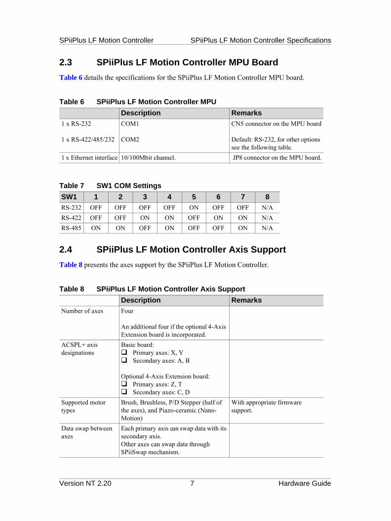
2.3 SPiiPlus LF Motion Controller MPU Board
Table 6 details the specifications for the SPiiPlus LF Motion Controller MPU board.
Table 6 SPiiPlus LF Motion Controller MPU
Description Remarks
1 x RS-232
1 x RS-422/485/232
COM1
COM2
CN5 connector on the MPU board
Default: RS-232, for other options see the following table.
1 x Ethernet interface 10/100Mbit channel. JP8 connector on the MPU board.
Table 7 SW1 COM Settings
SW1 1 2 3 4 5 6 7 8
RS-232 OFF OFF OFF OFF ON OFF OFF N/ARS-422 OFF OFF ON ON OFF ON ON N/ARS-485 ON ON OFF ON OFF OFF ON N/A
2.4 SPiiPlus LF Motion Controller Axis Support
Table 8 presents the axes support by the SPiiPlus LF Motion Controller.
Table 8 SPiiPlus LF Motion Controller Axis Support
Description Remarks
Number of axes Four
An additional four if the optional 4-Axis Extension board is incorporated.
ACSPL+ axis designations
Basic board:
Optional 4-Axis Extension board:
Supported motor types
Brush, Brushless, P/D Stepper (half of the axes), and Piazo-ceramic (Nano-Motion)
With appropriate firmware support.
Data swap between axes
Each primary axis can swap data with its secondary axis.Other axes can swap data through SPiiSwap mechanism.
Primary axes: X, Y Secondary axes: A, B
Primary axes: Z, T Secondary axes: C, D
Version NT 2.20 7 Hardware Guide

SPiiPlus LF Motion Controller SPiiPlus LF Motion Controller Specifications
2.5 Input & Output Specifications
Table 9 details the SPiiPlus LF Motion Controller input and output.
Note
In the signal designations given in the specifications the pound sign (#) stands in place of the actual axis designation, for example, #_RL can be X_RL, Y_RL, A_RL, and so forth.
Table 9 SPiiPlus LF Motion Controller Input/Output Specifications (page 1 of 6)
Description Remarks
Digital Encoder Inputs/Outputs
Signal Designations A: #_CHA±B: #_CHB±I: #_CHI±
Quantity One (6 signals) per axis. In dual loop, A and B encoders can be used as secondary encoders for X and Y axes.
Format A, B, IInterface type RS422 compatible.
Input impedance: 120. Maximum input frequency
7.5MHz 7.5MHz A & B input frequency appropriate to 30 million counts per second.
Analog Drive Commands Output
Signal Designations Phase S: #_IS_CMD±Phase T: #_IT_CMD±
Quantity Two per axis.Type ±10V, differential. Upon power-up
output is 0V.Can be configured by Jumper JP2B to be ±10V, single-ended output (valid only for the #_CMD+ signal). See Section 6.2.
Maximum output inaccuracy
5% in max output voltage at 25o C
Resolution 12-bit resolution Maximum zero offset
±50mV at 0V at 25oC Offset compensation can be made via the software (0.3 mV resolution) and the on-board potentiometers for fine tuning. See note in Section 5.1.2.
Maximum load 5mA for differential output1mA for single-ended output
Output short protected
Version NT 2.20 8 Hardware Guide

SPiiPlus LF Motion Controller SPiiPlus LF Motion Controller Specifications
Pulse/Direction Drive Command Output
Signal Designations Pulse: #_PWM0Dir: #_PWM1
Quanity Two commands per primary axis.Type TTL, bufferedMaximum pulse rate 4,000,000 pulse/secondPulse width Min. Pulse width - 25nS
Max. Pulse width - 51SResolution Command time resolution 25nS.Default state Power-up output state "Z"Maximum load Load current < 6mADiagnostic Pulse/Direction output signals for
stepper motors.Drive Enable Output
Signal Designation #_ENAQuanity One per axis.Type High voltage open collector, active low.Default state Upon power-up signal is high impedance
(output state "Z")Max. rating Up to 25V/7mAVoltage drop in active state
< 0.4 V
Diagnostic High voltage output, active lowDrive Fault Input
Signal Designation #_FLTQuanity One per axisType Sink input Default state Input is high/high impedance Input logic state “0”Max. ratings Current: Up to 0.4mA
Voltage: Up to 30V Less than 1V
In active (no fault) state
In fault stateIn active (no fault) state
Propagation delay ½ from input to measured output delay < 3mS
From Fault Input occurrence to response/activity in CTIME=1
Diagnostic Input. Normal operation: Input is low Fault: Input is high/high impedance
Input logic state “1”Input logic state “0”
Table 9 SPiiPlus LF Motion Controller Input/Output Specifications (page 2 of 6)
Description Remarks
Version NT 2.20 9 Hardware Guide

SPiiPlus LF Motion Controller SPiiPlus LF Motion Controller Specifications
Mechanical Brake
Supported only by way of the General Purpose Digital I/O - configurable via the software.
Limit Switches
Signal Designations Right limit: #_RLLeft limit: #_LL
Quantity One Left Limit and one Right Limit per axis
Type Single-ended, opto-isolated input. Configurable by the user as either source or sink (as a group).
Configuration by jumper JP1 (see Section 6.2)
Voltage 5V ±10% or 24V ±20%, automatically detected.
User has to supply V_SUP_SFTY and V_RTN_SFTY.
Input current 2.8-14mA Reference: V_SUP_SFTYDefault state No limit, no current.Propagation delay ½ from input to measured output delay
<3mSFrom Fault Input occurrence to response/activity in CTIME=1
Diagnostic Limit active - current through the opto-couplerNo limit - no current through the opto-coupler
E-Stop
Signal Designations ES± E-Stop should be used to indicate to the controller that there is an emergency condition and should not be relied upon as the E-Stop safety mechanism.
Quantity OneType Two ports, opto-isolated, input, with
automatic voltage detectionVoltage 5V ±10% or 24V ±20%, automatically
detected.No external supply is required.
Input current 2.8-14 mADefault state No ES, no current.Propagation delay ½ from input to measured output delay
<3mSFrom Fault Input occurrence to response/activity in CTIME=1
Diagnostic ES active - current through the opto-coupler
No ES - no current through the opto-coupler
Table 9 SPiiPlus LF Motion Controller Input/Output Specifications (page 3 of 6)
Description Remarks
Version NT 2.20 10 Hardware Guide

SPiiPlus LF Motion Controller SPiiPlus LF Motion Controller Specifications
General Purpose Logic Inputs
Signal Designations IN0, IN1, IN2, IN3, IN4, IN5, IN6, IN7Quantity Eight.Type TTL, opto-22 compatible, inputInput current 1 mAMax. voltage 5 VDefault state Logic state “1”Propagation delay ½ from input to measured output delay
<3mSFrom Fault Input occurrence to response/activity in CTIME=1
Diagnostic Input active - Logic state “0”Input inactive - Logic state “1”
Registration Mark
Signal Designations #_MARK1±#_MARK2±
Can also be used for general purposes.
Quantity Four per each primary axis.Type RS422 compatible, TTL input (through
General Purpose Digital I/O: IN4 through IN7)
User can program through the software using MARK instead of General Purpose Digital Input.
Input current >1 mAMax. voltage 5 VDefault state Logic state “0”Minimum pulse width
100ns
Diagnostic Input active - Logic state “1”Input inactive - Logic state “0”
General Purpose Outputs
Signal Designations OUT0, OUT1, OUT2, OUT3, OUT4, OUT5, OUT6, OUT7
SPiiPlus LF Motion Controller does not have a dedicated mechanical brake connection. However, the same pins of connectors can be defined, through the software, either as digital outputs or as mechanical brake outputs.Default: Digital output.
Quantity EightType TTL, opto-22 compatible outputMaximum current per single output
±30 mA ±60 mA total (for all outputs)
Default state Logic state “0”
Table 9 SPiiPlus LF Motion Controller Input/Output Specifications (page 4 of 6)
Description Remarks
Version NT 2.20 11 Hardware Guide

SPiiPlus LF Motion Controller SPiiPlus LF Motion Controller Specifications
Propagation delay ½ from input to measured output delay <3mS
Diagnostic Output active - Logic state “1”Output inactive - Logic state “0”
PEG Outputs
Signal Designations #_PEG± Position compared with digital encoders.Resolution: Quadrature counts.
Quantity One per each primary axisType RS422 or opto-22 compatible (with
buffer), outputThe user can, via the software, program PEG to be used instead of General Purpose Digital Outputs (OUT6 and OUT7)
Propagation delay <0.3S Propagation delay - The delay from the moment that the encoder reaches the set position until the output PEG pulse is generated. It includes both the delay generated by the encoder processing logic and the delay of the PEG logic.
PEG generated pulse width range
25nSec to 1.6mSec, programmable
Edge separation between two PEG events
>200nSec
Number of random PEG events (table based mode)
Up to 30,000
Default state Logic “0” by pull down.Diagnostic Output active - “1” logic
Output inactive - “0” logicHSSI
Signal Designations Control signal:H_CON_#±Input signal:H_DI_#±Output signal:H_DO_#±
Quantity Four internal
One external
X, Y, Z and T
X onlyInput word size 16x4 = 64 per HSSI channel. Output word size 16x4 = 64 per HSSI channel.
Table 9 SPiiPlus LF Motion Controller Input/Output Specifications (page 5 of 6)
Description Remarks
Version NT 2.20 12 Hardware Guide

SPiiPlus LF Motion Controller SPiiPlus LF Motion Controller Specifications
TX / RX type RS422 compatible.Input impedance 120Distance <10m.
Sampling rate All the 64 input bits are sampled and all the 64 output bits are updated every 50 S.
HSSI connection HSSI channels can be commutated as external or internal.
In internal commutated configuration SPii communication swapping is possible via the software.
Default state External modeEthernet
Signal Designations Transmit: ETH1_TX±Receive: ETH1_RX±
Quantity One Ethernet portLine impedance 100 Galvanic IsolatedProtocol TPC/IP 10/100MbpsRS232
Signal Designations COM1:Transmit:COM1_TXReceive:COM1_RXCOM2:Transmit:COM2_TXReceive:COM2_RX
ESD protected
Quantity Two RS232 portsMaximum Baud rate 115,200CAN Bus
Signal Designations CAN_HCAN_L
Quantity One The CAN bus connector, J7, is located on the CAN board that is connected to the Main board (see Section 5.1.4).
Protocol CANopenFrequency 1kHzLine impedance 120- galvanic isolated When jumper JP1on the CAN
board is installed (see Section 6.2).
CAN power supply Internal Galvanic isolated
Table 9 SPiiPlus LF Motion Controller Input/Output Specifications (page 6 of 6)
Description Remarks
Version NT 2.20 13 Hardware Guide

SPiiPlus LF Motion Controller Installation
3 InstallationThis chapter provides instructions for assembling and mounting the SPiiPlus LF Motion Controller.
3.1 SPiiPlus LF Motion Controller Assembly
Note
These assembly instructions apply to the complete SPiiPlus LF Motion Controller including the optional DIN rail, CAN card, and 4 Axis Extension card.
3.1.1 SPiiPlus LF Motion Controller Assembly HardwareThe parts required for SPiiPlus LF Motion Controller assembly is given in Table 10.
Table 10 SPiiPlus LF Motion Controller Parts List
Item Part Number Description Qty
1 MO-EBC22-LAN/LF EBC220 PC/104 CPU+LAN MODULE NPB 12 SP-20345-122 4.5 MM HEX M/F SS STANDOFF 12 MM 43 GG-14701-400 BRACKET FOR SP+LF 14 SB-14730-400/LF SP+LF CAN BUS CARD 15 SB-14730-000/LF SP+LF BASIC 4 AXIS CARD ASSY 16 SB-14730-402/LF SP+LF 4 AXIS EXTENSION CARD 17 SP-20345-142 4.5 MM HEX M/F SS STANDOFF 14 MM 28 SP-20345-152 4.5 MM HEX M/F NY STANDOFF 15 MM 49 SP-30345-052 4.5 MM HEX F/F SS STANDOFF 5 MM 310 GG-0HSSI-002 RAIL ADAPTER 211 SC-08036-220 SCREW PHILLIPS PAN M3x8 RoHS 412 WA-00003-000 FLAT WASHER SS FOR M3 RoHS 1213 SC-05035-222 SCREW PHILLIPS PAN M3x5 RoHS 614 SC-04033-248 SCREW PHILLIPS PAN M3x4 RoHS 615 SP-00WS3-560 FLAT WASHER NYLON FOR M3 RoHS 4
Version NT 2.20 14 Hardware Guide

SPiiPlus LF Motion Controller Installation
3.1.2 SPiiPlus LF Motion Controller AssemblyAssembling the SPiiPlus LF Motion Controller is as shown in Figure 4.
Note
The numbers in the diagram refer to the Item numbers in Table 10.
Figure 4 SPiiPlus LF Motion Controller Assembly Diagram
There is a definite order in assembling the SPiiPlus LF Motion Controller, that is, it is assembled from back to front:
1. The CAN card is connected to the Main Board.2. The 4-Axis Extension card (if there is one, otherwise the Main Board) is first connect to
the DIN rail.3. The MPU Board is then connected to the Main Board.
Version NT 2.20 15 Hardware Guide

SPiiPlus LF Motion Controller Installation
3.2 Mounting the SPiiPlus LF Motion Controller
To mount the SPiiPlus LF Motion Controller controller in the rack, do the following:
1. Verify the settings of the jumpers according to the digital I/O configuration and as your application requires (see Chapter 6 for details).
2. Power up the unit.3. Verify that after ~30sec the MPU_ON LED blinks and then stops blinking (until you
establish communication with the controller).4. Establish communication and verify/upload your application software into the controller
using your host computer or the SPiiPlus MMI Application Loader.5. Save your application in the controller Flash memory using your host computer or the
SPiiPlus MMI Main menu Save.
Version NT 2.20 16 Hardware Guide
SPiiPlus LF Motion Controller Safety and EMC Guidelines
4 Safety and EMC Guidelines
Warning
Read and understand the following guidelines and procedures before operating the SPiiPlus LF.
4.1 General Safety Guidelines
Under emergency situations the unit should be completely disconnected from any power supply. The E-Stop Inputs and Left/Right Limits on ACS Motion Control products are designed for use in conjunction with customer-installed devices to protect driver load. The end user is responsible for complying with all Electrical Codes.
4.1.1 Emergency Stop Device1. Locate an emergency stop device at each operator control station and other operating
stations where an emergency stop may be required. 2. The emergency stop device shall disconnect all electrical equipment connected to the
SPiiPlus LF Motion Controller from their respective power supplies. 3. It will not be possible to restore the circuit until the operator manually resets the emergency
stop. 4. In situations with multiple emergency stop devices the circuit shall not be restored until all
emergency stops devices are manually reset.
4.1.2 Fail-Safe Logic RecommendationACS Motion Control recommends connecting all safety inputs (limit inputs and emergency stop input) with a fail safe logic. The intention is that during normal operation the inputs are active. When a safety event happens (or the input wire is cut) the input becomes zero and the controller identifies that as a fault.
4.1.3 Initial Logic State of OutputsThe relevance of analog and digital output pins is product and model dependent. The initial logic state of the inactive analog and digital pins is undefined. They may carry a potential of 5V relative to ground.
4.1.4 Electrical SeparationElectrical separation is required between the control and power supply cables to prevent electrical shock or damage to the SPiiPlus LF Motion Controller.
Version NT 2.20 17 Hardware Guide

SPiiPlus LF Motion Controller Safety and EMC Guidelines
4.1.5 Protective Precautions
Warning
Read and understand the following precautions before operating the SPiiPlus LF.
Digital outputs are protected against short circuits with ground.
Over-travel Protection – Provides over-travel limit protection where over-travel is hazardous. Design and install the over-travel limiting device to interrupt the power circuit.
Over-current Protection – Use the software Current/Torque Limit parameters in the MMI Adjuster to provide over-current protection for the motors.
Thermal Detection – Use suitable thermal detection devices to interrupt the power circuit where abnormal temperatures can cause a hazardous condition.
Cooling Fans – Make sure the cooling fan remains unobstructed at all times.
In order to insure good heat dissipation, make sure that the cooling vents remain clean at all times.
4.2 General Wiring and Electromagnetic Compatibility (EMC) Guidelines
4.2.1 Routing Signal and Power CablesPower cables (to the motor, mains outlet, etc.) and signal cables (to I/O, encoder, RS-232, etc.) must be kept as far apart as possible. Keep at least an inch (2.5 cm) for each 3 feet (1 m) of parallel run as illustrated in Figure 5. For example, if the motor and encoder cables run parallel for 6 feet (2 m), maintain a 2 inch (5 cm) separation between them.
Figure 5 Cable Spacing
Version NT 2.20 18 Hardware Guide
SPiiPlus LF Motion Controller Safety and EMC Guidelines
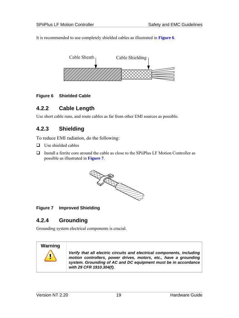
It is recommended to use completely shielded cables as illustrated in Figure 6.
Figure 6 Shielded Cable
4.2.2 Cable LengthUse short cable runs, and route cables as far from other EMI sources as possible.
4.2.3 Shielding
To reduce EMI radiation, do the following: Use shielded cables
Install a ferrite core around the cable as close to the SPiiPlus LF Motion Controller as possible as illustrated in Figure 7.
Figure 7 Improved Shielding
4.2.4 GroundingGrounding system electrical components is crucial.
WarningVerify that all electric circuits and electrical components, including motion controllers, power drives, motors, etc., have a grounding system. Grounding of AC and DC equipment must be in accordance with 29 CFR 1910.304(f).
Version NT 2.20 19 Hardware Guide

SPiiPlus LF Motion Controller Electrical Interface
5 Electrical InterfaceThis chapter provides details for the SPiiPlus LF Motion Controller connectors and electrical interfaces.
Figure 8 SPiiPlus LF Motion Controller Connector Locations
5.1 Main Board Connectors
5.1.1 J3 - General Purpose I/OThe General Purpose I/O connnector serves for connecting all General Purpose I/O signals. it is a male, header with box, 34-pin, 2.54mm pitch connector and is opto-22 compatible. Table 11 provides the pinout for the connector.
Table 11 J3 Connector Connector Pinout (page 1 of 2)
Pin # Signal Designator Remarks
1 IN02 DGND3 IN1
Version NT 2.20 20 Hardware Guide

SPiiPlus LF Motion Controller Electrical Interface
4 DGND5 IN26 DGND7 IN38 DGND9 IN4 Can also be programmed as X_MARK1 through
ACSPL+.10 DGND11 IN5 Can also be programmed as X_MARK2 through
ACSPL+.12 DGND13 IN6 Can also be programmed as Y_MARK1 through
ACSPL+.14 DGND15 IN7 Can also be programmed as Y_MARK2 through
ACSPL+.16 DGND17 OUT018 DGND19 OUT120 DGND21 OUT222 DGND23 OUT324 DGND25 OUT426 DGND27 OUT528 DGND29 OUT6 Can also be programmed as X_PEG through ACSPL+.30 DGND31 OUT7 Can also be programmed as Y_PEG through ACSPL+.32 DGND33 5V34 DGND
Table 11 J3 Connector Connector Pinout (page 2 of 2)
Pin # Signal Designator Remarks
Version NT 2.20 21 Hardware Guide

SPiiPlus LF Motion Controller Electrical Interface
5.1.2 J4 - Drive Interface ConnectorJ4 serves for interfacing the drives with the SPiiPlus LF Motion Controller Main board. It is a male, header with box, 50-pin, 2.54mm pitch connector. Table 12 provides the pinout for the connector.
Table 12 J4 Connector Pinout
Pin # Signal Designator Pin # Signal Designator
1 Y_IS_CMD+ 26 Y_PWM32 Y_IS_CMD- 27 X_PWM43 Y_IT_CMD+ 28 Y_PWM44 Y_IT_CMD- 29 X_PWM55 B_IS_CMD+ 30 Y_PWM56 B_IS_CMD- 31 Y_ENA7 B_IT_CMD+ 32 B_ENA8 B_IT_CMD- 33 X_ENA9 X_IS_CMD+ 34 A_ENA10 X_IS_CMD- 35 Y_FLT11 X_IT_CMD+ 36 B_FLT12 X_IT_CMD- 37 X_FLT13 A_IS_CMD+ 38 A_FLT14 A_IS_CMD- 39 X_PEG-15 A_IT_CMD+ 40 X_PEG+16 A_IT_CMD- 41 Y_PEG+17 AGND 42 Y_PEG-18 DGND 43 X_MARK1+19 X_PWM0 44 X_MARK1-20 Y_PWM0 45 X_MARK2+21 X_PWM1 46 X_MARK2-22 Y_PWM1 47 Y_MARK1+23 X_PWM2 48 Y_MARK1-24 Y_PWM2 49 Y_MARK2+25 X_PWM3 50 Y_MARK2-
Model
The PWM signals (X_PWM#, and Y_PWM#) are for internal use only and cannot be accessed by the user.
Version NT 2.20 22 Hardware Guide

SPiiPlus LF Motion Controller Electrical Interface
Note
#_IS_CMD± and #_IT_CMD± offset compensation can be made via the software (0.3 mV resolution) and the on-board potentiometers (see Figure 8) for fine tuning. The signal designators and their associated potentiometers are:
Signal Designator Potentiometer
X_IS_CMD± RV2
X_IT_CMD± RV3
Y_IS_CMD± RV6
Y_IT_CMD± RV7
A_IS_CMD± RV4
A_IT_CMD± RV5
B_IS_CMD± RV8
B_IT_CMD± RV9
5.1.3 J5 - Safety and Encoder Interface ConnectorJ5 serves for interfacing the SPiiPlus LF Motion Controller Main board with the encoder and safety signals. It is a male, header with box, 50-pin, 2.54mm pitch connector. Table 13 provides the pinout for the connector.
Table 13 J5 Connector Pinout (page 1 of 2)
Pin # Signal Designator Pin # Signal Designator
1 X_CHA+ 26 5V2 X_CHA- 27 X_RL (Right Limit)3 X_CHB+ 28 X_LL (Left Limit)4 X_CHB- 29 A_RL (Right Limit)5 X_CHI+ 30 A_LL (Left Limit)6 X_CHI- 31 Y_RL (Right Limit)7 A_CHA+ 32 Y_LL (Left Limit)8 A_CHA- 33 B_RL (Right Limit)9 A_CHB+ 34 B_LL (Left Limit)10 A_CHB- 35 Z_RL (Right Limit)11 A_CHI+ 36 Z_LL (Left Limit)12 A_CHI- 37 C_RL (Right Limit)13 Y_CHA+ 38 C_LL (Left Limit)14 Y_CHA- 39 T_RL (Right Limit)
Version NT 2.20 23 Hardware Guide

SPiiPlus LF Motion Controller Electrical Interface
5.1.4 J7 - CAN Bus ConnectionJ7 serves for connecting to the CAN bus. It is a female, 8-pin, RJ-45 connector. Table 14 provides the pinout for the connector.
Table 14 J7 Connector Pinout
Pin # Signal Designator Description
1 CAN_H CAN high2 CAN_L CAN low3 CAN_GND Ground, return CAN supply4 Not used5 Not used6 CAN_SHLD CAN shield7 CAN_GND Ground, return CAN supply8 Not used
Note
While pin 6 can serve as the CAN bus shield, the shield is normally supplied by the body of the connector if a drain wire is properly installed.
15 Y_CHB+ 40 T_LL (Left Limit)16 Y_CHB- 41 D_RL (Right Limit)17 Y_CHI+ 42 D_LL (Left Limit)18 Y_CHI- 43 V_SUP_SFTY19 B_CHA+ 44 V_RTN_SFTY20 B_CHA- 45 ES+ (Emergency Stop)21 B_CHB+ 46 ES- (Emergency Stop)22 B_CHB- 47 Not used23 B_CHI+ 48 Not used24 B_CHI- 49 Not used25 DGND 50 Not used
Table 13 J5 Connector Pinout (page 2 of 2)
Pin # Signal Designator Pin # Signal Designator
Version NT 2.20 24 Hardware Guide

SPiiPlus LF Motion Controller Electrical Interface
5.1.5 J8 - HSSI X ConnectorJ8 serves for connecting the SPiiPlus LF Motion Controller X axis to a High-Speed Synchronous Serial Interface (HSSI) channel. The connector is a male, dual row header with box, 8-pin, 2mm pitch connector. Table 15 provides the pinout for the connector.
Note
Table 15 J8 Connector Pinout
Pin # Signal Designator Description
1 H_CON_0+ Control signal - non-inverted output for channel X2 H_CON_0- Control signal - inverted output for channel X3 H_DI_0+ Serial data - non-inverted input for channel X4 H_DI_0- Serial data - inverted input for channel X5 H_DO_0+ Serial data - non-inverted output for channel X6 H_DO_0- Serial data - inverted output for channel X7 DGND Digital ground8 DGND Digital ground
A cable with a standard RJ45 connector can be ordered for connecting with J8.
5.1.6 J11 - Power ConnectorJ11 serves for connecting SPiiPlus LF Motion Controller to the power supply. The connector is a 5-pin PHOENIX MC1,5/5-GF-3,81 connector.
Note
Table 16 J11 Connector Pinout
Pin # Signal Designator Description
1 5V_IN 5V supply2 12V_IN 12V supply3 -12V_IN -12V supply4 DGND Digital ground5 EGND Shield
The pin numbers are from top to bottom when looking at the SPiiPlus LF from the top as shown in Figure 8.
Version NT 2.20 25 Hardware Guide

SPiiPlus LF Motion Controller Electrical Interface
5.2 MPU Board Connectors
5.2.1 CN5 - Communication ConnectorCN5 serves for connecing RS-232, RS-422 or RS-485 ports to the MPU. It is a male, dual row header, 20-pin, 2mm pitch connector. Table 17 provides the pinout for the connector.
Note
Table 17 CN5 Connector Pinout
Pin # Signal Designator Pin # Signal Designator
1 DCD1 11 DCD2/(TX-)for RS422/TXRX- RS485
2 DSR1 12 DSR23 RXD1 13 RXD2/(TX+) for
RS422/TXRX+ RS4854 RTS1 14 RTS25 TXD1 15 TXD2/(RX+) for RS4226 CTS1 16 CTS27 DTR1 17 DTR2/(RX-) for RS4228 RI1 18 RI2 or +5V or +12V(for
Jumper)9 GND 19 GND10 Not used 20 Not used
A cable set consisting of two standard D-type 9 pin connectors can be ordered for connecting with CN5.
Version NT 2.20 26 Hardware Guide

SPiiPlus LF Motion Controller Electrical Interface
5.2.2 JP8 - Ethernet ConnectorJ8 serves for connecting the MPU to the 10/100 Mbit Ethernet. It is a male, dual row header, 8-pin, 2mm pitch connector. Table 18 provides the pinout for the connector.
Note
Table 18 J8 Connector Pinout
Pin # Signal Designator Pin # Signal Designator
1 TX+ 5 Not used2 TX- 6 RX-3 RX+ 7 Not used4 Not used 8 Not used
A cable with a standard RJ45 connector can be ordered for connecting with J9.
Version NT 2.20 27 Hardware Guide

SPiiPlus LF Motion Controller Jumpers
6 JumpersThis chapter provides details of the various jumpers located on the SPiiPlus LF Motion Controller. Different jumper settings affect the following features:
Safety inputs in sink and source configuration
Analog outputs in differential and single-ended configuration
6.1 SPiiPlus LF Motion Controller Jumpers
Figure 9 shows the locations of the SPiiPlus LF Motion Controller jumpers.
Figure 9 SPiiPlus LF Motion Controller Jumper Locations
6.2 SPiiPlus LF Motion Controller Jumper Functions
Table 19 lists the jumper functions, and, where relevant, their settings:
Table 19 SPiiPlus LF Motion Controller Main Board Jumpers and Setting (page 1 of 2)
Jumper Function Jumper Settings
JP1 Safety (Limits) inputs in sink and source Position 1,2 - sinkPosition 2,3 - source
JP1 (CAN) 120 line impedance Installed - 120 line termination
Version NT 2.20 28 Hardware Guide

SPiiPlus LF Motion Controller Jumpers
JP4 Located on the back of the Main board.Used for testing the software.To recover the firmware, see MMI Utilities Emergency Wizard
No jumper - Normal modeJumper - Debug mode
JP2B-1 X axis S drive command Jumper - Differential modeNo Jumper - Single ended mode
JP2B-2 X axis T drive command Jumper - Differential modeNo Jumper - Single ended mode
JP2B-3 A axis S drive command Jumper - Differential modeNo Jumper - Single ended mode
JP2B-4 A axis T drive command Jumper - Differential modeNo Jumper - Single ended mode
JP2B-5 Yaxis S drive command Jumper - Differential modeNo Jumper - Single ended mode
JP2B-6 Yaxis T drive command Jumper - Differential modeNo Jumper - Single ended mode
JP2B-7 B axis S drive command Jumper - Differential modeNo Jumper - Single ended mode
JP2B-8 B axis T drive command Jumper - Differential modeNo Jumper - Single ended mode
Table 19 SPiiPlus LF Motion Controller Main Board Jumpers and Setting (page 2 of 2)
Jumper Function Jumper Settings
Version NT 2.20 29 Hardware Guide

SPiiPlus LF Motion Controller LED Indicators
7 LED IndicatorsThis chapter provides details of the SPiiPlus LF Motion Controller LED indicators. There are three LEDs located on the Main board, and one LED located on the MPU board, as shown in Figure 10.
Figure 10 SPiiPlus LF Motion Controller LED Indicators
7.1 Main Board LEDs
The Main board LEDs indicate the status of the power supplies and are detailed in Table 20.
Table 20 Main Board LED Indicators
LED Indicator Color Description
MPU_ON Green Motion Processing Unit (MPU) operational. When the control unit detects a receive message, this LED goes off for a fraction of a second. This indicates that the processor and communications are functioning properly.Note: This LED can blink or light steady about 30 seconds after the connection of the control supply.
+12V Green +12V available
Off +12V not available
-12V Green -12V available
Off -12V not available
Version NT 2.20 30 Hardware Guide
SPiiPlus LF Motion Controller LED Indicators
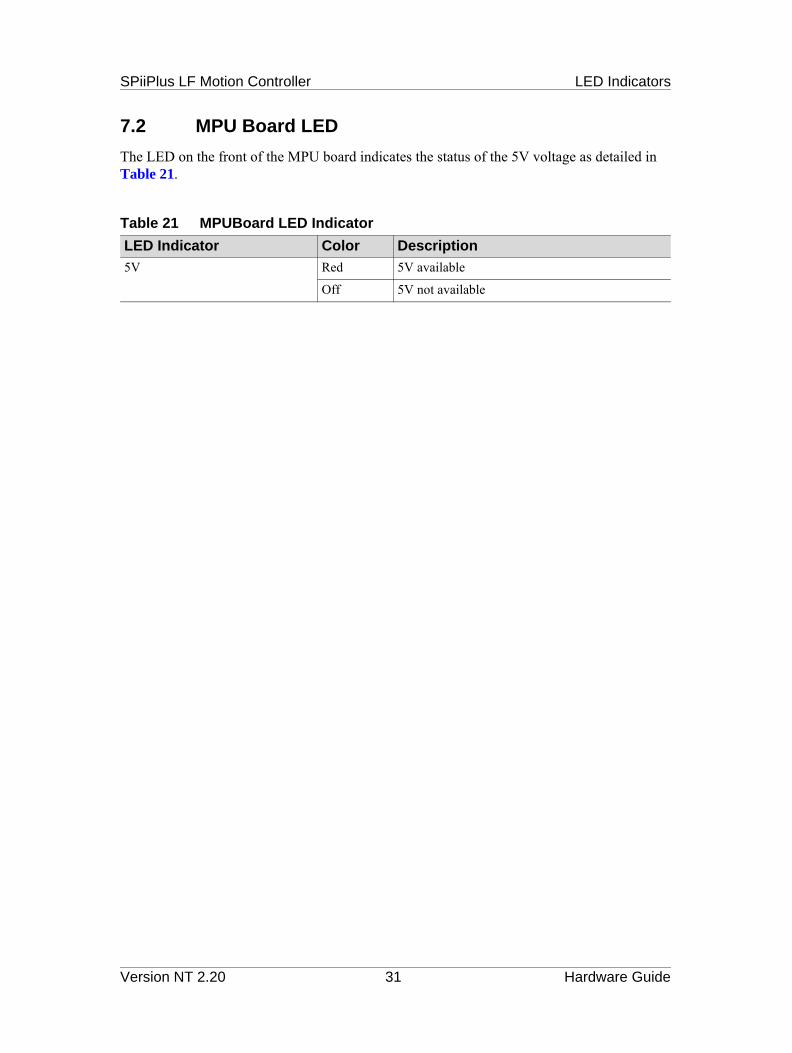
7.2 MPU Board LED
The LED on the front of the MPU board indicates the status of the 5V voltage as detailed in Table 21.
Table 21 MPUBoard LED Indicator
LED Indicator Color Description
5V Red 5V available
Off 5V not available
Version NT 2.20 31 Hardware Guide