Chapter 4 CONTROLLER - AutoCD.ru
86
CHAPTER 4 CONTROLLER 4-1 Chapter 4 CONTROLLER 1. Outline The controllers control the forklift truck and engine. Each controller is located as shown below. 1. Output unit 2. Meter Panel 3. Input unit 4. ECM 5. Gateway 6. VCM-6 (Vehicle Control Module) 609789 2 4 3 1 6 5
-
Upload
khangminh22 -
Category
Documents
-
view
0 -
download
0
Transcript of Chapter 4 CONTROLLER - AutoCD.ru

CHAPTER 4 CONTROLLER
4-1
Chapter 4 CONTROLLER 1. Outline
The controllers control the forklift truck and engine. Each controller is located as shown below.
1. Output unit2. Meter Panel3. Input unit4. ECM
5. Gateway 6. VCM-6 (Vehicle Control Module)
609789
2
43
1
6
5

CHAPTER 4 CONTROLLER
4-2
2. Main Functions of Controllers
Each controller connects into a CAN network, and information is exchanged between controllers through the CAN network.VCM-6 (vehicle control module) controller controls the whole forklift truck system, and the other controllers control relevantcomponents.
1. VCM-62. Input unit3. Output unit4. Meter panel
5. Gateway 6. ECM7. Connector
609575
470 471 484 485
476 477 474 475
470 471 486
492 493 927
472 473 488 489 488 489S027 S028 474A 475A
1 2 3 4 5 6
7
120?
120?
120?
CAN_
H
CAN_
L
CAN_IC
CAN_
H
CAN_
L
CAN_IC
CAN_
H
CAN_
L
CAN_IC
CAN_
H
CAN_
L
CAN_ICCA
N_H
CAN_
LCAN_IC
CAN_
H
CAN_
L
CAN_IC
CAN_
H
CAN_
L
CAN_IC

CHAPTER 4 CONTROLLER
4-3
2.1 Meter Panel
2.2 VCM-6 (Vehicle Control Module)
2.3 ECM (Engine Control Module)
2.4 Input and Output Units
2.5 Gateway
Primary function of each control is described below:
The meter panel is located below the steering wheel. Itdisplays fuel gauge, water temperature gauge, travel speed,clock time, and self-diagnostic information. For the other functions, see “3. ELECTRICAL SYSTEM”.
The VCM-6 controller is located on the left side of the forklifttruck and controls the whole forklift truck system (driving/mast interlock system, steering knob deviation correction,etc.)
The ECM controller is located on the left side of the forklifttruck and controls the engine. For more information, seeEngine Service Manual.
The input/output units are mounted on the forklift truck, andread signals from FC lever and control the FC control valve.
Located on the left side of forklift truck, the gatewaytransforms signals of the ECM and VCM-6.

CHAPTER 4 CONTROLLER
4-4
2.6 GSE Connector
When using service tool, the GSE connector is used toconnect PC and the forklift truck. The GSE connector islocated under the cup holder on the right side of dashboard.
(1) Pull up the upper side rim of the cup holder.
501271
(2) With the rim of the cup holder raised, push the cupholder in the direction of the mast.
501272
(3) Remove the cup holder and remove the GSE connectorfrom inside.
1. GSE connector
501273
1

CHAPTER 4 CONTROLLER
4-5
3. Service Tool 3.1 Service Tool Menus
Select functions from the main menu window.
1. Menu items 2. Tool bar
501275
Truck
Truck
1
2

CHAPTER 4 CONTROLLER
4-6
File menu- Print: allows you to print the screen being displayed. - Exit: allows you to terminate the application.
Monitor menu- Input monitor: allows you to monitor input values.- Output monitor: allows you to monitor output values.- Custom monitor: allows you to monitor customized
input/output values.- Truck status: allows you to monitor the current truck
conditions.- Truck history: allows you to check the past history.
Monitor menu- Set-up option: allows you to monitor or change setup
values.- Oscilloscope: allows you to view a graph of input/
output values. Also allows you to store the graphbeing displayed. Thus, a graph stored in memory canbe redisplayed.
- Active test: operating conditions can be checked byoutputting signals.
- Destination change: allows you to change thecontroller to connect and the controller to control.
- Firmware update: allows you to update the firmwareof controller being connected.
Communication menu- Setup: allows you to setup communication port,
communication speed, and flow control. Language menu
- allows you to select a language in the language menu. Help menu
- Contents: allows you to view contents of help menu. - Topics: allows you to search help topics.- Pop up display: allows you to have a pop-up display of
item name/button name. - Version information: allows you to check version
information.

CHAPTER 4 CONTROLLER
4-7
3.2 Outline of Toolbox
Input monitorThe monitor is used to check input status of sensors andswitches.
1. Input monitor button2. Monitor window
3. Description of the monitor item
505823
1 2
Truck Status
Input Monitor
Truck History
3
CHAPTER 4 CONTROLLER
4-8
Item Item
Seat switch ON/OFF 4V-5V changeover switch ON/OFF
Seat switch timer ON/OFF IN-UNIT status (RIO2)Normal/
Faulty
Seat belt switch ON/OFF Lowering speed switch ON/OFF
DC power supply [V] Lift operation switch ON/OFF
Direction lever F ON/OFF Tilt operation switch ON/OFF
Direction lever N ON/OFF Mast high switch ON/OFF
Direction lever R ON/OFF Tilt auto-stop switch ON/OFF
FNR lever Tilt angle [V]
Joystick (Lift lever 1) signal [%] Weight 0 set switch ON/OFF
Joystick (Lift lever 1) status Speed [km/h]
Joystick (Lift lever 2) signal [%] Speed sensor error [V]
Joystick (Lift lever 2) status Speed limit SW
Joystick (Tilt lever 1) signal [%] Power/Soft mode switch ON/OFF
Joystick (Tilt lever 1) status Handle angle [deg]
Joystick (Tilt lever 2) signal [%] Handle angle target [deg]
Joystick (Tilt lever 2) status Auto light signal ON/OFF
Joystick (ATT1 lever 1) signal [%] Coolant low level switch ON/OFF
Joystick (ATT1 lever 1) status Air cleaner switch ON/OFF
Joystick (ATT1 lever 2) signal [%] Transmission warning switch ON/OFF
Joystick (ATT1 lever 2) status Fuel warning switch ON/OFF
Joystick (ATT2 lever 1) signal [%] Oil temperature switch ON/OFF
Joystick (ATT2 lever 1) status Mode select switch ON/OFF
Joystick (ATT2 lever 2) signal [%] Oil pressure LIFT [MPa]
Joystick (ATT2 lever 2) status AUX AI [HEX]

CHAPTER 4 CONTROLLER
4-9
Output monitorThe monitor is used to check the output status of sensorsand switches.
1. Output monitor button
505824
1
Truck Status
Output Monitor
Truck History

CHAPTER 4 CONTROLLER
4-10
Signals that can be monitored are listed below:
Item Item
Transmission signal N Solenoid output (ATT3 valve 2) output [mA]
Transmission solenoid F Solenoid output (ATT3 valve) feedback [mA]
Transmission solenoid R Solenoid output (ATT3 valve 1) output
Transmission solenoid current [mA] Solenoid output (ATT3 valve 2) output
Solenoid output (Lift valve 1) output [mA] Solenoid output (ATT3 valve) status
Solenoid output (Lift valve 2) output [mA] PWM voltage (RIO1) [V]
Solenoid output (Lift valve) feedback [mA] PWM voltage (RIO1)
Solenoid output (Lift valve 1) output [mA] OUT-UNIT status (RIO1)
Solenoid output (Lift valve 2) output [mA] Unload solenoid
Solenoid output (Lift valve) status Unload solenoid feedback [mA]
Solenoid output (Tilt valve 1) output [mA] Lift lock solenoid
Solenoid output (Tilt valve 2) output [mA] Lift lock solenoid feedback [mA]
Solenoid output (Tilt valve) feedback [mA] Tilt lock solenoid
Solenoid output (Tilt valve 1) output Tilt lock solenoid feedback [mA]
Solenoid output (Tilt valve 2) output Park brake alarm
Solenoid output (Tilt valve) status Overload alarm
Solenoid output (ATT1 valve 1) output [mA] Overspeed alarm
Solenoid output (ATT1 valve 2) output [mA] Angle adjust solenoid
Solenoid output (ATT1 valve) feedback [mA] Angle adjust tilt lock current [mA]
Solenoid output (ATT1 valve 1) output Auto light OUT
Solenoid output (ATT1 valve 2) output Parking brake pressure leakage
Solenoid output (ATT1 valve) status AUX out 2
Solenoid output (ATT2 valve 1) output [mA] AUX out 3
Solenoid output (ATT2 valve 2) output [mA] Limp home
Solenoid output (ATT2 valve) feedback [mA] Shift solenoid 1 output status ON/OFF
Solenoid output (ATT2 valve 1) output Shift solenoid 1 feedback status
Solenoid output (ATT2 valve 2) output Parking brake solenoid ON/OFF
Solenoid output (ATT2 valve) status Parking brake solenoid feedback [mA]
Solenoid output (ATT3 valve 1) output [mA]

CHAPTER 4 CONTROLLER
4-11
Custom monitorCustom monitor screen allows you to select a monitor item you wish to view. The controller reads the value of selected itemand displays it on the screen.
1. Custom monitor button 2. Reset values button
505825
1
Truck History
Reset Values
Custom Monitor
2

CHAPTER 4 CONTROLLER
4-12
To select items, press the Display Item Edit Button to openthe Display Item Window, and select items you need tocheck.
1. Selection items2. Add button
3. OK button
505826
1 2
3
OK
>>
1. Items to be added
505827
1
1. Added items
505828
1

CHAPTER 4 CONTROLLER
4-13
Truck status Click the truck status button from the menu or toolbox to display the truck status monitor screen in the main window. In thetruck status monitor screen, you can monitor a warning that has occurred. Pressing the troubleshooting manual button in thelower part of screen brings up a list of diagnostic code and the troubleshooting information.
1. Truck status button 2. Troubleshooting manual button
505829
1
2
Truck Status
Troubleshooting manual

CHAPTER 4 CONTROLLER
4-14
501300
501303

CHAPTER 4 CONTROLLER
4-15
Truck history Click the truck history button from the menu or toolbox to read past warnings stored in the memory of controller. If the read issuccessfully completed, the dialog box displays a “Read successful” message. If not, a “Read error” message is displaced. Then,the truck history monitor screen is displayed in the main windows.
1. Truck history button
505830
1
Truck History
1) When the read is successful1. Success dialog
2) When the read is unsuccessful2. Error dialog
1)
1 2
2)
501308

CHAPTER 4 CONTROLLER
4-16
Set-up optionClick the set-up option button from the menu or toolbox to display the setup option screen in the main window. In the setupoption screen, you can monitor the current setup values, or you can rewrite the setup values. Click the write button to saveyour changes.
1. Set-up option button
505831
1
Truck Status
Truck History
Set-up option

CHAPTER 4 CONTROLLER
4-17
OscilloscopeClick the oscilloscope button from the menu or toolbox to display the oscilloscope screen in the main window. Theoscilloscope screen shows a graph of the input/output values you wish to check. The user can set up two items (CH1 and CH2)as input/output values to be expressed in the graph. The time axis of the graph is expressed in seconds. The user also can storethe data of the graph being displayed on the screen, and display the graph by reading it from the memory. The graph screencan be printed out on a printer by clicking the Print Screen button. Note that these graphs will have some amount of lag in thewave pattern and a margin of error due to the simple function of an oscilloscope. To obtain an accurate wave pattern, use adedicated measuring instrument.
1. Oscilloscope button2. Input/output read set-up button
3. Time axis set-up button
505832
2
1
3
Truck StatusTruck Status
Truck HistoryTruck History
Oscilloscope
Setting
12
501317

CHAPTER 4 CONTROLLER
4-18
1. Channel setting screen 2. Time axis set-up screen
505833
Oscilloscope

CHAPTER 4 CONTROLLER
4-19
Active testClick the active test button from the menu or toolbox to display the active test screen in the main window. In active test screen, you can check the operating conditions by selecting signals you wish to confirm. The active test screenconsists of the output signal names on the left side of screen and the monitored values on the right side of screen.
1. Active test button
505834
1
Active Test

CHAPTER 4 CONTROLLER
4-20
Connection changeClick the connection change button from the menu or toolbox to display the connection/target change dialog box. The connection/target change dialog box allows you to change the connecting controller and target controller. To change theconnection, select the controller being connected to the cable from the selection box on the right. To change the target, selectan appropriate controller from the selection box of target on the right. After the selection of the connection and target, clickthe OK button. Then the change of connection and target controllers will be executed. Click the cancel button if you wish itunchanged.
1. Connection change button
609768
1
Truck Status
Truck History
Connection change
7
7

CHAPTER 4 CONTROLLER
4-21
Firmware updateClick the firmware update on the menu or click the firmware update button of toolbox to display the firmware update screen.The displayed contents vary depending on the controller being connected. On firmware update screen, the user can select thesoftware version of controller as well as write software, or can update the software. Firmware can be updated in a setup modeonly. Note that updates are available at any time on the controller that does not have a setup mode.
1. Firmware update button
505836
Truck StatusTruck Status
Truck HistoryTruck History
1
Firmware Update

CHAPTER 4 CONTROLLER
4-22
4. Mast Interlock System4.1 Function
When the operator leaves the operator seat while the engine is running, the built-in seat switch is activated to lock the mast. The mast will not move even if the lift or tilt lever is operated.
1) STOP
E00397A
1)
1) 1)
Key switch position Engine status
Operator seat Vacant or Occupied
Meter panel Control lever
Mast interlock icon Lift Tilt
z (OFF) StopOccupied OFF Not active Not active
Vacant OFF Not active Not active
U (ON) StopOccupied OFF Lowering only Not active
Vacant Blinking Not active Not active
Z (START) RunningOccupied OFF Active Active
Vacant Blinking Not active Not active
Controller functionThe controller monitors the seat switch and if the operator isnot seated, the controller locks the lift and tilt motions.
VCM-6 controller, mast interlock function The VCM-6 controller interrupts electric current supply tothe unload solenoid and the lift lock solenoid if the operatoris not seated.

CHAPTER 4 CONTROLLER
4-23
4.2 Checking the Operation of Mast Interlock System of VCM-6 Controller
Mast interlock system- Raise the forks high enough to see them from the
operator seat. - Apply the parking brake and place the direction lever in
the NEUTRAL position. Then, under the engine idlingcondition (the accelerator pedal not depressedcondition), half rise from the operator seat.
- Make sure that the mast interlock icon blinks a fewseconds later. Operate the lift lever to make sure thatthe forks will not move up and down.
- Operate the tilt lever to ensure the mast does not tiltforward or backward.
501331
R CAUTION Make sure that sufficient space is available for the forklift truck to move around and that no one or no obstacle is around theforklift truck.
Checking the operation of mast Interlock System of VCM-6 Controller (1) Connect the service tool to VCM-6 controller. (2) Turn the key switch to the ON position and start the
engine. (3) Display the input monitor screen of the service tool. (4) Sit in the operator seat and make sure that the seat
switch status and the seat switch timer are ON on theinput monitor screen.
501333
(5) Display the service tool output monitor screen. Whenthe status of the seat switch timer is ON, the controllerunlocks the mast interlock and turns the unload outputand the lift lock output ON. You can operate the mast system under this condition.
501335

CHAPTER 4 CONTROLLER
4-24
(6) Leave the operator seat, and make sure that the seatswitch turns OFF on the input monitor screen and theseat switch timer turns OFF a few seconds later(function of seat delay counter).
501337
501339
(7) Make sure that the mast interlock icon on the meterpanel blinks.
1. Blinking
501340
1
CHAPTER 4 CONTROLLER
4-25
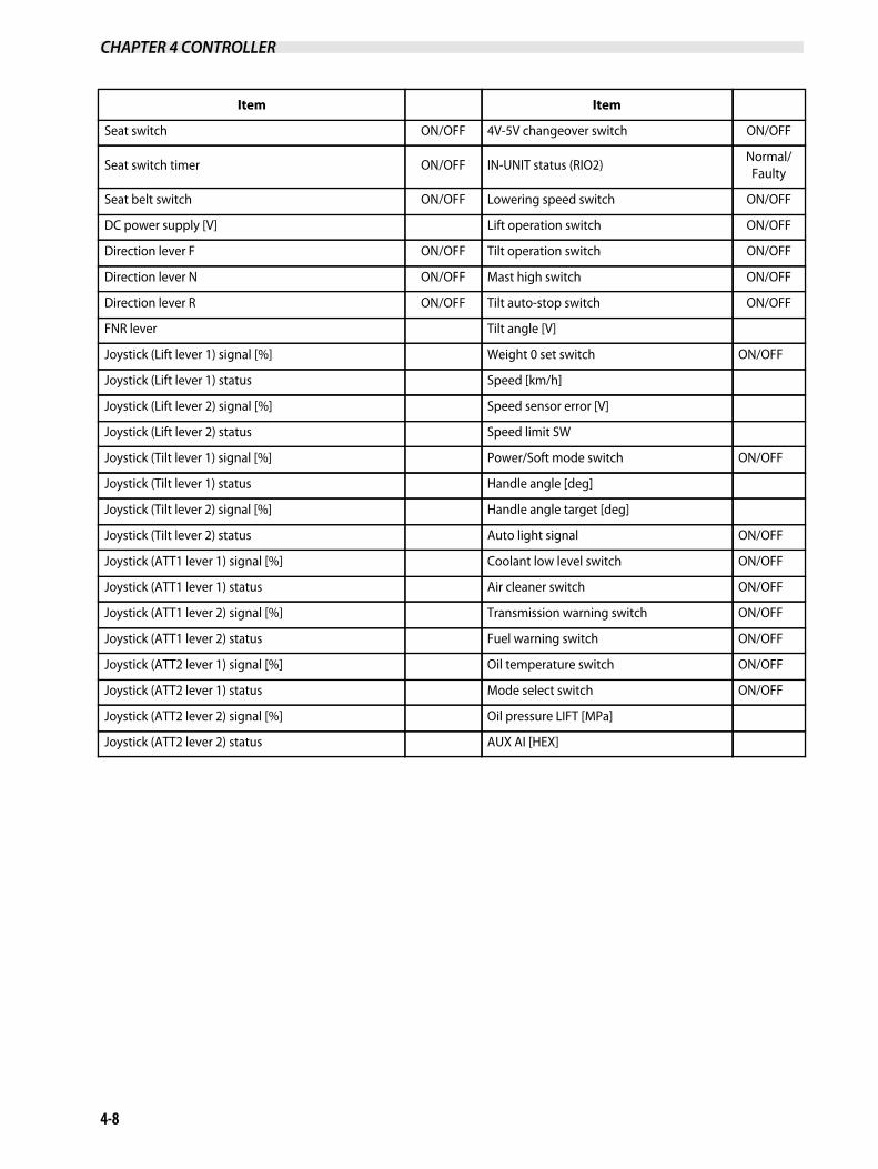
(8) The unload solenoid output and the lift lock solenoidoutput will turn OFF when the mast interlock system isactivated.Under this condition, operate the lift lever to make surethat the forks will not move up and down. Also operatethe tilt lever to make sure that the mast will not tiltforward and backward.
501343
If seat switch is not turned ONCheck the seat switch operation and wiring connections byreferring to 4-41 "Harness Codes", 4-41 "VCM-6", and 4-58"Seat Switch".
If unload solenoid is not turned ONCheck the solenoid output according to 4-26 "Active TestInspection Procedure". If the solenoid output will not turnON even after the active test inspection, see 4-62 "TruckStatus Display and Troubleshooting" and check for thepossible causes of the diagnostic code F-75 and F-79.
If lift lock solenoid is not turned ONCheck the solenoid output according to 4-26 "Active TestInspection Procedure". If the solenoid output will not turnON even after the active test inspection, see 4-62 "TruckStatus Display and Troubleshooting" and check for thepossible causes of the diagnostic code F-77 and F-79.

CHAPTER 4 CONTROLLER
4-26
4.3 Active Test Inspection Procedure
(1) Connect the service tool and turn the key switch to theON position. (Do not turn the engine ON.)
(2) Display the active test screen by pressing the active testbutton in the service tool screen.
1) Active test screen1. Active test flag
2. Active test3. Write button
505837
2 3
1
Truck StatusTruck Status
Truck HistoryTruck History
Active Test

CHAPTER 4 CONTROLLER
4-27
(3) Insert a check mark in the box of the active test flag, andpress the write button. When the write confirmation dialogue box is displayed,press the YES button.
1. Checkmark 2. Write button
501353
12
(4) When the write completed dialogue box is displayed,press the OK button.
501356
(5) Insert a check mark in the box of the unload solenoid/lift lock valve solenoid, and press the write button.
(6) When the write confirmation dialogue box is displayed,press the YES button the same as (3) above, and whenthe write completed dialogue box is displayed, pressthe OK button to complete the set-up.
1. Checkmark 2. Write button
501358
12
CHAPTER 4 CONTROLLER
4-28
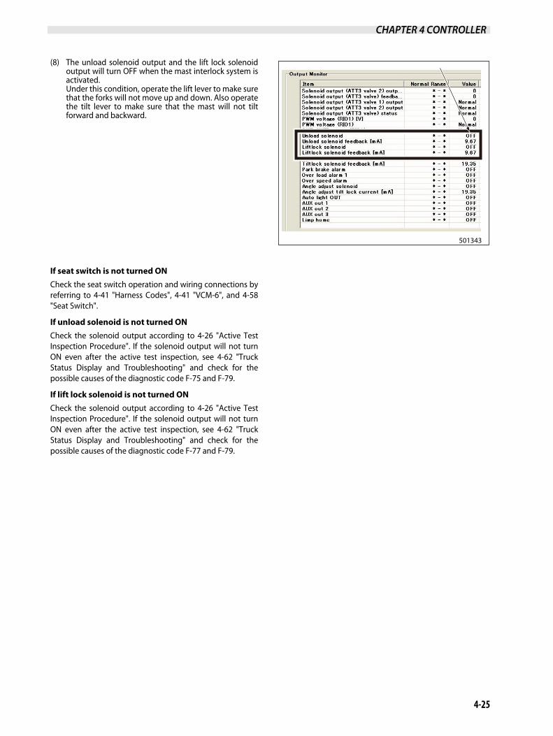
(7) Press the output monitor button on the service toolscreen, and check the electrical current values of theunload solenoid and the lift lock valve solenoid. If thevalue is not close to 2500 mA, a defect is suspected.
1. Check current values
501360
1
(8) After confirmation, turn the key switch to the OFFposition to terminate the active test. (Be sure to turnOFF the key switch before moving on to the nextoperation).
Note: If a defect is found, see 4-62 "Truck Status Display and Troubleshooting" and check for the possible causes of the diagnostic code F-75, F-77, and F-79.

CHAPTER 4 CONTROLLER
4-29
5. Driving Interlock System5.1 Controller Function
(1) The controller monitors the conditions describedbelow. If all the conditions are met, the controlleractivates the driving interlock system.
- The operator is not seated. (Seat switch and seatswitch timer [OFF])
- Forklift truck speed is less than 4 km/h (2.5 MPH).(Speed sensor value)
- The parking brake is released (at pulled position).(Parking brake switch is ON)
1) No Power Travel
E00398A
1) 1)
(2) The controlled condition by the driving interlocksystem will vary depending on forklift truck speed.
- If the speed is more than 4 km/h (2.5 MPH), the drivinginterlock control is de-activated.
- If the speed is less than 4 km/h (2.5 MPH), thetransmission solenoid F and R are turned OFF, and thepower from the engine is cut off.
- If the speed is less than 1 km/h (0.62 MPH), the parkingbrake solenoid is turned OFF, and the parking brake(negative brake) is activated to stop the forklift truck.
Note: Because the controller electrically controls the system, there is no physical movement of the direction lever and the parking brake lever.
R CAUTION (1) Be alert when the forklift truck is on a grade. The forklift truck may move and accelerate, instead of being stopped,
depending on a road condition. (2) Be sure to check the driving interlock function before operating the forklift truck. (3) This interlock system is provided only for risk reduction in case of a contingency. Always drive the forklift truck properly
with safety in mind. (4) When restoring the forklift truck to its normal driving condition, be sure to follow the instructions below:
- Sit properly in the operator seat. - Depress the brake pedal and stop the truck completely. - Place the direction lever in the NEUTRAL position once, and then shift it back to the FORWARD or REVERSE position. - Pull the parking brake lever in the lock position, and then push it back to the released position.
(5) When replacing the operator seat with a new one, be sure to use a genuine Mitsubishi forklift truck seat with the operatorpresence switch.
CHAPTER 4 CONTROLLER
4-30
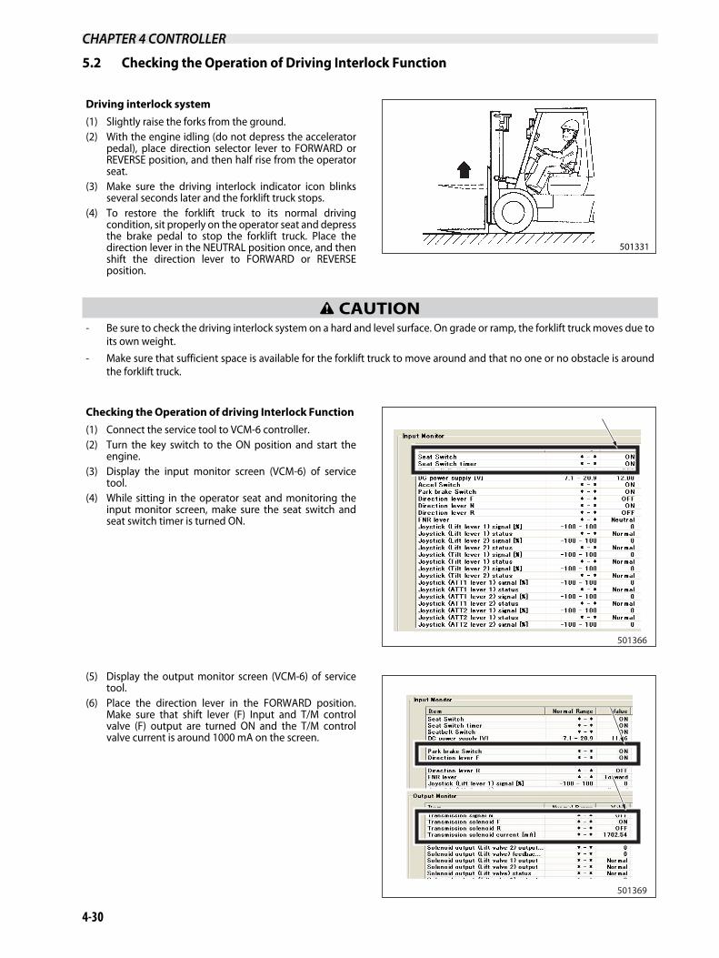
5.2 Checking the Operation of Driving Interlock Function
Driving interlock system(1) Slightly raise the forks from the ground. (2) With the engine idling (do not depress the accelerator
pedal), place direction selector lever to FORWARD orREVERSE position, and then half rise from the operatorseat.
(3) Make sure the driving interlock indicator icon blinksseveral seconds later and the forklift truck stops.
(4) To restore the forklift truck to its normal drivingcondition, sit properly on the operator seat and depressthe brake pedal to stop the forklift truck. Place thedirection lever in the NEUTRAL position once, and thenshift the direction lever to FORWARD or REVERSEposition.
501331
R CAUTION - Be sure to check the driving interlock system on a hard and level surface. On grade or ramp, the forklift truck moves due to
its own weight. - Make sure that sufficient space is available for the forklift truck to move around and that no one or no obstacle is around
the forklift truck.
Checking the Operation of driving Interlock Function (1) Connect the service tool to VCM-6 controller. (2) Turn the key switch to the ON position and start the
engine. (3) Display the input monitor screen (VCM-6) of service
tool. (4) While sitting in the operator seat and monitoring the
input monitor screen, make sure the seat switch andseat switch timer is turned ON.
501366
(5) Display the output monitor screen (VCM-6) of servicetool.
(6) Place the direction lever in the FORWARD position.Make sure that shift lever (F) Input and T/M controlvalve (F) output are turned ON and the T/M controlvalve current is around 1000 mA on the screen.
501369

CHAPTER 4 CONTROLLER
4-31
(7) Leave the operator seat, and make sure that the seatswitch turns OFF on the input monitor screen and theseat switch timer turns OFF a few seconds later(function of seat delay counter).
501372
501375
(8) Make sure that the neutral icon (N) on the meter panelblinks. Blinking of N icon means that the drivinginterlock is activated.
1. Blinking
501378
1

CHAPTER 4 CONTROLLER
4-32
(9) When the driving interlock is activated, T/M controlvalve (F) output is not turned ON even if the status ofthe direction lever (F) input is ON.
501384
(10) When the driving interlock is activated, make sure thatthe parking brake solenoid is OFF even if the parkingbrake switch is ON.
Note: Because this forklift truck's parking brake is a negative type parking brake, the parking brake is activated when the solenoid is OFF.
501386

CHAPTER 4 CONTROLLER
4-33
(11) To unlock the driving interlock, sit on the operator seatand return the direction lever to the NEUTRAL position.At this time, make sure that the driving interlockindicating N icon changes from blinking to a steadyglow.
If seat switch is not turned ONCheck the seat switch operation and wiring connections byreferring to 4-41 "Harness Codes", 4-41 "VCM-6", and 4-58"Seat Switch".
When T/M forward/backward solenoid warning occursCheck the solenoid output by referring to 4-34 "Active TestInspection Procedure". If the solenoid output will not turnON even after the active test inspection, see 4-62 "TruckStatus Display and Troubleshooting".
Check for the possible causes of the diagnostic code F-85, F-87 and F-89.
When a speed or speed sensor warning occursSee 4-62 "Truck Status Display and Troubleshooting" tocheck for the possible causes of the diagnostic code F-17and F-34.

CHAPTER 4 CONTROLLER
4-34
5.3 Active Test Inspection Procedure
R CAUTION During the active test inspection, the front wheels will rotate. To prevent the forklift truck from moving, be sure to block or raisethe front wheels before conducting active test inspection.
(1) Connect the service tool and turn the key switch to theON position. (Do not turn the engine ON.)
(2) Display the active test screen by pressing the active testbutton in the service tool screen.
1. Active test2. Active test flag
3. Write button
505838
2 3
1
Active Test
(3) Insert a check mark in the box of the active test flag, andpress the write button. When the write confirmationdialogue box is displayed, press the YES button.
1. Checkmark 2. Write button
501353
12
(4) When the write completed dialogue box is displayed,press the OK button.
501356

CHAPTER 4 CONTROLLER
4-35
6. Seat Belt Warning Icon6.1 Function of Seat Belt Warning Icon
(5) Insert a check mark in the box of either T/M solenoid For T/M solenoid R, and press the write button.
(6) When the write confirmation dialogue box is displayed,press the YES button the same as (4) above, and whenthe write completed dialogue box is displayed, pressthe OK button to complete the set-up.
Note: Do not check both boxes of T/M solenoid F or T/M solenoid R to avoid the controller damage.
501399
(7) Press the output monitor button in the service toolscreen to display the output monitor screen. Make sure that the T/M control valve current is 1000 mAor around.
501402
(8) After confirmation, turn the key switch to the OFFposition to terminate the active test. (Be sure to turnOFF the key switch before moving on the nextoperation).
Note: If a defect is found, see 4-62 "Truck Status Display and Troubleshooting" and check for the possible causes of the diagnostic code F-85, F-87, and F-89.
Seat belt warning iconThis icon blinks when the seat belt is not worn or notbuckled properly.
Controller functionThe controller sends a warning signal to the meter panel ifthe seat belt is not fastened.
1. Seat belt warning icon
501406
1

CHAPTER 4 CONTROLLER
4-36
6.2 Checking the Operation of Seat Belt Warning Icon
(1) Connect the service tool to VCM-6 controller. (2) Turn the key switch to the ON position and start the
engine. (3) Display the input monitor screen of the service tool. (4) Make sure that the seat switch status is turned OFF
when the seat belt is not fastened or not buckledproperly. Also check that the seat belt warning icon in the meterpanel glows.
501411
1. Illuminates
501413
1
(5) Make sure that the seat belt switch turns ON and theseat belt warning icon in the meter panel goes outwhen the seat belt is properly fastened.
501416

CHAPTER 4 CONTROLLER
4-37
7. Parking Brake Warning Alarm and Warning Icon 7.1 Checking the Operation of Parking Brake Warning Alarm/Warning Icon
Regardless whether the engine is stopped or running,leaving the operator seat with the parking brake releasedactivates the operator presence switch to cause the warningalarm to sound.
1. Parking brake warning icon 2. Parking brake lever
164919164919
1
2
R CAUTION (1) Before operating the forklift truck, be sure to check the parking brake warning icon and buzzer work properly. (2) The warning alarm and the warning icon alert the operator to set the parking brake lever before leaving the forklift truck.
Properly maintain the warning alarm and icon so that they function correctly. (3) How to park the forklift truck:
- Park the forklift truck on a hard and level surface. - Place the direction lever in the NEUTRAL position. - Lower the forks until the fork tips touch the floor/ground. - Apply the parking brake. - Turn the engine OFF and remove the key.
(4) When replacing the operator seat with a new one, be sure to use a genuine Mitsubishi forklift truck seat with the operatorpresence switch.
Controller functionWith the key switch in the ON position, the controller turnsthe warning alarm output ON if it detects that the operatorseat is vacant and the parking brake is released. (Warningalarm activates).When the key switch is in the OFF position, the VCM-6controller does not activate since the power to thecontroller is OFF. In this case, the relay circuit causes thewarning alarm to activate.

CHAPTER 4 CONTROLLER
4-38
7.2 Parking Brake Warning Alarm
(1) Connect the service tool to the VCM-6 controller. (2) Turn the key switch to the ON position and start the
engine. (Keep the parking brake engaged).(3) Display the input monitor screen of the service tool. (4) Sit in the operator seat and make sure that the seat
switch status and the seat switch timer are ON on theinput monitor screen.
501333
(5) Make sure the parking brake switch turns ON on theinput monitor screen. Also make sure the parking brake warning icon glows.
501423
1. Illuminates
501425
1
(6) Release the parking brake and leave the operator seat.

CHAPTER 4 CONTROLLER
4-39
(7) Make sure that seat switch and the parking brakeswitch turn OFF in the input monitor screen. Also make sure that the parking brake warning icon inthe meter panel goes out and the warning alarmactivates.
501339
501431
1. OFF
501425
1
(8) Apply the parking brake. Make sure that the parkingbrake warning icon in the meter panel illuminates andthe buzzer stops sounding.

CHAPTER 4 CONTROLLER
4-40
7.3 Checking the Operation of Parking Brake Warning Alarm/Warning Icon With Key in OFF Position
(1) Lock the parking brake and keep it locked. Place the direction lever in NEUTRAL. Turn the key switch to the OFF positionand turn OFF the engine. The power to the VCM-6 controller and meter panel will be turned OFF.
(2) Make sure that the parking brake warning alarm activates when the parking brake is released. (This function is not affectedby the seat switch status).
(3) Make sure that the parking brake warning alarm stops when the parking brake is shifted to the locked position.
R CAUTION Be sure to park the forklift truck on a hard and level surface to check this function.
If seat switch is not turned ONCheck the seat switch operation and wiring connections byreferring to 4-41 "Harness Codes", 4-41 "VCM-6", and “4-58"Seat Switch".
If parking brake switch is not turned ON Check the parking switch operation and wiring connectionsby referring to 4-41 "Harness Codes", 4-41 "VCM-6", and “4-58 "Parking Brake Switch".
If warning alarm is not turned ONIf the warning alarm is not turned ON, check the warningalarm output by referring to 4-26 "Active Test InspectionProcedure". If the warning alarm does not activate even after the activetest inspection, check the wiring connections by referring to4-41 "Harness Codes", 4-41 "VCM-6", 4-60 "Warning Alarm",4-60 "Warning Alarm Relay", and 4-61 "Warning AlarmCircuit".
501435

CHAPTER 4 CONTROLLER
4-41
8. Harness Codes8.1 VCM-6VCM-6 pin assignments
1. VCM-6 (E-01) 2. VCM-6 (E-02)
609770
9 544 543 542 541 540 539 538 1
17 550 549 548 547 546 10
25 18
34 471 470 561 560 559 569 568 26
2
9
17
25
34
525 522 520 1
10
18
26
532 531 530 526552
980 500
981 537 534 533 501
1
535
529528
503

CHAPTER 4 CONTROLLER
4-42
VCM-6 controller signal assignments (E-01)
Pin No. Wire No. (Wire Color) Signal Name
1 520 (G) Mode select switch
2 - -
3 - -
4 - -
5 - -
6 - -
7 522 (W) Power selector switch
8 - -
9 525 (Br) Direction lever switch (F)
10 526 (L/W) Direction lever switch (R)
11 552 (L) T/M shift solenoid output
12 529 (Y/R) Auto light sensor (+)
13 528 (Y/b) Auto light sensor (-)
14 530 (R/Y) Oil pressure sensor (+5V)
15 531 (Y/L) Oil pressure sensor signal
16 - -
17 532 (L) Oil pressure sensor GND
18 500 (2R) Power supply (+12V)
19 - -
20 - -
21 - -
22 - -
23 - -
24 - -
25 980 (2B) Power supply GND
26 501 (R) Power supply (+12V)
27 - -
28 - -
29 - -
30 533 (R/W) Unload solenoid output (+)
31 535 (Y/W) Lift lock solenoid (+)
32 534 (G/W) Unload solenoid (-)
33 537 (Y) Warning alarm output
34 981 (2B) Power supply GND

CHAPTER 4 CONTROLLER
4-43
VCM-6 controller signal assignments (E-02)
Pin No. Wire No. (Wire Color) Signal Name
1 538 (L/W) Seat switch
2 539 (G/W) Seat belt switch
3 540 (G/R) Direction lever switch (N)
4 - -
5 541 (Br) Weight zero set switch
6 542 (Y/L) Coolant low level switch
7 543 (R/Y) Air cleaner clog switch
8 544 (Br/W) Torque converter oil temperature switch
9 - -
10 546 (G) Speed sensor signal (+)
11 547 (G/B) Speed sensor signal (-)
12 - -
13 - -
14 - -
15 548 (W) Transmission solenoid F (+)
16 549 (Y) Transmission solenoid R (+)
17 550 (R/B) Transmission solenoid (-)
18 - -
19 - -
20 - -
21 503 (W/R) Auto light relay (-)
22 - -
23 - -
24 - -
25 - -
26 568 (Y/B) GND
27 569 (Y/R) FWE
28 559 (W/L) RX-232C TXD
29 560 (W/G) RS-232C RXD
30 561 (L/B) RX-232C GND
31 470 (P) CAN H
32 471 (P/G) CAN L
33 - -
34 - -

CHAPTER 4 CONTROLLER
4-44
8.2 Input Unit and Output Unit (FC model) Input unit pin assignments
609771
9
17
25
34
G022
G024
S028 A078
A084S026S025S024S023S022S021G021
A076
1
10
18
26
S027
S019 S020 A075

CHAPTER 4 CONTROLLER
4-45
Input unit signal assignments (E-04)
Pin No. Wire No. (Wire Color) Signal Name
1 A078 (1.25 Y/B) Power supply (+12V)
2 - -
3 - -
4 - -
5 S027 (W/B) CAN H
6 S028 (L/R) CAN L
7 - -
8 - -
9 G022 (0.85 B) GND
10 - -
11 - -
12 - -
13 - -
14 - -
15 - -
16 - -
17 G024 (B/Y) Switch GND
18 - -
19 - -
20 - -
21 A076 (L/R) Digital input 3
22 - -
23 - -
24 S020 (G/L) Analog input 7/Attachment 2/3 lever (Option)
25 S019 (G/B) Analog input 8/Attachment 2/3 lever (Option)
26 - -
27 A084 (L/R) Analog 5V (lift)
28 S026 (W/Y) Analog input 1 (lift)
29 S025 (W/R) Analog input 2 (lift)
30 S024 (Y/B) Analog input 3 (tilt)
31 S023 (Y/L) Analog input 4 (tilt)
32 S022 (L/Y) Analog input 5/Attachment 1 lever (Option)
33 S021 (L/B) Analog input 6/Attachment 1 lever (Option)
34 G021 (B/L) Analog GND

CHAPTER 4 CONTROLLER
4-46
Output pin assignments (E-03)
609772
9
17
25
34
984A 475A 504A 1
10
18
26
985 579 578 584 583
576 575 574
582 507A
986 588 587 586 508
474A
592 591 590
580
570 571 572
573

CHAPTER 4 CONTROLLER
4-47
Output signal assignments
Pin No. Wire No. (Wire Color) Signal Name
1 504A (R/L) Power supply (+12V)
2 - -
3 - -
4 - -
5 474A (P) CAN H
6 475A (P/G) CAN L
7 - -
8 - -
9 984A (0.85B) GND
10 - -
11 -
12 574 (W/L) Solenoid PMW 9 (+)
13 575 (W/R) Solenoid PMW 10 (+)
14 576 (W/G) Solenoid PMW 9 (-)/10 (-)
15 - -
16 - -
17 - -
18 507A (R/B) Emergency stop button
19 582 (G) Solenoid PMW 5 (+) /Attachment 1 lever (Option)
20 583 (G/W) Solenoid PMW 6 (+) /Attachment 1 lever (Option)
21 584 (G/B) Solenoid PMW 5 (-), 6 (-) /Attachment 1 lever (Option)
22 578 (Y) Solenoid PMW 7 (+) /Attachment 2 lever (Option)
23 579 (Y/L) Solenoid PMW 8 (+) /Attachment 2 lever (Option)
24 580 (Y/B) Solenoid PMW 7 (-), 8 (-) /Attachment 2 lever (Option)
25 985 (0.85 B/W) GND (solenoid)
26 508 (R/B) Emergency stop button
27 590 (Br) Solenoid PMW 1 (+) /Lift up
28 591 (L) Solenoid PMW 2 (+) /Lift down
29 592 (L/B) Solenoid PMW 1 (-), 2 (-) /Lift up
30 586 (R/W) Solenoid PMW 3 (+) /Tilt forward
31 587 (L/W) Solenoid PMW 4 (+) /Tilt backward
32 588 (W/B) Solenoid PMW 3 (-), 4 (-) /Tilt backward
33 - -
34 986 (0.85B/W) GND (solenoid)

CHAPTER 4 CONTROLLER
4-48
8.3 Input Unit and Output UnitInput unit pin assignments
505842
9
17
25
34
G022
G024
S028 A078
A084S026S025S024S023S022S021G021
A076
1
10
18
26
S027
S019 S020

CHAPTER 4 CONTROLLER
4-49
Input unit signal assignments (E-04)
Pin No. Wire No. (Wire Color) Signal Name
1 A078 (1.25 Y/B) Power (+12V)
2 - -
3 - -
4 - -
5 S027 (W/B) CAN H
6 S028 (L/R) CAN L
7 - -
8 - -
9 G022 (0.85 B) GND
10 - -
11 - -
12 - -
13 - -
14 - -
15 - -
16 - -
17 G024 (B/Y) Switch GND
18 - -
19 - -
20 - -
21 A076 (L/R) Digital input 3
22 - -
23 - -
24 S020 (G/L) Analog input 7 /Attachment 2/3 lever (option)
25 S019 (G/B) Analog input 8 /Attachment 2/3 lever (option)
26 - -
27 A084 (L/R) Analog 5V (Lift)
28 S026 (W/Y) Analog input 1 (Lift)
29 S025 (W/R) Analog input 2 (Lift)
30 S024 (Y/B) Analog input 3 (Tilt)
31 S023 (Y/L) Analog input 4 (Tilt)
32 S022 (L/Y) Analog input 5 /Attachment 1 lever (option)
33 S021 (L/B) Analog input 6 /Attachment 1 lever (option)
34 G021 (B/L) Analog GND

CHAPTER 4 CONTROLLER
4-50
Output unit pin assignments (E-03)
609773
9
17
25
34
984A 475A 504A 1
10
18
26
985 579 578 584 583
576 575 574
582 507A
986 588 587 586 508
474A
592 591 590
580
570 571 572
573

CHAPTER 4 CONTROLLER
4-51
Output unit signal assignments
Pin No. Wire No. (Wire Color) Signal Name
1 504A (R/L) Power (+12V)
2 - -
3 - -
4 - -
5 474A (P) CAN H
6 475A (P/G) CAN L
7 - -
8 - -
9 984A (0.85B) GND
10 - -
11 -
12 574 (W/L) Solenoid PMW 9 (+)
13 575 (W/R) Solenoid PMW 10 (+)
14 576 (W/G) Solenoid PMW 9 (-)/10 (-)
15 - -
16 - -
17 - -
18 507A (R/B) Emergency stop button
19 582 (G) Solenoid PMW 5 (+) /Attachment 1 lever (option)
20 583 (G/W) Solenoid PMW 6 (+) /Attachment 1 lever (option)
21 584 (G/B) Solenoid PMW 5 (-), 6 (-) /Attachment 1 lever (option)
22 578 (Y) Solenoid PMW 7 (+) /Attachment 2 lever (option)
23 579 (Y/L) Solenoid PMW 8 (+) /Attachment 2 lever (option)
24 580 (Y/B) Solenoid PMW 7 (-), 8 (-) / Attachment 2 lever (option)
25 985 (0.85 B/W) GND (Solenoid)
26 508 (R/B) Emergency stop button
27 590 (Br) Solenoid PMW 1 (+) /Lift up
28 591 (L) Solenoid PMW 2 (+) /Lift down
29 592 (L/B) Solenoid PMW 1 (-), 2 (-) /Lift up
30 586 (R/W) Solenoid PMW 3 (+) /Tilt forward
31 587 (L/W) Solenoid PMW 4 (+) /Tilt backward
32 588 (W/B) Solenoid PMW 3 (-), 4 (-) /Tilt backward
33 - -
34 986 (0.85B/W) GND (Solenoid)

CHAPTER 4 CONTROLLER
4-52
8.4 ECMECM controller pin assignments
ECM controller signal assignments (H-01)
1. ECM (H-01) 2. ECM (H-02)
609774
708707 714 719 720 722 727 728730 736 741 743 489 748
752 753 754 758 763 764 766 769774 779 780 781 782 783 784 785 786 794
701 991
703 992
705 993
801
816
831
846
802
817
832
848
804
834
849
835
850
806
837
808
823
838
853
809
824
839
810
825
840
855
811
826
841
812
827
857
813
828
843
858
814
844
859
815
860
1
2
776
716738 488
759 760
Pin No. Wire No. (Wire Color) Signal Name
1 701 (1.25 R/B) Battery + (A)
2 991 (3B) Battery - (1)
3 703 (3R) Battery + (B)
4 992 (2B) Battery - (2)
5 705 (2R) Battery + (C)
6 993 (2B) Battery - (3)
7 707 (Lg/Y) Lambda sensor heating
8 708 (Y) Start request input
9 - -
10 - -
11 - -
12 - -
13 - -
14 714 (Br/B) DPF pressure sensor supply
15 - -
16 716 (R) Throttle 1 5V supply
17 - -
18 - -
19 719 (G/R) Air temperature signal

CHAPTER 4 CONTROLLER
4-53
20 720 (G/Y) Air temperature GND
21 - -
22 722 (L/W) Glow plug control feedback
23 - -
24 - -
25 - -
26 - -
27 727 (Y/B) Start control output battery (-)
28 728 (L) Main relay
29
30 730 (Y/W) Water IN fuel switch
31
32
33
34
35
36 736 (Br/Y) DPF pressure sensor GND
37
38 738 (B/W) Throttle 1 GND
39
40
41 741 (L/B) Glow plug control GND
42
43 743 (L) DPF force regeneration switch
44
45
46 488 (G) CAN H
47 489 (G/W) CAN L
48 748 (Y/G) DPF disabled lamp
49
50
51
52 752 (L/R) Glow plug control command
53 753 (Y/R) Start control output battery (+)
54 754 (Y/B) IGN switch
55
56
57
Pin No. Wire No. (Wire Color) Signal Name

CHAPTER 4 CONTROLLER
4-54
58 758 (Br/R) DPF pressure sensor signal
59 759 (R/B) Manual regeneration interlock
60 760 (G) Throttle 1 signal
61
62
63 763 (Lg/W) Lambda voltage
64 764 (Lg) Lambda sensor current pump
65
66 766 (L/W) Regeneration disable switch
67
68
69 769 (Y/R) Oil pressure lamp
70
71
72
73
74 774 (Y/L) HEST lamp
75
76 776 (G/W) Throttle 1 IVS signal
77
78
79 779 (Y/R) DOC inlet temperature sensor GND
80 780 (Y) DOC inlet temperature sensor signal
81 781 (L/B) Exhaust gas temperature GND
82 782 (L/O) Exhaust gas temperature signature
83 783 (Br/W) DPF inlet temperature sensor GND
84 784 (Br) DPF inlet temperature sensor signal
85 785 (Lg/R) Lambda virtual GND
86 786 (Lg/B) Lambda current adjust
87
88
89
90
91
92
93
94 794 (Y/B) DPF lamp
Pin No. Wire No. (Wire Color) Signal Name

CHAPTER 4 CONTROLLER
4-55
ECM controller signal assignments (H-02)
Pin No. Wire No. (Wire Color) Signal Name
1 801 (2 G/B) Injector 1 HIGH bank 2
2 802 (2 Lg/R) Injector 2 HIGH bank 2
3
4 804 (Y) Electric waste gate value actuator
5
6 806 (L/R) Oil pressure switch
7
8 808 (Br) TVA position sensor supply
9 809 (Y/G) EGR position sensor supply
10 810 (G/R) Boost pressure sensor supply
11 811 (L/O) Fuel rail pressure sensor supply
12 812 (Lg/Y) Exhaust gas absolute pressure sensor supply
13 813 (Br/R) Camshaft speed sensor supply
14 814 (Br/B) Camshaft speed sensor signal
15 815 (1.25 L) Fuel metering unit supply
16 816 (2 G/Y) Injector 1 HIGH bank 1
17 817 (2 Lg) Injector 2 HIGH bank 1
18
19
20
21
22
23 823 (G) Fuel temperature sensor GND
24 824 (Y/W) EGR position sensor GND
25 825 (G/B) Boost pressure sensor GND
26 826 (L/Y) Fuel rail pressure sensor GND
27 827 (Lg/B) Exhaust gas absolute pressure sensor GND
28 828 (Br/Y) Camshaft speed sensor GND
29
30
31 831 (2 G/L) Injector 1 LOW bank 1
32 832 (2 G/R) Injector 1 LOW bank 2
33
34 834 (L/R) TVA motor (-)
35 835 (Y/B) EGR motor (-)
36
37 837 (Br/B) TVA position sensor GND
38 838 (G/W) Fuel temperature sensor signal

CHAPTER 4 CONTROLLER
4-56
8.5 Meter PanelMeter panel pin assignments
39 839 (Y/L) EGR position sensor signal
40 840 (G/Y) Boost pressure sensor signal
41 841 (L/B) Fuel rail pressure sensor signal
42
43 843 (Lg/W) Exhaust gas absolute pressure sensor signal
44 844 (Br/W) Crankshaft speed sensor (-)
45
46 846 (2 Lg/B) Injector 2 HIGH bank 2
47
48 848 (2 Lg/Y) Injector 2 LOW bank 2
49 849 (L) TVA motor (+)
50 850 (Y/R) EGR motor (+)
51
52
53 853 (Br/R) TVA position sensor signal
54
55 855 (G/L) Turbo inlet temperature
56
57 857 (Lg/R) Coolant sensor signal
58 858 (Lg) Coolant sensor GND
59 859 (Br) Crankshaft speed sensor (+)
60 860 (1.25 L/W) Fuel metering unit
Pin No. Wire No. (Wire Color) Signal Name
609776
314
300 982
316 317 486 471 470 486
983 312 30113
26
1
14

CHAPTER 4 CONTROLLER
4-57
Meter panel signal assignments (H-12)
Pin No. Wire No. (Wire Color) Signal Name
1 300 (R/G) Battery (+)
2 982 (B) Truck body GND
3 - -
4 - -
5 - -
6 - -
7 - -
8 983 (B) Truck body GND
9 - -
10 312 (G) ALT L
11 - -
12 - -
13 301 (R/W) IGN
14 - -
15 314 (Y/B) Fuel sensor
16 - -
17 316 (W/R) Brake fluid sensor
18 317 (L) Parking brake
19 - -
20 - -
21 - -
22 - -
23 486 (P) CAN terminal
24 471 (P/G) CAN LOW
25 470 (P) CAN HIGH
26 486 (P) CAN terminal

CHAPTER 4 CONTROLLER
4-58
8.6 Seat Switch
8.7 Parking Brake Switch
8.8 Direction Lever Switch
1. Seat belt
501457
651908652
0.5 Y0.5 B0.5 Y/R
651 908 652
1
(WHITE)
609778
272 919 317
12
3PU
LLPU
SH
272919317
0.5L0.5B0.5W/L
(BLACK)
609779
43
5
525916
915256
21 540
525
916 915
256540
0.5 G/R
0.5 L/ W
0.5 Br0.5 B
0.5 B
F N R
(WHITE)

CHAPTER 4 CONTROLLER
4-59
8.9 Travel Speed Sensor
8.10 T/M Solenoid
8.11 Unload Solenoid
609780
(BLACK)
547546
547546
0.5 G0.5 G/B
1. T/M forward/backward solenoid
609781
0.5 W0.5 R/B0.5 B0.5 L
548
552939550
T/MFWDSOL
T/MSOL
T/MBWDSOL
549 0.5 Y
552 548 549
939 550 -
1. Unload solenoid
609783
1533A534A534A533A
(BLACK)
0.5 R/W0.5 G/W

CHAPTER 4 CONTROLLER
4-60
8.12 Warning Alarm
8.13 Warning Alarm Relay
Note: Wire number 271 becomes 537 in the VCM-6 controller connector. (Wire harness branching)
609786
271270
271
270
0.5 Y0.5 R/B
(WHITE)
537 VCM
1. Relay box
609787
273913
271272
1
0.5 B0.5 W/L
271
258160 257
272
913 109
162273
753
911 108 254 727
910 255
0.5 W/L0.5 Y
(BLACK) (BLUE)
708

CHAPTER 4 CONTROLLER
4-61
8.14 Warning Alarm Circuit
1. Fuse box2. Warning alarm3. Warning alarm relay4. Park brake switch
1) Always energized 2) Relay ON when key switch is ON 3) Warning alarm relay4) Warning alarm5) VCM-6 controller6) To ECM 7) Parking brake buzzer activates if the key switch is
turned OFF without applying the parking brake. 8) To meter panel and VCM-6
609788
11)
2)
3)4)
5)
6)
7)
8)
2
3
4
+ 12 V
8 W8 W/G
0.5 W/L
0.5 R/B
10AF13
10AF 2220
102104
273
271270
271272
5370.5 Y0.5 R/B
0.5 W/L
0.5 L0.5 B0.5 W/L
0.5 Y
0.5 B0.5 W/L
0 V
919272
317123
PULL
PUSH
+ 12 V
+ 12 V
913273

CHAPTER 4 CONTROLLER
4-62
9. Truck Status Display and Troubleshooting 9.1 Truck Status Display
Truck status display Warnings that have been present are displayed.
TroubleshootingDisplay the truck status screen by clicking the truck statusbutton either from the monitor menu or toolbox. When thescreen is displayed, press the troubleshooting button on thebottom right of the screen to display a list of diagnosticcodes and their descriptions.
Example: Diagnostic code 34 (Speed sensor warning) (1) Connector contact bad(2) Harness bad(3) Speed sensor bad(4) Controller bad
501538
warning
warning
warning
warning
warning
Warning
warning
warning
501538
warning
warning
warning
warning
warning
Warning
warning
warning
Check items(1) Connector connection check(2) Harness connection check(3) Sensor connection check
501540
warning
501540
warning

CHAPTER 4 CONTROLLER
4-63
9.2 Diagnosis Table (F Code) Diagnostic code table
Diagnostic code descriptions
Diagnosis Lift Lever Neutral Warning (F10) Diagnostic name and diagnostic code
Logic conditions
F10· Input signal<2.3 V· Input signal>2.7V(when key switch is ON)
Diagnostic logic conditions
Warning occurs under condition A
Warning occurs under condition A or B
Recovery
Recovers automatically when the lever is placed in NEUTRAL.
Warning recovery condition
Action · Turn OFF all solenoid outputs of operating functions.
Control action when warning occurs
LED blink pattern C See "LED blink pattern" on 4-75 "LED Blink Pattern"
AA
BF F
AA
BF F

CHAPTER 4 CONTROLLER
4-64
Diagnosis VCM Memory warning (F01)
Logic conditions · EEPROM Sum check value(when key switch is ON)
F01
Recovery Turn ON power again.
Action · Stop the operation of controller (UP-TIME and CAN communication will not stop)
LED blink pattern B
Diagnosis VCM Battery voltage warning (F02)
Logic conditions · Power supply voltage is 7 V or less (1-second continuity)· Power supply voltage is 21 V or more (1-second continuity)
F02
Recovery Auto recovery
Action · Turn OFF all solenoid outputs.
LED blink pattern B
Diagnosis VCM communication warning (F03)
Logic conditions · CAN transmission from VCM-6 is not available. (2-second continuity)
F03
Recovery Auto recovery
Action · Warning indication only, the operation continues.
LED blink pattern B
Diagnosis ECM Communication warning (F04)
Logic conditions· No CAN sent from ECM. (2-second continuity) F04
Recovery Auto recovery
Action · Activates with default values of ECM incoming data.
LED blink pattern B
Diagnosis OCM communication warning (F06)
Logic conditions · No CAN received from OCM. (2-second continuity)
F06
Recovery Auto recovery
Action · Activates with default values of OCM incoming data.
LED blink pattern B
Diagnosis MP Communication warning (F07)
Logic conditions · No CAN received from meter panel. (2-second continuity)
F07
Recovery Auto recovery
Action · Activates with default values of metal panel incoming data.
LED blink pattern B
CHAPTER 4 CONTROLLER
4-65
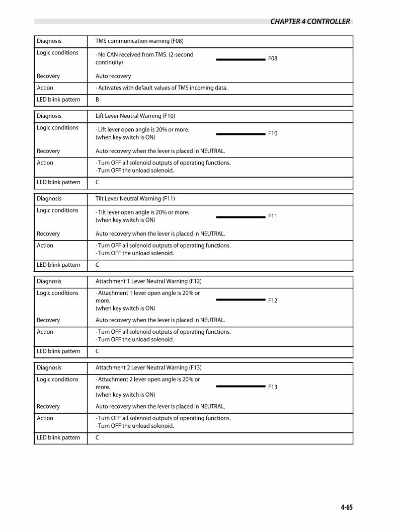
Diagnosis TMS communication warning (F08)
Logic conditions · No CAN received from TMS. (2-second continuity)
F08
Recovery Auto recovery
Action · Activates with default values of TMS incoming data.
LED blink pattern B
Diagnosis Lift Lever Neutral Warning (F10)
Logic conditions · Lift lever open angle is 20% or more. (when key switch is ON)
F10
Recovery Auto recovery when the lever is placed in NEUTRAL.
Action · Turn OFF all solenoid outputs of operating functions. · Turn OFF the unload solenoid.
LED blink pattern C
Diagnosis Tilt Lever Neutral Warning (F11)
Logic conditions · Tilt lever open angle is 20% or more.(when key switch is ON)
F11
Recovery Auto recovery when the lever is placed in NEUTRAL.
Action · Turn OFF all solenoid outputs of operating functions. · Turn OFF the unload solenoid.
LED blink pattern C
Diagnosis Attachment 1 Lever Neutral Warning (F12)
Logic conditions · Attachment 1 lever open angle is 20% or more. (when key switch is ON)
F12
Recovery Auto recovery when the lever is placed in NEUTRAL.
Action · Turn OFF all solenoid outputs of operating functions. · Turn OFF the unload solenoid.
LED blink pattern C
Diagnosis Attachment 2 Lever Neutral Warning (F13)
Logic conditions · Attachment 2 lever open angle is 20% or more. (when key switch is ON)
F13
Recovery Auto recovery when the lever is placed in NEUTRAL.
Action · Turn OFF all solenoid outputs of operating functions. · Turn OFF the unload solenoid.
LED blink pattern C

CHAPTER 4 CONTROLLER
4-66
Diagnosis Attachment 3 Lever Neutral Warning (F14)
Logic conditions · Attachment 3 lever open angle is 20% or more. (when key switch is ON)
F14
Recovery Auto recovery when the lever is placed in NEUTRAL.
Action · Turn OFF all solenoid outputs of operating functions. · Turn OFF the unload solenoid.
LED blink pattern C
Diagnosis Shift Lever Warning (F16)
Logic conditions· Shift lever overlap input · No shift lever signal (1800 ms continuity)
F16
Recovery Auto recovery with shift lever in N position
Action · Turn OFF the T/M forward/backward solenoids outputs.
LED blink pattern C
Diagnosis Vehicle Speed Warning (F17)
Logic conditions · Speed>30 km/h (18.6 MPH) (400 ms continuity)
F17
Recovery Auto recovery
Action · With T/M shift lock control, neglects the speed.· Speed of 0 km/h (0 MPH) is sent to other controllers.
LED blink pattern C
Diagnosis Shift Lever Warning (F20)
Logic conditions · CAN receiving of abnormal flag from input unit.
F20
Recovery Turn ON power again.
Action · Turn OFF the lift solenoid output. (Before 400-millisecond continuity, set the current command value to 0mA.)
LED blink pattern D
Diagnosis Tilt Lever Warning (F22)
Logic conditions · CAN receiving of abnormal flag from input unit.
F22
Recovery Turn ON power again.
Action · Turn OFF the lift solenoid output. (Before 400-millisecond continuity, set the current command value to 0mA.)
LED blink pattern D

CHAPTER 4 CONTROLLER
4-67
Diagnosis Attachment 1 Lever Warning (F24)
Logic conditions · CAN receiving of abnormal flag from input unit.
F24
Recovery Turn ON power again.
Action · Turn OFF the lift solenoid output. (Before 400-millisecond continuity, set the current command value to 0mA.)
LED blink pattern D
Diagnosis Attachment 2 Lever Warning (F26)
Logic conditions · CAN receiving of abnormal flag from input unit.
F26
Recovery Turn ON power again.
Action · Turn OFF the lift solenoid output. (Before 400-millisecond continuity, set the current command value to 0mA.)
LED blink pattern D
Diagnosis Attachment 3 Lever Warning (F28)
Logic conditions · CAN receiving of abnormal flag from input unit.
F28
Recovery Turn ON power again.
Action · Turn OFF the lift solenoid output. (Before 400-millisecond continuity, set the current command value to 0mA.)
LED blink pattern D
Diagnosis Joystick Lever redundant warning (F29)
Logic conditions · Abnormal lever signals of both primary and secondary
F29
Recovery Turn ON power again.
Action · Indication only
LED blink pattern D
Diagnosis Sensor battery warning (F31)
Logic conditions · Sensor battery is 2.5 V or less (20-millisecond continuity)
F31
Recovery Turn ON power again.
Action · Sensor battery is 2.5 V or less. · Photoelectronic sensor: Keep the status before warning occurs. · 12V DC power: Not considered as a fault. · Tilt angle sensor, Oil pressure sensor [lift]: No tilt auto-stop control, as it is not considered as a fault. · Speed sensor: not considered as a fault. Speed value is valid. · No warning detection is performed for current break, short, or leaks of solenoid [unload/lift lock], T/M control valve [F/R], power steering control valve/tilt lock solenoids (solenoid output status before warning is maintained). (20 ms continuity)
LED blink pattern B

CHAPTER 4 CONTROLLER
4-68
Diagnosis Oil pressure sensor (lift) warning (F32)
Logic conditions · Input signal is 0.1 V or less (400-millisecond continuity)· Input signal is 4.9 V or more (400-millisecond continuity)
F32
Recovery Turn ON power again.
Action · No tilt action with the load indication OFF and the tilt auto-stop SW ON.
LED blink pattern D
Diagnosis Vehicle Speed Sensor Warning (F34)
Logic conditions · Input signal is 1.3V or less (400-millisecond continuity)· Input signal is 4.9 V or more (400-millisecond continuity)
F34
Recovery Turn ON power again.
Action · With T/M shift lock control, neglects the speed.· On the forklift trucks with ECM, maximum speed limit value plus 1 km/h (0.6 MPH) is transmitted. On non-electric control engine, 0km/h is transmitted.
LED blink pattern D
Diagnosis Tilt angle warning (F38)
Logic conditions · Input signal is 0.1 V or less (400-millisecond continuity)· Input signal is 4.9 V or more (400-millisecond continuity)
F38
Recovery Turn ON power again.
Action · No tilt action with the tilt auto-stop ON.
LED blink pattern D
Diagnosis RI01 warning (F41)
Logic conditions · CAN receiving of abnormal flag from output unit.
F41
Recovery Auto recovery
Action · Indication only
LED blink pattern B
Diagnosis RI01 PWM power warning (F44)
Logic conditions · CAN receiving of abnormal flag from output unit.
F44
Recovery Auto recovery
Action · Indication only
LED blink pattern B
CHAPTER 4 CONTROLLER
4-69
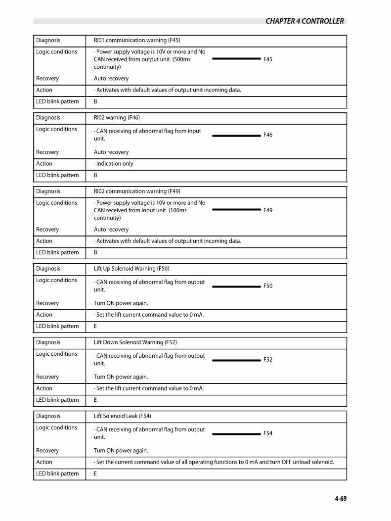
Diagnosis RI01 communication warning (F45)
Logic conditions · Power supply voltage is 10V or more and No CAN received from output unit. (500ms continuity)
F45
Recovery Auto recovery
Action · Activates with default values of output unit incoming data.
LED blink pattern B
Diagnosis RI02 warning (F46)
Logic conditions · CAN receiving of abnormal flag from input unit.
F46
Recovery Auto recovery
Action · Indication only
LED blink pattern B
Diagnosis RI02 communication warning (F49)
Logic conditions · Power supply voltage is 10V or more and No CAN received from input unit. (100ms continuity)
F49
Recovery Auto recovery
Action · Activates with default values of output unit incoming data.
LED blink pattern B
Diagnosis Lift Up Solenoid Warning (F50)
Logic conditions · CAN receiving of abnormal flag from output unit.
F50
Recovery Turn ON power again.
Action · Set the lift current command value to 0 mA.
LED blink pattern E
Diagnosis Lift Down Solenoid Warning (F52)
Logic conditions · CAN receiving of abnormal flag from output unit.
F52
Recovery Turn ON power again.
Action · Set the lift current command value to 0 mA.
LED blink pattern E
Diagnosis Lift Solenoid Leak (F54)
Logic conditions · CAN receiving of abnormal flag from output unit.
F54
Recovery Turn ON power again.
Action · Set the current command value of all operating functions to 0 mA and turn OFF unload solenoid.
LED blink pattern E

CHAPTER 4 CONTROLLER
4-70
Diagnosis Tilt Forward Solenoid Warning (F55)
Logic conditions · CAN receiving of abnormal flag from output unit.
F55
Recovery Turn ON power again.
Action · Set the lift current command value to 0 mA.
LED blink pattern E
Diagnosis Tilt Backward Solenoid Warning (F57)
Logic conditions · CAN receiving of abnormal flag from output unit.
F57
Recovery Turn ON power again.
Action · Set the lift current command value to 0 mA.
LED blink pattern E
Diagnosis Tilt Solenoid Leak (F59)
Logic conditions · CAN receiving of abnormal flag from output unit.
F59
Recovery Turn ON power again.
Action · Set the current command value of all operating functions to 0 mA and turn OFF unload solenoid.
LED blink pattern E
Diagnosis Attachment 1A Solenoid Warning (F60)
Logic conditions · CAN receiving of abnormal flag from output unit.
F60
Recovery Turn ON power again.
Action · Set Attachment 1 current command value to 0 mA.
LED blink pattern E
Diagnosis Attachment 1B Solenoid Warning (F62)
Logic conditions · CAN receiving of abnormal flag from output unit.
F62
Recovery Turn ON power again.
Action · Set Attachment 1 current command value to 0 mA.
LED blink pattern E
Diagnosis Attachment 1 Solenoid Leak (F64)
Logic conditions · CAN receiving of abnormal flag from output unit.
F64
Recovery Turn ON power again.
Action · Set the current command value of all operating functions to 0 mA and turn OFF unload solenoid.
LED blink pattern E

CHAPTER 4 CONTROLLER
4-71
Diagnosis Attachment 2A Solenoid Warning (F65)
Logic conditions · CAN receiving of abnormal flag from output unit.
F65
Recovery Turn ON power again.
Action · Set Attachment 2 current command value to 0 mA.
LED blink pattern E
Diagnosis Attachment 2B Solenoid Warning (F67)
Logic conditions · CAN receiving of abnormal flag from output unit.
F67
Recovery Turn ON power again.
Action · Set Attachment 2 current command value to 0 mA.
LED blink pattern E
Diagnosis Attachment 2 Solenoid Leak (F69)
Logic conditions · CAN receiving of abnormal flag from output unit.
F69
Recovery Turn ON power again.
Action · Set the current command value of all operating functions to 0 mA and turn OFF unload solenoid.
LED blink pattern E
Diagnosis Attachment 3A Solenoid Warning (F70)
Logic conditions · CAN receiving of abnormal flag from output unit.
F70
Recovery Turn ON power again.
Action · Set Attachment 3 current command value to 0 mA.
LED blink pattern E
Diagnosis Attachment 3B Solenoid Warning (F72)
Logic conditions · CAN receiving of abnormal flag from output unit.
F72
Recovery Turn ON power again.
Action · Set Attachment 3 current command value to 0 mA.
LED blink pattern E
Diagnosis Hour meter GAP warning (F73)
Logic conditions · Hour meter difference between meter panel and VCM-6 is ± 24 hours or more.
F73
Recovery Update #252 M/P hour meter with service tool.
Action · VCM-6 sends zero to hour meter. · VCM-6 hour meter is not overwritten.
LED blink pattern E

CHAPTER 4 CONTROLLER
4-72
Diagnosis Attachment 3 Solenoid Leak (F74)
Logic conditions · CAN receiving of abnormal flag from output unit.
F74
Recovery Turn ON power again.
Action · Set the current command value of all operating functions to 0 mA and turn OFF unload solenoid.
LED blink pattern E
Diagnosis Unload Solenoid Warning (F75)
Logic conditions · Current value is 160 mA or less (1800-millisecond continuity)· Input signal is 2.4 A or more (200-millisecond continuity)
F75
Recovery Turn ON power again.
Action · Turn OFF the unload solenoid output.
LED blink pattern E
Diagnosis Lift lock valve warning (F77)
Logic conditions · Current value is 160 mA or less (1800-millisecond continuity)· Current value is 3.4A or more (200-millisecond continuity)
F77
Recovery Turn ON power again.
Action · Turn OFF the Lift lock valve output.
LED blink pattern E
Diagnosis Unload lift lock solenoid leak (F79)
Logic conditions · Current value is 500 mA or more when output is OFF. (600-millisecond continuity)
F79
Recovery Turn ON power again.
Action · Turn OFF all solenoid outputs of operating functions.
LED blink pattern E
Diagnosis Power steering control (correction) valve solenoid warning (F80)
Logic conditions · Current value is 160 mA or less (400-millisecond continuity)· Current value is 3.54A or more (200-millisecond continuity)
F80
Recovery Turn ON power again.
Action · Turn OFF the power steering correction solenoid output.
LED blink pattern E

CHAPTER 4 CONTROLLER
4-73
Diagnosis VCM tilt lock valve warning (F82)
Logic conditions · Current value is 160 mA or less (1800-millisecond continuity)· Current value is 2.88A or more (200-millisecond continuity)
F82
Recovery Auto recovery
Action · Turn OFF the tilt lock valve output.
LED blink pattern E
Diagnosis Power steering correction solenoid leak (F84)
Logic conditions · Current value is 180mA or more when output is OFF. (600-millisecond continuity)
F84
Recovery Turn ON power again.
Action · Turn OFF the power steering correction solenoid output.
LED blink pattern E
Diagnosis T/M Forward Solenoid Warning (F85)
Logic conditions · Current value is 250mA or less (1800-millisecond continuity)· Current value is 3.8 A or more (200-millisecond continuity)
F85
Recovery Turn ON power again.
Action · Turn OFF the T/M forward solenoid output.
LED blink pattern E
Diagnosis T/M Backward Solenoid Warning (F87)
Logic conditions · Current value is 250mA or less (1800-millisecond continuity)· Current value is 3.8 A or more (200-millisecond continuity)
F87
Recovery Turn ON power again.
Action · Turn OFF the T/M backward solenoid output.
LED blink pattern E
Diagnosis Transmission Solenoid Leak (F89)
Logic conditions · Current value is 280mA or more when output is OFF. (600-millisecond continuity)
F89
Recovery Auto recovery
Action · Turn OFF the T/M forward and backward solenoids outputs.
LED blink pattern E

CHAPTER 4 CONTROLLER
4-74
Diagnosis Parking seizure warning (F92) *Serious warning
Logic conditions · Parking brake SW is ON when traveling at speed of 5 km/h (3.107 miles/h) or more.
F92
Recovery Turn ON power again.
Action · Serious warning mode of meter panel.
LED blink pattern E
Diagnosis Shift solenoid 1 warning (F93)
Logic conditions · Current value is 600 mA or less when output is ON. (1800-millisecond continuity)
F93
Recovery Turn ON power again.
Action · Turn OFF the shift solenoid 1 output.
LED blink pattern E
Diagnosis M/P memory check warning (P01)
Logic conditions· EEPROM Warning P01
Recovery Turn ON power again.
Action · EEPROM initialization
LED blink pattern -
Diagnosis VCM communication warning signal (P03)
Logic conditions· No CAN received from VCM-6 P03
Recovery Auto recovery
Action · Warning indication only, the operation continues.
LED blink pattern -
Diagnosis ECM communication warning signal (P04)
Logic conditions· No CAN received from ECM P04
Recovery Auto recovery
Action · Warning indication only, the operation continues.
LED blink pattern -
Diagnosis M/P memory check warning signal (P07)
Logic conditions· No CAN sending from M/P P07
Recovery Auto recovery
Action · Warning indication only, the operation continues.
LED blink pattern -

CHAPTER 4 CONTROLLER
4-75
9.3 LED Blink Pattern
When diagnostic codes cannot be identified due to the following reasons; meter panel failure, VCM-6 communication circuitproblem, GSE cable damage, or no presence of UP-TIME service tool, you can identify diagnostic codes to some extent byreading the LED blink patterns of the VCM-6 controller.
Note: Place the key switch in the ON position for checking.
LED blink pattern LED blinking status
A
Lighting 1.2 1.2 (sec.)
OFF 1.2 1.2
B
Lighting 1.2 0.3 (sec.)
OFF 0.6 2.7
C
Lighting 1.2 0.3 0.3 (sec.)
OFF 0.6 0.6 1.8
D
Lighting 1.2 0.3 0.3 0.3 (sec.)
OFF 0.6 0.6 0.6 0.9
E
Lighting 1.2 0.3 0.3 0.3 0.3 (sec.)
OFF 0.6 0.9
F
Lighting
OFF (No change: LED light remains ON or OFF.)

CHAPTER 4 CONTROLLER
4-76
9.4 Diagnostic Codes and Troubleshooting
Note: See the engine service manual when the diagnostic code that starts with “D” is displayed on the meter panel screen.
Diagnosticcode Diagnostic code name Probable cause Check items
F-01D-51
Memory check warning 1. Controller bad
F-02Supply power voltage warning
1. Connector contact bad 1. Connector connection check
2. Harness bad 2. Harness connection check
3. Controller bad
F-03D-53L-03
VCM communication warning
1. Connector contact bad 1. Connector connection check
2. Harness bad 2. Harness connection check
3. VCM-6 Controller bad 3. Communication line check
4. Controller bad
F-04D-54L-04
ECM Communication warning
1. Connector contact bad 1. Connector connection check
2. Harness bad 2. Harness connection check
3. ECM Controller bad 3. Communication line check
4. Controller bad
F-07D-57L-07
MP Communication warning
1. Connector contact bad 1. Connector connection check
2. Harness bad 2. Harness connection check
3. Meter panel defect 3. Communication line check
4. Controller bad
F-08D-58P-08L-08
TMS communication warning
1. Connector contact bad 1. Connector connection check
2. Harness bad 2. Harness connection check
3. TMS Controller bad 3. Communication line check
4. Controller bad
F-09 Load type set warning 1. Controller setting failure 1. Check setting with service tool.
2. Controller bad
F-10 Lift lever neutral warning
1. Connector contact bad 1. Connector connection check
2. Harness bad 2. Harness connection check
3. Lift lever bad 3. Lever connection check
4. Controller bad
F-11 Tilt lever neutral warning
1. Connector contact bad 1. Connector connection check
2. Harness bad 2. Harness connection check
3. Tilt lever bad 3. Lever connection check
4. Controller bad
F-12Attachment1 lever neutral warning
1. Connector contact bad 1. Connector connection check
2. Harness bad 2. Harness connection check
3. Attachment 2 lever bad 3. Lever connection check
4. Controller bad

CHAPTER 4 CONTROLLER
4-77
F-13Attachment 2 lever neutral warning
1. Connector contact bad 1. Connector connection check
2. Harness bad 2. Harness connection check
3. Attachment 2 lever bad 3. Lever connection check
4. Controller bad
F-14Attachment 3 lever neutral warning
1. Connector contact bad 1. Connector connection check
2. Harness bad 2. Harness connection check
3. Attachment 3 lever bad 3. Lever connection check
4. Controller bad
F-16 Shift lever warning
1. Connector contact bad 1. Connector connection check
2. Harness bad 2. Harness connection check
3. Shift lever bad 3. Shift lever check
4. Controller bad
F-17 Vehicle speed warning
1. Connector contact bad 1. Connector connection check
2. Harness bad 2. Harness connection check
3. Vehicle speed sensor bad 3. Sensor connection check
4. Controller bad
F-20 Lift lever warning
1. Connector contact bad 1. Connector connection check
2. Harness bad 2. Harness connection check
3. Lift lever bad 3. Lever connection check
4. Controller bad
F-22 Tilt lever warning
1. Connector contact bad 1. Connector connection check
2. Harness bad 2. Harness connection check
3. Tilt lever bad 3. Lever connection check
4. Controller bad
F-24 Attachment 1 lever warning
1. Connector contact bad 1. Connector connection check
2. Harness bad 2. Harness connection check
3. Attachment 1 lever bad 3. Lever connection check
4. Controller bad
F-26Attachment 2 lever neutral warning
1. Connector contact bad 1. Connector connection check
2. Harness bad 2. Harness connection check
3. Attachment 2 lever bad 3. Lever connection check
4. Controller bad
F-28Attachment 3 lever neutral warning
1. Connector contact bad 1. Connector connection check
2. Harness bad 2. Harness connection check
3. Attachment 3 lever bad 3. Lever connection check
4. Controller bad
Diagnosticcode Diagnostic code name Probable cause Check items

CHAPTER 4 CONTROLLER
4-78
F-29 Joystick redundant warning
1. Joystick lever bad1. Check if any other warnings are present(Examples: F20, F22, F24, F26 or F28)
2. Input unit bad 2. Input unit check
3. Harness bad 3. Harness connection check
F-31 Sensor voltage warning
1. Wheel angle sensor bad 1. Wheel angle sensor check
2. VCM-6 bad 2. VCM-6 check
3. Harness bad 3. Harness connection check
F-34 Vehicle speed sensor warning
1. Connector contact bad 1. Connector connection check
2. Harness bad 2. Harness connection check
3. Vehicle speed sensor bad 3. Sensor connection check
4. Controller bad
F-38 Tilt angle sensor warning
1. Connector contact bad1. Link connection and damage check
2. Connector connection check
2. Harness bad 3. Harness connection check
3. Tilt angle sensor bad 4. Sensor connection check
4. Controller bad
F-40 Steering warning
1. Connector contact bad 1. Connector connection check
2. Harness bad 2. Harness connection check
3. Wheel angle sensor bad 3. Sensor connection check
4. Controller bad
F-41 Output unit warning 1. Output unit bad 1. Output unit check
F-44Output unit PWM voltage warning
1. Power shortage 1. Battery voltage check
2. Output unit bad 2. Output unit check
3. VCM-6 bad 3. VCM-6 check
4. Harness bad 4. Harness connection check
F-45Output unit communication warning
1. Output unit bad 1. Output unit check
2. VCM-6 bad 2. VCM-6 check
3. Harness bad 3. Harness connection check
F-46 Input unit warning 1. Input unit bad 1. Input unit check
F-49Input unit communication warning
1. Input unit bad 1. Input unit check
2. VCM-6 bad 2. VCM-6 check
3. Harness bad 3. Harness connection check
F-50 Lift up solenoid warning
1. Connector contact bad 1. Connector connection check
2. Diode bad 2. Diode connection check
3. Harness bad 3. Harness connection check
4. Lift up solenoid bad 4. Lift up solenoid connection check
5. Controller bad
Diagnosticcode Diagnostic code name Probable cause Check items

CHAPTER 4 CONTROLLER
4-79
F-52 Lift down solenoid warning
1. Connector contact bad 1. Connector connection check
2. Diode bad 2. Diode connection check
3. Harness bad 3. Harness connection check
4. Lift up solenoid bad 4. Lift up solenoid connection check
5. Controller bad
F-54 Lift solenoid leak
1. Connector contact bad 1. Connector connection check
2. Diode bad 2. Diode connection check
3. Harness bad 3. Harness connection check
4. Lift up solenoid bad 4. Lift up solenoid connection check
5. Controller bad
F-55 Tilt FW solenoid warning
1. Connector contact bad 1. Connector connection check
2. Diode bad 2. Diode connection check
3. Harness bad 3. Harness connection check
4. Tilt FW solenoid bad 4. Tilt FW solenoid connection check
5. Controller bad
F-57 Tilt BW solenoid warning
1. Connector contact bad 1. Connector connection check
2. Diode bad 2. Diode connection check
3. Harness bad 3. Harness connection check
4. Tilt BW solenoid bad 4. Tilt BW solenoid connection check
5. Controller bad
F-59 Tilt solenoid leak
1. Connector contact bad 1. Connector connection check
2. Diode bad 2. Diode connection check
3. Harness bad 3. Harness connection check
4. Tilt lock solenoid bad 4. Tilt solenoid connection check
5. Controller bad
F-60Attachment 1A solenoid warning
1. Connector contact bad 1. Connector connection check
2. Diode bad 2. Diode connection check
3. Harness bad 3. Harness connection check
4. Attachment 1A solenoid bad4. Attachment 1A solenoid connection check
5. Controller bad
F-62Attachment 1B solenoid warning
1. Connector contact bad 1. Connector connection check
2. Diode bad 2. Diode connection check
3. Harness bad 3. Harness connection check
4. Attachment 1B solenoid bad4. Attachment 1B solenoid connection check
5. Controller bad
Diagnosticcode Diagnostic code name Probable cause Check items

CHAPTER 4 CONTROLLER
4-80
F-64 Attachment 1 solenoid leak
1. Connector contact bad 1. Connector connection check
2. Diode bad 2. Diode connection check
3. Harness bad 3. Harness connection check
4. Attachment 1 solenoid bad4. Attachment 1 solenoid connection check
5. Controller bad
F-65Attachment 2A solenoid warning
1. Connector contact bad 1. Connector connection check
2. Diode bad 2. Diode connection check
3. Harness bad 3. Harness connection check
4. Attachment 2A solenoid bad4. Attachment 2A solenoid connection check
5. Controller bad
F-67Attachment 2B solenoid warning
1. Connector contact bad 1. Connector connection check
2. Diode bad 2. Diode connection check
3. Harness bad 3. Harness connection check
4. Attachment 2B solenoid bad 4. Attachment 2B solenoid connection check
5. Controller bad
F-69 Attachment 2 solenoid leak
1. Connector contact bad 1. Connector connection check
2. Diode bad 2. Diode connection check
3. Harness bad 3. Harness connection check
4. Attachment 2 solenoid bad4. Attachment 2 solenoid connection check
5. Controller bad
F-70Attachment 3A solenoid warning
1. Connector contact bad 1. Connector connection check
2. Diode bad 2. Diode connection check
3. Harness bad 3. Harness connection check
4. Attachment 3A solenoid bad4. Attachment 3A solenoid connection check
5. Controller bad
F-72Attachment 3B solenoid warning
1. Connector contact bad 1. Connector connection check
2. Diode bad 2. Diode connection check
3. Harness bad 3. Harness connection check
4. Attachment 3B solenoid bad 4. Attachment 3B solenoid connection check
5. Controller bad
F-73 Hour meter gap warning 1. Hour meter time difference between VCM-6 and M/P.
1. Connect service tool and update #252 M/P hour meter.
Diagnosticcode Diagnostic code name Probable cause Check items

CHAPTER 4 CONTROLLER
4-81
F-74 Attachment 3 solenoid leak
1. Connector contact bad 1. Connector connection check
2. Diode bad 2. Diode connection check
3. Harness bad 3. Harness connection check
4. Attachment 3 solenoid bad4. Attachment 3 solenoid connection check
5. Controller bad
F-75 Unload solenoid warning
1. Connector contact bad 1. Connector connection check
2. Diode bad 2. Diode connection check
3. Harness bad 3. Harness connection check
4. Unload solenoid bad 4. Unload solenoid connection check
5. Controller bad
F-77 Lift lock solenoid warning
1. Connector contact bad 1. Connector connection check
2. Diode bad 2. Diode connection check
3. Harness bad 3. Harness connection check
4. Lift lock solenoid bad 4. Lift lock solenoid connection check
5. Controller bad
F-78 Parking solenoid leak
1. Connector contact bad 1. Connector connection check
2. Diode bad 2. Diode connection check
3. Harness bad 3. Harness connection check
4. Parking solenoid bad 4. Parking solenoid connection check
5. Controller bad
F-79 Unload solenoid leak
1. Connector contact bad 1. Connector connection check
2. Diode bad 2. Diode connection check
3. Harness bad 3. Harness connection check
4. Unload solenoid bad 4. Unload solenoid connection check
5. Controller bad
F-80Power steering correction valve solenoid warning
1. Connector contact bad 1. Connector connection check
2. Diode bad 2. Diode connection check
3. Harness bad 3. Harness connection check
4. Power steering correction valve solenoid bad
4. Power steering correction valve solenoid connection check
5. Controller bad
F-82 Lift lock solenoid warning
1. Connector contact bad 1. Connector connection check
2. Diode bad 2. Diode connection check
3. Harness bad 3. Harness connection check
4. Tilt lock solenoid bad 4. Tilt solenoid connection check
5. Controller bad
Diagnosticcode Diagnostic code name Probable cause Check items

CHAPTER 4 CONTROLLER
4-82
F-84Power steering correction valve solenoid leak
1. Connector contact bad 1. Connector connection check
2. Diode bad 2. Diode connection check
3. Harness bad 3. Harness connection check
4. Power steering correction valve solenoid bad
4. Power steering correction valve solenoid connection check
5. Controller bad
F-85 T/M forward solenoid warning
1. Connector contact bad 1. Connector connection check
2. Diode bad 2. Diode connection check
3. Harness bad 3. Harness connection check
4. T/M forward solenoid bad 4. T/M FW solenoid connection check
5. Controller bad
F-87T/M backward solenoid warning
1. Connector contact bad 1. Connector connection check
2. Diode bad 2. Diode connection check
3. Harness bad 3. Harness connection check
4. T/M backward solenoid bad 4. T/M BW solenoid connection check
5. Controller bad
F-89 T/M solenoid leak
1. Connector contact bad 1. Connector connection check
2. Diode bad 2. Diode connection check
3. Harness bad 3. Harness connection check
4. T/M solenoid bad 4. T/M solenoid connection check
5. Controller bad
F-92 Parking seizure warning
1. Connector contact bad 1. Connector connection check
2. Harness bad 2. Harness connection check
3. Parking switch bad 3. Switch connection check
4. Controller bad
F-93 Shift solenoid 1 warning
1. Connector contact bad 1. Connector connection check
2. Diode bad 2. Diode connection check
3. Harness bad 3. Harness connection check
4. Shift solenoid bad 4. Shift solenoid connection check
5. Controller bad
D-01 Accelerator sensor 1 warning
1. Erratic, intermittent, or incorrect 1. Throttle switch circuit check
2. Erratic, intermittent, or incorrect 2. Analog throttle position sensor circuit check
3. Voltage above normal3. Analog throttle position sensor circuit check
4. Voltage below normal4. Analog throttle position sensor circuit check
D-05Fuel rail pressure warning (pump)
1. Fuel rail pressure relief valve is active
1. Fuel rail pressure problem
Diagnosticcode Diagnostic code name Probable cause Check items

CHAPTER 4 CONTROLLER
4-83
D-07Fuel rail pressure sensor warning
1. Pressure is high 1. Fuel rail pressure problem
2. Pressure is low 2. Fuel rail pressure problem
3. Voltage above normal3. Engine pressure sensor open or short circuit check
4. Voltage below normal4. Engine pressure sensor open or short circuit check
D-09 Injector N/V-cylinder 1
1. Erratic, intermittent, or incorrect 1. Injector data incorrect check
2. Current below normal 2. Injector solenoid circuit check
3. Current above normal 3. Injector solenoid circuit check
D-10 Injector N/V-cylinder 2
1. Erratic, intermittent, or incorrect 1. Injector data incorrect check
2. Current below normal 2. Injector solenoid circuit check
3. Current above normal 3. Injector solenoid circuit check
D-11 Injector N/V-cylinder 3
1. Erratic, intermittent, or incorrect 1. Injector data incorrect check
2. Current below normal 2. Injector solenoid circuit check
3. Current above normal 3. Injector solenoid circuit check
D-12 Injector N/V-cylinder 4
1. Erratic, intermittent, or incorrect 1. Injector data incorrect check
2. Current below normal 2. Injector solenoid circuit check
3. Current above normal 3. Injector solenoid circuit check
D-21 Fuel control valve warning1. Current below normal 1. Solenoid valve check
2. Current above normal 2. Solenoid valve check
D-22EGR inlet/outlet pressure warning
1. Voltage above normal1. Engine pressure sensor open or short circuit check
2. Voltage below normal2. Engine pressure sensor open or short circuit check
3. Calibration required 3. Sensor calibration required check
4. Data drifted low 4. 5V sensor supply circuit check
D-24 Engine speed sensor warning
1. Abnormal frequency, pulse width, or period
1. Engine speed/timing sensor circuit check
2. Engine speed is too high 2. Engine overspeeds
3. Engine timing sensor defective3. Engine speed/timing sensor circuit check
D-25 Engine over-run warning
1. Abnormal frequency, pulse width, or period
1. Engine speed/timing sensor circuit check
2. Engine speed is too high 2. Engine overspeeds
D-26 Boost pressure sensor warning1. Boost pressure is high 1. Intake manifold air pressure is high
2. Boost pressure is low 2. Intake manifold air pressure is low
D-29Atmospheric pressure sensor warning
1. Voltage above normal1. Engine pressure sensor open or short circuit check
2. Voltage below normal2. Engine pressure sensor open or short circuit check
3. Data drifted low 3. 5V sensor supply circuit check
Diagnosticcode Diagnostic code name Probable cause Check items

CHAPTER 4 CONTROLLER
4-84
D-30 CAN signal warning 1. Abnormal update rate 1. CAN data link circuit check
D-31 Starter relay warning
1. Voltage above normal 1. Starter relay circuit check
2. Current below normal 2. Starter relay circuit check
3. Current above normal 3. Starter relay circuit check
D-32Water temperature sensor warning
1. Temperature is high 1. Coolant temperature is too high
2. Voltage above normal2. Engine temperature sensor open or short circuit check (Passive sensors)
3. Voltage below normal3. Engine temperature sensor open or short circuit check (Passive sensors)
D-33 ECM system warning
1. Calibration memory is erratic, intermittent, or incorrect
1. Flash programming
2. Calibration module is erratic, intermittent, or incorrect
2. ECM memory check
D-34 Injector circuit warning1. Current above normal 1. Injector solenoid circuit check
2. Not responding correctly 2. Injector solenoid circuit check
D-35Fuel temperature sensor (inlet) warning
1. Voltage above normal1. Engine temperature sensor open or short circuit check (Passive sensors)
2. Voltage below normal2. Engine temperature sensor open or short circuit check (Passive sensors)
3. Temperature is high 3. Fuel temperature is high
D-37 EGR position sensor warning1. Voltage above normal 1. Valve position sensor check
2. Voltage below normal 2. Valve position sensor check
D-40 EGR warning
1. Current below normal 1. Motorized valve check
2. Current above normal 2. Motorized valve check
3. Not responding properly 3. Motorized valve check
D-43 ECM relay warning1. Not responding correctly 1. Electric power supply check
2. Special instruction 2. Electric power supply check
D-44 Glow plug warning 1. Not responding correctly 1. Glow plug starting aid check
D-48 Glow relay warning 1. Current above normal 1. Glow plug relay circuit check
D-52Supply power voltage warning
1. Power input 1 is erratic, intermittent, or incorrect
1. Ignition keyswitch circuit and battery supply circuit check
2. Voltage above normal2. Ignition keyswitch circuit and battery supply circuit check
3. Voltage below normal3. Ignition keyswitch circuit and battery supply circuit check
D-63 Overheat warning (STEP 1)
1. Temperature is high 1. Coolant temperature is too high
2. Voltage above normal2. Engine temperature sensor open or short circuit check (Passive sensors)
3. Voltage below normal3. Engine temperature sensor open or short circuit check (Passive sensors)
Diagnosticcode Diagnostic code name Probable cause Check items

CHAPTER 4 CONTROLLER
4-85
D-64 Overheat warning (STEP 2)
1. Temperature is high 1. Coolant temperature is too high
2. Voltage above normal2. Engine temperature sensor open or short circuit check (Passive sensors)
3. Voltage below normal3. Engine temperature sensor open or short circuit check (Passive sensors)
D-67 W/G bypass valve warning1. Current below normal 1. Solenoid valve check
2. Current above normal 2. Solenoid valve check
D-70Sensor supply power voltage warning
1. Voltage is erratic, intermittent, or incorrect
1. 5V sensor supply circuit check
D-74 Lambda sensor warning
1. Voltage above normal 1. Oxygen level check
2. Voltage below normal 2. Oxygen level check
3. Current below normal 3. Oxygen level check
D-75 Idle switch warning 1. Erratic, intermittent, or incorrect 1. Idle validation switch circuit check
D-80Air intake throttle position warning
1. Voltage above normal 1. Valve position sensor check
2. Voltage below normal 2. Valve position sensor check
D-82Exhaust temperature sensor warning
1. Voltage above normal1. Engine temperature sensor open or short circuit check
2. Voltage below normal2. Engine temperature sensor open or short circuit check
D-83DPF inlet temperature sensor warning
1. Voltage above normal1. DPF temperature sensor open or short circuit check (Active sensors)
2. Voltage below normal2. DPF temperature sensor open or short circuit check (Active sensors)
3. Temperature is low 3. DPF temperature is low
D-84DPF absolute pressure sensor warning
1. Voltage above normal1. Engine pressure sensor open or short circuit check
2. Voltage below normal2. Engine pressure sensor open or short circuit check
D-85DPF differential pressure sensor warning
1. Abnormal rate of change 1. Differential pressure problem
2. Pressure is high 2. DPF collects excessive soot
3. Pressure is low 3. Differential pressure problem
D-87 DPF warning 1. Soot load percent is high 1. DPF collects excessive soot
D-89Engine oil pressure sensor warning
1. Voltage above normal1. Engine oil pressure sensor open or short circuit check
2. Voltage below normal2. Engine oil pressure sensor open or short circuit check
3. Pressure is low 3. Low engine oil pressure
4. Data drifted low 4. 5V sensor supply circuit check
D-90 Engine oil viscosity warning 1. Viscosity is low 1. Oil contains fuel
D-92Intake manifold pressure sensor warning
1. Pressure is severely high 1. Intake manifold air pressure is high
2. Pressure is severely low 2. Intake manifold air pressure is low
Diagnosticcode Diagnostic code name Probable cause Check items

CHAPTER 4 CONTROLLER
4-86
D-93Intake manifold temperature sensor warning
1. Voltage above normal1. Intake manifold temperature sensor open or short circuit check (Passive sensors)
2. Voltage below normal2. Intake manifold temperature sensor open or short circuit check (Passive sensors)
3. Temperature is high3. Intake manifold air temperature is high
D-94Air intake temperature sensor warning
1. Voltage above normal1. Air take temperature sensor open or short circuit check (Passive sensors)
2. Voltage below normal2. Air take temperature sensor open or short circuit check (Passive sensors)
D-95Fuel rail pressure sensor warning
1. Pressure is high 1. Fuel rail pressure problem
2. Pressure is low 2. Fuel rail pressure problem
3. Voltage above normal3. Engine pressure sensor open or short circuit check
4. Voltage below normal4. Engine pressure sensor open or short circuit check
D-96 Fuel leak warning 1. Leakage is most severely high 1. Fuel rail pressure problem
D-97 ECM system warning
1. Calibration memory is erratic, intermittent, or incorrect
1. Flash programming
2. Calibration module is erratic, intermittent, or incorrect
2. ECM memory check
D-98 DPF warning 1. Soot load percent is severely high 1. DPF collects excessive soot
P-03 VCM communication warning
1. Connector contact bad 1. Connector connection check
2. Harness bad 2. Harness connection check
3. VCM-6 Controller bad 3. Communication line check
4. Controller bad
P-06 OCM communication warning
1. Connector contact bad 1. Connector connection check
2. Harness bad 2. Harness connection check
3. OCM Controller bad 3. Communication line check
4. Controller bad
Diagnosticcode Diagnostic code name Probable cause Check items