FCU-4 FAN COIL CONTROLLER - Titan Products
10
BACnet Enabled FCU-4 FAN COIL CONTROLLER
-
Upload
khangminh22 -
Category
Documents
-
view
0 -
download
0
Transcript of FCU-4 FAN COIL CONTROLLER - Titan Products

BACnet Enabled
FCU-4 FAN COIL CONTROLLER
t: +44 (0)161 406 6480 ● e: [email protected] ● w: www.titanproducts.comUK DESIGNED, DEVELOPED AND MANUFACTURED
Ref: SKU 99
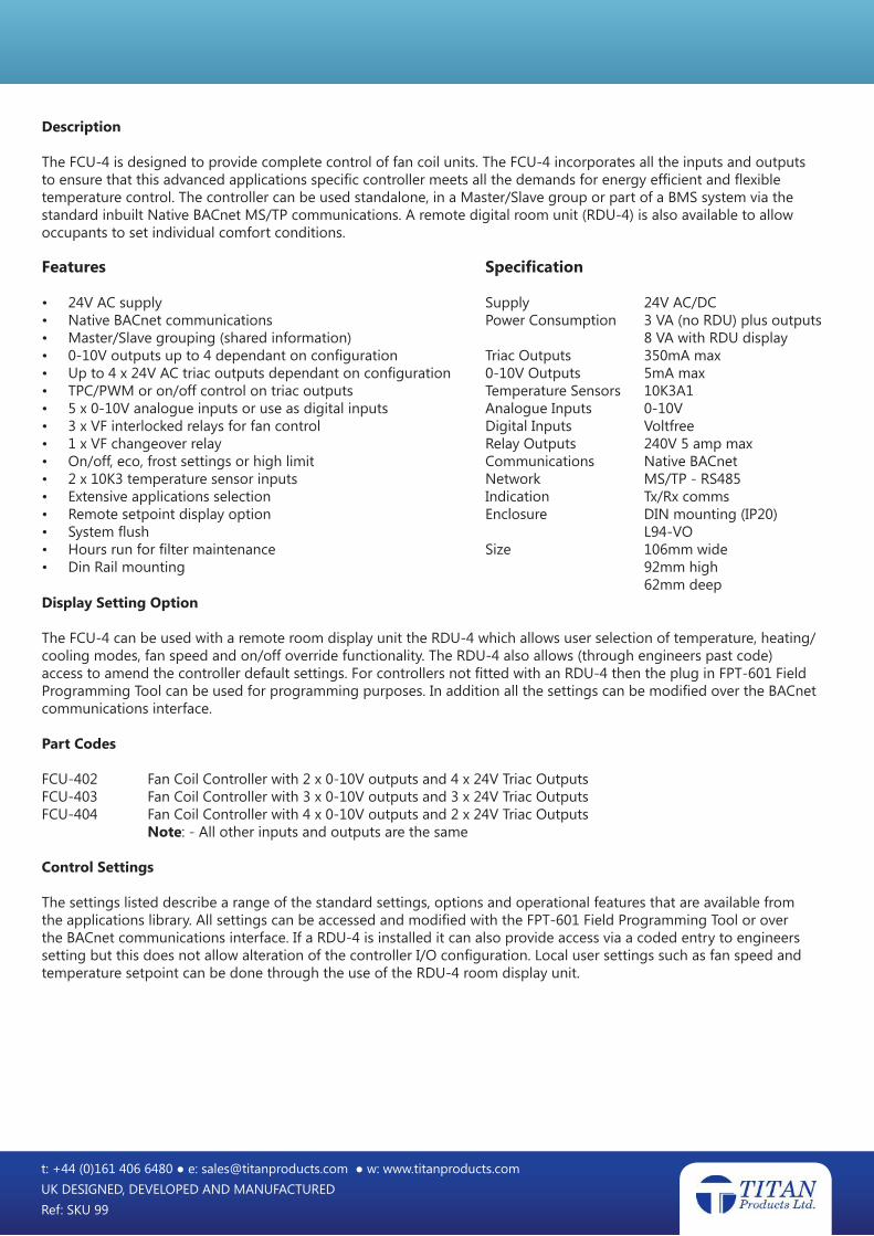
Description
The FCU-4 is designed to provide complete control of fan coil units. The FCU-4 incorporates all the inputs and outputs to ensure that this advanced applications specific controller meets all the demands for energy efficient and flexible temperature control. The controller can be used standalone, in a Master/Slave group or part of a BMS system via the standard inbuilt Native BACnet MS/TP communications. A remote digital room unit (RDU-4) is also available to allow occupants to set individual comfort conditions.
Display Setting Option
The FCU-4 can be used with a remote room display unit the RDU-4 which allows user selection of temperature, heating/cooling modes, fan speed and on/off override functionality. The RDU-4 also allows (through engineers past code) access to amend the controller default settings. For controllers not fitted with an RDU-4 then the plug in FPT-601 Field Programming Tool can be used for programming purposes. In addition all the settings can be modified over the BACnet communications interface.
Part Codes
FCU-402 Fan Coil Controller with 2 x 0-10V outputs and 4 x 24V Triac OutputsFCU-403 Fan Coil Controller with 3 x 0-10V outputs and 3 x 24V Triac OutputsFCU-404 Fan Coil Controller with 4 x 0-10V outputs and 2 x 24V Triac Outputs Note: - All other inputs and outputs are the same
Control Settings
The settings listed describe a range of the standard settings, options and operational features that are available from the applications library. All settings can be accessed and modified with the FPT-601 Field Programming Tool or over the BACnet communications interface. If a RDU-4 is installed it can also provide access via a coded entry to engineers setting but this does not allow alteration of the controller I/O configuration. Local user settings such as fan speed and temperature setpoint can be done through the use of the RDU-4 room display unit.
Features
• 24V AC supply• Native BACnet communications• Master/Slave grouping (shared information)• 0-10V outputs up to 4 dependant on configuration• Up to 4 x 24V AC triac outputs dependant on configuration• TPC/PWM or on/off control on triac outputs• 5 x 0-10V analogue inputs or use as digital inputs• 3 x VF interlocked relays for fan control• 1 x VF changeover relay• On/off, eco, frost settings or high limit• 2 x 10K3 temperature sensor inputs• Extensive applications selection• Remote setpoint display option• System flush• Hours run for filter maintenance• Din Rail mounting
Specification
Supply 24V AC/DCPower Consumption 3 VA (no RDU) plus outputs 8 VA with RDU displayTriac Outputs 350mA max0-10V Outputs 5mA maxTemperature Sensors 10K3A1Analogue Inputs 0-10VDigital Inputs VoltfreeRelay Outputs 240V 5 amp maxCommunications Native BACnetNetwork MS/TP - RS485Indication Tx/Rx commsEnclosure DIN mounting (IP20) L94-VOSize 106mm wide 92mm high 62mm deep

t: +44 (0)161 406 6480 ● e: [email protected] ● w: www.titanproducts.comUK DESIGNED, DEVELOPED AND MANUFACTURED
Ref: SKU 99
Controller Settings & Options
Network Native BACnet or standalone
Unit Address Sets the controller unit MAC address on MS/TP bus. Range 1 to 127 for a master
Baud Rate Set communication baud rate Range options:- 9,600 19,200 38,400 or 76,800
Dev Object ID Allows the setting of the device object ID Range 0 to 4194302
Group Control Allows individual controllers to be set-up as a Group Master or Group Slave. This sets groups of controllers to take control information and instructions such as temperature, fan speed, ON/Off etc. from a common Master (125 Slaves max). Any number of Groups can be set within the limit of 126 controllers on the MS/TP network.
Temp Units Set deg C or deg F
Temp/Setpoint Display This is used when the controller is used with a remote display setting unit (RDU-4) and allows the actual measured temperature to be displayed or hidden.
Fan Display Condition When the room display unit (RDU-4) is used. This allows the Fan status condition to be shown in digital (0/1/2/3) or text (Off/Low/Med/High) or Graphic bar symbols.
Offset Value Allows a positive or negative offset to be applied to the measured control temperature. Range –10 to +10˚C in 0.1 deg C steps - default 0˚C
Dead Band Setting Provides a dead band between the heating and cooling Control points. Range 0 to 4˚C in 0.1˚C steps - default 1˚C
Prop Band setting Sets the proportional band for the heating and cooling control cycle. Range 1 to 5˚C in 0.1˚C steps - default 2’C
Integ. Time This setting defines the I time for the P+I control function. Range 10 to 100seconds in 10sec steps - default 20 sec
Max Setpoint This setting defines the maximum setpoint value the system user can enter. Range 15 to 30˚C in 0.5˚C steps - default 30˚C
Min Setpoint This setting defines the minimum setpoint value the system user can enter. Range 15 to 30˚C in 0.5˚C steps - default 15˚C
Default Setpoint This defines the value of the control setpoint on power up or switch On Range 15 to 30˚C in 0.5˚C steps - default 21˚C
Low Limit Setpoint This limit setting option is to prevent cold draughts in the space when the unit is operating in a (supply air temperature) cooling mode. The control action is to reduce the cooling output in a proportional manner prior to the low limit setpoint value being reached if this value is reached the cooling input will be reduced to zero. Two settings are provided for this function a setpoint and a low limit proportional band. Setpoint range 15 to 21 in 0.5˚C steps - default 17˚C Proportional band 1 to 5 in 0.5˚C steps - default 3˚C

t: +44 (0)161 406 6480 ● e: [email protected] ● w: www.titanproducts.comUK DESIGNED, DEVELOPED AND MANUFACTURED
Ref: SKU 99
High Limit Setpoint This limit setting option is to prevent excessive temperatures in the supply air and overheating when the controller is operating in a heating mode. The control action is to reduce the heating output in a proportional manner prior to the high limit setpoint value being reached if this value is reached the heating input will be reduced to zero. Two settings are provided for this function a setpoint and a high limit proportional band. Setpoint range 20 to 50 in 0.5˚C steps - default 40˚C Proportional band 1 to 12 in 0.5˚C steps - default 5˚C
Note: - Limit setpoints can be assigned to the temperature sensor S2, the normal control sensor S1 or one of the 0-10V analogue inputs.
Fan Control Type Provides an option of up to 3 stage Relay Output or 0-10V Analogue control for EC Fans. Relay Control uses the 3 x Voltfree relays. Analogue Control uses one of the 0-10V outputs with a maximum of 10 stages available plus Off = 0V and min/max values on the output. Relay or Analogue Control
Note: - If Analogue Fan Control is required then refer to the order codes for the input/ output options as this could affect the available heat/cool control output signals.
Fan Speeds This sets the number of fan speeds required and is dependant on the use of relays or 0-10V. Range Relay Operation: 1, 2, or 3 speed Range 0-10V operation: Up to 10 speeds with min and max speed setting
Auto Fan Speed If set the fan automatically steps from the Low/Med/High speeds (relay output option) or Variable speed on the 0-10V Analogue Control Options in 1V steps dependent on the temperature deviation from the controller setpoint. (see Fan Stage Control for temperature setting).
Fan Stage Auto Temp Control Only available if Auto Fan is selected. This defines the value of the temperature deviation + or – from the setpoint. per stage of fan speed from 0 to full fan speed. Range: 0.2 to 3 deg in 0.1˚C steps for each stage - default 0.5˚C
Fan (Default Speed) This defines the default fan speed on power up or when switched to an “On” condition during an occupancy period. Range Relay Operation: Low, Med, High or Auto. Range 0-10V selection depends on number of speeds selected and min/max values
Fan Start Up This provides an option to start up the fan at full speed whenever it is switched from an Off condition to an On condition. If selected the fan will receive full power for 10 seconds on start up and after the initial 10 seconds has expired the fan speed will reduce to the selected default value.
Fan Overrun When enabled this feature sets a fan overrun time after any switch Off. If selected and when the controller is in the Fan Overrun period the Fan will default to low speed and the selection will flash on the RDU-4 display intermittently for the duration of the overrun period. Range 0 to 15 minutes in 1 min steps - default 0
Fan On Delay Setting This setting provides an option to delay the start of the Fan when the controller is switched from an Off condition to an On condition. This is to prevent the possibility of cold draughts if thermal actuators are being used. The delay period allows the thermal actuator to warm up after a prolonged Off period. The Fan Delay time period is only activated if the control temperature is in the heating cycle and is dependent on the period of time the fan has been switched off. There is no delay in the cooling cycle.

t: +44 (0)161 406 6480 ● e: [email protected] ● w: www.titanproducts.comUK DESIGNED, DEVELOPED AND MANUFACTURED
Ref: SKU 99
Operation of Fan Start Delay The Delay Start Time period is automatically varied dependant on the period of Off time, with a minimum value of 30 seconds. If the off period is less than 30 seconds then no delay is given If it is greater than 30 seconds the delay is directly proportional to the time the fan has been off and the maximum delay setting, for example with a Fan Delay time of 3 minutes: - If Off for less than 30 seconds – No Delay
If Off for 30 seconds to 3 minutes the Fan Start Delay time is proportional to the off time up to 3 minutes
If the off period is greater than 3 minutes then the Fan Delay Start is 3 minutes
During this Fan Start delay period the Fan Speed Selection on the RDU-4 will flash intermittently. Range 0 to 3 minutes in 30 second stages - default 0 min
Occupancy Timed Override This option provides a timed override “On” to the system. If any value other than 0 is set then the override can be started using the RDU-4 fan push buttons or, if programmed, by using a digital input and a remote push button. Range 0 to 240 minutes in 30 min steps - default 0 min
The FCU-4 is an advanced applications specific controller that is pre-configured to the customers application thereby providing ease of installation with the minimum commissioning time. The control functions defined in the next two sections describe the selections that are made at the time of configuration in order to maximise the use of the available I/O on the various hardware build options. Re-configuration at site level is done through the use of field programming tools or via the BACnet communications when used is a BMS.
Control Outputs Type (0-10V) The 0-10V outputs can be configured for use control of heating/cooling valves or to provide other control functions such a DC variable fan speed (see fan speed control section and Physical IO options). Heat/Cool control options are:- Dual Output 2 x 0-10V for individual control of heating and cooling.
Single Output heating and cooling are a single 0-10V signal on AO1 with 5V acting as the balance setpoint. The heating has a span of 5 to 10V and the cooling has a span of 5 to 0V.
Valve Control Type Options available for digital valve control for heating and cooling or other switched(Triac Control) functions will depend on the number of triacs used in the Build type (see product codes).
PWM Pulse width modulation Uses two triac outputs to provide heating and cooling
TPC Time proportional control Uses four triac outputs to provide positional control of both heating and cooling valves.
On/Off control Uses one or two triac outputs to switch the heating and/or cooling load or they can be configured to provide up to 4 stages of heating (via load relays) or DX cooling. If not used for heating control then any Triac 24V switched output can be configured to switch auxiliary/associated plant.
PWM Control The PWM time operates on a mark/space ratio that is determined by the temperature deviation from the setpoint across Pb setting. PWM control is fully on when the temperature is outside the PB setting Range 10 to 360 seconds - default 30 sec
If PWM is selected the controller provides an option to select an Intermittent Pre-Heat time for use with thermal actuators. The purpose of this is to keep inactive thermal actuators warm so achieving a close level of control. (see below).

t: +44 (0)161 406 6480 ● e: [email protected] ● w: www.titanproducts.comUK DESIGNED, DEVELOPED AND MANUFACTURED
Ref: SKU 99
Valve Actuator Pre-Heat Time Intermittent Valve Pulse Control When the controller is On and if the controller is in the cooling cycle then the heating valve is intermittently pulsed to keep the thermal actuator warm. If the controller is in the heating cycle then the cooling valve is pulsed. If the temperature is within the Db setting then both valves are pulsed. The setting of the intermittent pulse period is a percentage of the actual PWM setting. If 0% is set then the function is ignored.
Example: - with a PWM setting of 100 seconds and a Pulse setting of 1% then the controller will provide intermittent pulses of “On” for 1 second and “Off” for 99 seconds. Range 0-5% of PWM setting in 0.1% increments - default 0%
TPC Control Time Proportional Control (TPC) is for 24V Open and Close actuators. The setting should match the full run time of the actuator from fully closed to fully open. When TPC is used the controller automatically synchronises the position of the actuators on switch Off and every 24Hrs on a continuous running system. Range 10 to 360 seconds
On/Off Control (Triac 24V) If ON/OFF control of the heating and or cooling circuits is used then the Pb setting equals the On/Off differential and the controller uses the assigned triac outputs for heat and cool control. The value of the Dead band setting is also used in On/Off control and represents the temperature value between the Off point (heat or cool) and the switch On point (cool or heat).
Unoccupied Conditions This setting defines the action to be taken when the controller is switched Off to an unoccupied mode via an allocated DI the RDU-4 or from the BMS. Off:- Heat/Cool outputs off, Fan is switched Off or goes to overrun then Off. Low & High Temperature: - This selection allows for a minimum low temperature condition (frost) and a high temperature condition to be set. It uses the control temperature sensor and if the measured temperature reaches either of these settings then the controller will switch “On” the fan goes to Default Fan Speed Selection until the temperature rises (frost level) or falls (high level) by 2’C from the respective settings. Note both these settings can be implemented at the same time.
High temperature during Off condition Range 25 to 40˚C. Operates as High setting stated above
Low temperature during Off condition Range 5 to 20˚C. Operates as Frost setting stated above
ECO 2 (1 to 10’C) The ECO economy setting replaces the controller default dead band thereby decreasing the heating setpoint and increasing the cooling setpoint by the value selected and the fan remains on at a low speed. Range 1 to 10˚C.
ECO 1 (1 to 10’C) This ECO setting acts in the same manner as ECO2 above but is specific to the hotel application to provide an “Occupied Standby” mode of operation with the fan running on low speed although it could be used in other applications. Range 1 to 10˚C.
Filter Maintenance
The FCU-4 controllers can incorporate an hour run timer with reset to flag when the fan coil filter requires changing.
System Flush
The FCU-4 offers a system flush which can be set to run every 24 to 240 hours with an adjustable valve open time up to 500 seconds with increments of 50 seconds.

t: +44 (0)161 406 6480 ● e: [email protected] ● w: www.titanproducts.comUK DESIGNED, DEVELOPED AND MANUFACTURED
Ref: SKU 99
These values can be edited in the RDU-4 commissioning screens, factory pre-set or adjusted via a BMS using BACnet communications.
The flush won’t exercise a valve fully if the valve is already in use at the time of auto flush as it will know that the water is circulating and therefore a flush isn’t required on this valve.
Physical I/O
5 x Analogue or Digital Inputs Each of the 5 inputs In1 to In5 can be used as either analogue (0-10V) inputs or used as digital voltfree switched inputs.
Analogue Inputs When used as 0-10V analogue inputs each input can be configured for any of the following functions:
Temperature Reset input: If the RDU-4 is not used a 0-10V input can used to provide a control Setpoint adjustment with a variable range selectable in 1’C stages from +/-2’C to +/- 5’C with 5V = to 0’C of reset.
Optional Control of R4: On value can be set 0 to 100% and the Off Value can be set 0 to 100%.of the range of the input signal, with the On/Off values not allowed within 2% of each other. The control action can be with a rise or fall in signal input value.
Monitoring with Alarm: The 0-10V inputs can be scaled and ranged to specified units with alarm thresholds positive or negative activation for example:- Temp ‘C Humidity %RH Pressure Pa Power Amps/Volts/KW
Digital Inputs When used as Digital Inputs the voltfree switched contacts can operate on open or closed contacts examples of the configuration options are as follows:-
ON/OFF – This is used to switch the controller ON (occupied) or Off (unoccupied) from a remote switch and if an RDU-4 is used “Off” will be displayed. Window Interlock – For applications with a window contact to switch Off the FCU, if used in conjunction with a RDU-4 then “WINDOW OPEN” will be displayed. Summer/Winter – Used when the system employs a common single valve for heating and cooling. When the allocated DI is activated the heating control output is changed to a cooling control output This action can be transmitted globally when used as in a Master/Slave configuration or by the BMS system . If used on a single valve system the controller can be configured to provide an auxiliary heat control from one of the spare analogue or triac outputs. When used with an RDU-4 room display unit only the cool or heat symbol will be shown to indicate Summer or Winter Operation.
Fan Proving – Used with a DPS to identify that the fan is running before the heating or cooling control outputs are activated. Status Monitoring with Alarms Counters for Metering Limit State Monitoring – Can be Interlocked to shut Off Control Outputs (Heat/Cool or Both) Condensate Detection – Used to close either cooling only or both heat / cool control actions if condensate is detected. The fan control can also be inhibited when a condensate input is received. Relay 4 can be set to enable a condensate pump whenever the cooling action is enabled. If a condensate pump is connected to Relay 4, this must be configured under the Relay Output options within the FCU-4 controller.

t: +44 (0)161 406 6480 ● e: [email protected] ● w: www.titanproducts.comUK DESIGNED, DEVELOPED AND MANUFACTURED
Ref: SKU 99
Occupancy Extension – Uses a Momentary Push Button to start/stop the controller for a set time period outside the normally occupancy run time (See Occupancy Timed Override).
Temperature Sensor Input S1 S1 Temperature sensor input is a 10K3A1 Thermistor and is normally used for the control reference. This can be connected direct to the FCU-4 or it can be integral to the RDU room display unit.
Temperature Sensor Input 2 S2 Temperature sensor input is a 10K3A1 Thermistor and can be used for either High of Low limit control. The sensor if connected is automatically detected on power up and the function needs to be decided at the time of controller configuration. (See Limit Setpoint for set up information). Alternatively S2 can be configured to provide a separate independent zone control with its own setpoint, Pb and Db setting. The control output is dependant on the available free points and the controller Build type.
0-10V Analogue Inputs The 0-10V outputs maximum 4 dependant on Build type (see part codes) can be configured to provide the following control options: - Heating, Cooling Heating and Cooling (single output control one 0-10V) Cooling or Heating changeover (Summer/Winter control one 0-10V output) Fan Control (0-10V control 1to10 stages with min and max output settings). 0-10V On/Off condition
0-10V control output from an allocated 0-10V input or temperature sensor.
Triac 24Vac Outputs The 24VAC digital outputs maximum of 4 dependant on product build (see part code) can be configured to provide the following control options: - Heating Control (PWM, TPC or On/Off) Cooling Control (PWM, TPC or On/Off) Cooling or Heating (Summer/Winter control) On/Off switching functions. Sequence switching of 2 or more outputs dependant on Build type (see part codes)
Relays (1, 2, 3) Fan Control Used for fan Control the relays are voltfree and pre-wired to common supply input the allocation of these relays is fixed. The relays rated at 5 amp 240V AC max.
Relay 4 Options The independent Voltfree relay can be configured to operate under the following Options: Auxiliary Plant – Used to start up common circuits when the FCU-4 is On in an Occupied Mode with an option for a delay Off time range 0-60 seconds. Condensate Pump – Used with a Digital Input to Activate the relay on detection of Condensate or can be run on an intermittent time base whenever the FCU cooling valve is active. Interlocked – The operation of relay 4 can interlocked to operate with any of the Digital Inputs or on a threshold setting of the Control or Limit temperature sensor or on a value of one of the 0-10V Analogue inputs. When used in conjunction with a temperature sensor or an A0 then a differential value for deactivation can be set.

t: +44 (0)161 406 6480 ● e: [email protected] ● w: www.titanproducts.comUK DESIGNED, DEVELOPED AND MANUFACTURED
Ref: SKU 99
Terminal Connections Diagram shows FCU-402 (2 x 0-10V Analogue Outputs)
Terminal Connections Diagram shows FCU-403 (3 x 0-10V Analogue Outputs)

t: +44 (0)161 406 6480 ● e: [email protected] ● w: www.titanproducts.comUK DESIGNED, DEVELOPED AND MANUFACTURED
Ref: SKU 99
Terminal Connections Diagram shows FCU-404 (4 x 0-10V Analogue Outputs)
DIN Rail Enclosure Dimensions