Position Control for Linear Motion Servo System via Nominal Characteristic Trajectory Following...
7
Proceedings of the 3 rd International Conference on Mechatronics, ICOM’08 18 – 20 December 2008, Kuala Lumpur, Malaysia Position Control for Linear Motion Servo System via Nominal Characteristic Trajectory Following (NCTF) Controller 1 Noor Hisham Jalani, 2 Jamaludin Jalani, 3 Jiwa Abdullah 1 Mechatronics Section, Department of Electrical Technology Advanced Technology Training Centre (ADTEC), 83000 Batu Pahat, Johor, Malaysia 2 Department of Electrical Technology, Faculty of Electrical Engineering 3 Department of Communication Engineering, Faculty of Electrical Engineering Universiti Tun Hussein Onn (UTHM), 86400 Parit Raja, Batu Pahat, Johor, Malaysia 1 [email protected], 2 [email protected], 3 [email protected] ABSTRACT This paper presents a position tracking control strategy that meets the position tracking performance. A practical controller is proposed known as a Nominal Characteristic Trajectory Following (NCTF) to control the position of the cart. The effectiveness of the proposed NCTF controller is evaluated and compared with Proportional-Velocity (PV) controller through simulation. Keywords: NCTF, PV, position control, linear motion servo system. 1. INTRODUCTION Motion control system is a challenging problem in the area of control systems. It is very useful to demonstrate concepts in linear control such as the stabilization of unstable systems. Motion control system plays important roles in industrial equipment. One type of motion control systems is point-to- point positioning system, which is used to move an object from one point to another point. In the existing motion control systems, usually three control loops are connected sequentially: position, velocity, and torque loops. In general, the position and velocity loops are the major focus of the motion control design, while the torque control loop is completed through electrical current amplifier. It is due to the fact that the current control loop has much higher bandwidth than that of the position and velocity control loops. Since the position and velocity control loops directly deal with the system load, they would definitely be limited by the physical ability of motor drives and the effective load. Therefore, the overall performance of the motion control systems is usually restricted by the bandwidth of the position and velocity control loops. Until now, a lot of intelligent approaches about the position control for linear motion servo system have been proposed. A two-degree-of-freedom internal model control method based on fuzzy logic has been presented, which adjusts the parameter of feedback controller on-line for the permanent magnet linear synchronous motor position servo system. The control system structure is simplified and has fast dynamic response, while parameter identification is not demanded [1]. Another researcher has also used fuzzy logic controller for position control. The results gave smaller overshoot, shorter settling time and smaller steady-state error than the PID controller [2]. 2. CONTROLLER 2.1 PV Controller Such a controller introduces two corrective terms: one is proportional (by K p) to the position error and the other is proportional (by K v) to velocity (or the derivative of the actual position) of the plant. Equation, below, expresses the PV control law, where x d is the reference signal (i.e. the desired position to track): ) ( )) ( ) ( ( ) ( t x dt d K t x t x K t V v d p m (1) 373
Transcript of Position Control for Linear Motion Servo System via Nominal Characteristic Trajectory Following...
Proceedings of the 3rd International Conference on Mechatronics, ICOM’0818 – 20 December 2008, Kuala Lumpur, Malaysia
Position Control for Linear Motion Servo System via
Nominal Characteristic Trajectory Following (NCTF) Controller
1Noor Hisham Jalani, 2Jamaludin Jalani, 3Jiwa Abdullah 1Mechatronics Section, Department of Electrical Technology
Advanced Technology Training Centre (ADTEC), 83000 Batu Pahat, Johor, Malaysia2Department of Electrical Technology, Faculty of Electrical Engineering
3Department of Communication Engineering, Faculty of Electrical EngineeringUniversiti Tun Hussein Onn (UTHM), 86400 Parit Raja, Batu Pahat, Johor, Malaysia
[email protected], [email protected], [email protected]
ABSTRACT
This paper presents a position tracking control strategy that meets the position tracking performance. A practical controller is proposed known as a Nominal Characteristic TrajectoryFollowing (NCTF) to control the position of the cart. The effectiveness of the proposed NCTFcontroller is evaluated and compared with Proportional-Velocity (PV) controller through simulation.Keywords: NCTF, PV, position control, linear motion servo system.
1. INTRODUCTION
Motion control system is a challenging problem in the area of control systems. It is very useful to demonstrate concepts in linear control such as the stabilization of unstable systems. Motion control system plays important roles in industrial equipment. One type of motion control systems is point-to-point positioning system, which is used to move an object from one point to another point.
In the existing motion control systems, usually three control loops are connected sequentially:position, velocity, and torque loops. In general, the position and velocity loops are the major focus ofthe motion control design, while the torque control loop is completed through electrical current amplifier. It is due to the fact that the current control loop has much higher bandwidth than that of the position and velocity control loops. Since the position and velocity control loops directly deal with the system load, they would definitely be limited by the physical ability of motor drives and the effectiveload. Therefore, the overall performance of the motion control systems is usually restricted by the bandwidth of the position and velocity control loops.
Until now, a lot of intelligent approaches about the position control for linear motion servo systemhave been proposed. A two-degree-of-freedom internal model control method based on fuzzy logic has been presented, which adjusts the parameter of feedback controller on-line for the permanent magnet linear synchronous motor position servo system. The control system structure is simplified and has fast dynamic response, while parameter identification is not demanded [1]. Another researcher hasalso used fuzzy logic controller for position control. The results gave smaller overshoot, shortersettling time and smaller steady-state error than the PID controller [2].
2. CONTROLLER
2.1 PV Controller
Such a controller introduces two corrective terms: one is proportional (by Kp) to the position errorand the other is proportional (by Kv) to velocity (or the derivative of the actual position) of the plant. Equation, below, expresses the PV control law, where xd is the reference signal (i.e. the desiredposition to track):
)())()(()( txdt
dKtxtxKtV vdpm
(1)
373
Proceedings of the 3rd International Conference on Mechatronics, ICOM’0818 – 20 December 2008, Kuala Lumpur, Malaysia
2.2 NCTF Controller
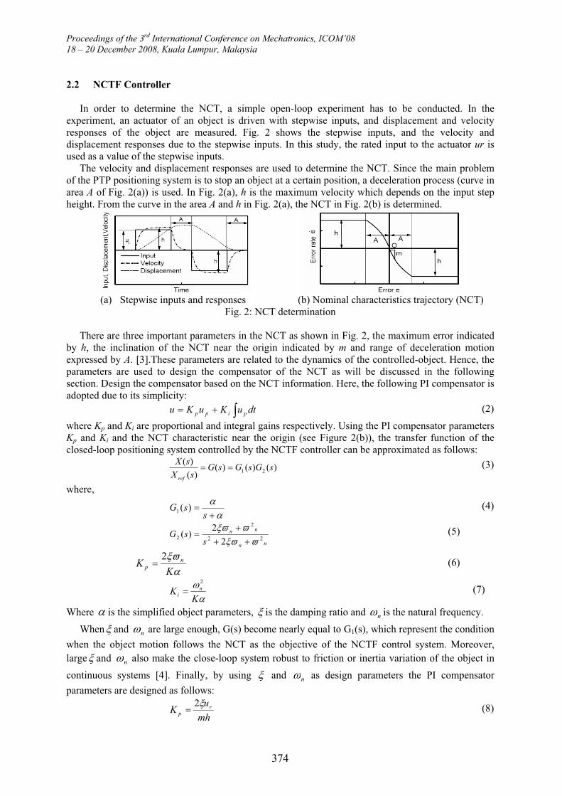
In order to determine the NCT, a simple open-loop experiment has to be conducted. In theexperiment, an actuator of an object is driven with stepwise inputs, and displacement and velocityresponses of the object are measured. Fig. 2 shows the stepwise inputs, and the velocity anddisplacement responses due to the stepwise inputs. In this study, the rated input to the actuator ur isused as a value of the stepwise inputs.
The velocity and displacement responses are used to determine the NCT. Since the main problem of the PTP positioning system is to stop an object at a certain position, a deceleration process (curve in area A of Fig. 2(a)) is used. In Fig. 2(a), h is the maximum velocity which depends on the input stepheight. From the curve in the area A and h in Fig. 2(a), the NCT in Fig. 2(b) is determined.
(a) Stepwise inputs and responses (b) Nominal characteristics trajectory (NCT)Fig. 2: NCT determination
There are three important parameters in the NCT as shown in Fig. 2, the maximum error indicatedby h, the inclination of the NCT near the origin indicated by m and range of deceleration motionexpressed by A. [3].These parameters are related to the dynamics of the controlled-object. Hence, the parameters are used to design the compensator of the NCT as will be discussed in the followingsection. Design the compensator based on the NCT information. Here, the following PI compensator isadopted due to its simplicity:
dtuKuKu pipp (2)
where Kp and Ki are proportional and integral gains respectively. Using the PI compensator parametersKp and Ki and the NCT characteristic near the origin (see Figure 2(b)), the transfer function of theclosed-loop positioning system controlled by the NCTF controller can be approximated as follows:
)()()()(
)(21 sGsGsG
sX
sX
ref
(3)
where,
ssG )(1
(4)
nn
nn
ssG
22
2
2 2
2)( (5)
KK n
p
2 (6)
KK n
i
2
(7)
Where is the simplified object parameters, is the damping ratio and n is the natural frequency.
When and n are large enough, G(s) become nearly equal to G1(s), which represent the condition
when the object motion follows the NCT as the objective of the NCTF control system. Moreover, large and n also make the close-loop system robust to friction or inertia variation of the object in
continuous systems [4]. Finally, by using and n as design parameters the PI compensator
parameters are designed as follows:
mh
uK r
p
2 (8)
374
Proceedings of the 3rd International Conference on Mechatronics, ICOM’0818 – 20 December 2008, Kuala Lumpur, Malaysia
mh
uK rn
i
2
(9)
3. EXPERIMENTAL RESULTS
3.1 System Description
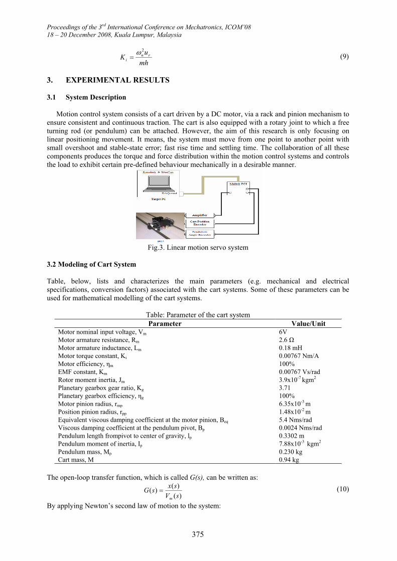
Motion control system consists of a cart driven by a DC motor, via a rack and pinion mechanism to ensure consistent and continuous traction. The cart is also equipped with a rotary joint to which a free turning rod (or pendulum) can be attached. However, the aim of this research is only focusing onlinear positioning movement. It means, the system must move from one point to another point withsmall overshoot and stable-state error; fast rise time and settling time. The collaboration of all these components produces the torque and force distribution within the motion control systems and controls the load to exhibit certain pre-defined behaviour mechanically in a desirable manner.
Fig.3. Linear motion servo system
3.2 Modeling of Cart System
Table, below, lists and characterizes the main parameters (e.g. mechanical and electricalspecifications, conversion factors) associated with the cart systems. Some of these parameters can be used for mathematical modelling of the cart systems.
Table: Parameter of the cart systemParameter Value/Unit
Motor nominal input voltage, Vm 6VMotor armature resistance, Rm 2.6Motor armature inductance, Lm 0.18 mHMotor torque constant, Ki 0.00767 Nm/AMotor efficiency, m 100%EMF constant, Km 0.00767 Vs/radRotor moment inertia, Jm 3.9x10⁻⁷ kgm2
Planetary gearbox gear ratio, Kg 3.71Planetary gearbox efficiency, g 100%Motor pinion radius, rmp 6.35x10⁻³ mPosition pinion radius, rpp 1.48x10⁻² mEquivalent viscous damping coefficient at the motor pinion, Beq 5.4 Nms/radViscous damping coefficient at the pendulum pivot, Bp 0.0024 Nms/radPendulum length frompivot to center of gravity, lp 0.3302 mPendulum moment of inertia, Ip 7.88x10⁻³ kgm2
Pendulum mass, Mp 0.230 kgCart mass, M 0.94 kg
The open-loop transfer function, which is called G(s), can be written as:
)(
)()(
sV
sxsG
m
(10)
By applying Newton’s second law of motion to the system:
375
Proceedings of the 3rd International Conference on Mechatronics, ICOM’0818 – 20 December 2008, Kuala Lumpur, Malaysia
)()()(2
2
txdt
dBtFtx
dt
dM eqc
(11)
Here, the inertial force due to the motor’s armature in rotation is neglected. The cart’s Coulombfriction is also neglected. The driving force, Fc, generated by the DC motor and acting on the cart through the motor pinion can be expressed as:
mp
mgg
cr
TKF (12)
Using Kirchhoff’s voltage law, the following equation was obtained:
0emfmmmmm EIt
LIRV (13)
However, since Lm << Rm, the motor inductance can be disregard with:
m
emfm
mR
EVI (14)
Since the back-emf voltage created by the motor, Eemf, is proportional to the motor shaft velocity m ,
then:
m
mmmm
R
KVI (15)
Moreover, in order to account for the DC motor electrical losses, the motor efficiency is introduced tocalculate the torque generated by the DC motor:
mtmm IKT (16)
Substituting Equation (15) and (16) into Equation (12) leads to:
mpm
mmmtmgg
crR
KVKKF
)( (17)
By considering the rack and pinion and the gearbox mechanisms, the motor angular velocity can be written as a function of the cart linear velocity, as expressed by:
mp
g
mr
txdt
dK )(
(18)
Therefore, substituting Equation (18) into Equation (17) and rearranging leads to:
2mpm
mgmpmtmgg
crR
txdt
dKKrVKK
F (19)
As seen at the motor pinion, the armature inertial force due to the motor rotation and acting on the cartcan be expressed as a function of the armature inertial torque:
mp
aigg
air
TKF (20)
Applying Newton’s second law of motion to the motor shaft:
)()(2
2
tTtdt
dJ aimm
(21)
Moreover, the mechanical configuration of the cart’s rack-pinion system gives the followingrelationship:
mp
g
mr
xK (22)
Substituting Equations (20) and (21) into Equation (19) provides the following expression for the armature inertial force:
376

Proceedings of the 3rd International Conference on Mechatronics, ICOM’0818 – 20 December 2008, Kuala Lumpur, Malaysia
2
2
22 )(
mp
mgg
air
txdt
dJK
F (23)
Finally, substituting (19) and (23) into (10), applying the Laplace transform and rearranging yields the desired open loop transfer function for the cart system, such that:
srRBKKKsJKRMrR
KKrsG
mpmeqmtmggmggmmpm
tmggmp
))(()(
2222
3.2 Design of Proposed Control Method
Fig.4. Proposed NCTF-based linear motion servo system
(a) Stepwise input (b)Velocity response
(c) Displacement response Fig.6. The nominal characteristic trajectoryFig.5. Stepwise input and plant response
The stepwise input shown in Fig. 5(a) is applied to the plant. The height of the stepwise input,which is 10V, is decided based on the rated input to the motor driver. The velocity and displacementresponses due to the stepwise input are shown in Figs. 5(b and c), respectively.
Then, Fig. 6 illustrates the determined NCT based on Fig. 5. The NCT has a 17.095 s-1 inclination near the origin and a 143 mm/s maximum error rate h. The compensator parameters are designed byusing h and m of the NCT. By referring to the digital implementation of the PI compensator asdiscussed [5], design parameters = 5000 and n = 1 are selected. Table 1 shows the value of the
compensator parameters calculated from Eq. (8) and (9).
377
Proceedings of the 3rd International Conference on Mechatronics, ICOM’0818 – 20 December 2008, Kuala Lumpur, Malaysia
4. PERFORMANCE EVALUATION
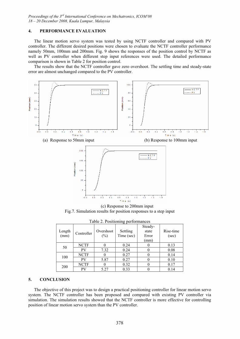
The linear motion servo system was tested by using NCTF controller and compared with PVcontroller. The different desired positions were chosen to evaluate the NCTF controller performancenamely 50mm, 100mm and 200mm. Fig. 9 shows the responses of the position control by NCTF aswell as PV controller when different step input references were used. The detailed performance comparison is shown in Table 2 for position control.
The results show that the NCTF controller gave zero overshoot. The settling time and steady-stateerror are almost unchanged compared to the PV controller.
(a) Response to 50mm input (b) Response to 100mm input
(c) Response to 200mm inputFig.7. Simulation results for position responses to a step input
Table 2. Positioning performances
Length(mm)
ControllerOvershoot
(%)Settling
Time (sec)
Steady-stateError(mm)
Rise-time (sec)
NCTF 0 0.24 0 0.1350
PV 7.32 0.24 0 0.08NCTF 0 0.27 0 0.14
100PV 5.87 0.27 0 0.10
NCTF 0 0.32 0 0.17200
PV 5.27 0.33 0 0.14
5. CONCLUSION
The objective of this project was to design a practical positioning controller for linear motion servo system. The NCTF controller has been proposed and compared with existing PV controller via simulation. The simulation results showed that the NCTF controller is more effective for controlling position of linear motion servo system than the PV controller.
378
Proceedings of the 3rd International Conference on Mechatronics, ICOM’0818 – 20 December 2008, Kuala Lumpur, Malaysia
REFERENCES
[1] Dongmei Yu, Qingding Guo and Qing Hu, “Position Control of Linear Servo System Using Intelligent Feedback Controller”, in Proceeding of the Sixth International Conference on Intelligent Systems Design and Application (ISDA’06): 0-7695-2528-8/06, 2006.
[2] Wahyudi; Jamaludin Jalani,”Design and Implementation of Fuzzy Logic Controller for an Intelligent Gantry Crane System”, in Proceedings of The 2nd International Conference on Mechatronics, pp.345-351, 2005.
[3] Wahyudi, Tarig. F. Ibrahim and Momoh J.E. Salami, “Robustness Evaluation of Fuzzy-based NCTF Control of Point-to-point (PTP) Positioning Systems”, 1-4244-1264-1/07, 2007.
[4] Wahyudi; Jamaludin Jalani, Riza Muhida, Momoh Jimoh Emiyoka Salami, “Control Strategy for Automatic Gantry Crane Systems: A Practical and Intelligent Approach”, International Journal of Advanced Robotic Systems, Vol.4, No.4, 2007.
[5] Wahyudi, “New Practical Control of PTP Positioning System”, Ph.D Thesis, Tokyo Institute of Technology, 2002.
379