Modeling and control of standalone hybrid (Wind / photovoltaic) generator
Upload
khangminh22Category
view
1download
0
GE Fanuc Automation
Programmable Control Products
S2K Series Standalone Motion Controller
User's Manual
GFK-1848F December 2003
GFL-002
Warnings, Cautions, and Notes as Used in this Publication
Warning Warning notices are used in this publication to emphasize that hazardous voltages, currents, temperatures, or other conditions that could cause personal injury exist in this equipment or may be associated with its use.
In situations where inattention could cause either personal injury or damage to equipment, a Warning notice is used.
Caution Caution notices are used where equipment might be damaged if care is not taken.
Note Notes merely call attention to information that is especially significant to understanding and operating the equipment.
This document is based on information available at the time of its publication. While efforts have been made to be accurate, the information contained herein does not purport to cover all details or variations in hardware or software, nor to provide for every possible contingency in connection with installation, operation, or maintenance. Features may be described herein which are not present in all hardware and software systems. GE Fanuc Automation assumes no obligation of notice to holders of this document with respect to changes subsequently made.
GE Fanuc Automation makes no representation or warranty, expressed, implied, or statutory with respect to, and assumes no responsibility for the accuracy, completeness, sufficiency, or usefulness of the information contained herein. No warranties of merchantability or fitness for purpose shall apply.
The following are trademarks of GE Fanuc Automation North America, Inc.
Alarm Master Genius PROMACRO Series Three CIMPLICITY Helpmate PowerMotion VersaMax CIMPLICITY 90–ADS Logicmaster PowerTRAC VersaPro CIMSTAR Modelmaster Series 90 VuMaster Field Control Motion Mate Series Five Workmaster FrameworX PACSystems Series One GEnet ProLoop Series Six
©Copyright 1989-2003 GE Fanuc Automation North America, Inc.
All Rights Reserved.
Preface
GFK-1848F iii
Content of This Manual
Chapter 1. Before Operation: Unpacking and inspecting components, storage, and product part number reference.
Chapter 2 Hardware Overview: Product specifications, motor speed/torque curves.
Chapter 3 Installation: Heat load ratings, mounting and wiring.
Chapter 4 Getting Started: Connecting the system, establishing communications with Motion Developer software, Configuring the system.
Chapter 5 Software Reference: Programming basics and command listing.
Chapter 6 Using Motion Developer: How to use the software for creating motion programs, for configuring the hardware, and for monitoring operation.
Chapter 7 Diagnostics: Status codes, command messages, and diagnostics.
Chapter 8 Using DeviceNet: Contains specifications and instructions for using S2K controllers on DeviceNet. Also contains an introduction to DeviceNet.
Chapter 9 Using RTU Serial Communications: Contains specifications and instructions for using S2K controllers with Remote Terminal Unit serial communication protocol. Also contains information on configuring QuickPanel and DataPanel terminals for use with the S2K controller.
Chapter 10 PROFIBUS Communications. Supplies information on how to commission an S2K controller and incorporate it into a PROFIBUS network segment.
Appendix A. Tables and Formulas: ASCII codes, temperature conversion, wire size conversion.
Appendix B. S2K Motion Templates: Provides code to accomplish various tasks. Topics covered are Homing Motions, Velocity-Based Motions, Time-Based Motions, Pulse-Based Motions, Torque Limited Motions, Synchronized Motions, and Utility Templates.
Related Publications GFK-1866 S2K Series Brushless Servo Amplifier User’s Manual

Contents
GFK-1848F v
Before Operation............................................................................................................................1-1 1.1 System Overview .......................................................................................... 1-1 1.2 Unpacking and Inspecting Components ........................................................ 1-2 1.3 Storage........................................................................................................... 1-2 1.4 Part Numbers................................................................................................. 1-3 1.5 Confirming System Components .................................................................. 1-5 1.6 Agency Approvals ......................................................................................... 1-8 1.7 S2K Series Now Includes Resolver Feedback Models ................................. 1-8
Hardware Overview ......................................................................................................................2-1 2.1 Specifications ................................................................................................ 2-1 2.2 Motor Speed/Torque Curves ....................................................................... 2-14 2.3 Servo Motor Derating Based on Ambient Temperature.............................. 2-29 2.4 Servo Motor Sealing.................................................................................... 2-30 2.5 Servo Motor Holding Brakes....................................................................... 2-30 2.6 NEMA Motor Mounting ............................................................................. 2-31 2.7 S-Series Servo Motor Vibration Testing ..................................................... 2-32
Installation......................................................................................................................................3-1 3.1 Heat Load and Cooling.................................................................................. 3-1 3.2 Controller Mounting Guidelines and Environmental Conditions.................. 3-2 3.3 Installing the Controller................................................................................. 3-3 3.4 Installing the Motor ....................................................................................... 3-4 3.5 Mounting Dimensions ................................................................................... 3-5 3.6 Wiring.......................................................................................................... 3-24 3.7 Wiring The Optional Motor Brake .............................................................. 3-67 3.8 Regenerative Discharge Resistor Selection and Wiring.............................. 3-68 3.9 Dynamic Braking Contact and Operation ................................................... 3-75
Getting Started...............................................................................................................................4-1
Software Reference ........................................................................................................................5-1 5.1 Software Overview........................................................................................ 5-1 5.2 S2K Programming Language Basics............................................................. 5-2 5.3 Programming Resources................................................................................ 5-3 5.4 Saving and Restoring Parameters, Variables and Programs........................ 5-18 5.5 Advanced Programming.............................................................................. 5-19 5.6 Software Quick Reference Lists.................................................................. 5-42 5.7 Commands and Registers ............................................................................ 5-59
Contents
vi S2K Series Standalone Motion Controller User's Manual – December 2003 GFK-1848F
Using Motion Developer................................................................................................................6-1
6.1 Installing Motion Developer .............................................................6-1 6.1.1 Computer System Requirements ................................................................... 6-1 6.1.2 Installation ..................................................................................................... 6-1 6.1.3 Product Authorization ................................................................................... 6-2 6.1.4 Technical Support.......................................................................................... 6-3
Diagnostics......................................................................................................................................7-1 7.1 LED Display Status Codes ............................................................................ 7-1 7.2 Status Messages............................................................................................. 7-2 7.3 Status Register Messages .............................................................................. 7-7 7.4 Application Program Diagnostics................................................................ 7-17 7.5 Troubleshooting Flow Chart........................................................................ 7-23
Using DeviceNet Communications ...............................................................................................8-1 8.1 DeviceNet - What it is and How it Works..................................................... 8-1 8.2 Certification and Testing ............................................................................... 8-6 8.3 Network Size and Device Types ................................................................... 8-6 8.4 S2K Series Real-Time Operating System (RTOS)........................................ 8-6 8.5 Getting Started............................................................................................... 8-7 8.6 Using Explicit Messages ............................................................................. 8-37 8.7 Introduction to DeviceNet Object Modeling............................................... 8-47 8.8 Frequently Asked Questions about S2K DeviceNet.................................... 8-60
Using Serial Communications.......................................................................................................9-1 9.1 Getting Started ............................................................................................ 9-1 9.2 ASCII Protocol ............................................................................................ 9-1 9.3 RTU Protocol ............................................................................................... 9-4
PROFIBUS Communications .....................................................................................................10-1 10.1 PROFIBUS Network Overview .................................................................. 10-1 10.2 Getting Started............................................................................................. 10-5 10.3 Overview of Master/Slave Station Types.................................................... 10-9 10.4 Diagnostics ................................................................................................ 10-30
Tables and Formulas ....................................................................................................................A-1 Standard ASCII (American Standard Code for Information Interchange) Codes............ A-1 AWG to Metric Wire Size Conversion ............................................................................ A-2 Temperature Conversion.................................................................................................. A-2
Contents
GFK-1848F Contents vii
S2K Motion Templates ................................................................................................................. B-1 B.1 Homing Routines.......................................................................................... B-1 B.2 Velocity Based Motion................................................................................. B-8 B.3 Time-Based Motion.................................................................................... B-15 B.4 Pulse-Based Motion ................................................................................... B-19 B.5 Torque Limited Motion .............................................................................. B-25 B.6 Synchronized Motion ................................................................................. B-27 B.7 Utility Templates........................................................................................ B-36

GFK-1848F 1-1
Before Operation
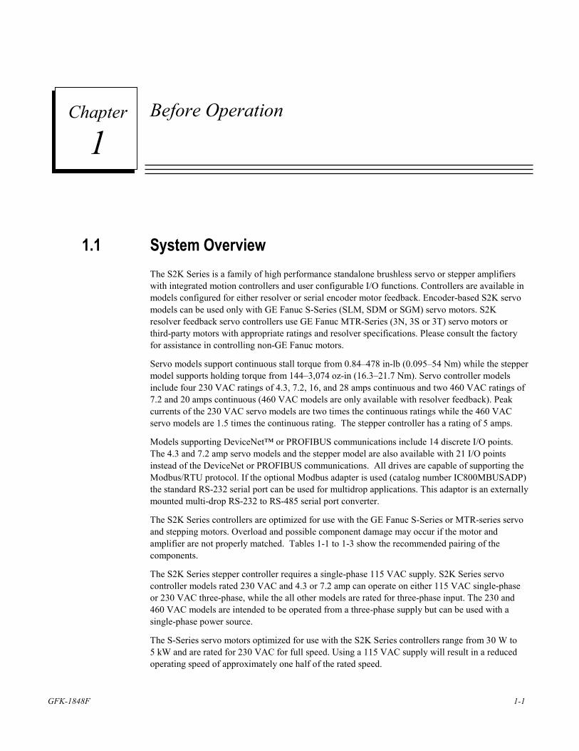
1.1 System Overview The S2K Series is a family of high performance standalone brushless servo or stepper amplifiers with integrated motion controllers and user configurable I/O functions. Controllers are available in models configured for either resolver or serial encoder motor feedback. Encoder-based S2K servo models can be used only with GE Fanuc S-Series (SLM, SDM or SGM) servo motors. S2K resolver feedback servo controllers use GE Fanuc MTR-Series (3N, 3S or 3T) servo motors or third-party motors with appropriate ratings and resolver specifications. Please consult the factory for assistance in controlling non-GE Fanuc motors.
Servo models support continuous stall torque from 0.84–478 in-lb (0.095–54 Nm) while the stepper model supports holding torque from 144–3,074 oz-in (16.3–21.7 Nm). Servo controller models include four 230 VAC ratings of 4.3, 7.2, 16, and 28 amps continuous and two 460 VAC ratings of 7.2 and 20 amps continuous (460 VAC models are only available with resolver feedback). Peak currents of the 230 VAC servo models are two times the continuous ratings while the 460 VAC servo models are 1.5 times the continuous rating. The stepper controller has a rating of 5 amps.
Models supporting DeviceNet™ or PROFIBUS communications include 14 discrete I/O points. The 4.3 and 7.2 amp servo models and the stepper model are also available with 21 I/O points instead of the DeviceNet or PROFIBUS communications. All drives are capable of supporting the Modbus/RTU protocol. If the optional Modbus adapter is used (catalog number IC800MBUSADP) the standard RS-232 serial port can be used for multidrop applications. This adaptor is an externally mounted multi-drop RS-232 to RS-485 serial port converter.
The S2K Series controllers are optimized for use with the GE Fanuc S-Series or MTR-series servo and stepping motors. Overload and possible component damage may occur if the motor and amplifier are not properly matched. Tables 1-1 to 1-3 show the recommended pairing of the components.
The S2K Series stepper controller requires a single-phase 115 VAC supply. S2K Series servo controller models rated 230 VAC and 4.3 or 7.2 amp can operate on either 115 VAC single-phase or 230 VAC three-phase, while the all other models are rated for three-phase input. The 230 and 460 VAC models are intended to be operated from a three-phase supply but can be used with a single-phase power source.
The S-Series servo motors optimized for use with the S2K Series controllers range from 30 W to 5 kW and are rated for 230 VAC for full speed. Using a 115 VAC supply will result in a reduced operating speed of approximately one half of the rated speed.
1 Chapter
1-2 S2K Series Standalone Motion Controller User's Manual GFK-1848F
1
The 30 to 1,000 Watt S-Series servo motors (SLM models only), MTR-3S and MTR-3N series and all stepping motor models are designed with standard NEMA shaft and flange mounting configurations for easy mounting to off-the-shelf gear reducers and couplings. The 750-Watt S-Series motor uses an oversized shaft diameter (0.625 inches) for the NEMA 34 mounting in order to handle the peak torque rating of this model. S-Series motor models from 1 to 5 kW (except the SLM100 1kW motor) and all MTR-3T Series motors have metric mounting configurations.
All servo motors are available with an optional 24 VDC holding brake. These brakes are spring-set, electrically released models designed for holding stationary loads. The user must supply a separate 24 VDC brake power supply. The 30-750 Watt S-Series motors have a pigtail cable with box style connectors for motor power, encoder and brake connections. The 1,000 to 5,000 Watt S-Series motors have MS style connectors and the brake power (when required) is integrated with the motor power connections in a common connector/cable. MTR-series servo motors include MS type connectors for brake power input. The MTR-3N and MTR-3T series brake motors integrate the brake power with the motor power in the same cable. MTR-3S brake motors require a separate brake power cable (CBL-30-BT).
S2K Series controllers are configured and programmed using the Motion Developer software for a personal computer. This software is a standalone application that works within the Machine Edition software environment and provides tools to simplify programming for the novice while providing direct code entry for the advanced user.
The following sections outline what should be accomplished before operating the S2K Series controller.
1.2 Unpacking and Inspecting Components After opening the S2K Series package, please verify the following:
1. Did you receive the correct model components? The model number of each component is shown on the carton and product labels.
2. Did you receive all items shown on the packing list?
3. Was anything damaged during shipment?
Note If you find any damage, please contact your local dealer/distributor or GE Fanuc directly.
1.3 Storage Store S2K components in a clean, dry location that is not exposed to direct sunlight, rain, excessive temperatures (exceeding -40°C to 80°C), corrosive gasses or liquids.
For maximum protection, store all components in the original shipping container.
Before Operation
GFK-1848F Chapter 1 Before Operation 1-3
1
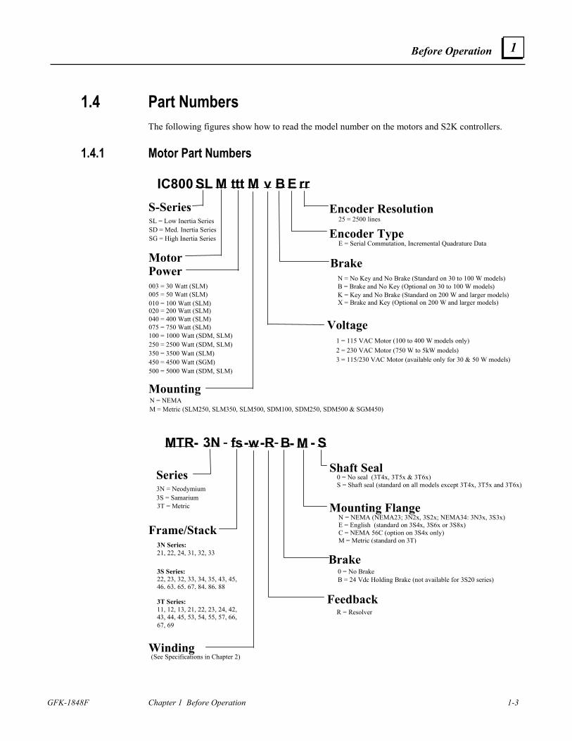
1.4 Part Numbers The following figures show how to read the model number on the motors and S2K controllers.
1.4.1 Motor Part Numbers
IC800 SL M ttt M v B E rrS-Series
Voltage 1 = 115 VAC Motor (100 to 400 W models only)
Encoder Type E = Serial Commutation, Incremental Quadrature Data
Encoder Resolution 25 = 2500 lines
Brake
K = Key and No Brake (Standard on 200 W and larger models)X = Brake and Key (Optional on 200 W and larger models)
Motor Power
Mounting N = NEMA
020 = 200 Watt (SLM) 040 = 400 Watt (SLM) 075 = 750 Watt (SLM) 100 = 1000 Watt (SDM, SLM)250 = 2500 Watt (SDM, SLM)
450 = 4500 Watt (SGM) 500 = 5000 Watt (SDM, SLM)
M = Metric (SLM250, SLM350, SLM500, SDM100, SDM250, SDM500 & SGM450)
SL = Low Inertia Series SD = Med. Inertia Series SG = High Inertia Series
005 = 50 Watt (SLM) 003 = 30 Watt (SLM) 010 = 100 Watt (SLM)
350 = 3500 Watt (SLM) 2 = 230 VAC Motor (750 W to 5kW models) 3 = 115/230 VAC Motor (available only for 30 & 50 W models)
N = No Key and No Brake (Standard on 30 to 100 W models)B = Brake and No Key (Optional on 30 to 100 W models)
MTR- 3N - fs -w -R- B - M - S
Series
FeedbackR = Resolver
Mounting Flange N = NEMA (NEMA23; 3N2x, 3S2x; NEMA34: 3N3x, 3S3x) E = English (standard on 3S4x, 3S6x or 3S8x) C = NEMA 56C (option on 3S4x only) M = Metric (standard on 3T)
Shaft Seal 0 = No seal (3T4x, 3T5x & 3T6x) S = Shaft seal (standard on all models except 3T4x, 3T5x and 3T6x)
Brake
Frame/Stack
Winding
3T Series: 11, 12, 13, 21, 22, 23, 24, 42, 43, 44, 45, 53, 54, 55, 57, 66, 67, 69
3N = Neodymium 3S = Samarium 3T = Metric
3N Series: 21, 22, 24, 31, 32, 33 3S Series: 22, 23, 32, 33, 34, 35, 43, 45, 46, 63, 65, 67, 84, 86, 88
0 = No BrakeB = 24 Vdc Holding Brake (not available for 3S20 series)
(See Specifications in Chapter 2)
1-4 S2K Series Standalone Motion Controller User's Manual GFK-1848F
1
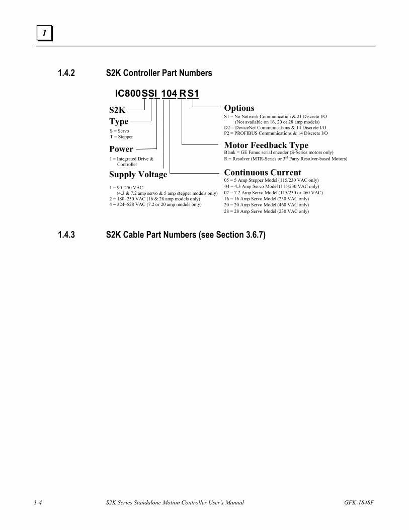
1.4.2 S2K Controller Part Numbers
IC800SSI RS1S2KType
OptionsS1 = No Network Communication & 21 Discrete I/O
(Not available on 16, 20 or 28 amp models)D2 = DeviceNet Communications & 14 Discrete I/OP2 = PROFIBUS Communications & 14 Discrete I/O
PowerI = Integrated Drive &
Controller
S = ServoT = Stepper
104
Continuous Current04 = 4.3 Amp Servo Model (115/230 VAC only)
Supply Voltage1 = 90–250 VAC
(4.3 & 7.2 amp servo & 5 amp stepper models only)2 = 180–250 VAC (16 & 28 amp models only)4 = 324–528 VAC (7.2 or 20 amp models only)
07 = 7.2 Amp Servo Model (115/230 or 460 VAC)16 = 16 Amp Servo Model (230 VAC only)20 = 20 Amp Servo Model (460 VAC only)
Motor Feedback TypeBlank = GE Fanuc serial encoder (S-Series motors only)R = Resolver (MTR-Series or 3rd Party Resolver-based Motors)
28 = 28 Amp Servo Model (230 VAC only)
05 = 5 Amp Stepper Model (115/230 VAC only)
1.4.3 S2K Cable Part Numbers (see Section 3.6.7)
Before Operation
GFK-1848F Chapter 1 Before Operation 1-5
1
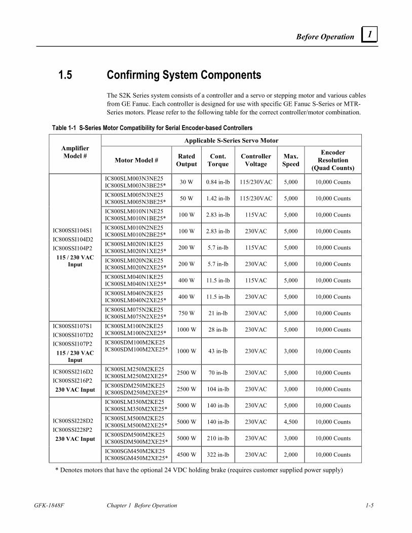
1.5 Confirming System Components The S2K Series system consists of a controller and a servo or stepping motor and various cables from GE Fanuc. Each controller is designed for use with specific GE Fanuc S-Series or MTR-Series motors. Please refer to the following table for the correct controller/motor combination.
Table 1-1 S-Series Motor Compatibility for Serial Encoder-based Controllers
Applicable S-Series Servo Motor Amplifier Model # Motor Model # Rated
Output Cont.
Torque Controller
Voltage Max. Speed
Encoder Resolution
(Quad Counts) IC800SLM003N3NE25 IC800SLM003N3BE25* 30 W 0.84 in-lb 115/230VAC 5,000 10,000 Counts
IC800SLM005N3NE25 IC800SLM005N3BE25* 50 W 1.42 in-lb 115/230VAC 5,000 10,000 Counts
IC800SLM010N1NE25 IC800SLM010N1BE25* 100 W 2.83 in-lb 115VAC 5,000 10,000 Counts
IC800SLM010N2NE25 IC800SLM010N2BE25* 100 W 2.83 in-lb 230VAC 5,000 10,000 Counts
IC800SLM020N1KE25 IC800SLM020N1XE25* 200 W 5.7 in-lb 115VAC 5,000 10,000 Counts
IC800SLM020N2KE25 IC800SLM020N2XE25* 200 W 5.7 in-lb 230VAC 5,000 10,000 Counts
IC800SLM040N1KE25 IC800SLM040N1XE25* 400 W 11.5 in-lb 115VAC 5,000 10,000 Counts
IC800SLM040N2KE25 IC800SLM040N2XE25* 400 W 11.5 in-lb 230VAC 5,000 10,000 Counts
IC800SSI104S1 IC800SSI104D2 IC800SSI104P2
115 / 230 VAC Input
IC800SLM075N2KE25 IC800SLM075N2XE25* 750 W 21 in-lb 230VAC 5,000 10,000 Counts
IC800SLM100N2KE25 IC800SLM100N2XE25* 1000 W 28 in-lb 230VAC 5,000 10,000 Counts IC800SSI107S1
IC800SSI107D2 IC800SSI107P2
115 / 230 VAC Input
IC800SDM100M2KE25 IC800SDM100M2XE25* 1000 W 43 in-lb 230VAC 3,000 10,000 Counts
IC800SLM250M2KE25 IC800SLM250M2XE25* 2500 W 70 in-lb 230VAC 5,000 10,000 Counts IC800SSI216D2
IC800SSI216P2 230 VAC Input
IC800SDM250M2KE25 IC800SDM250M2XE25* 2500 W 104 in-lb 230VAC 3,000 10,000 Counts
IC800SLM350M2KE25 IC800SLM350M2XE25* 5000 W 140 in-lb 230VAC 5,000 10,000 Counts
IC800SLM500M2KE25 IC800SLM500M2XE25* 5000 W 140 in-lb 230VAC 4,500 10,000 Counts
IC800SDM500M2KE25 IC800SDM500M2XE25* 5000 W 210 in-lb 230VAC 3,000 10,000 Counts
IC800SSI228D2 IC800SSI228P2 230 VAC Input
IC800SGM450M2KE25 IC800SGM450M2XE25* 4500 W 322 in-lb 230VAC 2,000 10,000 Counts
* Denotes motors that have the optional 24 VDC holding brake (requires customer supplied power supply)
1-6 S2K Series Standalone Motion Controller User's Manual GFK-1848F
1
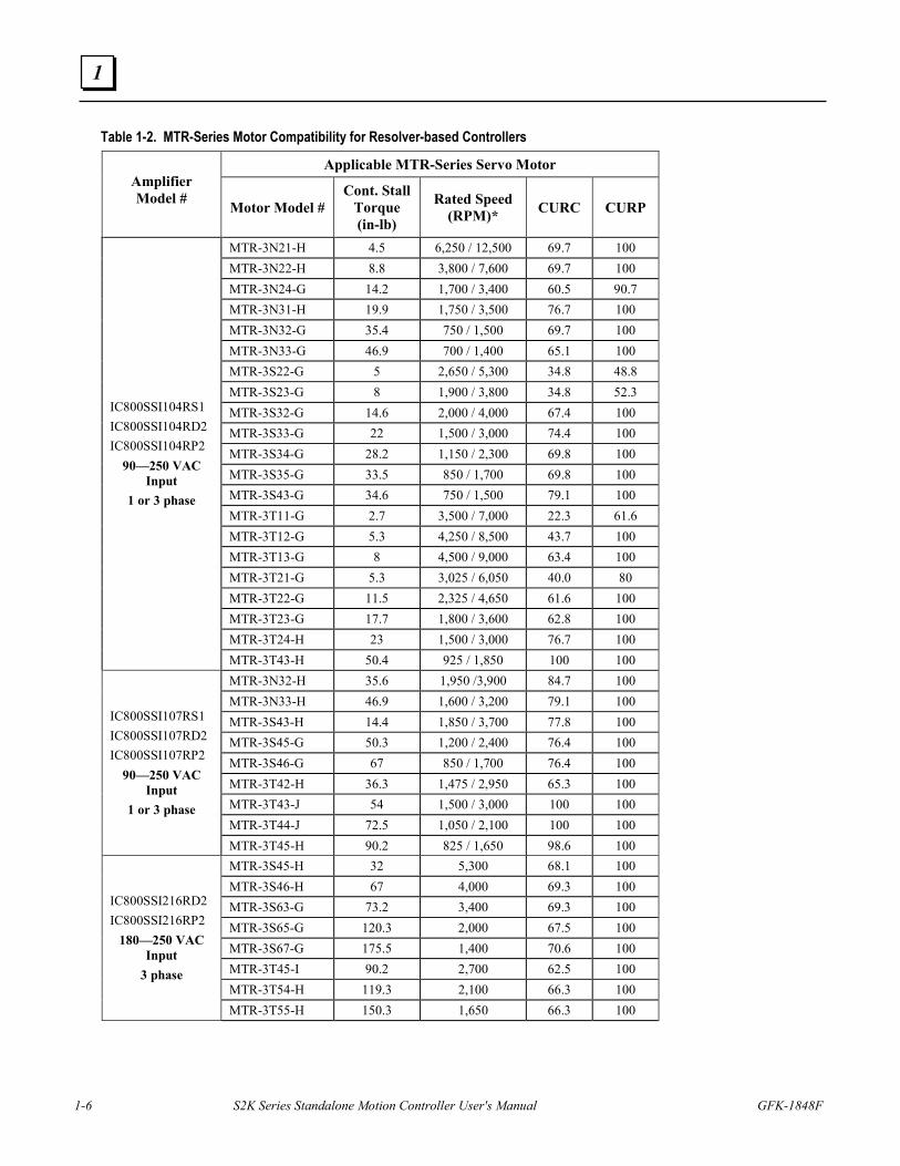
Table 1-2. MTR-Series Motor Compatibility for Resolver-based Controllers
Applicable MTR-Series Servo Motor Amplifier Model # Motor Model #
Cont. Stall Torque (in-lb)
Rated Speed (RPM)* CURC CURP
MTR-3N21-H 4.5 6,250 / 12,500 69.7 100 MTR-3N22-H 8.8 3,800 / 7,600 69.7 100 MTR-3N24-G 14.2 1,700 / 3,400 60.5 90.7 MTR-3N31-H 19.9 1,750 / 3,500 76.7 100 MTR-3N32-G 35.4 750 / 1,500 69.7 100 MTR-3N33-G 46.9 700 / 1,400 65.1 100 MTR-3S22-G 5 2,650 / 5,300 34.8 48.8 MTR-3S23-G 8 1,900 / 3,800 34.8 52.3 MTR-3S32-G 14.6 2,000 / 4,000 67.4 100 MTR-3S33-G 22 1,500 / 3,000 74.4 100 MTR-3S34-G 28.2 1,150 / 2,300 69.8 100 MTR-3S35-G 33.5 850 / 1,700 69.8 100 MTR-3S43-G 34.6 750 / 1,500 79.1 100 MTR-3T11-G 2.7 3,500 / 7,000 22.3 61.6 MTR-3T12-G 5.3 4,250 / 8,500 43.7 100 MTR-3T13-G 8 4,500 / 9,000 63.4 100 MTR-3T21-G 5.3 3,025 / 6,050 40.0 80 MTR-3T22-G 11.5 2,325 / 4,650 61.6 100 MTR-3T23-G 17.7 1,800 / 3,600 62.8 100 MTR-3T24-H 23 1,500 / 3,000 76.7 100
IC800SSI104RS1 IC800SSI104RD2 IC800SSI104RP2
90—250 VAC Input
1 or 3 phase
MTR-3T43-H 50.4 925 / 1,850 100 100 MTR-3N32-H 35.6 1,950 /3,900 84.7 100 MTR-3N33-H 46.9 1,600 / 3,200 79.1 100 MTR-3S43-H 14.4 1,850 / 3,700 77.8 100 MTR-3S45-G 50.3 1,200 / 2,400 76.4 100 MTR-3S46-G 67 850 / 1,700 76.4 100 MTR-3T42-H 36.3 1,475 / 2,950 65.3 100 MTR-3T43-J 54 1,500 / 3,000 100 100 MTR-3T44-J 72.5 1,050 / 2,100 100 100
IC800SSI107RS1 IC800SSI107RD2 IC800SSI107RP2
90—250 VAC Input
1 or 3 phase
MTR-3T45-H 90.2 825 / 1,650 98.6 100 MTR-3S45-H 32 5,300 68.1 100 MTR-3S46-H 67 4,000 69.3 100 MTR-3S63-G 73.2 3,400 69.3 100 MTR-3S65-G 120.3 2,000 67.5 100 MTR-3S67-G 175.5 1,400 70.6 100 MTR-3T45-I 90.2 2,700 62.5 100 MTR-3T54-H 119.3 2,100 66.3 100
IC800SSI216RD2 IC800SSI216RP2
180—250 VAC Input
3 phase
MTR-3T55-H 150.3 1,650 66.3 100
Before Operation
GFK-1848F Chapter 1 Before Operation 1-7
1
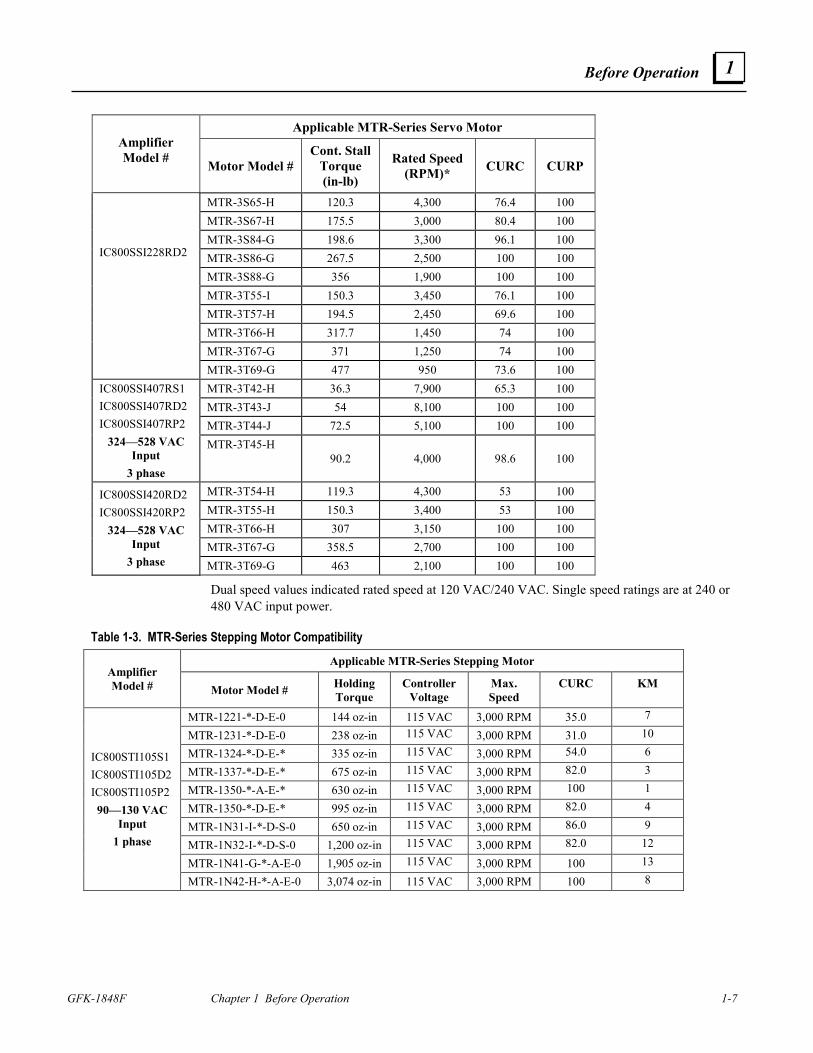
Applicable MTR-Series Servo Motor Amplifier Model # Motor Model #
Cont. Stall Torque (in-lb)
Rated Speed (RPM)* CURC CURP
MTR-3S65-H 120.3 4,300 76.4 100 MTR-3S67-H 175.5 3,000 80.4 100 MTR-3S84-G 198.6 3,300 96.1 100 MTR-3S86-G 267.5 2,500 100 100 MTR-3S88-G 356 1,900 100 100 MTR-3T55-I 150.3 3,450 76.1 100 MTR-3T57-H 194.5 2,450 69.6 100 MTR-3T66-H 317.7 1,450 74 100 MTR-3T67-G 371 1,250 74 100
IC800SSI228RD2
MTR-3T69-G 477 950 73.6 100 MTR-3T42-H 36.3 7,900 65.3 100 MTR-3T43-J 54 8,100 100 100 MTR-3T44-J 72.5 5,100 100 100
IC800SSI407RS1 IC800SSI407RD2 IC800SSI407RP2
324—528 VAC Input
3 phase
MTR-3T45-H 90.2 4,000 98.6 100
MTR-3T54-H 119.3 4,300 53 100 MTR-3T55-H 150.3 3,400 53 100 MTR-3T66-H 307 3,150 100 100 MTR-3T67-G 358.5 2,700 100 100
IC800SSI420RD2 IC800SSI420RP2
324—528 VAC Input
3 phase MTR-3T69-G 463 2,100 100 100
Dual speed values indicated rated speed at 120 VAC/240 VAC. Single speed ratings are at 240 or 480 VAC input power.
Table 1-3. MTR-Series Stepping Motor Compatibility
Applicable MTR-Series Stepping Motor Amplifier Model # Motor Model # Holding
Torque Controller
Voltage Max. Speed
CURC KM
MTR-1221-*-D-E-0 144 oz-in 115 VAC 3,000 RPM 35.0 7
MTR-1231-*-D-E-0 238 oz-in 115 VAC 3,000 RPM 31.0 10
MTR-1324-*-D-E-* 335 oz-in 115 VAC 3,000 RPM 54.0 6
MTR-1337-*-D-E-* 675 oz-in 115 VAC 3,000 RPM 82.0 3
MTR-1350-*-A-E-* 630 oz-in 115 VAC 3,000 RPM 100 1
MTR-1350-*-D-E-* 995 oz-in 115 VAC 3,000 RPM 82.0 4
MTR-1N31-I-*-D-S-0 650 oz-in 115 VAC 3,000 RPM 86.0 9
MTR-1N32-I-*-D-S-0 1,200 oz-in 115 VAC 3,000 RPM 82.0 12
MTR-1N41-G-*-A-E-0 1,905 oz-in 115 VAC 3,000 RPM 100 13
IC800STI105S1 IC800STI105D2 IC800STI105P2 90—130 VAC
Input 1 phase
MTR-1N42-H-*-A-E-0 3,074 oz-in 115 VAC 3,000 RPM 100 8
1-8 S2K Series Standalone Motion Controller User's Manual GFK-1848F
1
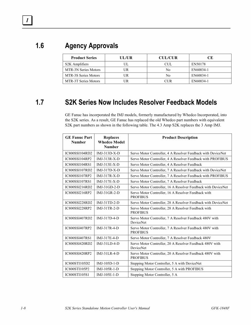
1.6 Agency Approvals Product Series UL/UR CUL/CUR CE
S2K Amplifiers UL CUL EN50178 MTR-3N Series Motors UR No EN60034-1 MTR-3S Series Motors UR No EN60034-1 MTR-3T Series Motors UR CUR EN60034-1
1.7 S2K Series Now Includes Resolver Feedback Models GE Fanuc has incorporated the IMJ models, formerly manufactured by Whedco Incorporated, into the S2K series. As a result, GE Fanuc has replaced the old Whedco part numbers with equivalent S2K part numbers as shown in the following table. The 4.3 Amp S2K replaces the 3 Amp IMJ.
GE Fanuc Part Number
Replaces Whedco Model
Number
Product Description
IC800SSI104RD2 IMJ-313D-X-D Servo Motor Controller, 4 A Resolver Feedback with DeviceNet IC800SSI104RP2 IMJ-313R-X-D Servo Motor Controller, 4 A Resolver Feedback with PROFIBUS IC800SSI104RS1 IMJ-313E-X-D Servo Motor Controller, 4 A Resolver Feedback IC800SSI107RD2 IMJ-317D-X-D Servo Motor Controller, 7 A Resolver Feedback with DeviceNet IC800SSI107RP2 IMJ-317R-X-D Servo Motor Controller, 7 A Resolver Feedback with PROFIBUS IC800SSI107RS1 IMJ-317E-X-D Servo Motor Controller, 7 A Resolver Feedback IC800SSI216RD2 IMJ-31GD-2-D Servo Motor Controller, 16 A Resolver Feedback with DeviceNet IC800SSI216RP2 IMJ-31GR-2-D Servo Motor Controller, 16 A Resolver Feedback with
PROFIBUS IC800SSI228RD2 IMJ-31TD-2-D Servo Motor Controller, 28 A Resolver Feedback with DeviceNet IC800SSI228RP2 IMJ-31TR-2-D Servo Motor Controller, 28 A Resolver Feedback with
PROFIBUS IC800SSI407RD2 IMJ-317D-4-D Servo Motor Controller, 7 A Resolver Feedback 480V with
DeviceNet IC800SSI407RP2 IMJ-317R-4-D Servo Motor Controller, 7 A Resolver Feedback 480V with
PROFIBUS IC800SSI407RS1 IMJ-317E-4-D Servo Motor Controller, 7 A Resolver Feedback 480V IC800SSI420RD2 IMJ-31LD-4-D Servo Motor Controller, 20 A Resolver Feedback 480V with
DeviceNet IC800SSI420RP2 IMJ-31LR-4-D Servo Motor Controller, 20 A Resolver Feedback 480V with
PROFIBUS IC800STI105D2 IMJ-105D-1-D Stepping Motor Controller, 5 A with DeviceNet IC800STI105P2 IMJ-105R-1-D Stepping Motor Controller, 5 A with PROFIBUS IC800STI105S1 IMJ-105E-1-D Stepping Motor Controller, 5 A
GFK-1848F 2-1
Hardware Overview
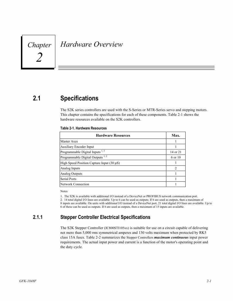
2.1 Specifications The S2K series controllers are used with the S-Series or MTR-Series servo and stepping motors. This chapter contains the specifications for each of these components. Table 2-1 shows the hardware resources available on the S2K controllers.
Table 2-1. Hardware Resources
Hardware Resources Max. Master Axes 1 Auxiliary Encoder Input 1 Programmable Digital Inputs 1, 2 14 or 21 Programmable Digital Outputs 1, 2 6 or 10 High Speed Position Capture Input (30 µS) 1 Analog Inputs 2 Analog Outputs 1 Serial Ports 1 Network Connection 1
Notes 1. The S2K is available with additional I/O instead of a DeviceNet or PROFIBUS network communication port. 2. 14 total digital I/O lines are available. Up to 6 can be used as outputs. If 6 are used as outputs, then a maximum of 8 inputs are available. On units with additional I/O instead of a DeviceNet port, 21 total digital I/O lines are available. Up to 6 of these can be used as outputs. If 6 are used as outputs, then a maximum of 15 inputs are available.
2.1.1 Stepper Controller Electrical Specifications
The S2K Stepper Controller (IC800STI105xx) is suitable for use on a circuit capable of delivering not more than 5,000 rms symmetrical amperes and 130 volts maximum when protected by RK5 class 15A fuses. Table 2-2 summarizes the Stepper Controllers maximum continuous input power requirements. The actual input power and current is a function of the motor's operating point and the duty cycle.
2 Chapter
2-2 S2K Series Standalone Motion Controller User's Manual GFK-1848F
2
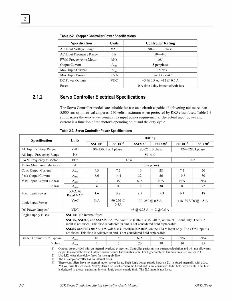
Table 2-2. Stepper Controller Power Specifications
Specification Units Controller Rating AC Input Voltage Range VAC 90—130, 1 phase AC Input Frequency Range Hz 50—440 PWM Frequency to Motor kHz 16.4 Output Current Arms 5 per phase Max. Input Current Arms 10 A rms Max. Input Power KVA 1.3 @ 130 VAC DC Power Outputs VDC +5 @ 0.5 A; +12 @ 0.5 A Fuses 10 A time delay branch circuit fuse
2.1.2 Servo Controller Electrical Specifications
The Servo Controller models are suitable for use on a circuit capable of delivering not more than 5,000 rms symmetrical amperes, 250 volts maximum when protected by RK5 class fuses. Table 2-3 summarizes the maximum continuous input power requirements. The actual input power and current is a function of the motor's operating point and the duty cycle.
Table 2-3. Servo Controller Power Specifications
Rating Specification Units SSI1043 SSI1074 SSI2164 SSI2284 SSI4074 SSI4204
AC Input Voltage Range VAC 90−250, 1 or 3 phase 180−250, 3 phase 324−528, 3 phase AC Input Frequency Range Hz 50−440 PWM Frequency to Motor kHz 16.4 8.2 Motor Minimum Inductance mH 1 (per phase) Cont. Output Current1 Arms 4.3 7.2 16 28 7.2 20 Peak Output Current Arms 8.6 14.4 32 56 10.8 30
Arms 7 15 N/A N/A N/A N/A Max. Input Current 1-phase 3-phase Arms 4 8 18 30 8 22
Max. Input Power KVA @ Rated VAC 1.6 3.8 8.5 14.3 6.4 18
Logic Input Power VAC N/A 90-250 @ 0.5A
90−250 @ 0.5 A +18−30 VDC@ 1.5 A
DC Power Outputs3 VDC +5 @ 0.25 A; +12 @ 0.5 A Logic Supply Fuses SSI104: No internal fuses
SSI107, SSI216, and SSI228: 2A, 250 volt fuse (Littelfuse #224002) on the 2L1 input only. The 2L2 input is not fused. This fuse is soldered in and is not considered field replaceable. SSI407 and SSI420: 5A, 125 volt fuse (Littelfuse #251005) on the +24 V input only. The COM input is not fused. This fuse is soldered in and is not considered field replaceable.
Arms 10 15 N/A N/A N/A N/A Branch Circuit Fuse2 1-phase 3-phase Arms 5 15 20 30 10 25
1) Outputs are provided with an internal overload protection. Controller performs rms current calculation and will not allow rms output to exceed the Cont. Output Current values listed in this table. For higher ambient temperatures, see section 2.3.
2) Use RK5 class time delay fuses for the supply line. 3) The 4.3 amp controller has no internal fuses. 4) These controllers have no internal motor power fuses. Their logic power supply input on 2L1 is fused internally with a 2A,
250 volt fuse (Littelfuse #224002). This fuse is soldered to the board and is not considered to be field-replaceable. This fuse is designed to protect against an internal logic power supply fault. The 2L2 input is not fused.
Hardware Overview
GFK-1848F Chapter 2 Hardware Overview 2-3
2
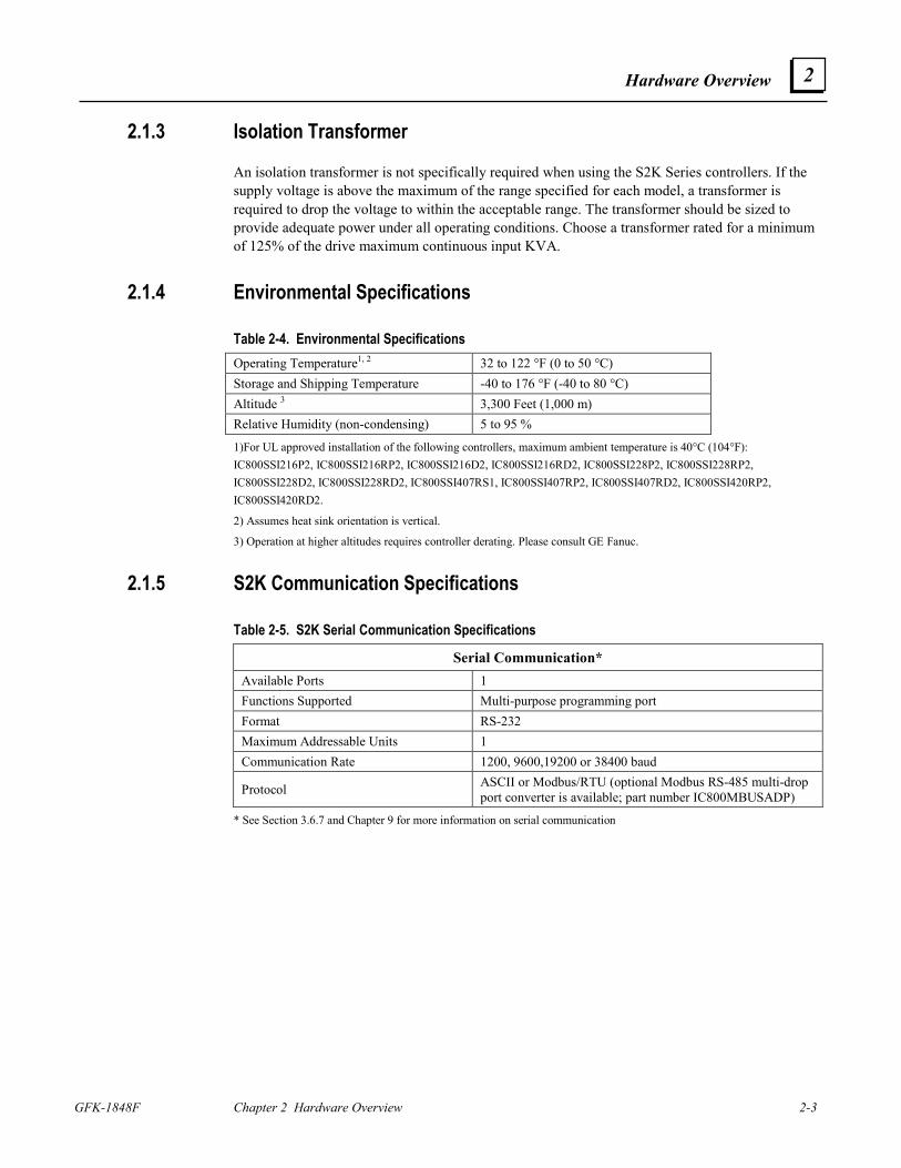
2.1.3 Isolation Transformer
An isolation transformer is not specifically required when using the S2K Series controllers. If the supply voltage is above the maximum of the range specified for each model, a transformer is required to drop the voltage to within the acceptable range. The transformer should be sized to provide adequate power under all operating conditions. Choose a transformer rated for a minimum of 125% of the drive maximum continuous input KVA.
2.1.4 Environmental Specifications
Table 2-4. Environmental Specifications Operating Temperature1, 2 32 to 122 °F (0 to 50 °C) Storage and Shipping Temperature -40 to 176 °F (-40 to 80 °C) Altitude 3 3,300 Feet (1,000 m) Relative Humidity (non-condensing) 5 to 95 %
1)For UL approved installation of the following controllers, maximum ambient temperature is 40°C (104°F): IC800SSI216P2, IC800SSI216RP2, IC800SSI216D2, IC800SSI216RD2, IC800SSI228P2, IC800SSI228RP2, IC800SSI228D2, IC800SSI228RD2, IC800SSI407RS1, IC800SSI407RP2, IC800SSI407RD2, IC800SSI420RP2, IC800SSI420RD2.
2) Assumes heat sink orientation is vertical.
3) Operation at higher altitudes requires controller derating. Please consult GE Fanuc.
2.1.5 S2K Communication Specifications
Table 2-5. S2K Serial Communication Specifications
Serial Communication* Available Ports 1 Functions Supported Multi-purpose programming port Format RS-232 Maximum Addressable Units 1 Communication Rate 1200, 9600,19200 or 38400 baud
Protocol ASCII or Modbus/RTU (optional Modbus RS-485 multi-drop port converter is available; part number IC800MBUSADP)
* See Section 3.6.7 and Chapter 9 for more information on serial communication
2-4 S2K Series Standalone Motion Controller User's Manual GFK-1848F
2
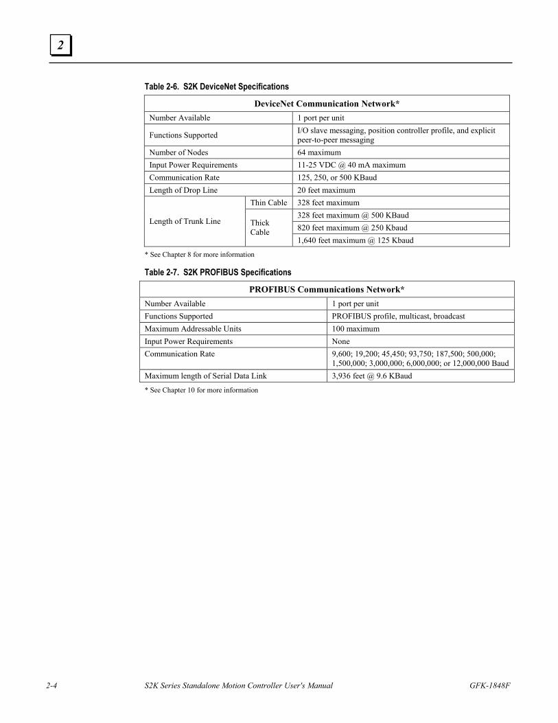
Table 2-6. S2K DeviceNet Specifications
DeviceNet Communication Network* Number Available 1 port per unit
Functions Supported I/O slave messaging, position controller profile, and explicit peer-to-peer messaging
Number of Nodes 64 maximum Input Power Requirements 11-25 VDC @ 40 mA maximum Communication Rate 125, 250, or 500 KBaud Length of Drop Line 20 feet maximum
Thin Cable 328 feet maximum 328 feet maximum @ 500 KBaud 820 feet maximum @ 250 Kbaud
Length of Trunk Line Thick Cable
1,640 feet maximum @ 125 Kbaud
* See Chapter 8 for more information
Table 2-7. S2K PROFIBUS Specifications
PROFIBUS Communications Network* Number Available 1 port per unit Functions Supported PROFIBUS profile, multicast, broadcast Maximum Addressable Units 100 maximum Input Power Requirements None Communication Rate 9,600; 19,200; 45,450; 93,750; 187,500; 500,000;
1,500,000; 3,000,000; 6,000,000; or 12,000,000 Baud Maximum length of Serial Data Link 3,936 feet @ 9.6 KBaud
* See Chapter 10 for more information
Hardware Overview
GFK-1848F Chapter 2 Hardware Overview 2-5
2
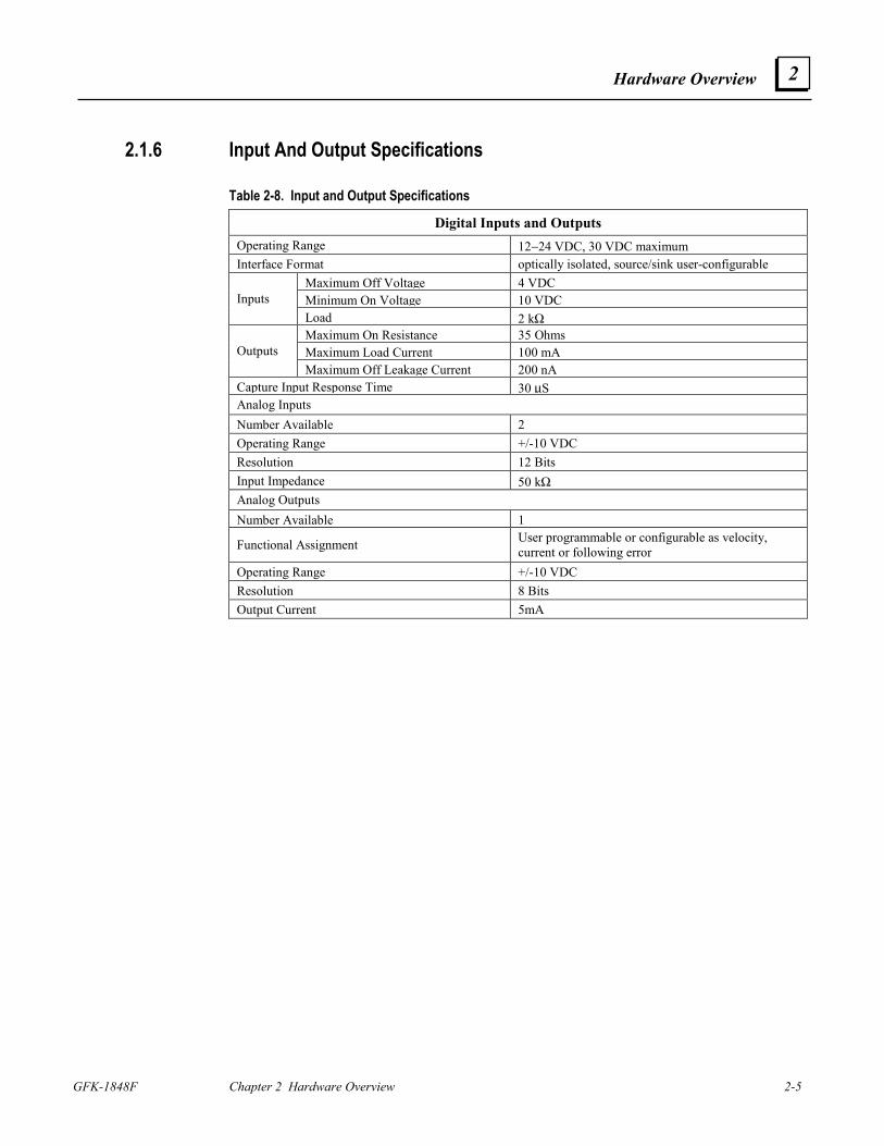
2.1.6 Input And Output Specifications
Table 2-8. Input and Output Specifications
Digital Inputs and Outputs Operating Range 12−24 VDC, 30 VDC maximum Interface Format optically isolated, source/sink user-configurable
Maximum Off Voltage 4 VDCMinimum On Voltage 10 VDCInputs Load 2 kΩMaximum On Resistance 35 OhmsMaximum Load Current 100 mAOutputs Maximum Off Leakage Current 200 nA
Capture Input Response Time 30 µSAnalog Inputs Number Available 2 Operating Range +/-10 VDC Resolution 12 Bits Input Impedance 50 kΩAnalog Outputs Number Available 1
Functional Assignment User programmable or configurable as velocity, current or following error
Operating Range +/-10 VDC Resolution 8 Bits Output Current 5mA
2-6 S2K Series Standalone Motion Controller User's Manual GFK-1848F
2
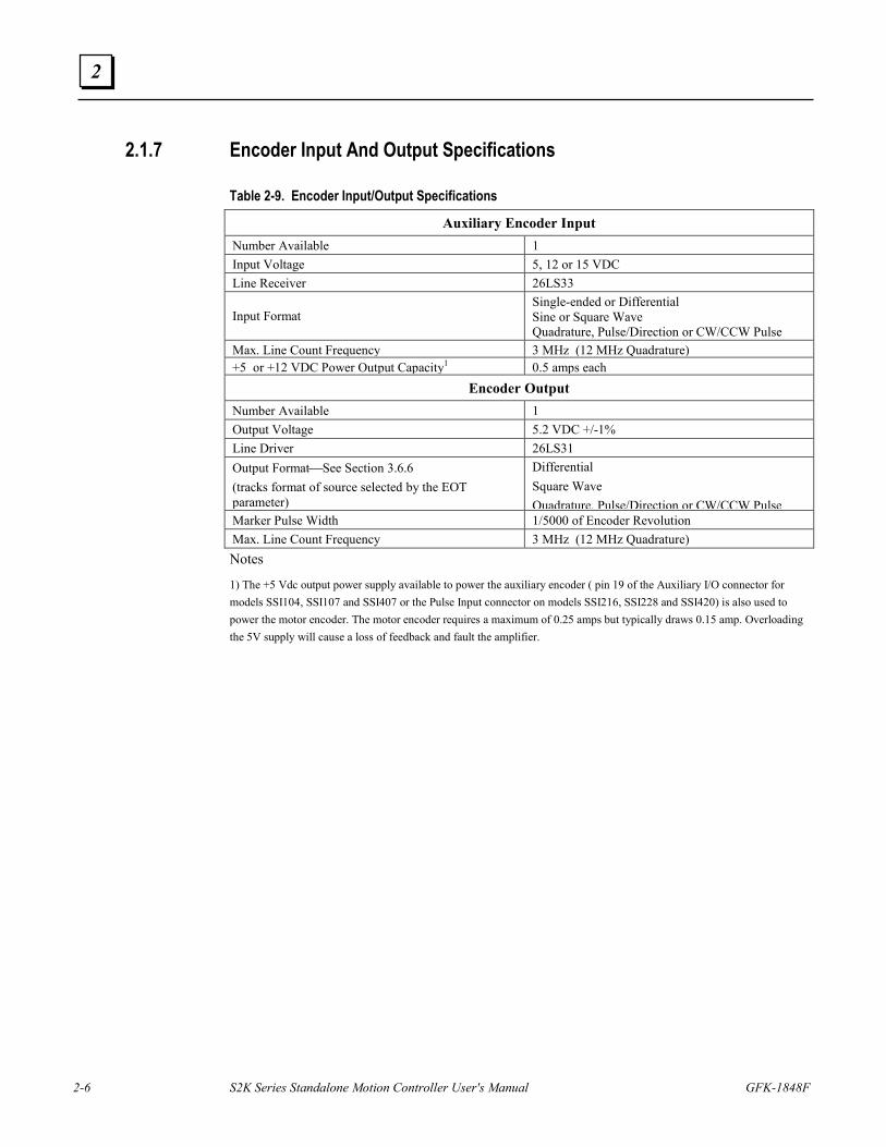
2.1.7 Encoder Input And Output Specifications
Table 2-9. Encoder Input/Output Specifications
Auxiliary Encoder Input Number Available 1 Input Voltage 5, 12 or 15 VDC Line Receiver 26LS33
Input Format Single-ended or Differential Sine or Square Wave Quadrature, Pulse/Direction or CW/CCW Pulse
Max. Line Count Frequency 3 MHz (12 MHz Quadrature) +5 or +12 VDC Power Output Capacity1 0.5 amps each
Encoder Output Number Available 1 Output Voltage 5.2 VDC +/-1% Line Driver 26LS31 Output FormatSee Section 3.6.6 (tracks format of source selected by the EOT parameter)
Differential Square Wave Quadrature, Pulse/Direction or CW/CCW Pulse
Marker Pulse Width 1/5000 of Encoder Revolution Max. Line Count Frequency 3 MHz (12 MHz Quadrature) Notes
1) The +5 Vdc output power supply available to power the auxiliary encoder ( pin 19 of the Auxiliary I/O connector for models SSI104, SSI107 and SSI407 or the Pulse Input connector on models SSI216, SSI228 and SSI420) is also used to power the motor encoder. The motor encoder requires a maximum of 0.25 amps but typically draws 0.15 amp. Overloading the 5V supply will cause a loss of feedback and fault the amplifier.
Hardware Overview
GFK-1848F Chapter 2 Hardware Overview 2-7
2
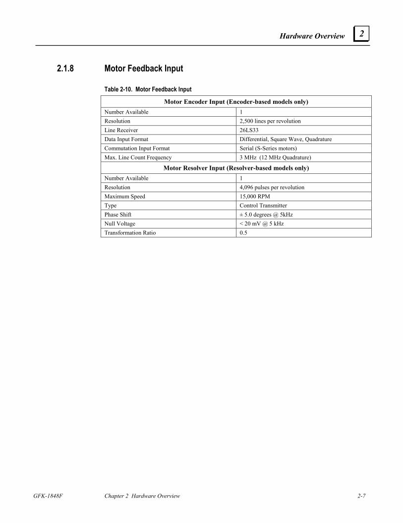
2.1.8 Motor Feedback Input
Table 2-10. Motor Feedback Input
Motor Encoder Input (Encoder-based models only) Number Available 1 Resolution 2,500 lines per revolution Line Receiver 26LS33 Data Input Format Differential, Square Wave, Quadrature Commutation Input Format Serial (S-Series motors) Max. Line Count Frequency 3 MHz (12 MHz Quadrature)
Motor Resolver Input (Resolver-based models only) Number Available 1 Resolution 4,096 pulses per revolution Maximum Speed 15,000 RPM Type Control Transmitter Phase Shift ± 5.0 degrees @ 5kHz Null Voltage < 20 mV @ 5 kHz Transformation Ratio 0.5
2-8 S2K Series Standalone Motion Controller User's Manual GFK-1848F
2
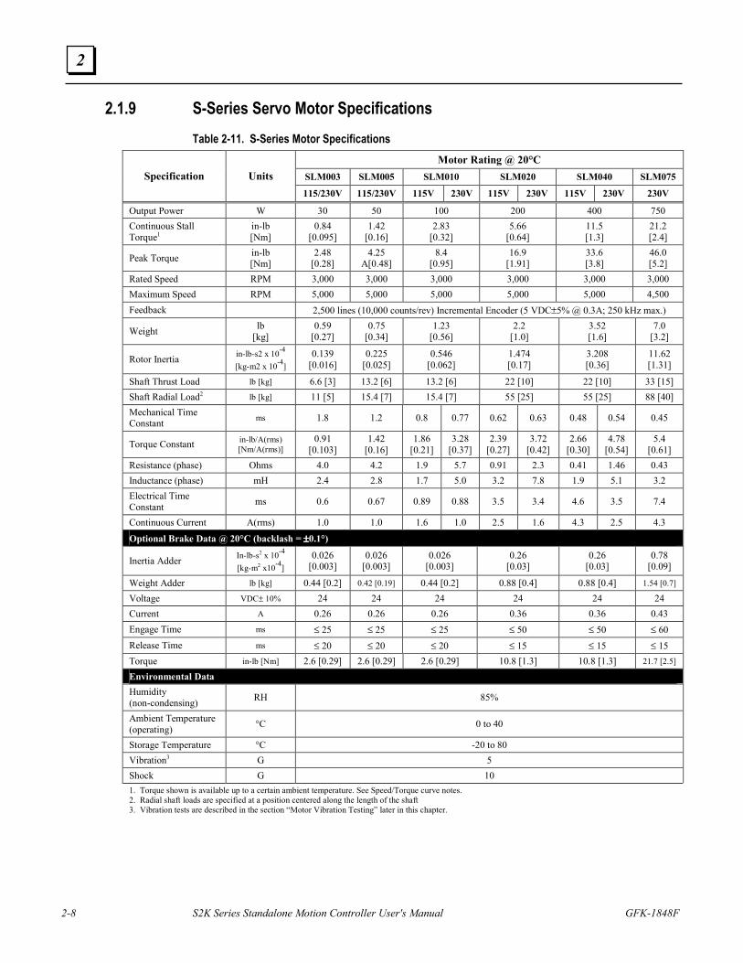
2.1.9 S-Series Servo Motor Specifications Table 2-11. S-Series Motor Specifications
Motor Rating @ 20°C SLM003 SLM005 SLM010 SLM020 SLM040 SLM075 Specification Units 115/230V 115/230V 115V 230V 115V 230V 115V 230V 230V
Output Power W 30 50 100 200 400 750 Continuous Stall Torque1
in-lb [Nm]
0.84 [0.095]
1.42 [0.16]
2.83 [0.32]
5.66 [0.64]
11.5 [1.3]
21.2 [2.4]
Peak Torque in-lb [Nm]
2.48 [0.28]
4.25 A[0.48]
8.4 [0.95]
16.9 [1.91]
33.6 [3.8]
46.0 [5.2]
Rated Speed RPM 3,000 3,000 3,000 3,000 3,000 3,000 Maximum Speed RPM 5,000 5,000 5,000 5,000 5,000 4,500 Feedback 2,500 lines (10,000 counts/rev) Incremental Encoder (5 VDC±5% @ 0.3A; 250 kHz max.)
Weight lb [kg]
0.59 [0.27]
0.75 [0.34]
1.23 [0.56]
2.2 [1.0]
3.52 [1.6]
7.0 [3.2]
Rotor Inertia in-lb-s2 x 10-4 [kg-m2 x 10-4]
0.139 [0.016]
0.225 [0.025]
0.546 [0.062]
1.474 [0.17]
3.208 [0.36]
11.62 [1.31]
Shaft Thrust Load lb [kg] 6.6 [3] 13.2 [6] 13.2 [6] 22 [10] 22 [10] 33 [15] Shaft Radial Load2 lb [kg] 11 [5] 15.4 [7] 15.4 [7] 55 [25] 55 [25] 88 [40] Mechanical Time Constant ms 1.8 1.2 0.8 0.77 0.62 0.63 0.48 0.54 0.45
Torque Constant in-lb/A(rms) [Nm/A(rms)]
0.91 [0.103]
1.42 [0.16]
1.86 [0.21]
3.28 [0.37]
2.39 [0.27]
3.72 [0.42]
2.66 [0.30]
4.78 [0.54]
5.4 [0.61]
Resistance (phase) Ohms 4.0 4.2 1.9 5.7 0.91 2.3 0.41 1.46 0.43 Inductance (phase) mH 2.4 2.8 1.7 5.0 3.2 7.8 1.9 5.1 3.2 Electrical Time Constant ms 0.6 0.67 0.89 0.88 3.5 3.4 4.6 3.5 7.4
Continuous Current A(rms) 1.0 1.0 1.6 1.0 2.5 1.6 4.3 2.5 4.3
Optional Brake Data @ 20°C (backlash = ±±±±0.1°)
Inertia Adder In-lb-s2 x 10-4 [kg-m2 x10-4]
0.026 [0.003]
0.026 [0.003]
0.026 [0.003]
0.26 [0.03]
0.26 [0.03]
0.78 [0.09]
Weight Adder lb [kg] 0.44 [0.2] 0.42 [0.19] 0.44 [0.2] 0.88 [0.4] 0.88 [0.4] 1.54 [0.7]
Voltage VDC± 10% 24 24 24 24 24 24 Current A 0.26 0.26 0.26 0.36 0.36 0.43 Engage Time ms ≤ 25 ≤ 25 ≤ 25 ≤ 50 ≤ 50 ≤ 60 Release Time ms ≤ 20 ≤ 20 ≤ 20 ≤ 15 ≤ 15 ≤ 15 Torque in-lb [Nm] 2.6 [0.29] 2.6 [0.29] 2.6 [0.29] 10.8 [1.3] 10.8 [1.3] 21.7 [2.5]
Environmental Data Humidity (non-condensing) RH 85%
Ambient Temperature (operating) °C 0 to 40
Storage Temperature °C -20 to 80 Vibration3 G 5 Shock G 10 1. Torque shown is available up to a certain ambient temperature. See Speed/Torque curve notes. 2. Radial shaft loads are specified at a position centered along the length of the shaft 3. Vibration tests are described in the section “Motor Vibration Testing” later in this chapter.
Hardware Overview
GFK-1848F Chapter 2 Hardware Overview 2-9
2
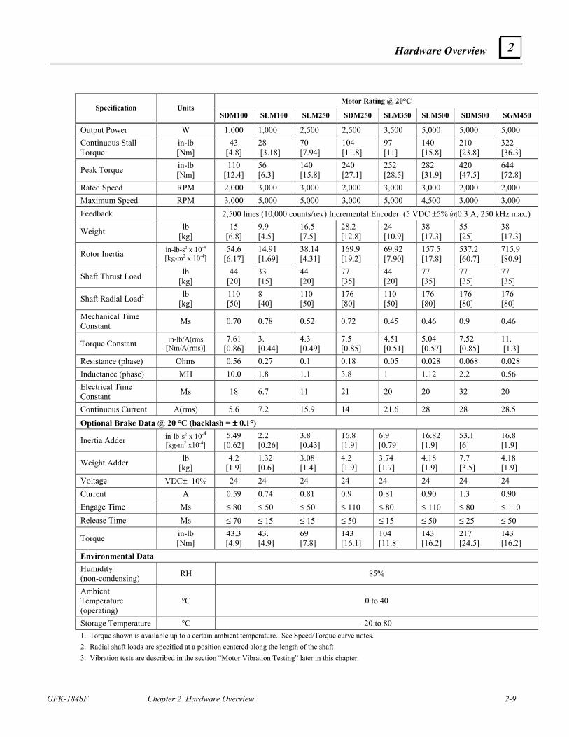
Motor Rating @ 20°C Specification Units
SDM100 SLM100 SLM250 SDM250 SLM350 SLM500 SDM500 SGM450
Output Power W 1,000 1,000 2,500 2,500 3,500 5,000 5,000 5,000 Continuous Stall Torque1
in-lb [Nm]
43 [4.8]
28 [3.18]
70 [7.94]
104 [11.8]
97 [11]
140 [15.8]
210 [23.8]
322 [36.3]
Peak Torque in-lb [Nm]
110 [12.4]
56 [6.3]
140 [15.8]
240 [27.1]
252 [28.5]
282 [31.9]
420 [47.5]
644 [72.8]
Rated Speed RPM 2,000 3,000 3,000 2,000 3,000 3,000 2,000 2,000 Maximum Speed RPM 3,000 5,000 5,000 3,000 5,000 4,500 3,000 3,000 Feedback 2,500 lines (10,000 counts/rev) Incremental Encoder (5 VDC ±5% @0.3 A; 250 kHz max.)
Weight lb [kg]
15 [6.8]
9.9 [4.5]
16.5 [7.5]
28.2 [12.8]
24 [10.9]
38 [17.3]
55 [25]
38 [17.3]
Rotor Inertia in-lb-s2 x 10-4 [kg-m2 x 10-4]
54.6 [6.17]
14.91 [1.69]
38.14 [4.31]
169.9 [19.2]
69.92 [7.90]
157.5 [17.8]
537.2 [60.7]
715.9 [80.9]
Shaft Thrust Load lb [kg]
44 [20]
33 [15]
44 [20]
77 [35]
44 [20]
77 [35]
77 [35]
77 [35]
Shaft Radial Load2 lb [kg]
110 [50]
8 [40]
110 [50]
176 [80]
110 [50]
176 [80]
176 [80]
176 [80]
Mechanical Time Constant Ms 0.70 0.78 0.52 0.72 0.45 0.46 0.9 0.46
Torque Constant in-lb/A(rms [Nm/A(rms)]
7.61 [0.86]
3. [0.44]
4.3 [0.49]
7.5 [0.85]
4.51 [0.51]
5.04 [0.57]
7.52 [0.85]
11. [1.3]
Resistance (phase) Ohms 0.56 0.27 0.1 0.18 0.05 0.028 0.068 0.028 Inductance (phase) MH 10.0 1.8 1.1 3.8 1 1.12 2.2 0.56 Electrical Time Constant Ms 18 6.7 11 21 20 20 32 20
Continuous Current A(rms) 5.6 7.2 15.9 14 21.6 28 28 28.5 Optional Brake Data @ 20 °C (backlash = ±±±± 0.1°)
Inertia Adder in-lb-s2 x 10-4 [kg-m2 x10-4]
5.49 [0.62]
2.2 [0.26]
3.8 [0.43]
16.8 [1.9]
6.9 [0.79]
16.82 [1.9]
53.1 [6]
16.8 [1.9]
Weight Adder lb [kg]
4.2 [1.9]
1.32 [0.6]
3.08 [1.4]
4.2 [1.9]
3.74 [1.7]
4.18 [1.9]
7.7 [3.5]
4.18 [1.9]
Voltage VDC± 10% 24 24 24 24 24 24 24 24 Current A 0.59 0.74 0.81 0.9 0.81 0.90 1.3 0.90 Engage Time Ms ≤ 80 ≤ 50 ≤ 50 ≤ 110 ≤ 80 ≤ 110 ≤ 80 ≤ 110 Release Time Ms ≤ 70 ≤ 15 ≤ 15 ≤ 50 ≤ 15 ≤ 50 ≤ 25 ≤ 50
Torque in-lb [Nm]
43.3 [4.9]
43. [4.9]
69 [7.8]
143 [16.1]
104 [11.8]
143 [16.2]
217 [24.5]
143 [16.2]
Environmental Data Humidity (non-condensing) RH 85%
Ambient Temperature (operating)
°C 0 to 40
Storage Temperature °C -20 to 80 1. Torque shown is available up to a certain ambient temperature. See Speed/Torque curve notes. 2. Radial shaft loads are specified at a position centered along the length of the shaft 3. Vibration tests are described in the section “Motor Vibration Testing” later in this chapter.
2-10 S2K Series Standalone Motion Controller User's Manual GFK-1848F
2
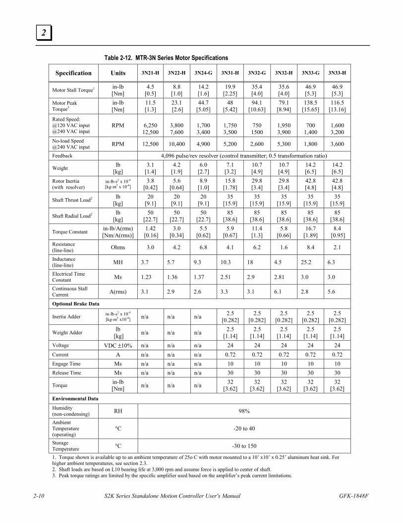
Table 2-12. MTR-3N Series Motor Specifications
Specification Units 3N21-H 3N22-H 3N24-G 3N31-H 3N32-G 3N32-H 3N33-G 3N33-H
Motor Stall Torque1 in-lb [Nm]
4.5 [0.5]
8.8 [1.0]
14.2 [1.6]
19.9 [2.25]
35.4 [4.0]
35.6 [4.0]
46.9 [5.3]
46.9 [5.3]
Motor Peak Torque3
in-lb [Nm]
11.5 [1.3]
23.1 [2.6]
44.7 [5.05]
48 [5.42]
94.1 [10.63]
79.1 [8.94]
138.5 [15.65]
116.5 [13.16]
Rated Speed: @120 VAC input @240 VAC input
RPM
6,250 12,500
3,800 7,600
1,700 3,400
1,750 3,500
750 1500
1,950 3,900
700
1,400
1,600 3,200
No-load Speed @240 VAC input RPM 12,500 10,400 4,900 5,200 2,600 5,300 1,800 3,600
Feedback 4,096 pulse/rev resolver (control transmitter; 0.5 transformation ratio)
Weight lb [kg]
3.1 [1.4]
4.2 [1.9]
6.0 [2.7]
7.1 [3.2]
10.7 [4.9]
10.7 [4.9]
14.2 [6.5]
14.2 [6.5]
Rotor Inertia (with resolver)
in-lb-s2 x 10-4 [kg-m2 x 10-4]
3.8 [0.42]
5.6 [0.64]
8.9 [1.0]
15.8 [1.78]
29.8 [3.4]
29.8 [3.4]
42.8 [4.8]
42.8 [4.8]
Shaft Thrust Load2 lb [kg]
20 [9.1]
20 [9.1]
20 [9.1]
35 [15.9]
35 [15.9]
35 [15.9]
35 [15.9]
35 [15.9]
Shaft Radial Load2 lb [kg]
50 [22.7]
50 [22.7]
50 [22.7]
85 [38.6]
85 [38.6]
85 [38.6]
85 [38.6]
85 [38.6]
Torque Constant in-lb/A(rms) [Nm/A(rms)]
1.42 [0.16]
3.0 [0.34]
5.5 [0.62]
5.9 [0.67]
11.4 [1.3]
5.8 [0.66]
16.7 [1.89]
8.4 [0.95]
Resistance (line-line) Ohms 3.0 4.2 6.8 4.1 6.2 1.6 8.4 2.1
Inductance (line-line) MH 3.7 5.7 9.3 10.3 18 4.5 25.2 6.3
Electrical Time Constant Ms 1.23 1.36 1.37 2.51 2.9 2.81 3.0 3.0
Continuous Stall Current A(rms) 3.1 2.9 2.6 3.3 3.1 6.1 2.8 5.6
Optional Brake Data
Inertia Adder in-lb-s2 x 10-4 [kg-m2 x10-4] n/a n/a n/a 2.5
[0.282] 2.5
[0.282] 2.5
[0.282] 2.5
[0.282] 2.5
[0.282]
Weight Adder lb [kg] n/a n/a n/a 2.5
[1.14] 2.5
[1.14] 2.5
[1.14] 2.5
[1.14] 2.5
[1.14] Voltage VDC ±10% n/a n/a n/a 24 24 24 24 24 Current A n/a n/a n/a 0.72 0.72 0.72 0.72 0.72 Engage Time Ms n/a n/a n/a 10 10 10 10 10 Release Time Ms n/a n/a n/a 30 30 30 30 30
Torque in-lb [Nm] n/a n/a n/a 32
[3.62] 32
[3.62] 32
[3.62] 32
[3.62] 32
[3.62] Environmental Data
Humidity (non-condensing) RH 98%
Ambient Temperature (operating)
°C -20 to 40
Storage Temperature °C -30 to 150
1. Torque shown is available up to an ambient temperature of 25o C with motor mounted to a 10’ x10’ x 0.25’ aluminum heat sink. For higher ambient temperatures, see section 2.3. 2. Shaft loads are based on L10 bearing life at 3,000 rpm and assume force is applied to center of shaft. 3. Peak torque ratings are limited by the specific amplifier used based on the amplifier’s peak current limitations.
Hardware Overview
GFK-1848F Chapter 2 Hardware Overview 2-11
2
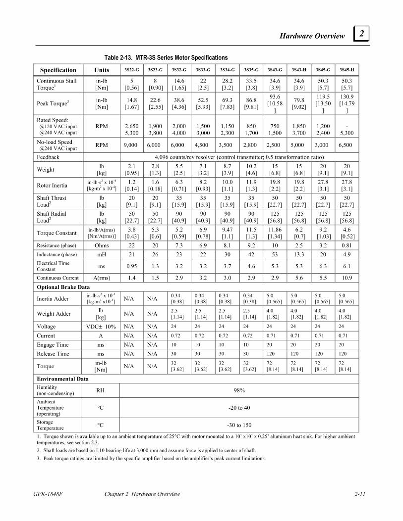
Table 2-13. MTR-3S Series Motor Specifications
Specification Units 3S22-G 3S23-G 3S32-G 3S33-G 3S34-G 3S35-G 3S43-G 3S43-H 3S45-G 3S45-H
Continuous Stall Torque1
in-lb [Nm]
5 [0.56]
8 [0.90]
14.6 [1.65]
22 [2.5]
28.2 [3.2]
33.5 [3.8]
34.6 [3.9]
34.6 [3.9]
50.3 [5.7]
50.3 [5.7]
Peak Torque3 in-lb [Nm]
14.8 [1.67]
22.6 [2.55]
38.6 [4.36]
52.5 [5.93]
69.3 [7.83]
86.8 [9.81]
93.6 [10.58
]
79.8 [9.02]
119.5[13.50
]
130.9[14.79
]
Rated Speed: @120 VAC input @240 VAC input
RPM
2,650 5,300
1,900 3,800
2,0004,000
1,5003,000
1,1502,300
850
1,700
750
1,500
1,850 3,700
1,2002,400
-
5,300 No-load Speed @240 VAC input RPM 9,000 6,000 6,000 4,500 3,500 2,800 2,500 5,000 3,000 6,500
Feedback 4,096 counts/rev resolver (control transmitter; 0.5 transformation ratio)
Weight lb [kg]
2.1 [0.95]
2.8 [1.3]
5.5 [2.5]
7.1 [3.2]
8.7 [3.9]
10.2 [4.6]
15 [6.8]
15 [6.8]
20 [9.1]
20 [9.1]
Rotor Inertia in-lb-s2 x 10-4 [kg-m2 x 10-4]
1.2 [0.14]
1.6 [0.18]
6.3 [0.71]
8.2 [0.93]
10.0 [1.1]
11.9 [1.3]
19.8 [2.2]
19.8 [2.2]
27.8 [3.1]
27.8 [3.1]
Shaft Thrust Load2
lb [kg]
20 [9.1]
20 [9.1]
35 [15.9]
35 [15.9]
35 [15.9]
35 [15.9]
50 [22.7]
50 [22.7]
50 [22.7]
50 [22.7]
Shaft Radial Load2
lb [kg]
50 [22.7]
50 [22.7]
90 [40.9]
90 [40.9]
90 [40.9]
90 [40.9]
125 [56.8]
125 [56.8]
125 [56.8]
125 [56.8]
Torque Constant in-lb/A(rms) [Nm/A(rms)]
3.8 [0.43]
5.3 [0.6]
5.2 [0.59]
6.9 [0.78]
9.47 [1.1]
11.5 [1.3]
11.86 [1.34]
6.2 [0.7]
9.2 [1.03]
4.6 [0.52]
Resistance (phase) Ohms 22 20 7.3 6.9 8.1 9.2 10 2.5 3.2 0.81 Inductance (phase) mH 21 26 23 22 30 42 53 13.3 20 4.9 Electrical Time Constant ms 0.95 1.3 3.2 3.2 3.7 4.6 5.3 5.3 6.3 6.1
Continuous Current A(rms) 1.4 1.5 2.9 3.2 3.0 2.9 2.9 5.6 5.5 10.9 Optional Brake Data
Inertia Adder in-lb-s2 x 10-4 [kg-m2 x10-4] N/A N/A 0.34
[0.38] 0.34 [0.38]
0.34 [0.38]
0.34 [0.38]
5.0 [0.565]
5.0 [0.565]
5.0 [0.565]
5.0 [0.565]
Weight Adder lb [kg] N/A N/A 2.5
[1.14] 2.5 [1.14]
2.5 [1.14]
2.5 [1.14]
4.0 [1.82]
4.0 [1.82]
4.0 [1.82]
4.0 [1.82]
Voltage VDC± 10% N/A N/A 24 24 24 24 24 24 24 24
Current A N/A N/A 0.72 0.72 0.72 0.72 0.71 0.71 0.71 0.71
Engage Time ms N/A N/A 10 10 10 10 20 20 20 20
Release Time ms N/A N/A 30 30 30 30 120 120 120 120
Torque in-lb [Nm] N/A N/A 32
[3.62] 32 [3.62]
32 [3.62]
32 [3.62]
72 [8.14]
72 [8.14]
72 [8.14]
72 [8.14]
Environmental Data Humidity (non-condensing) RH 98%
Ambient Temperature (operating)
°C -20 to 40
Storage Temperature °C -30 to 150
1. Torque shown is available up to an ambient temperature of 25°C with motor mounted to a 10’ x10’ x 0.25’ aluminum heat sink. For higher ambient temperatures, see section 2.3. 2. Shaft loads are based on L10 bearing life at 3,000 rpm and assume force is applied to center of shaft. 3. Peak torque ratings are limited by the specific amplifier based on the amplifier’s peak current limitations.
2-12 S2K Series Standalone Motion Controller User's Manual GFK-1848F
2
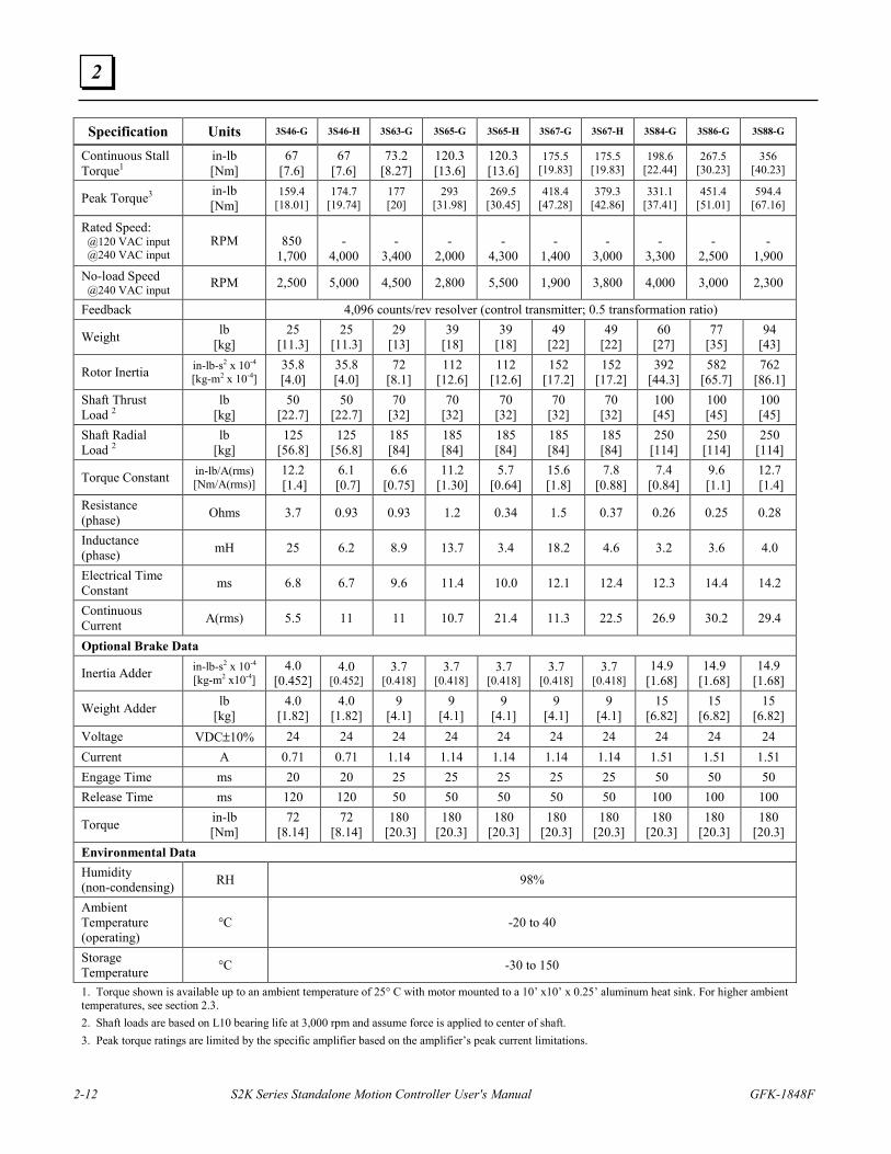
Specification Units 3S46-G 3S46-H 3S63-G 3S65-G 3S65-H 3S67-G 3S67-H 3S84-G 3S86-G 3S88-G
Continuous Stall Torque1
in-lb [Nm]
67 [7.6]
67 [7.6]
73.2 [8.27]
120.3[13.6]
120.3[13.6]
175.5 [19.83]
175.5 [19.83]
198.6 [22.44]
267.5 [30.23]
356 [40.23]
Peak Torque3 in-lb [Nm]
159.4 [18.01]
174.7 [19.74]
177 [20]
293 [31.98]
269.5 [30.45]
418.4[47.28]
379.3[42.86]
331.1 [37.41]
451.4 [51.01]
594.4 [67.16]
Rated Speed: @120 VAC input @240 VAC input
RPM
850 1,700
-
4,000
-
3,400
-
2,000
-
4,300
-
1,400
-
3,000
-
3,300
-
2,500
-
1,900 No-load Speed @240 VAC input RPM 2,500 5,000 4,500 2,800 5,500 1,900 3,800 4,000 3,000 2,300
Feedback 4,096 counts/rev resolver (control transmitter; 0.5 transformation ratio)
Weight lb [kg]
25 [11.3]
25 [11.3]
29 [13]
39 [18]
39 [18]
49 [22]
49 [22]
60 [27]
77 [35]
94 [43]
Rotor Inertia in-lb-s2 x 10-4 [kg-m2 x 10-4]
35.8 [4.0]
35.8 [4.0]
72 [8.1]
112 [12.6]
112 [12.6]
152 [17.2]
152 [17.2]
392 [44.3]
582 [65.7]
762 [86.1]
Shaft Thrust Load 2
lb [kg]
50 [22.7]
50 [22.7]
70 [32]
70 [32]
70 [32]
70 [32]
70 [32]
100 [45]
100 [45]
100 [45]
Shaft Radial Load 2
lb [kg]
125 [56.8]
125 [56.8]
185 [84]
185 [84]
185 [84]
185 [84]
185 [84]
250 [114]
250 [114]
250 [114]
Torque Constant in-lb/A(rms) [Nm/A(rms)]
12.2 [1.4]
6.1 [0.7]
6.6 [0.75]
11.2 [1.30]
5.7 [0.64]
15.6 [1.8]
7.8 [0.88]
7.4 [0.84]
9.6 [1.1]
12.7 [1.4]
Resistance (phase) Ohms 3.7 0.93 0.93 1.2 0.34 1.5 0.37 0.26 0.25 0.28
Inductance (phase) mH 25 6.2 8.9 13.7 3.4 18.2 4.6 3.2 3.6 4.0
Electrical Time Constant ms 6.8 6.7 9.6 11.4 10.0 12.1 12.4 12.3 14.4 14.2
Continuous Current A(rms) 5.5 11 11 10.7 21.4 11.3 22.5 26.9 30.2 29.4
Optional Brake Data
Inertia Adder in-lb-s2 x 10-4 [kg-m2 x10-4]
4.0 [0.452]
4.0 [0.452]
3.7 [0.418]
3.7 [0.418]
3.7 [0.418]
3.7 [0.418]
3.7 [0.418]
14.9 [1.68]
14.9 [1.68]
14.9 [1.68]
Weight Adder lb [kg]
4.0 [1.82]
4.0 [1.82]
9 [4.1]
9 [4.1]
9 [4.1]
9 [4.1]
9 [4.1]
15 [6.82]
15 [6.82]
15 [6.82]
Voltage VDC±10% 24 24 24 24 24 24 24 24 24 24 Current A 0.71 0.71 1.14 1.14 1.14 1.14 1.14 1.51 1.51 1.51 Engage Time ms 20 20 25 25 25 25 25 50 50 50 Release Time ms 120 120 50 50 50 50 50 100 100 100
Torque in-lb [Nm]
72 [8.14]
72 [8.14]
180 [20.3]
180 [20.3]
180 [20.3]
180 [20.3]
180 [20.3]
180 [20.3]
180 [20.3]
180 [20.3]
Environmental Data Humidity (non-condensing) RH 98%
Ambient Temperature (operating)
°C -20 to 40
Storage Temperature °C -30 to 150
1. Torque shown is available up to an ambient temperature of 25° C with motor mounted to a 10’ x10’ x 0.25’ aluminum heat sink. For higher ambient temperatures, see section 2.3. 2. Shaft loads are based on L10 bearing life at 3,000 rpm and assume force is applied to center of shaft. 3. Peak torque ratings are limited by the specific amplifier based on the amplifier’s peak current limitations.
Hardware Overview
GFK-1848F Chapter 2 Hardware Overview 2-13
2
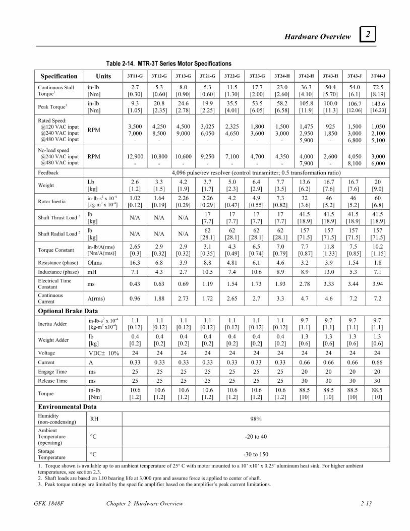
Table 2-14. MTR-3T Series Motor Specifications
Specification Units 3T11-G 3T12-G 3T13-G 3T21-G 3T22-G 3T23-G 3T24-H 3T42-H 3T43-H 3T43-J 3T44-J
Continuous Stall Torque1
in-lb [Nm]
2.7 [0.30]
5.3 [0.60]
8.0 [0.90]
5.3 [0.60]
11.5 [1.30]
17.7 [2.00]
23.0 [2.60]
36.3 [4.10]
50.4 [5.70]
54.0 [6.1]
72.5 [8.19]
Peak Torque3 in-lb [Nm]
9.3 [1.05]
20.8 [2.35]
24.6 [2.78]
19.9 [2.25]
35.5 [4.01]
53.5 [6.05]
58.2 [6.58]
105.8 [11.9]
100.0[11.3]
106.7[12.06]
143.6[16.23]
Rated Speed: @120 VAC input @240 VAC input @480 VAC input
RPM
3,500 7,000
-
4,2508,500
-
4,5009,000
-
3,0256,050
-
2,3254,650
-
1,8003,600
-
1,500 3,000
-
1,475 2,950 5,900
925
1,850-
1,5003,0006,800
1,0502,1005,100
No-load speed @240 VAC input @480 VAC input
RPM
12,900 -
10,800
-
10,600
-
9,250
-
7,100
-
4,700
-
4,350
-
4,000 7,900
2,600
-
4,0508,100
3,0006,000
Feedback 4,096 pulse/rev resolver (control transmitter; 0.5 transformation ratio)
Weight Lb [kg]
2.6 [1.2]
3.3 [1.5]
4.2 [1.9]
3.7 [1.7]
5.0 [2.3]
6.4 [2.9]
7.7 [3.5]
13.6 [6.2]
16.7 [7.6]
16.7 [7.6]
20 [9.0]
Rotor Inertia in-lb-s2 x 10-4 [kg-m2 x 10-4]
1.02 [0.12]
1.64 [0.19]
2.26 [0.29]
2.26 [0.29]
4.2 [0.47]
4.9 [0.55]
7.3 [0.82]
32 [3.6]
46 [5.2]
46 [5.2]
60 [6.8]
Shaft Thrust Load 2 lb [kg] N/A N/A N/A 17
[7.7] 17
[7.7] 17
[7.7] 17
[7.7] 41.5
[18.9] 41.5
[18.9] 41.5
[18.9] 41.5
[18.9]
Shaft Radial Load 2 lb [kg] N/A N/A N/A 62
[28.1] 62
[28.1] 62
[28.1] 62
[28.1] 157
[71.5] 157
[71.5] 157
[71.5] 157
[71.5]
Torque Constant in-lb/A(rms) [Nm/A(rms)]
2.65 [0.3]
2.9 [0.32]
2.9 [0.32]
3.1 [0.35]
4.3 [0.49]
6.5 [0.74]
7.0 [0.79]
7.7 [0.87]
11.8 [1.33]
7.5 [0.85]
10.2 [1.15]
Resistance (phase) Ohms 16.3 6.8 3.9 8.8 4.81 6.1 4.6 3.2 3.9 1.54 1.8 Inductance (phase) mH 7.1 4.3 2.7 10.5 7.4 10.6 8.9 8.9 13.0 5.3 7.1 Electrical Time Constant ms 0.43 0.63 0.69 1.19 1.54 1.73 1.93 2.78 3.33 3.44 3.94
Continuous Current A(rms) 0.96 1.88 2.73 1.72 2.65 2.7 3.3 4.7 4.6 7.2 7.2
Optional Brake Data
Inertia Adder in-lb-s2 x 10-4 [kg-m2 x10-4]
1.1 [0.12]
1.1 [0.12]
1.1 [0.12]
1.1 [0.12]
1.1 [0.12]
1.1 [0.12]
1.1 [0.12]
9.7 [1.1]
9.7 [1.1]
9.7 [1.1]
9.7 [1.1]
Weight Adder lb [kg]
0.4 [0.2]
0.4 [0.2]
0.4 [0.2]
0.4 [0.2]
0.4 [0.2]
0.4 [0.2]
0.4 [0.2]
1.3 [0.6]
1.3 [0.6]
1.3 [0.6]
1.3 [0.6]
Voltage VDC± 10% 24 24 24 24 24 24 24 24 24 24 24 Current A 0.33 0.33 0.33 0.33 0.33 0.33 0.33 0.66 0.66 0.66 0.66 Engage Time ms 25 25 25 25 25 25 25 20 20 20 20 Release Time ms 25 25 25 25 25 25 25 30 30 30 30
Torque in-lb [Nm]
10.6 [1.2]
10.6 [1.2]
10.6 [1.2]
10.6 [1.2]
10.6 [1.2]
10.6 [1.2]
10.6 [1.2]
88.5 [10]
88.5 [10]
88.5 [10]
88.5 [10]
Environmental Data Humidity (non-condensing) RH 98%
Ambient Temperature (operating)
°C -20 to 40
Storage Temperature °C -30 to 150
1. Torque shown is available up to an ambient temperature of 25° C with motor mounted to a 10’ x10’ x 0.25’ aluminum heat sink. For higher ambient temperatures, see section 2.3. 2. Shaft loads are based on L10 bearing life at 3,000 rpm and assume force is applied to center of shaft. 3. Peak torque ratings are limited by the specific amplifier based on the amplifier’s peak current limitations.
2-14 S2K Series Standalone Motion Controller User's Manual GFK-1848F
2
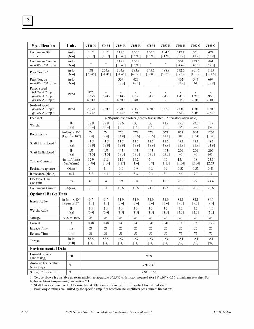
Specification Units 3T45-H 3T45-I 3T54-H 3T55-H 3T55-I 3T57-H 3T66-H 3T67-G 3T69-G
Continuous Stall Torque1
in-lb [Nm]
90.2 [10.2]
90.2 [10.2]
119.3 [13.48]
150.3 [16.98]
150.3 [16.98]
194.5 [21.98]
317.7 [35.9]
371 [41.9]
477 [53.9]
Continuous Torque w/ 480V, 20A drive
in-lb [Nm] - - 119.3
[13.48] 150.3
[16.98] - - 307 [34.69]
358.5 [40.5]
463 [52.3]
Peak Torque3 in-lb [Nm]
181 [20.45]
274.8 [31.05]
304.9 [34.45]
383.9 [43.38]
345.6 [39.05]
488.8 [55.23]
772.5 [87.29]
901.6 [101.9]
1165 [131.6]
Peak Torque w/ 480V, 20A drive
in-lb [Nm] - - 339
[38.3] 426
[48.1] - - 462 [52.2]
540 [61]
699 [78.9]
Rated Speed: @120v AC input @240v AC input @480v AC input
RPM
825
1,650 4,000
-
2,700 -
-
2,100 4,300
-
1,650 3,400
-
3,450 -
-
2,450 -
-
1,450 3,150
-
1,250 2,700
-
950 2,100
No-load speed @240v AC input @480v AC input
RPM
2,350 4,750
3,300
-
2,700 5,450
2,150 4,300
4,300
-
3,050
-
2,000 3,950
1,700 3,400
1,300 2,650
Feedback 4096 pulse/rev resolver (control transmitter; 0.5 transformation ratio)
Weight lb [kg]
22.9 [10.4]
22.9 [10.4]
28.6 [13]
33 [15]
33 [15]
41.9 [19]
79.3 [36]
92.5 [42]
119 [54]
Rotor Inertia in-lb-s2 x 10-4 [kg-m2 x 10-4]
74 [8.4]
74 [8.4]
220 [24.9]
271 [30.6]
271 [30.6]
373 [42.1]
833 [94]
965 [109]
1230 [139]
Shaft Thrust Load 2 lb [kg]
41.5 [18.9]
41.5 [18.9]
31.5 [18.9]
31.5 [18.9]
31.5 [18.9]
31.5 [18.9]
48.3 [21.9]
48.3 [21.9]
48.3 [21.9]
Shaft Radial Load 2 lb [kg]
157 [71.5]
157 [71.5]
115 [52.3]
115 [52.3]
115 [52.3]
115 [52.3]
200 [45]
200 [45]
200 [45]
Torque Constant in-lb/A(rms) [Nm/A(rms)]
12.9 [1.46]
9.2 [1.04]
11.3 [1.27]
14.2 [1.6]
7.1 [0.8]
10 [1.13]
15.4 [1.74]
18 [2.04]
23.3 [2.63]
Resistance (phase) Ohms 2.1 1.1 0.8 0.9 0.2 0.3 0.32 0.35 0.41 Inductance (phase) mH 8.7 4.4 7.1 8.8 2.2 3.1 6.5 7.7 10 Electrical Time Constant ms 4.1 4 8.9 9.8 11 10.3 20.3 22 24.4
Continuous Current A(rms) 7.1 10 10.6 10.6 21.3 19.5 20.7 20.7 20.6
Optional Brake Data
Inertia Adder in-lb-s2 x 10-4 [kg-m2 x10-4]
9.7 [1.1]
9.7 [1.1]
31.9 [3.6]
31.9 [3.6]
31.9 [3.6]
31.9 [3.6]
84.1 [9.5]
84.1 [9.5]
84.1 [9.5]
Weight Adder lb [kg]
1.3 [0.6]
1.3 [0.6]
3.3 [1.5]
3.3 [1.5]
3.3 [1.5]
3.3 [1.5]
4.8 [2.2]
4.8 [2.2]
4.8 [2.2]
Voltage VDC± 10% 24 24 24 24 24 24 24 24 24 Current A 0.48 0.48 0.41 0.41 0.41 0.41 0.73 0.73 0.73 Engage Time ms 20 20 25 25 25 25 25 25 25 Release Time ms 30 30 50 50 50 50 75 75 75
Torque in-lb [Nm]
88.5 [10]
88.5 [10]
159 [16]
159 [16]
159 [16]
159 [16]
354 [40]
354 [40]
354 [40]
Environmental Data Humidity (non-condensing) RH 98%
Ambient Temperature (operating) °C -20 to 40
Storage Temperature °C -30 to 150 1. Torque shown is available up to an ambient temperature of 25°C with motor mounted to a 10’ x10’ x 0.25’ aluminum heat sink. For higher ambient temperatures, see section 2.3. 2. Shaft loads are based on L10 bearing life at 3000 rpm and assume force is applied to center of shaft. 3. Peak torque ratings are limited by the specific amplifier based on the amplifiers peak current limitations.
Hardware Overview
GFK-1848F Chapter 2 Hardware Overview 2-15
2
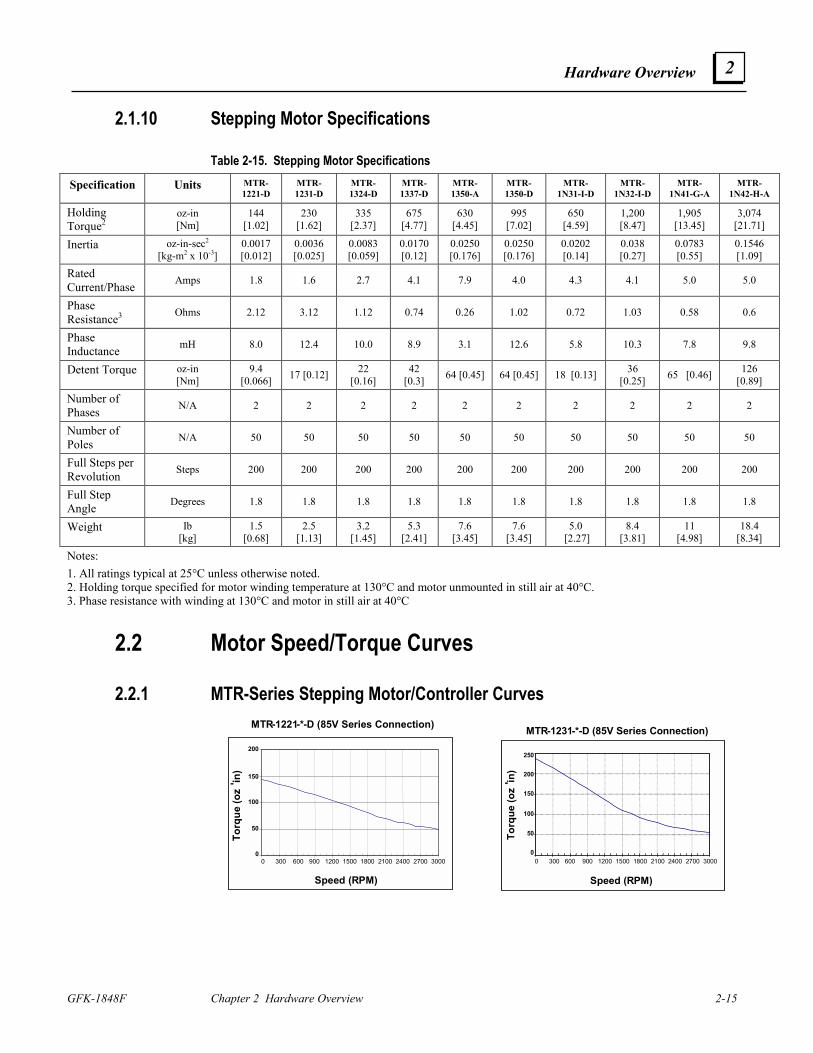
2.1.10 Stepping Motor Specifications
Table 2-15. Stepping Motor Specifications
Specification Units MTR-1221-D
MTR-1231-D
MTR-1324-D
MTR-1337-D
MTR-1350-A
MTR-1350-D
MTR-1N31-I-D
MTR-1N32-I-D
MTR-1N41-G-A
MTR-1N42-H-A
Holding Torque2
oz-in [Nm]
144 [1.02]
230 [1.62]
335 [2.37]
675 [4.77]
630 [4.45]
995 [7.02]
650 [4.59]
1,200 [8.47]
1,905 [13.45]
3,074 [21.71]
Inertia oz-in-sec2 [kg-m2 x 10-3]
0.0017 [0.012]
0.0036 [0.025]
0.0083 [0.059]
0.0170 [0.12]
0.0250 [0.176]
0.0250 [0.176]
0.0202 [0.14]
0.038 [0.27]
0.0783 [0.55]
0.1546 [1.09]
Rated Current/Phase Amps 1.8 1.6 2.7 4.1 7.9 4.0 4.3 4.1 5.0 5.0
Phase Resistance3 Ohms 2.12 3.12 1.12 0.74 0.26 1.02 0.72 1.03 0.58 0.6
Phase Inductance mH 8.0 12.4 10.0 8.9 3.1 12.6 5.8 10.3 7.8 9.8
Detent Torque oz-in [Nm]
9.4 [0.066] 17 [0.12] 22
[0.16] 42
[0.3] 64 [0.45] 64 [0.45] 18 [0.13] 36 [0.25] 65 [0.46] 126
[0.89]
Number of Phases N/A 2 2 2 2 2 2 2 2 2 2
Number of Poles N/A 50 50 50 50 50 50 50 50 50 50
Full Steps per Revolution Steps 200 200 200 200 200 200 200 200 200 200
Full Step Angle Degrees 1.8 1.8 1.8 1.8 1.8 1.8 1.8 1.8 1.8 1.8
Weight Ib [kg]
1.5 [0.68]
2.5 [1.13]
3.2 [1.45]
5.3 [2.41]
7.6 [3.45]
7.6 [3.45]
5.0 [2.27]
8.4 [3.81]
11 [4.98]
18.4 [8.34]
Notes: 1. All ratings typical at 25°C unless otherwise noted. 2. Holding torque specified for motor winding temperature at 130°C and motor unmounted in still air at 40°C. 3. Phase resistance with winding at 130°C and motor in still air at 40°C
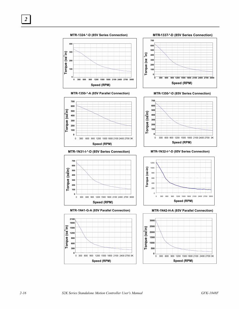
2.2 Motor Speed/Torque Curves
2.2.1 MTR-Series Stepping Motor/Controller Curves MTR-1221-*-D (85V Series Connection)
0
50
100
150
200
0 300 600 900 1200150018002100240027003000
Speed (RPM)
0 300 600 900 1200 1500 1800 2100 2400 2700 3000
Torq
ue (o
z
- in)
200
150
100
50
0
MTR-1231-*-D (85V Series Connection)
Speed (RPM)
Torq
ue (o
z
- in)
0 300 600 900 1200 1500 1800 2100 2400 2700 3000
250
200
150
100
0
50
2-16 S2K Series Standalone Motion Controller User's Manual GFK-1848F
2
0
50
100
150
200
250
300
350
400
0 300 600 900 1200 1500 1800 2100 2400 2700 3000
MTR-1324-*-D (85V Series Connection)
Speed (RPM)
0 300 600 900 1200 1500 1800 2100 2400 2700 3000
Torq
ue (o
z- in)
400
300
200
100
0
0
50
100
150
200
250
300
350
400
450
500
550
600
650
700
0 300 600 900 1200 1500 1800 2100 2400 2700 3000
MTR-1337-*-D (85V Series Connection)
Speed (RPM)
Torq
ue (o
z
- in)
0 300 600 900 1200 1500 1800 2100 2400 2700 3000
700
600
500
200
0
100
300
400
0
50100
150200
250300
350
400450
500
550
600650
700
MTR-1350-*-A (85V Parallel Connection)
Speed (RPM)
0 300 600 900 1200 1500 1800 2100 2400 2700 3K
Torq
ue (o
z- in)
700
500
400
100
0
300
200
600
0
50100
150200
250300
350
400450
500550
600650
700
0 300 600 900 1200 1500 1800 2100 2400 2700 3000
MTR-1350-*-D (85V Series Connection)
Speed (RPM)To
rque
(oz- in
)
0 300 600 900 1200 1500 1800 2100 2400 2700 3K
700
600
500
200
0
100
300
400
0
100
200
300
400
500
600
700
0 300 600 900 1200 1500 1800 2100 2400 2700 3000
MTR-1N31-I-*-D (85V Series Connection)
Speed (RPM)0 300 600 900 1200 1500 1800 2100 2400 2700 3000
Torq
ue (o
z- in)
700
500
400
100
0
300
200
600
MTR-1N32-I-*-D (85V Series Connection)
0
200
400
600
800
1000
1200
0 300 600 900 1200 1500 1800 2100 2400 2700 3000
Speed (RPM)
Torq
ue (o
z-in
)
0 300 600 900
1200 1500 1800
0 300 600 900 1200 1500 1800 2100 2400 2700 3000
MTR - 1N41 - G - A (85V Parallel Connection)
Speed (RPM)
0 300 600 900 1200 1500 1800 2100 2400 2700 3K
Torq
ue (o
z - in)
2100
1500 1200
300 0
900 600
1800
0
500
1000
1500
2000
2500
3000
0 300 600 900 1200 1500 1800 2100 2400 2700 3000
MTR-1N42-H-A (85V Parallel Connection)
Speed (RPM)
Torq
ue (o
z- in)
0 300 600 900 1200 1500 1800 2100 2400 2700 3K
3000
2500
1000
0
500
1500
2000
Hardware Overview
GFK-1848F Chapter 2 Hardware Overview 2-17
2
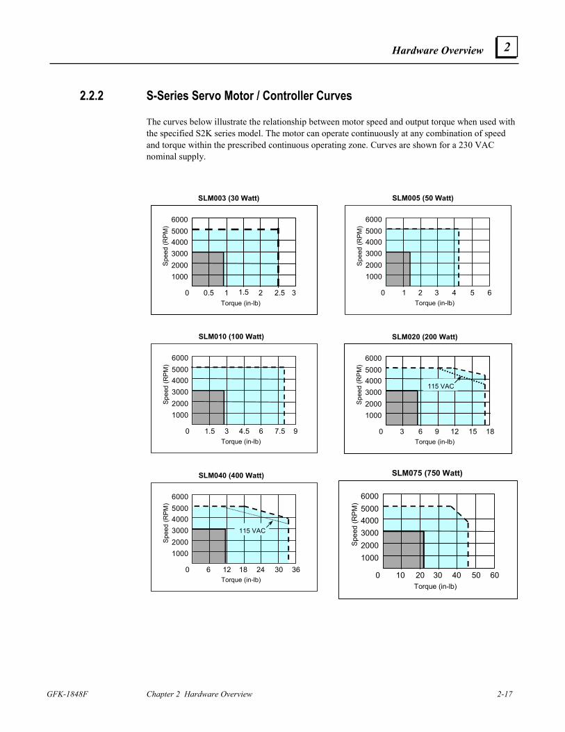
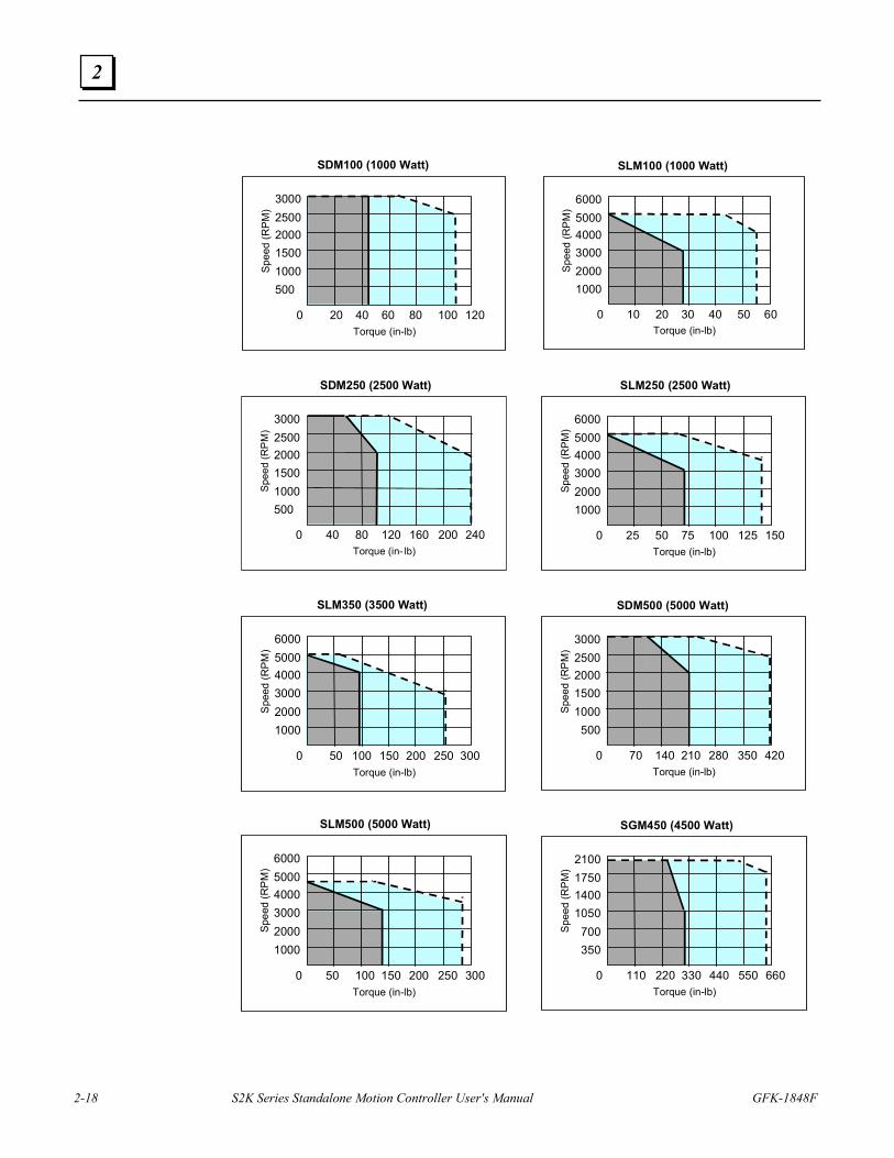
2.2.2 S-Series Servo Motor / Controller Curves
The curves below illustrate the relationship between motor speed and output torque when used with the specified S2K series model. The motor can operate continuously at any combination of speed and torque within the prescribed continuous operating zone. Curves are shown for a 230 VAC nominal supply.
1000
400050006000
30002000Sp
eed
(RPM
)
Torque (in-lb)0 0.5 1 1.5 3 2 2.5
SLM003 (30 Watt)
1000
400050006000
30002000Sp
eed
(RPM
)
Torque (in-lb)0 1 2 3 64 5
SLM005 (50 Watt)
1000
400050006000
30002000Sp
eed
(RPM
)
Torque (in-lb)0 1.5 3 4.5 96 7.5
SLM010 (100 Watt)
1000
400050006000
30002000Sp
eed
(RPM
)
Torque (in-lb)0 3 6 9 1812 15
115 VAC
SLM020 (200 Watt)
1000
400050006000
30002000Sp
eed
(RPM
)
Torque (in-lb)0 6 12 18 3624 30
SLM040 (400 Watt)
115 VAC
1000
400050006000
30002000Sp
eed
(RPM
)
Torque (in-lb)0 10 20 30 6040 50
SLM075 (750 Watt)
2-18 S2K Series Standalone Motion Controller User's Manual GFK-1848F
2
500
200025003000
15001000Sp
eed
(RPM
)
Torque (in-lb)0 20 40 60 12080 100
SDM100 (1000 Watt)
1000
400050006000
30002000Sp
eed
(RPM
)
Torque (in-lb)0 10 20 30 6040 50
SLM100 (1000 Watt)
500
200025003000
15001000Sp
eed
(RP
M)
Torque (in- lb)0 40 80 120 240160 200
SDM250 (2500 Watt)
1000
400050006000
30002000Sp
eed
(RPM
)Torque (in-lb)
0 25 50 75 150100 125
SLM250 (2500 Watt)
1000
400050006000
30002000S
peed
(RPM
)
Torque (in-lb)0 50 100 150 300200 250
SLM350 (3500 Watt)
500
200025003000
15001000Sp
eed
(RP
M)
Torque (in-lb)0 70 140 210 420280 350
SDM500 (5000 Watt)
1000
400050006000
30002000Sp
eed
(RPM
)
Torque (in-lb)0 50 100 150 300200 250
SLM500 (5000 Watt)
350
140017502100
1050 700Sp
eed
(RPM
)
Torque (in-lb)0 110 220 330 660440 550
SGM450 (4500 Watt)
Hardware Overview
GFK-1848F Chapter 2 Hardware Overview 2-19
2
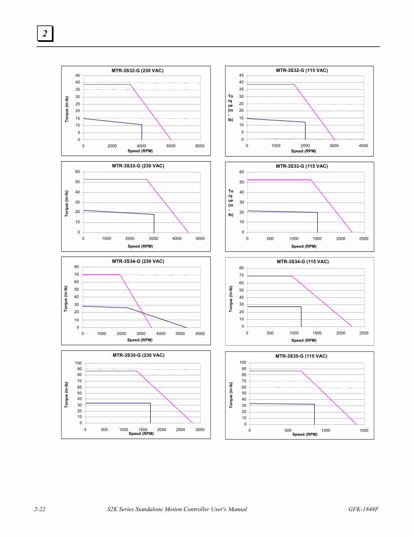
Note Continuous torque available for each motor model depends on the ambient temperature. These curves depict the maximum continuous torque available for each model up to the following ambient temperatures:
• SLM003, SLM100, SDM100, SDM250 & SGM450 = 40°C
• SLM005, SLM250, SLM500 = 20°C
• SLM350 = 25°C
• SDM500 = 35 C
Higher ambient temperatures require motor derating as shown in the temperature derating curves in Section 2.3.
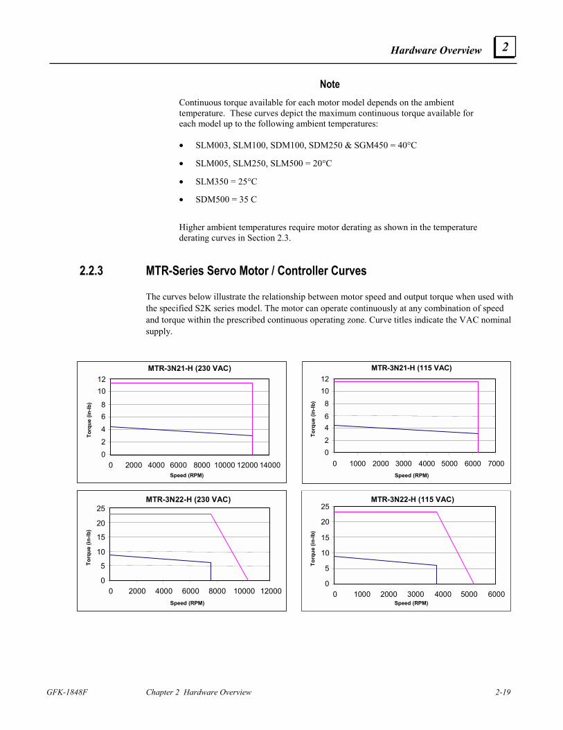
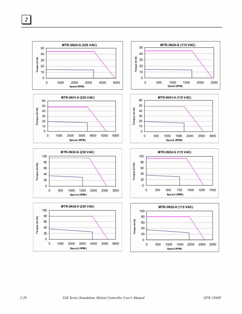
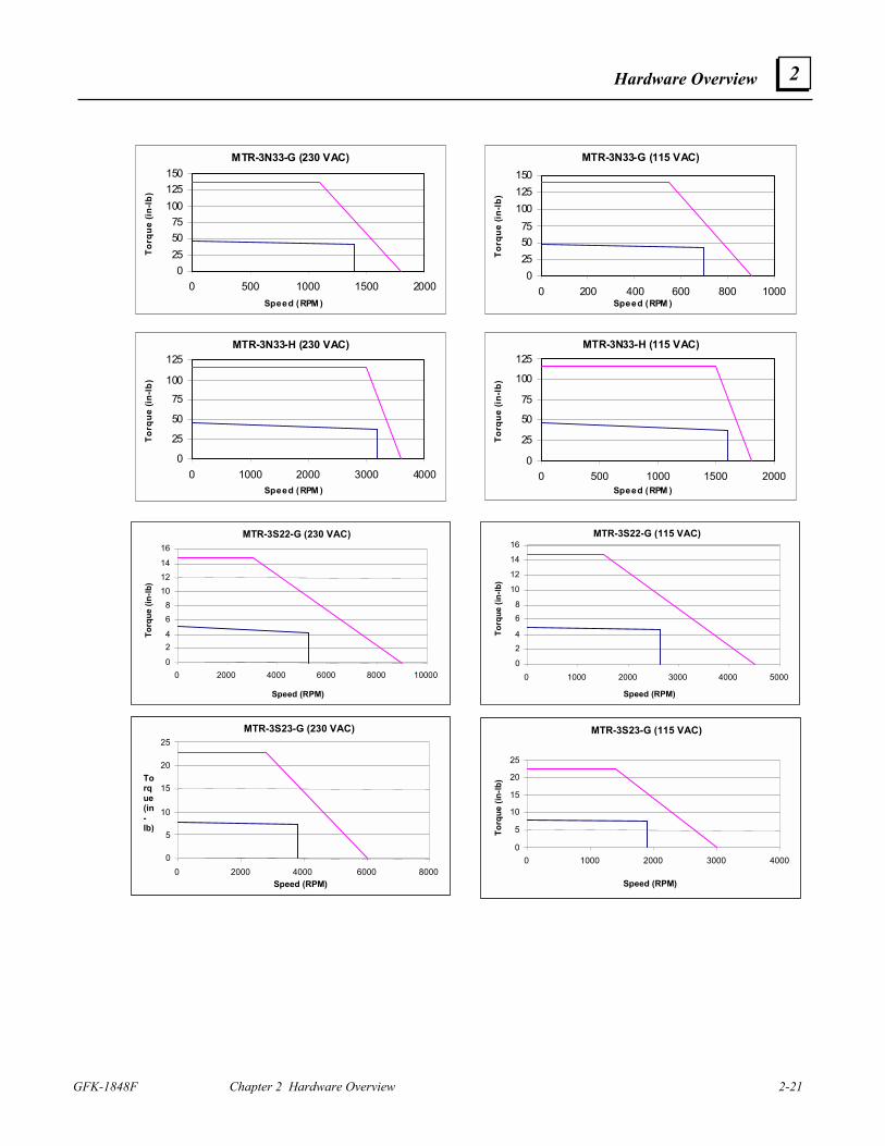
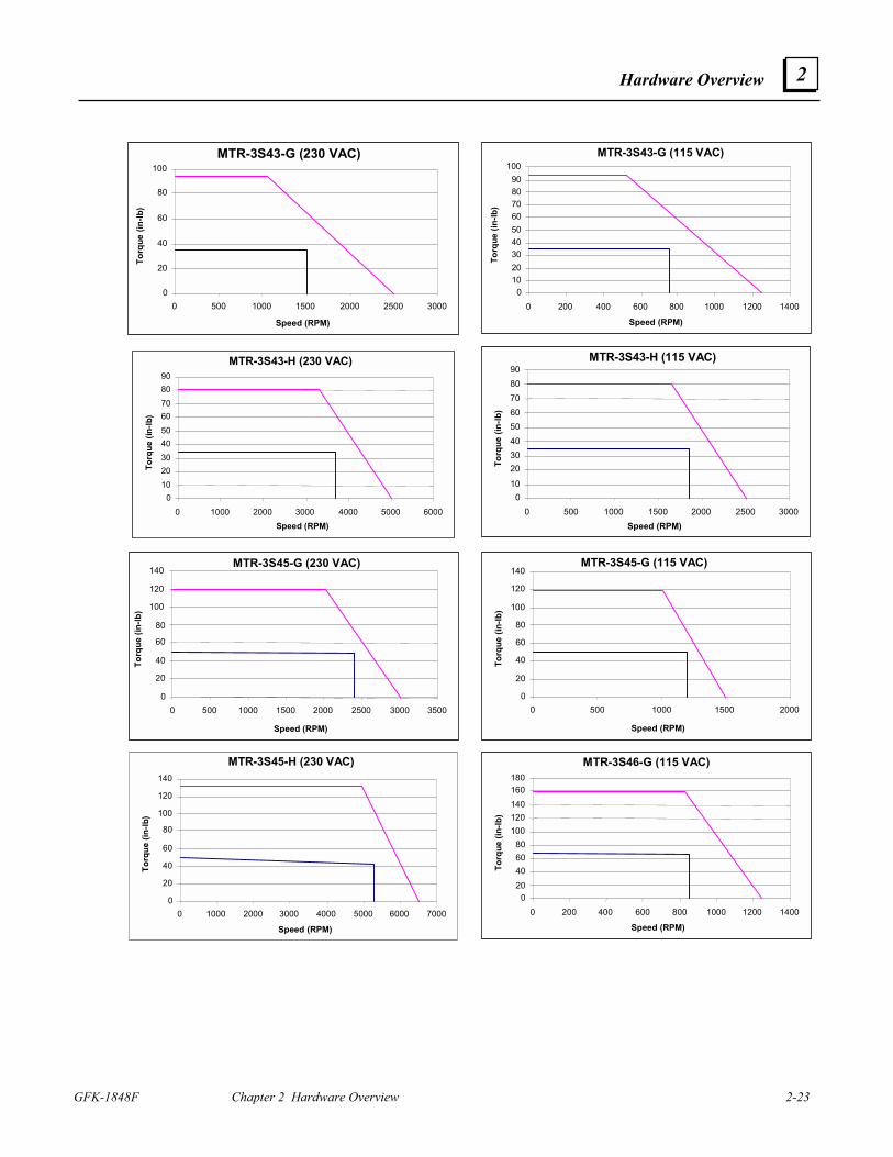
2.2.3 MTR-Series Servo Motor / Controller Curves
The curves below illustrate the relationship between motor speed and output torque when used with the specified S2K series model. The motor can operate continuously at any combination of speed and torque within the prescribed continuous operating zone. Curve titles indicate the VAC nominal supply.
MTR-3N21-H (230 VAC)
02468
1012
0 2000 4000 6000 8000 10000 12000 14000Speed (RPM)
Torq
ue (i
n-lb
)
MTR-3N21-H (115 VAC)
0246
81012
0 1000 2000 3000 4000 5000 6000 7000Speed (RPM)
Torq
ue (i
n-lb
)
MTR-3N22-H (230 VAC)
0
5
10
15
20
25
0 2000 4000 6000 8000 10000 12000Speed (RPM)
Torq
ue (i
n-lb
)
MTR-3N22-H (115 VAC)
0
5
10
15
20
25
0 1000 2000 3000 4000 5000 6000Speed (RPM)
Torq
ue (i
n-lb
)
2-20 S2K Series Standalone Motion Controller User's Manual GFK-1848F
2
MTR-3N24-G (230 VAC)
0
10
20
30
40
50
0 1000 2000 3000 4000 5000Speed (RPM)
Torq
ue (i
n-lb
)
MTR-3N24-G (115 VAC)
0
10
20
30
40
50
0 500 1000 1500 2000 2500Speed (RPM)
Torq
ue (i
n-lb
)
MTR-3N31-H (230 VAC)
0102030405060
0 1000 2000 3000 4000 5000 6000Speed (RPM)
Torq
ue (i
n-lb
)
MTR-3N31-H (115 VAC)
0
10203040
50
60
0 500 1000 1500 2000 2500 3000Speed (RPM)
Torq
ue (i
n-lb
)
MTR-3N32-G (230 VAC)
0
20
40
60
80
100
0 500 1000 1500 2000 2500 3000Speed (RPM )
Torq
ue (i
n-lb
)
MTR-3N32-G (115 VAC)
0
20
40
60
80
100
0 250 500 750 1000 1250 1500Speed (RPM )
Torq
ue (i
n-lb
)
MTR-3N32-H (230 VAC)
0
20
40
60
80
100
0 1000 2000 3000 4000 5000 6000Speed (RPM )
Torq
ue (i
n-lb
)
MTR-3N32-H (115 VAC)
0
20
40
60
80
100
0 500 1000 1500 2000 2500 3000Speed (RPM)
Torq
ue (i
n-lb
)
Hardware Overview
GFK-1848F Chapter 2 Hardware Overview 2-21
2
MTR-3N33-G (230 VAC)
0255075
100125150
0 500 1000 1500 2000Speed (RPM )
Torq
ue (i
n-lb
)
MTR-3N33-G (115 VAC)
0255075
100125150
0 200 400 600 800 1000Speed (RPM )
Torq
ue (i
n-lb
)
MTR-3N33-H (230 VAC)
0
25
50
75
100
125
0 1000 2000 3000 4000Speed (RPM )
Torq
ue (i
n-lb
)
MTR-3N33-H (115 VAC)
0
25
50
75
100
125
0 500 1000 1500 2000Speed (RPM )
Torq
ue (i
n-lb
)
MTR-3S22-G (230 VAC)
0
24
68
101214
16
0 2000 4000 6000 8000 10000
Speed (RPM)
Torq
ue (i
n-lb
)
MTR-3S22-G (115 VAC)
0
24
68
10
12
14
16
0 1000 2000 3000 4000 5000
Speed (RPM)
Torq
ue (i
n-lb
)
MTR-3S23-G (230 VAC)
0
5
10
15
20
25
0 2000 4000 6000 8000Speed (RPM)
Torque(in-lb)
MTR-3S23-G (115 VAC)
0
5
10
15
20
25
0 1000 2000 3000 4000
Speed (RPM)
Torq
ue (i
n-lb
)
2-22 S2K Series Standalone Motion Controller User's Manual GFK-1848F
2
MTR-3S32-G (230 VAC)
0
5
1015
2025
30
35
4045
0 2000 4000 6000 8000Speed (RPM)
Torq
ue (i
n-lb
)
MTR-3S32-G (115 VAC)
0
5
1015
2025
30
35
4045
0 1000 2000 3000 4000Speed (RPM)
Torque(in-lb)
MTR-3S33-G (230 VAC)
0
10
20
30
40
50
60
0 1000 2000 3000 4000 5000
Speed (RPM)
Torq
ue (i
n-lb
)
MTR-3S33-G (115 VAC)
0
10
20
30
40
50
60
0 500 1000 1500 2000 2500
Speed (RPM)
Torque(in-lb)
MTR-3S34-G (230 VAC)
0
10
20
30
40
50
60
70
80
0 1000 2000 3000 4000 5000 6000Speed (RPM)
Torq
ue (i
n-lb
)
MTR-3S34-G (115 VAC)
0
10
20
3040
50
60
70
80
0 500 1000 1500 2000 2500
Speed (RPM)
Torq
ue (i
n-lb
)
MTR-3S35-G (230 VAC)
0102030405060708090
100
0 500 1000 1500 2000 2500 3000Speed (RPM)
Torq
ue (i
n-lb
)
MTR-3S35-G (115 VAC)
0102030405060708090
100
0 500 1000 1500Speed (RPM)
Torq
ue (i
n-lb
)
Hardware Overview
GFK-1848F Chapter 2 Hardware Overview 2-23
2
MTR-3S43-G (230 VAC)
0
20
40
60
80
100
0 500 1000 1500 2000 2500 3000
Speed (RPM)
Torq
ue (i
n-lb
)
MTR-3S43-G (115 VAC)
0102030405060708090
100
0 200 400 600 800 1000 1200 1400
Speed (RPM)
Torq
ue (i
n-lb
)
MTR-3S43-H (230 VAC)
0102030405060708090
0 1000 2000 3000 4000 5000 6000Speed (RPM)
Torq
ue (i
n-lb
)
MTR-3S43-H (115 VAC)
010
2030405060708090
0 500 1000 1500 2000 2500 3000Speed (RPM)
Torq
ue (i
n-lb
)
MTR-3S45-G (230 VAC)
0
20
40
60
80
100
120
140
0 500 1000 1500 2000 2500 3000 3500
Speed (RPM)
Torq
ue (i
n-lb
)
MTR-3S45-G (115 VAC)
0
20
40
60
80
100
120
140
0 500 1000 1500 2000
Speed (RPM)
Torq
ue (i
n-lb
)
MTR-3S45-H (230 VAC)
0
20
40
60
80
100
120
140
0 1000 2000 3000 4000 5000 6000 7000
Speed (RPM)
Torq
ue (i
n-lb
)
MTR-3S46-G (115 VAC)
020406080
100120140160180
0 200 400 600 800 1000 1200 1400
Speed (RPM)
Torq
ue (i
n-lb
)
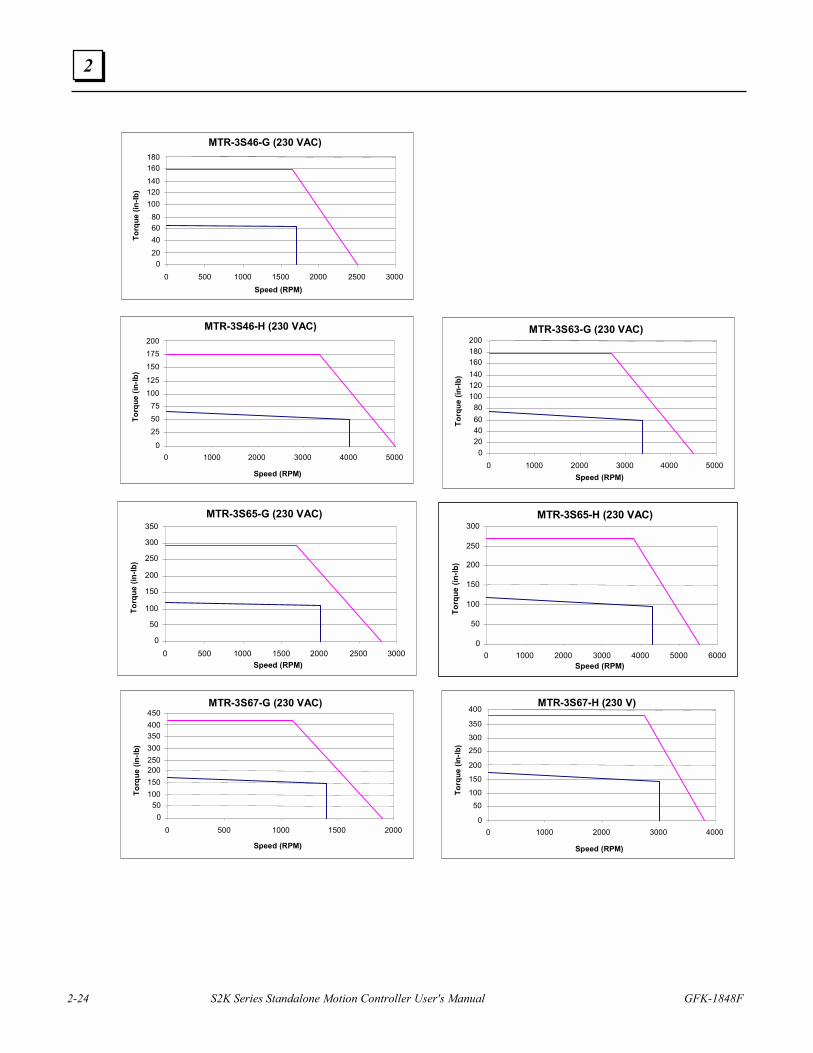
2-24 S2K Series Standalone Motion Controller User's Manual GFK-1848F
2
MTR-3S46-G (230 VAC)
020406080
100120140160180
0 500 1000 1500 2000 2500 3000Speed (RPM)
Torq
ue (i
n-lb
)
MTR-3S46-H (230 VAC)
0
255075
100125
150175200
0 1000 2000 3000 4000 5000
Speed (RPM)
Torq
ue (i
n-lb
)
MTR-3S63-G (230 VAC)
020406080
100120140160180200
0 1000 2000 3000 4000 5000Speed (RPM)
Torq
ue (i
n-lb
)
MTR-3S65-G (230 VAC)
0
50
100
150
200
250
300
350
0 500 1000 1500 2000 2500 3000Speed (RPM)
Torq
ue (i
n-lb
)
MTR-3S65-H (230 VAC)
0
50
100
150
200
250
300
0 1000 2000 3000 4000 5000 6000Speed (RPM)
Torq
ue (i
n-lb
)
MTR-3S67-G (230 VAC)
050
100150200250300350400450
0 500 1000 1500 2000
Speed (RPM)
Torq
ue (i
n-lb
)
MTR-3S67-H (230 V)
0
50100
150
200
250300
350
400
0 1000 2000 3000 4000
Speed (RPM)
Torq
ue (i
n-lb
)
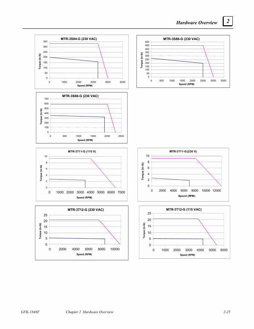
Hardware Overview
GFK-1848F Chapter 2 Hardware Overview 2-25
2
MTR-3S84-G (230 VAC)
0
50
100
150
200
250
300
350
0 1000 2000 3000 4000 5000Speed (RPM)
Torq
ue (i
n-lb
)
MTR-3S86-G (230 VAC)
050
100150200250300350400450500
0 500 1000 1500 2000 2500 3000 3500Speed (RPM)
Torq
ue (i
n-lb
)
MTR-3S88-G (230 VAC)
0
100
200
300
400
500
600
700
0 500 1000 1500 2000 2500Speed (RPM)
Torq
ue (i
n-lb
)
MTR-3T11-G (115 V)
0
2
4
6
8
10
0 1000 2000 3000 4000 5000 6000 7000Speed (RPM)
Torq
ue (i
n-lb
)
MTR-3T11-G (230 V)
0
2
4
6
8
10
0 2000 4000 6000 8000 10000 12000Speed (RPM)
Torq
ue (i
n-lb
)
MTR-3T12-G (230 VAC)
0
510
15
20
25
0 2000 4000 6000 8000 10000Speed (RPM)
Torq
ue (i
n-lb
)
MTR-3T12-G (115 VAC)
0
5
10
15
20
25
0 1000 2000 3000 4000 5000 6000Speed (RPM)
Torq
ue (i
n-lb
)
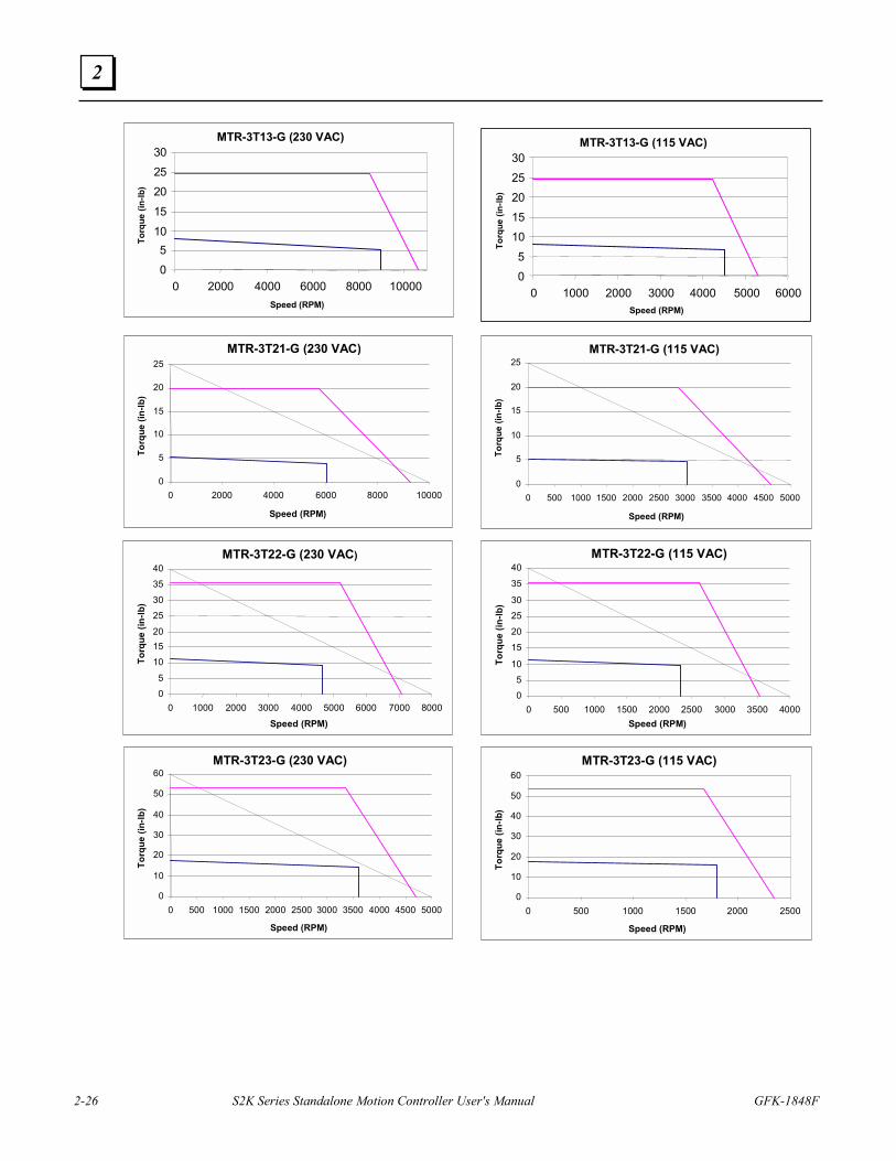
2-26 S2K Series Standalone Motion Controller User's Manual GFK-1848F
2
MTR-3T13-G (230 VAC)
05
1015202530
0 2000 4000 6000 8000 10000Speed (RPM)
Torq
ue (i
n-lb
)
MTR-3T13-G (115 VAC)
05
1015202530
0 1000 2000 3000 4000 5000 6000Speed (RPM)
Torq
ue (i
n-lb
)
MTR-3T21-G (230 VAC)
0
5
10
15
20
25
0 2000 4000 6000 8000 10000
Speed (RPM)
Torq
ue (i
n-lb
)
MTR-3T21-G (115 VAC)
0
5
10
15
20
25
0 500 1000 1500 2000 2500 3000 3500 4000 4500 5000
Speed (RPM)
Torq
ue (i
n-lb
)
MTR-3T22-G (230 VAC)
05
101520
25303540
0 1000 2000 3000 4000 5000 6000 7000 8000
Speed (RPM)
Torq
ue (i
n-lb
)
MTR-3T22-G (115 VAC)
05
10
15202530
35
40
0 500 1000 1500 2000 2500 3000 3500 4000Speed (RPM)
Torq
ue (i
n-lb
)
MTR-3T23-G (230 VAC)
0
10
20
30
40
50
60
0 500 1000 1500 2000 2500 3000 3500 4000 4500 5000
Speed (RPM)
Torq
ue (i
n-lb
)
MTR-3T23-G (115 VAC)
0
10
20
30
40
50
60
0 500 1000 1500 2000 2500
Speed (RPM)
Torq
ue (i
n-lb
)
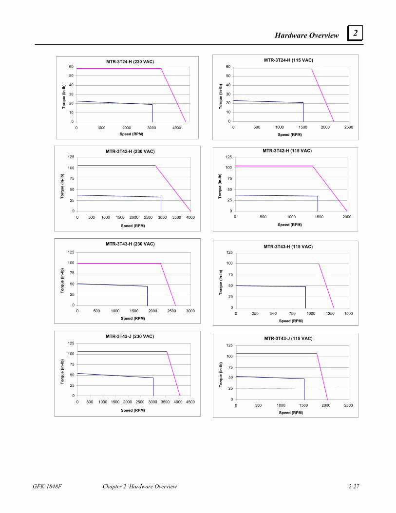
Hardware Overview
GFK-1848F Chapter 2 Hardware Overview 2-27
2
MTR-3T24-H (230 VAC)
0
10
20
30
40
50
60
0 1000 2000 3000 4000Speed (RPM)
Torq
ue (i
n-lb
)
MTR-3T24-H (115 VAC)
0
10
20
30
40
50
60
0 500 1000 1500 2000 2500
Speed (RPM)
Torq
ue (i
n-lb
)
MTR-3T42-H (230 VAC)
0
25
50
75
100
125
0 500 1000 1500 2000 2500 3000 3500 4000
Speed (RPM)
Torq
ue (i
n-lb
)
MTR-3T42-H (115 VAC)
0
25
50
75
100
125
0 500 1000 1500 2000
Speed (RPM)To
rque
(in-
lb)
MTR-3T43-H (230 VAC)
0
25
50
75
100
125
0 500 1000 1500 2000 2500 3000
Speed (RPM)
Torq
ue (i
n-lb
)
MTR-3T43-H (115 VAC)
0
25
50
75
100
125
0 250 500 750 1000 1250 1500
Speed (RPM)
Torq
ue (i
n-lb
)
MTR-3T43-J (230 VAC)
0
25
50
75
100
125
0 500 1000 1500 2000 2500 3000 3500 4000 4500
Speed (RPM)
Torq
ue (i
n-lb
)
MTR-3T43-J (115 VAC)
0
25
50
75
100
125
0 500 1000 1500 2000 2500
Speed (RPM)
Torq
ue (i
n-lb
)
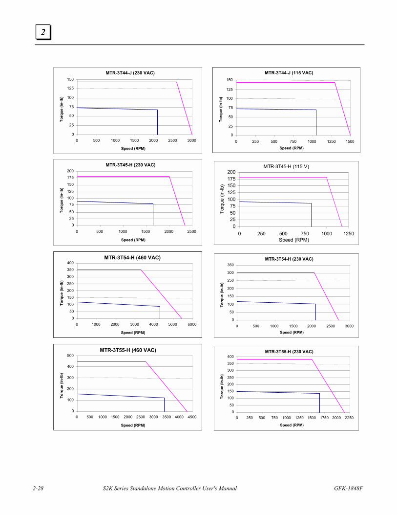
2-28 S2K Series Standalone Motion Controller User's Manual GFK-1848F
2
MTR-3T44-J (230 VAC)
0
25
50
75
100
125
150
0 500 1000 1500 2000 2500 3000
Speed (RPM)
Torq
ue (i
n-lb
)
MTR-3T44-J (115 VAC)
0
25
50
75
100
125
150
0 250 500 750 1000 1250 1500Speed (RPM)
Torq
ue (i
n-lb
)
MTR-3T45-H (230 VAC)
02550
75100125
150
175200
0 500 1000 1500 2000 2500
Speed (RPM)
Torq
ue (i
n-lb
)
MTR-3T45-H (115 V)
0255075
100125150175200
0 250 500 750 1000 1250Speed (RPM)
Torq
ue (i
n-lb
)
MTR-3T54-H (460 VAC)
0
50
100
150
200
250
300
350
400
0 1000 2000 3000 4000 5000 6000
Speed (RPM)
Torq
ue (i
n-lb
)
MTR-3T54-H (230 VAC)
0
50
100
150
200
250
300
350
0 500 1000 1500 2000 2500 3000Speed (RPM)
Torq
ue (i
n-lb
)
MTR-3T55-H (460 VAC)
0
100
200
300
400
500
0 500 1000 1500 2000 2500 3000 3500 4000 4500
Speed (RPM)
Torq
ue (i
n-lb
)
MTR-3T55-H (230 VAC)
0
50
100
150
200
250
300
350
400
0 250 500 750 1000 1250 1500 1750 2000 2250
Speed (RPM)
Torq
ue (i
n-lb
)
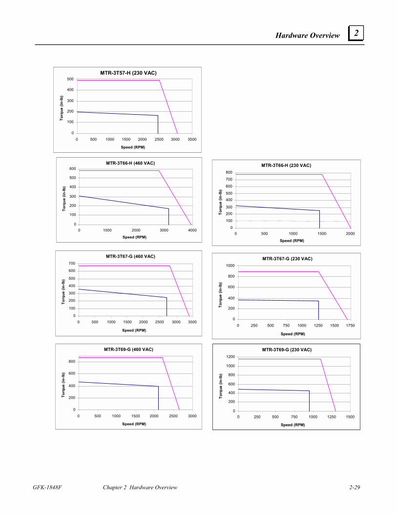
Hardware Overview
GFK-1848F Chapter 2 Hardware Overview 2-29
2
MTR-3T57-H (230 VAC)
0
100
200
300
400
500
0 500 1000 1500 2000 2500 3000 3500
Speed (RPM)
Torq
ue (i
n-lb
)
MTR-3T66-H (460 VAC)
0
100
200
300
400
500
600
0 1000 2000 3000 4000
Speed (RPM)
Torq
ue (i
n-lb
)
MTR-3T66-H (230 VAC)
0
100
200300
400500
600
700
800
0 500 1000 1500 2000
Speed (RPM)
Torq
ue (i
n-lb
)
MTR-3T67-G (460 VAC)
0
100
200
300
400
500
600
700
0 500 1000 1500 2000 2500 3000 3500
Speed (RPM)
Torq
ue (i
n-lb
)
MTR-3T67-G (230 VAC)
0
200
400
600
800
1000
0 250 500 750 1000 1250 1500 1750
Speed (RPM)
Torq
ue (i
n-lb
)
MTR-3T69-G (460 VAC)
0
200
400
600
800
0 500 1000 1500 2000 2500 3000
Speed (RPM)
Torq
ue (i
n-lb
)
MTR-3T69-G (230 VAC)
0
200
400
600
800
1000
1200
0 250 500 750 1000 1250 1500
Speed (RPM)
Torq
ue (i
n-lb
)
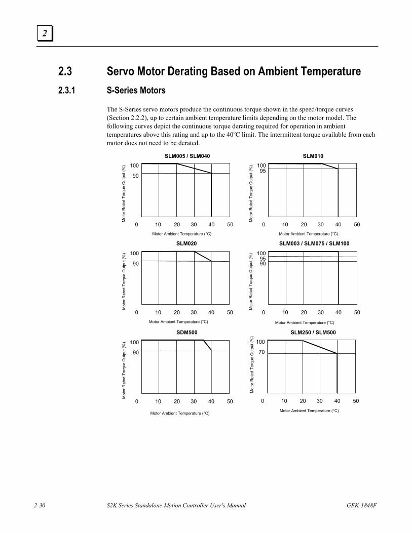
2-30 S2K Series Standalone Motion Controller User's Manual GFK-1848F
2
2.3 Servo Motor Derating Based on Ambient Temperature 2.3.1 S-Series Motors
The S-Series servo motors produce the continuous torque shown in the speed/torque curves (Section 2.2.2), up to certain ambient temperature limits depending on the motor model. The following curves depict the continuous torque derating required for operation in ambient temperatures above this rating and up to the 40oC limit. The intermittent torque available from each motor does not need to be derated.
100
90
Mot
or R
ated
Tor
que
Out
put (
%)
Motor Ambient Temperature (°C)
0 10 20 30 40 50
SLM005 / SLM040
10095
Mot
or R
ated
Tor
que
Out
put (
%)
0 10 20 30 40 50
SLM010
Motor Ambient Temperature (°C)
100
90
Mot
or R
ated
Tor
que
Out
put (
%)
0 10 20 30 40 50
SLM020
Motor Ambient Temperature (°C)
1009590
Mot
or R
ated
Tor
que
Out
put (
%)
0 10 20 30 40 50
SLM003 / SLM075 / SLM100
Motor Ambient Temperature (°C)
100
90
Mot
or R
ated
Tor
que
Out
put (
%)
0 10 20 30 40 50
SDM500
Motor Ambient Temperature (°C)
100
70
0 10 20 30 40 50
SLM250 / SLM500
Mot
or R
ated
Tor
que
Out
put (
%)
Motor Ambient Temperature (°C)
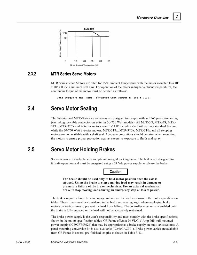
Hardware Overview
GFK-1848F Chapter 2 Hardware Overview 2-31
2
100
70
Mot
or R
ated
Tor
que
Out
put (
%)
0 10 20 30 40 50
SLM350
Motor Ambient Temperature (°C)
2.3.2 MTR Series Servo Motors
MTR Series Servo Motors are rated for 25oC ambient temperature with the motor mounted to a 10" x 10" x 0.25" aluminum heat sink. For operation of the motor in higher ambient temperatures, the continuous torque of the motor must be derated as follows:
Cont Torque @ amb. Temp, toC=Rated Cont Torque x (155-t)/130.
2.4 Servo Motor Sealing The S-Series and MTR-Series servo motors are designed to comply with an IP65 protection rating (excluding the cable connector on S-Series 30-750 Watt models). All MTR-3N, MTR-3S, MTR-3T1x, MTR-3T2x and S-Series motors rated 1-5 kW include a shaft oil seal as a standard feature, while the 30-750 Watt S-Series motors, MTR-3T4x, MTR-3T5x, MTR-3T6x and all stepping motors are not available with a shaft seal. Adequate precautions should be taken when mounting the motors to ensure proper protection against excessive exposure to fluids and spray.
2.5 Servo Motor Holding Brakes Servo motors are available with an optional integral parking brake. The brakes are designed for failsafe operation and must be energized using a 24 Vdc power supply to release the brake.
Caution
The brake should be used only to hold motor position once the axis is stopped. Using the brake to stop a moving load may result in damage or premature failure of the brake mechanism. Use an external mechanical brake to stop moving loads during an emergency stop or loss of power.
The brakes require a finite time to engage and release the load as shown in the motor specification tables. These times must be considered in the brake sequencing logic when employing brake motors on vertical axes to prevent the load from falling. The controller must remain enabled until the brake is fully engaged or the load will not be adequately restrained.
The brake power supply is the user’s responsibility and must comply with the brake specifications shown in the motor specification tables. GE Fanuc offers a 24 VDC, 5 Amp DIN-rail mounted power supply (IC690PWR024) that may be appropriate as a brake supply on multi-axis systems. A panel mounting conversion kit is also available (IC690PAC001). Brake power cables are available from GE Fanuc in several pre-finished lengths as shown in Table 3-13.
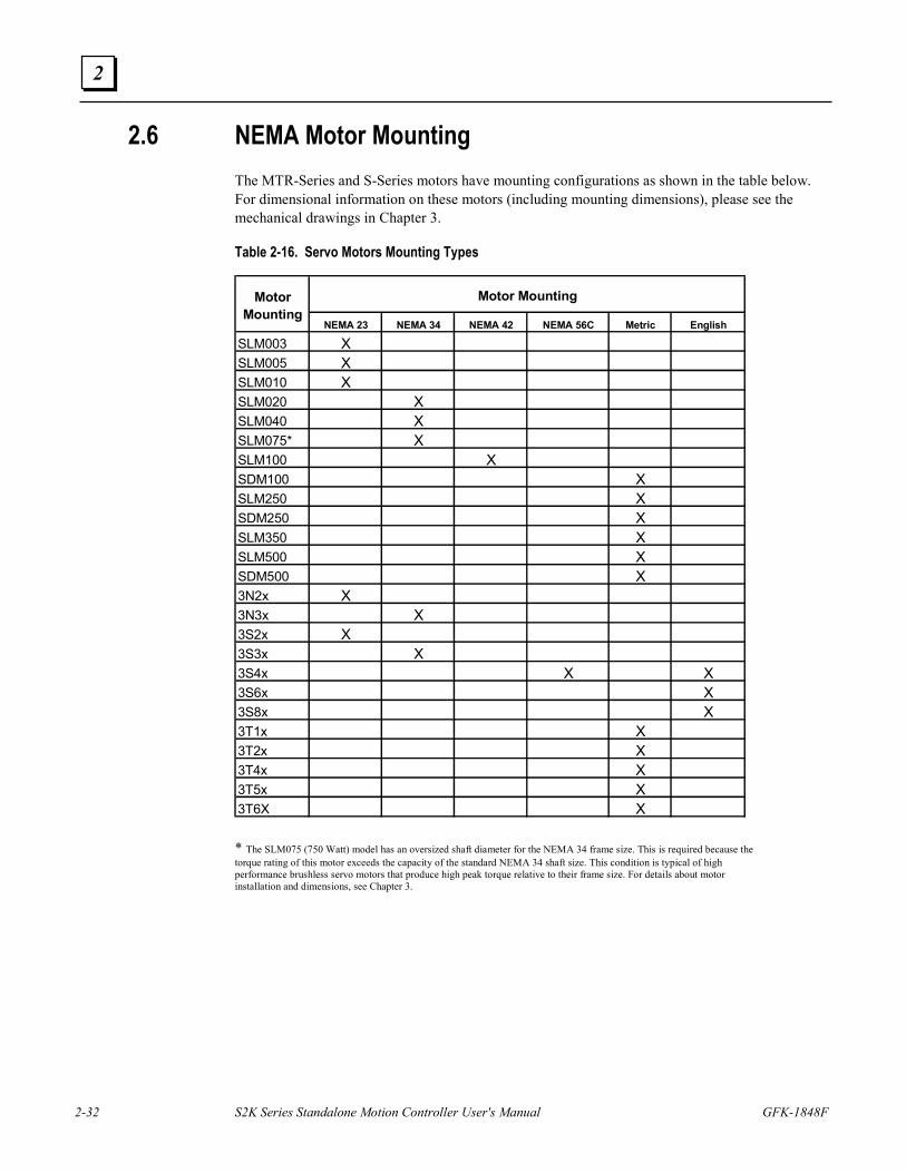
2-32 S2K Series Standalone Motion Controller User's Manual GFK-1848F
2
2.6 NEMA Motor Mounting The MTR-Series and S-Series motors have mounting configurations as shown in the table below. For dimensional information on these motors (including mounting dimensions), please see the mechanical drawings in Chapter 3.
Table 2-16. Servo Motors Mounting Types
* The SLM075 (750 Watt) model has an oversized shaft diameter for the NEMA 34 frame size. This is required because the torque rating of this motor exceeds the capacity of the standard NEMA 34 shaft size. This condition is typical of high performance brushless servo motors that produce high peak torque relative to their frame size. For details about motor installation and dimensions, see Chapter 3.
NEMA 23 NEMA 34 NEMA 42 NEMA 56C Metric English
SLM003 XSLM005 XSLM010 XSLM020 XSLM040 XSLM075* XSLM100 XSDM100 XSLM250 XSDM250 XSLM350 XSLM500 XSDM500 X3N2x X3N3x X3S2x X3S3x X3S4x X X3S6x X3S8x X3T1x X3T2x X3T4x X3T5x X3T6X X
Motor Mounting
Motor Mounting
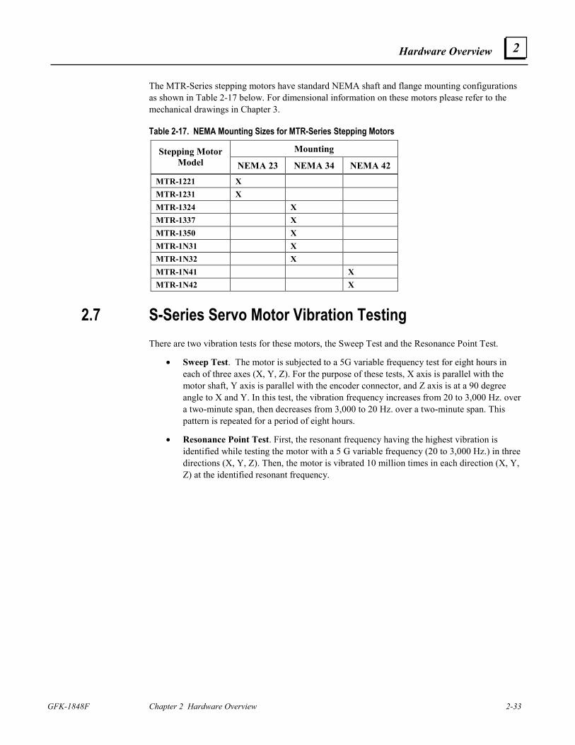
Hardware Overview
GFK-1848F Chapter 2 Hardware Overview 2-33
2
The MTR-Series stepping motors have standard NEMA shaft and flange mounting configurations as shown in Table 2-17 below. For dimensional information on these motors please refer to the mechanical drawings in Chapter 3.
Table 2-17. NEMA Mounting Sizes for MTR-Series Stepping Motors
Mounting Stepping Motor Model NEMA 23 NEMA 34 NEMA 42
MTR-1221 X MTR-1231 X MTR-1324 X MTR-1337 X MTR-1350 X MTR-1N31 X MTR-1N32 X MTR-1N41 X MTR-1N42 X
2.7 S-Series Servo Motor Vibration Testing There are two vibration tests for these motors, the Sweep Test and the Resonance Point Test.
• Sweep Test. The motor is subjected to a 5G variable frequency test for eight hours in each of three axes (X, Y, Z). For the purpose of these tests, X axis is parallel with the motor shaft, Y axis is parallel with the encoder connector, and Z axis is at a 90 degree angle to X and Y. In this test, the vibration frequency increases from 20 to 3,000 Hz. over a two-minute span, then decreases from 3,000 to 20 Hz. over a two-minute span. This pattern is repeated for a period of eight hours.
• Resonance Point Test. First, the resonant frequency having the highest vibration is identified while testing the motor with a 5 G variable frequency (20 to 3,000 Hz.) in three directions (X, Y, Z). Then, the motor is vibrated 10 million times in each direction (X, Y, Z) at the identified resonant frequency.
GFK-1848F 3-1
Installation
3.1 Heat Load and Cooling The heat load of the S2K Series controllers is dependent on the model as shown below:
Stepper Controller
Model SSI105: Heat Load = 20 Watts + (0.3 * current setting in percent) or 50 watts max.
Servo Controllers Model SSI104: Heat Load = 25 watts + (35 * duty cycle) watts or 60 watts max. Model SSI107: Heat Load = 35 watts + (65 * duty cycle) watts or 100 watts max. Model SSI216: Heat Load = 50 watts + (150 * duty cycle) watts or 200 watts max. Model SSI228: Heat Load = 60 watts + (280 * duty cycle) watts or 340 watts max Model SSI407: Heat Load = 35 watts + (65 * duty cycle) watts or 100 watts max.. Model SSI420: Heat Load = 60 watts + (250 * duty cycle) watts or 310 watts max. Duty cycle is defined as the percent of time the controller is at full rated output divided by the total cycle time. The SSI104 and SSI107 controllers are designed to operate at full rated current with only natural convection cooling at ambient temperatures up to 50°C. The SSI216, SSI228, SSI407 and SSI420 models have built-in fan cooling.
The controllers must be installed vertically for effective cooling. Allow a minimum clearance of 3 inches above and below the unit. A minimum of 2 to 3 inches clearance is also recommended on the right and left sides of the unit where possible.
Note For UL approved installation of the following controllers, maximum ambient temperature is 40°C (104°F): IC800SSI216P2, IC800SSI216RP2, IC800SSI216D2, IC800SSI216RD2, IC800SSI228P2, IC800SSI228RP2, IC800SSI228D2, IC800SSI228RD2, IC800SSI407RS1, IC800SSI407RP2, IC800SSI407RD2, IC800SSI420RP2, IC800SSI420RD2.
3 Chapter
3-2 S2K Series Standalone Motion Controller User's Manual GFK-1848F
3
3.2 Controller Mounting Guidelines and Environmental Conditions It is the user’s responsibility to install the components in a suitable location. The S2K controller must be installed in a location that satisfies the following environmental conditions:
1. Atmosphere: The circuitry must not be exposed to any corrosive or conductive contaminants.
2. Ambient temperature:
0°C to +50°C (operating) -40°C to 80°C (storage)
Note: For UL approved installation of the following controllers, maximum ambient temperature is 40°C (104°F): IC800SSI216P2, IC800SSI216RP2, IC800SSI216D2, IC800SSI216RD2, IC800SSI228P2, IC800SSI228RP2, IC800SSI228D2, IC800SSI228RD2, IC800SSI407RS1, IC800SSI407RP2, IC800SSI407RD2, IC800SSI420RP2, IC800SSI420RD2.
Install the controller into ambient temperature conditions within the range of 0° C to +50° C. If the temperature exceeds this range, it may cause malfunction or damage to the controller. The controller heatsink and motor generate high temperatures. If the controller is housed in an enclosed control cabinet this heat load must be considered when evaluating the enclosure cooling requirements (see Section 3.1-Heat Load and Cooling for details on controller losses). Use heat exchangers or cooling devices to maintain an ambient temperature of 50° C or less.
3. Humidity: 95% relative humidity or less (non-condensing)
4. Altitude: No more than 1,000m (3,300 ft) above sea level for full rating. Contact GE Fanuc Applications Engineering for derating at higher elevations.
5. Ventilation: This controller is designed for vertical installation to ensure proper cooling. Install the controller with sufficient space for ventilation. Avoid mounting wireways and other adjacent components too close to the heatsink, top or bottom of the controller.
6. Location: Keep the following location guidelines in mind when selecting a site for the controller:
• Do not install in places with high temperature, high humidity, dust, dirt, conductive powder or particulate, combustible gasses, or metal chips.
• Avoid places exposed to direct sunlight.
• Mount only to noncombustible materials such as metal.
• Do not stand/step on or put heavy articles on the controller or motor.
• The controller housing is not a waterproof enclosure. Do not use outdoors or in any unprotected environment. The controllers are designed with open construction and must be installed in a closed electrical operating area i.e. an enclosure that protects personnel from contact with wiring terminals and provides a pollution degree 2 environment.
• Avoid locations where there is exposure to radiation such as microwave, ultraviolet, laser light or X-rays.
• Do not apply excessive stress, put heavy articles on, or pinch the cables.

Installation
GFK-1848F Chapter 3 Installation 3-3
3
• Do not install the controller near heating elements such as cabinet heaters or large wire wound resistors. When such installation is unavoidable, provide a thermal shield between the servo controller and the heating elements.
• Mount controller and other heat producing components higher in the enclosure to avoid overheating other sensitive electronics installed in the same cabinet.
3-4 S2K Series Standalone Motion Controller User's Manual GFK-1848F
3
3.3 Installing the Controller The S2K Series controllers are designed for panel mounting in electrical enclosures designed for industrial applications. Enclosure cooling or ventilation must be adequate to maintain the ambient temperature to within the component’s specifications. Mount controllers vertically for proper cooling.
1. To ensure an adequate ground connection between the S2K and the panel to which it is mounted, install a star washer or equivalent under the mounting screws.
2. Firmly install the controller with screws and bolts without applying stress such as bending and twisting to the controller main unit.
3. Allow reasonable mounting clearance between adjacent units to ensure proper ventilation.
Caution
Since a misuse of the controller may lead to improper operation, or may damage the controller, carefully read the following cautions and warnings:
• Be sure to ground the controller properly using the ground terminals on the power input connector. Proper grounding includes conforming to applicable national and local electrical codes.
• Do not apply higher than rated voltage to the power input terminals (L1, L2 and L3) • Do not apply the main input power to terminals other than terminals L1, L2 and L3 or
damage will occur. Refer to Section 3.6 for wiring information. • The power supply uses a capacitor filter. When you turn on power, a high charging current
flows and you may see a large voltage drop. We recommend that you install line reactors to limit the charging current if this presents problems with other equipment on the machine.
• Do not perform a dielectric strength test or megger test on the controller or damage may occur. (When you perform a dielectric strength test or megger test to an external circuit, please disconnect all terminals to the controller so that no test voltage is applied to the controller.)
• If you use a ground fault breaker, use one rated for "Inverter," to withstand high frequency leakage current. See table 2-3 for fuse specifications.
• Use the motor and controllers only in the designated combinations (Table 1-1). • When transporting, use caution to prevent damage to the S2K components. Do not move or
carry the controller by holding the cables.
Installation
GFK-1848F Chapter 3 Installation 3-5
3
3.4 Installing the Motor The S-Series and MTR-Series servo motors are designed for either vertical or horizontal mounting and have a protection rating of IP65 (not including the connectors and shaft). The motors should be mounted in a location where the environmental conditions are within the specifications stated in Chapter 2. Use the following guidelines when mounting the motors:
• Observe the shaft radial and thrust load limits. Loads exceeding these limits will cause premature failure of the motor. Excessive belt tension could cause bearing or shaft failure.
• Be sure to ground the motor using the ground wire in the motor power cable. • Ensure that the motor cables are free from excessive stress, stretching, pinching or bending. • To avoid damage, do not carry a motor by holding the cables or shaft. • Do not apply excessive axial force or impact loads when installing the motor coupling or shaft
pulley, or the encoder may be damaged. See axial load limit ratings in Chapter 2. • Install the motor in a location free from corrosive contaminants, dust, excessive water spray, or
combustible gas. • The shaft of the S-series servo motor is treated with grease (Shell Oil Alvania No. 2) for corrosion
protection during storage. Consider the effect of the grease on any plastic parts that are mated with the shaft.
• The optional servo motor brake should be used for holding stationary loads only. Do not use this brake to stop a moving load, or reduced life or damage to the brake may occur. Apply this brake only after the motor is stopped.
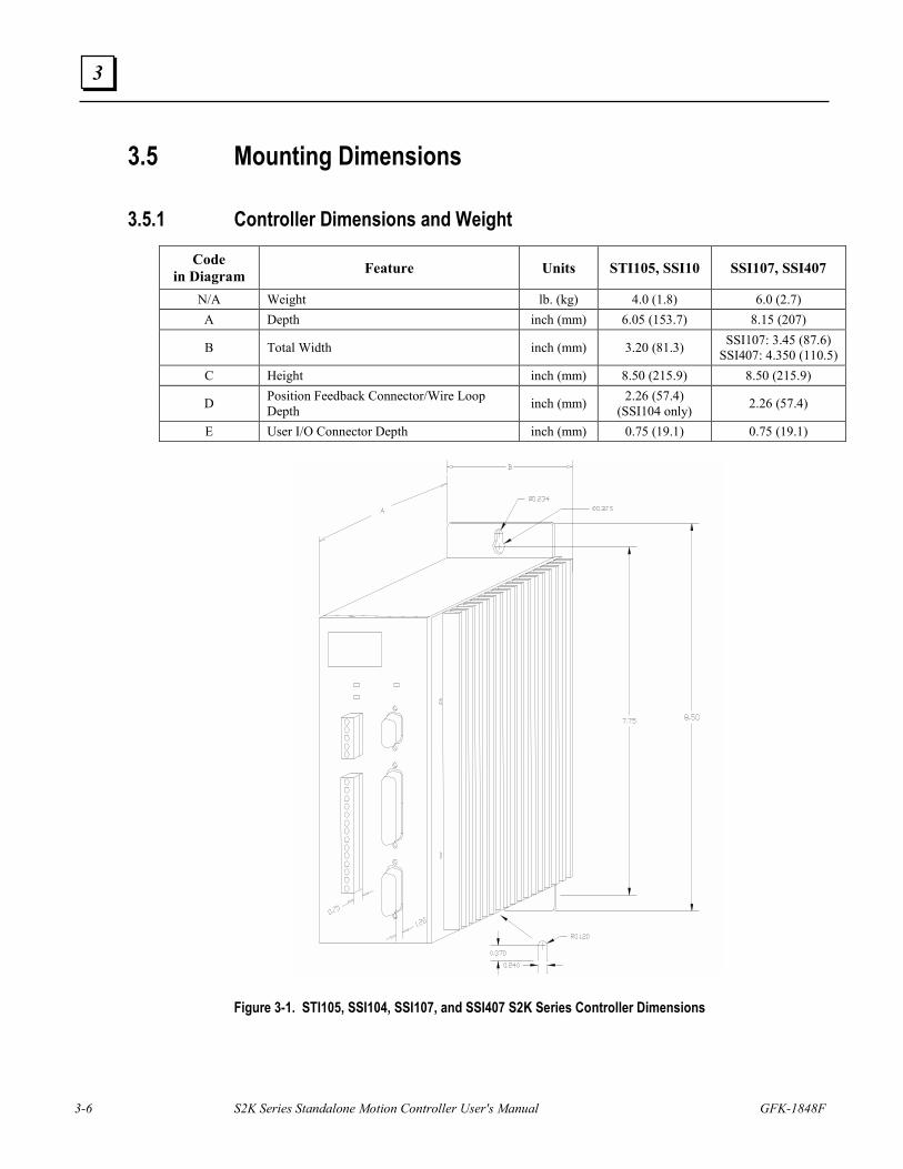
3-6 S2K Series Standalone Motion Controller User's Manual GFK-1848F
3
3.5 Mounting Dimensions
3.5.1 Controller Dimensions and Weight
Code in Diagram Feature Units STI105, SSI10 SSI107, SSI407
N/A Weight lb. (kg) 4.0 (1.8) 6.0 (2.7) A Depth inch (mm) 6.05 (153.7) 8.15 (207)
B Total Width inch (mm) 3.20 (81.3) SSI107: 3.45 (87.6) SSI407: 4.350 (110.5)
C Height inch (mm) 8.50 (215.9) 8.50 (215.9)
D Position Feedback Connector/Wire Loop Depth inch (mm) 2.26 (57.4)
(SSI104 only) 2.26 (57.4)
E User I/O Connector Depth inch (mm) 0.75 (19.1) 0.75 (19.1)
Figure 3-1. STI105, SSI104, SSI107, and SSI407 S2K Series Controller Dimensions
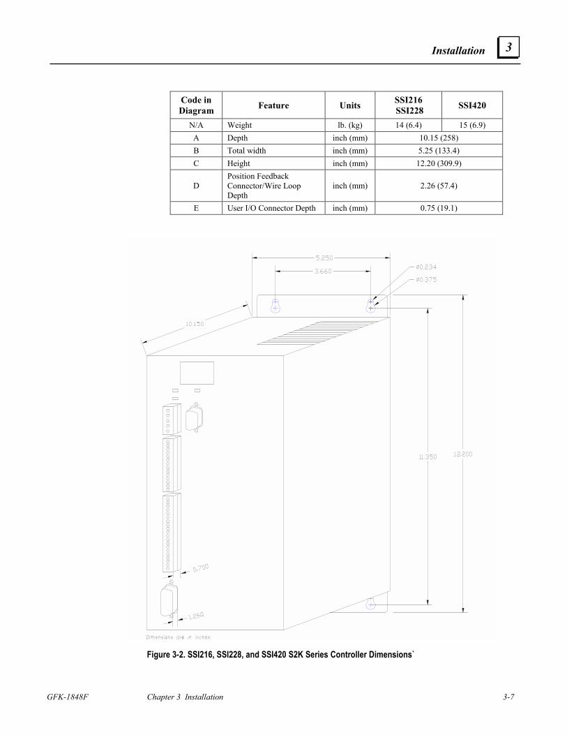
Installation
GFK-1848F Chapter 3 Installation 3-7
3
Code in Diagram Feature Units SSI216
SSI228 SSI420
N/A Weight lb. (kg) 14 (6.4) 15 (6.9) A Depth inch (mm) 10.15 (258) B Total width inch (mm) 5.25 (133.4) C Height inch (mm) 12.20 (309.9)
D Position Feedback Connector/Wire Loop Depth
inch (mm) 2.26 (57.4)
E User I/O Connector Depth inch (mm) 0.75 (19.1)
Figure 3-2. SSI216, SSI228, and SSI420 S2K Series Controller Dimensions`
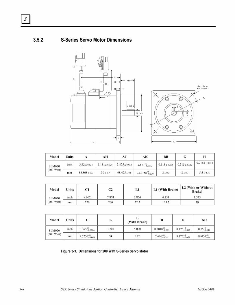
3-8 S2K Series Standalone Motion Controller User's Manual GFK-1848F
3
3.5.2 S-Series Servo Motor Dimensions
A
R
L
G
U
C2
AH
BB
L2
L1C1
4 x H dia onBolt circle AJ
XD S
AJ
RAK
Model Units A AH AJ AK BB G H
inch 024.042.3 ± 028.0181.1 ± 024.0875.3 ± 00012.0877.2 +
− 008.0118.0 ± 012.0315.0 ±010.02165.0 ±
SLM020 (200 Watt)
mm 6.0868.86 ± 7.030 ± 6.0425.98 ± 0030.00758.73 +
− 2.03 ± 3.08 ± 25.05.5 ±
Model Units C1 C2 L1 L1 (With Brake) L2 (With or Without Brake)
inch 8.662 7.874 2.854 4.154 1.535 SLM020 (200 Watt) mm 220 200 72.5 105.5 39
Model Units U L L (With Brake) R S XD
inch 00004.0375.0 +
− 3.701 5.000 0015.03018.0 +
− 0002.0125.0 +
− 0016.075.0 +
− SLM020 (200 Watt) mm 0
009.05250.9 +− 94 127 0
381.0666.7 +− 0
051.0175.3 +− 0
4.0050.19 +−
Figure 3-3. Dimensions for 200 Watt S-Series Servo Motor
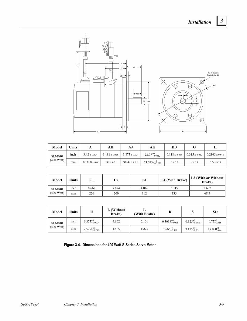
Installation
GFK-1848F Chapter 3 Installation 3-9
3
A
R
L
G
U
C2
AH
BB
L2
L1C1
4 x H dia onBolt circle AJ
XD S
AJ
RAK
Model Units A AH AJ AK BB G H
inch 024.042.3 ± 028.0181.1 ± 024.0875.3 ± 00012.0877.2 +
− 008.0118.0 ± 012.0315.0 ± 010.02165.0 ±SLM040 (400 Watt) mm 6.0868.86 ± 7.030 ± 6.0425.98 ± 0
030.00758.73 +− 2.03 ± 3.08 ± 25.05.5 ±
Model Units C1 C2 L1 L1 (With Brake) L2 (With or Without Brake)
inch 8.662 7.874 4.016 5.315 2.697 SLM040 (400 Watt) mm 220 200 102 135 68.5
Model Units U L (Without Brake)
L (With Brake) R S XD
inch 00004.0375.0 +
− 4.862 6.161 0015.03018.0 +
− 0002.0125.0 +
− 0016.075.0 +
− SLM040 (400 Watt) mm 0
009.05250.9 +− 123.5 156.5 0
381.0666.7 +− 0
051.0175.3 +− 0
4.0050.19 +−
Figure 3-4. Dimensions for 400 Watt S-Series Servo Motor
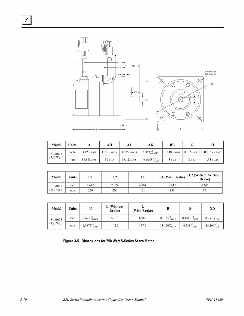
3-10 S2K Series Standalone Motion Controller User's Manual GFK-1848F
3
A
R
L
G
U
C2
AH
BB
L2
L1C1
4 x H dia onBolt circle AJ
XD S
AJ
RAK
Model Units A AH AJ AK BB G H
inch 024.042.3 ± 028.0181.1 ± 024.0875.3 ± 00012.0877.2 +
− 008.0118.0 ± 012.0315.0 ± 010.02165.0 ±SLM075 (750 Watt) mm 6.0868.86 ± 7.030 ± 6.0425.98 ± 0
030.00758.73 +− 2.03 ± 3.08 ± 25.05.5 ±
Model Units C1 C2 L1 L1 (With Brake) L2 (With or Without Brake)
inch 8.662 7.874 4.764 6.142 3.346 SLM075 (750 Watt) mm 220 200 121 156 85
Model Units U L (Without Brake)
L (With Brake) R S XD
inch 00004.0625.0 +
− 5.610 6.988 0015.05165.0 +
− 0002.01885.0 +
− 0016.0952.0 +
− SLM075 (750 Watt) mm 0
011.0875.15 +− 142.5 177.5 0
383.0120.13 +− 0
051.0788.4 +− 0
4.0200.24 +−
Figure 3-5. Dimensions for 750 Watt S-Series Servo Motor
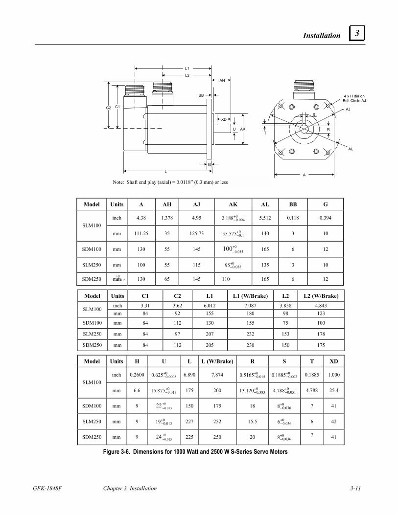
Installation
GFK-1848F Chapter 3 Installation 3-11
3
+0-0.035
A
R
L
G
U
AH
BB
L2
L1
XDS
AK
AJ
4 x H dia onBolt Circle AJ
AL
C1C2
T
Note: Shaft end play (axial) = 0.0118” (0.3 mm) or less
Model Units A AH AJ AK AL BB G
inch 4.38 1.378 4.95 0004.0188.2 +
− 5.512 0.118 0.394 SLM100
mm 111.25 35 125.73 01.0575.55 +
− 140 3 10
SDM100 mm 130 55 145 0035.0100+
− 165 6 12
SLM250 mm 100 55 115 0035.095+
− 135 3 10
SDM250 mm 130 65 145 110 165 6 12
Model Units C1 C2 L1 L1 (W/Brake) L2 L2 (W/Brake) inch 3.31 3.62 6.012 7.087 3.858 4.843
SLM100 mm 84 92 155 180 98 123
SDM100 mm 84 112 130 155 75 100
SLM250 mm 84 97 207 232 153 178
SDM250 mm 84 112 205 230 150 175
Model Units H U L L (W/Brake) R S T XD
inch 0.2600 00005.0625.0 +
− 6.890 7.874 0015.05165.0 +
−0
002.01885.0 +− 0.1885 1.000
SLM100 mm 6.6 0
013.0875.15 +− 175 200 0
383.0120.13 +−
0051.0788.4 +
− 4.788 25.4
SDM100 mm 9 0013.022 +
− 150 175 18 0
036.08+− 7 41
SLM250 mm 9 0013.019+
− 227 252 15.5 0036.06+
− 6 42
SDM250 mm 9 0013.024 +
− 225 250 20 0
036.08+− 7 41
Figure 3-6. Dimensions for 1000 Watt and 2500 W S-Series Servo Motors
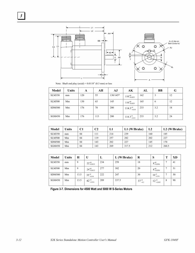
3-12 S2K Series Standalone Motion Controller User's Manual GFK-1848F
3
A
R
L
G
U
AH
BB
L2
L1
XDS
AK
AJ
4 x H dia onBolt Circle AJ
AL
C1C2
T
Note: Shaft end play (axial) = 0.0118” (0.3 mm) or less Model Units A AH AJ AK AL BB G
SLM350 mm 120 55 130/145* 0035.0110+
− 162 3 12
SLM500 Mm 130 65 145 0035.0110+
− 165 6 12
SDM500 Mm 176 70 200 0035.03.114 +
−
233 3.2 18
SGM450 Mm 176 113 200 0035.03.114 +
− 233 3.2 24
Model Units C1 C2 L1 L1 (W/Brake) L2 L2 (W/Brake) SLM350 mm 84 111 214 239 160 185 SLM500 Mm 84 119 257 282 202 227 SDM500 Mm 84 143 202 227 145 170 SGM450 Mm 84 143 269 317.5 212 260.5
Model Units H U L L (W/Brake) R S T XD SLM350 mm 9 0
013.022+− 234 259 18 0
036.08+− 7 41
SLM500 Mm 9 0013.024+
− 277 302 20 0036.08+
− 7 51
SDM500 Mm 13.5 0016.035+
− 222 247 30 0
036.010+−
7 50
SGM450 Mm 13.5 0016.042 +
− 289 337.5 0
2.037+−
0043.012+
− 8 90
Figure 3-7. Dimensions for 4500 Watt and 5000 W S-Series Motors
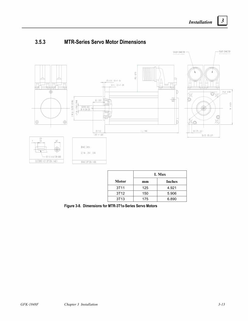
Installation
GFK-1848F Chapter 3 Installation 3-13
3
3.5.3 MTR-Series Servo Motor Dimensions
L Max
Motor mm Inches 3T11 125 4.921 3T12 150 5.906 3T13 175 6.890
Figure 3-8. Dimensions for MTR-3T1x-Series Servo Motors
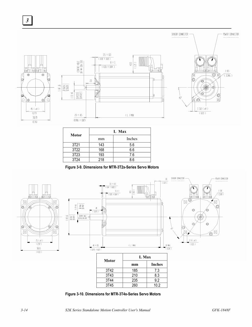
3-14 S2K Series Standalone Motion Controller User's Manual GFK-1848F
3
Figure 3-9. Dimensions for MTR-3T2x-Series Servo Motors
Figure 3-10. Dimensions for MTR-3T4x-Series Servo Motors
L Max Motor
mm Inches 3T21 143 5.6 3T22 168 6.6 3T23 193 7.6 3T24 218 8.6
L Max Motor
mm Inches 3T42 185 7.3 3T43 210 8.3 3T44 235 9.2 3T45 260 10.2
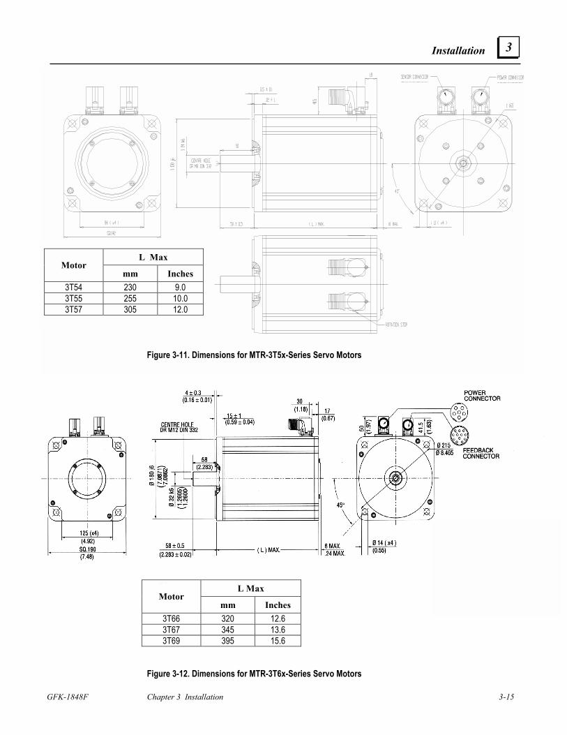
Installation
GFK-1848F Chapter 3 Installation 3-15
3
Figure 3-11. Dimensions for MTR-3T5x-Series Servo Motors
L Max Motor
mm Inches 3T66 320 12.6 3T67 345 13.6 3T69 395 15.6
Figure 3-12. Dimensions for MTR-3T6x-Series Servo Motors
L Max Motor
mm Inches 3T54 230 9.0 3T55 255 10.0 3T57 305 12.0
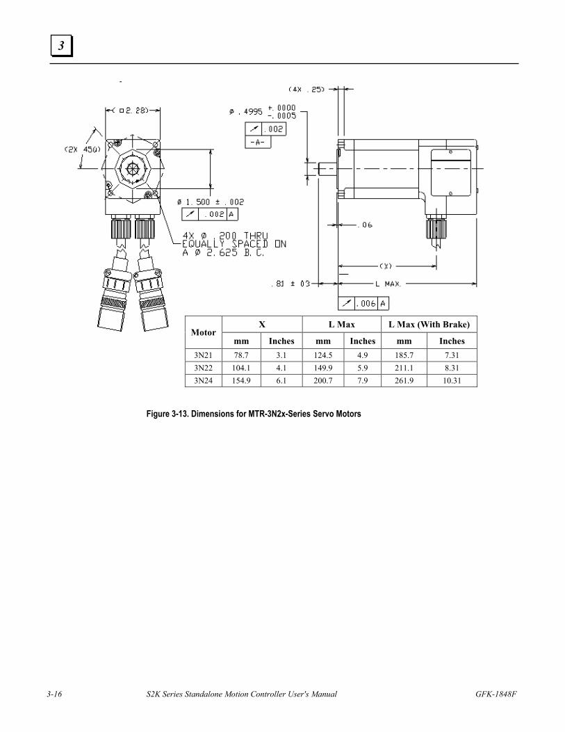
3-16 S2K Series Standalone Motion Controller User's Manual GFK-1848F
3
Figure 3-13. Dimensions for MTR-3N2x-Series Servo Motors
X L Max L Max (With Brake) Motor
mm Inches mm Inches mm Inches 3N21 78.7 3.1 124.5 4.9 185.7 7.31 3N22 104.1 4.1 149.9 5.9 211.1 8.31 3N24 154.9 6.1 200.7 7.9 261.9 10.31
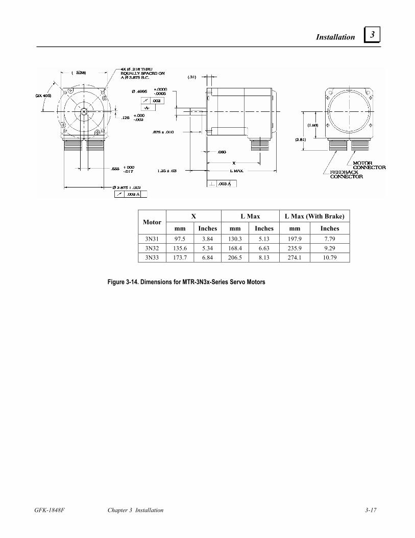
Installation
GFK-1848F Chapter 3 Installation 3-17
3
Figure 3-14. Dimensions for MTR-3N3x-Series Servo Motors
X L Max L Max (With Brake) Motor
mm Inches mm Inches mm Inches 3N31 97.5 3.84 130.3 5.13 197.9 7.79 3N32 135.6 5.34 168.4 6.63 235.9 9.29 3N33 173.7 6.84 206.5 8.13 274.1 10.79
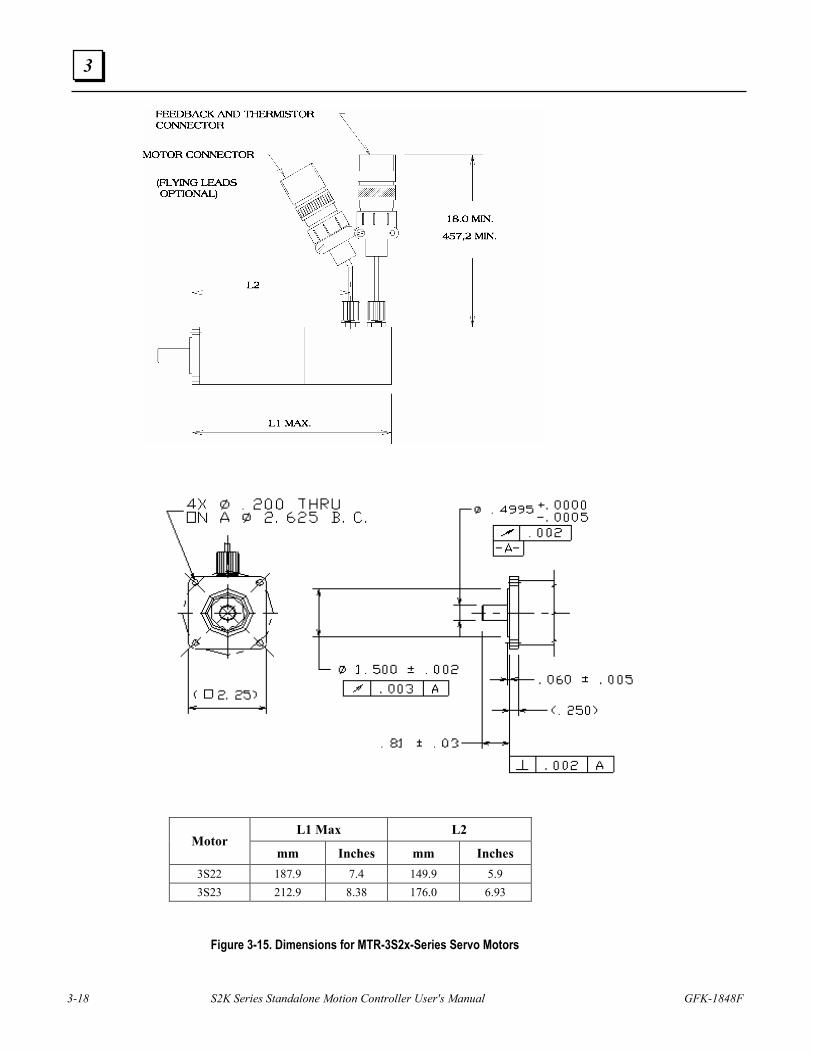
3-18 S2K Series Standalone Motion Controller User's Manual GFK-1848F
3
Figure 3-15. Dimensions for MTR-3S2x-Series Servo Motors
L1 Max L2 Motor
mm Inches mm Inches 3S22 187.9 7.4 149.9 5.9 3S23 212.9 8.38 176.0 6.93
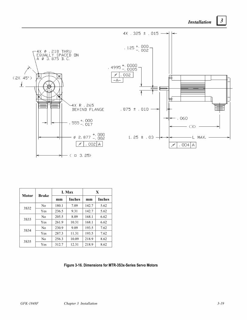
Installation
GFK-1848F Chapter 3 Installation 3-19
3
Figure 3-16. Dimensions for MTR-3S3x-Series Servo Motors
L Max X Motor Brake
mm Inches mm Inches No 180.1 7.09 142.7 5.62
3S32 Yes 236.5 9.31 142.7 5.62 No 205.5 8.09 168.1 6.62
3S33 Yes 261.9 10.31 168.1 6.62 No 230.9 9.09 193.5 7.62
3S34 Yes 287.3 11.31 193.5 7.62 No 256.3 10.09 218.9 8.62
3S35 Yes 312.7 12.31 218.9 8.62
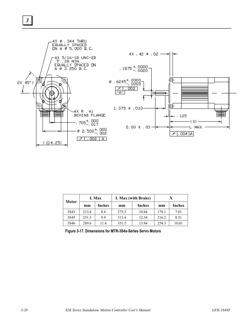
3-20 S2K Series Standalone Motion Controller User's Manual GFK-1848F
3
Figure 3-17. Dimensions for MTR-3S4x-Series Servo Motors
L Max L Max (with Brake) X Motor
mm Inches mm Inches mm Inches 3S43 213.4 8.4 275.3 10.84 178.1 7.01 3S45 251.5 9.9 313.4 12.34 216.2 8.51 3S46 289.6 11.4 351.5 13.84 254.3 10.01
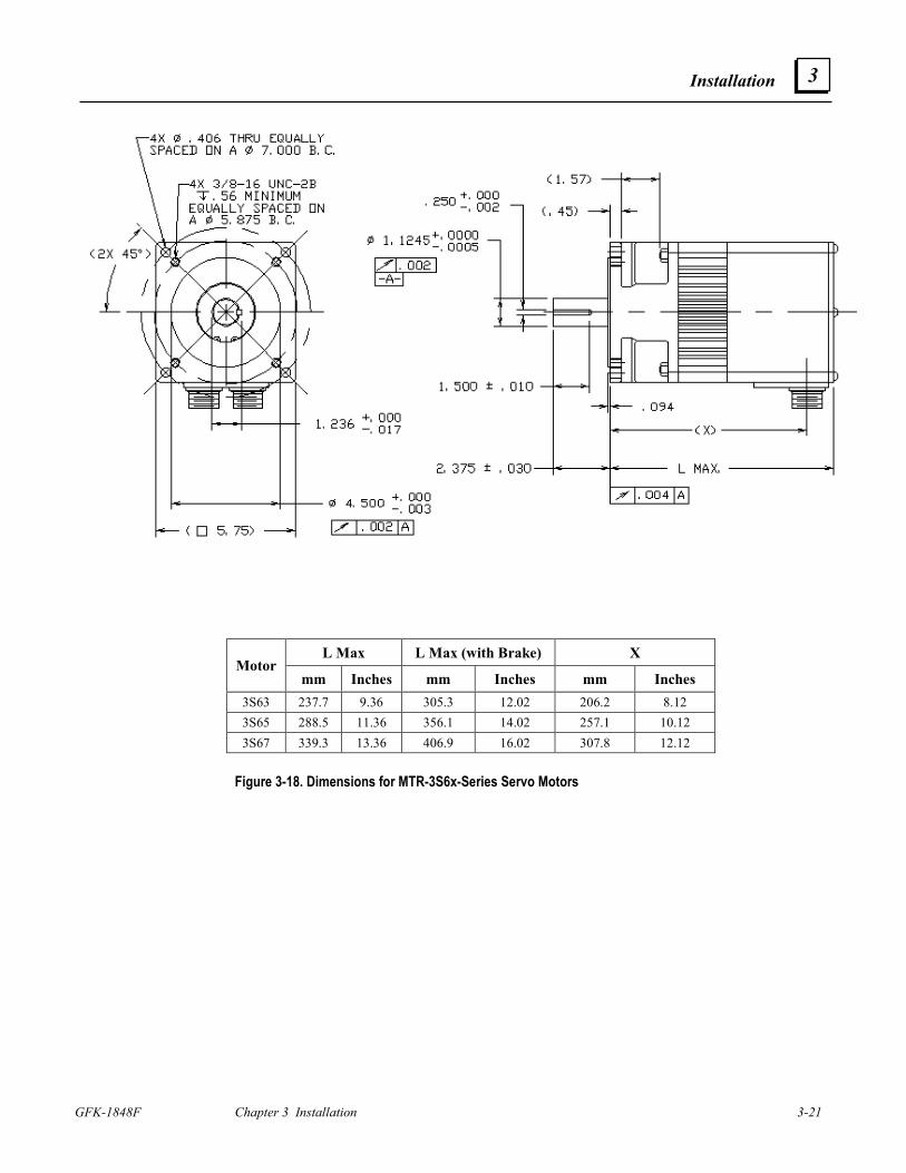
Installation
GFK-1848F Chapter 3 Installation 3-21
3
Figure 3-18. Dimensions for MTR-3S6x-Series Servo Motors
L Max L Max (with Brake) X Motor
mm Inches mm Inches mm Inches 3S63 237.7 9.36 305.3 12.02 206.2 8.12 3S65 288.5 11.36 356.1 14.02 257.1 10.12 3S67 339.3 13.36 406.9 16.02 307.8 12.12
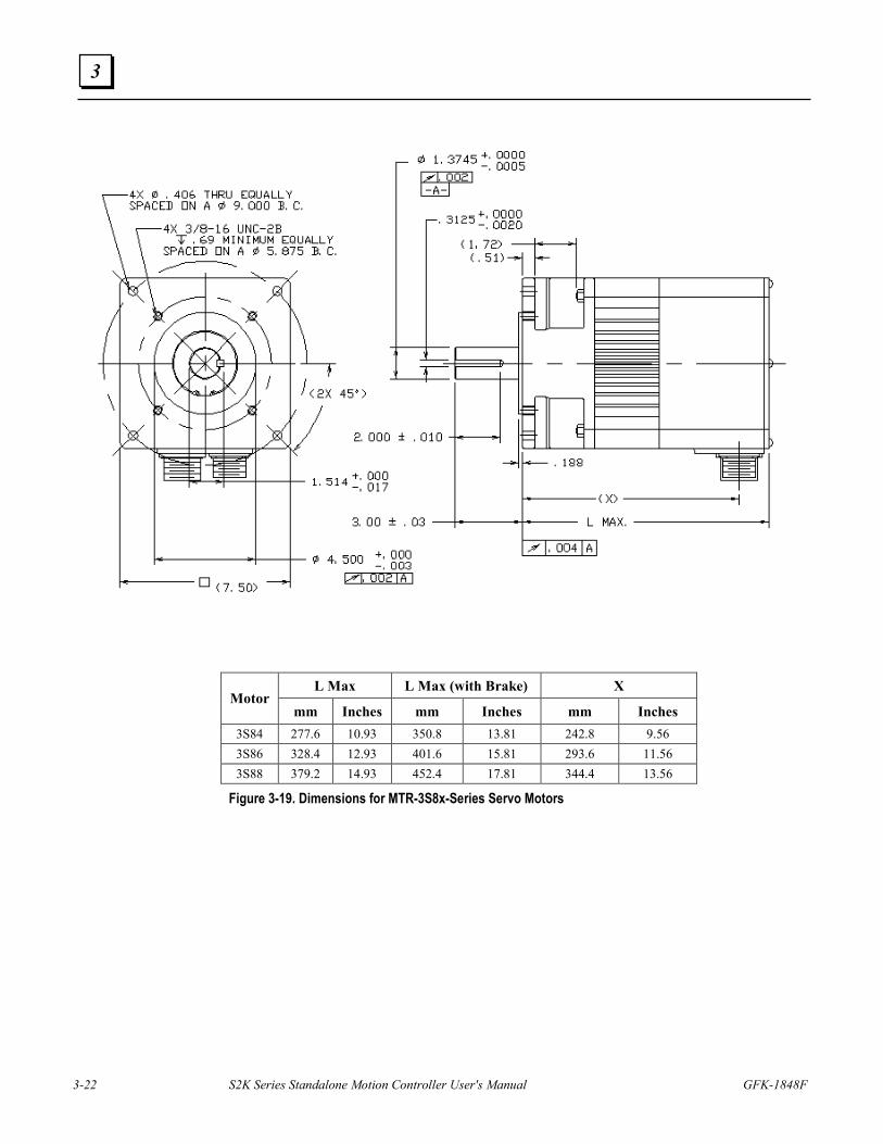
3-22 S2K Series Standalone Motion Controller User's Manual GFK-1848F
3
L Max L Max (with Brake) X Motor
mm Inches mm Inches mm Inches 3S84 277.6 10.93 350.8 13.81 242.8 9.56 3S86 328.4 12.93 401.6 15.81 293.6 11.56 3S88 379.2 14.93 452.4 17.81 344.4 13.56
Figure 3-19. Dimensions for MTR-3S8x-Series Servo Motors
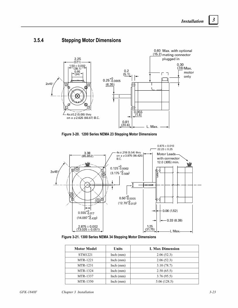
Installation
GFK-1848F Chapter 3 Installation 3-23
3
3.5.4 Stepping Motor Dimensions
Figure 3-20. 1200 Series NEMA 23 Stepping Motor Dimensions
Figure 3-21. 1300 Series NEMA 34 Stepping Motor Dimensions
Motor Model Units L Max Dimension STM1221 Inch (mm) 2.06 (52.3) MTR-1221 Inch (mm) 2.06 (52.3) MTR-1231 Inch (mm) 3.10 (78.7) MTR-1324 Inch (mm) 2.58 (65.5) MTR-1337 Inch (mm) 3.76 (95.5) MTR-1350 Inch (mm) 5.06 (128.5)
0.875 ± 0.010 22.23 ± 0.25
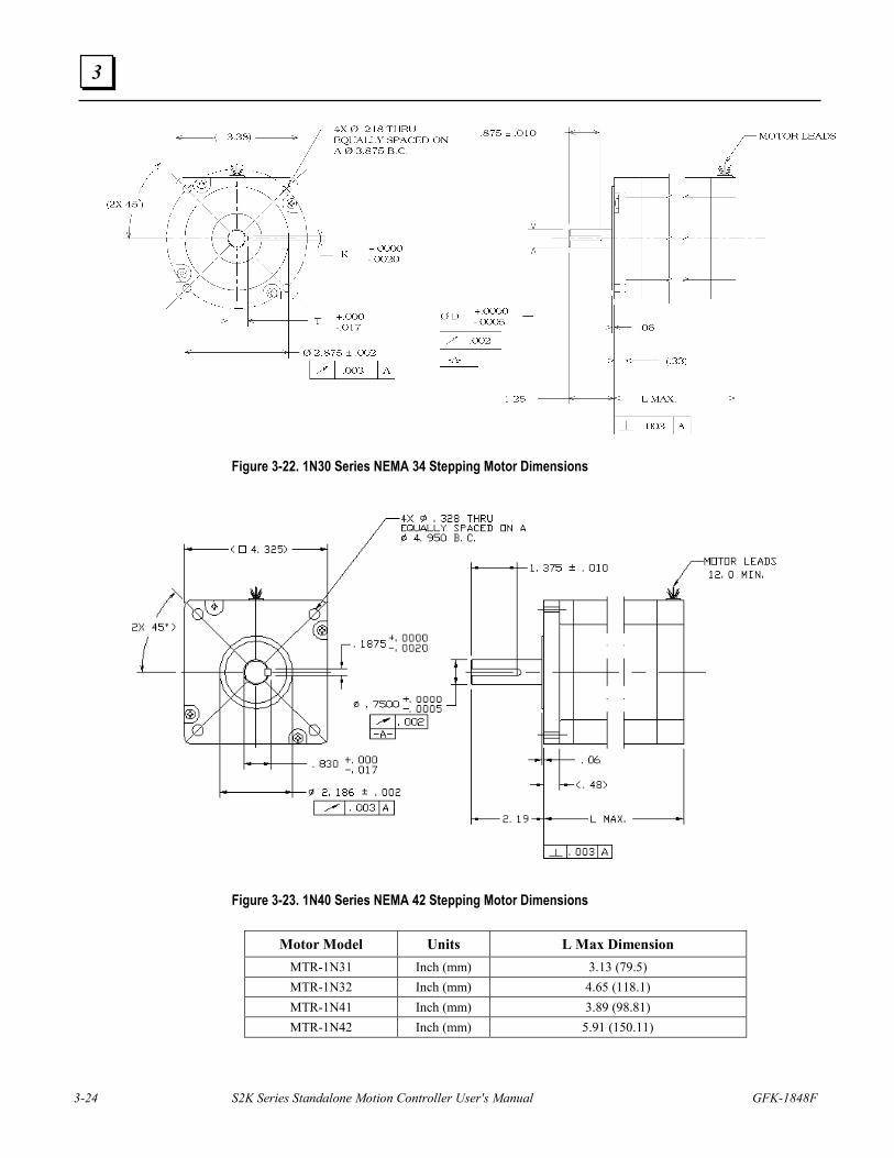
3-24 S2K Series Standalone Motion Controller User's Manual GFK-1848F
3
Figure 3-22. 1N30 Series NEMA 34 Stepping Motor Dimensions
Figure 3-23. 1N40 Series NEMA 42 Stepping Motor Dimensions
Motor Model Units L Max Dimension MTR-1N31 Inch (mm) 3.13 (79.5) MTR-1N32 Inch (mm) 4.65 (118.1) MTR-1N41 Inch (mm) 3.89 (98.81) MTR-1N42 Inch (mm) 5.91 (150.11)
Installation
GFK-1848F Chapter 3 Installation 3-25
3
3.6 Wiring 3.6.1 General Wiring Considerations
See Chapter 2 for AC supply power requirements, fuse and isolation transformer ratings.
All power, input, and output must be in accordance with Class I, Division 2 wiring methods as defined in Article 501-4(b) of the National Electrical Code, NFPA 70 for installations within the United States, or as specified in Section 18-152 of the Canadian Electrical Code for installation within Canada.
Attach wiring connections for the main circuit according to Tables 3-2 through 3-4 while observing the following cautions:
Caution Use vinyl-sheathed or equivalent wire rated at 250 VAC or greater for 230 VAC S2K models or 600VAC or greater for 460 VAC S2K models. Wire size should be determined considering ampacity and codes. Never connect AC main power to output terminals. Never allow wire leads to contact the enclosure. Never operate the S2K controllers without an earth ground.
Warning When using this equipment in a Hazardous (classified) location: Explosion hazard--substitution of components may impair suitability for Class I, Division 2; Explosion hazard--when in hazardous locations, turn off power before replacing or wiring modules; Explosion hazard--do not disconnect equipment unless power has been switched off or the area is known to be non-hazardous.
3.6.2 AC Supply and Motor Wiring and Grounding The S2K motion controllers are to be permanently connected in a closed electrical operating area. The mains input and motor output connections are made to the screw terminal connector located on the bottom of the S2K controller. The controllers are designed to operate with input voltages as shown in Chapter 2. No isolation transformer is required if the supply voltage is within the specified range. For the S2K servo controllers, the maximum achievable motor speed is directly related to the input voltage. For best performance connect these models to a three-phase 230 or 460 VAC power source depending on the controller’s rated voltage.
All of the terminals marked with the symbol are connected to the chassis ground. Connect the terminal at the mains input end of the connector to the panel earth ground. Connect the terminal near the motor output terminals to the motor frame ground wire in the motor power cable. DO NOT OPERATE THE S2K CONTROLLERS WITHOUT AN EARTH GROUND.
Design Notice. Where residual-current-operated protective device (RCD) is used for protection in case of direct or indirect contact, only RCD’s of Type B is allowed on the supply side of this Electronic Equipment (EE). Otherwise another protective measure shall be applied such as separation of the EE from the environment by double or reinforced insulation or isolation of EE and supply system by a transformer. To meet the requirements of EN55011 and CE mark, EMI power line filters shall be employed between the motion controller and the supply mains. Table 3-1 lists suggested mains filters.
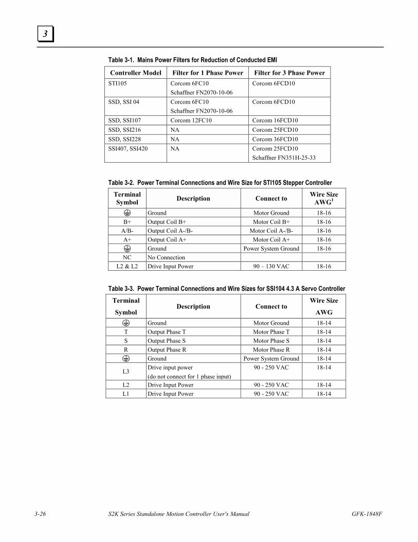
3-26 S2K Series Standalone Motion Controller User's Manual GFK-1848F
3
Table 3-1. Mains Power Filters for Reduction of Conducted EMI
Controller Model Filter for 1 Phase Power Filter for 3 Phase Power STI105 Corcom 6FC10
Schaffner FN2070-10-06 Corcom 6FCD10
SSD, SSI 04 Corcom 6FC10 Schaffner FN2070-10-06
Corcom 6FCD10
SSD, SSI107 Corcom 12FC10 Corcom 16FCD10 SSD, SSI216 NA Corcom 25FCD10 SSD, SSI228 NA Corcom 36FCD10 SSI407, SSI420 NA Corcom 25FCD10
Schaffner FN351H-25-33
Table 3-2. Power Terminal Connections and Wire Size for STI105 Stepper Controller Terminal Symbol Description Connect to Wire Size
AWG1
Ground Motor Ground 18-16 B+ Output Coil B+ Motor Coil B+ 18-16
A/B- Output Coil A-/B- Motor Coil A-/B- 18-16 A+ Output Coil A+ Motor Coil A+ 18-16
Ground Power System Ground 18-16 NC No Connection
L2 & L2 Drive Input Power 90 – 130 VAC 18-16
Table 3-3. Power Terminal Connections and Wire Sizes for SSI104 4.3 A Servo Controller
Terminal
Symbol Description Connect to
Wire Size
AWG
Ground Motor Ground 18-14 T Output Phase T Motor Phase T 18-14 S Output Phase S Motor Phase S 18-14 R Output Phase R Motor Phase R 18-14
Ground Power System Ground 18-14
L3 Drive input power (do not connect for 1 phase input)
90 - 250 VAC 18-14
L2 Drive Input Power 90 - 250 VAC 18-14 L1 Drive Input Power 90 - 250 VAC 18-14
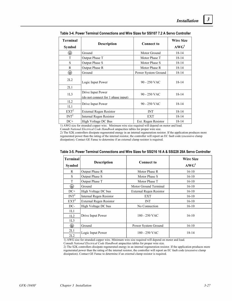
Installation
GFK-1848F Chapter 3 Installation 3-27
3
Table 3-4. Power Terminal Connections and Wire Sizes for SSI107 7.2 A Servo Controller
Terminal
Symbol Description Connect to
Wire Size
AWG1
Ground Motor Ground 18-14 T Output Phase T Motor Phase T 18-14 S Output Phase S Motor Phase S 18-14 R Output Phase R Motor Phase R 18-14
Ground Power System Ground 18-14
2L2
2L1 Logic Input Power 90 - 250 VAC 18-14
1L3 Drive Input Power (do not connect for 1 phase input)
90 - 250 VAC 18-14
1L2 1L1
Drive Input Power 90 - 250 VAC 18-14
EXT2 External Regen Resistor INT 18-14 INT2 Internal Regen Resistor EXT 18-14 DC+ High Voltage DC Bus Ext. Regen Resistor 18-14
1) AWG size for stranded copper wire. Minimum wire size required will depend on motor and load. Consult National Electrical Code Handbook ampacities tables for proper wire size. 2) The S2K controllers dissipate regenerated energy in an internal regeneration resistor. If the application produces more regenerated power than the rating of the internal resistor, the controller will report an EC fault code (excessive clamp dissipation). Contact GE Fanuc to determine if an external clamp resistor is required. Table 3-5. Power Terminal Connections and Wire Sizes for SSI216 16 A & SSI228 28A Servo Controller
Terminal
Symbol Description Connect to
Wire Size
AWG1 R Output Phase R Motor Phase R 16-10S Output Phase S Motor Phase S 16-10T Output Phase T Motor Phase T 16-10
Ground Motor Ground Terminal 16-10DC+ High Voltage DC bus External Regen Resistor 16-10INT2 Internal Regen Resistor EXT 16-10EXT2 External Regen Resistor INT 16-10DC- High Voltage DC bus No Connection 16-101L1 1L2 1L3
Drive Input Power 180 - 250 VAC 16-10
Ground Power System Ground 16-102L1 2L2
Logic Input Power 180 - 250 VAC 18-14
1) AWG size for stranded copper wire. Minimum wire size required will depend on motor and load. Consult National Electrical Code Handbook ampacities tables for proper wire size. 2) The S2K controllers dissipate regenerated energy in an internal regeneration resistor. If the application produces more regenerated power than the rating of the internal resistor, the controller will report an EC fault code (excessive clamp dissipation). Contact GE Fanuc to determine if an external clamp resistor is required.
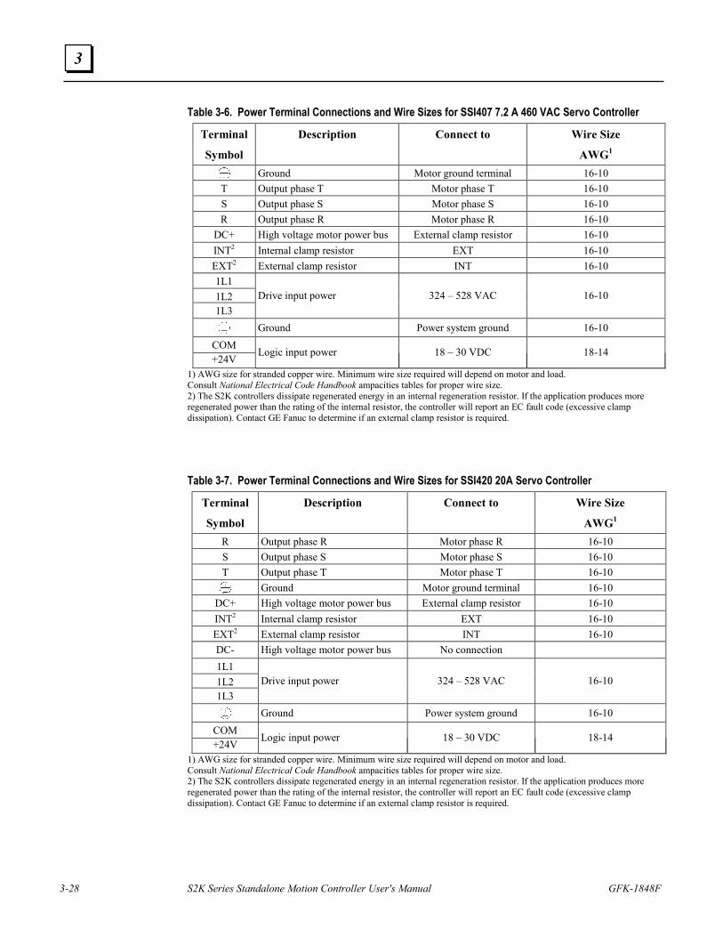
3-28 S2K Series Standalone Motion Controller User's Manual GFK-1848F
3
Table 3-6. Power Terminal Connections and Wire Sizes for SSI407 7.2 A 460 VAC Servo Controller
Terminal
Symbol
Description Connect to Wire Size
AWG1
Ground Motor ground terminal 16-10 T Output phase T Motor phase T 16-10 S Output phase S Motor phase S 16-10 R Output phase R Motor phase R 16-10
DC+ High voltage motor power bus External clamp resistor 16-10 INT2 Internal clamp resistor EXT 16-10 EXT2 External clamp resistor INT 16-10 1L1 1L2 1L3
Drive input power 324 – 528 VAC 16-10
Ground Power system ground 16-10 COM +24V
Logic input power 18 – 30 VDC 18-14
1) AWG size for stranded copper wire. Minimum wire size required will depend on motor and load. Consult National Electrical Code Handbook ampacities tables for proper wire size. 2) The S2K controllers dissipate regenerated energy in an internal regeneration resistor. If the application produces more regenerated power than the rating of the internal resistor, the controller will report an EC fault code (excessive clamp dissipation). Contact GE Fanuc to determine if an external clamp resistor is required.
Table 3-7. Power Terminal Connections and Wire Sizes for SSI420 20A Servo Controller
Terminal
Symbol
Description Connect to Wire Size
AWG1 R Output phase R Motor phase R 16-10 S Output phase S Motor phase S 16-10 T Output phase T Motor phase T 16-10
Ground Motor ground terminal 16-10 DC+ High voltage motor power bus External clamp resistor 16-10 INT2 Internal clamp resistor EXT 16-10 EXT2 External clamp resistor INT 16-10 DC- High voltage motor power bus No connection 1L1 1L2 1L3
Drive input power 324 – 528 VAC 16-10
Ground Power system ground 16-10 COM +24V
Logic input power 18 – 30 VDC 18-14
1) AWG size for stranded copper wire. Minimum wire size required will depend on motor and load. Consult National Electrical Code Handbook ampacities tables for proper wire size. 2) The S2K controllers dissipate regenerated energy in an internal regeneration resistor. If the application produces more regenerated power than the rating of the internal resistor, the controller will report an EC fault code (excessive clamp dissipation). Contact GE Fanuc to determine if an external clamp resistor is required.
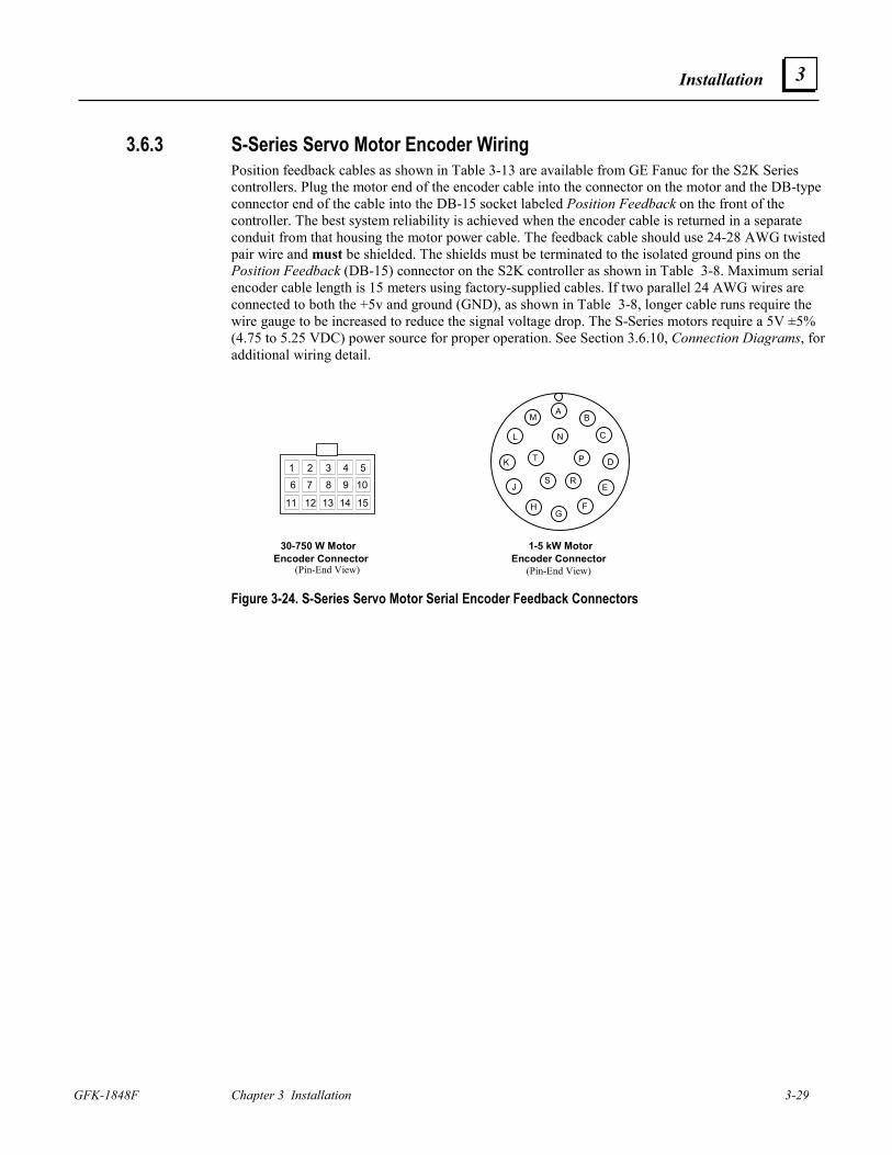
Installation
GFK-1848F Chapter 3 Installation 3-29
3
3.6.3 S-Series Servo Motor Encoder Wiring Position feedback cables as shown in Table 3-13 are available from GE Fanuc for the S2K Series controllers. Plug the motor end of the encoder cable into the connector on the motor and the DB-type connector end of the cable into the DB-15 socket labeled Position Feedback on the front of the controller. The best system reliability is achieved when the encoder cable is returned in a separate conduit from that housing the motor power cable. The feedback cable should use 24-28 AWG twisted pair wire and must be shielded. The shields must be terminated to the isolated ground pins on the Position Feedback (DB-15) connector on the S2K controller as shown in Table 3-8. Maximum serial encoder cable length is 15 meters using factory-supplied cables. If two parallel 24 AWG wires are connected to both the +5v and ground (GND), as shown in Table 3-8, longer cable runs require the wire gauge to be increased to reduce the signal voltage drop. The S-Series motors require a 5V ±5% (4.75 to 5.25 VDC) power source for proper operation. See Section 3.6.10, Connection Diagrams, for additional wiring detail.
30-750 W MotorEncoder Connector
1-5 kW MotorEncoder Connector
54321
1514131211
109876
AB
D
E
FG
H
J
K
L
M
T P
S R
N
(Pin-End View)(Pin-End View)
C
Figure 3-24. S-Series Servo Motor Serial Encoder Feedback Connectors
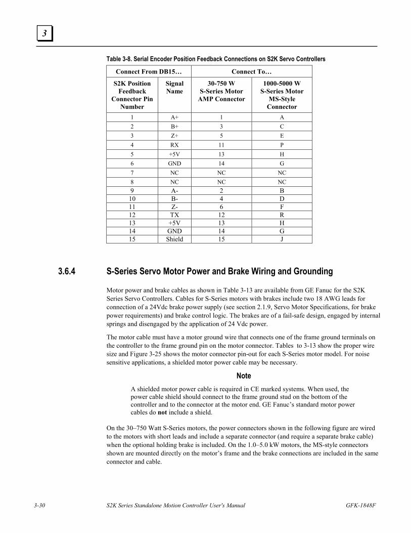
3-30 S2K Series Standalone Motion Controller User's Manual GFK-1848F
3
Table 3-8. Serial Encoder Position Feedback Connections on S2K Servo Controllers
Connect From DB15… Connect To…
S2K Position Feedback
Connector Pin Number
Signal Name
30-750 W S-Series Motor
AMP Connector
1000-5000 W S-Series Motor
MS-Style Connector
1 A+ 1 A 2 B+ 3 C 3 Z+ 5 E 4 RX 11 P 5 +5V 13 H 6 GND 14 G 7 NC NC NC 8 NC NC NC 9 A- 2 B
10 B- 4 D 11 Z- 6 F 12 TX 12 R 13 +5V 13 H 14 GND 14 G 15 Shield 15 J
3.6.4 S-Series Servo Motor Power and Brake Wiring and Grounding
Motor power and brake cables as shown in Table 3-13 are available from GE Fanuc for the S2K Series Servo Controllers. Cables for S-Series motors with brakes include two 18 AWG leads for connection of a 24Vdc brake power supply (see section 2.1.9, Servo Motor Specifications, for brake power requirements) and brake control logic. The brakes are of a fail-safe design, engaged by internal springs and disengaged by the application of 24 Vdc power.
The motor cable must have a motor ground wire that connects one of the frame ground terminals on the controller to the frame ground pin on the motor connector. Tables to 3-13 show the proper wire size and Figure 3-25 shows the motor connector pin-out for each S-Series motor model. For noise sensitive applications, a shielded motor power cable may be necessary.
Note A shielded motor power cable is required in CE marked systems. When used, the power cable shield should connect to the frame ground stud on the bottom of the controller and to the connector at the motor end. GE Fanuc’s standard motor power cables do not include a shield.
On the 30–750 Watt S-Series motors, the power connectors shown in the following figure are wired to the motors with short leads and include a separate connector (and require a separate brake cable) when the optional holding brake is included. On the 1.0–5.0 kW motors, the MS-style connectors shown are mounted directly on the motor’s frame and the brake connections are included in the same connector and cable.
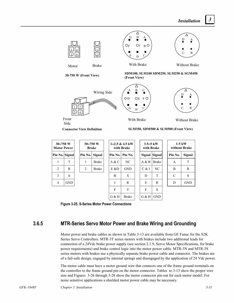
Installation
GFK-1848F Chapter 3 Installation 3-31
3
1
42
312
Motor Brake
30-750 W (Front View)
A B C
D E F
G H I
A
BC
D
With Brake Without Brake
SLM350, SDM500 & SLM500 (Front View)
G H A
F I B
E D C
A
BC
D
With Brake Without Brake
SDM100, SLM100 SDM250, SLM250 & SGM450(Front View)
1
42
3
Connector View Definition
Wiring Side
FrontSide
30−−−−750 W Motor Power
30−−−−750 W Brake
1−−−−2.5 & 4.5 kW with Brake
3.5−−−−5 kW with Brake
1-5 kW without Brake
Pin No. Signal Pin No. Signal Pin No. Pin No. Signal Signal Pin No. Signal
1 T 1 Brake A & C NC A & B Brake A T
2 R 2 Brake E &D GND C & I NC B R
3 S B S D T C S
4 GND I R E R D GND
F T F S
G & H Brake G & H GND
Figure 3-25. S-Series Motor Power Connections
3.6.5 MTR-Series Servo Motor Power and Brake Wiring and Grounding
Motor power and brake cables as shown in Table 3-13 are available from GE Fanuc for the S2K Series Servo Controllers. MTR-3T series motors with brakes include two additional leads for connection of a 24Vdc brake power supply (see section 2.1.9, Servo Motor Specifications, for brake power requirements) and brake control logic into the motor power cable. MTR-3N and MTR-3S series motors with brakes use a physically separate brake power cable and connector. The brakes are of a fail-safe design, engaged by internal springs and disengaged by the application of 24 Vdc power.
The motor cable must have a motor ground wire that connects one of the frame ground terminals on the controller to the frame ground pin on the motor connector. Tables to 3-13 show the proper wire size and Figures 3-26 through 3-28 show the motor connector pin-out for each motor model. For noise sensitive applications a shielded motor power cable may be necessary.
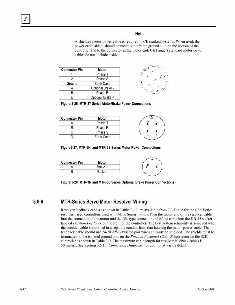
3-32 S2K Series Standalone Motion Controller User's Manual GFK-1848F
3
Note A shielded motor power cable is required in CE marked systems. When used, the power cable shield should connect to the frame ground stud on the bottom of the controller and to the connector at the motor end. GE Fanuc’s standard motor power cables do not include a shield.
Connector Pin Motor
1 Phase T 2 Phase S
Ground Earth Case 4 Optional Brake - 5 Phase R E Optional Brake +
Figure 3-26. MTR-3T Series Motor/Brake Power Connections Connector Pin Motor
A Phase T B Phase R C Phase S D Earth Case
Figure3-27. MTR-3N and MTR-3S Series Motor Power Connections Connector Pin Motor
A Brake + B Brake -
Figure 3-28. MTR-3N and MTR-3S Series Optional Brake Power Connections
3.6.6 MTR-Series Servo Motor Resolver Wiring Resolver feedback cables as shown in Table 3-13 are available from GE Fanuc for the S2K Series resolver-based controllers used with MTR-Series motors. Plug the motor end of the resolver cable into the connector on the motor and the DB-type connector end of the cable into the DB-15 socket labeled Position Feedback on the front of the controller. The best system reliability is achieved when the encoder cable is returned in a separate conduit from that housing the motor power cable. The feedback cable should use 24-28 AWG twisted pair wire and must be shielded. The shields must be terminated to the isolated ground pins on the Position Feedback (DB-15) connector on the S2K controller as shown in Table 3-9. The maximum cable length for resolver feedback cables is 50 meters. See Section 3.6.10, Connection Diagrams, for additional wiring detail.
A
BC
D
AB
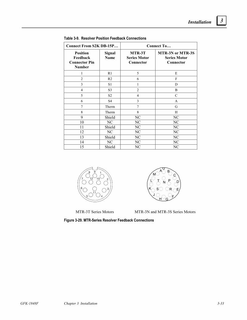
Installation
GFK-1848F Chapter 3 Installation 3-33
3
Table 3-9. Resolver Position Feedback Connections
Connect From S2K DB-15P… Connect To…
Position Feedback
Connector Pin Number
Signal Name
MTR-3T Series Motor
Connector
MTR-3N or MTR-3S Series Motor
Connector
1 R1 5 E 2 R2 6 F 3 S1 1 D 4 S3 2 B 5 S2 4 C 6 S4 3 A 7 Therm 7 G 8 Therm 8 H 9 Shield NC NC
10 NC NC NC 11 Shield NC NC 12 NC NC NC 13 Shield NC NC 14 NC NC NC 15 Shield NC NC
Figure 3-29. MTR-Series Resolver Feedback Connections
A BC
D
E
FGH
J
K
L
M
T P
S R
N
MTR-3T Series Motors MTR-3N and MTR-3S Series Motors
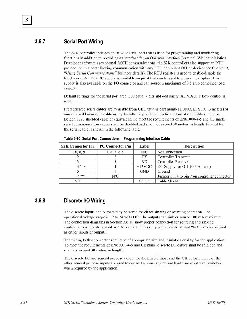
3-34 S2K Series Standalone Motion Controller User's Manual GFK-1848F
3
3.6.7 Serial Port Wiring
The S2K controller includes an RS-232 serial port that is used for programming and monitoring functions in addition to providing an interface for an Operator Interface Terminal. While the Motion Developer software uses normal ASCII communications, the S2K controllers also support an RTU protocol on this port allowing communication with any RTU-compliant OIT or device (see Chapter 9, “Using Serial Communications” for more details). The RTU register is used to enable/disable the RTU mode. A +12 VDC supply is available on pin 4 that can be used to power the display. This supply is also available on the I/O connector and can source a maximum of 0.5 amp combined load current.
Default settings for the serial port are 9,600 baud, 7 bits and odd parity. XON/XOFF flow control is used.
Prefabricated serial cables are available from GE Fanuc as part number IC800SKCS030 (3 meters) or you can build your own cable using the following S2K connection information. Cable should be Belden 8723 shielded cable or equivalent. To meet the requirements of EN61000-4-5 and CE mark, serial communication cables shall be shielded and shall not exceed 30 meters in length. Pin-out for the serial cable is shown in the following table.
Table 3-10. Serial Port ConnectionsProgramming Interface Cable
S2K Connector Pin PC Connector Pin Label Description 1, 6, 8, 9 1, 6 ,7 ,8, 9 N/C No Connection
2 2 TX Controller Transmit 3 3 RX Controller Receive 4 4 +12VDC DC Supply for OIT (0.5 A max.) 5 5 GND Ground 7 N/C Jumper pin 4 to pin 7 on controller connector
N/C 5 Shield Cable Shield
3.6.8 Discrete I/O Wiring
The discrete inputs and outputs may be wired for either sinking or sourcing operation. The operational voltage range is 12 to 24 volts DC. The outputs can sink or source 100 mA maximum. The connection diagrams in Section 3.6.10 show proper connection for sourcing and sinking configurations. Points labeled as “IN_xx” are inputs only while points labeled “I/O_xx” can be used as either inputs or outputs.
The wiring to this connector should be of appropriate size and insulation quality for the application. To meet the requirements of EN61000-4-5 and CE mark, discrete I/O cables shall be shielded and shall not exceed 30 meters in length.
The discrete I/O are general purpose except for the Enable Input and the OK output. Three of the other general purpose inputs are used to connect a home switch and hardware overtravel switches when required by the application.
Installation
GFK-1848F Chapter 3 Installation 3-35
3
3.6.8.1 Connecting Homing and Overtravel Switch Inputs
Many applications require the use of a home position sensor to define the reference or “home” position of the axis. The S2K controllers have a number of home reference commands that can be used to home the axis to various reference points such as the encoder marker (RMF, RMR), a home switch (RHF, RHR) and the overtravel switches (ROF, ROR). When a home sensor is used, it must be wired to the Discrete Input 1 (DI1) terminal. When the controller executes one of the Run To Home Input commands (RHF, RHR), it will look for a state change on this physical input.
When the controller executes a Home To Overtravel Input command (ROF, ROR), it will look for a state change on the respective overtravel switch. The forward overtravel switch must be connected to Discrete Input 2 (DI2), and the reverse overtravel switch must be connected to Discrete Input 3 (DI3). To use these end-of-travel switches as a home sensor, it is not necessary to have the hardware overtravel inputs enabled (OTE=1). However, if the application requires end-of-travel protection, you must enable the hardware overtravel inputs by setting the Overtravel Enable register true (OTE=1).
3.6.8.2 Connecting Handwheel Encoder Inputs
The controller has a special function that enables the connection of a handwheel encoder, typically used to jog the axis at a low speed, to two of the discrete inputs. When the Handwheel Enable register is set to true (HWE=1), Discrete Input 5 (DI5) is used to connect the A-channel of the handwheel, and Discrete Input 6 (DI6) is used to connect the B-channel. The handwheel encoder inputs are limited to a maximum pulse rate of 500 pulses/second. The axis will follow the handwheel input based on the values of the Gearing Ratio Numerator (GRN) and Gearing Ratio Denominator (GRD) as shown below: GRN Axis Pulses = ------- * Handwheel Pulses GRD
This additional encoder input can be used as a master source, within the maximum pulse rate limitation stated above, when the auxiliary encoder input is used for dual loop servo control.
3.6.9 Auxiliary I/O Wiring and Functional Descriptions The Auxiliary I/O connector includes a number of diverse signals used to interface the S2K controller to your motion controller and machine. The functions available include:
• Analog Command Input (AI1) • Torque Limit Analog Input (AI2) • Analog Output (AO) • +5 Vdc Output (for auxiliary encoder) (on the Pulse Input on SSI216, SSI228, & SSI420
models) • +12 Vdc Output (for Enable input) • Enable Input • OK Output • Encoder Output • Auxiliary Encoder Input (on the Pulse Input on SSI216, SSI228, & SSI420 models)
3-36 S2K Series Standalone Motion Controller User's Manual GFK-1848F
3
The SSI216, SSI228, & SSI420 models have a different configuration for the Discrete I/O and Auxiliary I/O connections as shown on the connection diagrams in Section 3.6.10.
The Enable input and OK output may be wired for either sinking or sourcing operation. The operational voltage range is 12 to 24 volts DC. The OK output can sink or source 100 mA maximum. The wiring to the Auxiliary I/O connector should be of appropriate size and insulation quality for the application. To meet the requirements of EN61000-4-5 and CE mark, Auxiliary I/O cables shall be shielded and shall not exceed 30 meters in length. SI105, SSI104, SSI107 and SSI407 Models The Auxiliary I/O connector on these models is a standard 25-pin female D-shell connector and is wired according to the pin-out shown in Table 3-11 and in section 3.6.10, Connection Diagrams, for the 4.3 and 7.2 amp servo controller models and 5 amp stepper controller model.
GE Fanuc offers prefabricated connection options for the Auxiliary I/O signals:
• A breakout terminal board assembly (44A726268-001) and associated “plug-and-go” interface cables (IC800SKCIxxx) make all of the signals available on screw terminals from a compact terminal block that can be panel or DIN-rail mounted.
• Flying lead cables (IC800SKCFLYxxx) have a connector on one end and marked, stripped wires on the other end. The stripped ends can be wired to a user-supplied terminal strip or to the machine controller’s terminal strip. Each wire on the stripped end is marked with the pin number it connects to on the connector end.
See Table 3-13 for cable selection.
SSI216, SSI228, and SSI420 Models
The Auxiliary I/O connector on these models is a standard screw terminal connector and is wired according to the pin-out shown in Table 3-11 and in section 3.6.10, Connection Diagrams (note that these models are available with either DeviceNet or Profibus network connectivity). Because the connections are made to screw terminals, no prefabricated cable is offered for Auxiliary I/O connections for these models.
Detailed descriptions for each signal on the Auxiliary I/O connector are shown in the following table.
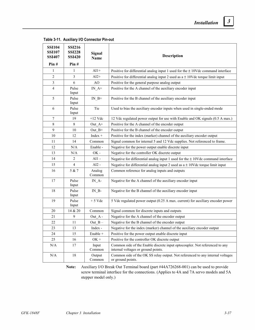
Installation
GFK-1848F Chapter 3 Installation 3-37
3
Table 3-11. Auxiliary I/O Connector Pin-out
SSI104 SSI107 SSI407
Pin #
SSI216 SSI228 SSI420
Pin #
Signal Name Description
1 1 AI1+ Positive for differential analog input 1 used for the ± 10Vdc command interface 2 3 AI2+ Positive for differential analog input 2 used as a ± 10Vdc torque limit input 3 6 AO Positive for the general purpose analog output 4 Pulse
Input IN_A+ Positive for the A channel of the auxiliary encoder input
5 Pulse Input
IN_B+ Positive for the B channel of the auxiliary encoder input
6 Pulse Input
Tie Used to bias the auxiliary encoder inputs when used in single-ended mode
7 19 +12 Vdc 12 Vdc regulated power output for use with Enable and OK signals (0.5 A max.) 8 8 Out_A+ Positive for the A channel of the encoder output 9 10 Out_B+ Positive for the B channel of the encoder output
10 12 Index + Positive for the index (marker) channel of the auxiliary encoder output 11 14 Common Signal common for internal 5 and 12 Vdc supplies. Not referenced to frame. 12 N/A Enable - Negative for the power output enable discrete input 13 N/A OK - Negative for the controller OK discrete output 14 2 AI1 - Negative for differential analog input 1 used for the ± 10Vdc command interface 15 4 AI2 - Negative for differential analog input 2 used as a ± 10Vdc torque limit input 16 5 & 7 Analog
Common Common reference for analog inputs and outputs
17 Pulse Input
IN_A- Negative for the A channel of the auxiliary encoder input
18 Pulse Input
IN_B- Negative for the B channel of the auxiliary encoder input
19 Pulse Input
+ 5 Vdc 5 Vdc regulated power output (0.25 A max. current) for auxiliary encoder power
20 14 & 20 Common Signal common for discrete inputs and outputs 21 9 Out_A - Negative for the A channel of the encoder output 22 11 Out_B – Negative for the B channel of the encoder output 23 13 Index - Negative for the index (marker) channel of the auxiliary encoder output 24 15 Enable + Positive for the power output enable discrete input 25 16 OK + Positive for the controller OK discrete output
N/A 17 Input Common
Common side of the Enable discrete input optocoupler. Not referenced to any internal voltages or ground points.
N/A 18 Output Common
Common side of the OK SS relay output. Not referenced to any internal voltages or ground points.
Note: Auxiliary I/O Break Out Terminal board (part #44A726268-001) can be used to provide screw terminal interface for the connections. (Applies to 4A and 7A servo models and 5A stepper model only.)
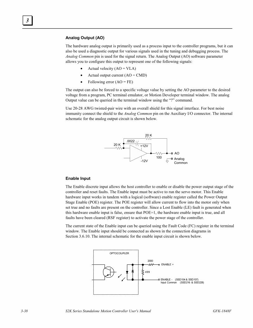
3-38 S2K Series Standalone Motion Controller User's Manual GFK-1848F
3
Analog Output (AO)
The hardware analog output is primarily used as a process input to the controller programs, but it can also be used a diagnostic output for various signals used in the tuning and debugging process. The Analog Common pin is used for the signal return. The Analog Output (AO) software parameter allows you to configure this output to represent one of the following signals:
• Actual velocity (AO = VLA) • Actual output current (AO = CMD) • Following error (AO = FE)
The output can also be forced to a specific voltage value by setting the AO parameter to the desired voltage from a program, PC terminal emulator, or Motion Developer terminal window. The analog Output value can be queried in the terminal window using the “?” command.
Use 20-28 AWG twisted-pair wire with an overall shield for this signal interface. For best noise immunity connect the shield to the Analog Common pin on the Auxiliary I/O connector. The internal schematic for the analog output circuit is shown below.
100AO
.0022
20 K
20 K
-12V
+12V
AnalogCommon
Enable Input
The Enable discrete input allows the host controller to enable or disable the power output stage of the controller and reset faults. The Enable input must be active to run the servo motor. This Enable hardware input works in tandem with a logical (software) enable register called the Power Output Stage Enable (POE) register. The POE register will allow current to flow into the motor only when set true and no faults are present on the controller. Since a Lost Enable (LE) fault is generated when this hardware enable input is false, ensure that POE=1, the hardware enable input is true, and all faults have been cleared (RSF register) to activate the power stage of the controller.
The current state of the Enable input can be queried using the Fault Code (FC) register in the terminal window. The Enable input should be connected as shown in the connection diagrams in Section 3.6.10. The internal schematic for the enable input circuit is shown below.
ENABLE +
OPTOCOUPLER
ENABLE - (SSD104 & SSD107)Input Common (SSD216 & SSD228)
499
2000
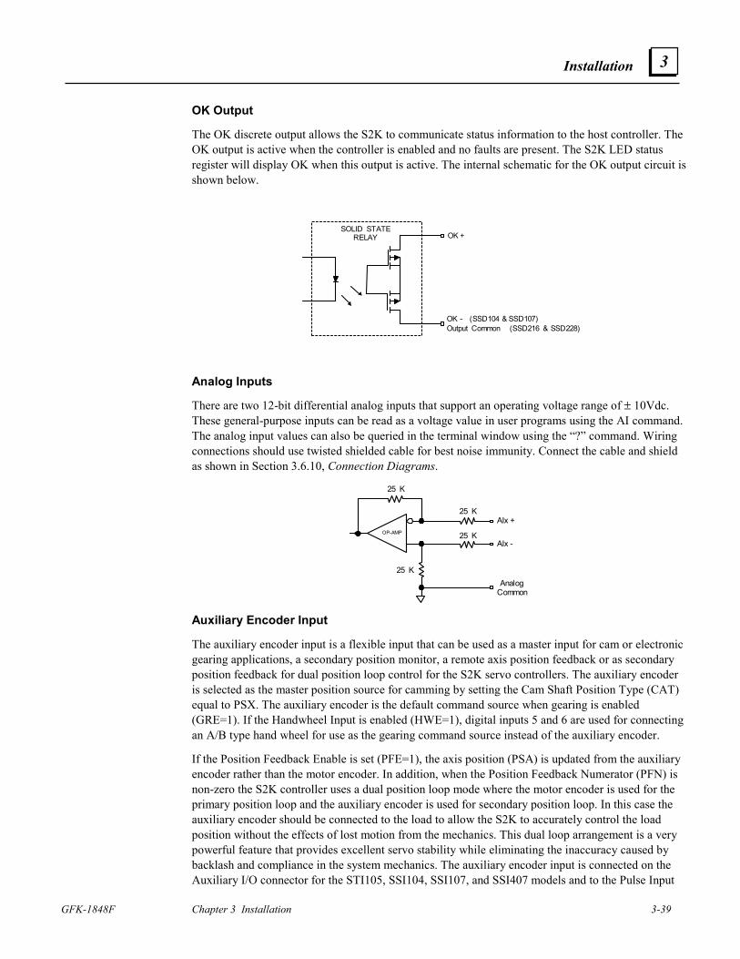
Installation
GFK-1848F Chapter 3 Installation 3-39
3
OK Output
The OK discrete output allows the S2K to communicate status information to the host controller. The OK output is active when the controller is enabled and no faults are present. The S2K LED status register will display OK when this output is active. The internal schematic for the OK output circuit is shown below.
SOLID STATERELAY OK +
OK - (SSD104 & SSD107)Output Common (SSD216 & SSD228)
Analog Inputs
There are two 12-bit differential analog inputs that support an operating voltage range of ± 10Vdc. These general-purpose inputs can be read as a voltage value in user programs using the AI command. The analog input values can also be queried in the terminal window using the “?” command. Wiring connections should use twisted shielded cable for best noise immunity. Connect the cable and shield as shown in Section 3.6.10, Connection Diagrams.
AIx +
AIx -OP-AMP
25 K
25 K
25 K
25 K
AnalogCommon
Auxiliary Encoder Input
The auxiliary encoder input is a flexible input that can be used as a master input for cam or electronic gearing applications, a secondary position monitor, a remote axis position feedback or as secondary position feedback for dual position loop control for the S2K servo controllers. The auxiliary encoder is selected as the master position source for camming by setting the Cam Shaft Position Type (CAT) equal to PSX. The auxiliary encoder is the default command source when gearing is enabled (GRE=1). If the Handwheel Input is enabled (HWE=1), digital inputs 5 and 6 are used for connecting an A/B type hand wheel for use as the gearing command source instead of the auxiliary encoder.
If the Position Feedback Enable is set (PFE=1), the axis position (PSA) is updated from the auxiliary encoder rather than the motor encoder. In addition, when the Position Feedback Numerator (PFN) is non-zero the S2K controller uses a dual position loop mode where the motor encoder is used for the primary position loop and the auxiliary encoder is used for secondary position loop. In this case the auxiliary encoder should be connected to the load to allow the S2K to accurately control the load position without the effects of lost motion from the mechanics. This dual loop arrangement is a very powerful feature that provides excellent servo stability while eliminating the inaccuracy caused by backlash and compliance in the system mechanics. The auxiliary encoder input is connected on the Auxiliary I/O connector for the STI105, SSI104, SSI107, and SSI407 models and to the Pulse Input
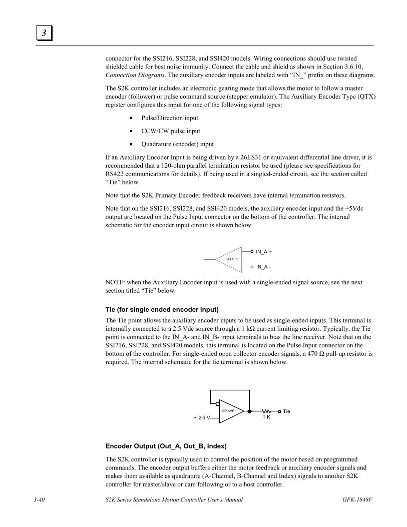
3-40 S2K Series Standalone Motion Controller User's Manual GFK-1848F
3
connector for the SSI216, SSI228, and SSI420 models. Wiring connections should use twisted shielded cable for best noise immunity. Connect the cable and shield as shown in Section 3.6.10, Connection Diagrams. The auxiliary encoder inputs are labeled with “IN_” prefix on these diagrams.
The S2K controller includes an electronic gearing mode that allows the motor to follow a master encoder (follower) or pulse command source (stepper emulator). The Auxiliary Encoder Type (QTX) register configures this input for one of the following signal types:
• Pulse/Direction input
• CCW/CW pulse input
• Quadrature (encoder) input
If an Auxiliary Encoder Input is being driven by a 26LS31 or equivalent differential line driver, it is recommended that a 120-ohm parallel termination resistor be used (please see specifications for RS422 communications for details). If being used in a singled-ended circuit, see the section called “Tie” below.
Note that the S2K Primary Encoder feedback receivers have internal termination resistors.
Note that on the SSI216, SSI228, and SSI420 models, the auxiliary encoder input and the +5Vdc output are located on the Pulse Input connector on the bottom of the controller. The internal schematic for the encoder input circuit is shown below.
26LS33
IN_A -
IN_A +
NOTE: when the Auxiliary Encoder input is used with a single-ended signal source, see the next section titled “Tie” below. Tie (for single ended encoder input) The Tie point allows the auxiliary encoder inputs to be used as single-ended inputs. This terminal is internally connected to a 2.5 Vdc source through a 1 kΩ current limiting resistor. Typically, the Tie point is connected to the IN_A- and IN_B- input terminals to bias the line receiver. Note that on the SSI216, SSI228, and SSI420 models, this terminal is located on the Pulse Input connector on the bottom of the controller. For single-ended open collector encoder signals, a 470 Ω pull-up resistor is required. The internal schematic for the tie terminal is shown below.
OP-AMP
1 KTie
+ 2.5 V
Encoder Output (Out_A, Out_B, Index)
The S2K controller is typically used to control the position of the motor based on programmed commands. The encoder output buffers either the motor feedback or auxiliary encoder signals and makes them available as quadrature (A-Channel, B-Channel and Index) signals to another S2K controller for master/slave or cam following or to a host controller.
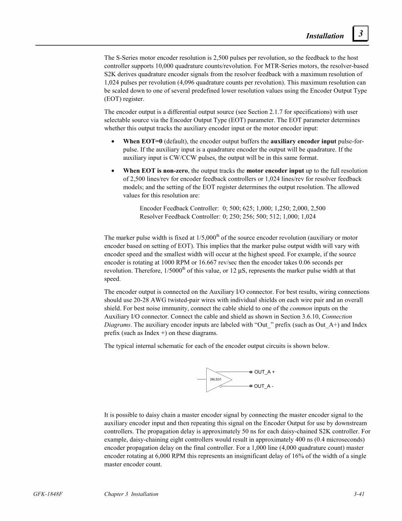
Installation
GFK-1848F Chapter 3 Installation 3-41
3
The S-Series motor encoder resolution is 2,500 pulses per revolution, so the feedback to the host controller supports 10,000 quadrature counts/revolution. For MTR-Series motors, the resolver-based S2K derives quadrature encoder signals from the resolver feedback with a maximum resolution of 1,024 pulses per revolution (4,096 quadrature counts per revolution). This maximum resolution can be scaled down to one of several predefined lower resolution values using the Encoder Output Type (EOT) register.
The encoder output is a differential output source (see Section 2.1.7 for specifications) with user selectable source via the Encoder Output Type (EOT) parameter. The EOT parameter determines whether this output tracks the auxiliary encoder input or the motor encoder input:
• When EOT=0 (default), the encoder output buffers the auxiliary encoder input pulse-for-pulse. If the auxiliary input is a quadrature encoder the output will be quadrature. If the auxiliary input is CW/CCW pulses, the output will be in this same format.
• When EOT is non-zero, the output tracks the motor encoder input up to the full resolution of 2,500 lines/rev for encoder feedback controllers or 1,024 lines/rev for resolver feedback models; and the setting of the EOT register determines the output resolution. The allowed values for this resolution are:
Encoder Feedback Controller: 0; 500; 625; 1,000; 1,250; 2,000, 2,500 Resolver Feedback Controller: 0; 250; 256; 500; 512; 1,000; 1,024
The marker pulse width is fixed at 1/5,000th of the source encoder revolution (auxiliary or motor encoder based on setting of EOT). This implies that the marker pulse output width will vary with encoder speed and the smallest width will occur at the highest speed. For example, if the source encoder is rotating at 1000 RPM or 16.667 rev/sec then the encoder takes 0.06 seconds per revolution. Therefore, 1/5000th of this value, or 12 µS, represents the marker pulse width at that speed.
The encoder output is connected on the Auxiliary I/O connector. For best results, wiring connections should use 20-28 AWG twisted-pair wires with individual shields on each wire pair and an overall shield. For best noise immunity, connect the cable shield to one of the common inputs on the Auxiliary I/O connector. Connect the cable and shield as shown in Section 3.6.10, Connection Diagrams. The auxiliary encoder inputs are labeled with “Out_” prefix (such as Out_A+) and Index prefix (such as Index +) on these diagrams.
The typical internal schematic for each of the encoder output circuits is shown below.
26LS31
OUT_A -
OUT_A +
It is possible to daisy chain a master encoder signal by connecting the master encoder signal to the auxiliary encoder input and then repeating this signal on the Encoder Output for use by downstream controllers. The propagation delay is approximately 50 ns for each daisy-chained S2K controller. For example, daisy-chaining eight controllers would result in approximately 400 ns (0.4 microseconds) encoder propagation delay on the final controller. For a 1,000 line (4,000 quadrature count) master encoder rotating at 6,000 RPM this represents an insignificant delay of 16% of the width of a single master encoder count.
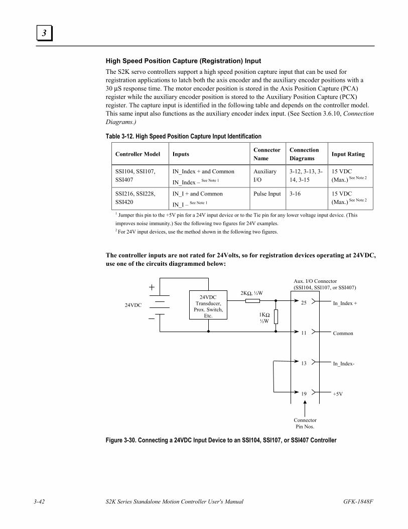
3-42 S2K Series Standalone Motion Controller User's Manual GFK-1848F
3
High Speed Position Capture (Registration) Input The S2K servo controllers support a high speed position capture input that can be used for registration applications to latch both the axis encoder and the auxiliary encoder positions with a 30 µS response time. The motor encoder position is stored in the Axis Position Capture (PCA) register while the auxiliary encoder position is stored to the Auxiliary Position Capture (PCX) register. The capture input is identified in the following table and depends on the controller model. This same input also functions as the auxiliary encoder index input. (See Section 3.6.10, Connection Diagrams.)
Table 3-12. High Speed Position Capture Input Identification
Controller Model Inputs Connector Name
Connection Diagrams
Input Rating
SSI104, SSI107, SSI407
IN_Index + and Common
IN_Index – See Note 1
Auxiliary I/O
3-12, 3-13, 3-14, 3-15
15 VDC (Max.) See Note 2
SSI216, SSI228, SSI420
IN_I + and Common
IN_I – See Note 1
Pulse Input 3-16 15 VDC (Max.) See Note 2
1 Jumper this pin to the +5V pin for a 24V input device or to the Tie pin for any lower voltage input device. (This improves noise immunity.) See the following two figures for 24V examples. 2 For 24V input devices, use the method shown in the following two figures.
The controller inputs are not rated for 24Volts, so for registration devices operating at 24VDC, use one of the circuits diagrammed below:
24VDC
Aux. I/O Connector (SSI104, SSI107, or SSI407)
25
11
13
19
In_Index +
Common
In_Index -
+5V
Connector Pin Nos.
2K Ω , ½W
1K Ω ½W
24VDC Transducer,
Prox . Switch, Etc.
Figure 3-30. Connecting a 24VDC Input Device to an SSI104, SSI107, or SSI407 Controller
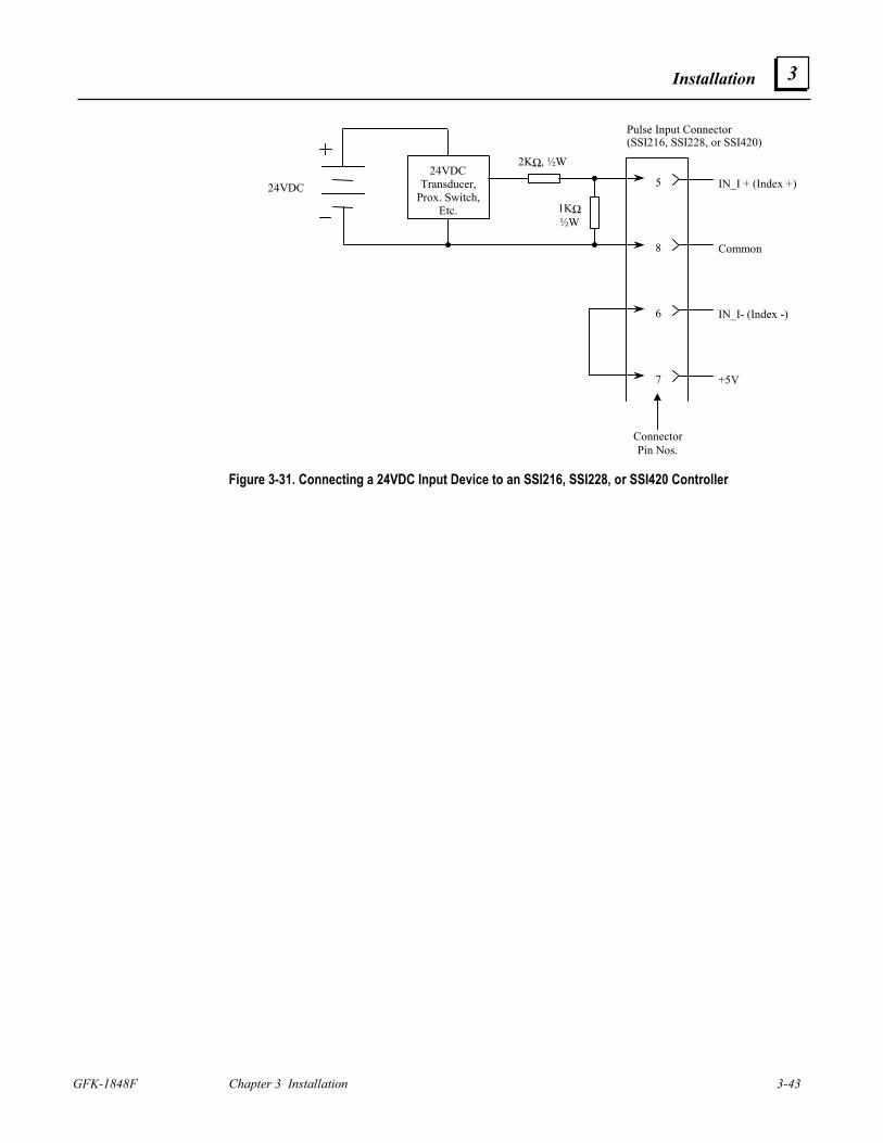
Installation
GFK-1848F Chapter 3 Installation 3-43
3
24VDC
Pulse Input Connector (SSI216, SSI228, or SSI420)
5
8
6
7
IN_I + (Index +)
Common
IN_I- (Index -)
+5V
Connector Pin Nos.
2K Ω , ½W
1K Ω ½W
24VDC Transducer,
Prox . Switch, Etc.
Figure 3-31. Connecting a 24VDC Input Device to an SSI216, SSI228, or SSI420 Controller
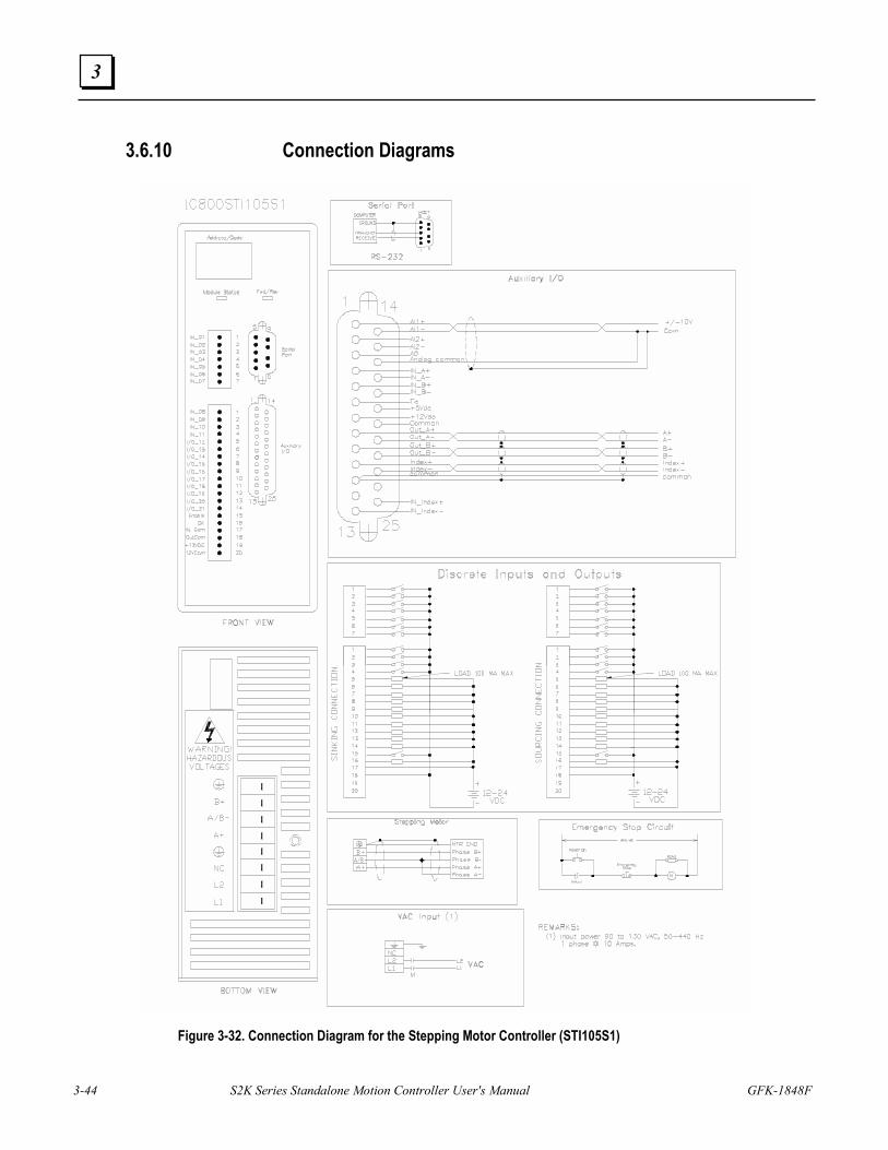
3-44 S2K Series Standalone Motion Controller User's Manual GFK-1848F
3
3.6.10 Connection Diagrams
Figure 3-32. Connection Diagram for the Stepping Motor Controller (STI105S1)
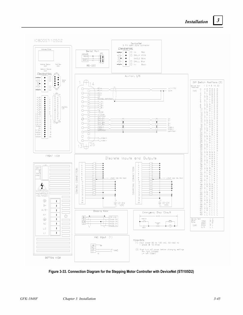
Installation
GFK-1848F Chapter 3 Installation 3-45
3
Figure 3-33. Connection Diagram for the Stepping Motor Controller with DeviceNet (STI105D2)
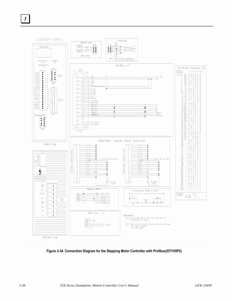
3-46 S2K Series Standalone Motion Controller User's Manual GFK-1848F
3
Figure 3-34. Connection Diagram for the Stepping Motor Controller with Profibus(STI105P2)
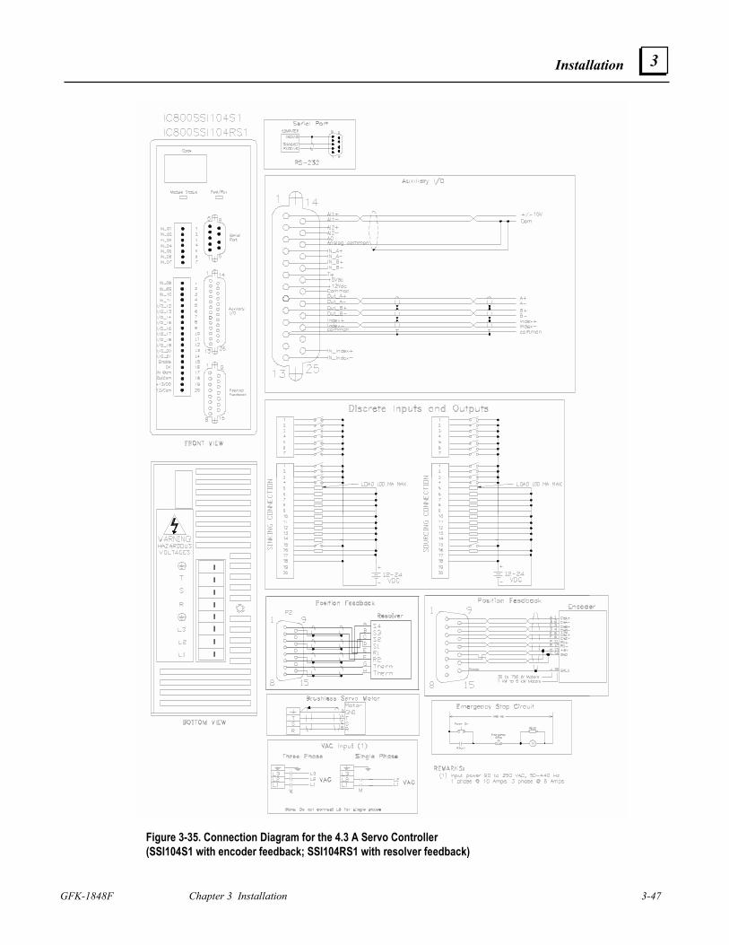
Installation
GFK-1848F Chapter 3 Installation 3-47
3
Figure 3-35. Connection Diagram for the 4.3 A Servo Controller (SSI104S1 with encoder feedback; SSI104RS1 with resolver feedback)
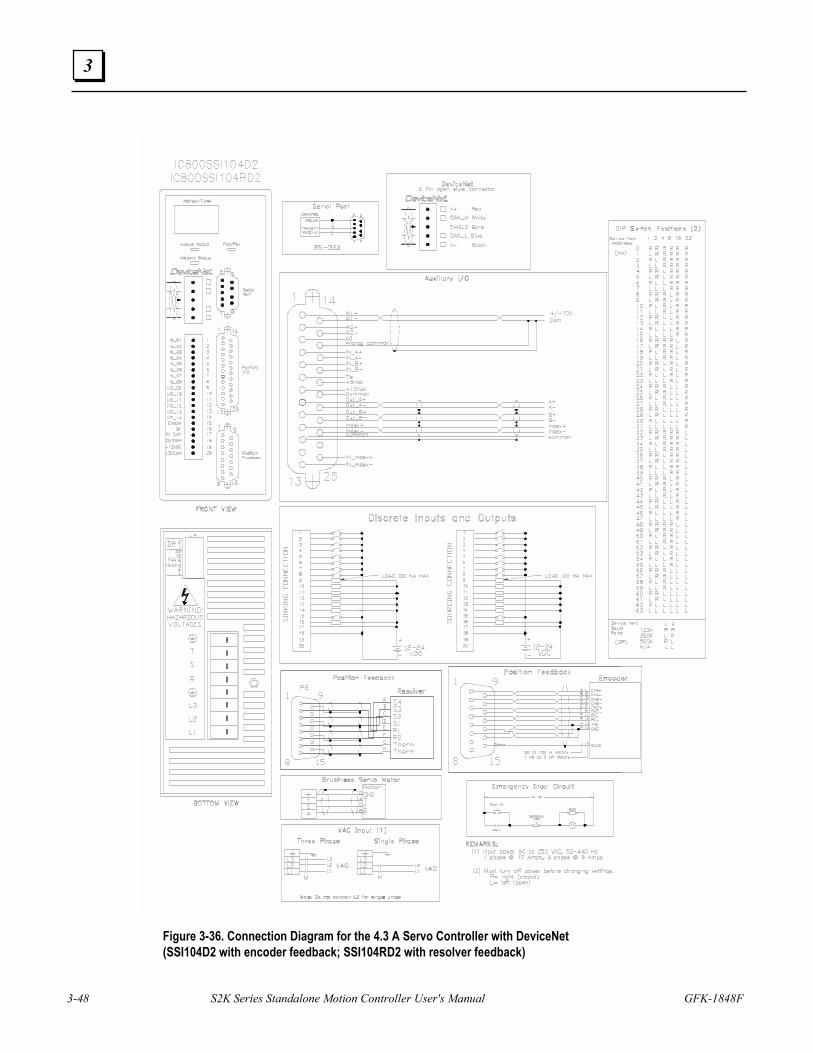
3-48 S2K Series Standalone Motion Controller User's Manual GFK-1848F
3
Figure 3-36. Connection Diagram for the 4.3 A Servo Controller with DeviceNet (SSI104D2 with encoder feedback; SSI104RD2 with resolver feedback)
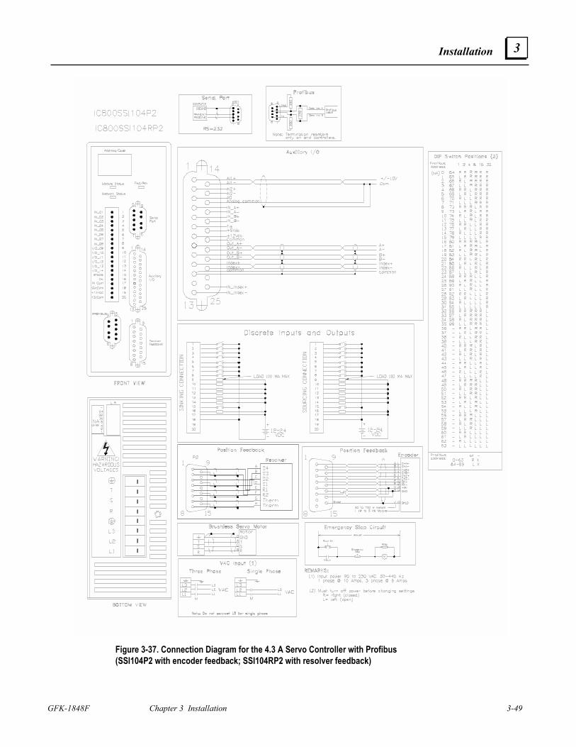
Installation
GFK-1848F Chapter 3 Installation 3-49
3
Figure 3-37. Connection Diagram for the 4.3 A Servo Controller with Profibus (SSI104P2 with encoder feedback; SSI104RP2 with resolver feedback)
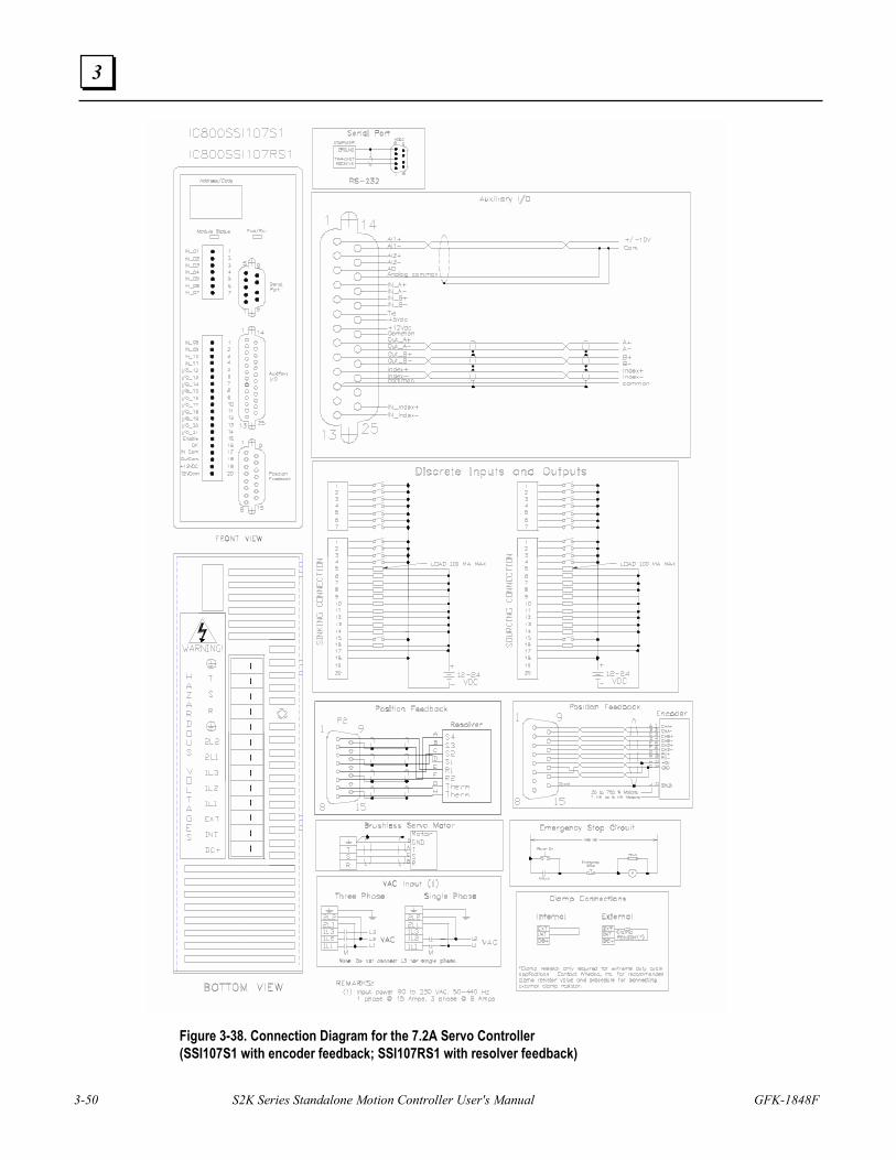
3-50 S2K Series Standalone Motion Controller User's Manual GFK-1848F
3
Figure 3-38. Connection Diagram for the 7.2A Servo Controller (SSI107S1 with encoder feedback; SSI107RS1 with resolver feedback)
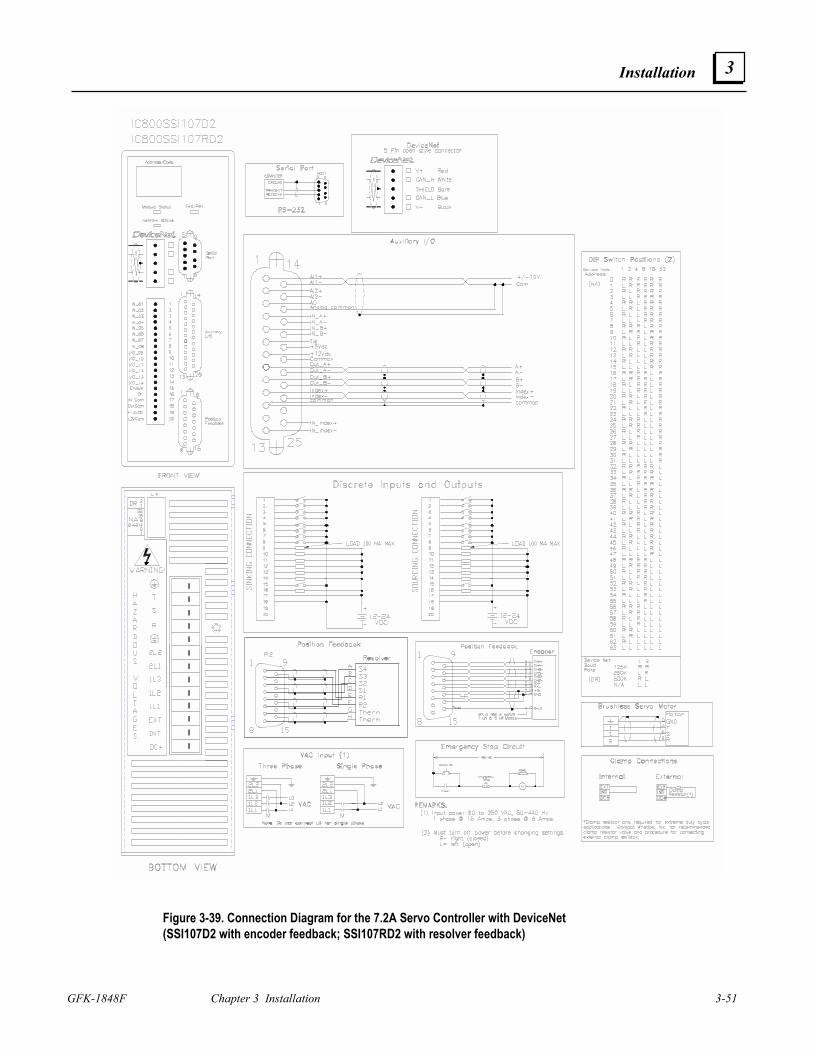
Installation
GFK-1848F Chapter 3 Installation 3-51
3
Figure 3-39. Connection Diagram for the 7.2A Servo Controller with DeviceNet (SSI107D2 with encoder feedback; SSI107RD2 with resolver feedback)
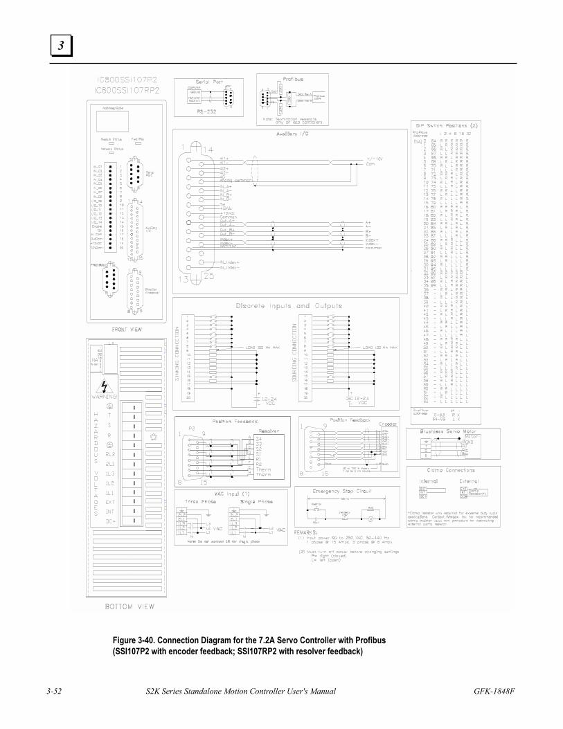
3-52 S2K Series Standalone Motion Controller User's Manual GFK-1848F
3
Figure 3-40. Connection Diagram for the 7.2A Servo Controller with Profibus (SSI107P2 with encoder feedback; SSI107RP2 with resolver feedback)
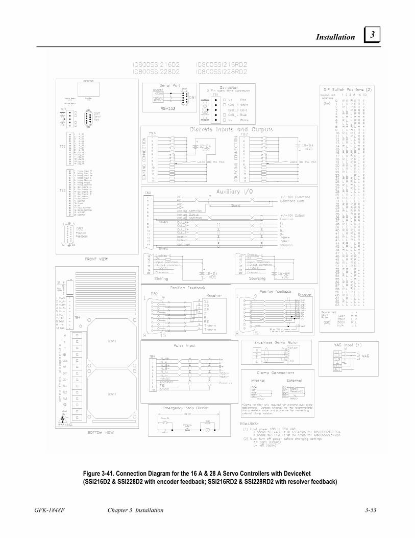
Installation
GFK-1848F Chapter 3 Installation 3-53
3
Figure 3-41. Connection Diagram for the 16 A & 28 A Servo Controllers with DeviceNet (SSI216D2 & SSI228D2 with encoder feedback; SSI216RD2 & SSI228RD2 with resolver feedback)
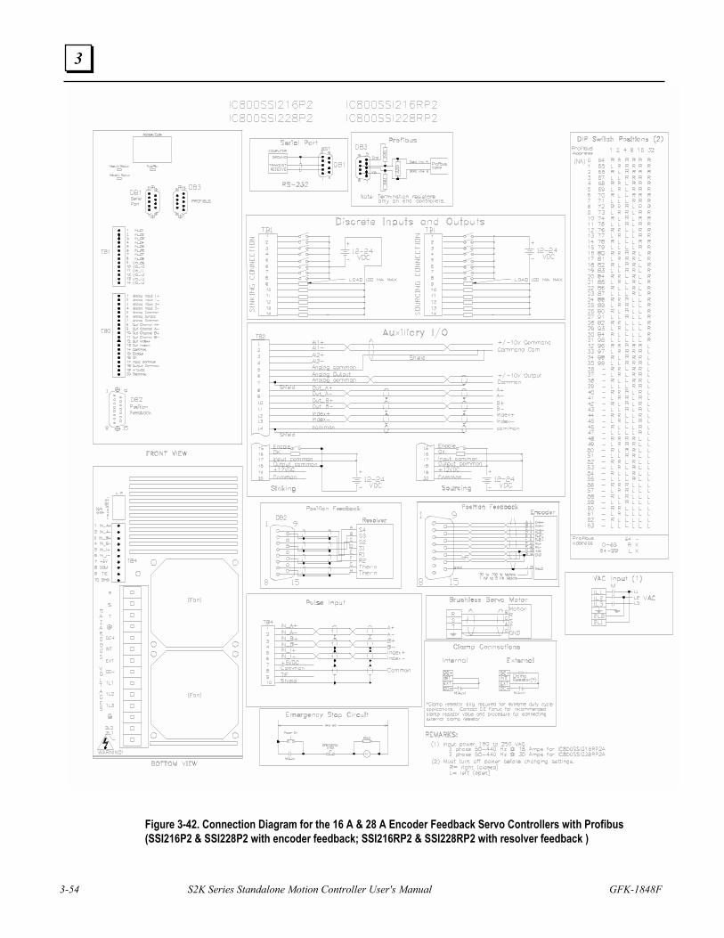
3-54 S2K Series Standalone Motion Controller User's Manual GFK-1848F
3
Figure 3-42. Connection Diagram for the 16 A & 28 A Encoder Feedback Servo Controllers with Profibus (SSI216P2 & SSI228P2 with encoder feedback; SSI216RP2 & SSI228RP2 with resolver feedback )
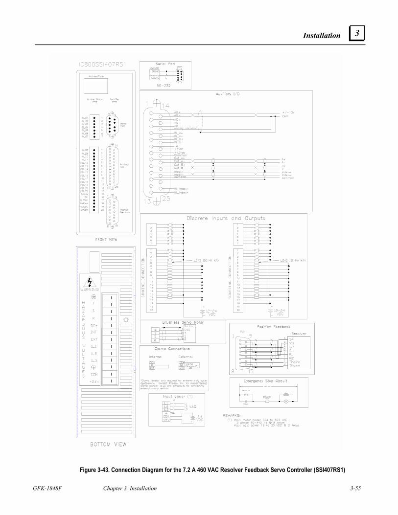
Installation
GFK-1848F Chapter 3 Installation 3-55
3
Figure 3-43. Connection Diagram for the 7.2 A 460 VAC Resolver Feedback Servo Controller (SSI407RS1)
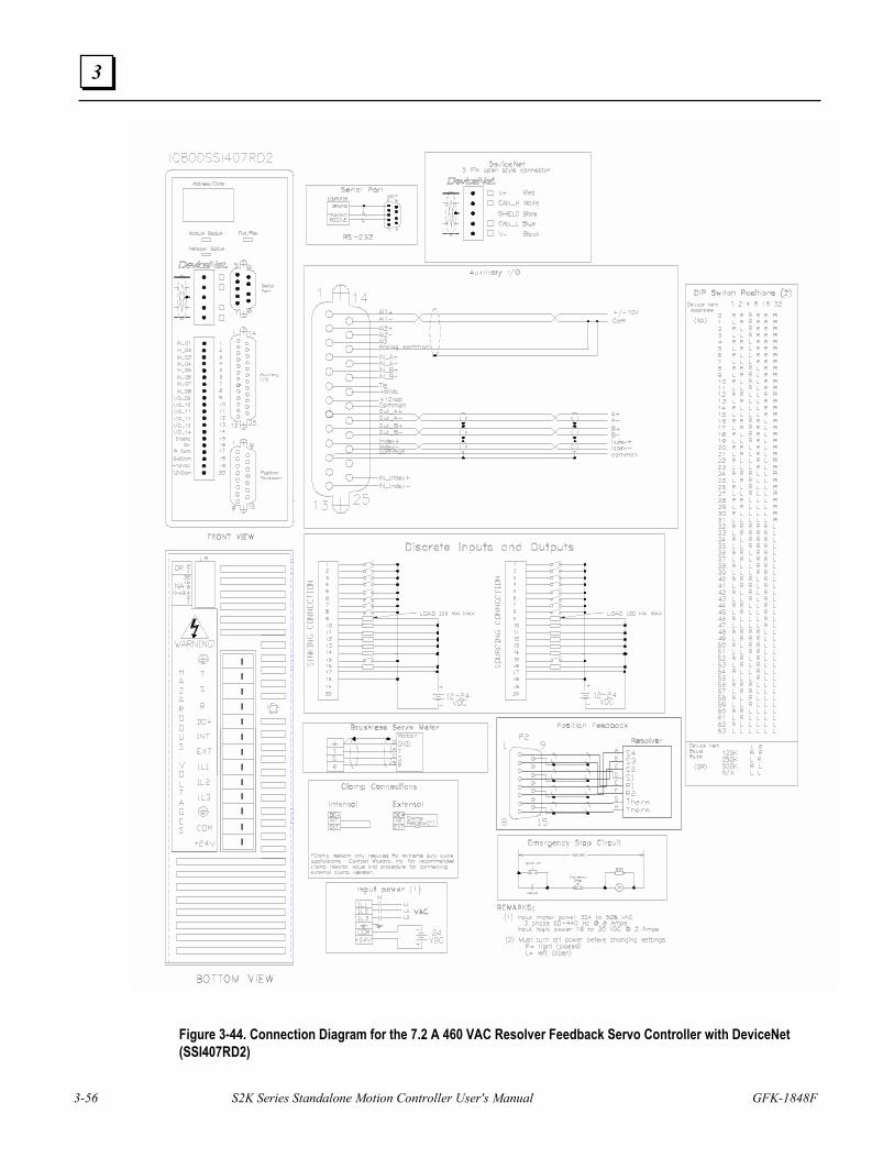
3-56 S2K Series Standalone Motion Controller User's Manual GFK-1848F
3
Figure 3-44. Connection Diagram for the 7.2 A 460 VAC Resolver Feedback Servo Controller with DeviceNet (SSI407RD2)
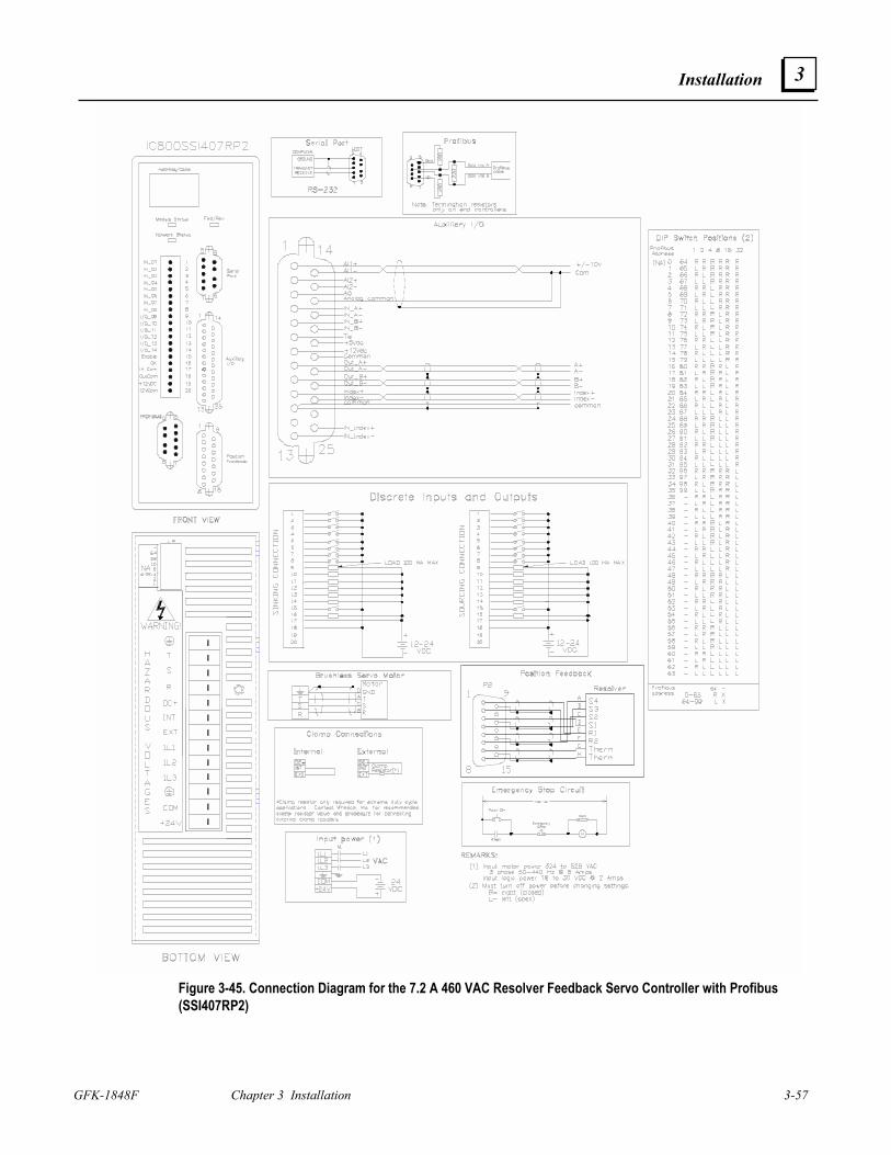
Installation
GFK-1848F Chapter 3 Installation 3-57
3
Figure 3-45. Connection Diagram for the 7.2 A 460 VAC Resolver Feedback Servo Controller with Profibus (SSI407RP2)
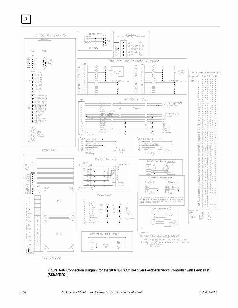
3-58 S2K Series Standalone Motion Controller User's Manual GFK-1848F
3
Figure 3-46. Connection Diagram for the 20 A 460 VAC Resolver Feedback Servo Controller with DeviceNet (SSI420RD2)
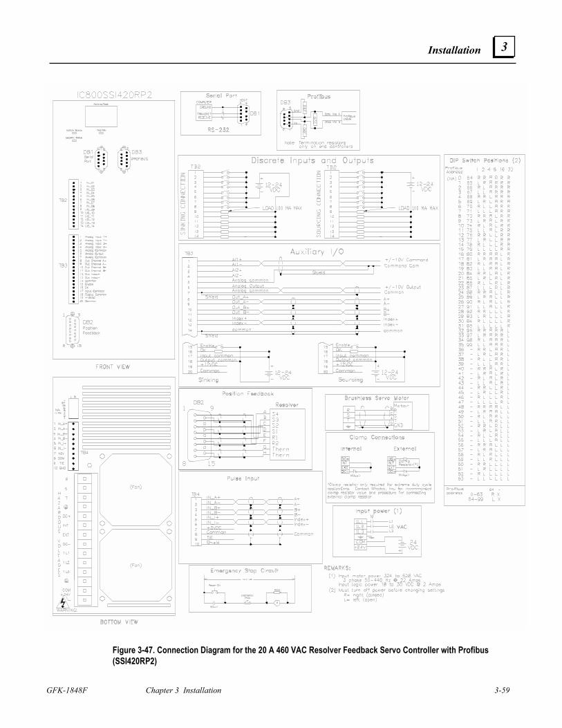
Installation
GFK-1848F Chapter 3 Installation 3-59
3
Figure 3-47. Connection Diagram for the 20 A 460 VAC Resolver Feedback Servo Controller with Profibus (SSI420RP2)
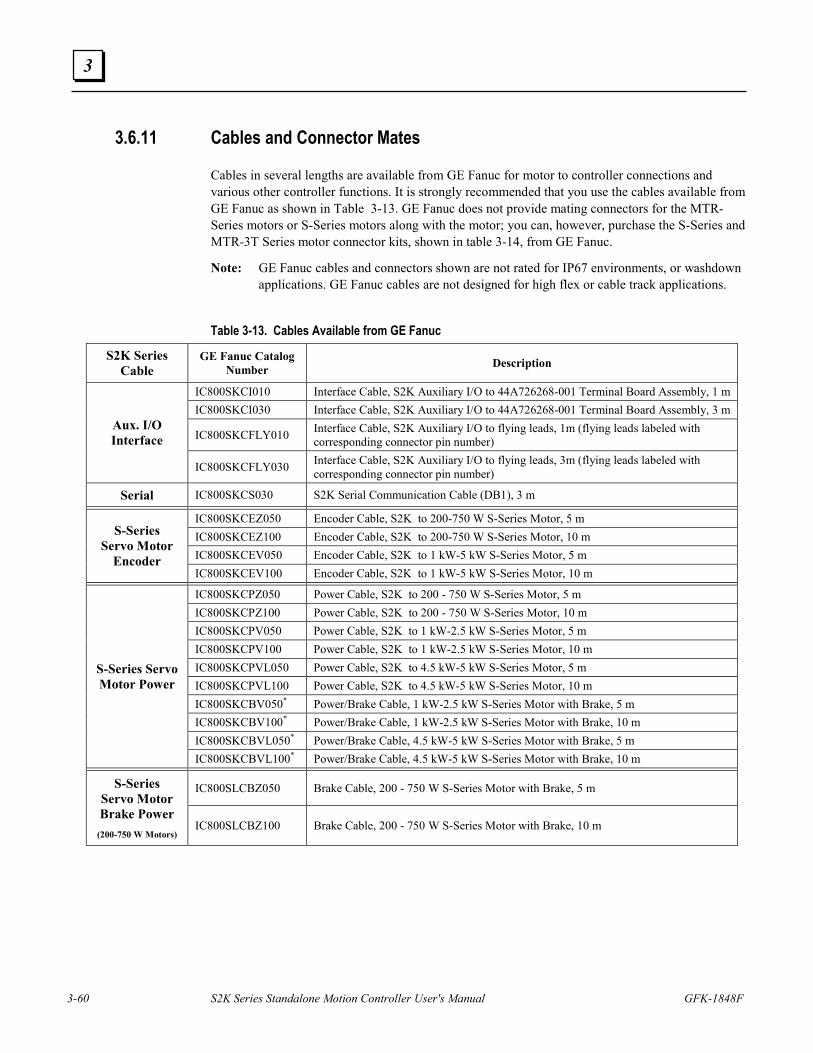
3-60 S2K Series Standalone Motion Controller User's Manual GFK-1848F
3
3.6.11 Cables and Connector Mates
Cables in several lengths are available from GE Fanuc for motor to controller connections and various other controller functions. It is strongly recommended that you use the cables available from GE Fanuc as shown in Table 3-13. GE Fanuc does not provide mating connectors for the MTR-Series motors or S-Series motors along with the motor; you can, however, purchase the S-Series and MTR-3T Series motor connector kits, shown in table 3-14, from GE Fanuc.
Note: GE Fanuc cables and connectors shown are not rated for IP67 environments, or washdown applications. GE Fanuc cables are not designed for high flex or cable track applications.
Table 3-13. Cables Available from GE Fanuc
S2K Series Cable
GE Fanuc Catalog Number Description
IC800SKCI010 Interface Cable, S2K Auxiliary I/O to 44A726268-001 Terminal Board Assembly, 1 m IC800SKCI030 Interface Cable, S2K Auxiliary I/O to 44A726268-001 Terminal Board Assembly, 3 m
IC800SKCFLY010 Interface Cable, S2K Auxiliary I/O to flying leads, 1m (flying leads labeled with corresponding connector pin number)
Aux. I/O Interface
IC800SKCFLY030 Interface Cable, S2K Auxiliary I/O to flying leads, 3m (flying leads labeled with corresponding connector pin number)
Serial IC800SKCS030 S2K Serial Communication Cable (DB1), 3 m
IC800SKCEZ050 Encoder Cable, S2K to 200-750 W S-Series Motor, 5 m IC800SKCEZ100 Encoder Cable, S2K to 200-750 W S-Series Motor, 10 m IC800SKCEV050 Encoder Cable, S2K to 1 kW-5 kW S-Series Motor, 5 m
S-Series Servo Motor
Encoder IC800SKCEV100 Encoder Cable, S2K to 1 kW-5 kW S-Series Motor, 10 m
IC800SKCPZ050 Power Cable, S2K to 200 - 750 W S-Series Motor, 5 m IC800SKCPZ100 Power Cable, S2K to 200 - 750 W S-Series Motor, 10 m IC800SKCPV050 Power Cable, S2K to 1 kW-2.5 kW S-Series Motor, 5 m IC800SKCPV100 Power Cable, S2K to 1 kW-2.5 kW S-Series Motor, 10 m IC800SKCPVL050 Power Cable, S2K to 4.5 kW-5 kW S-Series Motor, 5 m IC800SKCPVL100 Power Cable, S2K to 4.5 kW-5 kW S-Series Motor, 10 m IC800SKCBV050* Power/Brake Cable, 1 kW-2.5 kW S-Series Motor with Brake, 5 m IC800SKCBV100* Power/Brake Cable, 1 kW-2.5 kW S-Series Motor with Brake, 10 m IC800SKCBVL050* Power/Brake Cable, 4.5 kW-5 kW S-Series Motor with Brake, 5 m
S-Series Servo Motor Power
IC800SKCBVL100* Power/Brake Cable, 4.5 kW-5 kW S-Series Motor with Brake, 10 m
IC800SLCBZ050 Brake Cable, 200 - 750 W S-Series Motor with Brake, 5 m S-Series Servo Motor Brake Power
(200-750 W Motors) IC800SLCBZ100 Brake Cable, 200 - 750 W S-Series Motor with Brake, 10 m
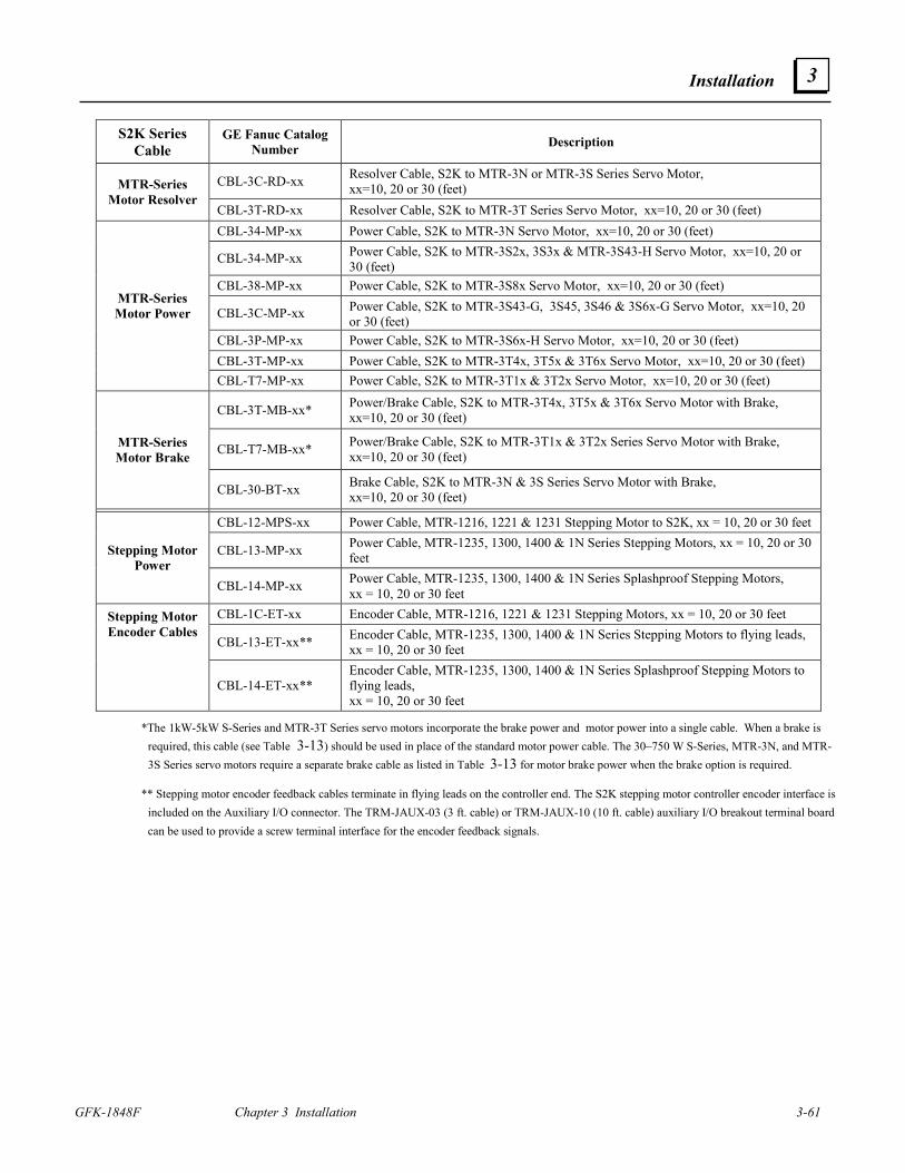
Installation
GFK-1848F Chapter 3 Installation 3-61
3
S2K Series Cable
GE Fanuc Catalog Number Description
CBL-3C-RD-xx Resolver Cable, S2K to MTR-3N or MTR-3S Series Servo Motor, xx=10, 20 or 30 (feet) MTR-Series
Motor Resolver CBL-3T-RD-xx Resolver Cable, S2K to MTR-3T Series Servo Motor, xx=10, 20 or 30 (feet) CBL-34-MP-xx Power Cable, S2K to MTR-3N Servo Motor, xx=10, 20 or 30 (feet)
CBL-34-MP-xx Power Cable, S2K to MTR-3S2x, 3S3x & MTR-3S43-H Servo Motor, xx=10, 20 or 30 (feet)
CBL-38-MP-xx Power Cable, S2K to MTR-3S8x Servo Motor, xx=10, 20 or 30 (feet)
CBL-3C-MP-xx Power Cable, S2K to MTR-3S43-G, 3S45, 3S46 & 3S6x-G Servo Motor, xx=10, 20 or 30 (feet)
CBL-3P-MP-xx Power Cable, S2K to MTR-3S6x-H Servo Motor, xx=10, 20 or 30 (feet) CBL-3T-MP-xx Power Cable, S2K to MTR-3T4x, 3T5x & 3T6x Servo Motor, xx=10, 20 or 30 (feet)
MTR-Series Motor Power
CBL-T7-MP-xx Power Cable, S2K to MTR-3T1x & 3T2x Servo Motor, xx=10, 20 or 30 (feet)
CBL-3T-MB-xx* Power/Brake Cable, S2K to MTR-3T4x, 3T5x & 3T6x Servo Motor with Brake, xx=10, 20 or 30 (feet)
CBL-T7-MB-xx* Power/Brake Cable, S2K to MTR-3T1x & 3T2x Series Servo Motor with Brake, xx=10, 20 or 30 (feet)
MTR-Series Motor Brake
CBL-30-BT-xx Brake Cable, S2K to MTR-3N & 3S Series Servo Motor with Brake, xx=10, 20 or 30 (feet)
CBL-12-MPS-xx Power Cable, MTR-1216, 1221 & 1231 Stepping Motor to S2K, xx = 10, 20 or 30 feet
CBL-13-MP-xx Power Cable, MTR-1235, 1300, 1400 & 1N Series Stepping Motors, xx = 10, 20 or 30 feet Stepping Motor
Power CBL-14-MP-xx Power Cable, MTR-1235, 1300, 1400 & 1N Series Splashproof Stepping Motors,
xx = 10, 20 or 30 feet CBL-1C-ET-xx Encoder Cable, MTR-1216, 1221 & 1231 Stepping Motors, xx = 10, 20 or 30 feet
CBL-13-ET-xx** Encoder Cable, MTR-1235, 1300, 1400 & 1N Series Stepping Motors to flying leads, xx = 10, 20 or 30 feet
Stepping Motor Encoder Cables
CBL-14-ET-xx** Encoder Cable, MTR-1235, 1300, 1400 & 1N Series Splashproof Stepping Motors to flying leads, xx = 10, 20 or 30 feet
*The 1kW-5kW S-Series and MTR-3T Series servo motors incorporate the brake power and motor power into a single cable. When a brake is required, this cable (see Table 3-13) should be used in place of the standard motor power cable. The 30–750 W S-Series, MTR-3N, and MTR-3S Series servo motors require a separate brake cable as listed in Table 3-13 for motor brake power when the brake option is required.
** Stepping motor encoder feedback cables terminate in flying leads on the controller end. The S2K stepping motor controller encoder interface is included on the Auxiliary I/O connector. The TRM-JAUX-03 (3 ft. cable) or TRM-JAUX-10 (10 ft. cable) auxiliary I/O breakout terminal board can be used to provide a screw terminal interface for the encoder feedback signals.
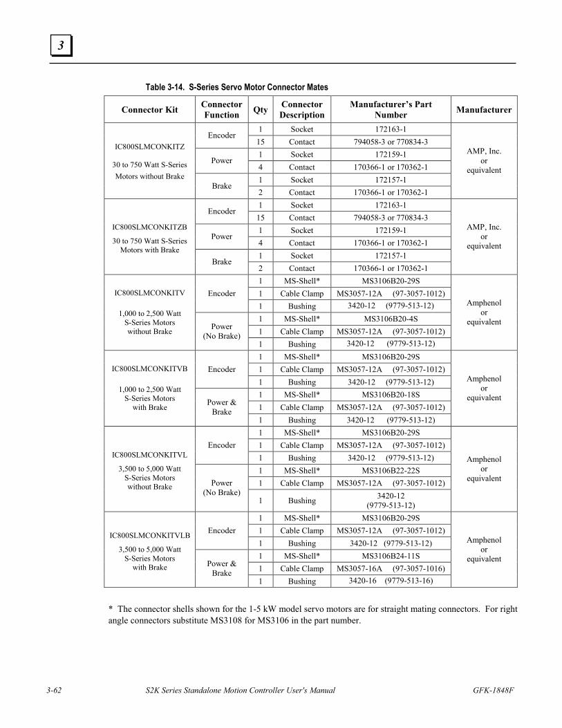
3-62 S2K Series Standalone Motion Controller User's Manual GFK-1848F
3
Table 3-14. S-Series Servo Motor Connector Mates
Connector Kit Connector Function Qty Connector
Description Manufacturer’s Part
Number Manufacturer
1 Socket 172163-1 Encoder
15 Contact 794058-3 or 770834-3 1 Socket 172159-1
Power 4 Contact 170366-1 or 170362-1 1 Socket 172157-1
IC800SLMCONKITZ
30 to 750 Watt S-Series Motors without Brake
Brake 2 Contact 170366-1 or 170362-1
AMP, Inc. or
equivalent
1 Socket 172163-1 Encoder
15 Contact 794058-3 or 770834-3 1 Socket 172159-1
Power 4 Contact 170366-1 or 170362-1 1 Socket 172157-1
IC800SLMCONKITZB
30 to 750 Watt S-Series Motors with Brake
Brake 2 Contact 170366-1 or 170362-1
AMP, Inc. or
equivalent
1 MS-Shell* MS3106B20-29S 1 Cable Clamp MS3057-12A (97-3057-1012) Encoder 1 Bushing 3420-12 (9779-513-12) 1 MS-Shell* MS3106B20-4S 1 Cable Clamp MS3057-12A (97-3057-1012)
IC800SLMCONKITV
1,000 to 2,500 Watt S-Series Motors without Brake Power
(No Brake) 1 Bushing 3420-12 (9779-513-12)
Amphenol or
equivalent
1 MS-Shell* MS3106B20-29S 1 Cable Clamp MS3057-12A (97-3057-1012) Encoder 1 Bushing 3420-12 (9779-513-12) 1 MS-Shell* MS3106B20-18S 1 Cable Clamp MS3057-12A (97-3057-1012)
IC800SLMCONKITVB
1,000 to 2,500 Watt S-Series Motors
with Brake Power & Brake
1 Bushing 3420-12 (9779-513-12)
Amphenol or
equivalent
1 MS-Shell* MS3106B20-29S 1 Cable Clamp MS3057-12A (97-3057-1012) Encoder 1 Bushing 3420-12 (9779-513-12) 1 MS-Shell* MS3106B22-22S 1 Cable Clamp MS3057-12A (97-3057-1012)
IC800SLMCONKITVL
3,500 to 5,000 Watt S-Series Motors without Brake Power
(No Brake) 1 Bushing 3420-12
(9779-513-12)
Amphenol or
equivalent
1 MS-Shell* MS3106B20-29S 1 Cable Clamp MS3057-12A (97-3057-1012) Encoder 1 Bushing 3420-12 (9779-513-12) 1 MS-Shell* MS3106B24-11S 1 Cable Clamp MS3057-16A (97-3057-1016)
IC800SLMCONKITVLB
3,500 to 5,000 Watt S-Series Motors
with Brake Power & Brake
1 Bushing 3420-16 (9779-513-16)
Amphenol or
equivalent
* The connector shells shown for the 1-5 kW model servo motors are for straight mating connectors. For right angle connectors substitute MS3108 for MS3106 in the part number.
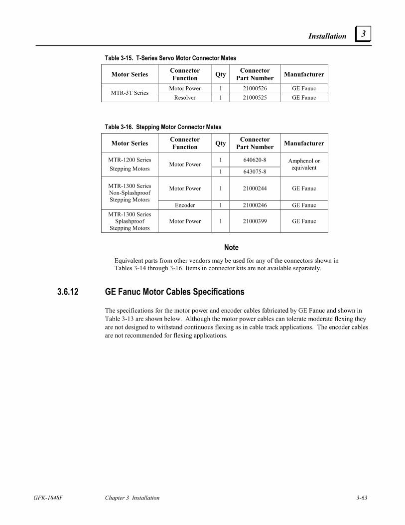
Installation
GFK-1848F Chapter 3 Installation 3-63
3
Table 3-15. T-Series Servo Motor Connector Mates
Motor Series Connector Function Qty Connector
Part Number Manufacturer
Motor Power 1 21000526 GE Fanuc MTR-3T Series
Resolver 1 21000525 GE Fanuc
Table 3-16. Stepping Motor Connector Mates
Motor Series Connector Function Qty Connector
Part Number Manufacturer
1 640620-8 MTR-1200 Series Stepping Motors
Motor Power 1 643075-8
Amphenol or equivalent
Motor Power 1 21000244 GE Fanuc MTR-1300 Series Non-Splashproof Stepping Motors
Encoder 1 21000246 GE Fanuc MTR-1300 Series
Splashproof Stepping Motors
Motor Power 1 21000399 GE Fanuc
Note Equivalent parts from other vendors may be used for any of the connectors shown in Tables 3-14 through 3-16. Items in connector kits are not available separately.
3.6.12 GE Fanuc Motor Cables Specifications
The specifications for the motor power and encoder cables fabricated by GE Fanuc and shown in Table 3-13 are shown below. Although the motor power cables can tolerate moderate flexing they are not designed to withstand continuous flexing as in cable track applications. The encoder cables are not recommended for flexing applications.
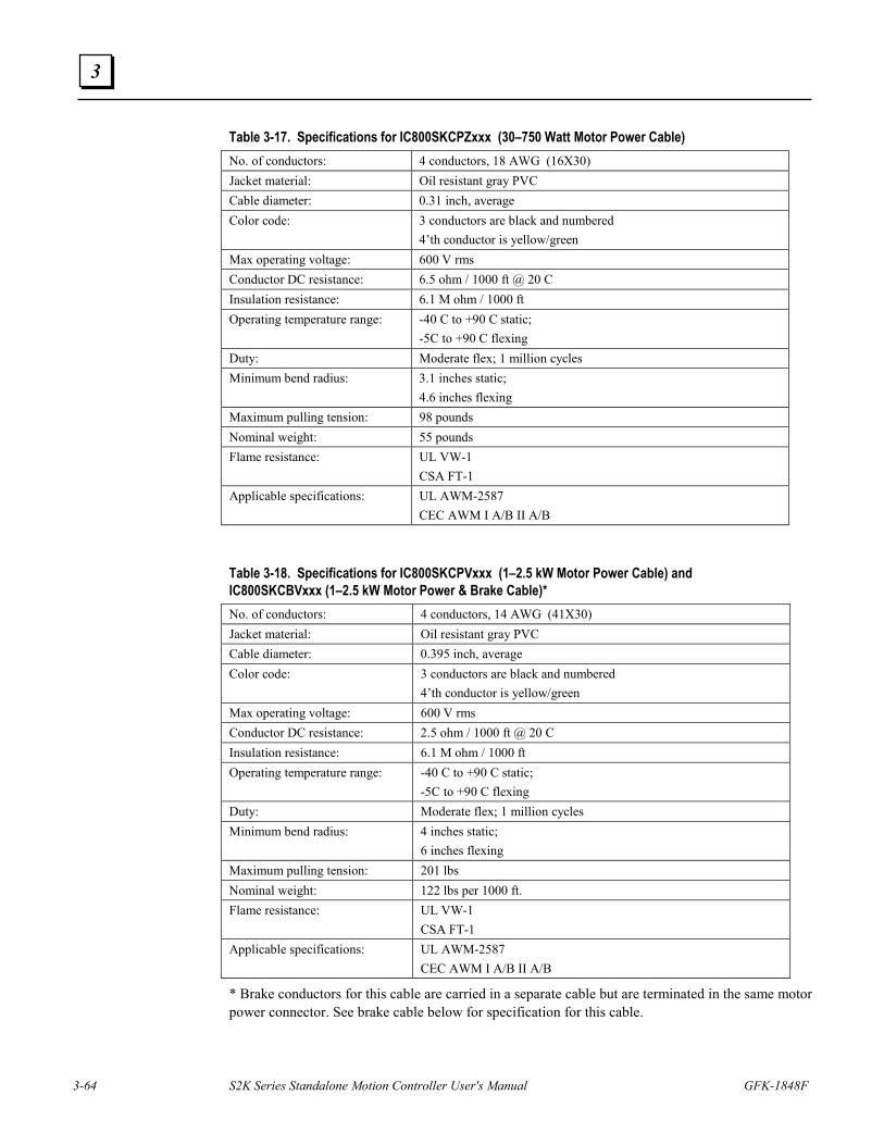
3-64 S2K Series Standalone Motion Controller User's Manual GFK-1848F
3
Table 3-17. Specifications for IC800SKCPZxxx (30–750 Watt Motor Power Cable) No. of conductors: 4 conductors, 18 AWG (16X30) Jacket material: Oil resistant gray PVC Cable diameter: 0.31 inch, average Color code: 3 conductors are black and numbered
4’th conductor is yellow/green Max operating voltage: 600 V rms Conductor DC resistance: 6.5 ohm / 1000 ft @ 20 C Insulation resistance: 6.1 M ohm / 1000 ft Operating temperature range: -40 C to +90 C static;
-5C to +90 C flexing Duty: Moderate flex; 1 million cycles Minimum bend radius: 3.1 inches static;
4.6 inches flexing Maximum pulling tension: 98 pounds Nominal weight: 55 pounds Flame resistance: UL VW-1
CSA FT-1 Applicable specifications: UL AWM-2587
CEC AWM I A/B II A/B Table 3-18. Specifications for IC800SKCPVxxx (1–2.5 kW Motor Power Cable) and IC800SKCBVxxx (1–2.5 kW Motor Power & Brake Cable)* No. of conductors: 4 conductors, 14 AWG (41X30) Jacket material: Oil resistant gray PVC Cable diameter: 0.395 inch, average Color code: 3 conductors are black and numbered
4’th conductor is yellow/green Max operating voltage: 600 V rms Conductor DC resistance: 2.5 ohm / 1000 ft @ 20 C Insulation resistance: 6.1 M ohm / 1000 ft Operating temperature range: -40 C to +90 C static;
-5C to +90 C flexing Duty: Moderate flex; 1 million cycles Minimum bend radius: 4 inches static;
6 inches flexing Maximum pulling tension: 201 lbs Nominal weight: 122 lbs per 1000 ft. Flame resistance: UL VW-1
CSA FT-1 Applicable specifications: UL AWM-2587
CEC AWM I A/B II A/B
* Brake conductors for this cable are carried in a separate cable but are terminated in the same motor power connector. See brake cable below for specification for this cable.
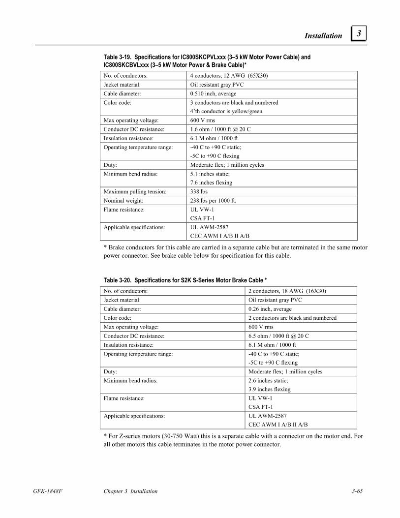
Installation
GFK-1848F Chapter 3 Installation 3-65
3
Table 3-19. Specifications for IC800SKCPVLxxx (3–5 kW Motor Power Cable) and IC800SKCBVLxxx (3–5 kW Motor Power & Brake Cable)* No. of conductors: 4 conductors, 12 AWG (65X30) Jacket material: Oil resistant gray PVC Cable diameter: 0.510 inch, average Color code: 3 conductors are black and numbered
4’th conductor is yellow/green Max operating voltage: 600 V rms Conductor DC resistance: 1.6 ohm / 1000 ft @ 20 C Insulation resistance: 6.1 M ohm / 1000 ft Operating temperature range: -40 C to +90 C static;
-5C to +90 C flexing Duty: Moderate flex; 1 million cycles Minimum bend radius: 5.1 inches static;
7.6 inches flexing Maximum pulling tension: 338 lbs Nominal weight: 238 lbs per 1000 ft. Flame resistance: UL VW-1
CSA FT-1 Applicable specifications: UL AWM-2587
CEC AWM I A/B II A/B
* Brake conductors for this cable are carried in a separate cable but are terminated in the same motor power connector. See brake cable below for specification for this cable.
Table 3-20. Specifications for S2K S-Series Motor Brake Cable * No. of conductors: 2 conductors, 18 AWG (16X30) Jacket material: Oil resistant gray PVC Cable diameter: 0.26 inch, average Color code: 2 conductors are black and numbered Max operating voltage: 600 V rms Conductor DC resistance: 6.5 ohm / 1000 ft @ 20 C Insulation resistance: 6.1 M ohm / 1000 ft Operating temperature range: -40 C to +90 C static;
-5C to +90 C flexing Duty: Moderate flex; 1 million cycles Minimum bend radius: 2.6 inches static;
3.9 inches flexing Flame resistance: UL VW-1
CSA FT-1 Applicable specifications: UL AWM-2587
CEC AWM I A/B II A/B
* For Z-series motors (30-750 Watt) this is a separate cable with a connector on the motor end. For all other motors this cable terminates in the motor power connector.
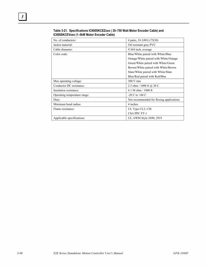
3-66 S2K Series Standalone Motion Controller User's Manual GFK-1848F
3
Table 3-21. Specifications IC800SKCEZxxx ( 30–750 Watt Motor Encoder Cable) and IC800SKCEVxxx (1–5kW Motor Encoder Cable) No. of conductors: 6 pairs, 24 AWG (7X30) Jacket material: Oil resistant gray PVC Cable diameter: 0.364 inch, average Color code: Blue/White paired with White/Blue
Orange/White paired with White/Orange Green/White paired with White/Green Brown/White paired with White/Brown Slate/White paired with White/Slate Blue/Red paired with Red/Blue
Max operating voltage: 300 V rms Conductor DC resistance: 2.5 ohm / 1000 ft @ 20 C Insulation resistance: 6.1 M ohm / 1000 ft Operating temperature range: -20 C to +60 C Duty: Not recommended for flexing applications Minimum bend radius: 4 inches Flame resistance: UL Type CL2, CM
CSA PPC FT-1 Applicable specifications: UL AWM Style 2690, 2919
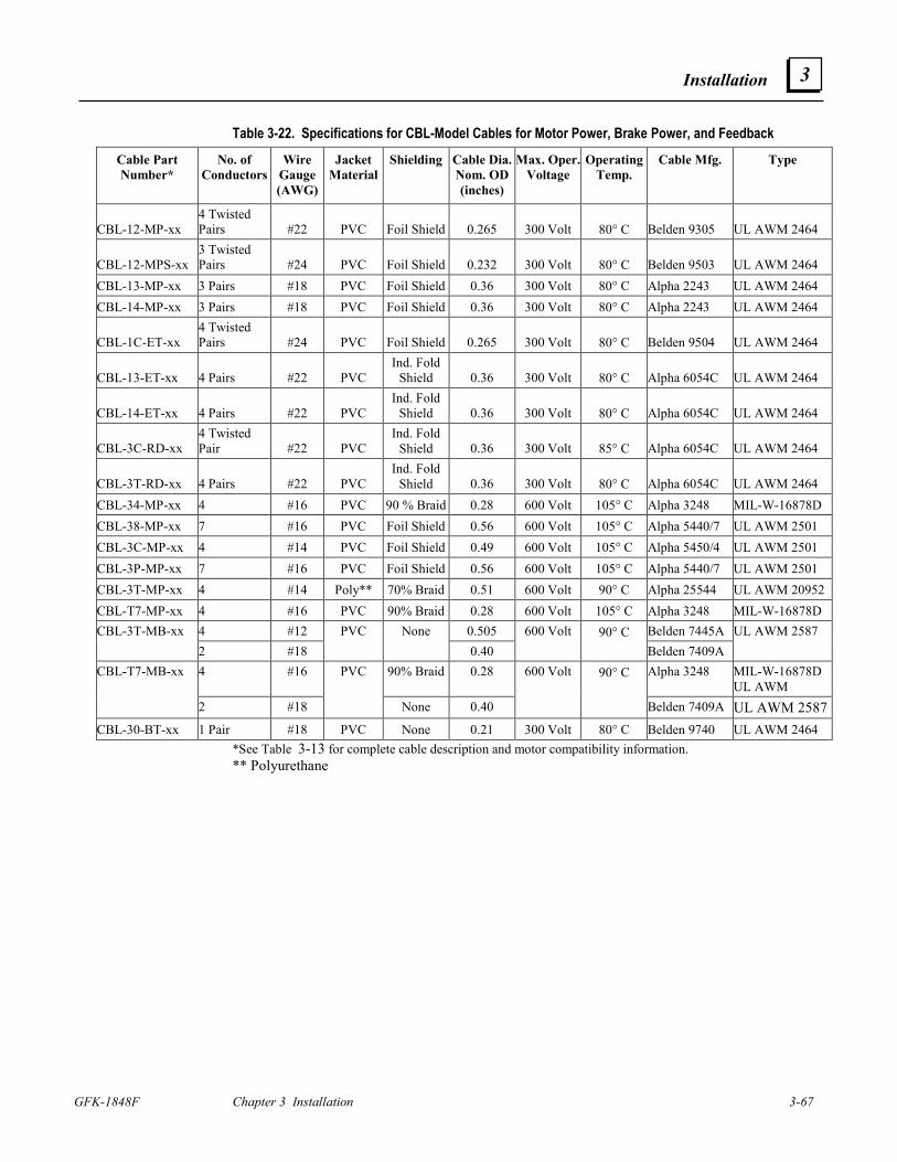
Installation
GFK-1848F Chapter 3 Installation 3-67
3
Table 3-22. Specifications for CBL-Model Cables for Motor Power, Brake Power, and Feedback
Cable Part Number*
No. of Conductors
Wire Gauge (AWG)
Jacket Material
Shielding Cable Dia. Nom. OD(inches)
Max. Oper. Voltage
Operating Temp.
Cable Mfg. Type
CBL-12-MP-xx 4 Twisted Pairs #22 PVC Foil Shield 0.265 300 Volt 80° C Belden 9305 UL AWM 2464
CBL-12-MPS-xx 3 Twisted Pairs #24 PVC Foil Shield 0.232 300 Volt 80° C Belden 9503 UL AWM 2464
CBL-13-MP-xx 3 Pairs #18 PVC Foil Shield 0.36 300 Volt 80° C Alpha 2243 UL AWM 2464 CBL-14-MP-xx 3 Pairs #18 PVC Foil Shield 0.36 300 Volt 80° C Alpha 2243 UL AWM 2464
CBL-1C-ET-xx 4 Twisted Pairs #24 PVC Foil Shield 0.265 300 Volt 80° C Belden 9504 UL AWM 2464
CBL-13-ET-xx 4 Pairs #22 PVC Ind. Fold
Shield 0.36 300 Volt 80° C Alpha 6054C UL AWM 2464
CBL-14-ET-xx 4 Pairs #22 PVC Ind. Fold
Shield 0.36 300 Volt 80° C Alpha 6054C UL AWM 2464
CBL-3C-RD-xx 4 Twisted Pair #22 PVC
Ind. Fold Shield 0.36 300 Volt 85° C Alpha 6054C UL AWM 2464
CBL-3T-RD-xx 4 Pairs #22 PVC Ind. Fold
Shield 0.36 300 Volt 80° C Alpha 6054C UL AWM 2464 CBL-34-MP-xx 4 #16 PVC 90 % Braid 0.28 600 Volt 105° C Alpha 3248 MIL-W-16878D CBL-38-MP-xx 7 #16 PVC Foil Shield 0.56 600 Volt 105° C Alpha 5440/7 UL AWM 2501 CBL-3C-MP-xx 4 #14 PVC Foil Shield 0.49 600 Volt 105° C Alpha 5450/4 UL AWM 2501 CBL-3P-MP-xx 7 #16 PVC Foil Shield 0.56 600 Volt 105° C Alpha 5440/7 UL AWM 2501 CBL-3T-MP-xx 4 #14 Poly** 70% Braid 0.51 600 Volt 90° C Alpha 25544 UL AWM 20952 CBL-T7-MP-xx 4 #16 PVC 90% Braid 0.28 600 Volt 105° C Alpha 3248 MIL-W-16878D
4 #12 0.505 Belden 7445A CBL-3T-MB-xx 2 #18
PVC None 0.40
600 Volt 90° C Belden 7409A
UL AWM 2587
4 #16 90% Braid 0.28 Alpha 3248 MIL-W-16878D UL AWM
CBL-T7-MB-xx
2 #18
PVC
None 0.40
600 Volt 90° C
Belden 7409A UL AWM 2587CBL-30-BT-xx 1 Pair #18 PVC None 0.21 300 Volt 80° C Belden 9740 UL AWM 2464
*See Table 3-13 for complete cable description and motor compatibility information. ** Polyurethane
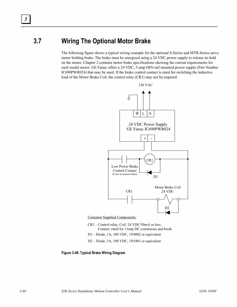
3-68 S2K Series Standalone Motion Controller User's Manual GFK-1848F
3
3.7 Wiring The Optional Motor Brake The following figure shows a typical wiring example for the optional S-Series and MTR-Series servo motor holding brake. The brake must be energized using a 24 VDC power supply to release its hold on the motor. Chapter 2 contains motor brake specifications showing the current requirements for each model motor. GE Fanuc offers a 24 VDC, 5 amp DIN-rail mounted power supply (Part Number IC690PWR024) that may be used. If the brake control contact is rated for switching the inductive load of the Motor Brake Coil, the control relay (CR1) may not be required.
24 VDC Power Supply GE Fanuc IC690PWR024
L N
+ -
CR1
120 VAC
Motor Brake Coil24 VDC
D2
CR1 – Control relay, Coil: 24 VDC/50mA or less, Contact: rated for 1Amp DC continuous and break
CR1
D1
D2 – Diode, 3A, 100 VDC, 1N5401 or equivalent
D1 – Diode, 1A, 100 VDC, 1N4002 or equivalent
Low Power BrakeControl Contact
(Close to release brake)
Customer Supplied Components:
Figure 3-48. Typical Brake Wiring Diagram
Installation
GFK-1848F Chapter 3 Installation 3-69
3
3.8 Regenerative Discharge Resistor Selection and Wiring Regenerative energy is normally created in applications with a high load inertia, high speed, vertical axes and/or frequent acceleration and deceleration. When decelerating a load, the stored kinetic energy of the load creates generator action in the motor causing energy to be returned to the servo controller. For light loads and low acceleration rates, the controller may be able to absorb and store this energy in the DC link filter capacitors or dissipate it in an internal regenerative resistor. Otherwise, an optional external regenerative discharge unit must be installed.
The S2K Series controllers include an internal regenerative discharge resistor that will control the regenerative energy in most applications. When an Over Voltage fault (LED Status Code OV) or an Excessive Clamp Duty Cycle fault (LED Status Code EC) occurs during motor deceleration, the cause is usually excessive regeneration and requires an optional external regenerative resistor kit. The SSI104 controller has no provisions for connecting an external resistor. As an alternative to adding an external resistor you can try a combination of the following actions:
• Reduce the deceleration rate and/or increase deceleration time
• Lower the top speed of the motor
• Reduce machine cycle rate
• Reduce load inertia connected to the motor
• Increase vertical axis counterbalance
GE Fanuc offers several different resistor kits (all kits include resistor mounting brackets) as shown in Table 3-23. Wiring between the resistor and the controller’s power terminals is not included in the kit and is the user’s responsibility. Connections to the resistor can be made by soldering, using a fast-on type terminal of appropriate size, or using a ring terminal bolted through the hole in the resistor terminal tab. See Figure 3-49.
Caution
Under normal operation the regenerative discharge resistor may become very hot. To prevent being burned, never touch the resistor. Mount the resistor well away from heat sensitive components or wiring to prevent damage. Also, the terminals of this resistor are at a high voltage potential. Either insulate the connections or provide adequate shielding to eliminate this shock hazard.
Table 3-23. Regenerative Discharge Resistor Kits
Resistor Kit Specifications GE Fanuc Regenerative
Discharge Resistor Kits
Resistance Continuous Power1
Peak Power for 230 VAC
Models2
Peak Power for 460 VAC
Models2
IC800SLR001 50 Ω 100 W 3362 W 13612
IC800SLR002 100 Ω 225 W 1681 W 6806
IC800SLR003 20 Ω 300 W 8405 W 34031
IC800SLR004 15 Ω 1000 W 11207 W 45375 1) Resistor continuous power ratings are at 25oC ambient temperature. Derate power linearly at 0.3% per oC above 25oC. 2) Peak power is based on an average discharge circuit turn-on voltage of 410 VDC for models rated 230 VAC and 825 VDC
for models rated 460 VAC.
3-70 S2K Series Standalone Motion Controller User's Manual GFK-1848F
3
The resistor values included with the kits are average values for a variety of conditions. Smaller capacity (wattage) resistors may work in some applications and larger resistors may be required in others. The lower the resistance value, the faster the regenerative energy can be dissipated. Applications with large inertial loads, high speeds, and high deceleration rates regenerate more energy and may require a resistor with a lower resistance and/or larger capacity (wattage). As an alternative, when the capacity or resistance of the standard external regenerative resistor is insufficient for the application, reducing load inertia, maximum speed, deceleration rate, increasing vertical axis counterbalance or some combination of these measures can decrease the regenerative energy. See Section 3.8.1 for details on selecting the proper resistor based on application requirements. The wiring between the controller and the regenerative resistor should be kept as short as possible (less than 20 inches or 50cm) to prevent possible damage to the switching transistor from voltage transients due to cable inductance. The regenerative resistor may become very hot during normal operation. Therefore, route all wiring away from the resistor so that the wiring does not touch the resistor and has a minimum clearance of 3 inches (76mm). Connect one terminal of the resistor to the controller’s “EXT” power terminal and the other resistor terminal to the “DC+” controller power terminal. See 3.6.10 Connection Diagrams.
Note If you are not using an external resistor, a wire jumper must be connected between the power terminals “INT” and “EXT” as shown in the “Clamp Connections-External” sections of 3.6.10. If this jumper is not installed, the internal resistor is disabled and the controller may exhibit symptoms associated with excessive regeneration. This note does not apply to the SSI104 model controller.
When mounting the resistor, tighten the lock nut sufficiently to compress the lock washer. Although the lock nut should be tightened securely, avoid over-tightening so as not to strip the bolt threads.
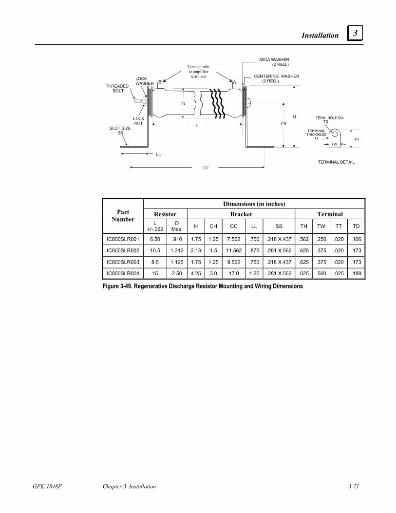
Installation
GFK-1848F Chapter 3 Installation 3-71
3
TERMINALTHICKNESS TT
TW
SLOT SIZE SS
TERM. HOLE DIA TD
LL
THREADED BOLT
LOCKWASHER
LOCK NUT
D
H
CHL
TH
CC
CENTERING WASHER (2 REQ.)
MICA WASHER (2 REQ.)
TERMINAL DETAIL
Connect tabsto amplifierterminals
Dimensions (in inches) Resistor Bracket Terminal Part
Number L
+/-.062 D
Max. H CH CC LL SS TH TW TT TD
IC800SLR001 6.50 .910 1.75 1.25 7.562 .750 .218 X.437 .562 .250 .020 .166
IC800SLR002 10.5 1.312 2.13 1.5 11.562 .875 .281 X.562 .625 .375 .020 .173
IC800SLR003 8.5 1.125 1.75 1.25 9.562 .750 .218 X.437 .625 .375 .020 .173
IC800SLR004 15 2.50 4.25 3.0 17.0 1.25 .281 X.562 .625 .500 .025 .188
Figure 3-49. Regenerative Discharge Resistor Mounting and Wiring Dimensions
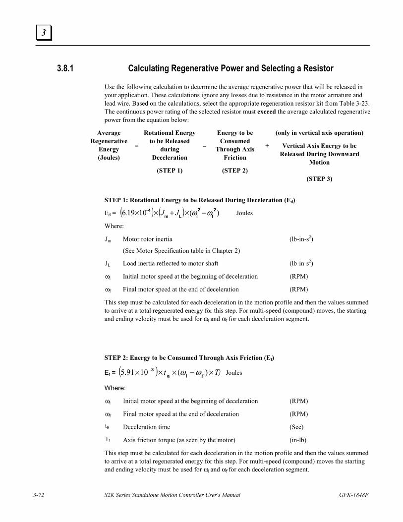
3-72 S2K Series Standalone Motion Controller User's Manual GFK-1848F
3
3.8.1 Calculating Regenerative Power and Selecting a Resistor
Use the following calculation to determine the average regenerative power that will be released in your application. These calculations ignore any losses due to resistance in the motor armature and lead wire. Based on the calculations, select the appropriate regeneration resistor kit from Table 3-23. The continuous power rating of the selected resistor must exceed the average calculated regenerative power from the equation below:
Average Regenerative
Energy (Joules)
=
Rotational Energy to be Released
during Deceleration
(STEP 1)
–
Energy to be Consumed
Through Axis Friction
(STEP 2)
+
(only in vertical axis operation)
Vertical Axis Energy to be Released During Downward
Motion
(STEP 3) STEP 1: Rotational Energy to be Released During Deceleration (Ed)
Ed = ( ) ( ) )(1019.6 2f
2iLm
4 ωω −×+×× − JJ Joules
Where:
Jm Motor rotor inertia
(See Motor Specification table in Chapter 2)
(lb-in-s2)
JL Load inertia reflected to motor shaft (lb-in-s2)
ωi Initial motor speed at the beginning of deceleration (RPM)
ωf Final motor speed at the end of deceleration (RPM)
This step must be calculated for each deceleration in the motion profile and then the values summed to arrive at a total regenerated energy for this step. For multi-speed (compound) moves, the starting and ending velocity must be used for ωI and ωf for each deceleration segment.
STEP 2: Energy to be Consumed Through Axis Friction (Ef)
Ef = ( ) fTt ×−××× − ) ( 1091.5 fωω ia3 Joules
Where:
ωi Initial motor speed at the beginning of deceleration (RPM)
ωf Final motor speed at the end of deceleration (RPM)
ta Deceleration time (Sec)
Tf Axis friction torque (as seen by the motor) (in-lb)
This step must be calculated for each deceleration in the motion profile and then the values summed to arrive at a total regenerated energy for this step. For multi-speed (compound) moves the starting and ending velocity must be used for ωI and ωf for each deceleration segment.
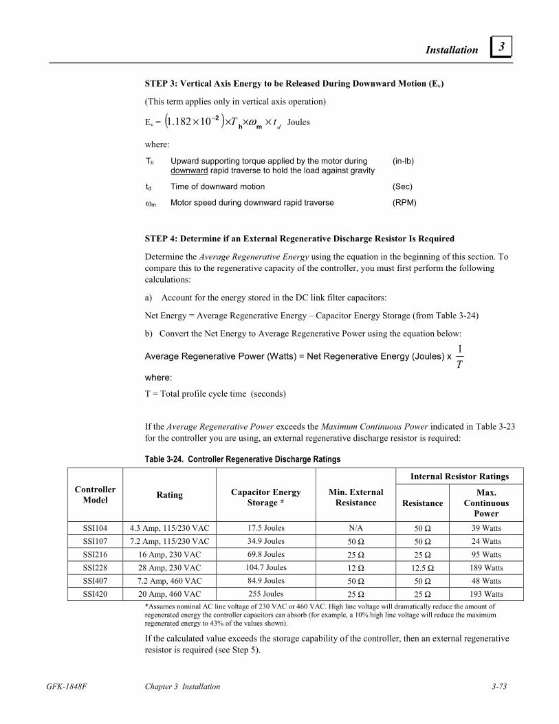
Installation
GFK-1848F Chapter 3 Installation 3-73
3
STEP 3: Vertical Axis Energy to be Released During Downward Motion (Ev)
(This term applies only in vertical axis operation)
Ev = ( ) dtT ×××× −mh
2 ω10182.1 Joules
where:
Th Upward supporting torque applied by the motor during downward rapid traverse to hold the load against gravity
(in-lb)
td Time of downward motion (Sec)
ωm Motor speed during downward rapid traverse (RPM)
STEP 4: Determine if an External Regenerative Discharge Resistor Is Required
Determine the Average Regenerative Energy using the equation in the beginning of this section. To compare this to the regenerative capacity of the controller, you must first perform the following calculations:
a) Account for the energy stored in the DC link filter capacitors:
Net Energy = Average Regenerative Energy – Capacitor Energy Storage (from Table 3-24)
b) Convert the Net Energy to Average Regenerative Power using the equation below:
Average Regenerative Power (Watts) = Net Regenerative Energy (Joules) x T1
where:
T = Total profile cycle time (seconds)
If the Average Regenerative Power exceeds the Maximum Continuous Power indicated in Table 3-23 for the controller you are using, an external regenerative discharge resistor is required:
Table 3-24. Controller Regenerative Discharge Ratings
Internal Resistor Ratings Controller
Model Rating
Capacitor Energy Storage *
Min. External Resistance Resistance
Max. Continuous
Power SSI104 4.3 Amp, 115/230 VAC 17.5 Joules N/A 50 Ω 39 Watts SSI107 7.2 Amp, 115/230 VAC 34.9 Joules 50 Ω 50 Ω 24 Watts SSI216 16 Amp, 230 VAC 69.8 Joules 25 Ω 25 Ω 95 Watts SSI228 28 Amp, 230 VAC 104.7 Joules 12 Ω 12.5 Ω 189 Watts SSI407 7.2 Amp, 460 VAC 84.9 Joules 50 Ω 50 Ω 48 Watts SSI420 20 Amp, 460 VAC 255 Joules 25 Ω 25 Ω 193 Watts
*Assumes nominal AC line voltage of 230 VAC or 460 VAC. High line voltage will dramatically reduce the amount of regenerated energy the controller capacitors can absorb (for example, a 10% high line voltage will reduce the maximum regenerated energy to 43% of the values shown).
If the calculated value exceeds the storage capability of the controller, then an external regenerative resistor is required (see Step 5).
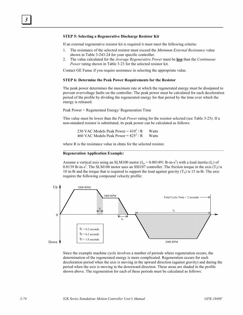
3-74 S2K Series Standalone Motion Controller User's Manual GFK-1848F
3
STEP 5: Selecting a Regenerative Discharge Resistor Kit
If an external regenerative resistor kit is required it must meet the following criteria: 1. The resistance of the selected resistor must exceed the Minimum External Resistance value
shown in Table 3-243-24 for your specific controller. 2. The value calculated for the Average Regenerative Power must be less than the Continuous
Power rating shown in Table 3-23 for the selected resistor kit. Contact GE Fanuc if you require assistance in selecting the appropriate value. STEP 6: Determine the Peak Power Requirements for the Resistor The peak power determines the maximum rate at which the regenerated energy must be dissipated to prevent overvoltage faults on the controller. The peak power must be calculated for each deceleration period of the profile by dividing the regenerated energy for that period by the time over which the energy is released. Peak Power = Regenerated Energy/ Regeneration Time This value must be lower than the Peak Power rating for the resistor selected (see Table 3-23). If a non-standard resistor is substituted, its peak power can be calculated as follows: 230 VAC Models Peak Power = 4102 / R Watts 460 VAC Models Peak Power = 8252 / R Watts where R is the resistance value in ohms for the selected resistor. _________________________________________________________________________________ Regeneration Application Example: Assume a vertical axis using an SLM100 motor (Jm = 0.001491 lb-in-s2) with a load inertia (JL) of 0.0139 lb-in-s2. The SLM100 motor uses an SSI107 controller. The friction torque in the axis (Tf) is 10 in-lb and the torque that is required to support the load against gravity (Th) is 15 in-lb. The axis requires the following compound velocity profile:
2000 RPM
1000 RPM
2000 RPM
Up
Down
0
t1 t3
t2
t1 = 0.2 secondst2 = 0.2 seconds
t3 = 1.0 seconds
Total Cycle Time = 2 seconds
Since the example machine cycle involves a number of periods where regeneration occurs, the determination of the regenerated energy is more complicated. Regeneration occurs for each deceleration period when the axis is moving in the upward direction (against gravity) and during the period when the axis is moving in the downward direction. These areas are shaded in the profile shown above. The regeneration for each of these periods must be calculated as follows:
Installation
GFK-1848F Chapter 3 Installation 3-75
3
STEP 1a: Calculate the rotational energy during period t1:
Ed1 = (6.19x10-4) x (0.001491+0.0139) x (20002 – 10002)= 28.58 Joules
STEP 1b: Calculate the rotational energy during period t2:
Ed2 = (6.19x10-4) x (0.001491+0.0139) x (10002 – 02) = 9.53 Joules
STEP 2a: Calculate the energy absorbed by friction during period t1:
Ef1 = (5.91x10-3) x 0.2 sec x (2000 RPM-1000 RPM) x 10 in-lb = 11.82 Joules
STEP 2b: Calculate the energy absorbed by friction during period t2:
Ef2 = (5.91x10-3) x 0.2 sec x 1000 RPM x 10 in-lb = 11.82 Joules
STEP 3: Calculate the regenerative energy for downward motion during period t3:
Ev = (1.182x10-2) x 15 in-lb x 2000 RPM x 1 Sec = 354.6 Joules
STEP 4: Calculate the Average Regenerative Energy for the entire cycle (Eavg):
Eavg = 28.58 + 9.53 – 11.28 – 11.82 + 354.6 = 369.1 Joules
To determine if the SSI107 controller can absorb this amount of energy, first determine the net energy the regeneration resistors must dissipate. To find this Net Energy value, subtract the energy stored in the controllers bus filter capacitors as shown under the Capacitor Energy Storage heading in Table 3-24.
Net Energy = 369.1 Joules – 41.1 Joules = 328 Joules
Next, we must convert this Net Energy to power so we can compare the result with the dissipation capability of the controller’s internal regeneration resistor.
Average Power = Net Energy / Total Cycle Time = 328 / 2 Sec = 164 Watts
We now compare this result to the controller’s Max. Continuous Power rating from Table 3-24. Since the 164 Watts required is more than the 25 watts allowed by the SSI107 controller, an external regenerative resistor is required.
STEP 5: Determine the proper external regeneration resistor size:
If we refer to the resistor selection criteria shown in Step 5 above, we must first select a resistor that has a resistance value larger than the Min. External Resistance for the SSI107 controller shown in Table 3-24. Therefore, our resistor must be at least 50 Ω. From the second criteria our calculated value of 164 Watts for the Average Regenerative Power must be less than the Continuous Power rating of the resistor we select.
From Table 3-23 we see that resistor kit IC800SLR002 has a resistance of 100Ω and a continuous power rating of 225 Watts which meets both of the selection criteria.
STEP 6: Check the peak power (Ppk) requirements for each regeneration period:
For period t1: Ppk1 = 28.58 Joules / 0.2 seconds = 142.9 Watts
For period t2: Ppk2 = 9.53 Joules / 0.2 seconds = 47.65 Watts
For period t3: Ppk3 = 369.1 Joules / 1 second = 369.1 Watts
The largest of these values, 369.1 Watts, is still less than the 2880 Watt Peak Power rating of the IC800SLR001 resistor kit so this standard resistor can be used.
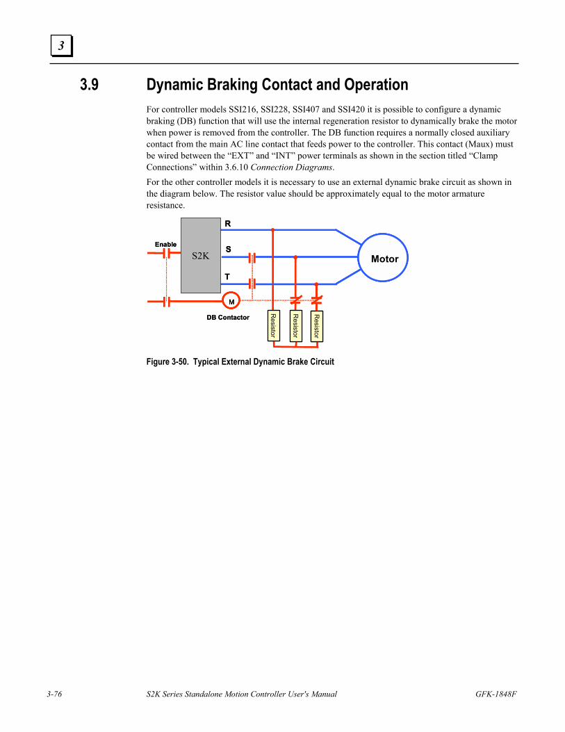
3-76 S2K Series Standalone Motion Controller User's Manual GFK-1848F
3
3.9 Dynamic Braking Contact and Operation For controller models SSI216, SSI228, SSI407 and SSI420 it is possible to configure a dynamic braking (DB) function that will use the internal regeneration resistor to dynamically brake the motor when power is removed from the controller. The DB function requires a normally closed auxiliary contact from the main AC line contact that feeds power to the controller. This contact (Maux) must be wired between the “EXT” and “INT” power terminals as shown in the section titled “Clamp Connections” within 3.6.10 Connection Diagrams. For the other controller models it is necessary to use an external dynamic brake circuit as shown in the diagram below. The resistor value should be approximately equal to the motor armature resistance.
Resistor
M
Motor
R
S
T
DB Contactor
Resistor
Resistor
S2KEnable
Resistor
MM
MotorMotorMotor
R
S
T
DB Contactor
Resistor
Resistor
Resistor
S2KEnable
Figure 3-50. Typical External Dynamic Brake Circuit
GFK-1848F 4-1
Getting Started
The flowchart in Figure 4-1 documents the process for completing a basic setup for an S2K motion controller. This chapter expands upon the pre-programming actions in this flowchart with step-by-step instructions for each part of the procedure. Once you have completed this basic set-up, you will be ready to start programming your motion control system.
Instructions for installing CIMPLICITY Motion Developer software to configure and program the controller are provided in Chapter 6, while Chapter 5 includes a detailed reference for all commands and registers supported by the S2K Series controllers. The Motion Developer software includes a Motion Expert Wizard that guides the novice user through the initial programming and parameter configuration of the S2K controller. The intent of this wizard is to provide a basic set-up that will allow you to run your motor. It does not attempt to cover all aspects of programming and configuring the controller since all applications have varied interface and program requirements.
The S2K configurations in this chapter illustrate how to set up S2K controllers I/O using the internal 12Vdc power supply for both servo and stepping models.
4 Chapter
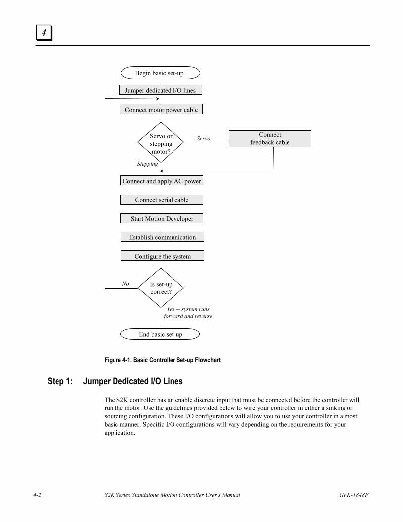
4-2 S2K Series Standalone Motion Controller User's Manual GFK-1848F
4
Figure 4-1. Basic Controller Set-up Flowchart
Step 1: Jumper Dedicated I/O Lines
The S2K controller has an enable discrete input that must be connected before the controller will run the motor. Use the guidelines provided below to wire your controller in either a sinking or sourcing configuration. These I/O configurations will allow you to use your controller in a most basic manner. Specific I/O configurations will vary depending on the requirements for your application.
Jumper dedicated I/O lines
Connect serial cable
Connect motor power cable
Connect feedback cable
Connect and apply AC power
Begin basic set-up
End basic set-up
Servo
Stepping
No
Establish communication
Servo or stepping motor?
Start Motion Developer
Configure the system
Yes -- system runs forward and reverse
Is set-up correct?
Getting Started
GFK-1848F Chapter 4 Getting Started 4-3
4
For Sinking (Low-True) Connections
Jumper connections 15 and 18; 18 and 20; 17 and 19 (on the 20-pin Auxiliary I/O connector for controllers SSI216, SSI228, and SSI420; on the 20-pin Discrete I/O connector for controllers STI105, SSI104, SSI107, and SSI407).
For Sourcing (High-True) Connections
Jumper connections 15 and 18; 18 and 19; 17 and 20 (on the 20-pin Auxiliary I/O connector for controllers SSI216, SSI228, and SSI420; on 20-pin Discrete I/O connector for controllers STI105, SSI104, SSI107, and SSI407).
Note: If outputs are low true, or sinking, then inputs must also be low true. If outputs are high true, or sourcing, then inputs must also be high true.
Step 2: Connect Motor Power Cable
To minimize wiring errors we recommend using prefabricated cables available from GE Fanuc. Section 3.6.12–Cables and Connector Mates includes part number and length information for cables available from GE Fanuc and motor connector mates available from the manufacturer.
For S2K Series Servo Motor Controllers: Connect the flying leads labeled R, S, T, and ground to the appropriately labeled slots on the bottom of the controller. For S-Series servo motors rated 750 W and below, connect the box-style connector to the similar connector on the motor pigtail. S-Series servo motors rated 1kW and larger and all MTR-Series motors use MS-style connectors that mate to an equivalent connector on the opposite end of the power cable. All motor connectors are keyed to prevent improper installation. For details on the servo motor power connectors see Section 3.6.4S-Series Servo Motor Power and Brake Wiring and Grounding and 3.6.5MTR-Series Servo Motor Power and Brake Wiring and Grounding.
For S2K Series Stepping Motor Controllers: Connect the flying leads labeled Ground, B+, A/B-, and A+ to the appropriately labeled screw terminals on the bottom of the controller. Plug the motor side connector on to the in-line barrel style connector on the motor pigtail for NEMA 34 stepping motors or directly onto the motor mounted connector for NEMA 23 motors.
Step 3: Connect Position Feedback Cable (Servo only)
Connect the D-shell connector to its mate, labeled Position Feedback on the front of the S2K. Tighten the connector retaining screws to fasten the connector.
For S-Series servo motors rated 750 W and below, connect the box-style connector to the similar encoder connector on the motor pigtail. S-Series servo motors rated 1kW and above and MTR-Series motors use MS-style connectors that mate to an equivalent connector on the opposite end of the feedback cable. All motor connectors are keyed to prevent improper installation. For details on the servo motor connectors see Section 3.6.3−Servo Motor Encoder Wiring and Section 3.6.6−MTR-Series Servo Motor Resolver Wiring.
4-4 S2K Series Standalone Motion Controller User's Manual GFK-1848F
4
Step 4: Connect and Apply AC Power
Refer to Section 3.6.2 – AC Supply and Motor Wiring and Grounding for additional information.
Single-Phase AC Input
STI105 Stepper and SSI104 Servo Models: Connect power wires to the L1, L2, and ground connections to the screw terminals on the bottom of the controller.
SSI107, SSI216 and SSI228 Servo Models: Connect power wires to the 1L1, 1L2, and ground connections to the screw terminals on the bottom of the controller. To supply power to the controller logic circuit, jumper the 1L2 to the 2L2 connection; then jumper the 1L1 to the 2L1 connection.
CAUTION! For single-phase operation DO NOT jumper the 1L3 connection.
Three-Phase AC Input
SSI104 Servo Model: Connect power wires to the L1, L2, L3, and ground connections on the bottom of the controller.
SSI107, SSI216, SSI228, SSI407, and SSI420: Connect power wires to the 1L1, 1L2, 1L3, and ground connections on the bottom of the controller (see figure 2.4). To supply power to the logic circuit for models SSI107, SSI216, and SSI228, jumper the 1L2 to the 2L2 connection; then jumper the 1L1 to the 2L1 connection. The SSI407 and SSI420 models require a 24 Vdc logic supply on the COM and +24V terminals.
Apply Power to the S2K Apply the proper AC voltage to the controller as shown below:
Model Rating Output Power Input Input Frequency
SSI105 5 Amps Continuous 90-130 VAC, single-phase @ 10.0 Amps 50 - 440 Hz SSI104 4.3 Amps Continuous 90-250 VAC
single-phase @ 7 Amps three-phase @ 4 Amps
50 - 440 Hz
SSI107 7.2 Amps Continuous 90-250 VAC single-phase @ 17 Amps three-phase @ 9 Amps
50 - 440 Hz
SSI216 16 Amps Continuous 180-250 VAC three-phase @ 19 Amps 50 - 440 Hz SSI228 28 Amps Continuous 180-250 VAC three-phase @ 34 Amps 50 - 440 Hz SSI407 7.2 Amps Continuous 324-528 VAC three-phase @ 8 Amps 50 - 440 Hz SSI420 20 Amps Continuous 324-528 VAC three-phase @ 22 Amps 50 - 440 Hz
Getting Started
GFK-1848F Chapter 4 Getting Started 4-5
4
Step 5: Establish Communication with Motion Developer Install the Motion Developer software on Your PC If you have not already installed Motion Developer on your PC, please do so at this time (see Chapter 6): 1. Close all Windows applications.
2. Insert the Motion Developer CD into your PC drive.
3. The CD has an autorun feature and should start automatically. If it does not then on the Windows task bar click Start/Run. Type D:\Setup (“D” should be replaced with the appropriate letter for your CD-ROM drive).
Connect Serial Communication Cable (IC800SKCS030)
1. Connect the end labeled “S2K” (9 pin female D-Shell connector) to the Serial port on the front of the S2K controller. Tighten the screws to fasten the connector.
2. Connect the end labeled “RS232 Port” (9 pin female D-Shell connector) to the RS-232 serial communication port on your computer. Tighten the screws to fasten the connector.
Run Motion Developer
From the Start menu, select Programs/CIMPLICITY Machine Edition/CIMPLICITY Machine Edition. The software will open to the Motion Developer home page in the InfoViewer window and the Manager tab in the Navigator window. (See the online help for details on using Motion Developer.)
Establish Communication
1. Create a new project in the Manager tab in Motion Developer. This will add a new Target (S2K controller) called Target1 to the Projects tab, which will now be showing in the Navigator window.
2. From the Motion Developer toolbar click on the Terminal Window button
3. Press the <Enter> key. If the controller is communicating the terminal window should respond with the following prompt:
*GE Fanuc S2K Series
Network Address - 0
4. If you do not see this prompt then refer to Chapter 6 for instructions on using the Motion Expert or Communication wizards to configure the controller for proper communication.
4-6 S2K Series Standalone Motion Controller User's Manual GFK-1848F
4
Using the Motion Developer Terminal Window The terminal window in Motion Developer allows you to communicate directly with your S2K in an immediate execution mode over its serial port.
Note Changes made to registers, programs or motion blocks using the terminal window are NOT saved to your Motion Developer project or to non-volatile (Flash) memory. The terminal window communicates directly with the controllers working memory (volatile SRAM). To save these changes to your project you can manually change the appropriate values in your project using the script editors or import the controller’s memory contents into your project target. This import will overwrite ALL existing configuration, programs and motion blocks for that target controller.
Here are a few tips for talking to your controller: 1. Motion controllers accept new commands and registers on a line-by-line basis. After you load
a register or enter a command, press the <Enter> key on your computer keyboard. 2. The motion controller will tell you if it accepts the command or register with one of the
following response in the terminal window:
Input Accepted: An asterisk “*” followed by no response or by a requested answer means that your last entry was okay and the controller is waiting for the next entry.
Input Not Accepted: A question mark “?” followed by a message (e.g. INVALIDCOMMAND. Additional messages are contained in Chapter 7.
3. Registers are loaded using the assignment command “=”. For example, to load a velocity value of 100 axis units per second into an S2K, you would enter MVL=100 <Enter>.
4. You can interrogate the S2K to find the contents of registers using either the Q or ? command. For example, to learn the value of the velocity register, type MVLQ <Enter> or MVL? <Enter>. These are equivalent statements. The controller will return the contents of the velocity register on the next line of the terminal window (e.g. *100).
5. You can ask the controller its status by interrogating the status and fault registers. A complete listing of the status registers is shown in Chapter 7 – Diagnostics. For now, you can try this by typing SRS?<Enter> to query the system status register.
6. To preserve changes when controller power is cycled you must save the SRAM memory to non-volatile Flash memory using the SAVE command in the terminal window or the “Save to Flash” button on the Controller Functions wizard.
Step 6: Configure the System
Chapter 6 details the installation of the Motion Developer software to configure the S2K series controllers. Once installed, the Motion Expert wizard will guide you through the configuration of your controller. Please refer to the online help for additional details on configuration and programming.
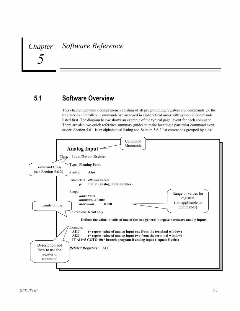
GFK-1848F 5-1
Software Reference
5.1 Software Overview This chapter contains a comprehensive listing of all programming registers and commands for the S2K Series controllers. Commands are arranged in alphabetical order with symbolic commands listed first. The diagram below shows an example of the typical page layout for each command. There are also two quick reference summary guides to make locating a particular command even easier. Section 5.6.1 is an alphabetical listing and Section 5.6.2 list commands grouped by class.
5 Chapter
Analog Input Class: Input/Output Register
Type: Floating Point Syntax: AIp1 Parameters allowed values p1 1 or 2 (analog input number) Range: units volts minimum -10.000 maximum 10.000 Restrictions: Read only.
Defines the value in volts of one of the two general-purpose hardware analog inputs. Example: AI1? (* report value of analog input one from the terminal window) AI2? (* report value of analog input two from the terminal window) IF AI1=5 GOTO 10 (* branch program if analog input 1 equals 5 volts) Related Registers: AO
Command Mnemonic
Command Class (see Section 5.6.2)
Range of values for registers
(not applicable to commands) Limits on use
Description and how to use the
register or command
5-2 S2K Series Standalone Motion Controller User's Manual GFK-1848F
5
5.2 S2K Programming Language Basics The S2K Series has been designed specifically for motion and machine control. The programming language uses mnemonic constructs and supports a broad range of functionality and program flexibility.
Registers, commands, and operators/operands are the basic tools that you will need to create your motion control application programs. Detailed information on each is provided in “Commands and Registers” on page 5-59.
A typical command line would adhere to the following syntax structure, for example:
command line: Wait IP When Not DI3 Goto 310
action: wait until axis is in position or if digital input 3 is not true, then go to label 310.
Registers can be loaded directly with a data value or indirectly with the contents of a variable, for example:
register: MPI=1000
MPI=VF100
action: the Incremental Move Position (MPI) register can be loaded with either the value 1,000 or the contents of floating point variable 100.
The S2K Series supports full floating-point math and operators for complex mathematical and logical operations. Multifunction, single-line math operations use standard infix notation to simplify program readability and flow, for example:
mathematical equation: VF1=SQR(VF2**2.+VF3**2.)
calculation: result stored in floating point variable 1 equals the square root of the sum of the squares of floating point variables 2 and 3.
The S2K controllers support two modes of operation: preprogrammed task execution and immediate mode.
Immediate Mode In immediate mode the serial communications port functions as your control port, allowing you to send commands or load registers online and in real-time from an external source. Immediate mode is useful for applications in which motion register values and/or commands are not known in advance and may be a function of operations performed elsewhere on the machine. This mode is also a useful tool for debugging controller operation using the Motion Developer terminal window interface. Immediate mode allows the following real-time operations: 1. Send/receive variables 2 Send immediate mode commands (e.g., AUTOTUNE, CLM) 3. Load/send new register values 4. Query system status and register values
5. Send motion commands
Software Reference
GFK-1848F Chapter 5 Software Reference 5-3
5
Note Changes made to registers, programs or motion blocks using the terminal window are NOT saved to your Motion Developer project or to non-volatile (Flash) memory. The terminal window communicates directly with the controllers working memory (volatile SRAM). To save these changes to your project you can manually change the appropriate values in your project using the script editors or import the controller’s memory contents into your project target. This import will overwrite ALL existing configuration, programs and motion blocks for that target controller. To save the changes to non-volatile memory, use the SAVE command in the terminal window or the “Save to Flash” button on the Controller Functions wizard.
Programmed Task Execution Mode Programmed task mode allows the S2K controller to execute user application programs that are stored in memory. Up to four programs can be stored and run concurrently (see Section 5.3).
5.3 Programming Resources The S2K controllers use a Real Time Operating System (RTOS) that allows you to create a control system for complex motion applications with real-time machine control and human-machine interface functions. The RTOS is multitasking and has global resources (shown in 5-1) that are shared by all tasks.
Multitasking provides a convenient and reliable technique for adding versatility and performance to real-time control systems. The S2K supports up to 6 concurrent tasks, including up to 4 programs, 1 motion block, and 1 communication port. Tasks run independently of each other except as designed by the programmer. Your communication port allows you to receive registers or commands while you are executing other tasks. Table 5-1 shows a listing of the programming resources available.
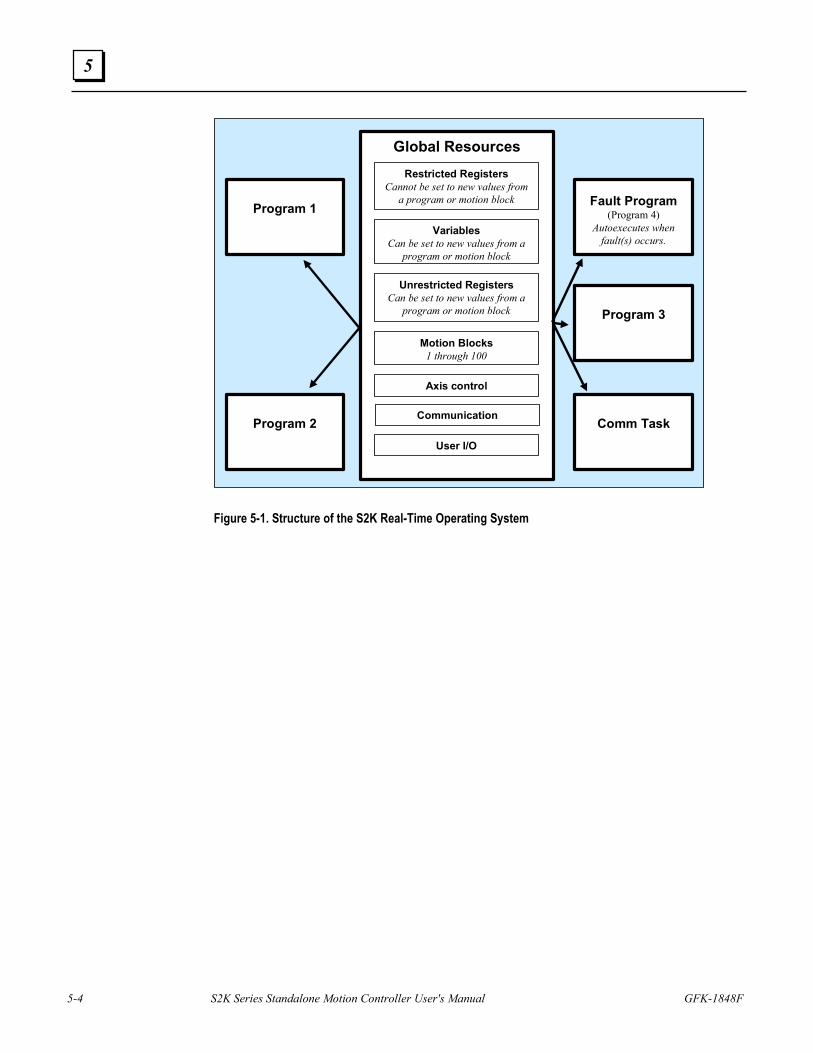
5-4 S2K Series Standalone Motion Controller User's Manual GFK-1848F
5
Global Resources
Motion Blocks1 through 100
VariablesCan be set to new values from a
program or motion block
Communication
User I/O
Axis control
Restricted RegistersCannot be set to new values from
a program or motion block
Unrestricted RegistersCan be set to new values from a
program or motion block
Program 1 Fault Program(Program 4)
Autoexecutes when fault(s) occurs.
Program 2
Program 3
Comm Task
Figure 5-1. Structure of the S2K Real-Time Operating System
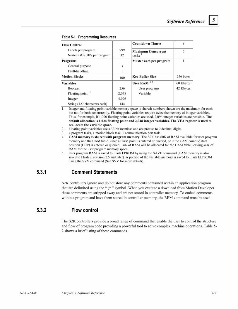
Software Reference
GFK-1848F Chapter 5 Software Reference 5-5
5
Table 5-1. Programming Resources Countdown Timers 8 Flow Control
Labels per program Nested GOSUBS per program
999 32
Maximum Concurrent tasks 3
6
Programs General purpose Fault-handling
3 1
Master axes per program 1
Motion Blocks 100 Key Buffer Size 256 bytes
Variables Boolean Floating point 1,2 Integer 1 String (127 characters each)
256 2,048 4,096 144
User RAM 4, 5 User programs Variable
60 Kbytes 42 Kbytes
1. Integer and floating point variable memory space is shared; numbers shown are the maximum for each but not for both concurrently. Floating point variables require twice the memory of integer variables. Thus, for example, if 1,000 floating point variables are used, 2,096 integer variables are possible. The default allocation is 1,024 floating point and 2,048 integer variables. The VFA register is used to reallocate the variable space.
2. Floating point variables use a 32-bit mantissa and are precise to 9 decimal digits. 3. 4 program tasks, 1 motion block task, 1 communication port task. 4. CAM memory is shared with program memory. The S2K has 60K of RAM available for user program
memory and the CAM table. Once a CAM point is entered or queried, or if the CAM compile start position (CCP) is entered or queried, 14K of RAM will be allocated for the CAM table, leaving 46K of RAM for the user program memory space.
5. User program RAM is saved to Flash EPROM by using the SAVE command (CAM memory is also saved to Flash in revision 2.5 and later). A portion of the variable memory is saved to Flash EEPROM using the SVV command (See SVV for more details).
5.3.1 Comment Statements
S2K controllers ignore and do not store any comments contained within an application program that are delimited using the “ (* ” symbol. When you execute a download from Motion Developer these comments are stripped away and are not stored in controller memory. To embed comments within a program and have them stored in controller memory, the REM command must be used.
5.3.2 Flow control
The S2K controllers provide a broad range of command that enable the user to control the structure and flow of program code providing a powerful tool to solve complex machine operations. Table 5-2 shows a brief listing of these commands.
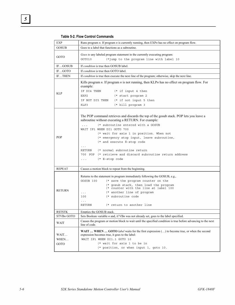
5-6 S2K Series Standalone Motion Controller User's Manual GFK-1848F
5
Table 5-2. Flow Control Commands EXP Runs program n. If program n is currently running, then EXPn has no effect on program flow. GOSUB Goes to a label that functions as a subroutine.
GOTO Goes to any labeled program statement in the currently executing program: GOTO10 (*jump to the program line with label 10
IF…GOSUB If condition is true then GOSUB label. IF…GOTO If condition is true then GOTO label. IF…THEN If condition is true then execute the next line of the program; otherwise, skip the next line.
KLP
Kills program n. If program n is not running, then KLPn has no effect on program flow. For example: IF DI4 THEN (* if input 4 then
EXP2 (* start program 2
IF NOT DI5 THEN (* if not input 5 then
KLP3 (* kill program 3
POP
The POP command retrieves and discards the top of the gosub stack. POP lets you leave a subroutine without executing a RETURN. For example: ... (* subroutine entered with a GOSUB
WAIT IP1 WHEN DI1 GOTO 700
(* wait for axis 1 in position. When not
(* emergency stop input, leave subroutine,
(* and execute E-stop code
...
RETURN (* normal subroutine return
700 POP (* retrieve and discard subroutine return address
... (* E-stop code
REPEAT Causes a motion block to repeat from the beginning.
RETURN
Returns to the statement in program immediately following the GOSUB, e.g., GOSUB 100 (* save the program counter on the
(* gosub stack, then load the program(* counter with the line at label 100
... (* another line of program
100 (* subroutine code
...
RETURN (* return to another line
RSTSTK Empties the GOSUB stack.STVBn GOTO Sets Boolean variable n and, if VBn was not already set, goes to the label specified.
WAIT Causes the program or motion block to wait until the specified condition is true before advancing to the next line of code.
WAIT… WHEN… GOTO
WAIT … WHEN … GOTO label waits for the first expression (…) to become true, or when the second expression becomes true, it goes to the label: WAIT IP1 WHEN DI1.1 GOTO 10
(* wait for axis 1 to be in
(* position, or when input 1, goto 10.
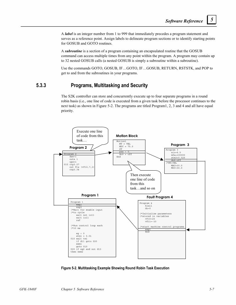
Software Reference
GFK-1848F Chapter 5 Software Reference 5-7
5
A label is an integer number from 1 to 999 that immediately precedes a program statement and serves as a reference point. Assign labels to delineate program sections or to identify starting points for GOSUB and GOTO routines.
A subroutine is a section of a program containing an encapsulated routine that the GOSUB command can access multiple times from any point within the program. A program may contain up to 32 nested GOSUB calls (a nested GOSUB is simply a subroutine within a subroutine).
Use the commands GOTO, GOSUB, IF…GOTO, IF…GOSUB, RETURN, RSTSTK, and POP to get to and from the subroutines in your programs.
5.3.3 Programs, Multitasking and Security
The S2K controller can store and concurrently execute up to four separate programs in a round robin basis (i.e., one line of code is executed from a given task before the processor continues to the next task) as shown in Figure 5-2. The programs are titled Program1, 2, 3 and 4 and all have equal priority.
Figure 5-2. Multitasking Example Showing Round Robin Task Execution
Program 1
Program 2Program 2
dse=1outs 1ups=1
010 crp3.27out fts (vf10,7,3)crp3.34
Program 3 Program 3
aio=6.5mfa=100000stm3=0.025do9-off
(*MT=VELMAC=30.0MDC=30.0
Motion Block Motion1
MT = VELMDC = 75.0STpsa = 0.do9 = off
End
Fault Program 4 Program 4
klalldo=0
(*Initialize parameters(*stored in variables
vf10=20vf11=-10
(*start machine control programsexp1End
Execute one line of code from this task…
Then execute one line of code from this task…and so on
Program 1exp2exp3
(*Wait for enable input(*to cycle
wait not io11wait io11rsf
(*Run control loop each(*10 ms
eg = 0stm1 = 0.01
010 wait tm1if di1 goto 020exm1goto 010
020 if eg2 and not di3then exm2
5-8 S2K Series Standalone Motion Controller User's Manual GFK-1848F
5
Programs 1 through 3 are general-purpose programs while program 4 is a special purpose program designated for fault handling. When the controller detects one or more fault conditions, the S2K controller indicates that one or more fault conditions exist and Program 4 is automatically executed. Many events can cause a fault—the two most common causes are power loss and enable loss. One or both of these conditions occur in the course of normal machine operation, for example, on power cycles or in an e-stop condition. Your fault handling program must diagnose the cause of the fault and determine the appropriate system behavior. Chapter 7 provides details on diagnosing system faults.
The Motion Developer software automatically creates placeholders for programs 1-4 for each new target controller added to the project. The Motion Expert wizard facilitates the development of Program 1 for general machine control and provides several selections for creating basic fault handling code for Program 4.
Any program can start or stop any other program. Use EXPn and KLPn to start and stop individual programs; use EXMn to start a motion block. The KLALL command will stop all programs. Table 5-3 tells you more about these multitasking commands:
Motion Developer allows you to substitute symbolic names in place of motion block or program numbers. For example, if motion block 1 represents a return to Home position move, it is more intuitive to call this move by the symbolic name “Home.” In this case you can start this motion by replacing the motion block number n with the symbolic name (EXM HOME) in the Execute Motion command.
Note Symbolic names are stored as a part of your Machine Edition project but are not downloaded and stored to the controller. Programs imported from controller memory do not include the symbolic names.
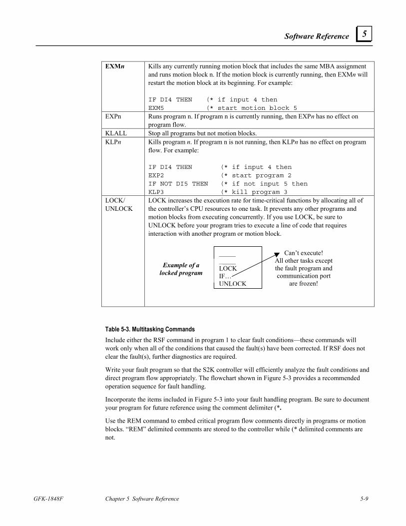
Software Reference
GFK-1848F Chapter 5 Software Reference 5-9
5
EXMn Kills any currently running motion block that includes the same MBA assignment
and runs motion block n. If the motion block is currently running, then EXMn will restart the motion block at its beginning. For example: IF DI4 THEN (* if input 4 thenEXM5 (* start motion block 5
EXPn Runs program n. If program n is currently running, then EXPn has no effect on program flow.
KLALL Stop all programs but not motion blocks. KLPn Kills program n. If program n is not running, then KLPn has no effect on program
flow. For example: IF DI4 THEN (* if input 4 thenEXP2 (* start program 2IF NOT DI5 THEN (* if not input 5 thenKLP3 (* kill program 3
LOCK/ UNLOCK
LOCK increases the execution rate for time-critical functions by allocating all of the controller’s CPU resources to one task. It prevents any other programs and motion blocks from executing concurrently. If you use LOCK, be sure to UNLOCK before your program tries to execute a line of code that requires interaction with another program or motion block.
__________LOCKIF…UNLOCK
Example of alocked program
Can’t execute!All other tasks exceptthe fault program andcommunication port
are frozen!
Table 5-3. Multitasking Commands Include either the RSF command in program 1 to clear fault conditions—these commands will work only when all of the conditions that caused the fault(s) have been corrected. If RSF does not clear the fault(s), further diagnostics are required.
Write your fault program so that the S2K controller will efficiently analyze the fault conditions and direct program flow appropriately. The flowchart shown in Figure 5-3 provides a recommended operation sequence for fault handling.
Incorporate the items included in Figure 5-3 into your fault handling program. Be sure to document your program for future reference using the comment delimiter (*.
Use the REM command to embed critical program flow comments directly in programs or motion blocks. “REM” delimited comments are stored to the controller while (* delimited comments are not.
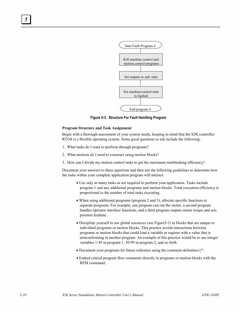
5-10 S2K Series Standalone Motion Controller User's Manual GFK-1848F
5
Start Fault Program 4
End program 4
Kill machine control andmotion control programs
Set outputs to safe state
Set machine control stateto faulted
Figure 5-3. Structure For Fault Handling Program Program Structure and Task Assignment Begin with a thorough assessment of your system needs, keeping in mind that the S2K controller RTOS is a flexible operating system. Some good questions to ask include the following:
1. What tasks do I want to perform through programs?
2. What motions do I need to construct using motion blocks?
3. How can I divide my motion control tasks to get the maximum multitasking efficiency?
Document your answers to these questions and then use the following guidelines to determine how the tasks within your complete application program will interact:
• Use only as many tasks as are required to perform your application. Tasks include program 1 and any additional programs and motion blocks. Total execution efficiency is proportional to the number of total tasks executing.
• When using additional programs (program 2 and 3), allocate specific functions to separate programs. For example, one program can run the motor, a second program handles operator interface functions, and a third program outputs motor torque and sets position feedrate.
• Discipline yourself to use global resources (see Figure5-1) in blocks that are unique to individual programs or motion blocks. This practice avoids interactions between programs or motion blocks that could load a variable or register with a value that is nonconforming in another program. An example of this practice would be to use integer variables 1-49 in program 1, 50-99 in program 2, and so forth.
• Document your programs for future reference using the comment delimiters (*.
• Embed critical program flow comments directly in programs or motion blocks with the REM command.
Software Reference
GFK-1848F Chapter 5 Software Reference 5-11
5
Manage Your Program Security
Use the SECURE command to protect your intellectual property—it will prevent programs and motions blocks from being uploaded from the controller. This command also blocks use of the FAULT command. To enable the secure feature, first send the application program file to the controller, and then, from the terminal window in Motion Developer, type SECURE <Enter>. To disable the SECURE feature, type CLM <Enter> to clear the memory and start over.
The PASSWORD command is intended to prohibit program modification in the field. To password-protect your program:
• Type PASSWORD from the terminal window in Motion Developer
• At the Enter Password prompt, type the four- to ten-character password of your choice.
Caution
Do NOT forget your password. After you set the password, you will have to enter the password before accessing the program. If you do not enter the correct password, you will be able to use only diagnostic commands—you will NOT be able to clear the memory (i.e., use the CLM command) to start over. To start over, you must return the controller to the factory. THERE IS NO BACKDOOR!
If you lose or forget your password, call GE Fanuc to get a return merchandise authorization (RMA) number. Once you have an RMA number, ship the unit to GE Fanuc for service.
To change the password, type CHANGEPW <Enter> in the Motion Developer terminal window and follow the prompts.
5.3.4 Motion Blocks
Motion blocks allow you to define motions that can be called and used by any program or executed in immediate mode from the Motion Developer terminal window or an external control device (using the EXMx command). You can create and edit motion blocks using the Motion Developer wizard or manually using the script editor. The S2K Series controllers support up to 100 motion blocks.
Rules of Motion Block Execution 1. Motion blocks
complete executing one line of code before proceeding to the next line of code.
2. You can
concurrently execute only one motion block with the executing program(s).
3. Once a motion
block is executed, it overrides the currently executing motion block or motion.
4. No labels are allowed in
motion block program code! Therefore, commands that use labels such as GOTO, IF…GOTO, GOSUB, etc. are not allowed in motion blocks.
5. REPEAT command causes motion block to be repeated continuously from the beginning.
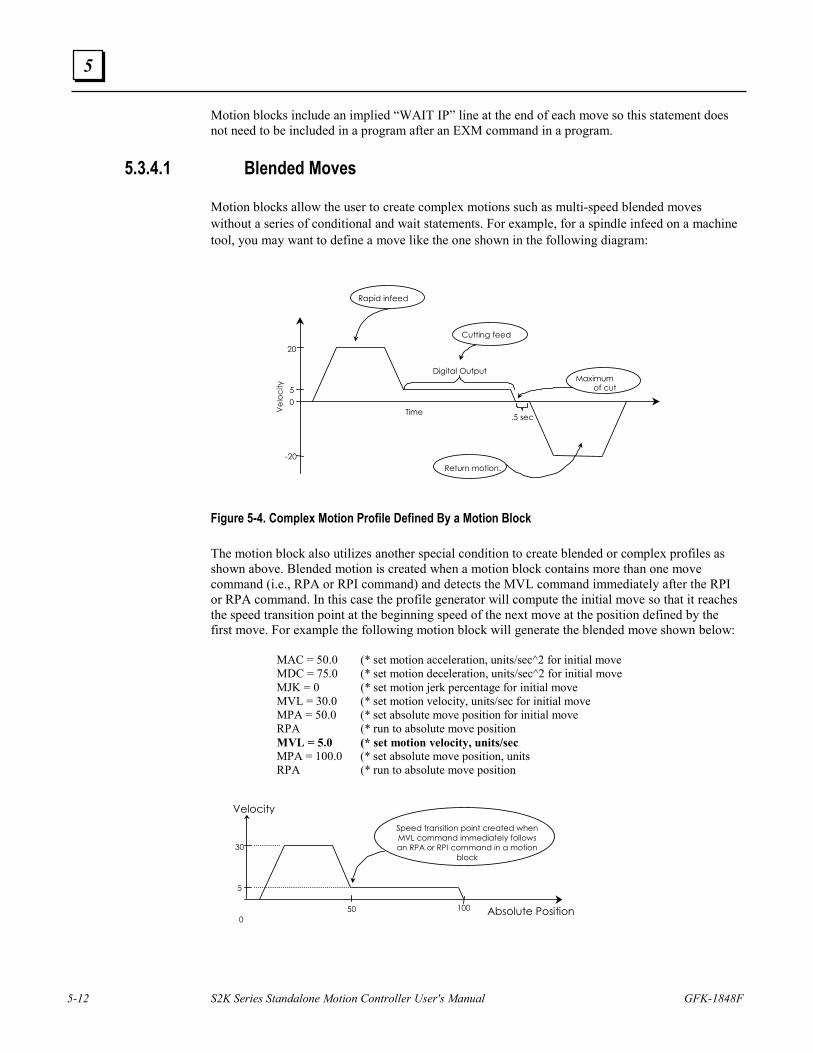
5-12 S2K Series Standalone Motion Controller User's Manual GFK-1848F
5
Motion blocks include an implied “WAIT IP” line at the end of each move so this statement does not need to be included in a program after an EXM command in a program.
5.3.4.1 Blended Moves
Motion blocks allow the user to create complex motions such as multi-speed blended moves without a series of conditional and wait statements. For example, for a spindle infeed on a machine tool, you may want to define a move like the one shown in the following diagram:
Figure 5-4. Complex Motion Profile Defined By a Motion Block The motion block also utilizes another special condition to create blended or complex profiles as shown above. Blended motion is created when a motion block contains more than one move command (i.e., RPA or RPI command) and detects the MVL command immediately after the RPI or RPA command. In this case the profile generator will compute the initial move so that it reaches the speed transition point at the beginning speed of the next move at the position defined by the first move. For example the following motion block will generate the blended move shown below: MAC = 50.0 (* set motion acceleration, units/sec^2 for initial move MDC = 75.0 (* set motion deceleration, units/sec^2 for initial move MJK = 0 (* set motion jerk percentage for initial move MVL = 30.0 (* set motion velocity, units/sec for initial move MPA = 50.0 (* set absolute move position for initial move RPA (* run to absolute move position MVL = 5.0 (* set motion velocity, units/sec MPA = 100.0 (* set absolute move position, units RPA (* run to absolute move position
TimeVel
ocity
.5 sec
Digital Output
20 5 0
-20
Rapid infeed
Cutting feed
Return motion.
Maximum of cut
0 Absolute Position
30
5 50
Speed transition point created when MVL command immediately follows an RPA or RPI command in a motion
block
100
Velocity
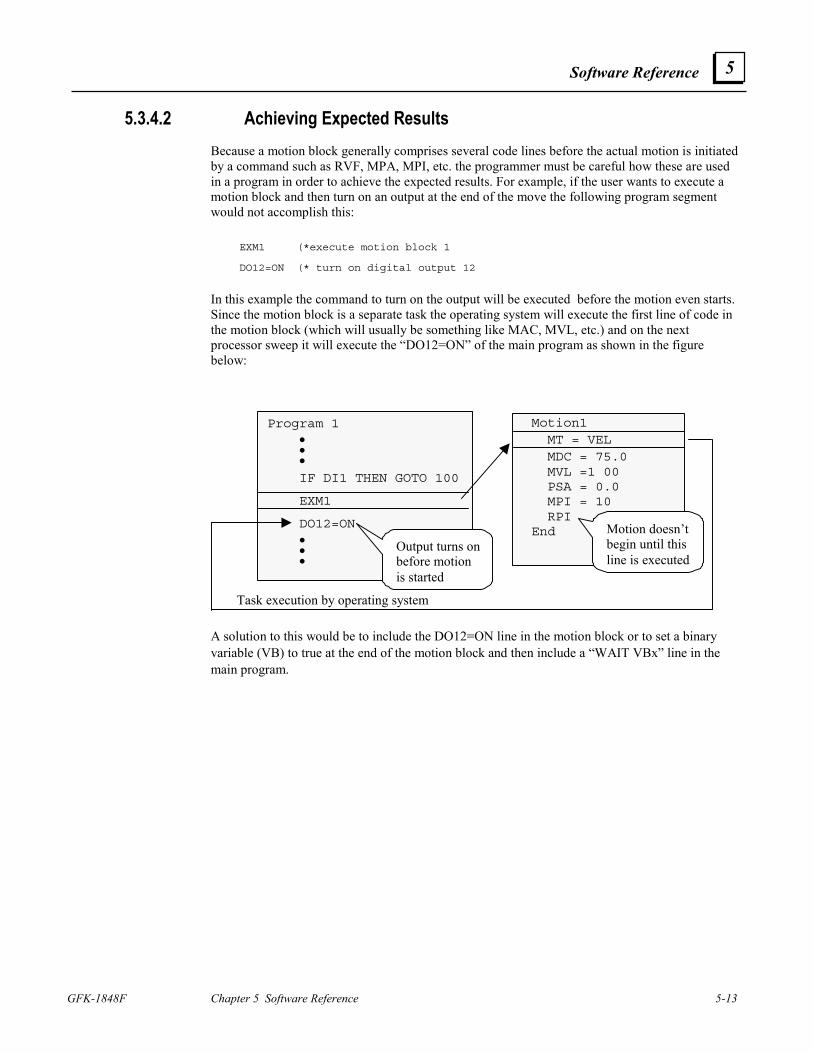
Software Reference
GFK-1848F Chapter 5 Software Reference 5-13
5
5.3.4.2 Achieving Expected Results Because a motion block generally comprises several code lines before the actual motion is initiated by a command such as RVF, MPA, MPI, etc. the programmer must be careful how these are used in a program in order to achieve the expected results. For example, if the user wants to execute a motion block and then turn on an output at the end of the move the following program segment would not accomplish this:
EXM1 (*execute motion block 1
DO12=ON (* turn on digital output 12
In this example the command to turn on the output will be executed before the motion even starts. Since the motion block is a separate task the operating system will execute the first line of code in the motion block (which will usually be something like MAC, MVL, etc.) and on the next processor sweep it will execute the “DO12=ON” of the main program as shown in the figure below:
Program 1 • • • IF DI1 THEN GOTO 100
EXM1
DO12=ON • • •
Motion1 MT = VEL MDC = 75.0 MVL =1 00 PSA = 0.0 MPI = 10 RPI
End Motion doesn’tbegin until thisline is executed
Output turns onbefore motionis started
Task execution by operating system
A solution to this would be to include the DO12=ON line in the motion block or to set a binary variable (VB) to true at the end of the motion block and then include a “WAIT VBx” line in the main program.
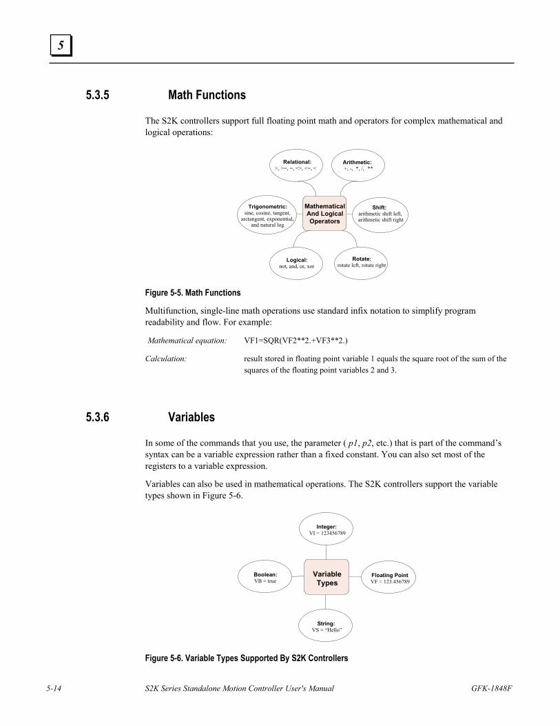
5-14 S2K Series Standalone Motion Controller User's Manual GFK-1848F
5
5.3.5 Math Functions
The S2K controllers support full floating point math and operators for complex mathematical and logical operations:
MathematicalAnd LogicalOperators
Relational:>, >=, =, <>, <=, <
Arithmetic:+, -, *, /, **
Logical:not, and, or, xor
Rotate:rotate left, rotate right
Shift:arithmetic shift left,arithmetic shift right
Trigonometric:sine, cosine, tangent,
arctangent, exponential,and natural log
Figure 5-5. Math Functions
Multifunction, single-line math operations use standard infix notation to simplify program readability and flow. For example:
Mathematical equation: VF1=SQR(VF2**2.+VF3**2.)
Calculation: result stored in floating point variable 1 equals the square root of the sum of the squares of the floating point variables 2 and 3.
5.3.6 Variables
In some of the commands that you use, the parameter ( p1, p2, etc.) that is part of the command’s syntax can be a variable expression rather than a fixed constant. You can also set most of the registers to a variable expression.
Variables can also be used in mathematical operations. The S2K controllers support the variable types shown in Figure 5-6.
VariableTypes
Integer:VI = 123456789
Floating PointVF = 123.456789
Boolean:VB = true
String:VS = “Hello”
Figure 5-6. Variable Types Supported By S2K Controllers
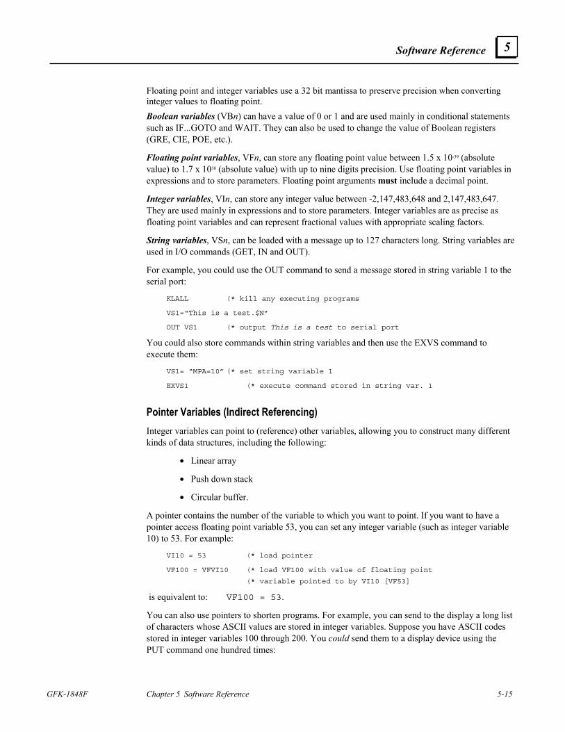
Software Reference
GFK-1848F Chapter 5 Software Reference 5-15
5
Floating point and integer variables use a 32 bit mantissa to preserve precision when converting integer values to floating point. Boolean variables (VBn) can have a value of 0 or 1 and are used mainly in conditional statements such as IF...GOTO and WAIT. They can also be used to change the value of Boolean registers (GRE, CIE, POE, etc.).
Floating point variables, VFn, can store any floating point value between 1.5 x 10-39 (absolute value) to 1.7 x 1038 (absolute value) with up to nine digits precision. Use floating point variables in expressions and to store parameters. Floating point arguments must include a decimal point.
Integer variables, VIn, can store any integer value between -2,147,483,648 and 2,147,483,647. They are used mainly in expressions and to store parameters. Integer variables are as precise as floating point variables and can represent fractional values with appropriate scaling factors.
String variables, VSn, can be loaded with a message up to 127 characters long. String variables are used in I/O commands (GET, IN and OUT).
For example, you could use the OUT command to send a message stored in string variable 1 to the serial port:
KLALL (* kill any executing programs
VS1=“This is a test.$N”
OUT VS1 (* output This is a test to serial port
You could also store commands within string variables and then use the EXVS command to execute them:
VS1= “MPA=10” (* set string variable 1
EXVS1 (* execute command stored in string var. 1
Pointer Variables (Indirect Referencing) Integer variables can point to (reference) other variables, allowing you to construct many different kinds of data structures, including the following:
• Linear array
• Push down stack
• Circular buffer.
A pointer contains the number of the variable to which you want to point. If you want to have a pointer access floating point variable 53, you can set any integer variable (such as integer variable 10) to 53. For example:
VI10 = 53 (* load pointer
VF100 = VFVI10 (* load VF100 with value of floating point
(* variable pointed to by VI10 [VF53]
is equivalent to: VF100 = 53.
You can also use pointers to shorten programs. For example, you can send to the display a long list of characters whose ASCII values are stored in integer variables. Suppose you have ASCII codes stored in integer variables 100 through 200. You could send them to a display device using the PUT command one hundred times:
5-16 S2K Series Standalone Motion Controller User's Manual GFK-1848F
5
PUT CHR(VI100)
PUT CHR(VI101)
...
PUT CHR(VI200)
Or you could make the process quick and far less tedious with variable pointers:
VI1=100 (* load the pointer 100
1 PUT CHR(VIVI1) (* send ASCII characters stored in
(* VIVI1 to the display
VI1=VI1+1 (* increment VI1 by 1
IF VI1<=200 GOTO 1 (* continue to increment by 1 if VI1 <= 200
When VI1 is less than or equal to 200, the program loops, sending all ASCII codes stored in variables 100 through 200 in the process. When VI1 is greater than 200, it fails the check and goes on to the next program line.
Note Motion Developer version 2.5 and earlier do not recognize indirect (pointer) variables that use a symbolic name (tag). For example, if you want to use VI200 as the pointer variable for a floating-point variable, you would construct the following:
VFVI200
However, if you rename VI200 to “Pointer_Variable,” Motion Developer will create the following construct:
VFPointer_Variable
The version 2.5 and earlier program parsers do not recognize the aliased construct and, therefore, do not replace the symbolic name VFPointer_Variable with VI200 when the program is downloaded to the controller; so VFPointer_Variable is sent to the controller. In turn, since the controller does not recognize the symbolic name VFPointer_Variable, a syntax error is generated. A workaround would be to create a new floating-point variable called VFPointer_Variable which is a tag for VFVI200.
5.3.7 Countdown Timers The S2K controllers support 8 crystal-based timers with a resolution in milliseconds.. Use the STMn = xx.xxx (xx.xxx is a time in seconds) command to set these timers. Once set, a timer counts from the starting value down to zero. The timer automatically resets to the initial value and continues counting each time it reaches zero.
The timer flag, TMn, is set each time the timer reaches zero and reset each time the flag is read. You can use TMn in conjunction with the WAIT command for conditional program flow. For example:
STM8 = 0.333 (* start timer 8 with a period of 333 ms
WAIT TM8 (* wait until timer 8 reaches zero
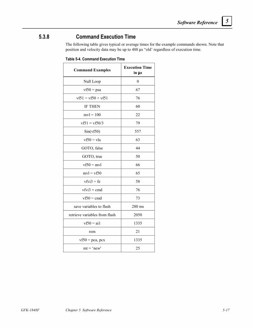
Software Reference
GFK-1848F Chapter 5 Software Reference 5-17
5
5.3.8 Command Execution Time The following table gives typical or average times for the example commands shown. Note that position and velocity data may be up to 488 µs “old’ regardless of execution time.
Table 5-4. Command Execution Time
Command Examples Execution Time in µµµµs
Null Loop 0
vf50 = psa 67
vf51 = vf50 + vf51 76
IF THEN 60
mvl = 100 22
vf51 = vf50/3 79
Sin(vf50) 557
vf50 = vla 63
GOTO, false 44
GOTO, true 50
vf50 = mvl 66
mvl = vf50 65
vfvi3 = fe 58
vfvi3 = cmd 76
vf50 = cmd 73
save variables to flash 280 ms
retrieve variables from flash 2050
vf50 = ai1 1335
rem 21
vf50 = pca, pcx 1335
mt = ‘new' 25
5-18 S2K Series Standalone Motion Controller User's Manual GFK-1848F
5
5.4 Saving and Restoring Parameters, Variables and Programs The S2K controllers use nonvolatile FLASH memory. When changing register values using the terminal window the changes are stored in the S2K controller ‘s volatile SRAM memory. To preserve the controllers memory contents when power is cycled it is necessary to save the SRAM memory image to FLASH memory. There are several ways this can be accomplished using the Motion Developer software:
1. Executing the SAVE command from the Motion Developer terminal window or host serial device (i.e., type SAVE <Enter>)
2. Clicking the Save To Flash button on the Motion Developer Controller Functions wizard page
The reverse of this process allows the user to reload the contents of the FLASH memory into the active SRAM memory. This can be accomplished as follows:
1. Executing the RETRIEVE command from the Motion Developer terminal window or host serial device (i.e., type RETRIEVE <Enter>)
2. Clicking the Get From Flash button on the Motion Developer Controller Functions wizard page
Since the S2K controller does not, by default, automatically load the FLASH contents to SRAM it is necessary to execute the autoretrieve command (AUTORET) before the SAVE command in order for the register values and the user programs to be automatically retrieved after each power cycle.
Note If AUTORET is not active (i.e., has not been set prior to the last SAVE command), all register values will be reset to the default values and the program memory space will be emptied after each power cycle. The AUTORET and SAVE commands are automatically included at the end of the application source code file each time Motion Developer performs a download operation.
The AUTORET, SAVE, and RETRIEVE commands cannot be included in programs.
AUTORET and SAVE do not save or restore variable values. Variables are all set to 0 at each power cycle. Variable values, however, can be saved to and restored from nonvolatile memory using the Save Variables (SVV) and Retrieve Variables (RTV) commands. The SVV command saves integer variables 1 through 1,024 and floating point variables 1 through 512 in FLASH memory. RTV restores the values of these variables to the controllers working memory (SRAM). The SVV and RTV commands are allowed only in programs and can only be executed when the motion generator is not active.
Caution
The controller flash memory can support a finite number of write cycles before the flash memory will fail. Although the typical limit for this type of flash is +100,000 write cycles, it is easy to exceed this limit by executing frequent SVV commands from within a program.
Software Reference
GFK-1848F Chapter 5 Software Reference 5-19
5
5.5 Advanced Programming The S2K controllers support many powerful programming features that allow you to handle complex applications. Electronic gearing and camming, pulse-based motion control and registration control using high-speed position capture inputs. This section provides details on the registers and programming methods for using these functions.
5.5.1 Using Pulse-based Motion
The S2K controller supports various operating modes selected using the Motion Type register (MT). The pulse-based mode allows the user to program axis motion relative to a pulse input from a master encoder rather than time. Pulse-based mode simplifies the programming of cyclic applications where the axis motion is continuously repeated each time the master source traverses a specified distance.
Overview
Pulse-based motion requires the auxiliary axis (master pulse source) to be unidirectional and connected so that the auxiliary position (PSX) always counts up (value increases). There are two different pulse modes that can be configured:
• MT=PULSE: Standard pulse mode
• MT=PULVEL: Pulse-Velocity mode
Both modes use many of the same registers to specify the axis motion, however the function of some registers is different depending on the mode selected. Programs may change between these two modes while the axis is in motion.
Within each of the pulse modes the programmer can specify either incremental/absolute position-based motion or continuous motion where the axis will run at a specified velocity ratio until commanded to stop.
When using pulse-based motion you must specify the pulse input signal type connected to the auxiliary input that will be used as the command source. Using the Auxiliary Quadrature Type (QTX) register the following pulse signal types can be selected:
• QTX=Q4: Standard quadrature encoder signals. Controller will generate four counts (pulses) for each electrical cycle of the encoder input. (default)
• QTX=PD: Pulse and direction signals
• QTX=CW: Clockwise and counterclockwise pulse inputs
Since most applications will use an encoder this configuration has been set as the controller default.
The static (i.e., motor is not moving) accuracy of the servo axis to the auxiliary axis is +/- 1 pulse during the motion and zero pulses at the end of the motion. The dynamic accuracy is the instantaneous servo following error + .0017 * VLX where VLX is the velocity of the auxiliary axis
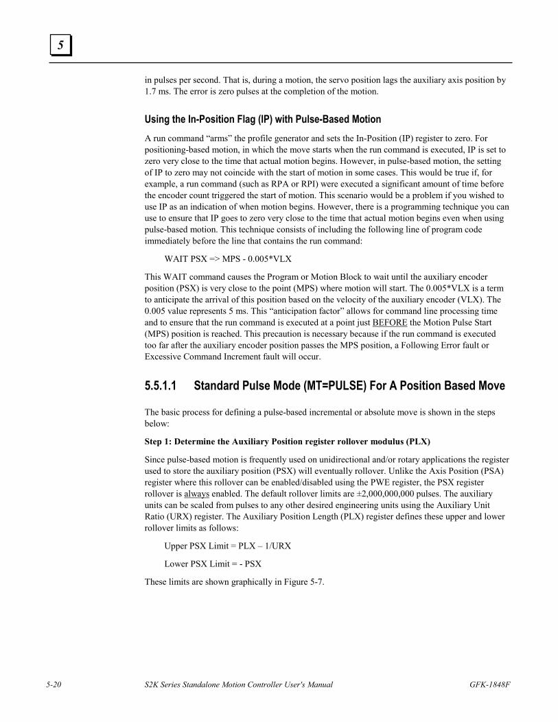
5-20 S2K Series Standalone Motion Controller User's Manual GFK-1848F
5
in pulses per second. That is, during a motion, the servo position lags the auxiliary axis position by 1.7 ms. The error is zero pulses at the completion of the motion.
Using the In-Position Flag (IP) with Pulse-Based Motion A run command “arms” the profile generator and sets the In-Position (IP) register to zero. For positioning-based motion, in which the move starts when the run command is executed, IP is set to zero very close to the time that actual motion begins. However, in pulse-based motion, the setting of IP to zero may not coincide with the start of motion in some cases. This would be true if, for example, a run command (such as RPA or RPI) were executed a significant amount of time before the encoder count triggered the start of motion. This scenario would be a problem if you wished to use IP as an indication of when motion begins. However, there is a programming technique you can use to ensure that IP goes to zero very close to the time that actual motion begins even when using pulse-based motion. This technique consists of including the following line of program code immediately before the line that contains the run command:
WAIT PSX => MPS - 0.005*VLX
This WAIT command causes the Program or Motion Block to wait until the auxiliary encoder position (PSX) is very close to the point (MPS) where motion will start. The 0.005*VLX is a term to anticipate the arrival of this position based on the velocity of the auxiliary encoder (VLX). The 0.005 value represents 5 ms. This “anticipation factor” allows for command line processing time and to ensure that the run command is executed at a point just BEFORE the Motion Pulse Start (MPS) position is reached. This precaution is necessary because if the run command is executed too far after the auxiliary encoder position passes the MPS position, a Following Error fault or Excessive Command Increment fault will occur.
5.5.1.1 Standard Pulse Mode (MT=PULSE) For A Position Based Move
The basic process for defining a pulse-based incremental or absolute move is shown in the steps below:
Step 1: Determine the Auxiliary Position register rollover modulus (PLX)
Since pulse-based motion is frequently used on unidirectional and/or rotary applications the register used to store the auxiliary position (PSX) will eventually rollover. Unlike the Axis Position (PSA) register where this rollover can be enabled/disabled using the PWE register, the PSX register rollover is always enabled. The default rollover limits are ±2,000,000,000 pulses. The auxiliary units can be scaled from pulses to any other desired engineering units using the Auxiliary Unit Ratio (URX) register. The Auxiliary Position Length (PLX) register defines these upper and lower rollover limits as follows:
Upper PSX Limit = PLX – 1/URX
Lower PSX Limit = - PSX
These limits are shown graphically in Figure 5-7.
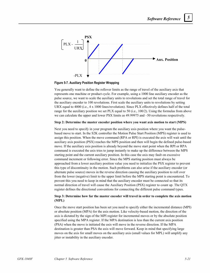
Software Reference
GFK-1848F Chapter 5 Software Reference 5-21
5
PSX
Aux. Position
PLX - 1
URX
-PLX
0
Figure 5-7. Auxiliary Position Register Wrapping
You generally want to define the rollover limits as the range of travel of the auxiliary axis that represents one machine or product cycle. For example, using a 1000 line auxiliary encoder as the pulse source, we want to scale the auxiliary units to revolutions and set the total range of travel for the auxiliary encoder to 100 revolutions. First scale the auxiliary units to revolutions by setting URX equal to 4000 (i.e., 4 x 1000 lines/revolution). Since PLX effectively defines half of the total range for the auxiliary position we set PLX equal to 50 (i.e., 100/2). Using the formulas from above we can calculate the upper and lower PSX limits as 49.99975 and –50 revolutions respectively.
Step 2: Determine the master encoder position where you want axis motion to start (MPS)
Next you need to specify in your program the auxiliary axis position where you want the pulse-based move to start. In the S2K controller the Motion Pulse Start Position (MPS) register is used to assign this position. When the move command (RPA or RPI) is executed the axis will wait until the auxiliary axis position (PSX) reaches the MPS position and then will begin the defined pulse-based move. If the auxiliary axis position is already beyond the move start point when the RPI or RPA command is executed the axis tries to jump instantly to make up the difference between the MPS starting point and the current auxiliary position. In this case the axis may fault on excessive command increment or following error. Since the MPS starting position must always be approached from a lower auxiliary position value you need to initialize the PSX register to prevent this type of discontinuity in the motion. Such problems can also arise if the auxiliary encoder (or alternate pulse source) moves in the reverse direction causing the auxiliary position to roll over from the lower (negative) limit to the upper limit before the MPS starting point is encountered. To prevent this you need to keep in mind that the auxiliary encoder must be connected so that its normal direction of travel will cause the Auxiliary Position (PSX) register to count up. The QTX register defines the directional conventions for connecting the different pulse command types.
Step 3: Determine how far the master encoder will travel in order to complete the axis motion (MPL)
Once the move start position has been set you need to specify either the incremental distance (MPI) or absolute position (MPA) for the axis motion. Like velocity-based motion, the direction of the axis is dictated by the sign of the MPI register for incremental moves or by the absolute position specified using the MPA register. If the MPA destination is less than the current axis position (PSA) when the move is initiated the axis will move in the reverse direction. If the MPA destination is greater than PSA the axis will move forward. Keep in mind that specifying large moves on the axis for small moves on the auxiliary axis (small values for MPL) will amplify any jitter or instability in the auxiliary encoder.
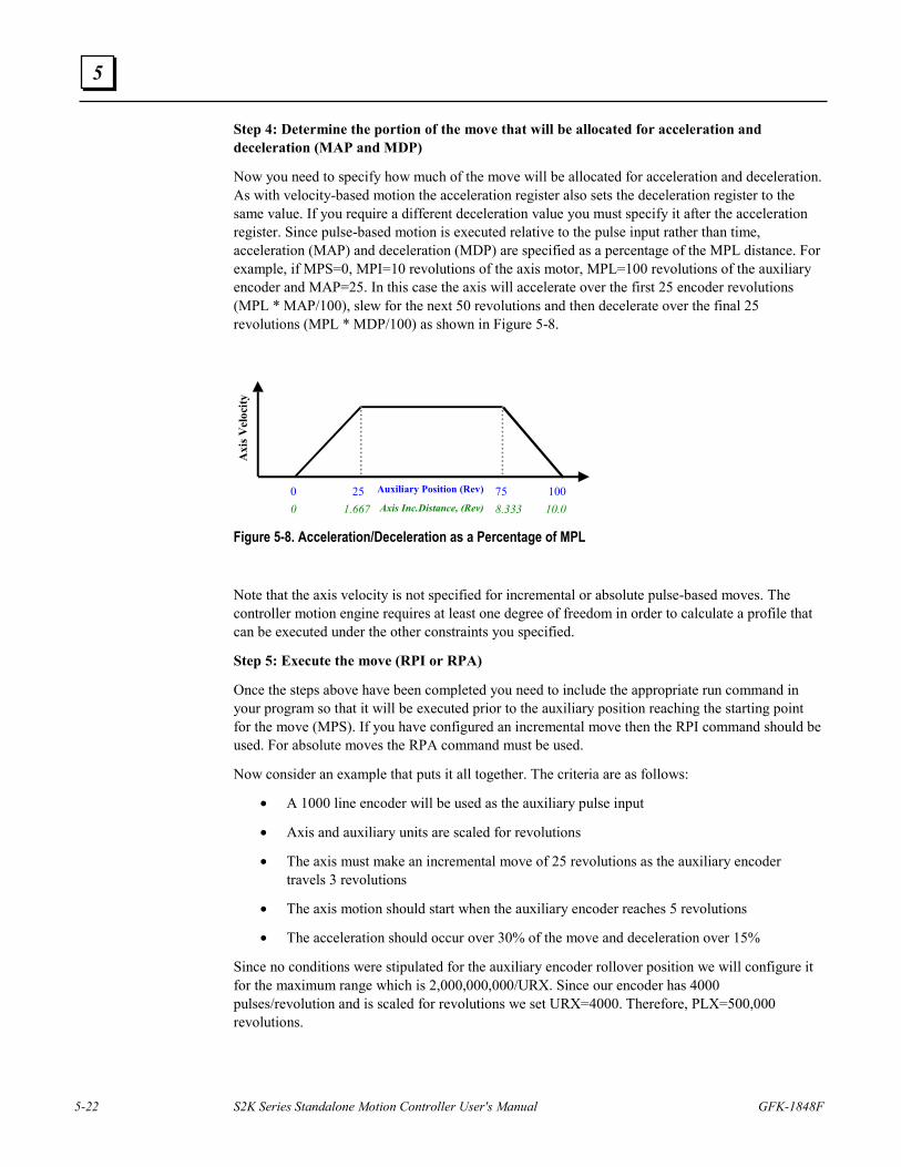
5-22 S2K Series Standalone Motion Controller User's Manual GFK-1848F
5
Step 4: Determine the portion of the move that will be allocated for acceleration and deceleration (MAP and MDP)
Now you need to specify how much of the move will be allocated for acceleration and deceleration. As with velocity-based motion the acceleration register also sets the deceleration register to the same value. If you require a different deceleration value you must specify it after the acceleration register. Since pulse-based motion is executed relative to the pulse input rather than time, acceleration (MAP) and deceleration (MDP) are specified as a percentage of the MPL distance. For example, if MPS=0, MPI=10 revolutions of the axis motor, MPL=100 revolutions of the auxiliary encoder and MAP=25. In this case the axis will accelerate over the first 25 encoder revolutions (MPL * MAP/100), slew for the next 50 revolutions and then decelerate over the final 25 revolutions (MPL * MDP/100) as shown in Figure 5-8.
Axis Inc.Distance, (Rev)
Axi
s Vel
ocity
Auxiliary Position (Rev)0 25 75 1000 1.667 8.333 10.0
Figure 5-8. Acceleration/Deceleration as a Percentage of MPL
Note that the axis velocity is not specified for incremental or absolute pulse-based moves. The controller motion engine requires at least one degree of freedom in order to calculate a profile that can be executed under the other constraints you specified.
Step 5: Execute the move (RPI or RPA)
Once the steps above have been completed you need to include the appropriate run command in your program so that it will be executed prior to the auxiliary position reaching the starting point for the move (MPS). If you have configured an incremental move then the RPI command should be used. For absolute moves the RPA command must be used.
Now consider an example that puts it all together. The criteria are as follows:
• A 1000 line encoder will be used as the auxiliary pulse input
• Axis and auxiliary units are scaled for revolutions
• The axis must make an incremental move of 25 revolutions as the auxiliary encoder travels 3 revolutions
• The axis motion should start when the auxiliary encoder reaches 5 revolutions
• The acceleration should occur over 30% of the move and deceleration over 15%
Since no conditions were stipulated for the auxiliary encoder rollover position we will configure it for the maximum range which is 2,000,000,000/URX. Since our encoder has 4000 pulses/revolution and is scaled for revolutions we set URX=4000. Therefore, PLX=500,000 revolutions.
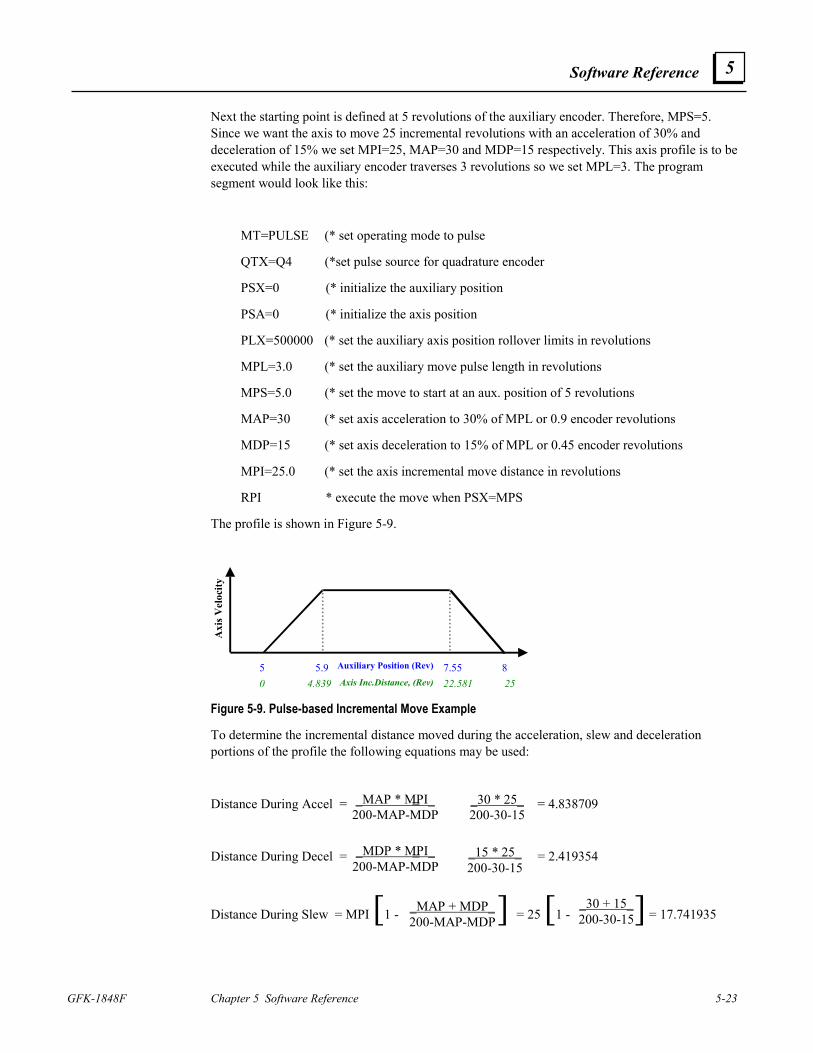
Software Reference
GFK-1848F Chapter 5 Software Reference 5-23
5
_MAP * MPI_ 200-MAP-MDP
_30 * 25_200-30-15
_MDP * MPI_ 200-MAP-MDP
_15 * 25_200-30-15
_MAP + MDP_200-MAP-MDP
_30 + 15_ 200-30-15
Next the starting point is defined at 5 revolutions of the auxiliary encoder. Therefore, MPS=5. Since we want the axis to move 25 incremental revolutions with an acceleration of 30% and deceleration of 15% we set MPI=25, MAP=30 and MDP=15 respectively. This axis profile is to be executed while the auxiliary encoder traverses 3 revolutions so we set MPL=3. The program segment would look like this:
MT=PULSE (* set operating mode to pulse
QTX=Q4 (*set pulse source for quadrature encoder
PSX=0 (* initialize the auxiliary position
PSA=0 (* initialize the axis position
PLX=500000 (* set the auxiliary axis position rollover limits in revolutions
MPL=3.0 (* set the auxiliary move pulse length in revolutions
MPS=5.0 (* set the move to start at an aux. position of 5 revolutions
MAP=30 (* set axis acceleration to 30% of MPL or 0.9 encoder revolutions
MDP=15 (* set axis deceleration to 15% of MPL or 0.45 encoder revolutions
MPI=25.0 (* set the axis incremental move distance in revolutions
RPI * execute the move when PSX=MPS
The profile is shown in Figure 5-9.
Axis Inc.Distance, (Rev)
Axi
s Vel
ocity
Auxiliary Position (Rev)5 5.9 7.55 80 4.839 22.581 25
Figure 5-9. Pulse-based Incremental Move Example
To determine the incremental distance moved during the acceleration, slew and deceleration portions of the profile the following equations may be used:
Distance During Accel = = = 4.838709
Distance During Decel = = = 2.419354
Distance During Slew = MPI [1 - ] = 25 [1 - ] = 17.741935
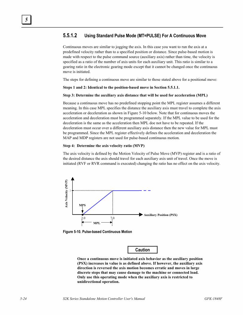
5-24 S2K Series Standalone Motion Controller User's Manual GFK-1848F
5
5.5.1.2 Using Standard Pulse Mode (MT=PULSE) For A Continuous Move
Continuous moves are similar to jogging the axis. In this case you want to run the axis at a predefined velocity rather than to a specified position or distance. Since pulse-based motion is made with respect to the pulse command source (auxiliary axis) rather than time, the velocity is specified as a ratio of the number of axis units for each auxiliary unit. This ratio is similar to a gearing ratio in the electronic gearing mode except that it cannot be changed once the continuous move is initiated.
The steps for defining a continuous move are similar to those stated above for a positional move:
Steps 1 and 2: Identical to the position-based move in Section 5.5.1.1.
Step 3: Determine the auxiliary axis distance that will be used for acceleration (MPL)
Because a continuous move has no predefined stopping point the MPL register assumes a different meaning. In this case MPL specifies the distance the auxiliary axis must travel to complete the axis acceleration or deceleration as shown in Figure 5-10 below. Note that for continuous moves the acceleration and deceleration must be programmed separately. If the MPL value to be used for the deceleration is the same as the acceleration then MPL doe not have to be repeated. If the deceleration must occur over a different auxiliary axis distance then the new value for MPL must be programmed. Since the MPL register effectively defines the acceleration and deceleration the MAP and MDP registers are not used for pulse-based continuous motion.
Step 4: Determine the axis velocity ratio (MVP)
The axis velocity is defined by the Motion Velocity of Pulse Move (MVP) register and is a ratio of the desired distance the axis should travel for each auxiliary axis unit of travel. Once the move is initiated (RVF or RVR command is executed) changing the ratio has no effect on the axis velocity.
Auxiliary Position (PSX)
Axi
s Vel
ocity
(MV
P)
2.0 7.0
3
MPL
MPS
Figure 5-10. Pulse-based Continuous Motion
Caution
Once a continuous move is initiated axis behavior as the auxiliary position (PSX) increases in value is as defined above. If however, the auxiliary axis direction is reversed the axis motion becomes erratic and moves in large discrete steps that may cause damage to the machine or connected load. Only use this operating mode when the auxiliary axis is restricted to unidirectional operation.
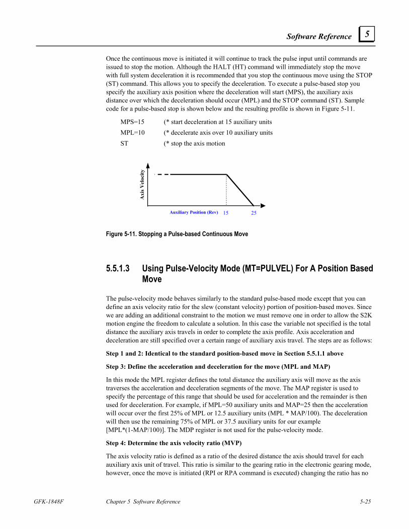
Software Reference
GFK-1848F Chapter 5 Software Reference 5-25
5
Once the continuous move is initiated it will continue to track the pulse input until commands are issued to stop the motion. Although the HALT (HT) command will immediately stop the move with full system deceleration it is recommended that you stop the continuous move using the STOP (ST) command. This allows you to specify the deceleration. To execute a pulse-based stop you specify the auxiliary axis position where the deceleration will start (MPS), the auxiliary axis distance over which the deceleration should occur (MPL) and the STOP command (ST). Sample code for a pulse-based stop is shown below and the resulting profile is shown in Figure 5-11.
MPS=15 (* start deceleration at 15 auxiliary units MPL=10 (* decelerate axis over 10 auxiliary units ST (* stop the axis motion
Axi
s Vel
ocity
Auxiliary Position (Rev) 15 25
Figure 5-11. Stopping a Pulse-based Continuous Move
5.5.1.3 Using Pulse-Velocity Mode (MT=PULVEL) For A Position Based Move
The pulse-velocity mode behaves similarly to the standard pulse-based mode except that you can define an axis velocity ratio for the slew (constant velocity) portion of position-based moves. Since we are adding an additional constraint to the motion we must remove one in order to allow the S2K motion engine the freedom to calculate a solution. In this case the variable not specified is the total distance the auxiliary axis travels in order to complete the axis profile. Axis acceleration and deceleration are still specified over a certain range of auxiliary axis travel. The steps are as follows:
Step 1 and 2: Identical to the standard position-based move in Section 5.5.1.1 above
Step 3: Define the acceleration and deceleration for the move (MPL and MAP)
In this mode the MPL register defines the total distance the auxiliary axis will move as the axis traverses the acceleration and deceleration segments of the move. The MAP register is used to specify the percentage of this range that should be used for acceleration and the remainder is then used for deceleration. For example, if MPL=50 auxiliary units and MAP=25 then the acceleration will occur over the first 25% of MPL or 12.5 auxiliary units (MPL * MAP/100). The deceleration will then use the remaining 75% of MPL or 37.5 auxiliary units for our example [MPL*(1-MAP/100)]. The MDP register is not used for the pulse-velocity mode.
Step 4: Determine the axis velocity ratio (MVP)
The axis velocity ratio is defined as a ratio of the desired distance the axis should travel for each auxiliary axis unit of travel. This ratio is similar to the gearing ratio in the electronic gearing mode, however, once the move is initiated (RPI or RPA command is executed) changing the ratio has no
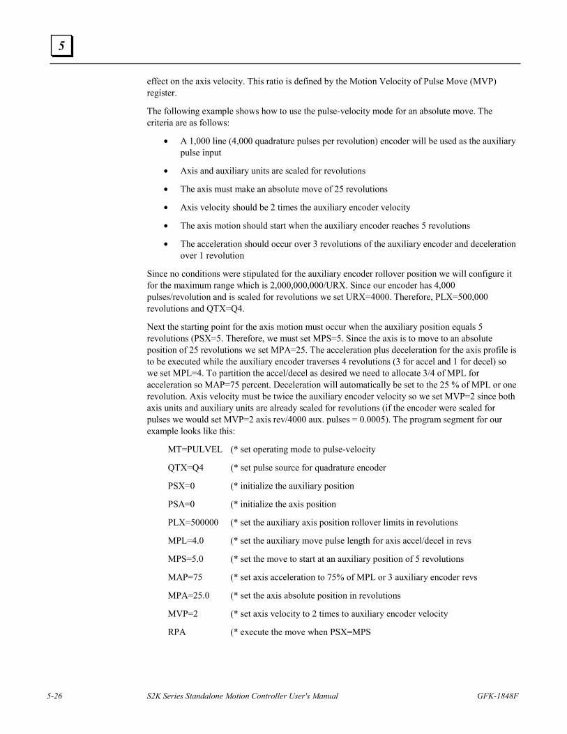
5-26 S2K Series Standalone Motion Controller User's Manual GFK-1848F
5
effect on the axis velocity. This ratio is defined by the Motion Velocity of Pulse Move (MVP) register.
The following example shows how to use the pulse-velocity mode for an absolute move. The criteria are as follows:
• A 1,000 line (4,000 quadrature pulses per revolution) encoder will be used as the auxiliary pulse input
• Axis and auxiliary units are scaled for revolutions
• The axis must make an absolute move of 25 revolutions
• Axis velocity should be 2 times the auxiliary encoder velocity
• The axis motion should start when the auxiliary encoder reaches 5 revolutions
• The acceleration should occur over 3 revolutions of the auxiliary encoder and deceleration over 1 revolution
Since no conditions were stipulated for the auxiliary encoder rollover position we will configure it for the maximum range which is 2,000,000,000/URX. Since our encoder has 4,000 pulses/revolution and is scaled for revolutions we set URX=4000. Therefore, PLX=500,000 revolutions and QTX=Q4.
Next the starting point for the axis motion must occur when the auxiliary position equals 5 revolutions (PSX=5. Therefore, we must set MPS=5. Since the axis is to move to an absolute position of 25 revolutions we set MPA=25. The acceleration plus deceleration for the axis profile is to be executed while the auxiliary encoder traverses 4 revolutions (3 for accel and 1 for decel) so we set MPL=4. To partition the accel/decel as desired we need to allocate 3/4 of MPL for acceleration so MAP=75 percent. Deceleration will automatically be set to the 25 % of MPL or one revolution. Axis velocity must be twice the auxiliary encoder velocity so we set MVP=2 since both axis units and auxiliary units are already scaled for revolutions (if the encoder were scaled for pulses we would set MVP=2 axis rev/4000 aux. pulses = 0.0005). The program segment for our example looks like this:
MT=PULVEL (* set operating mode to pulse-velocity
QTX=Q4 (* set pulse source for quadrature encoder
PSX=0 (* initialize the auxiliary position
PSA=0 (* initialize the axis position
PLX=500000 (* set the auxiliary axis position rollover limits in revolutions
MPL=4.0 (* set the auxiliary move pulse length for axis accel/decel in revs
MPS=5.0 (* set the move to start at an auxiliary position of 5 revolutions
MAP=75 (* set axis acceleration to 75% of MPL or 3 auxiliary encoder revs
MPA=25.0 (* set the axis absolute position in revolutions
MVP=2 (* set axis velocity to 2 times to auxiliary encoder velocity
RPA (* execute the move when PSX=MPS
Software Reference
GFK-1848F Chapter 5 Software Reference 5-27
5
The profile is shown below:
Axis Inc.Distance, (Rev)
Axi
s Vel
ocity
(MV
P)
Auxiliary Position (Rev)5 8 18.5 19.50 3 24 25
2
Figure 5-12. Pulse-velocity Absolute Move Example Profile
5.5.1.4 Using Standard Pulse Mode (MT=PULSE) For A Continuous Move
This mode is functionally identical to the standard pulse mode continuous move.
5.5.1.5 Pulse Mode Superimposed Over Electronic Gearing
The preceding sections discussed position-based and continuous axis motion that is relative to a non-moving frame of reference. There is one additional feature of the pulse-based operating modes that is very powerful capability for solving certain applications. Enabling electronic gearing while in pulse mode allows axis motion to be geared to follow a continuously moving master at a defined ratio while making correctional (superimposed) moves at defined master positions.
A rotary knife that does not require registration is an example of an application that can be simplified using this feature. Generally, this application involves a knife that follows a master encoder tracking a moving web of material. Once the knife is aligned to the cut location it will cut accurately while tracking any web speed variation. The base gear ratio is set so that the product cut length exactly equals the circumferential distance the tip of the knife blade traverses over one complete revolution. We call this the “synchronous cut length” since the knife blade rotates at a constant tangential velocity equal to the web speed. When the desired product length is shorter (super synchronous) or longer (subsynchronous) than this synchronous cut length the knife must respectively speed up or slow down when not in contact with the web as shown in Figure 5-13. Since the knife speed at the tip of the blade must be nearly equal to the web speed during the cut, there is a well-defined zone over which the knife can make these speed corrections. Typically the user defines a “cut angle” where the knife is in contact with the web. This cut angle will generally be larger for helical blades. Any required correction must be made over the remaining travel of knife rotation and must remain synchronized to the web position. Since axis motion during pulse mode is made relative to the position of the master (auxiliary encoder) it is ideal for this application.
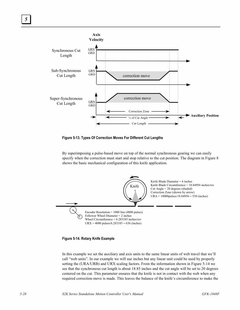
5-28 S2K Series Standalone Motion Controller User's Manual GFK-1848F
5
AxisVelocity
Auxiliary Position
GRN GRD
GRN GRD
GRN GRD
correction move
correction move
Synchronous CutLength
Sub-SynchronousCut Length
Super-SynchronousCut Length
Cut Length
Correction Zone
½ of Cut Angle
Figure 5-13. Types Of Correction Moves For Different Cut Lengths
By superimposing a pulse-based move on top of the normal synchronous gearing we can easily specify when the correction must start and stop relative to the cut position. The diagram in Figure 8 shows the basic mechanical configuration of this knife application.
Figure 5-14. Rotary Knife Example
In this example we set the auxiliary and axis units to the same linear units of web travel that we’ll call “web units”. In our example we will use inches but any linear unit could be used by properly setting the (URA/URB) and URX scaling factors. From the information shown in Figure 5-14 we see that the synchronous cut length is about 18.85 inches and the cut angle will be set to 20 degrees centered on the cut. This parameter ensures that the knife is not in contact with the web when any required correction move is made. This leaves the balance of the knife’s circumference to make the
+
Knife
+ E
Knife Blade Diameter = 6 inches Knife Blade Circumference = 18.84956 inches/rev Cut Angle = 20 degrees (shaded) Correction Zone (shown by arrow) URA = 10000pulses/18.84956 ≈ 530 (inches)
Encoder Resolution = 1000 line (4000 pulses) Follower Wheel Diameter = 2 inches Wheel Circumference = 6.283185 inches/rev URX = 4000 pulses/6.283185 ≈ 636 (inches)
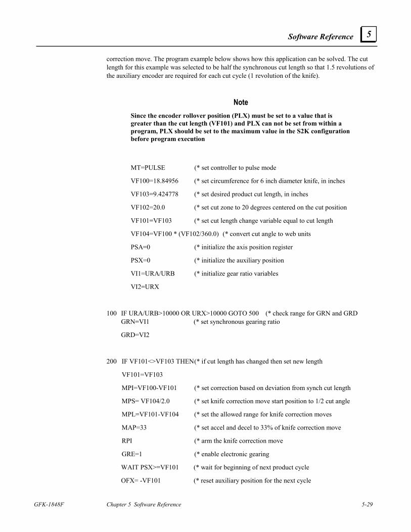
Software Reference
GFK-1848F Chapter 5 Software Reference 5-29
5
correction move. The program example below shows how this application can be solved. The cut length for this example was selected to be half the synchronous cut length so that 1.5 revolutions of the auxiliary encoder are required for each cut cycle (1 revolution of the knife).
Note Since the encoder rollover position (PLX) must be set to a value that is greater than the cut length (VF101) and PLX can not be set from within a program, PLX should be set to the maximum value in the S2K configuration before program execution
MT=PULSE (* set controller to pulse mode
VF100=18.84956 (* set circumference for 6 inch diameter knife, in inches
VF103=9.424778 (* set desired product cut length, in inches
VF102=20.0 (* set cut zone to 20 degrees centered on the cut position
VF101=VF103 (* set cut length change variable equal to cut length
VF104=VF100 * (VF102/360.0) (* convert cut angle to web units
PSA=0 (* initialize the axis position register
PSX=0 (* initialize the auxiliary position
VI1=URA/URB (* initialize gear ratio variables
VI2=URX
100 IF URA/URB>10000 OR URX>10000 GOTO 500 (* check range for GRN and GRD GRN=VI1 (* set synchronous gearing ratio
GRD=VI2
200 IF VF101<>VF103 THEN (* if cut length has changed then set new length
VF101=VF103
MPI=VF100-VF101 (* set correction based on deviation from synch cut length
MPS= VF104/2.0 (* set knife correction move start position to 1/2 cut angle
MPL=VF101-VF104 (* set the allowed range for knife correction moves
MAP=33 (* set accel and decel to 33% of knife correction move
RPI (* arm the knife correction move
GRE=1 (* enable electronic gearing
WAIT PSX>=VF101 (* wait for beginning of next product cycle
OFX= -VF101 (* reset auxiliary position for the next cycle
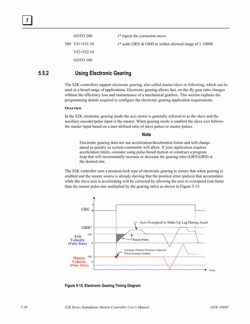
5-30 S2K Series Standalone Motion Controller User's Manual GFK-1848F
5
GOTO 200 (* repeat the correction move
500 VI1=VI1/10 (* scale GRN & GRD to within allowed range of 1-10000
VI2=VI2/10
GOTO 100
5.5.2 Using Electronic Gearing
The S2K controllers support electronic gearing, also called master/slave or following, which can be used in a broad range of applications. Electronic gearing allows fast, on-the-fly gear ratio changes without the efficiency loss and maintenance of a mechanical gearbox. This section explains the programming details required to configure the electronic gearing application requirements.
Overview
In the S2K electronic gearing mode the axis motor is generally referred to as the slave and the auxiliary encoder/pulse input is the master. When gearing mode is enabled the slave axis follows the master input based on a user-defined ratio of slave pulses to master pulses.
Note Electronic gearing does not use acceleration/deceleration limits and will change speed as quickly as system constraints will allow. If your application requires acceleration limits, consider using pulse-based motion or construct a program loop that will incrementally increase or decrease the gearing ratio (GRN/GRD) at the desired rate.
The S2K controller uses a position-lock type of electronic gearing to ensure that when gearing is enabled and the master source is already moving that the position error (pulses) that accumulates while the slave axis is accelerating will be corrected by allowing the axis to overspeed (run faster than the master pulse rate multiplied by the gearing ratio) as shown in Figure 5-15.
Figure 5-15. Electronic Gearing Timing Diagram
Axis Overspeed to Make Up Lag During Accel
Time
1
0
1
0
0
GRE
0
AxisVelocity
(Pulse Rate)
100
GRB*100
Auxiliary (Master) Position Captured When Gearing Enabled
Equal Areas
MasterVelocity
(Pulse Rate)
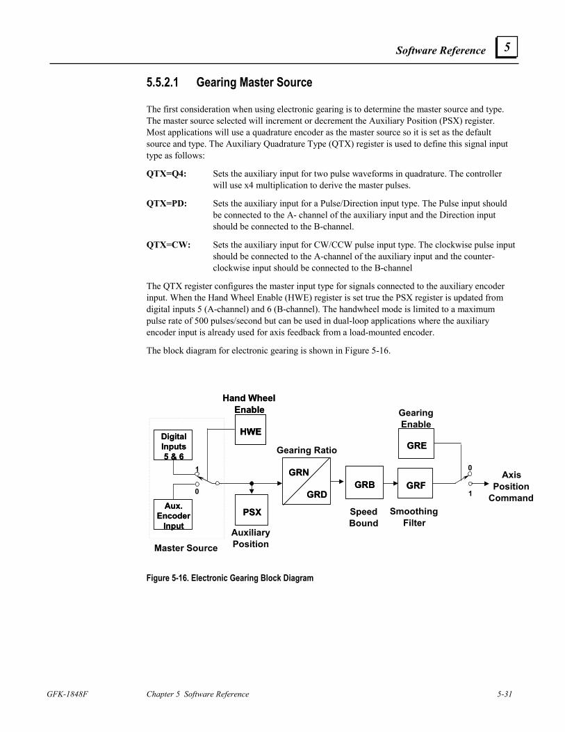
Software Reference
GFK-1848F Chapter 5 Software Reference 5-31
5
5.5.2.1 Gearing Master Source
The first consideration when using electronic gearing is to determine the master source and type. The master source selected will increment or decrement the Auxiliary Position (PSX) register. Most applications will use a quadrature encoder as the master source so it is set as the default source and type. The Auxiliary Quadrature Type (QTX) register is used to define this signal input type as follows:
QTX=Q4: Sets the auxiliary input for two pulse waveforms in quadrature. The controller will use x4 multiplication to derive the master pulses.
QTX=PD: Sets the auxiliary input for a Pulse/Direction input type. The Pulse input should be connected to the A- channel of the auxiliary input and the Direction input should be connected to the B-channel.
QTX=CW: Sets the auxiliary input for CW/CCW pulse input type. The clockwise pulse input should be connected to the A-channel of the auxiliary input and the counter-clockwise input should be connected to the B-channel
The QTX register configures the master input type for signals connected to the auxiliary encoder input. When the Hand Wheel Enable (HWE) register is set true the PSX register is updated from digital inputs 5 (A-channel) and 6 (B-channel). The handwheel mode is limited to a maximum pulse rate of 500 pulses/second but can be used in dual-loop applications where the auxiliary encoder input is already used for axis feedback from a load-mounted encoder.
The block diagram for electronic gearing is shown in Figure 5-16.
AuxiliaryPosition
GRD
GRN
GRD
GRNGRFGRF
Gearing Ratio
SpeedBound
GRBGRB
SmoothingFilter
GREGRE
GearingEnable
AxisPosition
Command1
0
PSXPSX
1
0
HWE
Hand WheelEnable
HWEHWE
Hand WheelEnable
Aux.Encoder
Input
Aux.Encoder
Input
DigitalInputs5 & 6
DigitalInputs5 & 6
Master Source
Figure 5-16. Electronic Gearing Block Diagram
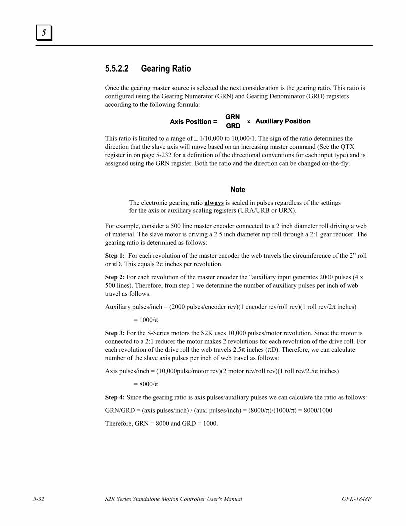
5-32 S2K Series Standalone Motion Controller User's Manual GFK-1848F
5
5.5.2.2 Gearing Ratio
Once the gearing master source is selected the next consideration is the gearing ratio. This ratio is configured using the Gearing Numerator (GRN) and Gearing Denominator (GRD) registers according to the following formula:
This ratio is limited to a range of ± 1/10,000 to 10,000/1. The sign of the ratio determines the direction that the slave axis will move based on an increasing master command (See the QTX register in on page 5-232 for a definition of the directional conventions for each input type) and is assigned using the GRN register. Both the ratio and the direction can be changed on-the-fly.
Note The electronic gearing ratio always is scaled in pulses regardless of the settings for the axis or auxiliary scaling registers (URA/URB or URX).
For example, consider a 500 line master encoder connected to a 2 inch diameter roll driving a web of material. The slave motor is driving a 2.5 inch diameter nip roll through a 2:1 gear reducer. The gearing ratio is determined as follows:
Step 1: For each revolution of the master encoder the web travels the circumference of the 2” roll or πD. This equals 2π inches per revolution.
Step 2: For each revolution of the master encoder the “auxiliary input generates 2000 pulses (4 x 500 lines). Therefore, from step 1 we determine the number of auxiliary pulses per inch of web travel as follows:
Auxiliary pulses/inch = (2000 pulses/encoder rev)(1 encoder rev/roll rev)(1 roll rev/2π inches)
= 1000/π
Step 3: For the S-Series motors the S2K uses 10,000 pulses/motor revolution. Since the motor is connected to a 2:1 reducer the motor makes 2 revolutions for each revolution of the drive roll. For each revolution of the drive roll the web travels 2.5π inches (πD). Therefore, we can calculate number of the slave axis pulses per inch of web travel as follows:
Axis pulses/inch = (10,000pulse/motor rev)(2 motor rev/roll rev)(1 roll rev/2.5π inches)
= 8000/π
Step 4: Since the gearing ratio is axis pulses/auxiliary pulses we can calculate the ratio as follows:
GRN/GRD = (axis pulses/inch) / (aux. pulses/inch) = (8000/π)/(1000/π) = 8000/1000
Therefore, GRN = 8000 and GRD = 1000.
Axis Position = GRDGRN
x Auxiliary PositionAxis Position = GRDGRN
x Auxiliary Position
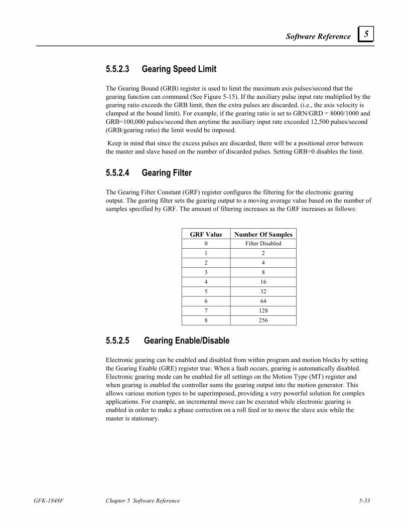
Software Reference
GFK-1848F Chapter 5 Software Reference 5-33
5
5.5.2.3 Gearing Speed Limit
The Gearing Bound (GRB) register is used to limit the maximum axis pulses/second that the gearing function can command (See Figure 5-15). If the auxiliary pulse input rate multiplied by the gearing ratio exceeds the GRB limit, then the extra pulses are discarded. (i.e., the axis velocity is clamped at the bound limit). For example, if the gearing ratio is set to GRN/GRD = 8000/1000 and GRB=100,000 pulses/second then anytime the auxiliary input rate exceeded 12,500 pulses/second (GRB/gearing ratio) the limit would be imposed.
Keep in mind that since the excess pulses are discarded, there will be a positional error between the master and slave based on the number of discarded pulses. Setting GRB=0 disables the limit.
5.5.2.4 Gearing Filter
The Gearing Filter Constant (GRF) register configures the filtering for the electronic gearing output. The gearing filter sets the gearing output to a moving average value based on the number of samples specified by GRF. The amount of filtering increases as the GRF increases as follows:
GRF Value Number Of Samples 0 Filter Disabled 1 2 2 4 3 8 4 16 5 32 6 64 7 128 8 256
5.5.2.5 Gearing Enable/Disable
Electronic gearing can be enabled and disabled from within program and motion blocks by setting the Gearing Enable (GRE) register true. When a fault occurs, gearing is automatically disabled. Electronic gearing mode can be enabled for all settings on the Motion Type (MT) register and when gearing is enabled the controller sums the gearing output into the motion generator. This allows various motion types to be superimposed, providing a very powerful solution for complex applications. For example, an incremental move can be executed while electronic gearing is enabled in order to make a phase correction on a roll feed or to move the slave axis while the master is stationary.
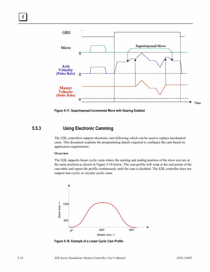
5-34 S2K Series Standalone Motion Controller User's Manual GFK-1848F
5
Time
0
GRE
0
Move0
Superimposed Move
AxisVelocity
(Pulse Rate)
MasterVelocity
(Pulse Rate)
Time
0
GRE
0
Move0
Superimposed Move
AxisVelocity
(Pulse Rate)
MasterVelocity
(Pulse Rate)
Figure 5-17. Superimposed Incremental Move with Gearing Enabled
5.5.3 Using Electronic Camming
The S2K controllers support electronic cam following which can be used to replace mechanical cams. This document explains the programming details required to configure the cam based on application requirements.
Overview
The S2K supports linear cyclic cams where the starting and ending position of the slave axis are at the same position as shown in Figure 5-18 below. The cam profile will wrap at the end points of the cam table and repeat the profile continuously until the cam is disabled. The S2K controller does not support non-cyclic or circular cyclic cams.
Master Axis ->0 180 360ooo
500
1500
Slav
e Ax
is ->
Figure 5-18. Example of a Linear Cyclic Cam Profile
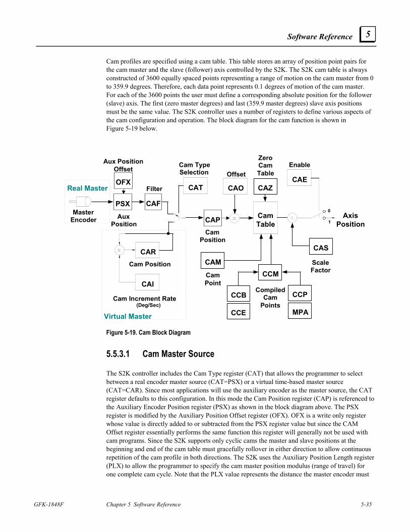
Software Reference
GFK-1848F Chapter 5 Software Reference 5-35
5
Cam profiles are specified using a cam table. This table stores an array of position point pairs for the cam master and the slave (follower) axis controlled by the S2K. The S2K cam table is always constructed of 3600 equally spaced points representing a range of motion on the cam master from 0 to 359.9 degrees. Therefore, each data point represents 0.1 degrees of motion of the cam master. For each of the 3600 points the user must define a corresponding absolute position for the follower (slave) axis. The first (zero master degrees) and last (359.9 master degrees) slave axis positions must be the same value. The S2K controller uses a number of registers to define various aspects of the cam configuration and operation. The block diagram for the cam function is shown in Figure 5-19 below.
AxisPosition
Offset
CAO
Enable
CAE
1
0CamTable
CATFilter
Cam TypeSelection
CamPosition
CAI
CARCam Position
Cam Increment Rate(Deg/Sec)
Virtual Master
ScaleFactor
CAPAuxPosition
PSX
OFX
Aux PositionOffset
CAZ
ZeroCamTable
CamPoint
CAM
CAS
CCE
CCB
CCM
CCP
MPA
CompiledCam
Points
MasterEncoder
Real Master
CAF
Figure 5-19. Cam Block Diagram
5.5.3.1 Cam Master Source
The S2K controller includes the Cam Type register (CAT) that allows the programmer to select between a real encoder master source (CAT=PSX) or a virtual time-based master source (CAT=CAR). Since most applications will use the auxiliary encoder as the master source, the CAT register defaults to this configuration. In this mode the Cam Position register (CAP) is referenced to the Auxiliary Encoder Position register (PSX) as shown in the block diagram above. The PSX register is modified by the Auxiliary Position Offset register (OFX). OFX is a write only register whose value is directly added to or subtracted from the PSX register value but since the CAM Offset register essentially performs the same function this register will generally not be used with cam programs. Since the S2K supports only cyclic cams the master and slave positions at the beginning and end of the cam table must gracefully rollover in either direction to allow continuous repetition of the cam profile in both directions. The S2K uses the Auxiliary Position Length register (PLX) to allow the programmer to specify the cam master position modulus (range of travel) for one complete cam cycle. Note that the PLX value represents the distance the master encoder must
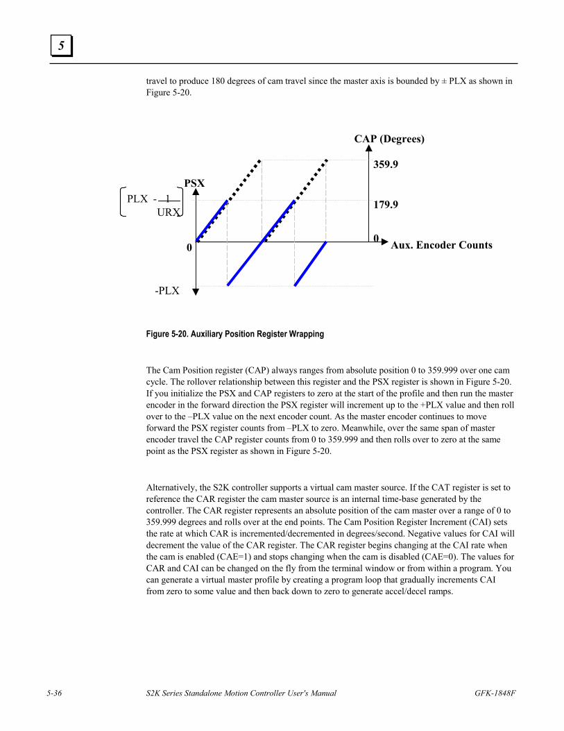
5-36 S2K Series Standalone Motion Controller User's Manual GFK-1848F
5
travel to produce 180 degrees of cam travel since the master axis is bounded by ± PLX as shown in Figure 5-20.
PSX
Aux. Encoder Counts
PLX - 1 URX
-PLX
0
CAP (Degrees)
179.9
359.9
0
Figure 5-20. Auxiliary Position Register Wrapping
The Cam Position register (CAP) always ranges from absolute position 0 to 359.999 over one cam cycle. The rollover relationship between this register and the PSX register is shown in Figure 5-20. If you initialize the PSX and CAP registers to zero at the start of the profile and then run the master encoder in the forward direction the PSX register will increment up to the +PLX value and then roll over to the –PLX value on the next encoder count. As the master encoder continues to move forward the PSX register counts from –PLX to zero. Meanwhile, over the same span of master encoder travel the CAP register counts from 0 to 359.999 and then rolls over to zero at the same point as the PSX register as shown in Figure 5-20.
Alternatively, the S2K controller supports a virtual cam master source. If the CAT register is set to reference the CAR register the cam master source is an internal time-base generated by the controller. The CAR register represents an absolute position of the cam master over a range of 0 to 359.999 degrees and rolls over at the end points. The Cam Position Register Increment (CAI) sets the rate at which CAR is incremented/decremented in degrees/second. Negative values for CAI will decrement the value of the CAR register. The CAR register begins changing at the CAI rate when the cam is enabled (CAE=1) and stops changing when the cam is disabled (CAE=0). The values for CAR and CAI can be changed on the fly from the terminal window or from within a program. You can generate a virtual master profile by creating a program loop that gradually increments CAI from zero to some value and then back down to zero to generate accel/decel ramps.
Software Reference
GFK-1848F Chapter 5 Software Reference 5-37
5
5.5.3.2 Cam Filter
If the cam seems to run rough due to jitter or unstable motion of the auxiliary encoder then the Cam Filter Constant (CAF) can be used to smooth the cam shaft motion. Configurations that generate large moves on the axis for a small change of the master generally require more filtering. The filter constant sets the number of past cam positions that are used in the moving average filter algorithm. Using a higher number of samples increases the filtering and generates a smoother profile but also reduces the response of the axis. Use the smallest amount of filtering that yields acceptable results.
5.5.3.3 Cam Offset
The Cam Offset register (CAO) allows for on the fly phase corrections of the master axis position. CAO can be used to advance or retard the cam position by ± 180 degrees. As indicated by the block diagram in Figure 5-19 the CAO value is summed with the CAP register value and does not change the actual CAP value. Offset correction moves are executed with full system speed and torque in order to complete the move as quickly as possible (i.e., MAC, MDC and MVL limits do not apply).
5.5.3.4 Generating a Cam Table
The cam table is a two dimensional array that stores a set of 3600 master/slave position pairs used to define the shape of the cam profile. As the cam cycles from 0 to 360 degrees the axis motor will move according to the position values associated with each 0.1 degree of cam movement. Before loading data points into the cam table the table should always be cleared to ensure no previous data points corrupt the desired profile. The Zero Cam Table command (CAZ) is used to clear the table and should precede any program lines that load cam points into the table.
5.5.3.5 Using the Cam Point Register
The S2K controller provides two methods for generating cam table data points. The simplest method is to use the CAM Point (CAM) register to directly load the specific points of interest and allow the controller to populate the interim points using linear interpolation. This method works well when the cam profile is relatively simple and requires only segments that can be rendered with sufficient accuracy using linear segments. The CAM command can use direct or indirect referencing to load a specific point. An example of direct referencing would use CAM 180 = xx to load the axis position “xx” for cam master position of 180 degrees. The following example directly loads values using the cam command:
CAZ (* clear cam table
CAM0=0 (* set axis position at 0 degrees to 0 axis units
CAM180=10 (* set axis position at 180 degrees to 10 axis units
CAM0=0 (* fill the rest of the cam table using linear interpolation
CAE=1 (* enable cam following
5-38 S2K Series Standalone Motion Controller User's Manual GFK-1848F
5
Indirect referencing uses variable pointers such as CAMVI20 = VF2 to load the axis position stored in floating point variable VF2 for the cam master position stored in integer variable VI20. Generally the easiest way to load cam points using the CAM register is to construct a program loop to increment the cam pointer value in 0.1-degree increments as shown below.
CAZ (* clear cam table
VI1 = 0 (* initialize cam pointer to zero degrees
10 CAMVI1 = SIN(ITF(VI1)/10.0) (* load cam table with a sine wave profile
VI1 = VI1 + 1 (* increment cam pointer by 0.1 degree
IF VI1 < 3600 GOTO 10 (* continue until 359.9 degrees
Note in this example that when an integer variable pointer is used as the argument in the CAM register its value represents ten times the actual cam master position in degrees. This allows the controller to satisfy the 0.1-degree point resolution requirement while using integer variable pointers.
5.5.3.6 Using the Cam Compile Command
The second method builds the cam table in segments by compiling conventional absolute moves for each cam segment. This method can be used to create more complex cam profiles with defined acceleration and jerk values. The S2K controller provides several registers that are used to define each compiled profile segment.
The Cam Compile Begin (CCB) and Cam Compile End (CCE) registers state the starting and ending cam master positions for the segment in degrees (0.1 degree resolution). The Cam Compile Start Position (CCP) and Absolute Move Position (MPA) registers define the starting and ending axis positions for the segment in axis units. The normal MAP, MDP and MJK registers are used to define the acceleration, deceleration and jerk percentages just like a conventional velocity-based move in the S2K. The Compile Cam Motion (CCM) command completes the compile function for the segment and populates the appropriate section of the cam table as shown in the example in Figure 5-21.
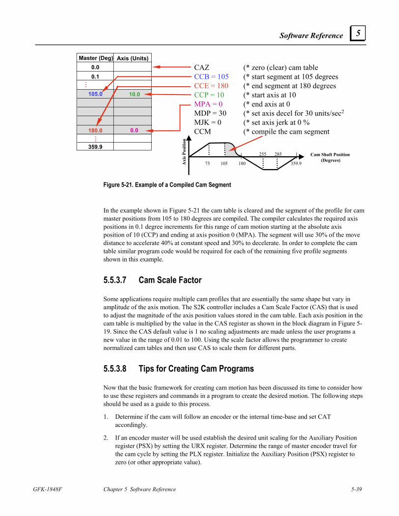
Software Reference
GFK-1848F Chapter 5 Software Reference 5-39
5
CAZ (* zero (clear) cam tableCCB = 105 (* start segment at 105 degreesCCE = 180 (* end segment at 180 degreesCCP = 10 (* start axis at 10MPA = 0 (* end axis at 0MDP = 30 (* set axis decel for 30 units/sec2
MJK = 0 (* set axis jerk at 0 %CCM (* compile the cam segment
Master (Deg) Axis (Units)0.00.1
359.9
180.0
105.0
...
...
10.0
0.0
Cam Shaft Position (Degrees)
Axi
s Pos
ition
75 105 180 359.9
255 285
Figure 5-21. Example of a Compiled Cam Segment
In the example shown in Figure 5-21 the cam table is cleared and the segment of the profile for cam master positions from 105 to 180 degrees are compiled. The compiler calculates the required axis positions in 0.1 degree increments for this range of cam motion starting at the absolute axis position of 10 (CCP) and ending at axis position 0 (MPA). The segment will use 30% of the move distance to accelerate 40% at constant speed and 30% to decelerate. In order to complete the cam table similar program code would be required for each of the remaining five profile segments shown in this example.
5.5.3.7 Cam Scale Factor
Some applications require multiple cam profiles that are essentially the same shape but vary in amplitude of the axis motion. The S2K controller includes a Cam Scale Factor (CAS) that is used to adjust the magnitude of the axis position values stored in the cam table. Each axis position in the cam table is multiplied by the value in the CAS register as shown in the block diagram in Figure 5-19. Since the CAS default value is 1 no scaling adjustments are made unless the user programs a new value in the range of 0.01 to 100. Using the scale factor allows the programmer to create normalized cam tables and then use CAS to scale them for different parts.
5.5.3.8 Tips for Creating Cam Programs
Now that the basic framework for creating cam motion has been discussed its time to consider how to use these registers and commands in a program to create the desired motion. The following steps should be used as a guide to this process.
1. Determine if the cam will follow an encoder or the internal time-base and set CAT accordingly.
2. If an encoder master will be used establish the desired unit scaling for the Auxiliary Position register (PSX) by setting the URX register. Determine the range of master encoder travel for the cam cycle by setting the PLX register. Initialize the Auxiliary Position (PSX) register to zero (or other appropriate value).
5-40 S2K Series Standalone Motion Controller User's Manual GFK-1848F
5
3. If the time-based internal master will be used the Cam Position Register Increment (CAI) must be set to establish the execution speed of the cam.
4. Initialize the Axis Position register (PSA) to zero (or other appropriate value). Note: When the cam is enabled (CAE=1 is executed) the master position is read by the controller and the axis motor is moved to its corresponding absolute position stored in the cam table. This move to the starting position is governed by the normal absolute motion registers in the S2K. Therefore, the cam program should initialize acceleration (MAC), deceleration (MDC) and velocity (MVL) for this move.
5. Since the auxiliary axis position register automatically wraps it is not necessary to set Position Register Wrap Enable (PWE=1).
6. The programmer must ensure that the axis position (axis position values stored in the cam table multiplied by the scale factor, CAS) is always within the software overtravel limit settings (OTF & OTR).
7. Initialize the Cam Filter Constant (CAF) if profile filtering is desired. This may need to be determined empirically and added later so you may want to include the program line “CAF=0” as a place holder.
8. Initialize the Cam Offset (CAO) if a phase adjustment is desired. This may need to be determined empirically and added later so you may want to include the program line “CAO=0” as a place holder.
9. Clear the cam table using the CAZ command.
10. Create the cam table using either the CAM register or the compiled method. The specific program code to accomplish this will vary greatly depending on the application requirements. Using indirect referencing with variable pointers as discussed above allows new cam table data to be loaded over the network. If you are loading all 3600 points the order they are entered is irrelevant. If you are only entering a few points and allowing the interpolator to fill in the remaining points you must build the table from the top down starting at the cam angle of zero degrees and ending with a “CAM0=0” or CAM359.9=0” to force the interpolator to fill in the last points in the table.
11. Determine if a Cam Scale Factor will be used and initialize the CAS register.
12. Disable the hardware overtravel limits (OTE=0) if not already done in controller configuration.
13. Enable the cam (CAE=1).
An example of a typical cam initialization program is shown below:
PSA=0 (* reset axis position
PSX=0 (* initialize cam starting point
OTE=0 (* disable hardware overtravel limits
CAT=PSX (* select the auxiliary encoder as the cam master source
CAO=0 (* set cam offset
CAS=2 (* set cam lift scale factor
Software Reference
GFK-1848F Chapter 5 Software Reference 5-41
5
CAF=0 (* set cam filter constant
MAC=200. (* set acceleration for initial axis move to position
MDC=100. (* set deceleration for axis move to position
MVL=50. (* set axis velocity for move to position
5.5.3.9 Additional Camming Information
1. If the axis move distance between two consecutive points is very large the controller may fault on following error.
2. The Cam Enable register (CAE) is reset to zero when a fault occurs or when the cam table is cleared (CAZ).
3. When the cam is disabled while the cam is running the axis motor decelerates to zero speed as quickly as the system constraints allow (similar to executing a HALT command).
5.5.4 Using High Speed Position Capture (Registration) Functions
The S2K controllers incorporate a software latch to capture both the axis and auxiliary positions when the capture input is set true. The capture input is the marker (Z-channel) input for the auxiliary encoder. Capture accuracy when the strobe input is activated is ± 30 µS and the captured axis position value is stored in the PCA register and the auxiliary position is stored in the PCX register. The IO register includes two bit flags that reflect the capture state as follows:
Bit 12 – Set true when the position capture input is active
Bit 13 – Set true when the capture input makes a low-to-high transition since the last time either of the capture registers (PCA or PCX) were read. Reset when either PCA or PCX is read.
Position capture can be used in a range of applications including measuring product length, product edge detection, determining product spacing and feeding to a registration mark.
5.5.5 Using Synchronized Axis and Auxiliary Position Readings
The S2K controllers include special versions of the Axis (PSA) and Auxiliary (PSX) Position registers for applications that require a snapshot in time for both positions in order to perform calculations or comparisons between the two values. The PZA and PZX registers allow such synchronized readings. Each time the program encounters the PZA command the value for axis position (PSA) is latched to the PZA register and a simultaneous reading (within 10 µs) of the auxiliary position (PSX) is latched to the PZX register. These values are overwritten each time the PZA command is executed.
5-42 S2K Series Standalone Motion Controller User's Manual GFK-1848F
5
5.6 Software Quick Reference Lists
5.6.1 Alphabetical Command and Register Listing * Indicates registers that cannot be set in a program Reg/Cmd Class Description
! Program exits terminal window line editor ? Diagnostic reports value of register to the terminal window
p1, p2 Operand floating point operands “p1”, $p2 Operand string operands
+ Operator concatenate strings p1 and p2 +, -, * , / , * * Operator arithmetic operators
>,>=, =, <>, <=, < Operator relational operators 16#p3 Operand base 16 integer operand 2#p2 Operand base 2 integer operand ABS Operator absolute value of any floating point or integer operand
ADDN System address of network port ADDR System RTU port address
AI Input/Output analog input AIB Input/Output analog input deadband AIN Input/Output network analog input AIO Input/Output analog input offset AND Operator logical AND of two operands of the same type AO Input/Output analog output
AON Input/Output network analog output AOP Input/Output power-up state of analog output ASC Operator converts 1st character in string operand to ASCII code ATN Operator arctangent trigonometric function
AUTORET System enables auto retrieving of user memory AUTOTUNE System automatically sets up control constants
BAUD System baud rate of serial port BAUDN System data rate of network port
BIT System data bits of serial port BS Input/Output backspaces cursor
CAE Motion cam enable CAF Motion cam filter constant CAI Motion cam position register increment
CAM Motion cam point CAO Motion cam offset CAP Motion cam shaft position CAR Motion cam position register CAS Motion cam scale factor CAT Motion cam shaft position type
Software Reference
GFK-1848F Chapter 5 Software Reference 5-43
5
Reg/Cmd Class Description CAZ Motion zeros cam table CCB Motion cam compile begin point CCE Motion cam compile end point CCM Motion compiles cam motion CCP Motion cam compile start position CE System conversion error
CHANGEPW System prompts for password change CHR Operator converts ASCII character code to its associated character CIE System computer interface format enable CLL Input/Output clears line and positions cursor at beginning of line CLM System clears user memory; resets registers to defaults CLS Input/Output clears display and positions cursor at home CMD Axis position controller command output CMO Axis commutation angle offset CMR Axis motor poles to resolver poles commutation ratio CNC System close network connection COS Operator cosine trigonometric function of a floating point operand CR Input/Output positions cursor at beginning of next line down
CRH Input/Output positions cursor at home CRM Input/Output remembers cursor position CRP Input/Output positions cursor CRR Input/Output positions cursor at remembered position
CURC Axis continuous current CURCN Axis network continuous current CURP Axis peak current CURS Axis power save current
CURSN Axis network power save current DEL Operator deletes characters from a string operand (see INS for operator
description) DEL Program deletes current statement in the terminal window line editor DGC Diagnostic loads diagnostic condition for printing DGE Diagnostic enables diagnostics DGI Diagnostic load diagnostic item to print DGL Diagnostic prints diagnostic line of items DGO Diagnostic outputs diagnostic register value to serial port DGP Diagnostic prints diagnostic message to serial port DGS Diagnostic sets program to single step mode DGT Diagnostic sets program to trace mode DI Input/Output digital input
DIN Input/Output network digital input DINA Input/Output network digital input register assignment DIR* Axis direction of motor for forward moves
DIRN* Axis network direction of motor for forward moves DIRX Axis direction of auxiliary position
DIRXN Axis network direction of auxiliary position
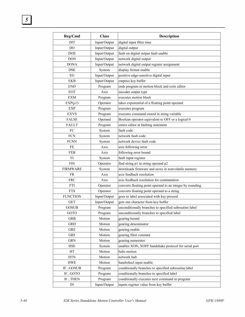
5-44 S2K Series Standalone Motion Controller User's Manual GFK-1848F
5
Reg/Cmd Class Description DIT Input/Output digital input filter time DO Input/Output digital output
DOE Input/Output fault on digital output fault enable DON Input/Output network digital output
DONA Input/Output network digital output register assignment DSE System display format enable EG Input/Output positive-edge-sensitive digital input
EKB Input/Output empties key buffer END Program ends program or motion block and exits editor EOT Axis encoder output type EXM Program executes motion block
EXP(p1) Operator takes exponential of a floating point operand EXP Program executes program
EXVS Program executes command stored in string variable FALSE Operand Boolean operator equivalent to OFF or a logical 0 FAULT Program enters editor at faulting statement
FC System fault code FCN System network fault code
FCNN System network device fault code FE Axis axis following error
FEB Axis following error bound FI System fault input register
FIN Operator find string p1 in string operand p2 FIRMWARE System downloads firmware and saves in nonvolatile memory
FR Axis axis feedback resolution FRC Axis axis feedback resolution for commutation FTI Operator converts floating point operand to an integer by rounding FTS Operator converts floating point operand to a string
FUNCTION Input/Output goes to label associated with key pressed GET Input/Output gets one character from key buffer
GOSUB Program unconditionally branches to specified subroutine label GOTO Program unconditionally branches to specified label GRB Motion gearing bound GRD Motion gearing denominator GRE Motion gearing enable GRF Motion gearing filter constant GRN Motion gearing numerator HSE System enables XON, XOFF handshake protocol for serial port HT Motion halts motion
HTN Motion network halt HWE Motion handwheel input enable
IF...GOSUB Program conditionally branches to specified subroutine label IF...GOTO Program conditionally branches to specified label IF...THEN Program conditionally executes next command in program
IN Input/Output inputs register value from key buffer
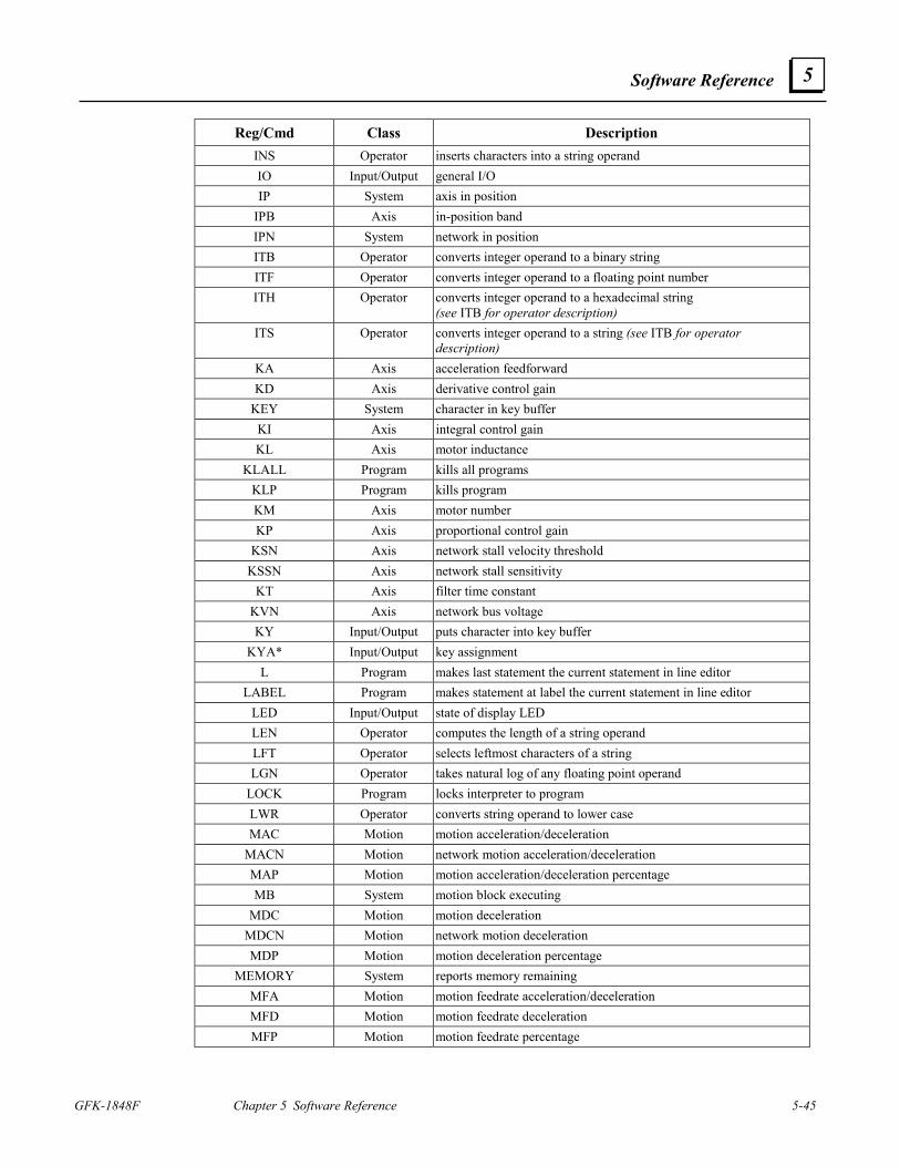
Software Reference
GFK-1848F Chapter 5 Software Reference 5-45
5
Reg/Cmd Class Description INS Operator inserts characters into a string operand IO Input/Output general I/O IP System axis in position
IPB Axis in-position band IPN System network in position ITB Operator converts integer operand to a binary string ITF Operator converts integer operand to a floating point number ITH Operator converts integer operand to a hexadecimal string
(see ITB for operator description) ITS Operator converts integer operand to a string (see ITB for operator
description) KA Axis acceleration feedforward KD Axis derivative control gain
KEY System character in key buffer KI Axis integral control gain KL Axis motor inductance
KLALL Program kills all programs KLP Program kills program KM Axis motor number KP Axis proportional control gain
KSN Axis network stall velocity threshold KSSN Axis network stall sensitivity
KT Axis filter time constant KVN Axis network bus voltage KY Input/Output puts character into key buffer
KYA* Input/Output key assignment L Program makes last statement the current statement in line editor
LABEL Program makes statement at label the current statement in line editor LED Input/Output state of display LED LEN Operator computes the length of a string operand LFT Operator selects leftmost characters of a string LGN Operator takes natural log of any floating point operand
LOCK Program locks interpreter to program LWR Operator converts string operand to lower case MAC Motion motion acceleration/deceleration
MACN Motion network motion acceleration/deceleration MAP Motion motion acceleration/deceleration percentage MB System motion block executing
MDC Motion motion deceleration MDCN Motion network motion deceleration MDP Motion motion deceleration percentage
MEMORY System reports memory remaining MFA Motion motion feedrate acceleration/deceleration MFD Motion motion feedrate deceleration MFP Motion motion feedrate percentage
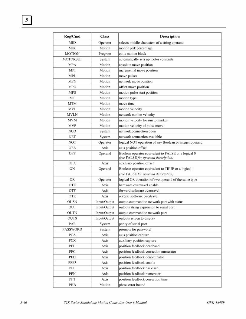
5-46 S2K Series Standalone Motion Controller User's Manual GFK-1848F
5
Reg/Cmd Class Description MID Operator selects middle characters of a string operand MJK Motion motion jerk percentage
MOTION Program edits motion block MOTORSET System automatically sets up motor constants
MPA Motion absolute move position MPI Motion incremental move position MPL Motion move pulses MPN Motion network move position MPO Motion offset move position MPS Motion motion pulse start position MT Motion motion type
MTM Motion move time MVL Motion motion velocity
MVLN Motion network motion velocity MVM Motion motion velocity for run to marker MVP Motion motion velocity of pulse move NCO System network connection open NET System network connection available NOT Operator logical NOT operation of any Boolean or integer operand OFA Axis axis position offset OFF Operand Boolean operator equivalent to FALSE or a logical 0
(see FALSE for operand description) OFX Axis auxiliary position offset ON Operand Boolean operator equivalent to TRUE or a logical 1
(see FALSE for operand description) OR Operator logical OR operation of two operand of the same type
OTE Axis hardware overtravel enable OTF Axis forward software overtravel OTR Axis reverse software overtravel
OUSN Input/Output output command to network port with status OUT Input/Output outputs string expression to serial port
OUTN Input/Output output command to network port OUTS Input/Output outputs screen to display PAR System parity of serial port
PASSWORD System prompts for password PCA Axis axis position capture PCX Axis auxiliary position capture PFB Axis position feedback deadband PFC Axis position feedback correction numerator PFD Axis position feedback denominator PFE* Axis position feedback enable PFL Axis position feedback backlash PFN Axis position feedback numerator PFT Axis position feedback correction time PHB Motion phase error bound
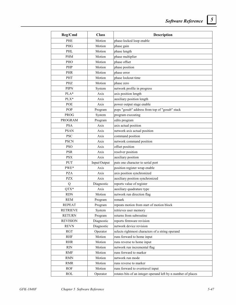
Software Reference
GFK-1848F Chapter 5 Software Reference 5-47
5
Reg/Cmd Class Description PHE Motion phase-locked loop enable PHG Motion phase gain PHL Motion phase length PHM Motion phase multiplier PHO Motion phase offset PHP Motion phase position PHR Motion phase error PHT Motion phase lockout time PHZ Motion phase zero PIPN System network profile in progress PLA* Axis axis position length PLX* Axis auxiliary position length POE Axis power output stage enable POP Program pops "gosub" address from top of "gosub" stack
PROG System program executing PROGRAM Program edits program
PSA Axis axis actual position PSAN Axis network axis actual position PSC Axis command position
PSCN Axis network command position PSO Axis offset position PSR Axis resolver position PSX Axis auxiliary position PUT Input/Output puts one character to serial port
PWE* Axis position register wrap enable PZA Axis axis position synchronized PZX Axis auxiliary position synchronized
Q Diagnostic reports value of register QTX* Axis auxiliary quadrature type RDN Motion network run direction flag REM Program remark
REPEAT Program repeats motion from start of motion block RETRIEVE System retrieves user memory RETURN Program returns from subroutine
REVISION Diagnostic reports firmware revision REVN Diagnostic network device revision RGT Operator selects rightmost characters of a string operand RHF Motion runs forward to home input RHR Motion runs reverse to home input RIN Motion network run incremental flag RMF Motion runs forward to marker RMN Motion network run mode RMR Motion runs reverse to marker ROF Motion runs forward to overtravel input ROL Operator rotates bits of an integer operand left by n number of places
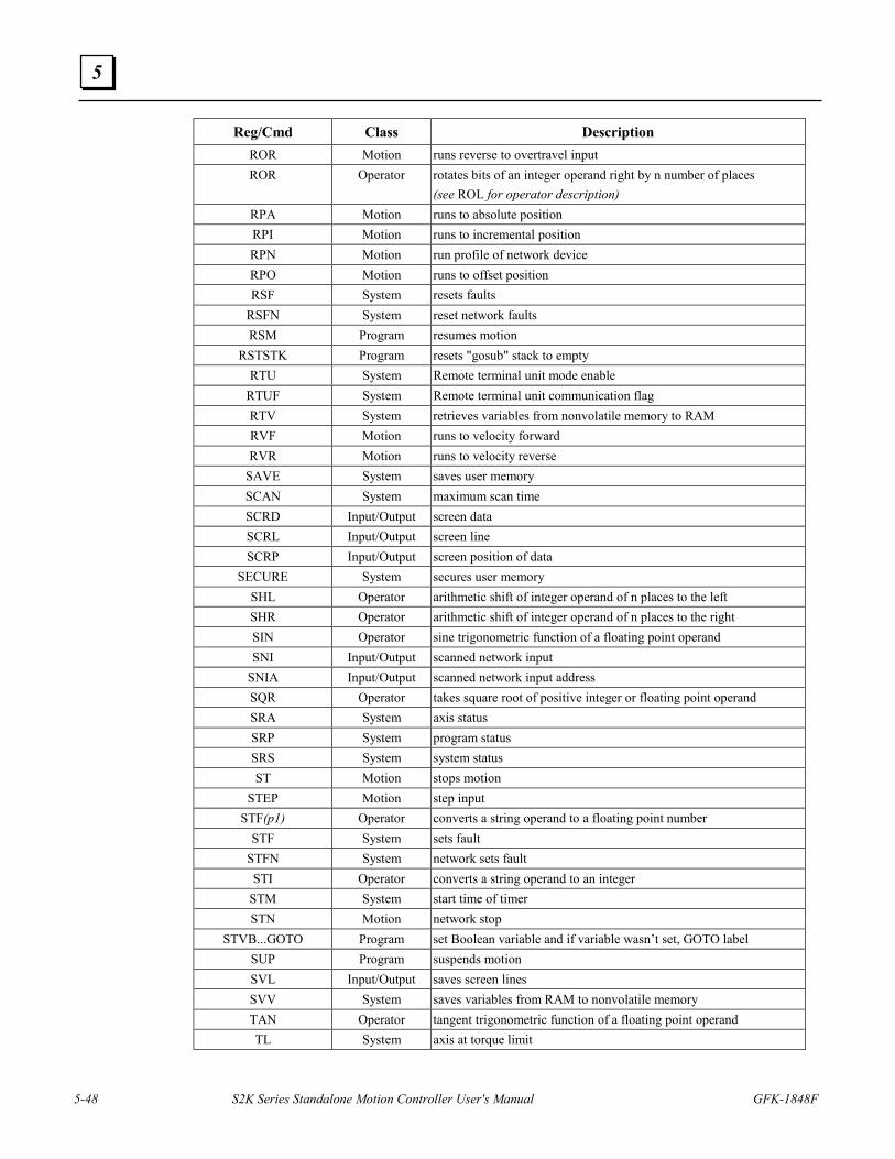
5-48 S2K Series Standalone Motion Controller User's Manual GFK-1848F
5
Reg/Cmd Class Description ROR Motion runs reverse to overtravel input ROR Operator rotates bits of an integer operand right by n number of places
(see ROL for operator description) RPA Motion runs to absolute position RPI Motion runs to incremental position RPN Motion run profile of network device RPO Motion runs to offset position RSF System resets faults
RSFN System reset network faults RSM Program resumes motion
RSTSTK Program resets "gosub" stack to empty RTU System Remote terminal unit mode enable
RTUF System Remote terminal unit communication flag RTV System retrieves variables from nonvolatile memory to RAM RVF Motion runs to velocity forward RVR Motion runs to velocity reverse
SAVE System saves user memory SCAN System maximum scan time SCRD Input/Output screen data SCRL Input/Output screen line SCRP Input/Output screen position of data
SECURE System secures user memory SHL Operator arithmetic shift of integer operand of n places to the left SHR Operator arithmetic shift of integer operand of n places to the right SIN Operator sine trigonometric function of a floating point operand SNI Input/Output scanned network input
SNIA Input/Output scanned network input address SQR Operator takes square root of positive integer or floating point operand SRA System axis status SRP System program status SRS System system status ST Motion stops motion
STEP Motion step input STF(p1) Operator converts a string operand to a floating point number
STF System sets fault STFN System network sets fault STI Operator converts a string operand to an integer
STM System start time of timer STN Motion network stop
STVB...GOTO Program set Boolean variable and if variable wasn’t set, GOTO label SUP Program suspends motion SVL Input/Output saves screen lines SVV System saves variables from RAM to nonvolatile memory TAN Operator tangent trigonometric function of a floating point operand TL System axis at torque limit
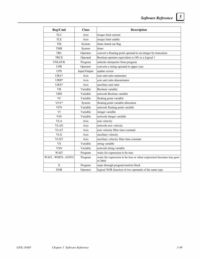
Software Reference
GFK-1848F Chapter 5 Software Reference 5-49
5
Reg/Cmd Class Description TLC Axis torque limit current TLE Axis torque limit enable TM System timer timed out flag
TMR System timer TRC Operator convert a floating point operand to an integer by truncation
TRUE Operand Boolean operator equivalent to ON or a logical 1 UNLOCK Program unlocks interpreter from program
UPR Operator converts a string operand to upper case UPS Input/Output update screen
URA* Axis axis unit ratio numerator URB* Axis axis unit ratio denominator URX* Axis auxiliary unit ratio
VB Variable Boolean variable VBN Variable network Boolean variable VF Variable floating point variable
VFA* System floating point variable allocation VFN Variable network floating point variable VI Variable integer variable
VIN Variable network integer variable VLA Axis axis velocity
VLAN Axis network axis velocity VLAT Axis axis velocity filter time constant VLX Axis auxiliary velocity
VLXT Axis auxiliary velocity filter time constant VS Variable string variable
VSN Variable network string variable WAIT Program waits for expression to be true
WAIT...WHEN...GOTO Program waits for expression to be true or when expression becomes true goes to label
X Program steps through program/motion block XOR Operator logical XOR function of two operands of the same type
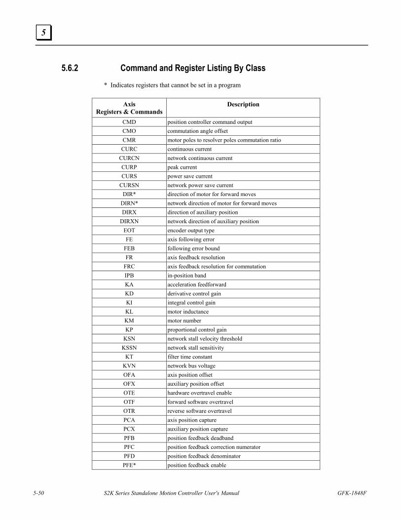
5-50 S2K Series Standalone Motion Controller User's Manual GFK-1848F
5
5.6.2 Command and Register Listing By Class * Indicates registers that cannot be set in a program
Axis Registers & Commands
Description
CMD position controller command output CMO commutation angle offset CMR motor poles to resolver poles commutation ratio CURC continuous current
CURCN network continuous current CURP peak current CURS power save current
CURSN network power save current DIR* direction of motor for forward moves
DIRN* network direction of motor for forward moves DIRX direction of auxiliary position
DIRXN network direction of auxiliary position EOT encoder output type FE axis following error
FEB following error bound FR axis feedback resolution
FRC axis feedback resolution for commutation IPB in-position band KA acceleration feedforward KD derivative control gain KI integral control gain KL motor inductance KM motor number KP proportional control gain
KSN network stall velocity threshold KSSN network stall sensitivity
KT filter time constant KVN network bus voltage OFA axis position offset OFX auxiliary position offset OTE hardware overtravel enable OTF forward software overtravel OTR reverse software overtravel PCA axis position capture PCX auxiliary position capture PFB position feedback deadband PFC position feedback correction numerator PFD position feedback denominator PFE* position feedback enable
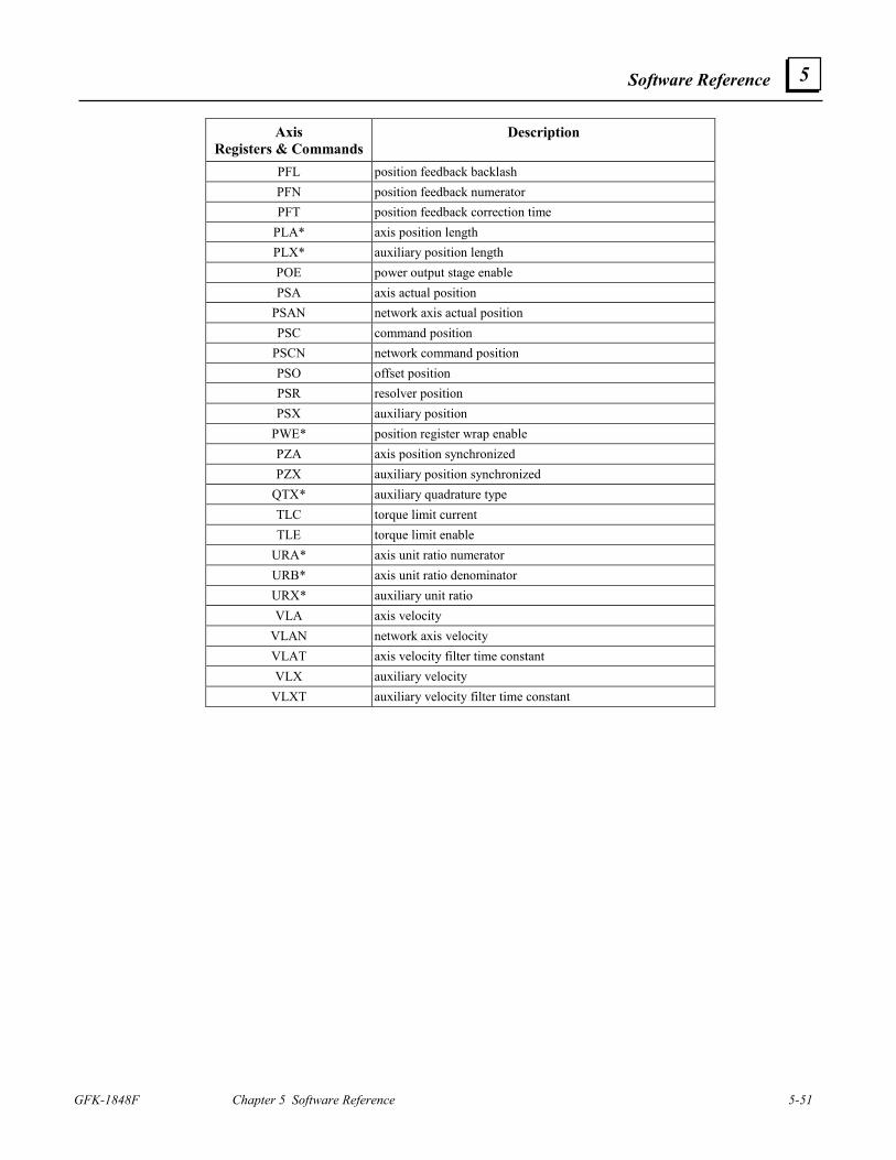
Software Reference
GFK-1848F Chapter 5 Software Reference 5-51
5
Axis Registers & Commands
Description
PFL position feedback backlash PFN position feedback numerator PFT position feedback correction time
PLA* axis position length PLX* auxiliary position length POE power output stage enable PSA axis actual position
PSAN network axis actual position PSC command position
PSCN network command position PSO offset position PSR resolver position PSX auxiliary position
PWE* position register wrap enable PZA axis position synchronized PZX auxiliary position synchronized
QTX* auxiliary quadrature type TLC torque limit current TLE torque limit enable
URA* axis unit ratio numerator URB* axis unit ratio denominator URX* auxiliary unit ratio VLA axis velocity
VLAN network axis velocity VLAT axis velocity filter time constant VLX auxiliary velocity
VLXT auxiliary velocity filter time constant
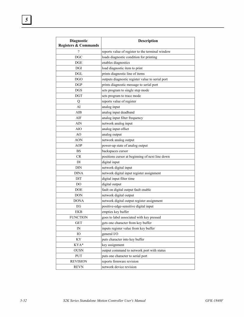
5-52 S2K Series Standalone Motion Controller User's Manual GFK-1848F
5
Diagnostic
Registers & Commands Description
? reports value of register to the terminal window DGC loads diagnostic condition for printing DGE enables diagnostics DGI load diagnostic item to print DGL prints diagnostic line of items DGO outputs diagnostic register value to serial port DGP prints diagnostic message to serial port DGS sets program to single step mode DGT sets program to trace mode
Q reports value of register AI analog input
AIB analog input deadband AIF analog input filter frequency AIN network analog input AIO analog input offset AO analog output
AON network analog output AOP power-up state of analog output BS backspaces cursor CR positions cursor at beginning of next line down DI digital input
DIN network digital input DINA network digital input register assignment DIT digital input filter time DO digital output
DOE fault on digital output fault enable DON network digital output
DONA network digital output register assignment EG positive-edge-sensitive digital input
EKB empties key buffer FUNCTION goes to label associated with key pressed
GET gets one character from key buffer IN inputs register value from key buffer IO general I/O KY puts character into key buffer
KYA* key assignment OUSN output command to network port with status PUT puts one character to serial port
REVISION reports firmware revision REVN network device revision
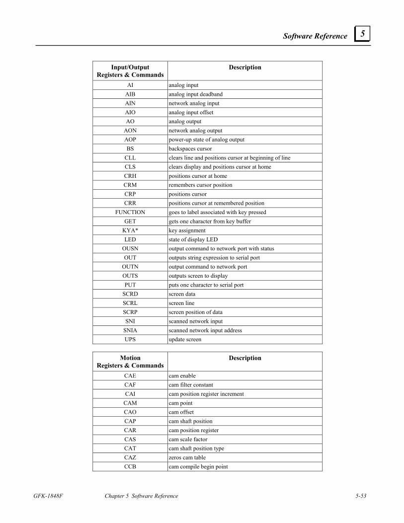
Software Reference
GFK-1848F Chapter 5 Software Reference 5-53
5
Input/Output
Registers & Commands Description
AI analog input AIB analog input deadband AIN network analog input AIO analog input offset AO analog output
AON network analog output AOP power-up state of analog output BS backspaces cursor
CLL clears line and positions cursor at beginning of line CLS clears display and positions cursor at home CRH positions cursor at home CRM remembers cursor position CRP positions cursor CRR positions cursor at remembered position
FUNCTION goes to label associated with key pressed GET gets one character from key buffer
KYA* key assignment LED state of display LED
OUSN output command to network port with status OUT outputs string expression to serial port
OUTN output command to network port OUTS outputs screen to display PUT puts one character to serial port
SCRD screen data SCRL screen line SCRP screen position of data SNI scanned network input
SNIA scanned network input address UPS update screen
Motion
Registers & Commands Description
CAE cam enable CAF cam filter constant CAI cam position register increment
CAM cam point CAO cam offset CAP cam shaft position CAR cam position register CAS cam scale factor CAT cam shaft position type CAZ zeros cam table CCB cam compile begin point
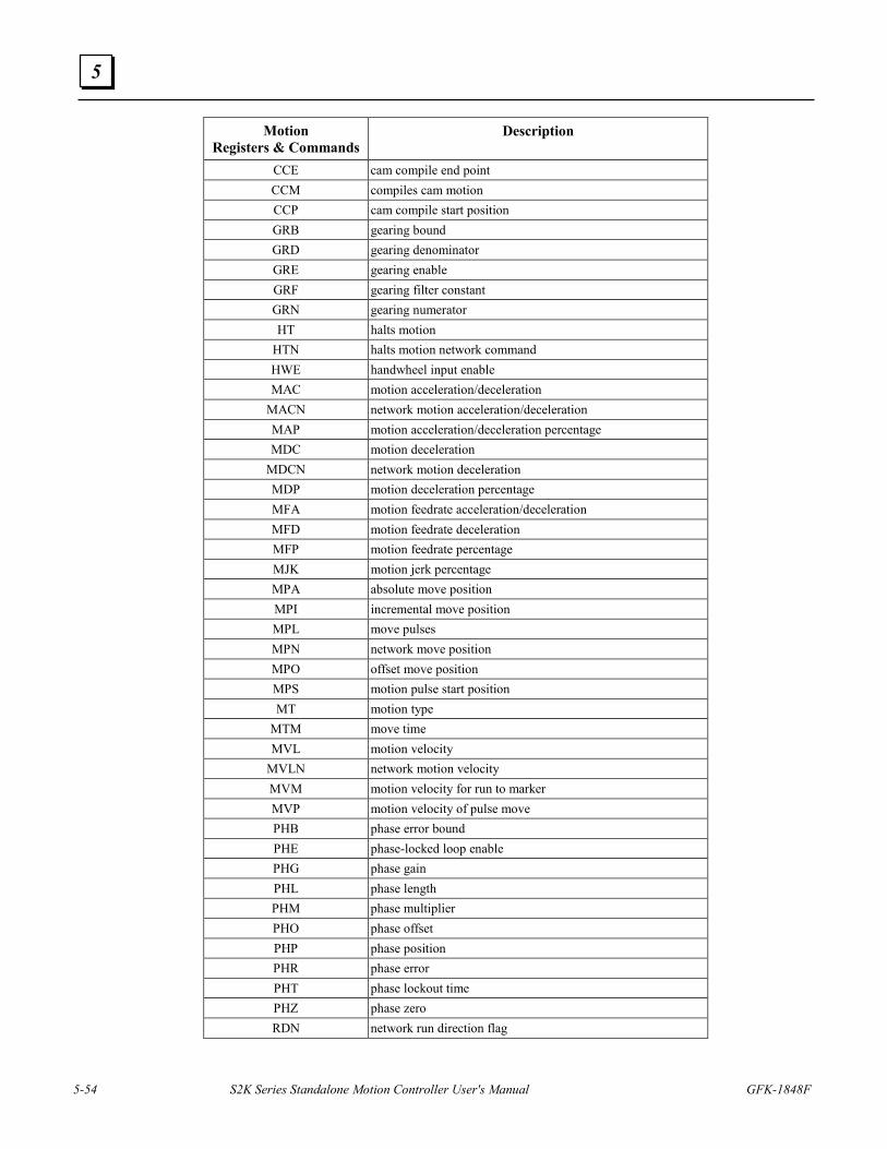
5-54 S2K Series Standalone Motion Controller User's Manual GFK-1848F
5
Motion Registers & Commands
Description
CCE cam compile end point CCM compiles cam motion CCP cam compile start position GRB gearing bound GRD gearing denominator GRE gearing enable GRF gearing filter constant GRN gearing numerator HT halts motion
HTN halts motion network command HWE handwheel input enable MAC motion acceleration/deceleration
MACN network motion acceleration/deceleration MAP motion acceleration/deceleration percentage MDC motion deceleration
MDCN network motion deceleration MDP motion deceleration percentage MFA motion feedrate acceleration/deceleration MFD motion feedrate deceleration MFP motion feedrate percentage MJK motion jerk percentage MPA absolute move position MPI incremental move position MPL move pulses MPN network move position MPO offset move position MPS motion pulse start position MT motion type
MTM move time MVL motion velocity
MVLN network motion velocity MVM motion velocity for run to marker MVP motion velocity of pulse move PHB phase error bound PHE phase-locked loop enable PHG phase gain PHL phase length PHM phase multiplier PHO phase offset PHP phase position PHR phase error PHT phase lockout time PHZ phase zero RDN network run direction flag
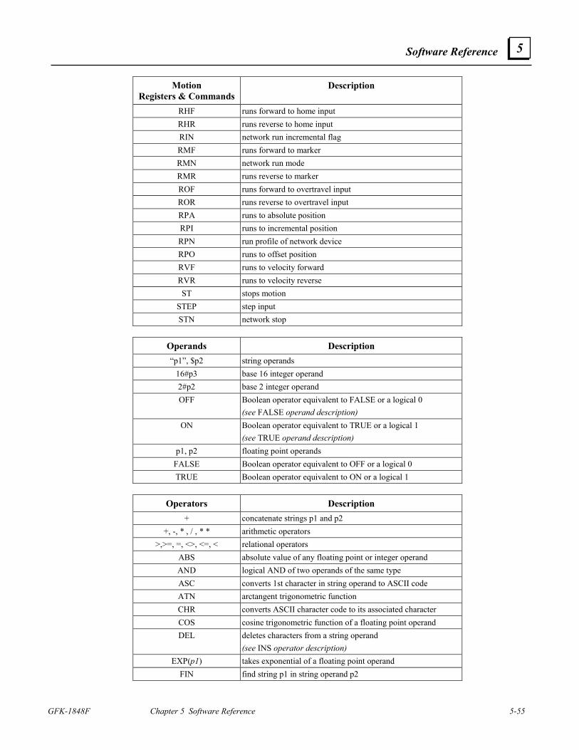
Software Reference
GFK-1848F Chapter 5 Software Reference 5-55
5
Motion Registers & Commands
Description
RHF runs forward to home input RHR runs reverse to home input RIN network run incremental flag RMF runs forward to marker RMN network run mode RMR runs reverse to marker ROF runs forward to overtravel input ROR runs reverse to overtravel input RPA runs to absolute position RPI runs to incremental position RPN run profile of network device RPO runs to offset position RVF runs to velocity forward RVR runs to velocity reverse ST stops motion
STEP step input STN network stop
Operands Description “p1”, $p2 string operands
16#p3 base 16 integer operand 2#p2 base 2 integer operand OFF Boolean operator equivalent to FALSE or a logical 0
(see FALSE operand description) ON Boolean operator equivalent to TRUE or a logical 1
(see TRUE operand description) p1, p2 floating point operands
FALSE Boolean operator equivalent to OFF or a logical 0 TRUE Boolean operator equivalent to ON or a logical 1
Operators Description
+ concatenate strings p1 and p2 +, -, * , / , * * arithmetic operators
>,>=, =, <>, <=, < relational operators ABS absolute value of any floating point or integer operand AND logical AND of two operands of the same type ASC converts 1st character in string operand to ASCII code ATN arctangent trigonometric function CHR converts ASCII character code to its associated character COS cosine trigonometric function of a floating point operand DEL deletes characters from a string operand
(see INS operator description) EXP(p1) takes exponential of a floating point operand
FIN find string p1 in string operand p2
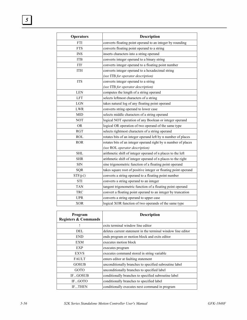
5-56 S2K Series Standalone Motion Controller User's Manual GFK-1848F
5
Operators Description FTI converts floating point operand to an integer by rounding FTS converts floating point operand to a string INS inserts characters into a string operand ITB converts integer operand to a binary string ITF converts integer operand to a floating point number ITH converts integer operand to a hexadecimal string
(see ITB for operator description) ITS converts integer operand to a string
(see ITB for operator description) LEN computes the length of a string operand LFT selects leftmost characters of a string LGN takes natural log of any floating point operand LWR converts string operand to lower case MID selects middle characters of a string operand NOT logical NOT operation of any Boolean or integer operand OR logical OR operation of two operand of the same type
RGT selects rightmost characters of a string operand ROL rotates bits of an integer operand left by n number of places ROR rotates bits of an integer operand right by n number of places
(see ROL operator description) SHL arithmetic shift of integer operand of n places to the left SHR arithmetic shift of integer operand of n places to the right SIN sine trigonometric function of a floating point operand SQR takes square root of positive integer or floating point operand
STF(p1) converts a string operand to a floating point number STI converts a string operand to an integer
TAN tangent trigonometric function of a floating point operand TRC convert a floating point operand to an integer by truncation UPR converts a string operand to upper case XOR logical XOR function of two operands of the same type
Program
Registers & Commands Description
! exits terminal window line editor DEL deletes current statement in the terminal window line editor END ends program or motion block and exits editor EXM executes motion block EXP executes program
EXVS executes command stored in string variable FAULT enters editor at faulting statement GOSUB unconditionally branches to specified subroutine label GOTO unconditionally branches to specified label
IF...GOSUB conditionally branches to specified subroutine label IF...GOTO conditionally branches to specified label IF...THEN conditionally executes next command in program
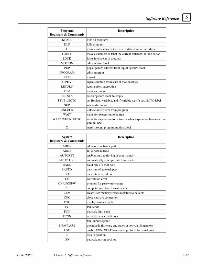
Software Reference
GFK-1848F Chapter 5 Software Reference 5-57
5
Program Registers & Commands
Description
KLALL kills all programs KLP kills program
L makes last statement the current statement in line editor LABEL makes statement at label the current statement in line editor LOCK locks interpreter to program
MOTION edits motion block POP pops "gosub" address from top of "gosub" stack
PROGRAM edits program REM remark
REPEAT repeats motion from start of motion block RETURN returns from subroutine
RSM resumes motion RSTSTK resets "gosub" stack to empty
STVB...GOTO set Boolean variable, and if variable wasn’t set, GOTO label SUP suspends motion
UNLOCK unlocks interpreter from program WAIT waits for expression to be true
WAIT..WHEN..GOTO waits for expression to be true or when expression becomes true goes to label
X steps through program/motion block
System Registers & Commands
Description
ADDN address of network port ADDR RTU port address
AUTORET enables auto retrieving of user memory AUTOTUNE automatically sets up control constants
BAUD baud rate of serial port BAUDN data rate of network port
BIT data bits of serial port CE conversion error
CHANGEPW prompts for password change CIE computer interface format enable
CLM clears user memory; resets registers to defaults CNC close network connection DSE display format enable FC fault code
FCN network fault code FCNN network device fault code
FI fault input register FIRMWARE downloads firmware and saves in nonvolatile memory
HSE enable XON, XOFF handshake protocol for serial port IP axis in position
IPN network axis in position
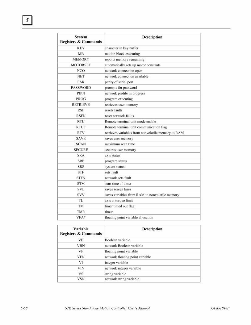
5-58 S2K Series Standalone Motion Controller User's Manual GFK-1848F
5
System Registers & Commands
Description
KEY character in key buffer MB motion block executing
MEMORY reports memory remaining MOTORSET automatically sets up motor constants
NCO network connection open NET network connection available PAR parity of serial port
PASSWORD prompts for password PIPN network profile in progress PROG program executing
RETRIEVE retrieves user memory RSF resets faults
RSFN reset network faults RTU Remote terminal unit mode enable
RTUF Remote terminal unit communication flag RTV retrieves variables from nonvolatile memory to RAM
SAVE saves user memory SCAN maximum scan time
SECURE secures user memory SRA axis status SRP program status SRS system status STF sets fault
STFN network sets fault STM start time of timer SVL saves screen lines SVV saves variables from RAM to nonvolatile memory TL axis at torque limit TM timer timed out flag
TMR timer VFA* floating point variable allocation
Variable
Registers & Commands Description
VB Boolean variable VBN network Boolean variable VF floating point variable
VFN network floating point variable VI integer variable
VIN network integer variable VS string variable
VSN network string variable
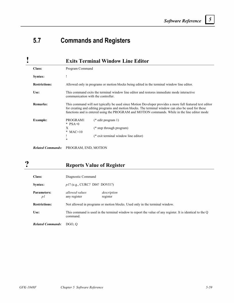
Software Reference
GFK-1848F Chapter 5 Software Reference 5-59
5
5.7 Commands and Registers
! Exits Terminal Window Line Editor Class: Program Command Syntax: ! Restrictions: Allowed only in programs or motion blocks being edited in the terminal window line editor. Use: This command exits the terminal window line editor and restores immediate mode interactive
communication with the controller. Remarks: This command will not typically be used since Motion Developer provides a more full featured text editor
for creating and editing programs and motion blocks. The terminal window can also be used for these functions and is entered using the PROGRAM and MOTION commands. While in the line editor mode
Example: PROGRAM1 (* edit program 1) * PSA=0 X (* step through program) * MAC=10 ! (* exit terminal window line editor) * Related Commands: PROGRAM, END, MOTION
? Reports Value of Register
Class: Diagnostic Command Syntax: p1? (e.g., CURC? DI4? DOVI1?) Parameters: allowed values description p1 any register register Restrictions: Not allowed in programs or motion blocks. Used only in the terminal window. Use: This command is used in the terminal window to report the value of any register. It is identical to the Q
command. Related Commands: DGO, Q
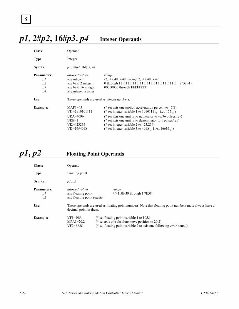
5-60 S2K Series Standalone Motion Controller User's Manual GFK-1848F
5
p1, 2#p2, 16#p3, p4 Integer Operands
Class: Operand Type: Integer Syntax: p1, 2#p2, 16#p3, p4 Parameters: allowed values range p1 any integer -2,147,483,648 through 2,147,483,647 p2 any base 2 integer 0 through 111111111111111111111111111111111 (2^32 -1) p3 any base 16 integer 00000000 through FFFFFFFF p4 any integer register Use: These operands are used as integer numbers. Example: MAP1=45 (* set axis one motion acceleration percent to 45%) VI1=2#10101111 (* set integer variable 1 to 101011112 [i.e., 17510]) URA=4096 (* set axis one unit ratio numerator to 4,096 pulses/rev) URB=1 (* set axis one unit ratio denominator to 1 pulses/rev) VI2=423234 (* set integer variable 2 to 423,234) VI3=16#40E8 (* set integer variable 3 to 40E816 [i.e., 1661610])
p1, p2 Floating Point Operands
Class: Operand
Type: Floating point Syntax: p1, p2 Parameters: allowed values range p1 any floating point +/- 1.5E-39 through 1.7E38 p2 any floating point register Use: These operands are used as floating point numbers. Note that floating point numbers must always have a
decimal point in them. Example: VF1=105. (* set floating point variable 1 to 105.) MPA1=20.2 (* set axis one absolute move position to 20.2) VF2=FEB1 (* set floating point variable 2 to axis one following error bound)
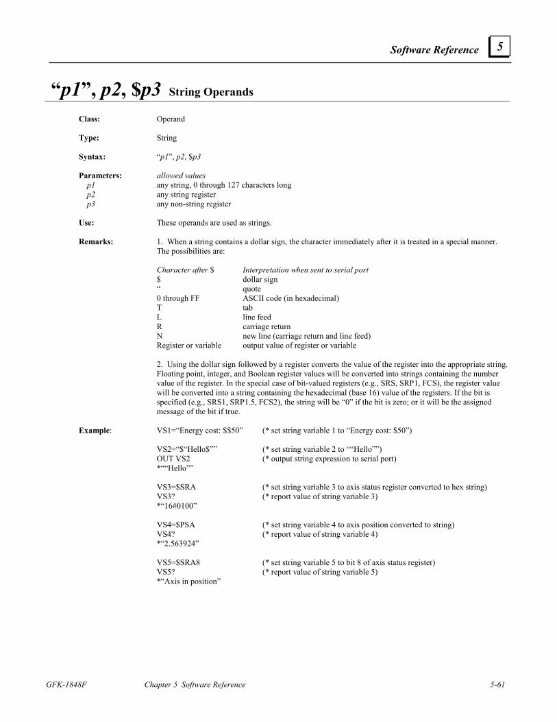
Software Reference
GFK-1848F Chapter 5 Software Reference 5-61
5
“p1”, p2, $p3 String Operands
Class: Operand Type: String Syntax: “p1”, p2, $p3 Parameters: allowed values p1 any string, 0 through 127 characters long p2 any string register p3 any non-string register Use: These operands are used as strings. Remarks: 1. When a string contains a dollar sign, the character immediately after it is treated in a special manner.
The possibilities are: Character after $ Interpretation when sent to serial port $ dollar sign “ quote 0 through FF ASCII code (in hexadecimal) T tab L line feed R carriage return N new line (carriage return and line feed) Register or variable output value of register or variable 2. Using the dollar sign followed by a register converts the value of the register into the appropriate string.
Floating point, integer, and Boolean register values will be converted into strings containing the number value of the register. In the special case of bit-valued registers (e.g., SRS, SRP1, FCS), the register value will be converted into a string containing the hexadecimal (base 16) value of the registers. If the bit is specified (e.g., SRS1, SRP1.5, FCS2), the string will be “0” if the bit is zero; or it will be the assigned message of the bit if true.
Example: VS1=“Energy cost: $$50” (* set string variable 1 to “Energy cost: $50”) VS2=“$“Hello$”” (* set string variable 2 to ““Hello””) OUT VS2 (* output string expression to serial port) *““Hello”” VS3=$SRA (* set string variable 3 to axis status register converted to hex string) VS3? (* report value of string variable 3) *“16#0100” VS4=$PSA (* set string variable 4 to axis position converted to string) VS4? (* report value of string variable 4) *“2.563924” VS5=$SRA8 (* set string variable 5 to bit 8 of axis status register) VS5? (* report value of string variable 5) *“Axis in position”
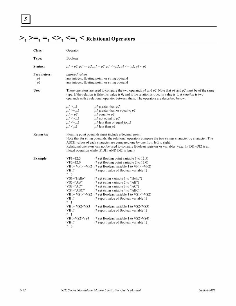
5-62 S2K Series Standalone Motion Controller User's Manual GFK-1848F
5
>, >=, =, <>, <=, < Relational Operators
Class: Operator Type: Boolean Syntax: p1 > p2, p1 >= p2, p1 = p2, p1 <> p2, p1 <= p2, p1 < p2 Parameters: allowed values p1 any integer, floating point, or string operand p2 any integer, floating point, or string operand Use: These operators are used to compare the two operands p1 and p2. Note that p1 and p2 must be of the same
type. If the relation is false, its value is 0; and if the relation is true, its value is 1. A relation is two operands with a relational operator between them. The operators are described below:
p1 > p2 p1 greater than p2 p1 >= p2 p1 greater than or equal to p2 p1 = p2 p1 equal to p2 p1 <> p2 p1 not equal to p2 p1 <= p2 p1 less than or equal to p2 p1 < p2 p1 less than p2 Remarks: Floating point operands must include a decimal point Note that for string operands, the relational operators compare the two strings character by character. The
ASCII values of each character are compared one by one from left to right. Relational operators can not be used to compare Boolean registers or variables. (e.g., IF DI1=DI2 is an
illegal operation while IF DI1 AND DI2 is legal) Example: VF1=12.5 (* set floating point variable 1 to 12.5) VF2=12.0 (* set floating point variable 2 to 12.0) VB1= VF1<=VF2 (* set Boolean variable 1 to VF1<=VF2) VB1? (* report value of Boolean variable 1) * 0 VS1=“Hello” (* set string variable 1 to “Hello”) VS2=“AB” (* set string variable 2 to “AB”) VS3=“AC” (* set string variable 3 to “AC”) VS4=“ABC” (* set string variable 4 to “ABC”) VB1= VS1<>VS2 (* set Boolean variable 1 to VS1<>VS2) VB1? (* report value of Boolean variable 1) * 1 VB1= VS2<VS3 (* set Boolean variable 1 to VS2<VS3) VB1? (* report value of Boolean variable 1) * 1 VB1=VS2>VS4 (* set Boolean variable 1 to VS2>VS4) VB1? (* report value of Boolean variable 1) * 0
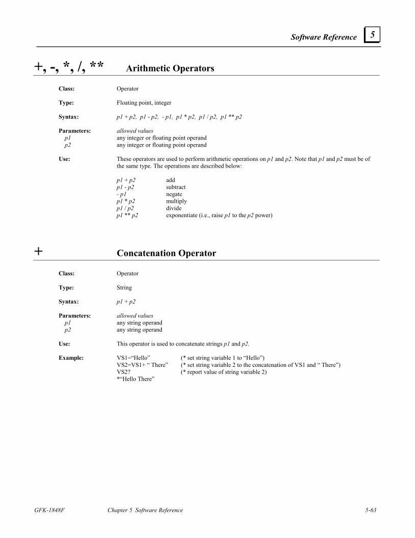
Software Reference
GFK-1848F Chapter 5 Software Reference 5-63
5
+, -, *, /, ** Arithmetic Operators
Class: Operator Type: Floating point, integer Syntax: p1 + p2, p1 - p2, - p1, p1 * p2, p1 / p2, p1 ** p2 Parameters: allowed values p1 any integer or floating point operand p2 any integer or floating point operand Use: These operators are used to perform arithmetic operations on p1 and p2. Note that p1 and p2 must be of
the same type. The operations are described below: p1 + p2 add p1 - p2 subtract - p1 negate p1 * p2 multiply p1 / p2 divide p1 ** p2 exponentiate (i.e., raise p1 to the p2 power)
+ Concatenation Operator
Class: Operator
Type: String Syntax: p1 + p2 Parameters: allowed values p1 any string operand p2 any string operand Use: This operator is used to concatenate strings p1 and p2. Example: VS1=“Hello” (* set string variable 1 to “Hello”) VS2=VS1+ “ There” (* set string variable 2 to the concatenation of VS1 and “ There”) VS2? (* report value of string variable 2) *“Hello There”
5-64 S2K Series Standalone Motion Controller User's Manual GFK-1848F
5
ABS Absolute Value Operator
Class: Operator Type: Floating point, integer Syntax: ABS(p1) Parameters: allowed values p1 any integer or floating point operand Use: This operator is used to take the absolute value of p1.
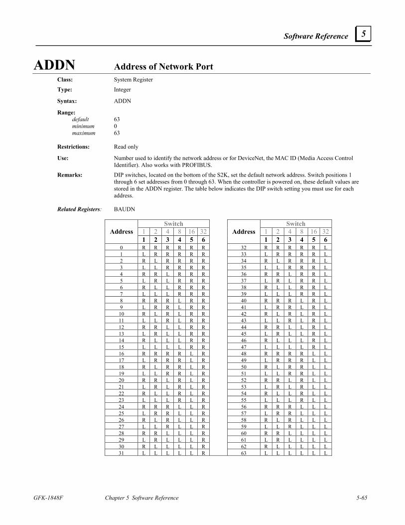
Software Reference
GFK-1848F Chapter 5 Software Reference 5-65
5
ADDN Address of Network Port Class: System Register
Type: Integer Syntax: ADDN Range: default 63 minimum 0 maximum 63 Restrictions: Read only Use: Number used to identify the network address or for DeviceNet, the MAC ID (Media Access Control
Identifier). Also works with PROFIBUS.
Remarks: DIP switches, located on the bottom of the S2K, set the default network address. Switch positions 1 through 6 set addresses from 0 through 63. When the controller is powered on, these default values are stored in the ADDN register. The table below indicates the DIP switch setting you must use for each address.
Related Registers: BAUDN
Switch Switch
1 2 4 8 16 32 1 2 4 8 16 32Address 1 2 3 4 5 6
Address 1 2 3 4 5 6
0 R R R R R R 32 R R R R R L1 L R R R R R 33 L R R R R L2 R L R R R R 34 R L R R R L3 L L R R R R 35 L L R R R L4 R R L R R R 36 R R L R R L5 L R L R R R 37 L R L R R L6 R L L R R R 38 R L L R R L7 L L L R R R 39 L L L R R L8 R R R L R R 40 R R R L R L9 L R R L R R 41 L R R L R L
10 R L R L R R 42 R L R L R L11 L L R L R R 43 L L R L R L12 R R L L R R 44 R R L L R L13 L R L L R R 45 L R L L R L14 R L L L R R 46 R L L L R L15 L L L L R R 47 L L L L R L16 R R R R L R 48 R R R R L L17 L R R R L R 49 L R R R L L18 R L R R L R 50 R L R R L L19 L L R R L R 51 L L R R L L20 R R L R L R 52 R R L R L L21 L R L R L R 53 L R L R L L22 R L L R L R 54 R L L R L L23 L L L R L R 55 L L L R L L24 R R R L L R 56 R R R L L L25 L R R L L R 57 L R R L L L26 R L R L L R 58 R L R L L L27 L L R L L R 59 L L R L L L28 R R L L L R 60 R R L L L L29 L R L L L R 61 L R L L L L30 R L L L L R 62 R L L L L L31 L L L L L R 63 L L L L L L
5-66 S2K Series Standalone Motion Controller User's Manual GFK-1848F
5
ADDR Address of RTU Port
Class: System Register Type: Integer Syntax: ADDR Range: default 1 minimum 1 maximum 247 Restrictions: Cannot be assigned in motion blocks. Available in firmware version 2.2 and higher. Use: The address of the RTU port is a number used to identify the RTU port. Related Registers: RTU
AI Analog Input
Class: Input/Output Register Type: Floating Point Syntax: AIp1 Parameters: allowed values p1 1 or 2 (analog input number) Range: units volts minimum -10.000 maximum 10.000 Restrictions: Read only. Use: Defines the value in volts of one of the two general-purpose hardware analog inputs. Example: AI1? (* report value of analog input one from the terminal window) AI2? (* report value of analog input two from the terminal window) IF AI1=5 GOTO 10 (* branch program if analog input 1 equals 5 volts) Related Registers: AO
Software Reference
GFK-1848F Chapter 5 Software Reference 5-67
5
AIB Analog Input Deadband
Class: Input/Output Register Type: Floating Point Syntax: AIBp1 (e.g., AIB1 AIB2) Parameters: allowed values p1 1 or 2 (analog input number) Range: units volts default 0 minimum 0 maximum 10.000 Restrictions: Cannot be assigned in motion blocks. Use: Defines a range over which the analog input remains constant at zero volts. When the analog input AI1 is
less than or equal to AIB1, the analog input is set to 0. When the analog input AI2 is less than or equal to AIB2, the analog input is set to 0.
Example: AIB2=1.5 (* set analog input deadband equal to 1.5 V) AIB2? (* report value of analog input deadband from the terminal window) Related Registers: AIp1
AIN Network Analog Input Class: I/O Register Type: Integer Syntax: AINp1.p2 (e.g., AIN28.2 AINVI5.6 AINVI2.VI7) Parameters: allowed values description p1 0 through 63 or VIn network address p2 1 through 64 or VIn analog input number Range: minimum -32,768 maximum 32,767 Note that these minimum and maximum values are a function of your analog input device. Refer to the
documentation for your analog input device to determine how to map its values to the motion controller. Restrictions: Read only. Cannot be accessed in immediate mode over a DeviceNet connection. Use: The network analog input is a general-purpose input used for process control. Related Registers: AON
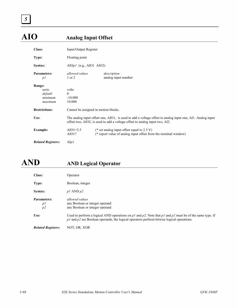
5-68 S2K Series Standalone Motion Controller User's Manual GFK-1848F
5
AIO Analog Input Offset Class: Input/Output Register Type: Floating point Syntax: AIOp1 (e.g., AIO1 AIO2) Parameters: allowed values description p1 1 or 2 analog input number Range: units volts default 0 minimum -10.000 maximum 10.000 Restrictions: Cannot be assigned in motion blocks. Use: The analog input offset one, AIO1, is used to add a voltage offset to analog input one, AI1. Analog input
offset two, AIO2, is used to add a voltage offset to analog input two, AI2. Example: AIO1=2.5 (* set analog input offset equal to 2.5 V) AIO1? (* report value of analog input offset from the terminal window) Related Registers: AIp1
AND AND Logical Operator
Class: Operator Type: Boolean, integer Syntax: p1 AND p2 Parameters: allowed values p1 any Boolean or integer operand p2 any Boolean or integer operand Use: Used to perform a logical AND operations on p1 and p2. Note that p1 and p2 must be of the same type. If
p1 and p2 are Boolean operands, the logical operators perform bitwise logical operations. Related Registers: NOT, OR, XOR
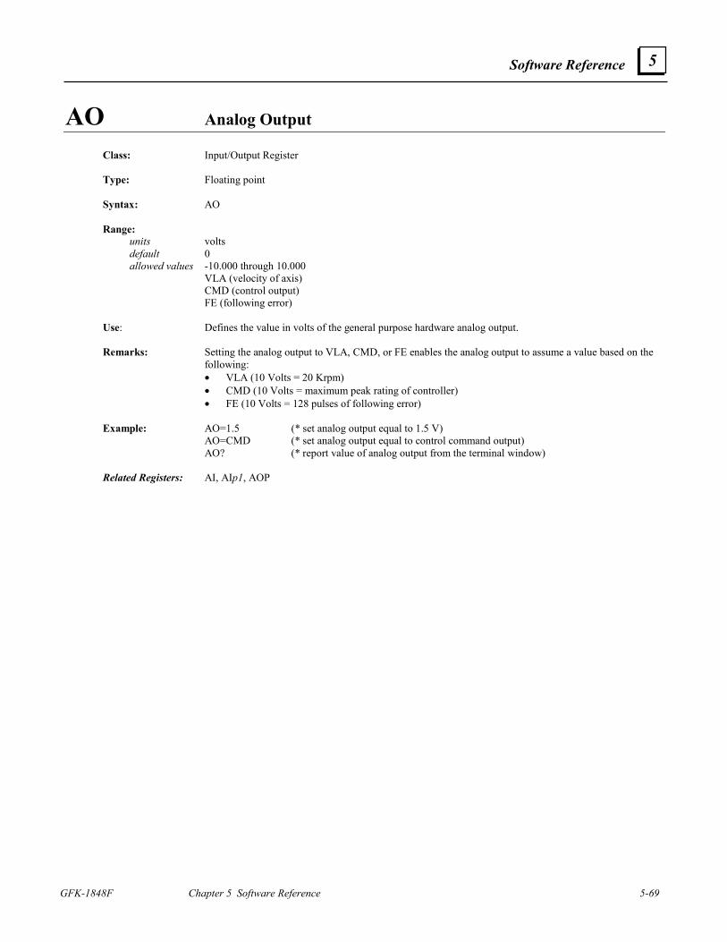
Software Reference
GFK-1848F Chapter 5 Software Reference 5-69
5
AO Analog Output Class: Input/Output Register Type: Floating point Syntax: AO Range:
units volts default 0 allowed values -10.000 through 10.000 VLA (velocity of axis) CMD (control output) FE (following error) Use: Defines the value in volts of the general purpose hardware analog output. Remarks: Setting the analog output to VLA, CMD, or FE enables the analog output to assume a value based on the
following: • VLA (10 Volts = 20 Krpm) • CMD (10 Volts = maximum peak rating of controller) • FE (10 Volts = 128 pulses of following error)
Example: AO=1.5 (* set analog output equal to 1.5 V) AO=CMD (* set analog output equal to control command output) AO? (* report value of analog output from the terminal window) Related Registers: AI, AIp1, AOP
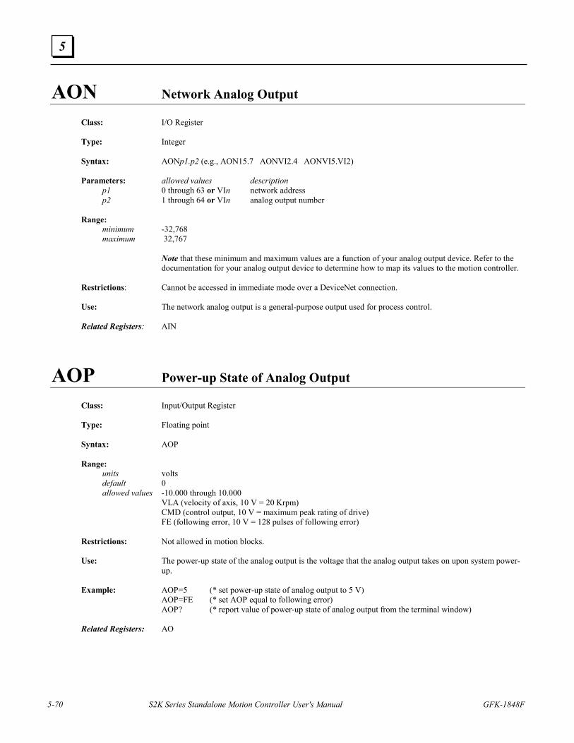
5-70 S2K Series Standalone Motion Controller User's Manual GFK-1848F
5
AON Network Analog Output Class: I/O Register Type: Integer Syntax: AONp1.p2 (e.g., AON15.7 AONVI2.4 AONVI5.VI2) Parameters: allowed values description p1 0 through 63 or VIn network address p2 1 through 64 or VIn analog output number Range: minimum -32,768 maximum 32,767 Note that these minimum and maximum values are a function of your analog output device. Refer to the
documentation for your analog output device to determine how to map its values to the motion controller. Restrictions: Cannot be accessed in immediate mode over a DeviceNet connection. Use: The network analog output is a general-purpose output used for process control. Related Registers: AIN
AOP Power-up State of Analog Output
Class: Input/Output Register Type: Floating point Syntax: AOP Range: units volts default 0 allowed values -10.000 through 10.000 VLA (velocity of axis, 10 V = 20 Krpm) CMD (control output, 10 V = maximum peak rating of drive) FE (following error, 10 V = 128 pulses of following error) Restrictions: Not allowed in motion blocks. Use: The power-up state of the analog output is the voltage that the analog output takes on upon system power-
up. Example: AOP=5 (* set power-up state of analog output to 5 V) AOP=FE (* set AOP equal to following error) AOP? (* report value of power-up state of analog output from the terminal window) Related Registers: AO
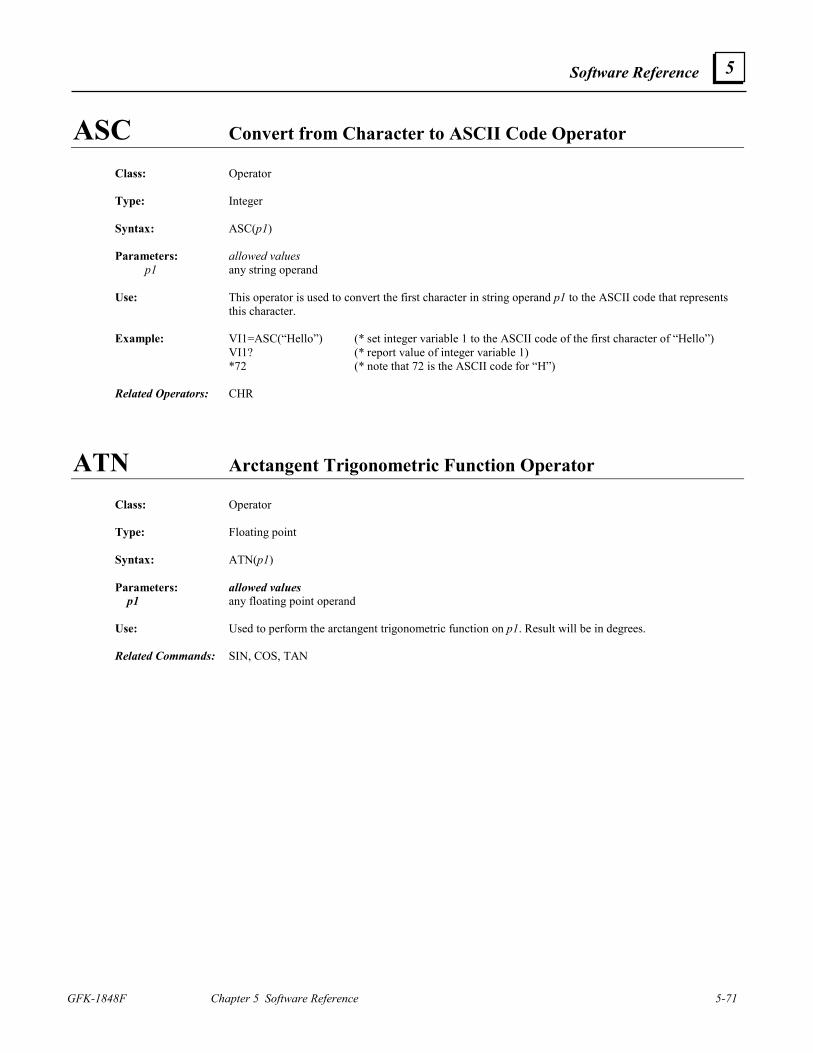
Software Reference
GFK-1848F Chapter 5 Software Reference 5-71
5
ASC Convert from Character to ASCII Code Operator
Class: Operator Type: Integer Syntax: ASC(p1) Parameters: allowed values p1 any string operand Use: This operator is used to convert the first character in string operand p1 to the ASCII code that represents
this character. Example: VI1=ASC(“Hello”) (* set integer variable 1 to the ASCII code of the first character of “Hello”) VI1? (* report value of integer variable 1) *72 (* note that 72 is the ASCII code for “H”) Related Operators: CHR
ATN Arctangent Trigonometric Function Operator Class: Operator Type: Floating point Syntax: ATN(p1) Parameters: allowed values p1 any floating point operand Use: Used to perform the arctangent trigonometric function on p1. Result will be in degrees. Related Commands: SIN, COS, TAN
5-72 S2K Series Standalone Motion Controller User's Manual GFK-1848F
5
AUTORET Enables Auto Retrieving of User Memory
Class: System Command Syntax: AUTORET Restrictions: Not allowed in programs or motion blocks. Use: This command is used to enable auto retrieving of user memory from nonvolatile memory on power-up.
This command must be included in the configuration data for the controller or the contents of the non-volatile memory will not be restored when controller power is cycled. The Motion Developer software automatically includes and saves this command when you develop and download a project.
Related Commands: RETRIEVE, SAVE
AUTOTUNE Automatically Sets Up Servo Tuning Constants Class: System Command Syntax: AUTOTUNE Restrictions: Servo only; not allowed in programs or motion blocks. Use: This command automatically sets up the control tuning constants, which are KA, KD, KI, KP, and KT. Remarks: This command will execute only when the controller is faulted, the axis Enable input is true, and no
programs or motion blocks are executing. The motor should be connected to the load when using this command. When executed, it causes the axis to move half a revolution in the forward direction. Be sure that the axis is free to move this far before executing this command. This command takes about two seconds to execute. When executed from the terminal window and the autotuning is finished, the controller will return either an asterisk (*) indicating successful completion or a question mark (?) followed by the appropriate error message. When executed from the Motion Developer Controller Function screen or main wizard page the status and/or error messages will be displayed in a pop-up dialog box. The possible error messages are as follows:
1. TORQUE TO INERTIA RATIO TOO LOW — the torque to inertia ratio of the axis is less than 125
radians/sec2. 2. TORQUE TO INERTIA RATIO TOO HIGH — the torque to inertia ratio of the axis is greater than
125,000 radians/sec2. 3. TORQUE RESPONSE NON-LINEAR — autotuning won’t work. If Autotune fails, the controller gains must be set manually using either the terminal window or the Motion
Developer Edit Axis Parameters selection on the main wizard page. Related Commands: MOTORSET Related Registers: KA, KD, KI, KP, KT, FR, CURC
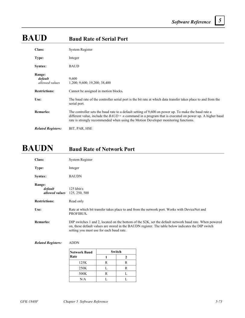
Software Reference
GFK-1848F Chapter 5 Software Reference 5-73
5
BAUD Baud Rate of Serial Port Class: System Register Type: Integer Syntax: BAUD Range: default 9,600 allowed values 1,200; 9,600; 19,200; 38,400 Restrictions: Cannot be assigned in motion blocks. Use: The baud rate of the controller serial port is the bit rate at which data transfer takes place to and from the
serial port. Remarks: The controller sets the baud rate to a default setting of 9,600 on power up. To make the baud rate a
different value, include the BAUD = n command in a program that is executed on power up. A higher baud rate is strongly recommended when using the Motion Developer monitoring functions.
Related Registers: BIT, PAR, HSE
BAUDN Baud Rate of Network Port
Class: System Register Type: Integer Syntax: BAUDN Range: default 125 kbit/s allowed values 125, 250, 500 Restrictions: Read only Use: Rate at which bit transfer takes place to and from the network port. Works with DeviceNet and
PROFIBUS. Remarks: DIP switches 1 and 2, located on the bottom of the S2K, set the default network baud rate. When powered
on, these default values are stored in the BAUDN register. The table below indicates the DIP switch setting you must use for each baud rate.
Related Registers: ADDN
Switch Network Baud
Rate 1 2 125K R R 250K L R 500K R L N/A L L
5-74 S2K Series Standalone Motion Controller User's Manual GFK-1848F
5
BIT Data bits of Serial Port Class: System Register Type: Integer Syntax: BIT Range: default 7 allowed values 7, 8 Restrictions: Cannot be assigned in motion blocks. Use: The number of data bits used to transfer characters to and from the serial port. Remarks: Setting parity, PAR, to NONE and BIT to 7 at the same time is not allowed. This register defaults to 7 on
power-up. Related Registers: BAUD, PAR, HSE
BS Cursor Backspace
Class: Input/Output Command Syntax: BS Use: This command backspaces the cursor on the display. Remarks: This command is used in conjunction with an ASCII operator display when the controller has display
format enabled (DSE = 1). When executed this command writes ASCII character $08 to the controller serial port.
Related Commands: CR, CRH, CRP Related Registers: DSE ASCII Code: $08
Software Reference
GFK-1848F Chapter 5 Software Reference 5-75
5
CAE Cam Enable
Class: Motion Register Type: Boolean Syntax: CAE Range: default 0 allowed values 0, 1 Use: Used to enable cam motion. If CAE is set to 1, then cam motion is enabled. If CAE is set to 0, cam motion
is disabled. Remarks: When the cam is initially enabled (CAE=1) the controller reads the current cam master position in register
CAP and generates an absolute move on the axis to its position that corresponds to that master position in the cam table. Current accel (MAC/MAP), decel (MDC/MDP) and velocity (MVL) constraints are used for this move. CAE is reset to zero when a fault occurs or the cam table is zeroed using the CAZ command.
Related Registers: CAM, CAO, CAP, CAS, CAF, CAI, CAR, CAT, CAZ Motion Templates: Electronic camming
CAF Cam Filter Constant
Class: Motion Register Type: Integer Syntax: CAF Range: default 0 minimum 0 maximum 3 Use: Used to smooth the motion of the axis when using cam following. A moving average filter of 1, 4, 8, or 16
past values of the cam master input is selected by the corresponding values of 0, 1, 2, or 3 for the cam filter constant.
Remarks: As the length of the moving average filter increases, the axis will increasingly lag the correct cam position.
Use as little filtering as the application will allow. The SAVE command does not save cam parameters to FLASH (nonvolatile) memory. Your program
must set these registers before enabling cam operation. Only the points defined by the CAM register are saved to FLASH using the SAVE command (firmware version 2.5 or higher).
5-76 S2K Series Standalone Motion Controller User's Manual GFK-1848F
5
CAI Cam Position Register Increment
Class: Motion Register Type: Integer Syntax: CAI Range: units degrees/sec default 0 minimum -10,000 maximum 10,000 Use: Defines the rate at which to increment the cam position register, CAR, when a virtual (time-based) cam
master is required Remarks: Use when Cam Shaft Position Type, CAT, is set to CAR which selects the virtual (time-based) cam
master. This command is not used when CAT is set to PSX, which selects the auxiliary encoder as the cam master input source. CAI determines rate at which the Cam Position Register (CAR) is loaded with a new cam master position.
The SAVE command does not save cam parameters to FLASH (nonvolatile) memory. Your program
must set these registers before enabling cam operation. Only the points defined by the CAM register are saved to FLASH using the SAVE command (firmware version 2.5 or higher).
Example: CAT=CAR (* use internal time-base as cam master source) CAI=10 (* set cam master register, CAR, to increment at 10 degrees/second) Related Registers: CAR, CAT
Software Reference
GFK-1848F Chapter 5 Software Reference 5-77
5
CAM Cam Point Class: Motion Register Type: Floating point Syntax: CAMp1 (e.g., CAM1 CAM32.4 CAMVI4) Parameters: allowed values description p1 0.0 through 359.9 cam position in degrees or VIn cam position in degrees times ten Range: units axis units default 0 pulses minimum -2,000,000,000 pulses maximum 2,000,000,000 pulses Use: Used to define the axis absolute position at the specified cam master position for each point in a cam
table. Remarks: 1. The cam table comprises 3,600 cam points that are always equally spaced at 0.1 degree increments. The
user may not need to enter every point in the table since the controller fills in any missing cam points by linearly interpolating between the points entered by the user.
2. The Zero Cam Table, CAZ, command should be executed before a new set of cam points are entered. This command clears the cam table of all previous data points and disables the cam function (CAE=0).
3. The controller can only store one cam table at a time. If multiple tables are required, subsequent tables must be loaded after the current table execution is completed. The controller variables can be used to store additional tables.
4. The numerical values for the minimum and maximum value of this register assume that the Axis Unit Ratio, (URA/URB), is set at its default value of 1. If (URA/URB) is set to a value other than 1, the default values will change according to:
Minimum = -2,000,000,000 pulses/(URA/URB) Maximum = 2,000,000,000 pulses/(URA/URB) 5. The axis will make an absolute move to the axis position that corresponds to the current cam master
position (CAP) at the instant the cam is enabled (CAE=1 is executed). 6. The Cam Scale Factor (CAS) command is used to scale the magnitude of every axis position value in
the cam table. The programmer must ensure that all cam points multiplied by the Cam Scale Factor (CAS) are within the settings for the software overtravel limits (OTR and OTF) as follows:
OTR ≤ CAM*CAS ≤ OTF 7. The cam table positions wrap at either end of the table, and the cam profile executes continuously until
camming is disabled. Notes regarding CAM memory allocation: 8. If the axis move distance between two consecutive points is very large the controller may fault on
following error. 9. The Cam Enable register (CAE) is reset to zero when a fault occurs or when the cam table is cleared
(CAZ). 10. When the cam is disabled while the cam is running, the axis motor decelerates to zero speed as quickly
as the system constraints allow (similar to executing a HALT command). 11. NOTE: Cam memory is shared with program memory. The S2K has 60K of RAM available for user
program memory and the cam table. Once a cam point is entered or queried, 14K of RAM will be allocated for the cam table, leaving 46K of RAM for the user program memory space. Likewise, if the cam compile start position (CCP) is entered or queried, 14K of RAM will be dedicated for the CAM table.
12. As of S2K firmware revision 2.5, the cam table is saved from RAM to flash memory using the SAVE command. The cam table will be automatically retrieved on power up. The CLM command will clear the
5-78 S2K Series Standalone Motion Controller User's Manual GFK-1848F
5
cam table and the cam table memory allocation (reallocating all 60K of RAM to user program memory). If a cam point is queried (i.e., allocating 14K of RAM to the CAM table), and a SAVE is executed, the controller will then power-up with the CAM memory allocation. CLM (Clear User Memory) will reallocate RAM to program memory space only while the unit is still powered-up. To have the unit power-up in the “all program memory” mode after it has saved the CAM allocation flag, enter CLM followed by the SAVE command. See the CLM description Remarks for the precautions recommended when using the CLM command.
Example: CAZ (* zero cam table) CAM0=0 (* set axis position at 0 degrees to 0 axis units) CAM180=10 (* set axis position at 180 degrees to 10 axis units) CAM0=0 (* fill rest of cam table) CAP=0 (* initialize the cam master position to zero CAE=1 (* enable cam following) What Will Happen: The cam table is cleared and the three CAM data points construct an absolute move on the axis from zero
to absolute position 10 and then back to zero. When the cam is enabled the controller reads the current master position (CAP which was initialized to zero) and moves the axis to its corresponding position from the cam table (in this case 0). The axis executes the 0-10-0 profile continuously until camming is disabled.
Related Commands: CAZ, CAE, CAO, CAS, CAT
Software Reference
GFK-1848F Chapter 5 Software Reference 5-79
5
CAO Cam Offset
Class: Motion Register Type: Floating point Syntax: CAO Range: units degrees default 0 minimum -180.0 maximum 180.0 Use: Used to define an offset on the cam master position. This has the effect of shifting all points on the cam
table by the offset value and is often used to set phasing or timing of the cam relative to other motion on the machine.
Remarks: The value of the CAO register does not change the value stored in the PSX, CAR or CAP position
registers. The value of CAO is summed with the value in the CAP register to offset the position of the cam master.
The SAVE command does not save cam parameters to FLASH (nonvolatile) memory. Your program
must set these registers before enabling cam operation. Only the points defined by the CAM register are saved to FLASH using the SAVE command (firmware version 2.5 or higher).
5-80 S2K Series Standalone Motion Controller User's Manual GFK-1848F
5
CAP Cam Shaft Position
Class: Motion Register Type: Floating point Syntax: CAP Range: units degrees minimum 0.000 maximum 359.999 Restrictions: Read only Use: This register is used to determine the cam shaft (master) position within the defined 0-359.999 degree
master cycle. Remarks: The defining input for this register is selected by the Cam Shaft Position Type, CAT, register. If CAT is
set to CAR , then the CAP command will report the cam master position based on the value of the internal time-based Cam Position Register (CAR). If CAT is set to PSX, then the CAP command will report the cam master position based on the value of the Auxiliary (encoder) Position register (PSX). This register cannot be set directly. When CAT=PSX, the Auxiliary Position Length (PLX) register is used to set the range of auxiliary encoder travel required to generate one complete cam cycle. For example, if the auxiliary encoder is a 1000 line device (4000 pulses) and the desired scaling is one auxiliary encoder revolution for one cam cycle (0-360 degrees span on CAP register), the PLX register must be set to 2000 pulses (since PLX sets the aux. encoder position rollover to ± PLX, one half the number of pulses for an encoder revolution are used). This configuration will cause CAP to count from 0-180 degrees as PSX counts from 0-1999 pulses. PSX then rolls over to –2000 pulses and counts back to zero as CAP completes the cycle from 181-359.999 degrees.
Related Registers: CAT, CAR, PLX, PSX
Software Reference
GFK-1848F Chapter 5 Software Reference 5-81
5
CAR Cam Position Register
Class: Motion Register Type: Floating point Syntax: CAR Range: units degrees default 0 minimum 0.000 maximum 359.999 Use: Used to define an internal time-base as a virtual master for cam following. Remarks: The cam shaft position, CAP, is set to the value of this register when the Cam Shaft Position Type (CAT)
is set to CAR. In this case the index rate for this register is defined by the Cam Position Register Increment (CAI) command in degrees/second. The CAR register increments at the rate defined by CAI while the cam function is enabled (CAE=1) and stops incrementing when camming is disabled (CAE=0). Camming can be enabled/disabled by a program and is automatically disabled when a controller fault occurs or the cam table is cleared (CAZ command is executed).
The SAVE command does not save cam parameters to FLASH (nonvolatile) memory. Your program
must set these registers before enabling cam operation. Only the points defined by the CAM register are saved to FLASH using the SAVE command (firmware version 2.5 or higher).
Related Registers: CAT, CAI
CAS Cam Scale Factor Class: Motion Register Type: Floating point Syntax: CAS Range: default 1 minimum .010000 maximum 100.000000 Use: Defines a scale factor to be applied to the magnitude of every axis position value entered in the cam point
table. Remarks: The Cam Scale Factor allows the user to create normalized cam tables that can then be rescaled for
different parts. The SAVE command does not save cam parameters to FLASH (nonvolatile) memory. Your program
must set these registers before enabling cam operation. Only the points defined by the CAM register are saved to FLASH using the SAVE command (firmware version 2.5 or higher).
Related Registers: CAM
5-82 S2K Series Standalone Motion Controller User's Manual GFK-1848F
5
CAT Cam Shaft Position Type
Class: Motion Register Syntax: CAT Range: allowed values PSX (auxiliary encoder position used as cam master source) CAR (Internal time-base used as virtual cam master source) Restrictions: Cannot be used in expressions. Use: Selects the position register to use as the source for the cam master input. For normal cam following, CAT
should be set to PSX. This makes the axis track the auxiliary encoder on the cam shaft. To make the axis move without the physical cam shaft turning, set CAT to CAR and set CAI to increment CAR at the desired rate.
Remarks: The SAVE command does not save cam parameters to FLASH (nonvolatile) memory. Your program
must set these registers before enabling cam operation. Only the points defined by the CAM register are saved to FLASH using the SAVE command (firmware version 2.5 or higher).
Example: CAT=CAR (* use internal time-base as cam master input source) CAT=PSX (* use auxiliary encoder as cam master input source CAI=100 (* set increment to 100 degrees/sec) Related Registers: PSX, CAR, CAP, CAI, CAM
CAZ Zeros Cam Table
Class: Motion Command Syntax: CAZ Use: This command zeros the cam table. This must be done before a new set of cam points is entered. Related Registers: CAM Motion Templates: Electronic camming
Software Reference
GFK-1848F Chapter 5 Software Reference 5-83
5
CCB Cam Compile Begin Point
Class: Motion Register Type: Floating point Syntax: CCB Range: units degrees default 0 minimum 0.0 maximum 359.9 Use: This register is used to define the beginning master position for compiling the cam motion. Related Registers: CCE Related Commands: CCM
CCE Cam Compile End Point
Class: Motion Register Type: Floating point Syntax: CCE Range: units degrees default 0 minimum 0.0 maximum 359.9 Use: Used to define the ending master position for compiling the cam motion. Related Registers: CCB Related Commands: CCM
5-84 S2K Series Standalone Motion Controller User's Manual GFK-1848F
5
CCM Compiles Cam Motion
Class: Motion Command Syntax: CCM Use: This command compiles motion into the cam table. Axis motion starts at the Cam Compile Start Position
(CCP) and ends at the value specified for the axis absolute move (MPA). The axis position data is put in the cam table starting at the cam master position specified by the Cam Compile Begin Point (CCB) and ending at the Cam Compile End Point (CCE). The axis motion is also defined by the usual parameters MAP, MDP, and MJK.
Remarks: The cam table can be populated with known master/slave position point pairs using simply the Cam Point
(CAM) command. However, the Cam Compile (CCM) command allows the user to break the cam cycle into segments (specific range of cam master motion) and define an axis absolute motion profile for each segment. The compile command computes the cam points in the required 0.1 degree increments and populates the cam table accordingly. It is necessary to define segments that encompass the entire 360 degree cam cycle.
Example: CCB=60 (* set cam compile beginning point to 60 degrees) CCE=250 (* set cam compile ending point to 250 degrees) CCP=0 (* set starting axis position to 0) MPA=10 (* set ending axis position to absolute position 10) MAP=30 (* set acceleration/deceleration percent to 30) MJK=100 (* set jerk percent to 100) CCM (* compile axis motion into the cam table) Related Registers: CCB, CCE, CCP, CCM, MPA, MAP, MDP, MJK Motion Templates: Electronic camming
Software Reference
GFK-1848F Chapter 5 Software Reference 5-85
5
CCP Cam Compile Start Position
Class: Motion Register Type: Floating point Syntax: CCP Range: units axis units default 0 pulses minimum -2,000,000,000 pulses maximum 2,000,000,000 pulses Use: This register is used to define the starting position of the axis for compiling the cam motion. Remarks: The numerical values for the default, minimum, and maximum of this register are assuming that the axis
unit ratio, (URA/URB), is set at its default value of 1. If the axis unit ratio is set to a value other than 1, the default, minimum, and maximum values will change appropriately (see URA and URB).
Related Registers: MPA Related Commands: CCM
CE Conversion Error Class: System Register Type: Boolean Syntax: CEp1 (e.g., CE1 CEVI4) Parameters: allowed values description p1 1 through 4 or Vin program number Range: allowed values 0 or 1 Restrictions: Read only. Use: The conversion error operand is used to determine whether a conversion operation in one of the programs
worked correctly. A conversion error occurs when one data type (e.g., string) is converted to another type (e.g., floating point) and results in invalid data. If a conversion in program p1 resulted in a conversion error, CEp1 is set to 1; and if no error has occurred, CEp1 is set to 0. Note that CEp1 is updated after every conversion in program p1.
Example: CEVI1? (* report conversion error for program VI1) Related Registers: SRP, ASC, CHR, ITF, STF, FTI, STI, FTS, ITB, ITH, ITS, ITD, ITT
5-86 S2K Series Standalone Motion Controller User's Manual GFK-1848F
5
CHANGEPW Prompts for Password Change
Class: System Command Syntax: CHANGEPW Restrictions: Not allowed in programs or motion blocks. Use: This command is used to prompt the user for an initial password or a password change. Remarks: If there is no existing password the CHANGEPW command will prompt for a new password. After the
new password has been entered, the controller will prompt for the new password again for verification. If a password already exists the controller will prompt for the old password. After the old password has been entered, the controller will then prompt for the new password. The password can be from four to ten characters long. After the new password has been entered, the controller will prompt for the new password again for verification. Once this has been entered, the password will be changed to the new value. By entering no characters when prompted for the new password, the password function will be disabled.
WARNING: Once set there is no way to recover normal use of the controller without a valid
password. Be sure to record the password and store in a safe location. Related Commands: PASSWORD
CHR Convert from ASCII Code to Character Operator
Class: Operator Type: String Syntax: CHR(p1) Parameters: allowed values p1 any integer operand Use: This operator is used to convert the ASCII code p1 to the character represented by ASCII code p1. Example: VS1=CHR(65) (* set string variable VS1 to the character represented by ASCII code 65) VS1? (* report value of string variable VS1 in the terminal window) * “A” Related Operators: ASC
Software Reference
GFK-1848F Chapter 5 Software Reference 5-87
5
CIE Computer Interface Format Enable Class: System Register Type: Boolean Syntax: CIE Range: default 0 allowed values 0, 1 Restrictions: Cannot be assigned in motion blocks. Use: The computer interface format enable register is used to define whether the computer interface format on
the serial/program port is enabled. If CIE is set to 1, computer interface format is enabled, and if set to 0, computer interface format is disabled.
Remarks: When the computer interface format is enabled, queries to fault and status registers return numerical values
instead of message strings. See Chapter 7 for fault and status register details. Related Registers: HSE, FC, FI, IO, SRA, SRP, SRS
CLL Clears Line and Positions Cursor at Beginning of Line
Class: Input/Output Command Syntax: CLL Use: This command clears the current line and positions the cursor at the beginning of the line on the display. Remarks: This command is used in conjunction with the display when DSE is set to 1. Related Commands: CLS Related Registers: DSE ASCII Codes: $1B$49
5-88 S2K Series Standalone Motion Controller User's Manual GFK-1848F
5
CLM Clears User Memory; Resets Registers to Defaults
Class: System Command Syntax: CLM Restrictions: Not allowed in programs or motion blocks. Use: This command removes all programs and motion blocks from the controller’s SRAM memory and resets
all registers to default values. Remarks: 1. This command is irreversible; you cannot retrieve any programs, motion blocks, or registers that you
have previously set after you execute this command. 2. This command is entered in the terminal window and will execute only when the controller is faulted
and no programs or motion blocks are executing. 3. A Program 4 that is designed to unconditionally reset faults makes it impossible to place the controller
in a faulted state, thereby preventing the use of the CLM command, which will prevent proper download to the target.
Notes regarding CAM memory allocation: NOTE: Cam memory is shared with program memory. The S2K has 60K of RAM available for user
program memory and the cam table. Once a cam point is entered or queried, 14K of RAM will be allocated for the cam table, leaving 46K of RAM for the user program memory space. Likewise, if the cam compile start position (CCP) is entered or queried, 14K of RAM will be dedicated for the CAM table.
As of S2K firmware revision 2.5, the cam table is saved from RAM to flash memory using the SAVE command. The cam table will be automatically retrieved on power up. The CLM command will clear the cam table and the cam table memory allocation (reallocating all 60K of RAM to user program memory). If a cam point is queried (i.e., allocating 14K of RAM to the CAM table), and a SAVE is executed, the controller will then power-up with the CAM memory allocation. CLM will reallocate RAM to program memory space only while the unit is still powered-up. To have the unit power-up in the “all program memory” mode after it has saved the CAM allocation flag, enter CLM followed by the SAVE command.
Software Reference
GFK-1848F Chapter 5 Software Reference 5-89
5
CLS Clears Display and Positions Cursor at Home Class: Input/Output Command Syntax: CLS Use: This command clears the display and positions the cursor at home (i.e., the first column of the first line of
the display). Remarks: This command is used in conjunction with the display when DSE is set to 1. Related Commands: CLL Related Registers: DSE ASCII Codes: $1B$4A
CMD Position Controller Commanded Output Class: Axis Register Type: Floating point Syntax: CMD Range: units % minimum -20,000.0 maximum 20,000.0 Restrictions: Read only. Use: The position controller commanded output is used to control the position of the axis. It is a percentage of
the controller continuous current setting, CURC. For KI = KD =0, use the following formula:
FE * KP CMD = 16,384 * CURC
Example: CMD? (* report position command output from the terminal window) Related Registers: CURC
5-90 S2K Series Standalone Motion Controller User's Manual GFK-1848F
5
CMO Commutation Angle Offset (Servo Only)
Class: Axis Register Type: Floating point Syntax: CMO Range: units degrees encoder feedback controllers default -90.0 resolver feedback controllers default 90.0 minimum -180.0 maximum 180.0 Restrictions: Brushless servo only. Use: The commutation angle offset of the motor is determined by the motor selected for use with the controller.
For GE Fanuc motors this value is set automatically by Motion Developer to the correct value for the motor model selected and typically will not require adjustment by the user. CMO values associated with GE Fanuc motor models are as follows:
Motor Model CMO Value S-Series -90 MTR-3N Series 90 MTR-3S Series -90 MTR-3T Series 90
If necessary, this value can be set automatically by the MOTORSET command. Only experienced users
should make adjustments to this setting after consulting GE Fanuc for assistance. Related Registers: None Related Commands: MOTORSET
Software Reference
GFK-1848F Chapter 5 Software Reference 5-91
5
CMR Motor Poles to Resolver Poles Commutation Ratio
Class: Axis Register Type: Integer Syntax: CMR Range: default Resolver feedback = 3; Encoder feedback = 1 minimum 1 maximum 16 Restrictions: Brushless servo only Use: Resolver Feedback The motor poles to resolver poles commutation ratio is one of the motor constants needed to operate a
servo motor with resolver feedback. This value, along with the value of CMO, can be set automatically by the MOTORSET command
Encoder Feedback For encoder-based controllers using third-party encoder-based motors, this register must be set to the
number of motor pole pairs (requires firmware revision 2.5 and later). NOTE: To run GE Fanuc S-Series servo motors, the CMR value must be set to 1, which is the controller default and the value set by the Motion Developer configuration wizard. Setting CMR=1 will automatically set FRC=10000 (firmware revision 2.5 and later). The CMR register can be set automatically with the MOTORSET command (see MOTORSET description for procedure).
Related Registers: CMO, FRC Related Commands: MOTORSET
CNC Close Network Connection
Class: System Command Syntax: CNCp1 Parameters: allowed values description p1 0 through 63 or VIn network address Restrictions: Cannot be accessed in immediate mode over a DeviceNet connection. Use: This command closes the network connection to the device addressed at p1. Related Registers: NCO
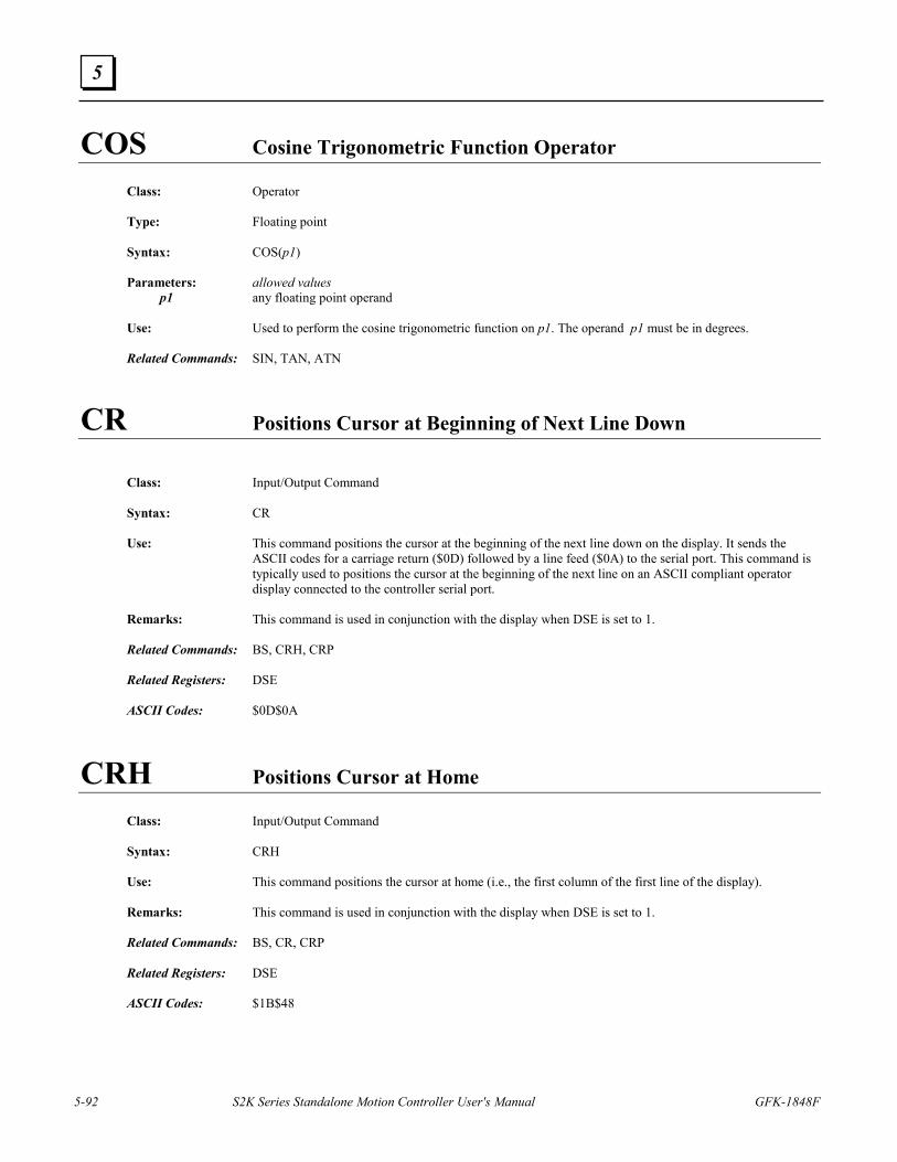
5-92 S2K Series Standalone Motion Controller User's Manual GFK-1848F
5
COS Cosine Trigonometric Function Operator
Class: Operator Type: Floating point Syntax: COS(p1) Parameters: allowed values p1 any floating point operand Use: Used to perform the cosine trigonometric function on p1. The operand p1 must be in degrees. Related Commands: SIN, TAN, ATN
CR Positions Cursor at Beginning of Next Line Down
Class: Input/Output Command Syntax: CR Use: This command positions the cursor at the beginning of the next line down on the display. It sends the
ASCII codes for a carriage return ($0D) followed by a line feed ($0A) to the serial port. This command is typically used to positions the cursor at the beginning of the next line on an ASCII compliant operator display connected to the controller serial port.
Remarks: This command is used in conjunction with the display when DSE is set to 1. Related Commands: BS, CRH, CRP Related Registers: DSE ASCII Codes: $0D$0A
CRH Positions Cursor at Home Class: Input/Output Command Syntax: CRH Use: This command positions the cursor at home (i.e., the first column of the first line of the display). Remarks: This command is used in conjunction with the display when DSE is set to 1. Related Commands: BS, CR, CRP Related Registers: DSE ASCII Codes: $1B$48

Software Reference
GFK-1848F Chapter 5 Software Reference 5-93
5
CRM Remembers Cursor Position Class: Input/Output Command Syntax: CRM Use: This command is used to remember the current position of the cursor. Remarks: CRM is used in conjunction with the display when DSE is set to 1. Related Commands: CRR ASCII Codes: $1B$3F
CRP Positions Cursor Class: Input/Output Command Syntax: CRPp1.p2 (e.g, CRP1.3 CRPVI2.3 CRP2.VI1 CRPVI1.VI2) Parameters: allowed values description p1 1 to 4 or VIn line position p2 1 to 40 or VIn column position Use: This command positions the cursor on line p1, column p2 of the display. Remarks: This command is used in conjunction with the display when DSE is set to 1. Example: CRP1.2 (* position cursor at line 1, column 2 of the display) CRP1.VI1 (* position cursor at line 1, column VI1 of the display) Related Commands: BS, CR, CRH Related Registers: DSE ASCII Codes: $1B$46 $(p2+20h) $(p1+20h)
CRR Positions Cursor at Remembered Position Class: Input/Output Command Syntax: CRR Use: This command is used to place the cursor at the position remembered by the CRM command. Remarks: This command is used in conjunction with the display when DSE is set to 1. Related Commands: CRM Related Registers: DSE ASCII Codes: $1B$40
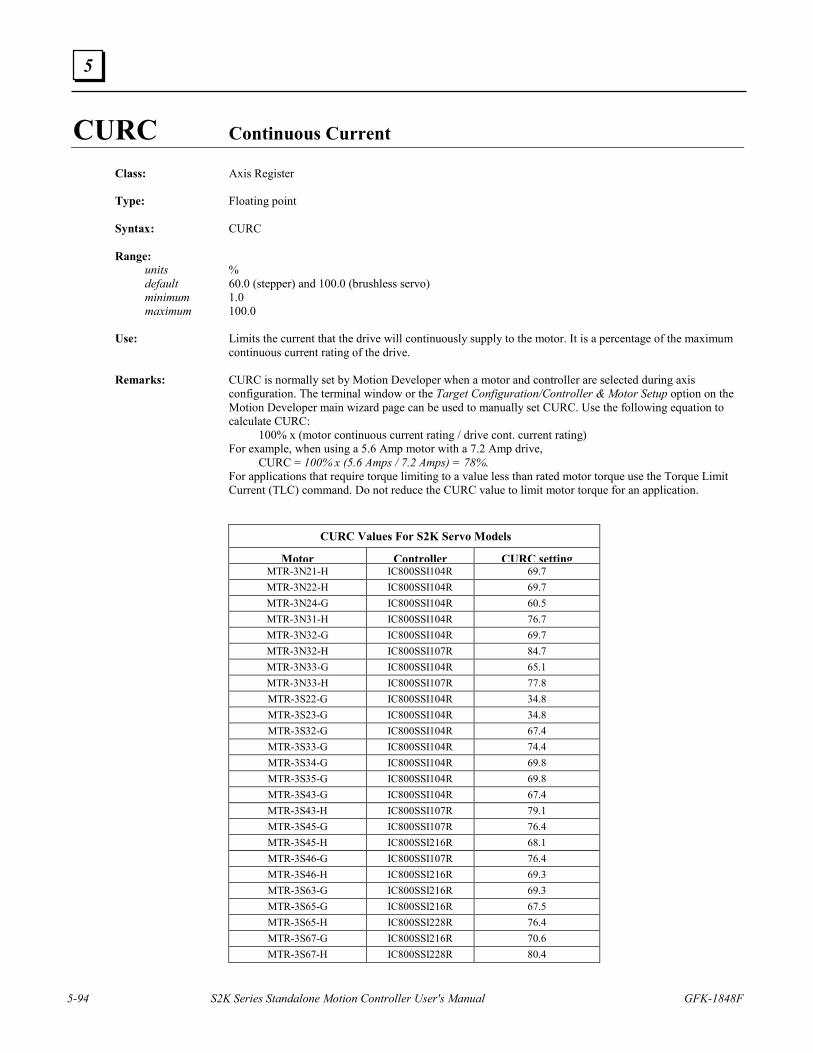
5-94 S2K Series Standalone Motion Controller User's Manual GFK-1848F
5
CURC Continuous Current Class: Axis Register Type: Floating point Syntax: CURC Range: units % default 60.0 (stepper) and 100.0 (brushless servo) minimum 1.0 maximum 100.0 Use: Limits the current that the drive will continuously supply to the motor. It is a percentage of the maximum
continuous current rating of the drive. Remarks: CURC is normally set by Motion Developer when a motor and controller are selected during axis
configuration. The terminal window or the Target Configuration/Controller & Motor Setup option on the Motion Developer main wizard page can be used to manually set CURC. Use the following equation to calculate CURC:
100% x (motor continuous current rating / drive cont. current rating) For example, when using a 5.6 Amp motor with a 7.2 Amp drive, CURC = 100% x (5.6 Amps / 7.2 Amps) = 78%. For applications that require torque limiting to a value less than rated motor torque use the Torque Limit
Current (TLC) command. Do not reduce the CURC value to limit motor torque for an application.
CURC Values For S2K Servo Models
Motor Controller CURC settingMTR-3N21-H IC800SSI104R 69.7 MTR-3N22-H IC800SSI104R 69.7 MTR-3N24-G IC800SSI104R 60.5 MTR-3N31-H IC800SSI104R 76.7 MTR-3N32-G IC800SSI104R 69.7 MTR-3N32-H IC800SSI107R 84.7 MTR-3N33-G IC800SSI104R 65.1 MTR-3N33-H IC800SSI107R 77.8 MTR-3S22-G IC800SSI104R 34.8 MTR-3S23-G IC800SSI104R 34.8 MTR-3S32-G IC800SSI104R 67.4 MTR-3S33-G IC800SSI104R 74.4 MTR-3S34-G IC800SSI104R 69.8 MTR-3S35-G IC800SSI104R 69.8 MTR-3S43-G IC800SSI104R 67.4 MTR-3S43-H IC800SSI107R 79.1 MTR-3S45-G IC800SSI107R 76.4 MTR-3S45-H IC800SSI216R 68.1 MTR-3S46-G IC800SSI107R 76.4 MTR-3S46-H IC800SSI216R 69.3 MTR-3S63-G IC800SSI216R 69.3 MTR-3S65-G IC800SSI216R 67.5 MTR-3S65-H IC800SSI228R 76.4 MTR-3S67-G IC800SSI216R 70.6 MTR-3S67-H IC800SSI228R 80.4
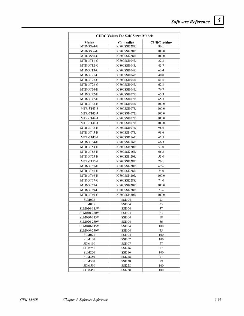
Software Reference
GFK-1848F Chapter 5 Software Reference 5-95
5
CURC Values For S2K Servo Models
Motor Controller CURC settingMTR-3S84-G IC800SSI228R 96.1 MTR-3S86-G IC800SSI228R 100.0 MTR-3S88-G IC800SSI228R 100.0 MTR-3T11-G IC800SSI104R 22.3 MTR-3T12-G IC800SSI104R 43.7 MTR-3T13-G IC800SSI104R 63.4 MTR-3T21-G IC800SSI104R 40.0 MTR-3T22-G IC800SSI104R 61.6 MTR-3T23-G IC800SSI104R 62.8 MTR-3T24-H IC800SSI104R 76.7 MTR-3T42-H IC800SSI107R 65.3 MTR-3T42-H IC800SSI407R 65.3 MTR-3T43-H IC800SSI104R 100.0 MTR-3T43-J IC800SSI107R 100.0 MTR-3T43-J IC800SSI407R 100.0 MTR-3T44-J IC800SSI107R 100.0 MTR-3T44-J IC800SSI407R 100.0 MTR-3T45-H IC800SSI107R 98.6 MTR-3T45-H IC800SSI407R 98.6 MTR-3T45-I IC800SSI216R 62.5 MTR-3T54-H IC800SSI216R 66.3 MTR-3T54-H IC800SSI420R 53.0 MTR-3T55-H IC800SSI216R 66.3 MTR-3T55-H IC800SSI420R 53.0 MTR-3T55-I IC800SSI228R 76.1 MTR-3T57-H IC800SSI228R 69.6 MTR-3T66-H IC800SSI228R 74.0 MTR-3T66-H IC800SSI420R 100.0 MTR-3T67-G IC800SSI228R 74.0 MTR-3T67-G IC800SSI420R 100.0 MTR-3T69-G IC800SSI228R 73.6 MTR-3T69-G IC800SSI420R 100.0
SLM003 SSI104 23SLM005 SSI104 23
SLM010-115V SSI104 37SLM010-230V SSI104 23SLM020-115V SSI104 58SLM020-230V SSI104 36SLM040-115V SSI104 100SLM040-230V SSI104 55
SLM075 SSI104 100SLM100 SSI107 100SDM100 SSI107 77SDM250 SSI216 87SLM250 SSI216 100SLM350 SSI228 77SLM500 SSI228 99SDM500 SSI228 100SGM450 SSI228 100
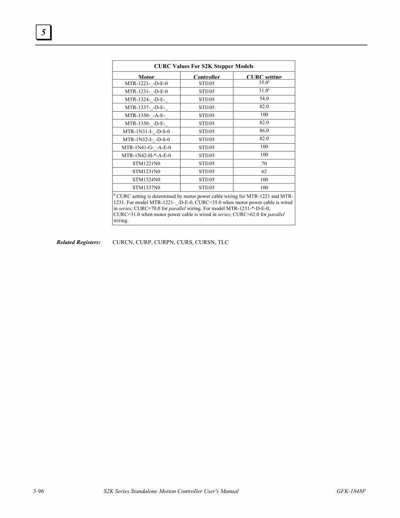
5-96 S2K Series Standalone Motion Controller User's Manual GFK-1848F
5
CURC Values For S2K Stepper Models
Motor Controller CURC settingMTR-1221-_-D-E-0 STI105 35.0a
MTR-1231-_-D-E-0 STI105 31.0a
MTR-1324-_-D-E-_ STI105 54.0
MTR-1337-_-D-E-_ STI105 82.0
MTR-1350-_-A-E-_ STI105 100
MTR-1350-_-D-E-_ STI105 82.0
MTR-1N31-I-_-D-S-0 STI105 86.0
MTR-1N32-I-_-D-S-0 STI105 82.0
MTR-1N41-G-_-A-E-0 STI105 100
MTR-1N42-H-*-A-E-0 STI105 100
STM1221N0 STI105 70 STM1231N0 STI105 62 STM1324N0 STI105 100 STM1337N0 STI105 100
a CURC setting is determined by motor power cable wiring for MTR-1221 and MTR-1231. For model MTR-1221-_-D-E-0, CURC=35.0 when motor power cable is wired in series; CURC=70.0 for parallel wiring. For model MTR-1231-*-D-E-0, CURC=31.0 when motor power cable is wired in series; CURC=62.0 for parallel wiring.
Related Registers: CURCN, CURP, CURPN, CURS, CURSN, TLC
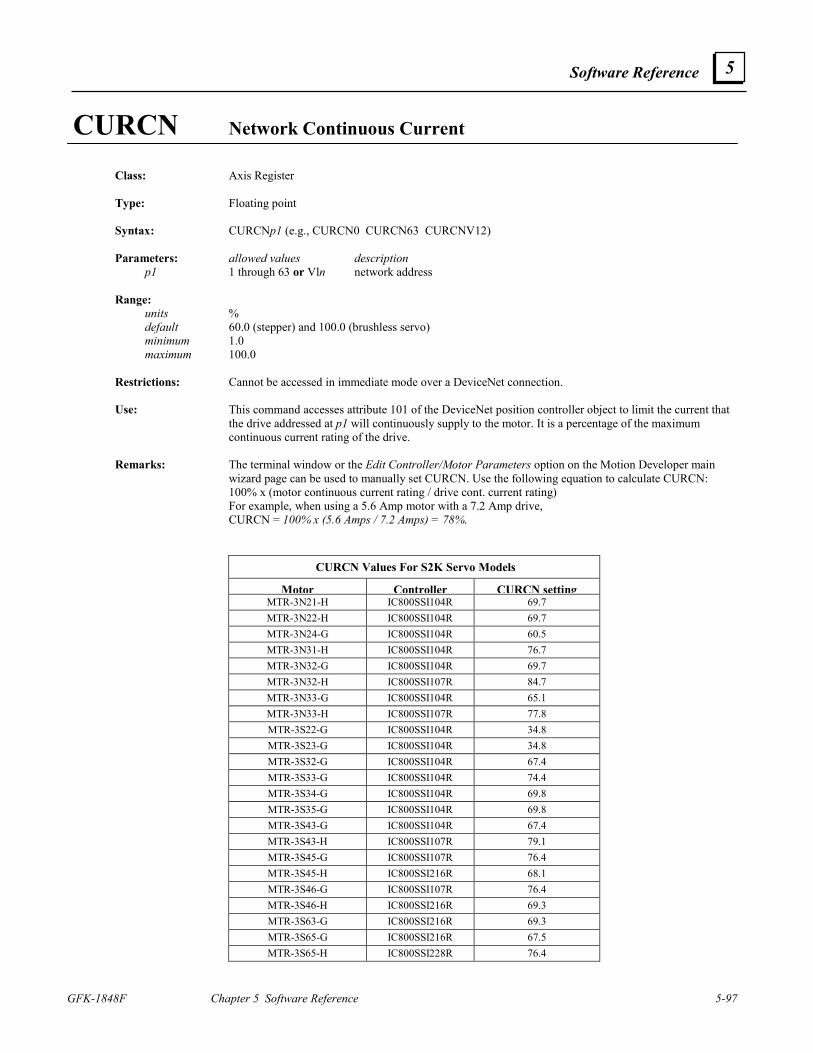
Software Reference
GFK-1848F Chapter 5 Software Reference 5-97
5
CURCN Network Continuous Current Class: Axis Register Type: Floating point Syntax: CURCNp1 (e.g., CURCN0 CURCN63 CURCNV12) Parameters: allowed values description p1 1 through 63 or Vln network address Range: units % default 60.0 (stepper) and 100.0 (brushless servo) minimum 1.0 maximum 100.0 Restrictions: Cannot be accessed in immediate mode over a DeviceNet connection. Use: This command accesses attribute 101 of the DeviceNet position controller object to limit the current that
the drive addressed at p1 will continuously supply to the motor. It is a percentage of the maximum continuous current rating of the drive.
Remarks: The terminal window or the Edit Controller/Motor Parameters option on the Motion Developer main
wizard page can be used to manually set CURCN. Use the following equation to calculate CURCN: 100% x (motor continuous current rating / drive cont. current rating) For example, when using a 5.6 Amp motor with a 7.2 Amp drive, CURCN = 100% x (5.6 Amps / 7.2 Amps) = 78%.
CURCN Values For S2K Servo Models
Motor Controller CURCN settingMTR-3N21-H IC800SSI104R 69.7 MTR-3N22-H IC800SSI104R 69.7 MTR-3N24-G IC800SSI104R 60.5 MTR-3N31-H IC800SSI104R 76.7 MTR-3N32-G IC800SSI104R 69.7 MTR-3N32-H IC800SSI107R 84.7 MTR-3N33-G IC800SSI104R 65.1 MTR-3N33-H IC800SSI107R 77.8 MTR-3S22-G IC800SSI104R 34.8 MTR-3S23-G IC800SSI104R 34.8 MTR-3S32-G IC800SSI104R 67.4 MTR-3S33-G IC800SSI104R 74.4 MTR-3S34-G IC800SSI104R 69.8 MTR-3S35-G IC800SSI104R 69.8 MTR-3S43-G IC800SSI104R 67.4 MTR-3S43-H IC800SSI107R 79.1 MTR-3S45-G IC800SSI107R 76.4 MTR-3S45-H IC800SSI216R 68.1 MTR-3S46-G IC800SSI107R 76.4 MTR-3S46-H IC800SSI216R 69.3 MTR-3S63-G IC800SSI216R 69.3 MTR-3S65-G IC800SSI216R 67.5 MTR-3S65-H IC800SSI228R 76.4
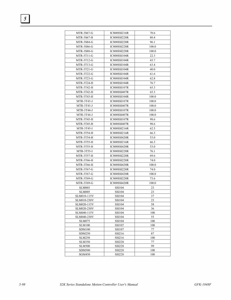
5-98 S2K Series Standalone Motion Controller User's Manual GFK-1848F
5
MTR-3S67-G IC800SSI216R 70.6 MTR-3S67-H IC800SSI228R 80.4 MTR-3S84-G IC800SSI228R 96.1 MTR-3S86-G IC800SSI228R 100.0 MTR-3S88-G IC800SSI228R 100.0 MTR-3T11-G IC800SSI104R 22.3 MTR-3T12-G IC800SSI104R 43.7 MTR-3T13-G IC800SSI104R 63.4 MTR-3T21-G IC800SSI104R 40.0 MTR-3T22-G IC800SSI104R 61.6 MTR-3T23-G IC800SSI104R 62.8 MTR-3T24-H IC800SSI104R 76.7 MTR-3T42-H IC800SSI107R 65.3 MTR-3T42-H IC800SSI407R 65.3 MTR-3T43-H IC800SSI104R 100.0 MTR-3T43-J IC800SSI107R 100.0 MTR-3T43-J IC800SSI407R 100.0 MTR-3T44-J IC800SSI107R 100.0 MTR-3T44-J IC800SSI407R 100.0 MTR-3T45-H IC800SSI107R 98.6 MTR-3T45-H IC800SSI407R 98.6 MTR-3T45-I IC800SSI216R 62.5 MTR-3T54-H IC800SSI216R 66.3 MTR-3T54-H IC800SSI420R 53.0 MTR-3T55-H IC800SSI216R 66.3 MTR-3T55-H IC800SSI420R 53.0 MTR-3T55-I IC800SSI228R 76.1 MTR-3T57-H IC800SSI228R 69.6 MTR-3T66-H IC800SSI228R 74.0 MTR-3T66-H IC800SSI420R 100.0 MTR-3T67-G IC800SSI228R 74.0 MTR-3T67-G IC800SSI420R 100.0 MTR-3T69-G IC800SSI228R 73.6 MTR-3T69-G IC800SSI420R 100.0
SLM003 SSI104 23SLM005 SSI104 23
SLM010-115V SSI104 37SLM010-230V SSI104 23SLM020-115V SSI104 58SLM020-230V SSI104 36SLM040-115V SSI104 100SLM040-230V SSI104 55
SLM075 SSI104 100SLM100 SSI107 100SDM100 SSI107 77SDM250 SSI216 87SLM250 SSI216 100SLM350 SSI228 77SLM500 SSI228 99SDM500 SSI228 100SGM450 SSI228 100
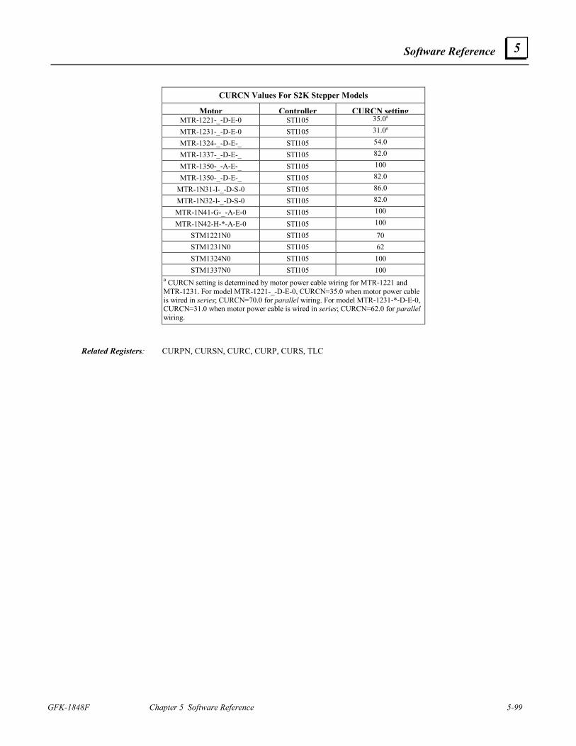
Software Reference
GFK-1848F Chapter 5 Software Reference 5-99
5
CURCN Values For S2K Stepper Models
Motor Controller CURCN settingMTR-1221-_-D-E-0 STI105 35.0a
MTR-1231-_-D-E-0 STI105 31.0a
MTR-1324-_-D-E-_ STI105 54.0
MTR-1337-_-D-E-_ STI105 82.0
MTR-1350-_-A-E-_ STI105 100
MTR-1350-_-D-E-_ STI105 82.0
MTR-1N31-I-_-D-S-0 STI105 86.0
MTR-1N32-I-_-D-S-0 STI105 82.0
MTR-1N41-G-_-A-E-0 STI105 100
MTR-1N42-H-*-A-E-0 STI105 100
STM1221N0 STI105 70 STM1231N0 STI105 62 STM1324N0 STI105 100 STM1337N0 STI105 100
a CURCN setting is determined by motor power cable wiring for MTR-1221 and MTR-1231. For model MTR-1221-_-D-E-0, CURCN=35.0 when motor power cable is wired in series; CURCN=70.0 for parallel wiring. For model MTR-1231-*-D-E-0, CURCN=31.0 when motor power cable is wired in series; CURCN=62.0 for parallel wiring.
Related Registers: CURPN, CURSN, CURC, CURP, CURS, TLC
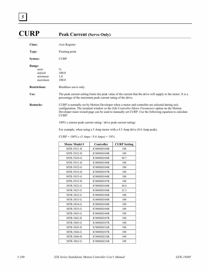
5-100 S2K Series Standalone Motion Controller User's Manual GFK-1848F
5
CURP Peak Current (Servo Only)
Class: Axis Register Type: Floating point Syntax: CURP Range: units % default 100.0 minimum 1.0 maximum 100.0 Restrictions: Brushless servo only. Use: The peak current setting limits the peak value of the current that the drive will supply to the motor. It is a
percentage of the maximum peak current rating of the drive. Remarks: CURP is normally set by Motion Developer when a motor and controller are selected during axis
configuration. The terminal window or the Edit Controller/Motor Parameters option on the Motion Developer main wizard page can be used to manually set CURP. Use the following equation to calculate CURP:
100% x (motor peak current rating / drive peak current rating) For example, when using a 5 Amp motor with a 4.3 Amp drive (8.6 Amp peak),
CURP = 100% x (5 Amps / 8.6 Amps) = 58%.
Motor Model # Controller CURP Setting MTR-3N21-H IC800SSI104R 100
MTR-3N22-H IC800SSI104R 100
MTR-3N24-G IC800SSI104R 90.7
MTR-3N31-H IC800SSI104R 100
MTR-3N32-G IC800SSI104R 100
MTR-3N32-H IC800SSI107R 100
MTR-3N33-G IC800SSI104R 100
MTR-3N33-H IC800SSI107R 100
MTR-3S22-G IC800SSI104R 48.8
MTR-3S23-G IC800SSI104R 52.3
MTR-3S32-G IC800SSI104R 100
MTR-3S33-G IC800SSI104R 100
MTR-3S34-G IC800SSI104R 100
MTR-3S35-G IC800SSI104R 100
MTR-3S43-G IC800SSI104R 100
MTR-3S43-H IC800SSI107R 100
MTR-3S45-G IC800SSI107R 100
MTR-3S45-H IC800SSI216R 100
MTR-3S46-G IC800SSI107R 100
MTR-3S46-H IC800SSI216R 100
MTR-3S63-G IC800SSI216R 100
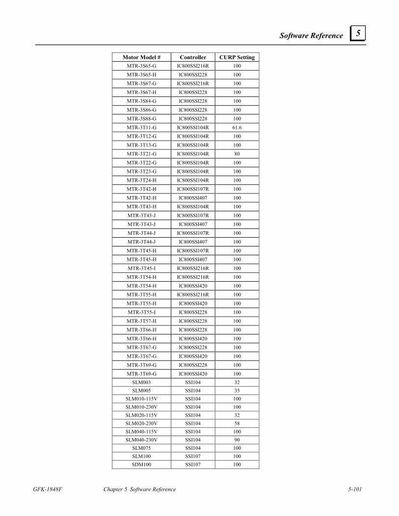
Software Reference
GFK-1848F Chapter 5 Software Reference 5-101
5
Motor Model # Controller CURP Setting MTR-3S65-G IC800SSI216R 100
MTR-3S65-H IC800SSI228 100
MTR-3S67-G IC800SSI216R 100
MTR-3S67-H IC800SSI228 100
MTR-3S84-G IC800SSI228 100
MTR-3S86-G IC800SSI228 100
MTR-3S88-G IC800SSI228 100
MTR-3T11-G IC800SSI104R 61.6
MTR-3T12-G IC800SSI104R 100
MTR-3T13-G IC800SSI104R 100
MTR-3T21-G IC800SSI104R 80
MTR-3T22-G IC800SSI104R 100
MTR-3T23-G IC800SSI104R 100
MTR-3T24-H IC800SSI104R 100
MTR-3T42-H IC800SSI107R 100
MTR-3T42-H IC800SSI407 100
MTR-3T43-H IC800SSI104R 100
MTR-3T43-J IC800SSI107R 100
MTR-3T43-J IC800SSI407 100
MTR-3T44-J IC800SSI107R 100
MTR-3T44-J IC800SSI407 100
MTR-3T45-H IC800SSI107R 100
MTR-3T45-H IC800SSI407 100
MTR-3T45-I IC800SSI216R 100
MTR-3T54-H IC800SSI216R 100
MTR-3T54-H IC800SSI420 100
MTR-3T55-H IC800SSI216R 100
MTR-3T55-H IC800SSI420 100
MTR-3T55-I IC800SSI228 100
MTR-3T57-H IC800SSI228 100
MTR-3T66-H IC800SSI228 100
MTR-3T66-H IC800SSI420 100
MTR-3T67-G IC800SSI228 100
MTR-3T67-G IC800SSI420 100
MTR-3T69-G IC800SSI228 100
MTR-3T69-G IC800SSI420 100 SLM003 SSI104 32 SLM005 SSI104 35
SLM010-115V SSI104 100 SLM010-230V SSI104 100 SLM020-115V SSI104 32 SLM020-230V SSI104 58 SLM040-115V SSI104 100 SLM040-230V SSI104 90
SLM075 SSI104 100 SLM100 SSI107 100 SDM100 SSI107 100
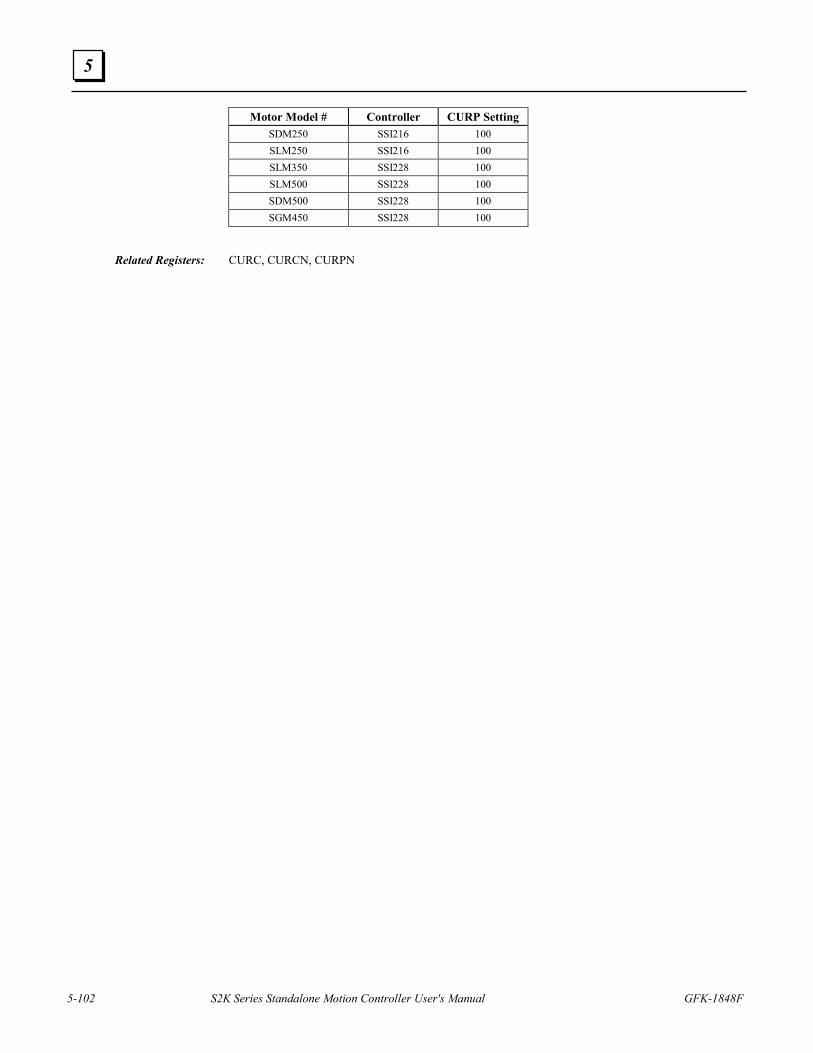
5-102 S2K Series Standalone Motion Controller User's Manual GFK-1848F
5
Motor Model # Controller CURP Setting SDM250 SSI216 100 SLM250 SSI216 100 SLM350 SSI228 100 SLM500 SSI228 100 SDM500 SSI228 100 SGM450 SSI228 100
Related Registers: CURC, CURCN, CURPN
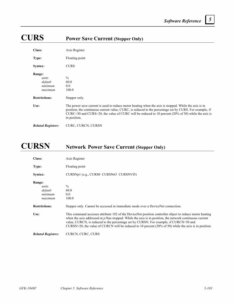
Software Reference
GFK-1848F Chapter 5 Software Reference 5-103
5
CURS Power Save Current (Stepper Only) Class: Axis Register Type: Floating point Syntax: CURS Range: units % default 60.0 minimum 0.0 maximum 100.0 Restrictions: Stepper only. Use: The power save current is used to reduce motor heating when the axis is stopped. While the axis is in
position, the continuous current value, CURC, is reduced to the percentage set by CURS. For example, if CURC=50 and CURS=20, the value of CURC will be reduced to 10 percent (20% of 50) while the axis is in position.
Related Registers: CURC, CURCN, CURSN
CURSN Network Power Save Current (Stepper Only) Class: Axis Register Type: Floating point Syntax: CURSNp1 (e.g., CURS0 CURSN63 CURSNVI5) Range: units % default 60.0 minimum 0.0 maximum 100.0 Restrictions: Stepper only. Cannot be accessed in immediate mode over a DeviceNet connection. Use: This command accesses attribute 102 of the DeviceNet position controller object to reduce motor heating
when the axis addressed at p1has stopped. While the axis is in position, the network continuous current value, CURCN, is reduced to the percentage set by CURSN. For example, if CURCN=50 and CURSN=20, the value of CURCN will be reduced to 10 percent (20% of 50) while the axis is in position.
Related Registers: CURCN, CURC, CURS
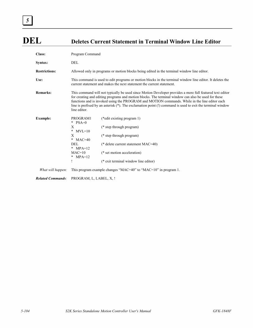
5-104 S2K Series Standalone Motion Controller User's Manual GFK-1848F
5
DEL Deletes Current Statement in Terminal Window Line Editor
Class: Program Command Syntax: DEL Restrictions: Allowed only in programs or motion blocks being edited in the terminal window line editor. Use: This command is used to edit programs or motion blocks in the terminal window line editor. It deletes the
current statement and makes the next statement the current statement. Remarks: This command will not typically be used since Motion Developer provides a more full featured text editor
for creating and editing programs and motion blocks. The terminal window can also be used for these functions and is invoked using the PROGRAM and MOTION commands. While in the line editor each line is prefixed by an asterisk (*). The exclamation point (!) command is used to exit the terminal window line editor.
Example: PROGRAM1 (*edit existing program 1) * PSA=0 X (* step through program) * MVL=10 X (* step through program) * MAC=40 DEL (* delete current statement MAC=40) * MPA=12 MAC=10 (* set motion acceleration) * MPA=12 ! (* exit terminal window line editor) What will happen: This program example changes “MAC=40” to “MAC=10” in program 1. Related Commands: PROGRAM, L, LABEL, X, !
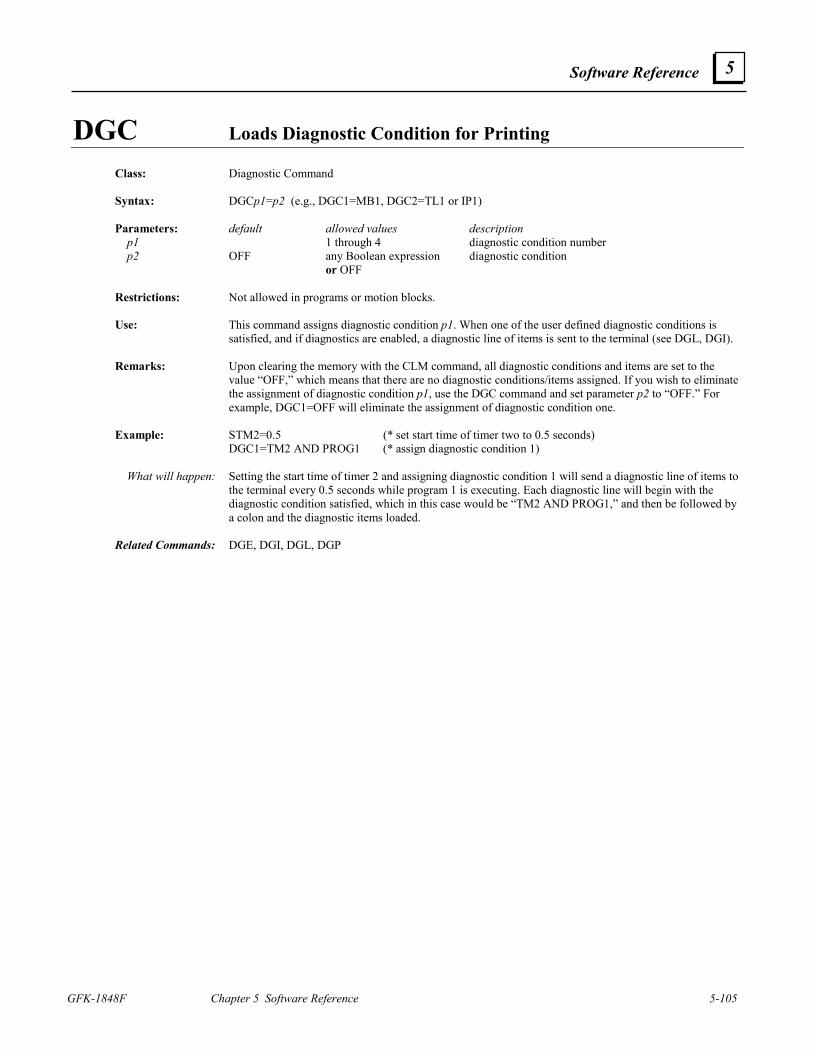
Software Reference
GFK-1848F Chapter 5 Software Reference 5-105
5
DGC Loads Diagnostic Condition for Printing
Class: Diagnostic Command Syntax: DGCp1=p2 (e.g., DGC1=MB1, DGC2=TL1 or IP1) Parameters: default allowed values description p1 1 through 4 diagnostic condition number p2 OFF any Boolean expression diagnostic condition or OFF Restrictions: Not allowed in programs or motion blocks. Use: This command assigns diagnostic condition p1. When one of the user defined diagnostic conditions is
satisfied, and if diagnostics are enabled, a diagnostic line of items is sent to the terminal (see DGL, DGI). Remarks: Upon clearing the memory with the CLM command, all diagnostic conditions and items are set to the
value “OFF,” which means that there are no diagnostic conditions/items assigned. If you wish to eliminate the assignment of diagnostic condition p1, use the DGC command and set parameter p2 to “OFF.” For example, DGC1=OFF will eliminate the assignment of diagnostic condition one.
Example: STM2=0.5 (* set start time of timer two to 0.5 seconds) DGC1=TM2 AND PROG1 (* assign diagnostic condition 1) What will happen: Setting the start time of timer 2 and assigning diagnostic condition 1 will send a diagnostic line of items to
the terminal every 0.5 seconds while program 1 is executing. Each diagnostic line will begin with the diagnostic condition satisfied, which in this case would be “TM2 AND PROG1,” and then be followed by a colon and the diagnostic items loaded.
Related Commands: DGE, DGI, DGL, DGP
5-106 S2K Series Standalone Motion Controller User's Manual GFK-1848F
5
DGE Enables Diagnostics
Class: Diagnostic Command Syntax: DGE=p1 (e.g., DGE=0) Parameters: default allowed values description p1 0 0 and 1 diagnostic enable bit Restrictions: Not allowed in programs or motion blocks. Diagnostics work only via serial communication. Use: This command is used to enable the diagnostic mode of the system. When DGE is set to 1, diagnostics are
enabled, and when set to 0, diagnostics are disabled. Remarks: DGE is set to 0 upon power-up. Related Commands: DGC, DGI, DGL, DGP, DGO, DGS, DGT
DGI Assigns Diagnostic Item to Print Class: Diagnostic Command Syntax: DGIp1=p2 (e.g., DGI1=VLA DGI3=PHR1) Parameters: default allowed values description p1 1 through 8 diagnostic item number p2 OFF any register or OFF diagnostic item Restrictions: Not allowed in programs or motion blocks. Use: This command assigns a diagnostic item to be printed whenever a DGL is executed or whenever one of the
user-defined diagnostic conditions is met. Remarks: Upon clearing the memory with the CLM command, all diagnostic conditions and items are set to the
value “OFF,” which means that there are no diagnostic conditions/items assigned. If you wish to eliminate the assignment of diagnostic item p1, use the DGI command and set parameter p2 to “OFF.” For example, DGI1=OFF will eliminate the assignment of diagnostic item one.
Example: DGI1=PSA (* assign diagnostic item one) DGI2=VLA (* assign diagnostic item two) DGI3=FE (* assign diagnostic item three) DGI4=PSR (* assign diagnostic item four) What will happen: Assigning these diagnostic items when diagnostics are enabled will send the diagnostic items to the
terminal when the DGL command is executed. Related Commands: DGE, DGC, DGL, DGP
Software Reference
GFK-1848F Chapter 5 Software Reference 5-107
5
DGL Prints Diagnostic Line of Items
Class: Diagnostic Command Syntax: DGL Use: This command prints to the terminal a diagnostic line of items that have been assigned with the DGI
command. This works only while diagnostics are enabled. Remarks: Since this command is ignored when diagnostics are not enabled, it can be left in programs even when you
are not using diagnostics. Example: DGI1=PSA (* assign diagnostic item one) DGI2=VLA (* assign diagnostic item two) DGI3=FE (* assign diagnostic item three) DGI4=PSR (* assign diagnostic item four) DGL (* print diagnostic line of items) *DGL: PSA=0, VLA=0 DGL: FE=0, PSR=3061 Related Commands: DGE, DGC, DGI, DGP
DGO Outputs Diagnostic Register Value to Serial Port
Class: Diagnostic Command Syntax: DGO p1 (e.g., DGO VLA, DGO IO) Parameters: allowed values description p1 any register register Use: This command outputs a diagnostic register value to the serial or program port when diagnostics are
enabled (DGE=1). DGO works the same as the “?” command, but it can also be used in programs and motion blocks.
Remarks: Since this command is ignored when diagnostics are not enabled, it can be left in programs even when you
are not using diagnostics. Example: DGO PSA (* outputs axis position to the serial port) DGOVLA (* outputs axis velocity to the serial port) Related Commands: DGE, DGL, DGP
5-108 S2K Series Standalone Motion Controller User's Manual GFK-1848F
5
DGP Prints Diagnostic Message to Serial Port Class: Diagnostic Command Syntax: DGP“p1” (e.g., DGP “Drill operating”) Parameters: allowed values description p1 any string, 0 through 127 characters long diagnostic message Use: This command prints the diagnostic message p1 to the serial port. It works only when diagnostics are
enabled. Remarks: Since this command is ignored when diagnostics are not enabled, it can be left in programs even when you
are not using diagnostics. Example: DGE=1 (* enable diagnostics) DGP “Diagnostics enabled” (* send diagnostic message to serial port) *Diagnostics enabled Related Commands: DGE, DGC, DGI, DGL
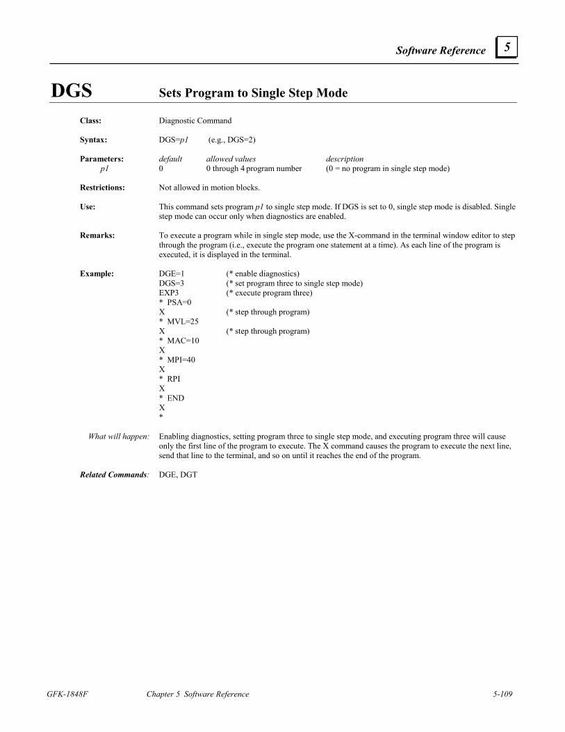
Software Reference
GFK-1848F Chapter 5 Software Reference 5-109
5
DGS Sets Program to Single Step Mode
Class: Diagnostic Command Syntax: DGS=p1 (e.g., DGS=2) Parameters: default allowed values description
p1 0 0 through 4 program number (0 = no program in single step mode) Restrictions: Not allowed in motion blocks. Use: This command sets program p1 to single step mode. If DGS is set to 0, single step mode is disabled. Single
step mode can occur only when diagnostics are enabled. Remarks: To execute a program while in single step mode, use the X-command in the terminal window editor to step
through the program (i.e., execute the program one statement at a time). As each line of the program is executed, it is displayed in the terminal.
Example: DGE=1 (* enable diagnostics) DGS=3 (* set program three to single step mode) EXP3 (* execute program three) * PSA=0 X (* step through program) * MVL=25 X (* step through program) * MAC=10 X * MPI=40 X * RPI X * END X * What will happen: Enabling diagnostics, setting program three to single step mode, and executing program three will cause
only the first line of the program to execute. The X command causes the program to execute the next line, send that line to the terminal, and so on until it reaches the end of the program.
Related Commands: DGE, DGT
5-110 S2K Series Standalone Motion Controller User's Manual GFK-1848F
5
DGT Sets Program to Trace Mode
Class: Diagnostic Command Syntax: DGT=p1 (e.g., DGT=2) Parameters: default allowed values description p1 0 0 through 4 program number (0 = no program in trace mode) Restrictions: Not allowed in motion blocks. Use: This command sets program p1 to trace mode. If DGT is set to 0, trace mode is disabled. Trace mode can
occur only when diagnostics are enabled. Remarks: 1. When trace mode is enabled, each line of program p1 is sent to the terminal as it is executing. 2. CAUTION: Trace mode can cause the program to run approximately 1,000 times slower than normal! Example: DGE=1 (* enable diagnostics) DGT=3 (* set program three to trace mode) EXP3 (* execute program three) * PSA=0 MVL=25 MAC=10 MPI=40 RPI END * What will happen: Enabling diagnostics, setting program three to trace mode, and executing program three will cause each
line of the program to be sent to the terminal while it is executing. Related Commands: DGE, DGS
Software Reference
GFK-1848F Chapter 5 Software Reference 5-111
5
DI Digital Input
Class: Input/Output Register Type: Integer, Boolean Syntax: DIp1 (e.g., DI DI4 DIVI1) Parameters:
Model allowed values description IC800S_IxxxD2 p1 IC800S_IxxxP2 p1 IC800S_IxxxRD2 p1 IC800S_IxxxRP2 p1
none or 1 through 14 or VIn digital input number
IC800S_IxxxS1 p1 IC800S_IxxxRS1 p1
none or 1 through 21 or VIn digital input number
Range:
Model allowed values IC800S_IxxxD2 p1 IC800S_IxxxP2 p1 IC800S_IxxxRD2 p1 IC800S_IxxxRP2 p1
0 through 3FFF16 or 0 and 1
IC800S_IxxxS1 p1 IC800S_IxxxRS1 p1
0 through 1FFFFF16 or 0 and 1
Restrictions: Read only. Use: The digital input register contains the values of digital inputs, which are general purpose inputs used for
process control. Remarks: 1. When the DIp1? command is executed, the value of the digital input p1 will be given as a Boolean
number. 2. When DI? is executed, the digital inputs will be reported as binary numbers. The left-most bit
represents digital input 14 or 21, depending on your controller model number (see Parameters above); and the right-most bit represents digital input 1.
3. DI1 = home; DI2 = forward overtravel (+OT) when OTE=1; DI3 = reverse overtravel (-OT) when OTE=1; DI 5 and DI 6 are used for the hand wheel inputs when HWE=1. Set OTE = 1 to enable the hardware overtravel inputs. The hardware overtravel inputs require a normally closed contact.
4. Since the controller includes I/O points that may be used either as input or outputs the DI register bits for these shared points will change state when any digital output command (DO) forces the state of the bit. For example, if DO10=1 is executed then DI10 will also be TRUE.
Example: DI? (* report value of digital input register; example 2#00010010110001) DI4? (* report value of digital input four) Related Registers: EG, DO, DID, IO, IOA, IOS
5-112 S2K Series Standalone Motion Controller User's Manual GFK-1848F
5
DIN Network Digital Input Class: I/O Register Type: Integer, Boolean Syntax: DINp1.p2 (e.g., DIN5 DINVI4 DIN3.28 DINVI3.16 DINVI6.VI9) Parameters: allowed values description p1 0 through 63 or VIn network address p2 none or 1 through 1024 or VIn digital input number Range: allowed values 0 through FFFFFFFF16 or 0 and 1 Note that these minimum and maximum values are a function of your digital input device. Refer to the
documentation for your digital input device to determine how to map its values to the motion controller. Restrictions: Read only. Cannot be accessed in immediate mode over a DeviceNet connection. Use: The network digital input register contains the values of the network digital inputs. The digital inputs are
general-purpose inputs used for process control. Remarks: 1. When the DINp1.p2? command is executed, the value of the digital input p2 of the network digital
input device addressed at p1 will be given as a Boolean number. 2. When DINp1? is executed, up to four bytes of the digital inputs of the assigned assembly object
instance of the network digital input device addressed at p1 will be reported as a hexadecimal number. Example: DINA17=101,2 (* set assembly object instance 101 and 2 bytes) DIN17? (* report value of network digital inputs) 16#13AC Related Registers: DINA, DON
Software Reference
GFK-1848F Chapter 5 Software Reference 5-113
5
DINA Network Digital Input Register Assignment
Class: I/O Register Syntax: DINAp1 (e.g., DINA3 DINA63) Parameters: allowed values description p1 0 through 63 network address Range: default 1,1 allowed values 1 through 255 assembly object instance 1 through 128 number of bytes Restrictions: Not allowed in expressions. Use: This register is used to assign the assembly object instance number and number of bytes to be used by the
DIN register to read the network digital inputs from the device addressed at p1. The first number of the assignment is the assembly object instance and the second number is the quantity of bytes used by the assembly object instance data attribute.
Example: DINA11=101,2 (* set assembly object instance 101 and 2 bytes) Related Registers: DIN
DIR Direction of Motor for Forward Moves Class: Axis Register Type: String Syntax: DIR Range: default CW allowed values CW, CCW Restrictions: Not allowed in motion blocks. Use: This register is used to define the direction of the motor assigned to the axis for forward moves. If DIR is
set to CW, a forward move by the motor is clockwise, facing the motor shaft. If DIR is set to CCW, a forward move by the motor is counterclockwise, facing the motor shaft. The Fwd/Rev LED on the front of the controller illuminates green when the axis is moving in the forward direction and yellow when the axis is moving in the negative direction. In a program, this register can be set only when the controller is in the faulted state.
The axis actual position (PSA) is derived from the motor feedback (encoder or resolver) when
PFE=0. When PFE=1, the axis position is derived from auxiliary encoder. See DIRX and PFE register descriptions for more details.
Related Registers: DIRN, DIRX , PFE
5-114 S2K Series Standalone Motion Controller User's Manual GFK-1848F
5
DIRN Network Direction of Motor Class: Axis Register Syntax: DIRNp1 (e.g., DIRN0 DIRN63 DIRNVI5) Parameters: allowed values description p1 0 through 63 or VIn network address Range: allowed values CW, CCW Restrictions: Not allowed in motion blocks. Cannot be accessed in immediate mode over a DeviceNet connection. Use: This command accesses attribute 24 of the DeviceNet position controller object to define the direction of
the motor assigned to the axis for forward moves. If DIR is set to CW, a forward move by the motor is clockwise, facing the motor shaft. If DIR is set to CCW, a forward move by the motor is counterclockwise, facing the motor shaft.
Software Reference
GFK-1848F Chapter 5 Software Reference 5-115
5
DIRX Direction of Auxiliary Position Class: Axis Register Type: String Syntax: DIRX Range: default CW allowed values CW, CCW Restrictions: S2K servo only. Requires firmware revision 2.5 or later. Use: The DIRX register defines the relative direction of the auxiliary position. It is important to make a
distinction between the axis position and the auxiliary position. The axis position is defined by PSA, while the auxiliary position is defined by PSX. However, the feedback path for auxiliary position is not always from the auxiliary encoder (since the S2K has a flexible set of position modes). The S2K servo controller has three modes of position feedback.
Normal Mode (PFE = 0, PFN = don’t care) In this mode, the axis position is from the main encoder and the auxiliary position is from the auxiliary
encoder. DIR controls the direction of forward moves from the main encoder feedback path. DIRX controls the relative direction of position from the auxiliary path (auxiliary encoder) routed to PSX. Therefore, switching DIRX from CW to CCW (or vice versa) will change the polarity of PSX.
Switched Mode (PFE = 1, PFN = 0) In this mode, the axis position is from the AUXILIARY encoder and the auxiliary position is from the
MAIN encoder. Switched Mode is the same as Normal Mode, except the auxiliary and main feedback paths have been switched. Thus, DIR controls the direction of forward moves from the auxiliary encoder feedback path. DIRX controls the relative direction of position from the main feedback path (main encoder) routed to PSX. In this case, switching DIRX from CW to CCW (or vice versa) will change still change the polarity of PSX, although the path will now be from the main encoder.
Dual Loop Mode (PFE = 1, PFN > 0) The S2K offers the ability to have both main and auxiliary encoder paths close the axis position loop. This
mode is similar to Switched Mode because the axis position is from the AUXILIARY encoder and the auxiliary position is from the MAIN encoder. Therefore, DIR controls the direction of forward moves from the auxiliary encoder feedback path. DIRX controls the relative direction of position from the main feedback path (main encoder) routed to PSX. For dual loop position mode to work correctly, the actual direction of the main and auxiliary encoders must be the same. That is, PSA and PSX must increment, as well as decrement, in the same motor direction. Otherwise, the system will be unstable resulting in a following error for any move.
Related Commands: DIR, DIRXN, PFE, PFN, PSA, PSX
5-116 S2K Series Standalone Motion Controller User's Manual GFK-1848F
5
DIRXN Network Direction of Auxiliary Position Class: Axis Register Type: String Syntax: DIRXNp1 (e.g., DIRXN0, DIRXN63, DIRXNVI5) Parameters: allowed values description p1 0 through 63 or VIn network address Range: allowed values CW, CCW Restrictions: S2K DeviceNet servo only. Requires firmware revision 2.5 or later. Not allowed in motion blocks. Cannot
be accessed in immediate mode over a DeviceNet connection. Use: This command accesses attribute 115 of the position controller object. DIRXN is a peer to peer network
command that can access (read or write) the DIRX register of any S2K node on a DeviceNet network. The DIRX register defines the relative direction of the auxiliary position (PSX). Please see the description of DIRX for a complete understanding of its behavior.
Related Commands: DIR, DIRX, PFE, PFN, PSA, PSX
DIT Digital Input Filter Time Class: Input/Output Register Type: Floating point Syntax: DITp1 (e.g., DIT2 DITVI3) Parameters: allowed values description p1 1 through 12 or VIn digital input number Range: units seconds default 0.000 minimum 0.000 maximum 4.000 Restrictions: Cannot be assigned in motion blocks. Use: This register allows up to three decimal places. The digital input filter time is used to represent the
minimum duration of a pulse that the filter will allow to pass. This filter time is applied to the digital input specified.
Remarks: The primary use for this command is to de-bounce a contact connected to a digital input. Generally,
contact bounce lasts for less than 30 milliseconds; so setting DIT=.03 should de-bounce the contact. Since filtering slows input response, use the smallest value for filter time that works for the application.
Example: DIT3=.03 (* set digital input filter time to 30 ms) Related Registers: DI, DIA
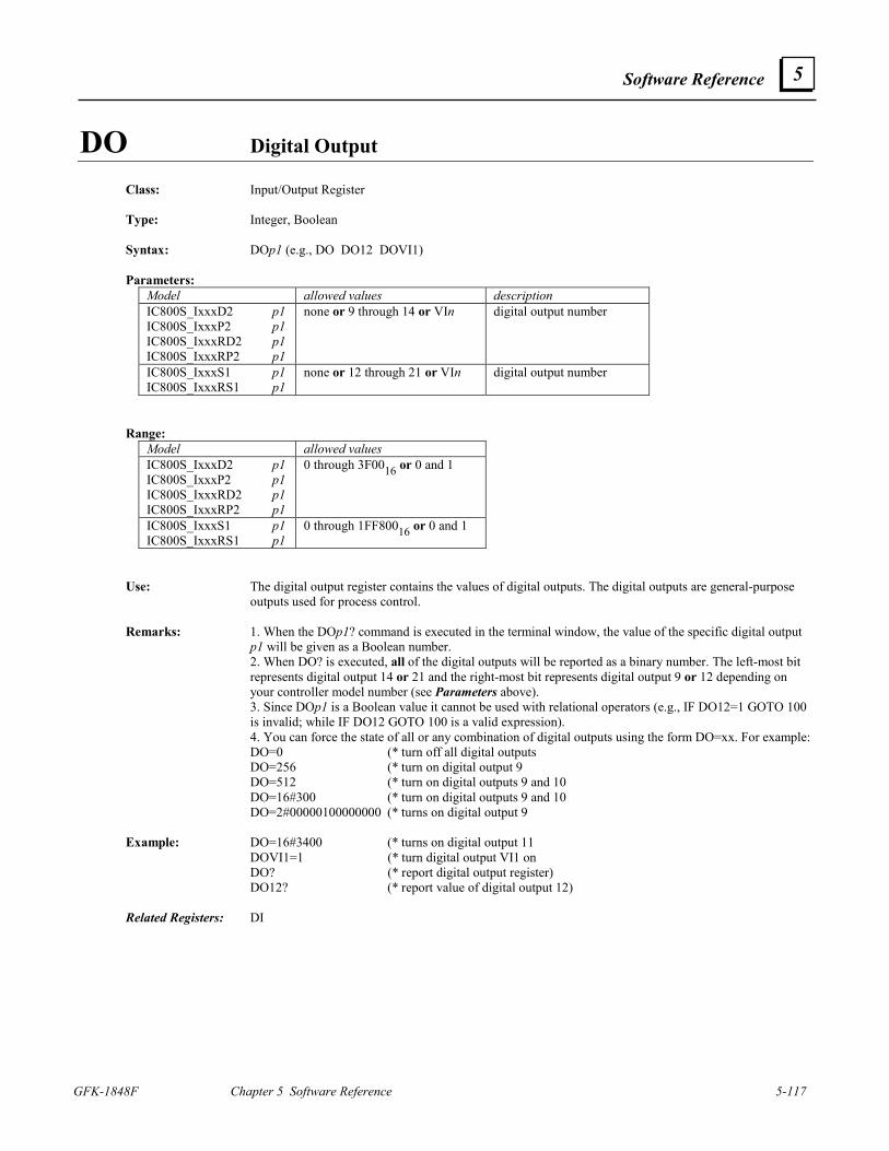
Software Reference
GFK-1848F Chapter 5 Software Reference 5-117
5
DO Digital Output
Class: Input/Output Register Type: Integer, Boolean Syntax: DOp1 (e.g., DO DO12 DOVI1) Parameters:
Model allowed values description IC800S_IxxxD2 p1 IC800S_IxxxP2 p1 IC800S_IxxxRD2 p1 IC800S_IxxxRP2 p1
none or 9 through 14 or VIn digital output number
IC800S_IxxxS1 p1 IC800S_IxxxRS1 p1
none or 12 through 21 or VIn digital output number
Range:
Model allowed values IC800S_IxxxD2 p1 IC800S_IxxxP2 p1 IC800S_IxxxRD2 p1 IC800S_IxxxRP2 p1
0 through 3F0016 or 0 and 1
IC800S_IxxxS1 p1 IC800S_IxxxRS1 p1
0 through 1FF80016 or 0 and 1
Use: The digital output register contains the values of digital outputs. The digital outputs are general-purpose
outputs used for process control. Remarks: 1. When the DOp1? command is executed in the terminal window, the value of the specific digital output
p1 will be given as a Boolean number. 2. When DO? is executed, all of the digital outputs will be reported as a binary number. The left-most bit
represents digital output 14 or 21 and the right-most bit represents digital output 9 or 12 depending on your controller model number (see Parameters above).
3. Since DOp1 is a Boolean value it cannot be used with relational operators (e.g., IF DO12=1 GOTO 100 is invalid; while IF DO12 GOTO 100 is a valid expression). 4. You can force the state of all or any combination of digital outputs using the form DO=xx. For example: DO=0 (* turn off all digital outputs
DO=256 (* turn on digital output 9 DO=512 (* turn on digital outputs 9 and 10 DO=16#300 (* turn on digital outputs 9 and 10 DO=2#00000100000000 (* turns on digital output 9
Example: DO=16#3400 (* turns on digital output 11 DOVI1=1 (* turn digital output VI1 on DO? (* report digital output register) DO12? (* report value of digital output 12) Related Registers: DI
5-118 S2K Series Standalone Motion Controller User's Manual GFK-1848F
5
DOE Fault on Digital Output Fault Enable
Class: Input/Output Register Type: Boolean Syntax: DOE Range: default 0 allowed values 0, 1 Restrictions: Cannot be assigned in motion blocks. Use: This register is used to enable the system to fault on a digital output fault. A digital output fault occurs
when the state of the digital output is true but the state of the associated digital input is not (after a time of 4 ms). If DOE is set to 1, the fault on digital output fault is enabled; and if DOE is set to 0, it is disabled.
DON Network Digital Output
Class: I/O Register Type: Integer, Boolean Syntax: DONp1.p2 (e.g., DON5 DONVI4 DON3.28 DONVI3.16 DONVI6.VI9) Parameters: allowed values description p1 0 through 63 or Vin network address p2 none or 1 through 1024 or VIn digital output number Range: allowed values 0 through FFFFFFFF16 or 0 and 1 Note that these minimum and maximum values are a function of your digital output device. Refer to the
documentation for your digital output device to determine how to map its values to the motion controller. Restrictions: Cannot be accessed in immediate mode over a DeviceNet connection. Use: The network digital output register contains the values of the network digital outputs. The digital outputs
are general-purpose outputs used for process control. Remarks: 1. When the DONp1.p2? command is executed, the value of the digital output p2 of the network digital
output device at address p1 will be given as a Boolean number. 2. When DONp1? is executed, up to four bytes of the digital outputs of the assigned assembly object
instance of the network digital output device at address p1 will be reported as a hexadecimal number. Example: DONA17=101,2 (* set assembly object instance 101 and 2 bytes) DON17? (* report value of all network digital outputs at node address17) 16#13AC Related Registers: DONA, DIN
Software Reference
GFK-1848F Chapter 5 Software Reference 5-119
5
DONA Network Digital Output Register Assignment
Class: I/O Register Syntax: DONAp1 (e.g., DONA3 DONA63) Parameters: allowed values description p1 0 through 63 network address Range: default 1,1 allowed values 1 through 255 assembly object instance 1 through 128 number of bytes Restrictions: Not allowed in expressions. Use: This register is used to assign the assembly object instance number and number of bytes to be used by the
DON register to get or set the network digital outputs of the device addressed at p1. The first number of the assignment is the assembly object instance and the second number is the quantity of bytes used by that assembly object instance’s data attribute.
Example: DONA11=101,2 (* set assembly object instance 101 and 2 bytes) Related Registers: DON
DSE Display Format Enable
Class: System Register Type: Boolean Syntax: DSE Range: default 1 allowed values 0, 1 Restrictions: Cannot be assigned in motion blocks. Use: This command is used to enable the display format on the serial port. If DSE is set to 1, the display format
is enabled; and if set to 0, the display format is disabled. Remarks: When the display format is enabled, output strings from the PUT and OUT commands are prefixed by
control code 1116 and suffixed by control code 1216. The Whedco OIP display intercepts all strings delimited by the control codes and does not send those strings to its host port.
Related Commands: PUT, OUT
5-120 S2K Series Standalone Motion Controller User's Manual GFK-1848F
5
EG Positive-Edge-Sensitive Digital Input
Class: Input/Output Register Type: Integer, Boolean Syntax: EGp1 (e.g., EG EG4 EGVI3) Parameters:
Model allowed values description IC800S_IxxxD2 p1 IC800S_IxxxP2 p1 IC800S_IxxxRD2 p1 IC800S_IxxxRP2 p1
none or 1 through 14 or VIn positive-edge-sensitive digital input number
IC800S_IxxxS1 p1 IC800S_IxxxRS1 p1
none or 1 through 21 or VIn positive-edge-sensitive digital input number
Range:
Model allowed values IC800S_IxxxD2 p1 IC800S_IxxxP2 p1 IC800S_IxxxRD2 p1 IC800S_IxxxRP2 p1
0 through 3FFF16 or 0 and 1
IC800S_IxxxS1 p1 IC800S_IxxxRS1 p1
0 through 1FFFFF16 or 0 and 1
Use: EG contains the values of all digital inputs that have made a low to high transition since they were last
cleared. Remarks: 1. When the EGp1? command is executed from the terminal window, its value will be given as a Boolean
number. A value of 1 means digital input p1 made a low to high state change since its EG value was last read (i.e., cleared).
2. When EG? is executed, all positive-edge-sensitive digital inputs will be reported as a binary number. The left-most bit represents digital input 14 or 21, depending on your S2K model number (see Parameters above); the right-most bit represents digital input 1.
3. After the state of an input is read using the EG command, the EG value of that input is set to zero. 4. When setting the positive-edge-sensitive digital inputs, note that a zero will reset the input, and a 1 will not change the state of the input.
Example: EG=16#1A (* set EG to 1A16 [i.e., don’t change inputs 2, 4, and 5, but reset all others]) EGVI1=0 (* set EG VI1 to 0 [i.e., reset the input represented by variable VI1]) EG? (* report positive-edge-sensitive input register) Related Registers: DI
Software Reference
GFK-1848F Chapter 5 Software Reference 5-121
5
EKB Empties Key Buffer
Class: Input/Output Command Syntax: EKB Restrictions: Not allowed in motion blocks. Use: This command empties the key buffer. Related Commands: KY, GET, IN Related Registers: KEY
END Ends Program or Motion Block and Exits Editor
Class: Program Command Syntax: END Restrictions: Allowed only in programs or motion blocks. Use: This command marks the end of a program or motion block only when using the terminal window line
editor. If entered while in the terminal window line editor this command also exits the terminal window editor mode. This command should not be included in any program or motion block created using the Motion Developer script editors.
Remarks: Caution: When used in the terminal window line editor this command will delete all program/motion
block statements that follow it. If you want only to exit the terminal window editor, use the “!” command. Example: PROGRAM1 (* define program 1 using the terminal window editor) PSA=0 (* set axis position register) MVL=10 (* set motion velocity) MAC=40 (* set motion acceleration) MPA=12 (* set absolute move position) RPA (* run to absolute position) END (* end program 1 and exit editor if using the terminal window editor) Related Commands: !, PROGRAM, MOTION
5-122 S2K Series Standalone Motion Controller User's Manual GFK-1848F
5
EOT Encoder Output Type Class: Axis Register Type: Integer Syntax: EOT Range: units lines per revolution default 0 allowed values Encoder Feedback Controller: 0; 500; 625; 1,000; 1,250; 2,000, 2,500 Resolver Feedback Controller: 0; 250; 256; 500; 512; 1,000; 1,024 Restrictions: Brushless servo only; not allowed in motion blocks. Use: This register sets the output type for the encoder output. When this register is set to zero, the encoder
output buffers the auxiliary encoder input pulse for pulse. If the input is a quadrature encoder the output will be quadrature. If the input is CW/CCW pulses, the output will be the same format. When the EOT register is non-zero, the encoder output tracks the motor feedback encoder at the resolution set by the EOT value. For encoder-based models, the lines per revolution of the motor encoder is 2,500 (10,000 quadrature) and the encoder output can use the full 2,500 or divide down this resolution based on the allowed values shown above.
The encoder output marker pulse width is fixed at 1/5000th of a revolution of the source encoder. This
implies that the marker pulse output width will vary with encoder speed and the smallest width will occur at the highest speed. For example, if the source encoder is rotating at 1,000 RPM or 16.667 rev/sec then the encoder takes 0.06 seconds per revolution. Therefore, 1/5000th of this value, or 12 µS, represents the marker pulse width at that speed.
There is a 40 nanosecond delay between the encoder input and encoder output signals when EOT=0. Example: EOT=0 (* encoder output uses the auxiliary encoder input) EOT=1000 (* encoder output provides 1,000 lines per revolution of the motor)
Software Reference
GFK-1848F Chapter 5 Software Reference 5-123
5
EXM Executes Motion Block Class: Program Command Syntax: EXMp1 (e.g., EXM50 EXMVI10) Parameters: allowed values description p1 1 through 100 or VI motion block number Restrictions: Not allowed in motion blocks. Use: This command executes motion block p1. If you rename a motion block in a Motion Developer project,
the symbolic name replaces the block number (p1) when the EXM command is used in programs. For example, renaming motion block 1 to Home would then enable the use of either the EXM1 or EXMHome to start the execution of this motion block.
Remarks: If a motion block is already executing when the EXM command is encountered the controller will quit
executing that motion block and then execute motion block p1. If motion block p1 is already executing, EXMp1 will restart it. One motion block cannot start another motion block.
Example: MOTION1 (* edit motion block 1 in the terminal window editor) MVL=10 (* set motion velocity) MAC=40 (* set motion acceleration) MPI=15 (* set incremental move position) RPI (* run to incremental move position) END (* end motion block 1 and the exit terminal window editor) EXM1 (* execute motion block 1) What will happen: Issuing the EXM1 command will cause the axis to move 15 axis units in the forward direction. Related Commands: EXP
5-124 S2K Series Standalone Motion Controller User's Manual GFK-1848F
5
EXP Executes Program Class: Program Command Syntax: EXPp1 (e.g., EXP4 EXPVI9) Parameters: allowed values description
p1 1 through 4 or Vin program number Restrictions: Not allowed in motion blocks. Use: This command executes program p1. If you rename a program in a Motion Developer project, the
symbolic name replaces the program number (p1) when the EXP command is used in programs. For example, renaming program 4 to Fault would then enable the use of either the EXP4 or EXPFault to start the execution of this program.
Remarks: If program p1 is already executing, then this command does nothing. Example: PROGRAM1 (* edit program 1 in the terminal window editor) PSA=0 (* set axis position register) MVL=10 (* set motion velocity) MAC=40 (* set motion acceleration) MPA=12 (* set absolute move position) RPA (* run to absolute position) END (* end program 1 and exit editor) EXP1 (* execute program 1) What will happen: Issuing the EXP1 command will cause the axis to move to an absolute position of 12 units. Related Commands: EXM
EXP(p1) Exponential Operator
Type: Floating point Syntax: EXP(p1) Parameters: allowed values p1 any floating point operand Use: This operator is used to take the exponential of p1 (i.e., raise the number e to the power p1).
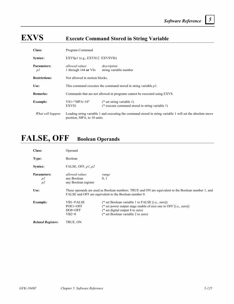
Software Reference
GFK-1848F Chapter 5 Software Reference 5-125
5
EXVS Execute Command Stored in String Variable Class: Program Command Syntax: EXVSp1 (e.g., EXVS12 EXVSVI6) Parameters: allowed values description p1 1 through 144 or VIn string variable number Restrictions: Not allowed in motion blocks. Use: This command executes the command stored in string variable p1. Remarks: Commands that are not allowed in programs cannot be executed using EXVS. Example: VS1=“MPA=10” (* set string variable 1) EXVS1 (* execute command stored in string variable 1) What will happen: Loading string variable 1 and executing the command stored in string variable 1 will set the absolute move
position, MPA, to 10 units.
FALSE, OFF Boolean Operands Class: Operand Type: Boolean Syntax: FALSE, OFF, p1, p2 Parameters: allowed values range p1 any Boolean 0, 1 p2 any Boolean register Use: These operands are used as Boolean numbers. TRUE and ON are equivalent to the Boolean number 1, and
FALSE and OFF are equivalent to the Boolean number 0. Example: VB1=FALSE (* set Boolean variable 1 to FALSE [i.e., zero]) POE1=OFF (* set power output stage enable of axis one to OFF [i.e., zero]) DO8=OFF (* set digital output 8 to zero) VB2=0 (* set Boolean variable 2 to zero) Related Registers: TRUE, ON
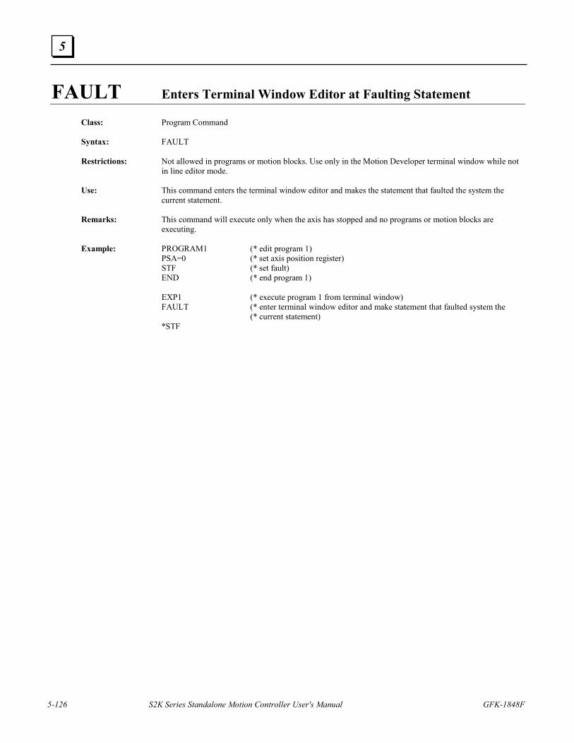
5-126 S2K Series Standalone Motion Controller User's Manual GFK-1848F
5
FAULT Enters Terminal Window Editor at Faulting Statement
Class: Program Command Syntax: FAULT Restrictions: Not allowed in programs or motion blocks. Use only in the Motion Developer terminal window while not
in line editor mode. Use: This command enters the terminal window editor and makes the statement that faulted the system the
current statement. Remarks: This command will execute only when the axis has stopped and no programs or motion blocks are
executing. Example: PROGRAM1 (* edit program 1) PSA=0 (* set axis position register) STF (* set fault) END (* end program 1) EXP1 (* execute program 1 from terminal window) FAULT (* enter terminal window editor and make statement that faulted system the (* current statement) *STF
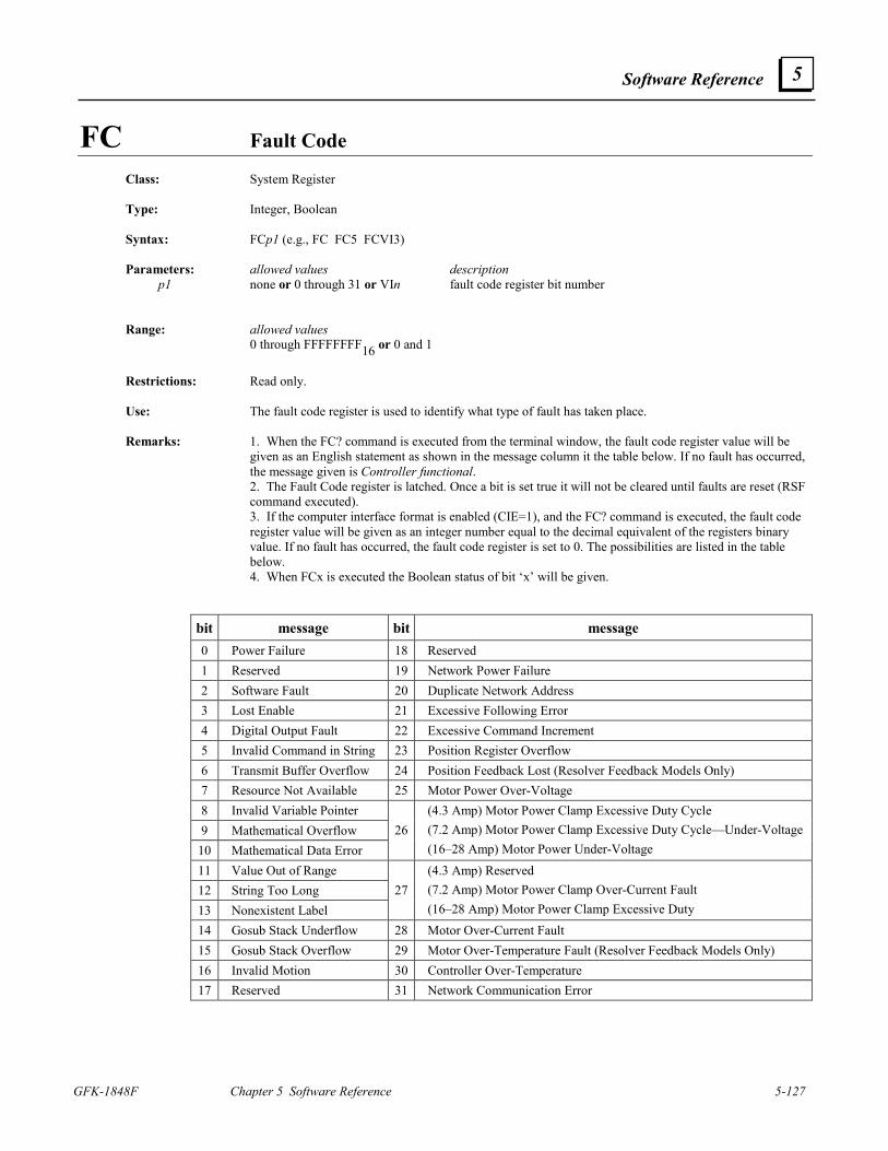
Software Reference
GFK-1848F Chapter 5 Software Reference 5-127
5
FC Fault Code Class: System Register Type: Integer, Boolean Syntax: FCp1 (e.g., FC FC5 FCVI3) Parameters: allowed values description p1 none or 0 through 31 or VIn fault code register bit number Range: allowed values 0 through FFFFFFFF16 or 0 and 1
Restrictions: Read only. Use: The fault code register is used to identify what type of fault has taken place. Remarks: 1. When the FC? command is executed from the terminal window, the fault code register value will be
given as an English statement as shown in the message column it the table below. If no fault has occurred, the message given is Controller functional.
2. The Fault Code register is latched. Once a bit is set true it will not be cleared until faults are reset (RSF command executed).
3. If the computer interface format is enabled (CIE=1), and the FC? command is executed, the fault code register value will be given as an integer number equal to the decimal equivalent of the registers binary value. If no fault has occurred, the fault code register is set to 0. The possibilities are listed in the table below.
4. When FCx is executed the Boolean status of bit ‘x’ will be given.
bit message bit message 0 Power Failure 18 Reserved 1 Reserved 19 Network Power Failure 2 Software Fault 20 Duplicate Network Address 3 Lost Enable 21 Excessive Following Error 4 Digital Output Fault 22 Excessive Command Increment 5 Invalid Command in String 23 Position Register Overflow 6 Transmit Buffer Overflow 24 Position Feedback Lost (Resolver Feedback Models Only) 7 Resource Not Available 25 Motor Power Over-Voltage 8 Invalid Variable Pointer 9 Mathematical Overflow
10 Mathematical Data Error 26
(4.3 Amp) Motor Power Clamp Excessive Duty Cycle (7.2 Amp) Motor Power Clamp Excessive Duty Cycle—Under-Voltage (16–28 Amp) Motor Power Under-Voltage
11 Value Out of Range 12 String Too Long 13 Nonexistent Label
27(4.3 Amp) Reserved (7.2 Amp) Motor Power Clamp Over-Current Fault (16–28 Amp) Motor Power Clamp Excessive Duty
14 Gosub Stack Underflow 28 Motor Over-Current Fault 15 Gosub Stack Overflow 29 Motor Over-Temperature Fault (Resolver Feedback Models Only) 16 Invalid Motion 30 Controller Over-Temperature 17 Reserved 31 Network Communication Error
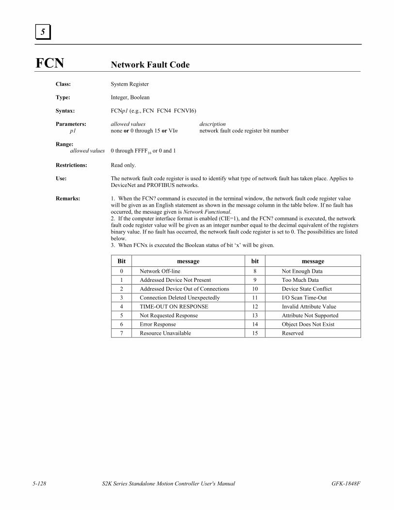
5-128 S2K Series Standalone Motion Controller User's Manual GFK-1848F
5
FCN Network Fault Code
Class: System Register Type: Integer, Boolean Syntax: FCNp1 (e.g., FCN FCN4 FCNVI6) Parameters: allowed values description p1 none or 0 through 15 or VIn network fault code register bit number Range: allowed values 0 through FFFF16 or 0 and 1 Restrictions: Read only. Use: The network fault code register is used to identify what type of network fault has taken place. Applies to
DeviceNet and PROFIBUS networks. Remarks: 1. When the FCN? command is executed in the terminal window, the network fault code register value
will be given as an English statement as shown in the message column in the table below. If no fault has occurred, the message given is Network Functional.
2. If the computer interface format is enabled (CIE=1), and the FCN? command is executed, the network fault code register value will be given as an integer number equal to the decimal equivalent of the registers binary value. If no fault has occurred, the network fault code register is set to 0. The possibilities are listed below.
3. When FCNx is executed the Boolean status of bit ‘x’ will be given.
Bit message bit message 0 Network Off-line 8 Not Enough Data 1 Addressed Device Not Present 9 Too Much Data 2 Addressed Device Out of Connections 10 Device State Conflict 3 Connection Deleted Unexpectedly 11 I/O Scan Time-Out 4 TIME-OUT ON RESPONSE 12 Invalid Attribute Value 5 Not Requested Response 13 Attribute Not Supported 6 Error Response 14 Object Does Not Exist 7 Resource Unavailable 15 Reserved
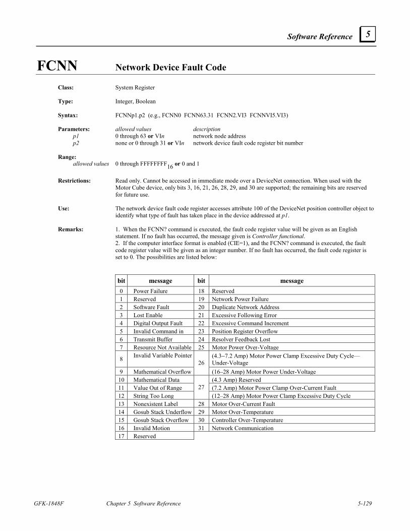
Software Reference
GFK-1848F Chapter 5 Software Reference 5-129
5
FCNN Network Device Fault Code Class: System Register Type: Integer, Boolean Syntax: FCNNp1.p2 (e.g., FCNN0 FCNN63.31 FCNN2.VI3 FCNNVI5.VI3) Parameters: allowed values description p1 0 through 63 or VIn network node address p2 none or 0 through 31 or VIn network device fault code register bit number Range: allowed values 0 through FFFFFFFF16 or 0 and 1
Restrictions: Read only. Cannot be accessed in immediate mode over a DeviceNet connection. When used with the
Motor Cube device, only bits 3, 16, 21, 26, 28, 29, and 30 are supported; the remaining bits are reserved for future use.
Use: The network device fault code register accesses attribute 100 of the DeviceNet position controller object to
identify what type of fault has taken place in the device addressed at p1. Remarks: 1. When the FCNN? command is executed, the fault code register value will be given as an English
statement. If no fault has occurred, the message given is Controller functional. 2. If the computer interface format is enabled (CIE=1), and the FCNN? command is executed, the fault
code register value will be given as an integer number. If no fault has occurred, the fault code register is set to 0. The possibilities are listed below:
bit message bit message 0 Power Failure 18 Reserved1 Reserved 19 Network Power Failure2 Software Fault 20 Duplicate Network Address3 Lost Enable 21 Excessive Following Error4 Digital Output Fault 22 Excessive Command Increment 5 Invalid Command in 23 Position Register Overflow6 Transmit Buffer 24 Resolver Feedback Lost7 Resource Not Available 25 Motor Power Over-Voltage
8 Invalid Variable Pointer (4.3−7.2 Amp) Motor Power Clamp Excessive Duty Cycle—Under-Voltage
9 Mathematical Overflow26
(16–28 Amp) Motor Power Under-Voltage 10 Mathematical Data (4.3 Amp) Reserved11 Value Out of Range (7.2 Amp) Motor Power Clamp Over-Current Fault12 String Too Long
27 (12–28 Amp) Motor Power Clamp Excessive Duty Cycle
13 Nonexistent Label 28 Motor Over-Current Fault14 Gosub Stack Underflow 29 Motor Over-Temperature15 Gosub Stack Overflow 30 Controller Over-Temperature16 Invalid Motion 31 Network Communication 17 Reserved
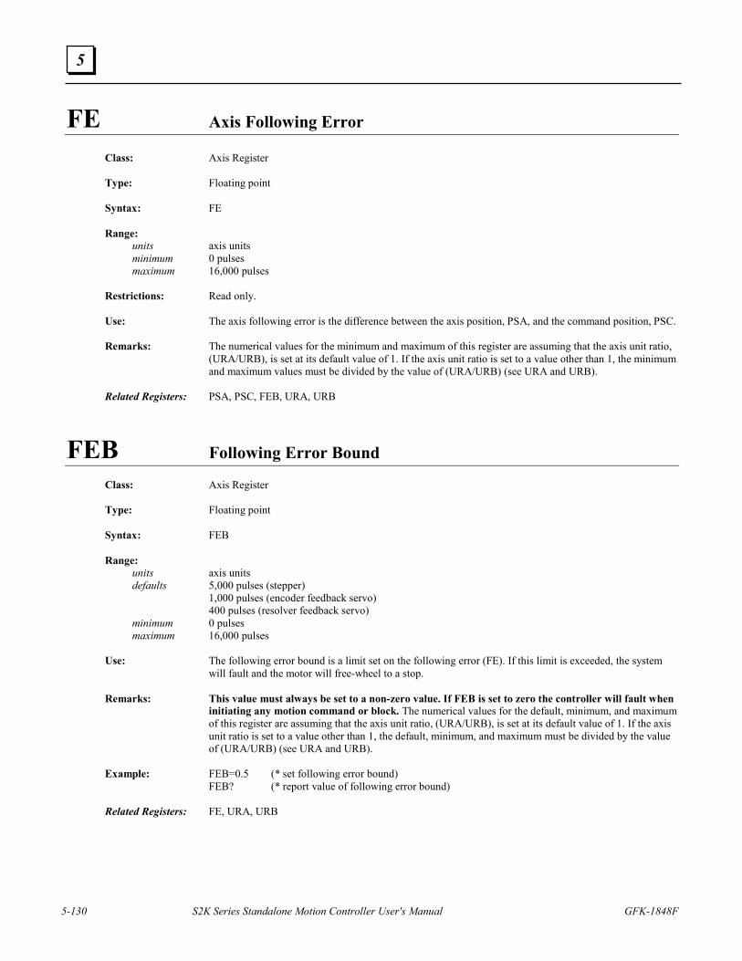
5-130 S2K Series Standalone Motion Controller User's Manual GFK-1848F
5
FE Axis Following Error
Class: Axis Register Type: Floating point Syntax: FE Range: units axis units minimum 0 pulses maximum 16,000 pulses Restrictions: Read only. Use: The axis following error is the difference between the axis position, PSA, and the command position, PSC. Remarks: The numerical values for the minimum and maximum of this register are assuming that the axis unit ratio,
(URA/URB), is set at its default value of 1. If the axis unit ratio is set to a value other than 1, the minimum and maximum values must be divided by the value of (URA/URB) (see URA and URB).
Related Registers: PSA, PSC, FEB, URA, URB
FEB Following Error Bound
Class: Axis Register Type: Floating point Syntax: FEB Range: units axis units defaults 5,000 pulses (stepper) 1,000 pulses (encoder feedback servo) 400 pulses (resolver feedback servo) minimum 0 pulses maximum 16,000 pulses Use: The following error bound is a limit set on the following error (FE). If this limit is exceeded, the system
will fault and the motor will free-wheel to a stop. Remarks: This value must always be set to a non-zero value. If FEB is set to zero the controller will fault when
initiating any motion command or block. The numerical values for the default, minimum, and maximum of this register are assuming that the axis unit ratio, (URA/URB), is set at its default value of 1. If the axis unit ratio is set to a value other than 1, the default, minimum, and maximum must be divided by the value of (URA/URB) (see URA and URB).
Example: FEB=0.5 (* set following error bound) FEB? (* report value of following error bound) Related Registers: FE, URA, URB
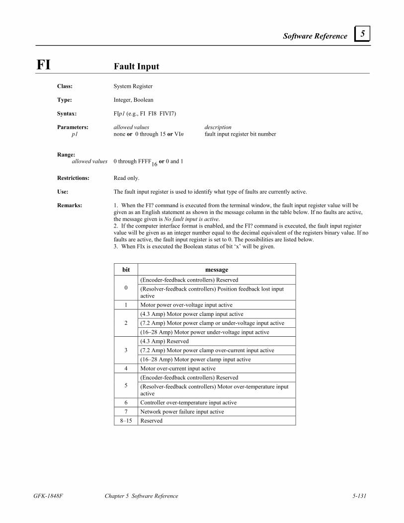
Software Reference
GFK-1848F Chapter 5 Software Reference 5-131
5
FI Fault Input Class: System Register Type: Integer, Boolean Syntax: FIp1 (e.g., FI FI8 FIVI7) Parameters: allowed values description p1 none or 0 through 15 or VIn fault input register bit number Range: allowed values 0 through FFFF16 or 0 and 1
Restrictions: Read only. Use: The fault input register is used to identify what type of faults are currently active. Remarks: 1. When the FI? command is executed from the terminal window, the fault input register value will be
given as an English statement as shown in the message column in the table below. If no faults are active, the message given is No fault input is active.
2. If the computer interface format is enabled, and the FI? command is executed, the fault input register value will be given as an integer number equal to the decimal equivalent of the registers binary value. If no faults are active, the fault input register is set to 0. The possibilities are listed below.
3. When FIx is executed the Boolean status of bit ‘x’ will be given.
bit message (Encoder-feedback controllers) Reserved
0 (Resolver-feedback controllers) Position feedback lost input active
1 Motor power over-voltage input active (4.3 Amp) Motor power clamp input active (7.2 Amp) Motor power clamp or under-voltage input active 2 (16–28 Amp) Motor power under-voltage input active (4.3 Amp) Reserved (7.2 Amp) Motor power clamp over-current input active 3 (16–28 Amp) Motor power clamp input active
4 Motor over-current input active (Encoder-feedback controllers) Reserved
5 (Resolver-feedback controllers) Motor over-temperature input active
6 Controller over-temperature input active 7 Network power failure input active
8–15 Reserved
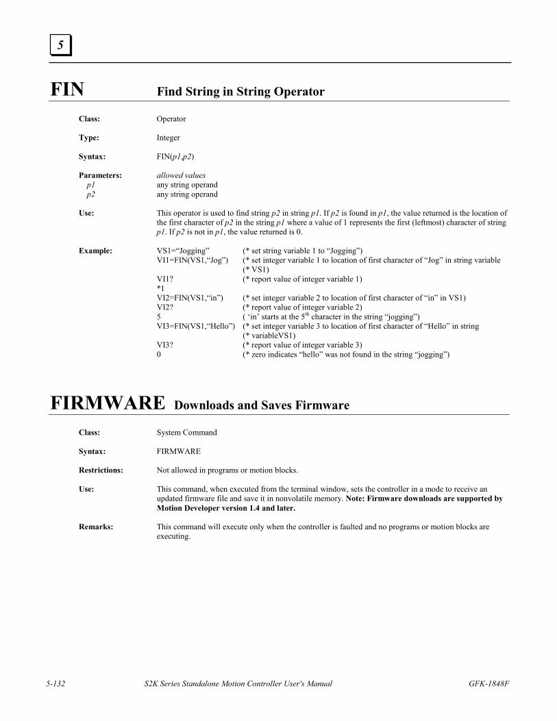
5-132 S2K Series Standalone Motion Controller User's Manual GFK-1848F
5
FIN Find String in String Operator
Class: Operator Type: Integer Syntax: FIN(p1,p2) Parameters: allowed values p1 any string operand p2 any string operand Use: This operator is used to find string p2 in string p1. If p2 is found in p1, the value returned is the location of
the first character of p2 in the string p1 where a value of 1 represents the first (leftmost) character of string p1. If p2 is not in p1, the value returned is 0.
Example: VS1=“Jogging” (* set string variable 1 to “Jogging”) VI1=FIN(VS1,“Jog”) (* set integer variable 1 to location of first character of “Jog” in string variable (* VS1) VI1? (* report value of integer variable 1) *1 VI2=FIN(VS1,“in”) (* set integer variable 2 to location of first character of “in” in VS1) VI2? (* report value of integer variable 2) 5 ( ‘in’ starts at the 5th character in the string “jogging”) VI3=FIN(VS1,“Hello”) (* set integer variable 3 to location of first character of “Hello” in string (* variableVS1) VI3? (* report value of integer variable 3) 0 (* zero indicates “hello” was not found in the string “jogging”)
FIRMWARE Downloads and Saves Firmware Class: System Command Syntax: FIRMWARE Restrictions: Not allowed in programs or motion blocks. Use: This command, when executed from the terminal window, sets the controller in a mode to receive an
updated firmware file and save it in nonvolatile memory. Note: Firmware downloads are supported by Motion Developer version 1.4 and later.
Remarks: This command will execute only when the controller is faulted and no programs or motion blocks are
executing.
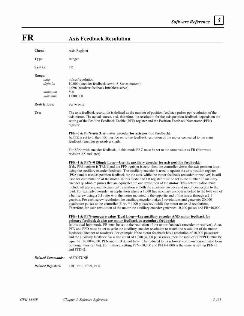
Software Reference
GFK-1848F Chapter 5 Software Reference 5-133
5
FR Axis Feedback Resolution Class: Axis Register Type: Integer Syntax: FR Range: units pulses/revolution defaults 10,000 (encoder feedback servo; S-Series motors) 4,096 (resolver feedback brushless servo) minimum 500 maximum 1,000,000 Restrictions: Servo only. Use: The axis feedback resolution is defined as the number of position feedback pulses per revolution of the
axis motor. The actual source, and, therefore, the resolution for the axis position feedback depends on the setting of the Position Feedback Enable (PFE) register and the Position Feedback Numerator (PFN) register:
PFE=0 & PFN=n/a (Use motor encoder for axis position feedback): In PFE is set to 0, then FR must be set to the feedback resolution of the motor connected to the main
feedback (encoder or resolver) path. For S2Ks with encoder feedback, in this mode FRC must be set to the same value as FR (Firmware
revision 2.5 and later). PFE=1 & PFN=0 (Single LoopUse the auxiliary encoder for axis position feedback): If the PFE register is TRUE and the PFN register is zero, then the controller closes the axis position loop
using the auxiliary encoder feedback. The auxiliary encoder is used to update the axis position register (PSA) and is used as position feedback for the axis, while the motor feedback (encoder or resolver) is still used for commutation of the motor. In this mode, the FR register must be set to the number of auxiliary encoder quadrature pulses that are equivalent to one revolution of the motor. This determination must include all gearing and mechanical translation in both the auxiliary encoder and motor connection to the load. For example, consider an application where a 1,000 line auxiliary encoder is belted to the load end of a ball screw using a 5:1 ratio with the motor mounted to the opposite end of the screw through a 2:1 gearbox. For each screw revolution the auxiliary encoder makes 5 revolutions and generates 20,000 quadrature pulses to the controller (5 rev * 4000 pulses/rev) while the motor makes 2 revolutions. Therefore, for each revolution of the motor the auxiliary encoder generates 10,000 pulses and FR=10,000.
PFE=1 & PFN=non-zero value (Dual LoopUse auxiliary encoder AND motor feedback for
primary feedback & also use motor feedback as secondary feedback): In this dual-loop mode, FR must be set to the resolution of the motor feedback (encoder or resolver). Also,
PFN and PFD must be set to scale the auxiliary encoder resolution to match the resolution of the motor feedback (encoder or resolver). For example, if the motor feedback has a resolution of 10,000 pulses/rev and the auxiliary feedback has a line count of 1,000 (4,000 pulses/rev), then the ratio of PFN/PFD must be equal to 10,000/4,000. PFN and PFD do not have to be reduced to their lowest common denominator form (although they can be). For instance, setting PFN=10,000 and PFD=4,000 is the same as setting PFN=5 and PFD=2.
Related Commands: AUTOTUNE Related Registers: FRC, PFE, PFN, PFD
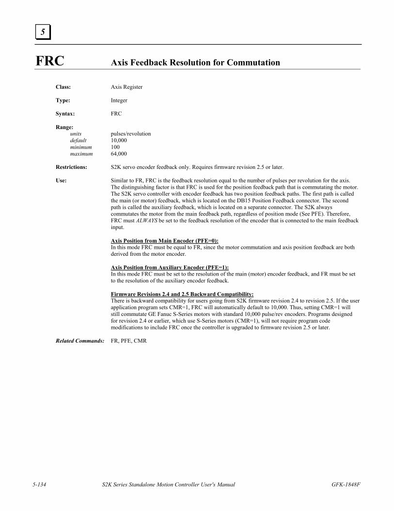
5-134 S2K Series Standalone Motion Controller User's Manual GFK-1848F
5
FRC Axis Feedback Resolution for Commutation
Class: Axis Register Type: Integer Syntax: FRC Range: units pulses/revolution default 10,000 minimum 100 maximum 64,000 Restrictions: S2K servo encoder feedback only. Requires firmware revision 2.5 or later. Use: Similar to FR, FRC is the feedback resolution equal to the number of pulses per revolution for the axis.
The distinguishing factor is that FRC is used for the position feedback path that is commutating the motor. The S2K servo controller with encoder feedback has two position feedback paths. The first path is called the main (or motor) feedback, which is located on the DB15 Position Feedback connector. The second path is called the auxiliary feedback, which is located on a separate connector. The S2K always commutates the motor from the main feedback path, regardless of position mode (See PFE). Therefore, FRC must ALWAYS be set to the feedback resolution of the encoder that is connected to the main feedback input.
Axis Position from Main Encoder (PFE=0): In this mode FRC must be equal to FR, since the motor commutation and axis position feedback are both
derived from the motor encoder. Axis Position from Auxiliary Encoder (PFE=1): In this mode FRC must be set to the resolution of the main (motor) encoder feedback, and FR must be set
to the resolution of the auxiliary encoder feedback. Firmware Revisions 2.4 and 2.5 Backward Compatibility: There is backward compatibility for users going from S2K firmware revision 2.4 to revision 2.5. If the user
application program sets CMR=1, FRC will automatically default to 10,000. Thus, setting CMR=1 will still commutate GE Fanuc S-Series motors with standard 10,000 pulse/rev encoders. Programs designed for revision 2.4 or earlier, which use S-Series motors (CMR=1), will not require program code modifications to include FRC once the controller is upgraded to firmware revision 2.5 or later.
Related Commands: FR, PFE, CMR
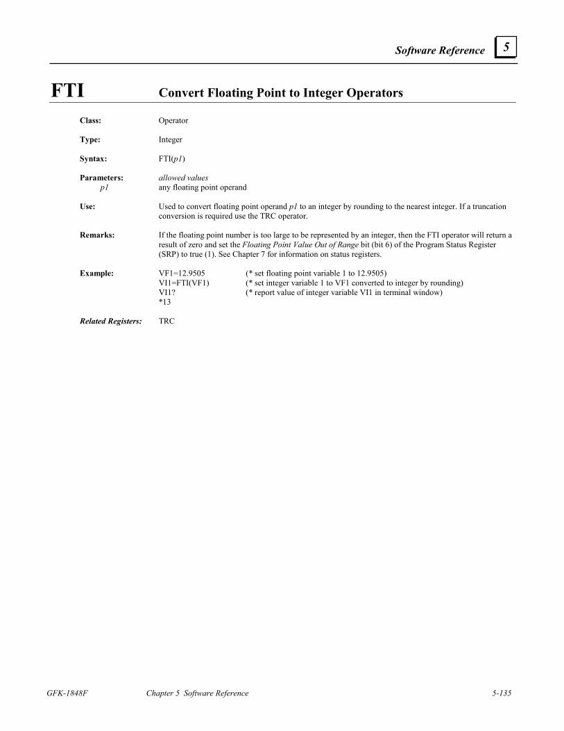
Software Reference
GFK-1848F Chapter 5 Software Reference 5-135
5
FTI Convert Floating Point to Integer Operators
Class: Operator Type: Integer Syntax: FTI(p1) Parameters: allowed values p1 any floating point operand Use: Used to convert floating point operand p1 to an integer by rounding to the nearest integer. If a truncation
conversion is required use the TRC operator. Remarks: If the floating point number is too large to be represented by an integer, then the FTI operator will return a
result of zero and set the Floating Point Value Out of Range bit (bit 6) of the Program Status Register (SRP) to true (1). See Chapter 7 for information on status registers.
Example: VF1=12.9505 (* set floating point variable 1 to 12.9505) VI1=FTI(VF1) (* set integer variable 1 to VF1 converted to integer by rounding) VI1? (* report value of integer variable VI1 in terminal window) *13 Related Registers: TRC
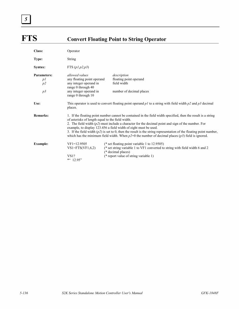
5-136 S2K Series Standalone Motion Controller User's Manual GFK-1848F
5
FTS Convert Floating Point to String Operator
Class: Operator Type: String Syntax: FTS (p1,p2,p3) Parameters: allowed values description p1 any floating point operand floating point operand p2 any integer operand in field width range 0 through 40 p3 any integer operand in number of decimal places range 0 through 10 Use: This operator is used to convert floating point operand p1 to a string with field width p2 and p3 decimal
places. Remarks: 1. If the floating point number cannot be contained in the field width specified, then the result is a string
of asterisks of length equal to the field width. 2. The field width (p2) must include a character for the decimal point and sign of the number. For
example, to display 123.456 a field width of eight must be used. 3. If the field width (p2) is set to 0, then the result is the string representation of the floating point number,
which has the minimum field width. When p2=0 the number of decimal places (p3) field is ignored. Example: VF1=12.9505 (* set floating point variable 1 to 12.9505) VS1=FTS(VF1,6,2) (* set string variable 1 to VF1 converted to string with field width 6 and 2 (* decimal places) VS1? (* report value of string variable 1) *“ 12.95”
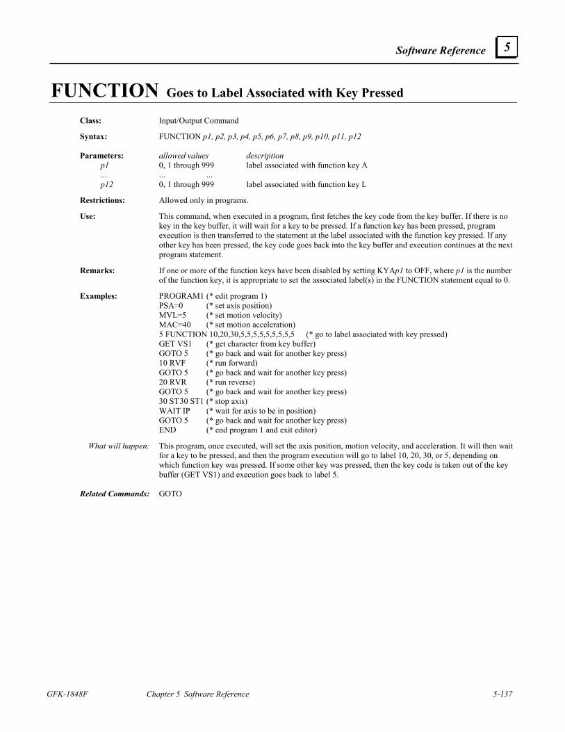
Software Reference
GFK-1848F Chapter 5 Software Reference 5-137
5
FUNCTION Goes to Label Associated with Key Pressed Class: Input/Output Command Syntax: FUNCTION p1, p2, p3, p4, p5, p6, p7, p8, p9, p10, p11, p12 Parameters: allowed values description p1 0, 1 through 999 label associated with function key A ... ... ... p12 0, 1 through 999 label associated with function key L Restrictions: Allowed only in programs. Use: This command, when executed in a program, first fetches the key code from the key buffer. If there is no
key in the key buffer, it will wait for a key to be pressed. If a function key has been pressed, program execution is then transferred to the statement at the label associated with the function key pressed. If any other key has been pressed, the key code goes back into the key buffer and execution continues at the next program statement.
Remarks: If one or more of the function keys have been disabled by setting KYAp1 to OFF, where p1 is the number
of the function key, it is appropriate to set the associated label(s) in the FUNCTION statement equal to 0. Examples: PROGRAM1 (* edit program 1) PSA=0 (* set axis position) MVL=5 (* set motion velocity) MAC=40 (* set motion acceleration) 5 FUNCTION 10,20,30,5,5,5,5,5,5,5,5,5 (* go to label associated with key pressed) GET VS1 (* get character from key buffer) GOTO 5 (* go back and wait for another key press) 10 RVF (* run forward) GOTO 5 (* go back and wait for another key press) 20 RVR (* run reverse) GOTO 5 (* go back and wait for another key press) 30 ST 30 ST1 (* stop axis) WAIT IP (* wait for axis to be in position) GOTO 5 (* go back and wait for another key press) END (* end program 1 and exit editor) What will happen: This program, once executed, will set the axis position, motion velocity, and acceleration. It will then wait
for a key to be pressed, and then the program execution will go to label 10, 20, 30, or 5, depending on which function key was pressed. If some other key was pressed, then the key code is taken out of the key buffer (GET VS1) and execution goes back to label 5.
Related Commands: GOTO
5-138 S2K Series Standalone Motion Controller User's Manual GFK-1848F
5
GET Gets One Character from Key Buffer
Class: Input/Output Command Syntax: GET p1 (e.g., GET VI5 GET VS10) Parameters: allowed values description p1 any variable register variable register Restrictions: Allowed only in programs. Use: This command gets one character from the key buffer (256 bytes max.)and loads it into the variable p1. If
no character is available in the key buffer, then this command waits until a character is put into the key buffer.
Remarks: 1. If p1 is a Boolean variable, VBn or VBVIn, the resulting value will be 0 if the character is ASCII 0;
otherwise the resulting value is 1. 2. If p1 is a floating point or integer variable, VFn, VFVIn, VIn, VIVIn, the resulting value will be the
ASCII value of the character. (see Appendix A) 3. If p1 is a string variable, VSn or VSVIn, the resulting value is the actual character. Example: PROGRAM1 (* edit program 1 in the terminal window) GET VI1 (* get one character from the key buffer) GET VS1 (* get one character from the key buffer) END (* end program 1 and exit editor) EXP1 (* execute program 1) KYE (* put character ‘E’ into key buffer) KYE (* put character ‘E’ into key buffer) VI1? (* report value of integer variable register) * 69 (* capital letter ‘E’ has an ASCII value of 69) VS1? (* report value of string variable register) * E Related Commands: PUT, IN, OUT, EKB
Software Reference
GFK-1848F Chapter 5 Software Reference 5-139
5
GOSUB Unconditional Branch to Subroutine Label
Class: Program Command Syntax: GOSUBp1 (e.g., GOSUB349 GOSUBVI10) Parameters: allowed values description p1 1 through 999 or VIn label number Restrictions: Allowed only in programs. Use: This command causes the program execution to go unconditionally to the subroutine at label p1. The
program will return to the line immediately following the GOSUB command when it encounters the RETURN command.
Remarks: There can be up to 32 nested GOSUB statements in a program. Example: PROGRAM1 (* program 1) PSA=0 (* set axis position register) MVL=1 (* set motion velocity) MAC=10 (* set motion acceleration) RVF (* run to velocity forward) GOSUB5 (* unconditional jump to subroutine at label 5) VI1=6 (* load integer variable) GOSUBVI1 (* unconditional jump to subroutine at label 6) GOTO10 (* unconditional jump to label 10) 5 OUT “Press any key to stop axis $N (* output string expression to display) GET VI2 (* get one character from key buffer) ST (* stop axis) RETURN (* return from subroutine at label 5) 6 OUT “Axis position is “+ FTS(PSA,5,2) + “ units.$N” (* output string expression to display) RETURN (* return from subroutine at label 6) 10 END (* end program 1) What will happen: This program, once executed, runs the axis in the forward direction. Then the execution goes to the
subroutine at label 5, which waits for a character from the key buffer and returns upon receiving the character. Next, the execution goes to the subroutine at label 6, which prints the axis position on the display and returns. It then goes to the statement at label 10, which ends the program.
Related Commands: GOTO, RETURN, POP, RSTSTK
5-140 S2K Series Standalone Motion Controller User's Manual GFK-1848F
5
GOTO Unconditional Jump to Program Label
Class: Program Command Syntax: GOTOp1 (e.g., GOTO50 GOTOVI43) Parameters: allowed values description p1 1 through 999 or VIn label number Restrictions: Allowed only in programs. Use: This command causes the program execution to go unconditionally to the statement at label p1. Example: PROGRAM1 (* program 1) PSA=0 (* set axis position register) MVL=1 (* set motion velocity) MAC=10 (* set motion acceleration) RVF (* run to velocity forward) GOSUB5 (* unconditional jump to subroutine at label 5) VI1=6 (* load integer variable) GOSUBVI1 (* unconditional jump to subroutine at label 6) GOTO10 (* unconditional jump to label 10) 5 OUT “Press any key to stop axis $N” (* output string expression to display) GET VI2 (* get one character from key buffer) ST (* stop axis) RETURN (* return from subroutine at label 5) 6 OUT “Axis position is “ + FTS(PSA,5,2) + “ units.$N” (* output string expression to display) RETURN (* return from subroutine at label 6) 10 END (* end program 1) What will happen: This program, once executed, runs the axis in the forward direction. Then the execution goes to the
subroutine at label 5, which waits for a character from the key buffer and returns upon receiving the character. Next, the execution goes to the subroutine at label 6, which prints the axis position on the display and returns. It then goes to the statement at label 10, which ends the program.
Related Commands: GOSUB
Software Reference
GFK-1848F Chapter 5 Software Reference 5-141
5
GRB Gearing Bound
Class: Motion Register Type: Floating point Syntax: GRB Range: units axis units/sec default 0 pulses/sec minimum 0 pulses/sec maximum 16,000,000 pulses/sec Use: This register sets a bound on the maximum axis pulses per second that the electronic gearing function can
command. If the pulse input rate times the gearing ratio (GRN/GRD)results in a value outside of the bound, then the extra pulses are discarded (i.e., the rate is clamped at the bound limit). When the value of GRB is zero, there is no bound on electronic gearing. See Section 5.5.2, Using Electronic Gearing, for more details.
Remarks: The numerical values for the default, minimum, and maximum of this register are assuming that the axis
unit ratio, (URA/URB), is set at its default value of 1. If the axis unit ratio is set to a value other than 1, the default, minimum, and maximum values must be divided by the value of (URA/URB) (see URA and URB).
Related Registers: GRN, GRD
GRD Gearing Denominator
Class: Motion Register Type: Integer Syntax: GRD Range: default 1 minimum 1 maximum 10,000 Use: The gearing denominator is a parameter used in electronic gearing. It is defined as the denominator of the
gearing ratio between the axis and the gearing input. The gearing input source is typically the auxiliary encoder input unless the handwheel input is enabled (HWE=1). Change the sign on the GRN parameter to change motor direction while gearing is enabled (GRE=1).
Axis Pulses = Gearing Input Pulses * GRN/GRD. If either GRN or GRD is outside the allowed range try dividing both register values by a prime number (2,
3, 5, 7, 11, etc.) until both values are integers within the allowable range. See Section 5.5.2, Using Electronic Gearing, for more details. Related Registers: GRN, GRE, HWE, QTX
5-142 S2K Series Standalone Motion Controller User's Manual GFK-1848F
5
GRE Gearing Enable Class: Motion Register Type: Boolean Syntax: GRE Range: default 0 allowed values 0, 1 Use: The gearing enable is used to enable electronic gearing. If GRE is set to 1, then electronic gearing is
enabled and the axis will follow the gearing input based on the gearing ratio (GRN/GRD); and if GRE is set to 0, it is disabled.
Remarks: Electronic gearing does not use acceleration/deceleration limits and will accelerate/decelerate as quickly as
system constraints will allow when the GRE bit is set true/false. Use pulse-based motion when acceleration limits are required. When the gearing enable bit is set true the controller will begin to accumulate master encoder pulses. If gearing is enabled while the master is moving the axis will overspeed within system constraints in an attempt to decrement any master pulses that accumulate while the axis is accelerating. Gearing is automatically disabled when a controller fault occurs. See Section 5.5.2 – Using Electronic Gearing for more details.
Related Registers: GRD, GRN, GRB, GRF, QTX Motion Templates: Electronic gearing
GRF Gearing Filter Constant Class: Motion Register Type: Integer Syntax: GRF Range: default 0 minimum 0 maximum 8 Use: The gearing filter constant is used to filter the output of electronic gearing. The amount of filtering
increases by the value as a power of two from 0 (no filter) to 8 (a filter of 256 samples). Note that higher values slow system response so use the smallest acceptable value. See Section 5.5.2, Using Electronic Gearing, for more details.
Related Registers: GRB, GRN, GRD
Software Reference
GFK-1848F Chapter 5 Software Reference 5-143
5
GRN Gearing Numerator
Class: Motion Register Type: Integer Syntax: GRN Range: default 1 minimum -10,000 maximum 10,000 Use: The gearing numerator is a parameter used in electronic gearing. It is defined as the numerator of the
gearing ratio between the axis and the gearing input. The gearing input source is typically the auxiliary encoder input unless the handwheel input is enabled (HWE=1). Changing the sign of the GRN value will change the direction of the motor while gearing is enabled (GRE=1).
Axis Pulses = Gearing Input Pulses * GRN/GRD. If either GRN or GRD is outside the allowed range try dividing both register values by a prime number (2,
3, 5, 7, 11, etc.) until both values are integers within the allowable range. See Section 5.5.2, Using Electronic Gearing, for more details. Related Registers: GRD, GRE, HWE, QTX
HSE XON, XOFF Handshake Protocol Enable
Class: System Register Type: Boolean Syntax: HSE Range: default 0 allowed values 0, 1 Restrictions: Cannot be assigned in motion blocks. Use: This register is used to enable the XON, XOFF handshake protocol on the serial/program port. If HSE is
set to 1, then handshake protocol is enabled; and if HSE is set to 0, then it is disabled. Related Registers: CIE
5-144 S2K Series Standalone Motion Controller User's Manual GFK-1848F
5
HT Halts Motion
Class: Motion Command Syntax: HT Use: This command immediately halts all axis motion. Remarks: This command should be used only at low velocities or in extreme situations as the sudden stop may
damage mechanical components in the system. This command sets SRA register bits 0, 1, 2, and 14 to Logic 0.
Example: MVL=10 (* set motion velocity) MAC=10 (* set motion acceleration) RVF (* run to velocity forward) HT (* halt motion) What will happen: Setting the velocity and acceleration and issuing the RVF command will cause the axis to run in the
forward direction. Issuing the HT command will cause the axis to halt immediately. Related Commands: ST
HTN Network Halt
Class: Motion Command Syntax: HTNp1 (e.g., HTN0 HTN63 HTNVI5) Parameters: allowed values description p1 0 through 63 or VIn network node address Restrictions: Cannot be accessed in immediate mode over a DeviceNet connection. Use: The network halt command accesses attribute 21 of the DeviceNet position controller object to
immediately halt all motion for the axis addressed at p1. Remarks: This command should be used only at low velocities or in extreme situations because the sudden stop may
damage mechanical components in the system. For normal stops use the STN command. Related Commands: HT, ST, STN
Software Reference
GFK-1848F Chapter 5 Software Reference 5-145
5
HWE Handwheel Input Enable Class: Motion Register Type: Boolean Syntax: HWE Range: default 0 allowed values 0, 1 Use: The handwheel input enable is used to enable handwheel quadrature input on digital inputs 5 (handwheel
channel A) and 6 (handwheel channel B) to be used in place of the auxiliary encoder input for electronic gearing. If HWE is set to 1, then handwheel input is enabled; and if HWE is set to 0, it is disabled and the auxiliary encoder is used as the electronic gearing input source. The axis will follow the auxiliary input based on the values of GRN and GRD as shown below:
Axis pulses = Handwheel Input Pulses * GRN/GRD Remarks: The maximum pulse rate is 500 pulses/second. Utility Template: Jog using electronic handwheel
5-146 S2K Series Standalone Motion Controller User's Manual GFK-1848F
5
IF...GOSUB Conditional Jumps to Subroutine Label
Class: Program Command Syntax: IF p1 GOSUBp2 (e.g., IF VB5 GOSUB35) Parameters: allowed values description p1 any Boolean expression Boolean expression p2 1 through 999 or VIn label number Restrictions: Allowed only in programs. Use: This command causes the program execution to go conditionally to the subroutine at label p2 if condition
p1 is true (i.e., evaluates to 1). The program will return when it encounters the RETURN command. Remarks: There can be up to 32 nested gosub statements in a program. Example: PROGRAM1 (* program 1) PSA=0 (* set axis position register) MVL=1 (* set motion velocity) MAC=10 (* set motion acceleration) RVF (* run to velocity forward) OUT “Press any key to stop axis $N” (* output string expression to display) 1 IF KEY GOSUB5 (* conditional jump to subroutine at label 5) IF IP GOTO10 (* conditional jump to label 10) GOTO1 (* unconditional jump to label 1) 5 OUT “Axis position is “ + FTS(PSA,5,2) + “ units.$N” (* output string expression to display)
EKB (* empty key buffer) ST (* stop axis) RETURN (* return from subroutine at label 5) 10 END (* end program 1) What will happen: This program runs the axis in the forward direction. It then waits for a character from the key buffer and
goes to the subroutine at label 5 upon receiving the character. This subroutine prints the axis position on the display, empties the key buffer, stops the axis, and returns. Once the axis is in position (IP), the execution goes to the statement at label 10, which ends the program.
Related Commands: GOSUB, IF...GOTO, RETURN, POP, RSTSTK
Software Reference
GFK-1848F Chapter 5 Software Reference 5-147
5
IF...GOTO Conditional Jump To Program Label Class: Program Command Syntax: IF p1 GOTOp2 (e.g., IF VB3 GOTO11) Parameters: allowed values description p1 any Boolean expression Boolean expression p2 1 through 999 or VIn label number Restrictions: Allowed only in programs. Use: This command causes the program execution to go conditionally to label p2 if p1 is true (i.e., evaluates to 1). Example: PROGRAM1 (* edit program 1) PSA=0 (* set axis position register) MVL=1 (* set motion velocity) MAC=10 (* set motion acceleration) RVF (* run to velocity forward) OUT “Press any key to stop axis$N” (* output string expression to display) 1 IF KEY GOSUB5 (* conditionally gosub 5) IF IP GOTO10 (* conditionally goto 10) GOTO1 (* unconditionally goto 1) 5 OUT “Axis position is “ + FTS(PSA,5,2) + “ units.$N” (* output string expression to display) EKB (* empty key buffer) ST (* stop axis) RETURN (* return from gosub) 10 END (* end program 1 and exit editor) What will happen: This program, once executed, runs the axis in the forward direction. It then waits for a character from the
key buffer and goes to the subroutine at label 5 upon receiving the character. This subroutine prints the axis position on the display, empties the key buffer, stops the axis, and returns. Once the axis is in position (IP), the execution goes to the statement at label 10, which ends the program.
Related Commands: GOTO, IF...GOSUB, IF...THEN
5-148 S2K Series Standalone Motion Controller User's Manual GFK-1848F
5
IF...THEN Conditionally Executes Next Command
Class: Program Command Syntax: IF p1 THEN (e.g., IF VF3>1.1 THEN) Parameters: allowed values description p1 any Boolean expression Boolean expression Restrictions: Allowed only in programs and motion blocks. Use: This command conditionally executes the next command in the program. If condition p1 is true the next
program line is executed. Otherwise, the next line is skipped. Example: PROGRAM1 (* edit program 1) VB1=0 (* set Boolean variable) IF VB1 THEN (* conditionally execute next command) VF5=30 (* set floating point variable) END (* end program 1 and exit editor) What will happen: This program, once executed, sets Boolean variable one to zero and does not set floating point variable to
30 because the condition of the IF...THEN command was false. Related Commands: IF...GOTO
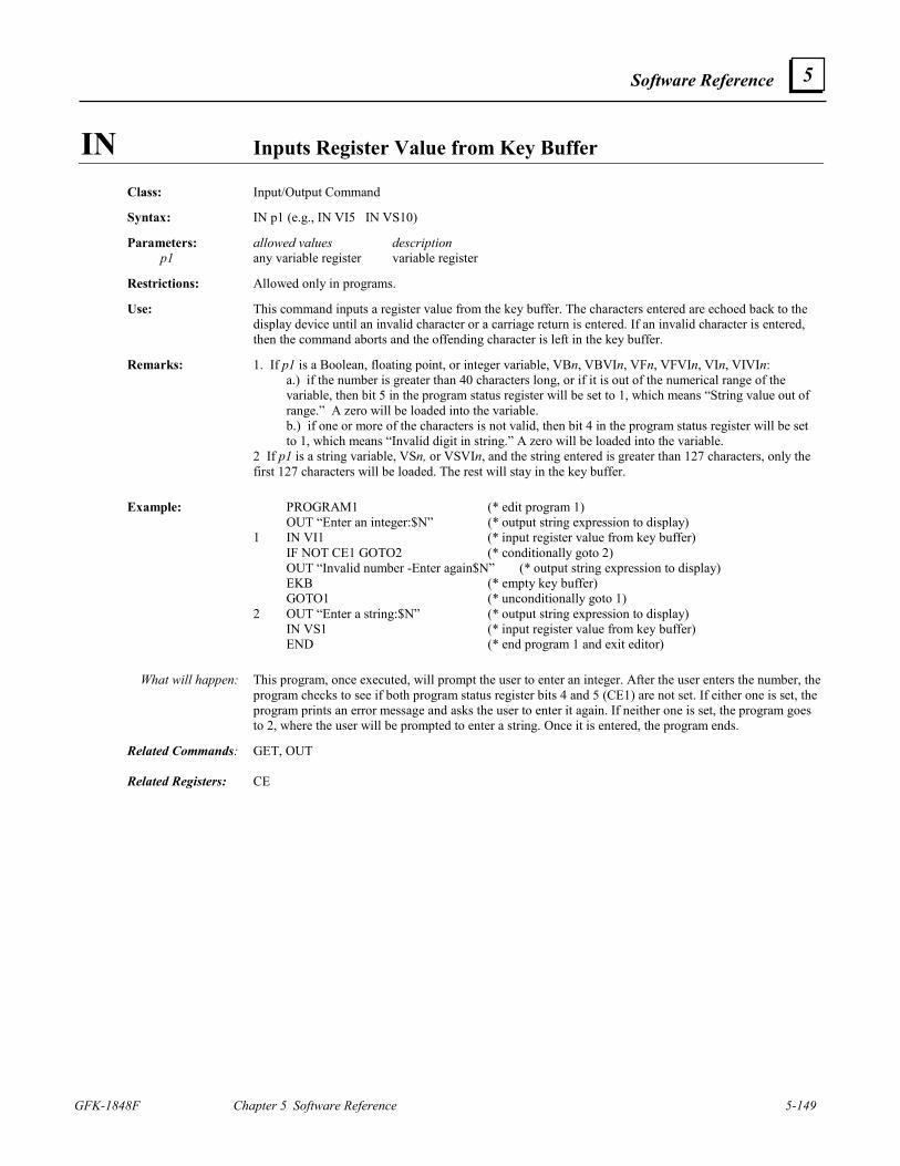
Software Reference
GFK-1848F Chapter 5 Software Reference 5-149
5
IN Inputs Register Value from Key Buffer Class: Input/Output Command Syntax: IN p1 (e.g., IN VI5 IN VS10) Parameters: allowed values description p1 any variable register variable register Restrictions: Allowed only in programs. Use: This command inputs a register value from the key buffer. The characters entered are echoed back to the
display device until an invalid character or a carriage return is entered. If an invalid character is entered, then the command aborts and the offending character is left in the key buffer.
Remarks: 1. If p1 is a Boolean, floating point, or integer variable, VBn, VBVIn, VFn, VFVIn, VIn, VIVIn:
a.) if the number is greater than 40 characters long, or if it is out of the numerical range of the variable, then bit 5 in the program status register will be set to 1, which means “String value out of range.” A zero will be loaded into the variable.
b.) if one or more of the characters is not valid, then bit 4 in the program status register will be set to 1, which means “Invalid digit in string.” A zero will be loaded into the variable.
2 If p1 is a string variable, VSn, or VSVIn, and the string entered is greater than 127 characters, only the first 127 characters will be loaded. The rest will stay in the key buffer.
Example: PROGRAM1 (* edit program 1) OUT “Enter an integer:$N” (* output string expression to display) 1 IN VI1 (* input register value from key buffer) IF NOT CE1 GOTO2 (* conditionally goto 2) OUT “Invalid number -Enter again$N” (* output string expression to display) EKB (* empty key buffer) GOTO1 (* unconditionally goto 1) 2 OUT “Enter a string:$N” (* output string expression to display) IN VS1 (* input register value from key buffer) END (* end program 1 and exit editor) What will happen: This program, once executed, will prompt the user to enter an integer. After the user enters the number, the
program checks to see if both program status register bits 4 and 5 (CE1) are not set. If either one is set, the program prints an error message and asks the user to enter it again. If neither one is set, the program goes to 2, where the user will be prompted to enter a string. Once it is entered, the program ends.
Related Commands: GET, OUT Related Registers: CE
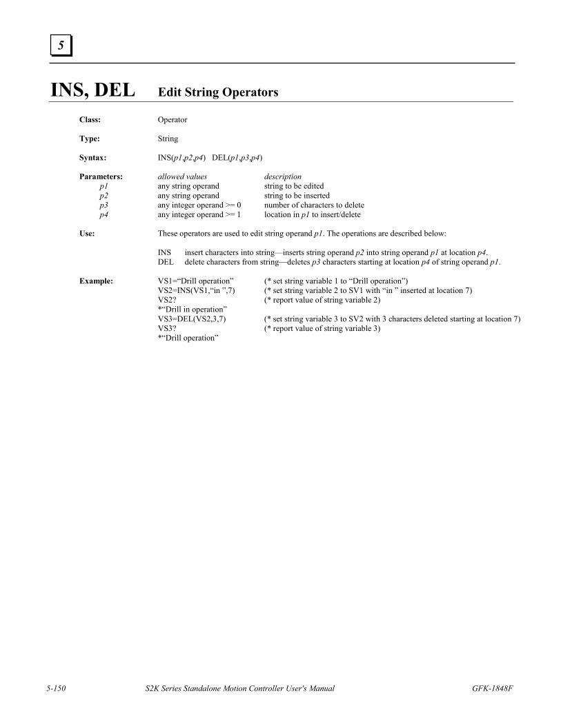
5-150 S2K Series Standalone Motion Controller User's Manual GFK-1848F
5
INS, DEL Edit String Operators
Class: Operator Type: String Syntax: INS(p1,p2,p4) DEL(p1,p3,p4) Parameters: allowed values description p1 any string operand string to be edited p2 any string operand string to be inserted p3 any integer operand >= 0 number of characters to delete p4 any integer operand >= 1 location in p1 to insert/delete Use: These operators are used to edit string operand p1. The operations are described below: INS insert characters into string—inserts string operand p2 into string operand p1 at location p4. DEL delete characters from string—deletes p3 characters starting at location p4 of string operand p1. Example: VS1=“Drill operation” (* set string variable 1 to “Drill operation”) VS2=INS(VS1,“in ”,7) (* set string variable 2 to SV1 with “in ” inserted at location 7) VS2? (* report value of string variable 2) *“Drill in operation” VS3=DEL(VS2,3,7) (* set string variable 3 to SV2 with 3 characters deleted starting at location 7) VS3? (* report value of string variable 3) *“Drill operation”
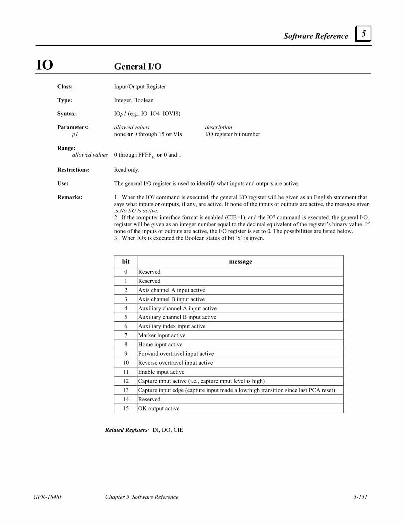
Software Reference
GFK-1848F Chapter 5 Software Reference 5-151
5
IO General I/O Class: Input/Output Register Type: Integer, Boolean Syntax: IOp1 (e.g., IO IO4 IOVI8) Parameters: allowed values description p1 none or 0 through 15 or VIn I/O register bit number Range: allowed values 0 through FFFF16 or 0 and 1 Restrictions: Read only. Use: The general I/O register is used to identify what inputs and outputs are active. Remarks: 1. When the IO? command is executed, the general I/O register will be given as an English statement that
says what inputs or outputs, if any, are active. If none of the inputs or outputs are active, the message given is No I/O is active.
2. If the computer interface format is enabled (CIE=1), and the IO? command is executed, the general I/O register will be given as an integer number equal to the decimal equivalent of the register’s binary value. If none of the inputs or outputs are active, the I/O register is set to 0. The possibilities are listed below.
3. When IOx is executed the Boolean status of bit ‘x’ is given.
bit message 0 Reserved 1 Reserved 2 Axis channel A input active 3 Axis channel B input active 4 Auxiliary channel A input active 5 Auxiliary channel B input active 6 Auxiliary index input active 7 Marker input active 8 Home input active 9 Forward overtravel input active
10 Reverse overtravel input active 11 Enable input active 12 Capture input active (i.e., capture input level is high) 13 Capture input edge (capture input made a low/high transition since last PCA reset) 14 Reserved 15 OK output active
Related Registers: DI, DO, CIE
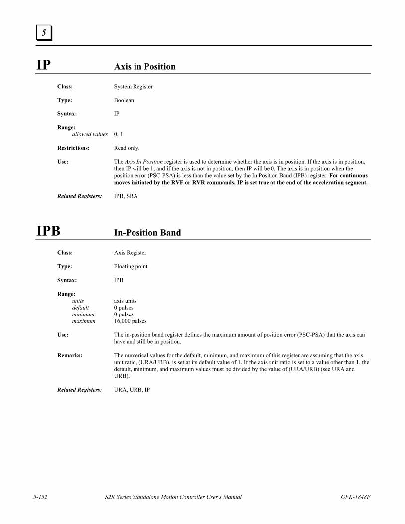
5-152 S2K Series Standalone Motion Controller User's Manual GFK-1848F
5
IP Axis in Position
Class: System Register Type: Boolean Syntax: IP Range: allowed values 0, 1 Restrictions: Read only. Use: The Axis In Position register is used to determine whether the axis is in position. If the axis is in position,
then IP will be 1; and if the axis is not in position, then IP will be 0. The axis is in position when the position error (PSC-PSA) is less than the value set by the In Position Band (IPB) register. For continuous moves initiated by the RVF or RVR commands, IP is set true at the end of the acceleration segment.
Related Registers: IPB, SRA
IPB In-Position Band
Class: Axis Register Type: Floating point Syntax: IPB Range: units axis units default 0 pulses minimum 0 pulses maximum 16,000 pulses Use: The in-position band register defines the maximum amount of position error (PSC-PSA) that the axis can
have and still be in position. Remarks: The numerical values for the default, minimum, and maximum of this register are assuming that the axis
unit ratio, (URA/URB), is set at its default value of 1. If the axis unit ratio is set to a value other than 1, the default, minimum, and maximum values must be divided by the value of (URA/URB) (see URA and URB).
Related Registers: URA, URB, IP
Software Reference
GFK-1848F Chapter 5 Software Reference 5-153
5
IPN Network In Position
Class: System Register Type: Boolean Syntax: IPNp1 (e.g., IPN0 IPN63 IPNVI5) Parameters: allowed values description p1 0 through 63 or VI n network node address Range: allowed values 0, 1 Restrictions: Read only. Cannot be accessed in immediate mode over a DeviceNet connection. Use: The network in position register accesses attribute 12 of the DeviceNet position controller object to
determine whether the axis addressed at p1 is in position. If the axis is in position, then IPN will be 1; and if the axis is not in position, then IPN will be 0.
Related Registers: IP, IPB, SRA
5-154 S2K Series Standalone Motion Controller User's Manual GFK-1848F
5
ITB, ITH, ITS Convert Integer to String Operators
Class: Operator Type: String Syntax: ITS(p1,p2) ITB(p1,p2) ITH(p1,p2) Parameters: allowed values description p1 any integer operand integer p2 any integer operand in range 0 through 40 field width Use: These operators are used to convert the integer operand p1 to a string. The operations are described below: ITB convert integer to binary string—converts p1 to a binary string. ITH convert integer to hex string—converts p1 to a hexadecimal string. ITS convert integer to string—converts p1 to a string. Remarks: 1. If the integer cannot be contained in the field width specified, then the result is a string of asterisks of
length equal to the field width. 2. If the field width is set to 0, then the result is the string representation of the integer, which has the
minimum field width. Example: VI1=2282 (* set integer variable 1 to 2282) VS1=ITS(VI1,6) (* set string variable 1 to VI1 converted to string with field width of 6) VS1? (* report value of string variable 1) *“ 2282” VS2=ITB(V11,4) (* set string variable 2 to VI1 converted to binary string with field width of 14) VS2? (* report value of string variable 2) *“2#100011101010” VS3=ITH(VI1,4) (* set string variable 3 to VI1 converted to hex string with field width of 4) VS3? (* report value of string variable 3) *“****” VS3=ITH(VI1,0) (* set string variable 3 to VI1 converted to hex string with minimum field width) VS3? (* report value of string variable 3) *“16#8EA”
Software Reference
GFK-1848F Chapter 5 Software Reference 5-155
5
ITF Convert Integer to Floating Point Operator Class: Operator Type: Floating point Syntax: ITF(p1) Parameters: allowed values p1 any integer operand Use: This operator is used to convert integer operand p1 to a floating point number. Both integer and floating
point data types use a 32 bit mantissa to prevent loss of precision when converting from integer to floating point.
Example: VI1=12 (* set integer variable 1 to 12) VF1=ITF(VI1) (* set floating point variable 1 to VI1 converted to floating point) VF1? (* report value of floating point variable 1)
*12.
5-156 S2K Series Standalone Motion Controller User's Manual GFK-1848F
5
KA Acceleration Feedforward
Class: Axis Register Type: Integer Syntax: KA Range: default 0 minimum 0 maximum 64,000 Restrictions: Servo only. Use: The acceleration feedforward constant is used to reduce following error during acceleration or
deceleration. The equation for setting KA based on the torque to inertia ratio and the axis feedback resolution, FR, is:
Where torque is the continuous torque of the motor in in-lbs and inertia is the system inertia in in-lb-sec2. The KA value along with the values of all the other control constants can be set automatically by the AUTOTUNE command.
Related Registers: FR Related Commands: AUTOTUNE
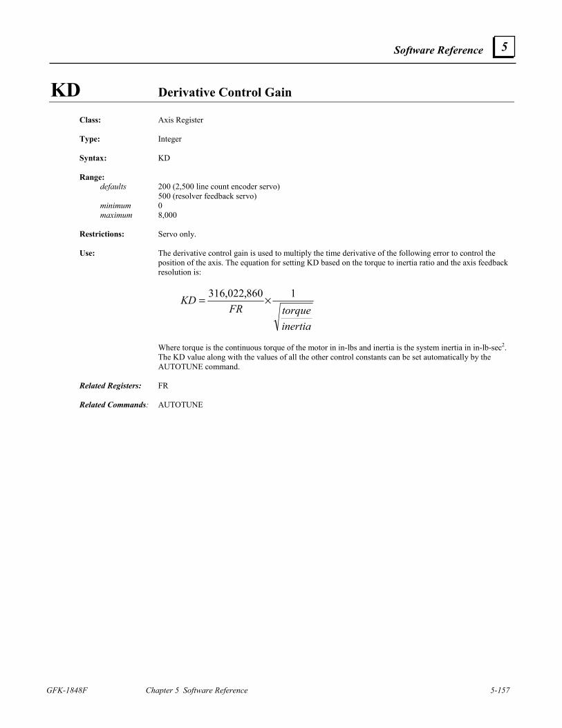
Software Reference
GFK-1848F Chapter 5 Software Reference 5-157
5
KD Derivative Control Gain
Class: Axis Register Type: Integer Syntax: KD Range: defaults 200 (2,500 line count encoder servo) 500 (resolver feedback servo) minimum 0 maximum 8,000 Restrictions: Servo only. Use: The derivative control gain is used to multiply the time derivative of the following error to control the
position of the axis. The equation for setting KD based on the torque to inertia ratio and the axis feedback resolution is:
inertiatorqueFR
KD 1860,022,316 ×=
Where torque is the continuous torque of the motor in in-lbs and inertia is the system inertia in in-lb-sec2.
The KD value along with the values of all the other control constants can be set automatically by the AUTOTUNE command.
Related Registers: FR Related Commands: AUTOTUNE

5-158 S2K Series Standalone Motion Controller User's Manual GFK-1848F
5
KEY Character in Key Buffer
Class: System Register Type: Boolean Syntax: KEY Range: allowed values 0, 1 Restrictions: Read only. Use: This register is used to determine whether a character is in the key buffer. KEY is equal to 1 when there is
a character in the key buffer, and it is equal to 0 when there is none. The Key buffer can hold up to 256 bytes.
Related Registers: SRS Related Commands: KY, EKB, GET, IN
KI Integral Control Gain
Class: Axis Register Type: Integer Syntax: KI Range: default 0 minimum 0 maximum 64,000 Restrictions: Servo only. Use: The integral control gain is used to multiply the time integral of the following error to control the position
of the axis. The equation for setting KI based on the torque to inertia ratio and the axis feedback resolution, FR, is:
inertiatorque
FRKI ×= 310,686
Where torque is the continuous torque of the motor in in-lbs and inertia is the system inertia in in-lb-sec2.
The KI value along with the values of all the other control constants can be set automatically by the AUTOTUNE command.
Related Registers: FR Related Commands: AUTOTUNE
Software Reference
GFK-1848F Chapter 5 Software Reference 5-159
5
KL Motor Inductance Class: Axis Register Type: Integer Syntax: KL Range: units mH default 4 mH for encoder feedback controllers 10 mH for resolver feedback controllers minimum 1 mH maximum 100 mH Restrictions: Servo only. Use: The motor inductance is used to tune the digital current controller to the attached motor. This register
should be set to the motor’s line-line inductance in mH—use the following table for your KL values:
S-Series Motor
KL Value (mH)
S-Series Motor
KL Value (mH)
S-Series Motor
KL Value (mH)
SLM003 5 SLM040-115V 4 SLM250 2 SLM005 6 SLM040-230V 10 SLM350 2 SLM010-115V 3 SLM070 6 SLM500 1 SLM010-230V 10 SLM100 4 SDM500 2 SLM020-115V 6 SDM100 10 SGM450 4 SLM020-230V 16 SDM250 4
MTR-Series
Motor KL Value
(mH) MTR-Series
Motor KL Value
(mH) MTR-Series
Motor KL Value
(mH) MTR-3N21-H 4 MTR-3S45-G 20 MTR-3T22-G 7 MTR-3N22-H 6 MTR-3S45-H 5 MTR-3T23-G 11 MTR-3N24-G 9 MTR-3S46-G 25 MTR-3T24-H 9 MTR-3N31-H 10 MTR-3S46-H 6 MTR-3T42-H 9 MTR-3N32-G 18 MTR-3S63-G 9 MTR-3T43-H 13 MTR-3N32-H 5 MTR-3S65-G 14 MTR-3T43-J 5 MTR-3N33-G 25 MTR-3S65-H 3 MTR-3T44-J 7 MTR-3N33-H 6.3 MTR-3S67-G 18 MTR-3T45-H 9 MTR-3S22-G 21 MTR-3S67-H 5 MTR-3T45-I 4 MTR-3S23-G 26 MTR-3S84-G 3 MTR-3T54-H 7 MTR-3S32-G 23 MTR-3S86-G 4 MTR-3T55-H 9 MTR-3S33-G 22 MTR-3S88-G 4 MTR-3T57-H 3 MTR-3S34-G 30 MTR-3T11-G 7 MTR-3T66-H 7 MTR-3S35-G 42 MTR-3T12-G 4 MTR-3T67-G 8 MTR-3S43-G 53 MTR-3T13-G 3 MTR-3T69-G 10 MTR-3S43-H 13 MTR-3T21-G 11
5-160 S2K Series Standalone Motion Controller User's Manual GFK-1848F
5
KLALL Kills All Programs
Class: Program Command Syntax: KLALL Restrictions: Not allowed in motion blocks. Use: This command kills all programs (i.e., it stops their execution). Remarks: 1. This command will not stop any motion caused by any previously executed programs. The motion will
run to completion. 2. If this command is executed in a program, then the program that executes the command will NOT be
killed. 3. If this command is executed from the terminal window it will kill all four programs. Related Commands: KLP
KLP Kills Program
Class: Program Command Syntax: KLPp1 (e.g., KLP3 KLPVI30) Parameters: allowed values description p1 1 through 4 or Vln program number Restrictions: Not allowed in motion blocks. Use: This command kills program p1 (i.e., it stops its execution). Remarks: This command will not stop any motion caused by program p1. The STOP (ST) or HALT (HT) commands
must be used to stop motion. Related Commands: KLALL
Software Reference
GFK-1848F Chapter 5 Software Reference 5-161
5
KM Motor Number
Class: Axis Register Type: Integer Syntax: KM Range: Units none Default 1 Minimum 1 Maximum 20 Restrictions: Stepper only. Use: The motor number parameter is used to tune the stepper controller current loop to provide optimum
performance for the attached stepper motor. This register must be set to the KM number found on the GE Fanuc stepper motor label or selected from the following table. The KM value is used as a pointer by the controller to look-up a number of tuning constants for a given motor. If the value for KM is not recognized by the controller a set of default tuning constants are used and may not be optimum for the connected motor. The Motion Developer Axis Configuration wizard automatically configures the KM value based on the selected motor.
Stepping Motor Model Motor Cube KM Value
STM1221N0 MCUB1221 7 MTR-1231-N-D-E-0 MCUB1231 10
MTR-1N31-I-N-A-S-0 MCUB1324 9 MTR-1N32-I-N-D-S-0 MCUB1337 12
Stepping Motor Model KM Wiring* Max Current
MTR-1221-*-D-E-0 7 Series 1.8 Amps
MTR-1231-*-D-E-0 10 Series 1.6 Amps
MTR-1324-*-D-E-* 6 Series 2.7 Amps
MTR-1337-*-D-E-* 3 Series 4.1 Amps
MTR-1350-*-A-E-* 1 Parallel 7.9 Amps
MTR-1350-*-D-E-* 4 Series 4.0 Amps
MTR-1N31-I-*-D-S-0 9 Series 6.6 Amps
MTR-1N32-I-*-D-S-0 12 Series 4.1 Amps
MTR-1N41-G-*-A-E-0 13 Parallel 5.5 Amps
MTR-1N42-H-*-A-E-0 8 Parallel 6.4 Amps
— 2, 5, 11, and 14−20
— —
The S2K controller is 5 Amps maximum
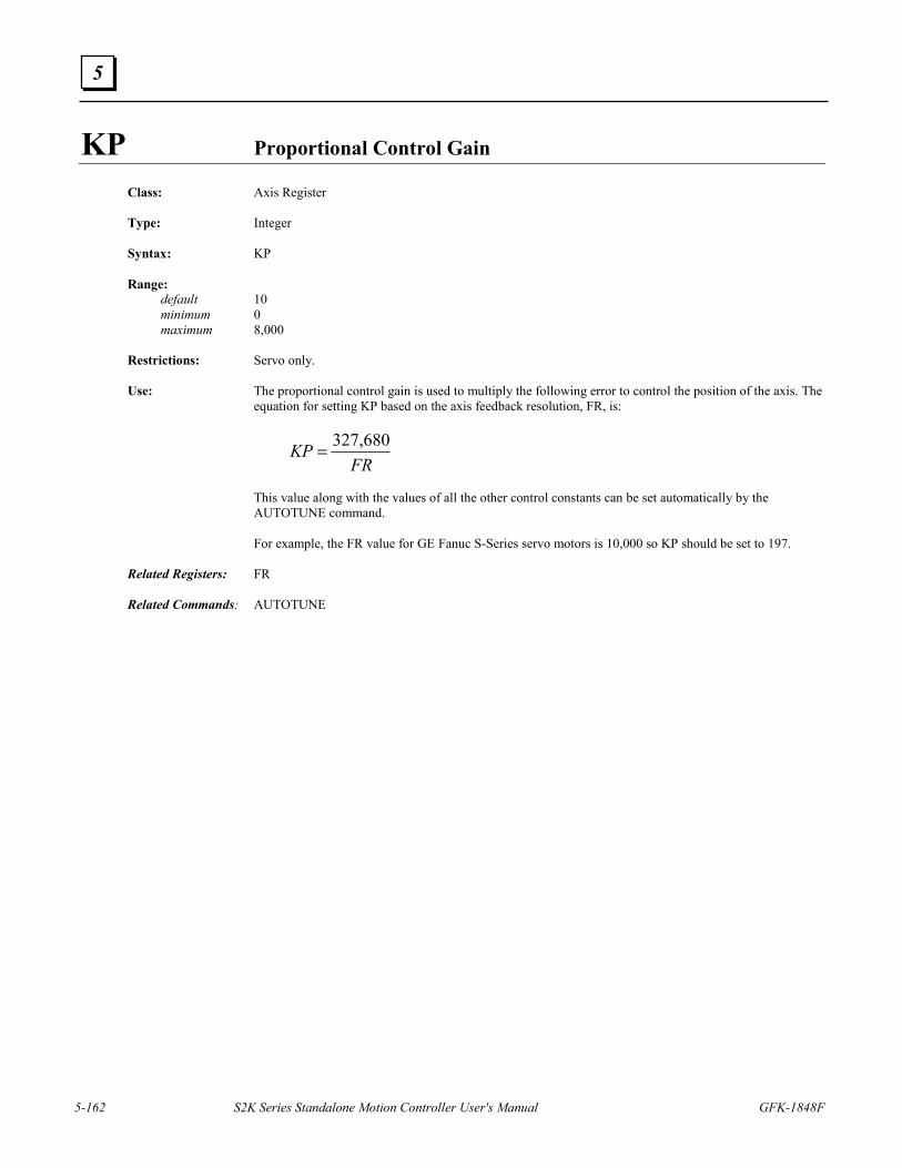
5-162 S2K Series Standalone Motion Controller User's Manual GFK-1848F
5
KP Proportional Control Gain
Class: Axis Register Type: Integer Syntax: KP Range: default 10 minimum 0 maximum 8,000 Restrictions: Servo only. Use: The proportional control gain is used to multiply the following error to control the position of the axis. The
equation for setting KP based on the axis feedback resolution, FR, is:
FR
KP 680,327=
This value along with the values of all the other control constants can be set automatically by the
AUTOTUNE command. For example, the FR value for GE Fanuc S-Series servo motors is 10,000 so KP should be set to 197. Related Registers: FR Related Commands: AUTOTUNE
Software Reference
GFK-1848F Chapter 5 Software Reference 5-163
5
KSN Network Stall Velocity Threshold
Class: Axis Register Type: Integer Syntax: KSNp1 (e.g., KSN0 KSN63 KSNVI5) Parameters: allowed values description p1 0 through 63 or VIn network node address Range: units pulses minimum 200,000 pulses maximum 16,000,000 pulses Restrictions: Cannot be accessed in immediate mode over a DeviceNet connection. Use: The network stall velocity register accesses attribute 111 of the DeviceNet position controller object to set
the minimum velocity at which stall detection will start to work. Remarks: The Position Controller attribute that this register accesses exists in GE Fanuc Motor CubesTM but not in
the S2K controllers. Related Registers: KVN
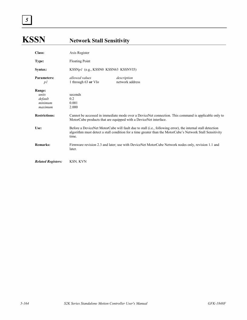
5-164 S2K Series Standalone Motion Controller User's Manual GFK-1848F
5
KSSN Network Stall Sensitivity
Class: Axis Register Type: Floating Point Syntax: KSSNp1 (e.g., KSSN0 KSSN63 KSSNVI5) Parameters: allowed values description p1 1 through 63 or VIn network address Range: units seconds default 0.2 minimum 0.001 maximum 2.000 Restrictions: Cannot be accessed in immediate mode over a DeviceNet connection. This command is applicable only to
MotorCube products that are equipped with a DeviceNet interface. Use: Before a DeviceNet MotorCube will fault due to stall (i.e., following error), the internal stall detection
algorithm must detect a stall condition for a time greater than the MotorCube’s Network Stall Sensitivity time.
Remarks: Firmware revision 2.3 and later; use with DeviceNet MotorCube Network nodes only, revision 1.1 and
later. Related Registers: KSN, KVN
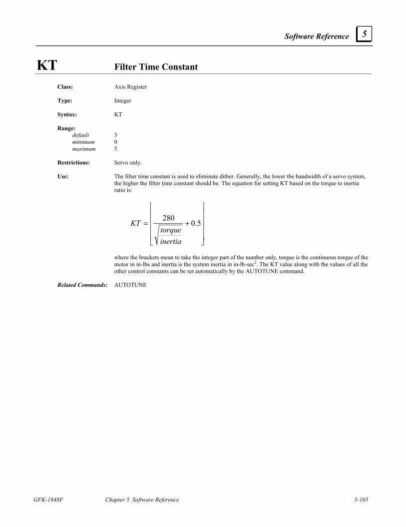
Software Reference
GFK-1848F Chapter 5 Software Reference 5-165
5
KT Filter Time Constant
Class: Axis Register Type: Integer Syntax: KT Range: default 3 minimum 0 maximum 5 Restrictions: Servo only. Use: The filter time constant is used to eliminate dither. Generally, the lower the bandwidth of a servo system,
the higher the filter time constant should be. The equation for setting KT based on the torque to inertia ratio is:
+= 5.0280
inertiatorque
KT
where the brackets mean to take the integer part of the number only, torque is the continuous torque of the
motor in in-lbs and inertia is the system inertia in in-lb-sec2. The KT value along with the values of all the other control constants can be set automatically by the AUTOTUNE command.
Related Commands: AUTOTUNE
5-166 S2K Series Standalone Motion Controller User's Manual GFK-1848F
5
KVN Network Bus Voltage Class: Axis Register Type: Integer Syntax: KVNp1 (e.g., KVN0 KVN63 KVNVI5) Parameters: allowed values description p1 0 through 63 or VIn network node address Range: units volts minimum 0 maximum 50 Restrictions: Cannot be accessed in immediate mode over a DeviceNet connection. Use: The network bus voltage register accesses attribute 112 of the position controller object to set the bus
voltage for the device addressed at p1. Remarks: The Position Controller attribute that this register accesses exists in GE Fanuc’s Motor CubesTM but not in
the S2K controllers. Related Registers: KSN
KY Puts One Character into Key Buffer
Class: Input/Output Command Syntax: KYp1 (e.g., KY1 KYB) Parameters: allowed values description p1 any ASCII character ASCII character Restrictions: Not allowed in motion blocks. Use: This command puts one character into the key buffer. Example: KYE (* put “E” into key buffer) Related Commands: GET, IN
Software Reference
GFK-1848F Chapter 5 Software Reference 5-167
5
KYA Key Assignment
Class: Input/Output Register Syntax: KYAp1 (e.g., KYA2) Parameters: allowed values description p1 1 through 12 function key A-L (see table below) Range: default SINGLE allowed values OFF (no key codes are put in the key buffer) SINGLE (only key-pressed code is put into key buffer) DOUBLE (key-pressed/key-released codes are put into key buffer) Restrictions: Not allowed in programs, motion blocks, or expressions. Use: This register is used to determine what function key codes are put into the key buffer after pressing and
releasing function key p1. Related Registers: KEY, KEYW
Function Key
Value
A 1 B 2 C 3 D 4 E 5 F 6 G 7 H 8 I 9 J 10 K 11 L 12
5-168 S2K Series Standalone Motion Controller User's Manual GFK-1848F
5
L Last Statement to Current Statement in Terminal Window Line Editor
Class: Program Command Syntax: L Restrictions: Allowed only in programs or motion blocks being edited in the terminal window line editor. Use: While editing a program or motion block using the terminal window line editor this command makes the
last statement the current statement in the line editor. Remarks: This command will not typically be used since Motion Developer provides a more full featured text editor
for creating and editing programs and motion blocks. The terminal window can also be used for these functions and is invoked using the PROGRAM and MOTION commands. While in the line editor each line is prefixed by an asterisk (*). Use the exclamation point (!) command to exit the terminal window line editor.
Example: PROGRAM1 (* edit program 1 from the terminal window) * PSA=0 X (* step through one line of the program) * MVL=10 X (* step through one line of the program) * MAC=40 L (* make last statement the current statement) * MVL=10 ! (* exit terminal window line editor) * Related Commands: PROGRAM, MOTION, X, !
Software Reference
GFK-1848F Chapter 5 Software Reference 5-169
5
LABEL Makes Statement at Label the Current Statement Class: Program Command Syntax: LABELp1 (e.g., LABEL53) Parameters: allowed values description p1 1 through 999 label number Restrictions: Allowed only in programs being edited in the terminal window line editor. Use: This command makes the statement at label p1 the current statement in the terminal window line editor. Example: PROGRAM1 (* edit program 1 from the terminal window) * PSA=0 LABEL5 (* make statement at label 5 current statement) *005OUT “Press any key to stop axis$N” ! (* exit line editor) * Related Commands: PROGRAM, L, X, !
LED State of Display Led Class: Input/Output Register Type: Boolean Syntax: LEDp1 (e.g., LED2 LEDVI5) Parameters: allowed values description p1 1 through 3 or VIn LED number Range: default 0 on power-up allowed values 0, 1 Restrictions: Write only. Use: This register contains the state of one of the display LEDs. Remarks: Write only. This register cannot be read. Example: LED1=1 (* set state of display LED one) ASCII Codes: See the following table.
Code (Hex) Description Command
31 Turn Led1 on LED1=1, OUT “$1B$31” 32 Turn Led2 on LED2=1, OUT “$1B$32” 33 Turn Led3 on LED3=1, OUT “$1B$33” 34 Turn Led 1 off LED1=0, OUT “$1B$34” 35 Turn Led 2 off LED2=0, OUT “$1B$35” 36 Turn Led 3 off LED3=0, OUT “$1B$36”
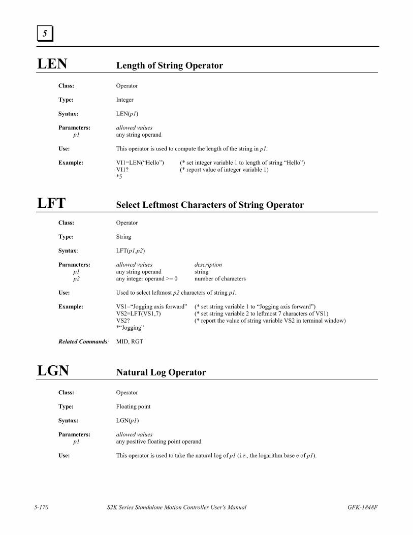
5-170 S2K Series Standalone Motion Controller User's Manual GFK-1848F
5
LEN Length of String Operator
Class: Operator Type: Integer Syntax: LEN(p1) Parameters: allowed values p1 any string operand Use: This operator is used to compute the length of the string in p1. Example: VI1=LEN(“Hello”) (* set integer variable 1 to length of string “Hello”) VI1? (* report value of integer variable 1) *5
LFT Select Leftmost Characters of String Operator
Class: Operator Type: String Syntax: LFT(p1,p2) Parameters: allowed values description p1 any string operand string p2 any integer operand >= 0 number of characters Use: Used to select leftmost p2 characters of string p1. Example: VS1=“Jogging axis forward” (* set string variable 1 to “Jogging axis forward”) VS2=LFT(VS1,7) (* set string variable 2 to leftmost 7 characters of VS1) VS2? (* report the value of string variable VS2 in terminal window) *“Jogging” Related Commands: MID, RGT
LGN Natural Log Operator
Class: Operator Type: Floating point Syntax: LGN(p1) Parameters: allowed values p1 any positive floating point operand Use: This operator is used to take the natural log of p1 (i.e., the logarithm base e of p1).
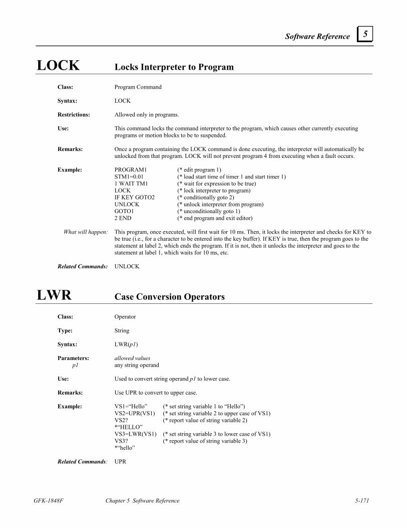
Software Reference
GFK-1848F Chapter 5 Software Reference 5-171
5
LOCK Locks Interpreter to Program Class: Program Command Syntax: LOCK Restrictions: Allowed only in programs. Use: This command locks the command interpreter to the program, which causes other currently executing
programs or motion blocks to be to suspended. Remarks: Once a program containing the LOCK command is done executing, the interpreter will automatically be
unlocked from that program. LOCK will not prevent program 4 from executing when a fault occurs. Example: PROGRAM1 (* edit program 1) STM1=0.01 (* load start time of timer 1 and start timer 1) 1 WAIT TM1 (* wait for expression to be true) LOCK (* lock interpreter to program) IF KEY GOTO2 (* conditionally goto 2) UNLOCK (* unlock interpreter from program) GOTO1 (* unconditionally goto 1) 2 END (* end program and exit editor) What will happen: This program, once executed, will first wait for 10 ms. Then, it locks the interpreter and checks for KEY to
be true (i.e., for a character to be entered into the key buffer). If KEY is true, then the program goes to the statement at label 2, which ends the program. If it is not, then it unlocks the interpreter and goes to the statement at label 1, which waits for 10 ms, etc.
Related Commands: UNLOCK
LWR Case Conversion Operators
Class: Operator Type: String Syntax: LWR(p1) Parameters: allowed values p1 any string operand Use: Used to convert string operand p1 to lower case. Remarks: Use UPR to convert to upper case. Example: VS1=“Hello” (* set string variable 1 to “Hello”) VS2=UPR(VS1) (* set string variable 2 to upper case of VS1) VS2? (* report value of string variable 2) *“HELLO” VS3=LWR(VS1) (* set string variable 3 to lower case of VS1) VS3? (* report value of string variable 3) *“hello” Related Commands: UPR
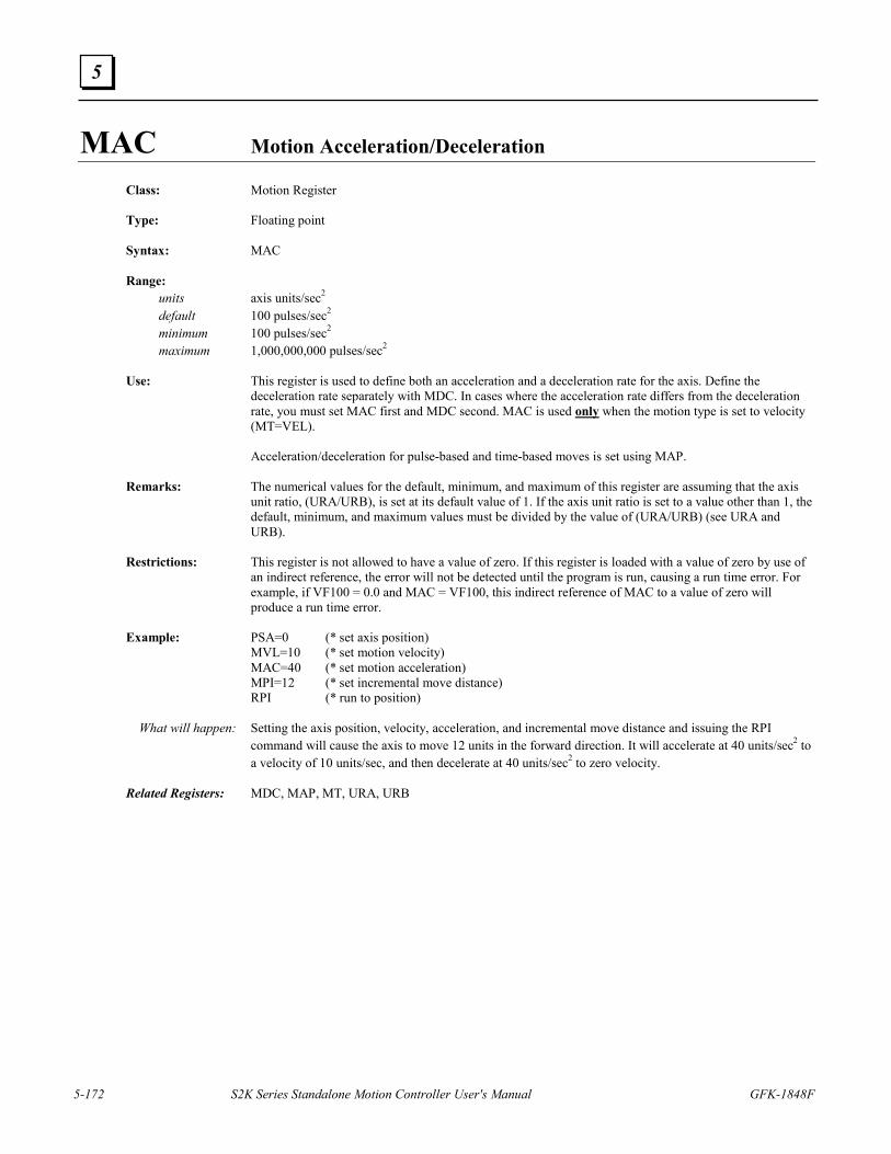
5-172 S2K Series Standalone Motion Controller User's Manual GFK-1848F
5
MAC Motion Acceleration/Deceleration
Class: Motion Register Type: Floating point Syntax: MAC Range: units axis units/sec2 default 100 pulses/sec2 minimum 100 pulses/sec2 maximum 1,000,000,000 pulses/sec2 Use: This register is used to define both an acceleration and a deceleration rate for the axis. Define the
deceleration rate separately with MDC. In cases where the acceleration rate differs from the deceleration rate, you must set MAC first and MDC second. MAC is used only when the motion type is set to velocity (MT=VEL).
Acceleration/deceleration for pulse-based and time-based moves is set using MAP. Remarks: The numerical values for the default, minimum, and maximum of this register are assuming that the axis
unit ratio, (URA/URB), is set at its default value of 1. If the axis unit ratio is set to a value other than 1, the default, minimum, and maximum values must be divided by the value of (URA/URB) (see URA and URB).
Restrictions: This register is not allowed to have a value of zero. If this register is loaded with a value of zero by use of
an indirect reference, the error will not be detected until the program is run, causing a run time error. For example, if VF100 = 0.0 and MAC = VF100, this indirect reference of MAC to a value of zero will produce a run time error.
Example: PSA=0 (* set axis position) MVL=10 (* set motion velocity) MAC=40 (* set motion acceleration) MPI=12 (* set incremental move distance) RPI (* run to position) What will happen: Setting the axis position, velocity, acceleration, and incremental move distance and issuing the RPI
command will cause the axis to move 12 units in the forward direction. It will accelerate at 40 units/sec2 to a velocity of 10 units/sec, and then decelerate at 40 units/sec2 to zero velocity.
Related Registers: MDC, MAP, MT, URA, URB
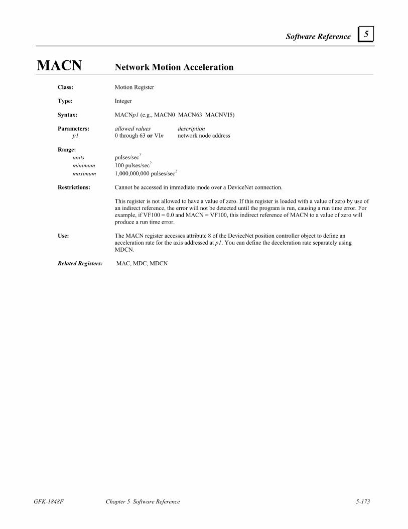
Software Reference
GFK-1848F Chapter 5 Software Reference 5-173
5
MACN Network Motion Acceleration Class: Motion Register Type: Integer Syntax: MACNp1 (e.g., MACN0 MACN63 MACNVI5) Parameters: allowed values description p1 0 through 63 or VIn network node address Range: units pulses/sec2 minimum 100 pulses/sec2 maximum 1,000,000,000 pulses/sec2 Restrictions: Cannot be accessed in immediate mode over a DeviceNet connection. This register is not allowed to have a value of zero. If this register is loaded with a value of zero by use of
an indirect reference, the error will not be detected until the program is run, causing a run time error. For example, if VF100 = 0.0 and MACN = VF100, this indirect reference of MACN to a value of zero will produce a run time error.
Use: The MACN register accesses attribute 8 of the DeviceNet position controller object to define an
acceleration rate for the axis addressed at p1. You can define the deceleration rate separately using MDCN.
Related Registers: MAC, MDC, MDCN
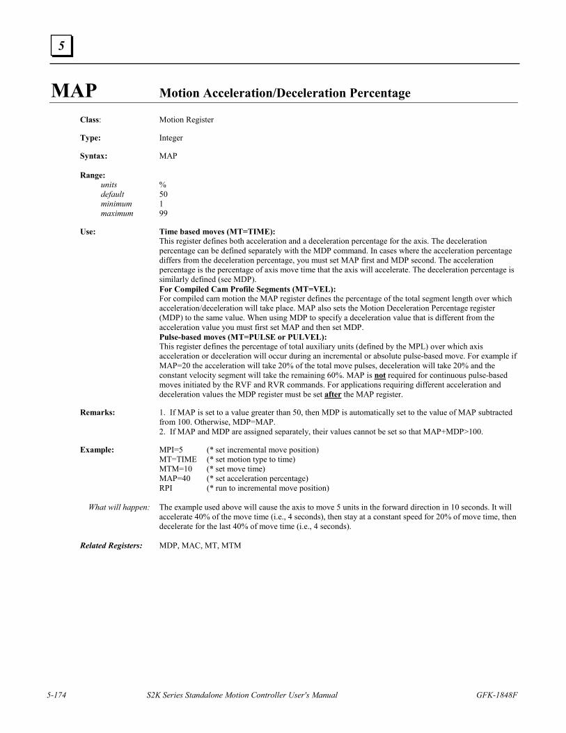
5-174 S2K Series Standalone Motion Controller User's Manual GFK-1848F
5
MAP Motion Acceleration/Deceleration Percentage
Class: Motion Register Type: Integer Syntax: MAP Range: units % default 50 minimum 1 maximum 99 Use: Time based moves (MT=TIME): This register defines both acceleration and a deceleration percentage for the axis. The deceleration
percentage can be defined separately with the MDP command. In cases where the acceleration percentage differs from the deceleration percentage, you must set MAP first and MDP second. The acceleration percentage is the percentage of axis move time that the axis will accelerate. The deceleration percentage is similarly defined (see MDP).
For Compiled Cam Profile Segments (MT=VEL): For compiled cam motion the MAP register defines the percentage of the total segment length over which
acceleration/deceleration will take place. MAP also sets the Motion Deceleration Percentage register (MDP) to the same value. When using MDP to specify a deceleration value that is different from the acceleration value you must first set MAP and then set MDP.
Pulse-based moves (MT=PULSE or PULVEL): This register defines the percentage of total auxiliary units (defined by the MPL) over which axis
acceleration or deceleration will occur during an incremental or absolute pulse-based move. For example if MAP=20 the acceleration will take 20% of the total move pulses, deceleration will take 20% and the constant velocity segment will take the remaining 60%. MAP is not required for continuous pulse-based moves initiated by the RVF and RVR commands. For applications requiring different acceleration and deceleration values the MDP register must be set after the MAP register.
Remarks: 1. If MAP is set to a value greater than 50, then MDP is automatically set to the value of MAP subtracted
from 100. Otherwise, MDP=MAP. 2. If MAP and MDP are assigned separately, their values cannot be set so that MAP+MDP>100. Example: MPI=5 (* set incremental move position) MT=TIME (* set motion type to time) MTM=10 (* set move time) MAP=40 (* set acceleration percentage) RPI (* run to incremental move position) What will happen: The example used above will cause the axis to move 5 units in the forward direction in 10 seconds. It will
accelerate 40% of the move time (i.e., 4 seconds), then stay at a constant speed for 20% of move time, then decelerate for the last 40% of move time (i.e., 4 seconds).
Related Registers: MDP, MAC, MT, MTM
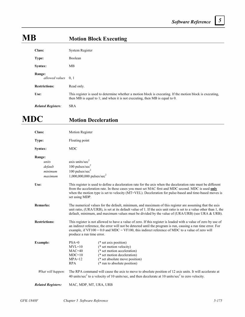
Software Reference
GFK-1848F Chapter 5 Software Reference 5-175
5
MB Motion Block Executing
Class: System Register Type: Boolean Syntax: MB Range: allowed values 0, 1 Restrictions: Read only. Use: This register is used to determine whether a motion block is executing. If the motion block is executing,
then MB is equal to 1; and when it is not executing, then MB is equal to 0. Related Registers: SRA
MDC Motion Deceleration
Class: Motion Register Type: Floating point Syntax: MDC Range: units axis units/sec2 default 100 pulses/sec2 minimum 100 pulses/sec2 maximum 1,000,000,000 pulses/sec2 Use: This register is used to define a deceleration rate for the axis when the deceleration rate must be different
from the acceleration rate. In these cases you must set MAC first and MDC second. MDC is used only when the motion type is set to velocity (MT=VEL). Deceleration for pulse-based and time-based moves is set using MDP.
Remarks: The numerical values for the default, minimum, and maximum of this register are assuming that the axis
unit ratio, (URA/URB), is set at its default value of 1. If the axis unit ratio is set to a value other than 1, the default, minimum, and maximum values must be divided by the value of (URA/URB) (see URA & URB).
Restrictions: This register is not allowed to have a value of zero. If this register is loaded with a value of zero by use of
an indirect reference, the error will not be detected until the program is run, causing a run time error. For example, if VF100 = 0.0 and MDC = VF100, this indirect reference of MDC to a value of zero will produce a run time error.
Example: PSA=0 (* set axis position) MVL=10 (* set motion velocity) MAC=40 (* set motion acceleration) MDC=10 (* set motion deceleration) MPA=12 (* set absolute move position) RPA (* run to absolute position) What will happen: The RPA command will cause the axis to move to absolute position of 12 axis units. It will accelerate at
40 units/sec2 to a velocity of 10 units/sec, and then decelerate at 10 units/sec2 to zero velocity. Related Registers: MAC, MDP, MT, URA, URB
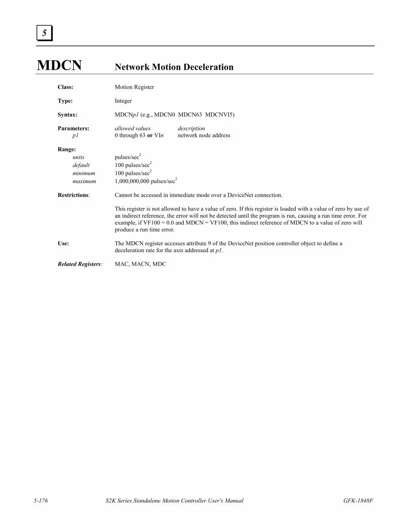
5-176 S2K Series Standalone Motion Controller User's Manual GFK-1848F
5
MDCN Network Motion Deceleration
Class: Motion Register Type: Integer Syntax: MDCNp1 (e.g., MDCN0 MDCN63 MDCNVI5) Parameters: allowed values description p1 0 through 63 or VIn network node address Range: units pulses/sec2 default 100 pulses/sec2 minimum 100 pulses/sec2 maximum 1,000,000,000 pulses/sec2 Restrictions: Cannot be accessed in immediate mode over a DeviceNet connection. This register is not allowed to have a value of zero. If this register is loaded with a value of zero by use of
an indirect reference, the error will not be detected until the program is run, causing a run time error. For example, if VF100 = 0.0 and MDCN = VF100, this indirect reference of MDCN to a value of zero will produce a run time error.
Use: The MDCN register accesses attribute 9 of the DeviceNet position controller object to define a
deceleration rate for the axis addressed at p1. Related Registers: MAC, MACN, MDC
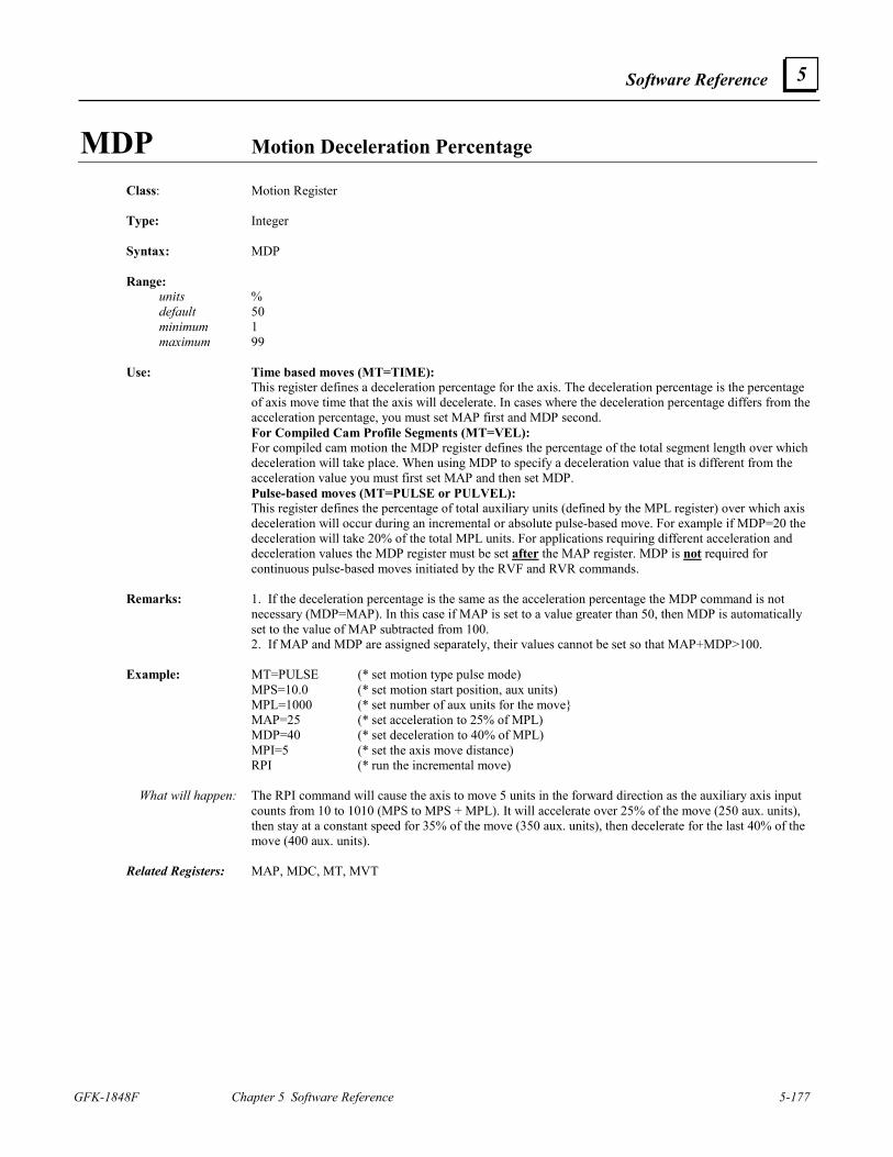
Software Reference
GFK-1848F Chapter 5 Software Reference 5-177
5
MDP Motion Deceleration Percentage
Class: Motion Register Type: Integer Syntax: MDP Range: units % default 50 minimum 1 maximum 99 Use: Time based moves (MT=TIME): This register defines a deceleration percentage for the axis. The deceleration percentage is the percentage
of axis move time that the axis will decelerate. In cases where the deceleration percentage differs from the acceleration percentage, you must set MAP first and MDP second.
For Compiled Cam Profile Segments (MT=VEL): For compiled cam motion the MDP register defines the percentage of the total segment length over which
deceleration will take place. When using MDP to specify a deceleration value that is different from the acceleration value you must first set MAP and then set MDP.
Pulse-based moves (MT=PULSE or PULVEL): This register defines the percentage of total auxiliary units (defined by the MPL register) over which axis
deceleration will occur during an incremental or absolute pulse-based move. For example if MDP=20 the deceleration will take 20% of the total MPL units. For applications requiring different acceleration and deceleration values the MDP register must be set after the MAP register. MDP is not required for continuous pulse-based moves initiated by the RVF and RVR commands.
Remarks: 1. If the deceleration percentage is the same as the acceleration percentage the MDP command is not
necessary (MDP=MAP). In this case if MAP is set to a value greater than 50, then MDP is automatically set to the value of MAP subtracted from 100.
2. If MAP and MDP are assigned separately, their values cannot be set so that MAP+MDP>100. Example: MT=PULSE (* set motion type pulse mode) MPS=10.0 (* set motion start position, aux units) MPL=1000 (* set number of aux units for the move MAP=25 (* set acceleration to 25% of MPL) MDP=40 (* set deceleration to 40% of MPL) MPI=5 (* set the axis move distance) RPI (* run the incremental move) What will happen: The RPI command will cause the axis to move 5 units in the forward direction as the auxiliary axis input
counts from 10 to 1010 (MPS to MPS + MPL). It will accelerate over 25% of the move (250 aux. units), then stay at a constant speed for 35% of the move (350 aux. units), then decelerate for the last 40% of the move (400 aux. units).
Related Registers: MAP, MDC, MT, MVT
5-178 S2K Series Standalone Motion Controller User's Manual GFK-1848F
5
MEMORY Reports Memory Remaining
Class: System Command Syntax: MEMORY Restrictions: Not allowed in programs or motion blocks. Use: This command reports the remaining memory in bytes.
MFA Motion Feedrate Acceleration/Deceleration Class: Motion Register Type: Integer Syntax: MFA Range: units percent/second default 1,000 minimum 1 maximum 200,000 Use: This register is used to define both an acceleration and a deceleration rate for the motion feedrate
percentage. Define the deceleration rate separately with MFD. In cases where the acceleration rate differs from the deceleration rate, you must set MFA first and MFD second.
Example: MFP=40 (* set motion feedrate percentage) MFA=500 (* set motion feedrate acceleration) MFP=80 (* set motion feedrate percentage) What will happen: Setting motion feedrate acceleration to 500 and motion feedrate percentage to 80 will cause the controller
to accelerate the motion feedrate from 40 percent to 80 percent at 500 percent/second. Related Registers: MFD, MFP
Software Reference
GFK-1848F Chapter 5 Software Reference 5-179
5
MFD Motion Feedrate Deceleration
Class: Motion Register Type: Integer Syntax: MFD Range: units percent/second default 1,000 minimum 1 maximum 200,000 Use: This register is used to define a deceleration rate for the motion feedrate percentage. In cases where the
acceleration rate differs from the deceleration rate, you must set MFA first and MFD second. Example: MFP=80 (* set motion feedrate percentage) MFD=500 (* set motion feedrate deceleration) MFP=40 (* set motion feedrate percentage) What will happen: Setting motion feedrate deceleration to 500 and the motion feedrate percentage to 40 will cause the
controller to decelerate the motion feedrate from 80 percent to 40 percent at 500 percent/second. Related Registers: MFA, MFP
5-180 S2K Series Standalone Motion Controller User's Manual GFK-1848F
5
MFP Motion Feedrate Percentage
Class: Motion Register Type: Floating point Syntax: MFP Range: units percent default 100.00 minimum 0.00 maximum 100.00 Use: This register is used to define a feedrate percentage for the axis motion. The feedrate percentage causes the
motion to run at a velocity that is a percentage of the motion velocity specified when the motion command was executed.
Remarks: This register is set to its default value on power-up. Example: MVL=20 (* set motion velocity) MAC=50 (* set motion acceleration) RVF (* run forward at velocity) MFD=500 (* set feedrate deceleration) MFP=63 (* set feedrate percentage) What will happen: Setting motion velocity, acceleration, feedrate deceleration, and feedrate percentage and issuing the run
forward at velocity (RVF) command will cause the axis to run forward at 63% of the MVL value of 20 units/second, or 12.6 units/second.
Related Registers: MFA, MFD Motion Templates: Absolute move with feedrate override; time based, absolute move with feedrate override
Software Reference
GFK-1848F Chapter 5 Software Reference 5-181
5
MID Select Middle Characters of String Operator
Class: Operator Type: String Syntax: MID(p1,p2,p3) Parameters: allowed values description p1 any string operand string p2 any integer operand >= 0 number of characters p3 any integer operand >= 1 location of characters Use: Used to select middle p2 characters of string p1. Example: VS1=“Jogging axis forward” (* set string variable 1 to “Jogging axis forward”) VS2=MID(VS1,4,9) (* set string variable VS2 to the middle 4 characters of VS1 starting from (* character 9) VS2? (* report value of string variable VS2 in terminal window) * “axis” Related Commands: LFT, RGT
5-182 S2K Series Standalone Motion Controller User's Manual GFK-1848F
5
MJK Motion Jerk Percentage Class: Motion Register Type: Integer Syntax: MJK Range: units % default 0 minimum 0 maximum 100 Restrictions: MJK has no effect when MT is set to PULSE or PULVEL. Use: This register is used to define a jerk percentage for the axis. The jerk percentage is the percentage of
acceleration/deceleration time that the axis will jerk. Remarks: If MJK is set to 0, there is no jerk limit (i.e., the jerk is infinite). Example: PSA=0 (* set axis position) MVL=5 (* set motion velocity) MAC=10 (* set motion acceleration) MPI=40 (* set incremental move position) MJK=100 (* set motion jerk percentage) RPI (* run to incremental move position) MJK=0 (* set motion jerk percentage) RPI (* run to incremental move position) What will happen: This program will cause the axis to move 40 units in the forward direction. The axis will smoothly ramp
the acceleration and deceleration up to 10 units/sec2 and back down to zero for the whole time it is accelerating and decelerating. Then, setting the jerk percentage to 0 and issuing the RPI command will enable the axis to achieve instantaneously the acceleration rate and deceleration rate during the move.
Software Reference
GFK-1848F Chapter 5 Software Reference 5-183
5
MOTION Edits Motion Block in the Terminal Window Line Editor
Class: Program Command Syntax: MOTIONp1 (e.g., MOTION60) Parameters: allowed values description p1 1 through 100 motion block number Restrictions: Allowed only in programs being edited in the terminal window line editor.
Use: Used to enter the terminal window line editor at the first statement of motion block p1. It can be used to
view or edit motion blocks but typically will not be used since the Motion Developer provides a more convenient and full featured editor.
Example: MOTION1 (* edit motion block 1 from the terminal window) MVL=10 (* set motion velocity) MAC=40 (* set motion acceleration) MPI=15 (* set incremental move position) ! (* exit terminal window line editor) * Related Commands: PROGRAM, DEL, L, X, !, FAULT
5-184 S2K Series Standalone Motion Controller User's Manual GFK-1848F
5
MOTORSET Automatically Sets Up Motor Constants
Class: System Command Syntax: MOTORSET Restrictions: Brushless servo only; not allowed in programs or motion blocks.
Use: This command automatically sets up the motor constants CMO and CMR required for proper commutation
of a brushless servo motor. For all GE Fanuc motors, the Motion Developer wizards automatically set the values for CMO and CMR when a specific motor is selected.
Remarks: This command will execute only when the controller is faulted, the axis Enable input is true, and no
programs or motion blocks are executing. The motor must not be connected to a load when you use this command. Executing MOTORSET with a load attached to the motor will yield improper values. When executed, MOTORSET causes the motor rotor to line up with two locations of the stator vector. This command must be executed from the terminal window and takes from 2 to 30 seconds to execute; when finished, the controller or system will return either an asterisk (*) indicating successful completion or a question mark and one of the following error messages:
1. SWITCH MOTOR LEADS—two motor leads should be switched. 2. BAD POLES RATIO—the motor poles to resolver poles ratio was less than 1 or greater than 16 It is important to set CURC and KL correctly for MOTORSET to work properly. For best results, set
CURC and KL before executing the MOTORSET command. Encoder Feedback Procedures If using a motor with an encoder, the following steps are required to correctly determine the CMO and
CMR of a motor. 1. Initialize Registers Set KL and CURC accordingly Set FR and FRC to the feedback resolution of the encoder Set CMR to a value other than 1 (from 2 to 16) Execute a SAVE command 2. Determine CMR Cycle the power Turn the motor shaft at least a ¼ of a revolution Execute a MOTORSET command Now CMR is computed, but CMO may be incorrect Execute a SAVE command to save CMR 3. Determine The Correct CMO Cycle the power Turn the motor shaft at least a ¼ of a revolution Execute a MOTORSET command CMO is now computed correctly Execute a SAVE command to save CMO Related Commands: AUTOTUNE Related Registers: CMO, CMR, CURC, FR, FRC, KL
Software Reference
GFK-1848F Chapter 5 Software Reference 5-185
5
MPA Absolute Move Position
Class: Motion Register Type: Floating point Syntax: MPA Range: units axis units default 0 pulses minimum -2,000,000,000 pulses maximum 2,000,000,000 pulses Use: For velocity-based, time-based and pulse-based moves this register is used to define the absolute position
to which the axis will move. For compiled cam profile segments the MPA register defines the axis absolute position at the end of the profile segment.
Remarks: The numerical values for the default, minimum, and maximum of this register are assuming that the axis
unit ratio, (URA/URB), is set at its default value of 1. If the axis unit ratio is set to a value other than 1, the default, minimum, and maximum values must be divided by the value of (URA/URB) (see URA and URB).
Example: PSA=0 (* set axis position) MVL=10 (* set motion velocity) MAC=40 (* set motion acceleration) MPA=8 (* set absolute move position) RPA (* run to absolute position) What will happen: Setting the axis position, velocity, acceleration, and absolute move position and issuing the RPA command
will cause the axis to move to absolute position of 8 axis units. CAZ (* clear the cam table) CCB=0 (* start profile segment at zero degrees) CCE=90 (* end segment at 90 degrees on cam master) CCP=0 (* start axis motion at absolute position zero) MPA=10 (* end axis motion at absolute position 10) CCM (* compile cam segment and load cam table) What will happen: The CCM command will compile the cam profile segment defined from 0 to 90 degrees (CCB to CCE) on
the cam master. Over this segment the axis will move from an absolute position of zero to an absolute position of 10 (CCP to MPA).
Related Registers: MPI, MPO, URA, URB Related Commands: RPA, CCM
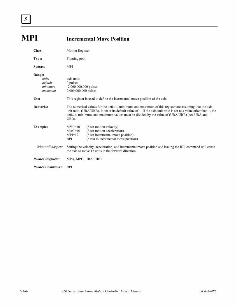
5-186 S2K Series Standalone Motion Controller User's Manual GFK-1848F
5
MPI Incremental Move Position Class: Motion Register Type: Floating point Syntax: MPI Range: units axis units default 0 pulses minimum -2,000,000,000 pulses maximum 2,000,000,000 pulses Use: This register is used to define the incremental move position of the axis. Remarks: The numerical values for the default, minimum, and maximum of this register are assuming that the axis
unit ratio, (URA/URB), is set at its default value of 1. If the axis unit ratio is set to a value other than 1, the default, minimum, and maximum values must be divided by the value of (URA/URB) (see URA and URB).
Example: MVL=10 (* set motion velocity) MAC=40 (* set motion acceleration) MPI=12 (* set incremental move position) RPI (* run to incremental move position) What will happen: Setting the velocity, acceleration, and incremental move position and issuing the RPI command will cause
the axis to move 12 units in the forward direction. Related Registers: MPA, MPO, URA, URB Related Commands: RPI
Software Reference
GFK-1848F Chapter 5 Software Reference 5-187
5
MPL Move Pulses Class: Motion Register Type: Floating point Syntax: MPL Range: units auxiliary units default 20,000,000 pulses minimum 1 pulse maximum 20,000,000 pulses Use: Used only for pulse-based motion (MT=PULSE or PULVEL). This register is not used for time-based or
velocity-based motion. For Incremental or Absolute Moves: When MT=PULSE: this register defines the number of input pulses (or auxiliary position units if URX is
not equal to 1) over which the axis makes its motion. When MT=PULVEL: this register defines the total auxiliary units over which the acceleration and
deceleration for the axis motion will occur. The percentage of MPL used for acceleration is defined by MAP (i.e., axis acceleration will occur over MPL*MAP/100 aux. units). The remainder of MPL is then used for deceleration. MVP in this case defines the axis velocity as a ratio of axis units/aux. unit.
For Continuous Moves: The MPL register defines the number of auxiliary position units over which the acceleration or
deceleration will occur. Remarks: The numerical values for the default, minimum, and maximum of this register assume that the pulse unit
ratio is set at 1. If the unit ratio is set to a value other than 1, the default, minimum, and maximum must be divided by the value of URX. (see URX)
Example: MT=PULSE (* set motion type to pulse) PSA=0 (* set axis position to zero) PSX=0 (* set auxiliary position to zero) MPS=2 (* set motion start position to 2 aux. units) MPL=5 (* set move to occur over 5 aux. units) MAP=20 (* set motion acceleration/deceleration percent to 20) MPA=10 (* set absolute move position to 10 axis units) RPA (* run to absolute position) What will happen: After you issue the RPA command, the axis will wait until the auxiliary position reaches 2 units. Then,
while the auxiliary position moves to 7 units, the axis will move to absolute position of 10 axis units, using 1 auxiliary unit of motion to accelerate, 3 aux. units to run at a constant velocity, and 1 aux. unit to decelerate to a stop.
MT=PULSE (* set motion type to pulse) PSA=0 (* set axis position to zero) PSX=0 (* set auxiliary position to zero) MPS=2 (* set motion start position to 2 aux. units) MPL=5 (* set move to occur over 5 aux. units) MVP=5.0 (* set axis velocity to 5 axis units/sec for each aux unit/sec) RVF (* run to velocity in the forward direction) What will happen: After you issue the RVF command, the axis will wait until the auxiliary position reaches 2 aux. units.
Then, accelerate the axis to a velocity of 5 axis units/sec for each aux. unit/sec as the auxiliary axis moves from 2 to 7 aux. units (MPS to MPS+MPL).
Related Registers: MT, MPS, MVP, URX
5-188 S2K Series Standalone Motion Controller User's Manual GFK-1848F
5
MPN Network Move Position
Class: Motion Register Type: Integer Syntax: MPNp1 (e.g., MPN0 MPN63 MPNVI5) Parameters: allowed values description p1 0 through 63 or VIn network node address Range: units pulses minimum -2,000,000,000 pulses maximum 2,000,000,000 pulses Restrictions: Cannot be accessed in immediate mode over a DeviceNet connection. Use: The MPN register accesses attribute 6 of the DeviceNet position controller object to define the move
position of the axis addressed at p1. Related Registers: MPI, MPA, MACN, MDCN, MVLN
Software Reference
GFK-1848F Chapter 5 Software Reference 5-189
5
MPO Offset Move Position
Class: Motion Register Type: Floating point Syntax: MPO Range: units axis units default 0 pulses minimum -2,000,000,000 pulses maximum 2,000,000,000 pulses Use: This register is used to define the destination position for an offset move initiated by the Run to Offset
Position (RPO) command. MPO is similar to MPA except that positions are with respect to the PSO register instead of the PSA register.
Remarks: The numerical values for the default, minimum, and maximum of this register are assuming that the axis
unit ratio, (URA/URB), is set at its default value of 1. If the axis unit ratio is set to a value other than 1, the default, maximum, and minimum values must be divided by the value of (URA/URB) (see URA and URB).
Example: PSO=0 (* set offset position register) MVL=10 (* set motion velocity) MAC=40 (* set motion acceleration) MPO=8 (* set offset move position) RPO (* run to offset move position) What will happen: Setting the offset position register, velocity, acceleration, and offset move position and issuing the RPO
command will cause the axis to move 8 units in the forward direction. Related Registers: MPA, MPI, URA, URB Related Commands: PSO, RPO
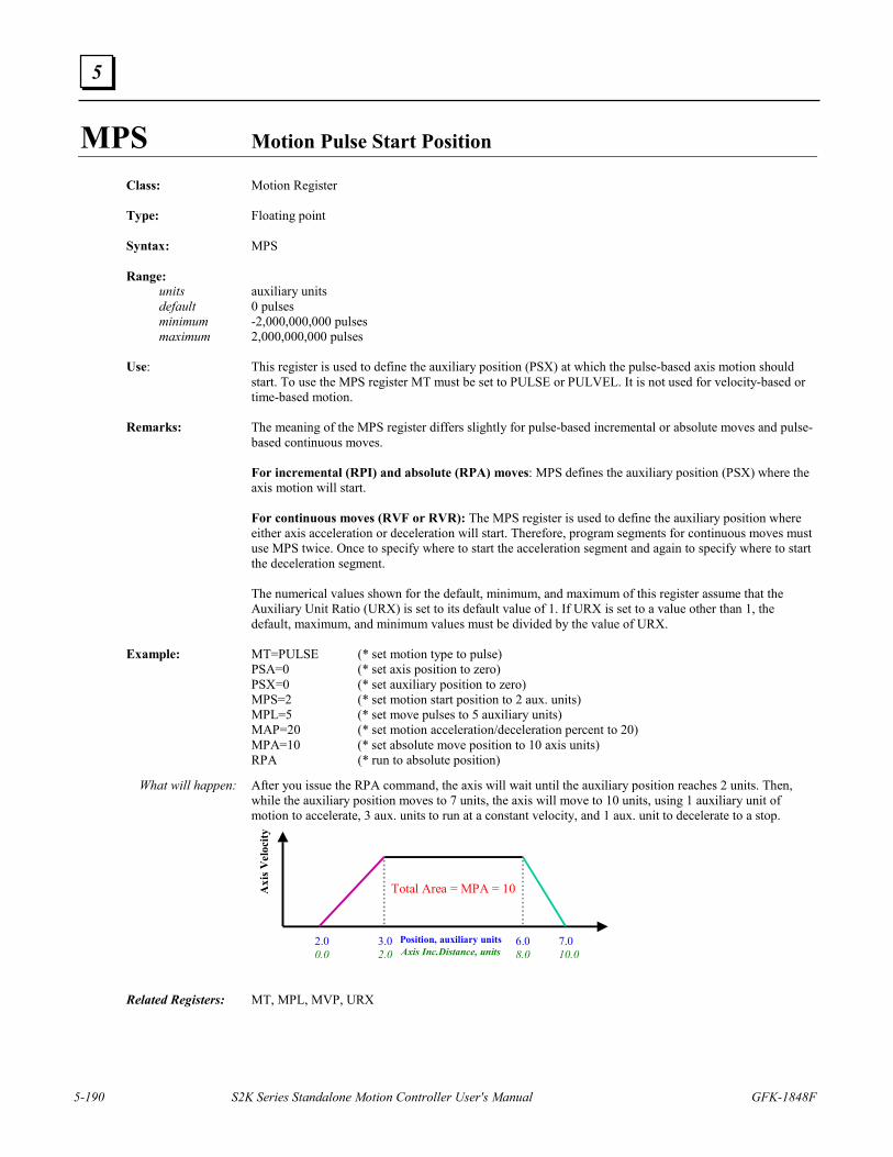
5-190 S2K Series Standalone Motion Controller User's Manual GFK-1848F
5
MPS Motion Pulse Start Position Class: Motion Register Type: Floating point Syntax: MPS Range: units auxiliary units default 0 pulses minimum -2,000,000,000 pulses maximum 2,000,000,000 pulses Use: This register is used to define the auxiliary position (PSX) at which the pulse-based axis motion should
start. To use the MPS register MT must be set to PULSE or PULVEL. It is not used for velocity-based or time-based motion.
Remarks: The meaning of the MPS register differs slightly for pulse-based incremental or absolute moves and pulse-
based continuous moves. For incremental (RPI) and absolute (RPA) moves: MPS defines the auxiliary position (PSX) where the
axis motion will start. For continuous moves (RVF or RVR): The MPS register is used to define the auxiliary position where
either axis acceleration or deceleration will start. Therefore, program segments for continuous moves must use MPS twice. Once to specify where to start the acceleration segment and again to specify where to start the deceleration segment.
The numerical values shown for the default, minimum, and maximum of this register assume that the
Auxiliary Unit Ratio (URX) is set to its default value of 1. If URX is set to a value other than 1, the default, maximum, and minimum values must be divided by the value of URX.
Example: MT=PULSE (* set motion type to pulse) PSA=0 (* set axis position to zero) PSX=0 (* set auxiliary position to zero) MPS=2 (* set motion start position to 2 aux. units) MPL=5 (* set move pulses to 5 auxiliary units) MAP=20 (* set motion acceleration/deceleration percent to 20) MPA=10 (* set absolute move position to 10 axis units) RPA (* run to absolute position) What will happen: After you issue the RPA command, the axis will wait until the auxiliary position reaches 2 units. Then,
while the auxiliary position moves to 7 units, the axis will move to 10 units, using 1 auxiliary unit of motion to accelerate, 3 aux. units to run at a constant velocity, and 1 aux. unit to decelerate to a stop.
Position, auxiliary unitsAxis Inc.Distance, units
Axi
s Vel
ocity
2.0 3.0 6.0 7.00.0 2.0 8.0 10.0
Total Area = MPA = 10
Related Registers: MT, MPL, MVP, URX
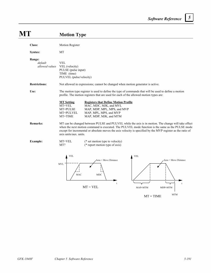
Software Reference
GFK-1848F Chapter 5 Software Reference 5-191
5
MT Motion Type
Class: Motion Register Syntax: MT Range: default VEL allowed values VEL (velocity) PULSE (pulse input) TIME (time) PULVEL (pulse/velocity) Restrictions: Not allowed in expressions; cannot be changed when motion generator is active. Use: The motion type register is used to define the type of commands that will be used to define a motion
profile. The motion registers that are used for each of the allowed motion types are: MT Setting Registers that Define Motion Profile MT=VEL MAC, MDC, MJK, and MVL MT=PULSE MAP, MDP, MPL, MPS, and MVP MT=PULVEL MAP, MPL, MPS, and MVP MT=TIME MAP, MDP, MJK, and MTM Remarks: MT can be changed between PULSE and PULVEL while the axis is in motion. The change will take effect
when the next motion command is executed. The PULVEL mode function is the same as the PULSE mode except for incremental or absolute moves the axis velocity is specified by the MVP register as the ratio of axis units/aux. units.
Example: MT=VEL (* set motion type to velocity) MT? (* report motion type of axis)
MT = VEL
MAC MDC
VEL
MVL
t
Area = Move Distance
MT = TIME
MAP∗MTM MDP∗MTM
VEL
t
Area = Move Distance
MTM
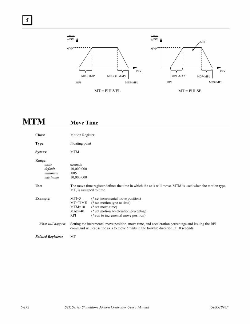
5-192 S2K Series Standalone Motion Controller User's Manual GFK-1848F
5
MT = PULVEL
MPL∗MAP MPL∗ (1-MAP)
MPS
PSX
MVP
∆PSA∆PSX
MPS+MPL
MT = PULSE
MPL∗MAP MDP∗MPL
MPS
PSX
MVP
∆PSA∆PSX
MPS+MPL
MPI
MTM Move Time
Class: Motion Register Type: Floating point Syntax: MTM Range: units seconds default 10,000.000 minimum .005 maximum 10,000.000 Use: The move time register defines the time in which the axis will move. MTM is used when the motion type,
MT, is assigned to time. Example: MPI=5 (* set incremental move position) MT=TIME (* set motion type to time) MTM=10 (* set move time) MAP=40 (* set motion acceleration percentage) RPI (* run to incremental move position) What will happen: Setting the incremental move position, move time, and acceleration percentage and issuing the RPI
command will cause the axis to move 5 units in the forward direction in 10 seconds. Related Registers: MT
Software Reference
GFK-1848F Chapter 5 Software Reference 5-193
5
MVL Motion Velocity Class: Motion Register Type: Floating point Syntax: MVL Range: units axis units/sec default 1 pulse/sec minimum 1 pulse/sec maximum 16,000,000 pulses/sec Use: This register is used to define the motion velocity of the axis. MVL is used when the motion type, MT, is
assigned to velocity. Remarks: The numerical values for the default, minimum, and maximum of this register assume that the axis unit
ratio, (URA/URB), is set at its default value of 1. If the axis unit ratio is set to a value other than 1, the default, maximum, and minimum values will change appropriately (see URA and URB).
Restrictions: This register is not allowed to have a value of zero. If this register is loaded with a value of zero by use of
an indirect reference, the error will not be detected until the program is run, causing a run time error. For example, if VF100 = 0.0 and MVL = VF100, this indirect reference of MVL to a value of zero will produce a run time error.
Example: PSA=0 (* set axis position) MVL=10 (* set motion velocity) MAC=40 (* set motion acceleration) MPA=12 (* set absolute move position) RPA (* run to absolute position) What will happen: Setting the axis position, velocity, acceleration, and absolute move position and issuing the RPA command
will cause the axis to move 12 units in the forward direction. It will accelerate at 40 units/sec2 to a velocity of 10 units/sec, and then decelerate at 40 units/sec2 to zero velocity.
Related Registers: MT, MAC, URA, URB
5-194 S2K Series Standalone Motion Controller User's Manual GFK-1848F
5
MVLN Network Motion Velocity Class: Motion Register Type: Integer Syntax: MVLNp1 (e.g., MVLN0 MVLN63) Parameters: allowed values description p1 0 through 63 or Vin network node address Range: units pulses/sec minimum 1 pulse/sec maximum 16,000,000 pulses/sec Restrictions: Cannot be accessed in immediate mode over a DeviceNet connection. This register is not allowed to have a value of zero. If this register is loaded with a value of zero by use of
an indirect reference, the error will not be detected until the program is run, causing a run time error. For example, if VF100 = 0.0 and MVLN = VF100, this indirect reference of MVLN to a value of zero will produce a run time error.
Use: This register accesses attribute 7 of the DeviceNet position controller object to define the motion velocity
of the axis. Related Registers: MAC, MACN, MVL
Software Reference
GFK-1848F Chapter 5 Software Reference 5-195
5
MVM Motion Velocity for Run to Marker
Class: Motion Register Type: Floating point Syntax: MVM Range: units axis units/sec default 4,096 pulses/sec minimum 1 pulse/sec maximum 4,096 pulses/sec Use: This register is used to define the motion velocity of the axis when one of the run to marker commands,
RMF or RMR, is used. Remarks: The numerical values for the default, minimum, and maximum of this register are assuming that the axis
unit ratio, (URA/URB), is set at its default value of 1. If the axis unit ratio is set to a value other than 1, the default, maximum, and minimum values must be divided by the value of (URA/URB) (see URA and URB).
Example: PROGRAM1 (* edit program one) MVM=0.5 (* set motion velocity for run to marker) MAC=40 (* set motion acceleration) RMF (* run forward to marker) WAIT IP (* wait for axis one to be in position) PSA=0 (* set axis position) END (* end program one and exit program editor) What will happen: This program, once executed, will set the velocity for run to marker and acceleration and then run the axis
forward until the marker is encountered. It will then wait for the axis to be in position and set the axis position to 0.
Related Registers: MT, MVL, URA, URB Related Commands: RMF, RMR
5-196 S2K Series Standalone Motion Controller User's Manual GFK-1848F
5
MVP Motion Velocity of Pulse Move Class: Motion Register Type: Floating point Syntax: MVP Range: units axis units/auxiliary units default 0.000001 minimum 0.000001 maximum 1,000 Use: This register defines the motion velocity only for pulse-based moves. When MT=PULSE: The MVP register is used only for continuous moves (initiated using the RVF or
RVR commands) and is expressed as a ratio of axis units to auxiliary units. For example, if both the axis and the auxiliary encoder are scaled for revolutions then MVP defines the number of revolutions the axis motor will move for each revolution of the auxiliary encoder.
When MT=PULVEL: In this mode the MVP register is used to define the axis velocity for incremental,
absolute and continuous moves and is expressed as a ratio of axis units to auxiliary units. The MVP register is not used for velocity-based moves or time-based moves. MVP cannot be changed for any move already armed (by executing the respective RPI, RPA, RVF
or RVR command) or in process. Example: MT=PULSE (* set motion type to pulse) PSX=0 (* set auxiliary position register to zero) MPS=1 (* set motion start position to 1 aux. unit) MPL=3 (* set move length for acceleration to 3 aux. units) MVP=2.5 (* set axis velocity to 2.5 axis units/auxiliary unit) RVF (* run at velocity in the forward direction) MPS=10 (* set motion start position to 10 aux. units) MPL=2 (* set move length for deceleration to 2 aux. units) ST (* stop motion) What will happen: When the RVF command is executed, the axis will wait until the auxiliary position reaches 1 unit (MPS).
Then, while the auxiliary position moves to 4 units (MPS+MPL), the axis will accelerate to a velocity of 2.5 axis units/auxiliary units. The axis will then wait until the auxiliary position reaches 10 units; then, while the auxiliary position moves to 12 units, the axis will decelerate to a stop.
Related Registers: MT, MPS, MPL
Software Reference
GFK-1848F Chapter 5 Software Reference 5-197
5
NCO Network Connection Open
Class: System Register Type: Boolean Syntax: NCOp1 Parameters: allowed values description p1 0 through 63 or VIn network address Range: allowed values 0, 1 Restrictions: Read only. Cannot be accessed in immediate mode over a DeviceNet connection. Use: This register returns a one when network connection is established with the device addressed at p1. If a
connection cannot be established, then this register returns a zero. Related Registers: NET Related Commands: CNC
NET Network Connection Available
Class: System Register Type: Boolean Syntax: NET Range: allowed values 0,1 Restrictions: Read only. Use: This register is used to determine when a network access can be made. Works with DeviceNet and
PROFIBUS. Related Registers: NCO, SRS
5-198 S2K Series Standalone Motion Controller User's Manual GFK-1848F
5
NOT Not Logical Operator
Class: Operator Type: Boolean, integer Syntax: NOT p1 Parameters: allowed values p1 any Boolean or integer operand Use: Used to perform a logical NOT operation on p1. Related Registers: AND, OR, XOR
OFA Axis Position Offset
Class: Axis Register Type: Floating point Syntax: OFA Range: units axis units minimum -2,000,000,000 pulses maximum 2,000,000,000 pulses Restrictions: Write only. Use: This register defines an offset to be applied to the axis position register, PSA. The offset is not stored;
rather, the value of the PSA register is changed by the offset. Remarks: The numerical values for the default, minimum, and maximum of this register are assuming that the axis
unit ratio, (URA/URB), is set at its default value of 1. If the axis unit ratio is set to a value other than 1, the default, maximum, and minimum values must be divided by (URA/URB). (see URA and URB).
Example: PSA? (* query value of axis position register) *5.326 (* current position) OFA=4.674 (* offset position register) PSA? (* query value of axis position register) *10 (* current position) Related Registers: PSA, URA, URB
Software Reference
GFK-1848F Chapter 5 Software Reference 5-199
5
OFX Auxiliary Position Offset
Class: Axis Register Type: Floating point Syntax: OFX Range: units auxiliary units minimum -2,000,000,000 pulses maximum 2,000,000,000 pulses Restrictions: Write only. Use: This register defines an offset to be applied to the auxiliary position register, PSX. The offset is not stored.
Rather, the value of the PSX register is changed by the offset. Remarks: The numerical values for the default, minimum, and maximum of this register are assuming that the
auxiliary unit ratio, URX, is set at its default value of 1. If the auxiliary unit ratio is set to a value other than 1, the default, maximum, and minimum values must be divided by the value of URX (see URX).
Example: PSX? (* query value of auxiliary position register) *5.326 (* current position) OFX=4.674 (* offset position register) PSX? (* query value of auxiliary position register) *10 (* current position) Related Registers: PSX, URX
OR OR Logical Operator
Class: Operator Type: Boolean, integer Syntax: p1 OR p2 Parameters: allowed values p1 any Boolean or integer operand p2 any Boolean or integer operand Use: Used to perform a logical OR operation on p1 and p2. Note that p1 and p2 must be of the same type. If p1
and p2 are integer operands, the logical operators perform bitwise logical operations. Related Commands: AND, NOT, XOR
5-200 S2K Series Standalone Motion Controller User's Manual GFK-1848F
5
OTE Hardware Overtravel Enable
Class: Axis Register Type: Boolean Syntax: OTE Range: default 0 allowed values 0, 1 Restrictions: Cannot be assigned in motion blocks. Use: The OTE register is used to enable hardware overtravel inputs using discrete inputs 2 and 3 (IN_01 and
IN_02). Input 2 is the forward overtravel input, and input 3 is the reverse overtravel input. Directional conventions are set by the DIR command.
Remarks: If the hardware overtravel inputs are disabled (OTE=0), they can be used as general purpose inputs. Use
bits 9 and 10 of the IO register to read the state of the hardware overtravel inputs when enabled. Bit 10 of the Axis Status Register (SRA) also reports if either overtravel limit is active but cannot specify which specific limit is active. The controller also supports software travel limits set using the OTF and OTR commands. Generally when travel limits are used in an application the Position Wrap Enable function should be disabled (PWE=0).
Related Registers: IO
Software Reference
GFK-1848F Chapter 5 Software Reference 5-201
5
OTF Forward Software Overtravel
Class: Axis Register Type: Floating point Syntax: OTF Range: units axis units default 2,100,000,000 pulses minimum -2,100,000,000 pulses maximum 2,100,000,000 pulses Use: This register is used to define the forward software overtravel limit for the axis. Remarks: The software overtravel limits are ignored during any of the homing functions (RHF, RHR, RMF, RMR,
ROF, ROR). The numerical values for the default, minimum, and maximum of this register are assuming that the axis unit ratio, (URA/URB), is set at its default value of 1. If the axis unit ratio is set to a value other than 1, the default, maximum, and minimum values must be divided by the value of (URA/URB) (see URA and URB).
Example: PSA=0 (* set axis position) MVL=10 (* set motion velocity) MAC=40 (* set motion acceleration) MPA=12 (* set absolute move position) OTF=10 (* set forward software overtravel limit) RPA (* run to absolute move position) What will happen: By setting the axis position, velocity, acceleration, absolute move position, and forward software
overtravel and issuing the RPA command, the axis will move 10 units in the forward direction and immediately halt all motion.
Related Registers: OTR, URA, URB
5-202 S2K Series Standalone Motion Controller User's Manual GFK-1848F
5
OTR Reverse Software Overtravel
Class: Axis Register Type: Floating point Syntax: OTR Range: units axis units default -2,100,000,000 pulses minimum -2,100,000,000 pulses maximum 2,100,000,000 pulses Use: This register is used to define the reverse software overtravel limit for the axis. Remarks: The software overtravel limits are ignored during any of the homing functions (RHF, RHR, RMF, RMR,
ROF, ROR). The numerical values for the default, minimum, and maximum of this register are assuming that the axis unit ratio, (URA/URB), is set at its default value of 1. If the axis unit ratio is set to a value other than 1, the default, maximum, and minimum values must be divided by the value of (URA/URB) (see URA and URB).
Example: PSA=0 (* set axis position) MVL=10 (* set motion velocity) MAC=40 (* set motion acceleration) MPA=-15 (* set absolute move position) OTR=-12 (* set reverse software overtravel limit) RPA (* run to absolute move position) What will happen: Setting the axis position, velocity, acceleration, absolute move position, and reverse software overtravel
and issuing the RPA command causes the axis to move 12 units in the reverse direction and immediately halts all motion.
Related Registers: OTF, URA, URB
Software Reference
GFK-1848F Chapter 5 Software Reference 5-203
5
OUSN Output a Command to Network Port with Status
Class: I/O Command Syntax: OUSNp1“p2” (e.g., OUSN5“MPA=3”) Parameters: allowed values description p1 0 through 63 or VIn network address p2 any valid program command Restrictions: Allowed only in programs. Cannot be accessed in immediate mode over a DeviceNet connection. Use: This command outputs a command over the network to be executed by the addressed controller. Remarks: If the command sent to the addressed controller is not accepted, then bit 8 in the program status register
(SRP, see Chapter 7) will be set to 1, indicating an Invalid Command Acknowledgment. Related Commands: OUTN
5-204 S2K Series Standalone Motion Controller User's Manual GFK-1848F
5
OUT Outputs String Expression to Serial Port Class: Input/Output Command Syntax: OUTp1 (e.g., OUT VS1, OUT “Hello”) Parameters: allowed values description p1 any string expression string expression Use: This command outputs a string expression to the serial port. The string operand “$” can be used to convert
register and variable values to strings for use by the OUT command. Remarks: The operand p1 can be from 1 to 127 characters long. If the display format is disabled (i.e., DSE=0), the
string expression will be sent to the terminal. Example: VS1=”This is a “ (* load string variable 1) VS2=“TEST” (* load string variable 2) OUT VS1+VS2 (* output string expression to the serial port) *This is a TEST OUT $PSA (* output value of axis position register) *2.563924 OUT $SRA8 (* output value of in position register) *Axis in position Related Commands: IN, PUT, $ Related Registers: DSE ASCII Codes: See the table below and the Standard ASCII Codes table in Appendix A.
Code (Hex) Description Use Command
08 backspace Moves the cursor back one space and prints a space. BS, OUT “$08” 0A line feed Moves the cursor down one line. OUT “$0A” 0D carriage return Moves the cursor to the leftmost space. OUT “$0D” 31 LED1 on Turns LED1 on. LED1=1, OUT “$1B$31” 32 LED2 on Turns LED2 on. LED2=1, OUT “$1B$32” 33 LED3 on Turns LED3 on. LED3=1, OUT “$1B$33” 34 LED1 off Turns LED1 off. LED1=0, OUT “$1B$34” 35 LED2 off Turns LED2 off. LED2=0, OUT “$1B$35” 36 LED3 off Turns LED3 off. LED3=0, OUT “$1B$36” 3C alpha off Disables the function key keypad. OUT “$1B$3C” 3E alpha on Enables the function key keypad. OUT “$1B$3E” 3F cursor remember Remembers the current cursor position. CRM, OUT “$1B$3F” 40 cursor return Returns the cursor to the remembered position. CRR, OUT “$1B$40” 41 cursor up Moves the cursor up one line. OUT “$1B$41” 42 cursor down Moves the cursor down one line. OUT “$1B$42” 43 cursor right Moves the cursor right one space. OUT “$1B$43” 44 cursor left Moves the cursor left one space. OUT “$1B$44”
46 cursor position
Places the cursor in a specific position defined by the next two ASCII codes sent. The first is the horizontal position with an offset of 32 (33-62) and the second is the vertical position with an offset of 32 (33-36).
CRPp1.p2, OUT “$1B$46$p3$p4” p3 - 33 through 62 (21 through 3E hex) p4 - 33 through 36 (21 through 24 hex)
48 cursor home Homes the cursor, i.e., moves it to the upper left-hand corner of the screen. CRH, OUT “$1B$48”
49 clear line Clears the current line and places the cursor at the beginning of the line. CLL, OUT “$1B$49”
4A clear display Clears the display and homes the cursor. CLS, OUT “$1B$4A”
Software Reference
GFK-1848F Chapter 5 Software Reference 5-205
5
OUTN Output Command to Network Port
Class: I/O Command Syntax: OUTNp1“p2” (e.g., OUTN5“MPA=3”) Parameters: allowed values description p1 0 through 63 or VIn recipient’s network address p2 any valid program command Restrictions: Cannot be accessed in immediate mode over a DeviceNet connection. Use: This command outputs a command over the network to be executed by the addressed controller. Related Commands: OUSN
OUTS Outputs Screen to Display
Class: Input/Output Command Syntax: OUTSp1 (e.g., OUTS2 OUTSVI1) Parameters: allowed values description p1 1 through 50 or Vin screen number Use: This command is used to output screen p1 to the display(OIP). Remarks: This command is used in conjunction with the display when DSE is set to 1. Related Registers: SCRL, DSE
PAR Parity of Serial Port
Class: System Register Syntax: PAR Range: default ODD allowed values NONE, EVEN, ODD Restrictions: Not allowed in motion blocks or expressions. Use: This register is used to define the parity of the serial port. Remarks: Setting PAR to NONE and BIT to 7 at the same time is not allowed. This register defaults to ODD on
power-up. Related Registers: BAUD, BIT, HSE
5-206 S2K Series Standalone Motion Controller User's Manual GFK-1848F
5
PASSWORD Prompts for Password
Class: System Command Syntax: PASSWORD Restrictions: Not allowed in programs or motion blocks. Use: This command prompts the user to enter a password that was previously defined using the CHANGEPW
command. Remarks: Enter the 4 to 10 character password at the Enter password: prompt to gain full access to the controller
programming and configuration. If the correct password is not entered at the prompt, only diagnostic commands can be entered. To assign an initial password or to change an existing password use the CHANGEPW command.
Warning Do NOT forget your password. Clearing memory will not reset the password. You must return the unit to the factory for repair. THERE IS NO BACKDOOR! Consider using the SECURE command instead. Related Commands: CHANGEPW, SECURE
Software Reference
GFK-1848F Chapter 5 Software Reference 5-207
5
PCA Axis Position Capture Class: Axis Register Type: Floating point Syntax: PCA Range: units axis units minimum -2,000,000,000 pulses maximum 2,000,000,000 pulses Restrictions: Read only. Use: This register is used to store the value of the position captured by the position capture input when this
input is used to capture the axis position. The position capture input is located on the Auxiliary I/O connector (IN-Index) for the SSI104 and SSI107 models or on the Pulse Input connector (IN_I) for the SSI216 and SSI228 model controllers.
Remarks: 1. If a position has not been captured, then the axis position capture register will be 0. Bit 12 of the I/O
register (IO) reflects the level of the capture input and is true when the capture input is active. Bit 13 of the IO register (IO) will be set to 1 when the capture input makes a low to high logical transition since PCA was last reset (read). After a position has been captured, the position can be reported using the PCA? command. Once the PCA register is read it will be reset to 0, and IO register bit 13 will be cleared (set to zero) until a position is captured again.
2. The numerical values for the minimum and maximum of this register are assuming that the axis unit ratio, (URA/URB), is set at its default value of 1. If the axis unit ratio is set to a value other than 1, the maximum and minimum must be divided by the value of (URA/URB) (see URA and URB).
Related Registers: URA, URB, PCX, IO
5-208 S2K Series Standalone Motion Controller User's Manual GFK-1848F
5
PCX Auxiliary Position Capture
Class: Axis Register Type: Floating point Syntax: PCX Range: units auxiliary units minimum -2,000,000,000 pulses maximum 2,000,000,000 pulses Restrictions: Read only. Use: This register is used to store the value of the position captured when the position capture is used to capture
the auxiliary encoder input of the axis. The position capture input is located on the Auxiliary I/O connector (IN-Index) for the SSI104 and SSI107 models or on the Pulse Input connector (IN_I) for the SSI216 and SSI228 model controllers.
Remarks: 1. If a position has not been captured, then the auxiliary position capture register will be 0. Bit 12 of the
I/O register (IO) reflects the level of the capture input and is true when the capture input is active. Bit 13 of the IO register (IO) will be set to 1 when the capture input makes a low to high logical transition since PCA was last reset (read). After a position has been captured, the position can be reported using the PCX? command. Once the PCX register is read it will be reset to 0, and IO register bit 13 will be cleared (set to zero) until a position is captured again.
2. To ensure proper operation of the edge trigger, always read PCA as well as PCX when using PCX. 3. The numerical values for the minimum and maximum of this register are assuming that the auxiliary
unit ratio, URX, is set at its default value of 1. If the auxiliary unit ratio is set to a value other than 1, the maximum and minimum values must be divided by the value of URX (see URX).
Related Registers: URX, PCA, IO
Software Reference
GFK-1848F Chapter 5 Software Reference 5-209
5
PFB Position Feedback Deadband
Class: Axis Register Type: Floating point Syntax: PFB Range: units axis units default 0 pulses minimum 0 pulses maximum 16,000 pulses Restrictions: Dual-loop servo only. Use: The Position Feedback Deadband is the amount of static position error allowed before the controller
attempts to correct the position error when the controller is configured for dual-loop mode. To enable dual-loop mode in the controller, set PFE equal to 1 and PFN equal to a non-zero value (Note:
PFD must also be set properly in this mode). In this mode the motor position feedback is the primary position feedback device and the auxiliary encoder is the secondary feedback device. The motor position feedback is used for position feedback while normal programmed motion is being executed, and the secondary feedback is used to ensure accurate static position based on the auxiliary encoder feedback. This dual-loop mode offers the best servo stability when using a separate (load mounted) position feedback device in application with lost motion in the motor drive train.
Remarks: The numerical values for the default, minimum, and maximum of this register are assuming that the axis
unit ratio, (URA/URB), is set at its default value of 1. If the axis unit ratio is set to a value other than 1, the default, maximum, and minimum values must be divided by the value of (URA/URB) (see URA and URB).
Related Registers: PFC, PFD, PFE, PFL, PFN, PFT, URA, URB
5-210 S2K Series Standalone Motion Controller User's Manual GFK-1848F
5
PFC Position Feedback Correction Numerator Class: Axis Register Type: Integer Syntax: PFC Range: default PFN minimum 0 maximum 10,000 Restrictions: Closed loop stepper or dual loop servo only. Use: The position feedback correction numerator is a parameter used when auxiliary encoder position feedback
is used to control the position of a stepper servo (i.e., closed loop stepper) or when a servo controller is configured for dual-loop mode. PFC replaces the numerator of the feedback ratio PFN/PFD and is used to fine tune this feedback ratio to eliminate hunting as the controller attempts to correct of the final position error.
To enable dual-loop mode in a servo controller, set PFE equal to 1 and PFN equal to a non-zero value
(Note: PFD must also be set properly in this mode). In this mode the motor position feedback is the primary position feedback device and the auxiliary encoder is the secondary feedback device. The motor position feedback is used for position feedback while normal programmed motion is being executed, and the secondary feedback is used to ensure accurate static position based on the auxiliary encoder feedback. This dual-loop mode offers the best servo stability when using a separate (load mounted) position feedback device in application with lost motion in the motor drive train.
Remarks: Normally this parameter is left at the default of PFN, which means it has the same value as PFN. If there
are problems with hunting for the final position, use this parameter to reduce the axis position error correction by setting it to a value slightly less than PFN.
Related Registers: PFD, PFE, PFN
Software Reference
GFK-1848F Chapter 5 Software Reference 5-211
5
PFD Position Feedback Denominator Class: Axis Register Type: Integer Syntax: PFD Range: default 1 for servo; 4 for stepper controllers minimum 1 maximum 10,000 Restrictions: Closed loop stepper or dual-loop servo only. Use: The position feedback denominator is a parameter used when auxiliary encoder position feedback is used
to control the position of a stepper servo (i.e., closed loop stepper) or when a servo controller is configured for dual-loop mode. PFD is defined as the denominator of the position feedback ratio (PFN/PFD) between the motor position feedback and the auxiliary encoder inputs. This ratio must equate the number of motor position feedback pulses to auxiliary encoder pulses per unit of load movement. This determination must include all gearing and mechanical translation in both the auxiliary encoder and motor connection to the load. For example, consider a servo application where a 1000 line auxiliary encoder is belted to the load end of a ball screw using a 2:1 ratio with the motor mounted to the opposite end of the screw through a 2:1 gearbox. For each screw revolution, the auxiliary encoder makes 2 revolutions and generates 8,000 quadrature pulses to the controller (2 rev * 4000 pulses/rev). For the same 1 revolution of the screw the motor makes 2 revolutions and generates 20,000 quadrature pulses (2 rev * 10,000 pulses/rev). Therefore, the PFN/PFD ratio must be equivalent to 20000/8000 and be within the allowable range. In this case PFN=20000 exceeds the 10,000 range limit for this register so if we divide both PFN and PFD by 2 we get a ratio of 10000/4000 or PFN=10000 and PFD=4000. (For a stepper use 50,000 pulses/rev instead of 10,000/rev)
To enable dual-loop mode in a servo controller, set PFE equal to 1 and PFN equal to a non-zero value
(Note: PFD must also be set properly in this mode). In this mode the motor position feedback is the primary position feedback device and the auxiliary encoder is the secondary feedback device. The motor position feedback is used for position feedback while normal programmed motion is being executed and while the secondary feedback is used to ensure accurate static position based on the auxiliary encoder feedback. This dual-loop mode offers the best servo stability when using a separate (load mounted) position feedback device in applications with lost motion in the motor drive train.
Stepper Controller (PFN= non-zero & PFE=1): For a stepper controller using encoder feedback the Position Feedback Ratio (PFN/PFD) is used to map the
auxiliary encoder feedback to the 50,000 steps/revolution of the motor. This is done by setting the ratio equal to the number of motor pulses/rev (50,000) divided by the number of auxiliary encoder pulses generated during 1 motor revolution. In the simplest case, where the encoder is mounted to the stepper motor, the denominator would be the quadrature resolution of the auxiliary encoder. For example using a 1000 line encoder (4000 quad pulses) the ratio is 50000/4000. Since the PFN and PFD registers are limited to a range of 10,000 we can reduce this ratio to 50/4 or PFN=50 and PFD=4 which are the default register values. If the feedback encoder is mounted at the load, this ratio must include all gearing and mechanical translation in both the auxiliary encoder and motor connection to the load (see example for dual-loop servo above except use 50,000 pulses/rev for the motor instead of 10,000/rev).
Related Registers: PFN, PFE
5-212 S2K Series Standalone Motion Controller User's Manual GFK-1848F
5
PFE Position Feedback Enable
Class: Axis Register Type: Boolean Syntax: PFE Range: default 0 allowed values 0, 1 Restrictions: Closed loop stepper or dual-loop servo only; not allowed in motion blocks. In a program, this register can
be set only when the controller is faulted. Use: The position feedback enable register is used to determine whether the axis receives position feedback
from the motor position feedback or the auxiliary encoder. Servo Controller (PFE=0): If PFE is set to 0, then the axis uses the motor position feedback. This is the controller’s normal operating
mode. Servo Controller (PFE = 1 and PFN=0): In this single-loop mode the auxiliary encoder is used for position feedback and directly updates the axis
position register (PSA). The motor position feedback is still used for commutation. Servo Controller (PFE = 1 and PFN=non-zero): In this dual-loop mode the motor position feedback is the primary position feedback device and the
auxiliary encoder is the secondary feedback device. The motor position feedback is used for position feedback while normal programmed motion is being executed and while the secondary feedback is used to ensure accurate static position based on the auxiliary encoder feedback. This dual-loop mode offers the best servo stability when using a separate (load mounted) position feedback device in application where there is lost motion in the motor drive train. The Position Feedback ratio (PFN/PFD) must be properly set when using this mode. Also the PFB, PFC, PFL and PFT registers are enabled in this mode.
Open Loop Stepper (PFE=0): If PFE is set to 0, then the stepper controller runs open loop. This is the controller’s default operating
mode. Closed Loop Stepper (PFE=1): If PFE is set to 1, then the stepper controller uses the auxiliary encoder feedback to close the position loop.
The Position Feedback Ratio (PFN/PFD) must be properly configured to map the auxiliary encoder feedback to the 50,000 steps/revolution of the stepper motor.
Related Registers: PFN, PFD, PFL, PFT, PFB, PFC
Software Reference
GFK-1848F Chapter 5 Software Reference 5-213
5
PFL Position Feedback Backlash
Class: Axis Register Type: Integer Syntax: PFL Range: units pulses default 0 minimum 0 maximum 16,000 Restrictions: Dual-loop servo only. Use: The position feedback backlash register is used to compensate for mechanical backlash when the servo
controller is configured for dual-loop mode (PFE=1 and PFN=non-zero value). In this mode the PFL value is used to offset an equivalent number of pulses lost due to mechanical backlash or other sources of lost motion in the motor drive train when axis direction is reversed.
Related Registers: PFT, PFB, PFE
5-214 S2K Series Standalone Motion Controller User's Manual GFK-1848F
5
PFN Position Feedback Numerator
Class: Axis Register Type: Integer Syntax: PFN Range: default 0 for servo; 50 for stepper controllers minimum 0 maximum 10,000 Restrictions: Closed loop stepper or dual loop servo only. Use: The position feedback numerator is a parameter used when auxiliary encoder position feedback is used to
control the position of a stepper servo (i.e., closed loop stepper) or is used to configure a servo controller for either single-loop or dual-loop position feedback mode.
Single-Loop Servo Controller (PFN=0 & PFE=1): When the controller is configured for single-loop position feedback, the auxiliary encoder is the primary
position feedback for the axis. In this case the auxiliary encoder directly changes the axis position register (PSA).
Dual-Loop Servo Controller (PFN= non-zero & PFE=1): When the controller is configured for dual-loop position feedback the motor position feedback is the
primary position feedback device and the auxiliary encoder is the secondary feedback device. The motor position feedback is used for position feedback while normal programmed motion is being executed and while the secondary feedback is used to ensure accurate static position based on the auxiliary encoder feedback. This dual-loop mode offers the best servo stability when using a separate (load mounted) position feedback device in application with lost motion in the motor drive train.
In this mode PFN is defined as the numerator of the position feedback ratio (PFN/PFD) between the axis (motor position feedback) and the auxiliary encoder inputs. This ratio must equate the number of motor encoder pulses to auxiliary encoder pulses per unit of load movement. This determination must include all gearing and mechanical translation in both the auxiliary encoder and motor connection to the load.
For example, consider an application where a 1000 line auxiliary encoder is belted to the load end of a ball screw using a 2:1 ratio with the motor mounted to the opposite end of the screw through a 2:1 gearbox. For each screw revolution the encoder makes 2 revolutions and generates 8,000 quadrature pulses to the controller (2 rev * 4000 pulses/rev). For the same 1 revolution of the screw the motor makes 2 revolutions and generates 20,000 quadrature pulses (2 rev * 10,000 pulses/rev). Therefore, the PFN/PFD ratio must be equivalent to 20000/8000 and be within the allowable range. In this case PFN=20000 exceeds the 10,000 range limit for this register so if we divide both PFN and PFD by 2 we get a ratio of 10000/4000 or PFN=10000 and PFD=4000.
Stepper Controller (PFN= non-zero & PFE=1): For a stepper controller using encoder feedback the PFE register must be set to 1. The Position Feedback
Ratio (PFN/PFD) is then used to map the auxiliary encoder feedback to the 50,000 steps/revolution of the motor. This is done by setting the ratio equal to the number of motor pulses/rev (50,000) divided by the number of auxiliary encoder pulses generated during 1 motor revolution. In the simplest case where the encoder is mounted to the stepper motor the denominator would be the quadrature resolution of the auxiliary encoder. For example using a 1000 line encoder (4000 quad pulses) the ratio is 50000/4000. Since the PFN and PFD registers are limited to a range of 10,000 we can reduce this ratio to 50/4 or PFN=50 and PFD=4 which are the default register values. If the feedback encoder is mounted at the load this ratio must include all gearing and mechanical translation in both the auxiliary encoder and motor connection to the load (see example for dual-loop servo above except use 50,000 pulses/rev for the motor instead of 10,000/rev).
Related Registers: PFD, PFE, PFC
Software Reference
GFK-1848F Chapter 5 Software Reference 5-215
5
PFT Position Feedback Correction Time
Class: Axis Register Type: Floating point Syntax: PFT Range: units seconds default .010 minimum .001 maximum 4.000 Restrictions: Stepper or dual-loop servo only. Use: The position feedback correction time is the time that the servo controller waits between position
corrections when using dual-loop position feedback (PFE=1 and PFN=non-zero value). The PFT, PFC and PFB registers, when properly adjusted, prevent limit cycling (hunting) around the final position.
Related Registers: PFL, PFB, PFE
PHB Phase Error Bound
Class: Motion Register Type: Integer Syntax: PHB Range: units pulses default 32,000 minimum 0 maximum 32,000 Use: The phase error bound register is used to define a bound on the phase error of the phase-locked loop. If
this limit is exceeded, the phase error is set to half of the phase error bound, and bit five of the axis status register, SRA, is set to 1. This corresponds to the axis status message Phase error past bound.
Related Registers: PHR, PHE
5-216 S2K Series Standalone Motion Controller User's Manual GFK-1848F
5
PHE Phase-Locked Loop Enable Class: Motion Register Type: Boolean Syntax: PHE Range: default 0 allowed values 0, 1 Use: This register is used to determine whether the phase-locked loop is enabled. If PHE is set to 1, then the
phase-locked loop is enabled; and if PHE is set to 0, it is disabled.
Phase-Locked Loop operation allows the controller to maintain the phase (in this case the value of the auxiliary encoder) constant with respect to a cyclic event (in this case a pulse on the “Z” channel auxiliary encoder input). Phase locked operation is achieved by varying the ratio between the axis and the auxiliary encoder input as a function of the phase performance. Applications include packaging and labeling. The relationship between the axis to auxiliary ratio and the phase error, gain, and zero settings during phase locked operation is given by:
PHM(n) = PHM(n-1) + [PHR(n) - PHR(n-1) * PHZ / 256] * [PHG / 64] Related Registers: PHB, PHG, PHL, PHM, PHO, PHP, PHR, PHT, PHZ Motion Templates: Phase-locked loop
PHG Phase Gain
Class: Motion Register Type: Integer Syntax: PHG Range: default 0 minimum 0 maximum 255 Use: The phase gain is used to multiply the phase error, PHR, to adjust the value of the phase multiplier, PHM. Related Registers: PHR, PHM, PHE
Software Reference
GFK-1848F Chapter 5 Software Reference 5-217
5
PHL Phase Length
Class: Motion Register Type: Integer Syntax: PHL Range: units pulses default 1,000 minimum 500 maximum 64,000 Use: The phase length register is used to define the number of pulses during one cycle of the reference input. Related Registers: PHP
PHM Phase Multiplier
Class: Motion Register Type: Floating point Syntax: PHM Range:
minimum 0.0001 maximum 10,000.0000 Restrictions: Read only. Use: The phase multiplier is the ratio between the axis and the reference input when using the phase-locked
loop. Related Registers: PHE
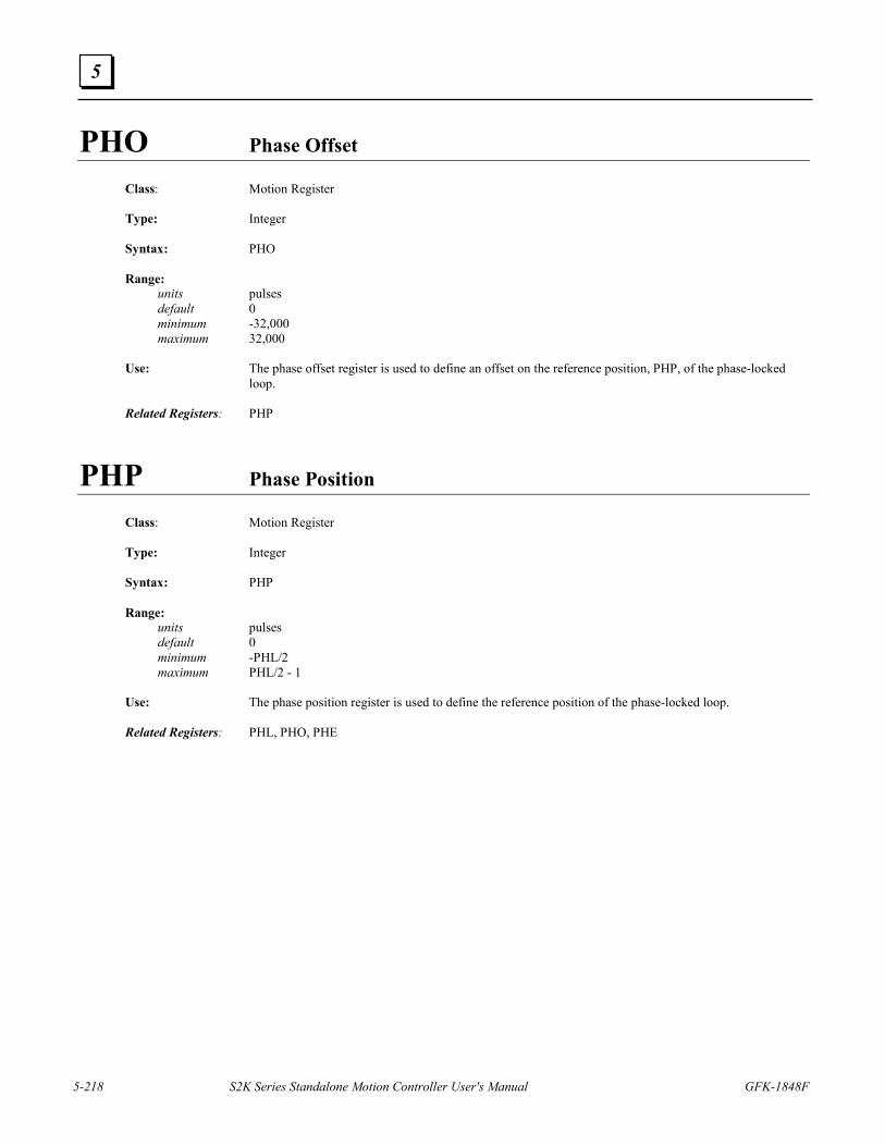
5-218 S2K Series Standalone Motion Controller User's Manual GFK-1848F
5
PHO Phase Offset
Class: Motion Register Type: Integer Syntax: PHO Range: units pulses default 0 minimum -32,000 maximum 32,000 Use: The phase offset register is used to define an offset on the reference position, PHP, of the phase-locked
loop. Related Registers: PHP
PHP Phase Position
Class: Motion Register Type: Integer Syntax: PHP Range: units pulses default 0 minimum -PHL/2 maximum PHL/2 - 1 Use: The phase position register is used to define the reference position of the phase-locked loop. Related Registers: PHL, PHO, PHE
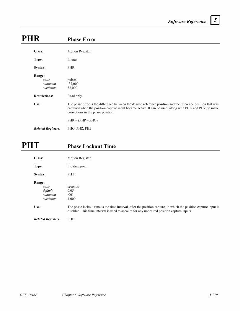
Software Reference
GFK-1848F Chapter 5 Software Reference 5-219
5
PHR Phase Error
Class: Motion Register Type: Integer Syntax: PHR Range: units pulses minimum -32,000 maximum 32,000 Restrictions: Read only. Use: The phase error is the difference between the desired reference position and the reference position that was
captured when the position capture input became active. It can be used, along with PHG and PHZ, to make corrections in the phase position.
PHR = (PHP – PHO) Related Registers: PHG, PHZ, PHE
PHT Phase Lockout Time Class: Motion Register Type: Floating point Syntax: PHT Range: units seconds default 0.05 minimum .001 maximum 4.000 Use: The phase lockout time is the time interval, after the position capture, in which the position capture input is
disabled. This time interval is used to account for any undesired position capture inputs. Related Registers: PHE
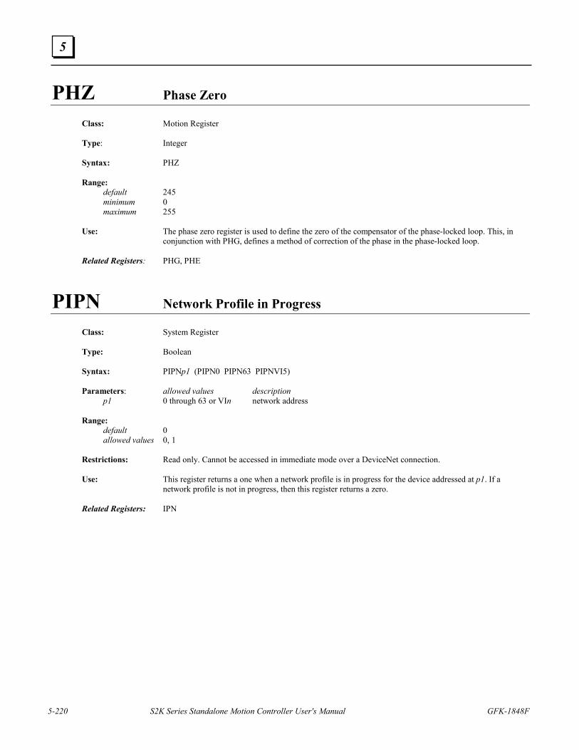
5-220 S2K Series Standalone Motion Controller User's Manual GFK-1848F
5
PHZ Phase Zero
Class: Motion Register Type: Integer Syntax: PHZ Range: default 245 minimum 0 maximum 255 Use: The phase zero register is used to define the zero of the compensator of the phase-locked loop. This, in
conjunction with PHG, defines a method of correction of the phase in the phase-locked loop. Related Registers: PHG, PHE
PIPN Network Profile in Progress
Class: System Register Type: Boolean Syntax: PIPNp1 (PIPN0 PIPN63 PIPNVI5) Parameters: allowed values description p1 0 through 63 or VIn network address Range: default 0 allowed values 0, 1 Restrictions: Read only. Cannot be accessed in immediate mode over a DeviceNet connection. Use: This register returns a one when a network profile is in progress for the device addressed at p1. If a
network profile is not in progress, then this register returns a zero. Related Registers: IPN
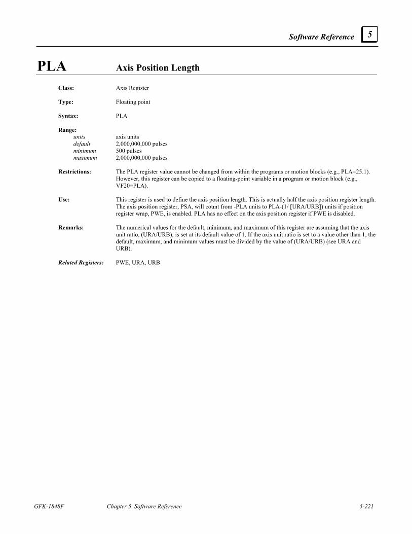
Software Reference
GFK-1848F Chapter 5 Software Reference 5-221
5
PLA Axis Position Length
Class: Axis Register Type: Floating point Syntax: PLA Range: units axis units default 2,000,000,000 pulses minimum 500 pulses maximum 2,000,000,000 pulses Restrictions: The PLA register value cannot be changed from within the programs or motion blocks (e.g., PLA=25.1).
However, this register can be copied to a floating-point variable in a program or motion block (e.g., VF20=PLA).
Use: This register is used to define the axis position length. This is actually half the axis position register length.
The axis position register, PSA, will count from -PLA units to PLA-(1/ [URA/URB]) units if position register wrap, PWE, is enabled. PLA has no effect on the axis position register if PWE is disabled.
Remarks: The numerical values for the default, minimum, and maximum of this register are assuming that the axis
unit ratio, (URA/URB), is set at its default value of 1. If the axis unit ratio is set to a value other than 1, the default, maximum, and minimum values must be divided by the value of (URA/URB) (see URA and URB).
Related Registers: PWE, URA, URB
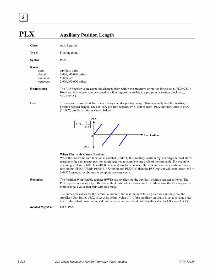
5-222 S2K Series Standalone Motion Controller User's Manual GFK-1848F
5
PLX Auxiliary Position Length Class: Axis Register Type: Floating point Syntax: PLX Range: units auxiliary units default 2,000,000,000 pulses minimum 500 pulses maximum 2,000,000,000 pulses Restrictions: The PLX register value cannot be changed from within the programs or motion blocks (e.g., PLX=25.1).
However, this register can be copied to a floating-point variable in a program or motion block (e.g., VF20=PLX).
Use: This register is used to define the auxiliary encoder position range. This is actually half the auxiliary
position register length. The auxiliary position register, PSX, counts from -PLX auxiliary units to PLX-(1/URX) auxiliary units as shown below:
PSX
Aux. Position
PLX - 1
URX
-PLX
0
When Electronic Cam is Enabled: When the electronic cam function is enabled (CAE=1) the auxiliary position register range defined above
represents the cam master position range required to complete one cycle of the cam table. For example, assuming we have a 1000 line (4000 pulse/rev) auxiliary encoder, the axis and auxiliary units are both in revolutions ([URA/URB]=10000; URX=4000) and PLX=0.5, then the PSX register will count from -0.5 to 0.49975 encoder revolutions to complete one cam cycle.
Remarks: The Position Wrap Enable register (PWE) has no effect on the auxiliary position register rollover. The
PSX register automatically rolls over at the limits defined above for PLX. Make sure the PSX register is initialized to a value that falls with this range.
The numerical values for the default, minimum, and maximum of this register are assuming that the
Auxiliary Unit Ratio, URX, is set at its default value of 1. If the auxiliary unit ratio is set to a value other than 1, the default, maximum, and minimum values must be divided by the value for URX (see URX).
Related Registers: URX, PSX
Software Reference
GFK-1848F Chapter 5 Software Reference 5-223
5
POE Power Output Stage Enable
Class: Axis Register Type: Boolean Syntax: POE Range: default 1 allowed values 0, 1 Use: This register is used to determine whether the power output stage of the amplifier of the axis is enabled. If
POE is set to 1, then the power output stage is enabled; and if POE is set to 0, it is disabled. The POE register is a logical enable that will allow current to flow into the motor only when set true and no faults are present on the controller.
POP Pops “Gosub” Address from Top of “Gosub” Stack
Class: Program Command Syntax: POP Restrictions: Allowed only in programs Use: This command pops the last gosub address from the top of the gosub stack. It causes the program to exit a
subroutine without returning. Example: PROGRAM1 (* edit program 1) MVL=5 (* set motion velocity) MAC=40 (* set motion acceleration) MPA=10 (* set absolute move position) GOSUB10 (* unconditionally gosub 10) GOTO20 (* unconditionally goto 20) 10 RPA (* run to absolute position) 11 IF IP GOTO12 (* conditionally goto 12) IF FC <> 0 GOTO15 (* conditionally goto 15) GOTO11 (* unconditionally goto 11) 12 RETURN (* return from gosub) 15 POP (* pop gosub address from top of gosub stack) OUT “CONTROLLER FAULT$N” (* output string expression to the display) OUT “TYPE ‘FC?’ FOR MESSAGE$N” (* output string expression to the display) 20 END (* end program 1 and exit editor) What will happen: This program, when executed, will set the velocity, acceleration rate, and absolute move position.
Execution will then go to the subroutine at label 10, which will run the axis in the forward direction for 10 units. While the axis is running, the program checks two things: 1) to see if the axis is in position (IP); and 2) to see if a fault has occurred (FC<>0). If a fault has occurred, the program execution will go to label 15. Then, the program will pop the address of label 10 off of the stack, print an error message, and end. If a fault does not occur, the program will return to the statement after “GOSUB10,” which goes to the statement at label 20, which ends the program.
Related Commands: GOSUB, RETURN, RSTSTK
5-224 S2K Series Standalone Motion Controller User's Manual GFK-1848F
5
PROG Program Executing
Class: System Register Type: Boolean Syntax: PROGp1 (e.g., PROG3 PROGVI4) Parameters: allowed values description p1 1 through 4 or Vin program number Range: allowed values 0, 1 Restrictions: Read only. Use: The program executing register is used to determine whether a program is executing. If program p1 is
executing, then PROGp1 will be 1; and if program p1 is not executing, then PROGp1 will be 0. Related Registers: SRP
PROGRAM Edit Program in Terminal Window Line Editor
Class: Program Command Syntax: PROGRAMp1 (e.g., PROGRAM2) Parameters: allowed values description p1 1 through 4 program number Restrictions: Not allowed in programs or motion blocks. Allowed only in Motion Developer terminal window. Use: This command starts the terminal window line editor at the first statement of PROGRAM p1. It is used
either to view or edit programs. Remarks: This command will not typically be used since Motion Developer provides a more full featured text editor
for creating and editing programs and motion blocks. The terminal window can also be used for these functions and is invoked using the PROGRAM and MOTION commands. While in the terminal window line editor each line is prefixed by an asterisk (*). Use the exclamation point (!) command to exit the terminal window line editor.
This command will execute only when the axis has stopped and no programs or motion blocks are
executing. Example: PROGRAM1 (* edit program 1) PSA=0 (* set axis position register) MVL=10 (* set motion velocity) MAC=40 (* set motion acceleration) MPA=12 (* load absolute move position) RPA (* run to absolute move position) END (* end program 1 and exit editor) Related Commands: MOTION, END, X, !, DEL, L, LABEL, FAULT
Software Reference
GFK-1848F Chapter 5 Software Reference 5-225
5
PSA Axis Position
Class: Axis Register Type: Floating point Syntax PSA Range: units axis units default 0 pulses minimum -2,000,000,000 pulses maximum 2,000,000,000 pulses Use: This register is used to define the position of the axis. Remarks: This register supports up to six decimal places. The numerical values for the default, minimum, and
maximum of this register are assuming that the axis unit ratio, (URA/URB), is set at its default value of 1. If the axis unit ratio is set to a value other than 1, the default, maximum, and minimum values must be divided by the value for (URA/URB) (see URA and URB).
Example: PSA=0 (* set axis position) MVL=10 (* set motion velocity) MAC=40 (* set motion acceleration) MPA=8 (* set absolute move position) RPA (* run to absolute position) What will happen: Setting the axis position, velocity, acceleration, and absolute move position and issuing the RPA command
will cause the axis to move 8 units in the forward direction. Related Registers: URA, URB, PLA, PWE, OFA
PSAN Network Axis Position Class: Axis Register Type: Integer Syntax: PSANp1 (e.g., PSAN0 PSAN63 PSANVI5) Parameters: allowed values description p1 0 through 63 or VIn network node address Range: units pulses minimum -2,000,000,000 pulses maximum 2,000,000,000 pulses Restrictions: Cannot be accessed in immediate mode over a DeviceNet connection. Use: This register accesses attribute 13 of the DeviceNet position controller object to define the actual position
of the axis.
5-226 S2K Series Standalone Motion Controller User's Manual GFK-1848F
5
PSC Commanded Position Class: Axis Register Type: Floating point Syntax: PSC Range: units axis units default 0 pulses minimum -2,000,000,000 pulses maximum 2,000,000,000 pulses Restrictions: Read only. Use: This register supports up to six decimal places. This register is used to determine the commanded position
of the axis. The commanded position is the controller’s required position for the axis. The difference between this and the axis position, PSA, is called the following error, FE.
Remarks: The numerical values for the default, minimum, and maximum of this register are assuming that the axis
unit ratio, (URA/URB), is set at its default value of 1. If the axis unit ratio is set to a value other than 1, the default, minimum, and maximum values must be divided by the value for (URA/URB) (see URA and URB).
Related Registers: PSA, FE, URA, URB
PSCN Network Command Position
Class: Axis Register Type: Integer Syntax: PSCNp1 (e.g., PSCN0 PSCN63 PSCNVI5) Parameters: allowed values description p1 0 through 63 or Vin network address Range: units pulses minimum -2,000,000,000 pulses maximum 2,000,000,000 pulses Restrictions: Read only. Cannot be accessed in immediate mode over a DeviceNet connection. Use: This register accesses attribute 15 of the DeviceNet position controller object to determine the command
position of the axis. The command position is the controller’s required position for the axis. The difference between this and the network axis position, PSAN, is called the following error, FE.
Related Registers: PSA, PSAN, FE
Software Reference
GFK-1848F Chapter 5 Software Reference 5-227
5
PSO Offset Move Reference Position
Class: Axis Register Type: Floating point Syntax: PSO Range: units axis units default 0 pulses minimum -2,000,000,000 pulses maximum 2,000,000,000 pulses Use: This register supports up to six decimal places. This register is used to define the reference position for
offset moves initiated using the MPO command. Remarks: The numerical values for the default, minimum, and maximum of this register are assuming that the axis
unit ratio, (URA/URB), is set at its default value of 1. If the axis unit ratio is set to a value other than 1, the default, maximum, and minimum values must be divided by the value for (URA/URB) (see URA and URB).
Example: PSO=0 (* set offset position) MVL=10 (* set motion velocity) MAC=40 (* set motion acceleration) MPO=10 (* set offset move position) RPO (* run to offset move position) What will happen: Setting the offset position, velocity, acceleration, and offset move position and issuing the RPO command
will cause axis one to move 10 units in the forward direction. Related Registers: MPO, RPO, URA, URB
PSR Resolver Position
Class: Axis Register Type: Integer Syntax: PSR Range: minimum 0 maximum 4,095 (resolver feedback brushless servo) or 65,535 (encoder feedback brushless servo) Restrictions: Brushless servo only; read only. Use: This register is used to determine the resolver position.
5-228 S2K Series Standalone Motion Controller User's Manual GFK-1848F
5
PSX Auxiliary Position
Class: Axis Register Type: Floating point Syntax: PSX Range: units auxiliary units default 0 pulses minimum -2,000,000,000 pulses maximum 2,000,000,000 pulses Use: Defines the position of the auxiliary encoder of the axis. Remarks: This register supports up to six decimal places. The numerical values for the default, minimum, and
maximum of this register are assuming that the auxiliary unit ratio, URX, is set at its default value of 1. If the auxiliary unit ratio is set to a value other than 1, the default, minimum, and maximum values must be divided by the value for URX (see URX).
Example: PSX=20 (* set auxiliary position to 20 auxiliary units) PSX? (* report auxiliary position) Related Registers: URX, PLX, OFX
PUT Puts One Character to Serial Port
Class: Input/Output Command Syntax: PUT p1 (e.g., PUT VS1 PUT“A”) Parameters: allowed values description p1 any string expression string expression Use: This command puts one character to the serial port. It takes the string expression and outputs only the first
character to the serial port. Example: PUT VS1 (* put one character of string variable 1 to serial port) PUT“Hello” (* put one character of the string “Hello” to serial port [i.e., H]) Related Commands: GET, IN, OUT
Related Registers: DSE

Software Reference
GFK-1848F Chapter 5 Software Reference 5-229
5
PWE Position Register Wrap Enable
Class: Axis Register Type: Boolean Syntax: PWE Range: default 0 allowed values 0, 1 Restrictions: Cannot be assigned in programs or motion blocks. Use: This register is used to determine whether the axis position register wrap is enabled. If PWE is set to 1,
axis position register wrap is enabled; and if PWE is set to 0, it is disabled. Remarks: When position register wrap is enabled, the controller will use the axis position length, PLA, to define the
upper and lower roll over limits for the Axis Position register (PSA) as -PLA axis units to PLA-(1/ [URA/URB]) axis units. Wrapping is required in unidirectional applications to prevent position register overflow or in applications where it makes sense to define a position modulus. PWE has no effect on the Auxiliary Position register (PSX) which always wraps. The setting of PWE has no effect on electronic cam mode.
Related Registers: PLA, PSA
5-230 S2K Series Standalone Motion Controller User's Manual GFK-1848F
5
PZA Axis Position Synchronize
Class: Axis Register Type: Floating point Syntax: PZA Range: units axis units default 0 pulses minimum -2,000,000,000 pulses maximum 2,000,000,000 pulses Restrictions: Read only. Use: This register is used to synchronize the reading of the axis position and the auxiliary position. This register
is read first, then the PZX register is read. By using these registers instead of the standard position registers (PSA and PSX), there will be no more than 10 microseconds between the two readings.
Remarks: Each time the PZA command is executed the value in the axis position register (PSA) is latched into the
PZA register and within 10 µs the value in the auxiliary position register (PSX) is latched into the PZX register. These values remain until the PZA command is executed again.
The numerical values for the default, minimum, and maximum of this register are assuming that the axis
unit ratio, (URA/URB), is set at its default value of 1. If the axis unit ratio is set to a value other than 1, the default, minimum, and maximum must be divided by the value for (URA/URB) (see URA and URB).
Example: VF1=PZA-PZX (* calculate difference between axis and auxiliary positions) Related Registers: PZX, URA, URB, PSA, PSX
Software Reference
GFK-1848F Chapter 5 Software Reference 5-231
5
PZX Auxiliary Position Synchronized
Class: Axis Register Type: Floating point Syntax: PZX Range: units auxiliary units default 0 pulses minimum -2,000,000,000 pulses maximum 2,000,000,000 pulses Restrictions: Read only. Use: This register is used to synchronize the readings of the auxiliary position and the axis position. The PZA
register is read first, then this register is read. By using these registers instead of the standard position registers (PSA and PSX), there will be no more than 10 microseconds between the two readings.
Remarks: Each time the PZA command is executed the value in the axis position register (PSA) is latched into the
PZA register and within 10 µs the value in the auxiliary position register (PSX) is latched into the PZX register. These values remain until the PZA command is executed again.
The numerical values for the default, minimum, and maximum of this register are assuming that the
auxiliary unit ratio, URX, is set at its default value of 1. If the auxiliary unit ratio is set to a value other than 1, the default, minimum, and maximum values must be divided by the value for URX (see URX).
Example: VF1=PZA-PZX (* calculate difference between axis and auxiliary positions) Related Registers: PZA, URX, PSA, PSX
5-232 S2K Series Standalone Motion Controller User's Manual GFK-1848F
5
Q Reports Value of Register
Class: Diagnostic Command Syntax: p1Q (e.g., SRSQ PSAQ MPAQ) Parameters: allowed values description p1 any register register Restrictions: Not allowed in programs or motion blocks. Use: This command is used to report the value of any register. It is exactly the same as the ? command. Related Commands: DGO, ?
QTX Auxiliary Quadrature Type
Class: Axis Register Syntax: QTX Range: default Q4 allowed values Q4 (quadrature x4) PD (pulse/direction) CW (clockwise/counterclockwise) Restrictions: Not allowed in expressions. Use: This register is used to define the signal input type for the auxiliary encoder input. The auxiliary encoder
input is discussed in Section 3.6.6. The signal types supported are listed below:
Q4 (quadrature x4) Sets the input for two pulse waveforms in quadrature with a pulse multiplier of 4. (e.g., a 1,000 line encoder will generate 4,000 pulses)
PD (pulse/direction) Sets the input for a pulse input on channel A (IN_A) and a direction input on channel B (IN_B). CW (CW/CCW) Sets the input for a pulse input on channel A (IN_A) for CW motion and a pulse input on channel B
(IN_B) for CCW motion. Remarks: The auxiliary encoder input will cause the Auxiliary Position register (PSX) to increase when: 1) QTX=Q4 and channel A leads channel B; 2) QTX=PD and channel B+ > channel B-; 3) QTX=CW and channel A has a pulse waveform and channel B does not. Related Registers: PSX
Software Reference
GFK-1848F Chapter 5 Software Reference 5-233
5
RDN Network Run Direction Flag
Class: Motion Register Type: Boolean Syntax: RDNp1 (RDN0 RDN63 RDNVI5) Parameters: allowed values description p1 0 through 63 or VIn network node address Range: allowed values 0, 1 Restrictions: Cannot be accessed in immediate mode over a DeviceNet connection. Use: This command accesses attribute 23 of the DeviceNet position controller object to set the direction of
motion of the axis addressed at p1 when the RMNp1 register is set to 1 (velocity mode). 1 = forward motion; 0 = reverse motion.
Related Registers: RMN Related Commands: RPN, RVR, RVF
REM Remark
Class: Program Command Syntax: REMp1 (e.g., REM Program starts here) Parameters: allowed values description p1 any string, 0 through 127 characters text comment Restrictions: Allowed only in programs or motion blocks. Use: This command is used to add textual comments to a program or motion block. Remarks: Comments are stored as part of a program or motion block, but they are ignored while the program or
motion block is executing. Example: PROGRAM1 (* edit program 1) REM Set update screen to 5 (* comment) UPS=5 (* set update screen register)
5-234 S2K Series Standalone Motion Controller User's Manual GFK-1848F
5
REPEAT Repeats Motion from Start of Motion Block
Class: Program Command Syntax: REPEAT Restrictions: Allowed only in motion blocks. Use: This command causes the motion block to repeat motion from the beginning of the motion block. Example: MOTION1 (* edit motion block 1) (* assign axis one to motion block) MVL=10 (* set motion velocity) MAC=40 (* set motion acceleration) MPI=15 (* set incremental move position) MPA=0 (* set absolute move position) RPI (* run to incremental position) RPA (* run to absolute position) REPEAT (* repeat motion from beginning of motion block) END (* end motion block 1 and exit editor) What will happen: This motion block, when executed, will load the velocity, acceleration rate, incremental move position,
and absolute move position. Next, the axis will move 15 units in the forward direction. Once the motion is completed, the axis will then move 15 units in the reverse direction. It will repeat this motion until a motion command or another motion block is executed.
RETRIEVE Retrieves User Memory
Class: System Command Syntax: RETRIEVE Restrictions: Not allowed in programs or motion blocks. Use: This command is used to retrieve user memory from nonvolatile memory. Remarks: This command will execute only when the controller or the system is faulted, the UPS register is set to its
default value of zero (i.e., UPS=0) and no programs or motion blocks are executing. Related Commands: SAVE, AUTORET
Software Reference
GFK-1848F Chapter 5 Software Reference 5-235
5
RETURN Returns from “Gosub”
Class: Program Command Syntax: RETURN Restrictions: Allowed only in programs. Use: This command causes the program to return from a subroutine to the statement after the gosub statement. Example: PROGRAM1 (* edit program 1) MVL=5 (* set motion velocity) MAC=40 (* set motion acceleration) MPA=10 (* set absolute move position) GOSUB10 (* unconditionally gosub 10) GOTO20 (* unconditionally goto 20) 10 RPA (* run to absolute position) WAIT IP (* wait for expression to be true) OUT “Axis in position$N” (* output string expression to display) RETURN (* return from gosub) 20 END (* end program 1 and exit editor) What will happen: This program, when executed, will load the velocity, acceleration rate, and absolute move position. It will
then go to the subroutine at label 10, which will run the axis in the forward direction for 10 units. Once the axis is in position, the program will print a string. The program will return to the statement after “GOSUB10,” which goes to the statement at label 20, which ends the program.
Related Commands: GOSUB, POP, RSTSTK
REVISION Reports Firmware Revision
Class: Diagnostic Command Syntax: REVISION Restrictions: Not allowed in programs or motion blocks. Use: This command reports the revision of the system firmware.
5-236 S2K Series Standalone Motion Controller User's Manual GFK-1848F
5
REVN Network Device Revision
Class: Diagnostic Command Syntax: REVNp1 (REVN0 REVN63) Parameters: allowed values description p1 0 through 63 network node address Restrictions: Not allowed in programs or motion blocks. Cannot be accessed in immediate mode over a DeviceNet
connection. This is a diagnostic command and is not allowed in programs or motion blocks. Use: This command accesses attributes 4 and 7 of the DeviceNet identity object to report the model number and
firmware revision of the device addressed at p1. Related Commands: REVISION
RGT Select Rightmost Characters of String Operator Class: Operator Type: String Syntax: RGT(p1,p2) Parameters: allowed values description p1 any string operand string p2 any integer operand >= 0 number of characters Use: Used to select the rightmost p2 characters of string p1. Example: VS1=“Jogging axis forward” (* set string variable 1 to “Jogging axis forward”) VS2=RGT(VS1,7) (* set string variable VS2 to rightmost 7 characters of VS1) VS2? (* report the value of string variable VS2 in terminal window) * “forward” Related Commands: LFT, MID
Software Reference
GFK-1848F Chapter 5 Software Reference 5-237
5
RHF Runs Forward to Home Input Class: Motion Command Syntax: RHF Use: This command runs forward to the home input. Remarks: When this command is executed, the axis will run forward until the home input is encountered. It will then
stop and run back to the position where the home input (digital input DI1) was detected. The software overtravel limits, OTF and OTR, are ignored while the axis is homing.
Example: PROGRAM1 (* edit program 1) MVL=1 (* set motion velocity) MAC=50 (* set motion acceleration) RHF (* run forward to home input) WAIT IP (* wait for axis to be in position) PSA=0 (* set axis position register) END (* end program 1 and exit editor) What will happen: This program, once executed, will first set the motion velocity and acceleration. It will then run the axis in
the forward direction until the home input is encountered, wait for the axis to be in position, and then set the axis position register to 0.
Related Commands: RHR, RMF, ROF Related Registers: When MT=VEL MVL, MAC, MDC, MJK, MFP, MFA, MFD When MT=TIME Command cannot be used When MT=PULSE Command cannot be used Motion Templates: Run reverse until home input; run reverse until home and marker inputs
5-238 S2K Series Standalone Motion Controller User's Manual GFK-1848F
5
RHR Runs Reverse to Home Input Class: Motion Command Syntax: RHR Use: This command runs reverse to the home input. Remarks: When this command is executed, the axis will run reverse until the home input is encountered. It will then
stop and run back to the position where the home input was detected. The software overtravel limits, OTF and OTR, are ignored while the axis is homing.
Example: PROGRAM1 (* edit program 1) MVL=1 (* set motion velocity) MAC=50 (* set motion acceleration) RHR (* run reverse to home input) WAIT IP (* wait for axis to be in position) PSA=0 (* set axis position register) END (* end program 1 and exit editor) What will happen: This program, once executed, will first set the motion velocity and acceleration. It will then run the axis in
the reverse direction until the home input is encountered, wait for the axis to be in position, and then set the axis position register to 0.
Related Commands: RHF, RMR, ROR Related Registers: When MT=VEL MVL, MAC, MDC, MJK, MFP, MFA, MFD When MT=TIME Command cannot be used When MT=PULSE Command cannot be used Motion Templates: Run reverse until home input; run reverse until home and marker inputs
Software Reference
GFK-1848F Chapter 5 Software Reference 5-239
5
RIN Network Run Incremental Flag
Class: Motion Register Type: Boolean Syntax: RINp1 (RIN0 RIN63) Parameters: allowed values description p1 0 through 63 or VIn network node address Range: allowed values 0, 1 Restrictions: Cannot be accessed in immediate mode over a DeviceNet connection. Use: This command accesses attribute 10 of the DeviceNet position controller object to set the absolute or
incremental position mode of the axis addressed at p1. 0 = absolute position mode; 1 = incremental position mode.
Related Registers: RMN Related Commands: RPA, RPI, RPN
5-240 S2K Series Standalone Motion Controller User's Manual GFK-1848F
5
RMF Runs Forward to Marker
Class: Motion Command Syntax: RMF Use: This command runs forward to the marker. The marker is defined as the encoder channel index input when
using encoder feedback controllers or as the zero position on the resolver when using resolver feedback controllers.
Remarks: When this command is executed, the axis will run forward at the velocity specified in the MVM register
until the marker is encountered. It will then stop and run back to the position where the marker was detected. The software overtravel limits, OTF and OTR, are ignored while homing the axis.
Example: PROGRAM1 (* edit program 1) MVM=1 (* set motion velocity for run to marker) MAC=50 (* set motion acceleration) RMF (* run forward to marker) WAIT IP (* wait for axis to be in position) PSA=0 (* set axis position register) END (* end program 1 and exit editor) What will happen: This program, once executed, will first set the motion velocity for run to marker and acceleration. It will
then run the axis in the forward direction until the marker is encountered, wait for the axis to be in position, and then set the axis position register to 0.
Related Commands: RMR, RHF, ROF Related Registers: When MT=VEL MVM, MAC, MDC, MJK, MFP, MFA, MFD When MT=TIME Command cannot be used When MT=PULSE Command cannot be used Motion Templates: Run reverse until marker input; run reverse until home and marker inputs; run reverse until overtravel and
marker inputs
Software Reference
GFK-1848F Chapter 5 Software Reference 5-241
5
RMN Network Run Mode
Class: Motion Register Type: Integer Syntax: RMNp1 (RMN0 RMN63 RMNVI5) Parameters: allowed values description p1 0 through 63 or VIn network node address Range: allowed values 0, 1 Restrictions: Cannot be accessed in immediate mode over a DeviceNet connection. Use: This command accesses attribute 3 of the DeviceNet position controller object to set the motion mode of
the axis addressed at p1. 0 = position mode; 1 = velocity mode; and 2 = torque mode. Related Registers: RDN, RIN Related Commands: RPA, RPI, RPN, RVF, RVR
RMR Runs Reverse to Marker
Class: Motion Command Syntax: RMR Use: This command runs reverse to the marker. The marker is defined as encoder channel index input on
encoder feedback controllers or as the zero position on the resolver of resolver feedback controllers. Remarks: When this command is executed, the axis will run reverse at the velocity specified in the MVM register
until the marker is encountered. It will then stop and run back to the position where the marker was detected. The software overtravel limits, OTF and OTR, are ignored while the axis is homing.
Example: PROGRAM1 (* edit program 1) MVM=1 (* set motion velocity for run to marker) MAC=50 (* set motion acceleration) RMR (* run reverse to marker) WAIT IP (* wait for axis to be in position) PSA=0 (* set axis position register) END (* end program 1 and exit editor) What will happen: This program, once executed, will first set the motion velocity for run to marker and acceleration. It will
then run the axis in the reverse direction until the marker is encountered, wait for the axis to be in position, and then set the axis position register to 0.
Related Commands: RMF, RHR, ROR Related Registers: When MT=VEL MVM, MAC, MDC, MJK, MFP, MFA, MFD When MT=TIME Command cannot be used When MT=PULSE Command cannot be used Motion Templates: Run reverse until marker input; run reverse until home and marker inputs; run reverse until overtravel and
marker inputs
5-242 S2K Series Standalone Motion Controller User's Manual GFK-1848F
5
ROF Runs Forward to Overtravel Input
Class: Motion Command Syntax: ROF Use: This command runs forward to the forward overtravel input. Remarks: When this command is executed, the axis will run until the forward overtravel input is encountered. It will
then stop and run back to the position where the forward overtravel input was detected. The software overtravel limits, OTF and OTR, are ignored while the axis is homing. The hardware overtravel inputs do not need to be enabled (OTE=1) to use this command.
Example: PROGRAM1 (* edit program 1) MVL=1 (* set motion velocity) MAC=50 (* set motion acceleration) ROF (* run forward to overtravel input) WAIT IP (* wait for axis to be in position) PSA=0 (* set axis position register) END (* end program 1 and exit editor) What will happen: This program, once executed, will first set the motion velocity and acceleration. It will then run the axis in
the forward direction until the forward overtravel input is encountered, wait for the axis to be in position, and then set the axis position register to 0.
Related Commands: ROR, RHF, RMF Related Registers: When MT=VEL MVL, MAC, MDC, MJK, MFP, MFA, MFD When MT=TIME or MT=PULSE Command cannot be used Motion Templates: Run reverse until overtravel inputs; run reverse until overtravel and marker inputs
ROL, ROR Rotate Operators
Class: Operator Type: Integer Syntax: p1 ROL p2 p1 ROR p2 Parameters: allowed values p1 any integer operand p2 any integer operand Use: These operators are used to rotate the bits of p1 by the number of places specified by p2. Example: VI1=2#11101001 (* set integer variable 1 to 2#11101001) VI2=VI1 ROL 2 (* set integer variable 2 to VI1 rotated left by 2 places) VS1=ITB(VI2,12) (* set string variable 1 to VI2 converted to binary string) VS1? (* report value of string variable 1) *“2#1110100100” VI3=VI1 ROR 3 (* set integer variable 3 to VI1 rotated right by 3 places) VS2=ITB(VI3,32) (* set string variable 2 to VI3 converted to binary string) VS2? (* report value of string variable 2) *“2#100000000000000000000000011101” Related Operators: SHL, SHR
Software Reference
GFK-1848F Chapter 5 Software Reference 5-243
5
ROR Runs Reverse to Overtravel Input
Class: Motion Command Syntax: ROR Use: This command runs reverse to the reverse overtravel input. Remarks: When this command is executed, the axis will run until the reverse overtravel input is encountered. It will
then stop and run back to the position where the reverse overtravel input was detected. The software overtravel limits, OTF and OTR, are ignored while the axis is homing. The hardware overtravel inputs do not need to be enabled (OTE=1) to use this command.
Example: PROGRAM1 (* edit program 1) MVL=1 (* set motion velocity) MAC=50 (* set motion acceleration) ROR (* run reverse to overtravel input) WAIT IP (* wait for axis to be in position) PSA=0 (* set axis position register) END (* end program 1 and exit editor) What will happen: This program, once executed, will first set the motion velocity and acceleration. It will then run the axis in
the reverse direction until the reverse overtravel input is encountered, wait for the axis to be in position, and then set the axis position register to 0.
Related Commands: ROF, RHR, RMR Related Registers: When MT=VEL MVL, MAC, MDC, MJK, MFP, MFA, MFD When MT=TIME Command cannot be used When MT=PULSE Command cannot be used Motion Templates: Run reverse until overtravel inputs; run reverse until overtravel and marker inputs
5-244 S2K Series Standalone Motion Controller User's Manual GFK-1848F
5
RPA Runs to Absolute Position
Class: Motion Command Syntax: RPA Use: This command runs the axis to the absolute move position. Remarks: The run commands override each other unless they are used in a motion block. Example: PSA=0 (* set axis position register) MVL=10 (* set motion velocity) MAC=40 (* set motion acceleration) MPA=8 (* set absolute move position) RPA (* run to absolute move position) What will happen: Setting the axis position register, velocity, acceleration, and absolute move position and issuing the RPA
command will cause the axis to move 8 units in the forward direction. Related Commands: RPI, RPO, RVF, RVR Related Registers: When MT=VEL MPA, MVL, MAC, MDC, MJK, MFP, MFA, MFD When MT=TIME MPA, MTM, MAP, MDP, MJK, MFP, MFA, MFD When MT=PULSE MPA, MPS, MPL, MAP, MDP, MVP Motion Templates: Absolute move; blended move; absolute move with feedrate override; time-based absolute move; time-
based absolute move with feedrate override; pulse-based absolute move; pulse-based blended move
RPI Runs to Incremental Position
Class: Motion Command Syntax: RPI Use: This command runs the axis to the incremental move position, MPI (i.e., it runs from the current position
of the axis to the current position incremented by the value of MPI). Remarks: The run commands override each other unless they are used in a motion block. Example: MVL=10 (* set motion velocity) MAC=40 (* set motion acceleration rate) MPI=12 (* set incremental move position) RPI (* run to incremental move position) What will happen: Setting the velocity, acceleration, and incremental move position and issuing the RPI command will cause
the axis to move 12 units in the forward direction. Related Commands: RPA, RPO, RVF, RVR Related Registers: When MT=VEL MPI, MVL, MAC, MDC, MJK, MFP, MFA, MFD When MT=TIME MPI, MTM, MAP, MDP, MJK, MFP, MFA, MFD When MT=PULSE MPI, MPS, MPL, MAP, MDP, MVP Motion Templates: Incremental move; time-based incremental move; pulse-based incremental move; index move after input;
index move at predefined auxiliary position reference
Software Reference
GFK-1848F Chapter 5 Software Reference 5-245
5
RPN Run Profile of Network Device
Class: Motion Command Syntax: RPNp1 (RPN0 RPN63) Parameters: allowed values description p1 0 through 63 or VIn network node address Restrictions: Cannot be accessed in immediate mode over a DeviceNet connection. Use: This command accesses attribute 11 of the DeviceNet position controller object to cause the axis addressed
at p1 to perform one of the following functions: Run to absolute position when RMN=0 and RIN=0 Run to incremental position when RMN=0 and RIN=1 Run to velocity forward when RMN=1 and RDN=1 Run to velocity reverse when RMN=1 and RDN=0 Run to torque when RMN = 2 Related Registers: RIN, RDN, RMN Related Commands: RPA, RPI, RVF, RVR
RPO Runs to Offset Position
Class: Motion Command Syntax: RPO Use: This command runs the axis to the Offset Move Position (MPO). Remarks: The run commands override each other unless they are used in a motion block. Example: PSO=0 (* set offset position register) MVL=10 (* set motion velocity) MAC=40 (* set motion acceleration rate) MPO=8 (* set offset move position) RPO (* run to offset move position) What will happen: Setting the offset position register, velocity, acceleration, and offset move position and issuing the RPO
command will cause the axis to move 8 units in the forward direction. Related Commands: MPO, PSO, RPA, RPI, RVF, RVR Related Registers: When MT=VEL MPO, MVL, MAC, MDC, MJK, MFP, MFA, MFD When MT=TIME MPO, MTM, MAP, MDP, MJK, MFP, MFA, MFD When MT=PULSE MPO, MPS, MPL, MAP, MDP, MVP Motion Templates: Offset move; time-based offset move; pulse-based offset move
5-246 S2K Series Standalone Motion Controller User's Manual GFK-1848F
5
RSF Resets Faults
Class: System Command Syntax: RSF Restrictions: Not allowed in motion blocks. Use: This command resets all controller faults. Remarks: The RSF command sets the axis commanded position equal to the actual position, thus making axis
following error and motor torque output equal to zero. Faults should be automatically reset by a program only after allowing appropriate inspection into the source of the fault.
Related Commands: STF Related Registers: FC
RSFN Reset Network Faults
Class: System Command Syntax: RSFNp1 (RSFN RSFN() RSFN63 RSFNV15) Parameters: allowed values description p1 none or 0 through 63 or VIn network node address Restrictions: Not allowed in motion blocks. Cannot be accessed in immediate mode over a DeviceNet connection. Use: When p1 is not specified, this command resets the network faults of the controller. When p1 is specified,
this command accesses attribute 17 of the position controller object to reset faults of the controller addressed at p1.
Related Commands: RSF, RSFS, RSFALL Related Registers: FCN
RSM Resumes Motion Class: Program Command Syntax: RSM Restrictions: Not allowed in motion blocks. Use: This command resumes axis motion suspended using the SUP command. Related Commands: SUP
Software Reference
GFK-1848F Chapter 5 Software Reference 5-247
5
RSTSTK Resets “Gosub” Stack to Empty
Class: Program Command Syntax: RSTSTK Restrictions: Allowed only in programs. Use: This command resets the gosub stack to empty. Remarks: This command will eliminate all gosubs that have been executed. Example: PROGRAM1 (* edit program 1) IN VI1 (* input variable value from key buffer) IF VI1>=0 GOTO5 (* conditionally goto 5) OUT“-” (* output string expression to serial port) VI1=-VI1 (* set integer variable 1) 5 VI2=10 (* set integer variable 2 with pointer) GOSUB10 (* unconditionally gosub 10) GOTO30 (* unconditionally goto 30) 10 VIVI2=VI1 - VI1/10*10 + 48 (* set integer variable VI2) VI1=VI1/10 (* set integer variable 1) VI2=VI2+1 (* set integer variable 2 with next pointer) IF VI2>16 GOTO20 (* conditionally goto 20) IF VI1<>0 GOSUB10 (* conditionally gosub 10) VI2=VI2-1 (* set integer variable 2 with pointer) OUT CHR(VIVI2) (* output string expression to serial port) RETURN (* return from gosub) 20 RSTSTK (* reset gosub stack to empty) OUT“ERROR:$N” (* output string expression to serial port) OUT“Number more than 6 digits$N” (* output string expression to serial port) 30 END (* end program 1 and exit editor) What will happen: This program inputs an integer variable value from the key buffer. If the value is negative, the program
sends a negative sign to the display, sets the integer value positive, and continues to label 5, which sets the variable pointer to 10. The program then goes to the subroutine at label 10, which stores the ASCII code of the ones digit in VI10, the ASCII code of the tens digit in VI11, etc. If the number of digits is greater than 6, the program goes to label 20, which resets the gosub stack and prints an error message; otherwise, each character of integer number VI1 will be sent to the serial port and the program ends at label 30.
Related Commands: POP, GOSUB
5-248 S2K Series Standalone Motion Controller User's Manual GFK-1848F
5
RTU Remote Terminal Unit Mode Enable Class: System Command Syntax: RTU Type: Boolean Range: default 0 allowed values 0, 1 Restrictions: Cannot be assigned in motion blocks. Available in firmware version 2.1 and higher. Use: The RTU enables the controller to communicate with a remote terminal unit (RTU). If RTU is set to 1,
RTU mode is enabled; if RTU is set to 0, RTU mode is disabled. Remarks: Allows user to toggle back and forth between RTU mode and serial communication mode. When the
controller is in RTU mode, receipt of 10 consecutive non-RTU messages (such as pressing the <Enter> key 10 consecutive times from the Terminal Window) will revert the controller back to serial communication mode with the currently set baud rate, odd parity, and 7 data bits. Once in this mode it is not possible to set RTU=1 and it is necessary to cycle power on the controller to re-enable RTU communications.
Related Registers: ADDR, BAUD, BIT, RTUF
RTUF Remote Terminal Unit Communication Flag
Class: System Command Syntax: RTUF Type: Boolean Range: allowed values 0, 1 Restrictions: Read only. Available in firmware version 2.1 and higher. Use: This register is used to tell whether Remote Terminal Unit (RTU) communication is occurring. This flag is
set to one when a RTU communication occurs correctly and is cleared to zero when its value is tested. A program can monitor for successful RTU communication by testing RTUF at a rate slower than the RTU communication rate. As long as RTUF continues to return a value of 1, RTU communication is correctly taking place.
Related Registers: ADDR, RTU
Software Reference
GFK-1848F Chapter 5 Software Reference 5-249
5
RTV Retrieve Variable from Nonvolatile Memory to RAM
Class: System Command Syntax: RTV Restrictions: Allowed only in programs. Use: The RTV command retrieves integer variables 1 through 1,024 and floating point variables 1 through 512
from nonvolatile memory (flash) to RAM. If the RTV command is executed before a Save Variables (SVV) command has been executed the affected variables will be set to zero.
Related Registers: VI, VF Related Commands: SVV, SAVE, RETRIEVE
RVF Runs to Velocity Forward
Class: Motion Command Syntax: RVF Use: This command runs the axis in the forward direction. Remarks: The run commands override each other unless they are used in a motion block. Example: MVL=10 (* set motion velocity) MAC=50 (* set motion acceleration) RVF (* run forward) What will happen: Loading the velocity and acceleration and issuing the RVF command will cause the axis to run in the
forward direction until another motion command is issued. Related Commands: RVR, RPA, RPI, RPO Related Registers: When MT=VEL MVL, MAC, MDC, MJK, MFP, MFA, MFD When MT=TIME Command cannot be used When MT=PULSE MPS, MPL, MVP Motion Templates: Run reverse until torque limit; velocity-based continuous move; run forward until torque limit; run reverse
at torque limit; single-axis run forward until input Utility Templates: Jog using single-pole, double-throw switch
5-250 S2K Series Standalone Motion Controller User's Manual GFK-1848F
5
RVR Runs to Velocity Reverse
Class: Motion Command Syntax: RVR Use: This command runs the axis in the reverse direction. Remarks: The run commands override each other unless they are used in a motion block. Example: MVL=10 (* set motion velocity) MAC=50 (* set motion acceleration) RVR (* run forward) What will happen: Setting the velocity and acceleration and issuing the RVR command will cause the axis to run in the
reverse direction until another motion command is issued. Related Commands: RVF, RPA, RPI, RPO Related Registers: When MT=VEL MVL, MAC, MDC, MJK, MFP, MFA, MFD When MT=TIME Command cannot be used When MT=PULSE MPS, MPL, MVP Motion Templates: Run reverse until torque limit; velocity-based continuous move; run forward until torque limit; run reverse
at torque limit; single-axis run forward until input Utility Templates: Jog using single-pole, double-throw switch
SAVE Saves User Memory
Class: System Command Syntax: SAVE Restrictions: Not allowed in programs or motion blocks. Use: This command is used to save user memory from RAM to nonvolatile memory. Starting with firmware
version 2.1 and later the Save command also executes the AUTORET command. Remarks: This command will execute only when the controller or system is faulted and no programs or motion
blocks are executing. Related Commands: AUTORET, RETRIEVE, SVV
Software Reference
GFK-1848F Chapter 5 Software Reference 5-251
5
SCAN Maximum Scan Time
Class: System Register Syntax: SCAN Range: units seconds default 0 minimum 0.00 maximum 1.00 Restrictions: Not allowed in programs, motion blocks or expressions. Use: Defines the maximum time allowed between updates of the I/O connection of the network. If the I/O
connection is not updated in time, then the system will fault due to Network Communication Error and the FCN register will indicate an I/O Scan Time-Out (bit 11 set to 1). If SCAN is set to zero, then no check of the update time is performed. Applies to DeviceNet and PROFIBUS networks.
Example: SCAN=0.05 (* set maximum scan time to 50 milliseconds)
SCRD Screen Data Class: Input/Output Register Syntax: SCRDp1.p2 (e.g., SCRD1.1 SCRDVI1.2 SCRDVI5.VI7) Parameters: allowed values description p1 1 through 50 or VIn screen number p2 1 through 4 or VIn line number Restrictions: Not allowed in expressions. Use: This register is used to define screen data for line p2 of screen number p1. Example: SCRD1.1=FTS(VLA,5,2) (* set screen data for screen 1, line 1 to axis velocity, field width of (* 5 and 2 decimal places) SCRDVI1.2=“Jogging” (* set screen data for screen VI1, line 2 to “Jogging”) Related Registers: SCRP, SCRL, UPS
5-252 S2K Series Standalone Motion Controller User's Manual GFK-1848F
5
SCRL Screen Line
Class: Input/Output Register Type: String Syntax: SCRLp1.p2 (e.g., SCRL1.1 SCRLVI2.3 SCRLVI4.VI9) Parameters: allowed values description p1 1 through 50 or VIn screen number p2 1 through 4 or VIn line number Range: default “” allowed values any string, 0 through 40 characters long Use: This register is used to define a line of characters for line number p2 of screen p1. Example: SCRL1.1=“Axis velocity:” (* set screen line 1 of screen 1 to “Axis velocity:”) SCRLVI2.3=“Motion Parameters” (* set screen line 3 of screen VI2 to “Motion Parameters”) Related Registers: SCRD, SCRL, UPS
SCRP Screen Position of Data
Class: Input/Output Register Type: Integer Syntax: SCRPp1.p2 (e.g., SCRP1.1 SCRPVI2.3 SCRPVI3.VI6) Parameters: allowed values description p1 1 through 50 or Vin screen number p2 1 through 4 or VIn line number Range: default 1 minimum 1 maximum 40 Use: This register is used to define the column position where the screen data, SCRD, is placed on the screen
line. Example: SCRP1.1=15 (* set screen position of data for screen 1, line 1 to column 15) SCRPVI2.3=20 (* set screen position of data for screen VI2, line 3 to column 20) Related Registers: SCRD, SCRL, UPS
Software Reference
GFK-1848F Chapter 5 Software Reference 5-253
5
SECURE Secures User Memory
Class: System Command Syntax: SECURE Restrictions: Not allowed in programs or motion blocks. Use: This command secures user memory space and protects user’s intellectual property. It disables the
PROGRAM, FAULT, and MOTION commands and prohibits programs or motion blocks from being uploaded to the controller. To re-enable these commands, you must execute the CLM command to clear the memory.
Related Commands: PASSWORD, CHANGEPW
5-254 S2K Series Standalone Motion Controller User's Manual GFK-1848F
5
SHL, SHR Arithmetic Shift Operators Class: Operator Type: Integer Syntax: p1 SHL p2 p1 SHR p2 Parameters: allowed values p1 any integer operand p2 any integer operand Use: These operators are used to perform an arithmetic shift of p1 by the number of places specified by p2. Example: VI1=2#11101001 (* set integer variable 1 to 2#01101001) VI2=VI1 SHL 3 (* set integer variable 2 to VI1 shifted left by 3 places) VS1=ITB(VI2,13) (* set string variable 1 to VI2 converted to binary string) VS1? (* report value of string variable 1) *“2#11101001000” VI3=VI1 SHR 2 (* set integer variable 3 to VI1 shifted right by 2 places) VS2=ITB(VI3,8) (* set string variable 2 to VI3 converted to binary string) VS2? (* report value of string variable 2) *“2#111010” Related Operators: ROL, ROR
SIN Sine Trigonometric Function Operator
Class: Operator Type: Floating point Syntax: SIN(p1) Parameters: allowed values p1 any floating point operand Use: Used to perform trigonometric functions on p1. The operand p1 must be in degrees.
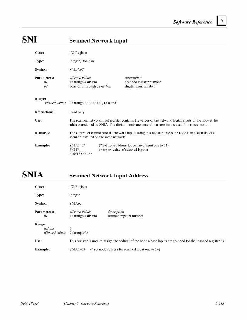
Software Reference
GFK-1848F Chapter 5 Software Reference 5-255
5
SNI Scanned Network Input
Class: I/O Register Type: Integer, Boolean Syntax: SNIp1.p2 Parameters: allowed values description p1 1 through 4 or Vin scanned register number p2 none or 1 through 32 or Vin digital input number Range: allowed values 0 through FFFFFFFF16 or 0 and 1 Restrictions: Read only. Use: The scanned network input register contains the values of the network digital inputs of the node at the
address assigned by SNIA. The digital inputs are general-purpose inputs used for process control. Remarks: The controller cannot read the network inputs using this register unless the node is in a scan list of a
scanner installed on the same network. Example: SNIA1=24 (* set node address for scanned input one to 24) SNI1? (* report value of scanned inputs) *16#135B60F7
SNIA Scanned Network Input Address
Class: I/O Register Type: Integer Syntax: SNIAp1 Parameters: allowed values description p1 1 through 4 or Vin scanned register number Range: default 0 allowed values 0 through 63 Use: This register is used to assign the address of the node whose inputs are scanned for the scanned register p1. Example: SNIA1=24 (* set node address for scanned input one to 24)
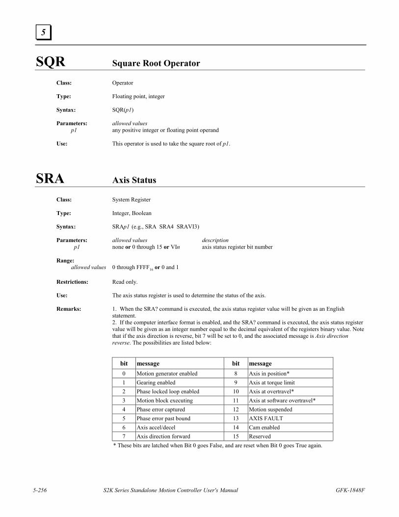
5-256 S2K Series Standalone Motion Controller User's Manual GFK-1848F
5
SQR Square Root Operator
Class: Operator Type: Floating point, integer Syntax: SQR(p1) Parameters: allowed values p1 any positive integer or floating point operand Use: This operator is used to take the square root of p1.
SRA Axis Status
Class: System Register Type: Integer, Boolean Syntax: SRAp1 (e.g., SRA SRA4 SRAVI3) Parameters: allowed values description p1 none or 0 through 15 or VIn axis status register bit number Range: allowed values 0 through FFFF16 or 0 and 1 Restrictions: Read only. Use: The axis status register is used to determine the status of the axis. Remarks: 1. When the SRA? command is executed, the axis status register value will be given as an English
statement. 2. If the computer interface format is enabled, and the SRA? command is executed, the axis status register
value will be given as an integer number equal to the decimal equivalent of the registers binary value. Note that if the axis direction is reverse, bit 7 will be set to 0, and the associated message is Axis direction reverse. The possibilities are listed below:
bit message bit message 0 Motion generator enabled 8 Axis in position* 1 Gearing enabled 9 Axis at torque limit 2 Phase locked loop enabled 10 Axis at overtravel* 3 Motion block executing 11 Axis at software overtravel* 4 Phase error captured 12 Motion suspended 5 Phase error past bound 13 AXIS FAULT 6 Axis accel/decel 14 Cam enabled 7 Axis direction forward 15 Reserved
* These bits are latched when Bit 0 goes False, and are reset when Bit 0 goes True again.
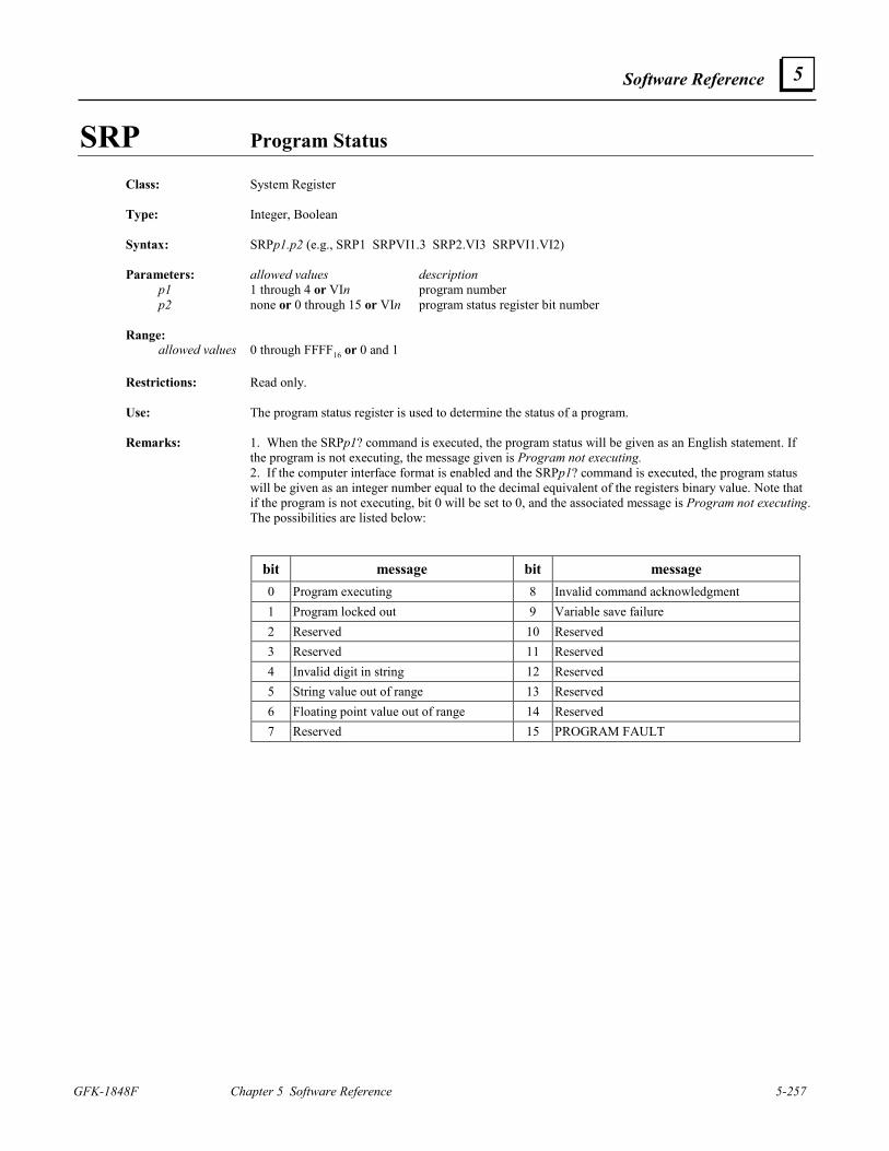
Software Reference
GFK-1848F Chapter 5 Software Reference 5-257
5
SRP Program Status
Class: System Register Type: Integer, Boolean Syntax: SRPp1.p2 (e.g., SRP1 SRPVI1.3 SRP2.VI3 SRPVI1.VI2) Parameters: allowed values description p1 1 through 4 or VIn program number p2 none or 0 through 15 or VIn program status register bit number Range: allowed values 0 through FFFF16 or 0 and 1 Restrictions: Read only. Use: The program status register is used to determine the status of a program. Remarks: 1. When the SRPp1? command is executed, the program status will be given as an English statement. If
the program is not executing, the message given is Program not executing. 2. If the computer interface format is enabled and the SRPp1? command is executed, the program status
will be given as an integer number equal to the decimal equivalent of the registers binary value. Note that if the program is not executing, bit 0 will be set to 0, and the associated message is Program not executing. The possibilities are listed below:
bit message bit message 0 Program executing 8 Invalid command acknowledgment 1 Program locked out 9 Variable save failure 2 Reserved 10 Reserved 3 Reserved 11 Reserved 4 Invalid digit in string 12 Reserved 5 String value out of range 13 Reserved 6 Floating point value out of range 14 Reserved 7 Reserved 15 PROGRAM FAULT
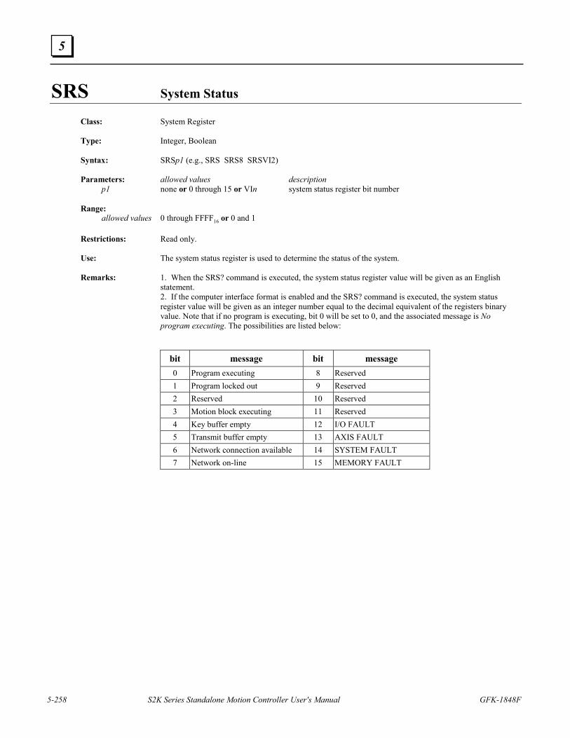
5-258 S2K Series Standalone Motion Controller User's Manual GFK-1848F
5
SRS System Status
Class: System Register Type: Integer, Boolean Syntax: SRSp1 (e.g., SRS SRS8 SRSVI2) Parameters: allowed values description p1 none or 0 through 15 or VIn system status register bit number Range: allowed values 0 through FFFF16 or 0 and 1 Restrictions: Read only. Use: The system status register is used to determine the status of the system. Remarks: 1. When the SRS? command is executed, the system status register value will be given as an English
statement. 2. If the computer interface format is enabled and the SRS? command is executed, the system status
register value will be given as an integer number equal to the decimal equivalent of the registers binary value. Note that if no program is executing, bit 0 will be set to 0, and the associated message is No program executing. The possibilities are listed below:
bit message bit message 0 Program executing 8 Reserved 1 Program locked out 9 Reserved 2 Reserved 10 Reserved 3 Motion block executing 11 Reserved 4 Key buffer empty 12 I/O FAULT 5 Transmit buffer empty 13 AXIS FAULT 6 Network connection available 14 SYSTEM FAULT 7 Network on-line 15 MEMORY FAULT
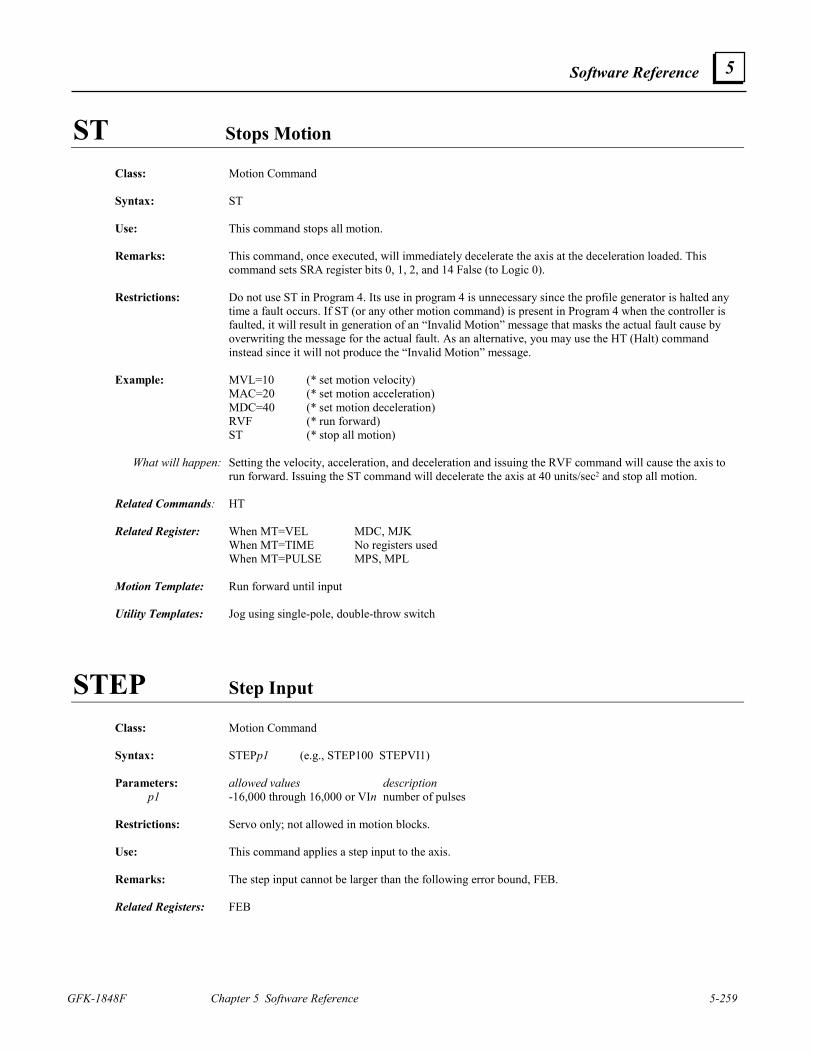
Software Reference
GFK-1848F Chapter 5 Software Reference 5-259
5
ST Stops Motion
Class: Motion Command
Syntax: ST
Use: This command stops all motion.
Remarks: This command, once executed, will immediately decelerate the axis at the deceleration loaded. This command sets SRA register bits 0, 1, 2, and 14 False (to Logic 0).
Restrictions: Do not use ST in Program 4. Its use in program 4 is unnecessary since the profile generator is halted any
time a fault occurs. If ST (or any other motion command) is present in Program 4 when the controller is faulted, it will result in generation of an “Invalid Motion” message that masks the actual fault cause by overwriting the message for the actual fault. As an alternative, you may use the HT (Halt) command instead since it will not produce the “Invalid Motion” message.
Example: MVL=10 (* set motion velocity) MAC=20 (* set motion acceleration) MDC=40 (* set motion deceleration) RVF (* run forward) ST (* stop all motion) What will happen: Setting the velocity, acceleration, and deceleration and issuing the RVF command will cause the axis to
run forward. Issuing the ST command will decelerate the axis at 40 units/sec2 and stop all motion. Related Commands: HT Related Register: When MT=VEL MDC, MJK When MT=TIME No registers used When MT=PULSE MPS, MPL Motion Template: Run forward until input Utility Templates: Jog using single-pole, double-throw switch
STEP Step Input Class: Motion Command Syntax: STEPp1 (e.g., STEP100 STEPVI1) Parameters: allowed values description p1 -16,000 through 16,000 or VIn number of pulses Restrictions: Servo only; not allowed in motion blocks. Use: This command applies a step input to the axis. Remarks: The step input cannot be larger than the following error bound, FEB. Related Registers: FEB
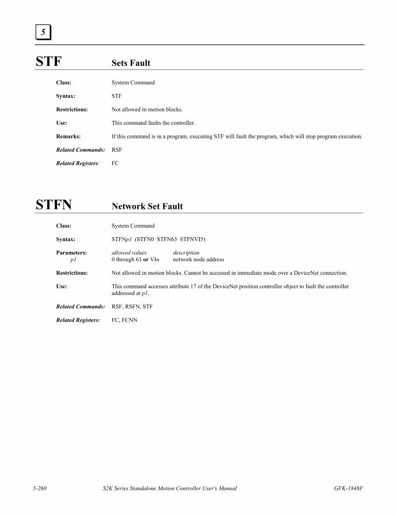
5-260 S2K Series Standalone Motion Controller User's Manual GFK-1848F
5
STF Sets Fault
Class: System Command Syntax: STF Restrictions: Not allowed in motion blocks. Use: This command faults the controller. Remarks: If this command is in a program, executing STF will fault the program, which will stop program execution. Related Commands: RSF Related Registers: FC
STFN Network Set Fault
Class: System Command Syntax: STFNp1 (STFN0 STFN63 STFNVI5) Parameters: allowed values description p1 0 through 63 or VIn network node address Restrictions: Not allowed in motion blocks. Cannot be accessed in immediate mode over a DeviceNet connection. Use: This command accesses attribute 17 of the DeviceNet position controller object to fault the controller
addressed at p1. Related Commands: RSF, RSFN, STF Related Registers: FC, FCNN
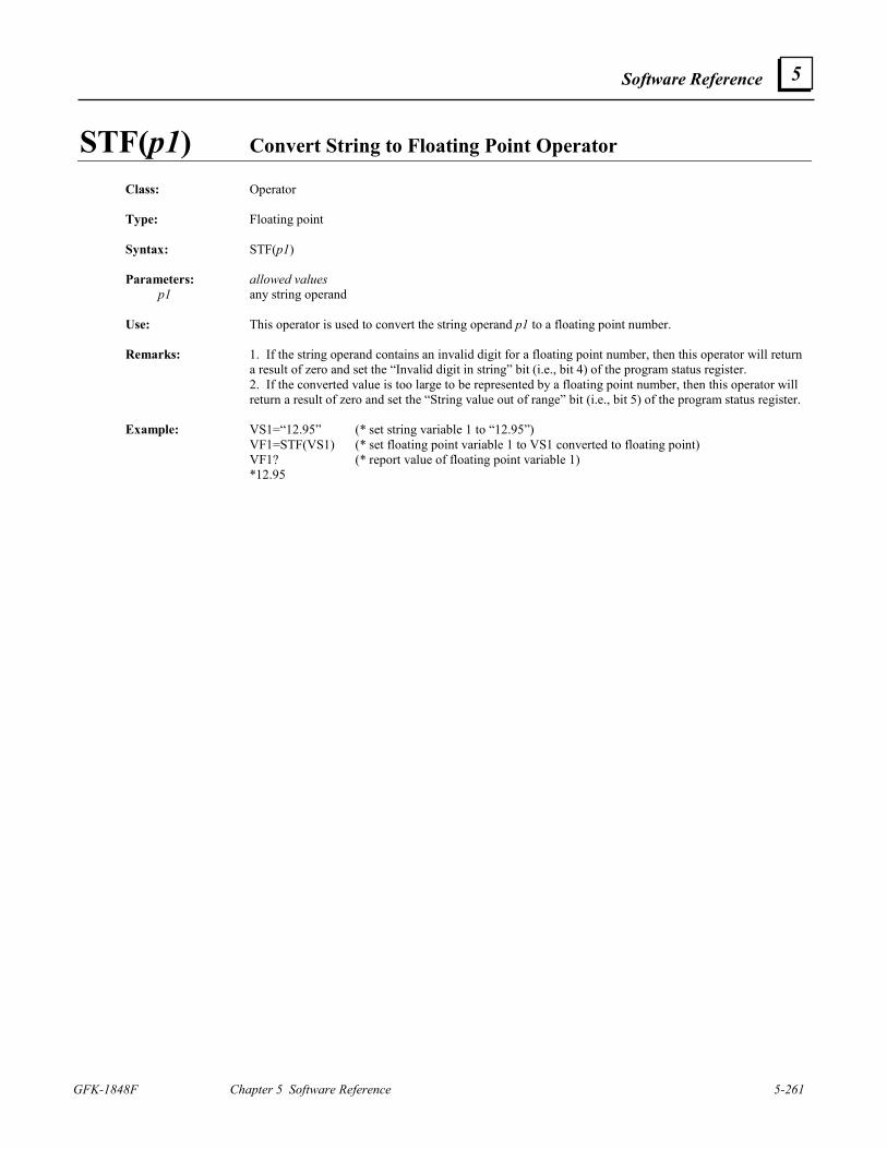
Software Reference
GFK-1848F Chapter 5 Software Reference 5-261
5
STF(p1) Convert String to Floating Point Operator Class: Operator Type: Floating point Syntax: STF(p1) Parameters: allowed values p1 any string operand Use: This operator is used to convert the string operand p1 to a floating point number. Remarks: 1. If the string operand contains an invalid digit for a floating point number, then this operator will return
a result of zero and set the “Invalid digit in string” bit (i.e., bit 4) of the program status register. 2. If the converted value is too large to be represented by a floating point number, then this operator will
return a result of zero and set the “String value out of range” bit (i.e., bit 5) of the program status register. Example: VS1=“12.95” (* set string variable 1 to “12.95”) VF1=STF(VS1) (* set floating point variable 1 to VS1 converted to floating point) VF1? (* report value of floating point variable 1) *12.95
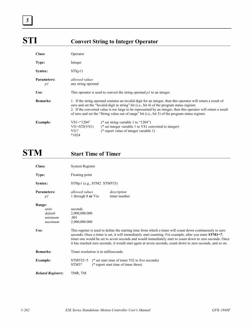
5-262 S2K Series Standalone Motion Controller User's Manual GFK-1848F
5
STI Convert String to Integer Operator
Class: Operator Type: Integer Syntax: STI(p1) Parameters: allowed values p1 any string operand Use: This operator is used to convert the string operand p1 to an integer. Remarks: 1. If the string operand contains an invalid digit for an integer, then this operator will return a result of
zero and set the “Invalid digit in string” bit (i.e., bit 4) of the program status register. 2. If the converted value is too large to be represented by an integer, then this operator will return a result
of zero and set the “String value out of range” bit (i.e., bit 5) of the program status register. Example: VS1=“1204” (* set string variable 1 to “1204”) VI1=STI(VS1) (* set integer variable 1 to VS1 converted to integer) VI1? (* report value of integer variable 1) *1024
STM Start Time of Timer Class: System Register Type: Floating point Syntax: STMp1 (e.g., STM2 STMVI3) Parameters: allowed values description p1 1 through 8 or Vin timer number Range: units seconds default 2,000,000.000 minimum .001 maximum 2,000,000.000 Use: This register is used to define the starting time from which a timer will count down continuously to zero
seconds. Once a timer is set, it will immediately start counting. For example, after you enter STM1=7, timer one would be set to seven seconds and would immediately start to count down to zero seconds. Once it has reached zero seconds, it would start again at seven seconds, count down to zero seconds, and so on.
Remarks: Timer resolution is in milliseconds. Example: STMVI2=5 (* set start time of timer VI2 to five seconds) STM3? (* report start time of timer three) Related Registers: TMR, TM
Software Reference
GFK-1848F Chapter 5 Software Reference 5-263
5
STN Network Stop Class: Motion Command Syntax: STNp1 (e.g., STN0 STN63 STNVI5) Parameters: allowed values description p1 0 through 63 or VIn network node address Restrictions: Cannot be accessed in immediate mode over a DeviceNet connection. Use: The network stop command accesses attribute 20 of the DeviceNet position controller object to stop all
motion for the axis addressed at p1. Remarks: This command, once executed, will immediately decelerate the axis at the deceleration loaded. Related Commands: HT, HTN, ST
STVB..GOTO Sets Boolean Variable; “Gotos” Label
Class: Program Command Syntax: STVBp1 GOTOp2 (e.g., STVB1 GOTO30 STVBVI1 GOTOVI2) Parameters: allowed values description p1 1 through 256 or VIn Boolean variable number p2 1 through 999 or VIn label number Restrictions: Allowed only in programs. Use: This command sets Boolean variable p1 and then checks to see if it was previously set. If Boolean variable
p1 was not set, this command will cause the program to go to label p2. Example: PROGRAM1 PROGRAM2 (* edit program) 10 VI1=VI1+1 10 VI2=VI2+1 (* set integer variable) IF VI1<1000 GOTO10 IF VI2<996 GOTO10 (* conditionally goto 10) STVB1 GOTO20 STVB1 GOTO20 (* set Boolean variable 1 and if Boolean (* variable 1 wasn’t set, goto 20) GOTO10 GOTO10 (* unconditionally goto 10) 20 OUT“VI1=” 20 OUT“VI2=” (* output string expression to the (* serial port) OUT ITS(VI1,5)+“$N” OUT ITS(VI2,5)+“$N” (* output string expression to the (* serial port) VI1=0 VI2=0 (* load integer variable) VB1=0 VB1=0 (* reset Boolean variable 1) GOTO10 GOTO10 (* unconditionally goto 10) END END (* end program and exit editor) What will happen: These two programs, when executed, will increment integer variables 1 and 2 until they reach 1,000 and
996 respectively. The first program to finish this task will set p1 equal to 1; and, since it was not previously set, it will go to the statement at label 20, which outputs the value to the display, loads 0 into the integer variable, and resets Boolean variable 1. If one program finishes this task while the other is outputting the value to the display, the program will go back to label 10, increment the integer variable, and check again for Boolean variable 1 to be reset.
Related Commands: IF...GOTO
5-264 S2K Series Standalone Motion Controller User's Manual GFK-1848F
5
SUP Suspends Motion
Class: Program Command Syntax: SUP Restrictions: Not allowed in motion blocks. Use: This command suspends axis motion. Remarks: Motion will continue to be suspended until the RSM command is executed, which resumes the motion. If,
however, a motion command is issued while motion is suspended, the suspended motion will be eliminated and the new motion will be executed.
Related Commands: RSM
SVL Saves Screen Lines
Class: System Command Syntax: SVL Restrictions: Not allowed in motion blocks. Use: This command is used to save the screen lines from RAM to nonvolatile memory. Remarks: If the screen lines are not saved correctly, then bit 9 in the program status register will be set to 1, which
means Screen Lines Save Failure. Related Commands: RETRIEVE, SAVE
Software Reference
GFK-1848F Chapter 5 Software Reference 5-265
5
SVV Save Variables from RAM to Nonvolatile Memory
Class: System Command Syntax: SVV Restrictions: Allowed only in programs. The Motion Generator cannot be running when the SVV command is executed
(SRA bits 0,1,2 and 14 must be false). The ST or HT command can be used to set these bits False (to Logic 0).
Use: The SVV command saves integer variables 1 through 1,024 and floating point variables 1 through 512
from RAM to nonvolatile memory. Remark: If the variables are not saved correctly, then bit 9 in the Program Status Register (SRP) will be set to 1,
which means Variable Save Failure. It is good programming practice to test the status of the Variable Save Failure flag each time the SVV command is executed to ensure that the save was successful.
It takes approximately 300 ms to write to flash memory and approximately 3 ms to read flash variables. To
ensure reliable execution of the SUV command, the program task should use the LOCK command to secure full access to the CPU. Communication through the serial port and network ports is suspended until the save is complete.
Caution: The controller flash memory can support a finite number of write cycles before the flash
memory will fail. Although the typical limit for this type of flash is +100,000 write cycles, it is easy to exceed this limit by executing frequent SVV commands from within a program.
When using multiple programs with multiple SVV commands, it is possible to get two SVV commands
executed at the same time, causing the controller to write -0.5s into the variables. To prevent this from occurring on your system, place a flag in your program and wait for it to be cleared before executing SVV, for example:
(* VB100 SVV in use flag PROGRAM1 . . . . WAIT NOT VB100 VB100 = 1 SVV VB100 = 0 . . . . END Related Registers: VI, VF Related Commands: SAVE, RETRIEVE, RTV
5-266 S2K Series Standalone Motion Controller User's Manual GFK-1848F
5
TAN Tangent Trigonometric Function Operator
Class: Operator Type: Floating point Syntax: TAN(p1) Parameters: allowed values p1 any floating point operand Use: Used to perform the tangent trigonometric function on p1. The operand p1 must be in degrees Related Commands: SIN, ATN, COS
TL Axis at Torque Limit
Class: System Register Type: Boolean Syntax: TL Range: allowed values 0, 1 Restrictions: Servo only; read only. Use: This register is used to determine whether the axis is at its torque limit. If the axis is at its torque limit, then
TL is equal to 1; and when it is not at its torque limit, then TL is equal to 0. Related Registers: TLC, TLE, SRA
Software Reference
GFK-1848F Chapter 5 Software Reference 5-267
5
TLC Torque Limit Current
Class: Axis Register Type: Floating point Syntax: TLC Range: units % default 100.0 minimum 0.1 maximum 100.0 Restrictions: Servo only. Use: This command loads the torque limit current as a percentage of the continuous current, CURC. Remarks: The torque limit is enabled by the TLE command. Related Registers: TL, TLE, CURC
TLE Torque Limit Enable
Class: Axis Register Type: Boolean Syntax: TLE Range: default 0 allowed values 0, 1 Restrictions: Servo only. Use: This command is used to enable the torque limit. If TLE is set to 1, then torque limit is enabled; and if
TLE is set to 0, it is disabled. Related Registers: TL, TLC Motion Templates: Run reverse until torque limit; run forward until torque limit; run reverse at torque limit.
5-268 S2K Series Standalone Motion Controller User's Manual GFK-1848F
5
TM Timer Timed Out Flag
Class: System Register Type: Boolean Syntax: TMp1 (e.g., TM1 TMVI3) Parameters: allowed values description p1 1 through 8 or Vin timer number Range: allowed values 0, 1 Restrictions: Read only. Use: This register is used to tell whether one of the timers timed out (i.e., was equal to 0). If TMp1 is set to 1,
then the timer timed out; if TMp1 is set to 0, it did not time out. After the state of the timed out flag is read, the flag is set to zero until the timer times out again. It is then set to 1 and will stay at 1 until it is read again.
Related Registers: TMR, STM
TMR Timer Class: System Register Type: Floating point Syntax: TMRp1 (e.g., TMR2 TMRVI3) Parameters: allowed values description p1 1 through 8 or Vin timer number Range: units seconds minimum 0.000 maximum 2,000,000.000 Restrictions: Read only. Use: The timer register is used to determine the current value of timer p1. Example: TMRVI2? (* report timer VI2) Related Registers: STM, TM
Software Reference
GFK-1848F Chapter 5 Software Reference 5-269
5
TRC Convert Floating Point to Integer Operators Class: Operator Type: Integer Syntax: TRC(p1) Parameters: allowed values p1 any floating point operand Use: Used to convert floating point operand p1 to an integer by truncation of the decimal values. If rounding is
required use the FTI operator. Remarks: If the floating point number is too large to be represented by an integer, then the TRC operator will return
a result of zero and set the Floating Point Value Out of Range bit (bit 6) of the Program Status Register (SRP). For information on status registers see Chapter 7.
Example: VF1=12.9505 (* set floating point variable 1 to 12.9505) VI2=TRC(VF1) (* set integer variable 2 to VF1 converted to integer by truncation) VI2? (* show value of VI2 in the terminal window) *12 Related Registers: FTI
TRUE, ON Boolean Operands Class: Operator Type: Boolean Syntax: TRUE, ON, p1, p2 Parameters: allowed values range p1 any Boolean 0, 1 p2 any Boolean register Use: These operands are used as Boolean numbers. TRUE and ON are equivalent to the Boolean number 1, and
FALSE and OFF are equivalent to the Boolean number 0. Example: VB1=TRUE (* set Boolean variable 1 to TRUE [i.e., one]) POE1=ON (* set power output stage enable of axis one to ON [i.e., one]) DO1.8=ON (* set digital output 8 of module 1 to one) VB2=0 (* set Boolean variable 2 to zero) Related Registers: FALSE, OFF
5-270 S2K Series Standalone Motion Controller User's Manual GFK-1848F
5
UNLOCK Unlocks Interpreter from Program Class: Program Command Syntax: UNLOCK Restrictions: Allowed only in programs. Use: This command unlocks the interpreter from the program, which lets other currently suspended programs
execute concurrently. Example: PROGRAM1 (* edit program 1) STM1=0.01 (* load start time of timer 1 and start timer 1) 1 WAIT TM1 (* wait for expression to be true) LOCK (* lock interpreter to program) IF KEY GOTO2 (* conditionally goto 2) UNLOCK (* unlock interpreter from program) GOTO1 (* unconditionally goto 1) 2 END (* end program and exit editor) What will happen: This program, once executed, will first wait for 10 ms. Then it locks the interpreter and checks for KEY to
be true (i.e., for a character to be entered into the key buffer). If KEY is true, then the program goes to the statement at label 2, which ends the program. If KEY is not true, it unlocks the interpreter and goes to the statement at label 1, which waits for 10 ms, etc.
Related Commands: LOCK
UPR Case Conversion Operators
Class: Operator Type: String Syntax: UPR(p1) Parameters: allowed values p1 any string operand Use: Used to convert string operand p1 to upper case. Remarks: Use LWR to convert to lower case Example: VS1=“Hello” (* set string variable 1 to “Hello”) VS2=UPR(VS1) (* set string variable 2 to upper case of VS1) VS2? (* report value of string variable VS2 in the terminal window) *“HELLO” VS3=LWR (VS1)(* set string variable 3 to lower case of VS1) VS3? (* report value of string variable VS3 in the terminal window) *“hello” Related Commands: LWR
Software Reference
GFK-1848F Chapter 5 Software Reference 5-271
5
UPS Update Screen Class: Input/Output Register Type: Integer Syntax: UPS Range: default 0 minimum 0 maximum 50 Use: This register is used to determine which screen is updated. The screen data, SCRD, for the screen specified
in UPS is updated every 1/4 second. Remarks: This register is set to 0 upon power-up. Related Registers: SCRD, SCRP
5-272 S2K Series Standalone Motion Controller User's Manual GFK-1848F
5
URA Axis Unit Ratio Numerator Class: Axis Register Type: Integer Syntax: URA Parameters: allowed values description p1 0 through 63 or VIn network address Range: units the ratio of URA/URB is in pulses/axis unit default 1 minimum 1 maximum 1,000,000 Restrictions: Requires firmware revision 2.5 or later. Not allowed in programs or motion blocks. Use: The axis unit ratio scales the axis programming units. The S2K controller uses various registers to
represent axis position, velocity, acceleration, deceleration and jerk (MPA, MPI, MVL, MAC, MDC, etc.). Internal to the S2K, these registers are computed using pulse units, which are fundamentally the same as the pulse units of the axis feedback. The axis unit ratio lets you simplify programming tasks by scaling the axis programming units, where:
Axis Units = (Pulses)/(URA/URB) For example, if the motor encoder has 10,000 pulses per revolutions and you want to program position
increments in revolutions, then the ratio of URA/URB would be set to 10,000 (URA=10,000, URB=1). Thus, setting MPI = 1 would be equivalent to 10,000 pulses or 1 revolution. Similarly, the unit ratio axis can be set to scale pulse units to any engineering units, such as inches or millimeters. The axis unit ratio (URA/URB) is simply the number of pulses per axis programming unit.
Remarks: 1. This register can be set only after the memory has been cleared using the CLM command and before
any programs or motion blocks are defined. 2. The numerical values for the default, minimum, and maximum of all registers with axis units are
assuming that the axis unit ratio (URA/URB) is set at the default of 1 (URA=1, URB=1). If the axis unit ratio is set to a value other than 1, then the maximum and minimum values will be scaled appropriately by the axis unit ratio. For example, the maximum value of the MAC register is 1,000,000,000. If the unit ratio axis is set to 4096 (URA=4096, URB=1), then the new maximum for MAC would be (1,000,000,000 pulses)/(4,096 pulses/axis unit) = 244140.625 axis units.
Related Commands: URA, URX, PLA, PSA, PZA, OFA, VLA
Software Reference
GFK-1848F Chapter 5 Software Reference 5-273
5
URB Axis Unit Ratio Denominator Class: Axis Register Type: Integer Syntax: URB Parameters: allowed values description p1 0 through 63 or VIn network address Range: units the ratio of URA/URB is in pulses/axis unit default 1 minimum 1 maximum 1,000,000 Restrictions: Requires firmware revision 2.5 or later. Not allowed in programs or motion blocks. Use: The axis unit ratio scales the axis programming units. The S2K controller uses various registers to
represent axis position, velocity, acceleration, deceleration and jerk (MPA, MPI, MVL, MAC, MDC, etc.). Internal to the S2K, these registers are computed using pulse units, which are fundamentally the same as the pulse units of the axis feedback. The axis unit ratio allows the user to simplify programming tasks by scaling the axis programming units, where:
Axis Units = (Pulses)/(URA/URB) For example, if the motor encoder has 10,000 pulses per revolutions and the user desires to program
position increments in revolutions, then the ratio of URA/URB would be set to 10,000 (URA=10,000, URB=1). Thus, setting MPI = 1 would be equivalent to 10,000 pulses or 1 revolution. Similarly, the unit ratio axis can be set to scale pulse units to any engineering units, such as inches or millimeters. The axis unit ratio (URA/URB) is simply the number of pulses per axis programming unit.
Remarks: 1. This register can be set only after the memory has been cleared using the CLM command and before
any programs or motion blocks are defined. 2. The numerical values for the default, minimum, and maximum of all registers with axis units are
assuming that the axis unit ratio (URA/URB) is set at the default of 1 (URA=1, URB=1). If the axis unit ratio is set to a value other than 1, then the maximum and minimum values will be scaled appropriately by the axis unit ratio. For example, the maximum value of the MAC register is 1,000,000,000. If the unit ratio axis is set to 4096 (URA=4096, URB=1), then the new maximum for MAC would be (1,000,000,000 pulses)/(4,096 pulses/axis unit) = 244140.625 axis units.
Related Commands: URA, URX, PLA, PSA, PZA, OFA, VLA
5-274 S2K Series Standalone Motion Controller User's Manual GFK-1848F
5
URX Auxiliary Unit Ratio
Class: Axis Register Type: Integer Syntax: URX Range: units Aux. encoder pulses/auxiliary unit default 1 minimum 1 maximum 1,000,000 Restrictions: This register cannot be changed from within programs or motion blocks. See Note below. Use: The auxiliary unit ratio is used to define auxiliary units (engineering units for the auxiliary encoder input)
for the PLX, PSX, PZX, OFX and VLX registers. The Motion Developer Axis Configuration wizards assist in properly configuring URX for the desired auxiliary units and controller configuration.
Remarks: 1. This register can be set only after the memory has been cleared using the CLM command and before
any programs, configuration parameters or motion blocks are defined. 2. The numerical values for the default, minimum, and maximum of all registers with auxiliary units are
assuming that the auxiliary unit ratio, URX, is set at its default value of 1. If the auxiliary unit ratio is set to a value other than 1, the maximum and minimum values will be divided by the auxiliary unit ratio (URX). For example, if the maximum value of a register is 2,000,000,000 pulses and the auxiliary unit ratio is set to 10,000 (i.e., auxiliary units in revolutions for a 4000 line encoder), the new maximum of that parameter will be (2,000,000,000 pulses)/(4,000 pulses/auxiliary unit) = 500,000 auxiliary units. In resolver-based controllers,
Related Registers: PLX, PSX, PZX, OFX, VLX, URA Note: URX is an integer register. Rounding of the calculated URX value to the nearest integer will result in
cumulative position error. The impact of this error is application dependent. Rotary unidirectional applications will continuously accumulate error in one direction, while for a linear application with limited travel the error may be acceptable. If this error is unacceptable changing mechanical gear ratios or selecting a different (larger) axis unit may reduce or eliminate this error. Selecting “counts” as your axis unit (URX=1) will always eliminate this error.
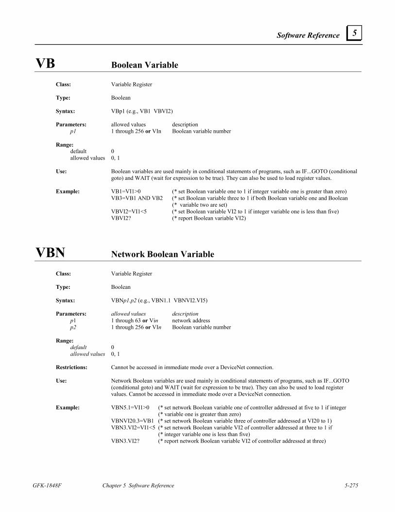
Software Reference
GFK-1848F Chapter 5 Software Reference 5-275
5
VB Boolean Variable
Class: Variable Register Type: Boolean Syntax: VBp1 (e.g., VB1 VBVI2) Parameters: allowed values description p1 1 through 256 or VIn Boolean variable number Range: default 0 allowed values 0, 1 Use: Boolean variables are used mainly in conditional statements of programs, such as IF...GOTO (conditional
goto) and WAIT (wait for expression to be true). They can also be used to load register values. Example: VB1=VI1>0 (* set Boolean variable one to 1 if integer variable one is greater than zero) VB3=VB1 AND VB2 (* set Boolean variable three to 1 if both Boolean variable one and Boolean (* variable two are set) VBVI2=VI1<5 (* set Boolean variable VI2 to 1 if integer variable one is less than five) VBVI2? (* report Boolean variable VI2)
VBN Network Boolean Variable
Class: Variable Register Type: Boolean Syntax: VBNp1.p2 (e.g., VBN1.1 VBNVI2.VI5) Parameters: allowed values description p1 1 through 63 or Vin network address p2 1 through 256 or VIn Boolean variable number Range: default 0 allowed values 0, 1 Restrictions: Cannot be accessed in immediate mode over a DeviceNet connection. Use: Network Boolean variables are used mainly in conditional statements of programs, such as IF...GOTO
(conditional goto) and WAIT (wait for expression to be true). They can also be used to load register values. Cannot be accessed in immediate mode over a DeviceNet connection.
Example: VBN5.1=VI1>0 (* set network Boolean variable one of controller addressed at five to 1 if integer (* variable one is greater than zero) VBNVI20.3=VB1 (* set network Boolean variable three of controller addressed at VI20 to 1) VBN3.VI2=VI1<5 (* set network Boolean variable VI2 of controller addressed at three to 1 if (* integer variable one is less than five) VBN3.VI2? (* report network Boolean variable VI2 of controller addressed at three)
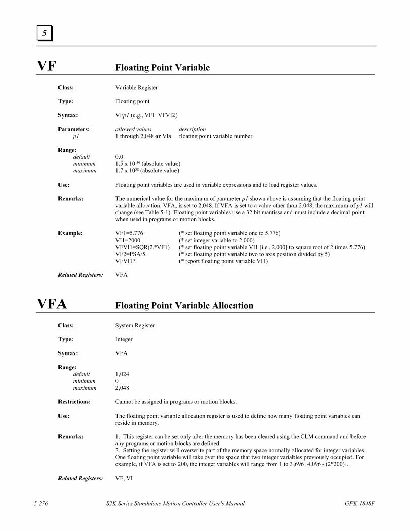
5-276 S2K Series Standalone Motion Controller User's Manual GFK-1848F
5
VF Floating Point Variable
Class: Variable Register Type: Floating point Syntax: VFp1 (e.g., VF1 VFVI2) Parameters: allowed values description p1 1 through 2,048 or Vln floating point variable number Range: default 0.0 minimum 1.5 x 10-39 (absolute value) maximum 1.7 x 1038 (absolute value) Use: Floating point variables are used in variable expressions and to load register values. Remarks: The numerical value for the maximum of parameter p1 shown above is assuming that the floating point
variable allocation, VFA, is set to 2,048. If VFA is set to a value other than 2,048, the maximum of p1 will change (see Table 5-1). Floating point variables use a 32 bit mantissa and must include a decimal point when used in programs or motion blocks.
Example: VF1=5.776 (* set floating point variable one to 5.776) VI1=2000 (* set integer variable to 2,000) VFVI1=SQR(2.*VF1) (* set floating point variable VI1 [i.e., 2,000] to square root of 2 times 5.776) VF2=PSA/5. (* set floating point variable two to axis position divided by 5) VFVI1? (* report floating point variable VI1) Related Registers: VFA
VFA Floating Point Variable Allocation Class: System Register Type: Integer Syntax: VFA Range: default 1,024 minimum 0 maximum 2,048 Restrictions: Cannot be assigned in programs or motion blocks. Use: The floating point variable allocation register is used to define how many floating point variables can
reside in memory. Remarks: 1. This register can be set only after the memory has been cleared using the CLM command and before
any programs or motion blocks are defined. 2. Setting the register will overwrite part of the memory space normally allocated for integer variables.
One floating point variable will take over the space that two integer variables previously occupied. For example, if VFA is set to 200, the integer variables will range from 1 to 3,696 [4,096 - (2*200)].
Related Registers: VF, VI
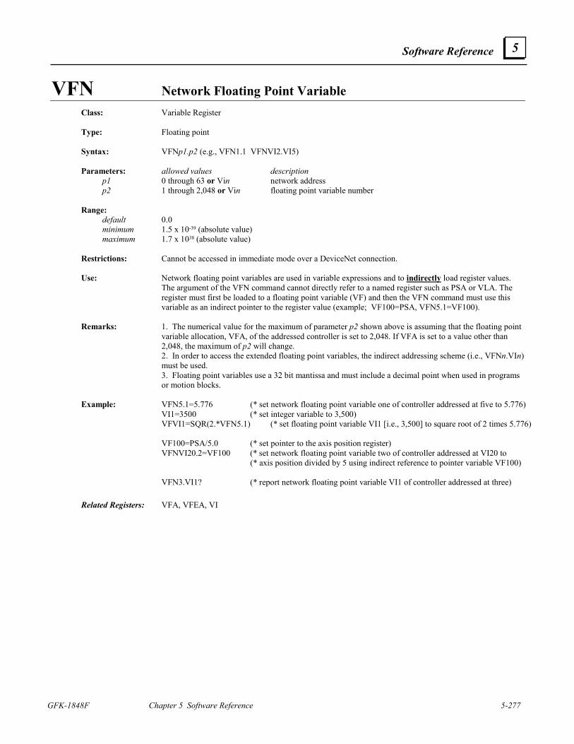
Software Reference
GFK-1848F Chapter 5 Software Reference 5-277
5
VFN Network Floating Point Variable
Class: Variable Register Type: Floating point Syntax: VFNp1.p2 (e.g., VFN1.1 VFNVI2.VI5) Parameters: allowed values description p1 0 through 63 or Vin network address p2 1 through 2,048 or Vin floating point variable number Range: default 0.0 minimum 1.5 x 10-39 (absolute value) maximum 1.7 x 1038 (absolute value) Restrictions: Cannot be accessed in immediate mode over a DeviceNet connection. Use: Network floating point variables are used in variable expressions and to indirectly load register values.
The argument of the VFN command cannot directly refer to a named register such as PSA or VLA. The register must first be loaded to a floating point variable (VF) and then the VFN command must use this variable as an indirect pointer to the register value (example; VF100=PSA, VFN5.1=VF100).
Remarks: 1. The numerical value for the maximum of parameter p2 shown above is assuming that the floating point
variable allocation, VFA, of the addressed controller is set to 2,048. If VFA is set to a value other than 2,048, the maximum of p2 will change.
2. In order to access the extended floating point variables, the indirect addressing scheme (i.e., VFNn.VIn) must be used.
3. Floating point variables use a 32 bit mantissa and must include a decimal point when used in programs or motion blocks.
Example: VFN5.1=5.776 (* set network floating point variable one of controller addressed at five to 5.776) VI1=3500 (* set integer variable to 3,500) VFVI1=SQR(2.*VFN5.1) (* set floating point variable VI1 [i.e., 3,500] to square root of 2 times 5.776) VF100=PSA/5.0 (* set pointer to the axis position register) VFNVI20.2=VF100 (* set network floating point variable two of controller addressed at VI20 to (* axis position divided by 5 using indirect reference to pointer variable VF100) VFN3.VI1? (* report network floating point variable VI1 of controller addressed at three)
Related Registers: VFA, VFEA, VI
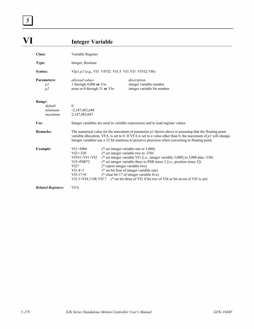
5-278 S2K Series Standalone Motion Controller User's Manual GFK-1848F
5
VI Integer Variable
Class: Variable Register Type: Integer, Boolean Syntax: VIp1.p2 (e.g., VI1 VIVI2 VI1.5 VI1.VI3 VIVI2.VI6) Parameters: allowed values description p1 1 through 4,096 or Vin integer variable number p2 none or 0 through 31 or VIn integer variable bit number Range: default 0 minimum -2,147,483,648 maximum 2,147,483,647 Use: Integer variables are used in variable expressions and to load register values. Remarks: The numerical value for the maximum of parameter p1 shown above is assuming that the floating point
variable allocation, VFA, is set to 0. If VFA is set to a value other than 0, the maximum of p1 will change. Integer variables use a 32 bit mantissa to preserve precision when converting to floating point.
Example: VI1=3000 (* set integer variable one to 3,000) VI2=-330 (* set integer variable two to -330) VIVI1=VI1+VI2 (* set integer variable VI1 [i.e., integer variable 3,000] to 3,000 plus -330) VI3=PSR*2 (* set integer variable three to PSR times 2 [i.e., position times 2]) VI2? (* report integer variable two) VI1.4=1 (* set bit four of integer variable one) VI5.17=0 (* clear bit 17 of integer variable five) VI2.3=VI4.2 OR VI5.7 (* set bit three of VI2 if bit two of VI4 or bit seven of VI5 is set) Related Registers: VFA
Software Reference
GFK-1848F Chapter 5 Software Reference 5-279
5
VIN Network Integer Variable
Class: Variable Register Type: Integer Syntax: VINp1.p2 (e.g., VIN1.1, VINVI2.VI5) Parameters: allowed values description p1 0 through 63 or VIn network address p2 1 through 4,096 or VIn integer variable number Range: default 0 minimum -2,147,483,648 maximum 2,147,483,647 Restrictions: Cannot be accessed in immediate mode over a DeviceNet connection. Use: Network integer variables are used in variable expressions and to load register values. Remarks: 1. The numerical value for the maximum of parameter p2 shown above is assuming that the floating point
variable allocation, VFA, of the address controller is set to 0. If VFA is set to a value other than 0, the maximum of p2 will change.
2. In order to access the extended integer variables, the indirect addressing scheme (i.e., VINn.VIn) must be used.
Example: VI1=5000 (* set integer variable one to 5,000) VIN5.2=-330 (* set network integer variable two of controller addressed at five to -330) VIN2.VI1=VI1+VIN5.2 (* set network integer variable VI1 [i.e., integer variable 5,000) (* of controller addressed at two to 5,000 plus -330] VINVI20.3=PSR*2 (* set network integer variable three to PSR times 2, [i.e., position times 2]) VINVI20.3? (* report network integer variable three of controller addressed at VI20) Related Registers: VFA, VFEA, VI
5-280 S2K Series Standalone Motion Controller User's Manual GFK-1848F
5
VLA Axis Velocity
Class: Axis Register Type: Floating point Syntax: VLA Range: units axis units/sec minimum -16,000,000 pulses/sec maximum 16,000,000 pulses/sec Restrictions: Read only. Use: This register is used to determine the current velocity of the axis. Remarks: The numerical values for the default, minimum, and maximum of this register are assuming that the axis
unit ratio, (URA/URB), is set at its default value of 1.If the axis unit ratio is set to a value other than 1, the default, maximum, and minimum values must be divided by the value of (URA/URB) (see URA and URB).
Related Registers: URA, URB, VLAT
VLAN Network Axis Velocity
Class: Axis Register Type: Integer Syntax: VLANp1 (e.g., VLAN0 VLAN63 VLANVI5) Parameters: allowed values description p1 0 through 63 or VIn network address Range: units pulses/sec minimum -16,000,000 pulses/sec maximum 16,000,000 pulses/sec Restrictions: Read only. Cannot be accessed in immediate mode over a DeviceNet connection. Use: This command accesses attribute 14 of the DeviceNet position controller object to determine the actual
velocity of the axis. Related Registers: VLA
Software Reference
GFK-1848F Chapter 5 Software Reference 5-281
5
VLAT Axis Velocity Filter Time Constant
Class: Axis Register Type: Floating point Syntax: VLAT Range: units seconds default 0.01 minimum 0.002 maximum 0.1 Use: The axis velocity filter time constant represents the length of the time window that is used to filter the axis
velocity, VLA. This time window is applied to previous values of VLA in order to calculate the current filtered value of VLA. This happens every 2 msec.
Remarks: VLAT can be set only in 2 msec increments (i.e., 0.002, 0.004,
0.006, ...). This corresponds to the number of previous values of VLA that are being filtered. For example, setting VLAT = 0.01 means that the previous 5 values of VLA will be filtered, since 0.002*5 = 0.01.
Example: VLAT=0.008 (* set axis velocity filter time constant to 0.008 sec) VLAT? (* report value of axis velocity filter time constant) Related Registers: VLA, VLXT
5-282 S2K Series Standalone Motion Controller User's Manual GFK-1848F
5
VLX Auxiliary Velocity
Class: Axis Register Type: Floating point Syntax: VLX Range: units auxiliary units/sec minimum -16,000,000 pulses/sec maximum 16,000,000 pulses/sec Restrictions: Read only. Use: This register is used to determine the current auxiliary velocity of the axis. Remarks: The numerical values for the default, minimum, and maximum of this register are assuming that the
auxiliary unit ratio, URX, is set at its default value of 1. If the auxiliary unit ratio is set to a value other than 1, the default, minimum, and maximum values must be divided by the value of URX (see URX).
Related Registers: URX, VLXT
VLXT Auxiliary Velocity Filter Time Constant
Class: Axis Register Type: Floating point Syntax: VLXT Range: units seconds default 0.01 minimum 0.002 maximum 0.1 Use: The auxiliary velocity filter time constant is used to represent the length of the time window that is used to
filter the auxiliary velocity, VLX. This time window is applied to previous values of VLX in order to calculate the current filtered value of VLX. This happens every 2 msec.
Remarks: VLXT can be set only in 2 msec increments (i.e., 0.002, 0.004, 0.006, ...) This corresponds to the number
of previous values of VLX that are being filtered. For example, setting VLXT = 0.01 means that the previous 5 values of VLX will be filtered, since 0.002*5 = 0.01.
Example: VLXT=0.008 (* set auxiliary velocity filter) VLXT? (* report value of auxiliary velocity filter time constant) Related Registers: VLX, VLAT
Software Reference
GFK-1848F Chapter 5 Software Reference 5-283
5
VS String Variable
Class: Variable Register Type: String Syntax: VSp1 (e.g., VS1 VSVI2) Parameters: allowed values description p1 1 through 144 or VIn string variable number Range: default “” allowed values any string, 0 through 127 characters long, enclosed in quotes Use: String variables are used mainly to load strings and in input/output commands such as GET, PUT, IN, and
OUT as a means of user interface. Example: VS1=“$20”+“$R” (* set string variable one to a space followed by a carriage return) VI1=2 (* set integer variable one to 2) VSVI1=“Done”+VS1 (* set string variable VI1 [i.e., string variable two] to “Done” followed by a (*space and a carriage return) VSVI2? (* report string variable VI2) Related Commands: EXVS, GET, PUT, IN, OUT
5-284 S2K Series Standalone Motion Controller User's Manual GFK-1848F
5
VSN Network String Variable
Class: Variable Register Type: String Syntax: VSNp1.p2 (e.g., VSN1.1, VSNVI2.VI5) Parameters: allowed values description p1 0 through 63 or VIn network address p2 1 through 144 or VIn string variable number Range: default “” allowed values any string, 0 through 127 characters long, enclosed in quotes Restrictions: Cannot be accessed in immediate mode over a DeviceNet connection. Use: Network string variables are used mainly to load strings and in input/output commands such as GET, PUT,
IN, and OUT as a means of user interface. Example: VSN5.1=“$20”+“$R” (* set network string variable one of controller addressed at five to a space (* followed by a carriage return) VI1=2 (* set integer variable one to 2) VSN3.VI1=“Done” (* set network string variable VI1 [i.e., string variable two] of controller (* +VSN5.1 addressed at three to “Done” followed by a space and a carriage (* return) VSNVI20.2? (* report network string variable two of controller addressed at VI20) Related Commands: GET, PUT, IN, OUT, VS
Software Reference
GFK-1848F Chapter 5 Software Reference 5-285
5
WAIT Waits for Expression to be True
Class: Program Command Syntax: WAITp1 (e.g., WAIT VB1 WAIT KEY) Parameters: allowed values description p1 any Boolean expression Boolean expression Restrictions: Allowed only in programs or motion blocks. Use: This command causes the program or motion block to wait for Boolean expression p1 to be true (i.e.,
evaluate to 1). Once p1 is true, the next program or motion block statement will be executed. Example: PROGRAM1 (* edit program 1) PSA=0 (* set axis position register) MVL=10 (* set motion velocity) MAC=40 (* set motion acceleration) MPA=0 (* set absolute move position) MPI=10 (* set incremental move position) RPI (* run to incremental move position) WAIT IP (* wait for expression to be true) STM1=1 (* set start time of timer 1) WAIT TM1 (* wait for expression to be true) RPA (* run to absolute move position) WAIT IP (* wait for expression to be true) OUT “Motion completed” (* output string expression to display) END (* end program 1 and exit editor) What will happen: This program sets the axis position register, velocity, acceleration, absolute move position, and
incremental move position. Then it issues the RPI command, which runs the axis 10 units in the forward direction. It then waits until the axis is in position. Next, it loads timer 1 with a start time of 1 second. The timer will then count down from 1 second to 0. Once it reaches 0, the RPA command is issued, which runs the axis 10 units in the reverse direction. It waits until the axis is in position, and then it prints Motion completed to the display.
Related Commands: WAIT...WHEN...GOTO
5-286 S2K Series Standalone Motion Controller User's Manual GFK-1848F
5
WAIT...WHEN...GOTO
Class: Program Command Syntax: WAIT p1 WHEN p2 GOTOp3 Parameters: allowed values description p1 any Boolean expression Boolean expression p2 any Boolean expression Boolean expression p3 1 through 999 or VIn label number Restrictions: Allowed only in programs. Use: This statement causes the program either to wait for p1 to become true (i.e., evaluate to 1) or to go
conditionally to label p3 if p2 is true (i.e., evaluates to 1). Example: PROGRAM1 (* edit program 1) MVL=5 (* set motion velocity) MAC=40 (* set motion acceleration) MPI=25 (* set incremental move position) RPI (* run to incremental move position) WAIT IP WHEN KEY GOTO5 (* wait for expression to be true or when condition becomes true (* goto 5) OUT “Motion complete$N” (* output string expression to display) GOTO10 (* unconditionally goto 10) 5 ST (* stop axis) WAIT IP (* wait for expression to be true) OUT “Motion interrupted$N” (* output string expression to display) 10 END (* end program 1 and exit editor) What will happen: This program, once executed, sets the velocity, acceleration, and incremental move position. It then issues
the RPI command, which runs the axis 25 units in the forward direction. If a character goes into the key buffer (KEY) before the axis is in position (IP), the program execution will go to the statement at label 5, which stops the axis. It then prints Motion interrupted to the display and ends. If a character does not go into the key buffer before the axis is in position, the program will continue to the next statement, which prints Motion complete. It then goes to the statement at label 10, which ends the program.
Related Commands: WAIT
Software Reference
GFK-1848F Chapter 5 Software Reference 5-287
5
X Steps Through Program/Motion Block in Terminal Window Line Editor
Class: Program Command Syntax: Xp1 (e.g., X X3 X10) Parameters: allowed values description p1 1 through 65,000 step size Use: While in the Motion Developer terminal window this command: 1. Steps p1 lines through a program or motion block while in the terminal window line editor. 2. Steps through the execution of a program if not in the line editor, diagnostic mode is enabled
(DGE=1) and single-step mode is enabled (DGS is set to the program you wish to step through). Note that p1 is optional. If p1 is not specified, a value of 1 will be assumed. Remarks: This command will most often be used for single step program execution while debugging program
execution and will not typically be used for creating and editing programs and motion blocks since Motion Developer provides a more full featured text editor. While in the terminal window line editor each returned line is prefixed by an asterisk (*). Use the Exit Line Editor (!) command to exit the terminal window line editor.
Example: PROGRAM1 (* edit program 1 from terminal window) * MVL=5 X (* step through one line of the program) * MAC=40 X2 (* step through two lines of the program) * MPI=25 ! (* exit terminal window line editor) * Related Commands: DGE, DGS, PROGRAM, MOTION, L, LABEL, !
5-288 S2K Series Standalone Motion Controller User's Manual GFK-1848F
5
XOR Exclusive OR Logical Operator
Class: Operator Type: Boolean, integer Syntax: p1 XOR p2 Parameters: allowed values p1 any Boolean or integer operand p2 any Boolean or integer operand Use: Used to perform a logical exclusive OR operation on p1 and p2. Note that p1 and p2 must be of the same
type. If p1 and p2 are integer operands, the logical operators perform bitwise logical operations. Related Commands: AND, NOT, OR
GFK-1848F 6-1
Using Motion Developer
6.1 Installing Motion Developer
The material in this chapter was developed using Motion Developer software.
6.1.1 Computer System Requirements The following describes the minimum requirements to install and run Motion Developer software (catalog number SA648MODEV).
Minimum Hardware Requirements 200 MHz Pentium-based workstation
64 MB RAM
200 MB free hard disk space
CD ROM drive or access to one via parallel port or network
800 by 600 resolution, 256 color display and video adapter
Software Compatibility Windows NTTM operating system version 4.0 with service pack 4 or later
Windows 98, Windows ME, Windows 2000, or Windows XP operating system
6.1.2 Installation To Install Motion Developer from a CD: 1. Shut down all other application programs.
2. Insert the CD into your CD-ROM drive. Windows will automatically start the setup program. If the setup program does not automatically start, use the Windows Start/Run utility. Run the setup.exe file in the root directory of the CD.
3. Click Install Motion Developer to start the install process.
4. Follow the instructions as they appear on the screen.
Windows is a registered trademark and NT is a trademark of Microsoft, Inc.
6 Chapter
6-2 S2K Series Standalone Motion Controller User's Manual GFK-1848F
6
6.1.3 Product Authorization Before you start developing projects, we strongly recommend that you authorize the software using the built-in Product Authorization utility. If you don’t authorize the software, you will be able to use it only for a four-day trial period. After the trial period, you cannot download or save target information. The authorization procedure will take only a few minutes and will also allow you to take advantage of any product support for which you qualify. You will need to contact us by telephone, fax, or Internet as part of the authorization process.
To Authorize Motion Developer: Have your serial number(s) ready. The serial numbers can be found on the License Key sheet that came with your product.
1. Run the Product Authorization utility from the Start menu/Programs/CIMPLICITY Machine Edition/Product Authorization. The Product Authorization dialog box appears.
2. Click Software, and then click Add.
3. You can authorize the software by means of the Internet, email, phone, fax, or disk (disk is used if transferring authorization from another computer). Make your selection, then click Next.
4. Under Mandatory, fill in the fields. If you are authorizing by fax, fill in the fields under Optional. Click Next.
5. You will be prompted for a key code. You can request your key code through the following means: Phone. Our phone number is listed on the screen.
Fax. Click Print FAX and fax the Product Authorization Request to us (our fax number will be on the print out). We will then fax you back with your new key code(s).
Internet. Go to www.gefanuc.com, select the Support link, then choose the Software Registration link on the Support page.
Product Authorization is complete once you type in the new key code and it has been accepted. Depending on the product you’ve purchased, you may need to run the Product Authorization program a number of times.
To Move the Authorization to Another Computer You can run the software only on the computer on which the Product Authorization was installed. If you want to develop your projects on a different computer, you will need to complete the following steps to move the authorization from one computer to another. 1. Install CIMPLICITY Motion Developer on the computer to which the authorization will be
moved. 2. Run the Product Authorization program from the Start menu/Programs/CIMPLICITY Machine
Edition/Product Authorization. The Product Authorization dialog box appears. 3. Click Software. There is a site code on the top right hand side of the screen. Write down this
site code carefully. This has to be accurate in order for the move to work. You will need it (Target Site Code) when you move the authorized software from the source computer.
4. Click Add. The Product Authorization wizard appears. 5. Click Authorize by disk. At this point, you need to go to the source computer that has the
authorized software, and move the authorization to a disk. 6. From the source computer, run the Product Authorization program and click Software.
Using Motion Developer
GFK-1848F Chapter 6 Using Motion Developer 6-3
6
7. Click Move, and then click OK. Enter the target site code that you wrote down from Step 3 and click Next. Verify that the site code is correct and click OK.
8. Insert a blank formatted floppy disk into the floppy drive and click Next. The authorization code will be moved to the disk and a dialog box should appear telling you it was successful. Click OK.
9. Go back to the computer to which you are moving the authorization and insert the floppy disk. (The screen that is asking for an authorization disk should be displayed.) Click Next.
10. Click Finish. A screen should appear telling you the move was successful. Click OK. The authorization has now been moved to the new computer.
6.1.4 Technical Support
Contact Choices You have several contact choices if you need help with your GE Fanuc products:
• Fax. Send a message via the Technical Support Fax number at (780) 420-2049 • Internet. Use the address www.gefanuc.com to reach the GE Fanuc home page, then click
the Support link to reach the main Support page. The Support pages allow you to look up technical information, download useful files, register software, or send a question to our support experts.
• Telephone. Call 1-800 GEFANUC (1-800 433-2682) • e-mail. Address your message to [email protected]
For Most Efficient Service
Motion Developer Software Help. When contacting us about a Motion Developer software problem, include the information listed below in your fax or message. If telephoning, call from a telephone near your computer and have your Motion Developer software running, if practical, and have the following information available to help us assist you as quickly as possible:
The GE Fanuc software product name, serial number, and version number. The brand and model of computer system hardware (computer, monitor, etc). Computer operating system and version number. The steps you performed prior to the problem occurrence.
S2K Motor and Controller Help. When contacting us about an S2K hardware problem, include the information listed below in your fax or message. If telephoning, call from a telephone near your installation, if practical, and have the following information available to help us assist you as quickly as possible:
The S2K model and serial number for controller and motor The circumstances leading up to the problem occurrence.

6-4 S2K Series Standalone Motion Controller User's Manual GFK-1848F
6
Intentionally Blank
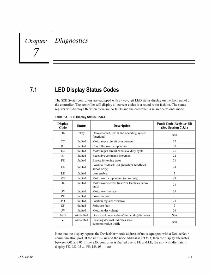
GFK-1848F 7-1
Diagnostics
7.1 LED Display Status Codes The S2K Series controllers are equipped with a two-digit LED status display on the front panel of the controller. The controller will display all current codes in a round robin fashion. The status register will display OK when there are no faults and the controller is in an operational mode.
Table 7-1. LED Display Status Codes
Display Code Status Description Fault Code Register Bit
(See Section 7.3.1) OK okay Drive enabled, CPUs and operating system
functional N/A
CC faulted Motor regen circuit over current 27 DT faulted Controller over temperature 30 EC faulted Motor regen circuit excessive duty cycle 26 EI faulted Excessive command increment 22 FE faulted Excess following error 21
FL faulted Position feedback lost (resolver feedback servo only) 24
LE faulted Lost enable 3 MT faulted Motor over temperature (servo only) 29 OC faulted Motor over current (resolver feedback servo
only) 28
OV faulted Motor over voltage 25 PF faulted Power failure 0 PO faulted Position register overflow 23 SF faulted Software fault 2 UV faulted Motor under voltage 26 0-63 ok/faulted DeviceNet node address/fault code (alternate) N/A
• ok/faulted Flashing decimal indicates serial communication traffic N/A
Note that the display reports the DeviceNetTM node address of units equipped with a DeviceNetTM communication port. If the unit is OK and the node address is set to 5, then the display alternates between OK and 05. If the S2K controller is faulted due to FE and LE, the unit will alternately display FE, LE, 05 … FE, LE, 05 … etc.
7 Chapter
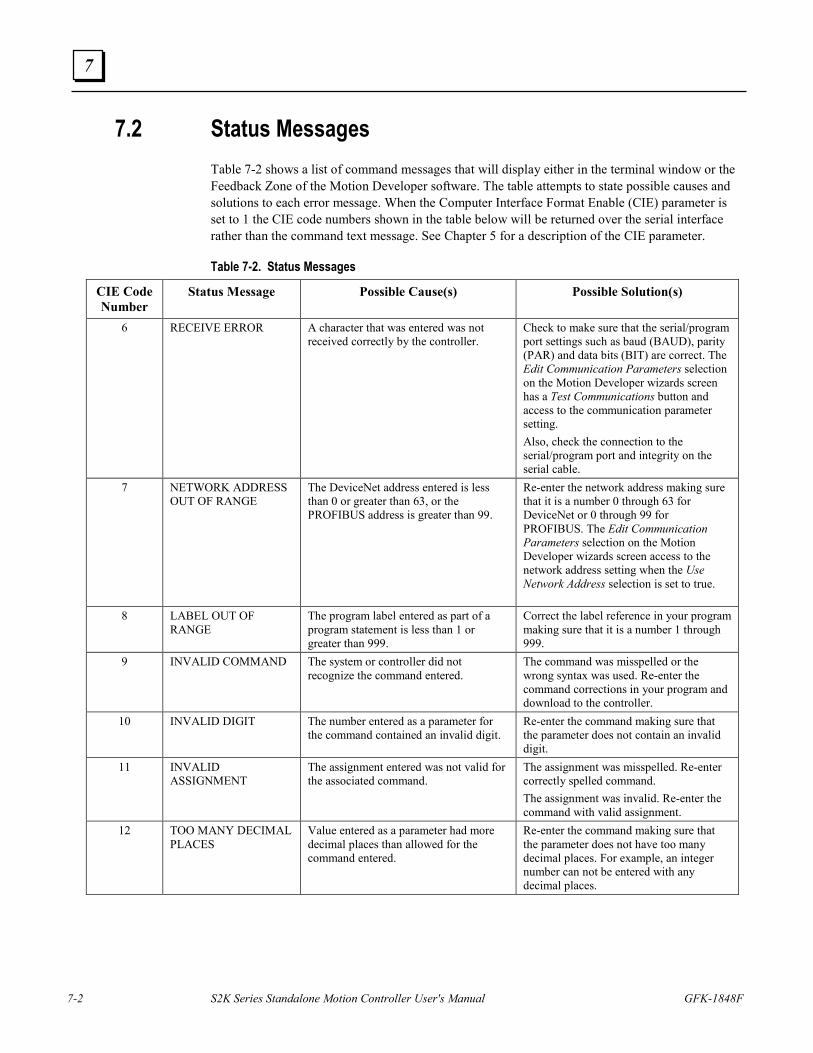
7-2 S2K Series Standalone Motion Controller User's Manual GFK-1848F
7
7.2 Status Messages Table 7-2 shows a list of command messages that will display either in the terminal window or the Feedback Zone of the Motion Developer software. The table attempts to state possible causes and solutions to each error message. When the Computer Interface Format Enable (CIE) parameter is set to 1 the CIE code numbers shown in the table below will be returned over the serial interface rather than the command text message. See Chapter 5 for a description of the CIE parameter.
Table 7-2. Status Messages
CIE Code Number
Status Message Possible Cause(s) Possible Solution(s)
6 RECEIVE ERROR
A character that was entered was not received correctly by the controller.
Check to make sure that the serial/program port settings such as baud (BAUD), parity (PAR) and data bits (BIT) are correct. The Edit Communication Parameters selection on the Motion Developer wizards screen has a Test Communications button and access to the communication parameter setting. Also, check the connection to the serial/program port and integrity on the serial cable.
7 NETWORK ADDRESS OUT OF RANGE
The DeviceNet address entered is less than 0 or greater than 63, or the PROFIBUS address is greater than 99.
Re-enter the network address making sure that it is a number 0 through 63 for DeviceNet or 0 through 99 for PROFIBUS. The Edit Communication Parameters selection on the Motion Developer wizards screen access to the network address setting when the Use Network Address selection is set to true.
8 LABEL OUT OF RANGE
The program label entered as part of a program statement is less than 1 or greater than 999.
Correct the label reference in your program making sure that it is a number 1 through 999.
9 INVALID COMMAND
The system or controller did not recognize the command entered.
The command was misspelled or the wrong syntax was used. Re-enter the command corrections in your program and download to the controller.
10 INVALID DIGIT The number entered as a parameter for the command contained an invalid digit.
Re-enter the command making sure that the parameter does not contain an invalid digit.
11 INVALID ASSIGNMENT
The assignment entered was not valid for the associated command.
The assignment was misspelled. Re-enter correctly spelled command. The assignment was invalid. Re-enter the command with valid assignment.
12 TOO MANY DECIMAL PLACES
Value entered as a parameter had more decimal places than allowed for the command entered.
Re-enter the command making sure that the parameter does not have too many decimal places. For example, an integer number can not be entered with any decimal places.
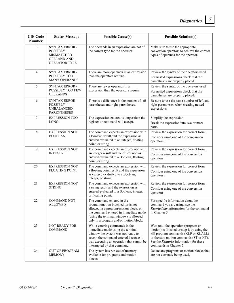
Diagnostics
GFK-1848F Chapter 7 Diagnostics 7-3
7
CIE Code Number
Status Message Possible Cause(s) Possible Solution(s)
13 SYNTAX ERROR - POSSIBLY MISMATCHED OPERAND AND OPERATOR TYPE
The operands in an expression are not of the correct type for the operator.
Make sure to use the appropriate conversion operators to achieve the correct types of operands for the operator.
14 SYNTAX ERROR - POSSIBLY TOO MANY OPERANDS
There are more operands in an expression than the operators require.
Review the syntax of the operators used. For nested expressions check that the parentheses are properly placed.
15 SYNTAX ERROR - POSSIBLY TOO FEW OPERANDS
There are fewer operands in an expression than the operators require.
Review the syntax of the operators used. For nested expressions check that the parentheses are properly placed.
16 SYNTAX ERROR - POSSIBLY UNBALANCED PARENTHESES
There is a difference in the number of left parentheses and right parentheses.
Be sure to use the same number of left and right parentheses when creating nested expressions.
17 EXPRESSION TOO LONG
The expression entered is longer than the register or command will accept.
Simplify the expression. Break the expression into two or more parts.
18 EXPRESSION NOT BOOLEAN
The command expects an expression with a Boolean result and the expression as entered evaluated to an integer, floating point, or string.
Review the expression for correct form. Consider using one of the comparison operators.
19 EXPRESSION NOT INTEGER
The command expects an expression with an integer result and the expression as entered evaluated to a Boolean, floating point, or string.
Review the expression for correct form. Consider using one of the conversion operators.
20 EXPRESSION NOT FLOATING POINT
The command expects an expression with a floating point result and the expression as entered evaluated to a Boolean, integer, or string.
Review the expression for correct form. Consider using one of the conversion operators.
21 EXPRESSION NOT STRING
The command expects an expression with a string result and the expression as entered evaluated to a Boolean, integer, or floating point.
Review the expression for correct form. Consider using one of the conversion operators.
22 COMMAND NOT ALLOWED
The command entered in the program/motion block editor is not allowed in a program/motion block, or the command entered in immediate mode (using the terminal window) is allowed only in a program and/or motion block.
For specific information about the command you are using, see the Restrictions information for the command in Chapter 5
23 NOT READY FOR COMMAND
While entering commands in the immediate mode using the terminal window the system was not ready to accept the command entered because it was executing an operation that cannot be interrupted by that command.
Wait until the operation (program or motion) is finished or stop it by using the kill program commands (KLP or KLALL) or the stop motion commands (ST or HT). See the Remarks information for these commands in Chapter 5.
24 OUT OF PROGRAM MEMORY
The system has run out of memory available for programs and motion blocks.
Delete any programs or motion blocks that are not currently being used.
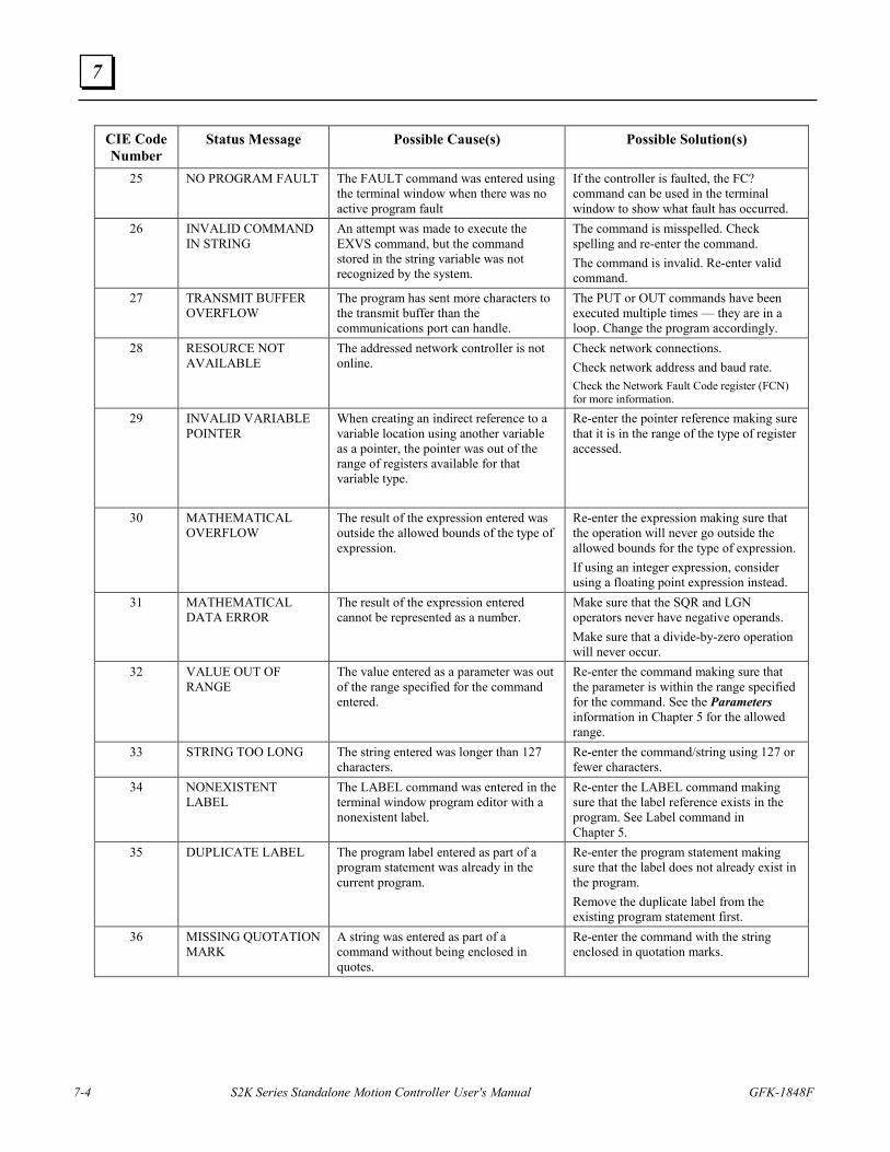
7-4 S2K Series Standalone Motion Controller User's Manual GFK-1848F
7
CIE Code Number
Status Message Possible Cause(s) Possible Solution(s)
25 NO PROGRAM FAULT The FAULT command was entered using the terminal window when there was no active program fault
If the controller is faulted, the FC? command can be used in the terminal window to show what fault has occurred.
26 INVALID COMMAND IN STRING
An attempt was made to execute the EXVS command, but the command stored in the string variable was not recognized by the system.
The command is misspelled. Check spelling and re-enter the command. The command is invalid. Re-enter valid command.
27 TRANSMIT BUFFER OVERFLOW
The program has sent more characters to the transmit buffer than the communications port can handle.
The PUT or OUT commands have been executed multiple times — they are in a loop. Change the program accordingly.
28 RESOURCE NOT AVAILABLE
The addressed network controller is not online.
Check network connections. Check network address and baud rate. Check the Network Fault Code register (FCN) for more information.
29 INVALID VARIABLE POINTER
When creating an indirect reference to a variable location using another variable as a pointer, the pointer was out of the range of registers available for that variable type.
Re-enter the pointer reference making sure that it is in the range of the type of register accessed.
30 MATHEMATICAL OVERFLOW
The result of the expression entered was outside the allowed bounds of the type of expression.
Re-enter the expression making sure that the operation will never go outside the allowed bounds for the type of expression. If using an integer expression, consider using a floating point expression instead.
31 MATHEMATICAL DATA ERROR
The result of the expression entered cannot be represented as a number.
Make sure that the SQR and LGN operators never have negative operands. Make sure that a divide-by-zero operation will never occur.
32 VALUE OUT OF RANGE
The value entered as a parameter was out of the range specified for the command entered.
Re-enter the command making sure that the parameter is within the range specified for the command. See the Parameters information in Chapter 5 for the allowed range.
33 STRING TOO LONG The string entered was longer than 127 characters.
Re-enter the command/string using 127 or fewer characters.
34 NONEXISTENT LABEL
The LABEL command was entered in the terminal window program editor with a nonexistent label.
Re-enter the LABEL command making sure that the label reference exists in the program. See Label command in Chapter 5.
35 DUPLICATE LABEL The program label entered as part of a program statement was already in the current program.
Re-enter the program statement making sure that the label does not already exist in the program. Remove the duplicate label from the existing program statement first.
36 MISSING QUOTATION MARK
A string was entered as part of a command without being enclosed in quotes.
Re-enter the command with the string enclosed in quotation marks.
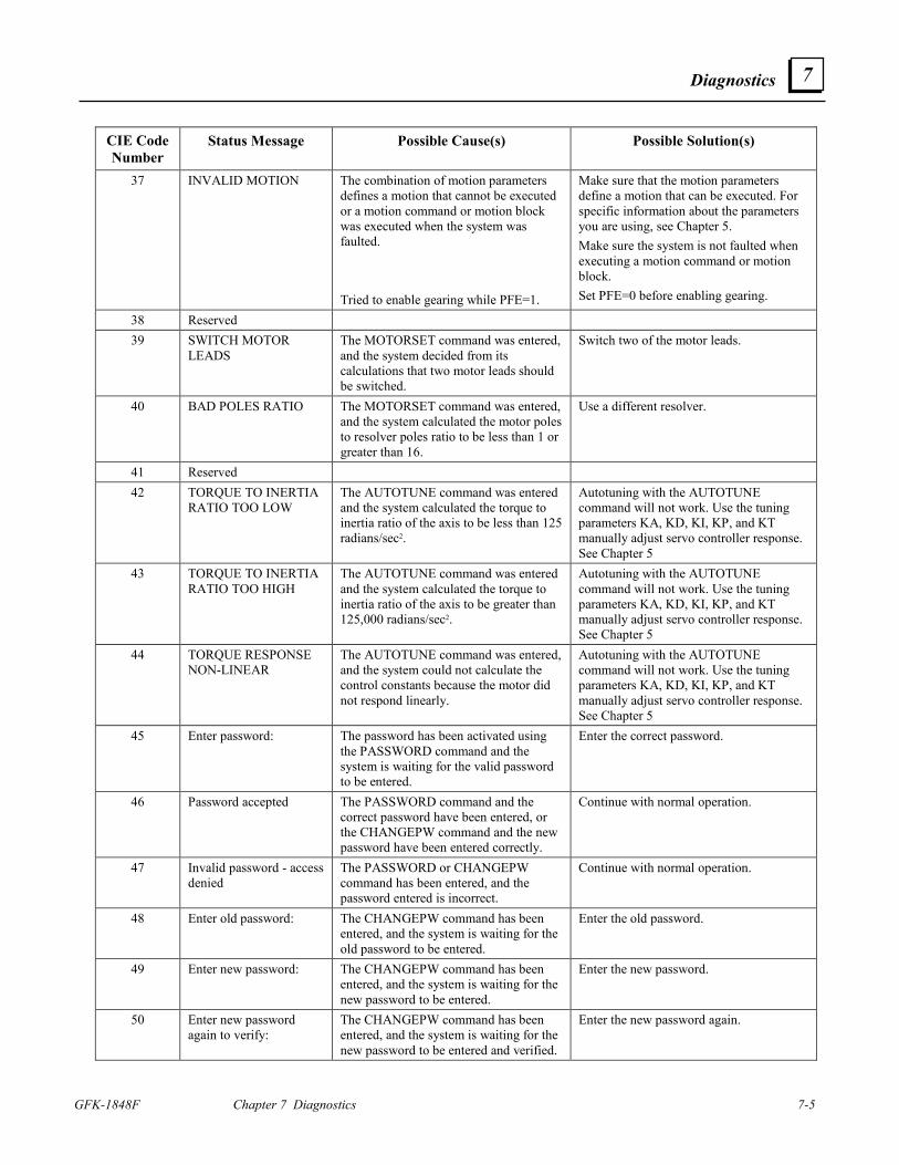
Diagnostics
GFK-1848F Chapter 7 Diagnostics 7-5
7
CIE Code Number
Status Message Possible Cause(s) Possible Solution(s)
37 INVALID MOTION The combination of motion parameters defines a motion that cannot be executed or a motion command or motion block was executed when the system was faulted. Tried to enable gearing while PFE=1.
Make sure that the motion parameters define a motion that can be executed. For specific information about the parameters you are using, see Chapter 5. Make sure the system is not faulted when executing a motion command or motion block. Set PFE=0 before enabling gearing.
38 Reserved 39 SWITCH MOTOR
LEADS The MOTORSET command was entered, and the system decided from its calculations that two motor leads should be switched.
Switch two of the motor leads.
40 BAD POLES RATIO The MOTORSET command was entered, and the system calculated the motor poles to resolver poles ratio to be less than 1 or greater than 16.
Use a different resolver.
41 Reserved 42 TORQUE TO INERTIA
RATIO TOO LOW The AUTOTUNE command was entered and the system calculated the torque to inertia ratio of the axis to be less than 125 radians/sec2.
Autotuning with the AUTOTUNE command will not work. Use the tuning parameters KA, KD, KI, KP, and KT manually adjust servo controller response. See Chapter 5
43 TORQUE TO INERTIA RATIO TOO HIGH
The AUTOTUNE command was entered and the system calculated the torque to inertia ratio of the axis to be greater than 125,000 radians/sec2.
Autotuning with the AUTOTUNE command will not work. Use the tuning parameters KA, KD, KI, KP, and KT manually adjust servo controller response. See Chapter 5
44 TORQUE RESPONSE NON-LINEAR
The AUTOTUNE command was entered, and the system could not calculate the control constants because the motor did not respond linearly.
Autotuning with the AUTOTUNE command will not work. Use the tuning parameters KA, KD, KI, KP, and KT manually adjust servo controller response. See Chapter 5
45 Enter password: The password has been activated using the PASSWORD command and the system is waiting for the valid password to be entered.
Enter the correct password.
46 Password accepted The PASSWORD command and the correct password have been entered, or the CHANGEPW command and the new password have been entered correctly.
Continue with normal operation.
47 Invalid password - access denied
The PASSWORD or CHANGEPW command has been entered, and the password entered is incorrect.
Continue with normal operation.
48 Enter old password: The CHANGEPW command has been entered, and the system is waiting for the old password to be entered.
Enter the old password.
49 Enter new password: The CHANGEPW command has been entered, and the system is waiting for the new password to be entered.
Enter the new password.
50 Enter new password again to verify:
The CHANGEPW command has been entered, and the system is waiting for the new password to be entered and verified.
Enter the new password again.
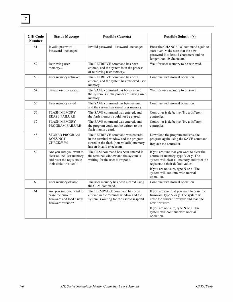
7-6 S2K Series Standalone Motion Controller User's Manual GFK-1848F
7
CIE Code Number
Status Message Possible Cause(s) Possible Solution(s)
51 Invalid password - Password unchanged
Invalid password - Password unchanged
Enter the CHANGEPW command again to start over. Make sure that the new password is at least 4 characters and no longer than 10 characters.
52 Retrieving user memory...
The RETRIEVE command has been entered, and the system is in the process of retrieving user memory.
Wait for user memory to be retrieved.
53 User memory retrieved The RETRIEVE command has been entered, and the system has retrieved user memory.
Continue with normal operation.
54 Saving user memory...
The SAVE command has been entered; the system is in the process of saving user memory.
Wait for user memory to be saved.
55 User memory saved The SAVE command has been entered, and the system has saved user memory.
Continue with normal operation.
56 FLASH MEMORY ERASE FAILURE
The SAVE command was entered, and the flash memory could not be erased.
Controller is defective. Try a different controller.
57 FLASH MEMORY PROGRAM FAILURE
The SAVE command was entered, and the program could not be written to the flash memory card.
Controller is defective. Try a different controller.
58 STORED PROGRAM DOES NOT CHECKSUM
The RETRIEVE command was entered in the terminal window and the program stored in the flash (non-volatile) memory has an invalid checksum.
Download the program and save the program again using the SAVE command. Replace the controller.
59 Are you sure you want to clear all the user memory and reset the registers to their default values?
The CLM command has been entered in the terminal window and the system is waiting for the user to respond.
If you are sure that you want to clear the controller memory, type Y or y. The system will clear all memory and reset the registers to their default values. If you are not sure, type N or n. The system will continue with normal operation.
60 User memory cleared The user memory has been cleared using the CLM command.
Continue with normal operation.
61 Are you sure you want to erase the current firmware and load a new firmware version?
The FIRMWARE command has been entered in the terminal window and the system is waiting for the user to respond.
If you are sure that you want to erase the firmware, type Y or y. The system will erase the current firmware and load the new firmware. If you are not sure, type N or n. The system will continue with normal operation.
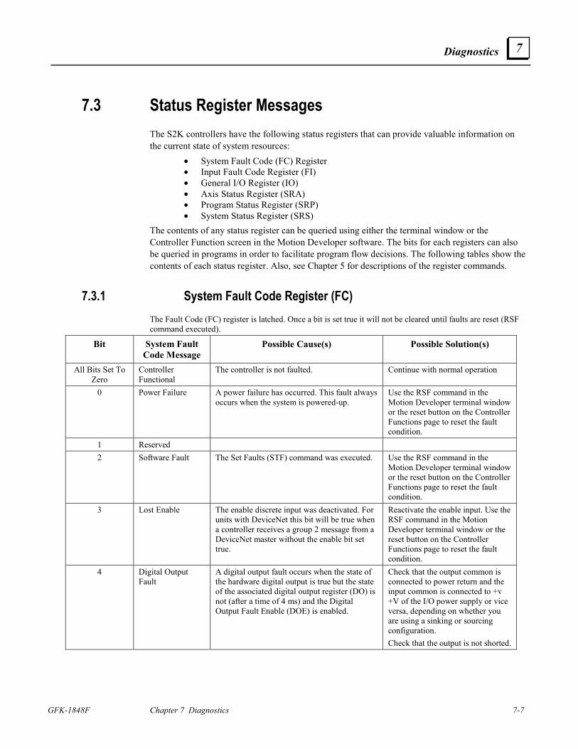
Diagnostics
GFK-1848F Chapter 7 Diagnostics 7-7
7
7.3 Status Register Messages The S2K controllers have the following status registers that can provide valuable information on the current state of system resources:
• System Fault Code (FC) Register • Input Fault Code Register (FI) • General I/O Register (IO) • Axis Status Register (SRA) • Program Status Register (SRP) • System Status Register (SRS)
The contents of any status register can be queried using either the terminal window or the Controller Function screen in the Motion Developer software. The bits for each registers can also be queried in programs in order to facilitate program flow decisions. The following tables show the contents of each status register. Also, see Chapter 5 for descriptions of the register commands.
7.3.1 System Fault Code Register (FC) The Fault Code (FC) register is latched. Once a bit is set true it will not be cleared until faults are reset (RSF command executed).
Bit System Fault Code Message
Possible Cause(s) Possible Solution(s)
All Bits Set To Zero
Controller Functional
The controller is not faulted. Continue with normal operation
0 Power Failure A power failure has occurred. This fault always occurs when the system is powered-up.
Use the RSF command in the Motion Developer terminal window or the reset button on the Controller Functions page to reset the fault condition.
1 Reserved 2 Software Fault
The Set Faults (STF) command was executed. Use the RSF command in the
Motion Developer terminal window or the reset button on the Controller Functions page to reset the fault condition.
3 Lost Enable The enable discrete input was deactivated. For units with DeviceNet this bit will be true when a controller receives a group 2 message from a DeviceNet master without the enable bit set true.
Reactivate the enable input. Use the RSF command in the Motion Developer terminal window or the reset button on the Controller Functions page to reset the fault condition.
4 Digital Output Fault
A digital output fault occurs when the state of the hardware digital output is true but the state of the associated digital output register (DO) is not (after a time of 4 ms) and the Digital Output Fault Enable (DOE) is enabled.
Check that the output common is connected to power return and the input common is connected to +v +V of the I/O power supply or vice versa, depending on whether you are using a sinking or sourcing configuration. Check that the output is not shorted.
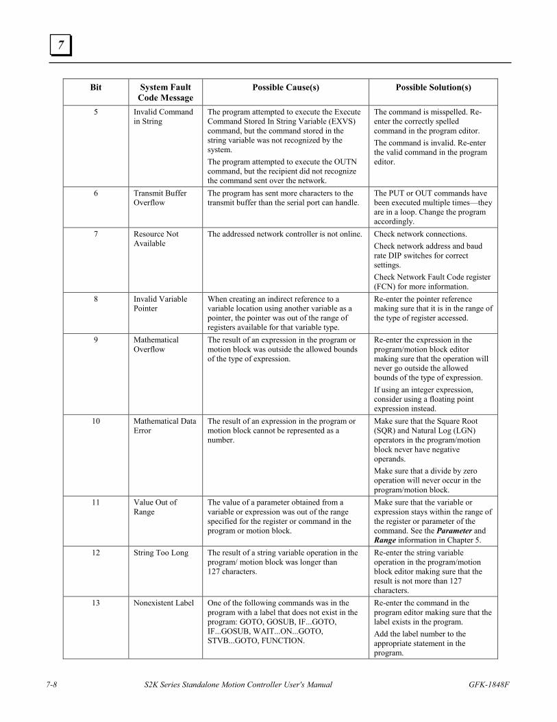
7-8 S2K Series Standalone Motion Controller User's Manual GFK-1848F
7
Bit System Fault Code Message
Possible Cause(s) Possible Solution(s)
5 Invalid Command in String
The program attempted to execute the Execute Command Stored In String Variable (EXVS) command, but the command stored in the string variable was not recognized by the system. The program attempted to execute the OUTN command, but the recipient did not recognize the command sent over the network.
The command is misspelled. Re-enter the correctly spelled command in the program editor. The command is invalid. Re-enter the valid command in the program editor.
6 Transmit Buffer Overflow
The program has sent more characters to the transmit buffer than the serial port can handle.
The PUT or OUT commands have been executed multiple times—they are in a loop. Change the program accordingly.
7 Resource Not Available
The addressed network controller is not online.
Check network connections. Check network address and baud rate DIP switches for correct settings. Check Network Fault Code register (FCN) for more information.
8 Invalid Variable Pointer
When creating an indirect reference to a variable location using another variable as a pointer, the pointer was out of the range of registers available for that variable type.
Re-enter the pointer reference making sure that it is in the range of the type of register accessed.
9 Mathematical Overflow
The result of an expression in the program or motion block was outside the allowed bounds of the type of expression.
Re-enter the expression in the program/motion block editor making sure that the operation will never go outside the allowed bounds of the type of expression. If using an integer expression, consider using a floating point expression instead.
10 Mathematical Data Error
The result of an expression in the program or motion block cannot be represented as a number.
Make sure that the Square Root (SQR) and Natural Log (LGN) operators in the program/motion block never have negative operands. Make sure that a divide by zero operation will never occur in the program/motion block.
11 Value Out of Range
The value of a parameter obtained from a variable or expression was out of the range specified for the register or command in the program or motion block.
Make sure that the variable or expression stays within the range of the register or parameter of the command. See the Parameter and Range information in Chapter 5.
12 String Too Long The result of a string variable operation in the program/ motion block was longer than 127 characters.
Re-enter the string variable operation in the program/motion block editor making sure that the result is not more than 127 characters.
13 Nonexistent Label One of the following commands was in the program with a label that does not exist in the program: GOTO, GOSUB, IF...GOTO, IF...GOSUB, WAIT...ON...GOTO, STVB...GOTO, FUNCTION.
Re-enter the command in the program editor making sure that the label exists in the program. Add the label number to the appropriate statement in the program.
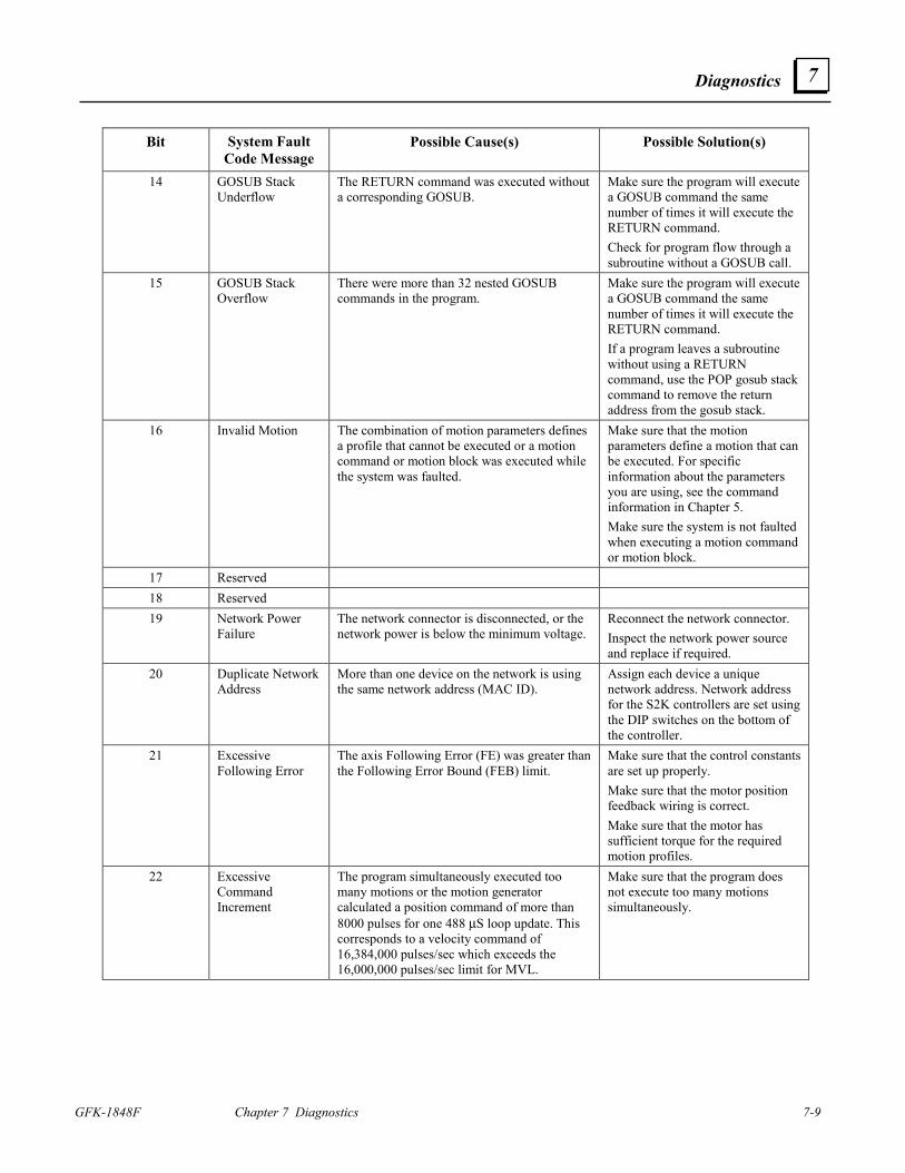
Diagnostics
GFK-1848F Chapter 7 Diagnostics 7-9
7
Bit System Fault Code Message
Possible Cause(s) Possible Solution(s)
14 GOSUB Stack Underflow
The RETURN command was executed without a corresponding GOSUB.
Make sure the program will execute a GOSUB command the same number of times it will execute the RETURN command. Check for program flow through a subroutine without a GOSUB call.
15 GOSUB Stack Overflow
There were more than 32 nested GOSUB commands in the program.
Make sure the program will execute a GOSUB command the same number of times it will execute the RETURN command. If a program leaves a subroutine without using a RETURN command, use the POP gosub stack command to remove the return address from the gosub stack.
16 Invalid Motion The combination of motion parameters defines a profile that cannot be executed or a motion command or motion block was executed while the system was faulted.
Make sure that the motion parameters define a motion that can be executed. For specific information about the parameters you are using, see the command information in Chapter 5. Make sure the system is not faulted when executing a motion command or motion block.
17 Reserved 18 Reserved 19 Network Power
Failure The network connector is disconnected, or the network power is below the minimum voltage.
Reconnect the network connector. Inspect the network power source and replace if required.
20 Duplicate Network Address
More than one device on the network is using the same network address (MAC ID).
Assign each device a unique network address. Network address for the S2K controllers are set using the DIP switches on the bottom of the controller.
21 Excessive Following Error
The axis Following Error (FE) was greater than the Following Error Bound (FEB) limit.
Make sure that the control constants are set up properly. Make sure that the motor position feedback wiring is correct. Make sure that the motor has sufficient torque for the required motion profiles.
22 Excessive Command Increment
The program simultaneously executed too many motions or the motion generator calculated a position command of more than 8000 pulses for one 488 µS loop update. This corresponds to a velocity command of 16,384,000 pulses/sec which exceeds the 16,000,000 pulses/sec limit for MVL.
Make sure that the program does not execute too many motions simultaneously.
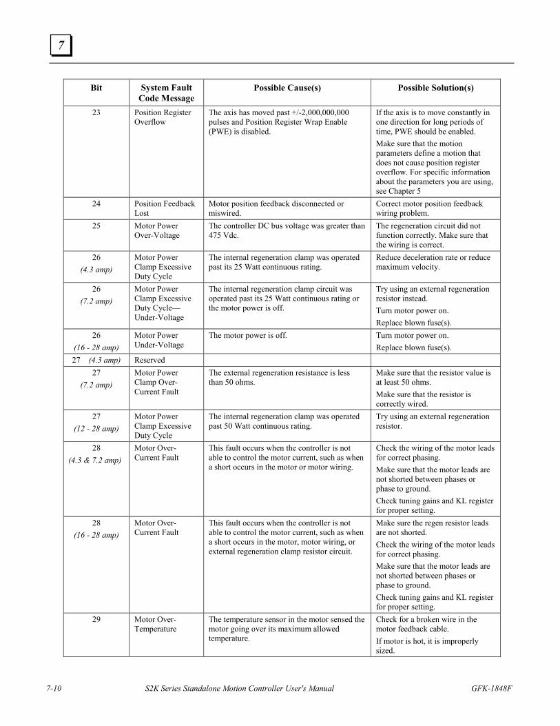
7-10 S2K Series Standalone Motion Controller User's Manual GFK-1848F
7
Bit System Fault Code Message
Possible Cause(s) Possible Solution(s)
23 Position Register Overflow
The axis has moved past +/-2,000,000,000 pulses and Position Register Wrap Enable (PWE) is disabled.
If the axis is to move constantly in one direction for long periods of time, PWE should be enabled. Make sure that the motion parameters define a motion that does not cause position register overflow. For specific information about the parameters you are using, see Chapter 5
24 Position Feedback Lost
Motor position feedback disconnected or miswired.
Correct motor position feedback wiring problem.
25 Motor Power Over-Voltage
The controller DC bus voltage was greater than 475 Vdc.
The regeneration circuit did not function correctly. Make sure that the wiring is correct.
26 (4.3 amp)
Motor Power Clamp Excessive Duty Cycle
The internal regeneration clamp was operated past its 25 Watt continuous rating.
Reduce deceleration rate or reduce maximum velocity.
26 (7.2 amp)
Motor Power Clamp Excessive Duty Cycle—Under-Voltage
The internal regeneration clamp circuit was operated past its 25 Watt continuous rating or the motor power is off.
Try using an external regeneration resistor instead. Turn motor power on. Replace blown fuse(s).
26 (16 - 28 amp)
Motor Power Under-Voltage
The motor power is off. Turn motor power on. Replace blown fuse(s).
27 (4.3 amp) Reserved 27
(7.2 amp) Motor Power Clamp Over-Current Fault
The external regeneration resistance is less than 50 ohms.
Make sure that the resistor value is at least 50 ohms. Make sure that the resistor is correctly wired.
27 (12 - 28 amp)
Motor Power Clamp Excessive Duty Cycle
The internal regeneration clamp was operated past 50 Watt continuous rating.
Try using an external regeneration resistor.
28 (4.3 & 7.2 amp)
Motor Over-Current Fault
This fault occurs when the controller is not able to control the motor current, such as when a short occurs in the motor or motor wiring.
Check the wiring of the motor leads for correct phasing. Make sure that the motor leads are not shorted between phases or phase to ground. Check tuning gains and KL register for proper setting.
28 (16 - 28 amp)
Motor Over-Current Fault
This fault occurs when the controller is not able to control the motor current, such as when a short occurs in the motor, motor wiring, or external regeneration clamp resistor circuit.
Make sure the regen resistor leads are not shorted. Check the wiring of the motor leads for correct phasing. Make sure that the motor leads are not shorted between phases or phase to ground. Check tuning gains and KL register for proper setting.
29 Motor Over-Temperature
The temperature sensor in the motor sensed the motor going over its maximum allowed temperature.
Check for a broken wire in the motor feedback cable. If motor is hot, it is improperly sized.
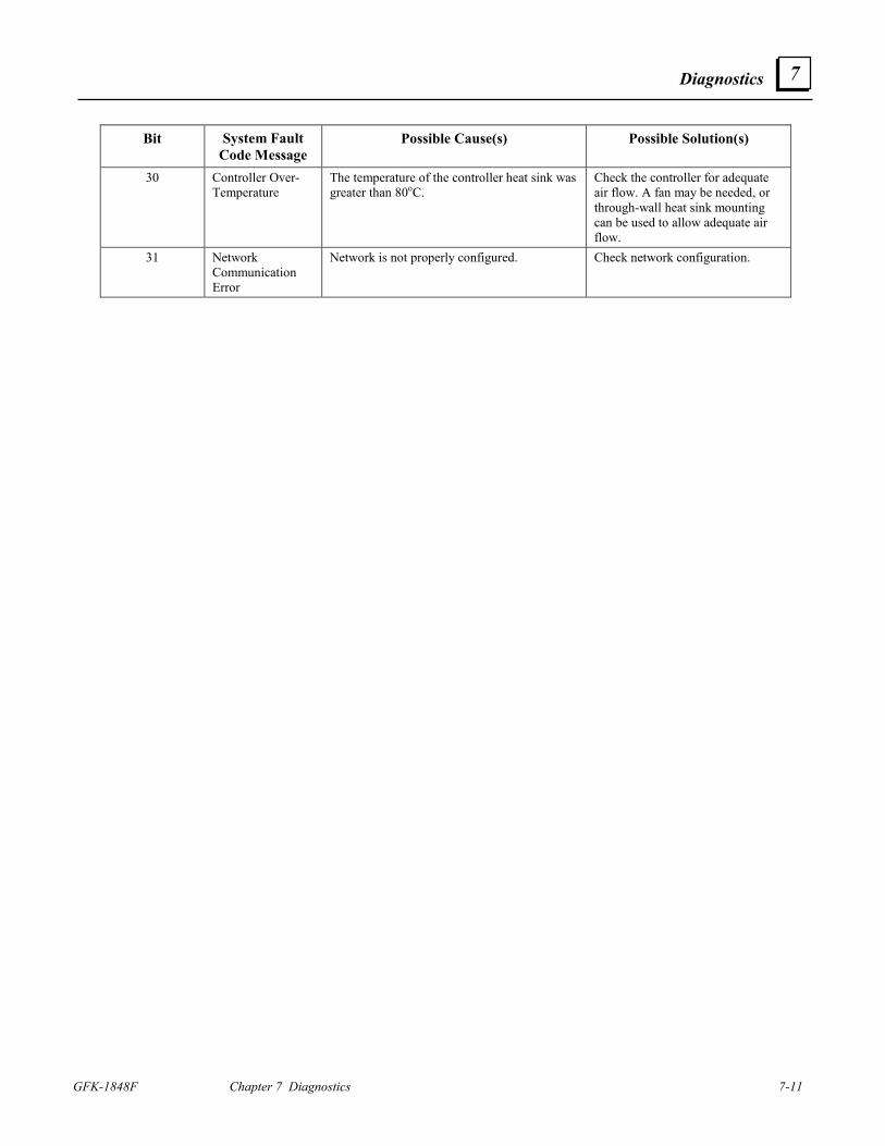
Diagnostics
GFK-1848F Chapter 7 Diagnostics 7-11
7
Bit System Fault Code Message
Possible Cause(s) Possible Solution(s)
30 Controller Over-Temperature
The temperature of the controller heat sink was greater than 80oC.
Check the controller for adequate air flow. A fan may be needed, or through-wall heat sink mounting can be used to allow adequate air flow.
31 Network Communication Error
Network is not properly configured. Check network configuration.
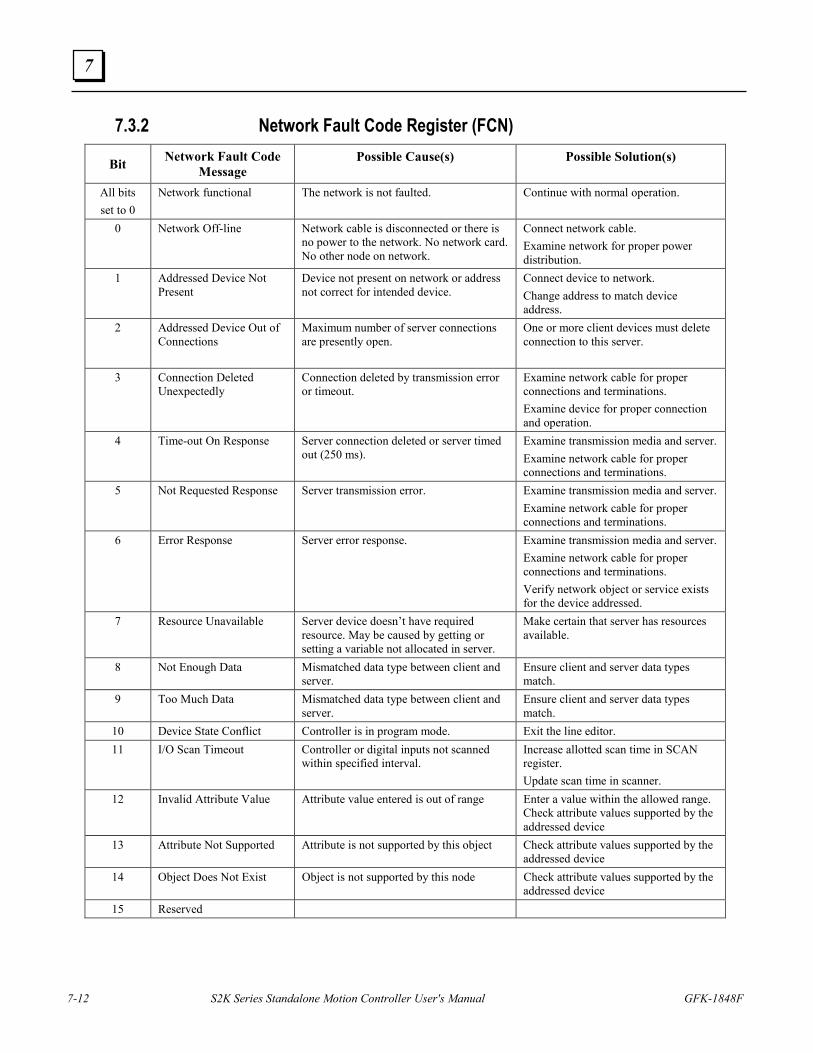
7-12 S2K Series Standalone Motion Controller User's Manual GFK-1848F
7
7.3.2 Network Fault Code Register (FCN)
Bit Network Fault Code
Message Possible Cause(s) Possible Solution(s)
All bits set to 0
Network functional The network is not faulted. Continue with normal operation.
0 Network Off-line Network cable is disconnected or there is no power to the network. No network card. No other node on network.
Connect network cable. Examine network for proper power distribution.
1 Addressed Device Not Present
Device not present on network or address not correct for intended device.
Connect device to network. Change address to match device address.
2 Addressed Device Out of Connections
Maximum number of server connections are presently open.
One or more client devices must delete connection to this server.
3 Connection Deleted Unexpectedly
Connection deleted by transmission error or timeout.
Examine network cable for proper connections and terminations. Examine device for proper connection and operation.
4 Time-out On Response Server connection deleted or server timed out (250 ms).
Examine transmission media and server. Examine network cable for proper connections and terminations.
5 Not Requested Response Server transmission error. Examine transmission media and server. Examine network cable for proper connections and terminations.
6 Error Response Server error response. Examine transmission media and server. Examine network cable for proper connections and terminations. Verify network object or service exists for the device addressed.
7 Resource Unavailable Server device doesn’t have required resource. May be caused by getting or setting a variable not allocated in server.
Make certain that server has resources available.
8 Not Enough Data Mismatched data type between client and server.
Ensure client and server data types match.
9 Too Much Data Mismatched data type between client and server.
Ensure client and server data types match.
10 Device State Conflict Controller is in program mode. Exit the line editor. 11 I/O Scan Timeout Controller or digital inputs not scanned
within specified interval. Increase allotted scan time in SCAN register. Update scan time in scanner.
12 Invalid Attribute Value Attribute value entered is out of range Enter a value within the allowed range. Check attribute values supported by the addressed device
13 Attribute Not Supported Attribute is not supported by this object Check attribute values supported by the addressed device
14 Object Does Not Exist Object is not supported by this node Check attribute values supported by the addressed device
15 Reserved
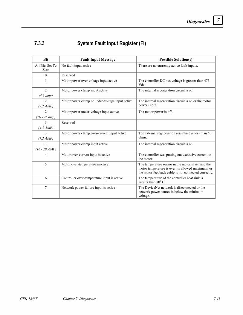
Diagnostics
GFK-1848F Chapter 7 Diagnostics 7-13
7
7.3.3 System Fault Input Register (FI)
Bit Fault Input Message Possible Solution(s) All Bits Set To
Zero No fault input active There are no currently active fault inputs.
0 Reserved 1 Motor power over-voltage input active The controller DC bus voltage is greater than 475
Vdc. 2
(4.3 amp) Motor power clamp input active The internal regeneration circuit is on.
2 (7.2 AMP)
Motor power clamp or under-voltage input active The internal regeneration circuit is on or the motor power is off.
2 (16 - 28 amp)
Motor power under-voltage input active The motor power is off.
3 (4.3 AMP)
Reserved
3 (7.2 AMP)
Motor power clamp over-current input active The external regeneration resistance is less than 50 ohms.
3 (16 - 28 AMP)
Motor power clamp input active The internal regeneration circuit is on.
4 Motor over-current input is active The controller was putting out excessive current to the motor.
5 Motor over-temperature inactive The temperature sensor in the motor is sensing the motor temperature is over its allowed maximum, or the motor feedback cable is not connected correctly.
6 Controller over-temperature input is active The temperature of the controller heat sink is greater than 80o C.
7 Network power failure input is active
The DeviceNet network is disconnected or the network power source is below the minimum voltage.
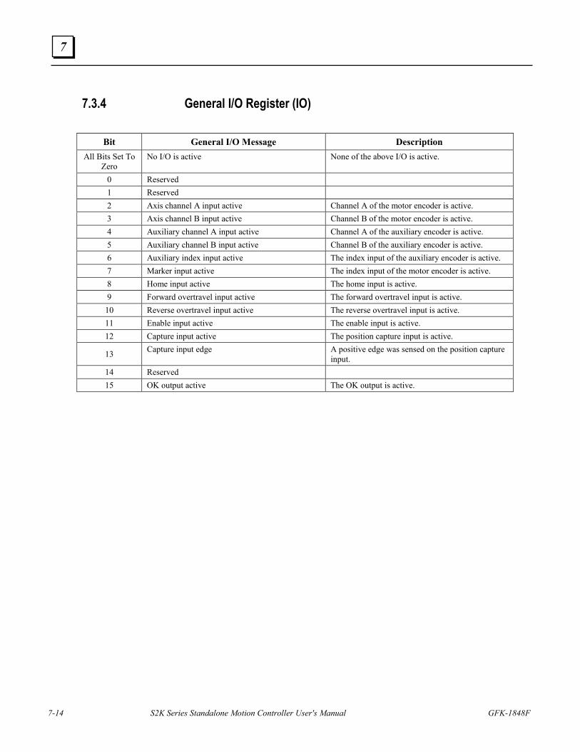
7-14 S2K Series Standalone Motion Controller User's Manual GFK-1848F
7
7.3.4 General I/O Register (IO)
Bit General I/O Message Description All Bits Set To
Zero No I/O is active None of the above I/O is active.
0 Reserved 1 Reserved 2 Axis channel A input active Channel A of the motor encoder is active. 3 Axis channel B input active Channel B of the motor encoder is active. 4 Auxiliary channel A input active Channel A of the auxiliary encoder is active. 5 Auxiliary channel B input active Channel B of the auxiliary encoder is active. 6 Auxiliary index input active The index input of the auxiliary encoder is active. 7 Marker input active The index input of the motor encoder is active. 8 Home input active The home input is active. 9 Forward overtravel input active The forward overtravel input is active.
10 Reverse overtravel input active The reverse overtravel input is active. 11 Enable input active The enable input is active. 12 Capture input active The position capture input is active.
13 Capture input edge A positive edge was sensed on the position capture input.
14 Reserved 15 OK output active The OK output is active.
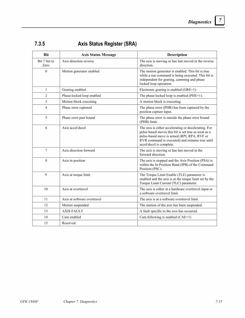
Diagnostics
GFK-1848F Chapter 7 Diagnostics 7-15
7
7.3.5 Axis Status Register (SRA)
Bit Axis Status Message Description Bit 7 Set to
Zero Axis direction reverse The axis is moving or has last moved in the reverse
direction.
0 Motion generator enabled The motion generator is enabled. This bit is true while a run command is being executed. This bit is independent for gearing, camming and phase locked loop operation.
1 Gearing enabled Electronic gearing is enabled (GRE=1).
2 Phase-locked loop enabled The phase-locked loop is enabled (PHE=1). 3 Motion block executing A motion block is executing.
4 Phase error captured The phase error (PHR) has been captured by the position capture input.
5 Phase error past bound The phase error is outside the phase error bound (PHB) limit.
6 Axis accel/decel The axis is either accelerating or decelerating. For pulse-based moves this bit is set true as soon as a pulse-based move is armed (RPI, RPA, RVF or RVR command is executed) and remains true until accel/decel is complete.
7 Axis direction forward The axis is moving or has last moved in the forward direction.
8 Axis in position The axis is stopped and the Axis Position (PSA) is within the In Position Band (IPB) of the Command Position (PSC).
9 Axis at torque limit The Torque Limit Enable (TLE) parameter is enabled and the axis is at the torque limit set by the Torque Limit Current (TLC) parameter.
10 Axis at overtravel The axis is either at a hardware overtravel input or a software overtravel limit.
11 Axis at software overtravel The axis is at a software overtravel limit.
12 Motion suspended The motion of the axis has been suspended.
13 AXIS FAULT A fault specific to the axis has occurred.
14 Cam enabled Cam following is enabled (CAE=1) 15 Reserved
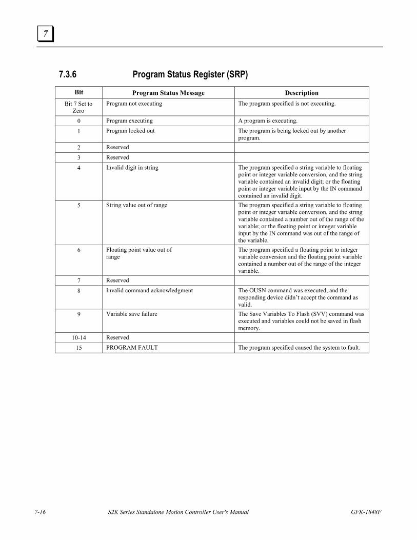
7-16 S2K Series Standalone Motion Controller User's Manual GFK-1848F
7
7.3.6 Program Status Register (SRP) Bit Program Status Message Description
Bit 7 Set to Zero
Program not executing The program specified is not executing.
0 Program executing A program is executing.
1 Program locked out The program is being locked out by another program.
2 Reserved
3 Reserved
4 Invalid digit in string The program specified a string variable to floating point or integer variable conversion, and the string variable contained an invalid digit; or the floating point or integer variable input by the IN command contained an invalid digit.
5 String value out of range The program specified a string variable to floating point or integer variable conversion, and the string variable contained a number out of the range of the variable; or the floating point or integer variable input by the IN command was out of the range of the variable.
6 Floating point value out of range
The program specified a floating point to integer variable conversion and the floating point variable contained a number out of the range of the integer variable.
7 Reserved
8 Invalid command acknowledgment The OUSN command was executed, and the responding device didn’t accept the command as valid.
9 Variable save failure The Save Variables To Flash (SVV) command was executed and variables could not be saved in flash memory.
10-14 Reserved
15 PROGRAM FAULT The program specified caused the system to fault.
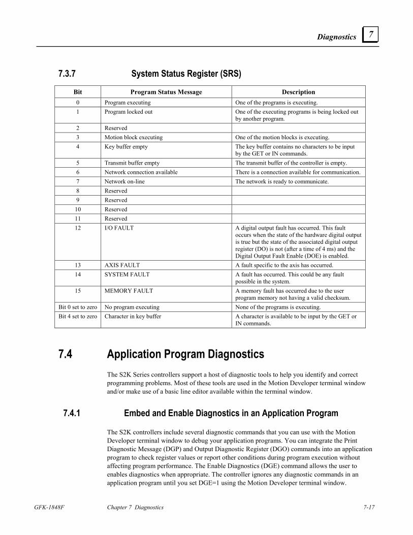
Diagnostics
GFK-1848F Chapter 7 Diagnostics 7-17
7
7.3.7 System Status Register (SRS)
Bit Program Status Message Description 0 Program executing One of the programs is executing. 1 Program locked out One of the executing programs is being locked out
by another program. 2 Reserved 3 Motion block executing One of the motion blocks is executing. 4 Key buffer empty The key buffer contains no characters to be input
by the GET or IN commands. 5 Transmit buffer empty The transmit buffer of the controller is empty. 6 Network connection available There is a connection available for communication. 7 Network on-line The network is ready to communicate. 8 Reserved 9 Reserved
10 Reserved 11 Reserved 12 I/O FAULT A digital output fault has occurred. This fault
occurs when the state of the hardware digital output is true but the state of the associated digital output register (DO) is not (after a time of 4 ms) and the Digital Output Fault Enable (DOE) is enabled.
13 AXIS FAULT A fault specific to the axis has occurred. 14 SYSTEM FAULT A fault has occurred. This could be any fault
possible in the system. 15 MEMORY FAULT A memory fault has occurred due to the user
program memory not having a valid checksum. Bit 0 set to zero No program executing None of the programs is executing. Bit 4 set to zero Character in key buffer A character is available to be input by the GET or
IN commands.
7.4 Application Program Diagnostics The S2K Series controllers support a host of diagnostic tools to help you identify and correct programming problems. Most of these tools are used in the Motion Developer terminal window and/or make use of a basic line editor available within the terminal window.
7.4.1 Embed and Enable Diagnostics in an Application Program
The S2K controllers include several diagnostic commands that you can use with the Motion Developer terminal window to debug your application programs. You can integrate the Print Diagnostic Message (DGP) and Output Diagnostic Register (DGO) commands into an application program to check register values or report other conditions during program execution without affecting program performance. The Enable Diagnostics (DGE) command allows the user to enables diagnostics when appropriate. The controller ignores any diagnostic commands in an application program until you set DGE=1 using the Motion Developer terminal window.
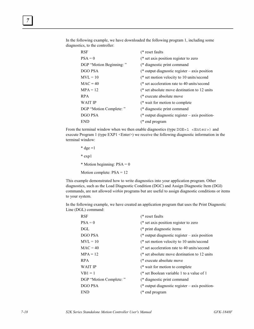
7-18 S2K Series Standalone Motion Controller User's Manual GFK-1848F
7
In the following example, we have downloaded the following program 1, including some diagnostics, to the controller: RSF (* reset faults PSA = 0 (* set axis position register to zero DGP “Motion Beginning: ” (* diagnostic print command DGO PSA (* output diagnostic register – axis position MVL = 10 (* set motion velocity to 10 units/second MAC = 40 (* set acceleration rate to 40 units/second MPA = 12 (* set absolute move destination to 12 units RPA (* execute absolute move WAIT IP (* wait for motion to complete DGP “Motion Complete: ” (* diagnostic print command DGO PSA (* output diagnostic register – axis position- END (* end program
From the terminal window when we then enable diagnostics (type DGE=1 <Enter>) and execute Program 1 (type EXP1 <Enter>) we receive the following diagnostic information in the terminal window:
* dge =1
* exp1
* Motion beginning: PSA = 0
Motion complete: PSA = 12
This example demonstrated how to write diagnostics into your application program. Other diagnostics, such as the Load Diagnostic Condition (DGC) and Assign Diagnostic Item (DGI) commands, are not allowed within programs but are useful to assign diagnostic conditions or items to your system.
In the following example, we have created an application program that uses the Print Diagnostic Line (DGL) command: RSF (* reset faults PSA = 0 (* set axis position register to zero DGL (* print diagnostic items DGO PSA (* output diagnostic register – axis position MVL = 10 (* set motion velocity to 10 units/second MAC = 40 (* set acceleration rate to 40 units/second MPA = 12 (* set absolute move destination to 12 units RPA (* execute absolute move WAIT IP (* wait for motion to complete VB1 = 1 (* set Boolean variable 1 to a value of 1 DGP “Motion Complete: ” (* diagnostic print command DGO PSA (* output diagnostic register – axis position- END (* end program
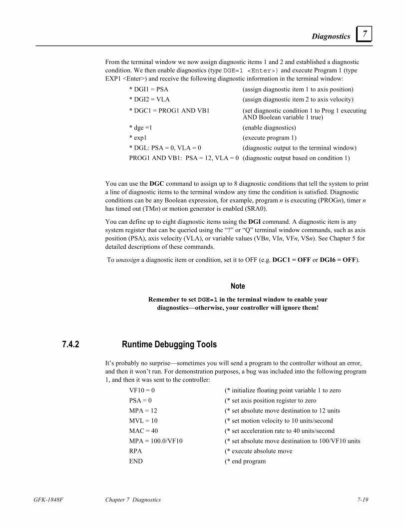
Diagnostics
GFK-1848F Chapter 7 Diagnostics 7-19
7
From the terminal window we now assign diagnostic items 1 and 2 and established a diagnostic condition. We then enable diagnostics (type DGE=1 <Enter>) and execute Program 1 (type EXP1 <Enter>) and receive the following diagnostic information in the terminal window:
* DGI1 = PSA (assign diagnostic item 1 to axis position) * DGI2 = VLA (assign diagnostic item 2 to axis velocity)
* DGC1 = PROG1 AND VB1 (set diagnostic condition 1 to Prog 1 executing AND Boolean variable 1 true)
* dge =1 (enable diagnostics) * exp1 (execute program 1)
* DGL: PSA = 0, VLA = 0 (diagnostic output to the terminal window) PROG1 AND VB1: PSA = 12, VLA = 0 (diagnostic output based on condition 1)
You can use the DGC command to assign up to 8 diagnostic conditions that tell the system to print a line of diagnostic items to the terminal window any time the condition is satisfied. Diagnostic conditions can be any Boolean expression, for example, program n is executing (PROGn), timer n has timed out (TMn) or motion generator is enabled (SRA0).
You can define up to eight diagnostic items using the DGI command. A diagnostic item is any system register that can be queried using the “?” or “Q” terminal window commands, such as axis position (PSA), axis velocity (VLA), or variable values (VBn, VIn, VFn, VSn). See Chapter 5 for detailed descriptions of these commands.
To unassign a diagnostic item or condition, set it to OFF (e.g. DGC1 = OFF or DGI6 = OFF).
Note Remember to set DGE=1 in the terminal window to enable your
diagnostics—otherwise, your controller will ignore them!
7.4.2 Runtime Debugging Tools
It’s probably no surprise—sometimes you will send a program to the controller without an error, and then it won’t run. For demonstration purposes, a bug was included into the following program 1, and then it was sent to the controller: VF10 = 0 (* initialize floating point variable 1 to zero PSA = 0 (* set axis position register to zero MPA = 12 (* set absolute move destination to 12 units MVL = 10 (* set motion velocity to 10 units/second MAC = 40 (* set acceleration rate to 40 units/second MPA = 100.0/VF10 (* set absolute move destination to 100/VF10 units RPA (* execute absolute move END (* end program
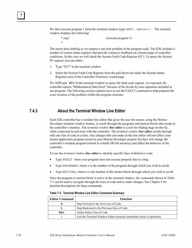
7-20 S2K Series Standalone Motion Controller User's Manual GFK-1848F
7
We then execute program 1 from the terminal window (type EXP1 <Enter>). The terminal window displays the following: * exp1 (execute program 1)
*
The motor does nothing so we suspect a run time problem in the program code. The S2K includes a number of system status registers that provide extensive feedback on a broad range of controller conditions. In this case we will check the System Fault Code Register (FC). To query the System FC register you can either:
1. Type “FC?” in the terminal window
2. Select the System Fault Code Register from the pull-down list under the System Status Registers area of the Controller Functions wizard page
We will type FC? In the terminal window to query the fault code register. As expected, the controller reports “Mathematical Data Error” because of the divide-by-zero operation included in our program. The following section explains how to use the FAULT command to help pinpoint the exact location of the problem within the program structure.
7.4.3 About the Terminal Window Line Editor
Each S2K controller has a resident line editor that gives the user the means, using the Motion Developer terminal window feature, to scroll through the programs and motion blocks that reside in the controller’s memory. The terminal window line editor is a tool for finding bugs on-the-fly, while connected in real-time with the controller. The terminal window line editor scrolls through only one line of code at a time. Any changes that you make in the line editor will not affect your master application program stored in your Motion Developer project; but they will change the controller’s resident program (stored in volatile SRAM memory) and affect the behavior of the controller.
To use the terminal window line editor to identify specific lines of defective code:
• Type FAULT when your program does not execute properly due to a bug.
• Type PROGRAMn, where n is the number of the program through which you wish to scroll.
• Type MOTIONn, where n is the number of the motion block through which you wish to scroll.
Once the program or motion block is active in the terminal window, the commands shown in Table 7-3 can be used to navigate through the lines of code and to make changes. See Chapter 5 for detailed descriptions for these commands.
Table 7-3. Terminal Window Line Editor Command Summary
Editor Command Function X Step Forward to the Next Line of Code L Step Backward to the Previous Line of Code
DEL Delete Entire Line of Code ! Exit the Terminal Window Editor (resumes immediate mode of operation)
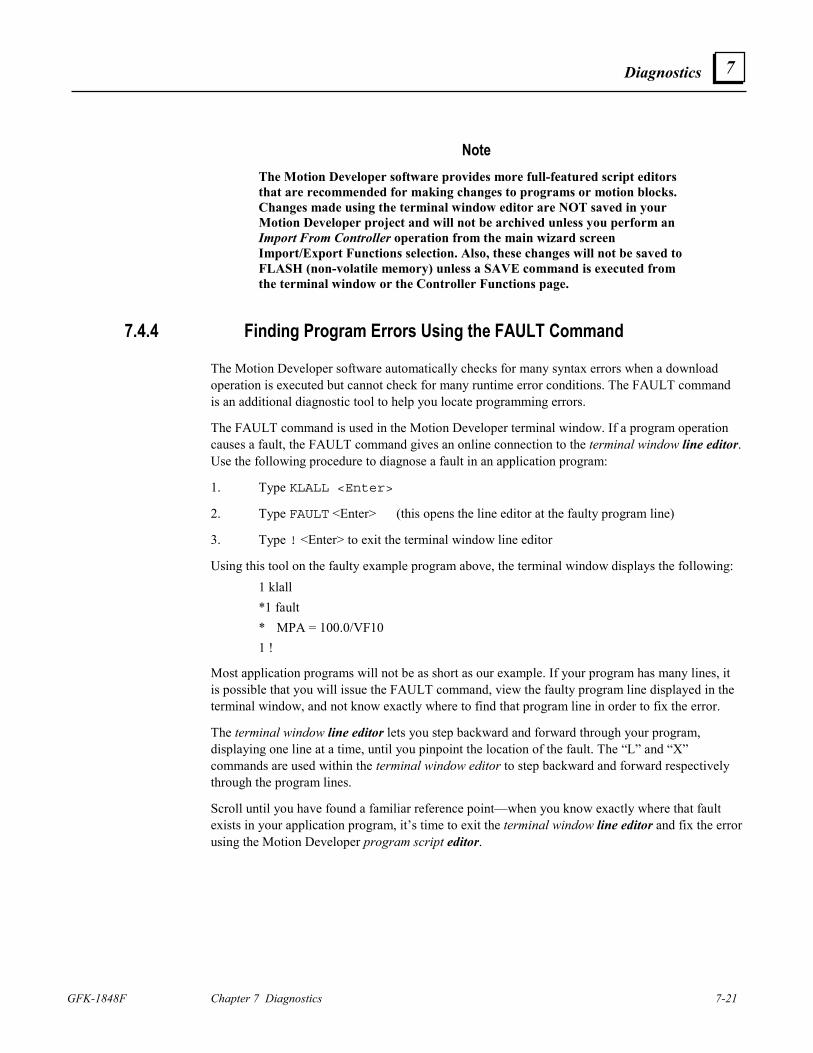
Diagnostics
GFK-1848F Chapter 7 Diagnostics 7-21
7
Note The Motion Developer software provides more full-featured script editors that are recommended for making changes to programs or motion blocks. Changes made using the terminal window editor are NOT saved in your Motion Developer project and will not be archived unless you perform an Import From Controller operation from the main wizard screen Import/Export Functions selection. Also, these changes will not be saved to FLASH (non-volatile memory) unless a SAVE command is executed from the terminal window or the Controller Functions page.
7.4.4 Finding Program Errors Using the FAULT Command
The Motion Developer software automatically checks for many syntax errors when a download operation is executed but cannot check for many runtime error conditions. The FAULT command is an additional diagnostic tool to help you locate programming errors.
The FAULT command is used in the Motion Developer terminal window. If a program operation causes a fault, the FAULT command gives an online connection to the terminal window line editor. Use the following procedure to diagnose a fault in an application program:
1. Type KLALL <Enter>
2. Type FAULT <Enter> (this opens the line editor at the faulty program line)
3. Type ! <Enter> to exit the terminal window line editor
Using this tool on the faulty example program above, the terminal window displays the following: 1 klall *1 fault * MPA = 100.0/VF10 1 !
Most application programs will not be as short as our example. If your program has many lines, it is possible that you will issue the FAULT command, view the faulty program line displayed in the terminal window, and not know exactly where to find that program line in order to fix the error.
The terminal window line editor lets you step backward and forward through your program, displaying one line at a time, until you pinpoint the location of the fault. The “L” and “X” commands are used within the terminal window editor to step backward and forward respectively through the program lines.
Scroll until you have found a familiar reference point—when you know exactly where that fault exists in your application program, it’s time to exit the terminal window line editor and fix the error using the Motion Developer program script editor.
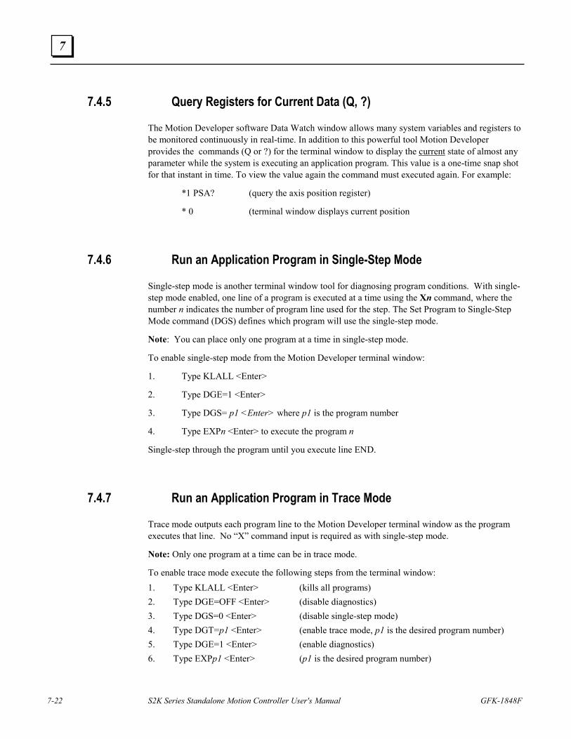
7-22 S2K Series Standalone Motion Controller User's Manual GFK-1848F
7
7.4.5 Query Registers for Current Data (Q, ?)
The Motion Developer software Data Watch window allows many system variables and registers to be monitored continuously in real-time. In addition to this powerful tool Motion Developer provides the commands (Q or ?) for the terminal window to display the current state of almost any parameter while the system is executing an application program. This value is a one-time snap shot for that instant in time. To view the value again the command must executed again. For example:
*1 PSA? (query the axis position register)
* 0 (terminal window displays current position
7.4.6 Run an Application Program in Single-Step Mode
Single-step mode is another terminal window tool for diagnosing program conditions. With single-step mode enabled, one line of a program is executed at a time using the Xn command, where the number n indicates the number of program line used for the step. The Set Program to Single-Step Mode command (DGS) defines which program will use the single-step mode.
Note: You can place only one program at a time in single-step mode.
To enable single-step mode from the Motion Developer terminal window:
1. Type KLALL <Enter>
2. Type DGE=1 <Enter>
3. Type DGS= p1 <Enter> where p1 is the program number
4. Type EXPn <Enter> to execute the program n
Single-step through the program until you execute line END.
7.4.7 Run an Application Program in Trace Mode
Trace mode outputs each program line to the Motion Developer terminal window as the program executes that line. No “X” command input is required as with single-step mode.
Note: Only one program at a time can be in trace mode.
To enable trace mode execute the following steps from the terminal window: 1. Type KLALL <Enter> (kills all programs) 2. Type DGE=OFF <Enter> (disable diagnostics) 3. Type DGS=0 <Enter> (disable single-step mode) 4. Type DGT=p1 <Enter> (enable trace mode, p1 is the desired program number) 5. Type DGE=1 <Enter> (enable diagnostics) 6. Type EXPp1 <Enter> (p1 is the desired program number)
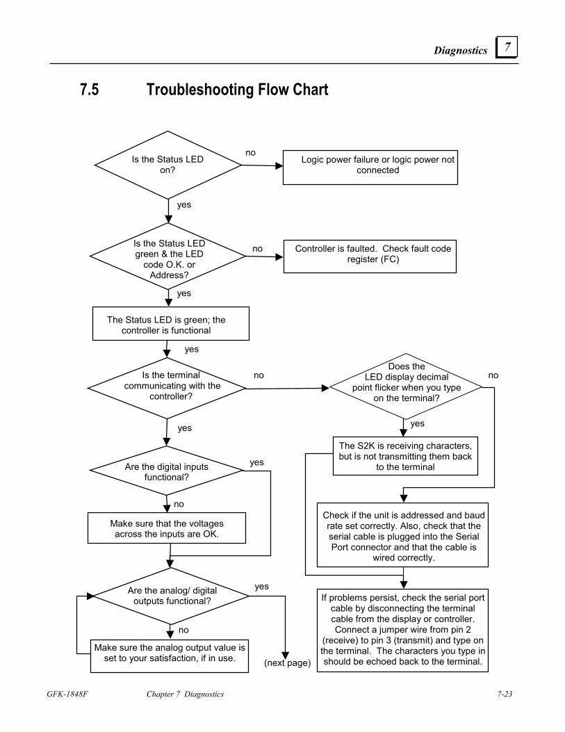
Diagnostics
GFK-1848F Chapter 7 Diagnostics 7-23
7
7.5 Troubleshooting Flow Chart
Logic power failure or logic power not connected
Is the Status LED on?
Is the Status LED green & the LED
code O.K. or Address?
Controller is faulted. Check fault code register (FC)
no
no
yes
yes
The Status LED is green; the controller is functional
yes
Is the terminal communicating with the
controller?
Are the digital inputs functional?
Make sure that the voltages across the inputs are OK.
yes
Are the analog/ digital outputs functional?
Make sure the analog output value is set to your satisfaction, if in use.
The S2K is receiving characters, but is not transmitting them back
to the terminal
Check if the unit is addressed and baud rate set correctly. Also, check that the serial cable is plugged into the Serial Port connector and that the cable is
wired correctly.
If problems persist, check the serial port cable by disconnecting the terminal cable from the display or controller. Connect a jumper wire from pin 2
(receive) to pin 3 (transmit) and type on the terminal. The characters you type in should be echoed back to the terminal.
yes
yes
yes
no
no
no
no
(next page)
Does the LED display decimal
point flicker when you type on the terminal?
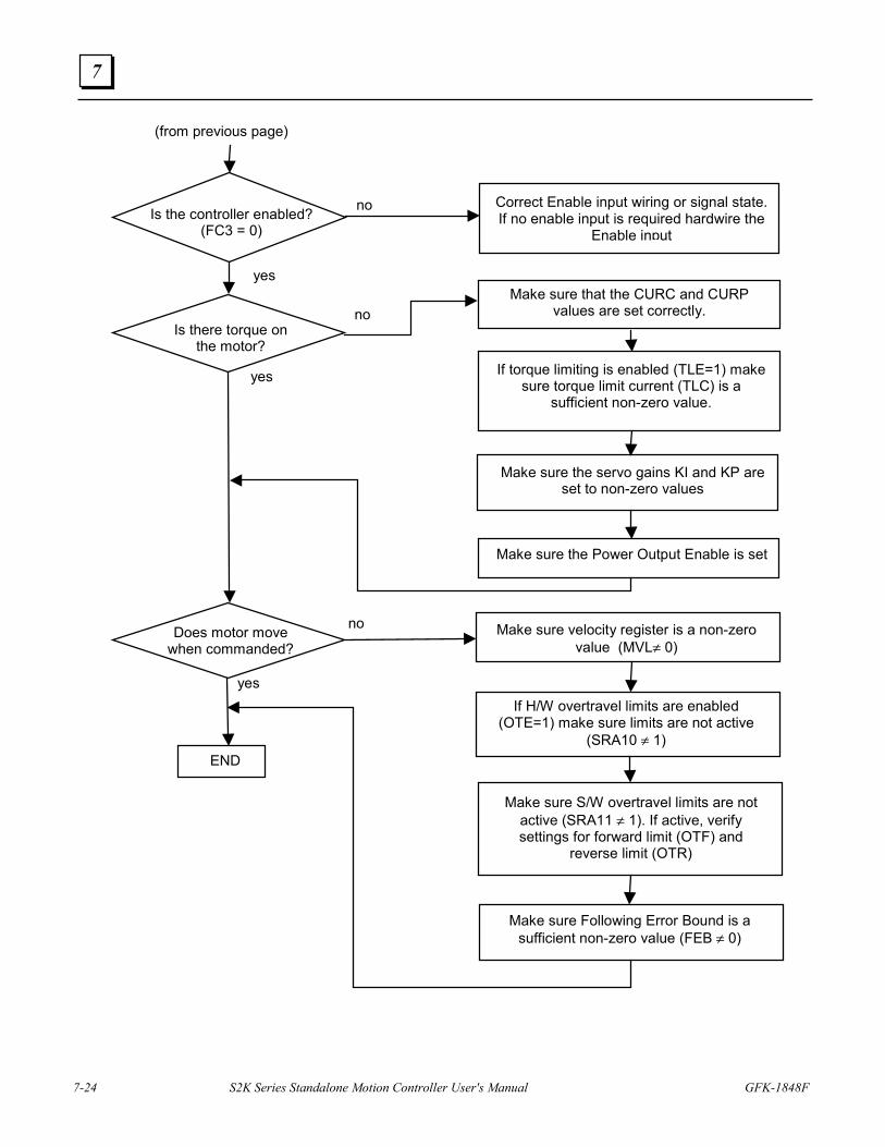
7-24 S2K Series Standalone Motion Controller User's Manual GFK-1848F
7
Is the controller enabled? (FC3 = 0)
Is there torque on the motor?
Make sure that the CURC and CURP values are set correctly.
yes
If torque limiting is enabled (TLE=1) make sure torque limit current (TLC) is a
sufficient non-zero value.
Correct Enable input wiring or signal state. If no enable input is required hardwire the
Enable input
yes
no
no
(from previous page)
Make sure the servo gains KI and KP are set to non-zero values
Make sure the Power Output Enable is set
Does motor move when commanded?
If H/W overtravel limits are enabled (OTE=1) make sure limits are not active
(SRA10 ≠ 1)
Make sure S/W overtravel limits are not active (SRA11 ≠ 1). If active, verify settings for forward limit (OTF) and
reverse limit (OTR)
Make sure velocity register is a non-zero value (MVL≠ 0)
yes
no
Make sure Following Error Bound is a sufficient non-zero value (FEB ≠ 0)
END
GFK-1848F 8-1
Using DeviceNet Communications
8.1 DeviceNet - What it is and How it Works DeviceNet is a digital, serial, multi-drop network that connects and serves as a communication path for GE Fanuc’s S2K controllers and other industrial controls and I/O devices. Using DeviceNet allows one network to connect both simple and high-level devices from many manufacturers. Those devices may each contain one or more nodes, or connection points, to the network. Each node gets a unique Node Address that serves as its network address.
DeviceNet is a producer-consumer network that supports multiple communication hierarchies and message prioritization. Therefore, when used on DeviceNet, S2K products can act as slaves to a DeviceNet master and/or communicate with other DeviceNet products in a peer-to-peer fashion, including other S2K controllers. Those two network architectures can also coexist on a single DeviceNet network, using both master/slave and peer-to-peer communication to create the distributed control architecture.
• DeviceNet specifications are managed and controlled by the Open DeviceNet Vendors
Association (ODVA) • ODVA members are users and designers who promote growth, use, and technology. • Based on Controller Area Network (CAN) technology • International standard • Well-suited to networking intelligent I/O devices • Uses low-cost serial bus system • Has real-time capabilities
DeviceNet is a trademark of the Open DeviceNet Vendors Association (ODVA)
8 Chapter
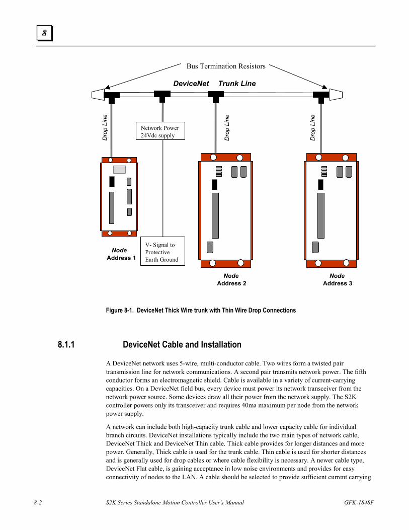
8-2 S2K Series Standalone Motion Controller User's Manual GFK-1848F
8
Network Power 24Vdc supply
V- Signal to Protective Earth Ground
DeviceNet Trunk Line
Dro
p Li
ne
Dro
p Li
ne
Node Address 1
Node Address 2
Dro
p Li
ne
Node Address 3
Bus Termination Resistors
Figure 8-1. DeviceNet Thick Wire trunk with Thin Wire Drop Connections
8.1.1 DeviceNet Cable and Installation
A DeviceNet network uses 5-wire, multi-conductor cable. Two wires form a twisted pair transmission line for network communications. A second pair transmits network power. The fifth conductor forms an electromagnetic shield. Cable is available in a variety of current-carrying capacities. On a DeviceNet field bus, every device must power its network transceiver from the network power source. Some devices draw all their power from the network supply. The S2K controller powers only its transceiver and requires 40ma maximum per node from the network power supply.
A network can include both high-capacity trunk cable and lower capacity cable for individual branch circuits. DeviceNet installations typically include the two main types of network cable, DeviceNet Thick and DeviceNet Thin cable. Thick cable provides for longer distances and more power. Generally, Thick cable is used for the trunk cable. Thin cable is used for shorter distances and is generally used for drop cables or where cable flexibility is necessary. A newer cable type, DeviceNet Flat cable, is gaining acceptance in low noise environments and provides for easy connectivity of nodes to the LAN. A cable should be selected to provide sufficient current carrying
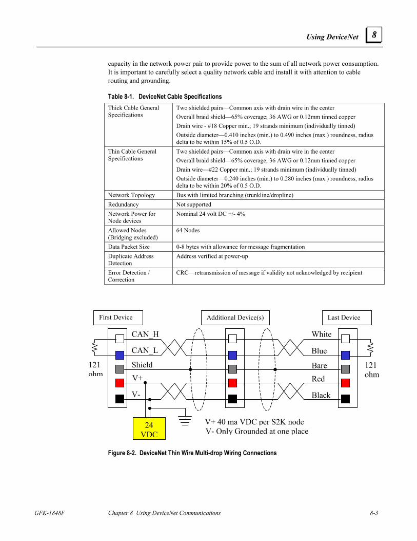
Using DeviceNet
GFK-1848F Chapter 8 Using DeviceNet Communications 8-3
8
capacity in the network power pair to provide power to the sum of all network power consumption. It is important to carefully select a quality network cable and install it with attention to cable routing and grounding.
Table 8-1. DeviceNet Cable Specifications Thick Cable General Specifications
Two shielded pairs—Common axis with drain wire in the center Overall braid shield—65% coverage; 36 AWG or 0.12mm tinned copper Drain wire - #18 Copper min.; 19 strands minimum (individually tinned) Outside diameter—0.410 inches (min.) to 0.490 inches (max.) roundness, radius delta to be within 15% of 0.5 O.D.
Thin Cable General Specifications
Two shielded pairs—Common axis with drain wire in the center Overall braid shield—65% coverage; 36 AWG or 0.12mm tinned copper Drain wire—#22 Copper min.; 19 strands minimum (individually tinned) Outside diameter—0.240 inches (min.) to 0.280 inches (max.) roundness, radius delta to be within 20% of 0.5 O.D.
Network Topology Bus with limited branching (trunkline/dropline) Redundancy Not supported Network Power for Node devices
Nominal 24 volt DC +/- 4%
Allowed Nodes (Bridging excluded)
64 Nodes
Data Packet Size 0-8 bytes with allowance for message fragmentation Duplicate Address Detection
Address verified at power-up
Error Detection / Correction
CRC—retransmission of message if validity not acknowledged by recipient
Figure 8-2. DeviceNet Thin Wire Multi-drop Wiring Connections
121 ohm
24 VDC
121 ohm V+
V-
Shield
CAN_L
CAN_H
Red
Black
Bare
Blue
White
V+ 40 ma VDC per S2K node V- Only Grounded at one place
First Device Additional Device(s) Last Device
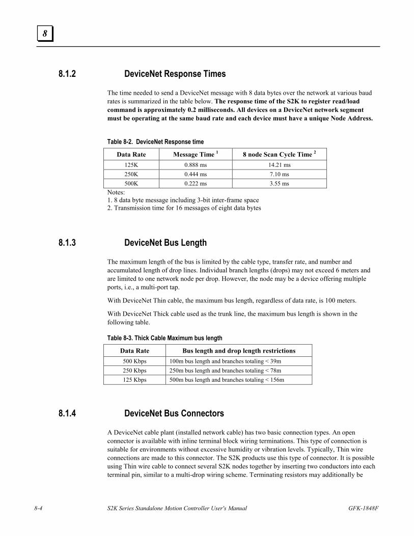
8-4 S2K Series Standalone Motion Controller User's Manual GFK-1848F
8
8.1.2 DeviceNet Response Times
The time needed to send a DeviceNet message with 8 data bytes over the network at various baud rates is summarized in the table below. The response time of the S2K to register read/load command is approximately 0.2 milliseconds. All devices on a DeviceNet network segment must be operating at the same baud rate and each device must have a unique Node Address.
Table 8-2. DeviceNet Response time
Data Rate Message Time 1 8 node Scan Cycle Time 2 125K 0.888 ms 14.21 ms 250K 0.444 ms 7.10 ms 500K 0.222 ms 3.55 ms
Notes: 1. 8 data byte message including 3-bit inter-frame space 2. Transmission time for 16 messages of eight data bytes
8.1.3 DeviceNet Bus Length
The maximum length of the bus is limited by the cable type, transfer rate, and number and accumulated length of drop lines. Individual branch lengths (drops) may not exceed 6 meters and are limited to one network node per drop. However, the node may be a device offering multiple ports, i.e., a multi-port tap.
With DeviceNet Thin cable, the maximum bus length, regardless of data rate, is 100 meters.
With DeviceNet Thick cable used as the trunk line, the maximum bus length is shown in the following table.
Table 8-3. Thick Cable Maximum bus length
Data Rate Bus length and drop length restrictions 500 Kbps 100m bus length and branches totaling < 39m 250 Kbps 250m bus length and branches totaling < 78m 125 Kbps 500m bus length and branches totaling < 156m
8.1.4 DeviceNet Bus Connectors
A DeviceNet cable plant (installed network cable) has two basic connection types. An open connector is available with inline terminal block wiring terminations. This type of connection is suitable for environments without excessive humidity or vibration levels. Typically, Thin wire connections are made to this connector. The S2K products use this type of connector. It is possible using Thin wire cable to connect several S2K nodes together by inserting two conductors into each terminal pin, similar to a multi-drop wiring scheme. Terminating resistors may additionally be
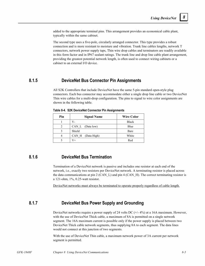
Using DeviceNet
GFK-1848F Chapter 8 Using DeviceNet Communications 8-5
8
added to the appropriate terminal pins. This arrangement provides an economical cable plant, typically within the same cabinet.
The second type uses a five-pole, circularly arranged connector. This type provides a robust connection and is more resistant to moisture and vibration. Trunk line cables lengths, network T connectors, network power supply taps, Thin wire drop cables and terminators are readily available in this form factor and in IP67 sealant ratings. The trunk line and drop line cable plant arrangement, providing the greatest potential network length, is often used to connect wiring cabinets or a cabinet to an external I/O device.
8.1.5 DeviceNet Bus Connector Pin Assignments
All S2K Controllers that include DeviceNet have the same 5-pin standard open-style plug connectors. Each bus connector may accommodate either a single drop line cable or two DeviceNet Thin wire cables for a multi-drop configuration. The pins to signal to wire color assignments are shown in the following table.
Table 8-4. S2K DeviceNet Connector Pin Assignments
Pin Signal Name Wire Color 1 V- Black 2 CAN_L (Data low) Blue 3 Shield Bare 4 CAN_H (Data High) White 5 V+ Red
8.1.6 DeviceNet Bus Termination
Termination of a DeviceNet network is passive and includes one resistor at each end of the network, i.e., exactly two resistors per DeviceNet network. A terminating resistor is placed across the data communications at pin 2 (CAN_L) and pin 4 (CAN_H). The correct terminating resistor is a 121-ohm, 1%, 0.25-watt resistor.
DeviceNet networks must always be terminated to operate properly regardless of cable length.
8.1.7 DeviceNet Bus Power Supply and Grounding
DeviceNet networks require a power supply of 24 volts DC (+/- 4%) at a 16A maximum. However, with the use of DeviceNet Thick cable, a maximum of 8A is permitted on a single network segment. The 16A maximum current is possible only if the power supply is placed between two DeviceNet Thick cable network segments, thus supplying 8A to each segment. The data lines would not connect at this junction of two segments.
With the use of DeviceNet Thin cable, a maximum network power of 3A current per network segment is permitted.
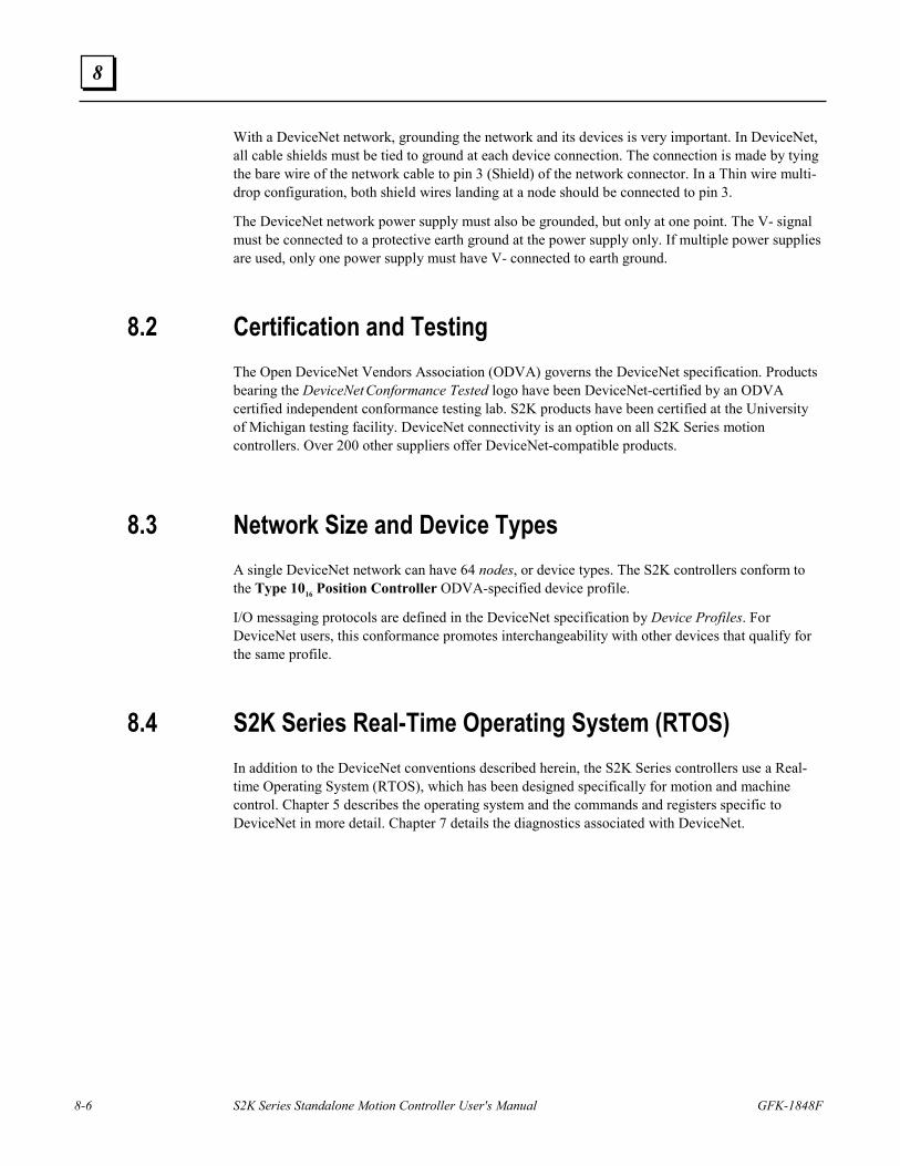
8-6 S2K Series Standalone Motion Controller User's Manual GFK-1848F
8
With a DeviceNet network, grounding the network and its devices is very important. In DeviceNet, all cable shields must be tied to ground at each device connection. The connection is made by tying the bare wire of the network cable to pin 3 (Shield) of the network connector. In a Thin wire multi-drop configuration, both shield wires landing at a node should be connected to pin 3.
The DeviceNet network power supply must also be grounded, but only at one point. The V- signal must be connected to a protective earth ground at the power supply only. If multiple power supplies are used, only one power supply must have V- connected to earth ground.
8.2 Certification and Testing The Open DeviceNet Vendors Association (ODVA) governs the DeviceNet specification. Products bearing the DeviceNet Conformance Tested logo have been DeviceNet-certified by an ODVA certified independent conformance testing lab. S2K products have been certified at the University of Michigan testing facility. DeviceNet connectivity is an option on all S2K Series motion controllers. Over 200 other suppliers offer DeviceNet-compatible products.
8.3 Network Size and Device Types A single DeviceNet network can have 64 nodes, or device types. The S2K controllers conform to the Type 1016 Position Controller ODVA-specified device profile.
I/O messaging protocols are defined in the DeviceNet specification by Device Profiles. For DeviceNet users, this conformance promotes interchangeability with other devices that qualify for the same profile.
8.4 S2K Series Real-Time Operating System (RTOS) In addition to the DeviceNet conventions described herein, the S2K Series controllers use a Real-time Operating System (RTOS), which has been designed specifically for motion and machine control. Chapter 5 describes the operating system and the commands and registers specific to DeviceNet in more detail. Chapter 7 details the diagnostics associated with DeviceNet.
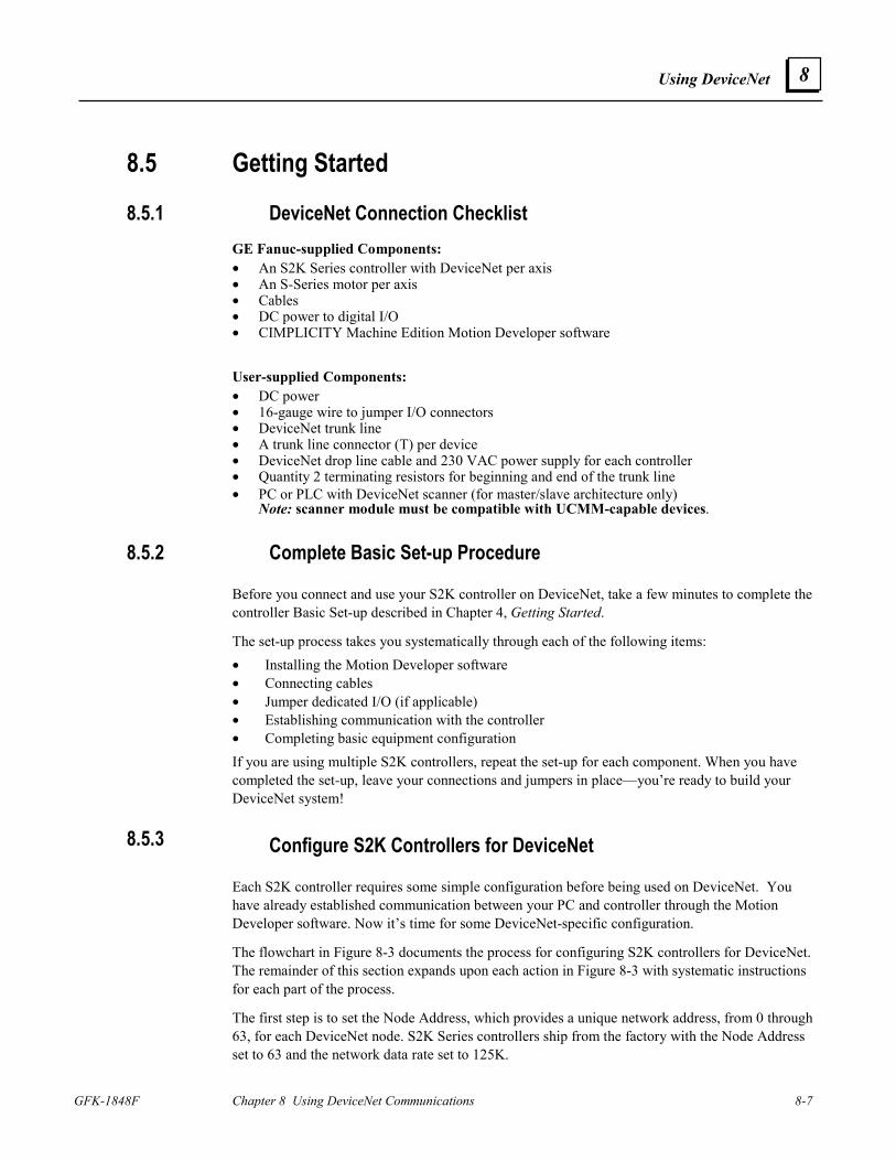
Using DeviceNet
GFK-1848F Chapter 8 Using DeviceNet Communications 8-7
8
8.5 Getting Started
8.5.1 DeviceNet Connection Checklist GE Fanuc-supplied Components: • An S2K Series controller with DeviceNet per axis • An S-Series motor per axis • Cables • DC power to digital I/O • CIMPLICITY Machine Edition Motion Developer software
User-supplied Components: • DC power • 16-gauge wire to jumper I/O connectors • DeviceNet trunk line • A trunk line connector (T) per device • DeviceNet drop line cable and 230 VAC power supply for each controller • Quantity 2 terminating resistors for beginning and end of the trunk line • PC or PLC with DeviceNet scanner (for master/slave architecture only)
Note: scanner module must be compatible with UCMM-capable devices.
8.5.2 Complete Basic Set-up Procedure
Before you connect and use your S2K controller on DeviceNet, take a few minutes to complete the controller Basic Set-up described in Chapter 4, Getting Started.
The set-up process takes you systematically through each of the following items: • Installing the Motion Developer software • Connecting cables • Jumper dedicated I/O (if applicable) • Establishing communication with the controller • Completing basic equipment configuration If you are using multiple S2K controllers, repeat the set-up for each component. When you have completed the set-up, leave your connections and jumpers in place—you’re ready to build your DeviceNet system!
8.5.3 Configure S2K Controllers for DeviceNet
Each S2K controller requires some simple configuration before being used on DeviceNet. You have already established communication between your PC and controller through the Motion Developer software. Now it’s time for some DeviceNet-specific configuration.
The flowchart in Figure 8-3 documents the process for configuring S2K controllers for DeviceNet. The remainder of this section expands upon each action in Figure 8-3 with systematic instructions for each part of the process.
The first step is to set the Node Address, which provides a unique network address, from 0 through 63, for each DeviceNet node. S2K Series controllers ship from the factory with the Node Address set to 63 and the network data rate set to 125K.
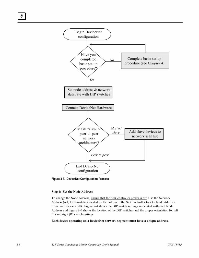
8-8 S2K Series Standalone Motion Controller User's Manual GFK-1848F
8
Set node address & networkdata rate with DIP switches
NoHave youcompleted
basic set-upprocedure?
End DeviceNetconfiguration
Begin DeviceNetconfiguration
Yes
Connect DeviceNet Hardware
Master/slave orpeer-to-peer
networkarchitecture?
Peer-to-peer
Master/slave Add slave devices to
network scan list
Complete basic set-upprocedure (see Chapter 4)
Figure 8-3. DeviceNet Configuration Process
Step 1: Set the Node Address
To change the Node Address, ensure that the S2K controller power is off. Use the Network Address (NA) DIP-switches located on the bottom of the S2K controller to set a Node Address from 0-63 for each S2K. Figure 8-4 shows the DIP switch settings associated with each Node Address and Figure 8-5 shows the location of the DIP switches and the proper orientation for left (L) and right (R) switch settings.
Each device operating on a DeviceNet network segment must have a unique address.
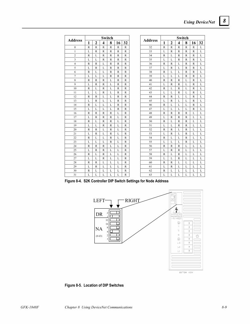
Using DeviceNet
GFK-1848F Chapter 8 Using DeviceNet Communications 8-9
8
Switch Switch Address 1 2 4 8 16 32 Address 1 2 4 8 16 320 R R R R R R 32 R R R R R L 1 L R R R R R 33 L R R R R L 2 R L R R R R 34 R L R R R L 3 L L R R R R 35 L L R R R L 4 R R L R R R 36 R R L R R L 5 L R L R R R 37 L R L R R L 6 R L L R R R 38 R L L R R L 7 L L L R R R 39 L L L R R L 8 R R R L R R 40 R R R L R L 9 L R R L R R 41 L R R L R L
10 R L R L R R 42 R L R L R L 11 L L R L R R 43 L L R L R L 12 R R L L R R 44 R R L L R L 13 L R L L R R 45 L R L L R L 14 R L L L R R 46 R L L L R L 15 L L L L R R 47 L L L L R L 16 R R R R L R 48 R R R R L L 17 L R R R L R 49 L R R R L L 18 R L R R L R 50 R L R R L L 19 L L R R L R 51 L L R R L L 20 R R L R L R 52 R R L R L L 21 L R L R L R 53 L R L R L L 22 R L L R L R 54 R L L R L L 23 L L L R L R 55 L L L R L L 24 R R R L L R 56 R R R L L L 25 L R R L L R 57 L R R L L L 26 R L R L L R 58 R L R L L L 27 L L R L L R 59 L L R L L L 28 R R L L L R 60 R R L L L L 29 L R L L L R 61 L R L L L L 30 R L L L L R 62 R L L L L L 31 L L L L L R 63 L L L L L L
Figure 8-4. S2K Controller DIP Switch Settings for Node Address
DR
NA(0-63)
21
32168
421
LEFT RIGHT
Figure 8-5. Location of DIP Switches
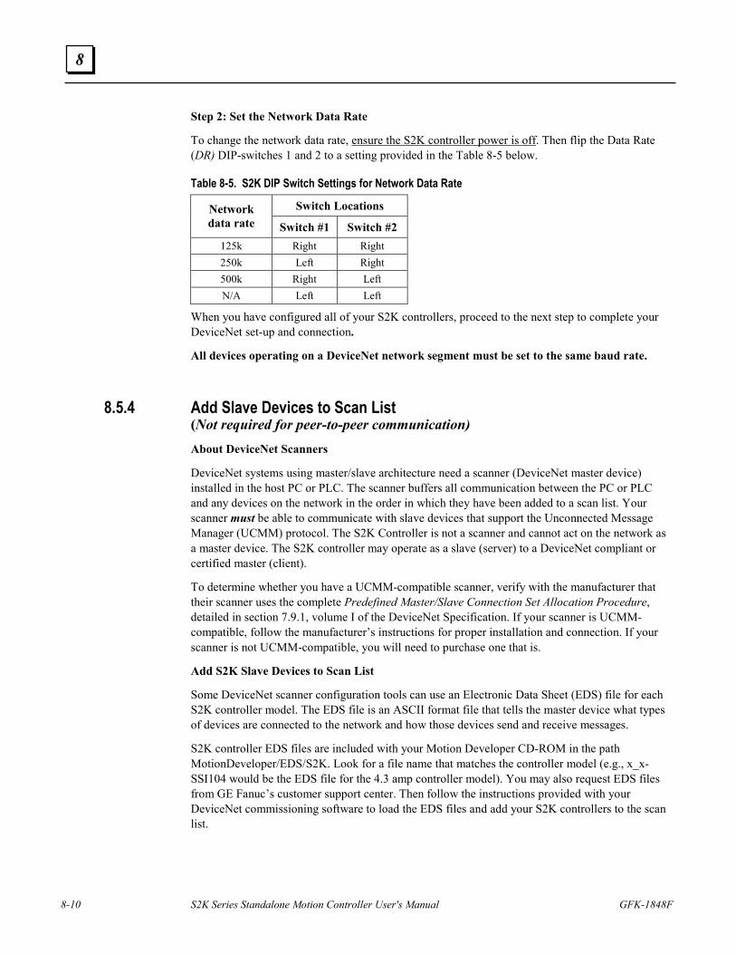
8-10 S2K Series Standalone Motion Controller User's Manual GFK-1848F
8
Step 2: Set the Network Data Rate
To change the network data rate, ensure the S2K controller power is off. Then flip the Data Rate (DR) DIP-switches 1 and 2 to a setting provided in the Table 8-5 below.
Table 8-5. S2K DIP Switch Settings for Network Data Rate
Switch Locations Network data rate Switch #1 Switch #2
125k Right Right 250k Left Right 500k Right Left N/A Left Left
When you have configured all of your S2K controllers, proceed to the next step to complete your DeviceNet set-up and connection.
All devices operating on a DeviceNet network segment must be set to the same baud rate.
8.5.4 Add Slave Devices to Scan List (Not required for peer-to-peer communication)
About DeviceNet Scanners
DeviceNet systems using master/slave architecture need a scanner (DeviceNet master device) installed in the host PC or PLC. The scanner buffers all communication between the PC or PLC and any devices on the network in the order in which they have been added to a scan list. Your scanner must be able to communicate with slave devices that support the Unconnected Message Manager (UCMM) protocol. The S2K Controller is not a scanner and cannot act on the network as a master device. The S2K controller may operate as a slave (server) to a DeviceNet compliant or certified master (client).
To determine whether you have a UCMM-compatible scanner, verify with the manufacturer that their scanner uses the complete Predefined Master/Slave Connection Set Allocation Procedure, detailed in section 7.9.1, volume I of the DeviceNet Specification. If your scanner is UCMM-compatible, follow the manufacturer’s instructions for proper installation and connection. If your scanner is not UCMM-compatible, you will need to purchase one that is.
Add S2K Slave Devices to Scan List
Some DeviceNet scanner configuration tools can use an Electronic Data Sheet (EDS) file for each S2K controller model. The EDS file is an ASCII format file that tells the master device what types of devices are connected to the network and how those devices send and receive messages.
S2K controller EDS files are included with your Motion Developer CD-ROM in the path MotionDeveloper/EDS/S2K. Look for a file name that matches the controller model (e.g., x_x-SSI104 would be the EDS file for the 4.3 amp controller model). You may also request EDS files from GE Fanuc’s customer support center. Then follow the instructions provided with your DeviceNet commissioning software to load the EDS files and add your S2K controllers to the scan list.
Using DeviceNet
GFK-1848F Chapter 8 Using DeviceNet Communications 8-11
8
The S2K motion controller supports the polled connection. Bytes produced are eight and bytes consumed are eight. You may optionally configure the scanner for an explicit connection of maximum 128 bytes transmitted and 128 bytes received.
Apply DC Voltage to the DeviceNet Trunk Line. You must have DC voltage on the DeviceNet LAN cable before you can communicate to the S2K controllers.
8.5.4.1 Communicating With DeviceNet Nodes Overview
Serial Port Communication
S2K controllers allow you to communicate serially while they are connected to a DeviceNet system. This means that at any time, you can bypass the network communication protocols and talk directly to your controllers to perform any task that the operating system permits, including application program development, diagnostics...even setting tuning constants or other registers.
Non-serial controller-to-controller communication over DeviceNet
The Motion Developer software makes it possible to communicate from a PC to any S2K controller on the same DeviceNet network after connecting to any single node on the network. The initial connection to the PC may be made serially or via a PC-installed DeviceNet card. No serial connection to the additional S2K controllers or knowledge of DeviceNet communication protocol is required. Program editing and diagnostics are as easy as typing simple mnemonic commands in the Motion Developer terminal window.
Running Resident Application Programs
S2K controllers allow you to run a complete program and communicate over DeviceNet. S2K Series controllers include DeviceNet extensions to read and write to variables within your controller, making the interface between your motion program and your master program straightforward, simple, and powerful.
Peer-to-Peer Systems
S2K controllers allow multiple controllers and some I/O devices from other vendors to communicate peer-to-peer over DeviceNet with no master. Each controller can share information with all other peer controllers on the network, so it’s easy to create a high-performance, multi-axis system.
Distributed Control Systems
S2K controllers can simultaneously function as slaves to a master device and as peers to each other. With distributed control, you can manage system behavior through peer-to-peer communication or DeviceNet communication from the master device. You also get the power to optimize network traffic to further boost system performance.
8.5.5 DeviceNet Communication Methods
DeviceNet systems provide several ways to communicate with S2K controllers and other network nodes. In fact, S2K controllers make it easy to use the DeviceNet I/O channel for system control. You can manipulate bits and bytes in the I/O message simply by turning them on and off as you would discrete inputs and outputs. S2K controllers also contain DeviceNet objects that allow users
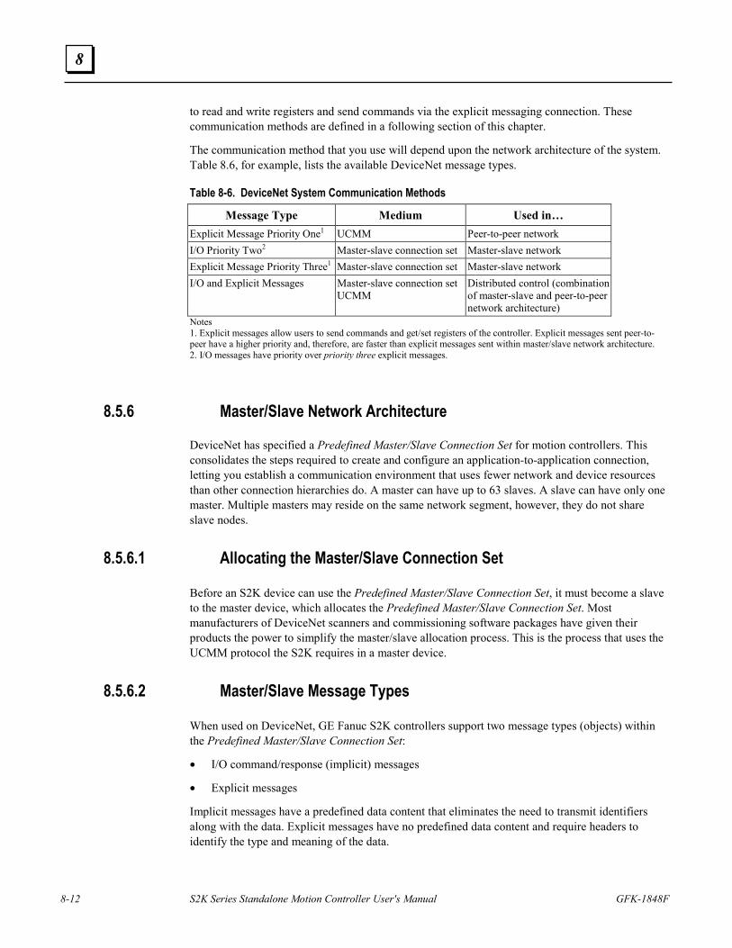
8-12 S2K Series Standalone Motion Controller User's Manual GFK-1848F
8
to read and write registers and send commands via the explicit messaging connection. These communication methods are defined in a following section of this chapter.
The communication method that you use will depend upon the network architecture of the system. Table 8.6, for example, lists the available DeviceNet message types.
Table 8-6. DeviceNet System Communication Methods
Message Type Medium Used in… Explicit Message Priority One1 UCMM Peer-to-peer network I/O Priority Two2 Master-slave connection set Master-slave network Explicit Message Priority Three1 Master-slave connection set Master-slave network I/O and Explicit Messages Master-slave connection set
UCMM Distributed control (combination of master-slave and peer-to-peer network architecture)
Notes 1. Explicit messages allow users to send commands and get/set registers of the controller. Explicit messages sent peer-to-peer have a higher priority and, therefore, are faster than explicit messages sent within master/slave network architecture. 2. I/O messages have priority over priority three explicit messages.
8.5.6 Master/Slave Network Architecture
DeviceNet has specified a Predefined Master/Slave Connection Set for motion controllers. This consolidates the steps required to create and configure an application-to-application connection, letting you establish a communication environment that uses fewer network and device resources than other connection hierarchies do. A master can have up to 63 slaves. A slave can have only one master. Multiple masters may reside on the same network segment, however, they do not share slave nodes.
8.5.6.1 Allocating the Master/Slave Connection Set
Before an S2K device can use the Predefined Master/Slave Connection Set, it must become a slave to the master device, which allocates the Predefined Master/Slave Connection Set. Most manufacturers of DeviceNet scanners and commissioning software packages have given their products the power to simplify the master/slave allocation process. This is the process that uses the UCMM protocol the S2K requires in a master device.
8.5.6.2 Master/Slave Message Types
When used on DeviceNet, GE Fanuc S2K controllers support two message types (objects) within the Predefined Master/Slave Connection Set:
• I/O command/response (implicit) messages
• Explicit messages
Implicit messages have a predefined data content that eliminates the need to transmit identifiers along with the data. Explicit messages have no predefined data content and require headers to identify the type and meaning of the data.
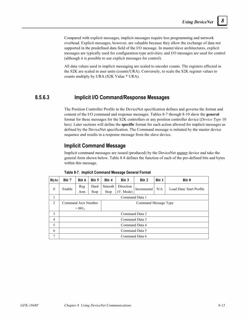
Using DeviceNet
GFK-1848F Chapter 8 Using DeviceNet Communications 8-13
8
Compared with explicit messages, implicit messages require less programming and network overhead. Explicit messages, however, are valuable because they allow the exchange of data not supported in the predefined data field of the I/O message. In master/slave architectures, explicit messages are typically used for configuration-type activities; and I/O messages are used for control (although it is possible to use explicit messages for control).
All data values used in implicit messaging are scaled to encoder counts. The registers affected in the S2K are scaled in user units (counts/URA). Conversely, to scale the S2K register values to counts multiply by URA (S2K Value * URA).
8.5.6.3 Implicit I/O Command/Response Messages
The Position Controller Profile in the DeviceNet specification defines and governs the format and content of the I/O command and response messages. Tables 8-7 through 8-10 show the general format for these messages for the S2K controllers or any position controller device (Device Type 10 hex). Later sections will define the specific format for each action allowed for implicit messages as defined by the DeviceNet specification. The Command message is initiated by the master device sequence and results in a response message from the slave device.
Implicit Command Message Implicit command messages are issued (produced) by the DeviceNet master device and take the general form shown below. Table 8-8 defines the function of each of the pre-defined bits and bytes within this message.
Table 8-7. Implicit Command Message General Format
Byte Bit 7 Bit 6 Bit 5 Bit 4 Bit 3 Bit 2 Bit 1 Bit 0
0 Enable Reg Arm
Hard Stop
SmoothStop
Direction (V. Mode)
Incremental N/A Load Data/ Start Profile
1 Command Data 1 2 Command Axis Number
= 0012 Command Message Type
3 Command Data 2 4 Command Data 3 5 Command Data 4 6 Command Data 5 7 Command Data 6
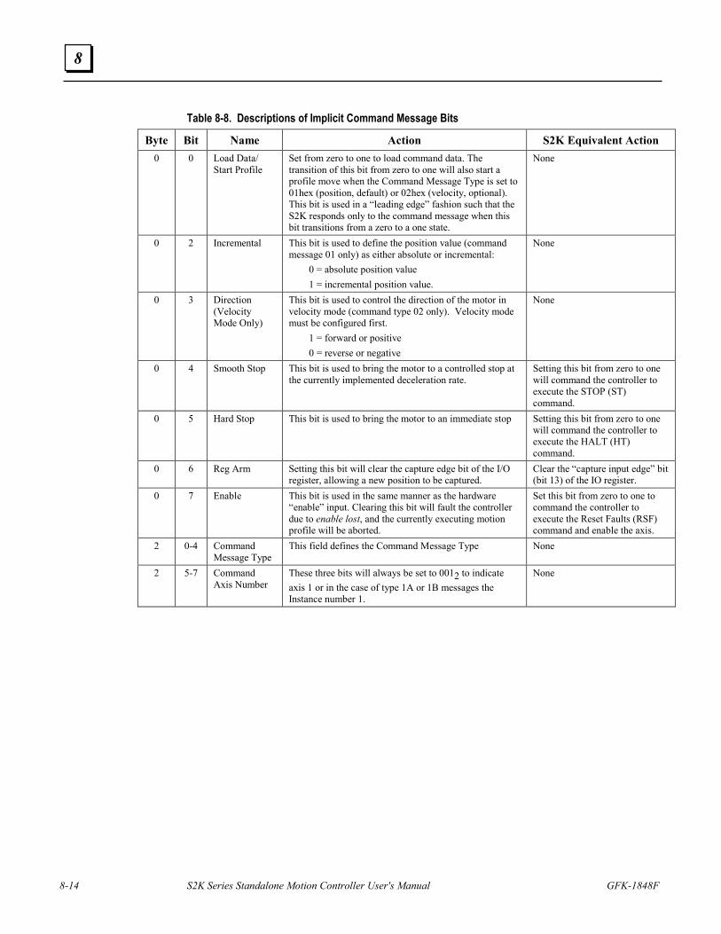
8-14 S2K Series Standalone Motion Controller User's Manual GFK-1848F
8
Table 8-8. Descriptions of Implicit Command Message Bits
Byte Bit Name Action S2K Equivalent Action 0 0 Load Data/
Start Profile Set from zero to one to load command data. The transition of this bit from zero to one will also start a profile move when the Command Message Type is set to 01hex (position, default) or 02hex (velocity, optional). This bit is used in a “leading edge” fashion such that the S2K responds only to the command message when this bit transitions from a zero to a one state.
None
0 2 Incremental This bit is used to define the position value (command message 01 only) as either absolute or incremental: 0 = absolute position value 1 = incremental position value.
None
0 3 Direction (Velocity Mode Only)
This bit is used to control the direction of the motor in velocity mode (command type 02 only). Velocity mode must be configured first. 1 = forward or positive 0 = reverse or negative
None
0 4 Smooth Stop This bit is used to bring the motor to a controlled stop at the currently implemented deceleration rate.
Setting this bit from zero to one will command the controller to execute the STOP (ST) command.
0 5 Hard Stop This bit is used to bring the motor to an immediate stop Setting this bit from zero to one will command the controller to execute the HALT (HT) command.
0 6 Reg Arm Setting this bit will clear the capture edge bit of the I/O register, allowing a new position to be captured.
Clear the “capture input edge” bit (bit 13) of the IO register.
0 7 Enable This bit is used in the same manner as the hardware “enable” input. Clearing this bit will fault the controller due to enable lost, and the currently executing motion profile will be aborted.
Set this bit from zero to one to command the controller to execute the Reset Faults (RSF) command and enable the axis.
2 0-4 Command Message Type
This field defines the Command Message Type None
2 5-7 Command Axis Number
These three bits will always be set to 0012 to indicate axis 1 or in the case of type 1A or 1B messages the Instance number 1.
None
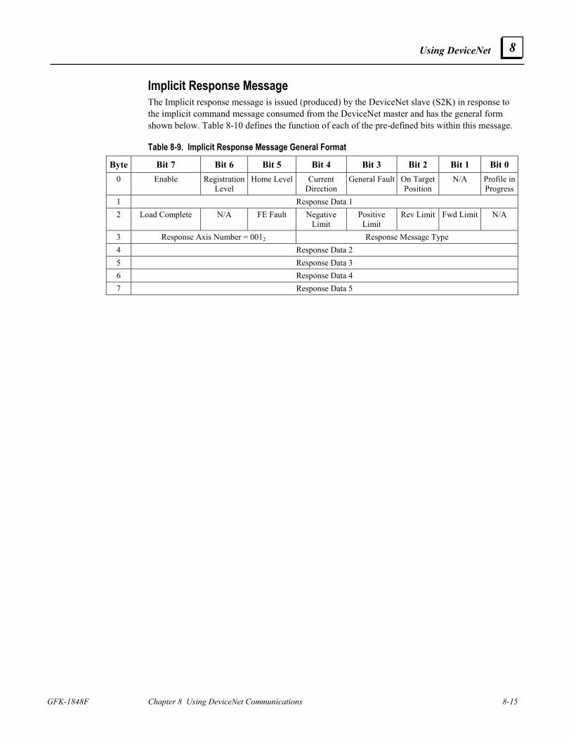
Using DeviceNet
GFK-1848F Chapter 8 Using DeviceNet Communications 8-15
8
Implicit Response Message The Implicit response message is issued (produced) by the DeviceNet slave (S2K) in response to the implicit command message consumed from the DeviceNet master and has the general form shown below. Table 8-10 defines the function of each of the pre-defined bits within this message.
Table 8-9. Implicit Response Message General Format
Byte Bit 7 Bit 6 Bit 5 Bit 4 Bit 3 Bit 2 Bit 1 Bit 0 0 Enable Registration
Level Home Level Current
Direction General Fault On Target
Position N/A Profile in
Progress1 Response Data 1 2 Load Complete N/A FE Fault Negative
Limit Positive
Limit Rev Limit Fwd Limit N/A
3 Response Axis Number = 0012 Response Message Type 4 Response Data 2 5 Response Data 3 6 Response Data 4 7 Response Data 5
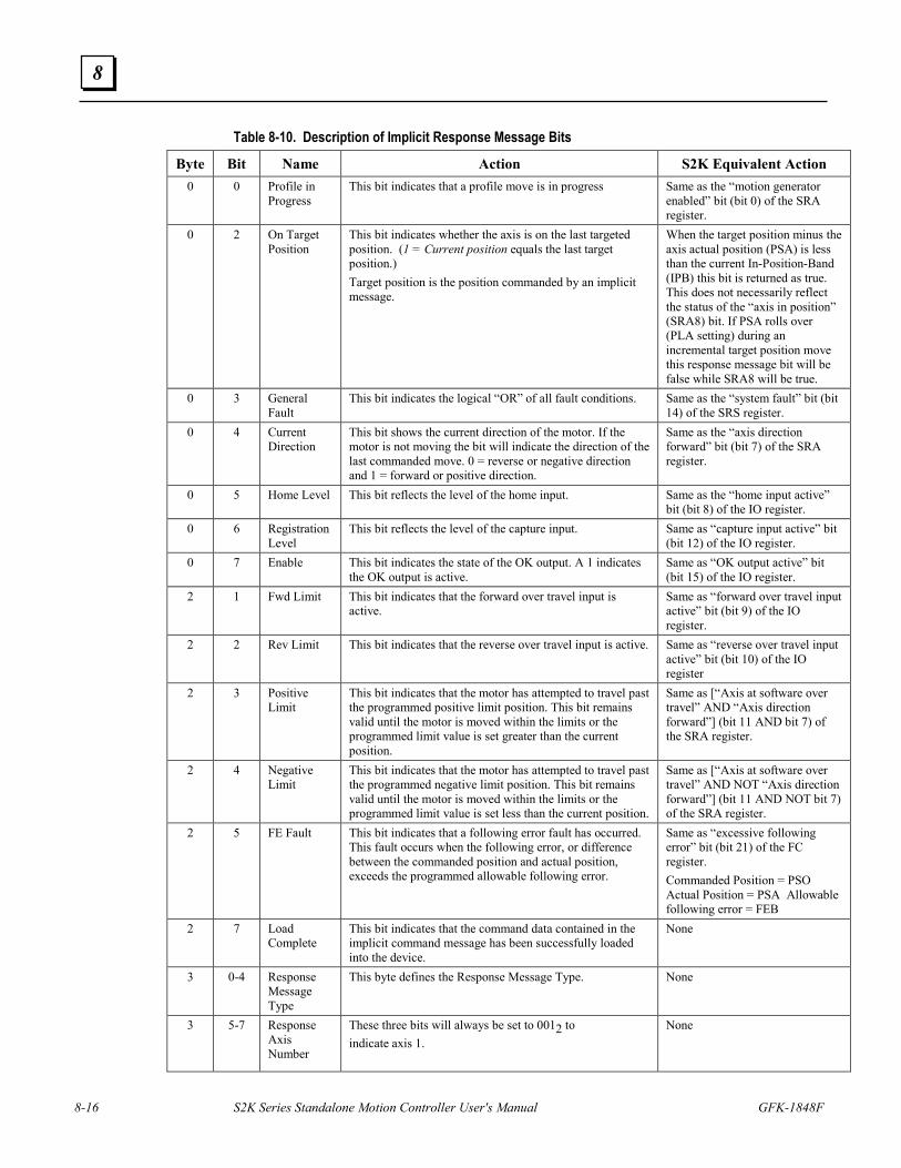
8-16 S2K Series Standalone Motion Controller User's Manual GFK-1848F
8
Table 8-10. Description of Implicit Response Message Bits
Byte Bit Name Action S2K Equivalent Action 0 0 Profile in
Progress This bit indicates that a profile move is in progress Same as the “motion generator
enabled” bit (bit 0) of the SRA register.
0 2 On Target Position
This bit indicates whether the axis is on the last targeted position. (1 = Current position equals the last target position.) Target position is the position commanded by an implicit message.
When the target position minus the axis actual position (PSA) is less than the current In-Position-Band (IPB) this bit is returned as true. This does not necessarily reflect the status of the “axis in position” (SRA8) bit. If PSA rolls over (PLA setting) during an incremental target position move this response message bit will be false while SRA8 will be true.
0 3 General Fault
This bit indicates the logical “OR” of all fault conditions. Same as the “system fault” bit (bit 14) of the SRS register.
0 4 Current Direction
This bit shows the current direction of the motor. If the motor is not moving the bit will indicate the direction of the last commanded move. 0 = reverse or negative direction and 1 = forward or positive direction.
Same as the “axis direction forward” bit (bit 7) of the SRA register.
0 5 Home Level This bit reflects the level of the home input. Same as the “home input active” bit (bit 8) of the IO register.
0 6 Registration Level
This bit reflects the level of the capture input. Same as “capture input active” bit (bit 12) of the IO register.
0 7 Enable This bit indicates the state of the OK output. A 1 indicates the OK output is active.
Same as “OK output active” bit (bit 15) of the IO register.
2 1 Fwd Limit This bit indicates that the forward over travel input is active.
Same as “forward over travel input active” bit (bit 9) of the IO register.
2 2 Rev Limit This bit indicates that the reverse over travel input is active. Same as “reverse over travel input active” bit (bit 10) of the IO register
2 3 Positive Limit
This bit indicates that the motor has attempted to travel past the programmed positive limit position. This bit remains valid until the motor is moved within the limits or the programmed limit value is set greater than the current position.
Same as [“Axis at software over travel” AND “Axis direction forward”] (bit 11 AND bit 7) of the SRA register.
2 4 Negative Limit
This bit indicates that the motor has attempted to travel past the programmed negative limit position. This bit remains valid until the motor is moved within the limits or the programmed limit value is set less than the current position.
Same as [“Axis at software over travel” AND NOT “Axis direction forward”] (bit 11 AND NOT bit 7) of the SRA register.
2 5 FE Fault This bit indicates that a following error fault has occurred. This fault occurs when the following error, or difference between the commanded position and actual position, exceeds the programmed allowable following error.
Same as “excessive following error” bit (bit 21) of the FC register. Commanded Position = PSO Actual Position = PSA Allowable following error = FEB
2 7 Load Complete
This bit indicates that the command data contained in the implicit command message has been successfully loaded into the device.
None
3 0-4 Response Message Type
This byte defines the Response Message Type. None
3 5-7 Response Axis Number
These three bits will always be set to 0012 to indicate axis 1.
None
Using DeviceNet
GFK-1848F Chapter 8 Using DeviceNet Communications 8-17
8
Starting a Profile Move
A profile move is a move that uses Acceleration, Target Velocity and Deceleration to run at a Target Velocity or to a Target Position. The S2K operating mode determines the type of move and is set via a separate implicit message (see Command Type 1B Position Controller message, attribute 3). The default mode setting is position and will execute a move to a target position. Multiple messages may be required to set Acceleration, Target Velocity and Deceleration prior to executing the target move.
Issuing a single or multiple messages to the S2K device should be done sequentially, using the handshake sequence, with the target move instruction occurring last in the sequence.
Master-Slave I/O Handshake Sequences
The Load Data/Start Profile bit (command message byte 0, bit 0) and the Load Complete bit (response message byte 2, bit 7) is used to synchronize data transfers between the DeviceNet master and the S2K controller (slave). The S2K acts on the data contained in a command message only when the Load Data/Start Profile bit goes true (rising edge). In each data transaction, you must reset the Load Data/Start Profile bit to zero before writing new command data into the scanner output table since action is taken only when this bit makes a 0 to 1 transition. Write a complete data set into the scanner output table (8 bytes of output data mapped to the node) before setting the Load Data/Start Profile bit to true. The Figure 8-6 below flowcharts the master/slave messaging handshake sequence.
To execute a profile move via implicit messaging, (to Target Position) or with configuration change (at Target Velocity) start at the beginning of the handshake sequence “start Client profile move.” For all other implicit commands, begin at “start client data load” in the handshake sequence.
The functionality of the “Load Complete” (response message byte 2 bit 7) bit insures that no messages will be lost in a communications sequence. This new DeviceNet specification functional bit has been included in S2K firmware version 2.1 and later.
The format of these messages and the handshake sequence complies with ODVA regulated specifications for the device type 10 hex (position controller) that the S2K belongs.
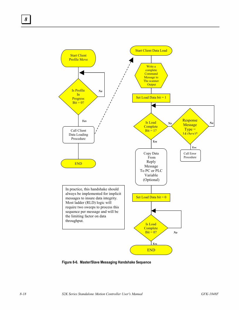
8-18 S2K Series Standalone Motion Controller User's Manual GFK-1848F
8
Figure 8-6. Master/Slave Messaging Handshake Sequence
Start Client Data Load
Set Load Data bit = 1
Write a complete
Command Message to The scanner
Output
Is Load CompleteBit = 1?
Set Load Data bit = 0
Is Load CompleteBit = 0?
END
No No
No
Yes
Yes
Yes
Start Client Profile Move
Call Client Data Loading
Procedure
Is Profile In
Progress Bit = 0?
END
No
Yes
Call ErrorProcedure
Response Message Type =
14 (hex)?
Copy Data From Reply
Message To PC or PLC
Variable (Optional)
In practice, this handshake should always be implemented for implicit messages to insure data integrity. Most ladder (RLD) logic will require two sweeps to process this sequence per message and will be the limiting factor on data throughput.
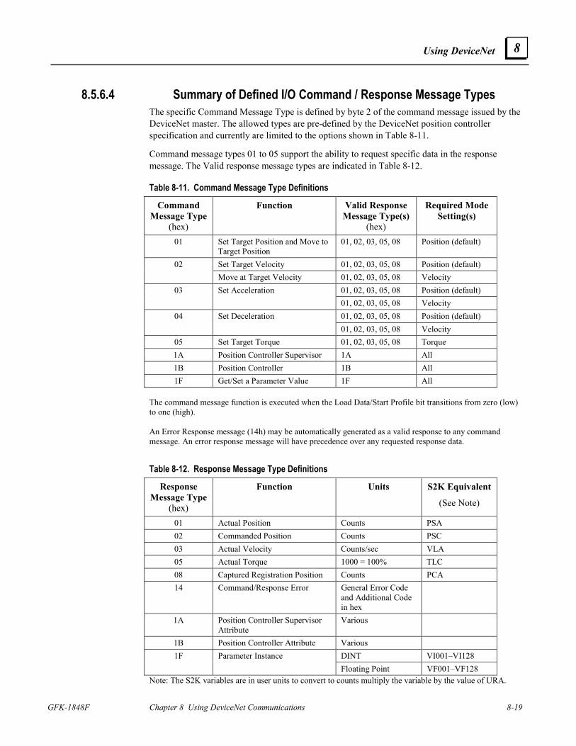
Using DeviceNet
GFK-1848F Chapter 8 Using DeviceNet Communications 8-19
8
8.5.6.4 Summary of Defined I/O Command / Response Message Types The specific Command Message Type is defined by byte 2 of the command message issued by the DeviceNet master. The allowed types are pre-defined by the DeviceNet position controller specification and currently are limited to the options shown in Table 8-11.
Command message types 01 to 05 support the ability to request specific data in the response message. The Valid response message types are indicated in Table 8-12.
Table 8-11. Command Message Type Definitions
Command Message Type
(hex)
Function Valid Response Message Type(s)
(hex)
Required Mode Setting(s)
01 Set Target Position and Move to Target Position
01, 02, 03, 05, 08 Position (default)
Set Target Velocity 01, 02, 03, 05, 08 Position (default) 02 Move at Target Velocity 01, 02, 03, 05, 08 Velocity
01, 02, 03, 05, 08 Position (default) 03 Set Acceleration 01, 02, 03, 05, 08 Velocity 01, 02, 03, 05, 08 Position (default) 04 Set Deceleration 01, 02, 03, 05, 08 Velocity
05 Set Target Torque 01, 02, 03, 05, 08 Torque 1A Position Controller Supervisor 1A All 1B Position Controller 1B All 1F Get/Set a Parameter Value 1F All
The command message function is executed when the Load Data/Start Profile bit transitions from zero (low) to one (high). An Error Response message (14h) may be automatically generated as a valid response to any command message. An error response message will have precedence over any requested response data.
Table 8-12. Response Message Type Definitions
Response Message Type
(hex)
Function Units S2K Equivalent
(See Note)
01 Actual Position Counts PSA 02 Commanded Position Counts PSC 03 Actual Velocity Counts/sec VLA 05 Actual Torque 1000 = 100% TLC 08 Captured Registration Position Counts PCA 14 Command/Response Error General Error Code
and Additional Code in hex
1A Position Controller Supervisor Attribute
Various
1B Position Controller Attribute Various DINT VI001–VI128 1F Parameter Instance Floating Point VF001–VF128
Note: The S2K variables are in user units to convert to counts multiply the variable by the value of URA.
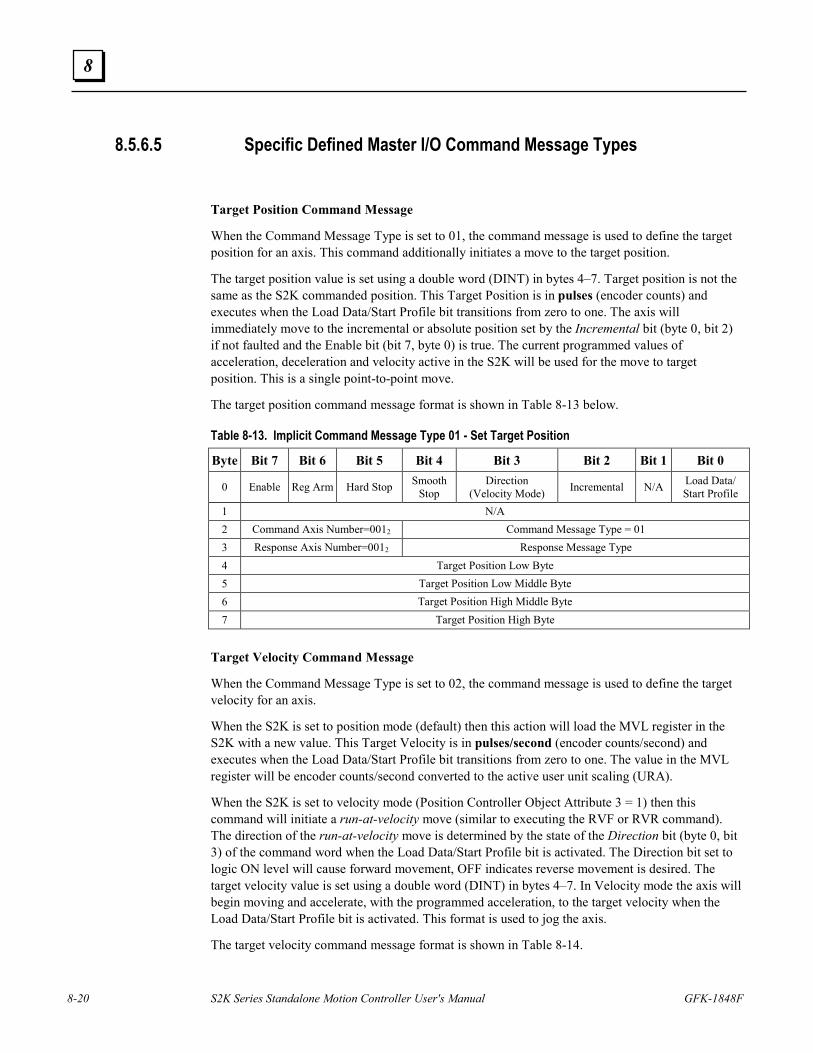
8-20 S2K Series Standalone Motion Controller User's Manual GFK-1848F
8
8.5.6.5 Specific Defined Master I/O Command Message Types
Target Position Command Message
When the Command Message Type is set to 01, the command message is used to define the target position for an axis. This command additionally initiates a move to the target position.
The target position value is set using a double word (DINT) in bytes 4–7. Target position is not the same as the S2K commanded position. This Target Position is in pulses (encoder counts) and executes when the Load Data/Start Profile bit transitions from zero to one. The axis will immediately move to the incremental or absolute position set by the Incremental bit (byte 0, bit 2) if not faulted and the Enable bit (bit 7, byte 0) is true. The current programmed values of acceleration, deceleration and velocity active in the S2K will be used for the move to target position. This is a single point-to-point move.
The target position command message format is shown in Table 8-13 below.
Table 8-13. Implicit Command Message Type 01 - Set Target Position
Byte Bit 7 Bit 6 Bit 5 Bit 4 Bit 3 Bit 2 Bit 1 Bit 0
0 Enable Reg Arm Hard Stop Smooth Stop
Direction (Velocity Mode) Incremental N/A Load Data/
Start Profile 1 N/A 2 Command Axis Number=0012 Command Message Type = 01 3 Response Axis Number=0012 Response Message Type 4 Target Position Low Byte 5 Target Position Low Middle Byte 6 Target Position High Middle Byte 7 Target Position High Byte
Target Velocity Command Message
When the Command Message Type is set to 02, the command message is used to define the target velocity for an axis.
When the S2K is set to position mode (default) then this action will load the MVL register in the S2K with a new value. This Target Velocity is in pulses/second (encoder counts/second) and executes when the Load Data/Start Profile bit transitions from zero to one. The value in the MVL register will be encoder counts/second converted to the active user unit scaling (URA).
When the S2K is set to velocity mode (Position Controller Object Attribute 3 = 1) then this command will initiate a run-at-velocity move (similar to executing the RVF or RVR command). The direction of the run-at-velocity move is determined by the state of the Direction bit (byte 0, bit 3) of the command word when the Load Data/Start Profile bit is activated. The Direction bit set to logic ON level will cause forward movement, OFF indicates reverse movement is desired. The target velocity value is set using a double word (DINT) in bytes 4–7. In Velocity mode the axis will begin moving and accelerate, with the programmed acceleration, to the target velocity when the Load Data/Start Profile bit is activated. This format is used to jog the axis.
The target velocity command message format is shown in Table 8-14.
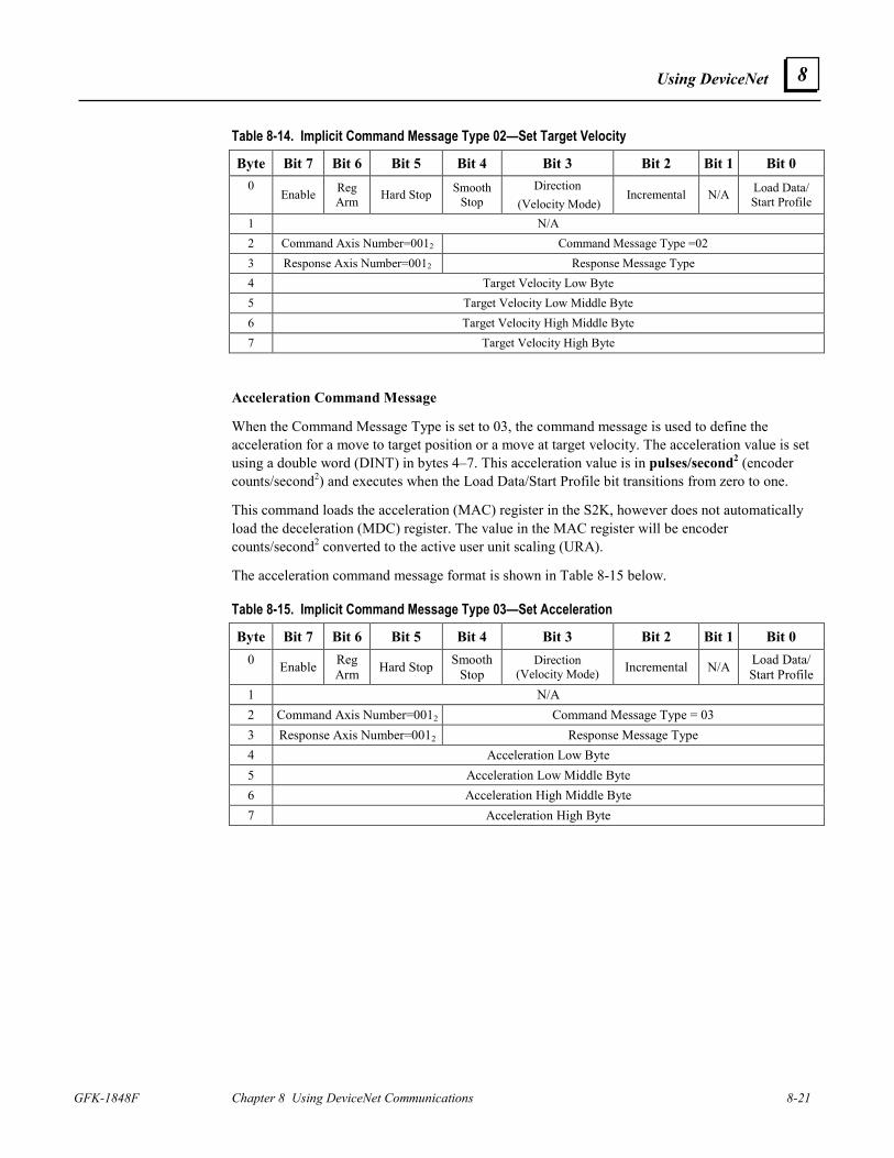
Using DeviceNet
GFK-1848F Chapter 8 Using DeviceNet Communications 8-21
8
Table 8-14. Implicit Command Message Type 02—Set Target Velocity
Byte Bit 7 Bit 6 Bit 5 Bit 4 Bit 3 Bit 2 Bit 1 Bit 0 0
Enable Reg Arm Hard Stop Smooth
Stop Direction
(Velocity Mode) Incremental N/A Load Data/
Start Profile
1 N/A 2 Command Axis Number=0012 Command Message Type =02 3 Response Axis Number=0012 Response Message Type 4 Target Velocity Low Byte 5 Target Velocity Low Middle Byte 6 Target Velocity High Middle Byte 7 Target Velocity High Byte
Acceleration Command Message
When the Command Message Type is set to 03, the command message is used to define the acceleration for a move to target position or a move at target velocity. The acceleration value is set using a double word (DINT) in bytes 4–7. This acceleration value is in pulses/second2 (encoder counts/second2) and executes when the Load Data/Start Profile bit transitions from zero to one.
This command loads the acceleration (MAC) register in the S2K, however does not automatically load the deceleration (MDC) register. The value in the MAC register will be encoder counts/second2 converted to the active user unit scaling (URA).
The acceleration command message format is shown in Table 8-15 below.
Table 8-15. Implicit Command Message Type 03—Set Acceleration
Byte Bit 7 Bit 6 Bit 5 Bit 4 Bit 3 Bit 2 Bit 1 Bit 0 0 Enable Reg
Arm Hard Stop Smooth Stop
Direction (Velocity Mode) Incremental N/A Load Data/
Start Profile 1 N/A 2 Command Axis Number=0012 Command Message Type = 03 3 Response Axis Number=0012 Response Message Type 4 Acceleration Low Byte 5 Acceleration Low Middle Byte 6 Acceleration High Middle Byte 7 Acceleration High Byte
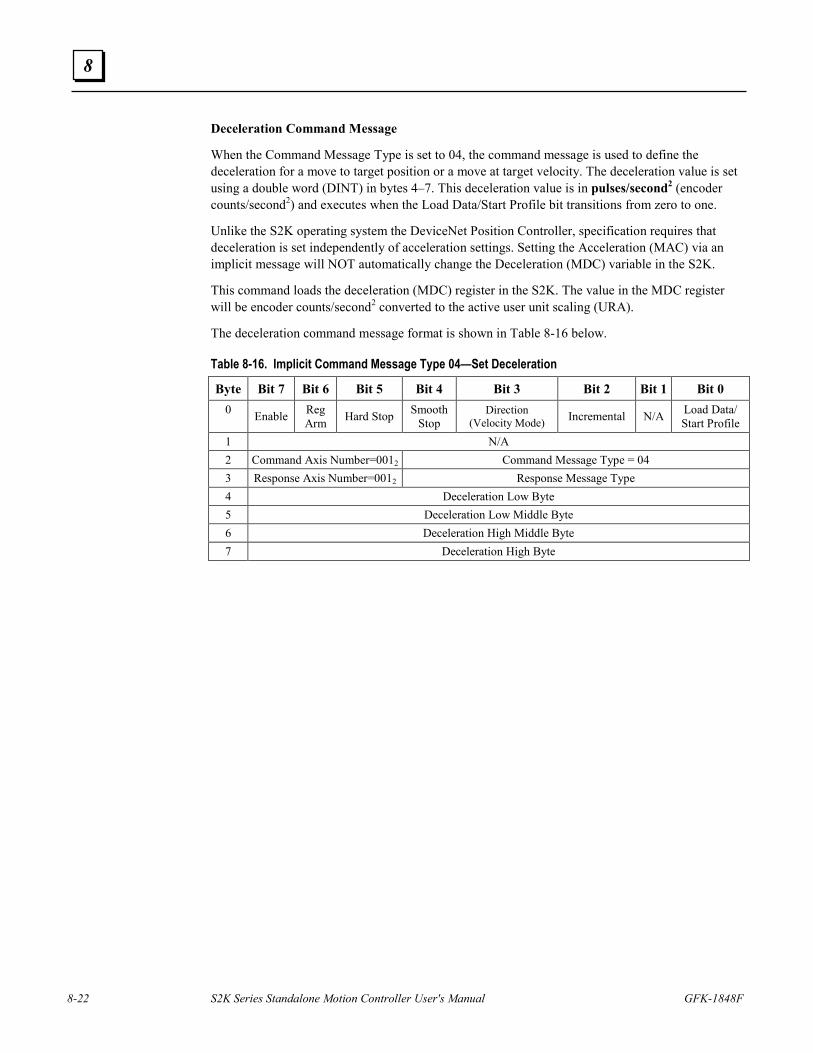
8-22 S2K Series Standalone Motion Controller User's Manual GFK-1848F
8
Deceleration Command Message
When the Command Message Type is set to 04, the command message is used to define the deceleration for a move to target position or a move at target velocity. The deceleration value is set using a double word (DINT) in bytes 4–7. This deceleration value is in pulses/second2 (encoder counts/second2) and executes when the Load Data/Start Profile bit transitions from zero to one.
Unlike the S2K operating system the DeviceNet Position Controller, specification requires that deceleration is set independently of acceleration settings. Setting the Acceleration (MAC) via an implicit message will NOT automatically change the Deceleration (MDC) variable in the S2K.
This command loads the deceleration (MDC) register in the S2K. The value in the MDC register will be encoder counts/second2 converted to the active user unit scaling (URA).
The deceleration command message format is shown in Table 8-16 below.
Table 8-16. Implicit Command Message Type 04—Set Deceleration
Byte Bit 7 Bit 6 Bit 5 Bit 4 Bit 3 Bit 2 Bit 1 Bit 0 0 Enable Reg
Arm Hard Stop Smooth Stop
Direction (Velocity Mode) Incremental N/A Load Data/
Start Profile 1 N/A 2 Command Axis Number=0012 Command Message Type = 04 3 Response Axis Number=0012 Response Message Type 4 Deceleration Low Byte 5 Deceleration Low Middle Byte 6 Deceleration High Middle Byte 7 Deceleration High Byte
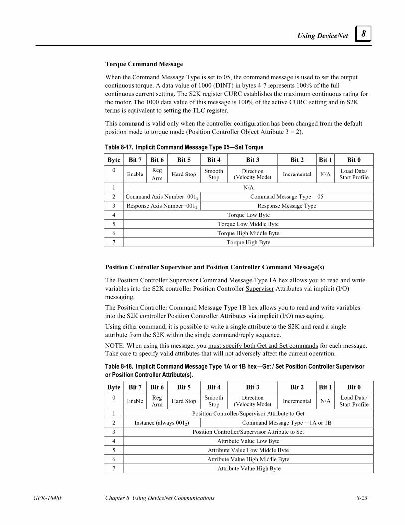
Using DeviceNet
GFK-1848F Chapter 8 Using DeviceNet Communications 8-23
8
Torque Command Message
When the Command Message Type is set to 05, the command message is used to set the output continuous torque. A data value of 1000 (DINT) in bytes 4-7 represents 100% of the full continuous current setting. The S2K register CURC establishes the maximum continuous rating for the motor. The 1000 data value of this message is 100% of the active CURC setting and in S2K terms is equivalent to setting the TLC register.
This command is valid only when the controller configuration has been changed from the default position mode to torque mode (Position Controller Object Attribute 3 = 2).
Table 8-17. Implicit Command Message Type 05—Set Torque
Byte Bit 7 Bit 6 Bit 5 Bit 4 Bit 3 Bit 2 Bit 1 Bit 0 0
Enable Reg Arm
Hard Stop Smooth Stop
Direction (Velocity Mode) Incremental N/A Load Data/
Start Profile
1 N/A 2 Command Axis Number=0012 Command Message Type = 05 3 Response Axis Number=0012 Response Message Type 4 Torque Low Byte 5 Torque Low Middle Byte 6 Torque High Middle Byte 7 Torque High Byte
Position Controller Supervisor and Position Controller Command Message(s)
The Position Controller Supervisor Command Message Type 1A hex allows you to read and write variables into the S2K controller Position Controller Supervisor Attributes via implicit (I/O) messaging. The Position Controller Command Message Type 1B hex allows you to read and write variables into the S2K controller Position Controller Attributes via implicit (I/O) messaging. Using either command, it is possible to write a single attribute to the S2K and read a single attribute from the S2K within the single command/reply sequence. NOTE: When using this message, you must specify both Get and Set commands for each message. Take care to specify valid attributes that will not adversely affect the current operation.
Table 8-18. Implicit Command Message Type 1A or 1B hex—Get / Set Position Controller Supervisor or Position Controller Attribute(s).
Byte Bit 7 Bit 6 Bit 5 Bit 4 Bit 3 Bit 2 Bit 1 Bit 0 0 Enable Reg
Arm Hard Stop Smooth Stop
Direction (Velocity Mode) Incremental N/A Load Data/
Start Profile 1 Position Controller/Supervisor Attribute to Get 2 Instance (always 0012) Command Message Type = 1A or 1B 3 Position Controller/Supervisor Attribute to Set 4 Attribute Value Low Byte 5 Attribute Value Low Middle Byte 6 Attribute Value High Middle Byte 7 Attribute Value High Byte
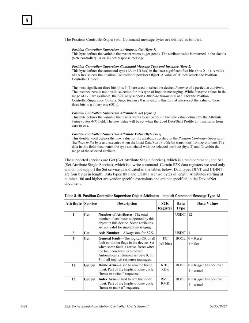
8-24 S2K Series Standalone Motion Controller User's Manual GFK-1848F
8
The Position Controller/Supervisor Command message bytes are defined as follows: Position Controller/ Supervisor Attribute to Get (Byte 1) This byte defines the variable the master wants to get (read). The attribute value is returned in the slave’s (S2K controller) 1A or 1B hex response message. Position Controller/ Supervisor Command Message Type and Instance (Byte 2) This byte defines the command type (1A or 1B hex) in the least significant five bits (bits 0 - 4). A value of 1A hex selects the Position Controller Supervisor Object. A value of 1B hex selects the Position Controller Object. The most significant three bits (bits 5–7) are used to select the desired Instance of a particular Attribute. The instance zero is not a valid selection for this type of implicit messaging. While Instance values in the range of 1- 7 are available, the S2K only supports Attribute Instances 0 and 1 for the Position Controller/Supervisor Objects. Since Instance 0 is invalid in this format always set the value of these three bits to a binary one (0012). Position Controller/ Supervisor Attribute to Set (Byte 3) This byte defines the variable the master wants to set (write) to the new value defined by the Attribute Value (bytes 4-7) field. The new value will be set when the Load Data/Start Profile bit transitions from zero to one. Position Controller/ Supervisor Attribute Value (Bytes 4–7) This double word defines the new value for the attribute specified in the Position Controller Supervisor Attribute to Set byte and executes when the Load Data/Start Profile bit transitions from zero to one. The data in this field must match the type associated with the selected attribute (byte 3) and fit within the range of the selected attribute.
The supported services are Get (Get Attribute Single Service), which is a read command, and Set (Set Attribute Single Service), which is a write command. Certain S2K data registers are read only and do not support the Set service as indicated in the tables below. Data types DINT and UDINT are four bytes in length. Data types INT and USINT are two bytes in length. Attributes starting at number 100 and higher are vendor specific extensions and are not specified in the DeviceNet document.
Table 8-19. Position Controller Supervisor Object Attributes—Implicit Command Message Type 1A
Attribute Service Description S2K Register
Data Type
Data Values
1
Get Number of Attributes -The total number of attributes supported by this object in this device. Some attributes are not valid for implicit messaging.
USINT 12
3 Get Axis Number—Always one for S2K. USINT 1 5 Get General Fault—The logical OR of all
fault condition flags in the device. Set when some fault is active. Reset when the fault condition is removed. Automatically returned as (byte 0, bit 3) in all implicit response messages.
FC (All bits)
BOOL 0 = Reset 1 = Set
12 Get/Set Home Arm—Used to arm the home input. Part of the Implicit home cycle “home to switch” sequence.
RHF, RHR
BOOL 0 = trigger has occurred 1 = armed
15 Get/Set Index Arm—Used to arm the index input. Part of the Implicit home cycle “home to marker” sequence.
RMF, RMR
BOOL 0 = trigger has occurred 1 = armed
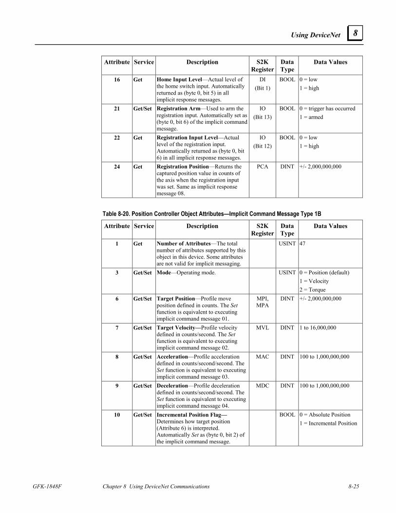
Using DeviceNet
GFK-1848F Chapter 8 Using DeviceNet Communications 8-25
8
Attribute Service Description S2K Register
Data Type
Data Values
16 Get Home Input Level—Actual level of the home switch input. Automatically returned as (byte 0, bit 5) in all implicit response messages.
DI (Bit 1)
BOOL 0 = low 1 = high
21 Get/Set Registration Arm—Used to arm the registration input. Automatically set as (byte 0, bit 6) of the implicit command message.
IO (Bit 13)
BOOL 0 = trigger has occurred 1 = armed
22 Get Registration Input Level—Actual level of the registration input. Automatically returned as (byte 0, bit 6) in all implicit response messages.
IO (Bit 12)
BOOL 0 = low 1 = high
24 Get Registration Position—Returns the captured position value in counts of the axis when the registration input was set. Same as implicit response message 08.
PCA DINT +/- 2,000,000,000
Table 8-20. Position Controller Object Attributes—Implicit Command Message Type 1B
Attribute Service Description S2K Register
Data Type
Data Values
1
Get Number of Attributes—The total number of attributes supported by this object in this device. Some attributes are not valid for implicit messaging.
USINT 47
3 Get/Set Mode—Operating mode. USINT 0 = Position (default) 1 = Velocity 2 = Torque
6 Get/Set Target Position—Profile move position defined in counts. The Set function is equivalent to executing implicit command message 01.
MPI, MPA
DINT +/- 2,000,000,000
7 Get/Set Target Velocity—Profile velocity defined in counts/second. The Set function is equivalent to executing implicit command message 02.
MVL DINT 1 to 16,000,000
8 Get/Set Acceleration—Profile acceleration defined in counts/second/second. The Set function is equivalent to executing implicit command message 03.
MAC DINT 100 to 1,000,000,000
9 Get/Set Deceleration—Profile deceleration defined in counts/second/second. The Set function is equivalent to executing implicit command message 04.
MDC DINT 100 to 1,000,000,000
10 Get/Set Incremental Position Flag—Determines how target position (Attribute 6) is interpreted. Automatically Set as (byte 0, bit 2) of the implicit command message.
BOOL 0 = Absolute Position 1 = Incremental Position
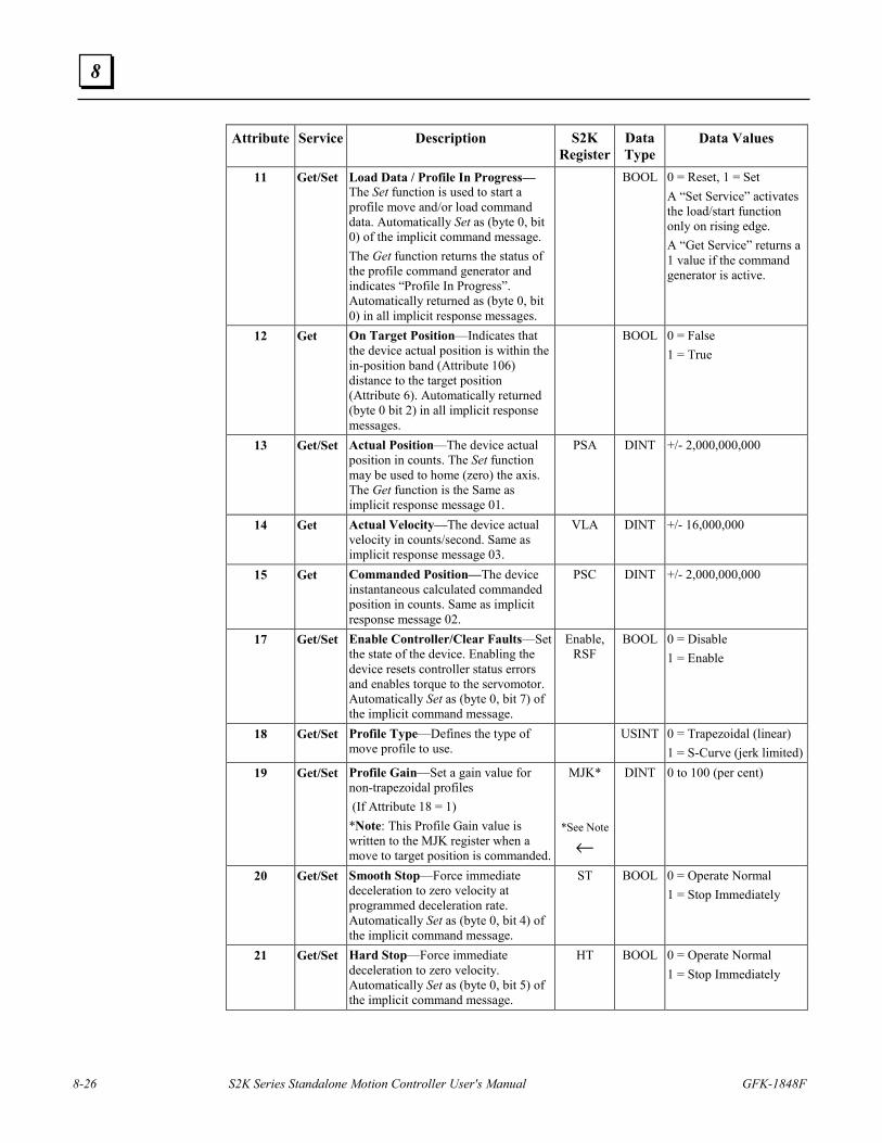
8-26 S2K Series Standalone Motion Controller User's Manual GFK-1848F
8
Attribute Service Description S2K Register
Data Type
Data Values
11 Get/Set Load Data / Profile In Progress—The Set function is used to start a profile move and/or load command data. Automatically Set as (byte 0, bit 0) of the implicit command message. The Get function returns the status of the profile command generator and indicates “Profile In Progress”. Automatically returned as (byte 0, bit 0) in all implicit response messages.
BOOL 0 = Reset, 1 = Set A “Set Service” activates the load/start function only on rising edge. A “Get Service” returns a 1 value if the command generator is active.
12 Get On Target Position—Indicates that the device actual position is within the in-position band (Attribute 106) distance to the target position (Attribute 6). Automatically returned (byte 0 bit 2) in all implicit response messages.
BOOL 0 = False 1 = True
13 Get/Set Actual Position—The device actual position in counts. The Set function may be used to home (zero) the axis. The Get function is the Same as implicit response message 01.
PSA DINT +/- 2,000,000,000
14 Get Actual Velocity—The device actual velocity in counts/second. Same as implicit response message 03.
VLA DINT +/- 16,000,000
15 Get Commanded Position—The device instantaneous calculated commanded position in counts. Same as implicit response message 02.
PSC DINT +/- 2,000,000,000
17 Get/Set Enable Controller/Clear Faults—Set the state of the device. Enabling the device resets controller status errors and enables torque to the servomotor. Automatically Set as (byte 0, bit 7) of the implicit command message.
Enable, RSF
BOOL 0 = Disable 1 = Enable
18 Get/Set Profile Type—Defines the type of move profile to use.
USINT 0 = Trapezoidal (linear) 1 = S-Curve (jerk limited)
19 Get/Set Profile Gain—Set a gain value for non-trapezoidal profiles (If Attribute 18 = 1) *Note: This Profile Gain value is written to the MJK register when a move to target position is commanded.
MJK*
*See Note
←
DINT 0 to 100 (per cent)
20 Get/Set Smooth Stop—Force immediate deceleration to zero velocity at programmed deceleration rate. Automatically Set as (byte 0, bit 4) of the implicit command message.
ST BOOL 0 = Operate Normal 1 = Stop Immediately
21 Get/Set Hard Stop—Force immediate deceleration to zero velocity. Automatically Set as (byte 0, bit 5) of the implicit command message.
HT BOOL 0 = Operate Normal 1 = Stop Immediately
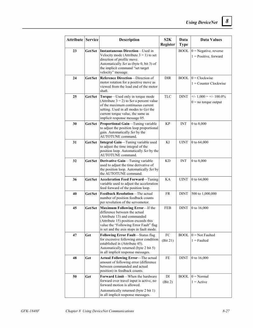
Using DeviceNet
GFK-1848F Chapter 8 Using DeviceNet Communications 8-27
8
Attribute Service Description S2K Register
Data Type
Data Values
23 Get/Set Instantaneous Direction—Used in Velocity mode (Attribute 3 = 1) to set direction of profile move. Automatically Set as (byte 0, bit 3) of the implicit command “set target velocity” message.
BOOL 0 = Negative, reverse 1 = Positive, forward
24 Get/Set Reference Direction—Direction of motor rotation for a positive move as viewed from the load end of the motor shaft.
DIR BOOL 0 = Clockwise 1 = Counter Clockwise
25 Get/Set Torque—Used only in torque mode (Attribute 3 = 2) to Set a percent value of the maximum continuous current setting. Used in all modes to Get the current torque value, the same as implicit response message 05.
TLC DINT +/- 1,000 = +/- 100.0% 0 = no torque output
30 Get/Set Proportional Gain—Tuning variable to adjust the position loop proportional gain. Automatically Set by the AUTOTUNE command.
KP INT 0 to 8,000
31 Get/Set Integral Gain—Tuning variable used to adjust the time integral of the position loop. Automatically Set by the AUTOTUNE command.
KI UINT 0 to 64,000
32 Get/Set Derivative Gain—Tuning variable used to adjust the time derivative of the position loop. Automatically Set by the AUTOTUNE command.
KD INT 0 to 8,000
36 Get/Set Acceleration Feed Forward—Tuning variable used to adjust the acceleration feed forward of the position loop.
KA UINT 0 to 64,000
40 Get/Set Feedback Resolution—The actual number of position feedback counts per revolution of the servomotor.
FR DINT 500 to 1,000,000
45 Get/Set Maximum Following Error—If the difference between the actual (Attribute 13) and commanded (Attribute 15) position exceeds this value the “Following Error Fault” flag is set and the axis stops in fault mode.
FEB DINT 0 to 16,000
47 Get Following Error Fault—Status flag for excessive following error condition established in (Attribute 45). Automatically returned (byte 2 bit 5) in all implicit response messages.
FC (Bit 21)
BOOL 0 = Not Faulted 1 = Faulted
48 Get Actual Following Error—The actual amount of following error (difference between commanded and actual position) in feedback counts.
FE DINT 0 to 16,000
50 Get Forward Limit—When the hardware forward over travel input is active, no forward motion is allowed. Automatically returned (byte 2 bit 1) in all implicit response messages.
DI (Bit 2)
BOOL 0 = Normal 1 = Active
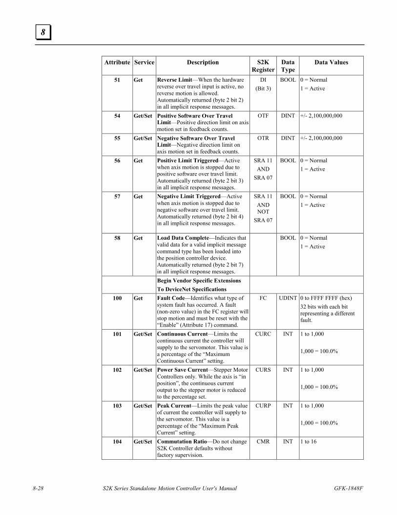
8-28 S2K Series Standalone Motion Controller User's Manual GFK-1848F
8
Attribute Service Description S2K Register
Data Type
Data Values
51 Get Reverse Limit—When the hardware reverse over travel input is active, no reverse motion is allowed. Automatically returned (byte 2 bit 2) in all implicit response messages.
DI (Bit 3)
BOOL 0 = Normal 1 = Active
54 Get/Set Positive Software Over Travel Limit—Positive direction limit on axis motion set in feedback counts.
OTF DINT +/- 2,100,000,000
55 Get/Set Negative Software Over Travel Limit—Negative direction limit on axis motion set in feedback counts.
OTR DINT +/- 2,100,000,000
56 Get Positive Limit Triggered—Active when axis motion is stopped due to positive software over travel limit. Automatically returned (byte 2 bit 3) in all implicit response messages.
SRA 11 AND
SRA 07
BOOL 0 = Normal 1 = Active
57 Get Negative Limit Triggered—Active when axis motion is stopped due to negative software over travel limit. Automatically returned (byte 2 bit 4) in all implicit response messages.
SRA 11 AND NOT
SRA 07
BOOL 0 = Normal 1 = Active
58 Get Load Data Complete—Indicates that valid data for a valid implicit message command type has been loaded into the position controller device. Automatically returned (byte 2 bit 7) in all implicit response messages.
BOOL 0 = Normal 1 = Active
Begin Vendor Specific Extensions To DeviceNet Specifications
100 Get Fault Code—Identifies what type of system fault has occurred. A fault (non-zero value) in the FC register will stop motion and must be reset with the “Enable” (Attribute 17) command.
FC UDINT 0 to FFFF FFFF (hex) 32 bits with each bit representing a different fault.
101 Get/Set Continuous Current—Limits the continuous current the controller will supply to the servomotor. This value is a percentage of the “Maximum Continuous Current” setting.
CURC INT 1 to 1,000 1,000 = 100.0%
102 Get/Set Power Save Current—Stepper Motor Controllers only. While the axis is “in position”, the continuous current output to the stepper motor is reduced to the percentage set.
CURS INT 1 to 1,000 1,000 = 100.0%
103 Get/Set Peak Current—Limits the peak value of current the controller will supply to the servomotor. This value is a percentage of the “Maximum Peak Current” setting.
CURP INT 1 to 1,000 1,000 = 100.0%
104 Get/Set Commutation Ratio—Do not change S2K Controller defaults without factory supervision.
CMR INT 1 to 16
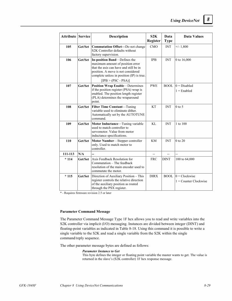
Using DeviceNet
GFK-1848F Chapter 8 Using DeviceNet Communications 8-29
8
Attribute Service Description S2K Register
Data Type
Data Values
105 Get/Set Commutation Offset—Do not change S2K Controller defaults without factory supervision.
CMO INT +/- 1,800
106 Get/Set In-position Band—Defines the maximum amount of position error that the axis can have and still be in position. A move is not considered complete unless in position (IP) is true. [IPB > (PSC - PSA)]
IPB INT 0 to 16,000
107 Get/Set Position Wrap Enable—Determines if the position register (PSA) wrap is enabled. The position length register (PLA) determines the wraparound point.
PWE BOOL 0 = Disabled 1 = Enabled
108 Get/Set Filter Time Constant—Tuning variable used to eliminate dither. Automatically set by the AUTOTUNE command.
KT INT 0 to 5
109 Get/Set Motor Inductance—Tuning variable used to match controller to servomotor. Value from motor inductance specifications.
KL INT 1 to 100
110 Get/Set Motor Number—Stepper controller only. Used to match motor to controller.
KM INT 0 to 20
111-113 N/A -- -- -- -- * 114 Get/Set Axis Feedback Resolution for
Commutation – The feedback resolution of the main encoder used to commutate the motor.
FRC DINT 100 to 64,000
* 115 Get/Set Direction of Auxiliary Position – This register controls the relative direction of the auxiliary position as routed through the PSX register.
DIRX BOOL 0 = Clockwise 1 = Counter Clockwise
* - Requires firmware revision 2.5 or later
Parameter Command Message
The Parameter Command Message Type 1F hex allows you to read and write variables into the S2K controller via implicit (I/O) messaging. Instances are divided between integer (DINT) and floating-point variables as indicated in Table 8-18. Using this command it is possible to write a single variable to the S2K and read a single variable from the S2K within the single command/reply sequence.
The other parameter message bytes are defined as follows: Parameter Instance to Get This byte defines the integer or floating point variable the master wants to get. The value is returned in the slave’s (S2K controller) 1F hex response message.
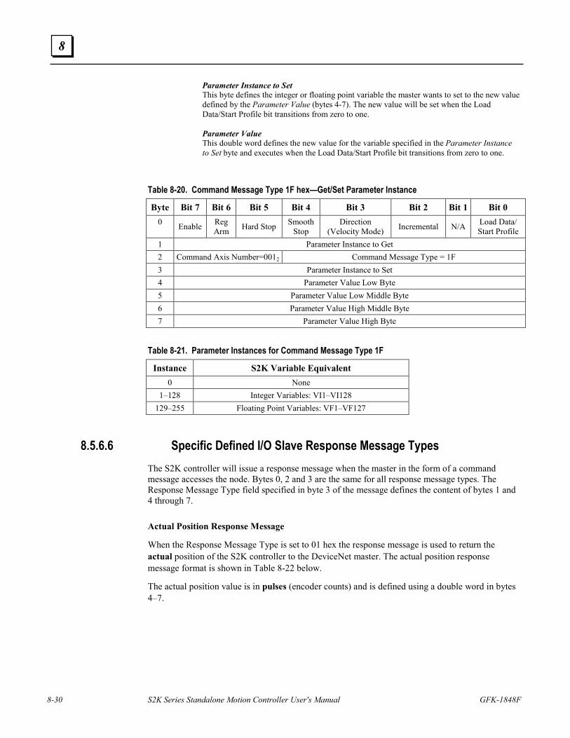
8-30 S2K Series Standalone Motion Controller User's Manual GFK-1848F
8
Parameter Instance to Set This byte defines the integer or floating point variable the master wants to set to the new value defined by the Parameter Value (bytes 4-7). The new value will be set when the Load Data/Start Profile bit transitions from zero to one. Parameter Value This double word defines the new value for the variable specified in the Parameter Instance to Set byte and executes when the Load Data/Start Profile bit transitions from zero to one.
Table 8-20. Command Message Type 1F hex—Get/Set Parameter Instance
Byte Bit 7 Bit 6 Bit 5 Bit 4 Bit 3 Bit 2 Bit 1 Bit 0 0 Enable Reg
Arm Hard Stop Smooth Stop
Direction (Velocity Mode) Incremental N/A Load Data/
Start Profile 1 Parameter Instance to Get 2 Command Axis Number=0012 Command Message Type = 1F 3 Parameter Instance to Set 4 Parameter Value Low Byte 5 Parameter Value Low Middle Byte 6 Parameter Value High Middle Byte 7 Parameter Value High Byte
Table 8-21. Parameter Instances for Command Message Type 1F
Instance S2K Variable Equivalent 0 None
1–128 Integer Variables: VI1–VI128 129–255 Floating Point Variables: VF1–VF127
8.5.6.6 Specific Defined I/O Slave Response Message Types
The S2K controller will issue a response message when the master in the form of a command message accesses the node. Bytes 0, 2 and 3 are the same for all response message types. The Response Message Type field specified in byte 3 of the message defines the content of bytes 1 and 4 through 7. Actual Position Response Message
When the Response Message Type is set to 01 hex the response message is used to return the actual position of the S2K controller to the DeviceNet master. The actual position response message format is shown in Table 8-22 below.
The actual position value is in pulses (encoder counts) and is defined using a double word in bytes 4–7.
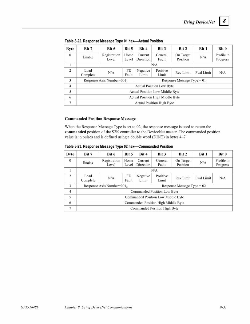
Using DeviceNet
GFK-1848F Chapter 8 Using DeviceNet Communications 8-31
8
Table 8-22. Response Message Type 01 hexActual Position
Byte Bit 7 Bit 6 Bit 5 Bit 4 Bit 3 Bit 2 Bit 1 Bit 0 0 Enable Registration
Level Home Level
Current Direction
General Fault
On Target Position N/A Profile in
Progress 1 N/A 2 Load
Complete N/A FE Fault
Negative Limit
Positive Limit Rev Limit Fwd Limit N/A
3 Response Axis Number=0012 Response Message Type = 01 4 Actual Position Low Byte 5 Actual Position Low Middle Byte 6 Actual Position High Middle Byte 7 Actual Position High Byte
Commanded Position Response Message
When the Response Message Type is set to 02, the response message is used to return the commanded position of the S2K controller to the DeviceNet master. The commanded position value is in pulses and is defined using a double word (DINT) in bytes 4–7.
Table 8-23. Response Message Type 02 hexCommanded Position
Byte Bit 7 Bit 6 Bit 5 Bit 4 Bit 3 Bit 2 Bit 1 Bit 0 0 Enable Registration
Level Home Level
Current Direction
General Fault
On Target Position N/A Profile in
Progress 1 N/A 2 Load
Complete N/A FE Fault
Negative Limit
Positive Limit Rev Limit Fwd Limit N/A
3 Response Axis Number=0012 Response Message Type = 02 4 Commanded Position Low Byte 5 Commanded Position Low Middle Byte 6 Commanded Position High Middle Byte 7 Commanded Position High Byte
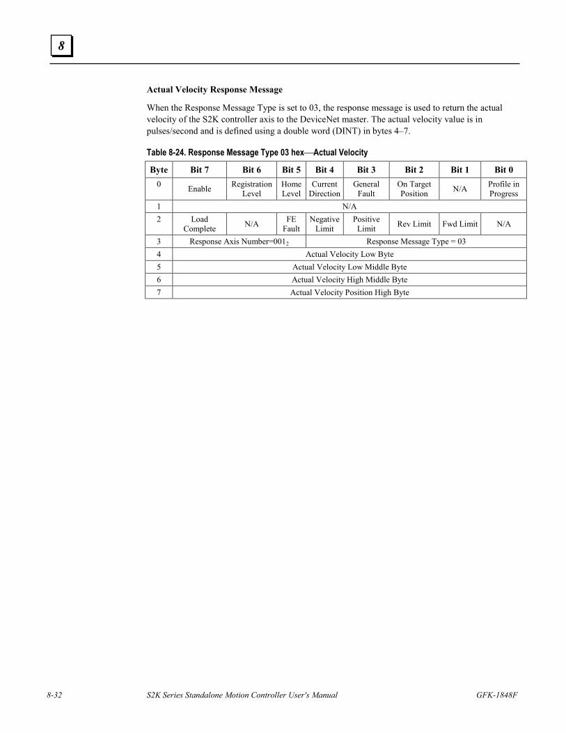
8-32 S2K Series Standalone Motion Controller User's Manual GFK-1848F
8
Actual Velocity Response Message
When the Response Message Type is set to 03, the response message is used to return the actual velocity of the S2K controller axis to the DeviceNet master. The actual velocity value is in pulses/second and is defined using a double word (DINT) in bytes 4–7.
Table 8-24. Response Message Type 03 hexActual Velocity
Byte Bit 7 Bit 6 Bit 5 Bit 4 Bit 3 Bit 2 Bit 1 Bit 0 0 Enable Registration
Level Home Level
Current Direction
General Fault
On Target Position N/A Profile in
Progress 1 N/A 2 Load
Complete N/A FE Fault
Negative Limit
Positive Limit Rev Limit Fwd Limit N/A
3 Response Axis Number=0012 Response Message Type = 03 4 Actual Velocity Low Byte 5 Actual Velocity Low Middle Byte 6 Actual Velocity High Middle Byte 7 Actual Velocity Position High Byte
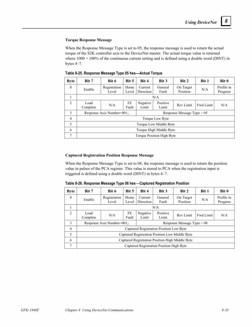
Using DeviceNet
GFK-1848F Chapter 8 Using DeviceNet Communications 8-33
8
Torque Response Message
When the Response Message Type is set to 05, the response message is used to return the actual torque of the S2K controller axis to the DeviceNet master. The actual torque value is returned where 1000 = 100% of the continuous current setting and is defined using a double word (DINT) in bytes 4–7.
Table 8-25. Response Message Type 05 hexActual Torque
Byte Bit 7 Bit 6 Bit 5 Bit 4 Bit 3 Bit 2 Bit 1 Bit 0 0 Enable Registration
Level Home Level
Current Direction
General Fault
On Target Position N/A Profile in
Progress 1 N/A 2 Load
Complete N/A FE Fault
Negative Limit
Positive Limit Rev Limit Fwd Limit N/A
3 Response Axis Number=0012 Response Message Type = 05 4 Torque Low Byte 5 Torque Low Middle Byte 6 Torque High Middle Byte 7 Torque Position High Byte
Captured Registration Position Response Message
When the Response Message Type is set to 08, the response message is used to return the position value in pulses of the PCA register. This value is stored to PCA when the registration input is triggered is defined using a double word (DINT) in bytes 4–7.
Table 8-26. Response Message Type 08 hexCaptured Registration Position
Byte Bit 7 Bit 6 Bit 5 Bit 4 Bit 3 Bit 2 Bit 1 Bit 0 0 Enable Registration
Level Home Level
Current Direction
General Fault
On Target Position N/A Profile in
Progress 1 N/A 2 Load
Complete N/A FE Fault
Negative Limit
Positive Limit Rev Limit Fwd Limit N/A
3 Response Axis Number=0012 Response Message Type = 08 4 Captured Registration Position Low Byte 5 Captured Registration Position Low Middle Byte 6 Captured Registration Position High Middle Byte 7 Captured Registration Position High Byte
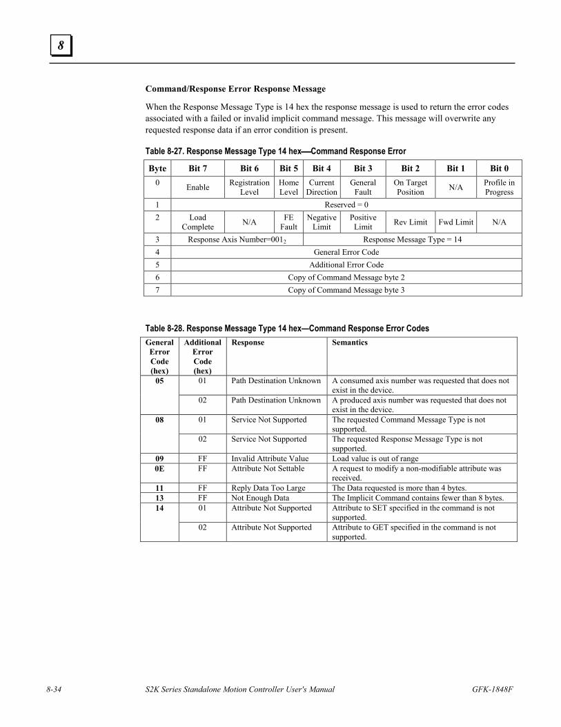
8-34 S2K Series Standalone Motion Controller User's Manual GFK-1848F
8
Command/Response Error Response Message
When the Response Message Type is 14 hex the response message is used to return the error codes associated with a failed or invalid implicit command message. This message will overwrite any requested response data if an error condition is present.
Table 8-27. Response Message Type 14 hexCommand Response Error
Byte Bit 7 Bit 6 Bit 5 Bit 4 Bit 3 Bit 2 Bit 1 Bit 0 0 Enable Registration
Level Home Level
Current Direction
General Fault
On Target Position N/A Profile in
Progress 1 Reserved = 0 2 Load
Complete N/A FE Fault
Negative Limit
Positive Limit Rev Limit Fwd Limit N/A
3 Response Axis Number=0012 Response Message Type = 14 4 General Error Code 5 Additional Error Code 6 Copy of Command Message byte 2 7 Copy of Command Message byte 3
Table 8-28. Response Message Type 14 hex—Command Response Error Codes General Error Code (hex)
Additional Error Code (hex)
Response Semantics
01 Path Destination Unknown A consumed axis number was requested that does not exist in the device.
05
02 Path Destination Unknown A produced axis number was requested that does not exist in the device.
01 Service Not Supported The requested Command Message Type is not supported.
08
02 Service Not Supported The requested Response Message Type is not supported.
09 FF Invalid Attribute Value Load value is out of range 0E FF Attribute Not Settable A request to modify a non-modifiable attribute was
received. 11 FF Reply Data Too Large The Data requested is more than 4 bytes. 13 FF Not Enough Data The Implicit Command contains fewer than 8 bytes.
01 Attribute Not Supported Attribute to SET specified in the command is not supported.
14
02 Attribute Not Supported Attribute to GET specified in the command is not supported.
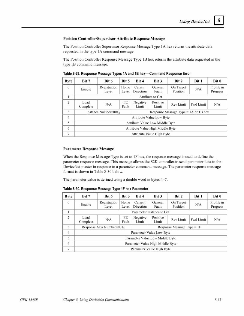
Using DeviceNet
GFK-1848F Chapter 8 Using DeviceNet Communications 8-35
8
Position Controller/Supervisor Attribute Response Message
The Position Controller Supervisor Response Message Type 1A hex returns the attribute data requested in the type 1A command message.
The Position Controller Response Message Type 1B hex returns the attribute data requested in the type 1B command message.
Table 8-29. Response Message Types 1A and 1B hexCommand Response Error
Byte Bit 7 Bit 6 Bit 5 Bit 4 Bit 3 Bit 2 Bit 1 Bit 0 0 Enable Registration
Level Home Level
Current Direction
General Fault
On Target Position N/A Profile in
Progress 1 Attribute to Get 2 Load
Complete N/A FE Fault
Negative Limit
Positive Limit Rev Limit Fwd Limit N/A
3 Instance Number=0012 Response Message Type = 1A or 1B hex 4 Attribute Value Low Byte 5 Attribute Value Low Middle Byte 6 Attribute Value High Middle Byte 7 Attribute Value High Byte
Parameter Response Message
When the Response Message Type is set to 1F hex, the response message is used to define the parameter response message. This message allows the S2K controller to send parameter data to the DeviceNet master in response to a parameter command message. The parameter response message format is shown in Table 8-30 below.
The parameter value is defined using a double word in bytes 4–7.
Table 8-30. Response Message Type 1F hex Parameter
Byte Bit 7 Bit 6 Bit 5 Bit 4 Bit 3 Bit 2 Bit 1 Bit 0 0 Enable Registration
Level Home Level
Current Direction
General Fault
On Target Position N/A Profile in
Progress 1 Parameter Instance to Get 2 Load
Complete N/A FE Fault
Negative Limit
Positive Limit Rev Limit Fwd Limit N/A
3 Response Axis Number=0012 Response Message Type = 1F 4 Parameter Value Low Byte 5 Parameter Value Low Middle Byte 6 Parameter Value High Middle Byte 7 Parameter Value High Byte
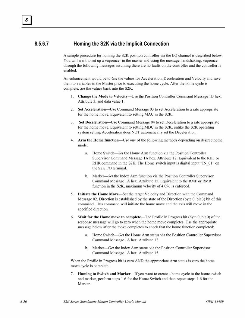
8-36 S2K Series Standalone Motion Controller User's Manual GFK-1848F
8
8.5.6.7 Homing the S2K via the Implicit Connection
A sample procedure for homing the S2K position controller via the I/O channel is described below. You will want to set up a sequencer in the master and using the message handshaking, sequence through the following messages assuming there are no faults on the controller and the controller is enabled.
An enhancement would be to Get the values for Acceleration, Deceleration and Velocity and save them to variables in the Master prior to executing the home cycle. After the home cycle is complete, Set the values back into the S2K.
1. Change the Mode to Velocity—Use the Position Controller Command Message 1B hex, Attribute 3, and data value 1.
2. Set Acceleration—Use Command Message 03 to set Acceleration to a rate appropriate for the home move. Equivalent to setting MAC in the S2K.
3. Set Deceleration—Use Command Message 04 to set Deceleration to a rate appropriate for the home move. Equivalent to setting MDC in the S2K, unlike the S2K operating system setting Acceleration does NOT automatically set the Deceleration.
4. Arm the Home function—Use one of the following methods depending on desired home mode:
a. Home Switch—Set the Home Arm function via the Position Controller Supervisor Command Message 1A hex. Attribute 12. Equivalent to the RHF or RHR command in the S2K. The Home switch input is digital input “IN_01” on the S2K I/O terminal.
b. Marker—Set the Index Arm function via the Position Controller Supervisor Command Message 1A hex. Attribute 15. Equivalent to the RMF or RMR function in the S2K, maximum velocity of 4,096 is enforced.
5. Initiate the Home Move—Set the target Velocity and Direction with the Command Message 02. Direction is established by the state of the Direction (byte 0, bit 3) bit of this command. This command will initiate the home move and the axis will move in the specified direction.
6. Wait for the Home move to complete—The Profile in Progress bit (byte 0, bit 0) of the response message will go to zero when the home move completes. Use the appropriate message below after the move completes to check that the home function completed:
a. Home Switch—Get the Home Arm status via the Position Controller Supervisor Command Message 1A hex. Attribute 12.
b. Marker—Get the Index Arm status via the Position Controller Supervisor Command Message 1A hex. Attribute 15.
When the Profile in Progress bit is zero AND the appropriate Arm status is zero the home move cycle is complete.
7. Homing to Switch and Marker—If you want to create a home cycle to the home switch and marker, perform steps 1-6 for the Home Switch and then repeat steps 4-6 for the Marker.
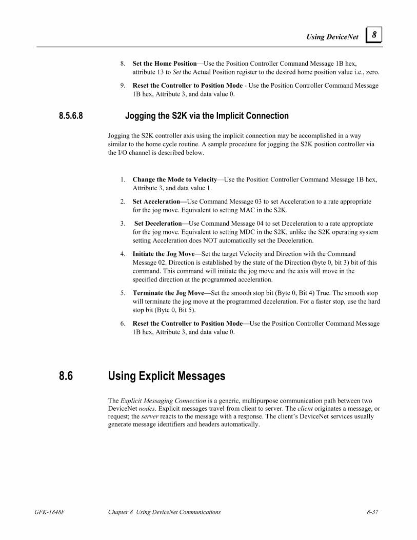
Using DeviceNet
GFK-1848F Chapter 8 Using DeviceNet Communications 8-37
8
8. Set the Home Position—Use the Position Controller Command Message 1B hex, attribute 13 to Set the Actual Position register to the desired home position value i.e., zero.
9. Reset the Controller to Position Mode - Use the Position Controller Command Message 1B hex, Attribute 3, and data value 0.
8.5.6.8 Jogging the S2K via the Implicit Connection
Jogging the S2K controller axis using the implicit connection may be accomplished in a way similar to the home cycle routine. A sample procedure for jogging the S2K position controller via the I/O channel is described below.
1. Change the Mode to Velocity—Use the Position Controller Command Message 1B hex, Attribute 3, and data value 1.
2. Set Acceleration—Use Command Message 03 to set Acceleration to a rate appropriate for the jog move. Equivalent to setting MAC in the S2K.
3. Set Deceleration—Use Command Message 04 to set Deceleration to a rate appropriate for the jog move. Equivalent to setting MDC in the S2K, unlike the S2K operating system setting Acceleration does NOT automatically set the Deceleration.
4. Initiate the Jog Move—Set the target Velocity and Direction with the Command Message 02. Direction is established by the state of the Direction (byte 0, bit 3) bit of this command. This command will initiate the jog move and the axis will move in the specified direction at the programmed acceleration.
5. Terminate the Jog Move—Set the smooth stop bit (Byte 0, Bit 4) True. The smooth stop will terminate the jog move at the programmed deceleration. For a faster stop, use the hard stop bit (Byte 0, Bit 5).
6. Reset the Controller to Position Mode—Use the Position Controller Command Message 1B hex, Attribute 3, and data value 0.
8.6 Using Explicit Messages The Explicit Messaging Connection is a generic, multipurpose communication path between two DeviceNet nodes. Explicit messages travel from client to server. The client originates a message, or request; the server reacts to the message with a response. The client’s DeviceNet services usually generate message identifiers and headers automatically.
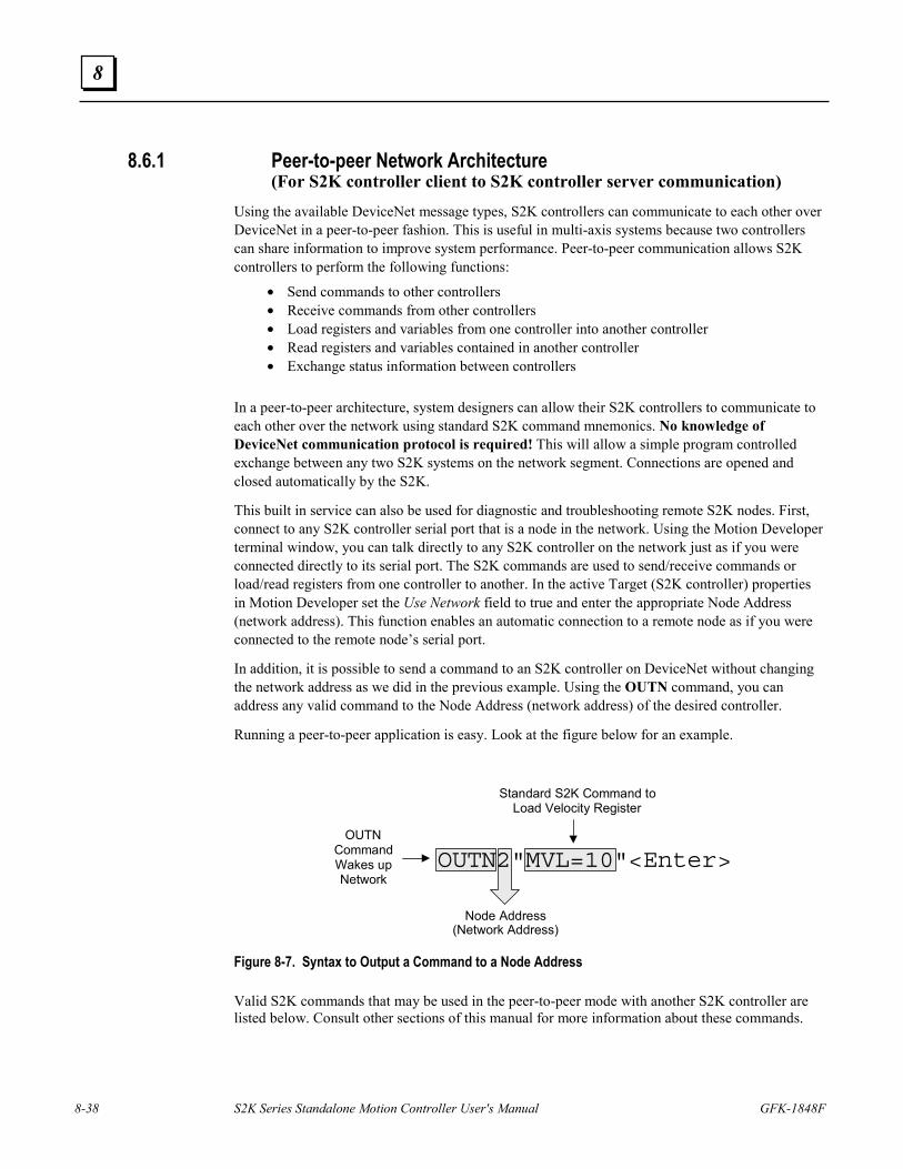
8-38 S2K Series Standalone Motion Controller User's Manual GFK-1848F
8
8.6.1 Peer-to-peer Network Architecture (For S2K controller client to S2K controller server communication)
Using the available DeviceNet message types, S2K controllers can communicate to each other over DeviceNet in a peer-to-peer fashion. This is useful in multi-axis systems because two controllers can share information to improve system performance. Peer-to-peer communication allows S2K controllers to perform the following functions:
• Send commands to other controllers • Receive commands from other controllers • Load registers and variables from one controller into another controller • Read registers and variables contained in another controller • Exchange status information between controllers
In a peer-to-peer architecture, system designers can allow their S2K controllers to communicate to each other over the network using standard S2K command mnemonics. No knowledge of DeviceNet communication protocol is required! This will allow a simple program controlled exchange between any two S2K systems on the network segment. Connections are opened and closed automatically by the S2K.
This built in service can also be used for diagnostic and troubleshooting remote S2K nodes. First, connect to any S2K controller serial port that is a node in the network. Using the Motion Developer terminal window, you can talk directly to any S2K controller on the network just as if you were connected directly to its serial port. The S2K commands are used to send/receive commands or load/read registers from one controller to another. In the active Target (S2K controller) properties in Motion Developer set the Use Network field to true and enter the appropriate Node Address (network address). This function enables an automatic connection to a remote node as if you were connected to the remote node’s serial port.
In addition, it is possible to send a command to an S2K controller on DeviceNet without changing the network address as we did in the previous example. Using the OUTN command, you can address any valid command to the Node Address (network address) of the desired controller.
Running a peer-to-peer application is easy. Look at the figure below for an example.
OUTN Command Wakes up Network
Standard S2K Command to Load Velocity Register
Node Address (Network Address)
OUTN2"MVL=10"<Enter>
Figure 8-7. Syntax to Output a Command to a Node Address Valid S2K commands that may be used in the peer-to-peer mode with another S2K controller are listed below. Consult other sections of this manual for more information about these commands.
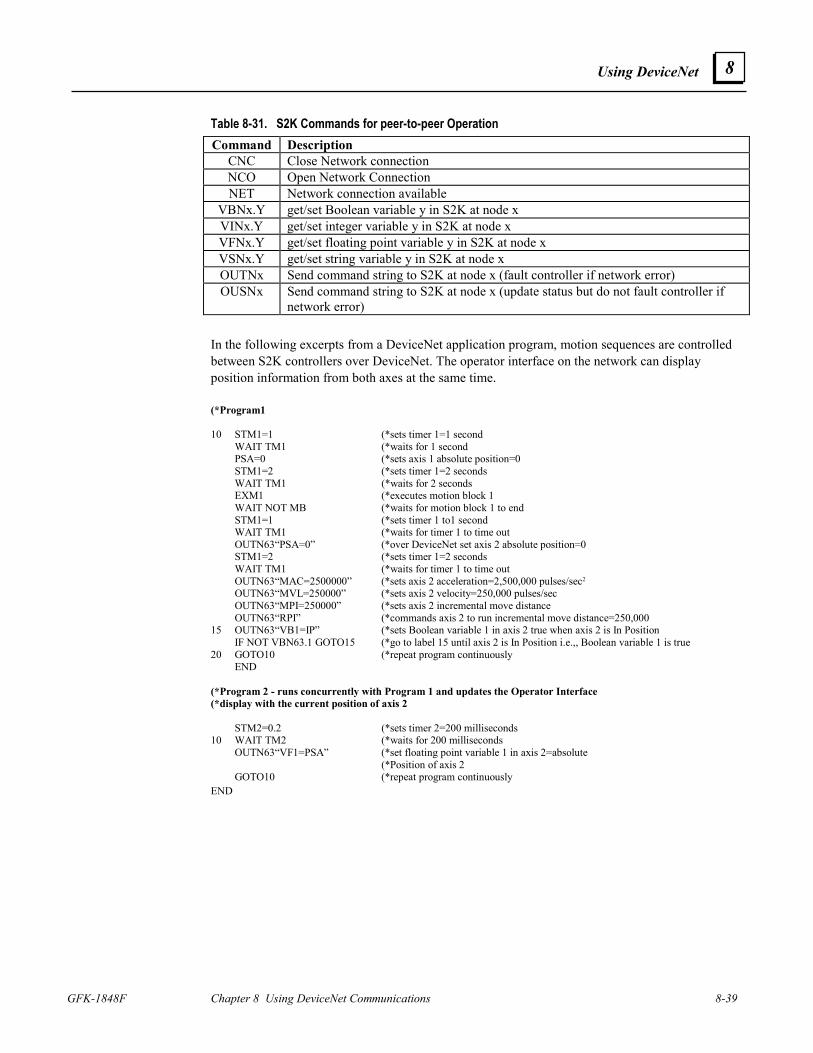
Using DeviceNet
GFK-1848F Chapter 8 Using DeviceNet Communications 8-39
8
Table 8-31. S2K Commands for peer-to-peer Operation Command Description
CNC Close Network connection NCO Open Network Connection NET Network connection available
VBNx.Y get/set Boolean variable y in S2K at node x VINx.Y get/set integer variable y in S2K at node x VFNx.Y get/set floating point variable y in S2K at node x VSNx.Y get/set string variable y in S2K at node x OUTNx Send command string to S2K at node x (fault controller if network error) OUSNx Send command string to S2K at node x (update status but do not fault controller if
network error) In the following excerpts from a DeviceNet application program, motion sequences are controlled between S2K controllers over DeviceNet. The operator interface on the network can display position information from both axes at the same time. (*Program1 10 STM1=1 (*sets timer 1=1 second WAIT TM1 (*waits for 1 second PSA=0 (*sets axis 1 absolute position=0 STM1=2 (*sets timer 1=2 seconds WAIT TM1 (*waits for 2 seconds EXM1 (*executes motion block 1 WAIT NOT MB (*waits for motion block 1 to end STM1=1 (*sets timer 1 to1 second WAIT TM1 (*waits for timer 1 to time out OUTN63“PSA=0” (*over DeviceNet set axis 2 absolute position=0 STM1=2 (*sets timer 1=2 seconds WAIT TM1 (*waits for timer 1 to time out OUTN63“MAC=2500000” (*sets axis 2 acceleration=2,500,000 pulses/sec2 OUTN63“MVL=250000” (*sets axis 2 velocity=250,000 pulses/sec OUTN63“MPI=250000” (*sets axis 2 incremental move distance OUTN63“RPI” (*commands axis 2 to run incremental move distance=250,000 15 OUTN63“VB1=IP” (*sets Boolean variable 1 in axis 2 true when axis 2 is In Position IF NOT VBN63.1 GOTO15 (*go to label 15 until axis 2 is In Position i.e.,, Boolean variable 1 is true 20 GOTO10 (*repeat program continuously END (*Program 2 - runs concurrently with Program 1 and updates the Operator Interface (*display with the current position of axis 2 STM2=0.2 (*sets timer 2=200 milliseconds 10 WAIT TM2 (*waits for 200 milliseconds OUTN63“VF1=PSA” (*set floating point variable 1 in axis 2=absolute (*Position of axis 2 GOTO10 (*repeat program continuously END
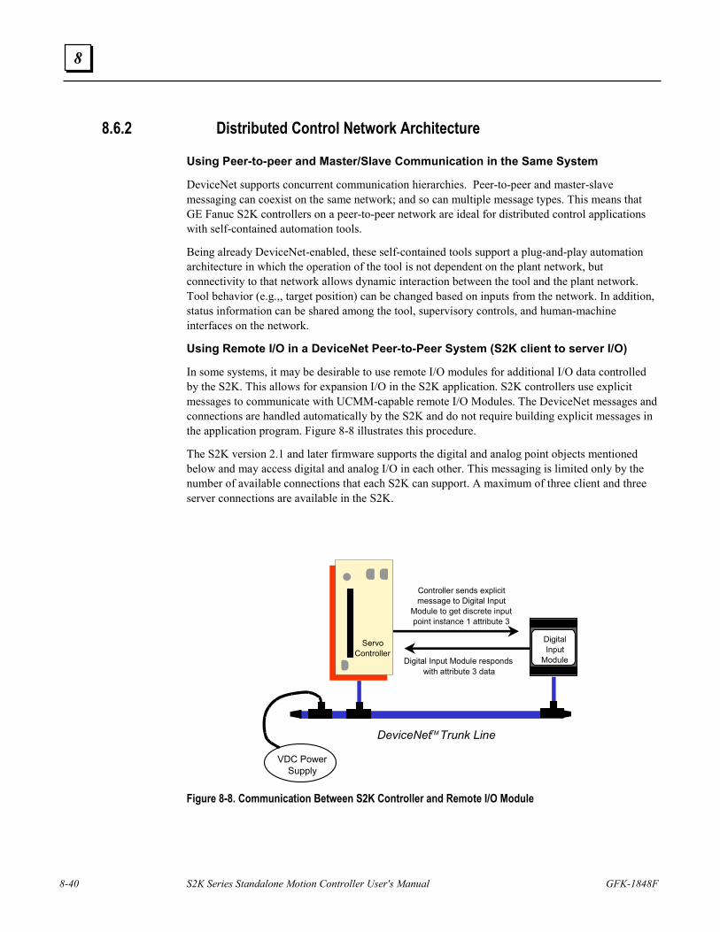
8-40 S2K Series Standalone Motion Controller User's Manual GFK-1848F
8
8.6.2 Distributed Control Network Architecture
Using Peer-to-peer and Master/Slave Communication in the Same System
DeviceNet supports concurrent communication hierarchies. Peer-to-peer and master-slave messaging can coexist on the same network; and so can multiple message types. This means that GE Fanuc S2K controllers on a peer-to-peer network are ideal for distributed control applications with self-contained automation tools.
Being already DeviceNet-enabled, these self-contained tools support a plug-and-play automation architecture in which the operation of the tool is not dependent on the plant network, but connectivity to that network allows dynamic interaction between the tool and the plant network. Tool behavior (e.g.,, target position) can be changed based on inputs from the network. In addition, status information can be shared among the tool, supervisory controls, and human-machine interfaces on the network.
Using Remote I/O in a DeviceNet Peer-to-Peer System (S2K client to server I/O)
In some systems, it may be desirable to use remote I/O modules for additional I/O data controlled by the S2K. This allows for expansion I/O in the S2K application. S2K controllers use explicit messages to communicate with UCMM-capable remote I/O Modules. The DeviceNet messages and connections are handled automatically by the S2K and do not require building explicit messages in the application program. Figure 8-8 illustrates this procedure.
The S2K version 2.1 and later firmware supports the digital and analog point objects mentioned below and may access digital and analog I/O in each other. This messaging is limited only by the number of available connections that each S2K can support. A maximum of three client and three server connections are available in the S2K.
VDC PowerSupply
ServoController
DeviceNetTM Trunk Line
DigitalInput
Module
Controller sends explicitmessage to Digital Input
Module to get discrete inputpoint instance 1 attribute 3
Digital Input Module respondswith attribute 3 data
Figure 8-8. Communication Between S2K Controller and Remote I/O Module
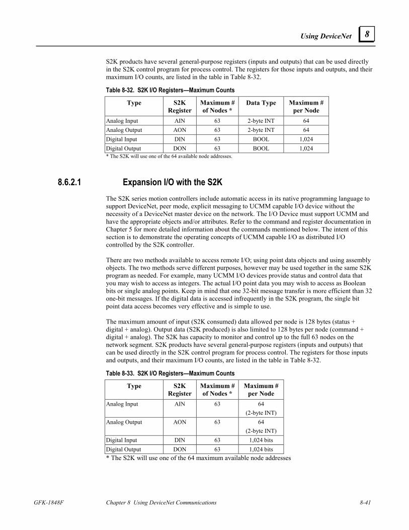
Using DeviceNet
GFK-1848F Chapter 8 Using DeviceNet Communications 8-41
8
S2K products have several general-purpose registers (inputs and outputs) that can be used directly in the S2K control program for process control. The registers for those inputs and outputs, and their maximum I/O counts, are listed in the table in Table 8-32.
Table 8-32. S2K I/O Registers—Maximum Counts
Type S2K Register
Maximum # of Nodes *
Data Type Maximum # per Node
Analog Input AIN 63 2-byte INT 64 Analog Output AON 63 2-byte INT 64 Digital Input DIN 63 BOOL 1,024 Digital Output DON 63 BOOL 1,024 * The S2K will use one of the 64 available node addresses.
8.6.2.1 Expansion I/O with the S2K The S2K series motion controllers include automatic access in its native programming language to support DeviceNet, peer mode, explicit messaging to UCMM capable I/O device without the necessity of a DeviceNet master device on the network. The I/O Device must support UCMM and have the appropriate objects and/or attributes. Refer to the command and register documentation in Chapter 5 for more detailed information about the commands mentioned below. The intent of this section is to demonstrate the operating concepts of UCMM capable I/O as distributed I/O controlled by the S2K controller. There are two methods available to access remote I/O; using point data objects and using assembly objects. The two methods serve different purposes, however may be used together in the same S2K program as needed. For example, many UCMM I/O devices provide status and control data that you may wish to access as integers. The actual I/O point data you may wish to access as Boolean bits or single analog points. Keep in mind that one 32-bit message transfer is more efficient than 32 one-bit messages. If the digital data is accessed infrequently in the S2K program, the single bit point data access becomes very effective and is simple to use. The maximum amount of input (S2K consumed) data allowed per node is 128 bytes (status + digital + analog). Output data (S2K produced) is also limited to 128 bytes per node (command + digital + analog). The S2K has capacity to monitor and control up to the full 63 nodes on the network segment. S2K products have several general-purpose registers (inputs and outputs) that can be used directly in the S2K control program for process control. The registers for those inputs and outputs, and their maximum I/O counts, are listed in the table in Table 8-32.
Table 8-33. S2K I/O Registers—Maximum Counts
Type S2K Register
Maximum # of Nodes *
Maximum # per Node
Analog Input AIN 63 64 (2-byte INT)
Analog Output AON 63 64 (2-byte INT)
Digital Input DIN 63 1,024 bits Digital Output DON 63 1,024 bits * The S2K will use one of the 64 maximum available node addresses
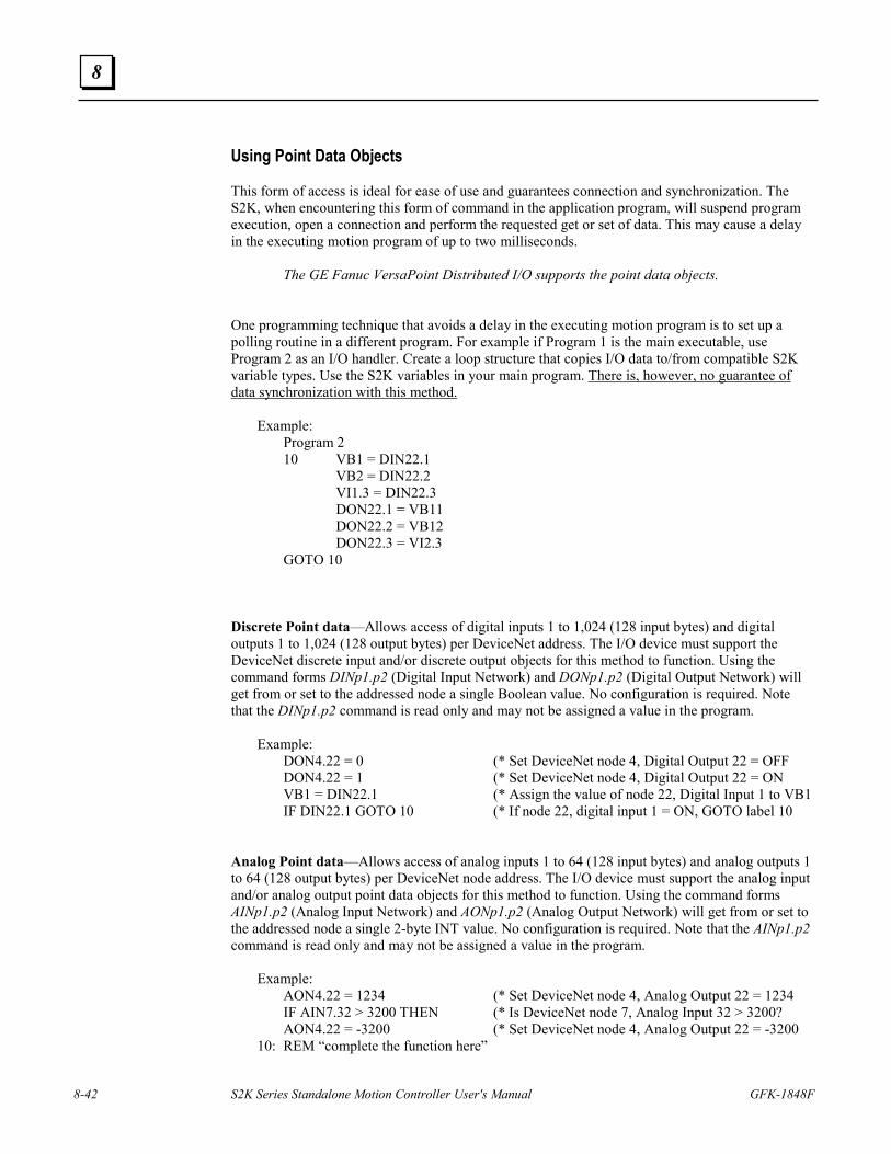
8-42 S2K Series Standalone Motion Controller User's Manual GFK-1848F
8
Using Point Data Objects This form of access is ideal for ease of use and guarantees connection and synchronization. The S2K, when encountering this form of command in the application program, will suspend program execution, open a connection and perform the requested get or set of data. This may cause a delay in the executing motion program of up to two milliseconds.
The GE Fanuc VersaPoint Distributed I/O supports the point data objects.
One programming technique that avoids a delay in the executing motion program is to set up a polling routine in a different program. For example if Program 1 is the main executable, use Program 2 as an I/O handler. Create a loop structure that copies I/O data to/from compatible S2K variable types. Use the S2K variables in your main program. There is, however, no guarantee of data synchronization with this method.
Example: Program 2
10 VB1 = DIN22.1 VB2 = DIN22.2 VI1.3 = DIN22.3 DON22.1 = VB11 DON22.2 = VB12 DON22.3 = VI2.3 GOTO 10
Discrete Point data—Allows access of digital inputs 1 to 1,024 (128 input bytes) and digital outputs 1 to 1,024 (128 output bytes) per DeviceNet address. The I/O device must support the DeviceNet discrete input and/or discrete output objects for this method to function. Using the command forms DINp1.p2 (Digital Input Network) and DONp1.p2 (Digital Output Network) will get from or set to the addressed node a single Boolean value. No configuration is required. Note that the DINp1.p2 command is read only and may not be assigned a value in the program.
Example: DON4.22 = 0 (* Set DeviceNet node 4, Digital Output 22 = OFF DON4.22 = 1 (* Set DeviceNet node 4, Digital Output 22 = ON VB1 = DIN22.1 (* Assign the value of node 22, Digital Input 1 to VB1 IF DIN22.1 GOTO 10 (* If node 22, digital input 1 = ON, GOTO label 10
Analog Point data—Allows access of analog inputs 1 to 64 (128 input bytes) and analog outputs 1 to 64 (128 output bytes) per DeviceNet node address. The I/O device must support the analog input and/or analog output point data objects for this method to function. Using the command forms AINp1.p2 (Analog Input Network) and AONp1.p2 (Analog Output Network) will get from or set to the addressed node a single 2-byte INT value. No configuration is required. Note that the AINp1.p2 command is read only and may not be assigned a value in the program.
Example: AON4.22 = 1234 (* Set DeviceNet node 4, Analog Output 22 = 1234
IF AIN7.32 > 3200 THEN (* Is DeviceNet node 7, Analog Input 32 > 3200? AON4.22 = -3200 (* Set DeviceNet node 4, Analog Output 22 = -3200 10: REM “complete the function here”
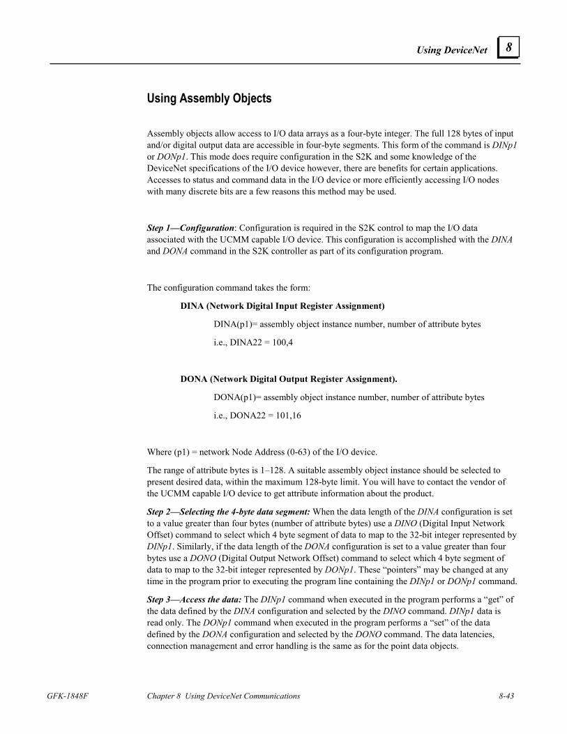
Using DeviceNet
GFK-1848F Chapter 8 Using DeviceNet Communications 8-43
8
Using Assembly Objects
Assembly objects allow access to I/O data arrays as a four-byte integer. The full 128 bytes of input and/or digital output data are accessible in four-byte segments. This form of the command is DINp1 or DONp1. This mode does require configuration in the S2K and some knowledge of the DeviceNet specifications of the I/O device however, there are benefits for certain applications. Accesses to status and command data in the I/O device or more efficiently accessing I/O nodes with many discrete bits are a few reasons this method may be used.
Step 1—Configuration: Configuration is required in the S2K control to map the I/O data associated with the UCMM capable I/O device. This configuration is accomplished with the DINA and DONA command in the S2K controller as part of its configuration program.
The configuration command takes the form:
DINA (Network Digital Input Register Assignment)
DINA(p1)= assembly object instance number, number of attribute bytes
i.e., DINA22 = 100,4
DONA (Network Digital Output Register Assignment).
DONA(p1)= assembly object instance number, number of attribute bytes
i.e., DONA22 = 101,16
Where (p1) = network Node Address (0-63) of the I/O device.
The range of attribute bytes is 1–128. A suitable assembly object instance should be selected to present desired data, within the maximum 128-byte limit. You will have to contact the vendor of the UCMM capable I/O device to get attribute information about the product.
Step 2—Selecting the 4-byte data segment: When the data length of the DINA configuration is set to a value greater than four bytes (number of attribute bytes) use a DINO (Digital Input Network Offset) command to select which 4 byte segment of data to map to the 32-bit integer represented by DINp1. Similarly, if the data length of the DONA configuration is set to a value greater than four bytes use a DONO (Digital Output Network Offset) command to select which 4 byte segment of data to map to the 32-bit integer represented by DONp1. These “pointers” may be changed at any time in the program prior to executing the program line containing the DINp1 or DONp1 command.
Step 3—Access the data: The DINp1 command when executed in the program performs a “get” of the data defined by the DINA configuration and selected by the DINO command. DINp1 data is read only. The DONp1 command when executed in the program performs a “set” of the data defined by the DONA configuration and selected by the DONO command. The data latencies, connection management and error handling is the same as for the point data objects.
8-44 S2K Series Standalone Motion Controller User's Manual GFK-1848F
8
The integer form of the command (DINp1 or DONp1) is not strictly limited to digital input or output data.
Example:
An I/O device with 16 DO and 8 DI and 1 AO and 2 AI, the assembly object data will have 2 bytes for the DO and 2 bytes for the AO on output and 1 byte for the DI and 4 bytes for the AI on input. The mapping of the data is vendor defined in most cases. You will need the assembly object instance documentation from the vendor for the selected devices.
There will also be status bytes in the assembly data, often the first few input and output bytes but, for this example, we will ignore them. The DINp1 register will get four bytes at a time of the five bytes of the assembly object input data. The particular 4-byte segment is determined by the DINO command. As you can see only one of the four bytes is really DI, the rest is AI data (it could be status data as well). The DINp1 form of the register isn't just DI, it is a window on the I/O data that the I/O device is producing just as the I/O device would send to a PLC or PC based controller.
Using GE Fanuc VersaPoint Distributed I/O Assembly Objects:
The assembly object instance number to use for VersaPoint I/O input data is 100. The byte length will vary depending on the number and type of input modules connected to the VersaPoint DeviceNet NIU. This data includes in LSB-MSB order; NIU status (2bytes) + discrete input data (number of input points rounded up to the nearest byte boundary) + analog input data (2 bytes per point). Some VersaPoint analog input modules include additional bytes of data other than the input value.
The assembly object instance number to use for VersaPoint I/O output data is 101. The byte length will vary depending on the number and type of output modules connected to the DeviceNet NIU. This data includes in LSB-MSB order; discrete output data (number of outputs rounded up to the nearest byte boundary) + analog output data (2 bytes per point).
VersaPoint I/O does not support separate assembly object instances for discrete and analog data and will combine all input data or output data into a single input or output block of data. Consult the VersaPoint documentation for configuration, installation and mapping of status and I/O data.
Connection Management The S2K manages DeviceNet client communications by using the UCMM (Unconnected Message Manager) protocol to establish a logical “connection” to the addressed server node (I/O device). This is the reason the I/O device must support UCMM. These connections are dynamic and usually are managed automatically by the S2K however; there are cases where the application program should use manual connection management. The S2K application programmer should be alert if more than three client connections are potentially active in the S2K. Master/Slave connection does not affect this since the S2K uses two server connections for the master scanner connection. Each S2K provides three client and three server connections each of which may be opened and closed independently.
Initial connection to the server (I/O) node requires opening the connection path and may cause a delay in the executing motion program of up to two milliseconds. A client connection is to the server node address and multiple Get/Set service messages may be performed to the same node without closing an open connection. Successive uses of a Get/Set command if called frequently in
Using DeviceNet
GFK-1848F Chapter 8 Using DeviceNet Communications 8-45
8
the motion program do not need to re-open the connection and are more efficient (approximately a one millisecond delay) in use. If the connection remains idle for 2.5 seconds it will time out and close automatically and the connection message will be required on the next access to the device node.
In the event that all the client connections in the S2K are in service when the command is executed in the motion program, the S2K will attempt to close one of the open existing idle client connections and attempt to open a connection to the specified node. Any network communication error will set FC31 and automatically execute program 4. The network fault code register (FCN) will indicate network faults in the connection and should be examined to determine network status after a fault.
Use the NCO read only register to check for valid connections if attempting to access a busy node address. The NCO will attempt to open a connection without faulting the S2K if the connection fails. Be certain that the lines of program code following the NCO line decide what to do about the connection.
Example: REM Start of connection test VI101 = 0 (* Clear variable used as error counter 10 IF NCO5 GOTO 20 (* IF a connection is available to node 5 GOTO 20 VI101 = VI101 + 1 (* Increment error counter IF VI101 > 50 THEN (* Waited 5 sec for a connection? STF (* Stop Fault the control STM1 = 0.100 (* Set Delay Timer WAIT TM1 (* Wait for 100ms GOTO 10 (* Loop for connect retries 20 DON5.9 = ON (* Set output on node 5 (* add all node 5 I/O commands here *)
8.6.3 DeviceNet Objects for Explicit Messaging (Used with non-S2K peer client)
It is useful to understand CAN messaging and DeviceNet objects in some detail in order to generate the client explicit message to the S2K server. The client interface will determine how the data exchange is implemented. The interface may vary from a very user-friendly interface to low-level message encoding. Follow instructions in the client DeviceNet driver to implement the message properly.
For an in-depth DeviceNet resource, consult the current DeviceNet Specification published by the ODVA (www.odva.org).
About CAN and DeviceNet
CAN (Controller Area Network) specifications define both a hardware specification (CAN controller chips) and description of the network stack up to the Data Link Layer. This includes several message frame types of which the “data frame” is the most commonly used DeviceNet message frame. DeviceNet is an application protocol linked to the CAN specification at the Data Link Layer.
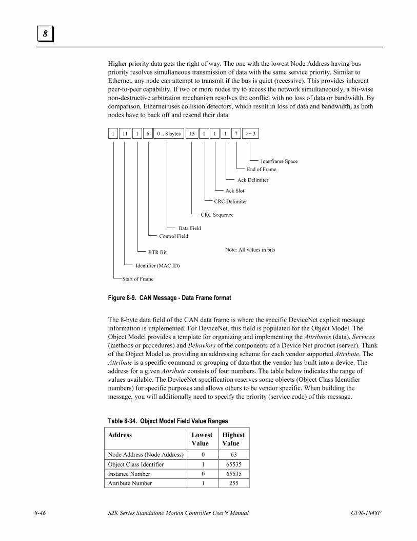
8-46 S2K Series Standalone Motion Controller User's Manual GFK-1848F
8
Higher priority data gets the right of way. The one with the lowest Node Address having bus priority resolves simultaneous transmission of data with the same service priority. Similar to Ethernet, any node can attempt to transmit if the bus is quiet (recessive). This provides inherent peer-to-peer capability. If two or more nodes try to access the network simultaneously, a bit-wise non-destructive arbitration mechanism resolves the conflict with no loss of data or bandwidth. By comparison, Ethernet uses collision detectors, which result in loss of data and bandwidth, as both nodes have to back off and resend their data.
0 .. 8 bytes 156 11111 1 1 7 >= 3
Interframe SpaceEnd of Frame
Ack Delimiter
Ack Slot
CRC Delimiter
CRC Sequence
Data FieldControl Field
RTR Bit
Identifier (MAC ID)
Start of Frame
Note: All values in bits
Figure 8-9. CAN Message - Data Frame format
The 8-byte data field of the CAN data frame is where the specific DeviceNet explicit message information is implemented. For DeviceNet, this field is populated for the Object Model. The Object Model provides a template for organizing and implementing the Attributes (data), Services (methods or procedures) and Behaviors of the components of a Device Net product (server). Think of the Object Model as providing an addressing scheme for each vendor supported Attribute. The Attribute is a specific command or grouping of data that the vendor has built into a device. The address for a given Attribute consists of four numbers. The table below indicates the range of values available. The DeviceNet specification reserves some objects (Object Class Identifier numbers) for specific purposes and allows others to be vendor specific. When building the message, you will additionally need to specify the priority (service code) of this message.
Table 8-34. Object Model Field Value Ranges
Address Lowest Value
Highest Value
Node Address (Node Address) 0 63 Object Class Identifier 1 65535 Instance Number 0 65535 Attribute Number 1 255
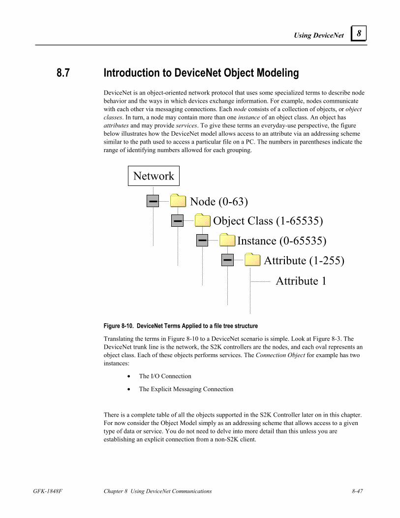
Using DeviceNet
GFK-1848F Chapter 8 Using DeviceNet Communications 8-47
8
8.7 Introduction to DeviceNet Object Modeling DeviceNet is an object-oriented network protocol that uses some specialized terms to describe node behavior and the ways in which devices exchange information. For example, nodes communicate with each other via messaging connections. Each node consists of a collection of objects, or object classes. In turn, a node may contain more than one instance of an object class. An object has attributes and may provide services. To give these terms an everyday-use perspective, the figure below illustrates how the DeviceNet model allows access to an attribute via an addressing scheme similar to the path used to access a particular file on a PC. The numbers in parentheses indicate the range of identifying numbers allowed for each grouping.
Figure 8-10. DeviceNet Terms Applied to a file tree structure
Translating the terms in Figure 8-10 to a DeviceNet scenario is simple. Look at Figure 8-3. The DeviceNet trunk line is the network, the S2K controllers are the nodes, and each oval represents an object class. Each of these objects performs services. The Connection Object for example has two instances:
• The I/O Connection
• The Explicit Messaging Connection
There is a complete table of all the objects supported in the S2K Controller later on in this chapter. For now consider the Object Model simply as an addressing scheme that allows access to a given type of data or service. You do not need to delve into more detail than this unless you are establishing an explicit connection from a non-S2K client.
Attribute (1-255)
Node (0-63)Object Class (1-65535)
Instance (0-65535)
Attribute 1
Network
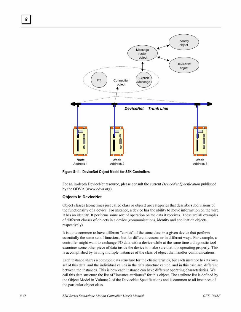
8-48 S2K Series Standalone Motion Controller User's Manual GFK-1848F
8
DeviceNet Trunk Line
NodeAddress 1
NodeAddress 2
NodeAddress 3
Connectionobject
I/OExplicit
Message
Messagerouterobject
Identityobject
DeviceNetobject
Figure 8-11. DeviceNet Object Model for S2K Controllers For an in-depth DeviceNet resource, please consult the current DeviceNet Specification published by the ODVA (www.odva.org).
Objects in DeviceNet
Object classes (sometimes just called class or object) are categories that describe subdivisions of the functionality of a device. For instance, a device has the ability to move information on the wire. It has an identity. It performs some sort of operation on the data it receives. These are all examples of different classes of objects in a device (communications, identity and application objects, respectively).
It is quite common to have different "copies" of the same class in a given device that perform essentially the same set of functions, but for different reasons or in different ways. For example, a controller might want to exchange I/O data with a device while at the same time a diagnostic tool examines some other piece of data inside the device to make sure that it is operating properly. This is accomplished by having multiple instances of the class of object that handles communications.
Each instance shares a common data structure for the characteristics, but each instance has its own set of this data, and the individual values in the data structure can be, and in this case are, different between the instances. This is how each instance can have different operating characteristics. We call this data structure the list of "instance attributes" for this object. The attribute list is defined by the Object Model in Volume 2 of the DeviceNet Specifications and is common to all instances of the particular object class.
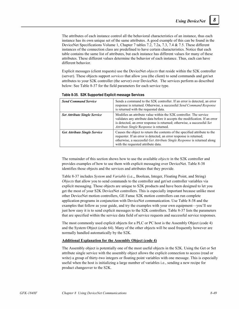
Using DeviceNet
GFK-1848F Chapter 8 Using DeviceNet Communications 8-49
8
The attributes of each instance control all the behavioral characteristics of an instance, thus each instance has its own unique set of the same attributes. A good example of this can be found in the DeviceNet Specifications Volume 1, Chapter 7 tables 7.2, 7.2a, 7.3, 7.4 & 7.5. These different instances of the connection class are predefined to have certain characteristics. Notice that each table contains the same list of attributes, but each instance has different values for many of these attributes. These different values determine the behavior of each instance. Thus, each can have different behavior.
Explicit messages (client requests) use the DeviceNet objects that reside within the S2K controller (server). These objects support services that allow you (the client) to send commands and get/set attributes to your S2K controller (the server) over DeviceNet. The services perform as described below: See Table 8-37 for the field parameters for each service type.
Table 8-35. S2K Supported Explicit message Services Send Command Service Sends a command to the S2K controller. If an error is detected, an error
response is returned. Otherwise, a successful Send Command Response is returned with the requested data.
Set Attribute Single Service Modifies an attribute value within the S2K controller. The service validates any attribute data before it accepts the modification. If an error is detected, an error response is returned; otherwise, a successful Set Attribute Single Response is returned.
Get Attribute Single Service Causes the object to return the contents of the specified attribute to the requester. If an error is detected, an error response is returned; otherwise, a successful Get Attribute Single Response is returned along with the requested attribute data.
The remainder of this section shows how to use the available objects in the S2K controller and provides examples of how to use them with explicit messaging over DeviceNet. Table 8-38 identifies those objects and the services and attributes that they provide.
Table 8-37 includes System and Variable (i.e.,, Boolean, Integer, Floating Point, and String) Objects that allow you to send commands to the controller and get/set controller variables via explicit messaging. Those objects are unique to S2K products and have been designed to let you get the most of your S2K DeviceNet controllers. This is especially important because unlike most other DeviceNet motion controllers, GE Fanuc S2K motion controllers can run complete application programs in conjunction with DeviceNet communication. Use Table 8-38 and the examples that follow as your guide, and try the examples with your own equipment—you’ll see just how easy it is to send explicit messages to the S2K controllers. Table 8-37 lists the parameters that are specified within the service data field of service requests and successful service responses.
The most commonly used explicit objects for a PLC or PC host is the Assembly Object (code 4) and the System Object (code 64). Many of the other objects will be used frequently however are normally handled automatically by the S2K.
Additional Explanation for the Assembly Object (code 4)
The Assembly object is potentially one of the most useful objects in the S2K. Using the Get or Set attribute single service with the assembly object allows the explicit connection to access (read or write) a group of thirty-two integers or floating point variables with one message. This is especially useful when the host is initializing a large number of variables i.e., sending a new recipe for product changeover to the S2K.
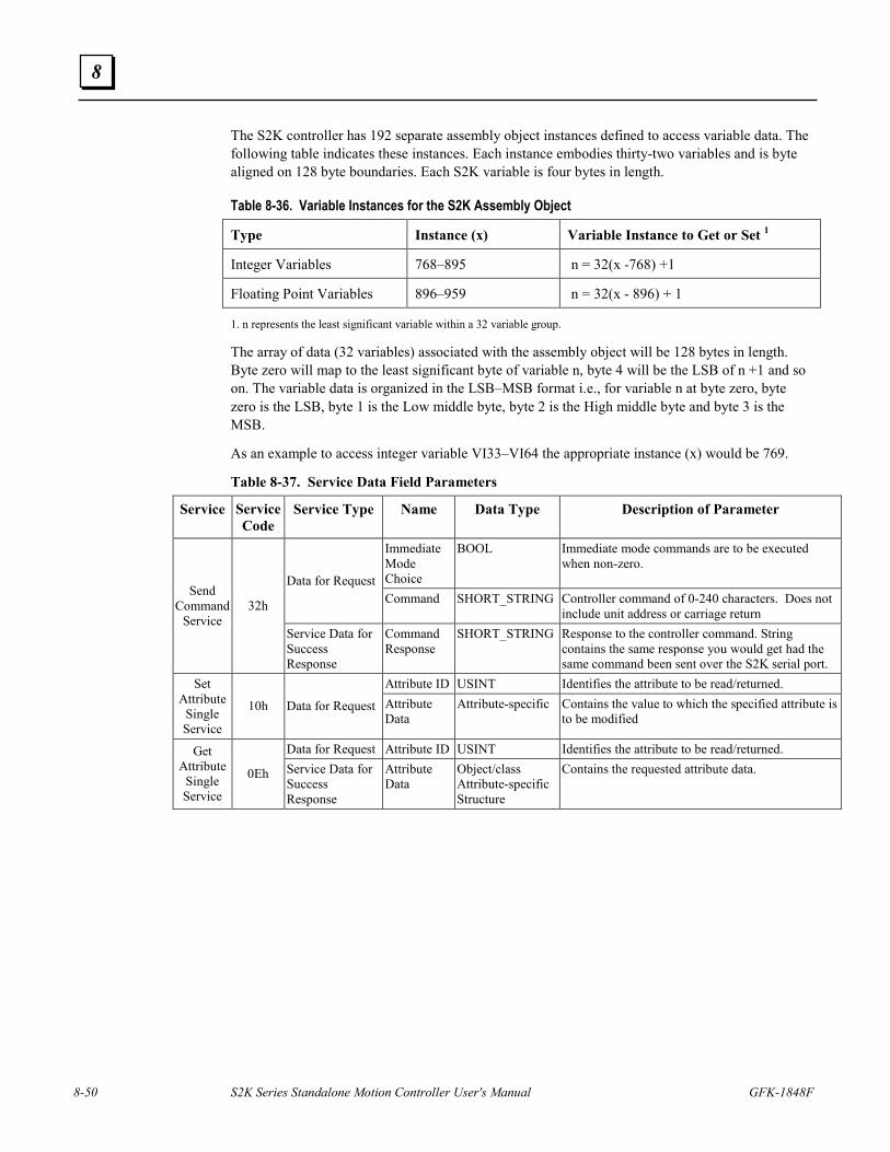
8-50 S2K Series Standalone Motion Controller User's Manual GFK-1848F
8
The S2K controller has 192 separate assembly object instances defined to access variable data. The following table indicates these instances. Each instance embodies thirty-two variables and is byte aligned on 128 byte boundaries. Each S2K variable is four bytes in length.
Table 8-36. Variable Instances for the S2K Assembly Object
Type Instance (x) Variable Instance to Get or Set 1
Integer Variables 768–895 n = 32(x -768) +1
Floating Point Variables 896–959 n = 32(x - 896) + 1
1. n represents the least significant variable within a 32 variable group.
The array of data (32 variables) associated with the assembly object will be 128 bytes in length. Byte zero will map to the least significant byte of variable n, byte 4 will be the LSB of n +1 and so on. The variable data is organized in the LSB–MSB format i.e., for variable n at byte zero, byte zero is the LSB, byte 1 is the Low middle byte, byte 2 is the High middle byte and byte 3 is the MSB.
As an example to access integer variable VI33–VI64 the appropriate instance (x) would be 769.
Table 8-37. Service Data Field Parameters
Service Service Code
Service Type Name Data Type Description of Parameter
Immediate Mode Choice
BOOL Immediate mode commands are to be executed when non-zero.
Data for Request Command SHORT_STRING Controller command of 0-240 characters. Does not
include unit address or carriage return
Send Command
Service 32h
Service Data for Success Response
Command Response
SHORT_STRING Response to the controller command. String contains the same response you would get had the same command been sent over the S2K serial port.
Attribute ID USINT Identifies the attribute to be read/returned. Set Attribute
Single Service
10h Data for Request Attribute Data
Attribute-specific Contains the value to which the specified attribute is to be modified
Data for Request Attribute ID USINT Identifies the attribute to be read/returned. Get Attribute
Single Service
0Eh Service Data for Success Response
Attribute Data
Object/class Attribute-specific Structure
Contains the requested attribute data.
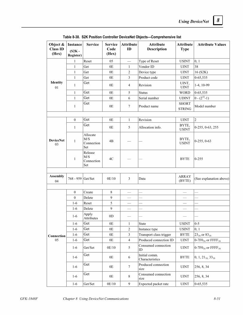
Using DeviceNet
GFK-1848F Chapter 8 Using DeviceNet Communications 8-51
8
Table 8-38. S2K Position Controller DeviceNet Objects—Comprehensive list
Object & Class ID
(Hex)
Instance (S2K -
Register)
Service Service Code (Hex)
Attribute ID
Attribute Description
Attribute Type
Attribute Values
1 Reset 05 — Type of Reset USINT 0, 1 1 Get 0E 1 Vendor ID UINT 38 1 Get 0E 2 Device type UINT 16 (S2K) 1 Get 0E 3 Product code UINT 0-65,535
1 Get 0E 4 Revision UINT, UINT 1-4, 10-99
1 Get 0E 5 Status WORD 0-65,535 1 Get 0E 6 Serial number UDINT 0 - (232-1)
Identity 01
1 Get
0E 7 Product name SHORT STRING
Model number
0 Get 0E 1 Revision UINT 2
1 Get 0E 5 Allocation info. BYTE, USINT 0-255, 0-63, 255
1
Allocate M/S Connection Set
4B — — BYTE, USINT 0-255, 0-63 DeviceNet
03
1
Release M/S Connection Set
4C — — BYTE 0-255
Assembly
04 768 - 959 Get/Set 0E/10 3 Data ARRAY
(BYTE) (See explanation above)
0 Create 8 — — — — 0 Delete 9 — — — —
1-6 Reset 5 — — — — 1-6 Delete 9 — — — —
1-6 Apply Attributes 0D — — — —
1-6 Get 0E 1 State USINT 0-5 1-6 Get 0E 2 Instance type USINT 0, 1 1-6 Get 0E 3 Transport class trigger BYTE 2316 or 8316 1-6 Get 0E 4 Produced connection ID UINT 0-7F016 or FFFF16
1-6 Get/Set 0E/10 5 Consumed connection ID UINT 0-7F016 or FFFF16
1-6 Get 0E 6 Initial comm. Characteristics BYTE 0, 1, 2116, 3316
1-6 Get 0E 7 Produced connection size UINT 256, 8, 34
1-6 Get 0E 8 Consumed connection size UINT 256, 8, 34
Connection 05
1-6 Get/Set 0E/10 9 Expected packet rate UINT 0-65,535
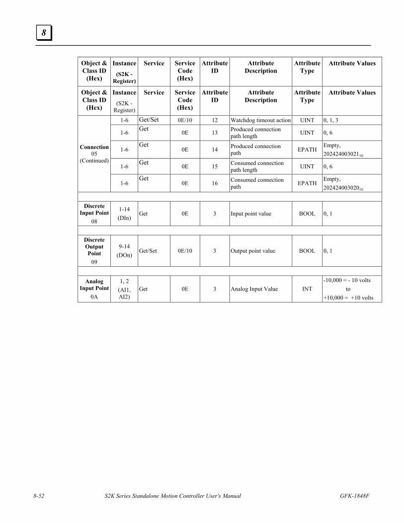
8-52 S2K Series Standalone Motion Controller User's Manual GFK-1848F
8
Object & Class ID
(Hex)
Instance (S2K -
Register)
Service Service Code (Hex)
Attribute ID
Attribute Description
Attribute Type
Attribute Values
Object & Class ID
(Hex)
Instance (S2K -
Register)
Service Service Code (Hex)
Attribute ID
Attribute Description
Attribute Type
Attribute Values
1-6 Get/Set 0E/10 12 Watchdog timeout action UINT 0, 1, 3
1-6 Get 0E 13 Produced connection path length UINT 0, 6
1-6 Get
0E 14 Produced connection path EPATH
Empty, 20242400302116
1-6 Get 0E 15 Consumed connection path length UINT 0, 6
Connection 05
(Continued)
1-6 Get
0E 16 Consumed connection path EPATH
Empty, 20242400302016
Discrete
Input Point 08
1-14 (DIn)
Get 0E 3 Input point value BOOL 0, 1
Discrete Output Point
09
9-14 (DOn)
Get/Set 0E/10 3 Output point value BOOL 0, 1
Analog Input Point
0A
1, 2 (AI1, AI2)
Get 0E 3 Analog Input Value INT -10,000 = - 10 volts to +10,000 = +10 volts
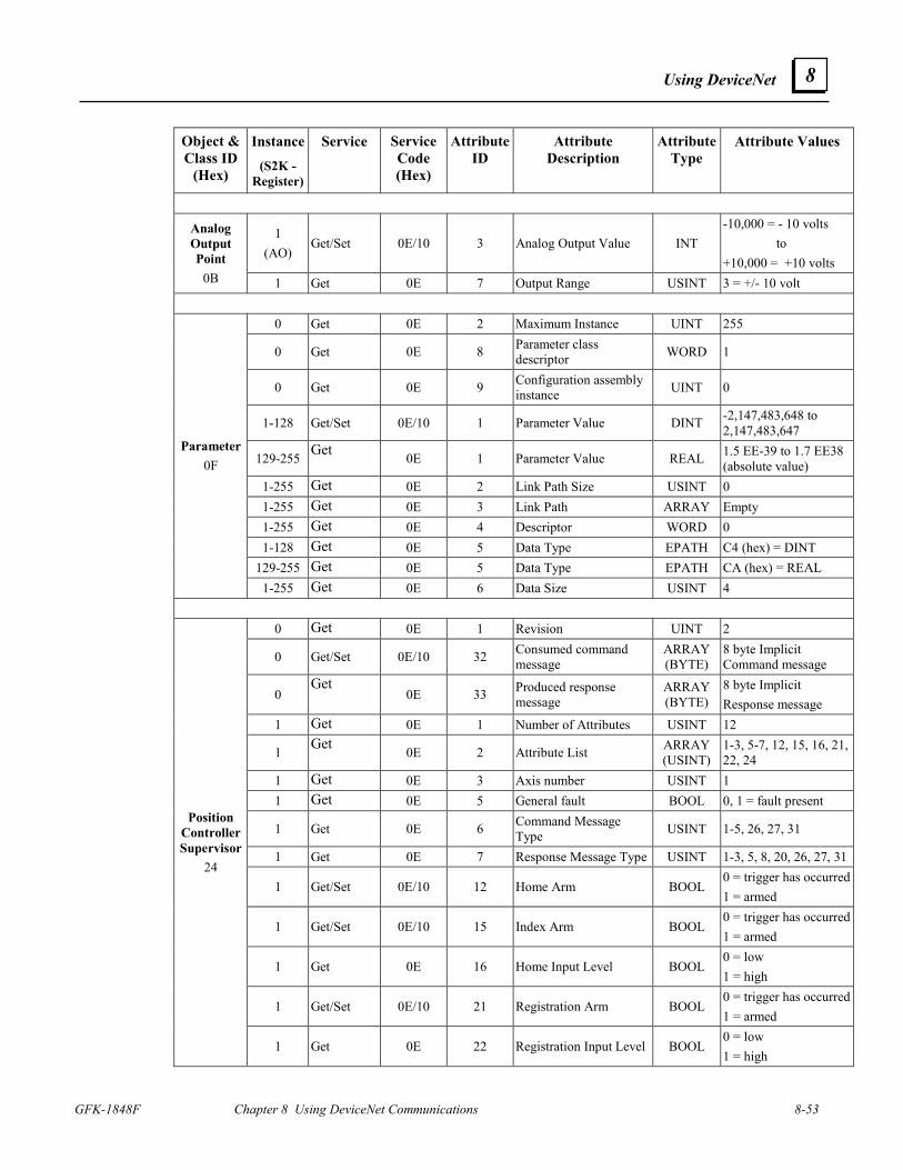
Using DeviceNet
GFK-1848F Chapter 8 Using DeviceNet Communications 8-53
8
Object & Class ID
(Hex)
Instance (S2K -
Register)
Service Service Code (Hex)
Attribute ID
Attribute Description
Attribute Type
Attribute Values
1 (AO)
Get/Set 0E/10 3 Analog Output Value INT -10,000 = - 10 volts to +10,000 = +10 volts
Analog Output Point
0B 1 Get 0E 7 Output Range USINT 3 = +/- 10 volt
0 Get 0E 2 Maximum Instance UINT 255
0 Get 0E 8 Parameter class descriptor WORD 1
0 Get 0E 9 Configuration assembly instance UINT 0
1-128 Get/Set 0E/10 1 Parameter Value DINT -2,147,483,648 to 2,147,483,647
129-255 Get 0E 1 Parameter Value REAL 1.5 EE-39 to 1.7 EE38 (absolute value)
1-255 Get 0E 2 Link Path Size USINT 0 1-255 Get 0E 3 Link Path ARRAY Empty 1-255 Get 0E 4 Descriptor WORD 0 1-128 Get 0E 5 Data Type EPATH C4 (hex) = DINT
129-255 Get 0E 5 Data Type EPATH CA (hex) = REAL
Parameter 0F
1-255 Get 0E 6 Data Size USINT 4
0 Get 0E 1 Revision UINT 2
0 Get/Set 0E/10 32 Consumed command message
ARRAY (BYTE)
8 byte Implicit Command message
0 Get
0E 33 Produced response message
ARRAY (BYTE)
8 byte Implicit Response message
1 Get 0E 1 Number of Attributes USINT 12
1 Get 0E 2 Attribute List ARRAY (USINT)
1-3, 5-7, 12, 15, 16, 21, 22, 24
1 Get 0E 3 Axis number USINT 1 1 Get 0E 5 General fault BOOL 0, 1 = fault present
1 Get 0E 6 Command Message Type USINT 1-5, 26, 27, 31
1 Get 0E 7 Response Message Type USINT 1-3, 5, 8, 20, 26, 27, 31
1 Get/Set 0E/10 12 Home Arm BOOL 0 = trigger has occurred1 = armed
1 Get/Set 0E/10 15 Index Arm BOOL 0 = trigger has occurred1 = armed
1 Get 0E 16 Home Input Level BOOL 0 = low 1 = high
1 Get/Set 0E/10 21 Registration Arm BOOL 0 = trigger has occurred1 = armed
Position Controller Supervisor
24
1 Get 0E 22 Registration Input Level BOOL 0 = low 1 = high
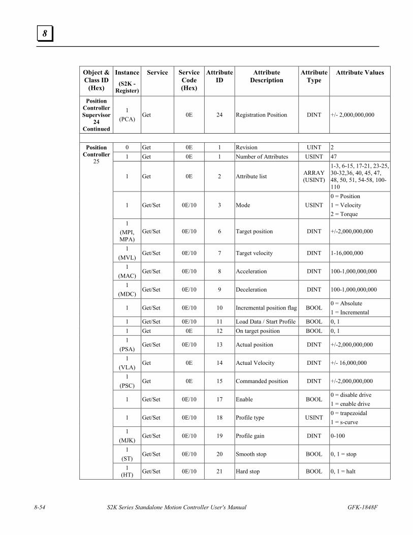
8-54 S2K Series Standalone Motion Controller User's Manual GFK-1848F
8
Object & Class ID
(Hex)
Instance (S2K -
Register)
Service Service Code (Hex)
Attribute ID
Attribute Description
Attribute Type
Attribute Values
Position Controller Supervisor
24 Continued
1 (PCA)
Get 0E 24 Registration Position DINT +/- 2,000,000,000
0 Get 0E 1 Revision UINT 2 1 Get 0E 1 Number of Attributes USINT 47
1 Get 0E 2 Attribute list ARRAY (USINT)
1-3, 6-15, 17-21, 23-25, 30-32,36, 40, 45, 47, 48, 50, 51, 54-58, 100-110
1 Get/Set 0E/10 3 Mode USINT 0 = Position 1 = Velocity 2 = Torque
1 (MPI, MPA)
Get/Set 0E/10 6 Target position DINT +/-2,000,000,000
1 (MVL)
Get/Set 0E/10 7 Target velocity DINT 1-16,000,000
1 (MAC)
Get/Set 0E/10 8 Acceleration DINT 100-1,000,000,000
1 (MDC)
Get/Set 0E/10 9 Deceleration DINT 100-1,000,000,000
1 Get/Set 0E/10 10 Incremental position flag BOOL 0 = Absolute 1 = Incremental
1 Get/Set 0E/10 11 Load Data / Start Profile BOOL 0, 1 1 Get 0E 12 On target position BOOL 0, 1 1
(PSA) Get/Set 0E/10 13 Actual position DINT +/-2,000,000,000
1 (VLA)
Get 0E 14 Actual Velocity DINT +/- 16,000,000
1 (PSC)
Get 0E 15 Commanded position DINT +/-2,000,000,000
1 Get/Set 0E/10 17 Enable BOOL 0 = disable drive 1 = enable drive
1 Get/Set 0E/10 18 Profile type USINT 0 = trapezoidal 1 = s-curve
1 (MJK)
Get/Set 0E/10 19 Profile gain DINT 0-100
1 (ST)
Get/Set 0E/10 20 Smooth stop BOOL 0, 1 = stop
Position Controller
25
1 (HT) Get/Set 0E/10 21 Hard stop BOOL 0, 1 = halt
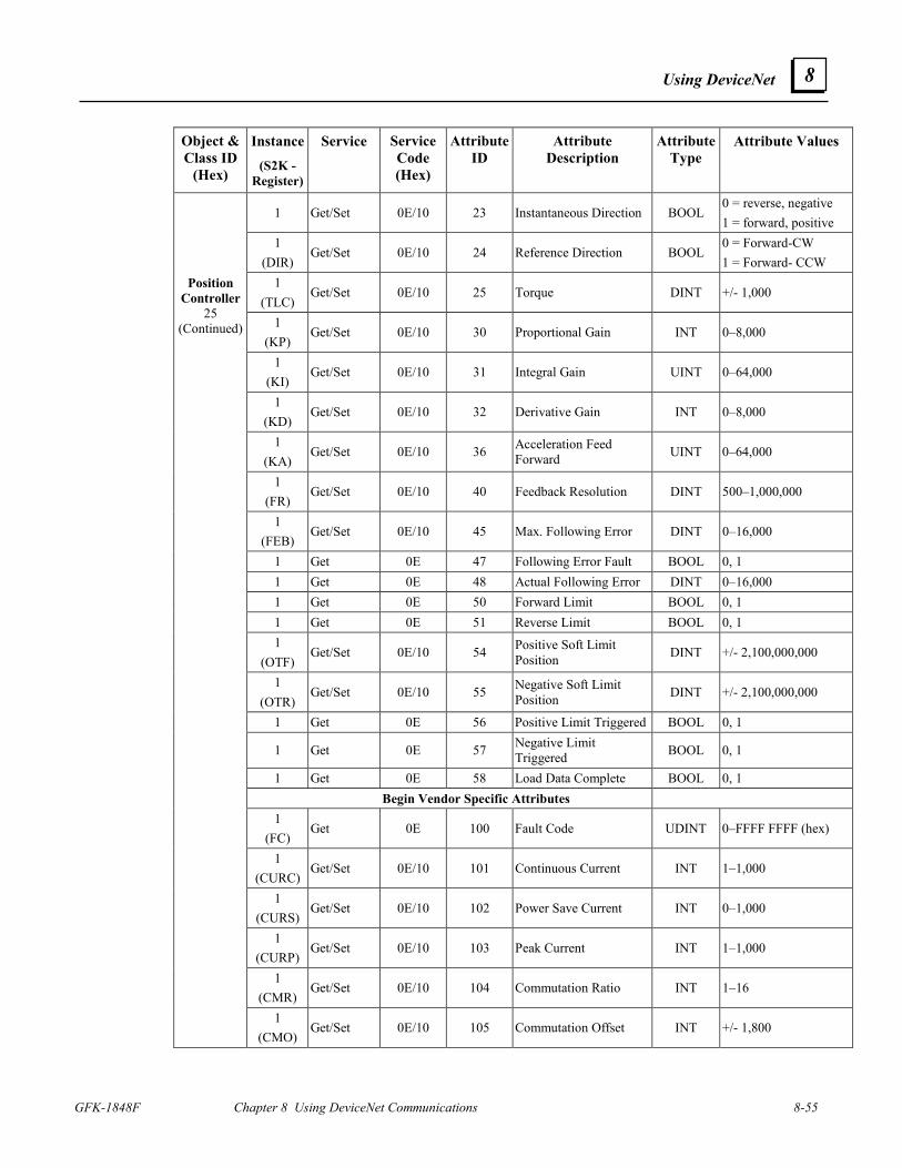
Using DeviceNet
GFK-1848F Chapter 8 Using DeviceNet Communications 8-55
8
Object & Class ID
(Hex)
Instance (S2K -
Register)
Service Service Code (Hex)
Attribute ID
Attribute Description
Attribute Type
Attribute Values
1 Get/Set 0E/10 23 Instantaneous Direction BOOL 0 = reverse, negative 1 = forward, positive
1 (DIR)
Get/Set 0E/10 24 Reference Direction BOOL 0 = Forward-CW 1 = Forward- CCW
1 (TLC)
Get/Set 0E/10 25 Torque DINT +/- 1,000
1 (KP)
Get/Set 0E/10 30 Proportional Gain INT 0–8,000
1 (KI)
Get/Set 0E/10 31 Integral Gain UINT 0–64,000
1 (KD)
Get/Set 0E/10 32 Derivative Gain INT 0–8,000
1 (KA)
Get/Set 0E/10 36 Acceleration Feed Forward UINT 0–64,000
1 (FR)
Get/Set 0E/10 40 Feedback Resolution DINT 500–1,000,000
1 (FEB)
Get/Set 0E/10 45 Max. Following Error DINT 0–16,000
1 Get 0E 47 Following Error Fault BOOL 0, 1 1 Get 0E 48 Actual Following Error DINT 0–16,000 1 Get 0E 50 Forward Limit BOOL 0, 1 1 Get 0E 51 Reverse Limit BOOL 0, 1 1
(OTF) Get/Set 0E/10 54 Positive Soft Limit
Position DINT +/- 2,100,000,000
1 (OTR)
Get/Set 0E/10 55 Negative Soft Limit Position DINT +/- 2,100,000,000
1 Get 0E 56 Positive Limit Triggered BOOL 0, 1
1 Get 0E 57 Negative Limit Triggered BOOL 0, 1
1 Get 0E 58 Load Data Complete BOOL 0, 1 Begin Vendor Specific Attributes
1 (FC)
Get 0E 100 Fault Code UDINT 0–FFFF FFFF (hex)
1 (CURC)
Get/Set 0E/10 101 Continuous Current INT 1–1,000
1 (CURS)
Get/Set 0E/10 102 Power Save Current INT 0–1,000
1 (CURP)
Get/Set 0E/10 103 Peak Current INT 1–1,000
1 (CMR)
Get/Set 0E/10 104 Commutation Ratio INT 1–16
Position Controller
25 (Continued)
1 (CMO)
Get/Set 0E/10 105 Commutation Offset INT +/- 1,800
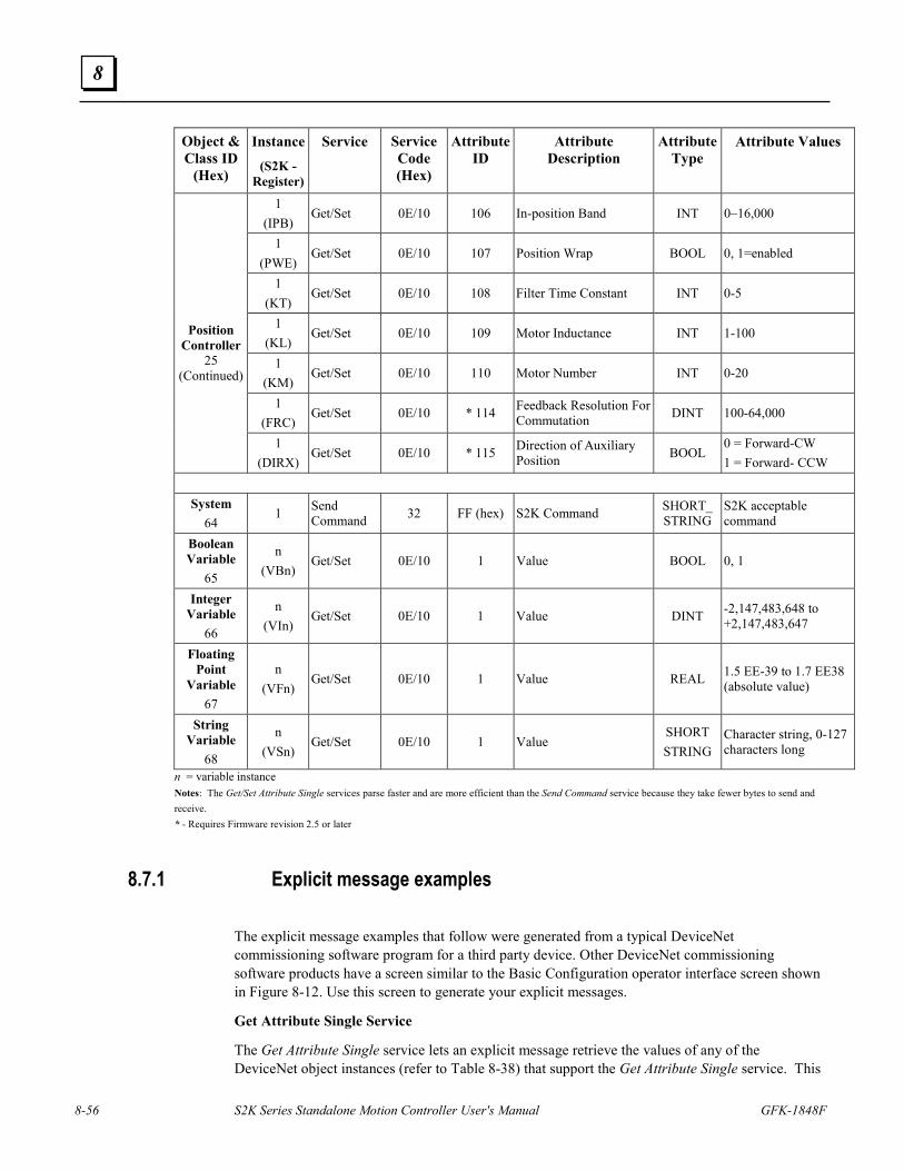
8-56 S2K Series Standalone Motion Controller User's Manual GFK-1848F
8
Object & Class ID
(Hex)
Instance (S2K -
Register)
Service Service Code (Hex)
Attribute ID
Attribute Description
Attribute Type
Attribute Values
1 (IPB)
Get/Set 0E/10 106 In-position Band INT 0–16,000
1 (PWE)
Get/Set 0E/10 107 Position Wrap BOOL 0, 1=enabled
1 (KT)
Get/Set 0E/10 108 Filter Time Constant INT 0-5
1 (KL)
Get/Set 0E/10 109 Motor Inductance INT 1-100
1 (KM)
Get/Set 0E/10 110 Motor Number INT 0-20
1 (FRC)
Get/Set 0E/10 * 114 Feedback Resolution For Commutation DINT 100-64,000
Position Controller
25 (Continued)
1 (DIRX)
Get/Set 0E/10 * 115 Direction of Auxiliary Position BOOL
0 = Forward-CW 1 = Forward- CCW
System
64 1 Send
Command 32 FF (hex) S2K Command SHORT_ STRING
S2K acceptable command
Boolean Variable
65
n (VBn)
Get/Set 0E/10 1 Value BOOL 0, 1
Integer Variable
66
n (VIn)
Get/Set 0E/10 1 Value DINT -2,147,483,648 to +2,147,483,647
Floating Point
Variable 67
n (VFn)
Get/Set 0E/10 1 Value REAL 1.5 EE-39 to 1.7 EE38 (absolute value)
String Variable
68
n (VSn)
Get/Set 0E/10 1 Value SHORT STRING
Character string, 0-127 characters long
n = variable instance Notes: The Get/Set Attribute Single services parse faster and are more efficient than the Send Command service because they take fewer bytes to send and receive. * - Requires Firmware revision 2.5 or later
8.7.1 Explicit message examples
The explicit message examples that follow were generated from a typical DeviceNet commissioning software program for a third party device. Other DeviceNet commissioning software products have a screen similar to the Basic Configuration operator interface screen shown in Figure 8-12. Use this screen to generate your explicit messages.
Get Attribute Single Service
The Get Attribute Single service lets an explicit message retrieve the values of any of the DeviceNet object instances (refer to Table 8-38) that support the Get Attribute Single service. This
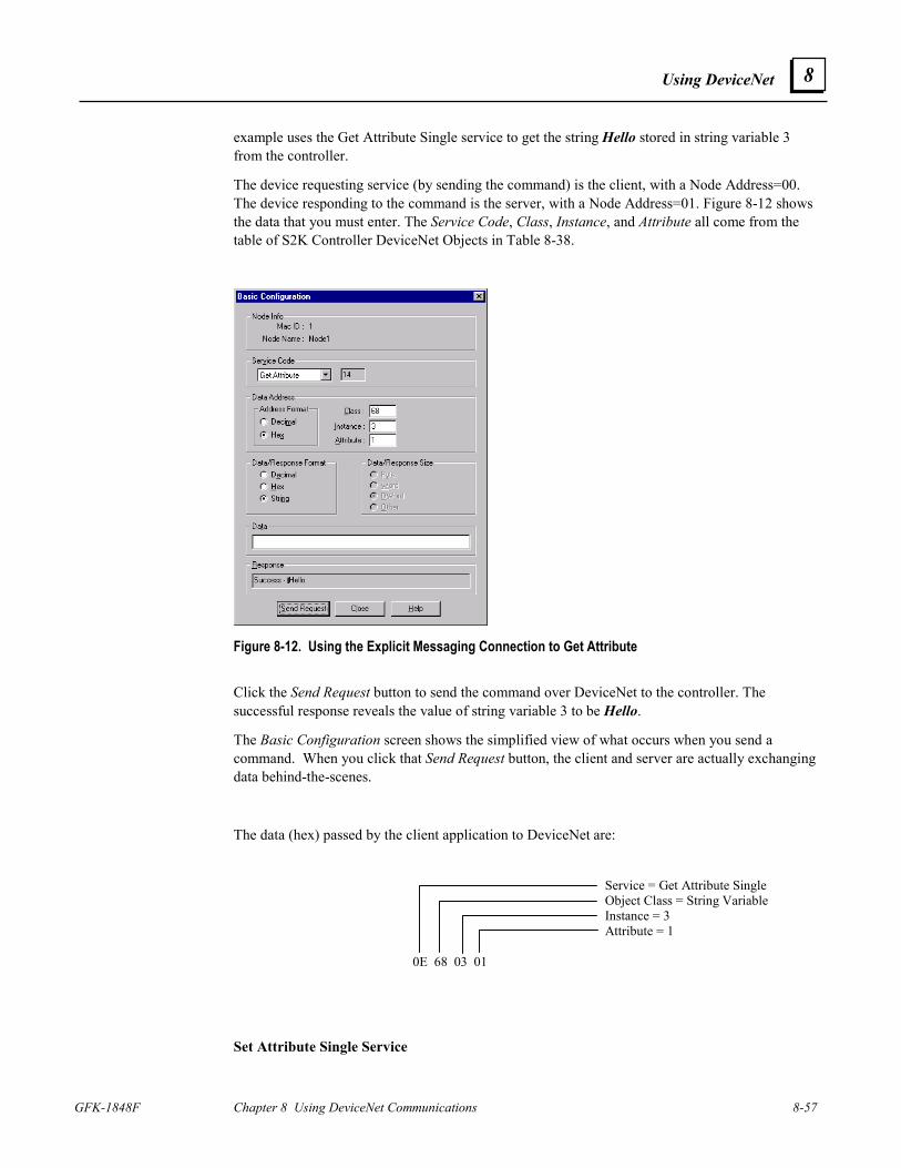
Using DeviceNet
GFK-1848F Chapter 8 Using DeviceNet Communications 8-57
8
example uses the Get Attribute Single service to get the string Hello stored in string variable 3 from the controller.
The device requesting service (by sending the command) is the client, with a Node Address=00. The device responding to the command is the server, with a Node Address=01. Figure 8-12 shows the data that you must enter. The Service Code, Class, Instance, and Attribute all come from the table of S2K Controller DeviceNet Objects in Table 8-38.
Figure 8-12. Using the Explicit Messaging Connection to Get Attribute Click the Send Request button to send the command over DeviceNet to the controller. The successful response reveals the value of string variable 3 to be Hello.
The Basic Configuration screen shows the simplified view of what occurs when you send a command. When you click that Send Request button, the client and server are actually exchanging data behind-the-scenes.
The data (hex) passed by the client application to DeviceNet are:
Service = Get Attribute Single Object Class = String Variable Instance = 3 Attribute = 1 0E 68 03 01
Set Attribute Single Service
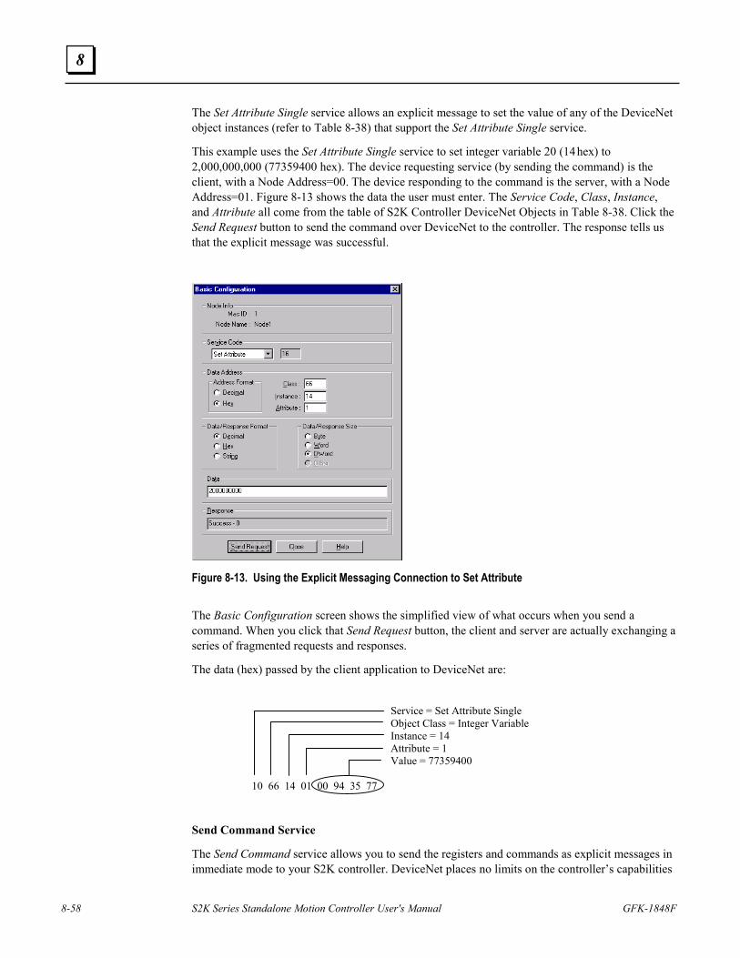
8-58 S2K Series Standalone Motion Controller User's Manual GFK-1848F
8
The Set Attribute Single service allows an explicit message to set the value of any of the DeviceNet object instances (refer to Table 8-38) that support the Set Attribute Single service.
This example uses the Set Attribute Single service to set integer variable 20 (14 hex) to 2,000,000,000 (77359400 hex). The device requesting service (by sending the command) is the client, with a Node Address=00. The device responding to the command is the server, with a Node Address=01. Figure 8-13 shows the data the user must enter. The Service Code, Class, Instance, and Attribute all come from the table of S2K Controller DeviceNet Objects in Table 8-38. Click the Send Request button to send the command over DeviceNet to the controller. The response tells us that the explicit message was successful.
Figure 8-13. Using the Explicit Messaging Connection to Set Attribute The Basic Configuration screen shows the simplified view of what occurs when you send a command. When you click that Send Request button, the client and server are actually exchanging a series of fragmented requests and responses.
The data (hex) passed by the client application to DeviceNet are:
Service = Set Attribute Single Object Class = Integer Variable Instance = 14 Attribute = 1 Value = 77359400 10 66 14 01 00 94 35 77
Send Command Service
The Send Command service allows you to send the registers and commands as explicit messages in immediate mode to your S2K controller. DeviceNet places no limits on the controller’s capabilities
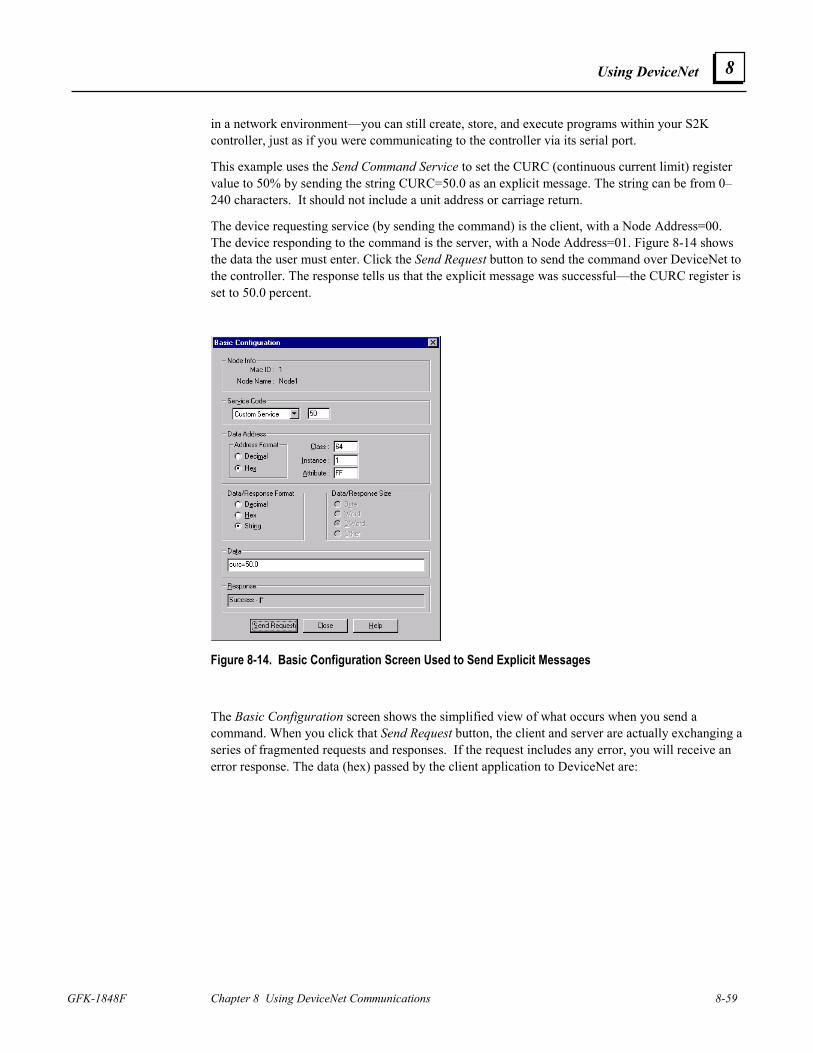
Using DeviceNet
GFK-1848F Chapter 8 Using DeviceNet Communications 8-59
8
in a network environment—you can still create, store, and execute programs within your S2K controller, just as if you were communicating to the controller via its serial port.
This example uses the Send Command Service to set the CURC (continuous current limit) register value to 50% by sending the string CURC=50.0 as an explicit message. The string can be from 0–240 characters. It should not include a unit address or carriage return.
The device requesting service (by sending the command) is the client, with a Node Address=00. The device responding to the command is the server, with a Node Address=01. Figure 8-14 shows the data the user must enter. Click the Send Request button to send the command over DeviceNet to the controller. The response tells us that the explicit message was successful—the CURC register is set to 50.0 percent.
Figure 8-14. Basic Configuration Screen Used to Send Explicit Messages The Basic Configuration screen shows the simplified view of what occurs when you send a command. When you click that Send Request button, the client and server are actually exchanging a series of fragmented requests and responses. If the request includes any error, you will receive an error response. The data (hex) passed by the client application to DeviceNet are:
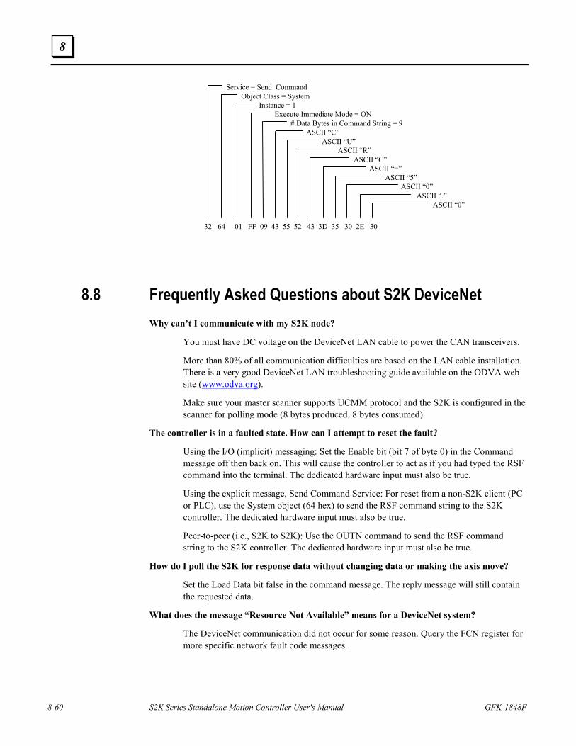
8-60 S2K Series Standalone Motion Controller User's Manual GFK-1848F
8
Service = Send_CommandObject Class = System
Instance = 1Execute Immediate Mode = ON
# Data Bytes in Command String = 9ASCII “C”
ASCII “U”ASCII “R”
ASCII “C”ASCII “=”
ASCII “5”ASCII “0”
ASCII “.”ASCII “0”
32 64 01 FF 09 43 55 52 43 3D 35 30 2E 30
8.8 Frequently Asked Questions about S2K DeviceNet Why can’t I communicate with my S2K node?
You must have DC voltage on the DeviceNet LAN cable to power the CAN transceivers.
More than 80% of all communication difficulties are based on the LAN cable installation. There is a very good DeviceNet LAN troubleshooting guide available on the ODVA web site (www.odva.org).
Make sure your master scanner supports UCMM protocol and the S2K is configured in the scanner for polling mode (8 bytes produced, 8 bytes consumed).
The controller is in a faulted state. How can I attempt to reset the fault?
Using the I/O (implicit) messaging: Set the Enable bit (bit 7 of byte 0) in the Command message off then back on. This will cause the controller to act as if you had typed the RSF command into the terminal. The dedicated hardware input must also be true.
Using the explicit message, Send Command Service: For reset from a non-S2K client (PC or PLC), use the System object (64 hex) to send the RSF command string to the S2K controller. The dedicated hardware input must also be true.
Peer-to-peer (i.e., S2K to S2K): Use the OUTN command to send the RSF command string to the S2K controller. The dedicated hardware input must also be true.
How do I poll the S2K for response data without changing data or making the axis move?
Set the Load Data bit false in the command message. The reply message will still contain the requested data.
What does the message “Resource Not Available” means for a DeviceNet system?
The DeviceNet communication did not occur for some reason. Query the FCN register for more specific network fault code messages.
Using DeviceNet
GFK-1848F Chapter 8 Using DeviceNet Communications 8-61
8
How does the S2K manage the UCMM connection?
Each S2K can open three client connections and respond to three server connections without any problems. The S2K automatically handles the network connection management. If all three connections of a given type are open and another connection is attempted the S2K will check for an available connection. If a connection is open but unused, the S2K will reassign it to the new connection. If all the message connections of the desired type (client or server) are used, the S2K will issue an “out of connection” fault. If you are using many devices on a network with a particular S2K node, the NCO register should be used.
What does NCO do?
NCO is a read only register that lets you attempt to make a connection without faulting the S2K if the connection is unavailable. When using NCO make sure that the next line of program code makes a decision about what to do if the connection is not available i.e., increment an error counter and try again x number of times.
How many server connections does the master/slave connection consume?
Typically, two server connections are consumed. One server connection is used for the I/O messaging and one for the explicit connection. If explicit messaging is not available or not being used, then only one server connection is used. The three client connections remain available for peer-to-peer or expansion I/O communication.
What is the meaning of the various states of the “Network Status” LED on the S2K?
The network status LED conforms to the DeviceNet specification and has the following conditions:
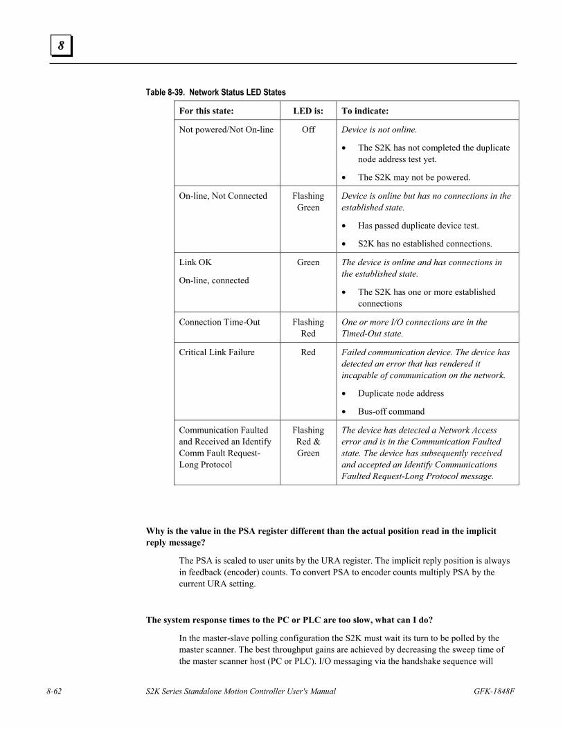
8-62 S2K Series Standalone Motion Controller User's Manual GFK-1848F
8
Table 8-39. Network Status LED States
For this state: LED is: To indicate:
Not powered/Not On-line Off Device is not online.
• The S2K has not completed the duplicate node address test yet.
• The S2K may not be powered.
On-line, Not Connected Flashing Green
Device is online but has no connections in the established state.
• Has passed duplicate device test.
• S2K has no established connections.
Link OK
On-line, connected
Green The device is online and has connections in the established state.
• The S2K has one or more established connections
Connection Time-Out Flashing Red
One or more I/O connections are in the Timed-Out state.
Critical Link Failure Red Failed communication device. The device has detected an error that has rendered it incapable of communication on the network.
• Duplicate node address
• Bus-off command
Communication Faulted and Received an Identify Comm Fault Request-Long Protocol
Flashing Red & Green
The device has detected a Network Access error and is in the Communication Faulted state. The device has subsequently received and accepted an Identify Communications Faulted Request-Long Protocol message.
Why is the value in the PSA register different than the actual position read in the implicit reply message?
The PSA is scaled to user units by the URA register. The implicit reply position is always in feedback (encoder) counts. To convert PSA to encoder counts multiply PSA by the current URA setting.
The system response times to the PC or PLC are too slow, what can I do?
In the master-slave polling configuration the S2K must wait its turn to be polled by the master scanner. The best throughput gains are achieved by decreasing the sweep time of the master scanner host (PC or PLC). I/O messaging via the handshake sequence will
Using DeviceNet
GFK-1848F Chapter 8 Using DeviceNet Communications 8-63
8
require two host sweeps per message. Generally, the scanner is running on a 10 ms network polling cycle (may be adjustable) and stays well ahead of the host ladder.
The advantage to the I/O (implicit) messaging is that the scanner maps implicit command/response data buffers for each networked node. Rather than sending all the messages to one node, send messages to multiple nodes and allow the S2Ks to communicate to each other in the much faster peer-to-peer mode. This is a distributed control approach.
Many scanners have the ability to use explicit messaging along with the I/O messaging. While there is typically only one explicit messaging transmit and receive buffer per network it is possible to use the Assembly Object (code 4) to get/set up to thirty two variables per two host sweeps to a single S2K.
What is the format of the floating-point numbers used in the DeviceNet interface?
DeviceNet uses the Single Precision Binary Real Format ANSI-IEEE 754-1985 specification as required for ODVA conformance. This is a 32-bit representation that allows values of 3.4 x 1038 to 1.2 x 10-38 to be used. Bits 0–22 are the fraction, bits 22–30 are the biased exponent and bit 31 is the sign bit. This format is compatible with many PLC floating-point formats as well. Internal to the S2K these values are automatically converted to the native S2K 8-byte format.

8-64 S2K Series Standalone Motion Controller User's Manual GFK-1848F
8
Intentionally Blank
GFK-1848F 9-1
Using Serial Communications
9.1 Getting Started The S2K Motion Controller includes a multi-purpose RS232 serial port. The S2K serial port may operate at 1,200; 9,600; 19,200 or 38,400 baud and has configurable settings for data bits (7,8) and parity (odd, even). Software flow control is supported and the S2K provides a variety of commands associated with the serial port and string manipulation. Usage of the port is alternately available as an ASCII serial port or as an RTU Slave protocol port. Using the port in one mode prohibits usage in the other however, program control is provided to switch between serial port modes.
This chapter assumes that you have completed the basic setup for your S2K controller. Basic setup entails connecting and configuring all motion control system components, applying power, and running the motor from the controller.
9.2 ASCII Protocol ASCII is the default mode of the serial port and may be used for many functions:
• Configuration and programming
• Downloading new S2K firmware
• Loading and storing programs and motion blocks
• Monitoring variable and register data via ASCII terminal
• Interfacing to serial devices such as RF tag readers, digital scales, bar code readers or serial printers.
When the serial port is in ASCII mode, the factory default is to operate at 9,600 baud, 7-bit, odd-parity. Chapter 5 provides detailed information about the instructions related to reading and writing ASCII data with the serial port as well as the extensive string manipulation commands available within the S2K.
Primarily the ASCII serial port is designed to be a programming and debugging interface. This is defined as “terminal” mode. Alternately it may be used in a “data” mode.
9 Chapter
9-2 S2K Series Standalone Motion Controller User's Manual GFK-1848F
9
9.2.1 ASCII Terminal Mode
In the default, terminal mode operation is very simple. You may use any “dumb” terminal that has the same serial configuration. You are automatically online to the S2K and valid commands are immediately processed. When using the CIMPLICITY Machine Edition Motion Developer terminal, the addressing is automatically done based on the active target properties. You do not have to type the address field on each line. If using a dumb terminal you will require the address field for each line sent.
The S2K expects the following command line format:
<Address> <command string> [query character] <terminator>
Address is a required field and in the S2K has two forms:
• Local–Any valid serial address 1-9 or A-V is permitted. The S2K does not require address setting via configuration and will accept any of the previous address settings.
• Local Connect-Remote/Redirected–DeviceNet networked S2Ks are accessible via the re-direct addressing format. This is accomplished by using the redirect character “>”. The following address field format should be used to access a remote S2K.
<Local Serial address> <redirect character> <Remote DeviceNet address>
For example, the serial connection is to a S2K controller networked and at address 1. Using the remote/redirect, the terminal connection to this node is able to operate as the terminal connection to a different networked node i.e., node 6. The address field would be “1>6”.
Command String is a required field and may be any valid S2K command. A command will be rejected if the S2K is not in the appropriate operating mode to accept it. In a query only the variable or register address is used in the command field. An example is to set a value to an S2K variable: “1 VF1=123.456 <cr>”. Query Character or “?” is an optional field and is used to instruct the S2K to return the data of the variable or register in the command string. An example would be to query the Axis Position register for networked node 6: “1>6 PSA? <cr>”. Terminator is a required field and is the ASCII carriage return character <cr>.
As each ASCII character of the command line is entered, the S2K will echo that character back to the terminal. A dumb terminal should be configured in full-duplex mode to avoid double characters on the terminal screen. When the S2K receives the terminator character <cr> an ASCII carriage return/line feed <cr/lf> is sent to the terminal. After each full command line, the S2K will return additional ASCII data in response to the command entered and the current executing circumstances. Typical responses are: Null Response is returned if the command field is blank or null. This is an ASCII string containing model identification and station address information. For example:
* GE Fanuc S2K Series <cr/lf> Network Address – 1 <cr/lf>
Using Serial Communications
GFK-1848F Chapter 9 Using Serial Communications 9-3
9
Status Message is returned if the S2K rejects the command line. The status string is prefixed with the ASCII “?” character and provides either a numeric or text status message based on the setting of the S2K CIE register. The return data is completed with an ASCII <cr/lf>. A complete list of the status messages may be found in Table 7-2. A sample status message would appear as: “? INVALID COMMAND <cr/lf>” Query Response Message is returned if the query command accessed a valid variable or register in the S2K. The data string is prefixed by the ASCII “*” character and includes the variable value. The return data is completed with an ASCII <cr/lf>. A sample query message would appear as: “1 PSA? <cr>’ and the response message is “*123.456 <cr/lf>” Special Operating Mode Messages are returned when the command message places the S2K control into special operating modes. These modes include: firmware loading, online program edit, single-step program, trace program, clear memory, auto tune (servo only) and diagnostic messaging.
9.2.2 ASCII Data Mode The ASCII data mode is really a specialized command sent via the normal terminal mode interface. This command allows the terminal equipment to write a string to the S2K, character by character that will not be interpreted as a command or generate a status response message. The KY command may be used to load any single ASCII character into a special S2K memory location, the KEY buffer. S2K internal commands are available to test for presence of data in the key buffer (KEY, SRS), clear the key buffer (EKB) and read the key buffer to a variable (GET, IN).
For example to send the word “HELLO” to the key buffer you need to format one command per character: 1 KYH <cr> 1 KYE <cr> 1 KYL <cr> 1 KYL <cr> 1 KYO <cr> You can have the S2K generate a string output to the terminal in any format in an S2K program (as long as its 7 bits odd parity) with the OUT command. For example:
OUT “Position is “+$PSA+”$N”
Send the string “Position is 123.456<cr,lf>” to the serial port . The “+” is the string concatenation operator. Special operators “$”, are listed in Chapter 5. You can control the number of digits, etc. if you use the FTS or ITS commands to convert register or variable values to strings, i.e.,
VS10 = FTS(VF100,7,2).
Alternately the PUT command allows a single character to be output to the terminal (serial port). Various program examples are shown in the PUT command documentation in Chapter 5.
9-4 S2K Series Standalone Motion Controller User's Manual GFK-1848F
9
9.3 RTU Protocol This chapter documents the basic setup procedure required to connect an S2K motion controller to a Remote Terminal Unit (RTU) master, such as a QuickPanel, Datapanel or CIMPLICITY Machine Edition - View software target (CE and NT ViewStation) and configure the controller for communication with the S2K. RTU slave mode is available in all S2K controllers with firmware version 2.1 or higher.
The RTU Slave functionality of the S2K allows the RTU Master to:
Read/Write single bits (Boolean) VB1-VB256.
Read/Write signed words (Integer) VI1-VI4096.
Read/Write signed double words (DINT) VI1-VI4096.
Read/Write floating-point variables VF1-VF2047.
Read Text (String variables 128 characters each) VS1-VS144.
The S2K serial communications is point-to-point only (no multi-drop), therefore, the S2K controller is always node address one unless the multi-drop port adaptor is used. Contact your GE Fanuc sales representative for more information about the S2K multi-drop adapter.
Refer to your RTU master device documentation for instructions on creating touch screen objects that are tagged to controller variables and for the proper use of any RTU function keys.
Note When RTU communication is enabled, the controller cannot communicate with the CIMPLICITY Machine Edition Motion Developer software. The controller will automatically disable RTU mode (RTU=0) if ten consecutive non-RTU messages are received (e.g., ten carriage returns from the Motion Developer Terminal Window). See the RTU command documentation in Chapter 5 for more details.
9.3.1 Connect S2K Controller to RTU master device The serial communications cable is limited to 50 feet maximum. There is however, an option to add the Modbus Adapter port converter, which supports multi-drop, longer distances and node addressing.
9.3.1.1 Modbus Adapter GE Fanuc’s Modbus adapter model ADP-COMJ-MBUS allows multidrop communication with S2K motion controllers via Modbus. The ADP-COMJ-MBUS fits into the RS-232 Serial Port on S2K motion controllers to convert the RS-232 signal to a RS-422/485 signal.
The RS-422/485 port has a 6-position terminal block connector with the Transmit Data outputs and Receive Data inputs labeled accordingly. Keep the Echo jumper in the “OFF” position.
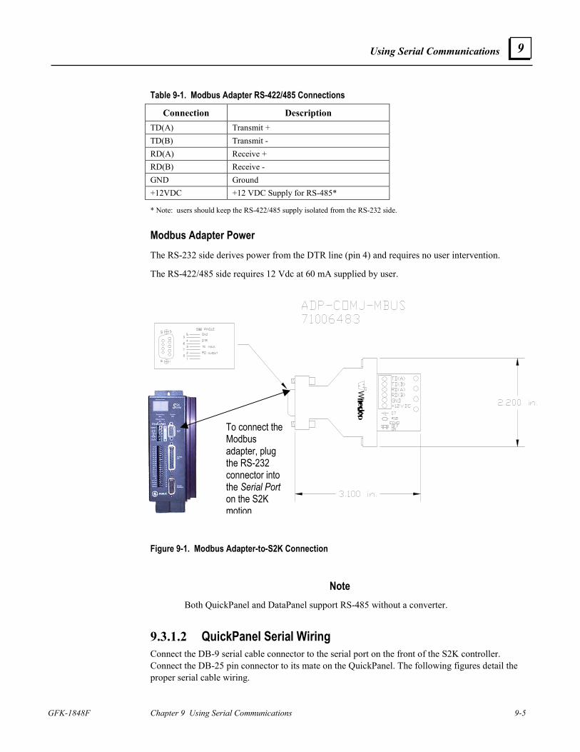
Using Serial Communications
GFK-1848F Chapter 9 Using Serial Communications 9-5
9
Table 9-1. Modbus Adapter RS-422/485 Connections
Connection Description TD(A) Transmit + TD(B) Transmit - RD(A) Receive + RD(B) Receive - GND Ground +12VDC +12 VDC Supply for RS-485*
* Note: users should keep the RS-422/485 supply isolated from the RS-232 side.
Modbus Adapter Power The RS-232 side derives power from the DTR line (pin 4) and requires no user intervention.
The RS-422/485 side requires 12 Vdc at 60 mA supplied by user.
Figure 9-1. Modbus Adapter-to-S2K Connection
Note Both QuickPanel and DataPanel support RS-485 without a converter.
9.3.1.2 QuickPanel Serial Wiring Connect the DB-9 serial cable connector to the serial port on the front of the S2K controller. Connect the DB-25 pin connector to its mate on the QuickPanel. The following figures detail the proper serial cable wiring.
To connect the Modbus adapter, plug the RS-232 connector into the Serial Port on the S2K motion
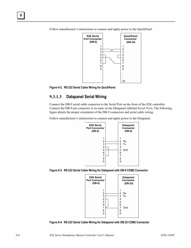
9-6 S2K Series Standalone Motion Controller User's Manual GFK-1848F
9
Follow manufacturer’s instructions to connect and apply power to the QuickPanel.
S2K SerialPort Connector
(DB-9)123456789
QuickPanel Connector
(DB-25) 123456789. . . 25
Figure 9-2. RS-232 Serial Cable Wiring for QuickPanel
9.3.1.3 Datapanel Serial Wiring Connect the DB-9 serial cable connector to the Serial Port on the front of the S2K controller. Connect the DB-9 pin connector to its mate on the Datapanel (labeled Serial Port). The following figure details the proper orientation of the DB-9 connectors and serial cable wiring.
Follow manufacturer’s instructions to connect and apply power to the Datapanel.
S2K SerialPort Connector
(DB-9)
123456789
Datapanel Connector
(DB-9)
1 2 Rx 3 Tx 4 5 Gnd6 7 8 9
Figure 9-3. RS-232 Serial Cable Wiring for Datapanel with DB-9 COM2 Connector
S2K SerialPort Connector
(DB-9)
123456789
Datapanel Connector
(DB-25)
12 Rx3 Tx4567 Gnd89
Figure 9-4. RS-232 Serial Cable Wiring for Datapanel with DB-25 COM2 Connector
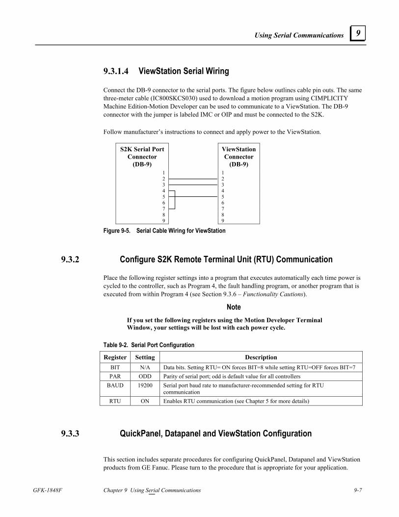
Using Serial Communications
GFK-1848F Chapter 9 Using Serial Communications 9-7
9
9.3.1.4 ViewStation Serial Wiring
Connect the DB-9 connector to the serial ports. The figure below outlines cable pin outs. The same three-meter cable (IC800SKCS030) used to download a motion program using CIMPLICITY Machine Edition-Motion Developer can be used to communicate to a ViewStation. The DB-9 connector with the jumper is labeled IMC or OIP and must be connected to the S2K. Follow manufacturer’s instructions to connect and apply power to the ViewStation.
S2K Serial Port Connector
(DB-9)
ViewStation Connector
(DB-9) 1 1 2 2 3 3 4 4 5 5 6 6 7 7 8 8 9 9
Figure 9-5. Serial Cable Wiring for ViewStation
9.3.2 Configure S2K Remote Terminal Unit (RTU) Communication
Place the following register settings into a program that executes automatically each time power is cycled to the controller, such as Program 4, the fault handling program, or another program that is executed from within Program 4 (see Section 9.3.6 – Functionality Cautions).
Note If you set the following registers using the Motion Developer Terminal Window, your settings will be lost with each power cycle.
Table 9-2. Serial Port Configuration
Register Setting Description BIT N/A Data bits. Setting RTU= ON forces BIT=8 while setting RTU=OFF forces BIT=7 PAR ODD Parity of serial port; odd is default value for all controllers
BAUD 19200 Serial port baud rate to manufacturer-recommended setting for RTU communication
RTU ON Enables RTU communication (see Chapter 5 for more details)
9.3.3 QuickPanel, Datapanel and ViewStation Configuration This section includes separate procedures for configuring QuickPanel, Datapanel and ViewStation products from GE Fanuc. Please turn to the procedure that is appropriate for your application.
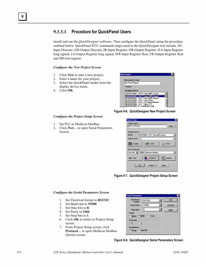
9-8 S2K Series Standalone Motion Controller User's Manual GFK-1848F
9
9.3.3.1 Procedure for QuickPanel Users
Install and run the QuickDesigner software. Then configure the QuickPanel using the procedure outlined below. QuickPanel RTU commands (tags) used in the QuickDesigner tool include: ID-Input Discrete, OD-Output Discrete, IR-Input Register, OR-Output Register, ILS-Input Register long signed, LS-Output Register long signed, IFR-Input Register float, FR-Output Register float and MS-text register. Configure the New Project Screen 1. Click New to start a new project. 2. Enter a name for your project. 3. Select the QuickPanel model from the
display device menu. 4. Click OK. Figure 9-6. QuickDesigner New Project Screen Configure the Project Setup Screen 1. Set PLC to Modicon Modbus. 2. Click Port… to open Serial Parameters
Screen.
Figure 9-7. QuickDesigner Project Setup Screen Configure the Serial Parameters Screen
1. Set Electrical format to RS232C 2. Set Baud rate to 19200. 3. Set Data bits to 8. 4. Set Parity to Odd. 5. Set Stop bits to 1. 6. Click OK to return to Project Setup
screen. 7. From Project Setup screen, click
Protocol… to open Modicon Modbus (Serial) screen.
Figure 9-8. QuickDesigner Serial Parameters Screen
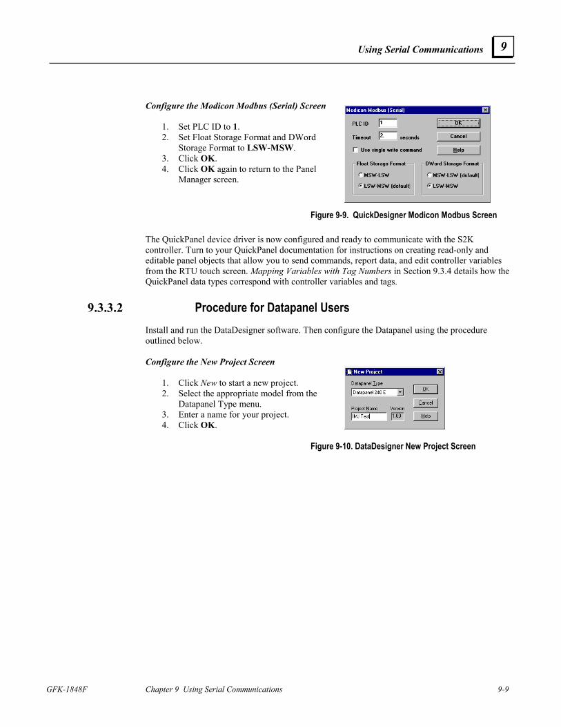
Using Serial Communications
GFK-1848F Chapter 9 Using Serial Communications 9-9
9
Configure the Modicon Modbus (Serial) Screen
1. Set PLC ID to 1. 2. Set Float Storage Format and DWord
Storage Format to LSW-MSW. 3. Click OK. 4. Click OK again to return to the Panel
Manager screen.
Figure 9-9. QuickDesigner Modicon Modbus Screen The QuickPanel device driver is now configured and ready to communicate with the S2K controller. Turn to your QuickPanel documentation for instructions on creating read-only and editable panel objects that allow you to send commands, report data, and edit controller variables from the RTU touch screen. Mapping Variables with Tag Numbers in Section 9.3.4 details how the QuickPanel data types correspond with controller variables and tags.
9.3.3.2 Procedure for Datapanel Users Install and run the DataDesigner software. Then configure the Datapanel using the procedure outlined below. Configure the New Project Screen
1. Click New to start a new project. 2. Select the appropriate model from the
Datapanel Type menu. 3. Enter a name for your project. 4. Click OK.
Figure 9-10. DataDesigner New Project Screen
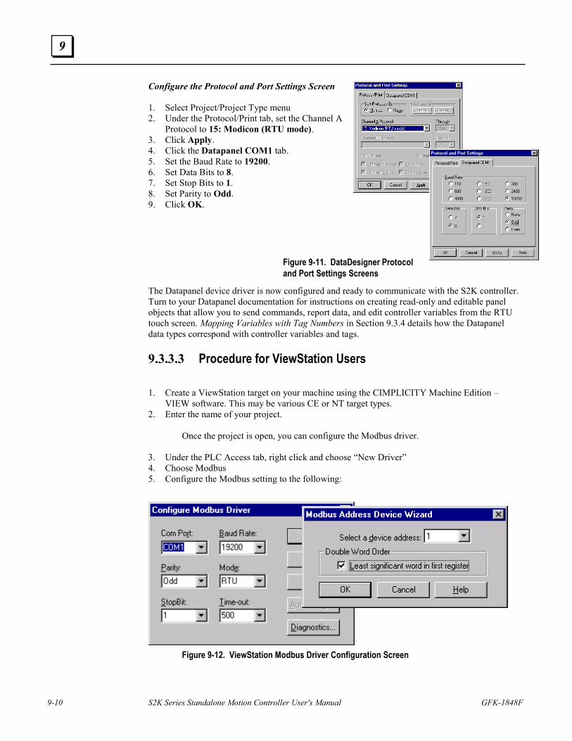
9-10 S2K Series Standalone Motion Controller User's Manual GFK-1848F
9
Configure the Protocol and Port Settings Screen
1. Select Project/Project Type menu 2. Under the Protocol/Print tab, set the Channel A
Protocol to 15: Modicon (RTU mode). 3. Click Apply. 4. Click the Datapanel COM1 tab. 5. Set the Baud Rate to 19200. 6. Set Data Bits to 8. 7. Set Stop Bits to 1. 8. Set Parity to Odd. 9. Click OK.
Figure 9-11. DataDesigner Protocol and Port Settings Screens
The Datapanel device driver is now configured and ready to communicate with the S2K controller. Turn to your Datapanel documentation for instructions on creating read-only and editable panel objects that allow you to send commands, report data, and edit controller variables from the RTU touch screen. Mapping Variables with Tag Numbers in Section 9.3.4 details how the Datapanel data types correspond with controller variables and tags.
9.3.3.3 Procedure for ViewStation Users 1. Create a ViewStation target on your machine using the CIMPLICITY Machine Edition –
VIEW software. This may be various CE or NT target types. 2. Enter the name of your project.
Once the project is open, you can configure the Modbus driver. 3. Under the PLC Access tab, right click and choose “New Driver” 4. Choose Modbus 5. Configure the Modbus setting to the following:
Figure 9-12. ViewStation Modbus Driver Configuration Screen
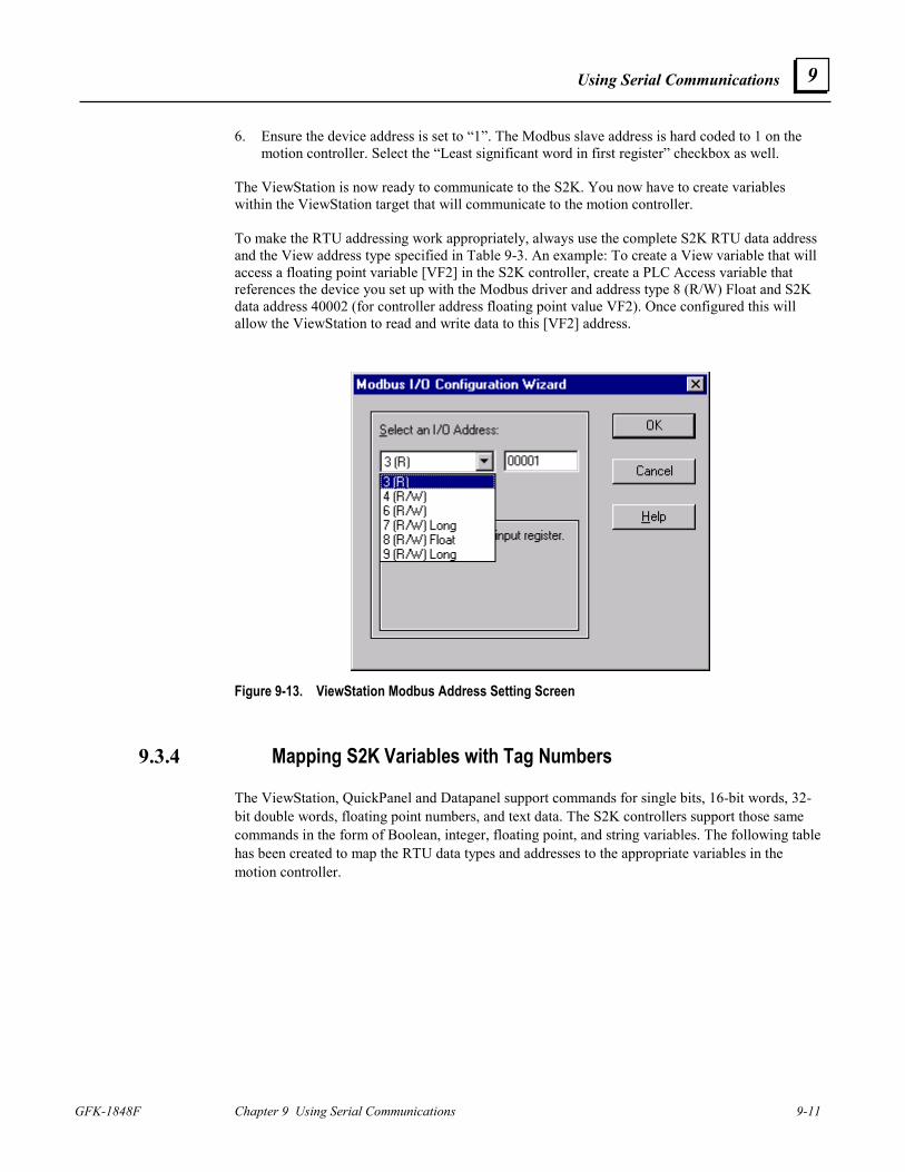
Using Serial Communications
GFK-1848F Chapter 9 Using Serial Communications 9-11
9
6. Ensure the device address is set to “1”. The Modbus slave address is hard coded to 1 on the motion controller. Select the “Least significant word in first register” checkbox as well.
The ViewStation is now ready to communicate to the S2K. You now have to create variables within the ViewStation target that will communicate to the motion controller. To make the RTU addressing work appropriately, always use the complete S2K RTU data address and the View address type specified in Table 9-3. An example: To create a View variable that will access a floating point variable [VF2] in the S2K controller, create a PLC Access variable that references the device you set up with the Modbus driver and address type 8 (R/W) Float and S2K data address 40002 (for controller address floating point value VF2). Once configured this will allow the ViewStation to read and write data to this [VF2] address.
Figure 9-13. ViewStation Modbus Address Setting Screen
9.3.4 Mapping S2K Variables with Tag Numbers
The ViewStation, QuickPanel and Datapanel support commands for single bits, 16-bit words, 32-bit double words, floating point numbers, and text data. The S2K controllers support those same commands in the form of Boolean, integer, floating point, and string variables. The following table has been created to map the RTU data types and addresses to the appropriate variables in the motion controller.
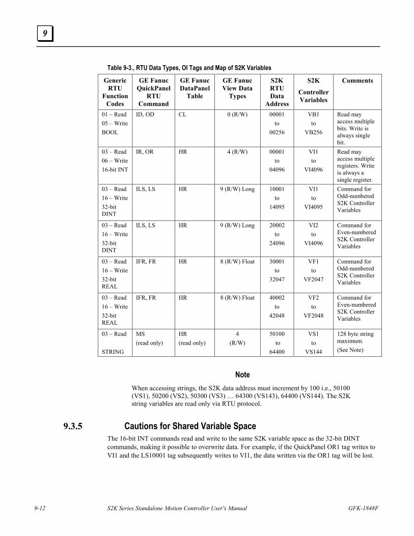
9-12 S2K Series Standalone Motion Controller User's Manual GFK-1848F
9
Table 9-3., RTU Data Types, OI Tags and Map of S2K Variables
Generic RTU
Function Codes
GE Fanuc QuickPanel
RTU Command
GE Fanuc DataPanel
Table
GE Fanuc View Data
Types
S2K RTU Data
Address
S2K
Controller Variables
Comments
01 – Read 05 – Write BOOL
ID, OD CL 0 (R/W) 00001 to
00256
VB1 to
VB256
Read may access multiple bits. Write is always single bit.
03 – Read 06 – Write 16-bit INT
IR, OR HR 4 (R/W) 00001 to
04096
VI1 to
VI4096
Read may access multiple registers. Write is always a single register.
03 – Read 16 – Write 32-bit DINT
ILS, LS HR 9 (R/W) Long 10001 to
14095
VI1 to
VI4095
Command for Odd-numbered S2K Controller Variables
03 – Read 16 – Write 32-bit DINT
ILS, LS HR 9 (R/W) Long 20002 to
24096
VI2 to
VI4096
Command for Even-numbered S2K Controller Variables
03 – Read 16 – Write 32-bit REAL
IFR, FR HR 8 (R/W) Float 30001 to
32047
VF1 to
VF2047
Command for Odd-numbered S2K Controller Variables
03 – Read 16 – Write 32-bit REAL
IFR, FR HR 8 (R/W) Float 40002 to
42048
VF2 to
VF2048
Command for Even-numbered S2K Controller Variables
03 – Read STRING
MS (read only)
HR (read only)
4 (R/W)
50100 to
64400
VS1 to
VS144
128 byte string maximum. (See Note)
Note When accessing strings, the S2K data address must increment by 100 i.e., 50100 (VS1), 50200 (VS2), 50300 (VS3) … 64300 (VS143), 64400 (VS144). The S2K string variables are read only via RTU protocol.
9.3.5 Cautions for Shared Variable Space The 16-bit INT commands read and write to the same S2K variable space as the 32-bit DINT commands, making it possible to overwrite data. For example, if the QuickPanel OR1 tag writes to VI1 and the LS10001 tag subsequently writes to VI1, the data written via the OR1 tag will be lost.
Using Serial Communications
GFK-1848F Chapter 9 Using Serial Communications 9-13
9
9.3.6 Functional Considerations The S2K programmable RTUF flag can be used by your program to monitor for successful RTU communications. See details for this register in Chapter 5.
Motor noise in the serial cable can interfere with the transfer, or download, of the controller file to the Datapanel or QuickPanel. To avoid this problem, consider disabling your motor before attempting to transfer a file to the Datapanel or QuickPanel, or try different grounding schemes for the serial cable to minimize noise.
Always design your S2K programs to include the hardware permissive, such as the Enable input, which must be set true before the Program 4 fault-handling code will reset faults and restart the main program. Failure to observe this recommendation could result in the controller being stuck in an endless loop if a runtime error occurs in the main program. This error will cause Program 4 to execute, which would then reset faults and restart the main program, which would fault again on the same runtime error. When not in RTU mode the normal procedure to break out of a repeating loop is to repeatedly type KLALL <Enter> in the Motion Developer Terminal Window. However, with RTU mode enabled the Motion Developer Terminal Window can no longer communicate with the controller since it requires standard ASCII serial communications. If you find yourself in this dilemma, try configuring Windows Hyper Terminal for the bit, parity and baud rate shown in Table 9-3 above and set Emulation to Auto Detect. Then try quickly and repeatedly typing KLALL <Enter> to interrupt the program loop. If this fails you will have to return the S2K unit to the factory to have the flash memory replaced.
A sample method of dealing with the RTU to ASCII mode selection is to have Program 1 enable the RTU protocol and have Program 4 (the fault handler) disable RTU and set serial port settings for the Motion Developer interface.
Note For the S2K firmware version 2.2 and later. Once ten illegal RTU characters are received in a row, the RTU flag is automatically set to zero. Receiving a valid RTU character or cycling the power resets the error counter. Once in this state, the RTU=1 command will not change RTU i.e., it will be maintained at 0 until the power is cycled. The indication that the controller is in this state is that the value of RTU will always be 0 regardless of any attempt to set it to 1. To break the loop, connect a terminal to the S2K, send 10 (or more) characters to disable RTU then type KLALL to stop the program execution. (KLALL does successfully interrupt the program in the example.) It is no hardship to connect a terminal: the user will have to repair the program anyway.

9-14 S2K Series Standalone Motion Controller User's Manual GFK-1848F
9
Intentionally Blank
GFK-1848E 10-1
PROFIBUS Communications
10.1 PROFIBUS Network Overview PROFIBUS is an open, vendor-independent fieldbus standard for a wide range of
applications in industrial automation, including motion control.
PROFIBUS is a dynamic technology that grows functionally while complying with the European Fieldbus Standard EN 50 170.
PROFIBUS Guidelines and Profiles provide the means for further technical development based on the ever-changing communication requirements of the networks, systems, and devices used in today's industrial automation applications.
PROFIBUS specifications reference three different protocols to cover a range of industrial requirements:
PROFIBUS – DP
High speed data communication. DP stands for Decentralized Periphery. In practice, the majority of slave applications are DP applications. The GE Fanuc S2K Motion Controller is a PROFIBUS-DP Slave device.
PROFIBUS – FMS Object oriented general-purpose data communication. FMS stands for Fieldbus Message Specification. FMS protocol devices may exchange data on the same bus used for DP devices.
PROFIBUS – PA
Meets requirements for intrinsic safety and non-intrinsic safety areas and includes bus-powered field devices.
The PROFIBUS logo is a trademark of the PROFIBUS International Organization. Membership in the organization is open to all individuals, companies and organizations. More information about the organization and the protocol is available at http://www.profibus.com
10 Chapter
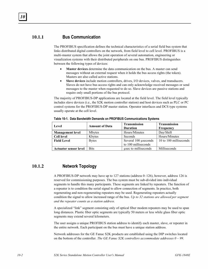
10-2 S2K Series Standalone Motion Controller User's Manual GFK-1848E
10
10.1.1 Bus Communication
The PROFIBUS specification defines the technical characteristics of a serial field bus system that links distributed digital controllers on the network, from field level to cell level. PROFIBUS is a multi-master system that allows the joint operation of several automation, engineering or visualization systems with their distributed peripherals on one bus. PROFIBUS distinguishes between the following types of devices:
• Master devices determine the data communication on the bus. A master can send messages without an external request when it holds the bus access rights (the token). Masters are also called active stations.
• Slave devices include motion controllers, drives, I/O devices, valves, and transducers. Slaves do not have bus access rights and can only acknowledge received messages or send messages to the master when requested to do so. Slave devices are passive stations and require only small portions of the bus protocol.
The majority of PROFIBUS-DP applications are located at the field level. The field level typically includes slave devices (i.e., the S2K motion controller station) and host devices such as PLC or PC control systems for the PROFIBUS-DP master station. Operator interfaces and DCS type systems usually operate at the cell level.
Table 10-1. Data Bandwidth Demands on PROFIBUS Communications Systems
Level Amount of Data Transmission Duration
Transmission Frequency
Management level Mbytes Hours/Minutes Day/Shift Cell level Kbytes Seconds Hours/Minutes Field Level Bytes Several 100 µseconds
to 100 milliseconds 10 to 100 milliseconds
Actuator sensor level Bits µsec to milliseconds Milliseconds
10.1.2 Network Topology
A PROFIBUS-DP network may have up to 127 stations (address 0–126), however, address 126 is reserved for commissioning purposes. The bus system must be sub-divided into individual segments to handle this many participants. These segments are linked by repeaters. The function of a repeater is to condition the serial signal to allow connection of segments. In practice, both regenerating and non-regenerating repeaters may be used. Regenerating repeaters actually condition the signal to allow increased range of the bus. Up to 32 stations are allowed per segment and the repeater counts as a station address.
A specialized “link” segment consisting only of optical fiber modem repeaters may be used to span long distances. Plastic fiber optic segments are typically 50 meters or less while glass fiber optic segments may extend several kilometers.
The user assigns a unique PROFIBUS station address to identify each master, slave, or repeater in the entire network. Each participant on the bus must have a unique station address.
Network addresses for the GE Fanuc S2K products are established using the DIP switches located on the bottom of the controller. The GE Fanuc S2K controllers accommodate addresses 0 – 99.
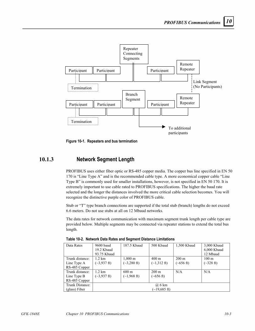
PROFIBUS Communications
GFK-1848E Chapter 10 PROFIBUS Communications 10-3
10
Figure 10-1. Repeaters and bus termination
10.1.3 Network Segment Length
PROFIBUS uses either fiber optic or RS-485 copper media. The copper bus line specified in EN 50 170 is “Line Type A” and is the recommended cable type. A more economical copper cable “Line Type B” is commonly used for smaller installations, however, is not specified in EN 50 170. It is extremely important to use cable rated to PROFIBUS specifications. The higher the baud rate selected and the longer the distances involved the more critical cable selection becomes. You will recognize the distinctive purple color of PROFIBUS cable.
Stub or “T” type branch connections are supported if the total stub (branch) lengths do not exceed 6.6 meters. Do not use stubs at all on 12 Mbaud networks.
The data rates for network communication with maximum segment trunk length per cable type are provided below. Multiple segments may be connected via repeater stations to extend the total bus length.
Table 10-2. Network Data Rates and Segment Distance Limitations Data Rates 9600 baud
19.2 Kbaud 93.75 Kbaud
187.5 Kbaud 500 Kbaud
1,500 Kbaud 3,000 Kbaud 6,000 Kbaud 12 Mbaud
Trunk distance: Line Type A RS-485 Copper
1.2 km (~3,937 ft)
1,000 m (~3,280 ft)
400 m (~1,312 ft)
200 m (~656 ft)
100 m (~328 ft)
Trunk distance: Line Type B RS-485 Copper
1.2 km (~3,937 ft)
600 m (~1,968 ft)
200 m (~656 ft)
N/A N/A
Trunk Distance: (glass) Fiber
@ 6 km (~19,685 ft)
To additional participants
Link Segment (No Participants)
Participant Participant
ParticipantParticipant
Participant
Participant
Branch Segment
Repeater Connecting Segments
Remote Repeater
Remote Repeater
Termination
Termination
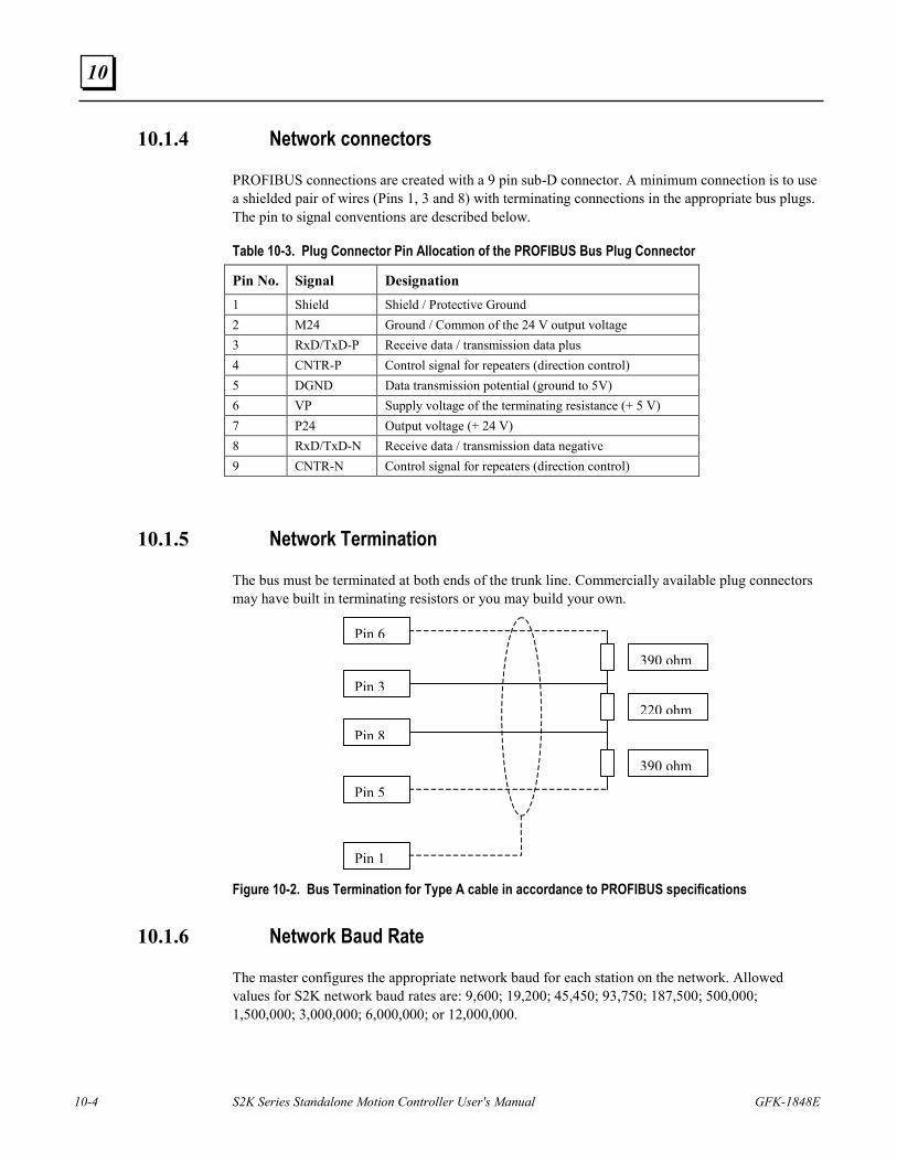
10-4 S2K Series Standalone Motion Controller User's Manual GFK-1848E
10
10.1.4 Network connectors
PROFIBUS connections are created with a 9 pin sub-D connector. A minimum connection is to use a shielded pair of wires (Pins 1, 3 and 8) with terminating connections in the appropriate bus plugs. The pin to signal conventions are described below.
Table 10-3. Plug Connector Pin Allocation of the PROFIBUS Bus Plug Connector
Pin No. Signal Designation 1 Shield Shield / Protective Ground 2 M24 Ground / Common of the 24 V output voltage 3 RxD/TxD-P Receive data / transmission data plus 4 CNTR-P Control signal for repeaters (direction control) 5 DGND Data transmission potential (ground to 5V) 6 VP Supply voltage of the terminating resistance (+ 5 V) 7 P24 Output voltage (+ 24 V) 8 RxD/TxD-N Receive data / transmission data negative 9 CNTR-N Control signal for repeaters (direction control)
10.1.5 Network Termination
The bus must be terminated at both ends of the trunk line. Commercially available plug connectors may have built in terminating resistors or you may build your own.
390 ohm
220 ohm
390 ohm
Pin 6
Pin 3
Pin 8
Pin 5
Pin 1
Figure 10-2. Bus Termination for Type A cable in accordance to PROFIBUS specifications
10.1.6 Network Baud Rate
The master configures the appropriate network baud for each station on the network. Allowed values for S2K network baud rates are: 9,600; 19,200; 45,450; 93,750; 187,500; 500,000; 1,500,000; 3,000,000; 6,000,000; or 12,000,000.
PROFIBUS Communications
GFK-1848E Chapter 10 PROFIBUS Communications 10-5
10
10.2 Getting Started The following information is intended to outline the steps required to commission a S2K and incorporate it into a PROFIBUS network segment.
10.2.1 Connection Checklist
GE Fanuc-Supplied Components 1 S2K controller with PROFIBUS per axis
1 motor per axis
Cables
CIMPLICITY Motion Developer software User-Supplied Components
DC power to digital I/O
16-gauge wire to jumper I/O connectors
PROFIBUS network hardware
10.2.2 Complete Basic Set-up Procedure
Before you connect and use your S2K controller on PROFIBUS, take a few minutes to complete the Process for Basic Set-up located in Chapter 4.
The set-up process takes you systematically through each of the following items:
• Install software
• Connect cables
• Jumper dedicated I/O (if applicable)
• Establish communication with the controller
• Complete basic equipment configuration
• Run the motor to verify correct set-up.
If you are using multiple S2K controllers, repeat the set-up for each controller. When you have completed the set-up, leave your connections and jumpers in place—you’re ready to configure your PROFIBUS system.
To operate S2K Controllers for PROFIBUS, the S2K controller requires some simple network configuration before being used.
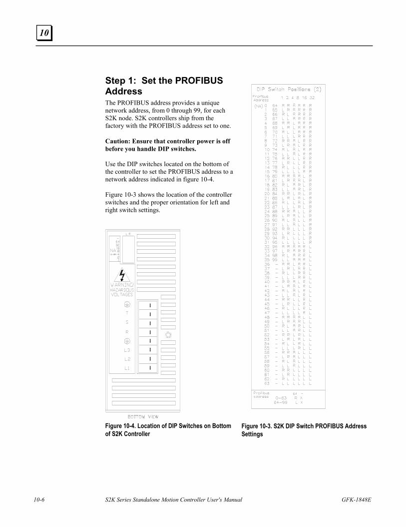
10-6 S2K Series Standalone Motion Controller User's Manual GFK-1848E
10
Step 1: Set the PROFIBUS Address The PROFIBUS address provides a unique network address, from 0 through 99, for each S2K node. S2K controllers ship from the factory with the PROFIBUS address set to one. Caution: Ensure that controller power is off before you handle DIP switches. Use the DIP switches located on the bottom of the controller to set the PROFIBUS address to a network address indicated in figure 10-4. Figure 10-3 shows the location of the controller switches and the proper orientation for left and right switch settings.
Figure 10-4. Location of DIP Switches on Bottom of S2K Controller
Figure 10-3. S2K DIP Switch PROFIBUS Address Settings
PROFIBUS Communications
GFK-1848E Chapter 10 PROFIBUS Communications 10-7
10
Step 2: Configure Master to Add Slave to the Network
PROFIBUS-DP systems accept S2K controllers as slaves to a network master. The network master automatically sets the network data rate for the S2K controllers that have been properly configured and connected to the network.
A device electronic data sheet or GSD file for the S2K Motion Controller is available from GE Fanuc to expedite the master configuration. A GSD file contains information to specify methods of communication and types of messaging available. Most PROFIBUS master configuration tools require the GSD file in order to operate.
10.2.3 The GSD File Data for the S2K Motion Controller ;====================================================== ; GSD File Standalone Motion Controller ; ; Version: V1.0 ;====================================================== #PROFIBUS_DP GSD_Revision = 1 ;General parameters Vendor_Name = "GE Fanuc" Model_Name = "Standalone Motion Controller" Revision = "V1.0" Ident_Number = 0x05E9 Protocol_Ident = 0 Station_Type = 0 FMS_supp = 0 Hardware_Release = "D" Software_Release = "V1.0" 9.6_supp = 1 19.2_supp = 1 45.45_supp = 1 93.75_supp = 1 187.5_supp = 1 500_supp = 1 1.5M_supp = 1 3M_supp = 1 6M_supp = 1 12M_supp = 1 MaxTsdr_9.6 = 60 MaxTsdr_19.2 = 60 MaxTsdr_45.45 = 250 MaxTsdr_93.75 = 60 MaxTsdr_187.5 = 60 MaxTsdr_500 = 100 MaxTsdr_1.5M = 150 MaxTsdr_3M = 250 MaxTsdr_6M = 450
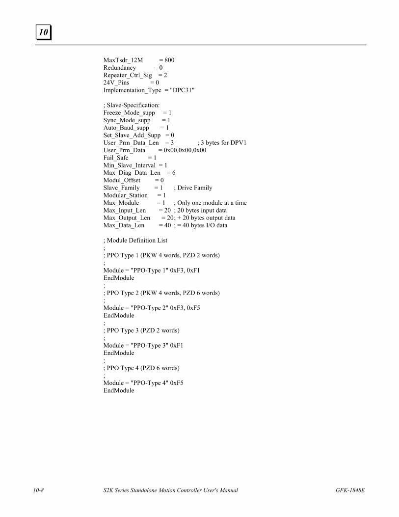
10-8 S2K Series Standalone Motion Controller User's Manual GFK-1848E
10
MaxTsdr_12M = 800 Redundancy = 0 Repeater_Ctrl_Sig = 2 24V_Pins = 0 Implementation_Type = "DPC31" ; Slave-Specification: Freeze_Mode_supp = 1 Sync_Mode_supp = 1 Auto_Baud_supp = 1 Set_Slave_Add_Supp = 0 User_Prm_Data_Len = 3 ; 3 bytes for DPV1 User_Prm_Data = 0x00,0x00,0x00 Fail_Safe = 1 Min_Slave_Interval = 1 Max_Diag_Data_Len = 6 Modul_Offset = 0 Slave_Family = 1 ; Drive Family Modular_Station = 1 Max_Module = 1 ; Only one module at a time Max_Input_Len = 20 ; 20 bytes input data Max_Output_Len = 20 ; + 20 bytes output data Max_Data_Len = 40 ; = 40 bytes I/O data ; Module Definition List ; ; PPO Type 1 (PKW 4 words, PZD 2 words) ; Module = "PPO-Type 1" 0xF3, 0xF1 EndModule ; ; PPO Type 2 (PKW 4 words, PZD 6 words) ; Module = "PPO-Type 2" 0xF3, 0xF5 EndModule ; ; PPO Type 3 (PZD 2 words) ; Module = "PPO-Type 3" 0xF1 EndModule ; ; PPO Type 4 (PZD 6 words) ; Module = "PPO-Type 4" 0xF5 EndModule
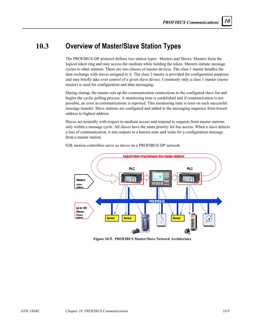
PROFIBUS Communications
GFK-1848E Chapter 10 PROFIBUS Communications 10-9
10
10.3 Overview of Master/Slave Station Types The PROFIBUS-DP protocol defines two station types: Masters and Slaves. Masters form the logical token ring and may access the medium while holding the token. Masters initiate message cycles to other stations. There are two classes of master devices. The class 1 master handles the data exchange with slaves assigned to it. The class 2 master is provided for configuration purposes and may briefly take over control of a given slave device. Commonly only a class 1 master (mono master) is used for configuration and data messaging.
During startup, the master sets up the communication connections to the configured slave list and begins the cyclic polling process. A monitoring time is established and if communication is not possible, an error in communications is reported. This monitoring time is reset on each successful message transfer. Slave stations are configured and added to the messaging sequence from lowest address to highest address.
Slaves act neutrally with respect to medium access and respond to requests from master stations only within a message cycle. All slaves have the same priority for bus access. When a slave detects a loss of communication, it sets outputs to a known state and waits for a configuration message from a master station.
S2K motion controllers serve as slaves on a PROFIBUS-DP network.
PLC
PROFIBUS
Actuator Transmitter
logical token ring between the master stations
T
PLC
Sensor Sensor
Masters Active stations
Up to 125 Slaves... Passive stations Sensor
Figure 10-5. PROFIBUS Master/Slave Network Architecture
10-10 S2K Series Standalone Motion Controller User's Manual GFK-1848E
10
10.3.1 PROFIBUS Communication
S2K’s communicate via cyclic data transfer, the process by which process data (PZD) and parameters (PKW) are transferred from master to slave and from slave to master. GE Fanuc S2K motion controllers use the PROFIBUS profile's Type 2 Octet-String 20—the 20-byte data string.
When writing data, the master transfers process data (control word and setpoints) and tasks for parameter processing to the slave. When the data are read, the master retrieves process data (status word and actual values) and responses from parameter processing.
10.3.2 Global Control for PROFIBUS-DP
The PROFIBUS-DP "global control" mechanism can be used when slave coordination requirements are high. For example, when setpoints must be switched or specified simultaneously.
In addition to the node-related user data communication, the masters can send control commands simultaneously to one slave, a group of slaves (Multicast) or all slaves (Broadcast). These global control commands can be used for event-controlled synchronization of the slaves. The master establishes the global commands to use and assigns the global group number to the slaves during the configuration message.
Typical global commands are “clear data” to establish a known output state on fault, the “freeze” message to coordinate the reading of the inputs and the “sync” message to coordinate switching of outputs. There is additionally an unfreeze and unsync command to restore the station to normal messaging.
The S2K Motion Controller supports global messages: clear data, auto baud, freeze/unfreeze and sync/unsync. The global message change address is not supported. The S2K station address is set via DIP switches.
10.3.3 Output Data Words
The format for the 20 bytes of data the PROFIBUS-DP master will write to the S2K motion controller is described in the following table. This format conforms to the user profile group PROFIDrive 0302hex (indicates Version 2, Application Class 3). User profile groups promote operability between products created by different vendors and allow users to interchange products.
The Parameter Channel (PKW), composed of the first four data words (eight bytes), is used with the appropriate Task ID and Parameter Number (PNU) to access variable and register data in the S2K on an as needed basis.
The Process Data Channel (PZD), composed of two to six words, is used to operate the axis and is always active.
The message (telegram) actually transmitted to the S2K will take one of the following supported message forms depending on the settings in the Task ID and Control Word (STW):
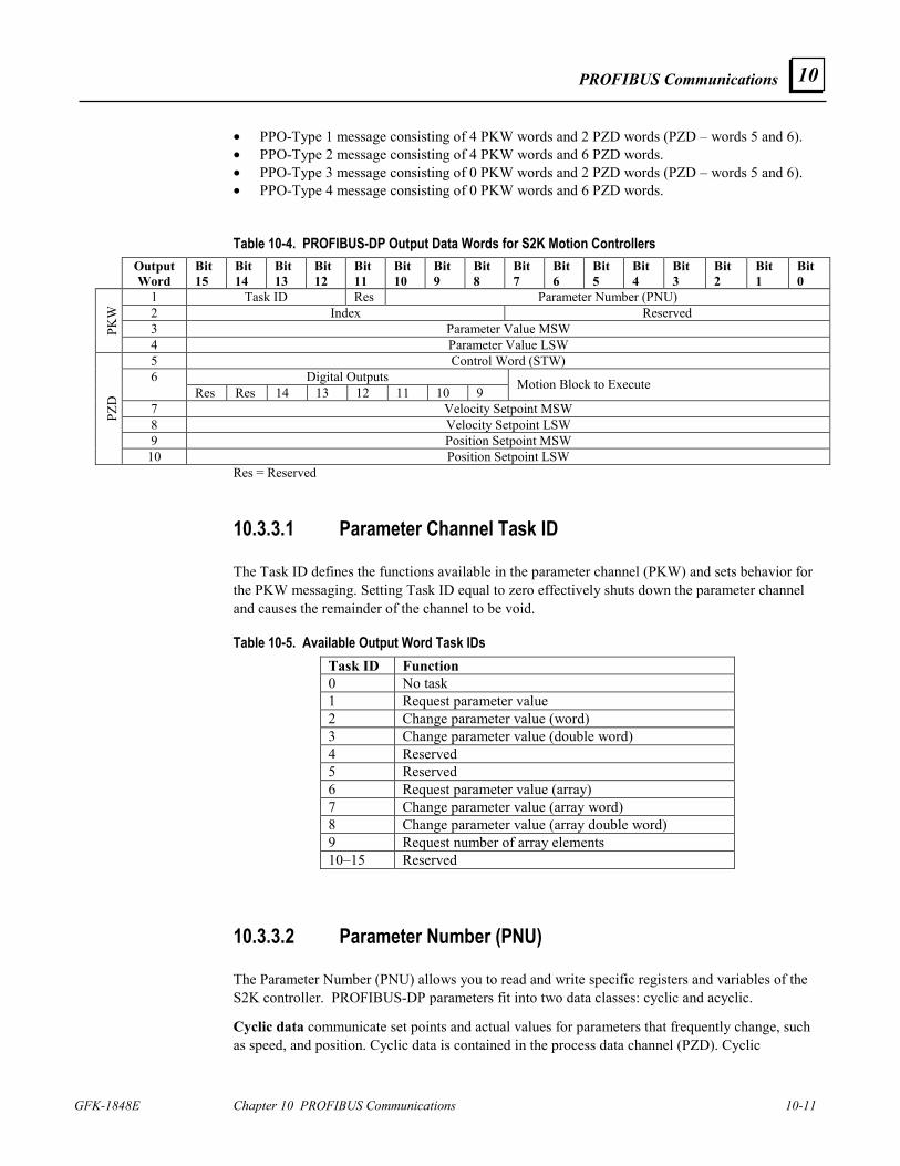
PROFIBUS Communications
GFK-1848E Chapter 10 PROFIBUS Communications 10-11
10
• PPO-Type 1 message consisting of 4 PKW words and 2 PZD words (PZD – words 5 and 6). • PPO-Type 2 message consisting of 4 PKW words and 6 PZD words. • PPO-Type 3 message consisting of 0 PKW words and 2 PZD words (PZD – words 5 and 6). • PPO-Type 4 message consisting of 0 PKW words and 6 PZD words.
Table 10-4. PROFIBUS-DP Output Data Words for S2K Motion Controllers Output
Word Bit 15
Bit 14
Bit 13
Bit 12
Bit 11
Bit 10
Bit 9
Bit 8
Bit 7
Bit 6
Bit 5
Bit 4
Bit 3
Bit 2
Bit 1
Bit 0
1 Task ID Res Parameter Number (PNU) 2 Index Reserved 3 Parameter Value MSW PK
W
4 Parameter Value LSW 5 Control Word (STW)
Digital Outputs 6 Res Res 14 13 12 11 10 9 Motion Block to Execute
7 Velocity Setpoint MSW 8 Velocity Setpoint LSW 9 Position Setpoint MSW
PZD
10 Position Setpoint LSW Res = Reserved
10.3.3.1 Parameter Channel Task ID
The Task ID defines the functions available in the parameter channel (PKW) and sets behavior for the PKW messaging. Setting Task ID equal to zero effectively shuts down the parameter channel and causes the remainder of the channel to be void.
Table 10-5. Available Output Word Task IDs Task ID Function 0 No task 1 Request parameter value 2 Change parameter value (word) 3 Change parameter value (double word) 4 Reserved 5 Reserved 6 Request parameter value (array) 7 Change parameter value (array word) 8 Change parameter value (array double word) 9 Request number of array elements 10–15 Reserved
10.3.3.2 Parameter Number (PNU)
The Parameter Number (PNU) allows you to read and write specific registers and variables of the S2K controller. PROFIBUS-DP parameters fit into two data classes: cyclic and acyclic.
Cyclic data communicate set points and actual values for parameters that frequently change, such as speed, and position. Cyclic data is contained in the process data channel (PZD). Cyclic
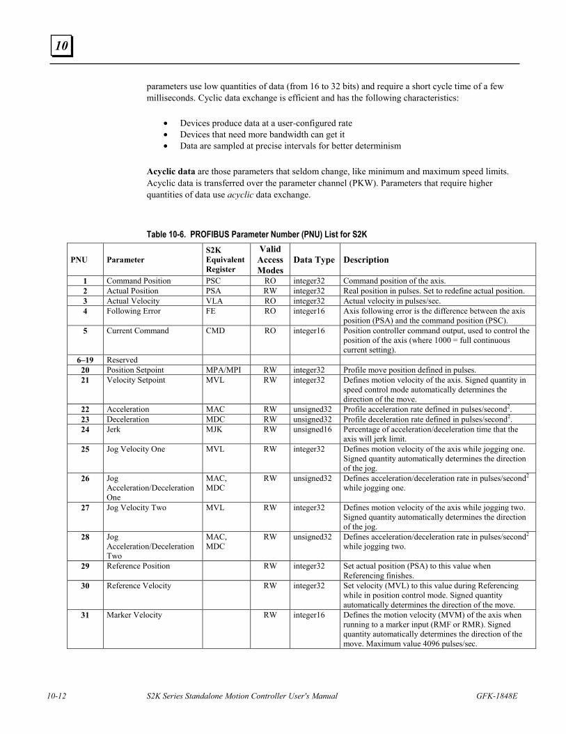
10-12 S2K Series Standalone Motion Controller User's Manual GFK-1848E
10
parameters use low quantities of data (from 16 to 32 bits) and require a short cycle time of a few milliseconds. Cyclic data exchange is efficient and has the following characteristics:
• Devices produce data at a user-configured rate • Devices that need more bandwidth can get it • Data are sampled at precise intervals for better determinism
Acyclic data are those parameters that seldom change, like minimum and maximum speed limits. Acyclic data is transferred over the parameter channel (PKW). Parameters that require higher quantities of data use acyclic data exchange.
Table 10-6. PROFIBUS Parameter Number (PNU) List for S2K
PNU Parameter S2K Equivalent Register
Valid Access Modes
Data Type Description
1 Command Position PSC RO integer32 Command position of the axis. 2 Actual Position PSA RW integer32 Real position in pulses. Set to redefine actual position. 3 Actual Velocity VLA RO integer32 Actual velocity in pulses/sec. 4 Following Error FE RO integer16 Axis following error is the difference between the axis
position (PSA) and the command position (PSC). 5 Current Command CMD RO integer16 Position controller command output, used to control the
position of the axis (where 1000 = full continuous current setting).
6–19 Reserved 20 Position Setpoint MPA/MPI RW integer32 Profile move position defined in pulses. 21 Velocity Setpoint MVL RW integer32 Defines motion velocity of the axis. Signed quantity in
speed control mode automatically determines the direction of the move.
22 Acceleration MAC RW unsigned32 Profile acceleration rate defined in pulses/second2. 23 Deceleration MDC RW unsigned32 Profile deceleration rate defined in pulses/second2. 24 Jerk MJK RW unsigned16 Percentage of acceleration/deceleration time that the
axis will jerk limit. 25 Jog Velocity One MVL RW integer32 Defines motion velocity of the axis while jogging one.
Signed quantity automatically determines the direction of the jog.
26 Jog Acceleration/Deceleration One
MAC, MDC
RW unsigned32 Defines acceleration/deceleration rate in pulses/second2
while jogging one.
27 Jog Velocity Two MVL RW integer32 Defines motion velocity of the axis while jogging two. Signed quantity automatically determines the direction of the jog.
28 Jog Acceleration/Deceleration Two
MAC, MDC
RW unsigned32
Defines acceleration/deceleration rate in pulses/second2
while jogging two.
29 Reference Position RW integer32 Set actual position (PSA) to this value when Referencing finishes.
30 Reference Velocity RW integer32 Set velocity (MVL) to this value during Referencing while in position control mode. Signed quantity automatically determines the direction of the move.
31 Marker Velocity RW integer16 Defines the motion velocity (MVM) of the axis when running to a marker input (RMF or RMR). Signed quantity automatically determines the direction of the move. Maximum value 4096 pulses/sec.
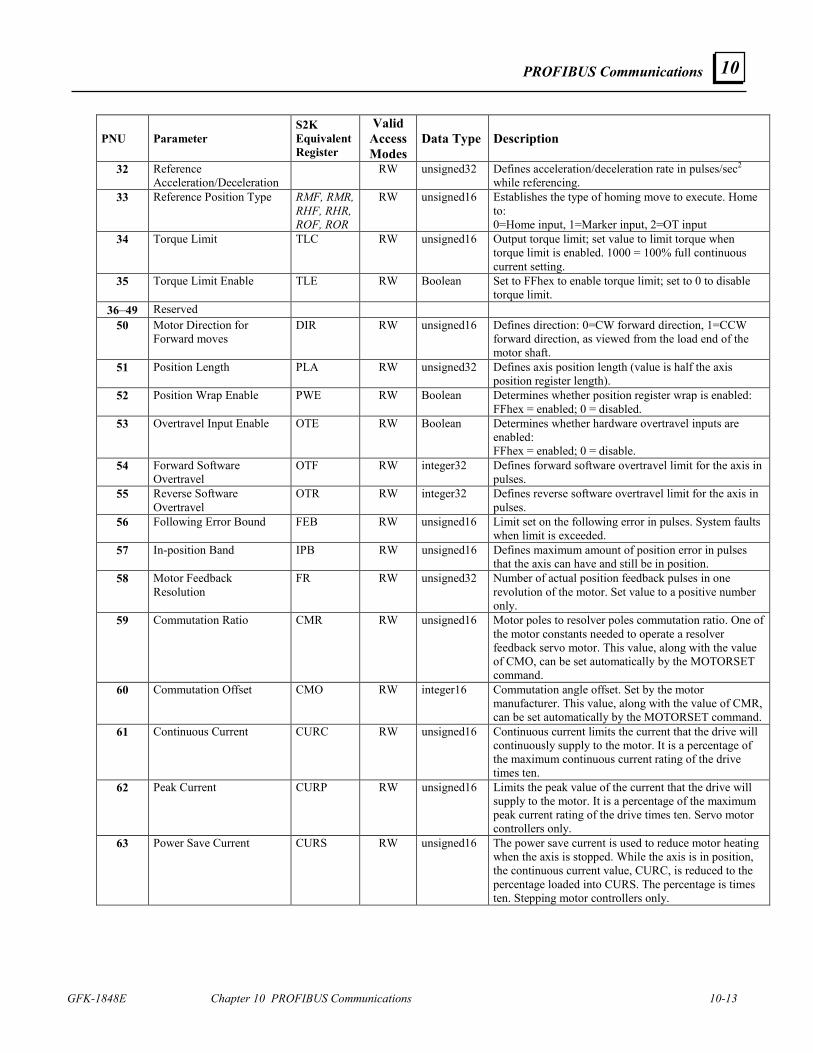
PROFIBUS Communications
GFK-1848E Chapter 10 PROFIBUS Communications 10-13
10
PNU Parameter S2K Equivalent Register
Valid Access Modes
Data Type Description
32 Reference Acceleration/Deceleration
RW unsigned32 Defines acceleration/deceleration rate in pulses/sec2 while referencing.
33 Reference Position Type RMF, RMR, RHF, RHR, ROF, ROR
RW unsigned16 Establishes the type of homing move to execute. Home to: 0=Home input, 1=Marker input, 2=OT input
34 Torque Limit TLC RW unsigned16 Output torque limit; set value to limit torque when torque limit is enabled. 1000 = 100% full continuous current setting.
35 Torque Limit Enable TLE RW Boolean Set to FFhex to enable torque limit; set to 0 to disable torque limit.
36–49 Reserved 50 Motor Direction for
Forward moves DIR RW unsigned16 Defines direction: 0=CW forward direction, 1=CCW
forward direction, as viewed from the load end of the motor shaft.
51 Position Length PLA RW unsigned32 Defines axis position length (value is half the axis position register length).
52 Position Wrap Enable PWE RW Boolean Determines whether position register wrap is enabled: FFhex = enabled; 0 = disabled.
53 Overtravel Input Enable OTE RW Boolean Determines whether hardware overtravel inputs are enabled: FFhex = enabled; 0 = disable.
54 Forward Software Overtravel
OTF RW integer32 Defines forward software overtravel limit for the axis in pulses.
55 Reverse Software Overtravel
OTR RW integer32 Defines reverse software overtravel limit for the axis in pulses.
56 Following Error Bound FEB RW unsigned16 Limit set on the following error in pulses. System faults when limit is exceeded.
57 In-position Band IPB RW unsigned16 Defines maximum amount of position error in pulses that the axis can have and still be in position.
58 Motor Feedback Resolution
FR RW unsigned32 Number of actual position feedback pulses in one revolution of the motor. Set value to a positive number only.
59 Commutation Ratio CMR RW unsigned16 Motor poles to resolver poles commutation ratio. One of the motor constants needed to operate a resolver feedback servo motor. This value, along with the value of CMO, can be set automatically by the MOTORSET command.
60 Commutation Offset CMO RW integer16 Commutation angle offset. Set by the motor manufacturer. This value, along with the value of CMR, can be set automatically by the MOTORSET command.
61 Continuous Current CURC RW unsigned16 Continuous current limits the current that the drive will continuously supply to the motor. It is a percentage of the maximum continuous current rating of the drive times ten.
62 Peak Current CURP RW unsigned16 Limits the peak value of the current that the drive will supply to the motor. It is a percentage of the maximum peak current rating of the drive times ten. Servo motor controllers only.
63 Power Save Current CURS RW unsigned16 The power save current is used to reduce motor heating when the axis is stopped. While the axis is in position, the continuous current value, CURC, is reduced to the percentage loaded into CURS. The percentage is times ten. Stepping motor controllers only.
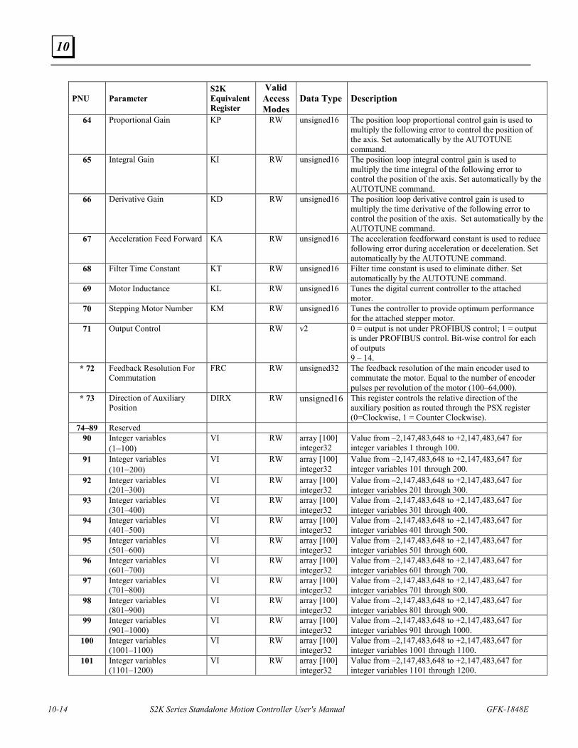
10-14 S2K Series Standalone Motion Controller User's Manual GFK-1848E
10
PNU Parameter S2K Equivalent Register
Valid Access Modes
Data Type Description
64 Proportional Gain KP RW unsigned16 The position loop proportional control gain is used to multiply the following error to control the position of the axis. Set automatically by the AUTOTUNE command.
65 Integral Gain KI RW unsigned16 The position loop integral control gain is used to multiply the time integral of the following error to control the position of the axis. Set automatically by the AUTOTUNE command.
66 Derivative Gain KD RW unsigned16 The position loop derivative control gain is used to multiply the time derivative of the following error to control the position of the axis. Set automatically by the AUTOTUNE command.
67 Acceleration Feed Forward KA RW unsigned16 The acceleration feedforward constant is used to reduce following error during acceleration or deceleration. Set automatically by the AUTOTUNE command.
68 Filter Time Constant KT RW unsigned16 Filter time constant is used to eliminate dither. Set automatically by the AUTOTUNE command.
69 Motor Inductance KL RW unsigned16 Tunes the digital current controller to the attached motor.
70 Stepping Motor Number KM RW unsigned16 Tunes the controller to provide optimum performance for the attached stepper motor.
71 Output Control RW v2 0 = output is not under PROFIBUS control; 1 = output is under PROFIBUS control. Bit-wise control for each of outputs 9 – 14.
* 72 Feedback Resolution For Commutation
FRC RW unsigned32 The feedback resolution of the main encoder used to commutate the motor. Equal to the number of encoder pulses per revolution of the motor (100–64,000).
* 73 Direction of Auxiliary Position
DIRX RW unsigned16 This register controls the relative direction of the auxiliary position as routed through the PSX register (0=Clockwise, 1 = Counter Clockwise).
74–89 Reserved 90 Integer variables
(1–100) VI RW array [100]
integer32 Value from –2,147,483,648 to +2,147,483,647 for integer variables 1 through 100.
91 Integer variables (101–200)
VI RW array [100] integer32
Value from –2,147,483,648 to +2,147,483,647 for integer variables 101 through 200.
92 Integer variables (201–300)
VI RW array [100] integer32
Value from –2,147,483,648 to +2,147,483,647 for integer variables 201 through 300.
93 Integer variables (301–400)
VI RW array [100] integer32
Value from –2,147,483,648 to +2,147,483,647 for integer variables 301 through 400.
94 Integer variables (401–500)
VI RW array [100] integer32
Value from –2,147,483,648 to +2,147,483,647 for integer variables 401 through 500.
95 Integer variables (501–600)
VI RW array [100] integer32
Value from –2,147,483,648 to +2,147,483,647 for integer variables 501 through 600.
96 Integer variables (601–700)
VI RW array [100] integer32
Value from –2,147,483,648 to +2,147,483,647 for integer variables 601 through 700.
97 Integer variables (701–800)
VI RW array [100] integer32
Value from –2,147,483,648 to +2,147,483,647 for integer variables 701 through 800.
98 Integer variables (801–900)
VI RW array [100] integer32
Value from –2,147,483,648 to +2,147,483,647 for integer variables 801 through 900.
99 Integer variables (901–1000)
VI RW array [100] integer32
Value from –2,147,483,648 to +2,147,483,647 for integer variables 901 through 1000.
100 Integer variables (1001–1100)
VI RW array [100] integer32
Value from –2,147,483,648 to +2,147,483,647 for integer variables 1001 through 1100.
101 Integer variables (1101–1200)
VI RW array [100] integer32
Value from –2,147,483,648 to +2,147,483,647 for integer variables 1101 through 1200.
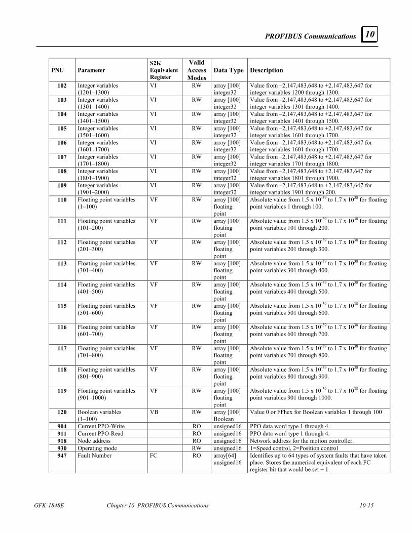
PROFIBUS Communications
GFK-1848E Chapter 10 PROFIBUS Communications 10-15
10
PNU Parameter S2K Equivalent Register
Valid Access Modes
Data Type Description
102 Integer variables (1201–1300)
VI RW array [100] integer32
Value from –2,147,483,648 to +2,147,483,647 for integer variables 1200 through 1300.
103 Integer variables (1301–1400)
VI RW array [100] integer32
Value from –2,147,483,648 to +2,147,483,647 for integer variables 1301 through 1400.
104 Integer variables (1401–1500)
VI RW array [100] integer32
Value from –2,147,483,648 to +2,147,483,647 for integer variables 1401 through 1500.
105 Integer variables (1501–1600)
VI RW array [100] integer32
Value from –2,147,483,648 to +2,147,483,647 for integer variables 1601 through 1700.
106 Integer variables (1601–1700)
VI RW array [100] integer32
Value from –2,147,483,648 to +2,147,483,647 for integer variables 1601 through 1700.
107 Integer variables (1701–1800)
VI RW array [100] integer32
Value from –2,147,483,648 to +2,147,483,647 for integer variables 1701 through 1800.
108 Integer variables (1801–1900)
VI RW array [100] integer32
Value from –2,147,483,648 to +2,147,483,647 for integer variables 1801 through 1900.
109 Integer variables (1901–2000)
VI RW array [100] integer32
Value from –2,147,483,648 to +2,147,483,647 for integer variables 1901 through 200.
110 Floating point variables (1–100)
VF RW array [100] floating point
Absolute value from 1.5 x 10-39 to 1.7 x 1038 for floating point variables 1 through 100.
111 Floating point variables (101–200)
VF RW array [100] floating point
Absolute value from 1.5 x 10-39 to 1.7 x 1038 for floating point variables 101 through 200.
112 Floating point variables (201–300)
VF RW array [100] floating point
Absolute value from 1.5 x 10-39 to 1.7 x 1038 for floating point variables 201 through 300.
113 Floating point variables (301–400)
VF RW array [100] floating point
Absolute value from 1.5 x 10-39 to 1.7 x 1038 for floating point variables 301 through 400.
114 Floating point variables (401–500)
VF RW array [100] floating point
Absolute value from 1.5 x 10-39 to 1.7 x 1038 for floating point variables 401 through 500.
115 Floating point variables (501–600)
VF RW array [100] floating point
Absolute value from 1.5 x 10-39 to 1.7 x 1038 for floating point variables 501 through 600.
116 Floating point variables (601–700)
VF RW array [100] floating point
Absolute value from 1.5 x 10-39 to 1.7 x 1038 for floating point variables 601 through 700.
117 Floating point variables (701–800)
VF RW array [100] floating point
Absolute value from 1.5 x 10-39 to 1.7 x 1038 for floating point variables 701 through 800.
118 Floating point variables (801–900)
VF RW array [100] floating point
Absolute value from 1.5 x 10-39 to 1.7 x 1038 for floating point variables 801 through 900.
119 Floating point variables (901–1000)
VF RW array [100] floating point
Absolute value from 1.5 x 10-39 to 1.7 x 1038 for floating point variables 901 through 1000.
120 Boolean variables (1–100)
VB RW array [100] Boolean
Value 0 or FFhex for Boolean variables 1 through 100
904 Current PPO-Write RO unsigned16 PPO data word type 1 through 4. 911 Current PPO-Read RO unsigned16 PPO data word type 1 through 4. 918 Node address RO unsigned16 Network address for the motion controller. 930 Operating mode RW unsigned16 1=Speed control, 2=Position control 947 Fault Number FC RO array[64]
unsigned16 Identifies up to 64 types of system faults that have taken place. Stores the numerical equivalent of each FC register bit that would be set + 1.
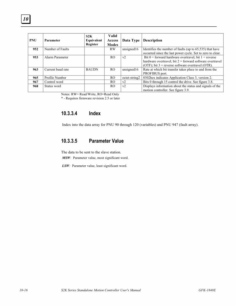
10-16 S2K Series Standalone Motion Controller User's Manual GFK-1848E
10
PNU Parameter S2K Equivalent Register
Valid Access Modes
Data Type Description
952 Number of Faults RW unsigned16 Identifies the number of faults (up to 65,535) that have occurred since the last power cycle. Set to zero to clear.
953 Alarm Parameter RO v2 Bit 0 = forward hardware overtravel; bit 1 = reverse hardware overtravel; bit 2 = forward software overtravel (OTF); bit 3 = reverse software overtravel (OTR).
963 Current baud rate BAUDN RO unsigned16 Rate at which bit transfer takes place to and from the PROFIBUS port.
965 Profile Number RO octet-string2 0302hex indicates Application Class 3, version 2. 967 Control word RO v2 Bits 0 through 15 control the drive. See figure 3.8. 968 Status word RO v2 Displays information about the status and signals of the
motion controller. See figure 3.9. Notes: RW= Read/Write, RO=Read Only * - Requires firmware revision 2.5 or later
10.3.3.4 Index
Index into the data array for PNU 90 through 120 (variables) and PNU 947 (fault array).
10.3.3.5 Parameter Value
The data to be sent to the slave station. MSW: Parameter value, most significant word. LSW: Parameter value, least significant word.
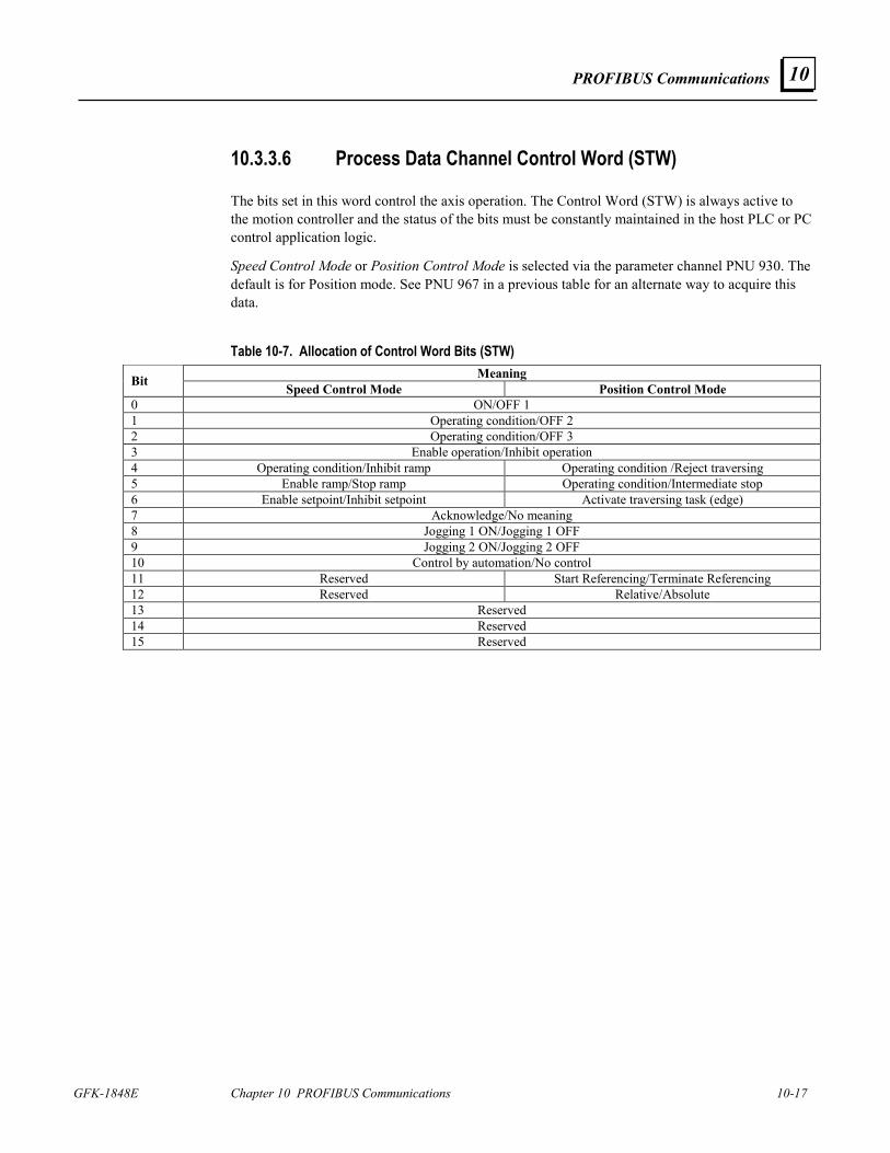
PROFIBUS Communications
GFK-1848E Chapter 10 PROFIBUS Communications 10-17
10
10.3.3.6 Process Data Channel Control Word (STW)
The bits set in this word control the axis operation. The Control Word (STW) is always active to the motion controller and the status of the bits must be constantly maintained in the host PLC or PC control application logic.
Speed Control Mode or Position Control Mode is selected via the parameter channel PNU 930. The default is for Position mode. See PNU 967 in a previous table for an alternate way to acquire this data.
Table 10-7. Allocation of Control Word Bits (STW) Meaning Bit Speed Control Mode Position Control Mode
0 ON/OFF 1 1 Operating condition/OFF 2 2 Operating condition/OFF 3 3 Enable operation/Inhibit operation 4 Operating condition/Inhibit ramp Operating condition /Reject traversing 5 Enable ramp/Stop ramp Operating condition/Intermediate stop 6 Enable setpoint/Inhibit setpoint Activate traversing task (edge) 7 Acknowledge/No meaning 8 Jogging 1 ON/Jogging 1 OFF 9 Jogging 2 ON/Jogging 2 OFF 10 Control by automation/No control 11 Reserved Start Referencing/Terminate Referencing 12 Reserved Relative/Absolute 13 Reserved 14 Reserved 15 Reserved
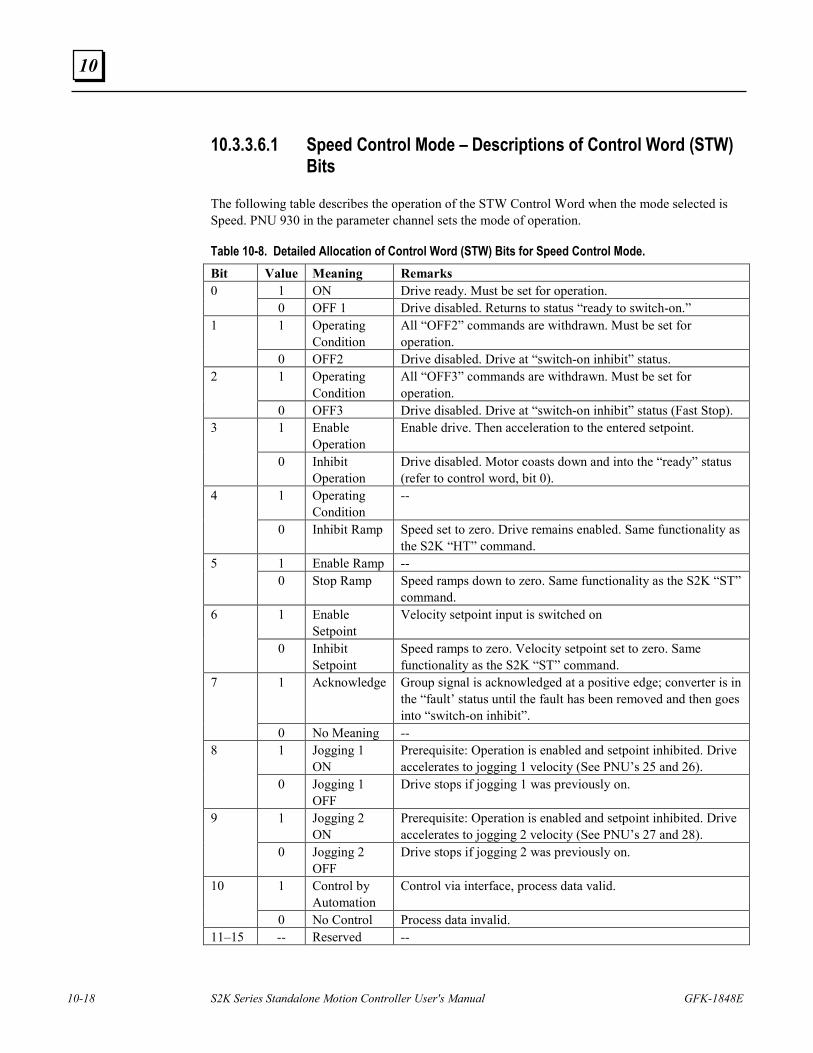
10-18 S2K Series Standalone Motion Controller User's Manual GFK-1848E
10
10.3.3.6.1 Speed Control Mode – Descriptions of Control Word (STW) Bits
The following table describes the operation of the STW Control Word when the mode selected is Speed. PNU 930 in the parameter channel sets the mode of operation.
Table 10-8. Detailed Allocation of Control Word (STW) Bits for Speed Control Mode. Bit Value Meaning Remarks
1 ON Drive ready. Must be set for operation. 0 0 OFF 1 Drive disabled. Returns to status “ready to switch-on.” 1 Operating
Condition All “OFF2” commands are withdrawn. Must be set for operation.
1
0 OFF2 Drive disabled. Drive at “switch-on inhibit” status. 1 Operating
Condition All “OFF3” commands are withdrawn. Must be set for operation.
2
0 OFF3 Drive disabled. Drive at “switch-on inhibit” status (Fast Stop). 1 Enable
Operation Enable drive. Then acceleration to the entered setpoint. 3
0 Inhibit Operation
Drive disabled. Motor coasts down and into the “ready” status (refer to control word, bit 0).
1 Operating Condition
-- 4
0 Inhibit Ramp Speed set to zero. Drive remains enabled. Same functionality as the S2K “HT” command.
1 Enable Ramp -- 5 0 Stop Ramp Speed ramps down to zero. Same functionality as the S2K “ST”
command. 1 Enable
Setpoint Velocity setpoint input is switched on 6
0 Inhibit Setpoint
Speed ramps to zero. Velocity setpoint set to zero. Same functionality as the S2K “ST” command.
1 Acknowledge Group signal is acknowledged at a positive edge; converter is in the “fault’ status until the fault has been removed and then goes into “switch-on inhibit”.
7
0 No Meaning -- 1 Jogging 1
ON Prerequisite: Operation is enabled and setpoint inhibited. Drive accelerates to jogging 1 velocity (See PNU’s 25 and 26).
8
0 Jogging 1 OFF
Drive stops if jogging 1 was previously on.
1 Jogging 2 ON
Prerequisite: Operation is enabled and setpoint inhibited. Drive accelerates to jogging 2 velocity (See PNU’s 27 and 28).
9
0 Jogging 2 OFF
Drive stops if jogging 2 was previously on.
1 Control by Automation
Control via interface, process data valid. 10
0 No Control Process data invalid. 11–15 -- Reserved --
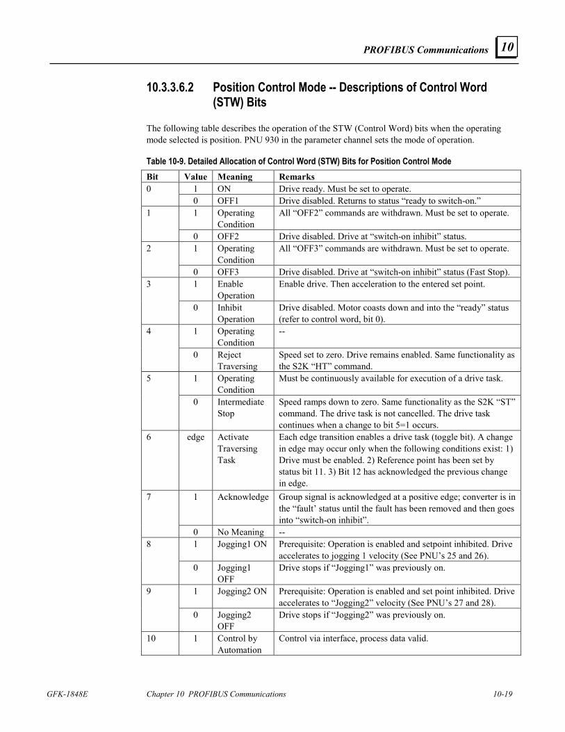
PROFIBUS Communications
GFK-1848E Chapter 10 PROFIBUS Communications 10-19
10
10.3.3.6.2 Position Control Mode -- Descriptions of Control Word (STW) Bits
The following table describes the operation of the STW (Control Word) bits when the operating mode selected is position. PNU 930 in the parameter channel sets the mode of operation.
Table 10-9. Detailed Allocation of Control Word (STW) Bits for Position Control Mode Bit Value Meaning Remarks
1 ON Drive ready. Must be set to operate. 0 0 OFF1 Drive disabled. Returns to status “ready to switch-on.” 1 Operating
Condition All “OFF2” commands are withdrawn. Must be set to operate. 1
0 OFF2 Drive disabled. Drive at “switch-on inhibit” status. 1 Operating
Condition All “OFF3” commands are withdrawn. Must be set to operate. 2
0 OFF3 Drive disabled. Drive at “switch-on inhibit” status (Fast Stop). 1 Enable
Operation Enable drive. Then acceleration to the entered set point. 3
0 Inhibit Operation
Drive disabled. Motor coasts down and into the “ready” status (refer to control word, bit 0).
1 Operating Condition
-- 4
0 Reject Traversing
Speed set to zero. Drive remains enabled. Same functionality as the S2K “HT” command.
1 Operating Condition
Must be continuously available for execution of a drive task. 5
0 Intermediate Stop
Speed ramps down to zero. Same functionality as the S2K “ST” command. The drive task is not cancelled. The drive task continues when a change to bit 5=1 occurs.
6 edge Activate Traversing Task
Each edge transition enables a drive task (toggle bit). A change in edge may occur only when the following conditions exist: 1) Drive must be enabled. 2) Reference point has been set by status bit 11. 3) Bit 12 has acknowledged the previous change in edge.
1 Acknowledge Group signal is acknowledged at a positive edge; converter is in the “fault’ status until the fault has been removed and then goes into “switch-on inhibit”.
7
0 No Meaning -- 1 Jogging1 ON Prerequisite: Operation is enabled and setpoint inhibited. Drive
accelerates to jogging 1 velocity (See PNU’s 25 and 26). 8
0 Jogging1 OFF
Drive stops if “Jogging1” was previously on.
1 Jogging2 ON Prerequisite: Operation is enabled and set point inhibited. Drive accelerates to “Jogging2” velocity (See PNU’s 27 and 28).
9
0 Jogging2 OFF
Drive stops if “Jogging2” was previously on.
10 1 Control by Automation
Control via interface, process data valid.
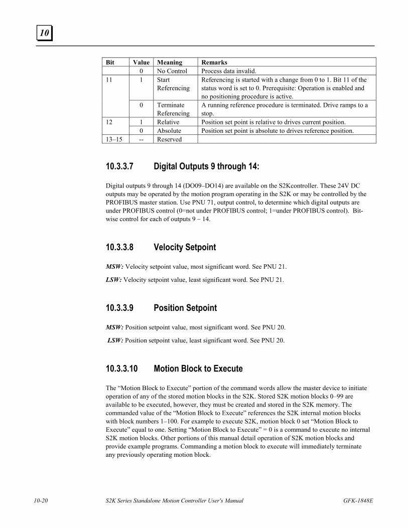
10-20 S2K Series Standalone Motion Controller User's Manual GFK-1848E
10
Bit Value Meaning Remarks 0 No Control Process data invalid.
1 Start Referencing
Referencing is started with a change from 0 to 1. Bit 11 of the status word is set to 0. Prerequisite: Operation is enabled and no positioning procedure is active.
11
0 Terminate Referencing
A running reference procedure is terminated. Drive ramps to a stop.
1 Relative Position set point is relative to drives current position. 12 0 Absolute Position set point is absolute to drives reference position.
13–15 -- Reserved
10.3.3.7 Digital Outputs 9 through 14:
Digital outputs 9 through 14 (DO09–DO14) are available on the S2Kcontroller. These 24V DC outputs may be operated by the motion program operating in the S2K or may be controlled by the PROFIBUS master station. Use PNU 71, output control, to determine which digital outputs are under PROFIBUS control (0=not under PROFIBUS control; 1=under PROFIBUS control). Bit-wise control for each of outputs 9 – 14.
10.3.3.8 Velocity Setpoint
MSW: Velocity setpoint value, most significant word. See PNU 21.
LSW: Velocity setpoint value, least significant word. See PNU 21.
10.3.3.9 Position Setpoint
MSW: Position setpoint value, most significant word. See PNU 20.
LSW: Position setpoint value, least significant word. See PNU 20.
10.3.3.10 Motion Block to Execute
The “Motion Block to Execute” portion of the command words allow the master device to initiate operation of any of the stored motion blocks in the S2K. Stored S2K motion blocks 0–99 are available to be executed, however, they must be created and stored in the S2K memory. The commanded value of the “Motion Block to Execute” references the S2K internal motion blocks with block numbers 1–100. For example to execute S2K, motion block 0 set “Motion Block to Execute” equal to one. Setting “Motion Block to Execute” = 0 is a command to execute no internal S2K motion blocks. Other portions of this manual detail operation of S2K motion blocks and provide example programs. Commanding a motion block to execute will immediately terminate any previously operating motion block.
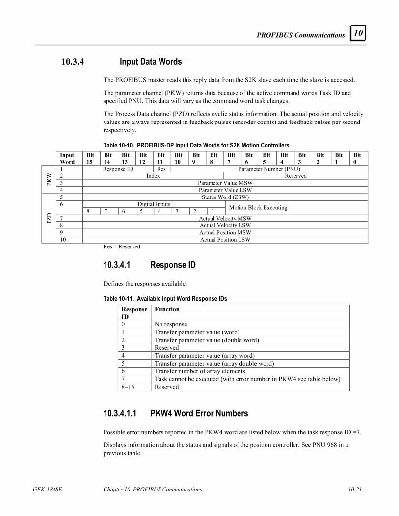
PROFIBUS Communications
GFK-1848E Chapter 10 PROFIBUS Communications 10-21
10
10.3.4 Input Data Words
The PROFIBUS master reads this reply data from the S2K slave each time the slave is accessed.
The parameter channel (PKW) returns data because of the active command words Task ID and specified PNU. This data will vary as the command word task changes.
The Process Data channel (PZD) reflects cyclic status information. The actual position and velocity values are always represented in feedback pulses (encoder counts) and feedback pulses per second respectively.
Table 10-10. PROFIBUS-DP Input Data Words for S2K Motion Controllers Input
Word Bit 15
Bit 14
Bit 13
Bit 12
Bit 11
Bit 10
Bit 9
Bit 8
Bit 7
Bit 6
Bit 5
Bit 4
Bit 3
Bit 2
Bit 1
Bit 0
1 Response ID Res Parameter Number (PNU) 2 Index Reserved 3 Parameter Value MSW PK
W
4 Parameter Value LSW 5 Status Word (ZSW)
Digital Inputs 6 8 7 6 5 4 3 2 1 Motion Block Executing
7 Actual Velocity MSW 8 Actual Velocity LSW 9 Actual Position MSW
PZD
10 Actual Position LSW Res = Reserved
10.3.4.1 Response ID
Defines the responses available.
Table 10-11. Available Input Word Response IDs Response ID
Function
0 No response 1 Transfer parameter value (word) 2 Transfer parameter value (double word) 3 Reserved 4 Transfer parameter value (array word) 5 Transfer parameter value (array double word) 6 Transfer number of array elements 7 Task cannot be executed (with error number in PKW4 see table below) 8–15 Reserved
10.3.4.1.1 PKW4 Word Error Numbers
Possible error numbers reported in the PKW4 word are listed below when the task response ID =7.
Displays information about the status and signals of the position controller. See PNU 968 in a previous table.
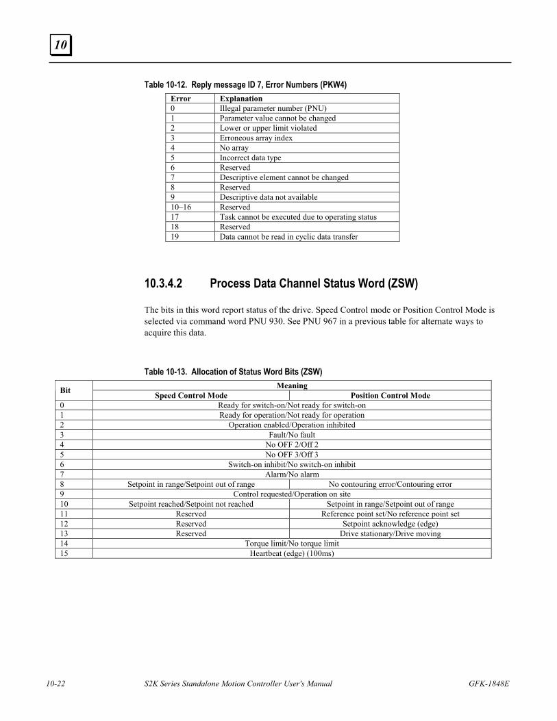
10-22 S2K Series Standalone Motion Controller User's Manual GFK-1848E
10
Table 10-12. Reply message ID 7, Error Numbers (PKW4) Error Explanation 0 Illegal parameter number (PNU) 1 Parameter value cannot be changed 2 Lower or upper limit violated 3 Erroneous array index 4 No array 5 Incorrect data type 6 Reserved 7 Descriptive element cannot be changed 8 Reserved 9 Descriptive data not available 10–16 Reserved 17 Task cannot be executed due to operating status 18 Reserved 19 Data cannot be read in cyclic data transfer
10.3.4.2 Process Data Channel Status Word (ZSW)
The bits in this word report status of the drive. Speed Control mode or Position Control Mode is selected via command word PNU 930. See PNU 967 in a previous table for alternate ways to acquire this data.
Table 10-13. Allocation of Status Word Bits (ZSW) Meaning Bit Speed Control Mode Position Control Mode
0 Ready for switch-on/Not ready for switch-on 1 Ready for operation/Not ready for operation 2 Operation enabled/Operation inhibited 3 Fault/No fault 4 No OFF 2/Off 2 5 No OFF 3/Off 3 6 Switch-on inhibit/No switch-on inhibit 7 Alarm/No alarm 8 Setpoint in range/Setpoint out of range No contouring error/Contouring error 9 Control requested/Operation on site 10 Setpoint reached/Setpoint not reached Setpoint in range/Setpoint out of range 11 Reserved Reference point set/No reference point set 12 Reserved Setpoint acknowledge (edge) 13 Reserved Drive stationary/Drive moving 14 Torque limit/No torque limit 15 Heartbeat (edge) (100ms)
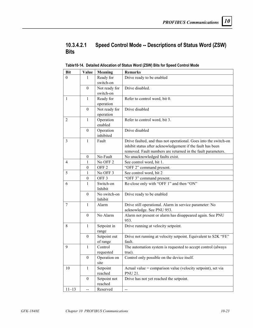
PROFIBUS Communications
GFK-1848E Chapter 10 PROFIBUS Communications 10-23
10
10.3.4.2.1 Speed Control Mode -- Descriptions of Status Word (ZSW) Bits
Table10-14. Detailed Allocation of Status Word (ZSW) Bits for Speed Control Mode Bit Value Meaning Remarks
1 Ready for switch-on
Drive ready to be enabled 0
0 Not ready for switch-on
Drive disabled.
1 Ready for operation
Refer to control word, bit 0. 1
0 Not ready for operation
Drive disabled
1 Operation enabled
Refer to control word, bit 3. 2
0 Operation inhibited
Drive disabled
1 Fault Drive faulted, and thus not operational. Goes into the switch-on inhibit status after acknowledgement if the fault has been removed. Fault numbers are returned in the fault parameters.
3
0 No-Fault No unacknowledged faults exist. 1 No OFF 2 See control word, bit 1. 4 0 OFF 2 “OFF 2” command present. 1 No OFF 3 See control word, bit 2 5 0 OFF 3 “OFF 3” command present. 1 Switch-on
Inhibit Re-close only with “OFF 1” and then “ON” 6
0 No switch-on Inhibit
Drive ready to be enabled
1 Alarm Drive still operational. Alarm in service parameter: No acknowledge. See PNU 953.
7
0 No Alarm Alarm not present or alarm has disappeared again. See PNU 953.
1 Setpoint in range
Drive running at velocity setpoint. 8
0 Setpoint out of range
Drive not running at velocity setpoint. Equivalent to S2K “FE” fault.
1 Control requested
The automation system is requested to accept control (always true).
9
0 Operation on site
Control only possible on the device itself.
1 Setpoint reached
Actual value = comparison value (velocity setpoint), set via PNU 21.
10
0 Setpoint not reached
Drive has not yet reached the setpoint.
11–13 -- Reserved --
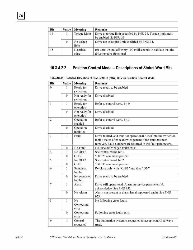
10-24 S2K Series Standalone Motion Controller User's Manual GFK-1848E
10
Bit Value Meaning Remarks 1 Torque Limit Drive at torque limit specified by PNU 34. Torque limit must
be enabled via PNU 35. 14
0 No torque limit
Drive not at torque limit specified by PNU 34.
15 Heartbeat edge
Bit turns on and off every 100 milliseconds to validate that the drive remains functional
10.3.4.2.2 Position Control Mode -- Descriptions of Status Word Bits
Table10-15. Detailed Allocation of Status Word (ZSW) Bits for Position Control Mode Bit Value Meaning Remarks
1 Ready for switch-on
Drive ready to be enabled 0
0 Not ready for switch-on
Drive disabled.
1 Ready for operation
Refer to control word, bit 0. 1
0 Not ready for operation
Drive disabled
1 Operation enabled
Refer to control word, bit 3. 2
0 Operation inhibited
Drive disabled
1 Fault Drive faulted, and thus not operational. Goes into the switch-on inhibit status after acknowledgement if the fault has been removed. Fault numbers are returned in the fault parameters.
3
0 No-Fault No unacknowledged faults exist. 1 No OFF2 See control word, bit 1. 4 0 OFF2 “OFF2” command present. 1 No OFF3 See control word, bit 2 5 0 OFF3 “OFF3” command present. 1 Switch-on
Inhibit Re-close only with “OFF1” and then “ON” 6
0 No switch-on Inhibit
Drive ready to be enabled
1 Alarm Drive still operational. Alarm in service parameter: No acknowledge. See PNU 953.
7
0 No Alarm Alarm not present or alarm has disappeared again. See PNU 953.
1 No Contouring error
No following error faults. 8
0 Contouring error
Following error faults exist.
9 1 Control requested
The automation system is requested to accept control (always true).
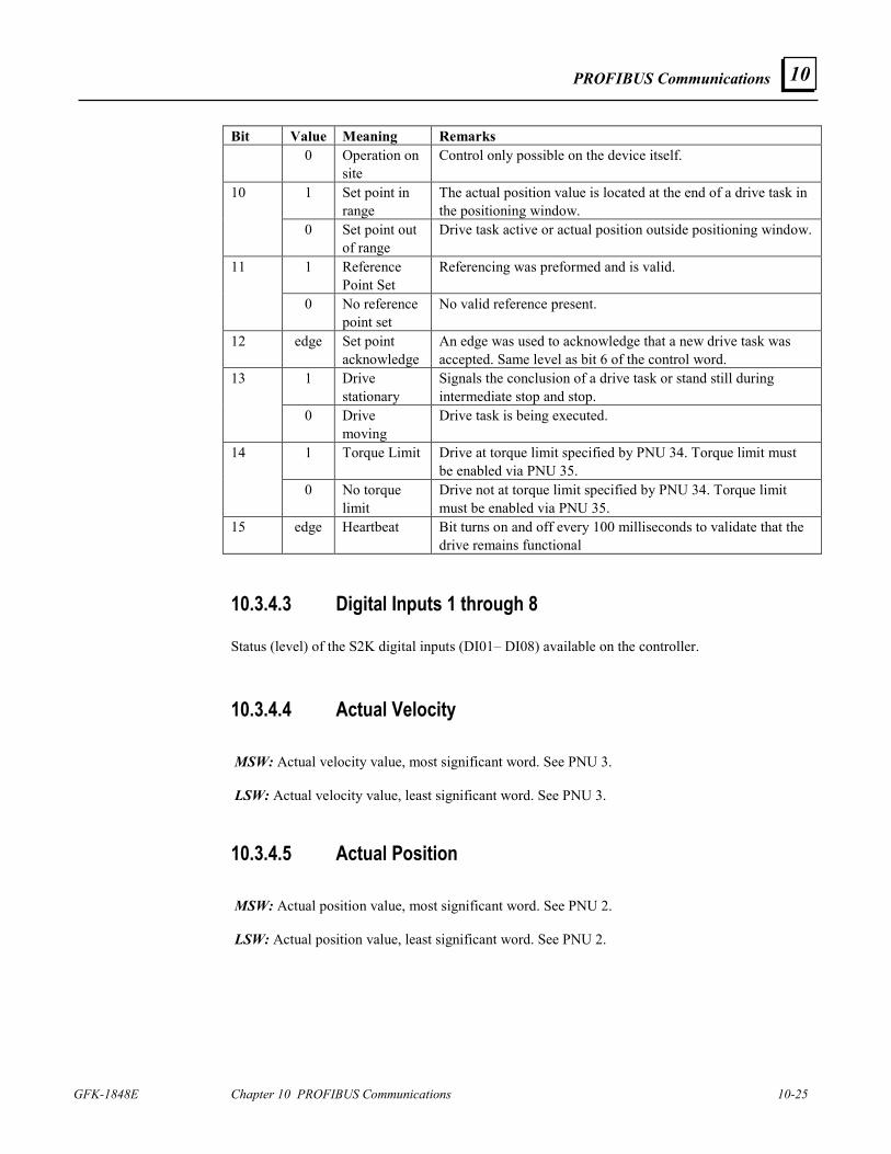
PROFIBUS Communications
GFK-1848E Chapter 10 PROFIBUS Communications 10-25
10
Bit Value Meaning Remarks 0 Operation on
site Control only possible on the device itself.
1 Set point in range
The actual position value is located at the end of a drive task in the positioning window.
10
0 Set point out of range
Drive task active or actual position outside positioning window.
1 Reference Point Set
Referencing was preformed and is valid. 11
0 No reference point set
No valid reference present.
12 edge Set point acknowledge
An edge was used to acknowledge that a new drive task was accepted. Same level as bit 6 of the control word.
1 Drive stationary
Signals the conclusion of a drive task or stand still during intermediate stop and stop.
13
0 Drive moving
Drive task is being executed.
1 Torque Limit Drive at torque limit specified by PNU 34. Torque limit must be enabled via PNU 35.
14
0 No torque limit
Drive not at torque limit specified by PNU 34. Torque limit must be enabled via PNU 35.
15 edge Heartbeat Bit turns on and off every 100 milliseconds to validate that the drive remains functional
10.3.4.3 Digital Inputs 1 through 8
Status (level) of the S2K digital inputs (DI01– DI08) available on the controller.
10.3.4.4 Actual Velocity MSW: Actual velocity value, most significant word. See PNU 3. LSW: Actual velocity value, least significant word. See PNU 3.
10.3.4.5 Actual Position MSW: Actual position value, most significant word. See PNU 2. LSW: Actual position value, least significant word. See PNU 2.
10-26 S2K Series Standalone Motion Controller User's Manual GFK-1848E
10
10.3.5 Fault History and Fault Cause Codes
Parameter (PNU) 952, number of faults, stores fault conditions (a maximum of 65,535) that have occurred since the last power cycle or since the last time the number of faults parameter (PNU 952) was reset by writing a zero.
The fault number parameter (PNU 947) can return up to eight fault causes for each of the eight fault conditions the S2K can store.
Fault condition—Any of the various severe faults that may occur to cause the S2K Motion Controller to immediately stop motion and internally execute motion program four. The S2K maintains a specific 32-bit register “FC” of which the transition to “on” state of one or multiple bits is considered a fault condition. Fault cause—In S2K terms this is any one of the possible thirty-two fatal errors constantly monitored and listed in the “FC” register. This is represented by a specific bit in the “FC” register.
Parameter (PNU) 947, fault number, identifies a single fault cause of a fault condition by returning a PROFIBUS fault number code. The PROFIBUS fault number codes are derived from the Fault Code (FC) register in the S2K controller and are represented by the FC register bit position plus one. For example, the S2K fault code register bit FC03 (bit 3) “lost enable” fault would be represented as PROFIBUS fault number code 04. FC21 (bit21) “excessive following error” would be PROFIBUS fault number code 22.
The S2K PROFIBUS controller internally maintains a 64-place data table (1–64) to store a series of PROFIBUS fault number codes. The S2K fault code data is organized in an 8x8 array table where each of the possible eight fault conditions (each time the S2K sensed a fault) may contain up to eight fault causes (fault code descriptions). This data is volatile and will be lost or reset to zero if the S2K is power cycled. Each element of the fault history array will contain one of the fault number codes in the following table or the value zero. A maximum of eight fault codes are stored when a fault condition occurs. A maximum of eight fault conditions, representing the most recent faults, are saved.
The PROFIBUS acknowledge/reset fault sequence described in the next section or other methods may be used to place the S2K back into operation. This does not clear the fault history data in the S2K. Only a power cycle clears the table.
When a new fault condition occurs, the number of faults (PNU 952) parameter is increased by one. The previous fault condition data (if present) is relocated eight places lower in the S2K fault history table. The new fault number data is placed in the first eight locations
The PNU 947 command will use the Index field of the PKW command (parameter channel) to select which element (1–64) of the fault data history to read. The command field Task ID should be set to one when the message is executed. This will return the value of the index selected PROFIBUS fault code parameter. Subsequent messages may increment the Index value to get the next fault code value stored in the S2K. A returned value of zero indicates the end of the fault code list for that fault condition. The fault codes for the most recent fault condition will always be in index one through eight.
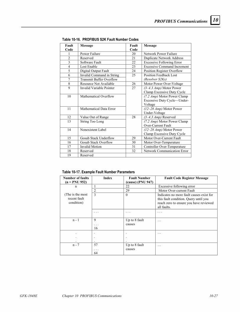
PROFIBUS Communications
GFK-1848E Chapter 10 PROFIBUS Communications 10-27
10
Table 10-16. PROFIBUS S2K Fault Number Codes Fault Code
Message Fault Code
Message
1 Power Failure 20 Network Power Failure 2 Reserved 21 Duplicate Network Address 3 Software Fault 22 Excessive Following Error 4 Lost Enable 23 Excessive Command Increment 5 Digital Output Fault 24 Position Register Overflow 6 Invalid Command in String 7 Transmit Buffer Overflow
25 Position Feedback Lost (Resolver S2Ks)
8 Resource Not Available 26 Motor Power Over-Voltage 9 Invalid Variable Pointer (3–4.3 Amp) Motor Power
Clamp Excessive Duty Cycle 10 Mathematical Overflow (7.2 Amp) Motor Power Clamp
Excessive Duty Cycle—Under-Voltage
11 Mathematical Data Error
27
(12–28 Amp) Motor Power Under-Voltage
12 Value Out of Range (3–4.3 Amp) Reserved 13 String Too Long (7.2 Amp) Motor Power Clamp
Over-Current Fault 14 Nonexistent Label
28
(12–28 Amp) Motor Power Clamp Excessive Duty Cycle
15 Gosub Stack Underflow 29 Motor Over-Current Fault 16 Gosub Stack Overflow 30 Motor Over-Temperature 17 Invalid Motion 31 Controller Over-Temperature 18 Reserved 32 Network Communication Error 19 Reserved
Table 10-17. Example Fault Number Parameters Number of faults
(n = PNU 952) Index Fault Number
(cause) (PNU 947) Fault Code Register Message
1 22 Excessive following error 2 29 Motor Over-current Fault 3 0 Indicates no more fault causes exist for
this fault condition. Query until you reach zero to ensure you have reviewed all faults.
n
(The is the most recent fault condition)
. . . . . . . . .
n - 1 9 . . . 16
Up to 8 fault causes
…
.
.
.
.
.
.
.
.
.
…
n - 7 57 . . . 64
Up to 8 fault causes
…
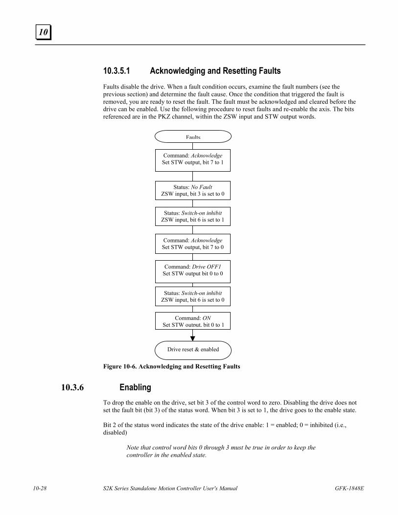
10-28 S2K Series Standalone Motion Controller User's Manual GFK-1848E
10
10.3.5.1 Acknowledging and Resetting Faults Faults disable the drive. When a fault condition occurs, examine the fault numbers (see the previous section) and determine the fault cause. Once the condition that triggered the fault is removed, you are ready to reset the fault. The fault must be acknowledged and cleared before the drive can be enabled. Use the following procedure to reset faults and re-enable the axis. The bits referenced are in the PKZ channel, within the ZSW input and STW output words. Figure 10-6. Acknowledging and Resetting Faults
10.3.6 Enabling To drop the enable on the drive, set bit 3 of the control word to zero. Disabling the drive does not set the fault bit (bit 3) of the status word. When bit 3 is set to 1, the drive goes to the enable state. Bit 2 of the status word indicates the state of the drive enable: 1 = enabled; 0 = inhibited (i.e., disabled)
Note that control word bits 0 through 3 must be true in order to keep the controller in the enabled state.
Command: Acknowledge Set STW output, bit 7 to 1
Status: No Fault ZSW input, bit 3 is set to 0
Status: Switch-on inhibit ZSW input, bit 6 is set to 1
Command: Acknowledge Set STW output, bit 7 to 0
Command: Drive OFF1 Set STW output bit 0 to 0
Status: Switch-on inhibit ZSW input, bit 6 is set to 0
Command: ON Set STW output, bit 0 to 1
Drive reset & enabled
Faults
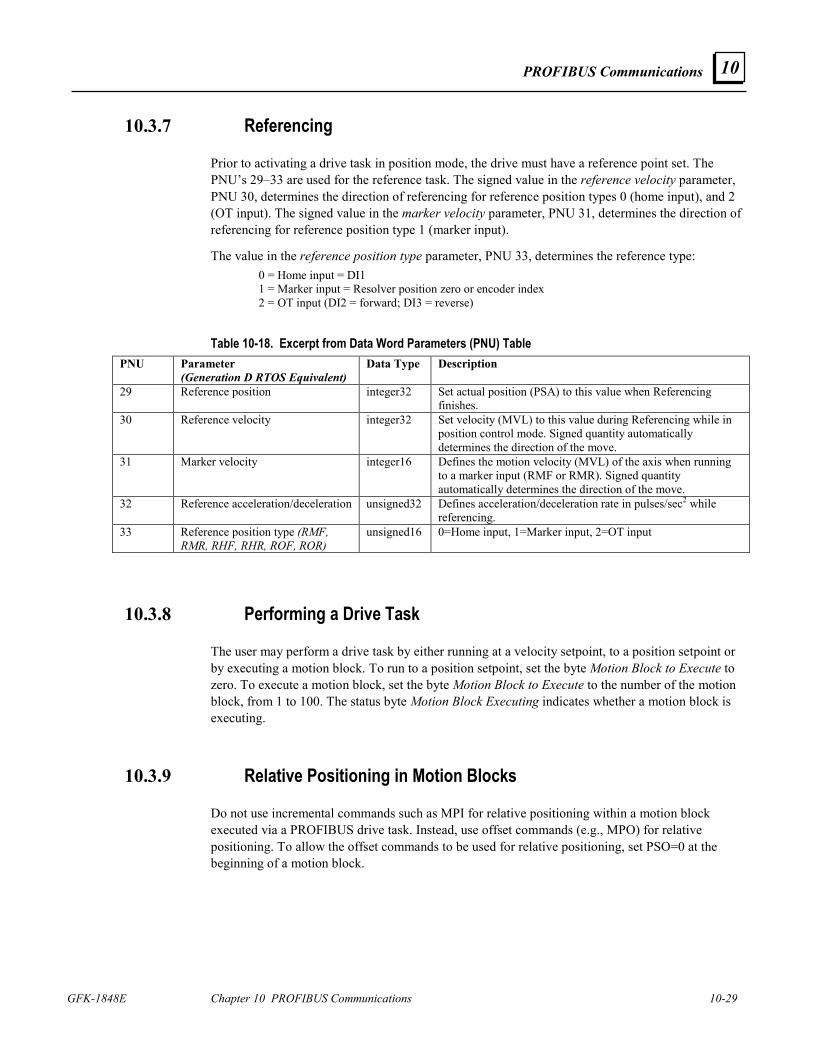
PROFIBUS Communications
GFK-1848E Chapter 10 PROFIBUS Communications 10-29
10
10.3.7 Referencing
Prior to activating a drive task in position mode, the drive must have a reference point set. The PNU’s 29–33 are used for the reference task. The signed value in the reference velocity parameter, PNU 30, determines the direction of referencing for reference position types 0 (home input), and 2 (OT input). The signed value in the marker velocity parameter, PNU 31, determines the direction of referencing for reference position type 1 (marker input).
The value in the reference position type parameter, PNU 33, determines the reference type: 0 = Home input = DI1
1 = Marker input = Resolver position zero or encoder index 2 = OT input (DI2 = forward; DI3 = reverse)
Table 10-18. Excerpt from Data Word Parameters (PNU) Table PNU Parameter
(Generation D RTOS Equivalent) Data Type Description
29 Reference position integer32 Set actual position (PSA) to this value when Referencing finishes.
30 Reference velocity integer32 Set velocity (MVL) to this value during Referencing while in position control mode. Signed quantity automatically determines the direction of the move.
31 Marker velocity integer16 Defines the motion velocity (MVL) of the axis when running to a marker input (RMF or RMR). Signed quantity automatically determines the direction of the move.
32 Reference acceleration/deceleration unsigned32 Defines acceleration/deceleration rate in pulses/sec2 while referencing.
33 Reference position type (RMF, RMR, RHF, RHR, ROF, ROR)
unsigned16 0=Home input, 1=Marker input, 2=OT input
10.3.8 Performing a Drive Task
The user may perform a drive task by either running at a velocity setpoint, to a position setpoint or by executing a motion block. To run to a position setpoint, set the byte Motion Block to Execute to zero. To execute a motion block, set the byte Motion Block to Execute to the number of the motion block, from 1 to 100. The status byte Motion Block Executing indicates whether a motion block is executing.
10.3.9 Relative Positioning in Motion Blocks
Do not use incremental commands such as MPI for relative positioning within a motion block executed via a PROFIBUS drive task. Instead, use offset commands (e.g., MPO) for relative positioning. To allow the offset commands to be used for relative positioning, set PSO=0 at the beginning of a motion block.
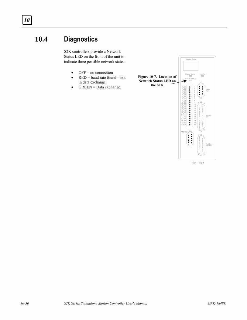
10-30 S2K Series Standalone Motion Controller User's Manual GFK-1848E
10
10.4 Diagnostics S2K controllers provide a Network Status LED on the front of the unit to indicate three possible network states:
• OFF = no connection • RED = baud rate found—not
in data exchange • GREEN = Data exchange.
Figure 10-7. Location of Network Status LED on
the S2K

PROFIBUS Communications
GFK-1848E Chapter 10 PROFIBUS Communications 10-31
10
Intentionally Blank
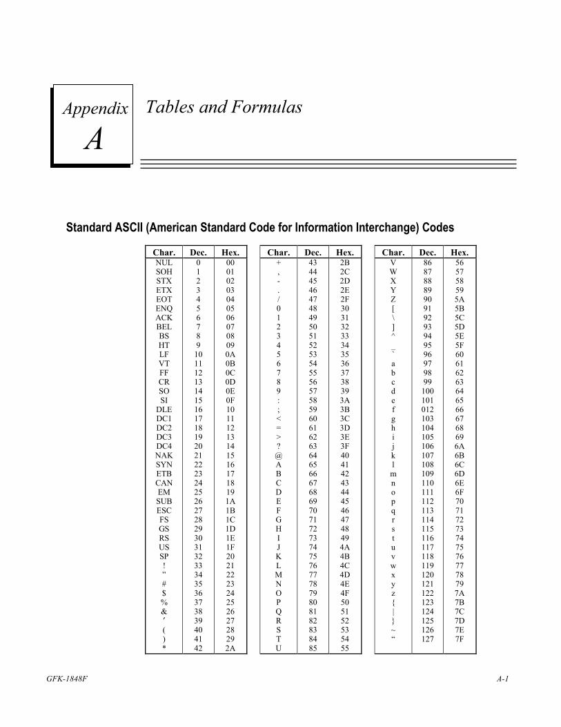
GFK-1848F A-1
Tables and Formulas
Standard ASCII (American Standard Code for Information Interchange) Codes
Char. Dec. Hex. Char. Dec. Hex. Char. Dec. Hex. NUL SOH STX ETX EOT ENQ ACK BEL BS HT LF VT FF CR SO SI
DLE DC1 DC2 DC3 DC4 NAK SYN ETB CAN EM SUB ESC FS GS RS US SP ! ” # $ % & ′ ( ) *
0 1 2 3 4 5 6 7 8 9
10 11 12 13 14 15 16 17 18 19 20 21 22 23 24 25 26 27 28 29 30 31 32 33 34 35 36 37 38 39 40 41 42
00 01 02 03 04 05 06 07 08 09 0A 0B 0C 0D 0E 0F 10 11 12 13 14 15 16 17 18 19 1A 1B 1C 1D 1E 1F 20 21 22 23 24 25 26 27 28 29 2A
+ , - . / 0 1 2 3 4 5 6 7 8 9 : ; < = > ? @ A B C D E F G H I J K L M N O P Q R S T U
43 44 45 46 47 48 49 50 51 52 53 54 55 56 57 58 59 60 61 62 63 64 65 66 67 68 69 70 71 72 73 74 75 76 77 78 79 80 81 82 83 84 85
2B 2C 2D 2E 2F 30 31 32 33 34 35 36 37 38 39 3A 3B 3C 3D 3E 3F 40 41 42 43 44 45 46 47 48 49 4A 4B 4C 4D 4E 4F 50 51 52 53 54 55
V W X Y Z [ \ ] ^ _ ` a b c d e f g h i j k l m n o p q r s t u v w x y z | ~ “
86 87 88 89 90 91 92 93 94 95 96 97 98 99
100 101 012 103 104 105 106 107 108 109 110 111 112 113 114 115 116 117 118 119 120 121 122 123 124 125 126 127
56 57 58 59 5A 5B 5C 5D 5E 5F 60 61 62 63 64 65 66 67 68 69 6A 6B 6C 6D 6E 6F 70 71 72 73 74 75 76 77 78 79 7A 7B 7C 7D 7E 7F
A Appendix
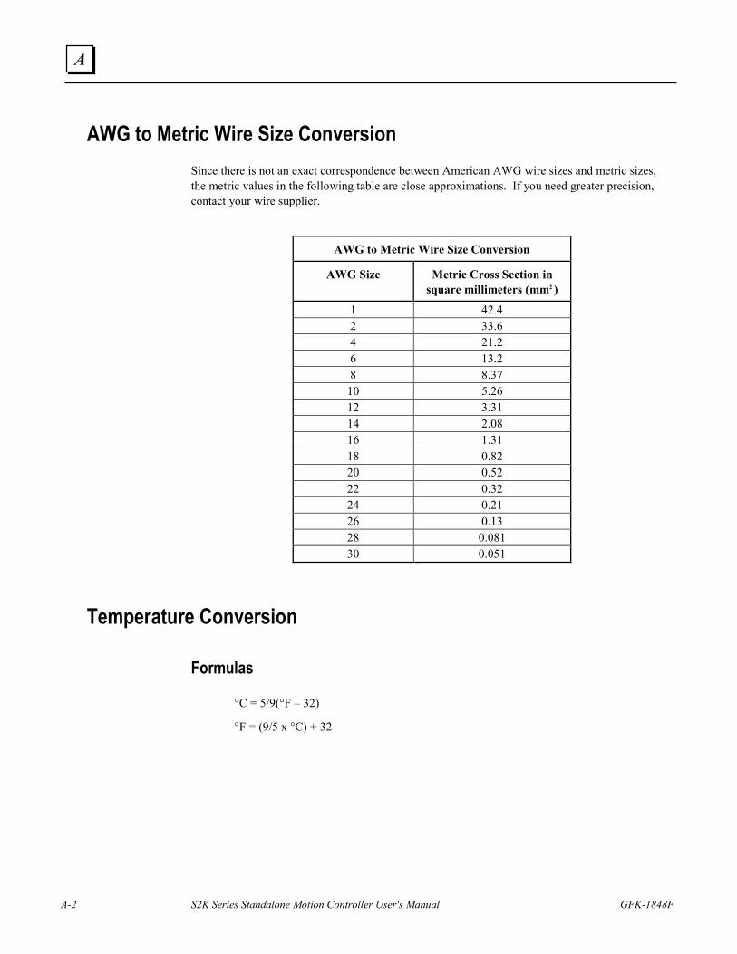
A-2 S2K Series Standalone Motion Controller User's Manual GFK-1848F
A
AWG to Metric Wire Size Conversion Since there is not an exact correspondence between American AWG wire sizes and metric sizes, the metric values in the following table are close approximations. If you need greater precision, contact your wire supplier.
AWG to Metric Wire Size Conversion
AWG Size Metric Cross Section in square millimeters (mm2 )
1 42.4 2 33.6 4 21.2 6 13.2 8 8.37
10 5.26 12 3.31 14 2.08 16 1.31 18 0.82 20 0.52 22 0.32 24 0.21 26 0.13 28 0.081 30 0.051
Temperature Conversion
Formulas
°C = 5/9(°F – 32)
°F = (9/5 x °C) + 32
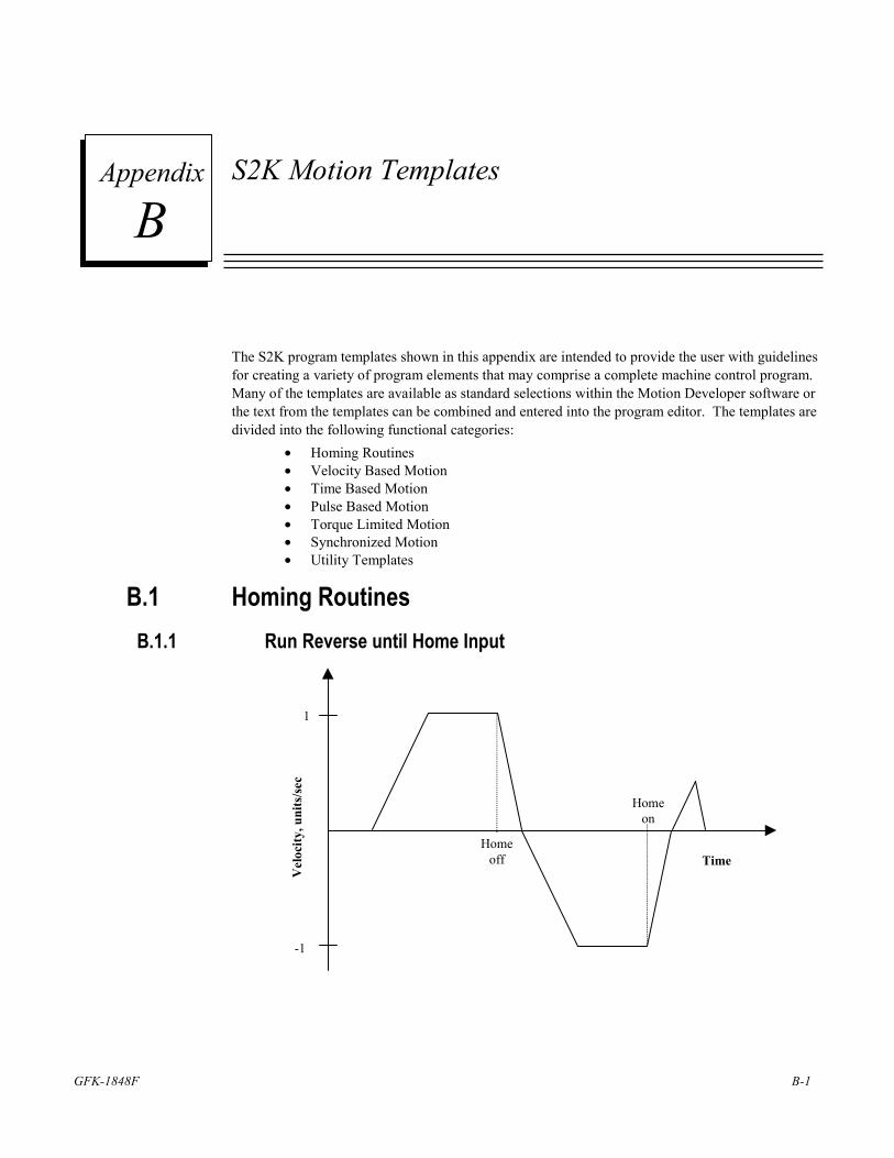
GFK-1848F B-1
S2K Motion Templates
The S2K program templates shown in this appendix are intended to provide the user with guidelines for creating a variety of program elements that may comprise a complete machine control program. Many of the templates are available as standard selections within the Motion Developer software or the text from the templates can be combined and entered into the program editor. The templates are divided into the following functional categories:
• Homing Routines • Velocity Based Motion • Time Based Motion • Pulse Based Motion • Torque Limited Motion • Synchronized Motion • Utility Templates
B.1 Homing Routines B.1.1 Run Reverse until Home Input
1
Time
Vel
ocity
, uni
ts/se
c
Homeoff
Homeon
-1
B Appendix
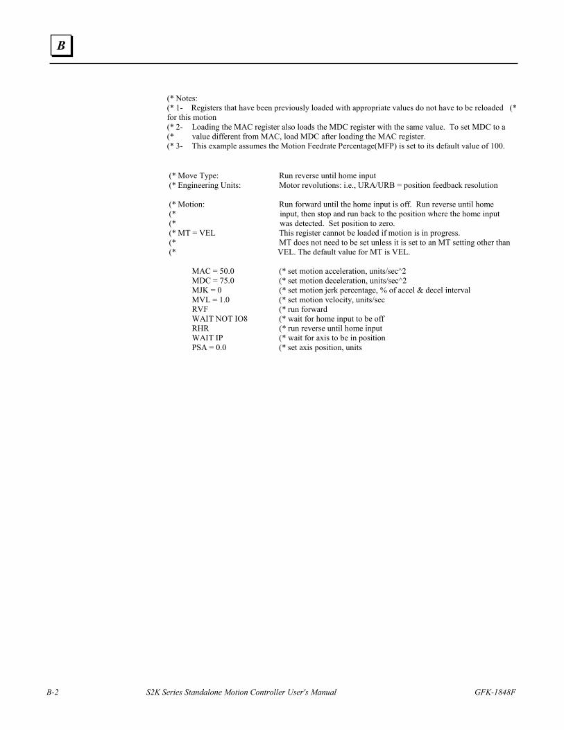
B-2 S2K Series Standalone Motion Controller User's Manual GFK-1848F
B
(* Notes: (* 1- Registers that have been previously loaded with appropriate values do not have to be reloaded (* for this motion (* 2- Loading the MAC register also loads the MDC register with the same value. To set MDC to a (* value different from MAC, load MDC after loading the MAC register. (* 3- This example assumes the Motion Feedrate Percentage(MFP) is set to its default value of 100.
(* Move Type: Run reverse until home input (* Engineering Units: Motor revolutions: i.e., URA/URB = position feedback resolution (* Motion: Run forward until the home input is off. Run reverse until home (* input, then stop and run back to the position where the home input (* was detected. Set position to zero. (* MT = VEL This register cannot be loaded if motion is in progress. (* MT does not need to be set unless it is set to an MT setting other than (* VEL. The default value for MT is VEL. MAC = 50.0 (* set motion acceleration, units/sec^2 MDC = 75.0 (* set motion deceleration, units/sec^2 MJK = 0 (* set motion jerk percentage, % of accel & decel interval MVL = 1.0 (* set motion velocity, units/sec RVF (* run forward WAIT NOT IO8 (* wait for home input to be off RHR (* run reverse until home input WAIT IP (* wait for axis to be in position PSA = 0.0 (* set axis position, units
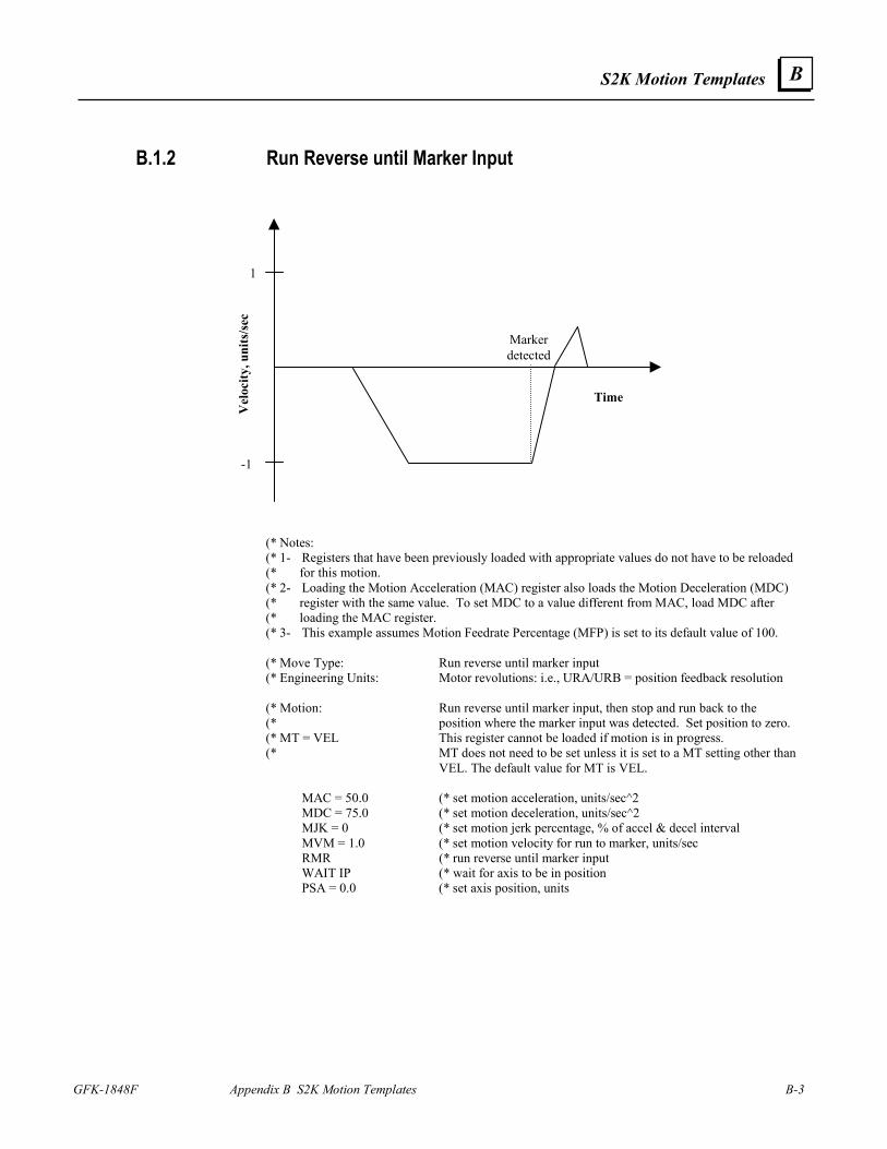
S2K Motion Templates
GFK-1848F Appendix B S2K Motion Templates B-3
B
B.1.2 Run Reverse until Marker Input
1
-1
Time
Vel
ocity
, uni
ts/s
ec
Markerdetected
(* Notes: (* 1- Registers that have been previously loaded with appropriate values do not have to be reloaded (* for this motion. (* 2- Loading the Motion Acceleration (MAC) register also loads the Motion Deceleration (MDC) (* register with the same value. To set MDC to a value different from MAC, load MDC after (* loading the MAC register. (* 3- This example assumes Motion Feedrate Percentage (MFP) is set to its default value of 100. (* Move Type: Run reverse until marker input (* Engineering Units: Motor revolutions: i.e., URA/URB = position feedback resolution (* Motion: Run reverse until marker input, then stop and run back to the (* position where the marker input was detected. Set position to zero. (* MT = VEL This register cannot be loaded if motion is in progress. (* MT does not need to be set unless it is set to a MT setting other than
VEL. The default value for MT is VEL. MAC = 50.0 (* set motion acceleration, units/sec^2 MDC = 75.0 (* set motion deceleration, units/sec^2 MJK = 0 (* set motion jerk percentage, % of accel & decel interval MVM = 1.0 (* set motion velocity for run to marker, units/sec RMR (* run reverse until marker input WAIT IP (* wait for axis to be in position PSA = 0.0 (* set axis position, units
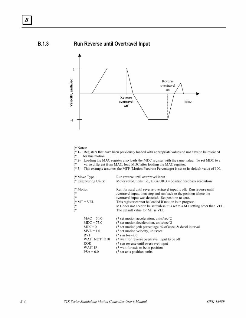
B-4 S2K Series Standalone Motion Controller User's Manual GFK-1848F
B
B.1.3 Run Reverse until Overtravel Input
(* Notes: (* 1- Registers that have been previously loaded with appropriate values do not have to be reloaded (* for this motion. (* 2- Loading the MAC register also loads the MDC register with the same value. To set MDC to a (* value different from MAC, load MDC after loading the MAC register. (* 3- This example assumes the MFP (Motion Feedrate Percentage) is set to its default value of 100. (* Move Type: Run reverse until overtravel input (* Engineering Units: Motor revolutions: i.e., URA/URB = position feedback resolution (* Motion: Run forward until reverse overtravel input is off. Run reverse until (* overtravel input, then stop and run back to the position where the (* overtravel input was detected. Set position to zero. (* MT = VEL This register cannot be loaded if motion is in progress. (* MT does not need to be set unless it is set to a MT setting other than VEL. (* The default value for MT is VEL. MAC = 50.0 (* set motion acceleration, units/sec^2 MDC = 75.0 (* set motion deceleration, units/sec^2 MJK = 0 (* set motion jerk percentage, % of accel & decel interval MVL = 1.0 (* set motion velocity, units/sec RVF (* run forward WAIT NOT IO10 (* wait for reverse overtravel input to be off ROR (* run reverse until overtravel input WAIT IP (* wait for axis to be in position PSA = 0.0 (* set axis position, units
Vel
ocity
, uni
ts/s
ec
Reverseovertravel
off
1
-1
Time
Vel
ocity
, uni
ts/s
ec
Reverseovertravel
off
Reverseovertravel
on
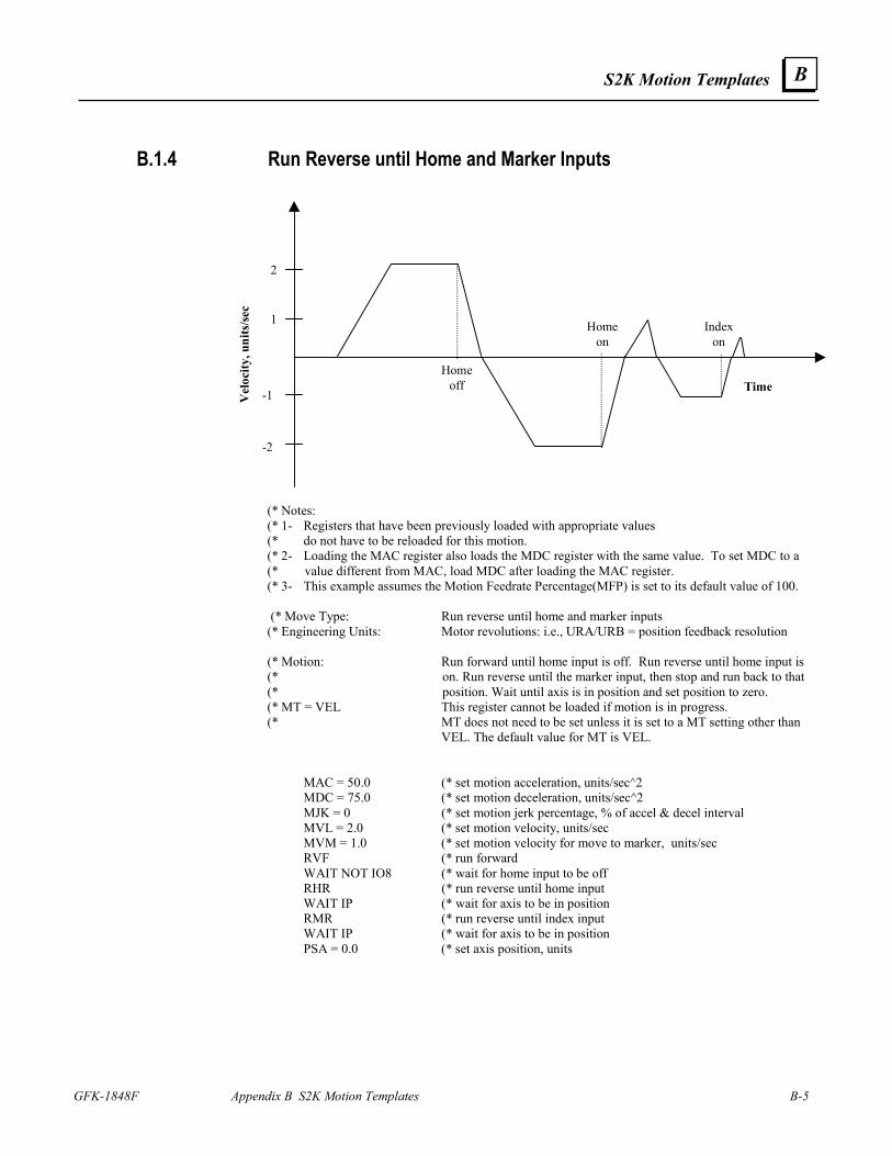
S2K Motion Templates
GFK-1848F Appendix B S2K Motion Templates B-5
B
B.1.4 Run Reverse until Home and Marker Inputs
2
-2
Time
Vel
ocity
, uni
ts/se
c
Homeoff
Homeon
-1
1 Indexon
(* Notes: (* 1- Registers that have been previously loaded with appropriate values (* do not have to be reloaded for this motion. (* 2- Loading the MAC register also loads the MDC register with the same value. To set MDC to a (* value different from MAC, load MDC after loading the MAC register. (* 3- This example assumes the Motion Feedrate Percentage(MFP) is set to its default value of 100. (* Move Type: Run reverse until home and marker inputs (* Engineering Units: Motor revolutions: i.e., URA/URB = position feedback resolution (* Motion: Run forward until home input is off. Run reverse until home input is (* on. Run reverse until the marker input, then stop and run back to that (* position. Wait until axis is in position and set position to zero. (* MT = VEL This register cannot be loaded if motion is in progress. (* MT does not need to be set unless it is set to a MT setting other than
VEL. The default value for MT is VEL. MAC = 50.0 (* set motion acceleration, units/sec^2 MDC = 75.0 (* set motion deceleration, units/sec^2 MJK = 0 (* set motion jerk percentage, % of accel & decel interval MVL = 2.0 (* set motion velocity, units/sec MVM = 1.0 (* set motion velocity for move to marker, units/sec RVF (* run forward WAIT NOT IO8 (* wait for home input to be off RHR (* run reverse until home input WAIT IP (* wait for axis to be in position RMR (* run reverse until index input WAIT IP (* wait for axis to be in position PSA = 0.0 (* set axis position, units
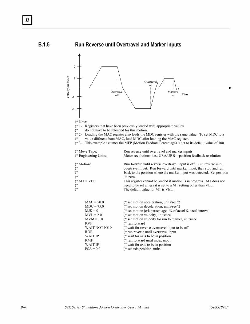
B-6 S2K Series Standalone Motion Controller User's Manual GFK-1848F
B
B.1.5 Run Reverse until Overtravel and Marker Inputs
2
-2
Time
Vel
ocity
, uni
ts/s
ec
Overtraveloff
Overtravelon
-1
1
Markeron
(* Notes: (* 1- Registers that have been previously loaded with appropriate values (* do not have to be reloaded for this motion. (* 2- Loading the MAC register also loads the MDC register with the same value. To set MDC to a (* value different from MAC, load MDC after loading the MAC register. (* 3- This example assumes the MFP (Motion Feedrate Percentage) is set to its default value of 100. (* Move Type: Run reverse until overtravel and marker inputs (* Engineering Units: Motor revolutions: i.e., URA/URB = position feedback resolution (* Motion: Run forward until reverse overtravel input is off. Run reverse until (* overtravel input. Run forward until marker input, then stop and run (* back to the position where the marker input was detected. Set position (* to zero. (* MT = VEL This register cannot be loaded if motion is in progress. MT does not (* need to be set unless it is set to a MT setting other than VEL. (* The default value for MT is VEL. MAC = 50.0 (* set motion acceleration, units/sec^2 MDC = 75.0 (* set motion deceleration, units/sec^2 MJK = 0 (* set motion jerk percentage, % of accel & decel interval MVL = 2.0 (* set motion velocity, units/sec MVM = 1.0 (* set motion velocity for run to marker, units/sec RVF (* run forward WAIT NOT IO10 (* wait for reverse overtravel input to be off ROR (* run reverse until overtravel input WAIT IP (* wait for axis to be in position RMF (* run forward until index input WAIT IP (* wait for axis to be in position PSA = 0.0 (* set axis position, units
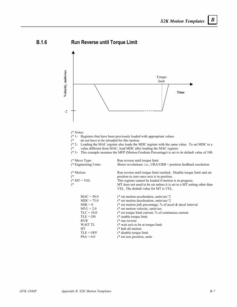
S2K Motion Templates
GFK-1848F Appendix B S2K Motion Templates B-7
B
B.1.6 Run Reverse until Torque Limit
-2
Time
Vel
ocity
, uni
ts/se
c
Torquelimit
(* Notes: (* 1- Registers that have been previously loaded with appropriate values (* do not have to be reloaded for this motion. (* 2- Loading the MAC register also loads the MDC register with the same value. To set MDC to a (* value different from MAC, load MDC after loading the MAC register. (* 3- This example assumes the MFP (Motion Feedrate Percentage) is set to its default value of 100. (* Move Type: Run reverse until torque limit (* Engineering Units: Motor revolutions: i.e., URA/URB = position feedback resolution (* Motion: Run reverse until torque limit reached. Disable torque limit and set (* position to zero once axis is in position. (* MT = VEL This register cannot be loaded if motion is in progress. (* MT does not need to be set unless it is set to a MT setting other than
VEL. The default value for MT is VEL. MAC = 50.0 (* set motion acceleration, units/sec^2 MDC = 75.0 (* set motion deceleration, units/sec^2 MJK = 0 (* set motion jerk percentage, % of accel & decel interval MVL = 2.0 (* set motion velocity, units/sec TLC = 10.0 (* set torque limit current, % of continuous current TLE = ON (* enable torque limit RVR (* run reverse WAIT TL (* wait axis to be at torque limit HT (* halt all motion TLE = OFF (* disable torque limit PSA = 0.0 (* set axis position, units
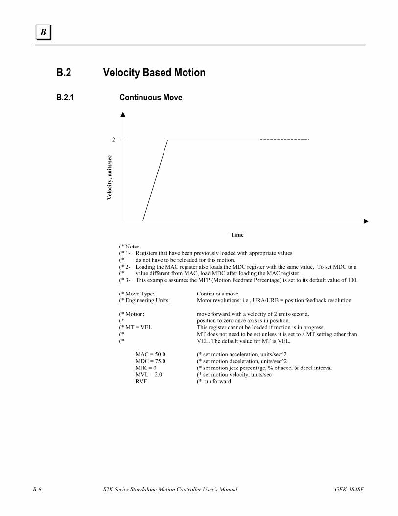
B-8 S2K Series Standalone Motion Controller User's Manual GFK-1848F
B
B.2 Velocity Based Motion
B.2.1 Continuous Move
2
Time
Vel
ocity
, uni
ts/s
ec
(* Notes: (* 1- Registers that have been previously loaded with appropriate values (* do not have to be reloaded for this motion. (* 2- Loading the MAC register also loads the MDC register with the same value. To set MDC to a (* value different from MAC, load MDC after loading the MAC register. (* 3- This example assumes the MFP (Motion Feedrate Percentage) is set to its default value of 100. (* Move Type: Continuous move (* Engineering Units: Motor revolutions: i.e., URA/URB = position feedback resolution (* Motion: move forward with a velocity of 2 units/second. (* position to zero once axis is in position. (* MT = VEL This register cannot be loaded if motion is in progress. (* MT does not need to be set unless it is set to a MT setting other than (* VEL. The default value for MT is VEL. MAC = 50.0 (* set motion acceleration, units/sec^2 MDC = 75.0 (* set motion deceleration, units/sec^2 MJK = 0 (* set motion jerk percentage, % of accel & decel interval MVL = 2.0 (* set motion velocity, units/sec RVF (* run forward
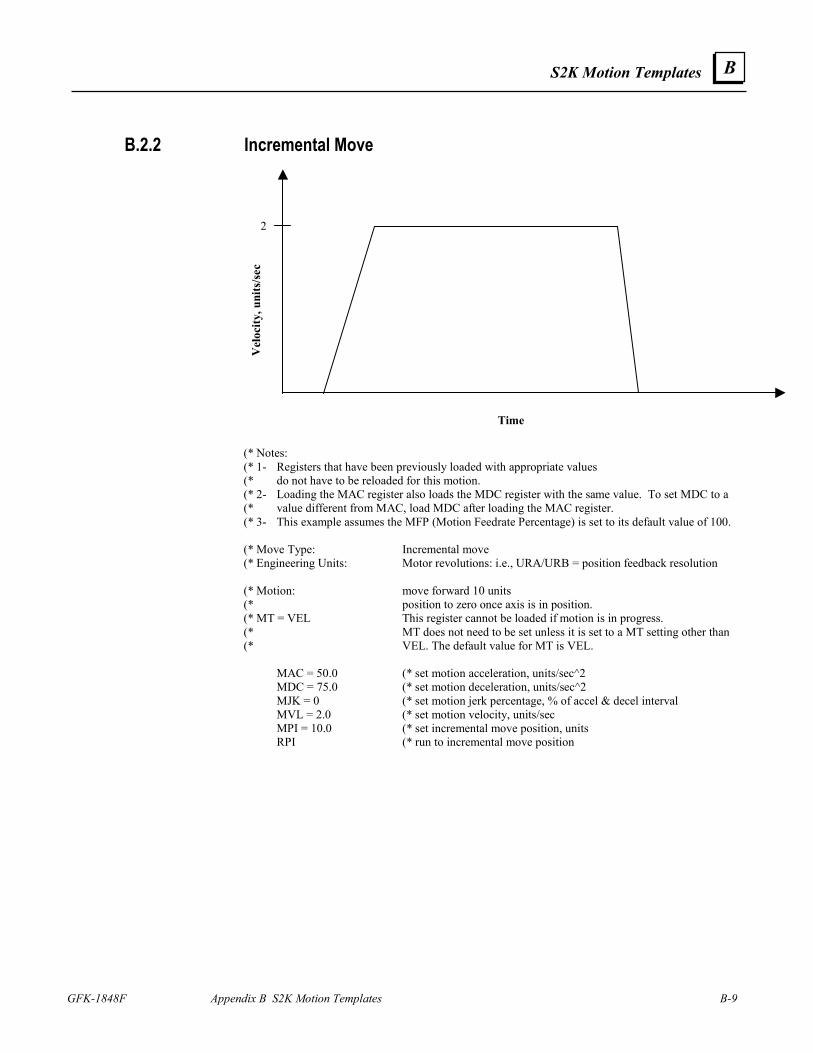
S2K Motion Templates
GFK-1848F Appendix B S2K Motion Templates B-9
B
B.2.2 Incremental Move
2
Time
Vel
ocity
, uni
ts/s
ec
(* Notes: (* 1- Registers that have been previously loaded with appropriate values (* do not have to be reloaded for this motion. (* 2- Loading the MAC register also loads the MDC register with the same value. To set MDC to a (* value different from MAC, load MDC after loading the MAC register. (* 3- This example assumes the MFP (Motion Feedrate Percentage) is set to its default value of 100. (* Move Type: Incremental move (* Engineering Units: Motor revolutions: i.e., URA/URB = position feedback resolution (* Motion: move forward 10 units (* position to zero once axis is in position. (* MT = VEL This register cannot be loaded if motion is in progress. (* MT does not need to be set unless it is set to a MT setting other than (* VEL. The default value for MT is VEL. MAC = 50.0 (* set motion acceleration, units/sec^2 MDC = 75.0 (* set motion deceleration, units/sec^2 MJK = 0 (* set motion jerk percentage, % of accel & decel interval MVL = 2.0 (* set motion velocity, units/sec MPI = 10.0 (* set incremental move position, units RPI (* run to incremental move position
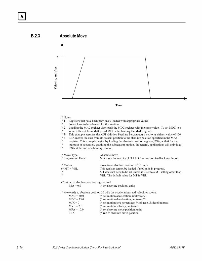
B-10 S2K Series Standalone Motion Controller User's Manual GFK-1848F
B
B.2.3 Absolute Move
2
Time
Vel
ocity
, uni
ts/s
ec
(* Notes: (* 1- Registers that have been previously loaded with appropriate values (* do not have to be reloaded for this motion. (* 2- Loading the MAC register also loads the MDC register with the same value. To set MDC to a (* value different from MAC, load MDC after loading the MAC register. (* 3- This example assumes the MFP (Motion Feedrate Percentage) is set to its default value of 100. (* 4- RPA moves the axis from its present position to the absolute position specified in the MPA (* register. This example begins by loading the absolute position register, PSA, with 0 for the (* purpose of accurately graphing the subsequent motion. In general, applications will only load (* PSA at the end of a homing motion. (* Move Type: Absolute move (* Engineering Units: Motor revolutions: i.e., URA/URB = position feedback resolution (* Motion: move to an absolute position of 10 units (* MT = VEL This register cannot be loaded if motion is in progress. (* MT does not need to be set unless it is set to a MT setting other than (* VEL. The default value for MT is VEL. (* Initialize absolute position register to 0 PSA = 0.0 (* set absolute position, units (* Move axis to absolute position 10 with the accelerations and velocities shown. MAC = 50.0 (* set motion acceleration, units/sec^2 MDC = 75.0 (* set motion deceleration, units/sec^2 MJK = 0 (* set motion jerk percentage, % of accel & decel interval MVL = 2.0 (* set motion velocity, units/sec MPA = 10.0 (* set absolute move position, units RPA (* run to absolute move position
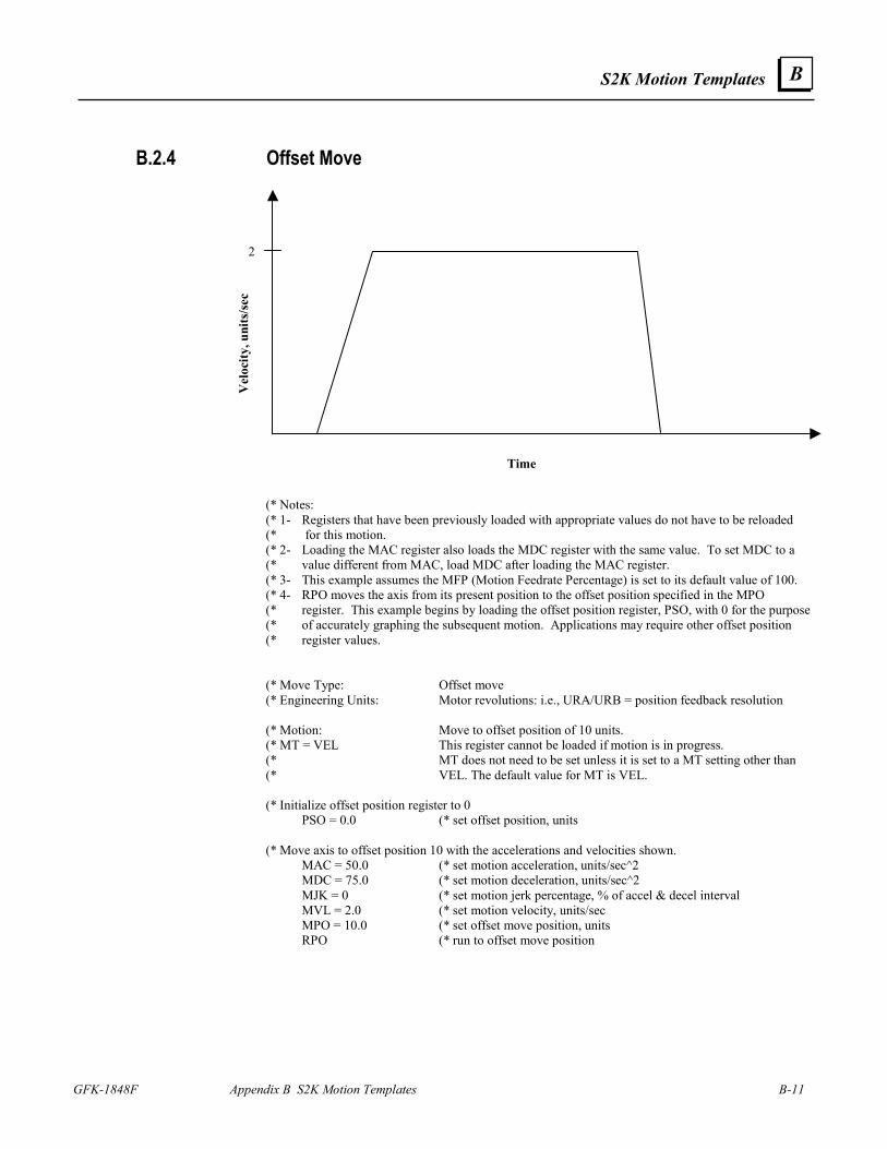
S2K Motion Templates
GFK-1848F Appendix B S2K Motion Templates B-11
B
B.2.4 Offset Move
2
Time
Vel
ocity
, uni
ts/s
ec
(* Notes: (* 1- Registers that have been previously loaded with appropriate values do not have to be reloaded (* for this motion. (* 2- Loading the MAC register also loads the MDC register with the same value. To set MDC to a (* value different from MAC, load MDC after loading the MAC register. (* 3- This example assumes the MFP (Motion Feedrate Percentage) is set to its default value of 100. (* 4- RPO moves the axis from its present position to the offset position specified in the MPO (* register. This example begins by loading the offset position register, PSO, with 0 for the purpose (* of accurately graphing the subsequent motion. Applications may require other offset position (* register values. (* Move Type: Offset move (* Engineering Units: Motor revolutions: i.e., URA/URB = position feedback resolution (* Motion: Move to offset position of 10 units. (* MT = VEL This register cannot be loaded if motion is in progress. (* MT does not need to be set unless it is set to a MT setting other than (* VEL. The default value for MT is VEL. (* Initialize offset position register to 0 PSO = 0.0 (* set offset position, units (* Move axis to offset position 10 with the accelerations and velocities shown. MAC = 50.0 (* set motion acceleration, units/sec^2 MDC = 75.0 (* set motion deceleration, units/sec^2 MJK = 0 (* set motion jerk percentage, % of accel & decel interval MVL = 2.0 (* set motion velocity, units/sec MPO = 10.0 (* set offset move position, units RPO (* run to offset move position
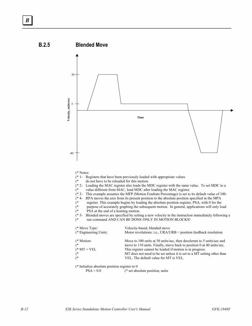
B-12 S2K Series Standalone Motion Controller User's Manual GFK-1848F
B
B.2.5 Blended Move
30
-40
Time
Vel
ocity
, uni
ts/s
ec
5
(* Notes: (* 1- Registers that have been previously loaded with appropriate values (* do not have to be reloaded for this motion. (* 2- Loading the MAC register also loads the MDC register with the same value. To set MDC to a (* value different from MAC, load MDC after loading the MAC register. (* 3- This example assumes the MFP (Motion Feedrate Percentage) is set to its default value of 100. (* 4- RPA moves the axis from its present position to the absolute position specified in the MPA (* register. This example begins by loading the absolute position register, PSA, with 0 for the (* purpose of accurately graphing the subsequent motion. In general, applications will only load (* PSA at the end of a homing motion. (* 5- Blended moves are specified by setting a new velocity in the instruction immediately following a (* run command AND CAN BE DONE ONLY IN MOTION BLOCKS! (* Move Type: Velocity-based, blended move (* Engineering Units: Motor revolutions: i.e., URA/URB = position feedback resolution (* Motion: Move to 100 units at 30 units/sec, then decelerate to 5 units/sec and (* move to 110 units. Finally, move back to position 0 at 40 units/sec. (* MT = VEL This register cannot be loaded if motion is in progress. (* MT does not need to be set unless it is set to a MT setting other than (* VEL. The default value for MT is VEL. (* Initialize absolute position register to 0 PSA = 0.0 (* set absolute position, units
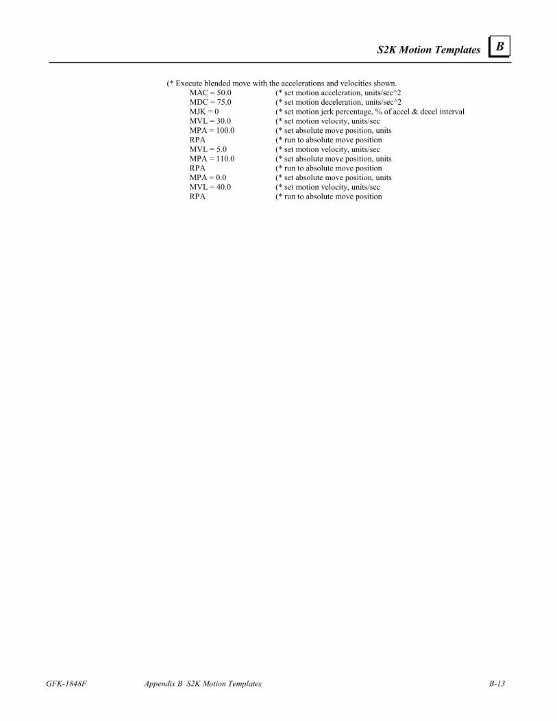
S2K Motion Templates
GFK-1848F Appendix B S2K Motion Templates B-13
B
(* Execute blended move with the accelerations and velocities shown. MAC = 50.0 (* set motion acceleration, units/sec^2 MDC = 75.0 (* set motion deceleration, units/sec^2 MJK = 0 (* set motion jerk percentage, % of accel & decel interval MVL = 30.0 (* set motion velocity, units/sec MPA = 100.0 (* set absolute move position, units RPA (* run to absolute move position MVL = 5.0 (* set motion velocity, units/sec MPA = 110.0 (* set absolute move position, units RPA (* run to absolute move position MPA = 0.0 (* set absolute move position, units MVL = 40.0 (* set motion velocity, units/sec RPA (* run to absolute move position
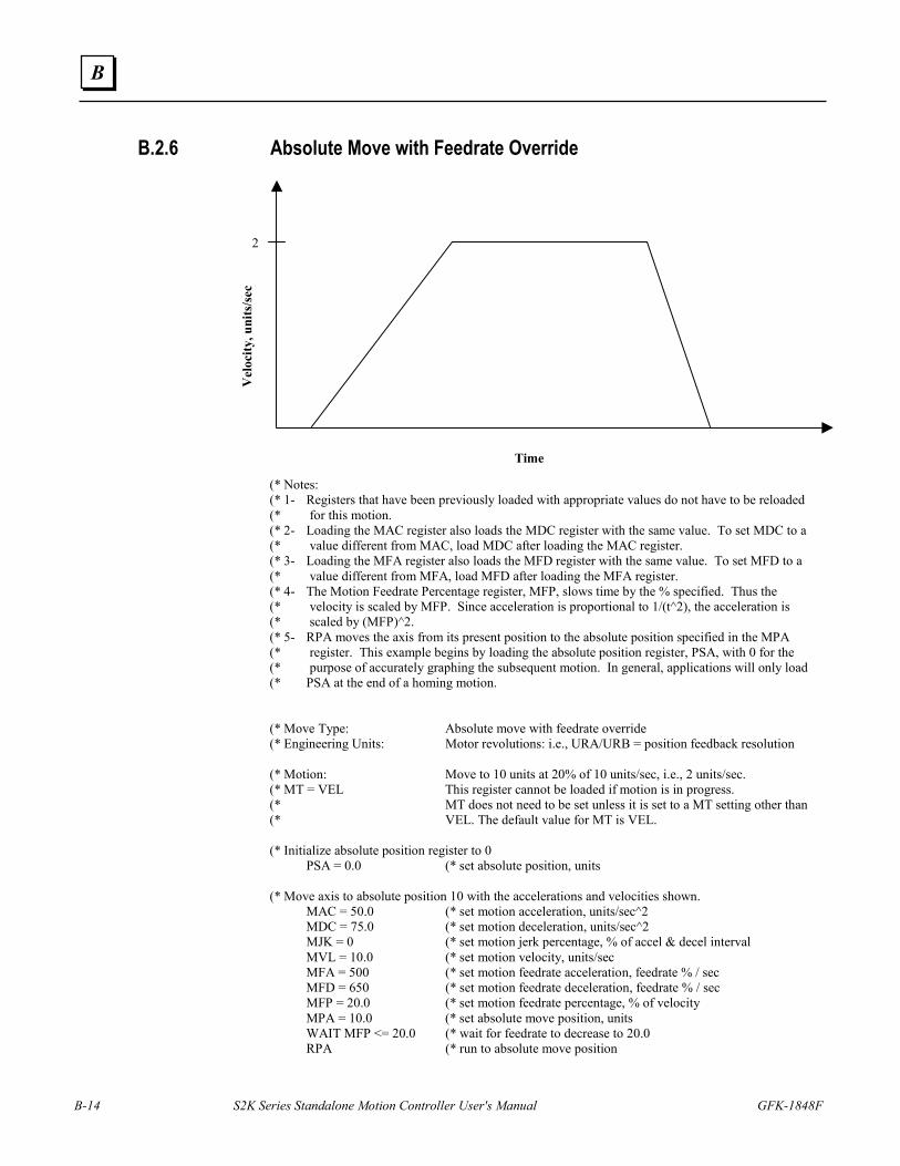
B-14 S2K Series Standalone Motion Controller User's Manual GFK-1848F
B
B.2.6 Absolute Move with Feedrate Override
2
Time
Vel
ocity
, uni
ts/s
ec
(* Notes: (* 1- Registers that have been previously loaded with appropriate values do not have to be reloaded (* for this motion. (* 2- Loading the MAC register also loads the MDC register with the same value. To set MDC to a (* value different from MAC, load MDC after loading the MAC register. (* 3- Loading the MFA register also loads the MFD register with the same value. To set MFD to a (* value different from MFA, load MFD after loading the MFA register. (* 4- The Motion Feedrate Percentage register, MFP, slows time by the % specified. Thus the (* velocity is scaled by MFP. Since acceleration is proportional to 1/(t^2), the acceleration is (* scaled by (MFP)^2. (* 5- RPA moves the axis from its present position to the absolute position specified in the MPA (* register. This example begins by loading the absolute position register, PSA, with 0 for the (* purpose of accurately graphing the subsequent motion. In general, applications will only load (* PSA at the end of a homing motion. (* Move Type: Absolute move with feedrate override (* Engineering Units: Motor revolutions: i.e., URA/URB = position feedback resolution (* Motion: Move to 10 units at 20% of 10 units/sec, i.e., 2 units/sec. (* MT = VEL This register cannot be loaded if motion is in progress. (* MT does not need to be set unless it is set to a MT setting other than (* VEL. The default value for MT is VEL. (* Initialize absolute position register to 0 PSA = 0.0 (* set absolute position, units (* Move axis to absolute position 10 with the accelerations and velocities shown. MAC = 50.0 (* set motion acceleration, units/sec^2 MDC = 75.0 (* set motion deceleration, units/sec^2 MJK = 0 (* set motion jerk percentage, % of accel & decel interval MVL = 10.0 (* set motion velocity, units/sec MFA = 500 (* set motion feedrate acceleration, feedrate % / sec MFD = 650 (* set motion feedrate deceleration, feedrate % / sec MFP = 20.0 (* set motion feedrate percentage, % of velocity MPA = 10.0 (* set absolute move position, units WAIT MFP <= 20.0 (* wait for feedrate to decrease to 20.0 RPA (* run to absolute move position
S2K Motion Templates
GFK-1848F Appendix B S2K Motion Templates B-15
B
B.3 Time-Based Motion
B.3.1 Time Based Incremental Move
Time, seconds
Vel
ocity
0.0 1.0 3.2 4.0
(* Notes: (* 1- Registers that have been previously loaded with appropriate values (* do not have to be reloaded for this motion. (* 2- Loading the MAP register also loads the MDP register with the same value. To set MDP to a (* value different from MAP, load MDP after loading the MAP register. (* 3- This example assumes the MFP (Motion Feedrate Percentage) is set to its default value of 100. (* Move Type: Time-based incremental move (* Engineering Units: Motor revolutions: i.e., URA/URB = position feedback resolution (* Motion: Move 5 units forward in 4.0 seconds. (* MT = TIME This register cannot be loaded if motion is in progress. (* MT does not need to be set unless it is set to a MT setting other than (* TIME. The default value for MT is VEL. MAP = 25 (* set motion acceleration percentage, % of move time MDP = 20 (* set motion deceleration percentage, % of move time MJK = 0 (* set motion jerk percentage, % of accel & decel interval MTM = 4.0 (* set move time, seconds MPI = 5.0 (* set incremental move position, units RPI (* run to incremental move position
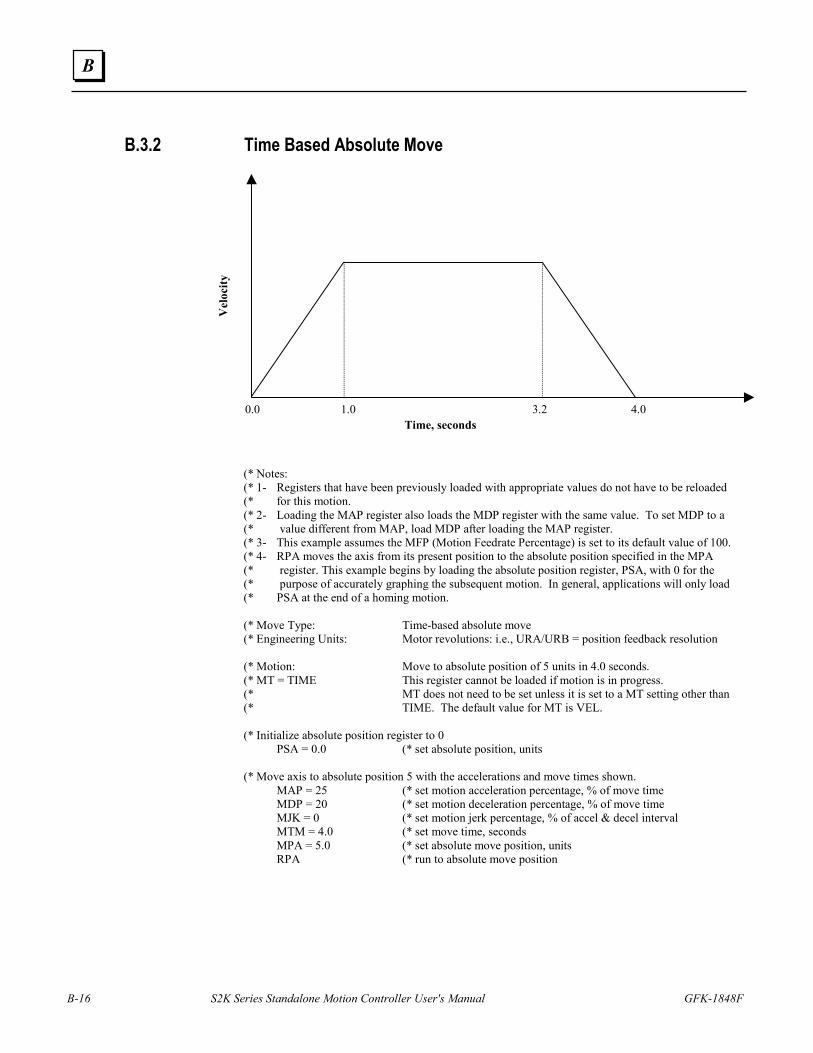
B-16 S2K Series Standalone Motion Controller User's Manual GFK-1848F
B
B.3.2 Time Based Absolute Move
Time, seconds
Vel
ocity
0.0 1.0 3.2 4.0
(* Notes: (* 1- Registers that have been previously loaded with appropriate values do not have to be reloaded (* for this motion. (* 2- Loading the MAP register also loads the MDP register with the same value. To set MDP to a (* value different from MAP, load MDP after loading the MAP register. (* 3- This example assumes the MFP (Motion Feedrate Percentage) is set to its default value of 100. (* 4- RPA moves the axis from its present position to the absolute position specified in the MPA (* register. This example begins by loading the absolute position register, PSA, with 0 for the (* purpose of accurately graphing the subsequent motion. In general, applications will only load (* PSA at the end of a homing motion. (* Move Type: Time-based absolute move (* Engineering Units: Motor revolutions: i.e., URA/URB = position feedback resolution (* Motion: Move to absolute position of 5 units in 4.0 seconds. (* MT = TIME This register cannot be loaded if motion is in progress. (* MT does not need to be set unless it is set to a MT setting other than (* TIME. The default value for MT is VEL. (* Initialize absolute position register to 0 PSA = 0.0 (* set absolute position, units (* Move axis to absolute position 5 with the accelerations and move times shown. MAP = 25 (* set motion acceleration percentage, % of move time MDP = 20 (* set motion deceleration percentage, % of move time MJK = 0 (* set motion jerk percentage, % of accel & decel interval MTM = 4.0 (* set move time, seconds MPA = 5.0 (* set absolute move position, units RPA (* run to absolute move position
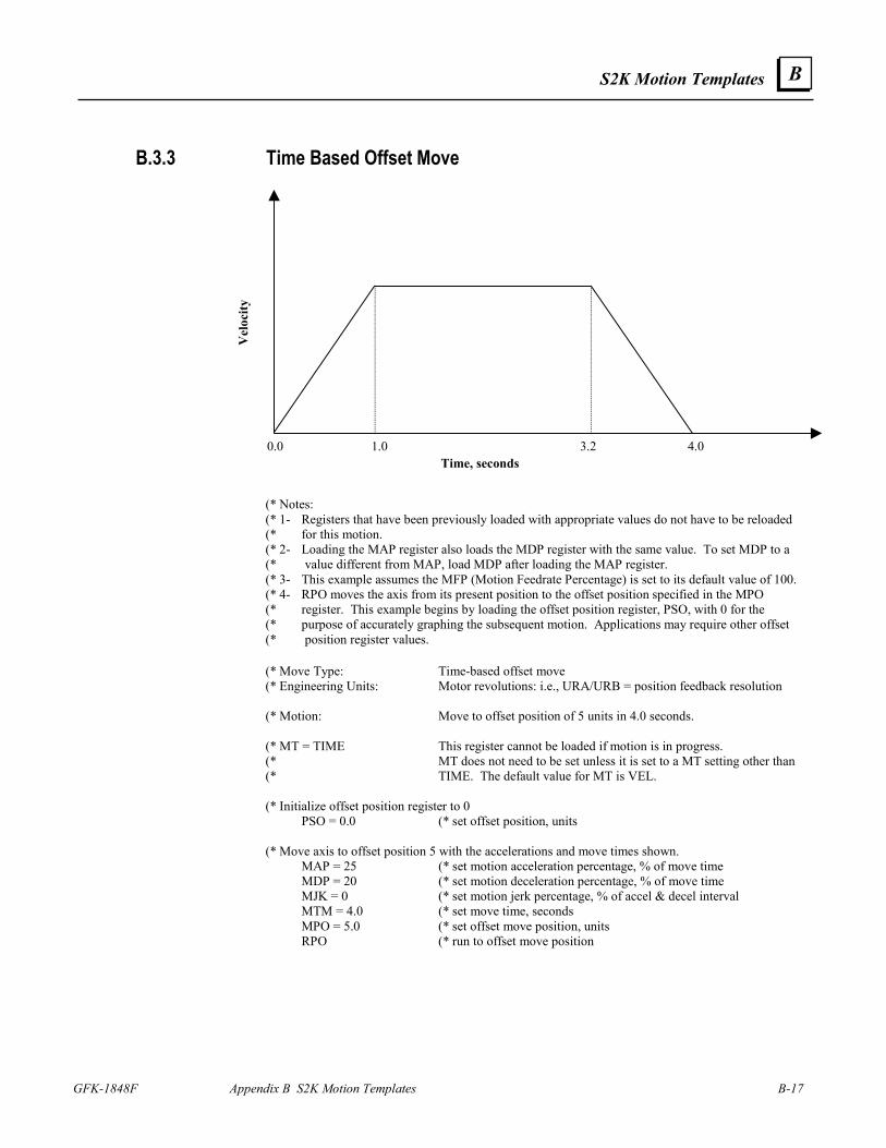
S2K Motion Templates
GFK-1848F Appendix B S2K Motion Templates B-17
B
B.3.3 Time Based Offset Move
Time, seconds
Vel
ocity
0.0 1.0 3.2 4.0
(* Notes: (* 1- Registers that have been previously loaded with appropriate values do not have to be reloaded (* for this motion. (* 2- Loading the MAP register also loads the MDP register with the same value. To set MDP to a (* value different from MAP, load MDP after loading the MAP register. (* 3- This example assumes the MFP (Motion Feedrate Percentage) is set to its default value of 100. (* 4- RPO moves the axis from its present position to the offset position specified in the MPO (* register. This example begins by loading the offset position register, PSO, with 0 for the (* purpose of accurately graphing the subsequent motion. Applications may require other offset (* position register values.
(* Move Type: Time-based offset move (* Engineering Units: Motor revolutions: i.e., URA/URB = position feedback resolution (* Motion: Move to offset position of 5 units in 4.0 seconds. (* MT = TIME This register cannot be loaded if motion is in progress. (* MT does not need to be set unless it is set to a MT setting other than (* TIME. The default value for MT is VEL. (* Initialize offset position register to 0 PSO = 0.0 (* set offset position, units (* Move axis to offset position 5 with the accelerations and move times shown. MAP = 25 (* set motion acceleration percentage, % of move time MDP = 20 (* set motion deceleration percentage, % of move time MJK = 0 (* set motion jerk percentage, % of accel & decel interval MTM = 4.0 (* set move time, seconds MPO = 5.0 (* set offset move position, units RPO (* run to offset move position
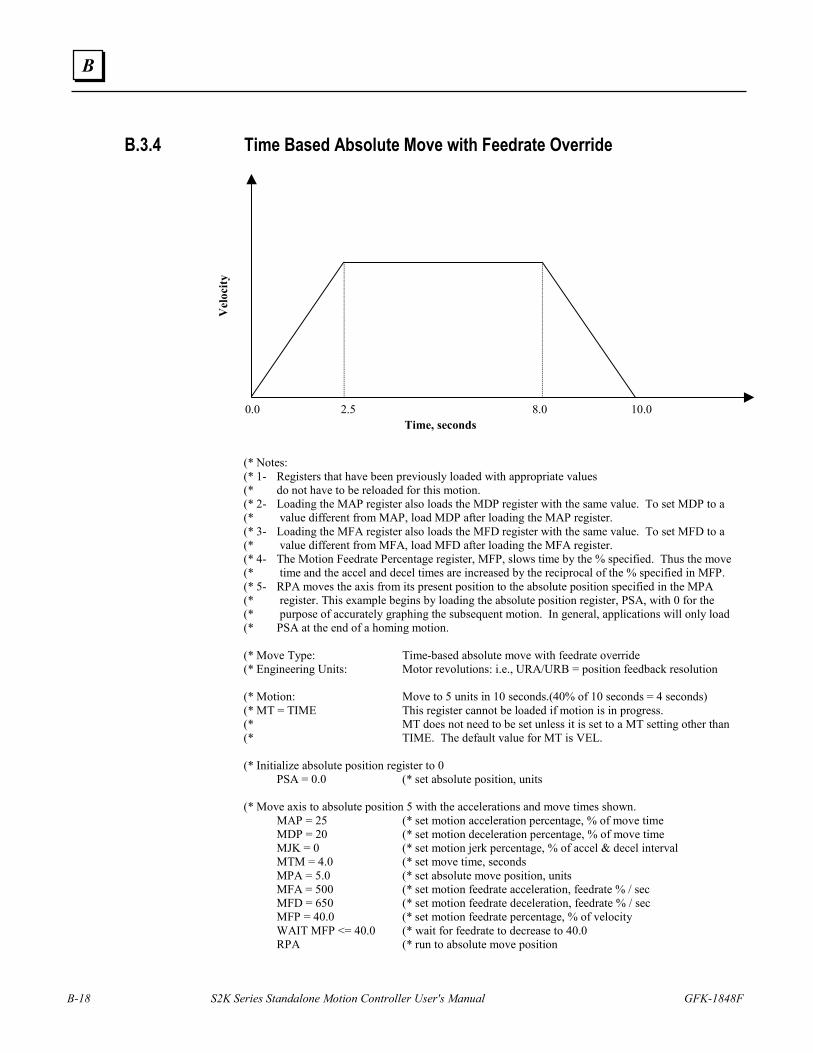
B-18 S2K Series Standalone Motion Controller User's Manual GFK-1848F
B
B.3.4 Time Based Absolute Move with Feedrate Override
Time, seconds
Vel
ocity
0.0 2.5 8.0 10.0
(* Notes: (* 1- Registers that have been previously loaded with appropriate values (* do not have to be reloaded for this motion. (* 2- Loading the MAP register also loads the MDP register with the same value. To set MDP to a (* value different from MAP, load MDP after loading the MAP register. (* 3- Loading the MFA register also loads the MFD register with the same value. To set MFD to a (* value different from MFA, load MFD after loading the MFA register. (* 4- The Motion Feedrate Percentage register, MFP, slows time by the % specified. Thus the move (* time and the accel and decel times are increased by the reciprocal of the % specified in MFP. (* 5- RPA moves the axis from its present position to the absolute position specified in the MPA (* register. This example begins by loading the absolute position register, PSA, with 0 for the (* purpose of accurately graphing the subsequent motion. In general, applications will only load (* PSA at the end of a homing motion. (* Move Type: Time-based absolute move with feedrate override (* Engineering Units: Motor revolutions: i.e., URA/URB = position feedback resolution (* Motion: Move to 5 units in 10 seconds.(40% of 10 seconds = 4 seconds) (* MT = TIME This register cannot be loaded if motion is in progress. (* MT does not need to be set unless it is set to a MT setting other than (* TIME. The default value for MT is VEL. (* Initialize absolute position register to 0 PSA = 0.0 (* set absolute position, units (* Move axis to absolute position 5 with the accelerations and move times shown. MAP = 25 (* set motion acceleration percentage, % of move time MDP = 20 (* set motion deceleration percentage, % of move time MJK = 0 (* set motion jerk percentage, % of accel & decel interval MTM = 4.0 (* set move time, seconds MPA = 5.0 (* set absolute move position, units MFA = 500 (* set motion feedrate acceleration, feedrate % / sec MFD = 650 (* set motion feedrate deceleration, feedrate % / sec MFP = 40.0 (* set motion feedrate percentage, % of velocity WAIT MFP <= 40.0 (* wait for feedrate to decrease to 40.0 RPA (* run to absolute move position
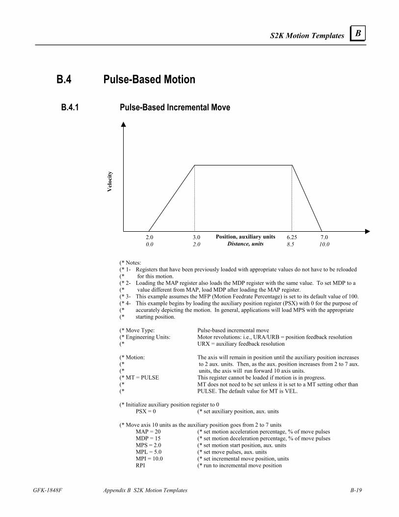
S2K Motion Templates
GFK-1848F Appendix B S2K Motion Templates B-19
B
B.4 Pulse-Based Motion
B.4.1 Pulse-Based Incremental Move
Position, auxiliary unitsDistance, units
Vel
ocity
2.0 3.0 6.25 7.0 0.0 2.0 8.5 10.0
(* Notes: (* 1- Registers that have been previously loaded with appropriate values do not have to be reloaded (* for this motion. (* 2- Loading the MAP register also loads the MDP register with the same value. To set MDP to a (* value different from MAP, load MDP after loading the MAP register. (* 3- This example assumes the MFP (Motion Feedrate Percentage) is set to its default value of 100. (* 4- This example begins by loading the auxiliary position register (PSX) with 0 for the purpose of (* accurately depicting the motion. In general, applications will load MPS with the appropriate (* starting position. (* Move Type: Pulse-based incremental move (* Engineering Units: Motor revolutions: i.e., URA/URB = position feedback resolution (* URX = auxiliary feedback resolution (* Motion: The axis will remain in position until the auxiliary position increases (* to 2 aux. units. Then, as the aux. position increases from 2 to 7 aux. (* units, the axis will run forward 10 axis units. (* MT = PULSE This register cannot be loaded if motion is in progress. (* MT does not need to be set unless it is set to a MT setting other than (* PULSE. The default value for MT is VEL. (* Initialize auxiliary position register to 0 PSX = 0 (* set auxiliary position, aux. units (* Move axis 10 units as the auxiliary position goes from 2 to 7 units MAP = 20 (* set motion acceleration percentage, % of move pulses MDP = 15 (* set motion deceleration percentage, % of move pulses MPS = 2.0 (* set motion start position, aux. units MPL = 5.0 (* set move pulses, aux. units MPI = 10.0 (* set incremental move position, units RPI (* run to incremental move position
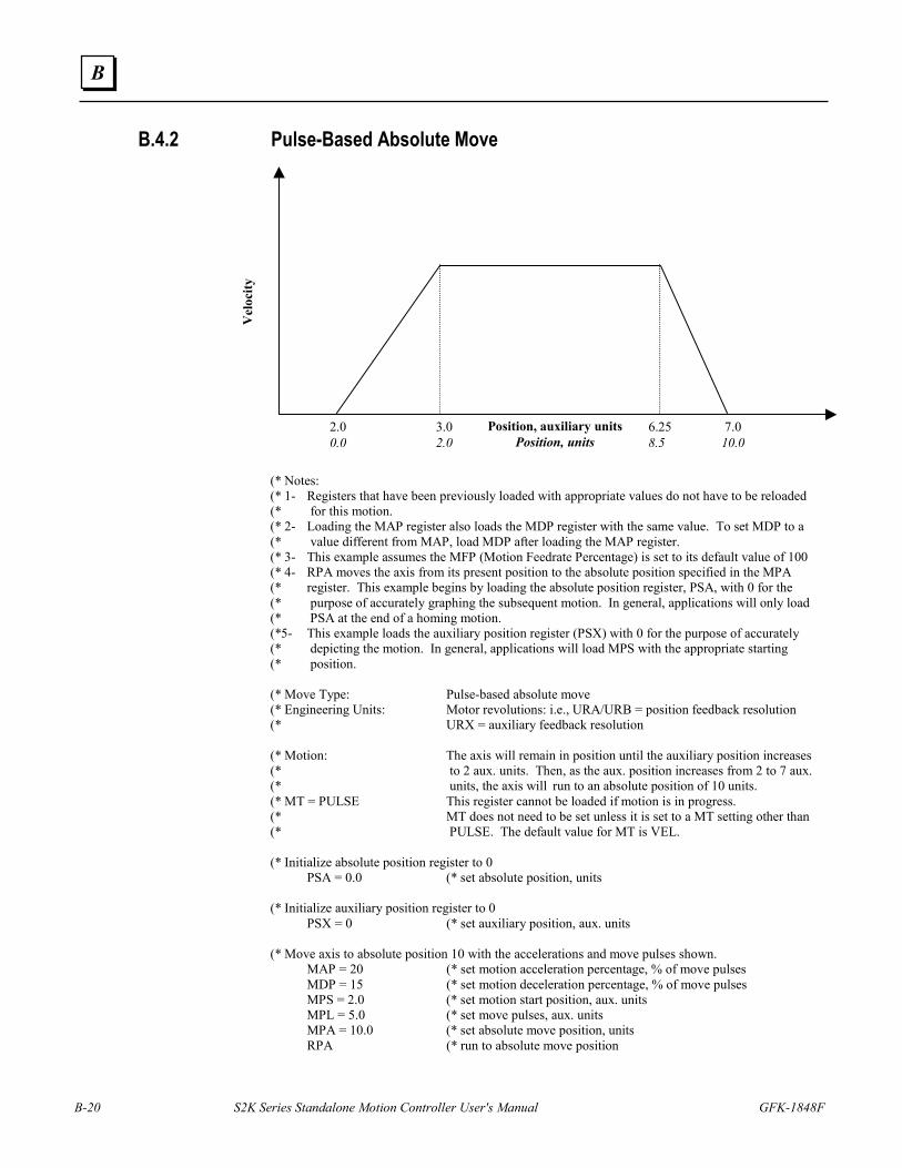
B-20 S2K Series Standalone Motion Controller User's Manual GFK-1848F
B
B.4.2 Pulse-Based Absolute Move
Position, auxiliary unitsPosition, units
Vel
ocity
2.0 3.0 6.25 7.0 0.0 2.0 8.5 10.0
(* Notes: (* 1- Registers that have been previously loaded with appropriate values do not have to be reloaded (* for this motion. (* 2- Loading the MAP register also loads the MDP register with the same value. To set MDP to a (* value different from MAP, load MDP after loading the MAP register. (* 3- This example assumes the MFP (Motion Feedrate Percentage) is set to its default value of 100 (* 4- RPA moves the axis from its present position to the absolute position specified in the MPA (* register. This example begins by loading the absolute position register, PSA, with 0 for the (* purpose of accurately graphing the subsequent motion. In general, applications will only load (* PSA at the end of a homing motion. (*5- This example loads the auxiliary position register (PSX) with 0 for the purpose of accurately (* depicting the motion. In general, applications will load MPS with the appropriate starting (* position. (* Move Type: Pulse-based absolute move (* Engineering Units: Motor revolutions: i.e., URA/URB = position feedback resolution (* URX = auxiliary feedback resolution (* Motion: The axis will remain in position until the auxiliary position increases (* to 2 aux. units. Then, as the aux. position increases from 2 to 7 aux. (* units, the axis will run to an absolute position of 10 units. (* MT = PULSE This register cannot be loaded if motion is in progress. (* MT does not need to be set unless it is set to a MT setting other than (* PULSE. The default value for MT is VEL. (* Initialize absolute position register to 0 PSA = 0.0 (* set absolute position, units (* Initialize auxiliary position register to 0 PSX = 0 (* set auxiliary position, aux. units (* Move axis to absolute position 10 with the accelerations and move pulses shown. MAP = 20 (* set motion acceleration percentage, % of move pulses MDP = 15 (* set motion deceleration percentage, % of move pulses MPS = 2.0 (* set motion start position, aux. units MPL = 5.0 (* set move pulses, aux. units MPA = 10.0 (* set absolute move position, units RPA (* run to absolute move position
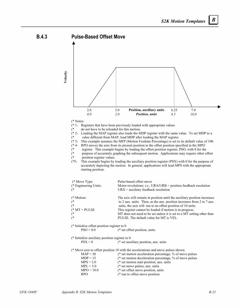
S2K Motion Templates
GFK-1848F Appendix B S2K Motion Templates B-21
B
B.4.3 Pulse-Based Offset Move
Position, auxiliary unitsPosition, units
Vel
ocity
2.0 3.0 6.25 7.0 0.0 2.0 8.5 10.0
(* Notes: (* 1- Registers that have been previously loaded with appropriate values (* do not have to be reloaded for this motion. (* 2- Loading the MAP register also loads the MDP register with the same value. To set MDP to a (* value different from MAP, load MDP after loading the MAP register. (* 3- This example assumes the MFP (Motion Feedrate Percentage) is set to its default value of 100. (* 4- RPO moves the axis from its present position to the offset position specified in the MPO (* register. This example begins by loading the offset position register, PSO, with 0 for the (* purpose of accurately graphing the subsequent motion. Applications may require other offset (* position register values. (*5- This example begins by loading the auxiliary position register (PSX) with 0 for the purpose of
accurately depicting the motion. In general, applications will load MPS with the appropriate starting position.
(* Move Type: Pulse-based offset move (* Engineering Units: Motor revolutions: i.e., URA/URB = position feedback resolution (* URX = auxiliary feedback resolution (* Motion: The axis will remain in position until the auxiliary position increases (* to 2 aux. units. Then, as the aux. position increases from 2 to 7 aux. (* units, the axis will run to an offset position of 10 units. (* MT = PULSE This register cannot be loaded if motion is in progress. (* MT does not need to be set unless it is set to a MT setting other than (* PULSE. The default value for MT is VEL. (* Initialize offset position register to 0 PSO = 0.0 (* set offset position, units (* Initialize auxiliary position register to 0 PSX = 0 (* set auxiliary position, aux. units (* Move axis to offset position 10 with the accelerations and move pulses shown. MAP = 20 (* set motion acceleration percentage, % of move pulses MDP = 15 (* set motion deceleration percentage, % of move pulses MPS = 2.0 (* set motion start position, aux. units MPL = 5.0 (* set move pulses, aux. units MPO = 10.0 (* set offset move position, units RPO (* run to offset move position
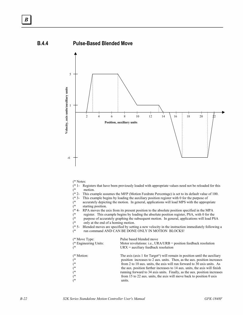
B-22 S2K Series Standalone Motion Controller User's Manual GFK-1848F
B
B.4.4 Pulse-Based Blended Move
5
-6
Position, auxiliary units
Vel
ocity
, axi
s uni
ts/a
uxili
ary
units
1
| | | | | | | | | | | 2 4 6 8 10 12 14 16 18 20 22
(* Notes: (* 1- Registers that have been previously loaded with appropriate values need not be reloaded for this (* motion. (* 2- This example assumes the MFP (Motion Feedrate Percentage) is set to its default value of 100. (* 3- This example begins by loading the auxiliary position register with 0 for the purpose of (* accurately depicting the motion. In general, applications will load MPS with the appropriate (* starting position. (* 4- RPA moves the axis from its present position to the absolute position specified in the MPA (* register. This example begins by loading the absolute position register, PSA, with 0 for the (* purpose of accurately graphing the subsequent motion. In general, applications will load PSA (* only at the end of a homing motion. (* 5- Blended moves are specified by setting a new velocity in the instruction immediately following a (* run command AND CAN BE DONE ONLY IN MOTION BLOCKS! (* Move Type: Pulse based blended move (* Engineering Units: Motor revolutions: i.e., URA/URB = position feedback resolution (* URX = auxiliary feedback resolution (* Motion: The axis (axis 1 for Target®) will remain in position until the auxiliary (* position increases to 2 aux. units. Then, as the aux. position increases (* from 2 to 10 aux. units, the axis will run forward to 30 axis units. As (* the aux. position further increases to 14 aux. units, the axis will finish (* running forward to 34 axis units. Finally, as the aux. position increases (* from 15 to 22 aux. units, the axis will move back to position 0 axis (* units.
S2K Motion Templates
GFK-1848F Appendix B S2K Motion Templates B-23
B
(* MT = PULSE This register cannot be loaded if motion is in progress. (* MT does not need to be set unless it is set to a MT setting other than (* PULSE. The default value for MT is VEL. (* Initialize auxiliary position register to 0. PSX = 0 (* set auxiliary position, aux. units (* Initialize absolute position register to 0 PSA = 0.0 (* set absolute position, units (* Execute blended move with the accelerations and velocities shown. MAP = 20 (* set motion acceleration percentage, % of move pulses MDP = 15 (* set motion deceleration percentage, % of move pulses MPS = 2.0 (* set motion start position, aux. units MPL = 8.0 (* set move pulses, aux. units MPA = 30.0 (* set absolute move position, units RPA (* run to absolute move position MVP = 1.0 (* set motion velocity of pulse move, axis units/aux. units MPS = MPS + 8.0 (* set motion start position, aux. units MPL = 4.0 (* set move pulses, aux. units MPA = 34.0 (* set absolute move position, units RPA (* run to absolute move position MPS = MPS + 5.0 (* set motion start position, aux. units MPL = 7.0 (* set move pulses, aux. units MPA = 0.0 (* set absolute move position, units RPA (* run to absolute move position
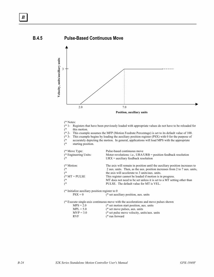
B-24 S2K Series Standalone Motion Controller User's Manual GFK-1848F
B
B.4.5 Pulse-Based Continuous Move
Position, auxiliary units
Vel
ocity
, uni
ts/a
uxili
ary
units
2.0 7.0
3
(* Notes: (* 1- Registers that have been previously loaded with appropriate values do not have to be reloaded for (* this motion. (* 2- This example assumes the MFP (Motion Feedrate Percentage) is set to its default value of 100. (* 3- This example begins by loading the auxiliary position register (PSX) with 0 for the purpose of (* accurately depicting the motion. In general, applications will load MPS with the appropriate (* starting position. (* Move Type: Pulse-based continuous move (* Engineering Units: Motor revolutions: i.e., URA/URB = position feedback resolution (* URX = auxiliary feedback resolution (* Motion: The axis will remain in position until the auxiliary position increases to (* 2 aux. units. Then, as the aux. position increases from 2 to 7 aux. units, (* the axis will accelerate to 3 units/aux. units. (* MT = PULSE This register cannot be loaded if motion is in progress. (* MT does not need to be set unless it is set to a MT setting other than (* PULSE. The default value for MT is VEL. (* Initialize auxiliary position register to 0 PSX = 0 (* set auxiliary position, aux. units (* Execute single-axis continuous move with the accelerations and move pulses shown MPS = 2.0 (* set motion start position, aux. units MPL = 5.0 (* set move pulses, aux. units MVP = 3.0 (* set pulse move velocity, units/aux. units RVF (* run forward

S2K Motion Templates
GFK-1848F Appendix B S2K Motion Templates B-25
B
B.5 Torque Limited Motion
B.5.1 Run Forward until Torque Limit
Time
Vel
ocity
, uni
ts/s
econ
d
Torquelimit reached
2
(* Notes: (* 1- Registers that have been previously loaded with appropriate values (* do not have to be reloaded for this motion. (* 2- Loading the MAC register also loads the MDC register with the same value. To set MDC to a (* value different from MAC, load MDC after loading the MAC register. (* 3- This example assumes the MFP (Motion Feedrate Percentage) is set to its default value of 100. (* 4- If this template is executed within a motion block, the WAIT TL command is not executed until (* the acceleration portion of the RVF command is complete. (* Move Type: Run forward until torque limit (* Engineering Units: Motor revolutions: i.e., URA/URB = position feedback resolution (* Motion: Run forward until torque limit. (* MT = VEL This register cannot be loaded if motion is in progress. (* MT does not need to be set unless it is set to a MT setting other than (* VEL. The default value for MT is VEL. MAC = 50.0 (* set motion acceleration, units/sec^2 MDC = 75.0 (* set motion deceleration, units/sec^2 MJK = 0 (* set motion jerk percentage, % of accel & decel interval MVL = 2.0 (* set motion velocity, units/sec TLC = 10.0 (* set torque limit current, % of continuous current TLE = ON (* enable torque limit RVF (* run forward WAIT TL (* wait for axis to be at torque limit ST (* stop all motion TLE = OFF (* disable torque limit
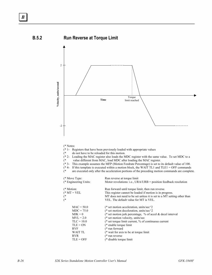
B-26 S2K Series Standalone Motion Controller User's Manual GFK-1848F
B
B.5.2 Run Reverse at Torque Limit
Time
Vel
ocity
, uni
ts/s
econ
d
Torquelimit reached
2
-2
(* Notes: (* 1- Registers that have been previously loaded with appropriate values (* do not have to be reloaded for this motion. (* 2- Loading the MAC register also loads the MDC register with the same value. To set MDC to a (* value different from MAC, load MDC after loading the MAC register. (* 3- This example assumes the MFP (Motion Feedrate Percentage) is set to its default value of 100. (* 4- If this template is executed within a motion block, the WAIT TL1 and TLE1 = OFF commands (* are executed only after the acceleration portions of the preceding motion commands are complete. (* Move Type: Run reverse at torque limit (* Engineering Units: Motor revolutions: i.e., URA/URB = position feedback resolution (* Motion: Run forward until torque limit, then run reverse. (* MT = VEL This register cannot be loaded if motion is in progress. (* MT does not need to be set unless it is set to a MT setting other than (* VEL. The default value for MT is VEL. MAC = 50.0 (* set motion acceleration, units/sec^2 MDC = 75.0 (* set motion deceleration, units/sec^2 MJK = 0 (* set motion jerk percentage, % of accel & decel interval MVL = 2.0 (* set motion velocity, units/sec TLC = 10.0 (* set torque limit current, % of continuous current TLE = ON (* enable torque limit RVF (* run forward WAIT TL (* wait for axis to be at torque limit RVR (* run reverse TLE = OFF (* disable torque limit
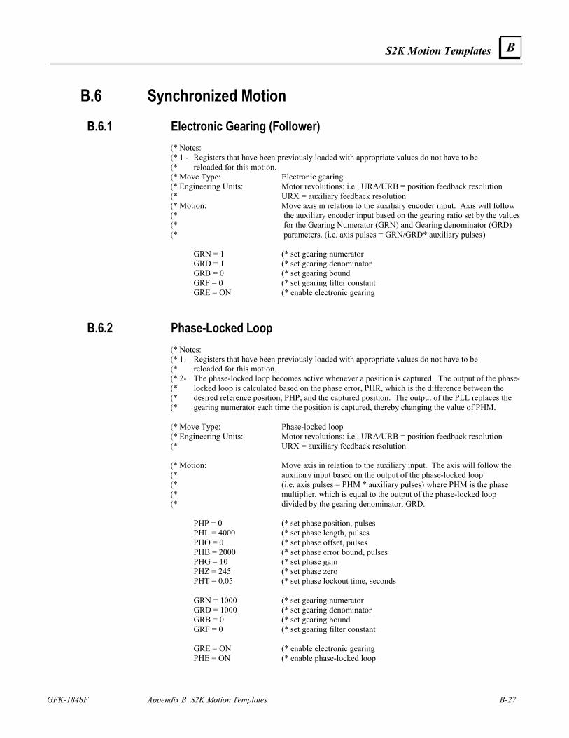
S2K Motion Templates
GFK-1848F Appendix B S2K Motion Templates B-27
B
B.6 Synchronized Motion B.6.1 Electronic Gearing (Follower)
(* Notes: (* 1 - Registers that have been previously loaded with appropriate values do not have to be (* reloaded for this motion. (* Move Type: Electronic gearing (* Engineering Units: Motor revolutions: i.e., URA/URB = position feedback resolution (* URX = auxiliary feedback resolution (* Motion: Move axis in relation to the auxiliary encoder input. Axis will follow (* the auxiliary encoder input based on the gearing ratio set by the values (* for the Gearing Numerator (GRN) and Gearing denominator (GRD) (* parameters. (i.e. axis pulses = GRN/GRD* auxiliary pulses ) GRN = 1 (* set gearing numerator GRD = 1 (* set gearing denominator GRB = 0 (* set gearing bound GRF = 0 (* set gearing filter constant GRE = ON (* enable electronic gearing
B.6.2 Phase-Locked Loop (* Notes: (* 1- Registers that have been previously loaded with appropriate values do not have to be (* reloaded for this motion. (* 2- The phase-locked loop becomes active whenever a position is captured. The output of the phase- (* locked loop is calculated based on the phase error, PHR, which is the difference between the (* desired reference position, PHP, and the captured position. The output of the PLL replaces the (* gearing numerator each time the position is captured, thereby changing the value of PHM. (* Move Type: Phase-locked loop (* Engineering Units: Motor revolutions: i.e., URA/URB = position feedback resolution (* URX = auxiliary feedback resolution (* Motion: Move axis in relation to the auxiliary input. The axis will follow the (* auxiliary input based on the output of the phase-locked loop (* (i.e. axis pulses = PHM * auxiliary pulses) where PHM is the phase (* multiplier, which is equal to the output of the phase-locked loop (* divided by the gearing denominator, GRD. PHP = 0 (* set phase position, pulses PHL = 4000 (* set phase length, pulses PHO = 0 (* set phase offset, pulses PHB = 2000 (* set phase error bound, pulses PHG = 10 (* set phase gain PHZ = 245 (* set phase zero PHT = 0.05 (* set phase lockout time, seconds GRN = 1000 (* set gearing numerator GRD = 1000 (* set gearing denominator GRB = 0 (* set gearing bound GRF = 0 (* set gearing filter constant GRE = ON (* enable electronic gearing PHE = ON (* enable phase-locked loop
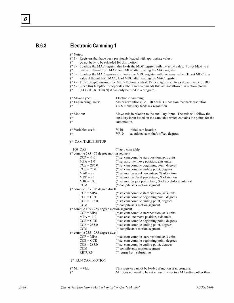
B-28 S2K Series Standalone Motion Controller User's Manual GFK-1848F
B
B.6.3 Electronic Camming 1 (* Notes: (* 1- Registers that have been previously loaded with appropriate values (* do not have to be reloaded for this motion. (* 2- Loading the MAP register also loads the MDP register with the same value. To set MDP to a (* value different from MAP, load MDP after loading the MAP register. (* 3- Loading the MAC register also loads the MDC register with the same value. To set MDC to a (* value different from MAC, load MDC after loading the MAC register. (* 4- This example assumes the MFP (Motion Feedrate Percentage) is set to its default value of 100. (* 5- Since this template incorporates labels and commands that are not allowed in motion blocks (* (GOSUB, RETURN) it can only be used in a program. (* Move Type: Electronic camming (* Engineering Units: Motor revolutions: i.e., URA/URB = position feedback resolution (* URX = auxiliary feedback resolution (* Motion: Move axis in relation to the auxiliary input. The axis will follow the (* auxiliary input based on the cam table which contains the points for the (* cam motion. (* Variables used: VI10 initial cam location (* VF10 calculated cam shaft offset, degrees (* CAM TABLE SETUP 100 CAZ (* zero cam table (* compile 285 - 75 degree motion segment CCP = -1.0 (* set cam compile start position, axis units MPA = 1.0 (* set absolute move position, axis units CCB = 285.0 (* set cam compile beginning point, degrees CCE = 75.0 (* set cam compile ending point, degrees MAP = 25 (* set motion accel percentage, % of motion MDP = 20 (* set motion decel percentage, % of motion MJK = 100 (* set motion jerk percentage, % of accel/decel interval CCM (* compile axis motion segment (* compile 75 - 105 degree dwell CCP = MPA (* set cam compile start position, axis units CCB = CCE (* set cam compile beginning point, degrees CCE = 105.0 (* set cam compile ending point, degrees CCM (* compile axis motion segment (* compile 105 - 255 degree motion segment CCP = MPA (* set cam compile start position, axis units MPA = -1.0 (* set absolute move position, axis units CCB = CCE (* set cam compile beginning point, degrees CCE = 255.0 (* set cam compile ending point, degrees CCM (* compile axis motion segment (* compile 255 - 285 degree dwell CCP = MPA (* set cam compile start position, axis units CCB = CCE (* set cam compile beginning point, degrees CCE = 285.0 (* set cam compile ending point, degrees CCM (* compile axis motion segment RETURN (* return from subroutine (* RUN CAM MOTION (* MT = VEL This register cannot be loaded if motion is in progress. (* MT does not need to be set unless it is set to a MT setting other than
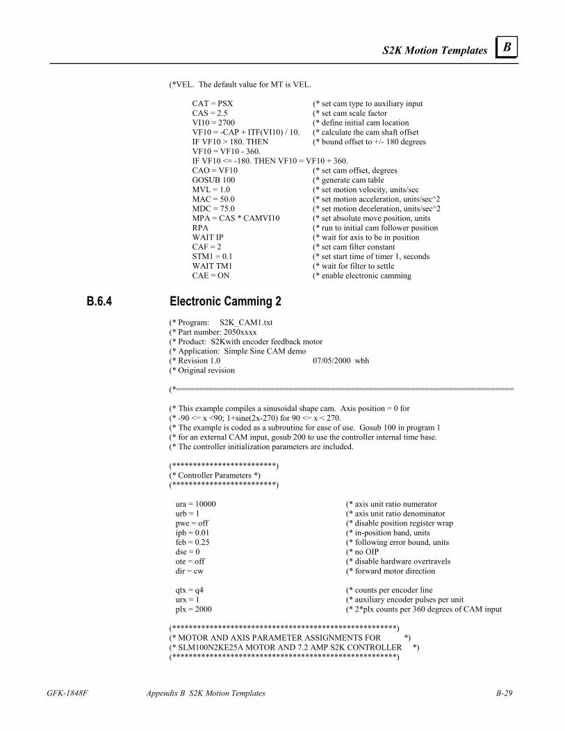
S2K Motion Templates
GFK-1848F Appendix B S2K Motion Templates B-29
B
(*VEL. The default value for MT is VEL. CAT = PSX (* set cam type to auxiliary input CAS = 2.5 (* set cam scale factor VI10 = 2700 (* define initial cam location VF10 = -CAP + ITF(VI10) / 10. (* calculate the cam shaft offset IF VF10 > 180. THEN (* bound offset to +/- 180 degrees VF10 = VF10 - 360. IF VF10 <= -180. THEN VF10 = VF10 + 360. CAO = VF10 (* set cam offset, degrees GOSUB 100 (* generate cam table MVL = 1.0 (* set motion velocity, units/sec MAC = 50.0 (* set motion acceleration, units/sec^2 MDC = 75.0 (* set motion deceleration, units/sec^2 MPA = CAS * CAMVI10 (* set absolute move position, units RPA (* run to initial cam follower position WAIT IP (* wait for axis to be in position CAF = 2 (* set cam filter constant STM1 = 0.1 (* set start time of timer 1, seconds WAIT TM1 (* wait for filter to settle CAE = ON (* enable electronic camming
B.6.4 Electronic Camming 2 (* Program: S2K_CAM1.txt (* Part number: 2050xxxx (* Product: S2Kwith encoder feedback motor (* Application: Simple Sine CAM demo (* Revision 1.0 07/05/2000 wbh (* Original revision (*======================================================================== (* This example compiles a sinusoidal shape cam. Axis position = 0 for (* -90 <= x <90; 1+sine(2x-270) for 90 <= x < 270. (* The example is coded as a subroutine for ease of use. Gosub 100 in program 1 (* for an external CAM input, gosub 200 to use the controller internal time base. (* The controller initialization parameters are included. (*************************) (* Controller Parameters *) (*************************) ura = 10000 (* axis unit ratio numerator urb = 1 (* axis unit ratio denominator pwe = off (* disable position register wrap ipb = 0.01 (* in-position band, units feb = 0.25 (* following error bound, units dse = 0 (* no OIP ote = off (* disable hardware overtravels dir = cw (* forward motor direction qtx = q4 (* counts per encoder line urx = 1 (* auxiliary encoder pulses per unit plx = 2000 (* 2*plx counts per 360 degrees of CAM input (******************************************************) (* MOTOR AND AXIS PARAMETER ASSIGNMENTS FOR *) (* SLM100N2KE25A MOTOR AND 7.2 AMP S2K CONTROLLER *) (******************************************************)
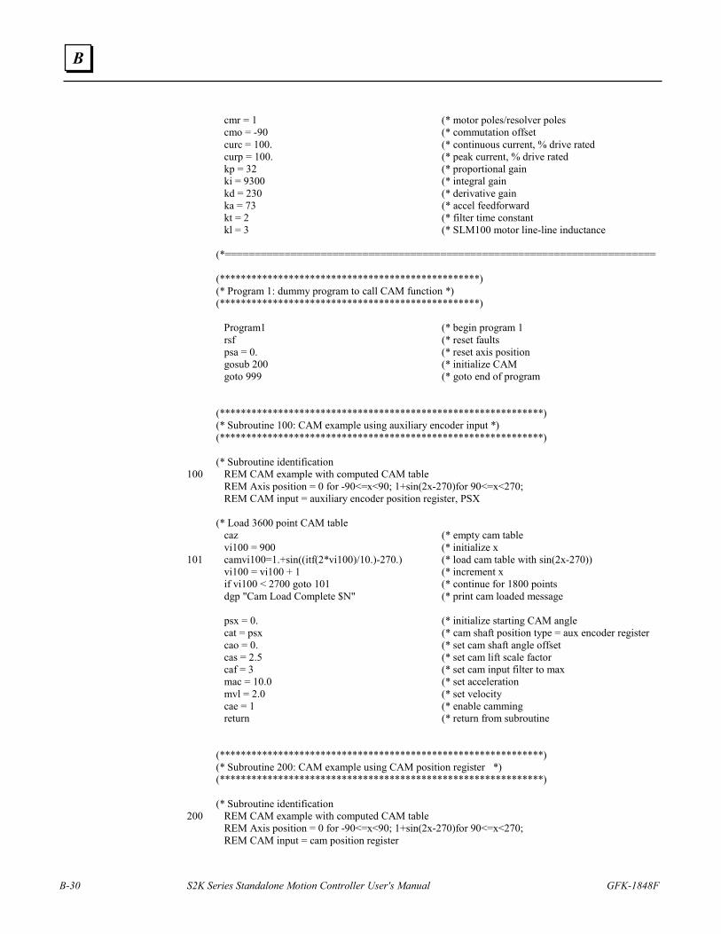
B-30 S2K Series Standalone Motion Controller User's Manual GFK-1848F
B
cmr = 1 (* motor poles/resolver poles cmo = -90 (* commutation offset curc = 100. (* continuous current, % drive rated curp = 100. (* peak current, % drive rated kp = 32 (* proportional gain ki = 9300 (* integral gain kd = 230 (* derivative gain ka = 73 (* accel feedforward kt = 2 (* filter time constant kl = 3 (* SLM100 motor line-line inductance (*======================================================================== (*************************************************) (* Program 1: dummy program to call CAM function *) (*************************************************) Program1 (* begin program 1 rsf (* reset faults psa = 0. (* reset axis position gosub 200 (* initialize CAM goto 999 (* goto end of program (*************************************************************) (* Subroutine 100: CAM example using auxiliary encoder input *) (*************************************************************) (* Subroutine identification
100 REM CAM example with computed CAM table REM Axis position = 0 for -90<=x<90; 1+sin(2x-270)for 90<=x<270; REM CAM input = auxiliary encoder position register, PSX (* Load 3600 point CAM table caz (* empty cam table vi100 = 900 (* initialize x
101 camvi100=1.+sin((itf(2*vi100)/10.)-270.) (* load cam table with sin(2x-270)) vi100 = vi100 + 1 (* increment x if vi100 < 2700 goto 101 (* continue for 1800 points dgp "Cam Load Complete $N" (* print cam loaded message psx = 0. (* initialize starting CAM angle cat = psx (* cam shaft position type = aux encoder register cao = 0. (* set cam shaft angle offset cas = 2.5 (* set cam lift scale factor caf = 3 (* set cam input filter to max mac = 10.0 (* set acceleration mvl = 2.0 (* set velocity cae = 1 (* enable camming return (* return from subroutine (*************************************************************) (* Subroutine 200: CAM example using CAM position register *) (*************************************************************) (* Subroutine identification
200 REM CAM example with computed CAM table REM Axis position = 0 for -90<=x<90; 1+sin(2x-270)for 90<=x<270; REM CAM input = cam position register
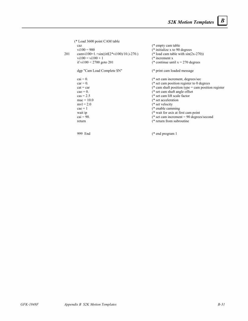
S2K Motion Templates
GFK-1848F Appendix B S2K Motion Templates B-31
B
(* Load 3600 point CAM table caz (* empty cam table vi100 = 900 (* initialize x to 90 degrees
201 camvi100=1.+sin((itf(2*vi100)/10.)-270.) (* load cam table with sin(2x-270)) vi100 = vi100 + 1 (* increment x if vi100 < 2700 goto 201 (* continue until x = 270 degrees dgp "Cam Load Complete $N" (* print cam loaded message cai = 0. (* set cam increment, degrees/sec car = 0. (* set cam position register to 0 degrees cat = car (* cam shaft position type = cam position register cao = 0. (* set cam shaft angle offset cas = 2.5 (* set cam lift scale factor mac = 10.0 (* set acceleration mvl = 2.0 (* set velocity cae = 1 (* enable camming wait ip (* wait for axis at first cam point cai = 90. (* set cam increment = 90 degrees/second return (* return from subroutine 999 End (* end program 1
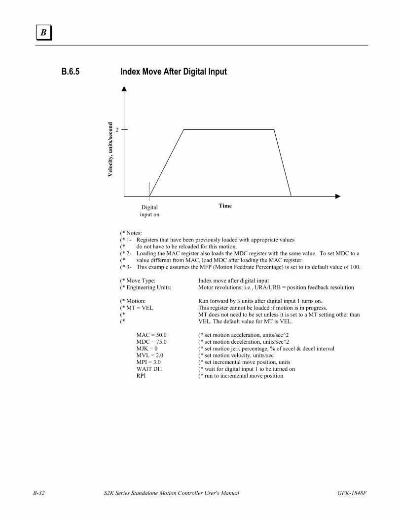
B-32 S2K Series Standalone Motion Controller User's Manual GFK-1848F
B
B.6.5 Index Move After Digital Input
Time
Vel
ocity
, uni
ts/s
econ
d
Digitalinput on
2
(* Notes: (* 1- Registers that have been previously loaded with appropriate values (* do not have to be reloaded for this motion. (* 2- Loading the MAC register also loads the MDC register with the same value. To set MDC to a (* value different from MAC, load MDC after loading the MAC register. (* 3- This example assumes the MFP (Motion Feedrate Percentage) is set to its default value of 100. (* Move Type: Index move after digital input (* Engineering Units: Motor revolutions: i.e., URA/URB = position feedback resolution (* Motion: Run forward by 3 units after digital input 1 turns on. (* MT = VEL This register cannot be loaded if motion is in progress. (* MT does not need to be set unless it is set to a MT setting other than (* VEL. The default value for MT is VEL. MAC = 50.0 (* set motion acceleration, units/sec^2 MDC = 75.0 (* set motion deceleration, units/sec^2 MJK = 0 (* set motion jerk percentage, % of accel & decel interval MVL = 2.0 (* set motion velocity, units/sec MPI = 3.0 (* set incremental move position, units WAIT DI1 (* wait for digital input 1 to be turned on RPI (* run to incremental move position
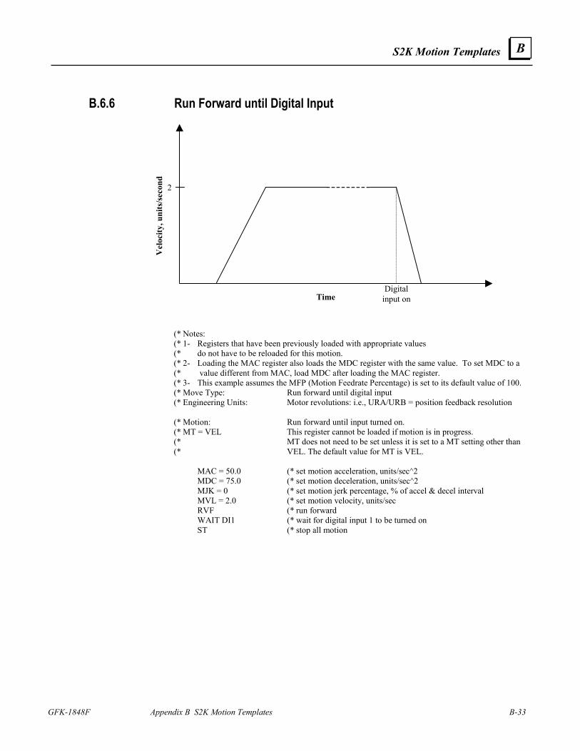
S2K Motion Templates
GFK-1848F Appendix B S2K Motion Templates B-33
B
B.6.6 Run Forward until Digital Input
Time
Vel
ocity
, uni
ts/s
econ
d
Digitalinput on
2
(* Notes: (* 1- Registers that have been previously loaded with appropriate values (* do not have to be reloaded for this motion. (* 2- Loading the MAC register also loads the MDC register with the same value. To set MDC to a (* value different from MAC, load MDC after loading the MAC register. (* 3- This example assumes the MFP (Motion Feedrate Percentage) is set to its default value of 100. (* Move Type: Run forward until digital input (* Engineering Units: Motor revolutions: i.e., URA/URB = position feedback resolution (* Motion: Run forward until input turned on. (* MT = VEL This register cannot be loaded if motion is in progress. (* MT does not need to be set unless it is set to a MT setting other than (* VEL. The default value for MT is VEL. MAC = 50.0 (* set motion acceleration, units/sec^2 MDC = 75.0 (* set motion deceleration, units/sec^2 MJK = 0 (* set motion jerk percentage, % of accel & decel interval MVL = 2.0 (* set motion velocity, units/sec RVF (* run forward WAIT DI1 (* wait for digital input 1 to be turned on ST (* stop all motion
B-34 S2K Series Standalone Motion Controller User's Manual GFK-1848F
B
B.6.7 Index Move at Predefined Auxiliary Position Reference (* Notes: (* 1- Registers that have been previously loaded with appropriate values (* do not have to be reloaded for this motion. (* 2- Loading the MAP register also loads the MDP register with the same value. To set MDP to a (* value different from MAP, load MDP after loading the MAP register. (* 3- This example assumes the MFP (Motion Feedrate Percentage) is set to its default value of 100. (* 4- In order for this example to work properly, the position register wrap must be enabled ( PWE =1) (* 5- Since this template incorporates labels and commands that are not allowed in motion blocks (* (GOTO), it can be used only in a program. (* Move Type: Index move at predefined auxiliary position reference (* Engineering Units: Motor revolutions: i.e., URA/URB = position feedback resolution (* URX = auxiliary feedback resolution (* Motion: The axis will remain in position until the position capture input edge is (* detected. Then, as the aux. position increases by 3 aux. units, the axis (* will run forward 6 axis units. (* MT = PULSE This register cannot be loaded if motion is in progress. (* MT does not need to be set unless it is set to a MT setting other than (8 PULSE. The default value for MT is VEL. MAP = 20 (* set motion acceleration percentage, % of move pulses MDP = 15 (* set motion deceleration percentage, % of move pulses MPL = 3.0 (* set move pulses, aux. units MPI = 6.0 (* set incremental move position, units VF10 = 0.2 (* load distance between sensor and motion start 001 VF20 = PCA (* reset position capture VF21 = PCX (* reset aux. position capture WAIT IO13 (* wait for position capture input edge VF11 = PCX + VF10 (* calculate motion start position IF VF11 < (PLX - (MPL + VF10)) - (1.0 / ITF(URX)) GOTO 10 (* if start position < max positive goto 10 OFX = -(MPL + VF10) (* offset aux. position by move pulses + distance between sensor and (* motion start MPS = VF11 - (MPL + VF10) (* set motion start position, aux. units RPI (* run to incremental move position WAIT IP (* wait until motion ends OFX = MPL + VF10 (* offset aux. position back to original GOTO 1 (* go back and wait for position capture 010 MPS = VF11 (* set motion start position, aux. units RPI (* run to incremental move position WAIT IP (* wait until motion ends GOTO 1 (* go back and wait for position capture

S2K Motion Templates
GFK-1848F Appendix B S2K Motion Templates B-35
B
B.6.8 Index with Registration Mark (* Program: Index1.txt (* Part number: 2050xxxx (* Product: S2K (* Application: Index with registration mark (* Revision 1.0 07/05/2000 wbh (* Original revision (* This program example illustrates an indexing application where the final (* position is determined by the location of a registration mark on the indexed (* material. Provision is also included for a registration window to reject (* extraneous registration signals. Not included in this example are procedures (* for homing and setting the initial position of the registration mark. (*************) (* Index I/O *) (*************) (* di4 (* start index input (* do12 (* index complete output (***************************) (* Index motion parameters *) (***************************) vf10 = 13.55 (* nominal index length vf11 = 10.00 (* location of beginning of registration window vf12 = 12.5 (* location of end of registration window vf13 = 2.00 (* distance to feed after registration mark vf100 = 0. (* scratchpad register (******************************) (* Index to registration mark *) (******************************) psa = 0.0 (* initialize axis position mac = 200. (* load index acceleration mdc = 300. (* load index deceleration mvl = 20. (* load index velocity
050 wait not di4 (* wait for no start input do12 = off (* turn off index complete output mpa = vf10 (* load nominal label length wait di4 (* wait for start input rpa (* start index motion wait psa >= vf11 (* wait for start of registration (* window vf100 = pca (* reset position capt flag wait io13 when psa >= vf12 goto 55 (* wait for capture edge (* when beyond window, go wait for motion to stop mpa = pca + vf13 (* compute updated index position rpa (* run to new index position
055 wait ip (* wait for motion complete do12 = on (* turn on index complete output ofa = -mpa (* subt the last move from the axis position goto 50 (* repeat index cycle
B-36 S2K Series Standalone Motion Controller User's Manual GFK-1848F
B
B.7 Utility Templates
B.7.1 First-In First-Out Buffer (* Function: First in first out buffer (* Operation: (* Subroutine 300: Increment stack input pointer and depth. (* Depth limited to value in VI21. (* Set VB20 if depth = VI21. (* (* Subroutine 310: If depth > 0, increment stack output pointer and (* decrement stack depth. VB21 set if depth = 0. (* (* Subroutine 320: Initialize FIFO stack input and output pointers to (* value in VI20. Initialize depth to 0. (* Global resources: (* VB20 FIFO full flag (* VB21 FIFO empty flag (* Module specific resources: (* Labels 300 through 320 (* VFVI20 - VF(VI20+VI21) FIFO stack variables (* VI20 FIFO start (* VI21 maximum FIFO length (* VI22 FIFO input pointer (* VI23 FIFO output pointer (* VI24 FIFO depth (* Example of FIFO use: (* (* VFVI22 = AIp1 (* load analog input into fifo, IMJ uses AIp1 register (* GOSUB 300 (* increment input pointer (* ... (* IF VI24 = 0 GOTO 20 (* check for data available (* AO = VFVI23 (* load analog output from fifo (* GOSUB 310 (* increment output pointer (* 20 ... (* begin FIFO (* Subroutine: Increment FIFO stack input pointer. Call after loading (* variable pointed to by VI22 with new input value. 300 VI22 = VI22 + 1 (* increment input pointer IF VI22 >= (VI20+VI21) THEN (* reset input pointer if VI22 = VI20 (* past top of buffer VI24 = VI24 + (NOT VB20) (* increment stack depth VB21 = FALSE (* reset FIFO empty flag VB20 = (VI24 >= VI21) (* set state of FIFO full flag RETURN (* return from subroutine (* Subroutine: Increment FIFO stack output pointer. Call after
S2K Motion Templates
GFK-1848F Appendix B S2K Motion Templates B-37
B
(* retrieving value from variable pointed to by VI23. 310 IF VI24 = 0 GOTO 315 (* If empty, return from subroutine VI23 = VI23 + 1 (* increment output pointer IF VI23 >= (VI20+VI21) THEN (* reset output pointer if VI23 = VI20 (* end of buffer VI24 = VI24 - 1 (* decrement stack depth VB21 = (VI24 = 0) (* set state of FIFO empty flag 315 RETURN (* return from subroutine (* Subroutine: Initialize FIFO 320 VI22 = VI20 (* initialize input pointer VI23 = VI20 (* initialize output pointer VI24 = 0 (* initialize stack depth VB20 = FALSE (* reset FIFO full flag VB21 = TRUE (* set FIFO empty flag RETURN (* return from subroutine
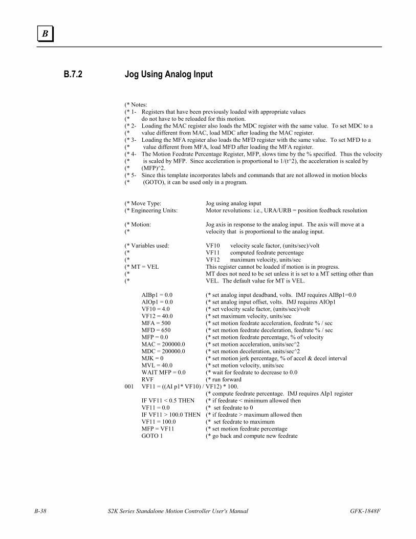
B-38 S2K Series Standalone Motion Controller User's Manual GFK-1848F
B
B.7.2 Jog Using Analog Input
(* Notes: (* 1- Registers that have been previously loaded with appropriate values (* do not have to be reloaded for this motion. (* 2- Loading the MAC register also loads the MDC register with the same value. To set MDC to a (* value different from MAC, load MDC after loading the MAC register. (* 3- Loading the MFA register also loads the MFD register with the same value. To set MFD to a (* value different from MFA, load MFD after loading the MFA register. (* 4- The Motion Feedrate Percentage Register, MFP, slows time by the % specified. Thus the velocity (* is scaled by MFP. Since acceleration is proportional to 1/(t^2), the acceleration is scaled by (* (MFP)^2. (* 5- Since this template incorporates labels and commands that are not allowed in motion blocks (* (GOTO), it can be used only in a program. (* Move Type: Jog using analog input (* Engineering Units: Motor revolutions: i.e., URA/URB = position feedback resolution (* Motion: Jog axis in response to the analog input. The axis will move at a (* velocity that is proportional to the analog input. (* Variables used: VF10 velocity scale factor, (units/sec)/volt (* VF11 computed feedrate percentage (* VF12 maximum velocity, units/sec (* MT = VEL This register cannot be loaded if motion is in progress. (* MT does not need to be set unless it is set to a MT setting other than (* VEL. The default value for MT is VEL. AIBp1 = 0.0 (* set analog input deadband, volts. IMJ requires AIBp1=0.0 AIOp1 = 0.0 (* set analog input offset, volts. IMJ requires AIOp1 VF10 = 4.0 (* set velocity scale factor, (units/sec)/volt VF12 = 40.0 (* set maximum velocity, units/sec MFA = 500 (* set motion feedrate acceleration, feedrate % / sec MFD = 650 (* set motion feedrate deceleration, feedrate % / sec MFP = 0.0 (* set motion feedrate percentage, % of velocity MAC = 200000.0 (* set motion acceleration, units/sec^2 MDC = 200000.0 (* set motion deceleration, units/sec^2 MJK = 0 (* set motion jerk percentage, % of accel & decel interval MVL = 40.0 (* set motion velocity, units/sec WAIT MFP = 0.0 (* wait for feedrate to decrease to 0.0 RVF (* run forward 001 VF11 = ((AI p1* VF10) / VF12) * 100. (* compute feedrate percentage. IMJ requires AIp1 register IF VF11 < 0.5 THEN (* if feedrate < minimum allowed then VF11 = 0.0 (* set feedrate to 0 IF VF11 > 100.0 THEN (* if feedrate > maximum allowed then VF11 = 100.0 (* set feedrate to maximum MFP = VF11 (* set motion feedrate percentage GOTO 1 (* go back and compute new feedrate
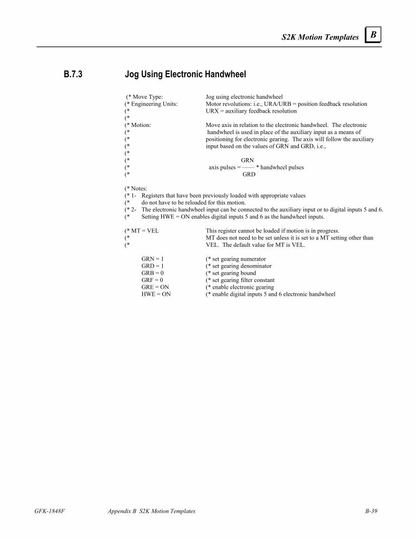
S2K Motion Templates
GFK-1848F Appendix B S2K Motion Templates B-39
B
B.7.3 Jog Using Electronic Handwheel (* Move Type: Jog using electronic handwheel (* Engineering Units: Motor revolutions: i.e., URA/URB = position feedback resolution (* URX = auxiliary feedback resolution (* (* Motion: Move axis in relation to the electronic handwheel. The electronic (* handwheel is used in place of the auxiliary input as a means of (* positioning for electronic gearing. The axis will follow the auxiliary (* input based on the values of GRN and GRD, i.e., (* (* GRN (* axis pulses = —— * handwheel pulses (* GRD (* Notes: (* 1- Registers that have been previously loaded with appropriate values (* do not have to be reloaded for this motion. (* 2- The electronic handwheel input can be connected to the auxiliary input or to digital inputs 5 and 6. (* Setting HWE = ON enables digital inputs 5 and 6 as the handwheel inputs. (* MT = VEL This register cannot be loaded if motion is in progress. (* MT does not need to be set unless it is set to a MT setting other than (* VEL. The default value for MT is VEL. GRN = 1 (* set gearing numerator GRD = 1 (* set gearing denominator GRB = 0 (* set gearing bound GRF = 0 (* set gearing filter constant GRE = ON (* enable electronic gearing HWE = ON (* enable digital inputs 5 and 6 electronic handwheel
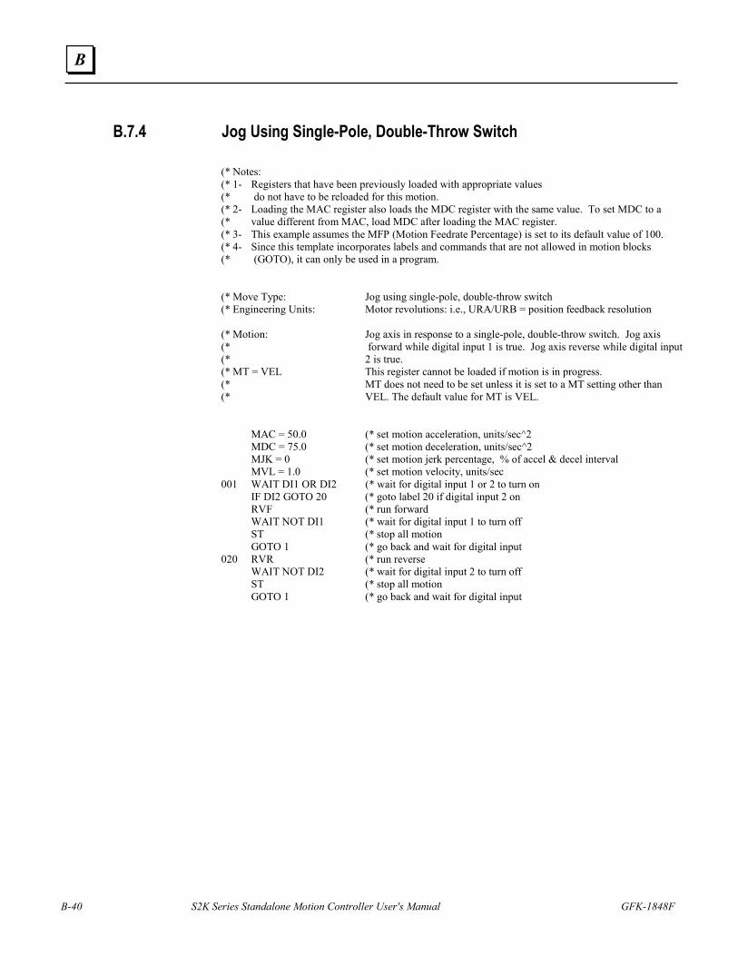
B-40 S2K Series Standalone Motion Controller User's Manual GFK-1848F
B
B.7.4 Jog Using Single-Pole, Double-Throw Switch (* Notes: (* 1- Registers that have been previously loaded with appropriate values (* do not have to be reloaded for this motion. (* 2- Loading the MAC register also loads the MDC register with the same value. To set MDC to a (* value different from MAC, load MDC after loading the MAC register. (* 3- This example assumes the MFP (Motion Feedrate Percentage) is set to its default value of 100. (* 4- Since this template incorporates labels and commands that are not allowed in motion blocks (* (GOTO), it can only be used in a program. (* Move Type: Jog using single-pole, double-throw switch (* Engineering Units: Motor revolutions: i.e., URA/URB = position feedback resolution (* Motion: Jog axis in response to a single-pole, double-throw switch. Jog axis (* forward while digital input 1 is true. Jog axis reverse while digital input (* 2 is true. (* MT = VEL This register cannot be loaded if motion is in progress. (* MT does not need to be set unless it is set to a MT setting other than (* VEL. The default value for MT is VEL. MAC = 50.0 (* set motion acceleration, units/sec^2 MDC = 75.0 (* set motion deceleration, units/sec^2 MJK = 0 (* set motion jerk percentage, % of accel & decel interval MVL = 1.0 (* set motion velocity, units/sec 001 WAIT DI1 OR DI2 (* wait for digital input 1 or 2 to turn on IF DI2 GOTO 20 (* goto label 20 if digital input 2 on RVF (* run forward WAIT NOT DI1 (* wait for digital input 1 to turn off ST (* stop all motion GOTO 1 (* go back and wait for digital input 020 RVR (* run reverse WAIT NOT DI2 (* wait for digital input 2 to turn off ST (* stop all motion GOTO 1 (* go back and wait for digital input
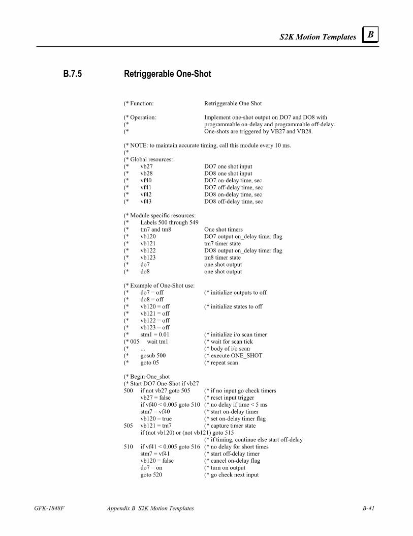
S2K Motion Templates
GFK-1848F Appendix B S2K Motion Templates B-41
B
B.7.5 Retriggerable One-Shot (* Function: Retriggerable One Shot (* Operation: Implement one-shot output on DO7 and DO8 with (* programmable on-delay and programmable off-delay. (* One-shots are triggered by VB27 and VB28. (* NOTE: to maintain accurate timing, call this module every 10 ms. (* (* Global resources: (* vb27 DO7 one shot input (* vb28 DO8 one shot input (* vf40 DO7 on-delay time, sec (* vf41 DO7 off-delay time, sec (* vf42 DO8 on-delay time, sec (* vf43 DO8 off-delay time, sec (* Module specific resources: (* Labels 500 through 549 (* tm7 and tm8 One shot timers (* vb120 DO7 output on_delay timer flag (* vb121 tm7 timer state (* vb122 DO8 output on_delay timer flag (* vb123 tm8 timer state (* do7 one shot output (* do8 one shot output (* Example of One-Shot use: (* do7 = off (* initialize outputs to off (* do8 = off (* vb120 = off (* initialize states to off (* vb121 = off (* vb122 = off (* vb123 = off (* stm1 = 0.01 (* initialize i/o scan timer (* 005 wait tm1 (* wait for scan tick (* ... (* body of i/o scan (* gosub 500 (* execute ONE_SHOT (* goto 05 (* repeat scan (* Begin One_shot (* Start DO7 One-Shot if vb27 500 if not vb27 goto 505 (* if no input go check timers vb27 = false (* reset input trigger if vf40 < 0.005 goto 510 (* no delay if time < 5 ms stm7 = vf40 (* start on-delay timer vb120 = true (* set on-delay timer flag 505 vb121 = tm7 (* capture timer state if (not vb120) or (not vb121) goto 515 (* if timing, continue else start off-delay 510 if vf41 < 0.005 goto 516 (* no delay for short times stm7 = vf41 (* start off-delay timer vb120 = false (* cancel on-delay flag do7 = on (* turn on output goto 520 (* go check next input
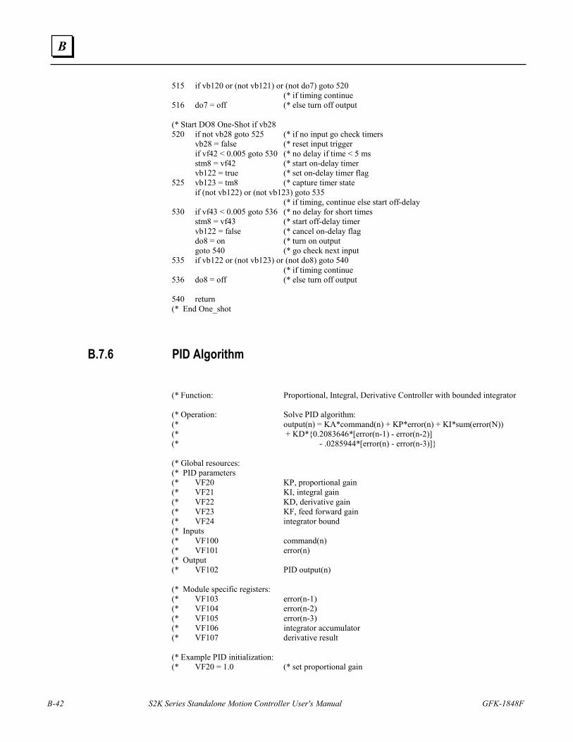
B-42 S2K Series Standalone Motion Controller User's Manual GFK-1848F
B
515 if vb120 or (not vb121) or (not do7) goto 520 (* if timing continue 516 do7 = off (* else turn off output (* Start DO8 One-Shot if vb28 520 if not vb28 goto 525 (* if no input go check timers vb28 = false (* reset input trigger if vf42 < 0.005 goto 530 (* no delay if time < 5 ms stm8 = vf42 (* start on-delay timer vb122 = true (* set on-delay timer flag 525 vb123 = tm8 (* capture timer state if (not vb122) or (not vb123) goto 535 (* if timing, continue else start off-delay 530 if vf43 < 0.005 goto 536 (* no delay for short times stm8 = vf43 (* start off-delay timer vb122 = false (* cancel on-delay flag do8 = on (* turn on output goto 540 (* go check next input 535 if vb122 or (not vb123) or (not do8) goto 540 (* if timing continue 536 do8 = off (* else turn off output 540 return (* End One_shot
B.7.6 PID Algorithm (* Function: Proportional, Integral, Derivative Controller with bounded integrator (* Operation: Solve PID algorithm: (* output(n) = KA*command(n) + KP*error(n) + KI*sum(error(N)) (* + KD*0.2083646*[error(n-1) - error(n-2)] (* - .0285944*[error(n) - error(n-3)] (* Global resources: (* PID parameters (* VF20 KP, proportional gain (* VF21 KI, integral gain (* VF22 KD, derivative gain (* VF23 KF, feed forward gain (* VF24 integrator bound (* Inputs (* VF100 command(n) (* VF101 error(n) (* Output (* VF102 PID output(n) (* Module specific registers: (* VF103 error(n-1) (* VF104 error(n-2) (* VF105 error(n-3) (* VF106 integrator accumulator (* VF107 derivative result (* Example PID initialization: (* VF20 = 1.0 (* set proportional gain
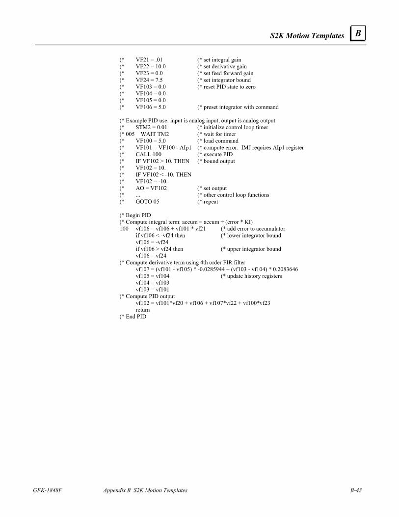
S2K Motion Templates
GFK-1848F Appendix B S2K Motion Templates B-43
B
(* VF21 = .01 (* set integral gain (* VF22 = 10.0 (* set derivative gain (* VF23 = 0.0 (* set feed forward gain (* VF24 = 7.5 (* set integrator bound (* VF103 = 0.0 (* reset PID state to zero (* VF104 = 0.0 (* VF105 = 0.0 (* VF106 = 5.0 (* preset integrator with command (* Example PID use: input is analog input, output is analog output (* STM2 = 0.01 (* initialize control loop timer (* 005 WAIT TM2 (* wait for timer (* VF100 = 5.0 (* load command (* VF101 = VF100 - AIp1 (* compute error. IMJ requires AIp1 register (* CALL 100 (* execute PID (* IF VF102 > 10. THEN (* bound output (* VF102 = 10. (* IF VF102 < -10. THEN (* VF102 = -10. (* AO = VF102 (* set output (* ... (* other control loop functions (* GOTO 05 (* repeat (* Begin PID (* Compute integral term: accum = accum + (error * KI) 100 vf106 = vf106 + vf101 * vf21 (* add error to accumulator if vf106 < -vf24 then (* lower integrator bound vf106 = -vf24 if vf106 > vf24 then (* upper integrator bound vf106 = vf24 (* Compute derivative term using 4th order FIR filter vf107 = (vf101 - vf105) * -0.0285944 + (vf103 - vf104) * 0.2083646 vf105 = vf104 (* update history registers vf104 = vf103 vf103 = vf101 (* Compute PID output vf102 = vf101*vf20 + vf106 + vf107*vf22 + vf100*vf23 return (* End PID
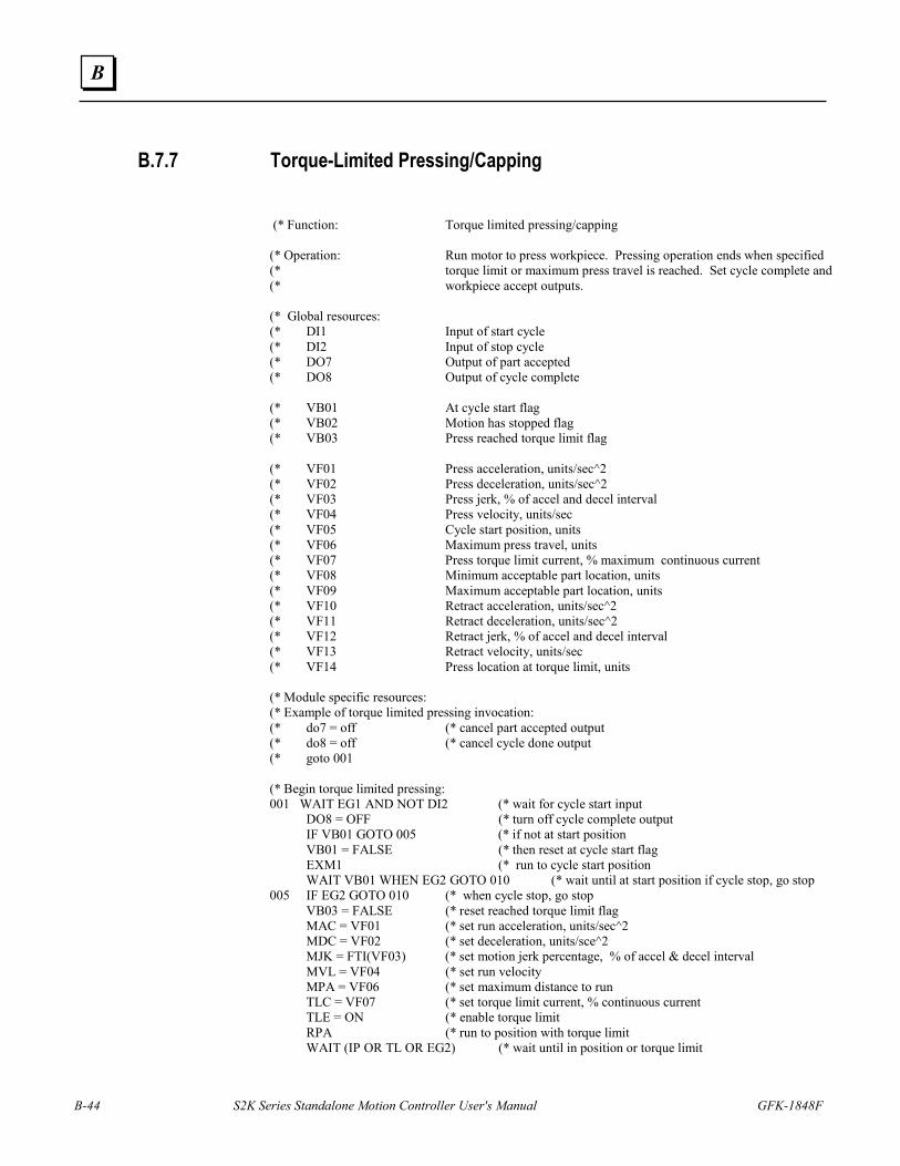
B-44 S2K Series Standalone Motion Controller User's Manual GFK-1848F
B
B.7.7 Torque-Limited Pressing/Capping (* Function: Torque limited pressing/capping (* Operation: Run motor to press workpiece. Pressing operation ends when specified (* torque limit or maximum press travel is reached. Set cycle complete and (* workpiece accept outputs. (* Global resources: (* DI1 Input of start cycle (* DI2 Input of stop cycle (* DO7 Output of part accepted (* DO8 Output of cycle complete (* VB01 At cycle start flag (* VB02 Motion has stopped flag (* VB03 Press reached torque limit flag (* VF01 Press acceleration, units/sec^2 (* VF02 Press deceleration, units/sec^2 (* VF03 Press jerk, % of accel and decel interval (* VF04 Press velocity, units/sec (* VF05 Cycle start position, units (* VF06 Maximum press travel, units (* VF07 Press torque limit current, % maximum continuous current (* VF08 Minimum acceptable part location, units (* VF09 Maximum acceptable part location, units (* VF10 Retract acceleration, units/sec^2 (* VF11 Retract deceleration, units/sec^2 (* VF12 Retract jerk, % of accel and decel interval (* VF13 Retract velocity, units/sec (* VF14 Press location at torque limit, units (* Module specific resources: (* Example of torque limited pressing invocation: (* do7 = off (* cancel part accepted output (* do8 = off (* cancel cycle done output (* goto 001 (* Begin torque limited pressing: 001 WAIT EG1 AND NOT DI2 (* wait for cycle start input DO8 = OFF (* turn off cycle complete output IF VB01 GOTO 005 (* if not at start position VB01 = FALSE (* then reset at cycle start flag EXM1 (* run to cycle start position WAIT VB01 WHEN EG2 GOTO 010 (* wait until at start position if cycle stop, go stop 005 IF EG2 GOTO 010 (* when cycle stop, go stop VB03 = FALSE (* reset reached torque limit flag MAC = VF01 (* set run acceleration, units/sec^2 MDC = VF02 (* set deceleration, units/sce^2 MJK = FTI(VF03) (* set motion jerk percentage, % of accel & decel interval MVL = VF04 (* set run velocity MPA = VF06 (* set maximum distance to run TLC = VF07 (* set torque limit current, % continuous current TLE = ON (* enable torque limit RPA (* run to position with torque limit WAIT (IP OR TL OR EG2) (* wait until in position or torque limit
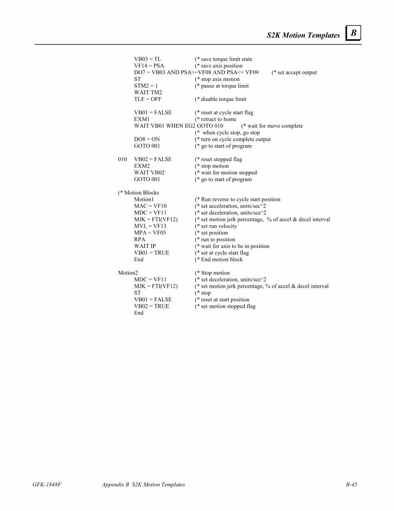
S2K Motion Templates
GFK-1848F Appendix B S2K Motion Templates B-45
B
VB03 = TL (* save torque limit state VF14 = PSA (* save axis position DO7 = VB03 AND PSA>=VF08 AND PSA<= VF09 (* set accept output ST (* stop axis motion STM2 = 1 (* pause at torque limit WAIT TM2 TLE = OFF (* disable torque limit VB01 = FALSE (* reset at cycle start flag EXM1 (* retract to home WAIT VB01 WHEN EG2 GOTO 010 (* wait for move complete (* when cycle stop, go stop DO8 = ON (* turn on cycle complete output GOTO 001 (* go to start of program 010 VB02 = FALSE (* reset stopped flag EXM2 (* stop motion WAIT VB02 (* wait for motion stopped GOTO 001 (* go to start of program (* Motion Blocks Motion1 (* Run reverse to cycle start position MAC = VF10 (* set acceleration, units/sec^2 MDC = VF11 (* set deceleration, units/sce^2 MJK = FTI(VF12) (* set motion jerk percentage, % of accel & decel interval MVL = VF13 (* set run velocity MPA = VF05 (* set position RPA (* run to position WAIT IP (* wait for axis to be in position VB01 = TRUE (* set at cycle start flag End (* End motion block Motion2 (* Stop motion MDC = VF11 (* set deceleration, units/sce^2 MJK = FTI(VF12) (* set motion jerk percentage, % of accel & decel interval ST (* stop VB01 = FALSE (* reset at start position VB02 = TRUE (* set motion stopped flag End
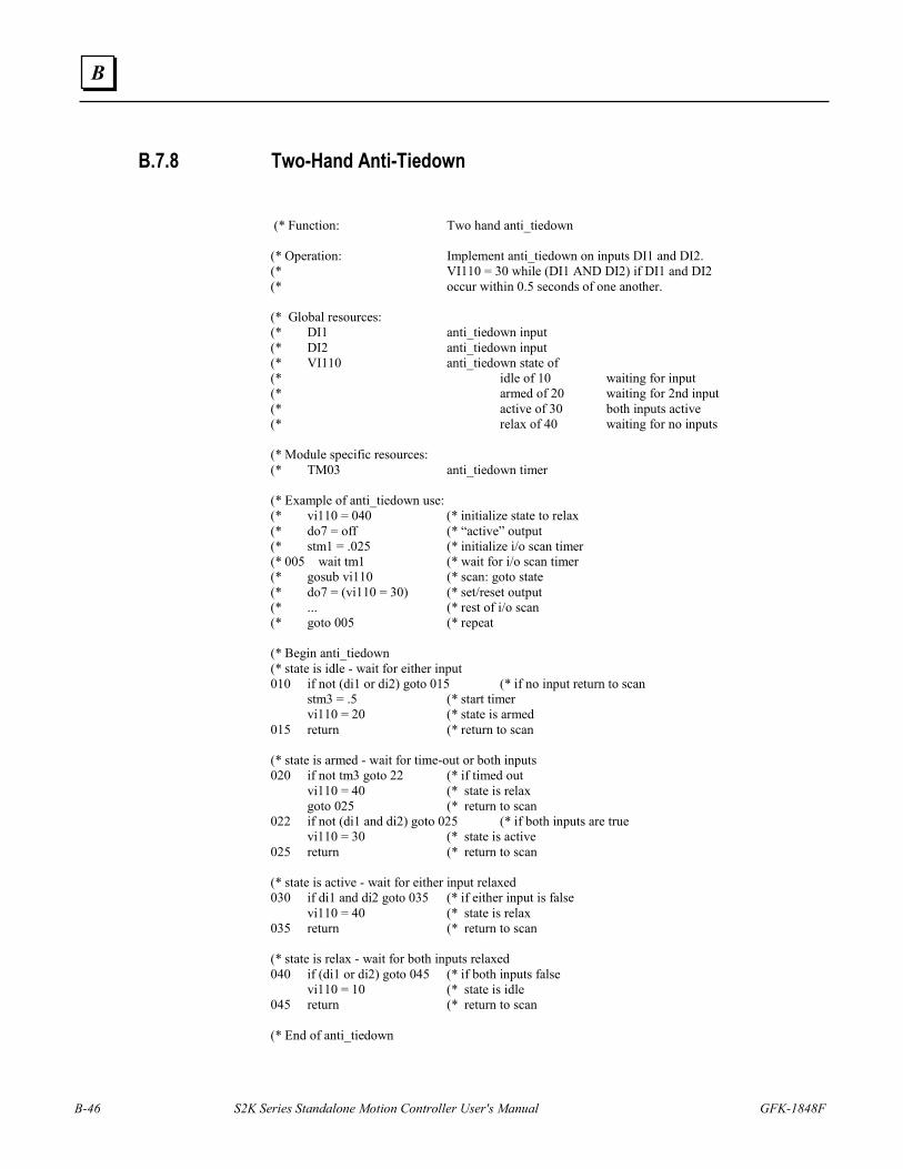
B-46 S2K Series Standalone Motion Controller User's Manual GFK-1848F
B
B.7.8 Two-Hand Anti-Tiedown (* Function: Two hand anti_tiedown (* Operation: Implement anti_tiedown on inputs DI1 and DI2. (* VI110 = 30 while (DI1 AND DI2) if DI1 and DI2 (* occur within 0.5 seconds of one another. (* Global resources: (* DI1 anti_tiedown input (* DI2 anti_tiedown input (* VI110 anti_tiedown state of (* idle of 10 waiting for input (* armed of 20 waiting for 2nd input (* active of 30 both inputs active (* relax of 40 waiting for no inputs (* Module specific resources: (* TM03 anti_tiedown timer (* Example of anti_tiedown use: (* vi110 = 040 (* initialize state to relax (* do7 = off (* “active” output (* stm1 = .025 (* initialize i/o scan timer (* 005 wait tm1 (* wait for i/o scan timer (* gosub vi110 (* scan: goto state (* do7 = (vi110 = 30) (* set/reset output (* ... (* rest of i/o scan (* goto 005 (* repeat (* Begin anti_tiedown (* state is idle - wait for either input 010 if not (di1 or di2) goto 015 (* if no input return to scan stm3 = .5 (* start timer vi110 = 20 (* state is armed 015 return (* return to scan (* state is armed - wait for time-out or both inputs 020 if not tm3 goto 22 (* if timed out vi110 = 40 (* state is relax goto 025 (* return to scan 022 if not (di1 and di2) goto 025 (* if both inputs are true vi110 = 30 (* state is active 025 return (* return to scan (* state is active - wait for either input relaxed 030 if di1 and di2 goto 035 (* if either input is false vi110 = 40 (* state is relax 035 return (* return to scan (* state is relax - wait for both inputs relaxed 040 if (di1 or di2) goto 045 (* if both inputs false vi110 = 10 (* state is idle 045 return (* return to scan (* End of anti_tiedown
Index
GFK-1848F Index-1
! !, 5-59
? ?, 5-59, 7-22
+ +
concatenation operator, 5-63 +, -, *, /, **, 5-63
> >, >=, =, <>, <=, <, 5-62
A ABS, 5-64 Absolute move position, 5-185 Absolute value operator, 5-64 AC Power, 4-4 AC Supply, 2-2 Acceleration
set as a percentage, 5-174 set as a rate, 5-172 set as a rate, network command, 5-173
Acceleration command message, 8-21 Acceleration feedforward, 5-156 Actual Position response message, 8-30 ADDN, 5-65 ADDR, 5-66 Address
network, 10-6 Agency approvals, 1-8 AI, 5-66 AIB, 5-67 AIN, 5-67 AIO, 5-68 Altitude, 3-2 Ambient temperature, 3-2 Analog I/O
wiring, 3-38 Analog input
deadband, 5-67 of network, 5-67 offset, 5-68 register, 5-66 specifications, 2-4
Analog output, 3-37 of network, 5-70 power-up state, 5-70
register, 5-69 specifications, 2-4
AND, 5-68 AO, 5-69 AO, 3-37 AON, 5-70 AOP, 5-70 Arithmetic operators, 5-63 Arithmetic shift operators, 5-254 ASC, 5-71 ASCII codes, 5-15, A-1 Assembly object instance number assignment
network digital output register, 5-119 Atmosphere, 3-2 ATN, 5-71 Attribute 115
of DeviceNet position controller object, 5-116 Authorization
Motion Developer, 6-2 moving Motion Developer, 6-2
AUTORET, 5-18, 5-72 AUTOTUNE, 5-72, 10-14
derivative gain, 5-156, 5-157 filter time constant, 5-165 integral gain, 5-158 proportional gain, 5-162
Auxiliary encoder input functions, 3-38 set quadrature type, 5-232 specifications, 2-5 using single ended inputs, 3-39 wiring, 3-38
Auxiliary I/O functional description, 3-34 wiring, 3-34
Auxiliary position, 5-228 synchronized with axis position, 5-41
Auxiliary position direction, 5-115 Auxiliary position length, 5-222 Auxiliary position offset (OFX), 5-199 Auxiliary position synchronized, 5-231 Auxiliary unit ratio, 5-274 Auxiliary velocity, 5-282 Auxiliary velocity filter time constant, 5-282 Axis
in position flag, 5-152 network position register, 5-225 network velocity command, 5-194, 5-280 position offset (OFA), 5-198 position register, 5-225 position register length, 5-221 position, synchronized reading, 5-41 velocity command, 5-280 velocity filter time constant, 5-281
Axis feedback resolution for commutation, 5-134
Axis in position flag
Index
Index-2 S2K Series Standalone Motion Controller User's Manual – December 2003 GFK-1848F
network command, 5-153 Axis position from auxiliary encoder, 5-134 Axis position from main encoder, 5-134 Axis status register, 5-256, 7-15 Axis unit ratio denominator, 5-273 Axis unit ratio numerator, 5-272
B Backlash compensation, 5-213 Backspace cursor, 5-74 BAUD, 5-73 Baud rate
of network port, 5-73 of serial port, 5-73
BAUDN, 5-73 BIT, 5-74 Blended moves, 5-12 Block diagram
electronic camming, 5-35 electronic gearing, 5-31
Boolean operands FALSE/OFF, 5-125 TRUE/ON, 5-269
Boolean variables, 5-5, 5-15, 5-275 of network, 5-275
Brake motor, 1-2 power supply, 3-67 Power Supply, 2-30 specifications, 2-10 wiring diagram, 3-67
BS, 5-74
C Cables, 3-59
motor power, 4-3 serial communication, 4-5 specifications, motor power and encoder, 3-62
CAE, 5-75 CAF, 5-75 CAI, 5-76 Cam
block diagram, 5-35 compile begin point, 5-83 compile cam motion, 5-84 compile end point, 5-83 compile start position, 5-85 enable, 5-75 filter constant, 5-37, 5-75 generating a table, 5-37 how to use, 5-34 master input source, 5-82 master position source selection, 3-38 master source selection, 5-35
offset, 5-37 point in cam table, 5-37, 5-77 position register, 5-81 position register increment, 5-76 profile types supported, 5-34 scale factor, 5-39, 5-81 scaling the master using PLX, 5-36 shaft position, 5-80 shaft position type, 5-82 tips for creating programs, 5-39 using the compile commands, 5-38 zero cam table, 5-82
CAM, 5-77 CAP, 5-80 Capture
auxiliary position, 5-208 axis position, 5-207 digital input, 3-41 using the capture input, 5-41
CAR, 5-81 CAS, 5-81 Case conversion operators, 5-171, 5-270 CAT, 3-38, 5-82 CAZ, 5-82 CCB, 5-83 CCE, 5-83 CCM, 5-84 CCP, 5-85 CE, 5-85 CE agency approvals, 1-8 CHANGEPW, 5-11, 5-86 Checksum, 7-6 CHR, 5-86 CIE, 5-87, 7-2
code numbers, 7-2 Circular buffer, 5-15 Clear user memory, 5-88 Clears line and positions cursor at beginning of
line, 5-87 CLL, 5-87 CLM, 5-88 Close network connection, 5-91 cls, 5-89 CMD, 5-89 CMO, 5-90 cmr, 5-91 CNC, 5-91 Command list
alphabetical listing, 5-42 by class, 5-50
Command Message acceleration, 8-21 deceleration, 8-22, 8-23 parameter get/set, 8-23, 8-29 target position, 8-20 target velocity, 8-20
Index
GFK-1848F Index Index-3
types, 8-19 Command not allowed, 7-3 Command output, 5-89 command position, 5-226 Commanded position, 5-226
network command, 5-226 Commanded Position response message, 8-31,
8-32, 8-33, 8-34, 8-35 Comments
embed with REM, 5-233 embedded with REM, 5-5 not stored, 5-5
Communication establish with Motion, 4-5
Commutation angle offset, 5-90 Compatibility
motor and controller combinations, 1-5 Complex profiles. See Blended moves Computer interface format enable, 5-87 Computer requirements
for Motion Developer, 6-1 Concatenation operator, 5-63 Configure
S2K Series Controller, 4-6 Connection diagram
SSI104 controller, 3-46, 3-48 SSI104D2 controller, 3-47 SSI107 controller, 3-49, 3-51 SSI216 & 228 controller, 3-52, 3-53 SSI407RD2, 3-55 SSI407RP2 controller, 3-56 SSI407RS1 controller, 3-54 SSI420RD2 controller, 3-57 SSI420RP2 controller, 3-58 STI105D2 controller, 3-44 STM105D2 controller, 3-45 STM105S1 controller, 3-43
Connections motor brake, 3-30 motor encoder, 3-31 motor power, 3-30
Connector stepping motor power, 3-62, 3-63, 3-64
Controller dimensions, 3-5 excess following error fault, 7-1 excessive command increment fault, 7-1 installation, 3-3 LED display, 7-1 lost enable fault, 7-1 overtemperature fault, 7-1 position register overflow fault, 7-1 power clamp overcurrent fault, 7-1 power failure fault, 7-1 software fault, 7-1 weight, 3-5
Controller Area Network, 8-45
Conversion error, 5-85 Convert floating point to integer operators, 5-
135, 5-269 Convert floating point to string operator, 5-136 Convert integer to floating point operator, 5-
155 Convert integer to string operators, 5-154 Convert string to floating point operator, 5-261 Convert string to integer operator, 5-262 Cooling, 3-1 COS, 5-92 Countdown timer
number available, 5-5 overview, 5-16 start, 5-262 timed out flag, 5-268
cr, 5-92 crh, 5-92 crm, 5-93 crp, 5-93 crr, 5-93 CUL/CUR agency approvals, 1-8 CURC, 5-97 CURC autotune, 5-72 CURP, 5-100 Current
amplifier ratings, 2-2 Current limit
continuous, 5-94 continuous, network, 5-97 peak, 5-100
CURS, 5-103 Cursor backspace, 5-74
D Data rate
DIP switches, 8-10 Data transfers
Load Data/Start Profile bit, 8-17 Deadband, 5-209 Deceleration
set as a rate, 5-175 set as a rate, network command, 5-176
Deceleration command message, 8-22, 8-23 DEL, 5-104
edit string operator, 5-150 derivative control gain, 10-14 Derivative control gain, 5-157 DeviceNet
acceleration command message, 8-21 actual position response message, 8-30 adding slave device to scanner, 8-10 address display, 7-1 application program example, 8-39
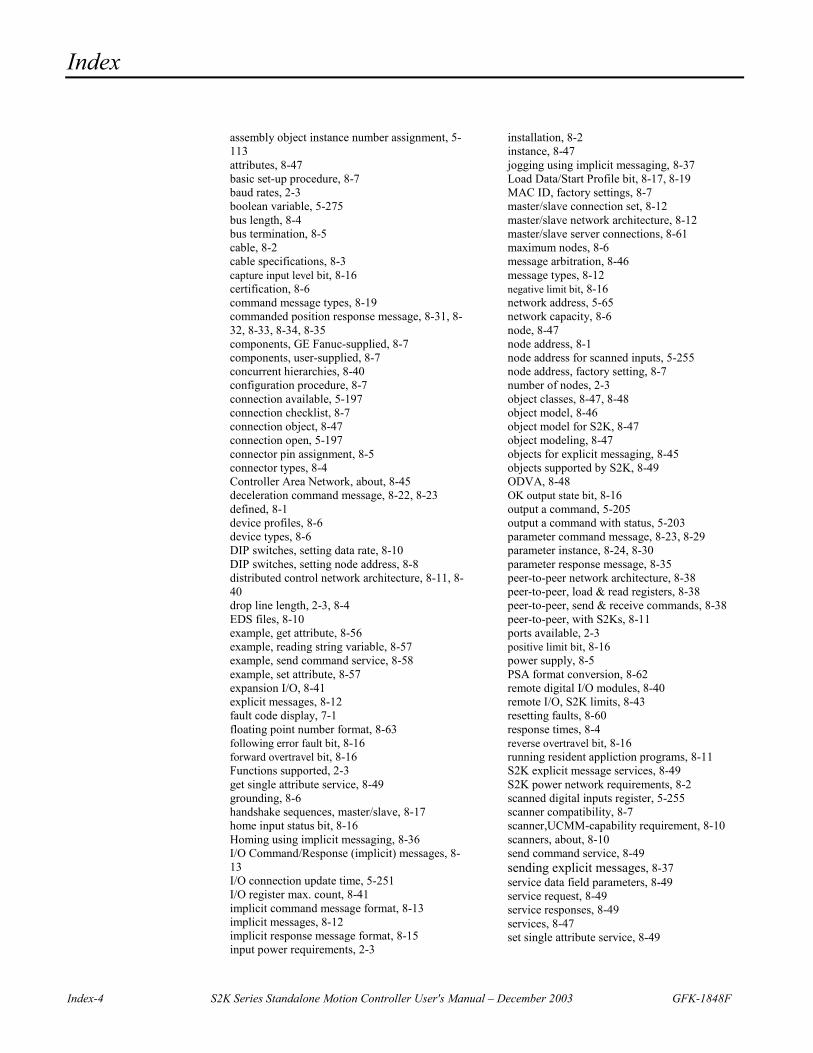
Index
Index-4 S2K Series Standalone Motion Controller User's Manual – December 2003 GFK-1848F
assembly object instance number assignment, 5-113 attributes, 8-47 basic set-up procedure, 8-7 baud rates, 2-3 boolean variable, 5-275 bus length, 8-4 bus termination, 8-5 cable, 8-2 cable specifications, 8-3 capture input level bit, 8-16 certification, 8-6 command message types, 8-19 commanded position response message, 8-31, 8-32, 8-33, 8-34, 8-35 components, GE Fanuc-supplied, 8-7 components, user-supplied, 8-7 concurrent hierarchies, 8-40 configuration procedure, 8-7 connection available, 5-197 connection checklist, 8-7 connection object, 8-47 connection open, 5-197 connector pin assignment, 8-5 connector types, 8-4 Controller Area Network, about, 8-45 deceleration command message, 8-22, 8-23 defined, 8-1 device profiles, 8-6 device types, 8-6 DIP switches, setting data rate, 8-10 DIP switches, setting node address, 8-8 distributed control network architecture, 8-11, 8-40 drop line length, 2-3, 8-4 EDS files, 8-10 example, get attribute, 8-56 example, reading string variable, 8-57 example, send command service, 8-58 example, set attribute, 8-57 expansion I/O, 8-41 explicit messages, 8-12 fault code display, 7-1 floating point number format, 8-63 following error fault bit, 8-16 forward overtravel bit, 8-16 Functions supported, 2-3 get single attribute service, 8-49 grounding, 8-6 handshake sequences, master/slave, 8-17 home input status bit, 8-16 Homing using implicit messaging, 8-36 I/O Command/Response (implicit) messages, 8-13 I/O connection update time, 5-251 I/O register max. count, 8-41 implicit command message format, 8-13 implicit messages, 8-12 implicit response message format, 8-15 input power requirements, 2-3
installation, 8-2 instance, 8-47 jogging using implicit messaging, 8-37 Load Data/Start Profile bit, 8-17, 8-19 MAC ID, factory settings, 8-7 master/slave connection set, 8-12 master/slave network architecture, 8-12 master/slave server connections, 8-61 maximum nodes, 8-6 message arbitration, 8-46 message types, 8-12 negative limit bit, 8-16 network address, 5-65 network capacity, 8-6 node, 8-47 node address, 8-1 node address for scanned inputs, 5-255 node address, factory setting, 8-7 number of nodes, 2-3 object classes, 8-47, 8-48 object model, 8-46 object model for S2K, 8-47 object modeling, 8-47 objects for explicit messaging, 8-45 objects supported by S2K, 8-49 ODVA, 8-48 OK output state bit, 8-16 output a command, 5-205 output a command with status, 5-203 parameter command message, 8-23, 8-29 parameter instance, 8-24, 8-30 parameter response message, 8-35 peer-to-peer network architecture, 8-38 peer-to-peer, load & read registers, 8-38 peer-to-peer, send & receive commands, 8-38 peer-to-peer, with S2Ks, 8-11 ports available, 2-3 positive limit bit, 8-16 power supply, 8-5 PSA format conversion, 8-62 remote digital I/O modules, 8-40 remote I/O, S2K limits, 8-43 resetting faults, 8-60 response times, 8-4 reverse overtravel bit, 8-16 running resident appliction programs, 8-11 S2K explicit message services, 8-49 S2K power network requirements, 8-2 scanned digital inputs register, 5-255 scanner compatibility, 8-7 scanner,UCMM-capability requirement, 8-10 scanners, about, 8-10 send command service, 8-49 sending explicit messages, 8-37 service data field parameters, 8-49 service request, 8-49 service responses, 8-49 services, 8-47 set single attribute service, 8-49
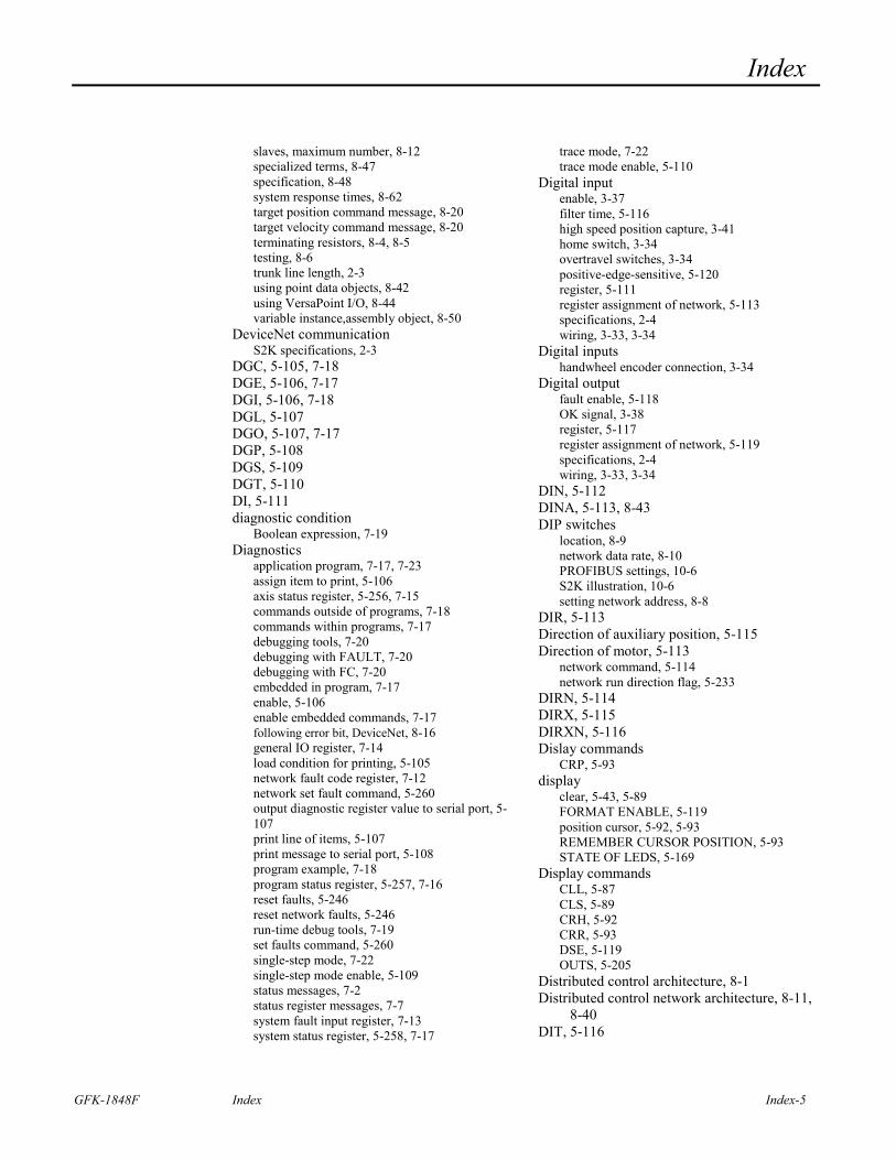
Index
GFK-1848F Index Index-5
slaves, maximum number, 8-12 specialized terms, 8-47 specification, 8-48 system response times, 8-62 target position command message, 8-20 target velocity command message, 8-20 terminating resistors, 8-4, 8-5 testing, 8-6 trunk line length, 2-3 using point data objects, 8-42 using VersaPoint I/O, 8-44 variable instance,assembly object, 8-50
DeviceNet communication S2K specifications, 2-3
DGC, 5-105, 7-18 DGE, 5-106, 7-17 DGI, 5-106, 7-18 DGL, 5-107 DGO, 5-107, 7-17 DGP, 5-108 DGS, 5-109 DGT, 5-110 DI, 5-111 diagnostic condition
Boolean expression, 7-19 Diagnostics
application program, 7-17, 7-23 assign item to print, 5-106 axis status register, 5-256, 7-15 commands outside of programs, 7-18 commands within programs, 7-17 debugging tools, 7-20 debugging with FAULT, 7-20 debugging with FC, 7-20 embedded in program, 7-17 enable, 5-106 enable embedded commands, 7-17 following error bit, DeviceNet, 8-16 general IO register, 7-14 load condition for printing, 5-105 network fault code register, 7-12 network set fault command, 5-260 output diagnostic register value to serial port, 5-107 print line of items, 5-107 print message to serial port, 5-108 program example, 7-18 program status register, 5-257, 7-16 reset faults, 5-246 reset network faults, 5-246 run-time debug tools, 7-19 set faults command, 5-260 single-step mode, 7-22 single-step mode enable, 5-109 status messages, 7-2 status register messages, 7-7 system fault input register, 7-13 system status register, 5-258, 7-17
trace mode, 7-22 trace mode enable, 5-110
Digital input enable, 3-37 filter time, 5-116 high speed position capture, 3-41 home switch, 3-34 overtravel switches, 3-34 positive-edge-sensitive, 5-120 register, 5-111 register assignment of network, 5-113 specifications, 2-4 wiring, 3-33, 3-34
Digital inputs handwheel encoder connection, 3-34
Digital output fault enable, 5-118 OK signal, 3-38 register, 5-117 register assignment of network, 5-119 specifications, 2-4 wiring, 3-33, 3-34
DIN, 5-112 DINA, 5-113, 8-43 DIP switches
location, 8-9 network data rate, 8-10 PROFIBUS settings, 10-6 S2K illustration, 10-6 setting network address, 8-8
DIR, 5-113 Direction of auxiliary position, 5-115 Direction of motor, 5-113
network command, 5-114 network run direction flag, 5-233
DIRN, 5-114 DIRX, 5-115 DIRXN, 5-116 Dislay commands
CRP, 5-93 display
clear, 5-43, 5-89 FORMAT ENABLE, 5-119 position cursor, 5-92, 5-93 REMEMBER CURSOR POSITION, 5-93 STATE OF LEDS, 5-169
Display commands CLL, 5-87 CLS, 5-89 CRH, 5-92 CRR, 5-93 DSE, 5-119 OUTS, 5-205
Distributed control architecture, 8-1 Distributed control network architecture, 8-11,
8-40 DIT, 5-116
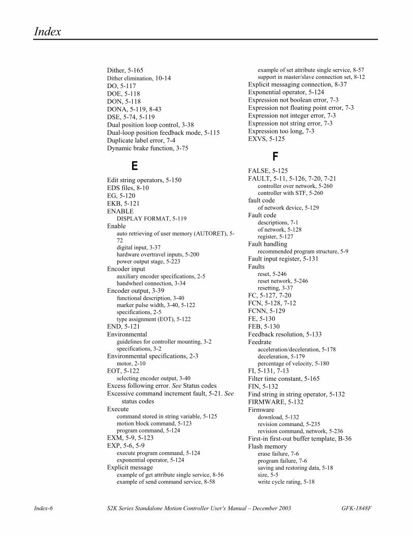
Index
Index-6 S2K Series Standalone Motion Controller User's Manual – December 2003 GFK-1848F
Dither, 5-165 Dither elimination, 10-14 DO, 5-117 DOE, 5-118 DON, 5-118 DONA, 5-119, 8-43 DSE, 5-74, 5-119 Dual position loop control, 3-38 Dual-loop position feedback mode, 5-115 Duplicate label error, 7-4 Dynamic brake function, 3-75
E Edit string operators, 5-150 EDS files, 8-10 EG, 5-120 EKB, 5-121 ENABLE
DISPLAY FORMAT, 5-119 Enable
auto retrieving of user memory (AUTORET), 5-72 digital input, 3-37 hardware overtravel inputs, 5-200 power output stage, 5-223
Encoder input auxiliary encoder specifications, 2-5 handwheel connection, 3-34
Encoder output, 3-39 functional description, 3-40 marker pulse width, 3-40, 5-122 specifications, 2-5 type assignment (EOT), 5-122
END, 5-121 Environmental
guidelines for controller mounting, 3-2 specifications, 3-2
Environmental specifications, 2-3 motor, 2-10
EOT, 5-122 selecting encoder output, 3-40
Excess following error. See Status codes Excessive command increment fault, 5-21. See
status codes Execute
command stored in string variable, 5-125 motion block command, 5-123 program command, 5-124
EXM, 5-9, 5-123 EXP, 5-6, 5-9
execute program command, 5-124 exponential operator, 5-124
Explicit message example of get attribute single service, 8-56 example of send command service, 8-58
example of set attribute single service, 8-57 support in master/slave connection set, 8-12
Explicit messaging connection, 8-37 Exponential operator, 5-124 Expression not boolean error, 7-3 Expression not floating point error, 7-3 Expression not integer error, 7-3 Expression not string error, 7-3 Expression too long, 7-3 EXVS, 5-125
F FALSE, 5-125 FAULT, 5-11, 5-126, 7-20, 7-21
controller over network, 5-260 controller with STF, 5-260
fault code of network device, 5-129
Fault code descriptions, 7-1 of network, 5-128 register, 5-127
Fault handling recommended program structure, 5-9
Fault input register, 5-131 Faults
reset, 5-246 reset network, 5-246 resetting, 3-37
FC, 5-127, 7-20 FCN, 5-128, 7-12 FCNN, 5-129 FE, 5-130 FEB, 5-130 Feedback resolution, 5-133 Feedrate
acceleration/deceleration, 5-178 deceleration, 5-179 percentage of velocity, 5-180
FI, 5-131, 7-13 Filter time constant, 5-165 FIN, 5-132 Find string in string operator, 5-132 FIRMWARE, 5-132 Firmware
download, 5-132 revision command, 5-235 revision command, network, 5-236
First-in first-out buffer template, B-36 Flash memory
erase failure, 7-6 program failure, 7-6 saving and restoring data, 5-18 size, 5-5 write cycle rating, 5-18
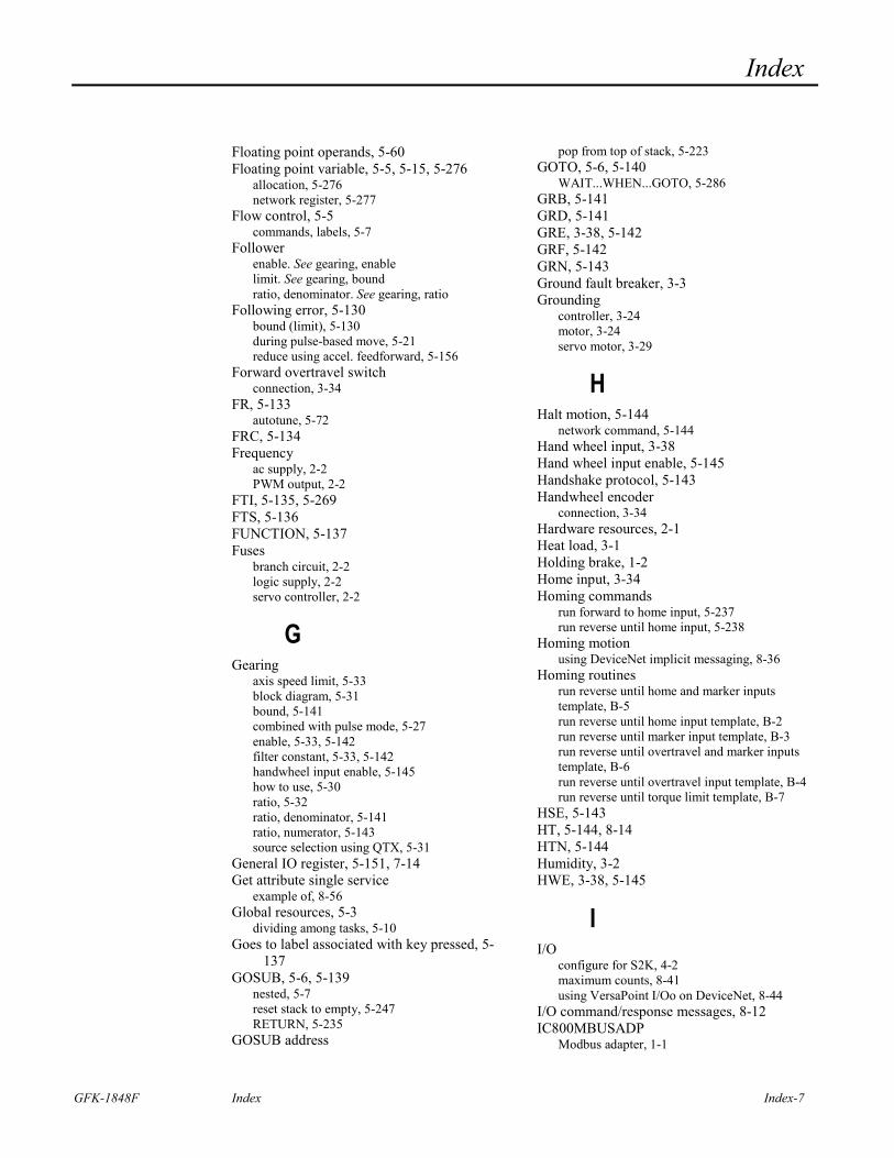
Index
GFK-1848F Index Index-7
Floating point operands, 5-60 Floating point variable, 5-5, 5-15, 5-276
allocation, 5-276 network register, 5-277
Flow control, 5-5 commands, labels, 5-7
Follower enable. See gearing, enable limit. See gearing, bound ratio, denominator. See gearing, ratio
Following error, 5-130 bound (limit), 5-130 during pulse-based move, 5-21 reduce using accel. feedforward, 5-156
Forward overtravel switch connection, 3-34
FR, 5-133 autotune, 5-72
FRC, 5-134 Frequency
ac supply, 2-2 PWM output, 2-2
FTI, 5-135, 5-269 FTS, 5-136 FUNCTION, 5-137 Fuses
branch circuit, 2-2 logic supply, 2-2 servo controller, 2-2
G Gearing
axis speed limit, 5-33 block diagram, 5-31 bound, 5-141 combined with pulse mode, 5-27 enable, 5-33, 5-142 filter constant, 5-33, 5-142 handwheel input enable, 5-145 how to use, 5-30 ratio, 5-32 ratio, denominator, 5-141 ratio, numerator, 5-143 source selection using QTX, 5-31
General IO register, 5-151, 7-14 Get attribute single service
example of, 8-56 Global resources, 5-3
dividing among tasks, 5-10 Goes to label associated with key pressed, 5-
137 GOSUB, 5-6, 5-139
nested, 5-7 reset stack to empty, 5-247 RETURN, 5-235
GOSUB address
pop from top of stack, 5-223 GOTO, 5-6, 5-140
WAIT...WHEN...GOTO, 5-286 GRB, 5-141 GRD, 5-141 GRE, 3-38, 5-142 GRF, 5-142 GRN, 5-143 Ground fault breaker, 3-3 Grounding
controller, 3-24 motor, 3-24 servo motor, 3-29
H Halt motion, 5-144
network command, 5-144 Hand wheel input, 3-38 Hand wheel input enable, 5-145 Handshake protocol, 5-143 Handwheel encoder
connection, 3-34 Hardware resources, 2-1 Heat load, 3-1 Holding brake, 1-2 Home input, 3-34 Homing commands
run forward to home input, 5-237 run reverse until home input, 5-238
Homing motion using DeviceNet implicit messaging, 8-36
Homing routines run reverse until home and marker inputs template, B-5 run reverse until home input template, B-2 run reverse until marker input template, B-3 run reverse until overtravel and marker inputs template, B-6 run reverse until overtravel input template, B-4 run reverse until torque limit template, B-7
HSE, 5-143 HT, 5-144, 8-14 HTN, 5-144 Humidity, 3-2 HWE, 3-38, 5-145
I I/O
configure for S2K, 4-2 maximum counts, 8-41 using VersaPoint I/Oo on DeviceNet, 8-44
I/O command/response messages, 8-12 IC800MBUSADP
Modbus adapter, 1-1
Index
Index-8 S2K Series Standalone Motion Controller User's Manual – December 2003 GFK-1848F
IF...GOSUB, 5-6, 5-146 IF...GOTO, 5-6, 5-147 IF...THEN, 5-6, 5-148 IMJ models
replaced by S2K resolver controllers, 1-8 Immediate mode, 5-2 Implicit messages, 8-12 IN, 5-149 In Position
band (IPB), 5-152 flag (IP), 5-152
In position flag network command, 5-153 use with pulse-based motion, 5-20
Incremental move position, 5-186 Indirect referencing, 5-15 Input current, 2-2 INS, 5-150 Inspecting, 1-2 Installation
control protection, 3-3 controller, 3-3 location, controller, 3-2 Motion Developer, 6-1 motor, 3-4
Integer operands, 5-60 Integer variables, 5-5, 5-15, 5-278
network register, 5-279 setting via explicit message example, 8-58
integral control gain, 10-14 Integral control gain, 5-158 Invalid
assignment, 7-2 command, 7-2 command string error, 7-4 digit, 7-2 motion, 7-5 password, 7-6 variable pointer, 7-4
IO register, 5-151, 7-14, 8-16 IP, 5-152
use with pulse-based motion, 5-20 IPB, 5-152 IPN, 5-153 ITB, 5-154 ITF, 5-155 ITH, 5-154 ITS, 5-154
J Jerk percentage, 5-182 Jog. See run, axis forward/reverse Jogging utilities
using analog input template, B-38 using DeviceNet implicit messaging, 8-37
using electronic handwheel, B-39 using single-pole double-throw switch, B-40
Jump. See GOTO based on boolean variable check, 5-263
Jumper I/O S2K controller, 4-2
K KA, 5-156 KA autotune, 5-72 KD, 5-157
autotune, 5-72 KEY, 5-158 key buffer
key assignment, 5-167 Key buffer
determine if character is in, 5-158 empty, 5-121 get one character from, 5-138 input register value from, 5-149 put one character into, 5-166 size, 5-5
KI, 5-158 autotune, 5-72
KL, 5-159 KLALL, 5-9, 5-160 KLP, 5-6, 5-9, 5-160 KM, 5-161 KP, 5-162
autotune, 5-72 KSN, 5-163, 5-164 KT, 5-165 KT autotune, 5-72 KVN, 5-166 KY, 5-166 KYA, 5-167
L L, 5-168, 7-21 LABEL, 5-169 Label out of range, 7-2 Labels, 5-7 LED, 5-169 LEN, 5-170 Length of string operator, 5-170 LFT, 5-170, 5-181, 5-236 LGN, 5-170 Limits
continuous current, 5-94 network continuous current, 5-97 peak current, 5-100
Line editor exit command, 5-59
Index
GFK-1848F Index Index-9
how to open in terminal window, 7-20 scroll program in terminal window, 7-21
Linear array, 5-15 Load command data, 8-14 Location, controller installation, 3-2 LOCK, 5-9, 5-171 Logic power supply, 2-2 Logical operators, 5-14, 5-198, 5-199, 5-288 Lost enable fault. See status codes LWR, 5-171, 5-270
M MAC, 5-172 MAC ID
ADDN register description, 5-65 MACN, 5-173 MAP, 5-174 Marker pulse width
encoder output, 3-40 Master/slave network architecture, 8-12 Math
function summary, 5-14 Mathematical data error, 7-4 Mathematical overflow error, 7-4 MB, 5-175 MDC, 5-175 MDCN, 5-176 MDP, 5-177 Memory
autoretrieve, 5-72 clear, 5-88 Flash write cycle rating, 5-18 retrieve, 5-234 retrieve variables from, 5-249 save to FLASH, 5-250 save variables to non-volatile, 5-265 secure, 5-253 size, 5-5
MEMORY, 5-178 MFA, 5-178 MFD, 5-179 MFP, 5-180 MID, 5-181 Missing quotation mark, 7-4 MJK, 5-182 Modbus
adapter, IC800MBUSADP, 1-1 Modes of position feedback, 5-115 Motion
combining gearing and positional moves, 5-33 combining pulse and gear modes, 5-27 halt, 5-144 installation, 4-5 network halt command, 5-144
network stop command, 5-263 resume, 5-246 step input command, 5-259 stop, 5-259 suspend, 5-264 terminal window, 4-6 using camming, 5-34 using electronic gearing, 5-30 using pulse mode, 5-19
MOTION command, 5-183
Motion blocks achieving expected results, 5-13 blended moves, 5-12 execute, 5-123 executing, 5-175 number allowed, 5-11 repeat motion from start of, 5-234 rules for execution, 5-11
Motion Developer authorization, 6-2 installation, 6-1 technical support, 6-3
Motion templates absolute move, B-10 absolute move with feedrate override, B-14 blended (complex) move, B-12 continuous move (jog), B-8 electronic camming, B-28 incremental move, B-9 index move after digital input, B-32 index move at predefined aux. position, B-34 offset move, B-11 phase-locked loop, B-27 pulse-based absolute move, B-20 pulse-based blended (complex) move, B-22 pulse-based continuous (jog) move, B-24 pulse-based incremental move, B-19 pulse-based offset move, B-21 run forward until digital input, B-33 run forward until torque limit, B-25 run reverse at torque limit, B-26 run reverse until home and marker inputs, B-5 run reverse until home input, B-2 run reverse until marker input, B-3 run reverse until overtravel and marker inputs, B-6 run reverse until overtravel input, B-4 run reverse until torque limit, B-7 time-based absolute move, B-16 time-based absolute move with feedrate override, B-18 time-based incremental move, B-15 time-based offset move, B-17
Motion type register, 5-191 Motor
brake speicifications, 2-10 brake wiring, 3-67 dimensions, servo, 3-7
Index
Index-10 S2K Series Standalone Motion Controller User's Manual – December 2003 GFK-1848F
environmental specifications, 2-10 feedback, 2-6 grounding, 3-24 holding brake, 1-2 installation, 3-4 NEMA Mounting, 2-31 specifications, 2-10 undervoltage fault. See Status codes
Motor constants automatically set, 5-184
Motor direction Current Direction bit, 8-16 Direction (V. Mode) bit, 8-14
Motor inductance (KL), 5-159 Motor power cable
connection, 4-3 MOTORSET, 5-184 Mounting
controller. See Installation, controller controller guidelines, 3-2 motor. See Installation, motor
Mounting dimensions controller, 3-5 SDM 1000W motor, 3-10 SDM 2500W motor, 3-10 SGM 4500W motor, 3-11 SLM 1000W motor, 3-10 SLM 200W motor, 3-7 SLM 2500W motor, 3-10 SLM 400W motor, 3-8 SLM 5000W motor, 3-11 SLM 750W motor, 3-9
Move position network command, 5-188
Move pulses, 5-187 Move time, 5-192 MPA, 5-185 MPI, 5-186 MPL, 5-187 MPN, 5-188 MPO, 5-189 MPS, 5-190 MT, 5-191 MTM, 5-192 MTR-Series Servo Motor Dimensions, 3-12 Multitasking, 5-7
capabilities, 5-3 commands, 5-8 dividing tasks for max. efficiency, 5-10 lock out other programs, 5-171 Max. concurrent tasks, 5-5 unlock program execution, 5-270
MVL, 5-193 MVLN, 5-194 MVM, 5-195 MVP, 5-196
N Natural log operator, 5-170 NCO, 5-197, 8-61 NEMA Mounting, 2-31 NET, 5-197 Network
acceleration rate command, 5-173 axis in position command, 5-153 axis position register command, 5-225 axis velocity command, 5-280 Boolean variable, 5-275 bus voltage command, 5-166 close connection, 5-91 commanded position command, 5-226 connection available, 5-197 connection open, 5-197 deceleration rate command, 5-176 device fault code, 5-129 digital input register, 5-112 digital input register assignment, 5-113 digital output register, 5-118 digital output register assignment, 5-119 fault code register, 5-128, 7-12 firmware revision command, 5-236 floating point variable, 5-277 halt motion command, 5-144 integer variable, 5-279 move position command, 5-188 node address for scanned inputs, 5-255 output a command, 5-205 output a command with status, 5-203 profile in progress flag, 5-220 resetting faults, 5-246 run direction flag, 5-233 run incremental flag, 5-239 run mode command, 5-241 run profile command, 5-245 scan time, max., 5-251 scanned digital inputs register, 5-255 stall velocity threshold command, 5-163, 5-164 statue LED states, 8-61 stop command, 5-263 string variable, 5-284 velocity command, 5-194
Network address, 5-65, 8-1 out of range, 7-2
Network analog input, 5-67 Network analog output, 5-70 Network architecture
distributed control, 8-1, 8-40 master-slave, 8-1, 8-12 peer-to-peer, 8-1, 8-38
Network direction of auxiliary position, 5-116 Network port
baud rate, 5-73 output command to, 5-205
No program fault, 7-4
Index
GFK-1848F Index Index-11
Node address DIP switches, 8-8 factory settings, 10-6
Nodes communicating with, 8-11 maximum on DeviceNet, 8-6
Nonexistent label error, 7-4 Normal position feedback mode, 5-115 NOT
logical operator, 5-198 Not ready for command, 7-3
O OFA, 5-198 OFF, 5-125 Offset
auxiliary position (OFX), 5-199 axis position (OFA), 5-198
Offset move destination position for offset move (MPO), 5-189 reference position (PSO), 5-227 run to offset position command, 5-245
OFX, 5-199 OK output, 3-38 ON, 5-269 Operands
conversion error, 5-85 false, 5-125 floating point, 5-60 integer, 5-60 off, 5-125 on, 5-269 string, 5-61 true, 5-269
Operating modes immediate mode, 5-2 programmed task execution, 5-2, 5-3
Operators absolute value, 5-64 arctangent, 5-71 arithmetic, 5-2, 5-14, 5-63 arithmetic shift, 5-254 case conversion, 5-171, 5-270 concatenation, 5-63 convert floating point to integer, 5-135, 5-269 convert floating point to string, 5-136 convert from ASCII code to character, 5-86 convert integer to floating point, 5-155 convert integer to string, 5-154 convert string to floating point, 5-261 convert string to integer, 5-262 convert to ASCII, 5-71 cosine, 5-92 determine length of string, 5-170 edit string, insert/delete, 5-150
exponential, 5-124 find string in string, 5-132 logical, 5-14 logical AND, 5-68 logical NOT, 5-198 logical OR, 5-199 logical XOR, 5-288 natural log, 5-170 relational, 5-62 rotate bits, 5-242 select characters of string, 5-170, 5-181 sine, 5-254 square root, 5-256 tangent, 5-266
OR, 5-199 OTE, 5-200 OTF, 5-201 OTR, 5-202 OUSN, 5-203 OUT, 5-204 OUTN, 5-205, 8-38 Output
a command to network port, 5-205 a command to network port with status, 5-203 amplifier OK, 3-38
Outputs screen to display, 5-205 OUTS, 5-205 Overtemperature fault. See status codes Overtravel
define forward software, 5-201 define reverse software, 5-202 enable hardware inputs, 5-200 switch connection, 3-34
P PAR, 5-205 Parameter Command Message, 8-23, 8-29 Parameter Instance to Set, 8-24, 8-30 Parameter response message, 8-35 Parameter Value, 8-24, 8-30 Parity
serial port, 5-205 Part numbers
amplifier, 1-3 motor, 1-3
Part Numbers, 1-3 Amplifier, 1-4 cables, 3-59 connector mate, stepping motors, 3-62, 3-63, 3-64 Motor, 1-3
Password change, 5-86 command messages, 7-5 lost, 5-11 protect application program, 5-11
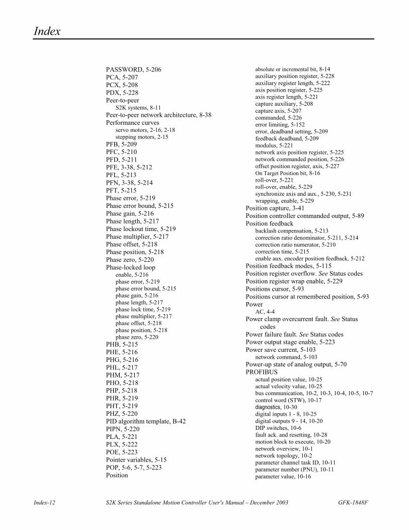
Index
Index-12 S2K Series Standalone Motion Controller User's Manual – December 2003 GFK-1848F
PASSWORD, 5-206 PCA, 5-207 PCX, 5-208 PDX, 5-228 Peer-to-peer
S2K systems, 8-11 Peer-to-peer network architecture, 8-38 Performance curves
servo motors, 2-16, 2-18 stepping motors, 2-15
PFB, 5-209 PFC, 5-210 PFD, 5-211 PFE, 3-38, 5-212 PFL, 5-213 PFN, 3-38, 5-214 PFT, 5-215 Phase error, 5-219 Phase error bound, 5-215 Phase gain, 5-216 Phase length, 5-217 Phase lockout time, 5-219 Phase multiplier, 5-217 Phase offset, 5-218 Phase position, 5-218 Phase zero, 5-220 Phase-locked loop
enable, 5-216 phase error, 5-219 phase error bound, 5-215 phase gain, 5-216 phase length, 5-217 phase lock time, 5-219 phase multiplier, 5-217 phase offset, 5-218 phase position, 5-218 phase zero, 5-220
PHB, 5-215 PHE, 5-216 PHG, 5-216 PHL, 5-217 PHM, 5-217 PHO, 5-218 PHP, 5-218 PHR, 5-219 PHT, 5-219 PHZ, 5-220 PID algorithm template, B-42 PIPN, 5-220 PLA, 5-221 PLX, 5-222 POE, 5-223 Pointer variables, 5-15 POP, 5-6, 5-7, 5-223 Position
absolute or incremental bit, 8-14 auxiliary position register, 5-228 auxiliary register length, 5-222 axis position register, 5-225 axis register length, 5-221 capture auxiliary, 5-208 capture axis, 5-207 commanded, 5-226 error limiting, 5-152 error, deadband setting, 5-209 feedback deadband, 5-209 modulus, 5-221 network axis position register, 5-225 network commanded position, 5-226 offset position register, axis, 5-227 On Target Position bit, 8-16 roll-over, 5-221 roll-over, enable, 5-229 synchronize axis and aux., 5-230, 5-231 wrapping, enable, 5-229
Position capture, 3-41 Position controller commanded output, 5-89 Position feedback
backlash compensation, 5-213 correction ratio denominator, 5-211, 5-214 correction ratio numerator, 5-210 correction time, 5-215 enable aux. encoder position feedback, 5-212
Position feedback modes, 5-115 Position register overflow. See Status codes Position register wrap enable, 5-229 Positions cursor, 5-93 Positions cursor at remembered position, 5-93 Power
AC, 4-4 Power clamp overcurrent fault. See Status
codes Power failure fault. See Status codes Power output stage enable, 5-223 Power save current, 5-103
network command, 5-103 Power-up state of analog output, 5-70 PROFIBUS
actual position value, 10-25 actual velocity value, 10-25 bus communication, 10-2, 10-3, 10-4, 10-5, 10-7 control word (STW), 10-17 diagnostics, 10-30 digital inputs 1 - 8, 10-25 digital outputs 9 - 14, 10-20 DIP switches, 10-6 fault ack. and resetting, 10-28 motion block to execute, 10-20 network overview, 10-1 network topology, 10-2 parameter channel task ID, 10-11 parameter number (PNU), 10-11 parameter value, 10-16
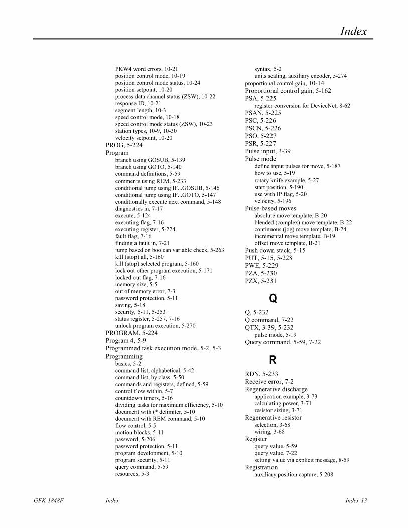
Index
GFK-1848F Index Index-13
PKW4 word errors, 10-21 position control mode, 10-19 position control mode status, 10-24 position setpoint, 10-20 process data channel status (ZSW), 10-22 response ID, 10-21 segment length, 10-3 speed control mode, 10-18 speed control mode status (ZSW), 10-23 station types, 10-9, 10-30 velocity setpoint, 10-20
PROG, 5-224 Program
branch using GOSUB, 5-139 branch using GOTO, 5-140 command definitions, 5-59 comments using REM, 5-233 conditional jump using IF...GOSUB, 5-146 conditional jump using IF...GOTO, 5-147 conditionally execute next command, 5-148 diagnostics in, 7-17 execute, 5-124 executing flag, 7-16 executing register, 5-224 fault flag, 7-16 finding a fault in, 7-21 jump based on boolean variable check, 5-263 kill (stop) all, 5-160 kill (stop) selected program, 5-160 lock out other program execution, 5-171 locked out flag, 7-16 memory size, 5-5 out of memory error, 7-3 password protection, 5-11 saving, 5-18 security, 5-11, 5-253 status register, 5-257, 7-16 unlock program execution, 5-270
PROGRAM, 5-224 Program 4, 5-9 Programmed task execution mode, 5-2, 5-3 Programming
basics, 5-2 command list, alphabetical, 5-42 command list, by class, 5-50 commands and registers, defined, 5-59 control flow within, 5-7 countdown timers, 5-16 dividing tasks for maximum efficiency, 5-10 document with (* delimiter, 5-10 document with REM command, 5-10 flow control, 5-5 motion blocks, 5-11 password, 5-206 password protection, 5-11 program development, 5-10 program security, 5-11 query command, 5-59 resources, 5-3
syntax, 5-2 units scaling, auxiliary encoder, 5-274
proportional control gain, 10-14 Proportional control gain, 5-162 PSA, 5-225
register conversion for DeviceNet, 8-62 PSAN, 5-225 PSC, 5-226 PSCN, 5-226 PSO, 5-227 PSR, 5-227 Pulse input, 3-39 Pulse mode
define input pulses for move, 5-187 how to use, 5-19 rotary knife example, 5-27 start position, 5-190 use with IP flag, 5-20 velocity, 5-196
Pulse-based moves absolute move template, B-20 blended (complex) move template, B-22 continuous (jog) move template, B-24 incremental move template, B-19 offset move template, B-21
Push down stack, 5-15 PUT, 5-15, 5-228 PWE, 5-229 PZA, 5-230 PZX, 5-231
Q Q, 5-232 Q command, 7-22 QTX, 3-39, 5-232
pulse mode, 5-19 Query command, 5-59, 7-22
R RDN, 5-233 Receive error, 7-2 Regenerative discharge
application example, 3-73 calculating power, 3-71 resistor sizing, 3-71
Regenerative resistor selection, 3-68 wiring, 3-68
Register query value, 5-59 query value, 7-22 setting value via explicit message, 8-59
Registration auxiliary position capture, 5-208
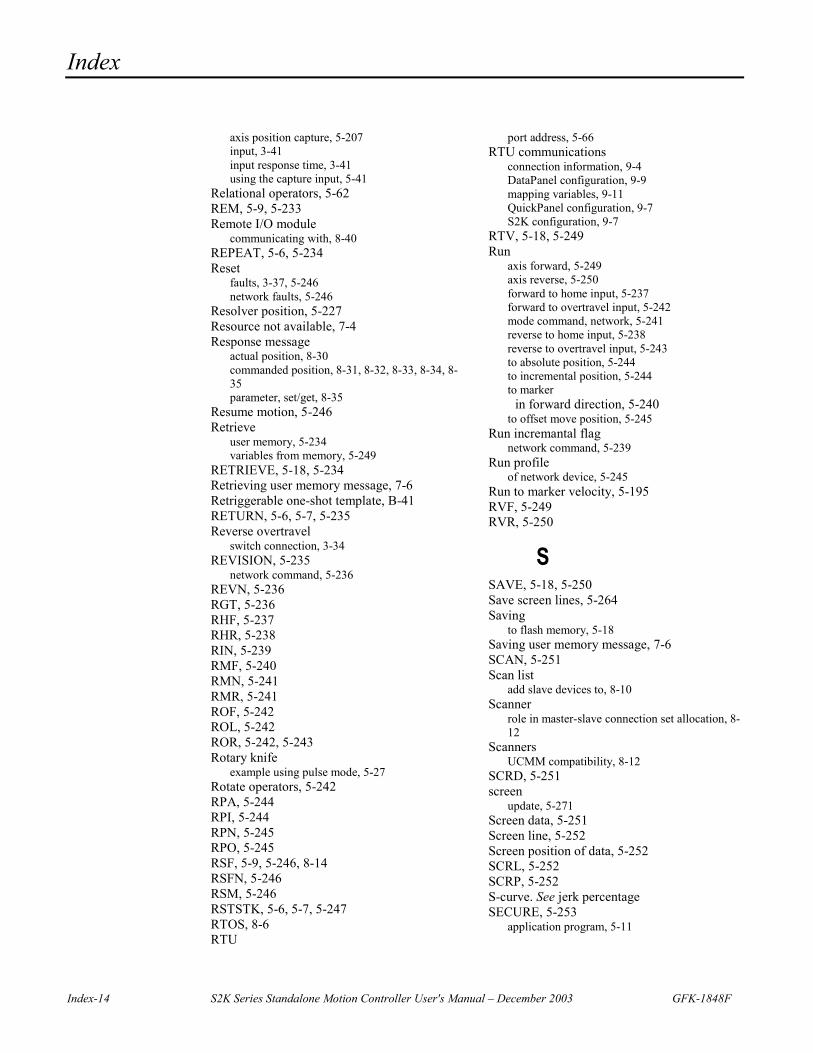
Index
Index-14 S2K Series Standalone Motion Controller User's Manual – December 2003 GFK-1848F
axis position capture, 5-207 input, 3-41 input response time, 3-41 using the capture input, 5-41
Relational operators, 5-62 REM, 5-9, 5-233 Remote I/O module
communicating with, 8-40 REPEAT, 5-6, 5-234 Reset
faults, 3-37, 5-246 network faults, 5-246
Resolver position, 5-227 Resource not available, 7-4 Response message
actual position, 8-30 commanded position, 8-31, 8-32, 8-33, 8-34, 8-35 parameter, set/get, 8-35
Resume motion, 5-246 Retrieve
user memory, 5-234 variables from memory, 5-249
RETRIEVE, 5-18, 5-234 Retrieving user memory message, 7-6 Retriggerable one-shot template, B-41 RETURN, 5-6, 5-7, 5-235 Reverse overtravel
switch connection, 3-34 REVISION, 5-235
network command, 5-236 REVN, 5-236 RGT, 5-236 RHF, 5-237 RHR, 5-238 RIN, 5-239 RMF, 5-240 RMN, 5-241 RMR, 5-241 ROF, 5-242 ROL, 5-242 ROR, 5-242, 5-243 Rotary knife
example using pulse mode, 5-27 Rotate operators, 5-242 RPA, 5-244 RPI, 5-244 RPN, 5-245 RPO, 5-245 RSF, 5-9, 5-246, 8-14 RSFN, 5-246 RSM, 5-246 RSTSTK, 5-6, 5-7, 5-247 RTOS, 8-6 RTU
port address, 5-66 RTU communications
connection information, 9-4 DataPanel configuration, 9-9 mapping variables, 9-11 QuickPanel configuration, 9-7 S2K configuration, 9-7
RTV, 5-18, 5-249 Run
axis forward, 5-249 axis reverse, 5-250 forward to home input, 5-237 forward to overtravel input, 5-242 mode command, network, 5-241 reverse to home input, 5-238 reverse to overtravel input, 5-243 to absolute position, 5-244 to incremental position, 5-244 to marker
in forward direction, 5-240 to offset move position, 5-245
Run incremantal flag network command, 5-239
Run profile of network device, 5-245
Run to marker velocity, 5-195 RVF, 5-249 RVR, 5-250
S SAVE, 5-18, 5-250 Save screen lines, 5-264 Saving
to flash memory, 5-18 Saving user memory message, 7-6 SCAN, 5-251 Scan list
add slave devices to, 8-10 Scanner
role in master-slave connection set allocation, 8-12
Scanners UCMM compatibility, 8-12
SCRD, 5-251 screen
update, 5-271 Screen data, 5-251 Screen line, 5-252 Screen position of data, 5-252 SCRL, 5-252 SCRP, 5-252 S-curve. See jerk percentage SECURE, 5-253
application program, 5-11
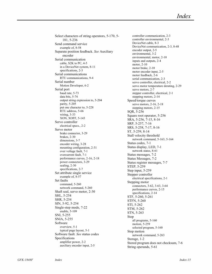
Index
GFK-1848F Index Index-15
Select characters of string operators, 5-170, 5-181, 5-236
Send command service example of, 8-58
Separate position feedback. See Auxiliary encoder
Serial communication cable, S2K to PC, 4-5 in a DeviceNet system, 8-11 specifications, 2-3
Serial communications RTU communications, 9-4
Serial number Motion Developer, 6-2
Serial port baud rate, 5-73 data bits, 5-74 output string expression to, 5-204 parity, 5-205 put one character to, 5-228 RTU address, 5-66 wiring, 3-33 XON, XOFF, 5-143
Servo controller electrical specs., 2-2
Servo motor brake connector, 3-29 brakes, 2-30 dimensions, 3-7 encoder wiring, 3-28 mounting configuration, 2-31 over voltage fault, 7-1 overcurrent fault, 7-1 performance curves, 2-16, 2-18 power connectors, 3-29 sealing, 2-30 specifications, 2-7
Set attribute single service example of, 8-57
Set faults command, 5-260 network command, 5-260
Shaft seal, servo motor, 2-30 SHL, 5-254 SHR, 5-254 SIN, 5-92, 5-254 Single-step mode, 7-22
enable, 5-109 SNI, 5-255 SNIA, 5-255 Software
overview, 5-1 typical page layout, 5-1
Software fault. See status codes Specifications
amplifier power, 2-2 auxiliary encoder input, 2-5
controller communication, 2-3 controller environmental, 2-3 DeviceNet cable, 8-3 DeviceNet communication, 2-3, 8-48 encoder output, 2-5 environmental, 3-2 environmental, motor, 2-10 inputs and outputs, 2-4 motor, 2-10 motor brake, 2-10 motor encoder input, 2-5 motor feedback, 2-6 serial communication, 2-3 servo controller, electrical, 2-2 servo motor temperature derating, 2-29 servo motors, 2-7 stepper controller, electrical, 2-1 stepping motors, 2-14
Speed/torque curves servo motors, 2-16, 2-18 stepping motors, 2-15
SQR, 5-256 Square root operator, 5-256 SRA, 5-256, 7-15, 8-16 SRP, 5-257, 7-16 SRS, 5-258, 7-17, 8-16 ST, 5-259, 8-14 Stall velocity threshold
network command, 5-163, 5-164 Status codes, 7-1 Status display, LED, 7-1
network states, 8-61 Status messages, 7-2 Status Messages, 7-2 Status register messages, 7-7 STEP, 5-259 Step input, 5-259 Stepper controller
electrical specifications, 2-1 Stepping motor
connectors, 3-62, 3-63, 3-64 performance curves, 2-15 specifications, 2-14
STF, 5-260, 5-261 STFN, 5-260 STI, 5-262 STM, 5-262 STN, 5-263 Stop
all programs, 5-160 motion, 5-259 selected program, 5-160
Stop motion network command, 5-263
Storage, 1-2 Stored program does not checksum, 7-6 String operands, 5-61
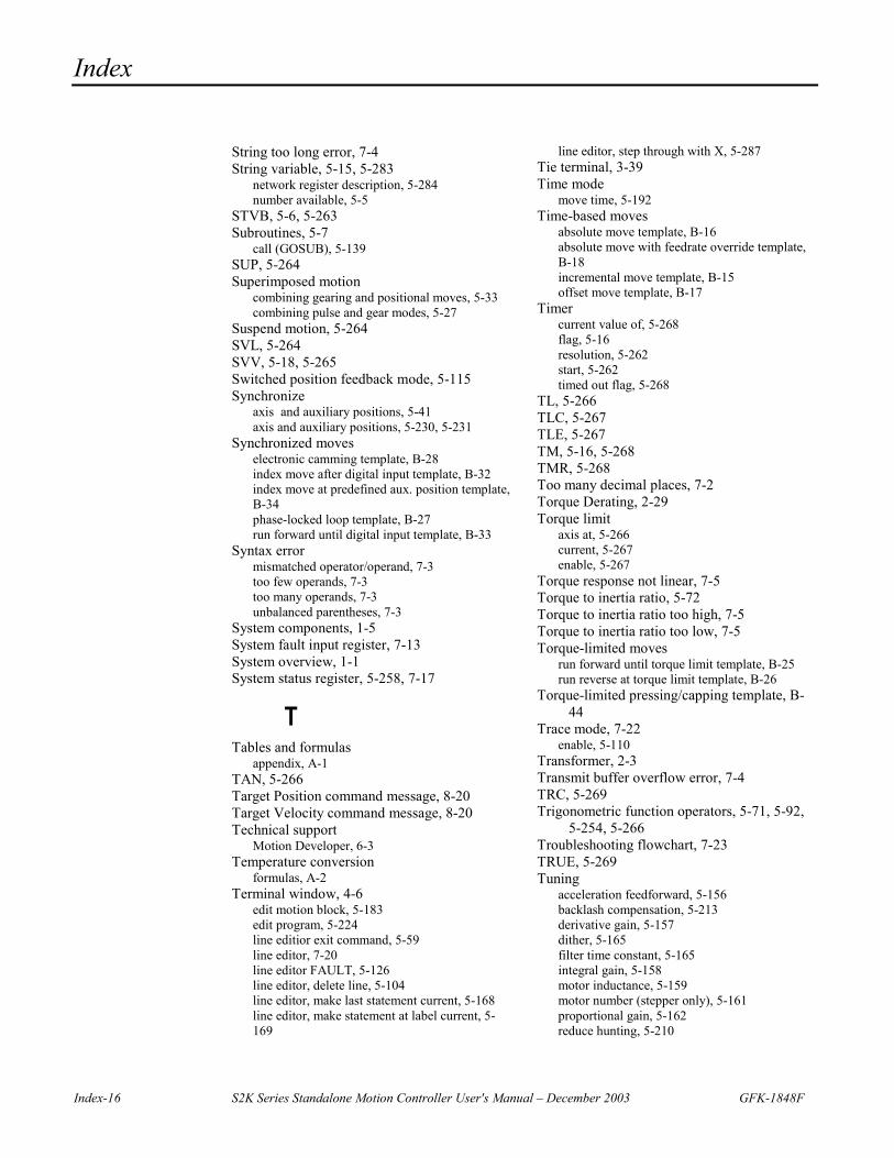
Index
Index-16 S2K Series Standalone Motion Controller User's Manual – December 2003 GFK-1848F
String too long error, 7-4 String variable, 5-15, 5-283
network register description, 5-284 number available, 5-5
STVB, 5-6, 5-263 Subroutines, 5-7
call (GOSUB), 5-139 SUP, 5-264 Superimposed motion
combining gearing and positional moves, 5-33 combining pulse and gear modes, 5-27
Suspend motion, 5-264 SVL, 5-264 SVV, 5-18, 5-265 Switched position feedback mode, 5-115 Synchronize
axis and auxiliary positions, 5-41 axis and auxiliary positions, 5-230, 5-231
Synchronized moves electronic camming template, B-28 index move after digital input template, B-32 index move at predefined aux. position template, B-34 phase-locked loop template, B-27 run forward until digital input template, B-33
Syntax error mismatched operator/operand, 7-3 too few operands, 7-3 too many operands, 7-3 unbalanced parentheses, 7-3
System components, 1-5 System fault input register, 7-13 System overview, 1-1 System status register, 5-258, 7-17
T Tables and formulas
appendix, A-1 TAN, 5-266 Target Position command message, 8-20 Target Velocity command message, 8-20 Technical support
Motion Developer, 6-3 Temperature conversion
formulas, A-2 Terminal window, 4-6
edit motion block, 5-183 edit program, 5-224 line editior exit command, 5-59 line editor, 7-20 line editor FAULT, 5-126 line editor, delete line, 5-104 line editor, make last statement current, 5-168 line editor, make statement at label current, 5-169
line editor, step through with X, 5-287 Tie terminal, 3-39 Time mode
move time, 5-192 Time-based moves
absolute move template, B-16 absolute move with feedrate override template, B-18 incremental move template, B-15 offset move template, B-17
Timer current value of, 5-268 flag, 5-16 resolution, 5-262 start, 5-262 timed out flag, 5-268
TL, 5-266 TLC, 5-267 TLE, 5-267 TM, 5-16, 5-268 TMR, 5-268 Too many decimal places, 7-2 Torque Derating, 2-29 Torque limit
axis at, 5-266 current, 5-267 enable, 5-267
Torque response not linear, 7-5 Torque to inertia ratio, 5-72 Torque to inertia ratio too high, 7-5 Torque to inertia ratio too low, 7-5 Torque-limited moves
run forward until torque limit template, B-25 run reverse at torque limit template, B-26
Torque-limited pressing/capping template, B-44
Trace mode, 7-22 enable, 5-110
Transformer, 2-3 Transmit buffer overflow error, 7-4 TRC, 5-269 Trigonometric function operators, 5-71, 5-92,
5-254, 5-266 Troubleshooting flowchart, 7-23 TRUE, 5-269 Tuning
acceleration feedforward, 5-156 backlash compensation, 5-213 derivative gain, 5-157 dither, 5-165 filter time constant, 5-165 integral gain, 5-158 motor inductance, 5-159 motor number (stepper only), 5-161 proportional gain, 5-162 reduce hunting, 5-210
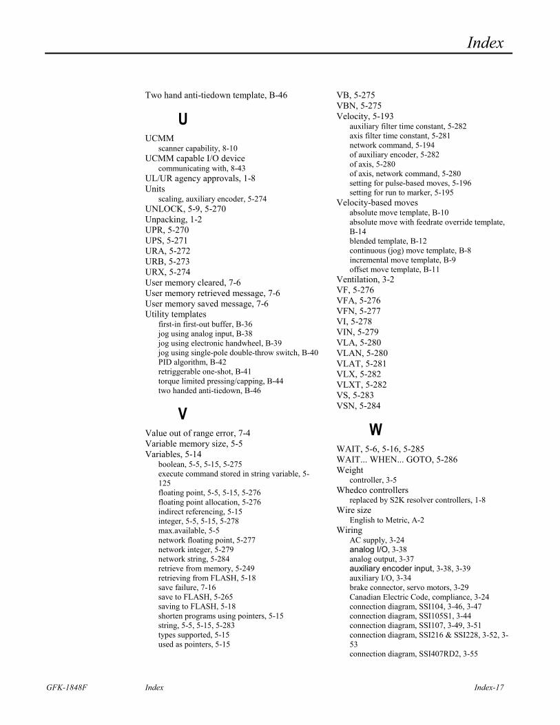
Index
GFK-1848F Index Index-17
Two hand anti-tiedown template, B-46
U UCMM
scanner capability, 8-10 UCMM capable I/O device
communicating with, 8-43 UL/UR agency approvals, 1-8 Units
scaling, auxiliary encoder, 5-274 UNLOCK, 5-9, 5-270 Unpacking, 1-2 UPR, 5-270 UPS, 5-271 URA, 5-272 URB, 5-273 URX, 5-274 User memory cleared, 7-6 User memory retrieved message, 7-6 User memory saved message, 7-6 Utility templates
first-in first-out buffer, B-36 jog using analog input, B-38 jog using electronic handwheel, B-39 jog using single-pole double-throw switch, B-40 PID algorithm, B-42 retriggerable one-shot, B-41 torque limited pressing/capping, B-44 two handed anti-tiedown, B-46
V Value out of range error, 7-4 Variable memory size, 5-5 Variables, 5-14
boolean, 5-5, 5-15, 5-275 execute command stored in string variable, 5-125 floating point, 5-5, 5-15, 5-276 floating point allocation, 5-276 indirect referencing, 5-15 integer, 5-5, 5-15, 5-278 max.available, 5-5 network floating point, 5-277 network integer, 5-279 network string, 5-284 retrieve from memory, 5-249 retrieving from FLASH, 5-18 save failure, 7-16 save to FLASH, 5-265 saving to FLASH, 5-18 shorten programs using pointers, 5-15 string, 5-5, 5-15, 5-283 types supported, 5-15 used as pointers, 5-15
VB, 5-275 VBN, 5-275 Velocity, 5-193
auxiliary filter time constant, 5-282 axis filter time constant, 5-281 network command, 5-194 of auxiliary encoder, 5-282 of axis, 5-280 of axis, network command, 5-280 setting for pulse-based moves, 5-196 setting for run to marker, 5-195
Velocity-based moves absolute move template, B-10 absolute move with feedrate override template, B-14 blended template, B-12 continuous (jog) move template, B-8 incremental move template, B-9 offset move template, B-11
Ventilation, 3-2 VF, 5-276 VFA, 5-276 VFN, 5-277 VI, 5-278 VIN, 5-279 VLA, 5-280 VLAN, 5-280 VLAT, 5-281 VLX, 5-282 VLXT, 5-282 VS, 5-283 VSN, 5-284
W WAIT, 5-6, 5-16, 5-285 WAIT... WHEN... GOTO, 5-286 Weight
controller, 3-5 Whedco controllers
replaced by S2K resolver controllers, 1-8 Wire size
English to Metric, A-2 Wiring
AC supply, 3-24 analog I/O, 3-38 analog output, 3-37 auxiliary encoder input, 3-38, 3-39 auxiliary I/O, 3-34 brake connector, servo motors, 3-29 Canadian Electric Code, compliance, 3-24 connection diagram, SSI104, 3-46, 3-47 connection diagram, SSI105S1, 3-44 connection diagram, SSI107, 3-49, 3-51 connection diagram, SSI216 & SSI228, 3-52, 3-53 connection diagram, SSI407RD2, 3-55
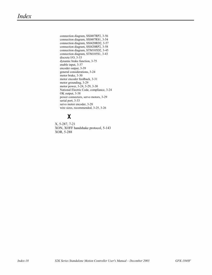
Index
Index-18 S2K Series Standalone Motion Controller User's Manual – December 2003 GFK-1848F
connection diagram, SSI407RP2, 3-56 connection diagram, SSI407RS1, 3-54 connection diagram, SSI420RD2, 3-57 connection diagram, SSI420RP2, 3-58 connection diagram, STM105D2, 3-45 connection diagram, STM105S1, 3-43 discrete I/O, 3-33 dynamic brake function, 3-75 enable input, 3-37 encoder output, 3-39 general considerations, 3-24 motor brake, 3-30 motor encoder feedback, 3-31 motor grounding, 3-29 motor power, 3-24, 3-29, 3-30 National Electric Code, compliance, 3-24 OK output, 3-38 power connectors, servo motors, 3-29 serial port, 3-33 servo motor encoder, 3-28 wire sizes, recommended, 3-25, 3-26
X X, 5-287, 7-21 XON, XOFF handshake protocol, 5-143 XOR, 5-288
Copyright © 2022 FDOKUMEN