Stationary Frame Voltage Harmonic Controller for Standalone Power Generation
10
Stationary Frame Voltage Harmonic Controller for Standalone Power Generation Arkadiusz Kulka, Tore Undeland, Sergio Vazquez 2 , Leopoldo G. Franquelo 2 Norwegian University of Science and Technology O.S. Bragstadsplass 2E, Trondheim, Norway +47 73594241 E-mail: {arkadiusz.kulka, tore.undeland}@elkraft.ntnu.no URL: http://www.elkraft.ntnu.no/eno 2 Escuela Superior de Ingenieros University of Seville, Spain E-mail: {svazquez, leopoldo}@gte.esi.us.es Keywords «Uninterruptible Power Supply», «Distributed power generation», «Voltage control», «Renewable energy», «parallel operation» Abstract The paper presents a new control scheme for voltage control of voltage source inverter (VSI) with LC output filter. Proposed high performance control scheme with use of stationary regulators can be used in UPS or standalone power generation where sine wave output voltage is to be maintained. The proposed controller is able to compensate voltage distortion from unbalanced and nonlinear loads, thus controlling negative and positive voltage sequence and its harmonics. For the control purpose only voltage measurement in required. Besides, the controller can be further used in distributed power generation where the parallel operation is desired. In order to improve the parallel operation and sharing any kind of distorting loads, the proposed controller allows adjusting the gain of selected harmonics required for proper harmonic sharing. The proposed scheme is fully appropriate for digital implementation of UPS systems where high quality AC output voltage is in importance. The diagram block of the proposed controller is shown together with some simulation and experimental results. Presented controller shows outstanding performance under nonlinear and unbalanced loads which uses selective harmonic compensators. I. Introduction. The main control objective for uninterruptible power supply (UPS) and stand-alone inverters is to track a pure sinusoidal voltage reference, providing an output voltage without harmonic content in spite of non-linear or unbalanced loads. Several codes and international standards limit the harmonic content of the output voltage in this kind of systems [15],[16]. Linear control technique, like PI controllers in stationary frame, has been widely used in those applications, however this technique does not complies with the codes. Besides, with the aim to reduce the weight, size and cost of the overall system and to increase the bandwidth of control, the LC output filter has been introduced. Moreover employing LCL output filter is shown in [2]. It is well known that these kinds of filters have a resonant peak that can make the system unstable. For all these reasons, new control strategies have been developed to accomplish with standards and to avoid systems instabilities. Among these control strategies can be notice linear PI regulators in synchronous frame [12], non-linear controllers like Resonant regulators [1][3][6][11], state feedback controllers[4], adaptive controllers[8], predictive controllers and repetitive controllers [7]. This paper presents a new current sensor-less control scheme for voltage control of VSI with LC output filter; the proposed controller uses resonant compensators for voltage harmonic control of
Transcript of Stationary Frame Voltage Harmonic Controller for Standalone Power Generation
Stationary Frame Voltage Harmonic Controller for Standalone Power Generation
Arkadiusz Kulka, Tore Undeland, Sergio Vazquez2, Leopoldo G. Franquelo2
Norwegian University of Science and Technology O.S. Bragstadsplass 2E, Trondheim, Norway
+47 73594241 E-mail: {arkadiusz.kulka, tore.undeland}@elkraft.ntnu.no
URL: http://www.elkraft.ntnu.no/eno 2Escuela Superior de Ingenieros
University of Seville, Spain E-mail: {svazquez, leopoldo}@gte.esi.us.es
Keywords «Uninterruptible Power Supply», «Distributed power generation», «Voltage control», «Renewable energy», «parallel operation»
Abstract The paper presents a new control scheme for voltage control of voltage source inverter (VSI) with LC output filter. Proposed high performance control scheme with use of stationary regulators can be used in UPS or standalone power generation where sine wave output voltage is to be maintained. The proposed controller is able to compensate voltage distortion from unbalanced and nonlinear loads, thus controlling negative and positive voltage sequence and its harmonics. For the control purpose only voltage measurement in required. Besides, the controller can be further used in distributed power generation where the parallel operation is desired. In order to improve the parallel operation and sharing any kind of distorting loads, the proposed controller allows adjusting the gain of selected harmonics required for proper harmonic sharing. The proposed scheme is fully appropriate for digital implementation of UPS systems where high quality AC output voltage is in importance. The diagram block of the proposed controller is shown together with some simulation and experimental results. Presented controller shows outstanding performance under nonlinear and unbalanced loads which uses selective harmonic compensators.
I. Introduction. The main control objective for uninterruptible power supply (UPS) and stand-alone inverters is to track a pure sinusoidal voltage reference, providing an output voltage without harmonic content in spite of non-linear or unbalanced loads. Several codes and international standards limit the harmonic content of the output voltage in this kind of systems [15],[16]. Linear control technique, like PI controllers in stationary frame, has been widely used in those applications, however this technique does not complies with the codes. Besides, with the aim to reduce the weight, size and cost of the overall system and to increase the bandwidth of control, the LC output filter has been introduced. Moreover employing LCL output filter is shown in [2]. It is well known that these kinds of filters have a resonant peak that can make the system unstable. For all these reasons, new control strategies have been developed to accomplish with standards and to avoid systems instabilities. Among these control strategies can be notice linear PI regulators in synchronous frame [12], non-linear controllers like Resonant regulators [1][3][6][11], state feedback controllers[4], adaptive controllers[8], predictive controllers and repetitive controllers [7]. This paper presents a new current sensor-less control scheme for voltage control of VSI with LC output filter; the proposed controller uses resonant compensators for voltage harmonic control of
inverter, and is able to achieve zero-steady-state error and selective harmonic compensation. Proposed high performance control scheme can be used in UPS or standalone power generation applications. Additionally this controller is suitable to use in different paralleling schemes where nonlinear loads must be shared [13][14]. For proper sharing it has the possibility of adjusting the gain of individual voltage harmonics. The harmonic rejection block is also able to operate in wide frequency range of fundamental frequency which is required in various methods of droop for sharing controls. This paper is organized as follows, first a system description and a review of the voltage harmonic compensation in synchronous and stationary frames is introduced, second the proposed control strategy is presented and validated with some simulation results, then, experimental results are shown to demonstrate the high performance achieved with the proposed controller. Finally some conclusions are included to summary the properties of the controller.
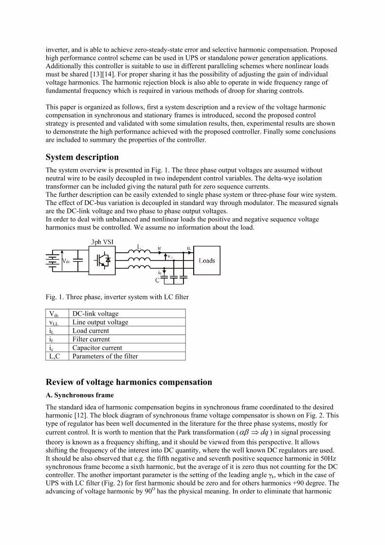
System description The system overview is presented in Fig. 1. The three phase output voltages are assumed without neutral wire to be easily decoupled in two independent control variables. The delta-wye isolation transformer can be included giving the natural path for zero sequence currents. The further description can be easily extended to single phase system or three-phase four wire system. The effect of DC-bus variation is decoupled in standard way through modulator. The measured signals are the DC-link voltage and two phase to phase output voltages. In order to deal with unbalanced and nonlinear loads the positive and negative sequence voltage harmonics must be controlled. We assume no information about the load.
Fig. 1. Three phase, inverter system with LC filter Vdc DC-link voltage vLL Line output voltage iL Load current if Filter current ic Capacitor current L,C Parameters of the filter
Review of voltage harmonics compensation A. Synchronous frame
The standard idea of harmonic compensation begins in synchronous frame coordinated to the desired harmonic [12]. The block diagram of synchronous frame voltage compensator is shown on Fig. 2. This type of regulator has been well documented in the literature for the three phase systems, mostly for current control. It is worth to mention that the Park transformation ( dq⇒αβ ) in signal processing theory is known as a frequency shifting, and it should be viewed from this perspective. It allows shifting the frequency of the interest into DC quantity, where the well known DC regulators are used. It should be also observed that e.g. the fifth negative and seventh positive sequence harmonic in 50Hz synchronous frame become a sixth harmonic, but the average of it is zero thus not counting for the DC controller. The another important parameter is the setting of the leading angle γk, which in the case of UPS with LC filter (Fig. 2) for first harmonic should be zero and for others harmonics +90 degree. The advancing of voltage harmonic by 90O has the physical meaning. In order to eliminate that harmonic

from the output voltage the control must start injecting this harmonic voltage from inverter side 90O earlier than it was detected at output voltage. The method of decomposition into separate harmonics easily allows us to do any phase shifting. The corresponding harmonic current will be 90 degree delayed to that voltage. The disturbing current from the load will match the correcting current from inductor and there will be no distortion in the output voltage. There should be also added the angle compensation for the system delay which is important for compensation of higher harmonics.
Fig. 2 Conventional synchronous frame voltage harmonic compensator The main disadvantage of using many harmonics compensator in the control is the computational complexity related to modulation and demodulation (Park and Park-1) of each harmonic. There is also need to derive for each harmonic accurate synchronous frame reference signal. Another drawback is that scheme is not able to compensate negative sequence harmonics, if only positive sequence harmonics are implemented.
B. Stationary frame ac compensator
It is possible to derive stationary frame ac harmonic compensator based on synchronous frame which will achieve zero phase and magnitude error [6],[9]. The derivation is based on a frequency ω shifting property of a PI regulator, )()()( ωω jsGjsGsG DCDCAC ++−= The transient response of the two controllers will be identical regardless whether they are implemented in stationary frame as an ac compensator or in synchronous frame as a dc compensator.
Fig. 3a) synchronous frame compensator, 3b) equivalent compensator in stationary frame The synchronous regulator shown in Fig. 3a can be represented in stationary reference frame as (1)
22
)sin()cos()(ω
γωγ+
⋅−⋅⋅=
ssKsHac i (1)
Reassembling equation for leading angles of 0 and -90 degree gives:
a) b)
20
20_ )(ω+⋅
+=s
sKKsH ipAC (2)
20
290_ )(ωω
+⋅
+=sKKsH i
pAC (3)
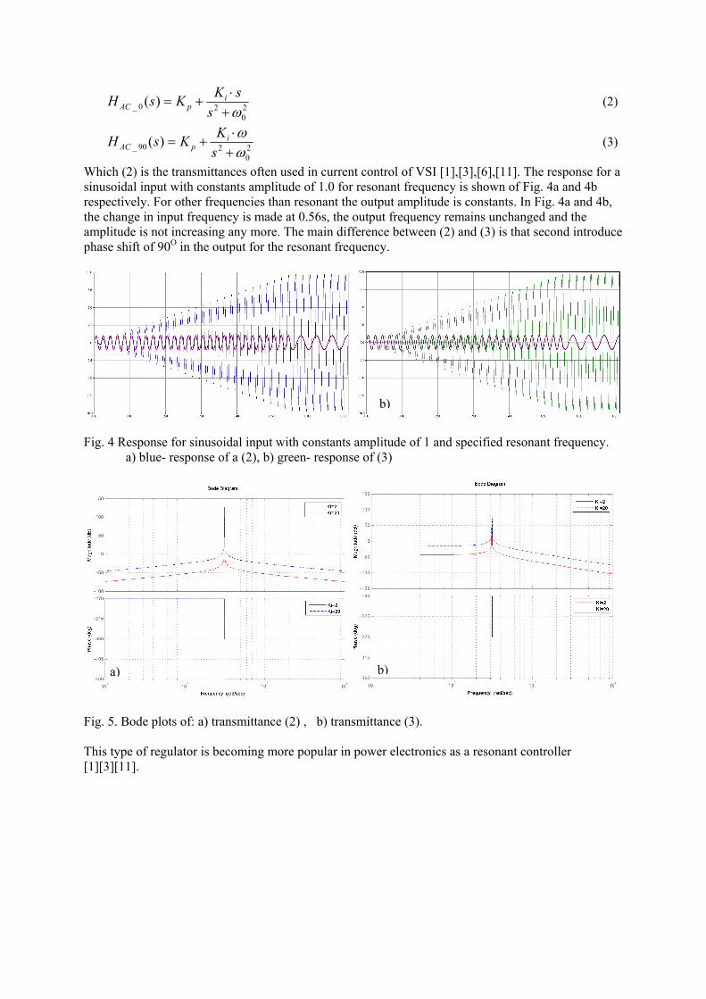
Which (2) is the transmittances often used in current control of VSI [1],[3],[6],[11]. The response for a sinusoidal input with constants amplitude of 1.0 for resonant frequency is shown of Fig. 4a and 4b respectively. For other frequencies than resonant the output amplitude is constants. In Fig. 4a and 4b, the change in input frequency is made at 0.56s, the output frequency remains unchanged and the amplitude is not increasing any more. The main difference between (2) and (3) is that second introduce phase shift of 90O in the output for the resonant frequency.
Fig. 4 Response for sinusoidal input with constants amplitude of 1 and specified resonant frequency. a) blue- response of a (2), b) green- response of (3)
Fig. 5. Bode plots of: a) transmittance (2) , b) transmittance (3). This type of regulator is becoming more popular in power electronics as a resonant controller [1][3][11].
b)
a) b)
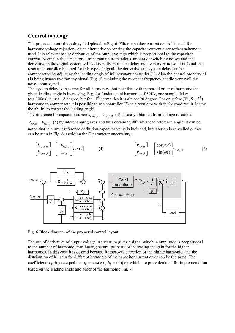
Control topology The proposed control topology is depicted in Fig. 6. Filter capacitor current control is used for harmonic voltage rejection. As an alternative to sensing the capacitor current a sensorless scheme is used. It is relevant to use derivative of the output voltage which is proportional to the capacitor current. Normally the capacitor current contain tremendous amount of switching noises and the derivative in the digital system will additionally introduce delay and even more noise. It is found that resonant controller is suited for this type of signal, the derivative and system delay can be compensated by adjusting the leading angle of full resonant controller (1). Also the natural property of (1) being insensitive for any signal (Fig. 4) excluding the resonant frequency handle very well the noisy input signal. The system delay is the same for all harmonics, but note that with increased order of harmonic the given leading angle is increasing. E.g. for fundamental harmonic of 50Hz, one sample delay (e.g.100us) is just 1.8 degree, but for 11th harmonics it is almost 20 degree. For only few (3rd, 5th, 7th) harmonic to compensate it is possible to use controller (2) as a regulator with fairly good result, losing the ability to correct the leading angle. The reference for capacitor current βα ,, CrefCref ii (4) is easily obtained from voltage reference
βα ,, refref vv (5) by interchanging axes and thus obtaining 90O advanced reference angle. It can be noted that in current reference definition capacitor value is included, but later on is cancelled out as can be seen in Fig. 6, avoiding the C parameter uncertainty.
[ ]Cvv
ii
ref
ref
refC
refC ⋅⎥⎦
⎤⎢⎣
⎡−=⎥
⎦
⎤⎢⎣
⎡ω
α
β
β
α
,
,
,,
,, (4) refdref
ref vtt
vv
,,
,
)sin()cos(⋅⎥⎦
⎤⎢⎣
⎡=⎥
⎦
⎤⎢⎣
⎡ωω
β
α (5)
Fig. 6 Block diagram of the proposed control layout The use of derivative of output voltage in spectrum gives a signal which in amplitude is proportional to the number of harmonic, thus having natural property of increasing the gain for the higher harmonics. In this case it is desired because it improves detection of the higher harmonic, and the distribution of Kii gain for different harmonic of the capacitor current error can be the same. The coefficients ak, bk are equal to: )cos(γ=ka , )sin(γ=kb which are pre-calculated for implementation based on the leading angle and order of the harmonic Fig. 7.
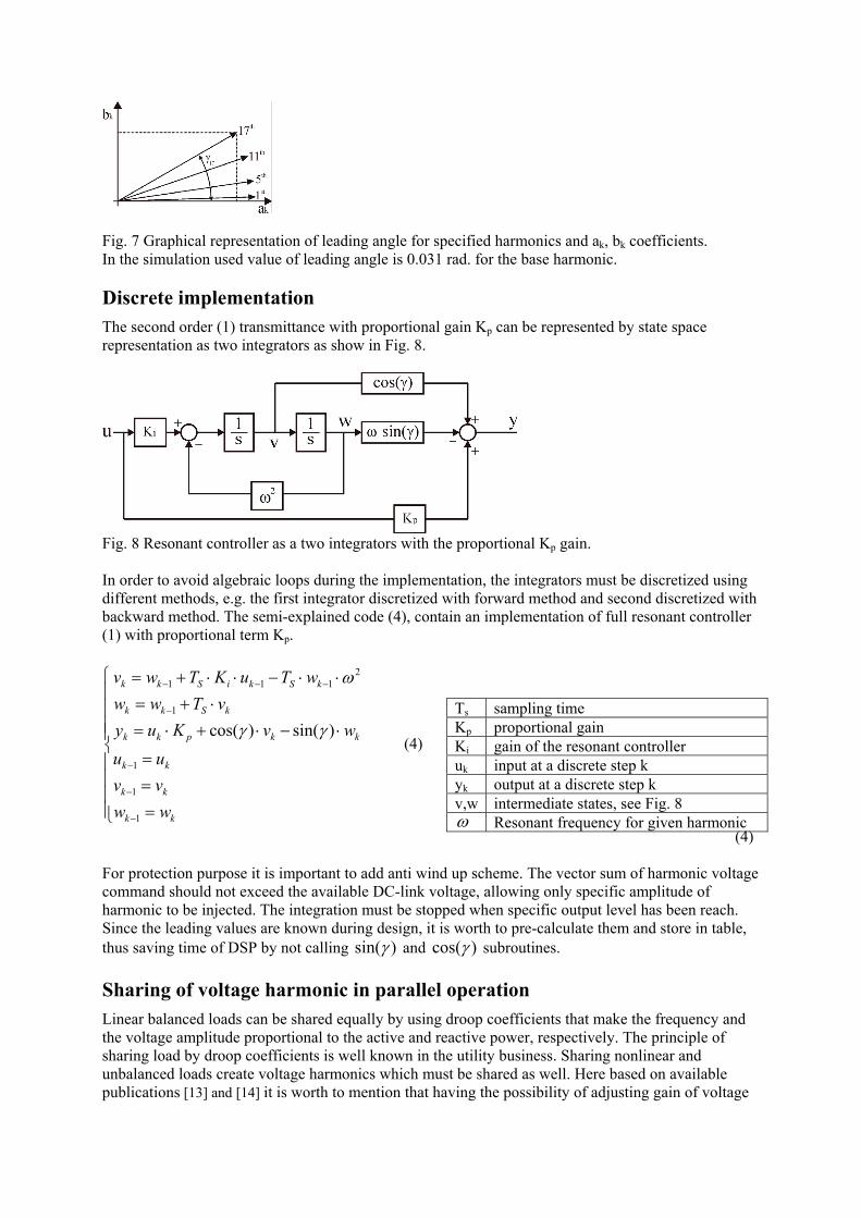
Fig. 7 Graphical representation of leading angle for specified harmonics and ak, bk coefficients. In the simulation used value of leading angle is 0.031 rad. for the base harmonic.
Discrete implementation The second order (1) transmittance with proportional gain Kp can be represented by state space representation as two integrators as show in Fig. 8.
Fig. 8 Resonant controller as a two integrators with the proportional Kp gain. In order to avoid algebraic loops during the implementation, the integrators must be discretized using different methods, e.g. the first integrator discretized with forward method and second discretized with backward method. The semi-explained code (4), contain an implementation of full resonant controller (1) with proportional term Kp.
⎪⎪⎪⎪
⎩
⎪⎪⎪⎪
⎨
⎧
===
⋅−⋅+⋅=⋅+=
⋅⋅−⋅⋅+=
−
−
−
−
−−−
kk
kk
kk
kkpkk
kSkk
kSkiSkk
wwvvuu
wvKuyvTww
wTuKTwv
1
1
1
1
2111
)sin()cos( γγ
ω
(4)
(4) For protection purpose it is important to add anti wind up scheme. The vector sum of harmonic voltage command should not exceed the available DC-link voltage, allowing only specific amplitude of harmonic to be injected. The integration must be stopped when specific output level has been reach. Since the leading values are known during design, it is worth to pre-calculate them and store in table, thus saving time of DSP by not calling )sin(γ and )cos(γ subroutines.
Sharing of voltage harmonic in parallel operation Linear balanced loads can be shared equally by using droop coefficients that make the frequency and the voltage amplitude proportional to the active and reactive power, respectively. The principle of sharing load by droop coefficients is well known in the utility business. Sharing nonlinear and unbalanced loads create voltage harmonics which must be shared as well. Here based on available publications [13] and [14] it is worth to mention that having the possibility of adjusting gain of voltage
Ts sampling time Kp proportional gain Ki gain of the resonant controller uk input at a discrete step k yk output at a discrete step k v,w intermediate states, see Fig. 8 ω Resonant frequency for given harmonic
controller proportional to the amount of delivered VA of that harmonic, a proper sharing of nonlinear and unbalanced loads can be handled. In various droop method the output frequency is also varied more than in utility grid, and this controller is suitable for this operation. For example the repetitive control schemes [7] are not well suited to wide base frequency variation due to algorithm in which the base frequency is highly related to sampling frequency, instead they shown good performance for fix output frequency, operating as a standalone.
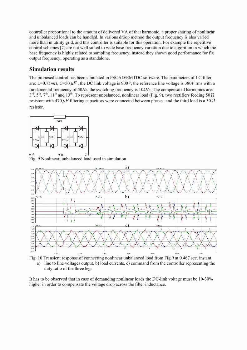
Simulation results The proposed control has been simulated in PSCAD/EMTDC software. The parameters of LC filter are: L=0.75mH, C=50 Fμ , the DC link voltage is 900V, the reference line voltage is 380V rms with a fundamental frequency of 50Hz, the switching frequency is 10kHz. The compensated harmonics are: 3rd, 5th, 7th, 11th and 13th. To represent unbalanced, nonlinear load (Fig. 9), two rectifiers feeding 50Ω resistors with 470 Fμ filtering capacitors were connected between phases, and the third load is a 30Ω resistor.
Fig. 9 Nonlinear, unbalanced load used in simulation
Fig. 10 Transient response of connecting nonlinear unbalanced load from Fig 9 at 0.467 sec. instant.
a) line to line voltages output, b) load currents, c) command from the controller representing the duty ratio of the three legs
It has to be observed that in case of demanding nonlinear loads the DC-link voltage must be 10-30% higher in order to compensate the voltage drop across the filter inductance.
a)
c)
b)
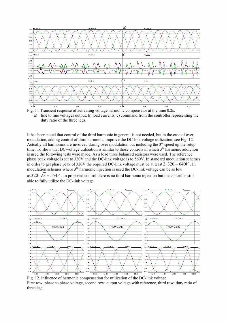
Fig. 11 Transient response of activating voltage harmonic compensator at the time 0.2s.
a) line to line voltages output, b) load currents, c) command from the controller representing the duty ratio of the three legs.
It has been noted that control of the third harmonic in general is not needed, but in the case of over-modulation, adding control of third harmonic, improve the DC-link voltage utilization, see Fig. 12. Actually all harmonics are involved during over modulation but including the 3rd speed up the setup time. To show that DC-voltage utilization is similar to those controls in which 3rd harmonic addiction is used the following tests were made. As a load three balanced resistors were used. The reference phase peak voltage is set to 320V and the DC-link voltage is to 560V. In standard modulation schemes in order to get phase peak of 320V the required DC-link voltage must be at least V6403202 =⋅ . In modulation schemes where 3rd harmonic injection is used the DC-link voltage can be as low as V5543320 =⋅ . In proposed control there is no third harmonic injection but the control is still able to fully utilize the DC-link voltage.
Fig. 12. Influence of harmonic compensation for utilization of the DC-link voltage. First row: phase to phase voltage, second row: output voltage with reference, third row: duty ratio of three legs.
a)
c)
b)

First column: the command is only the reference voltage, the output voltage THD is 3.6% Second column: the first harmonic voltage (Kiv=50) and Kpv=0.5 is enabled, the THD is 2.9% Third column: additionally the harmonic compensation is enabled with Kii=0.1, the THD drop to 0.6%. Its proof that harmonic compensator can handle nonlinear loads and fully utilize DC-link voltage.
Experimental results The control has been verified on 10kW, three phase inverter equipped with LC filter with parameters: L=0.75mH and C=50 Fμ . The control has been implemented on floating point DSP, TMS320VC33. The used parameters are: Kpv=0.4, Kiv=20, Kii=0.05, Kpi=1m, the controlled harmonics are: 3rd, 5th, 7th, 11th, 13th and 17th. The load is composed of three single phase rectifiers feeding parallel connected resistors of 15Ω and capacitor of 2200 Fμ . The DC-link voltage is 150V, and the commanded phase to phase rms voltage is 50V.
Fig. 13 Voltage and current of rectifier load, harmonic compensation enabled.
Fig. 14 Voltage and current on nonlinear load with parallel connected three resistors. Harmonic compensation enabled.
Fig. 15 Spectrum of the phase to phase output voltage, with voltage harmonic compensation.
Fig. 16 Voltages and current for the rectifier load when the harmonic compensation is disabled.
For clarity only one phase measurements are shown, the others two phases are very similar. The scaling for current measurement is 10A/div. The measured voltage distortion, when harmonic compensation is enabled is 0.8 % THD (Fig. 13). In Fig. 15 the difference between first harmonic and the highest amplitude of unwanted harmonic is 48dB, which is a great result. Fig. 16 is included just for comparisons, without any compensation the measured voltage THD is 7.8%.

Conclusions In this paper the estimated filter capacitor current controlled by Proportional Resonant (PR) controller is shown. The suitability for three phase voltage control of VSI has been presented. The PR controller can successfully replace the typical dq-PI control method, gaining improved harmonic rejection capability and advantages of reduction complexity and computational cost. The resonant controller frequency can be tuned on-line to follow the frequency changes required in various droop methods for power sharing. The experimental results show that proposed controller has high performance behavior for any kind of load including non-linear unbalanced loads. The proposed control uses only voltage measurement for control purpose.
References [1] R. Teodorescu, F. Blaabjerg, M. Liserre and P.C. Loh, “Proportional-resonant controllers and filters for grid-
connected voltage-source converters”, IEEE Pros.-Electr. Power Appl., Vol. 153, No. 5, Septempber 2006 [2] P.C. Loh, D. G. Holmes, “Analysis of Multiloop Control Strategies for LC/CL/LCL-Filtered Voltage-Source
and Current-Source Inverters”, IEEE Trans. Ind. Appl. Vol. 41, no. 2, March/April 2005 [3] G. Escobar, A.M. Stankovic, V.Cardenas, P.Mattavelli, “A controller based on resonant filters for a series
active filter used to compensate current harmonics and voltage unbalance”, IEEE Conf. Control App., 2002 [4] M.J. Ryan, W.E. Brumsickle, R.D. Lorenz, “Control Topology Options for Single-Phase UPS Inverters”,
IEEE Trans. Ind. Appl. Vol. 33, no. 2, March/April 1997 [5] P. Mattavelli, “Synchronous-frame harmonic control for high-performance AC power supplies”, IEEE
Trans. Ind. Appl. Vol. 37, no. 3, May/June 2001 [6] D.N. Zmood, D.G. Holmes, “Stationary frame current regulation of PWM inverters with zero steady-state
error”, IEEE Trans. Power Elec., vol. 18, no. 3, may 2003 [7] G. Escobar, A. A. Valdez, J. Leyva-Ramos, P. Mattavelli, “Repetitive-Based Controller for a UPS Inverter
to Compensate Unbalance and Harmonic Distortion”, [8] G. Escobar, P. Mattavelli, A. M. Stankovic, A.A. Valdez, J.L. Ramos, “An Adaptive Control for UPS to
Compensate Unbalance and Harmonic Distortion Using a Combined Capacitor/Load Current Sensing” IEEE 2005
[9] D. N. Zmood, D. G. Holmes, and G. H. Bode, “Frequency-domain analysis of three-phase linear current regulators”, IEEE Trans. Ind. Appl., vol. 37, no. 2, pp. 601-610, March/April 2001.
[10] P. Mattavelli, “A closed-loop selective harmonic compensation for active filters”, IEEE Trans. Ind. Appl., Vol.37, no. 1, pp. 81-89, Jan./Febr. 2001
[11] M. Liserre, R. Teodorescu, F. Blaabjerg, “Multiple Harmonics Control for Three-Phase Grid Converter Systems With the Use of PI-RES Current Controller in a Rotating Frame”, IEEE Trans. Power Elec., Vol. 21, no. 3, May 2006
[12] K.H. Kim, N.J. Park, D.S. Hyun, “Advanced Synchronous Reference Frame Controller for three-Phase UPS Powering Unbalanced and Nonlinear Loads”;, IEEE 2005, p.1699
[13] A. Tuladhar, H. Jin, T. Unger, and K. Mauch, “Parallel operation of single phase inverter modules with no control interconnections,” in Proc. IEEE APEC’97, vol. 1, 1997, pp. 94–100.
[14] A. Tuladhar, H. Jin, T. Unger, and K. Mauch, “Control of parallel inverters in distributed AC power systems with consideration of the line impedance effect,”. IEEE Trans. Ind. Appl. Vol. 36, No. 1, January/February 2000.
[15] Part 3: Method of specifying the performance and test requirements, IEC 62040-3 International Standard, 2001.
[16] Voltage characteristics of electricity supplied by public distribution networks, EN 50160 International Standard, 2006.