Digital Surveillance System Triplex Standalone DVR User's ...
27
Digital Surveillance System Triplex Standalone DVR User’s Manual (V2.1) KS-MA3000V20-EN Table of Contents Precautions for safety…………………………………………………………………….2 Package Content…………………………………………………………………………...2 DVR Introduction…………………………………………………………………………...2 1. Product Overview……………………………………………………………….3 2. Front Panel………………………………………………………………………3 3. Rear Panel………………………………………………………………………4 4. IR Remote Controller(Optional)……………………………………………….5 System Setup and Installation…………………………………………………………...5 1 Hard Disk Drive Installation…………………………………………………….5 1.1 Install the internal hard disk drive………………………………………5 1.2 Install DVD±RW or mobile rack for removable hard disk drive…...…6 2 Video Format Selection…………………………………………………………6 3 Monitor Connection……………………………………………………………...6 4 Camera Connection……………………………………………………………..7 5 USB & PS/2 Connection………………………………………………………..7 6 Sensor Installation……………………………………………………………….7 7 Alarm Installation………………………………………………………………...8 8 Network Connection…………………………………………………………….8 Getting Start Operation……………………………………………………………………9 1. Start Up the DVR System……………………………………………………….9 2. Main Screen…………………………………………………………………...…9 3. Set Up…………………………………………………………………………...10 3.1 Log In…………………………………………………………………….10 3.2 Camera Setting………………………………………………………….10 3.3 Record Setting…………………………………………………………..10 3.4 Sensor Setting…………………………………………………………..11 3.5 Motion Detection Setting……………………………………………….11 3.6 Screen Adjustment……………………………………………………...12 3.7 Audio Setting…………………………………………………………….12 3.8 System Setting…………………………………………………………..12
-
Upload
khangminh22 -
Category
Documents
-
view
5 -
download
0
Transcript of Digital Surveillance System Triplex Standalone DVR User's ...

Digital Surveillance System
Triplex Standalone DVR
User’s Manual
(V2.1)
KS-MA3000V20-EN
Table of Contents Precautions for safety…………………………………………………………………….2
Package Content…………………………………………………………………………...2 DVR Introduction…………………………………………………………………………...2
1. Product Overview……………………………………………………………….3
2. Front Panel………………………………………………………………………3
3. Rear Panel………………………………………………………………………4
4. IR Remote Controller(Optional)……………………………………………….5
System Setup and Installation…………………………………………………………...5 1 Hard Disk Drive Installation…………………………………………………….5
1.1 Install the internal hard disk drive………………………………………5
1.2 Install DVD±RW or mobile rack for removable hard disk drive…...…6
2 Video Format Selection…………………………………………………………6
3 Monitor Connection……………………………………………………………...6
4 Camera Connection……………………………………………………………..7
5 USB & PS/2 Connection………………………………………………………..7
6 Sensor Installation……………………………………………………………….7
7 Alarm Installation………………………………………………………………...8
8 Network Connection…………………………………………………………….8
Getting Start Operation……………………………………………………………………9 1. Start Up the DVR System……………………………………………………….9
2. Main Screen…………………………………………………………………...…9
3. Set Up…………………………………………………………………………...10
3.1 Log In…………………………………………………………………….10
3.2 Camera Setting………………………………………………………….10
3.3 Record Setting…………………………………………………………..10
3.4 Sensor Setting…………………………………………………………..11
3.5 Motion Detection Setting……………………………………………….11
3.6 Screen Adjustment……………………………………………………...12
3.7 Audio Setting…………………………………………………………….12
3.8 System Setting…………………………………………………………..12

2
3.8.1 Hard Disc Setup……………………………………………….12
3.8.2 Password Change…………………………………………….13
3.8.3 Time Set………………………………………………………..13
3.8.4 Event List……………………………………………………….13
3.8.5 Network…………………………………………………………14
3.8.6 RS-485………………………………………………………….15
3.8.7 Pan/Tilt/Zoom Device.………………………………………...15
3.8.8 Firmware Upgrade…………………………………………….15
3.8.9 Load Active-X Control…………………………………………15
3.9 Video Search…………………………………………………………….15
3.10 Language Selection…………………………………………………….15
3.11 Save System Setup…………………………………………………….16
3. Playback………………………………………………………………………...16
4. Back Up…………………………………………………………………………16
4.1 Back up via USB flash disc…………………………………………….16
4.2 Back up via internal CD-RW or DVD±RW Drive……………………..16
Player and Remote Monitoring…………………………………………………………17 1 Triplex Viewer – Player………………………………………………………..17
1.1 Main function menu& Display Screen………………………………..17
1.2 Play back with saved video data………………………………………18
1.3 Convert Video Format as standard AVI format……………………...19
2 Triplex Viewer – Net Viewer…………………………………………………..20
2.1 Main function menu& Display screen………………………………...20
2.2 Connect PC to DVR through local area network (network hub)……20
2.3 Connect PC to DVR through cross-over cable………………………21
3 Remote Monitoring through IE Browser……………………………………..22
4 DDNS Setup……………………………………………………………………24
Appendix A – Recommended HDD………………………………………………………26
Appendix B – Record Time Table………………………………………………………...27
Appendix C – Camera Installation Guide………………………………………………..27
Copyright Notice All rights reserved. No part of this specification may be reproduced or transmitted in
any form or by any means, or any information storage and retrieval system. No patent
rights or licenses to any of the circuits described herein are implied or granted to any
third party. Precautions for Safety For your safety, unplugging the power before moving the DVR, installing, or
replacing any parts or hard drive.
Keep DVR in a well-ventilated place and away from any heat generating object.
Do not install the equipment in a location subject to direct sunlight, or a location
near heat sources.
Keep the DVR in a temperature ranging 5℃ ~ 45℃, avoid a place of high
temperature and humidity.
Avoid mechanical shock to the equipment.
If you are not sure of the installation and setup, please consult the technicians. Package Contents 1. Triplex Standalone DVR Series DVR Main Unit
2. Power Adaptor & AC Power Cord
3. Software & User Manual CD for Installation
4. Optional Choice
CD-RW/DVD±RW
Mobile Rack
Remote Controller with AAA battery * 2
PS/2 Mouse for 4ch and 8ch, USB Mouse for 16ch
If there is any damage, shortage or inappropriate item in package, please contact with your local dealer.
※ The packing contents may verify by the region, please refer to the description on
package or confirm with your local dealer.

3
DVR Introduction 1、 Product Overview
Triplex Standalone DVR series is a triplex digital video recorder (DVR) system. It
adopts a digital image compression technology to compress the input channel video
streams, and uses HDD to record the compressed video stream. Triplex Standalone
DVR provides up to 16 channels and multiplex functionality. The features of this
equipment are as below:
1. True Triplex Functionality Simultaneously - Playback/ Record/ Network/ Back-up
at the same time.
2. Individual frame rate setting for each channel.
3. Show Video loss/Sensor trigger in event List.
4. RS-485 interface for PTZ Camera control.
5. Easy Firmware Upgrade and back-up via USB flash disc.
6. Multi-user remote control DVR by network.
7. Friendly User Interface
Triplex Standalone DVR series consist 3 product lines of 4, 8 and 16 channels shown
as below:
Triplex Standalone
DVR series
Basic
Function
Optional
Function
Optional Case
(HDD related)*
4-channel
8-channel
16-channel
USB Network DI / DO RS485 VGA Chassis A Chassis B
*Remark: a) Chassis A supports only one HDD (internal).
b) Chassis B supports Mobile Rack for removable HDD or CD-RW/DVD±RW.
2、Front Panel
Triplex Standalone DVR 4/8-channel with Chassis A
Panel A:
Panel B:
4/8 channel with Chassis B for Removable HDD Rack or CD-RW/DVD±RW Drive
16 channel with Chassis B for Removable HDD Rack or CD-RW/ DVD±RW Drive

4
Indicators:
No Button/Name Function
1 ■ STOP Stop playback
2 ►► FF Forward playback
3 ► PLAY Playback / Enter time search for video playback
4 ▌▌ PAUSE Pause playback
5 ◄◄ REW Backward playback
6 SELECT / ENTER To change values on menu.
7 V DOWN Move down through menu list
8 Λ UP Move up through menu list
9 MENU Enter or Exit main menu
10 ● REC Start / Stop manual recording (for all channel)
11 Mode Display screen by sequence, indicate as below
12 IR Receiver Remote controller input receiver
13 ▬ ● Red LED Light Shows HDD is recording or reading
14 ▬ ● Green LED Light Shows DVR is power-on and running
15 Mobile Rack For removable HDD or CD-RW/ DVD±RW driver
16 USB PORT (16CH) Firmware upgrade and back up
Display sequences indicate:
3、Rear Panel
Triplex Standalone DVR 4/8-channel
Triplex Standalone DVR 16-channel
No. Function 1 Main Power Switch 2 S-Video Out (Monitor) 3 VGA Video Out (Monitor) 4 Audio-In / Audio-Out 5 Video In (BNC) 6 BNC Video Out (Monitor) 7 LAN port 8 USB Port (Dedicated for Firmware upgrade and Back up 9 PS/2 Mouse Port 10 AC-DC Power Adapter Jack 11 DI/DO for SENSOR / ALARM / RS485
(4 Sensor Input for 4/8ch, 8 Sensor Input for 16ch) 12 USB Mouse Port (16ch only) 13 Spot Out (with auto skip function, 16ch only)

5
4、IR Remote Controller
No Button/Name Function 1 1~10 (channels) Channel selector (for CH11~CH16, push 10+ and 1~6 )
2 PTZ Start PTZ Camera function
3 REC Start or stop recording
4 ▲UP ▼DOWN
◄LEFT ►RIGHT
Moves Up / Display Sequence 1~16ch
Moves Down / Display 8 Split
Moves Left / Display Sequence 16~1ch
Moves Right / Display 4 Split
5 ENTER Use this button to change or confirm values on menu setting
6 MENU / ZOOM+ Enter or exit the menu / ZOOM in PTZ camera
7 ESC / ZOMM- Leave the menu / ZOOM out PTZ camera
8 PAUSE / IRIS+ Pause playback / IRIS+ PTZ camera
9 STOP / IRIS- Stop playback / IRIS- PTZ camera I
10 REW / FOCUS+ Backward search / FOCUS+ PTZ Camera
11 FF / FOCUS- Forward search / FOCUS- PTZ camera
12 PLAY Enter time search for playback function
System Setup and Installation 1、Hard Disc Drive Installation
1.1 Install the internal hard disc drive
(A) Make sure the DVR power is off before HDD
installation
(B) Unlock the screw and open DVR chassis.
(C) For IDE HDD: Plug in the IDE gray cable into IDE connector of main board, and
connect the HDD’s power cord.
Note: please make
sure the HDD jumper setting as “Master”, or it might disable DVR function. Before installing HDD, please set jumper as “Master” (The jumper setting varies depends on the hard disc drive manufactures. Refer to manufacture’s manual for master jumper setting.
(D) For SATA HDD:
(D-1) Panel A : Plug in the SATA cable into the SATA connector of the main board,
and connect the HDD’s power cord.
(D-2) Panel B : HDD Holders and Screws, please fix the 3rd hole of HDD holders to
HDD driver with screws.
(E) Connect the SATA and power cable to HDD, plug in the SATA cable into the
SATA connector of the main board, and connect the HDD’s power cord.
(E) After installing the HDD, slide in the cover chassis and fasten the screw.
IDE and power cable of HDD, the relative position may different by different manufacture.

6
1.2 Install a CD-RW/DVD±RW or a mobile rack for removable HDD
Chassis B
(A) Firstly, install a HDD into mobile rack, and plug
the mobile rack (or CD-RW/DVD±RW) into
DVR.
(B) Connect the 1 to 2 IDE cable to main board
and mobile rack: Connect one of the black
head to main control board; leave another IDE
cable with black head for embedded HDD
connection. Connect the cable with blue head to the
slot of mobile rack (or CD-RW/DVD±RW), also plug
in the power cord to mobile rack.
(C) Close the top cover of rack and slide the rack into
DVR.
Note: If this removable HDD will be treated as master, please make sure the HDD Jumper setting as “Master” and the other HDD embedded in the chassis must set to be “slave” mode.
※ The total maximal capacity of HDD for Triplex Standalone DVR series is 1TB for
4/8CH, and 2TB for 16CH, both with a 8MB buffer.
2、Video Format Selection
The DVR accept two video formats: NTSC and PAL, it can be changed by adjusting
jumper on main control board.
3、Monitor Connection
Monitor displays live view image and playback recorded video. For Triplex
Standalone DVR, BNC, VGA and S-Video output connectors on rear panel are
offered for connecting to monitor.
4/8CH (NTSC/PAL Selector: JS2) 16CH (NTSC/PAL Selector: JS3)
7
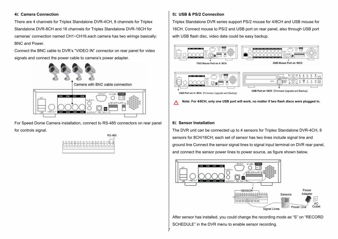
4、Camera Connection
There are 4 channels for Triplex Standalone DVR-4CH, 8 channels for Triplex
Standalone DVR-8CH and 16 channels for Triplex Standalone DVR-16CH for
cameras’ connection named CH1~CH16.each camera has two wirings basically:
BNC and Power.
Connect the BNC cable to DVR’s “VIDEO IN” connector on rear panel for video
signals and connect the power cable to camera’s power adapter.
For Speed Dome Camera installation, connect to RS-485 connectors on rear panel
for controls signal.
5、USB & PS/2 Connection
Triplex Standalone DVR series support PS/2 mouse for 4/8CH and USB mouse for
16CH. Connect mouse to PS/2 and USB port on rear panel, also through USB port
with USB flash disc, video data could be easy backup.
Note: For 4/8CH, only one USB port will work, no matter if two flash discs were plugged in.
6、Sensor Installation
The DVR unit can be connected up to 4 sensors for Triplex Standalone DVR-4CH, 8
sensors for 8CH/16CH; each set of sensor has two lines include signal line and
ground line Connect the sensor signal lines to signal input terminal on DVR rear panel,
and connect the sensor power lines to power source, as figure shown below.
After sensor has installed, you could change the recording mode as “S” on “RECORD
SCHEDULE” in the DVR menu to enable sensor recording.

8
7、Alarm Installation
The DVR has an internal switch for sounding alarm. The switch is normally open, but
when the sensor is triggered, the alarm is activated as well.
Connects the alarm signal lines to alarm switch terminal on rear panel and connect
the alarm power lines to power source.
8、Network Connection
Connect the LAN port on rear panel with router for remote monitoring, recording and
controlling via internet or local area network.
More network connecting information; please refer the Player and Remote Monitoring
chart for Net Viewer setting and remote controlling through IE Browser and DDNS
Setup.
Getting Start Operation 1、Start Up the DVR System
After the DVR unit and all the peripherals are properly installed, the DVR is ready to
record and play. Then apply power and switch on.
After the unit is powered on, the DVR will check HDD for several seconds, and then
DVR will enter into real-time display mode.
When installing a new HDD, please press “►PLAY” to format HDD※
If there is no HDD connected, it will show message as bellow

9
2、Main Screen
1 Channel Display with video channel or video name
2 Recording Mode Display the indication of recording mode: Sensor and Motion
3 Recording Indicator Display DVR operating with recording
4 Video Loss Icon appears with blue screen, the connection with camera not exit
5 Date/Time Display current date and time
6 Sequence Icon only shows in single channel, sequences by setting seconds
7 PTZ Adjustment Display the Zoom/Focus/Iris for PTZ camera
8 Alarm Display when alarm was triggered as alarm was set opened
9 Buzzer Display when sensor triggered as alarm by buzzer was opened
10 HDD Capacity Display total amount of recorded video
3、Set Up 3.1 Log In
The configuration of DVR can be customized by adjusting the menu setting. Press the
MENU button and password to enter setup menu. Password verification screen
displays as bellow.
The default password is “111111”. After entering menu list, use UP/Down and
ENTER button on front panel or remote controller to change the settings.
3.2 Camera Setting The DVR allows separate camera setting for each channel, in this function, users
adjust the video performance and video loss setting as well. Use UP/DOWN button to
move the cursor to select item and use ENTER button to change the setting value.
Channel: Select the channel which would be adjusted
Display: Choose to display the video on screen, or hide the video image as Off

10
Brightness/Contrast/Hue/Saturation: To adjust the image performance by setting
brightness, contrast, hue and saturation adjustment.
Video Loss: Set the Video Loss Alarm as Intermittent or Continues; alarmed by
Buzzer, Alarm Device, Both or Off.
3.3 Record Setting
In this item allows users to set record resolution, record speed, record quality, record
schedule and other recording parameters.
Resolution: The DVR offers two setting option in resolution as 320x224 and 640x224
in 16CH
Record Speed: The record speed could be changed for each channel with frame rate.
The higher the record rate, the more natural while playback. In this field, use LEFT
button to decrease record frame rate, and user RIGHT button to increase record
frame rate for each channel. If the record speed was set to be Off, there will be no
recording action on the channel.
Record Quality: Select the record quality as High, Normal or Low.
Event Rec Duration: Set the record duration from alarm was triggered in 5, 10, 15,
20, 25, 30 seconds.
Record Schedule: The Record Schedule is to set the scheduling record, the
numbers indicate the hour of a day from 00:00(12:00am) to 24:00(12:00pm). Use
RIGHT and LEFT button to move the cursor to indicate hour, and use ENTER button
to change the recording mode by color description on screen. Use ALL button, set the
whole day schedule at one time.
.
3.4 Sensor Setting
The sensor detection will beeped by buzzer on main PCB board or by relay of system,
to set buzzer or alarm device for your requirement in following features.

11
Sensor Type: Select DISABLE to deactivate sensor recording or choose the type of
sensor as NORMAL-CLOSE or NORMAL-OPEN installed in DVR.
In general, three common sensor types are available in home electronic store: (1)
Normal-Close, (2) Normal-Open and (3) Normal-Close & Open. Below is the brief
diagram about how each type of sensor is installed on DVR. The procedure for
sensor installation is shown as below.
Alarm Duration: This item set the alarm duration after alarm is activated as 5, 10, 15,
20, 25, 30 or continue and off.
Alarm by: Select alarm by Buzzer, Alarm Device or Both
3.5 Motion Detection Setting
In this function, by setting motion area, sensitivity and alarm on each channel, the
DVR will start to record on motion detection schedule according to the setting value.
Channel: Select the channel for recording mode.
Sensitivity: Adjust sensitivity of the built-in motion sensor, the most sensitive goes to
1, and the least goes to 4.
Motion Area: Use this option to set the range of motion detection area. Move the
cursor to starting area, press ENTER button in order to start selecting. Use
UP/DOWN/RIGHT/LEFT button move cursor to draw an area, press ENTER again to
set down the selected area.
Alarm Duration: Set the alarm duration since alarm was activated in 5~30 seconds
or Continue and Off.
Alarm by: Select alarm by Buzzer, Alarm Device or Both
3.6 Screen Adjustment
In this function, user can adjust the screen setting with screen location, border line or
auto sequence.
Border: Set the white border line around each channel by selecting ON, and close by
selecting OFF. Video Adjustment: To adjust the horizontal and vertical location of
screen by using UP/DOWN/RIGHT/LEFT button.
Auto Sequence: To setup the sequence for each channel display on full screen from
2 to 30 seconds.

12
3.7 Audio Setting
Change the recorded audio setting by adjusting setup in this item.
Record: Set the record ON to enable audio recording when a microphone device is
connected with AUDIO INPUT port on DVR rear panel.
Mute: Select ON or OFF. To enable the speaker, choose OFF.
Input Volume/ Output Volume: Adjust the input and output volume for speaker and
audio recording.
3.8 System Setting
3.8.1 Hard Disc Setup
Overwrite Enable: Choose “YES” to continue recording and overwrite previous
recording data when hard disc drive space is full; choosing “NO”, recording mode will
stop when hard disc drive is full of capacity.
Format HDD: If the hard disc drive was formatted, all the video data stored will be
deleted, the DVR system supports no restore option once the hard disc drive is
formatted.
When Format HDD, the passwords is needed, key in the password and presses any
button to continue.
When HDD is successfully formatted, the message below will display.
3.8.2 Password Change
Password could be changed for “Menu”, “Record” and “Format HDD” function option.
The default password is “111111”
※ If the password is forgotten, please contact with your local dealer
PASSWORD INPUT : - - - - - -
... PASSWORD OK.. .. HDD WAS FORMATTED..

13
3.8.3 Time Set
Users can set the current date, time and date format in Time Set menu, the menu
displays as follows.
Use UP/DOWN keys to move the cursor to previous or next field, by pressing ENTER
button to select, and use UP/DOWN key to change the value in selected field.
Time Set: set the current date and time
Daylight Saving Time: Choose NO or YES
Date Format: DVR offers two formats with YYYY/MM/DD and DD/MM/YYYY
3.8.4 Event List
EVENT LIST function allows users to playback video by event. The EVENT LIST will
display information contains Power on/off, Record start/stop, Sensor on/off showed
with date and time.
To playback by EVENT LIST, using UP/DOWN keys to move the cursor to select the
event and press PLAY button to playback.
3.8.5 Network Setting
You need to use the network setting information above for real-time network viewing
on PC using “Triplex Viewer” software for remote viewing through Ethernet
connection.
The Triplex Standalone DVR supports three network connections: STATIC, DHCP for
dynamic IP and PPPoE .
For PPPoE, Input your id account and password from ISP and save it, restart the
DVR, and DVR will auto connect to internet

14
For STATIC IP, input your static IP, gateway, net mask and save it, restart the DVR,
and DVR will auto connect to internet
For DHCP, Select DHCP and save it, restart the DVR and system will auto allot a IP
to use.
3.8.6 RS-485
Through RS-485 communication protocol, DVR could control speed dome camera,
adjust the RS-485 setting and setup the PTZ camera features in RS-485 and Pan/Tilt
Device field of menu.
Baud rate: Setup the baud rate of camera from 1200 to 115200
Data Bit: Set the data bit 7 or 8
Parity Bit: set the parity bit in none, odd or even
Stop Bit: set the stop bit in 1 or 2
3.8.7 Pan/Tilt/Zoom Device
Channel: Select the channel where PTZ camera is connected.
ID: Setup the ID of camera
Model: Setup the protocol of camera (only support Protocol D and Li Lin)
15
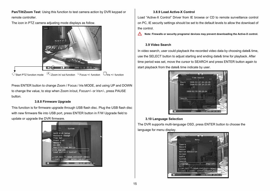
Pan/Tilt/Zoom Test: Using this function to test camera action by DVR keypad or
remote controller.
The icon in PTZ camera adjusting mode displays as follow.
Start PTZ function mode Zoom in/ out function Focus +/- function Iris +/- function
Press ENTER button to change Zoom / Focus / Iris MODE, and using UP and DOWN
to change the value, to stop when Zoom in/out, Focus+/- or Iris+/-, press PAUSE
button. 3.8.8 Firmware Upgrade
This function is for firmware upgrade through USB flash disc. Plug the USB flash disc
with new firmware file into USB port, press ENTER button in F/W Upgrade field to
update or upgrade the DVR firmware.
3.8.9 Load Active-X Control Load “Active-X Control” Driver from IE browse or CD to remote surveillance control
on PC, IE security settings should be set to the default levels to allow the download of
the control.
Note: Firewalls or security programs/ devices may prevent downloading the Active-X control.
3.9 Video Search
In video search, user could playback the recorded video data by choosing date& time,
use the SELECT button to adjust starting and ending date& time for playback. After
time period was set, move the cursor to SEARCH and press ENTER button again to
start playback from the date& time indicate by user.
3.10 Language Selection The DVR supports multi-language OSD, press ENTER button to choose the
language for menu display.

16
3.11 Save System Setup After the DVR setting adjustment is finish, it required to confirm the changes under
EXIT menu.
Exit & Save Change: Save for the system change and exit the menu.
Exit & Discard Change: Not save the system change and exit the menu.
Load Setup Default: back the system setting to default.
4、Playback
To playback, press PLAY button. A Time Search function will display on screen,
please refer to the 「Video Search」part for more information.
5、Back Up
The DVR supports easy video backup via USB flash disc or internal CD-RW /
DVD±RW, please ready your USB flash disc or CD-RW / DVD±RW ready and
connect to your DVR.
Set your DVR in playback mode, press MENU button, a function bar will display on
the button of screen. User could press SELECT button to copy video data In USB
flash disc, or press REC button to copy video data in CD-RW / DVD±RW.
For USB COPY, it will take few minutes to write data into flash disc, the number for
the size of file will keep increasing until the backup is finish.
For CDR COPY, when the backup is finish, CD/ DVD will pop out from the CD-RW/
DVD±RW drive
Notice: Triplex Standalone DVR supports all CD disc, DVD+R disc, for DVD+RW disc only the
on first writing, and not support for DVD-R and DVD-RW disc.
To view the video image saved in backup devices on personal computer, it need the
client software “Triplex Viewer” which provide in software CD.
Player and Remote Monitoring
Triplex Standalone DVR series comes with a software CD named “Triplex Viewer” for
remote monitoring, recording, controlling or video playback on the computer. Two
parts of Triplex Viewer will be introduced as DVR Player and DVR Net Viewer in
following chapter.

17
1、Triplex Viewer – Player 1.1 Main Function Menu
√ Player To playback video (VVF format) which saved on PC.
Net Viewer The software will switch to Net Viewer mode for network connection.
Open File Select the VVF format file to playback
Open Disk Select disc to read video data of HDD which installed in DVR for recording. (In this
function, HDD should be taken out from DVR and connect to PC).
Export Convert the VVF video format to AVI for standard player like Windows Media Player.
Close Close Triplex Viewer
Show Time To display date& time on Triplex viewer screen when playback.
Always On Top Make the display screen on top.
Playback Change the setting for playback as reverse playback, fast forward, rewind, speed
up/down, or show still video image by single frame
Capture Click this button in playback mode helps to create a BMP file and save the video
image to PC automatically. (the file default saving as C:\VxCapture )
Audio Make the audio volume up or down or mute.
Full Screen Make the video image full screen on monitor
Maximize Maximize the display image as the taskbar still on the button of screen.
Aspect Ratio Change the display ratio either between 640x480 or 640x554
Split Mode Choose “Split 1” for full screen display of each channel, choose “split 4” for quad
display.
Options To change the general settings such as DDNS configuration.
About View Display the information of version.
Exit Exit Triplex Viewer
Display Screen
Icon Indication
Open and play the saved video file
Rewind
Play Reverse
Go one frame backward and PAUSE
Pause
Go one frame forward and PAUSE
Playback
Fast Forward
Adjust volume or enable speaker sound ON/OFF
View in full screen mode
View in 4-channel screen mode
Click this button in playback mode helps to create a BMP file and save the
video image to PC automatically. (the file default saving as C:\VxCapture )

18
1.2 Play back with saved video data After saving the video images on back-up devices, users may want to view the video
image on PC. Please follow the instruction below.
(a) Connect the USB flash disk to your PC or insert the back-up CD into the CD/
DVD driver of computer
(b) Copy both “Triplex Viewer Setup” video image viewer software and the video file
with “VVF” file extension name to the local disc drive in your computer.
(c) Double click the “Triplex Viewer Setup” software to run the program. When the
viewer screen comes out, use the right click of mouse to show the function menu
and choose “Open File”.
(d) Select the video image file from USB or CD-RW/ DVD±RW drive which the
video file saved.
(e) Open the file and the video image will display by Triplex Viewer..
Note: For the instant playback, drag and drop the VVF file to Triplex Viewer window.

19
1.3 Convert Video Format as standard AVI format
Users can convert the backup VVF file into AVI format in order to view by the
standard MPEG-4 player or other media player (ex: Windows Media Player).
(1) Choose Export > AVI (Audio-Video Interleaved Files)
(2) Click “Browse” under “Input File” and select the file which to be converted
into AVI format.
(3) Choose the file which to be converted and click”Open“.
(4) Click “Browse” under Output File and select the directory which to save and
name the file. Then click “Select”.
(5) Select the type of convert format for compression.
(6) Click “OK” to start convert in few minutes.
(7) Go to the directory where the AVI file saved; open the file with standard
media player. (ex: Windows Media Player or GOM Player)

20
2、Triplex Viewer - Net Viewer
Open Triplex Viewer and select “Net Viewer” option for remote monitoring, remote
controlling and recording either on PC or DVR.
2.1 Main Function Menu
Player To playback video (VVF format) which saved on PC.
√ Net Viewer The software will switch to Net Viewer for network connection between PC and
DVR.
Connect Connect the DVR via network either by DHCP or Static IP
DVR Control Remote control DVR through network
Audio Adjust the volume up, down or off
Local Recording It make the video recorded on local PC (the file default saving as C:\VxCapture)
Always On Top Make the display screen on top.
Full Screen Make the video image full screen on monitor
Maximize Maximize the image display while the taskbar still display on the button of screen.
Aspect Ratio Change the display ratio either between 640x480 or 640x554
Options To change the general settings such as DDNS configuration.
About View Display the information of version.
Exit Exit Triplex Viewer
2.2 Connect PC to DVR through local area network (network hub)
(1) In “Net Viewer” mode. Click “Connect” option
(2) Type IP address (the IP address should be the same with DVR) and password
(the password is the same as Network setting of DV R menu, default password is
111111), and click “Login”.

21
2.3 Connect PC to DVR through cross-over cable
(1) Use the cross-over cable to make connection between DVR and PC. Users might
need to change TCP/IP setting under Windows systems. The DVR IP could be
set as below (for reference).
(2) And it needs to change the TCP/IP setting under Windows XP system shown as
below.
(3) Go to TCP/IP setting under Local Area Connection Properties of Windows XP
system.
(4) Key in the address number under IP address / Subnet mask / Default gateway
setting according to DVR settings. The IP address should be different with DVR.
Subnet mask and Default Gateway setting should be same with DVR setting.
Leave the DNS server blank unless it’s necessary.
(5) Click “OK” and run Triplex Viewer, click “Connet” under Net Viewer menu.

22
(6) Type IP address (same with DVR) and Password (default password is 111
111).
Note: Type DVR ID for connection through Dynamic IP service
(7) Once the connecttion starts, the DVR monitor screen will display on PC.
3、Remote Monitoring through IE Browser (1) At first, a Installation of Active-X Control component is needed
(A) Please insert the Triplex DVR CD into CD-ROM, also insert USB flash disc
to PC for backup, then copy the file “VXVSETUP.EXE” to USB flash disc
from the folder of Active-X Control\ Triplex-4 DVR or Triplex-8 DVR,
Triplex-16 DVR..
(B) Connect USB flash disc to DVR, stop any recording mode, and press
“Setup” option.
(C) Enter “System / Load Active-X control” of menu.
(D) If the windo shows “USB Device does not exist” message means USB
flash disc is not connected to DVR well, please try again.
(A) If it comes following message, please press Play button and install “Active-X
component” to DVR
(2) Install “VXVSETUP.EXE” to PC
(A) Input DVR IP Address:192.168.1.100 to URL as http://192.168.1.100 (reference)
23
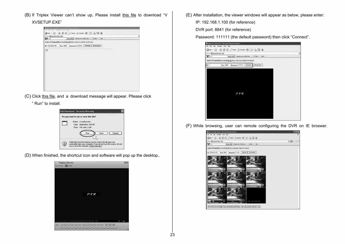
(B) If Triplex Viewer can’t show up, Please install this file to download “V
XVSETUP.EXE”
(C) Click this file, and a download message will appear. Pllease click
“ Run” to install.
(D) When finished, the shortcut icon and software will pop up the desktop..
(E) After installation, the viewer windows will appear as below, please enter:
IP: 192.168.1.100 (for reference)
DVR port: 8841 (for reference)
Password: 111111 (the default password) then click “Connect”.
(F) While browsing, user can remote configuring the DVR on IE broswer.

24
4、DDNS Setup
As the ISP cannot support static IP, we recommended using dynamic IP through
DDNS.
4.1 DynDNS Setting
(1) Firstly, apply a new account on DynDNS (DDNS service) website.
(DDNS website: http://www.dyndns.com)
(A) Apply a host account with ID & Password.
(B) Select “My hosts” to add host name.
(C) Enter the dynamic IP address detected by DynDNS (DynDNS will
auto-detect your dynamic IP address from your ISP) in “IP address”. Press
the button of “Save Changes” after your confirmation.
(2) Go to DVR Main Menu → SYSTEM → NETWORK →DDNS Setting to change
system setting
Enable: select YES
DNS IP Address: Specify DVR IP as private IP setting
DVR URL: Specify DDNS service provider (domain name)
User ID: Specify DDNS IP by DDNS account (user name)
Password: Specify DDNS IP by DDNS account (password)

25
4.2 Set up 2 DVR under the same router for DDNS
(1) First of all, connect these 2 DVR to the same router and we can name them as
DVR1 & DVR2.
(2) Change the system setting for DVR1 and DVR2 in DVR main menu:
(A) Local IP: a local IP will be shown in DHCP, ex:192.168.1.XXX (this is
allocated by router and number will be different)
(B) Port: set DVR1 and DVR2 in different port, such as set DVR1 as 8841, set
DVR2 as 8842.
(C) Mac address: set DVR1 and DVR2 in different Mac address, such as set
DVR1 as 12:34:56:78:9A:BC (default), set DVR2 as 12:34:56:78:9A:BD
(D) After set up, you may check whether you can see from the DHCP Client List
or not. (the layout of the DHCP Client List may be varied to different router,
but the function should be more or less the same.)
The picture shown as above, 2 DVR IP will be in the list. If the DVR IP
address or the IP account are not the same with your setting, please go back
to step (2).
(E) Then, enter the selection of NAT in router to set up the port of DVR1 &
DVR2 to a designated IP of DVR in virtual server. The designated IP of the
port 80 can choose to key in DVR1 or DVR2. (We recommend using 80 port
first. If the 80 port was occupied, change the port setting.)
(F) Afterwards, the set up under router is completed.
(3) Go to the set up page of DynDNS, please refer to the DDNS Setup chart step(1).
(A) Make the same setting process for DVR1 and DVR2.
(4) Go to the DVR main menu: SYSTEM / NETWORK / DDNS setting
Enable: Set to be “Yes”
DNS IP ADDRESS: No need to set
DVR URL: Key in your “Host Name” under DynDNS
USER ID: Key in your “ID” under DynDNS.
Password: Key in your “Password” under DynDNS.

26
After finishing the setting, you may want test. The following example is for your reference under IE Browser.
The connect screen of DVR1 (8841 port). The connect screen of DVR2 (8842 port).
The connect screen by using Client Software. The connect screen of DVR1 (8841 port).
The connect screen of DVR2 (8842 port).
Appendix A – Recommended HDD
Refer to the following list for some recommended HDD to be used in DVR
Manufacturer Model Name Interface Capacity
ST3160812AV IDE 160G
ST3250820AV IDE 250G
ST3160811AS SATA 160G
ST3250410AS SATA 250G
ST3500320AS SATA 500G
ST3750330AS SATA 750G
Seagate
ST31000340AS SATA 1T
WD250JB IDE 250G WD
WD5000AACS SATA 500G
HDS721616PLAT80 IDE 160G
HDP725050GLA360 SATA 500G HITACHI
HDS721075KLA330 SATA 750G

27
Appendix B – HDD Record Time Table
Base on recording frame and quality, a reference list for record time table is as
following table.
The recording hours is based on 250GB HDD for 4-Channel
Frame Per Second 3 4 5 7 10 15 30
High 303 228 182 130 91 61 30
Normal 405 303 243 173 121 81 40NTSC
Quality
Low 1214 910 728 520 364 243 121
hours
Frame Per Second 3 4 6 8 12 25
High 303 228 152 114 76 36
Normal 405 303 202 152 101 49PAL Quality
Low 1214 910 607 455 303 146
hours
The recording hours is based on 500GB HDD for 16-Channel
Frame Per Second 3 4 5 7
High 152 114 91 65
Normal 202 152 121 87NTSC
Quality
Low 607 455 364 260
hours
Frame Per Second 3 4 5 6
High 152 114 91 76
Normal 202 152 121 101PAL Quality
Low 607 455 364 303
hours
Appendix C – Camera Installation Guide
1) Check all accessories 2) Lock Screws with camera stand
3) Lock camera on stand
5) Adjust and lock the angle of shooting 6) Connect power lines and video cable
7) Camera video input through BNC