fast-forward-video-omega-hd-dual-channel-dvr-301-ta048-1 ...
Upload
khangminh22Category
view
0download
0
Design and Implementation of SMES Based SFCL and DVR to
Enhance Transient Stability
THOTLA LINGASWAMY1 | B SUBHASH2
1PG SCHOLAR, Department of EEE, Chaitanya Institute of Technology and Science, Warangal,
Telangana, India. 2Ph.D. ,ASSISTANT PROFESSOR, Department of EEE, Chaitanya Institute of Technology and
Science, Warangal, Telangana, India.
ABSTRACT: In this proposed paper we
propose an inductive SFCL and DVR to
enhance the power quality, generally the
power quality issues like voltage sag and
swells are compensated by DVR but in our
proposed method we are utilizing SMES and
SFCL to enhance the transient stability. The
simulations have demonstrated that the
proposed voltage sag compensation scheme
is able to maintain the stabilizations of root-
mean-square voltages, and mitigate the
adverse effects of voltage sag on sensitive
load. Furthermore, the compensated power
injected to sensitive load by DVR is
decreased owing to the additional voltage
improvement provided by SFCL, thereby
reducing the total capital costs of DVR.
KEYWORDS: SFCL, DVR, SMES, power
quality.
I.INTRODUCTION: IN RECENT years, a
promising voltage sag compensation scheme
based on the dynamic voltage restorer
(DVR) equipped with superconducting
magnetic energy storage (SMES) has been
investigated and technically demonstrated in
[1]–[6]. For instances, a 1.85-H/0.3-MJ
Notti magnet and its matched 150 KVA
current source converter (CSC) were
developed in [2] for protecting a 110-kVA
critical load from voltage sags. In terms of
HTS SMES magnets used in mitigating
voltage sag disturbances, two typical devices
are a 7.87-H/1-MJ/ 0.5-MVA BSCCO
magnet in Japan [5] and a 6.28-H/1-MJ/ 0.5-
MVA BSCCO magnet in China [7].
However, the SMES based DVR systems is
uneconomical compared to those equipped
with conventional Battery Energy Storage
(BES) devices, owing to the expensive
capital costs from SMES coils [8]. Thus, a
promising concept of hybrid energy storage
(HES) integrated a high-power low-capacity
SMES device and a medium-power high-
capacity BES device could be a more
suitable option in practice [9], [10]. In our
previous works in [11]–[13], a kW-class
HES-based DVR has been demonstrated to
integrate the fast-response feature from the
SMES and the high-capacity feature from
the BES. Subsequently, a MW-class SMES-
based DVR is also proposed and evaluated.
Nevertheless, all of these SMES-based DVR
schemes have a high power or energy
storage requirement for SMES, especially
for compensating severe voltage sag.
In addition, the superconducting
fault current limiter (SFCL) is validated to
be conducive to compensating voltage sag in
distribution power system [14]–[18]. Also, a
resistive-type SFCL with self-starting and
Journal of Information and Computational Science
Volume 10 Issue 10 - 2020
ISSN: 1548-7741
www.joics.org254
self-recovery for enhancing fault ride
through of Double Fed Induction Generator
(DFIG) has been proposed and investigated
in our previous work [19], [20]. Therefore, a
MW-class SMES-based DVR system
integrated with a resistive-type SFCL will be
introduced to mitigate the adverse effects of
voltage sag on sensitive load. The basic
topology and technical principle of this
system, parameters evaluation of SMES’s
magnet and SFCL, control strategy of DVR
and simulation verification are described in
detail. Furthermore, the comprehensive
performance evaluation of the proposed
compensation scheme is also interpreted
from the viewpoint of voltage sag
compensation, DVR’s output power under
distribution line fault.
SMES:
Superconducting magnetic energy storage
(SMES) systems store energy in the
magnetic field created by the flow of direct
current in a superconducting coil which has
been cryogenically cooled to a temperature
below its superconducting critical
temperature. A typical SMES system
includes three parts: superconducting coil,
power conditioning system and
cryogenically cooled refrigerator. Once the
superconducting coil is charged, the current
will not decay and the magnetic energy can
be stored indefinitely. The stored energy can
be released back to the network by
discharging the coil. The power conditioning
system uses an inverter/rectifier to transform
alternating current (AC) power to direct
current or convert DC back to AC power.
The inverter/rectifier accounts for about 2–
3% energy loss in each direction. SMES
loses the least amount of electricity in the
energy storage process compared to other
methods of storing energy. SMES systems
are highly efficient; the round-trip efficiency
is greater than 95%.[2] Due to the energy
requirements of refrigeration and the high
cost of superconducting wire, SMES is
currently used for short duration energy
storage. Therefore, SMES is most
commonly devoted to improving power
quality.
Advantages over other energy storage
methods There are several reasons for using
superconducting magnetic energy storage
instead of other energy storage methods.
The most important advantage of SMES is
that the time delay during charge and
discharge is quite short. Power is available
almost instantaneously and very high power
output can be provided for a brief period of
time. Other energy storage methods, such as
pumped hydro or compressed air, have a
substantial time delay associated with the
energy conversion of stored mechanical
energy back into electricity. Thus if demand
is immediate, SMES is a viable option.
Another advantage is that the loss of power
is less than other storage methods because
electric currents encounter almost no
resistance. Additionally the main parts in a
SMES are motionless, which results in high
reliability. Current use There are several
small SMES units available for commercial
use and several larger test bed projects.
Several 1 MW·h units are used for power
quality control in installations around the
world, especially to provide power quality at
manufacturing plants requiring ultra-clean
power, such as microchip fabrication
facilities.[citation needed] These facilities
have also been used to provide grid stability
Journal of Information and Computational Science
Volume 10 Issue 10 - 2020
ISSN: 1548-7741
www.joics.org255
in distribution systems.[citation needed]
SMES is also used in utility applications. In
northern Wisconsin, a string of distributed
SMES units were deployed to enhance
stability of a transmission loop.[citation
needed] The transmission line is subject to
large, sudden load changes due to the
operation of a paper mill, with the potential
for uncontrolled fluctuations and voltage
collapse. The Engineering Test Model is a
large SMES with a capacity of
approximately 20 MWH, capable of
providing 40 MW of power for 30 minutes
or 10 MW of power for 2 hours.
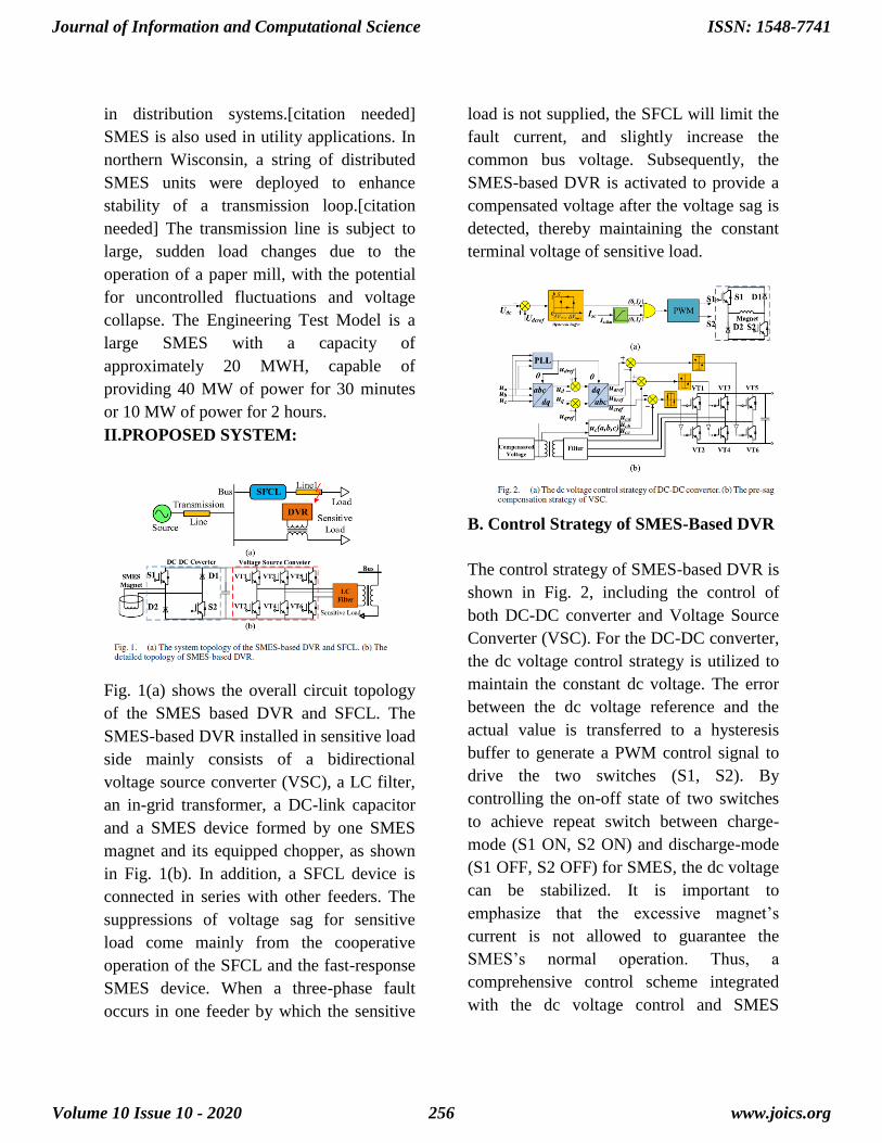
II.PROPOSED SYSTEM:
Fig. 1(a) shows the overall circuit topology
of the SMES based DVR and SFCL. The
SMES-based DVR installed in sensitive load
side mainly consists of a bidirectional
voltage source converter (VSC), a LC filter,
an in-grid transformer, a DC-link capacitor
and a SMES device formed by one SMES
magnet and its equipped chopper, as shown
in Fig. 1(b). In addition, a SFCL device is
connected in series with other feeders. The
suppressions of voltage sag for sensitive
load come mainly from the cooperative
operation of the SFCL and the fast-response
SMES device. When a three-phase fault
occurs in one feeder by which the sensitive
load is not supplied, the SFCL will limit the
fault current, and slightly increase the
common bus voltage. Subsequently, the
SMES-based DVR is activated to provide a
compensated voltage after the voltage sag is
detected, thereby maintaining the constant
terminal voltage of sensitive load.
B. Control Strategy of SMES-Based DVR
The control strategy of SMES-based DVR is
shown in Fig. 2, including the control of
both DC-DC converter and Voltage Source
Converter (VSC). For the DC-DC converter,
the dc voltage control strategy is utilized to
maintain the constant dc voltage. The error
between the dc voltage reference and the
actual value is transferred to a hysteresis
buffer to generate a PWM control signal to
drive the two switches (S1, S2). By
controlling the on-off state of two switches
to achieve repeat switch between charge-
mode (S1 ON, S2 ON) and discharge-mode
(S1 OFF, S2 OFF) for SMES, the dc voltage
can be stabilized. It is important to
emphasize that the excessive magnet’s
current is not allowed to guarantee the
SMES’s normal operation. Thus, a
comprehensive control scheme integrated
with the dc voltage control and SMES
Journal of Information and Computational Science
Volume 10 Issue 10 - 2020
ISSN: 1548-7741
www.joics.org256
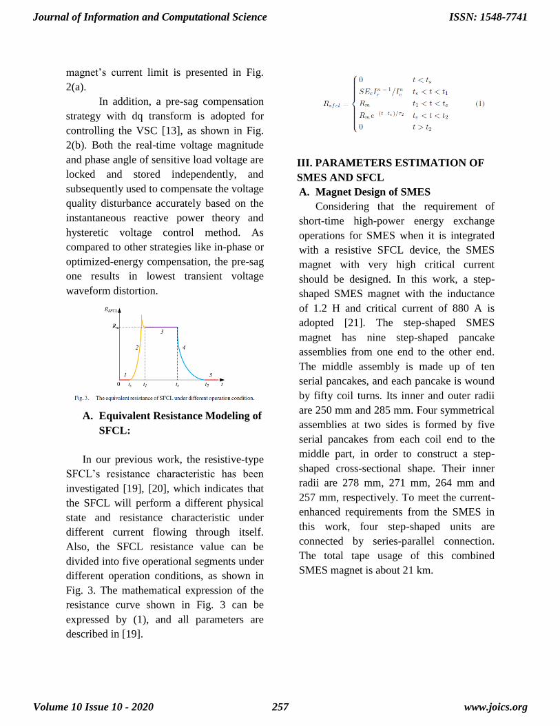
magnet’s current limit is presented in Fig.
2(a).
In addition, a pre-sag compensation
strategy with dq transform is adopted for
controlling the VSC [13], as shown in Fig.
2(b). Both the real-time voltage magnitude
and phase angle of sensitive load voltage are
locked and stored independently, and
subsequently used to compensate the voltage
quality disturbance accurately based on the
instantaneous reactive power theory and
hysteretic voltage control method. As
compared to other strategies like in-phase or
optimized-energy compensation, the pre-sag
one results in lowest transient voltage
waveform distortion.
A. Equivalent Resistance Modeling of
SFCL:
In our previous work, the resistive-type
SFCL’s resistance characteristic has been
investigated [19], [20], which indicates that
the SFCL will perform a different physical
state and resistance characteristic under
different current flowing through itself.
Also, the SFCL resistance value can be
divided into five operational segments under
different operation conditions, as shown in
Fig. 3. The mathematical expression of the
resistance curve shown in Fig. 3 can be
expressed by (1), and all parameters are
described in [19].
III. PARAMETERS ESTIMATION OF
SMES AND SFCL
A. Magnet Design of SMES
Considering that the requirement of
short-time high-power energy exchange
operations for SMES when it is integrated
with a resistive SFCL device, the SMES
magnet with very high critical current
should be designed. In this work, a step-
shaped SMES magnet with the inductance
of 1.2 H and critical current of 880 A is
adopted [21]. The step-shaped SMES
magnet has nine step-shaped pancake
assemblies from one end to the other end.
The middle assembly is made up of ten
serial pancakes, and each pancake is wound
by fifty coil turns. Its inner and outer radii
are 250 mm and 285 mm. Four symmetrical
assemblies at two sides is formed by five
serial pancakes from each coil end to the
middle part, in order to construct a step-
shaped cross-sectional shape. Their inner
radii are 278 mm, 271 mm, 264 mm and
257 mm, respectively. To meet the current-
enhanced requirements from the SMES in
this work, four step-shaped units are
connected by series-parallel connection.
The total tape usage of this combined
SMES magnet is about 21 km.
Journal of Information and Computational Science
Volume 10 Issue 10 - 2020
ISSN: 1548-7741
www.joics.org257
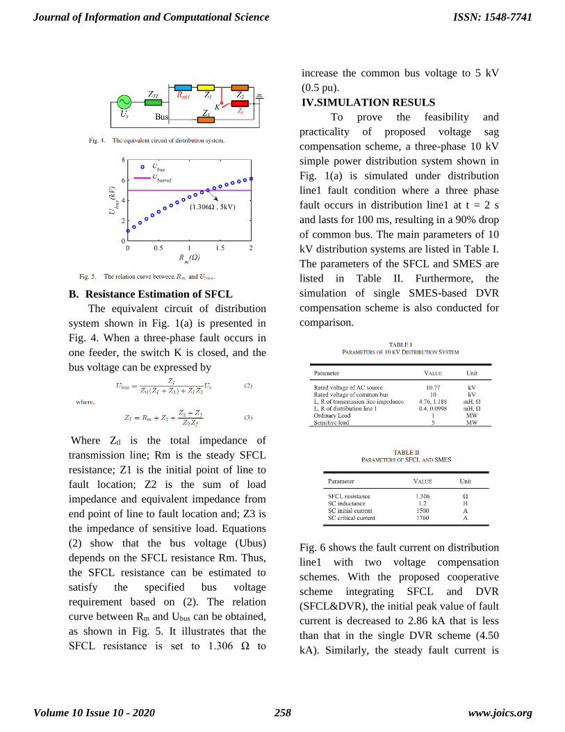
B. Resistance Estimation of SFCL
The equivalent circuit of distribution
system shown in Fig. 1(a) is presented in
Fig. 4. When a three-phase fault occurs in
one feeder, the switch K is closed, and the
bus voltage can be expressed by
Where Ztl is the total impedance of
transmission line; Rm is the steady SFCL
resistance; Z1 is the initial point of line to
fault location; Z2 is the sum of load
impedance and equivalent impedance from
end point of line to fault location and; Z3 is
the impedance of sensitive load. Equations
(2) show that the bus voltage (Ubus)
depends on the SFCL resistance Rm. Thus,
the SFCL resistance can be estimated to
satisfy the specified bus voltage
requirement based on (2). The relation
curve between Rm and Ubus can be obtained,
as shown in Fig. 5. It illustrates that the
SFCL resistance is set to 1.306 Ω to
increase the common bus voltage to 5 kV
(0.5 pu).
IV.SIMULATION RESULS
To prove the feasibility and
practicality of proposed voltage sag
compensation scheme, a three-phase 10 kV
simple power distribution system shown in
Fig. 1(a) is simulated under distribution
line1 fault condition where a three phase
fault occurs in distribution line1 at t = 2 s
and lasts for 100 ms, resulting in a 90% drop
of common bus. The main parameters of 10
kV distribution systems are listed in Table I.
The parameters of the SFCL and SMES are
listed in Table II. Furthermore, the
simulation of single SMES-based DVR
compensation scheme is also conducted for
comparison.
Fig. 6 shows the fault current on distribution
line1 with two voltage compensation
schemes. With the proposed cooperative
scheme integrating SFCL and DVR
(SFCL&DVR), the initial peak value of fault
current is decreased to 2.86 kA that is less
than that in the single DVR scheme (4.50
kA). Similarly, the steady fault current is
Journal of Information and Computational Science
Volume 10 Issue 10 - 2020
ISSN: 1548-7741
www.joics.org258

also limited from 4.09 kA (with single
DVR) to 2.78 kA (with SFCL&DVR).
Furthermore, the bus voltage will be
increased from 1.0 kV (with single DVR) to
5.0 kV (with SFCL&DVR), as shown in
Fig. 6(b). Because the voltage loss of
transmission line is reduced owing to the
suppression of fault current. Therefore, it is
concluded that the SFCL not only
effectively suppresses the fault current but
also increases the common bus voltage due
to its high resistance during distribution line
fault.
Proposed extension simlink diagram
Without dvr extension
Without dvr in existing system
With sfcl and dvr existing system
Journal of Information and Computational Science
Volume 10 Issue 10 - 2020
ISSN: 1548-7741
www.joics.org259
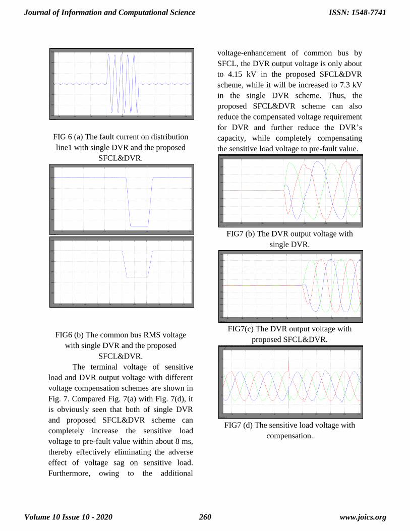
FIG 6 (a) The fault current on distribution
line1 with single DVR and the proposed
SFCL&DVR.
FIG6 (b) The common bus RMS voltage
with single DVR and the proposed
SFCL&DVR.
The terminal voltage of sensitive
load and DVR output voltage with different
voltage compensation schemes are shown in
Fig. 7. Compared Fig. 7(a) with Fig. 7(d), it
is obviously seen that both of single DVR
and proposed SFCL&DVR scheme can
completely increase the sensitive load
voltage to pre-fault value within about 8 ms,
thereby effectively eliminating the adverse
effect of voltage sag on sensitive load.
Furthermore, owing to the additional
voltage-enhancement of common bus by
SFCL, the DVR output voltage is only about
to 4.15 kV in the proposed SFCL&DVR
scheme, while it will be increased to 7.3 kV
in the single DVR scheme. Thus, the
proposed SFCL&DVR scheme can also
reduce the compensated voltage requirement
for DVR and further reduce the DVR’s
capacity, while completely compensating
the sensitive load voltage to pre-fault value.
FIG7 (b) The DVR output voltage with
single DVR.
FIG7(c) The DVR output voltage with
proposed SFCL&DVR.
FIG7 (d) The sensitive load voltage with
compensation.
Journal of Information and Computational Science
Volume 10 Issue 10 - 2020
ISSN: 1548-7741
www.joics.org260
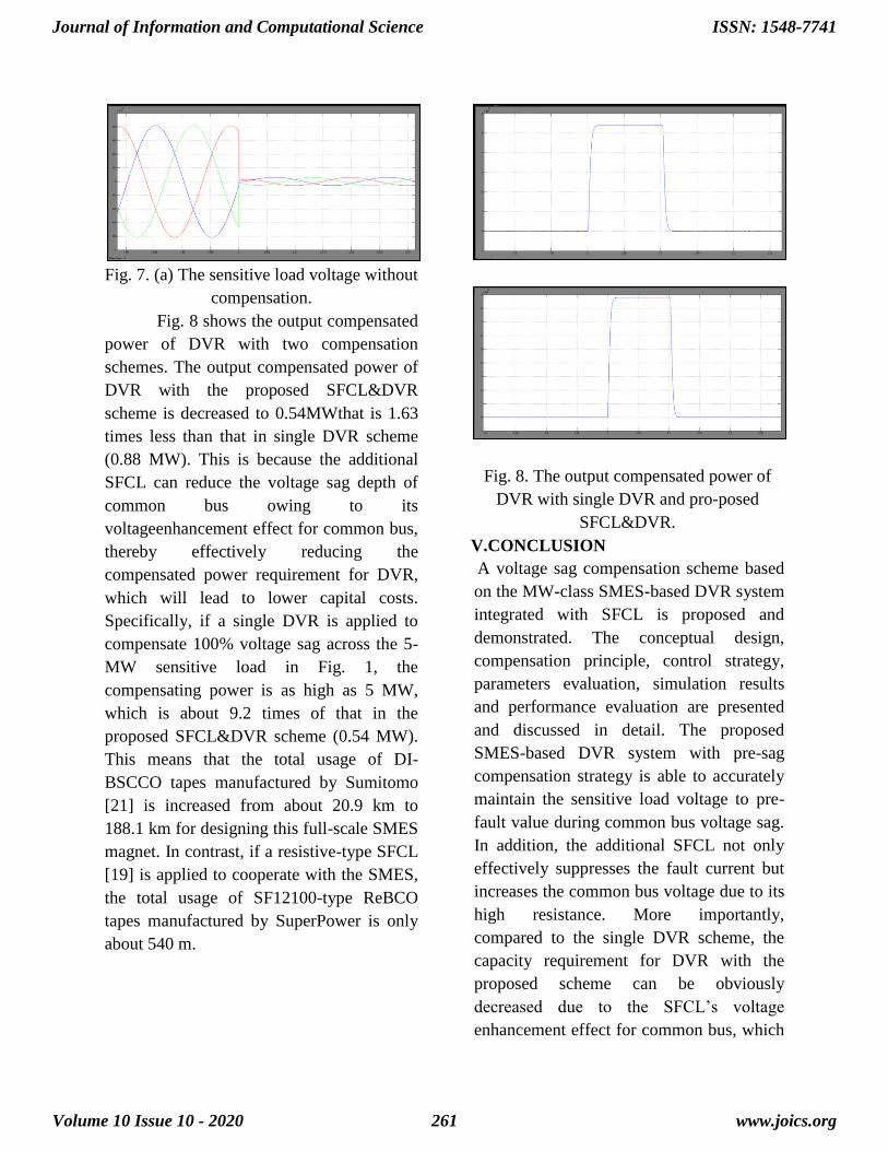
Fig. 7. (a) The sensitive load voltage without
compensation.
Fig. 8 shows the output compensated
power of DVR with two compensation
schemes. The output compensated power of
DVR with the proposed SFCL&DVR
scheme is decreased to 0.54MWthat is 1.63
times less than that in single DVR scheme
(0.88 MW). This is because the additional
SFCL can reduce the voltage sag depth of
common bus owing to its
voltageenhancement effect for common bus,
thereby effectively reducing the
compensated power requirement for DVR,
which will lead to lower capital costs.
Specifically, if a single DVR is applied to
compensate 100% voltage sag across the 5-
MW sensitive load in Fig. 1, the
compensating power is as high as 5 MW,
which is about 9.2 times of that in the
proposed SFCL&DVR scheme (0.54 MW).
This means that the total usage of DI-
BSCCO tapes manufactured by Sumitomo
[21] is increased from about 20.9 km to
188.1 km for designing this full-scale SMES
magnet. In contrast, if a resistive-type SFCL
[19] is applied to cooperate with the SMES,
the total usage of SF12100-type ReBCO
tapes manufactured by SuperPower is only
about 540 m.
Fig. 8. The output compensated power of
DVR with single DVR and pro-posed
SFCL&DVR.
V.CONCLUSION
A voltage sag compensation scheme based
on the MW-class SMES-based DVR system
integrated with SFCL is proposed and
demonstrated. The conceptual design,
compensation principle, control strategy,
parameters evaluation, simulation results
and performance evaluation are presented
and discussed in detail. The proposed
SMES-based DVR system with pre-sag
compensation strategy is able to accurately
maintain the sensitive load voltage to pre-
fault value during common bus voltage sag.
In addition, the additional SFCL not only
effectively suppresses the fault current but
increases the common bus voltage due to its
high resistance. More importantly,
compared to the single DVR scheme, the
capacity requirement for DVR with the
proposed scheme can be obviously
decreased due to the SFCL’s voltage
enhancement effect for common bus, which
Journal of Information and Computational Science
Volume 10 Issue 10 - 2020
ISSN: 1548-7741
www.joics.org261

can further reduce the total capital costs of
DVR. Therefore, the MW-class SMES
based DVR system integrated with SFCL
can be expected to utilize to enhance the
transient voltage quality in modern
distribution power system.
REFERENCES
[1] X. H. Jiang et al., “A 150 kVA/0.3 MJ
SMES voltage sag compensation system,”
IEEE Trans. Appl. Supercond., vol. 15, no.
2, pp. 1903–1906, Jun. 2005.
[2] S.Nagaya et al., “Field test results of
the 5MVASMESsystem for bridging
instantaneous voltage dips,” IEEE Trans.
Appl. Supercond., vol. 16, no. 2, pp. 632–
635, Jun. 2006.
[3] W. Y. Guo et al., “Control strategy of a
0.5 MVA/1 MJ SMES based dynamic
voltage restorer,” IEEE Trans. Appl.
Supercond., vol. 20, no. 3, pp. 1329–1333,
Jun. 2010.
[4] K. Shikimachi et al., “Development of
MVA class HTS SMES system for bridging
instantaneous voltage dips,” IEEE Trans.
Appl. Supercond., vol. 15, no. 2, pp. 1931–
1934, Jun. 2005.
[5] J. H. Zhu et al., “Design, dynamic
simulation and construction of a hybrid
HTS SMES (high-temperature
superconducting magnetic energy storage
systems) for Chinese power grid,” Energy,
vol. 51, no. 2, pp. 184–192, Mar. 2013.
[6] K. Shikimachi et al., “System
coordination of 2 GJ class YBCO SMES for
power system control,” IEEE Trans. Appl.
Supercond., vol. 19, no. 3, pp. 2012–2018,
Jun. 2009.
[7] L. Y. Xiao et al., “Fabrication and tests
of a 1 MJ HTS magnet for SMES,” IEEE
Trans. Appl. Supercond., vol. 18, no. 2, pp.
770–773, Jun. 2008.
[8] M. A. Green and B. P. Strauss, “The
cost of superconducting magnets as a
function of stored energy and design
magnetic induction times the field volume,”
IEEE Trans. Appl. Supercond., vol. 18, no.
2, pp. 248–251, Jun. 2008.
[9] S. Suzuki, J. Baba, K. Shutoh, and E.
Masada, “Effective application of
superconducting magnetic energy storage
(SMES) to load leveling for high speed
transportation system,” IEEE Trans. Appl.
Supercond., vol. 14, no. 2, pp. 713–716,
Jun. 2004.
[10] J. W. Shim, Y. Cho, S. J. Kim, S. W.
Min, and K. Hur, “Synergistic control of
SMES and battery energy storage for
enabling dispatchability of renewable
energy sources,” IEEE Trans. Appl.
Supercond., vol. 23, no. 3, Jun. 2013, Art.
no. 5701205.
[11] Z. X. Zheng, X. Y. Xiao, C. S. Li, Z.
Chen, and Y. Zhang, “Performance
evaluation of SMES system for initial and
steady voltage sag compensations,” IEEE
Trans. Appl. Supercond., vol. 26, no. 7, pp.
1–5, Oct. 2016, Art. no. 5701105.
[12] Z. X. Zheng, X. Y. Chen, X. Y. Xiao,
and C. J. Huang, “Design and evaluation of
a mini-size SMES magnet for hybrid energy
storage application in a kW-Class dynamic
voltage restorer,” IEEE Trans. Appl.
Supercond., vol. 27, no. 7, Oct. 2017, Art.
no. 5700911.
[13] Z. Zheng, X. Xiao, X. Chen, C.
Huang, L. Zhao, and C. Li, “Performance
evaluation of a MW-Class SMES-BES
DVR system for mitigation of voltage
quality disturbances,” IEEE Trans. Ind.
Journal of Information and Computational Science
Volume 10 Issue 10 - 2020
ISSN: 1548-7741
www.joics.org262
Appl., vol. 54, no. 4, pp. 3090–3099, Jul./Aug. 2018.
Journal of Information and Computational Science
Volume 10 Issue 10 - 2020
ISSN: 1548-7741
www.joics.org263
Copyright © 2022 FDOKUMEN