Optimization of the photovoltaic-hydrogen supply system of a stand-alone remote-telecom application
Upload
khangminh22Category
view
4download
0
Stand-Alone 4 CH Sequence View & Record Mobile DVR
User Manual (460M/460MS-V1) Please read this user manual completely before operating this DVR system and keep it in
a safe place for future reference.

1
TABLE OF CONTENTS
Table of Contents ………………………………………………………………….…… 1
Introduction ……………………………………………………………………….…….. 2
Important Safety Information …………………………………………………..……… 2
Unpacking Your System ……………………………………………………….……… 3
Control Panel and Function ……………………………………………….…….……. 6
Installation ………………………………………………………………………..……… 8
Delay Time Setting…...…………………………………………………………….…… 13
Before Operation …………………………………………………………………..…… 14
Operation ……………………………………………………………………………..…. 15
OSD (On Screen Display) Menu Setting Operation Process ……………..…….. 15
Key and function for operation ………………………………………….……...…… 16
OSD Setting Operation …………………………………………………………...…. 16
Camera Setup Operation …….…………………….………………………….…. 19
Date / Time / Daylight Saving Time Setting ……….....……………………….… 23
HDD Setup …...………………………………………….….………….……….…. 24
Record Setup …………..…….…………………….……………….….……….…. 26
Backup Setup……... …………………………………………………………….… 28
TCP/IP Setup………….. ………………………………………………………….. 29
Peripheral Setup ……………..……….………………………………….……….. 29
System Setup …………. …...…………………………………………………….. 33
Key Lock Setup ………………………….....…………………………….………. 37
Play Back Record Data ……..……………………………………………….………… 38
PTZ Camera Setting and Control ………………………………………….…………. 40
USB Download Instruction…….…………………………………………….…………. 42
Sensor Recorder Function Operation (for 460MS)…….………………….………… 45
PC Player Software Operation ……………………………………………………….. 48

2
INTRODUCTION
Thank you for purchasing our unique Mobile DVR system. To ensure that you optimize the full capabilities of this product, please read this user’s manual before proceeding. Be sure to keep this manual for future reference in case any problems or questions should arise. We hope you enjoy your new Mobile DVR system.
IMPORTANT SAFETY INFORMATION
When using your Mobile DVR equipment, basic safety precautions should always be followed to reduce the risk of fire, electric shock and personal injury. Please read the followings before using your equipment:
1. Read and follow all instructions carefully.
2. Follow all warnings and instructions on the product.
3. Unplug the product from the power outlet before cleaning. Do not use liquid cleaners or aerosol cleaners. Use a damp cloth for cleaning.
4. Do not use this product near water.
5. Do not place this product on an unstable cart, stand or table.
6. Do not allow anything to rest on the power cords. Do not place this product in a location where the cords can be stepped on or where someone can trip over them.
7. Do not use this product near an area where there is a potential of gas leaks or near any explosive fumes.
8. Do not place this product near or over a radiator or any other heat source.
9. Use ONLY the power cord supplied with the system.
10. Do not overload the wall outlet or power cord where the power cord is installed. This can result in fire or electric shock.
11. This equipment is to be opened by ONLY a qualified serviceperson. There are no user serviceable parts inside. Opening this equipment may expose you to dangerous voltage and other risks. Incorrect re-assembly of this equipment may result in electric shock.
12. Avoid spilling liquid on this equipment and do not insert any objects through the ventilation slots.
3
UNPACKING YOUR SYSTEM
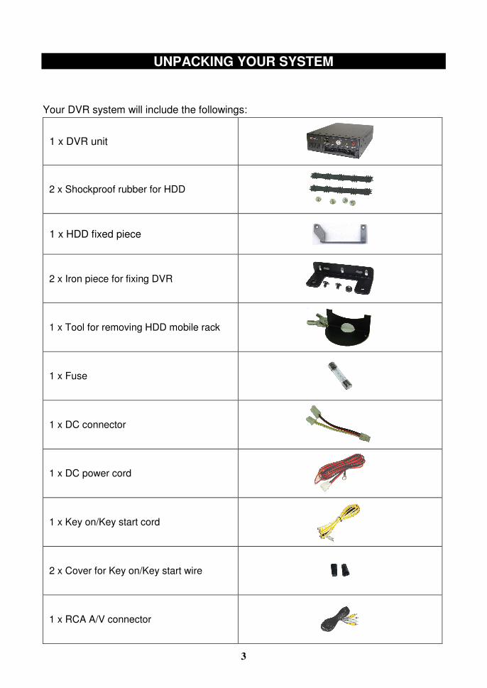
Your DVR system will include the followings:
1 x DVR unit
2 x Shockproof rubber for HDD
1 x HDD fixed piece
2 x Iron piece for fixing DVR
1 x Tool for removing HDD mobile rack
1 x Fuse
1 x DC connector
1 x DC power cord
1 x Key on/Key start cord
2 x Cover for Key on/Key start wire
1 x RCA A/V connector

4
1 x A/V Input connector
1 x USB cable for recorded data download
1 x Signal I/O Box
1 x IR Remote Control
1 x User’s Manual
Extra accessories for 460MS
1x Sensor signal box
1 x GPS antenna
5
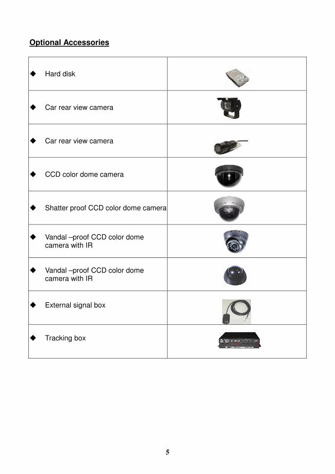
Optional Accessories
� Hard disk
� Car rear view camera � Car rear view camera
� CCD color dome camera
� Shatter proof CCD color dome camera
� Vandal –proof CCD color dome
camera with IR
� Vandal –proof CCD color dome
camera with IR
� External signal box
� Tracking box
6
CONTROL PANEL AND FUNCTION
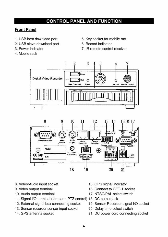
Front Panel 1. USB host download port 2. USB slave download port 3. Power indicator 4. Mobile rack
5. Key socket for mobile rack 6. Record indicator 7. IR remote control receiver
8. Video/Audio input socket 9. Video output terminal 10. Audio output terminal 11. Signal I/O terminal (for alarm PTZ control) 12. External signal box connecting socket 13. Sensor recorder sensor input socket 14. GPS antenna socket
15. GPS signal indicator 16. Connect to GET-1 socket 17. NTSC/PAL select switch 18. DC output jack 19. Sensor Recorder signal I/O socket 20. Delay time select switch 21. DC power cord connecting socket
7
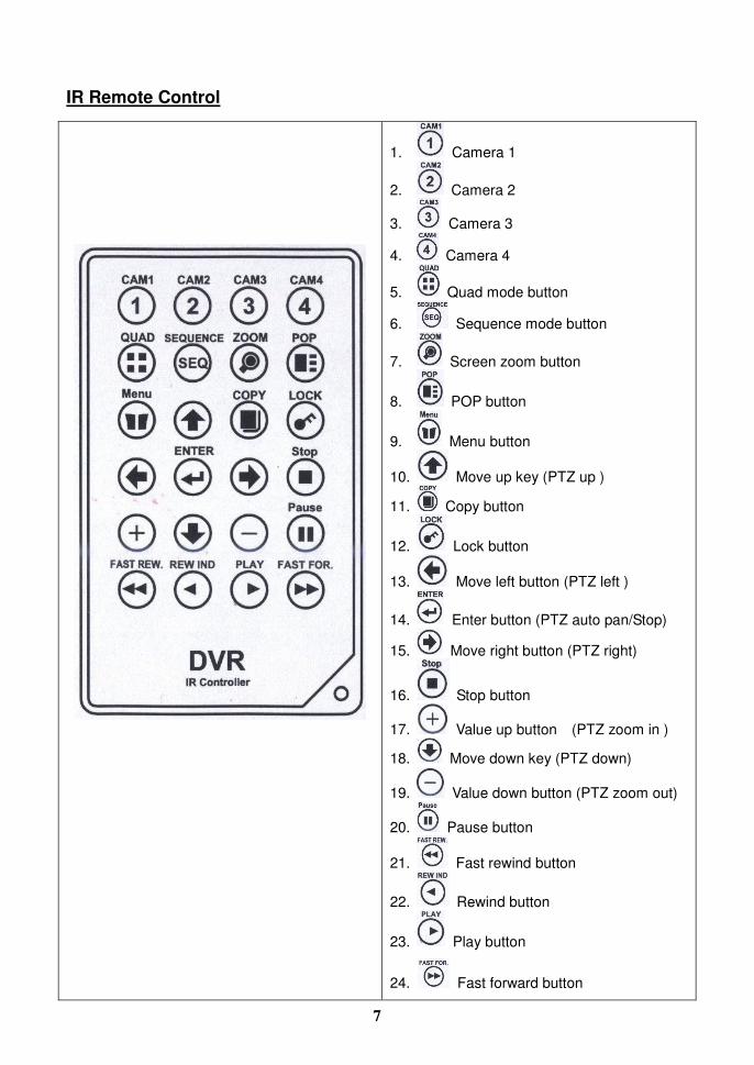
IR Remote Control
1. Camera 1
2. Camera 2
3. Camera 3
4. Camera 4
5. Quad mode button
6. Sequence mode button
7. Screen zoom button
8. POP button
9. Menu button
10. Move up key (PTZ up )
11. Copy button
12. Lock button
13. Move left button (PTZ left )
14. Enter button (PTZ auto pan/Stop)
15. Move right button (PTZ right)
16. Stop button
17. Value up button (PTZ zoom in )
18. Move down key (PTZ down)
19. Value down button (PTZ zoom out)
20. Pause button
21. Fast rewind button
22. Rewind button
23. Play button
24. Fast forward button

8
INSTALLATION
DVR Installation 1. Hard Disk installation
Please carefully follow the steps as below to install Hard Disk Drive.
a). Fix the rubbers to 2.5” HDD two sides as the picture showed below: (The rubber can protect the HDD.)
9
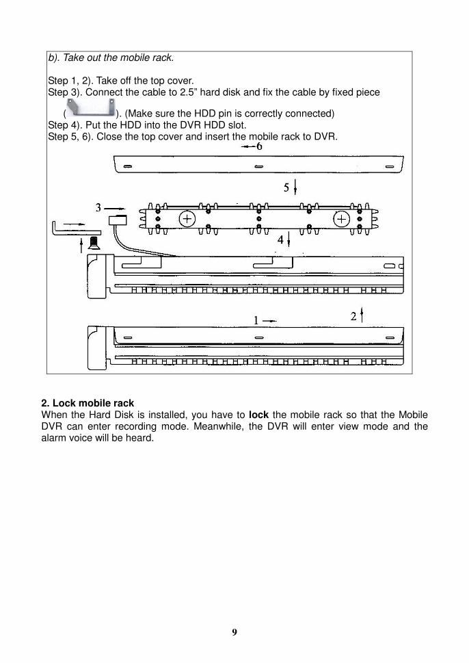
b). Take out the mobile rack. Step 1, 2). Take off the top cover. Step 3). Connect the cable to 2.5” hard disk and fix the cable by fixed piece
( ). (Make sure the HDD pin is correctly connected) Step 4). Put the HDD into the DVR HDD slot. Step 5, 6). Close the top cover and insert the mobile rack to DVR.
2. Lock mobile rack When the Hard Disk is installed, you have to lock the mobile rack so that the Mobile DVR can enter recording mode. Meanwhile, the DVR will enter view mode and the alarm voice will be heard.
10
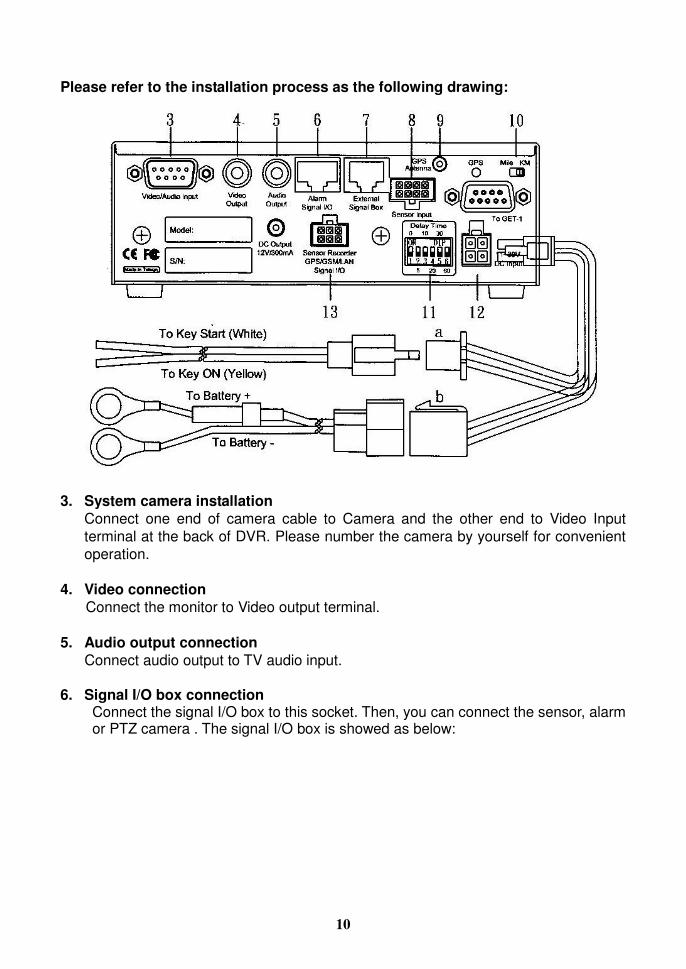
Please refer to the installation process as the following drawing:
3. System camera installation Connect one end of camera cable to Camera and the other end to Video Input terminal at the back of DVR. Please number the camera by yourself for convenient operation.
4. Video connection Connect the monitor to Video output terminal.
5. Audio output connection Connect audio output to TV audio input.
6. Signal I/O box connection Connect the signal I/O box to this socket. Then, you can connect the sensor, alarm or PTZ camera . The signal I/O box is showed as below:
11
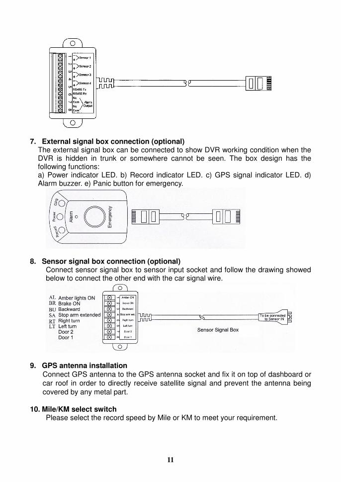
7. External signal box connection (optional) The external signal box can be connected to show DVR working condition when the DVR is hidden in trunk or somewhere cannot be seen. The box design has the following functions: a) Power indicator LED. b) Record indicator LED. c) GPS signal indicator LED. d) Alarm buzzer. e) Panic button for emergency.
8. Sensor signal box connection (optional)
Connect sensor signal box to sensor input socket and follow the drawing showed below to connect the other end with the car signal wire.
9. GPS antenna installation Connect GPS antenna to the GPS antenna socket and fix it on top of dashboard or car roof in order to directly receive satellite signal and prevent the antenna being covered by any metal part.
10. Mile/KM select switch Please select the record speed by Mile or KM to meet your requirement.

12
11. Delay time select switch Please refer to the “Delay Time Setting” instruction for more details.
12. Power connection a. Plug the wire for Key [On] and key [Start] wire connection
Connect the key on connecting wire (yellow) to car key “ON” position. Connect the key start wire (white) to car key “Start” position.
b. Plug the power cord to Battery (e.g. car battery). When the power is connected, the DVR is ready to be used. The built-in power supply with delay circuit board designed for DVR to delay switch-on time for 10 seconds. With the delay, it can avoid DVR working on unstable voltage. Switch on/off voltage: 10.5 ~10.8V Delay switch-on time while starting the car: 10 seconds
Note: The DVR switch-off delay function can work normally only when key on/key start wire is correctly connecting.
13. Sensor input socket connection (optional)
This socket can connect LAN box, sensor recorder or auto dialer box for future requirement.
14. Data download
This DVR has USB host and USB slave port for data download. This USB host is used the pen drive and USB slave is connecting USB cable for download. Please refer to “USB download Instruction” for more details.

13
Delay Time Setting The built-in delay circuit board is designed for DVR to delay switch-on time for 10 seconds. With the delay, it can avoid DVR working on unstable voltage. It can also delay switch-off time from 5 minutes to 60 minutes selected by switch depending on the user requirement. Specifications: Switch on voltage: 10~11V Switch off voltage: 8V Delay switch-on time while starting the car: 10 seconds
Delay time setting switch:
Switch No. 1 On 2 On 3 On 4 On 5 On 6 On All Off
Delay time Car key short
5 minutes
10 minutes
20 minutes
30 minutes
60 minutes
5 seconds
Remarks:
The Switch 1 is used to replace car key while using the DVR outside the car. The factory will preset delay time to “0” (= no delay time function). The user has to switch the required delay time so that it can function and will go standby mode without using any current while DVR is switch off.
Note: The DVR switch-off delay function can work normally only when key on/key start wire is correctly connecting.

14
BEFORE OPERATION
(1) The system will auto detecting the hardware and enter Recording mode while
hardware is in normal condition.
(2) The system will show [UNKNOW HDD] then enter [Format Menu] within 3 seconds
when first time start the system or hard disk driver is changed. Please select
[FORMAT HDD YES] to format HDD. The system will auto enter record mode after
format HDD. (Or, enter the main menu “Record Setup” and select HDD information
to format HDD.)
(3) If the system not setting time yet, will auto enter to time setting screen, please press
[MENU] key to exit after setting time.
(4) If [NO HD] signal show on screen, Please turn off the power then check HDD
connecting wire and check HDD master/slave select jumper need set to master
then turn the power on again.
(5) If screen show [NO VIDEO], please check video input connector whether is
connecting with camera correctly.
(6) Suggest turn on camera power before turn the system power on.

15
OPERATION
The system is preset [KEY LOCK] mode OFF, when the system setting [KEY LOCK] mode ON, the screen will show below message. Please key in the security code by remote control number keys to enter the OSD manual for setting.
Then, press [Enter] button. If the screen show as below, the password is correct.
If the screen shows as below, the password is incorrect. Then please enter correct password so that he can enter Main Menu or playback.
LOGIN DVR
PLEASE ENTER PASSWORD PASSWORD:
SELCT NUMBER: 0~9
LOGIN SUCCESS WELCOME TO DVR SYSTEM
PASSWORD ERROR PLEASE ENTER PASSWORD PASSWORD:
SELCT NUMBER: 0~9

16
OSD (On Screen Display) Menu Setting Operation Process
1. Press Menu button to enter menu selection mode.
2. Press up button/ down button / Left button / Right button to
select the item for setting.
3. Press Enter button to enter sub menu to select item for setting.
4. Press (value up) button or (value down) button to change the value for
your setting.
5. Press key to exist for other setting.
Key and Function for Operation
1 MENU operation key
Button Operation Remarks
MENU Enter OSD menu
1. Press Menu button to enter OSD menu.
2. Press direction key to select.
3. Press key to enter sub menu.
4. Press to exit while end of setting.
Up button Go Up
Down button Go Down
Left button Go Left
Right button Go Right
Value up
Value down
Enter button ENTER next page

17
2 Play operation key Button Operation Remarks
PLAY Play
FAST FOR. Fast Forward
FAST REW. Fast Rewind
Pause Pause
Stop
Stop
3 PTZ control key operation Button Operation Remarks
Screen Zoom
ZOOM IN
ZOOM OUT
Go Up
Go Down
Go Left
1. Press button to enter the function.
2. Press function key to operate. 3. Press direction to select the area.
Go Right
Auto pan Press one time
Auto pan Stop Press two times
5 Display operation key Key Operation Remarks
Sequence view
5 Number buttons Number 1 2 3 4 5 6 7 8 9 0
Button
18
Screen Instruction: 99%: The percentage of HDD recording space. 1: The Hard Disk CYCL: Cycle recording ONCE: Once recording CAM1: Camera 1 CAM2: Camera 2 CAM3: Camera 3 CAM4: Camera 4 07/03/05: Date 13:00: Time REC: Recording CON: Continuous recording ALM: Alarm recording MON: Motion recording
19
MAIN MENU
CAMERA SETUP DATE/TIME SETUP HDD SETUP RECORD SETUP BACKUP SETUP TCP/IP SETUP PERIPHERAL SETUP SYSTEM SETUP KEY LOCK SEUP
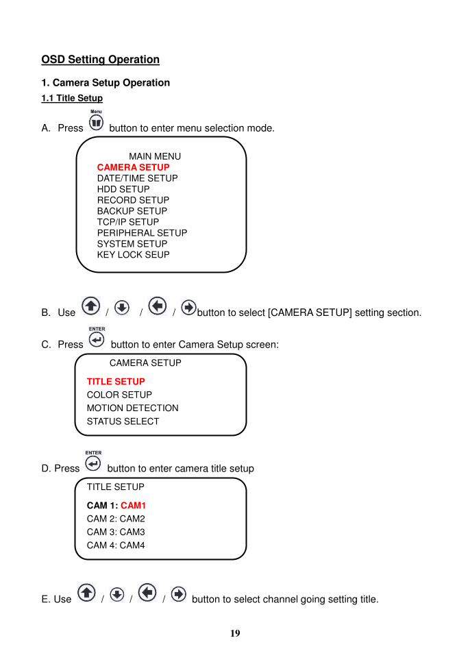
OSD Setting Operation
1. Camera Setup Operation 1.1 Title Setup
A. Press button to enter menu selection mode.
B. Use / / / button to select [CAMERA SETUP] setting section.
C. Press button to enter Camera Setup screen:
D. Press button to enter camera title setup
E. Use / / / button to select channel going setting title.
TITLE SETUP
CAM 1: CAM1 CAM 2: CAM2 CAM 3: CAM3 CAM 4: CAM4
CAMERA SETUP
TITLE SETUP COLOR SETUP MOTION DETECTION STATUS SELECT

20
F. Use / button to change the camera number.
G. Press key to exist for other setting
1.2 Color Setup
A. Press button to enter menu selection mode.
B. Use / / / button to select [CAMERA SETUP] setting section
and press button to enter channel select mode.
C. Use / / / button to select [COLOR SETUP] setting section and
press button to enter.
a. Brightness: Brightness is adjustable, “00” = the darkest, “63” = the lightest. b. Contrast: Contrast is adjustable, “00” = maximum, “63” = minimum. c. Saturation: Saturation is adjustable, “00” = maximum, “63” = minimum. d. Hue: Hue is adjustable, “00” = maximum, “63” = minimum.
D. Use / button to select the camera. (CAM 01/02/03/04)
E. Use / / / button to select the item you want to change.
F. Use / button to change the value.
G. Press key to exist for other setting
COLOR SETUP
CAM 01 BRIGHTNESS 32 CONTRAST 32 SATURATION 32 HUE 32 GAIN 32 (1~63)

21
1.3 Motion Detection
A. Press button to enter menu selection mode.
B. Use / / / button to select [CAMERA SETUP] setting section.
C. Use / / / button to select [MOTION DETECTION] setting
section.
D. Press [RUN] to enter area setting and the screen will show as below: (There are 16 x 12 blocks)
E. Use / / / button to select the area.
MOTION DETECTION
AREA SETTING CH01 RUN SENSITIVITY 7 (1: MOST SENSITIVE) ------------------------ 1 is the most sensitivity value. RELAY OUT ON There are 20 levels for select. FULL SCREEN OFF

22
F. Use / button to activate or close the detection the area. Press button to select all activate or close. (This function will activate when the record mode is selected “Motion Detection(M)”.)
G. Press button to exist above screen.
H. Use / / / button to select the item you want to change.
I. Use / button to change the value.
J. Press key to exist for other setting
1.4 Status Select
A. Press button to enter menu selection mode.
B. Use / / / button to select [CAMERA SETUP] setting section.
C. Use / / / button to select [STATUS SELECT] setting section.
D. Use / / / button to select the camera you want to change.
E. Use / button to change the screen will be visible or not. (Visible OFF: The recording information will be stored in hard disk, but the live picture will not be showed on screen. Visible ON: The recording information is showed as the same on screen.)
F. Press key to exist for other setting
STATUS SELECT
CH VISIBLE CAM 1 ON(OFF) CAM 2 ON(OFF) CAM 3 ON(OFF) CAM 4 ON(OFF)

23
DATE/TIME SETUP
DISPLAY FORMAT: DD/MM/YY 03/05/07 YEAR 2007 MONTH 3 DAY 28 HOUR 12 MINUTE 20 SECOND 50 DAYLIGHT SAVING TIME
2. Date / Time / Daylight Saving Time Setting
A. Press menu button to enter menu selection mode.
B. Use / / / button to select [DATE/TIME SETUP] setting
section.
C. Use / button to change the Display Format.
D. Use / / / button to select the other item
(Year/Month/Day/Hour/Minute/Second).
E. Use / button to change the value.
F. If you want setting daylight saving time, then you can use / / /
button to go daylight saving section and use / button t to turn daylight saving
mode on for setting. Or press menu button to exit for select other setting.
24
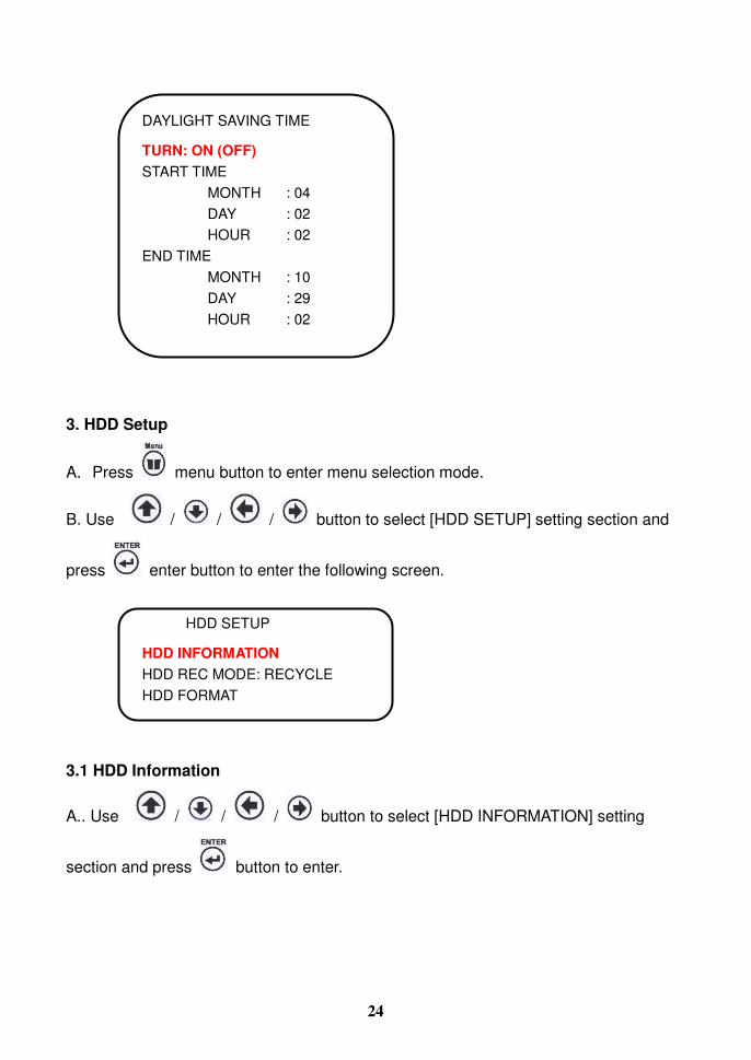
DAYLIGHT SAVING TIME
TURN: ON (OFF) START TIME MONTH : 04 DAY : 02 HOUR : 02 END TIME MONTH : 10 DAY : 29 HOUR : 02
3. HDD Setup
A. Press menu button to enter menu selection mode.
B. Use / / / button to select [HDD SETUP] setting section and
press enter button to enter the following screen.
3.1 HDD Information
A.. Use / / / button to select [HDD INFORMATION] setting
section and press button to enter.
HDD SETUP
HDD INFORMATION HDD REC MODE: RECYCLE HDD FORMAT

25
B. Press button to exit
3.2 HDD REC Mode
A.. Use / / / button to select [HDD REC MODE] setting section
and press button to enter.
B. Use / button to select HDD recording mode to recycle or once.
C. Press button to exit
3.3 HDD Format
A.. Use / / / button to select [HDD FORMAT] setting section and
press button to enter.
B. Use / / / button to select HDD: 01 section.
HDD INFORMATION
HD 1: MASTER MODEL: XXXXX SIZE: XXX GBYTES FREE SIZE: XX GBYTES
HDD REC MODE
HDD REC MODE: RECYCLE
HDD FORMAT
SELECT HDD: 1 CONFIRM: RUN

26
C. Use / button to select HDD 1 or HDD 2 .
D. Use / / / button to “RUN” and press button to enter.
E. Press button to exit
4. Record Setup
A. Press button to enter menu selection mode.
B. Use / / / button to select [RECORD SETUP] setting section.
C. Press button to enter [RECORD SETUP] select mode.
D. Use / / / to select tme for setting.
E. Use / button to select the record mode(C / M / A).
FORMAT HDD 01: NO (or YES)
RUN
RECORD SETUP
RECORD MODE CONTINUOUS RECORD MOTION RECORD ALARM RECORD
RECORD MODE 0 3 6 9
C C C C C C C C C C C C 12 15 18 21
C C C C C C C C C C C C

27
F. Press to enter selected section for setting, then use / / /
to select the section for setting and use / button to select the value.
G. Press button to exit.
a. Record Mode set up: 3 record modes (“C” = Continuous, “A” = Alarm and “M” =
Motion) for select. b. Continuous Record: for set-up 4 level record quality and 4 kinds frame rate for
record.
* Quality: Standard / Super / High / Normal. * REC FPS: Set up frame per second (fps) as below
NTSC: 2/4/8/16/30/60/120 (fps) PAL: 2/4/8/12/25/ (fps) (When the DVR power is ON, it will detect the system in NTSC or PAL by the camera installed.)
c. Alarm Record: for set-up 4 level record quality, 4 kinds frame rate and duration for
record while detect alarm or motion.
* Quality: Standard / Super / High / Normal.
* REC FPS: Set up frame per second (fps) as below NTSC: 120 / 60 / 30 / 16 / 8 / 4 / 2(fps) PAL: 100/50/25 / 12 / 8 / 4 (fps)
CONTINUOUS RECORD
RECORD QUALITY: SUPER REC FPS 30
ALARM RECORD
RECORD QUALITY: SUPER REC FPS: 30 REC TIME: 30 SECONDS PRE RECORD: ON/OFF

28
* REC Time: 10 / 20 / 30/ 40 / 50 /60 (seconds)
d. Motion Record: for set-up 4 level record quality, 4 kinds frame rate and duration
for record while detect alarm or motion.
* Quality: Standard / Super / High / Normal.
* REC FPS: Set up frame per second (fps) as below
NTSC: 120 / 60 / 30 / 16 / 8 / 4 / 2(fps) PAL: 100/50/25 / 12 / 8 / 4 (fps)
* REC Time: 10 / 20 / 30/ 40 / 50 /60 (seconds)
5. Backup Setup
A. Press button to enter menu selection mode.
B. Use / button to select [BACKUP SETUP] setting section.
C. Press button to enter [BACKUP SETUP] select mode.
Please refer to the “USB Download Instruction” for more details.
D. Press button to exit
BACKUP SETUP
USB SLAVE USB MASTER EVENT SETUP
MOTION RECORD
RECORD QUALITY: SUPER REC FPS: 60 REC TIME: 30 SECONDS PRE RECORD: ON/OFF

29
6. TCP/IP Setup (optional) (This function will be available when the LAN is connected.)
A. Press button to enter menu selection mode.
D. Use / button to select [TCP/IP SETUP] setting section.
E. Press button to enter [TCP/IP SETUP] select mode.
F. Use / to select item for setting.
G. Use / button to select value.
H. Press button to exit.
* Please refer to the LAN instruction manual for more detail. 7. Peripheral Setup
A. Press button to enter menu selection mode.
B. Use / / / button to select [PERIPHERAL SETUP] setting
section.
C. Press button to enter [PERIPHERAL SETUP] select mode.
TCP/IP SETUP
DHCP: OFF (or ON) MAC”: IP ADDRESS: 000.000.000.000
PORT: 80 MASK 000.000.000.000 DNS: 000.000.000.000 GATEWAY: 000.000.000.000 RUN

30
7.1 Buzzer setup
A. Use / / / button to select [BUZZER SETUP] setting section.
B. Press button to enter [BUZZER SETUP] select mode.
Buzzer: for setting buzzer alarm time for video loss, motion is detect, I/O alarm detect and key move alarm.
* Key beep: Buzz when button is pressed (one buzz) * Power on: Buzz when system power on (one buzz) * Video loss: Buzz when video signal is lost. * Alarm Event: Buzz when alarm input is triggered. * Motion: Buzz when system motion is detected.
C. Use / / / to select item for setting.
D. Use / button to select On/OFF.
E. Press button to exit.
BUZZER SETUP
KEY BEEP: ON (OFF) POWER ON: ON (OFF) VIDEO LOSS: ON (OFF) ALARM EVENT: ON (OFF) MOTION: ON (OFF) TIME DURATION: 1 (1~60 SECONDS)
PERIPHERAL SETUP
BUZZER SETUP ALARM SETUP SEQUENCE SETUP PASSWORD SETUP MONITOR SETUP

31
7.2 Alarm setup
A. Use / / / button to select [ALARM SETUP] setting section.
B. Press button to enter [ALARM SETUP] select mode.
* NC = Normal Close: The signal loop is closed under normal conditions. When the loop becomes open, alarm will be triggered until the loop becomes closed again. In other words, if the loop keeps on open for a period of time, alarm will keep on triggering in that time interval.
* NO = Normal Open: The signal loop is open under normal conditions. When the loop becomes closed, alarm will be triggered until the loop becomes open again. In other words, if the loop keeps on closed for a period of time, alarm will keep on triggering in that time interval.
*Full: Full screen
C. Use / / / to select item for setting.
ALARM SETUP
ALARM INPUT ALARM OUTPUT
ALARM INPUT SETUP
ALARM IN STATUS OUT FULL 1 NO/NC ON ON 2 NO/NC ON ON 3 NO/NC ON ON 4 NO/NC ON ON
ALARM OUTPUT SETUP
ALARM OUT STATUS TIME 1 ON/OFF 01~60

32
D. Use / button to select On/OFF.
E. Press button to exit.
7.3 Sequence setup
A. Use / / / button to select [SEQUENCE SETUP] setting section.
B. Press button to enter [SEQUENCE SETUP] select mode.
C. Use / / / to select item for setting.
D. Use / button to select value.
E. Press button to exit.
After above setting, press the (Sequence) button at Live/Record mode to activate
this function.
7.4 Password setup
A. Use / / / button to select [PASSWORD SETUP] setting section.
B. Press button to enter [PASSWORD SETUP] select mode.
(initial password: 0000)
SEQUENCE SETUP
FULL SCREEN: 01~60 SEC
PASSWORD SETUP
NEW: CONFIRM: SELECT NUMBER: 0~9
33
C. Use number button to change the password. (Please refer to Key & Function Operation section for the number keys.)
D. Press button to exit.
Please contact your distributor for more information if you forgot password.
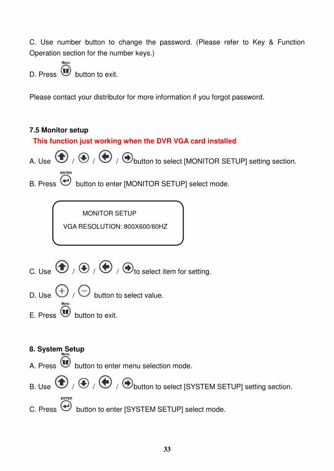
7.5 Monitor setup This function just working when the DVR VGA card installed
A. Use / / / button to select [MONITOR SETUP] setting section.
B. Press button to enter [MONITOR SETUP] select mode.
C. Use / / / to select item for setting.
D. Use / button to select value.
E. Press button to exit.
8. System Setup
A. Press button to enter menu selection mode.
B. Use / / / button to select [SYSTEM SETUP] setting section.
C. Press button to enter [SYSTEM SETUP] select mode.
MONITOR SETUP
VGA RESOLUTION: 800X600/60HZ
34
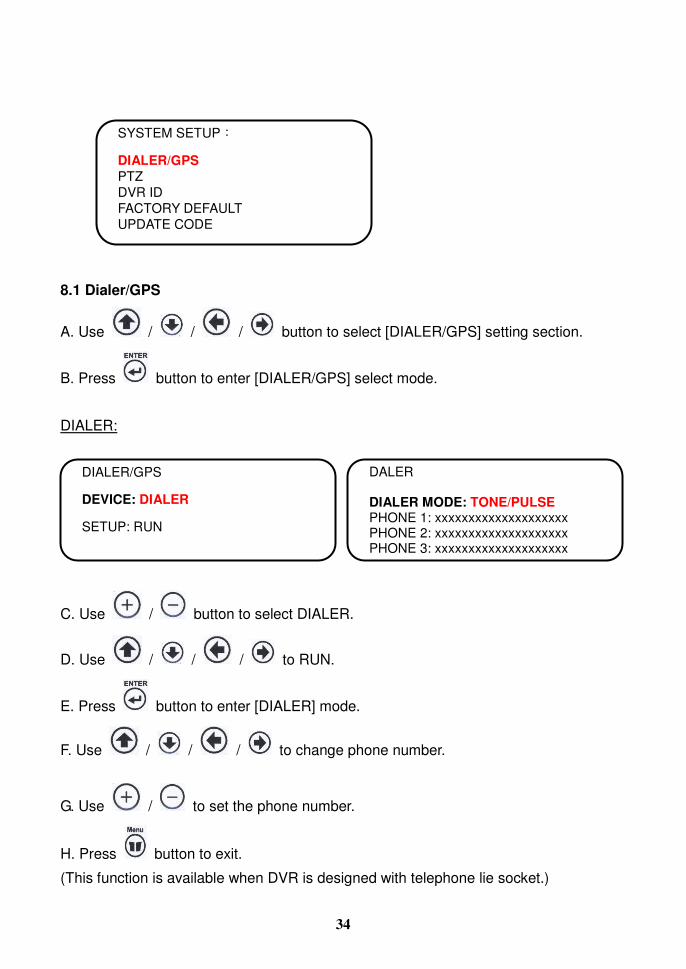
8.1 Dialer/GPS
A. Use / / / button to select [DIALER/GPS] setting section.
B. Press button to enter [DIALER/GPS] select mode.
DIALER:
C. Use / button to select DIALER.
D. Use / / / to RUN.
E. Press button to enter [DIALER] mode.
F. Use / / / to change phone number.
G. Use / to set the phone number.
H. Press button to exit.
(This function is available when DVR is designed with telephone lie socket.)
SYSTEM SETUP
DIALER/GPS PTZ DVR ID FACTORY DEFAULT UPDATE CODE
DALER DIALER MODE: TONE/PULSE PHONE 1: xxxxxxxxxxxxxxxxxxxx PHONE 2: xxxxxxxxxxxxxxxxxxxx PHONE 3: xxxxxxxxxxxxxxxxxxxx
DIALER/GPS
DEVICE: DIALER
SETUP: RUN
35
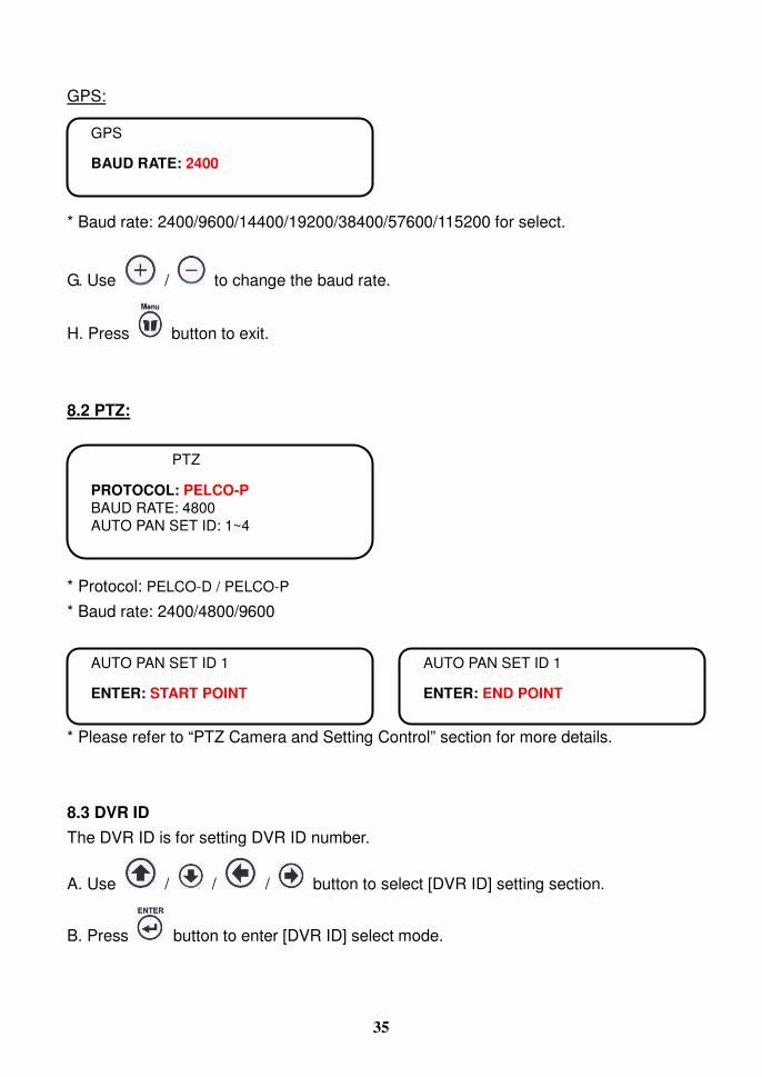
GPS: * Baud rate: 2400/9600/14400/19200/38400/57600/115200 for select.
G. Use / to change the baud rate.
H. Press button to exit.
8.2 PTZ: * Protocol: PELCO-D / PELCO-P
* Baud rate: 2400/4800/9600 * Please refer to “PTZ Camera and Setting Control” section for more details.
8.3 DVR ID The DVR ID is for setting DVR ID number.
A. Use / / / button to select [DVR ID] setting section.
B. Press button to enter [DVR ID] select mode.
GPS
BAUD RATE: 2400
PTZ
PROTOCOL: PELCO-P BAUD RATE: 4800 AUTO PAN SET ID: 1~4
AUTO PAN SET ID 1
ENTER: END POINT
AUTO PAN SET ID 1
ENTER: START POINT

36
* ID TYPE: ID/BUS/TAXI/TRAIN
C. Use / / / to select item for setting.
D. Use / button to select ID type. Use Number keys to change the ID number.
E. Press button to exit.
8.4 Factory default
A. Use / / / button to select [FACTORY DEFAULT] setting
section.
B. Press button to enter [FACTORY DEFAULT] select mode.
C. Use / button to select YES or NO.
D. Press button to RUN this function. (When you press Enter Key, the DVR will go back to factory default. The screen will show “FACTORY DEFAULT OK!”.)
E. Press button to exit.
8.5 Update code
A. Use / / / button to select [UPDATE CODE] setting section.
DVR ID
ID TYPE: ID ID : xxxx
FACTORY DEFAULT
LOAD FACTORY DEFAULT: YES

37
B. Press button to enter [UPDATE CODE] select mode.
C. Use / button to select YES or NO.
D. Press button to RUN this function.
E. Press button to exit.
9. Key Lock Setup
A. Press button to enter menu selection mode.
B. Use / / / button to select [KEYLOCK SETUP] setting section.
C. Press button to enter [KEYLOCK SETUP] select mode.
D. Use / / / to select item for setting.
E. Use / button to select YES or NO.
F. Press button to exit
After leave the OSD Main Menu, press the (Lock) button to activate this function.
UPDATE CODE
1. FORMATE USB DEVICE: NO 2. FIRMWARE UPGRADE-USB: NO 3. LOAD PC PLAYER: NO 4. FIRMWARE UPGRADE-CF:NO MERLIN304: XXX 00/ JAYS: XXX SKL: XXX PRESS ENTER KEY TO RUN
KEYLOCK SETUP LOCK: YES

38
PLAYBACK RECORD DATA
There are two ways to playback the record data.
1. Playback by Time:
a. Press the Play button, the screen will display SEARCH menu.
b. Use / / / buttons to select the start day and time which you want
to play back, then move to “RUN” and press Enter button to playback.
2. Playback by Event:
a Press “Play” button, you can select the PLAY BY EVENT from SEARCH
menu.
b Use / buttons to select page.
c Use / buttons to select event which you want to play back.
SEARCH
TIME: 2007-03-06 12:20:30 RUN EVENT SEARCH BEGIN: 2007-03-06 12:00 END: 2007-03-18 15:30
SEARCH
TIME: 2007-03-06 12:20:30 RUN EVENT SEARCH BEGIN: 2007-03-06 12:00 END: 2007-03-18 15:30
EVENT SEARCH PAGE001 0001 07/03/06 12:00:30 R1 0002 07/03/06 12:03:25 M1 0003 07/03/06 12:06:35 M2 0004 07/03/06 12:09:30 M3 0005 07/03/06 12:15:30 L1 0006 07/03/06 12:20:30 A1 0007 07/03/06 12:30:30 B1 0008 07/03/06 12:30:30 A2 0009 07/03/06 12:40:30 B2 0010 07/03/06 12:50:30 P1 A: Alarm L: Video loss M: Motion R: Record B: Boot P: Panic

39
d Press Enter button to playback.
e During playback, press stop button to back to EVENT SEARCH.
Press “Menu” button will exit.
* Each page can display 10 events (maximum 1000 events can be recorded). * The event log will be cleared simultaneously when format HDD. * EVENT is recorded in the HDD. It can be searched for playback when the HDD is
removed and installed into the other DVR in same type.
In the play mode you can use play bar to control play function. The play bar buttons introduction as below:
FAST FOR.: Fast Forward.
Press the “FF’ once the playback speed will change to x2 speed to play, press again it will change to x4 and press again it will change x8, if you want to return to the playback speed just press the “Play” button.
FAST REW.: Fast Rewind
Press the “FB’ once the backward speed will change to x2 speed to backward play, press again it will change to x4 and press again it will change x8, if you want to return to the playback speed just press the “Play” button.
Pause: Pause the playback.
Stop: Stop playback and go back to the view mode.

40
PTZ CAMERA SETTING AND CONTROL
1. Introduction: Connect the Signal I/O box to the DVR. The signal I/O box has RS485 ports for PTZ camera control.
2. Installation: 2.1 Setting PTZ camera control protocol: Follow PTZ camera user manual to choose and setting control protocol, all the
camera need to choose same protocol type. 2.2 Setting PTZ camera ID: Follow PTZ camera user manual to set PTZ ID, each camera has a unique ID
it’s own. We suggest stronger CH1 camera use the ID no: 1, CH2 camera use the ID no: 2 …, that you will have more convenience to control your PTZ cameras.
Follow the figure to connect all of cameras RS485 TX together and RX together, then insert RS485 TX into the RS485 TX terminal and RX insert into the RS485 RX terminal and tight it. The signal I/O box is as follows:
3. PTZ control setting: 3.1 Go to DVR menu and select system, into system list and select subject of
PTZ/Keyboard, then use left and right keys to select protocol to match your PTZ camera setting.
SYSTEM SETUP
DIALER/GPS PTZ DVR ID FACTORY DEFAULT UPDATE CODE
PTZ
PROTOCOL: PELCO-P/PELCO-D BAUD RATE: 4800 AUTO PAN SET ID: 1~4

41
3.2 Use / / / buttons to select PROTOCOL.
3.3 Use / up and down keys to select subject of BAUD RATE, then use
/ left and down keys to select baud-rate to match your PTZ camera
setting. 3.4 If you want to set auto pan, you can select auto pan=on. Go to auto-pan setup
and use / / / up/down/right/left buttons to set the start
point and end point. Press cam1 save right position, cam2 save left position and press cam3 demo auto pan, and then use Menu key to quit PTZ setting.
4. PTZ control: How to move PTZ camera?
1. Select channel which you want to control
2. Press PTZ (pause) button into PTZ mode.
3. Press Up key to move camera up.
4. Press Down key to move camera down.
5. Press Left key to move camera left.
Press Right key to move camera right.
5. At any time press Stop key to stop camera move.
6. Press Auto (Enter) key to turn the auto pan on.
7. Press PTZ key to quit PTZ control mode.
AUTO PAN SET ID 1
ENTER: END POINT
AUTO PAN SET ID 1
ENTER: START POINT
42
USB DOWNLOAD INSTRUCTION
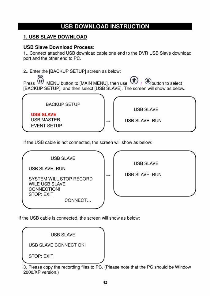
1. USB SLAVE DOWNLOAD
USB Slave Download Process: 1.. Connect attached USB download cable one end to the DVR USB Slave download port and the other end to PC. 2.. Enter the [BACKUP SETUP] screen as below:
Press MENU button to [MAIN MENU], then use / button to select [BACKUP SETUP], and then select [USB SLAVE]. The screen will show as below.
If the USB cable is not connected, the screen will show as below:
If the USB cable is connected, the screen will show as below:
3. Please copy the recording files to PC. (Please note that the PC should be Window 2000/XP version.)
BACKUP SETUP
USB SLAVE USB MASTER EVENT SETUP
USB SLAVE USB SLAVE: RUN
USB SLAVE USB SLAVE: RUN SYSTEM WILL STOP RECORD WILE USB SLAVE CONNECTION! STOP: EXIT CONNECT…
USB SLAVE USB SLAVE: RUN
USB SLAVE USB SLAVE CONNECT OK! STOP: EXIT

43
USB salve working recorded data download speed
1. The system is designed with USB salve 2.0 high speed. 2. The download speed is 400M bit per second. 3. Will download 50M byte per second at idea condition. Need 20 seconds for
download IG byte data, if the actual efficiency is 50%, it will need 40 seconds to download 1G byte data.
2. USB HOST DOWNLOAD a. Download by time
1. Connect the Flash device(Pen drive) to DVR Host download port. 2. Enter the [BACKUP SETUP] screen as below:
Press MENU button to [MAIN MENU], then use / button to select [BACKUP SETUP], and then select [USB MASTER]. The screen will show as below.
Press [Enter] button to download, the DVR will start to format the Flash Memory (Pen Drive). The screen will show:
WAIT …
INITIAL 10%
BACKUP SETUP
USB SLAVE
USB MASTER
EVENT SETUPITIAL 10%
USB MASTER HDD: YY/MM/DD HH:MM BEGIN 07/01/24 08:00 END 07/01/25 15:30 USB BACKUP BEGIN 07/01/24 10:00 END 07/01/25 10:02
USB BACKUP: RUN
USB MASTER WARNING FORMAT USB FLASH DEVICE ENTER: FORMAT USB FLASH STOP: EXIT USB BACKUP

44
When the format is finished, the “Bi” sound will appear, then it will continue to download and show the following on screen:
3. When the file is download completed, the DVR will appear continued “Bi” sound. Press Stop button and the warning voice will be stopped. Press MENU button to exit. b. Download during playback: 1. Press “PAUSE” button and then press “COPY” button. 2. The system will download the recorded data one minute before and one minute after you press “PAUSE” button. For example, if you press “PAUSE” button at 2006/12/01 13:01:24, then the downloaded data will be three minutes from 2006/12/01 13:00:00 to 2006/12/01 13:03:00. c. Quick download: 1. Plug memory stick into DVR USB Host port.
2. Press “COPY” button two times. Under such circumstances, the Record LED will stop flashing (in closed mode.)
3. The system will check whether there is any USB device connected. 4. If no, you will hear 5 short buzzing every 5 seconds. Press “STOP” button to exit.
Then, go back to Step 1. 5. If yes, DVR will start download process. Under such circumstances, the Record
LED will be in flashing mode. 6. When the download is completed, you will hear one long buzzing and the Record
LED will stop flashing. Please press “STOP” button to exit. Then, the Record LED will re-start to flash that means go back to Record mode.
7. If the memory stick capacity is not enough, you will hear 3 short buzzing every 5 seconds. Under such circumstances, you can plug another memory stick and press ”COPY” button one time to continue download process or press “STOP” button to exit.
8. If the memory stick is not well connected with DVR, you will hear 5 short buzzing every 5 seconds. Under such circumstances, please press “STOP” button to exit. Then, go back to Step 1.
WAIT …
BACKUP 3%
45
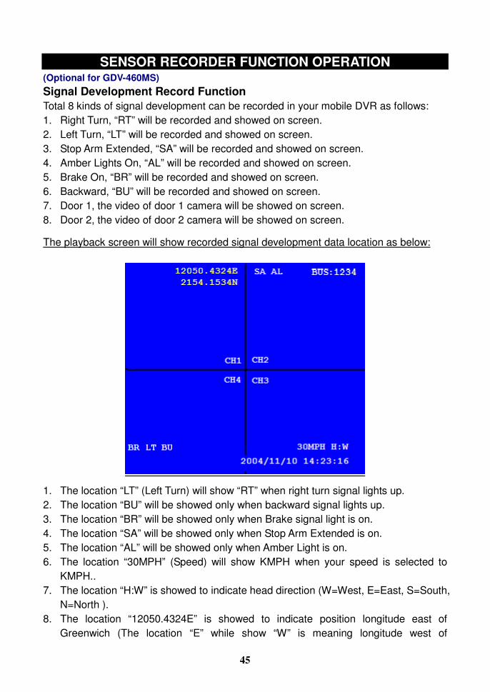
SENSOR RECORDER FUNCTION OPERATION (Optional for GDV-460MS) Signal Development Record Function Total 8 kinds of signal development can be recorded in your mobile DVR as follows: 1. Right Turn, “RT” will be recorded and showed on screen. 2. Left Turn, “LT” will be recorded and showed on screen. 3. Stop Arm Extended, “SA” will be recorded and showed on screen. 4. Amber Lights On, “AL” will be recorded and showed on screen. 5. Brake On, “BR” will be recorded and showed on screen. 6. Backward, “BU” will be recorded and showed on screen. 7. Door 1, the video of door 1 camera will be showed on screen. 8. Door 2, the video of door 2 camera will be showed on screen.
The playback screen will show recorded signal development data location as below:
1. The location “LT” (Left Turn) will show “RT” when right turn signal lights up. 2. The location “BU” will be showed only when backward signal lights up. 3. The location “BR” will be showed only when Brake signal light is on. 4. The location “SA” will be showed only when Stop Arm Extended is on. 5. The location “AL” will be showed only when Amber Light is on. 6. The location “30MPH” (Speed) will show KMPH when your speed is selected to
KMPH.. 7. The location “H:W” is showed to indicate head direction (W=West, E=East, S=South,
N=North ). 8. The location “12050.4324E” is showed to indicate position longitude east of
Greenwich (The location “E” while show “W” is meaning longitude west of

46
Greenwich). 9. The location “2154.1534N” is showed to indicate position of northern latitude (The
location “N” while show “S” is meaning latitudes south of the Equator). 10. The location show “BUS: 1234” is bus number key-in on DVR “OSD” menu under
sub menu section. 11. The location “2004/11/10 14:23:16 is showed as recorded time.
Video Signal Development Record Function Five camera outputs can be connected to the box’s video input connector. The sensor recorder CPU will manage the signal to follow the car signal development and select one of the camera inputs for video output connector.
(Remark: The sensor recorder CPU will manage to output “Right turn view camera’s input” when right turn signal lights up, output “Left turn view camera’s input” when left turn signal lights up and output “Back view camera’s input” when backward signal light up. All other signal development will only output “Main direction view camera’s input”).
The sensor recorder with two video output connectors share same video output signal. One BNC female output for connect to one of the DVR input to record the video signal and the RCA socket is designed for connect to car monitor as assistance for driver.
Position, Speed & Head Direction Record in DVR Function Car speed, position and head direction will be recorded in your mobile DVR. The speed can be recorded by KMPH or MPH (changed by ‘Select’ switch on front panel of the box); the recorded data will be showed on screen while playback.
GPS Location Record in Sensor Recorder Box Function More than 7 days car location data will be recorded in the Sensor Recorder box. The location data recorded in Sensor Recorder box can be downloaded in computer as a GPS location data file to show road map when map software is transferred into.
Special Note: The GPS can be positioned only when the antenna can directly receive at least 4 satellite signals. In other words, the GPS can be positioned only when there is no cover. So, if you are in garage or underground parking lot where can not receive satellite signal by GPS, when the car leaves this place, you have to check your DVR in the place where can receive and make sure you have got speed, direction and GPS data. This way, the recording can be done. Or, you have to stop the car for 1~3 minutes to let the GPS positioned for normal operation.
47
GPS Recorded Data Download Operation Process 1. Install USB driver software (attached in CD). 2. Install GPS download software (attached in CD). 3. Select GPS download software
a. Select COM port. b. Select “Download” and key-in file name. c. Press download button and keep for more than 2 seconds (can see the data
loaded to the file, then can release) to download the GPS recorded data. The download LED will light up till download is completed.
d. Select “CLOSE” after download is completed (The download LED will be off after download is completed).
e. The download file will be saved under GPS download file; user can open the file to view.
f. The download file data is in standard GPRMC format.
Remarks: 1. When GPS display LED flashed, it means GPS does not succeed to get position
data. When GPS display LED lights and keeps still, it means it gets position data. 2. Press and keep the download button, then turn on the power and then release the
download button. This process will delete all recorded GPS data. The LED will flash after data is deleted.
Show Road Map on Map Software 1. Transfer the GPS GPRMC file to match local map software. 2. Open local map software. 3. To transmit the recorded and transferred data to map software to show recorded
road track on the map.

48
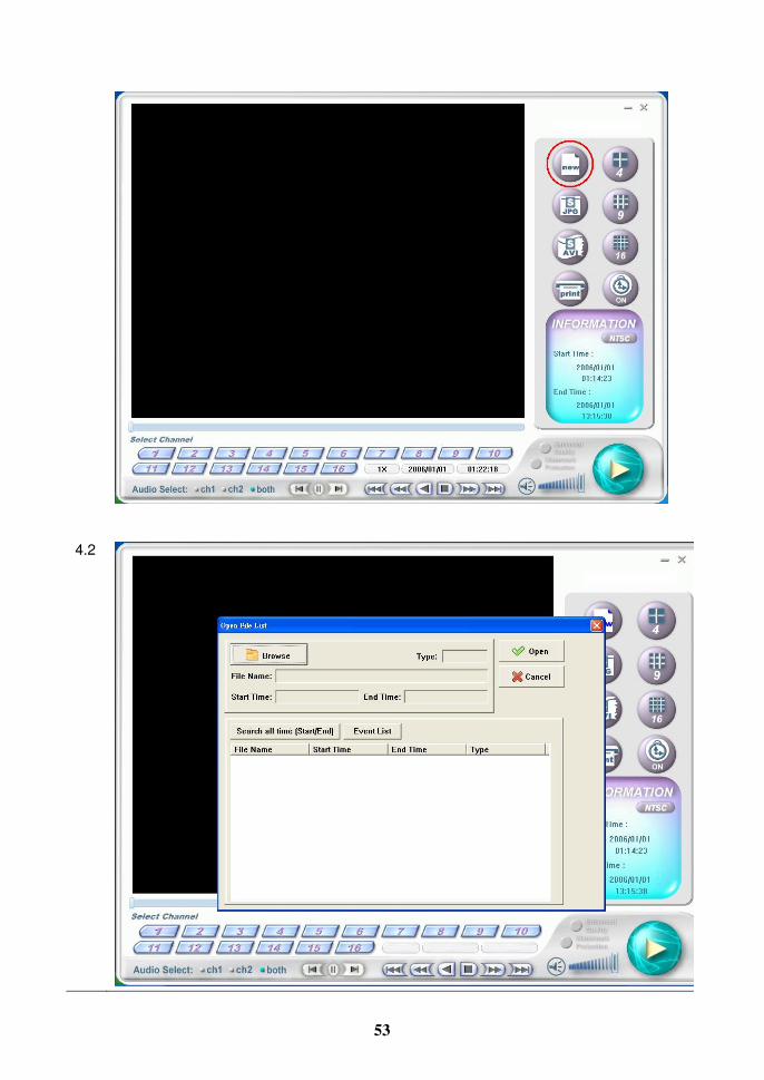
PC PLAYER SOFTWARE OPERATION
1. Install PC player software. 2. Control panel and function.
Open the file 4 splits
Save single image 9 splits
Transfer to AVI format 16 splits
Print Open or close displayed image

49
Minimize / Exit
�
Watermark Protection: The system will show the warning light and stop playing when the recorded data is abnormally put in or removed. Press “Play” button to continue the playback.
Information related to the current file
Play
Volume adjustment or activate mute play
Play speed adjustment
Audio channel selection
Camera channel selection
Double-click the left button of mouse to enlarge the channel

50
3. How to play the file 1 DVR side: MENU � RECORD SETUP � HDD INFO � USB SLAVE
2 Connect USB Cable to both DVR side and Computer. Install PC player software in
Computer.
3.
3-1
First way to play video:
Computer will detect the new Storage Device. It this case as “F”. *The Hard Disk Drive is divided to many file after user format it. And the DVR will create “modify time” to let the Computer (Operating System) know the file detail information (2004/12/10). *2004/12/10 means the software kernel date (basically will not change, unless the software kernel has to do some modify). *If user wants to know the detail DVR image information, please go to 4-5. To know the “EVENT”, please go to

51
3-2
Click right button of PC mouse. Select DVR Player.
3-3

52
Click to play video.
3-4
Play video in computer. Source is from DVR unit.
4.
4-1
Second way to search and play video.
53
4.2
54
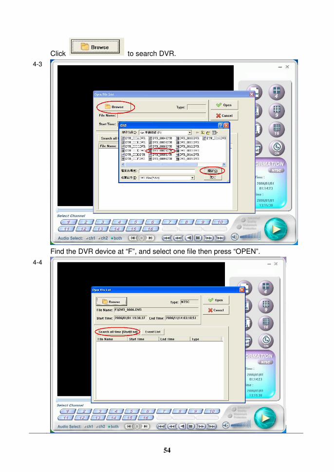
Click to search DVR. 4-3
Find the DVR device at “F”, and select one file then press “OPEN”.
4-4

55
If the file is not desired date/time, press to list all
recorded image. 4-5
Select the desired file to play.
4-6

56
Press . 4-7
Click to play video.

57
4-8
5 Play EVENT 5-1
Press to display all Event.

58
5-2
5-3

59
Select desired event, then press . 5-4
Click to play video.
Copyright © 2022 FDOKUMEN