Working Alone - Woodtools
162
-
Upload
khangminh22 -
Category
Documents
-
view
0 -
download
0
Transcript of Working Alone - Woodtools


Working Alone

TIPS & TECHNIQUES for SOLO BUILDING
John Carroll
The Taunton Press

Cover photo: Les Todd
Publisher: Jim Childs
Acquisitions Editor: Steve Culpepper
Assistant Editor: Jennifer Renjilian
Editorial Assistant: Carol Kasper
Copy Editor: Peter Chapman
Designer/Layout Artist: Henry Roth
Illustrator: Scott Bricher
Indexer: Lynda Stannard
Taunton BOOKS & VIDEOS
for fellow enthusiasts
Text © 1999 by John Carroll
Illustrations © 1999 by The Taunton Press, Inc.
All rights reserved.
Printed in the United States of America
10 9 8 7 6 5 4 3 2
For Pros / By Pros ™ is a trademark of The Taunton Press, Inc., registered in the U.S. Patent
and Trademark Office.
The Taunton Press, Inc., 63 South Main Street, PO Box 5506, Newtown, CT 06470-5506
e-mail: [email protected]
Library of Congress Cataloging-in-Publication Data
Carroll, John (John Michael), 1949-
For Pros / By Pros TM: Working alone : tips & techniques for solo bUilding / John Carroll.
p. cm.
Includes index.
ISBN 1-56158-425-8
I. Building-Technique. 2. House construction-Technique. 3. Self-employed. I. Title.
153.C37 1999
690' .8-dc21 99-33471
CIP

For my son Matthew

Acknowledgments I want to thank four very talented people who
have helped bring this book to fruition. First, I'd like to thank
Steve Culpepper, who encouraged me to write this book and pro
vided sound guidance through every step of the process. Next, I
want to thank the primary editor of this book, Jennifer Renjilian.
Jennifer's questions, insights, and suggestions have greatly
improved the organization and flow of this book. For providing
the fine drawings that appear throughout the book, I'm indebted
to Scott Bricher. Finally, I'd like to thank Peter Chapman for
copy-editing the book.
About Your Safety Home building is inherently dangerous. Using hand or power tools improperly or ignoring
standard safety practices can lead to permanent injury or even death. Don't try to perform
operations you learn about here (or elsewhere) unless you're certain they are safe for you. If
something about an operation doesn't feel right, don't do it. Look for another way. We want
you to enjoy the craft, so please keep safety foremost in your mind whenever you're building.

INTRODUUION 2
CHAPTER 1
Replacing a Helper's Hands 4 The principal challenges of working alone 6 Three ways to overcome the challenges 7
CHAPTER 2
Masonry Work 18 Working with mortar 19 Laying out a foundation 21 Squaring up small projects 32 Setting up scaffolding 33
CHAPTER 3
Floors and Walls 36 Framing floors 37 Building walls 41 Erecting walls 43
CHAPTER 4
Stick-Built Roofs 57 Laying out the roof 58 Building the roof 68

CHAPTER 5
The Shell 77 Framing nonbearing walls 78 Finishing the eaves and rakes 82 Installing windows and doors 88 Shingling the roof 90 Installing wood siding 93
CHAPTER 6
The Interior 98 Hanging drywall 99 Working on doors 103 Running trim 103 Hanging wall cabinets 110 Squaring up a large tile layout 110
CHAPTER 7
Decks 117 Outside structure 118 Inside joists 135 Final steps 139
CHAPTER 8
Limitations of Working Alone 141 Jobs for more than one 142 Using subcontractors to finish the job 145 Facing the workday alone 146
RESOURCES 149 INDEX 151
Introduction The idea for this book grew out of
a casual remark. Several years ago
I took a break on a job to chat with
the homeowner. "You know," he
remarked, "it's really interesting to
watch you work. I'm fascinated by
the way you manage to hold boards
and make measurements by your
self." I'd never given it much
thought, but I had, by that time,
developed a fairly comprehensive
system for working alone.
This system involves a lot of tools
and techniques that are not com
mon on building sites and are
rarely discussed in books and mag
azine articles. These methods may
be unusual but they are very valu
able. Being able to do common
building chores alone makes life
easier for all kinds of builders-not
just self-employed contractors.
"w. k d ." ee en warnors can do a proj-
ect without lining up neighbors or
in-laws. Professional builders can
keep working when some or all
of the crew is out. Or they can
leave the crew on one job and take
care of a small task on another
without dragging along a helper.
Even when all hands are present,
builders can save time by doing
little tasks alone rather than involv
ing a second crew member.
2
Yet, while the advantages of being
able to work alone are easy to see,
the techniques themselves are sel
dom obvious. They sometimes
require tools that you're not accus
tomed to using, and they often
require you to alter the pace and
the sequence you're used to follow
ing. The fact that these techniques
aren't immediately apparent, how
ever, doesn't necessarily mean that
they're difficult to do. Typically,
they only require a different way of
approaching your work. I wrote this
book to provide that different way
of looking at common building
problems.
This book is essentially a compila
tion of the techniques I 've devel
oped in my years of working alone.
The organization of the chapters
follows the schedule of a typical
residential building project, but the
discussion is not comprehensive by
any means. If you're new to this
kind of work, use this book in con
junction with a good basic guide
(I recommend several at the end of
this book). Instead of step-by-step
instructions for a specific project,
I single out those tasks that are dif
ficult to do alone, then I explain
how I approach those tasks by
myself. Most of the techniques I
describe are fairly easy to under
stand and accomplish, but some
will take time to learn.

Learning any building skill is an
active process. To use this book
effectively, look carefully at the
drawings ; think through each prob
lem and try to visualize the solu
tion; and, when you get out on
your job, finagle and experiment.
Your hands and eyes will teach you
the details of these methods. As
you work, feel free to disagree with
me. The approaches I suggest are,
by no means, the last word. On my
jobs, I often improvise and experi
ment, either to solve new problems
or to streamline the solutions to
old problems. Working alone is a
creative process. So, if you see an
opportunity to improve a jig or
technique I describe, go for it!
You may wonder at times why in
the world I don't just hire an assis
tant. On many occasions, I do just
that. In chapter 8, I describe the
jobs that I can't or won't do by
myself. In lining up subcontractors
and temporary helpers, however, I
don't take on the responsibility of
having a payroll. This simplifies the
business end of my company enor
mously. I do the books for the
entire year in one or two days and
see an accountant once a year.
Without a crew to keep busy, I
always have more work than I can
handle. This means I can turn
down work that I don't want.
Furthermore, by working alone and
using a few trusted subcontractors,
I 'm able to keep a tight lid on my
jobs . I work at a manageable pace,
make very few mistakes, and don't
have to worry about the quality of
someone else's work. I rarely get
out of sequence or have to redo
things. My jobs may not move as
quickly as a crew's, but they always
move forward. This orderly
progress is very satisfying, both to
my customers and to me.
I 'll never know for sure whether I
would make a better living if I had
a crew of employees. I do know
that I enjoy working alone more.
I'm also certain it has made me a
better builder. Working alone
forces you to set up your jobs more
thoroughly and to understand the
geometry that your layouts are
based on. Because you have to
think ahead and schedule tasks
more precisely, it hones your plan
ning and management skills. These
are valuable skills whether you're
working on your own house or run
ning a construction company.
3

he human hand is a magnificent
structure, and it will never be
completely replaced. Machines
can lift heavier objects; they can work to
finer tolerances; they can do repetitive
tasks a thousand times faster than human
hands. But compared to our hands, they
are clumsy and inflexible.
This is readily apparent to those of us who
build and repair houses. We use power
tools and equipment, but the equipment
is portable and guided by our hands.
Furthermore, when we use these machines
we usually have to finish up by hand.
Floor finishers, for example, use sanders
to do most of the sanding but follow up
with hand tools to do the perimeter of the
floor and stair treads. Machines relieve
us from a lot of hard, boring work, but
they're often too clumsy to finish the job.
Machines are not only clumsy but
also expensive and time-consuming.
Over the long haul, time and money
invested in complex, highly special
ized machinery can be recovered
on farms and in factories . But on
construction sites, which are tem
porary and ever-changing, it is
often impossible to use this kind of
equipment effectively or to recover
such large capital outlays.
For example, a machine that lays
bricks has been around for decades,
but it costs hundreds of thousands
of dollars and takes days to set up.
Such a machine is sometimes used
in a factory setting to produce the
prefabricated brick panels that go
on commercial buildings. But this
complex machine is not practical
on residential projects where the
scale is small, access to the site is
often limited, and most of the
work can be rapidly completed by
skilled craftsmen.
It may seem odd in this age of
orchestrated electrons and engi
neered genes, but the fastest and
most cost-effective way to build a
house or addition is usually for
crews of skilled workers to roll up
their sleeves and have at it with
portable equipment and handheld
tools.
Here's where working alone can get
difficult. Those of us in this busi
ness cut our eyeteeth as the low
man in a crew. We haul boards and
bricks, run errands, and get yelled
at when we move too slowly. Our
principal assets are our hands, and
we're reminded of this in the lan
guage that's used all through the
day. Our bosses tell us to "give me
a hand here," "hand me that
block," "hold this," "lift that." We
grow into our trades in a climate
where simple, direct methods are
taught and relentless forward
progress is demanded.
When you're alone on a job, of
course, you don't have the luxury
of a helper's hands, so many of the
standard techniques are useless. To
work alone you develop a different
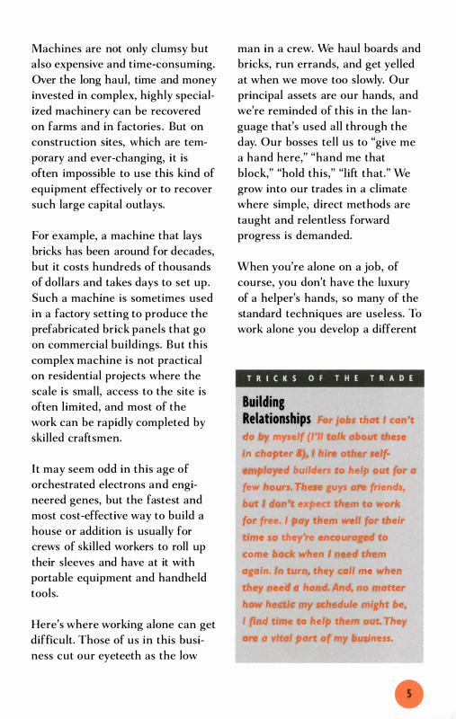
T R I C K S OF T H E T R A D E
Building Relationships For Jobs that I can't
do by myself (1''' talk about these
in chapter 8). , hire other self
employed builders to help out for a
few hours. These guys ate friends,
but I don't expect them to work
for free. I pay them well for their
time so they're encouraged to
come bock when I need them
again. In turn, they call me when
they need a hand. And. no matter
how hectic my schedule might be,
I find time to help them out. They
are a vital port of my business.

Because building is on
inherently dangerous occupation,
it makes sense to be prepared for
accidents. Keep a first-aid kit in
your cor or truck. Also, think about
getting a cell phone, which you can
keep right beside you as you work.
If you're working alone, there's a
good chance no one will be around
to drive you to a doctor if you get
hurt. In these situations, a cell
phone may be the most important
item to have on site.
mind-set and work at a different
pace. You can no longer attack your
work as you did when you worked
in a crew. This adjustment from a
brisk, sometimes frantic pace to a
deliberate, measured pace is the
first and most important step in
becoming an effective solo builder.
It's an adjustment that many
seasoned builders have a hard
time making.
The Principal Challenges of Working Alone When you decide to take on a proj
ect by yourself, you're confronted
with two fundamental challenges.
REPLACING A HELPER'S HANDS
First, how do you measure and
mark alone? Measuring and mark
ing by yourself may seem like a
daunting challenge. When a helper
is on hand, he holds one end of the
tape measure or chalkline. But
when you're by yourself, you either
devise some mechanical means of
holding the other end of the tape
or line, or you come up with an
alternate technique-one that
obviates the need for those tools.
These methods have to be precise
because close measurements are
basic to good workmanship. And
they have to be fast because you
use them often.
The second major challenge is to
figure out ways to lift, carry, hold,
and align the materials that go into
the building. These tasks can be
awkward and difficult in some
circumstances and dangerous in
others. But they don't have to be.
In most automotive shops, a single
mechanic thinks nothing of remov
ing and replacing an engine that
weighs 800 lb. or so. By taking a
page or two out of his book, bor
rowing a couple more from wood
working shops, and stealing the
occasional trick from other groups
(movers, riggers, sailors, post-and
beam builders, etc . ) , you can learn
to lift and secure just about any
thing that goes into a house-by
yourself.

Three Ways to Overcome the Challenges Back in the days when I worked
in a crew, I sometimes ended up,
for one reason or another, alone on
a job. In those days I found the
situation extremely frustrating.
Routine tasks with a helper became
slapstick comedies when I was
alone, and, true to form, I often
took on the role of an exasperated
Ollie Hardy or a volcanic Ralph
Installing a Fascia Board
Kramden. I was usually grateful
that there were no witnesses to
these grim and, no doubt, ridicu
lous performances.
Today, I'm happy to report, I rou
tinely do all the things by myself
that made me look so ridiculous
when I was 20 years younger.
Although I made this transition
gradually (often without conscious
ly thinking about it), I can now
identify the three basic ways I was
To install a fascia alone, use a site-built brocket, a clamp, and the proper sequence. By installing the fascia before installing the soffit on the underside of the eave, you can clamp the brocket to the frome.
--
- -- -
Site-built brocket holds one end of board.
- -
- - -
- ---
Bracket detail
THREE WAYS TO OVERCOME THE CHALLENGES

able to do so. First of all, I've
learned to plan and organize my
jobs more thoroughly than I did
when I had coworkers. Second, I've
acquired numerous manufactured
tools that help me do without that
second pair of hands. And, third,
I've become adept at making and
using jigs, templates, brackets, and
other site-built devices . Although
I'll be discussing these approaches
separately here, I often use them
in combination with each other,
as the drawing that shows how I
might install a fascia board demon
strates (see p. 7 ) .
Planning to Work Alone
All builders worth their salt develop
a well-thought-out master plan at
the beginning of a project and a
T R I C K S OF T H E T R A D E
Using Sharp Hand Tools As a solo builder, I've
found sharp chisels, planes, and
handsaws to be an invaluable part
of my tool collection. They not only
Improve the quality of my work but
also save steps. Rather than climb
down off a scaffold to saw '116 in.
off a board, for example, I usually
shave it off up on the scaffold
with a sharp block plane. It's less
work. and , get a better fit in the
process.
REPLACING A HELPER'S HANDS
series of battle plans for each
phase along the way. Then, as the
project gets under way, they come
up with modifications in the plan
to cover unexpected developments
and changes in the design. If you're
working alone, you have to do all
this planning-and more. You have
to include provisions in every
phase of the plan for the special
problems of doing things with just
two hands.
One of the basic planning consid
erations is the sequence in which
you build. As you'll see when we
get into specific techniques, there
are many instances when you can
make your life a lot easier by think
ing ahead, anticipating how you're
going to do things by yourself, and
then coming up with an appropri
ate order of assembly.
In addition to fine-tuning the
sequence of the job, you have to
plan just about every step along the
way. Often you even have to plan
how you're going to do minor
chores like safely sawing sheets of
plywood or installing long boards.
Sometimes these plans require a
careful setup or some clever site
built rig. At other times, the plans
are focused on subtle aspects of
your technique. Starting a nail
before you pick up a board, for
instance, can make installing that
board a lot easier.

The Hidden Potential in Manufactured Tools I spend a lot
of time looking at tools and imagin
ing how I'd use them on my jobs.
Among builders, this is not terribly
unusual behavior. Yet the tools that
attract my attention are often quite
different from those that interest
builders who work in crews. I focus
primarily on tools that replace a
helpers hands; they're looking for
tools that increase productivity and
thus help cover the cost of a payroll.
But even when a production builder
and I have the same tool, we're apt
to use it differently. I look for novel
uses for common tools; sometimes
I see uses for tools that the manu
facturers themselves seem to have
overlooked.
When I first sow ads in my tool cata
logs for Mastodon Jaw Extenders, for
example, I knew I had to get a pair.
While the manufacturer hawked
these devices as a way to make deep
clamping affordable, I bought them
for a different reason. The 1 0-in.
increase in clomp depth that the Jaw
Extenders create when attached to a
standard bar or pipe clamp is a great
help when I'm clamping something
against a wall. With a standard
clomp, the handle is too close to the
wall to turn, but with the Jaw
Extenders attached, the clamp is far
ther from the wall so I have plenty
of room to spin the handle.
Similarly, I recently bought a couple
of squares designed for builders who
work with steel studs. I hardly ever
work with steel studs, but I didn't
hesitate to lay down $1 0 apiece for
two of these squares. Called the
Swanson Magnetic Square, this tool
has magnetic strips that hold the
square firmly to steel studs. I wasn't
interested in this feature at all, but
I could see immediately that the
extra-deep (W4-in.) fence would be
very handy for clamping or screwing
the square to my work. So as soon
as I got the squares home, I drilled
several holes in them. Now I can
clamp or screw them to the surface
of my jobs and use them as brackets
for holding up light materials or for
anchoring the end of my tape
measure.
I've found that tools are often much
more versatile than they seem at
first. Look at them closely and let
your imagination wander-you'll get
a lot more out of them.
THREE WAYS TO OVERCOME THE CHALLENGES

The process of anticipating prob
lems and then visualizing smooth,
effective ways to overcome them is
at the heart of working alone. I'll
return again and again to this
theme as I discuss specific tech
niques in the chapters that follow.
Using Manufactured Tools
Many of the solutions that I 've
come up with involve tools and
techniques that I rarely, if ever,
used when I worked in a crew.
Some of the tools are common
items that are either ignored or
Clamps
One-hand bar clamp
Locking (-clamp
REPLACING A HELPER'S HANDS
poorly exploited by production
crews as they attack their work;
others are special-purpose tools
that are seldom seen on construc
tion sites (see the sidebar on p. 9).
Clamps and spreaders
I couldn't imagine taking on most
of the jobs I do without my large
and growing-collection of clamps.
Clamps hold things for me, some
times for days, and never complain.
They serve as handles for carrying
sheets of plywood and other
unwieldy materials. They provide
Bar clamp

muscle to push and pull things
into place. And they help make
my job sites safe.
C-clamps make the best handles,
and they take the place of screws
and nails for temporary setups.
They're cheap, and they provide
plenty of torque, but they're limited
in size and aren't good for quick
setups. When I need to clamp some
thing larger than 8 in. (the size of
my largest C-clamp) I use either a
bar clamp or a pipe clamp. My
longest bar clamp is 48 in., and
Adjustable-bracket pipe clamp
One-hand bar spreader
my longest pipe clamp is about
72 in. By threading sections of pipe
together, however, I 've been able to
use my pipe clamp for distances of
l O ft. and greater.
When I do a repetitive task, like
clamping material at the saw table,
I avoid C-clamps. They're frustrat
ingly slow because the only way to
adjust them is to turn the threaded
bolt. Bar clamps, in contrast, slide
quickly into adjustment-the
threaded portion is only to apply
pressure. Sometimes very little
Spring clamp
Reversible pipe clamp in spreading mode
THREE WAYS TO OVERCOME THE CHALLENGES

pressure is required, though, and a
simple spring clamp, which looks
and works like a big clothes pin,
speeds the process. Another clamp
that can be set up and released
in a few seconds is the "locking"
C-clamp, which uses a cam to
apply pressure. These clamps take
a minute or so to adjust but provide
a lot more pressure than spring
clamps and, once adjusted, are
quicker than bar clamps. (Unlike bar
clamps, which have to be screwed
tight each time they're used, lock
ing C-c1amps can be tightened with
a squeeze of the hand.)
One of the handiest clamps for a
solo builder is the one-hand bar
clamp. With this kind of clamp, I
can position a board with one hand
and immediately clamp it in place
with the other. One-hand bar
clamps aren't cheap, but they're
worth the extra expense for the
times when you really need them.
By tightening the jaws of a clamp,
you can apply hundreds, sometimes
thousands, of pounds of squeezing
force to the workpiece. Turn the
working parts around, and you can
apply the same force in the oppo
site direction. I have two pipe
clamps that can be reversed and
made into spreaders; and I've also
acquired one-hand bar spreaders.
I use them mainly for forcing
crooked lumber into line.
REPLACING A HELPER'S HANDS
Sawhorses, scaffolding, and ladders
Large production framing crews
often have next to nothing to work
off. On many occasions, I've seen
carpentry crews spend the day cut
ting lumber cradled on their foot
and working off a single, rickety
stepladder and some jerry-built
scaffolds. They do a lot of climb
ing, take unnecessary risks, and
squander man-hours, but they usu
ally achieve their primary objective,
which is to move rapidly through
the project.
A solitary carpenter can't work that
way. Because he doesn't have
another person to hold boards
when he's ripping them or cutting
them at an angle, a lone carpenter
has to set up a secure sawing sta
tion and use clamps (see "Building
a Job-Site Sawhorse" on p. 53 ) .
And when he starts getting off
the ground he needs good, sturdy
ladders and scaffolding.
The best all-purpose scaffolding
system is pipe scaffolding (the kind
bricklayers use) . Pipe scaffolding is
not terribly expensive, and I've
found the six sections I bought
years ago to be an excellent invest
ment. If you don't want to buy
them, sections of pipe scaffolding
can be rented for next to nothing.
They're very stable and strong, and,
with a little practice, you'll find it

Holding and Fastening a Board by Yourself
easy to set them up and take them
down by yourself. (For more on
scaffolding, see pp. 33-35 . )
When i t comes to ladders, I buy
only commercial-grade. Factor in
the day-to-day aggravation of work
ing with a ladder that doesn't oper
ate smoothly-not to mention the
cost of a single visit to the emer
gency room-and a cheap ladder is
a very bad investment.
3. Hammer in the nail.
Fastening options
and put a nail in the hole.
Holding a board with one hand and
nailing it with the other presents a
singular challenge. To start the
nail, you need two hands-one for
the nail and the other for the ham
mer. If you've got one hand on the
board, you've got a problem. In
some circumstances, you can get
around this problem by using a
clamp to hold the board; in others,
you can start the nail before you
THREE WAYS TO OVERCOME THE CHALLENGES

pick up the board. A third option is
to have a drill set up with a bit the
same diameter as the nails you're
using. As you hold the board with
one hand, drill a pilot hole with the
other (see the drawing on p. 1 3 ) .
Set the drill aside and, using your
free hand, slip a nail in the hole.
Now grab your hammer and drive
the nail home. To do this smoothly,
a well-designed tool belt with drill
holster and a good cordless drill are
highly recommended.
If you're willing to invest a few
hundred dollars, there are also two
mechanical solutions available. The
first is the nail or staple gun. Most
of these tools use compressed air to
drive the fasteners. Because they
can be operated with one hand,
holding and fastening a board is a
piece of cake. The other one-handed
fastening tool is the screw gun.
T R I C K S OF T H E T R A D E
Measuring and Cutting in Place The best measuring tool
;s often no measuring tool at all.
When possible, simply hold the
piece of material in place and
mark it directly. In many cases, you
don't even have to mark the mate
rial. You can often install it long,
and then cut it in place.
REPLACING A HELPER'S HANDS
These are now available with belts
of collated screws that feed auto
matically into the tip of the driver.
Measuring sticks
The standard measuring tool on
construction sites is the tape mea
sure. It's accurate, compact, conve
nient and, as a result, hangs from
nearly every tool belt. For the solo
builder, however, the tape measure
can be a maddening device. It's
designed to be pulled, and, as long
as it can be hooked or clamped to
the work surface, it works great.
But when it can't be hooked or
affixed at one end, frustration
quickly sets in. On flat surfaces, the
hook gets in the way and the case
repeatedly flops on its side. Over
open spaces, the tape collapses.
For a solo worker, it's often a lot
easier to use a 6-ft. folding ruler or
a measuring stick. I prefer the lat
ter and keep three inexpensive, alu
minum rulers-a 24 in., a 48 in.,
and a 72 in.-on my jobs. Because
these lie flat and stay secure on
roof decks, floors, and walls, I can
effortlessly hold them with one
hand while I mark with the other.
They're great for measuring across
open spaces, and they come in
handy as straightedges. I think
they're one of the best-kept secrets
in building.

Thinking Like a Gato del Campo Years ago, I had a
Spanish-speaking employee named
Jenaro who, along with other skills,
could shape and weld metal. He
often showed up at work with
special-purpose tools and jigs that
he fabricated at home in his spare
time. Whenever I asked him where he
found the materials for these sundry
gadgets, he grinned and said, "los
obtuve 'gato del campo:" by which
he meant, "I got them like a country
cat." In other words, he scrounged
them up by picking through the land
fill, foraging at job sites, and getting
freebies from coworkers, customers,
and unknown citizens who left them
at the curbside.
Like Jenaro, I get most of the mate
rials for my jigs and brackets like a
country cat. The brackets I use to
support siding and trim boards, for
example, were originally part of a
consumer item designed to provide
hooks on the inside of a bathroom
door. The bracket draped over the
top of a bathroom door, and a rack
of hooks for towels, robes, and so on
was bolted to it. When one of my
less-observant customers asked me
to fix his bathroom door, I saw
immediately that the brackets were
keeping his door from closing prop
erly. By Simply removing the brackets
and screwing the rack directly to the
door, I solved the problem. Then, as I
cleaned up the job, I deposited the
leftover brackets in my toolbox and,
thus, procured another tool like a
"gato del campo."
Over the years, I've developed a
stray cat's eye for useful discards. I
always save large plywood scraps,
particularly those from 'i4-in. plywood
subfloors. From these, I make tool
boxes, jigs, and brackets. I also use
them as templates, as cutting boards
(for cutting insulation), and as knee
boards (for finishing concrete).
Other scraps that I always save
include long strips ripped from wider
boards. From these, I make story
poles and measuring sticks. And I
never throw away solid-wood doors:
Stretched across a pair of sawhorses,
these make excellent saw stations.
The wide variety of jigs and devices
I make have but one feature in com
mon: They all cost exactly what a
stray cat pays for a meal.
THREE WAYS TO OVERCOME THE CHALLENGES 15

Using Special-Purpose Tools
Special-purpose tools are made to
do one or two things very well.
Usually these tools are superbly
designed, and they can substantial
ly expand the capabilities and
power of the solo builder. In the
chapters that follow we'll examine a
lift designed specifically for hoist
ing sheets of drywall, a stand for
supporting kitchen cabinets, and a
jack for raising framed walls . We'll
also look at several special-purpose
levers and jacks devoted solely to
straightening out crooked lumber.
And we'll examine a new breed of
builder's level that uses a laser
beam and is easily operated by one
person. Special-purpose tools are
Using Measuring Sticks
often expensive, but they can clear
frustrating, time-devouring obsta
cles out of the path of a solo
builder. The ones I 've bought are
worth every cent I spent.
However, you can also build your
own site-built tools and jigs.
Imagine you're working in a 2-ft.
high crawl space, trying to measure
the length of each of the bays
between the floor joists as you
install insulation batts. You're lying
on your back, in the dirt, wearing a
respirator and working with a very
unpleasant material. You definitely
don't want this job to drag on any
longer than necessary. But every
time you extend your tape measure
I �O-in. measuring stick Mark here.
I . Jam a 1 DO-in. stick into the end of boy. Mark at the end of the stick
REPLACING A HELPER'S HANDS

overhead it collapses, which gets
frustrating in a hurry.
In such cases, do yourself a favor
and leave your tape measure in
your toolbox. Instead of fooling
with a floppy tape, cut a rigid strip
of wood exactly 1 00 in. long and
bring it, along with your store
bought measuring sticks, under the
house. To measure a span that's,
say, 1 46Yz in. long, jam the l OO-in.
stick against one end of the bay
and mark the joist at the end of
the stick (see the drawing below) .
Then measure the remaining
46Yz in. by jamming a store-bought
measuring stick against the other
end. You can use the same tools to
measure and then to cut the insu
lation. They also make good
weapons if you're approached by
unfriendly vermin.
The l OO-in. measuring stick is but
one of dozens of site-built tools and
jigs I use to work safely and smooth
ly by myself. Most of these are easy
to put together, can be saved for
future projects, and-this is the
part I really like-cost nothing but
the little time I put into them.
Record measurement at mark.
2. Measure from the other end back to the , �O-in. mark with a manufactured measuring stick.
THREE WAYS TO OVERCOME THE CHALLENGES
f you have the skills and are willing
to endure the plodding pace, there
are no serious obstacles to laying
brick and block alone. Bricks and blocks
are manufactured in sizes that can be eas
ily handled by one person. Mortar can be
mixed in small batches and then placed in
the structure one trowelful at a time,
although keeping mortar fresh does pre
sent some challenges to a solo builder.
Except for concrete, which I'll discuss in
chapter 8, virtually all masonry materials
can be moved, lifted, and installed by one
person without undue difficulty.

The main challenge in masonry
work is not in the installation, it's
in the layout, particularly the lay
out of broad structures like founda
tions. Laying out a foundation is
difficult enough for a crew of two
or three; for a solo worker, it can
seem like an insurmountable task.
Because of several difficulties with
measuring and because the layout
has to be precise in three dimen
sions, perfectly level, and at the
correct height, I do not lay out
whole house foundations by myself
(see chapter 8 for more on the rea
sons why) . However, I have laid out
the foundations for large additions
by myself, and I've worked out a
system that is precise and takes a
reasonable amount of time (about
four hours for a simple rectangular
addition) .
Building the masonry structures is
not difficult for one person-either
at ground level or above. But
because of the weight of masonry
materials, building above ground
level does call for scaffolding. With
the right techniques and some
planning, it's possible for one per
son to erect the scaffolding and
make it level.
Working with Mortar
When most people look at a brick
wall they see bricks ; when a mason
looks at a brick wall he sees mor
tar. The reason for this is simple:
The quality and craftsmanship of
brick structures are determined
primarily by the mortar. When it's
installed properly, mortar holds
bricks tenaciously together and
seals out water. And it's pleasing to
the eye-well-crafted brick walls
have mortar joints that are neat
and consistent in size, color, and
tooling.
The key to getting this kind of
workmanship is to use mortar that
is mixed just right. Getting the dry
ingredients correctly proportioned
is a simple matter. The Portland
Cement Association recommends
mixing 2 Y2 to 3 parts sand to I part
masonry cement. To do this, I fill
the same bucket 2 Y2 times with
sand, followed by I bucketful of
masonry cement. If I want to make
a small batch of mortar, I use a
I-gal. bucket or even a coffee can.
If I want to make a large batch, I
use a 5-gal. bucket.
Determining the amount of water
needed is not so simple. Here the
Portland Cement Association does
not suggest a proportion; instead it
recommends that the mortar
should be as wet as possible-to
achieve a strong bond-yet have
enough body to let the mason do
good, neat work. Because the mois
ture content of the sand varies, the
amount of water needed to make
good, workable mortar changes
from day to day. Thus there is no
WORKING WITH MORTAR

T R I C K S O F T H E T R A D E
Installing Flue Liners If you don't happen to
have the digital strength of a rock
climber, it's very difficult to hold
the larger sizes of flue liners
between your fingers as you lower
them into place. You can make this
job a lot easier by affixing two
C-c1amps at the top opening of
the liner before you pick it up. The
clamps serve as handles as you
lower the flue into position during
installation.
formula for the correct amount of
water to use, and masons simply
add water until the mix looks and
feels right.
Making a perfect batch of mortar
doesn't mean that it will stay that
way. All cement-based products
begin changing the moment they're
mixed with water. To maintain a
good workable consistency, masons
sometimes "retemper" the mortar
by mixing in small amounts of
water. In this regard, they can go to
the well only so many times. The
longer a batch of mortar sits in the
pan, the harder it is to work with
and the more frequently it has to
be retempered. Excessive retemper-
MASONRY WORK
ing is not only time-consuming,
but it also affects the strength of
the mortar. As a result, the Portland
Cement Association recommends
discarding unused mortar after
2 hours.
Without question, the best way
to lay bricks is to use fresh mortar.
So it makes sense to mix up just
enough for 1 to 2 hours of work.
This requires careful planning
particularly when you're working
alone. I try to get everything into
position-the bricks, the blocks,
the line, and the tools-before I
make the mortar. I also size the
batch according to how fast I think
I'll use it. If I'm building a founda
tion, I make a large batch because
I know I'll go through the mortar
quickly. If I'm building a chimney,
on the other hand, I make smaller
batches because the work goes
slower.
When I 'm working off a scaffold, I
mix smaller batches than when I'm
working on ground level because I
know that hauling the mortar up a
ladder one bucketful at a time will
slow me down. If I'm building an
arch and I know I 'll have a lot of
time-consuming cuts to make, I do
as much of the cutting as I can
before I mix the mortar. And because
such work goes very slowly, I mix a
very small batch.

Laying Out a Foundation
When I lay out any foundation,
I have two basic concerns. First, I
want to get the layout level and at
the right elevation or height.
Second, I want to get the founda
tion square and to the right length
and width. To accomplish the first
goal, I use a laser level to establish
the top surface of the foundation.
To accomplish the second goal, I
use careful measurements and
geometry to lay out the length and
width of the foundation. When I'm
done, the layout consists of several
strings set up to represent the pre
cise, outside dimensions of the
foundation. These strings serve as
references to measure against as I
build the foundation.
Establishing the Level Plane
To illustrate how I go about laying
out the foundation for an addition,
I'll walk through the steps for a
foundation that's 20 ft. 8 in. long
and 1 2 ft. wide. The steps are the
same for any size addition founda
tion. For distances less than 30 ft.
(the length of my basic tape mea
sure), I've found that using inches
simplifies mathematical calcu la
tions. So, I'll refer to this as a
248-in. by 1 44-in. foundation.
The long wall
After stripping the siding off the
house, I need to make two marks
exactly 248 in. apart on the
exposed frame of the house. These
marks represent the long dimen
sion of the foundation. Making the
first mark is easy: The addition typ
ically begins at or a few feet from
the corner of the house or some
other critical reference (such as
a door).
Pulling the 248-in. measurement
and making the second mark is the
hard part. Because no helpers are
available, I need to rig up some
way to hold the end of the tape as
I pull it out and mark the 248-in.
dimension. To do this, I nail a
scrap of 2x2 to the wall with the
end of it even with my first mark;
then I hook my tape over the end
of the scrap, pull the measurement,
and make the second mark (see the
drawing on p. 22) . Once in a while
the hook of the tape slips off the
end of the block. When this hap
pens, I use a spring clamp to hold
it to the block.
Once the long ends of the founda
tion are marked on the house, it's
time to lay out the long, outside
wall of the foundation that runs
parallel to and 1 44 in. away from
the house. I begin this process by
driving four 2x4 stakes into the
ground. I install these stakes in
pairs a few feet outside the marks
on the house that represent the
new foundation. I put one stake in
each pair roughly 1 20 in. away
from the house, and the other
LAYING OUT A FOUNDATION

Pulling a Wall Measurement
Line marking beginning of new foundation
Tape measure hook
A scrap of wood nailed to the side of the house provides a surface to hook your tope measure to. If the tape slips off the block of wood, clamp it in place.
Tape
2x2 nailed to frame of house
about 1 60 in. away. (Because this
is a rough measurement, I run my
tape measure along the ground
and don't worry about hooking it to
the building.) This way the stakes
straddle a line parallel to and 1 44 in.
away from the house. Because I
will mark the top of the foundation
on these stakes, I make sure that
their tops are higher than the foun
dation of the house.
With the stakes in place, I'm ready
to set up my laser level. I usually
set the laser up inside the founda
tion I'm laying out, but because it
MASONRY WORK
has an effective range of 1 00 ft. ,
I can set it up just about any place
inside or near the new foundation.
Builders use several tools to accu
rately mark off a level plane, but
when you're working alone nothing
is easier to use than a laser level.
For me, this tool has been a great
investment, and I highly recom
mend it to anyone who does a lot
of solo building.
Properly adjusted, my laser level
emits a level laser beam that's
accurate within a Y4 in. over 1 00 ft.
When I rotate the instrument, this

Marking the Top of the Foundation
3 I lls-in. mark
Top of existing foundation
3 I lls-in. mark
Batter board stake
4-ft. ruler
Hold the ruler so that the laser beam hits the desired dimension (3 I Ya in. here). Then mark the stake at the bottom of the ruler.
After leveling the instrument, measure the difference in elevation (3 I % in. here) between the laser beam and the top of the foundation. Then measure down the same amount at each stake to transfer the top-or-foundation elevation to the stakes.
beam becomes, in effect, a level
plane about 200 ft. wide. As you'll
see, this plane serves as a reference
to measure against when I lay out
the top of my foundations .
The first step is to carefully adjust
the instrument so it remains level
no matter which direction I point it
in. Then I aim it at the house. The
laser beam shows up as a red dot,
about Ys in. wide, on the side of
the house. Next I measure the dis
tance between the center of this
dot and the top of the existing
foundation, known as the "differ-
ence in elevation." For this founda
tion, the distance is 3 1 % in. I use
this difference in elevation to
transfer the elevation of the top of
the foundation from the house to
the stake.
I point the laser level at each stake
and measure down 3 1 % in. from
the laser dot with a 48-in. measur
ing stick. To get the measurement,
I hold the ruler vertically and move
it up or down until the laser dot
centers on the 3 1 %-in. mark. Then
I mark the stake at the bottom of
the ruler.
LAYING OUT A FOUNDATION
When all four stakes are marked, I
clamp a 2x4 batter board horizon
tally across each pair of stakes so
the top of the board aligns with the
marks on the stake. To get the top
edge of each batter board exactly
even with the marks, I hold the
board precisely in place with one
hand while I clamp it with the
other, using a large spring clamp.
(I could also use a one-hand bar
clamp or a locking C-clamp. ) Mter
the batter boards are in place, I
add C-clamps to hold the batter
boards securely for the week or two
that I need to leave them in place.
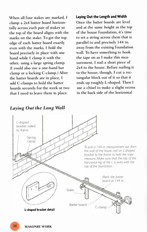
Laying Out the Long Wall
L-shaped bracket nailed
L -shaped bracket detail
MASONRY WORK
Laying Out the Length and Width
Once the batter boards are level
and at the same height as the top
of the house foundation, it's time
to set a string across them that is
parallel to and precisely 1 44 in.
away from the existing foundation
wall. To have something to hook
the tape on as I make this mea
surement, I nail a short piece of
2x4 to the house. Before nailing it
to the house, though, I cut a rec
tangular block out of it so that it
ends up roughly L-shaped. Then I
use a chisel to make a slight recess
in the back side of the horizontal
To pull a I 44-in. measurement out from the wall of the house, nail an L -shaped bracket to the frame to hold the tope measure. Make sure that the top of the horizontal leg of the L is even with the top of the foundation.
Batter board
Mark the batter board at I 44 in.

leg of the L. When I nail this brack
et to the house, I set it so that the
top of the cut-out portion is even
with the top of the foundation.
The slight recess allows me to
insert the hook of the tape in the
crack between the house and the
bracket. To hold the tape in place,
I use a spring clamp. I pull the tape
measure out from the house and
mark the batter board at 1 44 in.
After doing this on both ends of
the foundation, I set up the string
on the batter boards running from
mark to mark.
To hold the string on the batter
boards, I use mason's line blocks.
The advantage of these blocks is
that I can slide them laterally along
the batter board as I fine-tune the
position of the string in relation to
the house. Chances are I haven't
pulled the initial 1 44-in. measure
ment precisely perpendicular to the
house, so the string will not be
exactly 1 44 in. from the house. To
get the string exactly 1 44 in. from
the house, I swing the tape mea
sure in a gentle arc (see the draw
ing below). When the tape measure
is at the high point in the arc, it is
Pulling a Perpendicular Measurement
L-shaped bracket �
Batter board (
Slide the line block along the batter board.
I 44-in. dimension
String
To ensure that the string is at exactly 1 44 in., swing a tope measure across it. At the highest point in the are, the tope measure should cross the string at I 44 in. If it doesn'c move the line block holding the string until it's exactly in place.
Swing tope measure in are.
Batter board
String
lAYING OUT A FOUNDATION

Math and the Solo Builder The first time I ever
«squared up" a foundation, I was
working with a crew. We set up two
parallel pairs of strings representing
the length and width of the founda
tion. Then we measured the diago
nals of the layout, which, predictably,
were unequal. To get them equal, we
shifted the position of the side walls
down the length of one of the long
wall strings. Working systematically,
we moved and measured the strings
until the diagonals of the layout
were exactly even-at which point
we knew we had a true rectangle.
This method was gratifyingly simple,
and the whole process took no more
than 1 5 minutes. Unfortunately, it's
just about impossible for one person
to square up a foundation this way.
Other trial-and-error techniques
used at different stages of construc
tion are similarly difficult for the
solo builder to use. So we come face
to-face with one of the inescapable
facts of working alone: You usually
can't use the empirical, trial-and
error techniques that generations of
builders have devised. You need
another way, and that way is the math
that you learned--or were supposed
to have learned-in high school.
MASONRY WORK
Using moth doesn't necessarily mean
doing math. You can use a construc
tion calculator, which provides the
diagonal of the foundation after you
punch in the length and width. Some
builders love this gadget, but don't
be fooled into thinking it's essential.
In 30 years of building I've never
needed a construction calculator.
Using a basic $6 calculator and the
geometry I took in high school, I can
find the hypotenuse of any right tri
angle in less than a minute.
In the final analysis, though, it doesn't
really matter whether you use a
construction calculator or a basic
calculator to help you solve building
problems. The important thing is that
you use the math. It's a valuable tool
that doesn't reqUire a helper, is accu
rate, and saves time. E.ven when you
have a second pair of hands avail
able, it doesn't make sense to spend
1 5 minutes searching by trial-and
error for a measurement you can
compute in seconds. Moth is a vital
tool when you're working alone, and,
because it saves time and reduces
physical exertion, it makes you a
better builder when you're working
in a crew.
at the true 1 44-in. dimension.
While holding the tape measure
at this point, slide the line to the
1 44-in. dimension when it reaches
the high point in the arc.
I repeat this process at each end of
the foundation until I'm certain the
string is parallel to and 1 44 in. away
from the wall of the house. When
I'm satisfied with the final position
of the string, I mark it clearly on
the batter boards, remove the line
blocks, and install screws at the
marks. Then I stretch a string from
screw to screw; this string repre
sents the top, outside edge of the
long wall of the new foundation.
The short walls
As soon as I get the line represent
ing the long wall precisely into
position, I'm ready to lay out the
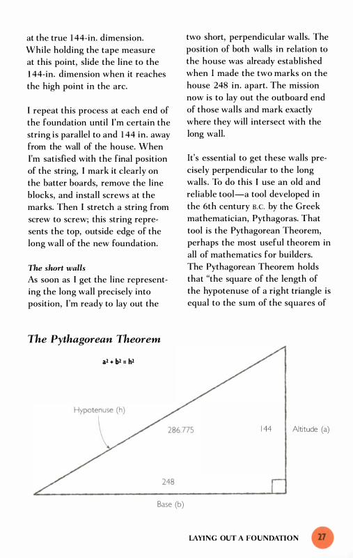
The Pythagorean Theorem
a2 + b2 = h2
Base (b)
two short, perpendicular walls. The
position of both walls in relation to
the house was already established
when I made the two marks on the
house 248 in. apart. The mission
now is to lay out the outboard end
of those walls and mark exactly
where they will intersect with the
long wall.
It's essential to get these walls pre
cisely perpendicular to the long
walls. To do this I use an old and
reliable tool-a tool developed in
the 6th century B.C. by the Greek
mathematician, Pythagoras. That
tool is the Pythagorean Theorem,
perhaps the most useful theorem in
all of mathematics for builders.
The Pythagorean Theorem holds
that "the square of the length of
the hypotenuse of a right triangle is
equal to the sum of the squares of
1 44 Altitude (a)
LAYING OUT A FOUNDATION
the lengths of the legs (altitude and
base)," which I know sounds con
fusing. Fortunately, it can be reduced
to a formula that is easy to use:
In most cases, you'll know the
dimensions of the altitude and base
(a and b) of the triangle because
they will be existing dimensions on
your layout (they are the short and
long foundation measurements in
our example) . Plug those dimen
sions into the Pythagorean
Theorem to find h. With the length
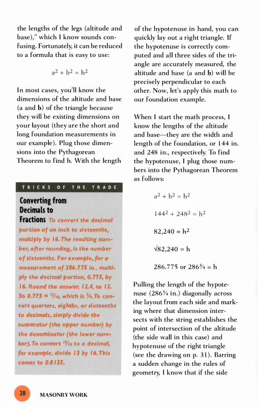
T R I C K S O F T H E T R A D E
Converting from Decimals to Fractions To convert the decimal
portion of an inch to sixteenths,
multiply by 1 6. The resulting num
ber, after rounding, is the number
of sixteenths. For example, for a
measurement of 286.775 in., multi
ply the decimal portion, 0. 775, by
1 6. Round the answer, 1 2.4, to 1 2.
So 0. 775 = 'Y'6, which is % To con
vert quarters, eighths, or sixteenths
to decimals, simply divide the
numerator (the upper number) by
the denominator (the lower num
ber). To convert '0/'6 to a decimal,
for example, divide 1 3 by 1 6. This
comes to 0.8 125.
MASONRY WORK
of the hypotenuse in hand, you can
quickly lay out a right triangle. If
the hypotenuse is correctly com
puted and all three sides of the tri
angle are accurately measured, the
altitude and base (a and b) will be
precisely perpendicular to each
other. Now, let's apply this math to
our foundation example.
When I start the math process, I
know the lengths of the altitude
and base-they are the width and
length of the foundation, or 1 44 in.
and 248 in., respectively. To find
the hypotenuse, I plug those num
bers into the Pythagorean Theorem
as follows:
82 ,240 = h2
';82,240 = h
286.775 or 286% = h
Pulling the length of the hypote
nuse (286% in.) diagonally across
the layout from each side and mark
ing where that dimension inter
sects with the string establishes the
point of intersection of the altitude
(the side wall in this case) and
hypotenuse of the right triangle
(see the drawing on p. 3 1 ) . Barring
a sudden change in the rules of
geometry, I know that if the side

A Bracket for Diagonal Measurements
You can overcome the biggest challenge of laying out an addition foundation--pulling the diagonal measurement to square up the layout-by fabricating a bracket to hold the tape at the correct angle.
Step 1 On a piece of scrap plywood lay out a scaled drawing of the foundation and mark the hypotenuse. Then measure the angle between the hypotenuse and altitude to find out the angle at which you need to hold the tape.
Step 2 Transfer the angle to an L -shaped bracket.
Step 3 Cut a kerf in the bracket where you've marked the angle. Then insert the hook of the tope measure into the kerf and you are ready to measure the diagonal.
1 4.4
Bevel square
Hypotenuse
24.8
LAYI NG OUT A FOUNDATION

walls meet the outside wall at this
point, then they will be perpendic
ular to the long walls.
With a helper, pulling these mea
surements takes just a few minutes.
If I'm by myself, however, it takes
about 20 minutes. That's because
I not only have to come up with a
way to hold the end of the tape
measure precisely in place, but I
also have to hold it at the right
angle for a diagonal measurement.
To determine the angle, I make a
scaled drawing that duplicates the
angle of the hypotenuse I need to
pull. A plywood scrap works well
for this purpose because it typically
has a nice, square, factory-cut cor
ner. From the corner of the scrap,
I measure 1 4 .4 in. up along the
vertical edge and 24.8 in. out along
the bottom edge. By connecting
these two marks with a straight
edge, I create an accurate scaled
drawing exactly one-tenth as big as
the full-sized triangle I want to lay
out. (The full-sized layout is 1 44 in.
by 248 in.) For making one-tenth
scaled drawings like these, I use
the 1 0ths scale on my rafter square.
The line I drew connecting the
marks is the hypotenuse of my
miniature triangle. The angle of
this line in relation to the base of
the triangle, therefore, is the exact
same angle (in relation to the wall
of the house) that I need to pull my
MASONRY WORK
diagonal measurement. But
because the hook of the tape runs
perpendicular across its length I
scribe a line running perpendicular
to the hypotenuse of the miniature
triangle with a rafter square. I mea
sure the angle formed by this line
and the base of the triangle with a
bevel square. Then I transfer this
angle (which is about a 30° bevel)
to an L-shaped bracket, as shown
in the drawing on p. 29. This
angle, incidentally, is the same as
the angle formed by the altitude
and the hypotenuse, and you can
save time by simply measuring the
angle there after you've drawn the
scaled right triangle.
This process is a lot to go through
for two measurements. But the
measurements have to be accurate
because they render the foundation
-and hence the entire addition
square. Making the scaled drawing
doesn't take more than 5 minutes.
(I just did it in 3 minutes.) If this
process is intimidating, you can try
a couple of other approaches. Try
calculating the angle, which is the
equivalent of the plumb cut on a
rafter, using algebra or trig. To use
algebra to convert the width and
length of this foundation into roof
pitch, the math would look like this:
1 44/248 = xl1 2
1 44/248 = 6.97/ 12
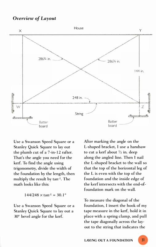
Overview of Layout
x House y
286� in. '-- 286� in.
1 44 in.
248 in. � J �w--�----------------------�-.r-------------��z· -� � Batter
board
Use a Swanson Speed Square or a
Stanley Quick Square to lay out
the plumb cut of a 7 -in- 1 2 rafter.
That's the angle you need for the
kerf. To find the angle using
trigonometry, divide the width of
the foundation by the length, then
multiply the result by tan- I . The
math looks like this:
1 44/248 x tan-1 = 30. 1 °
Use a Swanson Speed Square or a
Stanley Quick Square to lay out a
30° bevel angle for the kerf.
String
Batter board
After marking the angle on the
L-shaped bracket, I use a handsaw
to cut a kerf about Y2 in. deep
along the angled line. Then I nail
the L-shaped bracket to the wall so
that the top of the horizontal leg of
the L is even with the top of the
foundation and the inside edge of
the kerf intersects with the end-of
foundation mark on the wall.
To measure the diagonal of the
foundation, I insert the hook of my
tape measure in the kerf, hold it in
place with a spring clamp, and pull
the tape diagonally across the lay
out to the string that indicates the
LAYI NG OUT A FOUNDATION

long outside wall . I mark the string
with a felt-tipped marker where the
286%-in. measurement intersects
with the string (point Z on the
drawing on p. 3 1 ) . After repeating
this process across the other diago
nal of the layout (point W), I 've got
two marks on the string that repre
sent the two outside corners of the
foundation.
To check my work, I always mea
sure from dot to dot along the line
and make sure that distance is the
same as the length of the layout
(248 in., in this case) . Because
there is nothing at either dot to
hook to, I pull the measurement
from one of the batter boards, note
the amount at the first dot, then
continue pulling to the second dot.
By subtracting the first measure
ment from the second, I get the
dot-to-dot measurement. After I
determine that the layout is correct
(within \12 in. of square), I set up
batter boards to hold the strings
representing the side walls.
By stretching a string that runs from
the mark on the house (point Y)
through the mark on the string
(point Z) to a batter board, I lay out
the top outside edge of the right
side wall. The process is the same
for the left side wall, with the
string going from point X though
point W.
MASONRY WORK
Squaring Up Small Projects
Laying out the base of masonry
structures with a small footprint
(chimneys, porches, steps, and so
on) is a lot easier than laying out
the broad foundations that support
houses and additions. To square up
really small jobs, I just use my rafter
square. For jobs wider than 30 in.,
I often use a sheet of plywood as a
square. The factory-cut end is usu
ally within \Is in. of being square to
the long side. When I don't have a
sheet of plywood handy or the lay
out is wider than 5 ft. , I use geom
etry to calculate the hypotenuse (or
diagonal) , as just described in the
previous section. Then I measure
that dimension with a measuring
stick, which is a lot easier than
using a tape measure.
For long, narrow projects, it's not
necessary to calculate and measure
the diagonal of the entire layout.
To lay out a 6-ft. by 24-ft. porch,
for example, I prefer to block off a
6-ft. square at each end of the lay
out (see the drawing on the facing
page) . I use the diagonal of that
square to get the side walls of the
porch perpendicular. This technique
allows me to use a measuring stick
for the diagonal measurement
instead of fabricating a bracket to
hold the end of the tape.
To create the triangle, I attach a
string to batter boards centered 6 ft.
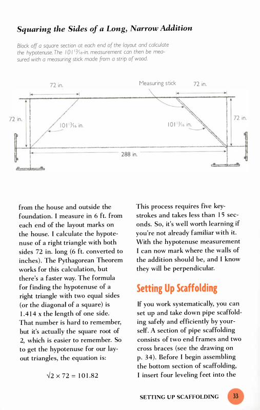
Squaring the Sides of a Long, Narrow Addition
Block off a square section at each end of the layout and calculate the hypotenuse. The 1 0 I /Y/6-in. measurement can then be measured with a measuring stick made from a strip of wood.
I'
72 in.
72 in.
-I
I O l i 1l 6 in . �
Measuring stick 72 in.
288 in.
,n n
from the house and outside the
foundation. I measure in 6 ft. from
each end of the layout marks on
the house. I calculate the hypote
nuse of a right triangle with both
sides 72 in. long (6 ft. converted to
inches) . The Pythagorean Theorem
works for this calculation, but
there's a faster way. The formula
for finding the hypotenuse of a
right triangle with two equal sides
(or the diagonal of a square) is
1 .4 1 4 x the length of one side.
That number is hard to remember,
but it's actually the square root of
2, which is easier to remember. So
to get the hypotenuse for our lay
out triangles, the equation is:
-/2 x 72 = 1 0 1 .82
This process requires five key
strokes and takes less than 1 5 sec
onds. So, it's well worth learning if
you're not already familiar with it.
With the hypotenuse measurement
I can now mark where the walls of
the addition should be, and I know
they will be perpendicular.
Setting Up Scaffolding
If you work systematically, you can
set up and take down pipe scaffold
ing safely and efficiently by your
self. A section of pipe scaffolding
consists of two end frames and two
cross braces (see the drawing on
p. 34) . Before I begin assembling
the bottom section of scaffolding,
I insert four leveling feet into the
SETIING UP SCAFFOLDING

A Section of Scaffolding
End frame
bottom legs of the two end frames.
I set two braces where I can reach
them as I stand up the first end
frame. Holding the end frame with
one hand, I slip the braces onto the
toggle pins of the frame with the
other. With the braces in place, I
can leave the first end frame upright
but leaning at an angle while I
fetch the second end frame. When
I attach the second end frame to
the braces, the first section of scaf
folding is assembled and in the
right place.
MASONRY WORK
A scaffolding section is made up of two cross braces and two end frames. Leveling feet can be used to make the section level on uneven terrain.
To level the assembly, I determine
which end frame is the higher of
the two. I clamp my level to the
top bar of that end frame and raise
the leg on the low side by rotating
the threaded bracket on the level
ing foot. Leveling feet are not
absolutely necessary (you can raise
the lower side of the end frame by
setting scraps of wood under the
leg), but they are very convenient.
I recommend renting or buying
these leveling feet whenever you
have to use this kind of scaffolding.

Mter I get the first end frame level,
I place my level on a straight board
that bridges both end frames, and
bring the second end frame up
level with the first.
Once I get the first section nice
and level, I set a few scaffolding
boards across the top and lean two
end frames and two braces against
the standing section of scaffolding
so I'll be able to reach them from
the first level. Then I climb up on
top of the boards and pull the end
frames up one at a time and set
them over the pins in the end
frames below.
Mter both end frames are in place,
I install the braces. Trying to install
this second tier of end frames from
the ground is a direct approach
that, at first, seems like the natural
way to go. But when you hold the
end frame upright from the bot
tom, you surrender a serious
mechanical advantage. It's much
easier and safer to work with gravi
ty and lower the end frame into
place from above. I never begrudge
the time it takes to climb up on the
scaffold because I know I'll have
to get up there anyway to install
the braces.
To erect subsequent layers of scaf
folding, repeat the process, setting
scaffolding boards in place then
installing each end frame from
above. I leave the boards in place
Scaffolding that is over
three sections high should always
be attached to the house to pre
vent it from tipping over. To con
nect the scaffold to the house, I
attach a scrap of 2x4 to the house,
screw the brace to the scrap, then
attach the scaffold to the brace
with metal pipe strops. These are
rigid and fit snugly over the round
bars of the scaffold end frames.
I use screws throughout this opera
tion, both because they hold better
than nails and because they're
easier to remove when I toke down
the scaffolds.
as I move up, both because I need
something to stand on to safely
install each new section of boards
and because I'll need to have some
thing to stand on later when I take
the scaffolding down. When I get
above the third tier of scaffolding,
I use a rope to pull the end frame
up; later, when I'm taking down the
scaffold, I use the rope to lower
the pieces to the ground.
SElTlNG UP SCAFFOLDING )S

hen you finish the founda
tion and turn your attention
to the frame, you confront
a new and very different set of problems
as a solo builder. Happily, though, this
phase of the job begins not over uneven
ground but on a square and level surface
the top of the foundation. This not only
provides a tangible reference to measure
against and a level base to build on, but it
also gives you something to hook or clamp
your tape measure to.
These very real advantages should not be
overstated, however. Laying out the vari
ous parts of the frame is a big job, and
there are hundreds of measurements
involved for most residential frames, some
of which are quite difficult for a person
working alone to do.

Yet the layout is not nearly as diffi
cult as the second basic challenge
that solo builders face : moving, lift
ing, and installing framing materi
als . In contrast to the compact and
easy-to-manage masonry units that
make up the foundation, the solo
builder is now faced with boards
that are 1 2 ft. , 1 6 ft. , even 20 ft.
long, and sheets of plywood that
are 4 ft. across and 8 ft. long. To
compound the problems (literally),
it's often convenient or necessary
to combine these materials into
larger components before lifting
them into place.
The materials of the frame are not
only large and unwieldy, but they
are also far from perfect. Wood
products are, by their nature,
dimensionally unstable. By the
time builders get their hands on
them, wood is often cupped,
bowed, or twisted. Seasoned car
penters expect these flaws and
respond by culling the worst speci
mens and by pushing, pulling,
torquing, and levering the others
into a reasonably straight line as
they install them. This process is
not too difficult when two or
three carpenters are working
together, but when a carpenter
works alone it takes some unique
thought and effort.
Framing Floors
Floor systems span across open
spaces and have to support the
weight of partitions and finish
materials as well as the people and
furnishings that will eventually go
inside the house. Because of these
requirements, floor systems have to
be built out of substantial pieces of
wood. There is no such thing as a
standard floor system, but a typical
system on my jobs consists of a
framework made out of 2xl 0s and
a deck comprised of %-in. tongue
and-groove plywood. This wood is
heavy, and lifting and carrying it is
hard work. Yet this part of the job
is not nearly as challenging as get
ting the individual pieces of wood,
which are invariably warped,
bowed, or imperfect in any of a
dozen other ways, joined together
in a reasonably straight, plumb,
and square structure.
Laying Out the Floor System
If you're working alone, laying out
the floor system of a house or addi
tion presents few serious obstacles.
A minor problem that occurs right
at the beginning is when you have
to transfer the location of the
anchor bolts (which are sticking
out of the top of the foundation)
onto the mudsill. To mark them,
carpenters usually set the sill on
top of the foundation, push it
against the bolts, and transfer the
location of the bolts with a square.
FRAMING FLOORS

Laying Out Bolt Locations on the Mudsill
Concrete block holds sill in place.
More than half of the mudsill is off the edge of the foundation.
The problem for a solo builder is
that the sill usually has to be held
in this position because less than
half its width is sitting on top of the
wall. To keep the sill from falling,
I set a couple of concrete blocks on
it. Putting a scrap of 2x4 under one
side of the block holds it square
with the top of the foundation, as
shown in the drawing above. Once
the bolt locations are marked, it's a
simple matter to drill the holes and
bolt the mudsill in place.
When it's time to lay out the joist
locations, another measuring tech
nique is useful. To get the layout
FLOORS AND WALLS
Use a square to transfer bolt locations.
Anchor bolt
1 6 in. on center (o.c.) , I usually
mark at 1 5 Y4 in., then pull the tape
measure from that point, marking
every 1 6 in. and setting the X ahead
of the marks (see the drawing on
the facing page). This technique
allows the first full sheet of ply
wood to break evenly on the joists.
To provide something at the 1 5 Y4-in.
mark to hook the tape measure to,
I nail my square to the sill at the
mark. I 've drilled two holes through
my square just for this purpose.
Wrestling the Wood into Place
As I install the floor system, I use
a variety of tools to straighten the

Laying Out Joist Locations
Nailing a square directly to the sill provides a good edge for hooking a tope measure to when laying out joist locations.
1 6 in.
wood (see the drawing on p . 40).
To straighten twisted joists as I
attach them to the band joist (also
called the rim joist) , I use a tool
designed specifically for this pur
pose, called the Tweaker, which is
an h-shaped steel bar. I begin this
process by attaching the bottom of
the joist on the layout line. Then I
hook the Tweaker over the top edge
of the joist. Holding the tool in my
left hand, I lever the joist into line
as I nail through the band joist and
into the top of the joist end with
my right hand. If I'm not using a
nail gun, of course, I have to start
the nail before I grab the Tweaker.
Tape measure
If necessary, I repeat the process at
the other end of the joist.
Attaching both ends of the joists at
the layout lines does not guarantee
that the midspans of the joists are
on layout. More often than not, the
joists are bowed and I have to pull
or push them into the 1 6-in. o.c.
layout as I nail the plywood sub
floor. To do this, I use either a bar
clamp (for pulling) or a spreader
(for pushing) that I set perpendicu
larly across the top of the joists.
The most difficult part of the floor
system to install solo is tongue-
FRAMING FLOORS

Tools for Working the Wood
Bar clamps and spreaders move joists into alignment with layout marks on the plywood.
Spreader
and-groove plywood decking.
Getting the tongue in the groove
is the rub. The plywood rarely lies
flat, so it's necessary to force it
down against the joists as you drive
it into the adjoining pieces. When
you have a crew handy, all you have
to do is station a well-fed helper
to weigh down the side where the
new sheet engages the previous
row. Then you use a sledgehammer
to knock the new sheet into the
groove of the previously installed
sheets.
FLOORS AND WALLS
Bar clamp
Layout l ine
A Tweaker levers a twisted joist to the layout line.
Working alone, of course, you don't
have access to such a partner, so
you need an alternate way to get
the sheet flat. One way is to use
hold-down blocks. First, lay the
sheet in place about Y4 in. from the
previously installed sheets. Then,
while standing on the new sheet,
screw two or three blocks of wood
on top of the previous row so they
overhang the joist where the next
sheet goes. The blocks hold the
new sheet in line as you drive it
into place with a sledge.

T R I C K S OF T H E T R A D E
Protecting the Decking To protect the out
side edge of plywood decking as
you bong it into place, use a "beat
ing block." The ideal material for
this sacrificial layer is a strip of the
decking itself. Find a scrap with the
factory-cut tongue and cut a strip
about 4 in. wide and 48 in. long.
Top the tongue of the strip into
the grooved edge of the plywood,
then pound away with your sledge
hammer. If you don't have a scrap
of the decking handy, use a straight
strip of 2x4.
This technique works fairly well,
but I 've found that using a special
purpose tool, called a Bo Wrench,
works even better. The BoWrench
is a large steel lever hinged at one
end to an F-shaped bar. To use the
tool, I hook the arms of the F over
a joist just beyond the sheet and
pull the plywood into place, as
shown in the drawing on p. 42.
The long handle provides plenty of
leverage and allows me to kneel on
the mating edge of the plywood as
I pull it into place. My own weight
holds the sheet flat, so I don't have
to install and later take up the
hold-down blocks. Also, because
I'm not banging the edge of the
plywood, the chance of damaging
the groove-and thus making the
job more difficult when I install the
next row of plywood-is greatly
reduced. The BoWrench and the
Tweaker are both excellent special
purpose tools with painless price
tags; I strongly recommend them
for anyone who does a lot of solo
building.
Building Walls
The process of laying out and
building walls is quite manageable
for one person, and even when a
full crew is available it makes sense
to divide much of the labor into
individual tasks. In this section, I'll
describe a few simple techniques
I 've developed to help lay out and
build walls without a helper. These
solo techniques should not be
reserved for those occasions when
you're on a job by yourself, though.
They are quick and accurate, and
they often require less time than
it would take to get a coworker
to stop what he's doing to give you
a hand.
Laying Out the Walls
The only purpose of the second
person at layout stage is to hold the
end of the tape measure, and it's
not that difficult to find a mechani
cal means to do that. Laying out
the walls by yourself not only frees
the helper's hands for more prof
itable work, but it can also make
your job easier. I find the presence
BUILDING WALLS

of another person distracting, and I
prefer to do the layout by myself
even when there are others avail
able. When I need to provide an
edge to hook my tape to, I nail my
speed square in place as I did when
laying out floor joists. When I lay
out small items, like closets, doors,
and windows, I use measuring
sticks, which are stiff, lie nice and
flat, and don't need to be anchored
at one end.
Straightening the Wood
Carpentry textbooks make building
a wall seem like a mere matter of
assembling parts. On real job sites,
though, the sticks of wood that
make up a wall are rarely straight
and must be persuaded into a
reasonably straight line as they're
installed. This process usually starts
when you're assembling the parts
of the wall. In fabricating such
things as headers, T-intersections,
and corners, you usually have to
force the individual pieces of lum
ber into alignment. If a helper is
available, he positions himself at
the end of an assembly and steers
one piece of lumber flush with an
adjoining piece as you work your
way up its length, fastening the
pieces together. When working
alone, though, you can use clamps
and wedges in place of that second
Pulling Plywood Decking into Place
The tongue of the tongue-and-groove plywood is forced into the groove of the previous row of plywood.
FLOORS AND WALLS
The worker's weight holds down the plywood edge.

Straightening the Lumber
Use a bar clamp to align the parts of headers. Bar clamp
T-intersection
2x6 box-beam header for 2x6 wall
'-.
Two 2x I Os with Y2-in. plywood spacer for 2x4 wall
2x l 0
2x6
Use a bar clamp to pull bow out of 2x4.
U" a wedge to d,� a "",�ed 2x 1 0 ,ora) alignment with the edge of the top plate.
pair of hands. Some of the tech
niques that I commonly use are
shown in the drawing above. Once
the parts are made up and I start
building the wall, it's often neces
sary to torque twisted studs into
conformity with the layout lines.
Here again, I use my Tweaker tool.
After attaching the stud with one
nail at the bottom, I crank it into
position with the Tweaker as I drive
in the top nail.
Erecting Walls
While building walls is a very
manageable affair for one person,
raising them is a different matter.
Walls are large and heavy and,
until they are safely braced, can be
quite dangerous. There are three
different ways to get past the
obstacle of raising walls when
you're working alone. The first is
to call in reinforcements. On
ERECTING WALLS

many occasions I 've scheduled a
crew of workers to stop by my job
on their way home from other jobs.
When they arrive, I have the wall
built, squared, sheathed, and ready
to tilt into place. We can usually
get the wall up and securely braced
in about 1 5 minutes.
Another way to get the wall raised
is to build it in manageable sec
tions that you can lift into place
yourself. To keep the wall light, I
wait to install the sheathing. When
the wall is up and secured, I install
the sheathing from the outside of
the house (see pp. 50-52) . I 've
found that I can usually handle a
Secause houses are
mostly built of large, flat sheets of
plywood and other sheathing
materials, wind is a serious hazard.
It can make walls Impossible to
control-even for a full crew. And
single sheets of plywood, pushed by
the wind, can knock a worker off
a building or a scaffold. When the
wind picks up, respect its force.
Avoid working up high on blustery
days, particularly with plywood,
sheathing, and other sheet materi
als, and save the wall raising for a
calmer tomorrow.
FLOORS AND WALLS
1 0-ft. to 1 4-ft. section of 2x4 wall
or 8 ft. to 1 2 ft. of 2x6 wall by
myself. The size and number of
headers in the wall substantially
affect the weight and manageability
of the wall (the more header mate
rial, the harder the wall is to raise) .
The third way to raise the wall is to
use the proper rigging. Like an
auto mechanic who thinks nothing
of removing an 800-lb. engine,
one carpenter can easily raise an
800-lb. wall-as long as he has the
right equipment. A good tool for
this job is the Proctor Wall Jack,
which is made specifically for rais
ing wood-frame walls. With a pair
of these jacks, one person can raise
an 8-ft. wall that weighs up to
2,000 lb. , which means you can
sheathe the wall before you raise it
into position. Although I don't own
a pair of these jacks, they are high
on my wish list of tools.
Whatever method you choose to
use, there are two important mea
sures to take before you begin the
wall-raising. The first is to provide
for some kind of restraint to keep
the wall from sliding off the edge
of the floor. Some carpenters pin
the wall to the layout line with
nails driven in at an angle. They
usually put these nails through the
bottom plate before they square the
wall and install the sheathing. As
the wall rotates into the upright
position, the nails pinning it to the
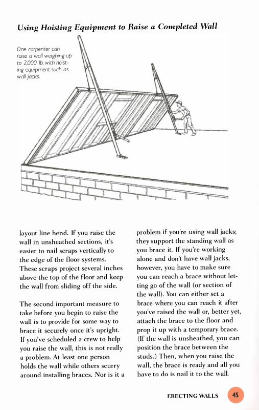
Using Hoisting Equipment to Raise a Completed Wall
One carpenter can raise a wall weighing up to 2,000 lb. with hoisting equipment such as wall jocks.
layout line bend, If you raise the
wall in unsheathed sections, it's
easier to nail scraps vertically to
the edge of the floor systems.
These scraps project several inches
above the top of the floor and keep
the wall from sliding off the side.
The second important measure to
take before you begin to raise the
wall is to provide for some way to
brace it securely once it's upright.
If you've scheduled a crew to help
you raise the wall, this is not really
a problem. At least one person
holds the wall while others scurry
around installing braces. Nor is it a
problem if you're using wall jacks;
they support the standing wall as
you brace it. If you're working
alone and don't have wall jacks,
however, you have to make sure
you can reach a brace without let
ting go of the wall (or section of
the wall) . You can either set a
brace where you can reach it after
you've raised the wall or, better yet,
attach the brace to the floor and
prop it up with a temporary brace.
(If the wall is unsheathed, you can
position the brace between the
studs. ) Then, when you raise the
wall, the brace is ready and all you
have to do is nail it to the wall.
ERECTING WALLS

Squaring and Sheathing the Walls
before Raising
Carpenters usually install the
sheathing on exterior walls before
they tilt them up. Before they start
sheathing the wall, however, they
must make sure that the wall is
square. (This makes the ends of
the wall plumb after it's tilted into
position, assuming the foundation
is level.) Carpentry crews typically
do this by temporarily nailing the
bottom plate in position along the
layout line and then measuring
the diagonals of the framed wall as
it lies flat on the floor deck. Some
one then taps at the opposite cor
ners until the diagonal measure
ments become equal and the wall
is square.
This trial-and-error procedure
works fairly well when two people
are doing the measuring, but for a
solo carpenter it takes too long. It's
easier to use geometry. Create a
right triangle using the height of
the wall for both sides, then calcu
late the hypotenuse, which will be
the diagonal measurement you use
to check for square. As we saw in
chapter 2 , the formula to find a
hypotenuse of a right triangle with
two equal sides is:
h = -12 x the length of one side
FLOORS AND WALLS
So, for example, the hypotenuse of
a 96-in. -high wall would be:
h = -12 x 96, or
h = 1 3 5%
Once you have the hypotenuse,
or diagonal measurement, you can
use it to check for square. First,
though, you need to "create" the
triangle on the wall. You already
have one side of the triangle-the
end of the frame equal to the
height of the wall. To get the other
side, measure in along the bottom
of the wall the same number of
inches as the height of the ceiling
and make a mark. In our example,
the mark would be at 96 in. (see
the drawing on the facing page).
Now you have the two sides of
your triangle and you can pull the
diagonal.
You'll need to hook your tape
measure to something to pull the
diagonal measurement. You can
cut a shallow 450 kerf at the 96-in.
mark on the bottom of the wall;
or you can scribe a 450 line at the
mark, nail a short strip of lx2
along the line, then hook the tape
over the strip. I like this second
method better because I don't like
to put a kerf in my brand new
wall. Insert the hook of your tape
measure in the kerf or hook it over
the strip, then pull the diagonal
measurement.

Squaring Up the Wall
96 in. / Bottom plate anchors at layout line for walls.
I ! I � J
l ine
" '"
� Top of wall
To square up a wall, measure the height and mark that dimension along the bottom plate of the wall. Then pull the diagonal measurement, which con be computed by multiplying the square root of 2 by the height of the wall. The diagonal in this example is I 35� in. When that dimension intersects with the top corner of the wall, it is square.
Top or�
96 in.
" � \
3 � in.
Tap e asure me
I 3514-in. mark / �
2x4 block nailed to top plate of wall
L-shaped block nailed to fioor
By affixing one block to the top of the wall and another to the �oor, you con pull the wall laterally into position with a pipe or bar clamp.
L-shaped block Moving the top of the wall into place
ERECTING WALLS

Squaring a Standing Wall Turnbuckle
Clamp level to corne�
You can pulf the end of a wolf plumb by setting up a couple of lengths of chain and a turnbuckle. Adjust the turnbuckle until the end of the wolf is plumb.
At the same time you're pulling the
tape measure, push or pull the wall
until the correct diagonal dimen
sion on the tape measure intersects
with the top corner. (For the 96-in.
high wall in our example, the wall
would be square when the tape
measure crossed the top corner at
1 3 5% in.) This may sound difficult,
but the wall is fairly easy to "rack"
before it's sheathed. If I have trou-
FLOORS AND WALLS
ble (and I sometimes do), I set up a
clamp to hold the tape. To help
move the wall into position, I
sometimes use a couple of blocks
of wood and a bar clamp, as shown
in the drawing on p. 47 .
As soon as the wall is square, I nail
it temporarily to the floor to hold it
in that position. Then I install the
sheathing on the framed wall.

When I've finished nailing off the
sheathing, I remove the nails I
installed to hold the wall square.
With the sheathing in place, the
wall is rigid and square and ready
for raising. Once you have the wall
up and securely braced, attach it to
the floor by nailing through the
bottom plate. The wall panel
should be square, and consequent
ly the edge of it will be plumb.
Raising the Walls
in Unsheathed Sections
There are two advantages to rais
ing a wall without the sheathing.
First, it makes it easier to divide
the wall into sections; second, it
makes each section considerably
lighter. But there's a price to pay
for these advantages : Without the
sheathing the sections of framed
wall are not very rigid. These sec
tions have a tendency to sag out of
square as they are lifted and
installed. So, instead of squaring
up each section of the wall as it
lies on the floor of the house, it
makes sense to postpone the
process until after the sections of
wall are braced upright and joined
together.
Squaring a standing wall
After I get all the sections raised,
braced roughly plumb, and nailed
securely together, I tie the wall to
the house by nailing through the
bottom plate into the floor of the
house. Next, I check the ends of
the wall with a spirit level to see if
they're plumb. (Getting the ends of
the wall plumb squares up the wall,
as long as the floor is level.) If the
wall is racked out-of-square (and it
usually is), I clamp my level to the
end of the wall. Then I try some
old-fashioned pushing and pulling
to get it plumb.
If I can't get and hold the corner
plumb that way, I set up a turnbuckle
with a couple of lengths of chain
and pull the end of the wall plumb.
I attach the two pieces of chain to
the frame of the house, as shown
in the drawing on the facing page,
T R I C K S O F T H E T R A D E
Selecting a Turnbuckle The best turnbuckles
for frame carpentry are at least
l O in. long and have built-in shack
les (which make it easy to attach
the ends to chains). Try to find a
turnbuckle that has a hexagonal
section that permits you to turn
the turnbuckle with an open-ended
wrench. If the only turnbuckle you
can find has eyelets instead of
shackles at the end of the bolts,
use a removable chain link or a
separate shackle to attach the
turnbuckle to the chain. Look for
turnbuckles and these related items
at old-fashioned hardware stores.
ERECTING WALLS

then I hook up the turnbuckle.
(You can use nails, clamps, or eye
bolts to attach the chains to the
wall.) I rotate the turnbuckle with a
wrench to draw the ends of the
chain together and to pull the top
corner of the wall over. I continue
rotating the turnbuckle until the
level indicates that the end of the
wall is perfectly plumb.
When I get the end of the wall
plumb, I know the wall is square
and I'm ready to install sheathing.
You may wonder what I'd have
done if I needed to move the top of
the wall in the other direction. In
that case, I would have set up the
Installing Plywood Sheathing
To install the first row of plywood sheathing, try using a 64-in.-long bracket.
The bracket supports one side of the sheet while you nail at the other end.
FLOORS AND WALLS
turnbuckle and chains at the other
end of the wall.
Sheathing a standing wall
I have two different types of brack
ets for holding up sheathing as I
nail it to the outside of the wall.
(I typically use Yz-in. plywood
sheathing and run it horizontally. )
To install the first row of sheathing,
I use a 64-in. -long steel bracket to
hold the sheathing in place. To
make the bracket, I had a welder
weld a heavy shelf bracket (which
I bought at a surplus store for $2)
to the bottom 10 in. of a 64-in.-Iong
steel bar. In cross section, the bar
is Y4 in. thick and 2 in. wide. The
Bracket 54 in.
1 0 in .

top 54 in. of this bracket is longer
than the plywood by 6 in. I nail the
bracket to the frame through two
holes I drilled in the top 6 in. of
the bracket, making sure that the
shelf is even with my layout line.
To install the sheathing, I rest one
end of the sheet on the bracket as
I line up and nail the other end.
Mter driving several nails into the
sheathing, I take out the nails that
hold up the bracket and it slides to
the ground. Because it's quite
heavy, I make a real effort to keep
the bracket from landing on my
foot. Some of the bracket will still
be under the sheathing, so I slip
After the first row is installed, use a pair of plywood brackets screwed to the wall to support the plywood as you install it.
it out from behind the sheathing
and finish nailing the sheathing to
the frame.
For subsequent rows of sheathing,
I use a couple of L-shaped ply
wood brackets, which I call my all
purpose brackets (see the sidebar
on p. 89) . These are a lot lighter
and easier to use than the large
steel bracket I used for the first
row. I screw the pair of brackets
which are about 1 4 in. deep-to
the wall. Then I set the sheathing
on them as I install it (see the
drawing below) . As I move up the
wall, getting the sheathing up on
the scaffolding becomes a chal-
1 4 in.
6 in.
Bracket detail
ERECTING WALLS

Straightening the Wall
Brace
comer plumb.
lenge in its own right. For this job,
a C-clamp, affixed to the top edge
of the plywood, is just the ticket.
Sometimes, I use the C-clamp as a
handle to pull the sheet up behind
me as I climb the ladder. At other
times, I find it easier to use a rope,
tied to the C-clamp, to hoist the
plywood up to the scaffold.
Plumbing and Straightening the Walls
Because raising a wall is inherently
dangerous, carpenters usually
secure the wall in an upright posi-
FLOORS AND WALLS
2x4 block holds string I Y2 in. in from top plate.
2x4 scraps nailed to fioor
Broce both comers plumb and set the rest of the wall to a string stretched comer to comer. To ovoid a false reading caused by contact with the string, set the string I 1'2 in. away from the top plate.
tion as quickly as possible and
worry about fine-tuning its position
afterward. Hence, the job of
plumbing and straightening the
wall typically begins with the wall
nailed in place at the bottom and
braced roughly plumb.
The standard way to adjust the wall
is to brace each corner plumb,
then set the rest of the wall to a
string pulled from corner to corner
along the top plate. The first thing
I do is remove a brace at one end
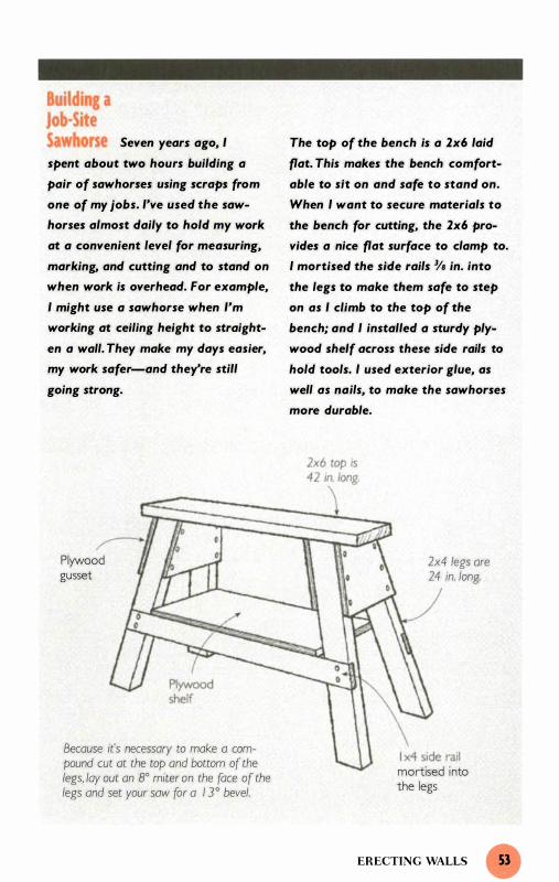
Seven years ago, I The top of the bench is a 2x6 laid
spent about two hours building a flat. This makes the bench comfort-
pair of sawhorses using scraps from able to sit on and safe to stand on.
one of my jobs. I've used the saw- When I want to secure materials to
horses almost daily to hold my work the bench for cutting, the 2x6 pro-
at a convenient level for measuring, vides a nice flat surface to clamp to.
marking, and cutting and to stand on I mortised the side rails % in. into
when work is overhead. For example, the legs to make them safe to step
I might use a sawhorse when I'm on as I climb to the top of the
working at ceiling height to straight- bench; and I installed a sturdy ply-
en a wall. They make my days easier, wood shelf across these side rails to
my work safer-and they're still hold tools. I used exterior glue, as
going strong. well as nails, to make the sawhorses
more durable.
Plyvvood gusset
Because it's necessary to make a compound cut ot the top and bottom of the legs, lay out an 8° miter on the face of the legs and set your saw for a 1 3° bevel.
2x4 legs are 24 in. long
mortised into the legs
ERECTING WALLS 53

of the wall. Next I clamp a spirit
level to the inside of the corner and
push or pull the end of the wall
until the level indicates that it's
plumb. While holding the wall in
position, I reattach the brace. After
repeating this process at the other
end of the wall, I get a wall that
has plumb corners but whose inter
vening length is, in all likelihood,
not straight.
To check the wall for straightness,
I nail a 2x4 scrap at the top inside
edge of each corner, then stretch a
string from the face of one block to
the other roughly even with the top
plate (see the drawing on p. 52) .
This offsets the string 1 �2 in . from
the plumb corners of the wall. By
T R I C K S O F T H E T R A D E
Setting Up Shop the Quick Way To set up a job-site
workbench, simply place an old
door across a pair of sawhorses.
This benchtop provides the brood
support needed to safely saw ply
wood without a helper. You can
also clamp pieces of lumber to the
bench as you make difficult cuts or
odd a layer of plywood and set up
your miter sow on it. And the
bench serves as a handy place to
make sketches.
FLOORS AND WALLS
setting the intervening length of
the wall 1 �2 in. from and parallel to
the string I get the wall straight
and plumb. To do this I use a 2x4
scrap as a spacer. I remove one or
two braces at a time, then nail my
spacer block just below the align
ment string. Now I push or pull
the wall until the edge of the block
is even with the string, then re
attach the brace. Working system
atically down its length, I get the
wall arrow straight.
Moving and holding the wall is not
as easy as it might seem. Even
when extra hands are available, it's
often necessary to rig some simple
levers to help force the top of the
wall into line. The reason for this is
not so much the resistance of the
wood as its height. The top of the
wall is 8 ft. in the air, and it's diffi
cult to apply the needed lateral
pressure on something that high.
Framing crews use stiff braces to
push the wall out and "bow boards"
to pull it in. They rely on team
work: As one person pulls or pushes
the wall another quickly nails on a
brace. (Not infrequently a third
person stays occupied mainly by
holding the block in place and
telling the others when the wall is
in line. )
For a solo builder this technique is
physically strenuous, awkward in
the best of circumstances, impossi
ble in others. To move and hold the

Pushing and Pulling the Wall into Place
Thrust block nailed to the wall
Insert wedge between thrust block and brace to drive brace down.
To push the top of the wall out, use a 2x4 brace. Containing the movement of the brace at the bottom with a thrust block while forcing the top down pushes the wall out.
Thrust block nailed to floor
Pushing the wall out
Nails driven hallWay in and bent over chain l ink
Chain
To pull the wall in, use two lengths of chain and a tumbuckle. Rotating the tumbuckJe draws the bolts together and pulls the wall in.
Turnbuckle
) Eyebolt
Pulling the wall in
ERECTING WALLS

wall precisely in place and, at the
same time, install the brace, you
need a better rig-one that controls
the position of the wall as you
adjust it and holds it there as you
attach the brace.
Here are the techniques I use. To
push the wall out, I set up a 45°
brace that's securely anchored at
the bottom but not at the top.
Driving the brace down exerts a
thrusting force that drives the wall
out. Although the precise length of
the brace is not critical, I usually
multiply the height of the wall by
1 .4 1 4 (the square root of 2) to fig
ure it out. This is the same length
as the hypotenuse of my measuring
triangle. That means the brace will
run at roughly a 45° angle (which
isn't essential) and will be long
enough to reach the top of the
wall. By doing this quick calcula
tion, I ensure that the brace is long
enough without having to hold a
brace in place and measure how
long to cut it to.
FLOORS AND WALLS
This 1 3 5%-in. measurement is the
same as the diagonal measurement
you used to square the wall. After
cutting 1 Y2 in. off the long point of
the miter at both the top and bot
tom, I set the brace in place
against the wall. Then I install two
"thrust blocks," one on the floor at
the bottom of the brace and the
other on the wall just above the
brace (see the drawing on p. 5 5 ) .
To force the brace down, I simply
drive a long wedge between the top
of the brace and the thrust block
on the wall. This forces the wall
out in a gradual and controlled
manner.
To pull the wall in, I set up two
lengths of chain and a turnbuckle.
Rotating the turnbuckle shortens
the length of this assembly and
thus moves the wall gradually in. I
attach the top piece of chain a cou
ple of inches down from the top of
the wall and the bottom length of
chain about 8 ft. out from the wall.
This makes the assembly run at
roughly a 45° angle-the exact
angle is not important.

n most houses, the roof system
is the first structural element
that is neither level nor plumb.
Roof structures are deliberately pitched
to direct rainwater to the outside of the
house. When trusses are used for roof
framing, the carpentry crew is spared the
sometimes-bewildering task of fitting
inclined structural members to level and
square surfaces. All of this complicated
layout, cutting, and fitting is done by the
truss manufacturer, and the carpenters
need only install these prefabricated
components on top of the bearing walls.

On the other hand, when rafters
are used, carpenters have to lay out
the whole structure and join the
individual pieces neatly and secure
ly together. This is more difficult
than it might seem. Carpenters not
only fit pieces to existing angles,
they also create those angles and,
in doing so, start from scratch.
If you're working alone, the diffi
culties posed by the layout are only
half the problem. You also have to
figure out some way to lift and
install the materials that make up
the frame. These materials are heavy
and unwieldy, and they have to be
installed overhead-sometimes far
overhead. It's not uncommon, for
example, for the ridge of the roof to
sit 1 2 ft. or more off the floor. Yet
as difficult as these problems might
seem, they can both be overcome.
As you'll see, the layout can be
simplified by understanding and
using the geometry that forms the
basis of roof framing and by using
a site-built jig. The installation can
be managed by developing a well
thought-out plan for lifting the
materials into place.
Laying Out the Roof
There are two basic ways to
approach the layout of a stick-built
roof. The first is to use a non math
ematical approach. The most com
mon non mathematical technique
(and the first one I learned as a
STICK-BUILT ROOFS
young carpenter) is to scribe the
rafter in place. To do this, posts are
set up to hold the ridge centered at
the correct height above the bear
ing walls. The height of the ridge is
determined either by math ( I'll dis
cuss the process below) or by scal
ing the height from the blueprint.
Once the ridge is in place, two car
penters (one at each end) hold the
rafter material so that it runs past
both the ridge and the top plate of
the wall. Then they scribe the top
and bottom cuts directly onto the
rafter material. After the first rafter
is cut, it serves as a pattern for the
rest of the roof.
If you're working alone, nonmathe
mati cal approaches like this one
take too much time. It's possible to
rig up a bracket to hold the rafter
as you mark it, but it's far easier to
compute the key dimensions math
ematically. This situation is similar
to the problems associated with
squaring up a foundation, and the
math used to solve those problems
is also similar to the solution here.
For the balance of this chapter, I'll
use an example to walk you through
the system I use to lay out and
build the most common type of
roof, a gable. Some of you may notice
that my system differs in several
respects from the system that is
usually presented in carpentry text
books. (See the sidebar on p. 60 for
a comparison of the two systems.)

Trusses and Rafters Trusses are structural
frames that, all in one, serve the
same purpose as rafters and ceiling
joists. They are designed by engineers,
manufactured by certified fabrica
tors, and shipped to the job. Trusses
span long distances and, on most
houses, bear only on exterior walls.
Because supporting walls usually
aren't required on the interior, rooms
can be large and open. Trusses offer
practical advantages too: They are
simple to install, structurally proven,
and go up quickly. And because
trusses are made from smaller pieces
of lumber than rafters and ceiling
joists, they can save lumber.
When you consider the advantages
of trusses, it's easy to see why they're
so popular. Yet trusses are not always
the best choice. The structure itself
takes up space, which means that
part or all of the space between the
top chord (at the roofline) and the
Truss
bottom chord (at the ceiling) is
wasted. In a stick-built roof, you can
fully exploit the space under the
rafters, adding square feet to the liv
ing area or attic space. You can also
create cathedral ceilings, which can
have a dramatic visual impact.
On many jobs, rafters are also easier
to use than trusses. Roof trusses
require advanced planning, space, a
crew, and, occasionally, a crane. If
you're building a new house or an
addition in an established neighbor
hood, there might not be enough
space for the crane. But even if
there is sufficient room to hoist and
maneuver trusses, it often makes
sense simply to stick-build the whole
thing anyway, especially with addi
tions. For a solo builder, of course,
the choice is easy: Trusses are
almost impossible for one person
to install alone.
Ceiling joist
Rafters
LAYING OUT THE ROOF

Two Paths to the Same Rafter The main difference
between my system of rafter layout
and the traditional, or textbook, sys
tem is the size of the right triangle
used to make the calculations. The
traditional way to lay out a rafter is
to measure from the outside of one
bearing wall to the outside of the
other. Divide the measurement in half
and you get what's called the «run"
of the rafter. It's actually the base of
the right triangle used to determine
the critical dimensions of the rafters
and the height of the ridge.
There are a two things I find confus
ing about this system. First, it's hard
to figure out just where to measure
the rafter. The line you have to mea
sure along is somewhere in the mid
dle of the board. The exact location
varies with the pitch of the roof, the
Traditional Rafter Layout
thickness of the exterior walls, and
the size of the rafter material.
Second, it's diffiCUlt to determine
exactly how high up to set the ridge.
In my system (see p. 62), I measure
from the inside of one bearing wall
to the inside of the other. From this
measurement, I subtract the thickness
of the ridge. Then I divide the remain
der in half to get the base of my
measuring triangle, which is different
from the base of the right triangle
used in the traditional approach. The
benefit to this approach is that the
rafter measurement is made along
the bottom of the rafter, not at some
hard-to-determine middle point. To
set the ridge at the correct height, I
cut a post that's equal to the length
of the altitude of the triangle plus
the height of the wall.
I
The measuring line in the traditional system of rafter layout extends from the top outside corner of the wall
Rafter is measured along this line.
I I I I I I I I I I
to a point in the center of the ridge.
STICK-BUILT ROOFS
Rafter run (half the width of bui lding)
- -I I

Both of these systems are effective
ways to calculate the key dimen
sions of a rafter. If you're already
familiar with the "textbook" method,
you may wish to continue using it.
But, if you're new to rafter layout
or if you've had trouble with the
textbook method, you may find my
system easier to understand.
Neither system can be called the
right or wrong way because they
both result in identical rafters. I
simply find my mathematical sys
tem easier. If you're working alone,
the system you use is not important
as long as it enables you to lay out
the rafter without having to physi
cally hold it in place.
To show how to take the necessary
measurements and do the required
calculations to lay out a roof as
well as how to build the roof (see
pp. 68-76), I'm going to use the
example of a gable roof on an addi
tion that is 1 4 ft. 1 0 in. ( 1 78 in.)
wide with a 1 0-in- 1 2 pitch. To
create a cathedral ceiling, a lami
nated beam 1 % in. thick by 1 1 % in.
wide is specified to serve as a
structural ridge. To provide room
for insulation, 2x l0 rafters are
required. Finally, to match the
eaves of the house, I need to pro
vide for an overhang on the rafter
that ends 1 2 in. away from the
wall of the house.
T R I C K S O F T H E T R A D E
Confused? Draw it Out If you're having a
tough time visualizing the layout,
draw it out. Often a simple, free
hand sketch is enough to get things
organized in your mind. If you want
a neat, scaled drawing, however,
you con use the tenths scale on
your rafter square. Let each tenth
represent an inch, and you'll get
a surprisingly accurate drawing
usually within an inch or two of
your computations.
Getting Started
It's time to start the roof job in
our example, but where do we
begin? The first thing to do is mea
sure the inside-to-inside distance
between the walls, which have
been built out of 2x6s. I clamp a
block of wood to the inside of one
wall to give me something to hook
my tape measure to and take the
measurement. The space between
the walls is 1 66 in. This dimen
sion, along with the specified pitch,
provides most of the information
I need for laying out the roof.
The next step is to subtract the
thickness of the ridge from the
inside-to-inside dimension, and
then divide the remainder by two.
LAYIN G OUT THE ROOF

The Geometry of a Common Rafter
Bird'smouth
Shaded area is the measuring triangle,
1 06,9 in,
c- Ridge ( 1 ,75 in, thick)
������������-1 66 in, --�����������-1
1 2-in, overhang
In my system of rafter layout, the first step is to measure the distance between the bearing walls ( 1 66 in.), then subtract the thickness of the ridge ( / . 75 in.) and divide by 2, This gives me the base of the measuring triangle (82, I 25 in.).
To establish the altitude of the triangle, which has a I O-in- I 2 pitch, I divide the base by 1 2 then multiply by 1 0 (the result is 68,44), To determine the hypotenuse of the measuring triangle, I use the Pythagorean Theorem (the result is 1 06,9),
In other words:
1 66 in. - 1 .7 5 in. = 1 64 .25 in.
1 64.25 in. 7 2 = 82. 1 2 5 in.
In the traditional parlance of roof
framing, this dimension might be
called the "run" of the rafter. But
that term has come to mean differ
ent things to different people. I
prefer to use the language of geom
etry, so I'll call the 82. 1 2 5-in.
dimension the base of my measur-
STICK-BUILT ROOFS
ing triangle, which is the right tri
angle highlighted in the drawing
above. With this dimension in
hand, I can quickly determine the
correct height of the ridge and the
critical dimensions of the rafter.
Creating the Measuring Triangle
Once the base of the measuring tri
angle is determined, I need to find
the altitude (ridge height) and
hypotenuse (rafter dimension) of
that triangle. The altitude can't be
found by measuring existing condi-

tions the way the base measure
ment can. Because the altitude
doesn't physically exist, I have to
create it to satisfy the specifica
tions of the plan. To do this, I
apply simple arithmetic to the base
dimension. Because I want the
measuring triangle to have a 1 0-in-
1 2 pitch, I know that the altitude
has to go up l O in. for every 1 2 in.
along the base. So I divide the base
measurement by 1 2 to determine
exactly how many 1 2-in. incre
ments there are in the base. Then I
multiply the result by 1 0 to get the
altitude of the triangle. Here's how
it works for our example:
82. 1 2 5 (base) -;- 1 2 = 6.84375
6.84375 x 1 0 = 68.4375
So the altitude of the triangle is
68.4375 in., or 68V'16 in. With the
base and altitude measurements in
hand, I now calculate the hypote
nuse of my measuring triangle
using the Pythagorean Theorem.
h2 = 68.43752 + 82. 1 252
h2 = 4683 .69 1 + 6744. 5 1 6
h2 = 1 1 428.2 1
h = '1' 1 1 428.2 1
h = 1 06.90 or 1 06%
As the drawing shows, the altitude
and the hypotenuse provide the
critical dimensions for this roof
frame. The altitude, 68V'16 in. , pro
vides the correct distance above
the top plate of the wall to set the
bottom of the ridge. The hypote
nuse, 1 06V's in. , provides the cor
rect distance to measure between
the top and bottom cuts of the
rafter. As the drawing shows, this
measurement is taken along the
bottom edge of the rafter.
Laying Out and Cutting the Rafters
Although it's not essential, I begin
this part of the job by fabricating a
rafter jig. I have several different
manufactured squares that I can
use to lay out the angled cuts of
the rafter, but I prefer to use this
jig. You probably wonder why I go
to the trouble of making this jig
when I already have several store
bought tools that serve the same
purpose. There are four reasons.
First, I find it easier to visualize the
cuts with the jig than with any
manufactured tool. Second, I find
the jig very effective for making
fast, repetitive layouts. Third, I use
the plumb edge of the jig as a cut
ting guide for my circular saw. And
finally, I use the jig again and again
later on, while I'm framing the
gable, finishing the eaves and rake,
or marking any material that fol
lows the pitch of the roof. I 've
never invested time in making a
LAYING OUT THE ROOF
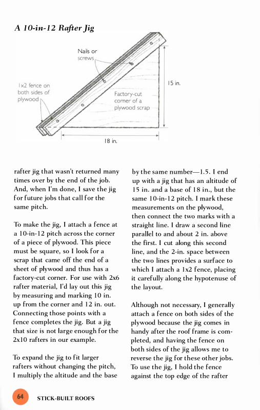
A 1 O-in- 1 2 Rafter Jig
Nails or
1 8 in.
rafter jig that wasn't returned many
times over by the end of the job.
And, when I'm done, I save the jig
for future jobs that call for the
same pitch.
To make the jig, I attach a fence at
a 1 O-in- 1 2 pitch across the corner
of a piece of plywood. This piece
must be square, so I look for a
scrap that came off the end of a
sheet of plywood and thus has a
factory-cut corner. For use with 2x6
rafter material, I'd lay out this jig
by measuring and marking 1 0 in.
up from the corner and 1 2 in. out.
Connecting those points with a
fence completes the jig. But a jig
that size is not large enough for the
2x l0 rafters in our example.
To expand the jig to fit larger
rafters without changing the pitch,
I multiply the altitude and the base
STICK-BUILT ROOFS
1 5 in.
'I
by the same number- 1 . 5 . I end
up with a jig that has an altitude of
1 5 in. and a base of 1 8 in., but the
same 1 0-in- 1 2 pitch. I mark these
measurements on the plywood,
then connect the two marks with a
straight line. I draw a second line
parallel to and about 2 in. above
the first. I cut along this second
line, and the 2-in. space between
the two lines provides a surface to
which I attach a l x2 fence, placing
it carefully along the hypotenuse of
the layout.
Although not necessary, I generally
attach a fence on both sides of the
plywood because the jig comes in
handy after the roof frame is com
pleted, and having the fence on
both sides of the jig allows me to
reverse the jig for these other jobs.
To use the jig, I hold the fence
against the top edge of the rafter

Laying Out a Rafter
L------� I , Mark along the plumb edge of the jig to lay out the ridge cut
"----_:�1:.G--'-------'.71 �-------------- I 06Ys in, -------------------+-1 2, Measure and mark I 06lfa in, from the heel of the ridge cut From the mark, scribe a line about 6 in. long along the level edge of the jig.
3, Measure in 6 in, from the mark and scribe along the plumb edge to complete the birds mouth,
4, From the plumb line of the birds mouth, scribe a level line (shown as a dotted line), Then measure and mark 1 2 in, out along the level line and scribe a plumb line down from that mark.
5. Use the jig to draw in the subfascia, Extend the lines from the inside and bottom of the subfascia to finish the rafter-toil layout
Level l ine
LAYING OUT THE ROOF

stock and scribe along the vertical
( I S -in.) side for plumb cuts and
along the horizontal ( I S-in . ) side
for level cuts. Keep in mind that
throughout this whole layout
process the rafter jig is oriented the
same way-with the fence held
snugly against the top edge of the
rafter and the plumb edge to the
ridge end of the rafter.
Now comes the fun part. With the
critical dimensions and the rafter
jig in hand, the rest of the job is a
stroll in the park. The first thing I
do is scribe along the plumb edge
of the jig to mark the ridge cut
(Step 1 in the drawing on p. 65 ) .
After I make the ridge cut, I mea-
T R I C K S O F T H E T R A D E
Using the Rafter Jig as a Cutting Guide To make crisp
plumb cuts, use the rafter jig as a
cutting guide. Just hold or clamp
the jig in place and run the saw
along the plumb edge. I've found
that it's usually necessary to clamp
the jig in place when I have to cut
rafters for steeply pitched roofs.
When I'm cutting rafters for roofs
pitched 8-in- I 2 or less, however,
1 just hold the jig with one hand
and run the saw through the wood
with the other.
STICK-BUILT ROOFS
sure the 1 06 %-in. dimension (the
hypotenuse) from the heel of the
cut along the bottom of the rafter
(Step 2) . To make this measure
ment, I clamp a square across the
rafter to provide something to hook
my tape measure to. After marking
the rafter at 1 06% in., I slide the
rafter jig to the mark and scribe
the level cut line. Because the
wall is 6 in. thick, I measure in
6 in. along the level line and mark.
Then I slide the jig to this mark
and scribe down along the plumb
edge to finish off the bird's-mouth
layout (Step 3) .
With the main part of the rafter
layout complete, it's time to work
on the rafter tail. First, use the jig
to scribe a level line out from the
plumb line of the bird's mouth.
I usually use a dotted line here to
distinguish this line from the others.
Because the plumb line of the
bird's mouth is even with the out
side of the wall, all I have to do in
this case is measure 1 2 in. out
along the dotted line to establish
where the end of the eaves (or
overhang) should be (Step 4) . After
marking this point, I slide the jig
into place and mark along the
plumb edge. But I won't be cutting
along that line. I generally install a
2x4 subfascia when I frame the
eaves, so I draw the subfascia full
sized inside the line I 've just
marked (Step 5 ) . The sketched-in
2x4 not only shows me where to

make my plumb cut on the rafter
tail ( l \12 in. in from the 1 2-in . mark
to accommodate the subfascia)j it
also shows me where to make the
level cut. As the drawing on p. 65
shows, I scribe a level line even
with the bottom of the 2x4 to com
plete the rafter-tail layout.
Carpenters often cut the first rafter
they lay out, then use it as a pat
tern to lay out the rest of the
rafters. Lining up and holding this
pattern rafter is awkward for one
person, though, so I use a different
technique-I make a measuring
stick. After I lay out the first rafter,
I hold a strip of wood against the
rafter and transfer the points where
the four lines at the tail of the
rafter intersect with the bottom
edge of the board. I use this cus
tom measuring stick to lay out the
tail section of each succeeding
rafter. After making the ridge cut
and pulling the 1 06%-in. measure
ment, I align the first mark on my
measuring stick with the l 06%-in.
Using a Measuring Stick to Transfer the Layout
After laying out the first rafter, mark on a strip of wood the four points where the birds mouth and rafter-tail layout lines intersect with the bottom of the rafter. Now you can use this measuring stick to transfer the layout to subsequent rafters.
��--�,����,�1�/--� � I' .[ Measuring stick
I . After marking the I 0618-in. measurement, align the measuring stick and transfer the other three marks.
2. Use the rafter jig to extend the layout from the marks.
1 0618 in .
-I
LAYING OUT THE ROOF

T R I C K S O F T H E T R A D E
Reference Mark on Rafter Measuring Stick To avoid
the possibility of lining up your
measuring stick backwards, put a
circle or other distinguishing sym
bol on the first mark on the stick.
mark and transfer the other three
marks to the rafter. Now I slide the
rafter jig in place and extend lines
out from these marks to lay out the
tail of the rafter.
Building the Roof
In the section on creating the mea
suring triangle (pp. 62-63), I found
the two critical dimensions for this
roof frame. You've just seen how I
used one of the critical dimensions,
the hypotenuse, to lay out the
rafter. In this section, I'll describe
how I use the other critical dimen
sion, the altitude, to set the ridge
to the proper height. After I describe
how I install the ridge, I 'll show
how I cut the ridge to length and
then lay out the points where the
rafters engage the ridge. Finally, I'll
explain how I install the rafters and
the plywood roof deck.
Setting the Ridge
The first step in setting the ridge is
to make a couple of posts to sup
port it at the correct height.
STICK-BUILT ROOFS
Because the walls in this addition
are 9712 in. high, the posts need to
be 9712 in. + 68/1 6 in. (the roof
altitude) , or 1 65 1�1 6 in. high. To
make each post, I cut two 2x4s this
length, then nail them to a 2x4
that is about 8 in. longer. This
third 2x4 stiffens the post and
serves as a "saddle," or niche, to
hold the ridge on top of the posts.
I center the posts between the
bearing walls and brace them
plumb in both directions. I typical
ly place each post about 1 8 in. in
from the end of the floor system.
Because I need to leave one side of
the post open for raising the ridge,
I place all the braces that run per
pendicular to the bearing walls on
the same side of the posts. When I
install these braces, I don't worry
about bracing the top third of the
posts; in fact, I like to leave some
play. When I install the rafters,
which will all be cut to the same
dimension, they'll center the ridge.
The primary concern at this stage
is getting the ridge at the right
height.
A ridge as large as the one speci
fied in this plan is quite heavy. To
get it on top of the posts, I have to
lift one end at a time and work it
up the post in manageable incre
ments (see the drawing on the fac
ing page) . To hold the ridge as I
step it up the posts, I use the same
all-purpose L-shaped brackets I

Raising the Ridge
To raise the ridge, lift one end at a time and move incrementally up the posts.
I 65 1'l16 in .
I Saddle
used for sheathing the outside of
the walls. I begin by clamping a
bracket on each post about 3 ft. off
the floor. Because of the weight of
the ridge, I use two C-clamps for
each bracket. I lift one end, then
the other to set the ridge on this
pair of brackets.
I keep my hand on the ridge beam
throughout this process, but once
it's in place on the brackets, I
clamp it to one of the posts with a
one-hand bar clamp. (I set this
clamp within reach before I pick
To keep the ridge from sliding off the bracket, install a clamp at the end of the bracket
up the ridge. ) I can now let go of
the beam and set up a second pair
of brackets about 3 ft. above the
first. After moving the ridge to this
level, I take off the first pair of
brackets and set them above the
second. I repeat this process, leap
frogging my brackets upward as I
go, until I have the ridge securely
set in the saddle atop the posts.
Good scaffolding is a vital part of
roof-building. As soon as I get the
ridge about 6 ft. off the floor, I set
up a section of pipe scaffolding,
BUILDING THE ROOF

one described in the text might
weigh over 200 'b .• so dropping It
cou'd be disastrous. To avert that
possibility. move methodically
through the task of rolslng the
beam and maintain contro' of the
beam throughout the process.
Make sure you stand on a stab'e
surface at all times. Once you get
above floor 'evel. use pipe scaffold
Ing, even If you have to stop work
Ing to go rent some.
which provides a secure surface to
stand on as I move the ridge up
another 6 ft. or so. After moving
the ridge another 5 ft. or 6 ft. , I set
up a second row of scaffolding on
top of the first. When I finish set
ting the ridge, my scaffolding is in
place for building the rest of the
roof. I want to re-emphasize here
how important it is to control this
heavy, potentially dangerous beam
at every point of this process. If
you decide to use this technique,
please take precautions (see the
safety tip above).
STICK-BUILT ROOFS
Cutting the Ridge and Laying Out
Rafter Locations
When I clamp the ridge to the
saddle on top of the posts I leave it
running long, with the intention of
cutting it in place. I have to cut the
ridge directly above the outside
edge of the floor system. To see
why I need to do this and how I go
about getting this cut in the right
spot, think about this addition in
plan view. If you look at the draw
ing on the facing page, you can see
that the ridge extends 1 ft. or so
beyond the edge of the floor sys
tem. Notice that the edge of the
floor system runs from the end of
one bearing wall to the end of the
other. Because the foundation has
been carefully squared up, the
floor system that rests on it is a
true rectangle. Thus, the edge of
the floor system runs perpendicular
to the bearing walls.
To get the end of the ridge in line
with the ends of the bearing walls,
then, I have to cut it at a point
that's directly above the outside
edge of the floor system. Once I
have the ridge cut at this point, I
pull identical layouts from the ends
of both bearing walls and the end
of ridge. Then, when I install
rafters on these layout marks, they
run perpendicular to the bearing
walls and the ridge. In essence, I 'm
transferring the square shape of the
floor system up to the roof frame.
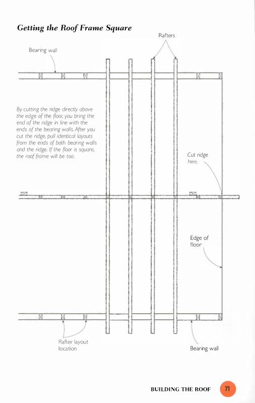
Getting the Roof Frame Square
Be,ricg \' JXl
By cutting the ridge directly above the edge of the fioor, you bring the end of the ridge in line with the ends of the bearing walls. After you cut the ridge, pull identical layouts from the ends of both bearing walls and the ridge. If the fioor is square, the roof frome will be too.
L/ Rafter layout location
Rafters
Cut ridge h'" \ r>7.l
Edge of flooe \,
Bearing wall
BUILDING THE ROOF

Cutting the Ridge Even with the Outside Edge of the Floor
Ridge
Post
Nail (about I ft. inside the end of the floor)
Cut ridge here.
( Post - - - - - - - -�f - - - - - - - -
To get the end of the ridge even with the outside edge of the �oor, lower a plumb bob from the ridge and mark where it engages the �oor. After measuring from the mark to the edge of the �oor, transfer that distance (X on the drawing) to the ridge.
Floor
x
End of bearing
I walls
� Plumb bob
Edge of floor
That's why I cut the ridge directly
above the outside edge of the floor
system; here's how I do it. First I
drive a nail in the side of the ridge
positioned (by eye) about 1 0 in.
inside the edge of the floor. I angle
this nail down as I hammer it
halfway in. Then I loop the string
of my plumb bob over the nail,
lower the bob, and mark where it
engages the floor. I measure the
distance from the mark to the edge
of the floor, then climb the scaffold
and measure the same amount out
from the nail to establish the point
that is precisely plumb to the out-
STICK-BUILT ROOFS

Using a Plumb Bob Here are a few simple
tricks I've discovered that make using
a plumb bob easy.
• Use a good, heavy bob (24 oz.) and
braided nylon mason's line. Braided
line is better than twisted line
because it doesn't unwind and
stretch from the weight of the bob .
• Set up a simple rig to hold the
string as you lower the bob. To lower
a bob from the side of on overhead
structure, drive a nail in at on angle
and loop the string over the nail. To
lower a bob from the underside of on
overhead structure, install a small
Cleat made from two nails with string wrapped in figure eight to tie off bob
Wall stud 24-oz. plumb bob
Mark on floor
eyebolt and thread the string
through the eye.
• Rig up a cleat to tie off the string
once the bob is lowered into posi
tion. You can buy a small cleat at
any hardware store, but I find it
more convenient to fashion one out
of two nails.
• To bring the bob quickly to a stand
still, rest a square or a block of wood
on the floor. With this method you
can hold the block or square steady
and it contacts the bob only at its
widest point (and thus does not jar it
out of alignment).
Braided mason's l ine
BUILDING THE ROOF

Installing the Rafters
A thrust block clamped at the heel of the bird's mouth holds the rafter in place during instal/ation.
T R I C K S O F T H E T R A D E
Converting Pitch to Degrees To convert the plumb
cut layout of a 1 0-in- 1 2 pitch into
degrees, place a Speed Square on
the edge of a board and rotate it
on the pivot until the 1 0-in- 1 2
pitch (in the common-rafter scale)
is even with the edge of the board.
Then look at the degree scale; it
should read just less than 40° in.
To use a Quick Square, adjust the
fence to the 1 0.pitch mark and
read the corresponding degrees in
the degree scale.
STICK-BUILT ROOFS
Ridge
Thrust block cut at 40° angle
side edge of the floor. (For more
information on how to use a plumb
bob see the sidebar on p. 73 . )
Using a square, I draw a straight
line through this mark and cut to
the line. The end of the ridge is
now even with the ends of the
bearing walls, and now all I have to
do is pull identical layouts from all
three ends .
Installing the Rafters
Holding and installing the rafters
on an addition like this is a surpris
ingly easy job. To keep the rafter
from sliding off the wall as I install
it at the ridge, I clamp a 2x2 thrust
block at the heel of the bird's-

Installing the Subfascia Rafters
L -shaped bracket (even with the level cut of the rafter) supports for end of subfascia during installation.
Measure and cut subfascia after installation.
Framed rake will end here.
mouth cut (see the drawing on the
facing page). I cut this block at an
angle so it fully and accurately
engages the top of the wall. The
angle of this cut is the same as the
plumb cut of the rafter, and it can
be laid out with the rafter jig. It's
faster to zip through this cut with a
miter saw, so I set my saw to a 40°
miter and slice off the angle with
out even making a line. (To convert
from angles described in pitch to
angles described in degrees see the
box on the facing page. )
After clamping the thrust block to
the rafter, I pull the rafter up on
the scaffold and, holding the upper
end above the ridge, slide the lower
end of it toward the wall. When
the thrust block engages the wall,
I lower the upper end of the rafter
down against the ridge. In that
position it's wedged in place and,
if I want, I can take a coffee break
before nailing it off.
Installing the Plywood Deck
After installing the rafters, I turn
my attention to the plywood deck.
I begin this process by setting up
pipe scaffolding under the eaves of
the roof. Once the scaffolding is
set up, I install the 2x4 subfascia
on the ends of the rafter tails (see
the drawing above) . To support the
BUILDING THE ROOF

Laying Down the Plywood
To hold the first row of plywood in place, clamp several stop blocks to the outside of the subfascia,
far end of the board, I screw an
L-shaped bracket to the wall, with
the shelf of the bracket flush with
the level cut of the rafter tail. (For
more on the L-shaped bracket, see
the sidebar on p. 89 . ) I install the
subfascia long, measure and mark
it in place, and then cut if off with
my circular saw. It's easier to make
this cut before installing the roof
deck. Also, it's important to make
the cut 1 Y2 in. short of the desired
width of the framed rake so the
next long board-the barge rafter
can run past the subfascia.
I then clamp several scraps of 2x4
to the outside face of the subfascia,
making sure the scraps project a
few inches above the tops of the
rafters. These scraps act as stop
STICK-BUILT ROOFS
Subfascia
blocks for the plywood. Next I
fetch a sheet of plywood. To get
the plywood up to the roof, I use a
C-c1amp as a handle and pull the
sheet up after me as I climb the
ladder. Once I have it at the roof, I
flop it into place across the rafters
1 ft. or so above the projecting
blocks. I can now slide the plywood
accurately into place against the
stop blocks.
After installing the first row of
plywood, I install roof jacks and
work off them as I set the subse
quent rows of plywood. To push
or pull the rafters into conformity
with the layout, I use bar clamps
and spreaders, just as I did when
I installed the floor deck.

you finish framing the
roof of a house or addition,
you have reached a water
shed in the job. This is especially true for
solo builders. The structural phase of the
job is now a thing of the past, and you no
longer have to envision and lay out new
elements or lift and install the brawny
materials that hold up the building. From
this point on, you'll be finishing the space
you've already built. The materials will
be noticeably lighter, and, for the most
part, the layout chores will be simpler and
easier. But this does not mean that you're
suddenly home free-a new set of chal
lenges emerges just as the previous ones
are disposed of.
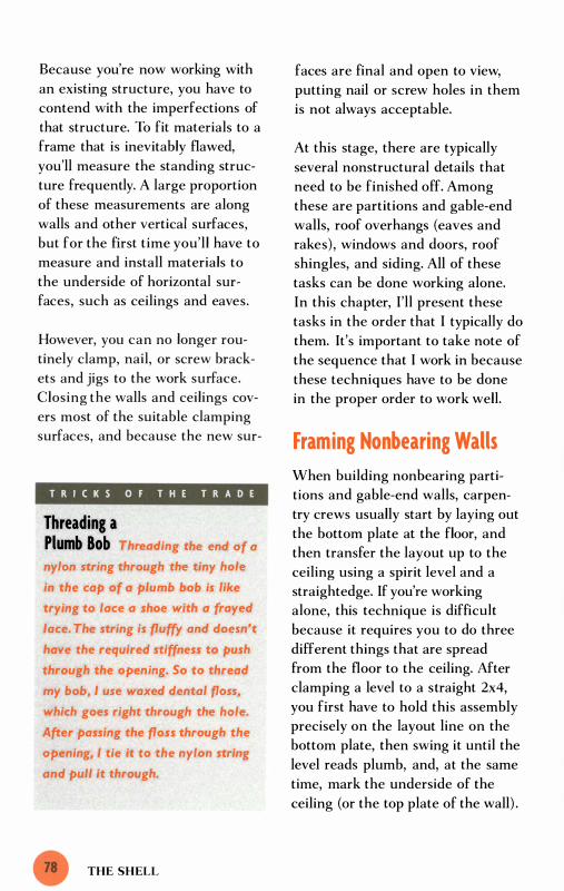
Because you're now working with
an existing structure, you have to
contend with the imperfections of
that structure. To fit materials to a
frame that is inevitably flawed,
you'll measure the standing struc
ture frequently. A large proportion
of these measurements are along
walls and other vertical surfaces,
but for the first time you'll have to
measure and install materials to
the underside of horizontal sur
faces, such as ceilings and eaves.
However, you can no longer rou
tinely clamp, nail, or screw brack
ets and jigs to the work surface.
Closing the walls and ceilings cov
ers most of the suitable clamping
surfaces, and because the new sur-
T R I C K S O F T H E T R A D E
Threading a Plumb Bob Threading the end of a
nylon string through the tiny hole
in the cap of a plumb bob is like
trying to lace a shoe with a frayed
lace. The string is fluffy and doesn't
have the required stiffness to push
through the opening. So to thread
my bob, I use waxed dental floss,
which goes right through the hole.
After passing the floss through the
opening, I tie it to the nylon string
and pull it through.
THE SHELL
faces are final and open to view,
putting nail or screw holes in them
is not always acceptable.
At this stage, there are typically
several nonstructural details that
need to be finished off. Among
these are partitions and gable-end
walls, roof overhangs (eaves and
rakes), windows and doors, roof
shingles, and siding. All of these
tasks can be done working alone.
In this chapter, I'll present these
tasks in the order that I typically do
them. It's important to take note of
the sequence that I work in because
these techniques have to be done
in the proper order to work well.
Framing Nonbearing Walls
When building nonbearing parti
tions and gable-end walls, carpen
try crews usually start by laying out
the bottom plate at the floor, and
then transfer the layout up to the
ceiling using a spirit level and a
straightedge. If you're working
alone, this technique is difficult
because it requires you to do three
different things that are spread
from the floor to the ceiling. After
clamping a level to a straight 2x4,
you first have to hold this assembly
precisely on the layout line on the
bottom plate, then swing it until the
level reads plumb, and, at the same
time, mark the underside of the
ceiling (or the top plate of the wall) .

It's possible for one person to do
this, but I find it a lot easier to use
a plumb bob. There's one odd thing
about using a plumb bob, though:
It works best when you start at the
top and work down. So when I
build any wall, I install the top
plate first and then transfer the lay
out down with my plumb bob.
Straight Walls
To determine the layout for a
straight wall, I must first find out
how far the partition needs to be
from the nearest standing wall.
Then I measure and mark that
dimension on a strip of wood. I use
this measuring stick to lay out the
location of the plate on the ceiling.
Before I lift the top plate into
place, I nail a 2x4 scrap on the wall
Laying Out and Installing the Top Plate Block installed between joists
Measuring stick butted against wall
Wali A (in background)
To lay out the position of a wal/ on the underside of a ceiling, measure and mark the specified distance on a measuring stick. then use the stick to measure across the ceiling.
- � Scrap of 2x4 nailed to wal/ holds up for end of top plate during its instal/ation.
� Wali A
� TOP pl't'
measurement from stick to ceiling.
( JOist
FRAMING NONBEARING WALLS

Transferring the Location of the Top Plate to the Floor
Top plate
Cleat
a little more than 1 \12 in. down
from the ceiling. This block sup
ports one end of the top plate while
I nail the other. If I think ahead, I
mark the layout on the top plate
before I install it; if not, I use a
measuring stick to mark the stud
locations on the installed plate.
The next step is to lower the plumb
bob from the side of the top plate
to mark the location of the bottom
plate (see the drawing above) .
Then, after nailing off the bottom
plate, I return to the top plate,
drive nails in at each stud location,
and use the plumb bob to transfer
the layout down to the bottom
plate. Mter marking the plate, I cut
and install the studs.
THE SHELL
( ,
Drive a nail halfWay into the side of the top plate and bend it up slightly.
Lower the bob from the nail and mark where it engages the ffoor.
Walls that Follow the Roofline
When the top plate follows the
underside of the roof-as it would
on a partition beneath a cathedral
ceiling or on a gable-end wall-the
layout is a little more difficult. To
get the studs on the normal 1 6-in.
layout, I determine the hypotenuse
of a right triangle that's the same
angle as the roof and has a 1 6-in.
base. It's easy to determine this
dimension mathematically, using
the same procedure I used when I
created the measuring triangle for
the roof frame. But for small lay
outs like this, I generally use my
rafter square to make a full-sized
drawing. It's fast, foolproof, simple
to do because it doesn't require cal
culations, and easier to visualize.

Laying Out an Angled Top Plate
Bottom pi",
1
40° bevel cut
1 6 in.
Plumb bob
Plywood scrap
1 6 in.
20 1716 in.
1 6 in.
r- I 6 in. ---1
Top plate
To determine the stud spacing on an angled top plate, first draw a triangle that matches the pitch of the roof (here, I O-in- I 2). Extend the hypotenuse as shown, and then measure out I 6 in. along the base to represent the I 6 in. between studs. Connect the end of the base to the hypotenuse.
FRAMING NONBEARING WALLS

I begin the layout by drawing a
right triangle that matches the pitch
of the roof-in this case 1 0-in- 1 2,
so the sides are l O in. and 1 2 in.
(see the drawing on p . 8 1 ) . When
I finish this triangle, I extend the
hypotenuse several inches beyond
the triangle and extend the base to
1 6 in. The new baseline is the cor
rect length for measuring between
studs. I draw a line perpendicular
to the base connecting the 1 6-in.
mark on the base to the hypotenuse
to finish the measuring triangle.
I measure the hypotenuse, which is
2010/1 6 in. for a 1 0-in- 1 2 pitch. This
measurement tells me the incre
ments I need to lay out on the top
plate to end up with studs spaced
1 6 in. apart.
The final step is to measure, cut,
and install the studs. Once again,
T R I C K S O F T H E T R A D E
Scaffolding Setup The same scaffolding setup
can often be used for several phases
of the job. On my last large addi
tion, I set up scaffolding after I
completed the roof frame and used
it to sheathe the exterior of the
house, frame and trim the roof
overhangs, set the windows, and
run the siding. Then I left it in
place for the painter.
THE SHELL
I use the right triangle I created for
layout. Looking at the altitude of
the right triangle, I can see that
each stud will be 1 3'11 6 in. longer
(as you approach the peak) than its
immediate predecessor in the lay
out. Instead of carefully measuring
every stud, I cut the first stud a
few inches long, then add 1 3'116 in.
to each succeeding stud. Now I
hold each rough-cut stud in place
on the layout lines and scribe the
top cut. Mter setting my miter saw
to a 40° bevel (the equivalent of a
1 0-in- 1 2 pitch), I cut along the
scribed line, then install the stud.
Notice that I 've completely violated
the old adage "measure twice, cut
once." Once a miter saw is set up,
cutting is faster than measuring;
and marking a piece directly is
more accurate than measuring a
distance, then transferring that
measurement to the piece.
Finishing the Eaves and Rakes
Carpentry crews often manage to
get through the job of finishing the
roof overhangs by working off lad
ders, but good scaffolding is just
about essential for a solo builder
(see pp. 33-3 5 ) . When you set up
the scaffolding, keep in mind that
the most intricate work is at the
corners, where the eaves meet the
rakes, so it's important to get the
scaffolding set up so that you can
move easily around a corner.
Another consideration is to get the

scaffolding at the right height.
Framing and trimming the over
hangs might take several days, so
take the time to set things up at a
comfortable working height. You
don't want to be reaching or stoop
ing. I 've found that putting the
scaffold 60 in. below the under
sides of the eaves and rakes works
well for me (I'm 5 ft. 7 in. tall) .
Once the scaffolding is in place,
you face a familiar pair of prob
lems. First, how do you measure
the long pieces that make up the
eaves and rakes? Second, how do
you hold up the far end of these
pieces as you install them? The
first problem is not as difficult as it
might seem. I avoid a lot of the
measurements involved in this job
by installing the pieces long and
then cutting them in place. Where
cutting in place is not practical, I
temporarily attach the piece and
mark it directly rather than taking
and transferring a measurement.
The second problem is also fairly
easy to solve. I use a number of
simple, site-built brackets-held
in place with screws, nails, or
clamps-to support the far end
of the boards.
Technically, the first step in this
job is installing the subfascia (also
called the rough fascia), but I do
that before I install the roof deck.
For more on installing the subfas
cia, see pp. 7 5-76.
T R I C K S O F T H E T R A D E
Using a Modified Chalk Box I often clamp my modi
fied chalk-box assembly in place,
but sometimes it's better to nail or
screw it in place. When I use fas
teners, I offset the nails or screws
from the chalkline, which allows
me to attach the line block with
out puncturing the finished surface
of the siding.
The Barge Rafter
Before I install the barge rafter,
which forms the outside edge of
the overhanging rake, I snap a
chalkline on the underside of the
overhanging plywood. This line
represents the inside of the barge
rafter. In most cases, I drive a nail
halfway in to hold one end of the
string as I snap lines. Driving 'a
nail into the underside of this
unanchored and springy plywood
overhang would be difficult, and,
in any event, the line would have
a tendency to fall off the nail.
Instead of using a nail, I use a
chalk box that has the end of the
line secured to a block of wood
(see the drawing on p. 96) . Using
a one-hand C-clamp, it's easy to
clamp the line-block assembly in
place to the underside of the ply
wood and snap the line overhead.
FINISHING THE EAVES AND RAKES

Building the Rake
/
Subfascia
Hold the blade against the sUbfascia during cutting.
Deep-reach clamp
THE SHELL
Ledge
Lookout
Barge rafter
2x4 ledge supports barge rafter during installation.
Cut the barge rafter fiush with the face of the sUbfascia after installation.
Test piece

After I snap this line for the barge
rafter, I install a 2x4 ledge under
the roof deck and against the
house. Next I install a series of 2x4
blocks (sometimes called lookouts)
that run out from the ledge and
end at the chalkline. The barge
rafter and plywood soffit are nailed
to the lookouts. I use a 5-in.-deep
bar clamp to hold the lookouts in
place as I nail through the roof
deck to attach them. I also toenail
them into the ledge.
Next, I cut and install the barge
rafter. I begin this process by cut
ting the top of the barge rafter to
the proper miter (40° for a 1 0-in-
1 2 roof) . To support the bottom
end of this board, I use my 5-in.
deep bar clamp to hold a 2x4 scrap
on the underside of one of the
lookouts . The scrap extends a few
inches past the end of the lookout
and serves as a temporary shelf. In
addition to supporting the weight
of the barge rafter, this shelf allows
me to move the rafter forward or
backward as I adjust its position.
To help get the barge rafter in the
right position, I use a test piece cut
at the proper miter (40° in this
example) to represent the opposing
barge rafter. As soon as I'm satis
fied with the fit at the converging
angles of the overhang, I nail the
barge rafter in place. After securing
the barge rafter, I use a sharp
handsaw to cut it flush with the
face of the subfascia. To get a good
square cut, I hold the side of the
sawblade against the subfascia with
one hand, while I saw with the other.
Notice that I did not try to measure
the distance and fit both ends at
the same time. Whenever possible,
I leave one end long and carefully
fit the other end. Only after I'm
satisfied with the fit at the first
end, do I concern myself with the
second end-where I either cut or
mark the piece in place.
Eave Frames
Finishing off the frame of the eaves
is straightforward. After leveling in
from the subfascia and snapping a
chalkline, I nail a 2x4 ledge at the
line. To support the far end of the
ledge, I go around to the gable side
of the house and nail a 2x4 that
extends several inches beyond the
corner (see the drawing on p. 86) .
This projecting board holds up one
end of the ledge as I nail it in
place. I leave the ledge long, then
plumb down from the barge rafter,
mark, and cut the ledge in place
with my circular saw. The portion
that projects out beyond the gable
end wall becomes an integral part
of the rake return.
Framing the rest of the eaves and
rake return are jobs that don't
require difficult measurements or
long boards. But using clamps makes
these tasks go more smoothly for a
FINISHING THE EAVES AND RAKES

Installing the Ledge
Ledge
Subfascia
solo builder. Typically, I install a
series of 2x4 cross-blocks running
across the eaves from the subfascia
to the ledge. As I install each cross
block, I use a one-hand bar clamp
to hold a scrap of wood to the
underside of the ledge. The scrap
acts as a little shelf, holding up the
inside of the cross-block while I
nail through the subfascia and into
the other end. I also use clamps to
hold materials in place as I frame
the rake return.
THE SHELL
Temporary support projects several inches post the comer of the house.
-
Finish Materials
As soon as I 've framed the eaves
and rakes, I fasten the finish mate
rials to them. I use the same basic
methods to install the finish mate
rials as I used on the underlying
frame. First, I install the fascia
running long. To hold it in place,
I clamp a bracket to one of the
cross-blocks (see the drawing on
p. 88) . Because the bottom of the
fascia has to be about 1 % in. below
the bottom of the subfascia, I make

Installing Cross-Block in Eaves
Subfascia Cross-block
One-hand bar clamp
this bracket roughly L-shaped.
After nailing off the fascia, I cut it
in place with my handsaw, holding
the blade flat against the barge
rafter as I saw. Then I install the
rake board. To hold up the lower
end of the board, I clamp an
L-shaped bracket to the underside
of one of the lookouts. For this
clamping chore, I use a deep
reaching bar clamp, with one pres
sure point under the bracket and
the other on top of the roof deck.
Ledge level with subfascia
Temporary shelf supports crossblock during installation,
As I did with the barge rafter, I let
the bottom of the rake board run
long while I fuss with the fit at the
apex of the overhang. When I get a
satisfactory fit, I nail the rake in
place and use my handsaw to cut
the bottom flush with the face of
the fascia. Cutting and fitting the
final pieces of the rake return pre
sents no special difficulties for a
solo carpenter.
FINISHING THE EAVES AND RAKES

Attaching the Fascia
Fascia
�--- --
L -shaped bracket supports fascia during installation.
The Soffit
The final phase of the job is to
install the plywood soffit that goes
on the underside of the eaves and
the rakes. To make the required
overhead measurements, I typically
use measuring sticks, but when I
have a small piece it can be easier
to hold the material in place and
mark where it needs to be cut. To
hold the far end of the plywood as
I install it, I screw one of my all
purpose L-shaped brackets to the
wall (about 1 in. below the frame
of the rake or eaves) .
THE SHELL
Ledge
---
----
One-hand bar clamp holds bracket to cross-block..
Installing Windows and Doors
For reasons I'll discuss in chapter 8 ,
I don't attempt to install large win
dow and door units by myself. But
I routinely install single windows
and exterior doors. Before I pick up
the window or door, I set up a
bracket that holds the unit in the
opening yet permits movement as
I fine-tune the installation. I begin
by measuring the amount that the
trim or nailing flange sticks out
beyond the outside of the jambs

The AU-Purpose Bracket Several years ago I spent
an hour or so fabricating four simple
L-shaped brackets. I call these site
built brackets my "all-1>urpose
brackets" because I use them for so
many different jobs. I built them for
a specific task, but after I had them
for a while I discovered their hidden
potential. When I built the brackets,
I was in the midst of a kitchen
remodel. I had to fabricate a custom
countertop with a curved front
edge, and I wanted something to
hold the countertop securely upright
as I applied a strip of laminate to
the edge. The brackets worked like
a charm.
In building the brackets, I knew I
could use them for a similar task
holding doors on edge-but I had no
idea how many other ways I'd end
up using them. For instance, I screw
plywood into two rectangular pieces.
One piece is 6 in. by 14 in., the other
6 in. by 14% in. Next I use my table
saw to cut a %-in. groove (about
Y4 in. deep) down the center of each
piece. I screw the pieces together in
the shape of an L (with the 1 4 %-in.
piece overlapping the 1 4-in. piece),
then I cut a triangle-shaped brace
with two 1 4-in. sides. To complete
the bracket, I fit the brace in the
grooves and secure it with a gener
ous amount of glue and some screws.
6 in. 1 4y,. in.
the brackets to a standing wall and 1 4 in. use them to hold up all manner of
materials, including framing lumber,
beams, plywood, drywall, exterior
trim, and kitchen cabinets.
The brackets are easy to make, espe
cially if you have a table saw set up
on the job. I cut a scrap of %-in.
INSTALLING WINDOWS AND DOORS

Window-Setting Bracket
Rough Opening
. J
o
Before setting the window in the opening. set up a simple bracket to hold it in place,
Setting up the bracket
o
T R I C K S O F T H E T R A D E
Centering Window and Door Units To center a window or
door in on opening, push it as for
as it will go to the left and mark
along the outside of the nailing
flange or casing. Repeat this process
on the right side, and then center
the window between the marks.
THE SHELL
2x4 blocks
� 0
U v-
Window \
~ In Q
u ip of /' Str
wo /f /� od
I This bracket holds the window securely in the opening but allows you to move the unit from side to side as you fine-tune the installation,
Installing the unit
of the unit. I mark this amount on
each side of the window opening,
then nail a couple of 2x4 blocks
about halfway up the opening and
an inch or two beyond these marks .
Mter securing the blocks to the
wall, I attach a strip of wood with
one nail to one of the blocks (see
the drawing above). I make sure
that this strip, which can be any
thing from a l x2 to a 2x4, swings
freely and spans across to the other

block when I rotate it up into a
horizontal position. Now I pick up
the window or door, set it in the
opening, swing the strip of wood
up across the unit, and nail it to
the block on the opposite side. The
unit is loose in the opening, but the
bar keeps it securely in place. And,
if I want, I can take a coffee break
before finishing the installation.
Shingling the Roof
Roofing crews typically work as a
team when they lay out the roof,
but after striking the lines each
roofer usually takes a section and
works by himself. They do this
because installing shingles is basi
cally a one-man job . The layout is
a different matter, though, and
without a second pair of hands it
can drag on.
The main challenge for the solo
roofer is to streamline the layout.
I do three things to get the layout
completed in a reasonable amount
of time. First, I use a 72-in. alu
minum measuring stick. This ruler
lies flat on the deck and is easy to
maneuver with one hand. And, at
72 in., it's exactly twice the width
of a standard shingle (see the draw
ing on p. 92) . This means that I
can mark it end-for-end to see how
my vertical coursing will end up on
the far side of the roof; or, in some
cases, I can move the bond layout
from the right to left side of the
roof if an interruption like a
dormer prevents me from laying
out the roof along the left side.
After marking the layout on the
roof, I work with an economy of
motion as I snap the chalklines.
To hold the string, I drive nails
halfway in along one side of the
layout. I secure the string to the
first nail and strike the line, but for
subsequent lines I do not reattach
the string to each nail. Instead, I
loop the string over the nails. Also,
I don't waste time reeling in the
string to rechalk it; instead, I use a
cube of red chalk, which I rub
across the outstretched string with
my left hand as I pull it taut with
my right. To mark the rake of the
roof (before cutting), I make a
short slit in the top shingle, slip the
end of the chalkline into the slit,
pull the string down to the bottom
of the rake, and snap the line.
The other thing I do to streamline
the process is to use a gauged roof
ing hammer. The gauge on the
hammer is 5 in. from the head of
the hammer. To get the required
5-in. exposure for the shingles, I
hook the gauge on the course I 've
just installed, then line up the
shingle on the head of the hammer.
I don't install the entire roof this
way because roofs installed without
any layout lines inevitably end up
with wavy courses. I use a combi
nation of layout lines and gauged
SHINGLING THE ROOF

Streamlining Shingle Layout
I" , " " , " , I i Ii i " , Ii '!'''''' Ii' "I"" Ii Ii' "I""" II Ii ','"' 'Ii ':' '�
'---------'�'___--'�'-------II ... ---'�'------'�'-----,I A 72-in. metal measuring stick equals the width of two shingles.
5 in .
THE SHELL
Chalklines
When I strike the lines, I slip the chalkline over the first nail, then loop it around the succeeding nails in the layout.
Layout lines
_ _ _ J
To reduce the number of horizontal lines needed to achieve first-closs workmanship, I use a gouged roofing hammer.
The gouge on this roofing hammer hooks on the bottom edge of shingle. The next shingle is set on the hammer head.

courses. Typically, I snap layout
lines every 20 in., which means
that I use the gauge for three
courses, then return to the layout
on the fourth course.
Installing Wood Siding
Installing wood siding is consider
ably more challenging for the solo
builder than shingling a roof. It's
not too difficult to see why: The
materials are long and are installed
on a vertical surface; much of the
work has to be completed standing
on scaffolding; and every piece has
to be cut and fit neatly into an
existing space. Yet this job is quite
manageable for one person. Over
the years, I 've discovered a number
of commonsense approaches and
simple tools and jigs that make
running siding by myself an enjoy
able process.
As always, I set up good scaffold
ing. Once it's set up I can work
quickly and safely through the rest
of the job.
Another thing that makes the sid
ing go smoothly is careful layout.
Before I begin the siding, I strike
two reference lines. The first is
about Y2 in. above the tops of the
windows; the second is about % in.
below the bottom of the sheathing
(see the drawing on p. 95 ) . The
next step is to drive a nail halfway
in on the upper layout line. I take a
long, straight strip of wood, butt it
against the nail, and mark it at the
bottom reference line. I bring this
strip of wood over to my work table
and divide the distance between
the two lines into equal increments.
Each increment represents a course
of siding.
To get equal increments, I use a
divider-a device that looks and
works much like a compass. When
I divide the space, I start with a
target increment, which is usually
6 in. for wood siding. The object
is to get an even spacing that's as
close to 6 in. as possible. To
Siding that is placed
across a section of scaffolding
looks a lot like a scaffold plank
and presents a serious hazard. If
you're not concentrating. you can
mistakenly step on the siding.
which can't support your weight.
Where possible, keep the siding on
the ground and lean it against the
scaffold to keep it within reach.
As you move higher up the wall,
you can either stack the siding
above the level you're walking on
or make sure it rests on solid
scaffolding planks.
INSTALLING WOOD SIDING

achieve this goal, I set the spread
of the divider to 6 in., march it
end-for-end up the wood strip, and
see if it is running long or short
(see the drawing below). I adjust
the spread of the divider according
ly and march it up the span again.
I repeat this process until I get the
divider to land on the mark-at
which point I know I have the
space evenly divided.
Now I march the divider up the
strip one more time, this time
marking the increments as I go. I
use this marked strip of wood as a
story pole for installing the siding
courses. By taking the time to
adjust the courses slightly, I 've pro
duced a layout that ensures that a
full piece of siding will run over the
windows. This trick saves time,
makes it easier to flash the top of
the window, and produces a better
looking job.
How I mark the courses depends
on the quality of the siding. If the
siding is straight and consistent in
width, I move the layout up to the
tops of the courses. To do this, I
take "a scrap of the siding, hold the
bottom of it even with the upper
reference line, and scribe along the
top of the scrap. After doing this at
each end of the wall and at the
ends of each space between the
windows, I drive nails halfway in at
the new marks. I can now lay out
the tops of the courses by butting
the story pole against the nails and
transferring the layout to the wall
(see the story pole to the left of
the window in the drawing on the
facing page). After marking the
courses, I snap lines using the same
basic technique I used on the roof.
Dividing a Distance into Equal Increments When divider lands exactly on the end of the space it is equally divided.
Turning knob adjusts the spread of the legs.
Start divider here.
THE SHELL
Distance being divided

Not all wood siding is straight
enough to be installed along layout
lines representing the top of the
course. Cheap siding often has a
gnarled top edge (it doesn't show
after it's installed), which makes it
difficult or impossible to follow a
top line for layout. Also, if the sid
ing is inconsistent in size, all the
inconsistency shows if you follow
Laying Out Lap Siding
Top reference line
Courses laid out on
Butt story pole here to lay out top of courses.
the wall � - - - - - - - - - - - - - - - - - -
- - - - - - - - - - - - - - - - - -
] Bottom reference line
lines along the top of the courses.
Conversely, all the inconsistency is
buried if you follow lines at the
bottom of the courses. That's
because the bottom of each siding
course overlaps the top of the pre
ceding course.
To lay out along the bottom, each
line has to be snapped-one at a
Siding Butt story pole here to lay out bottom of courses.
Nail
Each course is laid out on top of a preceding course.
INSTALLING WOOD SIDING

Using a Modified Chalkline
By removing the hook at the end of a chalkline and replacing it with a block of wood, you con strike lines without puncturing the siding.
Holes for attaching block with
time-on top of the course just
installed. Hence, the course layout
is an ongoing process that occurs
during the installation. After
installing each piece of siding, I
butt the story pole against the nail
installed at the original reference
line, then transfer the layout from
the pole to the wall (see the story
pole to the right of the window in
the drawing on p. 95 ) .
I don't use a nail to hold the chalk
line as I snap the course line. It's
THE SHELL
Corner board
not a good practice to nail through
the upper part of the siding, and
leaving a nail hole is completely
undesirable. Instead of nailing into
the top of the siding, I use my
modified chalkline, which has a
block of wood instead of a hook at
the end (see the drawing above) .
I can usually clamp the line in
place by clamping the block to
the window trim or to the corner
board. If this is not practical, I
attach the block to the wall by nail
ing in the area above the siding.

After I finish the layout, I begin
cutting and fitting the siding. I
rarely measure the spaces on the
wall; instead I hold each piece in
place and mark it directly. When I
need to mark a group of pieces
about the same size (when siding
between two windows, for example) ,
I cut several pieces a couple of
inches longer than the space. Then
I go to the layout and mark a piece
for every line. By keeping these
pieces in order, I get good custom
fits that accurately reflect the slight
variations in the width of the
space. At the same time, I save sev
eral trips to the saw. It's another
case of measure once and cut twice.
Because siding is fairly light, I can
usually hang short pieces of siding
without using a bracket to hold up
Bracket for Holding Siding
the far end of the board. For long
pieces, though, I often find it nec
essary to use a J-shaped bracket,
which I scrounged from a previous
job. If you don't have a ready-made
bracket, it's easy to fabricate one
out of a strip of mild steel about
Ya in. thick by 1 Y2 in. wide. Most
hardware stores carry a selection of
steel bars and rods.
The bracket I use is several inches
longer than the width of the siding
(usually 7 Y2 in. ) . I hang the bracket
in place with one or two nails,
driven halfway in toward the top
of the bracket (I drilled holes in
the bracket for this purpose) .
These nails end up above the top
of the siding I'm installing, and
they're easy to remove once the
siding is secured.
A j-shaped brocket supports one end of the siding as the other end is nailed up.
Siding
INSTALLING WOOD SIDING "

hile roofers and siders are
still working on the outside
of a house or addition,
special trade contractors-electricians,
plumbers, mechanical contractors, and
others-often begin lacing wires, pipes,
and ductwork through the skeleton of the
structure. At this critical period in the
project, the house is protected from the
weather but the inside of the frame
remains open and accessible.
After the special trade contractors finish
installing the inner workings of their sys
tems, the builder can install insulation in
the floors, walls, and ceilings. Then it's
time to hang drywall and to begin finish
ing the inside surfaces of the house. This
is the final stretch of the job, where the
building project visibly becomes a home.

Scores of interior materials need
to be installed, but this discussion
has to be limited. I won't go into
mechanical, electrical, and plumb
ing work because in most areas
such work has to be completed by
licensed contractors. I'm not per
mitted by law to do this work for
my customers, and I always hire it
out to licensed contractors. There
are other jobs that I'm allowed to
do but choose not to. In chapter 8 ,
I'll describe those jobs and explain
why or when I pass them off to
trusted subcontractors.
Even with the valuable help I get
from my subcontractors, I still do a
large portion of the interior work
on projects myself. I often install
the insulation, hang and finish the
drywall, and, with the exception of
hardwood floors, do the interior
carpentry myself. I also do my own
tile work. As different as these
materials are, the problems I run
into as a solo builder are remark
ably similar to those discussed in
earlier chapters. I have to come
up with a way to measure across
open spaces by myself, and I have
to transfer those measurements
quickly and accurately to the mate
rials. I also have to find a way to
hold the materials as I cut and
install them.
As you'll see, I often solve these
problems by going to my well-worn
bag of tricks and pulling out
another version of the same proven
methods I describe elsewhere in
this book. But I can't rely entirely
on these tried-and-true methods.
The conditions and materials
change in this stretch of the job,
and I sometimes have to make
corresponding adjustments to my
techniques. In some situations, an
adjustment is not enough, and I
have to find an entirely new
approach or make use of clever
new tools.
In this chapter I'll describe how
I install five different kinds of inte
rior materials. I won't get into jobs
that are obviously easy to do alone
(installing insulation, finishing dry
wall, painting) . I 've arranged the
topics in the same basic order that
I do them on my jobs . But unlike
many of the other chapters, where
the topics are interrelated and the
sequence of installation is such an
important part of the process, the
techniques described here are not
closely connected. On many houses,
in fact, these jobs are completed by
five different subcontractors.
Hanging Drywall
On small additions, I usually hang
and finish the drywall myself. By
far the biggest challenge is hanging
the ceiling. Not only are the sheets
heavy and unwieldy, but they are
also flimsy and easy to break. In a
few cases, I 've managed to man-
HANGING DRYWALL

Using a drywall lift makes hanging ceilings a simple matter.
handle a full 8-ft. sheet of drywall
onto a ceiling by myself, but I 've
never even attempted a I 2-ft. sheet.
In the past, when I got to the dry
wall phase of the job, I simply lined
up a helper for a few hours to get
the ceilings hung. But this proved
expensive, and it caused delays
because I had to hold off on dry
walling until someone was available
to help.
To solve this problem, I invested in
a drywall lift. The drywall lift is a
heavy-duty, telescoping jack made
specifically for lifting and holding
drywall and other large panels. I t
can be helpful for walls, but its pri
mary purpose is to hoist sheets of
THE INTERIOR
drywall to the ceilings. The model
I have raises the panel up to I I ft.
off the floor, and it can be modified
for ceilings up to 1 5 ft. high.
Before hoisting the sheet of dry
wall into position, it has to be cut
to fit. To measure the space, I face
a familiar problem. As we've seen,
a tape measure is about as effective
for measuring across long, open
spaces as a tennis racket is for
paddling a canoe. Instead of using
a floppy tape measure, I use mea
suring sticks for these overhead
measurements.
For longer measurements, I use a
strip of wood cut to exactly 1 00 in.

Measuring a Ceiling for Drywall
Cut a strip of wood exactly 1 00 in, long and use it to measure and mark the first I 00 in. Then measure the balance of the distance with a manufactured measuring stick to get the exact measurement
Measure from I OO-in, mark
Measure first 1 00 in, with strip of wood.
I DO-in, mark to center of joist with manufactured measuring stick.
1 4 ft, )
After butting one end of this 1 00-in.
measuring stick against the wall
(or, in some cases, against the edge
of the previous sheet of drywall),
I mark flush with the other end of
the stick. Then I measure the bal
ance of the space with one of my
metal measuring sticks. Adding
that dimension to the 1 00-in. mea
surement gives me the total mea
surement. I use this combination
of sticks because it's easy to add
the second measurement to a first
measurement of 1 00 and come up
with the total quickly.
Transferring the measurements to
the drywall panels is not difficult
for one person to do; in most cases,
you can hook a tape measure over
the edge and measure in the stan
dard manner. Measuring sticks can
also be used to measure the loca
tions of light fixtures, vents, and
other items in the ceiling. I often
mark their positions directly onto
a stick and transfer that measure
ment to the panel without ever
knowing (or caring) what the
dimension is.
Once the panel is cut, I use the lift
to raise the sheet to the ceiling.
Then I roll the lift to get the sheet
close to its proper position. After
locking the wheels of the lift, I
climb up a stepladder and slide the
sheet precisely into place before I
HANGING DRYWALL

T R I C K S O F T H E T R A D E
Enlarging a Door-Knob Hole To control the drill as you
enlarge an existing hole in a door,
use a scrap of wood to guide the
bit. First bore the desired hole size
through the scrap. Then clamp the
scrap to the door with the hole
positioned exactly where you want
to bore the hole. The prebored
scrap will guide the drill smoothly
into the door.
Holding a Door
Clamping a door bebNeen a couple of all-purpose brackets holds it securely on edge. For added stability you can put a second pair of brackets at the other end.
C-clamp
THE INTERIOR
screw it tight. A lift costs several
hundred dollars, but it has been an
excellent investment for me. The
first time I used it was on a large
remodeling project in an older
home with 1 0-ft. ceilings. On that
job alone, I saved about $ 1 00
in labor.
Hanging drywall on walls is hard
work but I 've never found it to be
particularly challenging to do by
myself. If you find it difficult to
control the upper piece as you
install it, however, you can use an
all-purpose bracket to support one
Door
All-purpose bracket ( 1 4 in. high)

end while you attach the other.
(Use the same basic technique
described in the section on
installing plywood to a standing
wall in chapter 3 . )
Working on Doors
When you hang prehung doors,
you install the jamb and door as a
unit. You don't need to cut or plane
the door, the hinges are already in
place, and the door and jamb are
bored and ready to accept knobs
and locksets. On many remodeling
and repair jobs, though, you have
to hang doors on existing door
jambs. When you do this, you need
to carefully trim and plane the
door to fit the existing opening.
Then you need to bore the door
for knobs and locksets and cut
mortises for the hardware. Finally,
you must install the knobs, lock
sets, and hinges.
To do this persnickety and unfor
giving work and at the same time
retain my sanity, I use a couple of
tricks to hold the door securely in
place as I work. When I'm trim
ming the door with my circular
saw, I need to hold the door flat.
That's easy-I just clamp it across
a couple of sawhorses. But when
I 'm planing the edge of the door,
boring the door for knobs and lock
sets, mortising the edges for hinges
and lock faces, and installing hard
ware, I need to hold the door
securely on edge. There are several
commercially available brackets
that are designed specifically for this
purpose, but they are not neces
sary. By clamping the door between
a pair or two of all-purpose brack
ets, I can hold the door every bit as
securely as I could by using a com
mercial bracket. The only differ
ence is that my site-built brackets
are free.
Running Trim
Interior trim should fit tightly and
neatly together, so measurement
mistakes even as small as Yl6 in.
Using power tools
to trim small pieces of wood is
dangerous. It's difficult to hold a
small piece securely, and if the
revolving blade gets bound In the
kerf, it can grab the piece and hurl
it at the speed of a major league
fastball. This careening chunk of
wood is a hazard in its own right,
but the fact that your hand might
be pulled into the path of the blade
is an even greater concern. Don't
take a chance. If you cut a small
piece of trim a bit too long, throw it
away and try again using a longer
and safer-piece of material.
RUNNING TRIM

Strategies for Measuring Walls for Trim
There are two basic ways to mark trim to length quickly and accurately when you're working alone.
Option 1 Where possible, mark the material in place.
V Outside corner or edge of door casing
Trim )
Option 2 For inside-to-inside measurements, use a combination of measuring sticks.
32 in . 1 00 in.
For measurements between 1 00 in. and 1 72 in.
70 in. 1 00 in. -I I'
For measurements greater than 1 72 in. ;1
I- -I 25 in.
2 1 in .
I' '1 70 in. I "
I' 'I 'I "T '( . , For measurements less than 1 00 in.
THE INTERIOR
., I '

can ruin a trim installation. If
you're working alone, it's essential
to come up with a way to make
quick, accurate measurements. In
many circumstances you can side
step this issue because many of the
pieces of trim that go into a house
can be held in place and marked
directly. Whenever I can, I start
with a rough preliminary measure
ment and cut the material a few
inches long. I hold the piece in
place and mark it, then cut it to fit.
To do this, I need to be able to run
the trim past the end of the space,
as when I'm fitting the material to
an outside corner of the wall or to
the side of a door casing.
When I measure from one inside
corner to another on the wall or
near the ceiling, however, I can't
let the piece run long, so I have to
measure the space. To measure
along the floor for base molding,
I can use my tape measure. But to
measure along the wall for chair
rail or crown molding, I need the
rigidity of measuring sticks. As I 've
done in other situations, I use a
site-built 1 00-in. measuring stick.
I push one end of the stick against
the corner of the space I'm mea
suring and mark even with the
other end. Then I measure from
the other corner to the mark with a
manufactured metal measuring
stick. Adding 1 00 in. to the second
measurement gives the length of
the space.
My longest metal measuring stick
is 72 in. If I have a space that
exceeds 1 72 in. ( 1 4 ft. 4 in. ) , I
make the first measurement with
my 1 00-in. stick the same way. But
I won't be able to span the remain
ing distance with my 72-in.-Iong
metal stick, so instead I mark the
second measurement from the cor
ner at 70 in., then measure the dis
tance between the two marks .
Adding the last measurement to
1 70 gives me the length of the
space. To measure a space just
under 1 00 in., I would use the
T R I C K S O F T H E T R A D E
Taking Inside Measurements The common way
to take an inside-to-inside mea
surement with a tape measure is
to poke the end into one corner,
extend it, and roll it up at the
other corner. With the tape curled
inside the corner, you can only esti
mate where you think the mea
surement would fall if the tape
measure was lying flat. You can
take the guesswork out of these
measurements by dividing the mea
surement into two parts. Measure
and mark l O in. from one corner,
then measure from the other cor
ner to the mark. Adding l O in. to
the second measurement gives you
the length of the space.
RUNNING TRIM
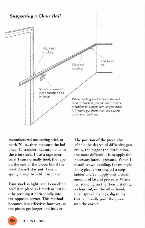
Supporting a Chair Rail
Mark trim in place.
Square screwed to wall through holes in fence
manufactured measuring stick to
mark 70 in., then measure the bal
ance. To transfer measurements to
the trim stock, I use a tape mea
sure. I can normally hook the tape
on the end of the piece, but if the
hook doesn't stay put, I use a
spring clamp to hold it in place.
Trim stock is light, and I can often
hold it in place as I mark or install
it by pushing it horizontally into
the opposite corner. This method
becomes less effective, however, as
the pieces get longer and heavier.
THE INTERIOR
1 6d finish nai l
When creating small holes in the wall is not a problem, you can use a nail or a bracket to support trim as you install it. If you've got more than one square, use one at each end.
The position of the piece also
affects the degree of difficulty; gen
erally, the higher the installation,
the more difficult it is to apply the
necessary lateral pressure. When I
install crown molding, for example,
I'm typically working off a step
ladder and can apply only a small
amount of lateral pressure. When
I'm standing on the floor installing
a chair rail, on the other hand,
I can spread my legs, dig in my
feet, and really push the piece
into the corner.

Supports for Installing Trim
U-shaped bracket �
Position a U-shaped brocket clamped to the top of a sawhorse next to the wall. Clamp a 2x4 at the correct height to support the chair roil (at about 30 in.).
2x4 clamped to bracket at correct height
Adjustable support for chair rail
\ Ceil ing
Scraps of 2x4 screwed to both sides of support
Concrete block keeps bottom of brocket from sliding away from wall.
) 200 bevel cut 2x4 with
3Y2-in. side facing wall
Attached at 200 bevel
Ceil ing
Hand-
Bar clamp
Stepladder
Supports for crown molding
Chair-rail molding
Crown molding
2x4
RUNNING TRIM
Carpet strip
Wall

Even when you're standing squarely
on the floor, though, this technique
has its limitations. You'll know it's
not working when your workday
begins to resemble a Laurel and
Hardy routine, where the piece
falls every time you get ready to
mark or install it. The solution to
this probkm can be as simple as a
1 6d finish nail. After marking
where the bottom of the molding
will be, you can drive the nail part
way in at that mark. The nail holds
up one end of the piece while you
mark or install the other. If you
want to make your life even easier,
put in a nail about 1 6 in. from
each end of the space to support
both ends of the trim.
I 've used finishing nails to good
effect for years but recently I dis
covered an even better way to sup
port the molding. Instead of a nail,
I now use a Swanson Mag Square.
Screwing the square to the wall
takes just a few seconds, yet it
creates a firmer and larger support
than a nail provides (see the draw
ing on p. 1 06) . I have two of these
squares, so I often put one near
each end of the space.
The downside to using either of
these methods is that they leave
holes in the wall. I consider this a
minor problem when I 'm planning
to paint or paper the walls. Drywall
is a forgiving material, and it's easy
to fill and repair the holes after I
THE INTERIOR
complete the trim. There have
been occasions, though, when I 've
installed trim on walls that were
finished, in which case leaving
exposed holes is not acceptable.
To avoid making holes while
installing chair-rail molding, I set
up an adjustable support (see the
top drawing on p. 1 07) . After mark
ing the height of the bottom of the
chair rail on the wall, I position a
sawhorse perpendicular to the wall,
then clamp a U-bracket to the top
of the sawhorse (see the sidebar on
the facing page). Now, as I hold a
2x4 that touches the wall at the
mark, I clamp it to the uprights of
the U-bracket.
To support the far end of crown
molding during installation, I use
another support. This support con
sists of a 2x4 leaned against the
wall with a couple of 2x4 blocks
screwed to the top (see the bottom
left drawing on p. 1 07) . The 2x4
blocks serve as a shelf to support
the crown as I install it. To keep
this assembly from sliding down
the wall, I place a toolbox or a con
crete block at its base.
Another option is to lean a step
ladder against the wall, then clamp
a bar clamp to the top step (see the
bottom right drawing on p. 1 07 ) .
Clamp a hands crew to the bar of
the clamp at the correct height to
support the crown molding. The

The U-Shaped Bracket For years I've used two
things to overcome the problems of
working outside over the uneven
ground: a good pair of sawhorses and
a combination of stakes and batter
boards. A few years ago I discovered
a way to combine these two systems.
In searching for something to sup
port long boards as I cut them with
my sliding compound miter saw, I
came up with a simple U-shaped
bracket. Clamping this bracket
(which I made out of 2x4s) to the
top of my sawhorse gave me a pair
2x4 crossbar clamped to bracket
(-clamps hold brocket to sawhorse.
of sturdy uprights. On these uprights
I clamped a 2x4 crossbar even with
the table of my saw.
The support worked like a charm,
and I soon discovered that I could
use this portable and adjustable rig
for other jobs. I also use it to sup
port lumber as I install it, to make a
batter board, and to provide a place
on which to hook my tape measure.
To lend stability to the U-shaped
bracket, I sometimes place a couple
of concrete blocks on the shelf of
the sawhorse.
RUNNING TRIM

possible configurations of jury
rigged brackets for this job are lim
ited only by your imagination.
Hanging Wall Cabinets
Kitchen cabinets are not terribly
heavy, and with a little planning it's
not too difficult to hang them by
yourself. There are at least three
good ways to approach this task.
The first approach is to screw a
pair of all-purpose brackets to the
wall and rest the cabinet on the
brackets as you install it. Mter the
first cabinet is secured to the wall,
clamp a scrap of wood to the
underside of the cabinet, extending
the scrap a few inches beyond the
side. This scrap serves as a shelf to
support and help align the next
cabinet. To install the next cabinet,
I often use a combination of this
shelf at one end and a single all
purpose bracket at the other (see
the top drawing on the facing page) .
If you object to the screw holes
that this method leaves in the wall,
you can use another approach.
Install the base cabinets first, then
set a site-built stand on top of the
lower units. Making the stand Y4 in.
shorter than the desired height of
the wall cabinets permits the use of
shims to precisely adjust the final
height of the cabinet.
The third approach to hanging wall
cabinets is to use a cabinet jack.
THE INTERIOR
The T-Jak is a tool specifically
designed to help solo builders hold
up cabinets during installation.
This jack can be quickly and finely
adjusted by turning a threaded
knob. The standard T-Jak has a lift
ing range of 53 in. to 84 in., but
with optional extensions it can be
used to support material at higher
levels. For those who like to hang
wall cabinets after installing the
base cabinets, there's also a Mini
Brute T-Jak, which is designed for
holding cabinets 1 5 in. to 24 in.
above the base cabinets.
The T-Jak can be used to support
other materials (such as drywall for
ceiling installation), and it can be
used effectively as a spreader. It's a
simple, well-conceived tool with an
agreeable price tag. You can get the
standard T-Jak for the price of a
good drill. If you're a full-time
kitchen installer, you might be
interested in another cabinet hoist
called the Lightning Lift. This rig
is quite a bit more expensive than
the T-Jak, but it's a heavier tool
with wheels. You can use it to lift
and move several cabinets at the
same time.
Squaring Up a Large Tile Layout Setting tile is very much a one-man
job. The only part of this job that
I 've found challenging to do by
myself is the process of squaring

Supporting Wall Cabinets
Deepthroated
- -- - - - .- � - - - �. -- - - ... � � - - -, - - - - -
2xB scrap holds one end of cabinet.
All-purpose bracket holds other end of cabinet.
I I , '
, ' , I ' I '
I I I I I I \ 1
I I I '
I Layout l ine for cabinet h';11
Screw a pair of all-purpose brackets to the wall to support the first cabinet. After setting the first cabinet, clomp a board under the installed cabinet to help support the next cabinet in line.
With all-purpose brackets
With site-built stand
Stand rests directly on bose cabinet (or on a piece of plywood if cabinet is open on top).
Wall cabinet
Threaded knob
�
With cabinet jack
Cabinet jack
SQUARING UP A LARGE TILE LAYOUT

up a large layout. In chapter 2, we
examined how to square up foun
dations using the Pythagorean
Theorem. When you square up a
tile layout, you can apply the same
technique. Use the length and
width of the layout to calculate the
hypotenuse of a right triangle, then
pull that dimension diagonally
across the layout to square it up.
This technique works, but there is
an easier way to square up a tile
layout-one that uses geometry in
a manner that takes advantage of
the circumstances of tile work.
Whether you're tiling a wall or a
floor, you begin the layout on a flat
surface. This is a lot easier than
laying out a foundation over
T R I C K S O F T H E T R A D E
Finding the Center of a Space To find the center of any
given space, toke a quick measure
ment of the total length and round
that measurement to the nearest
inch. Divide that total roughly in
half. Measure and mark that
amount from each end of the
space. The center is the point
halfway between the marks. Mark
the center point by eye and mea
sure again from both sides to make
sure it's centered.
THE INTERIOR
uneven ground. But you've still got
one problem-you have nothing to
hook your tape measure to. The
solution is to use a measuring stick.
In this situation, though, the mea
suring stick is more than a solu
tion; it's part of a new and better
method for squaring up the layout.
By using a measuring stick as a
beam compass, you can quickly
and easily lay out a perfect right
angle-without making precise,
time-consuming measurements.
What's more, this right angle can
be drawn out in the middle of the
layout. This option makes the
technique well suited to tile work,
which usually proceeds from the
inside of the layout toward the
perimeter.
To show you how I lay out tile, I'll
use the layout of a large tile floor
as an example. I start by marking a
baseline down the length of the
room. To lay out the position of
this line, which I 'll call the primary
baseline, I find the center of the
space at each end of the room. I
mark both ends, but for testing the
layout I'll work from only one mark.
After marking the center, I lay
out the tiles dry from this point
across the width of the room to see
whether this starting point yields
a narrow course at the edges.

Avoiding Narrow Courses of Tile
Dry run from center point indicates a narrow final course,
Mark the center of the width of the space, and then loy the tiles out dry from that point. If this dry run indicates that narrow courses (less than half the width of the tile) are in the making, shift the starting point half the width of one tile,
Shifting layout Y2 the width of one tile yields the widest possible course at the perimeter of the layout.
Center of width
Shifting layout Y2 the width) of one tile yields the widest possible course at the perimeter of the layout.
Primary baseline (off-center)
Starting point of perpendicular baseline
\ Center of length
Dry run from center point indicates a narrow final course,
L/ SQUARING UP A LARGE TILE LAYOUT
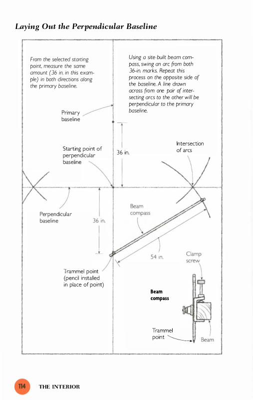
Laying Out the Perpendicular Baseline
From the selected starting point, measure the same amount (36 in. in this example) in both directions along the primary baseline.
Primary baseline
Starting point of perpendicular baseline
Perpendicular basel ine
1 Trammel point (pencil installed in place of point)
THE INTERIOR
-1 36 in.
Using a site-built beam compass, swing an arc from both 36-in. marks. Repeat this process on the opposite side of the baseline. A line drown across from one pair of intersecting arcs to the other will be perpendicular to the primary baseline.
Beam compass
Intersection of arcs
Trammel point �

(I strive to avoid narrow courses for
two reasons: first, because they're
hard to cut and install and, second,
because they offend the eye. ) If
this "dry run" yields unsightly nar
row courses (i.e., less than half the
width of the tile), I shift the entire
layout one half the width of the tile
and make new marks . This adjust
ment produces the largest possible
courses at the ends of the layout.
As soon as I'm satisfied with this
portion of the layout, I snap a
chalkline from mark to mark down
the length of the room. I usually
use a nail to hold the far end of the
chalkline as I strike the line. But if
there's a cement base on the floor,
I prefer not to drive a nail through
it. Instead, I loop the string around
a flat, heavy object, such as con
crete block or a toolbox. With the
string anchored on the mark at one
end, I pull to the mark at the other
end and snap the line.
After snapping this primary base
line, I lay out the position of a per
pendicular baseline. To do this, I
mark the center of the room as
measured along the primary base
line. Once again, I lay out the tiles
dry, this time in a line that runs
vertically along the primary base
line. If this dry run reveals that I'll
end up with narrow courses, I shift
the layout half the width of one tile.
After determining where I want the
perpendicular baseline to begin, I
measure and mark it on the floor.
It's imperative to get this second
baseline precisely perpendicular to
the primary baseline; otherwise the
tile courses will rack as you install
them and end up looking amateur
ish. To ensure that the perpendicu
lar baseline runs out at a 90° angle
from the primary baseline, I start
by making two equal-distance
marks out from the center along
the baseline (see the drawing on
the facing page). The exact length
isn't important, but it's essential
that both measurements be identi
cal. For this example, let's use a
36-in. measuring stick. I place one
end on the perpendicular baseline
mark and mark the other end.
T R I C K S O F T H E T R A D E
Site-Built Beam Compass To make a site
built beam compass, drive an 8d
nail through a I x2 a few inches
from the end. Measure and mark
the distance you want to make
the arc from the nail (which serves
as the pivot). Drill a �31-in. hole at
the mark. Insert a pencil through
tl1e hole, and the beam compass
is complete.
SQUARING UP A LARGE TILE LAYOUT

After making the marks in both
directions, I use trammel points to
set up a beam compass. Before
making the beam compass, I
remove the steel point from one of
my trammels and replace it with a
pencil. The exact length of this
beam compass is not important,
but I usually make it about 1 Y2
times the length of the measure
ment I 've just marked on the pri
mary baseline. For this example,
the beam compass would be 1 Y2
times 36 in., or 54 in.
To make the beam compass, I
clamp my trammel points about
54 in. apart on a 1x2 strip. This is
a quick and dirty measurement
because the exact length of the
beam compass is not important.
(If you don't own a pair of trammel
points, you can make a site-built
beam compass in a few minutes;
see the box below. )
To use the beam compass, I set the
end of one trammel point into one
of the 36-in . marks and use it as a
THE INTERIOR
pivot to swing an arc, as shown in
the drawing on p. 1 1 4. At the other
end of the compass a pencil draws
the arc on the floor. I repeat the
process at the other 36-in. mark,
pushing the trammel in at the
mark, swinging the compass, and
drawing the arc. The point where
these two arcs intersect is the criti
cal point I need for this layout. A
line extended from this point of
intersection to the center perpen
dicular baseline mark on the pri
mary baseline will be perpendicular
to the primary baseline.
To lay out a perpendicular line to
the opposite side of the primary
baseline, I swing a second pair of
arcs on that side. Typically, I swing
a pair of intersecting arcs on both
sides of the primary baseline, then
snap a line between their points of
intersection. It should pass right
through the middle mark. The
whole process takes just a few min
utes, is very accurate, and is easy
to do alone.

uilding a deck is part foundation
work, part frame carpentry, part
finish carpentry. The job begins
over the open ground, with no level or
square surfaces to measure against. You
have to develop these references from
scratch, just as you do when laying out a
foundation. Yet while deck layout is akin
to the layout of a foundation, the materi
als are similar to those found in the frame
of a house and require the skills of a
frame carpenter. Unlike the frame of a
house, though, the structure of a deck
remains open to view when the job is
done. Most of the deck consists of treated
lumber, which has to be joined neatly
together to satisfy aesthetic demands.
This is the realm of a trim carpenter.
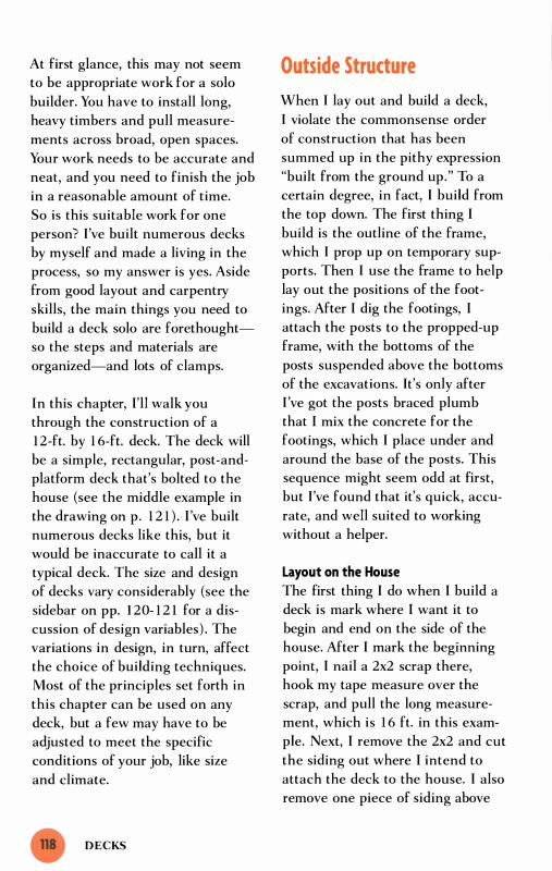
At first glance, this may not seem
to be appropriate work for a solo
builder. You have to install long,
heavy timbers and pull measure
ments across broad, open spaces.
Your work needs to be accurate and
neat, and you need to finish the job
in a reasonable amount of time.
So is this suitable work for one
person? I 've built numerous decks
by myself and made a living in the
process, so my answer is yes. Aside
from good layout and carpentry
skills, the main things you need to
build a deck solo are forethought
so the steps and materials are
organized-and lots of clamps.
In this chapter, I'll walk you
through the construction of a
1 2-ft. by 1 6-ft. deck. The deck will
be a simple, rectangular, post-and
platform deck that's bolted to the
house (see the middle example in
the drawing on p. 1 2 1 ) . I 've built
numerous decks like this, but it
would be inaccurate to call it a
typical deck. The size and design
of decks vary considerably (see the
sidebar on pp. 1 20- 1 2 1 for a dis
cussion of design variables) . The
variations in design, in turn, affect
the choice of building techniques.
Most of the principles set forth in
this chapter can be used on any
deck, but a few may have to be
adjusted to meet the specific
conditions of your job, like size
and climate.
DECKS
Outside Structure
When I lay out and build a deck,
I violate the commonsense order
of construction that has been
summed up in the pithy expression
"built from the ground up." To a
certain degree, in fact, I build from
the top down. The first thing I
build is the outline of the frame,
which I prop up on temporary sup
ports. Then I use the frame to help
lay out the positions of the foot
ings. After I dig the footings, I
attach the posts to the propped-up
frame, with the bottoms of the
posts suspended above the bottoms
of the excavations. It's only after
I 've got the posts braced plumb
that I mix the concrete for the
footings, which I place under and
around the base of the posts. This
sequence might seem odd at first,
but I 've found that it's quick, accu
rate, and well suited to working
without a helper.
Layout on the House
The first thing I do when I build a
deck is mark where I want it to
begin and end on the side of the
house. After I mark the beginning
point, I nail a 2x2 scrap there,
hook my tape measure over the
scrap, and pull the long measure
ment, which is 1 6 ft. in this exam
ple. Next, I remove the 2x2 and cut
the siding out where I intend to
attach the deck to the house. I also
remove one piece of siding above

Band Layout
End joist overlaps bond.
Top of bond is 2 Y2 in. below door sill (assumes I -in.-thick decking).
Band joist
the top of the intended deck to
make room for flashing. I know the
top of the deck will be just below
the threshold of the door, so it's
easy to see which piece of siding to
take out. For a freestanding deck,
there's no need to cut and remove
the siding.
The Band
The next step is to bolt the band
joist of the deck to the house. On
this deck, I 'm using 2xl Os for the
band and all the other joists. To lay
out the location of the band, I have
to think ahead and decide how I
want to do three things. First, I
must decide the precise level I
want the top of the finished deck
to be. I typically put the top of the
deck 1 in. down from the under
side of the doorsill. ( In areas where
heavy snow is expected, builders
often set the deck a full step down
from the doorsill.) So if I intend to
use 5/4 decking, which is a full
1 in. thick, I need to make the top
of the joists 2 in. down from the
underside of the doorsill.
I don't lay out the top of the band
at that level, however, because of
the second consideration: the
flashing. I install the top of the
band Y2 in. lower than the top of
the joists to accommodate the
flashing. This technique pr:events
the problem of trapped water above
the band and permits the water to
flow off the flashing. (See "The
Flashing" on p. 1 23 for more.) The
correct elevation for the top of the
band for this example is 2 Y2 in.
below the underside of the doorsill.
After striking a layout line at this
height, I turn my attention to the
third consideration: how I want to
attach the end joists to the band.
OUTSIDE STRUCTURE

Deck Design Variables In the simplest of terms
a deck is an outdoor floor system.
Because decks are made out of long,
rigid pieces of lumber, the easiest
and cheapest-shape to build is the
rectangle. In most cases, the width of
the deck is limited by the span of the
joists that make up the floor system.
To support your deck, you can make
use of the house by bolting one side
of the deck to it (top and middle
examples in the drawing on the fac
ing page). Although this widespread
practice saves time and money, there
is one good reason not to do it:
Water can be trapped between the
deck and the house.
If you decide to build the deck inde
pendent of the house, you have to
build a structure to support the side
of the deck adjacent to the house
(the bottom example in the draw
ing). On the outside of the deck, you
almost always have to build a sup
porting structure. Although you can
use masonry piers to hold up the
outside of the deck, the most com
mon supporting systems are a post
and-beam structure under the floor
DECKS
system (top example) or a series of
posts set along the perimeter of the
floor system (middle example).
When you cantilever the floor system
over a post-and-beam structure, the
deck takes on a contemporary look.
Setting the posts along the outside
edge, on the other hand, gives it a
more traditional feel--particularly
when the posts extend above the
deck and become part of the
balustrade.
The balustrade has an enormous
impact on how a finished deck looks.
To make a modern-looking
balustrade, use a continuous top rail
and let the balusters pass over the
face of the perimeter joists. To make
a traditional-looking balustrade, let
some of the posts poke a couple of
inches above the top rail and install
post caps or finials on top of the
posts. At the bottom, include a lower
rail set 3 in. to 4 in. above the deck.

Types of Deck
Decks are often classified according to the way the joists are supported at each end.
Band of deck bolted to house
II I
Platform runs over post -andbeam structure.
��----------� ---��------���--------
Cantilevered deck
-= FP ...., i'4l I'
Band of deck Posts set on bolted to house perimeter support
platform. ----------�
-
House Post-and-platform deck
/
0- This side of deck is not -- attached to house.
� Posts support this side of deck. -..........
Freestanding deck
OUTSIDE STRUCTURE

To cover the end grain of the band,
I like to lap the end joists over the
band. This means I have to mea
sure and mark I \12 in. in from each
end of the deck layout (marked on
the wall of the house) to determine
the starting and ending points of
the band.
I begin the installation of the band
by cutting the 2x1 0 to length and
width. The band needs to be 3 in.
less than the 1 6-ft. length ( I 92 in.)
to accommodate the end joists, so
I cut it 1 89 in. long. The band also
needs to be \12 in. down from the
Bracket for Installing the Band
.. - - -
Band joist \
. -.-
\
.- -_ .
Siding \ �
-
. . - .-.
top of the joists yet the bottoms
must be even, so I rip \12 in. off
the width to make the board 8% in.
wide. To hold the far end of the
band as I install it, I use an all
purpose bracket (see the sidebar
on p. 89) . Unfortunately, the
bracket has to be affixed to the
house below the floor frame.
Rather than try to screw the bracket
into the masonry foundation, I nail
a scrap of 2x lumber to the house
so that it hangs down to accept the
screws (see the drawing below).
This scrap needs to be about 24 in.
- - -
�
r · . � _ . - ..... -
Layout l ine \ \--\
i��c InQ�H 7 1 f All-purposel!
2x6 or 2x8 scrap (24 in. long) nailed to house
To ovoid screwing the bracket into the foundation, hong a scrap of 2x from the frame of the house first then screw the bracket to the scrap.
DECKS
Foundation bracket screwed to scrap

long. I make it extend from a point
about 2 in. above the layout line
for the band to about 1 2 in. below
the top of the foundation. Because
the scrap must accommodate a
6-in. -wide bracket, I use a piece
that's at least 5 Y2 in. wide. By keep
ing the nails for this scrap in the
area just above the layout line for
the band, I can easily reach them
later for removal. After I attach the
scrap to the wall, I measure and
mark 8% in. (the width of the
band) down from the layout line.
I screw the all-purpose bracket to
the scrap so the top of the bracket
is even with that mark.
I can now rest one end of the band
on the bracket while I nail the
other end in place along the layout
line. After I 've got five or six nails
in the unsupported half of the
band, I no longer need the bracket
to hold up the band. I take the
bracket off the scrap then remove
the nails holding the scrap and slip
it out from behind the band. Then
I finish nailing the rest of the
band. Once I have the band nailed
in place, I bolt it to the house. In
my area, the building code requires
a %-in. hot-dipped galvanized bolt
every 20 in.
The Flashing
With the band bolted securely to
the house, I turn my attention to
one of the most important details
of the job: the flashing. The purpose
Before you drill through
the band and into the side of a
house, go inside the basement or
the crawl space of the house,
peel back the insulation, and make
sure there are no wires in the path
of your drill bit. If you find wire
(or ducts and pipes for that
matter), consider drilling from
the inside out.
of flashing is to direct rainwater
away from the house. Without
flashing, water gets trapped between
the band of the deck and the wall
of the house. The consequences of
that water can be devastating. It's
imperative to provide a clear path
for large amounts of water to flow
off the flashing.
To protect the house from this
moisture, I install aluminum or
copper flashing bent in the shape
of an L, with part of the horizontal
leg of that L turned down (see the
drawing on p. 1 2 5 ) . The long verti
cal leg of this L is 3 in. ; the hori
zontal base is 1 Y2 in. ; and the part
that's bent down is 1 in. Because
this profile is not commercially
available, I have it made by a local
commercial roofer.
OUTSIDE STRUCTURE

Where Deck Meets House The Achilles' heel of decks
has historically been where the deck
meets the house. When decks first
became popular In the I 970s, car
penters typically just nailed a band
to the house and built the deck out
from that point. Unfortunately, some
of those decks collapsed. To make
matters worse, these catastrophic
failures usually occurred at precisely
the wrong place and time: on high
decks, top-heavy with people.
The reason for these failures turned
out to be the nails holding the band
to the house. Typically the weight of
the people-who in many cases were
dancing---caused the deck to peel
away from the house and come
crashing down. Building officials
responded to these failures by requir
ing that decks be bolted to the house
and that posts over 4 ft. high be
securely braced (to resist lateral
forces).
To install the flashing, I place it on
top of the band and nail through
the top half of the tall, vertical leg
into the house. The top half of the
flashing will later be covered by the
siding, so these nails will be pro-
DECKS
These measures have removed the
danger of sudden, catastrophic fail
ure in decks. But in the meantime
another problem at the house/deck
juncture has become apparent.
Water seeping between the band of
the deck and the wall of the house
causes the untreated wood on the
house to gradually rot. This is a slow,
insidious process, but once the dam
age is done it is very difficult-and
expensive-to repair.
There are two simple ways to avoid
this problem. The first is to carefully
flash the house/band juncture. The
second is to build the deck indepen
dent of the house. Designing and
building a freestanding deck is more
difficult than simply bolting one side
of the deck to the house, but by
leaving an open space between the
house and the deck. you eliminate
the problem of water trapped
against the house.
tected from the weather and well
above any sitting water. It's impor
tant to avoid nailing in the lower
half of the flashing, where water
flows and sometimes accumulates,
because that water often finds its

Installing the Flashing
Doorsi l l Nail only in the top half of the fiashing, then later cover the top of the fiashing with siding. :) ,
Laying out the top of the band below the top of the joists provides a clear path for water to run away from the house/band juncture after you install the fiashing.
2 in . I � /2 in.
r---<: ........ -+-."'"""'""' r-",.."".---"""""""""----5/4x6 decking
- --------- 9!i.1 in. sY-t in.
--------
Band joist Joist hanger Joist
way to the nail holes and seeps
under the flashing.
For a 1 6-ft. length, I have to use
two pieces of flashing, which
means I have to overlap the flash
ing several inches in the middle of
the band. This seam is a vulnerable
point in the flashing so I carefully
seal it with high-quality caulk. I
also take pains to seal the flashing
well at the two ends of the deck.
The Frame
The next step is to install the two
end joists. The first thing I do is set
up a support to hold the end of the
joist that's adjacent to the house.
I clamp a scrap of 2x4 (or 2x6)
under the bottom of the band (the
best clamp for this is a short pipe
clamp equipped with Mastodon
Jaw Extenders) . Letting this scrap
project a few inches past the end
of the band creates a shelf to sup
port the joist, as shown in the top
drawing on p. 1 26.
To support the outboard end of the
joist, I set up one of two possible
rigs, both of which roughly resem
ble football goalposts. If the deck is
going to be less than 4 ft. off the
ground, I use a U-shaped bracket
clamped to a sawhorse (see the
sidebar on p. 1 09) . If the deck is
OUTSIDE STRUCTURE

Installing End Joists
Scrap 2x shelf supports the end of the joist.
Band
2x shelf support
Band
Pipe clamp detail
DECKS
Pipe clamp with Mastodon Jaw Extenders
U-bracket supports outboard end of joist.
Cross-bar on U-bracket is level with bottom of band.
For end joists more than 4 ft. off the ground, drive a couple of stakes into the ground for the uprights of the goalpost-shaped support.

Squaring the End Joist to the House
Pull both 96-in. measurements from this point
96 in.
Sawhorse and U-bracket
� 2x4 scrap
Clamp
End joist J
more than 4 ft. off the ground, I
drive a couple of long stakes into
the ground and place a support in
between (this rig looks like a batter
board). I use my laser level to mark
the uprights of the rig even with
the underside of the band. (If you
don't have a laser level, you can
96 in .
Band �
I 35�-in. brace (cut long point to long point)
Calculate the hypotenuse of a right triangle with two 96-in. sides, then cut a brace the length of the hypotenuse ( 1 357'4 in.). Use the brace to set the end joist perpendicular to the house.
Slide the end joist and brace until the point of the brace intersects with the 96-in. mark on the joist When it does, the end joist is perpendicular to the house. Clamp or nail the brace to the joist to hold it square.
goalpost-like support, I set the end
joist in place and nail the end adja
cent to the house into the side of
the band.
use a level and a straightedge. ) Then
I clamp a horizontal 2x4 from mark
to mark. When I've completed my
The next task is to square the joist
to the house. To do this I use the
Pythagorean Theorem discussed in
chapter 2 . Instead of using strings
to represent the sides of a right tri
angle, however, I use three boards.
OUTSIDE STRUCTURE

Two of those boards-the band and
the end joist-will be part of the
permanent deck; the third, which
represents the hypotenuse, is a
temporary brace.
I calculate the hypotenuse of a
triangle with two 96-in.-Iong sides.
(The exact length of these sides
is not crucial; I chose this length
because it's half the length of
the deck.)
';2 X 96 = 1 3 5 .7 7 or 1 3 5% in.
Mter determining the hypotenuse,
I hook my tape measure over the
end joist and pull it along the band,
measuring and marking 96 in. from
Installing the Rim Joist
Band
Temporary support holds end joist level.
DECKS
Scrap clamped to underside of end joist supports the rim joist as you install it.
the corner. Next I measure and
mark 96 in. from the same corner
along the outside edge of the joist.
I now have the lengths of the two
sides of my measuring triangle.
Because the outboard end of the
joist is simply resting on the goal
post rig, I can swing the joist later
ally (like a hinge attached at the
band) as I set it square to the
band. Instead of using my tape
measure to pull the hypotenuse as
I brace the joist square to the
house, I use the brace itself as a
measuring stick.
I cut the brace exactly 1 3 5% in.
long with 45° miters at each end
(the 1 3 5%-in. dimension is mea-
End
Rim joist rests on scraps during installation.
Bar clamp
Scrap clamped to bottom of end joist
Note: The diagonal braces have been removed (rom the drawing for clarity.

sured from long point to long
point) . Next I set the brace diago
nally across from the corner
formed by the band and the end
joist and clamp it at the 96-in.
mark on the band. Then, I move
the joist and the brace until the
long point of the brace intersects
with the 96-in. mark on the joist.
When these points intersect, the
joist is perpendicular to the band,
so I clamp the brace to the joist to
hold it in place.
After repeating this process on the
other end of the deck, I install the
rim joist to complete the basic rec-
Quadruple-Duty Post
A single post can serve four functions: (a) be part of the balustrade, (b) help support the deck, (c) provide a framework for installing lattice, and (d) support the stair stringer.
tangle of the deck. To hold the rim
joist in place, I clamp 2x4 blocks
under the end of each end joist,
creating small shelves at both ends.
Installing the rim joist is then a
piece of cake, because both ends
are supported. On some decks, I
attach the rim joist temporarily,
mark the footing locations, and
then remove it while I'm digging
the footings. (I often do this on low
decks, where the rim joist would
interfere with the digging.)
The Footings and Posts
The deck structure is now a level
and square rectangle held up by
Balustrade
Stair stringer
OUTSIDE STRUCTURE

Laying Out Large Decks The width of a deck
is usually limited to the span of the
joists (typically 1 6 ft. or less). The
length of the deck. on the other
hand, can easily be made as long as
the house. To build a modest, 1 6-ft.
long deck. I use the rim joist both to
lay out the locations of posts and to
suspend the posts while I pour the
concrete footings. But what do I do
when I have to build a much longer
deck. where the rim joist has to be
pieced together from two or three
boards? I use string.
After installing and squaring up both
end joists as described in the text, I
set up a string that extends from the
top, outside corner of one end joist
to the top, outside corner of the
other. Next I hook my tape measure
over one of the end joists and mea
sure and mark the post locations on
the string. (I mark the layout on the
string with a felt-tipped marker; if
the tape measure won't stay put on
temporary supports. The next step
is to install the permanent posts.
I mark the location of the posts on
the perimeter joists (the end joists
and the rim joist), then transfer
those locations to the ground with
DECKS
the joist, I clamp it down.) After
transferring the layout from the
string to the ground, I lay out and dig
the footings.
The final step is to install the con
crete footings and the posts. To do
this, I work on one footing/post
assembly at a time and save the post
layout and cutting for later. I begin
by mixing a batch of moist but stiff
concrete. I pack 8 in. of this mixture
in the bottom of the footing then set
a post on the concrete. After making
sure that the post will be long
enough (39 in. above the string) to
accommodate the balustrade, I brace
it plumb in both directions and even
with the marks on the string.
With the post securely braced, I pour
a wet, mushy batch of concrete
around the post until it's level with
the surface of the ground. After the
concrete cures, I cut the notch and
the top of the post as it stands.
a plumb bob. Experience has
taught me to think about more
than just providing support for the
deck when I plan the locations of
the posts.

If I intend to underskirt the deck
with lattice, for instance, I make
sure the posts are no more than
8 ft. apart, which is the length of a
sheet of lattice. If I'm going to
build a set of stairs, I add a post to
support each stringer. Finally, if I
plan on having the posts extend
through the deck and serve as
newels for the balustrade, I make
sure the posts are no more than
8 ft. apart. (Keeping the space
between the newels under 8 ft.
lessens the chances that the rails
will sag or bow and provides for a
strong, safe balustrade. ) I often use
the same post for all of these func
tions (see the drawing on p. 1 29) .
After I determine where I want the
posts, I mark their locations on the
perimeter joists. This process is
simply a matter of pulling the tape
measure from the outside corners
of the propped-up perimeter. Next
I lower a plumb bob and transfer
the layout to the ground. Based on
this layout, I measure and mark the
outline of each footing, which I
make 1 6 in. square.
In my part of the country, the foot
ings only need to be 20 in. deep to
get below the frost line. The clay
soil that predominates here yields
readily to hand tools, so I rarely
spend more than 30 minutes dig
ging each footing by hand. When
I'm done, the excavation is neat,
with plumb sides, a flat bottom,
T R I C K S O F T H E T R A D E
Digging Tools When you dig the footings
for a deck, the goal is not to move
dirt-it's to carve a clean opening
in the ground, with a level bottom
and plumb sides. I've found thot
the best tools for this job are a
small, square shovel, a one-hond
mattock, and a couple of different
sized brick trowels. I olso keep a
large poir of loppers handy for
cutting tree roots.
and no loose soil-the perfect
form for the concrete. Having built
as far north as Maine, however, I
know that things aren't always so
easy. If you live in a cold region
and/or have to contend with diffi
cult soil, you may want to use exca
vating equipment (see the sidebar
on p. 1 32) .
When I finish digging, I pour the
footings and install the posts. I do
these things at the same time, so
the bottom of the post is embedded
in the concrete. Although this prac
tice is approved by most building
codes, some carpenters object to it
because they're concerned about
the long-term effects of leaving the
post in contact with the concrete.
The main concern is that the base
of the post will absorb moisture
OUTSIDE STRUCTURE

Building Decks in Cold Climates In cold climates, where
the frost line is more than 3 ft. down,
it often makes sense to bring in a
backhoe or an auger to dig the foot
ings. When you use excavating equip
ment, you can't dig the footings with
the perimeter joists in place because
you need room for the machinery.
So take down the perimeter joists
after you've laid out the footings on
the ground, bring in the excavator,
and dig the footings. When you're
done, it's surprisingly easy to reinstall
the perimeter joists, especially if
you've been able to leave the goal
post-shaped supports in place (see
PI'. 1 25- 1 2 7).
There are two other things to consider
if you're building in a cold climate.
The first is the concrete at the base
of the posts. Where deep freeze
occurs, the ground expands upward,
or heaves. If the sides of the con
crete are jagged-as they would be
if you used the excavated hole as a
form-the heaving soil might grab
the sides of the concrete and lift the
entire deck. It's good practice to use
concrete tubes or build wood forms
to create smooth sides when you
pour concrete around the bottoms
of the posts.
DECKS
The other consideration is the height
of the deck. Where heavy snow is
expected, it makes sense to build the
deck one step (7 in.) down from the
top of the doorsill. This space makes
it easier to open an outswinging door
(usually a storm door) after a bliz
zard and keeps melting snow from
seeping through the door opening.
Because building the deck at this
height frequently places over half
the band below the top of the foun
dation, there's a good chance you'll
have to drill through the foundation
to bolt the band to the house. If
you're building a new house and you
know where the deck will be, you
can save yourself a lot of work by
embedding these bolts as you build
the foundation. Or, if you prefer,
embed treated wood in the founda
tion to receive bolts when you install
the band.

Post Layout 2 in.
- - - - - - - - - -� - - -, -, - -I -, - -; ..., - ..... ..., -
I I I I I I I I I I I j I I I
I I I ; I I I
I t I I I I I I
I I I I I I I I
I I I I I I I
36 in. I I t I , I I I I I I I I I
I I I I I I I I I I I I I I
I I I I
1 I I I I
I I I I I I I
I I t I ! I I I
, , I I I I I I I , I , I I I I
- - - - , -,- _ ._. _ -1_. - _'_' _
39 in.
- - - - - - - - - - - - - - - -
- - - - - - - - - - - - -
� I -in. decking '-----
---------. 9� in.
End joist
20 in.
I Yl-in. x 9�-in . notch for rim joist
, (depth varies according to '
climate) , :>
from the concrete. After years of
using this method, however, I'm
convinced that this moisture does
not threaten the structure Uust
look at all the telephone poles that
have survived decades in the
8 in .
Distance varies
1 6 in.
ground). And there's a significant
advantage to encasing the posts
deep inside the concrete-the con
crete weighs hundreds of pounds
and imparts a rock-solid rigidity to
the posts.
OUTSIDE STRUCTURE

To get the posts set and the con
crete poured in one fell swoop, I
suspend each post above the bot
tom of the footing before I mix and
pour the concrete. I begin this
process by measuring the distance
from the bottom of each footing to
the underside of the perimeter
joist. Then I subtract 8 in. from
this dimension to allow for the 8 in.
of concrete under the post that's
required by my building code. After
measuring and marking this dis
tance on the post, I lay out a l l'z-in.
by 91'4-in . notch above the mark.
There are two reasons I go to the
trouble of making this notch. First,
when I finish the deck, the perime
ter joist(s) set in this notch bear
directly on solid wood (instead of
T R I C K S O F T H E T R A D E
Cutting a Notch To cut a 9Y4-in. by 1'/2-;n.
notch in a 4x4 post, I set my circu
lar saw blade to a depth of I Y2 in.
and don ear protection. After care
fully cutting along the top and bot
tom lines of the layout, I quickly
cut about two dozen kerfs between
the first two cuts. Next I knock out
the standing wafers of wood left
between the kerfs with my ham
mer. I finish the job by paring the
bottom of the notch smooth with a
sharp chisel.
DECKS
relying entirely on the bolts for
support). Second, this notch brings
the outside face of the post-and
thus the entire balustrade-even
with the outside edge of the deck.
Once the notch is laid out, I mea
sure and mark 39 in. above the top
of the notch and cut the post off at
that dimension. The 39-in. dimen
sion provides for a rail that will be
36 in. above the top of the deck,
which is required by code in my
area. It also allows the post to pro
ject 2 in. above the rail (see the
drawing on p. 1 33) .
Next, I cut the post to length and
cut out the notch, using a circular
saw and sharp hand tools. Then I fit each post over the location laid
out on the perimeter joists. When I
get the post aligned with the lay
out, I clamp it to the joist and
brace it plumb in both directions
(see the drawing on the facing
page). To make this task manage
able, I often clamp a 2-ft. level to
the post as I brace it plumb. Once
the posts are plumb, I begin mixing
concrete. With the bottom of the
post suspended 8 in. above the bot
tom of the footing, I pour the con
crete under and around the post
until the footing is filled up to
grade. To keep rainwater from
pooling around the post, I build up
the top surface of the concrete
slightly and make it slope down
and away from the post.

Installing Posts
Post leveled in both directions
Stake in ground
Brace
Post suspended 8 in. above bottom of footing
Inside Joists To avoid breaking the concrete,
I allow it to cure for at least 72
hours before I resume work on the
posts. When the cure period is
over, I remove the clamp holding
the post to the joist, drill Yz-in.
holes, and bolt the joist perma
nently to the post with carriage
bolts. With the posts embedded in
the concrete bases, the entire
structure is now rigid. I no longer
need the two diagonal braces to
Brace
Clamp
Level clamped to post
Perimeter joist
With the post clamped in place and braced plumb, fill the footing with concrete.
Concrete goes under and around post.
hold the perimeter of the deck
square. I remove the braces and
I'm ready to install the rest of
the joists.
The first thing I do is lay out the
locations of the joists-a straight
forward process. Pulling the tape
from the same side of the deck, I
measure and mark identical 1 6-in.
on-center layouts on both the band
and the rim joist. To measure the
space between the band and the
INSIDE JOISTS

Installing Inside Joists
Yl-in. strip on top of bond holds the joist Y2 in. above bond.
2x2 clamped to joist supports joist as you install it.
Joist hanger
----- ,
rim joist to determine how long to
make the joists, I use a l x2 strip as
a measuring stick. Because there's
no guarantee that the wall of the
house is perfectly straight, I mea
sure for each individual joist in the
layout.
Once I 've transferred the measure
ment to the joist, I cut it to length
and install joist hangers on both
ends. Before installing the joist
hangers, however, I "crown" the
joist. Most boards are slightly
bowed, and you want to make sure
the bow or crown of all the joists
points up as they're installed. To
crown each joist, I sight down the
edge and mark the high side of the
DECKS
Inside joist
Rim joist
bow with an arrow. Then, when I
install the joist hangers, I note
where the crown is and position
the hanger with the seat on the
opposite side of the board. This
placement ensures that the joist
will be oriented with the crown up
when I install it.
After attaching hangers to both
ends of the joist, I clamp a 2x2
block to the top of each end of the
joist, with about 1 in. of the scrap
projecting past the end of the joist
(see the drawing above). I set a
Y2-in. strip of plywood on top of the
band, then bring the joist inside
the deck area and slide it into place
between the band and the rim joist.

Four Ways to Straighten Deck Boards
To use a pipe clamp, leave a decking board out to provide purchase for the fixed jaw.
Decking Joists
Rotate the handle of a special purpose tool like a BoWrench to push the plank forward
To use a spreader. clamp or nail a scrap across the joists, then abut the fixed jaw against the scrap as you propel the other jaw forward by tuming the handle.
scrap to the top of the joisc then drive a wedge between the scrap and the plank
INSIDE JOISTS
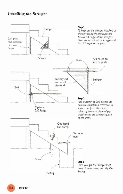
Installing the Stringer
2x4 prop holds stringer at correct height.
2x4
DECKS
Stringer
Square
Optional 2x2 ledge
Footing
Factory-cut corner of � plywood
One-hand bar clamp
Step 1 To help get the stringer installed at the correct height, measure the plumb cut angle of the stringer. Then cut a prop at that angle and install it against the post.
Step 2
2x4 nailed to face of posts
Stringer
Nail a length of 2x4 across the posts to establish a reference to square out from. Then use a rafter square or a piece of plywood to set the stringer square to the deck..
Torpedo level
Step 3 Once you get the stringer level, clamp it to a stake, then dig the footing.

The 2x2s hook over the band and
the rim joist and hold the joist at
the right height as I install it. The
plywood strip holds the joist \12 in.
above the band, but the other end
of the joist sits flush to the rim
joist. I attach the joist at the layout
lines by driving nails through the
flanges of the joist hangers.
Installing the Decking
Once I get all the joists installed, I start installing the decking. The
main challenge is to force the
wood-which is inevitably bowed
and twisted-into a reasonably
straight line as I install it. To do
this, I use a BoWrench (see p. 4 1 ) .
There i s also a similar tool called
the Boardbender. If you don't have
one of these special-purpose tools,
you can use a pipe clamp, a
spreader, or a block of wood and a
wedge (see the drawing on p. 1 37) .
These techniques are not as fast as
using a BoWrench or a Board
bender, but they get the job done.
Final Steps
The final steps for this deck are
the latticework and the stairs and
balustrade. Cutting and installing
the sheets of lattice is a straight
forward task that shouldn't present
problems for a solo builder. The
design and layout of stairs, on the
other hand, is a complicated task,
but the only part that's challenging
to do alone is installing the
stringers. To install a stringer cor
rectly you have to do three things:
attach it to the deck at the right
height, install it square to the deck,
and make the treads level.
To get the stringer at the right
height, I nail or clamp a 2x4 prop
against the post to hold the stringer
up as I toe-nail it in place (Step 1
in the drawing on the facing page) .
Because the stairs slope at an
angle, the top of the prop must be
cut at the correct angle. The angle
is the same as the plumb cut on
the stringer and can be measured
with a Stanley Quick Square or a
Swanson Speed Square. (For most
staircases, the angle is between
32° and 42°.) I sometimes incorpo
rate this prop into the design of
the deck and leave it permanently
in place.
To get the stringer square to the
deck, start by temporarily installing
a 2x4 across the posts (about
halfway up) . The 2x4 serves as a
reference to square the stringer to.
Most of the time, the stringers that
run perpendicular to the deck are
small and I can use a rafter square
or the factory-cut corner of a sheet
of plywood to get the stringer
square to the 2x4 (Step 2 ) . When I
have to build a long set of stairs off
a high deck, I usually design the
deck so that the stairs run along
the side of the deck or the house.
That way the stairs don't project
FINAL STEPS

deeply and awkwardly into the
yard. On the rare occasion when
I have to square up a long stringer
to the deck, I fabricate a large right
triangle out of straight strips of
wood and use it instead of the
square or sheet of plywood to set
the stringer square to the 2x4.
To get the treads of the stringer
level, I drive a stake into the
ground alongside the stringer and
about 20 in. in from the bottom
end. Then I set a torpedo level on
a tread and raise the stringer until
I get a level reading (Step 3 in the
drawing on p. l 38) . When the
tread is level, I clamp the stringer
to the stake with a one-hand bar
clamp. With the top of the stringer
nailed in place and the bottom
clamped to the stake, I dig a foot-
DECKS
ing under the bottom of the
stringer and pour concrete under
and around the stringer. If you use
this method, make sure you use
wood for the stringers that's rated
for ground contact.
The final step is to fabricate and
install the sections of the balustrade.
The fabrication of these sections is
not a difficult job (assuming you
have the required carpentry skills ) .
The only tricky part when you're
working alone is to hold it at the
right height as you install it. I usu
ally rest the section on a couple of
2x4 blocks (which I 've set on edge) .
The blocks hold the bottom rail of
the balustrade 3 Y2 in. off the deck.
This height looks good and allows
the homeowner to sweep leaves
under the rail.

he wide selection of portable
equipment available today
makes it possible for one person
working alone to build an entire house.
But there's a difference between what's
possible and what's practical. Some things
are too expensive, too risky, or simply too
much bother to do alone. In this chapter,
I'll identify the jobs that I can't, or won't,
do by myself.
The selection of jobs has been shaped to
a large degree by my skills and tempera
ment, but this selection might not be right
for you. To help you decide, I'll explain
how I weigh the risks of doing these tasks
solo. Then I'll explain why and when I
bring in help for those jobs. I'll also dis
cuss the mental challenges of facing the
workday alone and how I deal with them.

Jobs for More Than One
There are several jobs that I can't
do-either because I don't have the
necessary skills or because I don't
have the required licenses. There
are other jobs that I can do but
would rather farm out to others.
And then there are the jobs that I
do by myself on some occasions
but bring in reinforcements or hire
out to subcontractors on others.
My schedule, the schedule of sub
contractors, costs, and the scope of
the job all enter into the decision.
Underlying all of these issues,
though, is the simple question: "Is
doing this job myself really worth
the time and effort?" Sometimes it isn't.
Laying Out the Foundation
of a Whole House
In chapter 2, I described the layout
of the foundation for a fairly large
addition. Adding just a few feet to
the length and width of that foun
dation would make it large enough
for a small house. Yet, even for a
small house foundation, I usually
line up a helper for the layout.
What makes me decide to bring in
a helper for the house foundation?
The main problem is not the size of
the house foundation but the lack
of solid surfaces from which to pull
measurements.
When you lay out the foundation
for an addition, you can pull most
THE LIMITATIONS
of your measurements off the
existing house. When you lay out
the foundation for a house, on the
other hand, there are no solid sur
faces on which to anchor your tape
measure. It's possible to set up
brackets for every measurement,
but it's more cost-effective to line
up a helper to hold the end of the
tape. For a simple, rectangular
foundation, these measurements
can be completed in less than an hour.
Pouring Concrete
When it comes to concrete, time is
of the essence. First, the material
itself has a time limit. As soon as
water hits the dry ingredients of
concrete a chemical reaction called
hydration begins. This reaction
causes the ingredients to coalesce
and harden. It is a relentless and
irreversible process that can
progress at an alarming pace. On
hot summer days, the mushy mix
ture that flows down the chute of a
concrete truck becomes rock-hard
in a matter of hours. Needless to
say, it's essential to get the concrete
placed and finished before that
happens.
The second thing that makes time
so important is the way concrete is
produced and supplied. The cheap
est and most efficient way to install
concrete in quantities exceeding
1 cu. yd. is to buy "ready-mixed"
concrete. This material is delivered

in the large mixing trucks that are
a familiar sight on American roads.
The heavy equipment used to make
and haul concrete is expensive, and
the suppliers who have invested in
this equipment cannot afford to
have it tied up by ill-prepared con
tractors. To encourage builders to
be ready for their trucks, suppliers
stipulate the amount of time the
customer may use to unload the
material. Usually the supplier
allows 7 to 1 0 minutes per yard of
concrete. Builders who exceed
those limits have to pay more.
Getting the concrete unloaded,
placed, and finished as quickly as
possible is extremely important, but
it can be very difficult to do. One
cubic yard of concrete weighs close
to 4,000 lb., and residential jobs
often require several yards of con
crete. (For example, a poured base
ment usually requires over 20 yd.
of concrete. ) Rolling the concrete
into position in wheelbarrows,
dumping it, pulling it into place,
leveling it, and going over it with a
float is grueling work. It's just
about impossible for one person
to pour and finish a large amount
of concrete.
Even on fairly small pours of 2 yd.
or 3 yd. , which I might well be able
to handle by myself, I don't gamble
that everything will go according to
plan. Sometimes, for example, the
truck can't get as close to the pour
as I had hoped. Even worse, the
truck might get stuck or the form
might fail. Being undermanned
during these moments is a pre
scription for a messy and expensive
fiasco. There's no stopping and
there's no turning back in the mid
dle of a concrete pour, and I would
much rather err on the side of cau
tion. I always have plenty of help
when a concrete truck rumbles up
to one of my jobs. Even when
things go well, there's plenty of
work for everyone.
When I have small amounts of
concrete to pour-for the footings
of a deck, for example-I buy bags
of dry concrete and mix it myself
using my portable mixer. As a rule,
I mix my own concrete and work
alone on jobs that require less than
1 cu. yd. of concrete. But on any
thing larger, I buy ready-mix and
schedule a crew to meet the truck.
Setting Trusses
Trusses are difficult for one person
to install. They're long, broad,
and sometimes quite heavy. On top
of that, they have to be handled
properly. A truss should be carried
vertically-not in a flat position
and every effort should be made to
avoid bending it excessively. Allow
ing a truss to sag and bend loosens
the connecting plates and jeopar
dizes the structural integrity of the
truss. Because of these difficulties,
I rarely use trusses. Even on small
JOBS FOR MORE THAN ONE

jobs that require only small, easy
to-handle trusses, I prefer to stick
build the roof. For me, laying out
and building a stick-built roof is
easier (and more enjoyable) than
going through the rigmarole of
ordering trusses, storing them on
site, and installing them.
Sometimes, though, trusses are
specified for the job and I have to
use them. Typically these trusses
are specified because they can span
wide-open spaces. Consequently,
they're almost always too big for
me to hoist and install alone. I
could hire a crane to help lift the
trusses into place, but the cost of
the crane would mount consider
ably as I slowly installed the trusses
by myself. It's more cost-effective
to line up a carpentry crew for
setting trusses. When very large
trusses are specified, it makes
sense to bring in a carpentry crew
and hire a crane.
Installing Large Window
and Door Units
Like trusses, window and door
units have to be handled with care.
Mter you remove the straps and
cardboard that they're shipped in,
the units are pretty fragile. For this
reason, I never use a mechanical
hoist to help lift them in place as
I install them. Besides, the cost of
setting up such an apparatus
exceeds the cost of getting a couple
THE LIMITATIONS
of carpenters on site for an hour or
so to help me set the unit.
Some large sliding-glass doors
arrive in pieces and are easy to
install solo. The easy, piece-by
piece approach raises the question:
Is it worthwhile to take out the
glass panels that come in pre
assembled sliding glass doors or
French door units so they can be
installed solo? For that matter, does
it make sense to lighten large win
dows by removing the sash? I don't
think so. Taking the units apart
would create a lot of work. It's
easier to schedule a crew to help
install the window and door units.
Scheduling a crew for this task
rarely causes delays. When I finish
the frame, there are usually several
jobs that I can do in the mean
while, including finishing eaves
and rakes, installing roof shingles,
and framing interior walls. This
makes it easy to defer the window
and door installation until another
carpenter or a carpentry crew finds
an hour or two to help me out.
(Some of the larger units I 've
installed have required every bit of
a four-man crew to muscle them
into place. )
As I mentioned in chapter 6, I
install any unit that I can lift into
place by myself. I often install all
the units I can, therefore, and save
the large, heavy units for a day

when I have so�e help. Sometimes,
though, when I manage to get a
crew on site immediately, it makes
sense to use them to get all the
windows and doors installed at once.
Using Subcontractors to Finish the Job After I get the frame built, I turn
increasingly to subcontractors to
help me finish the job. There are
several reasons I look to others for
help. First, I have to use licensed
contractors for the electrical,
plumbing, and HVAC (heating,
venting, and air conditioning) . The
truth is I would use these subcon
tractors even if I were not required
by law to do so. I have no training
in those trades and don't have the
tools or expertise. I'm happy to
turn that work over to licensed
specialis ts.
Second, as the materials that cover
the inside and outside of the frame
become increasingly specialized so
do the tools and skills required to
install them. A dizzying variety of
materials is now available to cover
the inside surfaces of a house.
Some materials are so unique that
the manufacturer sells them only
through certified installers. There
are a number of these specialized
jobs that I don't do for different
reasons. Floor coverings vary great
ly, for example, and I routinely sub
out the installation.
I 've never installed carpet or hard
wood flooring, and I 've rarely put
down vinyl flooring (if I do, it's
always a small sheet with no seams) .
I 've fabricated plastic-laminate
countertops on site, but the unfor
giving nature of plastic laminates
causes stress and I'd just as soon
farm out the fumes and the stress
to someone else. And after cracking
two custom-made panels of insu
lated glass on the same ill-fated
Friday, I now pay my glass compa
ny to send a glazier out to my job
when I need to install fixed panes
of glass.
The third reason I turn to subcon
tractors is that they are willing and
prepared to do jobs I dislike. I
sometimes hire out the insulation
work just to avoid a day or two of
itchy, unpleasant work. In a similar
vein, I sub-out the painting for all
but the smallest jobs, partly
because I hate to paint and partly
because I don't have the skills of a
first-rate painter.
A final reason I turn to subcontrac
tors at this stage in the job is time
and exhaustion. At this point, I'm
ready to finish and so is my client.
Skilled subcontractors can often
knock out the finishing touches
much faster than I can without
sacrificing quality. I like to hang
and finish drywall, for example,
and I do a pretty good job on small
to medium-sized additions. But
USING SUBCONTRACTORS TO FINISH THE JOB

when I have a lot of drywall to
hang and finish, I bring in a dry
wall contractor to speed up the job.
Facing the Workday Alone
For many people, the hardest part
of working alone is spending the
day laboring in solitude. I enjoy the
benefits of working alone, but it
does present some mental chal
lenges that are different from the
obvious physical challenges men
tioned throughout the book. Here,
I 'l l address those challenges and
tell you the ways I've found to cope
with them, and even to view them
positively.
Making Decisions Solo
One thing that's missing when you
work alone is an informal consul
tant. You can't bounce ideas off
coworkers or have them "edit" your
layouts . You have to make every
decision, deal with all the clients,
inspectors, and suppliers, and, of
course, do all the building. You're
the boss-and the crew. These
responsibilities can bring a lot of
stress. The key to combating the
stress is to develop confidence in
your skills as a builder. There is no
quick way to do this, just the slow
way-through experience. The
more I work by myself successfully,
the less stressful it is for me to
make all the decisions.
THE LIMITATIONS
Once you get used to the decision
making, though, it can be hard
to work for someone else. When
I've worked for other contractors,
I've often found it frustrating and
demoralizing to defer to someone
else. When I work alone, I have
complete control over the job and
over my day.
Another benefit to making all the
decisions is the lack of controversy.
On construction sites, arguments
over the fastest way to do a job
often take more time than any of
the methods being debated. Workers
also argue over the level of quality
that's acceptable, what station the
radio should be tuned into, and
who is working hard and being
productive. When you work alone,
these interpersonal tensions are
blessedly nonexistent.
Getting Motivated
Staying enthused about your work
can be hard when you're alone.
When you work for or with some
one else, that person can help you
get motivated. There are all kinds
of ways this works: The boss might
offer a reward or threaten punish
ment; coworkers sometimes stimu
late by providing competition or
peer pressure. When you work
alone, on the other hand, you have
no one to motivate you and you
have every opportunity to goof off.
For craftsmen who like the excite-
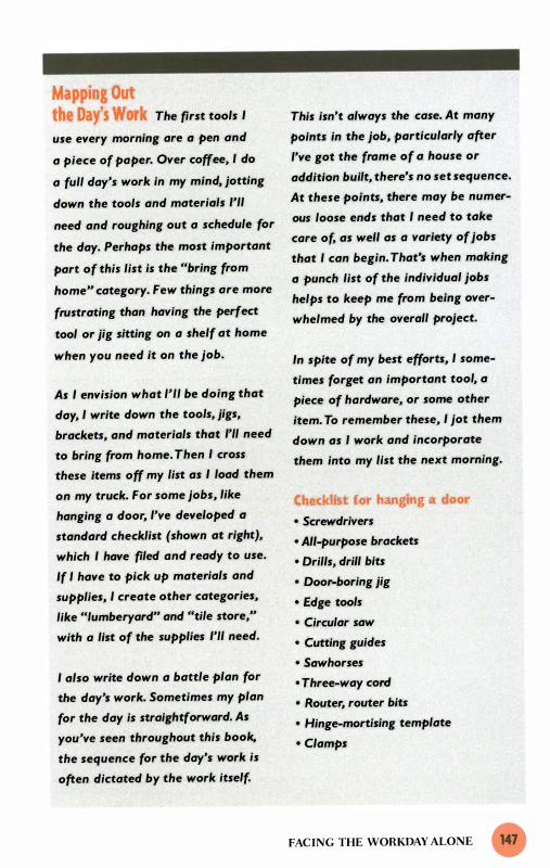
Mapping Out the Dayts Work The first tools I
use every morning are a pen and
a piece of paper. Over coffee, I do
a full day's work in my mind, jotting
down the tools and materials I'll
need and roughing out a schedule for
the day. Perhaps the most important
part of this list is the «bring from
home" category. Few things are more
frustrating than having the perfect
tool or jig sitting on a shelf at home
when you need it on the job.
As I envision what I'll be doing that
day, I write down the tools, jigs,
brackets, and materials that I'll need
to bring from home. Then I cross
these items off my list as I load them
on my truck. For some jobs, like
hanging a door, I've developed a
standard checklist (shown at right),
which I have filed and ready to use.
If I have to pick up materials and
supplies, I create other categories,
like «'umberyard" and «tile store,"
with a list of the supplies I'll need.
I also write down a battle plan for
the day's work. Sometimes my plan
for the day is straightforward. As
you've seen throughout this book.
the sequence for the day's work is
often dictated by the work itself.
This isn't always the case. At many
points in the job, particularly after
I've got the frame of a house or
addition built, there's no set sequence.
At these points, there may be numer
ous loose ends that I need to take
care of, as well as a variety of jobs
that I can begin. That's when making
a punch list of the individual jobs
helps to keep me from being over
whelmed by the overall project.
In spite of my best efforts, I some
times forget an important tool, a
piece of hardware, or some other
item. To remember these, I jot them
down as I work and incorporate
them into my list the next morning.
Checklist for hanging a door • Screwdrivers
• AII-purpose brackets
• Drills, drill bits
• Door-boring jig
• Edge tools
• Circular saw
• Cutting guides
• Sawhorses
• Three-way cord
• Router, router bits
• Hinge-mortising template
• Clamps
FACING THE WORKDAY ALONE

ment of working in a crew, driving
relentlessly forward, seeing dramat
ic changes in a few hours, a day
alone on a construction site would
be excruciatingly boring.
To keep from being bored, I bring
a radio to work. That way there's
always some background noise,
and I don't feel completely alone.
The radio also allows me to follow
a sporting event, a discussion, or
a piece of music while I'm busy
building.
Keeping motivated on large jobs,
when it feels like I'll never finish,
is possibly the biggest challenge.
To avoid getting discouraged in the
middle of such jobs, I set daily goals
and try not to focus too hard on
the finished product. I begin the
day by writing down what I want to
achieve (see the sidebar on p. 1 47) .
This keeps me on track and gives
me a sense of accomplishment
when I can cross something off the
list. If I hit the doldrums during the
day, I start doing the easiest things
on the list-just to keep moving
forward. I often catch a second
wind in the course of knocking out
these items, then take on the harder
tasks with newfound energy.
THE LIMITATIONS
Because I genuinely like my job,
I usually have little trouble drum
ming up enthusiasm for my day's
work. All these tips won't help you
keep motivated, though, if you
don't like your job.
Dealing with the Solitude
A final difficulty some people have
with working alone is the solitude.
Having no coworkers means there's
no one to spice up the day with
conversation. There are no jokes
and no laughter. There's no one
to commiserate with when the
weather's bad or when you have to
do an unpleasant job. There's none
of the camaraderie that often per
vades construction sites.
These are things I sometimes miss.
At the same time, I haven't forgot
ten that coworkers aren't always
fun and charming. I recall a few
that made the day seem long.
Working with others, I 've found,
can be a lot of fun or it can be
stressful; usually it's a combination
of the two. When you work alone,
you don't have the fun or the stress;
you have the quiet. There are no
techniques for dealing with it. It's
something that grows on you.

Resources Some of the tools listed throughout
the book can be found in local
hardware and building supply
stores, but most have to be ordered
directly from the manufacturer or
through a catalog.
Hoists and Jacks
Lightning Tool Corporation
1 07 1 1 Evergreen Way Suite A
Everett, WA 98204
(888) 839-5237
(206) 440-098 1 (fax)
http://www.lightningtool.com
Manufacturer of Lightning Lift
Patterson Avenue Tool Co., Inc.
65 1 5 High Meadow Court
Long Grove, IL 60047
(800) 662-3 557
(847) 949-8 1 49 (fax)
http://www.tjak.com
Manufacturer of T-Jak
Proctor Products Co., Inc.
P. O. Box 697
Kirkland, WA 98083-0697
(425) 822-9296
(206) 634-2396 (fax)
http://www.proctorp.com
Manufacturer of Proctor Wall Jacks
Telpro, Inc.
Route 1 , Box 1 38
Grand Forks, NO 5820 1
(800) 44 1 -05 5 1
http://www.telproinc.com
Manufacturer of Panel-Lift
Levers, Clamps, and Spreaders
Cepco Tool Co.
P.O. Box 1 53
Spencer, NY 1 4883
(800) 466-9626
Manufacturer of BoWrench
Mayhew Tools
2 Sears Street, P.O. Box 68
Shelburne Falls, MA 0 1 370
(800) 872-0037
http://www.mayhew.com
Manufacturer of the Tweaker
James Morton IAmerican
Clamping
50 Franklin Street, P.O. Box 399
Batavia, NY 1 402 1
(7 1 6) 344-0025
http://www.jamesmorton.com
Distributor of Bessey Clamps (the
Bessey Powergrip is the best one-hand
bar clamp on the market)
Wade Mfg. Co.
P.O. Box 23666
Portland, OR 97223
(503) 692-5353
(503) 692-5358 (fax)
Manufacturer of Mastodon Jaw
Extenders
Measuring and Marking Tools
General Tools
80 White Street,
New York, NY 1 00 1 3
(2 1 2) 4 3 1 - 6 1 00
Manufacturer of No. 523 adjustable
trammel points (the best trammel
points for construction layout)

Laser Tools Co.
3 520 W. 69th Street, Suite 40 1
Little Rock, AR 72209
(800) 598-5973
Manufacturer of laser levels
The Stanley Works
1 000 Stanley Drive
New Britain, CT 06053
(800) 782-6539
www.stanleyworks.com
Manufacturer of the Stanley Quick
Square
Swanson Tool Co.
1 0 1 0 Lambrecht Road
Frankfort, IL 60423
(8 1 5 ) 469-9453
Manufacturer of Swanson Speed
Square and Swanson Mag Square
Tool Catalogs
Garrett Wade Tool Company
1 6 1 Avenue of the Americas
New York, NY 1 00 1 3
(800) 2 2 1 -2942
(800) 566-9525 (fax)
http://www.garrettwade.com
Highland Hardware
1 045 N. Highland Ave. , NE
Atlanta, GA 30306
(404) 872-4466
(404) 876- 1 94 1 (fax)
http://www.highland-hardware.com
Tool Crib of the North
1 5 50 S. 48th Street, Suite 1 00
Grand Forks, N D 58201
(800) 3 58-3096
(800) 343-4205 (fax)
http://www.toolcribofthenorth.com
RESOURCES
Trend-Lines
1 35 American Legion Highway
Revere, MA 02 1 5 1
(800) 767-9999
http://www.trend-lines.com
William Alden Company
P.O. Box 4005
Taunton, MA 02780
(800) 249-8665
http://www.williamalden.com
Woodworker's Supply of North
Carolina
1 1 2 5 Jay Lane
Graham, NC 27253
(800) 645-9292
Building Guides
Bailey, Robert F. The Pocket Size
Carpenter's Helper. Liberty, ME: R.S.
Wood Inc. , 1 986.
Byrne, Michael. Setting Tile. Newtown,
CT: The Taunton Press, 1 995 .
Carroll, John. Measuring, Marking &Layout: A Builder's Guide. Newtown,
CT: The Taunton Press, 1 998.
Kreh, Richard. Building with Masonry:
Brick, Block &- Concrete. Newtown,
CT: The Taunton Press, 1 998.
Schuttner, Scott. Building and
Designing Decks. Newtown, CT: The
Taunton Press, 1 993.
Wagner, John D. House Framing.
Upper Saddle River, N.J . : Creative
Homeowner Press, 1 998.

Index
B Barge rafters. See Rafters, barge. Brackets:
C
all-purpose, 5 1 -52, 89, 1 02 , 1 03 , 1 22 for holding siding, 97 L-shaped, 24-25 , 29, 3 1 steel, for installing sheathing, 50-5 1 U-shaped, 1 09
Cabinets, wall, hanging, 1 1 0, I I I Chair rail, installing, 1 06- 1 08 Chalk box, modified, using, 83, 85 , 96 Clamps:
bar, 1 1 - 12 , 43 C-, 1 1 , 1 2 pipe, 1 1 , 1 2 types of, 1 0- 1 2
Compass, beam, for tile layout, 1 1 5- 1 6 Crown molding, installing, 1 06- 1 08
D Decimals, converting to fractions, 28 Decking, plywood, installing, 39-4 1 , 42 Decks:
balustrade, installing, 140 band joist,
installing, 1 22-23 laying out, 1 1 9, 1 22
in cold climates, 132 decking,
installing, 1 39 straightening, 1 37
end joists, installing, 1 2 5-27 squaring, 1 27-29
flashing for, 1 23-25 footings for, 1 3 1 , 1 34 inside joists, installing, 1 35-36 large, laying out, 1 30 lattice, installing, 1 39 laying out, on house, 1 1 8- 1 9 posts,
installing, 1 3 1 , 1 33-35 laying out, 1 30-3 1 , 1 33
rim joists, installing, 1 27, 128 safety and, 1 23
stairs, installing, 1 38, 139-40 types of, 1 20-2 1
Doors: door-knob hole in, enlarging, 102 installing, 88, 90-9 1 , 1 44-45 support brackets for, 1 02 , 1 03
Drywall, hanging, 99- 1 03 , 145-46 lift for, 100, 10 1 - 1 03 measuring sticks with, 1 00- 1 0 1
E Eaves:
F
frames of, 85-86 scaffolding for, 82-83 See also Fascia. Rakes. Soffit.
Fascia, installing, 7, 86-87, 88 Fastening boards, technique for, 1 3 - 1 4 Floors, framing, 37-4 1 Flue liners, installing, 20 Foundations:
J
help with, need for, 1 42 laying out, 1 9-32
Joists, floor:
L
laying out, 38, 39 straightening, 39 See also Decks.
Ladders, commercial-grade, 1 3 Laser levels, for foundation layout, 2 1 ,
22-23 Lumber, straightening, 39, 42-43
M Masonry structures:
squaring up, 32-33 See also Foundations.
Math, and the solo builder, 26 See also Pythagorean Theorem.
Measuring sticks: for drywall layout, 100- 1 0 1 for installing trim, 1 04-106 for rafter layout, 67-68 vs. tape measures, 1 4 for tile layout, 1 1 2, 1 1 5 using, 1 6- 1 7

Mortar, working with, 1 9-20 Mudsills:
p
anchor bolt layout on, 37-38 joist layout on, 38, 39
Plumb bobs: threading, 78 using, 72, 73, 79-80
Pythagorean Theorem:
R
and deck layout, 1 27-28 and foundation layout, 27-28 and roof layout, 62-63 and tile layout, 1 1 2
Rafters: barge, installing, 83, 85 geometry of, 62-63 installing, 74-75 laying out, 63-68
jig for, 63-64 measuring stick for, 67-68
layout systems for, 60 Rakes:
building, 84 rake board, installing, 87 scaffolding for, 82-83 See also Eaves. Rafters, barge.
Ridge beams: cutting, 70-72, 74 raising, 68-70
Roofs:
S
building, 68-76 deck of, installing, 75-76 laying out, 58-68
math vs. nonmath approach, 58 pitch of, converting to degrees, 74 shingling, 9 1 -93 stick-built, vs. truss, 58, 59 truss, 57 , 59, 1 44 See also Rafters. Ridge beams.
Safety: and cutting trim, 103 and raising ridge beam, 70 and raising walls, 44 and working alone, 6
Sawhorses, building, 53
INDEX
Scaffolding: pipe, 1 2- 1 3 for roof construction, 69-70, 7 5 setting up, 33-35, 82-83
Siding, wood, installing, 93-97 Soffit, installing, 88 Spreaders, described, 1 2, 39, 40 Studs, wall, installing, 82 Subcontractors, need for, 99, 145-46 Subfascia:
T
installing, 75-76, 83 See also Fascia.
Tiles, laying out, 1 1 2- 1 6 Tools:
hand, value of, 8 joist-straightening, 39, 40 manufactured, versatility of, 9 special-purpose/site-built, 1 6- 1 7
Top plates, laying out, 79-82 Trim:
cutting, 1 03 installing, 1 06- 1 08 measuring walls for, 1 03 - 106 See also Chair rail. Crown molding.
Trusses: help with, need for, 1 43-44 See also Roofs.
Turnbuckles, choosing, 49
W Walls, bearing:
erecting, 43-45 laying out, 4 1 -42 plumbing, 52, 54 sheathing, 50-52 squaring, 46-50 straightening, 52, 54-56
Walls, nonbearing, framing, 78-82 Windows:
help with, need for, 1 44-45 installing, 88, 89-90
Workbench, job-site, 54 Working alone:
challenges of, 6- 1 0 limitations of, 1 42-46 and motivation, 1 46, 1 48 and planning, 8, 1 0, 147 rewards of, 3, 148 and solitude, dealing with, 1 46, 148


m » z
ISBN 1-561 58-425-8
94 1 1 5 58425 8
ISBN 1 -561 58-425-8
9 78 1 56 1 584253 Taunton Product # 070539