SIRIUS 3UG48 monitoring relays for stand-alone installation ...
23
10/100 Siemens IC 10 · 2022 Monitoring and control devices Relays SIRIUS 3UG48 monitoring relays for stand-alone installation for IO-Link General data 10 ■ Overview SIRIUS 3UG48 monitoring relays The SIRIUS 3UG4 monitoring relays for electronic and mechanical variables monitor all important characteristics that allow conclusions to be drawn about the functionality of a plant. Both sudden disturbances and gradual changes, which may indicate the need for maintenance, are detected. Thanks to their relay outputs, the monitoring relays permit direct disconnection of the affected system components and alerting, e.g. by the triggering of a warning light. Thanks to adjustable delay times the 3UG4 monitoring relays can respond very flexibly to brief faults such as voltage dips or load changes and can thus avoid unnecessary alarms and disconnections and increase system availability. 3UG48 monitoring relays for IO-Link The SIRIUS 3UG48 monitoring relays for IO-Link also offer many other options based upon the monitoring functions of the tried- and-tested SIRIUS 3UG4 monitoring relays: • Measured value transmission to a controller, including resolution and unit, may be parameterizable as to which value is cyclically transmitted • Transmission of alarm flags to a controller • Full diagnostics capability by inquiry as to the cause of the fault in the diagnostics data record • Remote parameterization is also possible, in addition to or instead of local parameterization • Rapid parameterization of the same devices by duplication of the parameterization in the controller • Parameter transmission through uploading to a controller by IO-Link call or by parameter server (if IO-Link master from IO-Link specification V1.1 and higher is used) • Consistent central data storage in the event of parameter change locally or via a controller • Automatic reparameterizing when devices are exchanged • Blocking of local parameterization via IO-Link possible • Faults are saved in parameterizable and non-volatile fashion to prevent an automatic startup after voltage failure and to make sure diagnostics data are not lost • Integration into the automation level provides the option of parameterizing the monitoring relays at any time via a display unit, or displaying the measured values in a control room or locally at the machine/control cabinet. • The MindSphere app SIRIUS Asset Monitor enables access to the SIRIUS 3UG48 monitoring relay for IO-Link anytime and anywhere. It provides the user with detailed information on the device status as well as fault messages and warnings in a clearly arranged form, see page 14/26. Even without communication via IO-Link the devices continue to function fully autonomously: • Parameterization can take place locally at the device, independently of a controller. • In the event of failure or before the controller becomes available the monitoring relays work as long as the control supply voltage (24 V DC) is present. • If the monitoring relays are operated without the controller, the 3UG48 monitoring relays have, thanks to the integrated SIO mode, an additional semiconductor output, which switches when the adjustable warning threshold is exceeded. Thanks to the combination of autonomous monitoring relay function and integrated IO-Link communication, redundant sensors and/or analog signal converters – which previously took over the transmission of measured values to a controller, leading to considerable extra cost and wiring overhead – are no longer needed. Because the output relays are still present, the monitoring relays increase the functional reliability of the system, since only the controller can fulfill the control tasks if the current measured values are available, whereas the output relays can also be used for the disconnection of the system if limit values that cannot be reached during operation are exceeded. The individual 3UG48 monitoring relays for IO-Link offer the following functions in different combinations: • Phase sequence • Phase failure, neutral conductor failure • Phase asymmetry • Undershooting and/or overshooting of limit values for voltage • Undershooting and/or overshooting of limit values for current • Undershooting and/or overshooting of power factor limit values • Monitoring of the active current or the apparent current • Monitoring of the residual current • Undershooting and/or overshooting of limit values for speed Note: For more information on the IO-Link bus system, see page 2/87 onwards. Notes on security In order to protect plants, systems, machines and networks against cyber threats, it is necessary to implement – and continuously maintain – a holistic, state-of-the-art industrial security concept. Siemens products and solutions represent only one component of such a concept. For more information about the subject of Industrial Security, see www.siemens.com/industrialsecurity . More information Homepage, see www.siemens.com/sirius-monitoring-relays Industry Mall, see www.siemens.com/product?3UG48 Conversion tool, see www.siemens.com/conversion-tool © Siemens 2022
-
Upload
khangminh22 -
Category
Documents
-
view
0 -
download
0
Transcript of SIRIUS 3UG48 monitoring relays for stand-alone installation ...

10/100 Siemens IC 10 · 2022
Monitoring and control devicesRelaysSIRIUS 3UG48 monitoring relays for stand-alone installation for IO-Link
General data
10
■ Overview
SIRIUS 3UG48 monitoring relays
The SIRIUS 3UG4 monitoring relays for electronic and mechanical variables monitor all important characteristics that allow conclusions to be drawn about the functionality of a plant. Both sudden disturbances and gradual changes, which may indicate the need for maintenance, are detected.
Thanks to their relay outputs, the monitoring relays permit direct disconnection of the affected system components and alerting, e.g. by the triggering of a warning light. Thanks to adjustable delay times the 3UG4 monitoring relays can respond very flexibly to brief faults such as voltage dips or load changes and can thus avoid unnecessary alarms and disconnections and increase system availability.
3UG48 monitoring relays for IO-Link
The SIRIUS 3UG48 monitoring relays for IO-Link also offer many other options based upon the monitoring functions of the tried-and-tested SIRIUS 3UG4 monitoring relays:• Measured value transmission to a controller, including
resolution and unit, may be parameterizable as to which value is cyclically transmitted
• Transmission of alarm flags to a controller• Full diagnostics capability by inquiry as to the cause
of the fault in the diagnostics data record• Remote parameterization is also possible, in addition
to or instead of local parameterization• Rapid parameterization of the same devices by duplication
of the parameterization in the controller• Parameter transmission through uploading to a controller by
IO-Link call or by parameter server (if IO-Link master from IO-Link specification V1.1 and higher is used)
• Consistent central data storage in the event of parameter change locally or via a controller
• Automatic reparameterizing when devices are exchanged• Blocking of local parameterization via IO-Link possible• Faults are saved in parameterizable and non-volatile fashion
to prevent an automatic startup after voltage failure and to make sure diagnostics data are not lost
• Integration into the automation level provides the option of parameterizing the monitoring relays at any time via a display unit, or displaying the measured values in a control room or locally at the machine/control cabinet.
• The MindSphere app SIRIUS Asset Monitor enables access to the SIRIUS 3UG48 monitoring relay for IO-Link anytime and anywhere. It provides the user with detailed information on the device status as well as fault messages and warnings in a clearly arranged form, see page 14/26.
Even without communication via IO-Link the devices continue to function fully autonomously:• Parameterization can take place locally at the device,
independently of a controller.• In the event of failure or before the controller becomes
available the monitoring relays work as long as the control supply voltage (24 V DC) is present.
• If the monitoring relays are operated without the controller, the 3UG48 monitoring relays have, thanks to the integrated SIO mode, an additional semiconductor output, which switches when the adjustable warning threshold is exceeded.
Thanks to the combination of autonomous monitoring relay function and integrated IO-Link communication, redundant sensors and/or analog signal converters – which previously took over the transmission of measured values to a controller, leading to considerable extra cost and wiring overhead – are no longer needed.
Because the output relays are still present, the monitoring relays increase the functional reliability of the system, since only the controller can fulfill the control tasks if the current measured values are available, whereas the output relays can also be used for the disconnection of the system if limit values that cannot be reached during operation are exceeded.
The individual 3UG48 monitoring relays for IO-Link offer the following functions in different combinations:• Phase sequence• Phase failure, neutral conductor failure• Phase asymmetry• Undershooting and/or overshooting of limit values for voltage• Undershooting and/or overshooting of limit values for current• Undershooting and/or overshooting of power factor limit values• Monitoring of the active current or the apparent current• Monitoring of the residual current• Undershooting and/or overshooting of limit values for speed
Note:
For more information on the IO-Link bus system, see page 2/87 onwards.
Notes on security
In order to protect plants, systems, machines and networks against cyber threats, it is necessary to implement – and continuously maintain – a holistic, state-of-the-art industrial security concept. Siemens products and solutions represent only one component of such a concept.
For more information about the subject of Industrial Security, see www.siemens.com/industrialsecurity.
More information
Homepage, see www.siemens.com/sirius-monitoring-relays
Industry Mall, see www.siemens.com/product?3UG48
Conversion tool, see www.siemens.com/conversion-tool
© Siemens 2022

10/101Siemens IC 10 · 2022
Monitoring and control devicesRelays
SIRIUS 3UG48 monitoring relays for stand-alone installation for IO-Link
General data
10
Use of conventional monitoring relays Monitoring relays for IO-Link
Notes:
Devices required for communication via IO-Link:• Any controller that supports IO-Link (e.g. ET 200SP with CPU
or S7-1200), see Catalog ST 70.• IO-Link master (e.g. CM 4xIO-Link for SIMATIC ET 200SP, see
page 2/98 or SM 1278 for S7-1200, see page 2/97).
Each monitoring relay requires an IO-Link channel.
Article No. scheme
Note:
The Article No. scheme shows an overview of product versions for better understanding of the logic behind the article numbers.
For your orders, please use the article numbers quoted in the selection and ordering data.
■ Benefits
• Simple cyclical transmission of the current measured values, relay switching states and events to a controller
• Remote parameterization• Automatic reparameterizing when devices are exchanged• Simple duplication of identical or similar parameterizations• Reduction of control current wiring • Elimination of testing costs and wiring errors
• Reduction of configuration work• Integration in TIA means clear diagnostics if a fault occurs• Cost saving and space saving in control cabinet due to the
elimination of AI and IO modules as well as analog signal converters and duplicated sensors
3
1 2
Feeder
Motor
3UG46monitoring relay
3UG46monitoring relay
3UG46monitoring relay
Analog signal
converter
Current trans-
former
Autonomous operation without PLC
Signaling of limit value violation plus measurement data transmission to PLC
Signaling of limit value violation to PLC
1
23
ET 200SPwith IO-Link master
IC01_00003a
2
1
13UG48monitoring relay
3UG48monitoring relay
3UG48monitoring relay Feeder
Autonomous operation without PLC
Signaling of limit value violation plus measurement data transmission to PLC
2
Motor
1
ET 200SPwith IO-Link master
IC01_00004a
IO-Link
Product versions Article number
3UG4 monitoring relay with IO-Link 3UG4 @ @ @ – @ @ @ @ 0
Type of setting e.g. 8 = analogically adjustable @
Functions e.g. 15 = line monitoring @ @
Connection type Screw terminals 1
Spring-loaded terminals 2
Contacts e.g. A = 1 CO contact @
Supply voltage e.g. A4 = 160 ... 690 V AC @ @
Example 3UG4 8 1 5 – 1 A A 4 0
© Siemens 2022

10/102 Siemens IC 10 · 2022
Monitoring and control devicesRelaysSIRIUS 3UG48 monitoring relays for stand-alone installation for IO-Link
General data
10
■ Application
The use of SIRIUS monitoring relays for IO-Link is particularly recommended for machines and plants in which these relays, in addition to their monitoring function, are to be connected to the automation level for the rapid, simple and fault-free provision of the current measured values and/or for remote parameterization.
The monitoring relays can either relieve the controller of monitoring tasks or, as a second monitoring entity in parallel to and independent of the controller, increase the reliability in the process or in the system. In addition, the elimination of AI and IO modules allows the width of the controller to be reduced despite significantly expanded functionality.
■ Technical specifications
More information
Technical specifications, see https://support.industry.siemens.com/cs/ww/en/ps/16368/td
Equipment Manual and internal circuit diagrams, seehttps://support.industry.siemens.com/cs/ww/en/view/54375430
FAQs, see https://support.industry.siemens.com/cs/ww/en/ps/16368/faq
Type 3UG48General technical specificationsDimensions (W x H x D)
• For 3 terminal blocks- Screw terminals mm 22.5 x 92 x 91- Spring-loaded terminals mm 22.5 x 94 x 91
• For 4 terminal blocks- Screw terminals mm 22.5 x 103 x 91- Spring-loaded terminals mm 22.5 x 103 x 91
Permissible ambient temperature• During operation °C -25 ... +60
Connection type Screw terminals
• Terminal screw M3 (for standard screwdriver, size 2 and Pozidriv 2)• Solid mm2 1 x (0.5 ... 4), 2 x (0.5 ... 2.5)• Finely stranded with end sleeve mm2 1 x (0.5 ... 2.5), 2 x (0.5 ... 1.5)• AWG cables, solid or stranded AWG 2 x (20 ... 14)• Tightening torque Nm 0.8 … 1.2
Connection type Spring-loaded terminals
• Solid mm2 2 x (0.25 ... 1.5)• Finely stranded, with end sleeve acc. to DIN 46228 mm2 2 x (0.25 ... 1.5)• Finely stranded mm2 2 x (0.25 ... 1.5)• AWG cables, solid or stranded AWG 2 x (24 ... 16)
W
H
D
© Siemens 2022

10/103Siemens IC 10 · 2022
Monitoring and control devicesRelays
SIRIUS 3UG48 monitoring relays for stand-alone installation for IO-Link
Line monitoring
10
■ Overview
SIRIUS 3UG4815 monitoring relay
Solid-state line monitoring relays provide maximum protection for mobile machines, plants and hoisting equipment or for unstable networks. Network and voltage faults can thus be detected early and rectified before far greater damage ensues.
The line monitoring relays with IO-Link monitor phase sequence, phase failure (with or without N conductor monitoring), phase asymmetry and undervoltage and/or overvoltage.
Phase asymmetry is evaluated as the difference between the greatest and the smallest phase voltage relative to the greatest phase voltage. Undervoltage or overvoltage exist if the set limit values for at least one phase voltage are overshot or undershot. The rms value of the voltage is measured.
■ Benefits
• Can be used in any network from 160 to 630 V AC worldwide thanks to wide voltage range
• Variably adjustable to overshoot, undershoot or range monitoring
• Freely configurable delay times and RESET response• Width 22.5 mm• Display and transmission of actual value and network fault
type to controller• All versions with removable terminals• All versions with screw or spring-loaded terminals
■ Application
The relays are used above all for mobile equipment, e.g. air conditioning compressors, refrigerating containers, building site compressors and cranes.
Function Application
Phase sequence • Direction of rotation of the drive
Phase failure • A fuse has tripped
• Failure of the control supply voltage
• Broken cable
Phase asymmetry • Overheating of the motor due to asymmetrical voltage
• Detection of asymmetrically loaded networks
Undervoltage • Increased current on a motor with corresponding overheating
• Unintentional resetting of a device
• Network collapse, particularly with battery power
Overvoltage • Protection of a plant against destruction due to overvoltage
© Siemens 2022

10/104 Siemens IC 10 · 2022
Monitoring and control devicesRelaysSIRIUS 3UG48 monitoring relays for stand-alone installation for IO-Link
Line monitoring
10
■ Technical specifications
3UG4815/3UG4816 monitoring relays
The 3UG4815 and 3UG4816 line monitoring relays have a wide voltage range input and are supplied with power through IO-Link or from an external 24 V DC source.
The device is equipped with a display and is parameterized using three buttons. The 3UG4815 monitoring relay monitors 3-phase networks with regard to phase sequence, phase failure, phase asymmetry, undervoltage and overvoltage. The 3UG4816 monitoring relay monitors the neutral conductor as well. The hysteresis is adjustable from 1 to 20 V.
The device has two separately adjustable delay times for overvoltage and undervoltage and for line stabilization. If the direction of rotation is incorrect or a phase fails, the device switches off immediately. Thanks to a special measuring method, a phase failure is reliably detected in spite of the wide voltage range from and potentially high feedback through the load.
The 3UG4815 and 3UG4816 monitoring relays can be operated on the basis of either the open-circuit or closed-circuit principle and with Manual or Auto RESET.
If Manual RESET is selected in the menu (Memory = Yes), the switching relay remains in its current switching state and the current measured value and the symbol for undershooting and overshooting continue to flash, even when the measured variable reaches a permissible value again. This stored fault status can be reset by simultaneously pressing the UP▲ and DOWN▼ keys for 2.5 s.
With Manual RESET through IO-Link it is possible in addition to set whether fault messages are to be deleted when the control supply voltage is switched off and on (as Remote RESET) or whether the signals are to be permanently saved even in a voltage failure, with confirmation possible only through local RESET or via IO-Link.
With the closed-circuit principle selected
Wrong phase sequence
Phase failure
Undervoltage
Overvoltage
IC01
_000
05L3-L2-L111/1411/12
11/1411/12
L1-L2-L3L1-L2-L3-N
L2-L3L1-L2-L3
L1-L2-L3L1-L2-L3-N
IC01
_000
06IC
01_0
0007
< U
L+/L-
Q offQ on
11/1211/14
Ux-yHysteresis
DelaystDelay
> UL+/L-
Q offQ on
11/1211/14
Ux-yHysteresis
IC01
_000
08
DelaystDelay
Type 3UG4815, 3UG4816General technical specificationsRated insulation voltage UiPollution degree 2Overvoltage category III acc. to VDE 0110
V 690
Rated impulse withstand voltage Uimp kV 6Control circuitLoad capacity of the output relay• Thermal current Ith A 5Rated operational current Ie at• AC-15/24 ... 400 V A 3• DC-13 at
- 24 V A 1- 125 V A 0.2- 250 V A 0.1
Minimum contact load at 17 V DC mA 5Electrical endurance AC-15 million
operating cycles
0.1
Mechanical service life million operating cycles
10
© Siemens 2022

10/105Siemens IC 10 · 2022* You can order this quantity or a multiple thereof.Illustrations are approximate
Monitoring and control devicesRelays
SIRIUS 3UG48 monitoring relays for stand-alone installation for IO-Link
Line monitoring
10
■ Selection and ordering data • Adjustable via IO-Link and locally, with illuminated LCD• Power supply with 24 V DC via IO-Link or
external auxiliary voltage• Auto or Manual RESET• Open-circuit or closed-circuit principle• 1 CO contact, 1 semiconductor output (in SIO mode)
PU (UNIT, SET, M) = 1PS* = 1 unitPG = 41H
✓ Function supported
1) Absolute limit values.2) In SIO mode.
For accessories, see page 10/122.
Adjust-able hys-teresis
Under-voltage detection
Overvolt-age detection
Stabilizationtime adjustable stDEL
Tripping delay time adjustable Del
Version of auxiliary contacts
Measurable line voltage1)
SD Screw terminals SD Spring-loaded terminals
V s s V AC dArticle No. Price
per PU dArticle No. Price
per PUMonitoring of phase sequence, phase failure, phase asymmetry, overvoltage and undervoltage 1 ... 20 ✓ ✓ 0.1 … 999.9 0.1 … 999.9 1 CO + 1 Q2) 160 … 690 2 3UG4815-1AA40 2 3UG4815-2AA40
Monitoring of phase sequence, phase and N conductor failure, phase asymmetry, overvoltage and undervoltage 1 ... 20 ✓ ✓ 0.1 … 999.9 0.1 … 999.9 1 CO + 1 Q2) 90 … 400
against N2 3UG4816-1AA40 2 3UG4816-2AA40
3UG4815-1AA40 3UG4816-1AA40 3UG4815-2AA40 3UG4816-2AA40
© Siemens 2022
10/106 Siemens IC 10 · 2022
Monitoring and control devicesRelaysSIRIUS 3UG48 monitoring relays for stand-alone installation for IO-Link
Voltage monitoring
10
■ Overview
SIRIUS 3UG4832 monitoring relay
The relays monitor 1-phase AC voltages (rms value) and DC voltages against the set limit value for overshoot and undershoot.
■ Benefits
• Variably adjustable to overshoot, undershoot or range monitoring
• Freely configurable delay times and RESET response• Width 22.5 mm• Display and transmission of actual value and status messages
to controller• All versions with removable terminals• All versions with screw or spring-loaded terminals
■ Application
• Protection of a plant against destruction due to overvoltage• Switch-on of a plant at a defined voltage and higher• Protection from undervoltage due to overloaded supply
voltages, particularly with battery power
■ Technical specifications
3UG4832 monitoring relays
The 3UG4832 voltage monitoring relays are supplied with power through IO-Link or with an external auxiliary voltage of 24 V DC and perform overshoot, undershoot or range monitoring of the voltage depending on parameterization. The devices are equipped with a display and are parameterized by means of three buttons or through IO-Link.
The measuring range extends from 10 to 600 V AC/DC. The limit values for overshoot or undershoot can be freely configured within this range. If one of these limit values is reached, the output relay responds according to the set principle of operation as soon as the delay time has elapsed. This tripping delay time U▲Del/U▼Del can be set from 0 to 999.9 s, as can the ON-delay time onDel. The hysteresis is adjustable from 0.1 to 300 V.
The device can be operated on the basis of either the open-circuit or closed-circuit principle and with Manual or Auto RESET. One output changeover contact is available as a signaling contact, and a semiconductor output is available in addition in SIO mode.
If Manual RESET is selected in the menu (Memory = Yes), the switching relay remains in its current switching state and the current measured value and the symbol for undershooting and overshooting continue to flash, even when the measured variable reaches a permissible value again. This stored fault status can be reset by simultaneously pressing the UP▲ and DOWN▼ keys for 2.5 s.
With Manual RESET through IO-Link it is possible in addition to set whether fault messages are to be deleted when the control supply voltage is switched off and on (as Remote RESET) or whether the signals are to be permanently saved even in a voltage failure, with confirmation possible only through local RESET or via IO-Link.
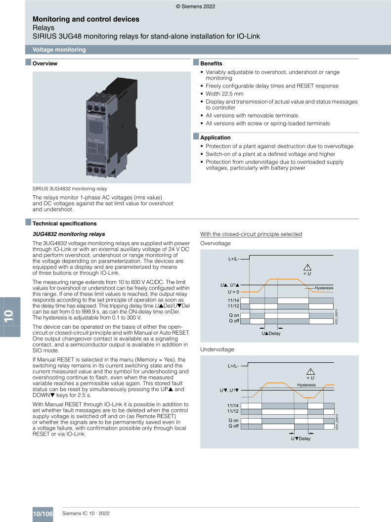
With the closed-circuit principle selected
Overvoltage
Undervoltage
IC01
_000
11
< U
L+/L-
Q offQ on
11/1211/14
= 0, !
Hysteresis
Delay
< U
L+/L-
Q offQ on
11/1211/14
, !Hysteresis
Delay
IC01
_000
12
© Siemens 2022

10/107Siemens IC 10 · 2022
Monitoring and control devicesRelays
SIRIUS 3UG48 monitoring relays for stand-alone installation for IO-Link
Voltage monitoring
10
With the closed-circuit principle selected
Range monitoring
IC01
_000
13
L+/L-
U = 0
Q offQ on
11/1211/14
, !
, !
< U< U
HysteresisHysteresis
Delay = DelayDelay Delay
Type 3UG4832General technical specificationsRated insulation voltage UiPollution degree 2Overvoltage category III acc. to VDE 0110
V 690
Rated impulse withstand voltage Uimp kV 6Measuring circuitPermissible measuring range 1-phase AC/DC voltage V 10 … 690
Measuring frequency Hz 40 ... 500
Setting range 1-phase voltage V 10 ... 600Control circuitLoad capacity of the output relay• Thermal current Ith A 5
Rated operational current Ie at• AC-15/24 ... 400 V A 3• DC-13 at
- 24 V A 1- 125 V A 0.2- 250 V A 0.1
Minimum contact load at 17 V DC mA 5
© Siemens 2022

10/108 Siemens IC 10 · 2022* You can order this quantity or a multiple thereof.
Illustrations are approximate
Monitoring and control devicesRelaysSIRIUS 3UG48 monitoring relays for stand-alone installation for IO-Link
Voltage monitoring
10
■ Selection and ordering data
• Adjustable via IO-Link and locally, with illuminated LCD• Power supply with 24 V DC via IO-Link or external
auxiliary voltage• Auto or Manual RESET• Open-circuit or closed-circuit principle• 1 CO contact, 1 semiconductor output (in SIO mode)
PU (UNIT, SET, M) = 1PS* = 1 unitPG = 41H
For accessories, see page 10/122.
Measuring range Adjustable hysteresis
ON-delay time adjustable onDel
Tripping delay time separately adjustable U▲Del/U▼Del
SD Screw terminals SD Spring-loaded terminals
V AC/DC V s s dArticle No. Price
per PU dArticle No. Price
per PUMonitoring of voltage for overshooting and undershooting10 … 600 0.1 ... 300 0 … 999.9 0 … 999.9 2 3UG4832-1AA40 2 3UG4832-2AA40
3UG4832-1AA40 3UG4832-2AA40
© Siemens 2022

10/109Siemens IC 10 · 2022
Monitoring and control devicesRelays
SIRIUS 3UG48 monitoring relays for stand-alone installation for IO-Link
Current monitoring
10
■ Overview
SIRIUS 3UG4822 monitoring relay
The relays monitor 1-phase AC currents (rms value) and DC currents against the set limit value for overshoot and undershoot.
■ Benefits
• Variably adjustable to overshoot, undershoot or range monitoring
• Freely configurable delay times and RESET response• Width 22.5 mm• Display and transmission of actual value and status messages
to controller• All versions with removable terminals• All versions with screw or spring-loaded terminals
■ Application
• Overcurrent and undercurrent monitoring• Monitoring the functionality of electrical loads• Monitoring for broken conductors
■ Technical specifications
3UG4822 monitoring relays
The 3UG4822 current monitoring relays are supplied with power through IO-Link or with an external voltage of 24 V DC and perform overshoot, undershoot or range monitoring of the current depending on the parameterization. The devices are equipped with a display and are parameterized using three buttons.
The measuring range extends from 0.05 to 10 A. For larger AC currents the measuring range can be extended by using commercially available current transformers. Using the adjustable transformer factor, the display of the measured primary currents up to 750 A instead of the secondary currents (max. 1 A or 5 A) is possible.
The rms value of the current is measured. The limit values for overshoot or undershoot can be freely configured within this range. If one of these limit values is reached, the output relay responds according to the set principle of operation as soon as the tripping delay time I▲Del/I▼Del has elapsed. This time and the ON-delay time onDel are adjustable from 0 to 999.9 s.
The hysteresis is adjustable from 0.01 to 5 A. The device can be operated with Manual or Auto RESET and on the basis of either the open-circuit or closed-circuit principle. You can decide here whether the output relay is to respond when the supply voltage Us = ON is applied, or not until the lower measuring range limit of the measuring current (I > 50 mA) is reached. One output changeover contact is available as a signaling contact, and a semiconductor output is available in addition in SIO mode.
If Manual RESET is selected in the menu (Memory = Yes), the switching relay remains in its current switching state and the current measured value and the symbol for undershooting and overshooting continue to flash, even when the measured variable reaches a permissible value again. This stored fault status can be reset by simultaneously pressing the UP▲ and DOWN▼ keys for 2.5 s.
With Manual RESET through IO-Link it is possible in addition to set whether fault messages are to be deleted when the control supply voltage is switched off and on (as Remote RESET) or whether the signals are to be permanently saved even in a voltage failure, with confirmation possible only through local RESET or via IO-Link.
With the closed-circuit principle selectedupon application of the control supply voltage
Current overshoot
Current undershoot
L+/L-
= 0
Q offQ on
11/1211/14
>
, !
DelayonDelay
Hysteresis
IC01
_000
16DelayonDelay
IC01
_000
17
L+/L-
= 0
Q offQ on
11/1211/14
<
, !
HysteresisHysteresis
onDelay Delay
© Siemens 2022

10/110 Siemens IC 10 · 2022
Monitoring and control devicesRelaysSIRIUS 3UG48 monitoring relays for stand-alone installation for IO-Link
Current monitoring
10
With the closed-circuit principle selectedupon application of the control supply voltage
Range monitoring
L+/L-
Q offQ on
11/1211/14
= 0
> <
, !
, !Hysteresis
onDelay DelayDelay
Delay
Delay
IC01
_000
18
=
Type 3UG4822General technical specificationsRated insulation voltage UiPollution degree 2Overvoltage category III acc. to VDE 0110
V 690
Rated impulse withstand voltage Uimp kV 6Measuring circuitMeasuring range for 1-phase AC/DC current A 0.05 … 15
Measuring frequency Hz 40 ... 500
Setting range for 1-phase current A 0.05 ... 10
Load supply voltage V Max. 300 (with protective separation)Max. 500 (with simple separation)
Control circuitLoad capacity of the output relay• Thermal current Ith A 5
Rated operational current Ie at• AC-15/24 ... 400 V A 3• DC-13 at
- 24 V A 1- 125 V A 0.2- 250 V A 0.1
Minimum contact load at 17 V DC mA 5
© Siemens 2022

10/111Siemens IC 10 · 2022* You can order this quantity or a multiple thereof.Illustrations are approximate
Monitoring and control devicesRelays
SIRIUS 3UG48 monitoring relays for stand-alone installation for IO-Link
Current monitoring
10
■ Selection and ordering data
• Adjustable via IO-Link and locally, with illuminated LCD• Power supply with 24 V DC via IO-Link or external
auxiliary voltage• Adjustable transformer factor to display the measured primary
current when an external current transformer is used• Auto or Manual RESET• Open-circuit or closed-circuit principle• 1 CO contact, 1 semiconductor output (in SIO mode)
PU (UNIT, SET, M) = 1PS* = 1 unitPG = 41H
For accessories, see page 10/122.
For AC currents I > 10 A it is possible to use commercially available current transformers, e.g. the Siemens 4NC current transformers, as accessories, see Catalog LV 10.
Measuring range Adjustable hysteresis
ON-delay timeadjustable onDel
Tripping delay time separately adjustable I▲Del/I▼Del
SD Screw terminals SD Spring-loaded terminals
A AC/DC A s s dArticle No. Price
per PU dArticle No. Price
per PUMonitoring of current for overshooting and undershooting 0.05 ... 10 0.01 ... 5 0.1 … 999.9 0.1 … 999.9 2 3UG4822-1AA40 2 3UG4822-2AA40
3UG4822-1AA40 3UG4822-2AA40
© Siemens 2022

10/112 Siemens IC 10 · 2022
Monitoring and control devicesRelaysSIRIUS 3UG48 monitoring relays for stand-alone installation for IO-Link
Power factor and active current monitoring
10
■ Overview
SIRIUS 3UG4841 monitoring relay
The 3UG4841 power factor and active current monitoring devices enable the load monitoring of motors.
Whereas power factor (p.f.) monitoring is used above all for monitoring no-load operation, the active current monitoring option can be used to observe and evaluate the load factor over the entire torque range.
■ Benefits
• Monitoring of even small 1-phase motors with a no-load supply current below 0.5 A
• Simple determination of threshold values by directly referencing measured variables to motor loading
• Range monitoring and active current measurement enable detection of cable breaks between control cabinets and motors, as well as phase failures
• Power factor (p.f.) and/or Ires (active current) can be selected as the measurement principle
• Width 22.5 mm• Display and transmission of actual value and status messages
to controller• All versions with removable terminals• All versions with screw or spring-loaded terminals
■ Application
• No-load monitoring and load shedding, such as in the event of a V-belt tear
• Underload monitoring in the low-end performance range, e.g. in the event of pump no-load operation
• Monitoring of overload, e.g. due to a dirty filter system• Power factor monitoring in networks for control of
compensation equipment• Broken cable between control cabinet and motor
■ Technical specifications
3UG4841 monitoring relays
3UG4841 monitoring relays are supplied with power through IO-Link or with an external auxiliary voltage of 24 V DC and are used for performing overshoot, undershoot or range monitoring of the power factor and/or the resulting active current, depending on parameterization. The load to be monitored is connected upstream of the IN terminal. The load current flows through the terminals IN and Ly/N. The setting range for the power factor is 0 to 0.99 and for the active current Ires it is 0.2 to 10 A. If the control supply voltage is switched on and no load current flows, the display will show I < 0.2 and a symbol for overshoot, undershoot or range monitoring. If the motor is now switched on and the current exceeds 0.2 A, the set ON-delay time onDel begins. During this time, if the set limit values are undershot or exceeded, this does not lead to a relay reaction of the changeover contact. If the operational flowing active current and/or the p.f. value falls below or exceeds the respective set threshold value, the tripping delay time begins. When this time has expired, the relay changes its switch position. The relevant measured variables for overshooting and undershooting in the display flash. If monitoring for active current undershoot is switched off (Ires▼= OFF), and if the load current undershoots the lower measuring range threshold (0.2 A), the CO contacts remain unchanged. If a threshold value is set for the monitoring of active current undershooting, then undershooting of the measuring range threshold (0.2 A) will result in a response of the CO contacts.
The relay operates either according to the open-circuit or closed-circuit principle.
If the device is set to Auto RESET (Memory = No), depending on the set principle of operation, the switching relay returns to its initial state and the flashing ends when the hysteresis threshold is reached.
If Manual RESET is selected in the menu (Memory = Yes), the switching relay remains in its current switching state and the current measured value and the symbol for undershooting and overshooting continue to flash, even when the measured variable reaches a permissible value again. This stored fault status can be reset by simultaneously pressing the UP▲ and DOWN▼ keys for 2.5 s.
With Manual RESET through IO-Link it is possible in addition to set whether fault messages are to be deleted when the control supply voltage is switched off and on (as Remote RESET) or whether the signals are to be permanently saved even in a voltage failure, with confirmation possible only through local RESET or via IO-Link.
© Siemens 2022

10/113Siemens IC 10 · 2022
Monitoring and control devicesRelays
SIRIUS 3UG48 monitoring relays for stand-alone installation for IO-Link
Power factor and active current monitoring
10
With the closed-circuit principle selected
Response in the event of undershooting the measuring range limit with activated monitoring of Ires▼
Response in the event of undershooting the measuring range limit with deactivated monitoring of active current undershooting
Overshooting of active current
Undershooting of active current
Range monitoring of active current
IC01
_000
20
< 0,2 A
L+/L-
21/2221/24
11/1211/14
= 0= 0,2 A
onDelay onDelayIC
01_0
0021
< 0,2 A
L+/L-
21/2221/24
11/1211/14
= 0= 0,2 A
onDelay onDelay
Q offQ on
11/1211/14
= 0
21/2221/24
> res
, !r rHysteresis
onDelay Delay
IC01
_000
22IC
01_0
0023
Q offQ on
11/1211/14
= 0
21/2221/24
< res
, !r rHysteresis
onDelay Delay
Q offQ on
11/1211/14
= 0
21/2221/24
> res < res
, !r r
, !r r
Hysteresis
onDelay DelayDelay
IC01
_000
24
© Siemens 2022
10/114 Siemens IC 10 · 2022
Monitoring and control devicesRelaysSIRIUS 3UG48 monitoring relays for stand-alone installation for IO-Link
Power factor and active current monitoring
10
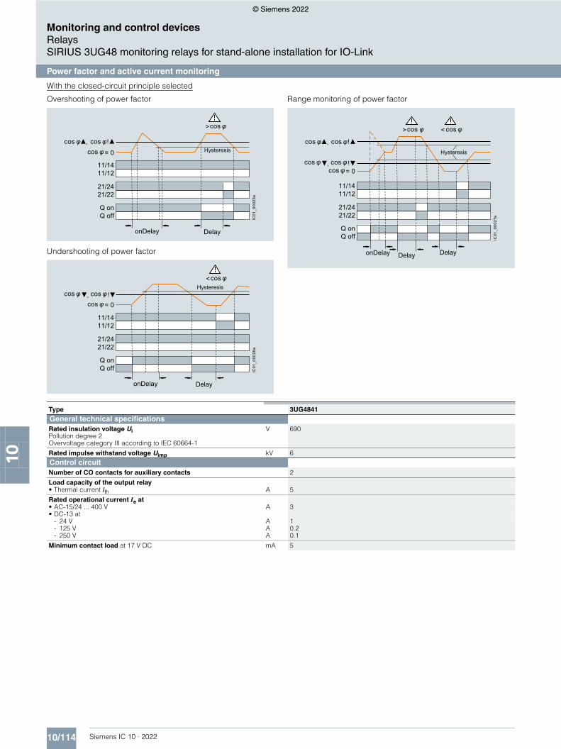
With the closed-circuit principle selected
Overshooting of power factor
Undershooting of power factor
Range monitoring of power factor
Q offQ on
11/1211/14
21/2221/24
>cos
!
cos,cos cos
= 0 Hysteresis
onDelay Delay
IC01
_000
25a
Q offQ on
11/1211/14
21/2221/24
<cos
!cos = 0,cos cos
Hysteresis
onDelay Delay
IC01
_000
26a
Q offQ on
11/1211/14
21/2221/24
> <cos cos
!,cos cos
cos = 0!,cos cos
Hysteresis
onDelay DelayDelay
IC01
_000
27a
Type 3UG4841General technical specificationsRated insulation voltage UiPollution degree 2Overvoltage category III according to IEC 60664-1
V 690
Rated impulse withstand voltage Uimp kV 6Control circuitNumber of CO contacts for auxiliary contacts 2
Load capacity of the output relay• Thermal current Ith A 5
Rated operational current Ie at• AC-15/24 ... 400 V A 3• DC-13 at
- 24 V A 1- 125 V A 0.2- 250 V A 0.1
Minimum contact load at 17 V DC mA 5
© Siemens 2022
10/115Siemens IC 10 · 2022* You can order this quantity or a multiple thereof.Illustrations are approximate
Monitoring and control devicesRelays
SIRIUS 3UG48 monitoring relays for stand-alone installation for IO-Link
Power factor and active current monitoring
10
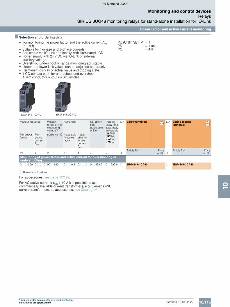
■ Selection and ordering data
• For monitoring the power factor and the active current Ires (p.f. x I)
• Suitable for 1-phase and 3-phase currents• Adjustable via IO-Link and locally, with illuminated LCD• Power supply with 24 V DC via IO-Link or external
auxiliary voltage• Overshoot, undershoot or range monitoring adjustable• Upper and lower limit values can be adjusted separately• Permanent display of actual value and tripping state• 1 CO contact each for undershoot and overshoot,
1 semiconductor output (in SIO mode)
PU (UNIT, SET, M) = 1PS* = 1 unitPG = 41H
1) Absolute limit values.
For accessories, see page 10/122.
For AC active currents Ires > 10 A it is possible to use commercially available current transformers, e.g. Siemens 4NC current transformers, as accessories, see Catalog LV 10.
Measuring range Voltage range of the measuring voltage1)
Hysteresis ON-delay time adjustable onDel
Tripping delay time separately adjustable U▲Del/U▼Del, ▲Del/ ▼Del
SD Screw terminals SD Spring-loaded terminals
For power factor
For active current Ires
50/60 Hz AC Adjustable for power factor
Adjust-able for active current Ires
P.f. A V P.f. A s s dArticle No. Price
per PU dArticle No. Price
per PUMonitoring of power factor and active current for overshooting or undershooting0.1 ... 0.99 0.2 ... 10 90 ... 690 0.1 ... 0.2 0.1 ... 3 0 ... 999.9 0 ... 999.9 2 3UG4841-1CA40 2 3UG4841-2CA40
3UG4841-1CA40 3UG4841-2CA40
© Siemens 2022
10/116 Siemens IC 10 · 2022
Monitoring and control devicesRelaysSIRIUS 3UG48 monitoring relays for stand-alone installation for IO-Link
Residual-current monitoring > Residual-current monitoring relays
10
■ Overview
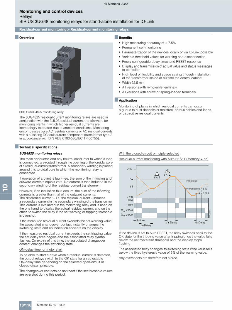
SIRIUS 3UG4825 monitoring relay
The 3UG4825 residual-current monitoring relays are used in conjunction with the 3UL23 residual-current transformers for monitoring plants in which higher residual currents are increasingly expected due to ambient conditions. Monitoring encompasses pure AC residual currents or AC residual currents with a pulsating DC fault current component (transformer type A in accordance with DIN VDE 0100-530/IEC TR 60755).
■ Benefits
• High measuring accuracy of ± 7.5%• Permanent self-monitoring• Parameterization of the devices locally or via IO-Link possible• Variable threshold values for warning and disconnection• Freely configurable delay times and RESET response• Display and transmission of actual value and status messages
to controller• High level of flexibility and space saving through installation
of the transformer inside or outside the control cabinet• Width 22.5 mm• All versions with removable terminals• All versions with screw or spring-loaded terminals
■ Application
Monitoring of plants in which residual currents can occur, e.g. due to dust deposits or moisture, porous cables and leads, or capacitive residual currents.
■ Technical specifications
3UG4825 monitoring relays
The main conductor, and any neutral conductor to which a load is connected, are routed through the opening of the toroidal core of a residual-current transformer. A secondary winding is placed around this toroidal core to which the monitoring relay is connected.
If operation of a plant is fault-free, the sum of the inflowing and outward currents equals zero. No current is then induced in the secondary winding of the residual-current transformer.
However, if an insulation fault occurs, the sum of the inflowing currents is greater than that of the outward currents. The differential current – i.e. the residual current – induces a secondary current in the secondary winding of the transformer. This current is evaluated in the monitoring relay and is used on the one hand to display the actual residual current and on the other, to switch the relay if the set warning or tripping threshold is overshot.
If the measured residual current exceeds the set warning value, the associated changeover contact instantly changes the switching state and an indication appears on the display.
If the measured residual current exceeds the set tripping value, the set delay time begins and the associated relay symbol flashes. On expiry of this time, the associated changeover contact changes the switching state.
ON-delay time for motor start
To be able to start a drive when a residual current is detected, the output relays switch to the OK state for an adjustable ON-delay time depending on the selected open-circuit or closed-circuit principle.
The changeover contacts do not react if the set threshold values are overshot during this period.
With the closed-circuit principle selected
Residual-current monitoring with Auto RESET (Memory = no)
If the device is set to Auto RESET, the relay switches back to the OK state for the tripping value after tripping once the value falls below the set hysteresis threshold and the display stops flashing.
The associated relay changes its switching state if the value falls below the fixed hysteresis value of 5% of the warning value.
Any overshoots are therefore not stored.
!
> > !
Hysteresis
Hysteresis = 5 %
L+/L-
11/14
11/12
Qon 21/24Qoff 21/22
= 0
IC01
_002
27
= 0,02 A
onDelayonDelay
InitDelay
© Siemens 2022

10/117Siemens IC 10 · 2022
Monitoring and control devicesRelays
SIRIUS 3UG48 monitoring relays for stand-alone installation for IO-Link
Residual-current monitoring > Residual-current monitoring relays
10
Residual-current monitoring with Manual RESET (Memory = yes)
If Manual RESET is selected in the menu, the output relays remain in their current switching state and the current measured value and the symbol for overshooting continue to flash, even when the measured residual current returns to a permissible value. This stored fault status can be reset by simultaneously pressing the UP▲ and DOWN▼ keys for > 2 seconds, or by switching the supply voltage off and back on again.
Note:
The neutral conductor must not be grounded downstream of the summation current transformer as this may impair the function of the residual-current monitoring device.
> > !
!
Hysteresis
Hysteresis = 5 %
t > 2,5 s
IC01
_002
28a
L+/L-RESET
11/14
11/12
Qon 21/24Qoff 21/22
= 0 = 0,02 A
Delay onDelayonDelayonDelay
Init
Type 3UG4825-1CA40,3UG4825-2CA40
General dataInsulation voltage for overvoltage category III acc. to IEC 60664 for pollution degree 3, rated value
V 300
Impulse withstand voltage, rated value Uimp kV 4Control circuitNumber of CO contacts for auxiliary contacts 2
Thermal current of the non-solid-state contact blocks, maximum A 5
Current-carrying capacity of the output relay• At AC-15 at 250 V at 50/60 Hz A 3• At DC-13
- At 24 V A 1- At 125 V A 0.2- At 250 V A 0.1
Operational current at 17 V, minimum mA 5
© Siemens 2022

10/118 Siemens IC 10 · 2022* You can order this quantity or a multiple thereof.
Illustrations are approximate
Monitoring and control devicesRelaysSIRIUS 3UG48 monitoring relays for stand-alone installation for IO-Link
Residual-current monitoring > Residual-current monitoring relays
10
■ Selection and ordering data
• For monitoring residual currents from 0.03 to 40 A, from 16 to 400 Hz
• For 3UL23 residual-current transformers with feed-through opening from 35 to 210 mm
• Permanent self-monitoring• Certified in accordance with IEC 60947, functionality
corresponds to IEC 62020• Digitally adjustable, with illuminated LCD• Permanent display of actual value and tripping state• Separately adjustable limit value and warning threshold• 1 changeover contact each for warning threshold and
tripping threshold
PU (UNIT, SET, M) = 1 PS* = 1 unit PG = 41H
For accessories, see page 10/122.
For 3UL23 residual-current transformers and accessories for 3UL23, see page 10/88.
Measurable current
Adjustable response value current
Switching hysteresis
Adjustable ON-delay time
Control supply voltage
SD Screw terminals SD Spring-loaded terminals
At DC, rated value
Article No. Priceper PU
Article No. Priceper PU
A A % s V d d
0.01 ... 43 0.03 ... 40 0 ... 50 0 ... 999.9 24 2 3UG4825-1CA40 2 3UG4825-2CA40
3UG4825-1CA40 3UG4825-2CA40
© Siemens 2022

10/119Siemens IC 10 · 2022
Monitoring and control devicesRelays
SIRIUS 3UG48 monitoring relays for stand-alone installation for IO-Link
Speed monitoring
10
■ Overview
SIRIUS 3UG4851 monitoring relay
3UG4851 monitoring relays are used in combination with a sensor to monitor drives for overspeed and/or underspeed.
Furthermore, the monitoring relays are ideal for all functions where a continuous pulse signal needs to be monitored (e.g. belt travel monitoring, completeness monitoring, passing monitoring, clock-time monitoring).
■ Benefits
• Variably adjustable to overshoot, undershoot or range monitoring
• Freely configurable delay times and RESET response• Display and transmission of actual value and fault type
to controller• Use of up to 10 sensors per rotation for extremely slowly
rotating motors• Two- or three-wire sensors and sensors with a mechanical
switching output or solid-state output can be connected• Auxiliary voltage for sensor integrated• All versions with removable terminals• All versions with screw or spring-loaded terminals
■ Application
• Slip or tear of a belt drive• Overload monitoring• Transport monitoring for completeness
■ Technical specifications
3UG4851 monitoring relays
The speed monitoring relay operates according to the principle of period duration measurement.
In the monitoring relay, the time between two successive rising edges of the pulse encoder is measured and compared to the minimum and/or maximum permissible period duration calculated from the set limit values for the speed.
Thus, the period duration measurement recognizes any deviation in speed after just two pulses, even at very low speeds or in the case of extended pulse gaps.
By using up to ten pulse encoders evenly distributed around the circumference, it is possible to shorten the period duration, and in turn the response time. By taking into account the number of sensors in the monitoring relay, the speed continues to be indicated in rpm.
ON-delay time for motor start
To be able to start a motor drive, and depending on whether the open-circuit or closed-circuit principle is selected, the output relay switches to the OK state during the ON-delay time, even if the speed is still below the set value.
The ON-delay time is started by either switching on the auxiliary voltage or, if the auxiliary voltage is already applied, by actuating the respective NC contact (e.g. auxiliary contact).
Speed monitoring with Auto RESET (Memory = no)
If the device is set to Auto RESET, the output relay switches to the OK state, once the adjustable hysteresis threshold is reached in the range of 1 to 99.9 rpm and the flashing stops. Any overshoots or undershoots are therefore not stored.
Speed monitoring with Manual RESET (Memory = yes)
If Manual RESET is selected in the menu, the output relay remains in its current switching state and the current measured value and the symbol for overshooting/undershooting continue to flash, even when the speed returns to a permissible value. This stored fault status can be reset by simultaneously pressing the UP▲ and DOWN▼ buttons for > 2.5 s or by connecting the RESET device terminal to 24 V DC.
With Manual RESET through IO-Link it is possible in addition to set whether fault messages are to be deleted when the control supply voltage is switched off and on (as Remote RESET) or whether the signals are to be permanently saved even in a voltage failure, with confirmation possible only through local RESET, the Remote RESET contact, or via IO-Link.
© Siemens 2022

10/120 Siemens IC 10 · 2022
Monitoring and control devicesRelaysSIRIUS 3UG48 monitoring relays for stand-alone installation for IO-Link
Speed monitoring
10
With the closed-circuit principle selected
Range monitoring without enable input Range monitoring with enable input
IC01
_000
30
Q offQ on
11/1211/14
RPM = 0
L+/L-
> RPM < RPMrpm rpm!
rpm rpm!Hysteresis
onDelay DelayDelay IC01
_000
31
11/1411/12
Q onQ off
RPM = 0
L+/L-
rpm rpm!
rpm rpm!
EN
> RPM < RPM
Hysteresis
onDelay DelayDelay
Type 3UG4851General technical specificationsRated insulation voltage UiPollution degree 2Overvoltage category III acc. to VDE 0110
V 300
Rated impulse withstand voltage Uimp kV 4Measuring circuitSensor supply• For three-wire sensor (24 V/0 V) mA Max. 50• For two-wire NAMUR sensor (8V2) mA Max. 8.2
Signal input• IN1 k 16, three-wire sensor, pnp operation• IN2 k 1, floating contact, two-wire NAMUR sensor
Voltage level• For level 1 at IN1 V 4.5 ... 30• For level 0 at IN1 V 0 ... 1
Current level• For level 1 at IN2 mA > 2.1• For level 0 at IN2 mA < 1.2
Minimum pulse duration of signal ms 5
Minimum interval between 2 pulses ms 5Control circuitNumber of CO contacts for auxiliary contacts 1
Load capacity of the output relayThermal current Ith A 5
Rated operational current Ie at• AC-15/24 ... 250 V A 3• DC-13 at
- 24 V A 1- 125 V A 0.2- 250 V A 0.1
Minimum contact load at 17 V DC mA 5
© Siemens 2022

10/121Siemens IC 10 · 2022* You can order this quantity or a multiple thereof.Illustrations are approximate
Monitoring and control devicesRelays
SIRIUS 3UG48 monitoring relays for stand-alone installation for IO-Link
Speed monitoring
10
■ Selection and ordering data
• For speed monitoring in revolutions per minute (rpm)• Two- or three-wire sensor with mechanical or electronic
switching output can be connected• Two-wire NAMUR sensor can be connected• Sensor supply 24 V DC/50 mA integrated• Input frequency 0.1 to 2 200 pulses per minute
(0.0017 to 36.7 Hz)• With or without enable signal for the drive to be monitored• Adjustable via IO-Link and locally, with illuminated LCD• Power supply with 24 V DC via IO-Link or
external auxiliary voltage• Overshoot, undershoot or range monitoring adjustable• Number of pulses per revolution can be adjusted• Upper and lower limit values can be adjusted separately• Auto, Manual or Remote RESET options after tripping• Permanent display of actual value and tripping state• 1 CO contact, 1 semiconductor output (in SIO mode)
PU (UNIT, SET, M) = 1PS* = 1 unitPG = 41H
For accessories, see page 10/122.
Measuring range Adjustable hysteresis
ON-delay time adjustable onDel
Tripping delay time separatelyadjustable rpm▲Del/rpm▼Del
Pulses per revolution
SD Screw terminals SD Spring-loaded terminals
rpm rpm s s dArticle No. Price
per PU dArticle No. Price
per PU
Speed monitoring for overshooting and undershooting0.1 ... 2 200 OFF
1 ... 99.90 ... 999.9 0 ... 999.9 1 ... 10 2 3UG4851-1AA40 2 3UG4851-2AA40
3UG4851-1AA40 3UG4851-2AA40
© Siemens 2022

10/122 Siemens IC 10 · 2022* You can order this quantity or a multiple thereof.
Illustrations are approximate
Monitoring and control devicesRelaysSIRIUS 3UG48 monitoring relays for stand-alone installation for IO-Link
Accessories
10
■ Selection and ordering data
1) PC labeling system for individual inscriptionof unit labeling plates available from:murrplastik Systemtechnik GmbH,see page 16/16.
Use Version SD Article No. Priceper PU
PU(UNIT,
SET, M)
PS* PG
dAccessories for enclosures
3RP1902
For 3UG48 Sealable covers For securing against unauthorized adjustment of setting knobs
5 3RP1902 1 5 units 41H
3RP1903
For 3UG48 Push-in lugs For screw fixing,2 units are required for each device
5 3RP1903 1 10 units 41H
Blank labels
3RT2900-1SB20
For 3UG48 Unit labeling plates 1)
For SIRIUS devices
• 20 mm x 7 mm, titanium gray 20 3RT2900-1SB20 100 340 units 41B
For 3UG48 Adhesive labels For SIRIUS devices,19 mm x 6 mm, titanium gray
5 3RT2900-1SB60 100 3060 units 41B
Tools for opening spring-loaded terminals
3RA2908-1A
For auxiliary circuit connections
ScrewdriversFor all SIRIUS devices with spring-loaded terminals
Spring-loaded terminals
Length approx. 200 mm,3.0 mm x 0.5 mm, titanium gray/black,partially insulated
2 3RA2908-1A 1 1 unit 41B
SoftwareFor 3UG48 SIRIUS Asset Monitor
The MindSphere app enables access to the SIRIUS 3UG48 monitoring relays anytime and anywhere and provides detailed information about the device status and fault messages and warnings,see page 14/26.
IC01
_001
81
© Siemens 2022