
The Lathe Book - Woodtools
196
COMPLETELY UPDATED AND REVISED THE ERNIE CONOVER BOOK A Complete Guide to the Machine and Its Accessories
-
Upload
khangminh22 -
Category
Documents
-
view
2 -
download
0
Transcript of The Lathe Book - Woodtools

COMPLETELY UPDATED AND REVISED
THE
ERNIE CONOVER
BOOK A Complete Guide
to the Machine and Its Accessories


The Lathe Book
A Complete Guide to the Machine and Its Accessories
Completely Revised and Updated
Ernie Conover
The Taunton Press

Publisher: JIM CHILDS
Editor: HELEN ALBERT
Associate Editor: JENNIFER RENJILIAN
Copy Editor: DIANE SINITSKY
Indexer: LYNDA STANNARD
Cover Designer: LYNNE PHILLIPS
Interior Designer: MARY McKEON
Layout Artist: ROSALIE VACCARO
Front Cover Photographer: SCOTT PHILLIPS
Back Cover Photographer (author photo) : RANDY O'ROURKE
Interior Photographer: ERNIE CONOVER, except where noted
Illustrator: MARIO FERRO
Text © 2001 by Ernie Conover
Photographs by Ernie Conover © 2001 by The Taunton Press, Inc.
Illustrations © 2001 by Mario Ferro
All rights reserved.
Printed in the United States of America
1 0 9 8 7 6 5
The Taunton Press, Inc., 63 South Main Street, PO Box 5506,
Newtown, CT 06470-5506
e-mail: [email protected]
Library of Congress Cataloging-in-Publication Data Conover, Ernie.
The lathe book : a complete guide to the machine and its accessories /
Ernie Conover.-Completely rev. and updated.
p. cm.
Includes index.
ISBN-13 : 978-1 -56158-416 - 1
ISBN-10: 1 -56158-416-9 1 . Lathes. 2 . Turning. 1. Title.
TT201 .C66 2001
684' .083---dc2 1 00-066300
To my mother and father. Both talented artists, tl1ey have always nurtured a quest for knowledge and lave of art, craft, and history.
Acknowledgtnents Writing a book is a big undertaking, and I would like to thank the
following people who were extremely generous with their time and
were long-suffering in reviewing material and discussing their opinions:
Clead Christiansen; Tim Clay of Oneway Manufacturing; Barrey Frey of
Safetronics Inc. ; Peter Gill of Robert Sorby Ltd.; Jerry Glaser of Glaser
Engineering Company; Dave Hout; Kevin Kee of Delta International
Machinery Corp. ; Brian Latimer of Teknatool International Ltd. ; Darrel
Nish of Craft Supplies USA; and Brad Packard of Packard Woodworks.
I'd particularly like to thank Teknatool International Ltd. and Woodcraft
Supply Corp. for supplying the Nova 3000 on which many of the photos
in this book were shot.
I would like to give special mention to my good friends at KSK Color
Labs. They ran test clips, pushed, pulled, and normally processed all of the
film for this book in an expeditious manner.
I'd also like to thank all of the folks at The Taunton Press, with
special mention to Helen Albert and my editor Jennifer Renj ilian.
ABOUT YOUR SAFETY Working with wood is inherently dangerous. Using hand or power tools
improperly or ignoring safety practices can lead to permanent injury or
even death. Don't try to perform operations you learn about here {or
elsewhere} unless you're certain they are safe for you. If something about
an operation doesn't feel right, don't do it. Look for another way. We
want you to enjoy the craft, so please keep safety foremost in your mind
whenever you're in the shop.

Contents
Introduction 2
Chapter 1 - The Turning Machine 4
Lathe Construction 5 Lathe Anatomy 11
Chapter 2 - Choosing and Buying a Lathe 27
Entry-Level Lathes 29 Mid-Range Lathes 30
Dream Lathes 31 Specialty Lathes 32
Chapter 3 - Setting Up a Lathe 35
Workflow 35 Machine Placement 35 Chip Removal and Ventilation 37 Electrical Service 37
��� � Tool Storage 38
Chapter 4 - Holding the Work 39
Centers 40 Faceplates 45 Special-Purpose Chucks 53
Chapter 5 - Accessories 75
Steady Rests 75 Arm Rests 77 Sharpening Equipment 80 Safety Equipment 98 Jigs for Special Techniques 101 Lathe Duplicators 111

Chapter 6 - Tools
Gouges
Chisels
Scrapers
Hook and Ring Tools
Chatter Tools
Chasers
Chapter 7 - Maintenance, Repair, and Modification
Routine Maintenance
Replacing Bearings
Drive Pulleys, Belts, and Motors
Removing Seized Morse Tapers and Faceplates
Tool Rests
Modifying a Lathe
Restoring a Used Lathe
Chapter 8 - Turning Techniques
Coves and Beads
Turning Square to Round
Faceplate Turning
Sanding
Finishing
Glossary
Resources
Index
112
115 124 137 143 144 145
147
147 149 155 158 160 161 164
165
165 171 172 176 180
181 184 186

Introduction
In this book, I will share with you my love of the woodturning lathe.
This is a book with a difference because it doesn't focus on the lathe
to the exclusion of all other woodworking. Rather, it treats the lathe as
another essential tool in the woodworking shop-a tool that can expand
your woodworking horizon and add pizzazz to your work. All woodworkers
need to be more familiar with the lathe because at some point your wood
working projects will require turned parts.
When The Taunton Press asked me to do the second edition of The
Lathe Book, I was delighted, but I never realized that rewriting is much
more difficult than writing. Much has changed since the first edition, so
there are many new machines, accessories, and gadgets to share. Turning
is becoming gentrified, and there are now tools and accessories that had
never before been dreamed of. While the philosophical side of me laments
the simplicity lost, the tool junkie side of me opens each "absolutely indis
pensable" new piece of hardware with childlike enthusiasm. My wife,
Susan, appropriately bought me a T-shirt claiming, "He who dies with
the most tools wins." I am in serious contention for the grand prize.
I am also a better turner today than I was eight years ago and have
taught scores of people to turn, so I can tell the story better. Because I
have also written Turning for Furniture Makers (a detailed spindle-turning
book with an accompanying video) and Turn a Bowl with Ernie Conover
(an action manual for bowl turners) since the first edition of The Lathe
Book, I decided to drop some of the techniques and concentrate more on
the lathe and it accessories. The tool chapter is much more readable and
the illustrations are better. Photography is entirely new and in color.

Turning books generally speak to dedicated turners who pursue turning
to the exclusion of all other forms of woodworking. But most woodworkers
are interested in turning only enough to use the lathe in their general
woodworking. Additionally, most turning books miss the mark because
they never really teach you to turn. They talk about equipment, philoso
phy, and history, but they never truly teach turning. With that in mind,
I've tried to keep this a wood turning book that speaks to all woodworkers
and gives the information necessary to be able to employ turning in furni
ture making. This book also offers much to the pure turner. A second
objective is to offer advice on buying, maintaining, modifying, and repair
ing lathes. A good part of the book is devoted to the intricacies of lathes
and their accessories.
I grew up at the lathe, and I've been turning both wood and metal since
I was 1 2 years old. I understand lathes and how they work. For many years,
my father and I owned a company that produced a lathe we codesigned
the Conover Lathe. An outgrowth of our lathe-manufacturing business is
Conover Workshops, a woodworking school that my wife and I now run
year-round. In 24 years of running the school, I've taught hundreds of
people to turn and have a fair sense of where the hurdles are in the
learning process.
It's my firm belief that most people have the ability to turn, but this skill
has been buried deep inside during the process of growing up. In many
cases, it has been masked by fear and dull tools. If you read through the
next 1 80 or so pages, I think you'll be able to regain your instinctive turn
ing skill and have some fun in the process. I look forward to this book
starting a revolution in your workshop.
Introduction 3
chapter
1 The Turning Machine
W oodturning is the art of shaping a rotating piece of wood by the
application of sharp tools. The machine that holds and rotates
the wood is a lathe. The wood turning lathe is a simple work
shop tool that can greatly expand your woodworking horizon. If you want
to shape table legs, chair spindles, and bedposts or add embellishments to
your furniture in the form of drawer pulls, cabinet knobs, and finials, then
you need a lathe. And if you want to make bowls, plates, stool seats, table
tops, and lidded boxes, a lathe is an indispensable machine.
In spindle turning, the grain of the wood being turned runs between
the centers of the lathe, that is, parallel to the axis of the lathe (see the
illustration on the facing page) . You would spindle-turn table legs, porch
columns, and chair rungs. In faceplate turning, however, the grain of the
work runs at right angles to the axis of the lathe. You would faceplate-turn
large drawer pulls and bowls.
Most lathes are supplied with basic chucks-a set of centers and a
faceplate. Some people mistakenly think the type of turning is dictated by
the type of chuck used to hold the work. For example, many woodworkers
associate turning between centers with spindle turning, but it's possible to
hold work between centers and yet be faceplate turning. Similarly, it's pos
sible to spindle-turn while having a piece screwed onto a faceplate. (The
screws in this case would be into the end grain of the wood.) The impor
tant thing to remember is that the orientation of the grain, not how the
work is held, dictates whether you are spindle or faceplate turning. It is
imperative to understand this distinction because each type of work
requires different tools and turning techniques, as you shall see in chap
ter 4. In fact, using spindle tools for faceplate work can be dangerous.

Spindle turning
Grain runs parallel to rotational axis of lathe.
Faceplate turning
Grain runs at right angles to rotational axis.
Spindle Turning vs. Faceplate Turning
Lathes range in size from gigantic industrial machines for architectural
turning to Lilliputian lathes for turning pens and dollhouse furniture.
Knowing about the construction and anatomy will help you choose the
right lathe and get it to work more effectively. The type of lathe you need
will depend to a large extent on the kind of work (and the amount of turn
ing) you plan to do. For example, if you occasionally want to turn a few
chair legs, a light-duty lathe would be more than adequate, whereas heavy
bowl turning would require a much sturdier and larger machine. However,
there are certain desirable features you should look for in any lathe, so I've
drawn attention to these throughout this section to help you make an
intelligent buying decision (see chapter 2 for more on choosing a lathe) .
Lathe Construction
The earliest lathes were made of wood, and the use of wood as a bed mate
rial has survived to the present ( I designed and turn on such a lathe) . More
commonly today, though, lathes are made with all-metal parts. You're likely
to encounter several lathe-construction materials: cast iron, fabricated
steel, steel stampings, cast aluminum, cast zinc, and extruded aluminum. I
have not mentioned plastic here because it is not yet used in major struc
tural components; rather it is reserved for handles, knobs, and housings.
Lathe Construction 5
THE LATHE IS ONE OF THE OLDEST complex tools known to
man, but determining an exact date of its invention is
impossible. The first lathes were undoubtedly spring
pole or bow lathes that were powered by the opera
tor. On a typical spring-pole lathe, the work was held
between a set of "dead" centers, which were merely
metal pOints (see the drawing on the facing page) .
Except for these two metal points, the rest of the lathe
was wood.
The bed of the lathe consisted of two stout timbers.
On this was mounted a set of "poppits, " which carried
the dead center points. A rope was attached to a tree
branch above the lathe, wrapped several times around
the work, and attached to a lever arm that the turner
moved up and down with his foot. Cutting was only
accomplished on the down stroke, the tree branch
providing a mild spring to return the rope for another
power stroke. Later, during medieval times, the pole lathe was
brought inside, and the tree branch was replaced with
a long bow mounted above the lathe. The rather powerful bow had two strings that passed through off
center holes in a large wood spool onto which the
rope was wound. Stepping down on the lever arm
turned the work, wound the spool, and compressed
the bow. The bow then turned the spool in the oppo
site direction, revolving the work backward and return
ing the lever arm to the up position.
A later bow lathe replaced the tree branch and rope
with a small bow. The bow was grasped by the operator and seesawed back and forth. Unless a helper
could be found, the operator had to hold the tool with
one hand. In India, Afghanistan, and Southeast Asia, it
is still common to see workers using bow lathes on
the ground and guiding the tools with their toes and
left hands while they work the bows with their right.
These early lathes could only turn between centers
because poppits carried immovable, or dead, centers.
Modern lathes came about when the left-hand poppit was given a rotating, or live, spindle and the right pop
pit was given a retracting spindle. Thus, the headstock
and tailstock were born. Needless to say, the head
stock also made modern faceplate turning possible.
The first live spindle was nothing more than a steel
spindle that frt precisely bored holes in each end of a cast-iron frame. These were called plane bearings. In
the 19th century, plane bearings gave way to babbitt, ball, and roller bearings.
These innovations made possible the construction of
the great-wheel lathe. In this type of lathe, a pulley on
the headstock spindle was belted to a large, or great,
wheel 4 ft. to 10 ft. dia. The great-wheel lathe was a
direct product of the guild system, under which appren
tices or slaves would turn the wheels. Later, water, steam, and gasoline provided the muscle, allowing the
great wheel to be replaced by an overhead shaft.
Of great concern to turners is the amount of vibration inherent in a
lathe. Any turning convention will find turners waxing lyrical about how
quiet and vibration-free their pet lathes are. Any machine has a natural
frequency of vibration when given an impulse from a variety of sources
such as the motor, work by the operator, or in the case of lathes the work
itself. The natural frequency of vibration is the frequency at which the
machine will continue to vibrate after an initial impulse, regardless of the
source. This frequency is directly proportional to the stiffness of the build
ing material and inversely proportional to mass. This means that the stiffer
the material, the higher the frequency, but the more massive the machine,
the lower the frequency. The old adage that "you can't beat a good heavy
machine" is undoubtedly true.
6 The Turning Machine
CAST IRON
Cast iron is a time-honored material for lathe construction that's still hard
to beat. The inherent mass of cast iron combined with a favorable modulus
of vibration makes for a sweet-running machine. Most woodworking

Head poppit
Turner p laces foot in loop to provide power.
Pole Lathe
Work spins on set of greased 60° dead centers.
Wood wedges hold poppits to bed.
Most machines come with a 1 2- in . rest, which is fine for most turning situations.
Tail poppit
Lathe Construction 7
8 The Turning Machine
machinery is cast from grade-25 gray iron, which has a nice balance
between strength, damping effect, and machinability. Castings require
expensive tooling in the form of patterns, and the casting process itself
is expensive-especially in small lots.
Top-quality lathes are made with a heavy cast-iron headstock, tail
stock, and tool-rest assembly. In the past, the bed would also have been
cast iron, but today makers are increasingly turning to fabricated structural
steel as the bed material.
A lathe with cast-iron major components mounted on a wooden bed
is known as a "High Wycombe lathe," so named after the lathes that were
popular with turners who turned furniture parts around High Wycombe,
England, until the early part of the 20th century. Many of the photographs
in this book are of a High Wycombe lathe that I codesigned.
The best economy lathes are often made with cast- iron parts, but the
castings are light in keeping with the lathe. On more expensive lathes, the
castings are "filled"-a substance not unlike auto body filler is squeegeed
on the castings-before painting, resulting in a much better paint job.
This difference is purely cosmetic but does reflect the attitude of the
manufacturer, just as a better car has a better finish.
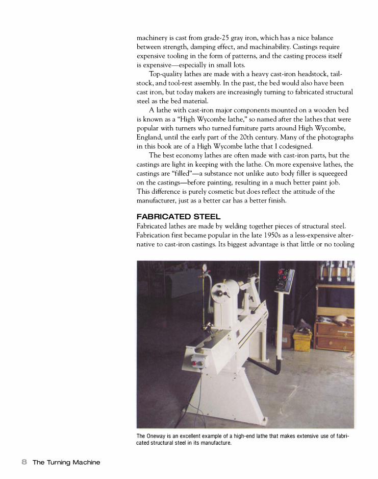
FABRICATED STEEL
Fabricated lathes are made by welding together pieces of structural steel.
Fabrication first became popular in the late 1 950s as a less-expensive alter
native to cast-iron castings. Its biggest advantage is that little or no tooling
The Oneway is an excellent example of a high-end lathe that makes extensive use of fabricated structural steel in its manufacture.

cost is required, which makes fabrication particularly well suited to small
production runs where amortizing the costs of patterns for castings would
be difficult. While traditional machine-design theory holds that steel has
poor damping qualities compared with grade-2S cast iron, that's only part
of the story. It is true that the stiffness of steel makes for high-frequency
vibration, but the welds tend to act as barriers to the transmission of vibra
tion. Instead they act much like a cracked glass, stopping vibration.
Fabrication is used in both the most expensive and the cheapest lathes,
so use common sense when making buying decisions.
STEEL STAMPINGS
Steel stampings are made by placing sheet steel between male and female
dies mounted in a press. The press closes the dies on the sheet steel and
forms it into the desired shape. Complicated shapes often entail a progres
sion of dies. The cost of the dies for stamping parts can be considerable,
but the stamping process itself (unlike foundry work) is cheap. This makes
traditional stampings great for high-production work but expensive for
short-run work. The last decade has seen the introduction of computer
numeric machines that can do short-run stamping on a cost-effective basis.
These machines can "nibble" out the basic shape with small round or
square dies, then form the material on various standard-forming dies. A
stamping made from heavy-gauge metal can be very good, but the most
charitable thing that can be said about stampings from light-gauge mate
rial is that they are vibration prone. Stampings are used extensively for
machine stands, belt covers, and the like.
CAST ALUMINUM AND ZINC
Parts such as pulleys, knobs, and hand wheels are often made from cast alu
minum or zinc. These are often called die castings because the low melting
temperature of aluminum and zinc allows them to be cast in metal molds
or dies. Die castings are almost perfect directly from the mold and require
little machining. The low weight of aluminum makes it a good material for
pulleys because balancing is less of a problem than with cast-iron pulleys.
Die-cast knobs and levers are a much better option than plastic.
EXTRUDED ALUMINUM
Occasionally lathes are made of extruded aluminum. Although extrusions
can be tempered, the alloys used for the process are soft and gummy. This
softness, as well as the tendency of raw aluminum to turn anything it
touches black, is somewhat lessened by anodizing, a plating process that
puts a thin, hard coat of aluminum oxide on the surface of the metal.
However, dents that go through the anodized surface into the soft alu
minum substrate are a potential problem.
There are more and more extrusions being used in woodworking
machinery today-my table saw fence is an extrusion, for example.
Although extrusions are acceptable for miniature lathes and parts of
Lathe Construction 9

Headstock
Motor mounts inside stand or at back of headstock.
On/off switch
� Speedcontrol lever for variable speed
Sheet-metal stand
1 0 The Turning Machine
Everylathe
Tool rest Tool rest
Tool base
Tool base lock lever
Spindle lock
Spindle
Some lathes now have modular beds which allow beds to be lengthened.
Wood-leg stand
Tailstock
Tailstock handwheel
Cross beam
lathes, I'm not convinced that they are suitable for an entire full-sized
machine. Before you buy a lathe made principally of extrusions, consider
how much and what type of use you intend for the machine.
HYBRID DESIGNS
Most lathes available today are hybrid designs, incorporating two or more
of the construction materials outlined above. A common design is a cast
iron headstock, tailstock, and tool base mounted on a structural-steel bed
or, on economy lathes, on solid- or hollow-steel tubing. Steel stampings,
sheet metal, aluminum extrusions, and plastic are often used for stands,
belt covers, and knobs.

Lathe Anatomy
Lathes come in all makes and sizes, from bench top models to industrial
heavyweights, but the basic design is the same on all lathes. A rigid bed
supports a stationary headstock and a tailstock that can be moved to
accommodate wood blanks of various lengths. A motor turns a spindle
mounted in the headstock, which in turn drives the work. The illustration
on the facing page shows a composite woodturning lathe combining the
features of many lathes. I call this lathe "Everylathe" because there is prob
ably no lathe that would have all of the features shown-at least at an
affordable price. Let's look at the parts in detail.
THE BED
The lathe bed supports the headstock, tailstock, and tool-rest assembly and
is in turn supported by a stand. The earliest lathe beds were no more than
two wood planks, and wood is still used on some modern lathes. Wood has
much to recommend itself as a bed material-it is relatively inexpensive,
readily available, absorbs vibration, and can yield a lathe of any desired
length between centers. The springiness of a timber bed has shock
absorbing characteristics unmatched by metal.
Starting in the 18th century, cast-iron lathe beds began to displace
wood. Cast iron is a good bed material because it is stable and has excel
lent vibration-damping characteristics. The casting process allows beds of
intricate design to be made. In an iron bed, each of the wood planks is
replaced by a strip, or rib, which is called a "way." The bed ways are typi
cally 1 in. to 1 1� in. apart. A number of lathes today offer modular cast-
A number of lathes offer modular beds so that any reasonable length between centers is possible. This Nova 3000 has 20-in. sections.
Lathe Anatomy 1 1

1 2 The Turning Machine
iron beds (see the photo on p. 1 1 ) . Under this scheme, the standard pack
age gives the turner a decent distance between centers, but additional sec
tions (typically 1 2 in. to 20 in. long) can be added to achieve a bed of any
reasonable length.
Although structural steel does not have the damping ability of cast
iron, it makes a good, solid bed if the weldments are designed properly.
Steel also makes longer beds possible at reasonable cost. You can even
make a "stretched" structural-steel bed by obtaining lengths of matching
steel from a steel fabricator.
I 've seen two lathes with beds made from aluminum extrusions.
Extrusions don't have much to offer as a bed material for anything but
a miniature lathe, so I would avoid them on a full-sized lathe.
In a bed, you should look for rigidity and workmanship. The ways
should have a smooth surface, and the distance between them should be
constant. Make sure the tailstock and tool base slide easily but lock solid
where you put them. Test the truth of the bed by checking the alignment
of the headstock and tailstock (see the sidebar on p. 23 ) .
T HE HEADSTOCK
The business end of any lathe-the part that drives the work-is the
headstock assembly. The headstock is fixed permanently at the left end of
the bed and consists of either a casting, a welded steel body, or an extru
sion that holds a spindle set in bearings. A pulley on the spindle is con-
Indexing pin
Outboard spindle nose (typically with same thread as nose but left hand)
Key fits bed of lathe.
Cast-iron housing
A Typical Headstock
Bearings (typically double-row ball bearings)
Indexing spacing holes (typically 12, 24, or 60)
Spindle nose is a coarse, right-hand thread.
Morse taper socket (typically #1 , #2, or #3 for wood lathes)

STANDARD SPINDLE SIZES AND MORSE TAPERS Spindle thread size Manufacturer Morse taper
Headstock Tailstock
5fs in. plain Shopsmith None
(unthreaded)
% in. x 16 TPI* Sears, Coronet, None or #1
Record, Beaver
7/S in. x 14 TPI Rockwell Homecraft #1
1 in. x 8 TPI Delta and many others #2
(most common spindle size)
1 in. x 12 TPI** Myford #2
1Ys in. x 8 TPI Oliver #2
1Y4 in. x 8 TPI General, Nova, #2
Woodfast, Vicmarc
M33 x 3.5mm Oneway #2
(with locking groove)
1Y2 in. x 8 TPI Conover, Powermatic, #2 or #3
Atlas, South Bend
1Y2 in. x 6 TPI Union Graduate #2
(Harrison)
*TPI = threads per inch **Whitworth thread (54° flank angle, rather than 60°)
nected by a belt to a motor, which is normally mounted below or behind
the headstock (see the illustration on the facing page) .
Spindle The spindle, a threaded shaft mounted horizontally, is the heart of the headstock. It accepts the drive centers, faceplates, and other accessories that hold and power the work. Spindles are either hollow or solid and range in size from l� in. to l l� in. dia.
The spindle size you need depends on the type of turning you intend
to do. For turning spindles between centers, you can get by with a small
diameter spindle. A common spindle size that is adequate for medium-duty
work is 1 in. For heavy-duty faceplate turning and architectural turning,
you will need at least a IlJ4-in. spindle that will not flex under load. Watch
out for spindles with odd thread sizes or odd taper sizes-what may seem
like a bargain will be no bargain at all if you can't easily obtain accessories
to fit the spindle. The chart above lists common spindle sizes for which
you have a good chance of readily finding accessories.
You should give much consideration to the spindle when choosing a
lathe. The most important thing to look for is a hollow spindle that is
machined to accept Morse-taper accessories. Morse tapers lock in place
when inserted into the matching tapered socket in the spindle.
More than any other feature, Morse tapers separate good lathes from
bad. Even if your turning needs are very casual, the advantages of Morse
#2
None or #1
#1
#2
#2
#2
#2
#3
#2
#2
Lathe Anatomy 1 3

Look for Morse Tapers
M orse tapers in both the head
stock and the tailstock are water
shed features that separate serious
lathes from bad ones. Avoid purchas
ing a lathe without Morse tapers.
1 4 The Turning Machine
LATHE SIZE IS TYPICALLY specified in three ways, the first two of which are
closely related. The first measurement is center height-the distance
between the point of a drive center in the spindle and the top of the
bed-which determines the diameter of the work that the lathe can
accommodate. The second measurement is swing, which is double the
center height of the lathe. For standard spindle turning between cen
ters, a center height of 4 in. (yielding a swing of 8 in.) is adequate. For
heavy-duty bowl turning, a center height of at least 6 in. is desirable.
The third measurement of lathe size is the maximum distance obtain
able between the headstock and tailstock centers. This capacity deter
mines the maximum length of work that can be turned. For spindle turn
ing, 30 in. is the absolute minimum and 36 in. or more is preferable.
tapers are enormous. A Morse-taper socket in the spindle makes for quick
and easy mounting of drive centers and a host of other chucking acces
sories. Morse tapers lock when driven home and release with an equal
opposite force. They're universal, so you're not dependent on the manufac
turer for replacement accessories. By contrast, on a lathe that has a solid
spindle, all accessories have to be screwed on, which is not only time
consuming but also limits the range of accessories available and ties you to
the manufacturer.
Morse tapers are available in sizes #0 through #7 (see the chart below
for the sizes common to wood lathes) . They have been widely copied in
the forms of other locking tapers, such as the American Standard taper,
the British Standard taper, the Brown and Sharps taper, and the lamo
taper. If you come across a used lathe with a taper size that does not appear
to be Morse, Machinery's Handbook (Industrial Press, 2000) will be a great
help. It lists dimensions for all types of locking tapers.
A further consideration is the height of the spindle above the bed,
which dictates the swing of the lathe and the diameter of the work that
can be turned (see the sidebar above) . At its simplest, swing is double
the height of the spindle center over the bed. For example, a lathe with
a center height of 6 in. will swing 1 2 in. You have to be careful of manu
facturers' claims because they sometimes quote the swing over a "gap,"
which is a short dip in the bed just ahead of the headstock. This gap,
MORSE-TAPER SIZES Size Dia. small end Dia. large end Length
#0 0.252 in. 0.356 in.
#1 0.369 in. 0.475 in.
#2 0.572 in. 0.700 in. 3Ya in.
#3 0.778 in. 0.938 in. 37/a in.

which is typically about 2 in. deep, allows you to turn larger-diameter face
plate work in this area. The problem is that when work extends into the
gap you can work only on the face (the exposed side) of it.
Unfortunately, twice the center height above the bed is not a true
measure of capacity. A better yardstick is to measure the distance from the
top of the tool base to the center of the spindle. Doubling this will give
you the true swing, which is the diameter of work the lathe will swing
between centers. A lot of faceplate turning also requires placing the tool
base under the work.
Bearings Bearings hold the spindle rigidly in place and allow it to turn with a minimum of friction. They're an important consideration when buying a lathe. The problem is that bearings are much harder to judge on cursory examination than features such as the construction method or spindle type.
Historically, lathes have run on plane cast-iron bearings, sleeve bear
ings, and babbitt bearings (see the illustration on p. 16 ) , but most lathes
made today have rolling-element bearings. These include ball, roller, and
tapered-roller bearings (see the photo below right) . Of these, ball bearings
are by far the most common type used in lathe construction. Each bearing
Tool-rest height d ramatically affects swing . This tool rest comes from a lathe that advertises a 16-in. swing . The standard tool rest for this Nova 3000 is much higher than the tool rest for a Conover lathe, which yields about 2 in. of extra swing over the rest.
Today most woodturning lathes have at least one set of double-row bearings. Shown here is an SKF angular-contact bearing of the type put in the best machines. (Photo courtesy SKF bearings.)
True Swing
T he true swing of a lathe is twice
the center height over the tool rest,
not the bed as most manufacturers
state in their literature.
Lathe Anatomy 1 5

Bearing Qual ity
In reality there is little you can tell
about the quality of the bearings of
any given lathe without taking the
machine apart. Fortunately, most
manufactu rers use bearings that are
more than adequate for the duty
rating of a machine.
16 The Turning Machine
I I
Plane Bearings
This simple cast-iron bearing is adjusted by placing shims between the two halves and tightening the two cap screws.
consists of an inner race and an outer race that are separated by a series of
steel balls. The opposing ends of the spindle ride on these rings of balls,
which provide a precise hold and allow the spindle to turn with a mini
mum of effort. The majority of the power from the motor can now be used
for productive work.
Bearings can sometimes be upgraded, which I will discuss on pp. 149-155.
Outboard turning feature Because some work will be too large in diameter to swing over the bed, lathe manufacturers often design the headstock so that work can be mounted on the outboard side. Outboard turning is accomplished in two basic ways. One is to put a left-hand thread on the outboard end of the headstock spindle and mount the work so that it faces away from the lathe. The other option is to design the headstock so that it pivots at right angles to the bed.
When work is mounted on the outboard end of the headstock, the
swing of the lathe becomes double the distance from the center of the
headstock spindle to the floor. Although this may sound like an ideal solu
tion for turning large-diameter work, outboard turning presents a number

of problems, the greatest of which is speed. Many lathes do not have a low
enough speed range to turn anything greater than 1 2 in. in diameter. For
large-diameter turning, you need a bottom speed of 150 rpm to 300 rpm.
Another problem with outboard turning is that there is no place to
support the tool rest. You have to use a floor-stand rest (typically a tripod
stand that holds the rest) , but this device is not as solid as a standard rest.
In addition, this method of outboard turning sometimes requires a second
set of left-hand-threaded faceplates, and it demands that you do everything
in reverse of your normal way of turning. (Delta makes many of its face
plates threaded in both directions, which means they can be screwed on
either end of the spindle. )
Some lathes that use the outboard end of the spindle for outboard
turning have a special tool base attached rigidly to the lathe, which is a
much better setup. In effect, this creates a small bowl lathe that is a mirror
image of the actual lathe.
The second option for outboard turning, the swing-head design, is
well adapted to light- and medium-duty lathes. In a swing-head lathe, the
headstock pivots at right angles, and the work is turned in front of the
lathe (see the photo at left on p. 1 8) . A special tool base attaches to the
base of the headstock into which the tool rest fits. Although such a setup
allows only a limited outboard swing of about 1 6 in. to 20 in. , it's a better
arrangement for a number of reasons. First, the diameter of the work is
limited to within the low-speed range of the lathe. Second, the tool base
is attached rigidly to the lathe bed, making turning sure and safe. Third,
Oneway offers a short bed that can be mounted outboard (opposite the standard bed that comes with the machine) , which turns the machine into a bowl lathe. This offers g reat convenience to a serious bowl turner because he has much better access.
A floor-stand rest allows outboard turning, but you must have a lathe with low enough speed to handle this kind of d iameter.
Lathe Anatomy 1 7

Most manufacturers of today's l ight- and medium-duty lathes handle outboard turning by allowing the head to pivot. This gives reasonable outboard capabi lity without having to go to a floor-stand rest or buy left-hand faceplates.
1 8 The Turning Machine
Indexing allows the locking of the headstock spindle at precise locations for purposes of layout (such as a clock face) , hand operations (carving flutes), or machine operations (mi l l ing reeds with a router). Most manufacturers offer at least 12 positions, with 24 or 60 being the common numbers.
turning is in the same direction and orientation as takes place over the
bed. Finally, a second set of left-hand-threaded faceplates is not required.
It has been my experience both in selling lathes and advising buyers
of lathes that turners place unnecessary emphasis on turning outboard. In
reality, outboard turning is something that most people will do only once
or twice in their lifetimes, if at all. Don't have tunnel vision about the out
board feature, ignoring all the other useful features that a lathe should
have and that you will use every turning session. You can always rig some
thing up or borrow a lathe for the once-in-a-lifetime big job.
Index heads Some headstocks are fitted with an index head, which is a mechanism that allows the spindle to be locked at equal intervals so that layout or auxiliary operations can be performed. Examples of such applications include laying out a clock face or a fluting pattern on a bowl or milling reeds or flutes in a column with a router (see pp. 102-1 04) . The most common setup for indexing is a series of holes drilled in the headstock drive pulley (see the photo above right) , which is mounted on the spindle. A pin in the headstock casting slides into the appropriate hole and locks the spindle in place. Common hole patterns are 1 2 , 24, and 60. I like the 24-stop configuration because it allows me to divide the circumference of a workpiece into many different but equal sets of parts: 24 (for fluted bowls and the like) , 1 2 (for clock faces) , 8 (common for periodfurniture shapes) , 6 (also for furniture) , and 3 (I have never used this) .
Indexing i s a feature that may or may not be of value to you. I have
spoken to many turners who have never used the index head. For certain

types of period-furniture turning, such as fluted legs, it is essential. If you
are considering a dandy lathe at a bargain price but it lacks indexing, buy
it anyway. An index head can be added later if you need it. There are sev
eral after-market chucks that incorporate the feature, or you can rig some
thing up yourself. Note that on most lathes the index head should not be
used as a spindle lock for removing faceplates because doing so may bend
the indexing stop. Most lathes have other provisions for locking the
spindle for faceplate removal.
MOTORS, BELTS, AND PULLEYS Almost all woodworking lathes are supplied with a single-phase induction
motor. The motor typically mounts inside the stand or at the back of the
headstock and is connected to a pulley on the spindle by a belt. For small
lathes, l� hp is adequate, whereas bigger machines require 1 hp or even
1 1� hp. Mini lathes can get by with as little as lJ4 hp. Machines imported
from Asia frequently have power specifications on the motor nameplates
that are optimistic. Often such machines are quite serviceable otherwise,
so the best course is to replace the anemic motor with a U.S. model if it
lacks the desired power or burns out.
Increasingly, manufacturers are putting variable-speed direct-current
(DC) and alternating-current (AC) motors with solid-state controllers on
lathes. Today's solid-state circuitry allows the use of controllers that effi-
A DC motor is a nice way to add variable speed to an existing lathe. Many manufacturers now offer DC (or variable-cycle-rate AC) as the method of variable speed .
Adding Variable Speed
T he easiest way to add variable
speed to an older machine is to
install a DC motor and controller or a
th ree-phase AC motor and a solid
state variable-cycle rate controller.
Lathe Anatomy 1 9
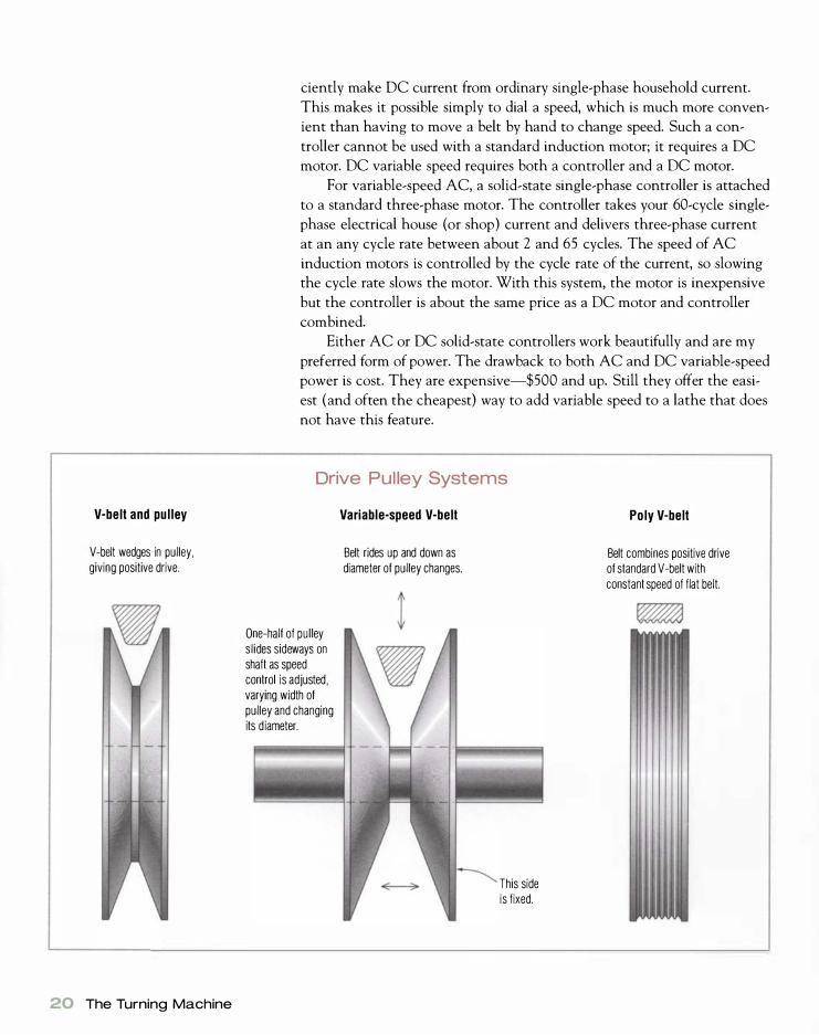
V-belt and pulley
V-belt wedges in pulley, giving positive drive.
20 The Turning Machine
ciently make DC current from ordinary single-phase household current.
This makes it possible simply to dial a speed, which is much more conven
ient than having to move a belt by hand to change speed. Such a con
troller cannot be used with a standard induction motor; it requires a DC
motor. DC variable speed requires both a controller and a DC motor.
For variable-speed AC, a solid-state single-phase controller is attached
to a standard three-phase motor. The controller takes your 60-cycle single
phase electrical house (or shop) current and delivers three-phase current
at an any cycle rate between about 2 and 65 cycles. The speed of AC
induction motors is controlled by the cycle rate of the current, so slowing
the cycle rate slows the motor. With this system, the motor is inexpensive
but the controller is about the same price as a DC motor and controller
combined.
Either AC or DC solid-state controllers work beautifully and are my
preferred form of power. The drawback to both AC and DC variable-speed
power is cost. They are expensive-$500 and up. Still they offer the easi
est (and often the cheapest) way to add variable speed to a lathe that does
not have this feature.
Drive Pul ley Systems
One-half of pul ley s l ides sideways on shaft as speed control is adjusted , varying width of pulley and changing its d iameter.
Variable-speed V-belt
Belt rides up and down as diameter of pulley changes.
This side is fixed.
Poly V-belt
Belt combines positive drive of standard V-belt with constant speed of flat belt.

The original drive system for connecting lathes to a power source was
a flat leather belt. A three- or four-step set of matched pulleys gave a good
range of speeds for the turner. Although flat leather belts gave very con
stant speed with no surging, they tended to slip, thus wasting power.
Most lathes made in recent years use V-belts for power transmission.
V-belts drive positively because greater tension on the belt causes it to
wedge tighter in the pulley groove. An additional advantage of V-belts is
that manufacturers can provide variable speed by installing a variable
width pulley set (see the illustration on the facing page) . A mechanical
control adjusts the width of the drive pulley, which effectively changes the
pulley diameter and thus the speed. Moving the two halves of the drive
pulley apart decreases the diameter (and decreases the speed) ; squeezing
the halves back together does the reverse.
The mating pulley on the headstock is similarly split but is spring
loaded so it automatically adjusts to the state of the drive pulley. This
setup gives a wide range of infinitely variable speeds. The only drawback
to such a speed-control system is that it wears out belts faster, necessitating
annual belt replacement for a lathe that gets moderate to heavy use.
A recent innovation is the poly V-belt, which is a flat rubber belt with
a series of small V-ribs machined on the inside surface (see the illustration
on the facing page). This design gives the belt the positive drive character
istics of a V-belt with the constant velocity of a flat leather belt. Many
newer lathes run on poly V-belts.
THE TAILSTOCK The tailstock assembly is composed of the main casting, a spindle (or
ram), a spindle-locking lever, a hand wheel, and a mechanism to secure the
unit to the lathe bed. Whereas the headstock is stationary, the tailstock
can slide along the bed to accommodate work of varying lengths and can
be locked at the desired distance from the headstock.
The advantages of a good tailstock should not be overlooked because
it does much more than just hold a center. As with the headstock spindle,
the tailstock spindle should be machined to accept Morse-taper acces
sories. Look for a spindle equipped with a #1 , #Z, or #3 Morse taper. The
tailstock spindle sometimes runs a bit smaller than the headstock spindle.
For example, if the headstock spindle is 1 liz in. dia., the tailstock spindle is
typically 1 in.
An important aspect of tailstock design is spindle travel-the amount
the spindle can be moved when the tailstock is locked to the bed. Lathes
typically have about Zllz in. of spindle travel, which is adequate for most
applications. I prefer to work with a tailstock spindle that can move as
much as possible because the tailstock itself doesn't have to be moved as
often.
The tailstock spindle is advanced and withdrawn by turning a hand
wheel, which is no more than a large nut. A lever on top of the tailstock
locks the spindle in place and prevents it from drifting due to the vibra-
A common tailstock design uses a lefthand thread on the outside of the spindle. The left-hand thread is necessary to make the adjustment logical-turn ing the handwheel right advances the spindle and vice versa. This also allows a hollow spindle for d ri l l ing through the tailstock.
Lathe Anatomy 21

Checking a Self-Ejecting Ta i lstock
If you own a lathe with a self-ejecting
tailstock, occasionally a taper wil l be
too short to eject. It is always good to
check any new accessory by lightly
inserting it and running the spindle
rearward to see if it ejects.
22 The Turning Machine
tion caused by turning. The traditional tailstock setup calls for the outside
of the spindle to be left-hand threaded (see the photo on p. 2 1). Because
the thread is left-handed, the spindle advances when the handwheel is
turned clockwise, which is normal to our way of thinking. This design is
typically used on cheaper lathes, although it is sometimes also found on
very expensive ones. Accessories are ejected by inserting a knockout bar
through the spindle.
A more elegant arrangement is a self-ejecting spindle. The inside of
the spindle is left-hand threaded, and a long left-hand screw extends from
the hand wheel into it (see the photo below). Turning the wheel to the
right advances the spindle, while turning it left withdraws it. As the spin
dle is retracted all the way rearward, the screw bumps the Morse taper in
the spindle and ejects it. A crank handle is often added to the handwheel
so that the spindle can be moved quickly.
The tailstock must lock securely to the bed and not move while you're
turning. There is a variety of locking mechanisms, ranging from a stud
running down between the bed rails with a plate and a nut to complicated
cams. The main thing to look for is a good positive lock that will hold the
tailstock without its drifting backward when you apply pressure to the
work with the hand wheel.
A more elegant design is the self-ejecting tailstock, which automatically ejects the Morse taper in the spindle when the spindle is fully withdrawn. You cannot dri l l through such spindles, however.

WHEN YOU BUY A NEW LATHE, it's a
good idea to check that the tail
stock aligns with the headstock.
(This test will also check the truth of
the bed.) The best gauge for test
ing center alignment is a pair of 60°
dead centers (see pp. 43-45), but
any set of Morse-taper accessories
that come to a point at the center
will work. Simply put one center in
the tailstock and one center in the
headstock, then slide the tailstock
forward until the two points touch.
The centers should align perfectly.
Center alignment is important in
faceplate work but relatively unimportant for spindle turning. Although reasonable center alignment is advantageous (if for no other reason
than that the tool rest aligns with the work) , center alignment could vary by 'fa in. or more on a 1 5-in. spindle.
The longer the turning, the more out of alignment the two centers could be. Center alignment is especially
important if you plan to do any metal spinning with your lathe. Woodcraft Supply Corp. sells a clever double
ended #2 Morse taper for checking spindle alignment, as shown above.
THE TOOL BASE AND TOOL REST
What we tend to think of as the tool rest is actually composed of two
parts-the tool-base assembly and the tool rest itself. The tool base, which
supports the tool rest, attaches to the bed of the lathe and can slide to any
point between the headstock and the tailstock. The base (known as the
banjo in England) also moves in and out so that the tool rest can be posi
tioned right next to the workpiece. Desirable features in a tool base
include ease of movement, rigidity, and a low profile. The latter feature
is important because the height of the base affects the swing of the lathe.
For each Ys in. that the tool-base height is reduced, you are rewarded with
an extra Y4 in. of swing.
The tool base must lock down securely and not slide under load. The
hold-down/locking mechanisms range from wedges under the bed that are
pounded snug with a mallet on classic wood-bed machines to a simple nut
and bolt that are tightened with a wrench on economy lathes to compli
cated lever-operated cam mechanisms on full-featured machines. With
each level of sophistication come commensurate increases in price. When
choosing a lathe, the best course is to try the tool base to see how it oper
ates. Move it to a variety of angles and positions, lock it in place, grab it
with both hands, and see if you can move it. Don't be afraid to throw some
body weight into this exercise.
Lathe Anatomy 23
24 The Turning Machine
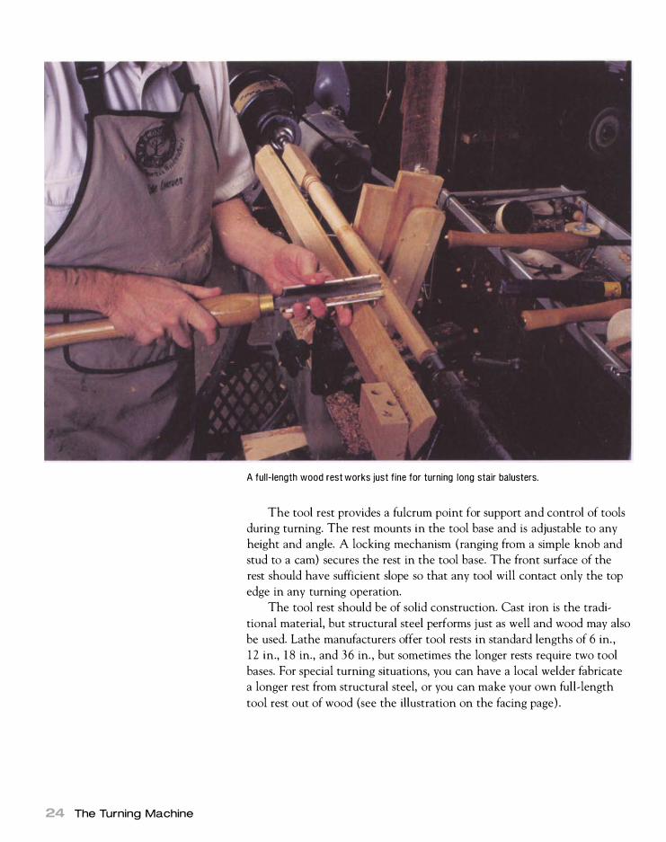
A full-length wood rest works just fine for turning long stair balusters.
The tool rest provides a fulcrum point for support and control of tools
during turning. The rest mounts in the tool base and is adjustable to any
height and angle. A locking mechanism (ranging from a simple knob and
stud to a cam) secures the rest in the tool base. The front surface of the
rest should have sufficient slope so that any tool will contact only the top
edge in any turning operation.
The tool rest should be of solid construction. Cast iron is the tradi
tional material, but structural steel performs just as well and wood may also
be used. Lathe manufacturers offer tool rests in standard lengths of 6 in. ,
1 2 in., 1 8 in., and 36 in. , but sometimes the longer rests require two tool
bases. For special turning situations, you can have a local welder fabricate
a longer rest from structural steel, or you can make your own full-length
tool rest out of wood (see the illustration on the facing page) .

Durable hardwood
T HE STAND
A Shop-Built Ful l-Length Tool Rest
Steel pin (of diameter to fit tool base) turned down to 3/8 in . or 1J2 in . to match the bolt.
When choosing a lathe, it's important to look for a solid stand that will
prevent the lathe from jumping around under full load. Nineteenth- and
early 20th-century lathes typically had heavy cast-iron legs (weighing as
much as 300 lb. ) that minimized vibration. The legs were usually bolted to
the end of the bed, which made for a freestanding machine that you could
stand close to without stubbing your toes.
Today, cast-iron legs have largely been replaced by stamped-sheet
metal stands. By using angle and box sections, manufacturers can fabricate
serviceable stands from light-gauge material. Such stands are inexpensive
to make, cut down on shipping weight, and, if shipped knocked down,
save on shipping volume. A well-designed sheet-metal stand can be very
good, whereas a poorly designed stand can impair the performance of an
otherwise good lathe.
\ '. / - � � :</; , I
3ja-in. or l/2-in. carriage bolt bent at right angle. Hacksaw off the head and install the stop collar.
Lathe Anatomy 25

If you must bui ld a shelf under your lathe, use dowels, which allow dust and chips to fall through but not your tools and accessories.
26 The Turning Machine
A Shop-Bui lt Lathe Stand
F i l l with sand.
F /a-in. by 1 7/a-in . pine or poplar
8/4 pine or poplar
Some economy lathes are sold with the stand as an option. These
stands are invariably of poor quality, and you're much better off building
your own stand (see the illustration above) . Building box sections and
filling them with sand will give you a base that soaks up vibration and
cuts down on lathe noise. Wood is stronger and more rigid than a light
stamped-steel stand. I built the stand for my Nova 3000 (see the photo
on p. 30) from heavy hardwood. The tapered-leg design increases stability,
and the shelf can accept sandbags if necessary.
Avoid shelves and drawers under your lathe unless they are made of
dowels or bars; otherwise they tend to fill with chips and collect dust. By
making a shelf with dowels, the chips will fall through. I prefer a lathe
with legs on either end rather than a box underneath so as to make sweep
ing and shoveling chips much easier.
Choosing and B uying a Lathe
T oday, a lathe buyer is presented with a startling array of lathes.
A happy outgrowth of 2 1 st century instant communication, the
woodworking press, and local turning clubs is that there are far
fewer really bad lathes out there. That is because manufacturers (and the
woodworking public) hear fast when something is wrong. In addition
to new lathes, however, there are lots of used lathes kicking around that
are begging for loving parents to adopt them. The used lathe represents
one of the best options for a buyer on a tight budget. In chapter 7, I give
ample information on repairing and refurbishing a previously owned lathe.
Restoring the classic beauty of an old warhorse only adds to the fun of
using it.
Before beginning your search, you need to analyze the type and
amount of turning you plan to do with your lathe. For example, if you
plan to make dollhouse furniture, a miniature lathe is the right bet. If,
on the other hand, you plan for the lathe to be only an adjunct to your
general furniture making, you can get by with a modest lathe. Almost
any lathe can handle chair legs, table legs, knobs, and pulls.
However, if you are a serious period furniture maker and wish to do
chairs with long back posts and Sheridan bedposts, you will need a heavy
lathe with good between-center distance, as much as 72 in. You also may
wish to make tilt tables, fern stands, and the like, which require good out
board faceplate capacity. If you wish to do really heavy turning, such as
architectural elements (porch columns, for example) , you will need an
even bigger lathe. If you enjoy bowl turning, then you may want to con
sider a bowl lathe.
chapter
2

LATHE TYPES
Type Use Capacity
True miniature lathes
Mini lathes (small lathes
with a short bed)
General tuming lathes
Bowl lathes
Omamental lathes (OT lathes)
How Much Can You Spend?
D ecide how much money you
have to spend before shopping
for a lathe, and remember that you
wi l l need at least $1 50 for some
tools and accessories after you pu r
chase you r lathe.
• True miniature tuming such
as dollhouse fumiture
• Turning pens
• As a second lathe or a portable lathe
• Teaching children
• Good general shop lathe
for any spindle work up to about
30 in. between centers and general
faceplate work 13 in. to 16 in. dia.
• Tuming bowls
• OT attachments do end-grain
cutting, side-grain cutting, and
threading.
• True OT lathes do omamental
pattems but are hard to find and
expensive.
Swing: 4 in. or less
Length between centers: 6 in. to 8 in.
Swing: up to 10 in.
Length between centers: up to 14 in.
Sometimes these lathes have
extension beds that turn them into
small benchtop lathes.
Swing: up to 16 in.
Length between centers: up to 52 in.
but most in the 28-in. to 36-in. range
Swing: at least 16 in. and often
22 in. or more.
Length between centers: not much
much more than 24 in. (on a true
bowl lathe the tailstock is minimal,
meant only to provide support during
roughing)
Capacities are typically
modest-no more than
6 in. center height.
Finally, you should decide at the outset how much money you can
spend for your lathe. Buying machinery, especially for an enthusiast, can be
much like buying a car-budgets get busted. Remember not to spend all
your money on the lathe because you also need tools, chucks, and acces
sories, which can add as much as $ 1 50 to $750 to your budget. There are
basically three price points in lathes: less than $ 1 ,000 (entry-level lathes} ,
less than $2 ,000 (mid-range lathes) , and more than $2 ,000 (dream lathes) .
There are also specialty lathes if you concentrate on one type of turning.
At the top end of the market almost any lathe will be satisfactory, but
among entry-level lathes it is possible to find virtually unusable examples.
Entry-level buyers need to be especially careful. Buying a lathe is much
like buying a car; a feature that you love may be a feature that I hate.
Before you buy your first lathe, try out the one you're considering.
A turning club is often worth joining because a member may own the
lathe you are interested in and be glad to let you try it. The Internet is also
a useful resource to find user feedback on any particular machine. On the
other hand, I would also caution you against taking other users' comments
too much to heart. Typically woodworkers get very comfortable with their
lathes and look askance at any machine that is different from what they
28 Choosing and Buying a Lathe

are used to. If most of the features of a particular lathe appeal to you, don't
be afraid if it seems a bit awkward at first. Using it will become second
nature within two weeks.
Entry-Level Lathes
Entry-level lathes are suitable for a craftsperson who wants to add turning
to his woodworking. They will handle the majority of furniture parts such
as table legs, chair legs, knobs, finials, and stool seats. Such lathes typically
have about a 1 0-in. to 14-in. swing (over the bed) with 28 in. to 36 in.
between centers. Longer turnings can normally be jointed at one or two
places, so you can even tackle period bedposts. Only back posts for ladder
back and rocking chairs present any problem (for these you need 42 in. to
55 in. between centers) . Because turners value swing, most entry-level
lathes have an ample amount.
New entry-level lathes cost from $500 to $ 1 ,000 dollars. But in this
category, a used lathe offers a lot of value. The only drawback is that you
may not get quite as much swing. On the other hand, you may find a nice
old workhorse for the price of a new lathe. During the Depression, a lot of
cheap lathes were manufactured with sleeve bearings, but I would stay away
from any machine that does not have ball or roller bearings. Likewise, stay
away from a machine that does not have Morse-taper sockets in both the
headstock and tails tack. Morse tapers are a watershed feature that separates
good lathes from not-sa-good lathes.
Join a Turning Club
J oin ing a turn ing c lub is a good
way to get opin ions about and
often the chance to test-drive a lathe
you plan to buy.
The Delta 46-700 was a groundbreaking lathe when it was introduced in the early 1 990s and is still a winner. It offers cast-iron construction where it counts, reasonable swing and between-center distances, and a swing head for larger faceplate work. Best of all, it has variable speed with a low-end speed of 350 rpm. (Photo courtesy Delta.)
Based on the Delta 46-700, this Jet lathe is a good small lathe that offers good swing and between-center d istances with a swing head for occasional larger faceplate work.
Entry-Level Lathes 29

30 Choosing and Buying a Lathe
Most entry-level lathes come with l/z-hp motors, although the motors
of lathes made in Asia are often a bit optimistic in their power ratings. You
can easily replace a motor when the original fails. Typically these lathes
come with three or four speeds, which are changed by switching belts, but
some entry-level machines have variable speed by variable-width sheaves.
A good entry-level lathe has excellent resale value should you ever
decide to upgrade.
Mid-Range Lathes
If you want to tum a lot of furniture parts or even make turning the main
focus of your woodworking, then there is probably a mid-range lathe in
your future. Mid-range lathes are of much heavier construction than an
entry-level machine, although they may not offer vastly more capacity
(swing and distance between centers) these days. Along with the heavier
construction, you also get better knobs and controls, smoother operation
of movable parts, and better power. The motor will be more powerful, typi
cally 1 hp to 1 1/z hp, and often of better construction. You will also get a
bigger selection of speeds or more likely variable speed. In general, the
weight and rigidity create a smoother-operating machine that is much less
prone to vibration. Mid-range lathes can easily last you a lifetime. They
cost from $ 1 ,000 to $2,000.
The Nova 3000 is a well-designed, mid-range lathe. It offers all the features of the Delta 46-700 with g reater swing, DC power options, and a modular bed design that allows the bed to extend. Nova also bu i lds an ornamental attachment for this lathe.

Dream Lathes
As the heading implies, these machines have everything you always
dreamed about in a lathe. Heavy-duty construction, controls that work
effortlessly, trouble-free operation, lots of power at any speed, and nice cos
metics. In short, this is a lathe you will never be ashamed about being seen
with in public. New lathes run more than $2 ,000 and as much as $6,000.
Of course, you may luck out and find a beautiful used lathe for much,
much less. Also included in this category are special-purpose lathes that
have huge swing and tremendous between-center capacity or that do orna
mental work. Dream lathes are generally the province of the avid turner
who forsakes other types of woodworking. Sure, it's a lot of money, but
then have you ever priced golf clubs?
The VB36 Master Bowlturner lathe certainly qualifies as a d ream lathe. Made in England, this robust bowl lathe weighs 850 lb. and costs just under $5,000.
Dream Lathes 31
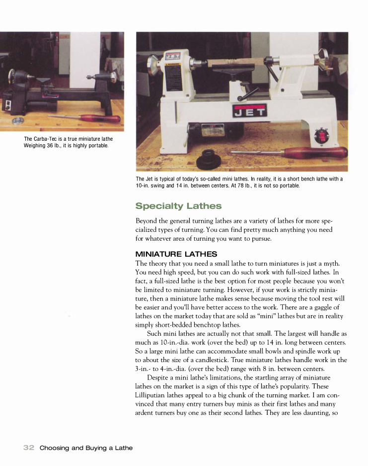
The Carba-Tec is a true min iature lathe Weighing 36 lb . , it is highly portable.
32 Choosing and Buying a Lathe
The Jet is typical of today's so-called mini lathes. In real ity, it is a short bench lathe with a l O-in. swing and 1 4 in . between centers. At 78 lb . , it is not so portable.
Specialty Lathes
Beyond the general turning lathes are a variety of lathes for more spe
cialized types of turning. You can find pretty much anything you need
for whatever area of turning you want to pursue.
MINIATURE LATHES
The theory that you need a small lathe to turn miniatures is just a myth.
You need high speed, but you can do such work with full-sized lathes. In
fact, a full-sized lathe is the best option for most people because you won't
be limited to miniature turning. However, if your work is strictly minia
ture, then a miniature lathe makes sense because moving the tool rest will
be easier and you'll have better access to the work. There are a gaggle of
lathes on the market today that are sold as "mini" lathes but are in reality
simply short-bedded benchtop lathes.
Such mini lathes are actually not that small. The largest will handle as
much as lO-in.-dia. work (over the bed) up to 1 4 in. long between centers.
So a large mini lathe can accommodate small bowls and spindle work up
to about the size of a candlestick. True miniature lathes handle work in the
3 -in. - to 4-in.-dia. (over the bed) range with 8 in. between centers.
Despite a mini lathe's limitations, the startling array of miniature
lathes on the market is a sign of this type of lathe's popularity. These
Lilliputian lathes appeal to a big chunk of the turning market. I am con
vinced that many entry turners buy minis as their first lathes and many
ardent turners buy one as their second lathes. They are less daunting, so
they make learning basics more enjoyable. They are particularly good if
you want to get a child interested in turning. A very nice mini lathe with
a variable-speed motor can cost an affordable $300 to $400.
Many avid turners take them to club meetings so that they can ac
tively participate in training sessions. Their portability is wonderful, and
they can be stored out of the way when not in use. I use mine whenever
I have to turn a bunch of knobs. One summer I spent several enjoyable
evenings on my patio turning 40 pulls for a kitchen's cabinets and drawers.
Mini lathes are also very popular with pen makers. Turning wooden
mechanical pencils as well as ball, felt-tip, and fountain pens is a huge
business these days, and many turning enthusiasts make nice secondary
incomes by turning pens. A mini lathe can be dedicated to pens, thus
leaving your main lathe open for general turning.
BOWL LATHES
Another specialty lathe is the bowl lathe. Because of the popularity of
turning bowls, a number of lathes have been designed with only this end
in mind. A bowl lathe has a short bed so that the turner can stand directly
in front of the work and walk 1 800 around it. The tailstock is rudimentary,
j ust holding the work during roughing and secondary operations. These
lathes are hard to find and can be expensive. Some manufacturers offer a
short cantilevered bed that mounts outboard opposite the main bed, turn
ing the lathe into a bowl lathe.
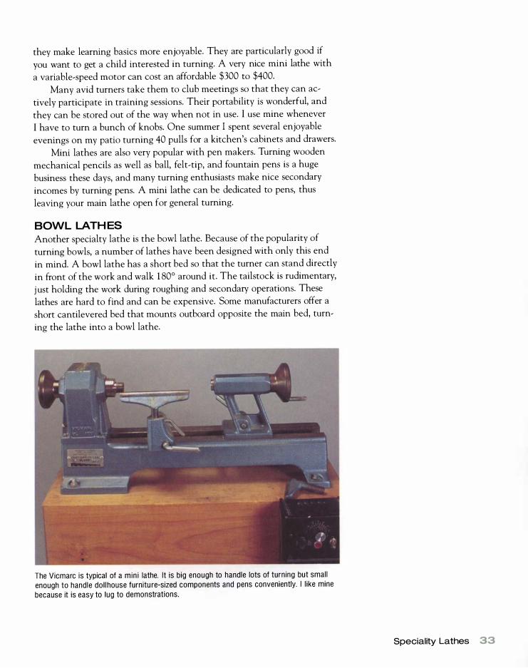
The Vicmarc is typical of a min i lathe. It is big enough to handle lots of turning but small enough to handle doll house furnitu re-sized components and pens conveniently. I like mine because it is easy to lug to demonstrations.
Speciality Lathes 33
34 Choosing and Buying a Lathe
ORNAMENTAL LATHES ARE MOST associated with John Jacob Holtzapffel ,
who was the most famous maker. He and his son were unabashed
partisans for ornamental turning and wrote five volumes on wood
working between 1 843 and 1 904. Volume IV, The Practice of Hand or Simple Turning was published in 1 897. As the name implies, it
deals with turning as we know it today. Volume V, The Principles and Practice of Ornamental or Complex Turning, published in 1 904,
is an action manual , much studied by ornamental turners today.
It should be noted, however, that Holtzapffel was not the only partisan of the craft. Fine lathes were made by James M unro of
Lamberth, England, and John Henry Evans among others. The Lathe & Its Uses, a guidebook for the use of Munro 's lathes, was
written by Claud Lukin in 1 868. Evans, l ike the Holtzapffels, was an
accomplished writer, whose Ornamental Turning (published in 1 886)
is a lucid text that modern ornamental turners still turn to. All except
Lukin's text are available in facsimile.
ORNAMENTAL LATHES
An interesting subgenre of turning that became popular (at least among
the wealthy) in the second half of the 1 9th century was ornamental turn
ing (OT), in which precisely cut decorations are put on turned surfaces.
Ornamental lathes were Rube Goldberg-like contraptions that married
woodturning and metalworking lathes with the milling machine.
After the initial turning process, an ornamental lathe could turn and
mill flutes, spirals, and screw threads, as well as intricate patterns into the
work. This was accomplished by applying single-pointed fixed tools in the
slides of the machine ( like the slides of a metal lathe) and small milling
cutters (much akin to a modern router bit) to the work. The spindle could
be indexed and could also be slowly advanced by hand on a screw thread.
Since ornamental lathes were treadle driven, the work had to be small and
of a hard, durable wood such as boxwood, granadilla, and ebony. Ivory and
ivory nut ( tagua) were also popular ornamental turning materials that
remain so today.
Ornamental turning has enjoyed a small but passionate following and
experienced a rebirth in the late 20th century. There are two reasonably
priced attachments for normal wood turning lathes that bring ornamental
turning to the masses. Antique ornamental lathes (built in the 1 9th cen
tury) are hard to find and go for thousands of dollars. Lawler Gear Corp.
( see Resources on p. 1 84) builds a true ornamental turning machine,
which goes for about $ 1 5 ,000. I'll look more at ornamental turning in
chapter 5 .

Setting Up a Lathe
S etting up a lathe involves more than just shoehorning the machine
into an available space in the workshop. You need to consider work
flow, machine placement, chip removal, ventilation, electrical
service, lighting, and tool storage.
Workflow
The lathe should be placed in such a way that work can flow naturally
to and from other machines in the shop (see the illustration on p. 36) . Billets for spindle turning are often jointed and planed square. They are
then cut to length on a table saw or radial-arm saw. Keeping this flow in
mind when placing the lathe will save unnecessary trips across the work
shop. Access to the bandsaw, which is often used to round up faceplate
work before it is mounted in the lathe, may be important depending on
your work. And whatever type of turning you do, it's a good idea to mount
the grinder and buffer close to the lathe so you won't have far to walk to
sharpen your tools.
Machine Placement
Most people tend to put a lathe against a wall, but I think that placing it
at right angles or at a 45° angle to a wall makes more sense. You still have
the wall for tool racks, but lathe access is much better. And if your lathe
has a sheet-metal box-type stand, you need enough room in back of it to
3
Plan Your lathe Setup -
B efore you install a lathe, taking
time to plan things such as its
placement, electrical access, and tool
storage will save hours, days, and
even months in increased production
time down the road.

Make Your Own Stand
If you are short or tall, making a stand not only saves money but also
g ives you exactly the right spindle height for your stature.
36 Setting Up A Lathe
Shop Layout �TOOIS
Bandsaw
� Lathe fDl � Dust blOWerT
�JOinter/Planer �G rinder n J-----.6 U Router table �U c:r Table �
L--
w ---.-_
Drawer units
sweep, since more than half the chips will accumulate there. Putting a
lathe against a wood or metal post is another good option. Electrical out
lets, lights, the grinder, and tool racks can be mounted on the post, turning
what might otherwise be a dead area into useful space.
Once you've actually positioned your lathe, it needs to be leveled. Test
for level parallel to and across the bed ways using a standard builder's level.
If you need to level the stand, use wood shims rather than metal because
wood is more resilient. A thin sheet of industrial rubber under each leg
can help reduce vibration. I've used scrap truck inner tube successfully,
cementing the tube to a 3 -in. to 4-in. square of Yz-in. plywood and placing
a square under each corner of the machine. I place additional shims of
lk-in. Masonite on top of the base plywood shim for fine adjustment.
Now is a good time to consider machine height. A good rule of thumb
is to have the spindle centerline at elbow height or just a touch higher. For
most people, this height is between 40 in. and 44 in. To raise the height of
the lathe, add wood blocks with rubber glued to the underside.
For normal spindle turning, a lathe need not be bolted to the floor.
In fact, I prefer the flexibility that leaving it unbolted allows-if my lathe
needs to be moved for some reason, it's an easy matter, and I don't have to
drill holes in my shop floor. If I have to turn some heavy work that will
cause the machine to walk, I weigh down the machine by draping sand
bags over the legs or placing them on the box section or shelf below
my machine.

Chip Removal and Ventilation
A lathe generates such a large amount of dust and chips that it is difficult
to extract it all with a dust-collection system. If your shop has a dust
collection system, it's a good idea to locate a pickup port near the lathe.
By placing a hose as close as possible to the work, much of the dust from
sanding can be vacuumed away. You can also wheel in portable dust
blowers and clamp a suitable wood bracket to the lathe to hold the pickup
hose close to the work.
Another good idea is to install an air-filtration system above or near
your lathe. Such systems are mounted on the ceiling of your shop and have
to be sized to the workspace so that all the air in the room changes every
few minutes. If properly sized, they dramatically reduce the dust level in
the shop.
If you don't have a dust-collection or air-filtration system, being able
to open doors and windows will help. In good weather, placing an exhaust
fan in the window near your lathe will carry most of the dust outside,
which will not only make a turning session more enjoyable but also will
be better for your health. For more on dust protection, see "Safety Equip
ment" on pp. 98-10 1 .
Electrical Service
It's important to have good access to electrical outlets at your lathe. Not
only should there be an outlet for the lathe itself but also enough 1 20-volt
outlets for portable power tools that will be used with the lathe, such as
electric drills, sanders, and routers. (You'll probably need at least four out
lets . ) Avoid extension cords because long cords can cause power loss,
which will result in lower voltage at the machine and in turn will cause
the motor to run hotter. Although this may not be enough to trip the
breaker or blow a fuse, it can shorten the life of the motor. You will also
notice less power and more frequent stalling of the machine. The cord
can also trip you.
Make sure that you have properly grounded outlets that meet your
local electrical building codes. Electrical codes vary from region to region,
so it's difficult to state what will be acceptable in your locality. Minimum
standards for an outlet are that it should be a properly grounded, fused cir
cuit with wire gauge adequate for the required amperage. Some localities
may require additional measures, such as running wires in conduit.
If you have an electrician run a new circuit, be sure to install ground
fault circuit interrupter (GFCI) breakers at the same time. GFCI breakers
are code in most states for bathrooms, basements, and garages. They sense
any problem in grounding and break the circuit, saving countless lives.
They are well worth the money. If you find that your lathe is continually
tripping the GFCI breaker, there's a problem with your lathe. Get it fixed !
Electrical Service 37

Palmer Sharpless's Tool Rack
Cleat fits between bed ways and supports center rack on lathe bed.
Hire an Electrician
If you're at all uncertain about electrical matters, hire a competent licensed electrician to do any wiring you need in your shop.
38 Setting Up A Lathe
If possible, run your lathe on 220-volt rather than I IO-volt current.
Your motor will start more quickly and overcome turning resistance more
easily. It will also be slightly cheaper to operate the motor on the higher
voltage. While it is tempting to put a IO-ft. or I S-ft. lead on your motor,
it's not a good idea. The plug at the end of the cord provides a second dis
connect should the switch fail or if it is unsafe to get to the switch. Also
it is imperative to unplug the machine during certain operations such as
maintenance. Although local codes vary from state to state, they often
specify that this plug/disconnect should be a short distance from the
machine. OSHA code, if applicable, is even more stringent.
Lighting
The importance of good lighting at the lathe cannot be overemphasized.
I prefer to work by natural light, so the lathes I work on most often are
near windows. Natural light is especially helpful when matching stains and
colors. Fluorescent lighting tends to be very cold, so I opt for full-spectrum
tubes that more closely mimic sunlight.
Although good general lighting is all that is necessary, it may also be
useful to attach a work lamp to the lathe. Sophisticated models with long
articulated arms are available at discount stores. Such a light will be help
ful for fine detail work or for seeing inside hollow work such as bowls.
Tool Storage
Tool storage around a lathe can present a real problem. Shelves or drawers
under the lathe fill with chips. Tool racks attached to the front of the
lathe tend to get in the way. Without a tool rack of some sort, you'll end
up balancing three tools on the bed and one will invariably fall off, point
first. After I'd made hundreds of trips to the grinder to fix such mishaps,
master woodturner Palmer Sharpless showed me a simple rack that fits
between the bed ways. It supports a working complement of three to five
tools and can be moved anywhere along the bed with the needs of the job
(see the illustration above) .
For the rest of your tools, there are several options. One of my
favorites is to mount a tool rack on the wall or post near your lathe. A
serviceable rack can be made quickly by drilling holes of the appropriate
diameter in a strip of wood, then affixing it to the wall. Design it with
minimal horizontal surfaces to collect dust.

Holding the Work
N oW that you have your lathe set up and running, it's time to think
about turning something. But first you need a way to hold the
work in the lathe. I've always maintained that I can turn any
thing, if given a way to mount it in my lathe. This is where chucking
comes in. Technically, a chuck is any device that holds work in the lathe.
It can be a set of centers, a faceplate, an elaborately manufactured jaw
type chuck, or a simple shop made glue block.
Understanding the difference between spindle turning and faceplate
turning is central to the concept of chucking. In spindle turning, the grain
of the wood being turned runs between the centers of the lathe, that is,
parallel to the axis of the lathe. In faceplate turning, the grain of the work
runs at right angles to the axis of the lathe (see the illustration on p. 5 ) .
Although turning between centers is commonly associated with spindle
turning, it's possible to hold work this way and yet be faceplate turning.
Similarly, it's possible to have something screwed onto a faceplate and still
be spindle turning. The screws in this case would be into the end grain of
the wood. Remember that the orientation of the grain, not how the work
is held, dictates the type of turning. Each type of work also requires differ
ent tools and turning techniques, as I will discuss in this chapters 6 and 8 .
4

Centers
The oldest and simplest way to hold work in the lathe is between a set
of centers, one mounted in the headstock and the other in the tailstock.
Most spindle work is held this way. Centers are a fast and reliable way to
mount work, and they allow unlimited chucking and unchucking, which
is an advantage when you want to trial-fit turned furniture parts or to
allow stains and finishes to dry between lathe operations.
DRIVE CENTERS
The drive center, or spur center, mounts in the headstock spindle. It both
holds the work and transmits power to it. Except on very inexpensive
lathes (where the center screws on the headstock spindle) , the shank of
the center is a Morse taper that fits into a matching socket in the spindle.
The business end of the center is a small central point surrounded by spurs
Drive Centers
This center is often supplied with a lathe.
This center has positive drive even if the bi l let end is not square.
This center is the right choice for a del icate hold.
40 Holding the Work
Springloaded point
Easing off on the tailstock causes the spring-loaded point to push work away from the drive teeth. Work on this center can be stopped without stopping the lathe motor.
Adjustable point

If the billet end is not square, a four-spur d rive center d rives on only one tine and the work constantly walks off-center. A two-spur center can be turned to drive on both tines, el iminating the problem .
(also called tines) . The central point should protrude I/!6 in. to I� in.
beyond the face of the tines to ensure centering of the work before the
tines bite in. On better drive centers, the central point is removable and
adjustable for the amount it stands proud of the tines.
Drive centers are sold in two-spur and four-spur models. A two-spur
center is generally better because it drives as well as a four-spur one and
can be oriented to give positive drive no matter what the contour of the
end of the turning billet (see the illustration on the facing page) . If the
surface is irregular, a four-spur center will drive on only one tine, which
can cause the work to go off-center and even kick out of the lathe in
extreme cases. If your lathe comes with a four-spur center, you can easily
modify it by grinding away two of the tines. Mini centers are also avail
able, which are used where a small footprint is desired, as in the turning
of a knob. The diameter of the tines is so small that minis are much less
sensitive about how square the end of a billet is.
Each tine of a spur center comes to a chisel edge. These edges must
not be in line with each other or the center will become a wedge and split
the work. If the tines become dull or damaged, you can grind them back to
a chisel edge, making sure you grind on the bevel side only. You should
also keep the central point sharp. If it is removable, it's easy to sharpen it
by mounting it in a cordless drill and simply touching it to a running
grinder.
It's normally not necessary to pound the center into the work or to
saw lines in the end of the billet, as some turners recommend, to achieve
positive drive. Pressure from the tailstock is generally sufficient to drive
A two-spur center (far left) drives just as well as a four-spur model (second from left). A mini center (second from right) is necessary when a delicate footprint is desired, such as when turning very small spindles, pen blanks, and the l ike . The center at far right is typical of those supplied with economy lathes; it is bu i lt on a short Morse taper.
How Many Spurs?
G iven a chOice, buy a two-spur center rather than a four-spur center.
It holds better if the end of your bi l let is not square and just as well as a fourspur center if it is square.
Centers 41

Steb centers are great for furniture work where the ends are cut square because they allow you to stop the work without stopping the lathe simply by easing the tailstock pressure.
42 Holding the Work
Place the center-punched end of the bi l let on the center pin of the steb center, and catch the other center-punch mark with the tailstock center. Once you tighten the tailstock, the work is securely held.
To inspect your work, s imply loosen the tailstock a bit and place you r open hand against the spinning bil let. It will stop instantly. To continue with your work, tighten the tailstock again .
the tines into the work. Even on small lathes, there is tremendous
mechanical advantage in the screw-thread mechanism of the tailstock
handwheel.
It's a good idea to grind a nick on the outer radial surface of one of the
tines. Whenever you remove work from the lathe but plan to rechuck it,
make a pencil mark on the workpiece next to the nick so you can reposi
tion it accurately. With wear, sharpening, and mishaps such as drops on
concrete, each tine gets to be a different length. Unless the work is reposi
tioned on the drive center exactly the way it was removed, perfect center
ing will be difficult. Your pencil mark and nick make rechucking simple.

Standard drive centers are available in Morse-taper sizes # 1 , #2, and
#3 . If you plan to turn miniature work such as dollhouse furniture, a stan
dard drive center is too large and will get in the way. The solution is to
buy a mini drive center, which has a smaller outside diameter ranging
from 3k in. to Yz in.
Lately my preference in drive centers for turning furniture parts has
become steb centers, which feature a serrated ring with a spring-loaded
central point. I center-punch each end of my billets and place the mark on
the center point of the steb center with the lathe running. I catch the
punch mark at the other end of the billet with the tailstock center and
advance the tailstock so that the work catches securely and turning pro
gresses normally (see the top photo at right on the facing page) . The great
advantage is that I don't have to shut off the lathe to check my work. I
just loosen the tailstock a tad and the center point pushes the work off the
serrated ring. I touch the work lightly and it stops dead (see the bottom
photo on the facing page) . After inspection I simply tighten the tailstock
and instantly start turning again. It is easy and much quicker than stop
ping and starting the motor.
Steb centers come in I -in. and Vz-in. sizes, which are measured by the
diameter of the serrated ring. I would not work without either. The I -in.
steb center handles normal-sized furniture parts well, while the liz- in. size is
perfect for knobs and other small items. A steb center only works well on
prepared billets (with square ends) of reasonable size; a 3-in. square table
leg is about the biggest it can handle. If work is taken off of the lathe,
rechucking is much easier with a steb center because it tends to center
more accurately than a normal drive center.
TAILSTOCK CENTERS
The tailstock center, which mounts in the tailstock spindle, centers the
work and exerts force through itself to the drive center in the headstock.
It also gives radial support to the work, thereby holding it in the lathe. As
with drive centers, the tailstock center has a Morse-taper shaft, but the
business end is quite different.
There are two types of tailstock centers: dead centers and live centers
(see the illustration on p. 44) . The simplest dead center is a 60° point, but
the more traditional design-a cup center-consists of a simple pivot bear
ing surrounded by a raised ring. Because the center is stationary, it needs to
be lubricated to reduce friction and heat buildup from the rotating work
piece. Any grease will do as a lubricant-I once used butter from a high
school cafeteria to get me through a demonstration. No matter what the
lubricant, you can expect some burning with a dead center. The benefit of
a cup center is that the ring around the point retains grease, so lubrication
is better and makes the work less prone to splitting.
Centers 43
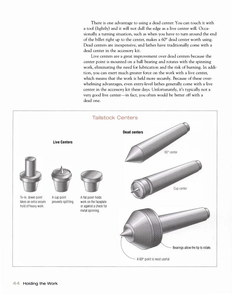
%-in. dowel point takes an extra secure hold of heavy work.
live Centers
A cup pOint prevents splitting.
44 Holding the Work
There is one advantage to using a dead center: You can touch it with
a tool ( lightly) and it will not dull the edge as a live center will. Occa
sionally a turning situation, such as when you have to turn around the end
of the billet right up to the center, makes a 60° dead center worth using.
Dead centers are inexpensive, and lathes have traditionally come with a
dead center in the accessory kit.
Live centers are a great improvement over dead centers because the
center point is mounted on a ball bearing and rotates with the spinning
work, eliminating the need for lubrication and the risk of burning. In addi
tion, you can exert much greater force on the work with a live center,
which means that the work is held more securely. Because of these over
whelming advantages, even entry-level lathes generally come with a live
center in the accessory kit these days. Unfortunately, it's typically not a
very good live center-in fact, you often would be better off with a
dead one.
Tailstock Centers
A flat point holds work on the faceplate or against a check for metal spinning.
Dead centers
A 60° point is most useful.
Bearings allow the tip to rotate.

At far left is a typical economy live center supplied with many lathes. The next fou r are ful l-featured live centers with four points (left to right): a cup; an extended cup; a core center, which can be d riven into a Y2-in . hole on very long and heavy work; and a 50-degree point mounted in the center. Second from right is a heavy-duty center by Oneway, which is a normal cup point as shown, but by attaching the cone at the far right it will center large bores or, when reversed, go over squares, hexes, and such.
Better live centers are sold with two or three interchangeable points.
The 60° point and cup center are standard designs, and some live centers
also come with a third flat-faced insert (see the photo above) , which
is used for special tasks such as holding a bowl in a jam chuck or spin
ning metal.
The idea behind the cup center is that the outside ring prevents the
work from splitting. In my experience, a 60° point has no greater tendency
to split work than a cup point. What's more, it holds in a much smaller
area, which allows you to turn nearly the center of the billet, and wears
much better in service. For these reasons, the 60° point is the only point
I give my students. You can often get 60° live centers from metalworking
supply houses at bargain prices. Even though these centers are designed
for metalworking lathes, they work fine for woodturning. The one time a
cup point center is necessary is when chucking split turnings. Split turn
ings have a paper joint in the middle and would be split prematurely by
a 60° center.
Faceplates
Faceplates are used to hold work that can't be supported (or that you don't
want to be supported) by a tailstock. Since this situation encompasses
most faceplate work, the type of turning has been named for the chucking
method. As mentioned previously, however, it's the orientation of the
grain that makes it facework, not how the work is held.
A faceplate is simply a metal disk with a threaded hub that screws
onto the headstock spindle. Circles of holes around the periphery allow
work to be fastened to the plate with screws. Most faceplates have a flat
surface, but the better models have a ledge around the outer edge that
allows the plate to better seat flat on uneven surfaces. Today, many face-
Faceplates are offered in a wide variety of sizes and q ualities.
Faceplates 45

46 Holding the Work
G lue Blocks
You can effectively increase the diameter of a faceplate with a heavy wood glue block.
A Shop-Bui lt Faceplate
Nut that matches the spindle thread
Heavy washer
Braze or weld the nut to the heavy washer. Use the lathe indexing to lay out the holes.
plates are made from cast aluminum, which works fine for most operations
but is not suitable for large-diameter and heavy work. For heavy-duty face
plate turning, there is no substitute for cast iron or steel.
Faceplates are available in various diameters depending on the lathe
manufacturer, but the most common sizes are 3 in. , 6 in. , and 9 in. Most
woodworkers think that they need a large faceplate, but for the vast major
ity of your work, a 3-in. plate (often known as a "bowl chuck") will serve
you much better. Because the base of a knob or a bowl should be about
one-third its widest dimension, it would be next to impossible to turn the
base on a 6-in. faceplate, unless the work is more than 1 8 in. dia.
Most bowl chucks have only three holes around the circumference.
It's a good idea to drill and countersink an extra hole between each of the
originals for a total of six. This allows you to use six screws in demanding
situations, thereby greatly increasing the holding power of the faceplate. I
recommend that you buy four or five 3- in. faceplates so you don't have to
mount and unmount them all the time. You'll need a larger faceplate only
if you plan to turn large-diameter, heavy work, and even then you can usu
ally get away with attaching a large glue block to a smaller faceplate (see
the illustration above left) .
Faceplates are manufactured to fit standard spindle sizes (see the chart
on p. 1 3 ) . If you have a lathe with an oddball spindle size, you can make
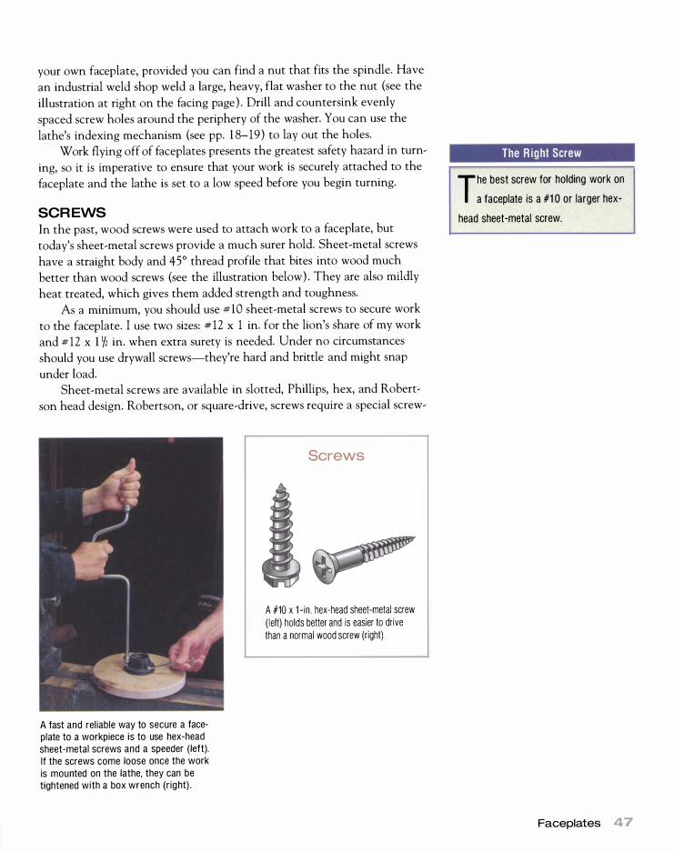
your own faceplate, provided you can find a nut that fits the spindle. Have
an industrial weld shop weld a large, heavy, flat washer to the nut (see the
illustration at right on the facing page) . Drill and countersink evenly
spaced screw holes around the periphery of the washer. You can use the
lathe's indexing mechanism (see pp. 1 8-19) to lay out the holes.
Work flying off of faceplates presents the greatest safety hazard in turn
ing, so it is imperative to ensure that your work is securely attached to the
faceplate and the lathe is set to a low speed before you begin turning.
SCREWS
In the past, wood screws were used to attach work to a faceplate, but
today's sheet-metal screws provide a much surer hold. Sheet-metal screws
have a straight body and 45° thread profile that bites into wood much
better than wood screws (see the illustration below) . They are also mildly
heat treated, which gives them added strength and toughness.
As a minimum, you should use #10 sheet-metal screws to secure work
to the faceplate. I use two sizes: #12 x 1 in. for the lion's share of my work
and #12 x 1 1� in. when extra surety is needed. Under no circumstances
should you use drywall screws-they're hard and brittle and might snap
under load.
Sheet-metal screws are available in slotted, Phillips, hex, and Robert
son head design. Robertson, or square-drive, screws require a special screw-
..-.t • • � -M " 1 I 11' I
I
�� --..
A fast and reliable way to secure a faceplate to a workpiece is to use hex-head sheet-metal screws and a speeder (left). If the screws come loose once the work is mounted on the lathe, they can be tightened with a box wrench (right) .
Screws
A #10 x 1 -in. hex-head sheet-metal screw ( left) holds better and is easier to drive than a normal wood screw (right)
The R ight Screw
T he best screw for holding work on a faceplate is a #1 0 or larger hex
head sheet-metal screw.
Faceplates 47
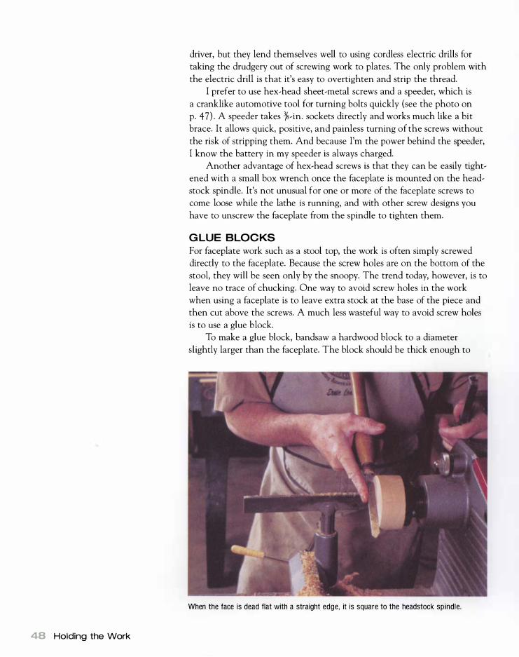
48 Holding the Work
driver, but they lend themselves well to using cordless electric drills for
taking the drudgery out of screwing work to plates. The only problem with
the electric drill is that it's easy to overtighten and strip the thread.
I prefer to use hex-head sheet-metal screws and a speeder, which is
a crank like automotive tool for turning bolts quickly (see the photo on
p. 47 ) . A speeder takes 3�_in. sockets directly and works much like a bit
brace. It allows quick, positive, and painless turning of the screws without
the risk of stripping them. And because I'm the power behind the speeder,
I know the battery in my speeder is always charged.
Another advantage of hex-head screws is that they can be easily tight
ened with a small box wrench once the faceplate is mounted on the head
stock spindle. It's not unusual for one or more of the faceplate screws to
come loose while the lathe is running, and with other screw designs you
have to unscrew the faceplate from the spindle to tighten them.
GLUE BLOCKS
For faceplate work such as a stool top, the work is often simply screwed
directly to the faceplate. Because the screw holes are on the bottom of the
stool, they will be seen only by the snoopy. The trend today, however, is to
leave no trace of chucking. One way to avoid screw holes in the work
when using a faceplate is to leave extra stock at the base of the piece and
then cut above the screws. A much less wasteful way to avoid screw holes
is to use a glue block.
To make a glue block, bandsaw a hardwood block to a diameter
slightly larger than the faceplate. The block should be thick enough to
When the face is dead flat with a straight edge, it is square to the headstock spindle.

Direct attachment
Attaching a Glue Block
Paper joint
Paper joint (or double-sided tape)
more than bury the screws. ( I use 5/4 material because it's thick enough
to get a cutoff tool between the screws and the work. ) Mount the block
on a faceplate, and scrape it flat with a large dome scraper. Check with a
straightedge to make sure the face is flat.
While it is tempting to simply joint one face flat and then thickness
plane to the appropriate thickness before bandsawing rounds, this scheme
does not work out well in practice. There is enough variation in thickness
from the average thickness planer to impart considerable runout to the
work once the glue block is attached. On the other hand, scraping the glue
block flat in the lathe creates a face that is flat and square to the axis of
rotation. This makes a big difference in the amount of runout at the
periphery when mounting a 1 2-in. or 1 4- in. stool seat or a platter.
In light of the above, I simply bandsaw rounds from reasonably flat
roughs awn planks and screw directly to the roughs awn material. As long
as the screws are well tightened, the roughs awn surface is fine.
It is best to drill pilot holes in glue blocks before mounting to avoid split
ting. There are three ways to attach the glue block to the work: direct gluing,
a paper joint, or a mortise-and-tenon joint (see the illustration above) .
Direct attach ment With this method, the glue block and attached faceplate are simply glued to the center of the work. This method works best when you need extreme strength in chucking in the hold, for example, when the piece is heavy or large or when building special j igs and fixtures.
Mortise-and-tenon joint
Tenon centers the work.
G lue area
Faceplates 49

Finding Kraft Paper
The best source of brown kraft paper is a used grocery shopping bag.
50 Holding the Work
It is imperative to use a good-quality glue and to achieve a joinery-level fit between the work and glue block.
Once you have scraped the glue block flat (as well as square to the
axis of rotation), you need only get one surface of the work flat because
you will make the face flat and square to the axis of rotation during the
turning process. The surface to be flattened may be jointed already; if not,
you can flatten it with a handplane. Once the surface is prepared, attach
the work to the block by using plenty of glue and clamping the joint. Be
sure to allow sufficient time for the glue to thoroughly cure before turning.
Your lathe itself is generally the best clamp and gives you exact centering
in the process.
For trays, stools, and the like, I lay out the desired circle with tram
mels on the face side of the work ( the side away from the chuck) , then
bandsaw to the trammel line and apply glue to the glue block. There is a
small dimple where the trammel centered. Pick up this dimple with your
live center, and use the pressure of the tailstock ram to force the work
against the glue block on the exact center.
If you are mounting to green wood (as bowl turners often do), you
will need to use cyanoacrylate glue because other glues will not hold to
the moist surface. Called Super Glue, cyanoacrylate glue can be found at
model shops and good woodworking-supply houses.
Once the work is mounted in the lathe, test the joint with a good
two-handed tug. After you've finished turning the work, simply cut off
slightly to the glue block side of the joint. You can now handplane or
orbital-sand the last traces of the glue block away from the work.
Your lathe itself is the best bar clamp you can find for g lue-ups.

MANY TURNERS TODAY use double-sided tape in place of a paper joint.
While double-sided tape works out well for chucking, it is not effective
for split turnings. There are also some safety considerations when
using double-sided tape. First, it is imperative that a cloth-based tape
be used. Most of the "carpet tape" at local hardware stores is foam
based, which does not have sufficient strength. Fabric-based tape is
available through industrial distribution chains.
The second consideration is that sufficient pressure must be applied
to the tape joint to achieve adequate adhesion. The joint should either
be clamped or pressed in a vise. Often the tailstock ram may be used to apply sufficient pressure. Clamping for a few seconds ensures good
adhesion. Many people tape directly to a faceplate, which works fine with stan
dard Delta-style flat-faced plates. My preference for faceplates with a
raised lip at the edge renders them unsuitable for tape. I can overcome
this by attaching a glue block. The other considerations of the tape joint are identical to those of the
paper joint. I do not like to tape as well as glue and paper, however. With glue you have a bit of open time to slide things around into per
fect position, but with tape you get only one shot. Releasing the taped
work from the chuck can also be problematic. I have broken or pulled
wood grain from the work when breaking tape joints. If the joint proves very stubborn, soak the edges of the joint for 15 to 20 minutes with
xylo to break down the adhesive.
Paper-joint chucking In paper-joint chucking, a piece of brown kraft paper is juxtaposed between the glue block and the work. The work is easy to remove from the glue block after chucking because the joint will separate along the paper joint. A joinery-level fit is still required. Although I prefer to use hide glue, yellow or white glue works just as well. Other than the paper, the joint is handled like any other woodworking joint: Apply plenty of glue on both sides of the paper, and clamp for the manufacturer's recommended clamping time. As in direct attachment, your lathe is the best clamp to apply pressure at the exact center and to achieve perfect centering.
To break the joint when you're done, give it a good rap at the periph
ery, but hit at the end grain, not the face grain, side because there is more
strength in that orientation. If the separation proves cantankerous, place a
sharp chisel in the glueline (again at the long grain edge) , and give it a
sharp rap with a mallet.
Paper joints have excellent sheer strength (they resist the rotating forces of the lathe) but poor axial strength. Therefore, I always keep a tail
stock against the work for as long as possible. This gets you through the
roughing process without putting substantial force on the paper joint.
Paper joints need to have a reasonable area in proportion to the diameter
of the work. A good starting point is one-third the diameter of the work-
Faceplates 51

52 Holding the Work
piece, so a 1 2-in. platter would require a 4-in.-dia. glue block. But much
depends on the skill of the turner. The beginner who catches now and
then will need the paper joint to cover plenty of area, while the seasoned
old hand can get away with much less.
Mortise-and-tenon joints Bowl turners most often use this method of glue-block chucking. It is particularly useful when something on a faceplate (or screw chuck) needs to be turned around for further turning, such as a bowl. To use this method, scrape a shallow mortise in the base of the bowl just before removing it from the faceplate or screw chuck. Next, mount the glue block on a faceplate or screw chuck and scrape it flat, then scrape a tenon on the glue block to match the mortise. It does not have to be a press fit (l�4 in. to 1h2 in. of slop is actually best) , and the tenon should not bottom out in the mortise (see the illustration below).
Apply glue only to the shoulder area, mate the two pieces, and apply
pressure with the tailstock ram. Cyanoacrylate glue works well and is
necessary if you're turning green wood. I generally apply the glue to the
glue block and spray the catalyst on the piece. When the two mate, the
glue dries within 30 seconds, so you have to have everything right.
A Properly Fitted Glue- Block Chuck
Glue block
Faceplate
Tenon for centering
Good shoulder-toshoulder glue area
Bowl

Chuck manufacturers offer a wide variety of jaws. Left to right: Nova lever with standard jaws; Nova lever with heavy stepped jaws that hold internally at two diameters; Nova lever with finger jaws especially suited for holding dowels, knobs, and such; Oneway lever with large-diameter, low-profile jaws suitable for internal and external holds on large, heavy faceplate work; and Oneway lever with rubber baby bumper jaws hold ing a bowl for reverse turning.
These antique smoking-pipe chucks are a cross between jam chucks and collet chucks. A wood ring sl ips over the chuck to force the collet closed around the work. There are also chucks to mount a sawblade ( left) and a grinding wheel (right) in the lathe.
Special-Purpose Chucks
Centers and faceplates are the two basic ways of holding work on the
lathe. They'll cope with the majority of your turning requirements; indeed,
you could turn for a lifetime using nothing more. There are times, how
ever, when other chucking methods can make life easier. Special-purpose
chucks can be invaluable for grabbing odd-shaped work, small work, and
finished work that requires modification. In production work, a special
purpose chuck can often speed things up considerably. Let's look at the
vast array of special-purpose chucks that you can buy or make yourself.
Choosing Jaws
S ome manufacturers have jaws for highly specialized purposes. When
shopping for a chuck, it is good to see how the jaws offered by a prospective manufacturer fit in with what you plan to turn.
Special-Purpose Chucks 53

Start Smal l
T he first law of jam chucking is never to chuck something you are
not prepared to be hit in the head with. For that reason, it's a good idea to start with small items.
54 Holding the Work
Jam chucks are used primarily to hold small items in the lathe, but bowls can also be jamchucked to allow turning of the base.
With this information, you'll be able to tackle any turning job safely and
confidently.
JAM CHUCKS One of the simplest and oldest homemade chucks is the jam, or cup,
chuck. It's a sure, simple way to grab small items without leaving marks
in the work. I use it to hold anything from knobs and finials to trays and
bowls. Until the early 20th century, a turner would typically have a range
of jam chucks made from gun metal by a local machinist. They worked
splendidly. The body of a jam chuck should be spindle-turned from a 3-in.-dia. to
4-in.-dia. piece of close-grained hardwood. Maple, ash, and beech all work
very well. Since scrap stock of this diameter is hard to come by, I normally
glue two pieces of 8/4 stock together. Yellow glue works fine, but be sure to
plane both surfaces for a perfect joint, use plenty of glue, and clamp for a
full 24 hours.
In the old days, a tap hole was drilled through the center of the billet,
and it was threaded to screw directly onto the headstock spindle (see the
bottom photo on p. 53 ) . Since suitable wood taps are unavailable today
and wood threads do not work out well in end grain anyway, it's easier to
screw the billet to a faceplate. (Remember I suggested buying extra face
plates?) Attach a 3-in. to 5 -in. section of the billet to the faceplate with
I -in. or I 1h-in. sheet-metal screws.
As shown in the photos on pp. 56-57 , mount the faceplate in your
lathe, and true up the outside diameter of the billet with a roughing-out

gouge. Face the end, and drill a 3k-in. hole through the center with a drill
bit mounted in the tailstock. The drill hole allows you to use a knockout
bar to eject the work from the chuck.
Next, scrape a tapered pocket into the face of the chuck that is the
diameter of the work you want to hold. The taper should be about 3°
inclusive ( the same angle as a Morse taper) . To cut the taper, I use a spe
cial scraper that can easily be ground from an old file and a long-forgotten
auxiliary tool rest, called an arm rest (for more about scrapers and the arm
rest, see pp. 1 3 7 and 77 , respectively) . You'll quickly find the right taper
if it's too steep or not steep enough, the chuck won't hold the work.
Most work for jam-chucking is turned between centers or on a face
plate before it's mounted in the jam chuck. Remember to square the end
of the work face that will go into the jam chuck. Insert the work into the
chuck by lining it up as square as possible and giving it a solid rap with a
hammer. Next, turn the lathe over by hand, watching for eccentricity. Rap
the edge opposite the point that is most eccentric and retest, then con
tinue until the work is perfectly centered. Rubbing some blackboard chalk
on the walls of the pocket will add greatly to the chuck's holding power.
To use a jam chuck, you have to be able to turn well enough so that a
catch is the exception rather than the rule because a catch can throw the
work from the chuck's embrace-or at least throw it out of kilter. J am
chucking is a skill, so the first few times will be an uphill battle; once
learned it will become second nature. Your first jam-chucking is best done
on small items, such as the box shown in the photo essay on pp. 56-57 .
I've successfully chucked items as big as boccie balls, and I jam-chuck
bowls regularly. If I have the least doubt about using a jam chuck, how
ever, I add security by trapping the work in the chuck with a tailstock. I
also keep speeds moderate, often no more than 200 rpm to 300 rpm for
bowls. (This is another reason I find variable speed indispensable.)
COLLET CHUCKS
A slightly different version of the jam chuck is to turn it into a collet
chuck. To make this chuck, mount a piece of wood on a faceplate with
sheet-metal screws. (Be sure to screw into end grain so that the wood is
aligned in spindle-turning orientation. ) Drill a hole in the very center that
is the diameter of the tenon on the knob (or finial) you are going to hold.
Next, turn a gentle taper on the outside of the chuck, and split it into
fours with a backsaw or bandsaw. Pound a wood or metal ring onto the
taper to force the collet closed. (Don't be tempted to use automotive hose
clamps-they don't have the closing power for this task. )
Often a metal ring of suitable size can be found, but it is little trouble
to turn a wood one. It's best to faceplate-turn the ring, but remember to
keep the cross section robust for strength. I like to make the chuck a bit
long for several reasons. First, it can be split far enough back to give the
jaws plenty of spring. Second, it may be cut back if you hit it with a tool
Special-Purpose Chucks 55

Making and Using a Jam Chuck
1 Attach a faceplate to the end of the chuck
blank and mount it in the lathe. This is spindle
tuming, so we are screwing into end grain.
56 Holding the Work
2True up the body of the chuck and square
(face) the end. Here I am using a spindle gouge
to face the billet, but a big scraper and the arm
rest work great for this task as well.
3 Drill a hole Y16 in. bigger
than the diameter of
your knockout bar through
the center of the chuck.
Most knockout bars are
% in. dia., so 7116 in. works
well. A spindle gouge actu
ally makes a good drill if
presented with the point at
dead center and the flute
tumed about 450 to the left
(facing 10 o'clock) .

Scrape a tapered pocket
into the face of the chuck
that is the same diameter as
the work to be held.
c... Tap the work into the pocket, and true up as
.J necessary. A carpenter's hammer is the per
fect tool.
6You're now free to work on the piece. Here,
I use a spindle gouge to tum the outside of
the box.
Special-Purpose Chucks 57

58 Holding the Work
or for subsequent jobs. By tapping the ring in place to where the jaws are
held but not compressed, it may be drilled out to larger diameters.
TAPERED MANDRELS
Tapered mandrels, or cone chucks, are essentially jam chucks turned inside
out. They're a good way to hold small items such as napkin rings (or the
closing ring for a collet chuck) and a great way to hold hollow spindle
turnings between centers. The advantages of tapered mandrels are that the
This homemade chuck is no more than a shop-built collet chuck. The outside of the chuck is turned to a gentle taper, and the tip is partially split by bandsawing or backsawing. A ring of suitable diameter is then added. By forcing the ring down over the taper, the chuck is closed.
You can turn small items like the closing ring for a collet chuck on a tapered mandrel.
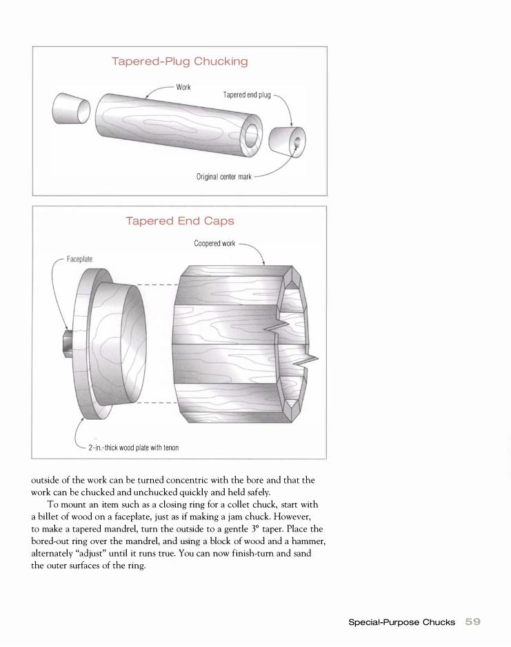
Tapered- Plug Chucking
Work Tapered end p lug
Original center mark
Tapered End Caps
Coopered work
2-in.-thick wood plate with tenon
outside of the work can be turned concentric with the bore and that the
work can be chucked and unchucked quickly and held safely.
To mount an item such as a closing ring for a collet chuck, start with
a billet of wood on a faceplate, just as if making a jam chuck. However,
to make a tapered mandrel, turn the outside to a gentle 3° taper. Place the
bored-out ring over the mandrel, and using a block of wood and a hammer,
alternately "adjust" until it runs true. You can now finish-turn and sand
the outer surfaces of the ring.
Special-Purpose Chucks 59

60 Holding the Work
As in the case of this coopered birdhouse, the headstock mandrel can be left on the screw chuck.
Depending on the size of the central hole, you can mount hollow
spindle turnings on the lathe with tapered plugs or tapered end caps.
Tapered plugs are used for cylindrical objects (such as a pepper mill) with
a fairly small central bore-anything up to about 1 in. inside diameter (see
the top illustration on p. 59) . Turn the plugs as a single piece between cen
ters, then saw them apart. Tap the plugs into the ends of the turning, and
remount on the lathe on the original center marks. The outside of the
object can now be turned concentric with the bore.
Tapered end caps are used with hollow work that has a large central
bore (see the bottom illustration on p. 59) . This is often coopered work
(glued up out of staves) , such as birdhouses, buckets, and columns. An
important difference from tapered plugs is that the mandrel for each end
is faceplate-turned as a separate item. A good way to hold each end cap is
to use a large screw chuck, which allows the tapered step in the mandrel
to be turned concentric with a center hole. Leave the headstock mandrel
on the screw chuck, then insert the tailstock mandrel into the work. The
center hole left by the screw chuck is caught by a 60° live center. The
work is now safely trapped between centers on the set of mandrels and
can be turned easily. I've chucked 1 2- in. -dia. by 8-ft.-Iong coopered
columns using this method.
PRESSURE-TURNING CHUCKS
A pressure-turning chuck is great for high-production turning, and it is
a dandy way to chuck lightweight, flat, round items such as plates. This
improvised chuck may also be used to hold work while scraping a dovetail
recess for expanding scroll chucks (see p. 73 ) .
The basis of a pressure-turning chuck is a glue block that has been
scraped flat, as described previously. Using a drill chuck in the tailstock,

drill a pilot hole slightly smaller than a lOd nail three-quarters of the way
through the center of the glue block. Pound a l Od nail into the hole so
that it bottoms out, then cut off the nail about 1/16 in. proud of the face of
the block and file it to a point (see the top photo below). The easy way to
point the nail is by touching a file to the nail with the lathe running.
To prepare for pressure turning. file the nail protruding from the glue block to a point.
Both sides of the work can be turned in their entirety. except for the small nub under the tailstock center.
Mount work for pressure turning between the nail block and a live center in the tailstock.
Special-Purpose Chucks 61

62 Holding the Work
Traditionally. screw chucks were used for l ight work and were bu i lt on Morse-taper blanks.
How a Screw Chuck Works
Tommy bars are used for levering the chuck on and off the spindle.
off the spindle.
Rotation di rection
Work
Because rounds are laid out with a compass, there will be a center
mark on the workpiece. Align this mark on the nail point, and force the
work against the glue block with the tailstock spindle (see the photo
below right on p. 6 1 ) . You can do this either by using a flat live-center
point in the tailstock or by interposing a small block of wood between a
cup center or 60° point and the work. Gluing I SO-grit sandpaper to the
face of the glue block will provide more positive drive to the work.

Using a pressure-turning chuck, you can completely turn flat work on
both sides, except for a small nub under the center point (see the bottom
left photo on p. 6 1 ) . Once the piece is removed from the lathe, you can
chisel away this nub and sand it smooth. The only sign of chucking will be
a small indent at the center of the plate base.
SCREW C HUCKS
A screw chuck has traditionally been a favorite for holding small items,
although it can also hold work as large as a dinner plate. The time
honored design is simplicity itself. A wood screw protrudes from the face
of a Morse-taper blank. A small hole, the body diameter of the screw, is
drilled in the work to facilitate threading it onto the chuck (see the illus-
The scroll chuck shown on the left is a Oneway chuck, which has a screw included that turns it into a screw chuck. The two center screw chucks are by Jerry Glaser. On the right is a Nova lever scroll chuck with an included screw.
Shop-built screw chucks are an ideal way to hold small work in the lathe, and they make d upl ication easy.
Special-Purpose Chucks 63

64 Holding the Work
Lightly touching the point of a skew to the center of the glue block before d ri l l ing wil l ensure that the d ri l l starts perfectly on-center.
tration on p. 62) . Since a right-hand thread opposes the rotation direction
of the lathe, the work self-tightens on the chuck. You can chuck and un
chuck work from a screw chuck with fair consistency. Screw chucks built
on Morse tapers are perfect for turning repetitive parts such as chess pieces
and drawer pulls. The small screw leaves little visible evidence of turning
(and the screw hole is typically concealed on the finished piece anyway) .
Recently, a second type of screw chuck has gained popularity. I t has a
much bigger screw and is built on a faceplate-like body, which allows it to
be threaded onto the headstock spindle (see the top photo on p. 63 ) . The
heavy screw has a straight body with a very coarse 45 ° thread profile. The
thread looks much like that on a drywall screw and makes for a very posi
tive hold in wood. Depending on the chuck, a 3h- in. to 7/16-in. hole is
required for mounting. The more positive drive of the threaded faceplate
like mount, combined with a heavy screw, makes it possible to hold very
large work such as bowl blanks. These chucks are also good for furniture
bases, trays, and plates.
In recent years, I have come to use heavy screw chucks a great deal.
I look at them as a great chucking bargain for the faceplate (especially
bowls) turner because one screw chuck will replace a bunch of faceplates.
I can mount a heavy bowl blank on a screw chuck and turn the outside,
then I can mount a glue block on the same screw and glue the base of the
bowl to the glue block to turn the inside of the bowl. Finally, I can mount
a disk of plywood on the screw chuck and scrape a groove the diameter of
the rim for reverse chucking to turn the base of the bowl (see Tum a Bowl
with Ernie Conover, The Taunton Press) .

When I was a boy, I always made my own screw chucks at the lathe.
I still think a shopmade chuck is superior to commercial models for hold
ing small items such as knobs, finials, and chess pieces. The great advan
tage of a shop-built screw chuck is that you can turn the face of the chuck
to the base diameter of the workpiece, which makes duplication of addi
tional pieces easy. Also, you can match the screw in the chuck to the
screw that will install the finished turning, as in the case of knobs.
To make a screw chuck, start with a l - in.- to 1 If4- in.-thick glue block,
and scrape the face of the glue block to the base diameter of the work
piece. Lightly touch the point of a skew to the center of the glue block,
then drill a small hole for the screw in the center of the block with a drill
bit secured in a chuck in the tailstock (see the photo on the facing page) .
Remove the faceplate from the headstock, and screw a suitable wood or
sheet-metal screw into the hole in the back of the glue block. Applying
some epoxy or cyanoacrylate glue to the screw thread will prevent it from
unscrewing during mounting of the work. The screw should protrude about
3k in. from the face of the block.
VACUUM CHUCKS The vacuum chuck is a nifty chuck that is particularly useful for high
production work but is also very good for one-off items, especially bowls.
To build a vacuum chuck, you need a vacuum source. There are several
ways to create a vacuum. The best way is a vacuum pump, but a good, new
pump is expensive-$300 to $500. It is sometimes possible to find used or
surplus vacuum pumps designed for the printing and refrigeration indus
tries for less than $ 1 00 (see Surplus Center in Resources on p. 1 85 ) .
If you own an air compressor, you can buy a venturi unit that will
make a vacuum from compressed air (see the photo below) . The quality
A venturi unit that can be hooked to an air compressor or a vacuum pump is one option for supplying vacuum.
Special-Purpose Chucks 65
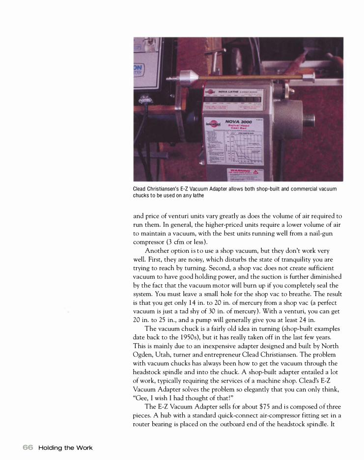
66 Holding the Work
Clead Christiansen's E-Z Vacuum Adapter allows both shop-built and commercial vacuum chucks to be used on any lathe
and price of venturi units vary greatly as does the volume of air required to
run them. In general, the higher-priced units require a lower volume of air
to maintain a vacuum, with the best units running well from a nail-gun
compressor (3 cfm or less ) .
Another option is to use a shop vacuum, but they don't work very
well. First, they are noisy, which disturbs the state of tranquility you are
trying to reach by turning. Second, a shop vac does not create sufficient
vacuum to have good holding power, and the suction is further diminished
by the fact that the vacuum motor will burn up if you completely seal the
system. You must leave a small hole for the shop vac to breathe. The result
is that you get only 1 4 in. to 20 in. of mercury from a shop vac (a perfect vacuum is just a tad shy of 30 in. of mercury) . With a venturi, you can get
20 in. to 25 in., and a pump will generally give you at least 24 in.
The vacuum chuck is a fairly old idea in turning (shop-built examples
date back to the 1950s), but it has really taken off in the last few years.
This is mainly due to an inexpensive adapter designed and built by North
Ogden, Utah, turner and entrepreneur Clead Christiansen. The problem
with vacuum chucks has always been how to get the vacuum through the
headstock spindle and into the chuck. A shop-built adapter entailed a lot
of work, typically requiring the services of a machine shop. Clead's E-Z
Vacuum Adapter solves the problem so elegantly that you can only think,
"Gee, I wish I had thought of that !"
The E-Z Vacuum Adapter sells for about $75 and is composed of three
pieces. A hub with a standard quick-connect air-compressor fitting set in a
router bearing is placed on the outboard end of the headstock spindle. It
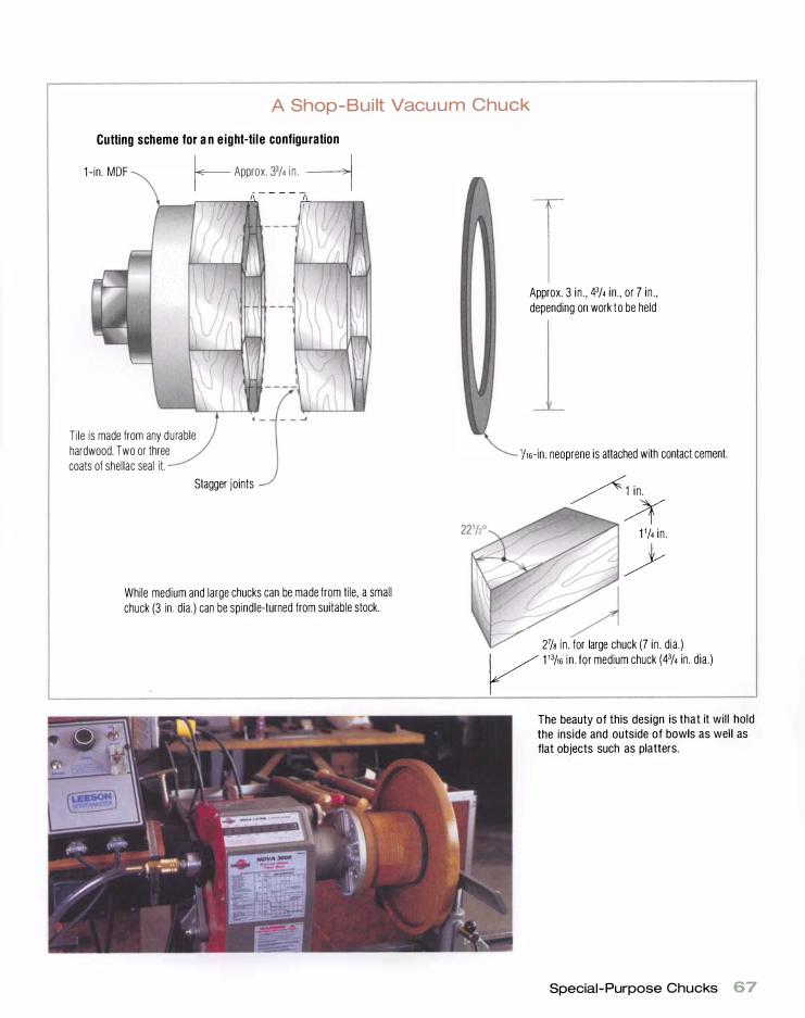
A Shop-Bui lt Vacuum Chuck
Cutting scheme for an eight-tile configuration
1 -in. MDF r-- Approx. 33/4 i n . -1 ; __ ...rT""--r-T"'-""'"",",,- - - - -rT" rT"1-"""""""
Tile is made from any durable hardwood. Two or three coats of shellac seal it.
Stagger joints
While medium and large chucks can be made from tile, a small chuck (3 in. dia.) can be spindle-turned from suitable stock.
T Approx. 3 in . , 43/4 in . , or 7 in . , depending on work to be held
1/16-in. neoprene is attached with contact cement.
/1 i n .
� 1 1/4 in .
7 ?
27/s in . for large chuck (7 in . dia.)
V 1 13/16 i n . for medium chuck W/4 in. dia.)
The beauty of this design is that it will hold the inside and outside of bowls as well as flat objects such as platters.
Special-Purpose Chucks 67

68 Holding the Work
Oneway makes a nice line of vacuum chucks as well as its own rotary vacuum adapter. It also sells vacuum pumps.
has a 60° taper to center it in the spindle. Setting the air-compressor fit
ting in a router bearing allows the headstock spindle to rotate, while the
fitting (and the vacuum hose connected to it) remains stationary. The
nose assembly is placed in the spindle nose and has vents to deliver the
vacuum to the chuck. It also has a centering point that can be adjusted to
any height or removed altogether depending on the needs of the chucking
situation.
Connecting the two parts and carrying the vacuum through the
spindle is a piece of standard Yz-in. lamp rod. The beauty of the lamp rod
is that it can be hacks awed to any length so it can accommodate any
length spindle. (After sawing, it is best to square the cut and lightly cham
fer the thread start on the grinder. ) A length of lamp rod comes with the
chuck, but you can purchase replacement lengths at any hardware store.
The vacuum hose is connected to the adapter with a standard air-line
quick connector.
The vacuum chuck itself can take almost any form according to the
needs of the chucking situation. It is easy to make a custom vacuum chuck
for a production situation and discard it later. Vacuum chucks are most
popular with bowl turners, and I have made a shop-built chuck that will
handle a wide variety of chucking situations (see the illustration on p. 67 ) .
Oneway makes commercial equivalents of this chuck in three sizes, which
work very well. It also sells vacuum pumps and its own rotary vacuum
spindle adapters. Since you can make essentially the same chuck yourself
for the price of a faceplate in less than an hour, it is time well spent.

Closed-cell foam rubber, neoprene rubber, and O-rings form an effective seal between the work and a shop-built vacuum chuck. Closed-cell foam needs to be thin ()46 in. or less) and resilient, while )46-in.-thick neoprene works best.
Although turning a suitable wood chuck to hold any item is straight
forward, getting a working seal between the work and the chuck is prob
lematic. Rubber or neoprene gasket material is required. Most turners find
that foam (either rubber or neoprene) works, but it must be thin, resilient
closed-cell foam to work. Do not use a thick piece of foam because it
allows movement of the workpiece, inviting a catch. Self-adhesive weather
stripping (available at any hardware store) also works well for special
chucks. I find that lf16-in.-thick neoprene works best because you can cut
it to any size and shape, and it forms to concave and convex chuck surfaces well and is highly resilient. Once cut to shape, the neoprene can be
affixed to the chuck with plastic-laminate adhesive or spray adhesive.
Another viable sealing material is a neoprene O-ring. Any bearing
supplier and many auto parts stores sell do-it-yourself O-ring kits. Selling
for about $25, the kit includes 7 ft. of O-ring material in four sizes (0. 1 03
in. , 0. 139 in., 0.2 1 0 in., and 0.275 in. ) , a splicing j ig, and glue to effect the
splice. Using this kit, it is easy to scrape an O-ring groove at the contact
point between the chuck and the work and to make an O-ring to fit in it.
All wood has some porosity, but a couple of coats of shellac will plug any
leakage. Paste wax is good to keep the O-ring in the groove and provide
further sealing at this point.
Quick and Easy Centering
G et into the habit of putting a smal l pencil dot at the center of the
work just before transferring it to the vacuum chuck. This practice makes centering chi ld's play because you can touch the dot with the tailstock center before turning on the vacuum.
Special-Purpose Chucks 69
70 Holding the Work
Once made, the vacuum chuck is fun to use. Simply place the work in
the chuck and turn on the vacuum. As with paper joints, you need suffi
cient vacuum area in relation to the size and weight of the work. A good
rule of thumb is a minimum of 10 sq. in. of area, which would give approxi
mately 135 lb. of pressure at 28 in. of mercury but only 100 lb. at 20 in. of
mercury. A 1 0-sq.-in. area works out to a 35k-in.-dia. circle inside the gas
ket. A 3%-in. circle may not, however, have sufficient diameter to give a
stable hold for work much larger in diameter than the chuck or with a
poor vacuum source. Common sense is required here, and keeping the
periphery of the chuck to about one-third the diameter of the work is good
shop practice. Also keep speeds low to moderate when using these chucks.
JACOBS CHUCKS Correctly called a "drill chuck," the Jacobs chuck is an old stalwart that is
more often named for its original American manufacturer. The head of
this chuck has an outer ring and an inner ring that encloses the jaws.
Turning the outer ring with a key causes the jaws to open and close. The
drill chuck mounts into the lathe on a Morse-taper shaft, which is actually
a separate piece that fits into the back of the chuck on a short Jarno taper.
Morse-taper "backs" can be purchased in any combination of Morse and
Jarno tapers. If you have a drill chuck that does not fit your lathe, you
can buy replacement backs from any machine-tool supplier. Also, smaller
tapers can be adapted to larger spindle sockets by using taper-sleeve
adapters.
The main use for drill chucks is to hold drill bits in either the head
stock or the tailstock, but they can also be used to grip small work such
as knobs and miniature turnings. Drill chucks are sold according to the
largest diameter they can grip. Common sizes are 3h in. and l� in., with
the latter being better for wood turning lathes.
FOUR-JAW SCROLL CHUCKS Scroll chucks are crossovers from metalworking. A steel body encases four
jaws that open or close in unison by the action of a circular scroll plate
(see the illustration on the facing page) . The jaws grip around the end of
the workpiece. In metalworking chucks, the scroll plate is typically actua
ted by means of a key acting through bevel gears. To save expense, wood
turning scroll chucks are often made without the bevel gears, instead using
steel levers that fit into holes in the two halves of the chuck body to allow
turning the scroll plate directly. The Nova and small Oneway chucks oper
ate this way.

Keyway
How a Scroll C huck Works
Top jaw
Bottom jaw
Snap ring holds scroll i n chuck body.
Most manufacturers make a wide assortment of top jaws for a variety of purposes.
The jaw s l ides in keyway by the action of the scroll plate.
Chuck body
Scroll plate
Turning the scroll plate with tommy bars moves the bottom jaws in and out of chuck body.
Tommy bars --"':...---
Special-Purpose Chucks 71

72 Holding the Work
Mounting a Bowl on a Four-Jaw Chuck
Bottom jaw
Chuck body
Scroll plate
Scrape a dovetail-shaped mortise.
Bowl
Oneway's Stronghold and Nova's Super Nova chucks use a novel
approach-a key fits in a hole in the chuck body and in effect becomes a
bevel gear. This affords much greater leverage in tightening the chuck.
For woodturning, a four-jaw scroll chuck is much more satisfactory
than the three-jaw variety because four jaws will grip squares nicely.
Although you may be tempted to use a surplus metal turning chuck, it
doesn't work as well. Even if the metalworking chuck is of the four-jaw
variety, the jaws are not designed for holding wood. They're too small and
tend to indent wood without ever centering it. The jaws are real knuckle
busters, too.
Scroll chucks made specifically for wood turning have jaws that hold
over a much greater surface area. The top half of the jaws can be unscrewed
so that a variety of jaws can be used, each holding a range of sizes (grip
range) . On some scroll chucks, four plates with numerous tapped holes in
their face can be mounted in place of the jaws. By screwing rubber posts to
the plates at strategic positions, you can hold odd shapes. For example, you
can hold a nearly finished bowl by the rim so that the base can be turned.
I call these rubber baby bumper jaws.

Regardless of the maker, rubber baby bumper jaws do not hold well.
They cannot be used for primary turning and are only of value for turning
away the chucking marks on the bottom of an open-shaped bowl. I can
typically mount a disk of plywood on a screw chuck and scrape a groove
that is a press fit with the rim much faster than I can change the jaws
over and arrange the baby bumpers on the correct circle for the hold. (A
vacuum chuck works far better for this purpose. )
Scroll chucks are quick and easy to use and leave no screw holes. If
used within the grip range of the jaws, they don't significantly indent the
wood. They're ideal for holding small furniture parts such as knobs and
finials. A handy way to turn small parts is to feed a standard-sized dowel
through the headstock spindle then through the chuck itself. (The advan
tage of using a dowel for turning is that it doesn't have to be trued round
first. ) As each small piece is finished and cut off, the dowel can be ad
vanced through the chuck, ready for turning the next piece.
Woodturners tend to think of scroll chucks as gripping by compressing
around the outside of the work, but the chucks can also be expanded
inside a recess in the work, which could be a pedestal, a bowl, or a small
tabletop. Woodturning scroll chucks are angled on the outside faces of the
jaws. If a dovetailed (undercut) recess is scraped in the work, the chuck
can be expanded to hold securely. This is one of the scroll chuck's most
useful features.
All of the chuck makers offer (usually in the standard package) a
screw that turns the scroll chuck into a heavy screw chuck. This is one of
the handiest accessories for a screw chuck. You can use the screw chuck to
grab a bowl blank for the turning of the outside and scraping of a dovetail
recess in the foot (base) . You can then grab the dovetail recess with a set
of jaws of the proper grip range for the turning of the inside of the bowl
(see the illustration on the facing page) . Now, you can convert back to a
screw chuck and grab a disk of plywood to jam-chuck the rim and turn
away the dovetail recess. Since you can generally grab the screw without
removing the primary jaws, this makes for quick holding.
Safety concerns with scroll chucks are twofold. First, the spinning jaws
present an ever-present danger. At best, they're knuckle-busters; at worst,
they can maim. Second, inadvertently extending a jaw beyond the grip of
the scroll will cause one or more jaws to go ballistic when you start the
lathe. Most scroll chucks have a safety feature that prevents this, but it's
still a good habit never to extend the jaw more than halfway out of the
chuck body. I once overextended the jaws of a scroll chuck when using a
metal lathe. A 9-lb. jaw ricocheted off the lathe carriage, went through
a Thermopane window, and landed 10 ft. from the building. I've never
disobeyed the halfway rule since.
If you are turning with the jaws outside the chuck, it's a good idea to
wrap the jaw area with duct tape. The tape softens sharp corners and pre
vents fingers from getting into the recesses between the jaws.
Special-Purpose Chucks 73

74 Holding the Work
COMMERCIALLY AVAILABLE SCROLL CHUCKS Manufacturer Model Size Method of operation
Axminster Carlton 4 in. Lever
Axminster Precision 4-Jaw 4 in. Key
Latalex Ltd. Nova (standard) 3Y2 in. Lever
Latalex Ltd. Super Nova 4 in. Key
Oneway Mfg. Scroll 4 in. Lever
Oneway Mfg. Talon 3Y2 in. Key
Oneway Mfg. Stronghold 4Y2 in. Key
Vicmarc VM 140 6 in. Lever
Vicmarc VM 120 5Y2 in. Key
Vicmarc VM 090 3Y2 in. Lever
Vicmarc VM 100 3Y2 in. Key
Manufacturers offer a variety of jaws for their chucks. Right now,
Nova is the only chuck that allows the jaws to be switched between the
lever and key chucks. All of the Nova lever jaws may be used on the Super
Nova, however, there is one new set of jaws for the Super Nova that can
not be used on the lever. For those who already own a lever Nova and
want to upgrade, the Super Nova is sold sans jaws at a cheaper price.
You need to look at more than just the price of a chuck. Cost out the
basic chuck and all of the jaws you think you will need to get a fair com
parison. The jaws run up the price of a chuck rapidly. Finally, don't think a
scroll chuck will be a panacea to your holding problems. I use scroll chucks
but not all that much. Learn to use centers, faceplates, and jam chucks
before rushing out to buy a scroll chuck.

Accessories
I suppose you could live without accessories, but at least for me they are
part of the fun of turning. Since you can build many accessories in the
shop, you don't necessarily have to part with a lot of cash either. If
your pockets are deep, the accessories can be as much fun as the turning.
In short, I have never met an accessory that I didn't enjoy trying, and
there are many that I wouldn't be without.
Steady Rests
There comes a point where a spindle is so long and thin that the only way
to prevent chatter is to use a steady rest to support the work. Many mod
ern turners have great misconceptions about steady rests because they
associate them with rests used in metalturning. In metal turning, the tool
is mounted on a carriage that rides along the bed ways of the machine, so
the rest must support the work on exact center to avoid turning a taper.
This requires surrounding the work with plane bearings or ball bearings
for support.
In wood turning, the tool is guided by the turner, and exact centering
by the steady rest is unimportant. A wood turning steady rest must be able
to dampen vibration, support the work to prevent it from bending away
from the tool, and be quick to adjust.
As with chucks, I feel that the best steady rest is one that you make
yourself. My plan for a steady rest, shown in the illustration on p. 76,
closely follows one outlined by Frank Pain in his book Practical
chapter
5
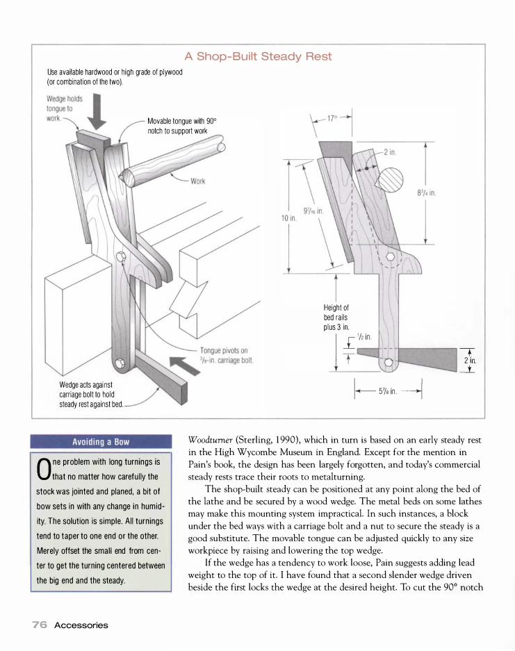
Use available hardwood or high grade of plywood (or combination of the two).
A Shop- Built Steady Rest
Movable tongue with 90° notch to support work
Wedge acts agai nst carriage bolt to hold steady rest against bed.
Avoid ing a Bow
O ne problem with long turnings is that no matter how careful ly the
stock was jointed and planed, a bit of bow sets in with any change in humidity. The solution is simple. All turnings tend to taper to one end or the other. Merely offset the small end from center to get the turning centered between the big end and the steady.
76 Accessories
Height of bed rails p lus 3 in. j L
''' ;n
l-- 57/8 in . � -r
2 in . --.t..
Woodtumer (Sterling, 1 990), which in turn is based on an early steady rest
in the High Wycombe Museum in England. Except for the mention in
Pain's book, the design has been largely forgotten, and today's commercial
steady rests trace their roots to metalturning.
The shop-built steady can be positioned at any point along the bed of
the lathe and be secured by a wood wedge. The metal beds on some lathes
may make this mounting system impractical. In such instances, a block
under the bed ways with a carriage bolt and a nut to secure the steady is a
good substitute. The movable tongue can be adjusted quickly to any size
workpiece by raising and lowering the top wedge.
If the wedge has a tendency to work loose, Pain suggests adding lead
weight to the top of it. I have found that a second slender wedge driven
beside the first locks the wedge at the desired height. To cut the 90° notch

in the top wedge, simply mount a lj16-in. drill bit in the headstock, set the
steady on the bed, and touch the movable tongue to the drill. Bandsaw a
90° corner at the drill mark, and the notch is at perfect center height for
your lathe. Once in place, the steady may still have to be fine-tuned by
chiseling one side of the notch a bit to get both sides to give equal pressure
to the spindle.
The advantage of this steady is that you can turn right through it, and
it quickly readjusts to support the work at the new diameter. If you find
that the workpiece becomes hot and starts to burn as it rubs against the
sides of the notch, slow down the lathe and add a little candle wax to pro
vide lubrication. Mechanically fastening ( I use carpet tacks) a patch of
nylon or Teflon to the notch area will also work. This steady works best at
rather slow speed (around 1 , 100 rpm for most spindle work), but this lower
speed deals better with harmonic chatter and is far superior for skew work.
In my experience, although all turners know that a steady rest is
needed at times to overcome harmonic chatter, very few of them use one.
Most turners just live with the chatter and sand it out at the end. I believe
that a steady rest is indispensable in spindle turning, whether you're mak
ing one part or many. The couple of hours spent making a steady will be
repaid many times by better work, less sanding, and less frustration.
Arm Rests
The arm rest is an auxiliary tool rest that saves you from having to move
your main tool rest when you're working on the face of the work. An
added advantage of the arm rest is that it allows you to quickly obtain
center height for the tool. At the very center of the work, the tool must
An arm rest saves fiddling with the tool rest. It can qu ickly be brought into play to support a tool, typically a scraper. Raising or lowering you r shoulder adjusts the rest height, so a tool can be brought to the center of the work almost instantly.
Why Al l the Chatter?
If you encounter harmonic chatter in al l your work no matter what correc
tive actions you take, the problem may be your bearings. If the bearings are worn to the point where there is excessive play or there is end play in the spindle due to an incorrect preload, you can expect almost constant harmonic chatter.
Arm Rests 77

Turning Long, Thin Spindles
To start, find a point near the middle of the turning that is either straight or slightly tapered. Set up the steady rest at this position, making sure it is firmly attached to the bed. Now establish a diameter about 1/16 in. larger in diameter than the actual turning at this point. This essentially forms a plane bearing around the work for the steady to ride on. Throughout this sequence , my lathe was running at about 1 , 000 rpm.
f Place the billet in the lathe between exact centers,
- and take a light cut in the middle with a roughing
out gouge. If you only cut on one or two comers, you
need to offset a bit. Once you've offset the billet, do
another trial cut to ensure that the stock is being
removed equally from all four comers.
2Tum the spindle round in the area of the steady rest.
Don't rough more than just this area because you
need the extra strength provided by the square section
to keep harmonic chatter to a minimum while you tum
a bearing surface.
78 Accessories
3 Using calipers and a cutoff tool, size to the final
diameter of the spindle to each side of the
steady rest.
4With a light touch, use the roughing-out gouge
to true up the area between the two parting
tool cuts. I hold the work in my left hand while
holding the tool down on the rest with my left
thumb to dampen vibration during this critical cut.
5 Start up the lathe, then apply some paraffin.
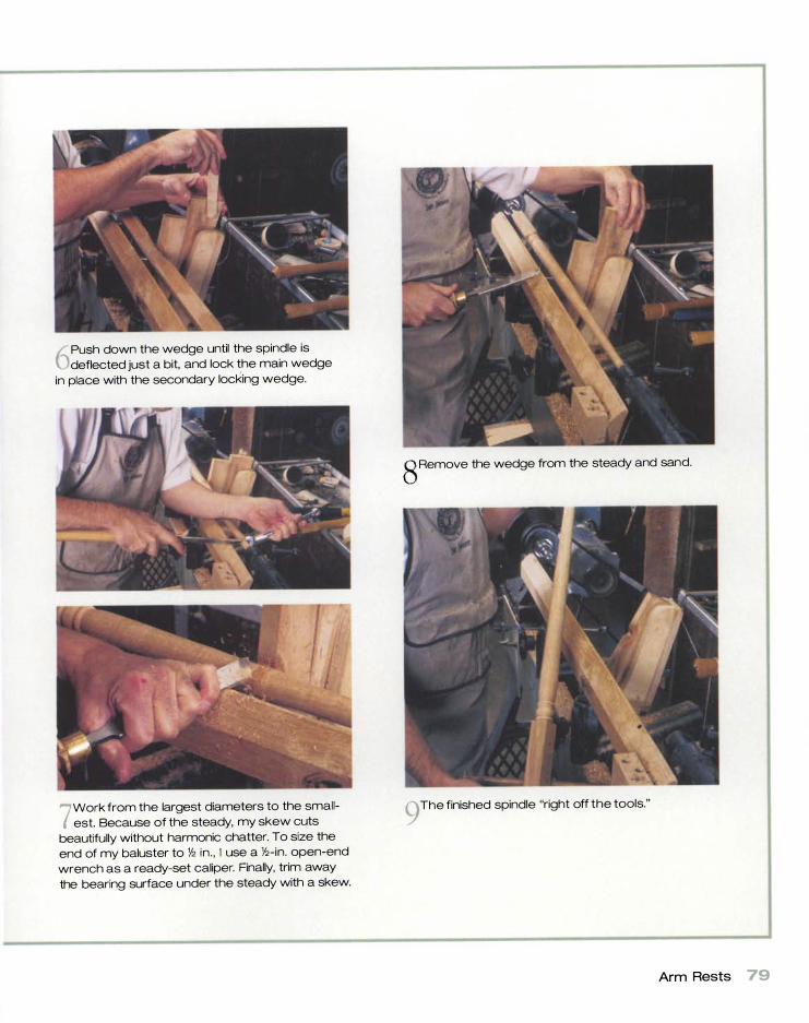
6PUSh down the wedge until the spindle is
deflected just a bit, and lock the main wedge
in place with the secondary locking wedge.
7 Work from the largest diameters to the small
est. Because of the steady, my skew cuts
beautifully without harmonic chatter. To size the
end of my baluster to '/2 in. , I use a Y2-in. open-end
wrench as a ready-set caliper. Finally, trim away
the bearing surface under the steady with a skew.
8Remove the wedge from the steady and sand.
9 The finished spindle "right off the tools."
Arm Rests 79

Keeping an Arm Rest Handy
D rill a hole in the end of the handle of your arm rest. You can loop a
cord through the hole and hang the rest under your left shoulder where it wil l always be ready for instant use.
80 Accessories
be exactly on-center, and any inaccuracies can be corrected instantly by
raising or lowering your shoulder.
The first time I saw an arm rest was in the hands of fourth-generation
master turner Dick Bailey. It struck me as such a good idea that I went
home and made one myself. Fortunately, they are now available commer
cially. Still, it is an easy tool to make yourself, since it's essentially a bent
piece of structural steel.
To use an arm rest, place its handle under your left arm and the shank
on the tool rest, then set your turning tool in the hook of the arm rest.
Most of the controlling of the tool is done using the right hand, but the
left hand can move the tool in and out by sliding the arm rest in the same
directions on the rest. The arm rest is most often used with scrapers for
making chucks and is essential for chasing inside threads (see pp. 145-
146) . It should not be used with roughing gouges or skew chisels.
Sharpening Equipment
Sharpening is the most difficult part of learning to turn. It is especially
hard to sort out on your own because you just don't know where to start
and you do not have a properly sharpened tool with which to compare
your efforts. The same skills and motions required to actually turn are nec
essary to sharpen (albeit in reverse or mirror image) . But wait a minute,
you may not have learned to turn yet. Adding insult to injury, you can't
learn to turn unless a sharp tool is placed in your hands. Which came first:
the chicken or the egg, turning or sharpening?
I have come to the conclusion that it is not difficult for anyone to
become proficient at wood turning if a sharp tool is placed in his or her
hands. The concept of how a turning tool cuts is easy to grasp, and the
execution only takes a bit of practice. The reason more people are not
proficient turners is that they don't start out with a sharp tool.
By sharp, I mean really sharp, sharp enough to shave hair off your arm.
But a sharp turning tool entails much more than this because I have had
numerous students bring tools that shaved hair but did not turn wood. In
addition to being sharp, the tool must also be of the correct shape and
have the correct grind angles on the bevels (see the illustration on p. 1 1 5 ) .
This is a tall order, since most turning tools are not delivered sharp or with
the correct grind angles. Most are not even the right shape. This is why I
have included illustrations of each turning tool in chapter 6. You can com
pare your tool with the appropriate illustration to better see whether you
have the correct grind angles.
When I first discovered wood turning, I had to learn to sharpen free
hand, which added time and difficulty to the learning curve. Today there
are a number of good, reasonably priced j igs that take 80 percent of the
freehand skill out of the sharpening equation. I teach j igs in all of my turn-

ing classes, and every student can sharpen his or her own tools within
half a day. When I had to teach freehand, I was lucky if two out of eight
students got the hang of sharpening in five days. While I can still sharpen
freehand, I now elect to use the j ig because I get perfect symmetrical
grinds (the same angles on both sides of a tool) . I recommend that you
start with a j ig as well.
Sharpening can be divided into three distinct operations: establishing
the correct shape and bevel angles, grinding when the tools become dull,
and honing. The establishment of the correct shape and bevel angles is
really a heavy grinding operation; after the correct shape is obtained, only
light grinding is necessary to maintain the tool. Honing makes the ground
edge really sharp. I'll look at the equipment needed for each of these oper
ations in detail.
GRINDERS
Bench grinders for home and light-industrial use come in 6-in., 7 -in. , 8-in.,
and 1 0- in. sizes. The smaller three sizes are generally built on a 3 ,450-rpm
motor frame, while the 1 0- in. one is constructed on a 1 ,725-rpm frame.
Many think the larger machine emits less heat because of the slower speed,
but there is really not much difference. A 6-in. grinding wheel at 3 ,450 rpm
has a surface speed of 5 ,4 16 ft. per minute, while a 1 0-in. wheel running at
1 ,7 25 rpm goes 4,5 16 ft. per minute. Several companies offer 6-in. grinders
built on a 1 ,725-rpm motor, which gives a surface speed of 2,7 1 0 ft. per
minute.
Economy bench grinders typically come with fixed, one-piece cast rests, which allow grinding only at 90·. That means aftermarket or shop-built rests and jig systems are necessary to grind turning tools effectively.
Sharpening Equipment 81
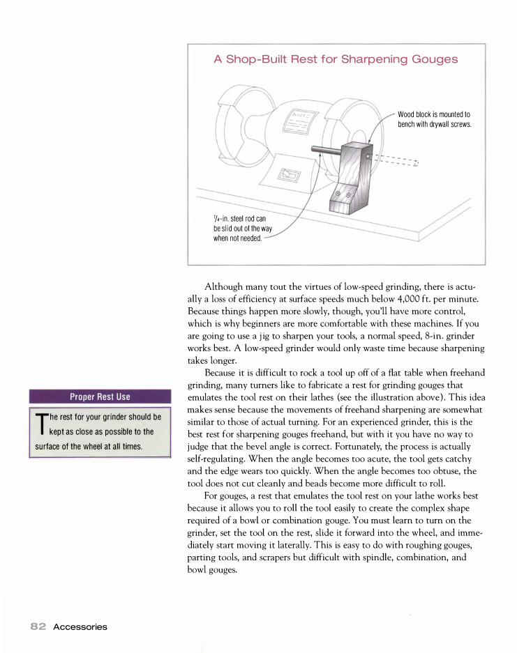
Proper Rest Use
The rest for your grinder should be
kept as close as possible to the
su rface of the wheel at all times.
82 Accessories
A Shop-Bui lt Rest for Sharpening Gouges
1/4-in. steel rod can be s l id out of the way when not needed.
Wood block is mounted to bench with drywal l screws.
Although many tout the virtues of low-speed grinding, there is actu
ally a loss of efficiency at surface speeds much below 4,000 ft. per minute.
Because things happen more slowly, though, you'll have more control,
which is why beginners are more comfortable with these machines. If you
are going to use a j ig to sharpen your tools, a normal speed, 8-in. grinder
works best. A low-speed grinder would only waste time because sharpening
takes longer.
Because it is difficult to rock a tool up off of a flat table when freehand
grinding, many turners like to fabricate a rest for grinding gouges that
emulates the tool rest on their lathes (see the illustration above) . This idea
makes sense because the movements of freehand sharpening are somewhat
similar to those of actual turning. For an experienced grinder, this is the
best rest for sharpening gouges freehand, but with it you have no way to
judge that the bevel angle is correct. Fortunately, the process is actually
self-regulating. When the angle becomes too acute, the tool gets catchy
and the edge wears too quickly. When the angle becomes too obtuse, the
tool does not cut cleanly and beads become more difficult to rolL
For gouges, a rest that emulates the tool rest on your lathe works best
because it allows you to roll the tool easily to create the complex shape
required of a bowl or combination gouge. You must learn to turn on the
grinder, set the tool on the rest, slide it forward into the wheel, and imme
diately start moving it laterally. This is easy to do with roughing gouges,
parting tools, and scrapers but difficult with spindle, combination, and
bowl gouges.

- - .... lC1 illif Ii r:-::r? � l:ll'7 .......
GRINDERS ARE AN OLD SHOP workhorse, but there are a number of safety
concerns connected with them. Let's take a look at how to grind safely.
Safety Shields
Make it a habit to view grinding activity through the glass or plastic
viewing shield because it provides a second barrier of protection (in
addition to your eyewear) should the wheel disintegrate. Traditionally,
the safety shields on any grinder were metal frames with tempered
safety glass in them-two layers of tempered safety glass with a sheet of plastic in between. This "sandwich" creates a nearly shatterproof,
scratch-resistant surface. Most grinders today are supplied with plastic viewing shields, which
reduces manufacturing costs. If your grinder has plastic shields in a
frame, consider replacing it with a glass/plastic sandwich. If you must
make do with plastic, some antistatic spray from a computer shop
helps to repel dust.
Lighting
Good lighting at a grinder is a must! Although industrial grinders often
have lighting built into the safety-shield frames, economy grinders
leave lighting to the end user. You' l l need a simple gooseneck lamp for direct local lighting.
Guards
Any grinder should provide guarding that encloses the wheel except
at the area just above the rest. An open, unguarded wheel should be
avoided under all circumstances. Most grinders have a sliding shield
called a spark arrestor at the top edge of the guard. In addition to reducing the number of sparks that land on your hands during grinding,
the spark arrestor helps to contain shrapnel inside the guards should
the wheel explode. You should slide the spark arrestors to within }l6 in.
of the wheel, and as the wheel is dressed, you should readjust them.
Eyewear
Safety glasses are obviously a must around any grinding equipment. If
your glasses are not true safety glasses with side shields, then you' ll need goggles or a face shield.
New wheels
A good practice with a new wheel , whether it is a replacement or one
on a new grinder, is to tap it to see how it rings. Like a baseball bat, it
will not ring true if it is cracked. When you mount a new wheel in the
grinder, it is best to stand to one side, start the machine, and leave the
room for a few minutes. If there is a defect in the wheel, it will typically disintegrate at or shortly after startup. Never start the grinder without
all guards securely in place.
Grinding wheels Most grinders are delivered with silicon-carbide wheels {available in most hardware stores} . Such wheels are good for grinding almost anything from steel to glass or even bathroom tiles, but
Sharpening Equipment 83

Quenching Carbon Stee l
When you grind carbon-steel
tools, keep a good-sized
quenching tub next to the g rinder. A
metal tub is best because a hot tool
can burn through the bottom of a
plastic tUb.
84 Accessories
they grind too hot for tool steel. A better choice for tool grinding is an aluminum-oxide wheel. Often called pink wheels, they are just as often blue or white. An aluminum-oxide wheel has a bonding medium that is softer than that of the silicon-carbide wheel, which helps create the right amount of friability. Friability means to crumble. "Why would anyone pay extra for grinding wheels that crumble ?" you ask. Because it makes the wheel self-sharpening and self-cleaning. Old, worn particles break off, which in turn brings up fresh sharp ones.
The trick is to find the correct amount of friability so that the wheel
is not excessively soft and will only shed particles as they become dull.
An aluminum-oxide wheel's code number will start with A (for aluminum
oxide) followed by the grit (36, 80, 1 00, and so on) , then a letter indi
cating the friability. The letters A through G indicate very soft wheels
that crumble easily, while the letters H through K represent soft wheels
in the range that is useful for sharpening woodworking tools. The letters
P through S appear on hard wheels, and letters beyond that are very
hard wheels.
In general, an H or I wheel has about the right friability for general
woodturning-tool grinding, as well as for carbon-steel tools such as plane
irons and bench chisels. For exclusive use on high-speed steel (HSS),
many turners prefer a harder wheel in the J or even K range. These harder
wheels are more aggressive and work well for initial shaping of HSS ( I use
an A46K wheel for initial shaping of new tools) . Without great care, how
ever, harder wheels will burn carbon steel.
Aluminum-oxide wheels can be found at industrial-tool suppliers. Fri
ability standards are a voluntary trade standard and can vary from manu
facturer to manufacturer. Once you find a brand you like, stick with it.
The vibration levels of many bench grinders may make them difficult
to use-especially if the grinder is lightweight. Dressing with a diamond
dresser usually improves this situation, but it seldom eliminates vibration
altogether. If the grinder is not clamped to a bench, it will walk away. The
principal culprit here is the average grinding wheel, which is often out of
balance. How out of balance it is depends on the wheel. Norton wheels,
for instance, tend to be very good, while the Chinese wheels that came
on my imported grinder are horrible. It pays to buy a good wheel.
You can improve your grinder's performance by installing One way
hubs, but you will have to buy new wheels with larger arbor holes to
accept the hubs. The hubs have a series of threaded holes that accept set
screws as counterweights. The manufacturer's directions suggest balancing
the wheel, then dressing it (with its fixture) , then balancing it again. The
result is that a Canadian faceted penny, which is supplied with the balanc
ing weights, will stand on edge on top of the grinder. Grinding is a joy:
The grinder just sits on the bench and purrs. With these advantages, a
One way balancing system is worth consideration.

By install ing new wheels with Oneway's hubs on you r grinder, it is possible to balance the wheels, which will remove all vibration and make grinding easier.
Most people make the mistake of grinding with too fine a wheel. A
good roughing wheel is 46 to 60 grit, while the finishing wheel should be
80 to 1 20 grit. For dry grinding, you should never use finer than 150 grit.
Remember that the grit you select for grinding wheels should never be as
coarse as what you would typically select for hand-sanding, which is how
most woodworkers typically judge grit. This is because each particle of
abrasive has less penetration when moving at speed.
Dressing wheels A new grinding wheel, whether it comes with the grinder or is a replacement, is about as round as a freshly mounted turning billet. It is impossible to grind well on such a wheel because the work will just hop up and down. Therefore, some means of truing your grinding wheel is as important as the grinder itself. Truing can be broken down into two operations. The first is the actual truing, that is, making the wheel concentric with the grinding machine's arbor and making the face of the wheel square (900 to the sides of the wheel ) . The second operation is dressing.
Dressing is done to give the wheel the desired texture and to bring up
sharp new particles when necessary. Only about 1 0 percent of the particles
in a given wheel actually cut-the rest just rub. As you grind, the 1 0 per
cent of the particles that are doing the work dull. The area between them
fills up with metal, causing the particles effectively to lose their clearance.
The wheel needs to be dressed to sharpen and clean it. Dressing must be
done any time you can see steel in the surface of the wheel, when the sur
face looks glazed, or when the wheel has grooves worn in it. It has to be
done more frequently with a hard wheel than with a soft one.
Sharpening Equipment 85

86 Accessories
Several accessories to true and dress are available. The best method to
true the wheel is by using a diamond dresser, preferably in combination
with some sort of j ig to ensure that the wheel is dressed square as well as
round. A diamond dresser is no more than an industrial diamond brazed
into the end of a piece of cold-rolled steel. By setting the shank on the
grinding rest and sliding the diamond tip laterally across the grinding
wheel, the wheel will become round. The diamond dresser should be pre
sented with a fairly light touch at a 5 ° negative (downhill) angle to the
face of the wheel in a scrape cut. The Oneway dressing attachment does
this automatically and dresses the wheel round and square to boot (see the
photo below). If you don't have a j ig, it is easy to tilt the table a bit down
hill and use it to support a standard dresser.
Buying a diamond dresser is like buying a diamond ring-the size dic
tates the price. Fortunately, industrial diamonds are cheap compared with
their aristocratic gem-quality cousins. A good diamond dresser will cost
you between $ 1 5 and $60. Bigger dressers, called clusters, contain more
The Oneway d ressing attachment presents the diamond dresser to the wheel at the correct 5° negative (downhi l l ) angle and ensures that the wheel is dressed true to its axis.

than one diamond and are typically in the $60 price range. Clusters, how
ever, are not good for truing a wheel with a j ig because they leave a finish
similar to that left by a star-wheel dresser. Diamond dressers are available
from industrial-supply houses, so pick one up when you are buying your
aluminum-oxide wheels.
A star-wheel dresser, which is available at any hardware store, is good
to use in combination with a diamond dresser. Since a star-wheel dresser
follows the contour of a wheel, it does not really make it round--only a
diamond can do that. But a star-wheel dresser does give the wheel a much
rougher texture than a diamond, so it is great for dressing your coarse
wheel (after it is made round with a diamond) in preparation for the ini
tial shaping of new tools. A star-dressed wheel is much more aggressive
than a diamond-dressed wheel, removing metal fast with a minimum of
heat. After about two dressings with a star wheel, the wheel will be out
of round and you'll need to use the diamond dresser again.
The worst type of dresser is a silicon-carbide stick. These sticks are
only marginally harder than the wheel, so they leave a glazed surface that
tends to grind hot.
HONING EQUIPMENT
A truly sharp edge is formed when two flat planes (or an arc and a flat
plane) meet perfectly with a good surface finish at the cutting edge. A
good surface finish may be defined as a polish or near polish. Honing
leaves a polished or near polished edge free of feather (or burr) . In short,
your spindle-turning tool should be razor sharp after honing.
There are two methods by which I hone lathe tools-whetstones
and buffing. If at all possible, I buff because it's the fastest, most effective
method. I only resort to whetstones when absolutely necessary, such as
when working in someone else's shop. The one tool that is an exception is
the skew chisel, which I always hone on whetstones. In fact, barring nick
ing the edge on a chuck or dropping it on a concrete floor, stones are the
only way I sharpen a skew. This is because the skew works best with an
absolutely flat bevel and must have a keen edge.
Whetstones As the name implies, whetstones are used with oil or water, which acts as a lubricant to prevent metal particles from bonding into the pores of the stone. Honing lathe tools requires polishing stones with very fine grit. Although I sharpen my skew chisels on the same stones that I use for plane irons and bench chisels, I have a collection of odd-shaped stones for the rest of my turning tools. These include small, tapered stones called slips and a variety of stones in triangular, round, and knife-edge designs. The latter are often sold in catalogs as files, but they are actually stones.
The trick to using flat stones to sharpen skew chisels is to keep the
bevel absolutely flat on the stone. A honing j ig can be of great help here.
Most of the j igs that are used for honing plane blades and bench chisels
can be adapted for honing a skew (see the illustration on p. 1 29 ) . The
advantage to a j ig is that you will obtain a flat bevel and a perfect edge.
Sharpening Equipment 87
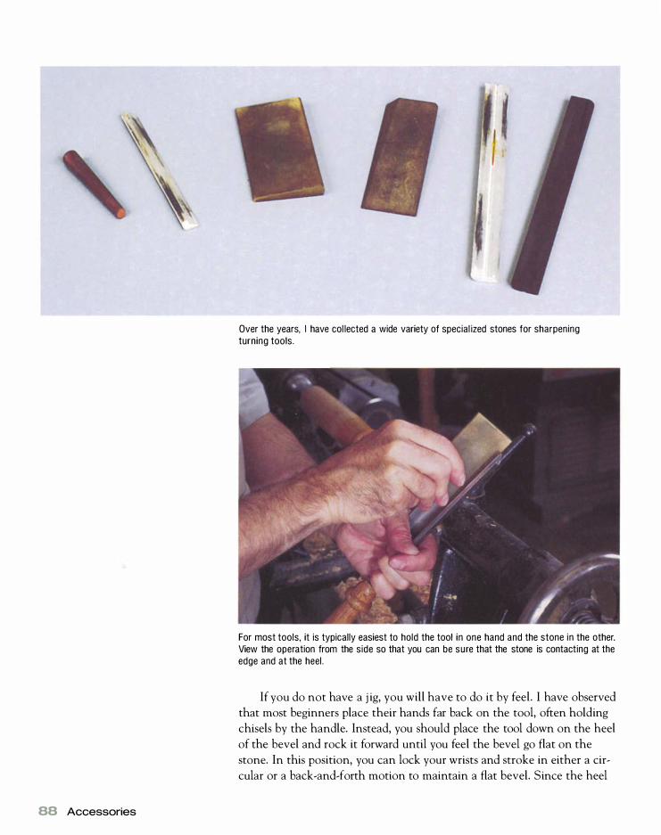
88 Accessories
Over the years, I have col lected a wide variety of special ized stones for sharpening turning tools.
For most tools, it is typically easiest to hold the tool in one hand and the stone in the other. View the operation from the side so that you can be sure that the stone is contacting at the edge and at the heel.
If you do not have a j ig, you will have to do it by feel. I have observed
that most beginners place their hands far back on the tool, often holding
chisels by the handle. Instead, you should place the tool down on the heel
of the bevel and rock it forward until you feel the bevel go flat on the
stone. In this position, you can lock your wrists and stroke in either a cir
cular or a back-and-forth motion to maintain a flat bevel. Since the heel

of the bevel is a fulcrum point, the shank of the tool is a lever arm. The
farther back you grip, the longer the lever arm and the less you can feel
the bevel. If possible, remove the tool handle because its weight throws
off your sense of feel.
Whether you use circular motions or linear motions for the actual
honing does not make much difference. The important thing is to main
tain the bevel flat on the stone by locking your wrists and using your arms
and upper body. Start with a sufficiently coarse stone that will remove
enough metal to establish a new bevel along the entire cutting edge. Stop
every so often and feel if you have rolled a burr along the back of the edge.
This will be less or more pronounced depending on the grit of the stone.
Work up to the next grade of stone, and keep progressing until you obtain
a polish.
For the rest of the tools, it is typically easiest to hold the tool in one
hand and the stone in the other. By looking sideways at the process, you
can tell if you have placed the stone flat on the bevel (contacting at the
edge and heel} . I often find it easier to brace the shank of the tool against
the headstock or tailstock. This gives me both leverage and steadiness.
For the flute side of gouges, it is just a matter of finding a stone with a
radius as close to the flute radius as possible and placing it flat down in the
flute (see the illustration at right) . Next, remove the burr and polish the
edge with a rapid back-and-forth motion. I use plenty of water or oil, as
required, during the entire process.
Honing is much easier with hollow-ground edges because the stone
will touch at the very edge and the heel of the bevel. It takes a short time
to bring up a polished edge. You can normally hone several times before
having to go back to the grinder.
B uffers Buffing is the technique of using cloth or felt wheels, which revolve at high speed and are charged with abrasive compound, to improve the surface finish of metal. The abrasive compound is typically a wax/ grease and abrasive mixture. Sold in stick form, it is crayoned on the revolving wheel. Many people make a buffer by simply mounting a cloth wheel in a bench grinder. I do not think a bench grinder makes a good buffer because the rest and guards get in the way.
One way to make a small buffer is to mount a buffing wheel in the
lathe itself. Small arbors with a lA-in. or 3h-in. shank are sold for mounting
a 4-in.-dia. buffing wheel in an electric drill. By mounting the arbor in a
drill chuck in the headstock spindle of your lathe, you have an inexpen
sive (less than $20 including the compound) and effective buffer. I first
latched onto this idea because I needed a buffer on the road when I do
seminars and demonstrations.
In the long run, you will want to build another kind of buffer. Using a
buffing wheel mounted in the lathe is inconvenient for tool sharpening
because the work must be removed from the lathe every time you want to
buff. Several companies manufacture inexpensive arbor heads for the pur-
Removing a Burr from a Gouge
Hold the gouge steady and move the stone back and forth to remove the burr on the inside of the gouge.
Sharpening Equipment 89

Buffer Motors
An old furnace blower motor is
g reat for powering a shop-built
buffer.
90 Accessories
Mount the wheel and arbor in a d ri l l chuck in the lathe.
pose of building a buffer. These arbor heads have a l�- in. arbor, which fits
readily available 6-in.-, 8-in.-, and 1 0-in.-dia. cloth wheels, and are best
powered by a lj4-hp or Ip_hp 1 ,725-rpm motor. Often a used motor can be
found at a motor rewinder for a nominal price. To calculate the correct
motor pulley diameter for 6-in. wheels and a 1 ,725-rpm motor, use the fol
lowing formula:
Motor pulley diameter = 2,000 X Arbor head pulley diameter
1 ,725
An rpm of 2 ,000 is needed to achieve 3 , 150 surface ft. per minute.
For an 8-in.-dia. wheel, use 1 ,500 rpm instead of 2 ,000 rpm, and for a
1 0-in.-dia. wheel, use 1 ,200 rpm to achieve 3 , 1 50 surface ft. per minute.
However, these bigger wheels can run even slower if pulley matching is
a problem.
Wheels are available in two types: spiral sewn and cushion sewn. The
descriptions denote how the layers of cloth that form the wheel are sewn
together. As the name implies, the first type is stitched in a spiral starting
at the center. The cushion-sewn wheel is stitched in concentric rings,
making this type of wheel softer and fluffier. The spiral-sewn wheel is bet
ter for coarser compounds where aggressive cutting action is desired, while
the cushion-sewn wheel is better for final polishing when gentle cutting
action and a mirror finish is the goal.
Buffing compounds tend to be sold according to their final purpose
buffing brass, steel, stainless steel, and so on. Sometimes a compound will
do several jobs. For instance, stainless-steel compound is good for final
buffing of steel or stainless steel and works well on brass.
For buffing lathe tools, I have found that a combination of two Dico
compounds-E5 Emery and SCR Stainless-works well. Dico compounds
and buffing wheels are made by Divine Brothers in Utica, N .Y., and are
available in most good hardware stores. Equivalent compounds are made
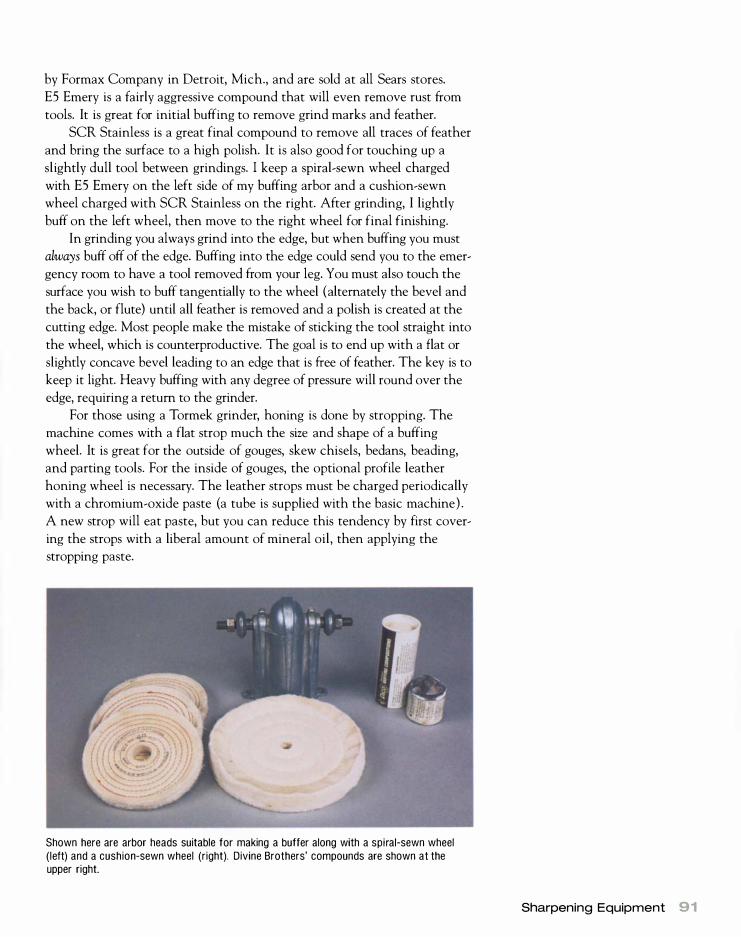
by Formax Company in Detroit, Mich., and are sold at all Sears stores.
ES Emery is a fairly aggressive compound that will even remove rust from
tools. It is great for initial buffing to remove grind marks and feather.
SCR Stainless is a great final compound to remove all traces of feather
and bring the surface to a high polish. It is also good for touching up a
slightly dull tool between grindings. I keep a spiral-sewn wheel charged
with ES Emery on the left side of my buffing arbor and a cushion-sewn
wheel charged with SCR Stainless on the right. After grinding, I lightly
buff on the left wheel, then move to the right wheel for final finishing.
In grinding you always grind into the edge, but when buffing you must
always buff off of the edge. Buffing into the edge could send you to the emer
gency room to have a tool removed from your leg. You must also touch the
surface you wish to buff tangentially to the wheel (alternately the bevel and
the back, or flute) until all feather is removed and a polish is created at the
cutting edge. Most people make the mistake of sticking the tool straight into
the wheel, which is counterproductive. The goal is to end up with a flat or
slightly concave bevel leading to an edge that is free of feather. The key is to
keep it light. Heavy buffing with any degree of pressure will round over the
edge, requiring a return to the grinder.
For those using a Tormek grinder, honing is done by stropping. The
machine comes with a flat strop much the size and shape of a buffing
wheel. It is great for the outside of gouges, skew chisels, bedans, beading,
and parting tools. For the inside of gouges, the optional profile leather
honing wheel is necessary. The leather strops must be charged periodically
with a chromium-oxide paste (a tube is supplied with the basic machine) .
A new strop will eat paste, but you can reduce this tendency by first cover
ing the strops with a liberal amount of mineral oil, then applying the
stropping paste.
Shown here are arbor heads suitable for making a buffer along with a spiral-sewn wheel (left) and a cushion-sewn wheel (right). Divine Brothers' compounds are shown at the upper right.
Sharpening Equipment 91

92 Accessories
Proper buffing technique when honing a spindle gouge requ ires you to buff off the edge and to hold the tool tangentially to the wheel.
For the inside of gouges, the optional profile honing strop on a Tormek machine mounts outboard on the normal strop supplied with the machine.
SHARPENING JIGS
Grinding is more a matter of practice than anything else, but as I men
tioned earlier, a j ig greatly simplifies the learning curve. For most people,
especially those who may have long hiatuses between turning sessions, a
j ig is the way to go. I think spindle gouges and bowl gouges come out bet
ter shaped and sharper from a j ig. I would call myself an accomplished tool

grinder, and I cannot grind a spindle or bowl gouge as well as a j ig does.
An added bonus is that much less steel is removed in the grinding process
so the tool lasts longer. With all these overwhelming advantages, j igs are
the way I now sharpen my tools.
The One way Wolverine grinding j ig is the most comprehensive j ig for
sharpening turning tools. It is the brainchild of Oneway's driving force,
Canadian Tim Clay, an avid amateur turner. Tim looked at the entire
grinding process and came up with some innovative solutions to old sharp
ening problems. His approach starts with balancing the wheels, dressing
them properly, and using j igs to create perfect geometry.
The basic Wolverine grinding j ig comes with two base units that
mount under each grinding wheel and an arm that will fit into either base
unit (see the photo below). The unit is designed for and works best with
an 8- in. grinder. Smaller 6-in. or 7- in. grinders can be blocked up, and a
system for lO-in. grinders is available on special request directly from
Oneway. There is also a generously sized (3-in. by 5-in. ) articulating table
that fits into either base unit. This table is great for plane irons and bench
chisels as well as turning scrapers.
Also available is the Vari-Grind j ig, which does a splendid job of
grinding spindle, combination, and bowl gouges to any desired combina
tion of nose and flank angle. Begin by clamping a gouge in the side
grinding j ig. In order to repeat a grind perfectly, the gouge must protrude
out of the j ig the same amount each time. To ensure the right placement,
draw a line beside the grinder as a reference point for setting the tool
extension. With the grinder stopped, place the tang of the j ig in the pocket
at the end of the arm, and adjust the arm in or out until the desired nose
The basic Wolverine jig from Oneway gives you a base unit to mount under each wheel, a tilting table that is good for scrapers, plane irons, and standard woodworking chisels, and an arm (pocket j ig) for sharpening roughing gouges and for use with the Vari-Grind jig.
Join ing Grinder and J ig
M ounting your grinder and sharp
ening jig on a su itable board
makes them portable but maintains the
sharpening jig's relationship to the
grinder. Put rubber feet (available at
most hardware stores) under the board
to make the grinder more stable.
Sharpening Equipment 93

Affix the j ig 1 3/4 in . from the t ip of the tool.
Jig
Setting
#1
#2
#3
94 Accessories
Jig Settings
Affix clamping un i t 13/16 in . back from the face of the wheel. Center it under the wheel (from the front).
Engrave marks at these positions. Al ign the mark with the front edge of the clamping un it .
Measurement
4% i n .
57/8 i n .
67/16 in .
Tool
Spindle gouges
Bowl gouges (advanced grind)
Bowl gouges (normal grind)
Note: These settings work about as well with 6-in. and 7-in. grinders, but those grinders need to be blocked up to clear clamping units.

angle of grind is achieved. The amount of articulation of the j ig itself con
trols the angle of the flanks adjacent to the nose.
Start the grinder, and slowly rotate the tool to achieve the desired
shape. While some skill is necessary to achieve the correct shape, the
process is so easy that it comes quite naturally. Also a perfect shape is
achieved because the tool contacts the wheel in the right place all the
time. If you wish to duplicate this grind easily in the future, it is best to
engrave marks on the arm with a vibrating engraving tool. I have included
my recommended settings for the j igs reviewed here in the illustration on
the facing page.
Oneway also makes a j ig for grinding skew chisels. Unfortunately, this
j ig doesn't work well for skew chisels. Following Oneway's directions, you
achieve a curved hollow grind, which is wretched for architectural turners.
The only way I know to achieve the flat grind is as outlined on p. 1 26.
The Sorby fingernail profiling j ig is the most economical of the j igs.
It exhibits beautiful workmanship and finish but comes with rather poor
directions. It works with any size grinder and is simple to operate. The
disadvantage is that it only works with the wheel you attach in front of it.
Any woodworker worth his salt, however, could work out some sort of
rapid clamping fixture to locate the j ig at either wheel or get it out of the
way when not grinding gouges.
For both the Sorby and Oneway j igs, I recommend mounting your
grinder on a suitable piece of wood, then attaching the j ig to this subbase.
This keeps the relationship between the j ig and the grinder constant but
allows the grinder to be portable. I like to attach four rubber feet to the
bottom of this subbase because they absorb vibration and help the grinder
to stay put.
The Sorby fingernail profiling jig is the most economical fingernail grinding jig. The articulated gooseneck part of this jig is actually bui lt by Tormek for Sorby.
Since the Vari-Grind jig depends on clamping on the top edges of the flute to hold the tool square in the jig, older tools whose flutes are short present a problem. The solution is to grind a flat spot (which is square with the flute) on the tool shank with a right-angle weld grinder.
Sharpening Equipment 95

96 Accessories
The Tormek SuperGrind sharpening system has a fingernail jig similar to Oneway's. It allows you to grind a wide variety of fingernails on both spindle and bowl gouges. It is a logical choice for those who already own a Tormek.
There is also a fingernail j ig for the Tormek SuperGrind sharpening
system. The Tormek is a superb low-speed wet grinder for general wood
working tools such as plane irons and bench chisels. With the fingernail
j ig, the Tormek works for spindle, bowl, and combination gouges. It can
not, however, grind a bowl gouge to a relatively short nose bevel with
medium bevels at the flanks-the asymmetrical grind necessary for deep
hollow-vessel work. This is a drawback for serious bowl turners, so if you
make a lot of bowls consider the Oneway system. If you are a general
woodworker who wants to do spindle work and casual faceplate turning,
the SuperGrind system is well worth a look, especially if you already own
a Tormek.
Another drawback to the Tormek for lathe tools is that it takes a
while to initially establish a bevel angle-I find it to be absolutely pokey.
Once the geometry is established, however, the time to resharpen the tool
is about the same as with a grinder and j ig. The Tormek comes with a
leather strop as the left wheel, which nicely replaces a buffer for honing.
For gouges, you will have to buy the profile leather honing wheel, which
mounts outboard of the main strop wheel, to do the flutes.
The Tormek is expensive, but if you do not own any sharpening equip
ment, it represents a good value because you would spend about the same in
the long run for a grinder, j ig, buffer, and some sharpening stones. It is an
especially good value if you also want to sharpen general woodworking tools.
More than one turner has looked at sharpening j igs and thought, "I
could build that myself." That is exactly what my friend King Heiple did.
King has generously shared the illustration on the facing page for his shop
built j ig.
When I go out to do turning demonstrations, I only carry a Oneway
Vari-Grind j ig in my tool kit. On site I scrounge a board approximately

King Heiple 's Shop-Bui lt J ig
The height o f wood block A wi l l vary depending on whether you are using an 8-in . , 7-in., or 6-in . grinder. The goal is to have the pivot dimple 4 i n . below the midpoint of the wheel and 7 in . out. ---
A
D imple�Bandsawn recess V
/ 1 " 2" 3" 4" 5" 6"
I I I I I I I SCALE
The only metal parts on the jig are two 5/16-in . T-nuts and matching thumbscrews.
SuperGlue or epoxy a '/4- in . by 6-i n .
5/16-in. T-nut
View A
8-in. 1 725 grinder (7 in . or 6 i n . w i l l also work, but the 8 i n . gives less hol low grind and lasts two to three times longer.)
Wheels must center over s l ides to match your grinder.
,J::.4---- 1 '/2 X 1 '/2 spaces---�i
Make th is space 2'/32 in . or match your bowl gouge.
View B metal rod in To use with smaller gouges, place of wood make a V-shaped centering
5/16-in. T-nut
5/16 x 1 '/2 thumbscrew strip at each end. for durabil ity.� strip. Fit loosely with a brass
1 " 2" 3" � • Make three or four at once because it's much safer culling longer strips. f---+--+--+-t-+--+I-+----i • Put T-nut i n flush before assembly because it wi l l be buried. SCALE
• For a spindle gouge fingernail grind, make the rod 6 in. long and bend the angle to 55° or 60°.
Sharpening Equipment 97

98 Accessories
An economical approach is to buy Oneway's Vari-Grind jig and clamp a board with a dimple carved in it as a pocket for the leg of the j ig.
3/4 in. by 2 in. by 18 in. Using a spindle gouge, I carve a small dimple in
one end of the board to accept the leg of the Vari-Grind j ig. I then clamp
this board under the grinder to form a quick and dirty pocket j ig. Any
woodworker could make a similar arm that adjusts easily and would only
have to buy a Vari-Grind j ig. Such an adjustable arm is shown in King
Heiple's illustration.
Safety Equipment
Safety equipment is essential. It protects you from harm and makes turning
a smoother operation. Without the following equipment, you risk injury.
PROTECTIVE CLOTHING
Always wear sturdy shoes when turning to provide protection against
dropped tools or workpieces. Faceplate turners should wear safety shoes.
EYE PROTECTION
Some sort of eye protection is essential when operating a lathe. The mini
mum is a pair of shatterproof eyeglasses, preferably with side shields. For
some types of work, such as turning wood with bark still on it or excep
tionally splintery material, a full face shield should be worn. By law all pre
scription glasses sold in the United States are shatterproof and probably
provide sufficient protection for many turning situations. However, most
glasses have plastic lenses to save weight. The plastic attracts dust, and
wiping it away dry (which is a necessity at times) scratches them quickly.
I specify shatterproof glass lenses in safety frames when ordering my shop
glasses. Though a bit heavy, they are much more scratch-resistant. Safety

frames also come with side shields, which are typically removable if you
want a more casual look.
VENTILATION AND DUST COLLECTION
It is equally important to protect yourself from dust. Wood dust, especially
from tropical species, can be quite toxic and even carcinogenic. A paper
dust mask, like those worn in automotive body shops, is a minimum
requirement. Better protection is afforded by a respirator, which has
replaceable cartridge-type filters and looks like a military gas mask.
Respirators offer good dust protection, but they're hot and tiring to wear
because you're doing the air pumping with your lungs. They also are a
problem for turners who have beards because of the difficulty in obtaining
a tight seal.
The best form of protection for both the eyes and the lungs is an air
helmet. Air helmets offer the safety of a full face shield and hard hat with
excellent dust protection that does not tax your respiratory system. The
helmet has a battery-powered motor that pumps air into it, which provides
positive air pressure inside the shield, excluding dust and preventing fog
ging. Since the motor is doing the pumping instead of your lungs, breathing
is much easier than with a respirator. Although some air helmets filter only
dust, others also filter organic vapors from glues and finishing products. Air
helmets cost a lot more than other types of dust protectors (as much as
$750), but if you do much woodworking, they're well worth the price.
• Make sure the lathe is properly grounded and meets local elec-
tric codes.
• Make sure the work is securely mounted in the lathe. • Check for any defects in the wood you are planning to turn. • Always start the lathe at an appropriate speed. • Never touch or move the belt while the lathe is running, and never
run the lathe without the belt cover in place.
• When mounting a new workpiece, check that the tool rest clears the work and that the rest is securely locked in position before starting
the lathe.
• Listen for unusual sounds coming from the lathe. They can indicate
that something is wrong.
• Always unplug the lathe while performing maintenance or repairs. • Use the correct tools for the job. Roughing gouges and skew chisels
should not be used for faceplate turning.
• Always work with tools that are sharp.
• Wear appropriate safety equipment for eye and lung protection, and wear clothes without dangling ends. Roll up your sleeves if you are
wearing a long-sleeve shirt.
• Take frequent breaks, especially when doing repetitive work where
your mind may drift.
Safety Equipment 99

WORK FLYING OUT OF THE LATHE and glued-up work flying
apart in the lathe constitute by far the biggest dangers in turning. In a few rare instances, flying work
has even caused death-usually when the operator is
hit in the head. Such accidents can almost always be
traced back to starting the lathe at too high a speed for the turning operation.
You need to work out a routine that will prevent
flyers. Form the habit of returning your lathe to its
lowest speed at the end of every turning session.
Unplugging it at this time and draping the plug across the bed is a great reminder. Make speed concerns
the foremost thought in your mind as you approach
the lathe, and make setting the appropriate speed the
first order of business when chucking work. Rotate
the work by hand to make sure that it clears the tool rest before you turn on the lathe. Finally, if you 're the least unsure, stand to the left of the lathe when you
turn it on. If the work is going to fly, you're out of the line of fire.
The tool rest provides some protection for the operator,
since it directs a high percentage of flyers to the back of
the lathe, but you also need to protect any observers in your
shop. Flyers tend to travel at
right angles to the headstock
spindle, so don't let spectators stand in the area 90° to the
spinning work. The best place
for viewers to stand is around
the tailstock. Warning others
in the shop when you first
start the lathe after mounting
work will do much to prevent
accidents.
Appropriate turning speed
is a difficult thing to specify.
As with driving a car, you can
negotiate higher speeds as you gain experience, but for begin-
1 00 Accessories
ners it's always best to err on the side of low speed.
Except for miniature work, turning need never take
place at a speed higher than 2 ,000 rpm. Sanding is
best done at the final turning speed and does not, as
some sources recommend, require higher speeds.
For turning spindles up to 2112 in. dia. , a roughing
speed of about 1 ,100 rpm and a finishing speed of
about 1 ,700 rpm are appropriate. The experienced
turner will be able to do the entire operation at the
higher speed as long as the work is well centered to start.
Faceplate turning is more prone to flyers because
of the greater diameter of the work and the greater
difficulty in centering. For work up to 10 in. dia. ,
600 rpm to 800 rpm is a good roughing speed, and
1 ,100 rpm is an appropriate finishing speed. Face
work need never be done at a speed greater than
1 ,100 rpm. For large-diameter facework, roughing
speeds as low as 200 rpm may be necessary.
- - - - - - - - - - - - - - - - - - - , I I I I I
Safest viewing area for spectators
L _ _ _ _ _ _ _ _ _ _ _ _ _ _ _ _ _ _
� Danger zone

An air helmet offers the best all-around eye and d ust protection to the turner. Ear protectors may also be added to this helmet for noisy situations.
Air-filtration systems that mount on the ceiling of your shop are also
widely available. These units are simply air movers with filters to remove
dust. The unit has to be sized to the cubic volume of your shop, and the
filters have to be cleaned on a regular basis. Most filters can be cleaned
with a shop vacuum numerous times before they need to be changed.
Although air-filtration systems do not eliminate dust from the environ
ment, they do minimize the exposure time and simplify cleanup. The best
of all possible worlds is to have a filter and a helmet.
If your shop has a central dust-collection system, placing a pickup near
your lathe can be useful for sucking up much of the dust from sanding. You
will have to rig some sort of clamping system so that you can position the
hose near the work. Dust collection will do little to suck up the chips
(especially wet ones) created by the lathe until they are on the floor. Wet
chips in the dust-collection bag or bin present a safety hazard due to spon
taneous combustion, so bins should be emptied every session. Chips with
oil finish present a similar hazard.
Jigs for Special Techniques
There is the old joke that it only takes one woodworker to change a light
bulb but that he has to build a j ig to do it. So it is with the lathe. Wood
working literature is resplendent with myriad j igs for turning. Here is a
small sampling.
Air-filtration systems that continuously clean the air in your shop are a great second l ine of defense after a d ust mask. They keep the shop cleaner as wel l . (Photo courtesy the JDS Company.)
Jigs for Special Techniques 1 01
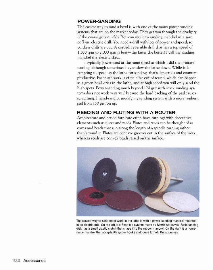
102 Accessories
POWER-SANDING
The easiest way to sand a bowl is with one of the many power-sanding
systems that are on the market today. They get you through the drudgery
of the coarse grits quickly. You can mount a sanding mandrel in a 1/4-in.
or 3h-in. electric drill. You need a drill with lots of power and speed, so
cordless drills are out. A corded, reversible drill that has a top speed of
1 ,500 rpm to 2,000 rpm is best-the faster the better! I call my sanding
mandrel the electric skew.
I typically power-sand at the same speed at which I did the primary
turning, although sometimes I even slow the lathe down. While it is
tempting to speed up the lathe for sanding, that's dangerous and counter
productive. Faceplate work is often a bit out of round, which can happen
as a green bowl dries in the lathe, and at high speed you will only sand the
high spots. Power-sanding much beyond 1 20 grit with stock sanding sys
tems does not work very well because the hard backing of the pad causes
scratching. I hand-sand or modify my sanding system with a more resilient
pad from 150 grit on up.
REEDING AND FLUTING WITH A ROUTER
Architecture and period furniture often have turnings with decorative
elements such as flutes and reeds. Flutes and reeds can be thought of as
coves and beads that run along the length of a spindle turning rather
than around it. Flutes are concave grooves cut in the surface of the work,
whereas reeds are convex beads raised on the surface.
The easiest way to sand most work in the lathe is with a power-sanding mandrel mounted in an electric d ri l l . On the left is a Snap-Ioc system made by Merrit Abrasives. Each sanding disk has a small plastic clutch that snaps into the rubber mandrel . On the right is a homemade mandrel that accepts Klingspor hooks and loops to hold the abrasives.

IF YOU WANT TO MAKE YOUR LATHE into a drill press, you can fit a drill pad
in effect, a mini drill-press table-into the tailstock spindle. Years ago, drill pads were a common accessory for both metal and wood lathes, but now you'll probably have to make your own since they're hard to
find. The illustration below shows a plan for a drill pad that will fit a
#2 Morse-taper spindle. For strength, the pad is best made in two
pieces, using a hardwood such as maple or red oak. The Morse taper
is spindle-turned, while the pad is faceplate-turned. Place a drill of the appropriate diameter in the headstock, and hold
the work on the drill pad. Use the tailstock handwheel to advance the
table and work into the drill. As in drilling with a drill press, make sure you can hold the work with sufficient leverage to keep it from spinning.
The bigger the drill, the more leverage you'll require.
Drill Pad
The best way to make the dr i l l pad is to turn a taper separately with a tenon on the end. Make the pad out of 1/2-in. or 3/4-in . plywood, dri l l to tenon size, and glue together.
A d ri l l pad is a nifty shopmade accessory that will turn you lathe into a dril l press.
The Power Skew
A Power-sand ing mandrel is also
good for long, straight spindle
work, such as columns and table legs.
I call it the power skew.
Jigs for Special Techniques 1 03
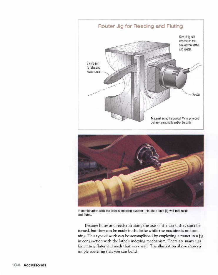
1 04 Accessories
Router Jig for Reeding and Fluting
Swing arm to raise and lower router
Size of jig wil l depend on the size of your lathe and router.
Router
Material: scrap hardwood; 3/4-in . plywood Joinery: glue, nai ls and/or biscuits
I n combination with the lathe's indexing system, this shop-built jig will mill reeds and flutes.
Because flutes and reeds run along the axis of the work, they can't be
turned, but they can be made in the lathe while the machine is not run
ning. This type of work can be accomplished by employing a router in a j ig
in conjunction with the lathe's indexing mechanism. There are many j igs
for cutting flutes and reeds that work well. The illustration above shows a
simple router j ig that you can build.

CUTTING DOVETAILS IN COLUMN BASES W IT H A ROUTER
Columns for Philadelphia pie-crust tables, tea tables, and similar structures
typically have three legs (often cabriole) attached at the bottom of the
column. Attaching the feet is best done with a dovetail joint. Dovetail
slots are made in the base of the column, and matching dovetails are cut
in the legs so that they may be attached by sliding in from the bottom of
the column.
Historically, dovetails were cut with a backsaw and chiseled out in
much the same way that a half-blind dovetail is cut by hand. Today, it is
better done with a router in the lathe.
It is simple to build a suitable j ig for making the cuts (see the illustra
tion below) . The j ig is essentially a box that surrounds the work and has
a wood key on the bottom that matches the gap in the lathe bed. A slot
in the top of the j ig matches a guide bushing on the router. I use a large
carbide-tipped dovetail bit to mill the dovetail. You can make the match
ing dovetail on the leg on a router table with the same dovetail bit. Using
the router table, I hold the work with a tenoning j ig from my table saw. I
run the tenoning j ig in the router table's miter slot.
Work
Key sized to lathe bed
Jig for Cutting Dovetails
Slot sized to guide bushing on router)
Height and width wi l l
prevent racking
depend on the size of the lathe.
Material: 3/4-in . plywood Joinery: biscuits, glue, nai ls
Jigs for Special Techniques 1 05

This open, double-barley twist candlestick took me about six hours to make, but much of the time was spent in carefully sanding the twists and applying repeated coats of oil finish.
1 06 Accessories
Here is a spiral column and a two-flute closed spiral of a tighter twist.
MULTIPLE STARTS FOR SPIRAL TURNING
Number of starts Pitch range
One 1 to 1Y4 times the diameter of the tuming
Two 2 times the diameter of the turning
Three 2Y2 to 3 times the diameter of the turning
Four 2 times the diameter of the turning
SPIRAL TURNING
Spiral turning has been around for centuries. Furniture and homes of the
1 8th and even 1 7th centuries are full of spiral turnings. I typically elect to
do this job by hand because I never have had to make more than two, but
there are new tools and j igs that make cutting spirals easier than ever.
One such tool is the Sorby spiral tool, which has a serrated wheel at
the end of a shaft that is mounted in a base plate. The shaft can be rotated
in the base plate but locks at the desired amount of rotation via socket
head screws. The more the rotation left or right, the steeper the pitch of
the spirals generated. The base plate contacts the tool rest and keeps the
entire tool at the same angle throughout the cut.
The tool is presented in a downhill scrape cut. The wheel revolves dur
ing the cut, which at first is a bit unnerving. Once the cut starts, you should
keep the tool in contact with the work and slowly advance left or right
(depending on the direction of the spiral) . You then withdraw the tool and
return to the start point. The wheel will pick up the first cut, and you move
the tool in again as before. Lathe speeds should be kept moderate.

Sorby spiral l ing tools will cut multistart twists in spindles. The pitch of the spiral is controlled by how far the wheel is angled to the right or left.
If you do the job by hand, you need to get the layout right. The top
of a single thread is referred to as the crest, while the valley between two
adjacent threads is referred to as the root. Normally, ornamental spirals are
rather steep in pitch. While pitch in screw threads is generally thought of
as the number of turns of thread per inch (measured between crests) , in
spiral wood turning the pitch is set by the diameter of the work. If you had
a 2-in.-dia. cylinder, for example, one pitch would be one turn in 2 in.
In most cases, spiral turnings entail multiple starts so that you have
two, three, four, or more threads starting at evenly spaced intervals around
the turning. The more starts you employ, the steeper the pitch must be
come to make the turning look right. By drilling through the center of a
multiple-start turning, the twist can be made "open," which is very attrac
tive. For twists that have a bit of taper, the pitch is the diameter at the
thickest spot, which is usually at or near the base. The chart on the facing
page gives you a good starting point for laying out various twist patterns.
If you want to produce spiral turnings on a production basis, you
should look into the line of Legacy Ornamental Milling Systems made
by Phantom Engineering. Ranging in price from $750 to $3,500, they
turn out spirals in a hurry.
ORNAMENTAL TURNING
Although ornamental turning (OT) enjoyed a strong following in the
19th century, it was a province only of the wealthy. Happily, the hobby is
within the means of almost anyone today. The cost is reasonable because
you can buy attachments that add ornamental capability to a normal
wood turning lathe.
Woodcraft sells a nice ornamental attachment that fits the Jet mini
lathe. Designed by Jerry Beal, it works beautifully but can only do small
work. Although it is intended for pens, it can handle anything within the
capacity of the Jet lathe. It is strongest in side-cutting mode, where it will
mill spirals as well as simple geometric patterns. End-grain cutting is under
development at the time of this writing. The basic Beal attachment sells
for about $350, but it also requires a Fordem shaft tool, which raises the
cost to about $550.
Jigs for Special Techniques 1 07

108 Accessories
The Nova Ornamental Tu rner adds ornamental turning capabilities to any lathe with 8 in . or more center height. Teknatool also has a 7 -in. model with adapter kits for many lathes.
The most ambitious OT attachment is the Nova Ornamental Turner.
Although the Nova attachment is designed for the Nova 3000 lathe, it
can be retrofitted to almost any lathe with 8 in. or greater center height
even my wood-bed lathe. Nova also has a model for lathes with up to 7 in.
center height ( 14- in. swing) , and it is developing adapter kits for popular
lathe brands and models. The attachment costs about $550.
The Nova Ornamental Turner is essentially a saddle (like those found
on metal lathes) with a spindle unit mounted on the top. The saddle is
composed of two slides that travel in x- and y-axes. The cross slide travels
in the y-axis (900 to the lathe bed) , while the compound slide is typically
run in the x-axis (parallel to the lathe bed) . The compound slide can,
however, be adjusted to any angle for cutting tapers and special operations.
Both the cross slide and the compound slide have stops that can be set to
limit travel so as to make every cut of equal depth.
The saddle replaces the tailstock of the lathe during OT operations.
The spindle unit in essence is identical to the headstock spindle with the
same thread ( l 1f4 in. x 8 ) and #2 MT. (There is a 1 -in. x 8 thread on the
7 -in. model.) The two spindles oppose each other. Work that has been
turned on a faceplate or in a chuck can be transferred to the spindle unit
and brought into play with a variety of cutters that are mounted on the
headstock spindle. The spindle unit actually mounts in a pedestal base,
which in turn mounts on the top of the compound. A grub screw in the
side of the pedestal locks the height and alignment of the spindle unit.
The Nova Ornamental Turner allows four types of ornamental work:
end-grain cutting, side cutting, threading, and metalturning.
End-grain cutting If you recall the child's toy called a spirograph, then you'll easily understand ornamental end-grain cutting. The spirograph created geometric designs on paper by changing gears and the length of the
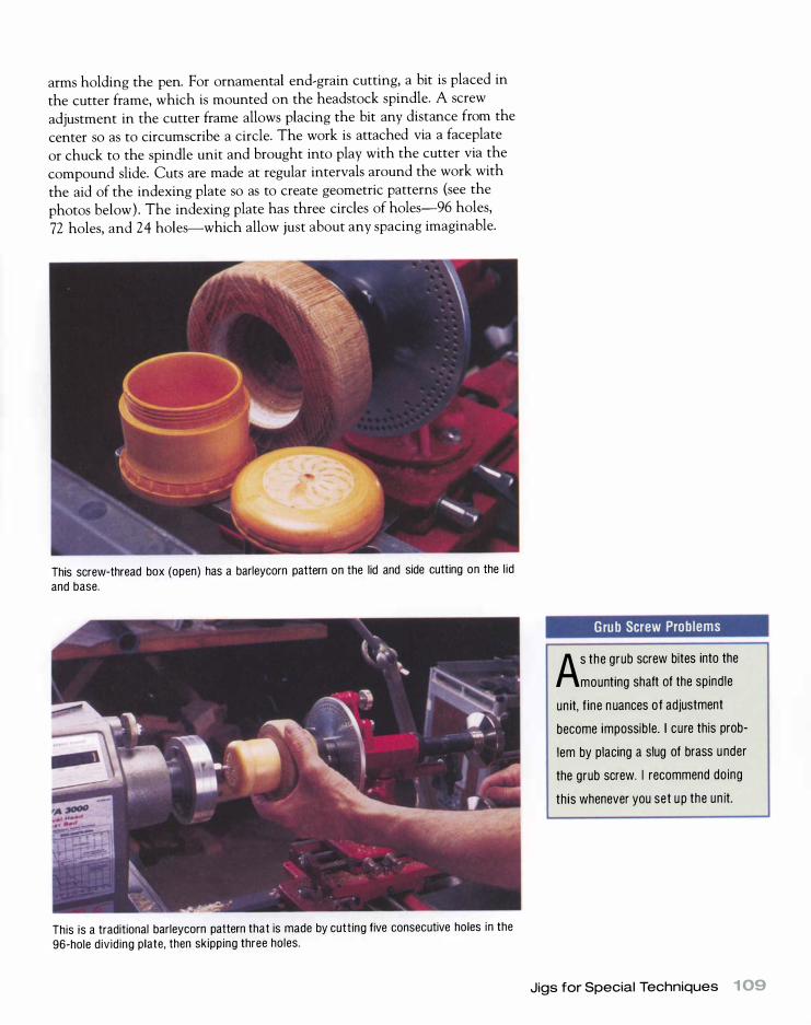
arms holding the pen. For ornamental end-grain cutting, a bit is placed in the cutter frame, which is mounted on the headstock spindle. A screw adjustment in the cutter frame allows placing the bit any distance from the center so as to circumscribe a circle. The work is attached via a faceplate or chuck to the spindle unit and brought into play with the cutter via the compound slide. Cuts are made at regular intervals around the work with the aid of the indexing plate so as to create geometric patterns (see the photos below). The indexing plate has three circles of holes-96 holes, 72 holes, and 24 holes-which allow just about any spacing imaginable.
This screw-thread box (open) has a barleycorn pattern on the lid and side cutting on the lid and base.
This is a traditional barleycorn pattern that is made by cutting five consecutive holes in the 96-hole dividing plate, then skipping three holes.
Grub Screw Problems
As the grub screw bites into the
mounting shaft of the spindle
unit, fine nuances of adjustment
become impossible. I cure this prob
lem by placing a slug of brass under
the grub screw. I recommend doing
this whenever you set u p the un it.
Jigs for Special Techniques 1 09

Virtual End-Grain Cutting
YOU can purchase an end-grain
cutting program for your com
puter called the Ornamental Turning
Companion. With this software, you
can visualize placement and cutting
patterns to save you wood, time, and
money. Even without an OT attach
ment, you can do some virtual end
grain cutting.
1 1 0 Accessories
Side cutting allows the mil l ing of geometric patterns into the side of a turning.
Side cutting In side cutting, the cross slide is used to bring the edge of the work into play with a cutter mounted on a boring bar, which in turn is threaded on the headstock spindle (see the photo above) . The indexing plate is used to make the cuts at regular intervals around the periphery of the work so as to create interesting texture and patterns. It is easy to overdo side cutting and wind up with a busy result. Simplicity is usually better.
Threading Threading is one of the neatest capabilities of the Nova Ornamental Turner. It allows you to make boxes with screw-on lids as well as a variety of threaded parts of 1 in. dia. or greater. For threading, one of three threading bushes is placed on the spindle unit and a half-nut is engaged into the bush. Turning the handwheel on the spindle unit advances the spindle at the pitch of the bush. A 60° cutter is placed in the boring bar, and the work is brought into contact with the cutter via the cross slide. Once in contact with the cutter, the work is advanced along the axis of the lathe via the handwheel on the spindle unit. It is imperative that the compound slide is not moved after the initial cut, or the thread will be ruined. Both internal and external threads may be milled with results in wood far superior to chasing.
The thread pitches of the bushes are metric. In the metric system,
pitch is measured by the distance between two adjacent crests rather than
the number of crests in 1 in. The bushes are 1 .5mm (about 1 7 pitch) , 2mm
(about 1 2Yz pitch) , and 3mm (about 8 1/z pitch) . One could only wish that
the third bush was 8 pitch exactly because then you could mill 1 1f4 in. x
8 threads, which is the size of the headstock spindle on the Nova 3000. I
made such a bush for my Nova Ornamental Turner, but not everyone has
a metal turning lathe to perform this task.

The Nova Ornamental Turner attachment enables you to cut screw threads in wood.
Three different threading bushes, which mount on the spindle un it, allow you to mi l l a host of useful threads. The one on the spindle is 2mm, which is about 1 2)1, pitch.
M etalturning By replacing the spindle unit with a tool holder, you get a metalturning lathe. You can cut cylinders or tapers with a compound slide and perform face cuts with a cross slide. You can, of course, also cut wood to a high degree of accuracy, which could be useful for patternmakers. The only additional thing you could want is travel dials on the hand wheel of the two slides to track travel in thousandths of an inch. Remember that when advancing the cross slide, you take double the advance off of the work because you are cutting both sides. Therefore, an advance of .01 5 in. actually reduces the diameter by 1/16 in.
Lathe Duplicators
While it's my firm belief that lathe duplicators have no place in a small
shop, I concede that they can save a considerable amount of time on large
scale production jobs. A duplicator is an auxiliary carriage that's bolted
onto a lathe bed with a knife connected to a pantograph that travels freely
on the carriage. A master part is placed between centers in the duplicator,
which is normally at the front of the lathe. A billet of the appropriate
diameter is placed between the actual centers of the lathe, then the panto
graph traces the master and moves the knife proportionally. Although
some duplicators have sophisticated knives that cut tangentially, others
make a simple scrape cut-the kind of cut I have been telling you to
avoid. Finally, a decent duplicator is going to cost $2,000 or more these
days, and cheaper ones are not worth having.
Lathe Duplicators 1 1 1

chapter
6 Tools
W hen it comes to tools, the good news is that a vast selection is offered in the marketplace. Unfortunately, there are some really bad tools in addition to some really good ones. Compounding
the problem, most turning tools are not delivered properly shaped or sharpened and need a good deal of user tuning (grinding to the correct shape) and honing to work properly (see chapter 5 for information on grinders and sharpening j igs) .
Most aspiring turners try to use tools directly from the package, doing
nothing more than honing to a sharp edge. They are disappointed by the
results and blame themselves when things do not go well. The fact is that
most people take to turning like ducks to water if sharp tools of the correct
shapes are placed in their hands. If you follow my prescriptions for tool
shapes and sharpening in this chapter, you will find learning to turn an
easier process.
Turning tools are available in three materials: high-carbon steel,
high-speed steel (HSS) , and powdered metal technology steel (PMTS) .
Traditionally, turning tools were made out of high-carbon steel, which is
iron with 3/4 percent to 1 liz percent carbon as the principal alloying ele
ment. Such steel is often referred to as "water-hardening" steel because it
must be quenched in water during hardening.
Water-hardening steel tools are still widely available, but in the last
two decades manufacturers have increasingly switched to high-speed steel
for their premium turning-tool lines. HSS tools are more expensive, but
they hold an edge substantially longer, thus requiring less frequent sharp
ening. HSS also has the quality of "hot hardness." Whereas carbon steel

cannot be heated higher than 430°F without drawing the temper, HSS
maintains its hardness at much higher temperatures and is thus more
immune to damage from burning and overheating due to excessive grind
ing. HSS is more expensive because tungsten, cobalt, and molybdenum
must be alloyed into the steel in addition to carbon.
Another desirable alloying element is vanadium, which forms
vanadium carbide in the steel structure. Vanadium carbide is highly wear
resistant, which makes for better edge holding. In conventional steel mak
ing, alloying elements in the right proportions are mixed while molten and
poured into a mold to form an ingot. The problem is that during cooling,
vanadium carbide "freezes out" first, creating areas of greater and lesser
concentrations of the vanadium carbide. At vanadium levels much above
a 4 percent, "stringers" are created in the resulting ingot that are so hard
that they make the steel difficult to machine or grind.
PMTS can have vanadium levels as high as 1 5 percent. This type of
steel is created by spraying a powdered mixture of the desired proportions
through a nozzle into an inert-atmosphere furnace where tiny spheres of
metal are formed. The resulting powdered metal is then rolled into sheets
and bars by using conventional cold working processes. The alloys of the
original molten mixture become evenly distributed through the PMTS,
giving it a homogenous structure that is free of stringers.
THE HARDNESS OF TOOL STEEL is measured in the Rockwell C Scale, which measures the penetration of a specially shaped diamond into the
material under a specific load. Readings are expressed as Hardness
Rockwell C (HRC) . Under the C Scale, a diamond would measure 100 HRC and a metal file would measure about 64 HRC. As it arrives from the mill, steel is about 30 HRC, but all turning tools need to be
much harder than this to hold an edge. To harden the steel , it's put through a heat-treating process. The first
stage is hardening. Freshly forged high-carbon tool steel is heated to cherry red then quenched in water. This leaves the steel at full hard
ness, around 64 HRC. The hardness is then tempered in a process called drawing. The steel is heated to a predetermined temperature,
which draws back the hardness to the desired level, typically 58 HRC
to 60 HRC for gouges and chisels. Without drawing, the steel would be too brittle; the drawing process actually toughens the tools.
High-speed steels have properties (imparted by the alloying of tung
sten and molybdenum) that make them more difficult to heat-treat but
on the other hand more difficult to damage due to overheating during
grinding or use. Heat-treating of HSS requires heating to much higher temperatures during the hardening process. Instead of being quenched in water, it can be quenched in moving air. The oxide formed
on the surface in air would be unacceptable, however, so heat-treating
is actually done in a vacuum or in inert gas atmosphere furnaces.
Tools 1 1 3

Is It HSS?
D o a spark test on your tool before
you grind it the fi rst time to see if
it's HSS. If you get a white starbu rst,
it's not an HSS tool and should not be
overheated in a grinder. If you get an
orange ball that looks l ike a meteor,
you have HSS.
1 1 4 Tools
PMTS is expensive and much more difficult to machine. However,
turning tools made from such metal hold their edges a long time. Some
kinds of PMTS are not high-speed steels, so they should be given the same
care to prevent overheating during grinding as carbon-steel tools. Many
PMTS are HSS, though, and in fact the best high-speed steels are now
made by powdered metal technology. Examples are M-4, MA2, and T15 .
When purchasing PMTS tools, i t i s best to check the manufacturer's
instructions as to grinding temperatures. There are a few small manufactur
ers (such as Jerry Glaser Engineering Company) making tools from PMTS.
If you're one of the lucky few for whom money is no object, I recom
mend that you buy only HSS or PMTS turning tools. If, like most of us,
you have to watch your budget, begin with high-carbon steel tools or a
mix of carbon steel, HSS, and PMTS tools, then upgrade as your budget
permits. Remember that generations of turners have produced wonderful
results without the benefit of HSS or PMTS. With carbon-steel tools (and
some PMTS) , you just have to be more careful not to overheat the metal
during grinding. By using a grinding j ig (see pp. 92-98) , this is a simple
matter nowadays.
Premium tools are offered in two types: standard and long-and-strong.
Standard tools are for spindle work, while the more robust long-and-strong
tools are for heavy-duty faceplate work. You would only need long-and
strong tools if you progress to turning large bowls.
When buying tools, avoid commercial sets, unless they are such bar
gains that you cannot pass them up. Sets tend to include only two or three
tools you really need, while the rest eventually become expensive scrapers.
Throughout this chapter, I will speak of short, medium, and long
bevels to describe grinding angles (see the illustration on the facing page) .
This age-old way of describing grind angles i s an excellent one for compar
ing two identical tools. A thick tool with a short bevel can be confused
with a thin tool with a long bevel, however. To avoid this confusion, the
IF YOU'RE JUST STARTING OUT, you may be confused about what tool to buy
first. I would build a set of HSS or PMTS tools in the following order: • %-in. spindle gouge
• %-in. or %-in. bowl gouge
• %-in. to 1Y4-in. roughing-out gouge
• 1 -in. or larger skew chisel
• Ys-in. parting tool • scrapers
If possible buy HSS or PMTS tools. However, you can get by with a carbon-steel skew chisel since, barring calamity ( i .e. , an edge-first fall onto a concrete floor) , it can be sharpened exclusively on stones. Similarly, you can easily make scrapers from any available piece of steel.

Bevel Lengths
Typical factory grind for a spindle gouge
Typical combination gouge grind
Typical grind for a working spindle gouge
GRINDING ANGLES FOR VARIOUS BEVEL LENGTHS Bevel length Grind angle
Short
Medium
Long
65° to 85° (typically about 75°)
About 45°
chart above connects bevel length to inclusive angles of grind. In general,
scrapers are ground to short bevels, but the resulting burr is what does the
cutting. Faceplate tools are generally ground to medium bevels and spindle
tools to long bevels.
Gouges
The most basic turning tool is a gouge. It is a stalwart friend in either
spindle or faceplate work. If I were banished to a desert island with a lathe
and just one tool, I would pick a spindle gouge. Mastery of the spindle
gouge is mastery of turning itself.
Traditionally, gouges were forged, and many are still made that way.
Forging entails heating the steel in a forge and hammering it while hot to
the correct shape. At one time, a local blacksmith or even the turner him
self did the forging, but since the Industrial Revolution, it has mostly been
done in drop forges. Drop-forging mechanizes the hand-forging process by
replacing the blacksmith's anvil and hammer with a set of dies of the cor
rect shapes. The dies are put in a powerful press that repeatedly closes
Gouges 1 1 5
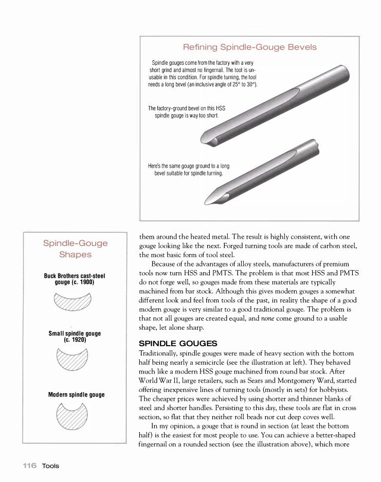
Spindle-Gouge
Shapes
Buck Brothers cast-steel gouge (c. 1 900)
Small spindle gouge (c. 1920)
Modern spindle gouge
1 1 6 Tools
Refining Spindle-Gouge Bevels
Spindle gouges come from the factory with a very short grind and almost no fingernail . The tool is unusable in this condition. For spindle turning, the tool needs a long bevel (an inclusive angle of 25° to 30°).
The factory-ground bevel on this HSS spindle gouge is way too short.
Here's the same gouge ground to a long bevel suitable for spindle turning.
them around the heated metal. The result is highly consistent, with one
gouge looking like the next. Forged turning tools are made of carbon steel,
the most basic form of tool steel.
Because of the advantages of alloy steels, manufacturers of premium
tools now turn HSS and PMTS. The problem is that most HSS and PMTS
do not forge well, so gouges made from these materials are typically
machined from bar stock. Although this gives modern gouges a somewhat
different look and feel from tools of the past, in reality the shape of a good
modern gouge is very similar to a good traditional gouge. The problem is
that not all gouges are created equal, and none come ground to a usable
shape, let alone sharp.
SPINDLE GOUGES
Traditionally, spindle gouges were made of heavy section with the bottom
half being nearly a semicircle (see the illustration at left) . They behaved
much like a modern HSS gouge machined from round bar stock. After
World War II, large retailers, such as Sears and Montgomery Ward, started
offering inexpensive lines of turning tools (mostly in sets) for hobbyists.
The cheaper prices were achieved by using shorter and thinner blanks of
steel and shorter handles. Persisting to this day, these tools are flat in cross
section, so flat that they neither roll beads nor cut deep coves well.
In my opinion, a gouge that is round in section (at least the bottom
half) is the easiest for most people to use. You can achieve a better-shaped
fingernail on a rounded section (see the illustration above) , which more

readily conforms to the shapes of coves and beads. The shape also gives
the tool more stability because it puts the area of contact with the tool rest
under the center of the force where the cutting takes place. With flatter
tools that have an oval section, contact with the rest can be to one side
of the area where the cut is taking place. The best spindle gouges have flutes that are a radius and not too deep.
This shape achieves a long fingernail yet keeps the area that is cutting
over the point where the shank contacts the rest.
Gouge
A simple bar-type rest is the best for sharpening spindle gouges freehand .
2AS you swing the tool, you must simultaneously
tip the tool upward (the handle down) and rotate
the handle slightly. Rotate the handle clockwise if
swinging to the right and counterclockwise if
swinging to the left.
1 Touch at the nose and immediately start swinging the
tool either to the right or to the left. In this case, I am
swinging to the right.
3 Repeat the same steps in mirror image for the
other half of the tool.
Gouges 1 1 7

1 1 8 Tools
In the past, many people have tried to use what I call a pocket j ig to
grind a spindle gouge. The handle is pocketed in a cup on a sliding arm in
front of the grinder and simply rotated against the wheel (see the illustra
tion below) . The problem with this arrangement is that although the point
is ground fine, the sides of the fingernail lack clearance, with the edge
being inside the bevel.
The Oneway, Sorby, and Tormek j igs improve on ordinary pocket j igs
by fixing the tool in an adjustable gooseneck, which itself rests in a pocket.
The result is a perfect fingernail grind with correct side angles. The angle
of the gooseneck and the actual length of the bevel control the relation
ship between the point and sides of the fingernail. Angle of grind is con
trolled by how far the pocket is placed from the grinding wheel. On the
Oneway j ig, the pocket is on an arm that slides in and out just below the
wheel. On the Sorby, the same result is achieved by adjusting the length of
the gooseneck, and on the Tormek, the mounting arm for the gooseneck
can be raised and lowered.
Pocket Jigs
because the bevel is outside the cutting edge.
Sl iding the pocket in or out changes the length of the bevel.
Spindle gouge is ground to a long bevel in pocket j ig .

A roughing-out gouge may be sharpened on a platform rest (left) or in a pocket j ig (right) . The platform rest is better because tool-handle length precludes a long bevel on most home-shop-sized grinders.
ROUGHING-OUT GOUGES
The roughing-out gouge is a useful tool. It can remove large amounts of
material quickly and is great for rounding billets fast. I also find it useful
for cutting cylinders and tapers. If ground to a long bevel, it produces
results nearly as good as a skew does with none of the behavior problems
associated with skews. Most large spindle gouges make good roughing-out
gouges, which is a good way to use a less-than-adequate spindle gouge if
you're on a budget.
In the past, American turners left a bit of a fingernail on roughing-out
gouges, which meant they could be used to cut large coves since they were
just large forged gouges. Today, most turners follow the English tradition of
grinding them square. Whichever way you grind them is largely a matter of
taste and training. Both grinds work equally well. I prefer a square British
grind because it is easier to do.
To sharpen a roughing-out gouge, you can use either a platform rest or
a pocket j ig. I generally employ a platform rest because I get more consis
tency from gouge to gouge. The long handle length of some modem HSS
examples means you can't obtain a long bevel with a pocket j ig. For those
who are good at freehand grinding, you can simply plant your feet well in
front of the grinder and rest the tool handle on your thigh. Your leg acts as
a pocket j ig (see the photo at right) .
Today, HSS roughing-out gouges tend to be made from l,k-in. HSS flat
stock, which is cut to a basic outline, then hot-bent to form a U. Although
the factory grind for the HSS variety has a cutting edge (or face) that is
square to the shank of the tool and a medium bevel, the tool works much
better with a long bevel about 25° to 30° (see the illustration on p. 1 20 ) .
For HSS roughing-out gouges, bigger i s better-I like the l lj4-in. size.
If you are already comfortable with freehand grinding, you don't need a j ig or a rest. Simply plant your feet well in front of the grinder, and rest the tool handle on your thigh.
Gouges 1 1 9

Bowl-Gouge Grind
A modified factory g rind is the
best g rind for learning to use a
bowl gouge.
1 20 Tools
Roughing-Out Gouges
� Cross section ---:::a;;;;;:;;;.-:
u Cross section
BOWL GOUGES
This very large spindle gouge can be used as a roughing-out gouge. It can be left with a blunt fingernail or reground square.
This modern HSS roughing-out gouge has a traditional British grind. I also prefer this 1 1/4-in . size.
The bowl gouge is designed for faceplate turning, in which the grain of the
wood runs across the axis of the lathe. The long bevel of a spindle gouge
would readily dig into the reverse grain, causing a nasty catch. The bowl
gouge provides a two-fold solution: Shorten the bevel of the gouge (the
traditional angle is 45°) , and cut at right angles to the axes of rotation. In
this cutting position, the bottom half of the flute does all of the work and
the nose bevel rides on the cylinder (or cone) being generated by the cut.
This prevents the gouge from following the reverse grain and gives you a
nice cut.
Bowl gouges have much deeper flutes than spindle gouges. Tradi
tionally, they were forged with deep U-shaped bevels, which is ground
all the way around to 45 ° (see the illustration on the facing page) . The
face is square to the shank. In fact, it is ground much like a roughing-out
gouge, except that the bevel is shorter. Modem bowl gouges, machined
from HSS round bar stock, generally have parabolic-shaped flutes.
Most turners find the tool more useful if they modify the factory grind.
The simplest modification is to rake the face of the tool back at least 1 5 °
but retain the 45 ° bevel (see the photos on p. 1 22 ) . You can further modify

Bowl-Gouge Profiles
Face is square to tool and bevel is ground to 45°.
Modern HSS bowl gouge has typical factory grind.
Same gouge has face raked back, which gets the top corners of the bevel out of the way so they are less prone to catching.
Asymmetric grind has nose bevel flattened to about 80° but with side bevels at 45°.
Advanced grind has face raked far back. It has flat nose bevel but aggressive side bevels (as little as 20°) and leaves a superlative f inish on wet wood and i n skil led hands.
Gouges 1 21

1 22 Tools
it by going to an asymmetric grind whereby the nose bevel is flattened in
relation to the side bevels, which remain at 45°. This grind is much better
for turning the insides of deep bowls because the nose bevel does not lose
contact when it goes around the area between the side wall and the bot
tom. A 45 ° nose bevel loses contact at this area, resulting in a rough cut.
Many bowl turners grind the side bevels back further and increase
the length of the bevel at the sides. In skilled hands, this grind can cut
through reverse grain with hardly any tearout, but it negates much of the
forgiving nature of a bowl gouge. Instead of rolling out of trouble, the
gouge tends to dig in deeper. I urge you to become proficient with one
of the milder grinds before progressing to this one.
To achieve a general-purpose grind on a bowl gouge, start by touching one side of the bevel to the wheel to grind an approximately 45° angle. (The entire cutting edge, on that half of the flute, should be fairly square to the wheeL ) Here I am starting with the left flank. Next, swing the handle toward center while s imultaneously raising and twisting it. Repeat the process in mirror image for the other half of the tool.

A Common Sharpening Mistake
Cutting starts here before nose can become engaged.
If the nose is ground too much, the side flutes start to cut before the nose can become engaged, so the tool skitters at the start and is hard to d irect once cutting begins
It is easy to grind more at the nose than on the side bevels, resulting
in the shape shown in the illustration above. This shape makes the tool
hard to start because the protruding side bevel will begin cutting before
the nose has a chance to engage itself on the cut. Because the nose is small
in relation to the side bevels, it will be ground away quicker than the sides
if you don't grind lightly in the nose area. With a properly ground bevel,
the nose engages simultaneously with the start of the lower bevel's cut.
I use a bowl gouge straight from the grinder without buffing it.
COMBINATION GOUGES
In the last decade, rather long HSS gouges with medium flutes have
emerged (see the top illustration on p. 1 24) . These combination gouges
can be ground to a medium bevel angle to do either faceplate or spindle
work. In truth, they do not work in spindle turning as well as a true spin
dle gouge (see the bottom illustration on p. 1 16) . They cannot be ground
to the really long bevel necessary for top-quality spindle work. This is
because a 30° bevel breaks through at the sides of the flute too low, leav
ing a ragged burr at the flanks.
The best use of a combination gouge is for taking a final light cut in
faceplate work. You should present the tool much like a bowl gouge but
more uphill. The tool can cut to the left or right, with the bevel riding
behind the cut to prevent the tool from digging into the reverse grain
areas. Used lightly, a combination gouge can save hours of sanding.
You can sharpen this gouge by eye in much the same way as a spindle
gouge, but I recommend sharpening this tool in a j ig. I buff a combination
gouge to achieve a really keen edge.
Gouges 1 23
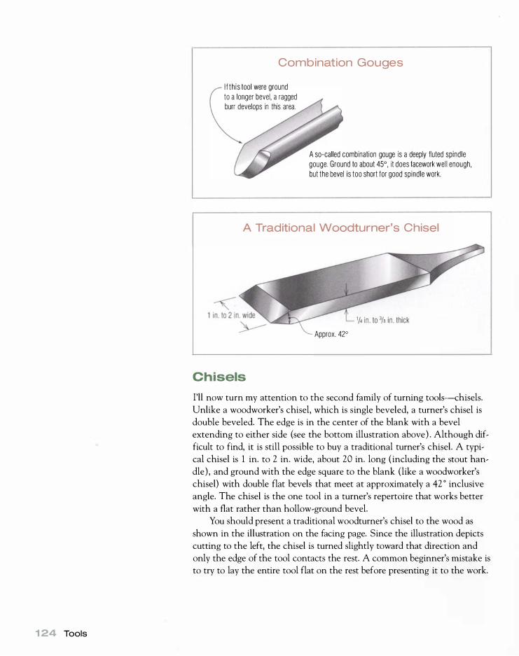
1 24 Tools
Combination Gouges
I f th is tool were ground to a longer bevel, a ragged burr develops in this area.
A so-called combination gouge is a deeply fluted spindle gouge. Ground to about 45°, it does facework well enough, but the bevel is too short for good spindle work.
A Traditional Woodturner's Chisel
1/4 i n . to % i n . thick
Approx. 42°
Chisels
I'll now turn my attention to the second family of turning tools-chisels.
Unlike a woodworker's chisel, which is single beveled, a turner's chisel is
double beveled. The edge is in the center of the blank with a bevel
extending to either side (see the bottom illustration above) . Although dif
ficult to find, it is still possible to buy a traditional turner's chisel. A typi
cal chisel is 1 in. to 2 in. wide, about 20 in. long ( including the stout han
dle) , and ground with the edge square to the blank (like a woodworker's
chisel) with double flat bevels that meet at approximately a 42 0 inclusive
angle. The chisel is the one tool in a turner's repertoire that works better
with a flat rather than hollow-ground bevel.
You should present a traditional wood turner's chisel to the wood as
shown in the illustration on the facing page. Since the illustration depicts
cutting to the left, the chisel is turned slightly toward that direction and
only the edge of the tool contacts the rest. A common beginner's mistake is
to try to lay the entire tool flat on the rest before presenting it to the work.

I like to lock my fingers around the right edge of a chisel using a
relaxed but firm grip. The real control of this tool comes from twisting it
ever so slightly up and down to keep it cutting correctly. A beginner often
makes the mistake of trying to raise and lower the handle or swing the
handle left and right to control the cut. In the split second the cut gets the
least off of the bevel, the edge starts cutting a helix in the work and is
drawn down toward the rest with the corner (T) digging in. These catches
A
How a Chisel Cuts
The bevel we cannot see (the one on the far side of the tool) is rubbing the work and the edge is cutting somewhere between the dotted l i nes "A" and "8". The cut should take place in an area to the left of center of the tool (as shown by the shaded area), and no more than half the length of the cutting edge should be engaged. This puts the cut in an area just to the right of the corner of the chisel "H" and somewhere just to the right of center. The other corner of the chisel 'T is well clear of the cut.
T
� �' r---------=-" 8
Chisels 1 25
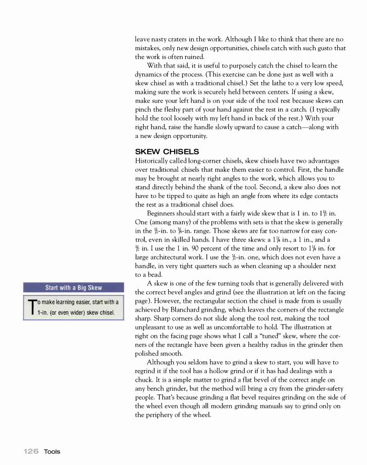
Start with a Big Skew
To make learning easier, start with a
1 -in . (or even wider) skew chisel.
1 26 Tools
leave nasty craters in the work. Although I like to think that there are no
mistakes, only new design opportunities, chisels catch with such gusto that
the work is often ruined.
With that said, it is useful to purposely catch the chisel to learn the
dynamics of the process. (This exercise can be done just as well with a
skew chisel as with a traditional chisel. ) Set the lathe to a very low speed,
making sure the work is securely held between centers. If using a skew,
make sure your left hand is on your side of the tool rest because skews can
pinch the fleshy part of your hand against the rest in a catch. ( I typically
hold the tool loosely with my left hand in back of the rest . ) With your
right hand, raise the handle slowly upward to cause a catch-along with
a new design opportunity.
SKEW CHISELS
Historically called long-corner chisels, skew chisels have two advantages
over traditional chisels that make them easier to control. First, the handle
may be brought at nearly right angles to the work, which allows you to
stand directly behind the shank of the tool. Second, a skew also does not
have to be tipped to quite as high an angle from where its edge contacts
the rest as a traditional chisel does.
Beginners should start with a fairly wide skew that is 1 in. to 1 Yz in.
One (among many) of the problems with sets is that the skew is generally
in the liz- in. to 3/4- in. range. Those skews are far too narrow for easy con
trol, even in skilled hands. I have three skews: a 1 1/4 in., a 1 in., and a
Yz in. I use the 1 in. 90 percent of the time and only resort to 1 1/4 in. for
large architectural work. I use the liz-in. one, which does not even have a
handle, in very tight quarters such as when cleaning up a shoulder next
to a bead.
A skew is one of the few turning tools that is generally delivered with
the correct bevel angles and grind (see the illustration at left on the facing
page) . However, the rectangular section the chisel is made from is usually
achieved by Blanchard grinding, which leaves the corners of the rectangle
sharp. Sharp corners do not slide along the tool rest, making the tool
unpleasant to use as well as uncomfortable to hold. The illustration at
right on the facing page shows what I call a "tuned" skew, where the cor
ners of the rectangle have been given a healthy radius in the grinder then
polished smooth.
Although you seldom have to grind a skew to start, you will have to
regrind it if the tool has a hollow grind or if it has had dealings with a
chuck. It is a simple matter to grind a flat bevel of the correct angle on
any bench grinder, but the method will bring a cry from the grinder-safety
people. That's because grinding a flat bevel requires grinding on the side of
the wheel even though all modern grinding manuals say to grind only on
the periphery of the wheel.

Skew Chisels
H
Long ago turners realized that by skewing the edge about 200 they could achieve a longer edge on any given chisel. The width of a skew refers to the length of the cutting edge. The long corner 'T' is referred to as the toe and the short corner "H" is referred to as the heel.
T A Tuned Skew
Radius edges
Chisels 1 27

1 28 Tools
The safety people are worried that an unskilled turner will put exces
sive side pressure on a thin wheel, causing it to break. They are also wor
ried that the same person might excessively dress the side of the wheel,
possibly dressing a groove that could start a general fault in the wheel-a
break on the dotted line so to speak. But I have never known an experi
enced toolmaker who did not grind on the side of a wheel once in a while.
In addition, hardware stores sell twist-drill sharpening j igs that only work
by using the side of a wheel.
The important thing is to bring some common sense to the situation.
An occasional grinding on the side of a wheel is okay if you put only light
side pressure on a l�_ in. or wider wheel ( the wider the better). Never
excessively dress the side of a wheel. I typically lightly dress the sides of a
wheel with a diamond dresser to true it up when I first mount it, then only
dress once or twice more with a diamond during the entire life of the
wheel. Always keep the grinding shields properly adjusted, and wear safety
glasses or, even better, a face shield with safety glasses.
To grind a skew, set the rest so that it is level, and use this as a place
to rest the shank of the tool for support. When grinding on the side of
the wheel, there is a tendency for the top half of the tool to be ground
less than the bottom, so you'll need to compensate for this by putting
additional pressure on the top half. I typically apply pressure with my
thumb against the top half. As you grind, alternate from one bevel to the
other until an edge is formed and you have contiguous flat. Start with a
Grinding a skew on the side of a wheel is the only way to obtain a flat bevel. Grinder manufacturers don't recommend this, but it is safe if you use moderate pressure against a wheel that is 'h in. or wider.
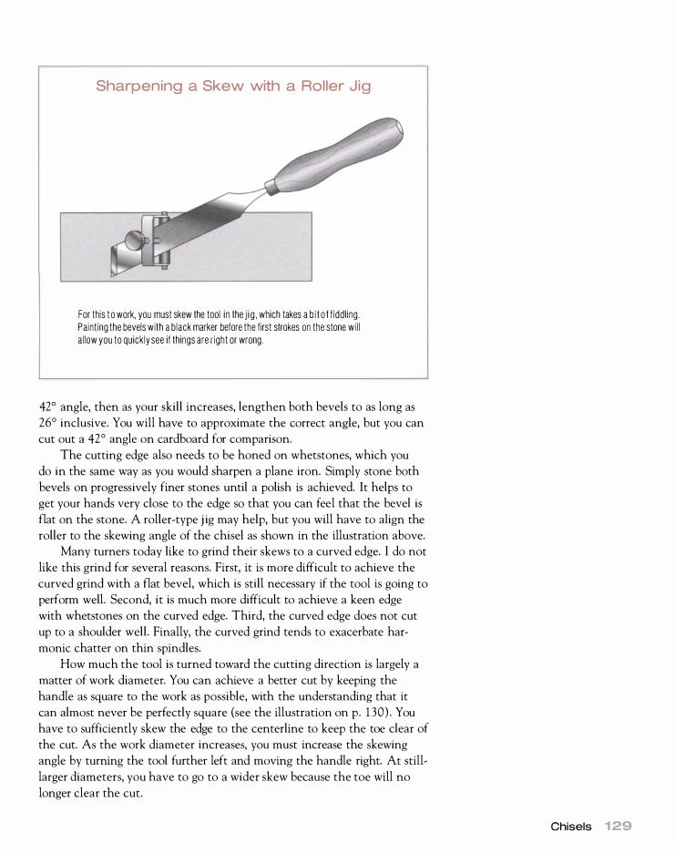
Sharpening a Skew with a Roller Jig
For this t o work, you must skew the tool i n the j i g , which takes a b i t o f f iddling. Painting the bevels with a black marker before the first strokes on the stone wil l al low you to quickly see if things are right or wrong
42° angle, then as your skill increases, lengthen both bevels to as long as
26° inclusive. You will have to approximate the correct angle, but you can
cut out a 42° angle on cardboard for comparison.
The cutting edge also needs to be honed on whetstones, which you
do in the same way as you would sharpen a plane iron. Simply stone both
bevels on progressively finer stones until a polish is achieved. It helps to
get your hands very close to the edge so that you can feel that the bevel is
flat on the stone. A roller-type j ig may help, but you will have to align the
roller to the skewing angle of the chisel as shown in the illustration above.
Many turners today like to grind their skews to a curved edge. I do not
like this grind for several reasons. First, it is more difficult to achieve the
curved grind with a flat bevel, which is still necessary if the tool is going to
perform well. Second, it is much more difficult to achieve a keen edge
with whetstones on the curved edge. Third, the curved edge does not cut
up to a shoulder well. Finally, the curved grind tends to exacerbate har
monic chatter on thin spindles.
How much the tool is turned toward the cutting direction is largely a
matter of work diameter. You can achieve a better cut by keeping the
handle as square to the work as possible, with the understanding that it
can almost never be perfectly square (see the illustration on p. 130) . You
have to sufficiently skew the edge to the centerline to keep the toe clear of
the cut. As the work diameter increases, you must increase the skewing
angle by turning the tool further left and moving the handle right. At still
larger diameters, you have to go to a wider skew because the toe will no
longer clear the cut.
Chisels 1 29

1 30 Tools
How a Skew Cuts
As with the traditional chisel, you can only use about half the edge, but skewing gives a longer edge, so you can take a heavier cut. Cutting takes place within the shaded area, which is from a point just to the right of the heel "H" to just to the right of center-but not more than half the length of the edge.
T
Long, thin work is subject to harmonic chatter where the work
vibrates between centers, causing a spiral ripple in the finish. The more
the edge is skewed to the work, the more harmonic chatter is exacerbated.
Therefore, you should keep the handle of the skew as square to the work as
possible.
A flat bevel contacts the centerline from the cutting edge to the heel
of the bevel. If the edge is hollow-ground, there is no support for the cut
ting edge between where the heel of the bevel contacts the centerline and
where the edge is cutting (which is also on the centerline) . Therefore, a
flat bevel makes the tool much more stable.

OVAL SKEWS
A rectangular skew chisel is difficult to use because the tool is unbalanced.
The center of gravity is not under the downward movements of force
because only one edge of the tool can contact the rest. An oval skew
changes all of this. It creates a skew with a center of gravity that is nearly
under the center of force-a center of gravity that is free to change with
the rolling action of the tool.
Unfortunately, most oval skews are delivered with too long a bevel
( 26°) for most beginners. The problem can be fixed, though, by shortening
the bevels to about 42°.
Cutting Up to a Shoulder with a Skew
Chisels 1 31
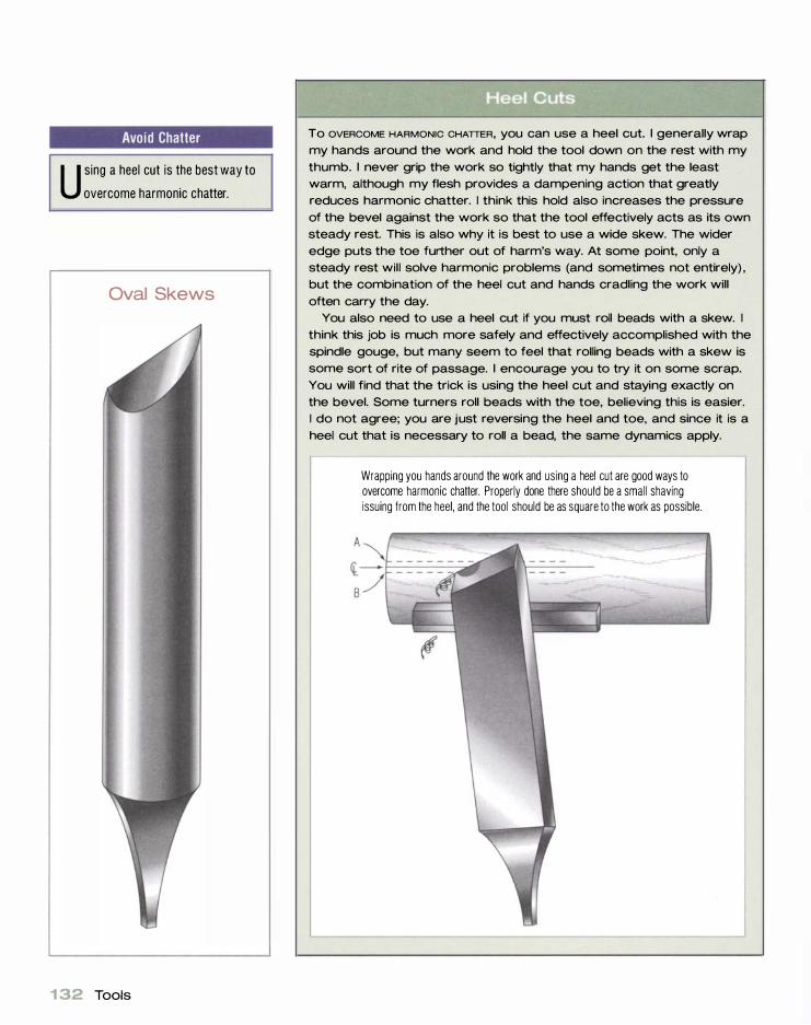
Avoid Chatter
U sing a heel cut is the best way to
overcome harmonic chatter.
Oval Skews
1 32 Tools
To OVERCOME HARMONIC CHATTER, you can use a heel cut. I generally wrap
my hands around the work and hold the tool down on the rest with my
thumb. I never grip the work so tightly that my hands get the least warm, although my flesh provides a dampening action that greatly
reduces harmonic chatter. I think this hold also increases the pressure
of the bevel against the work so that the tool effectively acts as its own
steady rest. This is also why it is best to use a wide skew. The wider
edge puts the toe further out of harm's way. At some point, only a steady rest will solve harmonic problems (and sometimes not entirely) ,
but the combination of the heel cut and hands cradling the work will
often carry the day. You also need to use a heel cut if you must roll beads with a skew. I
think this job is much more safely and effectively accomplished with the
spindle gouge, but many seem to feel that rolling beads with a skew is
some sort of rite of passage. I encourage you to try it on some scrap.
You will find that the trick is using the heel cut and staying exactly on
the bevel. Some turners roll beads with the toe, believing this is easier. I do not agree; you are just reversing the heel and toe, and since it is a
heel cut that is necessary to roll a bead, the same dynamics apply.
Wrapping you hands around the work and using a heel cut are good ways to overcome harmonic chatter. Properly done there should be a small shaving issuing from the heel, and the tool should be as square to the work as possible.

Cutoff Tools
Chisels 1 33

f...- _ .............. - -
.............. ........ - - - - ........ 3
'- '- .......... '- ..... " "
A Cutoff Tool in Action
\ / - - - ..::::. - - - - -'-�
����- - - - - - - - - - - - -2 .....
1 34 Tools
'-
I \
..... ..... " - .......... -"" ........
/ .-- ..... / "
+ " /
\ I /
'- ..... " \ \ \ \ \
," \ / I
/ / /
I I f
I / /
This cross section of the workpiece as viewed from the tailstock end of the lathe shows how a cutoff tool moves while in use.
A cutoff tool is easy to grind by eye. Simply touch both bevels to the grinder to achieve a 42° or less point, inclusive. Keep the point centered on the blank, especial ly on diamond tools.

CUTOFF TOOLS
The cutoff tool, sometimes called a parting tool, is also in the chisel
family (see the illustration on p. 133 ) . A diamond-shaped cutoff tool is
the best variation of the tool, although it also comes in a cheaper rectan
gular variety. The diamond shape has several advantages. It presents less
surface area to rub ( thus creating less friction in a deep cutoff); it will still
Other Chisels Bedan Beading-and-Parting Tool
Chisels 1 35

1 36 Tools
cut if the tool is not perfectly vertical on the tool rest; and it cuts a nar
rower kerf in faceplate-oriented cutoffs. The chief advantage of the rectan
gular version is its low cost. Both types are generally sold in widths ranging
from 1/16 in. to Y4 in. wide.
Because of the way a cutoff tool is presented, you can hollow-ground
it; it is best ground to a long double bevel of 42 0 or less, inclusive (see the
photo on p. 134) . Although most turners use the tool directly from the
grinder, it works better in spindle work if you remove the burr by honing
it on a fine stone.
To use a cutoff tool, place it vertically on the tool rest and present it
at a high angle with the bevel rubbing and the edge just cutting. Rock it
down until the cutting edge ends up at the exact center of the work and a
parting is achieved. As you can see in the illustration on p. 1 34, the tool
has to slide forward on the rest as the cutoff progresses to keep the bevel
rubbing. In a deep cutoff, it is best to take overlapping cuts to keep the
kerf wider than the tool. Presenting the tool this way in face work may
result in a catch, so for faceplate cutoffs, present the tool at or slightly
above the centerline and push it forward to the center.
CONE SEPARATION TOOLS
The cone separation tool is nothing more than a giant cutoff tool. It is
used for cutting away the interior of a bowl to save time and wood. By
coning away the center of a bowl, more bowls can be turned from the same
blank. I often mount a thick blank and cone three nesting bowls from it.
You use this tool the same way as a cutoff tool in facework, but you
will have to make overlapping cuts to keep the kerf considerably wider
than the shank of the tool. Keep the belt slack so that if there is a jam due
to chip buildup, the lathe will slip rather than break your arm. A cone sep
aration tool should never be used with a gear-driven lathe.
OTHER TYPES OF CHISELS
The bed an and beading-and-parting tool also fit in the chisel family (see
the illustration on p. 1 35 ) . A bedan is much like a 3h- in.-wide bench
chisel. It is essentially a superwide cutoff tool ( though it is single beveled)
and is used with exactly the same technique. The single bevel is ground
to a long bevel, about 25° to 30°, inclusive. Like the parting tool, it can
be hollow-ground but must be honed to a razor-sharp edge like the skew.
It is handy for sizing tenons.
The beading-and-parting tool is basically a 3h-in. -wide traditional
wood turner's chisel. It can be used both for sizing tenons and for rolling
beads, but for the latter it must have a flat bevel. Like a skew, it must be
used with a heel cut when rolling beads, but it may be a bit more control
lable than a skew for this task.

Scrapers
The term scraper refers to a whole class of tools that are purposely sharp
ened to a burr and used at a downhill slant. The word scrape is misleading
because in reality a scraper is taking a highly positive shear cut. A turner's
scraper works exactly as a common cabinet scraper. The burr is what does
the work because it is actually a micro cutting edge (see the illustration on
p. 138 ) . The short length of the burr effectively limits the depth of cut per
revolution of the work, making it a safe, predictable tool.
There are times when it is impossible to use a gouge, so a scraper is
called for. Scrapers are the workaday implements that get the job done
and often carry the day. A gouge may be the best way to cut wood because
it leaves the best finish, but it requires a fair amount of skill and cannot
reach blind areas. A scraper cuts wood handily in all situations and
requires only a modicum of skill. You can also grind scrapers to compli
cated shapes, making it easy to duplicate details.
A scraper is quite different from other turning tools, and at first it can
be a little unnerving to use. Up until now, you have been taught to shear
cut, which requires keeping the bevel of the tool rubbing on the work
surface. Suddenly, you must now point the tool downhill and drag the
burred edge for it to cut properly. In fact, pointing it uphill can cause a
nasty catch.
Scrapers are sharpened to a bu rr, which is d ragged across the work at a downward slope. A scraper can be made from almost any piece of steel, a screw d rive, a cement nail , an Allen wrench, or an old piece of spring steel. Here is a collection of scrapers I have either bought or improvised over the years.
Scrapers 1 37
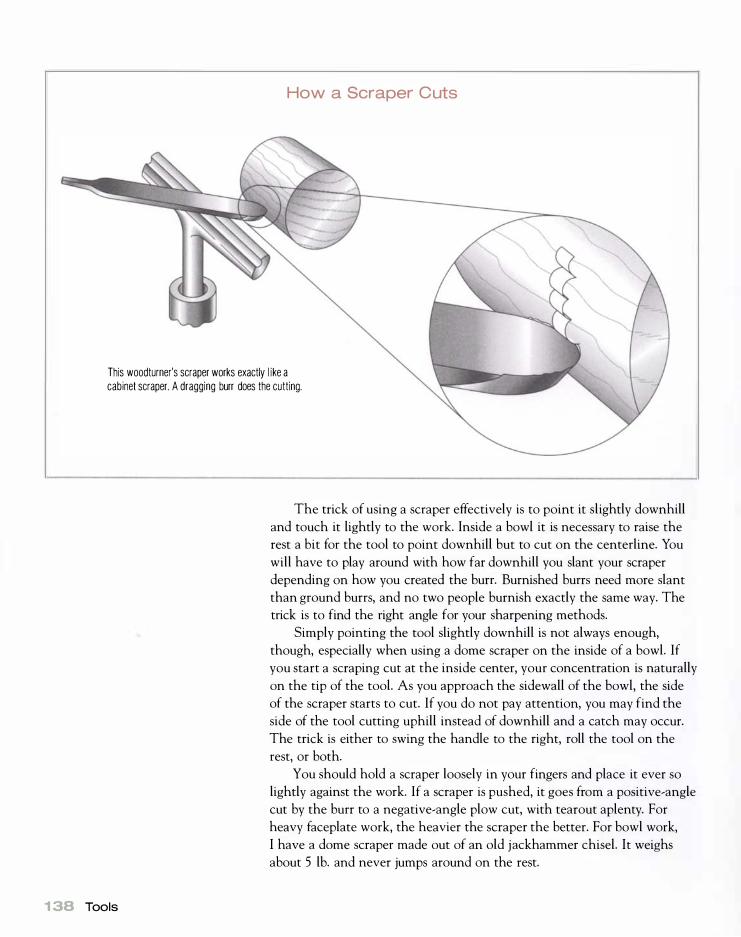
How a Scraper Cuts
This woodturner's scraper works exactly l ike a cabinet scraper. A dragging burr does the cutting.
1 38 Tools
The trick of using a scraper effectively is to point it slightly downhill
and touch it lightly to the work. Inside a bowl it is necessary to raise the
rest a bit for the tool to point downhill but to cut on the centerline. You
will have to play around with how far downhill you slant your scraper
depending on how you created the burr. Burnished burrs need more slant
than ground burrs, and no two people burnish exactly the same way. The
trick is to find the right angle for your sharpening methods.
Simply pointing the tool slightly downhill is not always enough,
though, especially when using a dome scraper on the inside of a bowl. If
you start a scraping cut at the inside center, your concentration is naturally
on the tip of the tool. As you approach the sidewall of the bowl, the side
of the scraper starts to cut. If you do not pay attention, you may find the
side of the tool cutting uphill instead of downhill and a catch may occur.
The trick is either to swing the handle to the right, roll the tool on the
rest, or both.
You should hold a scraper loosely in your fingers and place it ever so
lightly against the work. If a scraper is pushed, it goes from a positive-angle
cut by the burr to a negative-angle plow cut, with tearout aplenty. For
heavy faceplate work, the heavier the scraper the better. For bowl work,
I have a dome scraper made out of an old jackhammer chisel. It weighs
about 5 lb. and never jumps around on the rest.

A scraper is one of the easiest tools to grind.
G rind to shape using your pattern as a gu ide. Everything should be undercut at least 5° but no more than 1 5° .
There are two ways to sharpen a scraper: grinding and burnishing.
Grinding a scraper is simplicity itself. Set the grinding rest so that the
bevel will be ground to about a 75 ° inclusive angle (most turners refer to
this as 1 5 ° of clearance in the edge) . Place the tool flat on the rest, and
push it into the wheel. Keeping firm pressure on the tool, swing it to
achieve the desired shape (see the bottom photo above). You do not need
Making a Form Scraper
YOU can make a form scraper by
d rawing the shape you want on a
piece of paper, g lu ing the resulting
pattern to the scraper, and grinding to
the pattern.
Scrapers 1 39

1 40 Tools
When the scraper is g round, it should look like this. Note the undercut is also about 5° to the sides in the area of the bead.
to grind the tool upside down to achieve the burr; it forms just as well by
grinding right side up and you can see what is happening. A burr is the
natural outcome any time a tool is ground.
Even though a ground burr works quite well, burnishing creates an
even better burr. A burnish is no more than a round or oval bar of hard,
polished steel. It is like a file without teeth. When burnishing a commer
cially available scraper, you must use a carbide burnisher because a stan
dard cabinetmaker's burnisher will only work if a tool is soft enough
around 55 HRC. HSS turning tools (scrapers included) are in the range
of 58 HRC to 62 HRC.
It is possible, though, to make a scraper from a softer piece of metal
and burnish it successfully with a cabinetmaker's burnisher. You can also
draw the temper back on an old file to make it soft enough to burnish.
To do this, grind the file to the desired shape and buff the area adjacent to
the cutting edge to a good polish. Carefully and evenly heat the file with a
propane torch until the polished area turns a deep blue color. Keep the
torch moving all the time, and do not apply too much heat at the cutting
edge. You should apply more heat behind the edge so that the heat flows
out to the edge. When the tip area is bright blue, quench it in water. You
have now drawn the temper back to about 55 HRC and can burnish with
a standard cabinetmaker's burnisher.
The burnishing process changes the crystalline structure of the steel at
the cutting edge, increasing the hardness in this area. This is called work
hardening. It is not possible to burnish without first removing this work
hardened area by filing or grinding it away. Once the cutting edge has
been filed or ground, use an oil stone to bring the bevel and the back ( top
surface) of the tool to a good finish. It need not be a polish, just a good

Scraper
Burnishing a turning scraper is much the same as burnishing a cabinet scraper. It is a three-step process : grinding away the old, work-hardened edge ; bringing the ground edge to a hard , polished corner with oil stones ; and burnishing a burr with a burnishing tool.
1 Grind to remove the work-hardened metal at the edge.
2 Use an oil stone to bring the bevel and back to a
good finish.
3 Use a cabinetmaker's burnisher to roll the edge.
Considerable force is necessary, and a bit of wax
helps in rolling the burr because it makes the burnish
slide more easily. You may find clamping the tool in a
vise helpful.
Scrapers 1 41

Using a Burnished Scraper
YOU may have to tip a burnished
scraper further downhil l to get it
to cut than a g round scraper.
142 Tools
Veritas makes a burnishing fixture that will roll a burr even on HSS scrapers.
finish. Next, rub the burnish along the bevel edge with considerable force.
By slanting the burnish toward the back of the tool, you roll a burr. To get
sufficient leverage, you may find it necessary to clamp the tool in a bench
vise and place some body weight on the burnish. Waxing or oiling the bur
nish also helps because it reduces friction.
Although burnishing works well and produces a burr superior to grind
ing, it is not worth the trouble on small scrapers, especially if a scraper has
a complicated shape. When doing heavy faceplate work with a large
scraper, a burnished burr offers considerable advantages because it takes
heavier shavings and holds it edge slightly longer.
Veritas makes a burnishing fixture that will roll a burr even on HSS
scrapers (see the photo above) . It employs a carbide cone fixed in an alu
minum base, which screws to a work surface. A fulcrum pin, which can be
located in two positions, allows you to lever the cutting edge of any tool
against the carbide cone to roll the burr. The fixture works well and is
inexpensive.

Hook and Ring Tools
Hook tools and their easier-to-manufacture modern equivalents, ring tools,
are left over from the time when lathes were human powered. The easiest
way to visualize a hook tool is to think of bending the leading inch of a
roughing-out gouge up at a right angle (see the illustration below) . This
configuration allows you to present the edge of the tool at the bottom of a
bowl. The tool is most prevalent in Scandinavia, where its use has never
entirely died out.
If properly sharpened, hook tools are efficient, but they are designed
for very low speeds such as those you would encounter in spring-pole
lathes. I cannot emphasize enough that speeds of 1 50 rpm to 250 rpm are a
must when using this tool for faceplate work. Hooks are dangerous at high
turning speeds.
To use the tool, place it level (or even pointed slightly downhill) on
the rest. Roll it left about 45° so that the face of the cutting edge is
Hook and Ring Tools
Scandinavian turners use a fulcrum pin to aid in levering a tool in an arc. The tool is rolled 45° left during use.
Sorby's ring tool is turned, and shank is welded to the ring.
The Termite, Oneway's ring tool, is i nvestment cast and mechanically attached to the shank.
Rest
Fulcrum p in
Hook and Ring Tools 1 43
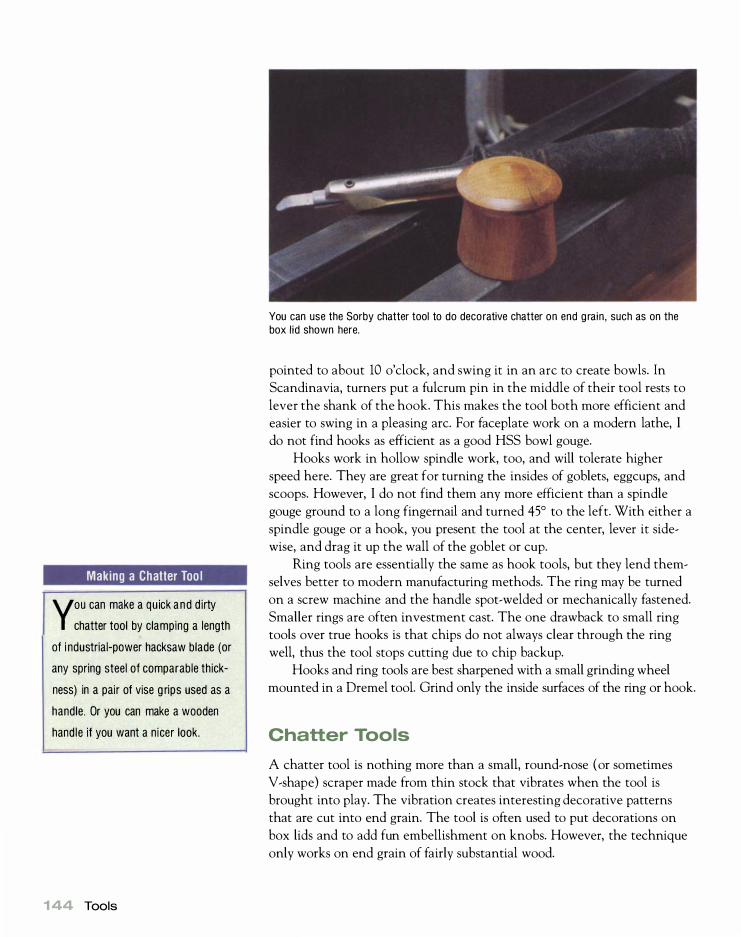
Making a Chatter Too l
YOU can make a quick and d irty
chatter tool by clamping a length
of i ndustrial-power hacksaw blade (or
any spring steel of comparable thick
ness) in a pair of vise g rips used as a
handle. Or you can make a wooden
handle if you want a n icer look.
1 44 Tools
You can use the Sorby chatter tool to do decorative chatter on end grain, such as on the box lid shown here.
pointed to about 10 o'clock, and swing it in an arc to create bowls. In
Scandinavia, turners put a fulcrum pin in the middle of their tool rests to
lever the shank of the hook. This makes the tool both more efficient and
easier to swing in a pleasing arc. For faceplate work on a modern lathe, I
do not find hooks as efficient as a good HSS bowl gouge.
Hooks work in hollow spindle work, too, and will tolerate higher
speed here. They are great for turning the insides of goblets, eggcups, and
scoops. However, I do not find them any more efficient than a spindle
gouge ground to a long fingernail and turned 45° to the left. With either a
spindle gouge or a hook, you present the tool at the center, lever it side
wise, and drag it up the wall of the goblet or cup.
Ring tools are essentially the same as hook tools, but they lend them
selves better to modern manufacturing methods. The ring may be turned
on a screw machine and the handle spot-welded or mechanically fastened.
Smaller rings are often investment cast. The one drawback to small ring
tools over true hooks is that chips do not always clear through the ring
well, thus the tool stops cutting due to chip backup.
Hooks and ring tools are best sharpened with a small grinding wheel
mounted in a Dremel tool. Grind only the inside surfaces of the ring or hook.
Chatter Tools
A chatter tool is nothing more than a small, round-nose (or sometimes
V-shape) scraper made from thin stock that vibrates when the tool is
brought into play. The vibration creates interesting decorative patterns
that are cut into end grain. The tool is often used to put decorations on
box lids and to add fun embellishment on knobs. However, the technique
only works on end grain of fairly substantial wood.
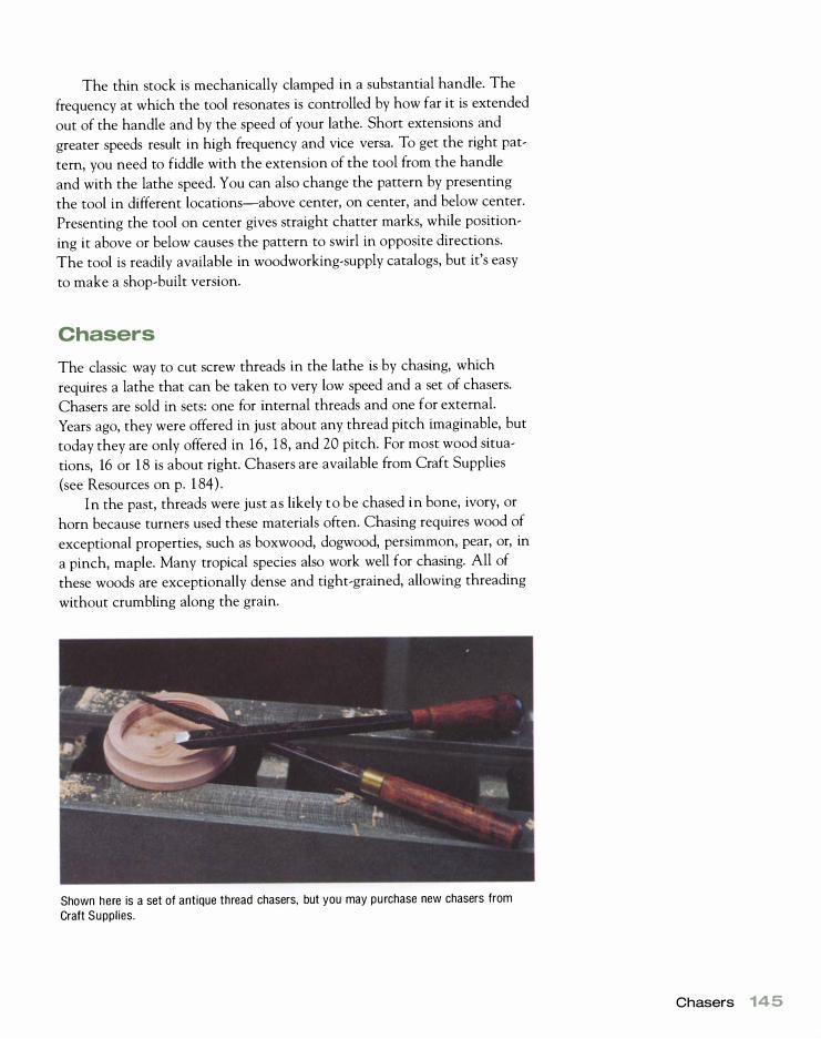
The thin stock is mechanically clamped in a substantial handle. The
frequency at which the tool resonates is controlled by how far it is extended
out of the handle and by the speed of your lathe. Short extensions and
greater speeds result in high frequency and vice versa. To get the right pat
tern, you need to fiddle with the extension of the tool from the handle
and with the lathe speed. You can also change the pattern by presenting
the tool in different locations-above center, on center, and below center.
Presenting the tool on center gives straight chatter marks, while position
ing it above or below causes the pattern to swirl in opposite directions.
The tool is readily available in woodworking-supply catalogs, but it's easy
to make a shop-built version.
Chasers
The classic way to cut screw threads in the lathe is by chasing, which
requires a lathe that can be taken to very low speed and a set of chasers.
Chasers are sold in sets: one for internal threads and one for external.
Years ago, they were offered in just about any thread pitch imaginable, but
today they are only offered in 16 , 1 8, and 20 pitch. For most wood situa
tions, 16 or 1 8 is about right. Chasers are available from Craft Supplies
(see Resources on p. 1 84) .
In the past, threads were just as likely to be chased in bone, ivory, or
horn because turners used these materials often. Chasing requires wood of
exceptional properties, such as boxwood, dogwood, persimmon, pear, or, in
a pinch, maple. Many tropical species also work well for chasing. All of
these woods are exceptionally dense and tight-grained, allowing threading
without crumbling along the grain.
Shown here is a set of antique thread chasers, but you may purchase new chasers from Craft Supplies.
Chasers 145

Threading Options
If you have a metal-cutting lathe, you
can mi l l th reads on it. Simply set up
the gearing for the pitch you wish to
cut, then mount a laminate router in
the tool post. Run the lathe by hand
by manually advancing the d rive belt.
Another way to mill threads is to use a
wood-lathe attachment such as the
Nova ornamental (see p. 1 08).
146 Tools
The trick to chasing is to start with only the face of the tool against the work and the cutting edge clear of the cut. Then gradually tip the tool down until the edge engages and a thread is cut.
The business end of a chaser looks much like a thick sawblade except
the teeth are angled at the pitch angle of the thread to be chased. The
trick to using a chaser is to set the lathe to a very low speed (5 rpm to
1 0 rpm) and tip the scraper up so that the angled face (edge of the teeth)
engages the wood but the actual cutting edge is clear of the cut. Because
the teeth are at the pitch angle of the thread, the tool will move sideways
as the work turns. You need to apply a firm inward pressure (or outward
pressure for internal threads) to chase a deep line in the area to be
threaded. Additionally, you must apply some sideways force to make the
chaser cut at the correct pitch.
Next, return the chaser to the beginning of the thread, and pick up
the lines that you have previously incised. The instant the thread is picked
up, tip the tool down to bring the edge into play in a scrape cut (see the
photo above). Again, some sideways pressure is necessary to maintain
pitch. Return the chaser to the start and repeat the process until a perfect
thread is formed. Internal threading is more difficult because you cannot
easily see what is happening.
If you are threading to a shoulder (as in boxes) , redrawing the chaser
at the precise moment is also required. In other words, very low speed is a
must. For those lacking a variable-speed lathe, an old trick for this kind of
work is to mount the motor on a swing arm controlled by a foot pedal.
Pushing down on the pedal lifts the motor and slackens the belt. Releasing
the pedal drops the motor and tightens the belt, giving normal power. This
allows fine nuances of power and speed. Often a spring or counterweight
provides proper belt tension during normal use, but this scheme only works
with V-belts.

Maintenance, Repair, and Modification
W hen you buy a new car, you spend the first few thousand miles
"breaking it in" and the rest of its life "wearing it out." So it is
with a lathe. Maintenance is required on a regular basis, and
sooner or later repair is necessary. Maintenance and repair are tasks that
most of us tend to neglect for one reason or another. My sense is that most
people aren't quite sure what to do. In this chapter, I'll explain what must
be done to keep your lathe running in tip-top condition and suggest some
things that may make it run even better.
This chapter is also intended as an aid to buying a used lathe. A ma
chine with a few years under its V-, poly-V-, or flat belt often represents
an exceptional value and may possess features you would have to pay a lot
for in a new machine. My father and I have purchased many classic lathes
(wood and metal) at bargain prices, and all have more than lived up to
our expectations. As my father aptly sums it up, "In former times, honest
construction was the rule, and manufacturers weren't afraid to pour a little
metal in the mold." Like the Rolls Royce salesman, I like to think of clas
sic machines not as used but as previously owned. A little love and main
tenance will restore such machines to their original conditions.
Routine Maintenance
Fortunately, a lathe doesn't require a great deal of maintenance and even
thrives in an environment of downright neglect. There are some habits
you can form and some things you can do that will greatly add to the life
chapter
7

LATHE MAINTENANCE SCHEDULE
Frequency Task Reason
Every time you use a
Morse-taper accessory
Every tuming session
Monthly
Annually
Every one to five years
Every decade regardless of use
Wipe dust out of the taper socket
with your finger and wipe the taper
accessory.
Sweep or vacuum chips from the
machine, then wax. all unpainted metal
parts such as the bed, spindles, and
tool rest.
Oil plane bearings. If your machine
has oil holes or cups, you should apply
a few drops of a high-viscosity (30 or
higher) machine oil. Some older motors
also have oil cups, which should be
lubricated.
Grease any zerk fittings. Some older
machines may have grease fittings for
the headstock bearings and possibly
the motor. They should be given one
shot of grease. Do not overgrease.
This should be a habit.
Clean all belt pulleys.
Check the belt for wear and the bear
ings for endplay and lubrication. On
most lathes that are used a reasonable
amount, this check should be done
more frequently. Since the spindle has
to be removed on most lathes to
replace the belt, you might as well
replace the bearings. On variable-width
sheave machines, belt replacement
will be required every year or two, so
replacing the bearings may not make
sense in this case.
Replace the belt and bearings.
The biggest cause of spindle
damage (headstock and tailstock)
is damaged tapers or taper seats
due to dirt.
Wood is hygroscopic and even dry
wood can promote rusting in the right
conditions. If you tum green wood,
this action is an absolute must.
Plane bearings will run forever if
lubricated. They require a film of oil;
if they don't have it, they will quickly fail .
Grease is required on a regular basis
to keep such bearings healthy.
Dirt and rubber buildup on pulleys
causes vibration.
A wom or loose belt causes vibration
and poor power transmission. Dry
bearings will soon fail (if they have
not already).
1ime alone will take its toll. Grease in
sealed bearings will dry out, and rub
ber in belts gets hard and cracks.
of your machine and to your enjoyment of using it. The first habit is to
unplug the machine when you perform most maintenance. Other habits
follow different schedules (see the chart above) . Routine maintenance will
keep your machine running smoothly for years.
1 48 Maintenance, Repair, and Modification
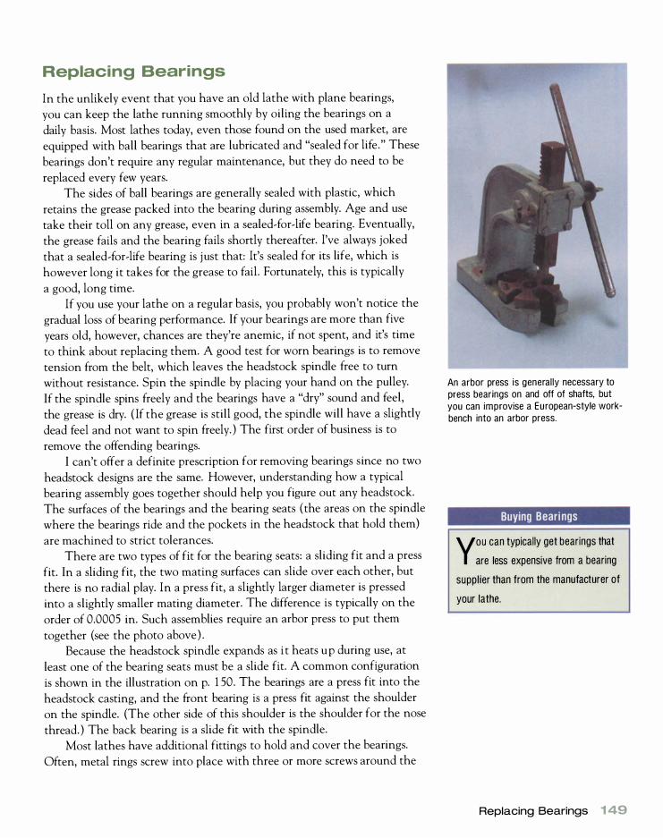
Replacing Bearings
In the unlikely event that you have an old lathe with plane bearings,
you can keep the lathe running smoothly by oiling the bearings on a
daily basis. Most lathes today, even those found on the used market, are
equipped with ball bearings that are lubricated and "sealed for life." These
bearings don't require any regular maintenance, but they do need to be
replaced every few years.
The sides of ball bearings are generally sealed with plastic, which
retains the grease packed into the bearing during assembly. Age and use
take their toll on any grease, even in a sealed-for-life bearing. Eventually,
the grease fails and the bearing fails shortly thereafter. I've always joked
that a sealed-for-life bearing is just that: It's sealed for its life, which is
however long it takes for the grease to fail. Fortunately, this is typically
a good, long time.
If you use your lathe on a regular basis, you probably won't notice the
gradual loss of bearing performance. If your bearings are more than five
years old, however, chances are they're anemic, if not spent, and it's time
to think about replacing them. A good test for worn bearings is to remove
tension from the belt, which leaves the headstock spindle free to turn
without resistance. Spin the spindle by placing your hand on the pulley.
If the spindle spins freely and the bearings have a "dry" sound and feel,
the grease is dry. ( If the grease is still good, the spindle will have a slightly
dead feel and not want to spin freely. ) The first order of business is to
remove the offending bearings.
I can't offer a definite prescription for removing bearings since no two
headstock designs are the same. However, understanding how a typical
bearing assembly goes together should help you figure out any headstock.
The surfaces of the bearings and the bearing seats (the areas on the spindle
where the bearings ride and the pockets in the headstock that hold them)
are machined to strict tolerances.
There are two types of fit for the bearing seats: a sliding fit and a press
fit. In a sliding fit, the two mating surfaces can slide over each other, but
there is no radial play. In a press fit, a slightly larger diameter is pressed
into a slightly smaller mating diameter. The difference is typically on the
order of 0.0005 in. Such assemblies require an arbor press to put them
together (see the photo above) .
Because the headstock spindle expands as i t heats up during use, at
least one of the bearing seats must be a slide fit. A common configuration
is shown in the illustration on p. 1 50. The bearings are a press fit into the
headstock casting, and the front bearing is a press fit against the shoulder
on the spindle. (The other side of this shoulder is the shoulder for the nose
thread. ) The back bearing is a slide fit with the spindle.
Most lathes have additional fittings to hold and cover the bearings.
Often, metal rings screw into place with three or more screws around the
An arbor press is generally necessary to press bearings on and off of shafts, but you can improvise a European-style workbench into an arbor press.
Buying Bearings
YOU can typically get bearings that
are less expensive from a bearing
supplier than from the manufacturer of
your lathe.
Replacing Bearings 1 49

Double nut a l lows adjustment of axial play in spindle/bearing assembly.
Back bearing is a sl ide fit with spindle to allow for expansion and to facil itate removal.
A Typical Headstock Bearing Configuration
Double-row bearings are pressed into bearing seats in casting --_
Nose thread
Front bearing is a press fit on the spindle and locates against the shoulder.
spindle, and these may contain seals that further protect the bearing. A
common design is to have a fine thread on the back of the spindle ( the
end opposite the nose) on which there are two nuts. The first nut runs up
against the inner race of the bearing and is adjusted until there is no play
in the assembly. The second nut is then locked against the first.
Sometimes a wavy washer is interposed between the nuts and the
bearing as well, its purpose being to remove play from the assembly. This
washer should be replaced with the bearings because it invariably takes a
set. Snap rings are used extensively today, and there are typically an array
of spacers and washers involved. As you disassemble the headstock, make
a careful sketch of the order in which you take off all of these parts so that
you can reassemble everything correctly.
Once you've taken the headstock apart, there are a variety of ways
to remove the bearings from the spindle. One method is to use a bearing
puller (see the photo on the facing page) . A tool of this type would be
used for removing the back bearing, and possibly the front, from the typi
cal headstock shown in the illustration above. To remove a press-fit bear
ing from the spindle, you'll normally need an arbor press. Often the entire
headstock must be placed in a press.
If you have a European-style workbench, it's not difficult to improvise
an arbor press (see the photo essay on pp. 1 52-153 ) . Using the bench dogs
in combination with arbors and support blocks, both turned and fabricated
1 50 Maintenance, Repair, and Modification

from durable wood, will provide the necessary support and force you need
to remove the bearings from the spindle.
Support blocks can be made in one of two ways. One is to nail and
glue up a right-angle plate from scrap wood. I used such a plate in the
photo essay of replacing the bearings in a Delta headstock on pp. 1 5 2-153 .
The second way i s to mount a square block in a four-jaw chuck and drill a
hole through it to a diameter slightly larger than the spindle ( 1 1� in. for
the spindle assembly in the photos) . Then scrape a pocket in the support
block to accept the bearing.
To make an arbor, turn a hickory or oak billet to a tenon with a shoul
der. The tenon diameter should be equal to the inside diameter of the
shaft. Clamp the support block to the workbench, insert the tenon into
the spindle, then use the tail vise to force the spindle out of the headstock
or bearing.
Although it's tempting to pound the assembly apart using soft-faced
mallets and blocks of wood, I strongly urge you not to do this because this
practice can ruin the bearings by putting flat spots on the balls. Although
it makes no difference in the disassembly, it does in the assembly. Since
one is merely the reverse of the other, it's not a good habit to get into-in
my opinion, hammers have no place around bearings. Once the bearings
are out, test them by spinning them with your hand. If the grease is dry,
the bearing will spin and even coast for a while; if it's really bad, you'll feel
flat spots in the bearing.
Replacement bearings are easy to obtain. Each bearing will have a
shield number on one or both sides, which should be all the information a
bearing supplier will need to get you a replacement. For instance, a 2802Z
would be a double-row bearing that presses into a 1 3�-in. bearing seat and
Bearing pul lers are used to remove the bearings from a headstock spindle. The pu l ler at right is for removing small bearings from shaft assemblies, while the larger model at left can adjust to a variety of situations.
Replacing Bearings 1 51

Replacing Bearings
This method uses a European-style workbench as an arbor press .
1 1 start by removing the shoulder nuts from both ends of the spindle. Here I am removing the inboard
nut. The outboard nut is left hand, so you need to tum in the opposite direction from normal.
2 Next, I use a hex wrench to remove the
flanges, which cover and protect the bearings.
1 52 Maintenance, Repair, and Modification
3 Now I use an arbor and the tail vise to push the spindle and the
outboard bearing out of the headstock. In this case, I was able
to put the bench dog directly against the outboard end of the
headstock and did not have to use a support block as I will for
reassembly.
4USing a wooden arbor (tumed to the
inside diameter of the inboard bearing)
and a support block of scrap plywood, I remove the inboard bearing from its seat.
I drilled a hole in the support block slightly
bigger than the bearing's outside diameter.

5 While the headstock is apart, it is time to take care
of rust. I use Klingspor's Sandflex blocks to remove
corrosion. The blocks come in coarse, medium, and
fine grits. I start with coarse and work to fine to obtain
a close-to-new finish. Emery paper is also good for
this purpose.
7 I push the outboard bearing back into the
headstock.
91 push the arbor and inboard bearing into place.
6 Now it's time to reverse the process to install the
new bearings. I install the inboard bearing back on
the spindle.
\ To replace the arbor and inboard bearing, I first have
U to drill a hole in my support block for the indexing pin
to go through. I also made an arbor that went over the
spindle nose and pushed on the inboard bearing directly.
1 0 Replace the shoulder nuts.
Replacing Bearings 1 53

Shown here are outboard ( left) and inboard (right) bearings with a wavy washer, which takes up play. The inboard bearing is wider because it is a double-row bearing that better takes the increased radial and axial loads at the inboard end of the spindle. By reading the shield nu mbers ( located at the top on both bearings here), you can go to a bearing supplier and obtain replacements.
accepts a sis-in. shaft. Bearing suppliers are listed in the Yellow Pages
(Bearing Distributors and Technico are two of the better-known compa
nies) . It never hurts to take the bearing along with you to the bearing
store so you can check the replacement directly against the original. You'll
be amazed at just how inexpensive a new set of bearings is-typically no
more than $25.
Once you have the new bearings for your lathe, reassemble the spindle
assembly and headstock in the reverse order that you took it apart. The
correct sequence for reinstalling the bearings on a Delta headstock is
shown in the photo essay on pp. 1 52-1 53 .
In the rare event that you have a very old set of bearings for which
replacements are no longer available, you may still be able to salvage the
bearings. Such bearings are typically shielded with a metal disk on one side
but not sealed. Once you have the bearings out of the headstock, soak
them in kerosene or a similar solvent ( in a well-ventilated area) to remove
the old, dried grease and dirt. Never use compressed air on bearings since
it normally ruins them. Using a soft brush and some elbow grease will
remove the dirt just fine.
Next, heat up some grease in a metal can by using an electric hot
plate. Be most careful of fire-I prefer to do this kind of work outside.
Almost any good-quality automotive grease will work, but if you're a stick
ler for doing it right, you can get tubes of grease specially formulated for
bearings at any bearing store. Drop the bearings in the liquid grease, and
1 54 Maintenance, Repair, and Modification

let them soak for a while. Once the grease cools, pull the bearings out,
remove the excess, and you're back in business.
Although it's not a difficult job to replace bearings, not everyone
has the proper tools for it. The best alternative to doing it yourself is to
take the entire headstock to an automotive machine shop and have the
work done for you. Automotive machine shops abound, and they're well
equipped for any work involving bearing removal and replacement. On
most lathes, the headstock is a separate piece that can be removed. If
the headstock and bed are a one-piece casting, you'll have to take the
entire machine to the shop. If you cannot find an automotive machine
shop, check the Yellow Pages and the Internet for "Machinery Repair
Companies."
Drive Pulleys, Belts, and Motors
Drive pulleys and belts can cause a good deal of trouble, even in new
lathes. If a lathe has "as cast" die-cast pulleys (which are common on
economy lathes) , chances are that they are neither perfectly concentric
nor round. Since V-belts grip on the flanks of the pulley groove, a dial
indicator is of little or no use in checking accuracy. The best method is to
turn the pulleys over by hand with a pointer held stationary in the groove.
You can clamp a pointed object such as a scriber in a suitable place near
the pulley. Any radial or side-to-side runout will be apparent through care-
VIBRATION IS A PROBLEM that can cause great consternation, since turning is difficult if the machine and work are moving around. Vibration tends to be speed related-most lathes have a bit of vibration, usually at one
or two specific speeds. This is one of the reasons I like variable speed. If the work itself is causing the vibration, tweaking the speed up or
down a bit is an instant cure. Pulleys and belts are the most common sources of vibration, so
these are the first things to inspect. Check for worn belts and out-of
true pulleys. If these are in good shape, next check the dynamic bal
ance of the rotating parts. The motor may even be out of balance;
although this isn't a common problem, it does happen.
Vibration is often a problem on lathes that have sheet-metal stands.
Pouring sand into the stand can work wonders, but you have to make sure that the sand doesn't get into the motor, pulleys, and other mov
ing parts. (If you're pouring sand into the stand, make sure you leave
some air space below the motor for cooling purposes.) Placing sand
bags in the base of the machine will often do the trick. Stamped-metal legs can be reinforced by adding wood cross braces, and vibration can be dampened by draping sand bags over the cross members. Another
alternative is to build a replacement plywood box stand for your lathe
and fill the legs with sand (see the photo and illustration on p. 26) .
Locating Vibration
A stethoscope is a useful tool for
isolating difficu lt-to-find vibration.
Drive Pulleys, Belts, and Motors 1 55

Truing Die ... Cast Pulleys in a Wood Lathe
If you have a lathe available while your lathe is apart , this is a good way to true a pulley.
Mount the pulley on a stub arbor that has been
turned from a square of hickory in a four-jaw scroll
chuck. Further support the pulley with a live center. I
also tighten the pulley grub screw to give a more
positive drive.
2 Use a woodturning scraper ground to the correct
shape to true the pulley grooves.
3 The finished pulley.
ful observation. Concentricity tolerances for pulleys are quite loose
typically O.OOS-in. to 0.006-in. minimum runout. If the runout is excessive
(more than 0.0 10 in. ) and your lathe is having vibration problems, the
pulley is the likely culprit.
What you should do about pulleys that are out of true will depend
largely on how much money you want to spend and how much trouble
you're willing to go to. The best solution is to replace the defective pulleys
with machined cast-iron models, which should last as long as your lathe.
High-quality pulleys to fit most spindles are available at most bearing
1 56 Maintenance, Repair, and Modification

stores, but they'll be expensive ($30 to $60 each) and will have to be
special-ordered. If your headstock spindle is an odd size, you may still have
to have the arbor hole in the pulley bored out and a new keyway roached.
Another remedy is to have the pulleys machined by a local machine
shop. I've also mounted die-cast pulleys in a wood lathe and machined the
sides of the grooves with a scraper. I mount a suitable square of wood in a
four-jaw scroll chuck such as the Nova or the Oneway (see p. 70) . I then
tum the end to a short stub arbor that's a press fit with the pulley. I push
the pulley on the arbor and lock it there with the setscrew in the pulley,
as shown in the photo essay on the facing page. I further support the
pulley by bringing the tailstock up close and engaging a live center with
a 60° point into the bore of the pulley. I now start the lathe and scrape
the offending groove flanks true. It's really quite simple. However, since
your lathe is apart there are some technical problems to overcome-you'll
either have to do the work on a second lathe, or temporarily substitute a
simple one-groove pulley for the one you're scraping.
Sometimes dirt and rubber from the belt will build up in the pulley
grooves and cause the belt to make a "klunking" sound as it runs. This
buildup can usually be removed with solvent, but sometimes it will require
sanding or filing. Again, mounting the pulley on a stub arbor can help in
this task. Finally, a pulley greatly out of balance can cause excessive vibra
tion. Many automotive machine shops have dynamic balancing machines
and can remedy the problem for you. For the headstock pulley, have both
the spindle and the pulley balanced as a unit.
Belts are much like tires, ranging greatly in price and quality. The dif
ference between discount-store belts and good belts is like the difference
between bias-ply tires and radial tires. A cheap belt will be stiff and un
even in cross section and will often cause noise and vibration. You can
obtain a high-quality replacement belt from a bearing store for less than
$20; Gates Green Belts is a reliable brand. It's good shop practice to
replace the belt whenever you replace the bearings and vice versa. Nor
mally, you can expect to get two to five years of use out of a good belt,
but less if your lathe has a variable-width pulley speed control.
The motor that powers your lathe may sometimes require attention.
When faced with a motor that won't run, you have two options: repair it
or replace it. Your nose will usually tell you if the motor is burned out-it
will have a distinct electrical-fire smell. Unless the motor is underpowered
to begin with, rewinding is typically a good option. A motor rewinder
( look in the Yellow Pages or on the Internet) can rebuild the motor for
$ 1 00 to $ 1 50. A rewinder can also help with other motor ills. Common
problems with single-phase induction motors are burned-out starting wind
ing, problems with the centrifugal starting switch, and a bad capacitor.
Drive Pulleys, Belts, and Motors 1 57

Finding Morse-Taper Accessories
M orse-taper accessories such as
dri l l chucks, live centers, and
taper adapters (taper sleeves) can be
found at machine-tool supply houses
at very reasonable prices-often more
reasonable than at your woodworking
machine dealer.
The best solution for a stuck Morse taper is to use a big hammer.
Removing Seized Morse Tapers and Faceplates
It's not uncommon for a Morse-taper accessory to become stuck in the
headstock or tailstock spindle. This typically occurs when you slam a
Morse taper hard into the socket when the spindle is hot after a bout of
high-speed turning. The hot socket shrinks around the cold Morse-taper
center. Running the lathe until it heats up again usually cures the prob
lem, but if this doesn't work, more drastic measures are necessary.
The correct way to remove a Morse taper is to insert a knockout bar
through the back of the spindle and drive it out with a snap of the wrist. If
the Morse taper is stuck, however, repeated blows with a knockout bar will
do no more than put flat spots in the bearings. The problem here is over
coming starting friction, and the best course of action is to get a heavy
hammer and give the knockout bar one firm blow (which does less damage
to the bearings than a series of light raps) .
Once you have overcome starting friction, the rest of the force from
your hammer blow goes into propelling the taper out of the spindle at
high velocity. Have your other hand ready to catch the taper, or, if you're
unsure of your catching abilities, hold a scrap board against it. For tapers
seized in self-ejecting tailstocks, the spindle has to be removed so that a
knockout bar can be placed against the taper.
A faceplate can also become frozen on the spindle thread. A common
cause is not threading a heavily loaded plate all the way home when ini
tially mounting it on the lathe. When the lathe is started, the faceplate is
158 Maintenance, Repair, and Modification

screwed home with tremendous force. There are a number of remedies for
this problem, the first being simply to get a bigger wrench. More leverage
can be obtained by using a "cheater," which is a short length of pipe that is
slipped over the handle of the wrench (see the photo below left) . Where
possible, rest the wrench for the spindle against the lathe bed or headstock
casting to provide a rock-solid stop. If the cheater doesn't work, try hitting
the wrench directly with a couple of blows from a lead or brass hammer.
If these methods fail, you'll have to resort to harsher remedies. Place
a heavy brass bar against one flat of the faceplate nut and give it a sharp
rap with a hammer (see the photo below right) . The idea is to give the
threaded portion of the faceplate a shocking blow at right angles to the
axis of the thread, which will break up the molecular interaction between
the two threads. If you go back to the wrenches, the faceplate will usually
come right off.
In the unlikely event that no mechanical means will remove the
seized faceplate, one final remedy is to use a propane torch to heat one
flat of the threaded area (wear heavy leather gloves for this operation) .
It's important to heat only one small area of the plate, which will cause
the circumference to expand much as if you form a circle with your thumb
and index finger then push the two slightly apart at the tips. Avoid heat
ing the spindle and bearings as much as possible. When the plate is hot,
use a wrench to remove it.
A cheater will typically provide the extra leverage to remove a stubborn faceplate.
Delivering a solid blow to the edge of a faceplate with a ham mer and brass d rift often frees a frozen faceplate.
Removing Seized Morse Tapers 1 59

Smooth Running
R ewax your tool rest before every
turning session to keep tools
sl id ing smoothly.
Tool Rests
Tool rests are subject to heavy wear during everyday turning and will bene
fit from occasional dressing. It's surprising to realize one day that there is a
definite low spot in the center of your metal rest, to say nothing of a mul
titude of nicks and dents. The best tool for removing these imperfections is
a large, single-cut mill file in either bastard or first cut (a double-cut file
will not work for this process ) . Draw-file the rest by turning the file side
ways and alternately pulling and pushing it over the rest, much as if it
were a spokeshave. You'll be rewarded with long ribbons of steel or iron.
Draw-filing also allows you to reshape a rest to your own needs. No
two manufacturers make their rests quite the same, and the best edge
shape is a matter of considerable debate. The illustration on the facing
page shows my personal preference for a tool-rest shape. This design places
the fulcrum point close to the work for good leverage and offers good sup
port of the tool in all types of turning (unlike rests of flatter design) .
Although the standard tool rest that comes with your lathe is adequate
for most turning operations, it's worth making special tool rests to speed up
production work. Tool rests are quite easy to fabricate from structural steel.
Use a short length of cold rolled steel of the appropriate diameter for the
neck, and braze or weld a piece of flat stock to it at the proper angle. Once
the rest is welded, draw-file the top to the desired shape. If you don't have
welding equipment, any welder can do the job for you at a nominal price.
I've made 1 8-in.-Iong rests in this way, as well as odd-shaped rests for spe
cial situations. A handy shape is an S-curve: It allows you to turn the inside
of a bowl from one end of the rest and the outside from the opposite end.
D raw-fil ing is the best way to redress a misshapen tool rest.
1 60 Maintenance, Repair, and Modification
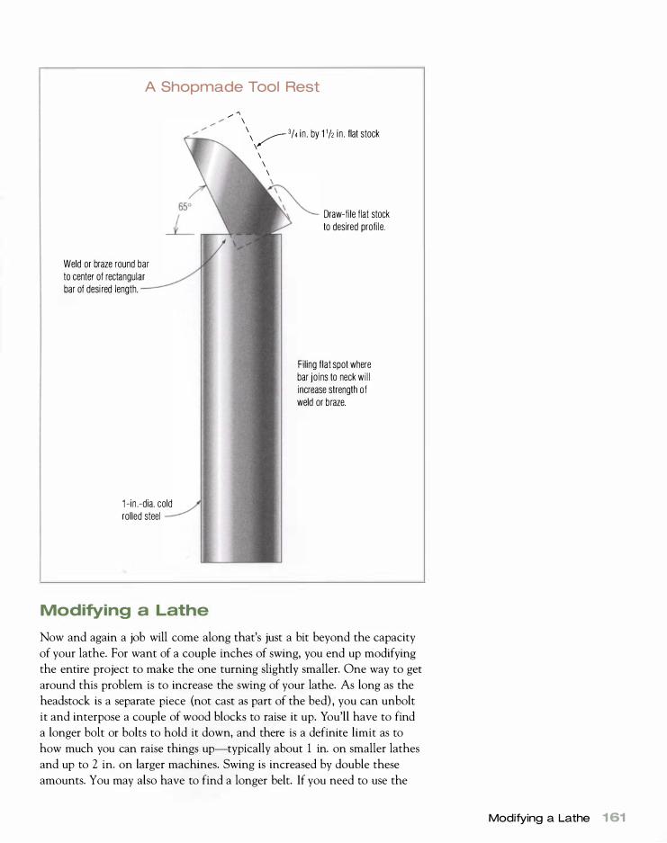
A Shopmade Tool Rest
Weld or braze round bar to center of rectangular bar of desi red length.
1 -in .-dia. cold rolled steel
Modifying a Lathe
.... " \ \ � 3/4 in . by 1 '/2 in . flat stock
\ \ \ \
Draw-file flat stock to desired profile.
Filing flat spot where bar jo ins to neck wi l l increase strength of weld or braze.
Now and again a job will come along that's just a bit beyond the capacity
of your lathe. For want of a couple inches of swing, you end up modifying
the entire project to make the one turning slightly smaller. One way to get
around this problem is to increase the swing of your lathe. As long as the
headstock is a separate piece (not cast as part of the bed) , you can unbolt
it and interpose a couple of wood blocks to raise it up. You'll have to find
a longer bolt or bolts to hold it down, and there is a definite limit as to
how much you can raise things up-typically about 1 in. on smaller lathes
and up to 2 in. on larger machines. Swing is increased by double these
amounts. You may also have to find a longer belt. If you need to use the
Modifying a Lathe 1 61

tailstock, block it up in the same way. (A word of caution: Make sure you
run your new blocked-up lathe at low speed. )
It's also possible to stretch a lathe so you can turn long work such as
porch columns and canopy-bed posts. Bench lathes are quite easy to
stretch. Simply bolt the bed to a plank of suitable length, then bolt the
tailstock to a block at the end of the plank that raises it to the proper
height. For floor-model lathes, bolt a suitable wood extension to the bed,
Rusted Parts
When restoring machinery, you are often presented with a truly seized bolt, nut, or other part-usually due to corrosion . No amount of twisting, prying, or pounding will get the offending parts loose . The solution is to use a "fine wrench, " more properly called an oxi-acetylene torch . The trick is to heat the part in once place , as described for removing seized faceplates on p. 1 59. A student of mine brought in a tool base from a classic Walker Turner lathe with the tool rest seized in the tool base , an excellent example for the following photo essay.
J Clamp the part in a vise and adjust the torch to a hot
flame with a tip big enough to give plenty of heat. Heat
one point on the periphery of the assembly (for nuts, heat
one flat) until it is dull cherry red. (Reducing the room lights
often helps to see this color change.) The flame should
contact the work just above the inner blue cone, which is
the hottest part of the flame. To prevent melting, always
keep the torch moving, even if it is only an inch or so.
162 Maintenance, Repair, and Modification
20nce the assembly is dull cherry red, start work
ing the parts free from one another. In the case
of this tool rest, I placed a brass drift against it and
pounded it out of the tool base. Be careful not to
bum yourself.
3 The freed parts.

TROUBLESHOOTING LATHE PROBLEMS
Problem Cause Solution
There is harmonic chatter in
the work.
The knob or control is hard
to turn.
The motor will not run.
The tailstock and/or tool rest
slides on the bed during turning
operations.
The tool does not move
smoothly on the rest.
Work slows down when you
apply a tool.
There is vibration.
• The work is too thin for the length.
• Bearings have failed or have
insufficient preload.
• There are wood chips and dust in
the thread.
• The thread is stripped.
• The motor is not plugged in.
• A circuit breaker or fuse has blown.
• The thermal switch in the motor
has tripped.
• A fuse has blown in the AC or DC
variable-speed drive.
• There is a brownout or no electricity.
• The motor winding has burned out.
• The bed has grease or finish on it.
• The hold-down mechanism needs
adjustment.
• The tool rest is dry.
• The tool rest needs dressing.
• The tailstock is loose.
• The belt is loose.
• The key has come out of the motor
or headstock pulley.
• The work is out of balance.
• A part is loose.
• A belt is worn.
• The motor or headstock pulleys
are dirty or not concentric.
• The pulleys are not in alignment.
• The pulleys are out of balance.
• There is a defective motor or a bent
motor shaft.
• The stand resonates.
or bolt the tailstock to a bench or table nearby. Remember that exact center
alignment is of no great importance in spindle turning. With either setup,
stretch a wooden tool rest from the tool base to the tailstock. You can also
tum the piece by halves, turning it around in the lathe to do the second
half. This way the standard tool rest is always over the bed of the lathe.
• Cradle the work in your hand, use a
heel cut with your skew, use a
gouge, or employ a steady rest.
• Adjust the preload or replace the
bearings.
• Clean the threads. If necessary, run a
tap into the internal thread and run a
die over the external thread.
• Replace parts; helicoil the internal
thread (kits are available at auto parts
stores).
• Plug in the motor.
• Reset the breaker or replace the fuse.
• Reset the thermal switch (usually by
pushing a button) .
• Replace the fuse.
• Check with your electric company.
• Rewind or replace the motor.
• Clean with the appropriate solvent.
• Adjust the hold-down mechanisrn.
• Wax the tool rest.
• Dress and wax the tool rest.
• Tighten the tailstock.
• Tighten the belt.
• Replace the key and tighten the grub
screw, which locks it.
• Round the work better with a band-
saw and/or drawknife; change speed.
• Find and tighten the loose part.
• Replace the belt.
• Clean or replace the pulleys.
• Adjust the pulleys.
• Have the pulleys balanced.
• Repair or replace the motor.
• Put sand bags in and/or on the stand.
Modifying a Lathe 1 63

FINDING A MISSING PART for an otherwise great classic lathe can present a
problem, since the manufacturer may have gone out of business long
ago. The Internet has become a great resource for searching for parts. Also, want ads in woodworking magazines and club newsletters can
yield results. The problem is you' l l often have to buy an entire lathe to
get the part you need.
Having the part made at a machine shop is often the best alternative, and prices can be quite reasonable-$1 00 to $200 for a part such
as a spindle, pulley, or tailstock wheel. If you're considering buying a
lathe that's missing major parts, such as a tailstock, check around
before buying. Such a lathe is not worth much unless the manufacturer
is still in business and parts are available.
Restoring a Used Lathe
Corrosion can be a chronic problem with lathes, and chances are that if
you buy an old lathe it will have some rust (see photo essay on p. 162) . To
restore the machine to its former glory, you can use Klingspor's Sandflex
blocks, emery paper, and steel wool. All are good weapons in the war on
rust. For extremely heavy rusting with pitting, various proprietary prepara
tions, often referred to as "naval jelly," work well. They loosen the surface
rust and change the chemical nature of the rust in the pits, thereby pre
venting further rusting.
The buffers described on p. 89 are also useful for restoring metal parts.
A spiral-sewn wheel with emery compound will make quick work of light
rust on the exterior surfaces of small parts that can be carried to the buffer.
For the best finish for your used lathe, brush on one or more coats of
machinery enamel, which is available at any hardware or paint store. It's
best to remove any bolts and screws possible and to mask areas such as
nameplates and bed ways with masking tape. Once the paint dries, remove
the masking tape, replace the bolts and screws, and you have a classic
restoration. To maintain your newly restored lathe (or any lathe) and pre
vent future rusting, get into the habit of wiping down the exterior surfaces
with a rag on a regular basis, and always apply a thin film of paste wax to
the bed after a turning session with green wood.
1 64 Maintenance, Repair, and Modification

Turning Techniq u es
O nce you have your chucks and lathe tools (and you can sharpen
them), it's time to do some turning-and have some fun. In this
chapter, I will show you how to get through the basic tool moves
without problems. I think gouges are the gateway to understanding tool
use. If you can use a spindle gouge and a bowl gouge well, everything else
will fall into place. It is like learning your first computer program. The rest
are different but similar.
Coves and Beads
All spindle-turning shapes encompass the turning of either a cove or a
bead, and mastering these two shapes will allow you to turn virtually any
furniture spindle. Coves and beads are like compulsory figures in tradi
tional ice skating-you can never practice them enough. Let's start with
the cove, which can be cut only with a spindle gouge.
CUTTING A COVE
In its simplest form, a cove is a U cut down into the surface of a cylinder.
The key to cutting any cove is to obey the Law of Perpendiculars; the
illustration of a simple cove on p. 1 66, with perpendiculars constructed
at four points, depicts this theory. The idea is to start at the top edges of the cove and take a series of
scooping cuts, always ending at the exact bottom. Start at the left edge of
the cove with the gouge almost on its side and the flute pointing toward
chapter
8

Gouge Size
M ake sure that you use a gouge
that is smaller than the cove you
want to cut.
1 66 Turning Techniques
the center of the cove (see the illustration on the facing page) . Bring the
gouge to the center of the cove, rolling it to horizontal as the cut pro
gresses. Next, repeat the motion from the right edge of the cove. Take a
series of scooping cuts from each side until the cove is cut to the desired
profile. Always cut downhill from the larger diameter to the smaller, and
don't cut beyond the center of the cove bottom.
Rolling the gouge as the cut progresses is only part of the story. In
addition to rolling, you must angle the tool left or right and slide it slightly
forward to keep the bevel rubbing. A common mistake among beginners is
to lock the handle of the gouge in one position against the hip and simply
roll the tool in the prescribed manner. A catch is always the result, since
the cove cut is not as simple as it seems. You're actually cutting a compli
cated compound shape, and if you simply roll the tool, you're not keeping
the bevel rubbing. The illustration on the facing page shows the correct
tool alignment. Pay particular attention to the handle and the large
amount of left, right, and up-and-down movement required.
The most frequent mistakes when cutting a cove are failure to roll the
gouge sufficiently ( it should start almost on its side) and failure to angle
the tool left or right sufficiently to have the bevel rubbing at the start of
the cut. You must also slide the tool very slightly forward as the cut pro
gresses because the diameter of the billet at the bottom of the cove is get
ting smaller, so the tangent point to the surface is moving away from the
tool rest.
Another common mistake is using a gouge that is too wide for the
cove. The cove must be wider than the gouge. Thus, it's useful to have
a range of spindle gouges for cutting different-sized coves. I try to use a
gouge that's about three-quarters the size of the cove I plan to cut.
Cutting a Cove : The Law of Perpendiculars
Roll gouge during cut so that perpendicular from tool coincides with perpendicular from surface of work.
--�----

C utting a Cove
1 . Start with spindle gouge almost on its side.
3. Finish at bottom of cove with gouge horizontal.
CUTTING A BEAD
2. Move gouge in scooping action while simu ltaneously rol l i ng it to left and moving it forward slightly.
4. Repeat procedure from opposite side.
The bead is the opposite of the cove, both in shape and in the way it is
turned. It can be cut with either a gouge or a chisel (skew or beading-and
parting tool) . Although it's exciting to cut beads with a skew a gouge is
much better suited for beginners if not all turners. Cutting a bead with a
spindle gouge is simple and straightforward, whereas using a chisel requires
a precise sense of being flat on the bevel.
As a woodworker, I find that I do my turning in spurts when I need
parts, and there are usually long lulls between sessions. After such a hiatus,
it takes an hour or so of turning for my skills to return. During this accli
matization period, I'm hard-pressed to turn a bead with a skew and I fre
quently catch, though once I'm back in the groove again it's a simple mat
ter. Therefore, the only beads I cut with a skew are during turning demon
strations to show others how to do it.
The R ight Gouge
B eads are best turned with a spin
dle gouge. You will get much
more consistent results (and much
less ruined work) than with a skew.
Coves and Beads 1 67

"F'"
� l L I
1 . Start at top center of bead in normal shear cut.
When making furniture, whether professionally or for your own plea
sure, time is money. You're dealing with expensive billets of wood that
take time to prepare, and you can't afford to waste them. A catch with a
chisel is a catastrophic event that generally relegates the work to the fire
wood pile. Even if this only happens once in every six or eight pieces, it's
still a great waste. You'll save time and money by taking the time to reach
for a gouge. Therefore, I strongly recommend that you use a gouge exclu
sively for cutting beads. Not only will you cut a cleaner bead of better pro
file, but also you'll have a better rate of success. Reserve the skew for plan
ing cylinders and gentle tapers.
The first task in cutting a bead is laying it out. Experience will allow
you to draw two pencil lines to mark the width of the bead, then proceed
to cut it directly into the surface of a cylinder. At first, you're better off
Cutting a Bead
Normal view (standing at the lathe)
2. Roll tool and angle left, cutting downhi l l .
Front view (at tool-rest level)
3. End with tool rolled sideways and pointing at center of work.
Note the large up-and-down handle movements that are not apparent in the normal view.
1 68 Turning Techniques

The beginner is well advised to start by cutting away either side of the spot where you are going to cut your bead to form a ronde! . A rondel is no more than a raised ridge , but it will help you cut your first beads with plenty of clearance to the left and right.
I Begin with the gouge flute up at the center of the
rondel.
) Raise the tool handle and push forward as you
) approach the bottom of the bead. The handle has
to be brought around to the right a bit as well to keep
curvature to the bead. The cut ends with the gouge
dead on its side with the very tip cutting. If you pushed
farther, you would go through the exact center of
the work.
Angle the tool to one side and roll it downhill, sliding
it back slightly on the tool rest.
.I' Retum to the center of the bead and start cutting
to the left. Repeat the procedure on the other side.
Coves and Beads 69
Handplaning Cyl inders
If your skew skil ls are weak, you
may use a hand plane to clean up
long cyl inders and gentle tapers such
as those found on Greek columns. I
l ike to use an 05 Jack, resting the
rear portion of the plane on the rest
and centering the mouth over the
work. A bit of fidd l ing is necessary
u ntil you produce a good curl ing
chip ; skewing the plane a b i t to the
work usually helps.
1 70 Turning Techniques
EVERYBODY, EVEN AN EXPERIENCED turner, makes a mistake at the lathe now
and then. Although it's tempting just to throw the work in the corner
and start again, there are a number of ways to sweep the blemish
under the rug, so to speak. For example, you can widen or slightly
deepen a cove and cut beads to a lower profile. You're probably the
only one who will ever know about such subtle changes. If you break a
piece off a bead, you can glue it back on (assuming, of course, that
you can find it amongst the shavings under your lathe) . If you can't find
the chip, you can always plane the spot flat with a handplane, glue a
new piece on, and re-turn the work. You can often turn a chipped
corner or bead to the inside of the finished piece of furniture during assembly. Just think of it as "antiquing."
A handy glue to use for repairs is cyanoacrylate, or Super Glue. To fix
a small blemish caused by a catch, fill the area with glue and sprinkle
some shavings into the glue. On some woods, this can be a very con
vincing fix. Cyanoacrylate glue is also good for arresting checks at the
end of a workpiece and for gluing small objects to a glue block. Cyanoacrylate glue is available from woodworking suppliers and
model shops in three viscosities: water thin, medium (my preferred
grade), and thick. A catalyst is also sold that will speed up setting time to 20 to 30 seconds. Take care when working with this glue, since
it will glue skin instantly. Avoid the temptation to hold the work with
your fingers while the glue sets, or you may end up glued to the work.
Cyanoacrylate glue is also very irritating to the eyes, so always wear safety glasses and work with plenty of ventilation.
For architectural turnings that are going to be painted, you can patch
holes with auto-body putty (Bondo is a common brand) . This material
can even be used to replace broken beads: Patch the break with a blob of the putty, then re-turn.
Stick shellac works wonders for small blemishes. If you use a black
stick shellac on cherry, it will look just like a pitch pocket. Remember there are no mistakes, just new design opportunities.
using the toe of a skew chisel to demarcate the limits of the bead. Al
though you can cut a bead directly into the surface of the cylinder, it's
a good idea for beginners to cut away the area on either side to leave a
raised square ridge, properly called a ronde!. Raising a rondel first allows
you to cut your bead without the worry of the bottom edge of the gouge
catching on the adjoining surfaces. To raise the rondel, use the toe of a
skew chisel as described for turning square to round with a shoulder, then
use a parting tool to remove the adjacent material (see pp. 1 35-136) .
Whether you're starting with a rondel or cutting directly into the sur
face of a cylinder, start in the middle of the bead in a classic shear cut,
with the gouge held at 90° to the axis of the lathe and the flute facing up
(see the illustration on p. 1 68 and the photo essay on p. 1 69 ) . If you're
cutting into the surface directly, you'll have to open up the areas adjacent
to the bead slightly-either with your gouge or with the toe of a skew.

To cut the left side of the bead, angle the tool left, slide it back
slightly on the tool rest, and roll it in the direction of the cut. Next, raise
the handle until the tool is on its side and aimed at the center of the work
(the tool is now aligned with a radius of the work). Push forward until you
reach the bottom of the bead. As the cut progresses, you'll also have to
swing the handle around behind the tool to create the curve of the bead
and keep the bevel rubbing.
Most beginners fail to lift the handle high enough or roll the tool
exactly on its side at the final stage of the cut. With the tool rolled only
45° and the handle raised only slightly, the result is invariably a catch on
the adjoining surfaces. Another common mistake is failing to swing the
handle around behind the cut but rather simply to push the gouge for
ward to the bottom of the bead, which results in a 45° flank instead of
a rounded form.
To cut the right side of the bead, return to the center and reverse the
procedure. Most beginners have difficulty making both halves of a bead
symmetrical, but this comes with practice. The nice thing about using a
gouge is that you can easily fine-tune a lopsided bead by recutting it by
halves. Although you can do the same thing with a skew, it's much more
difficult to produce a bead with a flowing profile.
One final note about beads. Most people today think of a bead as sim
ply an oval ridge on the surface of a cylinder. In former times, however,
turners always took the toe of a skew and incised a small groove, or bevel,
at each edge of the bead where it meets the cylinder. On most furniture
turnings, this grooving entails only a light scribing cut with the toe of a
skew, while on larger architectural turnings, a definite groove is incised
with repeated cuts of the skew.
Beveling the bead is a basic technique that adds tremendous visual
impact to any turning by giving depth to the bead and setting it off from
the surrounding spindle. On architectural turning, the bevel gives paint a
place to flow, preventing a buildup of paint at the transition point and a
loss of visual impact. One reason that machine turnings look so lifeless is
that they're made on cutterhead lathes that cannot cut bevels or under
cuts. As a hand turner, you have a real advantage in creating shapes that
can grab the eye of the viewer.
Turning Square to Round
One of the most frequent questions I'm asked in spindle-turning classes
is, "How do I get from square to round without breaking out the corners?"
The answer I always give is to use sharp tools and shear-cutting tech
niques. The actual mechanics of the cut depend on whether you want
the transition from square to round to be a square shoulder or a concave
or convex radius. Let's start with the square shoulder.
Matching Beads
To cut small beads that match
exactly, nothing beats a form
scraper. Simply grind the profile you
desire into the end of a scraper, and
make as many exactly matching beads
as you want.
Turning Square to Round 171
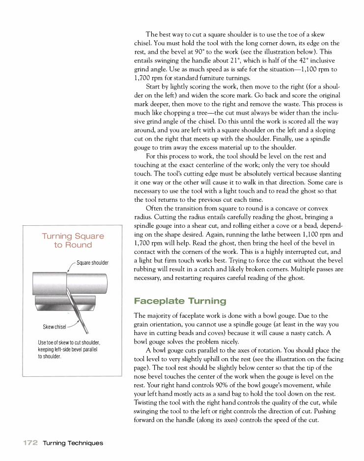
Turning Square to Round
Square shoulder
Skew chisel
Use toe of skew to cut shoulder, keeping left-side bevel paral lel to shoulder.
1 7� Turning Techniques
The best way to cut a square shoulder is to use the toe of a skew
chisel. You must hold the tool with the long corner down, its edge on the
rest, and the bevel at 90° to the work (see the illustration below). This
entails swinging the handle about 2 1 0, which is half of the 42 ° inclusive
grind angle. Use as much speed as is safe for the situation-1 , 1 00 rpm to
1 ,700 rpm for standard furniture turnings.
Start by lightly scoring the work, then move to the right (for a shoul
der on the left) and widen the score mark. Go back and score the original
mark deeper, then move to the right and remove the waste. This process is
much like chopping a tree-the cut must always be wider than the inclu
sive grind angle of the chisel. Do this until the work is scored all the way
around, and you are left with a square shoulder on the left and a sloping
cut on the right that meets up with the shoulder. Finally, use a spindle
gouge to trim away the excess material up to the shoulder.
For this process to work, the tool should be level on the rest and
touching at the exact centerline of the work; only the very toe should
touch. The tool's cutting edge must be absolutely vertical because slanting
it one way or the other will cause it to walk in that direction. Some care is
necessary to use the tool with a light touch and to read the ghost so that
the tool returns to the previous cut each time.
Often the transition from square to round is a concave or convex
radius. Cutting the radius entails carefully reading the ghost, bringing a
spindle gouge into a shear cut, and rolling either a cove or a bead, depend
ing on the shape desired. Again, running the lathe between 1 , 1 00 rpm and
1 , 700 rpm will help. Read the ghost, then bring the heel of the bevel in
contact with the corners of the work. This is a highly interrupted cut, and
a light but firm touch works best. Trying to force the cut without the bevel
rubbing will result in a catch and likely broken corners. Multiple passes are
necessary, and restarting requires careful reading of the ghost.
Faceplate Turning
The majority of faceplate work is done with a bowl gouge. Due to the
grain orientation, you cannot use a spindle gouge (at least in the way you
have in cutting beads and coves) because it will cause a nasty catch. A
bowl gouge solves the problem nicely.
A bowl gouge cuts parallel to the axes of rotation. You should place the
tool level to very slightly uphill on the rest (see the illustration on the facing
page) . The tool rest should be slightly below center so that the tip of the
nose bevel touches the center of the work when the gouge is level on the
rest. Your right hand controls 90% of the bowl gouge's movement, while
your left hand mostly acts as a sand bag to hold the tool down on the rest.
Twisting the tool with the right hand controls the quality of the cut, while
swinging the tool to the left or right controls the direction of cut. Pushing
forward on the handle (along its axes) controls the speed of the cut.

Using a Bowl Gouge
Push forward along the shank to make the cut progress in the direction the nose is pointed.
All cutting takes place on this beveled face.
The tool rests level on the tool rest, not uph i l l .
� Swing the tool left or right to change direction.
Twist the tool to control the quality of the cut and fi nd the "sweet spot."
Starting the tool can be tricky and requires aiming the nose bevel in
the direction you want to cut. Depending on the angle of the nose bevel,
the handle may be at what seems an odd angle. Hold the tool firmly down
on the tool rest with your left hand, and lightly touch the work with the
bottom half of the tool (see the the top photo on p. 1 74) .
Once the cut i s underway, you want to look for the "sweet spot," the
position where the tool cuts the best. You can find this spot by twisting
the tool ever so slightly to the left or right (see the bottom photo on
p. 1 74) . You are looking for the point where the bottom bevel rides on
the ledge that has been created ahead of the cut. This leaves the nose
bevel riding on the area just behind the cut, which serves to guide the
tool. With a little practice, finding the sweet spot becomes a natural,
involuntary action. You direct the tool by swinging the handle to the left or right. The
nose bevel is riding on the area just behind the ledge created by the cut,
and the bottom half of the bevel is cutting away on the face of this ledge.
Bowl Gouges
S ince most of the control of a bowl
gouge is in you r right hand, your
left is only a weight to keep the tool
from bouncing on the rest. When
learning to use this tool, a good test is
to remove your left hand periodically
(or only use your i ndex finger to hold
it down) and see if it continues to cut
in the same manner. I f everything is
right, you should be able to cut with
just your right hand.
Faceplate Turning 1 73

174 Turning Techniques
Start the cut by aiming the nose bevel in the d i rection you want to cut and touching the bottom half of the flute to the work.
Once the tool starts cutting, twist the tool slightly right or left until you find the "sweet spot."
The point of the nose-bevel contact becomes a fulcrum point as you swing
the handle left or right and makes for a smooth transition in direction.
You should keep the tool fairly flat on the rest during the entire operation.
Do not use your left hand to pull or push the tool; push forward with your
right hand along the tool's axis to make the tool go forward. After the tool
is started, if everything is cutting correctly, you should be able to do the
entire operation with your right hand and drop your left next to your side.

Start an inside cut exactly as shown in the top photo on the facing page. Here I have found the sweet spot, and the cut is proceeding normal ly. Push forward on the tool to advance it.
As you approach the center of an inside cut, the diameter is decreasing so the tool needs to be rotated to keep the cut sweet.
At the center, the flute should point almost straight up.
Faceplate Turning 1 75
1 70 Turning Techniques
Sanding
While one of the main purposes of this book is to teach methods that
eliminate excessive sanding, there comes a point in most turnings where
some sanding is necessary. If you use the shear-cutting methods I've recom
mended, you should be able to start sanding for spindle turning at 150 grit
or 1 80 grit rather than 60 grit or 80 grit, which would be the case if you
were scrape-cutting. Sanding facework ( in most woods) starts at a heavier
grit-typically 60 grit or 80 grit.
SANDING SPINDLE WORK
When sanding spindle work, the piece remains in the lathe. For beginners,
it makes sense to remove the tool rest, but experienced turners work
around the rest by sanding at the back of the piece. Never use a whole
(or even a large) sheet of sandpaper because it can wrap around the spin
dle and drag your fingers in with dire results. I always tear sandpaper into
quarter sheets, then fold these in half.
For spindle turnings, I generally start with 1 80 grit and finish with
220 grit, although you can go as fine as you like. The main thing is not to
skip grades of sandpaper or you'll get scratch marks on the work. By using
good spindle techniques, sanding is merely a final operation to remove fuzz
and make things uniform in texture for finish. Once you've finished sand
ing, its a good idea to burnish a turning with a handful of chips to improve
surface finish.
SANDING FACEWORK
Facework requires a good deal of sanding even when using textbook turn
ing techniques. An experienced turner will spend as much time sanding
facework as turning it. Start with 60-grit or 80-grit sandpaper to remove
the tearout in the end grain, then work up through grades to the desired
finish. A common sanding schedule might run 60, 1 00, 1 50, 220, and so
on. If providence allows you to start at 80 grit, then the schedule might
run 1 20, 1 80, 220.
Although hand-sanding works fine for spindle work, the best way to
sand face work is with a flexible pad mounted in an electric drill (see the
photo on p. 1 78 ) . The rubber pad is flexible enough for most facework.
There are various proprietary systems available, one of which uses hook
and-loop fasteners to attach the sanding media to the disk. Another sys
tem uses sanding circles that are backed with pressure-sensitive adhesive.
A third system has a metal or plastic clutch glued to the back of the sand
ing circle. All three systems allow quick changing of abrasive to work up
through finer grades. With the hook-and-loop and clutch systems, coarser
grades can be reused if they're not expended.

Beginners should slide the rest back out of the way during sanding (top), but experienced turners can sand opposite the rest so they don't have to remove it (bottom).
Sanding 1 77

178 Turning Techniques
The easiest way to sand facework is with a sanding arbor mounted in an electric d ri l l . Here I am using a shop-built hook-and-Ioop arbor that has sufficiently resilient padding to sand with the finest of grits without scratching.
Holding the spinning disk against the spinning work makes sanding go
much faster than if you were sanding by hand. Since the disk wipes at an
angle to the direction that the piece was turned, it produces a smoother
surface. The important thing to remember when power-sanding is to spend
enough time at the coarser grits to remove all of the tearout.
All of the clutch and some of the pressure-sensitive adhesive sanding
systems are unsuitable for sanding beyond 1 80 grit because at finer grits
there will be circular scratches even though the surface becomes more
polished generally. The reason is that dirt and oversize sanding particles
occasionally counteract the action of the majority of the sanding particles
in the paper.
The solution is to glue foam rubber ( I use 3h-in. neoprene rubber) to
an expended pad, then glue thin, flexible sandpaper to the foam. The
resilience of the foam combined with the flexibility of the thin paper
allows you to sand ultra-fine grades with ease. A thin piece of garnet or
aluminum-oxide sandpaper glued to the foam rubber with photo-mount
adhesive works splendidly. When the sandpaper needs changing, some
heat from a hair dryer will loosen the glue joint so you can remove the
sandpaper.

French Polishing
This is my favorite lathe finish. It i s quick to apply and dries instantly-just the finish to use on Christmas Eve.
1 To French-polish in the lathe, apply a coat of the
shellac mixture to the work with a small rag or a full
brush. However you apply the shellac, be sure to satu
rate the work completely-don't worry if some of it
dribbles onto the lathe bed. Brushes may be cleaned
completely and inexpensively with a mixture of ammo
nia and water.
2 Remove the tool rest, stand aside, and start the
lathe. You need plenty of speed-at least 1 ,700 rpm.
Grab a handful of shavings and apply them with firm
pressure to the spinning work. Turn the shavings often
since they will become saturated with the excess shel
lac. The shellac will melt under the burnishing action of
the shavings, leaving a pleasing French polish with
none of the fuss, pumice, oil, and other assorted trap
pings of conventional French polishing.
3 French polish is a very thin finish, yet it is quite durable, except to pro
longed contact with water, which will leave a white mark. To give the
finish some water-resistance and further beauty, I apply pure carnauba
wax to the spinning work. Pure carnauba, which is difficult to find, is very
hard and shatters like ice if dropped. Crayon the wax onto the work (left)
and finish by burnishing with shavings again (right) .
4 The finished piece.
Sanding 1 79

1 80 Turning Techniques
Finishing
Just as the lathe can be a great aid in reducing the drudgery of sanding, it
can also help in the finishing process. In most cases, turned furniture parts
will be finished with whatever is planned for the rest of the piece, and a
considerable amount of time can be saved by finishing them right after
they've been turned rather than when the piece is assembled. As outlined
in chapter 4, it's a good idea to reference the turned piece to the drive
center with a mark. This mark allows you to rechuck the piece with each
of the center tines in the same place and maintain centering. For example,
if you wanted 1 2 spindles, you would turn them all first, then rechuck and
stain, and finally resand and finish.
Using a small rag, you can wipe on stains and most finishes while the
lathe is running at a low speed. I use a rag about 2 in. square, which is
small enough so that it won't pull your fingers in with it should it get
caught in the spinning work-an important safety consideration. I often
burnish an oil finish with shavings, usually about five minutes after apply
ing the finish. Since burnishing with shavings wipes across the grain, there
is good filling of pores.
One finish that's easy to apply with the workpiece in the lathe merits
special mention. This is a lathe-applied French polish, which gives all the
beauty of the traditional method but takes much less time and bother. To
French-polish turner-style, you need to use genuine orange shellac made
from shellac flakes. The canned variety has preservatives and extenders to
prolong shelf life, which render it unsuitable for French polish.
I mix my shellac in 200ml plastic camping bottles, filling each bottle
about one-quarter full of shellac flakes and adding alcohol to just shy of
the top. I shake the bottle well and shake again every hour or so until
everything dissolves, then set it in direct sunlight for at least a day. The
wax and impurities settle out. I decant the liquid, which is pure orange
shellac, and throw away the sediment.

Glossary
Bead A raised, convex ridge on the surface of a turning.
Beading-and-parting tool A very small double-bevel chisel that can be used for turning beads. It's also useful for s izing tenons and, in combination with calipers, for sizing work. The inclusive grind angle between the two bevels is typically about 42°.
Bed The rail-like platform on which the headstock, tailstock, and tool base mount. The two strips that form the rails are called ways and are made of wood, cast iron, or structural steel. The tailstock and tool base can easily slide back and forth on the ways but can be locked fast as necessary.
Bedan A single-bevel chisel that is used much the same as the beading-andparting tool. The bevel is ground to about 30°.
Bevel The ground face of a turning tool that forms the cutting edge. Also a small cut at each edge of a bead, usually done with a skew.
Bowl gouge A gouge for faceplate work. It has an asymmetrical flute, and the bevel is ground to a variety of forms depending on the turning situation.
Bowl lathe A very short bed lathe, often without a tailstock, that is used exclusively for faceplate work. Its name derives from its popularity with bowl turners.
Catch The nick that occurs when the tool edge digs into the work after control is lost.
Centerline A line along the edge of the work at the same height as the centers (not to be confused with the true centerline, which lies along the longitudinal axis of the workpiece). This would be at 9 o'clock when viewing the work from the tailstock end.
Chatter work Decorative patterns created in the end grain by a small scraping tool of thin section, presented in such a way that it vibrates at a given frequency to create the pattern. See also Harmonic chatter.
Clearance angle The angle between the bevel of a tool and the surface of the work.
Collet chuck A metal chuck with a slotted cylinder that can be tightened around the work or expanded inside the work.
Cone chuck See Tapered mandrel.
Cove A U-shaped depression cut into the surface of a workpiece. It is the opposite shape to the bead.
Cup center A device with a center point on a Morse-taper shank of the appropriate size with a raised ridge around it (also called a ring center) . It allows the tailstock to hold the work both radially and axially.
Cup chuck See Jam chuck.
Cutoff tool See Parting tool.

182 Glossary
Dead center A cup or 60° center that mounts in the tails tack spindle to hold work. It does not spin with the work, hence its name. It both holds the work radially and acts as the bearing on which the work rotates.
Dressing The act of refacing a grinding wheel to make it round and bring fresh, sharp grinding particles to the surface. This is done with a diamondor star-wheel dresser.
Drill chuck See Jacobs chuck.
Drive/spur center A center on a Morsetaper shank of the appropriate size with a central point surrounded by two or four sharp tines that engage the work. On lathes with a solid spindle, the drive center sometimes screws on the spindle.
Duplicator A mechanical device that mounts on a lathe and allows you to copy any turned workpiece.
Faceplate A cast-iron, steel, or aluminumalloy disk that can be threaded onto the headstock spindle. There are one or more circles of holes around the periphery for screws to hold work to the surface of the plate.
Faceplate turning Any turning situation in which the grain of the work is at right angles to the axis of the lathe bed.
Flute A cove that runs the length of a spindle turning rather than around it. Also the concave groove along the shaft of a turning tool.
Form tool A scraper ground to a specific form. It allows convenient duplication of the shape and in some instances will make cuts that are not possible with any other tool.
Gap A dip in the bed just in front of the headstock on some lathes. It allows faceplate work of greater swing to be mounted in this area.
Ghost The hard-to-distinguish pattern created by the corners of the work spinning in the lathe before it is round. Seeing the ghost is an important part of turning from square to round.
Glue block A disk of wood slightly larger than the faceplate that is glued to the work for chucking.
Grind angle The inclusive angle from the back of a tool to the bevel.
Harmonic chatter A spiral pattern in spindle work caused when the work becomes thin enough to vibrate.
Headstock The heart of the lathe. It contains the spindle and assorted bearings. Pulleys on the spindle are belted to the motor. The spindle nose is threaded for faceplates and typically has a Morse-taper socket.
High Wycombe lathe A wood-bed lathe peculiar to the High Wycombe area of England. It was popular with the badgers who turned furniture parts in the forests in that area. Today, any wood-bed lathe is referred to as a High Wycombe lathe.
Hollow grind The hollowing of a tool bevel produced by the convex surface of the grinding wheel.
Index head A mechanism that locks the headstock spindle at regularly spaced intervals so that layout or auxiliary operations with a router can be performed.
Interrupted cut A cut made on work that is not perfectly round. The tool is cutting the work some of the time and cutting air the rest. Needless to say, the tool is much more difficult to control in an interrupted cut.
Jacobs chuck A key-type three-jaw chuck for holding drills in the headstock or tailstock.
Jam chuck A wooden chuck, made on a faceplate, that resembles a cup. The work is held in a tapered pocket scraped into the interior of the cup.
Laying grain down Cutting downhill on the grain.
Live center A tails tack center, either cup or 60°, that has bearings so that it can turn with the work.
Long-corner chisel See Skew chisel.
Morse taper A system of tapers (about 3° inclusive) that allows accessories to be mounted in the headstock or tailstock spindle.
Offset turning A turning situation where the workpiece is offset from the original starting center at one or both ends. (The crankshaft of a car is turned in this way. )
Outboard turning A situation where faceplate work is not turned over the bed of the lathe. On some lathes, the headstock swivels so that the work spins in front of the bed. On others, the back end of the headstock spindle is left-hand threaded to receive a special faceplate.
Paper joint A glue joint in which kraft paper is interposed in the glue line. This allows a spindle turning to be divided lengthwise into two, four, or more pieces. It also can be used for faceplate turnings and as a chucking method to attach a glue block to the work.
Parting The act of severing the work from the lathe with a parting tool to cut a spindle turning at an appropriate point or to cut facework from the faceplate.

Parting tool A tool for parting work from the lathe.
Pattern stick A thin strip of wood on which a full-scale drawing of the piece to be turned is laid out. Notches at appropriate points allow the information on the pattern stick to be transferred to the work with a pencil.
Planing cut The cut made by a skew chisel when it's cutting properly (so called because the geometry of the cut is similar to that made by a handplane).
Pressure turning A chucking method in which the work is held on a glue block by the pressure of the tailstock spindle acting through a live center. It allows quick chucking and unchucking and leaves no marks on the work.
Rake angle The angular distance from the top surface of the tool, just behind the cutting edge, to the surface of the work.
Reed A bead that runs the length of a spindle turning rather than around it.
Rondel A raised square ridge running around a spindle turning.
Roughing out The act of bringing a square turning billet round.
Roughing-out gouge A large, U-shaped gouge for roughing out.
Scrape cut The term has two meanings. One is when a normal turning tool is used incorrectly without the bevel rubbing. This entails presenting the tool at right angles to the work on the centerline rather than in a shear cut-a situation to be avoided. The second meaning is when a tool is intentionally sharpened to a burr and presented downhill. This is actually a shear cut because the burr is cutting at a highly positive angle.
Scraper Any tool ground or burnished to a burr and presented downhill.
Screw chuck A chuck consisting of a s imple wood screw onto which the workpiece is threaded.
Scroll chuck A metal chuck with three or four jaws that open or close in unison through the action of a scroll controlled by a key or levers.
Shear cut A cut made when the bevel of a turning tool is presented tangentially to the surface of the work. This gives a positive-rake-angle cut that pares wood and leaves a good surface finish.
Skew chisel A double-bevel chisel with the edge skewed 15° to 20° from 90° and an inclusive angle of grind of 42° or less.
Spindle This term has two meanings. First, it can refer to any spindle-turned workpiece. Second, it refers to the shaft in either the headstock or tailstock. The headstock spindle is set in bearings and has a nose thread to accept faceplates. The tailstock spindle is often referred to as the ram. Both spindles typically have Morse-taper sockets to accept accessories.
Spindle gouge A gouge with a flute of constant radius and ground to a fingernail point. It is the basic tool of any spindle turner because it handles most spindle-turning situations.
Spindle turning Any turning situation in which the grain of the workpiece runs parallel to the bed of the lathe.
Steady rest A device that supports a spindle turning at some point near its center and dampens vibration, hence eliminating harmonic chatter.
Story stick A thin strip of wood with notches cut at key points used in the layout of a spindle turning. It is a great aid in duplication.
Swing The capacity of a lathe, which is twice the height of the center above the bed. The true capacity of any lathe, however, is the swing above the tool base.
Tailstock A metal casting containing a spindle, or ram, that opposes the headstock. Its function is to hold pressure through a center on spindle work and to hold accessories such as drills while they act on work mounted on the headstock.
Tapered mandrel A chuck that is a tapered (about 3°) rod. Hollow work can be held on a tapered mandrel for turning the outside of the piece.
Tearout A surface imperfection produced when the grain is torn from the surface of the wood rather than pared away. This is most often a problem in the end grain of facework and requires heavy sanding to remove.
Tool base A metal casting that attaches to the bed and holds the tool rest. It should lock solidly on the bed yet be able to be moved quickly and easily to any location or angle.
Tool rest A T-shaped casting that mounts in the tool base and supports turning tools while they act on the workpiece.
Torus A doughnut-shaped surface generated by a circle rotated about an axis in its plane that does not intersect the circle.
Way One of the two rails that form the lathe bed.
Glossary 1 83

Reso urces The following companies sell lathes, turning tools, various accessories,
finishes, and safety equipment, either through distributors or mail order.
Many offer a catalog; call or write for the cost and other information.
This list also includes publishers of wood turning magazines and companies
and individuals who offer wood turning classes.
Airware America Highway 54 South P. O. Box 975 Elbow Lake, MN 5653 1 (218) 685-4458 (800) 328- 1 792 Air helmets and other safety equipment
American Association of Woodturners 667 Harriet Ave. Shoreview, MN 55126 (612) 484-9094 American Woodtumer magazine
Arrowmont School of Arts and Crafts Box 567 Gatlinburg, TN 37738 (61 5 ) 436-5860 Turning classes
Brookfield Craft Center 286 Whisconier Rd. P. O. Box 122 Brookfield, CT 06804 (203 ) 775-4526 Turning classes
Conover Workshops 18 125 Madison Rd. P. O. Box 679 Parkman, OH 44080 (440) 548-3491 Turning classes
Constantine 2050 Eastchester Rd. Bronx, NY 10461 (800) 223-8087 Lathes, turning tools, accessories, finishes ( including shellac flakes)
Craft Supplies USA 1287 E. 1 1 20 St. Provo, UT 84601 (800) 55 1 -8876 (801 ) 373-0917 Lathes, turning tools, accessories, turning classes
Delta International Machinery Corp. 4825 Highway 45 North Jackson, TN 38305 (901 ) 363-8800 Lathes
Eagle America 124 Parker Ct. P. O. Box 1099 Chardon, OH 44024 (800) 872-25 1 1 (216) 286-9334 Lathes, accessories, special router bits for lathe work
David Ellsworth Fox Creek 1378 Cobbler Rd. Quakertown, PA 1895 1 ( 2 15 ) 536-5298 Turning classes
Garrett Wade Company 161 Ave. of the Americas New York, NY 10013 (212) 807-1 155 Lathes, turning tools, accessories
General Manufacturing Co. 835 Cherrier St. Drummondville, Quebec J2B 5A8 Canada (819) 472-1 161 Lathes

Glaser Engineering Co. P. O. Box 95 EI Segundo, CA 90245-0095 (3 10) 823 - 7 1 28 Turning tools, screw chucks
Grizzly Imports P. O. Box 2069 Bellingham, WA 98227 ( 800) 541 -5537 Lathes, turning tools
Guild of Master Craftsmen Castle Place 1 66 High St. Lewes, East Sussex BN7 1 XU England (01273) 477374 Woodtuming magazine
Highland Hardware 1045 N . Highland Ave. , NE Atlanta, GA 30306 ( 800) 241 -6748 (404) 872-4466 Lathes, turning tools, accessories, turning classes
Lawler Gear Corp. 10220 E. 65th St. Raytown, MO 64 1 1 3 ( 800) 364-3038 Ornamental turning machines
Lee Valley Tools 1080 Morrison Dr. Ottawa, Ontario K2H 8K7 Canada ( 6 1 3 ) 596-0350 Lathes, turning tools, accessories
One way Manufacturing 241 Monteith Ave. Stratford, Ontario N5A 2P6 Canada (800) 5 65- 7288 ( 5 1 9 ) 2 7 1 -844 1 Lathes, chucks, grinder rests, diamond dressers
Packard Woodworks 101 Miller Rd. P. O. Box 7 1 8 Tryon, N C 28782 ( 704) 859-6762 Lathes, turning tools, accessories
Robert Sorby Ltd. Athol Rd./Woodseats Rd. Sheffield S8 OPA England (0742) 55423 1 Turning tools
RockIer Companies Inc. 4365 Willow Drive Medina, MN 55340 ( 800) 279-444 1 Turning tools, specialty finishes
Surplus Center P. O. Box 82209 Lincoln, NE 6850 1 ( 800) 488-3407 Vacuum pumps (new and used)
Trend-Lines Inc. 135 American Legion Hwy. Revere, MA 02 1 5 1 ( 800) 767-9999 Lathes, turning tools, woodworking supplies
Woodcraft Supply Corp. 2 1 0 Wood County Industrial Park p. O. Box 1 686 Parkersburg, WV 26102-1686 ( 800) 225 - 1 153 Lathes, turning tools, accessories
Woodworker's Supply 5604 Alameda Pl., NE Albuquerque, NM 8 7 1 1 3 - 2 1 00 ( 800) 645-9292 Lathes, turning tools, safety supplies, finishes
Resources 1 85

Index
A Accessories:
arm rests, 77, 80
buffers, 89-91
for cutting dovetails, 105
for end-grain cutting, 1 08-109
grinders, 8 1-87
honing equipment, 87-91
jigs for special techniques, 1 0 1-1 1 1
lathe duplicators, I I I
metal turning lathe, I I I
for ornamental turning (OT), 107-1 1 1
power sanding, 102
reeding and fluting with a router, 102-104
safety equipment, 98-10 I
sharpening equipment, 80-98
for side cutting, 109, 1 1 0
spiral turning, 1 06--107
steady rests, 75-77, 78-79
threading ornamental turning, 1 10, 1 1 1
whetstones, 87-89
AC variable-speed motors, 20-2 1
Air-filtration system, 37
Air helmets, 99, 10 1
Anatomy of lathes, 1 1-26
B Beading-and-parting tool, 135, 136
Beads, cutting, 165-71
Bearings, 6, 1 5-16, 29, 149-55
Bedan tool, 1 36
Belts, 19, 2 1 , 1 55-57
Bevel lengths, 1 15
Bowl chuck, 45-46
Bowl gouges, 120-23, 1 72-75
Bowl lathes, 4, 6--7, 27, 28, 33
Bowl turning: glue-block chucking, 52
vacuum chucks, 68
Bufferslbuffing equipment, 89-9 1
Burnishing scrapers, 140-42
Buying a lathe, 27-34
c Cast aluminum lathe construction, S, 9
Cast iron: "filled" lathes, 8
"High Wycombe lathe," 8
lathe construction, S, 6, 8
in stands, 25
Cast zinc lathe construction, S, 6, 8, 9
Center alignment in tailstock assembly, 23
Centers for holding work, 40-45
Chasers, 145-46
Chatter tools, 144-45
Chip removal and ventilation, 37
Chisels, 124--36
Choosing and buying a lathe, 27-34
Chucking, 4, 39
Collet chucks, 55, 58
Combination gouges, 123
Cone chucks, 58-60
Cone separation tools, 1 36
Coves, cutting, 1 65-7 1
Cup centers, 43-45
Cutoff tools, 133-36
o DC variable-speed motors, 20-21
Dead centers, 6, 43
Die castings lathe parts, 9
Direct attachment glue block, 49-50
Dovetails, jigs for cutting, 105
Drawer pulls, 4
Dream lathes, 3 1 -32
Dressing wheels, 85-87
Drill chuck, 70
Drive centers, 40-43
Drive pulleys, 1 55-57
Dust-collection system, 37, 99-101
E Electrical service for lathe setup, 37
End-grain cutting, 108-109
Entry-level lathes, 28-30
Extruded aluminum: anodized surface of, 9-10
lathe construction, S, 9-10
Extrusions in lathe beds, 12
F Fabricated steel lathe construction, S, 8-9
Faceplates, 1 58-59
holding the work, 45-52
turning, 4--5, 39, 172-75
vs. spindle turning, 4--5
Floor-stand rest, 17
Fluting, router jigs for, 102- 1 04
Four-spur center, 4 1
French polishing, 1 79

G General shop lathes, 28-29
Glue blocks, 46, 48-52
Gouges, 1 1 5--23
Grain of wood: orientation of, 4
in spindle and faceplate turning, 39
Great-wheel lathe, 6
Grinders, 81-87
Grinding wheels, 83-87
Ground-fault circuit interrupter (GFCI) breakers, 37
H Hardness of tool steel, 1 13
Headstocks, 6, 12-18
Heiple, King, jig, 96--97
High-carbon tools, 1 l 2-13, 1 14
High-speed steel (HSS) tools, 1 1 2-14
"High Wycombe lathe," 8
History of lathes, 6--7
Hold-down/locking mechanisms, 23-24
Holding the work: centers, 40-45
collet chucks, 55, 58
cone chucks, 58-{;0
drill chuck, 70
faceplates, 45-52
glue blocks, 46, 48-52
Jacobs chuck, 70
jam chucks, 54--57
pressure-turning chucks, 6Q-{j3
screw chucks, 63-{;5
screws, 47--48
scroll chucks, 70--74
special-purpose chucks, 53-74
tapered mandrels, 58-{;0
vacuum chucks, 65--70
Honing equipment, 87-91
Hook and ring tools, 143--44 HSS. See High-speed steel (HSS) tools Hybrid lathe designs, 1 0
Index heads, 18--19
Internet resources, 28-29
Jacobs chuck, 70
Jam chucks, 54--57
L Lathe anatomy:
basic design of, I I bearings, 1 5- 1 6
bed, I I-l2
center alignment, 23
headstocks, 12-18
index heads, 1 8-- 1 9
motors, belts, and pulleys, 19-21
outboard turning, 1 6--18
spindles, 13-15
stands, 25-26
tail stock assembly, 2 1-22
tool base and tool rest, 23-25
Lathe beds, 1 1- 1 2
Lathe construction, 4--1 0
Lathe duplicators, I I I Lathe types:
bowl, 28, 33
dream lathes, 3 1-32
entry-level, 28--30
general shop lathes, 28--29
miniature, 28, 32-33
ornamental lathes (aT lathes), 28, 34, 107-1 1 1
specialty, 32-34
true miniatures, 28, 32-33
Lighting for work area, 38
Lilliputian lathes, S, 32-33
Live centers, 43--44
Live spindle, history of, 6
Locking/hold-down mechanisms, 23-24
Long-and-strong tool type, 1 14
M Maintenance, repair, and modification, 147-{;0
drive pulleys, belts, and motors, 1 55--57
freeing rusted parts, 162-{;4
lathe modifications, 161-{;3
replacing bearings, 149-55
restoring a used lathe, 164
routine maintenance, 1 47--48
seized Morse tapers and faceplates, 1 58--59
tool rests, 160
vibration, 1 55-57
Metalturning lathes, I I I Mid-range lathes, 30
Miniature lathes, 28, 32-33
Modification. See Maintenance, repair, and modification
Morse tapers, 29-30, 1 58-59
accessories, 13-15
in tailstock assembly, 2 1-22
Mortise-and-tenon joints, 49, 52
Motors, 1 9-2 1 , 1 55-57
o Ornamental lathes (OT lathes), 28, 34, 107-1 1 1
Ornamental turning (aT), 34, 107- 1 1 1
aT lathes. See Ornamental lathes Outboard turning, 1 6--1 8
Oval skews, 1 3 1-32
p Paper-joint chucking, 51-52
Pen/mechanical pencils, 33
Plane bearings in live spindle, 6
PMTS. See Powdered metal technology steel (PMTS) tools
"Poppits" in historical lathes, 6
Powdered metal technology steel (PMTS) tools, 1 1 2-14
Power sanding jig, 102
Pressure-turning chucks, 6Q-{j3
Pulleys for lathes, 1 9-21
Index 1 87

1 88 Index
R Reeding and fluting with a router, 102-104
Repair of lathes. See Maintenance, repair, and modification
Restoring a used lathe, 27, 164
Rests, 75-80
See also Tool rests Roller bearings, 6
Rolling-element bearings, 16
Roughing-out gouges, 1 19
Router jig for reeding and fluting, 102-104
5 Safety:
eye protection, 98-99
facework debris, 46
flyers and turning speed, 100
with grinders, 83
lathe guidelines, 99
protective clothing, 98
with scroll chucks, 73
ventilation and dust collection, 37, 99-101
Sanding and finishing, 1 76--80
Scrapers, 137-42
Screw chucks, 63--{)5
Screws, holding the work, 47-48
Self-ejecting tailstocks, 22
Setting up a lathe, 35-38
Sharpening equipment, 80-98
Sharpening jigs, 92-98
Sharpless, Palmer, 38
Sizes: of lathes, S, 13-15
of spindles, 13-15
Special-purpose chucks, 53-74
Special-purpose lathes, 3 1-32
Spindle gouges, 1 1 6--18
Spindles: Morse-taper accessories, 13-15
sizes of, 1 3- 1 5
travel in tailstock assembly, 21-22
Spindle turning, 4-5, 39
vs. faceplate turning, 4-5
Spiral turning, 1 06--107
Spring-pole lathe, 6--7
Spur centers, 40-43
Standard tool type, 1 14
Stands, 25-26, 36
Steb centers, 43
Steel stampings: frequency of vibration, 9
lathe construction, S, 9
in stands, 25
"Stretched" lathe beds, 12
Stropping, 91
T Table legs, 4
Tailstock assembly, 2 1-22
Tailstock centers, 43-45
Tapered mandrels, 58--{)0
Tapered-roller bearings, 16
Threading ornamental turning, 1 10, I I I
Tool-base assembly, 23
Tool rests, 23-25, 160
Tool storage in work area, 38
True miniature lathes, 28, 32-33
Turning clubs, 28-29
Turning square to round techniques, 1 71-72
Turning techniques: correcting mistakes, 1 70
coves and beads, 165-7 1
faceplate turning, 1 72-75
sanding and finishing, 1 76--80
turning square to round, 1 7 1-72
Turning tools: beading-and-parting, 135, 136
bevel lengths, 1 1 5
bowl gouges, 1 20-23
chasers, 145-46
chatter tools, 144-45
chisels, 1 24-36
combination gouges, 123
cone separation tools, 1 36
cutoff tools, 133-36
gouges, 1 1 5-23
high-carbon, 1 1 2-13, 1 1 4
high-speed steel (HSS), 1 1 2-14
hook and ring tools, 143-44
"hot hardness" steel, 1 1 2-13
long-and-strong type, 1 14
oval skews, 1 3 1-32
powdered metal technology steel (PMTS), 1 1 2-14
roughing-out gouges, 1 19
scrapers, 1 37-42
skew chisels, 1 26--30
spindle gouges, 1 1 6--1 8
standard type, 1 14
tool steel hardness, 1 1 3
vanadium alloy, 1 13
"water-hardening" steel, 1 1 2-13
Two-spur centers, 41
u Used lathes, 27, 164
v Vacuum chucks, 65--70
Variable-speed direct-current (DC) motors, 20-21
Variable-width pulley, 2 1
V-belts, 2 1
Ventilation, 37, 99-101
Vibration, 6, 9, 1 55--57
w "Water-hardening" steel tools, 1 1 2-13
"Way" of lathe beds, I I
Whetstones, 87-89
Wood stands, 26
Woodturning, art of, 4
Workflow and machine placement, 35-36


CRAFTS & HOBBIES
THE Lathe BOOK A Complete Guide
to the Machine and Its Accessories
• Expert advice on
choosing a lathe
• Tips on maintaining
a lathe for optimal
performance
• Easy-to-follow basic
techniques that help
build lathe skills
• More than 220 color photos and
illustrations
$24 . 9 5 u.s. $34.95 CANADA
Ernie Conover, the co
designer of the Conover
Lathe, has taught thou
sands of students to turn.
He directs Conover
Workshops, offering
classes in a variety of
woodworking techniques,
and is a frequent contri
butor to woodworking
magazines in the U.S. and
abroad . His previous
books include Turning for Furniture and Turn a Bowl with Ernie Conover, both
from The Taunton Press.
" ... a comprehensive guide to wood
lathes ... "
-Woodshop lIews
No other book g ives you such valuable
i nformation on the essential turning tool .
Completely revised and u pdated , The Lathe Book is the comprehensive g uide to wood
turning machinery, incorporating the many
innovations in the lathe and its accessories.
It covers every aspect of the lathe , including
how to choose one, how to select tools and
accessories, how to maintain and repair the
machine, and basic techniques.
US $24.95 / $34.95 CAN ISBN 978-1-561 58-416-1
52495
9 781 561 584 1 6 1 Taunton Product #070541