Series 16/18-TB Operator Mnl (Lathe), GFZ-62444E/03
21
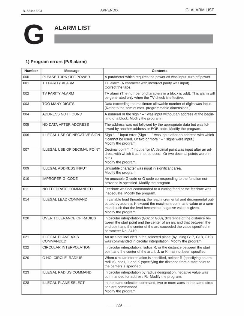
APPENDIX B–62444E/03 G. ALARM LIST 729 ALARM LIST G 1) Program errors (P/S alarm) Number Message Contents 000 PLEASE TURN OFF POWER A parameter which requires the power off was input, turn off power. 001 TH PARITY ALARM TH alarm (A character with incorrect parity was input). Correct the tape. 002 TV PARITY ALARM TV alarm (The number of characters in a block is odd). This alarm will be generated only when the TV check is effective. 003 TOO MANY DIGITS Data exceeding the maximum allowable number of digits was input. (Refer to the item of max. programmable dimensions.) 004 ADDRESS NOT FOUND A numeral or the sign “ – ” was input without an address at the begin- ning of a block. Modify the program . 005 NO DATA AFTER ADDRESS The address was not followed by the appropriate data but was fol- lowed by another address or EOB code. Modify the program. 006 ILLEGAL USE OF NEGATIVE SIGN Sign “ – ” input error (Sign “ – ” was input after an address with which it cannot be used. Or two or more “ – ” signs were input.) Modify the program. 007 ILLEGAL USE OF DECIMAL POINT Decimal point “ . ” input error (A decimal point was input after an ad- dress with which it can not be used. Or two decimal points were in- put.) Modify the program. 009 ILLEGAL ADDRESS INPUT Unusable character was input in significant area. Modify the program. 010 IMPROPER G–CODE An unusable G code or G code corresponding to the function not provided is specified. Modify the program. 011 NO FEEDRATE COMMANDED Feedrate was not commanded to a cutting feed or the feedrate was inadequate. Modify the program. 014 ILLEGAL LEAD COMMAND In variable lead threading, the lead incremental and decremental out- putted by address K exceed the maximum command value or a com- mand such that the lead becomes a negative value is given. Modify the program. 020 OVER TOLERANCE OF RADIUS In circular interpolation (G02 or G03), difference of the distance be- tween the start point and the center of an arc and that between the end point and the center of the arc exceeded the value specified in parameter No. 3410. 021 ILLEGAL PLANE AXIS COMMANDED An axis not included in the selected plane (by using G17, G18, G19) was commanded in circular interpolation. Modify the program. 022 CIRCULAR INTERPOLATION In circular interpolation, radius R, or the distance between the start point and the center of the arc, I, J, or K, has not been specified. 020 G NO CIRCLE RADIUS When circular interpolation is specified, neither R (specifying an arc radius), nor I, J, and K (specifying the distance from a start point to the center) is specified. 023 ILLEGAL RADIUS COMMAND In circular interpolation by radius designation, negative value was commanded for address R. Modify the program. 028 ILLEGAL PLANE SELECT In the plane selection command, two or more axes in the same direc- tion are commanded. Modify the program.
-
Upload
khangminh22 -
Category
Documents
-
view
1 -
download
0
Transcript of Series 16/18-TB Operator Mnl (Lathe), GFZ-62444E/03
APPENDIXB–62444E/03 G. ALARM LIST
729
ALARM LISTG1) Program errors (P/S alarm)
Number Message Contents
000 PLEASE TURN OFF POWER A parameter which requires the power off was input, turn off power.
001 TH PARITY ALARM TH alarm (A character with incorrect parity was input). Correct the tape.
002 TV PARITY ALARM TV alarm (The number of characters in a block is odd). This alarm willbe generated only when the TV check is effective.
003 TOO MANY DIGITS Data exceeding the maximum allowable number of digits was input.(Refer to the item of max. programmable dimensions.)
004 ADDRESS NOT FOUND A numeral or the sign “ – ” was input without an address at the begin-ning of a block. Modify the program .
005 NO DATA AFTER ADDRESS The address was not followed by the appropriate data but was fol-lowed by another address or EOB code. Modify the program.
006 ILLEGAL USE OF NEGATIVE SIGN Sign “ – ” input error (Sign “ – ” was input after an address with whichit cannot be used. Or two or more “ – ” signs were input.) Modify the program.
007 ILLEGAL USE OF DECIMAL POINT Decimal point “ . ” input error (A decimal point was input after an ad-dress with which it can not be used. Or two decimal points were in-put.)Modify the program.
009 ILLEGAL ADDRESS INPUT Unusable character was input in significant area.Modify the program.
010 IMPROPER G–CODE An unusable G code or G code corresponding to the function notprovided is specified. Modify the program.
011 NO FEEDRATE COMMANDED Feedrate was not commanded to a cutting feed or the feedrate wasinadequate. Modify the program.
014 ILLEGAL LEAD COMMAND In variable lead threading, the lead incremental and decremental out-putted by address K exceed the maximum command value or a com-mand such that the lead becomes a negative value is given.Modify the program.
020 OVER TOLERANCE OF RADIUS In circular interpolation (G02 or G03), difference of the distance be-tween the start point and the center of an arc and that between theend point and the center of the arc exceeded the value specified inparameter No. 3410.
021 ILLEGAL PLANE AXISCOMMANDED
An axis not included in the selected plane (by using G17, G18, G19)was commanded in circular interpolation. Modify the program.
022 CIRCULAR INTERPOLATION In circular interpolation, radius R, or the distance between the startpoint and the center of the arc, I, J, or K, has not been specified.
020 G NO CIRCLE RADIUS When circular interpolation is specified, neither R (specifying an arcradius), nor I, J, and K (specifying the distance from a start point tothe center) is specified.
023 ILLEGAL RADIUS COMMAND In circular interpolation by radius designation, negative value wascommanded for address R. Modify the program.
028 ILLEGAL PLANE SELECT In the plane selection command, two or more axes in the same direc-tion are commanded.Modify the program.
APPENDIXG. ALARM LIST B–62444E/03
730
Number ContentsMessage
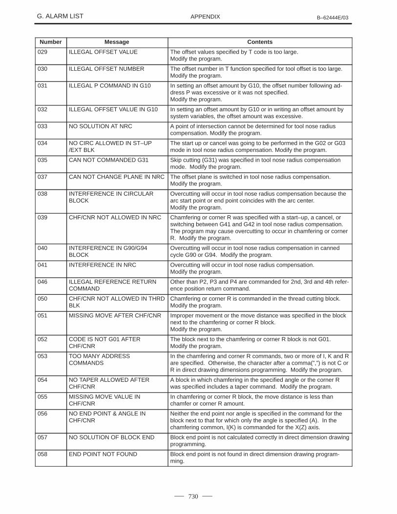
029 ILLEGAL OFFSET VALUE The offset values specified by T code is too large.Modify the program.
030 ILLEGAL OFFSET NUMBER The offset number in T function specified for tool offset is too large.Modify the program.
031 ILLEGAL P COMMAND IN G10 In setting an offset amount by G10, the offset number following ad-dress P was excessive or it was not specified.Modify the program.
032 ILLEGAL OFFSET VALUE IN G10 In setting an offset amount by G10 or in writing an offset amount bysystem variables, the offset amount was excessive.
033 NO SOLUTION AT NRC A point of intersection cannot be determined for tool nose radiuscompensation. Modify the program.
034 NO CIRC ALLOWED IN ST–UP/EXT BLK
The start up or cancel was going to be performed in the G02 or G03mode in tool nose radius compensation. Modify the program.
035 CAN NOT COMMANDED G31 Skip cutting (G31) was specified in tool nose radius compensationmode. Modify the program.
037 CAN NOT CHANGE PLANE IN NRC The offset plane is switched in tool nose radius compensation.Modify the program.
038 INTERFERENCE IN CIRCULARBLOCK
Overcutting will occur in tool nose radius compensation because thearc start point or end point coincides with the arc center. Modify the program.
039 CHF/CNR NOT ALLOWED IN NRC Chamfering or corner R was specified with a start–up, a cancel, orswitching between G41 and G42 in tool nose radius compensation.The program may cause overcutting to occur in chamfering or cornerR. Modify the program.
040 INTERFERENCE IN G90/G94BLOCK
Overcutting will occur in tool nose radius compensation in cannedcycle G90 or G94. Modify the program.
041 INTERFERENCE IN NRC Overcutting will occur in tool nose radius compensation.Modify the program.
046 ILLEGAL REFERENCE RETURNCOMMAND
Other than P2, P3 and P4 are commanded for 2nd, 3rd and 4th refer-ence position return command.
050 CHF/CNR NOT ALLOWED IN THRDBLK
Chamfering or corner R is commanded in the thread cutting block.Modify the program.
051 MISSING MOVE AFTER CHF/CNR Improper movement or the move distance was specified in the blocknext to the chamfering or corner R block.Modify the program.
052 CODE IS NOT G01 AFTERCHF/CNR
The block next to the chamfering or corner R block is not G01.Modify the program.
053 TOO MANY ADDRESSCOMMANDS
In the chamfering and corner R commands, two or more of I, K and Rare specified. Otherwise, the character after a comma(”,”) is not C orR in direct drawing dimensions programming. Modify the program.
054 NO TAPER ALLOWED AFTERCHF/CNR
A block in which chamfering in the specified angle or the corner Rwas specified includes a taper command. Modify the program.
055 MISSING MOVE VALUE INCHF/CNR
In chamfering or corner R block, the move distance is less thanchamfer or corner R amount.
056 NO END POINT & ANGLE INCHF/CNR
Neither the end point nor angle is specified in the command for theblock next to that for which only the angle is specified (A). In thechamfering common, I(K) is commanded for the X(Z) axis.
057 NO SOLUTION OF BLOCK END Block end point is not calculated correctly in direct dimension drawingprogramming.
058 END POINT NOT FOUND Block end point is not found in direct dimension drawing program-ming.
APPENDIXB–62444E/03 G. ALARM LIST
731
Number ContentsMessage
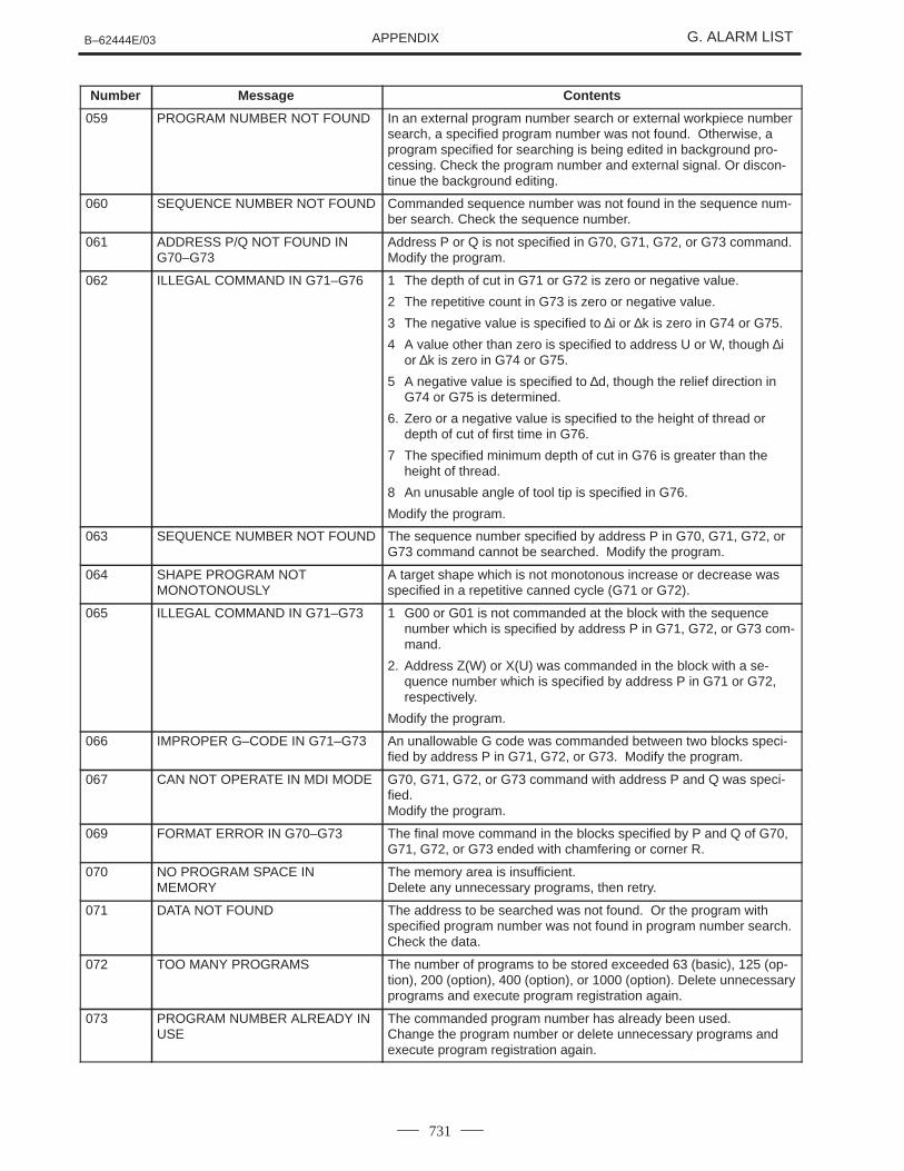
059 PROGRAM NUMBER NOT FOUND In an external program number search or external workpiece numbersearch, a specified program number was not found. Otherwise, aprogram specified for searching is being edited in background pro-cessing. Check the program number and external signal. Or discon-tinue the background editing.
060 SEQUENCE NUMBER NOT FOUND Commanded sequence number was not found in the sequence num-ber search. Check the sequence number.
061 ADDRESS P/Q NOT FOUND ING70–G73
Address P or Q is not specified in G70, G71, G72, or G73 command.Modify the program.
062 ILLEGAL COMMAND IN G71–G76 1 The depth of cut in G71 or G72 is zero or negative value.
2 The repetitive count in G73 is zero or negative value.
3 The negative value is specified to ∆i or ∆k is zero in G74 or G75.
4 A value other than zero is specified to address U or W, though ∆ior ∆k is zero in G74 or G75.
5 A negative value is specified to ∆d, though the relief direction inG74 or G75 is determined.
6. Zero or a negative value is specified to the height of thread ordepth of cut of first time in G76.
7 The specified minimum depth of cut in G76 is greater than theheight of thread.
8 An unusable angle of tool tip is specified in G76.
Modify the program.
063 SEQUENCE NUMBER NOT FOUND The sequence number specified by address P in G70, G71, G72, orG73 command cannot be searched. Modify the program.
064 SHAPE PROGRAM NOTMONOTONOUSLY
A target shape which is not monotonous increase or decrease wasspecified in a repetitive canned cycle (G71 or G72).
065 ILLEGAL COMMAND IN G71–G73 1 G00 or G01 is not commanded at the block with the sequencenumber which is specified by address P in G71, G72, or G73 com-mand.
2. Address Z(W) or X(U) was commanded in the block with a se-quence number which is specified by address P in G71 or G72,respectively.
Modify the program.
066 IMPROPER G–CODE IN G71–G73 An unallowable G code was commanded between two blocks speci-fied by address P in G71, G72, or G73. Modify the program.
067 CAN NOT OPERATE IN MDI MODE G70, G71, G72, or G73 command with address P and Q was speci-fied.Modify the program.
069 FORMAT ERROR IN G70–G73 The final move command in the blocks specified by P and Q of G70,G71, G72, or G73 ended with chamfering or corner R.
070 NO PROGRAM SPACE INMEMORY
The memory area is insufficient.Delete any unnecessary programs, then retry.
071 DATA NOT FOUND The address to be searched was not found. Or the program withspecified program number was not found in program number search.Check the data.
072 TOO MANY PROGRAMS The number of programs to be stored exceeded 63 (basic), 125 (op-tion), 200 (option), 400 (option), or 1000 (option). Delete unnecessaryprograms and execute program registration again.
073 PROGRAM NUMBER ALREADY INUSE
The commanded program number has already been used.Change the program number or delete unnecessary programs andexecute program registration again.
APPENDIXG. ALARM LIST B–62444E/03
732
Number ContentsMessage
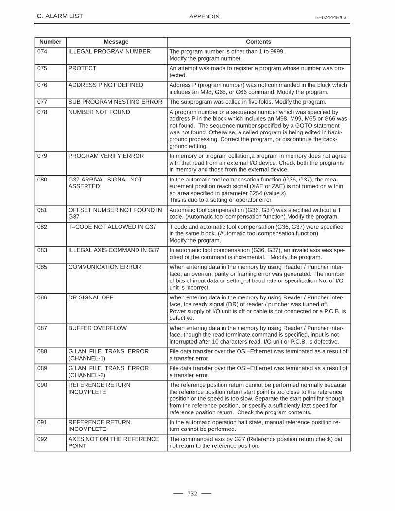
074 ILLEGAL PROGRAM NUMBER The program number is other than 1 to 9999.Modify the program number.
075 PROTECT An attempt was made to register a program whose number was pro-tected.
076 ADDRESS P NOT DEFINED Address P (program number) was not commanded in the block whichincludes an M98, G65, or G66 command. Modify the program.
077 SUB PROGRAM NESTING ERROR The subprogram was called in five folds. Modify the program.
078 NUMBER NOT FOUND A program number or a sequence number which was specified byaddress P in the block which includes an M98, M99, M65 or G66 wasnot found. The sequence number specified by a GOTO statementwas not found. Otherwise, a called program is being edited in back-ground processing. Correct the program, or discontinue the back-ground editing.
079 PROGRAM VERIFY ERROR In memory or program collation,a program in memory does not agreewith that read from an external I/O device. Check both the programsin memory and those from the external device.
080 G37 ARRIVAL SIGNAL NOTASSERTED
In the automatic tool compensation function (G36, G37), the mea-surement position reach signal (XAE or ZAE) is not turned on withinan area specified in parameter 6254 (value ε). This is due to a setting or operator error.
081 OFFSET NUMBER NOT FOUND ING37
Automatic tool compensation (G36, G37) was specified without a Tcode. (Automatic tool compensation function) Modify the program.
082 T–CODE NOT ALLOWED IN G37 T code and automatic tool compensation (G36, G37) were specifiedin the same block. (Automatic tool compensation function) Modify the program.
083 ILLEGAL AXIS COMMAND IN G37 In automatic tool compensation (G36, G37), an invalid axis was spe-cified or the command is incremental. Modify the program.
085 COMMUNICATION ERROR When entering data in the memory by using Reader / Puncher inter-face, an overrun, parity or framing error was generated. The numberof bits of input data or setting of baud rate or specification No. of I/Ounit is incorrect.
086 DR SIGNAL OFF When entering data in the memory by using Reader / Puncher inter-face, the ready signal (DR) of reader / puncher was turned off.Power supply of I/O unit is off or cable is not connected or a P.C.B. isdefective.
087 BUFFER OVERFLOW When entering data in the memory by using Reader / Puncher inter-face, though the read terminate command is specified, input is notinterrupted after 10 characters read. I/O unit or P.C.B. is defective.
088 G LAN FILE TRANS ERROR(CHANNEL-1)
File data transfer over the OSI–Ethernet was terminated as a result ofa transfer error.
089 G LAN FILE TRANS ERROR(CHANNEL-2)
File data transfer over the OSI–Ethernet was terminated as a result ofa transfer error.
090 REFERENCE RETURNINCOMPLETE
The reference position return cannot be performed normally becausethe reference position return start point is too close to the referenceposition or the speed is too slow. Separate the start point far enoughfrom the reference position, or specify a sufficiently fast speed forreference position return. Check the program contents.
091 REFERENCE RETURNINCOMPLETE
In the automatic operation halt state, manual reference position re-turn cannot be performed.
092 AXES NOT ON THE REFERENCEPOINT
The commanded axis by G27 (Reference position return check) didnot return to the reference position.

APPENDIXB–62444E/03 G. ALARM LIST
733
Number ContentsMessage
094 P TYPE NOT ALLOWED (COORDCHG)
P type cannot be specified when the program is restarted. (After theautomatic operation was interrupted, the coordinate system settingoperation was performed.)Perform the correct operation according to th operator’s manual.
095 P TYPE NOT ALLOWED (EXT OFSCHG)
P type cannot be specified when the program is restarted. (After theautomatic operation was interrupted, the external workpiece offsetamount changed.)Perform the correct operation according to th operator’s manual.
096 P TYPE NOT ALLOWED (WRK OFSCHG)
P type cannot be specified when the program is restarted. (After theautomatic operation was interrupted, the workpiece offset amountchanged.)Perform the correct operation according to th operator’s manual.
097 P TYPE NOT ALLOWED (AUTOEXEC)
P type cannot be directed when the program is restarted. (After pow-er ON, after emergency stop or P/S alarm 94 to 97 were reset, noautomatic operation was performed.) Perform automatic operation.
098 G28 FOUND IN SEQUENCERETURN
A command of the program restart was specified without the refer-ence position return operation after power ON or emergency stop,and G28 was found during search.Perform the reference position return.
099 MDI EXEC NOT ALLOWED AFT.SEARCH
After completion of search in program restart, a move command isgiven with MDI.
100 PARAMETER WRITE ENABLE On the PARAMETER(SETTING) screen, PWE(parameter writing en-abled) is set to 1. Set it to 0, then reset the system.
101 PLEASE CLEAR MEMORY The power turned off while rewriting the memory by program edit op-eration. If this alarm has occurred, press <RESET> while pressing<PROG>, and only the program being edited will be deleted.Register the deleted program.
109 P/S ALARM A value other than 0 or 1 was specified after P in the G08 code, or novalue was specified.
111 CALCULATED DATA OVERFLOW The result of calculation is out of the allowable range (–1047 to–10–29, 0, and 10–29 to 1047).
112 DIVIDED BY ZERO Division by zero was specified. (including tan 90°)Modify the program.
113 IMPROPER COMMAND A function which cannot be used in custom macro is commanded.Modify the program.
114 FORMAT ERROR IN MACRO There is an error in other formats than <Formula>.Modify the program.

APPENDIXG. ALARM LIST B–62444E/03
734
Number ContentsMessage
115 ILLEGAL VARIABLE NUMBER A value not defined as a variable number is designated in the custommacro or in high–speed cycle cutting.The header contents are improper in a high speed cycle cutting. Thisalarm is given in the following cases:
1. The header corresponding to the specified machining cycle num-ber called is not found.
2. The cycle connection data value is out of the allowable range (0 – 999).
3. The number of data in the header is out of the allowable range (0 – 32767).
4. The start data variable number of executable format data is out ofthe allowable range (#20000 – #85535).
5. The storing data variable number of executable format data is outof the allowable range (#85535).
6. The storing start data variable number of executable format data isoverlapped with the variable number used in the header.
Modify the program.
116 WRITE PROTECTED VARIABLE The left side of substitution statement is a variable whose substitutionis inhibited. Modify the program.
118 PARENTHESIS NESTING ERROR The nesting of bracket exceeds the upper limit (quintuple).Modify the program.
119 ILLEGAL ARGUMENT The SQRT argument is negative, BCD argument is negative, or othervalues than 0 to 9 are present on each line of BIN argument.Modify the program.
122 QUADRUPLE MACROMODAL–CALL
The macro modal call is specified in double.Modify the program.
123 CAN NOT USE MACRO COMMANDIN DNC
Macro control command is used during DNC operation.Modify the program.
124 MISSING END STATEMENT DO – END does not correspond to 1 : 1. Modify the program.
125 FORMAT ERROR IN MACRO <Formula> format is erroneous. Modify the program.
126 ILLEGAL LOOP NUMBER In DOn, 1� n �3 is not established. Modify the program.
127 NC, MACRO STATEMENT IN SAMEBLOCK
NC and custom macro commands coexist.Modify the program.
128 ILLEGAL MACRO SEQUENCENUMBER
The sequence number specified in the branch command was not 0 to9999. Or, it cannot be searched. Modify the program.
129 ILLEGAL ARGUMENT ADDRESS An address which is not allowed in <Argument Designation > is used.Modify the program.
130 ILLEGAL AXIS OPERATION An axis control command was given by PMC to an axis controlled byCNC. Or an axis control command was given by CNC to an axiscontrolled by PMC. Modify the program.
131 TOO MANY EXTERNAL ALARMMESSAGES
Five or more alarms have generated in external alarm message.Consult the PMC ladder diagram to find the cause.
132 ALARM NUMBER NOT FOUND No alarm No. concerned exists in external alarm message clear.Check the PMC ladder diagram.
133 ILLEGAL DATA IN EXT. ALARMMSG
Small section data is erroneous in external alarm message or exter-nal operator message. Check the PMC ladder diagram.
135 SPINDLE ORIENTATION PLEASE Without any spindle orientation , an attempt was made for spindleindexing. Perform spindle orientation.
136 C/H–CODE & MOVE CMD IN SAMEBLK.
A move command of other axes was specified to the same block asspindle indexing addresses C, H. Modify the program.
APPENDIXB–62444E/03 G. ALARM LIST
735
Number ContentsMessage
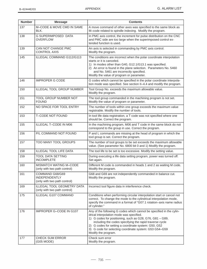
137 M–CODE & MOVE CMD IN SAMEBLK.
A move command of other axes was specified to the same block asM–code related to spindle indexing. Modify the program.
138 G SUPERIMPOSED DATAOVERFLOW
In PMC axis control, the increment for pulse distribution on the CNCand PMC side are too large when the superimposed control ex-tended function is used.
139 CAN NOT CHANGE PMCCONTROL AXIS
An axis is selected in commanding by PMC axis control.Modify the program.
145 ILLEGAL COMMAND G112/G113 The conditions are incorrect when the polar coordinate interpolationstarts or it is canceled.1) In modes other than G40, G12.1/G13.1 was specified.2) An error is found in the plane selection. Parameters No. 5460
and No. 5461 are incorrectly specified.Modify the value of program or parameter.
146 IMPROPER G CODE G codes which cannot be specified in the polar coordinate interpola-tion mode was specified. See section II–4.4 and modify the program.
150 ILLEGAL TOOL GROUP NUMBER Tool Group No. exceeds the maximum allowable value.Modify the program.
151 TOOL GROUP NUMBER NOTFOUND
The tool group commanded in the machining program is not set.Modify the value of program or parameter.
152 NO SPACE FOR TOOL ENTRY The number of tools within one group exceeds the maximum valueregistrable. Modify the number of tools.
153 T–CODE NOT FOUND In tool life data registration, a T code was not specified where oneshould be. Correct the program.
155 ILLEGAL T–CODE IN M06 In the machining program, M06 and T code in the same block do notcorrespond to the group in use. Correct the program.
156 P/L COMMAND NOT FOUND P and L commands are missing at the head of program in which thetool group is set. Correct the program.
157 TOO MANY TOOL GROUPS The number of tool groups to be set exceeds the maximum allowablevalue. (See parameter No. 6800 bit 0 and 1) Modify the program.
158 ILLEGAL TOOL LIFE DATA The tool life to be set is too excessive. Modify the setting value.
159 TOOL DATA SETTINGINCOMPLETE
During executing a life data setting program, power was turned off. Set again.
160 MISMATCH WATING M–CODE(only with two path control)
Different M code is commanded in heads 1 and 2 as waiting M code.Modify the program.
161 COMMAND G68/G69INDEPENDENTLY(only with two path control)
G68 and G69 are not independently commanded in balance cut.Modify the program.
169 ILLEGAL TOOL GEOMETRY DATA(only with two path control)
Incorrect tool figure data in interference check.
175 ILLEGAL G107 COMMAND Conditions when performing circular interpolation start or cancel notcorrect. To change the mode to the cylindrical interpolation mode,specify the command in a format of “G07.1 rotation–axis name radiusof cylinder.”
176 IMPROPER G–CODE IN G107 Any of the following G codes which cannot be specified in the cylin-drical interpolation mode was specified.1) G codes for positioning, such as G28, G76, G81 – G89,
including the codes specifying the rapid traverse cycle2) G codes for setting a coordinate system: G50, G523) G code for selecting coordinate system: G53 G54–G59Modify the program.
177 CHECK SUM ERROR(G05 MODE)
Check sum errorModify the program.

APPENDIXG. ALARM LIST B–62444E/03
736
Number ContentsMessage
178 G05 NOT ALLOWED IN G41/G42MODE
G05 was commanded in the G41/G42 mode.Correct the program.
179 PARAM. (NO. 7510) SETTINGERROR
The number of controlled axes set by the parameter 7510 exceedsthe maximum number. Modify the parameter setting value.
180 COMMUNICATION ERROR (REMOTE BUF)
Remote buffer connection alarm has generated. Confirm the numberof cables, parameters and I/O device.
194 SPINDLE COMMAND INSYNCHRO–MODE
A contour control mode, spindle positioning (Cs–axis control) mode,or rigid tapping mode was specified during the serial spindle synchronous control mode. Correct the program so that the serialspindle synchronous control mode is released in advance.
197 C–AXIS COMMANDED IN SPINDLEMODE
The program specified a movement along the Cf–axis when the sig-nal CON(DGN=G027#7) was off. Correct the program, or consult thePMC ladder diagram to find the reason the signal is not turned on.
199 MACRO WORD UNDEFINED Undefined macro word was used. Modify the custom macro.
200 ILLEGAL S CODE COMMAND In the rigid tapping, an S value is out of the range or is not specified.The maximum values for S which can be specified in rigid tapping isset in parameters 5241 to 5243. Change the setting in the parameteror modify the program.
201 FEEDRATE NOT FOUND IN RIGIDTAP
In the rigid tapping, no F value is specified.Correct the program.
202 POSITION LSI OVERFLOW In the rigid tapping, spindle distribution value is too large.
203 PROGRAM MISS AT RIGIDTAPPING
In the rigid tapping, position for a rigid M code (M29) or an S com-mand is incorrect. Modify the program.
204 ILLEGAL AXIS OPERATION In the rigid tapping, an axis movement is specified between the rigidM code (M29) block and G84 (G88) block. Modify the program.
205 RIGID MODE DI SIGNAL OFF Rigid tapping signal (DGNG061 #1) is not 1 when G84 (G88) isexecuted though the rigid M code (M29) is specified. Consult thePMC ladder diagram to find the reason the signal is not turned on.
210 CAN NOT COMAND M198/M099 1 M198 and M199 are executed in the schedule operation. OrM198 is executed in the DNC operation. Modify the program.
2 In a multiple repetitive pocketing canned cycle, an interrupt macrowas specified, and M99 was executed.
211 G31 (HIGH) NOT ALLOWED IN G99 G31 is commanded in the per revolution command when the high–speed skip option is provided. Modify the program.
212 ILLEGAL PLANE SELECT The direct drawing dimensions programming is commanded for theplane other than the Z–X plane. Correct the program.
213 ILLEGAL COMMAND INSYNCHRO–MODE
Movement is commanded for the axis to be synchronously controlled.
214 ILLEGAL COMMAND INSYNCHRO–MODE
Coordinate system is set or tool compensation of the shift type isexecuted in the synchronous control. Correct the program.
217 DUPLICATE G251 (COMMANDS) G51.2 or G251 is further commanded in the polygon machiningmode. Modify the program.
218 NOT FOUND P/Q COMMAND ING251
P or Q is not commanded in the G251 block, or the command valueis out of the range. Modify the program.
219 COMMAND G250/G251INDEPENDENTLY
G251 and G250 are not independent blocks.
220 ILLEGAL COMMAND INSYNCHR–MODE
In the synchronous operation, movement is commanded by the NCprogram or PMC axis control interface for the synchronous axis.
221 ILLEGAL COMMAND INSYNCHR–MODE
Polygon machining synchronous operation and axis control or bal-ance cutting are executed at a time. Modify the program.
224 RETURN TO REFERENCE POINT Not returned to reference point before cycle start.

APPENDIXB–62444E/03 G. ALARM LIST
737
Number ContentsMessage
225 SYNCHRONOUS/MIXED CONTROLERROR(only with two path control only)
This alarm is generated in the following circumstances. (Searched forduring synchronous and mixed control command.
1 When there is a mistake in axis number parameter setting.
2 When there is a mistake in control commanded.
Modify the program or the parameter.
226 ILLEGAL COMMAND INSYNCHRO–MODE(only with two path control only)
A travel command has been sent to the axis being synchronized insynchronous mode. Modify the program or the parameter.
229 CAN NOT KEEP SYNCHRO–STATE(only with two path control only)
This alarm is generated in the following circumstances.
1 When the synchro/mixed state could not be kept due to systemoverload.
2 The above condition occurred in CNC devices (hardware) andsynchro–state could not be kept.
(This alarm is not generated in normal use conditions.)
231 FORMAT ERROR IN G10 OR L50 Any of the following errors occurred in the specified format at the pro-grammable–parameter input.
1 Address N or R was not entered.
2 A number not specified for a parameter was entered.
3 The axis number was too large.
4 An axis number was not specified in the axis–type parameter.
5 An axis number was specified in the parameter which is not anaxis type.
6 An attempt was made to reset bit 4 of parameter 3202 (NE9) orchange parameter 3210 (PSSWD) when they are protected by apassword. Correct the program.
232 ILLEGAL AXIS COMMAND INHELICAL
Three or more axes were specified as helical axes in the helical inter-polation mode.
233 DEVICE BUSY When an attempt was made to use a unit such as that connected viathe RS–232–C interface, other users were using it.
239 BP/S ALARM While punching was being performed with the function for controllingexternal I/O units ,background editing was performed.
240 BP/S ALARM Background editing was performed during MDI operation.
244 P/S ALARM In the skip function activated by the torque limit signal, the number ofaccumulated erroneous pulses exceed 32767 before the signal wasinput. Therefore, the pulses cannot be corrected with one distribution.Change the conditions, such as federates along axes and torquelimit, and try again.
245 T–CODE NOT ALOWED IN THISBLOCK
One of the G codes, G50, G10, and G04, which cannot be specifiedin the same block as a T code, was specified with a T code.
5010 END OF RECORD The end of record (%) was specified.
5016 ILLEGAL COMBINATION OF MCODE
M codes which belonged to the same group were specified in ablock. Alternatively,an M code which must be specified without otherM codes in the block was specified in a block with other M codes.
5018 POLYGON AXIS SPPED ERROR The rotating speed ratio of the command value cannot be maintainedin the G51.2 mode , because the spped of the spindle or the polygonturning synchronous axis exceeds the clamp value or itis too slow.
5020 PARAMETER OF RESTARTERROR
An erroneous parameter was specified for restarting a program.
5030 ILLEGAL COMMAND (G100) The end command (G110) was specified before the registration startcommand (G101, G102, or G103) was specified for the B–axis.

APPENDIXG. ALARM LIST B–62444E/03
738
Number ContentsMessage
5031 ILLEGAL COMMAND (G100, G102,G103)
While a registration start command (G101, G102, or G103) was beingexecuted, another registration start command was specified for theB–axis.
5032 NEW PRG REGISTERED IN B–AXSMOVE
While the machine was moving about the B–axis, at attempt wasmade to register another move command.
5033 NO PROG SPACE IN MEMORYB–AXIS
Commands for movement about the B–axis were not registered be-cause of insufficient program memory.
5034 PLURAL COMMAND IN G110 Multiple movements were specified with the G110 code for the B–axis.
5035 NO FEEDRATE COMMANDEDB–AXIS
A feedrate was not specified for cutting feed about the B–axis.
5036 ADDRESS R NOT DEFINED ING81–G86
Point R was not specified for the canned cycle for the B–axis.
5037 ADDRESS Q NOT DEFINED IN G83 Depth of cut Q was not specified for the G83 code (peck drillingcycle). Alternatively, 0 was specified in Q for teh B–axis.
5038 TOO MANY START M–CODECOMMAND
More than six M codes for starting movement about the B–axis werespecified.
5039 START UNREGISTERED B–AXISPROG
An attempt was made to execute a program for the B–axis which hadnot been registered.
5040 CAN NOT COMMANDED B–AXISMOVE
The machine could not move about the B–axis because parameterNo.8250 was incorrectly specified, or because the PMC axis systemcould not be used.
5041 CAN NOT COMMANDED G110BLOCK
Blocks containing the G110 codes were successively specified intool–tip radius compensation for the B–axis.
5046 ILLEGAL PARAMETER (ST.COMP) Parameters related to straightness compensation have been erro-neously specified. Possible causes are as follows :
1 Invalid axis numbers have been assigned to move or compensa-tion axes.
2 The number of pitcherror compensation points between the maxi-mum positive and maximum negative points exceeds 128.
3 Straightness compensation point numbers have been assigned inother than ascending order.
4 Straightness compensation points could not belocated between themaximum positive and maximum negative pitch error compensa-tion points.
5 The amount of compensation per compensation point is too largeor too small.
5051 M–NET CODE ERROR Abnormal character reception(Characters except code used to transmit)
5052 M–NET ETX ERROR ”ETX” code is abnormal.
5053 M–NET CONNECT ERROR Connection time supervision error (parameter No.175)
5054 M–NET RECEIVE ERROR Boring time supervision error (parameter No.176)
5055 M–NET PRT/FRM ERROR Vertical parity or framing error detection
5056 M–NET BOARD SYSTEM DOWN Transmit time–out error (parameter No. 177)ROM parity errorCPU interruption detection of not listed above
5058 G35/G36 FORMAT ERROR A command for changing the major axis was specified during circularthreading. Alternatively, the leangth of the major axis was specifiedto be 0.
5059 RADIUS IS OUT OF RANGE During circular interpolation, the center of the arc specified with I, J,and K caused the radius to exceed nine digits.
APPENDIXB–62444E/03 G. ALARM LIST
739
Number ContentsMessage
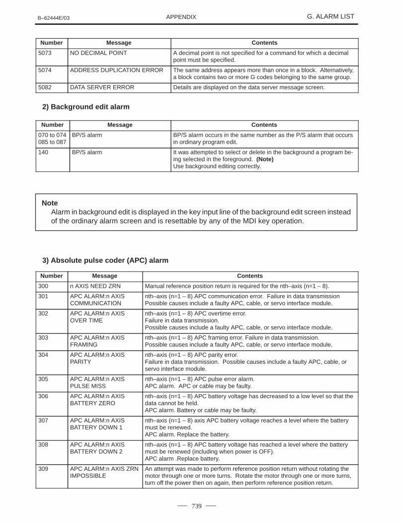
5073 NO DECIMAL POINT A decimal point is not specified for a command for which a decimalpoint must be specified.
5074 ADDRESS DUPLICATION ERROR The same address appears more than once in a block. Alternatively,a block contains two or more G codes belonging to the same group.
5082 DATA SERVER ERROR Details are displayed on the data server message screen.
2) Background edit alarm
Number Message Contents
070 to 074085 to 087
BP/S alarm BP/S alarm occurs in the same number as the P/S alarm that occursin ordinary program edit.
140 BP/S alarm It was attempted to select or delete in the background a program be-ing selected in the foreground. (Note) Use background editing correctly.
NoteAlarm in background edit is displayed in the key input line of the background edit screen insteadof the ordinary alarm screen and is resettable by any of the MDI key operation.
3) Absolute pulse coder (APC) alarm
Number Message Contents
300 n AXIS NEED ZRN Manual reference position return is required for the nth–axis (n=1 – 8).
301 APC ALARM:n AXISCOMMUNICATION
nth–axis (n=1 – 8) APC communication error. Failure in data transmission Possible causes include a faulty APC, cable, or servo interface module.
302 APC ALARM:n AXISOVER TIME
nth–axis (n=1 – 8) APC overtime error.Failure in data transmission.Possible causes include a faulty APC, cable, or servo interface module.
303 APC ALARM:n AXISFRAMING
nth–axis (n=1 – 8) APC framing error. Failure in data transmission.Possible causes include a faulty APC, cable, or servo interface module.
304 APC ALARM:n AXISPARITY
nth–axis (n=1 – 8) APC parity error.Failure in data transmission. Possible causes include a faulty APC, cable, orservo interface module.
305 APC ALARM:n AXISPULSE MISS
nth–axis (n=1 – 8) APC pulse error alarm. APC alarm. APC or cable may be faulty.
306 APC ALARM:n AXISBATTERY ZERO
nth–axis (n=1 – 8) APC battery voltage has decreased to a low level so that thedata cannot be held. APC alarm. Battery or cable may be faulty.
307 APC ALARM:n AXISBATTERY DOWN 1
nth–axis (n=1 – 8) axis APC battery voltage reaches a level where the batterymust be renewed.APC alarm. Replace the battery.
308 APC ALARM:n AXISBATTERY DOWN 2
nth–axis (n=1 – 8) APC battery voltage has reached a level where the batterymust be renewed (including when power is OFF).APC alarm .Replace battery.
309 APC ALARM:n AXIS ZRNIMPOSSIBLE
An attempt was made to perform reference position return without rotating themotor through one or more turns. Rotate the motor through one or more turns,turn off the power then on again, then perform reference position return.
APPENDIXG. ALARM LIST B–62444E/03
740
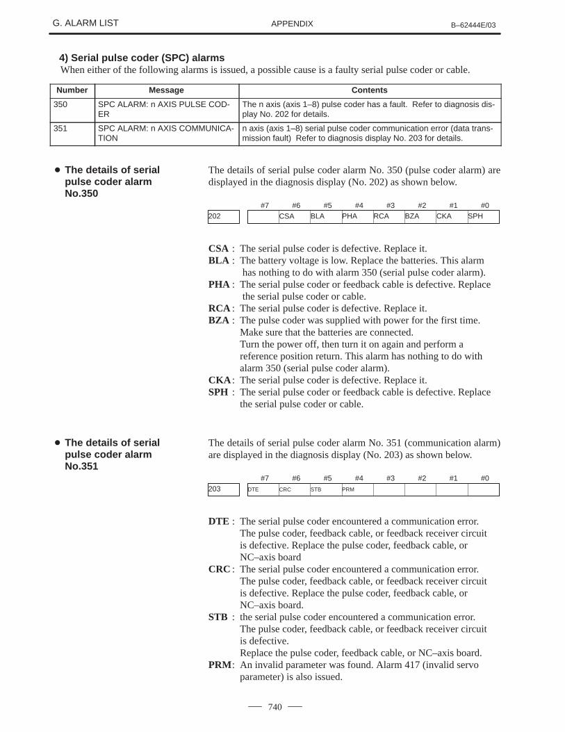
4) Serial pulse coder (SPC) alarms When either of the following alarms is issued, a possible cause is a faulty serial pulse coder or cable.
Number Message Contents
350 SPC ALARM: n AXIS PULSE COD-ER
The n axis (axis 1–8) pulse coder has a fault. Refer to diagnosis dis-play No. 202 for details.
351 SPC ALARM: n AXIS COMMUNICA-TION
n axis (axis 1–8) serial pulse coder communication error (data trans-mission fault) Refer to diagnosis display No. 203 for details.
The details of serial pulse coder alarm No. 350 (pulse coder alarm) aredisplayed in the diagnosis display (No. 202) as shown below.
#7 #6 #5 #4 #3 #2 #1 #0
CSA BLA PHA RCA BZA CKA SPH202
CSA : The serial pulse coder is defective. Replace it.BLA : The battery voltage is low. Replace the batteries. This alarm
has nothing to do with alarm 350 (serial pulse coder alarm).PHA : The serial pulse coder or feedback cable is defective. Replace
the serial pulse coder or cable.RCA : The serial pulse coder is defective. Replace it.BZA : The pulse coder was supplied with power for the first time.
Make sure that the batteries are connected.Turn the power off, then turn it on again and perform a
reference position return. This alarm has nothing to do with alarm 350 (serial pulse coder alarm).
CKA : The serial pulse coder is defective. Replace it.SPH : The serial pulse coder or feedback cable is defective. Replace
the serial pulse coder or cable.
The details of serial pulse coder alarm No. 351 (communication alarm)are displayed in the diagnosis display (No. 203) as shown below.
#7 #6 #5 #4 #3 #2 #1 #0DTE CRC STB PRM203
DTE : The serial pulse coder encountered a communication error.The pulse coder, feedback cable, or feedback receiver circuitis defective. Replace the pulse coder, feedback cable, orNC–axis board
CRC : The serial pulse coder encountered a communication error.The pulse coder, feedback cable, or feedback receiver circuitis defective. Replace the pulse coder, feedback cable, orNC–axis board.
STB : the serial pulse coder encountered a communication error.The pulse coder, feedback cable, or feedback receiver circuitis defective.Replace the pulse coder, feedback cable, or NC–axis board.
PRM : An invalid parameter was found. Alarm 417 (invalid servo parameter) is also issued.
� The details of serialpulse coder alarmNo.350
� The details of serial pulse coder alarm No.351

APPENDIXB–62444E/03 G. ALARM LIST
741
5) Servo alarms
Number Message Contents
400 SERVO ALARM: n AXISOVERLOAD
The n–th axis (axis 1–8) overload signal is on. Refer to diagnosisdisplay No. 201 for details.
401 SERVO ALARM: n AXIS VRDY OFF The n–th axis (axis 1–8) servo amplifier READY signal (DRDY) wentoff.
404 SERVO ALARM: n AXIS VRDY ON Even though the n–th axis (axis 1–8) READY signal (MCON) wentoff, the servo amplifier READY signal (DRDY) is still on. Or, when thepower was turned on, DRDY went on even though MCON was off.Check that the servo interface module and servo amp are connected.
405 SERVO ALARM: (WRONG ZRN) Position control system fault. Due to an NC or servo system fault inthe reference position return, there is the possibility that referenceposition return could not be executed correctly. Try again from themanual reference position return.
407 SERVO ALARM: EXCESS ERR The difference in synchronous axis position deviation exceeded theset value.
409 SERVO ALARM:EXCESS ERROR An abnormal load on the servo motor was detected. Alternatively, anabnormal load on the spindle motor was detected in Cs mode.
410 SERVO ALARM: n AXIS EXCESSERR
The position deviation value when the n–th axis (axis 1–8) stops islarger than the set value.Note) Limit value must be set to parameter No.1829 for each axis.
411 SERVO ALARM: n AXIS EXCESSERR
The position deviation value when the n–th axis (axis 1–8) moves islarger than the set value. Note) Limit value must be set to parameter No.1828 for each axis.
413 SERVO ALARM: n AXIS LSI OVER The contents of the error register for the n–th axis (axis 1–8) are be-yond of the range of –231 to 231. This error usually occurs as theresult of an improperly set parameters.
414 SERVO ALARM: n AXIS DETECTERR
N–th axis (axis 1–8) digital servo system fault. Refer to diagnosisdisplay No. 200 and No.204 for details.
415 SERVO ALARM: n AXIS MOTIONOVER
A speed higher than 511875 units/s was attempted to be set in then–th axis (axis 1–8). This error occurs as the result of improperly setCMR.
416 SERVO ALARM: n AXISDISCONNECT
Position detection system fault in the n–th axis (axis 1–8) pulse coder(disconnection alarm). Refer to diagnosis display No. 201 for details.
417 SERVO ALARM: n AXIS DGTLPARAM
This alarm occurs when the n–th axis (axis 1–8) is in one of theconditions listed below. (Digital servo system alarm)1) The value set in Parameter No. 2020 (motor form) is out of the
specified limit.2) A proper value (111 or –111) is not set in parameter No.2022
(motor revolution direction).3) Illegal data (a value below 0, etc.) was set in parameter No. 2023
(number of speed feedback pulses per motor revolution).4) Illegal data (a value below 0, etc.) was set in parameter No. 2024
(number of position feedback pulses per motor revolution).5) Parameters No. 2084 and No. 2085 (flexible field gear rate) have
not been set.6) A value outside the limit of {1 to the number of control axes} or
a non–continuous value (Parameter 1023 (servo axis number) contains a value out of the range from 1 to the number of axes,oran isolated value (for example, 4 not prceded by 3).was set in parameter No. 1023 (servo axisnumber).
421 SERVO ALARN : n AXIS EXCESSER (D)
While the dual position feedback function is being applied, an exces-sive difference was detected between a semi–closed loop error andclosed loop error. Check the dual position conversion factor set inparameter Nos. 2078 and 2079.
APPENDIXG. ALARM LIST B–62444E/03
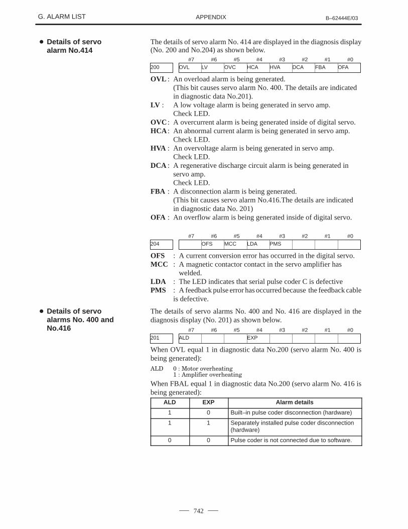
742
The details of servo alarm No. 414 are displayed in the diagnosis display(No. 200 and No.204) as shown below.
#7 #6 #5 #4 #3 #2 #1 #0OVL LV OVC HCA HVA DCA FBA OFA200
OVL : An overload alarm is being generated. (This bit causes servo alarm No. 400. The details are indicatedin diagnostic data No.201).
LV : A low voltage alarm is being generated in servo amp. Check LED.
OVC : A overcurrent alarm is being generated inside of digital servo.HCA : An abnormal current alarm is being generated in servo amp.
Check LED.HVA : An overvoltage alarm is being generated in servo amp.
Check LED.DCA : A regenerative discharge circuit alarm is being generated in
servo amp.Check LED.
FBA : A disconnection alarm is being generated.(This bit causes servo alarm No.416.The details are indicatedin diagnostic data No. 201)
OFA : An overflow alarm is being generated inside of digital servo.
#7 #6 #5 #4 #3 #2 #1 #0
OFS MCC LDA PMS204
OFS : A current conversion error has occurred in the digital servo.MCC : A magnetic contactor contact in the servo amplifier has
welded.LDA : The LED indicates that serial pulse coder C is defectivePMS : A feedback pulse error has occurred because the feedback cable
is defective.
The details of servo alarms No. 400 and No. 416 are displayed in thediagnosis display (No. 201) as shown below.
#7 #6 #5 #4 #3 #2 #1 #0ALD EXP201
When OVL equal 1 in diagnostic data No.200 (servo alarm No. 400 isbeing generated):��� � � ����� ��� ����
� � �������� ��� ����
When FBAL equal 1 in diagnostic data No.200 (servo alarm No. 416 isbeing generated):
ALD EXP Alarm details
1 0 Built–in pulse coder disconnection (hardware)
1 1 Separately installed pulse coder disconnection(hardware)
0 0 Pulse coder is not connected due to software.
� Details of servo alarm No.414
� Details of servo alarms No. 400 andNo.416
APPENDIXB–62444E/03 G. ALARM LIST
743
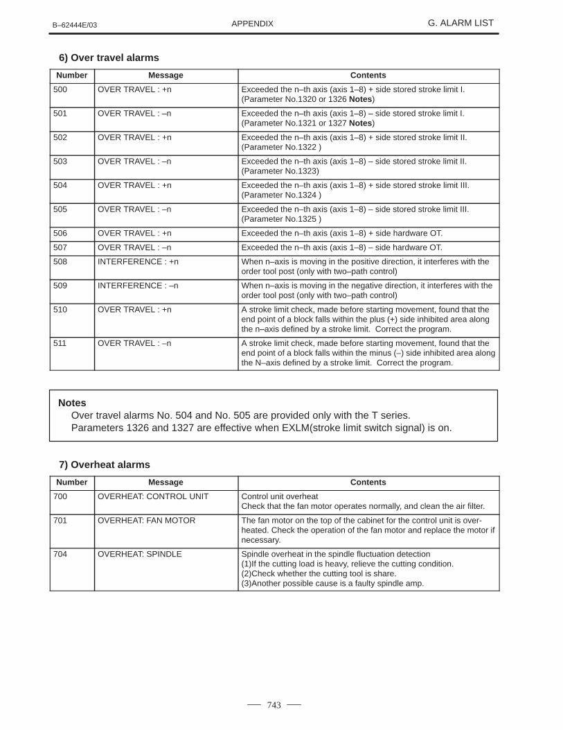
6) Over travel alarms
Number Message Contents
500 OVER TRAVEL : +n Exceeded the n–th axis (axis 1–8) + side stored stroke limit I.(Parameter No.1320 or 1326 Notes )
501 OVER TRAVEL : –n Exceeded the n–th axis (axis 1–8) – side stored stroke limit I.(Parameter No.1321 or 1327 Notes )
502 OVER TRAVEL : +n Exceeded the n–th axis (axis 1–8) + side stored stroke limit II.(Parameter No.1322 )
503 OVER TRAVEL : –n Exceeded the n–th axis (axis 1–8) – side stored stroke limit II.(Parameter No.1323)
504 OVER TRAVEL : +n Exceeded the n–th axis (axis 1–8) + side stored stroke limit III.(Parameter No.1324 )
505 OVER TRAVEL : –n Exceeded the n–th axis (axis 1–8) – side stored stroke limit III.(Parameter No.1325 )
506 OVER TRAVEL : +n Exceeded the n–th axis (axis 1–8) + side hardware OT.
507 OVER TRAVEL : –n Exceeded the n–th axis (axis 1–8) – side hardware OT.
508 INTERFERENCE : +n When n–axis is moving in the positive direction, it interferes with theorder tool post (only with two–path control)
509 INTERFERENCE : –n When n–axis is moving in the negative direction, it interferes with theorder tool post (only with two–path control)
510 OVER TRAVEL : +n A stroke limit check, made before starting movement, found that theend point of a block falls within the plus (+) side inhibited area alongthe n–axis defined by a stroke limit. Correct the program.
511 OVER TRAVEL : –n A stroke limit check, made before starting movement, found that theend point of a block falls within the minus (–) side inhibited area alongthe N–axis defined by a stroke limit. Correct the program.
NotesOver travel alarms No. 504 and No. 505 are provided only with the T series.Parameters 1326 and 1327 are effective when EXLM(stroke limit switch signal) is on.
7) Overheat alarms
Number Message Contents
700 OVERHEAT: CONTROL UNIT Control unit overheatCheck that the fan motor operates normally, and clean the air filter.
701 OVERHEAT: FAN MOTOR The fan motor on the top of the cabinet for the control unit is over-heated. Check the operation of the fan motor and replace the motor ifnecessary.
704 OVERHEAT: SPINDLE Spindle overheat in the spindle fluctuation detection(1)If the cutting load is heavy, relieve the cutting condition.(2)Check whether the cutting tool is share.(3)Another possible cause is a faulty spindle amp.
APPENDIXG. ALARM LIST B–62444E/03
744
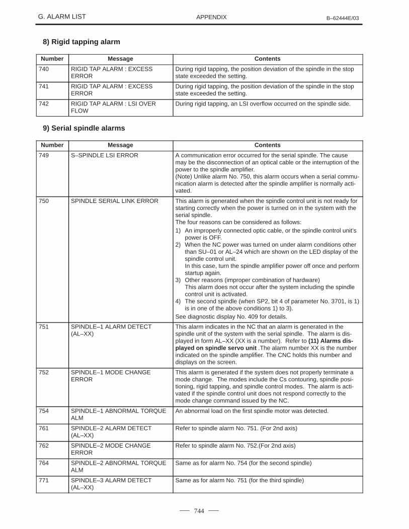
8) Rigid tapping alarm
Number Message Contents
740 RIGID TAP ALARM : EXCESSERROR
During rigid tapping, the position deviation of the spindle in the stopstate exceeded the setting.
741 RIGID TAP ALARM : EXCESSERROR
During rigid tapping, the position deviation of the spindle in the stopstate exceeded the setting.
742 RIGID TAP ALARM : LSI OVERFLOW
During rigid tapping, an LSI overflow occurred on the spindle side.
9) Serial spindle alarms
Number Message Contents
749 S–SPINDLE LSI ERROR A communication error occurred for the serial spindle. The causemay be the disconnection of an optical cable or the interruption of thepower to the spindle amplifier.(Note) Unlike alarm No. 750, this alarm occurs when a serial commu-nication alarm is detected after the spindle amplifier is normally acti-vated.
750 SPINDLE SERIAL LINK ERROR This alarm is generated when the spindle control unit is not ready forstarting correctly when the power is turned on in the system with theserial spindle.The four reasons can be considered as follows:1) An improperly connected optic cable, or the spindle control unit’s
power is OFF.2) When the NC power was turned on under alarm conditions other
than SU–01 or AL–24 which are shown on the LED display of thespindle control unit.In this case, turn the spindle amplifier power off once and performstartup again.
3) Other reasons (improper combination of hardware)This alarm does not occur after the system including the spindlecontrol unit is activated.
4) The second spindle (when SP2, bit 4 of parameter No. 3701, is 1)is in one of the above conditions 1) to 3).
See diagnostic display No. 409 for details.
751 SPINDLE–1 ALARM DETECT(AL–XX)
This alarm indicates in the NC that an alarm is generated in thespindle unit of the system with the serial spindle. The alarm is dis-played in form AL–XX (XX is a number). Refer to (11) Alarms dis-played on spindle servo unit .The alarm number XX is the numberindicated on the spindle amplifier. The CNC holds this number anddisplays on the screen.
752 SPINDLE–1 MODE CHANGEERROR
This alarm is generated if the system does not properly terminate amode change. The modes include the Cs contouring, spindle posi-tioning, rigid tapping, and spindle control modes. The alarm is acti-vated if the spindle control unit does not respond correctly to themode change command issued by the NC.
754 SPINDLE–1 ABNORMAL TORQUEALM
An abnormal load on the first spindle motor was detected.
761 SPINDLE–2 ALARM DETECT(AL–XX)
Refer to spindle alarm No. 751. (For 2nd axis)
762 SPINDLE–2 MODE CHANGEERROR
Refer to spindle alarm No. 752.(For 2nd axis)
764 SPINDLE–2 ABNORMAL TORQUEALM
Same as for alarm No. 754 (for the second spindle)
771 SPINDLE–3 ALARM DETECT(AL–XX)
Same as for alarm No. 751 (for the third spindle)

APPENDIXB–62444E/03 G. ALARM LIST
745
Number ContentsMessage
772 SPINDLE–3 MODE CHANGEERROR
Same as for alarm No. 752 (for the third spindle)
774 SPINDLE–3 ABNORMAL TORQUEALM
Same as for alarm No. 754 (for the third spindle)
The details of spindle alarm No. 750 are displayed in the diagnosis display(No. 409) as shown below.
#7 #6 #5 #4 #3 #2 #1 #0SPE S2E S1E SHE409
SPE 0 : In the spindle serial control, the serial spindle parametersfulfill the spindle unit startup conditions.
1 : In the spindle serial control, the serial spindle parameters donot fulfill the spindle unit startup conditions.
S2E 0 : The second spindle is normal during the spindle serial controlstartup.
1 : The second spindle was detected to have a fault during thespindle serial control startup.
S1E 0 : The first spindle is normal during the spindle serial controlstartup.
1 : The first spindle was detected to have a fault during thespindle axis serial control startup.
SHE 0 : The serial communications module in the CNC is normal.1 : The serial communications module in the CNC was detected
to have a fault.
10) System alarms
(These alarms cannot be reset with reset key.)
Number Message Contents
900 ROM PARITY ROM parity error (CNC/OMM/Servo)Replace the number of ROM.
910 RAM PARITY : (4N) RAM parity error in the tape memory RAM module. Clear thememory or replace the module.After this operation, reset all data including the parameters.
911 RAM PARITY: (4N+1) RAM parity error in the tape memory RAM module. Clear thememory or replace the module.After this operation, reset all data including the parameters.
912 RAM PARITY: (4N+2) RAM parity error in the tape memory RAM module. Clear thememory or replace the module.After this operation, reset all data including the parameters.
913 RAM PARITY : (4N+3) RAM parity error in the tape memory RAM module. Clear thememory or replace the module.After this operation, reset all data including the parameters.
914 SRAM PARITY (2N) RAM parity error for part program storage RAM or additional SRAM.Clear memory or replace the main CPU board or additional SRAM.
915 SRAM PARITY (2N+1)Clear memory or re lace the main CPU board or additional SRAM.Then, re–specify all data including parameters.
916 DRAM PARITY RAM parity error in the DRAM module. Replace the DRAM module.
920 SERVO ALARM (1/2/3/4 AXIS) Servo alarm (1st to 4th axis). A watchdog alarm or a RAM parity er-ror in the servo module occurred.Replace the servo control module on the main CPU board.
922 SERVO ALARM (5/6/7/8 AXIS) Servo alarm (5th to 8th axis). A watchdog alarm or a RAM parity er-ror in the servo module occurred.Replace the servo control module on the option 2 board.
� The details of spindle alarm No.750
APPENDIXG. ALARM LIST B–62444E/03
746
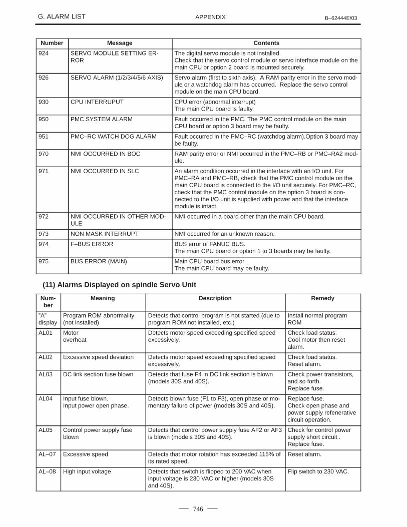
Number ContentsMessage
924 SERVO MODULE SETTING ER-ROR
The digital servo module is not installed.Check that the servo control module or servo interface module on themain CPU or option 2 board is mounted securely.
926 SERVO ALARM (1/2/3/4/5/6 AXIS) Servo alarm (first to sixth axis). A RAM parity error in the servo mod-ule or a watchdog alarm has occurred. Replace the servo controlmodule on the main CPU board.
930 CPU INTERRUPUT CPU error (abnormal interrupt) The main CPU board is faulty.
950 PMC SYSTEM ALARM Fault occurred in the PMC. The PMC control module on the mainCPU board or option 3 board may be faulty.
951 PMC–RC WATCH DOG ALARM Fault occurred in the PMC–RC (watchdog alarm).Option 3 board maybe faulty.
970 NMI OCCURRED IN BOC RAM parity error or NMI occurred in the PMC–RB or PMC–RA2 mod-ule.
971 NMI OCCURRED IN SLC An alarm condition occurred in the interface with an I/O unit. ForPMC–RA and PMC–RB, check that the PMC control module on themain CPU board is connected to the I/O unit securely. For PMC–RC,check that the PMC control module on the option 3 board is con-nected to the I/O unit is supplied with power and that the interfacemodule is intact.
972 NMI OCCURRED IN OTHER MOD-ULE
NMI occurred in a board other than the main CPU board.
973 NON MASK INTERRUPT NMI occurred for an unknown reason.
974 F–BUS ERROR BUS error of FANUC BUS.The main CPU board or option 1 to 3 boards may be faulty.
975 BUS ERROR (MAIN) Main CPU board bus error. The main CPU board may be faulty.
(11) Alarms Displayed on spindle Servo Unit
Num-ber
Meaning Description Remedy
”A”display
Program ROM abnormality(not installed)
Detects that control program is not started (due toprogram ROM not installed, etc.)
Install normal programROM
AL01 Motoroverheat
Detects motor speed exceeding specified speedexcessively.
Check load status.Cool motor then resetalarm.
AL02 Excessive speed deviation Detects motor speed exceeding specified speedexcessively.
Check load status.Reset alarm.
AL03 DC link section fuse blown Detects that fuse F4 in DC link section is blown(models 30S and 40S).
Check power transistors,and so forth.Replace fuse.
AL04 Input fuse blown.Input power open phase.
Detects blown fuse (F1 to F3), open phase or mo-mentary failure of power (models 30S and 40S).
Replace fuse.Check open phase andpower supply refenerativecircuit operation.
AL05 Control power supply fuseblown
Detects that control power supply fuse AF2 or AF3is blown (models 30S and 40S).
Check for control powersupply short circuit .Replace fuse.
AL–07 Excessive speed Detects that motor rotation has exceeded 115% ofits rated speed.
Reset alarm.
AL–08 High input voltage Detects that switch is flipped to 200 VAC wheninput voltage is 230 VAC or higher (models 30Sand 40S).
Flip switch to 230 VAC.

APPENDIXB–62444E/03 G. ALARM LIST
747
Num-ber
RemedyDescriptionMeaning
AL–09 Excessive load on main cir-cuit section
Detects abnormal temperature rise of power tran-sistor radiator.
Cool radiator then resetalarm.
AL–10 Low input voltage Detects drop in input power supply voltage. Remove cause, then resetalarm.
AL–11 Overvoltage in DC link sec-tion
Detects abnormally high direct current power sup-ply voltage in power circuit section.
Remove cause, then resetalarm.
AL–12 Overcurrent in DC link section Detects flow of abnormally large current in directcurrent section of power circuit
Remove cause, then resetalarm.
AL–13 CPU internal data memoryabnormality
Detects abnormality in CPU internal data memory.This check is made only when power is turned on.
Remove cause, then resetalarm.
AL–15 Spindle switch/output switchalarm
Detects incorrect switch sequence in spindleswitch/output switch operation.
Check sequence.
AL–16 RAM abnormality Detects abnormality in RAM for external data. Thischeck is made only when power is turned on.
Remove cause, then resetalarm.
AL–18 Program ROM sum check er-ror
Detects program ROM data error. This check ismade only when power is turned on.
Remove cause, then resetalarm.
AL–19 Excessive U phase currentdetection circuit offset
Detects excessive U phase current detection circuit offset.This check is made only when power is turned on.
Remove cause, then resetalarm.
AL–20 Excessive V phase currentdetection circuit offset
Detects excessive V phase current detection cir-cuit offset.This check is made only when power is turned on.
Remove cause, then resetalarm.
AL–24 Serial transfer data error Detects serial transfer data error (such as NC pow-er supply turned off, etc.)
Remove cause, then resetalarm.
AL–25 Serial data transfer stopped Detects that serial data transfer has stopped. Remove cause, then resetalarm.
AL–26 Disconnection of speeddetection signal for Cs con-touring control
Detects abnormality in position coder signal(suchas unconnected cable and parameter setting er-ror).
Remove cause, then resetalarm.
AL–27 Position coder signal discon-nection
Detects abnormality in position coder signal (suchas unconnected cable and adjustment error).
Remove cause, then resetalarm.
AL–28 Disconnection of positiondetection signal for Cs con-touring control
Detects abnormality in position detection signal forCs contouring control (such as unconnected cableand adjustment error).
Remove cause, then resetalarm.
AL–29 Short–time overload Detects that overload has been continuously ap-plied for some period of time (such as restrainingmotor shaft in positioning).
Remove cause, then resetalarm.
AL–30 Input circuit overcurrent Detects overcurrent flowing in input circuit. Remove cause, then resetalarm.
AL–31 Speed detection signal dis-connection motor restraintalarm or motor is clamped.
Detects that motor cannot rotate at specifiedspeed or it is detected that the motor is clamped.(but rotates at very slow speed or has stopped).(This includes checking of speed detection signalcable.)
Remove cause, then resetalarm.
AL–32 Abnormality in RAM internalto LSI for serial data transfer.This check is made onlywhen power is turned on.
Detects abnormality in RAM interior LSI for serialdata transfer. This check is made only when poweris turned on.
Remove cause, then resetalarm.

APPENDIXG. ALARM LIST B–62444E/03
748
Num-ber
RemedyDescriptionMeaning
AL–33 Insufficient DC link sectioncharging
Detects insufficient charging of direct current pow-er supply voltage in power circuit section whenmagnetic contactor in amplifier is turned on (suchas open phase and defective charging resistor).
Remove cause, then resetalarm.
AL–34 Parameter data setting be-yond allowable range of val-ues
Detects parameter data set beyond allowablerange of values.
Set correct data.
AL–35 Excesive gear ratio data set-ting
Detects gear ratio data set beyond allowablerange of values.
Set correct data.
AL–36 Error counter over flow Detects error counter overflow. Correct cause, then resetalarm.
AL–37 Speed detector parametersetting error
Detects incorrect setting of parameter for numberof speed detection pulses.
Set correct data.
AL–39 Alarm for indicating failure indetecting 1–rotation signal forCs contouring control
Detects 1–rotation signal detection failure in Cscontouring contorl.
Make 1–rotation signal ad-justment.Check cable shield status.
AL–40 Alarm for indicating 1–rotationsignal for Cs contouring con-trol not detected
Detects that 1–rotation signal has not occurred inCs contouring control.
Make 1–rotation signal ad-justment.
AL–41 Alarm for indicating failure indetecting position coder1–rotation signal.
Detects failure in detecting position coder 1–rota-tion signal.
Make signal adjustmentfor signal conversion cir-cuit.Check cable shield status.
AL–42 Alarm for indicating positioncoder 1–rotation signal notdetected
Detects that position coder 1–rotation signal hasnot issued.
Make 1–rotation signal ad-justment for signal conver-sion circuit.
AL–43 Alarm for indicating discon-nection of position coder sig-nal for differential speedmode
Detects that main spindle position coder signalused for differential speed mode is not connectedyet (or is disconnected).
Check that main spindleposition coder signal isconnected to connectorCN12.
AL–46 Alarm for indicating failure indetecting position coder1–rotation signal in threadcutting operation.
Detects failure in detecting position coder 1–rota-tion signals in thread cutting operation.
Make 1–rotation signal ad-justment for signal conver-sion circuitCheck cable shield status.
AL–47 Position coder signal ab-normality
Detects incorrect position coder signal count op-eration.
Make signal adjustmentfor signal conversion cir-cuit.Check cable shield status.
AL–48 Position coder 1–rotation sig-nal abnormality
Detects that occurrence of position coder 1–rota-tion signal has stopped.
Make 1–rotation signal ad-justment for signal conver-sion circuit.
AL–49 The converted differentialspeed is too high.
Detects that speed of other spindle converted tospeed of local spindle has exceeded allowablelimit in differential mode.
Check the position coderstate of the other side.
AL–50 Excessive speed commandcalculation value in spindlesynchronization control
Detects that speed command calculation valueexceeded allowable range in spindle synchroniza-tion control.
Check parameters suchas a position gain.
AL–51 Undervoltage at DC link sec-tion
Detects that DC power supply voltage of powercircuit has dropped (due to momentary power fail-ure or loose contact of magnetic contactor).
Remove cause, then resetalarm.
AL–52 ITP signal abnormality I Detects abnormality in synchronization signal (ITPsignal )with CNC (such as loss of ITP signal).
Remove cause, then resetalarm.
APPENDIXB–62444E/03 G. ALARM LIST
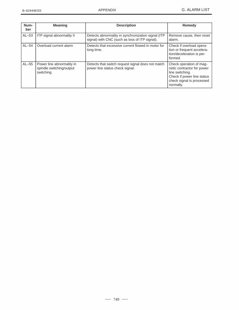
749
Num-ber
RemedyDescriptionMeaning
AL–53 ITP signal abnormality II Detects abnormality in synchronization signal (ITPsignal) with CNC (such as loss of ITP signal).
Remove cause, then resetalarm.
AL–54 Overload current alarm Detects that excessive current flowed in motor forlong time.
Check if overload opera-tion or frequent accelera-tion/deceleration is per-formed.
AL–55 Power line abnormality inspindle switching/outputswitching
Detects that switch request signal does not matchpower line status check signal.
Check operation of mag-netic contractor for powerline switching.Check if power line statuscheck signal is processednormally.