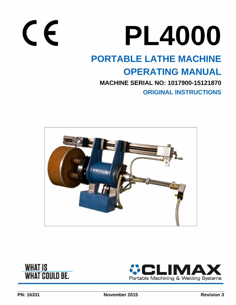
PORTABLE LATHE MACHINE OPERATING MANUAL
140
PN: 16331 November 2015 Revision 3 PL4000 PORTABLE LATHE MACHINE OPERATING MANUAL MACHINE SERIAL NO: 1017900-15121870 ORIGINAL INSTRUCTIONS
-
Upload
khangminh22 -
Category
Documents
-
view
1 -
download
0
Transcript of PORTABLE LATHE MACHINE OPERATING MANUAL
PN: 16331 November 2015 Revision 3
PL4000 PORTABLE LATHE MACHINE
OPERATING MANUAL MACHINE SERIAL NO: 1017900-15121870
ORIGINAL INSTRUCTIONS


P/N 16331, Rev. 3 Page A
©2015 Climax Portable Machining & Welding Systems or its subsidiaries. All rights reserved.
Except as expressly provided herein, no part of this manual may be reproduced, copied, transmitted, disseminated, downloaded, or stored in any storage medium, without the express prior written consent of Climax. Climax hereby grants permission to download a single copy of this manual and of any revision hereto onto an electronic storage medium to be viewed and to print one copy of this manual or any revision hereto, provided that such electronic or printed copy of this manual or revision must contain the complete text of this copyright notice and provided further that any unauthorized commercial distribution of this manual or any revision hereto is prohibited.
At Climax Portable Machining and Welding Systems, we value your opinion. For comments or questions about this manual or other Climax documentation, please e-mail [email protected].
For comments or questions about Climax products or services, please call Climax or e-mail [email protected]. For quick and accurate service, please provide your factory representative with the following:
• Your name • Shipping address • Telephone number • Machine model • Serial number (if applicable) • Date of purchase.
Climax World Headquarters
Climax Portable Machining and Welding Systems 2712 South Second Street Newberg, Oregon 97132 USA Telephone (worldwide): (503) 538-2185 Toll-free (North America):1-800-333-8311 Fax: 503.538.7600 E-mail: [email protected]
Climax European Headquarters
Climax GmbH Am Langen Graben 8 52353 Düren, Germany Telephone: +49 (0) 2421-9177-0 E-mail: [email protected]

Page B PL4000 Operating Manual
CLIMAX WORLDWIDE LOCATIONS

P/N 16331, Rev. 3 Page C
CE DOCUMENTTION

Page D PL4000 Operating Manual

P/N 16331, Rev. 3 Page i
NOISE LEVEL
Standard no.
EN 3744 & EN 11201
Author: J. Brooks Sound declaration
Machine: PM4200 (230V Electric)
Date: 3/10/15
The declared sound power level is: LWA = 97.5 dBA
The declared operator sound pressure level is: LpA = 89.2 dBA
The declared bystander sound pressure level is: LpA = 89.9 dBA

Page ii PL4000 Operating Manual
TABLE OF CONTENTS 1 INTRODUCTION ..................................................................................................................... 3
1.1 LIMITED WARRANTY ........................................................................................................................... 3 1.2 HOW TO USE THIS MANUAL ............................................................................................................... 4 1.3 SAFETY PRECAUTIONS ....................................................................................................................... 5 1.4 MACHINE-SPECIFIC SAFETY PRECAUTIONS .......................................................................................... 6 1.5 RISK ASSESSMENT AND HAZARD MITIGATION ..................................................................................... 6 1.6 RISK ASSESSMENT CHECKLIST .......................................................................................................... 7 1.7 ITEMS REQUIRED BUT NOT SUPPLIED ................................................................................................. 7 1.8 LABELS ............................................................................................................................................. 8 1.9 RECIPT AND INSPECTION .................................................................................................................... 9
2 OVERVIEW ........................................................................................................................... 11 2.1 FUNCTIONS ..................................................................................................................................... 11 2.2 COMPONENTS ................................................................................................................................. 11 2.3 DIMENSIONS .................................................................................................................................... 13 2.4 SPECIFICATIONS .............................................................................................................................. 14
3 SETUP ................................................................................................................................... 15 3.1 MACHINE ASSEMBLY ........................................................................................................................ 15 3.2 USING THE MOUNTING PLATE ........................................................................................................... 15 3.3 LIFTING THE MACHINE ...................................................................................................................... 16 3.4 MOUNTING THE MACHINE TO THE WORKPIECE ................................................................................... 17 3.5 CENTERING AND LEVELING THE MACHINE .......................................................................................... 18
3.5.1 Centering procedure ................................................................................................................ 18 3.5.2 Leveling proceedure ................................................................................................................ 18
3.6 ADJUSTING THE TURNING ARM .......................................................................................................... 18 3.7 INSTALLING THE TOOL ...................................................................................................................... 20 3.8 AIR MOTOR ...................................................................................................................................... 20 3.9 ADJUSTING THE FEED BOX. .............................................................................................................. 22 3.10 ATTACHING THE TOOL HEAD EXTENSION KIT ...................................................................................... 23 3.11 ATTACHING THE TURNING RAIDIUS EXTENSION KIT ............................................................................. 24
4 OPERATION ......................................................................................................................... 26 4.1 PRINCIPLES OF OPERATION .............................................................................................................. 27 4.2 PRE-OPERATIONAL CHECKS ............................................................................................................. 28 4.3 CONTROLS ...................................................................................................................................... 28
4.3.1 To start the machine: ............................................................................................................... 29 4.3.2 To stop the machine: ............................................................................................................... 29 4.3.3 Emergency Shutdown .............................................................................................................. 29
4.4 SETTING TOOL FEED DIRECTION AND SPEED ..................................................................................... 30 4.5 MACHINING THE WORKPIECE ........................................................................................................... 30 4.6 SHUTDOWN ..................................................................................................................................... 32 4.7 DISASSEMBLY .................................................................................................................................. 32

P/N 16331, Rev. 3 Page iii
TABLE OF CONTENTS (CONTINUED) 5 MAINTENANCE .................................................................................................................... 33
5.1 MAINTENANCE INTERVALS ................................................................................................................ 33 5.2 RECOMMENDED LUBRICANTS ........................................................................................................... 34 5.3 MAIN BODY ASSEMBLY ..................................................................................................................... 34 5.4 TURNING BAR AND COUNTERWEIGHT ASSEMBLY ................................................................................ 34 5.5 AIR MOTOR AND PNEUMATIC CONDITIONING UNIT ............................................................................... 35 5.6 ROTARY UNION ................................................................................................................................ 35 5.7 PNEUMATIC FEED BOX ASSEMBLY ..................................................................................................... 35 5.8 TOOL HEAD ASSEMBLY ..................................................................................................................... 35
6 STORAGE AND SHIPPING .................................................................................................. 37 6.1 STORAGE ........................................................................................................................................ 37
6.1.1 Short-term Stroage ................................................................................................................... 37 6.1.2 Long-Term Storage .................................................................................................................. 37
6.2 SHIPPING ......................................................................................................................................... 37
APPENDIX A TOOLS AND RECOMMENDED SPARE PARTS ................................................ 39 A.1 RECOMMENDED SPARE PARTS ......................................................................................................... 39 A.2 TOOL KIT ......................................................................................................................................... 40
APPENDIX B ASSEMBLY DRAWINGS AND PARTS LISTS .................................................... 41
APPENDIX C MSDS ............................................................................................................... C-54

Page iv PL4000 Operating Manual
LIST OF FIGURES FIGURE 1. PRINCIPAL COMPONENTS ............................................................................................................... 12
FIGURE 2. DIMENSIONS................................................................................................................................... 13
FIGURE 3. DETAIL OF MOUNTING PLATE ........................................................................................................... 16
FIGURE 4. DETAIL OF LIFTING THE MACHINE ..................................................................................................... 16
FIGURE 5. LOCATION OF CENTERING SETSCREWS ............................................................................................ 17
FIGURE 6. DETAIL OF SPINDLE SCREWS ........................................................................................................... 17
FIGURE 7. POSITIONING AN INDICATOR FOR CENTERING THE MACHINE .............................................................. 18
FIGURE 8. POSITIONING AN INDICATOR FOR LEVELING THE MACHINE ................................................................. 18
FIGURE 9. LOCATION OF TURNING BAR ANCHOR BOLTS .................................................................................... 19
FIGURE 10. DETAIL OF TOOL HEAD .................................................................................................................. 20
FIGURE 11. DETAIL OF PNEUMATIC CONTROL UNIT ........................................................................................... 20
FIGURE 12. CONNECTING THE AIR HOSES ........................................................................................................ 21
FIGURE 13. DETAIL OF FEED BOX .................................................................................................................... 22
FIGURE 14. FEEDBOX ENGAGED ...................................................................................................................... 22
FIGURE 15. FEEDBOX DISENGAGED ................................................................................................................. 22
FIGURE 16. DETAIL OF TOOL HEAD EXTENSION ................................................................................................ 23
FIGURE 17. ASSEMBLED TURNING RADIUS EXTENSION ..................................................................................... 24
FIGURE 18. ASSEMBLED TURNING RADIUS EXTENSION ..................................................................................... 25
FIGURE 19. NEEDLE VALVE ............................................................................................................................. 28
FIGURE 20. LOCATION OF EMERGENCY STOP LEVER ........................................................................................ 29
FIGURE 21. TOOL SETUP ................................................................................................................................. 30
FIGURE A-1. P/N 13142 MAIN BODY ASSEMBLY PL4000 ................................................................................. 42
FIGURE A-2. P/N 13142 MAIN BODY ASSEMBLY PL4000 ................................................................................. 43
FIGURE A-3. P/N 13168 TURNING BAR AND COUNTERWEIGHT ASSEMBLY ......................................................... 44
FIGURE A-4. P/N 13212 TOOL HEAD ASSEMBLY PL4000 ................................................................................. 45
FIGURE A-5. P/N 13480 PNEUMATIC FEED BOX ASSEMBLY .............................................................................. 46
FIGURE A-6. P/N 13480 PNEUMATIC FEED BOX ASSEMBLY PARTS LIST ............................................................. 47
FIGURE A-7. P/N 18900 TOOL HEAD EXTENSION KIT PL4000 ........................................................................... 48
FIGURE A-8. P/N 18901 TURNING RADIUS EXTENSION PL4000 ........................................................................ 49
FIGURE A-9. P/N 29438 PNEUMATIC POWER ASSEMBLY .................................................................................. 50
FIGURE A-10. P/N 29438 PNEUMATIC POWER ASSEMBLY PARTS LIST .............................................................. 51
FIGURE A-11. P/N 78264 PNEUMATIC CONDITIONING UNIT .............................................................................. 52
FIGURE A-12. P/N 78264 PNEUMATIC CONDITIONING UNIT PARTS LIST ............................................................. 53
P/N 16331, Rev. 3 Page 1
LIST OF TABLES TABLE 1. RISK ASSESSMENT CHECKLIST BEFORE SET-UP ................................................................................... 7
TABLE 2. RISK ASSESSMENT CHECKLIST AFTER SET-UP ...................................................................................... 7
TABLE 3. WARNING LABELS ............................................................................................................................... 8
TABLE 4. SPECIFICATIONS ............................................................................................................................... 14
TABLE 5. MAINTENANCE INTERVALS AND TASKS ............................................................................................... 33
TABLE 6 RECCOMENDED LUNBRICANTS ........................................................................................................... 34
TABLE 7. RECCOMENDED SPARE PARTS .......................................................................................................... 39
TABLE 8.P/N 16906 TOOL KIT PL4000 ............................................................................................................ 40

Page 2 PL4000 Operating Manual
This page left intentionally blank.

P/N 16331, Rev. 3 Page 3
1 INTRODUCTION
IN THIS CHAPTER:
1.1 LIMITED WARRANTY ............................................................................................................................................................. 3 1.2 HOW TO USE THIS MANUAL .................................................................................................................................................. 4 1.3 SAFETY PRECAUTIONS ........................................................................................................................................................ 5 1.4 MACHINE-SPECIFIC SAFETY PRECAUTIONS ........................................................................................................................... 6 1.5 RISK ASSESSMENT AND HAZARD MITIGATION ........................................................................................................................ 6 1.6 RISK ASSESSMENT CHECKLIST ............................................................................................................................................. 7 1.7 ITEMS REQUIRED BUT NOT SUPPLIED .................................................................................................................................... 7 1.8 LABELS ............................................................................................................................................................................... 8 1.9 RECIPT AND INSPECTION ..................................................................................................................................................... 9
1.1 Limited Warranty
Climax Portable Machine & Welding Systems, Inc. (hereafter referred to as “Climax”) warrants that all new machines are free from defects in materials and workmanship. This warranty is available to the original purchaser for a period of one year after delivery. If the original purchaser finds any defect in materials or workmanship within the warranty period, the original purchaser should contact its factory representative and return the entire machine, shipping prepaid, to the factory. Climax will, at its option, either repair or replace the defective machine at no charge and will return the machine with shipping prepaid.
Climax warrants that all parts are free from defects in materials and workmanship, and that all labor has been performed properly. This warranty is available to the customer purchasing parts or labor for a period of 90 days after delivery of the part or repaired machine or 180 days on used machines and components. If the customer purchasing parts or labor finds any defect in materials or workmanship within the warranty period, the purchaser should contact its factory representative and return the part or repaired machine, shipping prepaid, to the factory. Climax will, at its option, either repair or replace the defective part and/ or correct any defect in the labor performed, both at no charge, and return the part or repaired machine shipping prepaid.
These warranties do not apply to the following:
• Damage after the date of shipment not caused by defects in materials or workmanship
• Damage caused by improper or inadequate machine maintenance • Damage caused by unauthorized machine modification or repair • Damage caused by machine abuse • Damage caused by using the machine beyond its rated capacity
All other warranties, express or implied, including without limitation the warranties of merchantability and fitness for a particular purpose are disclaimed and excluded.
Page 4 PL4000 Operating Manual
Terms of sale
Be sure to review the terms of sale which appear on the reverse side of your invoice. These terms control and limit your rights with respect to the goods purchased from Climax.
About this manual
Climax provides the contents of this manual in good faith as a guideline to the operator. Climax cannot guarantee that the information contained in this manual is correct for applications other than the application described in this manual. Product specifications are subject to change without notice.
1.2 How to use this manual
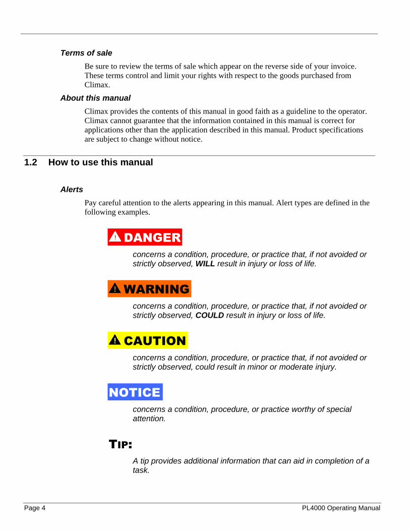
Alerts
Pay careful attention to the alerts appearing in this manual. Alert types are defined in the following examples.
DANGER concerns a condition, procedure, or practice that, if not avoided or strictly observed, WILL result in injury or loss of life.
WARNING concerns a condition, procedure, or practice that, if not avoided or strictly observed, COULD result in injury or loss of life.
CAUTION concerns a condition, procedure, or practice that, if not avoided or strictly observed, could result in minor or moderate injury.
NOTICE concerns a condition, procedure, or practice worthy of special attention.
TIP: A tip provides additional information that can aid in completion of a task.

P/N 16331, Rev. 3 Page 5
1.3 Safety precautions
Climax Portable Machining & Welding Systems leads the way in promoting the safe use of portable machine tools. Safety is a joint effort. You, the machine operator, must do your part by being aware of your work environment and closely following the operating procedures and safety precautions contained in this manual, as well as your employer’s safety guidelines.
Observe the following safety precautions when operating or working around the machine.
Training – Before operating this or any machine tool, you should receive instruction from a qualified trainer. Contact Climax for machine-specific training information.
Risk assessment – Working with, and around, this machine poses risks to your safety. You, the end user, are responsible for conducting a risk assessment of each job site before setting up and operating this machine.
Intended use – Use this machine in accordance with the instructions and precautions in this manual. Do not use this machine for any purpose other than its intended use as described in this manual.
Personal protective equipment – Always wear the appropriate personal protective gear when operating this or any other machine tool. Eye and ear protection are required when operating or working around the machine. Flame-resistant clothing with long sleeves and legs is recommended when operating the machine, as hot flying chips from the workpiece may burn or cut bare skin.
Work area – Keep the work area around the machine clear of clutter. Keep all cords and hoses away from the work area when operating the machine.
Lifting – Many Climax machine components are very heavy. Whenever possible, lift the machine or its components using proper hoisting equipment and rigging. Always use designated lifting points on the machine. Follow all lifting instructions in the setup procedures of this manual.
Lock out/tag out – Lock out and tag out the machine before doing maintenance.
Moving parts – Climax machines have numerous exposed moving parts and interfaces that can cause severe impact, pinching, cutting, and other injuries. Except for operating controls, avoid contact with moving parts by hands or tools during machine operation. Secure hair, clothing, jewelry, and pocket items to prevent them from becoming entangled in moving parts.
Sharp edges – Cutting tools and workpieces have sharp edges that can easily cut skin. Wear protective gloves and exercise caution when handling a cutting tool or workpiece.
Hot surfaces – During operation, motors, some housings, and cutting tools can generate enough heat to cause severe burns. Pay attention to hot surface labels, and avoid contact with bare skin until the machine has cooled.

Page 6 PL4000 Operating Manual
1.4 Machine-specific safety precautions
All aspects of the machine have been designed with safety in mind. Be aware of the machine and any personnel near the machine when it is in operation. The rotating parts of the machine are shielded by machine components or by the workpiece, but the machine itself rotates during operation.
Machine mounting – Do not operate the machine if it is not mounted to the workpiece as described in this manual.
Danger zone – It is the operator’s responsibility to make sure any bystander does not approach the machine during operation. Do not interact with the machine while it is running. Make sure the machine is off before making any adjustments.
Controls – Operator controls are located outside the danger zone of the machine. The on/off switches are clearly visible and identifiable. If a compressed air supply failure occurs, be sure to close the on/off valve before leaving the machine.
1.5 Risk assessment and hazard mitigation
Machine Tools are specifically designed to perform precise material-removal operations.
Stationery Machine Tools include lathes and milling machines and are typically found in a machine shop. They are mounted in a fixed location during operation and are considered to be a complete, self-contained machine. Stationery Machine Tools achieve the rigidity needed to accomplish material-removal operations from the structure that is an integral part of the machine tool.
Portable Machine Tools are designed for on-site machining applications. They typically attach directly to the workpiece itself, or to an adjacent structure, and achieve their rigidity from the structure to which it is attached. The design intent is that the Portable Machine Tool and the structure attached to it becomes one complete machine during the material-removal process.
To achieve the intended results and to promote safety, the operator must understand and follow the design intent, set-up, and operation practices that are unique to Portable Machine Tools.
The operator must perform an overall review and on-site risk assessment of the intended application. Due to the unique nature of portable machining applications, identifying one or more hazards that must be addressed is typical.
When performing the on-site risk assessment, it is important to consider the Portable Machine Tool and the workpiece as a whole.

P/N 16331, Rev. 3 Page 7
1.6 Risk assessment checklist
Use these checklists as a basis for your risk assessment:
TABLE 1. RISK ASSESSMENT CHECKLIST BEFORE SET-UP
Before set-up
I took note of all the warning labels on the machine.
I removed or mitigated all identified risks (such as tripping, cutting, crushing, entanglement, shearing, or falling objects).
I considered the need for personnel safety guarding and installed any necessary guards.
I read the Machine Assembly instructions (Section 3.1).
I took inventory of all the items required but not supplied (Section 1.7).
I considered how this machine operates and the best placement for the controls, cabling, and the operator.
TABLE 2. RISK ASSESSMENT CHECKLIST AFTER SET-UP
After set-up
I checked that the machine is safely installed (according to Section 3) and the potential fall path is clear. If the machine is elevated, I checked that the machine is safeguarded against falling.
I identified all possible pinch points, such as those caused by rotating parts, and informed the affected personnel.
I planned for containment of any chips or swarf produced by the machine.
I followed the Maintenance Intervals (Section 5.1) with the recommended lubricants.
I checked that all affected personnel have the recommended personal protective equipment, as well as any equipment required by the site or other regulations.
I checked that all affected personnel understand the danger zone and are clear of it.
1.7 Items required but not supplied
During setup, you will need the following items that are not included with the product:
• Dial indicator • Tape measure • Rigging and lifting equipment as needed for machine setup • Fittings required to connect to the pneumatic conditioning unit (PCU), or the plug
for the hydraulic power unit (HPU)
Climax offers a dial indicator kit for purchase; contact Climax for more information.

Page 8 PL4000 Operating Manual
1.8 Labels
The following warning labels should be on your machine. If any are defaced or missing, contact Climax immediately for replacements.
TABLE 3. WARNING LABELS
P/N 14684 Climax serial number, year and model number plate.
P/N 55547 Label safety warning rotating machinery
P/N 55550 Label safety warning impact hazard
P/N 22546 Caution label advising valve closue
P/N 81132 Caution label marking lockout point

P/N 16331, Rev. 3 Page 9
1.9 Recipt and inspection
Your Climax product was inspected and tested before shipment and packaged for normal shipment conditions. Climax does not guarantee the condition of your machine upon delivery.
When you receive your Climax product:
1. Inspect the shipping container for damage.
2. Check the contents of the shipping container against the included invoice to make sure that all components have been shipped.
3. Inspect all components for damage.
Contact Climax immediately to report damaged or missing components.
NOTICE Keep the shipping container and all packing materials for future storage and shipping of the machine.

Page 10 PL4000 Operating Manual
This page left intentionally blank
P/N 16331, Rev. 3 Page 11
2 OVERVIEW
IN THIS CHAPTER:
2.1 FUNCTIONS ....................................................................................................................................................................... 11 2.2 COMPONENTS ................................................................................................................................................................... 11 2.3 DIMENSIONS ..................................................................................................................................................................... 13 2.4 SPECIFICATIONS ............................................................................................................................................................... 14
2.1 Functions
This manual describes how to use your PL4000 Portable Lathe. This machine tool is designed for on-site shaft turning without costly dismantling. By using a stationary mounting flange bolted directly to the end of the shaft, the PL4000 cuts by rotating around the shaft.
Every part meets Climax Portable Machining & Welding Systems' strict quality standards. For maximum safety and performance, read the entire instruction manual before operating the machine.
The PL4000 Portable Lathe is used in a wide variety of end shaft turning applications. The modular design and versatile setup options allows for creativity solving difficult turning-related problems. However, follow the operating manual and maintain the integrity of the machine by not modifying it in any unspecified manner.
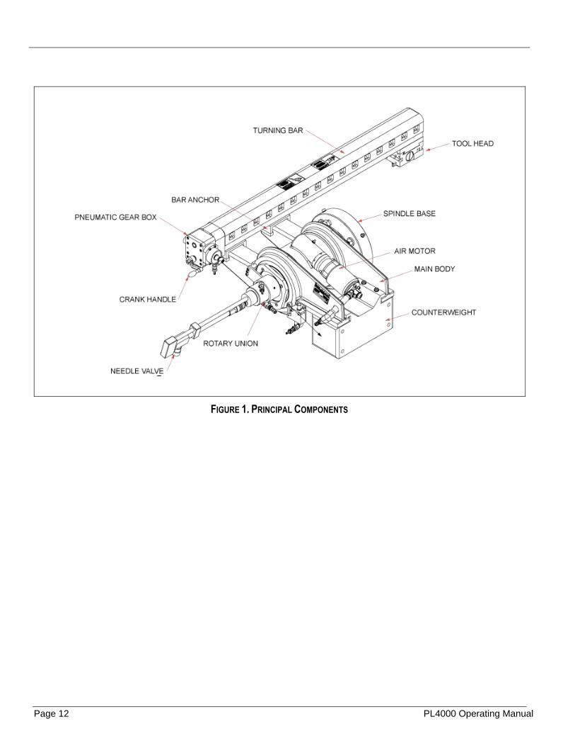
2.2 Components
The PL4000 Portable Lathe turns shafts by rotating the machine around the stationary shaft. The machine consists of the following components:
• Main body assembly • Turning bar and counterweight • Pneumatic Power Assembly • Pneumatic feed box • Pneumatic conditioning unit • Tool head • Optional tool head and bar extension kit
Page 12 PL4000 Operating Manual
FIGURE 1. PRINCIPAL COMPONENTS

P/N 16331, Rev. 3 Page 13
2.3 Dimensions
FIGURE 2. DIMENSIONS

Page 14 PL4000 Operating Manual
2.4 Specifications
TABLE 4. SPECIFICATIONS

P/N 16331, Rev. 3 Page 15
3 SETUP
IN THIS CHAPTER:
3.1 MACHINE ASSEMBLY ......................................................................................................................................................... 15 3.2 USING THE MOUNTING PLATE ............................................................................................................................................. 15 3.3 LIFTING THE MACHINE ....................................................................................................................................................... 16 3.4 MOUNTING THE MACHINE TO THE WORKPIECE .................................................................................................................... 17 3.5 CENTERING AND LEVELING THE MACHINE ........................................................................................................................... 18
3.5.1 Centering procedure ................................................................................................................................................ 18 3.5.2 Leveling proceedure................................................................................................................................................. 18
3.6 ADJUSTING THE TURNING ARM ........................................................................................................................................... 18 3.7 INSTALLING THE TOOL ....................................................................................................................................................... 20 3.8 AIR MOTOR ....................................................................................................................................................................... 20 3.9 ADJUSTING THE FEED BOX. ................................................................................................................................................ 22 3.10 ATTACHING THE TOOL HEAD EXTENSION KIT ....................................................................................................................... 23 3.11 ATTACHING THE TURNING RAIDIUS EXTENSION KIT .............................................................................................................. 24
3.1 Machine assembly
CAUTION Make sure to follow all machine assembly instructions before operating the machine. Failure to follow all assembly instructions may result in bad machining quality, damage to the machine or workpiece, or severe injury to the operator.
3.2 Using the mounting plate
The mounting plate attaches the PL4000 to the workpiece. Do the following to attach the mounting plate to the workpiece.
1. Center the mounting plate on the end of the workpiece. 2. Attach the mounting plate to the workpiece by clamping, bolting, or tack welding it to
the workpiece.
• If using bolts, drill and counter bore bolt holes to match the work piece. • At least four holes are necessary to attach the mounting plate to the work piece
firmly. • Make sure these bolts are flush or below the surface of the mounting plate.

Page 16 PL4000 Operating Manual
Attach the mounting plate to the workpiece securely as it is the connection between the PL4000 and the workpiece. The PL4000 machine weighs approximately 500 lbs.
The mounting plate is shipped blank (as shown in Figure 3). The four holes in the plate are for attaching the mounting plate to the spindle base on the PL4000 (see Figure 2 for location of spindle base).
3. Insert the mounting bolts into the provided holes on the mounting plate.
TIP: The mounting plate can be factory machined to match your shaft. Contact your sales representative by calling Climax toll free at 1-800-333-8311.for more information.
3.3 Lifting the machine
Lift the PL4000 using lifting straps on designated lift points. It is recommend lifting the machine by wrapping straps around the center section as seen in Figure 4.
CAUTION To avoid distorting the turning bar, wrap the hoist around the main body, not the turning bar.
FIGURE 3. DETAIL OF MOUNTING PLATE
FIGURE 4. DETAIL OF LIFTING THE MACHINE

P/N 16331, Rev. 3 Page 17
3.4 Mounting the machine to the workpiece
1. Before mounting the machine to the workpiece, retract the four centering setscrews on the side of the spindle base until they are flush or receded.
2. Lift the machine into place on the mounting plate.
3. Secure the machine to the mounting plate using the four mounting bolts shown in Figure 3.
4. Place the washers and mounting nuts on the mounting studs, and tighten to a torque value of 2 ft-lbs (2.7 N m). Final tightening occurs during the centering and leveling procedure.
FIGURE 5. LOCATION OF CENTERING SETSCREWS
FIGURE 6. DETAIL OF SPINDLE SCREWS
Page 18 PL4000 Operating Manual
3.5 Centering and leveling the machine
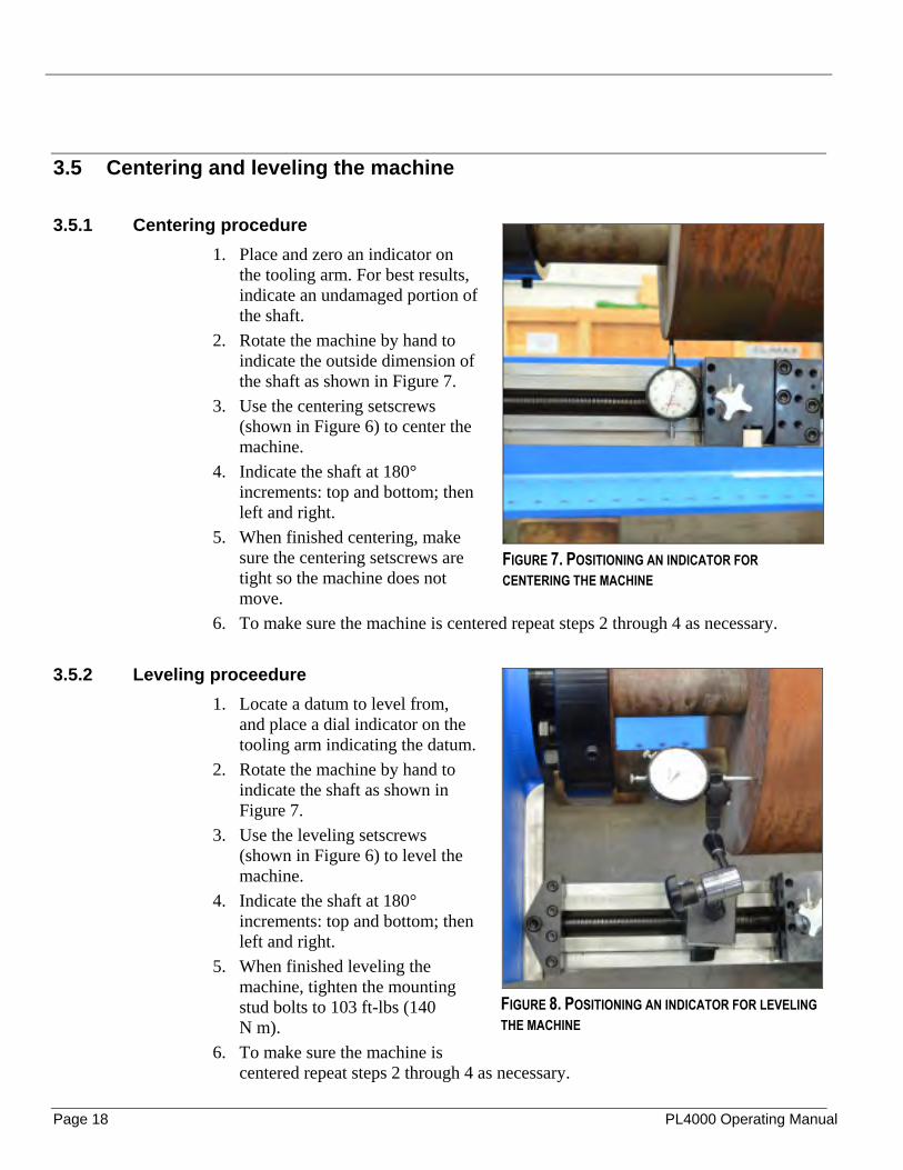
3.5.1 Centering procedure
1. Place and zero an indicator on the tooling arm. For best results, indicate an undamaged portion of the shaft.
2. Rotate the machine by hand to indicate the outside dimension of the shaft as shown in Figure 7.
3. Use the centering setscrews (shown in Figure 6) to center the machine.
4. Indicate the shaft at 180° increments: top and bottom; then left and right.
5. When finished centering, make sure the centering setscrews are tight so the machine does not move.
6. To make sure the machine is centered repeat steps 2 through 4 as necessary.
3.5.2 Leveling proceedure
1. Locate a datum to level from, and place a dial indicator on the tooling arm indicating the datum.
2. Rotate the machine by hand to indicate the shaft as shown in Figure 7.
3. Use the leveling setscrews (shown in Figure 6) to level the machine.
4. Indicate the shaft at 180° increments: top and bottom; then left and right.
5. When finished leveling the machine, tighten the mounting stud bolts to 103 ft-lbs (140 N m).
6. To make sure the machine is centered repeat steps 2 through 4 as necessary.
FIGURE 7. POSITIONING AN INDICATOR FOR
CENTERING THE MACHINE
FIGURE 8. POSITIONING AN INDICATOR FOR LEVELING
THE MACHINE

P/N 16331, Rev. 3 Page 19
3.6 Adjusting the turning arm
The turning arm is centered on the main body to fit in the shipping container and needs to be adjusted to before running the machine. To adjust the turning arm do the following procedure.
1. Loosen the turning bar anchor bolts located on the main body fins (Figure 9).
CAUTION The turning arm is heavy and presents a falling hazard.If adjustments to the turning arm are made with the machine mounted, make sure the machine is flat or slightly elevated.
2. Slide the turning arm out to the desired length. This distance determines the machine’s reach.
3. Adjust the bar for straight shaft turning or tapered turning.
4. Place an indicator on the tool head to align the bar with the shaft.
To advance or retract the tool head use the crank handle located on the pneumatic gearbox, or use a hex head on an electric drill on the bolt under the crank handle. Use a ½ inch drive socket for the ½ inch shaft.
To adjust the bar for a straight cut, do the following procedure:
1. Position the turning bar at the desired distance.
2. Make sure the distance between the bar and the two measuring flats on the main body are the same (the bar should be perpendicular to the centerline of the spindle).
To adjust the bar for a tapered cut, do the following procedure. 1. Position the turning bar at the desired distance. 2. Then allow the bar to be crooked and set the angle according to operator
preference. Check the angle of the bar against the workpiece with a dial indicator.
5. Tighten the turning bar anchor bolts.
FIGURE 9. LOCATION OF TURNING BAR ANCHOR
BOLTS

Page 20 PL4000 Operating Manual
3.7 Installing the tool
1. Slide the tool in one of three positions as shown in Figure 10.
2. Lock the tool into position with the setscrews located on top of the tool head.
3. Set the depth of cut using the tool depth dial. Each mark on the dial is .002" depth. Keep in mind that it takes .002" off each side of the shaft for a total of .004".
3.8 Air motor and pneumatic control unit
Figure 11. Detail of pneumatic control unit
The motor mounts to the main body via the motor mounting flange. Climax strongly recommends using the pneumatic control unit supplied with the machine.
FIGURE 10. DETAIL OF TOOL HEAD

P/N 16331, Rev. 3 Page 21
WARNING Rotating machinery can cause serious injury. Securely mount the machine to the shaft before connecting the air supply line.
Connect the air hoses to the machine as seen in Figure 12.
1. Make sure that the air supply lock-out valve is closed.
2. Make sure that the speed adjustment valve is closed.
3. Connect the PCU to an air supply with minimum 90 psi (6.21 bar) at 55 cfm (1.6 m3/min. The PCU should be set to 75 cfm (2.2 m3/min).
4. Connect the PCU air supply hose to the motor as shown in Figure 12.
The oil drip rate should be set to 6 drips per minute.
FIGURE 12. CONNECTING THE AIR HOSES

Page 22 PL4000 Operating Manual
3.9 Adjusting the feed box.
1. Use the crank handle to adjust the tool head to the correct position on the leadscrew.
2. The feed box direction switch has three positions: forward, backward and neutral.
3. Use the feed rate adjustment knob to adjust the tooling speed.
FIGURE 13. DETAIL OF FEED BOX
FIGURE 14. FEEDBOX ENGAGED
FIGURE 15. FEEDBOX DISENGAGED

P/N 16331, Rev. 3 Page 23
3.10 Attaching the tool head extension kit
The tool head extension kit (P/N 18900) is used to extend the reach of the tool head.
Do the following procedure to attach the tool head extension to the tool head.
1. Remove the four socket head screws from the tool head.
2. Use the four socket head cap screws supplied with the extension kit to attach the tool head extension to the tool head.
3. Install tool bit as described in Section 3.7 on page 20.
FIGURE 16. DETAIL OF TOOL HEAD EXTENSION

Page 24 PL4000 Operating Manual
3.11 Attaching the turning raidius extension kit
The turning radius extension kit (P/N 18901) is used to increase the turning radius of the machine. Using the turning radius extension kit requires the use of the supplied counterweight. Do not use the extension kit without the counterweight.
Refer to Figure 17 and Figure 18 on page 25 while assembling the turning radius extension kit.
1. Attach the bar extensions and the bar extension clamps to the main body using the as shown in Figure 17.
2. Attach the counterweight extension to the counterweight using the four supplied 5/8" socket head cap screws.
3. Slide the turning bar onto the bar extension and slide the two locking gibs into place between the turning bar and the bar extensions as shown in Figure 18.
4. Tighten the eight gib set screws to secure the bar extension to the turning bar.
FIGURE 17. ASSEMBLED TURNING RADIUS EXTENSION

P/N 16331, Rev. 3 Page 25
FIGURE 18. ASSEMBLED TURNING RADIUS EXTENSION

Page 26 PL4000 Operating Manual
This page left intentionally blank.

P/N 16331, Rev. 3 Page 27
4 OPERATION
IN THIS CHAPTER:
4.1 PRINCIPLES OF OPERATION ............................................................................................................................................... 27 4.2 PRE-OPERATIONAL CHECKS ............................................................................................................................................... 28 4.3 CONTROLS ....................................................................................................................................................................... 28
4.3.1 To start the machine: ............................................................................................................................................... 29 4.3.2 To stop the machine:................................................................................................................................................ 29 4.3.3 Emergency Shutdown .............................................................................................................................................. 29
4.4 SETTING TOOL FEED DIRECTION AND SPEED ....................................................................................................................... 30 4.5 MACHINING THE WORKPIECE ............................................................................................................................................. 30 4.6 SHUTDOWN ...................................................................................................................................................................... 32 4.7 DISASSEMBLY ................................................................................................................................................................... 32
4.1 Principles of operation
Do not operate this machine without adequate training to fully understand the safe setup, operation, and maintenance of the machine.
CAUTION To avoid serious personal injury, keep clear of moving machinery during operation.
The PL4000 may be used in dangerous locations (in elevated positions, near other operating equipment, overhead, etc.). Climax cannot foresee where this machine will be used.
CAUTION For machines with air motors, if the machine stops moving unexpectedly, de-pressurize and lock out the pneumatic safety valve located on the pneumatic conditioning unit before performing any troubleshooting.
Always follow safe work practices, including site-specific safety requirements. It is your responsibility to perform a risk assessment before you set up the machine and each time before you operate the machine.
Page 28 PL4000 Operating Manual
4.2 Pre-operational checks
WARNING Rotating machinery can cause serious injuries. Turn off and lock out the machine before making the preoperation checks. When operating the machine, always be aware of the location of all people in the vicinity of the machine.
Before starting the machine, always check the following:
1. Make sure that the work area is clear of non-essential personnel and equipment.
2. Make sure that the machine control/observation area will not be in the path of hot flying chips during machine operation.
3. Make sure the machine is securely mounted to the work piece.
4. Make sure that air hoses are routed and secured to avoid tripping, entanglement, damage from hot chips, or other damage should an air hose or connection fail.
5. Check the tool condition and sharpness.
6. On the PCU, make sure that the oil drip rate is set to 6 drips per minute.
7. Make sure all hand tools are removed from inside the machine and the work area.
8. Complete the Risk assessment checklist found in Section 1.6 on page 7.
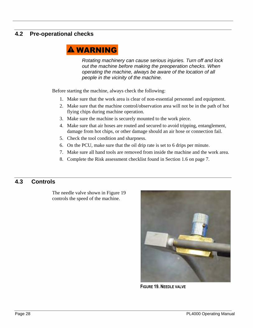
4.3 Controls
The needle valve shown in Figure 19 controls the speed of the machine.
FIGURE 19. NEEDLE VALVE

P/N 16331, Rev. 3 Page 29
NOTICE The air hose and needle valve will rotate with the motion of the machine. Make sure the air hoses do not get tangled around the needle valve.
4.3.1 To start the machine:
1. On the PCU, press the START button.
2. Engage the feed on the feed box.
3. Make sure the air valve on the PCU is open all the way.
4. Slowly open the needle valve until the rotary speed reaches the desired rate.
5. Slowly turn the feed box adjustment knob to increase the feed rate until you reach the desired feed rate.
6. Adjust the feed rate and rotary speed as necessary to maintain the desired cut.
7. Adjust the oil drip rate as needed.
NOTICE For best machine performance and service life, Climax recommends that the PCU oil drip rate not be adjusted below 6 drips per minute.
4.3.2 To stop the machine:
1. Close the needle valve. 2. Disengage the feed. 3. Press the lock-out/tag-out valve down to close it. This will release residual air
pressure in the PCU circuit.
4.3.3 Emergency Shutdown
In case of emergency press the emergency stop button located on the PCU.
FIGURE 20. LOCATION OF EMERGENCY STOP LEVER

Page 30 PL4000 Operating Manual
WARNING For machines with air motors, if the machine stops moving unexpectedly, lock out the pneumatic safety valve located at the filter lubricator assembly before performing any troubleshooting.
4.4 Setting tool feed direction and speed
1. Turn off and disconnect the air line.
2. Move the feed box direction switch to the desired feed direction.
3. Turn the tool feed adjusting knob to set the feed rate. Feed rate is adjustable up to .020" (0.5 mm) per revolution.
WARNING Do not attempt to manually adjust the cutting tool angle or change the feed box settings during operation. Attempting to operate the feed box controls by hand or with hand tools while the machine is running may result in severe injury.
4.5 Machining the Workpiece
WARNING Wear ear and eye protection while operating the machine.
FIGURE 21. TOOL SETUP

P/N 16331, Rev. 3 Page 31
1. Turn off and lock out the machine.
2. Check that the tool bit set screws are tight.
3. Turn the tool depth knob until the tool bit contacts the workpiece.
4. Set the feed direction and feed rate. A typical feed rate is about three turns out from the feed box.
5. Unlock the incoming air valve.
WARNING Moving machinery can cause serious personal injury. Stand clear of the machine while connecting the air line.
6. Slowly turn the needle valve counterclockwise until the machine is turning at the desired speed.
WARNING If the machine stops moving unexpectedly, lock out the pneumatic safety valve located at the filter lubricator assembly before performing any troubleshooting.
7. As cutting begins, apply cutting oil to the work piece.
8. Adjust the feed rate as needed to achieve the desired finish.
WARNING To avoid personal injury from flying chips and moving machinery, do not remove chips until the machine has stopped rotating.
9. Allow the machine to completely machine the workpiece.
10. After machining, close the needle valve.
11. Close the emergency air valve.
12. Lock out the machine.
13. To make another cut, rotate the tool depth dial to move the tool bit away from the workpiece.
14. Reverse the feed direction using the feed direction knob.
15. Use the hand crank to move the tool bit back to the starting position. The hand crank can be used to manually move the tool, but it will move the tool only in the direction set by the reversing knob.
NOTICE
Page 32 PL4000 Operating Manual
If large amounts of metal need to be removed, several 1/8" deep cuts are recommended.
16. Repeat steps 1 through 15 until desired depth and finish are reached. Finish cuts are made by cutting at a shallow depth and a slow feed rate.
17. After machining is finished, turn off the machine and disconnect the air supply.
4.6 Shutdown
1. Turn the needle valve clockwise all the way.
2. Push the emergency stop button on the PCU.
3. Lock out the machine.
4. Disconnect the air supply line.
4.7 Disassembly
1. Disconnect the air supply line.
2. Wrap a lifting strap around the main body of the machine.
CAUTION To avoid bending the turning bar, wrap the hoist around the main body, not the turning bar.
3. Loosen the centering setscrews on the spindle base.
4. Remove the mounting nuts that hold the spindle base to the mounting plate.
5. Carefully remove the machine from the mounting plate.
6. Remove the mounting plate from the work piece.

P/N 16331, Rev. 3 Page 33
5 MAINTENANCE
IN THIS CHAPTER:
5.1 MAINTENANCE INTERVALS ................................................................................................................................................. 33 5.2 RECOMMENDED LUBRICANTS ............................................................................................................................................. 34 5.3 MAIN BODY ASSEMBLY....................................................................................................................................................... 34 5.4 TURNING BAR AND COUNTERWEIGHT ASSEMBLY ................................................................................................................. 34 5.5 AIR MOTOR AND PNEUMATIC CONDITIONING UNIT ................................................................................................................ 35 5.6 ROTARY UNION ................................................................................................................................................................. 35 5.7 PNEUMATIC FEED BOX ASSEMBLY ...................................................................................................................................... 35 5.8 TOOL HEAD ASSEMBLY ...................................................................................................................................................... 35
This section contains periodic maintenance procedures and intervals as well as troubleshooting guidance.
5.1 Maintenance Intervals
TABLE 5. MAINTENANCE INTERVALS AND TASKS
Intervals Task Section
Before each use
Remove any moisture preventative applied prior to storage.
- -
Check and fill PCU air lubricator reservoir. - -
Before and after each use
Lubricate the leadscrew. 5.4
Apply a light layer of oil to the turning bar ways. 5.4
Drain the air filter. 5.5
Every 8 hours of operation
Lubricate the gears inside the main body. 5.3
After each use Clean machine of any swarf or metal. - -
Monthly Lubricate the rotary union. 5.6
Periodically
Check the sir pressure. 5.5
Inspect the rotary union for damage. 5.6
Lubricate the tool head assembly ways and slides. 5.8

Page 34 PL4000 Operating Manual
5.2 Recommended lubricants
Climax recommends the lubricants listed in Table 5-2. Listed alongside the regular lubricants are biodegradable alternatives. If these lubricants are not available in your area, contact Climax for alternatives. See Appendix C for MSDS information.
CAUTION To avoid damage and premature machine wear and to protect your warranty, use only recommended lubricants.
TABLE 6 RECCOMENDED LUNBRICANTS
5.3 Main body assembly
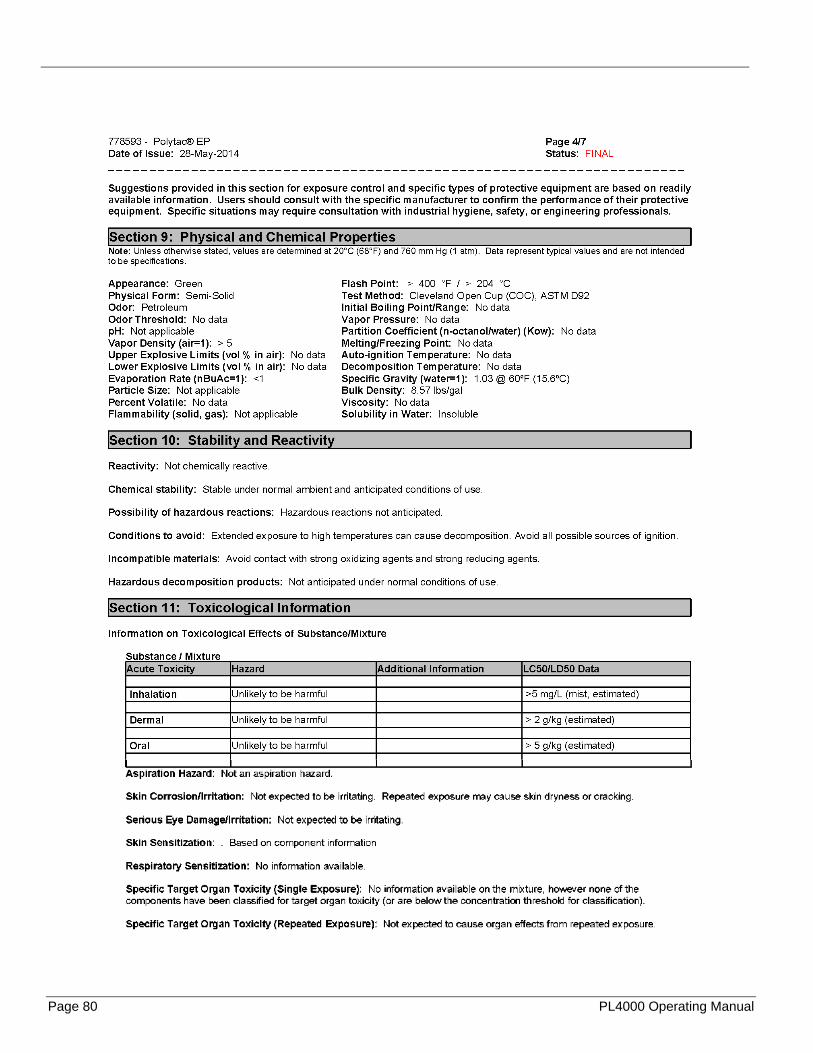
After every 8 hours of operation lubricate the gears inside the main body by pumping Conoco Polytac EP #2 into the grease fitting. One or two pumps are sufficient. Avoid excess lubrication of the gears inside the main body as it can cause overheating and may damage the seals.
5.4 Turning bar and counterweight assembly
Lubricate the leadscrew with a small amount of Conoco AW 32 monthly.
Apply a light layer of oil to the turning bar ways with way oil before and after each use.
Application area Lubricant Brand Biodegradable
alternative Frequency
Main body Gear grease Conoco Polytac EP #2
Castrol BioTac EP 2
After 8 hours of operation
Turning bar, unpainted surfaces
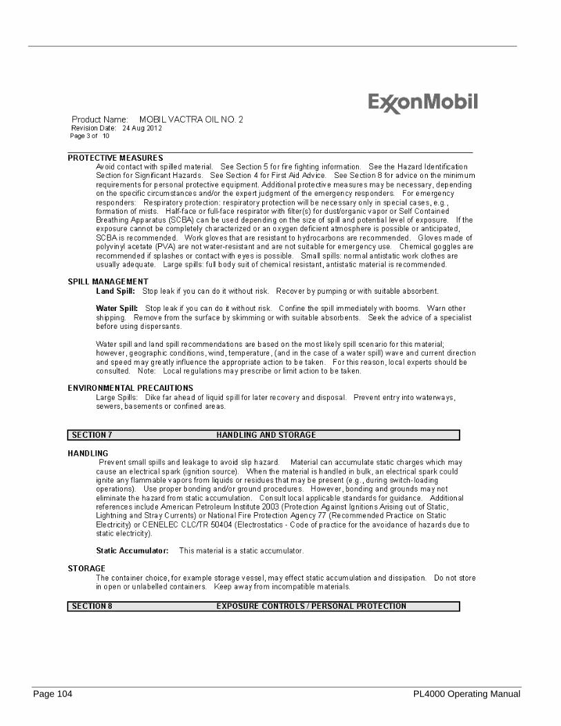
Way oil Mobil Vactra Oil No. 2
N/A Before and after each use
Tool bits, work piece Cutting oil Unocal Koolcut During machining
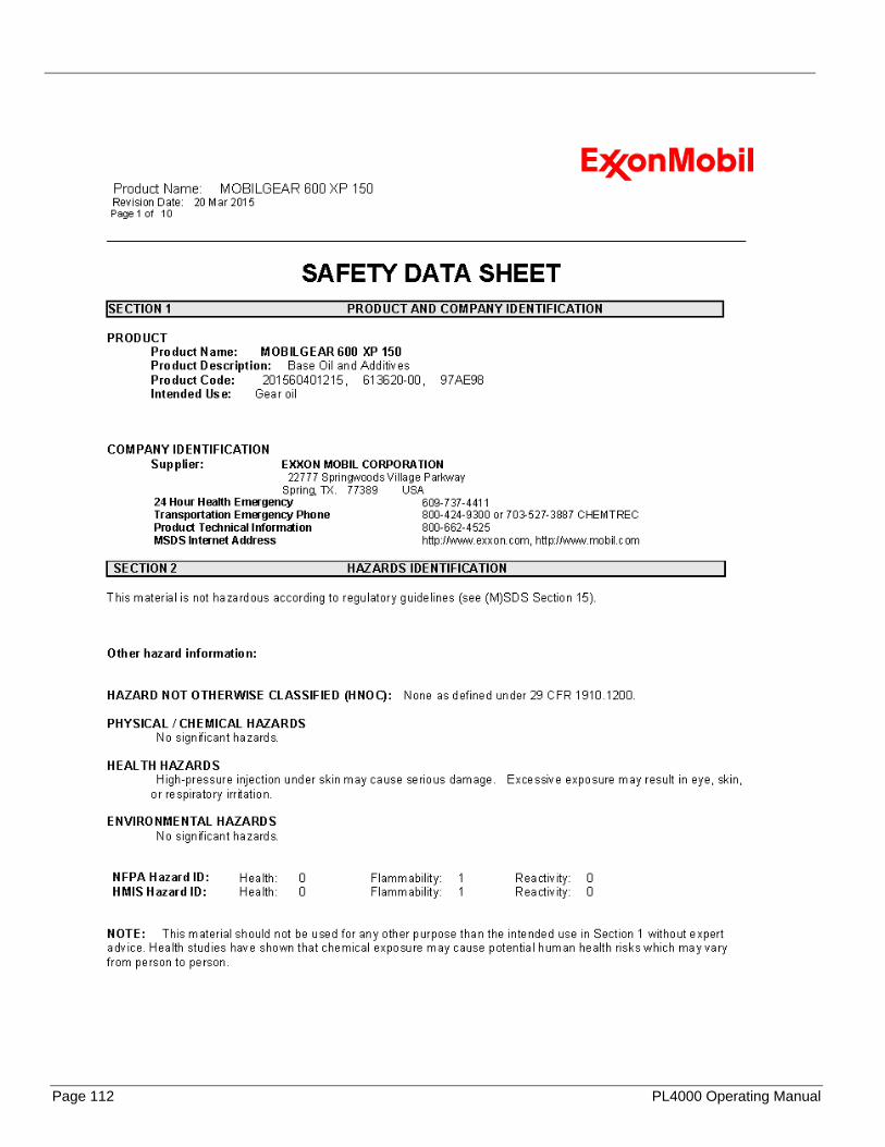
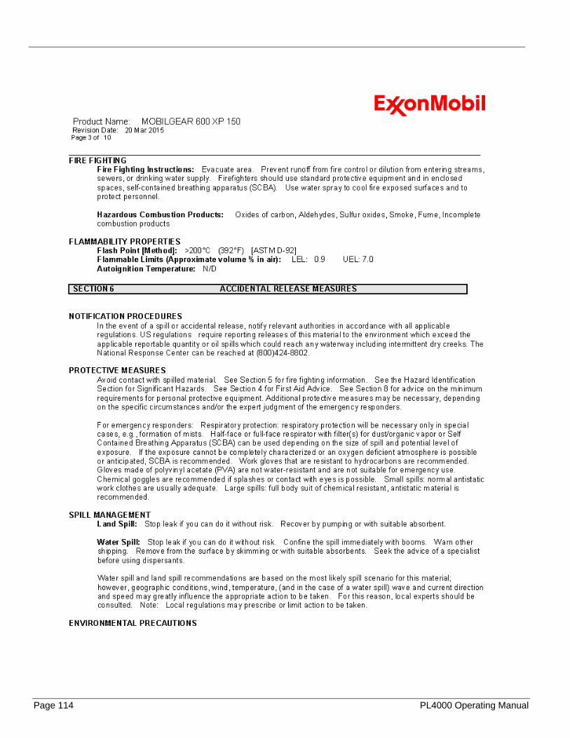
Lubricator oil cup Air oil Oil Mobilgear 600 N/A Before each use
Leadscrew and leadnut
Gearr oil Conoco AW 32 Conoco Ecoterra 32 Monthly
Unpainted surfaces Short-term sotrage
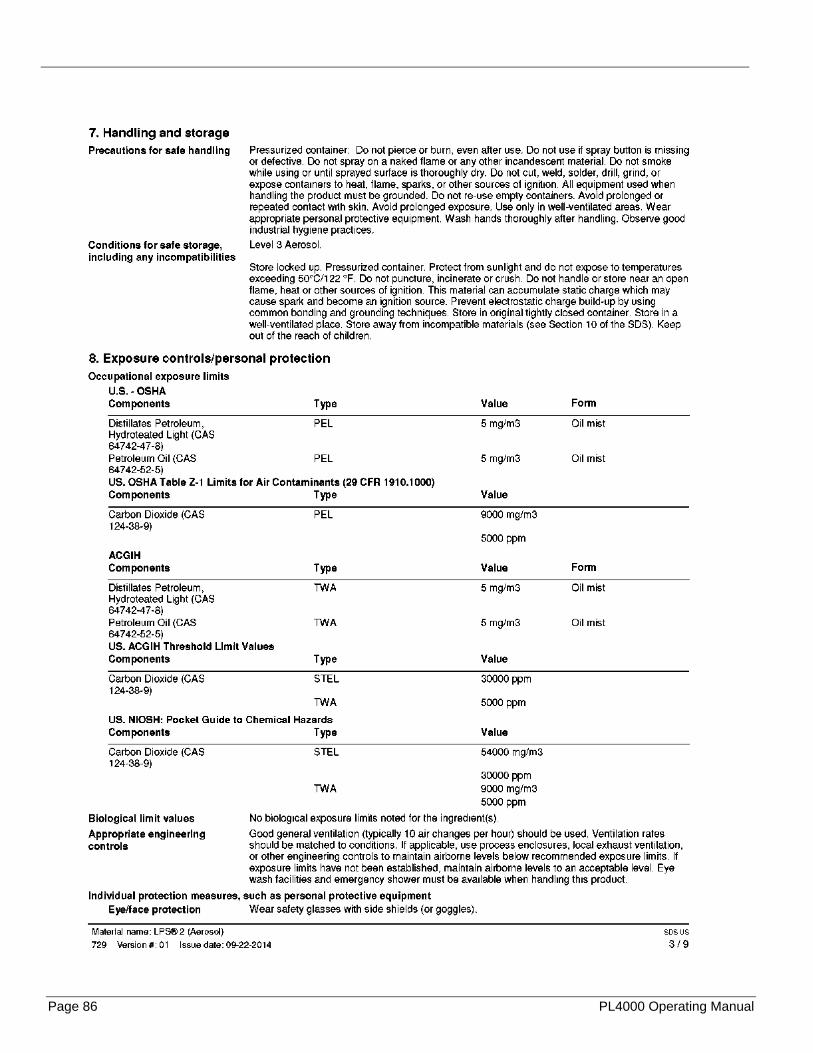
LPS2 N/A Before short-term strorage
Unpainted surfaces Long-term storage
LPS3 N/A Before long-term storage

P/N 16331, Rev. 3 Page 35
5.5 Air motor and pneumatic conditioning unit
Do the following to increase the life of the air motor:
1. Route the air supply through the lubricator and air filter.
WARNING To avoid serious personal injury from rotating machinery, shut off and lock out the machine before connecting the air supply line.
2. Use nonrestrictive air lines and fittings. Check the air system periodically to be sure the air pressure is 90 psi (620 kPa).
3. Adjust the motor speed by turning the needle valve.
NOTICE DO NOT adjust the motor speed by changing the in-line pressure from 90 psi (620 kPa).
4. Fill the lubricator oil cup with oil before using the machine. Use a type of air tool oil that has antioxidants and rust inhibitors.
• The lubricator should oil the air at a rate of 6 drops per minute.
5. Drain the air filter before and after using the machine.
CAUTION To prevent motor damage and increase motor performance, use the filter and lubricator provided.
5.6 Rotary union
Periodically inspect the rotary union for damage.
5.7 Pneumatic feed box assembly
Under normal use, the feed box is lubricated for life.
5.8 Tool head assembly
Periodically lubricate the ways and slides with light oil.

Page 36 PL4000 Operating Manual
This page intentionally left blank
P/N 16331, Rev. 3 Page 37
6 STORAGE AND SHIPPING
IN THIS CHAPTER:
4.4 SETTING TOOL FEED DIRECTION AND SPEED ....................................................................................................................... 30 6.1 STORAGE ......................................................................................................................................................................... 37
6.1.1 Short-term Stroage................................................................................................................................................... 37 6.1.2 Long-Term Storage .................................................................................................................................................. 37
6.2 SHIPPING .......................................................................................................................................................................... 37
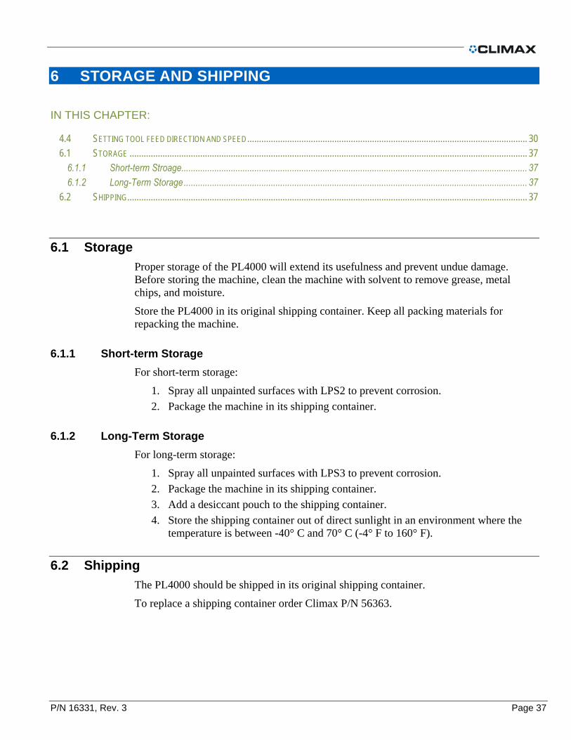
6.1 Storage
Proper storage of the PL4000 will extend its usefulness and prevent undue damage. Before storing the machine, clean the machine with solvent to remove grease, metal chips, and moisture.
Store the PL4000 in its original shipping container. Keep all packing materials for repacking the machine.
6.1.1 Short-term Storage
For short-term storage:
1. Spray all unpainted surfaces with LPS2 to prevent corrosion.
2. Package the machine in its shipping container.
6.1.2 Long-Term Storage
For long-term storage:
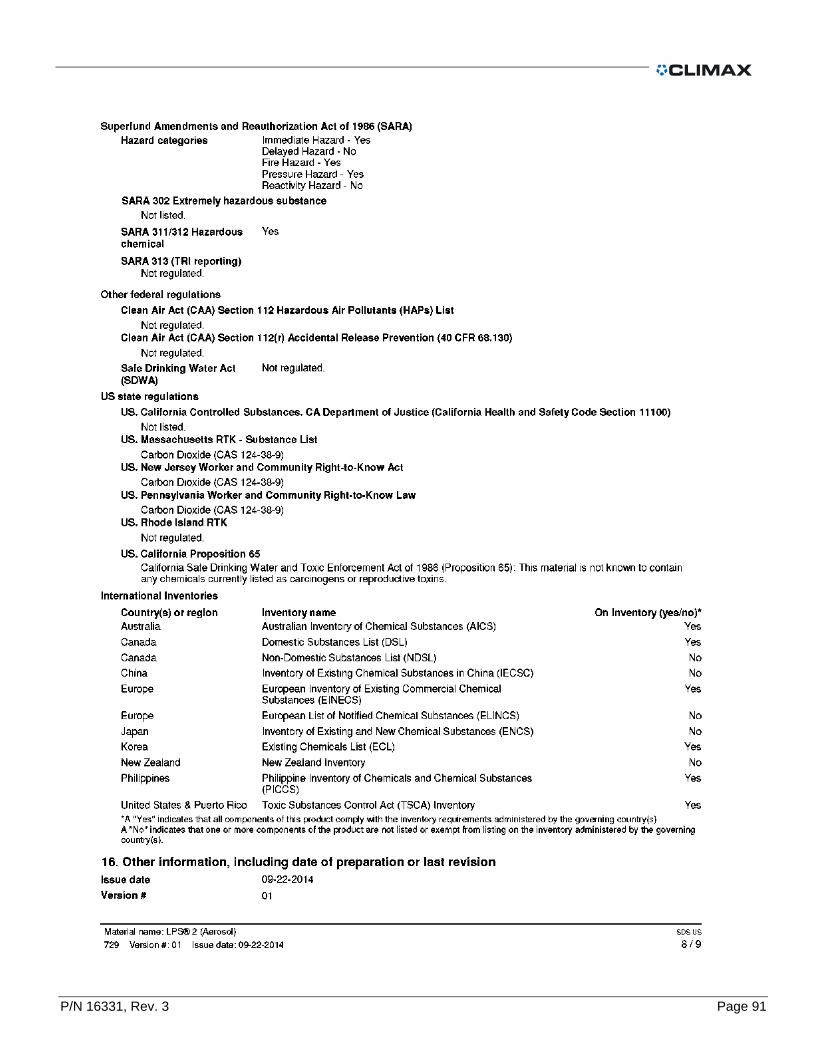
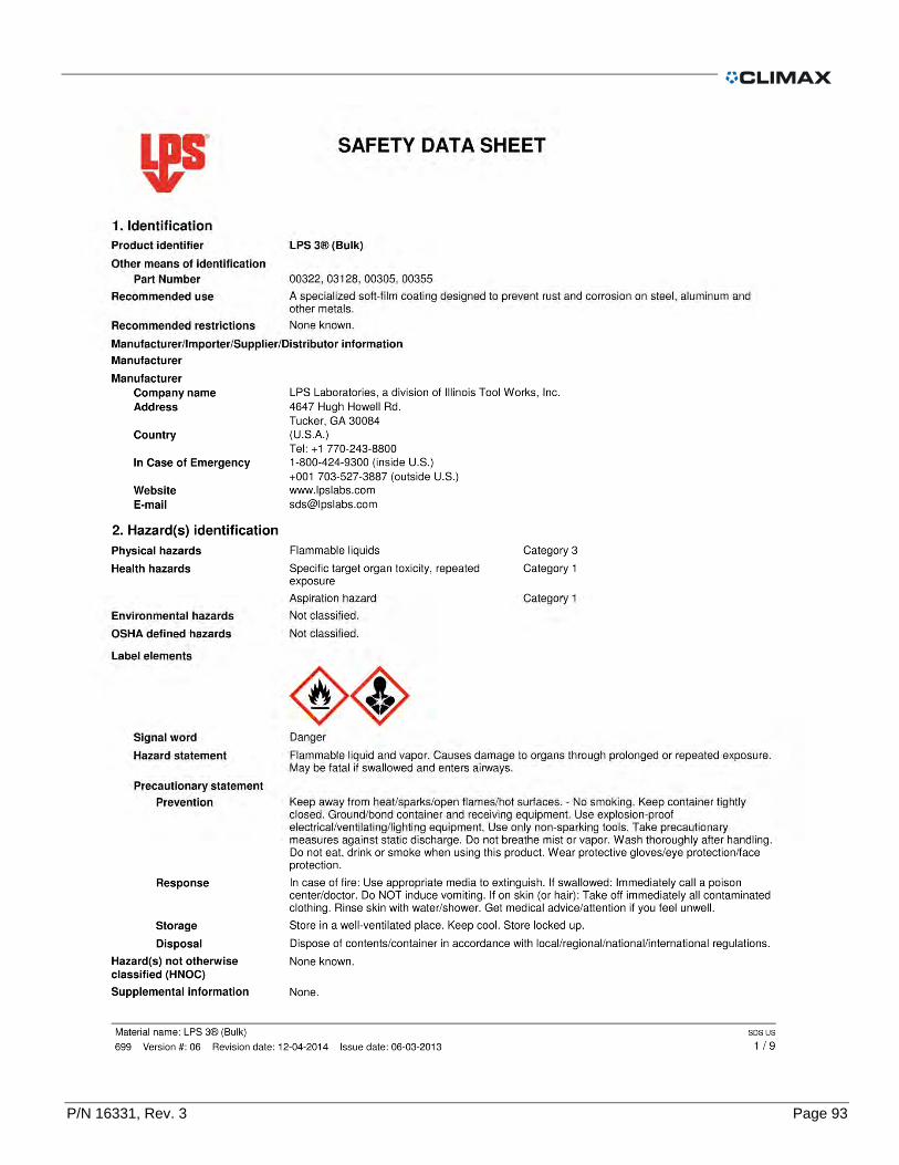
1. Spray all unpainted surfaces with LPS3 to prevent corrosion.
2. Package the machine in its shipping container.
3. Add a desiccant pouch to the shipping container.
4. Store the shipping container out of direct sunlight in an environment where the temperature is between -40° C and 70° C (-4° F to 160° F).
6.2 Shipping
The PL4000 should be shipped in its original shipping container.
To replace a shipping container order Climax P/N 56363.

Page 38 PL4000 Operating Manual
This page intentionally left blank

P/N 16331, Rev. 3 Page 39
APPENDIX A TOOLS AND RECOMMENDED SPARE PARTS
IN THIS CHAPTER:
A.1 RECOMMENDED SPARE PARTS ........................................................................................................................................... 39 A.2 TOOL KIT .......................................................................................................................................................................... 40
A.1 Recommended spare parts Listed below are parts most frequently replaced due to wear, loss or damage.
To avoid unscheduled downtime you may want to stock these items.
TABLE 7. RECCOMENDED SPARE PARTS
PART NO. DESCRIPTION QTY WHERE USED
12791 NUT 5/8-18 4
Main body assembly
11856 WASHER 5/8 4
10203 CRANK HANDLE 1/2 SQUARE 1
13160 MOUNTING PLATE 1
10840 O RING 1/16 X 1/2 ID X 5/8 OD 2
22961 O RING 3/32 X 1-1/2 ID X 1-11/16 OD 3
13221 LEADNUT BRASS SLIDE 2
29220 SCREW 5/8-18 X 2 SSSCP 4 Turning bar and counterweight assembly
13169 MODIFIED AIR MOTOR 1 Pneumatic power assembly

Page 40 PL4000 Operating Manual
A.2 Tool kit
TABLE 8.P/N 16906 TOOL KIT PL4000
16906 TOOL KIT PL4000
PART DESCRIPTION
16331 PL4000 OPERATING MANUAL
34866 OIL AIRTOOL COMPLETE
19700 CONTAINER SHIPPING FLAT ROOF 20 X 8.75 X 10.5
31859 TOOL BIT HSS 1/2 X 4.0 LH FINISHING SINGLE TC
31868 TOOL BIT HSS 1/2 X 4.0 LH ROUGHING SINGLE (KB)
33999 WRENCH HEX SET .050 - 3/8 BONDHUS BALL END (KB)
10586 HOLDER ABRASIVE BELT
12800 END WRENCH 15/16
10800 SCREW 1/4-20 X 1/2 SHCS
26848 INDICATOR .500 WITH MIGHTY-MAG BASE
12799 HEX WRENCH 5/32 X 6 T-HANDLE

P/N 16331, Rev. 3 Page 41
APPENDIX B ASSEMBLY DRAWINGS AND PARTS LISTS
IN THIS CHAPTER:
FIGURE A-1. P/N 13142 MAIN BODY ASSEMBLY PL4000 ................................................................................................................. 42
FIGURE A-2. P/N 13142 MAIN BODY ASSEMBLY PL4000 ................................................................................................................. 43
FIGURE A-3. P/N 13168 TURNING BAR AND COUNTERWEIGHT ASSEMBLY......................................................................................... 44
FIGURE A-4. P/N 13212 TOOL HEAD ASSEMBLY PL4000 ................................................................................................................. 45
FIGURE A-5. P/N 13480 PNEUMATIC FEED BOX ASSEMBLY .............................................................................................................. 46
FIGURE A-6. P/N 13480 PNEUMATIC FEED BOX ASSEMBLY PARTS LIST ............................................................................................ 47
FIGURE A-7. P/N 18900 TOOL HEAD EXTENSION KIT PL4000 .......................................................................................................... 48
FIGURE A-8. P/N 18901 TURNING RADIUS EXTENSION PL4000 ....................................................................................................... 49
FIGURE A-9. P/N 29438 PNEUMATIC POWER ASSEMBLY.................................................................................................................. 50
FIGURE A-10. P/N 29438 PNEUMATIC POWER ASSEMBLY PARTS LIST .............................................................................................. 51
FIGURE A-11. P/N 78264 PNEUMATIC CONDITIONING UNIT .............................................................................................................. 52
FIGURE A-12. P/N 78264 PNEUMATIC CONDITIONING UNIT PARTS LIST ............................................................................................ 53
NOTICE The following diagrams and parts lists are for reference purposes only. The machine Limited Warranty is void if the machine has been tampered with by anyone who has not been authorized in writing by Climax Portable Machining and Welding Systems, Inc. to perform service on the machine.

Page 42 PL4000 Operating Manual
FIGURE A-1. P/N 13142 MAIN BODY ASSEMBLY PL4000
P/N 16331, Rev. 3 Page 43
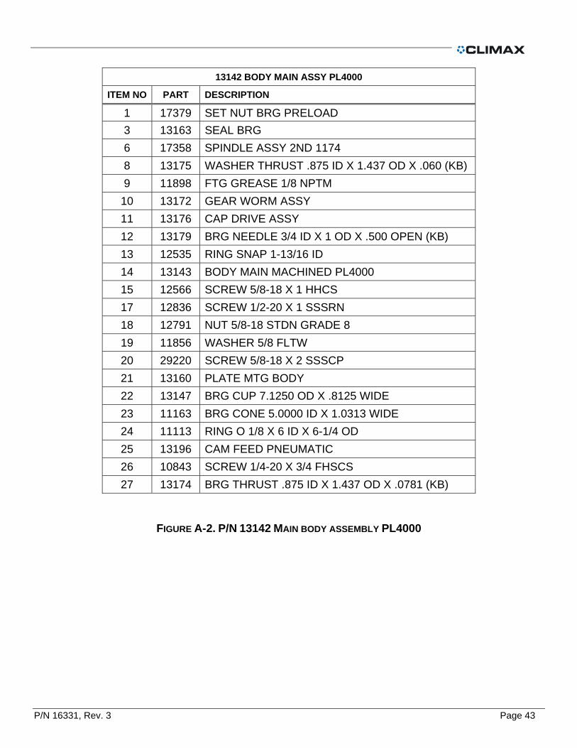
13142 BODY MAIN ASSY PL4000
ITEM NO PART DESCRIPTION
1 17379 SET NUT BRG PRELOAD
3 13163 SEAL BRG
6 17358 SPINDLE ASSY 2ND 1174
8 13175 WASHER THRUST .875 ID X 1.437 OD X .060 (KB)
9 11898 FTG GREASE 1/8 NPTM
10 13172 GEAR WORM ASSY
11 13176 CAP DRIVE ASSY
12 13179 BRG NEEDLE 3/4 ID X 1 OD X .500 OPEN (KB)
13 12535 RING SNAP 1-13/16 ID
14 13143 BODY MAIN MACHINED PL4000
15 12566 SCREW 5/8-18 X 1 HHCS
17 12836 SCREW 1/2-20 X 1 SSSRN
18 12791 NUT 5/8-18 STDN GRADE 8
19 11856 WASHER 5/8 FLTW
20 29220 SCREW 5/8-18 X 2 SSSCP
21 13160 PLATE MTG BODY
22 13147 BRG CUP 7.1250 OD X .8125 WIDE
23 11163 BRG CONE 5.0000 ID X 1.0313 WIDE
24 11113 RING O 1/8 X 6 ID X 6-1/4 OD
25 13196 CAM FEED PNEUMATIC
26 10843 SCREW 1/4-20 X 3/4 FHSCS
27 13174 BRG THRUST .875 ID X 1.437 OD X .0781 (KB)
FIGURE A-2. P/N 13142 MAIN BODY ASSEMBLY PL4000

Page 44 PL4000 Operating Manual
FIGURE A-3. P/N 13168 TURNING BAR AND COUNTERWEIGHT ASSEMBLY

P/N 16331, Rev. 3 Page 45
FIGURE A-4. P/N 13212 TOOL HEAD ASSEMBLY PL4000
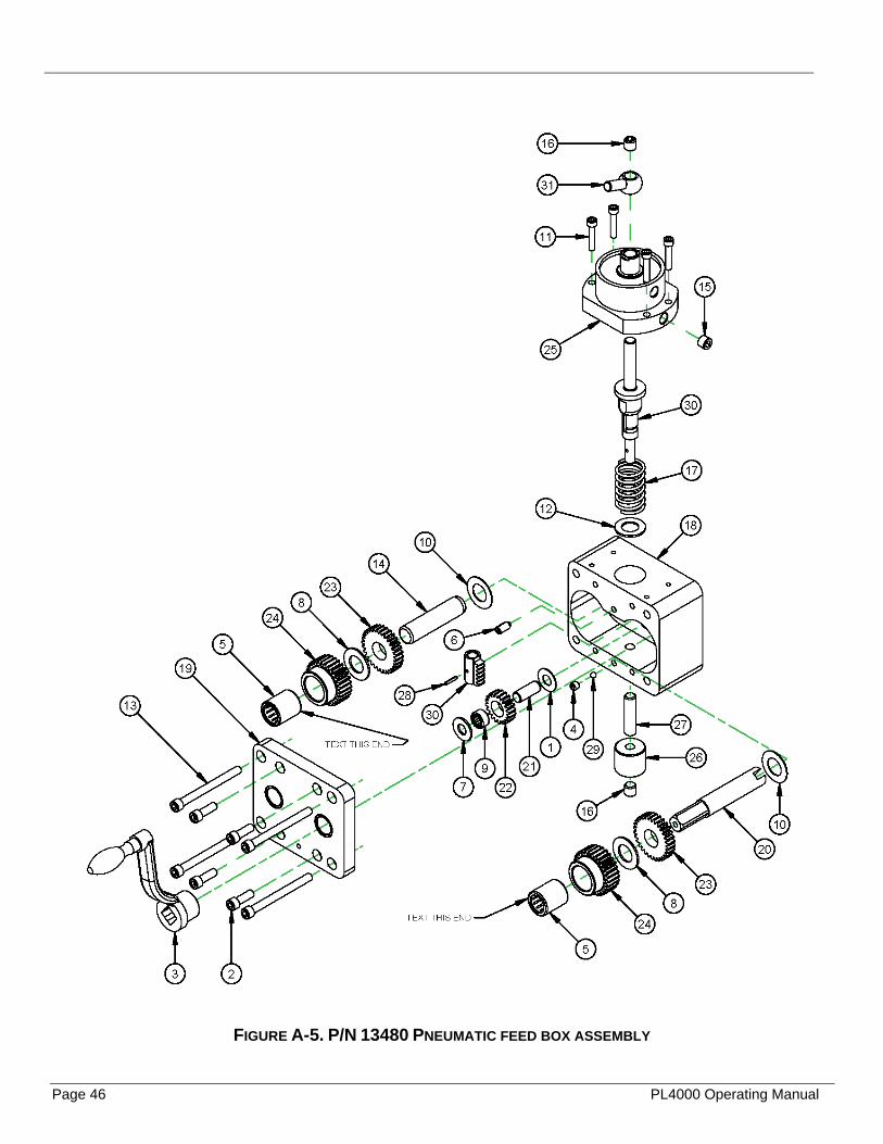
Page 46 PL4000 Operating Manual
FIGURE A-5. P/N 13480 PNEUMATIC FEED BOX ASSEMBLY

P/N 16331, Rev. 3 Page 47
FIGURE A-6. P/N 13480 PNEUMATIC FEED BOX ASSEMBLY PARTS LIST

Page 48 PL4000 Operating Manual
FIGURE A-7. P/N 18900 TOOL HEAD EXTENSION KIT PL4000
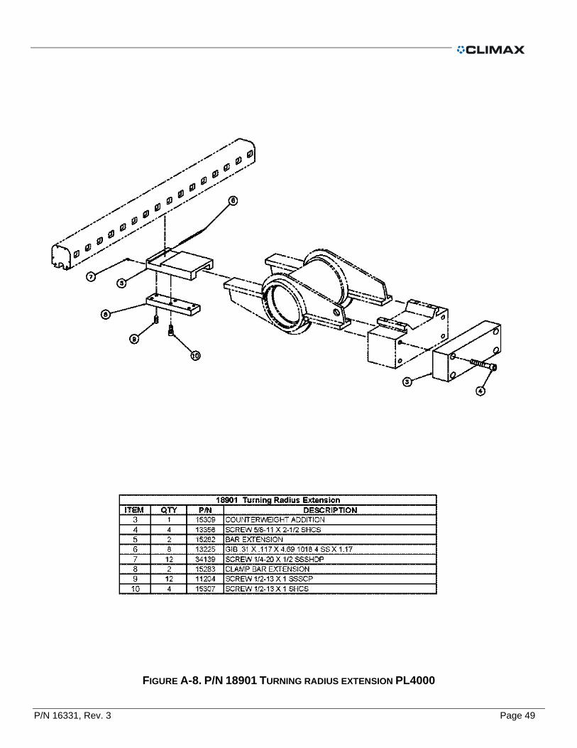
P/N 16331, Rev. 3 Page 49
FIGURE A-8. P/N 18901 TURNING RADIUS EXTENSION PL4000

Page 50 PL4000 Operating Manual
FIGURE A-9. P/N 29438 PNEUMATIC POWER ASSEMBLY
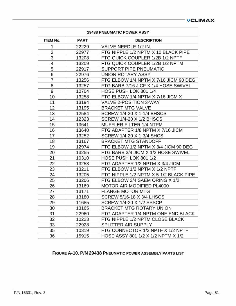
P/N 16331, Rev. 3 Page 51
29438 PNEUMATIC POWER ASSY
ITEM No. PART DESCRIPTION
1 22229 VALVE NEEDLE 1/2 IN. 2 22977 FTG NIPPLE 1/2 NPTM X 10 BLACK PIPE 3 13208 FTG QUICK COUPLER 1/2B 1/2 NPTF 4 13209 FTG QUICK COUPLER 1/2B 1/2 NPTM 5 22917 SUPPORT PIPE PNEUMATIC 6 22976 UNION ROTARY ASSY 7 13256 FTG ELBOW 1/4 NPTM X 7/16 JICM 90 DEG 8 13257 FTG BARB 7/16 JICF X 1/4 HOSE SWIVEL 9 10704 HOSE PUSH LOK 801 1/4
10 13258 FTG ELBOW 1/4 NPTM X 7/16 JICM X-11 13194 VALVE 2-POSITION 3-WAY 12 13195 BRACKET MTG VALVE 13 12584 SCREW 1/4-20 X 1-1/4 BHSCS 14 12323 SCREW 1/4-20 X 1/2 BHSCS 15 13641 MUFFLER FILTER 1/4 NTPM 16 13640 FTG ADAPTER 1/8 NPTM X 7/16 JICM 17 13252 SCREW 1/4-20 X 1-3/4 SHCS 18 13167 BRACKET MTG STANDOFF 19 12974 FTG ELBOW 1/2 NPTM X 3/4 JICM 90 DEG 20 13255 FTG BARB 3/4 JICM X 1/2 HOSE SWIVEL 21 10310 HOSE PUSH LOK 801 1/2 22 13253 FTG ADAPTER 1/2 NPTM X 3/4 JICM 23 13211 FTG ELBOW 1/2 NPTM X 1/2 NPTF 24 13205 FTG NIPPLE 1/2 NPTM X 5-1/2 BLACK PIPE 25 13206 FTG ELBOW 3/4 SAEM ORING X 1/2 26 13169 MOTOR AIR MODIFIED PL4000 27 13171 FLANGE MOTOR MTG 28 13180 SCREW 5/16-18 X 3/4 LHSCS 29 11685 SCREW 1/4-20 X 1/2 SSSCP 30 13165 BRACKET MTG ROTARY UNION 31 22960 FTG ADAPTER 1/4 NPTM ONE END BLACK 32 10223 FTG NIPPLE 1/2 NPTM CLOSE BLACK 33 22928 SPLITTER AIR SUPPLY 35 10319 FTG CONNECTOR 1/2 NPTF X 1/2 NPTF 36 15915 HOSE ASSY 801 1/2 X 1/2 NPTM X 1/2
FIGURE A-10. P/N 29438 PNEUMATIC POWER ASSEMBLY PARTS LIST
Page 52 PL4000 Operating Manual
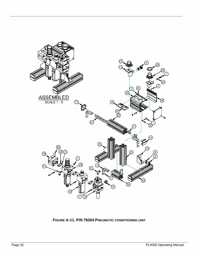
FIGURE A-11. P/N 78264 PNEUMATIC CONDITIONING UNIT
P/N 16331, Rev. 3 Page 53
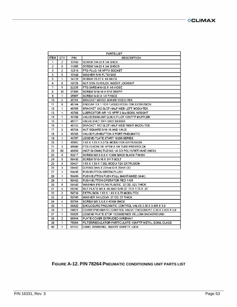
FIGURE A-12. P/N 78264 PNEUMATIC CONDITIONING UNIT PARTS LIST

Page 54 PL4000 Operating Manual
This page left intentionally blank.

P/N 16331, Rev. 3 Page 55
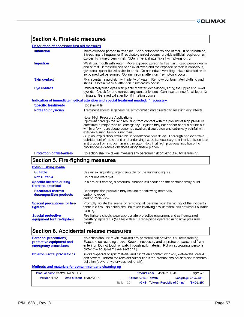
APPENDIX C MSDS
The MSDS are included in alphabetical order.
IN THIS CHAPTER:
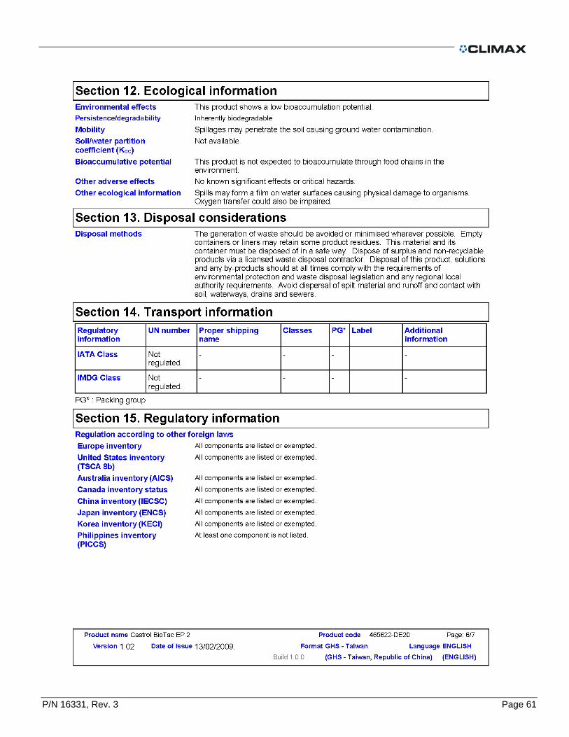
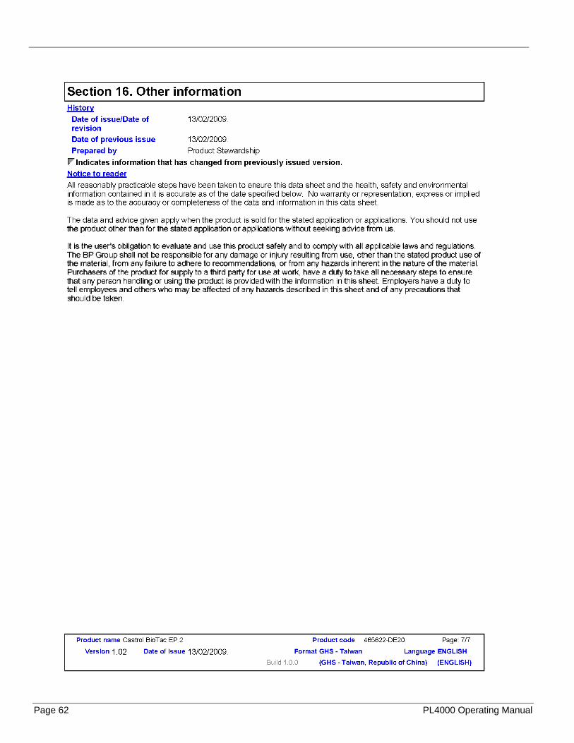
CASTROL BIOTAC EP 2 ............................................................................................................................................................... 55
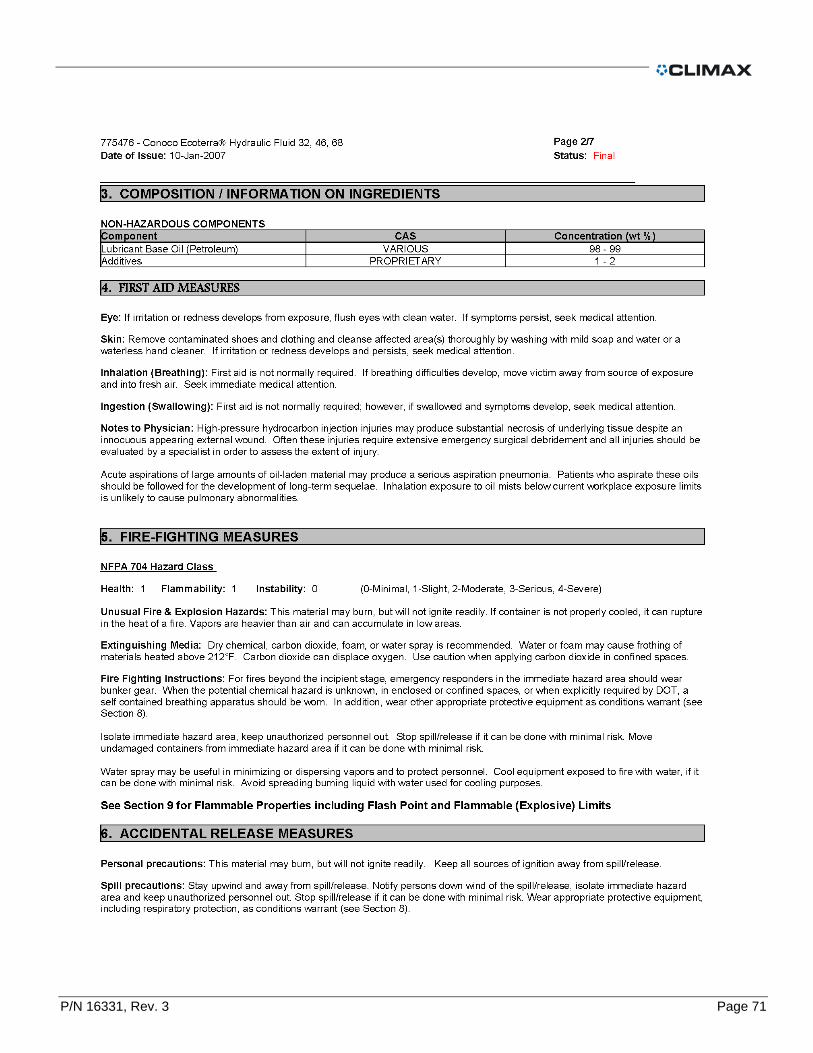
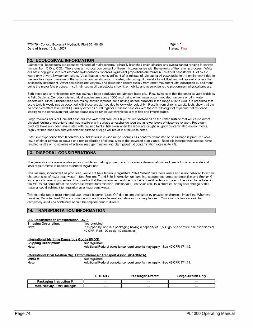
CONOCO AW 32 ........................................................................................................................................................................... 62
CONOCO ECOTERRRA 32 .......................................................................................................................................................... 69
CONOCO POLYTAC EP #2 .......................................................................................................................................................... 76
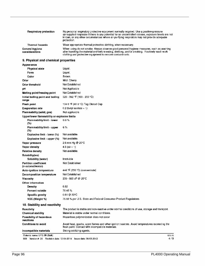
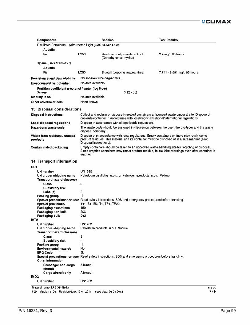
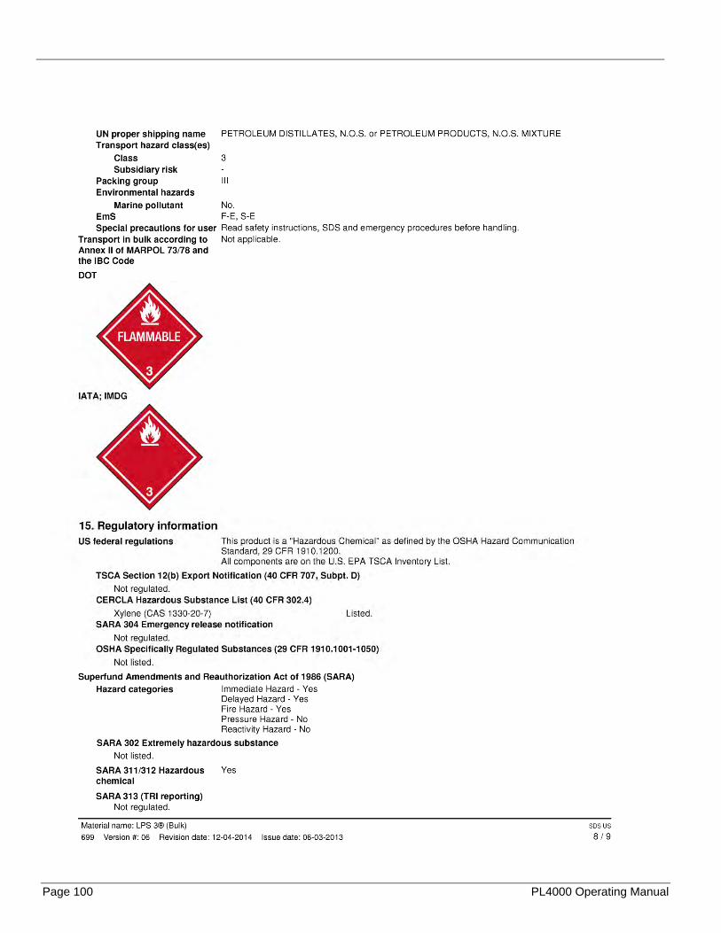
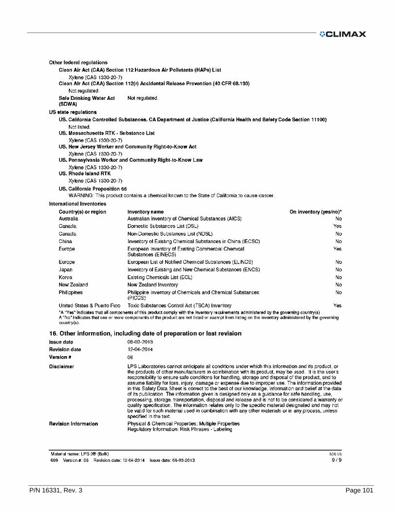
LPS2 .............................................................................................................................................................................................. 83
LPS3 .............................................................................................................................................................................................. 92
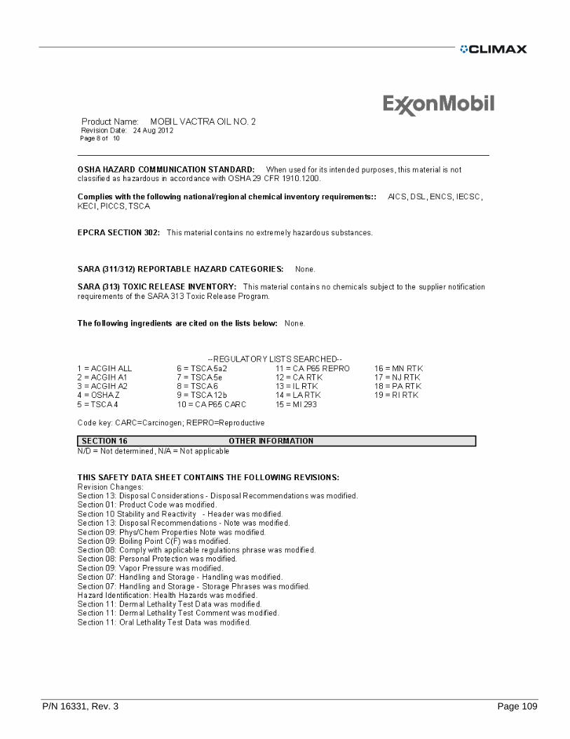
MOBIL VACTRA OIL No. 2 .......................................................................................................................................................... 101
OIL MOBILGEAR 600 .................................................................................................................................................................. 111
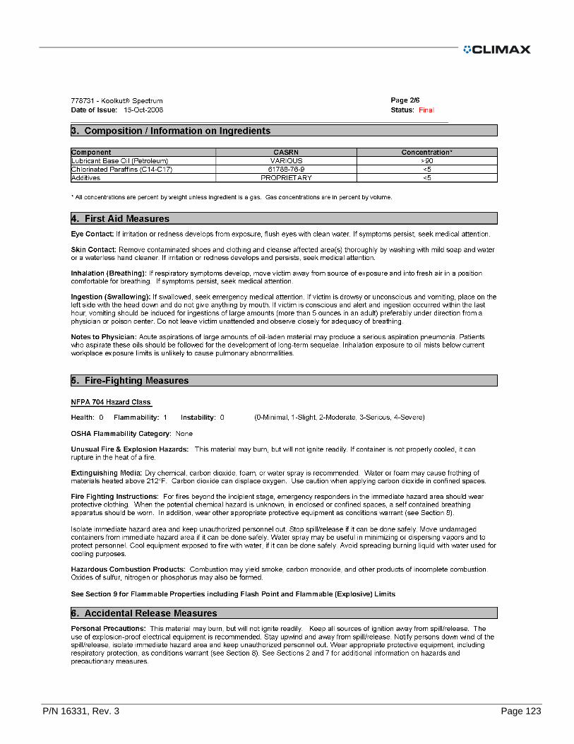
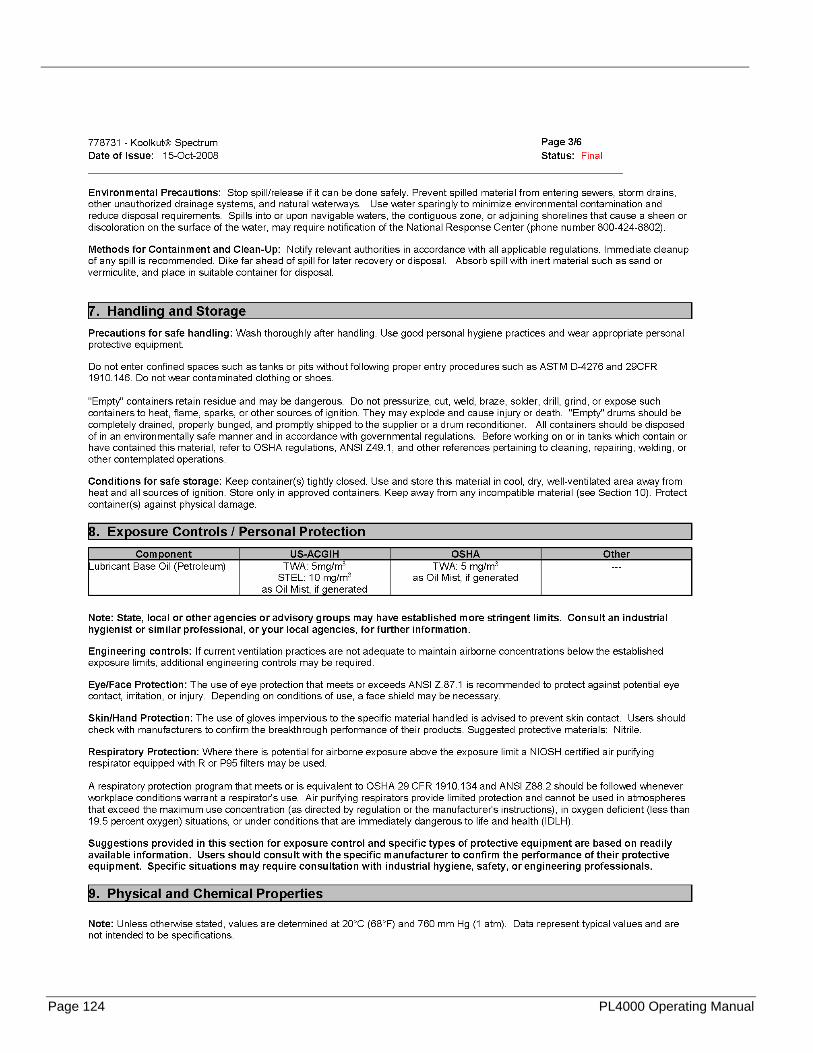
UNOCAL KOOLCUT .................................................................................................................................................................... 121

Page 56 PL4000 Operating Manual
P/N 16331, Rev. 3 Page 57

Page 58 PL4000 Operating Manual

P/N 16331, Rev. 3 Page 59

Page 60 PL4000 Operating Manual
P/N 16331, Rev. 3 Page 61
Page 62 PL4000 Operating Manual

P/N 16331, Rev. 3 Page 63

Page 64 PL4000 Operating Manual

P/N 16331, Rev. 3 Page 65

Page 66 PL4000 Operating Manual

P/N 16331, Rev. 3 Page 67

Page 68 PL4000 Operating Manual

P/N 16331, Rev. 3 Page 69

Page 70 PL4000 Operating Manual
P/N 16331, Rev. 3 Page 71

Page 72 PL4000 Operating Manual

P/N 16331, Rev. 3 Page 73
Page 74 PL4000 Operating Manual

P/N 16331, Rev. 3 Page 75

Page 76 PL4000 Operating Manual

P/N 16331, Rev. 3 Page 77

Page 78 PL4000 Operating Manual

P/N 16331, Rev. 3 Page 79
Page 80 PL4000 Operating Manual

P/N 16331, Rev. 3 Page 81

Page 82 PL4000 Operating Manual

P/N 16331, Rev. 3 Page 83

Page 84 PL4000 Operating Manual

P/N 16331, Rev. 3 Page 85
Page 86 PL4000 Operating Manual

P/N 16331, Rev. 3 Page 87

Page 88 PL4000 Operating Manual

P/N 16331, Rev. 3 Page 89

Page 90 PL4000 Operating Manual
P/N 16331, Rev. 3 Page 91

Page 92 PL4000 Operating Manual
P/N 16331, Rev. 3 Page 93

Page 94 PL4000 Operating Manual

P/N 16331, Rev. 3 Page 95
Page 96 PL4000 Operating Manual

P/N 16331, Rev. 3 Page 97

Page 98 PL4000 Operating Manual
P/N 16331, Rev. 3 Page 99
Page 100 PL4000 Operating Manual
P/N 16331, Rev. 3 Page 101

Page 102 PL4000 Operating Manual

P/N 16331, Rev. 3 Page 103
Page 104 PL4000 Operating Manual

P/N 16331, Rev. 3 Page 105

Page 106 PL4000 Operating Manual

P/N 16331, Rev. 3 Page 107

Page 108 PL4000 Operating Manual
P/N 16331, Rev. 3 Page 109

Page 110 PL4000 Operating Manual

P/N 16331, Rev. 3 Page 111
Page 112 PL4000 Operating Manual

P/N 16331, Rev. 3 Page 113
Page 114 PL4000 Operating Manual

P/N 16331, Rev. 3 Page 115
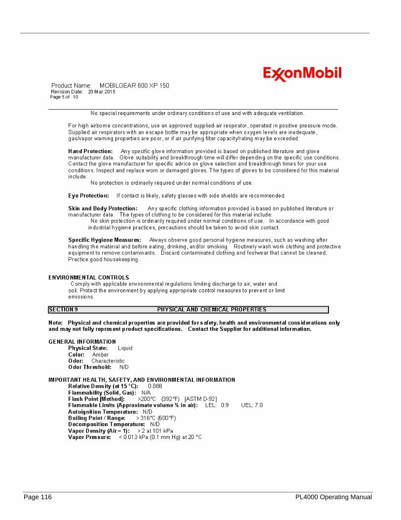
Page 116 PL4000 Operating Manual

P/N 16331, Rev. 3 Page 117

Page 118 PL4000 Operating Manual

P/N 16331, Rev. 3 Page 119
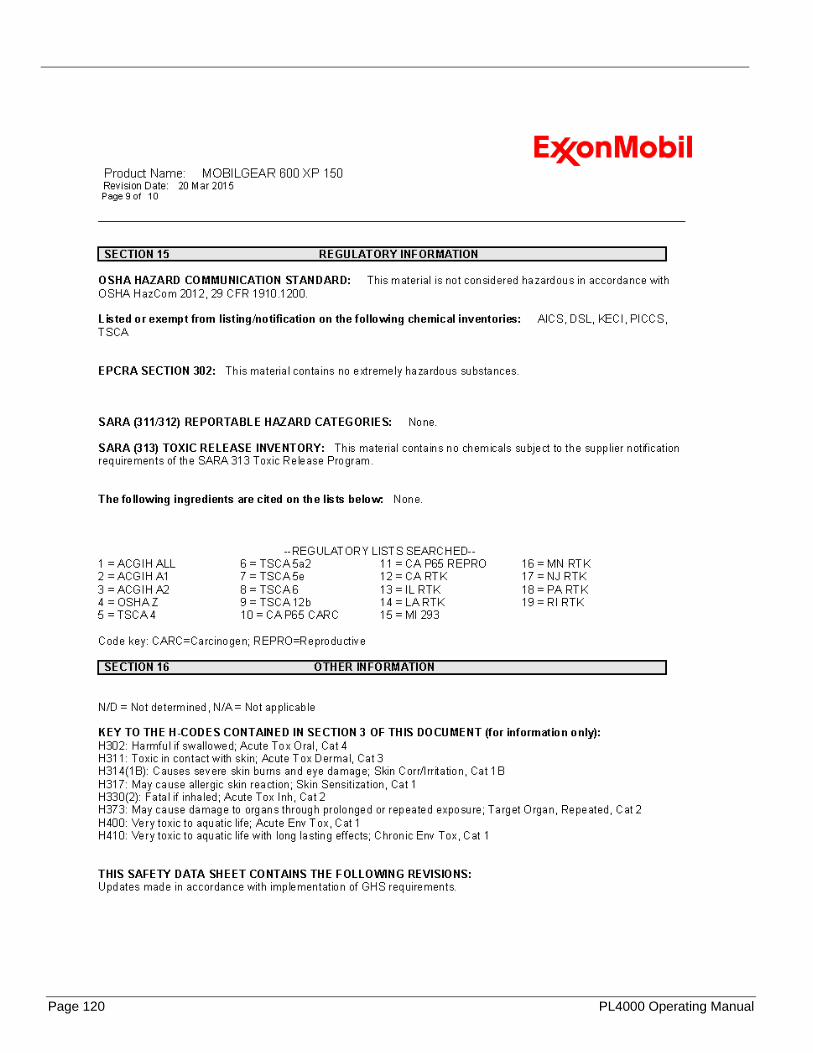
Page 120 PL4000 Operating Manual

P/N 16331, Rev. 3 Page 121

Page 122 PL4000 Operating Manual
P/N 16331, Rev. 3 Page 123
Page 124 PL4000 Operating Manual

P/N 16331, Rev. 3 Page 125
Page 126 PL4000 Operating Manual

P/N 16331, Rev. 3 Page 127

Page 128 PL4000 Operating Manual
This page left intentionally blank.