Digital Controller - TTM-200 series - User's Manual
264
Digital Controller TTM-200 series User’s Manual TOHO ELECTRONICS INC.
-
Upload
khangminh22 -
Category
Documents
-
view
0 -
download
0
Transcript of Digital Controller - TTM-200 series - User's Manual

Digital Controller
TTM-200 series
User’s Manual
TOHO ELECTRONICS INC.

48-7009-G i
User’s manual for digital controller TTM-200 series
Introduction Thank you for purchasing Toho Electronics’ TTM-200 series.
Before using the products, thoroughly read this manual for a better understanding of them.
Ensure to store this manual and use it whenever needed.
Precautions on the use of the products Ensure to read this manual before using the equipment.
Take care to understand the following for the safe use of the equipment.
Ensure this manual to be in hands of a person using the equipment.
★ Precautions on safety
Alarms are defined and categorized into either one of four groups in this manual, depending on degrees of
importance or risk in terms of the safe use of the equipment or prevention of accident or damage on the
equipment. For each alarm, symbol is assigned as shown below.
★ Alarm symbols
Danger
Improper handling of the equipment may cause fatality or serious injury for an impending reality.
Caution Improper handling of the equipment may cause injury or physical damage on it.
Warning Improper handling of the equipment may cause fatality or serious injury.
Reminder Care should be taken for ensuring safety.
An alarm categorized in the group of Caution may still yield to serious result, depending on circumstances.
Any symbol for the four groups intends to raise user’s attention for important description. Carefully observe
it.
★ Other symbols
General caution, warning or prohibition without particularity
Instruction on ground connection for the equipment with safety grounding terminals
Hazard of pinched fingers on a particular portion of the equipment
Possible injury caused by touching a particular portion of the equipment under specific conditions
Unspecific behaviors of general users
Hazard of injury due to high temperature under specific conditions
Hazard of an electric shock under specific conditions
Hazard of injury such as an electric shock due to disassembling or modification of the equipment
Hazard of burst under particular conditions
Supplementary explanation
Designation of reference for explanation
Care for use or operation
Note

48-7009-G ii
Warnings
Improper wiring to the equipment may cause a failure, such as fire. Upon completion of wiring, ensure to verify the proper wiring before turning on electricity.
Do not turn on electricity until all wiring is complete. Do not touch portions of high voltages such as power supply terminals, as an electric shock may be resultant.
Install appropriate protective circuits externally if a failure or abnormality of the equipment may seriously affect related systems.
Do not use the equipment out of the specified range, as it may fail or catch fire.
Do not under any circumstance to modify or disassemble the equipment, as a failure may be caused, resulting fire or an electric shock.
Do not use the equipment in ambience of flammable or explosive gases.
Cautions
Do not use the vacant terminals for wiring.
Do not use a pointed object to operate keys.
Do not turn on the power supply until wiring is fully complete in order to prevent an electric shock, failure or malfunctioning. For replacing a component connected on the equipment, ensure to turn off the power supply. For turning back on the power supply, do so after all wiring is complete.
Ensure not to trap heat in the space surrounding the equipment in order to provide sufficient heat release.
Do not put a metal piece or similar inside the equipment. A fire, an electric shock or failure may be caused.
The equipment is designed for instrumentation. For its use in environments of high voltages or intense noises, take appropriate measures on the side of user’s equipment.
The equipment is designed for controlling physical values, such as temperatures, on general industrial facilities. Do not use it for subjects of control that may seriously affect human life.
Turn off the power supply before cleaning the equipment, and wipe it with a soft dry cloth. Do not use thinners, as they may cause deformation or discoloration of the equipment.
The equipment may cause radio disturbances in domestic settings. User is required to take appropriate measure.
Ensure to tighten terminal screws at specified torque. Insufficient tightening the screws may cause an electric shock or fire.
Ensure to observe precautions listed in this manual for the use of the equipment.
Reprinting or duplicating this manual is prohibited.
This manual may be revised without prior notice.
Precaution regarding Export Trade Control Ordinance
Investigation on client or application by an appropriate party is required so that the equipment is not used for
mass destruction weapons and such (military application, military facilities, etc.).

48-7009-G iii
Notation convention in this manual
★ Summary notation
Abbreviations in alphabetical characters are used for the diagrams and text in this manual. Some major
examples are as follows.
Abbreviation Term
PV Present value
SV Setting value
AT Auto-tuning
ENT Determined
MV1 Primary operating amount
MV2 Secondary operating amount
CT Current transformer
AI Remote SV input
★ Notation of characters
For parameters and settings, numeric and alphabetic characters are inscribed as follows. (For initial setting, a
character is comprised of eleven segments.)
0 1 2 3 4 5 6
7 8 9 Minus Period Slash
A B C D E F G
H I J K L M N
O P Q R S T(t) U
V W X Y Z n v

48-7009-G iv
Contents
1. Overview
Outline of TTM-200 series is described, in terms of features, model configuration (codes), names of
components and functions. Thoroughly read this chapter prior to the first use.
This manual is applicable for the product of which main body has a firmware of Ver3.xx or later.
The previous manual must be used if the main body firmware of Ver2.xx or earlier is used.
1.1 Feature ..................................................................................................................................................... 1-2
1.2 Checking the product ............................................................................................................................... 1-3
1.3 Model table .............................................................................................................................................. 1-3
1.4 Names of parts and components .............................................................................................................. 1-4
1.5 Input/output function and essential functions .......................................................................................... 1-7
1.6 Basic flow of setting ...............................................................................................................................1-11
2. Installation
How to install TTM-200 series and precautions on the installation are described.
Read this chapter prior to the installation.
2.1 Precautions on installation ....................................................................................................................... 2-2
2.2 How to install or remove the equipment .................................................................................................. 2-3
2.3 Outside dimensions and panel cutting dimensions .................................................................................. 2-4
3. Wiring
Wiring of TTM-200 series is described.
Read this chapter prior to the wiring.
3.1 Precautions on wiring .............................................................................................................................. 3-2
3.2 Terminal arrangement .............................................................................................................................. 3-3
3.3 Wiring to each terminal ........................................................................................................................... 3-7
3-4 Examples of wiring ................................................................................................................................ 3-15
4. Basic functions
Basic operation (setting method) of TTM-200 series is described.
4.1 Flow of setting mode ............................................................................................................................... 4-2
4.2 Basic operation ........................................................................................................................................ 4-4
4.2.1 Switchover of parameters (flow as a whole) .................................................................................. 4-4
4.2.2 Description of setting item selection screen ................................................................................. 4-19
4.2.3 Setting of input types ................................................................................................................... 4-20
4.2.4 Setting of key functions ............................................................................................................... 4-21
4.2.5 How to set the SV limiter setting ................................................................................................. 4-22
4.2.6 How to set control types ............................................................................................................... 4-23
4.2.7 How to set outputs ........................................................................................................................ 4-25
4.2.8 How to set priority screens ........................................................................................................... 4-26
4.2.9 Switchover to the blind setting mode ........................................................................................... 4-27
4.2.10 Switchover to the ON/OFF control .............................................................................................. 4-29
5. Operation
Operation, often-used setting items, how to set each function and description of the function of TTM-200
series are described.
5.1 Precautions on operating the equipment .................................................................................................. 5-2
5.2 Operating monitor display ....................................................................................................................... 5-3
5.2.1 Operating amount monitor: SET 04 (control setting mode) ........................................................... 5-3
5.2.2 Timer remaining time monitor: Run mode ..................................................................................... 5-3
5.2.3 Temperature measurement monitor: Run mode ............................................................................. 5-3
5.2.4 CT monitor: SET 12 (CT setting mode) ......................................................................................... 5-3

48-7009-G v
5.3 How to set run settings............................................................................................................................. 5-4
5.3.1 Target value (SV) setting ................................................................................................................ 5-4
5.3.2 ON/OFF control setting.................................................................................................................. 5-7
5.3.3 PID control setting ......................................................................................................................... 5-9
5.3.4 Heating/cooling PID control setting ............................................................................................. 5-13
5.3.5 Indicator setting ............................................................................................................................ 5-15
5.3.6 Excessive ascent prevention unit (alarm unit) setting .................................................................. 5-17
5.3.7 Event setting ................................................................................................................................. 5-18
5.3.8 How to set MD/READY .............................................................................................................. 5-20
5.4 How to set each function and description of function ........................................................................... 5-22
5.4.1 Auto-tuning (AT) function ........................................................................................................... 5-22
5.4.2 Self-tuning function ..................................................................................................................... 5-25
5.4.3 Mode/manual function ................................................................................................................. 5-27
5.4.4 Bank function ............................................................................................................................... 5-28
5.4.5 Timer function .............................................................................................................................. 5-31
5.4.6 Loop abnormality function ........................................................................................................... 5-38
5.4.7 Current transformer (CT) abnormality function ........................................................................... 5-40
5.4.8 Position proportional control ........................................................................................................ 5-45
5.4.9 Concurrent temperature ascent function ...................................................................................... 5-46
5.5 Explanation of the program run function ............................................................................................... 5-47
5.5.1 Operation flow of the program run .............................................................................................. 5-48
5.5.2 SET 21 program function setting ................................................................................................. 5-49
5.5.3 SET 21 program function setting screen ...................................................................................... 5-52
5.5.4 SET 22 program setting ............................................................................................................... 5-53
5.5.5 SET 22 program setting screen .................................................................................................... 5-55
5.5.6 Explanation of the screen display and operation of a program run .............................................. 5-56
5.5.7 Complementary explanation of the program run ......................................................................... 5-61
5.6 Explanation of the bank automatic switching function .......................................................................... 5-70
5.6.1 Bank automatic switching setting ................................................................................................ 5-71
5.6.2 SET 23 bank automatic switching function setting mode setting screen ..................................... 5-73
5.6.3 Complementary explanation of the bank automatic switching function ...................................... 5-74
6. Parameters
Various parameters of TTM-200 series are described in terms of their functions.
Read this chapter prior to their settings.
6.1 Input 1 type setting .................................................................................................................................. 6-2
6.2 Remote SV input type setting .................................................................................................................. 6-8
6.3 Function key function setting ................................................................................................................ 6-12
6.4 Control function setting ......................................................................................................................... 6-14
6.5 Output (from OUT 1 to OUT 7) type setting ......................................................................................... 6-49
6.6 Current transformer (CT) setting ........................................................................................................... 6-57
6.7 DI setting ............................................................................................................................................... 6-59
6.8 Timer function setting ............................................................................................................................ 6-62
6.9 Communication function setting ............................................................................................................ 6-65
6.10 Initial setting .......................................................................................................................................... 6-67
6.11 Priority screen setting ............................................................................................................................ 6-71
6.12 Bank function setting ............................................................................................................................. 6-72
6.13 Program function setting ........................................................................................................................ 6-73
6.14 Program setting ...................................................................................................................................... 6-77
6.15 Bank automatic switching function setting ............................................................................................ 6-80
7. Appendix
Product specification, errors (troubles) and parameter setting table of TTM-200 series are described.
7.1 Product specifications .............................................................................................................................. 7-2
7.2 Accessories .............................................................................................................................................. 7-9
7.3 Error (abnormality) display ................................................................................................................... 7-10
7.4 Troubleshooting ......................................................................................................................................7-11
7.5 Setting list .............................................................................................................................................. 7-13

48-7009-G 1-1
1. Overview
Features of products, confirmation of products, and model coding and the name of each component or part are
described in this chapter.
1.1 Feature .................................................................................................................................................... 1-2
1.2 Checking the product ............................................................................................................................. 1-3
1.3 Model table............................................................................................................................................. 1-3
1.4 Names of parts and components ............................................................................................................. 1-4
1.5 Input/output function and essential functions ........................................................................................ 1-7
1.6 Basic flow of setting ..............................................................................................................................1-11

48-7009-G 1-2
1.1 Feature
★ Improved controllability due to new PID algorithm
(1) Time required to stabilize after start of control has been reduced (compared to Toho’s other models).
(2) Jumpless control function is supported, where post-disturbance overshoots are suppressed.
(3) Selection can be made from three types of PIDs.
(PID auto-tuning with the overshoot suppression function is set as factory default.)
★ Full multi-input
Thermocouples (13 types), resistance temperature detector (2 types), voltage (5 types) and current (one
type) are achieved as input specifications on a single unit. Their changes are possible through setting
changes of parameters. (“K thermocouple” is set as factory default)
★ Compact-sized with dimension of 55 mm (TTM-204) or 65 mm (other than TTM-204) in depth
★ Sampling cycle of 200 ms
★ Loader communication function
Best suited for setting various parameters
Dedicated cable: Option (with charge) (See page 7-9 for specifications.)
Dedicated software: Option (free-of-charge)
★ Blind function and priority screen for a simplified operation
Blind function: Among multiple parameters, only those needed can be displayed.
Priority screen: By transferring the necessary parameter screen to the operating mode screen, indication as
well as the setting would be possible without calling the parameter screens. (max. 20 screens)
★ The valve position proportional control is made possible without feedback resistance.
★ Bank function
Each process value (such as SV, PID constants) which varies in each process can be set at every bank,
enabling the setting changes according to the content of the process. (max. 8 points)
★ Simple timer function
Control of “start or stop of control after predetermined time has elapsed” can be done on a single unit.
The independent use of timer is also allowed. (Independent 3 points)
★ Protective structure In compliance with IP66 or equivalent (TTM-204 only)
★ Applicable to various instrumentation systems, using manual control
★ Password function
★ Modification to the settings at factory default is possible.
★ Display colors of PVs (measurement values) can be changed to green, red or orange.
★ Ramp function enables the setting of gradient.
★ Soft-start function
During PID control, a limit can be applied to an operation volume for a predetermined period of time
when the power switched.
★ Delay timer function
During ON/OFF control, the control output (primary/secondary) can be done with a predetermined lag
time.
★ Program run function
A max. of 8-step program operation is possible.
★ Bank auto-switchover run function
A bank auto-switchover run is possible by using 8 banks at most.

48-7009-G 1-3
1.2 Checking the product
Prior to the use, check the following.
★ Checking the model
The model number is printed on the box and side of the product. Check that the numbers thereon
matches with the model that had been ordered.
★ Appearance
Check that no scratch or damage is present on the case, front panel or terminal block.
★ Check that accessories are included in the box. (See below for the list of the accessories.)
Mounting tool, brief operation manual and rubber packing (attached to the main frame)
1.3 Model table
TTM20
① ② ③④ ⑤⑥⑦⑧⑨⑩ ⑪ Symbol Item Description Remarks
① Size
4 48 x 48
5 96 x 48
7 72 x 72
9 96 x 96
② Color Q Color of case: Black
X Color of case: Gray Not available for 205,7,9.
③ Output 1
N None J Voltage 0 - 5 VDC
R Relay F Voltage 1 - 5 VDC
P SSR drive voltage G Voltage 0 - 10 VDC
A Open collector I Current 4 - 20 mADC
K Voltage 0 - 1 VDC H Voltage 0 - 10 mVDC
④ Output 2
N None J Voltage 0 - 5 VDC
R Relay F Voltage 1 - 5 VDC
P SSR drive voltage G Voltage 0 - 10 VDC
A Open collector I Current 4 - 20 mADC
K Voltage 0 - 1 VDC H Voltage 0 - 10 mVDC
⑤ Outputs 3
and 4 A Open collector Common
R Relay contact Common
⑥ Outputs 5
and 6 A Open collector Not available for 204. *1
R Relay contact Not available for 204. *1
⑦ Output 7 A Open collector Not available for 204. *3
R Relay contact (common independent) Not available for 204. *3
⑧ AI input Y Remote SV input: Only voltage and current Not available for 204.
⑨ Option
Case of TTM-204,207
ST CT 1,2input *2
SV CT 1 input, Event 2 input *2
UV Event 1,2 input
STW CT 1,2input, Event 3 input Not available for 204.*2,*3
SVW CT 1 input, Event 2,3 input Not available for 204.*2,*3
UVW Event 1,2,3 input Not available for 204. *3
Case of TTM-205,209
ST CT 1,2input *2
SV CT 1 input, Event 2 input *2
UV Event 1,2 input
SVW CT 1 input, Event 2,3,4 input *2
UVW Event 1,2,3,4 input
STUV CT 1,2 input, Event 1,2 input *2
STUVW CT 1,2 input, Event 1,2,3,4 input *2
⑩ M Communication (RS-485)
⑪ 24 V power
supply
Free power supply
L 24 VAC / 24 VDC For models 205,207,209 are still under development.
*1 Output6 is not selectable for 207
*2 CT is not selectable, if there are only analogue output.
*3 Either W (only event3) or output7 should be selected for 207.
When the option from ④ is not added, the model code is omitted. Example. TTM-205-Q-RN-M

48-7009-G 1-4
1.4 Names of parts and components
■ Front panel
★ TTM-204 * The loader port is located in the bottom wall for TTM-204.
★ TTM-205
PV display
SV display
Up key
Down key
Function key Mode key
Bank display
Unit of temperature and timer display
Operation display
Loader port
(Located on the bottom wall)
PV display
SV display
Function key (1 to 5)
Up key
Down key
Mode key
Operation display
Unit of temperature and timer display
Bank display
Loader port

48-7009-G 1-5
★ TTM-207
★ TTM-209
Down key
Up key
Function key (1 to 5)
SV display
PV display
Bank display
Operation display
Unit of temperature and
timer display
Mode key Loader port
Bank display
PV display
SV display
Function key (1 to 5)
Up key
Down key Mode key Loader port
Unit of temperature and timer display
Operation display

48-7009-G 1-6
■ What the displays indicate
★ PV display Measurement value (present value) display, each character display and timer setting
time display
★ SV display Setting value (target value) display, output operating amount display, display of
setting value of each character, timer remaining time display and MVI (operating
amount) display
★ Unit of temperature The unit of temperature is displayed when setting data is for temperature. The
display is determined depending on setting for “unit of temperature” in the symbol
“C” or “F.”
Timer display Lights up when timer is set.
★ Bank display The bank selected is displayed.
★ Behaviors of the displays
OUT 1 Output 1 monitor display. Turns on when output is ON.
OUT 2 Output 2 monitor display. Turns on when output is ON.
OUT 3 Output 3 monitor display. Turns on when output is ON.
OUT 4 Output 4 monitor display. Turns on when output is ON.
OUT 5 Output 5 monitor display. Turns on when output is ON.
OUT 6 Output 6 monitor display. Turns on when output is ON.
OUT 7 Output 7 monitor display. Turns on when output is ON.
DI 1 DI 1 monitor display. Turns on when DI 1 is operating.
DI 2 DI 2 monitor display. Turns on when DI 2 is operating.
DI 3 DI 3 monitor display. Turns on when DI 3 is operating.
DI 4 DI 4 monitor display. Turns on when DI 4 is operating.
RDY RDY monitor display. Lights up when operation is in “READY (operation
halted).”
COM Communication monitor display. Blinks on and off when the communication
function is operating (in communication).
TMR Timer monitor display. Lights up when the timer function is operating.
■ Key operations
★ FUNC Function key. Used when a set function is to be executed.
★ MODE Mode key. Used when the screen is to be switched over.
Pressing it for 2 seconds changes the screen to the parameter screen.
Pressing it for 2 seconds changes the screen to the operating mode screen.
★ [△] Up key. Used for increasing setting values.
Used for changing over the input setting mode.
Holding it pressed accelerates the increase speed.
★ [▽] Down key. Used for reducing setting values.
Used for changing over the input setting mode.
Holding it pressed accelerates the reduction speed.
■ Others
★ Loader port Dedicated cables are connected for loader communication.

48-7009-G 1-7
1.5 Input/output function and essential functions
Input and output functions are described. See corresponding pages for setting each function.
Measurement value (PV) input
CT input (2 points: optional)
DI input (4 points: optional)
AI input (1 point: optional)
Output 1
Outputs 2 to 7 (optional)
Communication output (optional)
TOHO communication
MODBUS communication
Control
section
Assignment of outputs
Outputs 1 and 2
Primary output
Outputs 3 to 7
Primary output
Secondary output Secondary output
Event output Event output
RUN output RUN output
RDY output RDY output
Timer 1 output Timer 1 output
Timer 1 ON delay output Timer 1 ON delay output
Timer 1 OFF delay output Timer 1 OFF delay output
Timer 1 ON+OFF delay output Timer 1 ON+OFF delay output
Timer 2 output Timer 2 output
Timer 2 ON delay output Timer 2 ON delay output
Timer 2 OFF delay output Timer 2 OFF delay output
Timer 2 ON+OFF delay output Timer 2 ON+OFF delay output
Timer 3 output Timer 3 output
Timer 3 ON delay output Timer 3 ON delay output
Timer 3 OFF delay output Timer 3 OFF delay output
Timer 3 ON+OFF delay output Timer 3 ON+OFF delay output
Transmission output End output (during program run) *1
End output (during program run)
*1: Selectable only for a program run.
48-7009-G 1-8
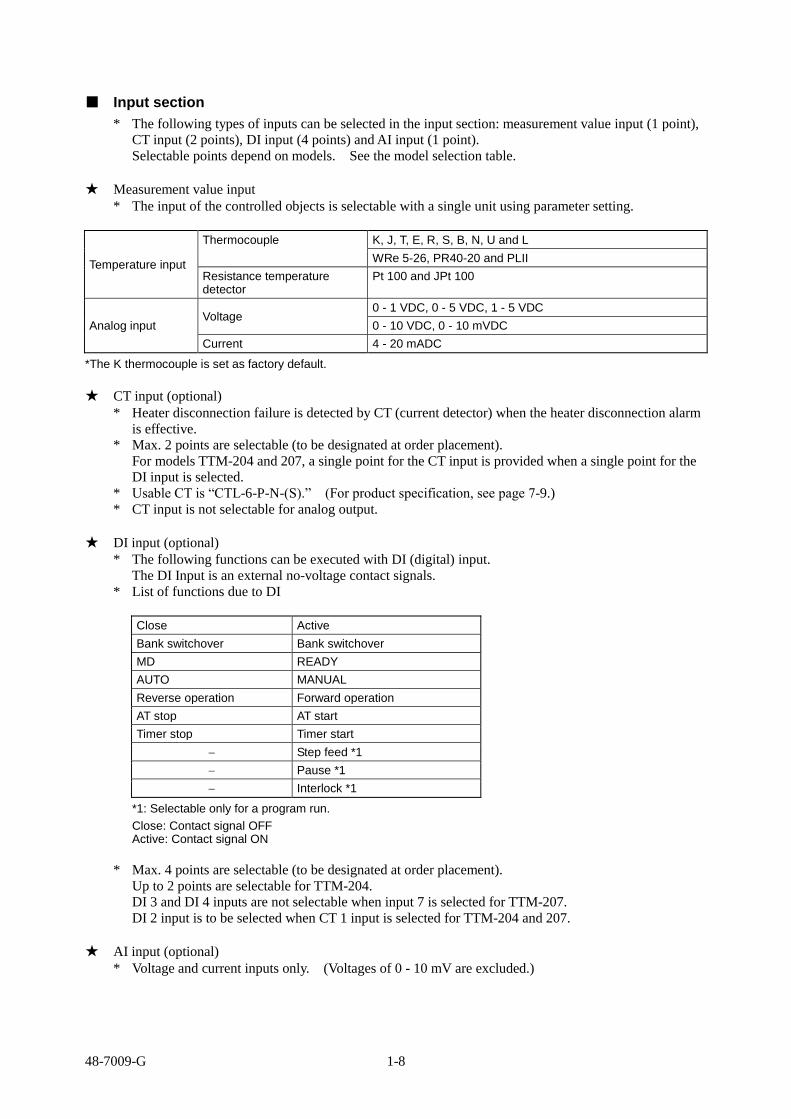
■ Input section
* The following types of inputs can be selected in the input section: measurement value input (1 point),
CT input (2 points), DI input (4 points) and AI input (1 point).
Selectable points depend on models. See the model selection table.
★ Measurement value input
* The input of the controlled objects is selectable with a single unit using parameter setting.
Temperature input
Thermocouple K, J, T, E, R, S, B, N, U and L
WRe 5-26, PR40-20 and PLII
Resistance temperature detector
Pt 100 and JPt 100
Analog input Voltage
0 - 1 VDC, 0 - 5 VDC, 1 - 5 VDC
0 - 10 VDC, 0 - 10 mVDC
Current 4 - 20 mADC
*The K thermocouple is set as factory default.
★ CT input (optional)
* Heater disconnection failure is detected by CT (current detector) when the heater disconnection alarm
is effective.
* Max. 2 points are selectable (to be designated at order placement).
For models TTM-204 and 207, a single point for the CT input is provided when a single point for the
DI input is selected.
* Usable CT is “CTL-6-P-N-(S).” (For product specification, see page 7-9.)
* CT input is not selectable for analog output.
★ DI input (optional)
* The following functions can be executed with DI (digital) input.
The DI Input is an external no-voltage contact signals.
* List of functions due to DI
Close Active
Bank switchover Bank switchover
MD READY
AUTO MANUAL
Reverse operation Forward operation
AT stop AT start
Timer stop Timer start
Step feed *1
Pause *1
Interlock *1
*1: Selectable only for a program run.
Close: Contact signal OFF Active: Contact signal ON
* Max. 4 points are selectable (to be designated at order placement).
Up to 2 points are selectable for TTM-204.
DI 3 and DI 4 inputs are not selectable when input 7 is selected for TTM-207.
DI 2 input is to be selected when CT 1 input is selected for TTM-204 and 207.
★ AI input (optional)
* Voltage and current inputs only. (Voltages of 0 - 10 mV are excluded.)

48-7009-G 1-9
■ Output section
* The number of outputs is 7 at most, which can be assigned individually for control output, event
output, RUN/RDY output, timer output and transmission output.
(Assignment of outputs is to be designated at order placement.)
★ Output (OUT) 1 and output (OUT) 2
* Target connection of output can be set.
Primary output, secondary output, event output, RUN output, RDY output, timer 1 output, timer 2
output, timer 3 output, transmission output and end output
★ Output (OUT) 3, output (OUT) 4, output (OUT) 5, output (OUT) 6 and output (OUT) 7
* Target connection of output can be set.
Primary output, secondary output, event output, RUN output, RDY output, timer 1 output, timer 2
output, timer 3 output and end output
* Some specifications are not selectable, depending on the model. Check them on the model table.
★ Selection of output types
* Outputs 1 and 2
Relay contact 250 VAC, 3 A (resistance loads) and 1a contact
Voltage for SSR drive 0 - 12 VDC (load resistance: 600 or greater)
Open collector 24 VDC, 100 mA (load current)
Voltage 0 - 5 VDC, 1 - 5 VDC and 0 - 10 VDC (resistance loads: 1 k or greater) 0 - 1 VDC and 0 - 10 mVDC (load resistance: 500 k or greater)
Current 4 - 20 mADC (load resistance: 600 or less)
* Outputs 3, 4, 5, 6 and 7
Relay contact 250 VAC, 1 A (resistance loads) and 1a contact
Open collector 24 VDC, 100 mA (load current)
* Transmission output function selection
PV (measurement value) output
SV (setting value) output
MV 1 (primary operating amount) output
MV 2 (secondary operating amount) output
Control SV (setting value) output
Forward and reverse operations can be switched over for all the outputs above.
★ Selectable outputs for each model
Output 1 Output 2 Output 3 Output 4 Output 5 Output 6 Output 7
TTM-204
TTM-205
TTM-207
TTM-209
* TTM-204: Outputs 3 and 4 are for common shared.
* TTM-207: Outputs 3 and 4 are for common shared.
When DI 3 is selected, output 7 will not be selectable.
* TTM-205 and 209: Outputs 3 and 4 are for common shared.

48-7009-G 1-10
★ Assignment of outputs
Each output can freely be assigned to output types.
Type of output Output 1 Output 2 Output 3 Output 4 Output 5 Output 6 Output 7
Primary output (heating)
Secondary output (cooling)
Transmission output
Event output
Timer output
End output *1
○: Output assignment possible ×: Output assignment not possible * At factory shipment, the output 1 is assigned to the primary output, and the outputs 2 to 7 to the secondary outputs. *1: Selectable only for a program run.
★ Details on output assignment targets
Each output can individually be assigned to the following item.
Output assignment targets
Primary output
Secondary output
Event output
RUN output
RDY output
Timer 1 output
Timer 1 ON delay output
Timer 1 OFF delay output
Timer 1 ON+OFF delay output
Timer 2 output
Timer 2 ON delay output
Timer 2 OFF delay output
Timer 2 ON+OFF delay output
Timer 3 output
Timer 3 ON delay output
Timer 3 OFF delay output
Timer 3 ON+OFF delay output
Transmission output
End output *1
*1: Selectable only for a program run.
■ Communication function
★ Communication
* This function is for communication with a host computer. (The communication function option is
required.)
* Communication protocol TOHO protocol
MODBUS protocol (RTU mode)
MODBUS protocol (ASCII mode)
* Interface RS485
* For detailed specifications, see pages 6-65 and 66.
★ Loader communication
* This communication function is for setting all data of TTM-200 series in a lump.
* In order to use the loader communication, the dedicated software for the communication must be
installed on the personal computer (PC) being used.
* To connect TTM-200 series to your PC, TOHO’s dedicated connection cable “TTM-LOADER” (sold
separately) is required.
(For the product specifications, see page 7-9.)
* When normal communication (or communication in option) is used (or active), the loader
communication cannot be used.

48-7009-G 1-11
1.6 Basic flow of setting
Power-on
The mode changes to either “constant value run mode” or “program run mode” when four seconds are elapsed after the power is turned-on.
Initial screen
4 sec
* Constant run value mode is established with the SET 21 operating type setting (C/P 0). In addition, the SET 21 and 22 parameters are not displayed. * With SET 23 bAF 1, the auto bank switchover function is selectable. With bAF 0, the SET 23 parameters are not displayed.
Constant value run mode * All setting item selection screens can move to the constant value run mode screen.
MODE key for 2 seconds
The screen SET 01 appears when the run mode screen moves to each setting item selection screen. Each setting item selection screen
SET 01 - SET 23
* Using the ▲/▼ key, the setting item selection screens SET 01 to SET 23 are displayed in sequence.
(In case of no function registered, the corresponding screen is not displayed.)
(For bank auto-switchover, see page 6-80.)
Blind setting screen
Parameter setting screen in each
SET
* Each parameter setting screen is displayed in sequence when the MODE key is pressed on the parameter setting screen, which is displayed when the MODE key is pressed in each setting item selection screen (SET**). Holding the MODE key pressed for at least 2 seconds moves each parameter setting screen back to the run mode screen.
Program run mode
* Program run mode is established with the SET 21 operating type setting (C/P 0).
* With SET 23 bAF 1, the auto bank switchover function is selectable.
With bAF 0, the SET 23 parameters are not displayed.
MODE key for 2 seconds
Each setting item selection screen SET 01 - SET 23
* Using the ▲/▼ key, the setting item selection screens SET 01 to SET 23 open in sequence.
(In case of no function registered, the corresponding screen is not displayed.)
(For program run, see page 6-73.) (For bank auto-switchover, see page 6-80.)
Blind setting screen
Parameter setting screen in each
SET
* All setting item selection screens can move to the run mode screen.
* Each parameter setting screen is displayed in sequence when the MODE key is pressed on the parameter setting screen, which is displayed when the MODE key is pressed in each setting item selection screen (SET**). Holding the MODE key pressed for at least 2 seconds moves each parameter setting screen back to the run mode screen.
* A shortcut to SET 22 can be made if FU* d is set for the SET 3 function key function setting.
(For details, see pages 6-12 and 13.)
* The screen moves back to the run mode screen in case of no key operation in each setting item selection screen or parameter setting screen in each SET for about 2 minutes.
* For how to set the blind setting, see pages 4-27 and 28, the section 4-2-9 “Basic operation.”

48-7009-G 2-1
2. Installation
Precautions on installation, installation method and outside dimensions are described in this chapter.
2.1 Precautions on installation ..................................................................................................................... 2-2
2.2 How to install or remove the equipment ................................................................................................ 2-3
2.3 Outside dimensions and panel cutting dimensions ................................................................................. 2-4

48-7009-G 2-2
2.1 Precautions on installation
Warning
Ensure to turn the power supply off before beginning removal or reinstallation of the equipment in order to prevent an electric shock or equipment failure.
★ Ambient temperature and humidity (the equipment to be used in the specified range as listed below)
(1) Temperature range: 0 - 50 °C
(2) Humidity range: 20 - 90% PH (no dew condensation allowed)
(3) Installation gradient: Base plane ± 10 degrees
★ Do not install the equipment in the following places.
(1) Where temperature abruptly changes to generate dew
(2) Where corrosive or flammable gases are generated
(3) Where water, oil, steam or chemicals are received
(4) Where vibration or noise is directly applied
(5) Where dusty or salty ambience, or many iron scraps is present
(6) Where direct sunlight is received
(7) Where circuits may negatively be affected by static electricity, noise or magnetism
(8) Where direct warm or cool air is received from an air-conditioner
★ Precautions on installation
(1) Provide sufficient space for ventilation so that the ambient temperature does not rise to 50 °C or
higher. In case that the temperature of 50 °C or higher is suspected, use a fan or air-conditioner to
cool the ambience.
Take care that no cold air flows directly on the equipment.
(2) Do not install the equipment on a device that may generate large heat, such as heater and
transformer.
(3) Install the equipment away as much distant as possible from high-voltage devices, power lines or
power equipment.
(4) Do not block off the ventilation opening on the equipment. Ensure a sufficient gap between
stacked units of equipment.

48-7009-G 2-3
2.2 How to install or remove the equipment
★ Installation on a panel
(1) Make an opening on the panel.
(2) Insert the equipment into the opening.
(3) Install the mounting attachment from behind the panel. Ensure that the equipment is securely
fixed.
* Conduct wiring after the equipment is installed.
* Turn on the power after the wiring.
TTM-204 TTM-205/207/209
★ Removal from the panel
(1) Turn off the power.
(2) Disconnect the wiring.
(3) Insert a flat-head screw driver into the clearance formed between gabs on the equipment and
attachment. Turn the screw driver clockwise or counterclockwise to dislocate the gabs to remove
the attachment from the equipment.
(4) Remove the equipment from the panel.
* Ensure to conduct removal work after turning off the power.
TTM-204 TTM-205/207/209
48-7009-G 2-4
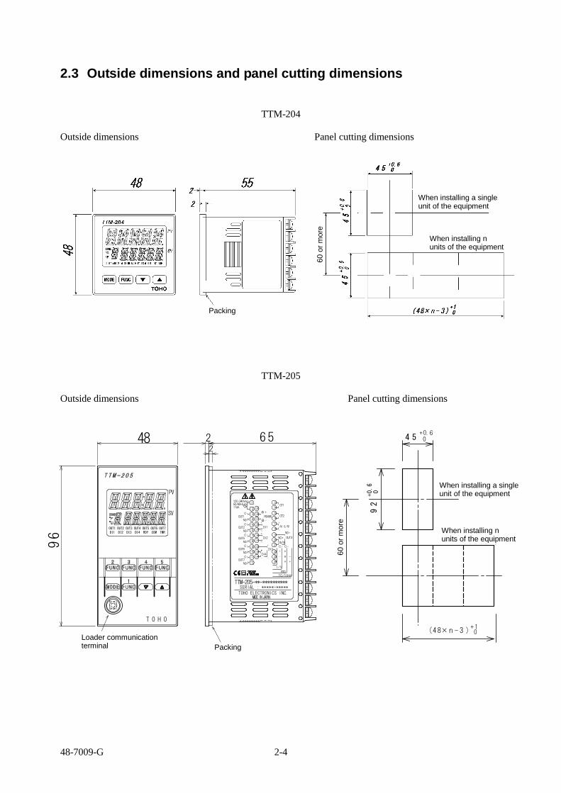
2.3 Outside dimensions and panel cutting dimensions
TTM-204
Outside dimensions Panel cutting dimensions
TTM-205
Outside dimensions Panel cutting dimensions
26 52
1
2
3
4
C-
NO+OUT1
C-
NO+
C-
NO+
C-
NO+
C-
NO+
5
6
7
8
9
10
11
12
MADEINJAPANTOHO ELECTRONICS INC.
++
-DI4
-
+
DI2
34
33
32
31
30
-
+
DI129
28
27
26(A)+
RS485
(B)-
+
-
DI3
+A
I/V
RTD
TC/10mV
+ b
-- B
24
23
22
C-21
20
19
18
17AI(I/V)
CT2
CT1
OUT4
C-
NO+
OUT3NO+
+
-
16
15
14
13
SERIAL : *****-*****
100-240Vac~50/60Hz
T O H O
PV
SV
DI3OUT3
DI2OUT2
DI1OUT1
RDYOUT5
COMOUT6
TMROUT7
DI4OUT4
ローダ通信端子
TTM-205-**-**********
48
96
OUT2
OUT5
OUT6
OUT7
2511VA
パッキン
92+0.6
0
4 5+0.60
1台取付時
n台取付時
(48×n - 3 )+ 10
60以上
When installing a single unit of the equipment
When installing n units of the equipment
Packing 60 o
r m
ore
Packing
Loader communication terminal
When installing a single unit of the equipment
When installing n units of the equipment
60 o
r m
ore

48-7009-G 2-5
TTM-207
Outside dimensions Panel cutting dimensions
TTM-209
Outside dimensions Panel cutting dimensions
パッキン
2652
ローダ通信端子
FUNC5FUNC4
MODE
FUNC2 FUNC3
FUNC1
1
2
100-240Vac~50/60Hz
(A)+
(B)-
3C- +
4NO+ -
C- 5+
NO+
C-
6
7
-
OUT1
OUT2
DI1CT1
DI2CT2
RS485 AI(I/V)
+
-NO+
+ b
C-
-- B
I/V
RTD
TC/10mV
NO+ 8 +A
NO+
C-
OUT4
OUT3
10
11
12
13
14
15
16
17
18
19
20
21
22
23
24
MADEINJAPANTOHO ELECTRONICS INC.SERIAL : *****-*****
TTM-207-**-**********
9
OUT5 OUT7
+
-
NO+
C-
DI3
11VA
DI3DI2DI1
TMRCOMRDY
OUT5OUT4OUT3OUT2OUT1
OUT7
72
48
7 2
0( 7 2× n -3)+ 1
68+0
. 60
68+0 .60
9 0以上
1台取付時
n台取付時
2652
FUNC2
MODE
FUNC3 FUNC4 FUNC5
FUNC1
PV
SV
T O H O
OUT1 OUT2 OUT3 OUT4 OUT5 OUT6 OUT7DI1 DI2 DI3 DI4 RDY COM TMR
ローダ通信端子
1
2
3
4
C-
NO+OUT1
C-
NO+
C-
NO+
C-
NO+
C-
NO+
5
6
7
8
9
10
11
12
MADE IN JAPANTOHO ELECTRONICS INC.
++
-DI4
-
+
DI2
34
33
32
31
30
-
+
DI129
28
27
26(A)+
RS485
(B)-
+
-
DI3
+A
I/V
RTD
TC/10mV
+ b
-- B
24
23
22
C-21
20
19
18
17AI(I/V)
CT2
CT1
OUT4
C-
NO+
OUT3NO+
+
-
16
15
14
13
TTM-209-**-**********SERIAL : *****-*****
100-240Vac~50/60Hz
OUT2
OUT5
OUT6
OUT7
2511VA
パッキン
96
96
120以
上
9 2+0.60
92
+0.6 0 1台取付時
n台取付時
(96× n-3)+10
Packing Loader communication terminal
When installing a single unit of the equipment
When installing n units of the equipment
90 o
r m
ore
Packing Loader communication terminal
When installing a single unit of the equipment
When installing n units of the equipment
120 o
r m
ore

48-7009-G 3-1
3. Wiring
Precautions on wiring and arrangement of terminals are described in this chapter.
3.1 Precautions on wiring ........................................................................................................................... 3-2
3.2 Terminal arrangement ........................................................................................................................... 3-3
3.3 Wiring to each terminal ......................................................................................................................... 3-7
3-4 Examples of wiring ............................................................................................................................. 3-15

48-7009-G 3-2
3.1 Precautions on wiring
Warning
Do not turn on the power until all wirings are complete in order to prevent an electric shock or equipment failure.
★ For inputs from a thermocouple, use the specified wires or compensating leads.
★ For inputs from a resistance temperature detector, use lead wires with small resistance and no resistance
difference is present among the 3 wires (3-wire type).
★ Provide input signal lines away from power supply lines, power lines or load lines so as not to affect input
signal lines with noise induction.
★ Wire the power supply for instruments such that they do not receive noises from the power supply for
power devices.
The use of a noise filter is recommended in case that the equipment is vulnerable to noises.
Take note of the following points when using a noise filter.
◎ Install the noise filter as close to a temperature controller as possible.
Wire the instruments in as short a distance as possible to output lines (secondary side) of the noise
filter and power terminals for the temperature controller.
◎ Isolate the noise filter input line (primary side) from its output line (secondary side).
High-frequency elements of noises may be induced, resulting in no provision of much noise
attenuation effect as expected, in case of input and output wires being close one another, such as
being bundled together or installed in a same duct or tube.
◎ Wire the grounding wire of the noise filter in as short a distance as possible.
A long grounding wire is like inserting an inductance, resulting in deteriorated high-frequency
characteristics.
◎ Before installing the noise filter, peel off the paint applied on a mounting plate of the noise filter as
appropriate, in order to reduce the contact resistance between the noise filter and equipment housing.
★ For the power supply, use and twist wires that cause less voltage drop.
★ It takes about 4 seconds for the unit to activate after its power is turned on. Use delay relays when using
the equipment for generating signals for interlocking circuits.
★ When using the unit with 24 V power supply, supply the power from a SELV circuit (power supply
secured with safety).
★ When using the unit with DC24V power source, set ①-terminal to plus (+), ②-terminal to minus (-).
★ The equipment is not attached with power supply switch fuses. Separately install fuses in proximity of
the equipment, as needed.
◎ Recommended fuse rating: Rated voltage of 250 V and rated current of 1 A
★ Use crimping terminals that match the screw sizes.
◎ Size of crimping terminal: Terminal width of 6 mm or smaller
Crimping terminal recommended
Manufacturer: NICHIFU
Model: ICTV-1.25Y-3N (Y terminal)
ICTV-1.25-3S (round terminal)
◎ Tightening torque recommended: 0.5 Nm (5 kgfm)
◎ Applicable wire
Use wires in sizes suitable for the terminals.
The use of shielded wires is recommended.
For Pt100 (resistance temperature detector), use identical wires of low lead resistance and no
resistance difference among 3 wires.
★ For the communication ,use a shielded twisted pair cable.
3.7
5.8

48-7009-G 3-3
3.2 Terminal arrangement
Notation for terminal arrangement is as follows.
C: Common
NO: Normal open
+, -: There is polarity for wiring.
A, B, b: There is designation for wiring.
CT: Current transformer input (no polarity)
DI: Digital input
RTD: Resistance temperature detector input
TC: Thermocouple input
I: Current input
V: Voltage input (excluding 0 - 10 mV)
* Parameters can be used for changing input types. (Multi-input)
* “NO” and “C” for outputs are for the equipment model with relay contact output. “+” and “-” for
other than the equipment model with relay contact output.
* Terminal block is not provided in case the model selection is not made at the product model.
★ TTM-204
* Outputs 3 and 4 are for common (C) shared
Relay Open collector
① ⑬ ⑦ NO +
Input power supply
② ⑭ ⑧ NO +
Output 4
- C ③ ⑮ ⑨ C -
Output 1
+ NO ④ ⑯ ⑩ b +
- C ⑤ ⑰ ⑪ B - -
Output 2
+ NO ⑥ ⑱ ⑫ A +
Relay RTD input TC input Analog input
0 - 10 mV input
Output 3
Other than
relay output
A ⑬ A ⑬ A ⑬
RS-485 RS-485 RS-485
B ⑭ B ⑭ B ⑭
⑮ ⑮ ⑮
CT 1 input DI 1 input CT 1 input
⑯ ⑯ ⑯
⑰ ⑰ ⑰
CT 2 input DI 2 input DI 2 input
⑱ ⑱ ⑱
* Only the above can be selected
for the model with CT and DI.
Specifications for communication
and 2 points of CT
Specifications for communication
and 2 points of DI
Specifications for communication,
1 point of CT and 1 point of DI
Main body rear surface terminals
+
+ +
-
- -

48-7009-G 3-4
★ TTM-207
Input power supply
Output 1
Output 2
Output 5
Other than
relay output
Relay
(The output 5 is only for an open collector.)
AI input (models in voltage and current)
Output 3
Output 4
Relay Open collector
* Outputs 3 and 4
are for common
(C) shared
RTD input TC input
0 - 10 mV input
Analog input
Main body rear surface terminals

48-7009-G 3-5
Communication + 2 points of CT + Output 7 Communication + 3 points of DI
CT 1 input
CT 2 input
Output 7
Open collector Relay
NO
DI 1 input
DI 2 input
DI 3 input
Communication + 1 point of CT + 1 point of Communication + 1 point of CT +
DI + Output 7 2 points of DI
CT 1 input
DI 2 input
Output 7
Open collector Relay
NO
CT 1 input
DI 2 input
DI 3 input
RS-485 RS-485
+
+
+
+ +
+
-
-
-
-
-
-
+
-
NO
C
+
-
NO
C

48-7009-G 3-6
★ TTM-205/209
Other than
relay output
Relay
Input power supply
Output 1
Output 2
Output 5
Output 6
Output 7
AI input (models in voltage and current)
Relay Open collector
* Outputs 3 and 4 are for common (C) shared
Output 3
Output 4
RTD input TC input
0 - 10 mV input
Analog input
CT 2 input
CT 1 input
Communication + DI
DI 1 input
DI 2 input
DI 3 input
DI 4 input
Main body rear surface terminals
+
+
+
+
-
-
-

48-7009-G 3-7
3.3 Wiring to each terminal
In connection diagrams, left side of the terminal number represents inside the equipment while right side
shows the external side of the equipment.
★ Power supply
TTM-204
Terminal Nos. ① and ② TTM-205
TTM-207
TTM-209
TTM-204
Type of power supply Fluctuation range Frequency Power consumption
100 to 240 VAC 85 to 264 VAC 50/60 Hz 10 VA or less
24 VAC 21.6 to 26.4 VAC 50/60 Hz 4 W or less
24 VDC 21.6 to 26.4 VDC 4 W or less
TTM-205/207/209
Type of power supply Fluctuation range Frequency Power consumption
100 to 240 VAC 85 to 264 VAC 50/60 Hz 11 VA or less
24 VAC 21.6 to 26.4 VAC 50/60 Hz 6 W or less
24 VDC 21.6 to 26.4 VDC 6 W or less
* Wire the power supply for instruments in such a way that they don’t receive noise from the power supply of the power devices.
The use of a noise filter is recommended in case that the equipment is vulnerable to noises. Take care the following when a noise filter is used.
◎ Install the noise filter as close to a temperature controller as possible. Wire the instruments in as short a distance as possible to output lines (secondary side) of the noise filter and
power terminals for the temperature controller. ◎ Isolate the noise filter input line (primary side) from its output line (secondary side). High-frequency elements of noises may be induced, resulting in no provision of much noise attenuation effect as
expected, in case of input and output wires being close one another, such as being bundled together or installed in a same duct or tube.
◎ Wire the grounding wire of the noise filter in as short a distance as possible. A long grounding wire is equivalent to insert of an inductance, resulting in deteriorated high-frequency
characteristics. ◎ Before installing the noise filter, peel off the paint applied on a mounting plate of the noise filter as appropriate, in
order to reduce the contact resistance between the noise filter and equipment housing.
* For the power supply, use and twist wires that has lesser voltage drop.
* It takes about 4 seconds for the unit to activate after its power is turned on. Use delay relays when
using the equipment for generating signals for interlocking circuits.
* In case of using the equipment with a 24 V power supply, supply the power from a SELV circuit
(power supply secured with safety).
* The equipment is not supplied with power supply switch fuses. Separately install fuses in proximity
of the equipment, as needed.
◎ Recommended fuse rating: Rated voltage of 250 V and rated current of 1A
* The input power supply and the input/output are isolated one anther on the equipment.
* Isolation diagram Where relays and open collectors are included in outputs
Where outputs are SSRs, current outputs or voltage outputs
Power supply circuit Power supply circuit
PV input
CPU circuit
Output 1 PV input
CPU circuit
Output 1
AI input Output 2 AI input Output 2
CT input Outputs 3 to 7 CT input Outputs 3 to 7
DI Communication DI Communication
* No. of outputs depends on specifications and models. Isolated * Outputs 3 to 7 are isolated. ------ Non-isolated

48-7009-G 3-8
★ Input
TTM-204 Terminal Nos. ⑩, ⑪ and ⑫ * Use sensors that match the types of inputs. (“K thermocouple” is set as factory default.) * For thermocouple input, use wires or compensated
leads. * For input from resistance temperature detector, use
wires that the wire resistance of leads is small and no resistance difference is present among 3 wires (3-wire type).
* Provide input signal lines distant from power supply lines, power lines or load lines so as not to affect input signal lines with noise induction.
TTM-205 Terminal Nos. ○22 , ○23 and ○24
TTM-207 Terminal Nos. ⑭, ⑮ and ⑯
TTM-209 Terminal Nos. ○22 , ○23 and ○24
Thermocouple 0 - 10 mV Resistance temperature detector Analog input
TTM-204
Thermocouple 0 - 10 mV Resistance temperature detector Analog input
TTM-205/209
Thermocouple 0 - 10 mV Resistance temperature detector Analog input
TTM-207

48-7009-G 3-9
★ AI input (current and voltage only)
TTM-205 Terminal Nos. ⑰ and ⑱
TTM-207 Terminal Nos. ⑨ and ⑩
TTM-209 Terminal Nos. ⑰ and ⑱
TTM-207 TTM-205/209
* AI input is optional.
(TTM-204 is not equipped with AI input.)
* Provide input signal lines distant from power supply lines, power lines or load lines so as not to affect
input signal lines with noise induction.
★ CT (current detector) input
TTM-204 Terminal Nos. ⑮, ⑯, ⑰ and ⑱
TTM-205 Terminal Nos. ⑬, ⑭, ⑮ and ⑯
TTM-207 Terminal Nos. ⑲, ⑳, ○21 and ○22
TTM-209 Terminal Nos. ⑬, ⑭, ⑮ and ⑯
* When the event input (DI 1 or
DI 2) is selected, CT 1 or CT 2
are not selectable.
* When the event input (DI 2) is
selected, CT 2 is not selectable.
* When the event input (DI 1 or
DI 2) is selected, CT 1 or CT 2
are not selectable.
* When the event input (DI 2) is
selected, CT 2 is not selectable.
TTM-204
TTM-207 TTM-205/209
* CT input is optional.
* Heater disconnection failure is detected by CT (current detector) when the heater disconnection alarm
is effective.
* CT possible to be used is “CTL-6-P-N”
* Max. 2 points are selectable (to be designated at order placement).
* CT input is not selectable for analog output.

48-7009-G 3-10
★ Event (DI) input
TTM-204 Terminal Nos. ⑮, ⑯, ⑰ and ⑱
TTM-205 Terminal Nos. ○28 , ○29 , ○30 , ○31 , ○32 , ○33 and ○34
TTM-207 Terminal Nos. ⑲, ⑳, ○21 , ○22 , ○23 and ○24
TTM-209 Terminal Nos. ○28 , ○29 , ○30 , ○31 , ○32 , ○33 and ○34
* When CT 1 or CT 2 is
selected, DI 1 or DI 2 are not
selectable.
* When CT 1 is selected, DT 1
is not selectable.
* When CT 1 or CT 2 is
selected, DI 1 or DI 2 is not
selectable.
* When CT 1 is selected, DI 1 is
not selectable.
* When the output 7 is selected,
DI 3 is not selectable.
TTM-204
TTM-207 TTM-205/209
* For TTM-205/209, the common for
DI 3/DI 4 is shared.
* DI input is optional.
* Max. 4 points are selectable (to be designated at order placement).
* The following functions can be executed through the DI (digital) inputs.
The DI inputs are external no-voltage contact signals.
* List of functions due to DI
Close Active
Bank switchover Bank switchover
During constant value run MD READY
During program run Start Stop
MD MANUAL
Reverse operation Forward operation
AT stop AT start
Timer Stop Timer Stop
Constant value run Program run
Step feed (during program run) *1
Pause (during program run) *1
Interlock *1
*1: Selectable only for a program run.
Close: Contact signal OFF Active: Contact signal ON
-
-
-
-
-
-
-
-
+
+
+
+
+
+
+
+
+

48-7009-G 3-11
★ Communication function
TTM-204 Terminal Nos. ⑬ and ⑭
TTM-205 Terminal Nos. ○26 and ○27
TTM-207 Terminal Nos. ⑰ and ⑱
TTM-209 Terminal Nos. ○26 and ○27
Communication
TTM-204 TTM-207 TTM-205/209
Communication Communication
* There are two types of communication functions, the “communication” and “loader communication”.
The “Communication” is optional.
★ Communication
* This function is for communication with a host computer. (The communication function option is
required.)
* Communication protocol
TOHO protocol
MODBUS protocol (RTU mode)
MODBUS protocol (ASCII mode)
* Interface
RS485
★ Loader communication
* This communication function is for setting all data of TTM-200 series in a lump.
* In order to use the loader communication, the dedicated software for the communication must be
installed on the personal computer (PC) being used.
* To connect TTM-200 series to your PC, TOHO’s dedicated connection cable “TTM-LOADER” (sold
separately) is required.

48-7009-G 3-12
★ Output
Model Terminal No.
Output 1 Output 2 Output 3 Output 4 Output 5 Output 6 Output 7
TTM-204 ③ and ④ ⑤ and ⑥ ⑦ and ⑨ ⑧ and ⑨
TTM-205 ③ and ④ ⑤ and ⑥ ⑲ and ○21 ⑳ and ○21 ⑦ and ⑧ ⑨ and ⑩ ⑪ and ⑫
TTM-207 ③ and ④ ⑤ and ⑥ ⑪ and ⑬ ⑫ and ⑬ ⑦ and ⑧ ○23 and ○24
TTM-209 ③ and ④ ⑤ and ⑥ ⑲ and ○21 ⑳ and ○21 ⑦ and ⑧ ⑨ and ⑩ ⑪ and ⑫
Assignment of outputs
Type of output Output 1 Output 2 Output 3 Output 4 Output 5 Output 6 Output 7
Primary output (heating)
Secondary output (cooling)
Transmission output
Event output
Timer output
End output
: Output assignment possible : Output assignment not possible
Type of output and specification
* Outputs 1 and 2
Relay contact 250 VAC, 3 A (resistance loads) and 1a contact
Voltage for SSR drive 0 - 12 VDC (load resistance: 600 or greater)
Open collector 24 VDC, 100 mA (load current)
Voltage 0 - 5 VDC, 1 - 5 VDC and 0 - 10 VDC (resistance loads: 1 k or greater) 0 - 1 VDC and 0 - 10 mVDC (load resistance: 500 k or greater)
Current 4 - 20 mADC (load resistance: 600 or less)
* Outputs 3, 4, 5, 6 and 7
Relay contact 250 VAC, 1 A (resistance loads) and 1a contact
Open collector 24 VDC, 100 mA (load current)
TTM-204
Output 1 Output 2
Outputs 3 and 4
Relay SSR/current/voltage/
open collector
Relay SSR/current/voltage/
open collector
* Outputs 3 and 4 are for common shared
Relay Open collector

48-7009-G 3-13
TTM-207
Output 1 Output 2
Outputs 3 and 4 Output 5
Relay
Output 7
SSR/current/voltage/
open collector
Relay SSR/current/voltage/
open collector
Relay Open collector Relay Open collector
* Outputs 3 and 4 are for common shared
Relay Open collector

48-7009-G 3-14
TTM-205/209
Output 1 Output 2
Outputs 3 and 4 Output 5
Relay
Output 6
SSR/current/voltage/
open collector
Relay SSR/current/voltage/
open collector
Relay Open collector Relay Open collector
* Outputs 3 and 4 are for common shared
Relay Open collector
Output 7
Relay Open collector
○19
○20
○21
* Max. 7 points of outputs are provided. They are usable for control output, event output, RUN/RDY
output, transmission output, and timer outputs (3 points).
They should be designated at order placement. See the model table on page 1-3.
* No. of outputs selectable depends on models. In the table “★ Output” on page 3-12, cells filled
with diagonal lines indicate that none is selectable. Selection can also be checked on the model table
on page 1-3.
* “NO” and “C” for outputs are for the equipment model of relay contact output. “+” and “-” for
outputs are for other than the equipment model of relay contact output. Properly wire outputs to
target connections, as target connections are designated.
(Take sufficient care the polarity “+” and “-” when wiring.)

48-7009-G 3-15
3-4 Examples of wiring
1) Input: K thermocouple, output 1: relay contact output and single phase 100 V
Temperature sensor
(K thermocouple)
External relay
Heater
★ Connection configuration
★ Configuration example
TTM-204
Heater
External relay
K thermocouple
* Take care when wiring, as thermocouple
has polarity of “+” and “-.”
Power supply
(Example) TTM-204
Power supply
Terminal description for the above wiring example
Terminal No. Description
① Power supply
②
③ Output 1
Common
④ Normal open
⑤ Output 2 Not used in this case.
⑥
⑦ Output 3
Output 4 Not used in this case. ⑧
⑨
⑩
Input
Not used in this case.
⑪ “-” side
⑫ “+” side
⑬ Communication Not used in this case.
⑭
⑮
CT or DI input Not used in this case. ⑯
⑰
⑱

48-7009-G 3-16
2) Input: resistance temperature detector, output 1: SSR drive voltage and single phase 100 V
★ Configuration example
Temperature sensor
(resistance
temperature detector)
(Example) TTM-209
TTM-209
Heater
★ Connection configuration
Power supply
Heater
Resistance temperature
detector
* Take care wiring, as “A,” “B” and “b” are
designated on a resistance temperature detector.
TRS1245
SSR
Power supply
Terminal description for the above wiring example
Terminal No.
Description Terminal
No. Description
① Power supply
⑲ Output 3
Output 4 Not used in this case. ② ⑳
③ Output 1
“-” side ○21
④ “+” side ○22
Input
b
⑤ Output 2 Not used in this case.
○23 B
⑥ ○24 A
⑦ Output 5 Not used in this case.
○25 This terminal is not used.
⑧ ○26 Communication Not used in this case.
⑨ Output 6 Not used in this case.
○27
⑩ ○28
DI input Not used in this case.
⑪ Output 7 Not used in this case.
○29
⑫ ○30
⑬
CT input Not used in this case.
○31
⑭ ○32
⑮ ○33
⑯ ○34
⑰ AI input Not used in this case.
⑱

48-7009-G 3-17
3) Input: resistance temperature detector, output 1: SSR drive voltage and 3-phase 200 V
Temperature sensor
(resistance temperature
detector)
(Example) TTM-204
* Usable SSR in 3-pahse 200 V is a product
with the input current of 10 mA or less.
Heater
★ Connection configuration
★ Configuration example
Heater
* Take care when wiring,
as SSR has polarity of
“+” and “-.”
* Take care wiring, as “A,” “B”
and “b” are designated on a
resistance temperature detector.
Power supply
Resistance temperature
detector
-
SSR
+
-
SSR
+
Power supply
Terminal description for the above wiring example
Terminal No. Description
① Power supply
②
③ Output 1
“-” side
④ “+” side
⑤ Output 2 Not used in this case.
⑥
⑦ Output 3
Output 4 Not used in this case. ⑧
⑨
⑩
Input
b
⑪ B
⑫ A
⑬ Communication Not used in this case.
⑭
⑮
CT or DI input Not used in this case. ⑯
⑰
⑱
* SSR may be shorted out
due to its internal failure.
The use of “temperature
fuses” or an
“over-temperature
prevention device” is
recommended to cut off the
output circuit of SSR.

48-7009-G 3-18
4) Input: K thermocouple, output 1: SSR drive voltage, output 2: relay contact output and single phase 100
V (heating/cooling control)
Temperature sensor
(K thermocouple)
★ Configuration example
(Example) TTM-205
External relay
Refriger- ator
Heater
Power supply
★ Connection configuration
* SSR may be shorted out due to its internal failure. The use of temperature
fuses or an over-temperature prevention device is recommended to cut off
the output circuit of SSR.
K thermocouple
* Take care when wiring,
as thermocouple has
polarity of “+” and “-.”
Refriger- ator
External relay
Heater
TRS1245
Power supply
Terminal description for the above wiring example
Terminal No.
Description Terminal
No. Description
① Power supply
⑲ Output 3
Output 4 Not used in this case. ② ⑳
③ Output 1
“-” side ○21
④ “+” side ○22
Input
Not used in this case.
⑤ Output 2
Common ○23 “-” side
⑥ Normal open ○24 “+” side
⑦ Output 5 Not used in this case.
○25 This terminal is not used.
⑧ ○26 Communication Not used in this case.
⑨ Output 6 Not used in this case.
○27
⑩ ○28
DI input Not used in this case.
⑪ Output 7 Not used in this case.
○29
⑫ ○30
⑬
CT input Not used in this case.
○31
⑭ ○32
⑮ ○33
⑯ ○34
⑰ AI input Not used in this case.
⑱

48-7009-G 3-19
5) Input: K thermocouple, output 1: relay contact output, output 2: transmission output and single phase
100 V
★ Configuration example
(Example) TTM-204
TTM-204
Temperature sensor
(K thermocouple)
External relay
Heater
Recorder
★ Connection configuration
External relay
Heater
K thermocouple
* Take care when wiring, as
thermocouple has polarity of “+”
and “-.”
Power supply
Power supply
Terminal description for the above wiring example
Terminal No. Description
① Power supply
②
③ Output 1
Common
④ Normal open
⑤ Output 2
“-” side
⑥ “+” side
⑦ Output 3
Output 4 Not used in this case. ⑧
⑨
⑩
Input
Not used in this case.
⑪ “-” side
⑫ “+” side
⑬ Communication Not used in this case.
⑭
⑮
CT or DI input Not used in this case. ⑯
⑰
⑱

48-7009-G 4-1
4. Basic operation
Basic operation is described in this chapter.
4.1 Flow of setting mode .............................................................................................................................. 4-2
4.2 Basic operation ....................................................................................................................................... 4-4
4.2.1 Switchover of parameters (flow as a whole) .................................................................................. 4-4
4.2.2 Description of setting item selection screen ................................................................................. 4-19
4.2.3 Setting of input types ................................................................................................................... 4-20
4.2.4 Setting of key functions ............................................................................................................... 4-21
4.2.5 How to set the SV limiter setting ................................................................................................. 4-22
4.2.6 How to set control types ............................................................................................................... 4-23
4.2.7 How to set outputs ........................................................................................................................ 4-25
4.2.8 How to set priority screens ........................................................................................................... 4-26
4.2.9 Switchover to the blind setting mode ........................................................................................... 4-27
4.2.10 Switchover to the ON/OFF control .............................................................................................. 4-29

48-7009-G 4-2
4.1 Flow of setting mode
PROG25
025
0I NP1
The equipment does not operate for
about 4 seconds after power-on.
At SET 21 program mode setting
In (C/P = 0) constant value run mode
Power-on
Initial screen
Constant value run mode screen
4 seconds 4 seconds
At SET 21 program mode setting
In (C/P 0) program run mode
Program run mode screen
The following is possible in this mode: display of PV value
(present value), setting of SV value (setting value) which is
the target value of control, display of remaining time
monitor for timer 1, 2 and 3, display of priority screens 1 to
16, display of the bank No. that is presently set and various
functions in effect (output, CT, communication, DI, AI, etc.)
The following is possible in this mode: display of PV
value (present value), program run status for SV value,
display of remaining time monitor for timer 1, 2 and 3,
display of priority screens 1 to 16, display of the bank
No. that is presently set and various functions in effect
(output, CT, communication, DI, AI, etc.)
MODE key for 2 seconds
At SET 21 program mode setting
Transition is made one another
according to the C/P setting.
MODE key for 2 seconds
Setting item selection screen (SET 01 - SET 23) (See the page 6-1 and thereafter.)
Various parameters regarding SET 01 - SET 23 are set.
SET 21 and 22 are settings for the program run.
MODE key
Parameter setting screen in each SET
Various parameters are set. (See pages 6-2 to 6-xx.)
* Using the MODE key, parameter screens for each setting mode is disp layed in sequence, and the screen
returns to the SET** screen.
* Using the ▲/▼ key, the setting item selection screens SET 01 to SET 23 is displayed in sequence.
(In case of no function registered, the corresponding screen is not displayed.)
(For program run mode, see pages 6-73 to 6-xx.)
* The screen moves back to the operating mode screen when holding the MODE key pressed for 2 seconds in
parameter screens for each SET screen.
Blind setting screen The screen for setting items to be “blinded”
(non-displayed) by using parameters appears.
For details, see pages 4-27 and 28.
MODE key for 10 seconds
MODE key for 10 seconds
★ No key operation for about 2 minutes automatically moves the screen back to the operating mode screen.
★ If a function is not specified, corresponding SET screen is not displayed.
★ Holding the MODE key pressed for at least 2 seconds moves the setting item selection screen back to the
operating mode screen or vice versa.
★ Use the ▲/▼ key to move the parameter setting screens.
★ Use the MODE key to move each parameter setting screen.

48-7009-G 4-3
■ Initial screen
The input type number is displayed right after the power turns on, and in 4 seconds, the run mode screen is
displayed.
Initial screen
Parameter for input display
Input type No.
(“0” is set at factory shipment.)
4 seconds
0I NP1
025
Constant value run
PV value (present value)
SV value (target value)
Power-on
At SET 21 program mode setting
A (C/P 0) program run mode is established.
Initial screen
Parameter for input display
Input type No.
(“0” is set at factory shipment.)
4 seconds
0I NP1
Program run mode screen
PV value (present value)
SV value (PROG)
Power-on
PROG25
Input type No. and input type
No. Input type
0 K thermocouple
1 J thermocouple
2 T thermocouple
3 E thermocouple
4 R thermocouple
5 S thermocouple
6 B thermocouple
7 N thermocouple
8 U thermocouple
9 L thermocouple
10 WRe5-26 thermocouple
11 PR40-20 thermocouple
12 PLII thermocouple
13 Pt100
14 JPt100
15 0 - 10 mVDC
16 0 - 1 VDC
17 0 - 5 VDC
18 1 - 5 VDC
19 0 - 10 VDC
20 4 - 20 mADC

48-7009-G 4-4
4.2 Basic operation
Flow of each setting item selection screen and each setting mode is described.
4.2.1 Switchover of parameters (flow as a whole)
* The ▲/▼ key is used for switching over setting item selection screens. * The MODE key is used for switching over screens in each setting mode.
The screen loops back to the setting item selection screen. * Some mode screens are not displayed, depending on product specifications.
Operating mode
MODE key held pressed for 2 seconds
Input 1 setting mode
Key function setting mode
Control setting mode
OUT 1 setting mode
Bank setting mode
MODE key
S04-51
MODE key MODE key
▲key ▼key
Input 2 setting mode
MODE key MODE key MODE key
▲key ▼key
▲key ▼key
▲key ▼key
▲key ▼key
▲key ▼key
▲key ▼key
MODE key MODE key
MODE key MODE key MODE key
MODE key MODE key MODE key
MODE key MODE key MODE key
MODE key
MODE key
Program run function setting
* Setting parameters of SET 21 C/P or after and those of SET 22 are not displayed if SET 21 C/P 0.
For details, see pages 6-13 and 14.
Bank auto-switchover function setting
* Setting parameters of SET 23 are not displayed if SET 23 bAF 0. For details, see page 6-15.
* Nos. located in upper left of each parameter screen is identical to the Nos. for items in each parameter screen.
Notation example S20-1: First item in the parameter screen SET 20.

48-7009-G 4-5
Flow of each setting mode Constant value run mode SET21 program mode setting A (C/P = 0) constant value run mode is established.
1. PV/SV screen
2. Timer 1 monitor
3. Timer 2 monitor
4. Timer 3 monitor
5. Priority screen 1 (The priority screens
from 1 to 16 displayed in sequence)
20. Priority screen 16
To item 1
Program run mode SET21 program mode setting A (C/P = 1) program run mode is established.
To item 1
MODE key
MODE key
MODE key
MODE key
MODE key
1. Program run screen
2. Step SV value screen
3. Step time monitor
4. Program run start/stop screen
5. Timer 1 monitor
6. Timer 2 monitor
7. Timer 3 monitor
8. Priority screen 1 (The priority screens from 1 to16 displayed in sequence)
23. Priority screen 16
MODE key
MODE key
MODE key
MODE key
MODE key
MODE key
MODE key
MODE key

48-7009-G 4-6
SET 1: Input 1 setting mode
0. Setting item selection screen
1 Input 1 type setting
2. Scaling upper limit setting * Displayed with current/voltage
input.
3. Scaling lower limit setting * Displayed with current/voltage
input.
5. PV compensation gain setting * Displayed during PV gain zero
point compensation.
4. PV compensation function setting *1
6. PV compensation zero setting * Displayed during PV gain zero
point compensation.
7. Lower limit setting before PV compensation
* Displayed during PV X-Y 2-point compensation
To SET 01, item 9
8. Upper limit setting before PV compensation
* Displayed during PV X-Y 2-point compensation
9. Lower limit setting after PV compensation
* Displayed during PV X-Y 2-point compensation
10. Upper limit setting after PV compensation
* Displayed during PV X-Y 2-point compensation
11. Input filter setting
12. Decimal point setting
To SET 01, item 0
*1: PV compensation function setting When (PVF1 0) is selected, select PV gain zero point compensation. When (PVF1 1) is selected, select PV X-Y 2-point compensation. For details, see pages 6-4 to 6-6.
MODE key
MODE key
MODE key
MODE key
MODE key
MODE key
MODE key
MODE key
MODE key
MODE key
MODE key
MODE key

48-7009-G 4-7
SET 2: Input 2 setting mode
1. Input 2 type setting
2. Scaling upper limit setting * Displayed with
current/voltage input.
3. Scaling lower limit setting * Displayed with
current/voltage input.
5. PV compensation zero setting
4. PV compensation gain setting
6. Input filter setting
7. Local/remote switchover
To SET 02, item 0
0. Setting item selection screen
SET 3: Key function setting mode
0. Setting item selection screen
1. Function key 1 function setting
2. Function key 2 function setting
3. Function key 3 function setting
4. Function key 4 function setting
5. Function key 5 function setting
6. Key lock setting mode
To SET 03, item 0

48-7009-G 4-8
SET 4: Control setting mode
0. Setting item selection screen
1. Bank setting
3. Control setting
4. SV limiter upper limit setting
5. SV limiter lower limit setting
6. Control mode setting
7. Control type setting
8. PID control type setting
9. Type B mode setting
10. Forward/reverse operation setting
To S04-11
To S04-21
11. Primary control operating amount
12. Primary control output gain setting
13. Tuning type setting
14. AT coefficient setting
15. AT sensitivity setting
16. AT start screen
17. Proportional band setting
18. Integral time setting
19. Derivative time setting
20. Primary control proportional cycle
Initial value Relay: 20 seconds SSR: 2 seconds
Continued to the next page
2. Bank upper limit setting
MODE key MODE key
MODE key MODE key
MODE key MODE key
MODE key MODE key
MODE key MODE key
MODE key MODE key
MODE key MODE key
MODE key MODE key
MODE key MODE key
MODE key MODE key
MODE key

48-7009-G 4-9
21. Anti-reset windup
22. Setting of primary control operation amount limiter upper
23. Setting of primary control operation amount limiter lower limit
24. Setting of primary control operation amount change rate limiter ascending
25. Setting of primary control operation amount change rate limiter descending
26. Setting of primary controller soft start output
27. Setting of primary controller soft start time
28. Setting of primary control operation amount at fault
29. Setting of primary control loop anomaly PV threshold
31. Setting of primary control loop anomaly PV threshold
30. Setting of primary control operation amount at fault and control amount threshold
32. Setting of primary control loop fault time
33. Setting of primary control OFF point position selection
34. Setting of primary control sensitivity
35. Setting of primary control OFF point position
36. Primary control safeguard off timer (0 to 99 minutes)
37. Primary control safeguard on timer (0 to 99 minutes)
38. Secondary control operation amount
39. Setting of secondary control output gain
40. Setting of secondary control proportional band
(0.10 to 10.00 times)
41. Setting of secondary control proportional interval
To S04-32
MODE key
To S04-42
MODE key
MODE key MODE key
MODE key MODE key
MODE key MODE key
MODE key MODE key
MODE key MODE key
MODE key MODE key
MODE key MODE key
MODE key MODE key
MODE key
MODE key
MODE key
Continued to the next page

48-7009-G 4-10
42. Setting of secondary control operation amount limiter upper limit
To S04-52
MODE key
43. Setting of secondary control operation amount limiter lower limit
44. Setting of secondary control operation amount change rate limiter ascending
45. Setting of secondary control operation amount change rate limiter descending
46. Setting of secondary control operation amount at fault
47. Setting of secondary control loop anomaly PV threshold
48. Setting of secondary control loop anomaly MV threshold
49. Setting of secondary control loop anomaly PV change threshold
50. Setting of secondary control loop fault time
51. Setting of secondary control sensitivity
52. Setting of secondary control OFF point position
53. Secondary control safeguard off timer (0 to 99 minutes)
54. Secondary control safeguard on timer (0 to 99 minutes)
55. Setting of manual reset
56. Setting of dead band
57. Setting of Ramp time
58. Setting of valve motor stroke time
59. Setting of valve motor drive dead band
60. Initial open ratio after AT completion
To SET 04, item 0
MODE key
MODE key MODE key
MODE key MODE key
MODE key MODE key
MODE key MODE key
MODE key MODE key
MODE key MODE key
MODE key MODE key
MODE key
MODE key
MODE key

48-7009-G 4-11
SET 5: OUT 1 setting mode
0. Setting item selection screen
1. Target connection setting
2. Event function 1 setting
3. Event upper limit setting
4. Event lower limit setting
5. Event sensitivity setting
6. Event delay timer setting
7. Event function 2 setting (PV abnormality)
8. Event function 3 setting (CT abnormality)
9. Event function 4 setting (Loop abnormality)
To S05-10
To SET 05, item 0
10. Event polarity setting
11. Transmission output function setting
12. Transmission scaling upper limit setting
13. Transmission scaling lower limit setting
MODE Key

48-7009-G 4-12
SET 6: OUT 2 setting mode
0. Setting item selection screen
1. Target connection setting
2. Event function 1 setting
3. Event upper limit setting
4. Event lower limit setting
5. Event sensitivity setting
6. Event delay timer setting
7. Event function 2 setting (PV abnormality)
8. Event function 3 setting (CT abnormality)
9. Event function 4 setting (Loop abnormality)
To S06-10
To SET 06, item 0
10. Event polarity setting
11. Transmission output function setting
12. Transmission scaling upper limit setting
13. Transmission scaling lower limit setting

48-7009-G 4-13
0. Setting item selection screen
1. Target connection setting
2. Event function 1 setting
3. Event upper limit setting
4. Event lower limit setting
5. Event sensitivity setting
6. Event delay timer setting
7. Event function 2 setting (PV abnormality)
8. Event function 3 setting (CT abnormality)
9. Event function 4 setting (Loop abnormality)
To SET 07, item 0
10. Event polarity setting
SET 7: OUT 3 setting mode
0. Setting item selection screen
1. Target connection setting
2. Event function 1 setting
3. Event upper limit setting
4. Event lower limit setting
5. Event sensitivity setting
6. Event delay timer setting
7. Event function 2 setting (PV abnormality)
8. Event function 3 setting (CT abnormality)
9. Event function 4 setting (Loop abnormality)
To SET 08, item 0
10. Event polarity setting
SET 8: OUT 4 setting mode

48-7009-G 4-14
0. Setting item selection screen
1. Target connection setting
2. Event function 1 setting
3. Event upper limit setting
4. Event lower limit setting
5. Event sensitivity setting
6. Event delay timer setting
7. Event function 2 setting (PV abnormality)
8. Event function 3 setting (CT abnormality)
9. Event function 4 setting (Loop abnormality)
To SET 09, item 0
10. Event polarity setting
SET 9: OUT 5 setting mode
0. Setting item selection screen
1. Target connection setting
2. Event function 1 setting
3. Event upper limit setting
4. Event lower limit setting
5. Event sensitivity setting
6. Event delay timer setting
7. Event function 2 setting (PV abnormality)
8. Event function 3 setting (CT abnormality)
9. Event function 4 setting (Loop abnormality)
To SET 10, item 0
10. Event polarity setting
SET 10: OUT 6 setting mode

48-7009-G 4-15
0. Setting item selection screen
1. Target connection setting
2. Event function 1 setting
3. Event upper limit setting
4. Event lower limit setting
5. Event sensitivity setting
6. Event delay timer setting
7. Event function 2 setting (PV abnormality)
8. Event function 3 setting (CT abnormality)
9. Event function 4 setting (Loop abnormality)
To SET 11, item 0
10. Event polarity setting
SET 11: OUT 7 setting mode SET 12: CT setting mode
0. Setting item selection screen
1. CT 1 target connection setting
2. CT 1 current value monitor
3. CT 1 abnormal current value setting
4. CT 2 target connection setting
5. CT 2 current value monitor
6. CT 2 abnormal current value setting
0. Setting item selection screen
1. Function setting
2. Polarity setting
SET 13: DI setting mode
To SET 13, item 0
To SET 12, item 0

48-7009-G 4-16
SET 14: Timer 1 setting mode
0. Setting item selection screen
1. Function setting
2. Unit setting
3. SV permissible range setting
4. ON delay timer setting
5. OFF delay timer setting
6. Repeat count setting
7. Remaining time monitor
To SET 14, item 0 To SET 15, item 0
SET 15: Timer 2 setting mode
0. Setting item selection screen
1. Function setting
2. Unit setting
3. SV permissible range setting
4. ON delay timer setting
5. OFF delay timer setting
6. Repeat count setting
7. Remaining time monitor

48-7009-G 4-17
SET 16: Timer 3 setting mode
0. Setting item selection screen
1. Function setting
2. Unit setting
3. SV permissible range setting
4. ON delay timer setting
5. OFF delay timer setting
6. Repeat count setting
7. Remaining time monitor
To SET 16, item 0
To SET 17, item 0
SET 17: Communication setting mode
0. Setting item selection screen
1. Communication protocol setting
2. Communication parameter setting
3. Communication speed setting
4. Communication address setting
5. Response delay time setting
6. Communication switchover setting
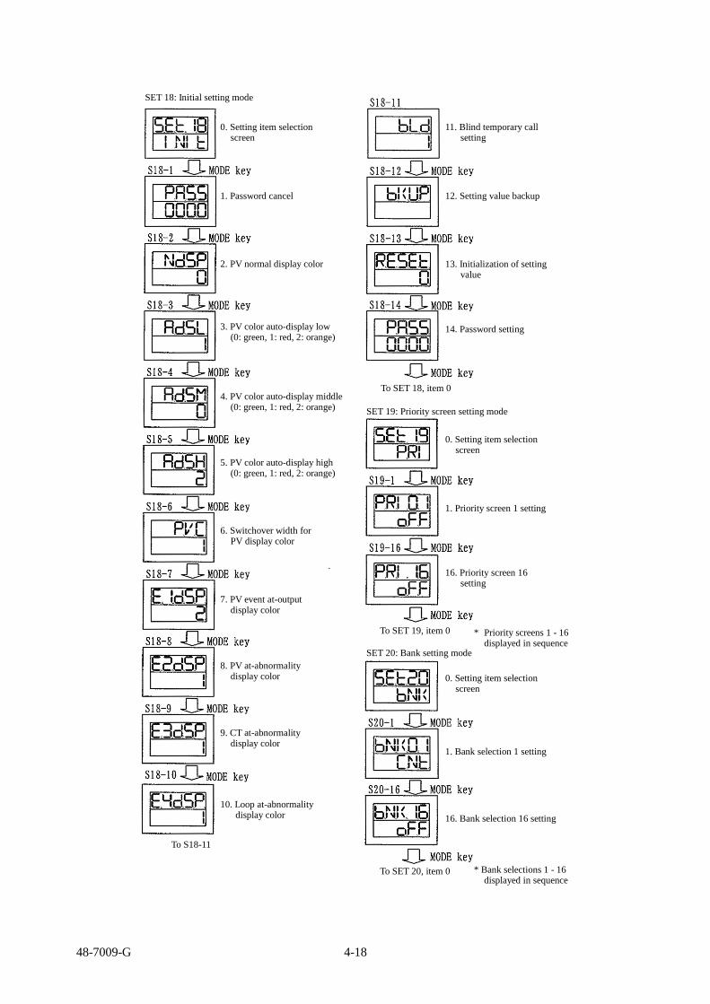
48-7009-G 4-18
SET 18: Initial setting mode
0. Setting item selection screen
1. Password cancel
2. PV normal display color
3. PV color auto-display low (0: green, 1: red, 2: orange)
4. PV color auto-display middle (0: green, 1: red, 2: orange)
5. PV color auto-display high (0: green, 1: red, 2: orange)
6. Switchover width for PV display color
7. PV event at-output display color
8. PV at-abnormality display color
9. CT at-abnormality display color
10. Loop at-abnormality display color
To S18-11
11. Blind temporary call setting
12. Setting value backup
14. Password setting
13. Initialization of setting value
To SET 18, item 0
SET 19: Priority screen setting mode
0. Setting item selection screen
1. Priority screen 1 setting
To SET 19, item 0 * Priority screens 1 - 16 displayed in sequence
SET 20: Bank setting mode
0. Setting item selection screen
1. Bank selection 1 setting
16. Bank selection 16 setting
* Bank selections 1 - 16 displayed in sequence
To SET 20, item 0
16. Priority screen 16 setting
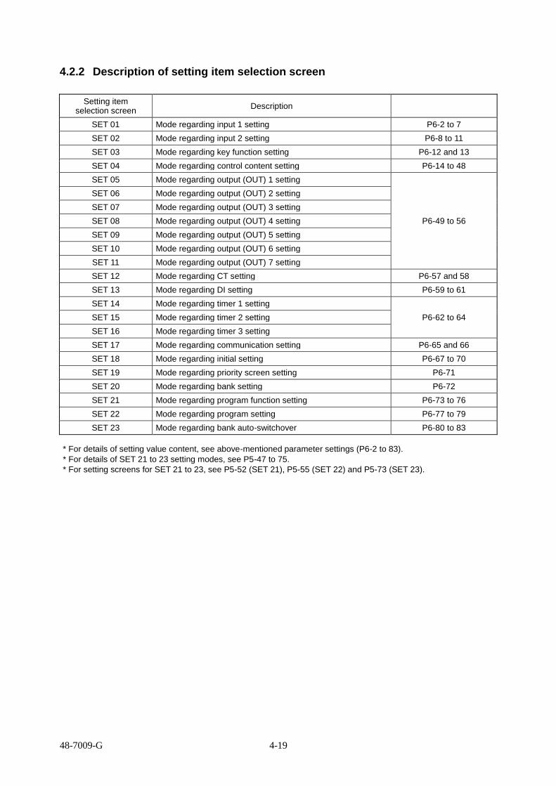
48-7009-G 4-19
4.2.2 Description of setting item selection screen
Setting item selection screen
Description
SET 01 Mode regarding input 1 setting P6-2 to 7
SET 02 Mode regarding input 2 setting P6-8 to 11
SET 03 Mode regarding key function setting P6-12 and 13
SET 04 Mode regarding control content setting P6-14 to 48
SET 05 Mode regarding output (OUT) 1 setting
P6-49 to 56
SET 06 Mode regarding output (OUT) 2 setting
SET 07 Mode regarding output (OUT) 3 setting
SET 08 Mode regarding output (OUT) 4 setting
SET 09 Mode regarding output (OUT) 5 setting
SET 10 Mode regarding output (OUT) 6 setting
SET 11 Mode regarding output (OUT) 7 setting
SET 12 Mode regarding CT setting P6-57 and 58
SET 13 Mode regarding DI setting P6-59 to 61
SET 14 Mode regarding timer 1 setting
P6-62 to 64 SET 15 Mode regarding timer 2 setting
SET 16 Mode regarding timer 3 setting
SET 17 Mode regarding communication setting P6-65 and 66
SET 18 Mode regarding initial setting P6-67 to 70
SET 19 Mode regarding priority screen setting P6-71
SET 20 Mode regarding bank setting P6-72
SET 21 Mode regarding program function setting P6-73 to 76
SET 22 Mode regarding program setting P6-77 to 79
SET 23 Mode regarding bank auto-switchover P6-80 to 83
* For details of setting value content, see above-mentioned parameter settings (P6-2 to 83).
* For details of SET 21 to 23 setting modes, see P5-47 to 75.
* For setting screens for SET 21 to 23, see P5-52 (SET 21), P5-55 (SET 22) and P5-73 (SET 23).

48-7009-G 4-20
4.2.3 Setting of input types
Settings for matching the input types being used is done.
* The factory default is set at “0: K thermocouple”.
Power-on
Initial screen Parameter for input display Input type No. (“0” is set at factory shipment.)
SET 21 program mode setting A (C/P 0) constant value run mode is established.
SET 21 program mode setting A (C/P 0) program run mode is established.
4 seconds
Constant value run mode screen
Ho
ld M
OD
E k
ey
pre
ssed
fo
r 2
seco
nd
s
PV value (present value) SV value (target value)
Hold MODE key pressed for 2 seconds
Input 1 setting mode
Each set screen Each setting mode
Press MODE key.
S01-1 Input type setting screen
Input type No.
For program run mode screen:
PV value (present value) SV value (PRoG)
Hold MODE key pressed for 2 seconds
Setting mode is the same as that for constant value run mode. (To input 1 setting screen)
* Input types are set in this screen. Numbers for input types are identical to those located in upper
right of the input type number table. In addition, what each number means is coincident with what
is described in the input type number table. * Use the ▲/▼ key for setting the numbers. The following is displayed when “0: K thermocouple,” which
is set at factory shipment, is changed to “1: J thermocouple.”
* Holding the MODE key pressed for 2 seconds moves each setting screen to the operating mode screen. * In about 2 minutes, each setting screen (or any setting screen) automatically moves back to the operating mode screen.
Input type No. and input type
No. Input type
0 K thermocouple
1 J thermocouple
2 T thermocouple
3 E thermocouple
4 R thermocouple
5 S thermocouple
6 B thermocouple
7 N thermocouple
8 U thermocouple
9 L thermocouple
10 WRe5-26 thermocouple
11 PR40-20 thermocouple
12 PLII thermocouple
13 Pt100
14 JPt100
15 0 - 10 mVDC
16 0 - 1 VDC
17 0 - 5 VDC
18 1 - 5 VDC
19 0 - 10 VDC
20 4 - 20 mADC

48-7009-G 4-21
4.2.4 Setting of key functions
How to set key functions is described.
Constant value run mode screen
PV value (present value) SV value (target value)
Hold MODE key pressed for 2 seconds.
Input 1 setting screen
Ho
ld M
OD
E k
ey p
ress
ed f
or
2 s
eco
nds.
Each set screen Each setting mode
Press the ▲ key twice. Press it, however, once for TTM-204.
Key function setting screen
Press MODE key.
S03-1 Function key 1 function setting screen
* The function key functions are set in this screen. For content of key functions, see the function key function assignment table as shown below. * The number displayed in the screen is coincident with that listed in the assignment table. * Use the ▲/▼ key for setting the numbers. * At factory shipment, “00: no function” is set. * Use the MODE key to move the screen for the setting screen to set the function keys 2 to 5. The screens change in sequence each time when the MODE key is pressed. (Note that only the function key 1 is available for TTM-204.)
Each set screen Each setting mode
Function key function assignment table
No. Pressing time setting
No. Function setting
★☆ ★☆
0* N/A *0 No function
1* Pressing time of 1 second *1 Digit shift
2* Pressing time of 2 seconds *2 Control mode/control stop
3* Pressing time of 3 seconds *3 AT start/AT stop
4* Pressing time of 4 seconds *4 Timer start/reset
5* Pressing time of 5 seconds *5 Screen reverse feed
*6 ENT
*7 Bank switchover
*8 AUTO/MANUAL switchover
*9 SV/MV screen switchover
*A Constant value run/program run switchover
*B Step feed
*C Pause
*D SET 22 call-up function
Example 1: 23 Two-second prolonged pressing makes the key effective, enabling the PID auto-tuning
start/stop key setting. Example 2: 44 Four-second prolonged pressing makes the key effective, enabling the timer function
start/reset key setting.
* Holding the MODE key pressed for 2 seconds moves each setting screen to the operating mode screen. * In about 2 minutes, each setting screen (or any setting screen) automatically moves back to the operating
mode screen. * The function key functions A to D are active only during a program run. They are also settable during a
constant value run.
For program run mode screen:
PV value (present value) SV value (PRoG)
Hold MODE key pressed for 2 seconds
Setting mode is the same as that for constant value run mode. (To input 1 setting screen)

48-7009-G 4-22
4.2.5 How to set the SV limiter setting
The SV limiter is for setting a settable range with upper and lower limits.
The range is a basis for setting the proportional band for the PID control.
Constant value run mode screen
PV value (present value) SV value (target value)
Hold MODE key pressed for 2 seconds.
Input 1 setting screen
Each set screen Each setting mode
Press the ▲ key three times. Press it, however, twice for TTM-204.
Control setting mode
Press MODE key three times.
S04-3 SV limiter upper limit setting screen
* The SV limiter upper limit is set in this screen. * Use the ▲/▼ key for the setting. * The set value is a value of MAX (upper limit) for which the SV setting is allowed. * The value is set at “1200” at factory shipment. * A small value of SLH contributes to prevent erroneous setting operation, resulting in
prevention of fire or failure.
S04-4 SV limiter lower limit setting screen
* The SV limiter lower limit is set in this screen. * Use the ▲/▼ key for the setting. * The set value is a value of MIN (lower limit) for which the SV setting is allowed. * The value is set at “0” at factory shipment.
* Holding the MODE key pressed for 2 seconds moves each setting screen to the operating mode screen. * In about 2 minutes, each setting screen (or any setting screen) automatically moves back to the operating
mode screen.
Ho
ld M
OD
E k
ey p
ress
ed f
or
2 s
eco
nds.
For program run mode screen:
PV value (present value) SV value (PRoG)
Hold MODE key pressed for 2 seconds
Setting mode is the same as that for constant value run mode. (To input 1 setting screen)

48-7009-G 4-23
4.2.6 How to set control types
How to set control types is described.
Constant value run mode screen
PV value (present value) SV value (target value)
Hold MODE key pressed for 2 seconds.
Input 1 setting screen
Each set screen Each setting mode
Press the ▲ key three times. Press it, however, twice for TTM-204.
Control setting mode
Press MODE key six times.
S04-6 Control type setting screen
* Set the control types in this screen. * The number displayed in the screen is coincident with that listed in the control type setting table. * Use the ▲/▼ key for the setting. * The value is set at “1” at factory shipment.
S04-8 PID control type setting screen
Press MODE key.
Continued to the next page
* The PID control types are set in this screen. * The number displayed in the screen is coincident with that listed in the PID control type setting table. * Use the ▲/▼ key for the setting. * The value is set at “1” at factory shipment.
Ho
ld M
OD
E k
ey p
ress
ed f
or
2 s
eco
nds.
Control type setting table
No. Primary control Secondary control
0 N/A N/A
1 PID N/A
2 ON/OFF N/A
3 PID PID
4 PID ON/OFF
5 ON/OFF ON/OFF
6 Position proportional Position proportional
PID control type setting table
No. Control type
0 Type A (normal)
1 Type B (overshoot suppression)
2 Type C (disturbance suppression)
For program run mode screen:
PV value (present value) SV value (PRoG)
Hold MODE key pressed for 2 seconds
Setting mode is the same as that for constant value run mode. (To input 1 setting screen)

48-7009-G 4-24
Continued from the previous page
S04-9 Type B mode setting screen
* The type of the PID Type B mode is set in this screen. * The number displayed in the screen coincident with that listed in the Type B mode setting table. * Use the ▲/▼ key for the setting. * The value is set at “1” at factory shipment.
Press MODE key.
S04-10 Forward/reverse operation setting screen
* Forward/reverse operation is set in this screen. * The number displayed in the screen coincident with that listed in the forward/reverse operation
setting table. * Use the ▲/▼ key for the setting. * The value is set at “0” at factory shipment.
Press MODE key three times.
S04-11 Tuning type setting screen
* The tuning types are set in this screen. * The number displayed in the screen coincident with that listed in the tuning type setting table. * Use the ▲/▼ key for the setting. * The value is set at “1” at factory shipment. * If the function is not specified for the equipment, corresponding screen is not displayed.
* Holding the MODE key pressed for 2 seconds moves each setting screen to the operating mode screen. * In about 2 minutes, each setting screen (or any setting screen) automatically moves back to the operating mode screen.
Type B mode setting table
No. Overshoot
0 Overshoot suppression - Moderate
1 Overshoot suppression - Intermediate
2 Overshoot suppression - Intense
Forward/reverse operation setting table
No. Operation type
0 Forward operation
1 Reverse operation
Tuning type setting table
No. Type
1 Primary auto-tuning
2 Primary self-tuning
3 Secondary auto-tuning
4 Secondary self-tuning
5 Primary/secondary auto-tuning

48-7009-G 4-25
4.2.7 How to set outputs
The description in this section is on how to set the OUT (output) 2 from the event output, which is set at
factory shipment, to the secondary output.
Constant value run mode screen
PV value (present value) SV value (target value)
Hold MODE key pressed for 2 seconds.
Input 1 setting screen
Each set screen Each setting mode
Press the ▲ key five times. Press it, however, four times for TTM-204.
OUT (output) 2 setting screen
Press MODE key once.
S06-1 Target connection setting screen
* The target connection (output function) is set for OUT 2 (output 2) in this screen. * Use the ▲/▼ key for the setting. * The value is set at “2” at factory shipment.
Changing the setting from “2” to “1” results in the secondary output (cooling).
* Holding the MODE key pressed for 2 seconds moves each setting screen to the operating mode screen. * In about 2 minutes, each setting screen (or any setting screen) automatically moves back to the operating
mode screen.
Each set screen Each setting mode
Ho
ld M
OD
E k
ey p
ress
ed f
or
2 s
eco
nd
s.
For program run mode screen:
PV value (present value)
SV value (PRoG)
Hold MODE key pressed for 2 seconds
Setting mode is the same as that for constant
value run mode.
(To input 1 setting screen)

48-7009-G 4-26
4.2.8 How to set priority screens
How to set priority screens is described.
Constant value run mode screen
PV value (present value) SV value (target value)
Hold MODE key pressed for 2 seconds.
Input 1 setting screen
Each set screen Each setting mode
Press ▼ key twice.
Priority screen setting screen
Each set screen Each setting mode
Press MODE key once.
S19-1 Priority screen 1 setting screen
* A parameter switched over to the priority screen is set in this screen. * Use the ▲/▼ key for the setting. * The value is set at “OFF” at factory shipment. * Each parameter is displayed in sequence. When a desired parameter
is displayed in the priority screen, press the MODE key to move to the next screen.
Press MODE key 15 times.
S19-16 Priority screen 16 setting screen
* A parameter switched over to the priority screen is set in this screen. * Use the ▲/▼ key for the setting. * The value is set at “OFF” at factory shipment. * A parameter that is already set for the priority screen is not displayed.
* Parameters are displayed in the operating mode screen in the sequence that they are set. * Holding the MODE key pressed for 2 seconds moves each setting screen to the operating mode
screen. * In about 2 minutes, each setting screen (or any setting screen) automatically moves back to the
operating mode screen.
Ho
ld M
OD
E k
ey p
ress
ed f
or
2 s
eco
nd
s.
For program run mode screen:
PV value (present value)
SV value (PRoG)
Hold MODE key pressed for 2 seconds
Setting mode is the same as that for constant
value run mode.
(To input 1 setting screen)

48-7009-G 4-27
4.2.9 Switchover to the blind setting mode
How to set the blind function is described.
Constant value run mode screen
PV value (present value) SV value (target value)
Hold MODE key pressed for 10 seconds.
Input 1 setting screen
Each set screen Each setting mode
When blinks, press the FUNC key, and then press the MODE key.
PV/SV blind setting screen * Use the FUNC key for its setting. In a blind state, characters in the lower row (red) are not displayed. (Pressing the FUNC key results in displaying “PVSV,” “PV,” “SV” and
“PVSV” in sequence.)
MO
DE
key
Timer 1 blind setting screen * Use the FUNC key for its setting. When the character “OFF” in the lower row (red) is displayed, the screen is
in a blind state.
Timer 2 blind setting screen * Use the FUNC key for its setting. When the character “OFF” in the lower row (red) is displayed, the screen is
in a blind state.
Timer 3 blind setting screen * Use the FUNC key for its setting. When the character “OFF” in the lower row (red) is displayed, the screen is
in a blind state.
Continued to the next page
For program run mode screen:
PV value (present value)
SV value (PRoG)
Hold MODE key pressed for 2 seconds
Setting mode is the same as that for constant
value run mode.
(To input 1 setting screen)

48-7009-G 4-28
Continued from the previous page
Hold MODE key pressed for 3 seconds. Holding the MODE key pressed for 3 seconds in any screen above results in changing the screen.
Use the ▲ /▼ key to change the item to be displayed. (Some items are not displayed depending on the equipment specification.)
Use the MODE key to change the item to be displayed. (Some items are not displayed depending on the equipment specification.)
Use the MODE key to change the item to be displayed. (Some items are not displayed depending on the equipment specification.)
MODE key
MODE key
MODE key
MODE key
MODE key
* Each SET item is also set for blind setting after moving the screen to the
parameter screen, using the MODE key.
* Always use the FUNC key to set screens for the blind settings.
When the character “OFF” in the lower row (red) is displayed, the
screen is in a blind state.
* Holding the MODE key pressed for 3 seconds in each screen results in
returning to .
* How to terminate the blind setting mode
1) After turning the power off, turn it back on. After the initial screen is displayed, the operating mode screen is
displayed again.
2) Holding the MODE key pressed for 3 seconds in each SET screen moves the screen to the PV/SV blind setting
screen.
Then, holding the MODE key pressed for about 10 seconds results in displaying the operating mode screen again.
* In the diagram above, only SET1 and SET20 are shown; other SET** are skipped.
The blind status of each parameter can also be settable for other SET**.

48-7009-G 4-29
4.2.10 Switchover to the ON/OFF control
The ON/OFF control is set in BANK 1 for the initial setting at factory shipment.
How to set the ON/OFF control is described.
Constant value run mode screen
PV value (present value) SV value (target value)
Hold MODE key pressed for 2 seconds.
Input 1 setting screen
Each set screen Each setting mode
Press the ▲ key three times. Press it, however, twice for TTM-204.
Control setting mode
Press MODE key once.
S04-1 Bank setting mode
Ho
ld M
OD
E k
ey p
ress
ed f
or
2 s
eco
nd
s.
* Setting change to the ON/OFF control is conducted in the bank setting screen.
Changing “0” to “1” using the ▲ key results in the setting of the ON/OFF control.
Then, holding the MODE key pressed for 2 seconds, the screen moves back to the operating mode screen.
(In about 2 minutes, the screen automatically moves back to the operating mode screen.)
* The sensitivity range for the ON/OFF control is set at 1 °C at factory shipment.
* Setting the ON/OFF control results in displaying no items related to the PID control.
For program run mode screen:
PV value (present value)
SV value (PRoG)
Hold MODE key pressed for 2 seconds
Setting mode is the same as that for constant
value run mode.
(To input 1 setting screen)

48-7009-G 5-1
5. Operating the equipment
How to operate the equipment is described in this chapter.
5.1 Precautions on operating the equipment ................................................................................................ 5-2
5.2 Operating monitor display ...................................................................................................................... 5-3
5.2.1 Operating amount monitor ............................................................................................................. 5-3
5.2.2 Timer remaining time monitor: Run mode ..................................................................................... 5-3
5.2.3 Temperature measurement monitor: Run mode ............................................................................. 5-3
5.2.4 CT monitor: .................................................................................................................................... 5-3
5.3 How to set run settings ........................................................................................................................... 5-4
5.3.1 Target value (SV) setting ................................................................................................................ 5-4
5.3.2 ON/OFF control setting.................................................................................................................. 5-7
5.3.3 PID control setting ......................................................................................................................... 5-9
5.3.4 Heating/cooling control setting .................................................................................................... 5-13
5.3.5 Indicator setting ............................................................................................................................ 5-15
5.3.6 Excessive ascent prevention unit (alarm unit) setting .................................................................. 5-17
5.3.7 Event setting ................................................................................................................................. 5-18
5.3.8 How to set MD/READY .............................................................................................................. 5-20
5.4 How to set each function and description of function .......................................................................... 5-22
5.4.1 Auto-tuning (AT) function ........................................................................................................... 5-22
5.4.2 Self-tuning function ..................................................................................................................... 5-25
5.4.3 Mode/manual function ................................................................................................................. 5-27
5.4.4 Bank function ............................................................................................................................... 5-28
5.4.5 Timer function .............................................................................................................................. 5-31
5.4.6 Loop abnormality function ........................................................................................................... 5-38
5.4.7 Current transformer (CT) abnormality function ........................................................................... 5-40
5.4.8 Position proportional control ........................................................................................................ 5-45
5.4.9 Concurrent temperature ascent function ...................................................................................... 5-46
5.5 Explanation of the program run function ............................................................................................. 5-47
5.5.1 Operation flow of the program run .............................................................................................. 5-48
5.5.2 SET 21 program function setting ................................................................................................. 5-49
5.5.3 SET 21 program function setting screen ...................................................................................... 5-52
5.5.4 SET 22 program setting ............................................................................................................... 5-53
5.5.5 SET 22 program setting screen .................................................................................................... 5-55
5.5.6 Explanation of the screen display and operation of a program run .............................................. 5-56
5.5.7 Complementary explanation of the program run ......................................................................... 5-61
5.6 Explanation of the bank automatic switching function ........................................................................ 5-70
5.6.1 Bank automatic switching setting ................................................................................................ 5-71
5.6.2 SET 23 bank automatic switching function setting mode setting screen ..................................... 5-73
5.6.3 Complementary explanation of the bank automatic switching function ...................................... 5-74

48-7009-G 5-2
5.1 Precautions on operating the equipment
Before beginning operation or turning on the power, check the following.
★ Operation for turning on the power
The equipment is not equipped with a power switch. Connecting a power will turn the power of the
unit ON. The initial screen is displayed for about 4 seconds, and then the equipment operates.
The control mode for the control setting mode is set for RUN (control start) in factory default. After
wiring is complete and the setting value (SV) is set, the control starts.
At factory default, the control method is set for the PID control.
* Proportional band: 3.0 %
Integration: 0 second
Derivation: 0 second
Proportional cycle: Relay contact output 20 seconds
SSR drive output 1 second
★ Behavior during input abnormality
Open or short (only for a resistance temperature detector) of input signals is determined as an input
abnormality (such as burnout) by the equipment.
Input type Display on the
equipment Operation of control
output Operation of event
output
Thermocouple
Overscale
Operating amount limiter lower limit
Analogous to the setting for at-input
abnormality. (See pages 6-52)
Resistance temperature detector
0 - 10 mVDC
0 - 1 VDC
Underscale
0 - 5 VDC
1 - 5 VDC
0 - 10 VDC
4 - 20 mADC
* Burnout function: A function to forcibly move outputs of a controller toward upper limit or lower
limit (safety side) in case the wires are disconnected on a thermocouple or resistance temperature
detector.
★ Checking each parameter
Set each parameter such as setting value (SV) or PID to a value that is appropriate for the subject of
control.
For details of setting each parameter, see the item 6 “Parameter setting.”
For details of switchover setting of RUN (control start) and READY (control stop), see pages 5-20 and
21.
★ Operation at power-outage (momentary outage)
There is no effect on operation in case of outage in 1 cycle or less.
1 cycle 50 Hz 20 ms
60 Hz 16.7 ms
For DC power with the outage for 40 ms or shorter, there is no effect on operation.
In case of the outage for longer than 40 ms, the equipment is reset.

48-7009-G 5-3
5.2 Operating monitor display
5.2.1 Operating amount monitor: SET 04 (control setting mode)
★ Output percentage at control is displayed.
1) Primary control operating amount monitor screen
S04-10 Primary control operating amount
* Smaller number indicates smaller operating (output) amount; larger number
indicates larger operating (output) amount.
* The control (output) amount is provided as output within the operating amount
setting limiter setting range.
For setting the operating amount setting, see page 6-17.
2) Secondary control operating amount display screen
S04-33 Secondary control operating amount
* Smaller number indicates smaller operating (output) amount; larger number
indicates larger operating (output) amount.
* The control (output) amount is provided as output within the operating amount
setting limiter setting range.
For setting the operating amount setting, see page 6-34.
5.2.2 Timer remaining time monitor: Run mode
★ Remaining time is displayed when the timer is operating.
Timer 1 remaining time monitor screen
Operating mode items 2, 3 and 4
* Upper row: ON delay
Lower row: OFF delay
* While operating, [:] blinks.
* ▲/▼ key to change remaining time
* Analogous to the remaining time monitor screens for timers 2 and 3
5.2.3 Temperature measurement monitor: Run mode
★ The present value being measured by the sensor is displayed.
Present measurement value monitor screen
* Upper row: Measurement value
* Lower row: Target value
5.2.4 CT monitor: SET 12 (CT setting mode)
★ The present value being measured by CT (current transformer) is displayed.
1) CT 1 measurement value monitor screen
S12-2 CT 1 current value monitor
* The present value being measured by the current transformer (CT) is displayed.
* Measurement value: 0.0 - 50.0 A
2) CT 2 measurement value monitor screen
S12-5 CT 2 current value monitor
* The present value being measured by the current transformer (CT) is displayed.
* Measurement value: 0.0 - 50.0 A

48-7009-G 5-4
5.3 How to set run settings
The target value (SV) setting, control setting and event setting are described as examples for constant value run
settings.
5.3.1 Target value (SV) setting
When the target value (SV) to be set at 450 °C
① Where setting it as is
Power-on
Initial screen
4 seconds
Constant value run mode screen
Measurement value (PV) Target value (SV): Set to “0” at factory shipment
Press the ▲ key until the target value changes to “450.” The digit automatically shifts up.
Constant value run mode screen
Measurement value (PV) Target value (SV) = 450C

48-7009-G 5-5
② When setting the digit shift function by assigning it on the FUNC key
Content of the function of the function key * The function key (FUNC) is set on the digit shift function in this screen. Use the ▲/▼ key to change “00” to “*1.” The symbol “*” represents the item to be designated for time for which the
function key (FUNC) is held pressed. 0: None, 1: 1 second, 2: 2 seconds, 3: 3 seconds, 4: 4 seconds and 5: 5 seconds * Example for setting: “11” indicates that holding the FUNC key pressed for 1
second enables it effective.
* Holding the MODE key pressed for 2 seconds moves each setting screen to the operating mode screen. * In about 2 minutes, each setting screen (or any setting screen) automatically moves back t o the
operating mode screen. Continued to the next page
Initial screen
4 seconds
Input 1 setting screen
Hold MODE key pressed for 2 seconds.
Press the ▲ key twice. Press it, however, once for TTM-204.
Ho
ld M
OD
E k
ey
pre
ssed
fo
r 2
seco
nd
s.
Power-on
4 seconds
Hold MODE key pressed for 2 seconds.
Key function setting screen
Press MODE key once.
S03-1 Function key 1 function setting screen
SET 21 program mode setting A (C/P 0) constant value run mode is established.
SET 21 program mode setting A (C/P 0) program run mode is established.
For constant value run mode screen:
Measurement value (PV) Target value (SV): Set to “0” at factory shipment
For program run mode screen:
PV value (present value) SV value (PRoG)
Hereinafter, to the input 1 setting screen similarly to that for the constant value run mode

48-7009-G 5-6
Continued from the previous page
Operating mode screen
Measurement value (PV) Target value (SV): Set to “0” at factory shipment
Target value setting screen
* Pressing the FUNC key blinks on and off the numerical character located rightmost. Pressing the MODE key changes the blinking character to lighting, which indicates
determination of the setting. In addition, the blinking automatically changes to lighting in about 3 seconds to determine
the setting.
Blinking
Target value setting screen
* Pressing once the FUNC key blinks on and off the second digit from right. In this state, change “0” to “5” using the ▲ key. Pressing the MODE key changes the blinking character to lighting, which indicates
determination of the setting. In addition, the blinking automatically changes to lighting in about 3 seconds to determine
the setting.
Blinking
* Pressing once the FUNC key blinks on and off the third digit from right. In this state, change “0” to “4” using the ▲ key. Pressing the MODE key changes the blinking character to lighting, which indicates
determination of the setting. In addition, the blinking automatically changes to lighting in about 3 seconds to determine
the setting.
Target value setting screen
Run mode screen
Measurement value (PV) Target value (SV) = 450C
Blinking

48-7009-G 5-7
5.3.2 ON/OFF control setting
When a measurement value (PV) being controlled reaches the target value (SV), the control output is turned
off. Then, the control output is turned on when the measurement value (PV) goes beyond the peak value,
approaches the target value (SV), and goes beyond it. This move is repeated at a particular position.
The adjustment sensitivity (sensitivity range), in this case, is defined as the difference between the point where
the control output turns off (measurement value) and point where the control output turns on.
★ Setting the ON/OFF control
The PID control is set as factory default.
As the ON/OFF control is preset at “1” of the bank function, the ON/OFF control can be set by changing
the setting in the bank setting screen of the control setting mode.
1) How to change the setting in the bank
For constant value run mode screen:
PV value (present value) SV value (target value)
Hold MODE key pressed for 2 seconds.
Input 1 setting screen
Each set screen Each setting mode
Press the ▲ key three times. Press it, however, twice for TTM-204.
Control setting mode
Press MODE key once.
S04-1 Bank setting mode
* Setting change to the ON/OFF control is conducted in the bank setting screen. Changing “0” to “1” using the ▲ key results in the setting of the ON/OFF control. Then, holding the MODE key pressed for 2 seconds, the screen moves back to the run
mode screen. (In about 2 minutes, the screen automatically moves back to the operating mode screen.) * The sensitivity range for the ON/OFF control is set at 1 °C at factory shipment. * Setting the ON/OFF control results in displaying no items related to the PID control.
Continued to the next page
Ho
ld M
OD
E k
ey p
ress
ed f
or
2 s
eco
nd
s.
For program run mode screen:
PV value (present value) SV value (PRoG)
Hold MODE key pressed for 2 seconds.
Setting mode is the same as that for Hereinafter, to the input 1 setting screen similarly to that for the constant value run mode

48-7009-G 5-8
Continued from the previous page
2) How to set the adjustment sensitivity
In order to stabilize the equipment operation, a particular range is provided for switching on and off in
the ON/OFF control. This range is called “adjustment sensitivity (hysteresis or sensitivity range).”
What is described below is how to set the adjustment sensitivity after the control method is changed to
the ON/OFF control in the bank setting. (Adjustment sensitivity of 1 °C is set at factory shipment.)
For constant value run mode screen:
PV value (present value) SV value (target value)
Move of the adjustment sensitivity (reverse operation)
Adjustment sensitivity (heating)
Target value
Hold MODE key pressed for 2 seconds.
Input 1 setting screen
Each set screen Each setting mode
Control setting mode
S04-30 Primary control sensitivity range setting screen.
Press the ▲ key three times. Press it, however, twice for TTM-204.
Press MODE key 13 times.
* Adjustment sensitivity is set in this screen. Use the ▲/▼ key to change the setting. Then, holding the MODE key pressed for 2 seconds, the screen moves back to the
operating mode screen. (In about 2 minutes, the screen automatically moves back to the operating mode screen.) * The sensitivity range for the ON/OFF control is set at 1 °C at factory shipment. * Setting the ON/OFF control results in displaying no items related to the PID control.
* Holding the MODE key pressed for 2 seconds moves each setting screen to the run mode screen. * In about 2 minutes, each setting screen (or any setting screen) automatically moves back to the run mode screen.
Ho
ld M
OD
E k
ey p
ress
ed f
or
2 s
eco
nd
s.
For program run mode screen:
PV value (present value) SV value (PRoG)
Hold MODE key pressed for 2 seconds.
Setting mode is the same as that for Hereinafter, to the input 1 setting screen similarly to that for the constant value run mode

48-7009-G 5-9
5.3.3 PID control setting
★ Setting the PID control
The “PID Control” is set as factory default, and the values for P = proportional band, I = integration, D
= derivation and proportional cycle are provisional values.
Those values are as follows: P1 = 3.0, I = 0, D = 0, proportional cycle = 1 second (SSR type) or 20
seconds (relay type).
1) How to start auto-tuning (AT)
* Execution of auto-tuning results in automatic setting of the most appropriate PID constant to the
target value.
* Auto-tuning cannot be executed in the RDY state or ON/OFF control.
* Results of the auto-tuning are reflected to values of P, I and D.
* For details of auto-tuning, see pages 5-22 to 24.
① In the auto-tuning start screen
For constant value run mode screen:
PV value (present value) SV value (target value)
Hold MODE key pressed for 2 seconds.
Input 1 setting screen
Each set screen Each setting mode
Press the ▲ key three times. Press it, however, twice for TTM-204.
Control setting mode
Press MODE key 15 times.
S04-15 AT start screen
* Auto-tuning is started in this screen. Use the ▲/▼ key for start and stop settings. * During auto-tuning, the target value and “At” is alternately displayed for SV (red). Upon completion of auto-tuning, the target value is displayed. (The screen returns to the operating mode screen.) * No operation is possible during auto-tuning, except operation of the ▲/▼ key. * “OFF” is set at factory shipment.
For program run mode screen:
PV value (present value) SV value (PRoG)
Hold MODE key pressed for 2 seconds.
Setting mode is the same as that for Hereinafter, to the input 1 setting screen similarly to that for the constant value run mode

48-7009-G 5-10
② Start using the function key
Set the function key function to the AT start/stop function as the first step.
★ ☆
For constant value run mode screen:
PV value (present value) SV value (target value)
Hold MODE key pressed for 2 seconds.
Input 1 setting screen
Each set screen Each setting mode
Press the ▲ key twice. Press it, however, once for TTM-204.
Key function setting screen
Press MODE key.
S03-1 Function key 1 function setting screen
Each set screen Each setting mode
* The function key functions are set in this screen. For content of key functions, see the function key function assignment table on page 4-21. * The number displayed in the screen is coincident with that listed in the assignment table. * Use the ▲/▼ key for setting the numbers. * At factory shipment, “00: no function” is set. * Set the items as follows: ★ = time period in which the function key is pressed and ☆ =
3 (AT start/stop function). * Use the MODE key to move the screen for the setting screen to set the function keys 2 to 5. The screens change in sequence each time when the MODE key is pressed. (Note that only the function key 1 is available for TTM-204.)
* With the above operation, the function key (FUNC) is set to the AT start/stop function key. * AT starts and stops by pressing the function key (FUNC) in the run mode screen. In addition, AT stops when the ▲/▼ key is pressed during AT being effective. * During auto-tuning, the target value and “At” is alternately displayed for SV (red). * Upon completion of auto-tuning, the target value is displayed. * Any function key is settable for the AT start/stop function, except on the model TTM-204. * Holding the MODE key pressed for 2 seconds moves each setting screen to the run mode screen. * In about 2 minutes, each setting screen (or any setting screen) automatically moves back to the run mode screen.
Ho
ld M
OD
E k
ey p
ress
ed f
or
2 s
eco
nd
s.
For program run mode screen:
PV value (present value) SV value (PRoG)
Hold MODE key pressed for 2 seconds.
Setting mode is the same as that for Hereinafter, to the input 1 setting screen similarly to that for the constant value run mode

48-7009-G 5-11
2) How to start self-tuning
* Self-tuning is a function to determine the PID constant when starting operation of the controller and
when changing the target value.
After determining the PID constant, self-tuning is not executed in the next start of operation, unless
the target value is changed.
* Self-tuning is executed when so set in the tuning type setting in SET 04 (control setting mode).
Auto-tuning is set at factory shipment.
For constant value run mode screen:
PV value (present value) SV value (target value)
Hold MODE key pressed for 2 seconds.
Input 1 setting screen
Each set screen Each setting mode
Press the ▲ key three times. Press it, however, twice for TTM-204.
Press MODE key 12 times.
S04-12 Tuning type setting screen
Control setting mode
* Tuning types are set in this screen. * The number displayed in the screen matches with that listed in the tuning type
setting table. * Use the ▲/▼ key for the setting. * “1: primary auto-tuning” is set at factory shipment. Changing the setting to “2: primary self-tuning” results in self-tuning.
Tuning type setting table
No. Type
1 Primary auto-tuning
2 Primary self-tuning
3 Secondary auto-tuning
4 Secondary self-tuning
5 Primary/secondary auto-tuning
* Holding the MODE key pressed for 2 seconds moves each setting screen to the run mode screen. * In about 2 minutes, each setting screen (or any setting screen) automatically moves back to the run mode
screen.
Hold
MO
DE
key
pre
ssed
for
2 s
econds.
For program run mode screen:
PV value (present value) SV value (PRoG)
Hold MODE key pressed for 2 seconds.
Setting mode is the same as that for Hereinafter, to the input 1 setting screen similarly to that for the constant value run mode

48-7009-G 5-12
3) How to manually set the PID constant
* The PID constant is set manually and individually in SET 04 (control setting mode).
For constant value run mode screen:
PV value (present value) SV value (target value)
Hold MODE key pressed for 2 seconds.
Input 1 setting screen
Each set screen Each setting mode
Press the ▲ key three times. Press it, however, twice for TTM-204.
Press MODE key 16 times.
S04-16 Proportional band (P) setting screen
Control setting mode
Each set screen Each setting mode
* Proportional band (P) is set in this screen. * Use the ▲/▼ key for the setting. * The value is set at “3.0” at factory shipment.
Press MODE key once.
S04-17 Integral time (I) setting screen
* Integral time (I) is set in this screen. * Use the ▲/▼ key for the setting. * The value is set at “0” at factory shipment. “0” indicates no integral operation.
Press MODE key once.
S04-18 Derivative time (D) setting screen
* Derivative time (D) is set in this screen. * Use the ▲/▼ key for the setting. * “0” indicates no derivative operation.
* Holding the MODE key pressed for 2 seconds moves each setting screen to the run mode screen. * In about 2 minutes, each setting screen (or any setting screen) automatically moves back to the run mode
screen.
Ho
ld M
OD
E k
ey p
ress
ed f
or
2 s
eco
nd
s.
For program run mode screen:
PV value (present value) SV value (PRoG)
Hold MODE key pressed for 2 seconds.
Setting mode is the same as that for Hereinafter, to the input 1 setting screen similarly to that for the constant value run mode

48-7009-G 5-13
5.3.4 Heating/cooling PID control setting
★ Setting the heating/cooling PID control
For the heating/cooling control, the output is selected and set for the subject of control to other than the
output 1, as well as the output function must be set to the secondary output, since the function is set, at
factory shipment, to the event output.
In addition, the control type setting for the secondary output must be set to PID, since it is set to “N/A”
at factory shipment.
At factory shipment, values for heating is set to the PID control with tentative values for P =
proportional band, I = integration, D = derivation and proportional cycle.
Those values are as follows: P1 = 3.0, I = 0, D = 0, proportional cycle = 1 second (SSR model) or 20
seconds (relay model).
Values of PID for cooling are as follows: P2 = 1.00 (a multiplication factor to the primary control
proportional band), proportional cycle = 20 seconds for both SSR and relay models, and values of I and
D being identical to those for the primary control.
* Setting when the output 1 (OUT 1) is for the heating control and the output 2 (OUT 2) for the
cooling control
◎ Types of controls and how to set the output function
For constant value run mode screen:
PV value (present value) SV value (target value)
Hold MODE key pressed for 2 seconds.
Input 1 setting screen
Each set screen Each setting mode
Press the ▲ key three times. Press it, however, twice for TTM-204.
Press MODE key six times.
S04-6 Control type setting screen
Control setting mode
Each set screen Each setting mode
Press MODE key six times.
Continued to the next page
* Control types are set in this screen. * Use the ▲/▼ key for the setting. * The value is set at “1” at factory shipment. Changing “1” to “3” results in setting heating/cooling PID.
Ho
ld M
OD
E k
ey p
ress
ed f
or
2 s
eco
nd
s.
For program run mode screen:
PV value (present value) SV value (PRoG)
Hold MODE key pressed for 2 seconds.
Setting mode is the same as that for Hereinafter, to the input 1 setting screen similarly to that for the constant value run mode

48-7009-G 5-14
Continued from the previous page
S04-12 Tuning type setting screen
* Tuning types are set in this screen. * Use the ▲/▼ key for the setting. * The value is set at “1” at factory shipment.
Changing “1” to “5” results in “PID auto-tuning” for both primary and secondary controls.
Press ▲ key twice.
Control setting mode
Each set screen Each setting mode
Press MODE key once.
OUT 2 setting screen
Each set screen Each setting mode
S06-1 Target connection setting screen
The above operations determine the setting of control types. Output function (target connection) is to be set next. Move the tuning type setting screen to the control setting mode screen, using the MODE key.
Ho
ld M
OD
E k
ey p
ress
ed f
or
2 s
eco
nd
s.
* The target connection (output function) is set for OUT 2 (output 2) in this screen. * Use the ▼ key for the setting. * The value is set at “2” at factory shipment.
Changing the setting from “2” to “1” results in the secondary control (cooling) output.
* For how to set PID, see page 5-9, item 5-3-3, “PID control setting.” For the heating/cooling control, no self-tuning function is provided.
* Holding the MODE key pressed for 2 seconds moves each setting screen to the run mode screen. * In about 2 minutes, each setting screen (or any setting screen) automatically moves back to the run mode
screen.

48-7009-G 5-15
5.3.5 Indicator setting
★ Setting as an indicator
Blinding the target value (SV) enables to use the screen as an indicator.
Hold MODE key pressed for 10 seconds.
Constant value run mode screen
PV value (present value) SV value (target value)
Input 1 setting screen
Each set screen Each setting mode
PV/SV blind setting screen
* Use the FUNC key for its setting. In a blind state, characters in the lower row (red) are not displayed. (Pressing the FUNC key results in displaying “PVSV,” “PV,” “SV” and “PVSV” in sequence.) Pressing once the FUNC key displays only characters of “PV” in the lower row (red). By turning the power off and back on, or holding the MODE key pressed for about 10 seconds in this state, only the upper row (green) is displayed.
The above operations determine the blind-setting of the target value (SV). Setting for no provision of outputs is conducted next.
Constant value run mode screen
Hold MODE key pressed for 2 seconds.
PV value (present value) SV value (target value)
Input 1 setting screen
Each set screen Each setting mode
Press the ▲ key three times. Press it, however, twice for TTM-204.
Continued to the next page
Ho
ld M
OD
E k
ey p
ress
ed f
or
2 s
eco
nd
s.
When blinks, press the FUNC key, and then press the MODE key.

48-7009-G 5-16
Control setting mode
Press MODE key six times.
Each set screen Each setting mode
S04-6 Control type setting screen
Ho
ld M
OD
E k
ey p
ress
ed f
or
2 s
eco
nd
s.
Continued from the previous page
* Control types are set in this screen. * Use the ▲/▼ key for the setting. * The value is set at “1” at factory shipment.
Changing the setting from “1” to “0” results in no provision of outputs.
* Holding the MODE key pressed for 2 seconds moves each setting screen to the run mode screen. * In about 2 minutes, each setting screen (or any setting screen) automatically moves back to the run
mode screen.

48-7009-G 5-17
5.3.6 Excessive ascent prevention unit (alarm unit) setting
★ Setting for the excessive ascent prevention unit
Setting to use the OUT 1 (output 1) as the excessive ascent prevention unit in constant value run mode
Hold MODE key pressed for 2 seconds.
Constant value run mode screen
PV value (present value) SV value (target value)
Press the ▲ key four times. Press it, however, three times for TTM-204.
Input 1 setting screen
Each set screen Each setting mode
OUT 1(output 1) setting screen
Ho
ld M
OD
E k
ey p
ress
ed f
or
2 s
eco
nd
s.
Each set screen Each setting mode
Press MODE key once.
S05-1 Target connection selection screen
* Target connection is set in this screen. * Use the ▲/▼ key for the setting. * The value is set at “0” at factory shipment.
Changing the setting from “0” to “2” results in the event output.
S05-2 Event function 1 setting screen
Press MODE key once.
Press MODE key once.
* Event function is set in this screen. * Use the ▲/▼ key for the setting. * The value is set at “000” at factory shipment.
Set the screen “006” or “016” for the use of the excessive ascent prevention unit (alarm unit). In case of the setting of “016,” the displayed value may exceed the target value, and it stays as is even when it decreases below the target value. The setting is reset by turning on the power again.
S05-3 Event upper limit setting mode
* Event upper limit is set in this screen. * Use the ▲/▼ key for the setting. * The value is set at “0” at factory shipment.
Set a specific target value.
* Holding the MODE key pressed for 2 seconds moves each setting screen to the run mode screen. * In about 2 minutes, each setting screen (or any setting screen) automatically moves back to the run mode
screen.

48-7009-G 5-18
5.3.7 Event setting
★ Setting the event setting value (alarm value)
When setting OUT 2 for the event setting value (alarm value)
Setting condition: Deviation lower limit, with standby function, 30 °C and sensitivity of 1 °C (no
other functions)
This setting is not possible in case that no selection is made for outputs as an option.
Hold MODE key pressed for 2 seconds.
For constant value run mode screen:
PV value (present value) SV value (target value)
Press the ▲ key five times. Press it, however, four times for TTM-204
Input 1 setting screen
Each set screen Each setting mode
OUT 2 (output 2) setting screen
Ho
ld M
OD
E k
ey p
ress
ed f
or
2 s
eco
nd
s.
Each set screen Each setting mode
Press MODE key twice.
S06-2 Event function 1 setting screen
* Event functions are set in this screen. * Use the ▲/▼ key for the setting. * The value is set at “000” at factory shipment.
Setting “000” to “023” results in the type of alarm for the deviation lower limit and standby function. Deviation lower limit: Range from the setting value (SV) being set Standby function: Function that no alarm is generated until a value exceeds the alarm range.
Press MODE key once.
S06-4 Event lower setting screen
* Event lower target value is set in this screen. * Use the ▲/▼ key for the setting. * The value is set at “0” at factory shipment.
Setting “0” to “30” results in setting the deviation lower limit alarm value to 30 °C. An alarm is generated in case that a value reaches 30 °C below the setting value (SV). Example: SV = 200 °C and lower limit alarm = 170 °C or lower
Press MODE key six times.
Continued to the next page
For program run mode screen:
PV value (present value) SV value (PRoG)
Hold MODE key pressed for 2 seconds.
Setting mode is the same as that for Hereinafter, to the input 1 setting screen similarly to that for the constant value run mode

48-7009-G 5-19
5. Event sensitivity setting screen
* Event sensitivity is set in this screen. * Use the ▲/▼ key for the setting. * The value is set at “0” at factory shipment.
Setting “0” to “1” results in setting the sensitivity range of the lower limit alarm to 1 °C. Temperature that an alarm enters: 170 °C Temperature that an alarm cancels: 169 °C
Continued from the previous page
* Holding the MODE key pressed for 2 seconds moves each setting screen to the run mode screen. * In about 2 minutes, each setting screen (or any setting screen) automatically moves back to the run mode screen.

48-7009-G 5-20
5.3.8 How to set MD/READY
★ Start of control (RUN) or stop of control (READY) is selected.
Switchover of RUN/READY can be executed through the key operation with the FUNC key assigned,
or through optional digital (DI) input or communication function.
① Setting with the function key
★ ☆
For constant value run mode screen:
PV value (present value) SV value (target value)
Hold MODE key pressed for 2 seconds.
Input 1 setting screen
Each set screen Each setting mode
Press the ▲ key twice. Press it, however, once for TTM-204.
Key function setting screen
Press MODE key.
S03-1 Function key 1 function setting screen
Each set screen Each setting mode
* The function key functions are set in this screen. For content of key functions, see the function key function assignment table on page 4-21.
* The number displayed in the screen is coincident with that listed in the assignment table. * Use the ▲/▼ key for setting the numbers. * The value is set at “00” at factory shipment. * To be set as follows: ★ = Time of holding the function key pressed and ☆ = 2 (control
start/control stop). ★ = 0: None, 1: 1 second, 2: 2 seconds, 3: 3 seconds, 4: 4 seconds and 5: 5 seconds
* Use the MODE key to move the screen for the setting screen to set the function keys 2 to 5. The screens change in sequence each time when the MODE key is pressed. (Note that only the function key 1 is available for TTM-204.)
* The above operations determine the setting of the function (FUNC) key to be the control start (RUN) and control stop (READY).
* Pressing the function (FUNC) key in the operating mode screen results in operations of RUN and READY. * Any function key can be assigned for RUN or READY on all equipment models except TTM-204. * Holding the MODE key pressed for 2 seconds moves each setting screen to the run mode screen. * In about 2 minutes, each setting screen (or any setting screen) automatically moves back to the run mode screen.
Ho
ld M
OD
E k
ey p
ress
ed f
or
2 s
eco
nd
s.
For program run mode screen:
PV value (present value) SV value (PRoG)
Hold MODE key pressed for 2 seconds.
Setting mode is the same as that for Hereinafter, to the input 1 setting screen similarly to that for the constant value run mode

48-7009-G 5-21
② Setting with the DI function (event input)
Optional DI function (event input) is required.
For constant value run mode screen:
PV value (present value) SV value (target value)
Hold MODE key pressed for 2 seconds.
Input 1 setting screen
Each set screen Each setting mode
Call up the DI setting screen by pressing the ▲ key. (The number of pressing times varies depending on the number of optional selection points.)
DI setting screen
Press MODE key.
S13-1 DI function setting screen
Each set screen Each setting mode H
old
MO
DE
key
pre
ssed
fo
r 2
sec
on
ds.
* The DI function is set in this screen. * Use the ▲/▼ key for the setting. * The value is set at “0000” at factory shipment. Setting to “2” results in the READY setting in the active state.
DI 1 setting
DI 2 setting
DI 3 setting
DI 4 setting
Press MODE key.
The number of points usable for DI varies depending on the equipment.
S13-2 DI polarity setting screen
* The DI function is set in this screen. * Use the ▲/▼ key for the setting. * The value is set at “0000” at factory shipment. Each digit is set to “0: close active” or “1: open active.”
DI 1 setting
DI 2 setting
DI 3 setting
DI 4 setting
* Holding the MODE key pressed for 2 seconds moves each setting screen to the run mode screen. * In about 2 minutes, each setting screen (or any setting screen) automatically moves back to the run
mode screen.
For program run mode screen:
PV value (present value) SV value (PRoG)
Hold MODE key pressed for 2 seconds.
Setting mode is the same as that for Hereinafter, to the input 1 setting screen similarly to that for the constant value run mode

48-7009-G 5-22
5.4 How to set each function and description of function
5.4.1 Auto-tuning (AT) function
■ What the auto-tuning is
• Auto-tuning (AT) is a function to operate turning on and off a subject of control so that the PID
parameter best suited for a set temperature is automatically calculated and set.
• For AT, ensure to wire the input 1 terminal and output terminal (such as power supply for heater), set
the setting temperature (SV), and use the equipment in a state possible to be controlled.
• For the control type setting, select the PID control {forward operation (cooling)/reverse operation
(heating)}, heating cooling PID control and position proportional control for using them when PID
parameters are desired to be automatically set.
• Upon completion of the AT setting, the automatically set PID parameters are recorded and stored
even when the power turns off. Repeat the operation, however, in case of power-off, halted AT or
AT error during setting AT, since it causes no change of the PID parameters.
Prohibition of the use of AT
① As AT forcibly executes turn-on and -off operations, PV greatly varies depending on a subject of control.
Do not use AT for a subject of control that cannot accept great fluctuation of PV.
② Do not use AT for a subject of control that provides fast response, such as pressure control or flow rate
control.
③ Do not use AT for a subject of control that may have a problem when a great change is applied to the
subject’s outputs, such as heater and solenoid valve.
The operating amount limiter is effective for analog outputs but not for digital outputs during AT.
The operating amount change limiter is not effective during AT.
Note Precautions on the use of AT
① The AT start screen is not displayed when the ON/OFF control is set for the control type setting.
② The AT start screen is not displayed when the self-tuning is set for the tuning type setting.
③ The time from start to completion of AT varies depending on subjects of controls.
④ Best suited PID parameters may not be obtained depending on subjects of controls.
For such cases, manually adjust the PID parameters.
⑤ AT starts also when the manual control mode is set. The mode, however, returns to the manual control
mode when AT stops. Set the control start in the control mode in order to reflect the AT result.
⑥ In case that abnormality, such as disconnected wire, is generated during AT, “ERR 02” is displayed and
AT is forcibly stopped. Repeat AT.
⑦ No change of any setting is allowed during AT.
⑧ AT may not properly complete its operation in case of subjects of controls for which temperature change
is very slow or in case of AT being executed in temperatures close to the ambience temperature due to
incorrect provision of temperature change. (“ERR 02” is displayed 3 hours after AT starts.) For such
a case, manually adjust the PID parameters.
⑨ Incompletion of AT in 3 hours may be caused by incorrect wiring of inputs and outputs, incorrect setting
of input type or incorrect setting of forward/reverse switchover. Recheck the wiring and parameters.
⑩ Best suited PID parameters may not be obtained by AT in case that the operating amount limiter is set.
The operating amount limiter is not effective during AT for digital outputs.
⑪ Best suited PID parameters may not be obtained by AT in case that the operating amount change limiter
is set.
⑫ AT for the primary control is not allowed in case that the secondary self-tuning is set for the tuning type
setting.
⑬ Parameters of the anti-reset windup are also automatically calculated in case that AT is executed for the
PID control type C.
Change the parameters to the initial values in case of changing the setting to type A or B, or not
particularly using the anti-windup.
⑭ Appropriately set the loop abnormality, since it may be caused also during AT. AT does not stop at
generation of the loop abnormality. The loop abnormality is not released even when AT stops.

48-7009-G 5-23
Re-execution of AT
PID parameters calculated by AT are not necessarily best suited for all states.
Re-execute AT because best suited control may not be possible for cases listed below where settings or
states are changed.
Changes on other than this equipment
Changes on this equipment
Sensor (changed to different type)
Setting of input type Control type setting Forward/reverse operation setting
Output (heater or power supply)
Great change of SV PID control type Tuning type setting
Change of operation of controlled subject
SV limiter upper limit and lower limit
Type B mode Primary/secondary control operating amount limiter
Primary/secondary control proportional band setting
Integral time setting Derivative time setting
Anti-reset windup Valve motor stroke time
■ Special operation of AT
① AT starts also when READY is set for DI, using the AT start screen or AT start/stop based on the
key function setting.
② AT continues when the control is changed from RUN to READY or vice versa, or changed from
Manual to Auto or vice versa for DI during AT.
③ The operation switches over from reverse to forward or vice versa for DI even during AT.
■ How to start/stop AT
AT can start in any state, such as control stop, temperature in rise or control in stability, as long as the
control is effective after power-on.
① Move to the setting item selection screen by prolonged pressing of the MODE key in the run
mode (power-on initial screen).
② Have the control setting mode (SET 04) displayed by pressing the ▽/△ key in the setting item
selection screen.
③ Have the AT start screen displayed by pressing the MODE key several times.
④ AT is executed by pressing the ▽/△ key. SV and AT alternately blinks on and off in the SV
screen during AT. Press the ▽/△ key to stop AT. The screen returns to the AT start screen.
⑤ The screen returns to the AT start screen when AT is complete. Upon the completion, PID
parameters are automatically set.
⑥ Prolonged pressing of the MODE key returns the mode to the operating mode.

48-7009-G 5-24
■ Post-AT control characteristics per control type
Note The control characteristics graph is an example and may differ depending on subjects of controls.
Take care it.
Post-AT control characteristics for setting of PID control types A to C
Time
Measurement value (PV)
Type A
Type B
Type C
Control setting
value (SV)
Control start point
Post-AT control characteristics for setting of PID control type B moderate to intense
Time
Measurement value (PV)
Type B - Moderate
Type B - Intermediate
Type B - Intense
Control setting
value (SV)
Control start point
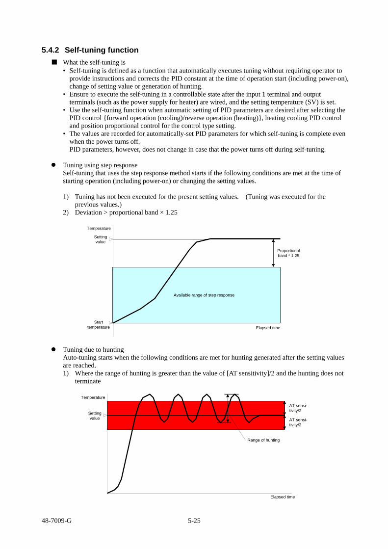
48-7009-G 5-25
5.4.2 Self-tuning function
■ What the self-tuning is
• Self-tuning is defined as a function that automatically executes tuning without requiring operator to
provide instructions and corrects the PID constant at the time of operation start (including power-on),
change of setting value or generation of hunting.
• Ensure to execute the self-tuning in a controllable state after the input 1 terminal and output
terminals (such as the power supply for heater) are wired, and the setting temperature (SV) is set.
• Use the self-tuning function when automatic setting of PID parameters are desired after selecting the
PID control {forward operation (cooling)/reverse operation (heating)}, heating cooling PID control
and position proportional control for the control type setting.
• The values are recorded for automatically-set PID parameters for which self-tuning is complete even
when the power turns off.
PID parameters, however, does not change in case that the power turns off during self-tuning.
Tuning using step response
Self-tuning that uses the step response method starts if the following conditions are met at the time of
starting operation (including power-on) or changing the setting values.
1) Tuning has not been executed for the present setting values. (Tuning was executed for the
previous values.)
2) Deviation > proportional band × 1.25
Available range of step response
Start
temperature
Setting
value
Elapsed time
Temperature
Proportional
band * 1.25
Tuning due to hunting
Auto-tuning starts when the following conditions are met for hunting generated after the setting values
are reached.
1) Where the range of hunting is greater than the value of [AT sensitivity]/2 and the hunting does not
terminate
AT sensi-
tivity/2
Range of hunting
Setting
value
Elapsed time
Temperature
AT sensi-
tivity/2

48-7009-G 5-26
Note Precautions on the use
Self-tuning is affected by the present control results, as it is a function to correct the PID constant using
responses from the normal control.
Under the following environments, precise compensation may not be possible.
(1) Control system with large disturbances (when hunting-like operation appears due to disturbances)
(2) Control system with much time required for providing control outputs
Under the following cases, use auto-tuning.
(1) Where overshoot suppression is focused
(2) Where target follow-up characteristics are focused
(3) Where disturbance response is focused
(4) Control system with fast response (soldering gun, etc.)
(5) Control system with much dead time (constant-temperature bath, etc.)

48-7009-G 5-27
5.4.3 Mode/manual function
■ Mode (MD)/manual (MAN) function
Controls set in the control mode and manual controls can be switched over using the FUNC key, DI or
communication.
Changeable controls are RUN, READY, MANUAL and timer controls in the control mode (MD) of
SET 4. The control mode (MD) can be changed using the ▽ key or △ key.
The following explanation is for switching over the control mode (MD) to RUN.
In the manual control, a control amount (outputs for control) is randomly set and provided as output
regardless of the state of the subject of control.
The manual control is used when checking operations of operation ends such as heater and valve at the
initial operation of a system, or when the normal control is not possible due to a sensor failure.
With the PID control, abrupt change of operating amount (control outputs) is suppressed when the
auto-control and manual control are switched over one another. In addition, the
balance-less/bump-less function is mounted for suppressing chances of damage on peripheral devices
and negative effects to the control system due to such an abrupt change, resulting in control at ease.
0
100
Time
Operating amount (MV)
Operating amount (MV) Auto-control Manual control
Switchover Change of operating amount
0
100
0
Time
Operating amount (MV)
Operating amount (MV) Manual control Auto-control
PV/SV screen at auto/manual
At RUN and READY At manual
℃OUT1
℃OUT1
Control setting value (SV) can be set. Operating amount can be set.
Note Use “SET 4/SV” for changing the control setting value (SV) in the manual control.

48-7009-G 5-28
5.4.4 Bank function
■ What the bank function is
• The bank function is a function that enables a desired control to be effective through changing the
bank settings for which parameters are preset in each bank and thereby no change of temperatures,
PID values or alarm settings are required each time when different temperature controls or alarm
settings are set on a single unit of this equipment.
Eight memory banks, or banks 0 to 7, are available. A memory bank is what particular groups of
setting values are integrated. In one setting value group, max. 16 types of parameters with bank
functions can be set.
Sixteen types of parameters are those set in the “bank setting mode.”
The parameters that are not set in the “bank setting mode” are common parameters for each bank.
Bank 0
Bank 1
Bank 2
Bank 3
Bank 4
Bank 5
Bank 6
Bank 7
Only 16 types of random parameters that are set in the
bank setting mode are changeable with settings.
Only 16 types of random parameters that are set in the
bank setting mode are changeable with settings.
Only 16 types of random parameters that are set in the
bank setting mode are changeable with settings.
Only 16 types of random parameters that are set in the
bank setting mode are changeable with settings.
Only 16 types of random parameters that are set in the
bank setting mode are changeable with settings.
Only 16 types of random parameters that are set in the
bank setting mode are changeable with settings.
Only 16 types of random parameters that are set in the
bank setting mode are changeable with settings.
Only 16 types of random parameters that are set in the
bank setting mode are changeable with settings.

48-7009-G 5-29
< How to set >
For setting the control setting mode (SET 04) ---see the page 6-14.
For setting the bank setting mode (SET 20) --- see the page 6-72.
■ Operation flow
Power-on
Run mode
About 4 seconds (automatic)
MODE key: 2 seconds
Input 1 setting mode
SET 01 screen
△/▽ key
Bank setting mode
SET 20 screen
MODE key
Bank selection 01 setting
Selection of parameters to be set
in the bank, using △/▽ key
Bank selection
02 setting?
Not required, MODE key,
to SET 20 screen
Bank selection 02 setting
Required, MODE key
Bank selection
03 setting?
Max. 16 pcs selectable
When no selection to be
made: OFF Not required, MODE key,
to SET 20 screen
Bank selection 16 setting
Selection of parameters to be set
in the bank, using △/▽ key
Selection of parameters to be set
in the bank, using △/▽ key
Bank setting mode
SET 20 screen
MODE key
To ①
Bank selection 03 to 16

48-7009-G 5-30
Set corresponding parameters into each bank.
Set the bank as the one to be used.
From ①
△/▽ key
Control setting mode
SET 04 screen
MODE key
Bank switchover
bANK * screen bANK *: 0 to 7
Parameter setting Other bank setting to be made
Bank already set
Control setting mode
SET 04 screen
Bank switchover
bANK * screen
MODE key
MODE key
Recording the switchover of banks
① Change of the control setting mode using “bank switchover” ---
The change is recorded when the MODE key is pressed (or when the screen moves to a next
screen.)
Take care that none is recorded when the △/▽ key is used for switchover.
② FUNC key .............. The change is recorded when the FUNC key is pressed.
③ DI ........................... The change is recorded when switchover is made in DI.
④ Communication ...... Only parameters for which limits are set when communication is used for
switchover. Recording is executed absolutely with “STR (store)” command.
STR .....See the chapter for communication in the operation manual.
Note Take care the switchover according to the items 2 to 4, since limiters may interfere with
setting values for parameters.
< Parameters with limits >
① Input type setting .................... INP 1, INP 2
② Decimal point position ........... dP 1, dP 2
③ Celsius/Fahrenheit .................. °C/°F
Example: Where the input type is changed from K thermocouple to T thermocouple
Setting values of SV limiter upper limit and lower limit change due to the setting range
narrower with T thermocouple.
<Measure> Set the parameter that interferes with the limits into the bank setting mode.

48-7009-G 5-31
5.4.5 Timer function
■ What the timer function is
• A function to generate an event for a predetermined time period or predetermined time after a trigger
is activated.
Some major examples of the use and settings are as follows.
■ Where automatic start/stop of control is desired after power-on (auto-start)
Example of setting for a control for 20 minutes at 180 °C, 2 hours after the power is turned on
SEt04 CNt
Name Setting content Setting value
SV Control setting 180 C 180
Md Control mode Timer 1 makes the control start/stop. TIME1
SEt14 tIME1
Name Setting content Setting value
tMF1 Function setting Auto-start 1
oNt1 On delay timer 2 hours 02:00
oFt1 Off delay timer 20 minutes 00:20
Power
supply
Control
On delay
2 hours
Off delay
20 minutes
ON
OFF
RUN
RDY
Temperature
180℃
Normal
temperature

48-7009-G 5-32
■ Where the control is desired to start/stop by pressing the FUNC key (manual start)
Example of setting for a control for 20 minutes at 180 °C, 2 hours after the FUNC key is pressed
SEt03 KEY
Name Setting content Setting value
FU1 Function key 1 function setting
No setting of time for the key held pressed/timer start/reset
04
SEt04 CNt
Name Setting content Setting value
SV Control setting 180 C 180
Md Control mode Timer 1 makes the control start/stop. TIME1
SEt14 tIME1
Name Setting content Setting value
tMF1 Function setting Manual-start 2
oNt1 On delay timer 2 hours 02:00
oFt1 Off delay timer 20 minutes 00:20
ON
OFF
RUN
RDY
180℃
Press FUNC key
Power
supply
Control
On delay
2 hours
Off delay
20 minutes
Temperature
Normal
temperature

48-7009-G 5-33
■ Where contact outputs are desired to be provided when a measurement value comes to a target value
(SV start)
Setting example for output 1 to be provided for 1 minute after 180 °C is reached
SEt04 CNt
Name Setting content Setting value
SV Control setting 180C 180
SEt5 oUt1
Name Setting content Setting value
o1F Target connection setting Timer 1 output 5
SEt04 tIME1
Name Setting content Setting value
tMF1 Function setting SV start 3
tSV1 Start SV permissible range setting Give range of 2 °C 2
oFt1 Off delay timer 1 minute 00:01
Temperature
180℃
Normal
temperature
Output 1
ON
OFF
Contact output is provided for 1 minute
Setting the start SV permissible range
setting to 2 °C results in timer
operation when the value falls in the
range of SV ± 1 ℃.

48-7009-G 5-34
■ Where contact outputs 3 and 4 are desired to be provided in sequence (Event * start)
Setting example where the output 3 is provided using the timer 1 and then the timer 2 starts operation
to provide the output 4 when the timer 1 terminates operation
SEt7/8 oUt3/4
Name Setting content Setting value
o3F Target connection setting Timer 1 output 5
o4F Target connection setting Timer 2 output 9
SEt14 tIME1
Name Setting content Setting value
tMF1 Function setting Auto-timer 1
oNt1 On delay timer 0 minute 00:00
oFt1 Off delay timer 1 minute 00:01
SEt15 tIME2
Name Setting content Setting value
tMF2 Function setting Event 3 start 10
oNt2 On delay timer 1 minute 00:01
oFt2 Off delay timer 1 minute 00:01
Power
supply
Off delay
1 minute
ON
OFF
Output 3
ON
OFF
On delay
1 minute
Output 4
ON
OFF
Off delay
1 minute

48-7009-G 5-35
■ Where the equipment is used as a simplified programmable controller (manual start and event * start)
Setting example where temperature is raised to 100 °C in 1 minute, maintained at 100 °C for 1 minute,
and then lowered to 0 °C in 1 minute
SEt03 KEY
Name Setting content Setting value
FU1 Function key 1 function setting
No setting of time for the key held pressed/timer start/reset
04
SEt7/8 oUt3/4
Name Setting content Setting value
o3F Target connection setting Timer 1 output 5
o4F Target connection setting Timer 2 output 9
SEt14 tIME1
Name Setting content Setting value
tMF1 Function setting Manual-start 2
oNt1 On delay timer 0 minute 00:00
oFt1 Off delay timer 1 minute 00:02
SEt15 tIME2
Name Setting content Setting value
tMF2 Function setting Event 3 start 10
oNt2 On delay timer 2 minutes 00:02
oFt2 Off delay timer 1 minute 00:01
SEt20 bNK
Name Setting content Setting value
bnk01 Control setting SV
bnk02 Ramp time setting RMP
For the following setting, enter the inputs during the switchover in bANK (bank switching) in SET 4.
* Set bANK to “0.”
SEt04 CNt
Name Setting content Setting value
SV Control setting 0 C 0
RMP Ramp time setting Setting turned off 0.0
* Set bANK to “1.”
SEt04 CNt
Name Setting content Setting value
SV Control setting 100 C 100
RMP Ramp time setting To be raised by 100 °C in 1 minute 100.0
* Set bANK to “2.”
SEt04 CNt
Name Setting content Setting value
SV Control setting 0 C 100
RMP Ramp time setting To be raised by 100 °C in 1 minute 100.0
* The bank cannot be switched over unless DI is set after the bank setting is complete.
SEt13
dI Name Setting content Setting value
dIF Function setting Both DI 1 and DI 2 to be switched over 0011
Wire the equipment upon completion of setting.

48-7009-G 5-36
204 205/209 207
Connect the output 3 with DI 1. ⑦-⑮ ⑨-⑯
⑲- -
⑬- ⑮-
Connect the output 4 with DI 2. ⑧-⑰ ⑨-⑱
⑳- -
⑭- ⑮-
Note When connecting the output and DI, select an open collector for the output.
Power
supply
Off delay
2 minutes
ON
OFF
Output 3
ON
OFF
On delay
2 minutes
Output 4
ON
OFF
Off delay
1 minute
FUNC key
Change of controlled
temperature
100℃
Normal
temperature
Temperature rises by 100℃in 1 minute using the ramp function.
Bank 1 Bank 2 Bank 0Bank 0
Temperature lowers by 100℃in 1 minute using the ramp function.

48-7009-G 5-37
■ Complementary explanation of “RDY lamp” lighting status
The table below shows an indication status of the RDY lamp when timer operation is set for control
mode. The indication status varies depending on the SET 04 control MD status (MD/READY).
Md
RDY RUN MAN
TIMEx
Before operation
On delay Off delay After
operation
None Blinking Extinction Extinction Blinking Blinking Extinction Blinking
func Md Blinking Extinction Extinction Blinking Blinking Extinction Blinking
MdRdY RdY Lighting Lighting Lighting Lighting Lighting Lighting Lighting
di Md Blinking Extinction Extinction Blinking Blinking Extinction Blinking
MdRdY RdY Lighting Lighting Lighting Lighting Lighting Lighting Lighting
* The blinking interval shown in the table is 500 ms.
* At a forced stoppage due to the interlock function, the blinking interval of the RDY lamp becomes
faster to 100 ms.

48-7009-G 5-38
5.4.6 Loop abnormality function
■ What the loop abnormality is
The function is to detect an abnormality in the control loop.
When a value falls in the judgment domain with respect to the conditions of the control loop
anomaly MV threshold(MS*) and control loop anomaly PV threshold(tS*), the control loop anomaly
PV change threshold is judged at each “LoP*” time.
A loop abnormality is determined if each change threshold is judged to be equal to or below “PS*.”
When [PS* = 0] is true, only time judgment is executed using LOP*.
When the time satisfying threshold of TS* or MS* exceeds LOP*, the loop abnormality is
determined as detected.
(The symbol “*” takes the following values: “1” for the primary control and “2” for the secondary
control.)
The loop abnormality function is usable when one of OUT 1 to OUT 7 is selected for the event
loop abnormality existent.
About primary control loop abnormality-related setting ............................. P6-26~29
About secondary control loop abnormality-related setting .......................... P6-39~42
About event function 4 loop abnormality(E1~7F4) setting ......................... P6-54
Monitoringtime
(LoP*)
ON
OFF
SV
PV
MLL*
MLH*
MV*
Monitoringtime
(LoP*)
Monitoringtime
(LoP*)
Loopabnormality
Judgmentdomain
Non-judgmentdomain
Judgmentdomain
Non-judgmentdomainControl loop
anomaly PVthreshold(TS*)
Control loopanomaly MVthreshold(MS*)

48-7009-G 5-39
< How to set >
Power-on
About 4 seconds (automatic)
Operating mode
MODE key: 2 seconds
Input 1 setting mode
SET 01 screen
△/▽ key
Control setting mode
SET 04 screen
MODE key
Primary control loop
abnormality time setting
LoP 1
Set the primary control abnormality
time setting, using the △/▽ key.
Secondary control loop
abnormality time setting
LoP 2
Set the secondary control abnormality
time setting, using the △/▽ key.
Control setting mode
SET 04 screen
OUT 1 to 7 setting mode
SET 05 to 11 screens
Set the screen to OUT * output screen, which is used for
outputting the loop abnormality, using the △/▽ key.
(Select among OUT 1 to 7.)
Target connection setting
o * F
Set it to the event output “2”, using
the △/▽ key.
Event function 4 setting
E * F 4
Set it to “01” of the loop abnormality existent
and “11” of the loop abnormality existent +
hold existent, using the △/▽ key.
Setting complete
MODE key
MODE key
△/▽ key
MODE key
MODE key
How to cancel the loop abnormality hold
(1) Set the additional function setting of the event function 4 setting to “0: None.”
(2) Turn off the power when no abnormality is present, and then turn it back on.

48-7009-G 5-40
5.4.7 Current transformer (CT) abnormality function
■ What CT (current transformer) is
• CT is a function to detect that outputs are not properly turned on and off due to failure of relays or
SSRs.
• For detection of failure, using CT, ensure to wire the CT terminal and output terminal (such as heater
power supply), set the CT * target connection setting (CI *) and CT 1 abnormality current value
setting (Ct 1), and establish the control effective.
State of control output 1 Power distribution to heater
CT abnormality state Output * Operation lamp
ON Lighting Existent *1) Normal
Nonexistent (output disconnection state) Abnormal
OFF Extinction Existent (output short state) Abnormal
Nonexistent *2) Normal
ON
Control output 1
Ton *3) Toff *4)
OFF
*1) Power distribution existent (normal) is determined when the CT 1 abnormal current value setting
is larger than the CT current value in the period Ton.
*2) Power distribution nonexistent (normal) is determined when the CT 1 abnormal current value
setting is smaller than the CT current value in the period Toff.
*3) State of the output disconnection is not detected when the ON time (Ton) of the control output 1 is
300 ms or smaller.
*4) State of the output short is not detected when the OFF time (Toff) of the control output 1 is 300 ms
or smaller.
* Detection is unstable when the CT current value is small. To solve the issue, wind CT with load
wires passing through the hole multiple times as illustrated below. Winding twice results in the
detection current being larger by a multiplication factor of 2.
Note The detection accuracy is, however, deteriorated by a multiplication factor of 2.
CT
■ Example of installation, setting calculation and parameter setting of CT
■ Single phase
Install CT in the location illustrated below.
AC line
To equipment CT input
Load Load: heater and such
Note Wire in one way in any direction.
Load wire

48-7009-G 5-41
■ Calculation of the CT 1 abnormal current value setting
Detection current to be set is calculated with the following equation as an indication:
∴ CT 1 abnormal current value setting value = Current normal value + current at heater disconnection
2
Note Take care that the current in a multiplication factor of N flows when the load wire is wound
around CT N times due to too small a measurement current. Sixty amperes or 6 times the
actual current of 10 A flows when the load wire is wound around CT 6 times.
Example: Heater of 100 V, 2kW [When normal]
[When disconnected]
Load Load
To equipment CT input
To equipment CT input
Disconnected
The current on the heater is 20 A at normal and 0 A at disconnected, thus the CT 1 abnormal current value
setting value is as follows.
∴ CT 1 abnormal current value setting value =
Current normal value + current at
heater disconnection
2
20 + 0
2 = = 10 [A]
■ Example of parameter setting
The example shown below is identical to the above example, except where CT 1 is installed on the
output 1 and CT abnormality is provided as output on the output 2.
SEt6 oUt2
Name Setting content Setting value
o2F Target connection setting Event output 2
E2F3
Event function 3 setting (CT abnormality)
All modes, no added function, CT 1 abnormality
001
SEt12
CT Name Setting content Setting value
CI1
CT 1 target connection setting Connected to OUT 1 (allowed to be set in case of DO)
1
Ct1 CT 1 abnormal current value setting 10.0

48-7009-G 5-42
■ For 3-phase
■ Delta connection
Example: Where 3 heaters of 200 V and 2 kW are used
[When normal]
To equipment CT input
To equipment CT input
Load
Load Load
Normal current is 17.3 A (≒√3 × 10 A) for each phase.
[When disconnected in between phases]
To equipment CT input
To equipment CT input
Load
Load Load
To equipment CT input
To equipment CT input
Load
Load Load
[When disconnected on load side]
Disconnected
Current when disconnected = 10A√3(√3/2)
= 15A
Disconnected
Current when disconnected = 10A√3(1/√3)
= 10A
The heater disconnection detection current value when disconnection occurs in between phases is as
follows.
CT 1 abnormal current value setting value = (17.3 + 15)/2 ≒ 16.1 [A]
The heater disconnection detection current value when disconnection occurs on the load side is as follows.
CT 1 abnormal current value setting value = (17.3 + 10)/2 ≒ 13.65 [A]
For detection in both cases, the CT 1 abnormal current value setting value is to be 16.1 A.

48-7009-G 5-43
■ Star connection
Example: Where 3 heaters of 200 V and 2 kW are used
[When normal]
To equipment CT input
To equipment CT input
Load
Load Load
Normal current is 5.8 A {≒10 A × (1/√3)} for each phase.
[When disconnected in between phases]
To equipment CT input
To equipment CT input
Load
Load Load
Disconnected
Current when disconnected in between phases = 10 A × (1/√3) × (√3/2) = 5A
[When disconnected on load side]
To equipment CT input
To equipment CT input
Load
Load Load
Disconnected
Current when disconnection occurs on the load side = 10 A × (1/√3) × (√3/2) = 5A
The CT 1 abnormal current value setting value for this connection is 5.4 A {= (5.8 + 5)/2}.

48-7009-G 5-44
■ V connection
Example: Where 2 heaters of 200 V and 2 kW are used
[When normal]
To equipment CT input
To equipment CT input
Load
Load
The current that flows in the target device for CT installation is 17.3 A (≒√3 × 10 A).
[Disconnected on the common side]
To equipment CT input
To equipment CT input
Load
Load
[When disconnected on load side]
To equipment CT input
To equipment CT input
Load
Load
Disconnected
Disconnected
Current when disconnected = 10A (1/2) = 5A
Current when disconnected = 10A 1 = 10A
The heater disconnection detection current value when disconnection occurs on the common side is as
follows.
Heater disconnection detection current value = (17.3 +5)/2 ≒ 11.2 [A]
The heater disconnection detection current value when disconnection occurs on the load side is as
follows.
Heater disconnection detection current value = (17.3 +10)/2 ≒ 13.7 [A]
Hence, the heater disconnection detection current value is to be 13.7 A in order to detect disconnection
in both cases.
■ Example of parameter setting
The following is an example when CT 1 and 2 are installed on the outputs 1 and 2 respectively in the
connection shown above and CT abnormality is provided as output on the output 3.
SEt6 oUt2
Name Setting content Setting value
o3F Target connection setting Event output 2
E3F3
Event function 3 setting (CT abnormality)
All modes, no added function, CT 1 abnormality + CT 2 abnormality
003
SEt12
CT Name Setting content Setting value
CI1 CT 1 target connection setting
Connected to OUT 1 (allowed to be set in case of DO)
1
Ct1 CT 1 abnormal current value setting 13.7
CI2 CT 2 target connection setting
Connected to OUT 2 (allowed to be set in case of DO)
2
Ct2 CT 2 abnormal current value setting 13.7

48-7009-G 5-45
5.4.8 Position proportional control
■ What the position proportional control is
• In the position proportional control, the temperature of the subject is controlled through adjusting the
flow rate, which depends on the valve opening ratio. The valve opening ratio is controlled by open
or close signal that is output for the valve, where an operating amount is calculated by the PID
control, taking into account the valve motor stroke time. The position proportional control can
control a subject without feedback resistance.
• The valve motor stroke time is defined as time required for a valve from full close to full open.
Sensor
Open signal
Close signal
Controller
Subject of control
Warm water
Discharge of warm water
ValveWarm
water
• Valve motor drive dead band
The controller for the position proportional control operates output of open or close signal such that
the operating amount of the controller is coincident with the valve opening ratio. To save service
life of the valve, frequent switchover operation for opening and closing the valve must be avoided as
much as possible.
Hence, a dead band is provided on the output switchover points for open and close signals, so that
outputs of both the open and close signals are halted in this band range in order to reduce the
frequency of open and close switchover operations.
Dead band
Opening ratio
MV
Open signal Close signal
• Post-AT initial opening ratio
The operating amount can be set for suppressing undershoot that is possibly generated right after the
termination of AT.
Example: Response in post-AT
t
温度
初期開度=100%
初期開度=0%
AT中 通常制御
Temperature

48-7009-G 5-46
5.4.9 Concurrent temperature ascent function
■ What the concurrent temperature ascent is
• When a concurrent temperature ascent control is executed for multiple channels using the RS-485
communication function, a target value can be reached for each channel at the same clock time,
disregarding characteristics of each channel through assigning master or slave to the channels.
The channel that requires the longest time for reaching the target value from the start of the control
is assigned as a master and others as slaves.
• The concurrent temperature ascent function is activated when operation starts, including when
power turns on, or setting value is changed, and terminated when the master reaches the target value.
Controller 1 ch Controller 2 ch Controller 3 ch Controller 4 ch
Heater Heater Heater Heater
Sensor Sensor
Sensor
Sensor
Oven
Input Output Input Output Input Output Input Output
• How to use the function
1) Set the communication protocol setting (SEt 17) to TOHO protocol.
2) Set the communication switchover setting (SEt 17) to a concurrent temperature ascent master
for a channel that requires the longest time to reach the target value, and to concurrent
temperature ascent slaves for others.
3) Set the primary control sensitivity setting (SEt 04).
Set the sensitivity to such a degree that no chattering is generated, as the slave sides are
ON/OFF-controlled to the present temperature on the master during concurrent temperature
ascent.
Note Precautions on the use
1) Conduct the auto-tuning for each channel as needed.
2) Do not execute external communication during the use of the concurrent temperature ascent function.

48-7009-G 5-47
5.5 Explanation of the program run function
■ The digital controller TTM-200 Series can provide a simple program controller. This chapter
explains the program run of TTM-200 Series.
• A program run of this product is established by automatically controlling “bank function” and
“program step function.” The process flow for establishing a program run is described below.
■ Program run operation explanation diagram
STEP1 STEP2 STEP3 STEP4 STEP5 STEP6 STEP7 STEP8
SV1
50℃TIM1
00:30
ST1BKBANK1
BANK1
RMP
10P1
4.0
・・・
o2F
I20
D
5
SV2
100℃TIM2
00:40
ST2BKBANK1
BANK1
RMP
10
・・・
o2F
SV3
150℃TIM3
00:50
ST3BKBANK1
BANK1
RMP
10
・・・
o2F
SV4
200℃TIM4
01:00
ST4BKBANK1
BANK1
RMP
10
・・・
o2F
SV5
150℃TIM5
00:30
ST5BKBANK2
BANK2
RMP
5
・・・
o2FTIMER ON
DELAY
SV6
100℃TIM6
00:40
ST6BKBANK2
BANK2
RMP
5
・・・
SV7
150℃TIM7
00:50
ST7BKBANK1
BANK1
RMP
10
・・・
o2F
SV8
20℃TIM8
00:10
ST8BKBANK3
BANK3
RMP
30
・・・
o2FRUN OUT
BANK0
RMP
P1
3.0MA
X.
16 P
AR
AM
ETER
・・・
o2FEND OUT
I0
D
0
BANK0
RMP
・・・
o2FEND OUT
STARTOPERATION
ENDOPERATION
ENDPV
BANK0
RMP
MA
X
16ハ
゚ラメー
タ
・・・
o2FEND OUT
OPERATIONSTOP
STOPOPERATION
STOP OPERATION
P1
2.0
I10
D
2
P1
3.0
I0
D
0
P1
3.0
I0
D
0
P1
4.0
I20
D
5
P1
4.0
I20
D
5
P1
4.0
I20
D
5
P1
4.0
I20
D
5
P1
2.0
I10
D
2
P1
2.0
I10
D
2
SET22
SETTING VALUE
MAX. 8 STEPS
SET20SETTING VALUE
STEP SV SETTING
STEP TIME SETTING
STEP BANK SETTING
o2F
TEMP. CHANGE PATTERN
REFER1BANK
OPERATIONSTOP
OUTPUT EXAMPLE
TIMER ONDELAY
o2F
A certain pattern of a status to be changed, such as temperature, is developed. The diagram
above shows an example of a temperature change pattern. To automatically change this pattern,
it is divided into the smallest units referred to as STEP.
Set the auto run sequence of a STEP to the SET 22 “program step” parameter.
For “step bank setting” of SET 22, SET 20 “bank function” is referred. With this reference,
operations of “input, output, timer output, event input/output, control parameters, etc.” for each
step are determined.
Parameters necessary for such control as “input,” “output,” “timer output,” or “event” are set.
The steps during an auto run sequence are automatically switched by the sequence, and banks set
with control parameters are also switched. This mechanism provides a program run.
This product allows a program run in eight steps at most.
o2F OUTPUT EXAMPLE
MA
X. 1
6
PA
RA
ME
TE
R

48-7009-G 5-48
5.5.1 Operation flow of the program run
■ Digital controller: This section explains operation process of the program run using TTM-200. To
perform a program run, the SET 20, SET 21 and SET 22 parameters must be set.
■ The setting content is as follows:
Set a parameter desired to change with setting value in the SET 20 bank setting for each step.
For the setting, select a parameter requiring to be switched during a program run from SETs 1 to
17.
For details of the bank setting, see operation explanation - bank function (P5-28 to 30).
The SET 21 program function setting sets a program run method. Also, the SET 22 program
setting sets a program run pattern. Perform the settings according to this manual.
Note No program is used in “constant value run mode” and “program run mode.” In “constant value
run mode,” the SET 22 program is not displayed. A switchover in this mode is made with SET
21 (C/P).
The diagram below shows a general process flow of a program run. Settings should be made
along with the flow.
For setting and operation check in Items 2 to 4 below, see “How to set run settings” (P5-4 to 21)
and “How to set each function and description of function” (P5-22 to 46).
1. Planning a program
Plan setting parameters and operating statuses required for control.
• Planning program run patterns
• Planning setting parameters
2. Setting basic settings: Set necessary parameters in SETs 1 to 19.
• “Input setting”: Sensor type, temperature range, etc.
• “Output setting”: Output type, output method, presence of alarm
setting, etc.
• “Presence/absence of event function usage”: DI polarity, etc.
“Presence/absence of timer function usage”: Timer operation method,
time setting, etc.
“Key setting”: Presence/absence of Func key usage, etc.
3. Setting a bank
• Set necessary parameters to the bank by switching SETs 1 to 17 in a
program run.
4. Checking an operation of constant value run mode
• Check the bank settings by manually switching the bank in key
operation or with DI.
Check each of all set banks for planned control condition.
5. Set a program run mode.
Set the SET 21 program function setting and SET 22 program setting in accordance with the program
run chart.
6. Checking an operation of program run mode
• Check operation status of each step by manually switching the step in key operation or with DI.
Caution: Before starting a program run:
Check program content and control status before starting an unattended run in order to prevent
accidents during the program run.
Planning a program
Setting basic settings (control settings)
Checking a run in constant value run mode
Setting a program run mode
Start a run in program run mode

48-7009-G 5-49
5.5.2 SET 21 program function setting
■ The SET 21 program function setting is for setting operating method of a program run.
Set the setting values for the following: “program run mode,” “power failure compensation range,”
“time unit,” “WAIT range” and “Program run start/stop.”
The flowchart below is for “SET 21 program function setting.”
Note Note that some screens do not appear depending on setting values. Characters indicated in
parentheses are those displayed on a screen.
[Setting flow]
SET 21 (PGF) Setting the program
function setting mode
SET 21 (C/P) Selecting an operating
type setting
II. When C/P 1:
Operating type setting *1 I. When C/P 0 (program run OFF) II. When C/P 1 (program run ON)
SET 21 (PGMd) Selecting a program mode
I. When C/P 0: SET 21 returns to the beginning.
Power failure compensation range setting *3 Displayed only with presence of power failure compensation for the program mode setting. Otherwise, none is displayed.
IV. When PGMD 2 or 3:
SET 21 (PoC) Setting the power failure
compensation range
III. When PGMD 0 or 1:
SET 21 (H/MP) Selecting time unit
Time unit setting *4 V. When H/MP 0 or 3 (step time) VI. When H/MP 1, 2, 4 or 5 (soak time)
V. When H/MP 0 or 3: VI.
When H/MP 1, 2, 4 or 5
SET 21 (WAIt) Setting the WAIT range
WAIT width setting *5 Displayed only with the soak time settings for time unit. None is displayed with step time.
SET 21 returns to the beginning.
Program mode setting *2 III. When PGMd 0 or 1 (program run ON) IV. When PGMd 2 or 3 (program run ON; with power failure compensation)
The next page describes the content of each setting value.

48-7009-G 5-50
*1: Operating type setting (C/P)
Set “operating method.”
Setting range Initial value: 0 in constant value run mode
0: Constant value run mode (program run mode OFF)
1: Program run mode (program run mode ON)
*2: Program rum mode setting (PGMd)
Set “return operating method” and “operation method after program run” in case of power failure
during a program run.
Setting range Initial value: 0 Program 1 (without power failure compensation)
0: Program 1 (without power failure compensation)
1: Program 2 (without power failure compensation)
2: Program 1 (with power failure compensation)
3: Program 2 (with power failure compensation)
• Program 1: Control stops when a program run ends. When a run ends, ENd is displayed and
control stops.
• Program 2: Control remains active at a status of the last step even after a program run ends.
Control continues even though ENd is displayed after a run ends. Control becomes in a stop
status by manual operation (key operation) or DI entry.
Note The SET 4 control mode setting (Md) becomes inactive in program rum mode (C/P 1). Only
constant value rum mode is active.
Regarding power failure compensation
Upon return from a power failure with “With power failure compensation,” the run restarts from
the step being in progress at the time of the power failure.
“Current step,” “repetitive count” and “remaining time” are stored.
In case of power failure, the status returns to that last-stored in the step, and the run restarts
provided that the setting condition of the power failure compensation range setting (PoC) is met.
Note Note that time error is generated within a step even though a run restarts from the middle of a
program run if the return condition (power failure compensation range setting) is met.
Note The return conditions is that the difference of the PV values between at return and before return is
smaller than the power failure compensation range setting (PoC) as shown in the formula below:
Condition Power failure compensation range setting (PoC) (PV value at return) (PV value
before return)
*3: Power failure compensation range setting (PoC)
Set the criteria range for the condition described above for return from a power failure.
Setting range Initial value: 0
Temperature input (C): 0 to 999 (0.0 to 999.9) Always return at 0.
Analog input (digit): 0 to 9999 Always return at 0.
Note Upon return from a power failure, no return operation is performed in case of disconnected or
failed sensor regardless the (PoC) setting value. The run status is of program run in stoppage.

48-7009-G 5-51
*4: Time unit setting (H/MP)
Set “time unit” and “step transfer condition (time countdown condition)” of a step.
Setting range Initial value: 0: Step time (hour: minute)
0: Step time (hour: minute)
1: Soak time 1 (hour: minute)
2: Soak time 2 (hour: minute)
3: Step time (minute: second)
4: Soak time 1 (minute: second)
5: Soak time 2 (minute: second)
Note Regarding meanings of “step,” “soak 1” and “soak 2”
“Step time”: The step proceeds in accordance with a set step time (SET 22 tIM*) regardless
statuses of PV or SV. Therefore, a step proceeds to the next one when set time
elapses.
“Soak time 1”: Time is count down if a PV falls within the set WAIT range even once. A step
proceeds to the next one when set time elapses. Judgment is made with a set PV
even if a ramp is set.
“Soak time 2”: Time is count down only within a set WAIT range.
For details, see “Complementary explanation of the program run” in Section 5.5.7 (P5-61 and 69).
*5: WAIT range setting (WAIt)
Set “range for a PV value” when using the “soak time 1 or 2” function.
Setting range Initial value: 2
(During temperature input)
Soak time 1: 0 to 999 (0.0 to 999.9)C
Soak time 2: 0 to 999 (0.0 to 999.9)C
(During analog input)
Soak time 1: 0 to 9999 (digit)
Soak time 2: 0 to 9999 (digit)
Note Complementary to the WAIT range setting
The operation for the soak time 2 (H/MP 2) is the same as that for the soak time 1 in the WAIT
range setting (WAIt 0).
For details, see “Complementary explanation of the program run” in Section 5.5.7 (P5-61 and 69).

48-7009-G 5-52
5.5.3 SET 21 program function setting screen
■ The program function setting screen is shown below.
SET21 PGF
PGMD 0
H/MP 0
WAI T 2
POC 0
25 25
Returns to SET21 PGF
SET01 I NP1
C/P 0
PV value (present value)
SV value (setting value)
Hold MODE key pressed for 2 seconds
Input 1 setting screen
Press the key or key several times.
Program function setting mode
Press MODE key.
Operating type setting
Ho
ld M
OD
E k
ey p
resse
d f
or
2 s
eco
nd
s
No. Setting range
0 Program mode 1 (without power failure compensation) initial value
1 Program mode 2 (without power failure compensation)
2 Program mode 1 (with power failure compensation)
3 Program mode 2 (with power failure compensation)
* No display when C/P 0 (normal)
No. Setting range
0 Constant value run mode (initial value)
1 Program run mode
Press MODE key.
Program mode setting
Press MODE key.
Power failure compensation range setting
Temperature input (initial value = 0)
0 to 999 (0.0 to 999.9) (C)
Analog input (initial value = 0)
0 to 9999 (digit)
* No display when C/P 0 (normal) or PGMd 0 or 1 (program run without power failure compensation) Press MODE key.
Time unit setting
0 Hour: minute (step time) (initial value)
1 Hour: minute (soak time 1)
2 Hour: minute (soak time 2)
3 Minute: second (step time)
4 Minute: second (soak time 1)
5 Minute: second (soak time 2)
* No display when C/P 0 (normal)
Press MODE key.
WAIT range setting
Press MODE key.
Temperature input (initial value = 2)
Soak time 1: 0 to 999 (0.0 to 999.9) (C)
Soak time 2: 0 to 999 (0.0 to 999.9) (C)
Analog input
Soak time 1: 0 to 9999 (digit)
Soak time 2: 0 to 9999 (digit)
* No display when C/P 0 (normal) or H/MP 0 or 3 (step time)

48-7009-G 5-53
5.5.4 SET 22 program setting
■ Set a pattern (program) of the program run in the SET 22 program setting.
[Setting items]
• Set “number-of-use-steps” of the program.
• Set “bank designation,” “step SV value” and “step time” of each step.
• Set “repetitive start step,” “repetitive end step” and “execution count.”
[Setting flow]
The flowchart below is for “SET 21 program function setting.” Characters indicated in
parentheses are those displayed on a screen.
SET 21 (C/P) operating type When C/P 1:
SET 22 (PRoG) Setting the program setting
mode
When the SET 21 (C/P) operating time is C/P 0 (program run OFF), the SET 22 screen is not displayed.
Setting the number of use steps Setting range: 1 to 8 Initial value: 8
Repetition of the number of use steps 1 to StEPN (Repetitively displays up to StEPN.)
SET 22 (St*bK) Setting the bank designation
Bank setting (St*bK) *5 Steps 1 to 8: Bank designation
SET 22 (SV*) Setting the step SV value
Step SV (SV*) Setting the SV value for each step Setting range: SLL to SLH Initial value: 0
SET 22 (tIM*) Setting the step time
Step time (tIM*) *6 Setting the time of a step
SET 22 (StRSt) Setting the repetitive start step
Repetitive start step Setting range: StRSt 1 to repetitive end step setting (ENdSt) Initial value: 1
SET 22 (ENdSt) Setting repetitive end step
Repetitive end step Setting range: Repetitive start step setting (StRSt StRSt) to
number-of-use-steps setting or StEPN * If StEPN is set, the value set for the number-of-use-steps
setting is “repetitive end step setting.” Initial value: StEPN
SET 22 (RUNP) Setting the execution count
Setting the execution count Setting range: RUNP 0 to 9999 (When 0: Unlimitedly repeated.) Initial value: 1
SET 22 returns to the beginning.
SET 22 (StEPN) Setting the number of use
steps (StEPN)
Note Some screens do not appear depending on setting values.
This screen is not displayed in constant value run mode (C/P 0).

48-7009-G 5-54
*5: Bank setting (St*bK)
Switchover is made for each step of a program. “Bank No.” can be designated.
Setting range: St*bK = 0 to 7 (The range depends on SET 4 bANKH.)
Initial value: St* bK = 0 (* = 1 to 8)
Note The symbol “*” of the parameter setting display “St*bK” indicates “step No.”
(The range depends on SET 22 StEPN.)
Note Effective only during a program run
Note When the bank automatic switching function is used (SET 23 BAF 1), no display
appears. The bank automatic switching function is prioritized over the “bank No.”
designation.
*6: Step time (tIM*)
Sets the step time of a program.
Setting range: tIM* = 00:00 to 99:59 Initial value: 00:00 to (* = 1 to 8)
Note The symbol “*” of the parameter setting display “tIM*” indicates “step No.”
(The range depends on SET 22 StEPN.)
Note The time unit is set in the time unit setting (SET 21 H/MP).
Note With the setting value of “00:00,” a run unlimitedly continues.

48-7009-G 5-55
5.5.5 SET 22 program setting screen
■ The program setting screen is shown below.
SET22 PROG
STEPN 8
SV1 0
TI M1 0 0 00
ST1BK 0
25 25
SET01 I NP1
SV8
0
TI M8 0 0 00
ST8BK 0
STRST 1
ENDST STEPn
Returns to SET22 PROG
RUNP 1
PV value (present value) SV value (setting value)
Hold MODE key pressed for 2 seconds
Input 1 setting screen
Press the key several times or key once.
Program setting mode
* When C/P 0, the setting SET 22 is not displayed. Therefore, all screens thereafter up to RUNP do not appear.
Press MODE key.
Number-of-use-step setting
Press MODE key.
Step designation bank setting
Ho
ld M
OD
E k
ey p
resse
d f
or
2 s
eco
nd
s
* Repetitively displayed up to StEPN
Press MODE key.
Re
pe
titi
on
: 1
to
StE
PN
Step SV setting
Press MODE key.
Step time setting
Repetitive start step setting
Ho
ld M
OD
E k
ey p
resse
d f
or
2 s
eco
nd
s
Press MODE key.
Step designation bank setting
Step SV setting
Step time setting
Press MODE key.
Press MODE key.
Press MODE key.
Repetitive end step setting
Execution count setting
Press MODE key.
Press MODE key.
* To be continued to the repetitive start step setting
Press MODE key.

48-7009-G 5-56
5.5.6 Explanation of the screen display and operation of a program run
■ Switching the run screen
Switching between “constant value run,” in
which no program is used, and “program run,” in
which a program automatically executes a run, is
performed with “SET 21 C/P.”
This section describes “program run mode.”
The diagram below shows that the display varies
depending on the difference of run modes.
Note The diagram indicates an example of “TTM-204
operation panel display/operation section.” The
operation method for TTM-205, 207 and 209 is
the same as that for TTM-204.
22 PROG ( 0
89 89 %0
0 0 30 0 0 29 ( 0
0 0 00 0 0 30 ( 1
0 0 00 0 0 30 ( 2
0 0 00 0 0 30 ( 3
PROG STOP 0
22 %0
0 0 00 0 0 30 ( 1
0 0 00 0 0 30 ( 2
0 0 00 0 0 30 ( 3
0
Constant value run mode
PV/SV screen PV display PV value
SV display SV value
MODE key
SET21 C/P=1
SET21 C/P=0
MODE key
Timer 1 monitor
PV display Timer 1 ON time
SV display Timer 1 OFF time
MODE key
Timer 2 monitor
PV display Timer 2 ON time
SV display Timer 2 OFF time
MODE key
Timer 3 monitor
PV display Timer 3 ON time
SV display Timer 3 OFF time
MODE key
Returns to PV/SV screen.
Program run mode
Program run screen
Auxiliary display Before run: Blank (no display) Run in process: Current step No. Run end: “E” displayed TIME blinks (run). TIME goes off (stop/end).
MODE key
Step SV screen
Auxiliary display Before run: Blank (no display) Run in process: Current step No. Run end: “E” displayed C (no display of analog time)
Step time monitor
Auxiliary display Before run: Blank (no display) Run in process: Current step No. Run end: “E” displayed TIME blinks (run in process) TIME goes off (stop in process/run end).
Program run/stop screen
Auxiliary display Before run: Blank (no display) Run in process: Current step No. Run end: “E” displayed
Timer 1 monitor
Auxiliary display 1. Before run; run in process; run end
Timer 2 monitor
Auxiliary display 2. Before run; run in process; run end
Timer 3 monitor
Auxiliary display 3. Before run; run in process; run end
PV display PV value: Before run; run in process; run end
SV display Before run: PRoG (before run) Run in process: Remaining time Run end: ENd
PV display Before run: PV value Run in process: PV value Run end: PV value
SV display Before run: ---- Run in process: Step SV value Run end: Final step SV value
PV display Before run: ---- Run in process: Step setting time Run end: 00:00
SV display Before run: --:-- Run in process: Step remaining time Run end: 00:00
PV display PRoG: Before run; run in process; run end
SV display Before run: StoP (before run) Run in process: RUN Run end: End (after run)
PV display Timer 1 ON time: Before run; run in process; run end
SV display Timer 1 OFF time: Before run; run in process; run end
Returns to the program run screen.
* The monitor only for a set timer is displayed. Monitors unused are skipped.
PV display Timer 2 ON time: Before run; run in process; run end
SV display Timer 2 OFF time: Before run; run in process; run end
PV display Timer 3 ON time: Before run; run in process; run end
SV display Timer 3 OFF time: Before run; run in process; run end
MODE key
MODE key
MODE key
MODE key
MODE key
MODE key
* The screens for run mode, step SV value, step time and program run start/stop are not displayed.
Details of “program run screen” are described in the next page, “Regarding operation and display of a
program run.”
Auxiliary display section
PV value display section
Auxiliary display section
SV value display section
SV display section
PV display section
PV
SV

48-7009-G 5-57
■ Regarding operation and display of a program run
The diagram below shows “screen display during a program run.” The screens are categorized into
“before run,” “run in process” and “run end” depending on run status.
22 PROG %0
89 89 %0
0 0 30 0 0 29 ( 0
0 0 00 0 0 30 ( 1
0 0 00 0 0 30 ( 2
0 0 00 0 0 30 ( 3
22 PROG %
22 0 0 29 ( 1
22 END %E
PROG STOP 0
PROG STOP
PROG RUN 1
PROG END E
%1 89 89
0 0 30 0 0 29 ( 1
0 0 50 0 0 30 ( 1
0 0 30 0 0 20 ( 2
0 0 10 0 0 03 ( 3
%E 89 23 %
89 ----
- -- 0 0 00 0 0 00 E
0 0 50 0 0 30 ( 1
0 0 50 0 0 30 ( 1
0 00 30
0 0 20 ( 2
0 0 30 0 0 20 ( 2
0 0 10 0 0 03 ( 3
0 0 10 0 0 03 ( 3
- - -- -
Program run screen
PV value
PROG/remaining time/ENd
Press MODE key
Step SV screen
PV value
Step SV value
Press MODE key
Step time monitor
Step setting time
Step remaining time
Press MODE key
Program run/stop screen
PRoG
SToP/RUN/ENd
Press MODE key
* The timer set for use is displayed. Unused monitors are not displayed.
Timer 1 monitor *
Timer 1 ON time
Timer 1 OFF time
Press MODE key
Timer 2 monitor *
Timer 2 ON time
Timer 2 OFF time
Press MODE key
Timer 3 monitor *
Timer 3 ON time
Timer 3 OFF time
Press MODE key
Returns to the run mode display screen.
Before run
Key operation: ① PV display: PV value SV display: PRoG Auxiliary display: Blank (no display)
Run in process Run end
Key operation: ② PV display: PV value SV display: ---- Auxiliary display: Blank (no display) C (no display of analog time)
Key operation: ⑤ PV display: --:-- SV display: --:-- Auxiliary display: Blank (no display)
Key operation: ⑧ PV display: PRoG SV display: StoP Auxiliary display: Blank (no display)
Key operation: ⑪ PV display: ON time setting value SV display: OFF time setting value Auxiliary display: Timer No.
Key operation: ⑬ PV display: ON time setting value SV display: OFF time setting value Auxiliary display: Timer No.
Key operation: ⑮ PV display: ON time setting value SV display: OFF time setting value Auxiliary display: Timer No.
Key operation: ① PV display: PV value SV display: Remaining time Auxiliary display: Current step No. TIME blinking
Key operation: ③ PV display: PV value SV display: Step SV value Auxiliary display: Current step No. C (no display of analog time)
Key operation: ⑥ PV display: Step setting time SV display: Remaining time Auxiliary display: Current step No. TIME blinking
Key operation: ⑨ PV display: PRoG SV display: RUN Auxiliary display: Current step No.
Key operation: ⑫ PV display: ON time remaining time SV display: OFF time remaining time Auxiliary display: Timer No.
Key operation: ⑭ PV display: ON time remaining time SV display: OFF time remaining time Auxiliary display: Timer No.
Key operation: ⑯ PV display: ON time remaining time SV display: OFF time remaining time Auxiliary display: Timer No.
Blinks during a pause.
Blinks during a pause.
Blinks during a pause.
Blinks during a pause.
Key operation: ① PV display: PV value SV display: ENd Auxiliary display: “E” displayed
Key operation: ④ PV display: PV value SV display: Final step SV value Auxiliary display: “E” displayed C (no display of analog time)
Key operation: ⑦ PV display: 00:00 SV display: 00:00 Auxiliary display: “E” displayed
Key operation: ⑩ PV display: PRoG SV display: ENd Auxiliary display: “E” displayed
Key operation: ⑪ PV display: ON time setting value SV display: OFF time setting value Auxiliary display: Timer No.
Key operation: ⑬ PV display: ON time setting value SV display: OFF time setting value Auxiliary display: Timer No.
Key operation: ⑮ PV display: ON time setting value SV display: OFF time setting value Auxiliary display: Timer No.
The numbers of ① to ⑯ in the diagram indicate key operations. Details are shown in the “program
run mode” operation list table in the next page.

48-7009-G 5-58
■ Regarding the “program run mode” operation list table
“Program run” is categorized into “before run,” “run in process” and “run end” depending on run status,
for which the operable keys vary. “Operation list table” indicates key operations corresponding to the
status.
“In-stop” indicates before a run, “run in process” a run in process and “After-end” a run ended.
The INDEX ① to ⑯ in the diagram corresponds to “operation and display of a program run” in the
previous page.
< Operation list table (1/3) >
INDEX Screen Key operation
Behavior Run status Type Operation method
① Program run screen
Before run MODE Prolonged press of 2 seconds To the setting mode
Run in process MODE Depression To step SV value display screen
Run end FU1-5 Depression Follows the function key setting.
Prolonged press of 2 seconds No action
Prolonged press of 2 seconds No action
Depression No action
Depression No action
② Step SV value screen
Before run MODE Prolonged press of 2 seconds To the setting mode
MODE Depression To step time monitor screen
FU1-5 Depression Follows the function key setting.
Prolonged press of 2 seconds Run start
Prolonged press of 2 seconds No action
Depression No action
Depression No action
③ Run in process MODE Prolonged press of 2 seconds To the setting mode
MODE Depression To step time monitor screen
FU1-5 Depression Follows the function key setting.
Prolonged press of 2 seconds No action
Prolonged press of 2 seconds No action
Depression Setting: SV value increased
Depression Setting: SV value decreased
④ Run end MODE Prolonged press of 2 seconds To the setting mode
MODE Depression To step time monitor screen
FU1-5 Depression Follows the function key setting.
Prolonged press of 2 seconds No action
Prolonged press of 2 seconds Run stop*4
Depression No action
Depression No action
Note *4: This key operation is ineffective if “start/stop” is set for the FUNC key or DI.

48-7009-G 5-59
< Operation list table (2/3) >
INDEX Screen Key operation
Behavior Run status Type Operation method
⑤ Step time monitor
Before run MODE Prolonged press of 2 seconds To the setting mode
MODE Depression To the program run start/stop screen
FU1-5 Depression Follows the function key setting.
Prolonged press of 2 seconds Run start
Prolonged press of 2 seconds No action
Depression No action
Depression No action
⑥ Run in process MODE Prolonged press of 2 seconds To the setting mode
MODE Depression To the program run start/stop screen
FU1-5 Depression Follows the function key setting.
Prolonged press of 2 seconds No action
Prolonged press of 2 seconds No action
Depression Setting: Remaining time increased
Depression Setting: Remaining time decreased
⑦ Run end MODE Prolonged press of 2 seconds To the setting mode
MODE Depression To the program run start/stop screen
FU1-5 Depression Follows the function key setting.
Prolonged press of 2 seconds No action
Prolonged press of 2 seconds Run stop*4
Depression No action
Depression No action
⑧ Program run start/stop screen
Before run MODE Prolonged press of 2 seconds To the setting mode
MODE Depression To the timer 1 monitor screen*1
FU1-5 Depression Follows the function key setting.
Prolonged press of 2 seconds Run start
Prolonged press of 2 seconds No action
Depression No action
Depression No action
⑨ Run in process MODE Depression To the timer 1 monitor screen*1
FU1-5 Depression Follows the function key setting.
Prolonged press of 2 seconds Step feed*3
Prolonged press of 2 seconds Run stop*4
Depression Run restart*2
Depression In pause*2
⑩ Run end MODE Depression To the timer 1 monitor screen*1
FU1-5 Depression Follows the function key setting.
Prolonged press of 2 seconds No action
Prolonged press of 2 seconds Run stop*4
Depression No action
Depression No action
Note *1: The timer monitor only displays the timer to be used. Timers unset are not displayed.
*2: This key operation is ineffective if “pause” is set for the FUNC key or DI.
*3: This key operation is ineffective if “step feed” is set for the FUNC key or DI.
*4: This key operation is ineffective if “start/stop” is set for the FUNC key or DI.

48-7009-G 5-60
< Operation list table (3/3) >
INDEX Screen Key operation
Behavior Run status Type Operation method
⑪ Timer 1 monitor*1
Before run MODE Prolonged press of 2 seconds To the setting mode
Run end MODE Depression To the timer 2 monitor screen
FU1-5 Depression Follows the function key setting.
Prolonged press of 2 seconds No action
Prolonged press of 2 seconds No action
Depression No action
Depression No action
⑫ Run in process MODE Prolonged press of 2 seconds To the setting mode
MODE Depression To the timer 2 monitor screen
FU1-5 Depression Follows the function key setting.
Prolonged press of 2 seconds No action
Prolonged press of 2 seconds No action
Depression Setting time increased
Depression Setting time decreased
⑬ Timer 2 monitor*1
Before run MODE Prolonged press of 2 seconds To the setting mode
Run end MODE Depression To the timer 3 monitor screen
FU1-5 Depression Follows the function key setting.
Prolonged press of 2 seconds No action
Prolonged press of 2 seconds No action
Depression No action
Depression No action
⑭ Run in process MODE Prolonged press of 2 seconds To the setting mode
MODE Depression To the timer 3 monitor screen
FU1-5 Depression Follows the function key setting.
Prolonged press of 2 seconds No action
Prolonged press of 2 seconds No action
Depression Setting time increased
Depression Setting time decreased
⑮ Timer 3 monitor*1
Before run MODE Prolonged press of 2 seconds To the setting mode
Run end MODE Depression To the run mode display screen
FU1-5 Depression Follows the function key setting.
Prolonged press of 2 seconds No action
Prolonged press of 2 seconds No action
Depression No action
Depression No action
⑯ Run in process MODE Prolonged press of 2 seconds To the setting mode
MODE Depression To the run mode display screen
FU1-5 Depression Follows the function key setting.
Prolonged press of 2 seconds No action
Prolonged press of 2 seconds No action
Depression Setting time increased
Depression Setting time decreased
Note * 1: The timer monitor only displays the timer to be used. Timers unset are not displayed.

48-7009-G 5-61
5.5.7 Complementary explanation of the program run
■ Regarding the time unit setting (H/MP)
Parameters for “step time” and “countdown condition” are provided in the program settings.
“Countdown condition” can be selected with a setting value. The example below is for STEPn 5
(step number 5).
The total time of each step is referred to as “step time” and a status terminated with temperature
variation as “soak time.” The time unit setting (H/MP) is performed for “countdown condition” of
“step time” according to the status.
Step 3
SV3
PV
② ③
Step 1 Step 2 Step 4 Step 5
SV3
SV2
SV1
PV
SV4
SV5 Step time
Step time Step time Step time Step time Enlarged
SV
SV
①
Step time
Soak time 1
Soak time 2
Wait range

48-7009-G 5-62
If an increase rate of PV is larger than that of SV, the countdown begins after SV reaches SV3.
SV3
PV
SV
①
Step time
Soak time 1
Wait range
Soak time 2
② ③
< Countdown condition >
Step time (H/MP 0 or 3): The program steps proceed in accordance with the time set for each step.
Time countdown begins regardless of the statuses of PV and SV values and a step proceeds to the next
one upon set time elapsed.
Soak time 1 (H/MP 1 or 4): When a PV value falls within the set wait range, time countdown begins.
Judgment is made with a set SV value even if a ramp is set. A step proceeds to the next one after the
countdown begins and the set time is elapsed.
Soak time 2 (H/MP 2 or 5): Time countdown is executed within a set wait range (① ② ③).
The countdown is halted while a value is out of the wait range. The countdown continues when the
value comes back within the range. Judgment is made with a set SV value even if a ramp is set. A
step proceeds to the next one after the countdown begins and the set time is elapsed.
Note If the soak time 1 or 2 is selected, the countdown begins based on comparison of the PV value
with the SV value. The comparison of the PV value with SV* (* 1 to 8) is executed within a
common wait range (WAIt).
Note The countdown generally begins based on the comparison between the PV and SV values; however,
the countdown begins when the current SV value SV* (* 1 to 8) is established if the ramp
function is used. No countdown is executed during temperature varying.
Note The ramp function cannot be used if a step time (H/MP 0 or 3) is set.
Note SV3: The control setting value is only for the purpose of explanation but not actual setting for the
main body.

48-7009-G 5-63
■ Regarding the ramp function
The ramp function can be used even during a program run. To use the function, first set a RMP for
either one of the banks [SET 20 bNK01 to 16]. Next, set the RMP value for each bank. The
function is executed with the RMP value designated by [SET 22 St*bK] during the program setting.
Note Note that the ramp function is ineffective if the step time [H/MP 0 or 3] is set.
Note In the case of ramp setting (RMP = 0), the ramp function does not work.
Step 1 Step 2 Step 3 Step 4 Step 5 Step 6 Step 7 Step 8
SV1
SV2
SV3
SV4
SV5 SV6
SV7
SV8
SV8
SV7
SV6 SV5
SV4
SV3
SV2
SV1
a
SV4
RMP
Step switched
Step 3 Step 2 Step 4
SV3
SV2
SV
Ramp function used; enlarged diagram
Ramp function unused
SV
SV
Ramp function used
Example for StEPN 8
1 minute The temperature setting values are varied from SV2 to SV3 by the variation rate set for RMP.
With a ramp time set, SV* is ramp-controlled at step switchover. The ramp is defined as the variation of SV* per minute. < Behavior > When a SV changes due to bank switchover at each step after starting a program run Note regarding event output during a ramp:
The SV for deviation upper/lower limit, deviation upper limit, deviation lower limit and deviation range is the SV during a ramp. Be careful that the SV is not a final target.

48-7009-G 5-64
■ Regarding the time signal output function
A signal of time signal can be output for each step during a program run. Timers 1 to 3 for step time
are usable as is, as a timer independent from those is used for the signal.
Note The function is active only during a run. Timer operation is also halted during In-stop or
After-end.
Note The timer is reset at step switchover and END transition.
Note Timer operation is skipped to make transition with a step time if a time longer than the step time is set.
Example for StEPN 3
Step 1 Step 2 Step 3
Step start
PV
On delay
Off delay
Timer 1
Soak start
On delay
Off delay
Timer 2
Step start
On delay
Off delay
Timer 3
The count of repetition: 1 The count of repetition: 1 The count of repetition: 1
The count of repetition: 1 The count of repetition: 1 The count of repetition: 1
The count of repetition: 2 The count of repetition: 0 (unlimited) The count of repetition: 3
All three timers (Timers 1 to 3) are usable at each step. The diagram indicates an example of Timer 1
set for step start, Timer 2 for soak start and Timer 3 for step start. To use a timer for each step,
parameters necessary for the timer function are first set in the bank [SET 20 bNK01 to 16]. For
details, see Section 5.4.5 Timer function (P5-31 to 37).
To use On or Off outputs from Timers 1 to 3 as time signals, set the output destination [o*F] in
“connection destination setting table” to either [5 to 16].
(Connection destination setting table)
SEt05 oUt1
to SEt11 oUt7
Setting content Initial value
1 o1F to
o7F
0 Primary output
o1F:0
o2F:2 to
o7F:2
1 Secondary output
2 Event output
3 RUN output
4 RDY output
5 Timer 1 output
6 Timer 1 during-on-delay output
7 Timer 1 during-off-delay output
8 Timer 1 during-[on + off]-delay output
9 Timer 2 output
10 Timer 2 during-on-delay output
11 Timer 2 during-off-delay output
12 Timer 2 during-[on + off]-delay output
13 Timer 3 output
14 Timer 3 during-on-delay output
15 Timer 3 during-off-delay output
16 Timer 3 during-[on + off]-delay output
17 Transmission output (for analog output)
18 Program run end output

48-7009-G 5-65
This section introduces the timer function. Timer behavior is determined by defining the following
parameters: timer function setting [tMF 1 to tMF 3], unit setting [H/M 1 to H/M 3], SV start allowable
range setting [tSV 1 to tSV 3], On delay timer [oNt 1 to oNt 3], Off delay timer [oFt 1 to oFt 3],
repetition count setting [RUN 1 to RUN 3], etc.
(Timer function setting)
SEt14 tIME1
to SEt16 tIME3
Setting content Initial value
1 tMF1
to tMF3
1 Auto start
1
2 Manual start
3 SV start
4 DI 1 start (settable when an option existent)
5 DI 2 start (settable when an option existent)
6 DI 3 start (settable when an option existent)
7 DI 4 start (settable when an option existent)
8 Event 1 start
9 Event 2 start
10 Event 3 start (settable when an option existent)
11 Event 4 start (settable when an option existent)
12 Event 5 start (settable when an option existent)
13 Event 6 start (settable when an option existent)
14 Event 7 start (settable when an option existent)
15 Step start
16 Soak start
(Unit setting)
Setting content Initial value
2 H/M1
to H/M3
1 Hour/minute 1
2 Minute/second
If the SV start is set, set the temperature in C or the digit width range which a timer starts.
(SV start permissible range setting)
Setting content Initial value
3 tSV1
to tSV3
Thermocouple/resistance temperature detector input 0.0 to 999.9 (C) 0 to 999 (C) 0
Voltage/current input 0 to 9999 (digit)
• The allowable range is set in range of tSV with its center at the SV value as illustrated below.
SV value tSV
• If tSV is set to 1.0 C, the timer becomes active when a temperature falls within the SV value 0.5
C.
Note If the ramp function is also used, tSV is attached to a target SV value.

48-7009-G 5-66
Set the ON delay timer, OFF delay timer and repeat count for a timer.
Set the ON delay timer for Timers 1 to 3 using [oNt 1 to oNt 3].
Set the OFF delay timer for Timers 1 to 3 using [oFt 1 to oFt 3].
Set the repetition count for Timers 1 to 3 using [RUN 1 to RUN 3].
(ON delay timer/OFF delay timer/repeat count setting)
Setting content Initial value
4 oNt1
to oNt3
0:00 to 99:59 (hour: minute or minute: second) 0:00
5 oFt1
to oFt3
0:00 to 99:59 (hour: minute or minute: second) 0:00
6 RUN1
to RUN3
0 to 99 counts (0 for unlimited counts) 1
Note If [tMF 1 to tMF 3] (function setting) is used for the SV start, the ON delay timer screen is not
displayed.
Remaining time of Timers 1 to 3 is displayed. Timers can be started from this screen.
(Remaining time monitor)
Setting content Initial value
7 tIA1
to tIA3
0:00 to 99:59 (hour: minute or minute: second) Start/stop of timer using / key
0:00
• When the ON delay timer and OFF delay timer are set, the setting value for the ON delay timer is
displayed.
• When only the OFF delay timer is set, the setting value for the OFF delay timer is displayed.
• When the timer starts, the remaining time for the ON or OFF delay timer currently counting down is
displayed.
When the timer completes the countdown, “0:00” is displayed.
• For display during a program run, see Section 5.5.6 Explanation of the screen display and operation
of a program run (P5-56 to 60).

48-7009-G 5-67
■ Regarding repetitive run
A repetitive run of a designated step can be executed during a program run. Any step (as a whole or
part) of program steps set in SET 22 can be repeated.
The diagram below shows an example of using this function where the steps 2 and 3 of total 4 steps are
repeated 3 times.
STEP1 STEP2 STEP3 STEP2 STEP3 STEP2 STEP3 STEP4
A program run begins.
Repetitive start step: STEP 2 Repetitive end step: STEP 3 Repeat count: 3 times
A program run ends.
The following parameters of SET 22 are used for the repetition setting in program setting mode.
SEt22 PROG
Setting content Initial value
5 StRSt Repetitive start step setting
1 Setting value range: 1 to repetitive end step setting [ENdSt]
6 ENdSt
Repetitive end step setting
StEPN Repetitive start step setting [StRSt StRSt] up to the number-of-use-step setting or StEPN * If StEPN is set, the value set for the number-of-use-step setting
is a setting for “repetitive end step setting.”
7 RUNP
Execution count setting
1 Setting value range: RUNP 0 to 9999 RUNP 0: Unlimited count
In the above example, the setting values are: StRSt 2, ENdSt 3 and RUNP 3.
Use the parameters listed below for the program step data setting in program setting mode.
(Setting regarding the program step data)
SEt22 PROG
Setting content Initial value
1 StEPN Number-of-use-step setting
8 Setting value range: n = 1 to 8
2 St*bK
Step* designated bank setting
0 Setting value range: St*BK = 0 to 7 * = 1 to 8
3 SV*
Step SV* value
0 Setting range value: SV* = SLL to SLH * 1 to 8
* If SLL or SLH are set in a bank, the value of SLL or SLH is set for each bank.
4 tIM*
Step* time
00:00 Setting value range: TIM* = 00:00 to 99:59 * = 1 to 8
* With 00:00, a run unlimitedly continues.

48-7009-G 5-68
■ Regarding switchover of the input types
If input 1 type [INP 1] is set in a bank, an operation of switching the input type can be executed during
a program run by using the “step* designated bank setting [St*bK] ” function.
Note Note that the input type must be selected from the same group as listed below. Input types from
different groups should not be mixed. Otherwise, switching the decimal point malfunctions.
Input 1 type in Group A
Setting No.
Input type Connection Measurement/ setting range
Designation resolution
Group A
0 K thermocouple TC -200.0 to +1372.0 1C/0.1C
Input type: thermocouple Decimal point: 0 or 0.0
1 J thermocouple TC -200.0 to +1200.0 1C/0.1C
2 T thermocouple TC -200.0 to +400.0 1C/0.1C
3 E thermocouple TC -200.0 to +1000.0 1C/0.1C
7 N thermocouple TC -200.0 to +1300.0 1C/0.1C
8 U thermocouple TC -200.0 to +400.0 1C/0.1C
9 L thermocouple TC -200.0 to +900.0 1C/0.1C
12 PL II thermocouple TC 0.0 to +1390.0 1C/0.1C
Input 1 type in Group B
Setting No.
Input type Connection Measurement/ setting range
Designation resolution
Group B
4 R thermocouple TC -50 to +1768 1C
Input type: Thermocouple Decimal point: 0
5 S thermocouple TC -50 to +1768 1C
6 B thermocouple TC 0 to +1800 1C
10 WRe5-26 thermocouple TC 0 to +2300 1C
11 PR40-20 thermocouple TC 0 to +1880 1C
Input 1 type in Group C
Setting No.
Input type Connection Measurement/ setting range
Designation resolution
Group C
13 Pt100 RTD -200.0 to +850.0 1C/0.1C Input type: Resistance temperature detector Decimal point: 0 or 0.0 14 JPt100 RTD -200.0 to +510.0 1C/0.1C
Input 1 type in Group D
Setting No.
Input type Connection Measurement/ setting range
Designation resolution
Group D
15 0 - 10 mVDC TC
-19999 to +29999 Display resolution to be 2000 or less
Random change of decimal point position allowed
Input type: Resistance temperature detector Decimal point: 0 or 0.0 0.00 or 0.000 or 0.0000
16 0 - 1 VDC I/V
17 0 - 5 VDC I/V
18 1 - 5 VDC I/V
19 0 - 10 VDC I/V
20 4 - 20 mADC I/V
* The decimal point setting for each bank can vary in a same group.

48-7009-G 5-69
■ The diagram below shows an example of a program run with StEPN 8.
STEP1 STEP2 STEP3 STEP4 STEP5 STEP6 STEP7 STEP8
OperationStart
OperationEnd
PV
Operation StopManipulation
Operation StartManipulation
STOPOperation
380025%1
480015%1
830032%2
960020%2
BANK1
RMP10
P14.0
o3F
I20D5
BANK1
RMP10
o3F
BANK1
RMP10
o3F
BANK1
RMP10
o3F
BANK2
RMP5
o3F
BANK2
RMP5
BANK1
RMP10
BANK3
RMP30
BANK0
RMP
P13.0
o3F
I0D0
BANK0
RMP
P12.0I
10D2
P13.0I0D0
P14.0I
20D5
P14.0I
20D5
P14.0I
20D5
P14.0I
20D5
P12.0I
10D2
P12.0I
10D2
SV150℃TIM100:30
ST1BKBANK1
SV2100℃TIM200:40
ST2BKBANK1
SV3150℃TIM300:50
ST3BKBANK1
SV4200℃TIM401:00
ST4BKBANK1
SV5150℃TIM500:30
ST5BKBANK2
SV6100℃TIM600:40
ST6BKBANK2
SV7150℃TIM700:50
ST7BKBANK1
SV820℃TIM800:10
ST8BKBANK3
St*bK
tIM*
SV*
SV
1390041%3
1470025%3
1810049%4
1910031%4
1510016%5
1580022%5
1010021%6
1040032%6
1480039%7
1500029%7
280004%8
380006%8
20
PROG%0
22
END%0
22
PROG%0
o2F o2F o2F o2F o2F o2F o2F o2Fo2F o2F
BANK3
RMP
P13.0I0D0
o2F
In the processof ending
OperationSuspended
In Program OperationOperationSuspended
18 18 18 18 18o3F18
o3F18
o3F18
o3F18 18
6
o3F18
6
*** Time Signal Output Setting *** *(SET14)tMF1=15, (SET14)tSV1=0, (SET14)oNt1=00:15 Step Start *(SET6)o2F=6 When Bank 2, o2F=Timer 1 on Delay Output. Other banks are Event Output (nofunction) *(SET7)o3F=18 End Output*** Program Function Setting *** *(SET21)C/P=1, (SET21) PGMD=3, (SET21)PoC=0, (SET21)H/MP=2, (SET21)WAIt=5 Program 2 (w/ Power Failure Compensation), 2: Soak Time 2 (Hr./Min.) *(SET22) StEPN=8, (SET22) StRSt=1, (SET22) ENdSt=8, (SET22)RUNP=1*** Other Settings *** *Set to (SET4) Bank=0. Also, "0" is assumed when BANK switchover is ON by DI.
22 22 2 2 2 2 2
bNK015 530
(SET21)PGMd=3
Setting OperationContinuation
oUt2
oUt3
bNK02
bNK03
bNK04
bNK05
bNK06
bNK07
bNK08
bNK09
bNK10
bNK11
bNK12
bNK13
bNK14
bNK15
bNK16
Operation Suspended(SET4)bANK=0DI(nonActive)
Program OperationDisplay Indication
Time Signal Output
ReferenceBank No.
SET20(bNK)Setting Value
Operation Suspended(SET4)bANK=0DI(nonActive)
SET22(PRoG)Setting Value
Time Signal Output Setting • (SET14)tMF1=15, (SET14)tSV1=0, (SET14)oNt1=00:15 Step Start • SET6)o2F=6 When Bank 2, o2F=Timer 1 on Delay Output. Other banks are Event Output (nofunction) • (SET7)o3F=18 End Output Program Function Setting • (SET21)C/P=1, (SET21) PGMD=3, (SET21) PoC=0, (SET21) H/MP=2, (SET21) WAIt=5 Program 2 (w/ Power Failure Compensation), 2: Soak Time 2 (Hr./Min.) • (SET22) StEPN=8, (SET22) StRSt=1, (SET22) ENdSt=8, (SET22)RUNP=1 Number-of-use-step: 8, repetitive start step: 1, repetitive end step: 8, execution count: 1 Other Settings • Set to (SET4) Bank=0. Also, "0" is assumed when BANK switchover is ON by DI.

48-7009-G 5-70
5.6 Explanation of the bank automatic switching function
■ Regarding the bank automatic switching function
The bank function can be automatically switched for each temperature. Setting control parameters for
each temperature beforehand enables realization of optimization and an accurate control. As
parameters unrelated to control can also be set similarly to the case of the normal bank function,
application for each temperature is possible for such functions as the timer and event functions.
Note Precaution when using this function together with the program run function
When using this function together with “program run,” the setting is ineffective even when the
bank designation is set using SET 22 “St*bK step* designated bank setting.” All banks are used
with priority when using the bank automatic switching function [SET 23 BAF 1]. Note that a
bank cannot be divided into parts for assigning one of them to, for example, a program run.
(Behavior diagram for explaining the bank automatic switching run)
SV
SLL ①
②
③
④
⑤
④
①
③
Threshold B: PM1 = 140, PM2 = PM3 = PM4 = PM5 = PM6 = PM7 = SLH
8BANK (All Threshold * Setting <PM1 to PM7>)
Zo
ne
th
resh
old
se
ttin
g
Refer
The designated bank is automatically switched according to the bank automatic switching source.
SV value
PM7≦ <SLH
SLL≦ <PM1
PM1≦ <PM2
PM2≦ <PM3
PM3≦ <PM4
PM4≦ <PM5
PM5≦ <PM6
PM6≦ <PM7
SET 20 setting value
Ma
x.
16
pa
ram
ete
rs
Max. 8BANK (Zone threshold = 7)
Bank 0 Bank 1 Bank 2 Bank 3 Bank 4 Bank 5 Bank 6 Bank 7
RMP RMP
10 RMP
10 RMP
10 RMP
10 RMP
5 RMP
5 RMP
10
P1 3.0
P1 4.0
P1 4.0
P1 4.0
P1 4.0
P1 2.0
P1 2.0
P1 4.0
I 0
I 20
I 20
I 20
I 20
I 10
I 10
I 20
D 0
D 5
D 5
D 5
D 5
D 2
D 2
D 5
• • •
• • •
• • •
• • •
• • •
• • •
• • •
• • •
PM* setting value
Bank auto-switching
source
Bank No.
SLH 200C Bank 7
PM7 160C ⑤150C Bank 7
PM6 140C Bank 6
PM5 120C Bank 5
PM4 90C ④100C Bank 4
PM3 60C ③70C Bank 3
PM2 40C Bank 2
PM1 20C ②35C Bank 1
SLL 0C ①10C Bank 0
PM1
PM2
PM3
PM4
PM5
PM6
PM7
Bank 6
Bank 5
Bank 4
Bank 3
Bank 2
Bank 1
Bank 0
Bank 7
SLH
Eight banks at most (threshold 7) can be used; the diagram is an example of all banks used. The
bank can automatically be switched for each temperature. The zone threshold* setting < PM 1 to PM
7 > is set in the SV value setting range from SLL to SLH.
The threshold required for automatic switching is set in SET 23 “bank automatic switching function
setting mode.”
For this function, SET 20 “bank function” must be set beforehand.

48-7009-G 5-71
5.6.1 Bank automatic switching setting
■ The operation procedure of bank automatic switching is explained below.
Switching conditions are set in the SET 23 parameter. The bank switching method (input, switching
sensitivity, etc.) and switching threshold are set.
Parameters desiring to be switched are set for each threshold in the SET 20 bank setting.
For details of the bank setting method, see Section 5.4.4 Bank function (P5-28 to 30).
The diagram below shows the procedure of the SET 23 parameter setting. Follow the procedure for
setting.
[Setting flow]
SET 23 (ZbNK) Setting the bank automatic
switching function setting mode
Setting bank automatic switching When SET 04 bANKH 0, bank automatic switching is ineffective. No parameter of SET 23 is displayed.
When bANKH = 0: SET 23 returns to the beginning.
When bANKH 0:
SET 23 (bAF) Selecting the bank automatic
switching function
Setting the bank automatic switching function selection *1 I. When bAF 0, the bank automatic switching run OFF II. When bAF 1, the bank automatic switching run ON
II. When bAS = 1
I. When bAF = 0: SET 23 returns to the beginning. SET 23 (bAS)
Setting the bank automatic switching source
Bank automatic switching source setting *2 III. When bAS 0 (SV value) When bAS 1 (ramp SV value) When bAS 2 (PV value)
III. When bAS = 0, 1, or 2:
SET 23 (PM*) Setting the zone threshold*
Zone threshold* setting *3 IV. PM* (“*” 1 to 7 repetitive setting)
III. When bAS = 2:
III. When bAS = 0:
SET 02 (LR) Setting the remote/local switching
Follow the status of the remote/local switching setting value. < When LR 0, ASC setting: Existent; when LR 1 or 2, ASC setting: Nonexistent > * This screen is not displayed in the SET 23 setting sequence. The setting should be made with SET 02 beforehand.
VI. When LR = 1 or 2:
V. When LR = 0:
SET 23 (ASC) Setting the zone threshold switching sensitivity range
Zone threshold switching sensitivity range setting *4 VII. ASC = 0.0 to 999.9
III. When bAS = 1:
SET 23 returns to the beginning.
Note The automatic switching is ineffective if [SET 04 bANKH 0].
In addition, be careful that the SET 23 parameter is not displayed.
Note The parameters of [bAS] and thereafter are not displayed if [bAF 0].
The parameter contents of SET 23 are explained in the next page.

48-7009-G 5-72
*1: Bank automatic switching function selection (bAF)
Set the bank automatic switching ON/OFF.
Setting range Initial value: 0 Bank automatic switching run OFF
0: Bank automatic switching run OFF
1: Bank automatic switching run ON
*2: Bank automatic switching source setting (bAS)
Select an input source. The bank is switched in accordance with the input of the source selected.
Setting range Initial value: 0 Select a SV value
0: Select a SV value {only local and remote (only option Y)}.
1: Select a ramp SV value
2: Select a PV value
Note When [bAF 1], the [SET 04 SV] value is selected for AT (auto tuning) regardless of the source
setting, which is used for bank auto switching.
If the zone threshold* setting (PM*) is set, a bank matching the SV value is selected based on the
result from AT (auto tuning). That is, a result from AT is reflected to the bank selected with a
threshold. As such, if a [P, I, d] value is desired to set for each temperature, perform AT (auto
tuning) after setting said value in the bank.
*3: Zone threshold* setting [PM 1 to PM 7]
A threshold is set for automatically switching a bank. Seven threshold values at most can be set
for eight banks.
Setting range: SLL to SLH Initial value: SLH
*4: Zone threshold switching sensitivity range setting (ASC)
A sensitivity range set in ASC is provided for each threshold [PM*] used for bank automatic
switching. (See the diagram below.) The sensitivity range is common to each threshold.
Setting range: During the temperature input 0 to 999 (0.0 to 999.9) (C) Initial value: 0
During analog input 0 to 9999 (digit)
Auto-SwitchingSource
BANK0
BANK1
BANK2
BANK3
BANK4
BANK5
BANK6
BANK7
PM1
PM2
PM3
PM4
PM5
PM6
PM7
SLH
SLL
PM*
(*=1~7)
MagnifiedDrawing
ASC
When"increasing"
Auto-SwitchingSource
When"decreasing"
Outset ofBANK
switching
Outset ofBANK
switching
Auto-SwitchingSource
The sensitivity range is effective if a remote SV or PV is selected for the bank automatic switching
source setting [bAS]. Other than this, the range is ineffective.
Note Condition on enabled ASC setting
When [bAS 2]
When SET 02 [LR 1, 2] with [bAS 0]
Note Condition on unable ASC setting
When [bAS 1]
When SET 02 [LR 0], even though [bAS 0]
PM* (*=1-7)

48-7009-G 5-73
5.6.2 SET 23 bank automatic switching function setting mode setting screen
■ The bank automatic switching function setting screen is shown below:
SET23 ZBNK
BAS 0
PM7 1200
ASC 0
PM1 1200
25 25
Returns to SET23 ZBNK
SET01 I NP1
BAF 0
Hold MODE key pressed for 2 seconds
Ho
ld M
OD
E k
ey p
ress
ed
fo
r 2
se
co
nd
s
No. Setting range
0 Bank automatic switching run OFF (initial value)
1 Bank automatic switching run ON
* Condition for non-display • When SET 04 bANKH 0
PV value (present value)
SV value (setting value)
Input 1 setting screen
Press the key or key several times.
Setting the bank automatic
switching function setting mode
Press MODE key.
Bank automatic switching
function selection
•
•
•
Press MODE key.
Bank automatic switching
source setting
No. Setting range
0 SV value (initial value)
1 Ramp SV value
2 PV value
* Condition for non-display • When bAF = 0 (OFF) • When SET 04 bANKH 0
Zone threshold 1 setting
Press MODE key.
Setting range: PM* = SLL to SLH (initial value: 1200) (*=1 to 7)
Press MODE key.
* Zone threshold 1-to-7 setting * Condition for non-display - When bAF = 0 (OFF) - When SET 04 bANKH 0 Displayed PM* varies depending on the bANKH value.
Zone threshold 7 setting
Zone threshold switching
sensitivity range setting
Press MODE key.
Press MODE key.
During temperature input (initial value = 2)
Setting range: 0 to 999 or (0.0 to 999.9) C
During analog input
Setting range: 0 to 9999 digit
* Condition for non-display • When bAF = 0 (OFF) and BAS = 0 • When BAS = 1 and SET 02 LR = 0 • When SET 04 bANKH 0

48-7009-G 5-74
5.6.3 Complementary explanation of the bank automatic switching function
Regarding the zone threshold* setting [PM1 to PM7]:
If all seven points at most are set with different values one another, eight zones can be established for each
temperature allowing eight banks to be used. The setting range is from SLL to SLH. If all seven points
are set to SLH, the threshold is integrated into one zone to provide the maximum value (applicable only for
the bank 0). The initial value is set to this status.
Note The threshold values are PM7 to PM1 in sequence from the largest. Changing the sequence is not
allowed. Therefore, a lower temperature should be set to a threshold with a smaller designation
number. (The system is constructed in such a way.)
The following is an example of the setting.
■ Setting example of the auto bank switching function setting mode (initial value: PM1 to PM7 1200)
The initial setting status is shown. The SLH is set for all PM1 to PM7. No auto switching is
performed.
SV
SLL ①
②
③
④
⑤
④
①
③
PM1=PM2=PM3=PM4=PM5=PM6=PM7=SLH
SLH PM7 PM6 PM5 PM4 PM3 PM2 PM1
When one bank is used (zone threshold: SLH for all initial values):
Zo
ne
th
resh
old
se
ttin
g
Bank 0
Refer
Bank 0 is fixed; no auto switching is performed.
SV value
PM7≦ <SLH
SLL≦ <PM1
PM1≦ <PM2
PM2≦ <PM3
PM3≦ <PM4
PM4≦ <PM5
PM5≦ <PM6
PM6≦ <PM7
SET 20 setting value
Ma
x.
16
pa
ram
ete
rs
One bank is used.
→ → → → → → → Bank 0
RMP 10
P1 3.0
I 0
D 0
• • •
PM* setting value
Bank auto-switching
source
Bank No.
SLH 200C Bank 0
PM7 200C ⑤150C Bank 0
PM6 200C Bank 0
PM5 200C Bank 0
PM4 200C ④100C Bank 0
PM3 200C ③70C Bank 0
PM2 200C Bank 0
PM1 200C ②35C Bank 0
SLL 200C ①10C Bank 0

48-7009-G 5-75
■ Setting example of the bank automatic switching function setting mode (2 banks used)
The example shows a threshold for auto switching to be of one point. In this case, Bank 0 and Bank 1
are used.
SV
SLL ①
②
③
④
⑤
④
①
③
Threshold B: PM1 = 140, PM2 = PM3 = PM4 = PM5 = PM6 = PM7 = SLH
SLH PM7 PM6 PM5 PM4 PM3 PM2 PM1
When two banks are used (zone threshold: 1 point):
Zo
ne
th
resh
old
se
ttin
g
Bank 0
Refer
Bank 0 and Bank 1 are switched at 140C as a threshold.
SV value
PM7≦ <SLH
SLL≦ <PM1
PM1≦ <PM2
PM2≦ <PM3
PM3≦ <PM4
PM4≦ <PM5
PM5≦ <PM6
PM6≦ <PM7
SET 20 setting value
Ma
x.
16
pa
ram
ete
rs
Two banks are used.
Bank 0 → → → → → → Bank 1
RMP 10
RMP 10
P1 3.0
P1 4.0
I 0
I 20
D 0
D 5
• • •
• • •
PM* setting value
Bank auto-switching
source
Bank No.
SLH 200C Bank 1
PM7 200C ⑤150C Bank 1
PM6 200C Bank 1
PM5 200C Bank 1
PM4 200C ④100C Bank 1
PM3 200C ③70C Bank 1
PM2 200C Bank 1
PM1 140C ②35C Bank 0
SLL 0C ①10C Bank 0
A
B
A
1
B
Bank 1

48-7009-G 5-76
■ Setting example 3: Bank automatic switching function setting mode (when the program run function is
also used)
This example shows use of both the program run and eight banks for the bank automatic switching
function. The “designated bank” setting for a program run is ineffective in a bank automatic
switching function run. The bank designation according to the bank automatic switching function is
always prioritized over others.
Note Note that the SET 22 [St1bK to St8bK] step* designated bank setting is not also displayed.
SV
SLH
PM7
PM6
PM5
PM4
PM3
PM2
PM1
SLL
SV value
PM7≦ <SLH
SLL≦ <PM1
PM1≦ <PM2
PM2≦ <PM3
PM3≦ <PM4
PM4≦ <PM5
PM5≦ <PM6
PM6≦ <PM7
SET 20 setting value
Ma
x.
16
pa
ram
ete
rs
Max. 8 banks
Bank 0 Bank 1 Bank 2 Bank 3 Bank 4 Bank 5 Bank 6 Bank 7
RMP RMP
10 RMP
10 RMP
10 RMP
10 RMP
5 RMP
5 RMP
10
P1 3.0
P1 4.0
P1 4.0
P1 4.0
P1 4.0
P1 2.0
P1 2.0
P1 4.0
I 0
I 20
I 20
I 20
I 20
I 10
I 10
I 20
D 0
D 5
D 5
D 5
D 5
D 2
D 2
D 5
• • •
• • •
• • •
• • •
• • •
• • •
• • •
• • •
STEP1 STEP2 STEP3 STEP4 STEP5 STEP6 STEP7 STEP8
SV1 50C
SV2 100C
SV3 150C
SV4 200C
SV5 150C
SV6 100C
SV7 150C
SV8 20C
TIM1 00:30
TIM2 00:40
TIM3 00:50
TIM4 01:00
TIM5 00:30
TIM6 00:40
TIM7 00:50
TIM8 02:10
Run start Run stop
Zone threshold setting
Temperature change pattern
Bank 7
Bank 6
Bank 5
Bank 4
Bank 3
Bank 2
Bank 1
Bank 0
Refer
SET 22 setting value
Step SV setting
Step time setting
Step bank setting
Max. 8 steps STOP operation
Run end
Ineffective when the bank automatic switching function is used
The designated bank is automatically switched according to the bank automatic switching source value.

48-7009-G 5-77
■ Regarding the “bank function” priority
If multiple settings are set for the bank switching designation, bank switching is applied from of a
function with a higher priority.
The following applies (“1” is of the highest priority).
1. “Bank automatic switching function”
SET 23 [PM*] zone threshold* setting (“*”: Zone No.)
2. “Program run”
SET 22 [St*bK] step* designated bank setting (“*”: Step No.)
3. “Switching with DI”
SET 13 DIF **** (when “*” 1)
4. “Switching with the function key”
SET 3 FU* 7 (“*”: Key No.)
5. “Setting value of SET 4 bBNK”
bBNK * (“*”: Bank value)
Note Note that, if multiple designations of 1 to 5 above are set, the designation with a lower priority is
disregarded.

48-7009-G 5-78
■ Regarding switchover of the input types
If input 1 type [INP 1] is set in a bank, an operation of switching the input type can be executed during
a program run by using the bank automatic switching function.
Note Note that the input type must be selected from the same group as listed below. Input types from
different groups should not be mixed. Otherwise, switching the decimal point malfunctions.
Input 1 type in Group A
Setting No.
Input type Connection Measurement/ setting range
Designation resolution
Group A
0 K thermocouple TC -200.0 to +1372.0 1C/0.1C
Input type: thermocouple Decimal point: 0 or 0.0
1 J thermocouple TC -200.0 to +1200.0 1C/0.1C
2 T thermocouple TC -200.0 to +400.0 1C/0.1C
3 E thermocouple TC -200.0 to +1000.0 1C/0.1C
7 N thermocouple TC -200.0 to +1300.0 1C/0.1C
8 U thermocouple TC -200.0 to +400.0 1C/0.1C
9 L thermocouple TC -200.0 to +900.0 1C/0.1C
12 PL II thermocouple TC 0.0 to +1390.0 1C/0.1C
Input 1 type in Group B
Setting No.
Input type Connection Measurement/ setting range
Designation resolution
Group B
4 R thermocouple TC -50 to +1768 1C
Input type: Thermocouple Decimal point: 0
5 S thermocouple TC -50 to +1768 1C
6 B thermocouple TC 0 to +1800 1C
10 WRe5-26 thermocouple TC 0 to +2300 1C
11 PR40-20 thermocouple TC 0 to +1880 1C
Input 1 type in Group C
Setting No.
Input type Connection Measurement/ setting range
Designation resolution
Group C
13 Pt100 RTD -200.0 to +850.0 1C/0.1C Input type: Resistance temperature detector Decimal point: 0 or 0.0 14 JPt100 RTD -200.0 to +510.0 1C/0.1C
Input 1 type in Group D
Setting No.
Input type Connection Measurement/ setting range
Designation resolution
Group D
15 0 - 10 mVDC TC
-19999 to +29999 Display resolution to be 2000 or less
Random change of decimal point position allowed
Input type: Resistance temperature detector Decimal point: 0 or 0.0 0.00 or 0.000 or 0.0000
16 0 - 1 VDC I/V
17 0 - 5 VDC I/V
18 1 - 5 VDC I/V
19 0 - 10 VDC I/V
20 4 - 20 mADC I/V
* The decimal point setting for each bank can vary in a same group.

48-7009-G 6-1
6. Explanation on parameters
Settings of various types of parameters are described in this chapter.
6.1 Input 1 type setting ................................................................................................................................................................... 6-2
6.2 Remote SV input type setting ................................................................................................................................................. 6-8
6.3 Function key function setting................................................................................................................................................ 6-12
6.4 Control function setting ......................................................................................................................................................... 6-14
6.5 Output (from OUT 1 to OUT 7) type setting ...................................................................................................................... 6-49
6.6 Current transformer (CT) setting .......................................................................................................................................... 6-57
6.7 DI setting ................................................................................................................................................................................. 6-59
6.8 Timer function setting ............................................................................................................................................................ 6-62
6.9 Communication function setting .......................................................................................................................................... 6-65
6.10 Initial setting ............................................................................................................................................................................ 6-67
6.11 Priority screen setting ............................................................................................................................................................. 6-71
6.12 Bank function setting ............................................................................................................................................................. 6-72
6.13 PROGRAM FUNCTION SETTING .............................................................................................................................. 6-73
6.14 PROGRAM SETTING ...................................................................................................................................................... 6-77
6.15 BANK AUTOMATIC SWITCHING FUNCTION SETTING .................................................................................. 6-80

48-7009-G 6-2
6.1 Input 1 type setting
■ Input 1 type setting
SEt01 INP1
Setting content Initial value
1 INP1 Press the MODE key for making a setting effective (including reverse feed).
0 0 to 20 See the input 1 type setting table.
Set the input type of the input 1.
The input 1 is for a multi-input for thermocouple, resistance temperature detector, voltage and current. Set according to the
input being used.
Input 1 type setting table
Setting No.
Input type Connection Measurement/ setting range
Indicator resolution
Accuracy
0 K thermocouple TC -200.0 to +1372.0 1C / 0.1C
Either larger ± (0.3 % + 1 digit) or ± 2°C Note: ± 3°C for - 100.0 to 0.0°C and ± 4°C for - 200.0 to - 100.0°C No specification for 400°C or lower for B thermocouple
1 J thermocouple TC -200.0 to +1200.0 1C / 0.1C
2 T thermocouple TC -200.0 to + 400.0 1C / 0.1C
3 E thermocouple TC -200.0 to +1000.0 1C / 0.1C
4 R thermocouple TC -50 to +1768 1C
5 S thermocouple TC -50 to +1768 1C
6 B thermocouple TC 0 to +1800 1C
7 N thermocouple TC -200.0 to +1300.0 1C / 0.1C
8 U thermocouple TC -200.0 to +400.0 1C / 0.1C Either larger ± (0.3 % + 1 digit) or ± 4°C ± 6°C for lower than 0°C 9 L thermocouple TC -200.0 to +900.0 1C / 0.1C
10 WRe5-26 thermocouple TC 0 to +2300 1C Either larger ± (0.6 % + 1 digit) or ± 4°C
11 PR40-20 thermocouple TC 0 to +1880 1C ± 9.4°C 1 digit No specification on accuracy for lower than 800°C
12 PL II thermocouple TC 0.0 to +1390.0 1C / 0.1C Either larger ± (0.3 % + 1 digit) or ± 2°C
13 Pt100 RTD -200.0 to +850.0 1C / 0.1C Either larger ± (0.3 % + 1 digit) or ± 0.9°C
14 JPt100 RTD -200.0 to +510.0 1C / 0.1C
15 0 - 10 mVDC TC
-19999 to +29999 Display resolution to be 20000 or less *1
Random change of decimal point position allowed
±0.5 % ±1 digit of full scale
16 0 - 1 VDC I/V
±0.3 % ±1 digit of full scale
17 0 - 5 VDC I/V
18 1 - 5 VDC I/V
19 0 - 10 VDC I/V
20 4 - 20 mADC I/V
*1 The display range of analog input is min. - 19999 digits and max. +29999 digits. The range, however, can be narrowed by
setting the scaling upper limit (FSH 1) and lower limit (FSL 1) settings. See below for the narrowed display range.
<Where input is 0 - 10 mV/0 - 1 V/0 - 5 V/0 - 10V>
• Display of the lower limit side: Up to - 2 % of the full scale
• Display of the upper limit side: Up to + 12 % of the full scale
<Where input is 1 - 5 V/4 - 20 mA>
• Display of the lower limit side: Up to - 12 % of the full scale
• Display of the upper limit side: Up to + 12 % of the full scale
Full scale is defined as the range from FSL 1 to FSH 1.
The display range for temperature input (setting Nos. of 0 to 12 in the table above) is fixed.

48-7009-G 6-3
Input 1 connection table
Model TTM-200 Series
Model No. 204 205 209
207
Connection Wiring Terminal No. Terminal No. Terminal No.
TC
12 11
24 23
18 17
RTD A B b
12 11 10
24 23 22
18 17 16
I/V
10 11
22 23
16 17
Note Switchover of the input types may result in change of each setting value due to limits being applied, such as SLH, SLL,
tRH and tRL.
■ Display scaling upper limit/lower limit setting
SEt01 INP1
Setting content Initial value
2 FSH1 Voltage/current input only FSL 1 to 29999 (digit)
10000
3 FSL1 Voltage/current input only -19999 to FSH 1 (digit)
-10000
Display scaling upper limit/lower limit are set for the input 1.
This setting is possible only when the input 1 is set for voltage/current input.
Setting example: Where the input type is the 4 - 20 mA setting and the display range is 0.0 digit for 4 mA and 100.0 digits
for 20 mA.
Set as INP 1: 20, FSH 1: 100.0, FSL 1: 0.0 and dP 1: 0.0.
* For this setting, the display range is - 12.0 to 112.0.
For -12.0 or smaller, the display is “underscale display.”
For 112.0 or larger, the display is “overscale display.”
PV
Input 1 4mA 20mA
100.0%(FSH1)
0.0%(FSL1)
Note
(1) Display resolution is 20,000 or less.
Take care it when the range from FSL 1 to FSH 1 is set larger than 20,000.
Setting example: Fluctuation or missing value of PV may be caused when the input 1 is set to the input type of 4 - 20 mA,
FSL 1 to -19999 digits and FSH 1 to 29999 digits.
(2) Take care that setting values for FSH 1 and FSL 1 can be the same.

48-7009-G 6-4
■ PV compensation gain/PV compensation zero setting
SEt01
INP1 SETTING CONTENTS
INITIAL
VALUE
4 PVF1
PV CORRECTION FUNCTION SETTING 3
0:PV Gain / Zero Point Correction
1:PV X・Y 2-Point Correction 0
5 PVG1 PVCorrection Gain Setting 0.500~2.000(X)
1.000
6 PVS1
PV Correction Zero Setting
Thermocouple
-999.9~999.9(℃)
-999~999(℃) 0
Voltage-Current Input
-9999~9999(digit)
7 PX1
PV Before Correction Lower Limit Value Setting 3 Setting Range:Setting Range Lower Limit to (PX 2 -
1℃) or Setting Range Lower Limit to (PX 2 –1.0℃)
:Setting Range Lower Limit to (PX 2- 10-digits)
Setting Units:1℃ or 0.1℃, 1-digit
0
8 PX2
PV Before Correction Upper Limit Value Setting 3 Setting Range:(PX 1 + 1℃) to Setting Range Upper
Limit , or (PX 1 + 1.0℃) to Setting Range Upper Limit
:(PX 1 + 10-digits) to Setting Range Upper Limit
Setting Units:1℃ or 0.1℃, 1-digit
1200
9 PY1
PV After Correction Lower Limit Value Setting 3 Setting Range:Setting Range Lower Limit to (PY 2 -
1℃) or Setting Range Lower Limit (PY 2 –1.0℃)
:Setting Range Lower Limit to (PY 2 - 10-digits)
Setting Units:1℃ or 0.1℃, 1-digit
0
10 PY2
PV After Correction Upper Limit Value Setting 3 Setting Range:(PY 1 + 1℃) to Setting Range Upper
Limit , or (PY 1 + 1.0℃) to Setting Range Upper Limit
:(PY 1 + 10-digits) to Setting Range Upper Limit
Setting Units:1℃ or 0.1℃, 1-digit
1200
When the PV Correction Function Setting (PVF1=0), PX1, PX2, PY1, PY2 are not indicated.
When PV Correction Function Setting (PVF1=1), PVG1, PVS1 are not indicated.
PV compensation gain setting: PV (measurement value) for the input 1 is multiplied by the compensation value.
Setting example: Where PV of the equipment is displayed for 90°C and the actual temperature is 100°C, and the display is
to be compensated to 100°C, using the PV compensation gain setting.
The display after PV compensation is about 100°C = 90°C (before PV compensation) × 1.111.
PV
PVG 1 = 100/90 = 1.111 times
100
90
0 100
After PV compensation Before PV compensation
Actual temperature

48-7009-G 6-5
PV compensation zero setting: PV (measurement value) for the input 1 is added by the compensation value.
Setting example: Where PV of the equipment is displayed for 90°C and the actual temperature is 100°C, and the display is
to be compensated to 100°C, using the PV compensation zero setting.
The display after PV compensation is 100°C = 90°C (before PV compensation) + 10°C.
PV
100
90
10
0 100
PVS 1=10℃
After PV compensation Before PV compensation
Actual temperature
* See below for an equation for combination of the PV compensation gain setting and PV compensation zero setting.
PV of input 1 = before PV compensation × PV compensation gain setting + PV compensation zero setting
Note
(1) Take care that stability of the measurement value may deteriorate when the PV compensation gain setting is large. (2) Take care that the display range may change when the PV compensation gain setting is set to a multiplication factor of 1 or
smaller. Setting example: Where K thermocouple input for - 200.0 to 1372.0°C PV compensation gain setting: Multiplied by 0.5 -100.0 to 686.0°C PV compensation gain setting: Multiplied by 0.1 -20.0 to 137.2°C
(3) Take care that the display range may change when the PV compensation zero setting is set to a value other than 0.
Setting example: Where K thermocouple input for - 200 to 1372°C PV compensation zero setting: +100°C -100 to 1372°C PV compensation zero setting: -100°C -200 to 1272°C
* The display range for analog input is not affected by the PV compensation zero setting.

48-7009-G 6-6
PV X-Y 2-POINT CORRECTION SETTING Determine any two points within the input range (upper and lower limit), then convert to corrected value to the PUV of Input 1. For Example) When the PV of the product is; 90℃ indication but actual temp. is 100℃ 310℃ indication but the actual temp. is 300℃ If these are to be corrected by 2-point Correction Setting; PV before correction: PX 1 = 90℃, PX 2 = 310℃ PV after correction: PY 1 = 100℃, PX 2 = 300℃
PX 1 PV Before Correction Lower Limit Value Setting Setting Range:Setting Range Lower Limit to (PX 2 - 1℃) or Setting Range Lower Limit to (PX 2 –1.0℃) :Setting Range Lower Limit to (PX 2 – 10-digits) Setting Units:1℃ or 0.1℃, 1-digit PX 2 PV Before Correction Upper Limit Value Setting Setting Range:(PX 1 + 1℃) to Setting Range Upper Limit , or (PX 1 + 1.0℃) to Setting Range Upper Limit :(PX 1 + 10-digits) to Setting Range Upper Limit Setting Units:1℃ or 0.1℃, 1-digit PY 1 PV After Correction Lower Limit Value Setting Setting Range:Setting Range Lower Limit to (PY 2 - 1℃) or Setting Range Lower Limit to (PY 2 –1.0℃) :Setting Range Lower Limit to (PY 2 – 10-digits) Setting Units:1℃ or 0.1℃, 1-digit PY 2 PV After Correction Upper Limit Value Setting Setting Range:(PY 1 + 1℃) to Setting Range Upper Limit , or (PY 1 + 1.0℃) to Setting Range Upper Limit :(PY 1 + 10-digits) to Setting Range Upper Limit Setting Units:1℃ or 0.1℃, 1-digit NOTE: - As much as possible, set the difference in the value of Before Correction and After
Correction bigger within the realizable range. When the difference is small, the margin of error might be bigger. - When the slope of PX 1 and PX 2 (before correction) is set to 1 and when the slope after Correction becomes less than 1, the indication range in each input type becomes narrow.
PX1
PY1
PY2
PX2
After Correction
Before Correction PV値
Actial Input Upper Limit Value Lower Limit Value

48-7009-G 6-7
■ PV filter setting
SEt01 INP1
Setting content Initial value
11 PdF1 0.0 to 99.9 (seconds) 0.0
The PV filter setting is a function that demonstrates the CR filter effect on software through performing a first-order lag calculation for
PV of the input 1. The filter effect is set using the time constant [t]. (Time constant is defined as the time required for PV to reach about 63 % when an input changes in a step configuration.) * CR filter --- a filter of first-order lag
Note Application of PV filter
(1) Effect of noise is alleviated due to elimination of high-frequency noise when electric noise applies on inputs. (2) Response can be delayed against abrupt change of an input.
100%
0%
Time
100%
0% Time
100%
0%
Time
63%
Time constant (t)
■ Input signal
■ Input read in
When no digital PV filter exists [Time constant (t) = 0] When a digital PV filter exists [Time constant (t) > 0]
■ Decimal point position setting
SEt01 INP1
Setting content Initial value
12 dP1
Thermocouple/resistance temperature detector input
0
0 Unit of 1°C
0.0 Unit of 0.1C
Current/voltage input
0 1/digit
0.0 0.1/digit
0.00 0.01/digit
0.000 0.001/digit
0.0000 0.0001/digit
A decimal point position is set for PV of the input 1.
■ °C/°F switchover
SEt01 INP1
Setting content Initial value
13 C/F1
Press the MODE key for making a setting effective (including reverse feed).
°C °C Celsius
°F Fahrenheit
Set the unit of temperature input.
Note Switchover of °C/°F may result in change of each setting value due to limits being applied, such as SLH, SLL, tRH and
tRL.

48-7009-G 6-8
6.2 Remote SV input type setting
■ Remote SV input type setting
SEt02 INP2
Setting content Initial value
1 INP2 Press the MODE key for making a setting effective (including reverse feed).
18 16 to 20 See the remote SV input type setting table.
Set the input type of the remote SV input.
The remote SV input is a multiinput of voltage and current. Set the remote SV input according to the input being used.
■ Remote SV input type setting table
Setting No.
Input type Connection Measurement/ setting range
Indicator resolution Accuracy
16 0 - 1 VDC I/V
-19999 to +29999 Display resolution to be 20000 or less
Random change of decimal point position allowed
± 0.3 % ± 1 digit of full scale
17 0 - 5 VDC I/V
18 1 - 5 VDC I/V
19 0 - 10 VDC I/V
20 4 - 20 mADC I/V
*1 The display range of analog input is min. - 19999 digits and max. +29999 digits. The range, however, can be narrowed by
setting the scaling upper limit (FSH 2) and lower limit (FSL 2) settings. See below for the narrowed display range.
<Where input is 0 - 1 V/0 - 5 V/0 - 10V>
• Display of the lower limit side: Up to - 2 % of the full scale
• Display of the upper limit side: Up to + 12 % of the full scale
<Where input is 1 - 5 V/4 - 20 mA>
• Display of the lower limit side: Up to - 12 % of the full scale
• Display of the upper limit side: Up to + 12 % of the full scale
Full scale is defined as the range from FSL 2 to FSH 2.
Remote SV input connection table
Model TTM-200 Series
Model No. 204 205 209
207
Connection Wiring Terminal No. Terminal No. Terminal No.
I/V
17 18
11 12
■ Display scaling upper limit/lower limit setting
SEt02 INP2
Setting content Initial value
2 FSH2 FSL 2 to SV setting range upper limit The unit depends on the input type setting for the input 1.
1200
3 FSL2 SV setting range lower limit to FSH 2 The unit depends on the input type setting for the input 1.
0
Set the display scaling upper limit/lower limit for the remote SV input.
The input type of the remote SV input can be set only for voltage or current input.

48-7009-G 6-9
PV
Remote SV input 4mA 20mA
100.0%(FSH2)
0.0%(FSL2)
Note
(1) Display resolution is 20,000 or less.
Take care it when the range from FSL 2 to FSH 2 is set larger than 20,000.
Setting example: Fluctuation or missing value of PV may be caused when the remote SV input is set to the input type
of 4 - 20 mA, FSL 2 to -19999 digits and FSH 21 to 29999 digits.
(2) Take care that setting values for FSH 2 and FSL 2 can be the same.
■ PV compensation gain/PV compensation zero setting
SEt02 INP2
Setting content Initial value
4 PVG2 0.500 to 2.000 (times) 1.000
5 PVS2
Thermocouple/resistance temperature detector -999.9 to 999.9 (C) -999 to 999 (C) 0
Voltage/current input -9999 to 9999 (digit)
PV compensation gain setting: PV (measurement value) for the remote SV input is multiplied by the compensation value.
Setting example: Where PV of the equipment is displayed for 90°C and the actual temperature is 100°C, and the display is
to be compensated to 100°C, using the PV compensation gain setting.
The display after PV compensation is about 100°C = 90°C (before PV compensation) × 1.111.
PV
PVG 2 = 100/90 = 1.111 times
100
90
After PV compensation Before PV compensation
0 100 Actual temperature

48-7009-G 6-10
PV compensation zero setting: PV (measurement value) for the remote SV input is added by the compensation value.
Setting example: Where PV of the equipment is displayed for 90°C and the actual temperature is 100°C, and the display is
to be compensated to 100°C, using the PV compensation zero setting.
The display after PV compensation is 100°C = 90°C (before PV compensation) + 10°C.
PV
100
90
10
0 100
PVS 2=10℃
After PV compensation Before PV compensation
Actual temperature
* See below for an equation for combination of the PV compensation gain setting and PV compensation zero setting.
PV of remote SV input = before PV compensation × PV compensation gain setting + PV compensation zero setting
Note
(1) Take care that stability of the measurement value may deteriorate when the PV compensation gain setting is large.
(2) Take care that the display range may change when the PV compensation gain setting is set to a multiplication factor of 1
or smaller.
Setting example: Where K thermocouple input for - 200.0 to 1372.0°C
PV compensation gain setting: Multiplied by 0.5 - 100.0 to 686.0°C
PV compensation gain setting: Multiplied by 0.1 - 20.0 to 137.2°C
(3) Take care that the display range may change when the PV compensation zero setting is set to a value other than 0.
Setting example: Where K thermocouple input for - 200 to 1372°C
PV compensation zero setting: + 100°C - 100 to 1372°C
PV compensation zero setting: - 100°C - 200 to 1272°C
* The display range for analog input is not affected by the PV compensation zero setting.

48-7009-G 6-11
■ PV filter setting
SEt02 INP2
Setting content Initial value
6 PdF2 0.0 to 99.9 (seconds) 0.0
The PV filter setting is a function that demonstrates the CR filter effect on software through performing a first-order lag
calculation for PV of the remote SV input.
The filter effect is set using the time constant [t].
(Time constant is defined as the time required for PV to reach about 63 % when an input changes in a step configuration.)
* CR filter --- a filter of first-order lag
Note Application of PV filter
(1) Effect of noise is alleviated due to elimination of high-frequency noise when electric noise applies on inputs.
(2) Response can be delayed against abrupt change of an input.
100%
0%
Time
100%
0% Time
100%
0%
Time
63%
Time constant (t)
■ Input signal
■ Input read in
When no digital PV filter exists [Time constant (t) = 0] When a digital PV filter exists [Time constant (t) > 0]
■ Local/remote switchover
SEt02 INP2
Setting content Initial value
7 LR
0 Local
0 1 Remote 1 (scaling at SLL , SLH)
2 Remote 2 (scaling at FSL 2, FSH 2)

48-7009-G 6-12
6.3 Function key function setting
■ Function settings for function keys 1 to 5
SEt03 KEY
Setting content Initial value
1 to
5
FU1 to FU5
Press the MODE key for making a setting effective.
00
Function settings
*0 No function
*1 Digit shift
*2
Follow the Set21 C/P Operatioin Type Setting <Constant Operation Mode> Control Mode (MD) / Control Stop (RdY) <Program Mode> 3 Program Start / Stop
*3 AT start/AT stop
*4 Timer start/reset
*5 Screen reverse feed
*6 ENT
*7 Bank switchover
*8 Control mode/manual
*9 SV/MV Display Switchover 3
*A Constant Operation Mode / Program Mode switchover 3
*b Step Forward 3
*C Pause 3
*d <For Program Operation Mode Only> 3 SET 22 Call-out Function (SET 22 Short-cut)
Pressing time setting
0* None
1* Pressing time 1 second
2* Pressing time 2 seconds
3* Pressing time 3 seconds
4* Pressing time 4 seconds
5* Pressing time 5 seconds
Set functions for the function keys 1 to 5
(1) Digit shift
The digit shifts each time when the FUNC key is pressed: 1 10 100 1000 1.
Thereby, changes of setting values can be executed with ease.
(2) Control mode/control stop
Pressing the FUNC key results in changing the modes from control mode to control stop or vice versa.
(3) AT start/AT stop
The FUNC key is set to the auto-tuning start/stop key during the PID control.
(4) Timer start/reset
The FUNC key is set to the start/reset key when the timers 1 - 3 setting mode is set for manual start, as well as to the restart/reset
key when a timer operation is once terminated.
(5) Screen reverse feed
Press the FUNC key when feeding a screen back to the one desired to display when it is passed beyond. (Reverse feed)
Note Take care that the reverse feed of SET 18 is not possible.

48-7009-G 6-13
(6) ENT
The FUNC key is used as a setting recording key.
Take care that a move to the next parameter without recording results in a return of the setting to the one before the change.
Note For moving to another function from the ENT function, select the desired function and press the FUNC (ENT) key.
(7) Bank switchover
The FUNC key is used as a key for switching over the banks 0 to 7.
(8) Control mode/manual
Pressing the FUNC key results in the switchover from the control mode to the manual or vice versa. (9) SV/MV SWITCH-OVER By pressing the FUNC-Key, The indication at the SV indication window can be
changed to SV or MV. (10) CONSTANT OPERATION MODE/PROGRAM OPERATION MODE SWITCH-OVER
By pressing the FUNC-key, mode can be switched to operation mode. Switching between the Constant Operation Mode and the Program Mode can be done.
(11) STEP FORWARD By pressing the FUNC-key, the steps can be forwarded during the program operation; NOTE: This function is effective only when the Program Operation is being selected. NOTE: When the bank no. at the auxiliary indication is not being shown, nothing happens
even if the step forward key is pressed.
(12) PAUSE By pressing the FUNC-key, the Program Operation can be stopped temporarily. Switching between Pause – In Operation will be made. NOTE: This function is effective only when the Program Mode is being selected.
(13) By pressing the FUNC-key, direct jump to SET 22 Parameter Setting Mode can be made. To go back to the operation mode from SET 22, press MODE key for 2 seconds, or press the FUNC-key. NOTE: This function is effective only when the Program Mode is being selected.
■Key Lock Setting
SEt03
KEY Setting Contents
Initial
Value
6 LoC
0 Lock OFF
0
1 All Lock
2 Operation Mode Lock
3 Lock except Operation Mode
4 All Lock (during RUN only) 3
5 Operation Mode Lock (during RUN only) 3
6 Lock except operation mode lock(during
RUN only) 3
7 Parameter Mode Lock (during RUN only) 3
Set the lock for keys.
Locked parameter settings cannot be changed using the / key. LoC=4-7 limits the lock depending on the control condition. The key-lock setting is effective only in (MD=RUN) during the constant operation, and in (in-operation or pause) during the program operation.
LoC=7 locks the parameter setting mode shift depending on the control condition. Changing to Parameter Setting Mode cannot be made in (MD=RUN) during the constant operation, and in (in-operation or pause) during the program operation. NOTE: Conditions in LoC=7 Key-Lock
It is necessary that either more than 1 Di is set at DIF=2, or more than 1 key function is FU=2.
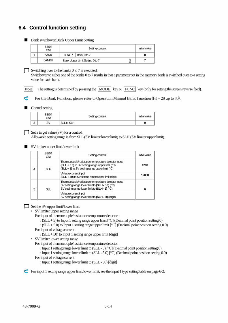
48-7009-G 6-14
6.4 Control function setting
■ Bank switchover/Bank Upper Limit Setting
SEt04 CNt
Setting content Initial value
1 bANK 0 to 7 Bank 0 to 7 0
bANKH Bank Upper Limit Setting 0 to 7 3 7
Switching over to the banks 0 to 7 is executed.
Switchover to either one of the banks 0 to 7 results in that a parameter set in the memory bank is switched over to a setting
value for each bank.
Note The setting is determined by pressing the MODE key or FUNC key (only for setting the screen reverse feed).
For the Bank Function, please refer to Operation Manual Bank Function (P5 – 28 up to 30).
■ Control setting
SEt04 CNt
Setting content Initial value
3 SV SLL to SLH 0
Set a target value (SV) for a control.
Allowable setting range is from SLL (SV limiter lower limit) to SLH (SV limiter upper limit).
■ SV limiter upper limit/lower limit
SEt04 CNt
Setting content Initial value
4 SLH
Thermocouple/resistance temperature detector input (SLL + 5.0) to SV setting range upper limit (°C) (SLL + 5) to SV setting range upper limit (°C)
1200
Voltage/current input (SLL + 50) to SV setting range upper limit (digit)
12000
5 SLL
Thermocouple/resistance temperature detector input SV setting range lower limit to (SLH - 5.0) (°C) SV setting range lower limit to (SLH - 5) (°C) 0
Voltage/current input SV setting range lower limit to (SLH - 50) (digit)
Set the SV upper limit/lower limit.
• SV limiter upper setting range
For input of thermocouple/resistance temperature detector
: (SLL + 5) to Input 1 setting range upper limit [°C] (Decimal point position setting 0)
: (SLL + 5.0) to Input 1 setting range upper limit [°C] (Decimal point position setting 0.0)
For input of voltage/current
: (SLL + 50) to Input 1 setting range upper limit [digit]
• SV limiter lower setting range
For input of thermocouple/resistance temperature detector
: Input 1 setting range lower limit to (SLL - 5) [°C] (Decimal point position setting 0)
: Input 1 setting range lower limit to (SLL - 5.0) [°C] (Decimal point position setting 0.0)
For input of voltage/current
: Input 1 setting range lower limit to (SLL - 50) [digit]
For input 1 setting range upper limit/lower limit, see the input 1 type setting table on page 6-2.

48-7009-G 6-15
■ Control mode
SEt04 CNt
Setting content Initial value
6 Md
RUN Control start
RUN
MAN Manual
RdY Control stop
tIME1 Timer 1 operation
tIME2 Timer 2 operation
tIME3 Timer 3 operation
Set the control mode. Control stop (RdY): Primary/secondary operating amount limiter lower limit is output. Control start (RUN): Normal control is executed. Manual (MAN): Operating amount set in the primary/secondary operating amount is output. Timer interlocking control (tIME 1 to 3): A control where the normal control and timer operation are interlocked is executed.
For start (RUN)/stop (RdY)/manual (MAN) of control, see section “5.4.3 Mode/manual function” on page 5-28.
For timer interlocking control (tIME 1 to 3), see section “5.4.5 Timer function” on pages 5-32 to 37.
■ Control type setting
SEt04 CNt
Setting content Initial value
7 CNt
0 Primary --- None Secondary --- None
1
1 Primary --- PID control Secondary --- None
2 Primary --- ONOFF control Secondary --- None
3 Primary --- PID control Secondary --- PID control
4 Primary --- PID control Secondary --- ONOFF control
5 Primary --- ONOFF control Secondary --- ONOFF control
6 Primary --- position proportional Secondary --- position proportional
Set the control type (method).
Control types of primary and secondary control outputs that are set on this equipment can be assigned to the methods of 0 to 6. For the content of the assignment, see the setting content listed above.
Note
(1) In case that the control type is set to 3 (primary/secondary PID control) and the tuning type to 3, 4 or 5, take care that the tuning type changes to 1 (primary tuning) in conjunction with the change of the control type.
(2) Take care that the position proportional control (CNt: 6) is selectable even when the primary/secondary control output is not set for the target connection setting.
■ PID control type/type B mode
SEt04 CNt
Setting content Initial value
8 tYP
0 type A (normal PID control)
1 1 type B (overshoot suppression function)
2 type C (disturbance suppression function)
9 bMd
0 Overshoot suppression --- moderate
1 1 Overshoot suppression --- intermediate
2 Overshoot suppression --- intense
Set the PID control type. For the use of the equipment in setting of the control type to be the PID control, a selection can be made among three control types of 0 (type A) to 2 (type C), whichever is best suited for the application.
Note The type B mode can be set when the PID control type is set to 1 (type B). In the type B mode, a result from integration (I) or differentiation (d) of the auto-tuning is multiplied by a coefficient. The intermediate type is same value as it is. The type C (disturbance suppression function) cannot be set when the self-tuning is set in the tuning type setting.
For control characteristics of each control type, see section “5.4.1 Auto-tuning (AT) function” on pages 5-23 to 25.

48-7009-G 6-16
■ Forward/reverse operation setting
SEt04 CNt
Setting content Initial value
10 dIR 0 Reverse operation
0 1 Forward operation
Set the forward/reverse operation of the primary control.
<Reverse operation>
• Reverse operation (heating control) is a control where the operating amount increases as PV (measurement value) lower
than SV (setting value).
MV
100
0 △
Low SV High
<Forward operation>
• Forward operation (cooling control) is a control where the operating amount increases as PV higher than SV.
MV
100
0 △
Low SV High
Note Take care the following when setting the secondary control.
• The secondary control is automatically set to the forward operation when the primary control is set to 0 or the reverse
operation.
• The secondary control is automatically set to the reverse operation when the primary control is set to 1 or the forward
operation.

48-7009-G 6-17
■ Primary control operating amount
SEt04 CNt
Setting content Initial value
11 MV1 MLL 1 to MLH 1 (%) 0.0
The screen is for displaying the operating amount for the primary control.
The operating amount cannot be set for the normal control.
The operating amount can be set only when the control mode is set to manual.
■ Primary control output gain setting
SEt04 CNt
Setting content Initial value
12 MV1G 0.0 to 1000.0 (%) 100.0
The operating amount (MV 1) for the primary control is multiplied by a compensation value.
[Operating amount for the primary control] = [Operating amount for the primary control before compensation] × [Primary
control output gain setting]
Note A change of the output gain setting may result in no provision of best suited PID parameter in AT.
Note Each limiter is output with a high priority, when the following is set: the primary control operating amount limiter upper limit
setting or primary control operating amount limiter lower limit setting.
Change of the output amount when the output gain setting is set to 70.0 %
100.0%
70.0%
50.0%
35.0%
Output operating amount calculated
Operating amount
Output operating amount that is actually output
SV temperature reached
Measurement temperature
Setting example:
When control characteristics in 100 VAC is desired to be maintained also in 120 VAC;
100 VAC and 100 W 120 VAC and 144 W, assuming that the heater resistance of 100 is identical for both 100 VAC and
120 VAC
100 W ÷ 144 W = 69.4 %
Thus, by setting the output gain setting to 69.4 %, control characteristics in 120 VAC can be expected to be analogous to those
in 100 VAC. NOTE: In case the loop disconnection is used when the output gain setting is at 50.0%, make the working volume limiter the same as
that of output gain.

48-7009-G 6-18
■ Tuning type setting
SEt04 CNt
Setting content Initial value
13 tUN
1 Primary auto-tuning (for primary PID/position proportional)
1
2 Primary self-tuning (for primary PID/position proportional)
3 Secondary auto-tuning (for primary PID/secondary PID)
4 Secondary self-tuning (for primary PID/secondary PID)
5 Primary/secondary auto-tuning (for primary PID/secondary PID)
Set the auto-tuning or self-tuning of the primary/secondary control.
Note
(1) This setting is allowed only when either primary or secondary control is set for the PID control or position proportional control. (2) AT of the primary control is not allowed when “4” (secondary self-tuning) is set. (3) Take care that a change of the control type results in the tuning type of “1” (primary auto-tuning) due to interlock when the
control type is set to “3” (primary/secondary PID control) and the tuning type to either one of “3” to “5.” <Auto-tuning>
In the auto-tuning, the PID constant is calculated using response in the ON/OFF control. The PID constant calculated does not change unless the auto-tuning is re-executed. Thus, the auto-tuning is suited for a subject of control where temperature cyclically changes, such as seal packaging machine.
<Self-tuning> The self-tuning is a tuning method where the PID constant is automatically calculated based on observation of control wave shapes. The self-tuning is suited for a control where subjects of control varies, where control or setting value changes, or where environment such as ambient temperature changes. Tuning time is not required to set for the self-tuning, unlikely the auto-tuning.
The decimal point of Bank display blinks, when the wave shape is being observed.
■ AT gain setting
SEt04 CNt
Setting content Initial value
14 AtG 0.1 to 10.0 (times) 1.0
The value of the proportional band to be calculated in AT is multiplied by a coefficient.
Note It is usually recommended that the initial value for the AT gain setting parameter is maintained as is.
■ AT sensitivity setting
SEt04 CNt
Setting content Initial value
15 AtC
Thermocouple/resistance temperature detector input 0.0 to 999.9 (C) 0 to 999 (C)
2
Voltage/current input 0 to 9999 (digit)
20
Set the sensitivity of ON/OFF operation during AT. The ON/OFF operation is executed during AT. An appropriate PID constant may not be calculated due to tuning results affected by a large fluctuation of the measurement value during AT. In such a situation, appropriate tuning results are obtained through adjustment of the AT sensitivity.
In addition, in case of the small AT sensitivity, measurement values may fluctuate due to noises, and the control at normal temperatures may greatly be affected by external environments. In such a situation, best-suited control characteristics may not be calculated due to recognition of external environments as subjects of control.
Note It is usually recommended that the initial value for the AT sensitivity setting parameter is maintained as is.

48-7009-G 6-19
■ AT start screen
SEt04 CNt
Setting content Initial value
16 At Use the / key for start and stop. PV/SV is displayed during AT.
oFF
The screen is used for starting AT.
Pressing the key or key allows start/stop of AT.
After setting the AT start/stop in the key function setting, pressing the FUNC key allows the AT start/stop. See page 6-12.
After setting the AT start/stop in the DI function setting, DI allows the AT start/stop. See pages 6-59 and 61.
Note The AT start/stop is not allowed on the AT start screen when the AT start/stop is set for DI or the FUNC key.
■ Proportional band setting
SEt04 CNt
Setting content Initial value
17 P1 0.1 to 200.0 (%) 3.0
Set the proportional band.
The proportional band for the heating cooling control is the one on the heating side.
The proportional band for the heating control is located as shown in the diagram below.
The proportional band for the cooling control is located in the upper side of SV in the diagram.
Temperature
Time
Proportional
band range
SV
The proportional band range can be calculated, using the equation below.
Proportional band range = (SLH - SLL) × P 1
SLH: SV limiter upper limit
SLL: SV limiter lower limit
Example: When SLH = 1200°C, SLL = 0°C, and P 1 = 3.0 %;
(1200°C - 0°C) × 3 % = 36°C.
Thus, the output gradually decreases from the one at the temperature 36°C below SV.
In general, wider proportional range results in a slower initial rise.
A narrower proportional range may result in that the control goes too far (overshoot), or forms waves (hunting) to cause
unstable output, although the initial rise is faster.

48-7009-G 6-20
■ Integral time setting
SEt04 CNt
Setting content Initial value
18 I 0 to 3600 (seconds) 0
Set the integral time.
Setting of 0 second results in no integral operation.
Both heating and cooling sides share to use this setting in the heating cooling control. (Individual setting is not allowed.)
The integral operation is an operation that makes the deviation between the setting value and measurement value, which is
generated in the proportional control, approach 0.
Temperature
Time
Deviation
Setting value
(SV)
The integral time is a value, in the unit of second, that defines intensity of the integral operation.
A smaller time value setting is equivalent to a more intense operation. (Because the value deviated is attempted to return in
the set time.)
■ Derivative time setting
SEt04 CNt
Setting content Initial value
19 d 0 to 3600 (seconds) 0
Set the derivative time.
Setting of 0 second results in no derivative operation.
Both heating and cooling sides share to use this setting in the heating cooling control.
The derivative operation is an operation that works to return fast to the original control state by supplying a large operating
amount against drastic disturbances.
The output provided by the derivative operation is proportional to the time derivative value of the measurement value.
The proportional and integral operations are corrective operations, so their responses tend to be slow to drastic temperature
changes (or disturbances). The derivative operation supplements such a shortcoming.
The derivative time is a value, in the unit of second, that defines intensity of the derivative operation.
A larger time value setting is equivalent to a more intense operation. (Because the interval to pick a variance becomes larger.)

48-7009-G 6-21
■ Primary control proportional cycle
SEt04 CNt
Setting content Initial value
20 t1 0.1 to 120.0 (seconds) 20.0
(1.0)
( ) When OUTPUT1 is SSR drive.
Set the primary control proportional cycle.
Relay contact output, voltage output for SSR drive or open collector output has only the state of ON or OFF for output, and
thereby no proportional operation is offered.
Thus, to solve the issue, concept of time proportional operation is applied.
In the time proportional operation, ON/OFF is repeated in a proportional cycle (time cycle), where the ON state is maintained
for a particular time period and the OFF state for the rest of the period.
Example: When the proportional cycle is 20 seconds and the operating amount (MV) is 40 %, the ON/OFF period is as
follows.
ON: 8 seconds
OFF: 12 seconds
ON OFF
Proportional cycle
■ Anti-reset windup (ARW)
SEt04 CNt
Setting content Initial value
21 ARW 0.0 to 110.0 (%) Function turned off at 110.0 (%) setting
110.0
Set the max. value of calculated integral operating amount.
Setting example: When ARW is set to 50 %, the operating amount accumulated in the integral operation reaches 50 %.
Anti-reset windup is an operation to suppress excessive integration of integral operation.
It is used to prevent overshoot, when a control contains an integral operation, by limiting the range of the effective integral
operation.
Note
(1) When ARW is set to 0 %, integral operation is ineffective.
(2) The value of ARW is automatically set by auto-tuning after setting tYP (PID control type) to “2” (type C: disturbance
suppression function).

48-7009-G 6-22
■ Primary control operating amount limiter upper limit
SEt04 CNt
Setting content Initial value
22 MLH1
Digital output MLL 1 to 100.0 (%)
100.0 Analog output MLL 1 to 110.0 (%)
Set the primary control operating amount limiter upper limit.
A limit is set for the upper limit of the operating amount calculated.
Output
Operating amount
limiter upper limit
50 %
100%
0%
■ Primary control operating amount limiter lower limit
SEt04 CNt
Setting content Initial value
23 MLL1
Digital output 0.0 to MLH 1 (%)
0.0 Analog output -10.0 to MLH 1 (%)
Set the primary control operating amount limiter lower limit.
A limit is set for the lower limit of the operating amount calculated.
Output
Operating amount
limiter lower limit
50%
100%
0%

48-7009-G 6-23
■ Primary control operating amount change limiter ascent setting
SEt04 CNt
Setting content Initial value
24 oU1 0.0 to 549.9 (%) Function turned off at 0.0 (%) setting
0.0
Set the primary control operating amount change limiter ascent.
A limit is set to the ascent percentage of the operating amount change calculated.
An operating amount allowed with ascent for a second is set in the unit of percentage.
Calculated
operating amount
Limited operating
amount
100%
100%
0%
0%
Time
MLL 1 is set for the initial MV at power-on.
Note
(1) The setting is effective also during AT.
(2) When the setting is changed, re-AT is required due to different control result.
(3) The setting value of 100 % allows ascent of only 20 % in the input sampling (200 ms).
In order to have ascent of 100 % in the input sampling (200 ms), set the setting value to 500 %.
(1 s ÷ 200 ms) × 100 % = 500 %
Set the setting value to 0.0 % (OFF) when ascent of 110 % from 0 % in a second is desired for an analog input.
■ Primary control operating amount change limiter descent setting
SEt04 CNt
Setting content Initial value
25 od1 0.0 to 549.9 (%) Function turned off at 0.0 (%) setting
0.0
Set the primary control operating amount change limiter descent.
A limit is set to the descent percentage of the operating amount change calculated.
An operating amount allowed with descent for a second is set in the unit of percentage.
100%
100%
0%
0%
Calculated
operating amount
Limited operating
amount
Time
MLL 1 is set for the initial MV at power-on.
Note
(1) The setting is effective also during AT.
(2) When the setting is changed, re-AT is required due to different control result.
(3) The setting value of 100 % allows descent of only 20 % in the input sampling (200 ms).
In order to have descent of 100 % in the input sampling (200 ms), set the setting value to 500 %.
(1 s ÷ 200 ms) × 100 % = 500 % Set the setting value to 0.0 % (OFF) when descent of 110 % from 0 % in a second is desired for an analog input.

48-7009-G 6-24
■ Primary control soft-start output setting
SEt04 CNt
Setting content Initial value
26 SFM ML 1 to MH 1 (%) 100.0
Set the primary control soft-start output setting.
A limit is set in a particular time period (or the primary control soft-start time) on the operating amount calculated.
■ Primary control soft-start time setting
SEt04 CNt
Setting content Initial value
27 SFt 00:00 to 499:59 (minute seconds) 000:00
Soft-starting PID control
Primary control soft-
start output setting
Power-on
Operating amount
(%)
Time elapsed
Note
(1) The SOFT START operates both when the power is switched ON and when the Control Mode is
switched from "READY to RUN".
The switching of the Control Mode can be done with setting such as (SEt04 Md)(SEt03 FU*) and
(SEt13 DIF)
(2) Soft-start is effective only during equipment operation. Note that the time elapses even after the mode changes to
control stop, manual or AT.
(3) The set time can be changed during soft-start, where the set time is the time from power-on.
Example 1) When the set time is changed from 6 minutes to 4 minutes in 5 minutes after power-on, soft-start
immediately stops.
Example 2) When the set time is changed from 6 minutes to 8 minutes in 5 minutes after power-on, soft-start will stop
in 3 minutes.

48-7009-G 6-25
■ Primary control abnormality operating amount setting
SEt04 CNt
Setting content Initial value
28 FAL1
Digital output 0.0 to 100.0 (%)
0.0 Analog output -10.0 to 110.0 (%)
Set the primary control at-abnormality operating amount setting.
This operating amount is the one provided in case of failure of gauges and such.
<Conditions on the primary control at-abnormality operating amount>
• Burn-out
• Err 1 (AD abnormality error)
• Err 2 (AT error)
Note
(1) The operating amount is output without constraint from MLH 1 (primary control operating amount limiter upper limit) or
MLL 1 (primary control operating amount limiter lower limit).
(2) Burn-out during the manual control results in outputting the operating amount that is set in MV 1 (primary control
operating amount).
(3) The operating amount cannot be set during the control type of ON/OFF control. (No screen is displayed.)

48-7009-G 6-26
■ Primary control loop anomaly PV threshold
SEt04 CNt
Setting content Initial value
29 tS1
Thermocouple/resistance temperature detector input 0.0 to 999.9 (°C)0 to 999 (°C)
0 Voltage/current input
0 to 9999 (digit)
Set the primary control loop anomaly PV threshold .
The function is to detect an abnormality in the control loop.
When width of tS1 has PV from an SV , a judgment of the loop anomaly acts.
The real judgment in PS1 and LoP1.
For details, see section “Loop abnormality function” on pages 5-38 and 39.
Control loop anomaly PV threshold (TS1)
SV setting value
(TS1)
PV
When PV is out of the judgment domain, the control loop anomaly is
not judged.
PV indicates present temperature.
Temperature threshold is a value specified by [SV – TS1].
Judgment domain
Non- judgment domain

48-7009-G 6-27
■ Primary control loop anomaly MV threshold
SEt04 CNt
Setting content Initial value
30 MS1 MV threshold MLL1 to MLH1 (%)
100.0
Set the primary control loop anomaly MV threshold.
The function is to detect an abnormality in the control loop.
When MV is more than the threshold, a judgment of the loop anomaly acts.
The real judgment in PS1 and LoP1.
For details, see section “Loop abnormality function” on pages 5-38 and 39.
MLL1
MLH1
MV1
Judgment domain
Non- judgment domain
When MV1 is out of the judgment domain, the control loop anomaly
is not judged.
"MV1" represents a control amount.
Control loop anomaly MV threshold (MS1)

48-7009-G 6-28
■ Primary control loop anomaly PV change threshold
SEt04 CNt
Setting content Initial value
31 PS1
Thermocouple/resistance temperature detector input 0.0 to 999.9 (°C)0 to 999 (°C) Applicable only for time judgment when PS 1 = 0 (LoP1)
0 Voltage/current input 0 to 9999 (digit) Applicable only for time judgment when PS 1 = 0 (LoP1)
Set the primary control loop anomaly PV change threshold.
The function is to detect an abnormality in the control loop.
When the time satisfying threshold of TS1 or MS1 exceeds LOP1, the loop abnormality is determined as
detected.
For details, see section “Loop abnormality function” on pages 5-38 and 39.
- The control loop anomaly PV change threshold is judged at each “LoP1” time.
- A loop abnormality is determined if each change threshold is judged to be equal to or below “PS1.”
- When [PS1 = 0] is true, only time judgment is executed using LOP1.
When the time satisfying threshold of TS1 or MS1 exceeds LOP1, the loop abnormality is determined as detected.
SV
PV
(PS1)
(LoP1)

48-7009-G 6-29
■ Primary control loop abnormality time setting
SEt04 CNt
Setting content Initial value
32 LoP1 0 to 9999 (seconds) 0
Set the primary control loop abnormality time setting.
The function is to detect an abnormality in the control loop.
- The control loop anomaly PV change threshold is judged at each “LoP1” time.
A loop abnormality is determined if each change threshold is judged to be equal to or below “PS1.”
For details, see section “5.4.6 Loop abnormality function” on pages 5-38 and 39.

48-7009-G 6-30
■ Primary control off-point position selection setting
SEt04 CNt
Setting content Initial value
32 CMod
0 SV unit setting
0 1 Upper
2 Middle
3 Lower
Set the primary control off-point position selection.
Set the selection setting to “0” for allowing to set the off-point position of sensitivity in the SV setting unit of °C and such.
Set the selection setting to “1” to “3” for automatically setting the off-point position of the primary control to upper, middle or
lower position with respect to SV.
<Reverse operation>
Cmod = 0 (SV) C1 CP1 CP2 C2 +db
ON
OFF
△ PV Low SV High
Cmod = 1 (upper) C1 db C2
ON
OFF
△ PV Low SV High
Cmod = 2 (middle) C1 db C2
ON
OFF
△ PV
Low SV High
Cmod = 3 (lower) C1 db C2
ON
OFF
△ PV
Low SV High
C1: Sensitivity setting 1 C2: Sensitivity setting 2 CP1: Off-point setting 1 = negative value CP2: Off-point setting 2 = positive value db: Dead band = positive value
C1: Sensitivity setting 1 C2: Sensitivity setting 2 db: Dead band = positive value
C1: Sensitivity setting 1 C2: Sensitivity setting 2 db: Dead band = positive value
C1: Sensitivity setting 1 C2: Sensitivity setting 2 db: Dead band = positive value

48-7009-G 6-31
<Forward operation>
Cmod = 0 (SV) C2 CP2 CP1 C1 -db
ON
OFF
△ PV Low SV High
Cmod = 1 (upper) C2 db C1
ON
OFF
△ PV Low SV High
Cmod = 2 (middle) C2 db C1
ON
OFF
△ PV Low SV High
Cmod = 3 (lower) C2 db C1
ON
OFF
△ PV Low SV High
C1: Sensitivity setting 1 C2: Sensitivity setting 2 CP1: Off-point setting 1 = positive value CP2: Off-point setting 2 = negative value db: Dead band = positive value
C1: Sensitivity setting 1 C2: Sensitivity setting 2 db: Dead band = positive value
C1: Sensitivity setting 1 C2: Sensitivity setting 2 db: Dead band = positive value
C1: Sensitivity setting 1 C2: Sensitivity setting 2 db: Dead band = positive value

48-7009-G 6-32
■ Primary control sensitivity setting
SEt04 CNt
Setting content Initial value
34 C1
Thermocouple/resistance temperature detector input 0.0 to 999.9 (C) 0 to 999 (C)
1
Voltage/current input 0 to 9999 (digit)
10
Set the primary control sensitivity.
Sensitivity (hysteresis) of ON/OFF operation is set. For heating control, the sensitivity is set below SV.
■ Primary control off-point position
SEt04 CNt
Setting content Initial value
35 CP1
Thermocouple/resistance temperature detector input -999.9 to 999.9 (C) -999 to 999 (C) 0
Voltage/current input -9999 to 9999 (digit)
Set the primary control off-point position.
Moving the off-point of the primary control sensitivity results in a move of entire range of the sensitivity.
< dIR=0 When primary control is Reverse operation >
Off-point CP1 = 0 C1
ON
OFF
△ PV Low SV High
Off-point CP1 = positive value C1
CP1
ON
OFF
△ A point PV Low SV High
Off-point CP1 = negative value C1 CP1
ON
OFF
B point △ PV Low SV High
C1: Sensitivity setting
C1: Sensitivity setting CP1: Off-point position A point: SV + CP1
C1: Sensitivity setting CP1: Off-point position B point: SV - CP1

48-7009-G 6-33
< dIR=1 When primary control is Forward operation >
Off-point CP1 = 0 C1
ON
OFF
△ PV Low SV High
Off-point CP1 = positive value CP1 C1
ON
OFF
△ C point PV Low SV High
Off-point CP1 = negative value C1
CP1
ON
OFF
D point △ PV Low SV High
C1: Sensitivity setting
C1: Sensitivity setting CP1: Off-point position C point: SV + CP1
C1: Sensitivity setting CP1: Off-point position D point: SV - CP1
■ Primary control protection timer
SEt04 CNt
Setting content Initial value
36 Fdt1 0 to 99 (minutes) 0
37 Ndt1 Main Control Protection on Timer 0~99(min.) 3 0
BEHAVIOR DURING THE SETTING OF MAIN CONTROL PROTECTION OFF TIMER
Setting value
Temperature
Control
output
Control
sensitivity
ON
OFF
Protection
timer

48-7009-G 6-34
■ Secondary control operating amount
SEt04 CNt
Setting content Initial value
38 MV2 MLL 2 to MLH 2 (%) 0.0
The screen is for displaying the operating amount for the secndary control.
The operating amount cannot be set for the normal control.
The operating amount can be set only when the control mode is set to manual.
■ Secondary control output gain setting
SEt04 CNt
Setting content Initial value
39 MV2G 0.0 to 1000.0 (%) 100.0
The operating amount (MV 1) for the secondary control is multiplied by a compensation value.
[Operating amount for the secondary control] = [Operating amount for the secondary control before compensation] ×
[Secondary control output gain setting]
■ Secondary control proportional band setting
SEt04 CNt
Setting content Initial value
40 P2 0.10 to 10.00 (times) 1.00
Set the secondary control proportional band.
The proportional band of the secondary control is set in a multiplication factor of 0.1 to 10 with respect to the proportional
band of the primary control.
The proportional band of the secondary control is always set in opposite side to the proportional band of the primary control
about SV.
Setting example: Where the proportional band range P2 of the secondary control is set to 2.00, P2 is twice as large as the
proportional band range P1 of the primary control.
Primary control proportional band
Temperature
SV
Secondary control
proportional band
When P2 = 2.00 is set, the proportional
band range of the secondary control is
twice as large as that of the primary
control.

48-7009-G 6-35
■ Secondary control proportional cycle
SEt04 CNt
Setting content Initial value
41 t2 0.1 to 120.0 (seconds) 20.0
Set the secondary control proportional cycle.
Relay contact output, voltage output for SSR drive or open collector output has only the state of ON or OFF for output, and
thereby no proportional operation is offered.
Thus, to solve the issue, concept of time proportional operation is applied.
In the time proportional operation, ON/OFF is repeated in a proportional cycle (time cycle), where the ON state is maintained
for a particular time period and the OFF state for the rest of the period.
Example: When the proportional cycle is 20 seconds and the operating amount (MV) is 40 %, the ON/OFF period is as
follows.
ON: 8 seconds
OFF: 12 seconds
ON OFF
Proportional cycle

48-7009-G 6-36
■ Secondary control operating amount limiter upper limit
SEt04 CNt
Setting content Initial value
42 MLH2
Digital output MLL 2 to 100.0 (%)
100.0 Analog output MLL 2 to 110.0 (%)
Set the secondary control operating amount limiter upper limit.
A limit is set for the upper limit of the operating amount calculated.
Output
Operating amount
limiter upper limit
50 %
100%
0%
■ Secondary control operating amount limiter lower limit
SEt04 CNt
Setting content Initial value
43 MLL2
Digital output 0.0 to MLH 2 (%)
0.0 Analog output -10.0 to MLH 2 (%)
Set the secondary control operating amount limiter lower limit.
A limit is set for the lower limit of the operating amount calculated.
Output
Operating amount
limiter lower limit
50 %
100%
0%

48-7009-G 6-37
■ Secondary control operating amount change limiter ascent setting
SEt04 CNt
Setting content Initial value
44 oU2 0.0 to 549.9 (%) Function turned off at 0.0 (%) setting
0.0
Set the secondary control operating amount change limiter ascent.
A limit is set to the ascent percentage of the operating amount change calculated.
An operating amount allowed with ascent for a second is set in the unit of percentage.
Calculated
operating amount
Limited operating
amount
100%
100%
0%
0%
Time
MLL 2 is set for the initial MV at power-on.
Note
(1) The setting is effective also during AT.
(2) When the setting is changed, re-AT is required due to different control result.
(3) The setting value of 100 % allows ascent of only 20 % in the input sampling (200 ms).
In order to have ascent of 100 % in the input sampling (200 ms), set the setting value to 500 %.
(1 s ÷ 200 ms) × 100 % = 500 %
Set the setting value to 0.0 % (OFF) when ascent of 110 % from 0 % in a second is desired for an analog input.
■ Secondary control operating amount change limiter descent setting
SEt04 CNt
Setting content Initial value
45 od2 0.0 to 549.9 (%) Function turned off at 0.0 (%) setting
0.0
Set the secondary control operating amount change limiter descent.
A limit is set to the descent percentage of the operating amount change calculated.
An operating amount allowed with descent for a second is set in the unit of percentage.
100%
100%
0%
0%
Calculated
operating amount
Limited operating
amount
Time
MLL 2 is set for the initial MV at power-on.
Note
(1) The setting is effective also during AT.
(2) When the setting is changed, re-AT is required due to different control result.
(3) The setting value of 100 % allows descent of only 20 % in the input sampling (200 ms).
In order to have descent of 100 % in the input sampling (200 ms), set the setting value to 500 %.
(1 s ÷ 200 ms) × 100 % = 500 %
Set the setting value to 0.0 % (OFF) when descent of 110 % from 0 % in a second is desired for an analog input.
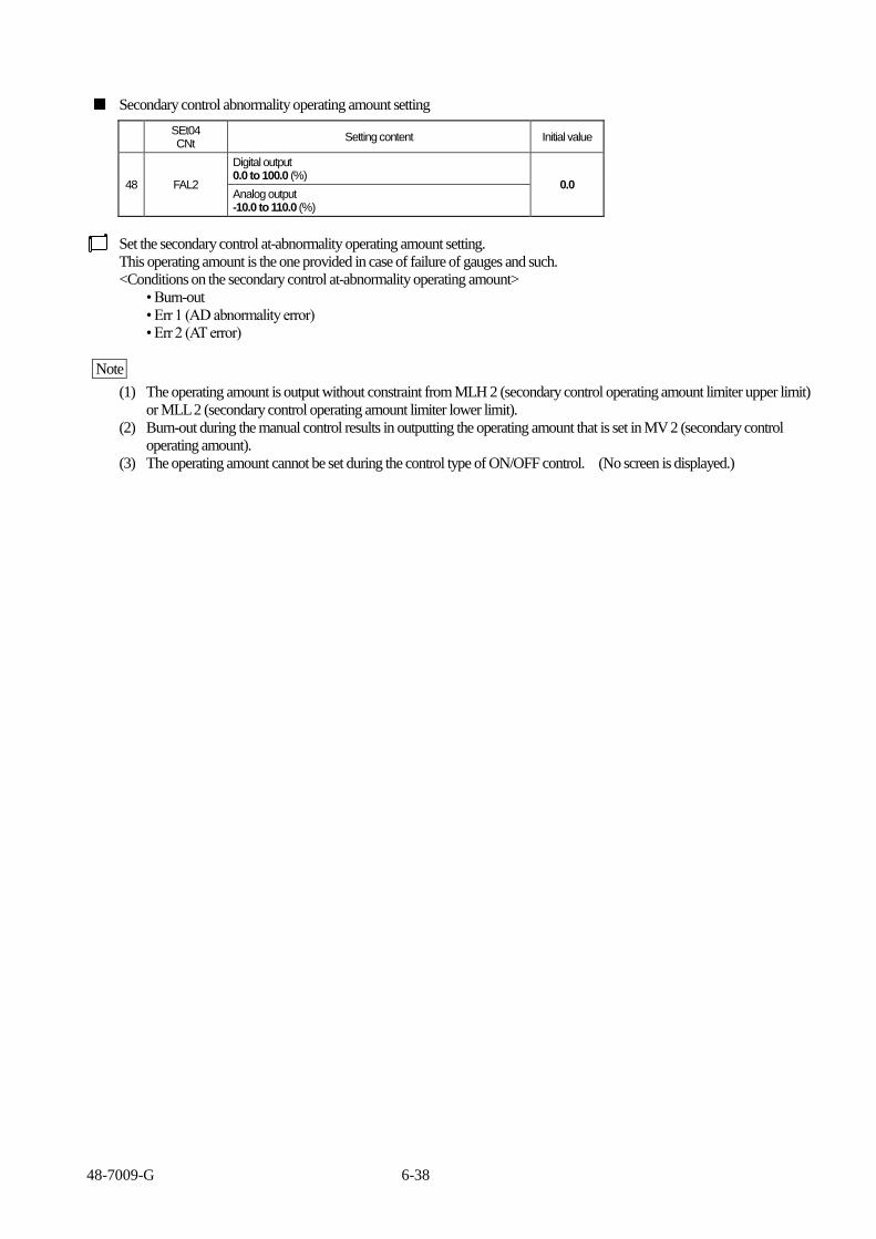
48-7009-G 6-38
■ Secondary control abnormality operating amount setting
SEt04 CNt
Setting content Initial value
48 FAL2
Digital output 0.0 to 100.0 (%)
0.0 Analog output -10.0 to 110.0 (%)
Set the secondary control at-abnormality operating amount setting.
This operating amount is the one provided in case of failure of gauges and such.
<Conditions on the secondary control at-abnormality operating amount>
• Burn-out
• Err 1 (AD abnormality error)
• Err 2 (AT error)
Note
(1) The operating amount is output without constraint from MLH 2 (secondary control operating amount limiter upper limit)
or MLL 2 (secondary control operating amount limiter lower limit).
(2) Burn-out during the manual control results in outputting the operating amount that is set in MV 2 (secondary control
operating amount).
(3) The operating amount cannot be set during the control type of ON/OFF control. (No screen is displayed.)

48-7009-G 6-39
■ Secondary control loop anomaly PV threshold
SEt04 CNt
Setting content Initial value
47 tS2
Thermocouple/resistance temperature detector input 0.0 to 999.9 (°C)0 to 999 (°C)
0 Voltage/current input
0 to 9999 (digit)
Set the secondary control loop anomaly PV threshold .
The function is to detect an abnormality in the control loop.
When width of tS1 has PV from an SV , a judgment of the loop anomaly acts.
The real judgment in PS2 and LoP2.
For details, see section “Loop abnormality function” on pages 5-38 and 39.
Control loop anomaly PV threshold (TS2)
SV setting value
(TS2)
PV
When PV is out of the judgment domain, the control loop anomaly is
not judged.
PV indicates present temperature.
Temperature threshold is a value specified by [SV – TS2].
Judgment domain
Non- judgment domain
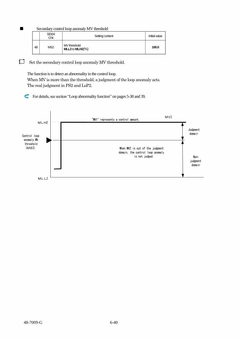
48-7009-G 6-40
■ Secondary control loop anomaly MV threshold
SEt04 CNt
Setting content Initial value
48 MS2 MV threshold MLL2 to MLH2(%)
100.0
Set the secondary control loop anomaly MV threshold.
The function is to detect an abnormality in the control loop.
When MV is more than the threshold, a judgment of the loop anomaly acts.
The real judgment in PS2 and LoP2.
For details, see section “Loop abnormality function” on pages 5-38 and 39.
MLL2
MLH2
MV2
Judgment domain
Non- judgment domain
When MV2 is out of the judgment domain, the control loop anomaly
is not judged.
"MV1" represents a control amount.
Control loop anomaly MV threshold (MS2)

48-7009-G 6-41
■ Secondary control loop anomaly PV change threshold
SEt04 CNt
Setting content Initial value
49 PS2
Thermocouple/resistance temperature detector input 0.0 to 999.9 (°C)0 to 999 (°C) Applicable only for time judgment when PS 2 = 0 (LoP2)
0 Voltage/current input 0 to 9999 (digit) Applicable only for time judgment when PS 2 = 0 (LoP2)
Set the secondary control loop anomaly PV change threshold.
The function is to detect an abnormality in the control loop.
When the time satisfying threshold of TS2 or MS2 exceeds LOP2, the loop abnormality is determined as
detected.
For details, see section “Loop abnormality function” on pages 5-38 and 39.
- The control loop anomaly PV change threshold is judged at each “LoP2” time.
A loop abnormality is determined if each change threshold is judged to be equal to or below “PS2.”
- When [PS2 = 0] is true, only time judgment is executed using LOP2.
When the time satisfying threshold of TS2 or MS2 exceeds LOP2, the loop abnormality is determined as detected.
SV
PV
(PS2)
(LoP2)

48-7009-G 6-42
■ Secondary control loop abnormality time setting
SEt04 CNt
Setting content Initial value
50 LoP2 0 to 9999 (seconds) 0
Set the secondary control loop abnormality time setting.
The function is to detect an abnormality in the control loop.
- The control loop anomaly PV change threshold is judged at each “LoP2” time.
A loop abnormality is determined if each change threshold is judged to be equal to or below “PS2.”
For details, see section “Loop abnormality function” on pages 5-38 and 39.

48-7009-G 6-43
■ Secondary control sensitivity setting
SEt04 CNt
Setting content Initial value
51 C2
Thermocouple/resistance temperature detector input 0.0 to 999.9 (C) 0 to 999 (C)
1
Voltage/current input 0 to 9999 (digit)
10
Set the secondary control sensitivity.
Sensitivity (hysteresis) of ON/OFF operation is set. For heating control, the sensitivity is set in the upper side of SV.
■ Secondary control off-point position
SEt04 CNt
Setting content Initial value
52 CP2
Thermocouple/resistance temperature detector input -999.9 to 999.9 (C) -999 to 999 (C) 0
Voltage/current input -9999 to 9999 (digit)
Set the secondary control off-point position.
Moving the off-point of the secondary control sensitivity results in a move of entire range of the sensitivity.
< dIR=0 When secondary control is Forward operation >
Off-point CP2 = 0 C2
ON
OFF
△ PV Low SV High
Off-point CP2 = positive value CP2 C2
ON
OFF
△ C point PV Low SV High
Off-point CP2 = negative value C2
CP2
ON
OFF
D point △ PV Low SV High
C2: Sensitivity setting
C2: Sensitivity setting CP2: Off-point position C point: SV + CP2
C2: Sensitivity setting CP2: Off-point position D point: SV - CP2

48-7009-G 6-44
< dIR=1 When secondary control is Reverse operation >
Off-point CP2 = 0 C2
ON
OFF
△ PV Low SV High
Off-point CP2 = positive value C2
CP2
ON
OFF
△ A point PV Low SV High
Off-point CP2 = negative value C2 CP2
ON
OFF
B point △ PV Low SV High
C2: Sensitivity setting
C2: Sensitivity setting CP2: Off-point position A point: SV + CP2
C2: Sensitivity setting CP2: Off-point position B point: SV - CP2
■ Secondary control protection timer
SEt04 CNt
Setting content Initial value
53 Fdt2 Sub-control Protection off Timer 0 to 99 (minutes) 0
54 Ndt2 Sub-control Protection on Timer 0~99(min.) 3 0
BEHAVIOR DUINRG SUB-CONTROL PROTECTION OFF TIMER (Fdt2) SETTING
Setting value
Temperature
Control
output
Control
sensitivity
ON
OFF
Protection
timer

48-7009-G 6-45
■ Manual reset
SEt04 CNt
Setting content Initial value
55 Pbb 0.0 to 100.0 (%), when CNt is 1, 2 or 6 -100.0 to 100.0 (%), when CNt is 3 or 4
0.0
Set the manual reset.
The operating amount is added by the value of the manual reset.
This value is to be set for canceling the off-set that is generated in the proportional control.
Set the manual reset as an indication to the operating amount that is stabilized in the proportional control.
■ Dead band setting
SEt04 CNt
Setting content Initial value
56 db
Thermocouple/resistance temperature detector input -999.9 to 999.9 (C) -999 to 999 (C) 0
Voltage/current input -9999 to 9999 (digit)
Set the dead band.
The proportional band (or sensitivity) of the secondary control moves. The primary and secondary controls are separate
when the value of the dead band is positive.
• When the value of the dead band setting is positive
MV
DB 100
Primary control
0
△ Low SV High
Secondary control
• When the value of the dead band setting is negative
MV
DB 100
0
△ Low SV High
Primary control
Secondary control

48-7009-G 6-46
■ Ramp time setting
SEt04 CNt
Setting content Initial value
57 RMP
Thermocouple/resistance temperature detector input 0.0 to 999.9 (C/minute)
0.0
Voltage/current input 0 to 9999 (digit/minute)
0
Set the ramp time.
A change of SV per minute is set when SV is changed.
The ramp control starts from the present PV.
<Start condition>
(1) At power-on
(2) SV change when bank being switched over
(3) When RDY being switched over to RUN
SV
* Settable at bank setting
The setting value changes from the temperature at start of the operation to SV, using the operating amount set for RMP. SV
RMP
1 minute
Time At start
Note Event output during ramp
The SV during ramp is equivalent to the SV for deviation upper/lower limit, deviation upper limit, deviation lower limit and
deviation range.
Take care that SV is not a final target value.
Note In the case of ramp setting (RMP = 0), the ramp function does not work.

48-7009-G 6-47
■ Valve motor stroke time
SEt04 CNt
Setting content Initial value
58 VLt 0.1 to 999.9 (seconds) 3.0
Set the valve motor stroke time.
Output is generated for the time set for VLt (valve motor stroke time) when PV (measurement value) changes in range by the
amount identical to the proportional band range.
For the valve motor stroke time, set the time period from full open to full close of the valve used.
Setting example: For the position proportional control of the heating control, where settings are as follows: SV of 200°C,
proportional band range of 200°C and VLt of 10 seconds.
Output change is described as an example when the temperature changes as shown in the diagram below.
The temperature changes from 0 to 200°C, where the amount of the change is equivalent to the
proportional band range. This change results in the secondary control output (close) being output for 10
seconds, which is equivalent to the setting time for VLt.
Then, the temperature changes from 200°C to 100°C, which is equivalent to the half the proportional band
range. This change results in the primary control output (open) being output for 5 seconds, which is
equivalent to a half the setting time for VLt.
100℃
Temperature
200℃
0℃
SV=200℃
Proportional
band range
200℃
Secondary control
output (close)
Primary control
output (open)
10 seconds
5 seconds
Note Take care when selecting a valve, as the output is not turned off when the operating amount is in either 0 % or 100 %.

48-7009-G 6-48
■ Valve motor drive dead band
SEt04 CNt
Setting content Initial value
59 Vdb 0.0 to 100.0 (%) 1.0
Set a range such that the position proportional output is not provided even when the operating amount changes.
The range is represented as a ratio to the proportional band range.
When the proportional band is 200°C and Vdb (valve motor drive dead band) is set to 10.0 %, the actual range is 20°C.
Setting example: In such a case that the range of the valve motor drive dead band is 20°C as shown in the diagram below, no
output is provided when the temperature increases by 20°C.
Then, further increase by 5°C results in the output equivalent to 25 % (= 25°C ÷ 200°C).
When VLt (valve motor stroke time) is 10.0 seconds, the resultant time value is 2.5 seconds.
Temperature
200
0
SV=200℃
Proportional
band range
200℃
Secondary control
output (close)
Primary control
output (open)
A A
PV increased by +20℃and further by +5℃
■ Post-AT initial opening ratio
SEt04 CNt
Setting content Initial value
60 ASP 0.0 to 100.0 (%) 50.0
Set the valve opening ratio for a value to be after the auto-tuning is conducted in the position proportional control.
The value of 50 % is normally appropriate.
After the auto-tuning is complete, the calculated operating amount is compared to the set operating amount in order to
determine a first output.

48-7009-G 6-49
6.5 Output (from OUT 1 to OUT 7) type setting
■ Outputs 1 to 7 target connection setting
SEt05 oUt1
to SEt11 oUt7
Setting content Initial value
1 o1F to
o7F
0 Primary output
1 Secondary output
2 Event output
3 RUN output
4 RDY output
5 Timer 1 output
6 Timer 1 during-on-delay output o1F: 0
7 Timer 1 during-off-delay output
8 Timer 1 during-[on + off]-delay output
9 Timer 2 output o2F: 2
10 Timer 2 during-on-delay output to
11 Timer 2 during-off-delay output o7F: 2
12 Timer 2 during-[on + off]-delay output
13 Timer 3 output
14 Timer 3 during-on-delay output
15 Timer 3 during-off-delay output
16 Timer 3 during-[on + off]-delay output
17 Transmission output (for analog output)
18 End Output (during program mode) 3
Set target connections for outputs 1 to 7.
This product allows free setting of output applications.
This product also allows duplicated setting of outputs 1 and 2 (such as setting the both outputs for either primary or secondary
output).
Note Transmission output can be selected only when the output 1 or 2 at order placement for the product is of analog output.
As no analog output being available for outputs 3 to 7, they cannot be set for the transmission output.
For operation of the event function 1 of the event output, see section of event function 1 operation on page 6-51.
For operations of the event functions 2 to 4 of the event output, see section of event functions 2 to 4 operations on pages 6-52
to 54.
For operation of the timer output, see section “5.4.5 Timer function” on pages 5-32 to 37.

48-7009-G 6-50
■ Event function 1/upper and lower limits/sensitivity/delay timer settings
SEt05 oUt1
to SEt11 oUt7
Setting content Initial value
2 E1F1
to E7F1
Function
000
**0 None
**1 Deviation upper and lower limits
**2 Deviation upper limit
**3 Deviation lower limit
**4 Deviation range
**5 Absolute value upper and lower limits
**6 Absolute value upper limit
**7 Absolute value lower limit
**8 Absolute value range
Add-on function
*0* None
*1* Hold
*2* Standby
*3* Delay
*4* Hold + standby
*5* Hold + delay
*6* Standby + delay
*7* Hold + standby + delay
Control mode interlocking function
0** All modes
1** RUN/MAN mode only
2** RUN mode only
3 E1H to
E7H
Thermocouple/resistance temperature detector input -1999.9 to 2999.9 (C) -1999 to 2999 (C) 0
Voltage/current input -19999 to 29999 (digit)
4 E1L to
E7L
Thermocouple/resistance temperature detector input -1999.9 to 2999.9 (C) -1999 to 2999 (C) 0
Voltage/current input -19999 to 29999 (digit)
5 E1C to
E7C
Thermocouple/resistance temperature detector input 0.0 to 999.9 (C) 0 to 999 (C) 0
Voltage/current input 0 to 9999 (digit)
6 E1t to
E7t 0 to 9999 (seconds) 0
Event function 1/event upper and lower limits/event sensitivity/event delay timer is set.
Event function 1 is a function that compares PV to the event setting value, and that, if set conditions are met, signals are output
(ON/OFF) from the outputs 1 to 7 assigned for the event output.
This function is effective for alarm of PV, and start/stop of other systems.
This function can be used when the target connection for the outputs 1 to 7 are set for the event output.
For the operation range and each setting value of the event function 1, see the event function 1 operation on page 6-51.

48-7009-G 6-51
■ Event function 1 operation
The operation range (range for turn-on) of the event function 1 assigned for outputs 1 to 7 is set in terms of the event function 1
setting, and event upper limit, event lower limit and event sensitivity settings. See below for the event function 1 operation
range.
■ Event function 1 operation range table
1 Deviation upper and lower limits 5 Absolute value upper and lower limits
E*C
SV
E*C
E*L E*H△
0℃
E*C E*C
E*LE*H
2 Deviation upper limit 6 Absolute value upper limit
SV
E*C
E*H△
0℃
E*C
E*H
3 Deviation lower limit 7 Absolute value lower limit
E*C
SV
E*L△
0℃
E*C
E*L
4 Deviation range 8 Absolute value range
E*C
SV
E*L E*H△
E*C
E*C E*C
0℃ E*LE*H
: Event function 1 operation range, : Location of SV, E * C: Event sensitivity E * H: Event upper limit setting (The chart in the table is for plus setting; for minus setting, the chart is to be reversed about SV or 0°C.) E * L: Event lower limit setting (The chart in the table is for plus setting; for minus setting, the chart is to be reversed about SV or 0°C.) Note Setting “none” for the event function 1 results in no operation. (For the symbol “*,” a numerical character from 1 to 7 for actual output is to be put
in.)
Explanation on the event function 1 add-on function/control mode interlocking function Hold: A function that holds and continuously provides the event output after it is once provided, even when PV is out of the operation range of the
event function 1 Note The event output held is released when the power returns or the event upper/lower limit setting changes. In addition, the hold is released due to a SV change when the event range is set in terms of deviation.
Standby: A setting where no output is initially provided but the product stands by even when PV is within the operation range of the event function 1, at power-on or setting change. The event output is provided when PV is out of the operation range once and returns within it.
This function is an effective function for the product not to operate in case of PV going in the operation range at power-on or setting change. Delay: A delay time is set where the time from PV being in the operation range of the event function 1 to event-outputting is to be delayed. This function is an effective function for the product not to event-output for a predetermined time after PV being in the operation range. Note No delay time is effective when PV moves from within the operation range of the event function 1 to out of the operation range.
Interlocking function: A control mode is set to operate the event function 1, using the control mode interlocking function.
A combination with standby-sequence is described in the next page.

48-7009-G 6-52
1) State when no event has occurred
No event occurs when RUN/READY is switched over.
2) Standby state
No event occurs when RUN/READY is switched over.
3) State when an event has occurred (an event occurs when the event moves out from the standby state.)
By switching over from RUN to READY, the event turns to OFF. It goes to 2)standby state.
■ Event function 2 setting (PV abnormality)
SEt05 oUt1
to SEt11 oUt7
Setting content Initial value
7 E1F2
to E7F2
Function
000
**0 Nonexistent
**1 Existent
Add-on function
*0* None
*1* Hold
*2* Delay
*3* Hold + delay
Control mode interlocking function
0** All modes
1** RUN/MAN mode only
2** RUN mode only
Set the event function 2 (PV abnormality).
Event function 2 is a function to output signals (ON/OFF) from the outputs 1 to 7 that are assigned for the event function 2
when an abnormality is generated in the input 1.
This function is effective when the event function 2 is set to **1.
This function is useful in case of improper setting of the input 1 type, alarming for input improper wiring, disconnection or
short, or start/stop of other systems.
This function can be used when the target connection for the outputs 1 to 7 are set for the event output.
Note Take care that the event function 2 may event-output when input 1 type is being changed.
For the operation range of the event function 1 and each setting value, see section of event function 1 operation on page 6-51.
For the add-on function of the event function 2 and the control mode interlocking setting, see again section of event function 1
operation on page 6-51
Example of PV abnormal setting: In the case of PV Abnormal, No Added Function, Control Mode
Interlock Full Mode, set to “001”.
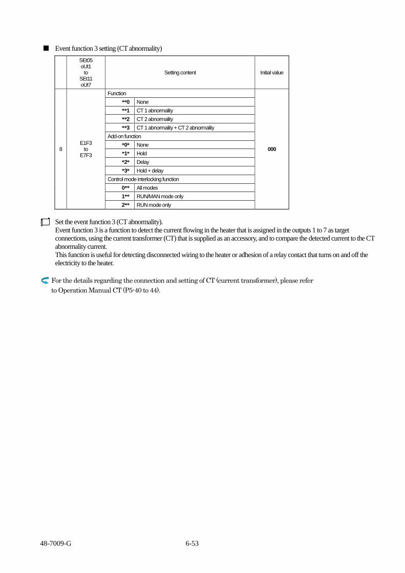
48-7009-G 6-53
■ Event function 3 setting (CT abnormality)
SEt05 oUt1
to SEt11 oUt7
Setting content Initial value
8 E1F3
to E7F3
Function
000
**0 None
**1 CT 1 abnormality
**2 CT 2 abnormality
**3 CT 1 abnormality + CT 2 abnormality
Add-on function
*0* None
*1* Hold
*2* Delay
*3* Hold + delay
Control mode interlocking function
0** All modes
1** RUN/MAN mode only
2** RUN mode only
Set the event function 3 (CT abnormality).
Event function 3 is a function to detect the current flowing in the heater that is assigned in the outputs 1 to 7 as target
connections, using the current transformer (CT) that is supplied as an accessory, and to compare the detected current to the CT
abnormality current.
This function is useful for detecting disconnected wiring to the heater or adhesion of a relay contact that turns on and off the
electricity to the heater.
For the details regarding the connection and setting of CT (current transformer), please refer
to Operation Manual CT (P5-40 to 44).

48-7009-G 6-54
■ Event function 4 (loop abnormality)
SEt05 oUt1
to SEt11 oUt7
Setting content Initial value
9 E1F4
to E7F4
Function
00
*0 Nonexistent
*1 Existent
Add-on function
0* None
1* Hold
Set the event function 4 (loop abnormality).
Event function 4 is a function that detects output abnormalities, and that outputs signals from the event output.
This function can be used when the event function 4 is set and the target connections of the outputs 1 to 7 are set to event
outputs.
For details of the setting of the loop abnormality, see section “5.4.6 Loop abnormality function” on pages 5-38 and 39.
For the setting of the loop abnormality time, see section of primary/secondary control loop abnormality time setting on pages
6-29and 42
■ Event polarity setting
SEt05 oUt1
to SEt11 oUt7
Setting content Initial value
10 E1P to E7P 0 Normal open
0 1 Normal close
Set “close active” or “open active” for the event function setting.
Close active: Event function closes when the event output is in the active state.
Open active: Event function opens when the event output is in the active state.

48-7009-G 6-55
■ Output 1 and 2 transmission output function setting
SEt05 oUt1
to SEt06 oUt2
Setting content Initial value
11 tRN1
tRN2
Transmission content selection
tRN1=01
tRN2=01
*1 PV (measurement value) output
*2 SV (setting value) output
*3 MV 1 (primary control operating amount) output
*4 MV 2 (secondary control operating amount) output
*5 Control SV (Setting Value) output 3
Forward/reverse operation selection
0* Forward operation
1* Reverse operation
Set the output content of transmission output.
The output 1 or output 2 being set for analog output can be used as a transmission output.
For using the output 1 or 2 as a transmission output, set 17 (transmission output) for the target connection of the output 1 or 2.
The transmission output is a function that delivers power of the conditions of the measurement value (PV), setting value (SV),
primary control operating amount (MV 1) , secondary control amount (MV 2) and the control SV (SV Setting Value ) output
with either the voltage or current signal (designated by model assignment upon order).
Also, by setting the movement to either forward or reverse, the voltage or current signal can also be made to move forward or
reverse.
Example: When transmitted in the following setting
Output 1 Output 2
Output type Current 4 - 20 mADC Current 4 - 20 mADC
Output target connection setting o1F=17 o2F=17
Transmission output function setting tRN1=03 tRN2=13
0
20
-10% 100%
MV transmission (forward operation) MV transmission (reverse operation)
Output current [mA]
Operating amount [%]
4

48-7009-G 6-56
■ Output 1 and 2 transmission scaling upper limit/lower limit setting
SEt05 oUt1
to SEt06 oUt2
Setting content Initial value
12 tRH1
to tRH2
Thermocouple/resistance temperature detector input tRL* to 2999.9 (C) tRL* to 2999 (C)
1200
Voltage/current input tRL* to 29999 (digit)
12000
13 tRL1
to tRL2
Thermocouple/resistance temperature detector input -1999.9 to tRH* (C) -1999 to tRH* (C) 0
Voltage/current input -19999 to tRH* (digit)
Set the transmission scaling upper limit/lower limit of the transmission output.
The output 1 or output 2 being set for analog output can be used as a transmission output.
For using the output 1 or 2 as a transmission output, set 17 (transmission output) for the target connection of the output 1 or 2.
This function is to scale the transmission output range with respect to the measurement/setting value.
The decimal point position is set in conjunction with the decimal point position setting (dP 1).
Note This function cannot be set when “3” or “4” (primary/secondary control operating amount) is set in the transmission output
function setting.
Example: When transmitted in the following setting
Output 1 Output 2
Output type Current 4 - 20 mADC Current 4 - 20 mADC
Output target connection setting o1F=17 o2F=17
Transmission output function setting tRN1=01 tRN2=11
Transmission scaling upper limit tRH1=1200.0 tRH2=1200.0
Transmission scaling lower limit tRL1=0.0 tRL2=0.0
0
20
0 1200
PV transmission (forward operation) PV transmission (reverse operation)
Output current [mA]
PV [C]
4

48-7009-G 6-57
6.6 Current transformer (CT) setting
■ CT 1 target connection setting
SEt12
CT Setting content Initial value
1 CI1
1 Connected to OUT 1 (settable when D0)
1
2 Connected to OUT 2 (settable when D0)
3 Connected to OUT 3 (settable when an option existent)
4 Connected to OUT 4 (settable when an option existent)
5 Connected to OUT 5 (settable when an option existent)
6 Connected to OUT 6 (settable when an option existent)
7 Connected to OUT 7 (settable when an option existent)
Set the output measured by CT 1.
Note An analog output cannot be set for the target connection.
For outputting the event output, see section of event function 3 setting (CT abnormality) on page 6-53
For changing screen colors depending on the CT abnormalities, see section of CT at-abnormality display color on page 6-69
Note At-abnormality display color does not change unless the event function 3 setting (CT abnormality) is set.
Note Take care that the product does not properly operate when the subject of control is connected to an output that is set for the CT
abnormality event.
■ CT 1 current value monitor
SEt12
CT Setting content Initial value
2 CM1 0.0 to 50.0 (A)
This function is to display the measurement value of CT 1.
■ CT 1 abnormal current value setting
SEt12
CT Setting content Initial value
3 Ct1 0.0 to 30.0 (A) Function turned off at 0.0 (A) setting
0.0
This function is to set the current value for the CT 1 abnormality.
For the guide to setting value, please refer to Operation Manual CT (Current Transformer) (P5-40 to 44).

48-7009-G 6-58
■ CT 2 target connection setting
SEt12
CT Setting content Initial value
1 CI2
1 Connected to OUT 1 (settable when D0)
1
2 Connected to OUT 2 (settable when D0)
3 Connected to OUT 3 (settable when an option existent)
4 Connected to OUT 4 (settable when an option existent)
5 Connected to OUT 5 (settable when an option existent)
6 Connected to OUT 6 (settable when an option existent)
7 Connected to OUT 7 (settable when an option existent)
Set the output measured by CT 2.
Note An analog output cannot be set for the target connection.
In case the Even Output is needed, please refer to P6 – 53 Event Function 3 Setting (CT abnormal).
In case of changing the display color due to CT abnormality, please refer to P6 – 69CT Display color During the CT
Abnormality.
Note At-abnormality display color does not change unless the event function 3 setting (CT abnormality) is set.
Note Take care that the product does not properly operate when the subject of control is connected to an output that is set for the CT
abnormality event.
■ CT 2 current value monitor
SEt12
CT Setting content Initial value
2 CM2 0.0 to 50.0 (A)
This function is to display the measurement value of CT 2.
■ CT 2 abnormal current value setting
SEt12
CT Setting content Initial value
3 Ct2 0.0 to 30.0 (A) Function turned off at 0.0 (A) setting
0.0
This function is to set the current value for the CT 2 abnormality.
For the target setting value, see section “5.4.7 Current transformer (CT) abnormality function” on pages 5-40 to 44.

48-7009-G 6-59
6.7 DI setting
■ DI function setting
SEt13
dI Setting content Initial value
1 dIF
Press the MODE key for making a setting effective (including reverse feed).
0000
**** |||| |||+-- DI 1 setting (settable when an option existent) ||+--- DI 2 setting (settable when an option existent) |+---- DI 3 setting (settable when an option existent) +----- DI 4 setting (settable when an option existent)
Active
0 None None
1 Bank switchover Bank switchover
2
When Constant operation Mode MD
When Program Mode Start
When Constant operation Mode READY
When Program Mode stop
3 MD MANUAL
4 Reverse operation Forward operation
5 AT stop AT start
6 Timer stop Timer start
7 Constant Operation Mode Program Mode 3
8 - Step Forward 3 (during program mode)
9 - Pause 3 (during program mode)
A nerlock - 3
Set the DI function.
0: No DI function
1: Bank switchover is executed.
Bank selection table per DI 1 state
DI1 DI3 DI2 DI1
0 Bank 0 0 0 0 Bank 0
1 Bank 1 0 0 1 Bank 1
0 1 0 Bank 2
DI2 DI1 0 1 1 Bank 3
0 0 Bank 0 1 0 0 Bank 4
0 1 Bank 1 1 0 1 Bank 5
1 0 Bank 2 1 1 0 Bank 6 0: Inactive 1: Active 1 1 Bank 3 1 1 1 Bank 7
The parameters change right after switchover when the bank is changed per DI.
2: <During Constant Operation Mode> Switching of Control Mode and STOP. <During the Program Mode> Switching of In-Operation and Operation Stop. 3: Switching of AUTO & MANUAL is done 4: Switching of Output Movement (forward / reverse movement) is done. 5: The Star & Stop of Auto-Tuning of PID Control is done. Maintain the DI to active condition until the auto-tuning is completed. In case the operation is suspended half-way, the auto-tuning will stop.

48-7009-G 6-60
6: Start and Stop of the timer operation, which is set in “function setting - DI 1 to 4 start” for timers 1 to 3 (see SET 14 to 16 on page
6-59, are switched over.
Stopping the timer during operation results to midway termination (state of control stop or event output OFF).
Note Setting with DI supersedes the setting change of “communication” or “FUNC key.”
Note Setting the function setting to the bank switchover may cause high-speed switchovers of banks when setting the DI function
setting to a bank.
To solve this phenomenon, delete DI function setting DIF from the bank setting, set DIF to the bank switchover setting, and
put the DIF into the bank.
Note Choose the open collector output when change DI by the event output.
7: CONSTANT OPERATION / PRGRAM MODE SWITCHING 3 Switching between the Constant Operation and the Program Mode will be made 8: STEP FORWARD 3 steps can be forwarded during the program mode. NOTE: This function is effective only when the Program Mode is being selected. 9: PAUSE 3 By pressing the FUNC-key, the Program Operation can be stopped temporarily. Switching between Pause – In Operation will be made. NOTE: This function is effective only when the Program Mode is being selected. A: Inter-Lock 3
When the "DI = Non-Active", the Control Mode can be stopped forcibly.
Its priority is the highest over all the Control Mode Condition.
The setting of Control Mode Condition can be switched with (SEt04 Md)(SEt03 FU*)(SEt13 DIF).
NOTE: During Constant Operation Mode When dIF=A, at the same time, the function-key function is set to FU1 – 5 = 2, to re-start the operation after DI=Active, press function key. NOTE: During the Program Mode With DI=Non-Active, it will forcibly go back to “Pre-Operation Condition”. Re-start the operation after DI=Active.

48-7009-G 6-61
Setting example: When “AT start” is assigned to DI 1 (close active)
Set dIF to 0005 and dIP to 0000.
When DI is inactive
200 200
200 At
Switch OFF DI1
Lighting
When DI is active
Switch ON
Usable DIs for each product model
DIs indicated in the table are usable when DI types are optionally designated.
TTM-204 TTM-205 TTM-209
TTM-207
DI1
DI2
DI3
DI4
■ DI polarity setting
SEt13
dI Setting content Initial value
2 dIP
**** |||| |||+-- DI 1 setting (settable when an option existent) ||+--- DI 2 setting (settable when an option existent) |+---- DI 3 setting (settable when an option existent) +----- DI 4 setting (settable when an option existent)
0000
0 Close active
1 Open active
“Close active” or “open active” is set for “DI function setting” described above.
Close active: DI is active when short (max. 333 ) is established between DI terminals.
Open active: DI is active when release (min. 500 k) is established between DI terminals.

48-7009-G 6-62
6.8 Timer function setting
■ Timer function setting
SEt14 tIME1
to SEt16 tIME3
Setting content Initial value
1 tMF1
to tMF3
1 Auto start
1
2 Manual start
3 SV start
4 DI 1 start (settable when an option existent)
5 DI 2 start (settable when an option existent)
6 DI 3 start (settable when an option existent)
7 DI 4 start (settable when an option existent)
8 Event 1 start
9 Event 2 start
10 Event 3 start (settable when an option existent)
11 Event 4 start (settable when an option existent)
12 Event 5 start (settable when an option existent)
13 Event 6 start (settable when an option existent)
14 Event 7 start (settable when an option existent)
15 Step Start (during program mode) 3
16 Soak Start (during program mode) 3
Set functions of timers 1 to 3.
Note Setting the control modes to TIME 1 to 3 or setting the target connection setting (o1F to o7F) to 5 to 16 is required for
operating timers.
Note Triggers for starting timers are DI, FUNC key and / key, in this order from higher priority.
For details of the timer setting, see section “5.4.5 Timer function” on pages 5-32 to 37.
When the SV start is set, set the start SV permissible range setting.
■ Unit setting
SEt14 tIME1
to SEt16 tIME3
Setting content Initial value
2 H/M1
to H/M3
1 Hour/minute 1
2 Minute/second
Set the unit of time for timers 1 to 3.

48-7009-G 6-63
■ Start SV permissible range setting
SEt14 tIME1
to SEt16 tIME3
Setting content Initial value
3 tSV1
to tSV3
Thermocouple/resistance temperature detector input 0.0 to 999.9 (C) 0 to 999 (C) 0
Voltage/current input 0 to 9999 (digit)
When the SV start is set, it is set that at what temperature range (°C) the timer should start.
The permissible range is determined in the range of tSV with SV in the center as shown below.
When tSV is set to 1.0°C, the timer operates when the temperature falls within SV ± 0.5°C.
SV tSV
Note When the ramp action is used together, tSV is set to target SV value.
■ ON delay timer/OFF delay timer/repeat count setting
SEt14 tIME1
to SEt16 tIME3
Setting content Initial value
4 oNt1
to oNt3
0:00 to 99:59 (hour: minute or minute: second) 0:00
5 oFt1 to
oFt3 0:00 to 99:59 (hour: minute or minute: second) 0:00
6 RUN1
To RUN3
0 to 99 counts (0 for unlimited counts) 1
Set the ON delay timer, OFF delay timer and repeat count setting of timers.
Use oNt 1 to 3 for setting the ON delay timer time of timers 1 to 3.
Use oFt 1 to 3 for setting the OFF delay timer time of timers 1 to 3.
Use RUN 1 to 3 for setting the repeat count of timers 1 to 3.
Note When the function setting of tMF 1 to 3 is set for the SV start, the ON delay timer screen is not displayed.
For the details on Timer Setting, please refer to Operation Manual Timer (P5 – 31 to 37).

48-7009-G 6-64
■ Remaining time monitor
SEt14 tIME1
to SEt16 tIME3
Setting content Initial value
7 tIA1 to
tIA3
0:00 to 99:59 (hour: minute or minute: second) Start/stop of timer using / key
0:00
Remaining time of timers 1 to 3 is displayed.
Timers can be started on this screen.
When the ON delay timer and OFF delay timer are set, the setting value for the ON delay timer is displayed.
When only the OFF delay timer is set, the setting value for the OFF delay timer is displayed.
When the timer starts, the remaining time for the ON or OFF delay timer currently counting down is displayed.
When the timer completes the countdown, “0:00” is displayed.

48-7009-G 6-65
6.9 Communication function setting
■ Communication protocol setting
SEt17 CoM
Setting content Initial value
1 PRt
Press the MODE key for making a setting effective (including reverse feed).
0 0 TOHO protocol
1 MODBUS protocol (RTU mode)
2 MODBUS protocol (ASCII mode)
Set the communication protocol (communication procedure).
For details of communication, see “TTM-200 series operation manual - communications.”
■ Communication parameter setting
SEt17 CoM
Setting content Initial value
2 CoM
***1 Stop bit length 1 bit
b8N2
***2 Stop bit length 2 bits
**N* Parity none
**o* Parity odd No.
**E* Parity even No.
*7** Data length 7 bits
*8** Data length 8 bits
N*** BCC check nonexistent (settable for TOHO protocol)
b*** BCC check existent (settable for TOHO protocol)
For MODBUS (RTU) Settable only with 8N2, 8N2, 8o1, 8o2, 8E1 and 8E2. For MODBUS (ASCII) Settable only with 7N1,7N2,7o1,7o2,7E1,7E2, 8N1,8N2,8o1,8o2,8E1,8E2
The following is set for communication data: stop bit length, parity and BCC check existent/nonexistent.
For details of communication, see “TTM-200 series operation manual - communications.”
■ Communication speed setting
SEt17 CoM
Setting content Initial value
3 bPS
2.4 2400 bps
9.6
4.8 4800 bps
9.6 9600 bps
19.2 19200 bps
38.4 38400 bps
Set the communication speed.
The term bps (bits per second) refers to the number of bits allowed in communication in a second.
For details of communication, see “TTM-200 series operation manual - communications.”

48-7009-G 6-66
■ Communication address setting
SEt17 CoM
Setting content Initial value
4 AdR TOHO protocol 1 to 99 (stations)
1 MODBUS protocol 1 to 247 (stations)
Set the address for communication.
Take care that no identical numbers are assigned for more than one unit of equipment.
For details of communication, see “TTM-200 series operation manual - communications.”
■ Response delay time setting
SEt17 CoM
Setting content Initial value
5 AWt 0 to 250 (ms) 0
Set the response delay time in communication.
Response delay time in communication is set for the time taken from when a host computer completes transmission of
“request message” until when it gives up the line to become in the input state.
Note Communication may not be properly executed when the response delay time setting is for too short a time.
Note For the actual operation time, processing time of the product is added on the response delay time.
For details of communication, see “TTM-200 series operation manual - communications.”
■ Communication switchover setting
SEt17 CoM
Setting content Initial value
6 Mod
0 Write inhibit
1 1 Writable
2 Concurrent temperature ascent master
3 Concurrent temperature ascent slave
Set the communication switchover.
When “0” is set, writing is inhibited.
When “1” is set, writing is enabled.
When “2” is set, master for the concurrent temperature ascent is established.
When “3” is set, slave for the concurrent temperature ascent is established.
For details of communication, see “TTM-200 series operation manual - communications.”

48-7009-G 6-67
6.10 Initial setting
■ Password input
SEt18 INIt
Setting content Initial value
1 PASS
(Blinking) 0000 to 9999 Change the 4-digit number and press the MODE key for canceling.
0000
To move to the initial setting mode, set the password.
A password is set for the product, key in the number in this screen, using the / key. Then, press the MODE key.
In the initial setting mode, the FUNC key is assigned for the digit shift function.
Key-in of the proper password number results in a move to the parameter setting of the initial setting mode.
Key-in of an improper password number results in a return to the SEt 18 screen.
■ PV normal display color
SEt18 INIt
Setting content Initial value
2 NdSP
0 1 2 3
Green Red Orange Automatic (NdSP only)
0
Set the normal display color of PV.
Priority of the display colors is as follows.
1. PV normal display color (when NdSP = 3)
2. PV at-abnormality display color (E2dSP)
3. CT at-abnormality display color (E3dSP)
4. Loop at-abnormality display color (E4dSP)
5. PV at-event display color (E1dSP)
6. PV normal display color (when NdSP = 0 to 2)
Note For the PV normal display color (when NdSP = 3), the following functions are unavailable: the PV at-abnormality display
color, CT at-abnormality display color, loop at-abnormality display color and PV at-event display color.
■ PV color auto-display low
SEt18 INIt
Setting content Initial value
3 AdSL 0 1 2
Green Red Orange
1
■ PV color auto-display middle
SEt18 INIt
Setting content Initial value
4 AdSM 0 1 2
Green Red Orange
0
■ PV color auto-display high
SEt18 INIt
Setting content Initial value
5 AdSH 0 1 2
Green Red Orange
2

48-7009-G 6-68
■ Switchover range for PV display color
SEt18 INIt
Setting content Initial value
6 PVC
Thermocouple/resistance temperature detector input 0.0 to 999.9 (C) 0 to 999 (C) 1
Voltage/current input 0 to 9999 (digit)
SV
Time elapsed
PV
Switchover range for PV
display color
PV color auto-
display low
PV color auto-
display middle
PV color auto-
display high
PV color auto-
display middle
Switchover range for PV
display color
PVC
PVC
■ PV at-event display color
SEt18 INIt
Setting content Initial value
7 E1dSP 0 1 2
Green Red Orange
2
Set the display color for PV event.
■ PV at-abnormality display color
SEt18 INIt
Setting content Initial value
8 E2dSP 0 1 2
Green Red Orange
1
Set the display color for PV abnormality.

48-7009-G 6-69
■ CT at-abnormality display color
SEt18 INIt
Setting content Initial value
9 E3dSP 0 1 2
Green Red Orange
1
Set the display color for CT abnormality.
■ Loop at-abnormality display color
SEt18 INIt
Setting content Initial value
10 E4dSP 0 1 2
Green Red Orange
1
Set the display color for loop abnormality.
■ Blind function effective/ineffective setting
SEt18 INIt
Setting content Initial value
11 bLd 0 Blind function nonexistent
1 1 Blind function existent
For displaying the screen blinded by using the blind function, set bLd to “0.”
For not displaying the screen blinded, set bLd to “1.”
■ Backup of the setting value
SEt18 INIt
Setting content Initial value
12 bKUP Backup starts by a 2-second press of the FUNC key. “SAVE” is displayed during backup. Upon completion of backup, display of “SAVE” disappears.
The setting value is backed up.
The data flow is shown below.
Backup explanation diagram
INP INP
Storage area for operation
Bank
Area for backup
Bank
Settings for the priority screen function, bank function and blind function are also backed up.
Note During backing up, response in communication is on nak 2.
Note During backing up, switchover of DI is not reflected.

48-7009-G 6-70
■ Initialization of setting values
SEt18 INIt
Setting content Initial value
13 RESEt
0 Setting at factory shipment
0 1 Backup setting
Initialization starts by a 2-second press of the FUNC key. “INIt” is displayed during initialization. Upon completion of initialization, display of “INIt” disappears.
Settings are initialized.
The data flow is shown below.
Initialization explanation diagram
IN ① INP ② INP
Storage area for initial values
① Operation when RESET is set to “0” (setting at factory shipment)
② Operation when RESET is set to “1” (backup setting)
Bank
Storage area for operation
Bank
Area for backup
Bank
Note The data backed up is not initialized even when initialization in the setting at factory shipment is executed.
In case that the data backed up is desired to initialize for the initial value at factory shipment, first execute initialization in the
setting at factory shipment and then in the backup setting.
Note During backing up, response in communication is on nak 2.
Note During backing up, switchover of DI is not reflected.
Note When the communication parameter on the product mismatches the one on the host after initialization, no communication is
possible.
Note Advancement of initialization results in no DI function.
Note When the initialization is executed, control action is initialized as well.
■ Password setting
SEt18 INIt
Setting content Initial value
14 PASS
(Lighting)
0000 to 9999 After changing the 4-digit number, a 2-second press of the FUNC key results in setting/canceling.
0000
Set the password.
When a password is set, set a desired number using the / key, and press the FUNC key for 2 seconds.
In the initial setting, the FUNC key is assigned for the digit shift function.
Note Do not forget the password.
Note In case of password forgotten, contact TOHO’s sales department.
For contacting TOHO’s sales department, see the last page of this user’s manual.

48-7009-G 6-71
6.11 Priority screen setting
■ Priority screens 1 to 16 setting
SEt19 PRI
Setting content Initial value
1 PRI01
Parameters for SEt 01 to SEt 17
oFF
2 PRI02 oFF
3 PRI03 oFF
4 PRI04 oFF
5 PRI05 oFF
6 PRI06 oFF
7 PRI07 oFF
8 PRI08 oFF
9 PRI09 oFF
10 PRI10 oFF
11 PRI11 oFF
12 PRI12 oFF
13 PRI13 oFF
14 PRI14 oFF
15 PRI15 oFF
16 PRI16 oFF
Set parameters frequently used or desired to display in the priority screen.
This enables a quick setting or display of the corresponding screen only by a press of the MODE key in the operating mode.
Max. 16 screens can be set.
Set to “OFF” when priority screens are not used.
Note Parameters not allowed with setting in the priority screens are listed below.
Take care that screens for such parameters are not displayed.
(1) All parameters in the initial value setting mode (SET 18)
(2) All parameters in the priority screen design mode (SET 19)
(3) All parameters in the bank setting mode (SET 20) (4) All parameters of Program Function Setting (SET 21) 3 (5) All parameters of Program Setting (SET 22) 3 (6) All parameters of Bank Auto-Switch Function Setting (SET 23) 3 (7) Some parameters are not selectable, depending on ordered models.

48-7009-G 6-72
6.12 Bank function setting
■ Banks 1 to 16 setting
SEt20 bNK
Setting content Initial value
1 bNK01
Parameters for SEt 01 to SEt 17
cNT
2 bNK02 oFF
3 bNK03 oFF
4 bNK04 oFF
5 bNK05 oFF
6 bNK06 oFF
7 bNK07 oFF
8 bNK08 oFF
9 bNK09 oFF
10 bNK10 oFF
11 bNK11 oFF
12 bNK12 oFF
13 bNK13 oFF
14 bNK14 oFF
15 bNK15 oFF
16 bNK16 oFF
Max. 16 of any parameter setting value can be changed in the banks 0 to 7.
For the no use of the bank, set the setting to “OFF.”
When the bank function is set, the bank Nos. 0 to 7 are displayed in the bank display section.
T TM-204
SV
PV
Note Parameters with which no bank function is selectable are listed below. Take care that no screen is displayed.
(1) Bank switchover of the control setting mode (SET 04)
(2) All parameters in the initial value setting mode (SET 18)
(3) All parameters in the priority screen design mode (SET 19)
(4) All parameters in the bank setting mode (SET 20) (5) All parameters of Program Function Setting (SET 21) 3 (6) All parameters of Program Setting (SET 22) 3 (7) All parameters of Bank Auto-Switch Function Setting (SET 23) 3 (8) Some parameters are not selectable, depending on ordered models.
Bank display

48-7009-G 6-73
6.13 PROGRAM FUNCTION SETTING
■Operation Type Setting
SEt21
PGF Setting Contents
Initial
Value
1 C/P
Operation Type Setting 3
0 0 Constant Operation Mode
1 Program Mode
※1 Operation Type Setting (C/P)
The program operation will take place when the Program Mode is set.
The Program Mode executes the program operation by automatically switching the “Bank Function” and
“Program Step Function”.
Setting Range
0: Constant Operation Mode (Program Mode OFF)
1: Program Mode (Program Mode ON)
■Behavior during the Program Mode
STEP1 STEP2 STEP3 STEP4 STEP5 STEP6 STEP7 STEP8
SV1
50℃TIM1
00:30
ST1BKBANK1
BANK1
RMP
10P1
4.0
・・・
o2F
I20
D
5
SV2
100℃TIM2
00:40
ST2BKBANK1
BANK1
RMP
10
・・・
o2F
SV3
150℃TIM3
00:50
ST3BKBANK1
BANK1
RMP
10
・・・
o2F
SV4
200℃TIM4
01:00
ST4BKBANK1
BANK1
RMP
10
・・・
o2F
SV5
150℃TIM5
00:30
ST5BKBANK2
BANK2
RMP
5
・・・
o2FTIMER ON
DELAY
SV6
100℃TIM6
00:40
ST6BKBANK2
BANK2
RMP
5
・・・
SV7
150℃TIM7
00:50
ST7BKBANK1
BANK1
RMP
10
・・・
o2F
SV8
20℃TIM8
00:10
ST8BKBANK3
BANK3
RMP
30
・・・
o2FRUN OUT
BANK0
RMP
P1
3.0MA
X.
16 P
AR
AM
ETER
・・・
o2FEND OUT
I0
D
0
BANK0
RMP
・・・
o2FEND OUT
STARTOPERATION
ENDOPERATION
ENDPV
BANK0
RMP
MA
X
16ハ
゚ラメー
タ
・・・
o2FEND OUT
OPERATIONSTOP
STOPOPERATION
STOP OPERATION
P1
2.0
I10
D
2
P1
3.0
I0
D
0
P1
3.0
I0
D
0
P1
4.0
I20
D
5
P1
4.0
I20
D
5
P1
4.0
I20
D
5
P1
4.0
I20
D
5
P1
2.0
I10
D
2
P1
2.0
I10
D
2
SET22
SETTING VALUE
MAX. 8 STEPS
SET20SETTING VALUE
STEP SV SETTING
STEP TIME SETTING
STEP BANK SETTING
o2F
TEMP. CHANGE PATTERN
REFER1BANK
OPERATIONSTOP
OUTPUT EXAMPLE
TIMER ONDELAY
o2F

48-7009-G 6-74
■Program Mode Setting / Power Failure Compensation Range Setting
SEt21
PGF Setting Contents
Initial
Value
2 PGMd
Program Mode Setting 3
0
0 Program 1(w/o Power Failure Compensation)
1 Program 2(w/o Power Failure Compensation)
2 Program 1(w/ Power Failure Compensation)
3 Program 2(w/ Power Failure Compensation)
※Program 1:After the operation, control stops.
※Program 2: After the operation, the control continues.
3 PoC
Power Failure Compensation Range Setting
<Always resume at 0> 3 0
During Temperature Input
0~999(0.0~999.9)(℃)
During Analog Input 0
0~9999 (digit)
*2 Program Mode Setting (PGMd) This is to set the operation condition of “POWER FAILURE COMPENSATION WITH / WITHOUT” setting
and “PROGRAM OPERATION END” during the program mode. Setting Range 0: Program 1 (Without Power Failure Compensation) 1: Program 2 (Without Power Failure Compensation) 2: Program 1 (With Power Failure Compensation) 3: Program 2 (With Power Failure Compensation) Program 1: The control stops after ending the program operation. END indication appears after the operation. After the END indication appears, the control will stop. Program 2: The control continues after ending the program operation. The END indication appears after the operation, but the control will continue. Operate the key or use DI to stop the control. NOTE: The SET4 Control Mode Setting (Md) becomes ineffective with Program Mode (C/P=1). This is effective only with Constant Operation. Re: Power Failure Compensation This is a function in which, when the power recovers, the operation restarts from the STEP before the power failure when the function is set to “With Power Failure Compensation”. The present step, repeat no. of times, remaining time is being stored. When the setting condition of the Power Failure Compensation Rage Setting (PoC) has been satisfied, it will return to the condition last stored by the STEP, and the operation restarts. *3 Power Failure Compensation Range Setting (PoC) This is to set the PV value range of the recovery decision during the power recovery. Setting Range Temperature Input (℃) 0 – 999 (0.0 – 999.9) Analog Input (digit) 0 – 9999 NOTE: The condition of recovery is when the difference between the PV value at the time of recovery and the PV value before the power failure is smaller than the power failure compensation range setting (PoC).
PoC ≧ (PV value at the time of recovery) – (PV value before the power failure) NOTE: After the power recovery, when the sensor is either disconnected or defective, the recovery action will not take place regardless of the PoC setting value. The operation condition will be “Program Operation Stop”.
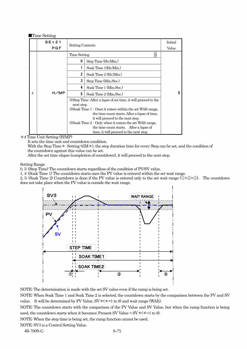
48-7009-G 6-75
■Time Setting
SEt21
PGF Setting Contents
Initial
Value
4 H/MP
Time Setting 3
0
0 Step Time (Hr./Min.)
1 Soak Time 1(Hr./Min.)
2 Soak Time 2 (Hr./Min.)
3 Step Time (Min./Sec.)
4 Soak Time 1 (Min./Sec.)
5 Soak Time 2 (Min./Sec.)
※Step Time:After a lapse of set time, it will proceed to the
next step.
※Soak Time 1:Once it enters within the set WAIt range,
the time count starts. After a lapse of time,
it will proceed to the next step.
※Soak Time 2:Only when it enters the set WAIt range,
the time count starts. After a lapse of
time, it will proceed to the next step.
*4 Time Unit Setting (H/MP) It sets the time unit and countdown condition. With the Step Time* Setting (tIM*), the step duration time for every Step can be set, and the condition of
the countdown against this value can be set. After the set time elapse (completion of countdown), it will proceed to the next step. Setting Range 0, 3: (Step Time) The countdown starts regardless of the condition of PV/SV value. 1, 4: (Soak Time 1) The countdown starts once the PV value is entered within the set wait range. 2, 5: (Soak Time 2) Countdown is done if the PV value is entered only to the set wait range (①+②+③). The countdown does not take place when the PV value is outside the wait range.
SV3
PV
② ③
STEP TIME
SOAK TIME1
SOAK TIME2
WAIT RANGE
SV
①
NOTE: The determination is made with the set SV value even if the ramp is being set.
NOTE: When Soak Time 1 and Soak Time 2 is selected, the countdown starts by the comparison between the PV and SV
value. It will be determined by PV Value, SV*(*=1 to 8) and wait range (WAIt).
NOTE: The countdown starts with the comparison of the PV Value and SV Value, but when the ramp function is being
used, the countdown starts when it becomes; Present SV Value = SV*(*=1 to 8).
NOTE: When the step time is being set, the ramp function cannot be used.
NOTE: SV3 is a Control Setting Value.

48-7009-G 6-76
■Wait Range Setting
SEt21
PGF Setting Contents
Initial
Value
5 WAIt
Wait Range Setting 3
2
During Temperature Input
Soak Time 1 0~999(0.0~999.9)(℃)
Soak Time 2 0~999(0.0~999.9)(℃)
※During H/MP(Soak Time 2)、the behavior will
be identical to that of (Soak Time 1) with Setting=0
During Analog Input
Soak Time 1 0~9999(digit)
Soak Time 2 0~9999(digit)
※During H/MP(Soak Time 2)、the behavior will
be identical to that of (Soak Time 1) with Setting=0
*5 WAIT RANGE SETTING (WAIt)
Time Unit Setting (H/MP) sets the condition of countdown (Range against PV Value) during the setting of
(Soak Time 1) (Soak Time 2).
Please refer to Time Unit Setting (H/MP) for the explanation of its action.
Setting Range
(During Temp. Input)
Soak Time 1: 0 to 999 (0.0 to 999.9)℃
Soak Time 2: 0 to 999 (0.1 to 999.9)℃
(During Analog Input)
Soak Time 1: 0 to 9999 (digit)
Soak Time 2: 0 to 9999 (digit)
NOTE: RE: Behavior during WAIT Range Setting (Setting Value = 0)
Even if the H/MP (Soak Time 2) is being set, when the Setting Value = 0, the behavior would be the same as that of (Soak
Time 1).
NOTE: Regarding the AT (Auto-Tuning) behavior during the program in operation.
The AT can be done while the program is in operation. The SV Value which operates the AT is the SV* (Step SV) Value that is set in
each steps. Also, this condition applies also during RMP in operation with set RMP movement.
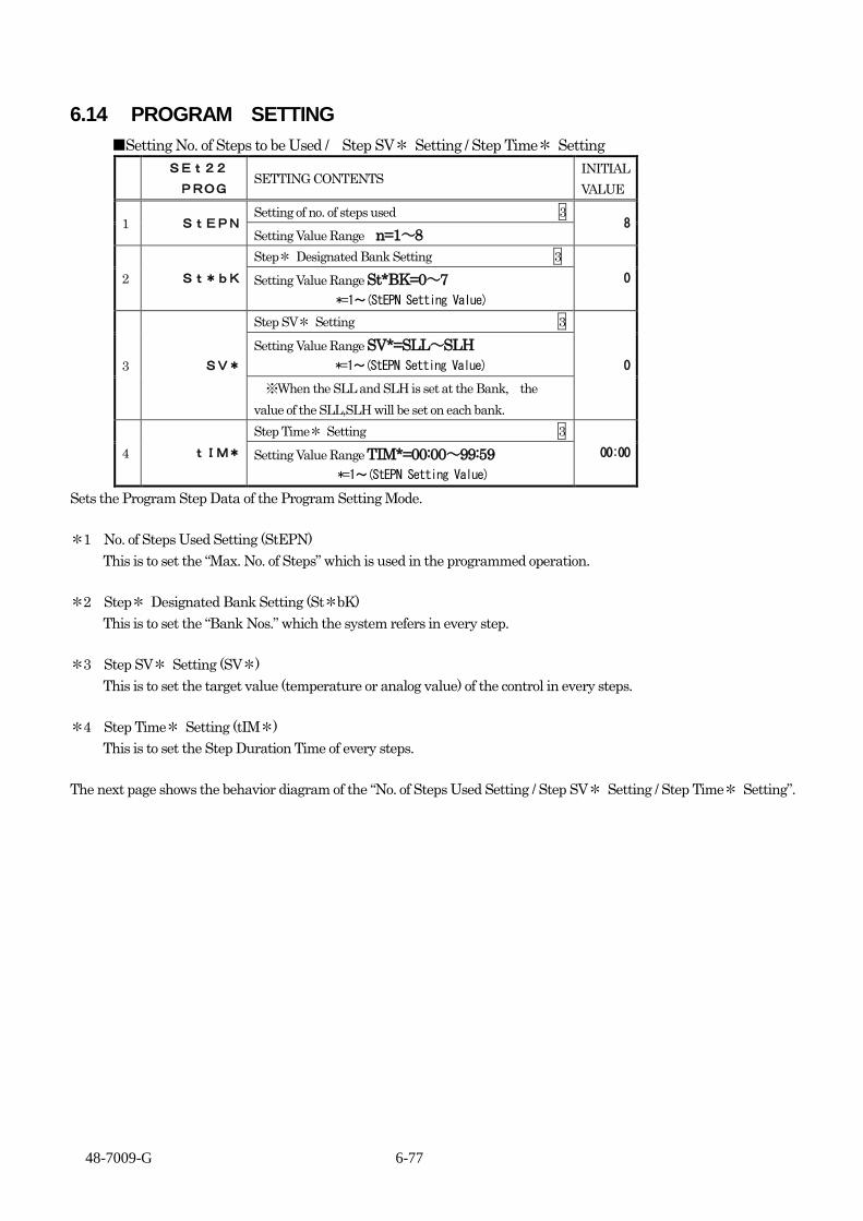
48-7009-G 6-77
6.14 PROGRAM SETTING
■Setting No. of Steps to be Used / Step SV* Setting / Step Time* Setting
SEt22
PROG SETTING CONTENTS
INITIAL
VALUE
1 StEPN Setting of no. of steps used 3
8 Setting Value Range n=1~8
2 St*bK
Step* Designated Bank Setting 3
0 Setting Value Range St*BK=0~7
*=1~(StEPN Setting Value)
3 SV*
Step SV* Setting 3
0
Setting Value Range SV*=SLL~SLH
*=1~(StEPN Setting Value)
※When the SLL and SLH is set at the Bank, the
value of the SLL,SLH will be set on each bank.
4 tIM*
Step Time* Setting 3
00:00 Setting Value Range TIM*=00:00~99:59
*=1~(StEPN Setting Value)
Sets the Program Step Data of the Program Setting Mode.
*1 No. of Steps Used Setting (StEPN)
This is to set the “Max. No. of Steps” which is used in the programmed operation.
*2 Step* Designated Bank Setting (St*bK)
This is to set the “Bank Nos.” which the system refers in every step.
*3 Step SV* Setting (SV*)
This is to set the target value (temperature or analog value) of the control in every steps.
*4 Step Time* Setting (tIM*)
This is to set the Step Duration Time of every steps.
The next page shows the behavior diagram of the “No. of Steps Used Setting / Step SV* Setting / Step Time* Setting”.

48-7009-G 6-78
■Setting No. of Steps to be Used / Step SV* Setting / Step Time* Setting Behavior Diagram
STEP1 STEP2 STEP3 STEP4 STEP5 STEP6 STEP7 STEP8
OperationStart
OperationEnd
PV
Operation StopManipulation
Operation StartManipulation
STOPOperation
380025%1
480015%1
830032%2
960020%2
BANK1
RMP10
P14.0
o3F
I20D5
BANK1
RMP10
o3F
BANK1
RMP10
o3F
BANK1
RMP10
o3F
BANK2
RMP5
o3F
BANK2
RMP5
BANK1
RMP10
BANK3
RMP30
BANK0
RMP
P13.0
o3F
I0D0
BANK0
RMP
P12.0I
10D2
P13.0I0D0
P14.0I
20D5
P14.0I
20D5
P14.0I
20D5
P14.0I
20D5
P12.0I
10D2
P12.0I
10D2
SV150℃TIM100:30
ST1BKBANK1
SV2100℃TIM200:40
ST2BKBANK1
SV3150℃TIM300:50
ST3BKBANK1
SV4200℃TIM401:00
ST4BKBANK1
SV5150℃TIM500:30
ST5BKBANK2
SV6100℃TIM600:40
ST6BKBANK2
SV7150℃TIM700:50
ST7BKBANK1
SV820℃TIM800:10
ST8BKBANK3
St*bK
tIM*
SV*
SV
1390041%3
1470025%3
1810049%4
1910031%4
1510016%5
1580022%5
1010021%6
1040032%6
1480039%7
1500029%7
280004%8
380006%8
20
PROG%0
22
END%0
22
PROG%0
o2F o2F o2F o2F o2F o2F o2F o2Fo2F o2F
BANK3
RMP
P13.0I0D0
o2F
In the processof ending
OperationSuspended
In Program OperationOperationSuspended
18 18 18 18 18o3F18
o3F18
o3F18
o3F18 18
6
o3F18
6
*** Time Signal Output Setting *** *(SET14)tMF1=15, (SET14)tSV1=0, (SET14)oNt1=00:15 Step Start *(SET6)o2F=6 When Bank 2, o2F=Timer 1 on Delay Output. Other banks are Event Output (nofunction) *(SET7)o3F=18 End Output*** Program Function Setting *** *(SET21)C/P=1, (SET21) PGMD=3, (SET21)PoC=0, (SET21)H/MP=2, (SET21)WAIt=5 Program 2 (w/ Power Failure Compensation), 2: Soak Time 2 (Hr./Min.) *(SET22) StEPN=8, (SET22) StRSt=1, (SET22) ENdSt=8, (SET22)RUNP=1*** Other Settings *** *Set to (SET4) Bank=0. Also, "0" is assumed when BANK switchover is ON by DI.
22 22 2 2 2 2 2
bNK015 530
(SET21)PGMd=3
Setting OperationContinuation
oUt2
oUt3
bNK02
bNK03
bNK04
bNK05
bNK06
bNK07
bNK08
bNK09
bNK10
bNK11
bNK12
bNK13
bNK14
bNK15
bNK16
Operation Suspended(SET4)bANK=0DI(nonActive)
Program OperationDisplay Indication
Time Signal Output
ReferenceBank No.
SET20(bNK)Setting Value
Operation Suspended(SET4)bANK=0DI(nonActive)
SET22(PRoG)Setting Value
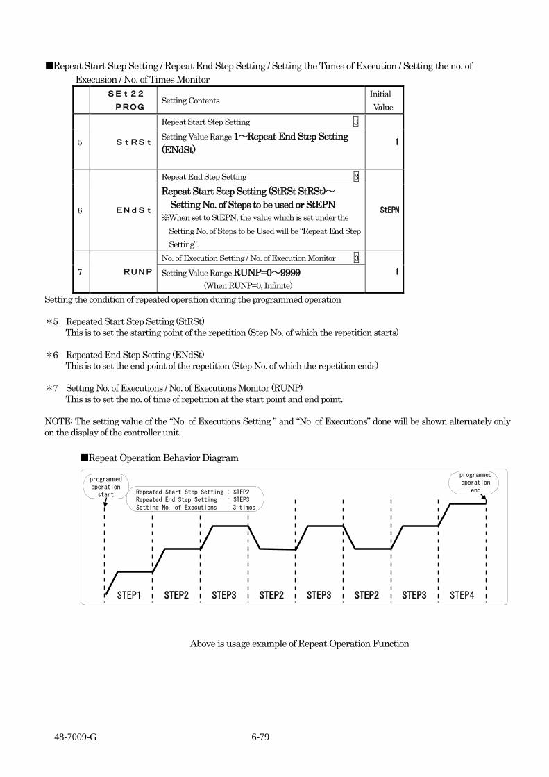
48-7009-G 6-79
■Repeat Start Step Setting / Repeat End Step Setting / Setting the Times of Execution / Setting the no. of
Execusion / No. of Times Monitor
SEt22
PROG Setting Contents
Initial
Value
5 StRSt
Repeat Start Step Setting 3
1 Setting Value Range 1~Repeat End Step Setting
(ENdSt)
6 ENdSt
Repeat End Step Setting 3
StEPN
Repeat Start Step Setting (StRSt StRSt)~
Setting No. of Steps to be used or StEPN
※When set to StEPN, the value which is set under the
Setting No. of Steps to be Used will be “Repeat End Step
Setting”.
7 RUNP
No. of Execution Setting / No. of Execution Monitor 3
1 Setting Value Range RUNP=0~9999
(When RUNP=0, Infinite)
Setting the condition of repeated operation during the programmed operation
*5 Repeated Start Step Setting (StRSt)
This is to set the starting point of the repetition (Step No. of which the repetition starts)
*6 Repeated End Step Setting (ENdSt)
This is to set the end point of the repetition (Step No. of which the repetition ends)
*7 Setting No. of Executions / No. of Executions Monitor (RUNP)
This is to set the no. of time of repetition at the start point and end point.
NOTE: The setting value of the “No. of Executions Setting ” and “No. of Executions” done will be shown alternately only
on the display of the controller unit.
■Repeat Operation Behavior Diagram
STEP1 STEP2 STEP3 STEP2 STEP3 STEP2 STEP3 STEP4
programmedoperationstart Repeated Start Step Setting : STEP2
Repeated End Step Setting : STEP3Setting No. of Executions : 3 times
programmedoperation
end
Above is usage example of Repeat Operation Function

48-7009-G 6-80
6.15 BANK AUTOMATIC SWITCHING FUNCTION SETTING
■Bank Automatic Switching Function Selection
SEt23
ZbNK Setting Contents
Initial
Value
1 bAF
Bank Automatic Switching Function Selection 3
0
0 Bank Auto-Switching Operation OFF
1 Bank Auto-Switching Operation ON
※In case the “Bank Auto-Switching Operation ON” is set;
・The Bank Switching Setting with the FUNC Key will be invalid.
・The Bank Switching Setting by DI will be invalid. ▲▼ key operation will not be possible either.
※When SET04 bANKH=0, the setting will be invalid.
There will be no indication either.
※1 Bank Automatic Switching Function Selection (bAF) This is to set the Bank Automatic Switching ON/OFF. When ON, the bank will be switched
automatically with the selected input by the Bank Automatic Switching Source Setting (bAS).
Setting Range:When 0: Bank Automatic Switching Operation OFF When 1: Bank Automatic Switching Operation ON
■Behavior Diagram when Bank Automatic Switching is ON
BANK1
RMP
10P1
4.0
・・・
I
20D
5
BANK2
RMP
10
・・・
BANK3
RMP
10
・・・
BANK4
RMP
10
・・・
BANK5
RMP
5
・・・
BANK6
RMP
5
・・・
BANK7
RMP10
・・・
BANK0
RMP
P1
3.0
MA
X.1
6 param
ete
r
・・・
I
0D
0
SV
P1
2.0I
10D
2
P1
4.0I
20D
5
P1
4.0I
20D
5
P1
4.0I
20D
5
P1
4.0I
20D
5
P1
2.0I
10D
2
SET20setting
Refer
BANK0
BANK1
BANK2
BANK3
BANK4
BANK5
BANK6
BANK7
PM1
PM2
PM3
PM4
PM5
PM6
PM7
SLH
SLL
SLL≦<PM1
SVvalue
PM1≦<PM2
PM2≦<PM3
PM3≦<PM4
PM4≦<PM5
PM5≦<PM6
PM6≦<PM7
PM7≦<SLH
Bank Automatic Switching.Switch the bank in accordance with
the source(SV)..
MAX. 8BANK
①
②
③
④
⑤
④
①
③
① 10℃
PM*setting
PM1
PM2
PM3
PM4
PM5
PM6
PM7
SLL
SLH
20℃
0℃
40℃
60℃
90℃
120℃
140℃
160℃
200℃
② 35℃
Bank 0
Bank 1
Bank 2
Bank 3
Bank 4
Bank 5
Bank 6
Bank 7
③ 70℃
④ 100℃
⑤ 150℃
Auto-Switchingsorce
Bank No.
8BANK(All Threshold*Setting <PM1 to PM7)>)
Bank 7
ZoneThresholdSetting
NOTE: When the Bank Automatic Switching Function is (SET23 bAF = 1), please note the following points in
case the parameters “SV, SLL, SLH” is set at SET 20 (Bank);
・The value of the “SV, SLL, SLH” set at the Bank will be invalid.
・The Bank registration of “SV, SLL, SLH” will be erased and will go back to the default value.
If (SET 23 bAF = 0) again, the bank registration of “SV, SLL, SLH” are erased, so there is a need to reset.

48-7009-G 6-81
■Bank Automatic Switching Source Setting
SEt23
ZbNK Setting Contents
Initial
Value
2 bAS
Bank Automatic Switching Source Setting 3
00
Function
*0 Select SV value
*1 Select ramp SV value
*2 Select PV value
Control Mode Interlock Function
0* All Mode
1* RUN/MAN Mode Only
2* RUN Mode Only
※Select the source for the SV value to which the
Bank Automatic Switching will be done.
※When “SET04 bANKH=0”, the setting will be
invalid.
There will be no indication either.
※2 Bank Automatic Switching Source Setting (bAS)
Select source to which the Bank Automatic Switching will be done. Switch the bank in accordance with
the source selected.
Setting Range:When 0, select SV Value <Local and Remote (only Option Y)>
:When 1, select ramp SV value.
:When 2, select PV value
NOTE: The behavior of AT (Auto-Tuning) when (bAF = 1).
・ Regardless of the source setting to which the Bank Automatic Switching will be done, it will select
SET04(SV). After the completion of the AT (Auto-Tuning), it will go back to Bank Automatic
Switching Source Setting (bAS).
・In case the Zone Threshold*Setting (PM*) is set, at the same time the parameter (P, I, D) is set to the
bank, the PID value obtained from the AT (Auto-Tuning) will be reflected to the Bank No. according to
the threshold.

48-7009-G 6-82
■Zone Threshold* Setting
SEt23
ZbNK Setting Contents
Initial
Value
3 PM*
Zone Threshold* Setting 3
1200
Setting Range
SV Limiter Lower Limit (SLL) to SV Limiter
Upper Limit (SLH) <PM* <= PM*+1>
(PM*) will depend on the setting value of
bANKH
PM7 PM6~SLH
PM6 PM5~SLH
PM5 PM4~SLH
PM4 PM3~SLH
PM3 PM2~SLH
PM2 PM1~SLH
PM1 SLL~SLH
※Setting of the Threshold is done for the Bank
Automatic Switching which will be done for *
= 1 to 7 (8 bank row).
※When SET04 bANKH=0, the setting will be invalid.
There will be no indication either.
※ 3 Setting of the Threshold is done for the Bank Automatic Switching which will be done for the Zone
Threshold*Setting (PM1 to PM7) <Max. 8 banks>
Setting Range: SLL to SLH
Threshold can be set to max. of 7 (8 banks).
The initial value set is 1200 for PM1 to PM7. The bank switching by selected source will not be done.
NOTE: The setting range is PM*SV Limiter Lower Limit (SLL) to SV Limiter Upper Limit, but when the
value of the PM(*・1) is set exceeding the PM(*), the PM (*) will be changed together.
The selectable range of the Zone Threshold*Setting (PM*) will depend on the setting value of bANKH.
SET04
bANKH= Selectable PM*
0 PM No Indication
1 * = 1
2 * = 1~2
3 * = 1~3
4 * = 1~4
5 * = 1~5
6 * = 1~6
7 * = 1~7
Note: the parameters indicated will vary depending on the value of SET04 BANKH.

48-7009-G 6-83
■Zone Threshold Switching Sensitivity Range Setting
SEt23
ZbNK Setting Contents
Initial
Value
4 ASC
Zone Threshold Switching Sensitivity Range Setting 3
2
During Temperature Input
0~999(0.0~999.9)(℃)
During Analog Input
0~9999(digit)
※Sets the sensitivity setting for the threshold of
the bank auto-switching.
At bAF=0(OFF) and bAS=*0 or *1, there will
be nol indication when the SET02 LR=0.
※When SET04 bANKH=0, the setting becomes
invalid.
There will be no indications either.
※4 Zone Threshold Switching Sensitivity Range Setting (ASC) Sets the Sensitivity Range to each intermediate points to which the bank auto-switching is done. Setting Range: During the Temperature Input 0~999(0.0~999.9)(℃)
During the Analog Input 0~9999(digits)
NOTE: With Threshold (PM 1 to PM 7), it will be common value. NOTE: It will be ±(ASC/2) with (PM1 to PM7) as the center. As for the behavior, please refer to the “Zone Threshold Switching Sensitivity Range Setting
Behavior Diagram” below.
■Zone Threshold Switching Sensitivity Range Setting Behavior Diagram
With each PM*Value as the center, the value set by ASC shall be the sensitivity range.
Auto-SwitchingSource
BANK0
BANK1
BANK2
BANK3
BANK4
BANK5
BANK6
BANK7
PM1
PM2
PM3
PM4
PM5
PM6
PM7
SLH
SLL
PM*
(*=1~7)
MagnifiedDrawing
ASC
When"increasing"
Auto-SwitchingSource
When"decreasing"
Outset ofBANK
switching
Outset ofBANK
switching
Auto-SwitchingSource
NOTE: This setting is effective only when the Bank Automatic Switching Source Setting (bAS) is selected
either Remote SV or PV.
<Conditions when ASC can be set>
When (bAS = 2)
When SET02 (LR = 1, 2) at (bAS = 0)
<Conditions when ASC cannot be set>
When (bAS = 1)
(bAS = 0) but when SET02 (LR = 0).

48-7009-G 7-1
7. Appendix
Product specifications and accessories are described in this chapter.
7.1 Product specifications ............................................................................................................................ 7-2
7.1.1 Rating and performance ................................................................................................................. 7-2
7.1.2 Environmental conditions .............................................................................................................. 7-7
7.2 Accessories ............................................................................................................................................. 7-9
7.2.1 Current transformer ........................................................................................................................ 7-9
7.2.2 Loader cable ................................................................................................................................... 7-9
7.3 Error (abnormality) display .................................................................................................................. 7-10
7.3.1 Display on measurement value (PV) side .................................................................................... 7-10
7.3.2 Display on target value (SV) side ................................................................................................ 7-10
7.4 Troubleshooting ....................................................................................................................................7-11
7.5 Setting list ............................................................................................................................................ 7-13
7.5.1 Run mode ..................................................................................................................................... 7-13
7.5.2 Input 1 setting mode (SET 01) ..................................................................................................... 7-14
7.5.3 Input 2 setting mode (SET 02) ..................................................................................................... 7-15
7.5.4 Key function setting mode (SET 03) ............................................................................................ 7-15
7.5.5 Control setting mode (SET 04) (1/4) ............................................................................................ 7-16
7.5.6 OUT 1 and 2 setting modes (SET 05 and 06) (1/3) ...................................................................... 7-20
7.5.7 OUT 3 to 7 setting modes (SET 07, 08, 09, 10 and 11) (1/2) ....................................................... 7-23
7.5.8 CT setting mode (SET 12) ........................................................................................................... 7-25
7.5.9 DI setting mode (SET 13) ............................................................................................................ 7-26
7.5.10 Timer 1 to 3 setting modes (SET 14, 15 and 16) .......................................................................... 7-27
7.5.11 Communication setting mode (SET 17) ....................................................................................... 7-28
7.5.12 Initial setting mode (SET 18) ....................................................................................................... 7-29
7.5.13 Priority screen setting mode (SET 19) ......................................................................................... 7-29
7.5.14 Bank setting mode (SET 20) ........................................................................................................ 7-30
7.5.15 Program function setting mode (SET 21)..................................................................................... 7-31
7.5.16 Program setting mode (SET 22) ................................................................................................... 7-32
7.5.17 Bank automatic switching function setting mode (SET 23) ......................................................... 7-33

48-7009-G 7-2
7.1 Product specifications
7.1.1 Rating and performance
(1) Input section 1) No. of input points One point for TTM-204, and up to 2 points for TTM-205, 207 or 209
* The second point on TTM-205, 207 or 209 cannot be selected for thermocouple, resistance temperature detector or voltage 0 - 10 mV.
2) Input type ① Input 1: Multi-input of thermocouple, resistance temperature detector, voltage and current ② Input 2: Multi-input of voltage and current (excluding voltage 0 - 10 mV)
3) Input type switchover Switchover of input type per setting 4) Measurement temperature range
See the table 1. 5) Setting temperature range
Identical to the measurement temperature range. 6) Measurement resolution
See the table 1. 7) Sampling cycle
0.2 seconds 8) Input specifications
① Thermocouple input a) Measurement accuracy
In standard environment conditions (23 ± 10 °C) Thermocouples of K, J, T, E, R, S, B and N: Either larger ± (0.3 % + 1 digit) or ± 2 °C of the indicated value Note: ±3 °C for -100 to 0 °C and ±4 °C for -200 to -100 °C No specification for 400 °C or lower for B thermocouple Thermocouples of U and L: Either larger ± (0.3 % + 1 digit) or ± 4 °C of the indicated value ± 6 °C for 0 °C or lower WRe 5-26: Either larger ± (0.6 % + 1 digit) or ± 4 °C of the indicated value PR 40-20: ± 9.4 °C ± 1 digit No accuracy specified for lower than 800 °C PL II: Either larger ± (0.3 % + 1 digit) or ± 2 °C of the indicated value
b) Effect from external resistance Within 0.5 μV/1 c) Input resistance 1 M as standard d) Handling of disconnection “ ” (overscale) displayed Control output: Operating amount limiter lower limit
② Resistance temperature detector input a) Measurement accuracy In standard environment conditions (23 ± 10 °C) Either larger ± (0.3 % + 1 digit) or ± 0.9 °C of the indicated value b) Allowable conductor wire resistance 10 or less (per wire; 3 wires to be with identical resistance) c) Measurement current 2 mA d) Handling of disconnection “ ” (overscale) displayed (for all of A, B and b) Control output: Operating amount limiter lower limit
③ Voltage input and Current input a) 0 - 1 VDC
I) Measurement accuracy In standard environment conditions (23 ± 10 °C), ± 0.3 % ± 1 digit of FS II) Input resistance 1 M or larger III) When disconnected “ ” (underscale) displayed Control output: Operating amount limiter lower limit
b) 0 - 5 VDC I) Measurement accuracy In standard environment conditions (23 ± 10 °C), ± 0.3 % ± 1 digit of FS II) Input resistance 1 M or larger III) When disconnected “ ” (underscale) displayed Control output: Operating amount limiter lower limit
c) 1 - 5 VDC I) Measurement accuracy In standard environment conditions (23 ± 10 °C), ± 0.3 % ± 1 digit of FS II) Input resistance 1 M or larger III) When disconnected “ ” (underscale) displayed Control output: Operating amount limiter lower limit

48-7009-G 7-3
d) 0 - 10 VDC I) Measurement accuracy In standard environment conditions (23 ± 10 °C), ± 0.3 % ± 1 digit of FS II) Input resistance 1 M or larger III) When disconnected “ ” (underscale) displayed Control output: Operating amount limiter lower limit
e) 0 - 10 mVDC I) Measurement accuracy In standard environment conditions (23 ± 10 °C), ± 0.5 % ± 1 digit of FS II) Input resistance 1 M or larger III) When disconnected “ ” (underscale) displayed Control output: Operating amount limiter lower limit
f) Current input 4 - 20 mADC I) Measurement accuracy In standard environment conditions (23 ± 10 °C), ± 0.3 % ± 1 digit of FS II) Input resistance Approx. 250 III) When disconnected “ ” (underscale) displayed Control output: Operating amount limiter lower limit
9) Isolation Isolated from power circuit and non-isolated from CPU circuit 10) Connection method Terminal block
Table 1 Measurement range and indicator resolution
Input type Standards Measurement/measurement
range Indicator resolution
Thermocouple
K JIS C 1602-1995 -200.0 to +1372.0 1C / 0.1C
J JIS C 1602-1995 -200.0 to +1200.0 1C / 0.1C
T JIS C 1602-1995 -200.0 to +400.0 1C / 0.1C
E JIS C 1602-1995 -200.0 to +1000.0 1C / 0.1C
R JIS C 1602-1995 -50 to +1768 1C
S JIS C 1602-1995 -50 to +1768 1C
B JIS C 1602-1995 0 to 1800 1C
N JIS C 1602-1995 -200.0 to +1300.0 1C / 0.1C
U DIN -200.0 to +400.0 1C / 0.1C
L DIN -200.0 to +900.0 1C / 0.1C
WRe5-26 ASTM 0 to 2300 1C
PR40-20 ASTM 0 to 1880 1C
PLII ASTM 0.0 to 1390.0 1C / 0.1C
Resistance temperature detector
Pt100 JIS C 1604-1997 -200.0 to +850.0 1C / 0.1C
J Pt100 JIS C 1604-1997 -200.0 to +510.0 1C / 0.1C
Voltage
0 - 1 VDC
-19999 to +29999 Display range of 20000
or less
Random change of decimal point position
allowed
0 - 5 VDC
1 - 5 VDC
0 - 10 VDC
0 - 10 mVDC
Current 4 - 20 mADC
When the measurement range is set to be smaller than the maximum range for the voltage or current input, display is possible up
to -2 % from the lower limit and +12 % from the upper limit in the setting that allows the input of 0 V.
Display is possible up to -12 % from the lower limit and +12 % from the upper limit for DC 1 to 5 and DC 4 to 20 mA.

48-7009-G 7-4
(2) Control output section
1) No. of output points
2 points
2) Output type (fixed per model designation)
① Relay contact output
a) Contact type 1a contact
b) Contact capacity 250 VAC, 3A (resistance loads)
c) Min. loads 5 VDC, 100 mA
d) Mechanical life 5 million counts or more
e) Electric life 100 thousand counts or more
(More than 80 thousand counts at the UL approval)
f) Isolation Isolated from power circuit and CPU circuit
② Voltage output for SSR drive
a) Output type ON/OFF
b) Output voltage 12 VDC
c) Output voltage accuracy ±1 V (23 ± 10 °C)
d) Load resistance 600 or larger
e) Leak current 21 μA or smaller (at output off)
f) Isolation Isolated from power circuit and CPU circuit
③ Open collector output
a) Output type Open collector
b) Output rating 24 VDC, 100 mA
c) Leak current 0.3 mA or smaller (at output tuned off)
d) Residual voltage 3 V or smaller (at output tuned on)
e) Isolation Isolated from power circuit and CPU circuit
④ Voltage 0 - 1 VDC output
a) Output type Continuous
b) Output accuracy ±0.3 % (23 ± 10 °C)
c) Output resolution Better than display resolution
d) Load resistance 500 k or larger
e) Isolation Isolated from power circuit and CPU circuit
⑤ Voltage 0 - 5 VDC output
a) Output type Continuous
b) Output accuracy ±0.3 % (23 ± 10 °C)
c) Output resolution Better than display resolution
d) Load resistance 1 k or larger
e) Isolation Isolated from power circuit and CPU circuit
⑥ Voltage 1 - 5 VDC output
a) Output type Continuous
b) Output accuracy ±0.3 % (23 ± 10 °C)
c) Output resolution Better than display resolution
d) Load resistance 1 k or larger
e) Isolation Isolated from power circuit and CPU circuit
⑦ Voltage 0 - 10 VDC output
a) Output type Continuous
b) Output accuracy ±0.3 % (23 ± 10 °C)
c) Output resolution Better than display resolution
d) Load resistance 1 k or larger
e) Isolation Isolated from power circuit and CPU circuit
⑧ Voltage 0 - 10 mVDC output
a) Output type Continuous
b) Output accuracy ±0.3 % (23 ± 10 °C)
c) Output resolution Better than display resolution
d) Load resistance 500 k or larger
e) Isolation Isolated from power circuit and CPU circuit
⑨ Voltage 4 - 20 mADC output
a) Output type Continuous
b) Output accuracy ±0.3 % (23 ± 10 °C)
c) Output resolution Better than display resolution
d) Load resistance 600 k or smaller
e) Isolation Isolated from power circuit and CPU circuit
3) Connection method
Terminal block

48-7009-G 7-5
(3) Auxiliary output section
1) No. of output points (see the table below)
2 points (TTM-204) Common shared
4 points (TTM-207)
For TTM-207, outputs 3 and 4 are for common shared and outputs 5 and 7 are for common independent. When
DI 3 exists, 4 points for 207.
5 points (TTM-205, 207 and 209)
For TTM-205 and 209, outputs 3 and 4 are for common shared and outputs 5 to 7 are for common independent.
2) Output type (fixed per model designation)
① Relay contact output
a) Contact type 1a contact
b) Contact capacity 250 VAC, 1A (resistance loads)
c) Min. loads 5 VDC, 100 mA
d) Mechanical life 5 million counts or more
e) Electric life 100 thousand counts or more
(More than 80 thousand counts at the UL approval)
f) Isolation Isolated from power circuit and CPU circuit
② Open collector output
a) Output type Open collector
b) Output rating 24 VDC, 100 mA
c) Leak current 0.3 mA or smaller (at output tuned off)
d) Residual voltage 3 V or smaller (at output tuned on)
e) Isolation Isolated from power circuit and CPU circuit
3) Connection method
Terminal block
Assignment of output functions
Type of output Control output Auxiliary output
Output 1 Output 2 Output 3 Output 4 Output 5 Output 6 Output 7
Primary output (heating)
Secondary output (cooling)
Transmission
Event
End output
: Output assignment possible : Output assignment not possible Assured accuracy for the transmission output is -10 % to +10 % of the output range.
(4) CT input section
1) No. of input points 2 points
2) Measurement current range 0 - 50.0 A
3) Setting current range 0.0 - 30.0 A (at-ON current/at-OFF current)
4) Setting resolution 0.1 A
5) Setting accuracy ±5 % of full span (1.0 A or less to be out of accuracy)
6) Disconnection detection 300 ms or longer for ON time of control output
7) Adhesion detection 300 ms or longer for OFF time of control output
8) Isolation Isolated from power circuit and non-isolated from CPU circuit
9) Connection method Terminal block
(5) Event input section
1) No. of input points 2 points (TTM-204 DI 1 and 2: Common independent)
3 points (TTM-207 DI 1, 2 and 3: Common independent)
4 points (TTM-205 and 209 DI 1 and 2: Common independent, and DI 3
and 4: Common shared)
2) Input specification No-voltage contact input
3) Input polarity Active switchover possible for each input
Close active/open active
4) Function See the operation specifications.
5) At-ON current Max. 10 mADC
6) At-OFF voltage Max. 6 VDC
7) Min. input time 200 ms
8) Allowable resistance value between terminals At ON, max. 333 and at OFF, min. 500 k
9) Isolation Isolated from power circuit and CPU circuit
10) Connection method Terminal block

48-7009-G 7-6
(6) Communication
Communication is in the use exclusively from loader communication.
1) Communication specification RS-485 (1:31)
2) Communication terminal RS-485 dedicated terminal
3) Protocol TOHO 100-model protocol/MODBUS (RTU)/MODBUS (ASCII)
4) Information direction Half-duplex
5) Synchronization system Asynchronous
6) Transmission code ASCII
7) Interface RS-485 (2-wire)
8) Communication speed 2400/4800/9600/19200/38400 bps
9) Communication distance 500 m
10) Response delay time 0 - 250 ms
11) Character
① Start bit 1 bit fixed
② Stop bit 1/2 bits
③ Data length 7/8 bits
④ Parity None/odd No./even No.
⑤ BCC check Nonexistent/existent * For MODBUS setting, BCC check is
ineffective
⑥ Address 1 - 99 stations * For MODBUS setting, 1 - 247 stations
12) Isolation Isolated from power circuit and CPU circuit
13) Connection method Terminal block
(7) Loader communication
Loader communication is in the use exclusively from communication.
1) Communication specification TTL (1:1)
2) Communication terminal Loader communication dedicated terminal
3) Protocol TOHO 100-model protocol/MODBUS (RTU)/MODBUS (ASCII)
4) Information direction Half-duplex
5) Synchronization system Asynchronous
6) Transmission code ASCII
7) Interface TTL level
8) Communication speed 2400/4800/9600/19200/38400 bps
8) Response delay time 0 - 250 ms
10) Character
① Start bit 1 bit fixed
② Stop bit 1/2 bits
③ Data length 7/8 bits
④ Parity None/odd No./even No.
⑤ BCC check Nonexistent/existent
* For MODBUS setting, BCC check is ineffective
⑥ Address 1 - 99 stations
* For MODBUS setting, 1 - 247 stations
11) Isolation Isolated from power circuit and non-isolated from CPU circuit
12) Connection method 2.5, 3-pin mini-jack
(8) Display and operation section
1) Measurement value display section
LCD display (with LED back light and emission colors of red, green and orange)
TTM-204/205 5-digit Character height of 10 mm
TTM-207 5-digit Character height of 13 mm
TTM-209 5-digit Character height of 20 mm
2) Setting value display section
LCD display (with LED back light and emission colors of red)
TTM-204/205 5-digit Character height of 8 mm
TTM-207 5-digit Character height of 8 mm
TTM-209 5-digit Character height of 10 mm
3) Auxiliary display section
LCD display (with LED back light and emission colors of green)
TTM-204/205 1-digit Character height of 8 mm
TTM-207 1-digit Character height of 8 mm
TTM-209 1-digit Character height of 10 mm
4) LCD lamp
LCD display (with LED back light and emission colors of red)
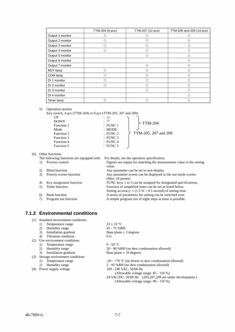
48-7009-G 7-7
TTM-204 (9 pcs) TTM-207 (12 pcs) TTM-205 and 209 (14 pcs)
Output 1 monitor
Output 2 monitor
Output 3 monitor
Output 4 monitor
Output 5 monitor
Output 6 monitor
Output 7 monitor
RDY lamp
COM lamp
DI 1 monitor
DI 2 monitor
DI 3 monitor
DI 4 monitor
Timer lamp
5) Operation section
Key switch, 4 pcs (TTM-204) or 8 pcs (TTM-205, 207 and 209)
UP :
DOWN :
Function 1 : FUNC 1
Mode : MODE
Function 2 : FUNC 2
Function 3 : FUNC 3
Function 4 : FUNC 4
Function 5 : FUNC 5
(6) Other functions
The following functions are equipped with. For details, see the operation specification.
1) Process control Signals are output for matching the measurement value to the setting
value.
2) Blind function Any parameter can be set to non-display.
3) Priority screen function Any parameter screen can be displayed in the run mode screen.
(Max. 16 points)
4) Key assignment function FUNC keys 1 to 5 can be assigned for designated specifications.
5) Timer function Function of simplified timer can be set as listed below.
Setting accuracy: ± (1.5 % + 0.5 second) of setting time
6) Bank function A series of parameters for setting can be switched over.
7) Program run function A simple program run of eight steps at most is possible.
7.1.2 Environmental conditions
(1) Standard environment conditions
1) Temperature range 23 ± 10 °C
2) Humidity range 45 - 75 %RH
3) Installation gradient Base plane ± 3 degrees
4) Vibration condition 0 G
(2) Use environment conditions
1) Temperature range 0 - 50 °C
2) Humidity range 20 - 90 %RH (no dew condensation allowed)
3) Installation gradient Base plane ± 10 degrees
(3) Storage environment conditions
1) Temperature range -20 - +70 °C (no freeze or dew condensation allowed)
2) Humidity range 5 - 95 %RH (no dew condensation allowed)
(4) Power supply voltage 100 - 240 VAC, 50/60 Hz
(Allowable voltage range: 85 - 110 %)
24 VAC/DC, 50/60 Hz (205,207,209 are under development.)
(Allowable voltage range: 90 - 110 %)
TTM-204
TTM-205, 207 and 209

48-7009-G 7-8
(5) Power consumption 100 - 240 VAC: 10 VA or less (TTM-204)
100 - 240 VAC: 11 VA or less (other than TTM-204)
24 VAC/DC: 4 W or less (TTM-204)
(6) Warm-up time 30 minutes
(7) Momentary power outage No effect of power outage in a single cycle.
(Reset at power outage for more than a cycle)
For DC power with the outage for 40 ms or shorter, there is no effect on
operation.
(8) Isolation resistance Measurement terminal - case 00 VDC, 20 M
Power terminal - case 500 VDC, 20 M
(9) Withstand voltage Measurement terminal - case 1000 VAC for a minute
Power terminal - case 1500 VAC for a minute
(10) Weight TTM-204: 120 g or less
TTM-205: 210 g or less
TTM-207: 260 g or less
TTM-209: 300 g or less
(11) Protection structure IP66 or equivalent (on the front surface): Only for TTM-204
For TTM-205, 207 and 209, no IP regulation applicable.
(Due to installation for loader communication)

48-7009-G 7-9
7.2 Accessories
7.2.1 Current transformer
★ Current transformer is used to measure current values of a heater through connecting it to TOHO’s
digital controller TTM-200 series and the heater.
Model: CTL-6-P-H-(S)
Product specifications
Current applicable 0.1 - 80.0 A rms (50/60 Hz) * This is specification for CT main frame.
Max. allowable current 80 A rms continuous
Withstand voltage 2000 VAC for a minute (between through-hole and output terminal)
Isolation resistance 500 VDC, 100 M or larger (between through-hole and output terminal)
Use temperature range -20 to 70 °C
Storage temperature range -30 to 90 °C
Weight Approx. 16 g
Accessories None
Outside dimension
7.2.2 Loader cable
★ Loader cable is used to connect TOHO’s digital controller TTM-200 series and a personal computer
(PC) and such so that various values are set and read on the PC, using the dedicated loader software
installed on it.
Model: TTM-LOADER
Product specifications
OS to meet Windows XP
USB I/F standards In compliance with USB Specification 2.0
DTE speed Up to 38400 bps
Connector specification PC side: USB Controller side: 2.5 mm stereo jack
Consumption current 90 mA
Use temperature range 0 to 50 °C
Use humidity range 20 to 90 %RH (no dew condensation allowed)
Storage temperature range -10 to 60 °C (no freeze or dew condensation allowed)
Storage humidity range 5 to 95 %RH (no dew condensation allowed)
Power supply voltage Bus-powered (to be supplied from PC side)
Weight 40 g
Outside dimension
USB connector Stereo plug

48-7009-G 7-10
7.3 Error (abnormality) display
Content of error is displayed when an abnormality is generated on this product.
7.3.1 Display on measurement value (PV) side
Display Content Handling Operation at error
Over display
* When input exceeds the display range upper limit
* When thermocouple is disconnected
* When input of 0 to 10 mV is disconnected
* When terminal A, B or b is disconnected for resistance temperature detector
* Make the input fall within the display range.
* Correct the disconnection.
* At-abnormality operating amount FAL 1 or FAL 2 is output.
Under display
* When input exceeds the display range lower limit
* When current/voltage input of other than 0 to 10 mV is disconnected
* Make the input fall within the display range.
* Correct the disconnection.
* At-abnormality operating amount FAL 1 or FAL 2 is output.
* Input range: Input type measurement range described in the section 6-1, input 1 type setting, on page 6-2.
7.3.2 Display on target value (SV) side
Display Content Handling Operation at error
ERR0
At memory error Request for a repair if re-power-on does not solve the error.
For output in relay, SSR or open collector, output OFF is resulted, and for analog output, output 0 % is resulted.
ERR1
When an input A/D switchover error or excessive input is provided.
Remove the excessive input. Request for a repair if re-power-on does not solve the error.
At-abnormality operating amount FAL 1 or FAL 2 is output.
ERR2
At auto-tuning error Auto-tuning error is displayed when an input is burned out or when it takes longer than 3 hours for auto-tuning. For a subject of control that cannot be auto-tuned, manually set the PID value.
At-abnormality operating amount FAL 1 or FAL 2 is output.
LoC When a parameter is changed during key-locking.
Release the key-lock. No change of setting value is allowed, displaying “LoC.”
DI When target value (setting value) assigned for DI input is attempted to change
Release the assignment for DI. No change of setting value is allowed, displaying “DI.”
FUNC When setting value assigned for FUNC function is attempted to change
Release the assignment for FUNC function.
No change of setting value is allowed, displaying “FUNC.”
REMO When setting value assigned for the local/remote function is attempted to change
Release the assignment of the local/remote function
No change of setting value is allowed, displaying “REMO.”
ZBNK When setting value assigned for the auto bank switching function is attempted to change
Release the assignment of the auto bank switching function.
No change of setting value is allowed, displaying “ZBNK.”

48-7009-G 7-11
7.4 Troubleshooting
Check corresponding items listed below to abnormal operation of this product before requesting for a repair.
In case of no normal operation restored, contact TOHO’s sales department to return the product for a repair.
Symptom Description Check item
Too much difference of temperatures
(1) Input type does not match the one of the main frame.
(2) Resistance temperature detector is not properly connected.
(3) Resistance temperature detector is disconnected or shorted.
(4) The product is affected by noise from the power line due to wires for lead and power supply being laid in the same tubing.
(5) Copper wire is used for connecting this product with thermocouple.
(6) Input compensation (PV compensation) is not properly set.
Setting at factory shipment is “0 °C.”
(1) Check the sensor type and properly set the input type on the main frame.
(2) Check the mounting location and polarity of the resistance temperature detector to properly connect it.
(3) Check the resistance temperature detector for disconnection or short.
(4) Separately wire them.
(5) Connect lead wires of the thermocouple directly to the product or use compensated leads suited for the thermocouple.
(6) Enter the appropriate value for the input compensation value.
No communication possible
(1) Inappropriate communication software
(2) Use of non-recommended converter
(1) Check the software protocol for inappropriateness.
(2) Check connection devices for abnormality.
No output provided (no turn-on)
(1) Control mode is set for READY. At factory shipment, the setting is RUN.
(2) Target control operation is not set. At factory shipment, the setting is “reverse
operation.” (3) Too large a sensitivity value is set for the
ON/OFF operation. At factory shipment, the setting is “1.0 °C.” (4) The setting is “control stop” due to assignment
of the function key for “control start/stop.” (5) Setting value is set with incorrect decimal
point position without noticing the position being shown as “0.0.”
(1) Set the control mode to RUN in the setting mode of SET 4, item 5. Currently, display lamp is lighting as RDY, indicating the state of control stop.
(2) Check the settings of “reverse operation (heating)” and “forward operation (cooling).”
(3) Set an appropriate value for the adjustment sensitivity.
(4) Have the state of control start by a single press of the FUNC key.
(5) Check settings of the decimal point position and value.
No rise in temperature
(1) Target control operation is not set. At factory shipment, the setting is “reverse
operation.” (2) Heater is disconnected or deteriorated.
(3) Insufficient capacity of heater.
(4) Cooling is operating.
(5) An overheat protector for a peripheral device is operating.
(1) Check the settings of “reverse operation (heating)” and “forward operation (cooling).”
(2) Check the heater for disconnection or deterioration. Consider the use of heater disconnection alarm (option) to detect abnormality.
(3) Check that the heater has a sufficient heating capacity.
(4) Check the operation for cooling being effective.
(5) Set the temperature setting of the overheat protector higher than that of this product.
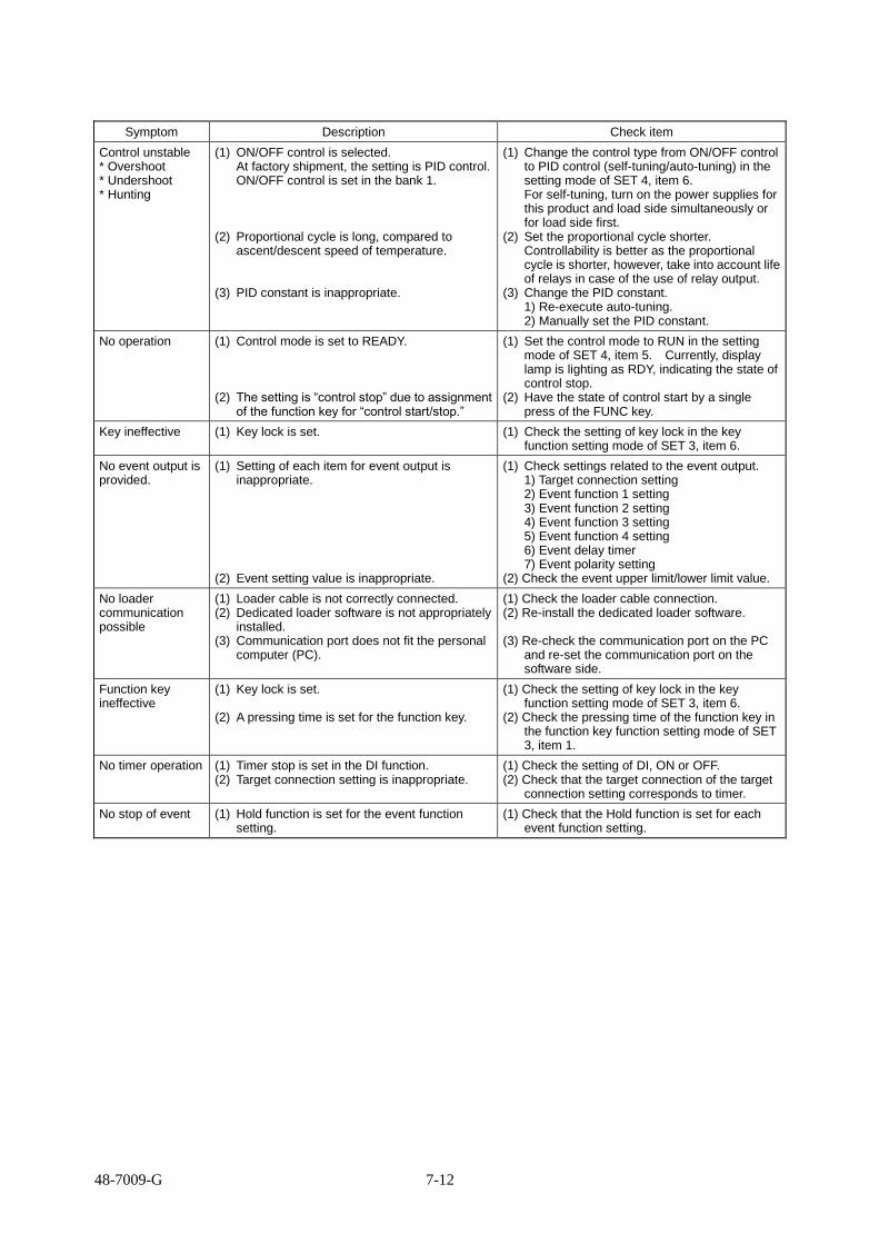
48-7009-G 7-12
Symptom Description Check item
Control unstable * Overshoot * Undershoot * Hunting
(1) ON/OFF control is selected. At factory shipment, the setting is PID control. ON/OFF control is set in the bank 1.
(2) Proportional cycle is long, compared to ascent/descent speed of temperature.
(3) PID constant is inappropriate.
(1) Change the control type from ON/OFF control to PID control (self-tuning/auto-tuning) in the setting mode of SET 4, item 6.
For self-tuning, turn on the power supplies for this product and load side simultaneously or for load side first.
(2) Set the proportional cycle shorter. Controllability is better as the proportional
cycle is shorter, however, take into account life of relays in case of the use of relay output.
(3) Change the PID constant. 1) Re-execute auto-tuning. 2) Manually set the PID constant.
No operation (1) Control mode is set to READY.
(2) The setting is “control stop” due to assignment of the function key for “control start/stop.”
(1) Set the control mode to RUN in the setting mode of SET 4, item 5. Currently, display lamp is lighting as RDY, indicating the state of control stop.
(2) Have the state of control start by a single press of the FUNC key.
Key ineffective (1) Key lock is set. (1) Check the setting of key lock in the key function setting mode of SET 3, item 6.
No event output is provided.
(1) Setting of each item for event output is inappropriate.
(2) Event setting value is inappropriate.
(1) Check settings related to the event output. 1) Target connection setting 2) Event function 1 setting 3) Event function 2 setting 4) Event function 3 setting 5) Event function 4 setting 6) Event delay timer 7) Event polarity setting (2) Check the event upper limit/lower limit value.
No loader communication possible
(1) Loader cable is not correctly connected. (2) Dedicated loader software is not appropriately
installed. (3) Communication port does not fit the personal
computer (PC).
(1) Check the loader cable connection. (2) Re-install the dedicated loader software.
(3) Re-check the communication port on the PC
and re-set the communication port on the software side.
Function key ineffective
(1) Key lock is set.
(2) A pressing time is set for the function key.
(1) Check the setting of key lock in the key function setting mode of SET 3, item 6.
(2) Check the pressing time of the function key in the function key function setting mode of SET 3, item 1.
No timer operation (1) Timer stop is set in the DI function. (2) Target connection setting is inappropriate.
(1) Check the setting of DI, ON or OFF. (2) Check that the target connection of the target
connection setting corresponds to timer.
No stop of event (1) Hold function is set for the event function setting.
(1) Check that the Hold function is set for each event function setting.

48-7009-G 7-13
7.5 Setting list
7.5.1 Run mode
Setting data Character Setting (monitor) value Initial value Unit Setting value
Blind
Present value (PV) Sensor input designation range C
Target value (SV) SV limiter upper limit SV limiter lower limit
1200 0
C
Timer 1 monitor 01:00 on delay 01:00 off delay
Hour, minute and second
Timer 2 monitor
Timer 3 monitor
Priority screen 1
SET 01 to SET 17 None None
Priority screen 2
Priority screen 3
Priority screen 4
Priority screen 5
Priority screen 6
Priority screen 7
Priority screen 8
Priority screen 9
Priority screen 10
Priority screen 11
Priority screen 12
Priority screen 13
Priority screen 14
Priority screen 15
Priority screen 16

48-7009-G 7-14
7.5.2 Input 1 setting mode (SET 01)
Setting data Character Setting (monitor) value Initial value Unit Setting value
Blind
Input type INP1
0: K thermocouple 1: J thermocouple 2: T thermocouple 3: E thermocouple 4: R thermocouple 5: S thermocouple 6: B thermocouple 7: N thermocouple 8: U thermocouple 9: L thermocouple 10: WRe5-26 11: PR40-20 12: PLII 13: Pt100 14: JPt100 15: 0 - 10 mVDC 16: 0 - 1 VDC 17: 0 - 5 VDC 18: 1 - 5 VDC 19: 0 - 10 VDC 20: 4 - 20 mADC
0
Scaling upper limit FSH1 FSL1 to 29999 10000 Digit
Scaling lower limit FSL1 -19999 to FSH1 -10000 Digit
PV compensation function setting
PVF1 0: PV gain zero point compensation 1: PV X-Y2 point compensation
0
PV compensation gain
PVG1 0.500 to 2.000 1.000 Times
PV compensation zero
PVS1 Temperature: -999.9 to 999.9 -999 to 999 Analog: -9999 to 9999
0 C
Digit
PV before- compensation lower limit value setting
PX1
Setting range: Setting range lower limit to (PX2 - 1C) Setting range lower limit to (PX2 - 10 digits) Setting unit: 1C or 0.1C; 1 digit
0
PV before- compensation upper limit value setting
PX2
Setting range: (PX1 1C) to setting range upper limit (PX1 10 digits) to setting range upper limit Setting unit: 1C or 0.1C; 1 digit
1200
PV after- compensation lower limit value setting
PY1
Setting range: Setting range lower limit to (PY2 - 1C) Setting range lower limit to (PY2 - 10 digits) Setting unit: 1C or 0.1C; 1 digit
0
PV after- compensation upper limit value setting
PY2
Setting range: (PY1 1C) to setting range upper limit (PY1 10 digits) to setting range upper limit Setting unit: 1C or 0.1C; 1 digit
1200
Input filter PdF1 0.0 to 99.9 0.0 second
Decimal point position
dP1 Temperature: 0/0.0 Analog: 0/0.0/0.00 0.000/0.0000
0 C
Digit
Unit of temperature C, F C
Note The characters (PVF1, PX1, PX2, PY1 and PY2) are selectable only on Ver3.xx or later.

48-7009-G 7-15
7.5.3 Input 2 setting mode (SET 02)
Setting data Character Setting (monitor) value Initial value Unit Setting value
Blind
Input type INP2
16: 0 - 1 VDC 17: 0 - 5 VDC 18: 1 - 5 VDC 19: 0 - 10 VDC 20: 4 - 20 mADC
18 None
Scaling upper limit FSH2 FSL 2 to SV setting range upper limit
1200
Scaling lower limit FSL2 SV setting range lower limit to FSH 2
0
PV compensation gain
PVG2 0.500 to 2.000 1.000 Times
PV compensation zero
PVS2 -999 to 999 0 Digit
PV filter PdF2 0.0 to 99.9 0.0 Second
Local/remote switchover
LR
0: Local 1: Remote 1 (Scaled with SLL , SLH ) 2: Remote 2 (Scaled with FSL 2, FSH 2)
0 None
7.5.4 Key function setting mode (SET 03)
Setting data Character Setting (monitor) value Initial value Unit Setting value
Blind
Function key 1 function Function key 2 function Function key 3 function Function key 4 function Function key 5 function
FU1 to
FU5
*0: No function *1: Digit shift *2: Control mode (MD)/control
stop (RDY) *3: AT start/AT stop *4: Timer start/stop *5: Screen reverse feed *6: ENT *7: Bank switchover *8: AUTO/MANUAL *9: SV/MV screen switchover *A: Constant value run mode/ Program mode switchover *1 *B: Step feed *1 *C: Pause *1 *d: SET 22 call-up function *1
0.0
None
0*: None 1*: Pressing time of 1 second 2*: Pressing time of 2 seconds 3*: Pressing time of 3 seconds 4*: Pressing time of 4 seconds 5*: Pressing time of 5 seconds
Second
Key lock LoC
0: Lock OFF 1: Lock all 2: Lock of run mode 3: Lock of other than run mode 4: Lock all (only during a run) *1 5: Lock of run mode (only during
a run) *1 6: Lock of other than run mode
(only during a run) *1 7: Lock of parameter mode (only
during a run) *1
0 None
*1: Selectable only on Ver3.xx or later

48-7009-G 7-16
7.5.5 Control setting mode (SET 04) (1/4)
Setting data Character Setting (monitor) value Initial value Unit Setting value
Blind
Bank switchover bANK
0: Bank 0
0 None
1: Bank 1
2: Bank 2
3: Bank 3
4: Bank 4
5: Bank 5
6: Bank 6
7: Bank 7
Bank upper limit setting
bANKH 0 to 7 7 None
Control setting SV SLL to SLH 0 C
SV limiter upper limit SLH
Temperature: (SLL + 5.0) to SV setting range
upper limit (SLL + 5) to SV setting range
upper limit Analog: (SLL + 50) to SV setting range
upper limit
1200
C
Digit
SV limiter lower limit SLL
Temperature: SV setting range lower limit to
(SLH - 5.0) SV setting range lower limit to
(SLH - 5) Analog: SV setting range lower limit to
(SLH - 50)
0
C
Digit
Control mode Md
RDY: Control stop RUN: Control start MAN: Manual TIME 1: Timer 1 operation TIME 2: Timer 2 operation TIME 3: Timer 3 operation
RUN None
Control type CNt
0: Primary nonexistent Secondary nonexistent 1: Primary PID control Secondary nonexistent 2: Primary ON/OFF control Secondary nonexistent 3: Primary PID control Secondary PID control 4: Primary PID control Secondary ON/OFF control 5: Primary ON/OFF control Secondary ON/OFF control 6: Primary position proportional Secondary position
proportional
1 None

48-7009-G 7-17
7.5.5 Control setting mode (SET 04) (2/4)
Setting data Character Setting (monitor) value Initial value Unit Setting value
Blind
PID control type tYP
0: Type A (normal PID) 1: Type B (overshoot
suppression) 2: Type C (disturbance
suppression)
1 None
Type B mode (overshoot suppression)
bMd 0: Moderate 1: Intermediate 2: Intense
1 None
Forward operation/reverse operation
dIR 0: Reverse operation 1: Forward operation
0 None
Primary control operating amount
MV1 MLL1 to MLH1 0.0 %
Primary control output gain
MV1G 0.0 to 1000.0 100.0 %
Tuning type tUN
1: Primary auto-tuning 2: Primary self-tuning 3: Secondary auto-tuning (at primary PID/secondary PID) 4: Secondary self-tuning (at primary PID/secondary PID) 5: Primary/secondary auto-tuning (at primary PID/secondary PID)
1 None
Auto-tuning coefficient
AtG 0.1 to 10.0 1.0 Times
Auto-tuning sensitivity
AtC Temperature: 0.0 to 999.9 0 to 999 Analog: 0 to 9999
2 C
Digit
Auto-tuning start At Start/stop with the ▲/▼ key PV/SV displayed during AT
OFF None
Proportional band P1 0.1 to 200.0 3.0 %
Integral time I 0 to 3600 0 Second
Derivative time d 0 to 3600 0 Second
Primary control proportional cycle
t1 0.1 to 120.0 20.0 (relay)
1.0 (SSR) Second
Anti-reset windup ARW 0.0 to 110.0 (Function turned off at 110.0)
110.0 %
Primary control operating amount limiter upper limit
MLH1 Digital output: MLL to 100.0 Analog output: MLL to 110.0
100.0 %
Primary control operating amount limiter lower limit
MLL1 Digital output: 0.0 to MLH1 Analog output: -10.0 to MLH1
0.0 %

48-7009-G 7-18
7.5.5 Control setting mode (SET 04) (3/4)
Setting data Character Setting (monitor) value Initial value Unit Setting value
Blind
Primary control operating amount change limiter ascent
oU1 0.0 to 549.9 0.0 %
Primary control operating amount change limiter descent
od1 0.0 to 549.9 0.0 %
Primary control soft-start output
SFM MLL1 to MLH1 100.0 %
Primary control soft-start time
SFT 00:00 to 499:59 Function turned off with 00:00 (second) setting
000:00 Second
Primary control at-abnormality operating amount
FAL1 Digital output: 0.0 to 100.0 Analog output: -10.0 to 110.0
0.0 %
Primary control loop anomaly PV threshold
tS1 Temperature: 0.0 to 999.9 0 to 999 Analog: 0 to 9999
0 C
Digit
Primary control loop anomaly MV threshold
MS1 MLL1 to LH1 100.0 %
Primary control loop anomaly PV change threshold
PS1 Temperature: 0.0 to 999.9 0 to 999 Analog: 0 to 9999
0 C
Digit
Primary control loop abnormality time
LoP1 0 to 9999 0 Second
Primary control off-point position selection
CMod
0: SV unit setting 1: Upper 2: Middle 3: Lower
0 None
Primary control sensitivity setting
C1 Temperature: 0.0 to 999.9 0 to 999 Analog: 0 to 9999
1
Digit
Primary control off-point position
CP1 Temperature: -999.9 to 999.9 -999 to 999 Analog: -9999 to 9999
0 C
Digit
Primary control protection off timer
Fdt1 0 to 99 0 Minute
Primary control protection on timer
Ndt1 0 to 99 0 Minute
Secondary control operating amount
MV2 MLL2 to MLH2 0.0 %
Secondary control output gain
MV2G 0.0 to 100.0 100.0 %
Secondary control proportional band
P2 0.10 to 10.0 1.00 Times
Secondary control proportional cycle
t2 0.1 to 120.0 20.0 Second
Secondary control operating amount limiter upper limit
MLH2 Digital output: MLL2 to 100.0 Analog output: MLL2 to 110.0
100.0 %
Secondary control operating amount limiter lower limit
MLL2 Digital output: 0.0 to MLH2 Analog output: -10.0 to MLH2
0.0 %
Secondary control operating amount change limiter ascent
oU2 0.0 to 549.9 0.0 %
Secondary control operating amount change limiter descent
od2 0.0 to 549.9 0.0 %
Note (Ndt1) is selectable only on Ver3.xx or later.
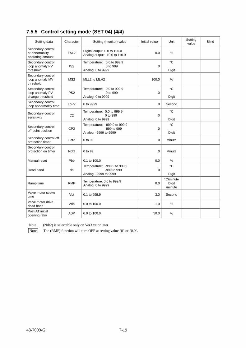
48-7009-G 7-19
7.5.5 Control setting mode (SET 04) (4/4)
Setting data Character Setting (monitor) value Initial value Unit Setting
value Blind
Secondary control
at-abnormality
operating amount
FAL2 Digital output: 0.0 to 100.0
Analog output: -10.0 to 110.0 0.0 %
Secondary control
loop anomaly PV
threshold
tS2
Temperature: 0.0 to 999.9
0 to 999
Analog: 0 to 9999
0
C
Digit
Secondary control
loop anomaly MV
threshold
MS2 MLL2 to MLH2 100.0 %
Secondary control
loop anomaly PV
change threshold
PS2
Temperature: 0.0 to 999.9
0 to 999
Analog: 0 to 9999
0
C
Digit
Secondary control
loop abnormality time LoP2 0 to 9999 0 Second
Secondary control
sensitivity C2
Temperature: 0.0 to 999.9
0 to 999
Analog: 0 to 9999
0
C
Digit
Secondary control
off-point position CP2
Temperature: -999.9 to 999.9
-999 to 999
Analog: -9999 to 9999
0
C
Digit
Secondary control off
protection timer Fdt2 0 to 99 0 Minute
Secondary control
protection on timer
Ndt2 0 to 99 0 Minute
Manual reset Pbb 0.1 to 100.0 0.0 %
Dead band db
Temperature: -999.9 to 999.9
-999 to 999
Analog: -9999 to 9999
0
C
Digit
Ramp time RMP Temperature: 0.0 to 999.9
Analog: 0 to 9999 0.0
C/minute
Digit
/minute
Valve motor stroke
time VLt 0.1 to 999.9 3.0 Second
Valve motor drive
dead band Vdb 0.0 to 100.0 1.0 %
Post-AT initial
opening ratio ASP 0.0 to 100.0 50.0 %
Note (Ndt2) is selectable only on Ver3.xx or later.
Note The (RMP) function will turn OFF at setting value "0" or "0.0".

48-7009-G 7-20
7.5.6 OUT 1 and 2 setting modes (SET 05 and 06) (1/3)
Setting data Character Setting (monitor) value Initial value Unit Setting value
Blind
Target connection o1F o2F
0: Primary output 1: Secondary output 2: Event output 3: RUN output 4: RDY output 5: Timer 1 output 6: Timer 1 during-on-delay output 7: Timer 1 during-off-delay output 8: Timer 1 during-[on + off]-delay
output 9: Timer 2 output 10: Timer 2 during-on-delay
output 11: Timer 2 during-off-delay
output 12: Timer 2 during-[on + off]-delay
output 13. Timer 3 output 14: Timer 3 during-on-delay
output 15: Timer 3 during-off-delay
output 16: Timer 3 during-[on + off]-delay
output 17: Transmission output 18: End output *1
OUT1: 0 OUT2: 2
None
Event function 1 E1F1 E2F1
Function **0: None **1: Deviation upper and lower
limits **2: Deviation upper limit **3: Deviation lower limit **4: Deviation range **5: Absolute value upper and
lower limits **6: Absolute value upper limit **7: Absolute value lower limit **8: Absolute value range Add-on function *0*: None *1*: Hold *2*: Standby *3*: Delay *4*: Hold + standby *5*: Hold + delay *6*: Standby + delay *7*: Hold + standby + delay Control mode interlocking function 0**: All modes 1**: RUN/MAN mode only 2**: RUN mode only
000 None
Event upper limit E1H E2H
Temperature: -1999.9 to 2999.9 -19999 to 2999 Note that, for thermocouples R, S and B, the value of WRe 5-26 or PR 40-20 is -1999 to 9999. Analog: -19999 to 29999
0
C
Digit
*1: Selectable only on Ver3.xx or later.

48-7009-G 7-21
7.5.6 OUT 1 and 2 setting modes (SET 05 and 06) (2/3)
Setting data Character Setting (monitor) value Initial value Unit Setting value
Blind
Event lower limit E1L E2L
Temperature: -1999.9 to 2999.9 -19999 to 2999 Note that, for thermocouples R, S and B, the value of WRe 5-26 or PR 40-20 is -1999 to 9999. Analog: -19999 to 29999
0
C
Digit
Event sensitivity E1C E2C
Temperature: 0.0 to 999.9 0 to 999 Analog: 0 to9999
0 C
Digit
Event delay timer E1t E2t
0 to 9999 0 Second
Event function 2 (PV abnormality)
E1F2 E2F2
Function **0: Nonexistent **1: Existent Add-on function *0*: None *1*: Hold *2*: Delay *3*: Hold + delay Control mode interlocking function 0**: All modes 1**: RUN/MAN mode only 2**: RUN mode only
000 None
Event function 3 (CT abnormality)
E1F3 E2F3
Function **0: Nonexistent **1: CT 1 abnormality **2: CT 2 abnormality **3: CT 1 abnormality + CT 2
abnormality Add-on function *0*: Nonexistent *1*: Hold *2*: Delay *3*: Hold + delay Control mode interlocking function 0**: All modes 1**: RUN/MAN mode only 2**: RUN mode only
000 None
Event function 4 (loop abnormality)
E1F4 E2F4
Function *0: Nonexistent *1: Existent Add-on function 0*: Nonexistent 1*: Hold
00 None
Event polarity E1P E2P
0: Normal open 1: Normal close
00 None

48-7009-G 7-22
7.5.6 OUT 1 and 2 setting modes (SET 05 and 06) (3/3)
Setting data Character Setting (monitor) value Initial value Unit Setting value
Blind
Transmission output function
tRN1 tRN2
Transmission content *1: PV (Measurement value) *2: SV (Setting value) *3: MV 1 (Primary control
operating amount) *4: MV 2 (Secondary control
operating amount) *5: Control SV (Setting value)
output *1 Forward/reverse operation 0*: Forward operation 1*: Reverse operation
00 None
Setting data Character Setting (monitor) value Initial value Unit Setting value
Blind
Transmission scaling upper limit
tRH1 tRH2
Temperature: tRL* to 2999.9 tRL* to 2999 Note that, for thermocouples R, S and B, the value of WRe 5-26 or PR 40-20 is tRL* to 9999. Analog: tRL* to 29999
1200
C
Digit
Transmissions scaling lower limit
tRL1 tRL2
Temperature: -1999.9 to tRH* -1999 to tRH* Analog: -19999 to tRH*
0 C
Digit
*1: Selectable only on Ver3.xx or later.

48-7009-G 7-23
7.5.7 OUT 3 to 7 setting modes (SET 07, 08, 09, 10 and 11) (1/2)
Setting data Character Setting (monitor) value Initial value Unit Setting value
Blind
Target connection
o3F o4F o5F o6F o7F
0: Primary output 1: Secondary output 2: Event output 3: RUN output 4: RDY output 5: Timer 1 output 6: Timer 1 during-on-delay output 7: Timer 1 during-off-delay output 8: Timer 1 during-[on + off]-delay
output 9: Timer 2 output 10: Timer 2 during-on-delay output 11: Timer 2 during-off-delay output 12: Timer 2 during-[on + off]-delay
output 13. Timer 3 output 14: Timer 3 during-on-delay
output 15: Timer 3 during-off-delay
output 16: Timer 3 during-[on + off]-delay
output 18: End output *1
2 None
Event function 1
o3F o4F o5F o6F o7F
Function **0: None **1: Deviation upper and lower
limits **2: Deviation upper limit **3: Deviation lower limit **4: Deviation range **5: Absolute value upper and
lower limits **6: Absolute value upper limit **7: Absolute value lower limit **8: Absolute value range Add-on function *0*: None *1*: Hold *2*: Standby *3*: Delay *4*: Hold + standby *5*: Hold + delay *6*: Standby + delay *7*: Hold + standby + delay Control mode interlocking function 0**: All modes 1**: RUN/MAN mode only 2**: RUN mode only
000 None
Event upper limit
E3H E4H E5H E6H E7H
Temperature: -1999.9 to 2999.9 -19999 to 2999 Note that, for thermocouples R, S and B, the value of WRe 5-26 or PR 40-20 is -1999 to 9999. Analog: -19999 to 29999
0
C
Digit
*1: Selectable only on Ver3.xx or later.

48-7009-G 7-24
7.5.7 OUT 3 to 7 setting modes (SET 07, 08, 09, 10 and 11) (2/2)
Setting data Character Setting (monitor) value Initial value Unit Setting value
Blind
Event lower limit
E3L E4L E5L E6L E7L
Temperature: -1999.9 to 2999.9 -1999 to 2999 Note that, for thermocouples R, S and B, the value of WRe 5-26 or PR 40-20 is -1999 to 9999. Analog: -19999 to 29999
0
C
Digit
Event sensitivity
E3C E4C E5C E6C E7C
Temperature: 0.0 to 999.9 0 to 999 Analog: 0 to 9999
0 C
Digit
Event delay timer
E3t E4t E5t E6t E7t
0 to 9999 0 Second
Event function 2 (PV abnormality)
E3F2 E4F2 E5F2 E6F2 E7F2
Function **0: Nonexistent **1: Existent Add-on function *0*: None *1*: Hold *2*: Delay *3*: Hold + delay Control mode interlocking function 0**: All modes 1**: RUN/MAN mode only 2**: RUN mode only
000 None
Event function 3 (CT abnormality)
E3F3 E4F3 E5F3 E6F3 E7F3
Function **0: Nonexistent **1: CT 1 abnormality **2: CT 2 abnormality **3: CT 1 abnormality + CT 2 abnormality Add-on function *0*: Nonexistent *1*: Hold *2*: Delay *3*: Hold + delay Control mode interlocking function 0**: All modes 1**: RUN/MAN mode only 2**: RUN mode only
000 None
Event function 4 (loop abnormality)
E3F3 E4F3 E5F3 E6F3 E7F3
Function *0: Nonexistent *1: Existent Add-on function 0*: Nonexistent 1*: Hold
00 None
Event polarity
E3P E4P E5P E6P E7P
0: Normal open 1: Normal close
00 None

48-7009-G 7-25
7.5.8 CT setting mode (SET 12)
Setting data Character Setting (monitor) value Initial value Unit Setting value
Blind
CT 1 target connection
CI1
1: Connected to OUT 1 2: Connected to OUT 2 3: Connected to OUT 3 4: Connected to OUT 4 5: Connected to OUT 5 6: Connected to OUT 6 7: Connected to OUT 7
1 None
CT 1 current value monitor
CM1 0.0 to 50.0 A
CT 1 abnormal current value setting
Ct1 0.0 to 30.0 (Turned off with 0.0)
0.0 A
CT 2 target connection
CI2
1: Connected to OUT 1 2: Connected to OUT 2 3: Connected to OUT 3 4: Connected to OUT 4 5: Connected to OUT 5 6: Connected to OUT 6 7: Connected to OUT 7
1 None
CT 2 current value monitor
CM2 0.0 to 50.0 A
CT 2 abnormal current value setting
Ct2 0.0 to 30.0 (Turned off with 0.0)
0.0 A

48-7009-G 7-26
7.5.9 DI setting mode (SET 13)
Setting data Character Setting (monitor) value Initial value Unit Setting value
Blind
DI function dIF
※, ★, ☆ and ◎ ◎: DI 1 setting ☆: DI 2 setting ★: DI 3 setting ※: DI 4 setting
0000 None
DI content (function) assignment table
Active
0 None None
1 Bank switchover Bank switcher
2 MD READY
3 AUTO MANUAL
4 Reverse operation Forward operation
5 AT stop AT start
6 Timer stop Timer start
7 Constant value run mode Program run mode *1
8 Step feed *1
9 Pause *1
A Interlock *1
*1: Selectable only on Ver3.xx or later.
Setting data Character Setting (monitor) value Initial value Unit Setting value
Blind
DI polarity dIP
※, ★, ☆ and ◎ ◎: DI 1 setting ☆: DI 2 setting ★: DI 3 setting ※: DI 4 setting Function assignment 0: Close active 1: Open active
0000 None

48-7009-G 7-27
7.5.10 Timer 1 to 3 setting modes (SET 14, 15 and 16)
Setting data Character Setting (monitor) value Initial value Unit Setting value
Blind
Timer function tMF1 tMF2 tMF3
1: Auto-start 2: Manual start 3: SV start 4: DI 1 start 5: DI 2 start 6: DI 3 start 7: DI 4 start 8: Event 1 start 9: Event 2 start 10: Event 3 start 11: Event 4 start 12: Event 5 start 13: Event 6 start 14: Event 7 start 15: Step start *1 16: Soak start *1
1 None
Unit H/M1 H/M2 H/M3
1: Hour/minute 2: Minute/second
1 Hour/
minute/ second
Start SV permissible range
tSV1 tSV2 tSV3
Temperature: 0.0 to 999.9 0 to 999 Analog: 0 to 9999
C
Digit
ON delay timer oNT1 oNT2 oNT3
0:00 to 99:59 0:00 Hour/
minute/ second
OFF delay timer oFt1 oFt2 oFt3
0:00 to 99:59 0:00 Hour/
minute/ second
Repeat count RUN1 RUN2 RUN3
0 - 99 (infinite with 0) 1 Count
Remaining time monitor
tIA1 tIA2 tIA3
0:00 - 99:59 Start/stop with the ▲/▼ key
0:00 Hour/
minute/ second
*1: Selectable only on Ver3.xx or later.

48-7009-G 7-28
7.5.11 Communication setting mode (SET 17)
Setting data Character Setting (monitor) value Initial value Unit Setting value
Blind
Communication protocol
PRt 0: TOHO 1: MODBUS (RTU) 2: MODBUD (ASCII)
0 None
Communication parameter
CoM
***1: 1 bit ***2: 2 bits **N*: Nonexistent **o*: Odd No. **E*: Even No. *7**: 7 bits*2 *8**: 8 bits N***: Without BCC *3 b***: With BCC *3 Caution: For MODBUS (RTU), only 8N1, 8N2, 8o1, 8o2, 8E1 and 8E2 are settable. For MODBUS (ASCII), only 7N1, 7N2, 7o1, 7o2, 7E1, 7E2, 8N1, 8N2, 8o1, 8o2, 8E1 and 8E2 are settable.
b8N2 None
Communication speed
bPS
2.4: 2400 4.8: 4800 9.6: 9600 19.2: 19200 38.4: 38400
9.6 bps
Communication address
AdR TOHO: 1 to 99 MODBUS: 1 to 247
1 Station
Response delay time in communication
AWt 0 to 250 0 ms
Communication switchover
Mod
0: Write inhibit 1: Writable 2: Concurrent temperature ascent
master 3: Concurrent temperature ascent
slave
1
*2: “Modbus (RTU)” should not be set. *3: Only TOHO protocol can be set.

48-7009-G 7-29
7.5.12 Initial setting mode (SET 18)
Setting data Character Setting (monitor) value Initial value Unit Setting value
Blind
Password cancel screen
PASS (Blinking)
0000 to 9999 Change the 4-digit value and press the MODE key for release.
0000 None
PV normal state display color
NdSP 0: Green 0
None
PV auto color display low
AdSL 1: Red 1
PV auto color display middle
AdSM 2: Orange 0
PV auto color display high
AdSH 3: Auto (only NdSP) 2
PV display color switchover
PVC
Thermocouple/resistance temperature detector input 0.0 to 999.9 (C) 0 to 999 (C) 1
C
Voltage/current input 0 to 9999 (digit)
Digit
PV at-event display color
E1dSP 0: Green 2
None
PV at-abnormality display color
E2dSP 1: Red 1
CT at-abnormality display color
E3dSP 2: Orange 1
Loop at-abnormality display color
E4dSP 0
Blind function effective/ineffective
bLd 0: Function existent 1: Function nonexixtent
0 None
Setting value backup bKUP
Backup begins by pressing the FUNC key for 2 seconds. “SAVE” is displayed during backup; terminated light indicates completed backup.
None
Setting value initialization
RESEt
0: At-factory-shipment setting 1: Backup setting Initialization begins by pressing the FUNC key for 2 seconds. “INIt” is displayed during initialization: terminated light indicates completed initialization.
0 None
Password setting PASS
(Lighting)
0000 to 9999 After a 4-digit numerical value is changed, pressing the FUNC key for 2 seconds confirms or cancels the change.
0000 None
7.5.13 Priority screen setting mode (SET 19)
Setting data Character Setting (monitor) value Initial value Unit Setting value
Blind
Priority screen 01 PRI01
Parameters for SET 01 to SET 17
OFF
None
Priority screen 02 PRI02 OFF
Priority screen 03 PRI03 OFF
Priority screen 04 PRI04 OFF
Priority screen 05 PRI05 OFF
Priority screen 06 PRI06 OFF
Priority screen 07 PRI07 OFF
Priority screen 08 PRI08 OFF
Priority screen 09 PRI09 OFF
Priority screen 10 PRI10 OFF
Priority screen 11 PRI11 OFF
Priority screen 12 PRI12 OFF
Priority screen 13 PRI13 OFF
Priority screen 14 PRI14 OFF
Priority screen 15 PRI15 OFF
Priority screen 16 PRI16 OFF

48-7009-G 7-30
7.5.14 Bank setting mode (SET 20)
Setting data Character Setting (monitor) value Initial value Unit Setting value
Blind
Bank selection 01 bNK01
Parameters for SET 01 to SET 17
cNT
None
Bank selection 02 bNK02 OFF
Bank selection 03 bNK03 OFF
Bank selection 04 bNK04 OFF
Bank selection 05 bNK05 OFF
Bank selection 06 bNK06 OFF
Bank selection 07 bNK07 OFF
Bank selection 08 bNK08 OFF
Bank selection 09 bNK09 OFF
Bank selection 10 bNK10 OFF
Bank selection 11 bNK11 OFF
Bank selection 12 bNK12 OFF
Bank selection 13 bNK13 OFF
Bank selection 14 bNK14 OFF
Bank selection 15 bNK15 OFF
Bank selection 16 bNK16 OFF

48-7009-G 7-31
7.5.15 Program function setting mode (SET 21)
Setting data Character Setting (monitor) value Initial value Unit Setting value
Blind
Operating type setting
C/P 0: Constant value run mode 1: Program run mode
0 None
Program mode setting
PGMd
0: Program mode 1 (without power failure compensation)
1: Program mode 2 (without power failure compensation)
2: Program mode 1 (with power failure compensation)
3: Program mode 2 (with power failure compensation)
Program 1: Control stops after a run ends. Program 2: Control continues after a run ends.
0 None
Power failure compensation range setting
PoC
Setting value range Thermocouple/resistance temperature detector input 0.0 to 999.9 (C) 0 to 999 (C) Voltage/current input 0 to 9999 (digit) If the setting is 0, the power failure is always restored.
0 C
Digit
Time unit setting H/MP
0: Step time (hour; minute) 1: Soak time 1 (hour; minute) 2: Soak time 2 (hour; minute) 3: Step time (minute; second) 4: Soak time 1 (minute; second) 5: Soak time 2 (minute; second) Step time: To the next step after predetermined time elapses Soak time 1: Counted with a falling-in within the set WAIT range Soak time 2: Counted only in the set WAIT range
0 None
WAIT range setting WAIt
Setting value range Thermocouple/resistance temperature detector input 0.0 to 999.9 (C) 0 to 999 (C) Voltage/current input 0 to 9999 (digit) If “0” is set for Soak time 2, then operation is for Soak time 1.
2 None
Note SET 21 is selectable only on Ver3.xx or later.

48-7009-G 7-32
7.5.16 Program setting mode (SET 22)
Setting data Character Setting (monitor) value Initial value Unit Setting value
Blind
Number-of-use-step setting
StEPN Setting value range n = 1 to 8
8 None
Step designation bank setting
St*bK Setting value range St*BK = 0 to 7 “*” 1 to (StEPN setting value)
0 None
Step SV setting SV*
Setting value range SV* = SLL to SLH “*” 1 to (StEPN setting value) * If SLL and SLH are set in a bank, the values of SLL and SLH are set for each bank.
0 C
Digit
Step time setting tIM* Setting value range TIM* = 00:00 to 99:59 “*” 1 to (StEPN setting value)
0.00 Hour,
minute and second
Repetitive start step setting
StRSt Setting value range 1 to repetitive end step setting (ENdSt)
1 None
Repetitive end step setting
ENdSt
Setting value range Repetitive start step setting (StRSt StRSt) to the number-of-use-step setting or StEPN * If a setting is made with StEPN,
the value set in the number-of-use-step setting becomes “repetitive end step setting.”
StEPN None
Repetitive count setting
RUNP Setting value range RUNP = 0 to 9999 RUNP 0: Unlimited count
1 Times
Note SET 22 is selectable only on Ver3.xx or later.

48-7009-G 7-33
7.5.17 Bank automatic switching function setting mode (SET 23)
Setting data Character Setting (monitor) value Initial value Unit Setting value
Blind
Bank automatic switching function selection
bAF
0: Bank automatic switching run OFF 1: Bank automatic switching run ON * With “Bank automatic switching
run ON” setting: - Bank switching setting by using
the FUNC key is ineffective. - Bank switching setting by using
DI is ineffective. / key operation is not also
allowed. * When SET 04 bANKH 0, the
setting is neither effective nor displayed.
0 None
Bank automatic switching source setting
bAS
Function: *0: Selects a SV value. *1: Selects a ramp SV value. *2: Selects a PV value. Control mode interlock function: 0*: All modes 1*: Only RUN/MAN mode 2*: Only RUN mode * Selects a source for the SV
value for performing auto bank switching.
* When SET 04 bANKH 0, the setting is neither effective nor displayed.
0.0 None
Zone threshold setting
PM*
SLL to SLH * Sets a threshold for bank
automatic switching of [“*” 1 to 7] (example of 8 banks).
* When SET 04 bANKH 0, the setting is neither effective nor displayed.
1200 C
Digit
Zone threshold sensitivity range setting
ASC
During temperature input 0 to 999 (0.0 to 999.9) (C) During analog input 0 to 9999 (digit) * Sets a sensitivity setting for a
threshold for performing bank automatic switching.
None is displayed if bAF 0 (OFF) and bAS *0 or *1 and SET 02 LR 0.
* When SET 04 bANKH 0, the setting is neither effective nor displayed.
0 C
Digit
Note SET 23 is selectable only on Ver3.xx or later.