Controller FS4
50
User manual Controller FS4 05/2020
-
Upload
khangminh22 -
Category
Documents
-
view
3 -
download
0
Transcript of Controller FS4

User manualController
FS4
05/2020

Contents Spectron Gas Control Systems GmbH
ii GES_FS4_0520
Contents1 Introduction.................................................................................................................................................. 4
2 Description................................................................................................................................................... 52.1 Intended use ......................................................................................................................................... 52.2 Misuse .................................................................................................................................................. 52.3 Identification / label ............................................................................................................................... 52.4 Environment.......................................................................................................................................... 5
2.4.1 Temperatures............................................................................................................................. 52.4.2 Degree of cleanliness ................................................................................................................ 6
2.5 Standards and laws .............................................................................................................................. 6
3 Safety............................................................................................................................................................ 73.1 Basic information on the safety instructions ......................................................................................... 73.2 Safety instructions ................................................................................................................................ 83.3 Emergencies and safety devices .......................................................................................................... 10
3.3.1 Emergency stop (emergency shut-off)....................................................................................... 103.4 Qualification of the operating and maintenance personnel................................................................... 10
4 Design and function .................................................................................................................................... 124.1 Design................................................................................................................................................... 124.2 Functional description........................................................................................................................... 134.3 Technical data ...................................................................................................................................... 144.4 Boundaries and interfaces .................................................................................................................... 14
5 Installation.................................................................................................................................................... 155.1 General information .............................................................................................................................. 155.2 Electrical connection............................................................................................................................. 15
5.2.1 Digital inputs .............................................................................................................................. 165.2.2 Analogue inputs ......................................................................................................................... 175.2.3 Relay outputs ............................................................................................................................. 17
5.3 Pneumatic connection .......................................................................................................................... 18
6 Commissioning............................................................................................................................................ 206.1 Preparations for commissioning ........................................................................................................... 206.2 Procedure for commissioning ............................................................................................................... 20
7 Operation...................................................................................................................................................... 217.1 General information on operation ......................................................................................................... 217.2 Configuration ........................................................................................................................................ 21
7.2.1 Language options ...................................................................................................................... 237.2.2 User management ..................................................................................................................... 247.2.3 System configuration ................................................................................................................. 257.2.4 Real Time Clock......................................................................................................................... 277.2.5 Analogue inputs ......................................................................................................................... 287.2.6 Digital inputs .............................................................................................................................. 317.2.7 Label valves ............................................................................................................................... 337.2.8 Assignment of the analogue inputs............................................................................................ 337.2.9 Tare setting ................................................................................................................................ 34
7.3 Commissioning a valve......................................................................................................................... 357.4 Putting the valve in standby mode........................................................................................................ 367.5 Automatic switchover............................................................................................................................ 37

Spectron Gas Control Systems GmbH Contents
GES_FS4_0520 iii
7.5.1 Recovery function ...................................................................................................................... 397.6 Manual mode ........................................................................................................................................ 407.7 Alarm history......................................................................................................................................... 437.8 Decommissioning ................................................................................................................................. 43
8 Maintenance, cleaning and repairs............................................................................................................ 448.1 General information on maintenance.................................................................................................... 448.2 Regular maintenance work and cleaning.............................................................................................. 45
9 Repair ........................................................................................................................................................... 469.1 General information on repair work ...................................................................................................... 469.2 Troubleshooting and fault rectification .................................................................................................. 47
10 Dismantling and disposal ........................................................................................................................... 4810.1 General information on dismantling ...................................................................................................... 4810.2 Disposal ................................................................................................................................................ 49
1 | Introduction Spectron Gas Control Systems GmbH
4 GES_FS4_0520
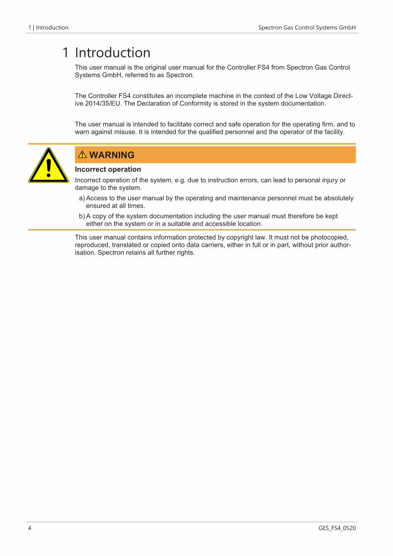
1 IntroductionThis user manual is the original user manual for the Controller FS4 from Spectron Gas ControlSystems GmbH, referred to as Spectron.
The Controller FS4 constitutes an incomplete machine in the context of the Low Voltage Direct-ive 2014/35/EU. The Declaration of Conformity is stored in the system documentation.
The user manual is intended to facilitate correct and safe operation for the operating firm, and towarn against misuse. It is intended for the qualified personnel and the operator of the facility.
WARNINGIncorrect operationIncorrect operation of the system, e.g. due to instruction errors, can lead to personal injury ordamage to the system.
a) Access to the user manual by the operating and maintenance personnel must be absolutelyensured at all times.
b) A copy of the system documentation including the user manual must therefore be kepteither on the system or in a suitable and accessible location.
This user manual contains information protected by copyright law. It must not be photocopied,reproduced, translated or copied onto data carriers, either in full or in part, without prior author-isation. Spectron retains all further rights.

Spectron Gas Control Systems GmbH Description | 2
GES_FS4_0520 5
2 Description
2.1 Intended useThe intended use of the Controller FS4 is the control of up to 4 pneumatic valves. These can beindividually configured or used for up to 2 automatic changeovers between 2 gas sources each.The permissible gas types and pressure ranges are each specified on the label (see "Identifica-tion / label").The Controller is not permitted to be used in an explosion hazard zone.To be able to use the Controllers as intended, all persons working with it must comply with thespecifications of the relevant user manual.The area in which hazards can occur when used as intended is the area around the Controllers.The danger zone changes depending on the system status and use.
2.2 MisuseAny improper use constitutes misuse. Controllers may only be used for the specified gases andin the specified pressure range. Controllers with electrical components without marking accord-ing to EU Directive 2014/34/EU may not be used in an explosion hazard zone.Furthermore, the following operating conditions are regarded as misuse:
– Use for gases in their liquid phase– Failure to carry out inspection and maintenance work– Pressurisation in reverse (opposite to the flow direction)– Operation with gases that are not specified on the label– Operation outside the permissible technical limit values– Failure to heed and comply with any applicable legal regulations and other provisions– Non-observance of the user manual– Failure to heed the information on the label and in the product data sheet
2.3 Identification / labelThe label is located on the on the housing of the Controller.The label provides the following details:
Details ExampleManufacturer Spectron Gas Control Systems GmbHArticle description FS4Article number 66QE0017
2.4 Environment
2.4.1 TemperaturesNormal temperatures expected in a production area are assumed when operating the system:0°C to +45°C. On storage, temperatures between -20°C and 60°C are permissible.The air humidity must be below 60 % rel. humidity to prevent condensation. The operating tem-perature depends on the gas used.

2 | Description Spectron Gas Control Systems GmbH
6 GES_FS4_0520
2.4.2 Degree of cleanlinessAccess to the system and to the escape and rescue routes must not be blocked.The product should be kept clean (dust-free).For the control air, compressed air must be used of at least class 5 according to ISO 8573-1 ornitrogen (minimum quality 6.0).
2.5 Standards and lawsThe design and construction of the controller is subject to the following standards and direct-ives:
2014/35/EU Low Voltage Directive2014/30/EU EMC DirectiveDIN EN ISO 12100:2010 Safety of MachineryDIN EN 60204-1 Safety of Machinery - Electrical equipment of
machines – Part 1: General requirements regu-lates general specifications and recommenda-tions as a sub-standard of EN 60204 Safety ofMachinery
Various additional laws, regulations and guidelines must be complied with when handling pres-surised gases. Find out about the laws, regulations and guidelines that apply in your location.
BetrSichV Betriebssicherheitsverordnung (Industrialhealth and safety ordinance)
ProdSG Produktsicherheitsgesetz (Product Safety Law)TRBS 1111 Technische Regeln Betriebssicherheit (Tech-
nical Regulations on Operational Safety)DGUV Regulation 1 German Trade Association Principles of Pre-
ventionDGUV Regulation 3 Electrical installations and equipment

Spectron Gas Control Systems GmbH Safety | 3
GES_FS4_0520 7
3 Safety
3.1 Basic information on the safety instructionsThe product complies with the recognised technical regulations. Nevertheless, knowledge of themedia used and their dangers as well as basic knowledge of the pressure control panel are pre-requisites for safe and accident-free operation.The user manual must be read and understood by every user. Instruction must be documentedin writing.The safety instructions are to be regarded as a supplement to the applicable accident preven-tion regulations and laws. Existing accident prevention regulations and laws must be observedin all cases.
NOTICEHazards from the operating environment of the system can lead to injuries to persons.
a) No changes may be made to the system which result in a change in function.b) It is not possible to outline and cover in this manual all hazards arising from the environment
or unforeseeable operating conditions of the system.
In the Safety Instructions chapter:– Users are informed regarding hazards, residual risks and measures for risk reduction.– The presentation of the safety instructions and the symbols is explained.– Basic safety instructions to be observed in general are listed. Specific safety instructions are
listed in the relevant chapters.
DANGERDANGER indicates an imminent danger. If not avoided, death or extremely serious injur-ies will result.
WARNINGWARNING indicates a potential imminent danger. If not avoided, death or serious injurycould result.
CAUTIONCAUTION indicates a potentially imminent danger. If not avoided, minor or moderate in-jury could result.
NOTICENOTICE indicates a potentially harmful situation. If not avoided, the system or property inits vicinity could be damaged.

3 | Safety Spectron Gas Control Systems GmbH
8 GES_FS4_0520
3.2 Safety instructions
DANGERVoltageThe components of the control and the connections are under voltage. There is a danger ofdeath on contact.
a) Only allow work in which the control unit must be opened to be carried out by trained spe-cialist personnel (electricians).
b) Only perform work in which the control unit must be opened when the power supply isswitched off.
c) The five safety rules according to DIN VDE 0105 are to be observed:ð Disconnect from the mainsð Secure against reconnectionð Verify that the system is deadð Carry out earthing and short circuitingð Provide protection from adjacent live parts
DANGERDefective productA defect on the product can result in unforeseeable operating conditions. Persons may be in-jured.
a) The product may only be operated in technically perfect condition in compliance with allchapters of the user manual.
b) Environmental protection laws and safety regulations must be observed.
WARNINGMaintenanceDue to a fault condition, e.g. due to insufficient maintenance, parts of the product can be unex-pectedly energised. This may result in electric shocks.
a) The electrical installation is to be tested regularly. Loose connections and defective cablesmust be rectified immediately.
b) Observe the maintenance intervals and maintenance regulations in this operating manual.c) Observe the maintenance intervals and maintenance guidelines from the manufacturer and
the applicable guidelines.d) Components may only be replaced by spare parts of the same design. The specifications of
the component manufacturers must be complied with during installation.
WARNINGNoise emissionWhen working on pressurised pneumatic supply, significant noise emission can occur. Acuteand chronic loss of hearing may result.
a) Never perform work on the pressurised pneumatic supply without hearing protection.b) Only replace the silencers when the supply is unpressurised.

Spectron Gas Control Systems GmbH Safety | 3
GES_FS4_0520 9
WARNINGDisplacement of atmospheric oxygenIn the event of inert gas leaks, displacement of atmospheric oxygen may occur. Danger of suf-focation!
a) The operator must ensure adequate ventilation and airing in all rooms with gas installationsand monitor the oxygen content.
WARNINGCross-contaminationCross-contamination of the control air with process gases can result in the control unit beingdamaged.
a) Ensure that cross-contamination of the control air line is prevented.
WARNINGRepairsIf the product is not used as intended, unpredictable operating conditions may occur. Seriouspersonal injuries are possible.
a) Repairs may not lead to a change in function. The system may not be tampered with ormodified.
b) Before each repair, the system must be depressurised and flushed through.c) Repairs are only permitted to be carried out by trained persons.
WARNINGWorking on the productIf an accident occurs when working on the product, there is a considerable risk of injury.
a) Never work on the product unattended or unannounced.b) Observe the site safety rules and permission procedure.
CAUTIONInjury or damage in the event of incorrect assembly or disassemblySpecial steps are required for assembly and disassembly work on the product. Personal injuriesand damage to the product are possible.
a) Assembly and disassembly work may only be carried out by the installation engineer or ap-propriately skilled specialist companies and persons.
b) The product is not permitted to be re-used following disassembly. All components must bedisposed correctly.

3 | Safety Spectron Gas Control Systems GmbH
10 GES_FS4_0520
CAUTIONStatic dischargeStatic discharges can occur in the event of contact between the control unit and persons orbetween parts of the electrical equipment. Injuries, shock responses and damage to the controlunit are possible.
a) Before commissioning, the operating firm must ensure that all electrical equipment isprovided with equipotential bonding (earthing).
b) The earthing function is to be tested on a regular basis. The intervals are specified by theoperating firm in its risk assessment.
NOTICELightingIncorrect switching actions or confusion can occur due to inadequate lighting.
a) Ensure sufficient lighting in accordance with the statutory regulations.
3.3 Emergencies and safety devicesThe operational local safety regulations of the system operator, such as the alarm plan, firesafety regulations and the escape and rescue plans, apply in all cases for the operation of theController.When handling gases, all specifications from the safety data sheets must be followed. Localemergency services should be informed of the gases used at the site of the system.In the event of mechanical damage, the product must be put into a safe operating condition.
3.3.1 Emergency stop (emergency shut-off)When the emergency stop is actuated, all valves are closed and the power supply to the solen-oid valves is interrupted.
3.4 Qualification of the operating and maintenancepersonnelThe intended user group is the system operator (user of the system) and the system mainten-ance personnel.Every person working on the system must be familiar with the functions and dangers associatedwith the overall system. Instruction on the system is to be documented in writing.Maintenance and repair work should only be carried out by specially trained personnel.
All operators, as well as personnel who regularly enter the area, must be trained on a minimumof the following topics:
– Alarm rules at the site and conduct in the event of malfunctions and leaks– Basic functions of the product– User manual– System documentation incl. manufacturer documentation– Position of the safety devices
Spectron Gas Control Systems GmbH Safety | 3
GES_FS4_0520 11
– Safety data sheets on the process gas used– Personal protective equipment
In addition, operators must have the requisite physical and mental skills to operate and maintainthe equipment.Persons who do not meet this requirement (e.g. visitors), must not remain alone in the overallsystem.Operating personnel must use appropriate personal protective equipment for the activities to beperformed and the associated environmental hazards. The operational instructions and the spe-cifications of the employers' liability insurance associations and the safety data sheets must becomplied with.
4 | Design and function Spectron Gas Control Systems GmbH
12 GES_FS4_0520
4 Design and function
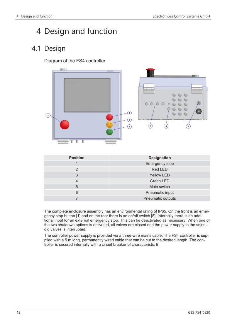
4.1 DesignDiagram of the FS4 controller
5
1
7 6
2
4
3
Position Designation1 Emergency stop2 Red LED3 Yellow LED4 Green LED5 Main switch6 Pneumatic input7 Pneumatic outputs
The complete enclosure assembly has an environmental rating of IP65. On the front is an emer-gency stop button [1] and on the rear there is an on/off switch [5]. Internally there is an addi-tional input for an external emergency stop. This can be deactivated as necessary. When one ofthe two shutdown options is activated, all valves are closed and the power supply to the solen-oid valves is interrupted.The controller power supply is provided via a three-wire mains cable. The FS4 controller is sup-plied with a 5 m long, permanently wired cable that can be cut to the desired length. The con-troller is secured internally with a circuit breaker of characteristic B.

Spectron Gas Control Systems GmbH Design and function | 4
GES_FS4_0520 13
Diagram of the FS4 controller
7
6
9
3
2
5
8
1
4
Position Designation1 8 fuses for analogue inputs2 Main fuse3 Circuit breaker4 External emergency stop input5 0V connection6 Digital inputs7 16 relay outputs8 Analogue inputs9 24V connection
4.2 Functional descriptionThe intended use of the Controller FS4 is the control of up to 4 pneumatic valves. These can beindividually configured or used for up to 2 automatic changeovers between 2 gas sources each.The control unit is designed to allow 3 different programs to be selected by the user:The first program is intended for 2 independent gas supply systems, each of which has 2 gassources, which switch automatically when one side is empty. This ensures uninterrupted gassupply. This can be carried out using valves located before or after the pressure regulating unit.The second program is intended for 1 independent supply system which has 2 gas sources thatswitch over automatically when one side is empty. This ensures uninterrupted gas supply. Thiscan be carried out using valves located before or after the pressure regulating unit. In addition,2 valves can be controlled for an emergency or source shutdown.The third program is intended for 4 valves for emergency or source shutdown. When valves areconfigured as independents, they can be enabled/disabled from the configuration screen.All controller actions which require an input from an operator are protected by a dual layer pass-word system that allows up to five trained operators to have different operational access viatheir own personal Identification Number (PIN).Configuration of the controller type, digital and analogue inputs and alarm settings are all set viathe GUI.

4 | Design and function Spectron Gas Control Systems GmbH
14 GES_FS4_0520
4.3 Technical data
NOTICEThe technical data can be taken from the data sheet for the relevant product. If this is not avail-able, you can view and download it at www.spectron.de.The maximum input and output pressures and the gas type are given on the identification or la-bel.
4.4 Boundaries and interfacesThe scope of supply includes the product as described in the "Design" chapter. The transferpoints to the control air and power supply are the connections on the controller.The following areas and functions have not been included in the scope of supply from Spectron:
– other systems, lines and installations of the overall system– Supply of auxiliary media (compressed air or purge gas)– Power supply– Lighting

Spectron Gas Control Systems GmbH Installation | 5
GES_FS4_0520 15
5 Installation
5.1 General information
CAUTIONInjury or damage in the event of incorrect assembly or disassemblySpecial steps are required for assembly and disassembly work on the product. Personal injuriesand damage to the product are possible.
a) Assembly and disassembly work may only be carried out by the installation engineer or ap-propriately skilled specialist companies and persons.
b) The product is not permitted to be re-used following disassembly. All components must bedisposed correctly.
The controller is to be mounted to a suitable wall or framework using four fixings with a max-imum diameter of 4.8 mm. Once installed, the four red plastic covers should be fitted over thescrews to maintain the IP65 rating. The data sheet and the dimensional drawing are stored inthe manufacturer's documentation.
5.2 Electrical connection
DANGERVoltageThe components of the control and the connections are under voltage. There is a danger ofdeath on contact.
a) Only allow work in which the control unit must be opened to be carried out by trained spe-cialist personnel (electricians).
b) Only perform work in which the control unit must be opened when the power supply isswitched off.
c) The five safety rules according to DIN VDE 0105 are to be observed:ð Disconnect from the mainsð Secure against reconnectionð Verify that the system is deadð Carry out earthing and short circuitingð Provide protection from adjacent live parts
The controller is shipped with a 5 metre hard wired cable which can be cut to the requiredlength. The controller is secured internally with a circuit breaker of characteristic B. All earthwires are connected to the room earthing via the power supply.

5 | Installation Spectron Gas Control Systems GmbH
16 GES_FS4_0520
5.2.1 Digital inputs
Illustration 1: Digital inputs
The digital input module (P1-16ND3) provides the connections for the digital sensor inputs. Di-gital inputs of sensors and switches are directly connected to the terminals of the digital PLC in-put module. The following information refers to the terminal designation (C1 to 16) of the mod-ules (see figure above) and not to the designations on the terminals.The terminals with red lines indicate the connections available for customer digital inputs. Theblack lines are part of the system wiring and may not be removed or added. Digital input 12 isoptionally available for remotely switching off the horn. This means that 10 individual digital in-puts are available which can be configured as normally open contacts or normally closed con-tacts. The configuration and use of the digital inputs is described in the corresponding instruc-tion manuals.All sensors must be connected with a two-wire cable. This cable (max. diameter 6 mm) ispassed through one of the cable glands on the base of the unit and connected according to theelectrical connection diagrams. The polarity of the sensors must be checked before connection.A short circuit when connecting a sensor results in one of the 24V control fuses being tripped.One wire on the digital input is connected to a free terminal (2 to 11) on the PLC input module.The other wire is connected to one of the free inputs of the common 24V connection.The cover of the input module (P1-16ND3) can be unfolded for access to the terminals on theconnection. The screw version terminals require a 0.4 x 2.5 mm flat screwdriver to clamp thewires. The wire end is stripped to a length of 9 to 10 mm and inserted into the connecting ter-minal. The maximum permissible diameter of the stripped wires is 1.5 mm².The 24V connection for digital inputs is as shown below.
Illustration 2: Wiring scheme for digital inputs

Spectron Gas Control Systems GmbH Installation | 5
GES_FS4_0520 17
5.2.2 Analogue inputs
Illustration 3: Analogue inputs and safety clip
The connections for the analogue inputs are connected directly to the module P1-08ADL-1. Thenegative terminal of each analogue signal generator is connected to one of the I+-terminals ofthe module. The positive terminal of the signal transmitter is connected to one of the 8 available24V fuse terminals. Each terminal is secured with a 32mA glass fuse (20 x 5 mm).All sensors must be disposed of professionally as hazardous waste. This cable (max. diameter6 mm) is passed through one of the cable glands on the base of the unit and connected accord-ing to the electrical connection diagrams.
5.2.3 Relay outputs
Illustration 4: Relay outputs
The connections for the relay outputs are connected directly to the output module P1-16TR.

5 | Installation Spectron Gas Control Systems GmbH
18 GES_FS4_0520
C1 and relay outputs 1 to 8 are used by the controller and must not be otherwise assigned. C1is disconnected from the network as soon as an emergency stop or remote shutdown signal isactive.The wiring of terminals C2 and the associated relay outputs 9 to 16 are provided for the follow-ing functions:
– C2: 24V power supply for relay outputs 9 to 16– 9: free– 10: External horn (NO)– 11: Emergency shutdown (NC)– 12: Warning signal (NC)– 13: Status valve 1 (NO)– 14: Status valve 2 (NO)– 15: Status valve 3 (NO)– 16: Status valve 4 (NO)
5.3 Pneumatic connection
DANGERIntended useOperation of the product with gases other than those specified or outside the limits may result indangerous reactions in the system. Incorrect use poses considerable risks to operating person-nel and the environment!
a) Only use the product for gases for which it was designed.b) Only use the product in the specified limit values for pressure and withdrawal quantity.c) Usage for another type of gas or outside the limit values is prohibited and constitutes mis-
use.
WARNINGNoise emissionWhen working on pressurised pneumatic supply, significant noise emission can occur. Acuteand chronic loss of hearing may result.
a) Never perform work on the pressurised pneumatic supply without hearing protection.b) Only replace the silencers when the supply is unpressurised.
WARNINGDisplacement of atmospheric oxygenIn the event of inert gas leaks, displacement of atmospheric oxygen may occur. Danger of suf-focation!
a) The operator must ensure adequate ventilation and airing in all rooms with gas installationsand monitor the oxygen content.

Spectron Gas Control Systems GmbH Installation | 5
GES_FS4_0520 19
WARNINGCross-contaminationCross-contamination of the control air with process gases can result in the control unit beingdamaged.
a) Ensure that cross-contamination of the control air line is prevented.
The solenoid valves require a supply of clean dry air or nitrogen filtered to 10μm, at max. 5.5bar. This is connected via a 4mm push-in fitting on the base of the device as indicated on the la-bel. Any exhaust from the solenoid valves is vented internally and excess pressure build-up isvented to atmosphere via an IP65 breather on the base of the unit.

6 | Commissioning Spectron Gas Control Systems GmbH
20 GES_FS4_0520
6 Commissioning
6.1 Preparations for commissioningThe controller may only be commissioned following installation at the place of use and connec-tion of the control air and the electrical power supply.The power supply and the electrical connections inside the housing must be checked beforecommissioning. The controller must not be operated without a fuse, loose connections must betightened before commissioning.Make sure that:
– the assembly has been correctly carried out,– the controller is connected to the correct control air– the control air supply is in operation and a pressure test for the control air has been per-
formed– the circuit breaker is not tripped
6.2 Procedure for commissioningSwitch on the controller by switching the main switch.

Spectron Gas Control Systems GmbH Operation | 7
GES_FS4_0520 21
7 Operation
7.1 General information on operationAll controller actions which require an input from an operator are protected by a dual layer pass-word system that allows up to five trained operators to have different operational access viatheir own personal Identification Number (PIN).Configuration of the controller type, digital and analogue inputs and alarm settings are all set viathe GUI.
Action Level 0 Level 1 Level 2Horn shutdown yes yes yesView analogue inputs yes yes yesView alarms yes yes yesEnable manual shutdown no yes yesEnable service mode no no yesEnable manual control no no yesAcknowledge alarms no yes yesEnter configuration no no yesTable 1: Access data matrix
7.2 ConfigurationOn power up, the following screen will be displayed:
Pressing the flag sets the system language. If necessary, other language libraries can be ad-ded.ll system on-screen instructions and alarm messages are displayed in the corresponding lan-guage.Press "Start" to display the system overview.

7 | Operation Spectron Gas Control Systems GmbH
22 GES_FS4_0520
When the system is first installed, the default values are loaded into all system variables.After the system has been adapted to the user's requirements, these values are stored in bat-tery-buffered memories.When the device is switched on again, it is restarted with the custom user settings.
Overview Screen when first switched on without adaptation to customer requirements:
To configure the system, first press "Log in".After that, the keyboard for entering the password is displayed.
The factory-set password is 1111. This gives you level 2 system access rights. In the "Usermanagement [} 24]" menu you can change the user and password settings.

Spectron Gas Control Systems GmbH Operation | 7
GES_FS4_0520 23
If a valid password has been entered, the login window displays the username and access levelfor that password. Pressing "Log out" logs out the user and removes the associated system ac-cess rights. 15 minutes after logging in, the user will be logged out automatically.
Press "Configure" to display the configuration menu.
7.2.1 Language optionsPressing "Language" takes you to the selection menu for the available languages. If necessary,other language libraries can be added.

7 | Operation Spectron Gas Control Systems GmbH
24 GES_FS4_0520
7.2.2 User managementPress "Administration" to manage names, passwords, and access levels.
Pressing the name or password displays a keyboard for data entry. A maximum of 16 charac-ters for the long name can be entered for each user. PIN numbers from 0001 to 9999 can beentered as passwords.
NOTICEIf the system is to be reset to the factory settings, all passwords must be set to 0000 and thesystem must then be restarted.

Spectron Gas Control Systems GmbH Operation | 7
GES_FS4_0520 25
7.2.3 System configurationPress "System Configuration" to configure the system.
Three different system configurations are available:– 2 systems with automatic changeover– 1 Automatic changeover (valves 1 and 2) and 2 independent valves (valves 3 and 4)– 4 independent valves
To change the system configurations, press the displayed system configuration. This allows youto scroll through the three options.The switching logic can be set for each system with an automatic changeover. The figure belowshows that both valves are open simultaneously when switched for 2 seconds. The time can beset by pressing the time displayed. The keyboard can be used to set a value of 0 to 10 seconds.Overlap time (both sides open for 2 seconds):

7 | Operation Spectron Gas Control Systems GmbH
26 GES_FS4_0520
To change the logic of the changeover overlap, press the logic icon.This switches between the two available overlap options (both valves open / both valvesclosed).Overlap time (both sides closed for 2 seconds):
If individual valves are enabled, they can be disabled by pressing "Enabled". They are then hid-den in the default overview.

Spectron Gas Control Systems GmbH Operation | 7
GES_FS4_0520 27
7.2.4 Real Time ClockThe real-time clock can be accessed via the configuration menu.The real-time clock ensures that all displayed error states are marked with the correct date andtime. The time is set via this screen:

7 | Operation Spectron Gas Control Systems GmbH
28 GES_FS4_0520
7.2.5 Analogue inputs
Press the name of an analogue input to change it.
"min" is used to select the minimum sensor value.Selecting "min"=
– "-1" automatically sets the pressure unit [bar]– "-14.5" will automatically set the pressure unit [psi]– "0" can select the units bar / psi / kg / lbs.
"max" is used to select the maximum sensor value.

Spectron Gas Control Systems GmbH Operation | 7
GES_FS4_0520 29
If there are inputs that are configured as weight (kg or lbs), the "Tare setting [} 34]" menu isused to automatically add an input field for the tare weight value.The current values of the analogue inputs are displayed as soon as the unit and the measuringrange are entered.
Pressing "Next" will take you to the analogue alarm configuration.
Up to 8 alarms can be configured here. In the first column, all analogue inputs are automaticallynumbered. Pressing one number scrolls to the next analogue input which means that multiplealarm configurations can be assigned to one input, for example.The analogue inputs that are to trigger an alarm must be switched from OFF to ON. The condi-tions for alarm triggering and the alarm designations displayed when activated can then be set.A single analogue input can be assigned to multiple alarm actions. For example, it is possible toset high and low pressure alarms on a single pressure transmitter.
Pressing "Next" will then open the list of alarm names. You can assign different alarm actions tothese alarm names.

7 | Operation Spectron Gas Control Systems GmbH
30 GES_FS4_0520
Press "No action" to scroll to the required alarm action.These are the possible settings for alarm actions:
Action DescriptionNo action The alarm is not activeWarning The alarm is active but does not switch any valves
Shutdown The alarm is active and closes all corresponding valves1LS-U The channel is active and an alarm is triggered on the 1st changeover system
on the left-hand side. The gas source is changed over from the left to theright-hand side in this process.
1RS-U The channel is active and an alarm is triggered on the 1st changeover systemon the right-hand side. The gas source is changed over from the right to theleft-hand side in this process.
2LS-U The channel is active and an alarm is triggered on the 2nd changeover sys-tem on the left-hand side. The gas source is changed over from the left to theright-hand side in this process.
2RS-U The channel is active and an alarm is triggered on the 2nd changeover sys-tem on the right-hand side. The gas source is changed over from the right tothe left-hand side in this process.
Table 2: Alarm actions
On the next screen, the settings have been configured to switch the 1st system from the leftside (1LS-U) to the right side if the cylinder pressure is too low.A changeover of the 1st system from the right side (1RS-U) to the left side if the cylinder pres-sure is too low has also been configured.If the pressure drops to 10 bar, a pre-alarm is issued in the form of a warning.If the outlet pressure is too high (20 bar), valves 1 and 2 are closed (shut off).For the shut-off of the valves, designations V1 and V2 must be pressed.

Spectron Gas Control Systems GmbH Operation | 7
GES_FS4_0520 31
7.2.6 Digital inputsPress the name of a digital input to change it.The status (normally open NO or normally closed NC), as well as the desired delay can be set.
Pressing " Next" will take you to the digital alarm configuration.The digital inputs that are to trigger an alarm must be switched from OFF to ON. The alarm des-ignations displayed when activated can then be assigned.

7 | Operation Spectron Gas Control Systems GmbH
32 GES_FS4_0520
Pressing "Next" will then open the list of alarm names. You can assign different alarm actions tothese alarm names.
Press "No action" to scroll to the required alarm action.These are the possible settings for alarm actions: see analogue inputs
The settings of the first 3 digital inputs have been configured on the following screen so that allvalves are closed in an alarm situation.To shut off the valves, designations V1, V2, V3 and V4 must be pressed.Alarm input 4 is purely a warning alarm.

Spectron Gas Control Systems GmbH Operation | 7
GES_FS4_0520 33
Pressing OK will take you back to the configuration menu.
7.2.7 Label valvesPressing "Label Valves" in the configuration menu to change the names of the valves in theoverview Screen.
7.2.8 Assignment of the analogue inputsAnalogue values can be displayed in the overview screen.To do this, select "Analogue Display" in the configuration menu.To assign these values to the display, press the "0" key in the required display enough times forthe number matches the required analogue value.

7 | Operation Spectron Gas Control Systems GmbH
34 GES_FS4_0520
"Display scale" automatically adds a cylinder scale symbol in the overview screen if an ana-logue value is assigned to it. For this reason, this value should also come from a scale.If an assignment is set to 0, the corresponding range in the overview screen remains empty.Pressing "OK" will take you back to the configuration menu.Pressing "Overview Screen" in the configuration menu to view the assigned displays.
7.2.9 Tare settingIn the configuration menu, press "Set Tare Weight" to enter the tare weight.On this screen you can enter the tare weight of the cylinder.

Spectron Gas Control Systems GmbH Operation | 7
GES_FS4_0520 35
If you have entered a tare weight, the weight of the cylinder content is output as a display value.This value is used to trigger alarm actions.
7.3 Commissioning a valveIf all valves are closed and there are no active errors, the valve status is displayed as "Out ofservice".Pressing the "Out of service" status display for valve 1 (V1L) will open a selection window.

7 | Operation Spectron Gas Control Systems GmbH
36 GES_FS4_0520
Press the "Enabled" button to commission the valve.
7.4 Putting the valve in standby modeIf you click the "Out of service" status display for valve 2 (V1R) during an automaticchangeover after commissioning the 1st valve, a selection window is displayed.

Spectron Gas Control Systems GmbH Operation | 7
GES_FS4_0520 37
Press the "Enabled" button. As valve 1 is already in operation, valve 2 is put into standby mode.
7.5 Automatic switchoverOn the following screen, the cylinder on valve V1L has triggered an alarm because the set cylin-der pressure is has not reached the setpoint value.As a result, the gas supply in the 1st system has been switched from the left side to the rightside according to the set logic.

7 | Operation Spectron Gas Control Systems GmbH
38 GES_FS4_0520
When an alarm is triggered, the date and time as well as the name of the alarm are recorded.The entries of the resolved alarms must be cancelled to be able to resume operation. They canonly be cancelled if access is enabled with a level 1 or 2 password.
After the error has been rectified and the alarm has been cleared, the reserve side can be re-commissioned. See "Putting the valve in standby mode [} 36]".

Spectron Gas Control Systems GmbH Operation | 7
GES_FS4_0520 39
If the error has not been rectified and the right side has also fallen below the set cylinder pres-sure, the right side remains in operation.All alarms are stored in the alarm history and can be retrieved via the configuration menu. Eachalarm is automatically cleared from the history after 3 months.
7.5.1 Recovery functionA "Recovery function" is integrated into this controller. This means that the pressure on the shutdown side is monitored for a specified time. If the pressure recovers within this time (liquefiedgases) and rises above the set limit value, the system is switched back to this side so that it canbe emptied as far as possible.Press "Configure" to display the configuration menu.

7 | Operation Spectron Gas Control Systems GmbH
40 GES_FS4_0520
Pressing "Recovery" takes you to the selection menu for the recovery function.Here you can activate and set the recovery function for the respective automatic changeover:
Switch on the recovery function for the system for which it is to be activated.Enter the value of the pressure increase on which the system is to switch back (recovery pres-sure = automatic changeover pressure + pressure increase).Enter the time during which the shut off side is to be monitored.If system 1 is currently in recovery mode, the following screen will be displayed during the mon-itoring time:
7.6 Manual modeWith level 2 system access rights, valves can be operated manually.
Spectron Gas Control Systems GmbH Operation | 7
GES_FS4_0520 41
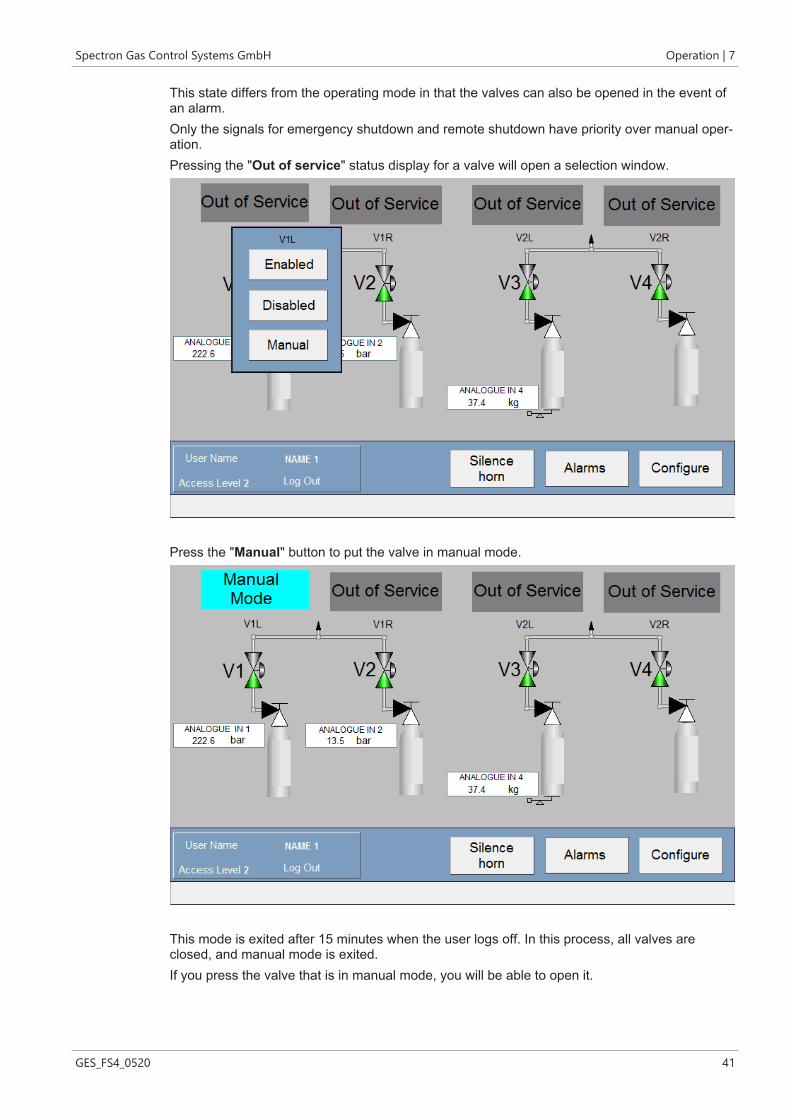
This state differs from the operating mode in that the valves can also be opened in the event ofan alarm.Only the signals for emergency shutdown and remote shutdown have priority over manual oper-ation.Pressing the "Out of service" status display for a valve will open a selection window.
Press the "Manual" button to put the valve in manual mode.
This mode is exited after 15 minutes when the user logs off. In this process, all valves areclosed, and manual mode is exited.If you press the valve that is in manual mode, you will be able to open it.

7 | Operation Spectron Gas Control Systems GmbH
42 GES_FS4_0520
Selecting "YES" will open the valve.
If you touch the opened valve, then you can close it again.

Spectron Gas Control Systems GmbH Operation | 7
GES_FS4_0520 43
7.7 Alarm historyThe configuration menu is used to access the "Alarm history". All generated alarms are displayed there. The alarms already rectified are marked in green.Each alarm is stored for 3 months and then deleted automatically.
7.8 DecommissioningSwitch off the controller by switching the main switch.

8 | Maintenance, cleaning and repairs Spectron Gas Control Systems GmbH
44 GES_FS4_0520
8 Maintenance, cleaning and repairs
8.1 General information on maintenance
DANGERVoltageThe components of the control and the connections are under voltage. There is a danger ofdeath on contact.
a) Only allow work in which the control unit must be opened to be carried out by trained spe-cialist personnel (electricians).
b) Only perform work in which the control unit must be opened when the power supply isswitched off.
c) The five safety rules according to DIN VDE 0105 are to be observed:ð Disconnect from the mainsð Secure against reconnectionð Verify that the system is deadð Carry out earthing and short circuitingð Provide protection from adjacent live parts
WARNINGNoise emissionWhen working on pressurised pneumatic supply, significant noise emission can occur. Acuteand chronic loss of hearing may result.
a) Never perform work on the pressurised pneumatic supply without hearing protection.b) Only replace the silencers when the supply is unpressurised.
WARNINGDisplacement of atmospheric oxygenIn the event of inert gas leaks, displacement of atmospheric oxygen may occur. Danger of suf-focation!
a) The operator must ensure adequate ventilation and airing in all rooms with gas installationsand monitor the oxygen content.
Correctly performed and timely maintenance increases the service life, ensures availability andhelps to avoid undesirable downtimes.Servicing and maintenance measures are only permitted to be carried out by competent spe-cialist companies and persons (electrical engineers).Maintenance work should be documented by the operator. The documentation should indicatewho carried out which work and when (proof of maintenance).It is only permitted to use original spare parts or equivalent spare parts as well as suitable tools:
– The recommended maintenance and test intervals are to be observed! (Also observe themanufacturer's documents)
– The causes of possible defects are to be investigated, e.g. damage, unusual noises, over-heating, etc.

Spectron Gas Control Systems GmbH Maintenance, cleaning and repairs | 8
GES_FS4_0520 45
Before beginning maintenance work, the controller must be enabled and secured against recon-nection. Observe the five safety rules according to DIN VDE 0105:
– Disconnect from the mains– Secure against reconnection– Verify that the system is dead– Carry out earthing and short circuiting– Provide protection from adjacent live parts
After completing the works, a re-commissioning process must be carried out (see "Commission-ing [} 20]").
8.2 Regular maintenance work and cleaningFor components in which the tests reveal wear or even malfunctions, repairs or component re-placement must be carried out by competent specialist companies and persons (electrical en-gineers).
Components Test IntervalPneumatic components Visual inspection for corrosion,
damage and correct fasteningFunctional testPressure and leakage test
At least annually and beforeeach commissioning process
Electrical components Visual inspection for corrosion,damage and correct fasteningFunctional testFunctional test
At least annually and beforeeach commissioning process
Earthing Visual inspection for damageand correct fastening
At least annually
Emergency stop Functional test At least annually
The controller should be cleaned on a regular basis. Heavy soiling can lead to malfunctions.

9 | Repair Spectron Gas Control Systems GmbH
46 GES_FS4_0520
9 Repair
9.1 General information on repair work
DANGERVoltageThe components of the control and the connections are under voltage. There is a danger ofdeath on contact.
a) Only allow work in which the control unit must be opened to be carried out by trained spe-cialist personnel (electricians).
b) Only perform work in which the control unit must be opened when the power supply isswitched off.
c) The five safety rules according to DIN VDE 0105 are to be observed:ð Disconnect from the mainsð Secure against reconnectionð Verify that the system is deadð Carry out earthing and short circuitingð Provide protection from adjacent live parts
WARNINGNoise emissionWhen working on pressurised pneumatic supply, significant noise emission can occur. Acuteand chronic loss of hearing may result.
a) Never perform work on the pressurised pneumatic supply without hearing protection.b) Only replace the silencers when the supply is unpressurised.
WARNINGDisplacement of atmospheric oxygenIn the event of inert gas leaks, displacement of atmospheric oxygen may occur. Danger of suf-focation!
a) The operator must ensure adequate ventilation and airing in all rooms with gas installationsand monitor the oxygen content.
The objectives of the repair are:– Detect and assess causes of malfunction– Rectify faults and restore operational readiness
Repairs to the controller may only be performed by the manufacturer or specialist personnel(electrical engineers) instructed on the system. Before beginning maintenance work, the controller must be enabled and secured against recon-nection. Observe the five safety rules according to DIN VDE 0105:
– Disconnect from the mains– Secure against reconnection– Verify that the system is dead
Spectron Gas Control Systems GmbH Repair | 9
GES_FS4_0520 47
– Carry out earthing and short circuiting– Provide protection from adjacent live parts.
After completing the works, a re-commissioning process must be carried out (see "Commission-ing [} 20]").
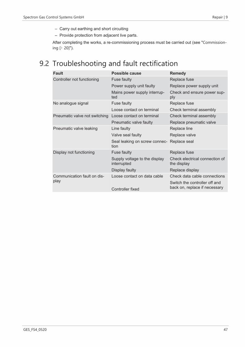
9.2 Troubleshooting and fault rectificationFault Possible cause RemedyController not functioning Fuse faulty
Power supply unit faultyMains power supply interrup-ted
Replace fuseReplace power supply unitCheck and ensure power sup-ply
No analogue signal Fuse faultyLoose contact on terminal
Replace fuseCheck terminal assembly
Pneumatic valve not switching Loose contact on terminalPneumatic valve faulty
Check terminal assemblyReplace pneumatic valve
Pneumatic valve leaking Line faultyValve seal faultySeal leaking on screw connec-tion
Replace lineReplace valveReplace seal
Display not functioning Fuse faultySupply voltage to the displayinterruptedDisplay faulty
Replace fuseCheck electrical connection ofthe displayReplace display
Communication fault on dis-play
Loose contact on data cable
Controller fixed
Check data cable connectionsSwitch the controller off andback on, replace if necessary

10 | Dismantling and disposal Spectron Gas Control Systems GmbH
48 GES_FS4_0520
10 Dismantling and disposal
10.1 General information on dismantling
DANGERVoltageThe components of the control and the connections are under voltage. There is a danger ofdeath on contact.
a) Only allow work in which the control unit must be opened to be carried out by trained spe-cialist personnel (electricians).
b) Only perform work in which the control unit must be opened when the power supply isswitched off.
c) The five safety rules according to DIN VDE 0105 are to be observed:ð Disconnect from the mainsð Secure against reconnectionð Verify that the system is deadð Carry out earthing and short circuitingð Provide protection from adjacent live parts
WARNINGNoise emissionWhen working on pressurised pneumatic supply, significant noise emission can occur. Acuteand chronic loss of hearing may result.
a) Never perform work on the pressurised pneumatic supply without hearing protection.b) Only replace the silencers when the supply is unpressurised.
WARNINGDisplacement of atmospheric oxygenIn the event of inert gas leaks, displacement of atmospheric oxygen may occur. Danger of suf-focation!
a) The operator must ensure adequate ventilation and airing in all rooms with gas installationsand monitor the oxygen content.
CAUTIONInjury or damage in the event of incorrect assembly or disassemblySpecial steps are required for assembly and disassembly work on the product. Personal injuriesand damage to the product are possible.
a) Assembly and disassembly work may only be carried out by the installation engineer or ap-propriately skilled specialist companies and persons.
b) The product is not permitted to be re-used following disassembly. All components must bedisposed correctly.
Before dismantling and disposal of the controller, it must be taken out of operation.

Spectron Gas Control Systems GmbH Dismantling and disposal | 10
GES_FS4_0520 49
The dismantling process is to be carried out in the following order:1. Decommissioning the controller2. Disconnect the controller from the power supply3. Disconnect the controller from the control air supply4. Pack the control.
10.2 DisposalDismantling and disposal must be carried out in accordance with the official and legal require-ments at the site of the system. The operator must produce a risk assessment and work instruc-tions before dismantling. A piece of equipment may only be disposed of when the decontamina-tion declaration (https://www.spectron.de/sites/default/files/2020-08/Declaration%20of%20de-contamination.pdf) has been provided, completed in full.

Spectron Gas Control Systems GmbHFritz-Klatte-Str. 8D-65933 FrankfurtTel: +49 (0)69 38016-0Fax: +49 (0)69 [email protected]