CR750-Q/CR751-Q Controller
94
Mitsubishi Industrial Robot CR750-Q/CR751-Q Controller INSTRUCTION MANUAL Controller setup, basic operation, and maintenance BFP-A8886-G
-
Upload
khangminh22 -
Category
Documents
-
view
2 -
download
0
Transcript of CR750-Q/CR751-Q Controller
Mitsubishi Industrial Robot
CR750-Q/CR751-Q ControllerINSTRUCTION MANUAL
Controller setup, basic operation, and maintenance
BFP-A8886-G

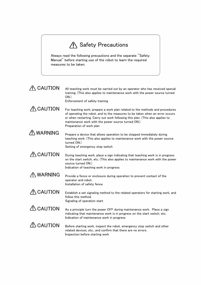
All teaching work must be carried out by an operator who has received special training. (This also applies to maintenance work with the power source turned ON.)Enforcement of safety training
For teaching work, prepare a work plan related to the methods and procedures of operating the robot, and to the measures to be taken when an error occurs or when restarting. Carry out work following this plan. (This also applies to maintenance work with the power source turned ON.)Preparation of work plan
Prepare a device that allows operation to be stopped immediately during teaching work. (This also applies to maintenance work with the power source turned ON.)Setting of emergency stop switch
During teaching work, place a sign indicating that teaching work is in progress on the start switch, etc. (This also applies to maintenance work with the power source turned ON.)Indication of teaching work in progress
Provide a fence or enclosure during operation to prevent contact of the operator and robot.Installation of safety fence
Establish a set signaling method to the related operators for starting work, and follow this method.Signaling of operation start
As a principle turn the power OFF during maintenance work. Place a sign indicating that maintenance work is in progress on the start switch, etc.Indication of maintenance work in progress
Before starting work, inspect the robot, emergency stop switch and other related devices, etc., and confirm that there are no errors.Inspection before starting work
Always read the following precautions and the separate "Safety Manual" before starting use of the robot to learn the required measures to be taken.
Safety Precautions
CAUTION
CAUTION
WARNING
CAUTION
WARNING
CAUTION
CAUTION
CAUTION
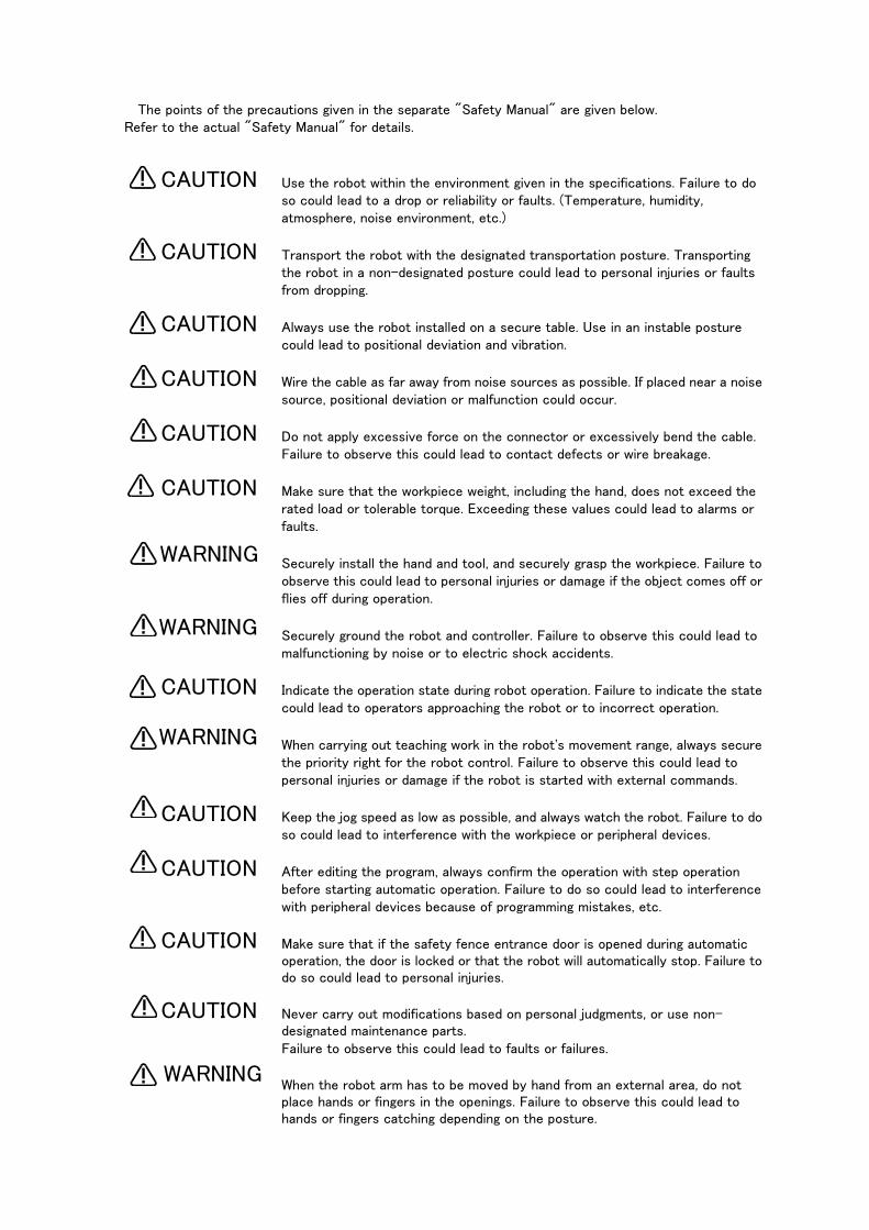
The points of the precautions given in the separate "Safety Manual" are given below.Refer to the actual "Safety Manual" for details.
Use the robot within the environment given in the specifications. Failure to do so could lead to a drop or reliability or faults. (Temperature, humidity, atmosphere, noise environment, etc.)
Transport the robot with the designated transportation posture. Transporting the robot in a non-designated posture could lead to personal injuries or faults from dropping.
Always use the robot installed on a secure table. Use in an instable posture could lead to positional deviation and vibration.
Wire the cable as far away from noise sources as possible. If placed near a noise source, positional deviation or malfunction could occur.
Do not apply excessive force on the connector or excessively bend the cable. Failure to observe this could lead to contact defects or wire breakage.
Make sure that the workpiece weight, including the hand, does not exceed the rated load or tolerable torque. Exceeding these values could lead to alarms or faults.
Securely install the hand and tool, and securely grasp the workpiece. Failure to observe this could lead to personal injuries or damage if the object comes off or flies off during operation.
Securely ground the robot and controller. Failure to observe this could lead to malfunctioning by noise or to electric shock accidents.
Indicate the operation state during robot operation. Failure to indicate the state could lead to operators approaching the robot or to incorrect operation.
When carrying out teaching work in the robot's movement range, always secure the priority right for the robot control. Failure to observe this could lead to personal injuries or damage if the robot is started with external commands.
Keep the jog speed as low as possible, and always watch the robot. Failure to do so could lead to interference with the workpiece or peripheral devices.
After editing the program, always confirm the operation with step operation before starting automatic operation. Failure to do so could lead to interference with peripheral devices because of programming mistakes, etc.
Make sure that if the safety fence entrance door is opened during automatic operation, the door is locked or that the robot will automatically stop. Failure to do so could lead to personal injuries.
Never carry out modifications based on personal judgments, or use non-designated maintenance parts. Failure to observe this could lead to faults or failures.
When the robot arm has to be moved by hand from an external area, do not place hands or fingers in the openings. Failure to observe this could lead to hands or fingers catching depending on the posture.
CAUTION
CAUTION
CAUTION
CAUTION
CAUTION
CAUTION
WARNING
WARNING
CAUTION
WARNING
CAUTION
CAUTION
CAUTION
CAUTION
WARNING
Do not stop the robot or apply emergency stop by turning the robot controller's main power OFF. If the robot controller main power is turned OFF during automatic operation, the robot accuracy could be adversely affected. Moreover, it may interfere with the peripheral device by drop or move by inertia of the arm.
Do not turn off the main power to the robot controller while rewriting the internal information of the robot controller such as the program or parameters.
If the main power to the robot controller is turned off while in automatic operation or rewriting the program or parameters, the internal information of the robot controller may be damaged.
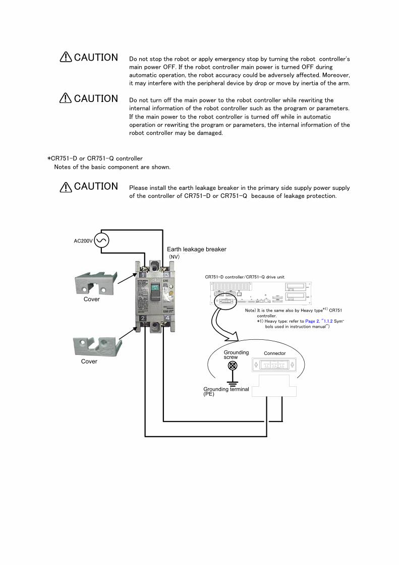
*CR751-D or CR751-Q controller
Notes of the basic component are shown.
Please install the earth leakage breaker in the primary side supply power supply of the controller of CR751-D or CR751-Q because of leakage protection.
CAUTION
CAUTION
CAUTION
保護アース端子(PE)
漏電遮断器(NV)
端子カバー
端子カバー
アース接続ネジ コネクタ
AC200V
CR751コントローラ(前面)CR751-D controller/CR751-Q drive unit
Earth leakage breaker
Cover
Cover
ConnectorGrounding screw
Grounding terminal(PE)
Note) It is the same also by Heavy type*1) CR751 controller.*1) Heavy type: refer to Page 2, "1.1.2 Sym-
bols used in instruction manual")

Revision history
Date of print Specifications No. Details of revisions
2012-06-05 BFP-A8886 ・ First print
2012-10-03 BFP-A8886-A ・The notes about installation of the controller and the robot arm were added. (neither
direct rays nor the heat of lighting)
2012-10-15 BFP-A8886-B ・ The noise filter (for CE) was added to "Table 2-1: Standard configuration".
・ The connecting method of the noise filter for CE specification was added to "Fig 2-6:
Connecting the power cable and grounding cable" and "Fig. 2-7 : Connecting the
power cable and grounding cable".
2012-11-20 BFP-A8886-C ・ The statement about trademark registration was added.
・ The wiring example 5 of the "Examples of safety measures" was corrected. (Error in
writing)
・ The notes about the input-output connected to the controller were added. (do not
ground the + side of 24V power supply prepared by customer)
・ The fuse was added to the "Table 2-1 : Standard configuration".
・ The note were added to the "4.3.1 Turning the control power ON".
2012-12-03 BFP-A8886-D ・ The connection method of the three phase power supply specification was added.
(use by single phase power supply)
2012-12-05 BFP-A8886-E ・ Distinction of the ACIN terminal was corrected.
2013-01-09 BFP-A8886-F ・ Note of the external emergency stop were added (opens the connector terminal at
factory shipping).
2013-03-21 BFP-A8886-G ・ The mass of the drive unit was shown which was divided by each robot type.
・ The explanation about the drive unit of RV-7FLL, RV-13F and RV-20F series were
added.
■ Introduction
Thank you for purchasing the Mitsubishi industrial robot.
This instruction manual explains the unpacking methods, installation, basic operation, maintenance and inspection of the controller.
Always read through this manual before starting use to ensure correct usage of the robot.
The optional equipments and power supply voltage are different according to connecting robot type.
Refer to separate "Standard Specifications Manual" for detail.
The information contained in this document has been written to be accurate as much as possible. Please interpret that items not described in this document "cannot be performed."
In this manual, CR750 series and CR751 series are written together. In CR751 controller, there are two kinds of the outside dimension different in its height.
・ 98 mm height: "CR751 (Thin type)"
・ 174 mm height: "CR751 (Heavy type)"
* Refer to Page 2, "1.1.2 Symbols used in instruction manual".
Installation of the emergency stop switch
To be able to stop the robot immediately at the time of the abnormalities because of safety, please install the emergency stop switch in the position which is certainly easy to operate it, and connect with the drive unit.. Refer to the Page 23, "2.3.4 Connecting the external emergency stop" for the connection method. And, the connection method of the door switch or the enabling device is also indicated here. Please use it together with the emergency stop switch.
Synchronous connection of the addition axis servo power supply It is building the circuit so that the output point of contact (the contactor control output for addition axes: AXMC) installed in the drive unit may be used in use of the addition axis function and the power supply of the servo amplifier for addition axes may be shut down by opening of this output,The servo ON/OFF state of the addition axis can be synchronized with the servo ON/OFF state of the robot arm. With reference to Page 44, "2.3.6 Magnet contactor control connector output (AXMC) for addition axes", I ask you to have synchronous connection made.
・ No part of this manual may be reproduced by any means or in any form, without prior consent from Mitsubishi.
・ The details of this manual are subject to change without notice.・ The information contained in this document has been written to be accurate as much as possible.
Please interpret that items not described in this document "cannot be performed." or "alarm may occur".
Please contact your nearest dealer if you find any doubtful, wrong or skipped point.・ This specifications is original.・ Company names and production names in this document are the trademarks or registered trade-
marks of their respective owners.
Copyright(C) 2012-2013 MITSUBISHI ELECTRIC CORPORATION
Notice*ONLY QUALIFIED SERVICE PERSONNEL MAY INSTALL OR SERVICE THE ROBOT SYSTEM.*ANY PERSON WHO PROGRAM, TEACHES, OPERATE, MAINTENANCE OR REPAIRS THE ROBOT SYSTEM IS TRAINED AND DEMONSTRATES COMPETENCE TO SAFELY PERFORM THE ASSIGNED TASK.
*ENSURE COMPLIANCE WITH ALL LOCAL AND NATIONAL SAFETY AND ELECTRICAL CODES FOR THE INSTALLATION AND OPERATION OF THE ROBOT SYSTEM.

For users operating robots that have not been mounted with an operation panel:
Operation of robot programs such as start-up and shutdown are carried out using external signals (exclusive input/output signals). This instruction manual is based on robots that are mounted with an operation panel at the front of the controller, and these operations are explained using key opera-tions on that panel. Using the parameter settings, please assign exclusive input/output signals that correspond with each key operation to general purpose input/output signals, and operate the robot using signal operations. The following table details exclusive input/output signals that correspond with the key operations of the operation panel explained in this manual. Please use this as a reference to assign signals and operate the robot. For further details regarding parameters please see the separate instruction manual "Detailed expla-nations of functions and operations".
Table: Conversion table of the buttons and dedicated I/O signals
Operation panel button, lamp
Parameter name
Class FunctionDefault setting
START button START button lamp
START Input Starts a program. 3,0
Output Indicates that a program is being executed.
STOP buttonSTOP button lamp
STOP Input Stops a program. 0,-1
Output Indicates that the program is paused.
RESET buttonRESET button lamp
ERRRESET Input Releases the error state. 2,2
Output Indicates that an error has occurred.
SLOTINIT Input Cancels the paused status of the program and brings the exe-cuting line to the top. Executing a program reset makes it possi-ble to select a program.
-1,-1
Output Outputs that in the program selection enabled state.
CHNG DISP buttonUP/DOWN button
PRGSEL Input Selects the value inputted into the signal assigned to the numer-ical input as a program number.
-1,
Output -
PRGOUT Input Outputs the program number selected to the signal assigned to the numerical output.
-1,-1
Output Indicates outputting the program number to the numerical out-put.
OVRDSEL Input Sets the value inputted into the signal assigned to the numerical input as a override.
-1,
Output -
OVRDOUT Input Outputs the override value to the signal assigned to the numeri-cal output.
-1,-1
Output Indicates outputting the override value to the numerical output.
LINEOUT Input Outputs the current line number to the signal assigned to the numerical output.
-1,-1
Output Indicates outputting the current line number to the numerical output.
ERROUT Input Outputs the error number to the signal assigned to the numerical output.
-1,-1
Output Indicates outputting the error number to the numerical output.
IODATA Input Reads the program number and the override value as a binary value.
-1,-1,-1,-1
Output Outputs the program number, line number and override value as a binary value.
END buttonEND button lamp
CYCLE Input Starts the cycle stop. -1,-1
Output Outputs that the cycle stop is operating.
SVO.ON buttonSVO.ON button lamp
SRVON Input Turns ON the servo power supply. 4,1
Output Indicates the servo power supply is ON.
SVO.OFF buttonSVO.OFF button lamp
SRVOFF Input Turns OFF the servo power supply. 1,-1
Output This output indicates a status where the servo power supply cannot be turned ON. (Echo back)
Contents
i
Page
1 Before starting use .......................................................................................................................... 1-1
1.1 Using the instruction manuals ................................................................................................... 1-11.1.1 The details of each instruction manuals ............................................................................... 1-11.1.2 Symbols used in instruction manual .................................................................................... 1-2
1.2 Safety Precautions .................................................................................................................... 1-31.2.1 Precautions given in the separate Safety Manual ................................................................ 1-4
2 Unpacking to installation .............................................................................................................................................................. 2-6
2.1 Confirming the products ....................................................................................................................................................... 2-6
2.2 Installation .................................................................................................................................................................................. 2-72.2.1 Unpacking procedures ................................................................................................................................................... 2-72.2.2 Transportation procedures .......................................................................................................................................... 2-72.2.3 Installation procedures .................................................................................................................................................. 2-8
(1) CR750 drive unit .......................................................................................................................................................... 2-8(2) CR751 drive unit ........................................................................................................................................................ 2-10
2.3 Installation and connection ............................................................................................................................................... 2-122.3.1 Installation of the robot CPU unit .......................................................................................................................... 2-12
(1) Notes on the handling .............................................................................................................................................. 2-12(2) Notes on base unit installation ............................................................................................................................ 2-14(3) Installation and removal of the unit ................................................................................................................... 2-16(4) Notes on the installation of the battery holder unit ................................................................................... 2-18
2.3.2 Connecting the power cable and grounding cable ........................................................................................... 2-19(1) Connecting the power cable (CR750 drive unit) .......................................................................................... 2-19(2) Connecting the power cable (CR751 drive unit) .......................................................................................... 2-20
2.3.3 Connection between the robot CPU system and the drive unit ............................................................... 2-21(1) Connection between the robot CPU system and the CR750 drive unit ............................................ 2-21(2) Connection between the robot CPU system and the CR751 drive unit ............................................ 2-22
2.3.4 Connecting the external emergency stop ........................................................................................................... 2-23(1) CR750 drive unit ........................................................................................................................................................ 2-25(2) CR751 drive unit ........................................................................................................................................................ 2-28
2.3.5 Examples of safety measures ................................................................................................................................... 2-31(1) CR750 drive unit ........................................................................................................................................................ 2-31(2) CR751 drive unit ........................................................................................................................................................ 2-36(3) External emergency stop connection [supplementary explanation] .................................................... 2-41
2.3.6 Magnet contactor control connector output (AXMC) for addition axes ................................................ 2-442.3.7 Connecting to the robot arm .................................................................................................................................... 2-46
2.4 Setting the origin ................................................................................................................................................................... 2-46
2.5 Confirming the operation .................................................................................................................................................... 2-46
3 Installing the option devices ..................................................................................................................................................... 3-47
4 Basic operations ............................................................................................................................................................................ 4-48
4.1 Handling the drive unit ........................................................................................................................................................ 4-494.1.1 Names of each parts .................................................................................................................................................... 4-49
(1) CR750 drive unit ........................................................................................................................................................ 4-49(2) CR751 drive unit ........................................................................................................................................................ 4-51
4.2 Handling the T/B ................................................................................................................................................................... 4-534.2.1 Installing and removing the T/B .............................................................................................................................. 4-53
(1) Installing the T/B (CR750 drive unit) ............................................................................................................... 4-53(2) Installing the T/B (CR751 drive unit) ............................................................................................................... 4-54(3) Removing the T/B (CR750 drive unit) ............................................................................................................. 4-54(4) Removing the T/B (CR751 drive unit) ............................................................................................................. 4-54
4.2.2 Functions of each key ................................................................................................................................................. 4-55
4.3 Turning the power ON and OFF ...................................................................................................................................... 4-564.3.1 Turning the control power ON ................................................................................................................................. 4-56
(1) CR750 controller ....................................................................................................................................................... 4-56
Contents
ii
Page
(2) CR751 controller ....................................................................................................................................................... 4-564.3.2 Input the serial number ............................................................................................................................................... 4-574.3.3 Shutting OFF the control power ............................................................................................................................. 4-58
4.4 Turning the servo power ON/OFF ................................................................................................................................. 4-594.4.1 Turning the servo power ON (servo ON) ............................................................................................................. 4-594.4.2 Shutting OFF the servo power (servo OFF) ...................................................................................................... 4-59
4.5 Jog operation .......................................................................................................................................................................... 4-60
4.6 Opening and closing the hand .......................................................................................................................................... 4-60
4.7 Programming ............................................................................................................................................................................ 4-61(1) Creation procedures ................................................................................................................................................ 4-61(2) Robot work ................................................................................................................................................................... 4-61
4.7.1 Creating the program ................................................................................................................................................... 4-62(1) Deciding the operation order ................................................................................................................................ 4-62(2) Deciding the operation position name .............................................................................................................. 4-63(3) Describing and creating the program ................................................................................................................ 4-64(4) Confirming the program .......................................................................................................................................... 4-70(5) Correcting the program .......................................................................................................................................... 4-71(6) Saving the program ................................................................................................................................................... 4-74(7) Start automatic operation. .................................................................................................................................... 4-75
5 Maintenance and Inspection ..................................................................................................................................................... 5-77
5.1 Maintenance and inspection interval ............................................................................................................................. 5-77
5.2 Inspection items ..................................................................................................................................................................... 5-785.2.1 Daily inspection items .................................................................................................................................................. 5-785.2.2 Periodic inspections ..................................................................................................................................................... 5-78
5.3 Maintenance and inspection procedures ..................................................................................................................... 5-795.3.1 Replacing the battery ................................................................................................................................................... 5-795.3.2 The check of the filter, cleaning, exchange ........................................................................................................ 5-80
(1) CR750 drive unit ........................................................................................................................................................ 5-80(2) CR751 drive unit ........................................................................................................................................................ 5-81
5.4 Maintenance parts ................................................................................................................................................................. 5-82
1Before starting use
Using the instruction manuals 1-1
1 Before starting useThis chapter explains the details and usage methods of the instruction manuals, the basic terminology and the safety precautions.
1.1 Using the instruction manuals1.1.1 The details of each instruction manuals
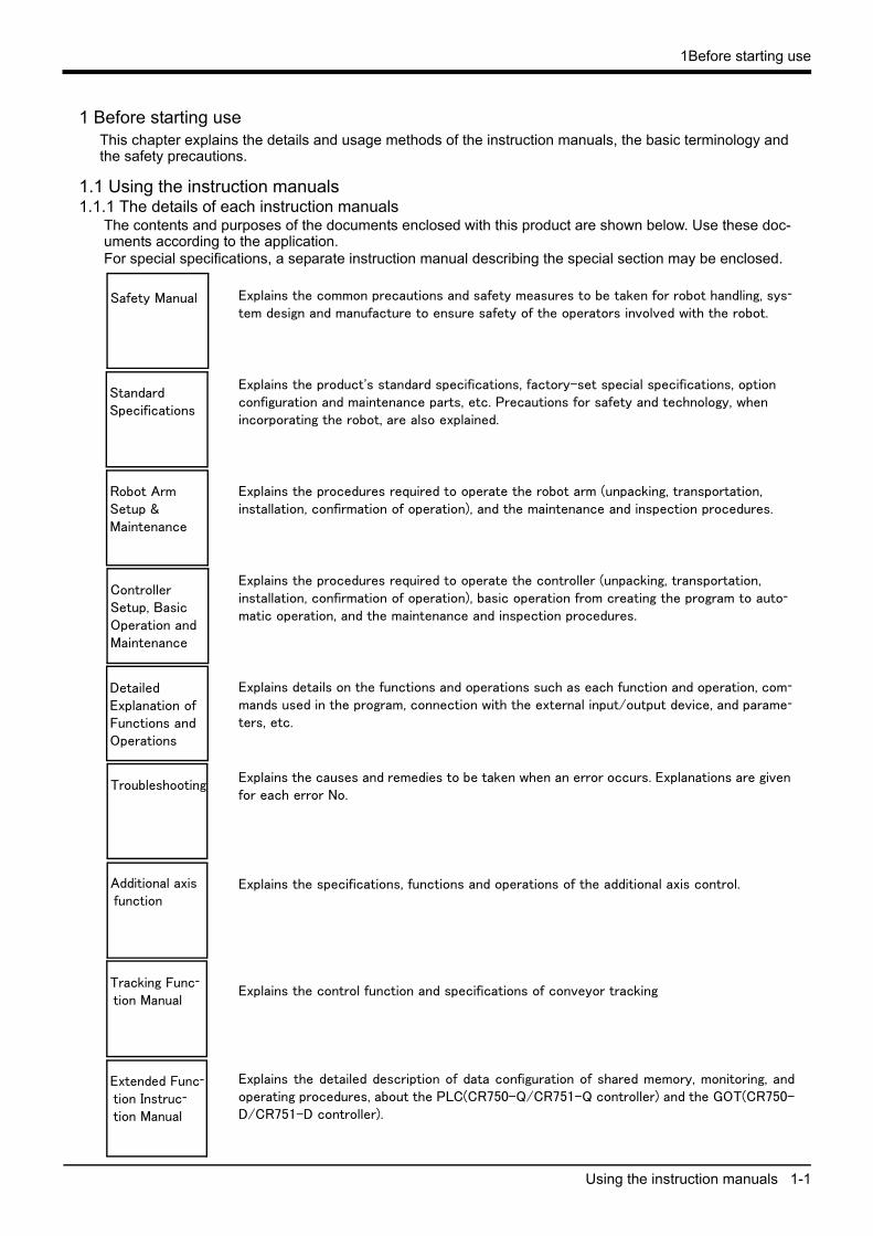
The contents and purposes of the documents enclosed with this product are shown below. Use these doc-uments according to the application.For special specifications, a separate instruction manual describing the special section may be enclosed.
Explains the common precautions and safety measures to be taken for robot handling, sys-
tem design and manufacture to ensure safety of the operators involved with the robot.
Explains the product's standard specifications, factory-set special specifications, option configuration and maintenance parts, etc. Precautions for safety and technology, when incorporating the robot, are also explained.
Explains the procedures required to operate the robot arm (unpacking, transportation, installation, confirmation of operation), and the maintenance and inspection procedures.
Explains the procedures required to operate the controller (unpacking, transportation, installation, confirmation of operation), basic operation from creating the program to auto-
matic operation, and the maintenance and inspection procedures.
Explains details on the functions and operations such as each function and operation, com-
mands used in the program, connection with the external input/output device, and parame-
ters, etc.
Explains the causes and remedies to be taken when an error occurs. Explanations are given for each error No.
Explains the specifications, functions and operations of the additional axis control.
Explains the control function and specifications of conveyor tracking
Explains the detailed description of data configuration of shared memory, monitoring, andoperating procedures, about the PLC(CR750-Q/CR751-Q controller) and the GOT(CR750-D/CR751-D controller).
Safety Manual
StandardSpecifications
Robot ArmSetup &Maintenance
ControllerSetup, BasicOperation andMaintenance
Detailed Explanation ofFunctions andOperations
Troubleshooting
Additional axis function
Tracking Func-
tion Manual
Extended Func-
tion Instruc-
tion Manual
1-2 Using the instruction manuals
1Before starting use
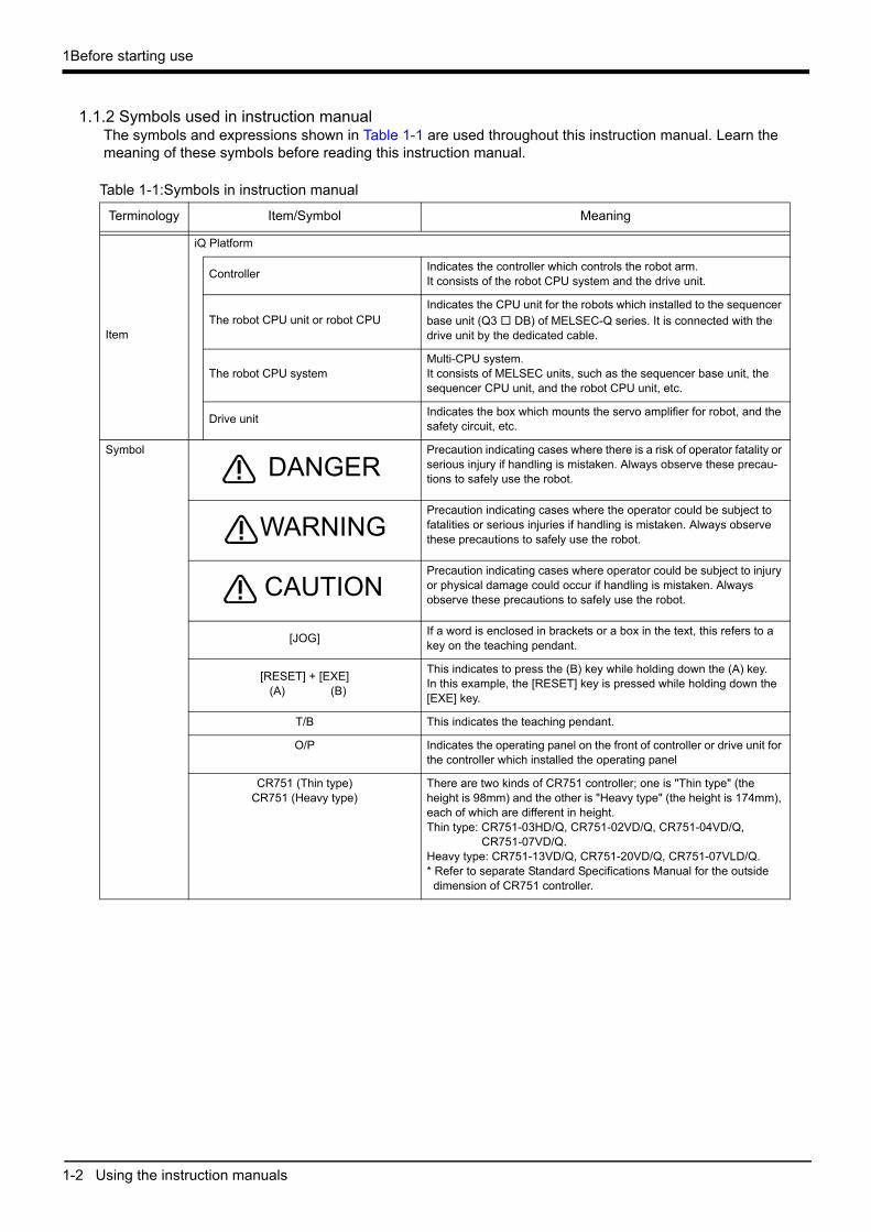
1.1.2 Symbols used in instruction manualThe symbols and expressions shown in Table 1-1 are used throughout this instruction manual. Learn the meaning of these symbols before reading this instruction manual.
Table 1-1:Symbols in instruction manual
Terminology Item/Symbol Meaning
Item
iQ Platform
ControllerIndicates the controller which controls the robot arm. It consists of the robot CPU system and the drive unit.
The robot CPU unit or robot CPUIndicates the CPU unit for the robots which installed to the sequencer base unit (Q3 □ DB) of MELSEC-Q series. It is connected with the drive unit by the dedicated cable.
The robot CPU systemMulti-CPU system.It consists of MELSEC units, such as the sequencer base unit, the sequencer CPU unit, and the robot CPU unit, etc.
Drive unitIndicates the box which mounts the servo amplifier for robot, and the safety circuit, etc.
Symbol Precaution indicating cases where there is a risk of operator fatality or serious injury if handling is mistaken. Always observe these precau-tions to safely use the robot.
Precaution indicating cases where the operator could be subject to fatalities or serious injuries if handling is mistaken. Always observe these precautions to safely use the robot.
Precaution indicating cases where operator could be subject to injury or physical damage could occur if handling is mistaken. Always observe these precautions to safely use the robot.
[JOG]If a word is enclosed in brackets or a box in the text, this refers to a key on the teaching pendant.
[RESET] + [EXE] (A) (B)
This indicates to press the (B) key while holding down the (A) key. In this example, the [RESET] key is pressed while holding down the [EXE] key.
T/B This indicates the teaching pendant.
O/P Indicates the operating panel on the front of controller or drive unit for the controller which installed the operating panel
CR751 (Thin type)CR751 (Heavy type)
There are two kinds of CR751 controller; one is "Thin type" (the height is 98mm) and the other is "Heavy type" (the height is 174mm), each of which are different in height.Thin type: CR751-03HD/Q, CR751-02VD/Q, CR751-04VD/Q,
CR751-07VD/Q.Heavy type: CR751-13VD/Q, CR751-20VD/Q, CR751-07VLD/Q.* Refer to separate Standard Specifications Manual for the outsidedimension of CR751 controller.
DANGER
WARNING
CAUTION
1Before starting use
Safety Precautions 1-3
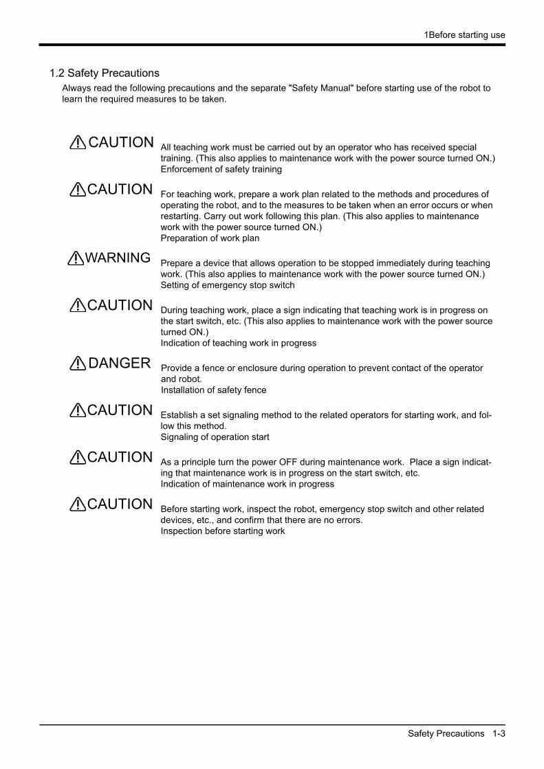
1.2 Safety PrecautionsAlways read the following precautions and the separate "Safety Manual" before starting use of the robot to learn the required measures to be taken.
All teaching work must be carried out by an operator who has received special training. (This also applies to maintenance work with the power source turned ON.)Enforcement of safety training
For teaching work, prepare a work plan related to the methods and procedures of operating the robot, and to the measures to be taken when an error occurs or when restarting. Carry out work following this plan. (This also applies to maintenance work with the power source turned ON.)Preparation of work plan
Prepare a device that allows operation to be stopped immediately during teaching work. (This also applies to maintenance work with the power source turned ON.)Setting of emergency stop switch
During teaching work, place a sign indicating that teaching work is in progress on the start switch, etc. (This also applies to maintenance work with the power source turned ON.)Indication of teaching work in progress
Provide a fence or enclosure during operation to prevent contact of the operator and robot.Installation of safety fence
Establish a set signaling method to the related operators for starting work, and fol-low this method.Signaling of operation start
As a principle turn the power OFF during maintenance work. Place a sign indicat-ing that maintenance work is in progress on the start switch, etc.Indication of maintenance work in progress
Before starting work, inspect the robot, emergency stop switch and other related devices, etc., and confirm that there are no errors.Inspection before starting work
CAUTION
CAUTION
WARNING
CAUTION
DANGER
CAUTION
CAUTION
CAUTION

1-4 Safety Precautions
1Before starting use
1.2.1 Precautions given in the separate Safety ManualThe points of the precautions given in the separate "Safety Manual" are given below.Refer to the actual "Safety Manual" for details.
If the automatic operation of the robot is operated by two or more control equip-ment, design the right management of operation of each equipment of the cus-tomer.
Use the robot within the environment given in the specifications. Failure to do so could lead to a drop or reliability or faults. (Temperature, humidity, atmosphere, noise environment, etc.)
Transport the robot with the designated transportation posture. Transporting the robot in a non-designated posture could lead to personal injuries or faults from dropping.
Always use the robot installed on a secure table. Use in an instable posture could lead to positional deviation and vibration.
Wire the cable as far away from noise sources as possible. If placed near a noise source, positional deviation or malfunction could occur.
Do not apply excessive force on the connector or excessively bend the cable. Failure to observe this could lead to contact defects or wire breakage.
Make sure that the workpiece weight, including the hand, does not exceed the rated load or tolerable torque. Exceeding these values could lead to alarms or faults.
Securely install the hand and tool, and securely grasp the workpiece. Failure to observe this could lead to personal injuries or damage if the object comes off or flies off during operation.
Securely ground the robot and controller. Failure to observe this could lead to malfunctioning by noise or to electric shock accidents.
Indicate the operation state during robot operation. Failure to indicate the state could lead to operators approaching the robot or to incorrect operation.
When carrying out teaching work in the robot's movement range, always secure the priority right for the robot control. Failure to observe this could lead to personal injuries or damage if the robot is started with external commands.
Keep the jog speed as low as possible, and always watch the robot. Failure to do so could lead to interference with the workpiece or peripheral devices.
After editing the program, always confirm the operation with step operation before starting automatic operation. Failure to do so could lead to interference with peripheral devices because of programming mistakes, etc.Make sure that if the safety fence entrance door is opened during automatic oper-ation, the door is locked or that the robot will automatically stop. Failure to do so could lead to personal injuries.
Never carry out modifications based on personal judgments, or use non-desig-nated maintenance parts. Failure to observe this could lead to faults or failures.
When the robot arm has to be moved by hand from an external area, do not place hands or fingers in the openings. Failure to observe this could lead to hands or fin-gers catching depending on the posture.
DANGER
CAUTION
CAUTION
CAUTION
CAUTION
CAUTION
CAUTION
WARNING
WARNING
CAUTION
WARNING
CAUTION
CAUTION
CAUTION
WARNING
1Before starting use
Safety Precautions 1-5
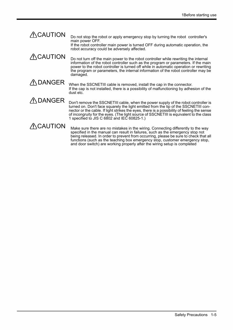
Do not stop the robot or apply emergency stop by turning the robot controller's main power OFF.If the robot controller main power is turned OFF during automatic operation, the robot accuracy could be adversely affected.
Do not turn off the main power to the robot controller while rewriting the internal information of the robot controller such as the program or parameters. If the main power to the robot controller is turned off while in automatic operation or rewriting the program or parameters, the internal information of the robot controller may be damaged.
When the SSCNETIII cable is removed, install the cap in the connector. If the cap is not installed, there is a possibility of malfunctioning by adhesion of the dust etc.
Don't remove the SSCNETIII cable, when the power supply of the robot controller is turned on. Don't face squarely the light emitted from the tip of the SSCNETIII con-nector or the cable. If light strikes the eyes, there is a possibility of feeling the sense of incongruity for the eyes. (The light source of SSCNETIII is equivalent to the class 1 specified to JIS C 6802 and IEC 60825-1.)
Make sure there are no mistakes in the wiring. Connecting differently to the way specified in the manual can result in failures, such as the emergency stop not being released. In order to prevent from occurring, please be sure to check that all functions (such as the teaching box emergency stop, customer emergency stop, and door switch) are working properly after the wiring setup is completed
CAUTION
CAUTION
DANGER
DANGER
CAUTION

2-6 Confirming the products
2Unpacking to installation
2 Unpacking to installation
2.1 Confirming the productsConfirm that the parts shown in the standard configuration of the controller shown in Table 2-1 are enclosed
with the purchased product.
Users who have purchased options should refer to the separate "Standard Specifications". The primary power supply cable and grounding cable must be prepared by the customer.
Table 2-1 : Standard configuration
No. Part name Type Qty. Remarks
CR750-Q controller
1 Controller CR750-Q 1 unit iQ Platform
2 Safety manual BFP-A8006 1 copy
3 CD-ROM (Instruction manual) 5F-RA01-C00 1 pc. iQ Platform
4 Dummy plug for T/B 2D-DP1 1 pc. Connect, when not using T/B.
5 CNUSR connector (Connector cover) 10350-52Y0-008 1 pc.
6 CNUSR connector (Plug) 10150-3000 PE 1 pc.
7 CNUSR connector BU770D007G51 3 pcs. For the CNUSR11/12/13 connector.
8 Ferrite coreE04SR301334
3 pcs. For emergency stop wiring, and TU, DISP, EMI
cable
9 Noise filter SUP-EL20-ER6 1 pc. CE specification only.
10 Lock cover set HL-05FA 1 pc. For locking the power switch.
11 Fuse (reserves) LM16 2 pcs. For the hand.
12 Fuse (reserves) HM32 2 pcs.
13 Cable clamp AL3 3 pcs. For TU, DISP, EMI cable.
14 Guarantee Card 1 copy
CR751-Q controller
1 Controller CR751-Q 1 unit iQ Platform
2 Safety manual BFP-A8006 1 copy
3 CD-ROM (Instruction manual) 5F-RA01-C00 1 pc. iQ Platform
4 ACIN connector 1-179958-3 1 pc.
5 ACIN terminal 316041-2 2 pcs.
6 Dummy plug for T/B 2F-DP1 1 pc. Connect, when not using T/B.
7 CNUSR connector (Connector cover) 10350-52Y0-008 2 pcs.
8 CNUSR connector (Plug) 10150-3000 PE 2 pcs.
9 Ferrite coreE04SR301334
3 pcs. For emergency stop wiring, and TU, DISP, EMI
cable
10 Noise filter SUP-EL20-ER6 1 pc. CE specification only.
11 Fuse (reserves) LM16 2 pcs. For the hand.
12 Fuse (reserves) HM32 2 pcs.
13 Cover plate 1 pc. For connector protection of the drive unit.
14 Cable fixing plate 1 pc. For fixing the cable of the drive unit.
15 Cable clampAB-10N
1 pcs. For fixing the machine cable
Two fixing screws (M4) is attached.
AB-6N
4 pcs. For fixing cables of TB (power supply) and
FG(communication).
ThreeFour fixing screws (M4) are attached.
AL3 3 pcs. For TU, DISP, EMI cable.
16 Guarantee Card 1 copy
2Unpacking to installation
Installation 2-7
2.2 Installation
2.2.1 Unpacking proceduresThe controller is shipped from the factory packaged in cardboard.
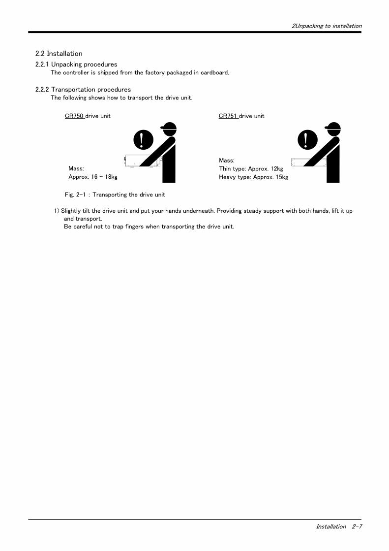
2.2.2 Transportation proceduresThe following shows how to transport the drive unit.
Fig. 2-1 : Transporting the drive unit
1) Slightly tilt the drive unit and put your hands underneath. Providing steady support with both hands, lift it up and transport. Be careful not to trap fingers when transporting the drive unit.
Mass:
Approx. 16 - 18kg
CR750 drive unit CR751 drive unit
Mass:
Thin type: Approx. 12kg
Heavy type: Approx. 15kg
2-8 Installation
2Unpacking to installation
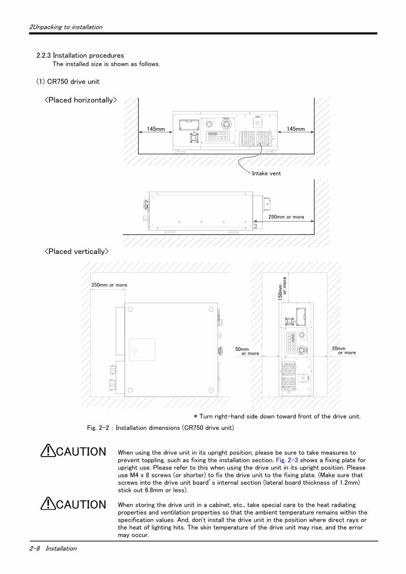
2.2.3 Installation proceduresThe installed size is shown as follows.
(1) CR750 drive unit
Fig. 2-2 : Installation dimensions (CR750 drive unit)
When using the drive unit in its upright position, please be sure to take measures to prevent toppling, such as fixing the installation section. Fig. 2-3 shows a fixing plate for upright use. Please refer to this when using the drive unit in its upright position. Please use M4 x 8 screws (or shorter) to fix the drive unit to the fixing plate. (Make sure that screws into the drive unit board’s internal section (lateral board thickness of 1.2mm) stick out 6.8mm or less).
When storing the drive unit in a cabinet, etc., take special care to the heat radiating properties and ventilation properties so that the ambient temperature remains within the specification values. And, don't install the drive unit in the position where direct rays or the heat of lighting hits. The skin temperature of the drive unit may rise, and the error may occur.
150m
m以
上
50mm以上 20mm以上
250mm以上
145mm 145mm
250mm以上
吸気口
<Placed horizontally>
* Turn right-hand side down toward front of the drive unit.
<Placed vertically>
Intake vent
250mm or more
250mm or more150
mm
or
more
20mm or more
50mm or more
CAUTION
CAUTION
2Unpacking to installation
Installation 2-9
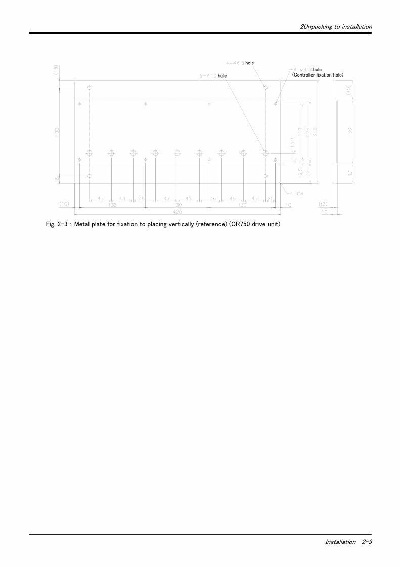
Fig. 2-3 : Metal plate for fixation to placing vertically (reference) (CR750 drive unit)
hole(Controller fixation hole)
hole
hole
2-10 Installation
2Unpacking to installation
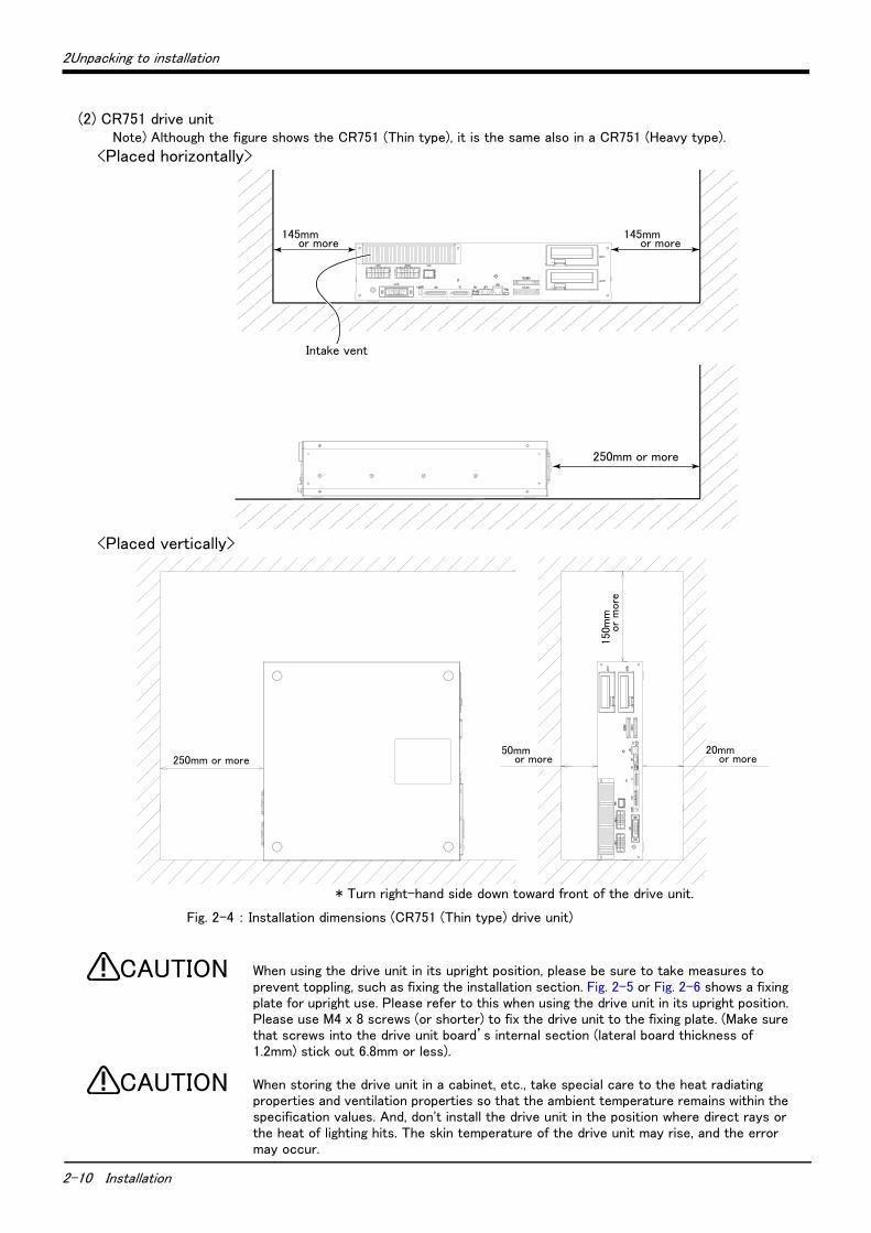
(2) CR751 drive unitNote) Although the figure shows the CR751 (Thin type), it is the same also in a CR751 (Heavy type).
Fig. 2-4 : Installation dimensions (CR751 (Thin type) drive unit)
When using the drive unit in its upright position, please be sure to take measures to prevent toppling, such as fixing the installation section. Fig. 2-5 or Fig. 2-6 shows a fixing plate for upright use. Please refer to this when using the drive unit in its upright position. Please use M4 x 8 screws (or shorter) to fix the drive unit to the fixing plate. (Make sure that screws into the drive unit board’s internal section (lateral board thickness of 1.2mm) stick out 6.8mm or less).
When storing the drive unit in a cabinet, etc., take special care to the heat radiating properties and ventilation properties so that the ambient temperature remains within the specification values. And, don't install the drive unit in the position where direct rays or the heat of lighting hits. The skin temperature of the drive unit may rise, and the error may occur.
150m
m以
上
50mm以上 20mm以上250mm以上
145mm 145mm
250mm 以上
吸気口
<Placed horizontally>
<Placed vertically>
Intake vent
250mm or more
250mm or more50mm
or more20mm
or more
* Turn right-hand side down toward front of the drive unit.
150m
m
or
more
145mm or more
145mm or more
CAUTION
CAUTION
2Unpacking to installation
Installation 2-11
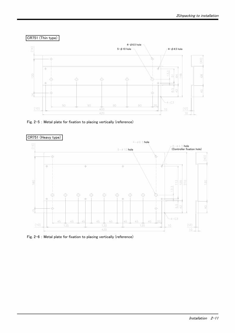
Fig. 2-5 : Metal plate for fixation to placing vertically (reference)
Fig. 2-6 : Metal plate for fixation to placing vertically (reference)
4-φ6.5 hole
5-φ10 hole 4-φ4.5 hole
CR751 (Thin type)
hole(Controller fixation hole)
hole
hole
CR751 (Heavy type)

-12 Installation and connection
2.3 Installation and connection
2.3.1 Installation of the robot CPU unit(1) Notes on the handling
Explain notes on the handling of the CPU unit, the input/output unit, the intelligent functional unit, the power supply unit, the base unit, etc.
1) Please do not drop the unit, the terminal stand connector, and the pin connector, or do not supply a strong shock.
2) The printed circuit board of the unit should not remove from the case. It becomes the cause of failure.3) Please carry out bolting of the unit fixing screw and the terminal stand screw in the range shown in Table 2-
2.
4) The basic base unit should equip with the power supply unit at any cost. If the load of the input/output unit and intelligent functional unit with which the base unit is equipped is low, it may operate, even if there is no power supply unit. However, since voltage becomes unstable, operation cannot be guaranteed.
5) Since it may malfunction by vibration if it installs the basic base unit in the plate, please be sure to fix with the screw for fixing.
1) Please use the robot CPU system in the environment of general specification given in this manual. If other, it becomes the electric shock, the fire, malfunction, the damage to the product, or the cause of deterioration.
2) Pressing down the unit lower lever for unit wearing, insert the projection for unit fixing in the fixing hole of the base unit surely, and install with the unit fixing hole as a fulcrum. If the unit is not installed correctly, it will become the cause of malfunction, failure, and drop. If it uses it in the environment with much vibration, fix the unit with the screw. Please perform bolting of the screw in the regulation torque range. If bolting of the screw is loose, it will become the cause of drop, the short circuit, and malfunction. If the screw is tightened too much, it will become the cause of drop by breakage of the screw or the unit, the short circuit, and malfunction.
3) Please be sure to do the installing and removing of the unit after shutting down all phase of the external power supply currently used by the system.
4) The installing and removing of the unit and the base may be less than 50 times after product use. It may become the cause of malfunction if it exceeds 50 times.
5) Please do not touch the electric conduction section or electronic components of the unit directly. It becomes malfunction of the unit, and the cause of failure.
Table 2-2 : Conclusion torque of the fixing screw
Place of the screw Bolting torque range
Robot CPU unit fixing screw (M3×13) 0.36 ~ 0.48N ・ m
Unit fixing screw (M3×12) 0.36 ~ 0.48N ・ m
Input/output unit terminal stand screw (M3) 0.42 ~ 0.58N ・ m
Input/output unit terminal stand attachment screw (M3.5)
0.68 ~ 0.92N ・ m
Terminal screw of the power supply unit (M3.5) 0.68 ~ 0.92N ・ m
CAUTION
Installation and connection -13
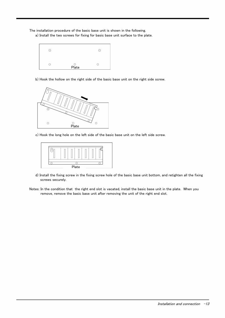
The installation procedure of the basic base unit is shown in the following.
a) Install the two screws for fixing for basic base unit surface to the plate.
b) Hook the hollow on the right side of the basic base unit on the right side screw.
c) Hook the long hole on the left side of the basic base unit on the left side screw.
d) Install the fixing screw in the fixing screw hole of the basic base unit bottom, and retighten all the fixing screws securely.
Notes: In the condition that the right end slot is vacated, install the basic base unit in the plate. When you remove, remove the basic base unit after removing the unit of the right end slot.
盤Plate
盤Plate
盤Plate
-14 Installation and connection
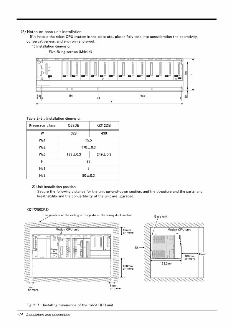
(2) Notes on base unit installation If it installs the robot CPU system in the plate etc., please fully take into consideration the operativity,
conservativeness, and environment-proof.
1) Installation dimension
Table 2-3 : Installation dimension
2) Unit installation positionSecure the following distance for the unit up-and-down section, and the structure and the parts, and breathability and the convertibility of the unit are upgraded.
Fig. 2-7 : Installing dimensions of the robot CPU unit
Dimension place Q38DB Q312DB
W 328 439
Ws1 15.5
Ws2 170±0.3
Ws3 138±0.3 249±0.3
H 98
Hs1 7
Hs2 80±0.3
I /O11
5-取付けネジ(M4×14)
W
Hs
H
OUT
FG
SG
5V
I/O11I/O10I/O9I/O8I/O6I/O5I/O4I/O3I/O2I/O1I/O0CPUPOWER I/O7
Ws2 Ws
Q312DB
3Ws1
2Hs1
Five fixing screws (M4x14)
盤I/O11I/O11
Q312DB
QX400 1 2 3 4 5 6 7
8 9 A B C D E F
SY.ENC1
Q172DEX
Q172DEX
2
1TRENSY.ENC
2
1
Q173DPX
PULSER
Q173DPX PLS.A
321
PLS.B
321
TREN
321
MELSECQ61P
POWER
PULL
Q03DCPU
USER
MODERUNERR.
BAT.BOOT
PULL
USB
RS-232
QX400 1 2 3 4 5 6 7
8 9 A B C D E F
BATFRONT
CN
2C
N1
EMICAUTION
STOP RUN1 2
SW
Q173DCPU
<Q172DRCPU>
The position of the ceiling of the plate or the wiring duct section Base unit
Motion CPU unit
Door
5mm or more
100mm or more
123.5mm
5mm or more
Motion CPU unit
100mm or more
40mm or more
Installation and connection -15
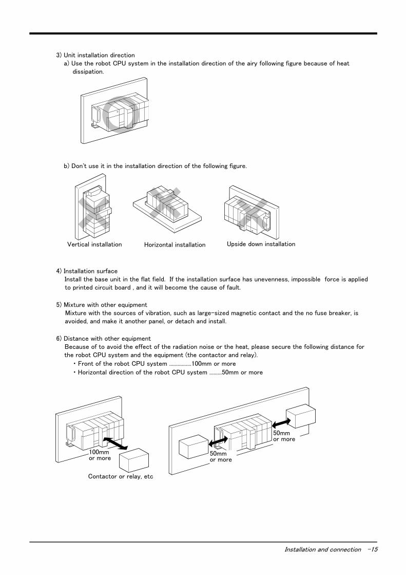
3) Unit installation directiona) Use the robot CPU system in the installation direction of the airy following figure because of heat
dissipation.
b) Don't use it in the installation direction of the following figure.
4) Installation surfaceInstall the base unit in the flat field. If the installation surface has unevenness, impossible force is applied to printed circuit board , and it will become the cause of fault.
5) Mixture with other equipmentMixture with the sources of vibration, such as large-sized magnetic contact and the no fuse breaker, is avoided, and make it another panel, or detach and install.
6) Distance with other equipmentBecause of to avoid the effect of the radiation noise or the heat, please secure the following distance for the robot CPU system and the equipment (the contactor and relay).
・ Front of the robot CPU system ................100mm or more
・ Horizontal direction of the robot CPU system .........50mm or more
縦取付け 水平取付け 天地逆取付けVertical installation Horizontal installation Upside down installation
50mm以上
コンタクタ,リレーなど
100mm以上 50mm以上
Contactor or relay, etc
100mmor more
50mmor more
50mmor more

-16 Installation and connection
(3) Installation and removal of the unitThe installing-and-removing procedure to base units, such as the power supply unit, the sequencer CPU unit, the robot CPU unit, the input-and-output unit, and the intelligent functional unit, is shown in the following.
1) Installing and removing of the unit to the base unit "Q3 □ DB"a) Installation to "Q3 □ DB"
*: Please be sure to fix the robot CPU unit to the base unit with the screw.
<Point>
・The unit should insert the projection for unit fixing in the unit fixing hole always. In that case, insert surelyso that the projection for unit fixing may not deviate from the unit fixing hole. If it installs forcibly, withoutinserting, the unit connector and the unit will be damaged.
・If it uses it at the place which is applied to of vibration and the shock, fix the unit to the base unit with thescrew. Unit fixing screw: M3x12 (prepare by the customer) Always fix the robot CPU unit to the base unitwith the screw with the attached unit fixing screw (M3x13).
・ The installing and removing of the unit and the base may be less than 50 times after product use. It maybecome the cause of malfunction if it exceeds 50 times.
Pressing down the unit lower lever for unit wearing, insert the projection for unit fixing in the fixing hole of the base unit surely, and install with the unit fixing hole as a fulcrum. If the unit is not installed correctly, it will become the cause of malfunction, failure, and drop. If it uses it in the environment with much vibration, fix the unit with the screw. Please perform bolting of the screw in the regulation torque range. If bolting of the screw is loose, it will become the cause of drop, the short circuit, and malfunction. If the screw is tightened too much, it will become the cause of drop by breakage of the screw or the unit, the short circuit, and malfunction.
*
Insert surely so that the projection for unit fixing may not deviate from the unit fixing hole.
P ush and ins ta ll the un it in the d irec t ion o f the a rrow by us in g the un it fix in g ho le a s the fu lc rum
C onfirm tha t the un it is insta lled su re ly .
If vibration and the shock are applied to, fix to the base unit with the screw.
Complete
Base unit
Unit
Unit connector
Projection for unit fixing
Unit fixing hole
Projection for unit fixing
Unit fixing hole
Unit installation lever
Base unit
Projection for unit fixing
Unit fixing hole
Unit installation lever
Base unit
Unit fixing hole
Projection for unit fixing
Base unit
Hook for unit fixing
CAUTION

Installation and connection -17
b) Removing from "Q3 □ DB"
<Point>
・Remove the screw, if the unit fixing screw is being used.Next, remove the projection for unit fixing from theunit fixing hole. If it tries to remove the unit by force, the projection for unit fixing will be damaged.
Since the heat dissipation fin of the robot CPU unit may become the high temperature for a power supply on, and after power supply off, please do not touch. It becomes the cause of the burn. When you remove the unit, be careful of the handling.
R em ove the sc rew , if the un it fix in g sc rew is be in g used .
H o ld the un it w ith bo th hands and push th e ups ide hook fo r fix ing , un til it s tops .
P ush the hook fo r un it fix in g , use low e r pa rt as the fu lc rum and pu ll it to the fron t.
H o ld ing up the un it, and rem ove the p ro jec tion sec tio n fo r fix in g from the ho le
Complete
Base unit
Unit connector
Unit
Unit fixing hole
Hook for unit fixing
Push
Holding upPull to the front
CAUTION
-18 Installation and connection
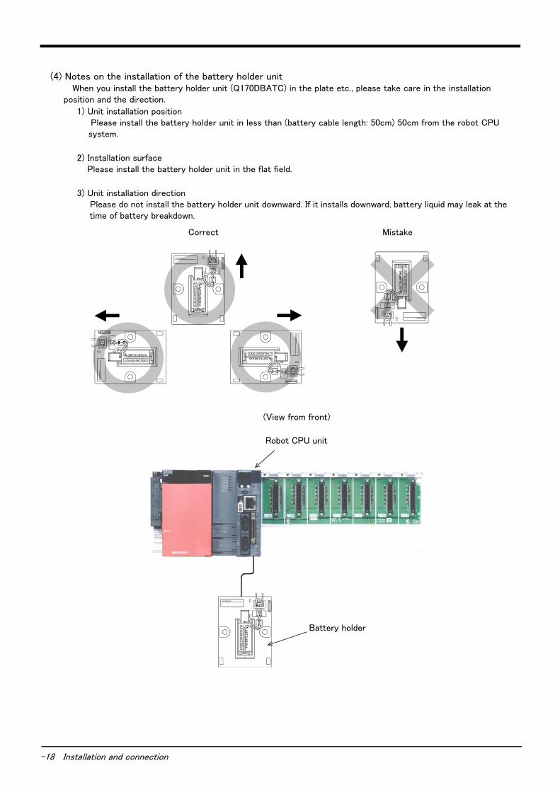
(4) Notes on the installation of the battery holder unit When you install the battery holder unit (Q170DBATC) in the plate etc., please take care in the installation
position and the direction.
1) Unit installation position Please install the battery holder unit in less than (battery cable length: 50cm) 50cm from the robot CPU system.
2) Installation surfacePlease install the battery holder unit in the flat field.
3) Unit installation directionPlease do not install the battery holder unit downward. If it installs downward, battery liquid may leak at the time of battery breakdown.
(正面から見る)
ロボットCPUユニット
バッテリホルダMIT
SU
BIS
HI
LIT
HIU
M B
AT
TE
RY
CPU
BATTERY
Q170DBATC
(正) (誤)
MIT
SU
BIS
HI
LIT
HIU
M B
AT
TE
RY
CPU
BATTERY
Q170DBATC
MITSUBISHI
LITHIUM BATTERY
CP
U
BA
TT
ER
Y
Q170D
BA
TC
MITSUBISHI
LITHIUM BATTERY
CP
U
BA
TTE
RY
Q17
0DB
AT
C
MIT
SU
BIS
HI
LIT
HIU
M B
AT
TE
RY
CPU
BATTERY
Q170DBATC
(View from front)
Robot CPU unit
Battery holder
Correct Mistake

2Unpacking to installation
Installation 2-19
2.3.2 Connecting the power cable and grounding cableThe following shows how to connect the power cables and grounding cables.
(1) Connecting the power cable (CR750 drive unit)
Fig. 2-8 : Connecting the power cable and grounding cable
1) Prepare the power cable (AWG#14 (2mm2) or more).2) Loosen the two screws fixing the terminal cover, and remove the cover.3) Confirm that the primary power matches the specifications.4) Confirm that the primary power is OFF and that the drive unit power switch is OFF.5) Connects the cable for the primary power supply connection to the ACIN terminal block of the drive unit.
When the terminal for single phase is attached, connect the primary power supply to L1 and L2 terminal. When the terminal for single phase/ three phase is attached, connect the primary power supply to L1, L2 and L3 terminal when using the three phase primary power supply, and connect the primary power supply to L1 and L3 terminal when using the single phase primary power supply.
6) Install the power terminal cover as before.
This completes the connection of the power and grounding cables.
GroundingACIN terminalL1
Single phase primary power supply
N/L2terminal (PE)
ACIN terminalL1 L3L2
Three phase primary power supply
Groundingterminal (PE)
ACIN terminalL1 L3L2
Single phase primary power supply
Groundingterminal (PE)
ACIN terminalRemove the cover
Note) When fixing the power cable to the ACIN terminal block with screws, be sure to hold the crimp terminal with your hand to ensure that it does not rotate while fastening screws. The dividers between terminals of the ACIN terminal block are fragile and may break if pressed.
Note 1) Fix the primary power cable to the terminal with the screw.
Screw size: M4Solderless terminal: φ8 or less
Recommendation: 2-M4 (JAPANESE SOLDERLESS TERMINALS CO.,LTD.)
Wire size: AWG #14(2mm2)/ for M4 screw.Note 2) Non CE specification: L2
CE specification: NNote 3) In the CE specification, as shown in the figure, con-
nects the noise filter (SUP-EL20-ER6) of attach-ment between ACIN terminal blocks and primary power supply.
Note 2)
<4> LINE/LOAD<3> LINE/LOAD
<1> LINE/LOAD
<2> LINE/LOAD
Noise filter (attachment)Type: SUP-EL20-ER
LabelNote 3)
For single phase For single phase/three phaseNote 1) Note 1)
2-20 Installation
2Unpacking to installation
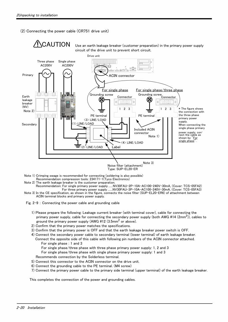
(2) Connecting the power cable (CR751 drive unit)
Fig. 2-9 : Connecting the power cable and grounding cable
1) Please prepare the following: Leakage current breaker (with terminal cover), cable for connecting theprimary power supply, cable for connecting the secondary power supply (both AWG #14 (2mm2)), cables toground the primary power supply (AWG #12 (3.5mm2 or above).
2) Confirm that the primary power matches the specifications.3) Confirm that the primary power is OFF and that the earth leakage breaker power switch is OFF.4) Connect the secondary power cable to secondary terminal (lower terminal) of earth leakage breaker.
Connect the opposite side of this cable with following pin numbers of the ACIN connector attached.For single phase : 1 and 3For single phase/three phase with three phase primary power supply: 1, 2 and 3For single phase/three phase with single phase primary power supply: 1 and 3
Recommends connection by the Solderless terminal.5) Connect this connector to the ACIN connector on the drive unit.6) Connect the grounding cable to the PE terminal. (M4 screw)7) Connect the primary power cable to the primary side terminal (upper terminal) of the earth leakage breaker.
This completes the connection of the power and grounding cables.
PE terminal
Grounding screw
Controller
Connector
AC200V AC200V
Connector
Primary
Secondary
PE terminal
Grounding screw
Use an earth leakage breaker (customer preparation) in the primary power supply circuit of the drive unit to prevent short circuit.
CAUTION
ACIN connector
Note 2)
Note 1) Crimping swage is recommended for connecting (soldering is also possible)Recommendation compression tools: 234171-1(Tyco Electronics)
Note 2) The earth leakage breaker is the customer preparation. Recommendation: For single primary power supply ......NV30FAU-2P-10A-AC100-240V-30mA, (Cover: TCS-05FA2)
For three primary power supply .......NV30FAU-3P-10A-AC100-240V-30mA, (Cover: TCS-05FA3)Note 3) In the CE specification, as shown in the figure, connects the noise filter (SUP-EL20-ER6) of attachment between
ACIN terminal blocks and primary power supply.
Drive unit
<4> LINE/LOAD
<3> LINE/LOAD<1> LINE/LOAD
<2> LINE/LOAD
Noise filter (attachment)Type: SUP-EL20-ER
Label
Note 3)
1 2 3
Included ACIN connector
Note 1)
For single phase/three phaseFor single phase
Three phase Single phase
Earth leakage breaker (NV)
* The figure showsthe connection with the three phase primary power supply.When connecting the single phase primary
power supply, con-nect the cable as shown by "For single phase".
1 2 3
-21
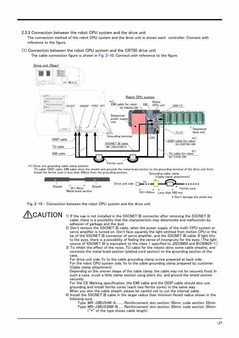
2.3.3 Connection between the robot CPU system and the drive unit The connection method of the robot CPU system and the drive unit is shown each controller. Connect with reference to the figure.
(1) Connection between the robot CPU system and the CR750 drive unitThe cable connection figure is shown in Fig. 2-10. Connect with reference to the figure.
Fig. 2-10 : Connection between the robot CPU system and the drive unit
1) If the cap is not installed in the SSCNET III connector after removing the SSCNET III cable, there is a possibility that the characteristic may deteriorate and malfunction by adhesion of garbage and the dust
2) Don't remove the SSCNET III cable, when the power supply of the multi-CPU system or servo amplifier is turned on. Don't face squarely the light emitted from motion CPU or the tip of the SSCNET III connector of servo amplifier, and the SSCNET III cable. If light hits to the eyes, there is a possibility of feeling the sense of incongruity for the eyes. (The light source of SSCNET III is equivalent to the class 1 specified to JISC6802 and IEC60825-1.)
3) To inhibit the effect of the noise, TU cable for the robots skins some cable sheaths, and connects the metal braid section (plaited cord section) to the grounding section of the case.For drive unit side, fix to the cable grounding clamp screw prepared at back side.For the robot CPU system side, fix to the cable grounding clamp prepared by customer. (Cable clamp attachment)Depending on the uneven shape of the cable clamp, the cable may not be securely fixed. In such a case, crush a little clamp section using pliers etc. and ground the shield section securely.For the CE Marking specification, the EMI cable and the DISP cable should also use grounding and install ferrite cores (each two ferrite cores) in the same way. When you skin the cable sheath, please be careful not to cut the internal cable.
4) Install the SSCNET III cable in the larger radius than minimum flexed radius shown in the following sure.
Type: MR-J3BUS*M-A.......... Reinforcement skin section: 50mm, code section: 25mmType: MR-J3BUS30M-B....... Reinforcement skin section: 50mm, code section: 30mm
("*" of the type shows cable length)
TU I/F
ロボットCPUユニット
シーケンサ電源ユニット
シーケンサベースユニット
EMI DISP I/F
SSCNETⅢケーブルMR-J3BUS10M-A
ロボット専用EMIケーブル2Q-EMICBL10M
20~30mm金属製ブレード部
シース シース
ロボット専用TUケーブル2Q-TUCBL10M
CN1
ロボット専用DISPケーブル2Q-DISPCBL10M
アースクランプ (ケーブルクランプ付属品)
フェライトコア
ドライブユニット側
500mm以下150~200mm
TU
アース端子*1)
*1)
*1)ケーブルの接地とフェライトコア取り付け
ドライブユニット背面
ロボットCPUシステム
CON3 OPTCNDISPDCOUT*1)
*1)
フェライトコア
TUケーブル
DISPケーブル
EMIケーブル
TUケーブル、DISPケーブル、EMIケーブルは、シースを剥いて露出させた金属製ブレード部をドライブユニット前面のアース端子へ接地します。接地箇所から500mm以内にフェライトコア(付属品)を取り付けます。
* Don't damage the shield line.
Drive unit (Rear)
Robot CPU system
EMI cable for robot
*1)
Robot CPU unit
Sequencer base unit
DISP cable for robot
TU cable for robot
*1)
*1)
SSCNET III cable
Sequencer power supply unit
DISP cable
TU cable
EMI cable
Grounding terminal
Sheath Sheath
Metal braid section
*1) Drive unit grounding cable clamp positionTU cable, DISP cable, EMI cable skins the sheath and grounds the metal braid section to the grounding terminal of the drive unit front.Install the ferrite core in less than 500cm from the grounding position.
Ferrite core
Drive unit side
Grounding cable clamp(Cable clamp attachment)
Ferrite core
*1)
Less than 500 mm
CAUTION
-22
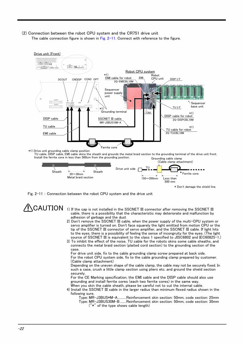
(2) Connection between the robot CPU system and the CR751 drive unitThe cable connection figure is shown in Fig. 2-11. Connect with reference to the figure.
Fig. 2-11 : Connection between the robot CPU system and the drive unit
1) If the cap is not installed in the SSCNET III connector after removing the SSCNET III cable, there is a possibility that the characteristic may deteriorate and malfunction by adhesion of garbage and the dust
2) Don't remove the SSCNET III cable, when the power supply of the multi-CPU system or servo amplifier is turned on. Don't face squarely the light emitted from motion CPU or the tip of the SSCNET III connector of servo amplifier, and the SSCNET III cable. If light hits to the eyes, there is a possibility of feeling the sense of incongruity for the eyes. (The light source of SSCNET III is equivalent to the class 1 specified to JISC6802 and IEC60825-1.)
3) To inhibit the effect of the noise, TU cable for the robots skins some cable sheaths, and connects the metal braid section (plaited cord section) to the grounding section of the case.For drive unit side, fix to the cable grounding clamp screw prepared at back side.For the robot CPU system side, fix to the cable grounding clamp prepared by customer. (Cable clamp attachment)Depending on the uneven shape of the cable clamp, the cable may not be securely fixed. In such a case, crush a little clamp section using pliers etc. and ground the shield section securely.For the CE Marking specification, the EMI cable and the DISP cable should also use grounding and install ferrite cores (each two ferrite cores) in the same way. When you skin the cable sheath, please be careful not to cut the internal cable.
4) Install the SSCNET III cable in the larger radius than minimum flexed radius shown in the following sure.
Type: MR-J3BUS*M-A..........Reinforcement skin section: 50mm, code section: 25mmType: MR-J3BUS30M-B .......Reinforcement skin section: 50mm, code section: 30mm
("*" of the type shows cable length)
TU I/F
ロボットCPUユニット
シーケンサ電源ユニット
シーケンサベースユニット
EMIDISP I/F
SSCNETⅢケーブルMR-J3BUS10M-A
ロボット専用EMIケーブル2Q-EMICBL10M
ロボット専用TUケーブル2Q-TUCBL10M
CON3 OPTCNDISP
CN1
ロボット専用DISPケーブル2Q-DISPCBL10M
DCOUT
アース端子*1)
*1)
ドライブユニット前面
ロボットCPUシステム*1)
*1)
20~30mm金属製ブレード部
シース シース
アースクランプ (ケーブルクランプ付属品)
フェライトコア
ドライブユニット側
500mm以下150~200mm
TU
*1)ケーブルの接地とフェライトコア取り付けフェライトコア
TUケーブル
DISPケーブル
EMIケーブル
TUケーブル、DISPケーブル、EMIケーブルは、シースを剥いて露出させた金属製ブレード部をドライブユニット前面のアース端子へ接地します。接地箇所から500mm以内にフェライトコア(付属品)を取り付けます。
* Don't damage the shield line.
Drive unit (Front)
Robot CPU system
EMI cable for robot*1) Robot
CPU unit
Sequencer base unit
DISP cable for robot
TU cable for robot
*1)
*1)
SSCNET III cable
Sequencer power supply unit
DISP cable
Grounding terminal
Sheath Sheath
Metal braid section
*1) Drive unit grounding cable clamp positionTU cable, DISP cable, EMI cable skins the sheath and grounds the metal braid section to the grounding terminal of the drive unit front.Install the ferrite core in less than 500cm from the grounding position.
Ferrite core
Drive unit side
Grounding cable clamp(Cable clamp attachment)
Ferrite core
*1)
TU cable
EMI cable
Less than 500 mm
CAUTION

2Unpacking to installation
2-23
2.3.4 Connecting the external emergency stopThe following shows how to connect the external emergency stop. The example is shown in "2.3.5Examples of safety measures".
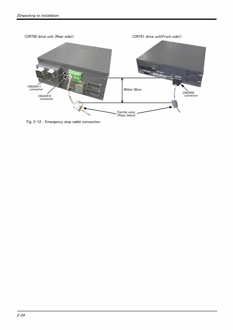
For external emergency stop, connect to the connector at the front of the drive unit (reference Fig. 2-12). When shipped from the factory, external emergency stop input, door switch input, and the enabling device terminal, are opened (contacts not shorted) as shown on Page 25 "Fig. 2-13: External emergency stop connection (CR750 drive unit)" and on Page 28 "Fig. 2-16: External emergency stop connection (CR751 drive unit)". Customers should be sure to prepare the external emergency stop, door switch and enabling device, etc. and use the robot while these are connected. Connection procedures are shown below.
[Caution] The emergency stop circuit is duplicated inside the controller. For the emergency stop switch, use a double contact-type switch, and be sure to connect both of the contacts to the connector pins as shown below in order to ensure the wiring is duplicated. An error cannot be reset if only one of the pins is connected.
1) Please prepare the emergency stop switch, door switch and enabling device.2) Connect the contacts of each switch to the contacts as shown below:
a) External emergency switch
・ CR750 drive unit.............CNUSR11 connector "between 3 and 4" and CNUSR12 connector "between 3 and 4"
・ CR751 drive unit.............CNUSR1 connector "between 2 and 27" and "between 7 and 32"
b) Door switch
・ CR750 drive unit.............CNUSR11 connector "between 7 and 8" and CNUSR12 connector "between 7 and 8"
・ CR751 drive unit.............CNUSR1 connector "between 4 and 29" and "between 9 and 34"
c) Enabling device
・ CR750 drive unit.............CNUSR11 connector "between 9 and 10" and CNUSR12 connector "between 9 and 12"
・ CR751 drive unit.............CNUSR1 connector "between 5 and 30" and "between 10 and 35"
[Caution] Be sure to use a shield cable for the emergency stop wiring cable. And when operating in an environment that is easily affected by noise, be sure to install the included ferrite core (model number: E04SR301334, manufacturer: Seiwa Electric Mfg. Co., Ltd.). Be sure to place the ferrite core in 30cm or less from the connecting terminal section.
Make sure there are no mistakes in the wiring. Connecting differently to the way specified in the manual can result in failures, such as the emergency stop not being released. In order to prevent from occurring, please be sure to check that all functions (such as the teaching box emergency stop, customer emergency stop, and door switch) are working properly after the wiring setup is completed.
When using several emergency stop switches, perform wiring carefully to make sure that each emergency stop switch functions independently. Check and make sure that the emergency stop does not function under an AND condition (when multiple emergency stop switches are ON at the same time).
CAUTION
CAUTION
2-24
2Unpacking to installation
Fig. 2-12 : Emergency stop cable connection
30cm以内
フェライトコア(2回通し)
<CR750 drive unit (Rear side)>
CNUSR11 connector
<CR751 drive unit(Front side)>
CNUSR12 connector
Ferrite core(Pass twice)
CNUSR2 connector
Within 30cm
2Unpacking to installation
2-25
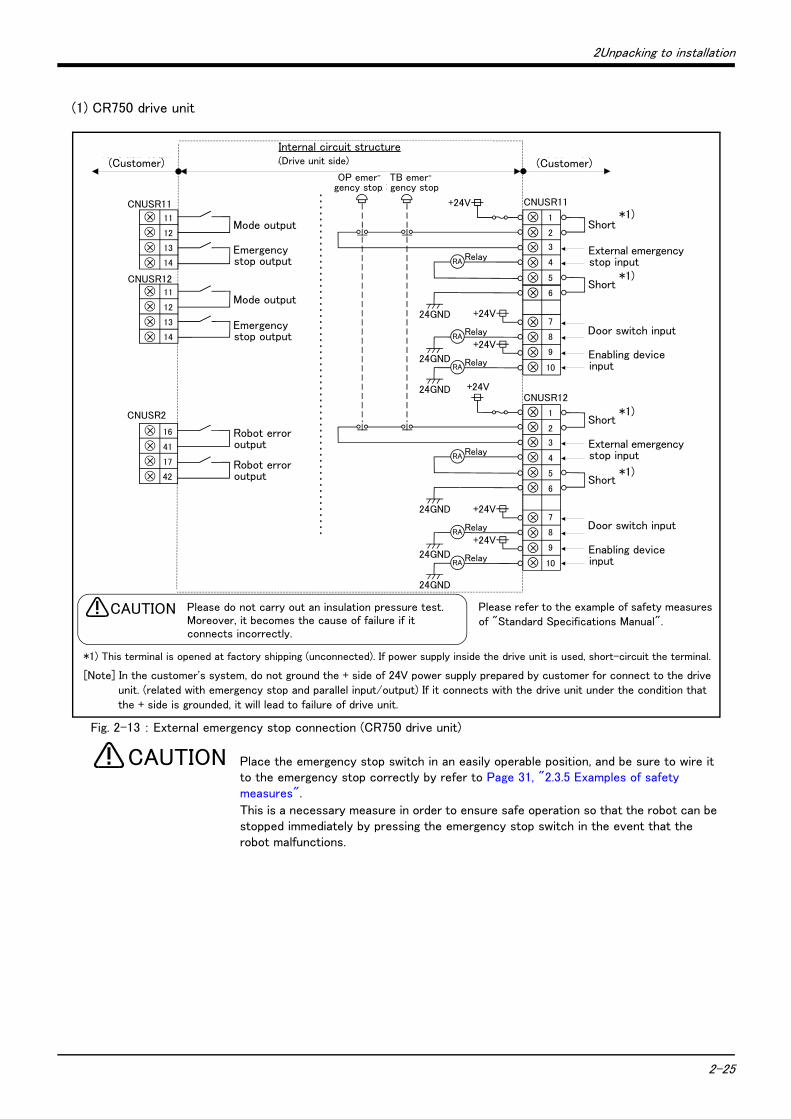
(1) CR750 drive unit
Fig. 2-13 : External emergency stop connection (CR750 drive unit)
Place the emergency stop switch in an easily operable position, and be sure to wire it to the emergency stop correctly by refer to Page 31, "2.3.5 Examples of safety measures".
This is a necessary measure in order to ensure safe operation so that the robot can be stopped immediately by pressing the emergency stop switch in the event that the robot malfunctions.
CNUSR11
CNUSR2
内部回路構成(お客様配線側) (コントローラ側)
警告 絶縁耐圧試験は行なわないでください。また誤って接続した場合は故障の原因となります。
10
9
8
7
3
4
2
CNUSR11+24V
Relay
+24V
24GND
24GND
24GND
RA+24V
RelayRA
RelayRA
外部非常停止入力
ドアスイッチ入力
イネーブリングデバイス入力
TB非常停止
+24V
Relay
+24V
24GND
24GND
24GND
RA+24V
RelayRA
RelayRA
14
13
12
11
17
41
16
モード出力
非常停止出力
ロボットエラー出力外部非常停止入力
ドアスイッチ入力
イネーブリングデバイス入力
(お客様配線側)
短絡
短絡
短絡
短絡
モード出力
非常停止出力
ロボットエラー出力
CNUSR12
14
13
12
11
1
5
6
10
9
8
7
3
4
2
1
5
6
CNUSR12
OP非常停止
Please refer to the example of safety measures of "Standard Specifications Manual".
内部回路構成( ド ラ イブユニ ッ ト 側 )
Please do not carry out an insulation pressure test.Moreover, it becomes the cause of failure if it connects incorrectly.
CAUTION
Internal circuit structure(Drive unit side)(Customer) (Customer)
Mode output
Mode output
Robot error output
Robot error output
Emergency stop output
Emergency stop output
Short
External emergency stop input
Short
Door switch input
Enabling device input
Short
External emergency stop input
Short
Door switch input
Enabling device input
TB emer-gency stop
OP emer-gency stop
*1) This terminal is opened at factory shipping (unconnected). If power supply inside the drive unit is used, short-circuit the terminal.
*1)
*1)
*1)
*1)
[Note] In the customer's system, do not ground the + side of 24V power supply prepared by customer for connect to the drive unit. (related with emergency stop and parallel input/output) If it connects with the drive unit under the condition that the + side is grounded, it will lead to failure of drive unit.
CAUTION
2-26
2Unpacking to installation
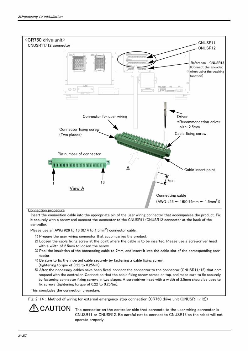
Fig. 2-14 : Method of wiring for external emergency stop connection (CR750 drive unit (CNUSR11/12))
The connector on the controller side that connects to the user wiring connector is CNUSR11 or CNUSR12. Be careful not to connect to CNUSR13 as the robot will not operate properly.
<CR750 drive unit>CNUSR11/12 connector
CNUSR11
CNUSR12
Cable fixing screw
Cable insert point
7mm
A
View A
161
Connector fixing screw
(Two places)
Pin number of connector
Connecting cable
(AWG #26 ~ 16(0.14mm ~ 1.5mm2))
Connector for user wiring
Reference: CNUSR13 (Connect the encoder, when using the tracking function)
Driver
*Recommendation driver size: 2.5mm.
Connection procedureInsert the connection cable into the appropriate pin of the user wiring connector that accompanies the product. Fix it securely with a screw and connect the connector to the CNUSR11/CNUSR12 connector at the back of the controller.
Please use an AWG #26 to 16 (0.14 to 1.5mm2) connector cable.
1) Prepare the user wiring connector that accompanies the product.2) Loosen the cable fixing screw at the point where the cable is to be inserted. Please use a screwdriver head
with a width of 2.5mm to loosen the screw.3) Peel the insulation of the connecting cable to 7mm, and insert it into the cable slot of the corresponding con-
nector.4) Be sure to fix the inserted cable securely by fastening a cable fixing screw.
(tightening torque of 0.22 to 0.25Nm)5) After the necessary cables save been fixed, connect the connector to the connector (CNUSR11/12) that cor-
respond with the controller. Connect so that the cable fixing screw comes on top, and make sure to fix securely by fastening connector fixing screws in two places. A screwdriver head with a width of 2.5mm should be used to fix screws (tightening torque of 0.22 to 0.25Nm).
This concludes the connection procedure.
CAUTION
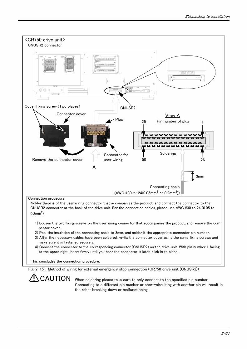
2Unpacking to installation
2-27
Fig. 2-15 : Method of wiring for external emergency stop connection (CR750 drive unit (CNUSR2))
When soldering please take care to only connect to the specified pin number. Connecting to a different pin number or short-circuiting with another pin will result in the robot breaking down or malfunctioning.
<CR750 drive unit>CNUSR2 connector
CNUSR2
3mm
A
View APlug
Connector cover
Connecting cable
(AWG #30 ~ 24(0.05mm2 ~ 0.2mm2))
Cover fixing screw (Two places)
Remove the connector cover
Pin number of plug25 1
50 26
SolderingConnector for user wiring
Connection procedureSolder thepins of the user wiring connector that accompanies the product, and connect the connector to the CNUSR2 connector at the back of the drive unit. For the connection cables, please use AWG #30 to 24 (0.05 to
0.2mm2).
1) Loosen the two fixing screws on the user wiring connector that accompanies the product, and remove the con-
nector cover.2) Peel the insulation of the connecting cable to 3mm, and solder it the appropriate connector pin number.3) After the necessary cables have been soldered, re-fix the connector cover using the same fixing screws and
make sure it is fastened securely.4) Connect the connector to the corresponding connector (CNUSR2) on the drive unit. With pin number 1 facing
to the upper right, insert firmly until you hear the connector’s latch click in to place.
This concludes the connection procedure.
CAUTION
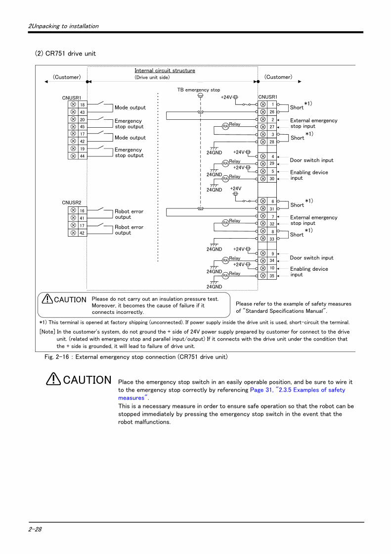
2-28
2Unpacking to installation
(2) CR751 drive unit
Fig. 2-16 : External emergency stop connection (CR751 drive unit)
Place the emergency stop switch in an easily operable position, and be sure to wire it to the emergency stop correctly by referencing Page 31, "2.3.5 Examples of safety measures".
This is a necessary measure in order to ensure safe operation so that the robot can be stopped immediately by pressing the emergency stop switch in the event that the robot malfunctions.
CNUSR1
CNUSR2
内部回路構成(お客様配線側) (コントローラ側)
警告 絶縁耐圧試験は行なわないでください。また誤って接続した場合は故障の原因となります。
CNUSR1+24V
Relay
+24V
24GND
24GND
24GND
RA+24V
RelayRA
RelayRA
外部非常停止入力
ドアスイッチ入力
イネーブリングデバイス入力
TB非常停止
+24V
Relay
+24V
24GND
24GND
24GND
RA+24V
RelayRA
RelayRA
43
18
17
41
16
モード出力
非常停止出力
ロボットエラー出力外部非常停止入力
ドアスイッチ入力
イネーブリングデバイス入力
(お客様配線側)
短絡
短絡
短絡
短絡
モード出力
非常停止出力
ロボットエラー出力
44
19
42
17
20
45 27
28
4
29
5
30
3
2
1
26
32
33
9
34
35
8
7
6
31
10
Please refer to the example of safety measures of "Standard Specifications Manual".
Please do not carry out an insulation pressure test.Moreover, it becomes the cause of failure if it connects incorrectly.
CAUTION
Internal circuit structure(Drive unit side) (Customer)
Mode output
Mode output
Robot error output
Robot error output
Emergency stop output
Emergency stop output
Short
External emergency stop input
Short
Door switch input
Enabling device input
Short
External emergency stop input
Short
Door switch input
Enabling device input
TB emergency stop
(Customer)
*1) This terminal is opened at factory shipping (unconnected). If power supply inside the drive unit is used, short-circuit the terminal.
*1)
*1)
*1)
*1)
[Note] In the customer's system, do not ground the + side of 24V power supply prepared by customer for connect to the drive unit. (related with emergency stop and parallel input/output) If it connects with the drive unit under the condition that the + side is grounded, it will lead to failure of drive unit.
CAUTION
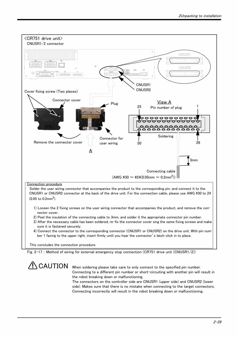
2Unpacking to installation
2-29
Fig. 2-17 : Method of wiring for external emergency stop connection (CR751 drive unit (CNUSR1/2))
When soldering please take care to only connect to the specified pin number. Connecting to a different pin number or short-circuiting with another pin will result in the robot breaking down or malfunctioning.The connectors on the controller side are CNUSR1 (upper side) and CNUSR2 (lower side). Makes sure that there is no mistake when connecting to the target connectors. Connecting incorrectly will result in the robot breaking down or malfunctioning.
<CR751 drive unit>CNUSR1/2 connector
CNUSR1
CNUSR2
3mm
A
View APlugConnector cover
Connecting cable
(AWG #30 ~ #24(0.05mm ~ 0.2mm2))
Connection procedureSolder the user wiring connector that accompanies the product to the corresponding pin, and connect it to the CNUSR1 or CNUSR2 connector at the back of the drive unit. For the connection cable, please use AWG #30 to 24
(0.05 to 0.2mm2).
1) Loosen the 2 fixing screws on the user wiring connector that accompanies the product, and remove the con-
nector cover.2) Peel the insulation of the connecting cable to 3mm, and solder it the appropriate connector pin number.3) After the necessary cable has been soldered, re-fix the connector cover sing the same fixing screws and make
sure it is fastened securely.4) Connect the connector to the corresponding connector (CNUSR1 or CNUSR2) on the drive unit. With pin num-
ber 1 facing to the upper right, insert firmly until you hear the connector’s latch click in to place.
This concludes the connection procedure.
Cover fixing screw (Two places)
Remove the connector cover
Pin number of plug25 1
50 26
SolderingConnector for user wiring
CAUTION
2-30
2Unpacking to installation
Place the emergency stop switch in an easily operable position, and be sure to wire it to the emergency stop correctly by referencing Page 31, "2.3.5 Examples of safety measures".
This is a necessary measure in order to ensure safe operation so that the robot can be stopped immediately by pressing the emergency stop switch in the event that the robot malfunctions.
When connecting the power line to the connector, be careful not to cause a short circuit with wires sticking out from adjacent poles. And on the CR750 controller//drive unit, please do not apply a solder coating to core wires to be inserted in the power line of connectors CNUSR11 to 13. In some cases solder coating can result in contact failure.
Examples of Safety Measures are shown below. Please reference these diagrams and implement adequate safety measures. The diagrams show normal conditions in which the emergency stop has not been triggered.
CAUTION
CAUTION
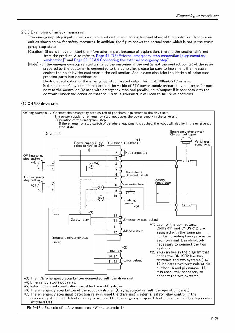
2Unpacking to installation
2-31
2.3.5 Examples of safety measuresTwo emergency-stop input circuits are prepared on the user wiring terminal block of the controller. Create a cir-
cuit as shown below for safety measures. In addition, the figure shows the normal state which is not in the emer-
gency stop state.
[Caution] Since we have omitted the information in part because of explanation, there is the section different from the product. Also refer to Page 41, "(3) External emergency stop connection [supplementary explanation]" and Page 23, "2.3.4 Connecting the external emergency stop".
[Note] ・ In the emergency-stop related wiring by the customer, if the coil (is not the contact points) of the relay prepared by the customer is connected to the controller, please be sure to implement the measure against the noise by the customer in the coil section. And, please also take the lifetime of noise sup-pression parts into consideration.
・ Electric specification of the emergency-stop-related output terminal: 100mA/24V or less.・ In the customer's system, do not ground the + side of 24V power supply prepared by customer for con-
nect to the controller. (related with emergency stop and parallel input/output) If it connects with the controller under the condition that the + side is grounded, it will lead to failure of controller.
(1) CR750 drive unit
Fig.2-18 : Example of safety measures (Wiring example 1)
<Wiring example 1>: Connect the emergency stop switch of peripheral equipment to the drive unit. The power supply for emergency stop input uses the power supply in the drive uni.<Operation of the emergency stop>
If the emergency stop switch of peripheral equipment is pushed, the robot will also be in the emergency stop state.
非常停止スイッチ(2接点タイプ)
周辺装置
安全柵のドア
1
CNUSR11/CNUSR12
CNUSR2
内部非常停止回路
非常停止出力
モード出力
OP非常停止ボタン
RA
RA
RA
}
ドアスイッチ入力
イネーブリングデバイス
2
3
4
5
6
7
8
9
10
13
14
11
12
16/17
41/42 エラー出力}
短絡
短絡
}
TB非常停止ボタン
内部電源 24V
安全リレー
*1) Each of the connectors, CNUSR11 and CNUSR12, are assigned with the same pin number, creating two systems for each terminal. It is absolutely necessary to connect the two systems.
*2) You can see in the diagram that connector CNUSR2 has two terminals and two systems (16/17 indicates two terminals at pin number 16 and pin number 17). It is absolutely necessary to connect the two systems.
Drive unit
*3) The T/B emergency stop button connected with the drive unit.*4) Emergency stop input relay.*5) Refer to Standard specification manual for the enabling device.*6) The emergency stop button of the robot controller. (Only specification with the operation panel.)*7) The emergency stop input detection relay is used the drive unit’s internal safety relay control. If the
emergency stop input detection relay is switched OFF, emergency stop is detected and the safety relay is also switched OFF.
Power supply in the robot controller 24V
OP Emergency stop button
TB Emergency stop button
Not connected
Door switch input
Enabling device
Mode output
Error output
Emergency stop outputSafety relay
Internal emergency stop circuit
Emergency stop switch (2- contact type)
Peripheral equipment
Safety fence door
*1)
*2)
*3)
*6) *4)
*5)
*7)
Short circuit(Short-circuited)

2-32
2Unpacking to installation
Fig.2-19 : Example of safety measures (Wiring example 2)
非常停止スイッチ(2接点タイプ)
周辺装置
安全柵のドア
周辺装置側電源24V
CNUSR2
内部非常停止回路
未接続
非常停止出力
モード出力
RA
RA
RA
}
ドアスイッチ入力
イネーブリングデバイス
16/17
41/42 エラー出力}
}
1
CNUSR11/CNUSR12
2
3
4
5
6
7
8
9
10
13
14
11
12
OP非常停止ボタン
TB非常停止ボタン
内部電源 24V
安全リレー
*1) Each of the connectors, CNUSR11 and CNUSR12, are assigned with the same pin number, creating 2 systems in each terminal. It is absolutely necessary to connect the 2 systems.
*2) You can see in the diagram that connector CNUSR2 has 2 terminals and 2 systems (16/17 indicates 2 terminals at pin number 16 and pin number 17). It is absolutely necessary to connect the 2 systems.
<Wiring example 2>: Connect the emergency stop switch of peripheral equipment to the drive unit. The power supply for emergency stop input uses the power supply of peripheral equipment. <Operation of the emergency stop>
If the emergency stop switch of peripheral equipment is pushed, the robot will also be in the emergency stop state.
Drive unit
*3) The T/B emergency stop button connected with the drive unit.*4) Emergency stop input relay.*5) Refer to Standard specification manual for the enabling device.*6) The emergency stop button of the robot controller.
(Only specification with the operation panel.)*7) The emergency stop input detection relay uses the drive unit’s internal safety relay control. If the
emergency stop input detection relay is switched OFF, emergency stop is detected and the safety relay is also switched OFF.
Power supply in the robot controller 24V
OP Emergency stop button
TB Emergency stop button
Not connected
Door switch input
Enabling device
Mode output
Error output
Emergency stop outputSafety relay
Internal emergency stop circuit
Emergency stop switch (2- contact type)
Peripheral equipment
Safety fence door
Power supply in the Peripheral equipment 24V
*1)
*2)
*3)
*6) *4)
*5)
*7)

2Unpacking to installation
2-33
Fig.2-20 : Example of safety measures (Wiring example 3)
<Wiring example 3>: Connect the emergency stop switch, door switch, and enabling device of peripheral equipment to the drive unit. The power supply for emergency stop input uses the power supply of peripheral equipment. Monitor the emergency stop state by the peripheral equipment side.<Operation of the emergency stop>
If the emergency stop switch of peripheral equipment is pushed, the robot will also be in the emergency stop state. And, if the emergency stop switch of OP or T/B is pushed in the state of the power of drive unit OFF, peripheral equipment state can be the emergency stop also.
非常停止スイッチ(2接点タイプ)
周辺装置
安全柵のドア
周辺装置側電源24V
監視
周 辺 装 置 側 内 部 回 路
CNUSR2
内部非常停止回路
未接続
非常停止出力
モード出力
RA
RA
RA
}
ドアスイッチ入力
イネーブリングデバイス
16/17
41/42 エラー出力}
監視
1
CNUSR11/CNUSR12
2
3
4
5
6
7
8
9
10
13
14
11
12
OP非常停止ボタン
TB非常停止ボタン
内部電源 24V
安全リレー
Drive unit
*1) Each of the connectors, CNUSR11 and CNUSR12, are assigned with the same pin number, creating 2 systems in each terminal. It is absolutely necessary to connect the 2 systems.
*2) You can see in the diagram that connector CNUSR2 has 2 terminals and 2 systems (16/17 indicates 2 terminals at pin number 16 and pin number 17). It is absolutely necessary to connect the 2 systems.
*4) Emergency stop input relay.*5) Refer to Standard specification manual for the enabling device.*6) The emergency stop button of the robot controller.
(Only specification with the operation panel.)*7) The emergency stop input detection relay uses the drive unit’s internal safety relay control. If the
emergency stop input detection relay is switched OFF, emergency stop is detected and the safety relay is also switched OFF.
Power supply in the robot controller 24V
OP Emergency stop button
TB Emergency stop button
Not connected
Door switch input
Enabling device
Mode output
Error output
Emergency stop outputSafety relay
Internal emergency stop circuit
Emergency stop switch (2- contact type)
Peripheral equipment
Safety fence door
Power sup-ply 24V
*1)
*2)
*3)
*6) *4)
*5)
*7)
Monitor
Monitor
Circuit
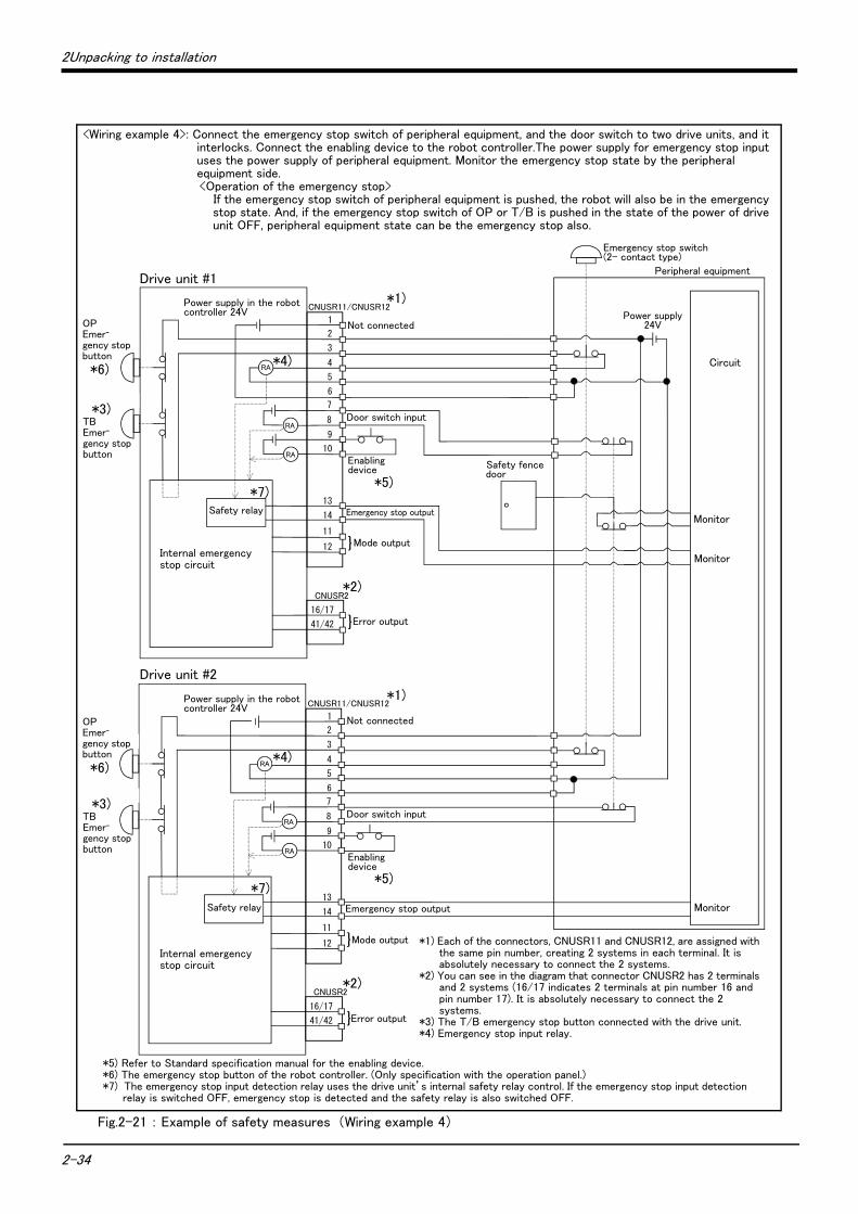
2-34
2Unpacking to installation
Fig.2-21 : Example of safety measures (Wiring example 4)
OP非常停止ボタン
TB非常停止ボタン
周辺装置の非常停止出力
周辺装置内部非常停止回路
周辺装置
非常停止スイッチ(4接点タイプ)
安全柵のドア
ドアスイッチ出力
監視
周辺装置の非常停止出力
周辺装置側電源24V
CNUSR2
内部非常停止回路
未接続
非常停止出力
モード出力
RA
RA
RA
}
ドアスイッチ入力
16/17
41/42 エラー出力}
監視
監視
CNUSR2
内部非常停止回路
未接続
非常停止出力
モード出力
RA
RA
RA
}
ドアスイッチ入力
16/17
41/42 エラー出力}
1
CNUSR11/CNUSR12
2
3
4
5
6
7
8
9
10
13
14
11
12
1
CNUSR11/CNUSR12
2
3
4
5
6
7
8
9
10
13
14
11
12
OP非常停止ボタン
TB非常停止ボタン
イネーブリングデバイス
イネーブリングデバイス
内部電源 24V
内部電源 24V
安全リレー
安全リレー
Drive unit #1
*5) Refer to Standard specification manual for the enabling device.*6) The emergency stop button of the robot controller. (Only specification with the operation panel.)*7) The emergency stop input detection relay uses the drive unit’s internal safety relay control. If the emergency stop input detection
relay is switched OFF, emergency stop is detected and the safety relay is also switched OFF.
Power supply in the robot controller 24V
OP Emer-gency stop button
TB Emer-gency stop button
Not connected
Enabling device
Mode output
Error output
Emergency stop outputSafety relay
Internal emergency stop circuit
Emergency stop switch (2- contact type)
Peripheral equipment
Safety fence door
Power supply 24V
*1)
*2)
*3)
*6)*4)
*5)*7)
Monitor
Monitor
Circuit
Door switch input
Not connected
<Wiring example 4>: Connect the emergency stop switch of peripheral equipment, and the door switch to two drive units, and it interlocks. Connect the enabling device to the robot controller.The power supply for emergency stop input uses the power supply of peripheral equipment. Monitor the emergency stop state by the peripheral equipment side.<Operation of the emergency stop>
If the emergency stop switch of peripheral equipment is pushed, the robot will also be in the emergency stop state. And, if the emergency stop switch of OP or T/B is pushed in the state of the power of drive unit OFF, peripheral equipment state can be the emergency stop also.
Monitor
Door switch input
Enabling device
Emergency stop output
Power supply in the robot controller 24V
Safety relay
TB Emer-gency stop button
*3)
OP Emer-gency stop button
*6)
Drive unit #2
*1) Each of the connectors, CNUSR11 and CNUSR12, are assigned with the same pin number, creating 2 systems in each terminal. It is absolutely necessary to connect the 2 systems.
*2) You can see in the diagram that connector CNUSR2 has 2 terminals and 2 systems (16/17 indicates 2 terminals at pin number 16 and pin number 17). It is absolutely necessary to connect the 2 systems.
*3) The T/B emergency stop button connected with the drive unit.*4) Emergency stop input relay.
Mode output
Error output
Internal emergency stop circuit
*1)
*2)
*7)
*4)
*5)
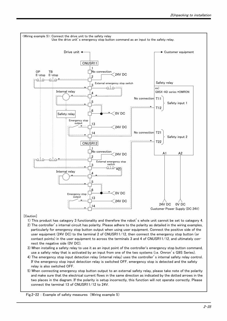
2Unpacking to installation
2-35
Fig.2-22 : Example of safety measures (Wiring example 5)
OPE-stop
1
2
3
4
5
6
CNUSR11
内部リレー
TBE-stop
0V DC
1
2
3
4
5
60V DC
内部リレー
T12
T11
T22
T21
No connection
No connection
安全入力1
安全入力2
24V DC 0V DC
例)オムロン社 G9SX-AD
安全リレー
お客様電源(DC 24V)
A1 A2
お客様装置
24V DC
外部非常停止スイッチ
13
14
24V DC
24V DC
外部非常停止スイッチ
13
14
24V DC
安全リレー
非常停止出力
非常停止出力
CNUSR12
No connection
No connection
Drive unit
Safety relay
*2)
<Wiring example 5>: Connect the drive unit to the safety relay Use the drive unit’s emergency stop button command as an input to the safety relay.
Internal relay
Emergency stop output
Internal relay
External emergency stop switch
External emergency stop switch
Emergency stop output
Customer equipment
Safety relay
ex)G9SX-AD series *OMRON
Safety input 1
Safety input 2
Customer Power Supply (DC 24V)
[Caution]
1) This product has category 3 functionality and therefore the robot’s whole unit cannot be set to category 4.2) The controller’s internal circuit has polarity. Please adhere to the polarity as detailed in the wiring examples,
particularly for emergency stop button output when using user equipment. Connect the positive side of the user equipment (24V DC) to the terminal 2 of CNUSR11/12, then connect the emergency stop button (or contact points) in the user equipment to across the terminals 3 and 4 of CNUSR11/12, and ultimately con-
nect the negative side (0V DC).3) When installing a safety relay to use it as an input point of the controller's emergency stop button command,
use a safety relay that is activated by an input from one of the two systems (i.e. Omron’s G9S Series).4) The emergency stop input detection relay (internal relay) uses the controller’s internal safety relay control.
If the emergency stop input detection relay is switched OFF, emergency stop is detected and the safety relay is also switched OFF.
5) When connecting emergency stop button output to an external safety relay, please take note of the polarity and make sure that the electrical current flows in the same direction as indicated by the dotted arrows in the two places in the diagram. If the polarity is setup incorrectly, this function will not operate correctly. Please connect the terminal 13 of CNUSR11/12 to 24V.
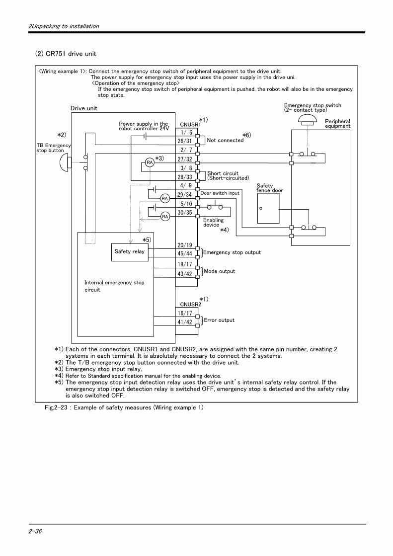
2-36
2Unpacking to installation
(2) CR751 drive unit
Fig.2-23 : Example of safety measures (Wiring example 1)
非常停止スイッチ(2接点タイプ)
周辺装置
安全柵のドア
1/ 6
CNUSR1
CNUSR2
内部非常停止回路
コントローラ
非常停止出力
モード出力
TB非常停止ボタン
RA
RA
RA
}
ドアスイッチ入力
イネーブリングデバイス
26/31
2/ 7
27/32
3/ 8
28/33
4/ 9
29/34
5/10
30/35
20/19
45/44
18/17
43/42
16/17
41/42 エラー出力}
短絡
短絡
}安全リレー
内部電源 24V
<Wiring example 1>: Connect the emergency stop switch of peripheral equipment to the drive unit. The power supply for emergency stop input uses the power supply in the drive uni.<Operation of the emergency stop>
If the emergency stop switch of peripheral equipment is pushed, the robot will also be in the emergency stop state.
Drive unit
*1) Each of the connectors, CNUSR1 and CNUSR2, are assigned with the same pin number, creating 2 systems in each terminal. It is absolutely necessary to connect the 2 systems.
*2) The T/B emergency stop button connected with the drive unit.*3) Emergency stop input relay.*4) Refer to Standard specification manual for the enabling device.*5) The emergency stop input detection relay uses the drive unit’s internal safety relay control. If the
emergency stop input detection relay is switched OFF, emergency stop is detected and the safety relay is also switched OFF.
Power supply in the robot controller 24V
TB Emergency stop button
Not connected
Door switch input
Enabling device
Mode output
Error output
Emergency stop outputSafety relay
Internal emergency stop circuit
Emergency stop switch (2- contact type)
Peripheral equipment
Safety fence door
*1)
*1)
*4)
Short circuit(Short-circuited)
*2)
*3)
*5)
*6)
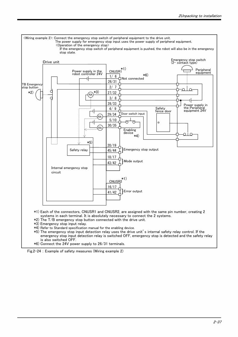
2Unpacking to installation
2-37
Fig.2-24 : Example of safety measures (Wiring example 2)
非常停止スイッチ(2接点タイプ)
周辺装置
安全柵のドア
周辺装置側電源24V
1/ 6
CNUSR1
CNUSR2
内部非常停止回路
コントローラ
未接続
非常停止出力
モード出力
TB非常停止ボタン
RA
RA
RA
}
ドアスイッチ入力
イネーブリングデバイス
26/31
2/ 7
27/32
3/ 8
28/33
4/ 9
29/34
5/10
30/35
16/17
41/42 エラー出力}
}20/19
45/44
18/17
43/42
安全リレー
内部電源 24V
<Wiring example 2>: Connect the emergency stop switch of peripheral equipment to the drive unit. The power supply for emergency stop input uses the power supply of peripheral equipment. <Operation of the emergency stop>
If the emergency stop switch of peripheral equipment is pushed, the robot will also be in the emergency stop state.
Drive unit
Power supply in the robot controller 24V
TB Emergency stop button
Not connected
Door switch input
Enabling device
Mode output
Error output
Emergency stop outputSafety relay
Internal emergency stop circuit
Emergency stop switch (2- contact type)
Safety fence door
Power supply in the Peripheral equipment 24V
*1)
*1)
*3)
*4)
*5)
Peripheral equipment
*1) Each of the connectors, CNUSR1 and CNUSR2, are assigned with the same pin number, creating 2 systems in each terminal. It is absolutely necessary to connect the 2 systems.
*2) The T/B emergency stop button connected with the drive unit.*3) Emergency stop input relay.*4) Refer to Standard specification manual for the enabling device.*5) The emergency stop input detection relay uses the drive unit’s internal safety relay control. If the
emergency stop input detection relay is switched OFF, emergency stop is detected and the safety relay is also switched OFF.
*6) Connect the 24V power supply to 26/31 terminals.
*2)
*6)
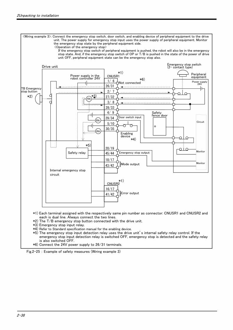
2-38
2Unpacking to installation
Fig.2-25 : Example of safety measures (Wiring example 3)
非常停止スイッチ(2接点タイプ)
周辺装置
安全柵のドア
周辺装置側電源24V
監視
周 辺 装 置 側 内 部 回 路
1/ 6
CNUSR1
CNUSR2
内部非常停止回路
コントローラ
未接続
非常停止出力
モード出力
TB非常停止ボタン
RA
RA
RA
}
ドアスイッチ入力
イネーブリングデバイス
26/31
2/ 7
27/32
3/ 8
28/33
4/ 9
29/34
5/10
30/35
16/17
41/42 エラー出力}
20/19
45/44
18/17
43/42監視
安全リレー
内部電源 24V
Drive unit
Power supply in the robot controller 24V
TB Emergency stop button
Not connected
Door switch input
Enabling device
Mode output
Error output
Emergency stop outputSafety relay
Internal emergency stop circuit
Emergency stop switch (2- contact type)
Safety fence door
Power supply 24V
*1)
*1)
*3)
*4)
*5)
Peripheral equipment
*1) Each terminal assigned with the respectively same pin number as connector: CNUSR1 and CNUSR2 and each is dual line. Always connect the two lines.
*2) The T/B emergency stop button connected with the drive unit.*3) Emergency stop input relay.*4) Refer to Standard specification manual for the enabling device.*5) The emergency stop input detection relay uses the drive unit’s internal safety relay control. If the
emergency stop input detection relay is switched OFF, emergency stop is detected and the safety relay is also switched OFF.
*6) Connect the 24V power supply to 26/31 terminals.
*2)
*6)
<Wiring example 3>: Connect the emergency stop switch, door switch, and enabling device of peripheral equipment to the drive unit. The power supply for emergency stop input uses the power supply of peripheral equipment. Monitor the emergency stop state by the peripheral equipment side.<Operation of the emergency stop>
If the emergency stop switch of peripheral equipment is pushed, the robot will also be in the emergency stop state. And, if the emergency stop switch of OP or T/B is pushed in the state of the power of drive unit OFF, peripheral equipment state can be the emergency stop also.
Monitor
Monitor
Circuit
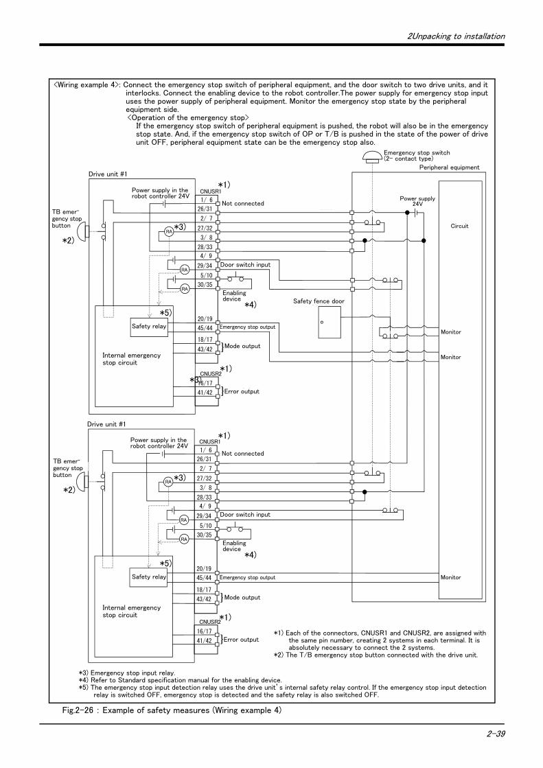
2Unpacking to installation
2-39
Fig.2-26 : Example of safety measures (Wiring example 4)
周辺装置の非常停止出力
周辺装置内部非常停止回路
周辺装置
非常停止スイッチ(4接点タイプ)
安全柵のドア
ドアスイッチ出力
監視
周辺装置の非常停止出力
周辺装置側電源24V
1/ 6
CNUSR1
CNUSR2
内部非常停止回路
コントローラ #1
未接続
非常停止出力
モード出力
TB非常停止ボタン
RA
RA
RA
}
内部電源 24V
ドアスイッチ入力
イネーブリングデバイス
26/31
2/ 7
27/32
3/ 8
28/33
4/ 9
29/34
5/10
30/35
16/17
41/42 エラー出力}
監視
監視
1/ 6
CNUSR1
CNUSR2
内部非常停止回路
コントローラ #2
未接続
非常停止出力
モード出力
TB非常停止ボタン
RA
RA
RA
}
ドアスイッチ入力
イネーブリングデバイス
26/31
2/ 7
27/32
3/ 8
28/33
4/ 9
29/34
5/10
30/35
16/17
41/42 エラー出力}
20/19
45/44
18/17
43/42
20/19
45/44
18/17
43/42
安全リレー
安全リレー
内部電源 24V
Drive unit #1
Power supply in the robot controller 24V
TB emer-gency stop button
Not connected
Door switch input
Enabling device
Mode output
Error output
Emergency stop output
Safety relay
Internal emergency stop circuit
Emergency stop switch (2- contact type)
Safety fence door
Power supply 24V
*1)
*1)
*3)
*4)
*5)
Peripheral equipment
*3) Emergency stop input relay.*4) Refer to Standard specification manual for the enabling device.*5) The emergency stop input detection relay uses the drive unit’s internal safety relay control. If the emergency stop input detection
relay is switched OFF, emergency stop is detected and the safety relay is also switched OFF.
*2)
Monitor
Monitor
<Wiring example 4>: Connect the emergency stop switch of peripheral equipment, and the door switch to two drive units, and it interlocks. Connect the enabling device to the robot controller.The power supply for emergency stop input uses the power supply of peripheral equipment. Monitor the emergency stop state by the peripheral equipment side.<Operation of the emergency stop>
If the emergency stop switch of peripheral equipment is pushed, the robot will also be in the emergency stop state. And, if the emergency stop switch of OP or T/B is pushed in the state of the power of drive unit OFF, peripheral equipment state can be the emergency stop also.
*1)
*1)
Drive unit #1
TB emer-gency stop button
*2)
Power supply in the robot controller 24V
Not connected
Door switch input
Mode output
Error output
Safety relay
*5)
Internal emergency stop circuit
Enabling device
*4)
Emergency stop output
Circuit
Monitor
*3)
*1) Each of the connectors, CNUSR1 and CNUSR2, are assigned with the same pin number, creating 2 systems in each terminal. It is absolutely necessary to connect the 2 systems.
*2) The T/B emergency stop button connected with the drive unit.
*3)

2-40
2Unpacking to installation
Fig.2-27 : Example of safety measures (Wiring example 5)
OPE-stop
1
26
2
27
3
28
CNUSR1
内部リレー
TBE-stop
0V DC
6
31
7
32
8
330V DC
内部リレー
T12
T11
T22
T21
No connection
No connection
安全入力1
安全入力2
24V DC 0V DC
例)オムロン社 G9SX-AD
安全リレー
お客様電源(DC 24V)
A1 A2
お客様装置
24V DC
外部非常停止スイッチ
20
45
24V DC
24V DC
外部非常停止スイッチ
19
44
24V DC
安全リレー
非常停止出力
非常停止出力
No connection
No connection
Drive unit
<Wiring example 5>: Connect the drive unit to the safety relay Use the drive unit’s emergency stop button to input safety relay.
Safety relay
Internal relay
Emergency stop output
External emergency stop switch
Customer equipment
Safety relay
ex)
G9SX-AD series *OMRON
Customer Power Supply (DC 24V)
Internal relay
Emergency stop output
External emergency stop switch
Safety input 1
Safety input 2
[Caution]
1) This product has category 3 functionality and therefore the robot’s whole unit cannot be set to category 4.2) The controller’s internal circuit has polarity. Please adhere to the polarity as detailed in the wiring examples,
particularly for emergency stop button output when using user equipment. Connect the positive side of the user equipment (24V DC) to the two terminals 26/31, then connect the emergency stop button (or contact points) in the user equipment to the 2-27 and 7-32 terminals, and ultimately connect to the negative side (0V DC).
3) Setup a safety relay on the user equipment, and when using to input the emergency stop button on the con-
troller, please only use a safety relay that functions when connecting the input to the one end of the 2 sys-
tems (i.e. Omron’s G9S Series).4) The emergency stop input detection relay (internal relay) uses the controller’s internal safety relay control.
If the emergency stop input detection relay is switched OFF, emergency stop is detected and the safety relay is also switched OFF.
5) When connecting emergency stop button output to an exterior safety relay, please take note of the polarity and make sure that the electrical current flows in the same direction as indicated by the dotted arrows in the two places in the diagram. If the polarity is setup incorrectly this function will not operate correctly. Please connect 20/19 terminal to 24V.
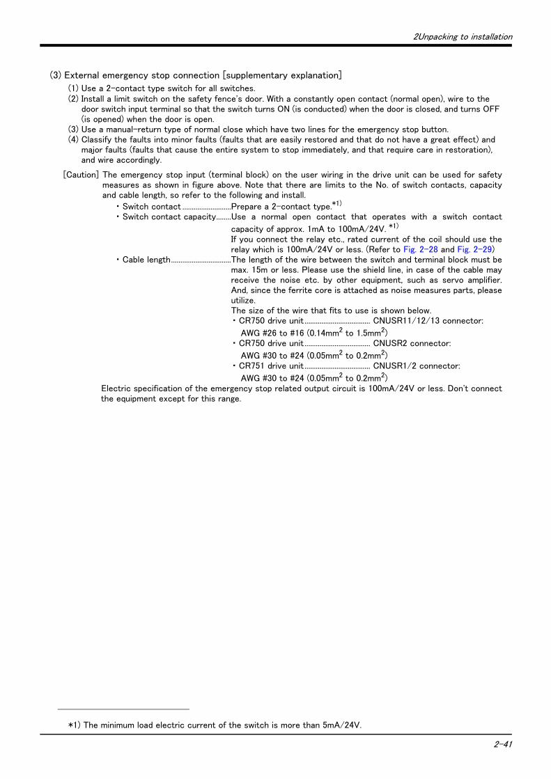
2Unpacking to installation
2-41
(3) External emergency stop connection [supplementary explanation]
(1) Use a 2-contact type switch for all switches.(2) Install a limit switch on the safety fence's door. With a constantly open contact (normal open), wire to the
door switch input terminal so that the switch turns ON (is conducted) when the door is closed, and turns OFF (is opened) when the door is open.
(3) Use a manual-return type of normal close which have two lines for the emergency stop button.(4) Classify the faults into minor faults (faults that are easily restored and that do not have a great effect) and
major faults (faults that cause the entire system to stop immediately, and that require care in restoration), and wire accordingly.
[Caution] The emergency stop input (terminal block) on the user wiring in the drive unit can be used for safetymeasures as shown in figure above. Note that there are limits to the No. of switch contacts, capacityand cable length, so refer to the following and install.
・ Switch contact ..........................Prepare a 2-contact type.*1)
・ Switch contact capacity........Use a normal open contact that operates with a switch contact
capacity of approx. 1mA to 100mA/24V. *1)
If you connect the relay etc., rated current of the coil should use therelay which is 100mA/24V or less. (Refer to Fig. 2-28 and Fig. 2-29)
・ Cable length................................The length of the wire between the switch and terminal block must bemax. 15m or less. Please use the shield line, in case of the cable mayreceive the noise etc. by other equipment, such as servo amplifier.And, since the ferrite core is attached as noise measures parts, pleaseutilize.The size of the wire that fits to use is shown below.・ CR750 drive unit ................................... CNUSR11/12/13 connector:
AWG #26 to #16 (0.14mm2 to 1.5mm2)・ CR750 drive unit ................................... CNUSR2 connector:
AWG #30 to #24 (0.05mm2 to 0.2mm2)・ CR751 drive unit ................................... CNUSR1/2 connector:
AWG #30 to #24 (0.05mm2 to 0.2mm2)Electric specification of the emergency stop related output circuit is 100mA/24V or less. Don't connectthe equipment except for this range.
*1) The minimum load electric current of the switch is more than 5mA/24V.
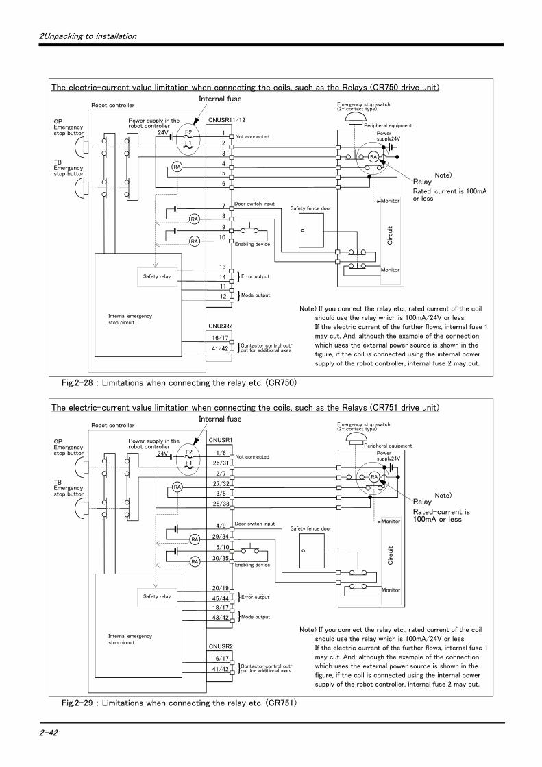
2-42
2Unpacking to installation
Fig.2-28 : Limitations when connecting the relay etc. (CR750)
Fig.2-29 : Limitations when connecting the relay etc. (CR751)
1
2
3
4
5
6
13
14
11
12
16/17
41/42
CNUSR11/12
CNUSR2
付加軸用コンタクタコントロール出力
内部非常停止回路
ロボットコントローラ
未接続
非常停止スイッチ(2接点タイプ)
エラー出力
モード出力
周辺装置
TB非常停止ボタン
OP非常停止ボタン
}
RA
RA
RA
}
}
ロボットコントローラ内電源 24V
ドアスイッチ入力安全柵のドア
イネーブリングデバイス
周辺装置側電源24V
監視
監視
周 辺 装 置 側 内 部 回 路
RA
安全リレー
7
8
9
10
F2
F1
The electric-current value limitation when connecting the coils, such as the Relays (CR750 drive unit)
RelayRated-current is 100mA or less
Note) If you connect the relay etc., rated current of the coil
should use the relay which is 100mA/24V or less. If the electric current of the further flows, internal fuse 1
may cut. And, although the example of the connection which uses the external power source is shown in the
figure, if the coil is connected using the internal power
supply of the robot controller, internal fuse 2 may cut.
Internal fuse
Not connected
Door switch inputSafety fence door
Enabling device
Error output
Mode output
Power supply in the robot controller
Robot controller
OPEmergency stop button
TBEmergency stop button
Safety relay
Internal emergency stop circuit
Emergency stop switch(2- contact type)
Peripheral equipment
Power supply24V
Contactor control out-put for additional axes
Monitor
Monitor
Circuit
Note)
1/6
26/31
2/7
27/32
3/8
28/33
16/17
41/42
CNUSR1
CNUSR2
付加軸用コンタクタコントロール出力
内部非常停止回路
ロボットコントローラ
未接続
非常停止スイッチ(2接点タイプ)
エラー出力
モード出力
周辺装置
TB非常停止ボタン
OP非常停止ボタン
}
RA
RA
RA
}
}
ロボットコントローラ内電源 24V
ドアスイッチ入力安全柵のドア
イネーブリングデバイス
周辺装置側電源24V
監視
監視
周 辺 装 置 側 内 部 回 路
RA
安全リレー
29/34
30/35
4/9
5/10
20/19
45/44
18/17
43/42
F2
F1
The electric-current value limitation when connecting the coils, such as the Relays (CR751 drive unit)
Note) If you connect the relay etc., rated current of the coil
should use the relay which is 100mA/24V or less. If the electric current of the further flows, internal fuse 1
may cut. And, although the example of the connection which uses the external power source is shown in the
figure, if the coil is connected using the internal power
supply of the robot controller, internal fuse 2 may cut.
RelayRated-current is 100mA or less
Internal fuse
Monitor
Monitor
Circuit
Emergency stop switch(2- contact type)
Peripheral equipment
Power supply24VNot connected
Door switch inputSafety fence door
Enabling device
Error output
Contactor control out-put for additional axes
Mode output
Power supply in the robot controller
Robot controller
Safety relay
Internal emergency stop circuit
OPEmergency stop button
TBEmergency stop button Note)

2Unpacking to installation
2-43
[Supplementary explanation regarding emergency stop circuit]The drive unit’s internal circuit is as shown in the below diagram. Be sure to build a circuit that properly
shuts off the emergency stop detection relay when the emergency stop button is pressed.
Be sure to perform wiring correctly. If there are mistakes in the wiring, the robot may not stop when the emergency stop button is pressed and there will be a risk of damage or personal injury occurring.After wiring, be sure to press each of the installed emergency stop switches and check whether the emergency stop circuit works properly.
Be sure to duplicate connection of the emergency stop, door switch and enabling switch. If not duplicated, these functions may fail due to a broken relay used by customer, etc.
OP非常停止
非常停止検出リレー
24VTB非常停止
+
-
OP非常停止検出
TB非常停止検出
外部非常停止検出
0V
入力
安全リレーSafety relay
Input
Emergency stop detection relay
TB emergency stop
OP emergency stop
OP emergency stop detection
TB emergency stop detection
External emergency stop detection
CAUTION
CAUTION
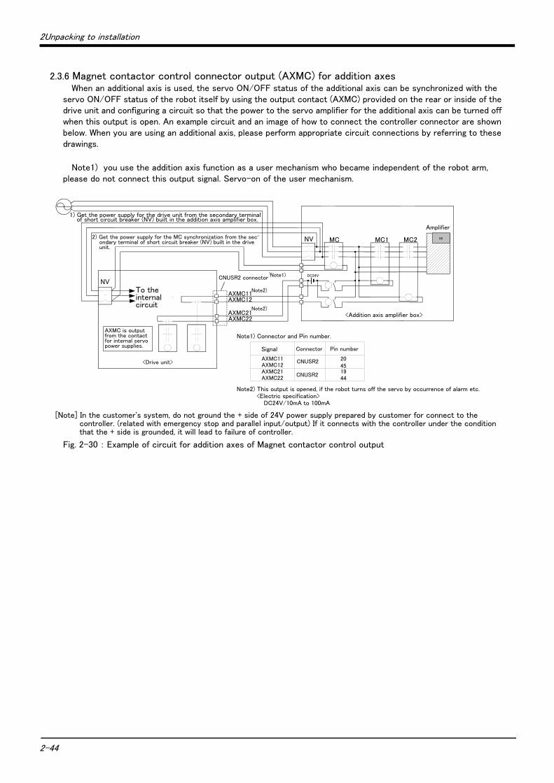
2-44
2Unpacking to installation
2.3.6 Magnet contactor control connector output (AXMC) for addition axesWhen an additional axis is used, the servo ON/OFF status of the additional axis can be synchronized with the
servo ON/OFF status of the robot itself by using the output contact (AXMC) provided on the rear or inside of the drive unit and configuring a circuit so that the power to the servo amplifier for the additional axis can be turned off when this output is open. An example circuit and an image of how to connect the controller connector are shown below. When you are using an additional axis, please perform appropriate circuit connections by referring to these drawings.
Note1) you use the addition axis function as a user mechanism who became independent of the robot arm, please do not connect this output signal. Servo-on of the user mechanism.
Fig. 2-30 : Example of circuit for addition axes of Magnet contactor control output
MC2NV MC MC1
内部回路へ
<ドライブユニット>
内部サーボ電源用コンタクタ接点より
AXMC出力
<走行軸(付加軸)アンプボックス>
NV
2)ドライブユニット内蔵漏電遮断器(NV)の2次側より、MC同期用電源を取り出す。
AXMC21注2)
1)付加軸アンプボックス内蔵漏電遮断器(NV)の2次側より、ドライブユニット電源を取り出す
AXMC11
注1)
88
CNUSRコネクタ
アンプ
DC24V
AXMC12
AXMC22
注2)
注1)コネクタとピン番号を以下に示します。
AXMC11AXMC12AXMC21AXMC22
注2)ロボットがアラームの発生などでサーボOFFしたとき、本出力(接点)が開放します。<接点容量>DC24V/10mA~100mA
信号名 ピン番号コネクタ
CNUSR2451944
20
CNUSR2
1) Get the power supply for the drive unit from the secondary terminal of short circuit breaker (NV) built in the addition axis amplifier box.
2) Get the power supply for the MC synchronization from the sec-ondary terminal of short circuit breaker (NV) built in the drive unit.
To the internal circuit
AXMC is output from the contact for internal servo power supplies.
<Drive unit>
CNUSR2 connector Note1)
Note2)
Note2)
Amplifier
<Addition axis amplifier box><Addition axis amplifier box>
Signal Connector Pin number
Note2) This output is opened, if the robot turns off the servo by occurrence of alarm etc.<Electric specification>
DC24V/10mA to 100mA
Note1) Connector and Pin number.
[Note] In the customer's system, do not ground the + side of 24V power supply prepared by customer for connect to the controller. (related with emergency stop and parallel input/output) If it connects with the controller under the condition that the + side is grounded, it will lead to failure of controller.
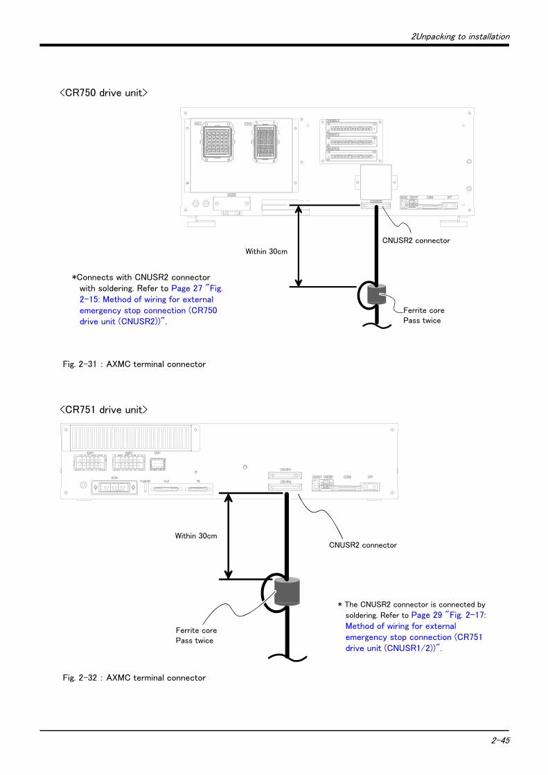
2Unpacking to installation
2-45
Fig. 2-31 : AXMC terminal connector
Fig. 2-32 : AXMC terminal connector
30cm以内
フェライトコア2回通し
CNUSR2コネクタ
*Connects with CNUSR2 connector with soldering. Refer to Page 27 "Fig. 2-15: Method of wiring for external emergency stop connection (CR750 drive unit (CNUSR2))".
Within 30cm
Ferrite corePass twice
CNUSR2 connector
<CR750 drive unit>
30cm以内
フェライトコア2回通し
CNUSR2コネクタ
* The CNUSR2 connector is connected by
soldering. Refer to Page 29 "Fig. 2-17: Method of wiring for external emergency stop connection (CR751 drive unit (CNUSR1/2))".
<CR751 drive unit>
Within 30cmCNUSR2 connector
Ferrite corePass twice
2-46 Setting the origin
2Unpacking to installation
2.3.7 Connecting to the robot armRefer to the separate manual "Robot arm setup and maintenance", and connect the drive unit and robot arm with machine cables.
2.4 Setting the origin
Refer to the separate manual "Robot arm setup and maintenance", and set the origin.
2.5 Confirming the operation
Refer to the separate manual "Robot arm setup and maintenance", and confirm the robot operation with jog operation.
3Installing the option devices
3-47
3 Installing the option devicesRefer to Page 53, "4.2.1 Installing and removing the T/B" for installing method of T/B. Refer to the separate "Standard Specifications" or each option's manual for the optional devices other than those described in this manual.
4-48
4Basic operations
4 Basic operations
In this chapter, the following items will be explained regarding the basic operations for handling the robot.
Handling the drive unit The functions of the various keys on the drive unit are explained.
Handling the teaching pendant The methods of installing/removing the T/B, and the functions of the various keys are explained.
Turning the power ON/OFF The items to confirm before turning on the controller power, and the methods of turning the power ON and OFF are explained.
Operating the robot with jog operation The methods for manually operating the robot arm using the teaching pendant are explained. This is mainly used for teaching work.
Opening and closing the hand The methods of opening and closing the hand using the teaching pendant are explained.
Program creation to automatic operation The procedures of creating the program are explained in order.
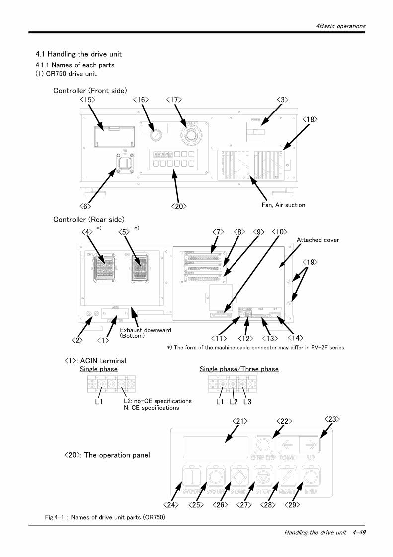
4Basic operations
Handling the drive unit 4-49
4.1 Handling the drive unit
4.1.1 Names of each parts(1) CR750 drive unit
Fig.4-1 : Names of drive unit parts (CR750)
<20>: The operation panel
<7> <10><8> <9>
<1><2>
Controller (Front side)
<19>
L1
Attached cover
Controller (Rear side)
L2: no-CE specificationsN: CE specifications
Exhaust downward(Bottom)
<5><4>*) *)
L1 L3L2
<1>: ACIN terminal
<24> <25> <26> <27> <28> <29>
<23><22><21>
Single phase Single phase/Three phase
<15>
<6>
<16> <17> <3>
<18>
<20> Fan, Air suction
<13><12><11> <14>*) The form of the machine cable connector may differ in RV-2F series.
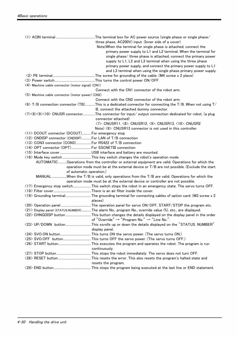
4-50 Handling the drive unit
4Basic operations
<1> ACIN terminal ................................................The terminal box for AC power source (single phase or single phase/three phase, AC200V) input. (Inner side of a cover) Note)When the terminal for single phase is attached, connect the
primary power supply to L1 and L2 terminal. When the terminal for single phase/ three phase is attached, connect the primary power supply to L1, L2 and L3 terminal when using the three phase primary power supply, and connect the primary power supply to L1 and L3 terminal when using the single phase primary power supply.
<2> PE terminal....................................................The screw for grounding of the cable. (M4 screw x 2 place)<3> Power switch..................................................This turns the control power ON/OFF<4> Machine cable connector (motor signal) (CN1)
Connect with the CN1 connector of the robot arm.<5> Machine cable connector (motor power) (CN2)
Connect with the CN2 connector of the robot arm.<6> T/B connection connector (TB)............This is a dedicated connector for connecting the T/B. When not using T/
B, connect the attached dummy connector.<7><8><9><10> CNUSR connector...............The connector for input/ output connection dedicated for robot. (a plug
connector attached)<7>: CNUSR11, <8>: CNUSR12, <9>: CNUSR13, <10>: CNUSR2Note) <9>: CNUSR13 connector is not used in this controller.
<11> DCOUT connector (DCOUT)........... For emergency stop <12> CNDISP connector (CNDISP) ........... For LAN of T/B connection<13> CON3 connector (CON3) .................. For RS422 of T/B connection<14> OPT connector (OPT) ........................ For SSCNETIII connection<15> Interface cover ...................................... USB interface and battery are mounted.<16> Mode key switch ................................... This key switch changes the robot's operation mode.
AUTOMATIC ..........Operations from the controller or external equipment are valid. Operations for which the operation mode must be at the external device or T/B are not possible. (Exclude the start of automatic operation.)
MANUAL ..................When the T/B is valid, only operations from the T/B are valid. Operations for which the operation mode must be at the external device or controller are not possible.
<17> Emergency stop switch...................... This switch stops the robot in an emergency state. The servo turns OFF.<18> Filter cover .............................................. There is an air filter inside the cover.<19> Grounding terminal ............................... The grounding terminal for connecting cables of option card. (M3 screw x 2
places)<20> Operation panel ..................................... The operation panel for servo ON/OFF, START/STOP the program etc.<21> Display panel (STATUS.NUMBER) ........... The alarm No., program No., override value (%), etc., are displayed.<22> CHNGDISP button ............................... This button changes the details displayed on the display panel in the order
of "Override" → "Program No." → "Line No.".<23> UP/DOWN button ............................... This scrolls up or down the details displayed on the "STATUS. NUMBER"
display panel.<24> SVO.ON button...................................... This turns ON the servo power. (The servo turns ON.)<25> SVO.OFF button.................................. This turns OFF the servo power. (The servo turns OFF.)<26> START button........................................ This executes the program and operates the robot. The program is run
continuously.<27> STOP button .......................................... This stops the robot immediately. The servo does not turn OFF.<28> RESET button ........................................ This resets the error. This also resets the program's halted state and
resets the program.<29> END button.............................................. This stops the program being executed at the last line or END statement.
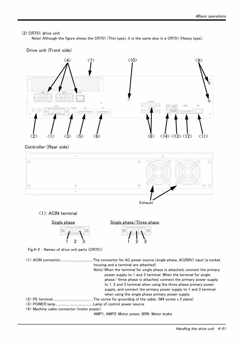
4Basic operations
Handling the drive unit 4-51
(2) CR751 drive unitNote) Although the figure shows the CR751 (Thin type), it is the same also in a CR751 (Heavy type).
Fig.4-2 : Names of drive unit parts (CR751)
<1> ACIN connector.......................................The connector for AC power source (single phase, AC200V) input (a socket housing and a terminal are attached)Note) When the terminal for single phase is attached, connect the primary
power supply to 1 and 3 terminal. When the terminal for single phase/ three phase is attached, connect the primary power supply to 1, 2 and 3 terminal when using the three phase primary power supply, and connect the primary power supply to 1 and 3 terminal when using the single phase primary power supply.
<2> PE terminal ................................................The screw for grounding of the cable. (M4 screw x 2 place)<3> POWER lamp.............................................Lamp of control power source<4> Machine cable connector (motor power)
AMP1, AMP2: Motor power, BRK: Motor brake
<2> <1> <3>
<4> <7> <9>
<5> <6> <14> <13> <12> <11><8>
<10>
Drive unit (Front side)
Exhaust
Controller (Rear side)
<1>: ACIN terminal
Single phase Single phase/Three phase
1 321 32
4-52 Handling the drive unit
4Basic operations
<5> Machine cable connector (motor signal)CN2: Motor signal
<6>T/B connection connector (TB) ........This is a dedicated connector for connecting the R33TB. When not using T/B, connect the attached dummy plug.
<7>Filter cover..................................................There is an air filter and buttery inside this cover.<8>CNUSR connector....................................The connector for input/ output connection dedicated for robot.
(CNUSR1、 CNUSR2) (a plug connector attached)<9>Grounding terminal ...................................The grounding terminal for connecting cables of option card. (M3 screw x 2
places)<10>Power supply charge lamp (CRARGE)
The lamp is to ensure safe timing (prevent electric shocks) when removing the cover (users are not normally required to remove the cover). This lamp is illuminated (red) when electrical energy accumulates on the controller’s power supply circuit board due to the robot’s servo being ON. After turning the control power OFF and allowing a few minutes to pass, the lamp will go out.
<11>OPT connector (OPT)..........................For SSCNETIII connection<12>CON3 connector (CON3)....................For RS422 of T/B connection<13>CNDISP connector (CNDISP)...........For LAN of T/B connection<14>DCOUT connector (DCOUT) ............For emergency stop
◇◆◇ What are the operation rights? ◇◆◇Even when multiple devices, such as a T/B and personal computer, are connected to the controller, the operation at one time is limited to one device. This limited device (has the operation rights)
◇◆◇ What operations require the operation rights? ◇◆◇Operations that start the robot, such as program start and alarm reset, and operations that can cause starting require the operation rights. Conversely, operation that stop the robot, such as stopping and servo OFF, can be used without the operation rights for safety purposes. Refer to the separate manual "Explanation of functions and operations" for details on the functions related to operation rights.
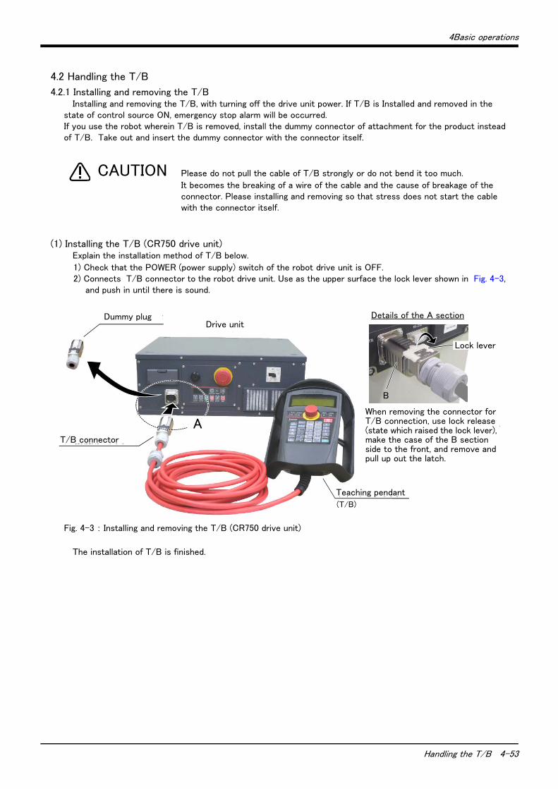
4Basic operations
Handling the T/B 4-53
4.2 Handling the T/B
4.2.1 Installing and removing the T/BInstalling and removing the T/B, with turning off the drive unit power. If T/B is Installed and removed in the
state of control source ON, emergency stop alarm will be occurred. If you use the robot wherein T/B is removed, install the dummy connector of attachment for the product instead of T/B. Take out and insert the dummy connector with the connector itself.
Please do not pull the cable of T/B strongly or do not bend it too much.
It becomes the breaking of a wire of the cable and the cause of breakage of the connector. Please installing and removing so that stress does not start the cable with the connector itself.
(1) Installing the T/B (CR750 drive unit)Explain the installation method of T/B below.
1) Check that the POWER (power supply) switch of the robot drive unit is OFF.2) Connects T/B connector to the robot drive unit. Use as the upper surface the lock lever shown in Fig. 4-3,
and push in until there is sound.
Fig. 4-3 : Installing and removing the T/B (CR750 drive unit)
The installation of T/B is finished.
CAUTION
ティーチングボックス
(T/B)
ダミーコネクタ
AT/B接続用コネクタ
A部詳細
T/B接続用コネクタを取り外す時は、ロック解除(ロックレバーを上側に起こした状態)にし、B部のケースを手前にスライドさせてラッチを外し引き抜きます。
ロックレバー
B
Drive unitDummy plug
T/B connector
Teaching pendant
Details of the A section
When removing the connector for T/B connection, use lock release (state which raised the lock lever), make the case of the B section side to the front, and remove and pull up out the latch.
Lock lever

4-54 Handling the T/B
4Basic operations
(2) Installing the T/B (CR751 drive unit)Explain the installation method of T/B below.
1) Check that the POWER (power supply) switch of the robot drive unit is OFF.2) Connect the T/B connector to the drive unit’s T/B connector. Make sure to fix it securely by fastening the
hand locks (in 2 places), as shown in Fig. 4-4.
Fig. 4-4 : Installing and removing the T/B (CR751 drive unit)
The installation of T/B is finished.
(3) Removing the T/B (CR750 drive unit)Explain the removing method of T/B below.
1) Check that the POWER (power supply) switch of the robot drive unit is OFF.2) Raise up the lock lever in the connector upper part , and pull up the connector.
Please install the dummy connector, if you use the robot, without connecting T/B.
The removing of T/B is finished.
(4) Removing the T/B (CR751 drive unit)Explain the removing method of T/B below.
1) Check that the POWER (power supply) switch of the robot drive unit is OFF.2) Loosen the handle locks (two places) of a connector, and pull up the connector.
Please install the dummy connector, if you use the robot, without connecting T/B.
The removing of T/B is finished.
A部
ティーチングボックス(T/B)
T/B接続用コネクタ
A部詳細
手回しロック(2箇所)
Drive unit
T/B connector
Teaching pendant
Details of the A section
A
Hand lock (Two places)
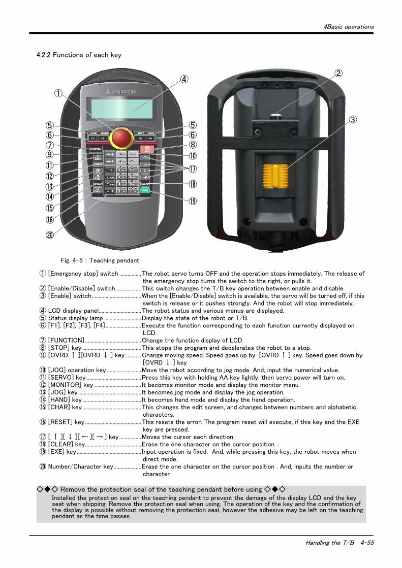
4Basic operations
Handling the T/B 4-55
4.2.2 Functions of each key
Fig. 4-5 : Teaching pendant
① [Emergency stop] switch ................The robot servo turns OFF and the operation stops immediately. The release of the emergency stop turns the switch to the right, or pulls it.
② [Enable/Disable] switch...................This switch changes the T/B key operation between enable and disable.③ [Enable] switch....................................When the [Enable/Disable] switch is available, the servo will be turned off, if this
switch is release or it pushes strongly. And the robot will stop immediately.④ LCD display panel...............................The robot status and various menus are displayed.⑤ Status display lamp ...........................Display the state of the robot or T/B.⑥ [F1], [F2], [F3], [F4]..........................Execute the function corresponding to each function currently displayed on
LCD. ⑦ [FUNCTION] .........................................Change the function display of LCD. ⑧ [STOP] key ...........................................This stops the program and decelerates the robot to a stop.⑨ [OVRD ↑ ][OVRD ↓ ] key............Change moving speed. Speed goes up by [OVRD ↑ ] key. Speed goes down by
[OVRD ↓ ] key⑩ [JOG] operation key .........................Move the robot according to jog mode. And, input the numerical value. ⑪ [SERVO] key ........................................Press this key with holding AA key lightly, then servo power will turn on. ⑫ [MONITOR] key .................................. It becomes monitor mode and display the monitor menu. ⑬ [JOG] key.............................................. It becomes jog mode and display the jog operation. ⑭ [HAND] key........................................... It becomes hand mode and display the hand operation.⑮ [CHAR] key...........................................This changes the edit screen, and changes between numbers and alphabetic
characters.⑯ [RESET] key.........................................This resets the error. The program reset will execute, if this key and the EXE
key are pressed. ⑰ [ ↑ ][ ↓ ][ ← ][ → ] key................Moves the cursor each direction .⑱ [CLEAR] key.........................................Erase the one character on the cursor position .⑲ [EXE] key............................................... Input operation is fixed. And, while pressing this key, the robot moves when
direct mode.⑳ Number/Character key....................Erase the one character on the cursor position . And, inputs the number or
character
⑪
⑭⑬
⑫
⑨
⑤⑥⑦
⑮
⑯
⑳
⑤⑥⑧
⑱
⑲
⑩
⑰
①
④
③
②
◇◆◇ Remove the protection seal of the teaching pendant before using ◇◆◇Installed the protection seal on the teaching pendant to prevent the damage of the display LCD and the key seat when shipping. Remove the protection seal when using. The operation of the key and the confirmation of the display is possible without removing the protection seal, however the adhesive may be left on the teaching pendant as the time passes.
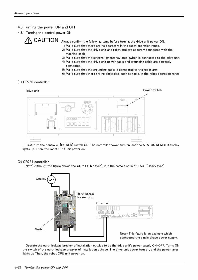
4-56 Turning the power ON and OFF
4Basic operations
4.3 Turning the power ON and OFF
4.3.1 Turning the control power ON
Always confirm the following items before turning the drive unit power ON.
1) Make sure that there are no operators in the robot operation range.2) Make sure that the drive unit and robot arm are securely connected with the
machine cable.3) Make sure that the external emergency stop switch is connected to the drive unit.4) Make sure that the drive unit power cable and grounding cable are correctly
connected.5) Make sure that the grounding cable is connected to the robot arm.6) Make sure that there are no obstacles, such as tools, in the robot operation range.
(1) CR750 controller
First, turn the controller [POWER] switch ON. The controller power turn on, and the STATUS NUMBER display lights up. Then, the robot CPU unit power on.
(2) CR751 controllerNote) Although the figure shows the CR751 (Thin type), it is the same also in a CR751 (Heavy type).
Operate the earth leakage breaker of installation outside to do the drive unit's power supply ON/OFF. Turns ON the switch of the earth leakage breaker of installation outside. The drive unit power turn on, and the power lamp lights up Then, the robot CPU unit power on..
CAUTION
Power switchDrive unit
漏電遮断器(NV)
コントローラ
AC200V
Switch
Drive unit
Earth leakage breaker (NV)
Note) This figure is an example which connected the single phase power supply.
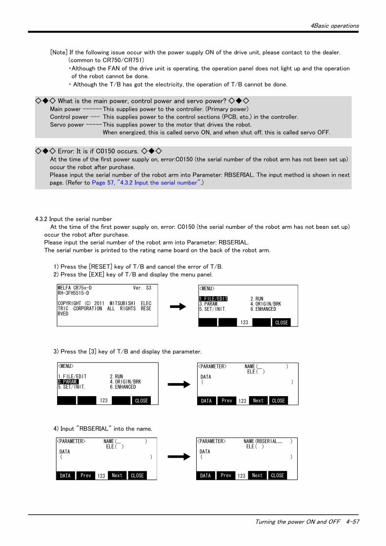
4Basic operations
Turning the power ON and OFF 4-57
[Note] If the following issue occur with the power supply ON of the drive unit, please contact to the dealer. (common to CR750/CR751)
・Although the FAN of the drive unit is operating, the operation panel does not light up and the operation of the robot cannot be done.
・ Although the T/B has got the electricity, the operation of T/B cannot be done.
4.3.2 Input the serial numberAt the time of the first power supply on, error: C0150 (the serial number of the robot arm has not been set up)
occur the robot after purchase.Please input the serial number of the robot arm into Parameter: RBSERIAL.The serial number is printed to the rating name board on the back of the robot arm.
1) Press the [RESET] key of T/B and cancel the error of T/B.2) Press the [EXE] key of T/B and display the menu panel.
3) Press the [3] key of T/B and display the parameter.
4) Input "RBSERIAL" into the name.
◇◆◇ What is the main power, control power and servo power? ◇◆◇Main power ------This supplies power to the controller. (Primary power)Control power --- This supplies power to the control sections (PCB, etc.) in the controller.Servo power -----This supplies power to the motor that drives the robot.
When energized, this is called servo ON, and when shut off, this is called servo OFF.
◇◆◇ Error: It is if C0150 occurs. ◇◆◇At the time of the first power supply on, error:C0150 (the serial number of the robot arm has not been set up) occur the robot after purchase.Please input the serial number of the robot arm into Parameter: RBSERIAL. The input method is shown in next page. (Refer to Page 57, "4.3.2 Input the serial number".)
<MENU>
1.FILE/EDIT 2.RUN3.PARAM. 4.ORIGIN/BRK5.SET/INIT. 6.ENHANCED
CLOSE 123
MELFA CR75x-D Ver. S3RH-3FH5515-D
COPYRIGHT (C) 2011 MITSUBISHI ELECTRIC CORPORATION ALL RIGHTS RESERVED
<MENU>
1.FILE/EDIT 2.RUN3.PARAM. 4.ORIGIN/BRK5.SET/INIT. 6.ENHANCED
CLOSE 123
<PARAMETER> NAME( ) ELE( ) DATA ( )
CLOSE 123 NextDATA Prev
<PARAMETER> NAME( ) ELE( ) DATA ( )
CLOSE 123 NextDATA Prev
<PARAMETER> NAME(RBSERIAL ) ELE( ) DATA ( )
CLOSE 123 NextDATA Prev

4-58 Turning the power ON and OFF
4Basic operations
5) Press the function key ([F1]) corresponding to the "data", and input the serial number of the robot arm.
Press the [EXE] key, and fix the value with sound, and return to the parameter screen.
6) Press the function key ([F1]) corresponding to the "close", and return to the menu screen.
4.3.3 Shutting OFF the control power
1) If the robot is operating, press the drive unit [STOP] switch, and stop the robot.
2) After the robot has stopped, press the drive unit [SVO OFF] switch, and turn the servo OFF.
3) Turns off the robot CPU system first. After that, * CR750 drive unit: turn OFF a front power switch. * CR751 drive unit: turn OFF the switch of the earth leakage breaker installed outside.
The control power will be shut off.
<PARAMETER> (RBSERIAL ) ( )
xxxxxxx
CLOSE 123 NextDATA Prev
<PARAMETER> NAME(RBSERIAL ) ELE( ) DATA ( )
CLOSE 123 NextDATA Prev
◇◆◇ The input of the number/character ◇◆◇Each time the [CHARACTER] key is pressed, the number input mode and the character input mode change.
The current input mode is displayed in the center under the screen, and the display of "123" shows that the number input mode and "ABC" is the character input mode.For details, please refer to "INSTRUCTION MANUAL/ Detailed explanations of functions and operations" of the separate volume.
<PARAMETER> NAME(RBSERIAL ) ELE( ) DATA (XXXXXXXX )
CLOSE 123 NextDATA Prev
<MENU>
1.FILE/EDIT 2.RUN3.PARAM. 4.ORIGIN/BRK5.SET/INIT. 6.ENHANCED
CLOSE 123
Stop the program
Shut OFF the motor powe
STOP
SVO OFF

4Basic operations
Turning the servo power ON/OFF 4-59
4.4 Turning the servo power ON/OFF
4.4.1 Turning the servo power ON (servo ON)
1) Confirm that the T/B [ENABLE] switch is set to "DISABLE".
2) Confirm that the mode of the drive unit is set to "AUTOMATIC".
3) Press the [SVO ON] switch on the front of the drive unit.The switch's lamp will light indicating that the servo is ON.
Make sure that there are not operators in the robot operation range before turning ON the servo.
4.4.2 Shutting OFF the servo power (servo OFF)
1) If the robot is operating, press the drive unit [STOP] switch on the front of the drive unit, and stop the robot.
2) After the robot has stopped, press the drive unit [SVO OFF] switch on the front of the drive unit, and turn the servo OFF. The switch's lamp will light indicating that the servo is OFF.
R/C disable
T/B disable
Servo on
Down:ENABLE *Lighting
Up :DISABLE
Rear of T/B
MODEMANUAL AUTOMATIC
SVO ON
CAUTION
Stop the program
Servo off
STOP
SVO OFF
◇◆◇ Operation rights not required ◇◆◇This operation does not require the operation rights, so the servo can be turned OFF at any time by pressing the [SVO OFF] switch.
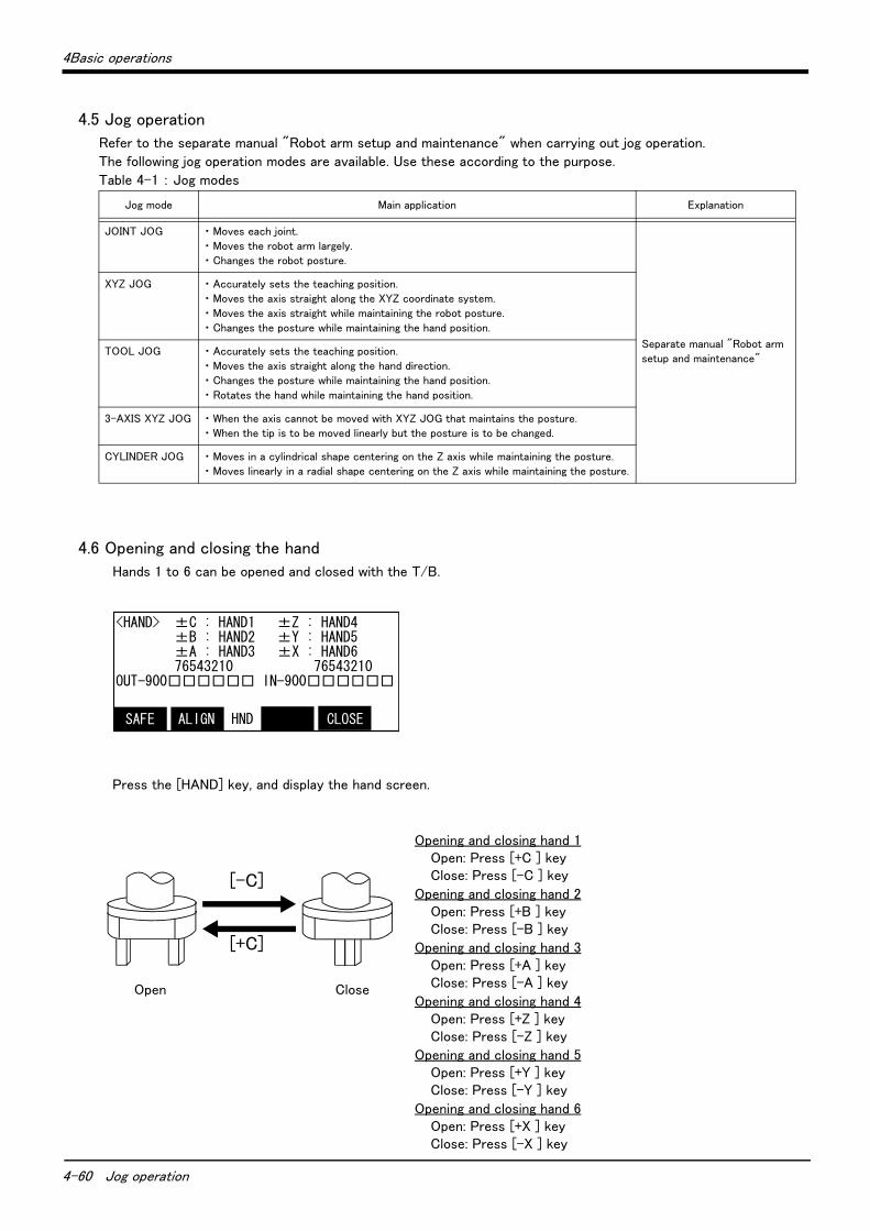
4-60 Jog operation
4Basic operations
4.5 Jog operation
Refer to the separate manual "Robot arm setup and maintenance" when carrying out jog operation.
The following jog operation modes are available. Use these according to the purpose.
Table 4-1 : Jog modes
4.6 Opening and closing the hand
Hands 1 to 6 can be opened and closed with the T/B.
Press the [HAND] key, and display the hand screen.
Opening and closing hand 1Open: Press [+C ] key Close: Press [-C ] key
Opening and closing hand 2Open: Press [+B ] key Close: Press [-B ] key
Opening and closing hand 3Open: Press [+A ] key Close: Press [-A ] key
Opening and closing hand 4Open: Press [+Z ] key Close: Press [-Z ] key
Opening and closing hand 5Open: Press [+Y ] key Close: Press [-Y ] key
Opening and closing hand 6Open: Press [+X ] key Close: Press [-X ] key
Jog mode Main application Explanation
JOINT JOG ・ Moves each joint.
・ Moves the robot arm largely.
・ Changes the robot posture.
Separate manual "Robot arm
setup and maintenance"
XYZ JOG ・ Accurately sets the teaching position.
・ Moves the axis straight along the XYZ coordinate system.
・ Moves the axis straight while maintaining the robot posture.
・ Changes the posture while maintaining the hand position.
TOOL JOG ・ Accurately sets the teaching position.
・ Moves the axis straight along the hand direction.
・ Changes the posture while maintaining the hand position.
・ Rotates the hand while maintaining the hand position.
3-AXIS XYZ JOG ・ When the axis cannot be moved with XYZ JOG that maintains the posture.
・ When the tip is to be moved linearly but the posture is to be changed.
CYLINDER JOG ・ Moves in a cylindrical shape centering on the Z axis while maintaining the posture.
・ Moves linearly in a radial shape centering on the Z axis while maintaining the posture.
<HAND> ±C : HAND1 ±Z : HAND4 ±B : HAND2 ±Y : HAND5 ±A : HAND3 ±X : HAND6 76543210 76543210OUT-900□□□□□□ IN-900□□□□□□
CLOSE HNDALIGNSAFE
Open Close
[-C]
[+C]
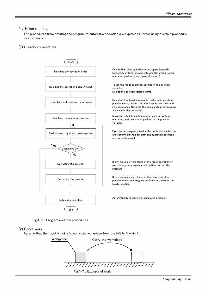
4Basic operations
Programming 4-61
4.7 Programming
The procedures from creating the program to automatic operation are explained in order using a simple procedure as an example.
(1) Creation procedures
Fig.4-6 : Program creation procedures
(2) Robot workAssume that the robot is going to carry the workpiece from the left to the right.
Fig.4-7 : Example of work
No
Yes
Start
Deciding the operation orderDecide the robot operation order, operation path
(necessity of linear movement), and the work at each
operation position (hand open/close, etc).
Deciding the operation position nameTeach the robot operation position in the position
variables.
Decide the position variable name.
Describing and creating the programBased on the decided operation order and operation
position name, convert the robot operations and work
into commands. Describe the commands in the program
and save in the controller.
Teaching the operation positionMove the robot to each operation position with jog
operation, and teach each position in the position
variables.
Confirmation of program and operation positionExecute the program saved in the controller line by line,
and confirm that the program and operation positions
are correctly saved.
Judgment: OK?
Correcting the programIf any mistakes were found in the robot operation or
work during the program confirmation, correct the
program.
Correcting the positionIf any mistakes were found in the robot operation
position during the program confirmation, correct the
taught position.
Automatic operationAutomatically execute the completed program.
End
Carry the workpieceWorkpiece
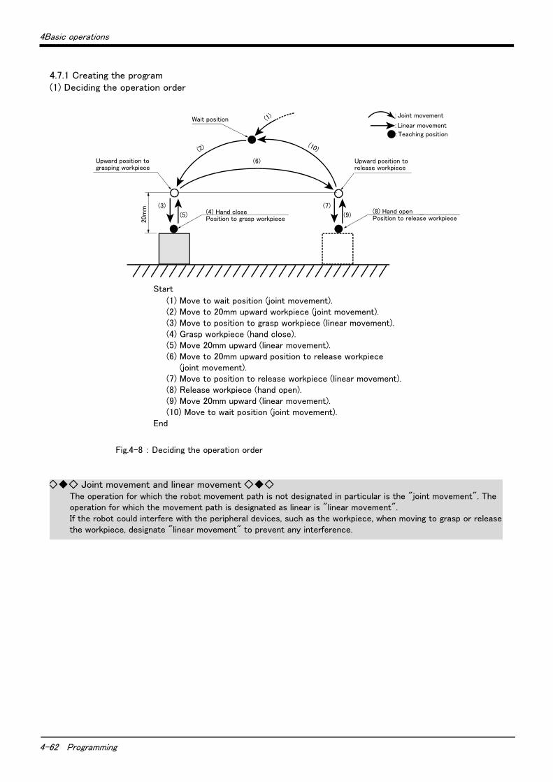
4-62 Programming
4Basic operations
4.7.1 Creating the program(1) Deciding the operation order
Fig.4-8 : Deciding the operation order
20m
m (3) (7)
(5) (9)
(10)
(4) Hand closePosition to grasp workpiece
Wait position
(6)
(2)
(1)
(8) Hand openPosition to release workpiece
:Joint movement
:Linear movement
:Teaching position
Upward position tograsping workpiece
Upward position torelease workpiece
Start
(1) Move to wait position (joint movement).(2) Move to 20mm upward workpiece (joint movement).(3) Move to position to grasp workpiece (linear movement).(4) Grasp workpiece (hand close).(5) Move 20mm upward (linear movement).(6) Move to 20mm upward position to release workpiece
(joint movement).(7) Move to position to release workpiece (linear movement).(8) Release workpiece (hand open).(9) Move 20mm upward (linear movement).(10) Move to wait position (joint movement).
End
◇◆◇ Joint movement and linear movement ◇◆◇The operation for which the robot movement path is not designated in particular is the "joint movement". The operation for which the movement path is designated as linear is "linear movement".If the robot could interfere with the peripheral devices, such as the workpiece, when moving to grasp or release the workpiece, designate "linear movement" to prevent any interference.
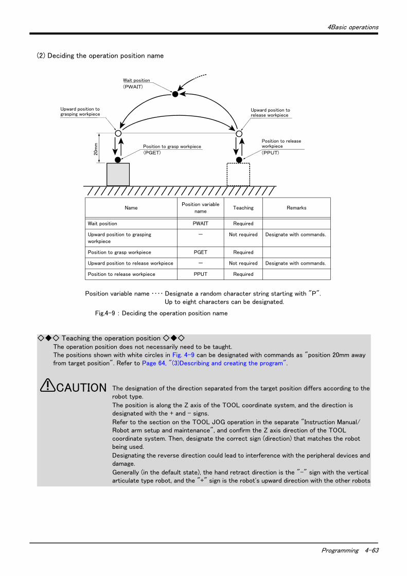
4Basic operations
Programming 4-63
(2) Deciding the operation position name
Fig.4-9 : Deciding the operation position name
20m
m Position to grasp workpiece(PGET)
Position to releaseworkpiece
(PPUT)
Wait position
(PWAIT)
Upward position tograsping workpiece
Upward position torelease workpiece
Position variable name ・・・・ Designate a random character string starting with "P".Up to eight characters can be designated.
NamePosition variable
nameTeaching Remarks
Wait position PWAIT Required
Upward position to grasping
workpiece
- Not required Designate with commands.
Position to grasp workpiece PGET Required
Upward position to release workpiece - Not required Designate with commands.
Position to release workpiece PPUT Required
◇◆◇ Teaching the operation position ◇◆◇The operation position does not necessarily need to be taught.The positions shown with white circles in Fig. 4-9 can be designated with commands as "position 20mm away from target position". Refer to Page 64, "(3)Describing and creating the program".
The designation of the direction separated from the target position differs according to the robot type.
The position is along the Z axis of the TOOL coordinate system, and the direction is designated with the + and - signs.
Refer to the section on the TOOL JOG operation in the separate "Instruction Manual/ Robot arm setup and maintenance", and confirm the Z axis direction of the TOOL coordinate system. Then, designate the correct sign (direction) that matches the robot being used.
Designating the reverse direction could lead to interference with the peripheral devices and damage.
Generally (in the default state), the hand retract direction is the "-" sign with the vertical articulate type robot, and the "+" sign is the robot's upward direction with the other robots.
CAUTION
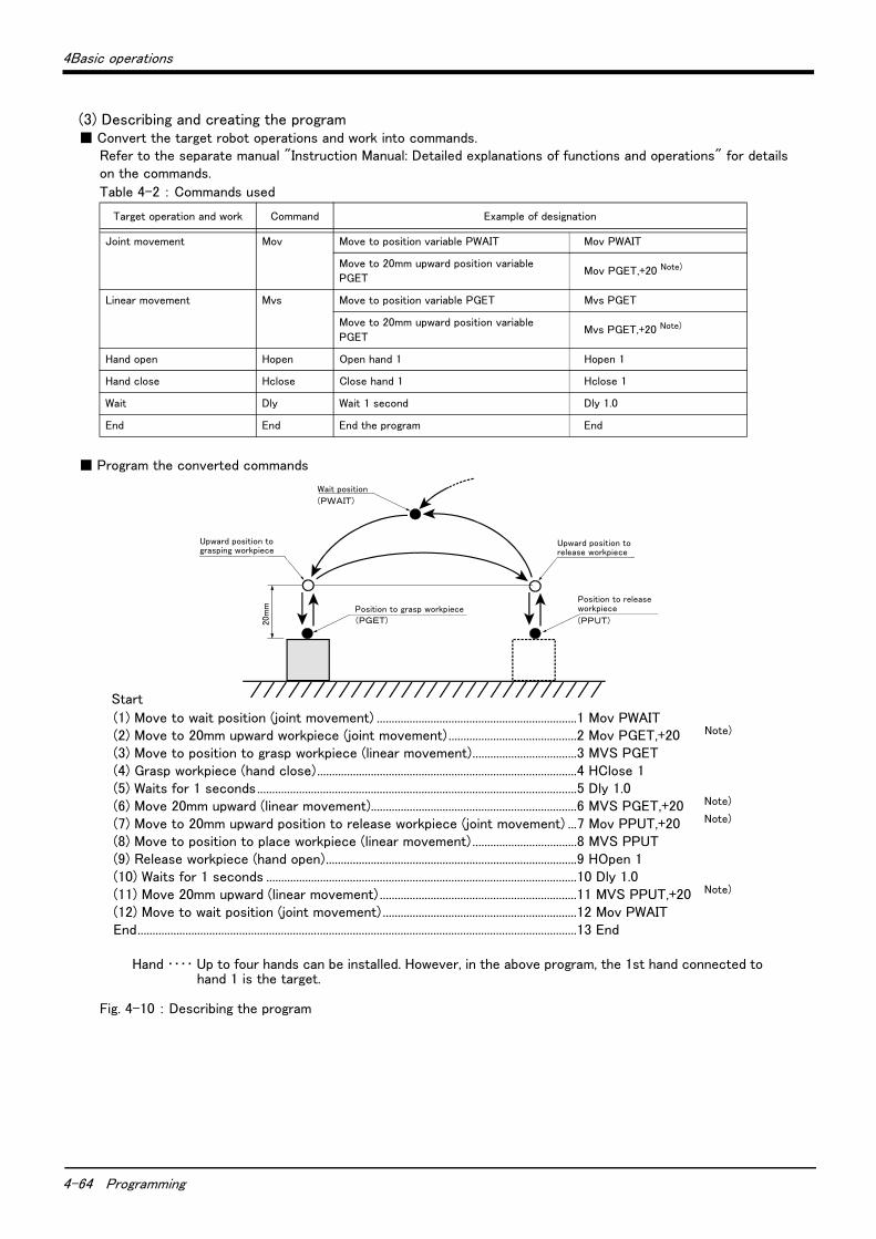
4-64 Programming
4Basic operations
(3) Describing and creating the program■ Convert the target robot operations and work into commands.
Refer to the separate manual "Instruction Manual: Detailed explanations of functions and operations" for details on the commands.
Table 4-2 : Commands used
■ Program the converted commands
Fig. 4-10 : Describing the program
Target operation and work Command Example of designation
Joint movement Mov Move to position variable PWAIT Mov PWAIT
Move to 20mm upward position variable
PGETMov PGET,+20 Note)
Linear movement Mvs Move to position variable PGET Mvs PGET
Move to 20mm upward position variable
PGETMvs PGET,+20 Note)
Hand open Hopen Open hand 1 Hopen 1
Hand close Hclose Close hand 1 Hclose 1
Wait Dly Wait 1 second Dly 1.0
End End End the program End
Start
(1) Move to wait position (joint movement) ...................................................................1 Mov PWAIT(2) Move to 20mm upward workpiece (joint movement) ...........................................2 Mov PGET,+20 Note)
(3) Move to position to grasp workpiece (linear movement)...................................3 MVS PGET(4) Grasp workpiece (hand close).......................................................................................4 HClose 1(5) Waits for 1 seconds...........................................................................................................5 Dly 1.0(6) Move 20mm upward (linear movement).....................................................................6 MVS PGET,+20 Note)
(7) Move to 20mm upward position to release workpiece (joint movement) ...7 Mov PPUT,+20 Note)
(8) Move to position to place workpiece (linear movement) ...................................8 MVS PPUT(9) Release workpiece (hand open)....................................................................................9 HOpen 1(10) Waits for 1 seconds ........................................................................................................10 Dly 1.0(11) Move 20mm upward (linear movement) ..................................................................11 MVS PPUT,+20 Note)
(12) Move to wait position (joint movement) .................................................................12 Mov PWAITEnd...................................................................................................................................................13 End
Hand ・・・・ Up to four hands can be installed. However, in the above program, the 1st hand connected to hand 1 is the target.
20m
m Position to grasp workpiece(PGET)
Position to releaseworkpiece
(PPUT)
Wait position
(PWAIT)
Upward position tograsping workpiece
Upward position torelease workpiece
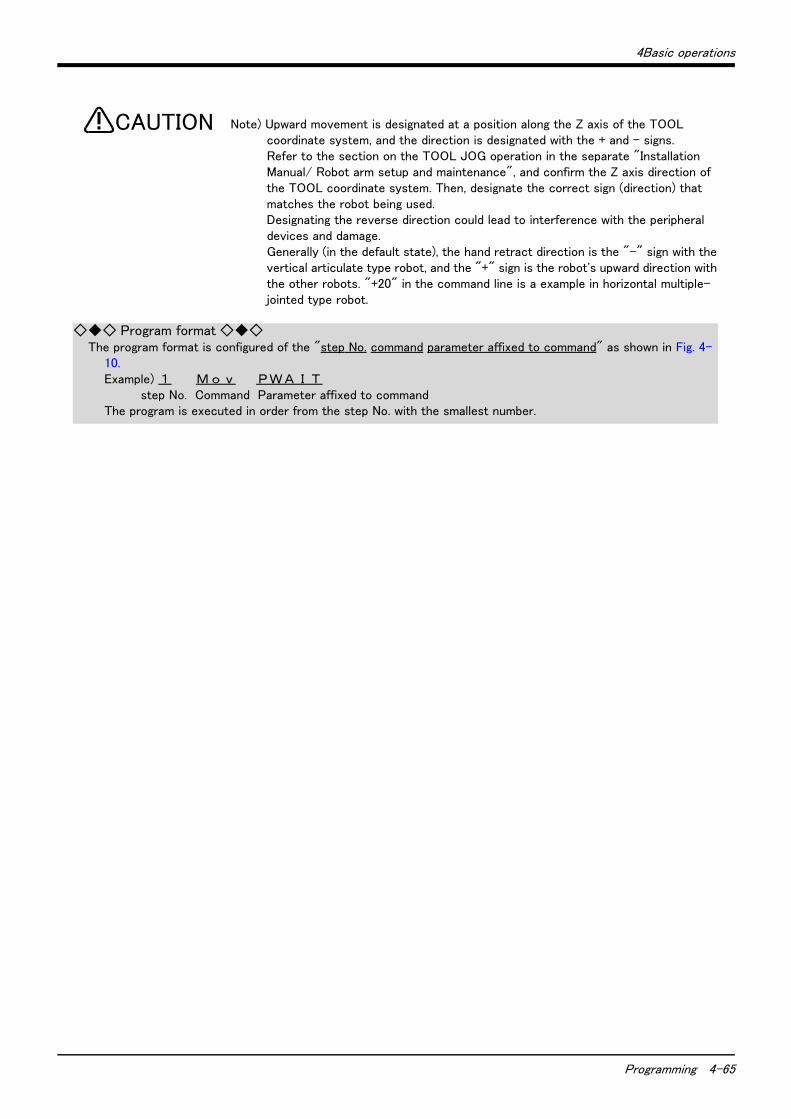
4Basic operations
Programming 4-65
Note) Upward movement is designated at a position along the Z axis of the TOOL coordinate system, and the direction is designated with the + and - signs.Refer to the section on the TOOL JOG operation in the separate "Installation Manual/ Robot arm setup and maintenance", and confirm the Z axis direction of the TOOL coordinate system. Then, designate the correct sign (direction) that matches the robot being used.Designating the reverse direction could lead to interference with the peripheral devices and damage.Generally (in the default state), the hand retract direction is the "-" sign with the vertical articulate type robot, and the "+" sign is the robot's upward direction with the other robots. "+20" in the command line is a example in horizontal multiple-jointed type robot.
CAUTION
◇◆◇ Program format ◇◆◇The program format is configured of the "step No. command parameter affixed to command" as shown in Fig. 4-
10.Example) 1 M o v PWA I T step No. Command Parameter affixed to commandThe program is executed in order from the step No. with the smallest number.
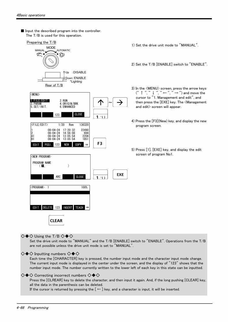
4-66 Programming
4Basic operations
■ Input the described program into the controller.The T/B is used for this operation.
1) Set the drive unit mode to "MANUAL".
2) Set the T/B [ENABLE] switch to "ENABLE".
3) In the <MENU> screen, press the arrow keys (" ↑ ", " ↓ ", " ← ", " → ") and move the cursor to "1. Management and edit", and then press the [EXE] key. The <Management and edit> screen will appear.
4) Press the [F3](New) key, and display the new program screen.
5) Press [1], [EXE] key, and display the edit screen of program No1.
Down:ENABLE *Lighting
Up :DISABLE
Rear of T/B
<MENU>
1.FILE/EDIT 2.RUN3.PARAM. 4.ORIGIN/BRK5.SET/INIT. 6.ENHANCED
CLOSE 123
Preparing the T/B
MODEMANUAL AUTOMATIC
~
<FILE/EDIT> 1/20 Rem 136320
1 08-04-24 17:20:32 224902 08-04-24 14:56:08 694A1 08-04-24 13:05:54 2208B1 08-04-24 13:05:54 1851
COPY123POSI.EDIT NEW ⇒
<NEW PROGRAM> PROGRAM NAME ( 1_ )
CLOSE ABC
<PROGRAM> 1 100%
TEACH123DELETEEDIT INSERT ⇒
◇◆◇ Using the T/B ◇◆◇Set the drive unit mode to "MANUAL" and the T/B [ENABLE] switch to "ENABLE". Operations from the T/B are not possible unless the drive unit mode is set to "MANUAL".
◇◆◇ Inputting numbers ◇◆◇Each time the [CHARACTER] key is pressed, the number input mode and the character input mode change.The current input mode is displayed in the center under the screen, and the display of "123" shows that the number input mode. The number currently written to the lower left of each key in this state can be inputted.
◇◆◇ Correcting incorrect numbers ◇◆◇Press the [CLREAR] key to delete the character, and then input it again. And, if the long pushing [CLEAR] key, all the data in the parenthesis can be deleted. If the cursor is returned by pressing the [ ← ] key, and a character is input, it will be inserted.
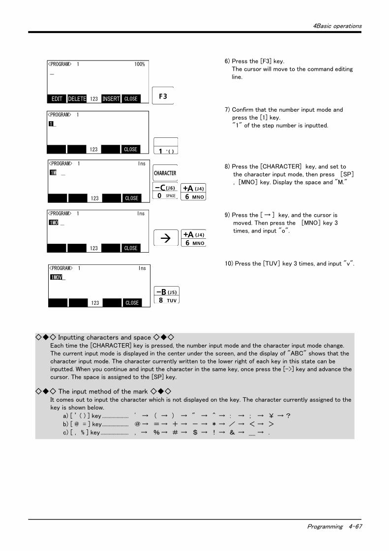
4Basic operations
Programming 4-67
6) Press the [F3] key.The cursor will move to the command editing line.
7) Confirm that the number input mode and press the [1] key. "1" of the step number is inputted.
8) Press the [CHARACTER] key, and set to the character input mode, then press [SP], [MNO] key. Display the space and "M."
9) Press the [ → ] key, and the cursor is moved. Then press the [MNO] key 3 times, and input "o".
10) Press the [TUV] key 3 times, and input "v".
SPACE
<PROGRAM> 1 100% _
CLOSE123
<PROGRAM> 1
1_
CLOSE123
<PROGRAM> 1 Ins
1MOV_
CLOSE123
<PROGRAM> 1 Ins
1MOV_
CLOSE123
<PROGRAM> 1 Ins
1MOV_
CLOSE123
EDIT DELETE INSERT
◇◆◇ Inputting characters and space ◇◆◇Each time the [CHARACTER] key is pressed, the number input mode and the character input mode change.The current input mode is displayed in the center under the screen, and the display of "ABC" shows that the character input mode. The character currently written to the lower right of each key in this state can be inputted. When you continue and input the character in the same key, once press the [->] key and advance the cursor. The space is assigned to the [SP] key.
◇◆◇ The input method of the mark ◇◆◇It comes out to input the character which is not displayed on the key. The character currently assigned to the key is shown below.
a) [ ’ ( ) ] key .................... ' → ( → ) → " → ^→ : → ; → ¥ →?
b) [ @ = ] key.................... @→ =→ + → - → *→ / → < → >
c) [ , % ] key ..................... , → %→ # → $ → !→ & → _ → .

4-68 Programming
4Basic operations
11) Press the [SP], [PQRS] key, and input the space and "P".
12) Press the [WXYZ] key, and input the space and "W".
13) Input "A", "I" and "T" in the same manner.
14) Press the [EXE] key."1 Mov PWAIT" will be set.
15) Input the program from step 2 to line 13 in the same manner.
This completes the inputting of the program.
SPACE
<PROGRAM> 1 Ins
1MOV P1_
CLOSE123
<PROGRAM> 1 Ins
1MOV PWAIT_
CLOSE123
<PROGRAM> 1 Ins
1MOV PWAIT_
CLOSE123
<PROGRAM> 1 Ins
1 MOV PWAIT_
CLOSE123
<PROGRAM> 1 Ins
1 MOV PWAIT_
CLOSE123
◇◆◇ Displaying the previous and next command step ◇◆◇Display the four lines on the screen of T/B. For moving the cursor to the front line, the [ ↑ ] key is pressed, for moving the cursor to the next line, press the [ ↓ ] key, and select.
◇◆◇ Displaying a specific line ◇◆◇Press the [FUNCTION] key, and change the function display, and press the [F2] key. The display changes to the JUNP screen. The specification line can be displayed, if the step number to display in the parenthesis is inputted and the [EXE] key is pressed.
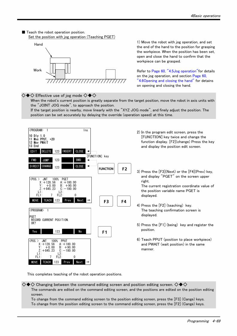
4Basic operations
Programming 4-69
■ Teach the robot operation position.
1) Move the robot with jog operation, and set the end of the hand to the position for grasping the workpiece. When the position has been set, open and close the hand to confirm that the workpiece can be grasped.
Refer to Page 60, "4.5Jog operation"for details on the jog operation, and section Page 60, "4.6Opening and closing the hand" for detains on opening and closing the hand.
2) In the program edit screen, press the [FUNCTION] key twice and change the function display. [F2](change) Press the key and display the position edit screen.
3) Press the [F3](Next) or the [F4](Prev) key, and display "PGET" on the screen upper right. The current registration coordinate value of the position variable name PGET is displayed.
4) Press the [F2] (teaching) key. The teaching confirmation screen is displayed.
5) Press the [F1] (being) key and register the position.
6) Teach PPUT (position to place workpiece) and PWAIT (wait position) in the same manner.
This completes teaching of the robot operation positions.
ワーク
ハンド
Set the position with jog operation (Teaching PGET)
Work
Hand
◇◆◇ Effective use of jog mode ◇◆◇When the robot's current position is greatly separate from the target position, move the robot in axis units with the "JOINT JOG mode", to approach the position.If the target position is nearby, move linearly with the "XYZ JOG mode", and finely adjust the position. The position can be set accurately by delaying the override (operation speed) at this time.
<PROGRAM> 1 Ins
10 Dly 1.011 Mvs PPUT, +2012 Mov PWAIT13 End
CLOSE123
BWD123
CLOSE123
INSERTDELETEEDIT
JUMPFWD
CHANGEDIRECT
[FUNCTION] key
<POS.> JNT 100% PGET X:+128.56 A:+180.00 Y: +0.00 B: +90.00 Z:+845.23 C:-180.00 L1: L2: FL1: 7 FL2: 0
Next123TEACHMOVE Prev ⇒
<PROGRAM> 1
PGET RECORD CURRENT POSITION. OK?
No123Yes
<POS.> JNT 100% PPUT X:+128.56 A:+180.00 Y: +0.00 B: +90.00 Z:+845.23 C:-180.00 L1: L2: FL1: 7 FL2: 0
Next123TEACHMOVE Prev ⇒
◇◆◇ Changing between the command editing screen and position editing screen. ◇◆◇The commands are edited on the command editing screen, and the positions are edited on the position editing screen.To change from the command editing screen to the position editing screen, press the [F3] (Cange) keys.To change from the position editing screen to the command editing screen, press the [F2] (Cange) keys.
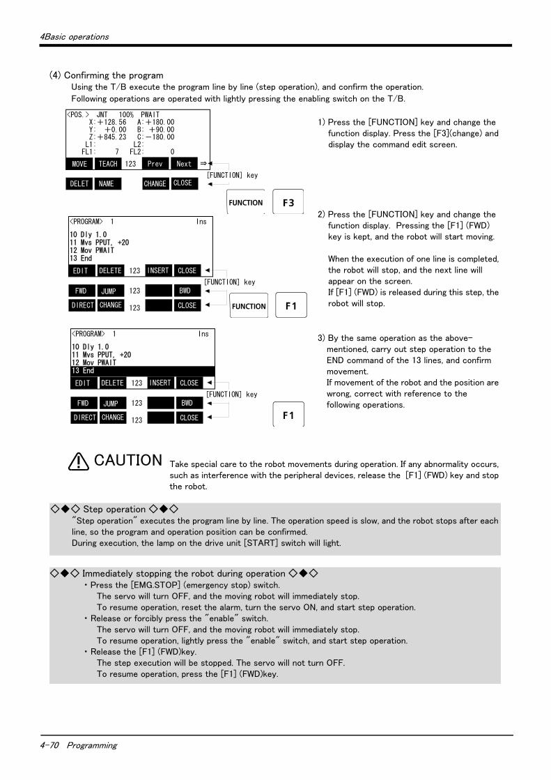
4-70 Programming
4Basic operations
(4) Confirming the programUsing the T/B execute the program line by line (step operation), and confirm the operation.
Following operations are operated with lightly pressing the enabling switch on the T/B.
1) Press the [FUNCTION] key and change the function display. Press the [F3](change) and display the command edit screen.
2) Press the [FUNCTION] key and change the function display. Pressing the [F1] (FWD) key is kept, and the robot will start moving.
When the execution of one line is completed, the robot will stop, and the next line will appear on the screen.If [F1] (FWD) is released during this step, the robot will stop.
3) By the same operation as the above-mentioned, carry out step operation to the END command of the 13 lines, and confirm movement. If movement of the robot and the position are wrong, correct with reference to the following operations.
Take special care to the robot movements during operation. If any abnormality occurs, such as interference with the peripheral devices, release the [F1] (FWD) key and stop the robot.
<PROGRAM> 1 Ins
10 Dly 1.011 Mvs PPUT, +2012 Mov PWAIT13 End
CLOSE123
BWD123
CLOSE123
INSERTDELETEEDIT
JUMPFWD
CHANGEDIRECT
[FUNCTION] key
<POS.> JNT 100% PWAIT X:+128.56 A:+180.00 Y: +0.00 B: +90.00 Z:+845.23 C:-180.00 L1: L2: FL1: 7 FL2: 0
Next123TEACHMOVE Prev ⇒
NextTEACHMOVE Prev NextTEACHMOVE Prev[FUNCTION] key
DELET NAME CHANGE CLOSE
<PROGRAM> 1 Ins
10 Dly 1.011 Mvs PPUT, +2012 Mov PWAIT13 End
CLOSE123
BWD123
CLOSE123
INSERTDELETEEDIT
JUMPFWD
CHANGEDIRECT
[FUNCTION] key
CAUTION
◇◆◇ Step operation ◇◆◇"Step operation" executes the program line by line. The operation speed is slow, and the robot stops after each line, so the program and operation position can be confirmed.During execution, the lamp on the drive unit [START] switch will light.
◇◆◇ Immediately stopping the robot during operation ◇◆◇・ Press the [EMG.STOP] (emergency stop) switch.
The servo will turn OFF, and the moving robot will immediately stop.To resume operation, reset the alarm, turn the servo ON, and start step operation.
・ Release or forcibly press the "enable" switch.The servo will turn OFF, and the moving robot will immediately stop.To resume operation, lightly press the "enable" switch, and start step operation.
・ Release the [F1] (FWD)key.The step execution will be stopped. The servo will not turn OFF.To resume operation, press the [F1] (FWD)key.
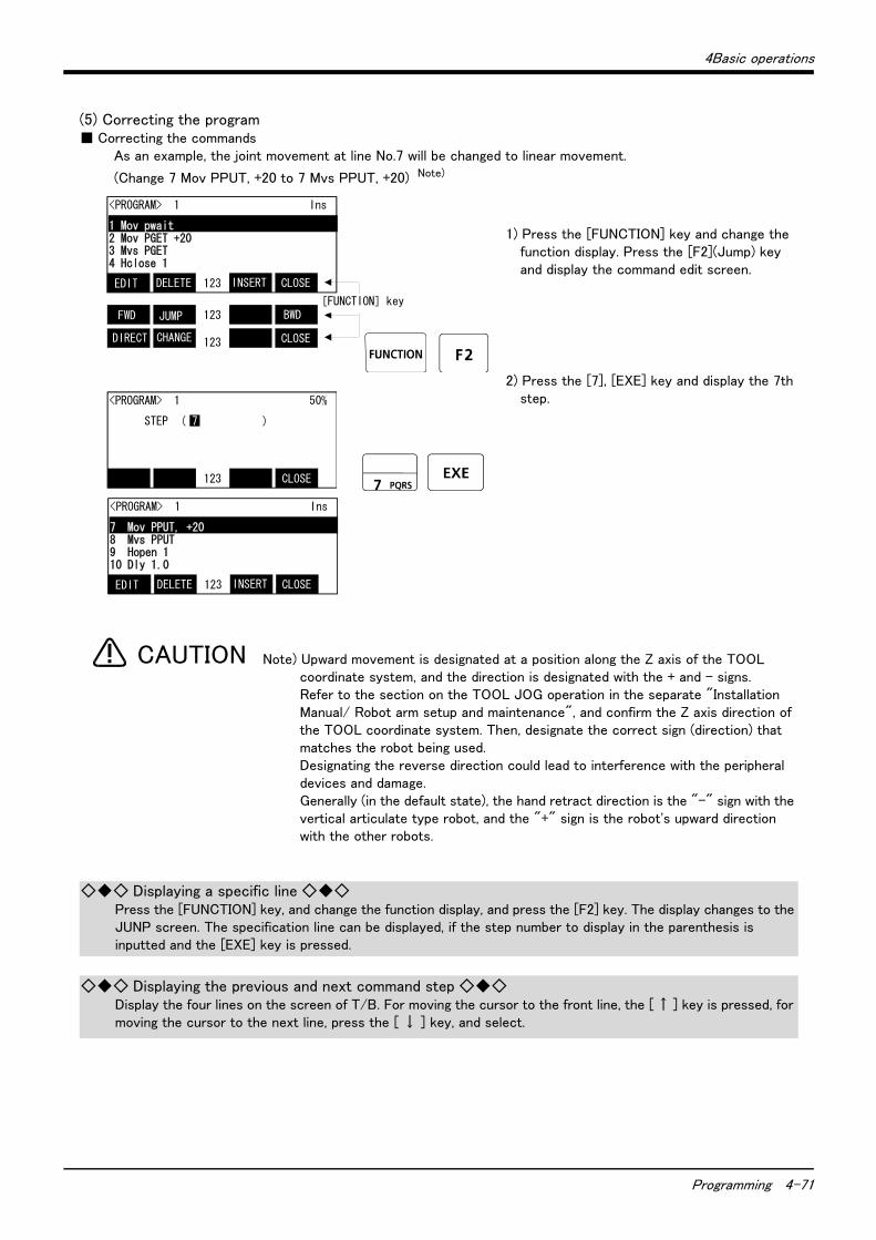
4Basic operations
Programming 4-71
(5) Correcting the program■ Correcting the commands
As an example, the joint movement at line No.7 will be changed to linear movement.
(Change 7 Mov PPUT, +20 to 7 Mvs PPUT, +20) Note)
1) Press the [FUNCTION] key and change the function display. Press the [F2](Jump) key and display the command edit screen.
2) Press the [7], [EXE] key and display the 7th step.
Note) Upward movement is designated at a position along the Z axis of the TOOL coordinate system, and the direction is designated with the + and - signs.Refer to the section on the TOOL JOG operation in the separate "Installation Manual/ Robot arm setup and maintenance", and confirm the Z axis direction of the TOOL coordinate system. Then, designate the correct sign (direction) that matches the robot being used.Designating the reverse direction could lead to interference with the peripheral devices and damage.Generally (in the default state), the hand retract direction is the "-" sign with the vertical articulate type robot, and the "+" sign is the robot's upward direction with the other robots.
<PROGRAM> 1 Ins
1 Mov pwait2 Mov PGET +203 Mvs PGET4 Hclose 1
CLOSE123
BWD123
CLOSE123
INSERTDELETEEDIT
JUMPFWD
CHANGEDIRECT
[FUNCTION] key
<PROGRAM> 1 50%
STEP ( 7 )
CLOSE123
<PROGRAM> 1 Ins
7 Mov PPUT, +208 Mvs PPUT9 Hopen 110 Dly 1.0
CLOSE123 INSERTDELETEEDIT
CAUTION
◇◆◇ Displaying a specific line ◇◆◇Press the [FUNCTION] key, and change the function display, and press the [F2] key. The display changes to the JUNP screen. The specification line can be displayed, if the step number to display in the parenthesis is inputted and the [EXE] key is pressed.
◇◆◇ Displaying the previous and next command step ◇◆◇Display the four lines on the screen of T/B. For moving the cursor to the front line, the [ ↑ ] key is pressed, for moving the cursor to the next line, press the [ ↓ ] key, and select.
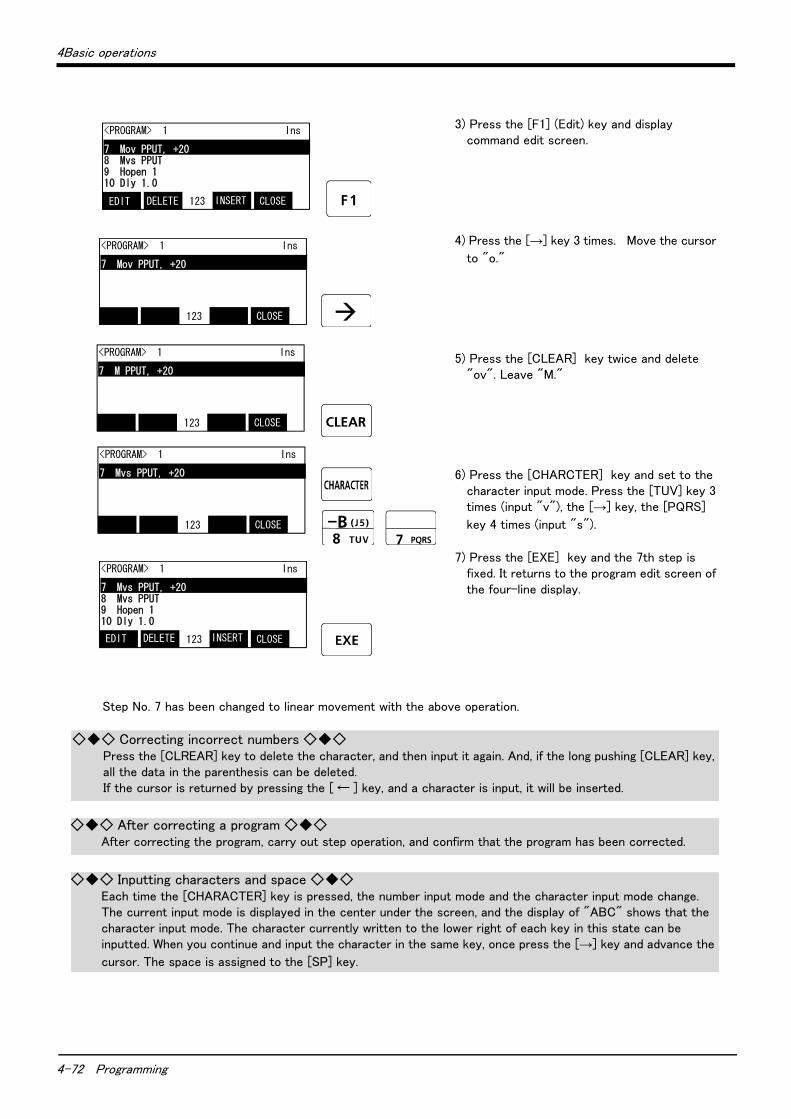
4-72 Programming
4Basic operations
3) Press the [F1] (Edit) key and display command edit screen.
4) Press the [→] key 3 times. Move the cursor
to "o."
5) Press the [CLEAR] key twice and delete "ov". Leave "M."
6) Press the [CHARCTER] key and set to the character input mode. Press the [TUV] key 3 times (input "v"), the [→] key, the [PQRS]
key 4 times (input "s").
7) Press the [EXE] key and the 7th step is fixed. It returns to the program edit screen of the four-line display.
Step No. 7 has been changed to linear movement with the above operation.
<PROGRAM> 1 Ins
7 Mov PPUT, +208 Mvs PPUT9 Hopen 110 Dly 1.0
CLOSE123 INSERTDELETEEDIT
<PROGRAM> 1 Ins
7 Mov PPUT, +20
CLOSE123
<PROGRAM> 1 Ins
7 M PPUT, +20
CLOSE123
<PROGRAM> 1 Ins
7 Mvs PPUT, +20
CLOSE123
<PROGRAM> 1 Ins
7 Mvs PPUT, +208 Mvs PPUT9 Hopen 110 Dly 1.0
CLOSE123 INSERTDELETEEDIT
◇◆◇ Correcting incorrect numbers ◇◆◇Press the [CLREAR] key to delete the character, and then input it again. And, if the long pushing [CLEAR] key, all the data in the parenthesis can be deleted. If the cursor is returned by pressing the [ ← ] key, and a character is input, it will be inserted.
◇◆◇ After correcting a program ◇◆◇After correcting the program, carry out step operation, and confirm that the program has been corrected.
◇◆◇ Inputting characters and space ◇◆◇Each time the [CHARACTER] key is pressed, the number input mode and the character input mode change.The current input mode is displayed in the center under the screen, and the display of "ABC" shows that the character input mode. The character currently written to the lower right of each key in this state can be inputted. When you continue and input the character in the same key, once press the [→] key and advance the
cursor. The space is assigned to the [SP] key.
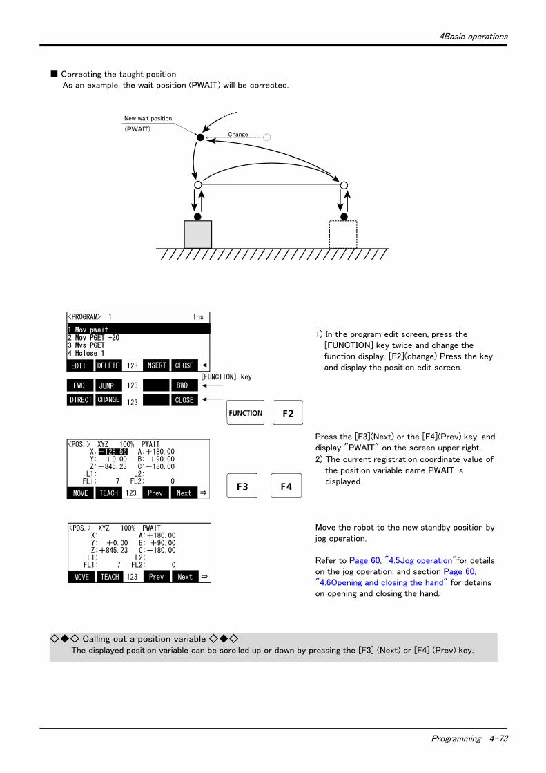
4Basic operations
Programming 4-73
■ Correcting the taught positionAs an example, the wait position (PWAIT) will be corrected.
1) In the program edit screen, press the [FUNCTION] key twice and change the function display. [F2](change) Press the key and display the position edit screen.
Press the [F3](Next) or the [F4](Prev) key, and display "PWAIT" on the screen upper right.
2) The current registration coordinate value of the position variable name PWAIT is displayed.
Move the robot to the new standby position by jog operation.
Refer to Page 60, "4.5Jog operation"for details on the jog operation, and section Page 60, "4.6Opening and closing the hand" for detains on opening and closing the hand.
New wait position
(PWAIT)Change
<PROGRAM> 1 Ins
1 Mov pwait2 Mov PGET +203 Mvs PGET4 Hclose 1
CLOSE123
BWD123
CLOSE123
INSERTDELETEEDIT
JUMPFWD
CHANGEDIRECT
[FUNCTION] key
<POS.> XYZ 100% PWAIT X:+128.56 A:+180.00 Y: +0.00 B: +90.00 Z:+845.23 C:-180.00 L1: L2: FL1: 7 FL2: 0
Next123TEACHMOVE Prev ⇒
<POS.> XYZ 100% PWAIT X:+128.56 A:+180.00 Y: +0.00 B: +90.00 Z:+845.23 C:-180.00 L1: L2: FL1: 7 FL2: 0
Next123TEACHMOVE Prev ⇒
◇◆◇ Calling out a position variable ◇◆◇The displayed position variable can be scrolled up or down by pressing the [F3] (Next) or [F4] (Prev) key.
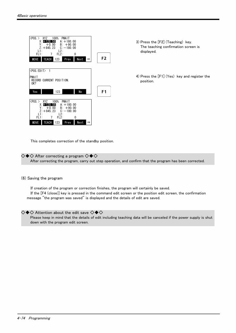
4-74 Programming
4Basic operations
3) Press the [F2] (Teaching) key. The teaching confirmation screen is displayed.
4) Press the [F1] (Yes) key and register the position.
This completes correction of the standby position.
(6) Saving the program
If creation of the program or correction finishes, the program will certainly be saved.
If the [F4 (close)] key is pressed in the command edit screen or the position edit screen, the confirmation message "the program was saved" is displayed and the details of edit are saved.
<POS.> XYZ 100% PWAIT X:+128.56 A:+180.00 Y: +0.00 B: +90.00 Z:+845.23 C:-180.00 L1: L2: FL1: 7 FL2: 0
Next123TEACHMOVE Prev ⇒
<POS.EDIT> 1
PWAIT RECORD CURRENT POSITION. OK?
No123Yes
<POS.> XYZ 100% PWAIT X:+128.56 A:+180.00 Y: +0.00 B: +90.00 Z:+845.23 C:-180.00 L1: L2: FL1: 7 FL2: 0
Next123TEACHMOVE Prev ⇒
◇◆◇ After correcting a program ◇◆◇After correcting the program, carry out step operation, and confirm that the program has been corrected.
◇◆◇ Attention about the edit save ◇◆◇Please keep in mind that the details of edit including teaching data will be canceled if the power supply is shut down with the program edit screen.
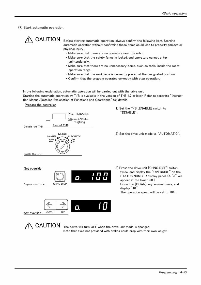
4Basic operations
Programming 4-75
(7) Start automatic operation.
Before starting automatic operation, always confirm the following item. Starting automatic operation without confirming these items could lead to property damage or physical injury.
・ Make sure that there are no operators near the robot.
・ Make sure that the safety fence is locked, and operators cannot enter unintentionally.
・ Make sure that there are no unnecessary items, such as tools, inside the robot operation range.
・ Make sure that the workpiece is correctly placed at the designated position.
・ Confirm that the program operates correctly with step operation.
In the following explanation, automatic operation will be carried out with the drive unit.
Starting the automatic operation by T/B is available in the version of T/B 1.7 or later. Refer to separate "Instruc-
tion Manual/Detailed Explanation of Functions and Operations" for details.
1) Set the T/B [ENABLE] switch to "DISABLE".
2) Set the drive unit mode to "AUTOMATIC".
3) Press the drive unit [CHNG DISP] switch twice, and display the "OVERRIDE" on the STATUS NUMBER display panel. (A "o" will appear at the lower left.)Press the [DOWN] key several times, and display "10".The operation speed will be set to 10%.
The servo will turn OFF when the drive unit mode is changed.Note that axes not provided with brakes could drop with their own weight.
CAUTION
Down:ENABLE *Lighting
Up :DISABLE
Rear of T/B
MODEMANUAL AUTOMATIC
Prepare the controller
Set override
Dsiable the T/B
Enable the R/C
Dsiplay override
Set override
CHNG DISP
DOWN UP
CAUTION
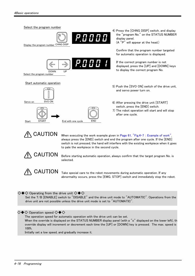
4-76 Programming
4Basic operations
4) Press the [CHNG DISP] switch, and display the "program No." on the STATUS NUMBER display panel.(A "P" will appear at the head.)
Confirm that the program number targeted for automatic operation is displayed.
If the correct program number is not displayed, press the [UP] and [DOWN] keys to display the correct program No.
5) Push the [SVO ON] switch of the drive unit, and servo power turn on.
6) After pressing the drive unit [START] switch, press the [END] switch.
7) The robot operation will start and will stop after one cycle.
When executing the work example given in Page 61, "Fig.4-7 : Example of work", always press the [END] switch and end the program after one cycle. If the [END] switch is not pressed, the hand will interfere with the existing workpiece when it goes to pale the workpiece in the second cycle.
Before starting automatic operation, always confirm that the target program No. is selected.
Take special care to the robot movements during automatic operation. If any abnormality occurs, press the [EMG. STOP] switch and immediately stop the robot.
Start automatic operation
Select the program number
Start End with one cycle
Display the program number
Select the program number
Servo on
CHNG DISP
DOWN UP
SVO ON
START END
CAUTION
CAUTION
CAUTION
◇◆◇ Operating from the drive unit ◇◆◇Set the T/B [ENABLE] switch to "DISABLE" and the drive unit mode to "AUTOMATIC". Operations from the drive unit are not possible unless the drive unit mode is set to "AUTOMATIC".
◇◆◇ Operation speed ◇◆◇The operation speed for automatic operation with the drive unit can be set.When the override is displayed on the STATUS NUMBER display panel (with a "o" displayed on the lower left), theoverride display will increment or decrement each time the [UP] or [DOWN] key is pressed. The max. speed is 100%.Initially set a low speed, and gradually increase it.
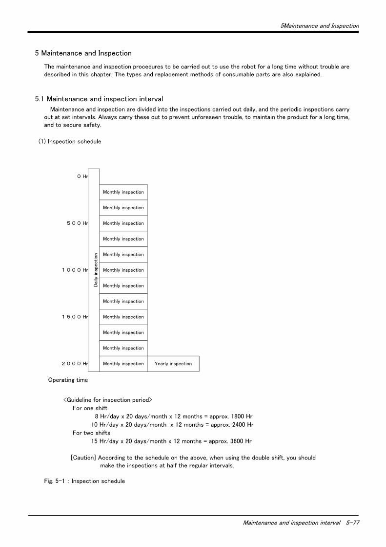
5Maintenance and Inspection
Maintenance and inspection interval 5-77
5 Maintenance and Inspection
The maintenance and inspection procedures to be carried out to use the robot for a long time without trouble are described in this chapter. The types and replacement methods of consumable parts are also explained.
5.1 Maintenance and inspection interval
Maintenance and inspection are divided into the inspections carried out daily, and the periodic inspections carry out at set intervals. Always carry these out to prevent unforeseen trouble, to maintain the product for a long time, and to secure safety.
(1) Inspection schedule
Fig. 5-1 : Inspection schedule
0 Hr
Dai
ly insp
ect
ion
Monthly inspection
Monthly inspection
5 0 0 Hr Monthly inspection
Monthly inspection
Monthly inspection
1 0 0 0 Hr Monthly inspection
Monthly inspection
Monthly inspection
1 5 0 0 Hr Monthly inspection
Monthly inspection
Monthly inspection
2 0 0 0 Hr Monthly inspection Yearly inspection
Operating time
<Guideline for inspection period>
For one shift
8 Hr/day x 20 days/month x 12 months = approx. 1800 Hr
10 Hr/day x 20 days/month x 12 months = approx. 2400 Hr
For two shifts
15 Hr/day x 20 days/month x 12 months = approx. 3600 Hr
[Caution] According to the schedule on the above, when using the double shift, you should make the inspections at half the regular intervals.
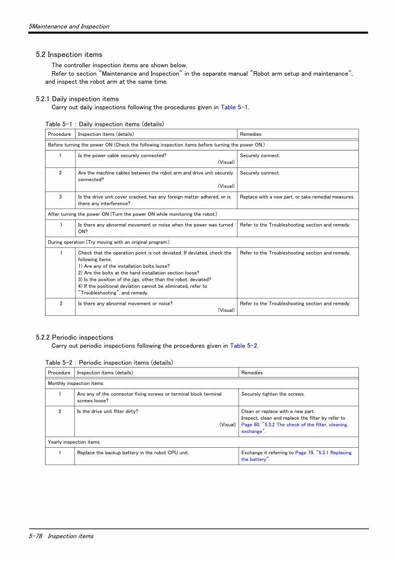
5-78 Inspection items
5Maintenance and Inspection
5.2 Inspection items
The controller inspection items are shown below.
Refer to section "Maintenance and Inspection" in the separate manual "Robot arm setup and maintenance", and inspect the robot arm at the same time.
5.2.1 Daily inspection itemsCarry out daily inspections following the procedures given in Table 5-1.
Table 5-1 : Daily inspection items (details)
5.2.2 Periodic inspectionsCarry out periodic inspections following the procedures given in Table 5-2.
Table 5-2 : Periodic inspection items (details)
Procedure Inspection items (details) Remedies
Before turning the power ON (Check the following inspection items before turning the power ON.)
1 Is the power cable securely connected?
(Visual)
Securely connect.
2 Are the machine cables between the robot arm and drive unit securely
connected?
(Visual)
Securely connect.
3 Is the drive unit cover cracked, has any foreign matter adhered, or is
there any interference?
Replace with a new part, or take remedial measures.
After turning the power ON (Turn the power ON while monitoring the robot.)
1 Is there any abnormal movement or noise when the power was turned
ON?
Refer to the Troubleshooting section and remedy.
During operation (Try moving with an original program.)
1 Check that the operation point is not deviated. If deviated, check the
following items.
1) Are any of the installation bolts loose?
2) Are the bolts at the hand installation section loose?
3) Is the position of the jigs, other than the robot, deviated?
4) If the positional deviation cannot be eliminated, refer to
"Troubleshooting", and remedy.
Refer to the Troubleshooting section and remedy.
2 Is there any abnormal movement or noise?
(Visual)
Refer to the Troubleshooting section and remedy.
Procedure Inspection items (details) Remedies
Monthly inspection items
1 Are any of the connector fixing screws or terminal block terminal
screws loose?
Securely tighten the screws.
2 Is the drive unit filter dirty?
(Visual)
Clean or replace with a new part.
Inspect, clean and replace the filter by refer to
Page 80, "5.3.2 The check of the filter, cleaning,
exchange".
Yearly inspection items
1 Replace the backup battery in the robot CPU unit. Exchange it referring to Page 79, "5.3.1 Replacing
the battery".

5Maintenance and Inspection
Maintenance and inspection procedures 5-79
5.3 Maintenance and inspection procedures
The procedures for carrying out periodic maintenance and inspection are described below. Thoroughly comprehend the procedures, and follow the instructions. This work can be commissioned to the Mitsubishi Service Dept. for a fee. (Never disassemble, etc., any of the parts not described in this section.)
The maintenance parts required for the maintenance and inspection are shown in Page 82, "5.4 Maintenance parts". Contact your dealer for these parts when required.
5.3.1 Replacing the batteryThe batteries are installed when the robot is shipped from the factory, but as these are consumable parts, they must be replaced periodically by the customer.
The guideline for replacing the battery is one year, but this will differ according to the robot's usage state.
There are the kind of the errors about the battery shown in Table 5-3. If error 7500 occurs, please exchange the batteries of the robot arm and the robot CPU unit simultaneously.
Table 5-3 : The error about the battery
The method of replacing the battery of drive unit is shown below. Refer to the separate "ROBOT ARM SETUP & MAINTENANCE" about robot arm's battery. About the purchase of the battery, refers to Page 82, "5.4 Maintenance parts".
If error No. 7500 or 112n occurs, the program data and other data in the controller is lost and it becomes necessary to load the data again.
Replace the batteries for the drive unit and robot arm at the same time. Replace the controller battery within 3 minutes after removing the old battery.
It is also recommended to save programs and position data on the personal computer side via the RT ToolBox 2 and so forth in advance.
Section Error number Description Disposition
Contr
olle
r
7520 The exhausting time is over.Exchange the batteries.
7510 Voltage is falling.
7500 Voltage fell. Backup data cannot be secured.
Robot
arm
7520 The exhausting time is over.Exchange the batteries.
133n Note1)
Note1) "n" shows the axial number.
Voltage is falling.
112nThe absolute position data of the encoder disappeared.
Backup data cannot be secured.
CAUTION
CAUTION
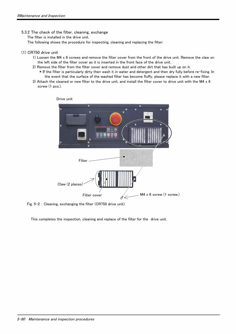
5-80 Maintenance and inspection procedures
5Maintenance and Inspection
5.3.2 The check of the filter, cleaning, exchange The filter is installed in the drive unit.
The following shows the procedure for inspecting, cleaning and replacing the filter:
(1) CR750 drive unit1) Loosen the M4 x 6 screws and remove the filter cover from the front of the drive unit. Remove the claw on
the left side of the filter cover as it is inserted in the front face of the drive unit.2) Remove the filter from the filter cover and remove dust and other dirt that has built up on it.
* If the filter is particularly dirty then wash it in water and detergent and then dry fully before re-fixing. In the event that the surface of the washed filter has become fluffy, please replace it with a new filter.
3) Attach the cleaned or new filter to the drive unit, and install the filter cover to drive unit with the M4 x 6 screw (1 pcs.).
Fig. 5-2 : Cleaning, exchanging the filter (CR750 drive unit)
This completes the inspection, cleaning and replace of the filter for the drive unit.
M4 x 6 screw (1 screw.)Filter cover
Filter
Claw (2 places)
Drive unit
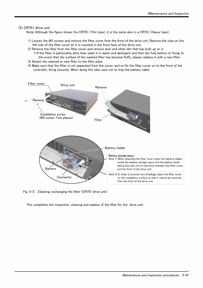
5Maintenance and Inspection
Maintenance and inspection procedures 5-81
(2) CR751 drive unitNote) Although the figure shows the CR751 (Thin type), it is the same also in a CR751 (Heavy type).
1) Loosen the M3 screws and remove the filter cover from the front of the drive unit. Remove the claw on the left side of the filter cover as it is inserted in the front face of the drive unit.
2) Remove the filter from the filter cover and remove dust and other dirt that has built up on it.* If the filter is particularly dirty then wash it in water and detergent and then dry fully before re-fixing. In
the event that the surface of the washed filter has become fluffy, please replace it with a new filter.
3) Attach the cleaned or new filter to the filter plate4) Make sure that the filter is not separated from the cover, and re-fix the filter cover on to the front of the
controller, fixing securely. When doing this take care not to trap the battery cable.
Fig. 5-3 : Cleaning, exchanging the filter (CR751 drive unit)
This completes the inspection, cleaning and replace of the filter for the drive unit.
バッテリ
バッテリホルダ
フィルタカバー
取付ネジ(M3ネジ)2箇所
外す
コネクタ
フィルタカバー
取付ネジ(M3ネジ)2箇所
外す
フィルタ
外す
Filter cover
Filter
Drive unit
Remove
Installation screw (M3 screw: Two places)
Battery
Connector
Battery holder
Battery storage space
Note 1) When attaching the filter cover insert the battery cables
inside the battery storage space and the battery itself,
taking due care not to trap them between the filter cover
and the front of the drive unit.
Note 2) In order to prevent wire breakage, place the filter cover
on the installation surface so that it cannot be removed
from the front of the drive unit.
Remove
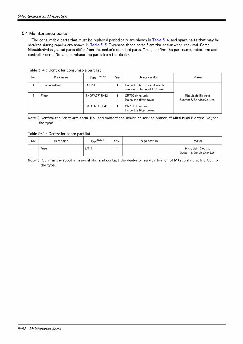
5-82 Maintenance parts
5Maintenance and Inspection
5.4 Maintenance parts
The consumable parts that must be replaced periodically are shown in Table 5-4, and spare parts that may be required during repairs are shown in Table 5-5. Purchase these parts from the dealer when required. Some Mitsubishi-designated parts differ from the maker's standard parts. Thus, confirm the part name, robot arm and controller serial No. and purchase the parts from the dealer.
Table 5-4 : Controller consumable part list
Table 5-5 : Controller spare part list
No. Part name Type Note1)
Note1) Confirm the robot arm serial No., and contact the dealer or service branch of Mitsubishi Electric Co., for the type.
Qty. Usage section Maker
1 Lithium battery Q6BAT 1 Inside the battery unit which
connected to robot CPU unit.
Mitsubishi Electric
System & Service;Co.,Ltd.
2 Filter BKOFA0773H42 1 CR750 drive unit:
Inside the filter cover
BKOFA0773H41 1 CR751 drive unit:
Inside the filter cover.
No. Part name TypeNote1)
Note1) Confirm the robot arm serial No., and contact the dealer or service branch of Mitsubishi Electric Co., for the type.
Qty. Usage section Maker
1 Fuse LM16 1 Mitsubishi Electric
System & Service;Co.,Ltd.

Mar., 2013 MEE Printed in Japan on recycled paper. Specifications are subject to change without notice.
HEAD OFFICE: TOKYO BUILDING, 2-7-3, MARUNOUCHI, CHIYODA-KU, TOKYO 100-8310, JAPANNAGOYA WORKS: 5-1-14, YADA-MINAMI, HIGASHI-KU, NAGOYA 461-8670, JAPAN
Authorised representative:
MITSUBISHI ELECTRIC EUROPE B.V. GERMANY
Gothaer Str. 8, 40880 Ratingen / P.O. Box 1548, 40835 Ratingen, Germany
HEADQUARTERS
EUROPEMITSUBISHI ELECTRIC EUROPE B.V.German BranchGothaer Straße 8D-40880 RatingenPhone: +49 (0)2102 / 486-0Fax: +49 (0)2102 / 486-1120
CZECHREP.MITSUBISHI ELECTRIC EUROPE B.V.-org.sl.Czech BranchAvenir Business Park, Radlická 714/113aCZ-158 00 Praha 5Phone: +420 - 251 551 470Fax: +420 (0)251-551-471
FRANCEMITSUBISHI ELECTRIC EUROPE B.V.French Branch25, Boulevard des BouvetsF-92741 Nanterre CedexPhone: +33 (0)1 / 55 68 55 68Fax: +33 (0)1 / 55 68 57 57
IRELANDMITSUBISHI ELECTRIC EUROPE B.V.Irish BranchWestgate Business Park, BallymountIRL-Dublin 24Phone: +353 (0)1 4198800Fax: +353 (0)1 4198890
ITALYMITSUBISHI ELECTRIC EUROPE B.V.Italian BranchViale Colleoni 7I-20864 Agrate Brianza (MB)Phone: +39 039 / 60 53 1Fax: +39 039 / 60 53 312
POLANDMITSUBISHI ELECTRIC EUROPE B.V.Poland BranchKrakowska 50PL-32-083 BalicePhone: +48 (0)12 / 630 47 00Fax: +48 (0)12 / 630 47 01
RUSSIAMITSUBISHI ELECTRIC EUROPE B.V.52, bld. 3 Kosmodamianskaya nab 8 floorRU-115054 МoscowPhone: +7 495 721-2070Fax: +7 495 721-2071
SPAINMITSUBISHI ELECTRIC EUROPE B.V.Spanish BranchCarretera de Rubí 76-80E-08190 Sant Cugat del Vallés (Barcelona)Phone: 902 131121 // +34 935653131Fax: +34 935891579
UKMITSUBISHI ELECTRIC EUROPE B.V.UK BranchTravellers LaneUK-Hatfield, Herts. AL10 8XBPhone: +44 (0)1707 / 27 61 00Fax: +44 (0)1707 / 27 86 95
JAPANMITSUBISHI ELECTRIC CORPORATIONOffice Tower “Z” 14 F8-12,1 chome, Harumi Chuo-KuTokyo 104-6212Phone: +81 3 622 160 60Fax: +81 3 622 160 75
USAMITSUBISHI ELECTRIC AUTOMATION, Inc.500 Corporate Woods ParkwayVernon Hills, IL 60061Phone: +1 847 478 21 00Fax: +1 847 478 22 53
EUROPEAN REPRESENTATIVES
AUSTRIAGEVAWiener Straße 89AT-2500 BadenPhone: +43 (0)2252 / 85 55 20Fax: +43 (0)2252 / 488 60
BELGIUMKoning & Hartman b.v.Woluwelaan 31BE-1800 VilvoordePhone: +32 (0)2 / 257 02 40Fax: +32 (0)2 / 257 02 49
BOSNIA AND HERZEGOVINAINEA RBT d.o.o.Aleja Lipa 56BA-71000 SarajevoPhone: +387 (0)33 / 921 164Fax: +387 (0)33 / 524 539
BULGARIAAKHNATON4, Andrei Ljapchev Blvd., PO Box 21BG-1756 SofiaPhone: +359 (0)2 / 817 6000Fax: +359 (0)2 / 97 44 06 1
CZECH REPUBLICAutoCont C.S. s.r.o.Technologická 374/6CZ-708 00 Ostrava-PustkovecPhone: +420 595 691 150Fax: +420 595 691 199
DENMARKBeijer Electronics A/SLykkegårdsvej 17DK-4000 RoskildePhone: +45 (0)46/ 75 76 66Fax: +45 (0)46 / 75 56 26
FINLANDBeijer Electronics OYPeltoie 37FIN-28400 UlvilaPhone: +358 (0)207 / 463 540Fax: +358 (0)207 / 463 541
GREECEUTECO5, Mavrogenous Str.GR-18542 PiraeusPhone: +30 211 / 1206 900Fax: +30 211 / 1206 999
HUNGARYAXICONT AUTOMATIKA Kft.(ROBOT CENTER) Reitter F. U. 132HU-1131 BudapestPhone: +36 1 / 412-0882Fax: +36 1 / 412-0883
MALTAALFATRADE Ltd.99, Paola HillMalta- Paola PLA 1702Phone: +356 (0)21 / 697 816Fax: +356 (0)21 / 697 817
NETHERLANDSHIFLEX AUTOM.TECHNIEK B.V.Wolweverstraat 22NL-2984 CD RidderkerkPhone: +31 (0)180 – 46 60 04Fax: +31 (0)180 – 44 23 55
EUROPEAN REPRESENTATIVES
NETHERLANDSKoning & Hartman b.v.Haarlerbergweg 21-23NL-1101 CH AmsterdamPhone: +31 (0)20 / 587 76 00Fax: +31 (0)20 / 587 76 05
NORWAYBeijer Electronics ASPostboks 487NO-3002 DrammenPhone: +47 (0)32 / 24 30 00Fax: +47 (0)32 / 84 85 77
PORTUGALFonseca S.A.R. João Francisco do Casal 87/89PT - 3801-997 Aveiro, EsgueiraPhone: +351 (0)234 / 303 900Fax: +351 (0)234 / 303 910
ROMANIASIRIUS TRADING & SERVICES SRLAleea Lacul Morii Nr. 3RO-060841 Bucuresti, Sector 6Phone: +40 (0)21 / 430 40 06Fax: +40 (0)21 / 430 40 02
SERBIAINEA RBT d.o.o.Izletnicka 10SER-113000 SmederevoPhone: +381 (0)26 / 615 401Fax: +381 (0)26 / 615 401
SLOVAKIASIMAP s.r.o.Jána Derku 1671SK-911 01 TrencínPhone: +421 (0)32 743 04 72Fax: +421 (0)32 743 75 20
SLOVAKIAPROCONT, spol. s r.o. PrešovKúpelná 1/ASK-080 01 PrešovPhone: +421 (0)51 7580 611Fax: +421 (0)51 7580 650
SLOVENIAINEA RBT d.o.o.Stegne 11SI-1000 LjubljanaPhone: +386 (0)1 / 513 8116Fax: +386 (0)1 / 513 8170
SWEDENBeijer Electronics Automation ABBox 426SE-20124 MalmöPhone: +46 (0)40 / 35 86 00Fax: +46 (0)40 / 93 23 01
SWITZERLANDRobotronic AGSchlachthofstrasse 8CH-8406 WinterthurPhone: +41 (0)52 / 267 02 00Fax: +41 (0)52 / 267 02 01
TURKEYGTSBayraktar Bulvari Nutuk Sok. No:5TR-34775 Yukarı Dudullu-Ümraniye-İSTANBULPhone: +90 (0)216 526 39 90Fax: +90 (0)216 526 3995
UKRAINECSC Automation Ltd.4-B, M. Raskovoyi St.UA-02660 KievPhone: +380 (0)44 / 494 33 55Fax: +380 (0)44 / 494-33-66
MIDDLE EAST REPRESENTATIVE
EGYPTI.C. SYSTEMS LTD.23 Al-Saad-Al-Alee St.EG-Sarayat, Maadi, CairoPhone: +20 (0) 2 / 235 98 548Fax: +20 (0) 2 / 235 96 625
ISRAELILAN & GAVISH Ltd.24 Shenkar St., Kiryat ArieIL-49001 Petah-TiqvaPhone: +972 (0)3 / 922 18 24Fax: +972 (0)3 / 924 0761
AFRICAN REPRESENTATIVE
SOUTH AFRICACBI Ltd.Private Bag 2016ZA-1600 IsandoPhone: + 27 (0)11 / 977 0770Fax: + 27 (0)11 / 977 0761
Mitsubishi Electric Europe B.V. /// FA - European Business Group /// Gothaer Straße 8 /// D-40880 Ratingen /// GermanyTel.: +49(0)2102-4860 /// Fax: +49(0)2102-4861120 /// [email protected] /// www.mitsubishi-automation.com
MITSUBISHI ELECTRIC