-*q + . - Citroen
221
AUTOMOTIVE -*q +. DIAGNbS.l I 4 P+ Wh4 I. ET $ I I 4 A ;FAULT cooesL ", ,12 I -h Extracting, interpreting and clearing of fault codes Fault code tables and step-by-step instructions The guide that shows you how and saves you money
-
Upload
khangminh22 -
Category
Documents
-
view
3 -
download
0
Transcript of -*q + . - Citroen

AUTOMOTIVE -*q + .
DIAGNbS.l I
4 P+ Wh4
I. ET $ I I
4 A
;FAULT cooesL ", ,12 I -h
Extracting, interpreting and clearing of fault codes Fault code tables and step-by-step instructions The guide that shows you how and saves you money

Automotive Diagnostic Fault Codes Techbook Charles White
Systems covered Bosch KE-Jetronlc Bosch KE-Motronic Bosch LH-Jetronic Bosch Mono-Jetronic Sosch Mono-Motro~ic Bosch Motrontc Dal hatsu MPi Bosch EZ-K and €2-L Ignition Fenlx ford EEC IV and EEC V GM/Delco SPi GM Multec
D Haynes Publishing 1998
A hook in the Haynea Techbook Series
lsuzu I-Tec Lucas 1 ICU and 14CUX Lucas LH Magneti-Marelli G5 and G6 Magneti-Marelli 8F and 8P Mazda EGi Mercedes HFM and PMS Mitsublsh~ ECI-Multi Nissan ECCS Proton ECI-Multi and ECI-SEFi Renix Rover MEMS
APCDE FGHIJ KLMNO Pr,
AH rights reserved. No part of this book may tx reproduced or transmitted in any form or by any means, electronic or mechanical, including phototopylng, recording or by any information storage or retrieval system, wrthout permission in writing horn the copyright holder.
ISBN 1 85960 472 2
Bnlish Library Cataloguing in Publicavan Data A catalagw record for thq? book IS a~a~lable from the British Library
Rover PGM-FI Saab Tr~onic Siemens Bendix MPi Siemens MS4.0 Si mos Simtec Subaru MPFi Suzuki EPi Toyota TCCS UAG MPi and MPFI VW Digifant Weber-MareJ11 IAW
H e y n ~ PublWIIw Sparkford, Nr Yeov~l. Somerset BA22 7JJ, England
H a m s North Amerlca, Inc 861 Lawrence Drive, N~wbury Park, California 9132G, USA
Editions Haynes S.A. Tour Autore - La Wfense 2 , l B Place des Reflets. 92975 PARIS LA DEFENSE Cedex
Haynes Publishing Nordlska AB Bow 1504,751 45 UPPSAIA, Svenge
Contents
GENERAL INFORMATION Introduction Page 0.4 - Safety first! Page 0.5
Index of vehicles covered Page 0.6
Chapter 1 Introduction to Self-Diagnosis -
Page 1.1
Chapter 2 Test equipment, training and technical data Page 2.1
Chapter 3 General test procedures Page 3.1 - - -
Chapter 4 Component test procedures -
Page 4.1
SYSTEM SPECIFICS (BY MANUFACTURER) Chanter 5 Alfa Romeo Paae 5.1
Chapter 6 Audi Page 6.7
Chapter 7 BMW Page 7.1 --
Chapter 8 Citroen Page 8.1
Chapter 9 - Daew 00 Page 9.1
Chapter 10 Daihatsu Page 10*1
Chapter 11 Fiat Page 11*1
Chapter 12 Ford Page 12.1
Chapter 13 Honda - Page 134 Chapter 1 4 Hyundai Page 14.1
Chapter f 5 lsuzu -
Page 15.1
Chapter 16 Jaguar Page 16.1
Chapter 1 7 Kia Page f 7.1

Contents Chapter 18 Lamia Page 98.1
Cha~ter 19 Land Rover P a ~ e 1 9- 1
Chapter 20 Lexus
Chapter 21 Mazda -
Page 21.1
Chapter 22 Mercedes Page 22.1
Chapter 23 Mitsubishi Page 23.1
Chapter 24 Nissan Page 24.1
Chapter 25 Peugeot Page 25.1
Chapter 26 Proton Page 26.1
Chanter 27 Renault Paae 27.1 -
Chapter 28 Rover Page 28.1
Chapter 29 Saab Page 29.1
Chapter 30 Seat Page 30.1
Chapter 31 Skoda Page 31.1
Chapter 32 Subaru Page 32-1
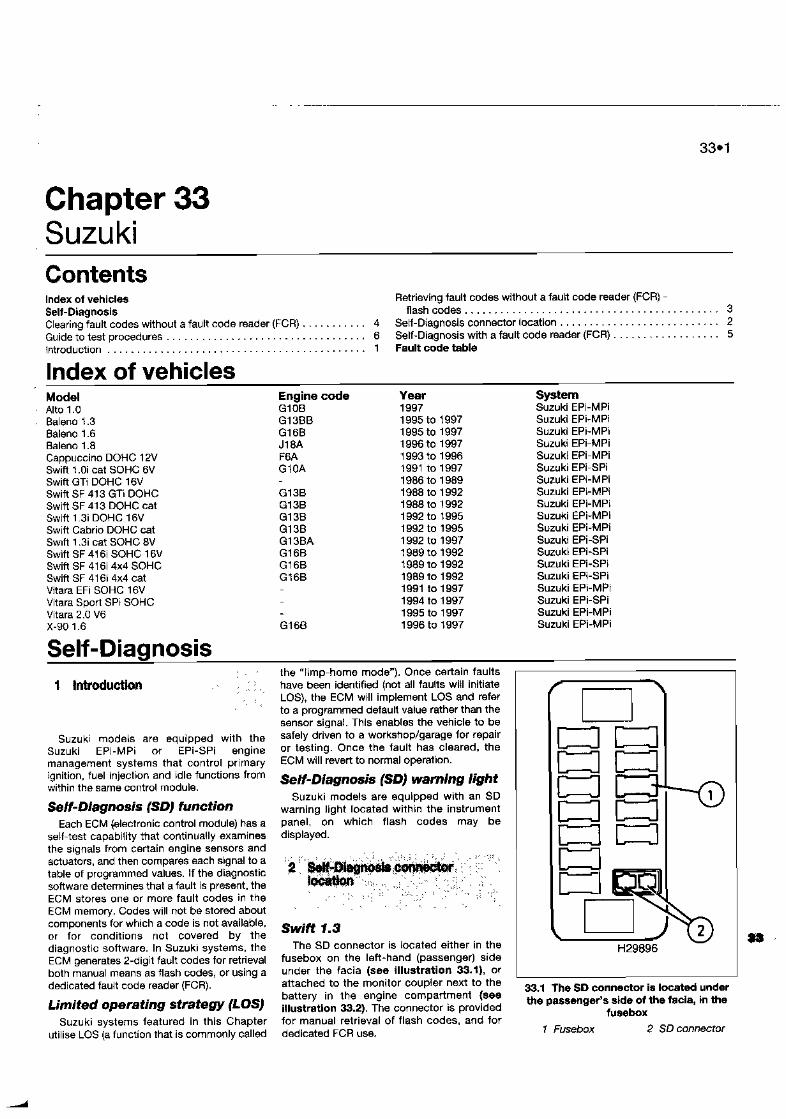
Chapter 33 Suzuki Page 33.1
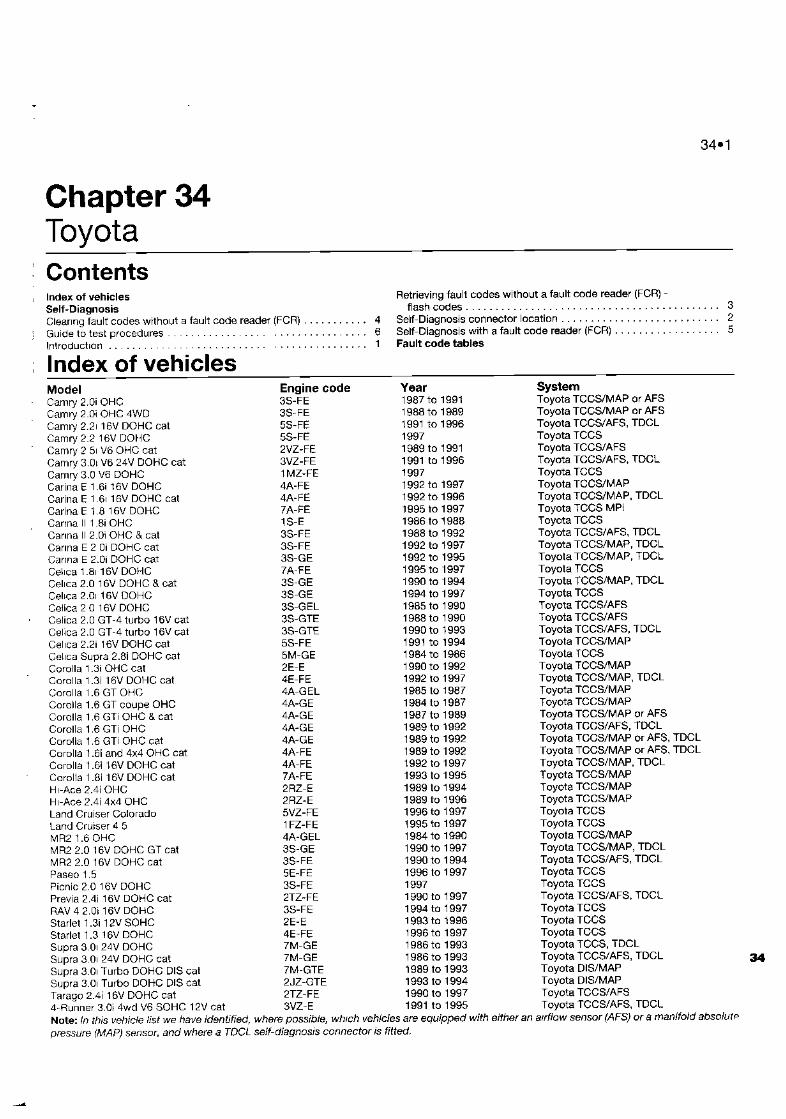
Chapter 34 Toyota Page 34.1
Chapter 35 - VauxhalROpel Page 35.1
Chapter 36 Volkswagen Page 38.1
Chapter 37 Volvo Page 37.1
Abbreviations, Warnings and Glossary of technical terms Page R E P 1

0.4 Introduction
This book Is devoted to the galhering ot fault codes, and to the understanding and testing af the sell-diagnosis element of the modern engine management system. This Automotive Diagnostic Fault Code Techbook is a companion volume to the Haynes Engine Management and Fuel Injection Systerns Manual, and for a complete understanding of the modern qngine management system, the content of both books should be examined.
The book first gives a technical ouerview of sen-diagnosis. Other Chapters describe test equipment and general test routines for individual components which may be indicated to tx? detective by the presance of a stored fault code. Finally, each vehicle manufacturer is given a specific Chapter with a comprehensive list of fault codes, details of how to obtain codes, and other relevant infomation. Even If the reader has no intention of actually attemptag to lnvestlgate faults on his or her own vehicle, the oook still provides valuable insight iito self-diagnosis. On the other hand, if you relish the task of
electronic fault diagnosis, this book will prw$de you with r n ~ h of the background knowledge necessary to test the components and circuits on your engine. Generally, we describe how lo dlagnme faults using sirnple tools and equipment, which will be available from most good automotive parts retailers. We also mention where the use ot more specralised equipment is necessary, and descnbe some of the common routines used by the profess~onal garage trade.
The vehicle manufacturers may not in fact spm-fically endorse a number of our tests and routines. In the main, this will be because the manufacturer's test routlnes are becoming
more focused on their own dedicated test equipment which is not generally available outside of a main dealer netwok In almost all instances, our own tests follow well-defirled testing methods taught in independent training schools, and used by many modern vahlcfe technical spec~allsts. We mainly describe simple testing methods that are possible uith the dd of the ubquitous digital muhi-meter (DMM).
Refer to the companion volume (Haynes Engine Management Techbook) for a description of the operation and test procedures of the modern engine rnanaqsment system. Our test procdures ore necessarily generic. However, in many cases, following our proceddres in conlunction with a good wiring dlagram will reveal the reason lor most faults. The routine and test methods which we describe are perfectly safe to carry out on electronic systems, so long as certain simple rules are observed. These r u l e are actually no more than the observation of good electrical practice. 8e aware that damage to highly-expensive electronic control moduhs can result from nol f~ l lowing these rules. Refer to the Warnings sectiori in the Reference section at the back of this book +
these warnings will be repeatsd/referred to where necessary in tb,e various procedures.
Throughout Furow, the USA and the Far East, the various rnanufacturan tend to use their own particular terms to describe a particular component. Of course, all these terms tend to be different, and the problem is exacerbated by translation into different languages. This often leads to confusion when several terms are used to describe
essentially the same component. There b:.: been severs! attampts to bring all ilk manufacturers into line, with a cornci.'. naming stahdard for al. One such does ii~r exist (J1930), but it seems unlikely that fl manufacturers will adopt thrs p a r t ~ c ~ l z standard, and we are not sure that the :;;;;;; used are that meaningful anyway. Thus, Lk t m s used in this book wll follow those w t k are commonly used in the UK. To reduo confusion, we will apply these t e r n for !be whde range of manufacturers covered in ::,G book, and any commonly-used alternatiw will be listed in the Reference section at th end.
Ackno wledgemenk We would lrke to thank all those FA
Sparkford and elsewhere who hovo helpod In the production of this book. In particular, we would like to thank Equiptech for pam~ssl~l to use illustra!ions from the "CAPS" fuel Injection fault diagnosis database, and for prov~ding much of the technical inforrnat~on used. We also thank Kate Eyres, who compiled the lists and tables, John Menin for his work on many of the Chapters, an3 Simon Ashby of HA Engineerirlg for additional technhcal information.
We take great prlde in the accvacy ol intonnation givm in thls book, but vehicb manufacturers make alterations and design changes durlng the produdm run of 8 pameular vehlcle of which they do not inform us. No liability can be acoeptd by the arthors or publlshtrrs for loss, damsgr or injury caused by any errors in, or omissions from, the Information given.
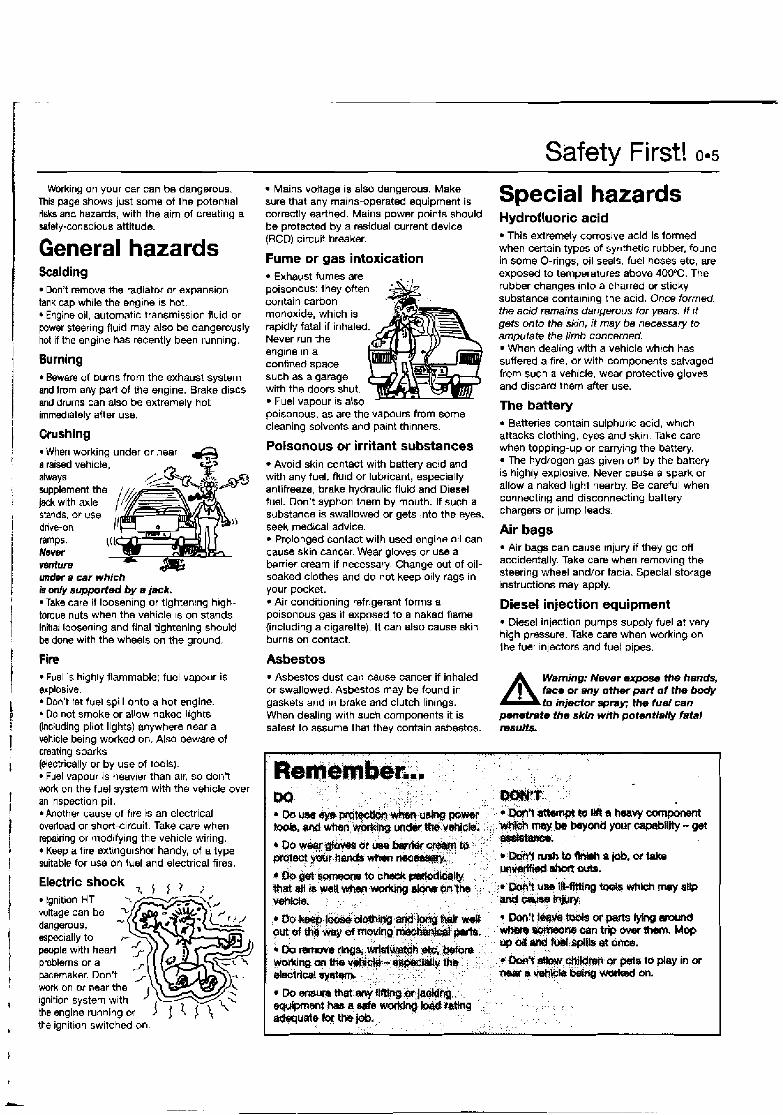
Working on your car can be dangerous. This paga shows just sorne of the p~tent~a l risks and hazards, with the aim ol creating a safety-conscious attitude.
General hazards Scalding
Don't remove the radiator or expansion tank cap while the engine IS hot. * Engine oil, automatic transmission fluid or power steering flu~d may also be dangerwsly hot if the engine has recently been runnlng.
Burning * Beware of burns from the exhaust system and fmm any part of the engine. Brake discs and drums can also be extremely hot immediately after use.
Crushing r When working under or near & a raised vehicle, A * always /LAY+#.
stands, or use ;& * , drive-on ramps. Never
((t
venture
supplem~ jack with
mt tb axle
under a car which k only supporled by e jack. Take care if loosening or tightenrng h~gh- toque nuts when the vehicle 1s on stands. Initial loosening and final tightening should be done with the wheels on the ground.
Fire Fuel IS highly flammable; fuel vapour is
explosive. Don't let fuel spill onto a hot engine. Do not smoke or allow naked llghts
(including pilot lights) anywhere near a vehicle being worked on. Also beware of creating sparks (electrically or by use of tools).
Fuel vapour is heavier than air, so don't work on the fuel system with the vehicle over an inspection pit.
hother cause of f~re is an electrical overload or short-c~rcuit. Take care when repainng or qodlly~ng the vehicle wiring. * Keep a tire extlngu~sher handy, of a type suitable for us8 On fuel and electrical fires.
Electric shock I , , , Ignition HT
voltage can be
the engine running or ) < ) $ ' , the ignition switched on.
Mains voltage is also dangerous. Make sure that any mains-operated equipment is correctly earth&. Mains power points should be protected by a residual current device (RCD) circuit breaker.
Fume or gas intoxication Exhaust fumes are
poisonous: they often contain carbon monoxide, which is rapidly fatal if inhaled Never run the snglne In a confined space such as a garage with the doors shut.
Fuel vapour 1s also poisonous, as are the vapours from sorne cleaning solvents and palnt thinners.
Poisonous or irritant substances Avoid skin contact with battery ac~d and
with any fuel, fluid or lubricant, especially antifreeze, brake hydraulic fluid and D~esel fuel. Don't syphon them by mouth. If such a substance is swallowed or gets into the eyes, seek medical advice.
Prolonged contact with us& engine oil can cause skin cancer. Wear gloves or use a bn ie r cream if necessarj. Change out of oil- soaked clothes and do not keep otly rags in your pocket. 4 Air conditioning refrigerant forms a poisonous gas if exposed to a naked name (including a cigarette). It can also cause skin burns on contact.
Asbestos Asbestos dust can cause cancer if inhaled
or swallowed. Asbestos may be found in gaskets and in brake and clutch linings. When dealing w~ ih such components it is safest to assume that they contain asbestos.
Safety First! 0.5
Special hazards Hydrofluoric acid
This extremdy corroslve acid is formed when certain types of synthetic rubber, found in some O-rings, oil seals, fuel hoses etc, are exposed to temperatures above 400°C. The rubber changes Into a charred or sticky substance containing the acid. Once formed. the acid remains dangerous for p r s . I f ~t gets onto the skin, it may be necesary to amputate the limb concerned.
When dealing with a vehicle which has suffered a flre. or with components salvaged from such a vehicle, wear p r o t ~ t i v e gloves and discard them after use.
The battery Batteries contain sulphurlc acid, wh~ch
attacks clothing, eyes and skln Take care when topping-up or carrying tho battery.
The hydrogen gas given on by the battery is highly explosive. Never cauw a spark or allow a naked light nearby. Be careful when connecting and disconnecting battery chargers or jump leads.
Air bags Air bags can cause Injury if they go off
accidentally. Take care when removing the steering wheel and/or facla. Special storage instructions may apply.
Diesel injection equipment Diesel injection pumps supply fuel a? very
high pressure. Take care when work~ng on the fuel lniectors and fuel pipes.
A Wnming: Never expose th8 hands, faco ~r any other part of the body to injector spay; the fuel can
penetrete the skin with potential& fatal m s u k
- o o n ~ t r & ~ . ~ ~ p m ~ a r a r n d wbmWmm+osntripwrrrthan. Mop rrpollMolW:f@Lat&m9.
*~&,cH?4hbrpgf@tr tomy in w nasr a v&@Li'&m,w on.
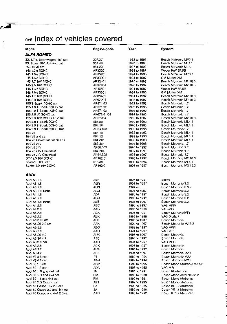
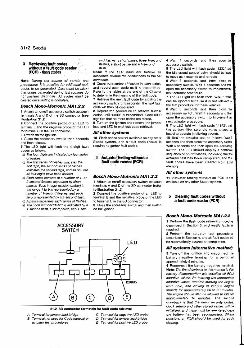
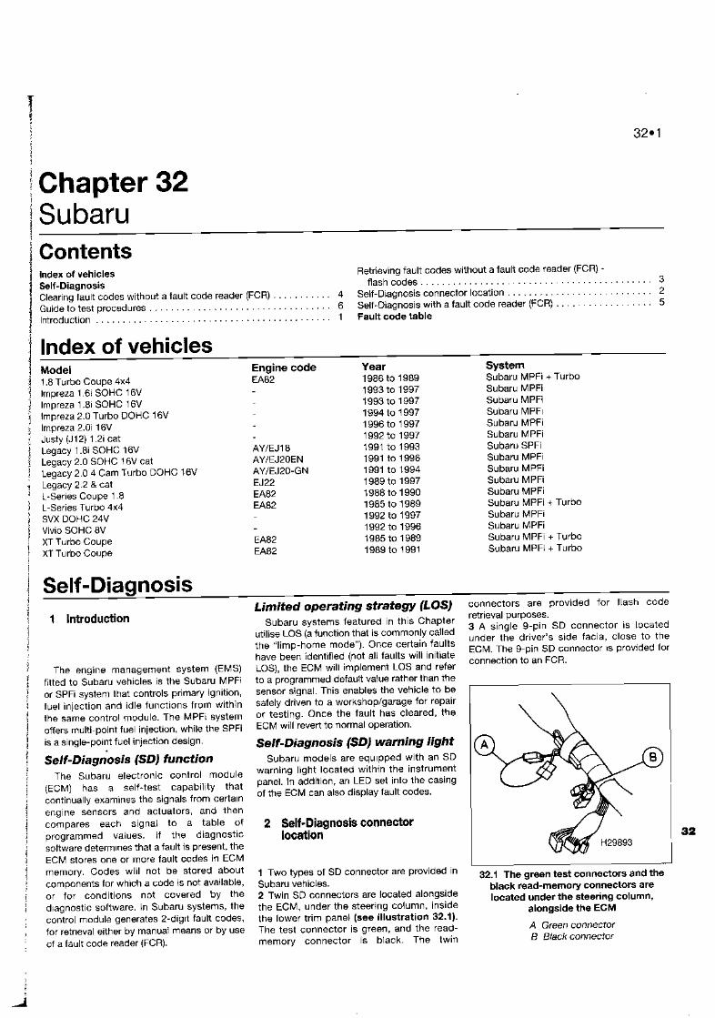
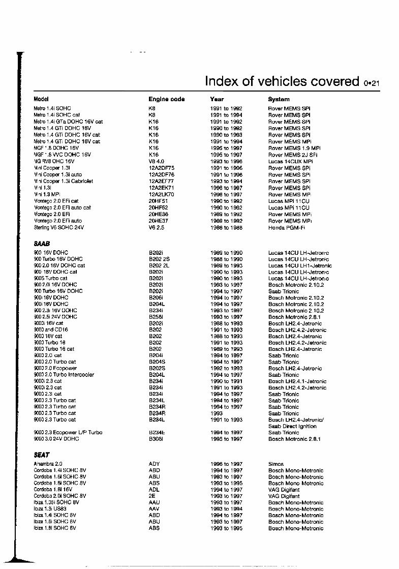
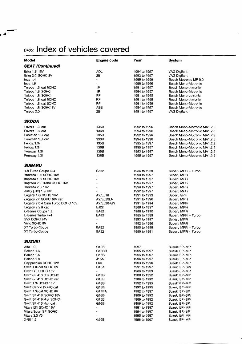
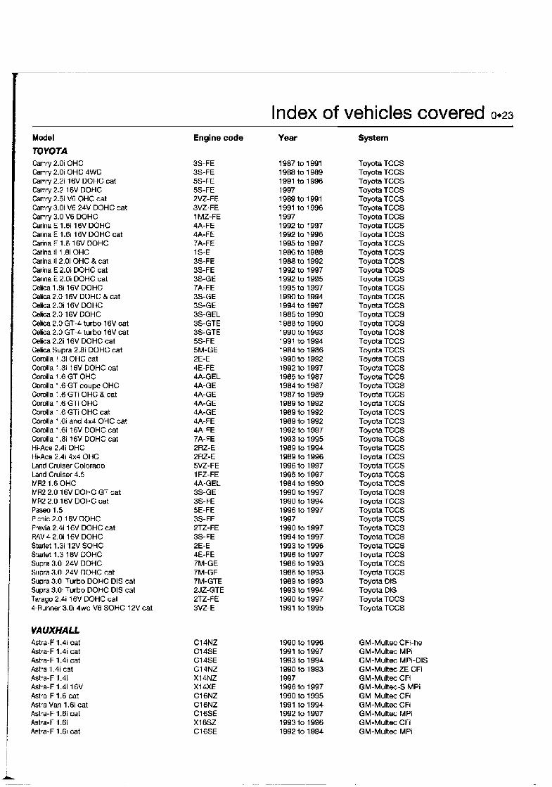
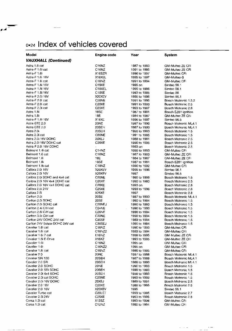
1 0.6 Index of vehicles covered
I Model
&FA ROMEO 33, 1.7ie. Sportwagon, 4x4 cat 33, Boxer 16V, 4x4 and cat 75 3 .Oi V6 cat 145 1.3ie SOHC 145 1.6ie SOHC 145 1.6ie SOHC 145 1.7 16V DOHC 145 2.0 16V DOHC 146 1 . 3 ~ SOHC 146 1.61e SDHC 146 1.7 16V DOHC 146 2.0 16V DOHC 155 T-Spark DOHC cat 155 1.8 T-Spark DOHC cat 155 2.0 T-Spark DOHC cat 155 2.5 V6 SOHC cat 1 55 2.0 t6V DOHC T-Spark 164 2.0 T-Spark DOHC 164 2.0 T-Spark DOHC cat 164 2.0 T-Spark DOHC 16V 164V6 164 V6 and cat 164 V6 Cloverleaf cat SOHC 164 V6 24V 164 V6 24V 164 V6 24V Cloverleaf 164 V6 24V Cloverleaf G W 2.0 1 6V DOHC Sp~der DOHC cat Sprder 2.0 16V DOHC
AUDI Audi A3 1.6 Audi A3 I .B Audi A3 1 .81 Audi A3 1.8 Turbo Audi A4 1.6 Audi A4 1.8 Audi A4 1.8 Turbo Aud~ A4 2.6 Aud~ A4 2.8 Audi A4 2.8 Audi A6 2.Oi Audi A6 2.8 30V Audl A6 S6 2.2 cat Audi A6 2.6 Audi A6 2.8 Audi A6 S6 d 2 Audi A6 S6 4.2 Audi A8 2.8i V6 Audi AB 2.8 Audi A8 3.7 Aud~ A8 4.2 Audi VB 3.6 cat Audi V8 4.2 cat Audi 80 1.6 cat h d i 80 1.6 cat Aud~ 80 1.8i and 4x4 cat Aud~ 80 I .8i and 4x4 cat Audi 80 1 .B and 4x4 cat Audi 80 2.01 Qualtm cat Audi 80 Coupe 16V 2.0 cat Aud! 80 Coupe 2.0 and 4x4 cat Audi 80 Coupe and 4x4 2.0 cat
Engine code
AEH AGN AGN AGU ADP ADR AEB A8C AAH ACK ABK ACK AAN ABC AAH AHK AEC AAH ACK AEW ABZ PT ABH ABM ADA JN PM PM ABT 6A 3A AAD
Year
-
System
Bosch Motronic MP3.1 Bosch Morronic ML4.1 Bosch Motronic ML4.1 WeSer IAW 8F.6B Bosch Motronic MP3.1 GM Multec XM Bosch Motronrc M2.10.3 Bosch Molronic M2.10.3 Weber IAW 8F.66 GM Multec XM Bosch Motronic M2.10.3 Bosch Motronic M2.10.3 Bosch Motronic 1.7 Bosch Motronic 1.7 Bosch Motronic 1 7 Bosch Motronic 1 . 7 Bosch Motronic M2.10.3 Bosch Motronic ML4. t Bosch Motron~c ML4.1 Bosch Motron~c 1.7 Bosch Motronic ML4.1 Bosch Motronic ML4.1 Bosch Motronic ML4.1 Bosch Motron~c 1.7 Bosch Motron~c 1.7 Bosch Motronic 1.7 Bosch Motronic 1.7 Bosch Motron~c M2.10.3 BOSC~I Motronic ML4.1 Bosch Motronic M2.10 3
Simos Bosch Motronic 3.2 Bosch Motron~c 3.8.2 Bosch Motronlc 3.2 Bosch Motronic 3.2 Bosch Motronic 3.2 Bosch Motronic 3.2 VAG MPFi VAG MPi Bosch Motronic MPI VAG Digifar,t Bosch Motronic Bosch Motronic MP.3.2 VAG MPFi VAG MPI Bosch Motronic Bosch Motronic VAG MPFI Bosch Motmnic Bosch Motronic Bosch Motronic M2.4 Bosch Motronic M2.4 Busch Motron~c M2.4 Bosch Mono-Motronic MA7.2 VAG MPi Bosch KE-Jetronrc Bosch Mono-Jetronic A2.2 Bosch Mono-Motronic Basch Mono-Matronic Bosch KE1.2 Motron~c Bosch KE1.1 Motronlc Bosch KE1.2 Motronic
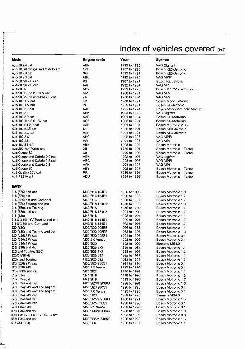
Index of vehicles covered 0-7 Model Audl 80 2.0 cat Audt 80,90 Coupe and Cabrio 2.3 Audt 80 2.3 cat Audi 80 2.6 cat Audi 80, 90 2.0 cat hd 80, 90 2.8 cat Audr 80 52 Audl 90 Coupe 2.0 20V cat Audi 90 Coupe and 4x4 2.3 cat Audi 100 1 81 cat Audi 100 1.81 cat Audi 100 2.0 cat Audi 1M 2.0i Audi 100 2.0 cat Audi 100 4x4 2.0 16V cat ~ u d j 100 s4 2.2 cat Audl 100 2.3E cat Audl 100 2.3 cat Audl 100 2.6 Audi 100 2.8 Audt 100 SJ 4.2 Atai 200 4x4 Turbo cat Audi Coupe S2 Audi Coupe and Cabrro 2 0 cat Audi Coupe and Cabr~o 2 6 cat Audi Coupe and Caorlo 2.8 h d i Coupe S2 Audi Quattm 20V cat Audl W2 Avant
BMW 316i (E30) and cat 31 6i (E36) cat 316i (€36) cat and Compact 318i (E30) Touring and cat 318i {EJO) and Tourlng 3?81 tE36) and cat 3181 tE36) 31 81s (E30) 16V Touring and cat 3181s (E36) and Compact 320i (E30) 320i (E30) and Touring and cat 320i (E36) 24V cat 32Di (E36) 24V cat 3mi (€36) 24V cat 3251 (E30) and 4x4 3251 and Touring (E30) 325iX (E30-4) 325ix and Touring 3251 (E36) 24V cat 3251 {E36) 24V 325e (€30) and cat 518i (€34) 51 81 (€34) cat 520i (EM) and cat 520i (EN) 24V and Touring cat 520i (E34) 24V and Touring cat 520i (E34) 24V cat 5251 (E34) and cat 5251 (€34) 24V cat 5251 (€34) 24V 5301 (E34) and cat 5301 (€34) V8 4.0 32V DOHC cat 5351 (E34) and cat 635 CSi (E24)
Engine code ABK NG NG ABC PS AAH ABY NM ?A 4B PH M E ABK AAD ACE AAN NF AAR ABC AAH ABH 38 36 ABK ABC A4H ABY RR ADU
M40/816 164Et MJO/B16 IWE1 M43/0 16 M40/B18 184E11 M401B18 M40W18 1 84 E2 M43/818 M421B18 184S1 M42l818 184S1 M20/B20 206EE MZOIB20 206EE M501B20 20651 M50 2.0 Vanos M50/B20 M20/B25 6KT M20/825 6K1 M2W025 6E2 M201B25 6EZ M50/B25 25681 M50 2.5 Vanos M20/B27 M40lB18 M43/B18 M201BZOM 206KA M50/620 206S1 M50 2.0 Vanos M50/620 M20/B25M 256K1 M50/B25 256Sl M50 2.5 Vanos M30W30M 306KA M60 M3DlB35M 346KB M30/834
Year 1992 to 1995 1987 to 1995 1 992 to 1994 1 992 to 1995 t 987 to 1991 1992 to 1 994 1993 to 1995 1988 to 1991 1988 to 1997 1988 to 1991 1985 to 1991 1991 to 1994 1993 to 1 996 1991 to 1 994 1 992 to 1994 1991 to 1997 1986 to 1991 1991 to 1994 1992 to 1997 1991 to 1997 1 993 to 1994 1 989 to 1991 1 990 to 1993 1982 to 1997 1993 to 1997 1991 to 1997 1993 to 1996 1989 to 1991 1 994 to 1996
System VAG Digifant Bosch KE3-Jetron~c Bosch KE3-Jetronic VAG M PFi Bosch K f Jetronic VAG MPI Bosch Motronic + Turbo VAG MPi VAG M Pi Bosch Mono-Jefmnic Bosch KE-Jetronic Bosch Mono-Motronic MA1.2 VAG Digllant Bosch KE-Motronic Bosch KE-Motronic Bosch Motronic 2.3.2 Bosch KE3-Jetronic Bosch KE3-Jetronic VAG MPFI VAG MPi Bosctl Motronic Bosch Motronic + Turbo Bosch Motronic + T u r b VAG Digifant VAG MPFi VAG MPI Bosch Motron~c + Turbo Bosch Motronic + Turbo Bosch Motronic + T u r b
Bosch Motronlc 1.3 Bosch Motronbc 1.7 Bosch Motronic 1.7 Bosch Motronic 1.3 Bosch Motronic 1.7 Bosch Motronic 1.7 Bosch Motronic 1.7 Bosch Motronic 1.7 Bosch Motronlc 1.7 Bosch Motronic 1.1 Bosch Molmnic 1.3 Bosch Motronic 3.1 Bosch Motronic 3.1 Siemens MS4.0 Bosch Motronic 1.1 Bosch Motronic 1.3 Bosch Motronic 1 . : Bosch Motronic 1.3 Bosch Motronic 3.1 Bosch Motronic 3.1 Sosch Motrgqic 1.1 Bosch Motronic 1.3 Bosch Motronic 1.7 Bosch Motronic 1.3 Bosch Motronic 3. T Bosch Motronlc 3.1 S~ernens MS4.0 Bosch Motronic 1.3 Bosch Motronic 3.1 Bosch Motronic 3.1 Bosch Motronic 1.3 Bosch Motronic 3.3 Bosch Motronic 1.3 Bosch Motrontc 1 . 1
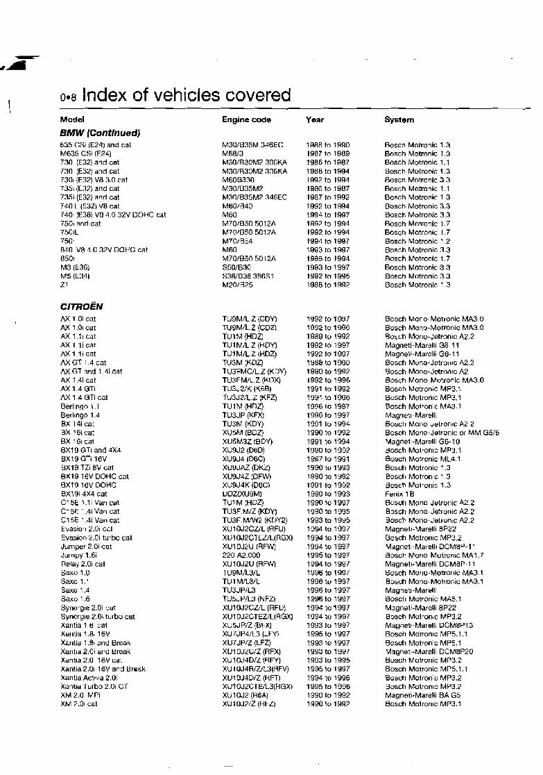
0.8 Index of vehicles covered Model
BMW (Continued) 635 CSI (E24) and cat M635 CSi (E24) 730i (E32) and cal 730i (€32) aqd cat 7301 (E32) V8 3.0 cat 7351 (E32) and cat 7351 (€32) and cat 740iL (E32) V8 cat 740i (€38) V8 4.0 32V DOHC cat 75Dl and cat 750iL 750i 040i V8 4.0 32V OOHC cat 8501 M3 (E36) M5 (E34) Z1
CITROEM AX 1 .Oi cat AX 1.01 cat AX 1.licat AX 1, l icat AX1 11 cat AXGT 1.4 cat AX GT and 1.4i cat AX 1.4i cat AX 1.4 GTI AX 1.4 GTi cat Berlingo 1 1 Berlingo 1.4 BX 14i cat BX f 6i cat BX 161 cat 6x79 GTI and 4x4 BX!9 GTi 16V 0x1 9 TZi 8V cat 0x19 16V DOHC cat BXf 9 f 6V DOHC BX19i 4x4 cat C15E l .l i Van cat C15E 1.4i Van cat C15E 1.4i Van cat Evasion 2.01 cat Evasion 2 .Oi turbo cal Jumper 2.01 cat Jumpy 1.6i Relay 2.0i cat Saxo 1.0 Saxo 1.1 Saxo 1 .a Saxo 1.6 Synergle 2.0i cat Synergre 2.0: turbo cat Xarltia 1 61 cat Xantia 1 .RI 16V Xantia 1.81 and Break Xantla 2.0i and Break Xantla 2.0i 16V cat Xantia 2.01 16V and Break Xantia Actlva 2.0i Xantia Turbo 2.0i CT XM 2.01 MPi XM 2 .Dl cat
Engine code
TUSM/L.Z (CDY) TUSM/L.Z (CDZ) rul M (HDZ) TUl M/L.Z (HDY) TU1 M/L.Z (HDZ) TUSM (KOZ) TUBFMC/L.Z (K DV) TUSFM/L.Z (KUX) TU3J2/K (K6B) TU3J2/L.Z (KFZ) TU1M (HDZ) TU3JP (KFX) TU3M (KDY) XUSM (BDZ) XU5M3Z IBDY) XU9J2 ( E D ) XU9J4 (D6C) XUSJAZ {DKZ) XU9d4Z (DFW) XU9J4K (D6C) DDZVUQM) TU1 M (HDZ) TUSF.M/Z (KDY) TU3F.MMr2 (KDY2) XU1 OJ2CUL (RFU) XUIOJPCTEZ/L(RGX) XU1 DJ2U (RFW) 220 A2.000 XU1 OJ2U ( R W TUSM/L3/L TU 1 M/L3/L TU3JP/L3 TUSJ P/LS (N FZI XUIOJSCUL (RFU) XU1 OJ2CTEZL(RGXj XUSJP/Z (BFX) XU7JP4/L3 (LFY) XU7JP/Z (LFZ) XU1 WZCIZ (RFX) XU 1 OJJD/Z (SFY) XU 1 OJ4R/UL3[HFV) XUlOJ4D/Z (RFT) XU1 OJ2CTE/L3(RGXI XU1 OJ2 (R6A) XU1 OJ2/Z (RFa
Year System
Bosch Motronic 1.3 Bosch Motronic 1.3 Bosch Motronic 1.1 Bosch Motronic 1.3 Bosch Motronic 3.3 Bosch Motronic 1.1 Bosch Motronic 1.3 Bosch Motronlc 3.3 Bosch Motronic 3.3 Bosch Motronic 1.7 Bosch Motron~c 1.7 Bosch Motronic 1.2 Bnsch Motronic 3.3 Bosch Motronic 1.7 Bosch Motronic 3.3 Bosch Motronic 3.3 Bosch Motronic 1.3
Bosch Mono-Motronic MA3 0 Bosch Mono-Motronic MA3.0 Bosch Mono-Jetronic A2.2 Magneti-Maralli G6-11 Magneti-Marelli G6-11 Bosch Mono-Jetron~c A2.2 Sosch Mono-Jetron~c A2 Bosch Mono-Motronic MA3.0 Bosch Motronic MP3.1 Bosch Motron~c MP3.1 Bosch Moironlc MA3.1 Magneti-Marelli Bosch Mono-Jetronrc A2 2 Bosch Mono-Jetronic or MM G5/6 Magneil-Marelli G6-10 Bosch Motronic MP3.1 Bosch Motronic ML4.1 Bosch Motronic 7.3 Bosch Motronlc 1.3 Bosch Motronic 1.3 Fenix 18 Rosch Mono-Jetronic A2.2 Bosch Mono-Jetronic A2.2 Bosch Mono-Jetron~c A2.2 Magnetl-Marelli 8P22 Bosch Motronic MP3.2 Magneli-Marelli DCMBP-11 Bosch Mono-Motromc MA1.7 Magneb-Marelli DCMBP- 1 1 Bosch Mono-Motronic MA3.1 Bosch Mono-Molronic MA3.1 Maynerj-Marelti Bosch Motronic MA5.1 Magneti-Marelli 8P22 Bosch Motronic MP3.2 Magneti-Marelti DCM8P13 Bosch Motron~c MP5.1.1 Hnsch Motron,~ MP5.1 Magneti-Marelli DCM8P20 Bosch Motronic MP3 2 Bosch Motronic MP5.1.1 Bosctl Motron~c MP3.2 Bosch Motron~c MP3.2 Magneti-Marelli BA G5 Bosch Motrontc MP3.1

- -
Model XM 2.Di cat XM 2.01 l6V cat XM 2.01 turbo cat XM 2.01 CT turbo cat XM 3.0 V6 LHO XM 3.0 V6 cat XM 3.0 V6 cat XM 3.0 V6 Estate XM 3.0 V6 24V cat XM 3 0 V6 24V tX 1 .l t cat ZX l.li cat Z X l . l i cat ZX l.li cat zx 1.41 cat ZX I.4i and Break Gal M 1.4i and Break cat M 1.6i W 1.6i ZX 1.6i cat ZX 1.6i and Break cat LX 1.6i and Break cat
1.8i and Break cat ZX 1.8i and Break cat M 1.9 8V
1.91 ZX 2.0i cat ZX 2.Di 16V cat ZX2.01 16V
DAEWOO Nexia 1.5 8V SOHC Nexia 1.5 16V DOHC Espero 1 5 16V OOHC Espero 1.8 8V SOHC Espero 2.0 8V SOHC
Applause Charade 1.3i cat SOHC 16V Charade 1.3 SO,K 16V Charade 1.5 SOHC 16V Charade 1.61 SOHC 16V H-Jet Sportrak cat SOHC 16V
FIAT Brava 1.4 1 2V Brava 1 6 1 GV Bravo 2.0 Cinquecento 899 OHV DIS cat Cl~quecento 900 OHV DIS cat Clnquecento Sporting Coupe 16V Coupe 16V Turbo Coupe 2.0 20v Croma 2000ie Croma 20001e OOHC 8V Croma 2.0ie DOHC Croma 2.01e DOHC D1S cat Croma 2.01~ 16V cat Fiorino 1500 SOHC cat Panda 1 .Die OHG and 4x4 cat Panda 1 .l ie OHC cal
Engine code XU1 OJ2/Z (RFZ) XU1 OJ4WW (RFVJ XU1 OJ2TE/Z (RGY) XUlOJ2TE/UZ(RGX) ZPJ (S6A) ZPJ (SFZ) ZPJ (UFZ) ZPJ/Z (U FY) ZPJ4Pf3 (SKZ) ZPJ4N3 (UKZ) TU1 MIZ (HDY) rui Mn (HDZ) TU1 M R (HDY) TU I M/Z (HDZ) TU3MlZ tKDY) TU3M (KDX) TU3M (KOX) XU5M.2K (B4A) XU5M.3K (B4A) XU5M.32 {BDY) XU5JPUZ (BFZ) XUSJPUZ (BFZ) XU7J PUZ (LFZ) XU7JPUZ (LFZ) XUSJAZ (DKZ) XU9 J#K (DEE) XUJ 1 OJ2/C/UZ(RFX) XUJ 1 OJ4/D/UZ(RFT) XUJ1 OJP/D/WZ(RFTJ
HD-E HC-E HC-E HE-E HD-E CB42 HD-E
Index of vehicles covered 0.9
Year System 7 992 to 1 994 Bosch Motronlc MP5.1 1994 to 1997 Bosch Motronic MP5.1.1 1993 to 1994 Bosch Motronic MP3.2 1994 to 1996 Bosch Motronic MP3.2 1 989 to 1993 Fenix 36 1989 to 1994 Fenix 3R 1994 to 1997 Fenix 38 1995 to I996 Fenix 38 199C to 1 994 Fenix 4 1994 to 1 997 Fenix 48 1991 to 1994 Bosch Mono-Jetronlc A2.2 1991 to 1994 Bosch Mono-Jetronic A2.2 1994 to 1997 Bosch Mono-Motronlc MA3.C 1994to 1997 Bosch Mono-Motronlc MA3 0 1991 lo 1992 Elosch Mono-Jetranic A2 2 1992 to 1997 Bosch Mono-Motronlc MA3.0 1994 to 1996 Magneti-Marel/i G6-14 1991 to 1992 Magnet!-Marelli G5 S2 1991 to 1993 Magnell-Marelli G6.12 1992 to 1993 Magnetl-Marelli G6.10 1994 to 1997 Magneti-Marelli 8P-13 1995 to 1996 SagernILucas 4GJ 1992 to 1997 Bosch Motronic MP5.1 1 995 to 1996 Magneti-Marelli BP-10 1992 to 1994 Bosch Motronic 1.3 1991 to 1992 Bosch Motronlc MP3.1 ! 992 to 1996 Magnell-Marelli 8P-20 1992 to 1995 Bosch Motron~c MP3.2 1994 to 1997 Bosch Motronic MP3.2
1989 to 1996 Daihatsu EFi 1991 to 1993 Da~hatsu EFi 1993 :a 1997 Daihatsu MPI 1996 to 1997 Daihatsu MPI 1993 to 1996 Daihatsu MPI 1995 to 1 997 Dalhatsu MPI 1990 to 1997 Daihatsu EFi
Bosch Mono-Motronlc SPi Weber Marell1 IAW Bosch Motronic M2.10.4 Weber-Marell1 IAW SPi Weber-Marelli IAW SPi Weber-Marelli IAW SPi Weber-Marelli LAW MPi Weber-Marelli IAW MPi Bosch Motronlc M2 10.4 Weber-Marelli IAW MPi Weber-Mare111 IAW MPi Weber-Marelli IAW MPi Weber-Marelli IAW MPi Bosch Motronic M I .7 Bosch Mono-Jetronic A2.4 Bosch Mono-Jetronic A2.4 Bosch Mono-Jetron~c A2.4
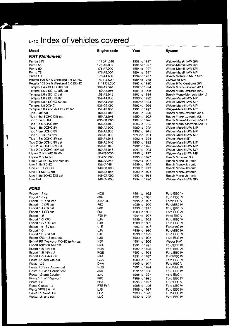
0.10 Index of vehicles covered Model Engine code
FIAT (Continued) Panda 899 11 70A; ,046 Punto 55 176 A6.000 Punto 60 IT6 A7.000 Punto 75 176 A8.000 Punto GT 1 76 A4.020 Regata 100 Sie 8 Weekend 1.6 DOHC 149 C3.000 Regata 100 Sie & Weekend 1.6 DOHC 11 49 C3.000 Tempra 1 . 4 ~ SOHC DIS cal 160 At ,046 Tampra 1.6ie SOHC DIS cat f 59 A3.046 Tempra 1.6ie SOHC cat 159 A3.046 Tempra 1.81e DOHC 8V 159 A4.000 Tempra 1.8ie DOHC BV cat 159 A4.046 Ternpra 1.8 OOHC 835 C2.000 Tempra 2.0ie and 4x4 DOHC SV 1 59 A6.046 T~po 1.4ie cat 160 A1.036 Tipo 1.61e SOHC DIS cat 159 A3.046 Tipo 1 . 6 ' ~ SOHC 835 C1 .OD0 Tipo 1.6ie SOHC cat 159 A3.046 Tlpo 1.8ie DOHC 8V 1 59 A4.000 Tipo 1.8ie DOHC 8V 159 A4.000
I Tipo 1.8i DOHC f6V 160 A5.000 Tipo 1.8ie DOHC BV cat 159 A4.046 T~pu 2.0ie DOHC 8V cat 159 A5.046
1 Tipo 2.0ie DOHC 8V cat 1 59 A6.046 T ipo 2.0te DOHC 16V cat 160 Ag.046 Ulysse 2.0 SOHC 89kW ZFA220000 Ulysw 2.0 Turbo ZFM20OOO Uno 1 .Die SOHC and Van cat 156 A2.246 Uno 1 .l ie SOHC 156 C.046 Una 70 1.4 SOHC 146 C1.000 Uno 1.4 SOHC cal 160 A1.046 Uno 1.51e SOHC DIS cat 149 C 1.000 Uno 994 146 C7.000
FORD Escort 1.3 cat EscDn 1.3 cat Escort 1.3i and Van Escort 1.4 CFi cat Escort 1.4 CFi cat Escort 1.4 GR cat Escort 1.4i Escort 1.6i XR3i Esccrt 1.6i XR3i cat Escort 1 6 16V cat Escort 1.61 Escort 1.6i and cat Escort XR3i 1.6 and cat Escort RS Cdsworth DOHC turbo cat Escort RS2000 and cat Escort 1.8i 16V cat Escort 1. .8i 16V cat Escort 2.0i 7 4x4 cat Fiesta 1.1 ana Van cat Flesla 1.25 Fiesta 1.3 Van Courier cat Fiesta 1.3i and Courier cat F~esta 1.3 and Courier Fiosta 1 4i and Van cat Fiesta 1.4 F~esta Class~c 1.4 Fies'a XRPi 1.6 cat Fiesta RS turbo 1.6 Fiosta 1.6i and cat
HCS J6A JJA/J4C F6D F6F F6G PTE F4 WA LJB H E WA LJE WD N5F N7A RDA RQB N7A G6A DHA HCS J68 JJA F6E FHA PTE F4A WD LH A LUC
Year System
Weber-Mare!li IAW SPi Wsber-Marolli IAW SPi Weber-Marelli IAW SPI Weber-Marelli IAW MPi Bosch Motron~c M2.7 MPI GMjOelco SPi Weber MIW Centrajet SPi Bosch Mano-Jetronic A2 4 Bosch Mono-Jetmnic A2.4 Bosch Mono-Moironic MA1.7 Webet-Marelli IAW MPI Waber-MarJlt IAW MPi Weber-Marell1 IAW MPi Weber-Marelli IAW MPi Bosch Mono-Jetronic A2.4 Bosch Mono-Jetronic A2.4 Bosch Mono- Motronic MA1.7 Bosch Mono-Motronlc MA1.7 Weber-Mareili IAW MPi Weber-Mare111 IAW MPi Weber-Marelli IAW MPi Weber-Marelii 8F Weber-Mareili IAW M PI Weber-Marelli IAW MPi Weber-Marelfi IAW MPi Weber-Marefli IAW MPI Bosch Motror~ic 3.2 Bosch Mono-Jetron~c Bosch Mono-Jetronic Bosch Mono-Jetronic Bosch Mono-Jetmnic Bosch Mono-Jetronic Weber-Marelli IAW SPI
Ford EEC IV Ford EEC IV Ford EEC V Ford EEC IV Ford EEC IV Ford EEG IV Ford EEC V Ford EEC \V Ford EEC IV Ford EEC IV Ford EEC IV Ford EEC IV Fmd EEC lV Weber IAW Ford EEC IV Ford EEC IV Ford EEC IV Ford EEC IV Ford EEC IV Ford EEC V Ford EEC IV Ford EEC IV Ford EEC V Ford EEC IV Ford EEC V Ford EEC IV Ford EEC IV Ford EEC IV Fwd EEG IV

. . .. . . . . . . . . . . -
Index of vehicles covered 0.11 - -
Model
Cl~stn XH21 1.6 Flesta I IGV Fle5t 3 <R;'I 1 $1 I ~ J V cat I es:(l 1 St ll,V cat GAIA*; ,> CI
G.3IJky ' .?
Gnlnxy 2 D a l ~ d 4x4 i;,nli.lda 2.U CTr Gr3na:ia 2 UI .m11 1 7 ~ t
Sranada 2.0 EFI -I~vrl cot ~13113d~ ? 4 Vfi Gr.jnatla ? ,I VG cat r>r:~rlarla 2 9 V6 a r ~ d 4x4 Gr;ll.lila 2 Y Vt i c , ~ t I;.nnnd,j 2.5 Vt; c.~t Glannda :' 9 Vt i r.lt Kn 1 3 hlaverlvk 2 1: V0~dt.u i t> TJidH,. ; C;I~
h!on.leo I .t;l 1 l i V ' ~ l ~ r 1 0 w 1 ,81 I FIV f~1ur1r:ro 1 81 and :Ix.l c.jt F,~Iuricleo P.01 ItiV 4r.4 c,rl h l o r > d ~ ~ ~ ? fll 16V Morlrlto .' 5 \:'5 UOtiC cat Mnrlrlro ? 51 Orion 1 .: chit \?l:'lti I.:! cat [jrlor~ 1 4 CFI <,a1 'JrlUll 1 .4 CFI cat >IU~. 1 4 CFI r.;~t
~ I I ( V T \ I ,GI c ~ r ~ d .>T
3 r b n 1 1,1 i . ~ t Or,>(, 1 1 i 1
Or~!,n I t l DOHG 16V cat Urlorl :.dl Orlnrl 1.81 t ti': L)C)HC [.a: Orlon 1 81 16V njltli: r.at Probe Z.UI 0C)HT: 1fiV [:at Prutje 2 !>I ?JL! r . ~ t
?,WL>III~P i 6 C V t I cL1t
S k ; ~ ~ ~ l " ' t ! 1 F1 (:Vt 1 cat Lppt l~r r 7 O EFI DO1 11:: S.>plpt>lr~~? O LI I UV Gal
Scorpln ? 01 Scorplo 1 0 t l I
Scnrplo 2 UI 1 L-V Sicrplu 2 UI ,arlcl ,.;lt
Scorpv 2 . u ~ Siljr[~lo 7 :11 I tiv br,ornlc, 7.8 4x.4 Scornlo 7.9 Vri ;IIILI 4 r 3 Scorl>lo P.9 VLi c;il Scorp~o :' 9 \!I; c,tt Scllrplh ? o L'b 2'1V cdt Scorpio 1 9 1 Vb Scorpla 2 91 Vt, :)4V SIP~~J. 1 6 CVH r.lt Slerra 1.8 C:VH r . ) I
5lerra 2.0 FFI flT)Hd: 8V Smerra :' O FFI RV c 3 t
Slrrra ? '1 XR .:x4 Vt j SIP^ r :I .' 1'1 X H 11 x.", Vti (,at Tranr,~t Vdr~ 2 U CF I <.At
T~~II:-,II V,III 2 U CFI cat 'mnslt 2 3 V6 CTI
-
Engine code LJC L7 G RDB nnc NSD Y5F N4 NRA NYB N9D ARC AR D BRC RRD ERE HUA JJH KA24F L I F l J L1 J RKB R KAIB NGA I-IGA SEA SEA HCS J6k F6D FtjF F6G L J F I J F I.JA L1 E LJA RDA HOE!
V 6 16B RRA N9A N4C NSO NRA N3A NYU NSD Y5A PRE RFIC BRD BRE BOA BRG BCOD L6B RI;A NYA N9C R4A B4 B N67
-
Year
1085) to In93 1994 to 1995 1992 to 19\15 1992 to 19% 1995 to 199: 1996 to I Y b I ,
l99!1 to 1997 1985 to 1989 1949 to 1995 1899 to 1992 1987 lcr 1993 1987 1u I!Wl
1987 I(> 1492 198i :o 1 9 9 d 1987 to1992 1391 to 1995 1991) to 1997 1993 to Is97 1993 to 1 996 199ts to 1997 194f> to 13'37 1 44,ri to 1396 19YJ to 1796 1996 tu 1997 1994 to 199(r ICJYL; to 1997 I YY I to 1941 1991 t~ 7395 1'38!3 lo 1990 1R9II to 1995 l.>!?Ll to 1995 I osn to I 993 1990 tu 1 QVJ
ISBY to 19YU 1992 tb 1119; 1989 lo 1'3tlr) 19Y2 lo 1995 19133 to 1995 1991 to 1997 199 1 to 1997 1990 tu 1993 1 992 t L b 199.3 1989 1rb 1YY2 1989 to 19S12 7rj94 to 1997 1985 to 1989 1993 to 1896 19851 tn 1995 1 9 w to 1997 749ri lu 1397 Is85 tu I'dBi 1937 to IVY2 1987 tu 1995 1987 to 199: 199 1 to 199'. 1994 to 199; 1994 to l ! W i l!i?U 110 1995 11307 to 199:' 1989 to 199'2 1399 to I(3Y:'
1 S8Y to 1991 1'389 to 19!); I U D O to 19o; 1981 to i!lil.- I L I P I to Inq:l
System Ford EEC IV Ford EEC IV Ford EEC IV Ford ECC IV t ord EEL V Ford EEC V Ford EEC V Foro' EEC IV Ford EEC IV Frrrd EEC IV Ford EEC IV Ford EEC IV Ford EEC. IV ForrA EEC IV F o r d FFC IV Ford EEC IV Ford EEC V Nlssan ECCS Ford EEC IV Ford EEC V F n ~ r l EEC V Ford EEC IV Fwd KEC IV Ford EEC V Furd EEC IV Ford EEC V Ford EEL IV Ford EEC IV F w d EEC IV Fold EEG IV Ford EEL IV Ford EEC IV Ford EEC IV Ford EEC IV Ford EFC 1V k orcl EFC IV Ford FFr: IV Ford EEC IV Mazda EG! Mazda CGI Ford L t C IV Ford EEC IV Ford L fC !V l o r d EEC IV I ord EEC IV I-ord EEC: IV Ford EEC V Ford EEC IV Ford EEC V Fnrd EfiC V F D I ~ E E L IV Ford EEC IV t urd EEC; IV Ford EES: IV t ord EEC IV Ford FFC V Ford EEC V Ford EEC IV FOI d EEC IV Fold EEC IV Ford EEC IV Ford EEC IV Ford EFC IV Ford E E L IV Ford E E L I:, Ford F F t : IV
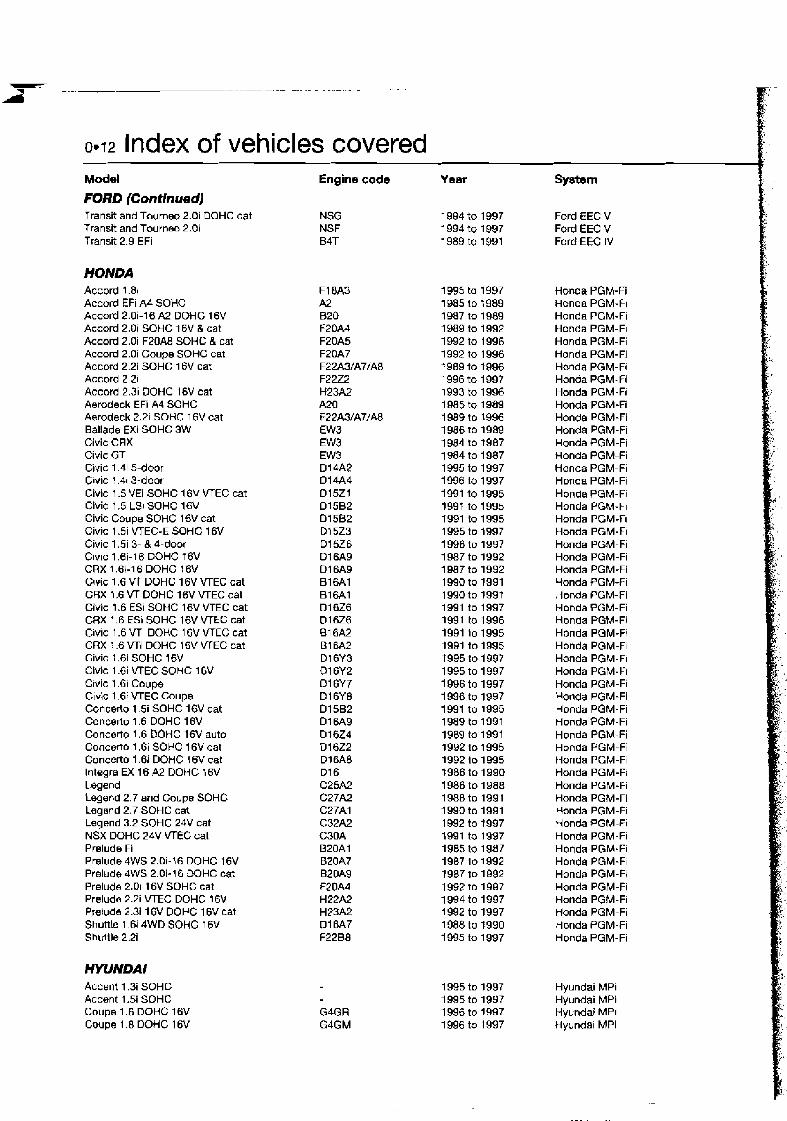
0.12 Index of vehicles covered Model Engine code
FORD (Continued) Transit and Toumeo 2.0i DOHC cat NSG Transit and Tourneo 2.0i NSF Transit 2.9 EFi B4T
HONDA Accord 1.81 Accord EFI A4 SOHC Accord 2.0i-16 A2 DOHC 16V Accord 2.0 SOHC 16V & cat Accord 2.0i F20A8 SOHC 8 cat Accord 2.0i Coupe SOHC cat Accord 2.2i SOHC 1 6V cat Accord 2 21 Accord 2.3i DOHC 16V cat Aerodeck EFi A4 SOHC Aerodeck 2.21 SOHC l6V cat Ballade €Xi SOHC 3W Civic CRX Clvic GT Civic 1.4i 5-door CIVIC ! .41 3-door Civic 1.5 VEi SOHC 16V VTEC cat Civic 1.5 LSi SOHC 16V Civic Coupe SOHC 16V cat Civic 1.5i VTEC-E SOHC 16V Civic 1.51 3- & 4-door CIVIC 1.6i-16 DOHC f6V CRX 1.6i-16 DOHC 16V C~vic 1.6 VT DOHC 16V bTEC cat CRX 1.6 VT DOHC 16V VTEC cat Civic 1.6 ESI SOHC 16V VTEC cat C8X 1.6 ESI SOHC 16V VTEC cat CIVIC 1.6 VTi DOHC 16V VTEC cat CRX 1.6 VTi DOHC 16V VTEC cat Civic 1.6i SOHC 16V Civic 1.6 VTEC SOHC 16V Crvic 1.6i Coupe Civic 1.6i VTEC Coupe Concerto 1 . 5 SOHC 16V cat Concerlo 1.6 DOHC 16V Concerto 1.6 DOHC 16V auto Concerto 1.61 SOHC 16V cat Concerto I .6i DOHC 16V cat lntegra EX 16 A2 DOHC 16V 1 egend Legend 2.7 and Coupe SOHC Legend 2.7 SOHC cat Legend 3.2 SOHC 24V cat NSX DOHC 24V VTEC cat Prelude Fi Prelude 4WS 2.0i-16 DOHC 16V Prelude 4WS 2.0i-16 W H C cat Prelude 2.01 16V SOHC cat Preludo 2.2i VTEC DOHC 16V Pralude 2.3i 16V DOHC 1 6V cat Shuttle 1.6i 4WD SOHC 16V Shullle 2.3
HYUNDAI Accent 1.3 SOHC Accent 1.5i SOHC Coupe 1.6 OOHC 16V Coupe 1.8 DOHC 16V
Year System
Ford EEC V Ford EEC V Ford EEC IV
tlonda PGM-Fi Honda PGM-FI Honda PGM-Fi Honda PGM-FI Honda PGM-Fi Honda PGM-Fi Hmda PGM-FI Honda PGM-Fi Honda PGM-FI Honda PGM-Fi Honda PGM-Fi Honda PGM-Fi Honda PGM-Fi Honda PGM-Fi Honda PGM-Fi Honda PGM-Fi Honda PGM-Fi Honda PGM-FI Honda PGM-R Honda PGM-Fi Honda PGM-Fi Honda PGM-Fi Honda PGM-Fi Honda PGM-fi Honda PGM-Fi Honda PGM-Fi Honda PGM-Fi Honda PGM-F! Honda PGM-FI Honda PGM-FI Honda PGM-Fi Honda PGM-Fi Honda PGM-Fi Honda PGM-Fi Honda PGM-Fi Honda PGM-FI Honda PGM-Fi Honda PGM-Fi Honda PGM-Fi Honda PGM-Fi Honda PGM-Fi Honda PGM-Fi Honda PGM-Fi Honda PGM-Fi Honda PGM-FI Honda PGM-FI Honda PGM-Fi Honda PGM-Fi Honda PGM-Fi Honda PGM-Fi honda PGM-Fi Honda PGM-Fi
Hyundai MPI Hyundai MPi Hyundai MPt Hyundal MPi

Model Coupe 2.0 DOHC 1 GV Lantra 1.5i SOHC cat Lantra 1.61 DOHC cat lantra 1.6 OOHC 16V Lantra 1.8~ DOHC cat Lsntra 1.8 DOHC l 6 V Pony X2 1.5 SOHC cat S Coupe 1.51 SOHC cat S Coupe 1.51 SOHC S Coupe 1.51 turbo SOHC Sonata 1.8 SOHC Sonale 2.0 SOHC Sonata 2 0 16V DOHC Sonata 2.4 SOHC Sonata 3.01 SOHC
ISUZU Piazza Turbo Trooper 2.6 Trooper 3.2i
JAGUAR XJWSovere~gn 3.2 DOHC cat UWSoverelgn 3.6 24V XJWSovsre~gn 4.0 U S 4.0
KIA Mentor 1.6; SOHC 8V Sportage 2.Ui SOHC BV Sportage 2.0i OOHC 16V
LAlVCCA Y10 LXle and 4wd 1308 SOHC FIRE Y10 1108ie and 4x4 SOHC cat Y10 11 Oaie and 4x4 SOHC cat Dedra 1.6ie SOHC Dedra 1600ie SOHC cat Dedra 1.8ie DOHC Dedra 1.8ie DOHC cat Dedra 2.0ie DOHC Dedra 2.0ie DOHC cat Dedra 2.0ie DOHC cat Dedra 2.0ie DOHC Turbo and cat Dedra 2.0ie Integrale Turbo and cat Ddla 2.0 16V Turbo b l ta 1600ie DOHC Oelta 16Wie DOHC Ddta 1600ie DOHC statlc Delta HF Turbo anU Martmi 1600 DOHC Delta HF TurDo DOHC cat Delta HF lntegrale Turbo DOHC D e h HF lntograle Turbo DOHC Delta HF lntegrale Turbo 16V DOHC Delta HF Integrals Turbo 16V and cat Prisma 1600ie DOHC Prisma 1600ie DOHC Prlsma 1600ie DOHC static Scudo 1.6i Thama FL 2000ie 16V DOHC cat Thema FL 20COie Turbo 16V DOHC cat Therna FL 3000 V6 SOHC cat
Index of vehicles covered 0.13 Engine code Year System G4GF 1996 to 1997 Hyundai MPi 4G15/G4J 1 993 to 1995 Hyundai MPi 4661 1991 to 1995 Hyundai MPi G4GR 1996 to 1997 Hyundai MPi 4G67 1992 to 1 995 Hyundai MPi G4GM 1 996 to 1997 Hyundal MPI 4G151G4J 1990 to 1994 Hyunda~ MPi 4GlS/G4J 1990 to 1992 Hyundai MPi Alpha 1992 to 1996 Bosch Motronic M2.10.1 Alpha 1992 to 1 996 Bosch Motronic M2.7 4G62 1 989 to 1992 Hyundai MPi 4G63 1989 to 1992 Hyundai MPi
1992 lo 1997 Hyundai MPi 4G64 1989 to 1 992 Hyundai MPi V6 1994 to 1997 Hyundai MPi
1986 to 1 990 lsuzu I-Tec + Turbo 1988 to 1 992 ISUZU I-TK 1893 to 1 997 ~SUZU I-Tm
1990 to 1 994 Lucas LH-1 5CU 1986 to 1 989 Lucas LH-9CU 1991 to 1997 Lucas LH-15CU 1991 to 1997 Lucas LH-75CU
1995 to 1 997 Kia EGi 1995 to 1 997 Bosch Motronic M2.10.1 1 995 to 1997 Bosch Motronic MP.lO. l
Bosch Mono-Jetronic A2.2 Bosch Mono-Jetronic A2.2 Bosch Mono- Motronic MA1.7 Weber MIW Centrajet 2 Bosch Mona-Jetronic A2.2 Weber-Marelli IAW MPi Weber-Marelli IAW MPi Weber-Marelli IAW MPi Webr-Marelli IAW MPi Weber-Marelli IAW MPI Weber-Marelli IAW MPi Weber-Marelli IAW MPi Weber-Marelll IAW MPi Weber-Mare111 IAW M Pi Webr-Marelli IAW MPi Wsber-Marelli IAW MPi Weber-Marelli IAW MPI Weber-Marelli IAW MPi Weber-Marell! IAW MPi Weber-Mare111 IAW MPi Weber-Mamlli IAW MPi Weber-Marelli IAW MPI Weber-Marelli IAW MPi Weber-Marelli IAW MPi Weber-Marelli IAW MPi Bosch Motronic 7.7 Bosch Motronic M1.7 Bosch Molronic M2.7 Bosch Motronic M I .7
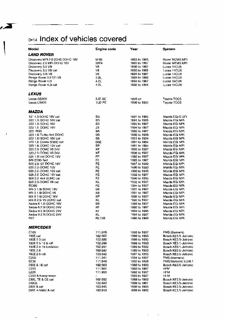
0.14 Index of vehicles covered Model
U V D ROVER Discovery MPi 2.0 20HD DOHC 16V Discovery 2.0 MPi DOHC 16V Discovery 3.5 VBi Discovery 3.5 V8i cat D~scovery 3.9i VB Range Rover 3.9 Efi V8 Range Rover 4.0i Range Rover 4.2i cat
LEXUS Lexus GS300 Lexus LS400
MAZDA 121 1.3 SOHC 16Vcat 323 1.3 SOHC 16V cat 323 1.31 SOHC 16V 323 1.51 DOHC 16V 323 1600i 323 l.6i Turbo 4x4 DOHC 323 1.6i SOHC 16V cat 323 l .6 i Estate SOHC cat 323 1.81 DOHC 16V cat 323 2.0i DOHC V6 24V 323 2 Oi DOHC V6 24V 626 1.8i cat DOHC 16V 626 2000i fwd 626 2.0i GT DOHC 16V 626 2.0i DOHC 16V 626 2.0i DOHC 16V cat 626 2.0i DOHC I6V cat 626 2.2i 4x4 SOHC cat 626 2.5 DOHC V6 cat €2000 MX-3 1.6i SOHC 16V MX-3 1.8i DOHC V6 MX-5 1 .Bi OOHC 16V MX-6 2.5i V6 DOHC cat Xedos 6 1.6i DOHC 16V Xedos 6 2.01 DOHC 24V Xedos 9 2.0i DOHC 24V Xedos 9 2 .3 DOHC 24V RX7
MERCEDES C180 190E cat l9OE 2.3 cat 190E 2.5-1 6 & cat l9OE 2.5-1 6 Evolution ? 90E 2.6 190E 2.6 cat C200 E200 200E & TE cat c22a €220 C230 & Kompressor 230E, TE & CE cat 230GE 260E a cat 260E 4-Matic 8 cat
Engine code
2JZ-GE 1 UZ-FE
Year System
Rover MEMS MPi Rover ME MS MPi Lucas l4CUX Lucas l4CUX Lucas 14CUX LUCaS l4CUX Lucas l4CUX Lucas 14CUX
Toyota TCCS Toyota TCCS
Mazda EGi-S SPi Mazda EGi MPi Mazda EGi MPi Mazda EGi MPi Mazda €GI MPi Mazda EGi MPi Mazda EGi MPI Mazda EGi MPi Mazda EGi MPi Mazda EGI MPi Mazda €GI MPi Mazda EGi MPi Mazda EGi MPi Mazda EGi MPI Mazda EGI MPi Mazda EGi MPi Mazda EGi MFi Mazda EGi MPi Mazda EGi MPi Mazda EGi MPi Marda EGi MPi Maxda EGi MPi Mazda EGi MPI Mazda EGi MPi Mazda EGi MPi Mazda EGi MPi Mazda EGi MPi Mazda Em MPi Marda EGi MPi
PMS (Siemens) Bosch KE3.5-Jetron~c Bosch KE3.5-Jetronic Bosch KE3.1 -Jetronic Bosch KE3,l-Jetronic B o s h KE3.5-Jetronic Bosch KE3.5-Jetronic PMS (Srernens) PMS/Motrarlic 6.W6.1 Bosch KE3.5-Jetronic HFM HFM HFM Bosch KE3.5-Jetronic Bosch KE3.5-Jetronic Bosch KE3.5-Jetronic Bosch KE3.5-J~tronic

Model
2MSE & cat C2M E280 cat S280 SL280 EN0 300SE, SEL & cat NOE, TE, CE & cat 300E & cat NOE-24, TE-24 & CE-24 cat 3DOTE 4-Matic & cat 300SL & cat 3OOSL-24 & cat E320 S320 SL320 400S, SE B SEL E420 S420 500E 500SL 500SE & SEL SOOSEC 500SL cat E500 WO woo BMISEL SBOO cat S600 SL600
MiTSUBISHl 3000 GT 24V Carisma 1.6 SOHC 16V Carisma 1.8 SOHC 1 6V Carisma 1.8 DOHC 16V Colt 1.31 SOHC 12V cat Colt 1 3 SOHC 12V Colt 1600 GTi DOHC Colt 1.61 SOHC 16V Colt 1.61 4x4 SOHC 16V cat Coh 1.6 SOHC 1 6V Colt 180C GTi-16V OOHC 16V Colt 1.8 GTi DOHC 16V cat Cwd~a 1800 Turbo Galant 1800 SOHC 1 6V cat Galant Turbo Galant 2000 GLSi SOHC Galan t 2000 GTi 16V DOHC Galant 2000 4WO DOHC Galant 2000 4WS cat OOHC Galant 2.0i SOHC 16V cat Galant 2.0i V6 OOHC 24V Galant Sapporo 2400 Galant 2.51 V6 DOHC 24V 1300 SOHC 16V Lancer 1600 GTi 1 6V DOHC Lancer 1.6i SOHC 16V Lancer 1.6i 4x4 SOHC t6V cat Lancer 1800 GTi W H C 16V Lancer 1.8 GTi DOHC t6V cat Lancer ?BOO 4WD cat %gun 3.5i V6 DOHC 24V Sigma Estate l2V
Index of vehicles covered 0.15
Engine code Year System 103.941 1 988 to 1992 Bosch KE3.5-Jetronic 104.941 1 993 to 1997 HFM 104.942 1 992 to 1996 HFM 104.944 1993 to 1 997 HFM 104.943 1993 to 1997 HFM 103.985 1992 to 1 995 Bosch KE3.5-Jetronic 103.981 1986 to 1 992 Bosch KE3.5-Jetronic 103.983 1987 to 1 993 Bosch KE3.5-Jetronic 103.985 1988 to 1993 Bosch KE3.5-Jetronic 104.980 1989 to t 993 Bosch KE5.2-Jetronic/EZ-L ignition 103.985 1988 to 1993 Bosh KE3.5-Jetronic f 03.984 1 989 to 1995 Bosch KE5.2-JetronidEZ-L ignition 104.981 1 989 to 1995 Bosch KE5.2-Jetronic/EZ-L ignition 104.992 1992 to 1997 HFM 104.994 1993 to 1997 HFM 104.991 1993 to 1997 HFM 1 19.971 1991 on Bosch LH4.1 -Jetronic/EZ-L ignition 1 19.975 1992 lo 1995 Bosch LH4.1 -Jetronic/EZ-L ignition 119.971 1993 to 1997 Bosch LH4.1 -Jetronic/EZ-L ignition 1 19.974 1992 on Bosch LH4.1 -Jetronic/EZ-L ignition 1 19.972 1 992 on Bosch LH4.1 -Jetronic/EZ-L ignition 1 19.970 l99l on Bosch LH4.1 -Jetronic/EZ-L ignition 1 19.970 1992 on Bosch LH4.1 -Jetronic/EZ-L ignit~on 1 19.960 1 989 to 1994 Bosch KE5.2-Jetronic/EZ-L Ignition 11 9.974 1 992 to 1996 Bosch LH4.1 -Jetron~c/EZ-L ignition 11 9.970 1993 to 1997 Bosch LH4.1 -Jetron!c/EZ-L ignition 11 9.972 1993 to 1997 Bosch LH4.1 -Jetronlc/EZ-L ignition 120.980 1991 to 1996 Busch LH-JetronidEZ-L ignition 120.980 1991 to 1996 Bosch LH4.1 -Jetronic/EZ-L ignition 120.980 1996 to 1997 Bosch LH4.l -Jetronic/EZ-L ignition 120.981 1993 to 1997 Bosch LH4.1 -Jetronic/EZ-L ignition
Mitsubishi ECI-Multi- MPI Mitsubishi ECI-Multi- MPI Mitsubishi ECI-Multi- MPi Mitsubishi ECI-Multi- MPI Mitsubishi ECI-Multi- MPi Mitsubishi ECI-Multi- MPi Mitsubishi ECI-Multi- MPi Mitsubishi ECI-Multi- MPi Mitsubishi ECI-Multi- MPi Mitsubishi ECI-Multi- SEFi Mitsubishi ECI-Multi- MPi Mitsubishi ECI-Multr- MPi Mitsubishi ECI-Multr- MPI Mitsubishi ECI-Multi- MPI Mitsubishi ECI-Multl- Turbo Mitsubislli ECI-Multi- MPI Mitsubishi ECI-Multi- MPI Mitsubishi ECI-Multi- MPI Mitsubishi ECI-Multi- MPI Mitsubishi ECI-Multi- MPI Mitsubishi ECI-Mdlti- MPt Mitsubishi ECI-Multi- MPt Mitsubishi ECI-Multi- MPi Mitsubtshi ECI-Multi- MPI Mitsubrshi ECI-Multi- MPi M~tsubishi ECI-Multi- MPi Mitsubishi ECI-Multi- MPi M~tsubishi ECI-Multi- MPi Mitsubishi ECI-Multi- MPi Mitsubishi EC1-Multi- MPi Mitsubishi EC1-Multi- MPi Mitsubishi EM-Multi- MPi
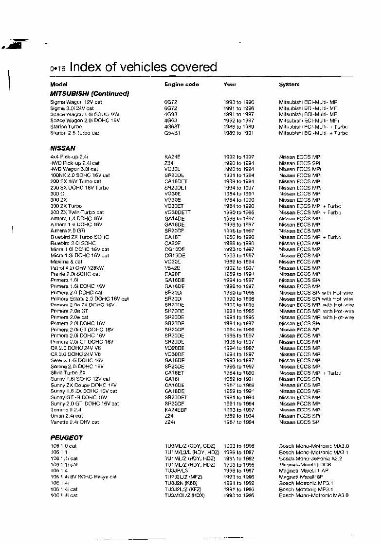
0.16 Index of vehicles covered Model
MlTSUBlSHI (Continued] S~gma Wagcn 12V cat Sigma 3.0i 24V cat space Wwc! 1 I .BI SOHG 16V Space Wagon 2.01 DOHC 16V Starion Turbo Starion 2.6 Turbo cat
NISSAN 4x4 Pick-up 2.41 4WD Pick-up 2.4i cat 4WD Wagon 3.01 cat 10ONX 2.0 SOHC 16V cat 200 SX 16V Turbo cat 230 SX DOHC 16V Turbc, 300 C 300 ZX 330 ZX Turbc 330 M Twin-Turbo cat Alrnera 1.4 DOHC 16V Amera 1 ti DOHC 16V A,mera F.D GTi B uebird ZX Turbo SOHC Bluebird 2 Oi SOHC M~rra 1 Oi DOHC j 6 V cat Miera 1-31 DOHC 16V cat Maxima & cat Patrol 4.2i OHV l2BkW Pra~rie 2.Di SOHC cat Prlmera 1.6i Pnmwa : .& DOHC 16V Primera 2.0 DOHC cat Primera Estate 2.0 DOHC 16V cat Ptinrora 2 . 0 ~ ZX DOHC IFV Prirnera 2.0e GT Primera 2.0e cat Pflrnera 2 Oi DOHC 16V Primera 2.0i GT DOHC 16V Prmera 2.0i W H C 16V Pr~mera 2.0i GT DOHC 16V OX 2.0 DOHC 24V V6 QX 3.0 DOHC 24V V6 Serena l .Gi DOHC 16V Serena 2.01 DOHC 16V Silvia Turbo ZX Sunny 1-61 SOdC 12V cat Sunny ZX Couoe DOHC: 1tN Sunny 1.8 ZX DOHC 16V cat Sunny GTI-R DOHC 16V Sumy 2.0 GTi DOHC 16V eat Terrano 11 2.4 Urvan 2.41 cat Vanette 2.41 OHV cat
PEUGEOf 106 1.Ocat 106 1.1 1% 1.11 cat 106 1.l i cat 106 1.4 106 1.4\ $V SOHC Rallye cat 1OE 1.41 106 1.4i cat IflF 1 4i cat
Engine code Year
KA24E Z24i VG30E SRPODE CAI BDET SR20DET VG30E VG3OE VG30ET VG30DETT GAl4DE GA16DE SR2DDE CAI 8T CA20E CG 1 ODE CG13D.E VG3OE T842E CA20E GAIGDE GAIGDE SR2ODi SRPODi SR20U.k SRPOOE SR2ODE SR20DE SR7DOE SR20DE SAZODE VQPODE VQBODE GA16DE SR20DE CAI BET GAT 6i CAIGDE CAI 8DE SR20DET SR200E KA24EBF Z24i Z24i
TU9MLtZ (CDY, CDZ) TU1 M/L3/L (HDY, HDZ) ru I MUZ IHDY, HDZ) TUl M W (HDY, HDZ) TU3JP/L3 TU2 J2UZ (MFZ) TU3J2K {KBB) TJ3JPL.Q (KFZ) TU3MCUZ (KOXJ
System
M~tsubishl ECI-Multl- MPI Mits~~hish~ ECI-Multi- MPI M~tsub~shr ECI-Multi- MPI M~tsub~shr ECI-MUIII- MPI Mitsubishl ECI-Multl- + Turbo Mitsub~sb~ ECI-Multl- + Turbo
N~ssan ECCS MPr Nissan EGCS SPi Nissan ECCS MPI N~ssan ECCS MPI Nissan ECCS MPI Nissan ECCS MPI Nlssan t L C S MPi Nissan EGCS MPI Nissan EGGS MPI + Turbo Nlssan EmZCS MPI + Turbo N~ssan EGCS MPI Nissan ECCS MPI Nlssan ECCS MPI Nlssan ECCS MPi + Turbo Nissan ECCS MPI N i a n ECCS AnP) Nlssan EGCS MPI Nlssan ECCS MPI Nwsan ECCS MP\ N~soan LCCS MPi Nissan ECCS SPI Nissm ECCS MP\ Nlssan ECCS SPI wlti Hol-wire Nlssan ECCS SPI with Hot-wire Nlssan ECCS MPI wtth Hot-w~re Nissan ECCS MPI wlth Hot-w~re Nlssan ECCS MPi with Hot-wlre Nlssan ECCS SPI N~ssan EGGS SPI Nlssan ECCS MPI Nissan ECCS MPI Ntssan ECCS MPI Nlssan ECCS MPi N~ssan ECCS MPi N~ssan ECCS MPI Nissan ECCS MPI + Turbo Nlssan ECCS SPI N~ssan ECCS MPI Nlssan ECCS MPi N~ssan ECCS MPI Nlssan ECCS MPI N~ssan ECCS MPI Nlssan ECGS SPi Ntssan ECCS SPI
Bosch Mono-Motronic MA3.0 Bosch Mono-Motronic MA3 1 Bosch Mono- Jetronic A2.2 Magnetl-Marell1 FDGG Magneti-Marelli 1 AP Magnet1 -Marell! 8P Bosch Motronic MP3.1 Bosch Motronic MP3.1 Bosch Mono-Motronic MA3.0

Index of vehicles covered 0.17
Model 106 1.6 106 1.6 1061.6 MPi 205 1 .l i cat 205 1.11 cat 205 1 41 LC cat 205 1 41 HC cat 205 f 4i 205 1 61 cat 205 1.61 and AT cat 205 GTI 1.9 8V cat 3061.li 3061.li 306 1.4i cat 306 1.41 cat 306 1.6 cat 306 1.81 Cabrio and cat 306 2.Ui Cabrio and cat 30620i 16Vcat 306 2 01 GT-6 309 1 11 cat 309 1.41 cat 309 1.4i cat 309 1.61 cat 309 1.6i cat 309 1.6i cat 309 1.9 8V 309 1.9 16V DOHZ 309 ! 9 16V DOHC 309 1 9 16V cat 3G9 1.9 SPi cat 405 1.4i cat 405 1 61 cat 405 1 6i cat 405 1.61 cat 405 1.61 cat 405 1.61 cat 405 1 61 cat 405 1.8: cat 405 1.9 8V cat 405 1.9 Mi1 6 and 4x4 16V 405 1.9 Mi1 6 and 4x4 1 6V 405 1.9 M116 cat 405 1.9i Wldistributor 405 1.9i DIS 405 1.9 SPi cat 405 2.01 and 4x4 8 V cat 405 ?.Dl 16V cat 405 2.01 16V turbo cat 406 1.6i cat 4C6 t 81 cat 406 1.8 l 6 V 406 2.0 16V 406 2.0 Turbo 605 2.01 cat 605 2.01 cat 605 2.0i 16V 605 2.0i turbo cat 605 2 Oi t u r h 605 3 01 cat 605 9 01 24V DOHC cat 506 3 01 24V V6 806 2 0 B06 2 0 Turbo Boxer 2.0
Engine code
TUSJPL'Z (NFZ) TU5JPfi3 TUSJPUUK [NFY) TU1 MU2 (HDZ) TU 1 MU2 (H DZ) TL13MZ (KDZ) TU3MUZ (KDY) TU3FM/L (KDY2) XUSMZVZ (BOY) XUSMBLfZ (BDY) XUSJAZ (DKZ) TU1 MU2 (HDY, HDZ) TUIMVZ (HDY, h D 4 TUBMCUZ (KDX) TUSMCUZ (KDX) TUSJPUZ (NFZ) Xi l7J PUT (LFZ) XU 1 OJ2CUZ (RFX) XU1 OJ4UZ (RFY) XU1 OJ4RS TUl MUZ (HDZ) TU3MZ (KDZ) TU3MUZ (KDY) XU5MZ (BDZ) XU5M2Ln (BDY) XU5M3U.7 (BOY) XUSJNZ (DKZ) XU9J4K (D6C) XU9J4K (D6C) XU9J4UZ (DFW) XUSMIZ (DDZ) TU3MCUZ (KDX) XU5MZ (BDZ) XUSM2UZ (BDY) XU5M3.Z (BDYj XUSM3L)Z (BOY) XUSJPUZ (BFZ) XUSJPL'Z (BFZ) XU7JPVZ (LFZ) XUSJNZ (DKZ) XU9J4K (D6C) XU9J4K (D6C) XU9J4/Z (DFW) XUSJZ'K (DGD) XU9J2K (D6D) XUQM/Z (DDZ) XUlOJ2CUZ (8FX) XU1OJW.Z (RFY) XU1 OJ4TEUZ (RGZ) XUSJPL3(BFZ) XU7JPKILGA) XU7JP4L XU1 OJ4RL XU1 OJ2TWL3 XU1 OMUZ (RDZ,' XU1 OJ2UZ (RiZ) XU1 OJJRUUL3 (RFV) XU1 OJ2TEUZ (RGY) XUldJ2CTEUZ (RGX) ZPJUZ (SFZ) ZPJJUZ (SKZ) ZPJ4UZ (UKZ) XU1 OJ2CUZ (RFU) XU1 OJ2CTEUZ [RGX) XUlOJ2U (RFW)
Year
1991 to 1996 1996 to 1997 1994 to 1996 1 989 to 1992 1992 to 1996 1988 to 1991 1991 to 1994 1994 to 1996 1990 lo 1991 1992 to 1997 1989 to 1993 1 993 to 1997 1993 to 1996 1993 to 1995 1994 to 1997 1993 to 1997 1993 to 1997 1994 to 1997 1 994 tc 1996 1996 to 1997 1991 to 1994 1988 to 1991 1991 to 1994 1989 to 1991 1991 to 1992 1992 to 1994 198B to f 992 1990 to 1991 1991 to 1992 1990 to 1992 1988 to 1993 1992 to 1994 1989 to 1991 1989 to 1991 1991 to 1992 1992 to 1993 1989 to f 992 1993 to 1995 1992 to 1997 19B9 to 1992 1988 to 1991 1990 to 1992 1990 to 1992 1990 to 1991 1991 to 1992 1989 to 1992 1992 to 1997 1992 to 1995 1993 to 1995 1996 to 1997 1998 to 1997 1995 to 1997 1995 to 1997 1996 to 1997 1989 to 1994 1990 to 1995 1995 to 1997 1993 to 1994 1995 to 1997 1 990 to 1 995 1990 to ! 994 1995 to 1997 1995 to 1997 1995 to 1997 1994 to 1997
System Bosch Motrorllc MP5.1 Bosch Motron~c 5 2 Magneti-Marelli 8P Bosch Mono-Jetronic A2.2 Magnetl-Marelli FDGG Bosch Mono-Jetronic A7.2 Bosch Mono-Jetronlc A2.2 Bosch Mono-Motron~c MA3 0 Magneti-Marelli BAGS Magneti-Marelli FDGG Bosch Molronlc 1.3 Magnetl-Marelli FDGG Bosch Mono-Motronic MA3.0 Bosch Mono-Motronic MA3.0 Magnetl-Marelli FDG6 Bosch Motronkc MP5.1 Magneti-Mare111 8P Magneti-Marelli BP Bosch Motronic MP3.2 Magneti-Marell1 AP 10 Bosch Mono-Jetron~c A2.2 Bosch Mono-Jetronic A2.2 Bosch Mono-Jetronic A2.2 Magneti-Marelli BAGS Maqneti-Marelli G5 Magneti-Maretli FDG6 Boscn Motronic 1.3 Bosch Motronic 4.1 Bosch Molronlc 1.3 Bosch Motronlc 1 3 Fenix 1 8 Mono Motronrc MA3.0 Magneti-Mare111 BAG5 Magneli-Marelli FOG5 Magneti-Marelli FDG6 Magneti-Marelli FDGG Bosch Motronic 1.3 Magneti-Marelli DCM8P13 Bosch Motronic MP5.1 Bosch Motronic 1.3 Bosch Motronic ML4.1 Bosch Motronlc 1.3 Bosch Motronlc 1.3 Bosch Motronlc MP3.1 Bosch Motronic MP3.1 Fenix 18 Magneti-Marelli 8P Bosch Motronic MP3.2 Magnetl-Marelli AP MPi Magnetl-Marelli 8P Magneti-Marell1 BP Bosch Motronic MP5 1.1 Bosch Motronic MP5.1.1 Bosch Motronic MP5.1.1 Magnelr-Marelli G5 Bosch Motronic MP3.1 Bosch Motronic MP5.1.1 Bosch Motronic MP3.2 Bosch Motronic MP3.2 Fenix 38 Fenix 4 Fenix 4 Magneti-Marell1 BP-22 Bosch Motronlc MP3.2 Magneti-Marelli BPI 1
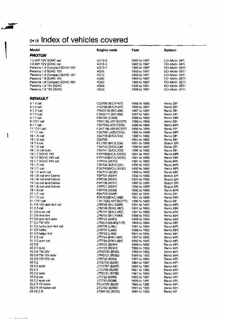
0.18 Index of vehicles covered Model
PROTON 1.3 M Pi 12V SOHC cat 1.5 MPi 12V SOHC cat Persona 1.3 CompacI SOHC 12V Persona 1.5 SOHC 12V Persona 1.5 Compact SOHC 1 W Persona 1.6 SOHC 16V Persona 1.6 Cornpad SOHC 16V Persona 1.8 12V SOHC Persona 1.8 7 6V DOHC
REMULT 5 7.4cat 5 1.4cat 5 1.7i cat 5 1.7i cat s t .7 cat 9 1721 cat 9 1.7 cat 11 1721 cat 11 1.7-t 19 1.4i cat 19 1.4i cat 19 1.4cat 19 t.7i cat 19 1.7i cat auto 19 1 .7 DOHC 16V 19 1.7DOHC 16Vcat 19 1.7 DOHC 16Vcat 19 1.7i cat 19 1 .?I cat 79 1.7i auto cat 19 1.81 cat ar.d Cabrio 19 l.8l cat and Cabrio 19 1.81 cat and Cabrb 19 1 .Bi cat and Cabrlo 19 1.a cat 21 1.7i cat 21 1.71 cet 21 1721 cat 21 2.0 12V and 4x4 cat 21 2.0 cat 21 2.0 auto cat 21 2.0 and 4x4 21 2.0 and 4x4 auto 27 2.0 TXf 12V 21 2.0 turbo and 4x4 cat 21 2.0 turbo 21 2.0 tu rb 4x4 21 2.2 cat 21 2.2 auto cat 25 2.0 25 2.0 auto 25 2.0 TXI 12V 25 2.0 TXi 12V auto 252.0TXi 12Vcal 25 2.2 25 2.2 auto 25 2.2 25 2.2 auto 25 2.2 cat 25 2.2 auto cat 25 2.5 V6 turbo 25 2.5 V6 turbo cat 25 V6 2.9i
-
Engine e d e
-
Year
-
System
ECI-Multi- MPi ECI-Multi- MPi EC1-Multi- SEFi ECI-Multi- SEFi ECI-Multi- SEFI ECI-Multi- SEFi ECI-Multi- SEFi ECI-Multi- SEFi ECI-Multi- SEF!
Ranix SPi Renix SPi Renix SPI Renix SPi Reniw MPi Renix SPi Renix MPI b n i x SPi Renix MPI Ranlx SPI Renix SPi Bosch SPi Ren~x SPi Renix SPI Renix MPi Renix MPI Renix MPI Renix MPi Ren~x MPi Renix MPi Bosch SPi Bosch SPi Bosch SPi Bosch SPi Renix MPi &nix SPi Renix MPi Renix SPi Renix MPi Renix MPi Renrx MPi Henix MPi Renix MPi Renin MPi Ren~x MPi Renix MPi Ranix MPi Renix MPi Renix MPi Renix MPI Renix MPi Renlx MPi Renix MPi Renix MPi Ren~x MPi Renix MPi Renix MPI Renix MPi Renix MPi Renix MPI Renix MPi Renix MPi Renix MPI
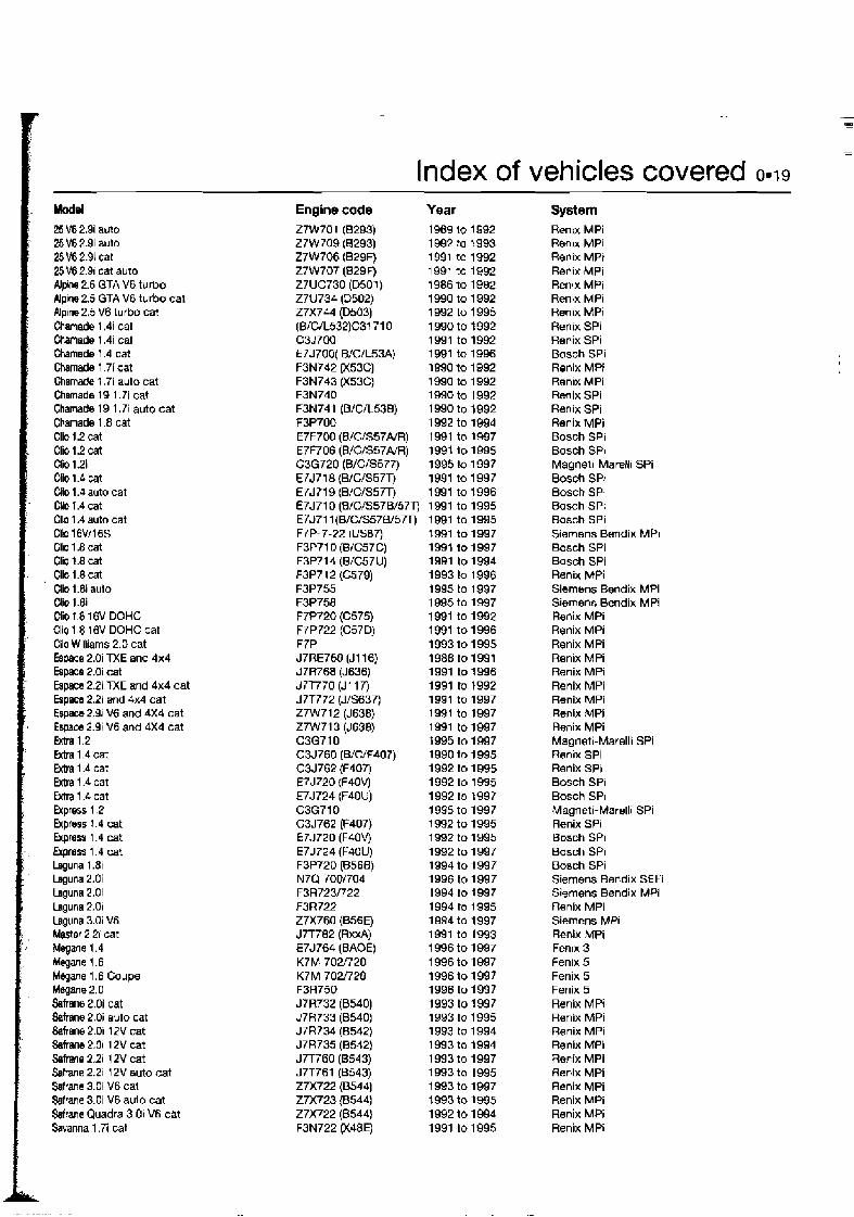
Index of vehicles covered 0.19 Model 25 V6 2.9i ado 25V6 2.9i auto 25 V6 2.9i cat 25 V6 2.91 cat auto Alpine 2.5 GTA V6 turbo Alplne 2.5 GTA V6 turbo cat Alpine 2.5 V6 turbo cat Chamade 1.4i cat Chmade 1.4i cat hamade 1.4 cat Chamade 1.7i cat Chamade f.7i auto cat chumads 19 1 .T i cat Chamade 19 1.7i auto cat Chamade 1.8 cat C l i 1.2 cat Clio 1.2 cat Clio 1.21 Cllo 1.4 cat Cllo 1.4 auto cat CHo 1.4 cat Cllo 1.4 auto cat Clb 16V116S Clb 1 .B cat Clio 1.8 cat Clio 1.8 cat Clio 1.8i aulo Clio 1 .Bi Qio 1.8 16V DOHC Cllo 1 8 16V DOHC cat Cllo Wllliams 2.0 cat Espace 2.0i TXE and 4x4 Espace 2.0i cat Espace 2.2i TXE and 4x4 cat Espace 2.2i and 4x4 cat Espaca 2.31 V6 and 4x4 cat Espaae 2.9i V6 and 4x4 cat Entra 1.2 Mra 1.4 cat Extra 1.4 cat Extra 1.4 cat M r a 1.4 cat Express 1.2 Bptess 1.4 cat Express 1.4 cat Ewprass 1.4 cat Laguna 1-81 Laguna 2.0i Laguna 2.01 Laguna 2.0i Laguna 3.0i M Mester 2.21 cat Megwe 1.4 Mqane 1.6 Megane 1.6 Coupe Mqane 2.0 S a h e 2.0i cat S a h e 2.0i auto cat Safrane 2.0i 12V cat Safrane 2.01 1 2V cat Safrane 2.21 1 2V cat Q h n e 2.2i 12V auto cat Safrane 3.0i V6 cat Safrane 3.0i V6 aulo cat Sefrane Quadra 3-01 V6 cat Savanna 1.7; cat
-
Engine code 27W70 1 (8293) 27W 709 (8293) Z7W706 (B29F) 27W707 (829F) Z7UC730 (D501) Z7U734 (D502) Z7X744 (D503) (B/C/L532)C31710 C3J700 E7JTOO( BICR53A) F3N742 (X53C) F3N743 (X53C) F3N740 F3N741 (B/C/L538) F3P700 E7F700 (B/CIS57A/R) E7F706 (B/C/S57A/R) C3G720 (BICIS577) E7J718 (B/C/S57T) E7J719 (BICIS5Aj E7J710 (B/C/S57B/57v E7J711 (B/C/S57W5m F ~ P - 7-22 (usa7) F3P71 D @/C57C) F3P714 (B/C57U) F3P712 (C579) F3P755 F3P758 F7P720 (C575) F7P722 (C57D) F7P J7RE760 (J116) J7R768 (J636) J7T770 (J117) d7T772 (J/S637) Z7W712 (J638) Z7W713 (J638) C3G710 C3J760 (WCiF407) C3J762 (F407) E7J720 (F40V) E7J724 (F40U) C3G710 C3J762 (F407) E7J720 (F40V) E7J724 (F40U) F3P720 (B568) N7Q 700/704 F3R723/722 F3R722 Z7X760 (B56Ei) J7T782 (RxxA) E7J764 (BAOE) K7M 702f720 K7M 7021'720 F3R750 J7R732 (8540) d7H733 (8540) J7R734 (8542) J7R735 (6542) J7T760 (8543) JiT76l (B543) 27x722 (85443 27x723 (6544) 27x722 (0544) F3N722 (X48E)
Year 1988 lo 1992 1 992 to 1993 1991 to 1992 1991 to 1992 1986 to 1992 1990 to 1 992 1992 to 1 995 1990 to 1992 1991 to 1992 1 991 to 1996 1990 to 1 992 1990 to 1 992 1990 to 1 992 1 990 to 1992 1 992 to 1994 1 991 to 1997 1991 10 1995 1995 $0 1 997 1991 to 1 997 1 991 to 1996 1991 to 1995 1 991 to 1995 1991 to 1997 1991 to 1997 1991 to 1994 1993 to 1 996 1995 to 1997 1 995 to 1997 1 991 to 1992 1991 to 1996 1993 to 1 995 1988 to 1991 1991 to 1 996 1 991 to 1992 1991 to 1997 1991 to 1997 1991 to 1997 1995 to 1997 1990 to 1 995 1992 to 1 095 1992 to 1 995 1 992 to 1997 1995 to 1997 1 992 to 1995 1 992 to 1995 1992 to 1997 1994 to 1997 1996 to 1997 1994 to 1997 1994 to 1995 1994 to 1997 1991 to 1993 1 996 to 1997 1 996 to 1997 1996 to 1997 1996 to 1997 1993 to 1997 1993 to 1 995 1993 to 1994 1993 to 1994 1 993 to 1997 1 993 to 1995 1 993 to 1997 1993 to 1995 1992 to 1 994 1991 10 1995
-
System Renix MPi Renix MPi Renix MPI Renix MPi Renjx MPi Renix MPi Renix MPI Renix SPi Renix SPi Bosch SPi Ronix MR Ren~x MPi Renix SPi Renix SPi Renix MPi Bosch SPi Bosch SPi Magnetl-Marelli SPi Bosch SPi Bosch SPI Bosch SPi Bosch SPi Siemens Bendix MPI Bosch SPi Bosch SPi Renix MPI Siemens Bendix MPi Siemens Bendix MPI Renix MPi Renix MPi Renix MPi Renix MPi Renix MPi Renix MPI Renix MPi Renix MPi Rmix MPi Magneti-Marelli SPi Ren~x SPi Renix SPi Bosch SPi Bosch SPI Magneti-Marelli SPi Renix SPi B D S C ~ SPi Bosch SPi Bosch SPi Siemens Bendix SEFi Siemens Bendix MPi Reniw MPi Siemens MPI Renix MPi Fenlx 3 Fen~x 5 Fenix 5 Fenix 5 Renix MPI Renix MPi Renix MPI Renix MPi Renix MPi Renix MPi Renix MPi Renix MPi Renix MPi Renix MPi

Index of vehicles covered 0.21 Model Metm 1.4i SOHC Meto 1.4i SOHC cat Metm 1.41 GTa W H C 16V cat Metra 1.4 GTi DOHC f 6V Metro 1.4 GTi DOHC 16V cat Metm 1.4 GTi DOHC 16V cat MGF 1.8 DOHC 16V MGF 1.8 WC DOHC 16V MG RV8 OHC 16V Mlnl Cooper 1.3 Mini Cooper 1.3i auto Mini Cooper 1.3i Cabriolet Mini l.3i Mini 1.3 MPi Montego 2.0 EFi cat Montego 2.0 EFi auto cat Montego 2.0 EFi Montego 2.0 EFi auto Sterling V6 SOHC 24V
SACLB 9001 16V DOHC 900 Turbo 16V DOHC 900 2.0 16V W H C cat WOi t6V DOHC cat WOS Turbo cat 900 2.0i 16V DOHC 900 Turbo 16V DOHC 90Oi 16V WHC 900i 16V WHC 900 2 . 3 16V DOHC 900 2.5i 24V DOHC QOODi 16V cat 9000 and CD16 9000 f6V cat 9000 Turbo t 6 9000 Turbo 16 cat 9000 2.0i cat 9000 2.0 Turbo cat 9000 2.0 Ecopower 9300 2.0 Turbo Intercmler WOOi 2.3 cat WODi 2.3 cat WOO 2.3i cat WOO 2.3 Turbo cat 9000 2.3 Turbo cat 9000 2.3 Turbo cat W[#) 2.3 Turbo cat
9000 2.3 Empower UP Turbo 9000 3.0 24V WHC
SEAT Alharnbra 2.0 Cordoba 1.4i SOHC 8V Ccfdoba 1.6i SOHC 8V Cwdoba 1.8i SOHC 8V Cordoba 1.8i 16V Cwdoba 2.0i SOHC 8V lMza 1-05 SOHC 8V lbiza t.3i US83 lbiza 1.4i SOHC 8V lbiza 1.6i SOHC 8V lbiza 1 .Bi SOHC BV
Engine code K8 K8 K16 K16 K16 K16 K16 K16 V8 4.0 12AZDW5 12A2DF76 12A2EF77 12A2EK71 12A2LK70 20Hf51 20HF52 20HE36 20HE37 V6 2.5
B202i 8202 25 8202 2L B202i B202i B202i B202i B208i B204L 82341 B258i B202i 8202 B202 8202 8202 B204i B204S B202S B204L 82341 82341 82341 B234L B234R 8234 B234L
0234E 83081
ADY ABD ABU ABS ADL 2E M U AAV ABD ABU ABS
Year 1991 to 1992 1 991 to 1994 1 991 to 1992 1990 to 1992 1 990 to 1993 1 991 to 1894 1995 to 1997 1995 to 1997 1983 to 1996 1991 to 1996 19Q1 to 1996 1993 to 1994 1996 to 1997 1996 to 1997 1990 to 1 992 1990 to 1 992 1989 to 1 992 1989 to 1 992 1986 to 1 988
1989 to 1 990 1988 to 1 990 1989 to t 993 1990 to 1993 1990 to 1 993 1993 to 1997 1994 to f 997 1994 to 7987 1994 to t 997 1993 to f 997 1993 to 1997 1988 to 1993 1991 to 1993 1 988 to 1993 1991 to 1993 1989 to 1993 1894 to 1987 1994 to 1997 1992 to 1993 1994 to 1997 1990 to 1991 1891 to 1993 1994 to 1997 1994 to 1997 1994 to 1997 1993 1991 to 1993
1994 to 1997 1995 to 1997
1996 to 1997 1994 to 1 997 1993 to 1 997 1993 to 1 995 1994 to 1 997 1993 to 1 997 1993 to 1 997 1993 to 1 994 1994 to 1 897 1993 to 1 997 1993 to 1 995
-em Rover MEMS SPi Rover MEMS SPi Rover MEMS SPi Rover MEMS SPi Rover MEMS SPI Rover MEMS MPi Rover MEMS 1.9 MPi Rover MEMS 2J SFi Lucas 14CUX MPi Rover MEMS SPi Rover MEMS SPi Rover MEMS SPi Rover MEMS SPi Rover MEMS MPi Lucas MPi 1 1 CU Lucas MPi 11CU Rover MEMS MPi Rover MEMS MPi Honda PGM-Fi
Lucas 14CU LH-Jetronic Lucas 14CU LH-Jetronic Lucas 14CU LH 1 Jetronic Lucas 14CU LH-Jetronic Lucas 14CU LH-Jetronic Bosch Motronic 2.1 0.2 Saab Trionic Bosch Motronic 2.1 0.2 Bosch Motmnic 2.1 0.2 Bosch Motronic 2.1 0.2 Bosch Motronic 2.8.1 Bosch LH2.4-Jetronic Bosch LH2.4.2-Jetronic Bosch LH2.4-Jetronic Bosch LH2.4.2-Jetronic Bosch LH2.4-Jetronic Saab Trionic Saab Trionic Bosch LH2.4-Jetronic Saab Trionic Bosch LH2.4.1 -Jetronic Bosch LH2.4.2-Jetronic Saab Trionic Saab Trionlc Saab Trionic Saab Trionic Bosch LH2.4-Jetronid Saab Direct Ignition Saab Trionlc Bosch Motronic 2.8.1
Sirnos Bosch Mono-Motronic Bosch Mono-Motronic Bosch Mono-Motronic VAG Digifant VAG Digifant Bosch Mono-Motronic Bosch Mono-Motronic Bosch Mono-Motronic Bosch Mono-Motronic Bosch Mono-Motronic
Index of vehicles covered 0.23 Model
TOYOTA Carny 2.0i OHC Camry 2.0i OHC 4WD Camry 2.2i 16V DOHC cat Camry 2.2 16V DOHC Camiy 2.3 V6 OHC cat Carnrj 3.0i V6 24V DOHC cat Carnrj 3.0 V6 DOHC Carina E 1.6i 16V DOHC Carina E 1.61 16V DOHC cat Carina E 1.8 16V DOHC Carina II 1.8i OHC Carina II 2.Di OHC & cat Carina E 2.01 DOHC cat Carina E 2.0i DOHC cat Celica 1.8i 16V DOHC Celica 2.0 16V DOHC & cat Celica 2.0i 16V DOHC Celica 2.0 16V DOHC Celica 2.0 GT-4 turbo 16V cat Celica 2.0 GT-4 turbo 16V cat Celica 2.2i f 6V DOHC cat Celica Supra 2.8i OOHC cat Corolla 1.3i OHC cat Corolla 1.3i 16V DOHC cat Corolla 1.6 GT OHC Corolla 1.6 GT coupe OHC Corolla 1.6 GTi OHC & cat Corolla 1.6 GTI OHC Corolla 1.6 GTi OHC cat Corolla 1.6i and 4x4 OHC cat Corolla 1.6i t6V DOHC cat Corolla 1.8i 16V DOHC cat Hi-Ace 2.4i OHC Hi-Ace 2.4i 4x4 OHC Land Cruiser Colorado Land Cruiser 4.5 MR2 1.6 OHC MR2 2.0 16V DOHC GT cat MR2 2.0 16V DOHC cat Paseo 1.5 Picnic 2.0 16V DOHC Previa 2.4i 16V DOHC cat RAV 4 2.0i 16V DOHC Starlet 1.3i 12V SOHC Starlet 1.3 16V OOHC Supra 3.0i 24V DOHC Supra 3.0i 24V DOHC cat Supra 3.0i Turbo DOHC DIS cat Supra 3.0i Turbo DOHC DIS cat Tarago 2.4i 76V DOHC cat 4-Runner 3.0i 4wd V6 SOHC 12V
VA UXHA L L Astra-F 1.4i cat Astra-F l .4i cat Astra-F 1.4i cat Astra 1.4i cat Astra-F 1.4i Astra-F 1.4i 16V Astra-F 1.6 cat Astra Van 1.6i cat Astra-F 1.6i cat Astra-F 1.6i Astra-F 1.61 cat
Engine code Year
3s-FE 3s-FE 5s-FE 5s-FE 2VZ-FE 3VZ-FE 1 MZ-FE 4A-FE 4A-FE 7A-FE 1 S-E 3s-FE 3s-FE 3s-GE 7A-FE 3s-GE 3s-GE 3s-GEL 3s-GTE 3s-GTE 5s-FE SM-GE 2E-E 4E-FE 4A-GEL 4A-GE 4A-GE 4A-GE 4A-GE 4A-FE 4A-FE 7A-FE 2RZ-E 2RZ-E SVZ-FE 1 FZ-FE 4A-GEL 3s-GE 3s-FE 5E-FE 3s-FE 2TZ-FE 3s-FE 2E-E 4E-FE 7M-GE 7M-GE 7M-GTE 2JZ-GTE 2TZ-FE
cat 3VZ-E
Toyota TCCS Toyota TCCS Toyota TCCS Toyota TCCS Toyota TCCS Toyota TCCS Toyota TCCS Toyota TCCS Toyota TCCS Toyota TCCS Toyota TCCS ~oyo ta TCCS Toyota TCCS Toyota TCCS Toyota TCCS Toyota TCCS Toyota TCCS Toyota TCCS Toyota TCCS Toyota TCCS Toyota TCCS Toyota TCCS Toyota TCCS Toyota TCCS Toyota TCCS Toyota TCCS Toyota TCCS Toyota TCCS Toyota TCCS Toyota TCCS Toyota TCCS Toyota TCCS Toyota TCCS Toyota TCCS Toyota TCCS Toyota TCCS Toyota TCCS Toyota TCCS Toyota TCCS Toyota TCCS Toyota TCCS Toyota TCCS Toyota TCCS Toyota TCCS Toyota TCCS Toyota TCCS Toyota TCCS Toyota 01s Toyota DIS Toyota TCCS Toyota TCCS
GM-Multec CFi-he GM-Multec MPi GM-Multec MPi-DIS GM-Multec ZE CFi GM-Multec CF1 GM-Multec-S MPi GM-Multe~ CFI GM-Multec CFi GM-Multec MPi GM-Multec CFi GM-Multec MPi
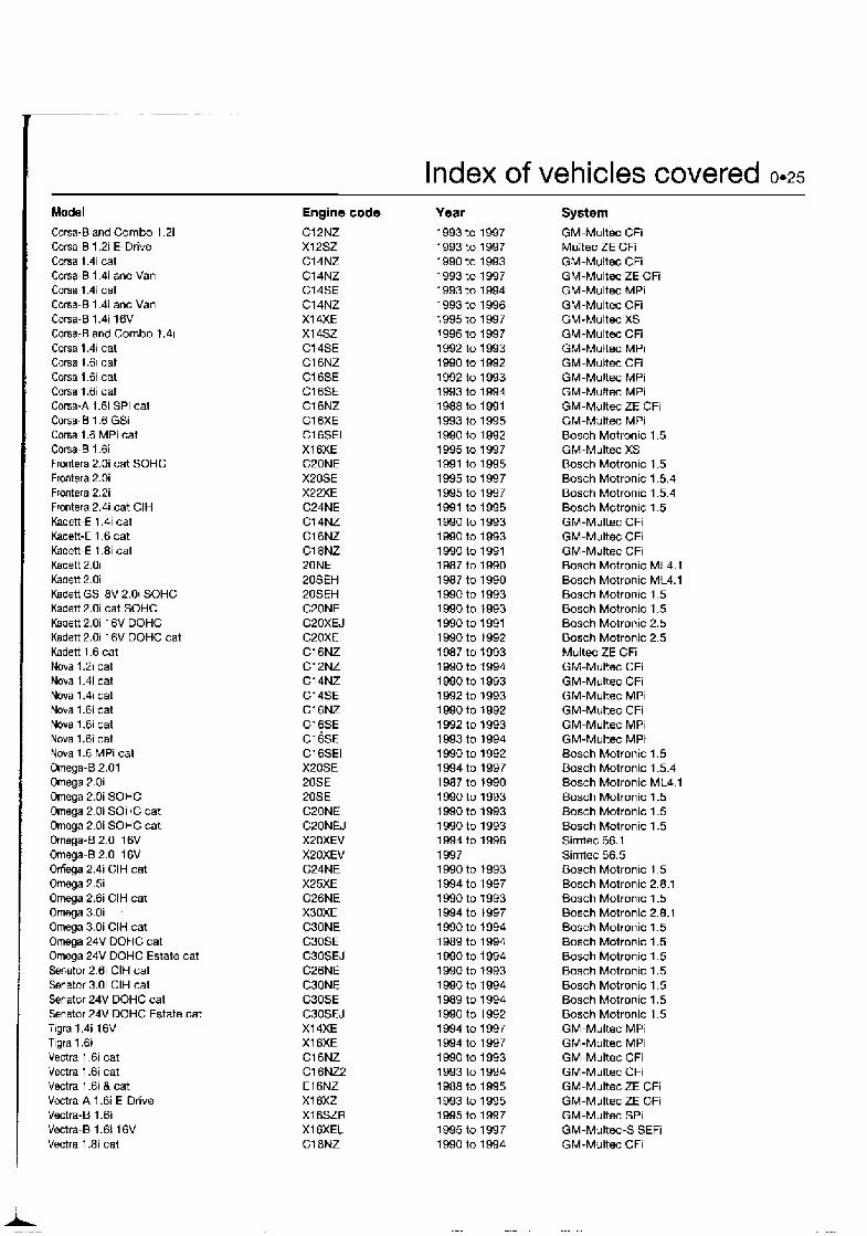
Index of vehicles covered 0.25
Model
Corsa-0 and Combo 1.2i Corsa-B 1.2i E-Drive Coma 1.4i cat Corsa-B 1.4i and Van Corsa 1.4i cat Corsa-B 1.4i and Van Corsa-B 1.4i 16V Corsa-B and Combo 1.41 Corsa 1.4i cat Corsa 1 dl cat Corsa 1.6i cat Corsa 1.6i cat Corsa-A l.6i SPi cat Corsa-0 1.6 GSi Corsa 1.6 MPi cat C o w - B 1.6i Fmntera 2.0i cat SOHC Frontera 2.0i Frontera 2.2i Frontera 2.4i cat CIH Kadett-E 1.4i cat Kadett-E 1.6 cat Kadett-E 1.8i cat Kadett 2.0i Kadett 2.0i Kadett GSi 8V 2.0i SOHC Kadett 2.0i cat SOHC Kadett 2.0i 16V DOHC Kadett 2.0i 16V DOHC cat Kadett 1.6 cat Nova 1.2i cat Nova 1.4i cat Nova 1.4i cat Nova 1.6i cat Nova 1.6i cat Nova 1.6i cat Nova 1.6 MPi cat Omega-B 2.01 Omega 2.0i Omega 2.0i SOHC Omega 2.0i SOHC cat Omega 2.0i SOHC cat Omega-B 2.0i 16V Omega-B 2.0i 16V Ofiega 2.4i CIH cat Omega 2.5i Omega 2.6i CIH car Omega 3.0i ,
Omega 3.0i CIH cat Omega 24V DOHC cat Omega 24V DOHC Estate cat Senator 2.6i CIH cat Senator 3.0i CIH cat Senator 24V DOHC cat Senator 24V DOHC Estate cat Tigra 1.4i 16V Tigra 1.6i Vectra 1.6i cat Vectra 1.6i cat Vectra 1.6i & cat Vectra-A 1.6i E-Drive Vectra-6 1.6i Vectra-B 1.6i 16V Vectra 1.8i cat
Engine code C12NZ X12SZ C14NZ C14NZ C14SE C14NZ XI 4XE XI 4SZ C14SE C16NZ C1 GSE Cl6SE C16RIZ C16XE C1 GSEI X I 6XE C20NE XPOSE X22XE C24NE C14NZ C16NZ Cl8NZ ZONE 20SEH 20SEH C20NE C20XEJ C20XE C16NZ Cl2NZ C14NZ C14SE C16NZ C16SE ~l ~ S E C16SEI XPOSE 20SE 20SE C20NE C20NEJ XSOXEV XPOXEV C24NE X25XE C26NE X3OXE C30NE C30SE CBOSEJ C26NE C30NE C3OSE CBOSEJ XI 4XE X16XE C16NZ C16NZ2 El 6NZ X16XZ X16SZR XI 6XEL C l aNZ
Year 1 993 to 1997 1 993 to 1997 1 990 to 1993 1993 to 1997 1993 to 1994 1993 to 1996 1995 to 1997 1996 to 1997 1992 to 1 993
System GM-Multec CFi Multec ZE CFi GM-Multec CFi GM-Multec ZE CFi GM-Multec MPi GM-Multec CFi GM-Multec XS GM-Multec CFi GM-Muttec MPi GM-Multec CFi GM-Multec MPi GM-Multec MPi GM-Multec ZE CFi GM-Multec MPi Bosch Motronic 1.5 GM-Multec XS Bosch Motronic 1.5 Bosch Motronic 1.5.4 Bosch Motronic 1.5.4 Bosch Motronic 1.5 GM-Multec CFi GM-Multec CFi GM-Multec CFi Bosch Motronic ML4.1 Bosch Motronic ML4.1 B O S C ~ Motronic 1.5 Bosch Motronic 1.5 Bosch Motronic 2.5 Bosch Motronic 2.5 Multec ZE CFi GM-Multec CFi GM-Multec CFi GM-Multec MPi GM-Multec CFi GM-Multec MPi GM-Multe MPi Bosch Motronic 1.5 Bosch Motronic 1.5.4 Bosch Motronic ML4.1 Bosch Motronic 1.5 Bosch Motronic 1.5 Bosch Motronic 1.5 Simtec 56.1 Simtec 56.5 B o s h Motronic 1.5 Bosch Motronic 2.8.1 Bosch Motronic 1.5 Bosch Motronic 2.8.1 Bosch Motronic 1.5 Bosch Motronic 1.5 Bosch Motronic 1.5 Bosch Motronic 1.5 Bosch Motronic 1.5 Bosch Motronic 1.5 Bosch Motronic 1.5 GM-Multec MPi GM-Multec MPi GM-Multec CFi GM-Multec CFi GM-Multec ZE CFi GM-Multec ZE CFi GM-Multec SPi GM-Multez-S SEFi GM-Multec CFi

0.26 Index of vehicles covered Model
VAUXHIlLL (Continued) Vectra-8 1.8; 16V Vectra-B 2.0i 1 BV V ~ t r a 2.0i Vectra 2.0i cat Vectra 2.0 SOHC VeMra 2.01 and 4x4 SOHC Vectra 2.0i SOHC cat Vectra GSi 200016V DOHC Vectra 2.0 16V 4x4 DOHC cat Vectra-A 2.01 16V Vectra-A Turbo cat Vectra-A 2.51 24V Vectn-6 2.3 V6
VQLKSWAGEN Caddy Pick-up Caravelle 2 .Di and cat Caravelle 2.0i cat Caravells 2.51 Caravelle 2.8 Corrado 1.8i ('360 supercharger) cat Corrado 2 .O 16V Corrado 2.0 BV Corrado VR6 Corrado 2.0i cat GoH 1.31 cat GoH 1.4i cat Golf 1.4i Golf 1.6i cat Golf 1.6i cat Golf 1.6i Golf 1.6i 8V Golf 1.6 8V Golf 1.8i Golf 1 .Bi cat Golf 16V cat Golf Syncro 2.9 Golf 1.81 cat Goif 1.8i cat Golf 1.8i and 4x4 Golf 1.8i cat Golf 2.0i cat Golf 2.0i 16V cat Golf 2.01 Golt 2.0 Gotl VR6 Jetta 1 6V cat Jetta 1.8i cat Jetta 1.8i Jetta 1.8i cat LT 2.3 Passat 1.6i cat Passat 16V cat Passat 1.6; Passat 1.8 cat Passat 1.8i and cat Passat 1.8i Passat 1.81 and cat Passat 1.81 cat Passat 1.81 cat Passat 1.8i cat Passat 1.8i cal Passat 1.8; Pmsa? i .8i
Engine
AEE AAC AAC ACU AES PG 9A ADY ABV 2E AAV ABD AEX ABU Am AEK AEE AFT GX GX PL ABV AAM ABS ADZ RP 2E ABF ADY AGG A4A FL RP GX GX AGL 1 F 9A AEK JN RP RP RP AAM AAM AAM AAM ABS AAM
code Year System
S~rntec 56.5 Simtec 56.5 Bosch Motronic ML4.1 Bosch Motronic 1.5 Bosch Motronic 1.5 Bosch Motron~c 1.5 Bosch Motronic 1.5 Bosch Motronic 2.5 Bosch Motronic 2.5 Sirntez 56.1 Basch Motronic 2.7 Bosch Motronic 2.8 Bosch Motronic 2.8.3
Magneti-Marelli 1 AV VAG Digifant VAG Digifant VAG Digifant Bosch Motronic VAG Bosch KE-Motronic 1.2 Simos Bosch Motronic 2.9 VAG Digdant Bosch Mono-Motronic 1.2.1 Bosch Mono-Motronic 1.2.3R Bosch Motronic MP9.0 Bosch Mono-Motronic 1.2.3 Bosch Mono-Motronic 1.3 Bosch Motronic Magneti-Mawlli 1AV Simos 452 Bosch KE-Jetronic 8osch KE--Jetronic Bosch KE-Jetronic Bosch Motron~c 2.9 MPi Bosch Mono-Motronic 1.2.3 Bosch Mono-Motronic 1.2.2 Bosch Mono-Mottonic Bosch Mono-Jetron~c A2.2 VAG Oigifant VAG Digkfant Simos Simos 4S MPi Bosch Motronic 2.7 Bosch KE-Jetronic Bosch Mono-Jetronic A2.2 Bwch KE-Jetronic Bosch KE-Jeti-on~c Bosch Motronic 8osch Mono-Jetrontc Bosch KE1.2-Motronic Bosch M2.9 Motronic Bosch KE-Jetronic Bosch Mono-Jetrgnic A2.2 Bosch Mono-Motronic 1.2.1 Bosch Mono-Motronic 1.2.1 Bosch Mono-Motronic 1.2.1 Bosch Mono-Motronic 1.2.3 Bmch Mono-Motronlc 1.2.3 Bosch Mono-Motronic 1.3 Bosch Mono-Motronic 1.2.1 Bosch Mono-Motronic 1.2.1
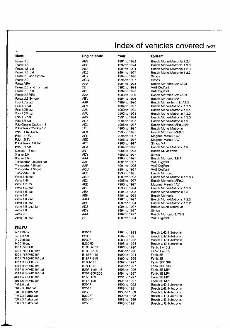
Index of vehicles covered 0.27 Model Passat 1.81 Pasat 1.8i Passat 1.8i cat Passat 1.8i cat Passat 2.0 and Syncro Passat 2.0i Passat VR6 Passat 2.0i and 4 x 4 cat Passat 2.0i cat Passat 2.8 VR6 Passat 2.9 Syncro Polo 1 .OSi cat Polo 1.0i cat Polo 1.05i cat Polo 1.05 cat Polo 1.3 cat Polo 1.3i cat Polo ClassicICaddy 1.4 Polo ClassicICaddy 1.6 Polo 1.4 8V 44kW Polo 1.4 1 6V Polo 1.6i 8V Polo Classic 1.6 8V Polo 1.6i cat Santana 1.8 cat Sharan 2.0 Sharan 2.8 Transporter 2.01 and cat Transporter 2.5i cat Transporter 2.5i cat Transporter 2.8 Vento 1.4i cat Vento 1.4i Vento 1.6i 8V Vento t .6i cat Vento 1.6i cat Vento 1.6i Vento 1.8i cat Vento 1.81 cat Vento 1.81 and 4x4 Vento 2.01 Vento VR6 Vento 2.01 cat
VOL VO 240 2.0i cat 240 2.3 cat 240 2.3 cat 240 2.3i cat '
400 1.7i SOHC 400 1.7i SOHC cat 400 1.71 SOHC 8V 400 1.7i SOHC 8V cat 400 1.81 SOHC cat 400 f.8i SOHC cat 400 2.0i SOHC 8V cat 400 2.0i SOHC 8V cat 440 1.6i SOHC 8V 460 1.6i SOHC 8V 740 2.0 cat 740 2.31 16V cat 740 2.3 Turbo cat 740 2.3 Turbo cat 760 2.3 Turbo cat 760 2.3 Turbo cat
Engine code ABS ABS ABS ADZ ADY AGG M A 2E ABF AAA ABV AAK AEV AAU AAU AAV ADX AEX 1 F AEX AFH AEE AFT AEA JN ADY AAA AAC AAF ACU AES ABD AEX AEE ABU AEA AEK AAM ABS ADZ ADY AAA 2E
Year 1991 to 1992 1 992 to 1994 1 992 to 1994 1 994 to 1997 1 994 to 1996 1995 to 1997 1991 to 1993 1992 to 1994 1 994 to 1995 1993 to 1996 1 994 to 1996 1 989 to 1990 1 994 to 1997 1 990 to 1993 1 993 to 1994 1991 to 1994 1 994 to 1995 1 996 to 1997 1996 to 1997 1 995 to 1997 1 996 to 1997 1995 to 1997 1 996 to 1997 1994 to 1996 1984 to 1988 1 995 to 1997 1995 to 1997 1991 to 1997 1991 to 1995 1 994 to 1997 1 996 to 1997 1 992 to 1995 1995 to 1997 1995 to 1997 1 993 to 1994 1 994 to 1995 1 994 to 1995 1 992 to 1997 1 992 to 1994 1 994 to 1997 1 994 to 1997 1 992 to 1997 1 992 to 1994
System
B o s h Mono-Motronic 1.2.1 Bosch Mono-Motronic 1.2.3 Bosch Mono-Motronic 1.2.3 Bosch Mono-Motronic 1.2.3 Simos Simos Bosch Motronic M2.7/2.9 VAG Digifant VAG Digifant Bosch Motronic M2.7/2.9 Bosch Motronic M2.9 Bosch Mono-Jetronic A2.2 Bosch Mono-Motronic 1.2.3 Bosch Mono-Motronic 1 2 .1 Bosch Mono-Motronic 1.2.3 Bosch Mono-Motronic 1.2.3 Bosch Mono-Motronic 1.3 Bosch Motronic MP9.0 MPi Bosch Mono-Motronic Bosch Motronic MP9.0 Magneti-Marelli 1 AV Magneti-Marelli 1AV Simos MPi Bosch Mono-Motronic 1.3 Bosch KE-Jetronic Sirnos Bosch Motronic 3.8.1 VAG Digifant VAG Digifant VAG Digifant Bosch Motronic Bosch Mono-Motronic 1.2.3R Bosch Motronic MP9.0 Magneti-Marelli f AV Bosch Mono-Motronic 1.2.3 Bosch Mono-Motronic 1.3 Bosch Motronic Bosch Mono-Motronic 1.2.3 Bosch Mono-Motronic 1.2.2 Bosch Mono-Motronic Simos Bosch Motronic 2.7/2.9 VAG Digifant
Bosch LH2.4-Jetronic Bosch LH2.4-Jetronic Bosch LH2.4-Jetronic Bosch LH2.4-Jetronic Fenix 1 or 3.2 Fenix 1 or 3.2 Fenix 3B Fenix 36 Fenix 3BF SPi Fenix 3BF SPi Fenix 36 MPi Fenix 36 MPi Fenix 38 MPi Fenix 38 MPi Bosch LH2.4-Jetronic Bosch LH2.4-Jetronic Bosch LH2.4-Jetronic Bosch LH2.4-Jetronic Bosch LH2.4-Jetronic Bosch LH2.4-Jetronic
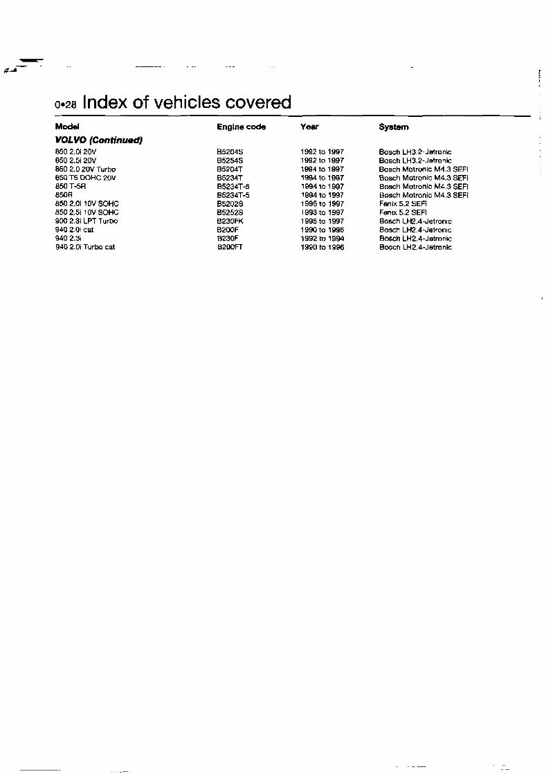
Om28 Index of vehicles covered Model Engine code Yeer System VOLYO (Continued) 850 2.0i 20V 850 2.5i 20V 850 2.0 20V Turbo 850 T5 DOHC 20V 850 T-5R 850R 850 2.0i 10V SOHC 850 2.5i 10V SOHC 900 2.31 LPT Turbo 940 2.0i cat 940 2.3 940 2.0i Turbo cat
Bosch LH3.2-Jetronic Bosch LH3.2-Jetronic Bosch Motronic M4.3 SEFl Bosch Motronlc M4.3 SEFl Bmch Motronic M4.3 SEFl Bmch Motronic M4.3 SEFl Fenix 5.2 SEFl Fenlx 5.2 SEFl Bosch LH2.4-Jetronic Bosch LH2.4-Jetronic Bosch LH2.4-Jetronic Bosch LH2.4-Jetronic

Chapter 1 Introduction to Self-Diagnosis Contents Adaptive control function . . . . . . . . . . . . . . . . . . . . . . . . . . . . . . . . . . 4 Introduction . . . . . . . . . . . . . . . . . . . . . . . . . . . . . . . . . . . . . . . . . . . . 1
. . . . . . . . . . Function of the Self-Diagnosis system . . . . . . . . . . . . . . . . . . . . . . . 2 Limited Operating Strategy (LOS) - "limp-home" mode 3
effective operation of vehicular engines was were introduced in California by Californian , , , , ,, , accept4 and argued by the California Air State Government under the "Clean Air Act" to
Resourcw Board (CARB). By 1968 regulations restrict pollutant emissions for passenger cars. , , , , , , A
, , , ,
The objective of the Self-Diagnosis (SD) function (sometimes termed On-Board Diagnosis or OBD) is to minimise pollutant emissions for motor vehicles. Self-diagnosis is the basis for controlling engine performance in order to provlde the most effective conditions for efficient operation.
Heynes Engine Management Techbook
A general knowledge of engine management system (EMS) operation and of the chemical sequences of combustion for internal combustion engines will help explain why and how SD has become such an important part of the modern vehicle. Refer to the companion volume "Automotive Engine Management and Fuel Injection Systems Manual" (Book No 3344, available from the publishers of this title) for a description of the operation of the modern EMS.
The chemical sequence of combustion
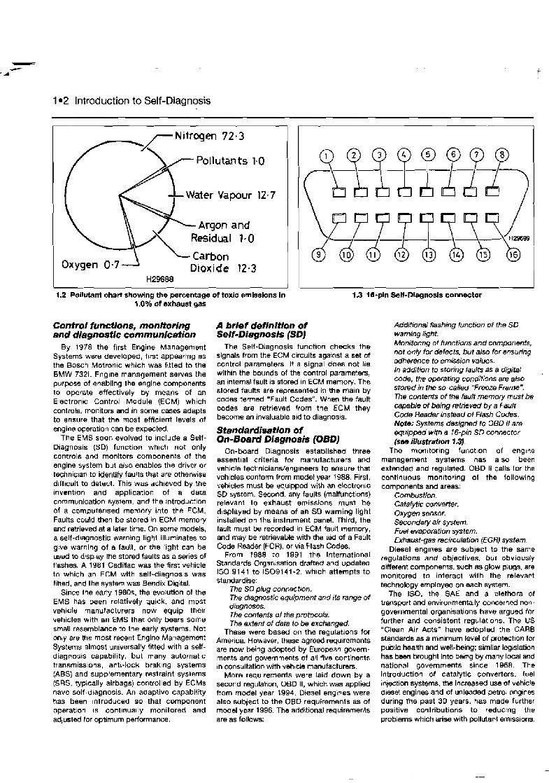
Fuels for spark ignition and diesel engines consist of various hydrocarbon compounds, which combine with the oxygen of the intake air. Nitrogen and other residual gases also combine during the combustion process. With perfect cordbustion, no toxic substances would be produced. Under actual operating conditions, non-toxic exhaust gases such as nitrogen (N,), water vapour (H,O) and carbon dioxide (CO,) join the toxic products of incomplete combustion. Toxic substances in exhaust gases include carbon monoxide (CO), partially-unbumt hydrocarbons (HC), nitrogen oxides, sulphur dioxide (SO,), lead compounds and soot (see illustrations 1.1 and 1.2). The high concentratlon of pollutants resulting from vehicle emissions are known to be causing health problems, notably respiratory illnesses, and also have environmentally-damaging effects.
The idea that toxic emissions should be reduced while maintaining or improving the
Dioxide
Perfect combustion
Water Hydrocarbons
l ncomplete combustion
Water
Hydrocarbons
ti WM
1.1 Combustion chart
1 12 Introduction to Self-Diagnosis
Pollutants 1.0
Water Vapour 12.7
Argon and
Oxygen 0.7- Dioxide 12.1 HZ9688
- d ' I 1.2 Pollutant chart showing the percentage of toxic smlssions in 1.3 18-pin Self-Diagnosis connector
1 .OW of exhaust gas
Confrol functions, monitoring and dlagnos flc communica fion
By 1978 the first Engine Management Systems were developed, f~rst appearing as the Bosch Motron~c which was fitted to the BMW 7321. Englne management serves the purpose of enabling the engine components to operate effectively by means of an Etectron~c Cantrot Module (ECM) which controls, monitors and in some cases adapts to ensure that tha most efficient levels of engine operation can be expected.
The EMS soon evolved to include a Self- Diagnosis (SD) function whlch not only controls and monitors components of the engine system but alsa enables the driver or technc~a~ to identify faults that are otherwise difficult to detect. This was achieved by the invention and application of a data communication system, and the introduction of a computertsed memory into the ECM. Faults could then be stored in ECM memory and retrieved at a latsr time. On some models, a self-diagnostic warning light illuminates to give warning of a fault, or the tight can be used to display the stored faults as a series of flashes. A 1981 Caditlac was the first vehicle to which an ECM with self-diagnosis was fitted, and the system was Bendix Digital.
Since the early 1980s, the evolution of the EMS has been relatively quick, and most vehicle manufacturers now equip their vehicles with an EMS that only bears some 5maU resemblance to the early systems. Not only are the most recent Engine Management Systems almost universally fitted with a self- diagnosis capability, but many automatic transmissions, anti-lock brak~ng systems (ABS) and supplementary restraint systems (SRS, typically airbags) controlled by ECMs have self-dragnosis. An adaptive capability has been ~ntroduced so that component operation is cont~nually monitored and adjusted for optimum performance.
A brief definition of SeM-Diagnosis (SDl
The Self-Diagnosis tunction checks tho signals from the ECM circuits against a set of control parameters. If a signal does not lie with~n the bounds of the control parameters, an lnternal fault rs stored In ECM memory. The stored faults are represented in the main by codes termed "Fault Codes". When the fault codes are retrieved from the ECM they become an invaluable aid to diagnosis.
Standardisation of On-Board Diagnosis (OBDJ
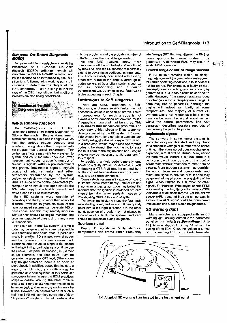
On-board Diagnosis established three essent~al criteria for manufacturers and vehicle technicians/eng~neers to ensure that vehicles contorm from model year 1988. First, vehicles must be eau~pped with an electronjc SD system. Second, any faults (malfunctions) relevant to exhaust emissions must be djsplayed by means of an SO warning light installed on the instrument panel. Third, the fault must be recorded in ECM fault memory, and may be retrievable with the aid of a Fault Code Reader (FCR), or via Flash Codes.
From 1988 to 1991 the International Standards Orgarusation drafted and updated 150 91 41 to IS09141-2, which attempts to standardise:
The SD plug connection. The diagnostic equipment and its range of diagnoses. The contents of the protocols. The extent of data lo be exchanged,
These were based on the regulations for America. However, these agreed requirements are now being adopted by European govern- mer.ts and governments of all five continents in consultation with veh~cle manufacturers.
More requirements were laid down by a second regulation, 060 11, whlch was applied from model year 1994. Diesel engines were also subject to the OSO requirements as of model year 1996. The additional requirements are as follows:
Additional flashing function of the SD warning light. Monitoring of functions and components, not only for defects, but also for ensuring adherence to emission vafues. In addition to storing faults as a digital code, the operating conditions are also stored in the so-called "Freeze Frame". The contents of the fault memory must be capable of being retrieved by a Fault C d e Reader instead of fiash Codes. Note: Systems designed fo OED /I are equipped with a 16-pin SD connector (see iIIustrution 1.3).
The monrtoring funct~on of engtne management systems has also been extended and regulated. OBD I1 calls for the cantinuo~~s monitoring of the following components and areas:
Combustion. Catalytic convemr. Oxygen sensor. Secondary air system. Fuel evaporation system. Exhaust-gas recirculation (EGR) system.
Diesel englnes are subject to the same regulations and objectives, but obviously different components, such as glow plugs, are monitored to interact with the relevant technology employed on each system.
The ISO, the SAE and a plethora of transport and environmentally-concerned non- governmental organisations have argued for further and consistent regulations. The US "Clean Air Acts" have adopted the CAR8 standards as a mmirnurn level of protection for pudic health and welkbeing; similar legbslation has been brought into be~ng by many local snd national governments since 1968. The Introduction of catatytic converters. fuel injection systems, the increased use of vehicle diesel engines and of unleaded petrol engines during the past 30 years, has made further positive contributions to reducing the problems which arise with pollutant emissions.
lntmduction to Self-Diagnosis 1 03
Eumpean On-Board Diagnosis I E O W
European vehicle manufacturers await the introduction of a European On-Board Oiagnosis (EOBD) def~nit~on, which will strengthen the IS0 91 4 t -CARB definition, and that Is expected to be introduced by the 2000 millennium. A Europe-wide worktng party is in axistence to determine the details of the EOBD standards. EOBD is likely to include rimy of the OBD II conditions, but additional rnasures are also being considered.
hfl-Diagnosis function The Self-bagnosis (SD) function
(sometimes termed On-Board Diagnosis or OBO) of the modern Engine Management System continualty exarnlnes the signal values from the various engine sensors and actuators. The signals are then cornpard wilh pre-programmed control parameters. The control parameters may vary from system to system, and could include upper and lower measurement values, a speciftc number of woneous signals within a pre-determined tlme period, implaus~ble signals, signals outs~de of adaptwe limits, and other parameters determined by the system dtrsigner or vehicle manufacturer. If the signal value IS outside of the conlrol parameters (for example a short-circuit or an open-circuit), the ECM determines that a fault is present, and stores a coda In ECM fault memorj.
Early SO systarns were capable of generating and storing no more than a handful of cMes. However, 10 years on, many of the more advanced systems can generate 100 or mwe codes, and this may sharply increase over the next decade as snglne management becomes capable of diagnosing many more fault conditions.
For exarnpk, in one SD system, a s;mple d e may be generated to cover a!l possible fault conditions that could affect a particular crrcuit. in anotper SD system, several codes may be generated to cover various fault conditions, and this could pinpoint the reason fw the tault in that part~cular sensor. If we use the Coolent Temperature Sensor {CTS) circuit as an example, the first code may be generated as a general CTS tault. Other ccdes may be generated to indicate an open or short-circuit. In additinn, codes that indicate a weak or a rich m~nture condition may be generated as a consequence of thls particular component failure. Where the ECM practises adaplive control around the ideal mixture ratio, a fault may cause the adaptive limlts to be exceeded, and even more codes may be raised. However. on determination of such a fault, the EMS will certainly move into LOS or "limp-home" mode - this will reduce the
m~Kture problems and the probable number of Interference (RFI) that may disrupt the EMS or different codes that could be generated. cause spurious (erroneous) codes to be
As the EMS evolves, many more generated. A disrupted EMS may result In cornwnen:s will be controlled and monitored erratic ECM ooeration. by the ECM, and the SD function w~ll certainly extend to cover these additional components. Th~s book is mainly concerned with testing areas that relate to the engine, although all codes generated by ancillary systems such as the air conditioning and automatic transmission wilt be listed in the Fault Code tables appearing In each Chapter.
Urnitations to Self-Diagmsis There are some limitations to Self-
Diagnosu, and some sensor faults may not necessarily cause a code to be stored. Faults in components for which a code is not available or for conditions not covered by the d~agnostic software wlll not be stored. This also means that mechanical problems and secondarj ignition circuit (HT) faults are not directly covered by the SD system. However, side-eHecls from, for example, a vacuum leak or faulty exhaust valve will create mixture and idle problems, which may cause appropriate codes to be stored. The tnck then is to relate the fault code to the engine condrtion - engine checks may I% necessary to aid diagnosis in this respect.
In addition, a fault code generally only points to a faulty circuit. For example, a code il?dicating a CTS fault may be caused by a faulty coolant temperature sensor, a wiring fault or a corroded connector.
Some vehicle systems are capable of storing faults that occur intermittently - others are not. In some instan-, a fault code may be lost the moment that the ignition is switched off; care should be taken when retrieving codes or investigating faults in this kind of system.
The smart technician will use the fault code as a starting point, and as such, it can cluicklv . . point hlrn in the right direction. On the other hand, absence of a code may not always be indicative af a fault-free system, and care shoubd be exercised during diagnosis.
Spurious signal Faulty HT s~gnals or faulty electrbcal
componerlts can create Radio Frequency
Umited range or out-of-range sensors If the sensor remains wi?hin its design
parameters, even if the permeters are incorrect for certa[n operating conddions, a fault o d e will not be stored. For example, a faulty coolanl t'emp6mture sensw will cause a fauk code to be qeneratnd if it is open-circuit or shorted to earth. However, if the sensor resistance does not change during a temperature change, a code may not be generated, although the engine will Indeed run badly at some temperatures. 'The majority of current SD systems would not recognise a fault m this instance because the signal would remain within the control parameters. The next paragraph describes poss~ble methods of overcoming this particular problem.
lmalausible sicmals The software in some newer systams IS
becoming more sophisticated, and may check for a change in vokage or current over a period oi tlrne. If the s ign~l output does not change as expected, a fault wrH be stored. Also, earlier systems would generate a fault code if a particular circhlt was outside of the control parameters without reference to other data or circuits. More modern systems may consider ths output from several components, and relate one s~gnal to another. A fault code may be generated based upon the plausibilrty of the signal when related to a number of other signals. For instance, if me engine speed mPM) is increasing, the throttle position sensor (TPS) indicates a wide-open throttle, yet the airflow sensor (AFS) does not indicate an increase in airflow, the AFS signal could be considered implausible and a c d e would be generatd.
Many vehicles are equipped with an SD warning light, usually located in the instrument panel on the facia (see lllustretions 1.4 to I .0). Alternatively, an LED may be set into the casing of the ECM. Onoe the ignition is turned on, the warning light or LED will illuminate.
1.4 A typical SD wemino light located In the insbment panel
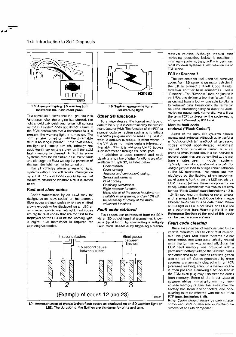
1 e 4 Introduction to Self-Diagnosis
1.5 A second typical SD warning light located in the instrument panel
This serves as a check that the light circu~l 4s functional After the engine has started, the light should ext!ngulsh and remaan off so long as the SD system does not detect a fault. If the ECM detemlnes that a detectable fault is present, the warning light IS turned on. The light remains turned on until the detectable fault is no longer present. If the fault clears, the light will usua\!y turn off, allhough the code itself may remaln stored until the ECM fault memory is cleared. A fault in some systems may tJe classified as a minor fault and although the ECM will log the presence of the fault, the light may not be turned on.
Not all vehicles utihse a warning light: systems w~thout one will require interrogation by a FCR or Flash Code d~splay by manual means to detenn~ne whether a fault 1s stored or nclt.
Fast and slow codes Codes transmitted by an ECM may be
designated as "slow codes" or "last codes". Slow codes are fault codes wh~ch are emrtted slowly enough to be displayed on an LED or on a facia-mounted warning light. Fast codes are digital fault codes that are too fast to be oisplayed on the LEO or on the warning light. A d~gltal FCR instrument is required for captur~ng tast codes.
1.6 Typical appearance for a SD warning light
Other SD functions To a large degree. the format ar,d type of
dala to be output is determined by the vehlcle manufacturer (VM). The fuvction of the FCR or manual code extraction routlne is to initlate the VM's program and to make the best of what is actually ava~lable. In other words, if the VM does not make certa~n lnforrnat~on available, then it is not possible to access such information through the serial port.
In addition to code retrieval and code clearing, a number of other functions are often available through SD, as l~sted below:
Code retrieval. Code clearing. Actuator and component testlng. Service adjustments. ECM coding. Obtaining Datastream. Flight recorder function. Note: Not all of the above functions are available in all systems, and an FCR will be necessary for many of the more advanced functions.
Fault code mtrieval Fault codes can be retneved from the ECM
via an SD output termrna! (sometimes known as a Ser~al Port), by connecting a suitable Fault Code Reader or by trigger:ng a manual
1 second flashos Short pause
1.5 second pause between codes
(Example of codes 12 and 23) I- I
1.7 Representation of typical 2-digit flash codes as display& on an SD warning light or LED. The duration of the flashes are the same for units and tens.
retr~evai routine. Although manual coae retnevlng (described below) rs possible In
most early systems, the practice IS dy~ng out; mcst modern systems allow retr~eva\ via an FCR alone.
FCR or Scanner ?
The professional tool used for retrieving codes from SD systems on motor veh~cles in the UK is termed a Fault Code Reader. However another term sometimes used IS
"Scanner". The "Scanner" term originated in the USA, and defrnes a tool that "scans" data, as dlstinct from a tool whose sole function 1s to "rel:~eve" data. Real~stically. the terms can be used interchangeably to descrlbe code- retrieving equ~pment. Generally, we will use the term FCR to descr~be the code-reading equlprnent covered by this book.
Manual fault code retrieval ("Flash Codes")
Some of the early SD systems allowed ~naoual code retrieval. Although qulte useful as a "quick-and-dirty" method of accessing codes without sophisilcated equipment, manual code retrieval is Irrn~ted, slow and prone to error. In addition, it is not possrble to retneve codes that are transmitted at Ine h~gh trar~sfer rates seen In modern syslems. Typically, manual code relrieval is initiated by using a jumper lead to br~dge certain terminals III the SD connector. The codes are then displayed by the flashng of the Instrument panel warning light, or on :he LED set into the ECM casing (where these components are fittd). Codes oLtained in th~s fashon are often ternled "Flash Codes" (see iltustrations 1.7 to 1.9). By counting the flashes or meter sweeps and referr~ng to the Fault Code table in earn Chapter, faults can thus be detennined. Where an SD light or LED is not fitted, an 1-ED diode or a voltmeter (see Warning No 5 in the Reference Section at the end of this book) can be used In some systems.
Fault code clearing There are a number of methods used by the
vehicle manufacturers to clear fault memory over the years. Mid-198Ds systems d ~ d not retain codes, and were aulornalically cleared once the ignttron was t~rrned off. Soon the ECM fault memory was provided with a permanent battery voltage that allowed codes and other data to be retained aRer the ignrtion was turned off Codes generated by these systems are normally cleared with an FCR (preferred method), altnough a manual routine is often possible. Removing a battery lead or the ECM multi-plug may also clear the codes from memory. Some of the lalest types of systems utflise non-volatile memory Non- volatile memory retarns data even afler the battery has been d~sconnected, and code clearing must be effected w~th the a~cl of an FCR {see illuslration 1.19). Noie: Codes should always be cleared after component tests or after repairs ~nvolving the removal 61 an EMS corhponert

Introduction to Self-Diagnosis 1 *5
Clearing codes manually It is often possible to clear fault codes by
in~tiat~ng a manual rout~ne sirnrlar to that used to retrieve flash codes.
Actuator and component testing The FCR can be used to test the wiring and
components In certain actuator circu~ts. For example, the idle speed control valve (ISCV) circult could be energlsed. If the valve actuates, this proves the Integrity of that circuit. Depending on the system (it is not possible to test a particular actuator unless the routine has been designed into the SD system), possible circuits include the fuel Injectors, relays. ISCV, and emission actuators amongst others. It may also be possrble to test the signals from certain sensors. A common test IS to check the signal from the throttle posltlor~ sensor (TPS) as the throttle IS moved from the closed to the fully-open position and then returned to the closed position. Afault will be reg~stered ~f the potentlometer track 1s deemed to be defective.
Manual sensor testing and component actuation
Component actuation is normally the provlnce of the FCR. However, in a very few systerns, rrlanual actuation ar~d component testlng is possible. Where appropriate, these rout~nes will be described In the relevant Chapter.
Service adjustments In most modern engines. any kind of
adlustment to the Idle mixture or ignition tlmlng 1s not poss~ble. However, some older systems are denied external adjustment, and an FCR is essential if certain adjustments are to be effected. Examples include some Ford vehicles with EEC IV, the Rover 800 SPI, and more recent Rover veh~cles with MEMS. All of these veh~cles require an FCR for varlous adiustments including ignition timing and/or rdle mixture adjustment.
ECM coding In some systems, an FCR may be used to
code the control unit for certain applications. Th~s funct~on is normally reserved for the vehicle mat~ufacturer's rnain agent, and allows a smaller range of control modules to be bu~lt for a large number of different applications. Codrng the control un~t would match the ECM to a particular vehicle.
Obtaining Datastream Datastream ~nformation IS live data from the
varlous sensors and actuators that can be displayed on the FCR screen. This function is particularly useful for rapid testing of suspect sensors and actuators Dynamic tests could be performed and the sensor response recorded. Where a component seems faulty, but a code is not generated, Datastream could be viewed over a range of englne speeds and temperatures. For example, the coolant temperature sensor signal could be viewed
Multiples of 10 indicated by Units indicated
1 2 3 2 (Example of codes 12 and 32) HA
1.8 Representation of typical 2-digit flash codes as displayed on an SD warning light or LED. The flash duration is longer for the multiples of ten, and shorter for the single units
1 second flashes 1.5 second pause
1 2 2 3 (Example of code 1223) !
1.9 Representation of typical 4-digit flash codes as displayed on an SD warning light or LED
with the engine cold, and closely monitored as the englne IS warmed up. Any irregular~tres In the signal should be obvious during the course of the time taken to warm the engine.
Although signals from the various components can be viewed by connecting an osc~tloscope or dlgltal multi-meter (DMM) to the relevant circuit, it is often quicker and more convenient to view the system data on the screen of the FCR. This function is only available with the aid of a FCR, and manual display of Datastream is not possible. Some FCRs can be connected to a standard personal computer (PC) and the data from all monitored components could be displayed simultaneously upon the screen. This overcomes the problem of displaying data from a small number of components on a small FCR screen. As dynamic tests are initiated. the response from each component could be more easily observed. In addition, with the aid of suitable software, the PC could chart and record each signal as various tests are performed. All of the signals (or a selection) could then be played back and reviewed at some later stage.
1.10 A common proprietary Fault Code Reader
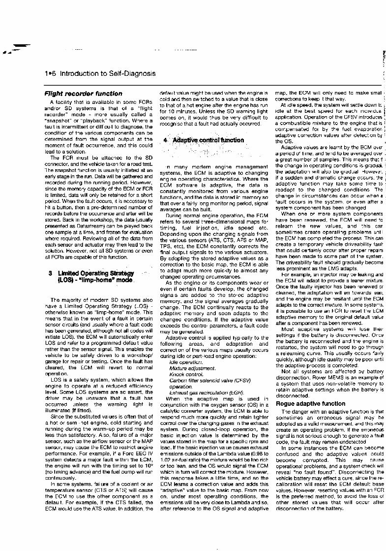
1.6 Introduction to Self-Diagnosis
Flight mcorrder function A tacil~ty that is available in some FCRs
and/or SD systems is Ihal of a "flight recorder" mode - more usually called a "snapshot" or "playback" function. Where a fault is intermittent or difficult to diagnose, the condition of the various components can be determined from the signal output at the moment of fault occurrence, and this could lead to a solution.
The FCR must be attached to the SD connector, and the vehicle taken for a road test. The snapshot function is usually initiated at an early stage in the run. Data will be gathered and recorded during the running period. However, since the memory capacity of the ECM or FCR is limited, data will only be retained for a short period. When the fault occurs, it is necessary to hit a button, then a pre-determined number of records bfore the occunence and after will be stored. Back in the workshop, the data (usually presented as Datastream) can be played back one sample at a time, and frozen for evaluation where requird. Reviewing all of the data from each sensor and actuator may then lead to the solution. However, not all SD systems or even all FCRs are capable of this function.
The majority of modern SD systems also have a Limited Operating Strategy (LOS) -
othewise known as "limp-home" mode. This means that in the event of a fault in certain sensor circuits (and usually where a fault code has b e n generated, although not all codes will initiate LOS), the ECM will automatically enter LOS and refer to a programmed default value rather than the sensor signal. This enables the vehicle to be safely driven to a workshop/ garage for repair or testing. Once the fault has cleared, the ECM will revert to normal operation.
LOS is a safety system, which allows the engine to operate at a reduced efficiency level. Some LOS systems are so smart, the driver may be unaware that a fault has occurred unless the warning light is illuminated (if fitted).
Since the substituted values is often that of a hot or semi-hot engine, cold starting and running during the warm-up period may be less than satisfactory. Also, failure of a major sensor, such as the airflow sensor or the MAP sensor, may cause the ECM to restrict engine performance. For example, if a Ford EEC IV system detects a major fault within the ECM, the engine will run with the timing set to lo0 (no timing advance) and the fuel pump will run continuously.
In some systems, failure of a coolant or air temperature sensor (CTS or ATS) will cause the ECM to use the other component as a default. For example, if the CTS failed, the ECM would use the ATS value. In addition, the
default value might be used when the engine is cold and then switched to a value that IS close to that of a hol wnglno after the englne has run for 10 minutes. Unless the SD warnrng light comes on, it would thus be very difficult to recognise that a fault had actually occurred.
In many modern engine management systems, the ECM is adaptive to changing engine operating characteristics. Where the ECM software is adaptive, the data is constantly monitored from various engine functions, and the data is stored in memory so that over a fairly long monitoring period, signal averages can be built.
During normal engine operation, the ECM refers to several three-dimensional maps for timing, fuel injection, idle speed etc. Depending upon the changing signals from the various sensors (ATS, CTS, AFS or MAP, TPS, etc), the ECM constantly corrects the final output signals to the various actuators. By adopting the stored adaptive values as a correction to the basic map, the ECM is able to adapt much more quickly to almost any changed operating circumstances.
As the engine or its components wear or even if certain faults develop, the changed signals are added to the stored adaptive memory, and the signal averages gradually change. The ECM continually reacts to the adaptive memory and soon adapts to the changed conditions. If the adaptive value exceeds the control parameters, a fault code may be generated.
Adaptive control is applied typically to the following areas, and adaptation and correction of the various maps usually occurs during idle or part-load engine operation:
Idle operation. Mixture adjustment. Knock control. Carbon filter solenoid valve {CFSV) operation. Exhaust gas recirculation (EGR}.
When the adaptive map is used in conjunction with the oxygen sensor (0s) in a catalytic converter system, the ECM is able to respond much more quickly and retain tighter control over the changing gases in the exhaust system. During closed-loop operation, the basic injection value Is determined by the vatues stored in the map for a specific rpm and load. If the basic injection value causes exhaust emissions outside of the lambda value (0.98 to 1.02 air-fuel ratio) the mixture would be too rich or too lean, and the OS would signal the ECM which in turn will correct the mixture. However, this response takes a little time, and so the ECM learns a correction value and adds this "adaptive" value to the basic map. From now on, under most operating conditions, the emissions will be very close to Lambda and so, after reference to the OS signal and adaptive
map, the ECM wlll only need to make small ; correct~ons to keep ~t that way. !
At ldle speed, the system w~ll settle down to ; idle at the best speed for each ~ndlv~dual ' t application. Operation of the CFSV ~ntroduces , a combustible mixture to the engine that 1s 1
compensated for by the fuel evaporation : adaptive correction values after detect~on by the 0s.
Adapitvo vaiues are learnt by the ECM ovsr ) a per~od of Ilrne, and tend to be averaged ovw I a great number of samples. This means that r l the change in operating conditions is gradual. the adaptation w~l l also be gradual. However. if a sudden and dramat~c change occurs. the adapt~ve funct~on may take some tlme to readapt to the changed conditions. The change in circumstances can occur when a fault occurs In the system, or even arter a system component has been changed
When one or more system components have been renewed, the ECM will need to relearn the new values, and th~s can sometimes create operating problems unt~l the ECM has compleled the process. This can create a temporary veh~cle dr~veabil~ty fault that could certatnly occur after proper repairs have been made to some part of the system. The driveabllity faull should gradually become less prominent as the EMS adapts.
For example, an injector may be leak~ng and the ECM will adapt to prov~de a leaner mixture Once the faulty injecior has been rwnewed or cleaned, the adaptation w~l l en towards lean, and the engine may be hesitant until the ECM adapts to the correct m~xture. In some systems. it is possible to use an FCR lo reset Ihe ECM adaptive memorj to the or~ginal default value after a mmponent has been renewed.
Most adaptive systems w~ l l lose ihwr settings if the battery is d~sconnected. Once the battery is reconnecled and the engrne 1s restarted, the system will need to go through a relearning curve. This usually occurs 7arrly quickly, although idle quality may be poor unt~l the adaptive process is completed.
Not all systems are affected by batterj disconnection. Rover MEMS IS an example of a system that uses non-volat~le memory to retain adaptive settings when the battery 1s disconnected.
Rogue adaptive function The danger with an adaptive functlon IS lhat
sometimes an erroneous signal may be adopted as a valid measurement, and th~s may create an operating problem. If the erroneous signal is not serious enough to generate a fault code, the fault may remain undetected.
In some instances the ECM can become confused and the adaptive values could become corrupted. This may cause operational problems, and a system check will reveal "no fault found". Disconnecting the vehicle battery may effect a cure. since there- calibration will reset the ECM default base values. However, resening values with an FCR is the preferred method, to avo~d the loss of other stored values that w~ l l occur after disconnection ol the batterj.
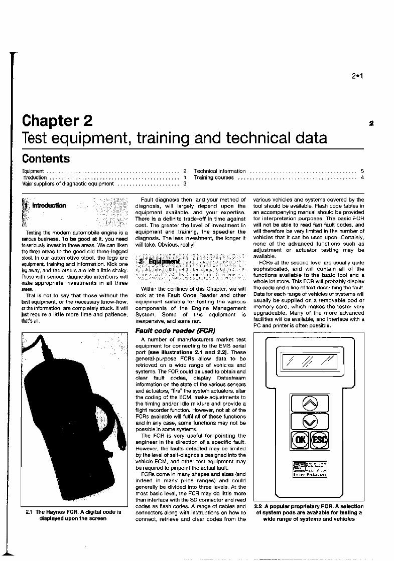
Chapter 2 Test equipment, training and technical data Contents Equipment . . . . . . . . . . . . . . . . . . . . . . . . . . . . . . . . . . . . . . . . . . . . . 2 Technical information . . . . . . . . . . . . . . . . . . . . . . . . . . . . . . . . . . . . 5 Introduction . . . . . . . . . . . . . . . . . . . . . . . . . . . . . . . . . . . . . . . . . . . . 1 Trainingcourses . . . . . . . . . . . . . . . . . . . . . . . . . . . . . . . . . . . . . . . . 4
. . . . . . . . . . . . . . . . . . . . . Major suppliers of diagnostic equipment 3
Testing the modem automobile engine is a seriws business. To be good at it, you n d to seriously invest in three areas. We can liken the t h r ~ areas to the good old threelegged stool. In our automotive stool, the legs are equipment, training and information. Kick one leg away, and the others are left a little shaky. Those with serious diagnostic intentions will make appropriate investments in all three areas.
That is not to say that those without the M t equipment, or the necessary know-how, or the information, are completely stuck. It will just require a little more time and patience, that's all.
2.1 The Haynes FCR. A digital code is displayed upon the screen
Fault diagnosis then, and your method of diagnosis, will largely depend upon the equipment available. and your expertise. There is a definite trade-off in time against cost. The greater the level of investment in equipment and training, the speedier the diagnosis. The less investment, the longer it will take. Obvious, really!
Within the confines of this Chapter, we will look at the Fault Code Reader and other equipment suitable for testing the various components of the Engine Management System. Some of this equipment is inexpensive, and some not.
Fault code reader (FCR) A number of manufacturers market test
equipment for connecting to the EMS serial port (see illustrations 2.1 and 2.2). These general-purpose FCRs allow data to be retrieved on a wide range of vehicles and systems. The FCR could be used to obtain and clear fault codes, display Datastream Information on the state a f the various sensors and actuators, "fire" the system actuators, alter the coding of the ECM, make adjustments to the timing and/or idle mixture and provide a flight recorder function. However, not all of the FCRs available wlll fulftl all of these functions and in any case, some functions may not be possible in some systems.
The FCR is very useful for pointing the engineer in the direction of a specific fault. However, the faults detected may be limited by the level of self-diagnosis designed into the vehicle ECM, and other test equipment may be required to pinpoint the actual fault.
FCRs come in many shapes and sizes (and indeed in many price ranges) and could generally be divided into three levels. At the most basic level, the FCR may do little more than interface with the SO connector and read codes as flash codes. A range of cables and connectors along with instructions on how to connect, retrieve and clear codes from the
various vehicles and systems covered by the tool should be available. Flash code tables in an accompanying manual should be provided for interpretation purposes. The basic FCR will not be able to read fast fault codes, and will therefore be very limited in the number of vehicles that it can be used upon. Certainly, none of the advanced functions such as adjustment or actuator testing may be available.
FCRs at the second level are usually quite sophisticated, and will contain all of the functions available to the basic tool and a whole lot more. This FCR will probably display the code and a line of text describing the fault. Data for each range of vehicles or systems will usually be supplied on a removable pod or memory card, which makes the tester very upgradeable. Many of the more advanced facilities will be available, and interface with a PC and printer is often possible.
2.2 A popular proprietary FCR. A selection of system pods are available for testing a
wide range of systems and vehicles
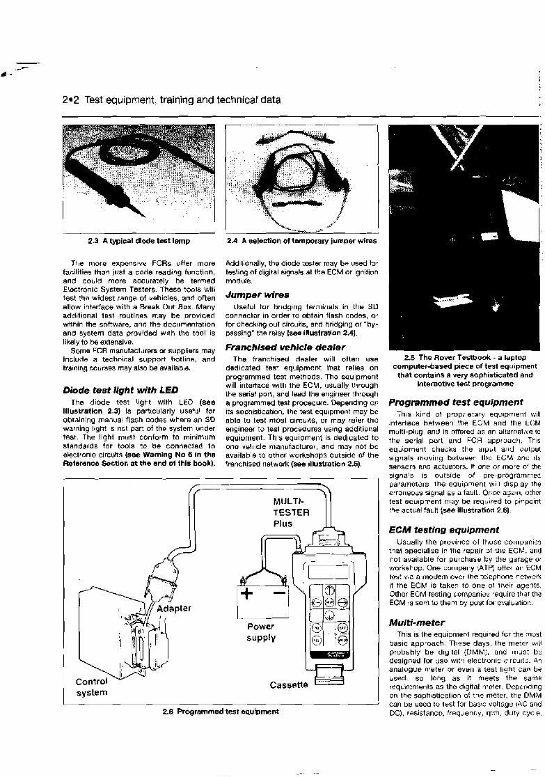
2.2 Test equipment, training and technical data
23 A typical dl& test lamp 2.4 A selsctlon of temporary jumper wires
The more expensive FCRs offer more facilities than just a code reading function, and could more accurately be termed Eiectronic System Testers. These tools will test the widest range of vehicles, and often allow interface with a Break Out Box. Many additional test routines may be provided within the software, and the documentation and system data provided w ~ t h the tool is
Additionally, the diode tester may be used tor testing of digital signals at the ECM or ignition module.
Jumper wires Useful for brrdging terminals in the SD
connector in order to obtain flash codes, or for checking out circuils, and bridging or "by- passing" the relay (see illustration 2.4).
likely k be extensive. Some FCR manufacturers or suppliers may Franchke* vehicle dealer
include a technical support hotline, and The franchised dealer will often use tralning courses may also be available. dedicated test equipment Ihat relies on
aroarammed test methods. The eauinment
Diode test llght with LED The diode test Ught with LEO (see
illustration 2.3) is particularly useful for obtaining manual flash codes where an SD warning l~ght is not part of the system under test. The light must conform to minimum standards for tools to be connected to ebectronic circuits (see Wamlng No 8 In the Reference Section a t the end ol this book).
kill Tnte~acs with the ECM, usually through the serial port, and lead the engineer through a programmed test procedure. Depending on its sophistication, the test equipment may be able to test most circuits, or may reier the engineer to lest procedures uslng additior,al equipment. This equipment is ded~cated to one vehicle manufacturer, and may not be available to other workshops outside nf the franchised network (see illustration 2.5).
2.6 Programmed test equipment
2.5 The Rover Testbook - a laptop computer-based piece of test equipment that contains a very sophisticated and
interactive test programme
Programmed test equipment T h ~ s kind of proprietary equipment will
interface between the ECM and the ECM multi-plug, and is offered as an alternahe to
the serial port and FCR approach. Th\s equipment checks the input and output signals moving between the ECM and rts sensors and actuators. If one or more of the signals is outside of pre-programmed parameters, the equipment w~l l d~splay the erroneoils s~gnal as a fault. Once aga\n, other test equ~prr~ent may be requlred to pinpoint the actual fault (sm illustration 2.6)
ECM testing equipment Usually the province of those companies
that specialise in the repair of the ECM, and not available for purchase by the garage or workshop. One company ;hTP) offer an ECM lest via a modem over the teiephone network if the ECM is takeo to one ol their agents. Other ECM testing companies require that the ECM is sent to them by post for evaluat~on.
This is the equipment required for the most basic approach. These days, the meter w~l l probably be dlgltal (DMM), and must be designed for use w~th electronic clrcu~ts. An analogue meter or even a test l~ght can be used, so long as it meets the same requirements as the d~gital meter. Depending on the sophrstication of the meter, the DMM can be used to test for bas^ voltage (AC and DC), resistance. frequency, rpm, duty cycle.

Test equipmer lt, training and technical data 2.3
temperature etc. (see illustrations 2.7 and 2.8). A select~on 01 I h ~ n probes and banana plugs foc connecting to a break-out box (BOB) will also be useful (refer l o illustratlon 2.13).
If the fault is a straightforward electrical fault, the meter will often be adequate. However, the drawback is that a DMM cannot analyse Ihe complex electrical waveforms produced by many electronic sensors and actuators, and test results can sometimes be misleading.
Dscillosmpe (with or without DM# and engine analyser)
An oscilloscope (see illustratlon 2.9) is essentially a graphlc voltmeter. Voltage is rarely still, and tends to rise and fall over a period of time. The oscilloscope (or 'scope) measures voltage against time, and displays it in the form of a waveform. Even when the voltage change is very rapid, the scope can usually capture the changes. Circuit faults can often be spotted much faster than when uslng other types of test instrument. Traditionally, the 'scope has been used for many years to dlagnose faults in the primary and secondary ignition systems of conventional non- electronic vehicles. With the advent 01 electronics, the 'scope has become even more important, and when a labscope function 1s available, analysis of complex waveforms is possible. This equ~prnent is often used in conjunction w~ th other equipment, for speedy diagnosis of a w~de range of problems. The large engine analyser and 'scope is now giving way to a plethora of smaller handheld 'scopes that pack great diagnost~c power Into portable form.
Exhaust gas anaiyser These days the state-of-the-art gas
analyser comes w~ th the ability to measure four of the gases present in the exhaust pipe, and ~t also calculates the Lambda ratio. The gases are oxygen, carbon dioxide, carbon
2.7 Two typical high-impedance DMMs with similar performance but different sets
of leads and probes. The left unit is equipped with alligator clips and the right
unit with spiked probes. Using the alligator clips frees your hands lor other tasks,
whilst the probes are useful for backpmbing multi-plug connectors
monoxide and hydrmarbons. Less-expensive gas anatysers are available that will measure one, two or three gases. However, the better the gas analyser, the easier it gets. The gas analyser is now a recognised diagnostic tool. Faults in ignition, fuelling and various mechanical engine problems can be diagnosd from the state of the various gases present In the exhaust.
Fuel pressure test kit Fuel pressure is vitally important to the welt-
being of the fuel-injecid engine, and a proper test gauge that will measure fuel pressures up to 7.0 bar is essential. The pressure gauge is
2.9 Oscilloscope
2.8 Top of the range Fluke DMM with a multitude of features and attachments
normally supplied with a kit of adapters to connect it to a wide range of disparate fuel systems (see illustration 2.1 0).
Variabk potentiometer Because of the widespread use of the
"limp-home" mode or LOS in the modern EMS, disconnecting a sensor such as the coolant temperature sensor (CTS) may have little effect on the running of tne engtne The ECM will assume a fault, and place a fixed value as replacement for that sensor. However, it is useful to be able to vary the resistance sent to the ECM and note the effect. One answer IS to use a potentiometer with a variable resistance. If th~s IS connected in place of the CTS resistor, then ECM response. injection duration and CO may be checked at the various resistance values that relate to a certain temperature (see Illustration 2.11).
2.10 Fuel pressure gauge and adapter kit

- . --
2.4 Test equipment, training and technical data
2.11 Using a variable potentiometer to vary the CTS resistance. Voltage change can be measured and the engine can be fooled into thinking it is cold or hot when the reverse is the case. This moms that simulated cold running tests can be accomplished
with the engine hot and without waiting for it to w o l
Noid light A nold l~ght is a small ~nexpensive light for
checking the slgnal to the injector. She Injector harness IS detached at the injector, and the noid light plugged into the injector harness. I t the engina IS then cranked. the light will flash H the injector is being pulsed by the ECM (see illustration 2.12).
Brsak-out box (808) The BOB (see illustration 2.13) is a box
containing a number o f connectors that allows easy access to the ECM input and output signals, without directly probing the ECM pins. The BOB loom terminates in a universal connector. A multi-plug harness of similar construction to the ECM harness is ioterfaced between the ECM and its multi-plug, and the other end is connected to 1Pe 806 loom. The 800 will now intercept all s~gr~als that go to and from the ECM. If a DMM or an oscilloscope or any otb8er suitable kind of test equipment IS connected to the relevant BOB connectors, ihe ECM signals can be easily measured. The maln drawback IS the number of different ECM multi-plug connectors
2.13 Using a Break-Out Box to obtain voltage at the ECM pins
req11:rsd for a good coverage of electronic systems. Small BOBS are also available for measuring values at components where it is difficult to connect the test equipment.
There are three maln reasons why use of a BOB Is desirable in order to access the signals:
7) Ideally, the connection point for measuring data values from sensors and actflatow is at the ECM multi-plug (with the ECM mujtt-plug connected). The ECM nlulti-plug is the point through which all incoming and outgoing signals will pass. and dynamically testing at this point is considered to give mom accurate results.
2) in modern ~8hiC/es, k e multr -plug is becoming more heavrly iflsulated, and removing the insulation or d~smantling the ECM multi-plug so that back-probing is possrble, is becoming almost impossibb. To a certain extent, the same is true of some components.
2.12 Injector noid light
3) ECM multi-plug temrnals (pins) are a? best fmgtle, and froquent probing or backprobing can cause damage. Some pins are gold-plated, and will lose thetr conductivity r f the plating is scraped off. Using a 608 protects the pins from such damage.
Battery saver Actually, "battery saver" is a misnomer,
since the func!ion of this device is to hold power to permanently live circuits wh~lst the battery is removed cr changed. Tne live circuits may provide power to the radro security and slation memory, and to the ECM aaaptive memory, etc.
1 Jump leads with surge protection I
It is possible to deslroy an ECM if l unprotected jump leads are used to prov~de : emergency power to the battery. Rather than : use jump leads, it is far safer to charge the 1 battery before attempting to start the veh~cle ' A poor engine or chassis earth, flat battery or i tired starter molor and unprotecled jump leads are a recipe for t ~ l a l disaster. 1
Vacuum gauge As useful as it always was. The vacuum
gauge takes the pulse of the engine from a conned~on to the ~nlet manifold, and is u~-?ful for diagnosin~ a wide range of timing and mechanical faults, ~ncluding a blocked exhaust system or vacuum leak (see illustration 2.14)
2.f4 Vacuum gauge

I Test equipment, training and technical data 2.5
Vacuum pump The vacuum pump can be used to check
the multitude of vacuum-operated devices that are fitted to many modern vehicles (see illustration 2.15). A crude vacuum pump can be constructed from a bicycle pump. Reverse the washer in the pump, and the pump will then "suck" instead of "blow".
Spark jumper Useful for attaching to an HT lead to check
for a spark. If you hold the lead from a modem high-output ~ g n ~ t ~ o n system whilsi cranking the engine, you may get quite a shock when testing for spark. Apart lrorn curllog your hair, the ignithon system may also be damaged.
Feeler gauges Still usetul for measuring the various
clearances at the crank angle sensor, throttle switch, spark plug, valve clearances etc.
Hairdryer or cold spray Useful for gently heating or cooling
2.18 HT lead puller
Hf lead puller Ideal for safely break~ng the HT lead-to-
spark plug seal and then safely disconnecting the lead (see illustration 2.16) How many times have you pulled a i a lead to have ~t disintegrate into your hand?
Exhaust back-pressure tester Useful for check~ng lor exhaust back-
pressure; screws into the oxygen sensor hole
2.15 Vacuum pump klt components during a test where heat may be on catalyst vehicles. The presence of back- contributing to iailure. pressure indicates an exhaust blockage.
S wor suppliiers of dlegnostic equipment
Note: The details below are correct at the time of writing (Spring 1998).
Alba D~agnostics Ltd Bankhoad Avenue Bankhead Industrial Estate Glenrothes Fl fe Scotland KW 6JG Tel: 01 333 425000
Asnu (UKJ ~ t d 27 Bournehall Avenue Bushey, Herls WD2 3AU Tel: 01 81 420 3494
ATF Electron~c Dsvelopments Ltd Victoria St Hednesford, Staffordshire WS12 5BU Tel: 01 543 879788
AutoD~agnos :UK) Ltd Preston Technology Centre Marsh Lane Pwston, Lancashire PR1 BUD Tel: 01 772 887774
Auto Smart tools Ltd (Electronic tools for German vehicles) Tudor House Sycamore Road Arnersham Bucks. HP6 600 Tel: 01494 722738
Cryplon Ltd Br~stol Road Br~dgwater. Sornersei TA6 4BX Tet: 01 278 436200
Fluke (UK) Ltd Colonial Way Watford, Hetts WD2 3WO Tel: 01923 24051 1
Gunson Ltd Pudding Mill Lane London E l 5 2PJ Tel: 01 81 9848855
Intermotor Occupation Road Hucknall, Nottingham NGI 5 6DZ Tel: 01 15 9528000
Lucas Aftermarket Operations Stratford Road Solihull Birmingham 890 dAX Tel: 0121 6975000
Omitech lnstrurnentation Ltd Hopton Industrial Estate London Road Dev~zes, W~ltshire SN10 2EU Tel: 01 380 729256
Robert Bosch Ltd PO Boa 98 Broadwater Park Denharn, Uxbridge Middx U89 5HJ Tel: 01 095 I334466
SPX UK Ltd Churchilt Way High March Daventry, Noilhanls NN11 4NF Tel: 01 327 706461
Sun Electr~c (UK) Ltd Oldmedow Road Kings Lynn, Nolfolk PE30 4JW Tel: 01 553 692422
Sykes-Pickavant Ltd Kilnhouse Lane Lytham St. Annes Lancs. FY8 3DU Tel: 01 253 784800

2.6 Test equipment, training and technical data
: I , : :
, , , ~,
4 Training cwraes , , , ,", , . , ,,' , ,, ; , . . , , :, : . . .:' ,; . , ,
, , . ... : , , , , , , ,, < , , .~
Note: The details below are correct at the time of writing (Spring 1998).
There are a number of companies that special~se in training for the motor industry. The same tra~ning courses are usually ava~lable to the general public. Please contact the various badio~ listcd below if you wi* lo learn more aboLt training for the automotive m d ~ 3 t y .
AA External Training Courses Wid-nerpool Hall Keyworth, Notts NG12 5QB Tel: 021 501 7357/7389
Crypton Ltd Bristol Road Br~dgwater, Somerset TA6 40X Tel: 01 278 436210
Fuel Injeciion Senlces Unit 7 Salter Street Prest~n PRI !NT Tel: 01 772 201 597
Lucas Test International Training Centre Ur~lt 7 , M~ca Close Tamworth, Staffs B77 4QH Tel: oaz7 63503
MasterTech Freepost RM1109 Wickford, Essex SS11 88R Tel: 01268 570700
Note: The details below are ccrrect at the t,;rne of writing (Spring 19981.
Specific information on the various systems Equiplech is essential if effective diagnosis and repairs Yawl House are to be completed Companies that Main Road specal~se In automotive techn~cal information Marchwood, Southampton are listed below. SO40 4UZ
Sel: 01703 862240
Autologic Data Systems Lid Arnewood Br~dge Road, Sway Lymrngton. Hsnts SO41 6DA Tel, 01 590 683868
Glass's Information Serv~ces Ltd No. 1 Princes Road Weybrdge, Surrey KT1 3 QTU Tel: 01 332 823823
OTC E~rope Ltd VL Churchill Ltd PO BOK 3. London 9oad Davenfry. Northants N N l l 4NF Te1: 01 327 704461
Sun Electr~c (UK) Ltd Oldmedow Road Kings Lynn, Norfolk PE30 4JW Tel: 07553 692422
Sykes-P~ckavant Ltd K~lnhouse Lane Lytham St. Annes Lancs. FY83W Tel; 01 253 784800
Haynes Publish~ng Sparkford, Nr Yeovil Somerset BA22 7JJ Tel: 0 1 %3 440635
MasterTech Freepost RMl t 09 Wbckford. Essex SS11 813R T el: 01268 5701 00

Chapter 3 General test procedures Contents Bask inspection Variable potentlometer . . . . . . . . . . . . . . . . . . . . . . . . . . . . . . . . . 6
. . . . . . . . . . . . . . . . . . . . . . . . . . . . . . . . . . . . . . . . Mgital mufti-meter (OMM) tests Voltage tests 3 Duty cycle tests . . . . . . . . . . . . . . . . . . . . . . . . . . . . . . . . . . . . . . . . . 5 General fauR dlagnosis Introduction . . . . . . . . . . . . . . . . . . . . . . . . . . . . . . . . . . . . . . . . . . 2 lntroduct~on . . . . . . . . . . . . . . . . . . . . . . . . . . . . . . . . . . . . . . . . . . 1 Resistance iests . . . . . . . . . . . . . . . . . . . . . . . . . . . . . . . . . . . . . . . 4
General fault diagnosis - 1 Introduction
1 As a general rule. it IS usually beneficial to work through the checks listed in "Basic inspection" before connecting Ihe fault code reader. The reason for this is clear - electrical and HT faults may adversely affect eleci ronic mntrol module operat~on, giving incorrect or spurious results, and causing much confusion. Only after elecirical and HT problems have been resolved should the operation of the ECM and ~ t s sensors be evaluated 2 The fault code reader can be used lor the following iasks: a) Readrq fault codes. b) Clearing fault codes. c; Datastream tesirng (not all systems, for
example Ford E EC lV cannot provide Datastream).
d) Actuator and component testmg. e) Serd~ce adjustments. 17 ECM coding. g] Snapshot function.
Limitations of Self-Diagnosis systems 3 Sorne may see the fault code reader (FCR] as a panacea for solving all electronic prob!ems
tn the vehlcls, but reading the fault code is only the beginning. To a large degree, the software designed into the vehic!e ECM provides the information to be decoded by the FCR. The FCR makes the most of this information, but if certain facil~t~es or data are not designed for output al the serial port, t h e facilities will not be available to the FCR. 4 In many instances. the FCR can provide the answer to a puzzling fault very quickly. However, it w~l i not provide all lbe answers, because some faults (including actual EGM faults) may not even generate a fault code. 5 There are a number ol d~stinct limital~ons to Self-Diagnosis systems: a) The vehicle manufacturer fays down ttre
basic data that can be extracted from the engine management system by the FCR, and the Self-Diagnosis system and FCR must work within those limitations
6) A code will not be stored if the ECM IS
not programmed to recognise tnat a oarticular cornDonen1 is bultv. - -
c) 'Spurious codes can be triggered by electrrcal or secondary HT faults.
d) One or more spurious codes can be trrggered by a faulty component that may or may not trigger a code by itself.
e) The fault code indicates a faulty crrcuit, and not necessarily a component. F-or example, a faulty sensor. wiring fault, or corroded cmnector may cause 2 code indicating a coolant temperature sensor
(CTS) fault. Always check the wiring and connectors, and apply proper tests to the component before judging it to be faulfy.
f) Limited range or out of range sensors. If the sensor remains wlthiri its design parameters, even if the parameters are incorrect for certam operatrng conditions. a fauit code wil, not be stored. For example, a faulty CCTS will generate a fault code ~f t t is open-circurt or shorted to earth. However, if the CTS is stuck at erther the hot or cold fesatance, a code may not be generated, although the engine will rndeed run badly a! some temperatures.
g) Some vehicle systems are capable of logging faults that occur mtermittentlv. and others are not.
h) In some tnstances, a fault code may be lost when the ignition is swtlched off, and due allowance should be made for this kind of system.
11 Older vehicles with besic electronic f~el injection systems do not support Self- Diagnosis.
Testing Self-Diagnosis systems 6 Is the engine management system warning light {where fitled) ~Iluminated while the englne is running? If so, this is indlcai~ve cf a system fault, Note: Be aware that some lights do not illuminate for faults that are desrgnated as minor faults.
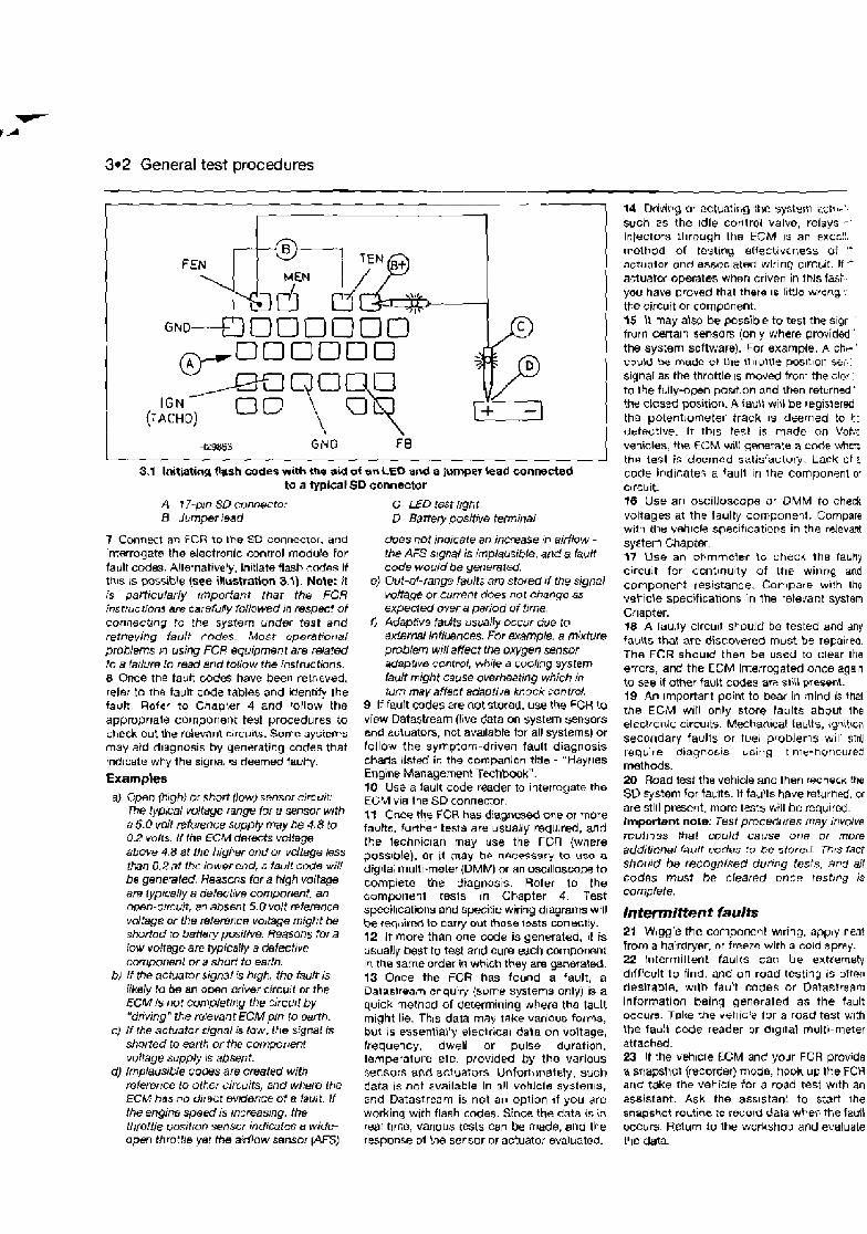
3*2 General test procedures
I 000000
IGN
I
3.1 Initiating flash mdes with the aid of ern LED and a Iumpw lead conmcted to a typical SD connector
A 17-pin SD conn~ctor G LED test ltght 0 jumper lead D Batter). positM terminal
7 Cmnect an FCR to the Sf3 connector, and does not rndicaie an increase :n airflow - infarrogats the electronic control module for the AFS stgnal is imp/ausibie, at~d a $ult fault codes. Alternatively, initiate flash c d e s if code wouldbe p i s r a t . thls IS possible (see ihwtratlon 3.1). Mote: jt e} Out-&range faults am stored rf the signal is particularly important that the FCR voltage or current does not change &.s instrucrions am carefully fotlowed in respect of expected over a period of ilme. connecting to the system under test and fl Adaptve faults us~ally occur due to retrieving fstrlt rndes. Most operat!or+al i?xtemef influences. For examp&. a m!xture problems n using FCP equipment are Mated problem wilt affect the oxygen sensor to 8 Ja~ture to read and follow the instructions. adaptive cootrol, whb a coo/!r~g system 8 Once the tault codes have been retrieved, fault might cause overheating which in refer to the fault code tables and identify the rum may affect adwtive knock control. fault. Rofer to Chap:er 4 and tallow the 9 If fault cades Ere mtstoted. use the FCR to appropriate component test procedures to view Datastream (Irve data on system sensors check out the relevant circuits. Some systems and a~luators, not ava~lable far all syslems) or may aid diagnosis by generating codes that fo l lo:~ the symptom-driven fault diagnosis ind~cate why the signal is deemed faulty. charts listed in the companion title - "Wajr~es
Examples Engine Management Techbook". 10 Use a fault code reader to interrogate the
a) Cpen {Pjgh) or short flow) ssnsor circut:: EC;M the SD connector, f~Pca/ vdtage r a n p fcrf a sensor with 17 the FCR has diagnosed one more
a5 ,0vd t~ fe rencesu~ iYmaYbe4 .8 to fauIts,furtkertestsareusuallyrequrred,and 0.2 volts. It the ECM detects voltage the lechnician may use the FCR (where above 4.8 at the higher end or v&age less possible). or it may he nRCeSSary to uso a than 0.2 at the bwer end, Q fault cCde w;ll digit& multi-meter (DMM) an oscjlloscops to be gene'vted, R e a m s for a high voItW complete the diagnosis. Refer tn the a ~ ~ i c a ~ / ~ a d ~ f e c t : ' v e c o m P o n e n t . a n ~onipurier~t resls in Chapter 4. Test Open-C~f~UIt , an absent 5.0 volt fifefence specihcations and specific wirilg diagrams will vdfage or the refemme voitage might be b, rw\,ired to carT out those tests rxln ect!y. shoflod bntler~ Wsif/ve. Reasons fora 12 If more than one code is generated, it is low voltage are typicafly a defective usually best to test and cure each cornpomnt cmponent or a shot? to earth. in the same order in which they are ge,neraled.
bl If the actmator signal b h~gh, the fault is 13 Once the FCR has found a fault, a likely bo an open oriver circuit or the Datastream cnquiry (surne systems only) is a ECM Is not completicg the zircuitby quick methad of determining whera the fault "dnvtng" the reievant ECM pin to ~ r t h . might lie. Tkis data may take various forms,
c) If the actuaforsj9ignoi;s low, Itle si~nal is but is essentially electrical data on voltage, shorted to earth or the component frequency, dwell or pulse duration. vol!age supply rs absent. temperature etc. provlded by the various
d) Implausi~e codes are created with sensors and actuators. Unfortunately, such reference to other circuits, and where the data i$ not available in all vchicle sydterr~s, ECM has no drrecr evaence of a fault. If 2nd Datastream is not an option ~f you are the engine speed is inrreastng, the working with flash codes. Since the data is in thro!t/epositron enso or indimfcs a wide- real time, vanous tests can be made, and the open thro:tle ye! the a:dlow sensor (Am response of Ine secsor or actuator evaluated.
14 Dti,~ing a- actuating the systm ~ct l I-'.
such zs the Idle control valve, relays - -
injectos rhrough the ESM 15 an escr;!!. method of tastrng affectiveness of " actuator and associated wlring c ~ r c ~ i t . If actualw operates when crlven in this fasb you hate proved that there 1s limo wrong, tke circuit or compcnent. 15 It may alw be possib e to test the slpi '
frurrl cwfaln sensors (only where pro:~ided '
the sys:em software). For example, A ch- '
could be ma& OT the Ihrollle poslt~or: stii signal as the throttle IS mooed from the cia?- - to the ftlly-open position and then retcrned'. the closed position. 4 fault will be reg~srered the potentrometer track IS deemed to t: defective. It thrs test 1s made on Vc!w vsii les, the ECM wil! gemrate a code whtz tha test is doerned satisfactory. Lack 0 1 n code ind~cates a faull in the component or circuit. t6 Use an oscilloscope or OMM to check voRages at the faulty component. Compare wifli the vahlcle specifications in the relevant system Chapter. 17 \ h e an obrnmcter lo l;hecA the faulty circuit for ccntinuity of the wiring and component resistance. Compare wi!h iho veticle s~eciflcat~ons In the retetanl syslem Chapter. 18 A lau,ry clrcu~t si-ould be tested and any faults that are discobered must be repaired. The FCR should then be used to clear the errcrs, and the ECM interrqated once again to see if other fault codes ar;? slirl present. 19 An importart point to bear in mind is that the ECM w~lt only store faults about the electronic circuits. Mehanical falrlts, ig~i t lon secondary faults or fuel problems will strll reqtire diagnosrs using tirna-hur~oured methods. 20 Road test the vehicle anc then recheck the SD qsteni for taults. If faults have returned, or are still p r e n t , more tests bill be required. Important note: Test procedures may involve routines that could cause one or more addiiinnal BL I I~ codes !o bc stored. Thrs fact should be recognmed duri~g tests, and all codes must be cleared oncn wstrng is compiete.
Intermittent faults 21 Wiggle the component w~ring, apply neat from a hairdryer, nr freeze with a. cold spray- 22 Intermiltent faults can be extremely d~fficult to find, and on-road testing is often desirable, w ~ l h fault codes or Datastream information being generated as the fault occurs. Toke the veh~cfd tor a road test with the fault c d e reader or d~grtal multi-meter attached. 23 If rhe vehicle ECM and yodr FCR provide a snapshot (recoreer) mode, hook ul: the FCR arid take the vehicle for a road test w~th an assistant. Ask the ass~stan! to start The snapshot ro~tine to recold data wh* the fault occurs. Return to the wcrkshog and evaluate tCle data.
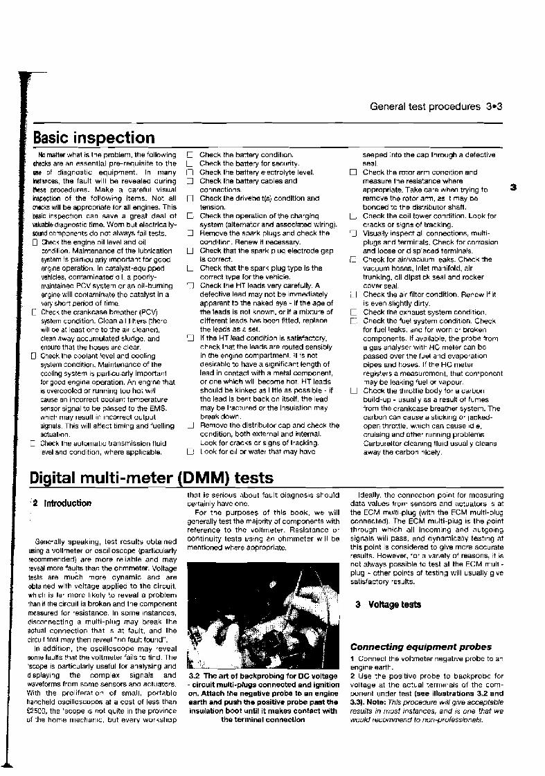
General test procedures 3.3
1 Basic inspection 1 No matter what is the problem, the following ! checks are an essential pre-requisite to the
use of diagnost~c equipment. In many bt~nces , the fault will be revealed during these procedures. Make a careful visual inspection of the following items. Not all checks will be appropriate lor all engines. This La i c inspection can save a great deal of &able dlagnostic time. Worn but electrically- wnd components do not always fail tests. 0 Check the engine oil level and o ~ l
condition. Maintenance of the lubrication system is particularly Important for good engine operation. In catalyst-equ~pped vehicles, contaminated 011, a poorly- maintained PCV system or an oil-burning engine will contaminate the catalyst in a verj short period of time.
r Check the crankcase breather (PCV) system condition. Clean all l~lters (?here will be at least one to the alr cleaner), clean away accumulated sludge, and ensure thal the hoses are clear.
0 Check the coolant level and cool~ng system condition. Maintenance of the cooling system is particularly important for goca englne operation. An englne that 1s overcooled or running too hot will cause an incorrect coolant temperature sensor signal to be passed lo the EMS, wh~ch may result in Incorrect output signals. This will affect timing and fuelling actuatron.
C Check the autornat~c transmission fluid level am condition, where appl~cabls.
Check the battery condition. Check the battery for security. Check the baltety electrolyte level. Check the battery cables and connections. Check the drivebelt(?,) condition and tension. Check the operation of the charging system (alternator and associated wiring). Remove the spark pluys and check the condition. Renew d necessaty. Check that the spark plug electrode gap is correct. Ghwk that the spark plug type is the correct type for the vehicle. Check the HT leads verj carefully. A defective lead may not be immediately apparent to the naked eye - if the age of the leads is not known, or if a mixture of different leads has been fitted, replace the leads as a set. If the HT lead cond~tion is satisfactory, check that the leads are routed sensibly in the engine compartmeni. H is not des~rable to have a significant length of lead in contact with a metal component, or one which will become hot. HT leads should be krnked as little as possible - if the lead is bent back on itself, the lead may be fractured or the insulation may break down. Remove the distributor cap and check the condition, both external and i~ternal. Look for cracks or slgns of tracking. Look for oil or water that may have
seeped into the cap through a defect~ve seal. Check the rotor arm conctlt~on and measure the res~stance where appropriate. Take care when trylng to remove the rotor arm, as ~t may be bonded to the distributor shaft. Check the co~ l tower condition. Look for cracks or stgns of track~ng. Visually ~nspect all connections, rnulti- plugs and terminals. Check for corrosion and loose or d~splaced term~na!~. Check for airhawurn leaks. Check the vacuum hoses, inlet manifold, air trunking, oil dipst~ck seal and rocker cover seal. Check the sir f~lter condition. Renew ~f ~t is even sl~ghtly d~rty. Check the exhaust system condrt~wi. Check the fuel system condtt~on. Check for fuel leaks, and for worn or broken components. If available, the probe from a gas analyser w ~ t h HC meter can be passed over the fuel and evaporation pipes and hoses. If the HC meter reg~sters a measurement, that component may be leaking fuel or vapour. Check the throttle body for a carbon build-up - usually as a resull of fumes from the crankcase breather system. The carbon can cause a st~ck~ng or lacked- open throttle. wh~ch can cause Idle. cruis~ng and other runnlng problems Carbureltor clean~ng fluid usuatly cleans away the carlmn nicely.
Diaital multi-meter (DMM) tests that is serious about fault diagnosis should
- 2 Introduction certainly have one. For the purposes of this book, we will
generally test the majority af components with reference to the voltmeter. Resistance or
Generally speaking, test results obtained continuity tests using an ohmmeter will be
using a voltmeter or oscilloscope {particularly appropriate.
recommended) are more fellable and may reveal more fau!ts thar: the ohmmeter. Voltage t8sts are much more dynamic and are obtained with voltage applied to the circuit, wh~ch is far more Ihkely to reveal a problem than il the circuit is broken and the component measured for resistance. In some tnstances, d~sconnecting a multi-plug may break the actual connection that 1s at fault, and the circuit test may then reveal "no fault found".
In addition, the oscilloscope may reveal some faulis that the voltmeter fails to find. The 'scope is particularly useful for analysing and displaying the complex signals and 3.2 The art of backprobing tor DC voltage waveforms from some sensors am' actuators. - circuit multi-plugs connected and ignition Wjth the proliferat~on of small, portable on. Attach the negative probe to an engine handheld oscilloscopes at a cost of less than earth and push the positive probe past the £2500, the 'scope 1s not quite in the province insuiation boot until it makes contact with of the home rnechan~c, but every workshop the terminal connection
Ideally, the connectlon po~nt for measuring data values lrom sensors and actuators is at the ECM multi-plug (with the ECM multi-plug connected). The ECM multi-plug IS the point through whch all incoming and outgoing signals will pass, and dynamicalby testlng at this point is considered to give more accurate results. However, for a varlety of reasons, it is not always possible to test at the ECM mulrl- plug - other points of testing will usually glve satisfactorj results.
Connecting equipment probes 1 Connect the voltmeter negative probe to an englne earth. 2 Use the positive probe to backprobe for voltage at the actual terminals of the corn- ponent under test (see illuatrations 3.2 and 3.3). Note: This procedure WIN give acceptable results in most instances, and is one that we wou/d mcommend to nm-professionak.
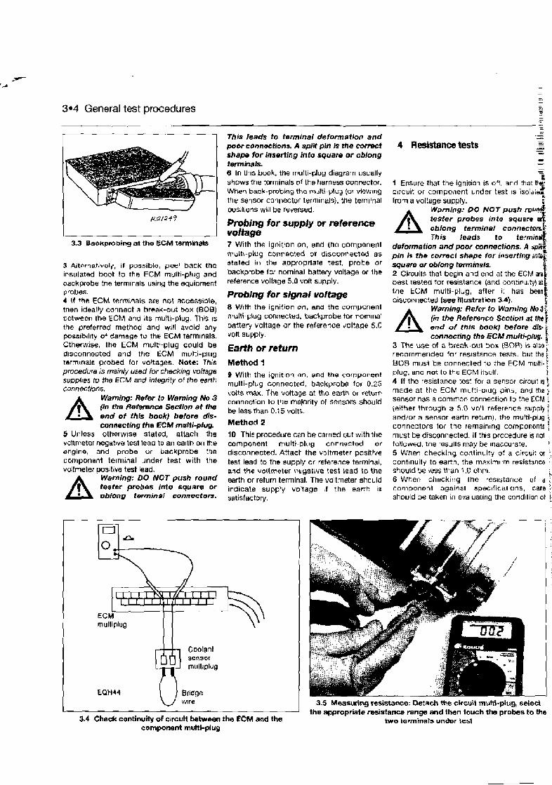
3.4 General test procedures --
3.3 Baokpmbing at the ECM taminas
3 Alternativoly, if possible, peel back the insulated boot to the ECM multi-plug and backprobe the termirals usirig the equipment probes. 4 If the ECM terminals are not accesside, tnen ideally connect a hreak-out box (BOB) between the ECM and its multi-piug. This is the preferred method and will avoid any posslbrllty of damage tv the ECM terminals. Otherwise, the ECM mult8-plug could be disconnected and the ECM multi-plug termmais probed tor voltages. Note: This procedure is mainly used for checking voltage supplres to the ECM and intwrity of the eanh connectbns.
A Warning: Refer to Waming No 3 (in the Reterrrnes Section at ihe end of this book) before dis- mmcthg the ECM multi-pfug.
5 Unless otherwise stated, attach the voltmeter negatlve test lead to an earth on the engine, and probe or backprobe toe campbnent terminal under test with the vdtmeter positive test lead.
A Waming: DO NOT push round tester probes into square or oblonp terminal connectors.
This leads to terminal deformation and poor mnnoefiona A split pin Is the correct shape for inserting into square or oblong terminals. 6 In h i s book, the multi-plug diagram usually shows the tmrninals of the harness connector. When back-probing the rn~lti-$ua (of vi5WvlrlnQ
the sensor c3nnector terminals), the terminal positions will be re~ rsed .
Probing for supply or reference volfage 7 With the ignition on, and the component multi-plug connected or disconnected as stated in the appropriate test, probe or backpmbe Iw nominal battery voltage or Ihe reference voltage 5.0 volt supply.
Probing for signal voltage 8 With the igniiion on, and the corilpGnent multi-plug connected, backprobe for nominal aattery voltage or the reference voltage 5.0 volt supply.
9 With the ignit~nn nn, and the component multi-plug connected, backprobe for 0.25 volts W. The vdtage at the earth or feturn connectio1-r tu the majority of sensors should be less Ran 0.1 5 volts. Method 2
10 This procedure can be carned ~ u t with the component multi-plug connected or disconnected. Attach the voltmeter positive test lead to the supply or reference termiiai, and the valtrnster \7ryative test read to the earth or return terminal. The voltmeter shculd ivdicale supply voltage , f the earth 1%
satisfactory.
Coolant sensor rnultrplug
EQH44 Bndge
- s
1 Ensure that t he iqnitioi is off, anrl that circuit or component under test IS isol;r;<- from a voltage su~ply. I
A Warning: PO NOT push r o ~ d tester probes into square o;%: oblong tsrminal connectors& This bsda to termin3
deformafion and poor connections. A i w r pin is the corred shape for inssrtlng ;ii$
square or obfong terminals. 2 Circuits that begin and end e l the ECM am1 best tested lor resistance (and continuity) at the ECM multi-plug, after I: has b e n i disconnected [see nlustratibn 3-41.
A Waming: Refer to Warning No 3 (in the Reference Section at th end of thls book) before dis. connecting the ECM multi-plug. I
3 The use of a break-out box (BOR) is also; recommended for resistance tests, but the BOB must be connected to the ECM multi- j plug, and not to the ECM iiself. i 4 If the resistance rest for a sensor cjrcult IS \ made at the ECM multi-plug pins. and the 2 sensor has a common connection to the ECM ? (either \hrough a 5.0 voH reference supply f and/or a sensor earth retbrn). the mufti-plug i connentors lor the remarnlng components ; must be disconnected. If thts procedure k not , tolluwed, the results may be rnacwrate. 5 When checking contin~ity of a circuit or j cont~nuity to earth, the m>xim~rm resistance +
should be iess than 1.0 ohm. 6 When checking the resistance of a component against spet~l ical ons, care ] should be taken in evaluating the condition of !
3.5 Measuing resistance: M a c h the circuit muM-plug, select the appropriate resistance range and then touch the probes to the
3.4 Check continuity of circuR between the ECM and the two terminals under tes~ component multi-plug
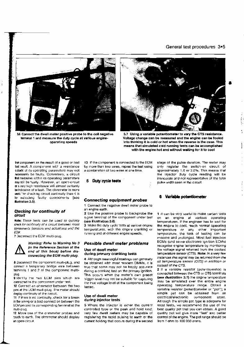
1 General test procedures 3.5
3.6 Connect the dwell meter positive probe to the coil negative 3.7 Uslng a variable potentiometer to vary the CTS resistance. terminal 1 and measure the duly cycle at various engine- Voltage change can be rneasurad and the engine can be fooled
operating speeds into thinking it is cold or hot Hmen the reverse is the case. This means that simulated cord running tests can be accomplished
with the englne hot and wlthout waiting for it to cool
Rat component as the result of a good or bad test result. A component with a resistance outside of ~ t s operating parameters may not ~wcessarlly be faulty. Conversely, a circuit that measures with~n 1:s operating parameters may still be faully. However, an open-circuit w a very h~gh resistance will almost certainly beind~cat~ve of a fault. The ohmmeter is more usefiri lor check~ng circuit cont~nuity than it is hr lndicat~ng faully components (see Ilkrstration 3.5).
13 If the component is connected lo the ECM stage of the pulse duration. The meter may by more than two wlres, repeat the test using only register the swilcn-on circuit of a cornb~nation of two wires at one time. approximately 1 .O or 2.0%. This means ihet
the injector duty cycle reading will be inaccurate and not representative of the total pulss wldth seen In the circuit.
Connecting equipment probes I Vaiabkptmtkmbr
1 Connect the negative dwell mHw probe to
Checking lor continuity of an engine earth.
cirwit 2 Use the posltive probe to backprobe the 1 It can be vety uselul to make certain tests s~gnal term~nal of the component under test on an engine at various operating
Note: These rests can be used to q u i c k l ~ (,- illustration 3.6). temperatures. If the englneer has to walt for for contmul@ O f a orcurt between most 3 Make the duly cycle tests at varlous engine the engine to cool, reach normal operating
components (sensors and actuators) and the temperatures, with the englne cranking or temperature or any other important ECM running and at different englne speeds. temperature, the task of testing can be 7 D~sconnect the ECM multl-plug irksome and prolonged. Most fuel injection
Warning: Refer to Warning No 3
A (in the Reference Section at the end of this book) before dis- connecting the ECM muhi-plug.
8 Rsconnect the component r~~~ l l t~ -p lug , and connect a temporary bridge wire between terminals 1 and 2 at the component millti- plug- 9 ldent~fy the two ECM pins wh~ch are connected to the component under test. 10 Connect an ohmmerer between the two oms at the ECM multi-olua. The meter shou!d
Possible dwell meter problems Use of dwell meter during primary cranking tests 4 Although meaningful readlogs can generally be obtained with most modern DMMs, 11 is true that some may not be totally accurate during a crank:ng test on the prlrnary ignition. This occu:s when the meter's own preset trigger level may not be suitable for capturing the true voltage level of Iho component being tested.
ECMs (and some electronic ignition ECMs) recognise engine temperature by monitoring the voltage signal returned from the coolant temperature sensor (GTS). Note: In a very few instances this signal may be returned from the oil temperature sensor (OTS) in additron or instead of the CTS. 2 If a variable resistor (potentiometer) is connected between the CTS or OTS terminals (see itlustration 3.7) the englne temperature may be simulated over the entire engine operating temperature range. Obtain a variable resistor (potentiometer or "pot"); a . .,
d~splay continubty of the circuit. simple p d can be obtained from an 11 If there is no continuity, check lor a break Of meter electrical/electronic component store. in the w i r y or a bad connection between the during tests Although the simple pot type is adequate for ECM pan and its corresponding terminal at the 5 Where the injector is elther the current most tests, we recommend the use o i the multi-plug. controlled type or the peak and hold kind; best quality pot that you can obtain. A good 12 Move one of the ohmmeter probes and very few dwell meters may be capable of quality pot will give more "feel" and better touch to earth. The ohmmeter should d~splay registering the rapid pulsing to eanh or the control of the engine. The pot range should be an open-circu~t current boldlng that occurs during the second from 1 ohm to 100 000 ohms.

3.6 General test procedures
Testing procedum b) Connect the p t between the two multi- e) On some engines you will set faun codes 3 The following procedures should be plugiermina1- during test procedures, and these codes followed when usng the pat with either the C) Set the pot to the resishcco for must be erahad aflrr testrng Is completsd OTS or CTS: the temperature that you wish to simulate. 0 Referto the fault cede section in the
d) Vary the resistance and make the test relevant Chapter for instructions on how a) Disccnnect the CTS rnulri-plug. pmeclures as required. to char fault codes.
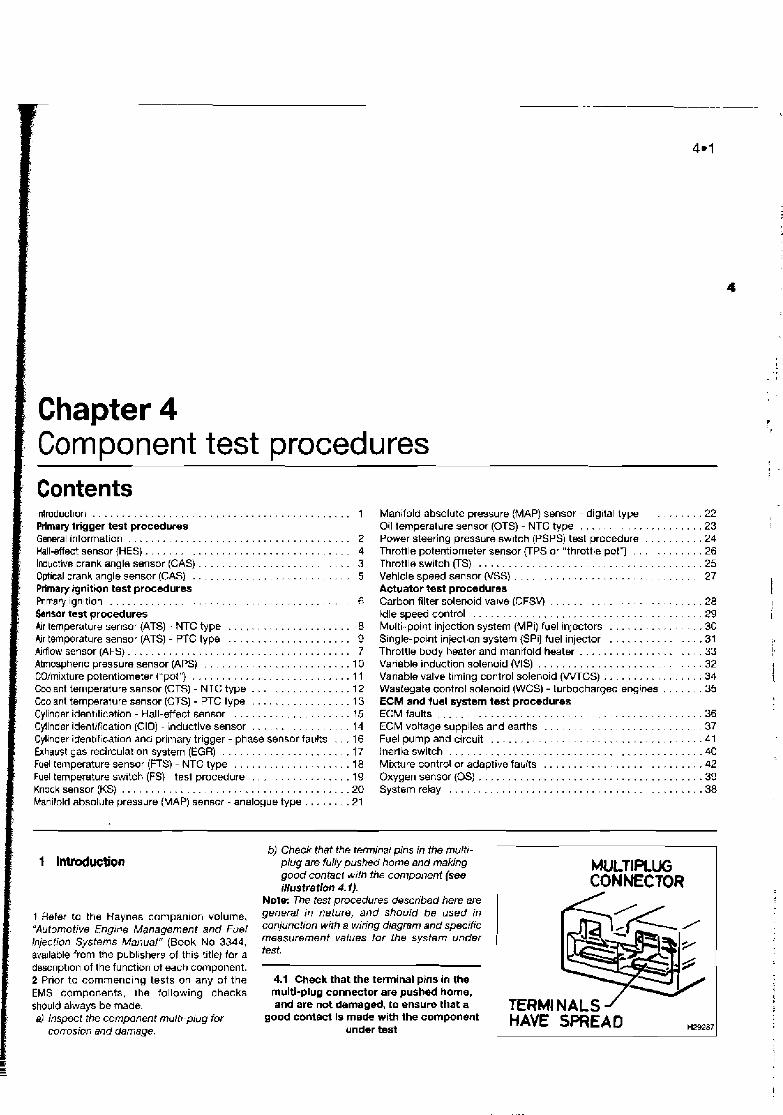
: lntroduct~on . . . . . . . . . . . . . . . . . . . . . . . . . . . . . . . . . . . . . . . . . . 1 /, Prlmary trigger test procedures . General information . . . . . . . . . . . . . . . . . . . . . . . . . . . . . . . . . . . . 2
. . . . . . . . . . . . . . . . . . . . . . . . . . . . . . . . . . . Hall-effect sensor (HES) 4 Inductive crank angle sensor (CAS) . . . . . . . . . . . . . . . . . . . . . . . 3 Opt~cal crank angle sensor (CAS) . . . . . . . . . . . . . . . . . . . . . . . . . . . 5 Primary ignition test procedures RImary lgnltion . . . . . . . . . . . . . . . . . . . . . . . . . . . . . . . . . . . . . . . . 6 Lnsor test procedures Air temperature sensor {ATS) - NTC type . . . . . . . . . . . . . . . . . . . . . 8 Air temperature sensor (ATS) - PTC type . . . . . . . . . . . . . . . . . . . . . 9 Airflow sensor (AFS) . . . . . . . . . . . . . . . . . . . . . . . . . . . . . . . . . . . . . 7 Atmospheric pressure sensor (APS) . . . . . . . . . . . . . . . . . . . . . . . 10 COlmixture potentiometer ("pol") . . . . . . . . . . . . . . . . . . . . . . . . . . . 11 Coolant temperature sensor (CTS) - NTC type . . . . . . . . . . . . . . . . 12 Caolant temperature sensor (CTS) - PTC type . . . . . . . . . . . . . . . . . 13 Cylinder ident~tication - Hall-effect sensor . . . . . . . . . . . . . . . . . . . . 15 Cylinder idenlificat~on (CIO) - inductive sensor . . . . . . . . . . . . . . . . 14 Cylinder identlf~cat~on and primary trigger - phase sensor faults . . . 16 Exhaust gas recirculation system (EGR) . . . . . . . . . . . . . . . . . . . . . 17 Fuel temperature sensor (FTS) - NTC type . . . . . . . . . . . . . . . . . . . 18 Fuel temperature switch (FS} - test procedure . . . . . . . . . . . . . 19 Knock sensor (KS) . . . . . . . . . . . . . . . . . . . . . . . . . . . . . . . . . . . . . .20 Manifold absolute pressure (MAP) sensor - analogue type . . . . . . . .21
Manifold absolute pressure (MAP) sensor - digltal type . . . . . . . 22 Oil temperature sensor (OTS) - NTC type . . . . . . . . . . . . . . . . .23
. . . . . . . . Power steering pressure switch (PSPS) test procedure .24 Throttle potentiometer sensor (TPS or "throttle pot") . . . . . . . . . . .26 Throttle switch (TS) . . . . . . . . . . . . . . . . . . . . . . . . . . . . . . . . . . . . . . 25
. . . . . . . . . . . . . . . . . . . . . . . . . . . . . . Vehicle speed sensor (VSS) 27 Actuator test procedures Carbon filter solenoid valve (CFSVJ . . . . . . . . . . . . . . . . . . . . . . . . . .28 Idlespeedcontrol . . . . . . . . . . . . . . . . . . . . . . . . . . . . . . . . . . . . . 29 Multi-point injection system (MPI) fuel injectors . . . . . . . . . . . . . 30 Single-point injection system (SPi) fuel injector . . . . . . . . . . . . . . . 31 Throttle body heater and manifold heater . . . . . . . . . . . . . . . . . . . .33 Variable induction solenoid (VIS) . . . . . . . . . . . . . . . . . . . . . . . 32 Vanable valve timing control solenoid W C S ) . . . . . . . . . . . . . . . . . 34 Wastegatg control solenoid (WCS) - turbocharged engines . . . . . . . 35 ECM and fuel system test procedures ECMfaults . . . . . . . . . . . . . . . . . . . . . . . . . . . . . . . . . . . . . . . . . . . . 36 ECM voltage supplies and earths . . . . . . . . . . . . . . . . . . . . . . . . 37
. . . . . . . . . . . . . . . . . . . . . . . . . . . . . . . . . Fuel pump and circuit .41 Inertiaswitch . . . . . . . . . . . . . . . . . . . . . . . . . . . . . . . . . . . . . . . . . 40 Mixture control or adaptive faults . . . . . . . . . . . . . . . . . . . . . . . . . .42
. . . . . . . . . . . . . . . . . . . . . . . . . . . . . . . . . . . . . . Oxygensensor(0S) 39 . . . . . . . . . . . . . . . . . . . . . . . . . . . . . . . . . . . . . . . . . Systemrelay 38
1 Introduction
1 Refer to the Haynes companion volume, "Automotive Engrne Management and Fuel Injection Systems Manual" (Book No 3344, available from the publishers of this title) lor a descr~ption of the function of each component. 2 Prior to comrnenclng tests on any of the EMS components, the !allowing checks should always be made.
R) Inspect the component multr-plug for corrosion and damage.
6) Check that the terminal pins in the multi- plug are fully pushed home and making good contacf *rth the component (see illustration 4. I).
Note: The test procedures described here are general i n nature, and should be used in canjunction with a wiring diagmm and specific measurement values for the system under test.
4.1 Check that the terminal pins in the multi-plug connector are pushed hame, and are not damaged, to ensure that a
good contact Is made with the component under test
MULTIPLUG CONNECTOR
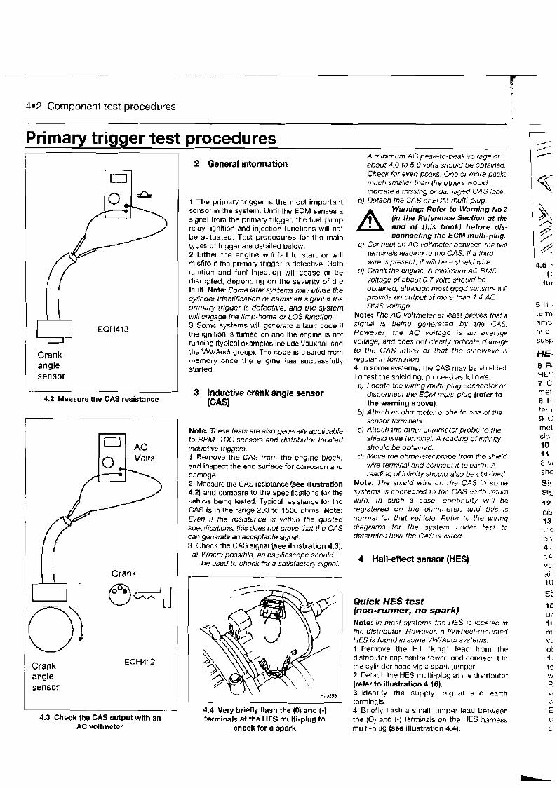
4.2 Component test procedures
Primary trigger test procedures
Crank angle sensor
lo(
4.2 Measure the CAS resistance
2 General information
I Crank angle
Crank
1 The primary trigger IS the most important sensor In the system. Until the ECM senses a signal tron the primary trigger, the fuel pump relay, Ignition and inject~on functions will not be actuated. Test procedures for the main types of trigger are deta~led below. 2 Either the engine w~ l l fall to start or w~l l misfire if the prlmar)' rrlqger IS defective. Both ~qnltion and fuel irljection will cease or be d~srupted, depending on the severity of the fault. Note: Some latersysfems may ulrl~se ttle cylinder rdentificat~on or camshaft signal r f the prtmary trrgger IS defectrve, and lhe system will engage the Itmp-home or LOS function. 3 Some systems will geoerate a fault code if the lynltron is turned on and the engine is not rhnnlrlg (typical examples include Vauxhall and the W1Aud1 group). The code 15 cleared from memory once the enylne has successfully started.
3 Inductive crank angle sensor GAS)
Note: These tests are also generally applicable to RPM, TDC sensors and distributor-located rnductrve triggers. 1 Remove the GAS from the englne block, and inspect the end stirface for corrosion and damage. 2 Measure the CAS resistance (see illustration 4.2) and compare to the specifications for the vehicle be~ng tested. Typical resistance for the CAS is in the range 200 to 1500 ohms Note: Even if the reststance IS within the quoted spectficatrons, this does nof prove that the CAS can generate an acceptable stgnal 3 Check the CAS stgnal {see illustration 4.3): a) Where possible, an osctlioscope should
be used to check for a sairslactoty signal.
- - J ' 4.4 Very briefly flash the (0) and (-) 4.3 Check the CAS output with an terminals at the HES multi-plug to
AC voltmeter check for a spark
A minimum AC peak-to-peak voltage o f about 4.0 to 5.0 volts should be obrained. Check for e v e n peaks. One or more peaks rnirch smaller than the others woulo' indrcate d rnissing or damaged CAS lobe.
6) Detach the CAS or ECM multi-plug.
A Warning: Refer to Warning No 3 (in the Reference Section at the end of this book) before dis+ connecting i he ECM multi-plug.
C) Connect an AC voltmeter behvwn t t i ~ two terminals Ieadfng to the CAS. I f J th~td wire 1s presefl?. if will be a sheld 1.1 tsWe
d) Crank the el?glt?e. A minimum AC RMS voltage of about 0.7 volts should be obta~ned, although most good setnors will provrde an output o f niore than 1.4 AC RMS voltage.
Note: The AC volfmeter at least prpves that a stgnal rs being generated b y the CAS. However, the AC voltage is an alerage voltage, and does not dearly indicate dr~rnage to the CAS lobes of that the sinewave I S
regular m formalfon. 4 In some systems, the GAS may be shielded. To test the shielding, proceed as follows:
a) Locate the wiring multi-pkrg cuflnector or disconrlect the ECM mulfr-plug (refer to the warning above).
6) Attach an ohmmeter probe to one of the sensor terminals
cj Attach the other ohmmeter probe to the shie/d wire terminal. A feadtng of fnftn~ty should be obta~ned.
dl Move the ohmn7eterprobe from the stlflld ujire terminal and connect rt to earth A readiqg oftnf~nrty should also bp cbta~ne?
Note: The shield wire on the CAS In sorne systems 1s connected to the GAS earth return wfre. in such a case, continuity wfll be regrstered on the ohmmeter. atld this I S
normal for that vehicle. Refer to the w~ring diagrams for the sysrerr? uoder test to defefmine how the CAS 1s wrred
4 Hall-effect sensor (HES)
Quick HES test (non-runner, no spark) Note: In most systems the HES 1s located in the dislribuior However, a flywheel-rnounl~d HES is found in some VW/ALJ~ I systems. 1 Remove the HT "k~ng" lead frarrl the drstrtbutor cap centre tower. and connect ~t l o the cylinder head via a spark lumper. 2 Detach the HES multi-plug at Ihe d~str~butor (refer t o illustration 4.16). 3 ldent~ty the supply. s~gnal and earth terminals 4 Briefly llash a small jumper lead between the (0) and (-) terminals on the HES harness multi-plug (see illustration 4.4).
4.5 . ( :
tur
5 If . term
amp and susp
HE- 6 R< HE5 7 C met 8 It terri 9 C met sigr 10 11 8 vl s hc
= i a 1.-
12 di2 13 thc Prr 4.:. 14 VP
air t 0 Ei I
i E d l 1: m VC
0;
1, t :: W
F V ' v, r-
C
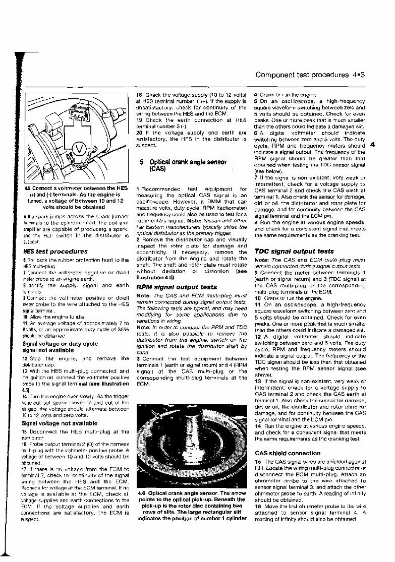
Component test procedures 4.3
i 45 Connect a voltmeter between the HES (+)and (-1 termlnals. As the engine is
i turned, a voltage of between 10 and 12 I I
volts should be obtained
5 11 a spark jumps across the spark jumper lerninals to the cyl~nder head, the corl and ampl~f~er are capable of producing a spark, and the Hall switch in the distributor is suspect.
HES test procedures 6 Roll back the rubber protection boot to the HES multi-pluy 7 Connect the voltmeter negat~ve or dwell meter probe to an rnylne earth. 8 ldent~fy the supply, signal and earlh terminals 8 Connect the voltmeter positive or dwell meter probe to the wlre altached to the HES s~gnal termlnal 10 Allow the engine to Idle li An average voltage of approx~tnately 7 to 8 volts, or on approximate duty cycle of 35% should be ublaiiled
Signal voltage or duty cycle signal not available 12 Stcp the englne, and remove Ihe distr~butor cap. 13 With the HES multi-plug connected, and the ignition on. connect the voltmeter posltlve probe to the s~gnal terrr~inal (see illustration 4.51. 14 Turn the engine over s~owly. As the trigger vane cut-out space moves i r l and out of the air aap. the voltage stiould alternate between 10 to I ? volts and zero volts.
Signal voltage not available 15 Disconnect the HES mult l-plu~ at the dstrrbutor 16 Probe output terminal 2 (0) of Ihe harness multi-plug with the voltmeter positlue probe A voltage of between 10 and 12 volts should be obtained. 17 If there is no voltage from the ECM to terminal 2, check lo: continuity of the signal wlrlng between the HES and the ECM. Recheck for wltaae at the ECM terrn~nal. If no
18 Check the voltage supply (1 0 lo 12 volts) at HES terminal number 1 (+). If the supply is unsatisfactory, check for continuity of the wir~ng between the HES and the ECM. I 9 Check :he earth connection at HES terminal number 3 (-). 20 If the voltage supply and earth are satisfactory, the HES in the distribulor is susoect.
5 Optical crank angle swrw . (CMl
1 Recommended test equipment for measurlvg the optical CAS s~gnal is an osc~lloscope. However, a DMM that can measure volts, duty cycle, RPM (tachometer) and frequency could also be used to test for a rudimentary signal. Note: Nissan and other Far Eastern mani~facturers typically utilise the optical distributor as the pnmaty trigger. 2 Remove the distributor cap and visuatly inspect the rotor plate for damage and eccentricity. If necessary, remove the distributor from the englne and rotate the shaft. The shaft and rotor plate must rotate wllhout deviation or distortion (see illustration 4.6).
RPM signal output tests Note: The CAS and ECM mu:,:tr-plug must remain connected during signal output tests. The following tests are typtcal, and may need modifying for some applications due to variations In wiring. Note: In order to conduct the RPM and TDC tests, it is also possible to remove Ihe distribulor from the engine, switch on the rgnition and rotate the distributor shaii by hand. 3 Connect the test equipment between terminals 1 (earth or signal return) and 4 (RPM signal) at the CAS multi-plug or the corresponding multi-plug termlnals at the ECM.
4 Crank or run the engine. 5 On an osc~lloscope, a high-frequency square waveform switching between zero ant) 5 volts should be obtained. Check for evefi peaks. One or more peak that is much smaller than the others could indicate a damaged slit. 6 A digltal voltmeter should indicate switchlng between zero and 5 volts. The duty cycle, RPM and frequency meters should 4 ~ndicate a signal output. The frequency of the RPM srgnal should be greater than that oblained when testing the TDC sensor signal (see below). 7 If the signal 1s non-existent, very weak 01 intermitter~t, check for a voltage supply t o CAS term~nal 2 and check the CAS eadh at tenlnal 1. Also check the sensor for damage. dirt or 011, the distributor and rolor plate for damage, and for cont~nulty between the GAS s~gnal termmal and the ECM pln. 8 Run the englne at various engine speeds. and check for a cons~stent signal that meets the same requirements as the cranking test.
TDC signal output tests Note: The CAS and ECM muli~ plug must fernam connected during signal output tests 9 Connect the meter between terminals 1 (earth or signal return) and 3 r D C signal) at the CAS multi-plug or the correspondirlg multi-plug terminals al Ihe ECM. 10 Crank or run the englne. 11 On an oscilloscope, a high-frequency square wavelorm switchlng between zero and 5 volts should be obtained. Check for even peaks. One or more peak that is much smaller than the others could indicate a damaged slit. 12 A digital voltmeter should lndlcate swltchlng between zero and 5 volts The duty cycle, RPM and frequency meters should ~ndicate a slgnal output. The frequency of the TDC signal should be less than that obtalned when test~ng the RPM sensor slgnal (see above). 13 If the s~gnal 1s non-existent, very weak or Intermbttent, check for a voltage supply to CAS terminal 2 and check the CAS earth at terminal 1. Also check the sensor for damage. dirt or oil, the dlstrlbutor and rotor plate for damage, and for conlinulty between the GAS s~gnal terminal and the ECM pln 14 Run the engine at varlolrs engine speeds, and check for a consistent s~gnal that meets the same requirements as the crankqng test.
CAS shield connection 15 The CAS s~gnal wires are shielded against RFI. Locate the wiring multi-plug connector or drsconnsct the ECM multi-plug. Attach an ohmmeter probe to the wire attached to sensor signal terminal 3, and attach ttie other
voltage IS available at the ECM, check all 4-6 Optical crank angle sensor. The arrow ohmmeter probe to earth. A reading of lnf~nrty voltagr supplies and earth connections to the points to the optical pick-up. Beneath the should be obtained. ECM I f ttie voltage supplies and earth pick-UP is the rotor disc containing two 16 Move the first ohmmeter probe to the wire connections are satisfactory, the ECM is rows of slits. The large reCtangular slit attached to sensor s~gnal term~nal 4. A suspect. indicates the position of number 1 cylinder reading of infinity should also be obtained.

L
4*4 Component test procedures
ECM multiplug
4.7 Check the coil primary mslstanoe. Disconnect the low tension 4.8 Detach the ECM multi-plug and check for battaw voltage at wires and connect lha ohmmeter between the positive end the ECM prirnw ignition terminal
negative terminals
,,', :' , ,, < ? ; , < ,, , , ' ' , , : ; 10 Check for voltage to the cojl negatfve (-) ''#?-.-ti'' ~~ , 11,1, >,: ,
:, , , ; , terminal (7). H there is no voltage, remove the
.'.. .:: ,,;, , ' , , : >,.v: ':< ; ,>, , A , ,
,,, ,,, , A < , , , , ,
,,, ,. v - .: wire to the coil (-) terminal and recheck. I f , , , < >
> . , , < , ? , , , , , , , : , r : ...,~.: , ,: . ~ , > , , < , , , there is ztlll no voltaga, check the coll primary .,: - ,,.
< , , ,. c, . ' .,: ',,,:
, , , resistance (see Hlustration 4.7). I 1 If the voltage is at nominal battery level,
Gemre1 check for a short lo earth between the coil 1 Check the coil terminals for good clean number terminal and Ihe apprOprlate ECM connections, and clean 2way accumulations of pi" If there is still no voltage, the coil is drrt and the residue from a maintenance spray. 8uspct- Ther=iduewillanmctdirt,andthismay,ead l2 DetachtheECMmulti-~lugandcheckfor
to bleeding of the HT current to earth. battery voltage at the appropriate ECM pin
the ignition coil for signs tracking, {see Illustration 4.81. If there 4s no voltage, check for continuily between the coll number particularly arour,d the coil tower area. 1 terminal and the appropriate ECM pin. Note: Although the foliow~ng tests am
accomplished with the aid of a basic dwell A Warning: Refbr to Warning No 3 (in the Reftmnca Section at the
meter, an osci/loscope IS a more suitable instrument for anabing the signah generated
end of thls book) before dls- connecting the ECM rnutti-plug.
by the primary ignition. 13 If the wiring is satisfactory, check all ECM Engine non-runner test procedures 3 Connect the dwell meter negative probe to an englne earth. 4 Connect the dwell meter positive probe to the coil negative (-) terminal (usually marked 1 in Bosch systems). 5 C~ank the engine on the starler. 6 A duty cycle reading of approximately 5 to 20% should be obta~ned. If there is a satisfactory primary signal, the pclmaty ignition (including the primary trigger) are providing an acceptable s~gnal.
Primary sign&! not available (amplifier inside the ECM) 7 Check the primary trigger for a good signal (re!er to GAS or HES test), B Swilch on the Ignition. 9 Check for a voltage supply to *he coil posrtive {+) lerminal (1 5). If there is no voltage, check the wiring back to the supply (usually the ignition switch, but coukl be one of the relays).
voltage supplies ar,d earth connections. If testing reveals no faulls, the ECM is suspect. However, a substitute ignition coil should be tried before renewing the ECM. 14 If the Ignition system is of distributorless type (Dl$ repeat the tests for the second or third coil (where fitted). The ECM connectlan varies according to system.
Prlmary signal not available (separate external amplifier) 15 Check the prlrnary trigger tor a good signal (Refm to GAS or HES test). 16 Switch the ignition on. 17 Check for a voltage supply to the coil positive (+I terminal (1 5). If there is no voltage, check the wiring back to the supply (usually the ignltion sw~tch or one of the system relays). 18 Check for voltage to the coil negative (-) terminal (1). If there is no voltage, remove the wire to the coil (-) terminal and recheck. If there IS still no voltage, check the coil primary resistance, the coil IS suspecl (refsr to illustration 4.41.
18 If the voltage is equal to batterj voltage. check for a short to earth between the coil number 1 termrnal and the amplif~er. If the wiring is satisfactory. the amplifier is suspect. 20 Disconnect the amplifier multi-plug.
A Warning: Refer to Warning Alo 3 fm the Refemnee Section at the end of this book) befor8 dis- connecting the multi-plug.
21 Check for voltage at the amplifier terminal that is connected to the ignition coil term~nal 1 (see (Ilustratlon 4.9). If there is no voltage. check lor continu~ty of wiring between the amplifier and ignition coil lerminal number 1.
4.9 Checking for voltage at the amplifier terminal ( I ) that is connected to the
ignition mll terminal Na. 1. The v o h e t e r negative probe Ls connected to me
amplifier earth connection (2)
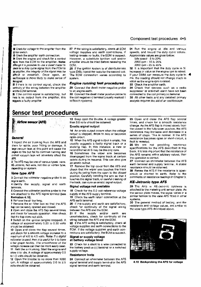
Component test procedures 4.5
P1 Check for voltage to the amplitier from the bnltion switch. I - : I Check the amplifier earth connection.
: W Crank the engine and check for a control i dgnal from the ECM to the amplifier. Note: Mhough i f rs possible to use a dwell meter to
' W tor a duty cycle signal from the EC# to h amplifmr, the integrity of the signal may be &Hicult to esteblrsh. Once again, an cwcillosrope is more likely to make sense of bbs qm/. eS If there is no control signal, check the continuity of the wiring between the amplifier md the ECM terminal. a If the control signal is sat~sfactory, but there is no output from the amplifier, this wests a faulty arnpiifier.
27 If the wiring is satisfactory, check all ECM voltage supplies and earth connections. If testing reveals no faults, the ECM is suspect. However, a substitute ignition coil and/or amplifier should be tried before renewing the ECM. 28 If the ignition system is of distributorless type (DIS), repeat the tests for the second coil. The ECM connection varies according to system.
Engine running test pmcedures 29 Connect the dwell meter negative probe to an engine earth. 30 Connect the dwell meter positive probe to the coil negatwe I-) terminal (usually marked 1 in Bosch systems).
Sensor test procedures !
13 Snap open the throttle. A voltage greater < m - w @ than 3.0 volts should be obta~ned.
Erratic signal output 14 An erratlc output occurs when the voltage output IS stepped, drops to zero or becomes
Qemral 1 Inspect the air trunking from the AFS and check fur splits, poor fitting or damage. A lsrge vacuum leak at this point will cause the engine to fire but fail to continue running and 8 small vacuum leak will adversely affect the AFR. 2 The AFS may be one of vacous types: vane, KE-Jetmnic, hot-wire, hot-film or vortex type, depending on system.
Vane type AFS 3 Connect the voltmeter negative probe to an engine earth. 4 Identify the supply, signal and earth termnals. 6 Connect the voltmeter positive p b e to the wire attached to the AFS signal terminal (see llwtration 4.10). 6 Remove the air trunkmg. 7 Remove the air filter box so that the AFS flap can be easily opened and closed. 8 Open and close the AFS flap several times and check for'smooth operation. Also check that the flap does not stick. 8 Switch on the Ignition (engine stopped). A voltage of approximately 0.20 to 0.30 volts should be obtained. 10 Open and close the flap several times, and check for a smooth voltage increase to a maximum of 4.0 to 4.5 volts. Note: I f a digital vollmeter is used, then rt is useful for it to have a bar graph facility. The smoothness o f the voltage mcrease can then be more easily seen. 11 Reflt the alr trunking. Start the englne and allow ~t to idle. A voltage of approx~mately 0.5 to 1.5 volts should be obtained. 12 Open the throttte to no more than 3000
open-circuit. 15 When the AFS signal output is erratic. this usually suggests a faulty signal track or a st~cking ftap. In this instance, a new or reconditioned AFS may be the only cure. 16 Sometimes the wiper arm becomes disengaged from the signal track at certain points during its traverse. This can also give an erratic output. 17 Remove the top cover from the AFS and check that the wiper arm touches the track during its swing from the open to the closed posit~on. Carefully bending the arm so that It touches the signal track, or careful cleaning of the track, can cure an erratic signal output.
Signal vottage not available 18 Check for the 5.0 volt reference voltage supply at the AFS supply terminal. 19 Check the earth return connection at the AFS earlh terminal. 20 If the supply and earth are satisfactory, check for continuity of the signal wirlng between the AFS and the ECM. 21 If the supply and/or earth are unsatisfactory, check for continuity of the wiring between the AFS and the ECM. 22 If the AFS wiring is satisfactory, check all boltage supplies and earth connections to the ECM. If the voltage supplies and earth con- nections are satisfactory, the ECM is suspect.
Signal or supply voltage at battery voltage level 23 Check tor a short to a wire connected to the battery positive (+) terminal or a switched supply voltage.
Resistance tests 24 Connect an ohmmeter between the AFS
31 Run the englne at idle and various speeds, and record the duty cycle values. Approximate values are given below:
Idle speed - 5 to 20% 2000 rprn - 75 to 35% 3000 rpm - 25 to 45%
32 It is important that the duty cycle In % Increases in value as the engrne rprn is raised. If your DMM can measure the duty cycle in 4 ms, the reading should not change much in value as the engine rprn IS raised. 33 Checklheamplifier earth. 34 Check that devices such as a radio suppresser or anti-theft alarm have not been connected to the coil primarj (-) terminal. 35 All other tests and any detailed prlmary analysis requires the aid of an oscilloscope.
25 Open and close the AFS flap several times, and check for a smooth resistance change. As the AFS flap is moved slowly from the closed to the fully-open poslt~on, the AFS resistance may increase and decrease in a series of steps. This is normal. It ihe AFS resistance becomes open or short-clrcult, a fault is revealed. 26 We are not provid~ng res~stance specifications tor the AFS described in this book. It is less irnporlant that the resistance of the AFS remains withln arbitrary values, than the operation is correct. 27 Connect an ohmmeter between the AFS earth terminal and supply terminal. A stable resistance should be obtained. 28 Renew the AFS if the resistance is open- circuit or shorted to earth. Refer to the comments on resistance readings in Chapter 3.
KE-Jetronic type AFS 29 The AFS In KE-Jetronic systems is attached to the metering unit sensor plate. As the sensor prate moves, the signal varies in a similar fashion to the vane AFS fitted in other systems. 3Q The general method of testing, and the reslstance and voltage values, are slmilar to the vane type AFS described above.
I rpm. A voltage of approximately 2.0 to 2.5 signal terminal and supply terminal or the AFS 4.10 Backprobing the AFS for voltage volts should be obtained signal terminal and earth terminal.
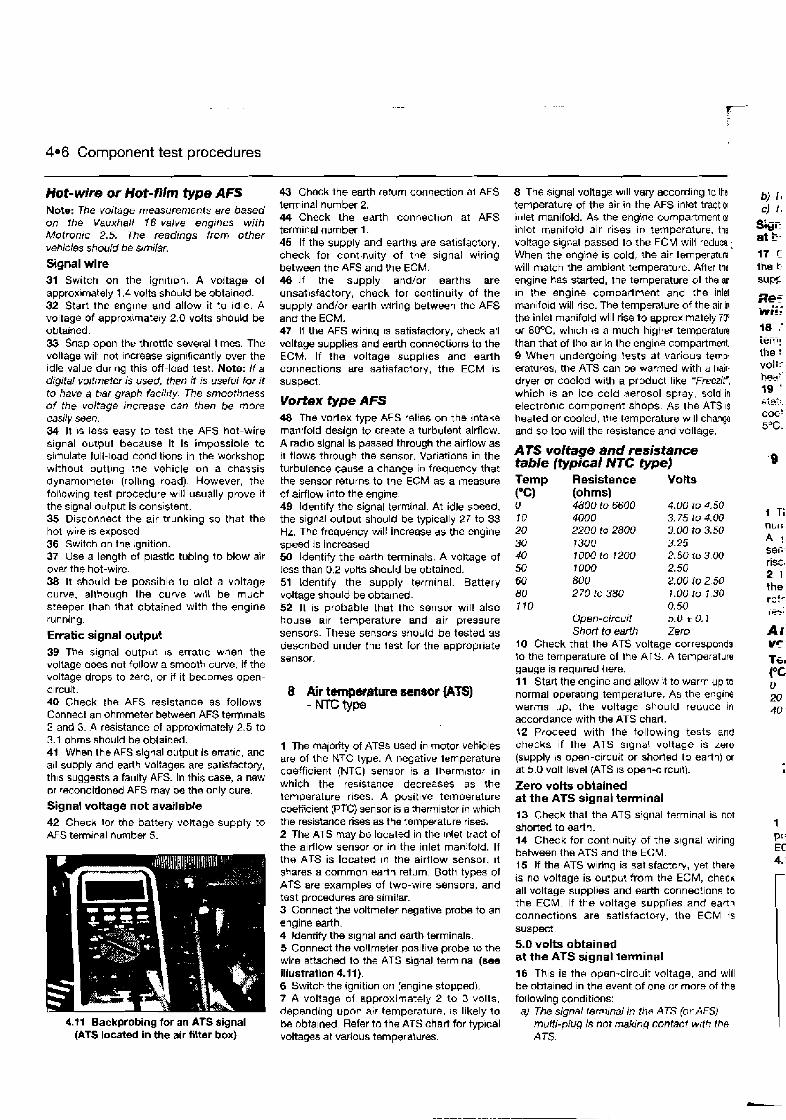
4.6 Component test procedures
Hot-wire or Hot-film type AFS Note: The voltage measurements are based on the Vauxhall 16-valve engrnes with Motronic 2.5. The readings from other vehicles should be stmilar. Signal wire 31 Switch on the ign~tion. A voltage of approximately 1.4 volts should be obtainad. 32 Start the englne and allow it to idle. A voltage of approx\mately 2.0 volts should be obtained. 33 Snap open the throttle several times. The voltage will not increase significantly over the die value dur~r~g this off-load test. Note: i f a digital volI~rreter is used, then it is useful for it to have a bar graph facilrty. The smoothness of the voltage increase can then be more easily seen. 34 It \s less easy to test the AFS hot-wire signal output because it is impossible to simulate full-load conditions in the workshop without puttlng :he vehicle on a chassis dynamometer (rolling road). However, the foliowing test procedure w~l l usually prove it the s~gnal output is cons~stent. 35 Disconnect the air trunking so that the hot-wire IS exposed 36 Switch on the hgnition. 37 Use a length of plastic tubing to blow air over the hot-wire. 38 It should be possible l o plot a voltage curve, allbough the curve w ~ l l be much steeper than that obtained with the engine running.
Erratic signal output 39 The signal output IS erratic when the voltage does not follow a smooth curve, if the voltage drops to zero, or if it becomes open- c~rcuit. 40 Check the AFS resistance as follows. Connect an ohmmeter between AFS terminals 2 and 3. A resistance of approximately 2.5 to 3.1 ohms should be obtained. 41 When the AFS signal output is erratlc, and all supply and earth voltages are satisfactory, th~s suggests a faulty AFS. In this case, a new or reconditioned AFS may be tha only cure.
Signal voltage not available 42 Check lor the battery voltage supply to AFS terminal number 5.
4.71 Backprobing for an ATS signal (ATS located in the air fiitar box)
43 Check the earth return ~onnection al AFS terminal number 2. 44 Check the earth connection at AFS terminal number 1. 45 If the supply and earths are satisfactory. check for continuity of the signal wiring between the AFS and the ECM. 46 I f the supply and/or earths are unsatisfactory, check for continuity of the supply andlor earth wring between the AFS and the ECM. 47 If the AFS winng IS satisfactory, check all voltage supplies and earth connections to the ECM. If the voltage suppl~es and earth connections are satisfactory, the ECM IS
suspect.
Vortex type AFS 48 The vortex type AFS relies on the intake rnanrfold design to create a turbulent airflow. A rad~o siqnal is passed through the airflow as it flows through the sensor. Var~ations in the turbulence cause a change in frequency that the sensor returns to the ECM as a measure of airflow into the engine. 49 ldent~fy the signal terminal. At idle speed, the slgr,al output should be lypically 27 to 33 Hz. The frequency will increase as the engine speed is increased 50 Identify the ~ a r t h terminals. A voltage of less than 0.2 votts should be obtained. 51 identify the supply terminal. Battery voltage should be obtained. 52 It is probable that the sensor will also house alr temperature and air Dressure sensois. These sensors should be tested as descr~bed under the test for the appropriate sensor.
8 Air temperMure sensor (Am) - ~ V P
1 T ~ E rnalorrty of ATSs used in motor vehicles are of the NTC type. A negative iemperature coefficient (NTC) sensor is a therm\stor in which the reslstaoce decreases as the temperature rises. A posit~ve temperature coeficient (PTC) sensor is a thermistor in which the resistanca rises as the temperature rises. 2 The A l S may be located in the Inlet tract of the airflow sensor or in the inlet rnandold. If the ATS is located in the airflow sensor, it shares a common eartn return. Both types of ATS are examples of two-wlre sensors, and test procedures are similar. 3 Connect the voltmeter negat~ve probe to an engine earth. 4 Identify the srgnal and earth terminals. 5 Connect the voltmeter positive probe lo the wire saached to the ATS signal term~nal (see illustration 4.11). 6 Switch the ignition on (engine stopped). 7 A voltage of approximately 2 to 3 volts, depending upon atr temperature, is likely to be obta~ned. Refer to the ATS chart for typ~cal voltages at various temperatures.
8 The signal voltage will vary according to the temperature of the air in the AFS inlet tract oc inlet manifold. As the engine compartment u inlet manifold air rises in temperature, tha voltage signal passed to the ECM will redua.; When the eng~ne is cold, the air ternperaturn will match the ambient temperature. ARer the engine has started, the temperature ot the ar in the engine compartment and the inled man~fold will rise. The temperature of the air in the inlet maoitold will rise to approx~mately 700 or 80°C, whlch 1s a much higher temperature than that of the alr in the engine compartrnmt. 9 When undergoing tests at various temp. eratures, the ATS can be wanned with a hall- dryer or cooled with a product like "Freezit", which IS an ice cold aerosol spray, sold in electronic component shops. As the ATS IS
heated or cooled, the temperature w~l l changa and so too will the resistance and voltage.
ATS voltage and resistance table (typ~cai NTC type) Temp Resistance Vofts (*c) (ohms) 0 4800 to 6600 4.00 to 4.50 10 4000 3.75 to 4.00 20 2200 to 2800 3.00 to 3.50 30 1300 3.25 40 7000to7200 2.50to300 50 1000 2.50 60 800 2.00 to 2.50 80 2 70 to 380 1.00 to 1 30 110 0.50
Open-circuit 5.0 t a . 1 Short to earth Zero
10 Check that the ATS voltage corresponds 10 the ternperature of Ihe ATS. A temperature gauge is requlred here. 11 Start the engine and allow it to warm up to normal operating temperalure. As the englne warms I J ~ , the voltage should reduce in accordance with the ATS chart. 12 Proceed with the following tosts and checks if the ATS signal voltage is zero (supply IS open-c~rcuit or shorted to earth) or at 5.0 volt level (ATS is open-c~rcult].
Zero volts obtained at the ATS signal terminal 13 Check that the ATS signal terminal IS not shorted to earth. 14 Check for cont~nuity of the s~gnal wiring between the ATS and the ECM. 15 If the ATS w~ring is satisfactory, yet there 1s no voltage is outplrt from the ECM, check all voltage supplies and earth connections to the ECM. I f the voltage supplies and earth connections are satisfactory, Ihe ECM is suspect.
5.0 votts obtained at the ATS signal terminal 16 Thls is the open-circuit voltage, and will be obta~ned In the event of one cr more of the following condl tions: a) The signal tern~~nai in the ATS (or AFS)
multi-plug is not rnaktng contact wrth !he ATS.
bl 11 c) I .
s g c at
17 C the t: sup::
SeE .A-
wl?!
18 f -.-. ielrl! the : voii- hew?' 19 ' bid:..
cot-! 5°C.
1 Ti null A : seii- risG: 2 1 the ro!? i*.
AI w Tun {"C. 0 20 40
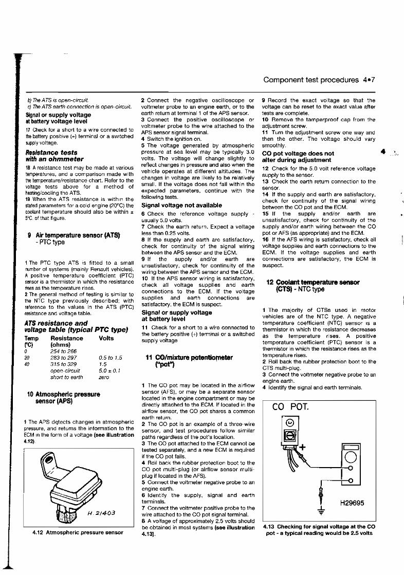
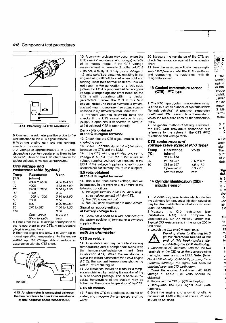
4.8 Component test procedures
4.14 Checking the CTS resistance
5 Connect the voltmeter positive probe to the wlre attached to the CTS signal terminal. 6 With the ongine cold and not running. switch OF the rgnition. 7 A voltage of approximately 2 to 3 volts, depending upon temperature, is likely to be obtained. Refer to the CTS chart below for Pypical voltages at varlous temperatures.
CTS volta~e and resistance table (typical1 f emp Resistance Volta rc) (ohms) 0 4800 to 6600 4.00 to 4.50 T O 4000 3.75 to4.00 20 2200 to 2800 3.00 to 3.50 30 1300 3.25 40 1000 ta 1200 2.50 to 3.00 50 7 000 2.50 60 800 2.00 to 2.50 BO 2 70 to 380 3.00 to 7.30 770 0.50
Open-circuit 5.0k 0.1 Short to earlh zer9
8 Check that Ihe CTS voltage corresponds to the temperature of the CTS. A temperature gauge is required here. B Start the engine and aibw it to warm up to normal operating temperature. As the engine warms up, the voltage shouid reduce in accordance wrth the CTS chart.
-
4.tS An ohmmeter is connected b W m n h e two terminals to check the resistance
of the inductive phase sensor (CID)
10 A common problem may occur where the CTS varles io resistance (and voltage) outs~de of its normat range. lf the CTS voltage measurement is normally 2 volts coldI0.5 volts hot, a faulty CTS may give a voltage of 1.5 volts cold/I .25 volts hot, resulting in the englne being difficult to star1 when cold and running richer than normal when hot. This will not result in the generation ol a fault code (unless the ECM is programmed to recognise voltage changes against time) because the CTS is still operaling within its design parameters. Renew the CTS if t h ~ s fault occurs. Note: The above example IS typical, and not meant to represent an actual voltage obtained in a pan~cular system under test. 11 Proceed with the following tests and checks if the CTS signal voltage is zero (supply IS open-circuit or shorted to earth) or at 5.0 volt level (CTS is open-circuit).
Zero volts obtained at the CTS signal terminal 12 Check that the CTS signal terminal is not sb.orted to earth. 13 Check for continuity of the signal wiring between the CTS and the ECM. 14 If the CTS wiring is satsfactory, yet no voltage is output from the ECM, check all voltage supplies and earth connections to the ECM. If the voltage supplies and eanh con- nections are satisladory, the ECM IS suspect.
5.0 volts obtained at the CTS signal terminal 15 This is ihe open-circuit voltage, and will be obtained in the event of one or more of the tollowing conditions: a) The signal terminal m rhe CTS multi-plug
rs nct making contact with the CTS. b) The CTS is open-circuit. c) The CTS earth connection is open-circuit.
Signal or supply voltage at battery voltage lwel 16 Check for a short to a wire connected to the batlery positive (+) term~nal or a switched supply vollage.
Resistance tests with an ohmmeter
CTS on vehicle 17 A resistance test may be made at various temperatures and a comparison made with the ternperaturelresistance chart (see illustration 4.14). When the resistance is w~thin the stated parameters for a cold englne (2DLC), the coolant temperature should be with~n i5'C of that figure. 18 An allowance should be made lor a ternp- erature oblaineb by probing the outside of the CTS or coolant passage. This is because the actual temperature of the coolant may be hotter than the surface tsrnperature of the CTS.
CTS off vehicle 19 Place the CTS In a suitable contamer of water, and measure the temperature of the water.
20 Measure the resistance of the CTS, ard check ths resistance against Ihe temperatum chart. 21 Heat the water, periodically measuring the. water temperature and the CTS resistance,
and comparing lhe resistance with the temperature charl.
q3 Codant brnpmture sensor ' (Cl3) - PTC type
1 The PTC type coolant temperature sensor is fltted lo a small number of systems (mainly Renault vehicles). A positive lemperature coefficient (PTC} sensor is a thermistor in which the res~stance rises as the temperahre rises. 2 The general method of testing is similar i n the NTC type previously described: with reference to the values in the CTS (PTC) resistance and voltage table.
CTS resistance and voltage table (typical PTC type) Temp Resistance Volts rc) (ohms) 0 254 to 266 20 283 10 297 0.6io 08 80 383 io 397 1.0 to 1.2
Open-arcu~ t 5.0 i- 0.1 Short to earth zem
14 Cylinder identiflcatiion (CID) - inductive sensor
I The tnduct~ve phase sensor whtch ~dentif~es the cylinders for sequentla1 injectmn operation may be fitted :nside the distr~butor or mounted upon the camshaft. 2 Measure the CID resistance (see illustration 4.15) and compare to specifications for the veh~cle under tesl. Typical CID resistance IS In the range 200 to 900 ohms. 3 Detach the d D or ECM multl-plug.
A Wamlng: Refer to Warning No 3 (in the Reference Section at the end of this book) before dis- connecting the ECM multi-plug.
4 Connect an AC voltmeter between the two terminals ai tne CID or at the correspond~ng rnultt-plug terrn~nals at the ECM. Note: Better results are usually obtarned by probrng the t terminal, although the s:gnal can often be obtained upon the CID earth return 5 Crank tbe engine. A minimum AC RMS voltage d about 0.40 volts should be obta~ned. 6 Reconnect the CID or ECM multi-plug 7 Backprobe the CID srgnal and eanh term~nals. 8 Starl the englne and allow ~t to ~dle. A min~rnurn AG RMS voltage of about 0 . i5 volts should be obtained.
1 The ideni~i: operai: or mo! proce' distrit c~-iteF 2 Cor meter g Idel terrni~ f0ll o:....
4 Cc met< sign- me [ 5 Fa' of W !
duty
Sin1 dui 6 S 7 F. 8 :. 9 V siyr 10 var air 5.0
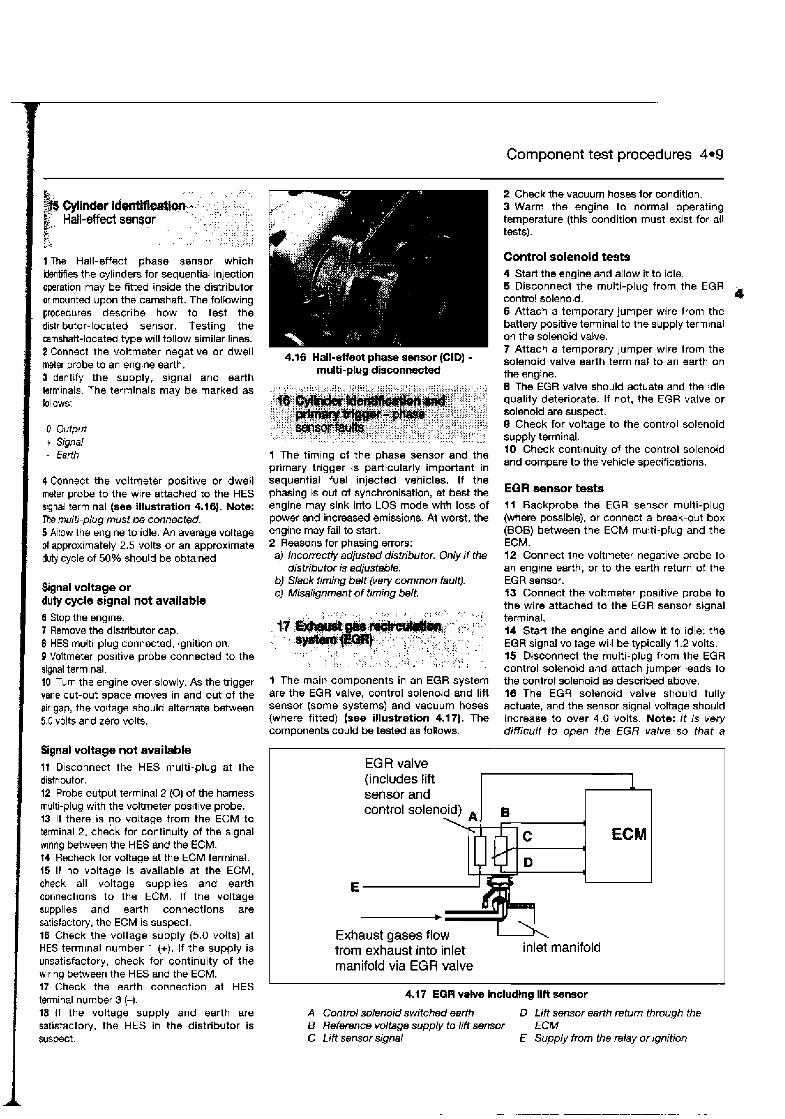
1 Component test procedures 4.9
1 The Hall-effect phase sensor which identifies the cylinders for sequential injection operation may be fitted inside the distributor or mountd upon the camshaft. The following procedures describe how to test the distributor-located sensor. Testing the camshaft-located type will follow similar lines. 2 Connect the voltmeter negative or dwell meter probe to an engine earth. Sldentify the supply, signal and earth terminals. The terminals may be marked as fnllows:
0 Output t Signal - Earth
4 Connect the voltmeter positive or dwell meter probe to the wire attached to the HES signal terminal (see illustration 4.16). Note: The multi-plug must be connected. 5 Allow the engine to idle. An average voltage of approximately 2.5 volts or an approximate duty cycle of 50% should be obtained
Signal voltage or duty cycle signal not available 6 Stop the engine. 7 Remove the distributor cap. 6 HES multi-plug connected, ignition on. B Voltmeter positive probe connected to the signal terminal. 10 Turn the engine over slowly. As the trigger vane cut-out space moves in and out of the air gap, the voltage should alternate between 5.0 volts and zero volts.
Signal voltage not available I t Disconnect the HES multi-plug at the distributor. 12 Probe output terminal 2 (0) of the harness multi-plug with the voltmeter positive probe. 13 If there is no voltage from the ECM to terminal 2, check for continuity of the signal wlrlng between the HES and the ECM. t4 Recheck for voltage at the ECM terminal. 15 If no voltage is available at the ECM, check all voltage supplies and earth connections to the ECM. If the voltage supplies and earth connections are satisfactory, the ECM is suspect. 16 Check the voltage supply (5.0 volts) at HES terrnrnal number 1 (+). If the supply is unsatisfactory, check for continuity of the wiring between the HES and the ECM. 17 Check the earth connection at HES terminal number 3 (-). 18 If the voltage supply and earth are satisfactory, the HES in the distributor is suspect.
4.16 Hall-Mect phase sensor (CID) - multi-ptug disconnected
1 The timing of the phase sensor and the primary trigger is particularly important in sequential fuel injected vehicles. If the phasing is out of synchronisation, at best the engine may sink into LOS mode with loss of power and increased emissions. At worst, the engine may fail to start. 2 Reasons for phasing errors: a) Incorrectly adjusted distributor. Only i f the
distributor is adjustable. b) Slack timing belt (very common fault). c) Misalignment of timing belt.
1 The main components in an EGR system are the EGR valve, control solenoid and lift sensor (some systems) and vacuum hoses (where fitted) (see illustration 4.17). The components could be tested as follows.
2 Check the vacuum hoses for condition. 3 Warm the engine to normal operating temperature (this condition must exist for all tests).
Control solenoid tests 4 Start the engine and allow it to idle. 5 Disconnect the multi-plug from the EGR control solenoid. a 6 Attach a temporary jumper wire from the battery positive terminal to the supply terminal on the solenoid valve. 7 Attach a temporary jumper wire from the solenoid valve earth terminal to an earth on the engine. 8 The EGR valve should actuate and the idle quality deteriorate. If not, the EGR valve or solenoid are suspect. 8 Check for voltage to the control solenoid supply terminal. 10 Check continuity of the control solenoid and compare to the vehicle specifications.
EGR sensor tests 11 Backprobe the EGR sensor multi-plug (where possible), or connect a break-out box (BOB) between the ECM multi-plug and the ECM. 12 Connect the voltmeter negative probe to an engine earth, or to the earth return of the EGR sensor. f3 Connect the voltmeter positive probe to the wire attached to the EGR sensor signal terminal. 14 Start the engine and allow it to idle; the EGR signal voltage will be typically 1.2 volts. 15 Disconnect the multi-plug from the EGR control solenoid and attach jumper leads to the control solenoid as described above. 18 The EGR solenoid valve should fully actuate, and the sensor signal voltage should increase to over 4.0 volts. Note: It i s very difficult to open the EGR valve so that a
EGR valve
sensor and
E - Exhaust gases flow from exhaust into inlet inlet manifold manifold via EGR valve
4.1 7 EG W valve includtng lift sensor
A Control solenoid switched earth D Lift sensor earth return through the B Reference voltage supply to lift sensor ECM C Lift sensor signal E Supply from the relay or rgnition
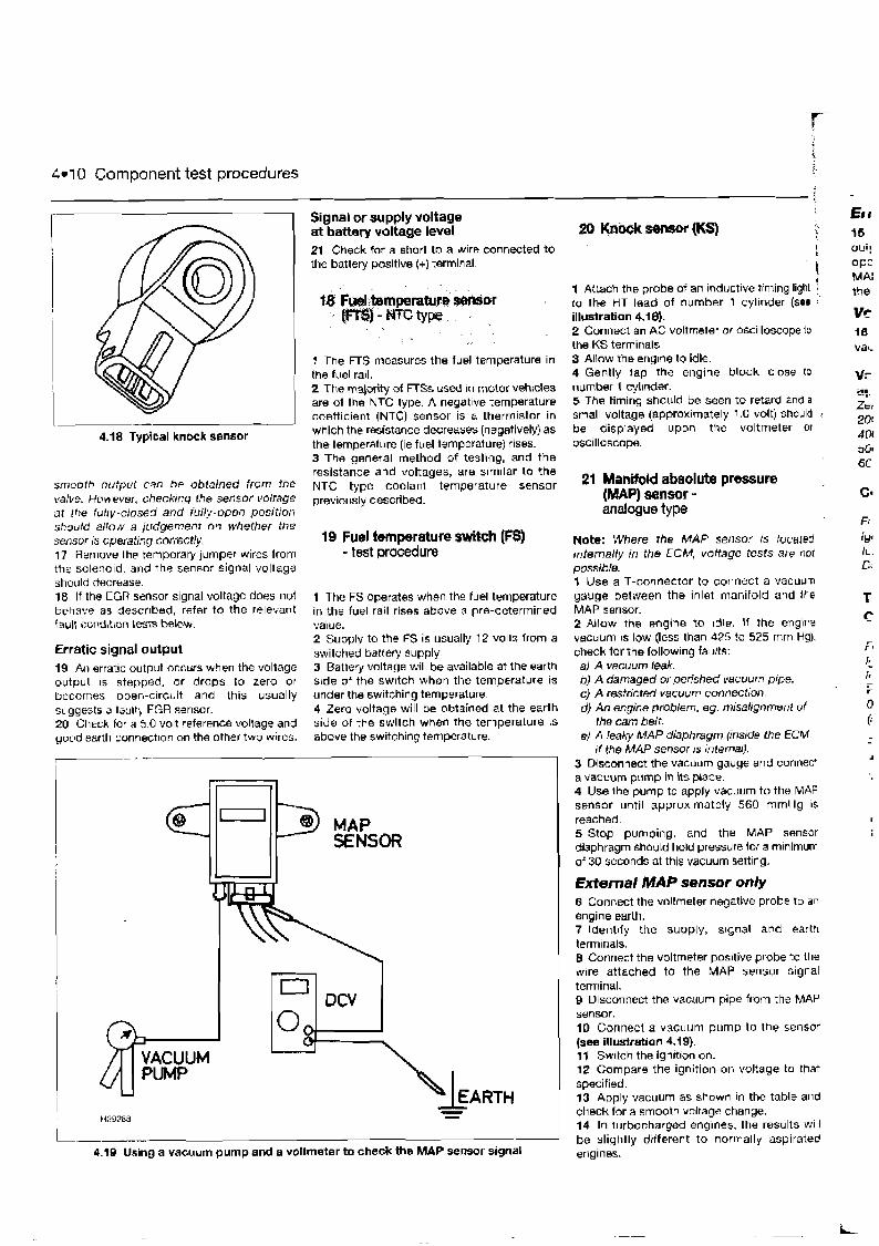
4.1 0 Component test procedures
4.18 Typical knock sensor
Signal or supply voltage at battery voltage level 21 Check for a short to a wlre connected to the battery positive (+) terminal.
1 The FTS measures the fuel temperature in the fuel rail. 2 The majority of FTSs used In motor vehicles are of the NTC type. A negat~ve temperature coefficient (NTC) sensor is a thermistor in which the resistance decreases (negatively) as the temperature (ie fuel temperature) rises. 3 The general method of tesling, and the resistance and voltages, are s~rn~lar to the
smooth output can be obtained from the NTC type coolan1 temperature sensor valve. However, checking the sensor Voltage described. at rhe fullv-closed and fully-open position should allow a judgement in whether the sensor is operating correctly. 17 Remove ihp temporary jumper wires from the solenoid, and the sensor signal voltage should decrease 18 If the EGR sensor signal voltage does not behave as descr~bed, refer to the relevant fault cond~t~on tests below.
Erratic signal output 19 AII erratic output occbrs when the voltage output IS stepped, or drops to zero or becomes open-c~rcuit and this usualty suggests a iacrlt, EGR sensor. 20 Check for a 5.0 volt reference voltage and good earth connection on the other two wires.
19 Fuel iemprature switch (FS) - test procedure
1 The FS operates when the fuel temperature in the fuel rail rises above a pre-determined value. 2 Supply to the FS is usually 12 volis from a switched battery supply. 3 Batiery voltage will be available at the earth side of the swrtch when the temperature is under the switching temperature. 4 Zero voltage will be obtained at the earth side of the switch when the temperature is above the switching temperature.
VACUUM &-J 4.19 Using a vacuum pump and a voltmeter to check the MAP sensor signal
20 k h k s€mw (KS)
1 Attach the probe of an inductive lrrning ligm to the HT lead of number 1 cyllnder (see :'
illustration 4.18). 2 Connect an AC voltmeter or oscilloscope to the KS terminals 3 AHow the englne to idle. 4 Gently iap the engine block close to number 1 cylinder. 5 The timing should be seen to retard and a small voltage (approximately 1.0 volt) should be displayed upon tee voltmeter Or oscilloscope.
21 Manifold absolute pressure (MAP) sensor - analogue type
Note: Where the M A P sensor IS located rnternally in the ECM, voltage tests are not possible. 1 Use a T-connector to connect a vacuum gauge between the Inlet manifold and the MAP sensor. 2 Allow t h e engine to Idle. If the engine vacuum 1s low (less than 425 ?o 525 mm Hg). check for the following faults: a) A vacuum leek. bJ A damaged or perished vacuum pipe. c} A restricted vacuum connection. dJ An engine pmblem, sg. misalignment of
the cam belt. e) A leaky MAP diaphragm (inside the ECM
tf the MAP sensor rs 1nlermIJ. 3 Disconnect the vacuum gauge and connen a vacuum pump in its place 4 Use lhe pump to apply vacuum to the MAP sensor until approximately 560 mmHg 15 reached. 5 Stop pumping, and the MAP sensor diaphragm should hold pressure lor a mlnimum of 30 seconds at this vacuum settlng.
External MAP sensor only 6 Connect the voltmeter negative probe to an engine earth. 7 ldent~fy the supply, s~gnal and earth terminals. 8 Connect the voltmeter positive probe to the wire attached to the MAP sensor signal terminal. 9 Disconnect the vacuum pipe from the MAP sensor. 10 Connect a vacuum pump to the sensor (see illusiratian 4.19). 11 Switch the ign~t~on on. 12 Compare the ignition on voJ?age to that specified. 13 Apply vacuum as shown In the table and check for a smooth voltage change. 14 In t~lrbocharged englnes, the results will be slighily different to normally aspirated engines.
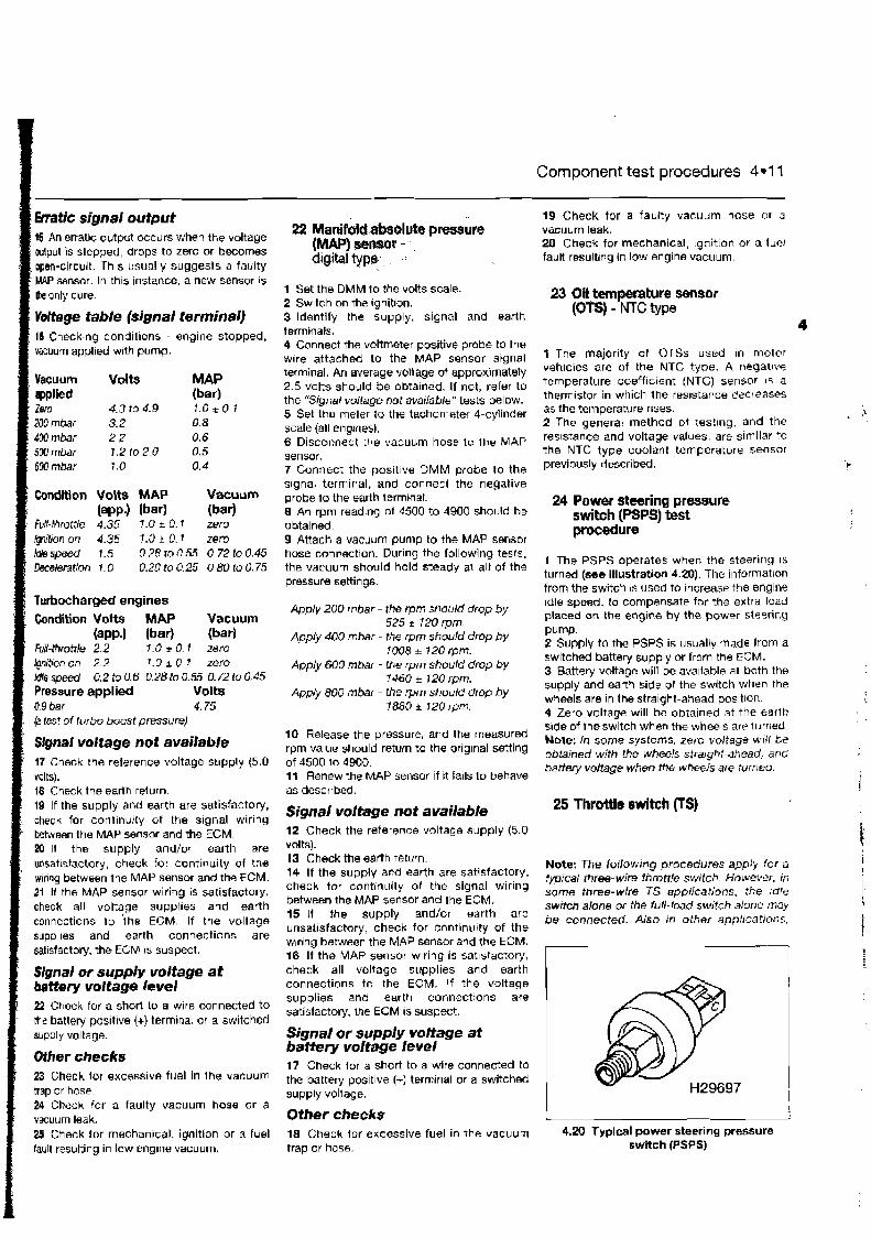
Component test procedures 4-1 I
t5 An erratlc output occurs when the voltage output is stepped, drops to zero or becomes open-circuit. Th~s usually suggeds a faulty MAP sensor. In th~s instance, a new sensor is / L only cure.
/ Yottage table (signal terminal) / 16 Checking condil~ons - engine stopped,
vacuum applied with pump.
Vacuum Volts MAP : applied (bar) , Zem 4.3 to 4.9 1 . 0 * 0 7 ' 200mbar 3.2 0 8 Mmbar 2 2 0.6 500mbar 12 lo 20 0.5 GW mbar 1 .O 0.4
Condition Volts MAP Vacuum (app.1 (bar1 (bar1
Full-(hrottle 4.35 7 .U + 0.1 zero @ition on 4.35 1.0 + 0. I zero )oYe speed 1.5 0 28 to 0.55 0.72 to 0.45 Deceleration I . 0 0.2C to 0.25 0.80 to 0.75
Turbocharged engines Condition Volts MAP Vacuum
Iapp.1 (bar) (bar) Fd-throtile 2.2 1.0*0.1 w r o Ignit~on on 2.2 1 . 0 ~ 0 7 zero Idle speed 0.2 to 0.6 0.28 lo 0.55 0.72 to 0.45 Pressure applied Volts 0.9 bar 4.75 (a test of turbo boost pressure)
Signal voltage not available 17 Check the reference voltage supply (5.0 volts).
I 18 Check the earth return. 19 If the supply and earth are satisfactorj, check for continu:ty of the signal wir~ng between the MAP sensor and the ECM.
; 20 H the supply and/or earth are I unsatrsfactory, check for continuity of the I w~ring between the MAP sensor and the ECM.
21 H the MAP sensor wiring is satisfactory, check all voltage suppl~es and earth connections l o ihe ECM. If the voltage supplles and earth connections are satisfactorj, the ECM IS suspect.
Signal or supply voltage at battery voltage level 22 Check for a short to a wire connected to the batteiy positive (+) term~nal or a switched supply voltage.
Other checks 23 Check lor gxcessive fuel in the vacuum trap or hose 24 Check lor a faulty vacuum hose or a vacuum leak. 25 Check for rnechan~cal, ignition or a fuel fault resulting in low englne vacuum.
22 ~ a n i f i l d .WE~SOIM€I pressure PAP) ~~~ - ,, d l ~ t d t@@., . ,:
1 Set the DMM to the volts scale. 2 Switch on the ~gnition. 3 Identify the supply, signal and earth terminals. 4 Connect the voltmeter positive probe to the wlre attached to the MAP sensor signal terminal. An average voltage of approximately 2.5 volts should be obrained. If not, refer to the "Signal voltage not available" tests below. 5 Set Iha meter to the tachometer 4-cylinder scale (all engmes). 6 Disconnect the vacuum hose 10 the MAP sensor. 7 Connect the positive DMM probe to the signal terminal, and connect the negative probe to the earth terrn~nal. 8 An rpm reading of 4500 to 4900 should be obtained. 9 Attach a vacdurn pump to the MAP sensor hose conrection. During the following tests. the vacuum should hold steady at all of the pressure settings.
Apply 200 mbar - the rpm st~oitlrl drop by 525 r 120 rpm.
Apply 400 mbar - the rprn should drop by 1008 + 120 rpm.
Apply 600 mbaf - the rprn should drop by 1460 + 120 rprn.
App+ 800 mbar - the rprn should drop by 1880 i 120 rpm.
10 Release the pressure, and the measured rpm value should return to the original setting of 4500 lo 4900. 11 Renew the MAP sensor if it fails to behave as described
Signal voltage not available 12 Check the reference voltage supply (5.0 volts). 13 Check the earth return. 14 If the supply and earth are satisfactory, check for cont~nuity of the signal wiring between the MAP sensor and the ECM. 15 I the supply andlor earth are unsatisfactory, check for continutty of the w~rlng between the MAP sensor and the ECM. 18 If the MAP sensor wiring is sat~sfactory, check all voltage supplies and earth connections to the ECM. If the voltage supplies and earth connections are satisfactoty, lhe ECM 1s suspect.
Signal or supply voltage at baitery voltage level 17 Check for a short to a wire connected to the battery positive (+) terminal or a switched supply voltage.
Other checks 18 Check for excessive fuel in the vacuum trap or hose.
19 Check for a faulty vacuum hose or a vacuum leak. 20 Check for mechanical, ~gnition or a iuel fault resulting in low engine vacuum.
23 Oit temperature sensor (Om - NTC type
4
1 The major~ty of OTSs used in mulor vehicles are of the NTC type. A negallw temperature coeffic~ent (NTC) sensor 15 a therm~stor in which the resistance clact eases as the temperature rises. 2 The general method ot test~ng, and the reslstarice and voltage values, are similar to the NTC type coolant tenlperature sensor previously described.
24 Power steering pressure switch (PSPS) test procedure
1 The PSPS operates when the steering 15
turned (see illustration 4.20). The information from the switch is used to Increase the engine Idle speed. to compensate for the extra load placed on the engine by the poww sleeriny Pump. 2 Supply to the PSPS is usually made from a switch4 battery supply or from the ECM. 3 Battery voltage will be available at both the supply and earth side 0 1 the switch when the wheels are in the straight-ahead pos~tlon 4 Zero voltage will be obtained at the earth side of theswitch when the wheels are turned Note: In some systems, zero voltage bt? obtained with the wheels stra~ghl-ahead, and battefery voltage when the wheels are turned.
Note: The follow~ng procedures apply for a typical three-wire throttle switch. HowevGr, in some three-wire TS applicalions, the rdle switch alone or the full-load switch alone may be connected. Also m other applications,
4.20 Typical power steering pressure switch (PSPS)
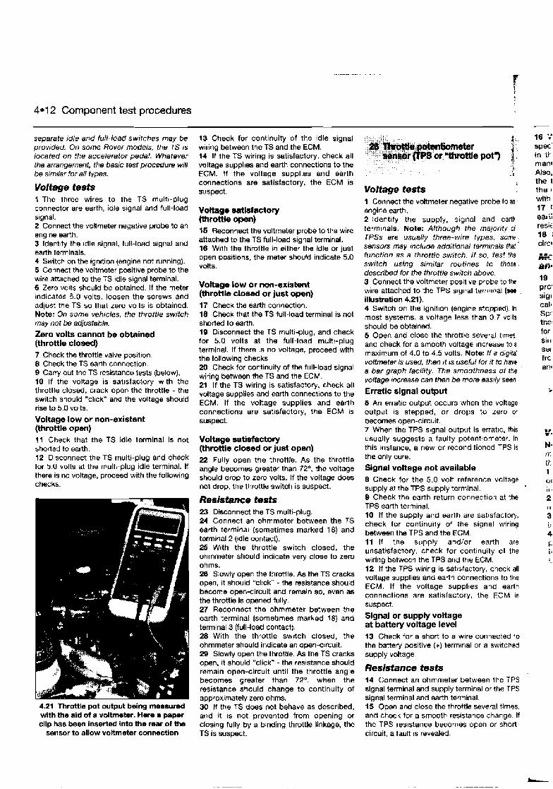
4.1 2 Component test procedures
separate idle and full-load switches may be provided. On some Rover models. the TS 1s located on the accelerator pedal. Whatever the arrangement, the basic test procedure will be similar for all types.
Voltage tests t The three wires to Ihe TS multl-plug connector are earth, idle slgnal and full-load signal. 2 Connect the voltmeter negative probe to an englne earth. 3 Idwnllfy the idle signal, full-load signal and earth terminals. 4 Switch on the lgnltion (engine not running). 5 Connect the voltmeter positive probe to the wire attached to the TS idle signal terminal. 6 Zero volts should be obtained. If the meter Indicates 5.0 volts, loosen the screws and adjust the TS so that zero volts is obtained. Note: On some vehicles, the throttle switch may not be adjustable. Zero volts cannot be obtained (throttle closed) 7 Check the throttle valve posltlon. 8 Check the TS sarlh connection. 9 Carry out the TS resistance tests (below). 10 If the voltage is sat~sfactory wlth the throttle closed, crack open the throttle - the switch should "clrck" and the voltage should rise to 5.0 volts.
Voltage low or non-existent (throttle open) 11 Check that the TS idle terminal is not shortd to earth. 12 Disconnect the TS multi-plug and check for 5.0 volts at the multl-plug idle terminal. It there is no voltage, proceed with the following chacks.
4.21 Throttle pot output being meowed with the aid of a voltmeter. Hare a paper clip has been inserted into the rear of h e
sensor to allow voltmeter conneetlon
13 Check for continuity of the idle signal wiring between the TS and the ECM. 14 If the TS wiring is satisfactory, check all voltage supplles and earth connections to the ECM. H the voltage supplies and earth connections are satisfactory, the ECM is suspect.
$5 Reconned the voltmeter prow to the wire attached to the TS full-load signal terminal. 16 With the throttle in either the idle or just open positions, the meter should indicate 5.0 volts.
Voltage Low or non-existent (throttle c l o d or just open) 17 Check the earth connection. I8 Check that the TS full-load terminal is not shortd to earth. 19 Disconnect the TS multi-plug, and check for 5.0 volts at the full-load multi-plug terminal. If there is no voltage, proceed with the following checks 20 Check for continuity of the full-load signal wiring between the TS and the ECM. 21 If the TS wiring is satisfactory, check all voltage supplies and earth connections to the ECM. If the voltage supplies and earth connections are satisfactory, the ECM is suspect.
Voltage satisfactory (throttle dosed or just open) 22 Fully open the throttle. As the throttle angle becomes greater than 72O. the voltage should drop to zero volts. If the voltage does not drop, the throttle switch is suspect.
Resistance tests 23 Disconnect the TS multi-plug. 24 Connect an ohmmeter between the TS earth terminal (sometimes marked 18) and terminal 2 (Idle contact). 25 With the throttle switch closed, the ohmmeter should indicate very close to zero ohms. 26 Slowly open the throttle. As the TS cracks open, it should "click - the resistance should become open-circuit and remain so, even as the throttle is opened fully. 27 Reconnect the ohmmeter between the earth terminal (sornet~mes marked 18) and terminal 3 (full-load contact). 28 With the throttle sw~tch closed, the ohmmeter should indicate an open-c~rcuit. 29 Slowly open the throttie. As the TS cracks open, it should "click* - the reslstance should remain open-circuit until the throttle angle becomes greater than 72O, when the resistance should change to continuity of approximately zero ohms. 30 It the TS does not behave as described, and ~t IS not prevented from opening or closing fully by a binding throttle Ilnkage, the TS is suspect.
Voltage tests 1 Connect the voltmeter negative probe to an, mgine earth. Sldentlfy the supply, signal and earth terminals. Note: Although the majority ot TPSs ere usua//y three-wire types, some; sensors may mclude additional terminals thaf function as a throttle switch. / f so, test the switch using similar routines to thoss . described for the throtl/e switch above. 3 Connect the voltmeter posltlve probe to the wire attached to the TPS slgnal termmat (wv , illustration 4.21). 4 Switch on the ign~l~on (engine stopped) In most systems, a voltage less than 0.7 volts should be obtained. 5 Open and close the throttle several t~mes. and check for a smooth voltage Increase to a maximum of 4.0 to 4.5 volts. Note: It a d~gild voltmeter is used, then I? IS useful far it ?a have a bar graph facility. The smoothness o f the vo/iape mrease can then be more easily seen.
Erratic signal output 6 An erratic output occurs when the voltage output is stepped, or drops to zero or becomes open-circuit. 7 When the TPS signal output is errat~c, this usually suggests a faulty potentiometer. In this Instance, a new or reconditioned TPS is the only cure.
Signal voltage not available 8 Check for the 5.0 volt reference voltage supply at the TPS supply terminal. 9 Check the earth return connectio~ at the TPS earth terminal. $0 If the supply and earih are satisfactory, check for continu~ly of the signal wiring between the TPS and the ECM. 11 If the supply and/or earth are unsatisfactory, check for continuity of the wiring betwean the TPS and the ECM. 12 If the TPS wiring is satisfactory, check all voltage supplies and earth connections to the ECM. If the voltage supplies and earth connections are satisfactory, the ECM is suspect.
Signal or supply voltage at battery voltage level i 3 Check for a short to a wire connected to the battery positive (+) terminal or a sw~tched supply voltage.
Resistance tests 14 Connect an ohmmeter between the TPS signal terminal and supply terminal or the TPS signal terminal and earth terminal. 15 Open and close the throttle several times. and check for a smooth reslstance change. If the TPS res~stance becomes open or short- circuit, a fault IS reveald.
16 7 spec' in t i macl Also, the I the I with 17 (
gal ii - ,F>'t
18 i clrcl
19 prc' siyr calk SF:- the: for S ~ I I
Sur
frc a,-!'
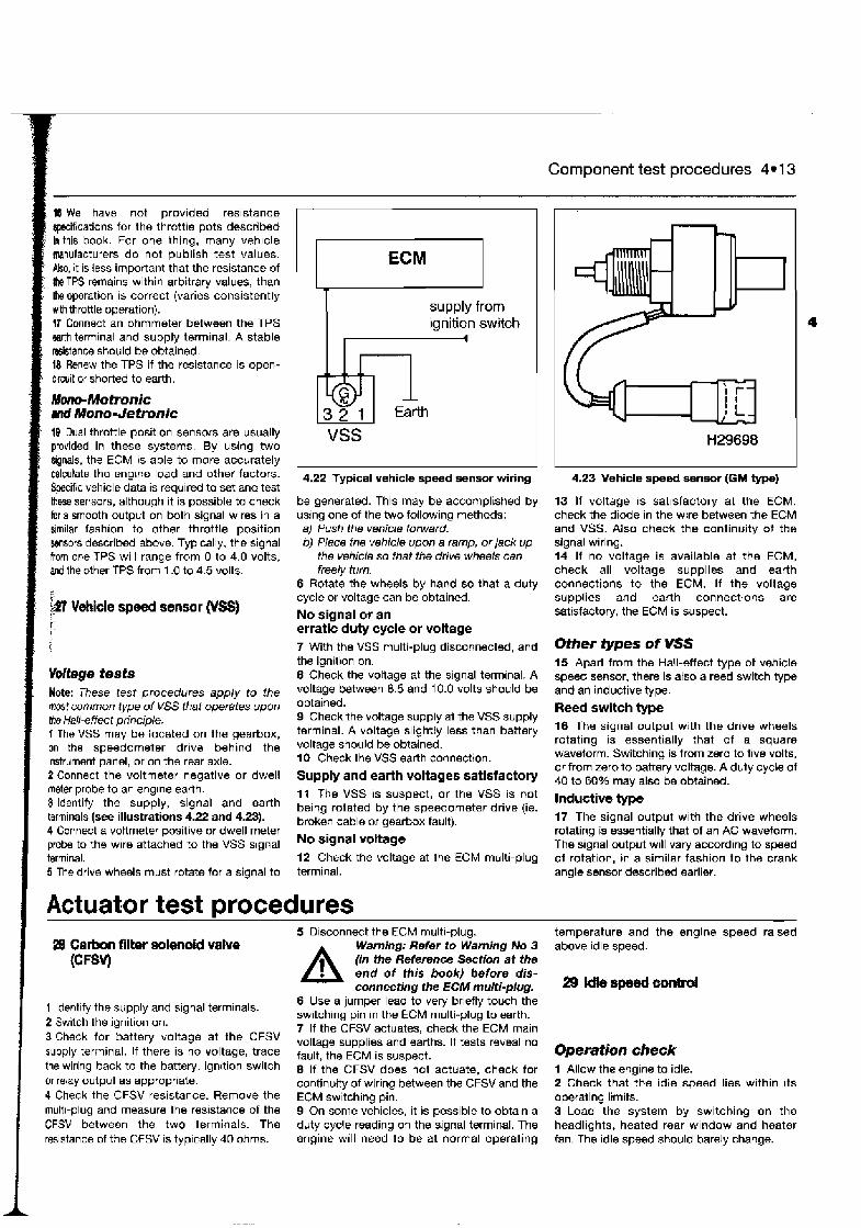
- .
Component test procedures 4.1 3
18We have not provided resistance ~i f icat ions for the throttle pots described In this book. For one thing, many veh~cle manufacturers do not publish test values.
! Also, it is less important that the resistance of i the TPS remains within arbitrary values, than : the operation is correct (varies consistently
with throttle operation). 17 Connect an ohmmeter between the TPS w t h terminal and supply terminal. A stable resistance should be obtained. 18 Renew the TPS if the resistance is open- circuit or shorted to earth.
Mono- Motmnic md Mono- Jetronic I# Dual throttle position sensors are usuausually provided in these systems. By using two signals, the ECM is able to more accurately calculate the englne load and other factors. Specific vehicle data is required to set and test thsse sensors, although it is possible to check for a smooth output on both signal wires in a similar fashion to other throttle position gensors described above. Typically, the signal from one TPS will range from 0 to 4.0 volts, and the other TPS from 1 .O to 4.5 volts.
1 voltage tests Note: These test procedures apply to the mast common type of VSS that operates upon ha Hall-effect principle. 1 The VSS may be located on the gearbox, on the speedometer drive behind the instrument panel, or on the rear axle. 2 Connect the voltmeter negative or dwell meter probe to an englne earth. 3 Identify the supply, signal and earth terminals (see illustrations 4.22 and 4.23). 4 Connect a voltmeter positive or dwell meter probe to the wire attached to the VSS signal terminal. 5 The drive wheels must rotate for a signal to
4.22 Typical vehicle speed sensor wiring
ECM -
supply from ignition switch
I
1
be generated. This may be accomplished by using one of the two following methods: a) Push the vehicle forward. b) Place the vehicle upon a ramp, or jack up
the vehicle so that the drive wheels can freely turn.
6 Rotate the wheels by hand so that a duty cycle or voltage can be obtained.
--- Id 3 2 1
No signal or an erratic duty cycle or voltage
- Earth
7 With the VSS multi-plug disconnected, and the ignition on. 8 Check the voltage at the signal terminal. A voltage between 8.5 and 10.0 volts should be obtained. 9 Check the voltage supply at the VSS supply terminal. A voltage slightly less than battery voltage should be obtained. 10 Check the VSS earth connection.
VSS
Supply and earth voltages satisfactory 11 The VSS is suspect, or the VSS is not being rotated by the speedometer drive (ie. broken cable or gearbox fault).
No signal voltage 12 Check the voltage at the ECM multi-plug terminal.
4.23 Vehicle speed sensor (GM type)
13 If voltage is sat~sfactory at the ECM. check the diode in the wire between the ECM and VSS. Also check the continuity of the signal wiring. 14 If no voltage is available at the ECM, check all voltage supplies and earth connections to the ECM. If the voltage supplies and earth connections are satisfactory, the ECM is suspect.
Other types of VSS 15 Apart from the Hall-effect type of vehicle speed sensor, there is atso a reed switch type and an inductive type. Reed switch type 16 The signal output with the drive wheels rotating is essentially that of a square waveform. Switching is from zero to five volts, or from zero to battery voltage. A duty cycle of 40 to 60% may also be obtained.
Inductive type 17 The signal output with the drive wheels rotating is essentially that of an AC waveform. The signal output will vary according to speed of rotation, in a similar fashion to the crank angle sensor describd earlier.
1 Actuator test procedures 28 Carbon filter solenoid vatve
ICFW
1 Identify the supply and signal terminals. 2 Switch the ignition on. 3 Check for battery voltage at the CFSV supply terminal. If there is no voltage, trace the wiring back to the battery, ignition switch or relay output as appropriate. 4 Check the CFSV resistance. Remove the multi-plug and measure the resistance of the CFSV between the two terminals. The resistance of the CFSV is typically 40 ohms.
5 Disconnect the ECM multi-plug.
A Warning; Refer to Warning No 3 (in the Referwnce Sectmn at the end of this book) before dis- connecting the ECM multi-plug.
6 Use a jumper lead to very briefly touch the switching pin in the ECM multi-plug to earth. 7 If the CFSV actuates, check the ECM main voltage supplies and earths. If tests reveal no fault, the ECM is suspect. 8 If the CFSV does not actuate, check for continuity of wiring between the CFSV and the ECM switching pin. 9 On some vehicles, it is possible to obtain a duty cycle reading on the signal terminal. The engine will need to be at normal operating
-
temperature and the engine speed raised above idle speed.
Operation check 1 Allow the engine to idle. 2 Check that the idle speed lies within its operating limits. 3 Load the system by switching on the headlights, heated rear window and heater fan. The idle speed should barely change.
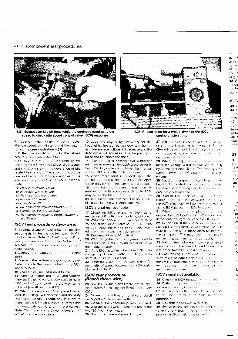
4.1 4 Component test procedures -
4.24 Squeeze an idle air hose while the engine is running at idle speed to check idle speed control valve (ISCV) response
4.25 Backpn
4 If pr,sslhle 5< lu -e79 one of the air tiuses. 13 Load the englna hy swrtching o i the I!ie rdle speerl shrl l~lr l surqe and ttlerl ret~lrr l headlights, heated rear w ~ n d r ~ w and heater too normal (see ~l lustrat ion 4.24) fan. The average vultage :v~ll decrease arld the 5 H l h r !die c o n d ~ t ~ n n rnqetq tl)+ atlove duty cycle w ~ l l Increase. The t requer~cy of c::rltt?rl.l. 11 IS III:~I~CJI.J to tje at I ~ u l t pulse should renlaln constant. 6 F,?IIIIs In OIIF! o r rr1urr-J t i t the ~ t r r n s o n the tollmt,~nq l~s l bv~ll advnr~sl y 311rr:I idle I ~ I t r q r~ ty ,
and rou ld htlng at>oul Ttw yerit.rutlor1 c~f lcile relatrd ta~ l l t r.nl-1es Trlctr+ 11~! t15 St~D~rld t ~ e cllechsd brtor17 . ~ f l c m p l r ~ - ~ q rl~;lr_ln~?s~.; d f the idle sperd c:rml~r>l dnlvr: (I!>CV) or stepper rw tu r
:<j t r i q f ~ r In?< t n t >1ca/ tclr~I1 h) I~ILLV~PL t ~~I~ I~ I I ) I> t ~ ~ ~ t r n q cj An III(~II[:~I~~ > V~L . I I L I~> / e ~ h
d ) I t J ~ l P ~ f ~ ~ f LO I+Vkl .
cj Cloogr-ri nrr h l t ~ f . 1) At) !ncor-rectly-ndllrsted throttle valve. y) Ccvhurj-tuuled throttle phte. t i ) 411 ir)correutly-adj~~sted throttle swttch or
Itlroltk pot.
ISCV test procedure (two- wire) 7 /I uoltmeter and,nr dwell rneter are suilable ~rl-lr~rrrierlt:; for te:;tlng thr: two wlre ISCV in rrlosl systems Note: A dwcll meter wtll not 91v.e puud r e s ~ ~ l t s when conncctcd to Fotd s \ sterns - a vulirrreter ur vscrlluscupc is n fi?ttr?r (:IJOICL?. 8 Connect thr: negatlve probe to an eriylrle
14 If an alr leak ur another tault I S ptesent resulting In more alr bypassirlg tt is throttle, the ISCV duty cyclc w~l l he lomer thatr tlorrrlal as the CCM pulses the ISCV Icss npcn. 15 When rnore load 1s plar:ed u p o i thc engine, the FCM pulses the ISCV rrlure uperl (larger duty cyclc) tn Increase the idle speed. 16 I r l addlitor) ~f the enqrnc 1s rncchnl~~r;l l ly r~nso~ lnd or the lhrottle valve 1s d~rt:, thf ECM may p:rlcc the ISCV more t i py r~ I(> irlcrerlse the ~ d l e spevrl T h ~ s may resLllt In :irl 1I.IPven ~ d l e arid a t t ~ a r ~ r~c~rrri;~l <I<II,,{ ryc,lr
ISCV signal not available 17 Check the ISCV ~res~s!arir-e [ yp~r_,~l ly, 2
res~star~ce of P to 16 nhms sha~~ l r l he ~ t ~ f Irrwd 18 With the i g n ~ t ~ u r i un check !or b?t t t7ry voltngr: nt thr: S I J ~ P I Y T P I I ~ ~ I I I R I If ll)rrr IS r ~ c l
voltage, trace I h r ~ V I I lna bark to l h r . Inaln relay or iqnltlori swbl~di ;I? dp[?r(.rl,r~ale 19 D~scur~r lecl the ISI:V rnllltl p l ~ i g 20 With the ~gnlt lvn on. LIW 3 j u ~ ~ ~ p e r 14-36 to very krlefly tuuch l h ~ = aclLl3tor pin 117 thr- I X V rr~rlltl-plug to nnrtli 21 If the 1SCV a d ~ ~ ~ i l e : : ch%k lhc, EKFJ m a n voltaqe suppl~es and e;lnT~% H Iest~rlq rt:veals
t.srth no fault, ttle ECM 1s su~pec t . 9 Cilr~rlri:t the voltmctcr posltlve or dwell 22 I f the l S C ~ do(+, actuale, ctle,;k fur rrieter p r ~ t l e lo the wlre attached to the ISCV ,,nti,,llitv wirl,lu between the IS(;V ~llllltl. .. . - -2 - ‘ ~ I L C ~ ~ ~ I terr~l~rlal, p l i ~ g and thc FCM. 10 .C,l,jrl It)? erigrrle and alluw ~t to Idle. 11 Wrth l\lr enqIIrP t t ~ ) t . ;I varylrlg voltagr: lSCV test procedure hrlwepn 7 11 l o 0 volts, a duly cycle ~t 40 to (BOSC~ three-wire) ~ l 4 ~ % , and n f ~ ~ q l l f i l ~ y of I1U ?re I~kvly to he obta~ned (see i l lustrat~on 4.25) 12 Wt,erl the erlqlne 17 r~ i r l nr pl;lr.srl LJndfY load. Ihe vullage w ~ l l decrease and thr: duty cycle will Increase. F requenrv 15 Ihkely tn rclnaln statjle for rriust Idle c~>nt~cr l valves lth? f reql~ency will ~ ~ s ~ ~ a l l y al l r r 111 I L Y ~ v,jlves! Note: Thc rcndtng otl a d1~11t,7/ \ ~d tn l r te r ~vrtl ~rrdtcate thc nvorngr! voltngr
23 A vultrrwt'r 2nd a dwcll mnter nre SI rtahte 1nstrurntwt5 firr testlng l t le Busct! ttlrech-w~re ISCV 24 Canner,t tt lrT voltmeter nerjative or dwell meter probe to ari erlyirle earth 25 (:onn17ct Itlr voltmeter pus~t ive clr dwell rnzler prube to tile wlre attnchcd to onr: nf the two ISCV slgn;ll terrnltrals. 26 Start thp rng l i l r and allow ~t to ~d l s .
3bing lor a typlcal dwell at the ISCV. engine at Idle speed
27 fl1)t.n it i? enplne 15 TI( ,l :I ,::I jsr;( , t l ,'I<<
or a duly c\.ile u i rlthr5r 3[ i~>tO>~rl1,H.~I , ; 1 . :.I
69% ~ ? 1 I 1 bc vht,~lnrr l Thr r l . l t j ,I b . . .I ,.,,I .:#: WI I I d e p c ~ i d I J ~ > ~ > I - I ~~,~II-I~,-II . . - ~ I ~ I I ~ I , ~ ~ 1 1 -
i r l s f rum~nl 17 cg1inr.r t ~ j
28 W h ~ n lhf: crlqll I(- I' s-r,l~: I ,I 11 I. t :! 1,:1;:t.
had, the vnllsq? $,,:I rli:cfc;lsr ;,ic th :~ :I .I) cycle w ~ l l I ~ L ~ E ~ S F : Note: T ~ P !ra, - ! ,~;g , : - 2
d tg~ ta l \ o/T/)-tet~?r v/lC! II?(?I~:~?:~ :!yts 1 1 ?!<!$?
voltage 29 Load t l w cnqlnn by s\*;~:rtl~vrl ? r 8
he;lrll~qhts, hcrltrcj rc,ir r~,~r~rrc)i:. . j r~ , l ' , z z t t ~ tall The nvcwgr volt~r!r: w ~ l l :I t . ( I.,.~:.I. , : r l , : 'he duty cyclr: w~ l l Inrrensp 30 I f an nlr lnak nr nnott,r't f , ~ . ~ ! t :, l:rrl<+'-! 1t.sult113q In 17)nrr nlr t-~~n;l<,.;l~r~~l ltlr, 1!11,1:i t. the ISCV dhty cyclr nclll 1)s Ioiwf~r i m i , i r l S , < . ~ I ~ . : I ~
a5 the ECM pulses tlii: ISI;V 11:v; i j l > t > r i
31 When more load 1s pla\.nil ~.;:::rl tit
erlgirle the ECM pillscr, t h r IS<:\: ,n:11+ ,q:er (larger duty cycle) to Iricri.nxr: +h~-, ~ r l l , ~ !;l~r+&! 32 In . -~ i l d~ t~nn . ~f t k r : i.nglnr I:, ::lt>r 'I,I~II:,I I,, unr;~3\1nil tor Ihc thrclttlr bi1lvp I.; r l l~t;. t t ~ r I <'I.* n l t l y p11l:;t~ the ISCV r)ir)rt> q ) + r ~ 1:) I;IL,Y:IW+
lnt3 ( L I I ~ ~ ql>uxc(c T l i ~ ? 1mLly r t ~ * < ~ l I ' 1 1 ,111 L ~ r ~ t : b A ~
I C ~ I P AI?,~? .> l.lr+?r tt~1r1 r iorrr ik j ' t lh~l~ c?c,l:, 33 5wltr.i: t l l t o imr,ltn~etrr [ : r j . ; ~ t ~ h t . t;r I::>,:; mlCti:( r>tr>I-l? lh the? vilre < ~ t i ~ > r J I ~ L I 1 % ) I!I~- \>. ! ,?
one of the two IS(;\/ :~:jrl 1 1 t r j r r ~ l r1.1':-
34 With the englltr: Ihr l . ;I .l.ir; ' r l . I ~ . ~ , l t . l ~ I- 1 1 . . duty cycle nf nrtlicr , > l - l p c , , l r ' l . ~ t ' , l , .I, 1 " .
69% w ~ l l br: nhtn~t icd The 11111; , , I I- ot. I.il81-I
wtll d e p e ~ ~ d Idpnti wti11-I- ~ P I I I ~ I . I I 4 h ~ f
Instrument is cotiripctno
ISCV signal not available
35 Check the I S ( X rr:s~stani., I,:I.I, l > t , : ( s , ; .
36 I l l ~ t h the Iqnrttnli 011, I-I?,,I I> ' 1 . 1 t , . ~ ' ' + . voltage at the suppl',: t e r ~ i ~ t i n l 37 I f there IS no vultaqt: tr;lr,. th, , Y, t lm7v> I: -1, I
to the rrlalrl relay 01- 1qrl1111:n 5\;,:.,1 :I(
apprupr~ate 38 U~sconrle(:t thr: lS(:V ~nu l i l 11l11g 39 Sw~tch 01) the IqnltlcI). IJT-I' .1 1 1 l - r [ ) ; I r . I
tu very br~etly tuuck, onc n? 1111 . 1,,,.,-, -I: ' 1 I;I'~-,~
plrls In the ISCV m t ~ l t ~ plucl t{> 1'2tT l1
43 F 44 C terrn resis 45 1 cent I .."-
two ohn
St:. 47 rTio tesl d r r " A ! I ( . , , .
'11
48 ttit- thr ~t (3 1; Id!: 1UI \ t T l
49 1111
st1
0 1
\'I
t c <
I)!
:I . 11
51

. -. . . .
Component test procedures 4.1 5
I 10 If the ISCV actuates, check the ECM man approximately 5 to 10% should be obtained. If voltage suppl~es and earths. If testing reveals 30 the dwell meter can measure the value ~n no fault, the ECM IS suspect. m i l l i ~ o n d s , th~s could be even more useful. 41 If the ISCV does not actuate, check for continu~ty of wiring between the fSCV muiti- plbg and the ECM 42 Switch the jumper lead to very briefly touch the other ISCV actuator pin in the ISCV multi-plug to earth. Evaluate the results as in pxagraphs 40 and 41 above.
lSCV resistance (three- wire) 4l Remove the tSCV multi-plug. 44 Connect an ohmmeter between the centre terminal and one of the outer terminals. A resistance of 20 ohms should be obtained. 45 Reconnect the ohmmeter between the csntre terminal and the other outer ISCV terrr,\nal. A resistance of 20 ohms should be obta~ned. 46 Reconnect the ohmmeter between the two outer ISCV term~nals. A resistance of 20 ohms should be obta~ned.
Stepper motors 47 A number of different types 0 1 stepper motor are usad in motor veh~cles. Spec~fjc test procediires for a number of popular types are detailed In the Haynes companion volume "Automotive Engine Management and Fuel lnject~on Syslems Manual". 48 A sw~tch is somalimes incorporated into the stepper motor assembly Refer to the throttle swltch tests tor a general description of earth and supply tests. ldle switch operallon IS particularly important for good idle qual~ly. H the ECM does not recognlse the Idle condillon, ldle control cannot be rmplementsd. 40 The typical stepper molor employs two motor windings. The ECM positions the stepper motor by energising the windings in one direction and then the reverse. A voltmeter or oscilloscope could be used to test for a stepper motor signal. However, atthough a signal can usually be obtained on all of the motor terminals, the signal is fleeting and will only be generated as the motor winding is actuated. 50 Check the resistance of both windings and compare to the vehicle specifications. Values are usually under 100 ohms.
W/Audi idle control motors
- ,
, ,
1 Check for corrosion in the connection plugs between the relay and the injector, and the ECM and the injector. Corrosion in connection plugs is a common reason for poor Injector performance. 2 Connect the dwell meter negatlve probe lo an engine earth. 3 Identify the supply and signal Isrminals. Note: An injector dwell reading will only be obtained upon the signal terrnmnal which is the wire connecting the injector to the ECM If you cannot obtain a reading, reconnect the probe to the other terminal and retry. 4 Connect the dwell meter positive probe to the wlre attached to the injector signal terminal. 5 Although the following tests are accomplished with the aid of a basic dwell meter, an osc~lloscope is a more suitable lnstrurnent far analysing the signals generated by the electronic fuel injector circuits. B Initially, the probe can be connected to the signal term~nal of any one of the injectors.
Current-controlled or peak-and-hold injection circuits (dwell meter) 7 When the injector IS of the current- controlled ktnd, very few dwell meters may be capable of reg~stering the second stage of the pulse duration. The meter may only register the swrtch-on citcuit of approximately 1.0 or 2.0%. Thls means that the injector duty cycle readlng will be inaccurate and not representative of the total pulse width seen in the circurt. Only a small number of DMMs can actually measure this circuit satisfactorily.
Engine non-nmmer test procedu~es 8 Crank the engine. B A duty cycle reading (injector duty cycle) of
Good injector signal 10 Check for an injector pulse on the other injectors. 11 If the rnjector signal is satisfactory and if the primary ignition signal is also providing an acceptable signal, the fault IS unlikely to be related to the ECM.
Poor or no injector signal on one or more injectan Note: In some Motronic systems, the frequency o f injection increases for several seconds during inifial ci-ankino. 12 Check the fuel pressure and fuel flow. 13 Check the primary trlgger (crank angle sensor or Hall-effect sensor) for a good signal. 14 Check the voltage at the signal terminal of the injector multi-plug. Battery voltage should be obtained. 15 If there is no voltage, check the injector resistance and the injector voltage supply. 16 Disconnect the ECM multi-plug.
A Warning: Refer to Warning No 3 (in the Reference Section at the end of this book) before dis- connecting the ECM multi-plug.
17 Switch on the ignition. 18 Use a jumper lead to very briefly touch each one of the injector actuator pins In the ECM muhi-plug to earth (see illustration 4.26). 19 If the injector actuates, check the ECM main voltage supplies and earth's. If tests reveal no fault, the ECM is suspect. 20 If the injector does not actuate, check for battery voltage at the ECM pin. If voltage is present, the injector is suspect. If there is no voltage, check for continuity of wiring between the injector multi-plugs and the ECM multi-plug. 21 If the injector circuit is banked or sequential, individually check each connection to the ECM.
ECM multiplug
51 The type of control motor fitted to many current VWlAudi vehicles incorporates a reversible stepper motor winding, a Hall sensor that s~gnais the stepper motor postion, a TPS, and an idle switch. An 8- terminal multi-plug connects the motor to the wiring loom. The component parts that make up the control motor can be tested by referring to the test procedures described under the headings for individual 4.26 Using a jumper lead to very briefly touch an injector actuator pin in the components. ECM muHi-plug to earth
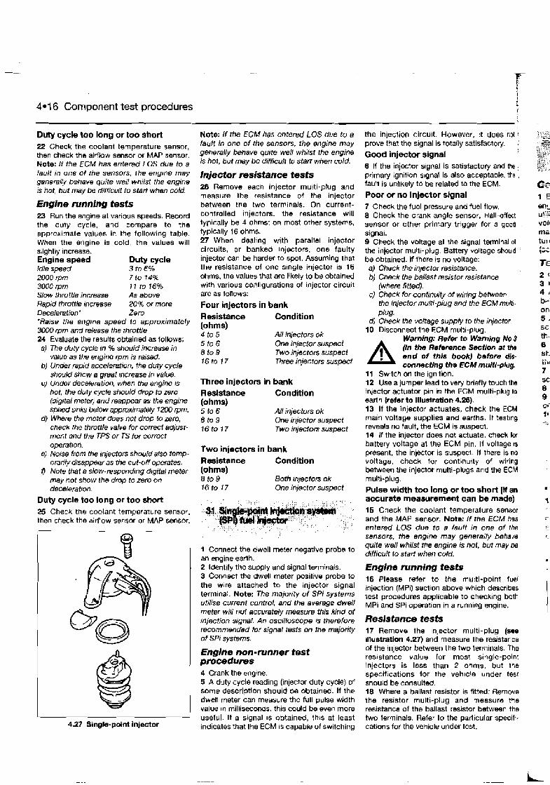
4.1 6 Component test procedures
Duty cycle too long or too short 22 Check the coolant temperature sensor, then check the airflow sensor or MAP sensor. Note: I f the ECM has entered LOS due to a fault in on8 of the sensors, the engine may generally behave quite well whilst the engine is hot, but may be difficult to start when cold.
Engine nrnning tests 23 Run the engine at various speeds. Record the duly cycle, and compare to the approx~mats values in the following table. When the engine is cold, the values will slightly increase. Engine speed Duty cycle Idle speed 3 t06% 2000 ~ p m 7 to 74% 3000 rpm I I to 16% Slow throttle jncreasa As above Hslpid throttle jvcmse 20% or more Deceleration' Zem *Raise the engrne speed to approximately 30W rpm and release the rhrottle 24 Evaluate the resu!h obtained as follows; a) The duty cycle in % should increase in
value as the engine rpm is raised. b) Under rapid acceleration, the duty cycle
should show a great ncreas in value. c) Under deceleration, when the engine ts
hot, the duty cycle should drop to zero (digital met@ and reappear as the engine speed smks below wroximate4y 1200 rpm.
d) Where the meter does not drop to zero, check the throttle valve for correct adjust- ment and the TPS or TS for correct operatiofl.
e) Noise from the injectors should also temp- orarily dtsappeer as the cut-OIY operates.
f ) Note that a slow-respwding drgital meter may not show ihe drop to zero on deceleration.
Duty cycle too long or too short 25 Check the coolant temperature sensor, then check the airtlow sensor or MAP sensor.
4.27 Single-point injector
Note: If the ECM has entered LOS due to a fault in one of the sensors, ihe engine may generally behave quite well whilst the engine is hot, but may be difficult to Stat? when cold.
Injector msistance tests 28 Remove eacn injector multi-plug and measure the resistance of the injector between the two term~nals. On current- controlled injectors, the resistance will typically be 4 ohms: on most other systems, typically 1 6 ohms. 27 Whwn dealing with parallel injector circuits, or banked ~njectors, one faulty injector can be harder to spot. Assuming that the resistance of one slngle injector is 16 ohms, the values that are likely to be obtained w~th various configurations of injector circuit are as follows:
Four injectors in bank Resistance Condition (ohms) 4 to 5 All injectom ok 5 to 6 One injector suspect 8 to9 Two injectors suspect 16to 17 Three injectors suspeci
Three injectors in bank Resistance Condition (ohms) 5 10 6 AN itljectors ok 8to9 One injector suspect 16to 17 Two injectors suspect
Two injectors in bank Resistance Condition (ohms) 8 to 9 Both inlectors ok 16to 17 One injector suspect
1 Connect the dwell mebr negative probe to an engine earth. 2 Identify the supply and signal terminals. 3 Connect the dwell meter positive probe to the wlre attached to the Injector signal terminal. Note: The majority of SPi systems utilise current control, and the average dwell meter will not accurately measure this kind of injection signd An oscilloscope I S therefore recommended for signal tests on the majority of SPt sys&rns.
Englne non-runner test procedums 4 Crank the engtne. 5 A duty cycle reading (injector duty cycle) of some description should be obtained. If the dwell meter can measure the full pulse width value in milliseconds, this could be even more useful. If a signal IS obtained, this at least indicates that the ECM is capable of switching
the injection circuit. However, ~t does not t
prove that the signal is totally satisfactoty. : Good injector signal 6 If the injeHor signal is satisfactory and the : primary ignition slgnal is also acceptable, tho . fault is unhkely to be related to the ECM.
Poor or no injector signal 7 Check the fuel pressure and fuel flow. 8 Check the crank angle sensor, Hall-effect sensor or other primary trigger for a good . signal. 9 Check tho voltage at the signal terminal 01 the injwtor rnultl-plug. Battery voltage should ,
be obtained. If there is no voltage: a) Check the injector resistance. b) Chmk the ballast msistor resistance
(where fitted). c) Check for continuity of wiring between
the injector multi-plug and the ECM multi- PIUS.
d) Check the voltage supply to the injector. 10 Dbsconnect the ECM multi-plug.
Warning: Refer to Warning No 9
A (in the Reference Sectlon at the end of this book) bsfom dis- connecting the ECM mulii-plug.
11 Switch on the ignition. 12 Use a jumper lead to very briefly touch Ihe inlector actuator pln In the ECM multi-plug to earth {refer to illustration 4.26). 13 If the injector actuates, check the ECM main voltage supplies and earlhs. If testing reveals no fault, the ECM is suspect. 14 If the injector does not actuate, check lw battery voltage at the ECM pin. If voltage 1s present, the injector is suspect. If there is no voltage, check for continuity of wiring between the injector multi-plugs and the ECM multi-plug. Pulse width too long or too short (if an accurate measurement can be made) 15 Check ths coolant temperature sensor and the MAP sensor. Note: If the ECM has entered LOS due to a fault in one of the sensors, the engine may generally behave quite we// whilst the engine is hot, but may be difficult to start when cold.
Engine nrnning tests 16 Please refer to the multi-point fuel injection (MPi) secllon above which descr~bes rest procedures applicable to checklng both MPi and SPi operation in a running engine.
Resistance tests 17 Remove the injector multi-plug (see illustration 4.27) and measure the resistance of the injector between the two terminals. The resistance value for most single-point injectors is less than 2 ohms, but the specil~cations for the vehicle under test should be consulted. 18 Where a ballast resistor is fitted: Remove the resistor multi-plug and measure the resistance of the ballast resistor between the h o lerminals. Refer to the particular specifi- cations for the vehicle under test.
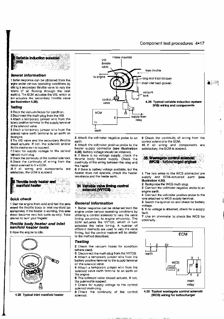
Component test procedures 4.1 7
1 General information t Better response can be obtained from the wine under various operating conditions by utilslng a secondary throttle valve to vary the volume of air flowing through the inlet manifold. The ECM actuates the VIS, which in hrrn actuates the secondary throttle valve
illustretion 4.28).
: resting 2 Check the vacuum hoses for condrhon. B Disconnect the multi-plug from the VIS. I Attach a temporary jumper wlre from the kttey positive terrnlnal to the supply termrnal on the solenoid valve. 6 Attach a temporary jumper w~re from the solenoid valve earth terrn~nal to an earth on the engine. 6 The VIS valve and the secondary throttle should actuate. If not, the solenoid and/or throttle mechanlsm is suspect. J Check for supply voltage to the control solenoid rnultl-plug. 8 Check the contrnuity ot the control solenoid. Q Check the continu~ty of wlrrng from the control solenoid to the ECM. 10 If all wlring and components are disfactory, the ECM is suspect.
1 Start the englne from cold and feel the area around the throttle body or inlet manifold (as agpmpriate). If the heater is working, this area ahould become very hot quite quickly. Take care not to burn your fingers1
nlmttle body heater and inlet menifold heater tests 2 Allow the englne to idle.
I 4.29 Typical inlet manifold heater
Intake manltold
long inlet tract (torque)
short lnlet tract (power)
4.28 Typical variable induetlon aystarn PIS) wiring and componatrts
earth
3 Attach the voltmeter negative probe to an earth. 4 Attach the voltmeter positive probe to the heater supply connector (see illustration 4.29); batterj voltage should be obtained. 5 If there is no vottage supply, check the throttle body heater supply. Check the continuity of the wiring between the relay and th8 heatw. 6 If there is battery voltage available. but the heater does no1 operate, chock the heater resistance and the heater earth.
General infomation 1 Better response can be obtained from the engine under various operating conditions by utilising a control solenoid to vary the valve timing according to engine elflciency. The ECM actuates the W C S , which in turn actuates the valve timing. A number of different methods are used to vary the valve timing, but the control method will be similar to the method described.
2 Check the vacuum hoses for condition (where used). 3 Disconnect the multi-plug from the VVTCS. 4 Attach a temporary jumper wire from the batley positive terrn~nal to the supply terminal on the solenoid valve. 5 Attach a temporary jumper wire from the solenoid valve earth term~nal to an earth on the 8ngir.e. 6 The solenoid valve should actuate. If not, the solenoid is suspect. 7 Check tor supply voltage to the control solenold multi-plug. 8 Check the continu~ty of the control solenord.
9 Check the continuity of wlrlng from the control solenoid to the ECM. 10 If all wrring and components are satisfactory, the ECM is suspect.
1 The two wires to the WCS connector are supply and ECM-actuated earth (we Illustration 4.30). 2 Backprobe the WCS multi-plug. 3 Connect the voltmeter negative p r o h to an engine earth. 4 Connect the voltmeter positive probe to the wire attached to WCS supply terminal. 5 Switch the ignit~on on and check for battery voltage. 6 If no voltage is obtarned, check for a suppty fault. 7 Use an ohmmeter to check the WCS for continuity.
ECM
1 2 22
t T 1 earth
WCS
5
main relay
4.30 Typical wastegate control wlenoid WCS) wiring for turbochaqer

4.1 8 Component test procedures
ECM and fuel system test procedures c) P 1 c
36 ECM faults
1 When a fault code IS generated that suggests an ECM fault, the following procedures should first be followed before the ECM IS replaced. 2 Check the ECM earth, voltage supplies and relays as described below. 3 Where possible, try a substitute ECM (known good un~t) and check that the fault code does not reappear.
37 ECM vottage supplies and earths
1 Inspect
Warning: Refer to Warning No 3 fin the Reference Section at the end of this book) before dis- connecting the ECM multi-plug. the ECM multl-plug for corrosion
and damage. 2 Check that the terminals In the ECM rnultl- plug are fully pushed home and making good contact with the ECM plns. Note: Poor contact and corrosron are common reasons for maccurate signals from the ECM. 3 Voltage supplies and earths are best measured at the ECM mutli-plug Use one 01 these test methods. a) Peel back the ECM multi-plug insulation
(not always pmsrble) and backprobe the ECM multr-plug pms.
bJ Attach a break-our box (BOB) between the ECM and rls mulir-plug, and probe the box for voltages.
c) Detach the ECM from rts mulfr-plug, and probe lor voltages at the rnultl-plug pms.
4 Attach the voltmeter negatlve probe to an englne eanh lor the ECM connected tests. 5 ldent~fy Ihe varlous lypes of connection and the relevant ECM plns from a wlring diagram for the vehlcle In question. Note: Not all of Ihe folrow~ng connectrons W I N be avarlable In any particular system.
ECM battery supply pin 6 This pin is d~rectly connected to the battery i+) lerrnlnal, and a constant vollage should be ava~lable at all times, even wbth Ihe lgnltlon key off. 7 W~th Ihe ECM multi-plug connecled: a) Backprobe the relevant ECM ptn - nominal
battery voltage should be obta~ned I f vollags 1s low or non-exfslent, check the battery condrtton and supply arcutt.
bJ Slan 1.k engrne and raise ttle erlg~ne speed to 2500 rpm Ensure that the voltage r~ses to betwesn 13.0 and 15.0 r,olts (refer to vehrcle spew frcstrons). Check the alternator r f the voltage remains 10rv
8 With the ECM multi-plug disconnected: a) Attach the voltmeter negative probe to an
ECM earth pin. 6) Attach the voltmeter positive probe to the
relevant ECM pin - norninal battery voltage should be obtained. I f voltage is low or non-existent, check the battety condition and supply circuit.
cJ Sfarf the engine and raise the engine speed to 2500 rprn. Ensure that the voltage rises to between 13.0 and 7 5.0 volts (refer to vehicle specifications). C k k the alternator i f the voltage remains low.
ECM cranking supply pin 9 This pin is connected to the ignition switch starter terminal, and a battety voltage will only be available during engine cranking. 10 With the ECM multi-plug connected: a) Backprobe the relevant ECM pin. b) Crank the engine on the starter - battery
voltage should only be obtained during cmnking.
11 With the ECM multi-plug disconnected: a) Attach the voltmeter negative probe to an
ECM earth pin. b) Attach the voltmeter positive probe to the
relevant ECM pin c) Crank the engine on the starter - battety
voltage should only be obtained during cranking.
12 In either case, if there is no voltage or the voltage is low, check the starter motor or the supply back to the ~gn~t ion switch starter terminal.
ECM suppry from the ignition switch 13 This pln is connected to the rgn~tlon switch, and voltage shoutd be available at all tlrnes whllst the lgnlt~on is switched on or the englne is running 14 With the ECM multi-plug connected: a) Backpmbe the relevant ECM pin. 61 Switch on the ignrtton - nomrnal battery
vollage should be obtarned. I f the voltage rs low or non-existent, check the battew condttton and supply circutt
c) Start lhs engine and raise the engrne speed to 2500 rpm. Ensure that the voltage nses to between 13 0 and 15.0 volts (refer io vehicle spec~ficalrons). Chech ?he alternator it the voltage remains low.
15 W~th the ECM multl-plug drsconoected' a) Altach the volirnetef negattve probe to an
ECM earth pm. b) Altach the voltmeterpos~ttve probe to the
relevant ECM ptn. c) Swttch on the rgnrtron - nom~nal battery
voltage should be obtarned. I f the voltage IS low or non-eastent, check the battery cond~t~on and supply crrcult.
dl Start the engrne and rarse the engine speed lo 2500 rpm. Ensure that the voltage nses to between 13 0 and 15.0 volts (refer to vehrcle specrfrcabons)
Check the alternator if the voltage remains
low. ! ECM supply from the main system relay 16 This pin is connected to the main relay.; and voltage should be available at all times; whilst the ignition is switched on or the englnti is running. This supply may be made to mote i, than one ECM pin. 17 With the ECM multi-plug connected, a) Backprobe the relevant ECM pin. b) Switch on the ignrtron - nominal battery
voltage should be obtatned. I f the voltage is low or non-existent, check the battev condition and supply crrcutt back to the main system relay. Also check the relay ~tself.
c) Start the engine and raise the engrne ,
speed to 2500 rpm. Ensure that the voltage rises to between 13.0 and 15.0 ,
volts (refer to vehrcle specrfications) Check the alternator i f the voltage remains low ,
18 With the ECM multi-plug disconnected: a) Attach the voltmeter negattve probe to an :
ECM earth pin. b) Attach the voltmeter positive probe to the
relevant ECM pin. c) Switch on the ignition - nominal battery
voltage should be obtained I f the voltage is low or non-existent, check the baffery condition and supply circurt back to the main system relay. Also check the relay
,
itself. d) Stari the engine and raise the engtne ,
speed to 2550 rpm. Ensure that the voltage nses to between 13.0 and 15.0 volts (refer to vehicle specifications). Check the alternator if the voltage remains low.
ECM earth connections 19 Wlth the ECM multl-plug connected, a) Switch on the ignrtron. b) Atfach the voltmeter negative probe to an
engine earth. c) Attach the voltmeterposrtrve probe to the
earth terminal under test - the voltmeter should rndrcate 0 25 volts rnaxrrnum
20 W~th the ECM multi-plug dlsconrr&c:eil (Ignition on or om: al Attach the vo:tmeter negative probe to
the earth termtnal under test. b) Anach the voltmeter positive probe to the
ECM battery supply or dtrectly to the battery postttve temtnal - the voltmeter should indicate battery voltage i f the earth is satrslac tory.
ECM coding earth pins Note: The codtng ptns are used to code the ECM for certain vehicle configurations (some systems only). 21 W~th the ECM multl-plug connected: a) Switch on the ignition. 6) Attach the voltmeter negatrve probe to an
engine earth
22 1
the win* 23 EC! teui'
w: 24 25 mai po: obt rel: 26 d rc an1 the 27 thr ch CC
SA
dc re: re'
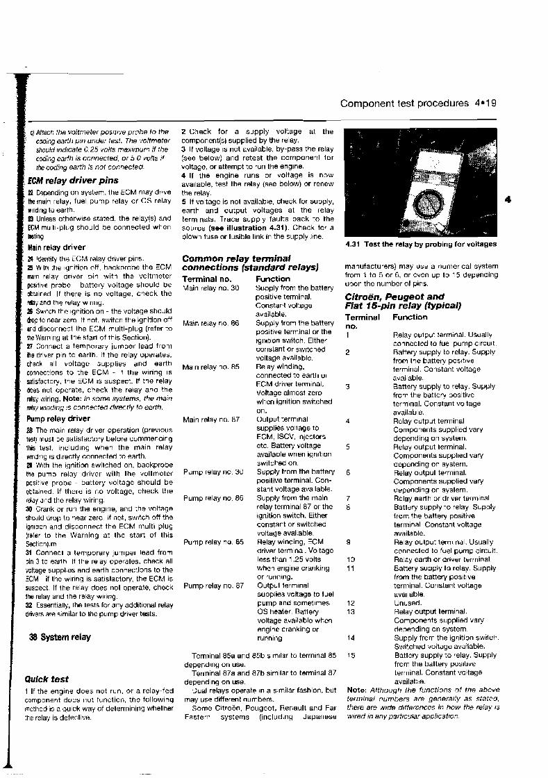
c) Attach the voltmeter posrfrve prabe lo the coding earth pin under lest. The voltmeter should indicate 0.25 volts maximum if the cw'ing earth is connected, or 5.0 volls rf the coding earth is nol connectedl
, ECM relay driver pins I PZ Depending on system, the ECM may dr~ve 1 tk main relay. fuel pump ralay ar OS relay r wind~ng to earth. I Unless otherwise stated, the relay($) and ' ECM multi-plug should be connected when : btlng.
, Main relay driver 24 Identify the EGM relay driver pins. 25 W~th the ignition off, backprobe the ECM marn relay drlver pin with the voltmeter positlve probe - battery voltage should be obta~ned If there is no voltage, check the relay and ths relay wlrlng. 18 Switch the ignition on - the voltage should drop to near zero. If not, switch the ignition off and disconnect the ECM multi-plug (refer to
I the Warning at the start of this Section). 27 Connect a temporary jumper lead from Re driver pin to earth. If the relay operates.
I check all voltaye supplies and earth / connections to the ECM - if the wring IS
; satisfactory, the ECM I S suspect. If the relay r does not operate, check the rekay and the - why wiring. Note: In some systems, the marn
d a y winding IS connected drrectly to earth.
Pump relay driver 28 The main relay dr~ver operatior1 (prev~ou~ test) must be satisfactory before cornmenclng
' this lest. ~nclud~ng when the main relay wrnd!ng IS d~rectly connected to earth. B With the ignition switched on, backprobe the pump relay driver with the voltmeter pos~t~ve probe - battery voltage should be obtarnsd. If there is no voltage, check the relay and the relay wiring. XI Crank or run the englne, and the voltage should drop to near zero. Lf not, sw~tch off the ignlt~on and disconnect the ECM multi-plug (refer to the Warning at the start of this Section).m 31 Connect a temporary jumper lead from pin 3 to earlh If lhe relay operates, check all voltage suppl~as and earlh connections to the ECM - if the wlrlng 1s satistactory, the ECM is suspect. If the relay does no1 operate, check !he relay and Ihe relay wlrlng. SZ Essentially, Ihe lests for any add~tlonal relay drivers are sim~lar to ?he pump dr~ver tests.
Quick tesf 1 If the engine does not run, or a relay-fed component does not function, the follow~ng method is a quick way of determining whelher the relay is defective.
Component test procedures 4.1 9
2 Eheck for a supply voltage at the componentIs) supplied by the relay. 3 I f voltage 1s not available, by-pass the relay (see below) and retest the component lor voltage, or attempt to run the englne. 4 If the engine runs or voltage is now ava~lable, test the relay (see below) or renew the relay. 5 If voltage is not available, check for supply, earth and output voltages at the relay term~nats. Trace supply faults back to the source (see illustration 4.31). Check tor a blown fuse or fusible link in the supply Irne.
4.31 Test the relay by probing for voltages
Common relay terminal connections (standard relays) Terminal no. Main relay no. 30
Ma~n relay no. 86
Ma~n relay no. 85
Main relay no. 87
Pump relay no 30
Pump relay no. 86
Pump relay no. 85
Pump relay no. 87
Function Supply from the battery positive terminal. Constant voltage available. Supply from the battery posltlve terminal or the tgn~tion switch. Either constant or sw~tched voltage available. Relay winding, connected to earlh or ECM driver tsminal. Voltage almost zero when ignition switched on. Output term~nal supplies voltage to ECM, ISCV, lnlectors etc. Battery voltage available when Ignition switched on. Supply from the battery positive terminal. Con- stant voltage ava~lable. Supply from the main relay terminal 87 or the ignition switch. Either constant or switched voltage avaitable. Relay winding, ECM driver terminal. Voltage less than 1.25 volts when engine cranking or running. Output terminal supplies voltage to fuel pump and sornet~mes OS healer. Batiery voltage available when engine cranking w runnlng
Terminal 85a and 85b similar to terminal 85 depending on use.
Terminal 87a and 87b s~m~lar to terminal 87 depending on use.
Dual relays operate In a similar fashion, but lnay use d~fferent numbers.
Some Citroen. Peugeot, Renault and Far Eastern systems (including Japanese
manufacturers) may use a numerical system from 1 to 5 or 6, or even up to 15 depending upon the number of pins.
Citroen, Peugeot and Fiat 15-pin relay (typical) Terminal Function no. 1 Relay oulput ?atminal. Usl~ally
connected to fuel pump clrcult 2 Battery supply to relay. Supply
from the banery positive terminal. Constant voltage available.
3 Battey supply to relay. Supply from the battery positive terminal. Constant voltage available.
4 Relay output terminal. Components supplied vary depending on system.
5 Relay output terminal. Components suppl~ed vary depending on system.
6 Relay output terminal. Components supplied vary depending on system.
7 Relay earth or drlv~r terminal. 8 Batlery silpply to relay. Supply
from the baitery positive tsrrninal. Constant voltage available.
9 Relay oulput terminal. Usually connected to fuel pump circuit.
10 Re!ay earth or driver terminal. 11 Battery supply to relay. Supply
from the battery posltlve terminal. Constant voltage ava~lable.
12 Unused. 13 Relay output terminal.
Components supplied vary depending on system.
14 Supply from the ignition swilch Switched voltage available.
15 Battery supply to relay. Supply from the battery positive terminal. Constant voltage available.
Note: Although the functions of the abc& terminaf numbers are generally as s:ated, there are w ~ d e differences in how the relay rs wired In any partrcular applrcatior:
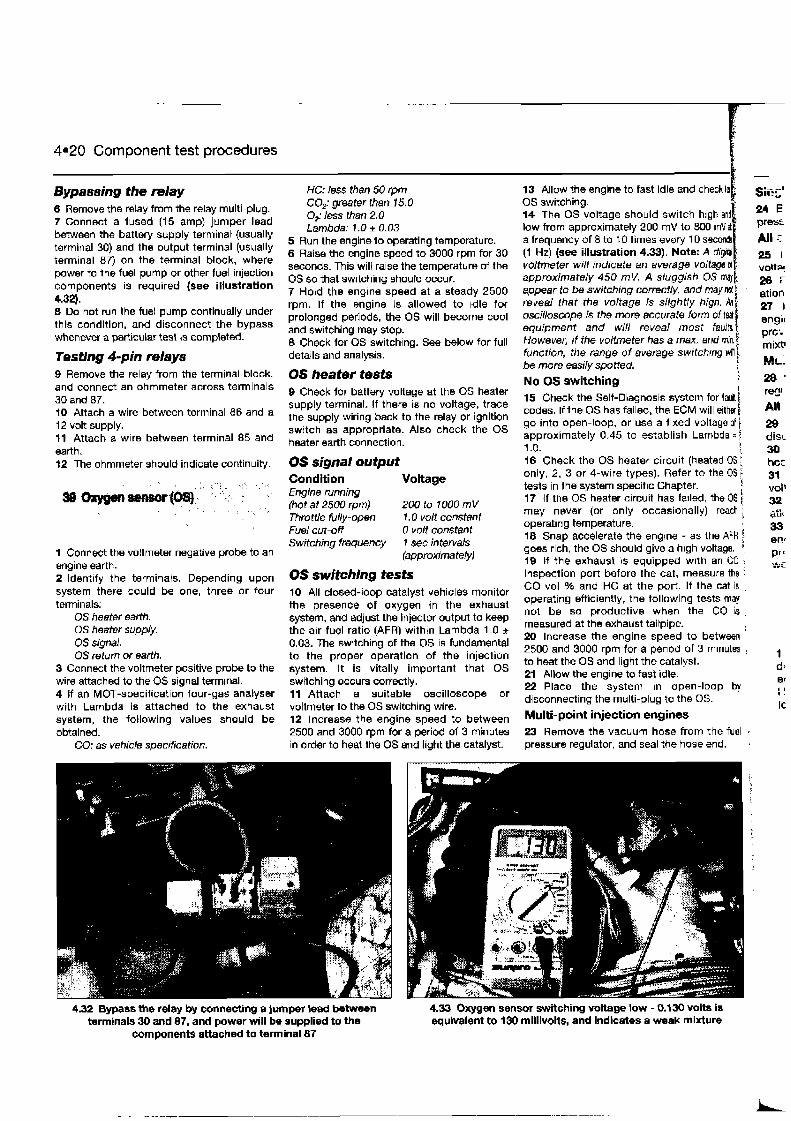
4.20 Component test procedures
Bypassing the relay 6 Remove the relay from the relay multi-plug. 7 Connect a fused (15 amp) jumper lead between the battery supply terminal (usually terminal 30) and the output terminal (usually terminal 87) on the terminal block, where power to the fuel pump or other fuel injection components is required (see illustration 4.32). 8 Do not run the fuel pump continually under this condition, and disconnect the bypass whenever a particular test is completd.
Testing 4-pin relays 9 Remove the relay from the terminal block, and connect an ohmmeter across terminals 30 and 87. 10 Attach a wire between terminal 86 and a 12 volt supply. 11 Attach a wire between terminal 85 and earth. 12 The ohmmeter should indicate continuity.
1 Connect the voltmeter negative probe to an engine earth. 2 Identify the terminals. Depending upon system there could be one, three or four terminals:
OS heater earth. OS heater supply. 0s signal. OS return or earth.
3 Connect the voltmeter positive probe to the wire attached to the OS signal terminal. 4 If an MOT-specification four-gas analyser with Lambda is attached to the exhaust system, the following values should be
HC: less than 50 rprn CO; greater than 15.0 0; less than 2.0 Lambda: 1.0 i 0.03
5 Run the engine to operating temperature. 6 Raise the engine speed to 3000 rprn for 30 seconds. This will raise the temperature of the OS so that swrtchinq should occur. 7 Hold the engine speed at a steady 2500 rpm. If the engine is allowed to tdle for prolonged periods, the OS will become cool and switching may stop. 8 Check for OS switching. See below for full details and analysis.
OS heater tests 9 Check for battery voltage at the OS heater supply terminal. If there is no voltage, trace the supply wiring back to the relay or ignition switch as appropriate. Also check the OS heater earth connection.
OS signal output Condition Voltage Engine running (hot at 2500 rpm) 200 to 1000 mV Throttle fully-open 1.0 volt constant Fuel cut-off 0 volt constant Switching frequency 1 sec intewds
(approximately~
0s switching tests 10 All closed-loop catalyst vehicles monitor the presence of oxygen in the exhaust system, and adjust the Injector output to keep the air-fuel ratio (AFR) within Lambda 1.0 * 0.03. The switching of the OS is fundamental to the proper operation of the injection system. It is vitally important that OS switching occurs correctly. t l Attach a suitable oscilloscope or voltmeter to the OS switching wire. 12 Increase the engine speed to between
13 Allow the engine to fast idle and check OS switching. 14 The OS voltage should switch high low from approximately 200 rnV to 800 rn a frequency of 8 to 10 times every 10 secondl (1 Hz) (see illustration 4.33). Note: A diw voltmeter will indicate an average voltage d approximately 450 mV. A sluggish OS me)
appear to be switching correctly, and may reveal that the voltage is slightly high. oscilloscope is the more sccurate form of tsst equipment and will reveal most faults However, if the voltmter has a mar and rrh f
I function, the range of average switchrng J $
be more easily spotted. P i
No OS switching i i 15 Check the Self-Diagnosis system for{&$ codes. If the OS has failed, the ECM will eithar go into open-loop, or use a fixed voltage of 1 approximately 0.45 to establish Lambda = I 1 .o. 1 16 Check the OS heater circuit (heated OS : only, 2 , 3 or 4-wire types). Refer to the 0s; tests in the system specific Chapter. 17 If the OS heater circuit has falled, the 06 1 may never (or only occasionally) reach ; operating temperature. 18 Snap accelerate the englne - as the AFR I goes rich, the OS should give a high voltage. ', 19 If the exhaust is equipped with an CO ; inspection port before the cat, measure the : CO vol % and HC at the port. If the cat is ,
operating efficiently, the following tests may not be so productive when the CO is ,
measured at the exhaust tailpipe. 20 Increase the engine speed to between 2500 and 3000 rpm for a penod of 3 mlnuta I to heat the OS and light the catalyst. 21 Allow the engine to fast idle. 22 Place the system in open-loop by disconnecting the multi-plug to the 0s. Multi-point injection engines
obtained. 2500 and 3000 rpm for a period of 3 minutes 23 Remove the vacuum hose from the fuel CO: as vehicle specification. in order to heat the OS and light the catalyst. pressure regulator, and seal the hose end.
-
Sic:! 24 E presE
E
25 1 VORP!
r ation n engi~ prc'. rniytl
UL: 28 '
r q '
All 29 +. 30 hcz 31 voi: 32 .A. Z!!X
33 en< pi-< ....- -1.-
4.32 Bypass the relay by connecting a Jumper lead between 4.33 Oxygen sensor switching voltage tow - 0.130 volts is terminals 30 and 87, and power will be supplied to the equhralent to 130 mllllvolts, and lndlcates a weak mixture
components attached to terminal 87
Component test procedures 4.21
Single-point injection engines 24 Sr~efly clArnp the fuel ret l~rn line from the yessure req~;i:itor back t u the fur l lank
fil engines 15 The CO shot~lr i ~ncrease arld the OS ,:?14aqe should swltch h ~ g h 26 Return the system to closed- loop cper- atanby ~zconrjecting the multi-plug lo tne OS. 27 The c.CI -,huuld return l o nclrrnal as the engine responds tu !he r11.11 m~xture . Thls pwes that tlit: US and ECM c.dn handle a rich I xture.
Multi-point injection engines
l Place the systrrn In open-loop by d sconnectlng the rr~ulti-plug to the 0s. 30 Half pull th r d ~ p s t ~ c k or deiarh a vacuum lase to ~r~trodc~cP a vacuLlni leak 31 The CO s t~ou ld decrease, and the OS (sitdqe should switch Ivn: 32 Rgturn the systerr, t r , closed-loop nper- at~cn by ~econrlect;ny the multi-plug to r h r r 3 S . D The C n shauld return to nurrrjal 3s the eiglne (+:.ponds to rhe 11-:an m!xture. Thls prni:Ps t t l ~ f the OS and FT,M c a n handle a c a k mixture.
1
1 The inert1:3 s w ~ t c t ~ 15 a safety devlr,c lesl~ned to sola ate the fuel pump or cut l h r anglne eleciriral system d u r ~ n q a crash. Heavv clerslt:rat~ar~ or a thump cirjss to i ts
28 Refit thc vacuurn hose to the pressure
2 Reset Uhe lnert~a s u ~ t c h by pressmy do\:n the reset button 3 If voltage IS st111 not ava~latdp ;lt the fuel p u m p cr other protected r l r r ~ r l t x cor~tinc e w ~ i h the tests
Checking inertia switch operation 4 lnspfd :ne inertla s w ~ t c h t e r ~ i l ~ n a l conneci~ons for corroslon 3 r d ddniage. 5 Check that the terminal conncct~ons a - r making good contact will) the ssvitc:h. 6 Study a specl l~c wring diagrarr~ t o idenldv the c ~ r c u ~ t w h ~ c b the Inertla s w ~ l r h p~c iec t s . Typical circuits xi. a) Rejay atauipi~t to ttw fuel pump b) Relay si~pply. rj Relav driver circr~~t to the ECM
7 Check the supr j ly voltage and e;.ar!h connection?. to the lnertra sw~tch.
41 Fuel pump and circuit
Fuel pump test procedures 1 locate the fuel pump l yp~c,ally, the t ~ ~ e l pump will eithttr he bolted t d thc chass~s n ~ u l to the fuel tank, u r Irsra:ed lnslde ttie fuel tank ~tsel f . Access tcr l ! ie ~ n - t a n k p u ~ ~ l p 1s often gallled by burr(,w~ng under the rear [);is-,Prlrler seat or brio! rlonr. 2 Connect thr: voltrr~eler n+g;lt:ve probe t n nn earth. 3 Identify the supply nnd esrth term~nnls 4 Connect Illr vanltmeter pusltlvs probe to :fie wire a t tachrd tu the fuel ~ U I T I C supljly term~nal 5 Clank the engme or bypass :nll fuel pu~ r l p relay - battery voltage should be o b t s ~ r ~ e d
Voltage supply not available a) Check tne fuel pump fuse iruhcre httem bj Chech the fuel pump relay c) Check/reset the ~nertld st^ f !ch (where
htted) cY) Check cont~rli,~ly of the w~rrrlg
6 Attach the voltmeter p o s ~ t ~ v e [;robe to the fuel pump earth termlnal 7 Crank the englne or bypass ttle rPlav A
4
voltage of 0 25 volts mrllclmuni shoi~lr ! h? obta~ned.
42 Mixture control or adaptive faults
I A whole uallety of d~ffersnt reason5 m.vk be resporlsible for fault CO&S 1t13t indlratt: ~nqxture dorltr~2l or adaptive problems. Othcr codes may also be raised that ~ - r ~ u t d rlarrow :Ilk f~eld.
Rich mixture or out of Iimit adaptive function 2 Check for excesslve enylns hlowbv, t ~ ~ g t i fuel pressure, coolant len~l jsrat l l r r : serlsor. a~r f low ser~sl.jr. MAP seriscir, evaporat ;Q
co~ i t ro l , KGH c-ustern. arid for leak~riq ~rllectors.
Weak mixture or out of limit adaptive function 3 It Q n l cyllrlder IS shnwir~g a probleni 01 tlie erlgitie mls f~res , check thc spark plugs. t!~el pressure, Idle ~u r i t r o l . ~ n d u r t ~ u r l systpnl tcmr vacuum Ir-ak- fuel Injectors lo: fo l~r lng. extiaust systsrr~ for leaks englne compression, valvr gear. he3d gasket and s ~ c u r ~ d a r y HT sysikrn

5.2 Alfa Romeo
Self -Diaanosis 1 Introduction
The engine management systems (EMSs) fitted to Alfa Homeo vehicles are mainly of Bosch origir~, and include: Bosch Molronic versions ML4.1, 1.7, 2.1 0.3/4, MP3.1 and also Multec XM and Weber IAW SF 66. All Alfa engine management systems control primary ignition, fuelling and idle functions from within the same control module.
Self-Diagnosis (SDJ function Each electronic control module (ECM) has a
self-test capability that continually examines the s~gnals from certaln engine sensors and actuators, and cornpares each signal to a table of programaied values. If the diagnost~c software determ~nes !hat a fault is present, the ECM stores one or more fault codes Codes will not be slored about components for which a code is not available, or for conditions not covered by the diagnostic sottware. Bosch Motronic ML4.1 and 1.7
In these systems, the EMS generates 4- digit flash codes for retr~eval by manual methods. When a fault cads reader (FCR) is used to retrieve fault codes, the code numbers displayed upon the FCR screen may well be different. Refor to the fault code table at the end of this Chapter, and refer to the columns headed "Flash code" or "F CR code" as appropriate.
All other systems Alfa-Romeo software does not generate
fault code numbers for systems other than Bosch Motronic ML4.1 and 1.7. and the FCR normally displays faults on the FCR screen without reference to a spec~fic code number. Alttlough actual code numbers are not ava~laole, faults in one or more of the circuits and component covered by the diagnostic software will cause a fault to be stored.
Limited operating strategy (LOS) Alfa Romeo systems featured in this
Chapter ut~lise LOS (a function that is
5.1 Three-pin SO connector for FCR use
commonly called the "limp-home mode"). Once certain faults have been identified (no? all faults will initlate LOS), the ECM will implement LOS, and refer to a programmed default value ralher Ihan the sensor signal. This enables the vehicle to be safely driven to a workshop/garage for repair or testmg. Once the fault has cleared, the ECM w ~ l l revert to normat operatron.
Adaptive or learning capability Alfa systems also utilise an adaptrve function
that will modily the basic programmed values for most effective operation durlng normal running and with due regard to engine wear.
Self- Diagnosis warning light US models are equipped w ~ t h a "Check
Er,gineW warning light located within the instrument panel; as demanded by US OBDll regulations. Fault codes indicating failure of emission-rel*ed components may be retrieved through the flashing of the I~ght. European models are not equipped with a warning tight.
Bosch Motmnic ML4. I The two SD connectors are located in the
passenger compartment under the facia. The 3-pin multi-plug is provided for ded~cated FCR use (see illustration 5.1) and the 4-pin multi-plug is provided for retrieving flash codes.
Bosch Mofmnic MI. 7 The 3-p~n SD connector is provided for
both ded~cated FCR use and for retrieving flash codes, and is normally located under the passenger's side facia close to the ECM.
Other sysfems The 3-pin SD connector is provided lor FCR
use alone, and may be located in the engine compartment on the right-hand wing, in the centre console close to the ECM, or under the driver's side or passenger's side facia close to the ECM.
Note: Durrng the course of certain tesi procedures, it is possrbie for additional fault codes to be generated. Care must be taken that any codes generated during test routines do not mislead diagrlosrs; all codes must be cleared once testing is complete. Flash code numbers retrieved using manual methods may
be different to those code numbers displaydl with the aid of an FCR. Refer to the fault ~4 fable at the end of this Chapter, in the colum headed "Ffash code".
Bosch Motronic ML4.1
I - ,, 5.2 Motronic ML4.I - connect an
accessory switch and LED to the 4-pin SD connector in order to retrieve flash codes ; A SD comector C LED diode light B Accessory swrich
1 Attach an LED d~ode light and an accessob switch to the 4-p~n SD connector [w illustration 5.2). 2 Swltch on the ignition - the LEO should illuminate. 3 Close the accessory sw~tch for between25 and 5.0 seconds, and then open the sw~lch. The LED will illuminate for 2.5 seconds and then begin to flash. 4 The 4-digit fault codes are Indicated by the flashing of the LED as follows: a) The four digits are mdicated by four series
of flashes. b) The first series of ((ashes indicates the
first digit, the second senes of fiashes indicates the second digit, and so on unN all tour dig& have been flashed.
cj Each senes consists of a number of 1 - or 2-second flashes, separated by short pauses. Each lnfeger (whole number) in the range 7 to 9 is represented by a
7 C0ll trans11 codes 8 If c( are sir 9 Turl light - retria.
number of 1 -second Washes, and each zem is represented by 2-second flashes.
dJ A 2.5-second pause separates each series of flashes.
e) The code number "1213" is indicated by6
10 F senst proc: does I 1 c baii:: she:: necf multj back muii. that proc two. 12 : eng; acc: Thl? Sec' 13 and 14 the
a)
'
7 -second ffash, a short pause, two 1 -sec- ond flashes, a short pause, one I -second fiash, a shod pause and three 1 -second fiashes. After a 2.5-second pause, the code will be repeated.
5 Count the number of flashes in each ser~as and record the code. Refer to the tables at the end of the Chapter to determine the meaning 07 the fault code.
I 6 Each code wrll be repeated unlll I~E
I accessory switch IS once more closed for
opened. The next code will then be displayed.
I between 2.5 and 5.0 seconds and then 1
A maximum of five codes can be stored by ML4.1 at one time.

7 Contnue retrieving codes until code 0000 is hnsrnitted. Coae 0000 signifies that no more codes are stored. B If code 4444 is transm~tted, no fault codes
#Turn off the ign~tion and remove the diode @M and accessory switch to end fault code
h c h Motronic I . 7 10 Ensure that the throtlle potentiometer aensor FPS) 1s funct~nnal. The following procedures cannot be triggered if !Re ECM do^ not receive correct signals from the TPS. 11 Connect a diode test light between the battery (+j supply and ECM pin number B as shown (see illustration 5.3). Note: It will be necessary to detach the back of the ECM multi-plug so rha t the LED negative probe can backprobe the ECM pin number with the multr-plug connected. Care must be taken kt the ECM pins am not damaged by this pmcess, and !he LED probe must not short lwo pins together. 12 Sw~tch on the ignition w~thout starting the engine, and fully depress and release the accelerator pedal flve times in succession.
This process must be completed with 5.0 -
w a n d s of turning on Ihe Ignition. 13 The LED will illurnlnate for 2.5 seconds and then begin lo flash. 14 The 4-dig~t fault codes are indicated by the Rash;ng of the LED as follows: a) Tne four digits are indicated by four serres
of flashes. b) The first series of flashes hdtcates the
first dg~f, the second series of flashes indicates the second drgit and so of1 until all four digrts have been flashed.
c) Each series comrsts of a cumber of 1 - or 2-second flashes, separated by short pauses. Each integer (whole nurnber) in the range 1 to 9 is represented b y a number of 7 -second flashes, and each zero is represented by 2-second flashes.
d) A 2.5-second pause separates each series of ffashes.
el The code nurnber "1213" is indicated by a 1 -second flnsh, a shod pause, two 7 -sec- ond flashes, a short pause, one I -second flash, a short pause and three 1 -second #ashes. After a 2 5-serondpause, the code wrll be repeated
15 Count the number of flashes in each series, and record the code. Refer to the tables at the end of the Chapter to determine the meanlng of the fault code. 16 Each code will be repeated until the accelerator pedal IS fully depressed and released five times in suecesslon within a period of 5.0 seconds. The next code will then be displayed. 17 Continue retrieving codes until code 0000 or 1000 IS transmitted. Code 0000 (or 1000) sbgnifies that no more codes are stored. 18 If code 4444 IS trans~nitted, no fault codes are stored. 10 Turn off the ~g~ i t ion and remove the diode light to end fault code retrieval
Alfa Romeo 5.3
- -
5.3 Motronic 1.7 - connect a d i i s test ligM between the battery (+) supply and ECM pin number 8 in order to retrieve flash codes
All other systems radio security codes, clock setting and other
20 Flash codes are available, A dedicated stored values WIN be iniltalrsed, and these must fault code reader (FCR) must be used to be Once the bettery has been
retrieve fault codes. reconnected. Whea possible, an FCR strould be used lor code cleating.
4 Clemg faub codes WOW 5 AWabrWngwiMwta s fault code reader Fm hut. code r W w (FCR)
Bosch Motronic ML4. I 1 Follow the procedure descrtbed in Section 3 lo retrieve fault codes. 2 When code 0000 is transmitted, close the accessory sw~tch for approxifiiately 10 seconds, and then open the switch. All fault codes are now cleared trom the ECM memory. 3 Turn ofl the ignition and remove the accessorv sw~tch. .... , - -
Bosch Motmnic MI . 7
Bosch Motmnic ML4. f only 1 Attach an LED diode light and an accessory switch to the 4-pin SD connector {refer to illustration 5.2). 2 Close lhe accessory switch and switch on the ignition. 3 Wait 2.5 to 5.0 seconds and then open the accessory sw~tch. The LED light will flash code number 1411 and the injector circuit will actuate. Audible opera ti or^ of the lnjector solenoids should be heard.
A Warnha: The injectors will 4 Follow the procedure described in Section actuafefor as long as the circuit 3 to retrieve fault codes. is closed, and there is a real 5 When code 0000 or 1000 is transmitted, danger of filllng the cylinders tullv de~ress the accelerator oedal for with petrol. If testing is required tor more ap;roxlmately 10 seconds and then release. All fault codes are now cleared from the ECM memory. 6 Twn off the Ignition.
All systems (alternative method) 7 Turn off the ignitlon and disconnect the battery negative termlnal for a period of approximately 5 minutes. 8 Re-connecf The battery negative terminal Note: The lint drawback to this method 1s that ba Very disconn ectioo will initialis@ all ECM adaptive values. Re-learning the appropriate adaptive values requires starting the engine from cold, and driving at vmaus engine speeds for approximately 20 lo 30 minirtes. The engine should also be allowed to idle for approximately 10 minutes. The second drawback is that the
than I second, disconnect the fuel pump supply (or #move the fuel pump fuse) befom commencing this test. 4 D!scontinue the injector test by closing the accflssory sw~ich once more. 5 Wait 2.5 to 5.0 seconds and then open the accessory switch. The LED will flash code number 141 2 and the lSCV circuit will actuate. Audible operation of the idle control solenoid should be heard. 6 Discontinue the ISCV lest by closing the accessory switch once more, 7 Wabt 2.5 to 5.0 seconds and then open the accessory switch. The LED w~l l flash code number 1414 and the value timing actuator circuit will actuate (if so equipped). Aud~ble operation of the valve tirrling control solenoid should be heard.

5.4 Alfa Romeo
8 Discont~nue the valve timing actuator test A// AIfa Romeo models refer to the fault code table at the end a f t 4 by closing the accessory swltch once more. 9 Wait 2.5 to 5.0 seconds and then open the accessory switch. The LEE will flash code number 141 4 and the CFSV c ~ r c ~ i t will actuate ( ~ f so equipped). Audible operat~on of the carbon filter solenoids should be heard. 10 Discontinue the CFSV circuit test by closing the accessory switch once more. 1 7 Wait 2.5 to 5.0 seconds and then open the accessory sw~tch. The LED will flash code number OD00 and the actuator tests are completed 12 Turn off the ignition and remove the diode light and accessory switch to end actuator act~vat~on.
All other systems 13 A dedicated fault code reader (FCR) must be used tc test the actuators.
8 Self-Diagnosis wlth a fault c o b madar (FCR)
Note: Durtng the course of certain test procedures, it is possible for add~tronal fault codes to be generated. Care musI be laken itla! codes generated during test routines do not mislead dragnosts.
Fault code table
1 Connect an FCR to the SD connector. Use the FCR for the following purposes, in strict compliance with the FCR mar~ufacturer's instructions: a) Retrieving fault codes or displaying faults. b) Clearing fault codes or faults. c) Testing actuators.
2 On Bosch Motronlc ML4.1 and 1.7 systems, the code numbers displayed upan the FCR screen may be different to the code numbers retrieved dur~ng the manual method described in Section 3. Refer to the fault code table at the end of this Chapter, in the colurnn headed "FCR codes". 3 Codes must always be cleared after component testing, or after repairs involv~ng the renloval or replacement of an engine management component.
Chapter to determine their meanmg. 3 If several codes are gathered, look for common factor such as a defective eanh return or supply. I 4 Refer lo the component test proceduresd Chapler 4, where you will find a meansol testing the majority circuits found in the moderr, EMS. 5 Once the fault has been repaired, clear ttt
cleared.
codes and run the conditions to determine if the problem has[
6 Check the ECM for fault codes once more: Repeat the above procedures where codas\ are still being stored. !
7 Refer to Chapter 3 for more information rnl how to effectively test the engine rnanagernmli system. 3 No codes stored 8 Where a runnlng problem IS exper~ericed,'
? Guide t0 test p ~ ~ & l m ~ wt no codes are stored, the fault 1s outsided / the parameters designed into the SD sysierr, " Refer to Chapter 3 for more information on k how to effectively test the englne
1 Use an FCR to interrogate the ECM for management system. i faults or codes (as appl~cable), or manually 9 If the problem Points to a specific: gather codes, as described in Section 3 or 6. component, refer to the test procedures in
Codes stored Chapter 4, where you w~ l l find a means of 7 testing the rnajnrlty of components and!
2 11 one or more fault codes are gathered, circuik found in the modern EMS
Bosch Motronic ML4.f and 1.7 Flash FCR Description code code 0000 - End of fault code output 1000 - End of fault code output 121 1 037 Battery 1212 052 Throttle switch nS), idle switch 1213 053 Throttle switch OS), full-load switch 1274 045 Coolant temperature sensor (CTS) or CTS circult 121 5 043 CO adjuster or CO circuit 121 6 01 2 Throttle pot sensor (TPS) or TPS circu~t 122 1 007 Vane a~rflow sensor (AFS) or AFS circuit 1222 004 idle speed control valve (ISCV) or ISCV circuit 1223 010 Oxygen sensor (0s) or OS circu~t 1224 028 Oxygen sensor (0s) or OS clrcult 1225 044 Air temperature sensor (ATS) or ATS clrcuit 7226 1 OD Electronic control module (ECM) 1227 - Injectors or injector circu~t 1228 - Injectors or injector circuit 1229 - Air conditioning (A/C) heater control or WC ckcu~t 1231 031 Vehicle speed s~gnal (VSS) - automatic
transmission or VSS circuit 1232 032 Injectors (tour-cylinder: 1 & 3, six-cylinder: 1. 2 &
4) or injector circu~t 1233 002 Injectors (four-cyl~nder: 2 & 4, six-cylinder: 3, 5 &
6) or injector circuit 1234 013 Automatic transmission (AT) or AT ctrcuit 1235 085 Air conditioning (AfCj or A/C ctrcult
Flash FCR Description code code 1236 021 Air condit~oning (A/C) compressor control or NC :
circuit 1243 1003 Fuel pump relay or circuit t 1244 034 Carbon filter solenoid valve (CFSV) or CFSV circuit 1 1245 023 Variable valve timing actuator nwln Spark
models) or circuit 1251 001 Electronic control module (ECM) 1252 009 Crank angle sensor (CAS) or CAS c~rcuit 1254 - Throttle pot sensor VPS) or TPS circuit 7255 - Camshaft positlon (CMP) sensor or CMP sensor
circuit 1265 01 5 Self-Diagnosis (SD) warnlng light or SD c~rcuit : 2111 - Knock sensor (KS) 1 or KS c~rcult 2112 - Knock sensor (KS) 2 or KS c~rcult 2113 - Electronic control module (ECM) 2116 - Electronic control module (ECM) 4444 - No faults found in the ECM. Proceed with normal
diagnostic methods
All systems excepf Bosch Motronic ML4.1 and 1.7
Alla-Romeo software does not usually generate fault codes, and the FCR normally d~splays faults on the FCR screen w~thout reference to a specitrc code number. Although actual code nlrmbers are not available. hulls rn one or more of the circuits and components covered by the diagnoslic software will cause a fault to be stored.
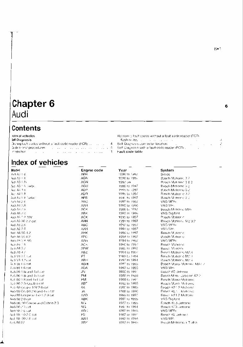
1 Audi 1 Contents
Index of vehicles Heirlev11 I[: t.7dt coces ~vlthout a faul! code rcader !TCr{l Self-D~agnosis (lash ct , L ? ~ Y , . . , . . I
CIPA'I~IIJ l , l~~! i rorle:; w~ttll>ut a far~l i code rsnder (FCH) . . . d Sell U13gr ~ c ~ s l s imn,lector loc,?!lsln .
:u:de I(: ti.-t pruceriures . . . . . . . , . . . . . . li Srt? Ulayrlnsls wttb a t a ~ ~ l l rode reader (FCT!, ~'tr~idllirlorl . . . . . . . , . . . . . 1 Fault code table
Eng~ne code AEH RGN AGN AG11 ADP AVR AF R 4ac AAt1 ACK ABK ACK AAN ABC AAH AHK AF(' Tdl! I AC I\ AFW AUL PT ARH 4GM ADA JN PM PM ABT 6A ')A AAD ABK N[:; Nt; A h ; tJs AAH ABY 1
Year 1996 tn ! 9 9 l 1996 t o I Y I J , 1YYI ur1 1996 to lr13; 1'1'?, 14-1 8997 1 495 I r j 199 i I 9<IL.1 f c 1997 1095 to l 9 9 i 1995 to 1 LiLW IYYC; t o 'qn; 1139.3 to 1996 1995 tu 1997 1'491 to 1997 I!??? to 199; 1991 lo 199? 1996 I t 1 :(I97 I99J tKI 1997 139,l to l!!il/ 1996 to 151'3 ,' IYYS to 1997 199-1 to l o t . ' , '
1 Ti?' to l'l!J4 \'I[>;? to 1994 i:I!?" t q 1993 1 99 3 lil 1 995 1986 tc 1091 1988 to 1 'jtj!J
1 990 t ~ , 1 ?I<' 1
I ii92 !o 1995 l'j(j0 to 1995 1 ?3:m i o I L 9 X ) IY!A) to 199? l<>W TI1 liP:l!J
19E7 t ~ b I'4>3!1 19L3.~ tt> 1 !9\14 inn? to 1w.1 1 CX17 lu 1 L1V4 1
1 9 9 2 to Inr+-: 113Q:3 to 1 L P : >
lndex of vehicles Model AII,!I ti.; I ~ 4ud1 A:i I F;
Auds ,A3 I .t?l ,Au<: As ! $ 5 1 ( 1 1 !I< I
411: A,: ! I ; 211: 45 1 8 A U L ~ I F.1 1 H l u r b o i d j l f14 :) lj
Au31 A-I ?'.R du31 A 4 ,- :: Aud~ A6 :! [:I
AUAI A! .' :I nov kc i~ AG :;6 2 2 cat A U ~ ~ I A6 2,tj H u : ~ At; ? R Aud &A :;6 1 % Aui: AF t;l; 1 ? Aur:~ A:{ :' 81 Vi; llaL!l ,I3 ' 8 & L I [ ~ I A8 :I. /'
All(i1 ;If3 -1 >' T\LLII L'F :< [, l . .~ t AL.;II Uf\ :I :' L:LI
> I , A ~ I 51) I l; (:at ALI:.II H o 1 t; cat 4~1.11 $'I 1 81 311~1 3x3 ( .3t
A u l . l10 I HI 2nd 2k 1 #,st 4u:I 8U 1 8 2;-~rl 4x.l cai , i u : l : Fro :' O I (J!latlr(.l r a t A111-:1 4L) [ ;OLI~? I t;v ? 0 <:2t 11~l:l ~:01 IPC ." ~ j l l < d 4 \-I (..It A~.l',l 80 L[i l lpe :1111t 2 ( 1 ;'.(I GiI
4utl1 80 L' U :\UL!I $0. r h l l (;<J!IIM LII ti (-:;lbrln 2 2 ,4u(Il >,I> ,' - $ ~;; l t
A \ l ' l l .' 6.1 <,;It
- i ,~ l< l l NI, 00 7 0 [:;it ,qL1\l NI 90 :> L4 Gli
4,1:1, 80 :<?
System Slmos Rosch Motruri~c. 3 :' Rrsc t i Mott<>ll l i 3 U 2 E?u~r:h Motrnnlc: 2 L' t j~hc. t i Mntrorl~c: C: : Roszh Mutrurilr: .i Bosch h21,tronlr: 3 2 VAG MPFI VACi M , ~ I Er>sch Mntri lni~: M? I VAG D~g~far l t Bnsch Molrorl~r. Bu:ich Motrnl,!; hl2 3,:l VAC A,l .lr F I
VA!> I.?P I Bosct~ h40trotilc U u ~ c t l Mutron~c VAT, MPFI R o s c l ~ MG~I 1.mr Pusct~ Mr,ir~3nlt Hs)-,~-l? Motrur~tc: rvl.l..4 Rn:;cll Mut~unlc. b,l' I Uarcl i Motron~c M:, ; Rosch Morlo-Mo!r;lall\ MA 1 ,; VAG MPI Uosch KE-. l~: t ror~~c Rose!) Mor~u-Jelrcxi~c A2 :' Fnxh Mur1u-k4ottnti1c: R(j'jct1 Munr) P..~L-~I cr:rr; Dus<:h KFI 2 Mr.~:rr~nlr. Ro:,ch KL I . 1 h,lb>tri~.~~c: Uosl-t~ hF1 -2 Mot ru l~~c. VAG nlqltant Rosch K t3 -J~ t rn t i ~ r : Bosctl KF3 .Ictrorl~r V A G MPFI R n x h KL Jrtr;~nlc ?i,A*IG MP, Ul~5,;ii Motror~lc I T ~ ~ r h n
i

- - . - - - - . . . . . . - - - -. - -
6.2 Audi
Model Engine code Year System Audi 90 Coupe 2.0 20V cat NM 1988 to 1991 VAG MPi Aud190 Coupe and 4x3 2.3 cat 7A 1988 to 1991 VAG MPI Audi 100 1.81 cat 4 8 1988 to 1991 Bosch Mono-Jetronic Audi 100 1.8i cat PH 1985 to 1991 Bosch KE-Jetronic Audi 10G 2.0 cat M E 1991 to 1994 Bosch Mono-Motronic MA1.2 Audi 100 2.m ABK 1993 to 1 996 VAG O~g~fant Audi I00 2.Dcal A4D 1997 to 1994 Bosch KE-Motronic Audi 100 ax4 2.0 16V cat ACE 1992 to 1994 Bosch KE-Motron~c Audi I00 54 2.2 cat AAN 1991 to 1997 8osch Motronic 2.3 2 Audi 100 2.3E cat NF 1986 to 1991 Bosch KE3-Jetron~c Aud~ 100 2.3 cat AAR 1991 to 1994 Bosch KE3-Jetronic Aud! 100 2.6 ABC 1992 to 1997 VAG MPFi Audi 100 2.8 A4H 1991 to 1997 VAG MPi Audi 100 S4 4.2 ABH 1993 to 1 994 Bosch Motronic Audi 200 4x4 Turbo cat 3 8 1989 to 1991 Bosch Motronic .t Turbo Audi Coupe S2 3 8 1990 to 1 993 Bosch Motronic + Turbo Audi Coupe and Cabrio 2.0 cat ABK 1992 l o 1997 VAG Digifant Audi Coupe and Cabrio 2.6 cat ABC 1993 to 1997 VAG MPFi Audi Coupe and Gabrio 2.8 AAH 1991 to 1997 VAG MPI Aud~ Coupe S2 ABY 1993 to 1996 Bosch Motronic + Turbo Aud~ Quattro 20V cat RR 1989 to 1997 Bosch Motronic + Turbo i, Audi RS2 Avant AOU 1994 to 1996 Bosch Matronic + Turbo 1
i'
Self-Diaanosis
The engine management and fuel injection systems fitted to Audi veh~cles are mainly of Bosch origin. Bosch Motron~c versions 2.3.2, 2.4, 3 2, and 3.8.2, Mono-Jetronic, Mono- Moiromc 1.1 and 1 .?. KE-Motronic 1 .I and 1.2, KE-3 Jetron~c. Slrnos, VAG Digifanl, VAG MPi and VAG MPFi may be fitted.
All Audi englne management systems (EMSs) control prrmary ignition, fuelling and idle funct~ons from within the same control module: the exceptions are Mono-Jetronic and KE-3 Jetronic systems. which control fuell~ng and idle functions alone.
Self-Diagnosis (SD) function Each ECfd has a self-test capability that
continually examlnes the s~gnals from certain engine sensors and actuators, and compares leach signal to a table of programmed values. If the d~agnost~c software determines that a fault is present, the ECM stores one or more fault codes Codes will not be slored about cornponenls for which a code is not available, or for conditions not covered by the diagnostic software.
Audi systems are capable of generating two knds of fault codes - 4-digit flash codes and 5-digit fault codes.
Evolution of Aud~ systems has meant that the codes generated, and their read~ng procedures, now fall rnto one of three groups. The changeover point in a particular vehicle
range is not always obvious. 3 Some early SySt81-m will only generate 4-
digit flash codes which can be retrieved via the warning light (where fitted), an LED bght, or a dedicated fault code reader (FCR]. These systems include Mono- Jetronrr and Mono-Motronic MA1.2.t.
b) Later systems can generate both 4-dig,[ flash codes and 5-digit fault codes. The #-digit flash codes are generated via the warning light (where lifted), or an LED light, whilst a dedicated FCR is required to retrieve the 5-drgit codes. These systems rnclude Bosch Molrun~c versions 2.3. 2.4, and 2.7, KE-3 Jetronic, KE- Motronic and Mono-Motronic (early 45- pin ECM).
C) The very latest systems can only generate 5-digit fault codes, and these must be retrieved with the aid of a dedicated FCR. These systems include Bosch Motronic versions 2.9, 3.2 and 3.8.2, Mono- Motronic MA 1.2.2 (later 45-pin ECMj, Simos, VAG Digifant (68-pin ECM) and VAG MPI and MPFi.
LlmCted operating strategy (LOS) Audi systems featured In th~s Chapter utilise
LOS (a funct~on that is commonly called the "limp-home mode"). O~?ce certain faulls have been ident~fred (not all faults will initiale LOS), the ECM will lrnpltment LOS and reler to a programmed detault value rather than the sensor signal. 7 hrs enables the vehicle to be safely driven to a workshoplgarags lor repair or testing. Once the fault has cleared, the ECM will revert to normal operation.
Adaptive or learning mpability i i Auol systems also utlllse an adaptwe I ,
funchon that will modify the bas~c I i programmed values for most effective ' I
operat~on dur~ng normal runnlng, and with due ; regard to engine wear. I
Self-Diagnosis (SD) warning light i Certa~n models are equipped with a SD 1
warning light located within Ihe ~nstrument panel
!
2 SaM-DiagnoQs connector kcat ion
Mono- Jetmnic (Audi 80 and 100 1.8i up to July 19881
On top of the fuel pump relay (see illustration 6.1) for flash code retrieval alone.
Mono- Jetronic (Audi 80 and 100 1.8ifmmAugust 1988) :
Dual 2-pin SD connectors located in the passenger's side footwell (see illustration 6.2) for flash code retrieval and FGR use.
Bosch Mono-Motmnic Dual 2-pin SD connectors located in the
passenger's s ~ d e foolwell, under the facia, (refer to illustration 6.2) or in the engine compartment left-hand fusebox close to the bulkhead (see illustration 8.3) for flash code retrreval and FCR use. The ECM IS usually localed In the driver's or passenger's side footwell, or In the engine compartment behind the bulkhead.
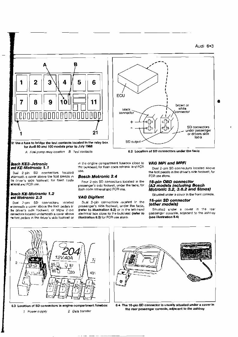
-. .-. . .
Audi 6-3
I
SD connectors
acts located in the relay box
A Fuel pump elay location B Test contacts 6.2 Location of SD connectors under the facia
~ C / I KE3- Jetronic ~n the engine compartment fusebox close to VAG MPi and MPFi md KE-Motmnic 1. f the bulkhead; for flash code retrieval and FCR Dual 2-pin SD connectors located above
use. h a 1 2-pin SD connectors located the foot pedals in the driver's side footwell; for mderneath a cover above the foot pedals in B ~ g c h M~tronjc 2.4 FCR use alone. '' driver's side for flash code Four 2-pin SD connectars located in the fg-pjn OBD connector retrieval and FCR use. passenger's side footvvell, under the facia; for @3 models including Bosch
flash code retrreval and FCR use. IWotfwnic 3.2,3.8.2 and Sirnos) h ~ h KE-Motronic 1.2 Situated under a cover in the front console. md Motmnic 2.3 WAG Digifant
Dual 2-pin SD connectors located Dual 2-pin connectors located In the 16-pin SD connector underneath a Cbuer above the foot pedals in passenger's side footweil, under the facia, lother the driver's s~de footwell, or triple 2-pin (refer to illustration 6.2) or in the letl-hand S~tuated under a cover in the rear connectors located underneath a cover above electrical box close to the bulkhead (refer to passenger console, adlacent to the ashtray the foot pedals in the driver's side footwell or illustration 6.3) for FCR use alone. (see illustration 6.4)
I I I
6.3 Location of SD connectors in engine compartment fuwbox 6.4 The 16-pin SD connector is usually situated under a cover in the rear passenger console, adjacent l o the ashtray
7 Pwiief supply 2 Data transfer
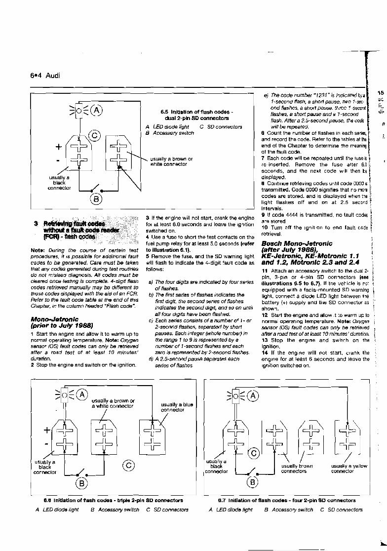
6.4 Audi
e) The code number " 123 1 " is indrcated by a 1 - s a d dash, a short pause, two ond flashes, a short pause, three 7- flashes, a short pause and a I -seco flash. After a 2.5-second pause, the rode will be repeated.
6 Count the number of flashes in each sen and r m r d the code. Refer to the table end of the Chapter lo determine the rr.eanlq of the fault code. 7 Each code will be repeat& until the luse is , re-inserted. Rerr,ovs the fuse alter 6.0 seconds, and the next code w~ l l ihen be f displayed. 8 Continue retrieving codes unt~l code 0000 1s transmitted. Cads OD00 signiTies that no m a t ( codes are stored, and is displayed when the light flashes off and on at 2 .1 second intervals. I 9 If code 4444 is transmitted, no fault cod6 are stored. 5 10 Turn off the ign~tton to end fault ccde retrieval. I
6.5 Initiation d flash code8 - dual 2-pin SD connectors $g
usually a black
connector
A LED diode light B Accessory switch
C SD connectors
\ usually a brown or white connector
3 If the engine will not start, crank frw engine for at least 6.0 seconds and leave the Ignition switched on. 4 Use a fuse to short the test contacts on the fuel pump relay for at least 5.0 seconds (refer to illustration 8.1). 5 Remove the fuss, and the SD warning lrght will flash to indicate the Cdigit fault code as follows:
Bosh Mono- Jetmnic {after July 7 9881,
I ? 1 KE- Jetrwric, KE-Motronic 1. I .
and 1.2, Motmnic 2.3 and 2.4 . Note: During the course of certain test procedures, it ts possible for addittonal fault codes to be generated. Care must be taken that any genereted during test routines do not mislead diagnosis. AN codes must be cleared once testing is comp!ete. #-digit ash codes retrieved manuaNy may be diffeferent to those codes displayed with the aid of an FCR. Refer to the fault code table at the end of th~s Chapter, in the column headed "Flash code*
11 Attach an accessory switch to the dual 2- f pin, 3-phn or 4-pin SD connectors (see 1 illustmtions 8.5 to 6.7). If the veh~cle is not (
equipped w ~ t h a tacia-mounted SD warnlng & light, connect a diode LED hght between the , battery (+) supply and the SD connector as : shown. : i 2 Start the englne and allow ~t to warrn up to normal operat~ng temperature. Note: Oxygen i sensor (OS) fault codes can only be retrieved ?
aftera road test of at (east 70 minutes' duratrm. j 13 Stop the englne and swnch on the : ignition. ! 14 If the engine will not start, crank the engine for at least 6 seconds and leave the rgnit~on switched on.
a) The four digits am indicated by four series of flashes.
b) me 1Srst series of flashes indicates the firsf dtgit, the second serres of flashes indicates the second dig~t, and so on until all four drgits heve been flashed.
c) Each swries conslsts of a number of 1 - or 2-second flashes, separated by short pauses. Each integer (whde number) in the range I lo 9 is represented by a number of 7 -second flashes and each zero is represented by 2-second flashes.
d) A 2.5-second pause separates each series of flashes.
Mono- Jetmnic (prior t~ July 1988) 1 Start the englne and allow it to warm up to n ~ m a l operating iwmperature. Nate: O w n sensor (05) fault codes can only be retrieved after a road test of at least 10 mmutes' duration. 2 Stop the engine and switch on the ignition.
usually a brown or a white connector usually a blue
connector
black usually a yellow conneclor
usually brown conneclors connector
6.6 lnklatlon of flash codes - triple- 2-pin 80 cornrectors
A LED diode light 8 Accessory switch C SD connectom
6.7 Initiation of flash codes - four 2-pln SD connectors
A LED diode light B Accessory switch C SO connectors
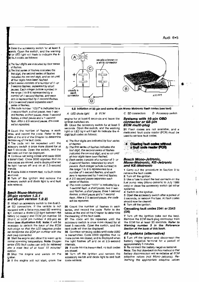
Audi 6.5
Close the accessory switch for at least 5 mds. Open the switch, and the warning tor LED light will flash to indicate the 4- t fault codes as follows:
4 7k four digits are indicated by four sefles of flashes.
bj The first series of #ashes indicates the first digit, the second series of flashes indicates !he second digit, and so on until d four digits have been flashed.
J Ewn series consists of a number of I - or 2-second flashes, Separated by shod pauses. Each integer (whole number) in the range 7 to 9 is represenfed by a number of 1 -second flashes, and each zero is represented by 2-second flashes.
Q A 2.5-second pause separates each series of flashes.
BJ The code number " 123 1 " is indicated by a 1-second flash, a short pause, two I-sec- ond flashes, a short pause, three I-second Rashes, a short pause and a 7 -second Rash. After a 2.5-second pause, the code will be repeated.
W Count the number of flashes in each Mries, and record the code. Refer to the $blss at the end of the Chapter to determine Uw meanlng of ihe fault cade. 17 The code will be repeated until the accessory sw~tch is once more closed for at least 5 seconds. Open the switch, and the next code will then be d~sptayed.
. 18 Continue retr~eving codes until code 0000 is transm~ttsd. Code 0000 signifies that no more codes are stord. and is d~splayed when the light flashes oll a d on at 2.5-second
10 If code 4444 1s transm~tted, no fault codes
BD Turn off the ignition and remove the , accessory switch and diode ligM to end fault
h c h Mono-Motronic ' (35-pin version 1.2.1
and 45-pin version 1.2.2) 21 Attach an accessory switch to the dual 2- pin SD connectors. If the vehicle is not equipped with a facia-mounted SD warning Ilght. connect a diode LED light between the battery (+) supply and ECM pin number 33 (35-p~n) or ECM pin number 4 (45-pin) as shown (see illustration 6.8). Note: it will be necessary to detach the back of the ECM multt-plugs so that the LED negative probe can backprobe the ECM ptn number with the multi-plug connected. 22 Start the engine and allow it to warm up to normal operating temperature. Note: Oxygen sensor (OSj Iartlt codes can only be retrieved afiw a road lest of at least I 0 minutes' duration. 23 Stop the engine and switch on the ignition. 24 If the engine w~ l l not start, crank the
usually a brown or a wllite connector
I I 6.8 lnltiation ol35-pin and some &-pin Mono-Motronlc flash codes (see bxt)
A LED diode light 8 ECM C SD connectom D Accessory switch
engine for at least 6 seconds and leave the Systems with f6-pin O8D ignition switched an. ~ 0 n n ~ t a r or 68-pin 25 Close the accessory switch for at least 5 ECM mulfl-plug seconds. Open the switch, and the warning Flash codes are not available, and a light or LED light will flash to indicate the 4- dedicated fault code reader (FCR, must be digit fault codes as follows: used to retrieve fault codes.
a) me four digits are indicated by four series ,, ,
of fiashes. ::3&!;: b) The first series of flashes indicates the
, , ,, > ~ A , , , > , < , , ,
first digit, the second series of flashes ", ,, , ", , < , c , < , ; < y *;
> x , >
indicates the second digif, and so on untii : ":'., . "'"'.+: ' '
ail four digits have been flashed. CJ ~ a c h series consists of a number of 1 - or B O S C ~ M o n o - J e f ~ i c ,
2-second f/ashes, separated by shori Mono-Motronic, KE- Je tronic pauses. Each integer (whole numbed in and KE-Mofmnic the range 7 to 9 is represented by a 1 Carry out the procedure in Section 3 to number of ?-second f lasks, and each retrieve the fault c d e s , zero is represented by 2-scond flashes. 2 T~~~ off the ignition,
dl A 2.5-second pause separates each 3 Use a fuse to short the test contacts on the series of flashes. fuel pump relay (Mono-Jetronic to July 1988
8) The code number "1237" is lndicafed by a only) or close the accessory switch (all Other I-second Hash, a shortpause, two I-sec- ,Ft,tems), ond flashes, a shortpause, three 1-second 4 switch on the ignltlon, flashes, a shod pause and a I-second 5 Oper! the accessory switch after a period of ffash. After a 2.5-second Pause. the code 5 seconds, or remove the fuse. All fault codes will be repeated. should now be cleared.
F!? usual1 a blaci
connector
rn
0 Turn off the ignition. 26 Count the number of flashes in each series, and record the code. Refer to the fauR codes 2341 Or 2343 tables at the end of the Chapter to determine toS)
,8., :~
the meaning of the fault code. 27 The code will be repeated until the accessory switch is once more closed for at least 5 seconds. Open the switch, and the next code will then be displayed. 28 Continue retrieving codes until code 0000 is transmitted. Code 0000 signifies that no more codes are stored, and is displayed when the light flashes off and on at 2.5-second intervals. 29 If code 4444 is transmitted, r o fault codes are stored. 30 Turn off the ignitiw and remove the accessory switch and diode light to end fault code retrieval.
7 Turn off the ignition (take out the key). Remove the ECM multi-plug connector from the ECM for at least 30 seconds. Refer to Warning number 3 in the Refemnce Secflon at the back of this book.
All systems (alternative) 8 Turn off the ignition and disconnect the battery negative terrntnal fur a period of approximately 5 minutes. 9 Re-connect the battery negative terminal. Note: The first drawback to this method is that baltery disconnection will re-mitialise all ECM adaptive values (not Mono-Jetronic). Re- learning the appropriate adaptive values
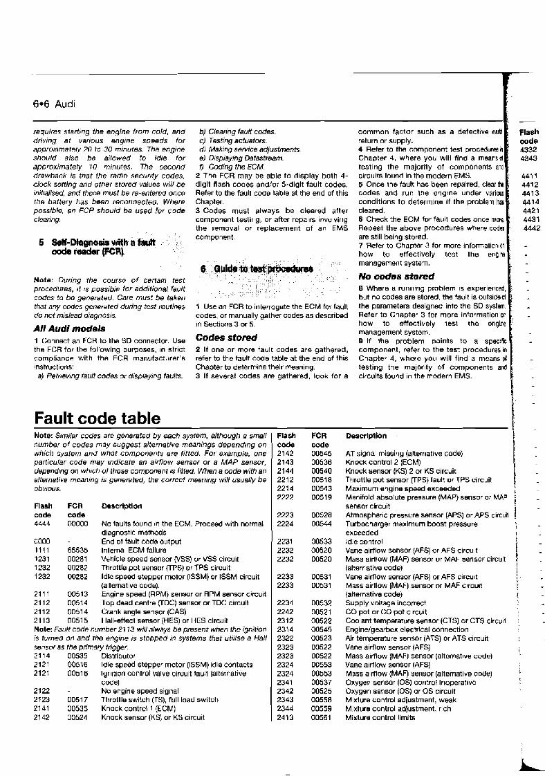
6.6 Audi
requires starting the engine from cold, and driving at various engrne speeds for approximately 20 to 30 minutes. The engine should also be allowed to idle for approximately 10 minutes. The second drawback is that ihe radio security codes, clock setting and other stored vallles will be mitralised, and these must be re-ented once the battery has been reconnected. Where possible, an FCR should be used for code clearing.
b) Clearing fault codes. c) Testing actuators. dl Making sdrvice adjustments. e) D~splay~ng Datastream. 0 Coding the ECM.
2 The FCR may be able to display both 4- digit flash codes and/or 5-digit fault codes. Refer to the fault code table at the end of this Chapter. 3 Codes must always be cleared after component testing, or after repairs involving the removal or replacement of an EMS component.
Note: During the course of ceriarn test procedures, it IS possible for additional fault codes to be generated. Care must be taken that any c d e s generated during test routines do not mislead dragnas~s.
All Audi models 1 Connect an FCR to the SD connector. Use the FCR for the following purposes, In strict compliance with the FCR manufacturer's bnstruct~ons: a) Retrrevrng fault codes or displeying faults.
Fault code table
1 Use an FCR to interrogate the ECM fw faull codes, or manually gather codes as described In Sections 3 or 5.
Codes sfored 2 If one or more fault codes are gathered, refer to the fault code table at the end of this Chapter to determine their meaning. 3 If several codes are gathered, look for a
common factor such as a defectwe earth return or supply. 4 Refer to the component test procedutesm Chaoter 4, where you will find a meansd testlng the majority of components and c~rcuits found in the modern EMS. 5 Once the fault has been reparred, clearthe codes and run the englne under various conditions to determine ~f the problem h cleared. 6 Check the ECM for faull codes once mors, Repeat the above procedures where ccdu are still being stored. 7 Refer to Chapter 3 for more ~nformationon how to effectrvely test the enqlne management system.
No codes stored I 8 Where a running problem 1s experienced, but no codes are stored, the tault is outsideof the parameters designed into the SO system. Refer to Chapter 3 for more information on how to effectively lest the engine management system. 9 If the problem points to a spec~fic component, refer to the test procedures In Chapter 4, where you will find a means ol testing the major~ty of components and circuits found In the modern EMS.
Mote: Similar codes are g8nemted by each system, although a small number of codes may suggest alternative meanings depending on which system and what components are fitted. For example, one particular code may indicate an arrflow sensor or a MAP sensor, dependrng on whrch of those component is fitfed When a code with an alternative meaning is generated, the correct meaning will usually be obvious.
Flash FCR Wscription code code 4444 00000 No faults found In the ECM. Proceed w~th normal
diagnosttc methods oa00 - End of tablt code output 11 11 65535 Internal ECM failure 1231 00281 Vehicle speed sensor (VSS) or VSS circuit 1232 00282 Throttle pot sensor (TPS) or TPS circuit 1232 00282 ldle speed stepper motor (ISSM) or ISSM circuit
(alternative code). 21 1 1 00513 Engine speed (RPM) sensor or RPM senmr circu~t 21 12 00514 Top dead centre (TDC) sensor or TDC circult 21 12 0051 4 Crank angle sensor (CAS) 21 13 0051 5 Hall-effect sensor (HES) or HES circuit Note: Fault code number 21 13 will always be present when the ignition is turned on and the engine is stopped in systems that uiilrse a Hall sensor as the primary trigger. 2 1 14 DO535 Distributor 21 21 00516 Idle speed stepper motor (ISSM) idle contacts 2121 0051 6 lgn~tion control valve circuit taul? (alternative
code) 2122 - No engine speed signal 2123 0051 7 Throttle switch VS), full load switch 21 41 00535 Knock control 1 (ECM) 21 42 00524 Knock sensor (KS) or KS circuit
Flash code 4332 4343
441 I 441 2 4413 441 4 4421 4437 4442
Flash code 1 2142 2143 21 44 2212 2214 2222
2223 2224
1 2231 2232 2232
2233 2233
2234 2242 2312 231 4 2322 2323 2323 2324 2324 2341 2342 2343 2344 2413
FCR code 00545 00536 00540 OD51 8 OD543 00519
00528 00544
00533 00520 00520
00531 00531
00532 0052f 00522 00545 00523 03522 00522 00553 00553 00537 00525 00558 00559 00561
Descrlptlon I AT signal missing (alternative ccde) Knock control 2 (ECM) Knock sensor {KS) 2 or KS circuit Throttle pot sensor (TPS) fault or TPS circuit Mawirnum engine speed exceeded Manifold absolute pressure m o r or MAP i sensor circuit Atmospheric pressure sensor (APS) or APS circuil 1 Turbocharger maximum boost pressure i exceeded ldle control Vane airflow sensor (AFS) or AFS circu~t Mass airflow (MAF) sensor or MAF sensor circuit ! (alternat~ve code) 1 : Vane almow sensor (AFS) or AFS c~rcult I ' M-s aidlow (MAF) sensor or MAF crrcu~t 1 - (alternative code) I Supply voltage incorrect CO pot or CO pot clrcu~t Coolant temperature sensor (CTS) or CTS circv~l : Enqindgearbox electrical connection Air temperature sensor (ATS) or ATS circuit Vane airflow sensor (AFS) Mass airflow (MAF) sensor (alternat~ve code) i Vane airflow sensor (AFS) I Mass a~rflow (MAF) sensor (alternative code) Oxygen sensor (0s) control Inoperatwe Oxygen sensor (0s) or OS circuit Mixture control adjustment, weak Mixture control adjustment, rich Mixture control limits
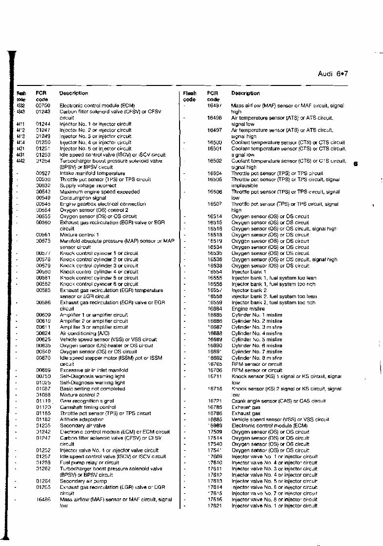
-- FCR code 00750 01 243
01244 01 247 31 249 01250 01251 01 253 01 254
00527 00530 00532 00543 00549 00545 00554 00555 00560
00561 00575
00577 00578 m579 00580 00581 00582 00585
00586
00609 00610 Ki611 00624 00625 00635 00660 OD670
00689 00750 01 025 01 087 01 088 01119, 01120 01 165 01182 01 235 01 242 01 247
01252 El257 01259 01 262
01264 01265
16486
Description
Electronic control module (ECM) Carbon filter solenoid valve (CFSVj or CFSV circuit lnjector No. 1 or inlector circuit lnjector No. 2 or Injector circuit lnjector No. 3 or injector circuit lnjector No. 4 or injector circult Injector No. 5 or injector circuit ldle speed control valve (ISCV) or lSCV crrcuit Turbocharger boost pressure solenoid valve (BPSW or BPSV c~rcuit lntakc manifold temperature Throttle pot sensor VPS) or TPS circuit Supply voltage incorrect Maximum engine speed exceeded Consurnpt!on signal Engine gearbox electrical connection Oxygen sensor (0s) control 2 Oxygen sensor (0s) or OS circuit Exhaust gas recirculation {EGR) valve or EGR circuit Mixture control 1 Msnilold absolute presswe (MAP) sensor or MAP sensor circuit Knock control cy!inder 1 or circuit Knock control cyllnder 2 or circuit Kncck control cyl~nder 3 or c~rcuit Knock control cylinder 4 or circuit Knock control cylinder 5 or circuit Knock control cylinder 6 or circuit Exhaust gas recirculation (EGR) temperature sensor or EGR circuit Exhaust gas recirculation (EGR) valve or EGR circu~t Amplifier 1 or amp!ifier circuit Amplifier 2 or amplifier circuit Amplifier 3 or amplifier circuit Air condltlaning (AjC) Vehrcle speed sensor (VSS) or VSS circuit Oxygen sensor (0s) heater or OS circu~r Oxygen sensor (0s) or OS circuit ldle speed stepper motor (ISSM) pot or ISSM circuit Excess~ve air in inlet man~fold Self-Diagnosis warning l~ght Self-Diagnos~s warning light Basic setting not completed Mixture control 2 Gear recognition signal Camshaft timing control Throttle pot sensor (TPS) or TPS circurt Altitude adaptation Secondary air valve Electron~c control module [ECM) or ECM circuit Carbon filter solenoid valve (CFSV) or CFSV circuit lnjector valve No. 4 or bnjector valve circuit ldle speed control valve (ISCV) or ISCV circuit Fuel pump relay or circuit Turbocharger boost pressure solenoid valve (BPSV) or BPSV circu~t Secondary alr pump Exhaust gas rec~rculation (EGR) valve or EGR circuit Mass alrfldw (MAF) sensor or MAF circuit, s~gnal tow
- - -
Flash FCR code code
16487
Audi 6.7
Description
Mass airllow (MAF) sensor or MAF circuit, signal high Air temperature sensor (ATS) or ATS circuit, signal low Air temperature sensor (ATS) or ATS circuit, s~gnal high Coolant ternpreture sensor (CTS) or CTS circuit Coolanl iamperature sensor (CTS) or CTS circu~t. signal low Coolant temperature sensor (CTS) or CTS circuit, signal high e Throttle pot sensor UPS) or TPS circuit Throttle pot sensor (TPS) or TPS circuit, signal implausible Throttle pot sensor mPS) or TPS circuit, signal low Throttle pot sensor (TPS) or TPS orcult, signal high Oxygen sensor (0s) or OS c~rcuit Oxygen sensor (0s) or OS circuit Oxygen sensor (0s) or OS circuit, signal hlgh Oxygen sensor (0s) or OS circuit Oxygen sensor (0s) or OS circurt Oxygen sensor (0s) or OS circubt Oxygen sensor (0s) or OS circuit Oxygen sensor (0s) or OS circuit, signal hlgh Oxygen sensor (0s) or OS circuit lnjector bank 1 Injector bank 1, fuel system too lean lnjector bank 1 , fuel system too rlch Injector bank 2 lnjector bank 2, fuel system too lean lnjector bank 2, fuel system too nch Engine misfire Cylinder No. 1 misfire Cylinder No. 2 misfire Cylirider No. 3 mlsflre Cylinder No. 4 misfire Cylinder k. 5 misfire Cylinder No. 6 misfire Cytnder No. 7 misfire Cylinder No. 8 misfire RPM sensor or c~rcuit RPM sensor or cscuit Knock sensor (KS) 1 signal or KS circuit, signal low Knock sensor (KS) 2 slgnal or KS circuit, signal low Crank angle sensor (CAS) or CAS circuit Exhaust gas Exhaust gas Vehicle speed sensor (VSS) or VSS circurl Electronic control rr~odule (ECM) Oxygen sensor (0s) or OS circu~! Oxygen sensor (0s) or OS circuit Oxygen sensor (0s) or OS circuit Oxygen sensor (0s) or OS circuit Injector valve No, 1 or injector circuit lnjector valve No. 4 or injector circu~t lnjector valve No. 3 or injector circuit Injector valve No. 4 or injector circuit Injector valve No. 5 or injector circuit Injector valve No. 6 or injector circu~t Injector valve No. 7 or injector circu~t Injector valve No. 8 or injector circuit Injector valve No. 1 or injwtor circuit
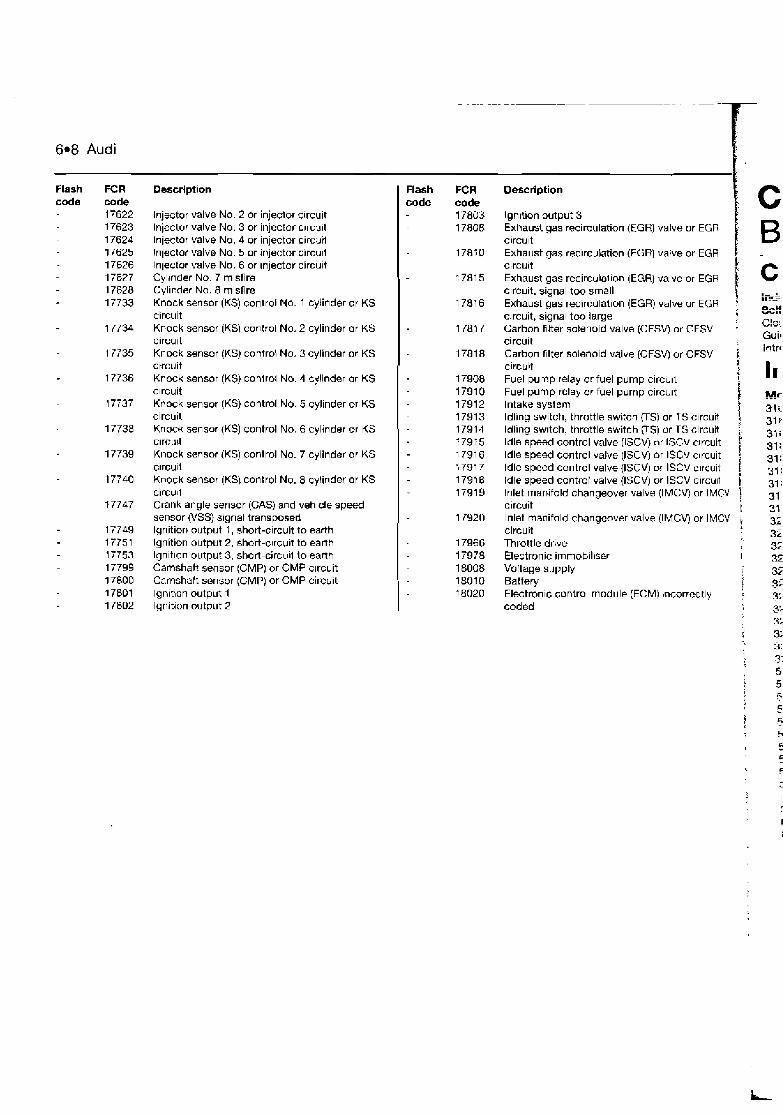
6.8 Audi
Flash FCR code code
17622 17623 17624 17625 17626 17627 17628 17733
17734
1 7735
1 7736
17737
17738
17739
17740
17747
17749 17751 17753 17794 17800 17801 17802
Description
Injector valve No. 2 or injector clrcuit Injector valve No. 3 or injector c~rcilit Injector valve No. 4 or injector circuii injector valve No. 5 or injector circu~i lnjector valve No. 6 or ~njector circult Cylrnder No. 7 misfire Cyl~r~der No. 8 misfire Knock sensor (KS) control No. 1 cylinder or KS circuit Knock sensor (KS) control No. 2 cylinder or KS circu~t Knock sensor (KS) control No. 3 cylinder or KS circuit Knock sensor (KSj control No. 4 cylinder or KS clrcuit Knock sensor (KSj control No. 5 cylinder or KS circuit Knock sensor (US) control No. 6 cylinder or KS clrcuit Knock sensor (KS) control No. 7 cylinder or KS clrcull Knock sensor IKS) control No. 8 cylinder or KS circu~t Crank angle sensor (GAS) and veh~cle speed sensor (VSS) signal transposed lgnition output 1, short-clrcuit to earth lgnition output 2, short-c~rcu~t to earth lgnitlon output 3, short-circull lo earth Camshaft sensor (CMP) or CMP clrcuit Camshaft sensor (CMP) or CMP circuit Ignlnon output 1 lgnition wtput 2
Flash FCR code code
17803 1780B
Description I lgnition output 3 Exhaust gas recirculation (EGR) valve or EGR circuit Exhaust gas rec~rculation (EGR) valve or EGR circuit Exhaust gas recirculai~on (EGR) valve or EGR circuit, signal too small Exhaust gas recirculation (EGR) valve or EGR circuit, signal too large 1.
Carbon filter solenoid valve (CFSV) or C.FSV circuit Carbon fllter solenoid valve (CFSV) or CFSV i circuit 1 Fuel pump relay or fuel pump circu~t I
Fuel pump relay or fuel pump circu~t I Intake system Idling switch, throttle switch (TS) or TS circuit i t Idling swltch, throttle switch (TS) ur TS circuit ldle speed control valve (ISCV) nr ISCV circuit Idle speed control valve (ISCV) or lSCv c~rcuit f ldle speed control valve {ISCV) or ISCV c~rcuit 1. ldle speed control valve (ISCV) or ISCV circull j Inlet manifold changeover valve (IMCV) or IMCV ) circuit r lnlet manifold changeover valve (IMCVJ or IMCV circuit I Throttle drive Electronic irnrnob~l~ser I
Voltage supply Battery I Electronic control module (ECM) ;ncorrectly : coded
i
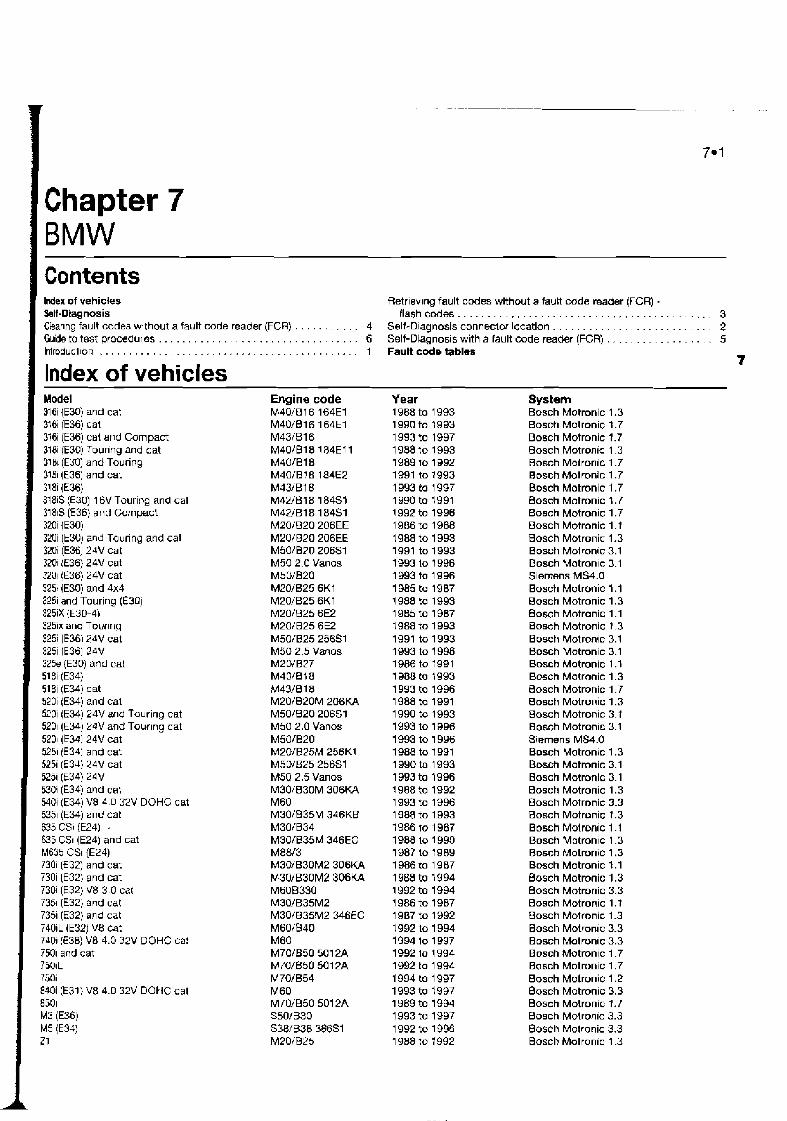
1 Chapter 7 1 BMW I Contents I Index of vehicles Retrlev~ng fault codes without a fault code reader (FCR) -
. . . . . . . . . . . . . . . . . . . . . . . . . . . . . . . . . . . . . . . . . . . Self-Diagnosis flashcdes 3 . . . . . . . . . . . . . . . . . . . . . . . . . . . . . . . . . . . . . Cbanng fault codes without a fault code reader (FCR) 4 Self-Diagnosis connector location 2
. . . . . . . . . . . . . . . . . Guide to test procedures . . . . . . . . . . . . . . . . . . . . . . . . . . . . . . . . . . 6 Self-Diagnosis with a fault code reader (FGR) 5 lntroducl~on . . . . . . . . . . . . . . . . . . . . . . . . . . . . . . . . . . . . . . . . . . . .
Index of vehicles Model 316i (E30) and cat 316i (E36) cat 316i (E36) cat and Compact 3f8i (E30) Tourlng and cat 3181 (€30) and Touring 3151 (€36) and cat 31 8i ( E X ) 318iS (€30) 16V Touring and cat 3181s (€36) and Compact 320i ( E M ) 320i (E30) and Touring and cat 320i (E36) 24V cat 3201 (€36) 24V cat 3201 (E36) 24V cat 3251 (E30) and 4x4 3251 and Touring (E3Uj 325iX (E30-4) 325ix and Tourlng 3251 (E36124V cat 325i [E36] 24V 325e (E30) and cat 518i (E34) 518i (E34) cat 520i (€34) and cal 520i (E34) 24V and Touring cat 5201 (E3d) 24V and Touring cat 5201 (f341 24V cat 5251 (i341 and cat 5251 (€34) 74V cat 5251 (€34) 24V 530i (€34) and cat 540i (E34) VB 4 D 32V DOHC cat 5351 (E34) and cat 635 CSi (E2J) . 635 CSI (E24) and cat M635 CSi (€24) 7301 (E32) and cat 730i (E32) and cat 730i (E32) V8 3 0 cat 7351 (E32) and cat 7351 (E32) and cat 740iL (E32) VB cat 7401 (1538) V8 4.0 32V DOHC ca! 7501 and cat i501L 7501 840i (E31) V8 4.0 32V DOkIC cat 8501 M3 (E36) M5 (E3JI 21
Engine code MJO/B16 164E1 M40/B16 164E1 M431516 M401018 184E7 1 M40/B18 MdO/B!8 184E2 M33/B18 M42/!318 184S1 M42/B18 184S1 M201620 206EE M20/520 206EE MSO/BPO 206S1 M50 2.0 Vanos M50/820 M20/B25 6K1 M20/625 6K1 M20/825 6E2 M20/B25 6E2 M50/B25 25651 M50 2.5 Vanos M2D/BZ7 ~401818 M43IB 18 M20/B20M 206KA M50/820 20651 M50 2.0 Vanos M50/B20 M20/B25M 256K1 M5D/B25 25651 M50 2.5 Vanos M30/B30M 306K.A ME0 M30/835M 346K8 M30/834 M30/635M 3d6EC M8W3 M30/B30M2 306KA M301B30M2 306KA M6OB330 M30/B35M2 M30/B35M2 346EC M60/B40 M60 M70/B50 50 1 PA M70/850 501 2A M70/B54 M60 M70/B50 501 2A S50/B30 S38lB38 38681 M20/B25
1 Fault code tables 7
Year 1988 to 1 993 19g0 to 1993 1993 to 1997 1988 to 1993 1989 to 1992 1991 to 1993 1993 to 1997 1990 to 1991 1992 to 1996 1986 to 1988 1988 to 1993 1991 to 1993 1993 lo 1 996 1993 to 1996 1985 to 1987 7988 to 1993 1 985 to 1987 1988 to 1993 1991 to 1993 1993 to 1 996 1986 to 7991 1988 to 1993 1993 to 1996 1988 to 1991 1990 to 1993 1993 to 1996 1993 to 1996 1988 to 1991 1990 to 1993 1 993 to 1996 7988 to 1992 1 993 to 1996 1988 to 1993 1986 to 1987 1988 lo 1 990 1987 to 7989 1986 to 1987 1 988 to 1994 1992 to 1994 1 986 to 1987 1 987 to 1992 1992 to 1 994 1994 to 1997 199'2 lo 1 994 1992 to 1 994 1994 to 1 997 1 993 to 1997 1 989 to 1994 1993 to 1997 1 992 to 1996 1988 to 1992
System Bosch Motronic 1.3 Bosch Motronic t .7 Bosch Motronic 1.7 Bosch Motronic 1.3 Bosch Motronic 1 - 7 Bosch Motronic 1.7 B ~ s c h Motronic 1.7 Bosch Motronic 1.7 Brssch Motronic 1.7 Bosch Motronic 1 .I Bosch Mbtronic 1.3 Bosch Molronic 3.1 Bosch Motranlc 3.1 Siemens MS4.0 Bosch Motronic 1 .I Bosch Motronic 1.3 Bosch Motronic 1.1 Bosch Motronic 1.3 Bosch Motronqc 3.1 Bosch Mutronic 3.1 Bosch Motronic 1 .I Bosch Motrnnic 1.3 Bosch Motronic 1.7 Bosch Motronic 1.3 Bosch Motronic 3.1 Bosch Motron~c 3.1 Siemens MS4.0 Bosch Motronic 1.3 Bosch Motronic 3.1 Basch Motronic 3.1 Bosch Motronic 1.3 Bosch Motronic 3.3 Basch Motronic 1.3 Bosch Molronic 1 . I Bosch Motranlc 1.3 Bmch Motronic 1.3 Basch Motronic I .1 Bosch Motronic 1.3 Bosch Motronic 3.3 Bosch Motronic 1. t Bosch Motronic 1.3 Boxh Motronlc 3.3 Bosch Motron~c 3.3 Bosch Motronlc I .7 Bosch Motronic 1.7 Bosch Motronic 1.2 Bosch Motronic 3.3 Bosch Motronic 1.7 Bosch Motroqic 3.3 Bosch Motronic 3.3 Bosch Motronic 1.3

7.2 BMW
Self-Diaanosis
The engine management systems (EMS@ fitted to BMW models are mainly of Bosch origin, and include Bosch Motronlc versions l.t/1.3, 1.2, 1.7, 3.1, 3.3 and Siemens MS4.0. All BMW engine management systems control primary ignition, fuelling and idle functions from within the same ECM.
SelY-Diagnosis (SDJ function Each ECM has a self-test capability that
continually examines the signals from certaln engine sensors and actuators, and compare each signal to a table of programmed values. If the diagnostic software determines that a faull IS present, the ECM stores one or more fautt codes. Codes will not be stored about components for which a cdw is not avarlable, or for condltioos not covered by the diagnostic software. Depend~ng upon system, BMW control modules will generate either 2- digit or 3-digit fault codes, and a dedicated FCR must be used for rwtriwval. Flash codes that can b retrieved without an FCR are only available in US market rndels. Bosch Motronic 1.2
Early BMW V12 engines are equlpped wlth Bosch Motronlc M1.2, which has two electronic control modules. Each module is allocated to a bank of 6 cylinders (ECM 1 for the right-hand bank, and ECM 2 for the left- hand bank) and gathers data from its own sensors. Each ECM stores its own fault codes, and should be treated independently.
Limited operating sfrategy (LOSJ BMW systems featured in this Chapter
utllise LOS {a function that is commonly called the "limp-home mode"). Once certain faults have been identified (not all faults will initiate LOSX the ECM will implement LOS and refer to a programmed default value rather than the sensor slgnal. This enables the vehicle to be safely driven to a workshop/garage for repair or testing. Once the fautt has cleared, the ECM will revertto normal operation.
Adeptiw or learning capabiliiy BMW systems also utilise an adaptive
function that will modify the basic programmed values for most effective operation during normal running, and with due regard to engine wear.
SeM-Diagnosis (SDJ wamIng light BMW models for the US market are
equipped with a facia-mounted "Check Engine" warning light as demanded by US OBDll regulations. Fault codes indicating failure of emission-related components may be retrieved through the flashing of the Ilghl. European market models are not equipped with a warning light.
The SD connector IS tor FCR use alone, and is located In the englne compartment along the left or right-hand wing, either close to the bulkhead or suspension turret (see tllusbvtion 7.1).
Bosch Motmnic 1.7, 1.2 and f .3 (US models only)
A limited number of emissions-related flash codes are available via the flashing of the facia-mounted "Check Engine" warning tight. Refer to the flash code table at the end of this Chapter to determine the meaning of the flash mde.
1 Turn off the ignition and disconnect the battery negative terminal for a per~od of approximately 2 minutes. 2 Re-connect the batterj negative terminal. Note: The first drawback to this methd is that battery disconnection will re-initialise all ECM adaptive values. Re-/earning the appropriate adaptive values requires starting the engine from cold, and driving at various engine speeds for approximately 20 to 30 m!nufes. The engine should also be allowed to !d(e for approximarely 10 minutes. The second drawback is that the radio security codes, clock settrng and other stored vaiues wili be initralised, and these must be re-entered once the battery has been reconnected. Where powble, an FCR shouid be used for code cl~aring.
7.1 BMW 20-pin SD connector. Unscrew the cap and attach the FCR to the exposed connector
Note: During the course of certain test procedures, it is possible for additional faull codes to be generated. Care must be taken that any codes generated dunng test routtnes do not mislead diagnosis
All BMW models 1 Connecl an FCR to the SO connector. Uss the FCR for the following purposes, in strlct compliance with the FCR manufacturer's instructions: a) Retrieving fault codes. b) Clearing bull codes. cJ Testing actuamrs. d) Displaying D a t a s h m .
2 Codes must always be cleared aftw component testing, or after repaws involv~ng ths removal or rwplacement oi an EMS comp~nmi I Note: Many of the fault code numbers 1- correspond to the ECM pm number - eg. fwault 1 code 04 cornsponds to ECM pin number 4. &
I.
Fa1 -
peg.: mesh cock 01 02 03 04
me. FCR code 01 03 04 05 07 10
15 16 17 23 28 29 33
1 Use an FCR to interrogate the ECM for fault codes. or (where possible) manually gather codes as described in Sections 3 or 5.
4 n
Codes stomd 2 If one or more fault codes are gathered, refer to the fautt code tables at the end of this Chapter to determine their meaning. 3 If several codes are gathered, look for a common factor such as a defective earth 1 Oi re!um or supply. I 0' 4 Refer to the component test procedures in Chapter 4. where you will find a means of testing the majority of components and
1 01 01
circuits found in the modern EMS. 5 Once the fault has been repaird, clear the codes and run the engine under varlous
1 : conditions to determine if the problem has j cleared. i 8 Check the ECM for fault codes once more Repeat the above procedures where codes ! are still being stored. ! 7 Refer to Chapter 3 for more information on : how to effectively test the EMS.
No codes stored 8 Where a running problem is experienced. ,
but no codes are stored, the fault is outside of the parameters designed into the SD syslem Refer to Chapter 3 for more informallon on how to effectively test the EMS. 9 If the problem points to a speclflc I
component, refer to the test procedures In : Chapter 4, where you will find a means of testing the majority of components and ' circuits found in the modern EMS.
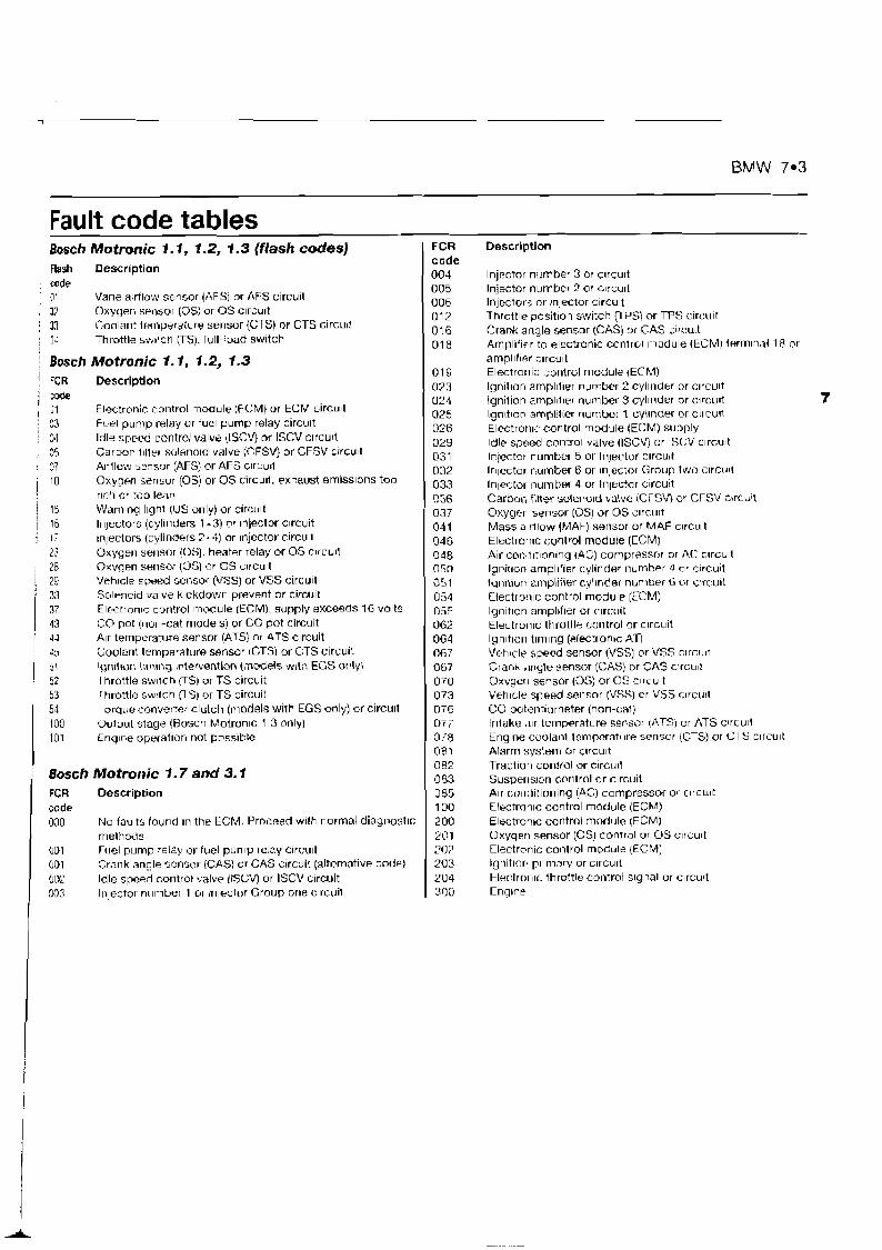
BMW 7.3
Fault code tables Bosch Motmnic 1.1, 1.2, 1.3 (flash codes) nash Description code 7 . Vane alr~low sensor (AFS] or AFS c~rcuit J? Oxyqerl sellsol (0s) or OS clrcult
: 33 Goolar~t teqnperaiure sensor (CTS) or CTS c~rcu~! : 3- Throttle Y V ~ I ~ C I ~ TTS), full-load switch
/ Bosch Motronic 7 .1 , 1.2, 1.3 ! FCR Description 1 code ; :I Electronic control module (ECM) or ECM circu~l : C3 Furl pump relay or fuel p u r n ~ relay circu~t : M Idle speed control valve (ISCV) or ISCV clrcult
35 Carbon I1l1t.r sclleno~d valve (CFSV) or CFSV crrcu~t : C i A~rflow 5ensur (AFS) or AFS clrcurl , 10
Oxygm srrlsur (0s) or OS circu~i. exhaust emiss~ons too rlcll Or too lean
i 15 Wariling g h t (US only) or circclt / l o lr~jectors (cylinders 1 +3) crr rnjector c~rcuit i I: ~nlectors (cylinders 243) or Injector circu~l
13 Oxygeri serisor (0s). heater relay or OS c~rcult : 28 Oxvgen serlsur (US) or OS circuit
29 Vah~cle speed sensor (VSSJ or VSS circu~i 33 Solenold valve kickdown prevent or circu~t
1 ii Electron~c control module [ECM). supply exceeds 16 volts CCO pot (non-cat models) or CG pot circuit
[ 44 Air temperature sensor (AT51 or ATS circuit ;ri Coolant temperature sensor (CTS] or CTS circuit
I ;; lgnitlon timlng intervention (models w~th EGS only\ I hrottle sw~tch ITS) or TS circuit
53 I hrottle sw~lch VS) or TS circuit 54 Tcrrq~re converter. clutch (models with EGS only) or circult 100 Oulput stage (Rosch Motrorl~c 1.3 only) 101 Enq~ne upsration not pcrss~hle
Bosch Motronic 1.7 and 3.1 FCR Description code 000 No faults found In the ECM. Proceed w~th normal diaynost~c
metho~is 001 Fuel pump relay or fuel pump relay Circult 001 Crank angle sensol (GAS) or GAS c~rcuit (alternative code) 902 Idle speed control va lv~ (ISCV) or ISCV circult 033 Inlector n~~mber 1 or ~nlector Group orle c~rcuil
FCR code 004 005 006 012 016 D l 8
- -
Description
Injector number 3 or clrcu~t Injector nutnber 2 or L I ~ C U I ~
Injectors or !n]ector c~rcuit Throttle position switch VPS) or TPS circu~f Crank angle sensor (CAS) crt CAS circu~t Arnpllf~er to electronic control module (ECM) termlnar 18 or ampl~fler circuit Electror~ic control module 1ECMI lgnilion ampl~fler number 2 cyl1ndt.r or clrcult Ignition ampl~fier number 3 cyl~nder or circu~l lgn~t~wn ampl!t~er number 1 cylinder or c l~cwl Electroti~c control module (ECM) supply ldle speed control valve (ISCV) or IST,V c~rcu~t Infector number 5 or lnjeftor clrcu~t lr~lector number 6 or ~njector Group two circurt In1er;tor number 4 or Inlet?ar c~rcuit Carbon filter solenold halve (CFSV) or CFSV cbrcull Oxyger sensor (0s) at OS I'lrcult Mass s rllow (MAF) sensor or MAF clrcuit Electrorllc control module (ECM) Air con~rltlonlng (AC) compressor or AC clrcu~t lgrit~on ampl~f~er cylinder number 4 or c;lrcuit (qnition amplifier cyl~nder nunrkr ti of circuit Electro!~ic control module (ECM) lgnit~on arnpllf~er or c~ruuit Electro~lic throtlle control or c~rcuit lgn~t~orl tlrnlng (~lectron~c A n Vetirclr speed sensor (VSS) or VSS clrcu~t Crank ,mgle sensor (CAS) or GAS clrcu~! O X Y ~ ~ I I sensor (0s) or OS c ~ ~ c u ~ t Veh~cle speed sensor (VSS) or VSS clrcukt CO potentiometer (non-cal) Intake ,llr ternp~rature sei,s~>r ( A T 3 ur ATS c~rcult Eng~ne cuolanl lemtxrrature sensor (CTS) or CTS c~rcu~t Alarrr~ ?:ysterr~ rjr clrcult Tractiorl conlral or c~rcuit Susper~sion Corltrol or c~rcuit Air conditioning (AC) compressor or crrcu~t Electron~c control modolp (ECM) Electronic control rnodrllp (ECM] O~ygerl serlsor (0s) conrrol or OS c~rcu~t Electroriic control module {ECM) Ignitlor 1111maw or clrcult Etectrol-IIC t h ~ dtle control slgnal or c~rcuit Englne

Chapter 8 Citroen Contents Index of vehicles Rettlevlnq Fault co~les without a fault code reader (FCR1 Self-Diagnosis flash ccdes . . . . . . . . . . . . . . . . . . . . Lt~ator tesl~ng w~thmlt a la11l1 code leader (FCR) . . . . . . . . . . . . 5 Selt-Dlagnas~s cor~nector location . . . . . .
Cearlng fnt~lt codcs w~thoul 3 fault cudr reader (FGR) . . . . . . . 4 Self-D~ayr~as~s wltli a fault code diagnosis (FCRi . Gu~de to test procedtlres . . . . . . . . . . . . . . . . I Fault code tables Iitr~ducl~ur~ . . . . . . . . . . . . . . . . . . . . . . . . 1
lndex of vehicles Engine code TU9MIL.Z (CDY) TU9M/L Z (CDZ) TUI M (HDL) TU1 M1L.Z (HDY) TU 1 MIL Z (H DZ) TUSM (kD.2) TU'3FMC:I 7 (hDY) TU3FM:L 2 (hDX) TLJ3JZ/K (KGB) TU3J2/L.Z (KFZ) TUlM (HDZ) TUSJP lKFX] TUsM (KDY) XUSM (BOZI XclSM3Z (BDY) XUUJ2 (060) X119J4 (D6C) XUVJAZ (DKZ) XU9J4Z (DFW) XLJ9J4K (DGC) DDZ(XU9M) TUlM (HDZ) TUSF MIZ (KDY) TU3F M/W% (KUY2) XU1 OJ2CZiL (FiFU) XU1 OJ2CTEUL(RGX) XUlOJ2U (HTW) 220 A2.000 XUlOJ2U (RFW) TUUMIL3iL T U 1 M L3:L TL13JPfL3 TU5JP L3 (1.11 L) X U 1 UJ2CUL (RFIJ) XU:OJ7CTEZ/LlRGX) XUSJPIZ (UFX) XUiJP4'13 (I FY) XCI~.IPJZ [L FZ) x u 1 a J x . Z (HFX) XU1 OJ40, Z {HFY) XU1 0J4R/UL3[flF V) XU I OJ4DI.Z (HTT) XU 1 0J2CTE/L3(RGXI
Model kA I 2i AX 1 01 ra t LA 1 11 r.>t k4 I l b L,+I Ab, 1 I , r.3t
k\ Gl 1 4 1 cat , k4 ;T dr~cj I JI cat ' AV ' 41 cat , ,At-, i 5 T i
, A t 1 1 (-7 1 1 (;dl
i P r r l ~ r ~ ~ l ~ ~ l 1
/ e b ~ r l l f l \ ~ ~ 7 1 - 1 i BX ' 41 c:it ; EX '61 cat i EX !GI cat
j Bh IS G TI arlcl 4x3 B Y ~ ~ G T I 16V
Bk19 1GV DOHC L;I~ 1 i l l 9 1 G i DOH( 3x1 91 4X.: (:at i ' 5 L 1 I I Van r,lt
i i l 5 E 1 41 Van cni 1 C1.E 1 I ";in I,.! Evas~or~ 2 UI r.,11
:' 01 t l~rhn cat I J , l ~ l ~ t w 2.0, cat I JJ:I#V, I t j ~ I R U I ; ~ ~ 2 cat
Year 1992 to 1997 1992 lo 1956 1989 to 1992 1992 to 1947 1902 to 19(+T l9R8 to 1990 1990 tu 1992 1 YY2 tu 1996 1991 to 1992 1991 to 1996 1996 tu 19931 1996 tn 1897 1991 to 1994 199U to 1992 1991 to 1994 1990to I992 1987 to 1991 1990 to 1993 1 F190 tu 1992 1991 to 1992 1990 t p 1P9i 1990 10 190; 1990 lu 1095 1999 10 1995 199.9 9 0 1997 1994 lu 199; 1994 10 199; 1995 to 1kl9; 1494 to 139- 1'396to 199; 1996 to 1997 1996 tu 199? 1996 tn 1997 1994 to 1997 t994 to lYYl 1993 to 1997 1995 to 1997 1993 lo 1997 1993 to 1997 1993 to 1995 19YS to 1997 1994 to 1996 1995 to 1996
!
System Bosch Mono-Motron~c MA3 U Bosch Mono-Motron~c MA3 0 Basch Mono-Jetron~c A2 2 Magnstl-Marel11 G6-1 1 Magnetl-Mare111 Gti- 11 E0.;t,t1 rJono-Jetrnn~c A2 2 B~>s ih Mono-Jetron~c A2 B i l ~ i h Mono-Motron~c MA3 0 Bosch Mutrorl~c. MP? 1 Bosch Mctron~c MP3 1 Bosch Molr~nlc. MA3 1 Magnet[- Marr l l~ Bosch hlr~t~r>-.letrnnli AZ 2 Bosch Mono-Jelrrvili or MM G 5 6 Magnetl-Mare111 GC- lP Bosch FAotronlc MP3 1 Bosch Motron~r. hll 4 1 Bosch Motro~~lc 1 3 Bosr,h htotronlc 1 3 Bosch Motrorllc 1 3 Lerl~x 1 B Bosch Mono-Jetronlc A2 2 Bosch Mono-Jetrorllc A2 2 Uusch Mono-Jetrrlti~c A? ? Magnet1 Marell! 8P22 Bosch Motrurvc MP3.2 Magnetl-Marel11 DCM8P 11 Rosrh Mono-Motronlc MA1 7 Magnetl-Mare111 DCMBP-1 1 Bosch Mono-Motron~c MA3 1 Bosch Mono-Motron~c MA3 1 Magnetl-Marelh Rosch Motron~c MA5 1 Magnrtl hlarell~ 8P22 Etosch Mulronlr LIP3 2 Maqrnrtl-blarelll DGMRP13 Bosct-L Molrv~,~c MP5 1 1 B o ~ c h Molronlc MPS 1 Magl\etl-Marell~ UGM8P2O Hosch hlotrnnlc MP3 2 Ecsch Mutror~lc MPS 1 1 Bosctj MotrL>nlc MP7 7 Rnsch Mfltrt>nlr: MP? 2
5aro 1 0 5.VO I I 52.11 1 'I ?,arc 1 6 j..r,erq~e 2.01 cat :>.;18?r~l~ 7 0 1 lurko C.It
qdl;t13 1 61 CC3f
Xantla 1 81 16V Xantld 1 HI and Brcak Xantla 7 111 ,lnd Hreak Xar~t~a L' UI 1 ~ i b cdl Xantta 111 1t;V FI (.,3h Xanttn Arilvn 2 01 Xonto 1 ~ ~ r t ~ u 2 UI C - T
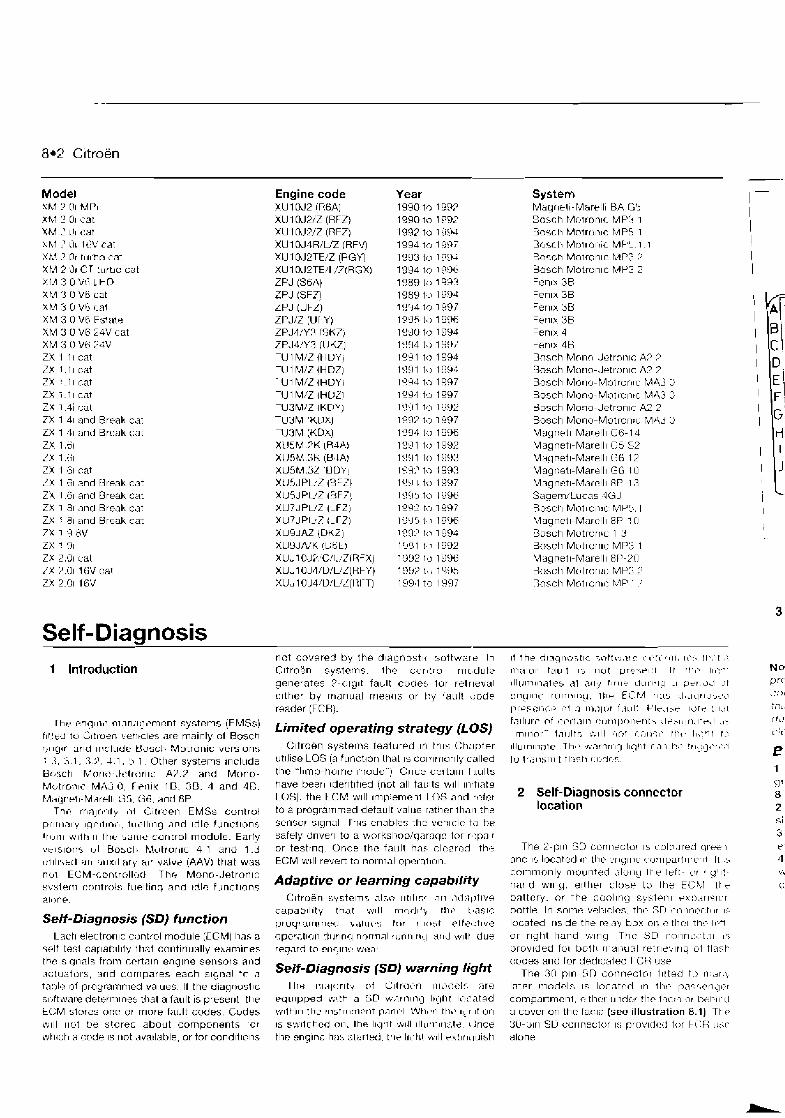
Model XM ? (11 MPI Xhl 2 01 cat XM 2 L11 c;it hh.1 ' 01 1t;V cat XLf, 2 Or turho i n t XFA 2 'JI c'T turbu cat 2I.A 3 G lili LHI? % M 3 UVbcat XFA 3 O Vh (-at Xh4 3 0 V6 Fslate XM 3 U V6 24V cat XM 3 O V 6 2 4 V ZX 1 1 I cat ZX 1 . 1 I cat ZX ?.I I r.at ZX 1-11 cat ZX 1.4i cal 7X 1 41 and Break c:at ZX 1 41 and Brcak cot ZX 1.61 ZX 1 .GI ZX 1 61 cat LX 1 61 and Ureak cat ZX 1.61 arid Ureak cat ZX 1 81 and Rrenk c ~ t ZX I 81 arld Break c b 7 X 1 9 HV ZX 1 91 ZX 2.01 c:al 7 X p.01 1 I;V cat ZX 2.01 1GV
Engine code XU 1 UJ2 (RGA) XU1 OJ2/Z (RFL) XU1 OJ2/Z (RF7) XU1 OJ4R/UZ (RFV) XU1 OJ2TE/Z (RGY) XU1 n.l2TE/I :7(RGX) ZPJ (SGA) ZPJ (SF71 ZPJ (UFZ) ZPJ/Z (Ul Y) ZPJ4/Y3 r$K7) ZPJ4N3 (IJKZ] TU 1 MIZ (klU'1'1 TU 1 M/Z (HUZj 1 U 1 M I L (HUY I TIJ 1 M/Z WUZl TU3Ml.Z {KUY I TU3M 1KDX) TlJSPvl (KOX) XU5M ?K { R I A ) XU%' .?h {B,LA) XUSM.31 IHDYI XUSJPLZ laFZI XllSJPUZ iBF7) XU7JPUZ iLFZj Yu7JP1~7 (LTZI XU5AAZ (UKZj X U Y J N K IUGL) XUJl OJP:CII.:liRFY.) XUJ l OJI/D/L'Z(RFY) XUJ 1 UJ4/D:L'L(Ht T )
Year 1990 trl InP? 1990 to 199: I 992 to I a w 199.1 to I 9!77 1993 t t ~ 109; 1994 tc: 1991, 1909 tn 199? 1989 t.3 1 YYJ 1994 to 1997 19'-15 t i l 1 996 1990 ta 1994 199.1 t,, 1997 l a w tc1 1994 1981 to 18% 1".1 ttil 1997 1994 ta tYY7 1:1:31 to 1992 19111 t i l 7 997 I YCI? ta t 996 19~11 t r l 199% 1991 tc3 1993 1Y4.' to f 993 19~14 tu 1997 11,1515 to 1 Y Y t i 1YgI tn I997 1W5 1 7 I996 199.' tv I994 199 1 t .1 1 992 1992 1 , ~ 1996 IOS? 1 % ~ 1395 199.1 to 1997
System Ivlngilerl- l,Aart.ll~ BA G', EnscP, Motronlc PAP'$ 1 Bosctr Motrbnlc MP5 1 B(Js(-~I tvl(>!r0111(- P.4F.5 1 1
Eo.-ch Motronlc MP3 7 Bosch Motrunlc MP3 2 Fen~x 3R Fen~x 38 F e r ~ ~ x 38 Feri~x 38 Fen~x 4 Fen~x 48 B m r h Mnno .lutrorilc A? 7 Bosch Mur~u-Jetrur~lc A7 ;7
Bosch Morlu-Motrur~lc: MA3 C. Bosch Mono-Motron~c MA3 C Husch Mo!io-Jetronlc A2 2 Bosch Mono-Motror l :~ MA3 O Magnet1 Marell1 Gt5-14 Maqnetl-Mare111 G 5 S2 Magrletl-Mare111 Gti 12 Magnetl-Marell1 GG. I U Mngnetl-Msrelll RP 13 SagemILucas 4GJ Bosch Mntronrc hlP:~. 1 h4agnet1-Marel11 8P :[I Busctl Mutrurl~c 1 3 Bosch Motronlc LIP3 1 Magnetl-Mal-ell1 8l'-:'O Busct~ Mut lur~~c: hlP3.2 Rosch Motrrjn~r: hlP : '
Self-Diagnosis 1 Introduction
not covered by the dlagnostlc suttware In ~t l h r dlaqnoit lc ;crtt~~.,trr 1- l t . t i . f111, ILP? t t ~ . ~ t : Cltroen systerns. ttle cur~ t ru l rrlr,dutt. I~;$IL>I tLj~1lt I,> ~ I L I ~ vre3elmt I t I~IL, IIL:,'
generates ?-cllglt fault code?. tor retrieval I I IL I IT~I I I~ I?~ dl ?.fly t1rr1G L ~ L I ~ I ~ I L I .I kler LA! ~t clthcr by manual rneacls or t)y IauH \:ode cnglnt- runnwny, rhr E i h . 1 11.15 , I 8 . l ~ l r~~~>er~ reader (FCH). 1 1 1 ~ ~ ~ : 1 ~ , - , ~ 111 .I l l i , l l L> l ~.ILII: PlCLl5+ I L > ~ ? : I I < ~ I
I h r englnc ni;ln,~q,~rncnt systems (FMSs) f ; l l l l ~ l t - pf I -~- I I .~ I~ r.ornljonrrlt-, , I + > ~ t l r l . l ' r , l .,- f l trrd tu Cltrorn r . e t~~z l r s are mninlv of Bnsch
LimitedoperatingstrategY~LOS~ 1,11,,1-- ,,,,I,, ,-I,, tt,,, I I S . ~ , ~ t: . . .
r,ll~,rl 9r1d Irlc.lude ijLlsch ~ ~ t ~ ~ ~ i ~ versions Cltroen systerns featured In tths Ch:~pter ~Ilurnlliate Th,, ,f;,?rnrl~q I I C - ~ I - I ~ ~ , > I - I I-+- ! ~ I L - : ~ + ~ ~ F , L I - >
: -1, -1 1, ; ;>, 1 1, s 1 other systems Irlclude LJtlli~e LOS (a funct~ori ttlal IS culrlrrlurlly called i w lraj l~sri i l t TI:jF,tr l:~,rjr-~,
~ ~ , ~ ~ h Monl, ,ttqrilrllc- A?.? and Mono. the "limp-tlurrle nlude") Once certaln f3ults
M5tro;ilc MA3 0 , Ft=n~r 18. 3 8 . 4 and 48. Magr~t. !~-M~rt . l l~ G5, G 6 . dnd 8P.
Thc rr~njo:lty t l f Z~ t roen EMSs cori lrul prlrnary ~ q n l i ~ n l ? , f t ~ ~ ~ l l l n g and ~ d l e functions l r ~ ~ l l l ~ 1 i t 1 1 1 1 l t ~ e 5drlle ~ c l l l t f ~ b module. Early v t ls lo r~> I J ~ B o s c l ~ M ~ ~ t r u r l ~ c 4.1 arid 1.3 1111llskrl arl ; I I I X I ~ I ~ I ~ ~ i(lr valve (AAV) that was nb1 ECM-r.ontrallr:rl The Mono-Jetron~c svsterr~ uur~trols tuellinq and rdlc functions alorlp.
Self-Diagnosis (SD) function
have beer1 lder~tltled (not all ta~:lts w ~ l l In,tlate LOS). the LCM will ~niplement ILOS and refer to a prograrr~rrled deta~rlt v a l ~ ~ r : rather than the sensor slynal I-hls enables thr: vchlclr: to he safely drlver~ tu a worksl,op;qarnqe for r8:pnlr or testrnq. U n c e thr: fault ha5 clcarnd the ECM w ~ l l revert to normal operailon.
Adaptive or learning capability Crtrcrerl systelns al:,n II~IIIV .in . i i l . l l)t~ve
capab l l~ ty that will rnr~rllf?, r l l + t,nslc proqrzm!nprl valt lr? trrr m r b t etfe<;tlve
2 Self-Diagnosis connector location
The 2-l)lrl SC) curir~rctur 15 c,olrl,~red clree'~ arid 1s lot.ated d r i rh r t.r~yll~t. cu:r~partr~,er~t 1 1 .s cn~nmnti ly l-rlourired ,jlurng !tie left- c > r , <'I:-
hand wuiy, e l t h ~ r < l r jsr tc) i t ~ e EC!s;l 1 1 , ~ hnttcry. n r the cc)nllnc_l sy51~r l1 vx:jdrl'jlur bottle. In solne vehlclcs, thc- :;TI r:vlnrr.tor I< located lllslde the relay hox L~I: cltlior ttit7 It3-t
Lach electrorllc ucjntrol module (ECM) has a ~ ~ I I I I 1 1 n n r J I ~ I I ~ L I I due ur rlght-Itand wlng Thc SD ro!in~:h:tnr 1s splf tesl capabal~ty ltiat coritiriually exarn~nes reqard to cnrlln!: wear provided fol butt1 r ~ ~ a ~ > r ~ r j l retrlrtlrny ot tlayk tbc slqnals from ccrtoln engltie sensors and codes and for ded~caled I CH use ~ictuaturs, arld currlpares each signal tn a Se'f-DiagnOsis fSD) warning light The 3n p ~ n Sr j cnriner:lor i l l let1 tt, r l : ~ r .)
table of proyrarnnied values, l l the diagrlosllc Tlie r:l,ilurlty uf Lltr0i.n nlwili.lq nm Inter modclr, la lncntnil 111 t h r pn?',rn,l<r sr~ftwnre deterrnlnes thal a fault is preser~l, t t i r r q i ~ l p p e d wl th a SD w.lrnlng llgllt l i < i d ted compnrtmcnt. 171thcr 11tidcr thr. fnc;,~ or thll!Plr-rl tl:M stores onr: or more fault codes. Cudes wl lh~n tlic rnsfl l~nlrrlt parlcl C Z l t h t > r l ttw ~ q r ltlun a cover on thc tncln (see i l lustration 8.1) Tt-r ~vl l l rlut be stored about components tor IS srv~lchcd on. i t ~ e I l i l t i t till lllurllrrlate Once 30-plr1 SU uurllwctor I:; prrivld<!d for ki:R tl:;r
wh~ch a code 1s rlut ,iva~lable, or tor condltlcns the englntc hi)?. ctaneu, the l1gti1 ~ t . ~ l l ekrlr~~luish alur~e

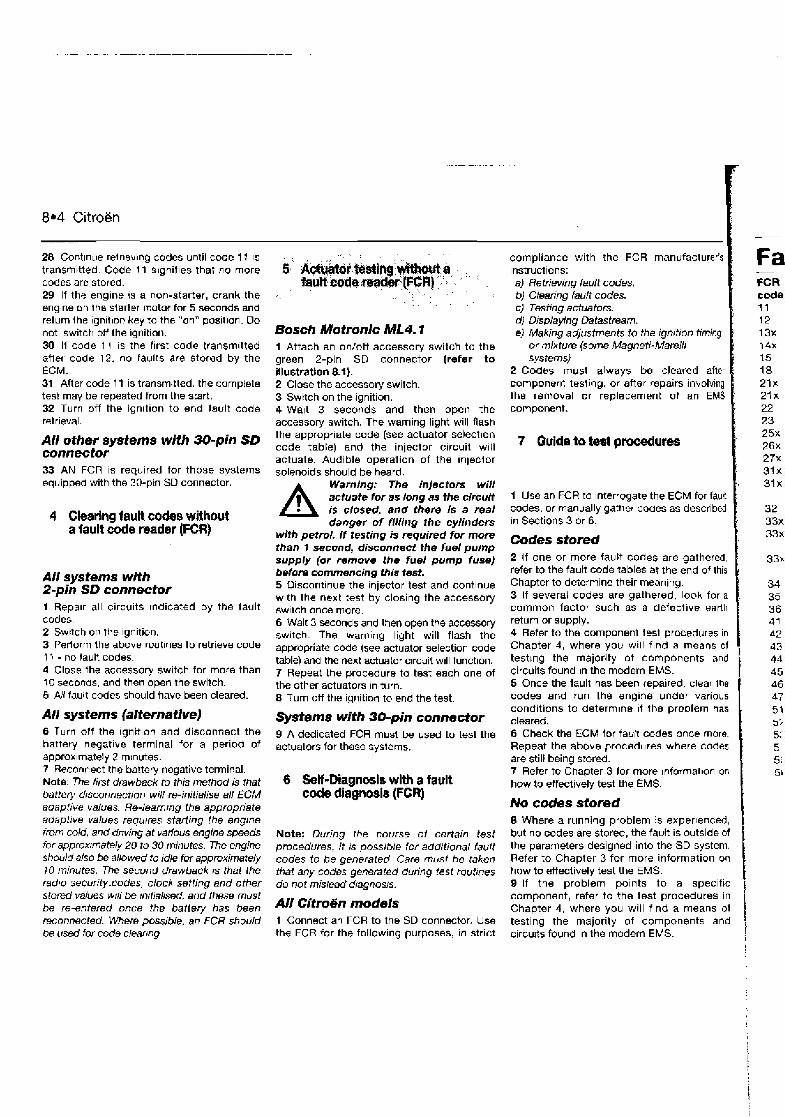
8.4 Citroen - - - -. . .
28 Cont~nue relrlevlng codes until code 11 IS
transmitted Code 11 signit~es that no more codes are stored. 29 If the engine IS a non-starter, crank the engine on ihs starler motor for 5 seconds and return Ihe ignltlon key to the "on" poxit~on. Do not switch off the ~qrlition. 30 H code 1 I IS the flrst code transm~tted after code 12, no faults are stored by the ECM. 31 After code 11 is transmitted, the complete test may be repeated from the start. 32 Turn off the ign~tion to end fault code retrieval.
All other systems with 30-pin SD connector 33 AN FCR is required for those systems equipped with the 30-pin SD connector.
4 Clearlng lault codes without a fault code reader (FCR)
All systems with 2-pin SD connector 1 Repa~r all circuits indicated by the fault codes. 2 Sw~tch un the ignition. 3 Perform the above rwtlnes to retrieve code 11 - no lault codes. 4 Close the accessory switch for more than I0 seconds, and then open the switch. 5 All fault codes should have been cleared.
All systems (alternative) 6 Turn off the ignition and disconnect the battery negatlve terminal for a period of approx~mately 2 rn~nutes. 7 Reconnect the battery negative terminal. Note: The first drawback to this method is that barter). drsconnection will re-initialise all ECM adaptive values. Re-leammg the appropriate adaptive values requ~res starting the engine from cold, and dnving at various engine speeds for approxrmately 20 to 30 minutes. The engine should also be allowed to idle fur approximately 10 minutes. The Second drawback a that the radto security.codes, clock setting and other stored values will be inrtialrsed, and [hese must be re-entered once the batlery has been reconnected. Where possrble, an FCR should be used for code clear~ng.
Bosch Motronlc ML4.1 1 Attach an onloff accessory switch to the green 2-pin SD connector (refer to illustration 8.1). 2 Close the accessory switch. 3 Switch on the ignition. 4 Walt 3 seconds and then open the accessory switch. The warning light will flash the appropriate code (see actuator selection code table) and the injector circuit w~ l l actuate. Audible operation of the injeclor solenoids should be heard.
A Warning: The injectors will actuate for as long as the circuit is closed, and there Is a real danger of f//IIng the cylinders
with petrol. If testing is required for more than 1 second, disconnect the fuel pump supply (or remove the fuel pump fuse) before commencing this test. 5 Discont~nue the Injector test and continue with the next test by closing the accessory sw~tch once more. 6 Wait 3 seconds and then open the accasory switch. The warning light will flash the appropriate code (see actuator selection code table) and the next actuator circuit will function. 7 Repeat the procedure to test each one of the other actuators In turn. 8 Turn off the ignition to end the test.
Systems with 30-pin connector 9 A dedicated FCR must be used to test the actuators for these systems.
6 Self-Diagnosis wlth a fault code diagnosls (FCR)
Note: During the course of certain test procedures, it rs possrble Icr addrlianal fault codes to be generated. Care must be taken that any codes genemted during test mutrnes do not mislead dragnos~s.
All Citmtin models 1 Connect an FCR to the SD connector. Use the FCR for the following purposes, In strict
compliance with the FCR manufacturer's instructions: a) Retrieving fault codes. b) Clearing fault codes. c) Testing actuators. d) ~ ~ s p l a ~ i n ~ Datastream. eJ Making a@ustrnents to the ignition timing
or mixture (some Magneti-MareNi systems)
2 Codes must always be cleared after component testing, or after fepairs ~nvolving Ihe removal or replacement of an EMS component.
Fa - FCR code 11
1 Use an FCR to Interrogate the ECM for fautt codes, or manually gather codes as described in Sections 3 or 6.
Codes stored 1
No codes stored I
2 If one or more fault codes are gathered, refer to the fault code tables at the end of this Chapter to determine their meaning. 3 If several codes are gathered, loclh for a common factor such as a defective earth
8 Where a running problem is exper~enced, but no codes are stored, the fault is outside of the parameters designed into the SD system. Refer to Chapter 3 for more information on how to effectively test the EMS. 8 If the problem points to a specific component, refer to the test procedures in Chapter 4, where you will find a means of testing the majority of components and circults found in the modern EMS. i
return or supply. 4 Refer to the component tesl procedures In
Chapter 4, where you will find a means of test~ng the majority ot components and circuits found in the modern EMS. 5 Once the fault has been repaired, clear Ihe codes and run the engine under various conditions to determine i f the problem has cleared. 6 Check the ECM for fauit codes once more. Repeat the above procedures where codes
. are still being SMred. 7 Refer to Chapter 3 for more lnformat~on on how to effectively test the EMS.
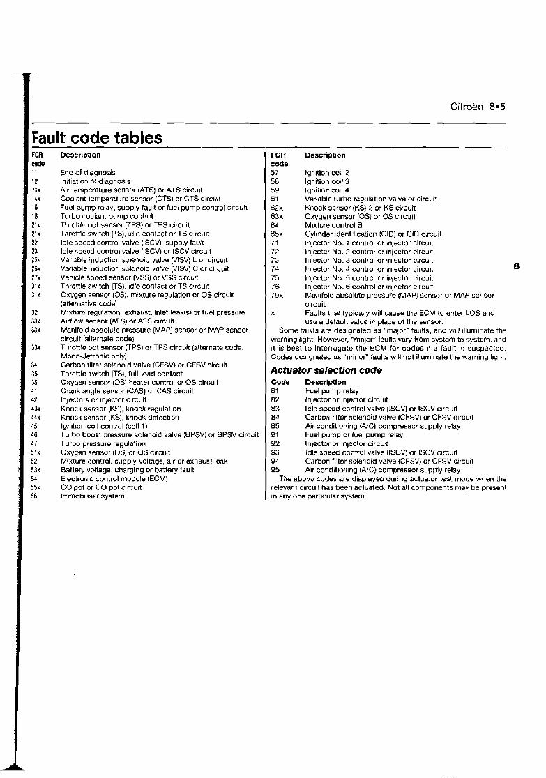
Citroen 8.5
Fault code tables FCR d e I 1 12 13x I 4n 15 18 2lx 21x 22 n 25x 26x 27x 3:x 31x
Description
End of diagnosis Initiation of diagnosis Air temperature sensor (ATS) or ATS circuit Coolant temperature sensor (CTSI or CTS circuit Fuel pump relay, supply fault or fuel pump control circuit Turbo cooiant pump control Throttle pot sensor UPS) or TPS circuit Throttle switch FS), Idle conlact or TS circuit ldle speed control valve (ISCV), supply fault ldle speed control valve (ISCVj or ISCV c~rcuit Variable induction solenoid valve (VISV) L or circuit Variable lnductron solenoid valve (VISVj C or circuit Vehicle speed sensor (VSS) or VSS circuit Throttle switch (TS), Idle contact or TS circuit Oxygen sensor (OS), mixture regulation or OS circu~t (alternative cwe) Mixture regulat~on, exhahst, inlet leak@) or fuel pressure Airflow sensor (AFS) or AFS circuit Manifold absolute pressure (MAP) sensor or MAP sensor circuit (alternate code) Throttle pot sensor UPS) or TPS circuit (alternate code. Mono-Jetronic only) Carbon filter solenoid valve (CFSV) or CFSV crrcuit Throttle switch (TS}, full-toad contact Oxygen sensor (0s) heater control or OS circuit Crank angle sensor (GAS) or CAS circuit injectors or Injector circuit Knock sensor (KS), knock regulation Knock sensor (KS), knock detection lgnltlon coil control (coil 1) Turbo boos1 pressure solenold valve (BPSVj or BPSV circuit Turbo pressure regulation Oxygen sensor (0s) or OS circuit Mixture control, supply voltage, alr or exhaust leak Battery voltage, charging or battery fault Electronic control module (ECM) CO pot or CO pot clrcuit Immobiliser system
FCR Description code 57 lgn~tion coil 2 58 Ignition coil 3 59 Ignitlor: coil 4 61 Variable turbo regulation valve or circuit 62x Knock sensor {KS) 2 or KS cncuk 63x Oxygen sensor (0s) or OS circuit 64 Mixture control B 65x Cyfinder identification (ClD) or CiD circuit 71 Injector No. 1 control or lnlector circuit 72 injector No. 2 control or injector circurt 73 Injector No. 3 control or injector c!rcult 74 Injector No, d control or injector circuit 75 lnjector No. 5 control or injector circuit 76 Injector No. 6 control or Inlector clrctiit 79x Man~fold absolute pressure (MAP) sensor or MAP sensor
circuit x Faults that typically will causs the ECM to enter LOS and
use a default value in place of the sensor. Some faults are designated as "major" faults, and will illuminate the
warning I~ght. However, "major" faults vary ffom system to system. and ~t is best to interrogate the ECM for codes I1 a fault is suspected. Codes designated as "minor" faults will not illurn~nate the warning light.
Actuator selection code Code Description 81 Fuel pump relay 82 Injector or injecror circuit 83 Idle speed control valve (ISCV) or ISCV circuit 84 Carbon filter solenoid valve (CFSV) or CFSV circu~t 85 Air conditioning (A/C) compressor supply relay 91 Fuel pump or fuel pump relay 92 Injector w injector circu:t 93 Idle speed control valve (ISCV or ISCV circuit 94 Carbon filter solenold valve (CFSV) or CFSV crrcult 95 Air conditioning (NC) compressor supply relay
The above codes are displayed during actuator test mode W e n the relevant circurt has been acluated. Not all components may be present In any one particular system.
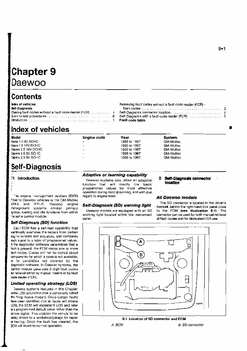
I Chapter 9 Daewoo Contents hdex of vehicles Retrieving fault codes without a fault code reader (FCR) - W-Diagnosis flashcodes . . . . . . . . . . . . . . . . . . . . . . . . . . . . . . . . . . . . . . . . . . . 3 f l~ar iny fault codes without a fault code reader (FCH) . . . . . . . . . . . 4 Self-Diagnosis connector location . . . . . . . . . . . . . . . . . . . . . . . . . . . 2 Gu~de to test procedures . . . . . . . . . . . . . . . . . . . . . . . . . . . . . . . . . 6 Sell-Diagnosis with a fault code reader (FCR) . . . . . . . . . . . . . . . . . 5 Inb-oduct~on . . . . . . . . . . . . . . . . . . . . . . . . . . . . . . . . . . . . . . . . . . 1 Fault code table
Index of vehicles Model Engine code Year System Nexia 1.5 8V SOHC 1995 to 1997 GM-Multec Nerr~a 1.5 l6V DOHC 1 995 to 1997 GM-Multec Espero 1.5 16V DOHC 1995 to 1997 GM-Multec Espero 1.8 8V SOHC 1 995 to 1997 GM-Multec Espero 2.0 8V SOHC 1995 to 1997 GM-Multec
f Self-Diagnosis
The engine management system (EMS) flttcd to Daewoo vehicles is the GM-Multec IEFI-6 and IEFI-S. Daewoo engine management systems control primary ignition, fuelling and idle functions from within the same control module.
Self-Diagnosis (SD) function Each ECM has a self-test capability that
continually examlnes the signals from certain engine sensors and actuators, and compares each signal to a table of programmed values. If the d~agnostic software determines that a fault is present, the ECM stores one or more fault codes. Codes will not be stored about components for which a code is not available, or for conditions nor covered by the diagnostic sottware. In Daewoo systems, the control module generates 2-digit fault codes for retrieval erther by manual means or by fault code reader (FCR).
limited operating strategy (LOSJ Daewoo systems featured ~ r l this Chapter
utllise LOS (a function that :s commonly called the "l~mp-home mode") Once certain faults have been identifeu (not all faults will initiate LOS), the ECM will Implement LOS and refer toa programmed default value rather than the sensor slgnal. this enables the veh~cls to be safsly drlven to a workshop/garage for repalr or testing. Once the fault has cleared, the ECM will revert to normal operation.
Adaptive or ieaming capability Daewoo systems also utilise an adaptive
function that will modify the basic programmes values for most efi~ct!ve operation dur~ng normal running, and with due regard to engine wear.
Self-Diagnosis (SD) warning light Daewoo models are equipped with an SD
warning light located within the instrument panel.
All Daewoo models The SD connector 4s located in the dr~ver's
footwell. M i n d the right-hand kick panel close to the ECM (see illustration 9.1). The connector can be used for both manual retrieval of flash codes and for dedicated FCR u s .
9.1 Location of SD connector and ECM
A ECM 8 SD connectof

9.2 Daewoo
9.2 Retrieve flash codes by conn6ding a bridge wlre between terminals A and B on
the SD connector
Note: Dunng the course of certain test prucedures, it IS possible for additional fault codes to be generated. Care must be taken that any codes generated during test routines do not m~slead diagnosis. All codes must be cleamd once testlng is complete. 1 Use a jumper lead to bridge terminals A and B in the SO connector (sse lllustratlon 9.2). 2 Switch on the ignition, but do not start the engine. 3 The codes are displayed on the SD warning light in the instrument panel. The flashing of the light indicates the 2-digit fault codes as follows:
a) The two digits are indicated by two series of flashes.
bJ The first series of flashes indicates the multiples of ten, the second series of flashes indicates the single units.
c) A 0.4-second tiash fo/lowed by a 1.2- second interval indicates fault codes in multip/es of ten. A 0.4-second flash followed in quick succession by another flash indjcates units
d) A 3.2-second pause separates the rransmrssion of each rndtvtdual code.
e) Code number "12" IS tndtcated by one short (0.4-second) flash, followed by a 1.2-second pause then two flashes of 0.4 seconds in quick succession.
Fault code table FlasW FCR code 12
4 Count the n u m b of flashes in each series, and record each code as it is transmitted. Refer l o the table at the end of the Chapter to determine the meaning of the fault code. 5 The first code transmitted will be code "1 2", which signifies code initiation. 6 Each flash code will be repeated three times followed by the next code in sequence. 7 Continue retrieving codes until al l stored codes have been retrieved and recorded. 8 Turn off the ignition and remove the jumper lead to end fault code retrieval.
A11 systems 1 Turn otf the ignition and disconnect the battery negative terminal for a period of approximately 5 minvles. 2 Reconnect the battery nwative terminal. Note: The first drawbeck to this method is that battery disconnection will re-initialtse all ECM adaptive values. Re-learning the appropriate adaptive values requires starting the engine from cold, and driving at various engine speeds for approximately 20 to 30 minutes. The engine should also be allowed to idle for approximately 10 minutes. The second drawback is that the radio security codes, clock setting and other stored values wili be initlalised, and these must be re-entered once the battery has been reconnected. Where possible, an FCR should be used for code clearing.
Note: During the course of certain test procedures, it is possible for additional fault codes to be generated Care must bs taken that any codes generated during test routines do not mislead diagnosts.
AII Dae woo models 1 Connect an FCR to the SD connector. Use the FCR for the following purposes, in strict
compliance wlth the FCR manufacturer's instructions: a) Retrieving faun codes. bJ Clmring fault codes. c) #splaying Datastream.
2 Codes must always be cleared aftar component testing, or after repairs involving the removal or replacement of an EMS component.
Description
No faults found in the ECM. Procwd with normal diagnostic methods Oxygen sensor (0s) or OS clrcuit Coolant temperature sensor (CTS) or CTS circuit Throttle pot sensor (TPS) or TPS circuit Air temperature sensor (ATS) or ATS circuit Vehicle speed sensor (VSS) or VSS circuit Exhaust gas reclrculat~on (EGR) error or EGR circuit
1 Use an FCR to interrogate the ECM for faun cdes, or manually gather codes as described in %ions 3 or 5.
Flash/ FCR code 33
42 44 45 51 54
Codes stomd 2 If one or more fault codes are gathered, refer to the fault code table at the end of this Chapter to determine their meaning. 3 If several codes are gathered, look for a common factor such as a defective earth return or supply. 4 Refer to the component test procedures m Chapter 4, where you will find a means o l testing the majority of components and circuits found in the modern EMS. 5 Once the fault has been repaired, clear the codes and run the engine under various conditions to determine i f the problem has cleared. 6 Check the ECM tor fault codes once more Repeat the above procedures whore codes are still being stored. 7 Refer to Chapter 3 for more ~nlormat~on on how to effaively test the EMS.
No codes stored 8 Where a running problem IS experienced, but no codes are stored, the faun is outside d the parameters designed into the SD system. Refer to Chapter 3 for more intormation on how to effectively test the EMS. 9 If the problem polnts to a specific component, refer to the test procedures in Chapter 4, where you will find a means of testing the majority of components and circuits found In the modern EMS.
Description !
Manifold absolute pressure (MAP) sensor or MAP sensor clrcuit lgnltlon control circuit error 7 Oxygen sensor (0s) lean or OS clrcu~t Oxygen sensor (0s) nch or OS c~rcuit Electronic control module (ECM) error CO adjust error
lr -.
Mr AP! Ch, Ch. Cb CLl. Hi-. SPI
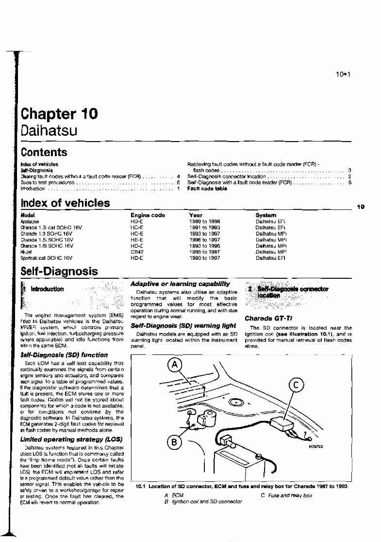
Contents hdex of vehicles Retrieving tault codes without a fault code readm (FCR) - &If-Diagnosis flashcodes . . . . . . . . . . . . . . . . . . . . . . . . . . . . . . . . . . . . . . . . . . . 3 Claaring fault codes without a fault code reader (FCR) . . . . . . . . . . . 4 Self-D~agnosis connector location . . . . . . . . . . . . . . . . . . . . . . . . . . . 2 Guide to test procedures . . . . . . . . . . . . . . . . . . . . . . . . . . . . . . . . . . 6 Self-Diagnosis with a fault code reader (FCR) . . . . . . . . . . . . . . . . . . 5 Introduction . . . . . . . . . . . . . . . . . . . . . . . . . . . . . . . . . . . . . . . . . . . . 1 Faultcodetable
Index of vehicles Model Ppplause Charade 1.3i cat SOHC 16V Charade 1.3 SOHC 16V Charade 1.5i SOHC 16V Charade l.6i SOHC 16V HiJet Sportrak cat SOHC 16V
Engine code HD-E HC-E HC-E HE-E HD-E C842 HD-E
Year 1 989 to 1996 1991 to 1993 1993 to 1 997 1996 to 1997 1 993 to 1996 1 995 to 1997 1990 to 1997
l a System Daihatsu EFi Daihatsu EFI Daihatsu MPI Daihatsu MPi Dalhatsu MPi Daihatsu MPi Daihatsu EFi
Self-Diagnosis
The engine management system (EMS) fitted to Daihatsu vebicles is the Daihatsu MPilEFi system, whlch controls primary ignition, fuel injection, turbocharging pressure {where app,icable) and ~dle functions from with~n the same ECM.
SaH-Diagnosis (SD) function Each ECM has a self-test capability that
continually examines the signals from certain engine sensors and actuators, and compares m c h signal to a table of programmed values. If the diagnostic software determines that a fault is present, the ECM stores one or more fault codes. Codes will nor be stored aboul components for which a code is not available. or for conditions not covered by the diagnostic software. In Oaihatsu systems, the ECM generates 2-digit fault codes for retrieval as Rash codes by manual methods alone.
Umited operating strategy (LOSJ Daihatsu systems featured in this Chapter
utilise LOS [a function that is commonly called the 'limp-home mode"). Once certain f a u k have been identified (not all faults w~ll initlate LOS), the ECM will ~rnpternent LOS and refer to a programmed default value rather than the sensor signal. This enables the vehicle to be safely onven to a workshop/garage for repalr or testing. Once the fault has cleared, the ECM will revert to normal operation.
Adaptive or kaming capability Daihatsu systems also utilise an adaptive
function that will modify the basic programmed values for most effective operation during normal running, and with due regard to engine wear.
Self-Diagnosis (SD] warning light Daihatsu models are squipped with an SO
warning light located within the instrument panel.
I
Charade GT- Ti The SD connector is located near the
ignition coll (see Illustration 10.1). and IS
provided for manual retr~eval of flash codes alone.
10.1 Locathn of SD connector, ECM and fuse and relay box for Charade 1987 to 1993
A ECM C Fuse and relay box B Ignition coil and SD connector
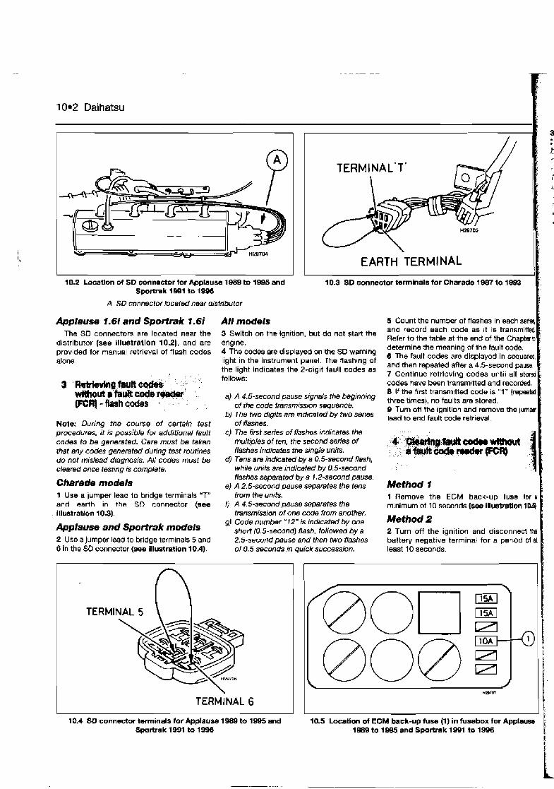
10*2 Daihatsu
TERMINAL'T' h
I EARTH TERMINAL I
10.2 Locatlon of SD connector lor Applause 1689 to 1945 and 10.3 SO connector terminals for Charade 1W7 to 1993 Sportra k 1991 to 1996 I
A SD connector located near distributor B: Applause 1.6i and Sportrak I. 6i All models 5 Count the number of flashes in each seriq [
The SD connectors are located near the 3 Switch on the ignition, but do not starl the and each 'Ode as it is
distributor {see lllustratlon 10.2), and are engine. Refer to the table at the end of the Chapterto determine the meaning of the fault ccde. provided for manual retrieval of flash codes 4 The codes are displayed on the SO warning
The fault codes are in swuw alone. light in the Instrument panel. The flash~ng of
the light lndlcates the 2 - d ~ g ~ t fault codes as and then repeated after a 4.5-second pause. , , 7 Continue retrieving codes until all stored
codes have been transmitt4 and recorded.
WtUwd ~'h* & 0 ~ @ $ ..I 8 If the first transmttted code is "1" (re- (FCq-&h&s : , . . . : ,
a) A 4.5-second pause signals the bepinning thrw times), no faults are stored. , , of the code transmiwon sequence. 0 Turn off the ignition and remove the jump
b, The two are indlceted fwo Smes lead to end fault code retrieval. Note: Durinq the course of certain test of flashes. procedures, 2 is possible for additional fault codes to be generated. Care must be taken that any codes generated during test routines do not mislead diagnosis. All codes must be cleared once test~ng IS complete.
Charade models 1 Use a jumper lead to bridge terminals "T" and earth in the SD connector (see illustration 10.3).
Applause and Sportrak models 2 Use a jumper lead to bridge terminals 5 and 6 in the SD connector (sea illustration 10.4).
c) The tirst series of flashes indicates the muttiples of ten, the second series of flashes indicates the single units.
d) Tens are indicated by a 0.5-second flash, while units are indicated by 0.5-second flashes separated by a 1.2-second pause.
eJ A 2.5-second pause separates the tens from the unrts.
I) A 4.5-second pause separates the tiansrnissmn of one code from another.
gJ Code number '12" is tndicated by one short (0.5-second) flash, followed by a 2.5-second pause and then two flashes of 0.5 seconds in quick succession.
10.4 SO connector terminals tor Applause 1989 to 1985 and Sportrak 1891 to
Method 1 1 Remove the ECM back-up fuse tor r minimum of 10 seconds (see illus?mtion 1U).
Method 2 2 Turn off the ignition and disconnect Me battery negative terminal for a pev~od o l al least 10 seconds.
I t 10.5 Location of ECM back-up fum (1) in fusebox for Applause
1989 to 1995 and Sportrak 1991 to 1996 1 I
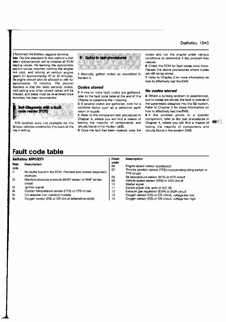
Daihatsu I 0.3
+" + + + 1 f Reconnect the battery negative terminal. ::::::?. ::~:G<~:?E?;$:;FA;;::;::::::;G;:::;;:~::::;;: ,,:,...... !..H:: :$ + + codes and run the engtne under various Me: The fmt drawback to this method is that ?,gi :-"$$t'~$':a:;
' P k F ~ ~ : i k ~ conditions to determine if the problem has <&+?" < " > < , < a Mdry disconnectron wtli re-initialise ail ECM iaji:? z;T:;;::j:::;::A::y;:;::::::;::::~<:;;;::::, ,::
wtivs ues, Fle-,mm,ng the :;!;?& :::A. .~:::il:::::~x:t.:::f:,::~:1~::::~::~::~;~::1;,:~~x::%z?::!a:a f cleared+ 6 Check the ECM for fault codes once more.
) , , A A , " A " " A ) x " iA , tA , " t " " , A A " , ", rdeptrve values requires stafi;ng the engine :~F:~~:<~;~:;C~;;:;:~::,L;~:;~~~ ,, : v~,:;:~y:::?: ::!i:~f;;:~:?:;;~:: A, Repeat the above procedures where codes hm "ld, and drtving at vanOus engine 1 Manually gather codes as described in are still being stored. ~pesds tor approximately 20 to 30 minutes. Sectlon 3. 7 Refer to Chapter 3 for mom information on me engine should also be allowed to idle for how to effectivdy jest the EMS. approximately 10 minutes. The second drawback is that the radio security codes, clock setling and other stored values will be initlalised, and these must be re-entered once the battety has been reconnected.
FCR facilities were not available for the Daihatsu vehicles covered by this book at the tkne of writing.
Codes stomd 2 If one or more fault codes are gathered. refer to thw fault code table at the end of this Chapler to determine their meaning. 3 If several codes are gathered, look for a common factor such as a defective earth return or supply. 4 Refer to the component test procedures in Chaplsr 4, where you wtll find a means of testing the majority of components and circuits found In the modern EMS. 5 Once the taull has been repaired, clear the
No codes stored 8 Where a running problem is experienced, but no codes are stored, the fault is outside of the parameters designed into the SD system. Refer to Chapter 3 for more information on how to effectively test the EMS. 9 H the problem points to a specific component, refer to the test procedures in *':.:: Chapter 4, where you will find a means of '?,:! testing the majority of components and circuits found in the modem EMS.
Dalhatsu MPi/EFi Flash Descrlptlon eode 01 No faults found in the ECM. Proceed with normal diagnost~c
methods 02 Manifold absolute pressure (MAP) sensor or MAP sensor
circuit 03 lgnit~on slgnal Cd Coolant temperature sensor (CTS) or CTS circuit 05 GO adjuster (non-catalyst models) 05 Oxygen sensor (0s) or OS circuit (alternative code)
Flash code 06 07
Description
Engine speed sensor (distributor) Throttle position sensor (TPS) incorporating idling switch or TPS circujt Alr temperature sensor (ATS) or ATS circult Vehicle speed sensor (VSS) or VSS circuit Starter signal Switch signal idle, auto or ffC.05 Exhaust gas regulation (EGR) or EGR circuit Oxygen sensor (0s) or OS circuit, voltage tw low Oxygen sensor (0s) or OS circuit, voltage too h~gh
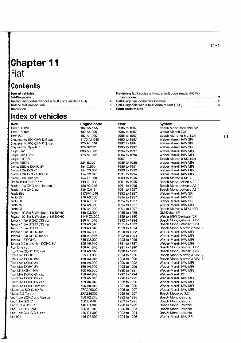
Contents M e x of vehicles W-Diagnosis Cleating fault codes without a fault code reader (FCR) . . . . . . .
. . . . . . . . . . . . . . . . . . . . . . . . . . . . . . Guide to test procedures Introduction . . . . . . . . . . . . . . . . . . . . . . . . . . . . . . . . . . . . . . . .
Index of vehicles Model Brava 1.4 12V Brava I .6 16V Bravo 2.0 Cinquecento 899 OHV DIS cat Cinquecento 900 OHV DIS cat Cinquecento Sporting Coupe 16V Coupe 16V Turbo Coupe 2.0 20V Croma 2000ie Crorna 2000ie DOHC 8V Croma 2.0ie DOHC Croma 2.0ie DOHC DIS cat Cmma 2.0ie 16V cat Fiorino 1500 SOHC cat Panda 1 .Oie OHC and 4x4 cat Panda 1 .l be OHC cat Panda 899 Punto 55 Punto 60 Punto 75 Punto GT Regata 100 Sie 8 Weekend 1.6 DOHC Regata 100 Sie & Weekend 1.6 DOHC Tempra 1.4ie SOHC DIS cat Tempra 1.6ie SOHC DIS cat Tempra 1 . 6 ~ SOHC cat Tempra 1.8ie DOHC 8V Tempra 1.8ie DOHC 8V cat Tempra 1.8 DOHC Tempra 2.01s and 4x4 DOHC 8V Tipo 1.4ie cat Tipo 1 61e SOHC ,DIS cat Tipo 1.6ie SOHC Tipo 1.6ie SOHC cat Tipo 1.8ie DOHC 8V Tipo 1.8ie DOHC 8V Tipo 1.8i DOHC 16V Tipo 1.81e DOHC 8V cat Tipo 2.0ie DOHC 8V cat Tipo 2.0ie DOHC BV cat Tipo 2.0ie DOHC 16V cat Ulysse 2.0 SOHC 89kW Ulysse 2.0 Turbo Uno 1 .Ole SOHC and Van cat Uno 1 . I ie SOHC Uno 70 1.4 SOHC Uno 1.4 SOHC cat Uno 1.51e SOHC DIS cat Uno 994
Engine code 182 M . f A A 182 A4.000 182 A1.OOO 11 70 At ,046 170 A1.046 176 82000 836 A3.000 175 A1.OOO
834 8.000 154 C.000 154 C3.000 154 C3.046 154 E l ,000 149 C1.OOO 156 A2.246 156 C.046 1 170Af ,046 1 76 A6.000 176 A7.000 176 A8.000 176 A4.000 149 C3.000 11 49 C3.000 160 A1.046 159 A3.046 159 A3.046 159 A4.000 159 A4.046 835 C2.000 159 A6.046 160 A1.046 159 A3.046 835 C1.000 159 A3.046 159 A4.000 159 A4.000 160 A5.000 159 A4.046 159 A5.046 159 A6.046 160 A8.046 ZFA220000 ZFA220000 156 A2.246 156 C.046 146 C1.000 160 A1.046 149 C1.000 146 C7.000
Retrieving fault codes without a fault code reader (FCR) - flashcodes . . . . . . . . . . . . . . . . . . . . . . . . . . . . . . . . . . . . . . . . . . . 3
. . . . . . . . . . . . . . . . . . . . . . . . . . . 4 Self-Diagnosis connector location 2 6 Self-Diagnosis with a fault code reader (FCR) . . . . . . . . . . . . . . . . . . 5 1 Fault code tables
Year 1996 to 1997 1996 to 1997 1996 to 1997 1993 to 1997 1992 to 1994 1995 to 1997 1994 to 1997 1994 to 1996 1997 1986 to 1989 1989 to 1991 1990 to 1992 1991 to 1994 1993 to t 995 1991 to 1995 1991 to 1996 1991 to 1997 1992 to 1997 1994 to 1997 1994 to 1997 1994 to 1997 1994 to 1997 1986 to 1988 1988 to 1990 1992 to 1994 t 991 to 1992 1993 to 1 994 1990 to 1 992 1992 to 1 994 1993 to 1 996 1991 to 1997 1991 to 1996 1990 to 1 992 1994 to 1996 1993 to 1995 1990 to 1992 1992 to 1995 1990 to 1991 1992 to 1994 1990 to 1992 1992 to 1995 1991 to 1995 1995 to 1997 1995 to 1997 1 992 to 7 995 1989 to 1995 1 990 to 1992 1 990 to 1995 1993 to 1994 1994 to 1996
System Bosch Mono-Motronic SPi Weber Marelli IAW Bosch Motronic M2.10.4 I t Weber-Marelli IAW SPi Weber-Marelli IAW SPi Weber-Marelli IAW SPi Weber-Marelli IAW MPi Weber-Marelli IAW MPi Bosch Motronic M2.10.4 Weber-Marelli IAW MPi Weber-Marelli IAW MPi Weber-Marel11 IAW MPi Weber-Marelli IAW MPi Bosch Motronic M I .7 Bosch Mono-Jetron~c A2.4 Bosch Mono-Jetronic A2.4 Bosch Mono-Jetronic A2.4 Weber-Marelli IAW SPi Weber-Marelli IAW SPi Weber-Marelli IAW SPi Weber-Marelli IAW MPi Bosch Motronic M2.7 MPi GM/Delco SPi Weber MIW Centrajet SPi Bosch Mono-Jetronic A2.4 Bosch Mono-Jetronic A2.4 Bosch Mono-Motronic MA1.7 Weber-Marelli IAW MPi Weber-Maretli IAW MPi Weber-Marelli IAW MPi Weber-Marelli IAW MPi Bosch Mono-Jetronic A2.4 Bosch Mono-Jetronic A2.4 Bosch Mono-Motronic MA1.7 Bosch Mono-Motronic MA1.7 Weber-Marelli IAW MPi Weber-Marel11 IAW MPi Wsber-Marelli IAW MPi Weber-Marelli 8 f Weber-Marelli IAW MPi Weber-Marelli IAW MPi Weber-Marelli IAW MPi Weber-Marell! IAW MPi Bosch Motronic 3.2 Bosch Mono-Jetronic Bosch Mono-Jetronic Bosch Mono-Jetronic Bosch Mono-Jetronic Bosch Mono-Jetronic Weber-Marelli IAW SPi

11 02 Fiat
Self-Diannosis
The engine management systems (EMSs) fitted to Fiat vehicles are mainly of Bosch or Weber-Marelli origin, and include Bosch Motron~c verslons 1.7, 2.7 and 2.10.4, and Weber-Marelli IAW. Other systems include Bosch Mono-Jetronic A2.4, Mono-Motronic MA1.7 and GM SPi. Apart from Mono- Jetronic, Fiat engine management systems control the primary ignition, fuelling and idle functions from within the same control module. The Mono-Jetronic system controls fuelling and idle speed alone.
Self-Diagnosis (SD) function Each ECM has a self-test capability that
continually examines the signals from certain engine sensors and actuators, and compares each signal to a table of programmed values. if the diagnostic software determines that a fault is present, the ECM stores a fault. Codes will not be stored about components for which a code is not available, or for conditions not covered by the diagnostic software.
GM-Deleo SPi In the GM-Delco SPi system, the EMS
generates 2-digit fault codes for retrieval by both manual means and by fault code reader (FCR).
All other Fiat systems Fiat software does not generate fault code
numbers for the majority of Fiat systems. A fault code reader (FCR) normally displays faults on the FCR screen without reference to a specffic code number. Although actual code numbers are not available, faults in one or more of the circuits and components covered by the diagnostic software will cause a fault to be stored.
Limited operating strategy (LOSJ Fiat systems featured in this Chapter utilise
LOS (a function that is commonly called the "limp-home mode"). Once certain faults have
11.1 3-pin SD connector used for retrieving fauk codes from Fiat systems
been identified (not all faults will initiate LOS), the ECM will implement LOS and refer to a programmed default value rather than the sensor signal. This enables the vehicle to be safely driven to a workshop/garage for repair or testing. Once the fault has cleared, the ECM will revert to normal operation.
Adaptive or learning capability Fiat systems also utilise an adaptive
function that will modify the basic programmed values for most effective operation during normal running, and with due regard to engine wear.
Self-Diagnosis {SD) warning light Many Fiat models are equipped with an SD
warning light located within the instrument panel. When the ignition is switched on, the light will humi in ate. Once the engine has started, the light will extinguish if the diagnostic software determines that a fault is not present. If the Itght remains illuminated at any time whilst the engine is running, the ECM has diagnosed presence of a system fault.
The 3-pin SD connector (see illustration 11.1) is located under the passenger's side glove compartment, close to the ECM. Both manual retrieval of flash codes and dedicated FCR use is possible.
Bosch Mono-Jetmnic The 3-pin SD connector IS usually located
on the bulkhead in the engine compartment. Alternative locations are close to the ECM under the passenger's side glove compart- ment, or in the centre console. The SD connector is provided for use by a dedicatd FCR alone.
Bosch Mono-Motronic MA 1.7 The 3-pin SD connector is usually located
beside the ECM on the right-hand inner wing in the engine compartment. Alternative locations are close to the ECM under the passenger's side glove compartment, or in the centre console. The SD connector is provided for use by a dedicated FCR alone.
Bosch Motronic 1.7 MPi The 3-pin SD connector is usually located
close to the ECM under the passenger's side glove compartment, and is provided for use by a dedicated FCR alone.
Bosch Motronic 2.7 MPi The 3-pin SO connector is usually located
close to the ECM on the bulkhead in the
engine compartment, and is provided for w by a dedicated FCR alone.
Bosch Motmnic 2. i 0.4 The 3-p~n SO connector is usually locatd
close to the right-hand side suspension turd in the engine compartment, and is provided for use by a dedicated FCR alone.
Hifachi The 3-pin SD connector is usually located
close to the ECM behind the passenger's side footwell trim, and is provided for use bya dedicated FCR alone.
Weber-Marelli MPi The 3-pin SD connector is usually located
in the engine compartment on the r~ght-hard bulkhead, or in the passenger compartment under the facia, close to the ECM. The SD connector is provided for use by a dedicated FCR alone.
Weber-Marelli SPi The 3-pin SD connector is usually located
in the engine compartment beside the ECM on the left-hand wing (Cinquecento) or beside the ECM on the right-hand wlng (other vehicles). The SD connector is provided for use by a dedicated FCR alone. I
3 Rettlevhgtaultcodes with& a fauit code reader (FCR) - flash codes
e) Cc 811
PL
r! 5 Cnl and I
Refer to dei 6 TI?: whici repe:. of ihi 7 Aii light 8 Ai' wlll ; Eacb pli: 9 If light 10 jum!
A11 I1 ,
d i s ~ to c
4
Ail 1 I ha:
Note: During the course of certain test procedums, it is possible for additional faun codes to be generated. Care must be taken that any codes generated during test routines do not mislead diagnosis. AN codes musf be cleared once testing IS complete.
Fiat GM (DelcoJ SPi I 1 Switch on the ignition -the SD warning light f should illuminate. 2 Use a jumper lead to bridge terminals A and
and black).
I 6 In the 3-pin SD connector (I~ght bluelwh~te y
! 3 The stepper motor will operate once so that 1 the plunger will fully extend and then retract. j 4 The codes are displayed on the SD warning light in the instrument panel. The flashmg of i
the light indicates the 2-digit fault codes as . follows: a) The two digits are indicated by two series :
of flashes. b) The first series of flashes indicates the
multiples of ten, while the second series 1 of flashes indicates the single units. \ c) A single flash indicates fault codes in tens, while a flash followed in quick I succession by a second flash indicates t units.
d) A 3.2-second pause separates the i transmission of each individual code. !
i
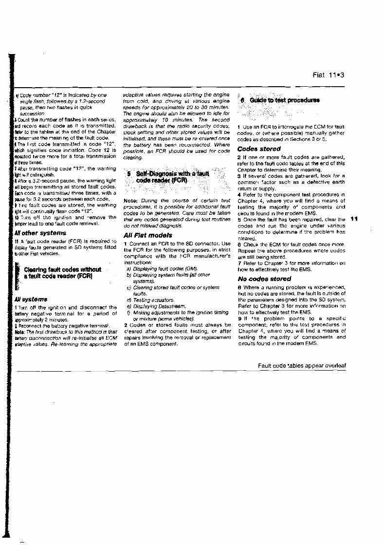
ounl the number of flashes in each series, record each code as it IS transmitted. to the tables at the end 01 the Chapter ermine the meaning of the fault code.
wl wlll extinguish. 1 After a 3.2-second pause. the warning light will begin transmittlng all stored fault codes. Each code IS transmitted three times. w~th a
for 3.2 seconds between each code. # i f no fault codes are stored, the warnlng $M will conimuatly flash code "1 2". tO Turn off the ign~tion and remove the bmper lead to end fault code retrieval.
41 other systems H A fault code reader (FCR) is required to display faults generated In SD systems fitted bother Fiat vehicles.
CBeatlng Pa& codes W M W t a feuR cvde reader tFCR)
1 Turn off the ignition and disconnect the batley negat~ve terminal for a period of wroxirnately 2 minutes. 2 Reconnect the battery negative term~nel. Note: The /let drawback to this method a that tmtfery disconnection WIN re-iniiralise all ECM -live values. Re-learning the appropriate
--.----
adaptive values requrres starting the engine from cold, and drivtng at various engine speeds for approximately 20 lo 30 minutes. The engine should also be allowed to idle for approximately I 0 minutes. The second drawback is that the radio security codes, clock setting and other stored values will be initialisad, and these must be re-entered once the battery has been reconnected. Where possible, an FCR should be wed for code clearing.
Note: During the course of certain tesl procedures, it I S possible lor additional fault codes lo be genemfed. Care must be taken that any codes generated during rest f0utin8S do not mislead diagnosis.
All Fiat modek 1 Connect an FCR to the SD conneztor. Use the FCR for the following purposes, in strict compliance with the FCR manufacturer's instructions: a) Displaying fault codes (GM). b) Displaying system faults (all other
systems). c) Cleanng stored IauEl codes or system
faults. d) Testing actuators. el Dispkying Datastream. rJ Making adjustments to the ign~tion timing
or mixture (some vehicles). 2 Codes or stored fauits must always be cleared after component testing, or after repairs involving the removal or replacement of an EMS comwnent.
Fiat 11 m3
1 Use an FCR to interrogate the ECM for tault codes, or (where possible) manually gather codes as desc r iw in Sections 3 w 5.
Codes stored 2 If one or more fault codes are gathered, refer to the fault Code tables at the end of this Chapter to determine their meaning. 3 If several codes are gathered, look for a common factor such as a defective earth return or supply. 4 Refer to the component test procedures in Chapter 4, where you will find a means of testing the majority of components and circuits found in the m d e m EMS. 5 Once the fault has been repaired, clear the 11 codes and run the engine under various cond~tions to determhne if the problem has cleared. 6 Check the ECM for fault codes once more. Repeal the above procedures where codes are still being stored. 7 Refer to Chapter 3 for more Information on how to effectively test the EMS.
No codes stared 8 Where a running problem IS exper~enced, but no codes are stored, the fault is outs~de of the parameters desrgnd into the SO system. Refer to Chapter 3 for more information on how to effectrvely test the EMS. 9 If the problem po~nts to a specific component, refer to the test procadures in Chapter 4 , where you will find a means cl testing the majority of components and circuits found In the modern EMS.
Fault code tables appear overleaf

. - "-.. -
11 e 4 Fiat
Fault code tables GM-Delco SPI
Flash/ Descrlptlon FCR code 14 Coolant temperature sensor (CTS) or CTS circuit 15 Coolant temperature sensor (CTS) or CTS circuit 21 Throttle position sensor VPS) or TPS circuit 22 Throttle position sensor (TPS) or TPS circuit 23 Air temperature sensor (ATS) or ATS circuit 25 Air temperature sensor (ATS) or ATS circuit 33 Manifold absolute pressure (MAP) sensor signal or circuit 34 Manifold absolute pressure (MAP) sensor signal or clrcuit 42 Ignition circuit 51 Electronic control module (ECM) 52 Electronic control module (ECM) 55 Electronic control module (ECM)
All ofher systems Fiat software does not usually generate fault codes. The FCR
normally displays faults on the FCR screen without reference to a specific code number. Although actual code numben are not available, faults in one or more of the following list of circuits and components will cause a fault to be stored.
List of circuits checked by Fiat SD system Adaptive control limits. When the limits em reached, thrs suggesk serious engine (mechanid) condition. Air temperature sensor (ATS) or ArS circurt Battery voltage too low or too high Crank angle sensor (CAS) or CAS circuit, loss of signal Carbon filter solenoid valve (CFSL) or CFSV circuit Coolant temperaturn sensor {CTS) or CTS circuit Electronic control module (ECM) Distributor phase sensor circuit (CID) Ignition coil(s) control or circuit Injector control or injector circuit Knock sensor (KS) or KS circuit Oxygen sensor (0s) or OS circuit Manifold absolute pressure (MAP) sensor or MAP sensor crrcuil Manifold absolute pressure (MAP) sensor, no cotrelation between W signal and throttle position sensor (TPS) and crank angle sensor (cASI signals Mismatch between crank angle sensor (CAS) signal and dislr~butw phase sensor signal or circuit Oxygen sensor (0s) or 0s circuit Relay control or circuit Sel f-Diagnosis FD) warning light or circuit Idle speed stepper motor (ISSM) or ISSM circuit Tachometer Throttle pot sensor FPS) or TPS circuit
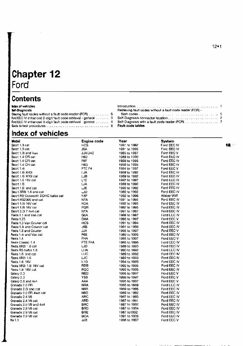
. . . . . . . . . . . . . . . . . . . . . . . . . . . . . . . . . . . . . . . . . . I hdsw 01 vehicles Introduction W-Diagnosis Retrieving tault codes without a fault code reader (FCR) -
. . . . . . . . . . . . . . . . . . . . . . . . . . . . . . . . . . . . . . . . . . . . . . . . . . . . h r n g fault codes without a fault code reader (FCR) 6 flash codes Ford EEC IV enhanced 2-digit fault code retrieval - general . . . . . . . 3 Self-D~agnosis connector location . . . . . . . . . . . . . . . . . . . . . . . . . Fwd EEC IV enhanced 3-digit fault code retrieval - general . . . . . . . 4 Setf-D~agnosis with a faun code reader (FCR) . . . . . . . . . . . . . . . . Guids to test procedures . . . . . . . . . . . . . . . . . . . . . . . . . . . . . . . . . . 8 FauH Eode tables
Index of vehicles Model Escort 1.3 cat Wrt 1.3 cat h r t 1.3i and Van b r t 1.4 CFi cat ! k o r t 1.4 CFi cat fscort 1.4 CFi cal Escort 1.4i Escort 1.6i XR3i Escort 1.6i XR3i cal bcort 1.6 16V cat Escort 1.6i Escort 1.6i and cat Escort XR3i 1.6 and cat Escort RS Cosworth DOHC turbo cat Escort RS2000 and cat Escort 7.8i 16V cat Escort 1.8i 16V cat Escort 2.0i 7 4x4 cal Nesta 1.1 and Van cat Fiesta 1.25 Fiesta 1.3 Van Cour~er cet Fiesta 1.3i and Courier cat Rsta 1.3 and Courier Asta 1.4i and Van cat Fiesta 1.4 Fwsta Ciassic 1.4 Fiesta XR2i 1.6 cat Fiesta RS turbo 1.6 Fiesta 1.6i and cat Flesta XR2i 1.6 Fiesta 1.6i 16V Fieeta XR2i 1.8i 16V cat Fiesta 1.8i 16V cat Galaxy 2.0 Galaxy 2.3 Galaxy 2.8 and 4x4 Granada 2.0 EFi Granada 2.0i and cat Granada 2.0 EFi 4wd cat Granada 2.4 V6 Granada 2.4 V6 cat Granada 2.9 V6 and 4x4 Granada 2.9 V6 cat Granada 2.9 V6 cat Granada 2.9 V6 cat l(a 1.3
Engine code HCS J6A J JNJ4C F6D F6F F6G PTE F4 WA LJB L1 E LJA U E WO N5F N7A RDA RQB N7A G6A DHA HCS J6B JJ A F6E FHA PTE F4A WD LH A LUC WC U G RDB RQC NSD Y5B A M NRA N9B N9D ARC ARD BRC BRD BRE BOA JJB
Year 1991 to 1992 1991 to 1995 19% to 1997 1989 to 1 990 1990 to 1995 1990 to r 995 1994 to 1 997 1 989 to 1992 1 989 to 1992 1 992 to 1997 1 989 to 1990 1 990 to 1992 1 989 to 1992 t 992 to 1996 1991 to 1995 1992 to 1 995 1992 to 1 995 1991 to 1997 1989 to 1 997 1995 to 1 997 1991 to 1 994 1991 to 1 996 1995 to 1997 1 989 to 1995 1 995 to 1997 1 995 to 1996 1 989 to 1993 1 990 to 1992 1 989 to 1992 1 989 to 1993 7 99d to 1 995 t 992 to 1995 199210 1995 1995 to 1997 1996 to 1997 1995 lo 1 997 1985 to 1 989 1989 to 1995 1989 to 1 992 1387 to 1 993 1987 to 1991 1 987 to 1992 1987 to 1994 1987 to1992 1991 to 1995 1996 to 1997
System Ford EEC 1V Ford EEC IV Ford EEC V Ford EEC IV Ford EEC IV Ford EEC IV Ford EEC V Ford EEC IV Ford EEC IV Ford EEC IV Ford EEC IV Ford EEC IV Ford EEC IV W e k r IAW Ford EEC 1V Ford EEC IV Ford EEC IV Ford EEC IV Ford EEC IV Ford EEC V Ford EEC IV Ford EEC IV Ford EEC V Ford EEC IV Ford EEC V Ford EEC IV Ford EEC IV Ford EEC !V Ford EEC IV Ford EEC IV Ford EEC IV Ford EEC IV Ford EEC IV Ford EEC V Ford EEC V Ford EEC V Ford EEC IV Ford EEC IV Ford EEC IV Ford EEC IV Ford EEC IV Ford EEC IV Ford EEC IV Ford EEC IV Ford EEC IV Ford EEC V
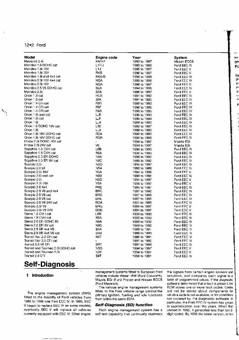
12.2 Ford
Model Maverick 2.4i Mondeo 1.6 DOHC cat Mondeo l.6i 16V Mondeo 1.8i 16V Mondeo 1.8i and 4x4 cat Mondeo 2.0i 16V 4x4 cat Mondeo 2.0i 16V Mondeo 2.5 V6 DOHC cat Mondeo 2.5i Orion 1.3 cat Orion 1.3 cat Orion 1.4 CFi cat Orion 1.4 CFi cat
k., Orion 1.4 CFi cat Orion 1.6i and cat Orion l.6i cat Orion 1.6i Orion 1.6 DOHC 16V cat Orion 1.6i Orion 1.8i 16V DOHC cat Orion 1.8i 16V DOHC cat Probe 2.0i DOHC 16V cat Probe 2.3 24V cat Sapphire 1.6 CVH cat Sapphire 1.8 CVH cat Sapphire 2.0 EFi DOHC Sapphire 2.0 EFi 8V cat Scorpio 2.0i Scorpio 2.0 EFi Scorpio 2.0i 16V Scorpio 2.0i and cat Scorpio 2 .Oi Scorpio 2.3i 16V Scorpio 2.8 4x4 Scorpio 2.9 V6 and 4x4 Scorpio 2.9 V6 cat Scorpio 2.9 V6 cat Scorpio 2.9 V6 24V cat Scorpio 2.9i V6 Scorpio 2.9i V6 24V Sierra 1.6 CVH cat Sierra 1.8 CVH cat Sierra 2.0 EFi DOHC 8V Sierra 2.0 EFi 8V cat Sierra 2.9 XR 4x4 V6 Sierra 2.9 XR 4x4 V6 cat Transit Van 2.0 CFi cat Transit Van 2.0 CFi cat Transit 2.9 V6 EFi Transit and Tourneo 2.0i DOHC cat Transif and Tourneo 2.0i Transit 2.9 EFi
Self-Diagnosis
Engine KA24E L1 F/J L1 J RKB RKA/B NG A NGA SEA SEA HCS J6A F6D F6F F6G WE WF WA L1 E WA RDA RQB
V6 L6B R6A N9A N9C NSD N RA N3A N9B NSO Y5A PRE BRC BRO BRE BOA BUG BOB L68 R6A N9A N9C B3A 838 N6T
BRT NSG NSF B4T
code Year 1993 to 1997 1993 to 1 996 1996 to 1997 1996 to 1997 1993 to 1 996 1993 to 1 996 1996 to 1997 1994 to 1 996 1996 to 1 997 1991 to 1992 1991 to 1995 1989 to 1 990 1990 to 1995 1990 to 1995 1990 to 1 993 1990 to 1 994 1989 to 1 990 1992 to 1997 1989 to 1990 1992 to 1995 1992 to 1 995 1994 to 1997 1994 to 1997 1990 to 1 993 1992 to 1993 1989 to 1992 1989 to 1992 1994 to 1997 1985 to 1989 1994 to 1996 1989 to 1995 1994 to 1997 1996 to 1997 1985 to 1987 1987 to 1992 1987 to 1995 1987 to 1995 1991 to 1995 1994 to 1997 1994 to 1997 1 990 to 1993 1992 to 1993 1 989 to 1992 1999 to 1992 1989 to 199: 1989 to 1 993 1990 to 1991 1991 to 1 992 1991 to 199d 1994 to 1997 1994 lo 1997 79B9 to 1991
Ford EEC IV Ford EEC V Ford EEC V Ford EEC IV Ford EEC IV Ford EEC V Ford EEC IV Ford EEC V Ford EEC IV Ford EEC IV Ford EEC IV Ford EEC IV Ford EEC IV Ford EEC IV Ford EEC IV Ford EEC IV Ford EEC IV Ford EEC IV Ford EEC IV Ford EEC IV Mazda EGi Mazda EGi Ford EEC IV Ford EEC IV Ford EEC IV Ford EEC IV Ford E E C IV Ford EEC IV Ford EEC V Ford EEC IV Ford EEC V Ford EEC V Ford EEC IV Ford EEC IV Ford EEC IV Ford EEC IV Ford EEC IV Ford EEC V Ford EEC V Ford EEC IV Ford EEC IV F ofd EEC IV Ford EEC tV Ford EEC IV Ford EEC IV Ford EEC IV Ford EEC IV Ford EEC IV Ford EEC V Ford EEC V Ford EEC IV
1 Introduction
The engine management system (EMS) fitted to the majority of Ford vehicles from 1985 to 1996 was Ford EEC IV. In 1996, EEC V began to replace EEC IV on some models; eventually EEC V will replace all vehicles currently equ~pped with EEC IV. Other engine
management systems fitted to European Ford vehicles include Weber IAW (Ford Coswonh), Mazda EGi (Ford Probe) and Nissan ECCS (Ford Maverick).
The various englne management systems fitted to the Ford vehicle range control the primary ignition, fuelling and idle lunct~ons from within the same ECM.
Self-Diagnosis (SO) function Each engine management system has a
self-test capability Ihal cont~nually examrnes
the slgnals from cerla~n engine sensors and actuators, and compares each slgnal to a table of programmed values If the d~agnost~c sonware determines that a tault 1s present, the ECM stores one or more fault codes. Codes w~ l l not be stored about components for wh~ch a code is not available, or for cond~tions no? covered by the d~agnost~c software In particular, the Ford EEC 1V system has grown in soph~st~cat~on over the years. When f~rst utlllsed in 1985, ~t generated less than ten 2- dig~t codes. By 1996 the latest versron, which
t

Ford 12.3
I has now evolved into EEC V, is capable of generating over a hundred 3-dig~t codes.
Ford EEC V system Ford EEC V software does not generate
fault code numbers, a d the fault code reader FCRJ nortnally displays any faults on the FCR scrsen without reference to a specific code number. Although code numbers are not available, faults in one or more of the circuits w conlponents covered by the diagnostic wftware w~ll cause a fault to be stored.
I Umited operating strategy (LO$) 1 In 1988, EEC IV was equipped with keep
alive memory (KAM) which utilises LOS, otherw~sa known as the "l~mp-home mode". Prior to the fitting of KAM, EEC IV systems did not utilise LOS. Once certaln codes have been generated (not all codes will initiate LOS), the ECM w~ll implement LOS and refer to a programmed default value rather than the sensor signal. Thls enables the vehicle to be aafely driven to a workshop/garage for repair or tesllng. Once the fault has cleared, the ECM will revert lo normal operation. Other Ford vehicles that u t~ l~ss LOS include those equipped with Ford EEC V, Ford Probe [Mazda EGi) and Ford Maverick (Nissan ECCS). Ford Cosworth vehicles equipped with Weber IAW do not utilise LOS.
I Adaptive or learning capability All Ford vehbcles equipped with EEC IV
(with KAM). EEC V, Mazda EGi and h'issan
-
ECCS systems alse utilise an adaptive funct~on that w~l l modify the basic programmed values for most effectme operation during normal wnning, and with due regard to engine wear. However. Ford Cosworth (Weber IAW) does not utilise adaptive covti-01.
Self-Diagnosis (Sb) warning light The Ford Maverick alone is equippd with a
facia-mounted SD warning I~ght. In addition, an LED is located upon the ECM casing. When the ignition is switched on, the SD warnlng light and the LED will illun~~nate. O ~ c e the englne has started, the light and LED w~l l extinguish unless the diagnostic software determines that a system faull 1s present. If the light or LED illuminates at any time during a per~od of engine running, the ECM has diagnosed presence of a system fault. The warnlng light and LED can alsa be triggered to transmit flash codes.
Ford EEC IV: 2.0 SOHC, 2.0 DOHC, 2 .42 .8 and 2.9 V6
The 3-pin w 5-pin SD connector is located in the engine compartment, close to the ballery (see illustration 12.1).
--- -
12.1 The EEC IV (2.0 litrerY6) SD connector is located close to the battery
F u d EEC IV: CFi, EFi and Zetec (Escort and Fiesta)
The 3-pin SD connector is located In the engine compartment, behind the left-hand headlamp or left-hand wing (see illustration 42.2).
Ford EEC IV: Zetec (MondeoJ 12 The 3 - p ~ n SO connector I S located on a
plate on the engine compartment bulkhead along with the octane plug and the FDS2000 connector (see illustration 12.3).
Ford EEC IV and V (I 6-pin) The 16-pin 080 connector (see
illustrationl2-4) is usually located in Ihe engine compartment, under the steer~ng column, in the passenger footwell beh~nd the trim, or behind the ashtray in the centre console (Ford Galaxy).
PIN 19 40160 29/42 PIN
17 40/60 1 -- -
12.2 The EEC 1V (EscorVFiesta) SD connector is located behind 12.3 The EEC IV (Mondeo) SO connector ia located on a plate the left-hand headlight or on the left-hand wing along with the octane plug and the FDS2MXI
I 1 FDS2000 diagnostic 3 Octsne loop wire connector 4 SD connector
2 Octane conn%ctor
7 Power steering reservoir 3 SD connector 2 FDS2000 diagnostic 4 Octane connector
con?ector 5 Octane plug
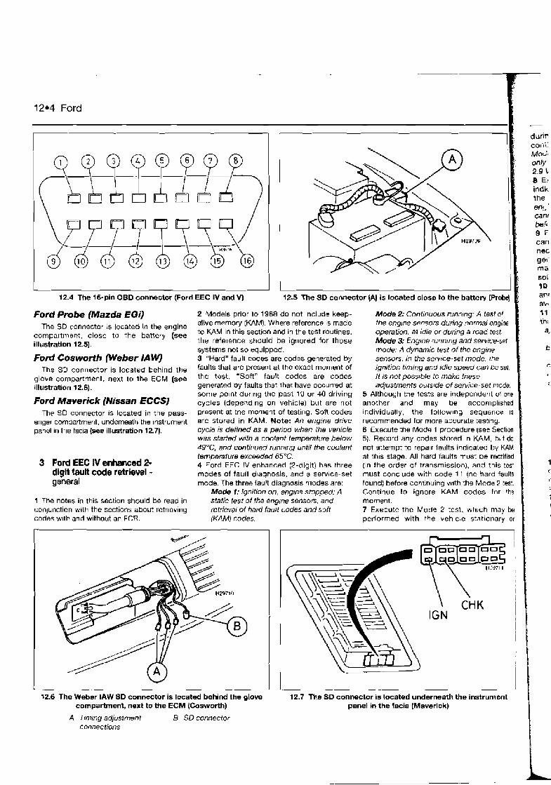
12.4 Ford
durir coiri' MoL. onb 2.9 '. 8 E: indir the ens can! beit 9 : can nec ge i ma soi 10 an(
' aw Ford Probe (Mazda EGi) 2 Models prior to 1988 do not include keep- Mode 2; Continuous runmng. A test of
The SD connector is located in the engine alive memory (KAM). Where reference 1s made the englne sensors during normal engine
compartment, close to the battery (see to KAM ~n this section and in the test routines. operation. a1 idle or during a road test.
illustration 12.5). the reference should be ignored for those Mode 3: Engrne cunnrng and serwce-ser systems not so equipped. mode: A dynamic lest of the engine
Ford Cosworth Weber lA WJ 3 "Hard" fault codes are codes generatd by sensors. In the semce-set mode. the
~h~ SD connector is located behind the faults that are present at the exact moment of ignition timing and idle speed can be set.
next +a +he ECM (see the test. "Soft" fault codes are codes li IS not pbssrble to make these illustration 12.6). generated Dy faults that that have occurred at adjustments outsrde of service-set mode.
some polnt dur~ng the past 10 or 40 driving 5 Although the tests are independent of one Ford Maverick (Mi~an EcCS] cycles (depending on vehicle) but are not another and may be accomplished
~ h p SO connector 1s located in the pass- present at the moolent of testing. Soft codes individually, the follow~ng sequence IS
enger compartment, underneath the instrument are stored in KAM. Note: An engine drive recommended for more accurate testlng. panel in the facra (see illustration 1271. cycle is defined as a period when the vel?icle 6 Execute the kbde 1 procedure (see Section
was Stad8d with a coolant temperature below 5). Record any codes stored in M M , bdt do 49"C, and continued runn~ng until the coolant not attempt to repalr laillts indicated by KAM temperature exceeded 65°C. at this stage. All hard faults must be rectified
3 Ford EEC IV enhanced 2- 4 Ford EEC IV enhanced (2-digit) has three (in the order of transmission), and this test diglt fault code retrieval - modes of fault diagnosis, and a service-set must concluae with code 11 (no hard faults general mode. The three fault diagnosis modes are: found) before continuing wlth the Mode 2 test.
Modet:lgnitionon,engrnestopped:A Continue to ignore KAM codes for !he 1 The notes in this section should be read in static test of the engrne sensoa, and moment. conjunction with the sections about retriev~ng retrieva! oi hard fault codes and soft 7 Execute the Mode 2 test, whrch may be codes w~th and without an FCR. (KAM) codes. performed with the vehicle s!at~onary or
1
I 12.6 The Weber IAW SD connector is located behind the glove
panel in the facia (Maverick) 12.7 The SD connector is located underneath the instrument
compartment, next to h e ECM [Cosworth)
A Trn71ng adjusimrtn t B SD connector connections

during a road test. Rectlfy all faults before continuing with Ihe Mode 3 test. Note: The Mcde 2 test is provided for Europeen vehicles only (not USA); with the exceplmn of 2.4 and 2 J V6 catalyst-equipped European vehicles. 8 Execute the Mode 3 test, rectify any faults fld~cated, and then make adjustments under the service-set mode ( ~ f required). Note: An mgfne rvnntng test for I988 and later vehicles cannot be performed if a hard code is present h e h the test begins. B Fault codes that were retrieved from KAM can now be ~nvesiigated and rectified as necessary Rect~fying the hard faults generated during the three test procedures may solve the reason for the generation of soh codes without funher testing. HI It IS good practice tn turn the ign~t~on off and wait 10 seconds between each test, to woid an erroneous self-diagnosis test. 11 Before commencing an SD lest, ensure mat the follow~ng cond~tions are met: 8) T k engine has attained narrnal operating
temperature. bl Automatrc transmission is in neutral or
Park. cj The handbrake is firmly applied. dJ The air conditioning is swrlched off. 8) Where applicable, the octane and idle
adjust {service-set) w i ~ s have been
I disconnected.
I 4 Ford EEC 1V enhanced 3-
digit fault code retrieval - general
1 The notes In t h ~ s section should be read in mnjunct~on w ~ t h the sections about retriev~ng codes with an FCR. 2 "Hard" fault codes are codes generated by tadts that are presenl at the exact rnornent of the test. "Soft" fault codes are codes generated by faults that that have occurred at some polnt dur~ng the past 40 driving cycles (most veh1c:es) or 80 driving cycles (24-valve V6), bu: are not present at the moment of testing. Soft codes are stored In keep-alive memory (KAM). Note: An engine drive cycle is defined as a pertcd when the vehicle was starred with a coohot temperature below 49"C, and continued runnrng until the coolant temperatlrre exceeded 65°C. 3 Ford EEC IV enhanced (3-digit) has two modes of fault diagnosis and a service-set mode. The two fault diagnosis modes are,
Mode 1 4 Ignition on, englne stopped:
I) A static test of the engine serlsors and retreval o f hard fault codes and soft (KAM) codes.
id A ~ t a l ~ c "wiggle test" of sensors and connecttons
iii) A switch nionitor test of selecied actuators.
Mode 2 S Engine runnlng and service-set mode:
I) A dynamic test of the engine sensors.
ii) A service-set mode where the idle speed and cylmder balance can be checked.
iii) A dynamic "wiggle test" of sensors and connecttons.
6 Although the tests are independent of one another and may be accomplrshed indiv~duelly. the following sequence IS
recommended for more accurate test~ng. 7 Execute the Mode 1 procedure (see Section 6). Record any codes stored in KAM, but do not attempt lo repair faults indicated by KAM at this stage. All hard faults mllst be rectifted (In the order ol transmission) and this test must conclude with code 1 11 (no hard faults found) bsfore continuing with the Mode 2 test. Contlnue to ignore KAM codes for the moment. 8 Executc the Mode 2 test, rectify any faults indicated, and then make adjustments under the service-set mode (if requ~red). Note: k i
engine running test for 1988 &nd lafer vehicles cannot be performed if a hard code is present before the test begins. 9 Fault codes that were retrieved from KAM can now be investigated and rectif~ed as necessary Rectifying the hard faults generated during the imo test procedures may solve the reason for the generation of soft codes without further testing. 10 It is good practlce to turn the ignition off and wait 10 seconds between each test, to avoid an erroneous self-diagnosis test. 11 Before commencing an SD test, ensure that the following COnditi~ns are met: a) The engine has aflalned norma! operating
tempemlure. b) Automatic transmission is in neutml or
Psrk. -. .
r) The handbrake is firmly applied. dj The air conditroning is switched of. e) Where applicable, Ine octane and idle
adjust (sen/ice-set] wires have been disconnected.
5 Retrieving fault coks without a fault code reader (FGR) - flash codes
Note: During the course of cerfain test procedures, i t is possibk for additronal fauit codas to be generated. Care must be taken ihat any codes generated during test routines do not mislead diagnosis. All codes must be cleared once testing is complete.
Ford EEC A! (basic) 1 Ensure that the engine has attamed normal operating temperature before commencing tests. 2 Attach an LED diode light between temlnal 3 at the SD connector (negative lead) and the battery posltive terminal ( w e illustration 1 2.8). Note: It is also posstble to retrieve flash codes by connecting an anelog~re voltmeter in a s~milar fashion, and counting the needle sweeps.
Ford 12.5
3 Use a juln~er lead to bridge tem~nals 1 and 2 in the SO connector. 4 Start the engine and allow ~t to idle. Note: If the engine is a non-starter, crank the engine on the starter motor. After approximately 45 seconds, the LED test light will begin to flash the 2-digit fault codes as follows, a) The two digits are indicated by two series
of flashes. bj The first series of flashes indicates the
mult~ples of ten, the second series of flashes rndicates the srngle units.
c) Both tens and units are indicated b y 1 - second flashes separated by 7 -second pagses.
d) A 4-second pause separates the tens from the units, and a 6-second pause separates the iransmission of each individual rode.
eJ Code number "12" is Indicated by or~e flash of I-second durat~on, followed by a 4-second pause then two flashes of 1 - second duration separated by a I -second 1 2 muse.
5 C o ~ ~ n t the number nf flashes in each series. and record each code as ~t is transmitted. Refer to the tables at the end of the Chapter to determine the rneanrng of the fault code Note: The engine idle speed will fluctuate during code rerneval. I f the idle speed does not fluctuate. Ifris suggests a rau/ty iSCV or ISCV orcult. 6 Fault codes generated by the basic EEC IV system are only available whilst the fault is present and when the ignition is switched on If the fault IS permanent (present all the h e ) , then an appropriate code will be stored each time the ignition is switched on. However, ~f the fault is intermittent and the ign~t~on IS
switched off, the fault code will be lost unt~i the fault recurs 7 Continue retriev~ng codes unt~l all stored codes have been retrieved and recorded. 8 If code 1 I is transmitted. no fault codes are stored.
I OUTP
EARTH INPUT
I J
12.8 Retrieving codes from 5-pin Ford EEC LV and Weber IAW systems
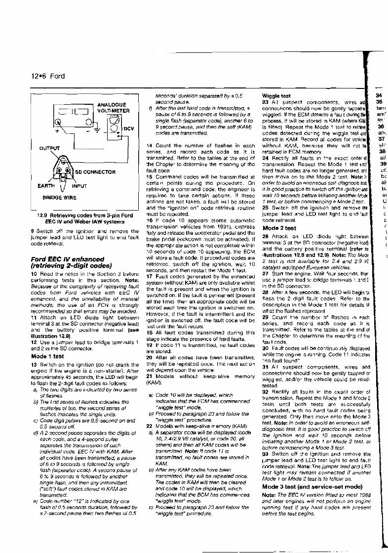
ANALOGUE
OUTPUT
-- I
12.9 Retrieving codes from 3-pin Ford EEC IV and Weber IAW systems
9 Switch off the ignition and remove the jumper lead and LED test light to end fault code retrieval.
Ford EEC IV enhanced (retrieving 2-digit codes) 10 Read the notes in the Section 3 before performing tests in this section. Note: Because of the complexity of retrieving fault codes from Ford vehfcles with EEC IV enhanced, and the unreliability of manual methods, the use of an FCR 1s strongly recommended so that errors may be avoided. 11 Attach an LED diode light between lerminal 3 at the SO connector (negative lead) and the battery positive tarm~nal (see illustration 12.0). 12 Use a jumper lead to bridge terminals 1 and 2 in the SO connector.
Mode t test 13 Switch on the ign~tion (do not crank the engine if the engine is a non-starter). After approximately 35 seconds, the LED w~ll begin to flash the 2-d~git fault codes as follows:
a] The two drgits are tndicated by two senes of flashes.
6) The first series of flashes Indicates the multiples of ten, the second senes of flashes ind~cates the single units.
C) Code digit pulses are 0.5-second on and 0.5-second off.
d) A 2-second pause separates the digits of each code, and a 4-second pulse separates the tmnsrnissron of each individual code. EEC lV with KAM: Atfer aW codes have been transmitted, a pause of 6 to 9 seconds 1s followed by s~ngle flash (separator code). A second pause of 6 to 9 seconds rs followed by another single flash, and then any intermit tent ("soft') faun codes stored in KAM are
seconds' duration separated by a 0.5 second pause.
f ) After the last hard rude rs transmitted, a pause of 6 to 9 seconds rs followed by a smgk flash (separator code), another 6 to 9 second pause, and then the soft (KAM) codes are transnlrtied.
14 Count the number of flashes in each series, and record each code as it is transmitted. Refer to the tables at the end of the Chapler to determine the rneanmg of the fault code. 15 Command codes will be transm~tisd at certain points durlng the procedure. On retrieving a command code. the engineer is required to take certain actlons. If these actions are not taken, a faull w~l l be stored and the "ignition on" code retrieval routine must be repeated. 16 If code 10 appears (some automatic transmtss~on vehicles from 1991). depress fully and release the accelerator pedal and the brake pedal (klckdown must be activated). If the appropriate action is not completed within 10 seconds of code 10 appearing, the ECM will store a fault code. If procedural codes are retrieved, sw~tch off the ~gnltlon, wait 10 seconds. and then restart the Mode 1 test. 17 Fault codes generated by the enhanced system (without KAM) are only available whilst the fault i$ present and when the ignition is swltched on. If the fault is permanent (present all the l~me), then an appropriate code will be stored each lirne the ignition IS switched on. However, if the fault is intermittent and the ignition is sw~tched OW, the fault code will be 10s: until the fault recurs. 18 Ali fault codes transmitted during this stage indlcate the presence of hard faults. 18 If code 11 is transmitted, no fault codes are stored. 20 After all codes have been transmitted. they will be repeated once. The next action w~ll depend upon the vehicle. 21 Models w~thout keep-alive memory (KAM):
a! Code 70 will be drspfayed, which rdicates that the ECM has commenced "wjggb test" mode.
b) Procwd to paragraph 23 and follow the "wiggle tesi" procedure.
22 Models w~th keepalive memory (KAM). a) A separator code wrll be displayed (code
10, 2.4i2.9 V6 catalysl, or code 20, all others) and then all KAM codes WIN Oe transmitted. Note: If code 7 l IS
transmitted, no fault codes are stored in KA M.
b) After any KAM codes have been transmitted, they will be repeated once. The codes in KAM will then be cleared and code 10 will be displayed, wbtch
code retrieval.
Mode 2 test 26 Attach an LED diode f~ght between terminal 3 at the SD connector (negative lead) and the battery positive terminal (retw ta illustrations 12.8 and 12.9). Note: The Mode 2 test is not available for 2 .4 and 2 9 V6 catalys t-aquipped European vehicles. 27 Start tne engine. Wait four seconds, thm use a jumper lead to bridge terminals 1, and 2 iu the SD connector. 28 After a few seconds, the LEU will begin to flasn the 2-digit fault codes Refer to the descriphon in the Mode 1 test for details r ~ f what the flashes represenl 29 Count the number of flashes in each series, and record each code as it is transmitted. Refer to the tables at the end of the Chapter to deterrnlne ths meaning of the fauli code. 30 Fault codes will be continuously displayed while the engine IS running. Code I f indicates "no fault found". 31 All suspect components, wires and connections should now be gently tapped or wiggled, and/or the vehicle coljld be road- tested. 32 Rectify all fau!ts in the exact order of transmission. Repeat the Mode 1 and Mode 2 te-sls until both tests are successfully concluded, w~ th no hard fault codes being generated. Only then move onlo the Mode 3 test. Note: In order to avoid an emneoLrs sen- diagnosis test, it is good practice to swltcn off the ignition and watt 10 seconds before indating another Mode 1 or Mode 2 test, or before commencing a Mode 3 test. 33 Switch OH the ignition and remove the lumper lead and LED test light to end fault code retrieval. Note: The jumper lead and LFO lest light may remain connected i f another Mode I or Mode 2 test is to follow on.
Mode 3 test (and service-set mode) 1 tmnsrniited. indicares that the ECM has commencM Note: The EEC IV version fitted to mosf 1988
e) Code number " 12" 1s indrcated by one "w~ggle test" mode. and later engines w1l1 not perform an engine flash of 0 5 seconds duration, followed by c) Proceed to paragraph 23 and foflow the ronntng test if any hard codes are present a 2-sectxld pause ttlen two flashes of 0.5 "wiggfe test" procedure. before the test begins. I

Ford 12.7
be transmitted. If t h~s code is transmitted alone, or along with one or more coolant lemperature sensor (CTS) fault codes, the mgine temperature is either too low or the CTS IS signalling a too-low temperature. The latter reason could be due to an engine cooling system tault, or an nut-of-range sensor that is sl~ll w~thin the CTS parameters and will no: therefore generate a fault code. T h Mode 3 test will not commence until the EClM has verified that operating temperature has been attained. 40 Once the ECM has verifled the temperature, the test proper will commence. The engine speed will rise to a last idle as EEC IV runs through a set of pre-determined tests of sensors and actuators. Note: I f Re speed Ws not rise within 60 s m n d s , check that the engine is at operating temperature and then re- attempt the test. Also, if 8ny one of the servrce- set connecttons are connected, an appropriate code will be transmitted and the test aborted 47 When code 10 is displayed, blip the throttle so that the engine speed mornentarijy rises above 3000 rpm (4000 rpm on catalyst models). Allow the engine to idle agaln. The 'blip" test loads the a~rflow sensor or MAP senscr, throttle pot and other dynamic sensors. Fault codes will be stored if signal($ do not conform to the expected parameters, or if the signal :s absent or not executed
42 Fault codes detected durlng the Mode 3
present, these musl be rectified before it is poss~ble to enter servrce-set mode. 43 If no faults are detected, code 1 1 will be
vat transmit code 60. Once code 1 ? has been transmitted, the system has effectively commenced semce-set mode. Sewice-set mode 44 When the ECM enters service-set mode, the ign~tlon timing and id!e speed ars de- regulated, and adjustments can be madc to Ihe base ~gnitior! tlmtng (models with distributor alone) and the base idle speed (where poss~ble). Where it is not possible to adjust the base lgriition timing (DlS models) or base Idle speed, the va!des can still be checked and compared with published spec~fications. If t,9e measured valuos are incorrect, this suggests a system or ECM fault.
Analogue vo#meter
12.1 0 Retrieving codes ftom Ford Probe models
45 After 2 minutes (catalyst models) or 10 minutes (European non-catalyst models), code 70 will be displayed. This signifies the end of service-set mode, and that Ihs ECM has rega~ned control of the ign~t~on timing and idle speed. If adjustments have not been completed, re-enter code 60 by repeating the Mode 3 and service-set routines. 46 Switch off the Ignition and remove the jumper lead and LED test light to end fault code retr~eval. 47 Remember to re-connect the octane and idle adjust (service-set) wlres, where these were disconnected prior to commsncing the self-test procedures.
Ford EEC IV (3-digit) and EEC V 48 AQ FCR is required to display fault codes generated by Ford EEC IV (3-digit) and EEC V.
Weber /A W (Ford Cosworth) 49 Ensure that the engine has attarned normal operating temperature before cornmenclng tests. 50 Attach an LED diode test light between term~nal 3 at the SD connector (negative lead) and the battery pos~tive terminal (refer to illustration 12.8). 51 Use a jumper lead to bridge terminals 1 and 2 rn the SD connector. 52 Switch on the ignition or start the engine and allow it to idle. Note: ff the engine is a non-starter, crank the engine on the starter motor. After approximately 45 seconds, the LED will begin to flash the 2-digit fault codes as follows: aj The two drgits are rndrcated by two series of flashes.
b) The first series of flashes indicates the multiples of ten, the second series of flashes indicates the single units.
separates the transmission of each individual code.
eJ C d e number " 12 " is indicated by one fiash of I-second airration, followed by a #-second pause, then twr: flashes of I - second duration separated by a 1 -second pause.
53 Count the number of flashes in each serres, and rewrd each code as it is transmitted. Refer to the tables at the end of the Chapter to detemiine the meaning of the fault cde. 54 Fault codes generated by the Weber IAW system are only ava:lable whilst the fault is present and the ignitlon IS sw~tched on. If the fault is permanent (present all the time), then an appropriate code will be stored each time ihe ign~t~on is switched on. However, if the fault is intermittent and the ign~l~on is switched off, the fault code w~l l be lost. 55 Continue retrieving codes until ail stored codes heve been retrieved and recorded. 58 Sw~tch off the ign~tion and remove the jumper lead and LED test hght to end fault code retrieval.
Mazda EGi (Fond Probe) 57 Mazda EGi has three modes of fault diagnosis. The three modes are as follows: i) Mode 1 - ignition on. engrne off: A static
test of the engine sensors. AN faults must be repaired (in fhe order of transmtssra~) before continuing with the engine mnnmg test.
ti) Mode 2 - engine running: A dynamic test of the engine sensors.
I;;] Mode 3 - switch monitor test: A test of various ECM switched inputs.
Note: The sequence of testing must observe the above order for accurate diagnosis
Mode I - retrieving codes C) BOth tens and units areindiceted by 1 - 58 Attach an analogue voltmeter between
second flashes separated by I-second terminal FEN at the SD connector (voltmeter pauses. negative lead) and the battery posltlve
d) A 4-second pause separates the tens terminal (voltmeter positive lead) (see from the units, and a 6-second pulse illushation 12.10).
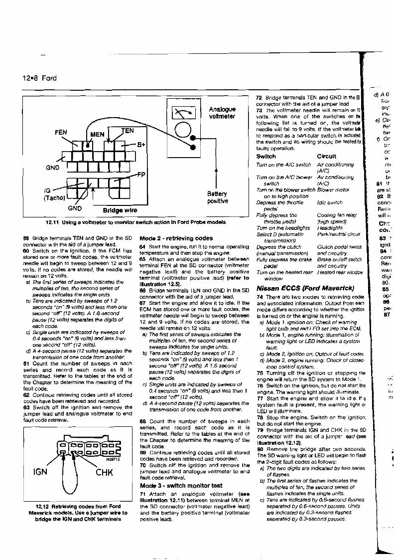
12.8 Ford
12.11 Using a voltmeter to monitor switch action in Ford P r o b models
58 Bridge terminals TEN and GND in the SD connector with the aid of a jumper lead. Wl Switch on the ignition. It the ECM has stored one or more fault codes, the voRrneter needle will bq rn to sweep between 12 and 9 volts. If no codes are stored, the needle will remain on 12 volts.
a) The h i series of sweeps indicates the muhpies of ten, the second &s of sweeps indicetes the single unrts.
b) Tens are indicated by sweeps of 1.2 seconds "on" (9 volts) and less than one second "off (7 2 volts). A 1.6-second peuse (12 volts) separates the digits of ertch code.
c) Single units are indicated by sweeps of 0.4 seconds "on" 19 volts) and less than one second 'off" ( 1 2 wits).
d) A &second pause (12 volts) separates the transmission of one code from another.
61 Count the number of sweeps in each series and record each code as it is transmitted. Refer to the tables at the end of the Chapter to determine the meaning of the
Mode 2 - retrieving codes 84 Startthe engine, run it to normal operating temperature and then stop the englne. 05 Attach an analogue voltmeter between terminal FEN at the SD connector (voltmeter negative lead) and the battery positive terminal (voltmeter posilive Iead) (refer to Illustration 12.5). 68 Bridge terminals TEN and GND in the SD connector with the ald af a jumper lead. 67 Start the engine and allow it to idle. If the ECM has stored one or more fault cod=, the voltmeter needle will w i n to sweep between 12 and 9 volts. If no codes are stored, the needle will rernaln on 12 volts: a) The first series of sweeps indicates the
muitiples of ien, +h secofld sties of sweeps indicates the single units.
b) Tens are indicated by sweeps of 1.2 seconds "on" (9 volts) and less than I second "OF (1 2 dk). A 1.6-second pause (12 volts) ts)sepRmh the dig,ts of each code.
C) Slnale units are indicated bv s w e e ~ s of fault code.
' 0.4geconds "onn (9 volts) &d ksi than I 62 Continue retrieving codes until all stored 040p (12 v o l ~ l - codes have been retrieved and recorded. dJ A 4-second pause (12 volts) ssparates the 63 Swltch off the ignition and remove the of one code +mm jumper Iead and analogue voltmeta to end faun code retrtaval. 68 Count the number of sweebs in each r I series, and record each code as it is
IGN ( \ ~ H K
12.12 ReMedng codes from Ford Maverick models. Use e jumper wire to
bridge the IGN and CHK tetmlnals
transmitted. Refer to the tables at the end of the Chapter to determine the meanlng of the fault code. gs Continue retrieving codes until all stored codes have h e n retrieved and recorded. 70 Switch off the ignition and remove the jumper lead and analogue voltmeter to end faubt code retrieval.
Mode 3 - switch monitor test 71 Attach an analogue voltmeter (see illustmtion 12.11) between termlnal MEN at the SD connector (voltmeter negative lead) and the battery positive larmlnal (voltmeter posave lead).
72 Bridge terminals TEN and GND in the9J connector with the aid of a jilmper Iead. 73 The voltmeter needle wlll remain on 12 volts. When one of the switches on th following lisl is turned on, the volt needle will fall to 9 volts. to respond as a partrcuta the switch and its wiring should be test faulty operation.
Switch Turn on the AlC switch Air conditronrng
Turn on the A/C blower AN conditioning switch
Turn on the blower switch Blower motor on to high position
Depress the throttle idle swttch pedal
Fully depress the Cooling fan relay throttle pedal
Turn on the headlights Headlights Select D (automatic Park/neutral circwt
transmrssion) Depress the clutch Clutch pedal (manual transmission) and c~rcuilry Fully depress the brake
pedal and circurtry Turn on the heated rear Heated mar window
window
htissan ECCS (Ford Maverick) 74 There are two modes to retr~eving codes and associated information. Output from each mode differs according to whether the rgnition is turned on or the engine is running. a) Mode 1 . rgnition on: Check of wamjng
light bulb and red LED set into the ECM. b) Mode T , engine running: lllumrnation of
warning lighi or LED indicetes a system fault.
c) Mode 2, ignition on: Output of fault codes. d) Mode 2, engine running: Check of closed
loop contd system. 75 Turning off the ign~tion or stopp~ng the sngrne will return the SD system to Mode 1. 76 Switch on the ignrtron, but do not start the engine. The warning light should rlluminate. 77 Stan the engine and ailow tt lo ~dle. If a system fault is present, the warning light or
LED will illurnlnate. 78 Stop the engine. Switch on the ignitton, but do not start the engne. 79 Bridge terminals IGN and CHK in the SD connector with the aid of a jumper lead (see illustration 12.12). 80 Remove the bridge after two seconds. The SD warning light or LED will begln to flash the 2-digit fault codes as follows:
a) The two digits are indicated by two series o f flashes.
b) The F i ~ t series of #ashes indicates the multiples ol ten, the second series of flashes indicates the single units.
c) Tens are indicated by 0.6-second flashes separated by 0.6-second pauses. Units am indicated by 0.3-second flashes separated by 0.3-second pauses.
Ford 12.9
separates the transmission of each
hvo 0.3-second flashes. 1 Once all fauit codes have h e n
m r t t e d in numerical order of smallest mUe brst end greatest code last, the Itght
unti! the test connector connections are bridged once more.
mnector with the a ~ d of a jumper lead. h o v e the bridge after 2 seconds. The ECM Jl revel to Mode 1.
4wck the closed-loop mixture mtrol (catalyst models only)
connector w ~ t h the a ~ d of a jumper lead. Remove the brldge after 2 seconds. The SD warning light or LED wilt begin to flash the 2-
A Start the engine and run it to normal operatrng temperature. $ Raise the engine speed lo 2000 rpm for a p o d of 2 minutes. 87 Observe the warning l~ght or L.ED display:
Light or LED switches ofland on at a frequency of 5 times m 10 seconds: Eng~ne is m closed-loop control. Lighl or LED remains off or on: Engins is in open-loop control. Whm !he bght or LED is on, the fueI11ng is
When the hght or LED is off, the fuelling IS
W The light or LED will reflect the current condition of lean or rich by stay~ng on or off immediately before switching to open-loop
I control.
Ford EEC IV (basic and enhanced without KCIM), Weber lA W 1 Early variations of EEC IV and Weber IAW do not retain fault codes after the ignition is switched off.
Ford EEC IV enhanced (with KAMJ 2 Fault codes stored in KAM ("soft" codes) are automatically cleared once retr:eval rs
completed and the ECM moves into "wiggle test" mode. "Hard" fault codes are not retained after the ignition is switched off.
Ford EEC V 3 The only manual method of clearing fault codes generated by Ford EEC V is to disconnect the battery - see paragraphs 9 and 10.
Mazds EGi (Fad Probe) 4 Ensure that the ignitjon switch is switched off. 5 Disconnect the battery negative terminal. 6 Fully depress the brake pedal for between 5 and 10 seconds. 7 Reconnect the battery negative terminal. Refer to the note after paragraph 1 D below.
Nissan ECCS (Ford MaverfckJ 8 The codes will remaln stored until one of the foltowinq actions are performed:
a) The codes am displayed (Mode 2) and then the SD function is switched back to Mod8 I .
b) The vehicle battery IS disconnected for 24 hours - refer to the note after paragraph 10 below.
C) The fault is automatically cleamd once the starter motor has been used for a total of 50 times after the fault has been fixed. If th@ Iairlt recurs before 50 starts Have been made, the counter wiV be reset to zem, and another SO starts must occur befom the fault is automatical/y cleared. This procedure occurs on an individuel fault code basis, and eech code will only be cleared after 50 starts have taken place without recurrence of the fault on that particular circuit.
Alternative method - Ford EEC IV and EEC V 9 Switch off the ignition and disconnect the battery negative terminal for a period of approximately 2 mlnutes. 10 Reconnect the battery negative terminal. Note: me ftnt drawback to disconnecting the battery is that i t will re-initialise a// ECM adaptive values. Re-learning the appropriete adaptive values requires starting the engine and allowing it to idle for approximately 3 minutes. The engine should then be warmad- up to normal operating temperature and the engine speed raised to 1200 rpm for approximately 2 minutes. Re-learning can be completed by driving at various engine speeds for approxtmaIery 20 to 30 minutes in various drivino conditions. The second drawback is that the radro security codes, clock setllngs and other stored values will be inltialtsed. and these must be re-entered once the battery has been reconnected. Where possible, an FCH should be used for code clearing on Ford vehicles.
Note: During the course of certain test procedures, it is possible for 8dditional fault codes to be generated. Care must be taken that any codes genemted during test routines do not mlslead diagnasis. A fallurn to retrieve codes setisfactorily from Ford EEC /V is usually caused by incorrect operation of the FCR, or a farlure to observe the c o m t test procedums.
F o d EEC IV (basic s m m ) and Weber IAW 1 Connect an FCR to the SD connector, and use the FCR to retrieve fault codes in strict compliance with the FCR manufacturer's instructlons. 2 Both EEC IV [bas~c) and Weber IAW are ,
only capable of generating a small number of *a fault codes, and do not employ any of the mors sophist~cated features of later systems. 3 On the EEC IV (basic) system, the idle speed will fluctuate during code retrieval If the idle speed does not fluctuate, this suggests a faulty lSCV or ISCV circuit.
Ford EEC IV (mtdevlng 2-digit codes) 4 Connect an FCR to the SD connector, and use the FCR for the following purposes in strict compl~ance with the FCR manufacturer's instructions:
iJ Mod8 f - ignition on, engine stopped: A static test of the engine senson. and wtrieval of hard fault codes end soft (WM) codes.
ii) hkde 2 - continuous nmnnmg: A test of the engine sensors dumg normal engine operation, at rdle or during a road test (not 2.4/2.9 mt).
iii) Mode 9 - engine running and service-set mode: A dynamic test of the engine sensors. In the .mice-set mode, the ignition timing and idle speed can be set it is not possible to meke these adjustments outside of servrce-set mode.
5 Read the notes in Section 3 before performing tests in this &ion.
Mode 1 test 6 Turn on the FCR and then switch on the ignition. After approximately 45 seconds, the FCR w~l l display the 2-digit fault codes. 7 Record each code as it is transmitted. Refer to the tables at the end of the Chapter to determine the meaning of the fault code. B Command codes wilt be transmitted at certain points during the procedure. On retrieving a command code, the engineer is required to take certain actions. If these actions are not taken, a fault will be stored, and the Mode 1 code mtr~eval routine must be repeated.
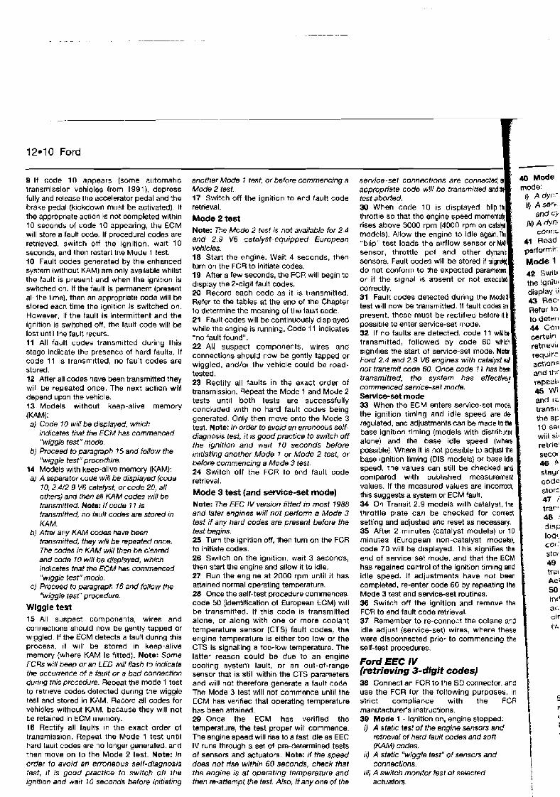
12*10 Ford
9 I f code 10 appears (some automatic transmission vehicles from 1991), depress fully and release the accelerator pedal and the brake p d a l (klckdown must be activated). If the appropriate actlon is not completed with~n 10 seconds of code 10 appearing, the ECM will store a fault code. If procedural codes are retrieved, switch off :he ignition, walt 10 seconds, and then restart the Mode 1 test. $0 Fault codes generated by the enhanced system (without KAM) are only ava~lable whilst the fault is present and when the ignitton is switched on. If the fault is permanent (present all the !:me), then an appropriate code will be slored each time the ignition is switched on. However, if the fault is intermittent and the ignition is switched OR, the fault code wilt be lost until the fault recurs. 11 All fault codes transm~tted during this stage indicate the presence of hard faults. If code f 1 is transmttted, no fault codes are stored. 12 After all codes have been transmitted they w~l l be repeated once. The next action will depend upon the vehicle. 13 Models without keep-alive memory (KAM): a) Code I0 will be d~splayed, which
indicates that the ECM has commenced "wiggle test" mode.
b) Proceed to paragraph 7 5 and follow the "wiggle test"promdufe.
14 Models with keep-alive memory (KAM): a) A seperator code will be displayed (code
10, 2.4/2.9 V6 catahst, or code 20, all others) and then all KAM codes will be transmitt&. Note: If code 1 7 is transmitted, no taulf codes are stored in KAM.
b) After any KAM codes have been tmnsmitfed, they will be repeated once. The codes in KAM will then be cieamd and code 10 wiN be displayed, whtch indtcates that the ECM has commenced "wiggle test" mode.
c) Proceed to paragraph 15 and follow the "wiggle test" procedure.
Wiggle test 15 All suspect components, wires and connections should now be gently tapped or wiggled. If the ECM detezts a fau:t dunng th~s process, it w~ l l be stored in keep-alrve memory (where KAM is fitted). Notm: Some FCRs will besp or an LED will flash to indicate the occurrence of a fault or a bad connection dunr>g this procedure. Repeat the mode 1 test to retrieve codes detected during the wiggle tast and stored in KAM. Record all codes for vehicles without KAM, because they will not be retained in ECM memoty. 16 Rectify all faults In the exact order of transmission. Repeal the Mode 1 test until hard fault codes are no longer generated, and then move on to the Mode 2 test. Note: In order 10 avoid an erroneous self-diagnosis test, it is good practice to switch oif the ignition and wad 10 seconds before initiating
another Mode 7 test, or before commencing a Mode 2 test. 17 Switch off the ignition to end fault code retrieval.
Mode 2 test Note: The Mode 2 test is not available for 2.4 and 2.9 V6 catalyst-equipped European vehicles. 18 Start the engine. Wait 4 seconds, then turn on the FCR to initiate codes. 19 After a few seconds, the FCR will begin to display the 2-digit fault codes. 20 Record each code as it IS transm~tted. Refer to the tables at the end of the Chapter to determine the meaning of the fault code. 21 Fairlt codes will be continuously displayed whde the engine is running. Code 11 indicates -no fault found". 22 All suspect components, wires and connections should now be gently tapped or wiggled, and/or Ihe vehicle could be road- tested. 23 Rectify all faults in the exact order of transmission. Repeat the Mode 1 and M d e 2 tests until both tests are successfully ~ 0 n c l ' ~ d e d w ~ t h no hard fault codes being generated. Only then move onto the Mode 3 test. Note: In order to avoid an erroneous self- diagnos~s lest, it is good practice to switch off the ignition and wait 10 seconds before initiating another Mode 7 or Mode 2 test, or befor8 commencing a Mode 3 test. 24 Switch off the FCR to end fault code retrieval.
Mode 3 test (and setvice-set mode) Note: The EEC IV version fitted to most 1988 and later engines wit/ not perform a Mode 3 test if any hard codes are present before the test begins. 25 Turn the tgnition off, then turn on the FCR to initiate codes. 26 Switch on the ignition. wait 3 seconds, then start the engine and allow it to idle. 27 Run the engine at 2000 rpm until it has atla~ned normal operating temperature. 28 Once the self-test procedure commences, code 50 Fdentification of European ECM) wrll be transmitted. If t h ~ s code is transmitted alone, or along with one or more coolant temperature sensor (CTS) fault codes, the engine temperalure 1s either too low or the CTS is signalling a too-low temperature. The latter reason could be due to an engine cooling system fault, or an out-of-range sensor that is still within the CTS parameters and will not therefore generate a fault code. The Mode 3 test will not commence until the ECM has verrtled that operating temperature has been attained. 29 Once the ECM has verified the temperature, the test proper will commence. The engine speed will rise 10 a fast idle as EEC IV runs through a set ot pre-determined tests of sensors and actuators. Note: H the speed does not rise within 60 seconds, check that the engine is at operating temperature and then re-attempt the test. Also, If any one of the
appropriate code will be transmilted and test aborted. 30 When code 10 is displayed, blip
sensor. throttle pot and other dy
or if the s~gnal is absent or not e correctly. 31 Fault codes detected during the test will now be transmitted. If fault c present, these must be rectifred b possible to enter service-set mode. 32 If no faults are detected, code transmitted, followed by code slgnlfles the start of service-set m Ford 2.4 and 2.9 V6 engines with not transmit code 60. Once code transmitted, the system has commenced service-set mode. Servlce-set mode 33 When the ECM enters servic the ignition timing and idle sp regulated, and adjustments can bs made to lb base ignition tlming (models wi alone) and the base idle s
speed, the values can still be compared with published measurement values. If the measured va\ues are incorrect, thls suggests a system or ECM fautt. 34 On Transit 2.9 m0d~lS with catalyst, ths throttle plate can be checked for correct setting and adjusted and reset as necessav. 35 After 2 mlnutea (catalyst models) or 10 minutes (European non-catalyst models). code 70 will be displayed. This signifies Iha end of service-set mode, and that the ECM has regained control of the ignition timing and idle speed. !t adjustments have not been completed, re-enter ccde 60 ay repeating the Mode 3 test and service-set routines. 36 Switch off the ignition and remave the FCR to end fault code retrieval. 37 Remember to re-connect the octane and Idle adlust (service-set) wires, where these were disconnected prior to commencing the self-test procedures.
Ford EEC IV (retrieving 3-digit codes) 38 Connect an FCR to the SD connector, and use the FCR for the following purposes, In strict compliance with the FCR manufacturer's instructions. 39 Mode 1 - Ignition on, engine stopped.
iJ A static test of the engine sensors and retfieval of hard fault codes and sofi (KAM) codes.
it) A static "wiggle test" of sensors and connections.
110 A switch monitor test of selected I
actuators. 1
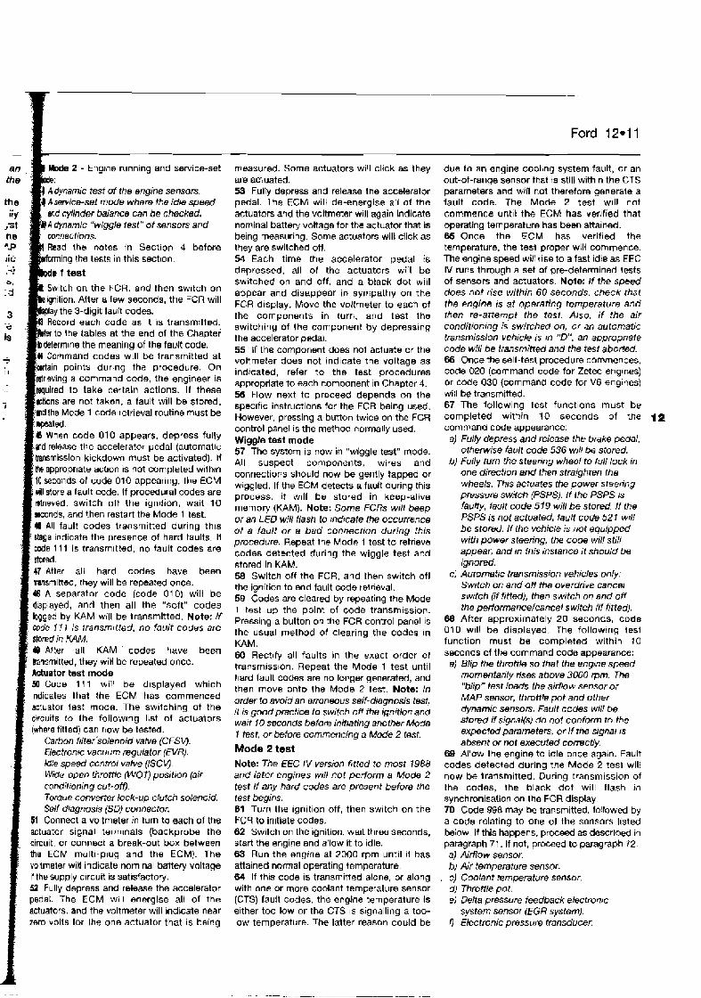
Ford 12-11
ing the tests in this section.
h code as it is transmitted.
odes will be transmitted at
II When code 010 appears, depress fully md release the accelera!or pedal (autornallc bansmission kickdoun must be activated). If Ihe appropriate acl~on is not completed withm 10 seconds ol code 010 appearing. the ECM dl store a fault code. If procedural codes are drieved, switch off the igniiion, wait 10 m n d s , and then restart the Mode 1 test.
47Atter all hard codes have been taismltted, they will be repea!& once. I A separator code {code 010) will be displayed, and then all the "soft" codes logged by KAM will be transmitted. Note: H code I I I is rransmrtted, no fault codes are sfwed in KAM. 19 After all KAM ' codes have been gansrnitted, they will be repeated once. Actuator test mode 50 Code I l l will be d~splayed which indicates that the ECM has commenced actuator lest mode. The switching of the circuits to the follow~ng list of actuators (where fitted) can rlaw be tested.
Carbon filter 'solenoid valve (CFSW. Electronic vacuum regulator (EVR). Idle speed confml valve (ISCVJ. Wide-open throwe (WOO position (air condilron~ng cut-off). Torque converter lock-up clutch solenoid. Self-dragnosis (SD} connector.
51 Connect a voltmeter in turn to each of the actuator signal terminals (backprobe the circuit, or conned a break-out box between the ECM rnultl-plug and the ECM). The vollrneter will indicate nominal battery voltage if thesupply circuit is satisfactory. 52 Fully depress and rsleme the accelerator pedat. The ECM will energise all of the
actuators, and the voltmeter will indicate near z0ro volts lor Ihe one actuator that is baing
measured. Some actuators will click as they are actuated. 53 Fully depress and release the accelerator pedal. The ECM will de-energise ail of the actuators and the voltmeter will again indicate nominal battery voltage for the actuator that is being measuring. Some actuators wilk click as they are switched ow. 54 Each time the accelerator pedal is depressed, all of the actuators will be swbtched on and off, and a black dot will appear and disappear in sympathy on the FCR display. Move the voltmeter to each of the components in turrl, and test the switching of the carnponent by depresstng the accelerator pedal. 55 If the component does not actuate or the voltmeter does not indicate the voltage as indicated, refer to the test procedures appropriate to each com,wnent in Chapter 4. 56 blow next to proceed depends on the spec~f~c instructions for the FCR being used. However, pressing a button twice on the FCU control panel is the method normally used. Wiggle test mode 57 The system is now in "wiggle test" mode. All suspect components, wires and connections should now be gently tapped or wiggled. If the ECM detects a fault during mis process, it will be stored in keep-alive memory (KAM). Note: Some FCRs wrll beep or an LED will fiash to indicate the OCCUwnC8 of a fault or a bad connection during this procedure. Repeat the Mode 1 test to retrieve codes detected during the wiggle test and stored in KAM. 58 Switch off the FCR, and then switch off the ignition to end fault code retrieval. 59 Codes are cleared by repeating the Mode 1 test up the point of code transmission. Pressing a button on the FCR control panel is the usual method of clearing the codes in KAM. 60 Rec!rfy all faults in the exact order of transmission. Repeat the Mode 1 test until hard fault codes are no longer generated, and then move onto the Mode 2 test. Note: In order to avoid an emneous self-diagnosis test, it is good practtce to switch off the ignrtion and wait I0 seconds before initiating another Mode I test, or before commencing a Mode 2 test.
Mode 2 test Note: The EEC IV version htted to most 1988 and later engines w11l not perform a Mode 2 test if any hard codes are present before the test begins. 61 Turn the ~gni t~on off, then switch on the FCR to initiate codes. 62 Switch on the ign~t~on, wa~t three seconds, start the engine and allow it to idle. 63 Run the engrne at 2000 rpm unt~l 11 has attalned normal operat~ng temperature. 64 If thrs code 1s transmitted alone, or along with one or more coolant temperature sensor (CTS) fault codes, the engine temperature 1s e~ther too low or the CTS IS signalling a too- low temperature. The latter reason could be
due to an engine coolbng system fault, or an out-of-range sensor that is still within the CTS parameters and will not therefore generate a fault code. The Mode 2 test w~lJ not commence unt~l the ECM has ver!fied that operating temperature has been attained. 65 Once the ECM has verified the temperature, the tesl proper will commence. The engine speed will rise to a fast idle as EEC IV runs through a set of pre-detemined tests of sensors and actuators. Note: If the speed does not rise within 60 seconds. check that the engine is at operating temperature and then re-attempt the test. Also, if the air conditioning is switched on, or an automatic transmission vehtcle 1s m "DM, an appropnafe code will be transmitted and the test aborted. 66 Once the self-test procedure commences, code 020 (command code for Zetec englnes) or code 030 (command code for V6 engines) will &transmitted. 67 The lollowing test functions must be completed within 10 seconds of the 12 command code appearance:
a) Fully depress and release the brake pedal, 0 l h e ~ i ~ 8 fault code 536 will be stored.
bJ Fully turn the steering wheel to full lock in one direction and then straighten the wheels. This actuates the power st~eting pressure sw.;lch (PSPS). I f the PSPS is faulty, halt code 519 will be stored. If the PSPS is not actuated, fault code 52 1 wrll be storad. If the vehicle is not equipped with power steering, the code will still appmr, and m this instance it should be ignored.
c) Automatic transmission vehicles only, Switch on and off the overdrive cancel switch (if fitted), then switch on and off the perfomnce/cancel switch (if htted).
68 After approximately 20 seconds, code 010 will be displayed. The following lesl function must be completed within 10 seconds of the command code appearance: a) Blip the throttle so that the engme speed
momentarrly rises above 3000 rprn. The "blip" test loads the airflow sensor or MAP sensor, Ihrottle pot and other dynamic senson. Fault codes will be stored if signal(s} do not conform to the expecled parameters, or if the signal IS
absent or not executed correctly. 69 Allow the engine to idle once again. Fault codes detected during the Mode 2 test will now be transmitted. During transmission of the codes, the black dot will flash In synchronisation on the FCR display 70 Ccde 998 may be transmitted, fo!lowed by a code relating to one of the sensors l~sted blow. If this happens, proceed as described in paragraph 71. If not, proceed to paragraph 72. a) Airflow sensor. b) Air temperature sensor. c) Coolant Srnperatum sensor. d) Throttle pot. el Delta pressure feedback eiectronrc
system sensor (EGR system). I) Electronic pressure transducer.

12.12 Ford
71 If code 998 is transm~tted, followed by a code relating to one of the sensors listed in paragraph 70, proceed as follows: a) Exit the Mode 2 tes! bJ Stop the engine. cJ Test the component as detailed m the
relevant component test procedure (Chapter 4) and rectify all faults.
d) Restar? the Mode 2 test. 72 If fault codes are present, these must be rectifted betore ~t IS possible to enter setvice- set mode. 73 If code 536 or code 521 are transmltted. ~ncorrect practices were adopted during the mutmes. Repeat the Mode 2 test prccedure. 74 Coae 1 1 1 will be transmitted if no faults are detected. When the black dot ceases flash~ng, this signifies the start of servlce-set mode. The last Iransmitted code w~l l remain displayed on the FCR screen, wh~ch should ord~narily be code 1 1 j . Service-set mode
connections should now be gently tapped or component testing, or after repalrs ~nvolving wiggled. If the ECM detects a fault during this the removal or replacement of an EM$ process, it will be stored In keep-alive component. memory (KAM). Note: Some FCRs wrrl beep or an LED will flash to indicate the occurrence of a fauft w a bad conneclion during fhrs pcadums 1 procedure. Repeat the Mode 1 test to retrieve fault codes stored In KAM after being detected during the wlggle test. 79 Rectify all faults in the exact order of 1 Use an FCR to Interrogate the ECM lor faun transmission. Repeat the Mode 1 test until codes, or manually gather codes as described hard fault codes are no longer generated. in Sections 5 or 7. Note: In order to avoid an erroneous self- diagnosis test, it is good practice to switch off the ignition and wait 10 seconds before initiating another Mode I test, or before commencing a Mode 2 test. 80 Switch off the FCR and switch off the igni:lon to end fault code retr~eval. Remove the FCR from the vehicle SD connector.
75 When the ECM enters service-set mode. the idle speed is de-regulated and set at the base Idle value (usually slightly higher than normal idle). No adjustments are possible, although the idle speed can be checked agalnst specifications If the measured values are incorrect, this suggests a system or ECM lalrlt. 76 On englnes with sequential injection, fully depressing the acceierator pedal during the 2 minutes serv~ce-set mode will set the ECM into cylinder balance test mode. Each injector rs switched off in turn for a predetermined
Ford EEC V
moment. The ECU checks for a calibrated fall :o rpm, and will set a fault code tf there appears to be a problem. Alter 2 minutes, the englne rpm will rise hriefly and then setlle at normal idle speed Th~s signifies the end of the service-set mode. Wiggle test mode 77 The ECM will now enter "wlygle test" mode. 78 All suspect components, wlres and
Fault code tables
81 Connect an FCR to the SD connector, and use the FCR for the following purposes, in strict compliance with tho FCR manufacturer's instructions: a) Drsplaying system faults. b) Clearing system faults. c) Testrng actuators. 19) Displaymg Datastream.
82 Faults must always be cleared after component testing, or after repairs involving the removal or replacement of an EMS component.
Ford Probe and Maverick 83 Connect an FCR to the SD connector, and use the FCR for the following purposes, in strict compliance wlth the FCR manufacturer's instructions: a) Retrrev~ng fault codes. b) Clear~ng fault codes. c) Testifig switch inputs to ECM.
84 Codes must always be cleared after
Codes stored I 2 If one or more fault codes are gathered. refer to the fault code tables at the er,d of tha Chapter to determine their meanlng. 3 If several wdes are gathered, look tor a common factor such as a defective eanh return or supply 4 Refer to the component test procsdures in Chapter 4, where you will t ~nd a means of testing the majority of components and c~rcuits found in the modem EMS. 5 Once the fault has been repaired, clearlb codes and run the engrrie under various conditions to determine ~f the problem has cleared. 6 Check the ECM for fault codes once more. Repeat the above procedures where codes are still being stored. 7 Refer to Chapter 3 for more ~nlormat~on an how to effectrvely test the EMS.
No codes stored 8 Where a running problem IS experienced. but no codes are stored, the fault is outside of Ihe parameters designed into the SO system. Refer to Chapter 3 for more lnformatlon on how to eftectively test the EMS. 9 If Ihe problem points to a speclflc component, refer to the test procedures In
Chapter 4, where you will f ~ n d a means of testing the majority of components and circuits found in the modern EMS.
EEC IV "basic" (2.0 SOHC and 2.8 V6 engines) I EEC IV "enhanced", fwo-digit codes {except 2.4l2.9 V 6 catalyst and 1.8 CFi) I
Code 11
12 13 14 15 22 23
31 32
Description No taults found in the ECM. Proceed w~th normal diagnostic methods Airflow sensor (AFS) or AFS circuit number one Coolant temperature sensor (CTS) or CTS circuit Air temperature sensor (ATS! or ATS circuit (in AFS) Throttle pot sensor (TPS) or TPS c~rcuit Airflow sensor (AFS) number two or AFS c~rcuit Airflow sensor (AFS) or AFS circuit number one and number two Wiringlmodule fault Wirlnglmodule fault
Code 10
11
13 14 15 16 17
Description Command code. Operator actlon required as follows: lgnrtlon on, engine off: wiggle test Engine running: load engine by "blipping" the throttle The englne speed must exceed 2500rpm No faults found In the ECM. Proceed w ~ i h normal diagnostic :
methods Coolant temperature sensor (CTS) or CTS circuit Air temperature sensor (ATS) or ATS circuit Throttle pot sensor ('TPS) or TPS clrcu~t i Arrflow sensor (AFS) or AFS circu~t number two Manilold absolute pressure (MAP) sensm or MAP sensor i circuit

Description Low Sattery voltage Keep-al~ve memory (KAM) or KAM circuit, end and restart SO test. If code repeats, make ECM circuit tests Separator code Separates "soft'* (KAM) codes from "hard" codes (codes of a permanent nature) Ignliion, irregular signal A~rflow sensor (AFS) or AFS circu:: numher one, voltage too h~gh Gnolant temperature sensor (CTS) or CTS circuit, vcAage too high Alr temperature sensor (ATS) or ATS circuit Throttle pot sensor UPS) or TPS circuit, voltage too high Airflow sensor (AFS) number two, voltage too high Manrfold absolute pressure (MAP) sensor or MAP sensor clrcult, value too high Oxygen sensor (0s) or OS circuit Oxygen sensor (0s) 1 or OS circuit (2.0 DOHC 16V only), rich mixlure or farled sensor Oxygen sensor (0s) 2 or OS circuit (2.0 DOHC 16V only), rich mlxturs or failed sensor Marker code, ident~f~es ECM for 6-cylinder engines Electronic control module (ECM] or ECM circuit ROMjRAM failure Airflow sensor (AFS) or AFS circuit number two, voltage too low Coolant temperature sensor (CTS! or CTS circuit, voltage too low Alr temperature sensor (ATS) or ATS circuit Throttle pot sensor VPS) or TPS circuit, voltage too low Airflow sensor (AFS) or AFS circuit number two, voltage too low Manifold absolute pressure (MAP) sensor or MAP sensor circurt, value too low Onygen sensor (0s) 1 or OS clrcuit (2.0 DOHC 16V only), lean mixture or failed sensor Oxygen sensor (0.51 2 (2.0 DOHC 16V only), lean m~xture or failed sensor Manifold absolute pressure (MAP) sensor or MAP sensor circu~i Throttle not sensor FPS) or TPS c~rcuit "Blip" test not performed or late response to message Vehicle speed sensor {VSS) or VSS circuit Idle speed control va~Je (ISCV) or ISCV cjrcurt failure, max rprn not achieved ldle speed control valve (ISCV) or ISCV circuit failure, min rpm not achleved ldle speed control valve (ISCV) or ISCV circuit European electronic control module (ECM) fitted Air conditioning (AC) "on", turn A/C off and repeat SD test Automatic Iransmission: Vehicle in "D" durlrrg SD test - select "Nu or "P" and repeat SD test Octane adlust (OA) wire number m e earthed. Disconnect sewlce adjust wire and repeat SD test Octane adjust (OA) w r e number two earthed. Disconnect sewice adjust wires and repeat SD test Idle speed adjust wire earthed. Disconnect service adjust wire and repeat SD test Throtile moved during self-diagnosis (SO) test (prior to code lo), :epeat SD test Phasrng of profile ignition pick-up. (PIP) and spark advance word (SAW) GO pot or CO pot clrcu~t, outside test limits Start of service -set mode I-oss of power - cylinder 1 Loss of power - cylinder 2 Loss of power - cyllnder 3 Loss of power - cylinder 4
Ford 12-13
- Code Description 65 Brake on/off switch 66 Kickdown switch or circuit 67 Fusl temperature switch (FTS) or ITS circuit 68 Turbo boost pressure solenoid valve (BPSW or BPSV circult 69 Turbo boost pressure solenoid valve (BPSV) or BPSV circult 70 End of sewice-set mode 72 Wastegate control solenoid (WCS) (1.6 CVH Turbo only) or
WCS circult 73 Carbn filter solenoid valve (CFSVJ or CFSV circuit 74 314 shift solenoid 75 Clutch converter lock-~p solenoid 76 Brake "on" indicated 77 Kickdown indicated 78 Power steering pressure switch (PSPS), PSPS not activated
during SO procedure. Check if PSPS fitted, if so repeat SD procedure
91 Oxygen sensor (0s) or OS clrcuit, connections iriterchanged (2.0 16V DOHC engine)
EEC IV "enhanced', two-digit codes (2.42.9 V 6 catalyst and 1.8 CFiJ Code Description 10 Command code/separator code for KAM 10 Operator action required as follows:
Engine running. Load engine by "blipping" the throttle. The engine speed must exceed 2500 rpm
11 No faults found in the ECM. Proceed wrth normal diagnostic methods (system pass)
12 Idle speed control valve {ISCV or ISCV circuit 12 Idle speed stepper motor (ISSM) or ISSM c~rcuit, idle
contacts (1 .B CFi) 13 Idle speed control valve (ISCV) or ISCV clrcult
Idle speed stepper motor (ISSM) or ISSM circuit, idle contacts (1.8 CFi)
14 Erratic profile ignition pick-up (PIP) signal or clrcuit 15 Keep-alive memory (KAM)/read only memory (ROM)
(module failure) or KAM/ROM circuit 16 Engine test speed too low 17 ldle speed stepper motor (ISSM) or ISSM circuit, idle
contacts (1.8 CFi) 18 Ignition module operation (IDM) or IDM circuit 19 Voltage supply to module 20 4-cylinder identificatior! mode (1.8 CFi) 21 Coolant temperature sensor (CTS) or CTS cacurt 22 Manifold absolute pressure (MAP) sensor or MAP sensor
circuit 23 Throttle pot sensor (lPS) or f PS circuit 24 Air temperature sensor (ATS! or ATS circuit 25 Knock sensor (KS) or KS circuit 27 Cruise control delayed 28 Cruise control - speed too advanced 29 Vehicle speed sensor (VSS) or VSS c~rcult 30 Marker code - ident~fies ECM for 6-cylinder engines 31 Electronic pressure transducer {EPT) or EPT circuit, voltage
too low 32 Electronic pressure transducer (EPT) or EPT circu~t, outside
specification 33 No exhaust gas recirculation (EGR) 34 Electronic pressure transducer (EPT) or EPT circu~t, outside
spec~f:cation 35 Electronic pressure transducer (EPT) or EPT circuit, vo!tage
too high 36 No increase in engine test speed 37 Decrease in engine test speed 38 Idle speed stepper motor (ISSMI or ISSM circu~t, idle
contacts (1.8 CR) 39 Torque converter lock-up clutch
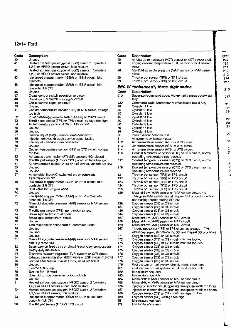
Ford
Code 40 41
Description Unused Heated exhaust gas oxygen (HEGO) sensor 1 (cylinders 1,2,3) or HEGO sensor circutt, lean mixture Heated exhaust gas oxygen (HEGO) sensor 1 (cylinders 1,2,3) or HEGO sensor circuit, rich mixture ldle s m stepper motor (ISSM) or ISSM circuit, idle contacts ldle speed stepper motor (ISSM) or ISSM circuit, idle contacts (1.8 CFi) Unused Cruise control switch operation or circuit Cruise wntrol switch sticking or circuit Crulse control signal or circuit Unused Coolant temperature sensor (CTS) or CTS circuit, voltage too h~gh Power steerlng pressurn switch (PSPS) or PSPS circuit Throttle pot sensor (TPS) or TPS circuit, voltage too high Air temperature sensor (ATS) or ATS circuit Unused Unused Octane adjusl (OA)) - service loom connector Injection delayed through service adjust facility ldle adjust - service loom connector Unusd Cwlant temperature sensor (CTS) or CTS circuit, voltage too low Automatic transmission (AT) shift solenoid 4/3, closed Throttle pot sensor (TPS) or TPS circuit, voltage too tow Alr temperature sensor (ATS) or ATS c~rcuit, voltage too low Unused Unused Air condltloning (A/C) swilched on, or automatic transmission in "Ow ldle speed stepper motor (ISSM) or lSSM circuit, idle contacts (1.8 CFI) Shift valve for 312 gear open Unused ldle speed stepper motor {ISSM) or ISSM circuit, idle contacts (1.8 Cfi) Manifold absolute pressure (MAP) sensor or MAP sensor circuit Throttle pot sensor (TPS), no reaction tot& Brake light swltch circuit open Brake light switch shwl-circuit Unused Late response to "blip throttle" command code Unused Unused Unused Manifold absolute pmssure (MAP) sensor or MAP sensor circuit (Transit V6) Secondary air feed valve or circurt (secondary combustion) Heavy duty fan switch Electronic vacuum regulator (EVR) system or EVR circuit Exhaust gas recirculation (EGR) valve or EGR circuit (1.8 CFi) CarbDn filter solenoid valve (CFSVj or CFSV circuit Unused f ledric fuel pump Electrlc fan - if fittad Solenoid torque converter lock-up clutch Unused Heated exhaust gas oxygen (HEGO) sensor 2 (cylinders 4,5,6) or HEGO sensor circuit, lean mixture Heated exhaust gas oxygen (HEGO) senmr 2 (cylinders 4,5,6) or HEGO sensm, rich mixture Idle speed stepper motor (ISSM) or ISSM circu~t, idle contacts (1.8 CFi) Throttle pot sensor VPS) or TPS crrcuit
Code Description 98 Air charge temperature (ACT) sensor or ACT sensor circuit 98 Engine coolant temperature (ECT) sensor or ECT sensor
circuit 98 Manifold absolute pressure {MAP) sensor or MAP sensor
circu# 98 Throttle pot sensor qPS) or TPS c~rcui: 99 Throttle pot sensor (TPS) or TPS c~rcuit
EEC IV '*enhancedw, three-digit codes Code Description 01 0 ~e~ara<ar/cornrnand code. Momentarily press accelerator
fully command code. Mornentardy press brake pedal fully Cylinder 1 low Cylinder 2 low Cylinder 3 low Cylinder 4 low Cylinder 5 low Cylinder 6 low Cylinder 7 low Cylinder 8 low Pass cylinder balance test All systems ok (system pass) Air temperature sensor (ATS) or ATS circuit Air temperature sensor (ATS) or ATS circuit Air iemperature sensor (ATS) or ATS circuit Coolant temperature sensor (CIS) or CTS circuit, normal operating tempsrature not reached Coolant temperature sensor (CTS) or CTS circu~t, normal operating temperature not reached Coolant temperature sen= (CTS) or CTS circu~t, normal operating temperature not reached Throttle pot sensor (TPS) or TPS clrcuit Throttle pot sensor (TPS) or TPS circu~: Throttle pot seneor (TPS) or TPS circuit Throttle pot sensor (TPS) or TPS circuit Throttle pot sensor VPS) or TPS circuit Mass airflow (MAF) sensor or MAF sensor circuit. No change in MAF sensor signal. Repeat SD procedure whist depressing throttle during SD test Oxygen sensor (0s) or OS circurl O~ygen sensor (0s) or OS circu~t Oxygen sensor (0s) or OS circuit Oxygen sensor (0s) or OS c~rcuit Mass airflow (MAF) sensor or MAF circuit Mass airflow (MAFj sensor or MAF circuit Mass aimow (MAF) sensor or MAF circu~t Thronle pot sensw VPS) or TPS circuil, no change in TPS whilst depressrng throttle during SD tet . Repeat SD procedure Oxygen sensor (0s) or OS circuit Oxygen sensor (0s) or OS circuit. mixture too lean Oxygen sensor (0s) or OS circuit, mixture too rich Oxygen sensor (0s) or OS circuit Oxygen sensor (0s) or OS circutt Oxygen senmr (0s) or OS circuit Oxygen sensor (0s) or OS circuit Oxygen sensor (0s) or OS circuit Fuel system or fuel system circuit, mixture too lean Fuel system or fuel system circuit, mixture too rich ldle mixture too lean ldle mixlure too rich Mass airflow (MAF) sensor or MAF sensor circuit Mass airflow (MAF) sensor or MAF sensor c~rcu~t injector or Injector circuit, opening time ( p u b width too long) injector or injector clrcuit, opening time (pulse w~dth too short) Oxygen sensor (0s) or OS circuit, voltage too low Oxygen sensor (OS), voltage too high \ ldle mtxture too lean ldle mixture too lean
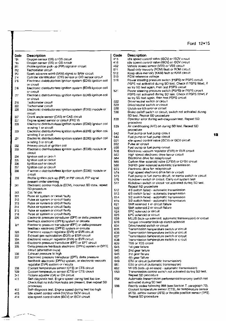
Ford 12.15
Description Oxygen sensor (0s) or OS circu~t Oxygen sensor (0s) or OS ctrcuit Proille ignition pick-up (PIP) signal or circuit Tachometer circuit Spark advance word (SAW) signal or SAW circuit Cylinder identification (CID) sensor or CID sensor circuit Electronrc d~str~butorless ign~t~on system (EDIS) ignition coil or circuit Electronic distributorless ignition system (EDISJ ignition coil or c~rcuit Electronic distrlbutorless ignition system (EDIS) ignition coil or circuit Tachometer circuit Tachometer circuit Elmtronic distributorless Ignition system (EDIS] module Or circuit Crank angle serrsor (CAS) or CAS circuit Engine speed sensor or circuit (EEG V) Electronic distributorless ignition system (EDIS) ign~l~on coil wlnding 1 or circuit Electronic distributorless ignition system (EDiS) ignition coil winding 2 or circuit Electronic distributorleSS Ignition system (EOIS) ignition coil winding 3 m circuit Primaty c~rcuit of ignition coil Electronic distributorless ign~t~on system (EDiS) module or circuit lgndion coil or circurt Ignition coil or circu~t lgnition co~! or circuit lgnitlon coil or circuit Electron~c d~stributorless ign~tlon system (EDIS) module or circuit Profile ignition pick-up (PIP) or PIP circuit PIP signal present under cranking Electronic control module (ECM). incorrect SD data. repeat SD procedure Coil failure Pulse air system or circuit faulty Pulse air system or circu~t faulty Pulse air system or circuit faulty Pulse air system or circuit faulty Pulse air system or circuit faulty Pulse air system or circuit faulty Electronic pressure trensducer (EPT) or delta pressure feedback electranLC (DPFE) system or circuits Electronic pressure transducer (EPT) or delta prmsure feedback ekctronic (DPFE) sptern or circuits Elsctrm~c vacuum regulator {EVR) or EVR circuit Exhaust gas recirculation (EGR) or EGR circult Electronic vacuum regulator (EVR) or EVR clrcuit Electronic pressure transducer (EPT) or EFT circuit Oelta pressure feedback electronic (DPFE) system or DPFE circuit (alternative code) Exhaust pressure to high Electron~c pressure transducer (EPT), dnlta pressure feedback electronic (DPFE) system, or electronic vacuum regulator (EVR) system or c~rcuits Coolant temperature sensor (CTS) or CTS circuit Coolant temperature sensor (CTSj or CTS circuit Octane adjuster (OA) or OA circu~t Self-diagnosis tesl. Engine speed during test too low. Check that no induction leaks are present, then repeat SD procedure Self-diagnosis test. Eng~ne speed during test too high Idle speed control valve (ISCV) or !SCV circuit idle speed control valve (ISCV) or ISCV circuit
Code 41 5 416 452 51 1 51 2 51 3 519
521
522 523 528 536
538
539
542 543 551 552 556 558 563 564 565 566 573 574 575 576 577
612 613 61 4 61 5 621 622 624 625 620 629 634 635 636 637 638 639 645 645 645 645 649 651 652 653
658
998
- -
Description idle speed control valve (ISCV) or lSCV circuit idle speed control valve (ISCV) or lSCV circuit Vehicle speed sensor (VSSI or VSS circuit Read only memory (ROM) fault or ROM c~rcuit Keep-alive memory (KAM) fault or KAM circuit ECM reference voltage Power steering prBssure swltch (PSPS) or PSPS clrcuit. PSPS not activated durlng SD test. Check if PSPS fitted, if so try SD test agarn. then test PSPS circuit Power steering pressure switch (PSPS) or PSPS circu~t. PSPS not activatd during SD tesi. Check if PSPS fitted, if so try SSD test again, then test PSPS circu~t Drivdneutral switch or circuit Drivdneutral switch orcircu~t Clutch switch error or circuit Brake ordoff switch or circuit, switch mt activated during SD tesl. Repeat SD procedure Operator error during self-diaglnosis test, Repeat SD procedure Air conditioning (NC) on dunng SD test. Repeat SD procedure Fuel pump or fuel pump circuit Fuel pump or fuel pump circuit idle speed control valve (ISCV) or ISCV circuit Pulse air circuit Fuel pump or fuel pump clrcuit Elecfronic vacuum regulator (EVR) or N R circuit High speed electronic drlve fan or clrcu~t Electronic drive fan relay/clrcuit Carbon filter solenoid valve (CFSV) or CFSV circuit 3rd14th gear solenoid automatic transmission Efectronic drive fan relay/circuit H ~ g h speed electronic drive fan or circuit Fuel pump or fuel pump circuit, or Inertla switch or circuit Kickdown switch or circuit. Carry out system test Kickdown switch or circuit not activatd during SD lest. Repeat SD procedure 4/3 switch failed - automatic transmission 4/3 switch failed - automatic tran$mission 312 switch fa~led - automatic transmission 3/2 switch failed - automatic transmission Shift solenold 1 or circuit failure Shifl solenoid 2 or circult failure EPC solenoid or circuit EPC solenoid or circu~t MLUS (lock-up solenoid, automatic transmission) or circu~t Torque convener lock-up clutch salenotd Drivdnevtral switch or circuit Transmission temperature switch or circuit Transmission temperatwe switch or circuit Transmission temperature switch or circuit Transmission temperature switch or circuit TSS or TSS circult 1 st gear fatlure 2nd gear failure 3,d gear failure 4th gear failure ElV or circuit (automatic transmission) IEW or circuit (automatic transm~ssion) MLUS (lock-up solenoid - automatic transmission) Transmission control switch not act~vated during SD test. Repeat SD procedure Automatic transmissian perfomance/economy switch not activated during SO test Rectify codes following 998 (see Sect~on 7, paragraph 70). Coolant temperature sensor (CTS), Air temperature sensor (ATS}, airflow sensor (AFS) throttle positlon sensor VPS). Repeat SD procedure
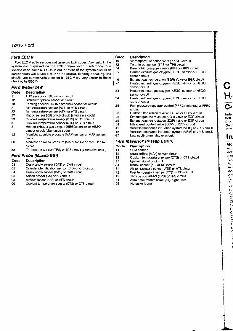
12.16 Ford
Ford EEC Y Ford EEC V software does not generate faull cooes. Any faults in the
system are displayed on the FCR screen without reference to a specific code number. Faults in one or more of the system c~rcuits or components will cause a fault to be stored. Broadly speaking. the c~rcuits and components checked by EEC V are very sirn~lar to those checked by EEC IV.
Ford Weber /A W Code 11 12 t 3 21 22 22 23 31 31
32
33
33
Description TDC sensor or TDC sensor circuit Distributor phase sensor or circuit Phasing speednDC to distributor sensor or circuit Air temperature sensor (ATS) or ATS circuit Air temperature sensor (ATS) or ATS circuit Knock sensor (KS) or KS circuit (alternative code) Coolani temperature sensor (CTS) or CTS circuit Coolani temperature sensor (CTS) or CTS circuit Heated exhaust gas oxygen (HEGO) sensor or tiEGO sensor circuit (alternative code) Manifold absolute pressure (MAP) sensor or MAP sensor circu~t Manifold absolute pressure (MAP) sensor or MAP sensor circuit Throttle pot sensor (TPS) or TPS circuit (ahernative code)
Ford Pmbe (Mazda EGO Code Description 02 Crank angle sensor (GAS) w GAS circuit 03 Cyllnder identification sensor (CID) or CID circuit 04 Crank angle sensor (CAS) or CAS circutl 05 Knock sensor (KS) or KS circuit 08 Airflow sensor (AFS) or AFS circuit 09 Coolant temperature sensor (CTS) or CTS crrcuit
Code 10 12 I4 15
16
1 j7 23
24
25
26 28 29 34 41 46 67
F o d Code I1 12 13 21 34 41 42 43 54 55
Description Air temperature sensor (ATS) or ATS circuit Throttle pot sensor (TPS) or TPS circuit Barometric pressure sensor (BPS) or BPS c~rcuit Heated exhaust gas oxygen (HEGO) sensor or HEGO sensor circud Exhaust gas recirculation (EGR) Valve or EGR circurt Heated exhaust gas oxygen (HEGO) sensor or HEGO sensor circurt Heated exhaust gas oxygen (HEGO) sensor or HEGO sensar c~rcuit Heated exhaust gas oxygen (HEGO) sensor or HEGO sensor c~rcuif Fuel pressure regulator control (FPRC) solenold or FPRC circuit Carbon filter solenoid valve (CFSV) or CFSV circuit Exhaust gas recirculat~on (EGR) valve or EGR circuit Exhaust gas recirculation (EGR) valve or EGR circuit Idle speed control valve (ISCV) or ISCV circuit Variable resonance induction system (VRIS) or VRtS circuit Variable resonance inductton system (VRIS) or VRlS circuit Low cooling fan relay or circuit
Maverick (NTssan ECCS) Description RPM sensor Mass alMow (MAF) sensor circuit Coolant lernperature sensor (CTS) or CTS circuit Ignition signal or circuit Knock sensor (KS) or KS circuit Air temperature sensor (ATS) or ATS circuit Fuel temperature sensor (FTS) or FTS circuit Throttle pot sensor (TPS) or TPS crrcuit Automatic transmission (AT), signal lost No faults found
C H. - cn Inde. Self GI@&. Guid lntrc
In -
Mc ACC
Acc Acc Ai-c Ac* Ac* ACC
AC*
Ac. n ;- r. - h - r ..
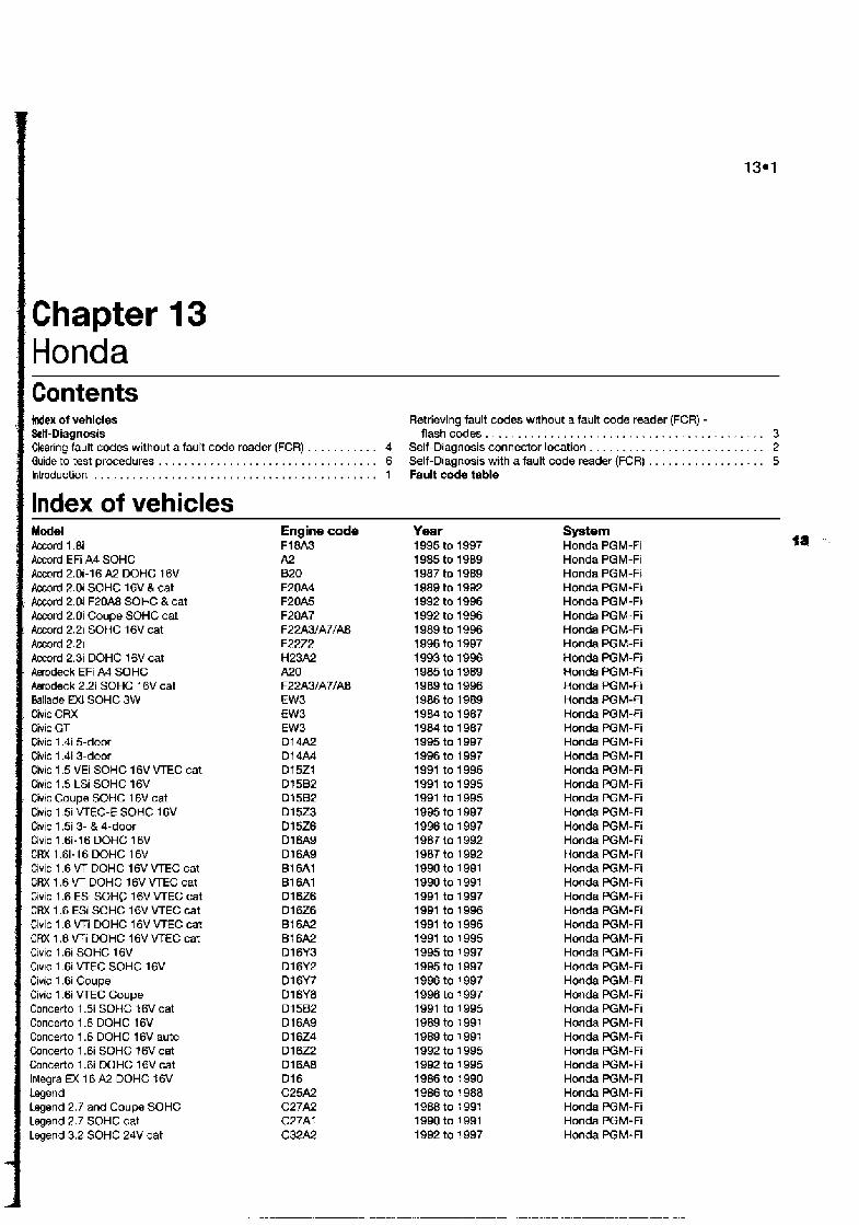
Cha pter I Honda I Contents
, Index of vehlcles I &If-Diagnosis Clearing fault codes without a fault code reader (FCR) . . . . . . . . . . Guide to test procedures . . . . . . . . . . . . . . . . . . . . . . . . . . . . . . . . . Introduction . . . . . . . . . . . . . . . . . . . . . . . . . . . . . . . . . . . . . . . . . . .
: Index of vehicles Model
' Accord 1.8i Accord EFi A4 SOHC ! Accord 2.0i-16 A2 DOHC 16V
i Accord 2.0i SOHC 16V & cat I. Accord 2.0i F20A8 SOHC & cat
Accord 2.0i Coupe SOHC cat r Accord 2.21 SOHC 16V cat
Accord 2.21 Accord 2.3i DOHC 16V cat Awodeck EFi A4 SOHC Awodeck 2.2i SOHC 16V cat Ballade EXi SOHC 3W
, Civic CRX Civic GT Civic 1.4i 5-door Civic 1.4i 3-door Civic 1.5 VEI SOHC 16V VTEC cat Civic 1.5 LSi SOHC 16V
- Civic Coupe SOHC 16V cat Civic 1.5i VTEC-E SOHC 16V Civic 1.51 3- & 4-door Civic 1.6i-16 DOHC 16V CRX 1.6i-16 DOHC 16V Civic 1.6 VT DOHC 16V VTEC cat CRX 1.6 VT DOHC 16V VTEC cat Civic t .6 ESi SOHC 16V VTEC cat CRX 1.6 ESi SOHC 16V VTEC cat Civic 1.6 VTi DOHC 16V VTEC cat CRX 1.6 VFi DOHC 16V VTEC cat Civic 1.6i SOHC 16V CIVIC 1.6i VTEC SOHC 16V Civic 1.6i Coupe Civic 1.6i VTEC Coupe Concerto 1.5i SOHC 16V cat Concerto 1.6 DOHC 16V Concerto 1.6 DOHC 16V auto Concerto 1.6i SOHC 16V cat Concerto 1.6i DOHC 16V cat lntegra EX 16 A2 DOHC 16V Legend Legend 2.7 and Coupe SOHC Legend 2.7 SOHC cat Legend 3.2 SOHC 24V cat
Retrieving fault codes without a fault code reader (FCR) - flashcodes . . . . . . . . . . . . . . . . . . . . . . . . . . . . . . . . . . . . . . . . . . . 3
. 4 Self-Diagnosis connector location . . . . . . . . . . . . . . . . . . . . . . . . . . . 2
. 6 Self-Diagnosis with afault code reader (FCR) . . . . . . . . . . . . . . . . . . 5
. 1 FauR code table
Engine code F18A3 A2 820 F20A4 F20A5 F20A7 F2 2A3/A7/A8 F2222 H23A2 A20 F2 2A3/A7/A8 EW3 EW3 EW3 Dl 4A2 D l 4 M D15Z1 Dt 5B2 D15B2 D15Z3 D l 526 D l 6A9 D l 6A9 B16A1 B16A1 D l 626 D l 626 B16A2 B16A2 D l 6Y3 D16Y2 D16Y7 D16Y8 D l 5B2 D l 6A9 D l 6Z4 D l 6Z2 D l 6A8 D l 6 C25A2 C27A2 C27At C32A2
Year 1 995 to 1997 1 985 to 1989 1987 to 1989 1 989 to 1992 1 992 to 1996 1 992 to 1996 1 989 to 1996 1 996 to 1997 1 993 to 1996 1 985 to 1989 1989 to 1996 7986 to 1989 t984 to 1987 1984 to 1987 1995 to 1997 1996 to 1 997 1991 to 1995 1991 to 1995 1991 to 1995 1995 to 1997 1996 to 1997 1987 to 1 992 1987 to 1 992 1990 to 1991 1990 to 1 991 1991 to 1997 1991 to 1996 1991 to 1995 1991 to 1 995 1995 to 1 997 1995 to 1 997 1996 to 1 997 1896 to 1 997 1991 to 1 995 1889 to 1 991 1989 to 1 991 1992 to 1 995 1992 to 1 995 1986 to 1 990 1986 to 1 988 1988 to 1 991 1990 to 1 991 1992 to I 997
System Honda PGM-Fi Honda PGM-Fi Honda PGM-Fi Honda PGM-Fi Honda PGM-Fi Honda PGM-Fi Honda PGM-Fi Honda PGM-Fi Honda PGM-Fi Honda PGM-Fi Honda PGM-Fi Honda PGM-Fi Honda PGM-Fi Honda PGM-Fi Honda PGM-Fi Honda PGM-Fi Honda PGM-Fi Honda PGM-Fi Honda PGM-Fi Honda PGM-Fi Honda PGM-Fi Honda PGM-Fi Honda PGM-Fi Honda PGM-Fi Honda PGM-Fi Honda PGM-Fi Honda PGM-Fi Honda PGM-Fi Honda PGM-Fi Honda PGM-Fi Honda PGM-Fi Honda PGM-Fi Honda PGM-Fi Honda PGM-Fi Honda PGM-Fi Honda PGM-Fi Honda PGM-Fi Honda PGM-Fi Honda PGM-Fi Honda PGM-Fi Honda PGM-Fi Honda PGM-Fi Honda PGM-Fi
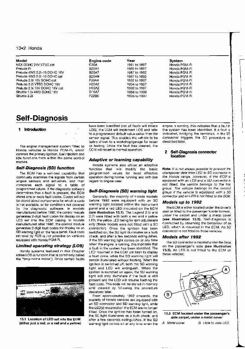
13.2 Honda
Model NSX DOHC 24V VTEC cat Prelude Fi Prelude 4WS 2.0i-16 DOHC 16V Prelude 4WS 2.0i-16 DOHC cat Prelude 2.0i 16V SOHC cat Prelude 2.2i VTEC DOHC 16V Prelude 2.3i 16V DOHC 16V cat Shuttle 1.61 SWD SOHC 16V Shuttle 2.2i
Self -Diannosis
The engine management system fitted to Honda vehicles is Honda PGM-Fi, which controls the primary ignition, fuel injection and idle funct~ons from within the same control module.
Self-Diagnosis (SDJ function The ECM has a self-test capability that
conttnually examines the signals from certain sng~ne sensors and actuators, and then compares each signal to a table of programmed values. If the diagnostic software determines that a fault is present, the ECM stores one or more fault codes. Codes will not be stored about components for wh~ch a code is not available, or for conditions not covered by the diagnostic software. In models manufactured before 1992, the control module generates 2-digit fault codes for display on an LED set into the ECM casing. In models manufactured after 1992, the conlrol module generates 2-digit fault mdes for d~splay on an SD warning light on the lacla panel. Fault code retrieval by FCR is not poss~ble on vehicles equipped with Honda PGM-FI.
Limited operating strategy (LOSJ Honda systems featured in this Chapter
util~se LOS (a tunct~on that is commonly called the "limp-ho-me niode"). Once certain faults
13.1 Location of LED set into the ECM (either just a red, or a red and a yellow)
Engine code C30A BZOAl B2OA7 BZOAQ F20A4 H22A2 H23A2 Dl 6A7 F22BB
Year 1991 to 1997 1985 to 1987 1987 to 1992 1987 to 1992 1992 to 1997 1994 lo 1997 1992 to 1997 1988 to 1 990 1995 to 1997
have been identified (not all faults wtll initlate LOS), the ECM will implement LOS and refer to a programmed default value rather than the sensor signal. This enables the vehicle to be safely driven to a workshop/garage for repair or testlng. Once the fault has cleared, the ECM will revert to normal operation. '
Adaptive or learning capability Honda systems also util~se an adaptive
function thal will mod~fy the basic programmed values for most effective operation during normal runnlng, and with due regard to englne wear.
Self-Diagnosis (SD) warning Iight Generally, the majority of Honda models
before 1992 were equipped with an SD warning light located within the instrument panel and a red LED mounted on the ECM (see illustration 13.1). The Legend 2.5i and 2.7i were fitted with both a red and a yellow LED, the yellow LED being for rpm adjustment only (these models were not fitted with a SD connector). Once the ignition has been switched on, the SD light illuminates as a bulb check, and after a few seconds extinguishes. If the SD warning light comes on at any time when the englne IS running, this indicates that a fault in the system has been ident~fied. The LED mounled IV the ECM w~ll flash to display a fault code, whlle the SD warnlng light will remain illum~nated w~thout flashing. When the ignition is sw~lched OH, both the SO warning light and LED will exl~ngulsh. When the ignition is sw~tched on agaln, the SD warning light will only illumlnale 11 the fault IS still present and Ihe LED w~l l resume flash~ng the fault code. Th~s code will be stored in memory until cleared by following the procedure described later.
From approximately 1992 onwards, the maiority of Honda vehicles are equipped with an SD connector and SD warning light, while the LED(s) mounted on the ECM are no longer fitted. Once the ignition has been turned on, the SO light illuminates as a bulb check, and after a few seconds extinguishes. If the SD warning light comes on at any time when the
System Honda PGM-Fi Honda PGM-Fi Honda PGM-Fi Honda PGM-Fi Honda PGM-Fi Honda PGM-Fi Honda PGM-Fi Honda PGM-Fi Honda PGM-Fi
2 Self-Diagnosis connector location
englne IS running, this indicates that a fault in the system has been identified. If a fault 1s indicated, bridging the terminals in the SD connector triggers the SD procedure as described later.
Note: It is not always pmrble to ptnpotnt the changeover date from LED to SD connector to the Honda range. However, r f the ECM is equipped with an LED and a SD connector is not fitted, the vehicle belongs to the first group. The vehlcle belongs to the second group r f the vehrcle is equipped with a SD connector and an LED is not frtted to the ECM.
'
I .
I
Models up to 1992 The ECM IS either located under the drlver's
seal or fl'i?ed to the passenger's side footwell, under the carpet and under a metal cover (see illustration 13.2). Self-diagnosis is conducted by observing the behaviour of an LED, which is mounted in the ECM. An SD connector is not titted to these vehicles.
Models after 1992 The SD connector is located under the fac~a
on the passenger's side (see illustration 13.3). An LED is not f~t ted to the ECM on these vehicles.
13.2 ECM located under the passenger's side carp&, under a metal cover
A Metal cover B Hole to view LED
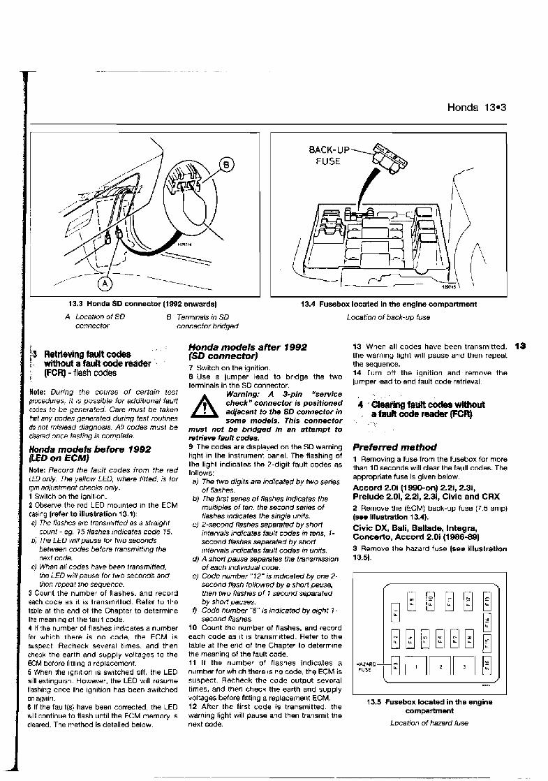
Honda 13.3
I
a ' I
13.3 Honda SD connector (1992 onwards) 13.4 Fusebox located in the engine cornparhnent
I A Location of SD 8 Terminals in SD connector connector bridged
> , ,
!3 Retrieving fault oodes t - without or fa& code reader ', f (FCR]-f la~hc&e~
Note: During the course of certain rest procedures, it rs possible for additional fault codes to be generated. Care must be taken hat any codes generated during test routines do not mislead diagnosis. All codes musf cleared once testing is complete.
Honda models before 1992 &ED on ECMJ Note: Record the fault codes from the red LED only. The yellow LED, where fitted, is lor rpm adjustment checks only. 1 Switch on the ign~t~on. 2 Observe the red LED rnounled In the ECM caslng (refer to Illustration 13.1). a) The flashes are transmttted as a straight
count - eg. 15 flashes tndicates code 75. b) The LED will pause for two seconds between codes before trensmttt~ng the next code.
c) When all codes have been I ransmr~M, the LED wiN pause far two seconds and then repeat the sequence.
S Count Ihe number of flashes, and record each code as ~t 1s Iransm~tted Refer to the table at the end ot the Chapter to determine the meanlng of Ihe fault code. 4 If the number of flashes ~ndrcates a number for whlch there is no code, the ECM is suspect Recheck several tlmes, and then check the earth and supply voltages to the ECM before flttlnq a replacement. 6 When the ~gnltlon IS switched off, the LED will extlngu~sh However, the LEO will rasums flashlng once the ign~tion has been switched on again. 6 If the fault@.) have been correct&, the LED wlll contlnue to flash until the ECM memory IS
cleared. The method is detalled below.
Honda models after 1992 [SD connector) 7 Switch on the ~gnition. 8 Use a jumper lead to brtdge the two temlnals in the SD connector.
A Warning: A 3-pin -service check" connector is positioned aaacent to the SD connector in some models. This connector
must not be bridged in an attempt to mirieve fault codes. 9 The codes are d~splayed on the SD warning light In the instrument panel. The flash~ng of Ihe light indicates Ihe 2-d~git fault codes as follows: a) The two digits are indicated by two series
of #@shes. b) The irrst senes of flashes mdrcates the
multrples of ten. the second ser~es of flashes mdrcates the single units.
c) 2-sw-vnd flashes sepamted by short intervals indicates fault codes m tens, I - second flashes separated by short tntervals indicaies fault codes m unrts.
d) A short pause separates the tmnsrnrssron of each indivrdual code.
e) Code number "12" is ~ndrcated by one 2- second flash followed by a shod @use, then two flashes of 1 second separated by shon pauses.
I) Code number "8 " is indicated by eght I - second flashes.
10 Count the number of flashes, and record each code as ~t 1s transrn~tted Refer to the table at the end of the Chapter to determine the meaning of the fault code. 11 If the number of flashes indicates a number tor whlch there IS no code, the ECM is suspect. Recheck the code output several times, and then check the earth and supply voltages before fating a replacement ECM. 12 After the first code is transmitted, the warnlng light w~ll pause and then transmlt the next ccde.
Location o f back-up fuse
13 When all codes have been transmitted, l a the warning light will pause and then repeat the sequence. 14 Turn off the ignition and remove the jumper lead to end fault ccde retrieval.
Preferred method 1 Removing a fuse from the fusebox for more than 10 seconds will clear the fault codes. The appropriate fuse is given below.
Accord 2.0i (1 990-on) 2.2i, 2.3i, Prelude 2-04 2.24 2.3i, Civic and CRX 2 Remove the (ECM) back-up fuse (7.5 amp) (see lllustratlon 13.4).
Civic DX, Bali, Ballade, Integra, Concerto. Accord 2.0i (1 986-89) 3 Remove the hazard fuse (see i l lustratbn 13.5).
13.5 Fusebox located in the engine compartment
Location of hazard fuse
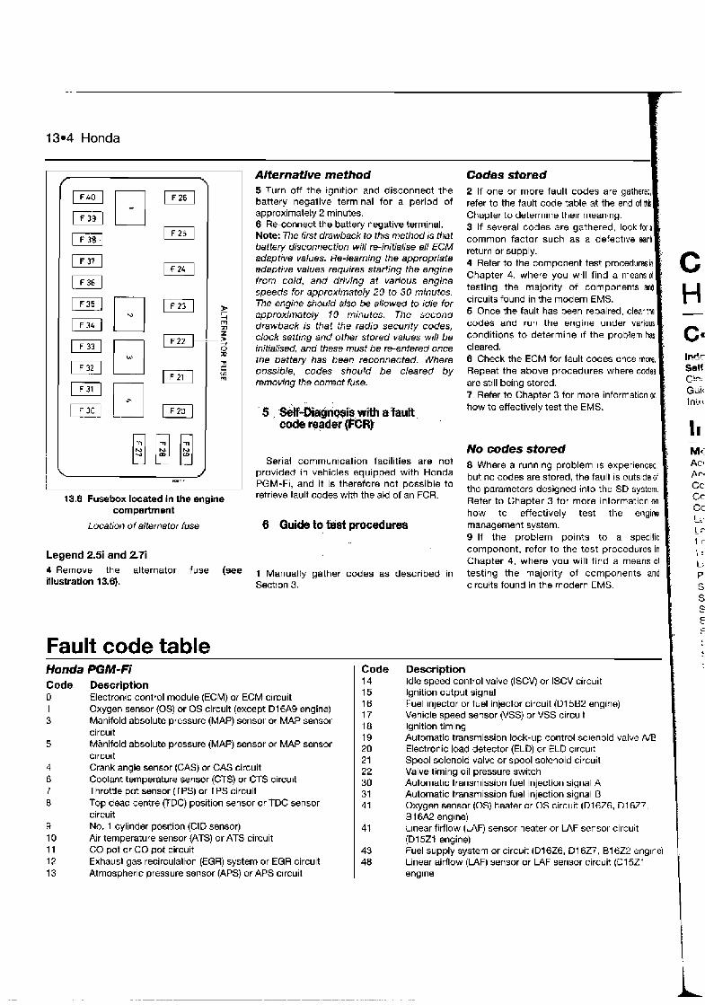
13.4 Honda
Codes stored 1 Alternative method 5 Turn off the ignition and disconnect the battery negative terminal for a period of approximately 2 minutes. 6 Re-connect the battery negative terminal. Note: The firsf drawback to this method is that battery disconnection will re-initialise aN ECM adaptive values. Re-learning the appropriate adaptive values requires starting the engine from cold, and driving at various engine speeds for approximately 20 to 30 minutes. The engine should also be allowed to idle for approximately 10 minutes. The second drawback is that the radio security codes, clock setting and other stored values will be initialised, and these must be re-entered once the battery has been reconnected. Where possible, codes should be cleared by removing the correct fuse.
2 If one or more fault codes are gathered, refer to the fault code table at the end of ~ Chapter to determine the~r rneanjng. 3 If several codes are gathered, look fora common factor such as a defect~ve eanh return or supply. 4 Refer to the component test procedures kl Chapter 4, where you will find a meansol testing the majority of components and circuits found in the modern EMS. 5 Once the fault has been repaired, clear ths codes and run the engine under various conditions to determine ~f the problem has cleared. 6 Check the ECM for fault codes once more, Repeat the above procedures where codes are still being stored. 7 Refer to Chapter 3 for more information on how to effectively test the EMS.
In@? Self I?c: Guir Inirt
' 5 , w-Diegiosiq with e fautt code wader PCRt
-
No codes stored [ M. Serial communication facilities are not
provided in vehicles equipped with Honda PGM-Fi, and it is therefore not possible to
13,8 Fusebox located In the engine retrieve fault codes with the aid of an FCR.
compartment
Location of alternator fuse 6 Quide to bst procedwe~
8 Where a running problem IS experienced, but no codes are stored, the fault is outs~de of the parameters designed into the SD system. Refer to Chapter 3 for more information on how to effectively test the engine management system. 9 If the problem points to a specific component, refer to the test procedures in Chapter 4, where you will find a means o l testing the majority of components and circuits found in the modern EMS.
Legend 2.5i and 2.7i
Remove the alternator fuse bee 1 Manually gather codes as described in illustration 13.8). Section 3.
Fault code table Honda PGM-Fi Code
14 15 16 17 18 19 20 21 22 30 31 41
Description Idle speed control valve (ISCVj or ISCV circuit Ignition output signal Fuel injector or fuel injector circuit (Dl582 engine) Vehicle speed sensor (VSS) or VSS circu~t Ignition timing Automatic transmission lock-up control solenoid valve NB Electronic load detector (ELD) or EL0 c~rcu~t Spool solenoid valve or spool solenoid circuit Valve timing oil pressure switch Automatic transmission fuel injection signal A Automatic transmission fuel injection signal I3 Oxygen sensor (0s) heater or OS circuit (D16Z6, 01 627, 51 6A2 engine) h e a r firflow (WF) sensor heater or L4F sensor circuit (D15ZI engine) Fuel supply system or circuit (D16Z6, 01 627, 81 622 engine) Linear airflow (LAF) sensor or LAF sensor circuit (I31 521 englne
Code Description 0 Electronic control module (ECM) or ECM circuit 1 Oxygen sensor (0s) or OS circuit (except D16A9 engine) 3 Manifold absolute pressure (MAP) sensor or MAP sensor
circuit Manifold absolute pressure (MAP) sensor or MAP sensor circu~t Crank angle sensor (GAS) or CAS circuit Coolant temperature sensor (CTS) or CTS circurt Throttle pot sensor VPS) or TPS circuit Top dead centre (TDC) position sensor or TDC sensor circuit No. 1 cylinder pos~tion (ClD sensor) Air temperature sensor (ATS) or ATS circuit CO pot or CO pot circuit Exhaust gas recirculation (EGR) system or EGR circuit Atmospheric pressure sensor (APS) or APS circuit
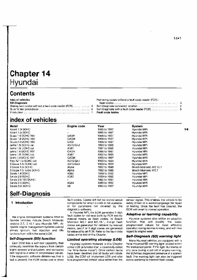
Chapter 14 Hyundai Contents mdex of vehicles Retrieving codes without a tault code reader (FCR) -
. . . . . . . . . . . . . . . . . . . . . . . . . . . . . . . . . . . . . . . Self-Diagnosis flashcodes 3 Clear~ng fault codes without a fault code reader (FCR) . . . . . . . . . 4 Self-Diagnosis conneMor location . . . . . . . . . . . . . . . . . . . . . . . . . . . 2 Gu~de to tsst procedures . . . . . . . . . . . . . . . . . . . . . . . . . . . . . . . . 6 Self-D~agnosis with a fault code reader (FCR) . . . . . . . . . . . . . . . . . 5 lntroduct~on . . . . . . . . . . . . . . . . . . . . . . . . . . . . . . . . . . . . . . . . . . . . 1 Fault code tables
Index of vehicles Model Accent 1.3i SOHC Accent 1.5i SOHC Coupe 1.6 DOHC 16V Coupe 1 .B DCHC 16V Coupe 2.0 DOHC 16V lanlra 1 .Si SOHC cat Lantra 1.6i DOHC cat tantra 1.6 DOHC 16V lantra 1.8i DOHC cat Lantra 1.8 DOHC 16V Pony X2 1.5i SOHC cat S Coupe 1.51 SOHC cat S Coupe 1.51 SOHC S Coupe 1 51 turbo SOHC Sonala 1.8 SOHC 5anata 2.0 SOHC Sonata 2.0 16V DOHC Sonata 2.4 SOHC Sonata 3.0i SOHC
Engine code
G4GR G4GM G4GF 4G1 S/G4J 4G61 G4G R 4G6 7 G4GM 4G151G4.l 4G151G4J Alpha Alpha 4G62 4G63
4G64 V6
Year 1995 to 1997 1995 to 1 997 1 996 to 1997 1996 to 1997 1996 to 1997 1993 to 1995 199' to 1995 1996 to 1997 1992 to 1995 1996 to 1997 1990 to 1994 1 990 to 1992 1 992 to 1996 1992 to 1996 1989 to 1992 1989 to 1 992 1992 to 1997 1989 to 1992 1994 to 1997
System Hyundai MPi 14 Hyundai MPi Hyundai MPi Hyundai MPI Hyunda~ MPi Hyundai MPi Hyundai MPi Hyundai MPi Hyundai MPi Hyundai MPi Hyundai MPi Hyundai MPi Bosch Motronic M2.10 1 Bosch Motronic M2.7 Hyundal MPi Hyundai MPi Hyundai MPi Hyundai MPi Hyundai MPi
Self-Diagnosis fault codes. Codes will not be stored about sensor signal. This enables the vehicle to be components for which a code ts not available, safely driven to a workshopfgarage for repair or for conditions not ccvered by the or testing. Once the fault has cleared, the diagnostic software. ECM w~l l revert to normal operation.
In Hyundai MPi, the ECM generates 2-digit
The engine management systems f~tted to fault codas for refr~eval both by FCR and by Or learning capabi'iw manual means as flash codes. In Bosch Hyundal systems also utilise an adsplive
vehicles Iqclude 'Osch Motronic M2.7 and M2.10.1, 4-dlg1t flash function that will modify the basic versions 2.7. 2.10.1 and Hyundai MPI. All codes are generated for retrieval by manual programmed values for most effective
Hyundai engine management 'ystems means, and 2 or 3-digit codes are generaled operation during normal running, and with due pri'naQ' ignltlonf and idle for retrieval by an FCR. Refer to the fault code regard to engine wear. fwrct~ons from within the same ECM. tables at the end of this Chapler. Self- Diagnosis (SD) warning Iight Self-Diagnosis (SbJ function Limifed operating strategy (LOSJ Many Hy undai vehicles are equipped w~th a
Each EcM has a self-test capability that Hyundai systems featured in this Chapter facia-mounted SD warning light located wllhln contlnuall~ examines the signals from certain ut~l~se LQS (a function that 1s commonly called the instrument panel. If the light illuminates at engine sensors and actuators, and compares the "limp-home mode"). Once certain faults any time during a period ot engine runnlng, each signal l o a table of programmed values. have been identified (not all faults will initiate the ECM has d~agnosed presenceof a system If the d~agnost~c software deterrn~nes that a LOS), the ECM will implernenl LOS and refer fault. The warning light can also be triggered faull IS present, the ECM stores one or more to a programmed default value ralher than the (some systems) to transmit flash codes.
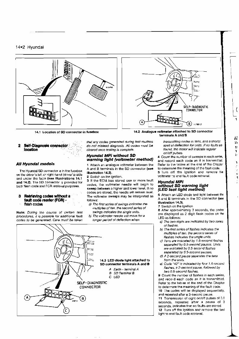
14-2 Hyundai
14.1 Location of 80 connector in fusebox
All Hyundai models
The Hyundai SD connector IS in the fusebox on the driver's left or righl-hand (driver's) side and under the facia (see Illustrations 14.1 and 14.2). The SD connector IS provided for both flash code and FCR retrieval purposes.
S W&tkgcodeawfthwta Lutr&tsader(FCR)- flash codes
Note: During the course of cerfarn test procedures, ri is possrble for addltronal fault codes to be generated. Care must be taken
I
14.2 Analogue voltmeter attached to SD connector terminals A and 6
' I that any codes genemted during test routines do not mislead diagnosis. All codes must be cleared once testing is complete.
Hyundai MPi without SD warning light (voltmeter method) 1 Attach an analogue voltmeter between the A and B terminals in the SD connector (see illustration 14.2). 2 Switch on the ignition. 3 If the ECM has stored one or more fault codes, the voltmeter needle will begin to sweep between a higher and tower level. If no codes are stored, the needle will remain level. The voltmeter sweeps may be interpreted as follows:
a) The first series of swings indicates the rnu/fiples of ten, the second ~ 8 h 8 ~ of swings rndrcates the single units.
bJ The voltmeter needle will move for a longer period of deflection when
transmitting codes in tens, and a shorter spell of deflection for units. if no faults are found, the meter will indicate regular onloff pulses.
4 Caunt the number of weeps in each s e r i ~ , and record each code as it is transmitted. Refer to the tables at the end of the Chapter to determine the meaning of the fault code. 5 Turn off the ignition and remove the voltmeter to end fault code retrieval.
Hyundai MPi without SD warning light (LED test light method) 8 Attach an LED diode test light between the A and B terminals in the SD connector (see illustration 14.3). 7 Switch on the ignition 8 After approximately 3 seconds, the codes are displayed as 2-digit flash codes on the LED as follows: a) The two digits are indicated bv two series
$yyJ\F 14.3 LED diode llgM attached to
K ~ F - DIAGNOSTIC CONNECTOR
- of flashes.
b) The first series of flashes indicates the multiples of ten. the second series o f flashes indicates the s~ngle units.
c) Tens am indicated by 1.5-second flashes separated by 0.5-second pauses. Units are md~cated by 0.5-second flashes separated by 0.5-second pauses.
d) A 2-second pause separates the tens from the units.
el Code "42" is tndicated by four 1.5-second flashes, a 2-second pause, followed by two 0.5-second flashes.
9 Count the number of flashes in each series, and record each code as it is transmitted. Refer to the tables at the end of the Chapter to determ~ne the meaning of the fault code. 10 The codes will be displayed sequentially, and repeated after a 3-second pause. 11 Transmission of eight on/off pulses of 0.5 seconds, repeated after a pause of 3 seconds, indicates that no faults are stored. 12 Turn off the ignition and remove the test tight to end fault code retrieval.

Hyundai 14*3
I-.. I
14.4 Hyundai MPi: Jwnwr lead attached to SD connector terminals A and B
A Earlh 8 SD Term~nal 8 - terminal A C Jumper lead
Hyundai MPi with SD warning light 13 Switch on the ~gnitibn. 14 Use a jumper lead to br~dge the A and B terminals in the SD connector (see Hlustration 14.4)
I 15 Atler approximately 3 secorids, the codes are displayed as 2-digit flash codes on the SD warning l~ght In the same way as for a warate LED (see paragraphs 8 lo 11 above). 16 Turn off the ignition and remove the )urnper lead to end fault code retrieval.
Bosch Motronic M2.7 and 2.10.1 Mote: 4-digit flash codes retrieved manually may be different to those codes displayed wrlh Ihe a ~ d of an FCR. Refer to the fault code tables at the end of this Chapter, in the cotuumn headed "Flash code". 17 Switch on the ignition. 18 Use a jumper lead to br~dge the A and B terminals in the SD Connector (see Illustration 14.5). 19Remove the jumper lead after approxjmately 2 to 3 seconds. 20 The warning l~ght will begin to flash the 4- dlglt tault codes as follows: el The four digrfs are indicated by four series
of flashes. bJ Tho first series of flashes tndicates the
first digit, the second senes of flashes indicates the second digit, and so on until all 4 dtgdts have been flashed.
c) Each series consists of a number of I - or 2-second flashes, separated by short pauses (0.5 seconds). Each integer (whole number) in the range 1 to 9 is represented by a number of 7.5-second flashes.
dJ A 2.5-second pause separates each series of flashes.
e) The code number " 1233" rs indicated by a 1.5-second flash, a 0.5-second pause, two 1.5-second flashes, a 0.5-second pause. three 1 . &second flashes. a 0.5- second pause and three 1.5-second flashes. After a 2.5-second pause. the code will be repeated.
2? Gount the number of flashes In each series. and record the code. Refer to the tables'at the end of the chapter to determine the rneaning of the fault code. 22 The code wilt be constantly repeated until the jumper lead IS used to bridge the A and 8 terminals in the SD connector once more. Remove the jumper lead after approx~mately 2 to 3 seconds, and the next fault code will be drsplayed. 23 Continue this procedure until all stored codes have been displayed. End of code transmission will be indicated on the SD warning light by code "3333". 24 Turn off the ignition and remove the jumper lead to end fault code retrieval. L
14.5 Bosch Moiranic: Jumper lead
4 Ckerihg fault cod& *but attached to SD connector tumlnals A and B
a fault cod& reader (feh) A Eedh - 6 S D Terminal B teminal A C Jumper lead
Hyundai MPi methods described almve untll code '3333" is transmitted.
1 Turn off the ignition and disconnect the 4 the jumper lead to bridge the A and B battery negative terminal for a ,period of terminals in the SD mnnector for 10 -on&,, approximately 15 seconds. and the codes wi!l be cleared. 2 Reconnect the battery negatlve terminal. Note: The first drawback to this method is that battery disconnection wi/l re-~nitialise aN ECM adaptive values. Re-learntg the appropriate adaptive values requires starting the engine from cold, and driving at various engine speeds for approxin~ately 20 to 30 minutes. The engine shouldalso be atlowed to idle for approxrrnately 10 minutes. The second drawback is that the radio security codes, clock selting and other stored values will be mrtialised. and these must be re-entered once !he battery has been reconnected. Where possrble, an FCR should be used for code clearing.
Bosch Motmnic 2.10.7 and M2.7 3 Retr~eve codes from the ECM by the
-
Note: During the course of certain test proc8dures. it rs pvss~ble for additional fault codes to be generated. Care must be taken that any codes generated during test routines do not mslead dragnosis.
A// Hyundai models 1 Connect an FCR to the SD connector, and use the FCR for the following purposes, in strict compliance with the FCR manufacturer's instructions (see illustration 14.8):
14.6 FCR attached to SD connector
A SD connector B The slave battery provides
supply voltage /or the FCR /

14*4 Hyundai
a) Retrieving fault codes. b) Clearing fault codes.
2 The FCR may be able to display both 4- digit flash codes and/or 2-digit fault codes. Refer to the fault code tables at the end of this Chapter, in the column headed "Flash code" or "FCR code" as appropriate. 3 Codes must always be cleared after component testing, or after repairs involving the removal or replacement of an EMS component.
1 Use an FCR to interrogate the ECM for fault
codes, or manually gather codes as described in Sections 3 or 5.
Codes stored 2 If one or more fault codes are gathered, refer to the fault code tables at the end of this Chapter to determine their meaning. 3 )f several codes are gathered, look for a common factor such as a defective earth return or supply. 4 Refer to the component test procedures in Chapter 4, where you will flnd a means of testing the majority of components and circuits found in the modern EMS. 5 Once the fault has been repaired, clear the codes and run the engine under various conditions to determine if the problem has cleared.
6 Check the ECM for fault codes once mom Repeat the above procedures where codes are still being stored. 7 Refer to Chapter 3 for more information pn
how to effectively test the EMS.
No codes stomd k 8 Where a running problem is experiend, but no codes are stored, the fault is outsidad the parameters designed into the SD system. Refer to Chapter 3 for more informationon how to effectively test the engin management system. 9 If the problem points to a specle component, refer to the test procedures in Chapter 4, where you will find a meansol testing the majority of components and circuits found in the modern EMS.
Fault code tables Hyundal MPi FtasW Description FCR oode 11 Oxygen sensor (0s) or OS circuit 12 Airflow sensor (AFS) or circuit 13 Air temperature sensor (ATS) or ATS circuit 14 Throttle position sensor (TPS) or circuit 15 Motor position sensor 21 Coolant temperature sensor (CTS) or CTS circuit 22 Crank angle sensor (GAS) or circuit 23 Cylinder number one top dead centre (TDC) sensor or
TDC sensor circuit 24 Vehicle speed sensor (VSS) or VSS circuit 25 Atmospheric pressure sensor (APS) or APS circuit 41 Injector or circuit 42 Fuel pump or circuit 43 No faults found in the ECM. Proceed wlth normal
diagnostic methods 44 Ignition coil 59 Rear oxygen sensor (0s) or OS circuit
Bosch Motmnic 2.7 and 2.10. I Flash FCR Dewription code code 1121 36 Electronic control module (ECM) or ECM circuit
(Motronic 2.7) 1122 - Ele.ctronic control module (ECM) 1233 - Eleztronic control module (ECM), read only
memory (ROM) failure 1234 - Electronic control module (ECM), random access
memoty (RAM) failure 2121 - Manifold absolute pressure (MAP) sensor or MAP
sensor circult 2721 21 Turbo wastegate solenoid valve or circuit
(Motronic 2.7) 2222 - Start of fault code output 3112 17 Injector Number 1 or injector circuit 3114 04 Idle speed control valve (ISCV) or ISCV circuit 3116 16 Injector Number 3 or injector circuit 3117 07 Vane airflow sensor (AFS) or AFS circuit 31 21 49 Manifold absolute pressure (MAP) sensor or MAP
sensor circuit {Motronic 2.7) 3122 22 Idle speed control valve (ISCV) or ISCV circuit 3128 28 Oxygen sensor (0s) or OS circuit
Flash C M i e 3135 3137
FCR code 05 37
Description
Carbon filter solenoid valve (CFSV) or CFSV cirail Battety voltage supply to electronic control module (ECM) or circuit Coolant temperature sensor (CTS) or CTS circul Air conditioning (A/C) Boost pressure signal or circuit (Motronic 2.7) Manifold absolute pressure (MAP) sensor or MAP sensor circuit Throttle pot sensor VPS) or TPS circuit Crank angle sensor (CAS) or CAS circuit Knock sensor (KS) or KS circuit Camshaft position sensor (CMP) or CMP circuit Knock sensor (KS) or KS circuit (Motronic 2.10.1) Electronic control module (ECM) (Motronic 2.n Camshaft position sensor (CMP) or CMP circuit Cylinder identification (CID) sensor or CID sensor circuit Electronic control module (ECM) (Motronic 2.7)
.- . LE. i - Pdi W..
C::?: GI.:: Lri i i -
. .
Knock sensor (KS) or KS circuit Injector Numbr 2 or injector circuit lnjector Number 4 or injector circuit Electronic control module (ECM) or ECM circuit (Motronic 2.10.1) Electronic control module (ECM) or ECM circuit (Motronic 2.10.1) Electronic control module (ECM) or ECM circuit (Motronic 2.10.1) End of fault code output Fuel pump or fuel pump circuit (Motronic 2.1 0.1) Oxygen sensor (0s) or OS circuit (Motronic 2.10.1) Airffuel control fault (Motronic 2.7) Oxygen sensor (0s) or OS circuit Oxygen sensor (0s) or OS circuit Oxygen sensor (0s) or OS circuit Electronic control module (ECM) Manifold absolute pressure (MAP) sensor or MAP sensor circuit Boost pressure signal or circuit (Motronic 2.7) No faults found in the ECM. Proceed with normal diagnostic methods
I
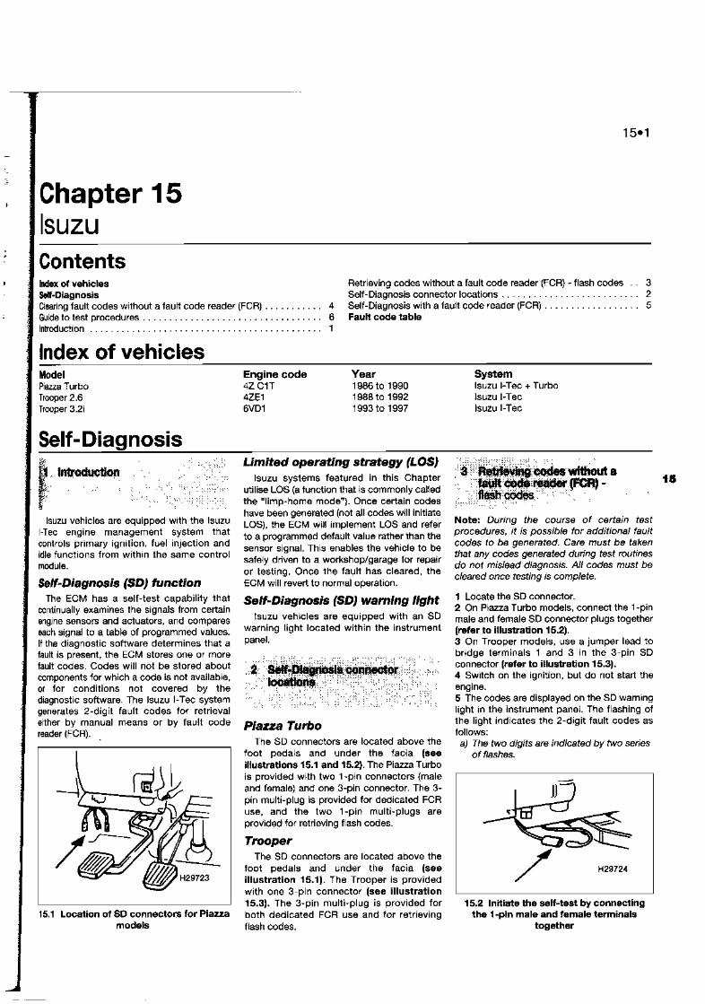

.-
15.2 lsuzu
I 1 Turning off the ignition and disconnecting component testing, or attw repairs i the connactors or jumper lead will end fault the removal of an EMS component. code retrieval.
, , , , > , , , ,",, , ,,+,
,, , ,
, , , , id;, ~ ~ * ~ n s ; ' -
, : , ,,, , ,, . , , , ; ,; ,
, > , ,,,< , ,, , ,,,, , ,", I ,,> ,,, ," , ,, I , ' , ,, ,,,",A,
, ,, <
<,,, ^ , . , , , > ,
. A , ,," ,, ,
,,, , , , , " , < , ,
, ,,, ,,,, ,
, , , A , , ,+,< .,,",, , , ,,, ,,; ;; ,<:,<:;<:,
, A < 1 Use and FCR to interrogate the E
Piaaa Turbo models fault codes, or manually gather co described in Sections 3 or 5.
1 Turn off the ignition and remove fuse 4 Codes stored
15.3 Location of SD connector for Trooper Imated the junction 'Ox.
#re seH-test by Note: The drawback to Ihts m m o d Is that the 2 If one or more fault codes are galnerd,
the terminals radio secunty codes, clock setting and other refer to the fault code t a b l ~ at the end of thb stored values will be initialised. and these Chapter to determine their meaning.
b, The Of mdicates the must be re-entered once the fuse is refitted. 3 If several codes are gathered, lo multiples of ten, the second series of Where possible, an FCR should be used for common factor such as a defective earth flashes indicates the single units. code clearing. return or supply.
c) Tens and units are tndicated by 0.4-second 4 Refer to the component test procedures in flashes, separated by a s h o ~ pause. Trooper models Chapter 4, where you will find a rneaas of
d, Apause seconds separates tens 2 rum off the ignition and remove fuse 13 testing the majority of components and and units. from the fusebox. Fuse 4 may be removed circuits found in the modern EMS.
e) A 3.2-second pause separates the instead, but removing fuse 13 obviates the 5 Once the fault has been repaired, clearthe transmission of each indivjdual code. need to reset the radio and clock. codes and run the engine under various
f ) Code number "72' is rndicated by one 0.4-second flash. Iollowed by a 1.2- , l + v , , I .li...llP .. .Y:+:. ' , ,+, + ,-
conditions to determine if the problem has , A , , , . , > ,,, , " " , , A , z , , cleared. second pause, then two flashes of 0.4 :$,;:,'
, ,+A ,a secorids in quick succession. c , , , , , ,
: : , ,, , ,, 6 Check the ECM for faul codes once rn~o. ,, , , >,, ,
A , > , , <, ,, < + 0 Count the number of flashes in each senes, , ; ,, ,
, , , , , < , , , Repeat the above procedures where codes , ,,, ,,, , and record each code as it is transmitted. , ' "~.:'":'':x:t , , , 'I, , I, : are stdl being stored.
Refer to the table at the end of ihe Chapter to '
7 Refer to Chapter 3 for more information on determine the meaning ot the fault code. Note: During the course of certain test how to effmively test the EMS.
Fault codes are In sequence, and procedures, it is possible for additional fault
three time5 befm the next code is coder to be g e m " . Care must be taken COdM transmitted. that any codes generated dunng test routines 8 Where a running problem is exper~enced,
B On Piazza Turbo models, when code do mislead diagnosis. but no codes are stored, the fauR is oulside ol number "12" is transmitted, this indicates the lsuZu mode/s
the parameters desrgned into the SD system. Refer to Chapter 3 for more information on start of the test procedure. If "12" IS repeated
constantly, no faults are stored. 1 Connect an FCR to the SD connector. Use how to effectively test the engine management 9 On Trooper models, when code number the FCR for the following purposes, in strict system. "12" is transmitted, th!s indicates that the compliance W!th the FCR manufacturer's 9 If the problem points to a specific engine has not been started and faults have instructions: component. refer to the test procedures in not been stored. a) Retrieving fault codes. Chapter 4. where you will find a means of 10 Continue processing until all stored codes b) Clearing fault codes. testing $he majority of components and have been retr~eved and recorded. 2 Codes must always be cleared after circuits found in the mcdem EMS.
Fault code table Isuzu /-Tee Flash1 Description FCR code 12 Englne 1s not started (Trooper) 12 Start of fault code output (Piazza) 13 Oxygen sensor (OS} or OS circu~t 14 Coolant temperature sensor (CTS) or CTS circuit 15 Coolant temperature sensor (CTS) or CTS circuit 21 Throttle sw~tch ITS), ~dle and full-load contacts both closed 22 Starter signel circuit 23 Power transistor for ign~lion or circuit 25 Vacuum switching valve system for pressure regulator or
circuit 26 Carbon finer solenoid valve (GFSVj or GFSV circu~t. high
voltage 27 Carbon tllter solenoid valve (CFSVj or CFSV circuit, low
voltage 33 Fuel lnjector system or fuel injector circuit 35 Power transistor for ignition or circuit
:
Flash1 Description FCR code 41 Crank angle sensor (GAS) or CAS circuit 43 Throttle swkch (TS), full-load switch 44 Oxygen sensor (0s) or OS circuit 45 Oxygen sensor (0s) or OS circuit 51 Electronic controt module (ECM) or ECM circu~t 52 Electron~c control module (ECM) or ECM cwcuit 53 Vacuum switching valve system for pressure regulator or
circu~t 54 lgnition control 61 Airflow sensor (AFS) or AFS circuit 62 Airflow sensor (AFS) or AFS circuit 63 Vehicle speed sensor (VSS) or VSS circutl 64 Fuel ivjwtor system or fuel injecior cucult 65 Throttle switch ITS), full-load switch 66 Knock sensor 72 Exhaust gas regulat~on (EGR) or EGR circuit
I
I
73 Exhaust gas regulat~on (EGR) or EGR circuit t i !

1 Jaguar 1 Contents
I Mex of vehlcles Retrieving fault codes without a fault code reader (FCRJ . . . . . . . . . 3 W-Megnosis Selt-D~agnosis connector location . . . . . . . . . . . . . . . . . . . . . . . . . . . 2 Claaring fault codes without a fault code reader (FCRj . . . . . . . . . . . 4 Self-Diagnosis with a fauR code reader (FCR) . . . . . . . . . . . . . . . . . . 5 N~de to test procedures . . . . . . . . . . . . . . . . . . . . . . . . . . . . . . . . . . 6 Fault code tables htroduction . . . . . . . . . . . . . . . . . . . . . . . . . . . . . . . . . . . . . . . . . . . 1
Index of vehicles Model Englne code Year This Chapter XJGISovereign 3.2 WHC cat AJ-6 1990 to 1 994 XJGISovereign 3.6 24V AJ-6 1 986 to 1989 WSovereqn 4.0 AJ-6 1991 to 1997 U-S 4.0 AJ-6 1991 to 1997 Ptfier Jeguar vehictealaystems not covered by this book Oouble 6 6.0 SOHC cat V12 1993 to 1 994 V12 6.0 SOHC cat V t 2 1993 to f 994
- XJ6 3.2 DOHC 24V AJ16 1994 to 1997 XJ6 4.0 Sport AJ16 1894 to 1997 XJR 4.0 Supercharged AJ16 1994 to 1997 XJ-S V12 6.0 V7 2 1993 to 1996 U-S V12 6.0 R-cat V12 1993 to t 997 U12 6.0 V12 SOHC V12 1 994 to 1997 XJ-S & XJSC V12 OHC V12 1990 to 1993 U-S B XJSC V12 R-cat V12 1990 to 1993
Self-Diaanosis Y
,, : <':,, ,', , ;,' ,,..,, '
, , z : + j , ~ ~ c ~ : ~ : ~ , ~ Lucas LH-9CU and LH-15CU systems
,,,: , , , z , v , ,, generate 2-digit fault codes for retrieval and , , , , , , , :
, , a , A ,
, . < ,
, , , " ~ , , , < , , display on the facia-mounted vehicle
', > , ; ";<:,;:, , , , ,"
, , < :,
", , ,. , condltlon monitor, and for retrieval by a
dedicatd FCR. The engine management systems (EMS?.) I Wed to Jaguar vehctes are mainly of Lucar
origin, and include LH-SCU, LH-1 SCU, LH- 26CU and LH-36CU. All Jaguar engine management systems control primary gnition, fuelling and idle functions from within Ce same control module, iucas LH-9CU and LH-t5CU atone are coveted by this book. Fault code tables and methods of retrieving data for other models were not available at the time cl going to prcss. However, ~t is certain that a dedicated fault code reader (FCR) is requlred to retrieve codes and other data from the majority of Jaguar models.
Self-Diagnosis (SDJ functlon Each ECM has a self-test capability that
conl~nuelly examines the signals from certain englne sensors and acluetors, which then compares each siqnal to a table of
Limited operating strategy (LOSJ Jaguar sys!ems featured In this Chapter
utilise LOS (a function that is commonly called the Ylmp-home mode"). Once certain codes have been identified (not all codes will initiate LOS), the ECM will ~rnplement LOS and refa to a prcgrammed default value rather than the sensor signal. This enables the vehicle to be safely driven to a workshop/garage for repair or testing. Once the fault has cleared, the ECM will revert to normal operation.
Jaguar systems also utilise an adaptive function that will modify the basic programmed values for most eHectlve operatlnn during normal running, and with due regard to engine wear.
I programmed values. If the diagnostic software determrnes that a fault is present, the Self"Diagnoais (SDl di lay ECM stores one or more fault codes. Codes m o x o r ~
I will not be stored about components for Jaguar models are equipped w ~ t h a facla- which a code is not available, or for condltions mounted SD display panel called the vehicle not covered by the diagnostic software. condition monitor.
System
LUCS LH-1 5CU L U C ~ LH-QCU Lucas W-1 5CU Lucas LH-ISCU
Lucas LH-36CU Lucas LHd6CU Lucas GEMS Lucas GEMS Lucas GEMS Lucas LH-36CU Lucas LH-36CU Lucas LH-36CU Lucas LH-26CU Lucas LH-26CU
The SD connector provided for FCR use is located in front of the battery in the englne companment. The connector is usually coloured brown, round and is of &pin design. In addition, the vehicle is equipped with a vehicle condition monitor (VCM) fw fault code retrieval. The VCM is mounted below the instrument paner (see iltustration 18.1).
18.1 Vehicle condition monkor
I Button 3 VCM display clew 2 Code display button
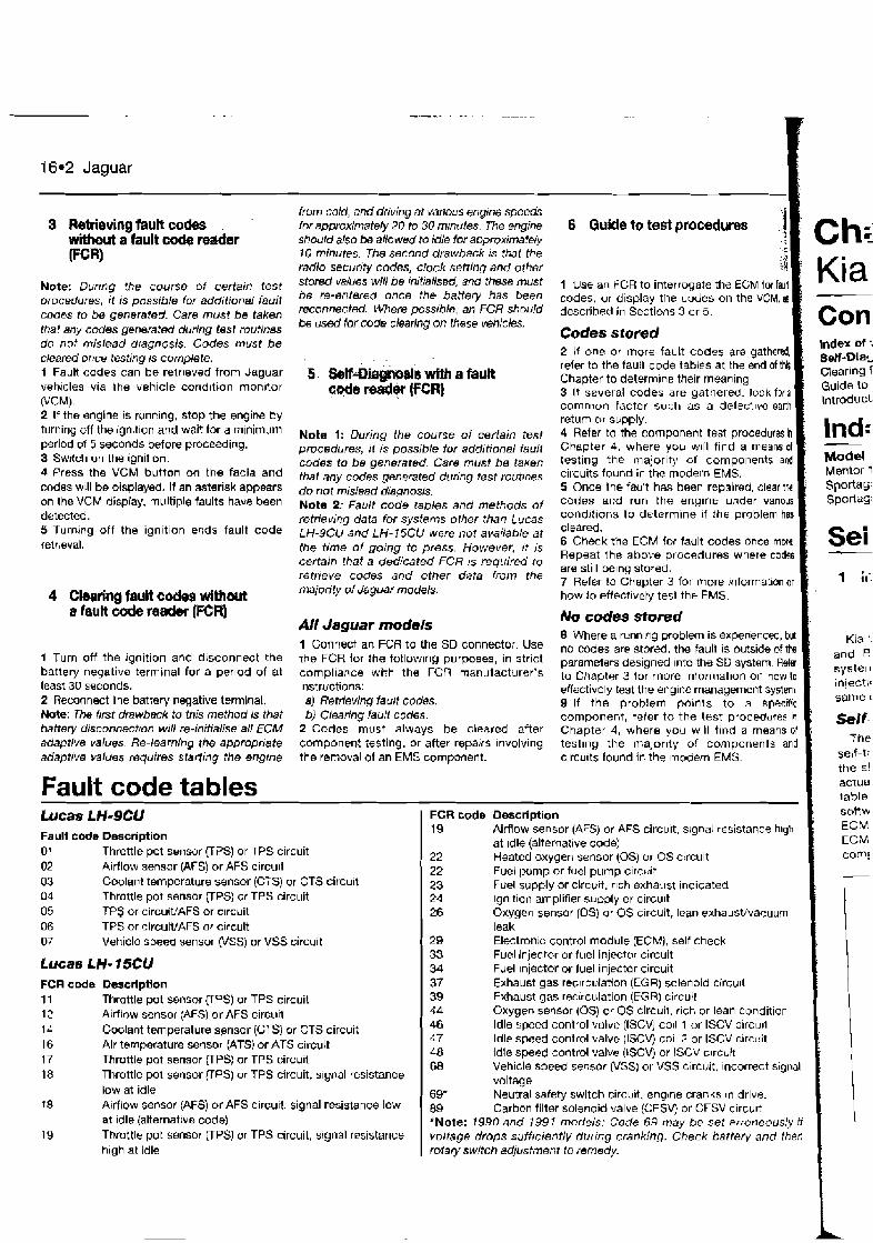
16.2 Jaguar
3 Retrieving fauk codes without a fault code reader (FCR)
Note: Durrng the course of certain test procedures, it is possible lor additional fault codes to be generated. Care must be taken that any codes generated during test routines do not mislead dragnosis. Codes must be cleared once testing is complete. I Fault codes can be relr~eved from Jaguar vehicles via the vehicle cond~tion monltor rVCM). 2 If the engine is running, stop the engine by turning off the ign~t~on and wait for a m~nimum period of 5 seconds before proceeding. 3 Swtlch on the ignit~on. 4 Press the VCM button on the facia and codes will be displayed. H an asterisk appears on the VCM display, multiple faults have been detected. 5 Turning off the ignition ends fault code te1r:eval.
1 Turn off the ignition and disconnect the battery negative terminal for a per~od of at least 30 seconds. 2 Reconnect the battery vegative terminal. Note: The first drawback to this method is that battery disc~nnectton wrll re-initialise all ECM adaptive values. Re-learning the appropriate adaptive values requires starling the engrne
Fault code tables
from cold, and driving at vanws engine speeds fw approximately 20 to 30 mmutes. The engine should also be allowed to idle for approximafely 7 0 minutes. The second drawback is that the radio secunfy codes, clock setting and other stored vaiues will be initialised, and these must be re-entered once the battery has been reconnected. Where possible, an FCR should be used for code clearing on these vehicles.
Note I: During the course of certain test prucedures, rt IS possible for additional fault codes to be generated. Care must be taken that any codes genwared during test rout~nes do not mislead dragnosis. Note 2; Faulf code tables and methods of retrieving data for sysfems other than Lucas LH-9CU and LH-ISCU were not available at the time of going to press. However, i t 1s certain that a dedicated FCR is required to retrieve codes and other data from the majority of Jaguar modeis.
All Jaguar modeis 1 Connect an FCR to the SD connectoi. Use the FCR lor the fotlowlng purposes, in strict compliance with the FCR manufacturer's lnstrlictions: a) Retrieving fault codes. 6) Clearing fault codes.
2 Codes must always be cleared after component testing, or after repatrs ~nvolving the removal of an EMS component.
Fault coda Description 01 Throttle pot swnsor (TPS) or TPS circuit 02 Airflow sensor (AFS) or AFS circu~l 03 Coolant temperature sensor (CTS) or CTS circu~t 04 Throttle pot sensor (TPS) or TPS circuit 05 TP$ or circuiVAFS or c~rcuit 06 TPS or circuiVAFS or circuit 07 Vehicle speed sensor (VSS) or VSS circi~~t
Lucas LH- 15CU FCR code 1 1 12 14 16 17 18
Descripaon Throttle pot sensor VPS) or TPS circuit Airflow sensor (AFS) or AFS circu~t Coolant temperature sensor (CTS) or CTS circuit Air temperature sensor (ATS) or ATS circuit Throttle pot sensor UPS) or TPS circuit Throttle pol sensor VPS} or TPS circuit, s~gnal resistance low at idle Airflow sensor (AFS) or AFS circu~l, signal resistance low at ~ d l ~ (alternative code) Throtlle pot sensor [TPS) or TPS circuit, signal resistance high at idle
6 Gukle to test procedures
1 Use an FCR to interrogate the ECM for faun codes, or display the cades on the VCM, as described in Sections 3 or 5.
Codes stored 2 If one or rriore fault codes are gathered refer to the fault code tables at the end ofthil Chapter to determ~ne !he~r mean~ng 3 If several codes are gathered. look fwi common factor such as a delect~ue eartl
Con Index of : S d - D i a ~
I Clearing i Guide to i / Intmduct:
return or svpply. 4 Refer m the component tea Drocedur. in I ~ n d ~ Chapter 4, where ;ou will find a means of - testing the majority of components and Model c~rcuits found in the modern EMS. I Mentor 1 5 Once the facllt has been repaired, clear tk Spofla5 codes and run the engine under varlous SpOHaG: cond!:~ons to determine i f the problem has cleared. 6 check the EcM lor fault codes once more. t ~ e i - Repeat the above procedures where codes - are still be~ng stored. 7 Refer to Chapter 3 for more !nformatron on 1 ;I: how io effect~vely test thb EMS.
No codes sfored 8 Where a runnlng problem IS experienced, but no codes ars stored, the fault IS b u b d e of tne paramelers designed Into the SD system Refer to Chapter 3 for more ~nformat~on on how to effectively test the englPe management system 9 If the problem points to a specific component, refer to the test procedures In
Chapter 4, where you w~ l l t ~ ~ d a means ol test~ng the malor~ty of components and clrcults found in the modern EMS
- - -
FCR code Description 19 Airflow sensor (AFS) or AFS circuit, slgna! resistance h~gh
at Idle (alternat~ve code) 22 Heated oxygen sensor (0s) or OS circuit 22 Fuel pump or fuel pump circuit 23 Fuel supply or circuit, r~ch exhaust indicated 24 lgnltlon amplifier su~ply or circu~t 26 Oxygen sensor (0s) or OS circuit, lean exhausWvacuum
leak 29 electron:^ control module (ECM), self check 33 Fuel injector or fuel injector circuit 34 Fuel Injector or fuel injector circuit 37 Exhaust gas rec~rculation (EQR) solenoid circu~t 39 Exhaust gas recirculation (EGR) circuit 44 Oxygen sensor (0s) or OS circuit, rich or lean condition 46 Idle speed control valve (ISCVj coll 1 or ISCV clrcurl 47 Idle speed control valve (ISCV) toll 2 or ISCV c~rcuit 48 Idle speed control valve (tSCV) or ISCV c~rcuit 68 Vehicle speed sensor (VSS) or VSS c~rcuit, Incorrect slgnal
voltage 69* Neutral safety switch circu~t, englne cranks In drive. 89 Carbon filter solenoid valve (CFSV) or CFSV c~rcu~t *Note: 1990 and 1991 models: Code 69 may be set erroneously i f voltage dmps sufficiently dhrrng cranking. Check battery and therr rolary switch adjustment to remedy.
Kia '. and f2 syste~ injectl~ same (
Seif- Tne
t
j self-t:
actua table soRvv ECM ECM corn:
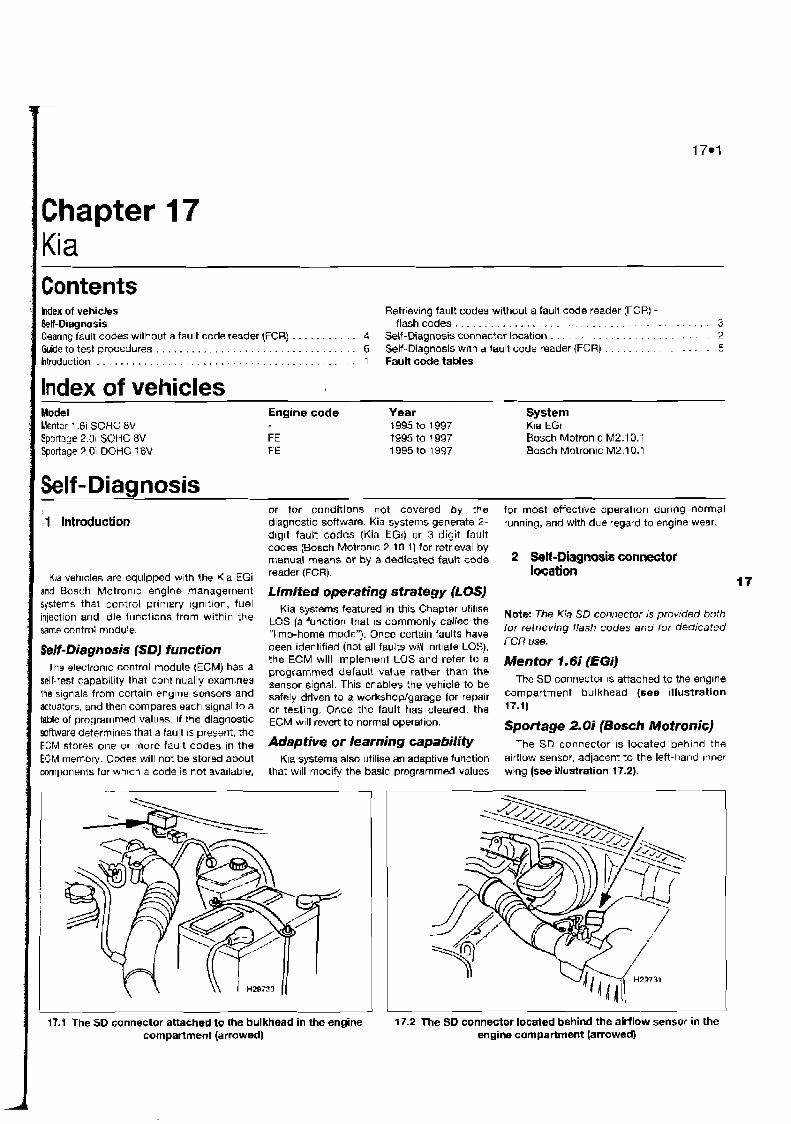
Retrlevlng fault codes without a tault code reader (FCR) - . . . . . . . . . . . . . . . . . . . . . . . . . . . . . . . . . . . . . . . . . flashcodes 3
Charing fault codes without a fault code reader (FCR) . . . . . . . . . . . 4 Self-Diagnosis connector location . . . . . . . . . . . . . . . . . . . . . . . 2
Guide to test procedures . . . . . . . . . . . . . . . . . . . . . . . . . . . . . . . . . . 6 Self-Diagnosis wlth a tault code reader {FCR) . . . . . . . . . . . . . . 5 htmduction . . . . . . . . . . . . . . . . . . . . . . . . . . . . . . . . . . . . . . . . . . 1 Fault code tables
Index of vehicles Engine code Year System
Mentor 1.6i SOHC BV 1995 to 1997 Kla €GI Sportaye 2.01 SOHG 8V FE 1995 to 1997 Bosch Motronic M2.10.1 Sportage 2 01 DOHC 16V FE 1995 to 1997 Bosch Motronic M2.10.1
or for conditions not covered by the for most effectwe operation during normal -1 Introduction diagnostic software. Kia systems generate 2- running, and with due regard to engine wear.
dlg~t fault codes (Kia EGI) or 3-digit fault codes (Bosch Motron~c 2.10.1) for retrieval by manual means or by a dedicated fault code 2 Sell-Wwn~is connector
K:aveh~clesareequippedw~ththeK~aEGi reader'FGR). location and ~ o s c t i Motronrc engine management Ljmitedoperatingstrategy(LOS) rystems that primary 'gnltlon' fuel Kia rys?ema featured in this Chapter vtillse Note: I(ia SD co ,,!, ecfoi pmnded injection and Idle functions from withln the same control module
'a function that is commonly the for retrreving flash codes and for dedicated "limp-home mode"). Once certain faults have
Self- Diagn osis (SD) function been identified (not all faults will lnltlate LOS), FCR
the ECM will implemeni LOS and refer to a Mentor f,6i (EGi) The electronic control module (ECM) has a programmed default value rather than the selCtest capability that continually exarnlnes sensor signal, This the vehicle to be The SD connector 1s attached to the englne Ihe s~gnals from certain englne sensors and safely driven to a workshop,garage for repair compartment bulkhead (see illustration actuators, and then Compares each signal to a or testlng, Once the fault has cleared, the 17*11- table of programmed values. If the diagnostic ECM will revert to normal operation, software determines that a fault IS present, the Sportage 2.0i (Bosch Motronic] ECM stores one or more fault codes in the Adaptive or learning =~abili@ The SD connector is located behind the ECM memory. Cwes will not be stored about Kla systems also utilise an adaptive function airflow sensor, adlacent to the left-hand inner components for whlch a code is not ava~lable, that will modify the basic programmed values wing (see illustration 17.2).
compartment (atrowecl) 17.1 'The SO connector attached to the bulkhead in the engine 17.2 The SD connector located behind the airflow sensor in the
engine compartment (armwed)
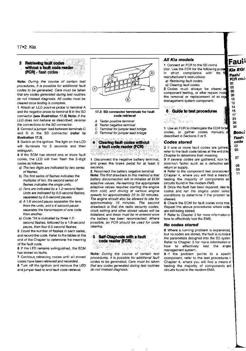
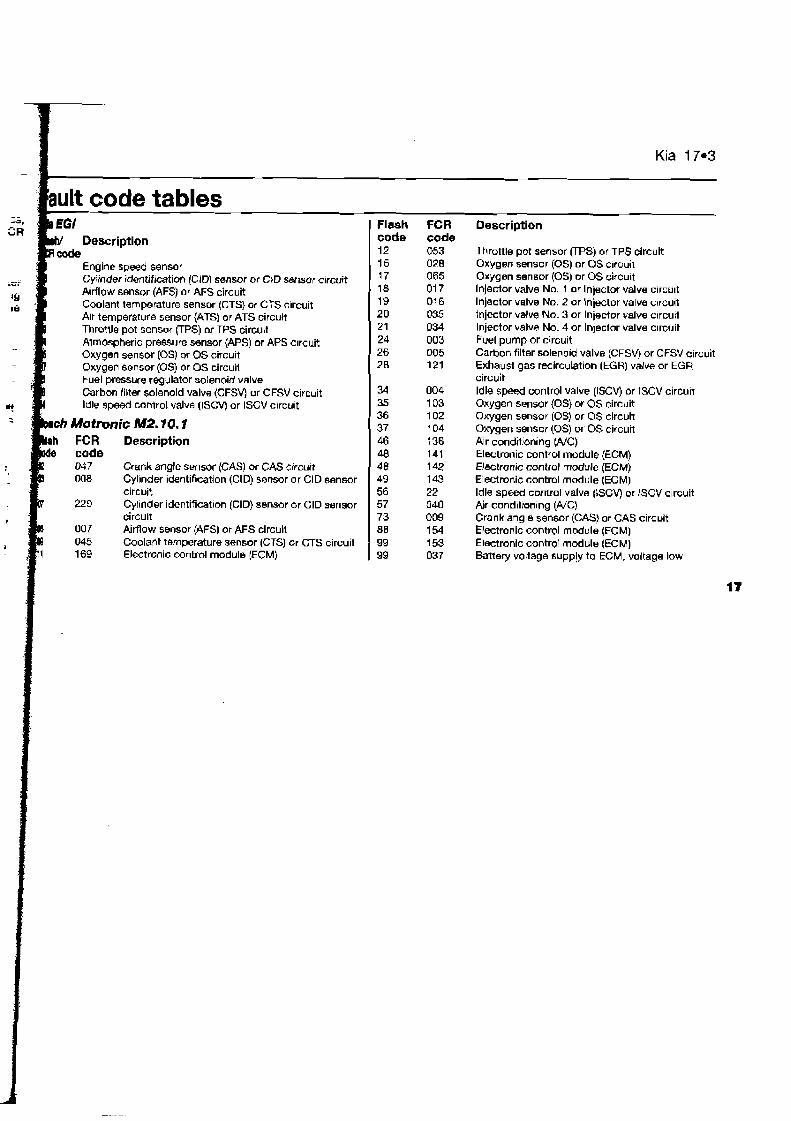
Flash FCR Description eode eode 12 053 Throttle pot sensor VPS) or TPS circuit
Engine speed sensor 15 028 Oxygen sensor (0s) or OS circuit CyWndsr identification (C1D) sensor or CID sensor circuit j7 065 Oxygen sensor (0s) or OS circuit A~rflow sensor (AFS) or AFS circuit 18 01 7 Injector valve No. 1 or Injector valve circu~t Coolant temperature sensor {CTS) or CTS circuit 18 01 6 Injector valve No. 2 ar Injector valve circuit A r temperature sensor (ATS) or ATS circuit 20 035 tnjector value No. 3 or Injector valve circuit Throttle pot sensor (TPS) or TPS circuit 21 034 Injector valve No. 4 or In~ector valve circuit Atmospheric pressure sensor (APS) or APS circuit 24 003 Fuel pump or circuit Oxygen sensor (0s) or QS circuit 26 005 Carbon filter soleno~d valve (CFSVj or CFSV circuit Oxygen sensor (0s) or OS circuit 28 121 Exhaust gas recirculation (EGH) velve or EGR Fuel pressuw regulator solenoid valve circuit Carbon filter solenoid valve (CFSV) or CFSV circuit 34 004 Idle speed control valve (ISCV) or ISCV circuit Idle speed control valve IlSCVj or ISCV circuit 35 103 Oxygen sensor (0s) or OS circuit
36 102 Oxygen sensor (0s) or OS circuit h Motmnic M2.10.1 37 104 Oxygen sensor (0s) or 0s circuit
FCR Description 46 136 kr conditioning (A/C) 48 141 Eletronic control module (ECM)
047 Crank angle sensor (GAS) or CAS circuit 48 142 Electronic control module (ECM) 008 Cylinder identification (CID) sensor or CID sensor 49 143 Electronic control module (ECM)
circuit 56 22 Idle speed control valve (ISCV) or ISCV circuit 229 Cylrnder identificat~on (CID) sensor or CID serlsor 57 040 Air condltan~ng (AK)
circuit 73 009 Crankanglesensor(CAS)orCAScircuit 007 Airflow sensor (AFS) or AFS circuil 88 154 Electronic control module (ECM) 045 Coolant temperature sensor (CTS) or CTS circuit 99 153 Electronic control module (ECM) 169 Electronic control module (ECM) 99 037 Battery voltage supply to ECM, voitage low
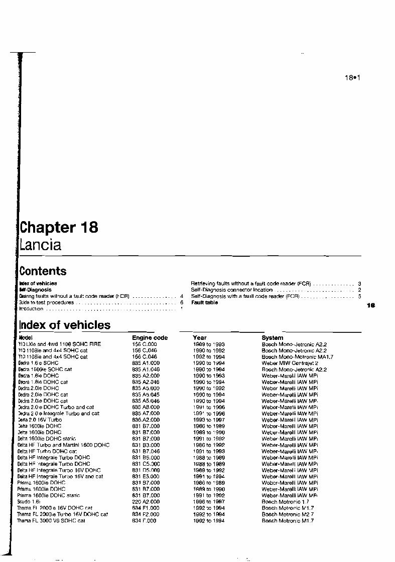
I M x of vehicles Retrieving faults without a fault code reader (FCR) . . . . . . . . . . . . . . 3 &If-Diagnosis Self-Diagnosis connector location . . . . . . . . . . . . . . . . . . . . . . . . . . 2 Crsar~ng faults without a 7ault code reader (FCR) . . . . . . . . . . . . . . . 4 Self-Diagnosis with afauk ccde reader (FCR) . . . . . . . . . . . . . . . . . . 5 Qu'ie to test procedures . . . . . . . . . . . . . . . . . . . . . . . . . . . . . . . . . . 6 FauA table htroduct~on . . . . . . . . . . . . . . . . . . . . . . . . . . . . . . . . . . . . . . . . . . . . 1
I@
I lndex of vehicles Model Y10 LXie and 4wd 11 08 SOHC FIRE Y10 1108ie and 4x4 SOHC cat Y10 1108ie and 4x4 SOHC cat M r a 1.61e SOHC M r a 16001~ SOHC cat M r a i .8ie DOHC Dean 1.8ie DOHC cat Dedra 2.0ie DOHC Dedra 2.0ie W H C cat M r a 2.0ie DOHC cat M r a 2.0ie DOHC Turbo and cat M r a 2.01e Integrale T u r b and cat Deka 2.0 16V Turbo Delta 1600ie DOHC hka 1600ie DOHC Delta 1600ie DOHC static Oelta HF Turbo and Martini 1600 DOHC Delta HF Turbo DOHC cat Dslta HF Interale Turbo DOHC Delta HF lntegrale Turbo DOHC Ddta HF lntegrale Turbo 16V DOHC Wta HF lntegrale Turbo 16V and cat Pnsrna 1600ie DOHC Prisma 1600ie DOHC hisma l6OOie DOHC static kudo 1 .Bt Thema FL 20001e 16V DOHC cat Thema FL 20001e Turbo 16V DOHC cat Thena FL 3000 V6 SOHC cat
Engine code 156 C.000 156 C.046 156 C.046 835 A1.OOO 835 A1.046 835 A2.000 835 A2.046 835 A5.000 835 A5.045 835 A5.046 835 A8.000 835 A7.000 836M .OD0 &31 87.000 831 87.000 831 67.000 831 83.000 831 67.046 831 B5.000 831 C5.000 831 05.005 6-31 €5.000 831 87.000 831 87.000 831 67.000 220 A2.000 834 F1.000 834 F2.000 834 F.000
Year 1989 to 1 993 1990 to 1992 1 992 to 1994 1 990 to 1994 1990 to 1994 1990 to 1993 1990 to 1994 1990 to 1 992 1990 to 1994 1 990 to 1994 1991 to 1996 1991 to 1996 1993 lo 1 997 1986 to 1 989 1989 to 1 990 1 991 to 1992 1 986 to 1992 1991 to 1993 1 988 to 1989 1 a88 to 1 989 19B9 to 1 992 1991 to 1994 1986 to 1 989 1989 to 1990 1991 to 1992 1 996 to 1997 1 992 to 1994 1992 to 1 994 1992 to 1994
Sys?am Bosch Mono-.Jetronic A2.2 Bosch Mono-Jetron~c M . 2 Bosch Mono-Motronic MA1.7 Weber MIW Centrajet 2 Bosch Monodstronic A2.2 Weber-Marelli IAW MPi Weber-Marelli IAW MPi Weber-Marelli IAW MPi Weber-Marelli IAW MPI Webr-Matelli IAW MPI Weber-Marelli IAW MPi Weber-MareHi JAW MPi Weber-Marelli IAW MPi Weber-Marelli IAW MPi Weber-Marelli IAW MPi Webw-Marelli IAW MPi Weber-Marelli IAW MPI Weber-Marelli IAW MPI Weber-Maretli IAW MPi Weber-Mareli IAW MPi Weber-Marelli IAW MPi Weber-Marell! IAW MPi Weber-Marelli IAW MPi Weber-Marelli IAW MPi Weber-Marelli !AW MR Bosch Motronic 1.7 Bosch Motronic M I .7 Bosch Motronic M2.7 Bosch Motronic M I .7

-. -- . . .
18.2 Lancia
Self-Diagnosis
The engine management systems (EMSs) fitted to Lancia vehicles are mainly of Bosch or Weber-Marelli or~gin, and include Bosch Mottonic versions 1.7, 2.7 and Weber-Marelli IAW. Other systems include Bosch Mono- Jetronic A2.2, Bosch Mono-Motronic and Weber Centrajet. Apart from Mono-Jetronic, Lancia engine management systems control the primary ign~t~on, fuelling and idle functions from within the same control module. The Mono-Jetronic system controls fuelling and idle speed alone.
Self-Diagnosis (SD) function Each ECM has a self-test capability that
continually examines the signals from certain engine sensors and actuators, and compares each signal to a table of programmed values. If the diagnostic software determines that a fault is present, the ECM stores a fault. Codes will not be stored about components for which a code is not available, or for conditions not covered by the diagnostic software.
Lancia software does not generate fault code numbers - a fault code reader (FCR) normally displays any faults on the FCR screen without reference to a specific code number. Although actual code numbers are not available, faults in one or more of the circuits and components covered by the diagnostic software will cause a fault to be stored. Flash codes are not available - a ddicated FCR is required for code retrieval.
Limited operating strategy ( L a ) Lancia systems featured in this Chapter
utilise LOS (a function that is commonly called the "limp-home mode"). Once certain faults have been identified (not all faults will initiate LOS), the ECM will implement LOS and refer to a programmed default value rather than the sensor signal. This enables the vehicle to be safely driven to a workshop/garage for repair or testing..Once the fault has cleared, the ECM will revert to normal operation.
18.1 3-pin SD connector used for retrieving fault codes from Lancia systems
Adaptive or learning apability Lancia systems also utilise an adaptive
function that will modify the basic programmed values for most effective operation during normal running, and with due regard to engine wear.
Self-Diagnosis (SD) warning light Many Lancia models are equipped with an
SD warning light located within the instrument panel. When the ignition is switched on, the light will illuminate. Once the engine has started, the light will extinguish if the diagnostic software determines that a system fault is not present. If the light illuminates at any time during a pericd of engine running, the ECM has diagnosed presence of a system fault.
Note: Flash codes are not available in Lancia systems, and the SD connector is provided for connection to a dedicated FCR alone.
Bosch Motronic I . 7 The 3-pin SD connector (see illustration
18.1) is usually located close to the ECM under the passenger's side glove compartment.
Bosch Mono- Jetronic A2.2 The 3-pin SD connector is usually located
on the bulkhead, or may be situated close to the ECM under the passenger's side glove compartment, or in the centre console.
Boseh Mono-Motronic MA 1.7 The 3-pin SD connector is usually located
beside the ECM on the right-hand wing in the engine compartment. Alternative locations are close to the ECM under the passenger's side glove compartment, or in the centre console.
Weber-Mareili #Pi The 3-pin SD connector is usually located
in the engine compartment on the right-hand bulkhead or under the passenger's side facia, close to the ECM.
Weber Centrajet The 3-pin SD connector is usually located
beside the ECM on the front right-hand wing in the engine compartment.
3 Refbving faults withut a fa&# wde wader (FCW
A fault code reader (FCR) is required to display faults generated in SD systems fitted to Lancia vehicles - although an SD warning light is fitted to many Lancia models, it cannot be used to display flash codes.
testin!
4' ~iewing without a fault code reader FCR)
ReFe
AII systems 1 1 Turn off the ignit~on and disconnect the battery negative terminal for a period d approximately 2 minutes. 2 Reconnect the battery negative terminal. Note: The first drawback to this method is tha~ battery disconnection will re-initialise all ECM adaptive values. Re-learning the appropr~te adaptive values requires starting the engine from cold, and driving at various engine speeds for approximately 20 to 30 mmutes. The engine should also be allowed to idle fw approximately 10 minutes. The second drawback is that the radro security codes, cbck setting and other stored values will be initialised, and these must be re-entered once the battery has been reconnected. Where possible, an FCR should be used for cod clearing.
5 Self-Diagnosis with a fault code reader (FcR) I
Note: Durrng the course of certain test procedures, it is possible for additional fault codes to be generated. Care must be taken that any codes generated during test routines do not mislead diagnosis. I AII Lancia models \ 1 Connect an FCR to the SD connector. Use the FCR for the following purposes, in str~ct compliance with the FCR manufacturer's instructions: a) Displaytng system faults. b) Clearing stored system faults. c) Testing actuators. d) Displaying Datastream. e) Making adjustments to the ignition timing
or mixture (some vehicles). 2 Stored faults must always be cleared after component testing, or after repairs involving the removal of an EMS component.
6 Guide to test pmcedures I 1 Use an FCR to interrogate the ECM for faults. I Faults stored 1
F: -
All I
fa^: on SF'
nu1 m i CC
C - 5;
At i?
(11
2 If several faults are gathered, look for a common factor such as a defective earth return or supply. 3 Refer to the component test procedures in Chapter 4, where you w~ l l f ~ n d a means of
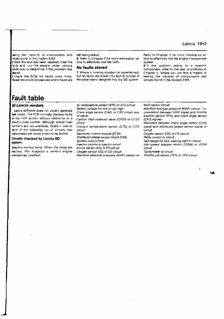
Lancia 18.3
kt lng the majority ot components and still being stored. Refer to Chapter 3 for more informallon on urcuits found in the modern EMS. 6 Refer to Chapter 3 for more bnformation on how to effectively test the engine management 1 Once the fault has been repaired, clear the how to effectively test the EMS system. faults and run the engine under various No faults stomd 8 If the problem points to a specific mndit~ons to determine if the problem has component, refer to the test procedures in &red. 7 Where a running problem is experienced. Chapter 4, where you will find a means of 5 Check Ihe ECM for faults once more. but no fauhs are stord, the fault is outs~de of testing the majority of components an6 Repeat !he above procedures where faults are the Parameters designed into the SD System. circuits found In the modem EMS.
Fault table 111 Lancia models
Lancia software does not usually generate fault codes. The FCR normally displays faults on the FCR screen without reference to a specific code number. Although actual code numbers are not ava~lable, faults in one or more of the following list of circu~ts and components will cause a tault to be stored.
Circuits checked by Lencia SO system Adaptive control ttmrts. When the limits ere reached, this suggests a serious engine
Air temperature sensor (Am or ATS circurt Batery voltage too low or too high Crank angle sensor (CAS) or CAS circuit loss of signal Carbon filter solenoid valve (CFSL) or CFSV circuit Coolant temperature sensor (CTS) or CTS circuit Electronic contra/ module (ECM) Distributor phase sensor circuit {CID) Ignrtion coils control Injector control or injector crrcuit Knock sensor {US) or KS circuit Oxygen sensor (0s) or OS circuit
MAP sensor circurt Manifold absolute pressure (MAPI sensor - no correlation between MAP signal and throttle position sensor V S ) and crank angle sensor (CAS) signals Mismatch between crank angle sensor {CAS) s~gnal and distributor phase sensor stgnel or circuit Oxygen sensor (0s) or 0s circuit Relay control or circuit Self-diagnosis (SD) warning lrght or circuit Idle speed stepper motor (ISSMJ or iSSM circuit Tachometer or crrcurt

I
Chapter 19 Land Rover
) Contents Index of vehicles Retriev~ng fault codas without a fault code reader (FCR) . . . . . . . . . 3 LH- Diagnosis Self-Diagnosis connector location . . . . . . . . . . . . . . . . . . . . . . . . 2 Clearing fault codes wllhout a fault code reader (FCR) . . . . . . . . . . . 4 Self-D~agnosis with a fault code reader (FCR) . . . . . . . . . . . . . . . . . . 5 Guide to test procedures . . . . . . . . . . . . . . . . . . . . . . . . . . . . . . . . . 6 Fault code lables Introduction . . . . . . . . . . . . . . . . . . . . . . . . . . . . . . . . . . . . . . . . . 1
Index of vehicles Model Discovery MPi 2.0 20HD DOHC 16V Discovery 2.0 MPi DOHC 16V Discovery 3.5 VBI D~scovety 3.5 V8i cat Discwery 3.9i V8 Range Rover 3.9 EF I V8 Range Rover 4.0i Range Rover 4.2i cat
Engine code M76i 20T4 V8 V8 V8 3.9L 4.0L 4.2L
Year 1993 to 1995 1995 to 1997 1990 to 1992 1990 to 1995 1995 to 1997 1989 to 1 996 1 994 to 1997 1 992 to 1994
System Rover MEMS MPi Rover MEMS MPI Lucas 14CUX Lucas l4CUX Lucas I4CUX Lucas I4CUX Lucas 14CUX Lucas l4CUX
I Self-Diagnosis I Introduction
The engine management systems (EMSs) i ~ f i d to Land Rover vehicles are of Lucas or Rover origin. Rover MEMS controls primary ignition, fuelling and Idle functions from with~n the same control module. Lucas 14CUX controis fuel inject~on and idle functions alone.
Self- Diagnosis (SD) function Each electronic control module (ECM) has a
self-test capability that continually examines the slgnals trow certaln engine ssnsors and actuators, and then compares each slgnal to a
r I
-
table of prograrllrned values. If the diagnostic software determines that a fault 1s present, the ECM stores one or more fault codes in the ECM memory. Codes are not stored about com- ponents for wh:ch a code is not eva~lahte or for conditims not covered by the diagnostic software.
Lucas 14CUX generates 2-diglt fault codes for retrieval by a ded~cated fault cw'e reader (FCR).
Rover MEMS software does not generate fault code nurnbers - a fault code reader normally displays faults on the FC8 screen without reference to a specific code number Although actual code numbers are not available, faults in one or more of the circuits and components covered by the diagnostic software will cause a fault to be storm.
It is not possible to retrleve flash codes from the Lucas 14CUX system or from Rover MEMS.
Limited operating strategy (LOS] Land Rover systems featured in thls
Chapter utilise LOS (a function that is commonly called the "limp-home mode"). Once certain faults have been ~dent~fied (not all faults will initiate LOS), the ECM will
- -
Adaptive or learning capability Land Rover systems also utilise an adaptive
function that will mod~fy the basic programmed values for most effective operation during nwmal running, and w~th due regard to engive wear.
2 Self-Diagnosis connector location
Lucas 14CUX The SD connector 1s located either under
the driver's seat (early models) or behind the driver's footwell kick-panel trim (later models) (see illustrations 19.1 and 19.2) and IS
provided for use by a dedicated FCR alone.
I implement LOS and reler lo a programmed delault value rather than the sensor signal.
I - / I I Thls enables the veh~cle to be safely drlvan to 19.2 of SD connector and ECM - '''' Location Of sD and ECM - a workshop/garage for repair or testing. Once Lucas 14CUX, early models Lucas 14CUX, later models the fault has cleared, the ECM will revert to
A SO connector 8 ECM normal operation. A SD connector 8 ECM
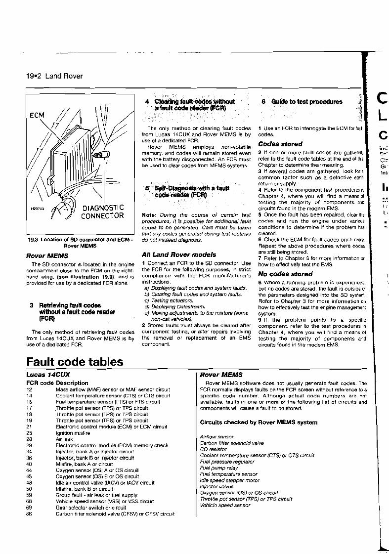
19.2 Land Rover
19.3 Location of SD connector and ECM - Rover MEMS
Rover MEMS The SO connector 1s located in the englne
compartment close to the ECM on the right- hand wing. (see illustration 19.31, and is providsd for use by a dedicated FCR alone.
3 Rerrlevlng fauh codes without a fault cmle medw WR)
The only method of retrieving fault codes from Lucas I4CUX and Rover MEMS 1s by use of a dedicated FCR.
Fault code tables
The only method of clearing fault codes from Lucas 14CUX and Rover MEMS is by use of a dedicated FCR.
Rover MEMS employs non-volatile memory, and codes will remain stored even wrth the battery disconnected. An FGR must be used to clear codes from MEMS systems
, < ,,, , , , , 6::::&#I izraa@ ,' ,,
: : Me*&# , , (SGR) , , , , ,
, , , , I , , ,
, , , , ,
Note; During the course of certain lost procedures, it is possible for additional fault codes to be generated. Care must be taken that Bny codes generaf~d during fest routines do not mislead diagnosis.
All Land Rover models 1 Connect an FCR to the SD connector. Use the FC8 for the following purposes, In strict compliance w ~ t h the FCR manufacturer's instructions: a) Displaying fault codes and system faulfs. b) Clearing fault codes and system faults. c) Testing actuators. dl D~splaying Datastream. e} Making adjustments to the mixture (some
non-cat vehicles) 2 Stored faults must always be cleared aher component test~ng, or after repairs involving the removal or replacement of an EMS component.
LU~~SGCUX - -
FCR code Description 12 Mass atrflow (MAF) sensor or MAF sensor cifcult 14 Coolant temperature sensor (CTSI or CTS circuit 15 Fuel temperature sensor (FTS) or FTS circuit 17 Throltle put sensor (TPS) or TPS circuit 18 Throttle pot sensor FPS) or TPS circuit 19 Throttle pot sensor (TPS) or TPS circuit 21 Electron~c control mcdule IECM) or ECM circuit > ,
Ignition misfire Alr leak Electronic control module (ECM) memory check Injector, bank A or injector circuit Injector, bank B or injector circuit Misfire, bank A or circuit Oxygen sensor (0s) A or OS circuii Oxygen sensor IDS) 8 or OS circuit Idle air caltrol valve (IACVj or lACV circuit Misfire, bank B or circuit Group fault -air leak or fuel supply Vehicle speed sensor (VSS) or VSS circuit Gear selector switch or circuit
8 ',%I& tn bst pr&Wm , , , ,
, , ,, ,, ,
1 Use an FCR to interrogate the ECM for fault codes.
Codes stored I 2 If one or more fault codes are gathered, ' refer to the fault code tables at the end ot this Chapter to deterrn~ne therr meaning. 3 If several codes are galhered. look for a common factor such as a defactive earth ,
return or supply. 4 Refer to the component test procedura in Chapter 4, where you will find a means of ,
testing the majority of components and circuits found in the modern EMS. 5 Once the fault has been repaired, clear the codes and run the englne under various conditions to determine if the problem has cleared. 6 Check the EGM for fault codes once more. Repeat the above procedures where codes are still being stored. 7 Refer to Chapter 3 for more information on how to effect~vely test the EMS.
-
C iiiL es- C!c GI lnir
I I .A .*. Lr: I;
C
L
No codes stored I i 8 Where a running problem is experienced. but no codes are stored, the fault is oulslda d the parameten desrgned into the SD system. Refer to Chapter 3 for more information on how to effectively test the engine management system. 9 If the problem points to a specific component, refer to the test procedures in Chapter 4, where you will Ilnd a means of testlng the majority of components and circuits found in the modem EMS.
I Rover MEMS Rover MEMS sofiware does not usually generate fault codes. The
FCR normally displays faults on the FCR screen without reference to a specific code number. Although actual code numbers are not available, faults In one or more of the following list of c~rcuits and components will cause a fault to be stored.
I Circuits checked by Rover MEMS system
A~rflo w sensor Carbon filter solenoid valve CO mststor Coolant temperature sensor (CTSJ or CTS ctrcuit Fuel pressure regulator Fuel pump relay Fuel temperature sensor Idle speed stepper motor Injector valves Oxygen sensor (0s) or OS circurt Thrvlte pot sensor FPS) or TPS crrcutt Vehici~ speed sensor
88 Carbon filter solenoid valve (CFSVj or CFSV circuit I I
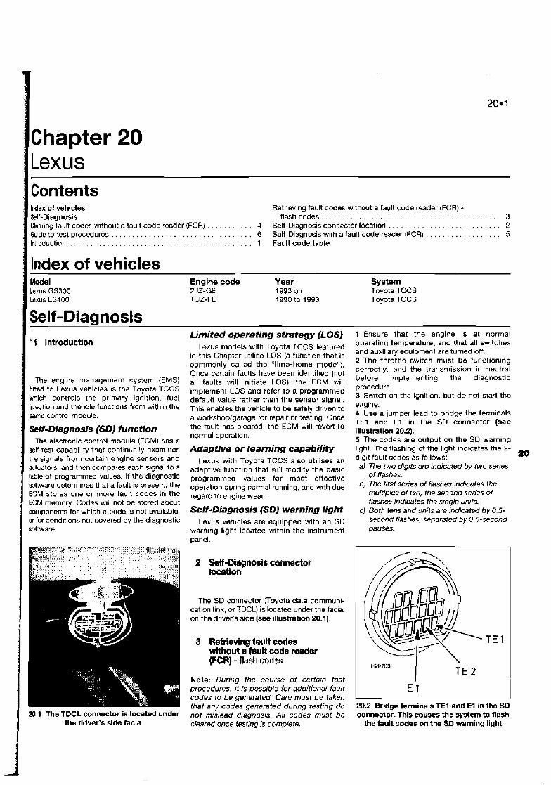
1 Lexus Contents Index of vehicles Retrieving fault codes without a fault code reader (FCR) - M-Diagnosis flashcodes.. . . . . . . . . . . . . . . . . . . . . . . . . . . . . . . . . . . . . . . . . 3
. . . . . . . . . . . . . . . . . . . . . . . . . . . Clwar~ng fault codes without a fault code reader (FCR) . . . . . . . . . . . 4 Self-Diagnosis connector location 2 . . . . . . . . . . . . . . . . . . Gulde to tesl procedures . . . . . . . . . . . . . . . . . . . . . . . . . . . . . . . . . 6 Self-Diagnosis wr~h a fault code reader (FCR) 5
htroduction . . . . . . . . . . . . . . . . . . . . . . . . . . . . . . . . . . . . . . . . . . . 1 Fault code table
1 Index of vehicles
I Model Lexus GS300 Lexus LSJOO
Engine code Year System 2 JZ-GE 1993 on Toyota TCCS 1 LIZ-FE 1990 to 1993 Toyota TCCS
1 Self-Diagnosis
The engine management system (EMS) fitted to Lexus vehicles 1s the Toyota TCCS which controls the prlrnary ignition, fuel injection and the idle functions from wlthin the same control module.
Self-Diagnosis (SD) function The electronic control module (ECM) has a
self-test capability that continually examines the signals from certain engine sensors and actuators, and then compares each signal to a table of programmed values. If the diagnostic sotware determines that a fault is present, the EGM stores one or more fault codes in the ECM memory. Codes will not be stored about components for which a code is not available, or far conditions not covered by the diagnostic software.
Limited operating stmtegy (LOSJ Lexus models with Toyota TCCS featured
in this Chapter utilise LOS (a function that is commonly called the "limp-home mode"). Once certain faults have been idenlif~ed (not all faults will initiate LOS), the ECM will implement LOS and refer to a programmed default value rather than the sensor signal. This enables the vehicle to be safely driven to a workshop/garage tor repair or testing. Once the fault has cleared, the ECM will revert to normal operation.
Adaptive or learning capabilify Lexus with Toyota TCCS also utilises an
adaptive tunct~on thal will modify the basic prograrn~ned values for most effective operat~on dur~ng normal running, and with due regard to englne wear.
Self- Diagnosis (SD) warning light Lexus veh~cles are equipped with an SD
walnlng light located within the instrument panel.
1 Ensure that the engine IS at normal operating temperature, and that all swrtches and auxiliary equipment are turned off. 2 The throttle switch must be function~ng correctly, and the transmission in neutral belore implementing the diagnostic procedure. 3 Switch on the ignition, but do not start the eliglne. 4 Use a lurnper lead to bridge the terminals TEl and E l in the SD connector (see illustmtion 20.2). 5 The codes are output on the SD warning I~ght. The flashing of the light indicates the 2- digit fault codes as follows: a0 a) The two digits are indicated by two serres
of flashes. b) The first series of flashes indicates the
multiples of ten, the second series of flashes indicates fhe srngle unrls.
c) Both tens and unRs are indicated by 0.5- second flashes, separated by 0.5-second pauses.
20.1 The TDCL connector is located under the driver's side facia
The SD connector voyota data cornmunt- cation link, or TDCL) is located under the facia. on the driver's side (see illustration 20.1).
3 Retrieving fault codes wfthotf? a fwlt code nader (FCR) - R M i X d ~
Note: During the course o f certarn test procedures. I! is possible for additional fault codes to be generated. Care must be taken thal eny codes generated during testing do not mislead diagnosis. All codes must be d e a r 4 once testing is complete.
20.2 Bridge terminals TEI and E l in the SD connector. This causes the system to flash
the fault codes on the SD warning light
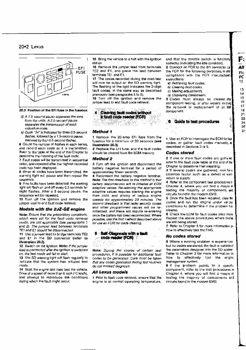
20.2 Lexus
-
20.3 Position of the EFi fuse In the fusebox
d) A I. 5-second pause separates the tens fmm the units. A 2.5-second pause sepamtes the transm~ssrm of each mdividual code.
8) Code "34" is indicated by three 0.5-second #ashes, followed by a 1.5-second pause. followed by four 0.5-second flashes.
6 Count the number of flashes in each series, and record each code as it is trarismitted. Rder to the table at the end of tho Chapter to determioe the meaning of the laua code. 7 Fault codes w~l l be transmitted in sequential order, and repeatd after the highest recorded code has been displayed. 8 When all codes have been transmitted. the warning light will pause and then repeat the sequence. 9 If no faults have been detected, the warning light will flash on and off every 0.5 seconds for eight flashes. After a 3-second pause, the sequence will be repeated. 10 Turn ofl the ignition and remove the jilmper lead to end fault code retrieval.
Modek with the 2JZ-GE engine Note: Ensum that the preparatory conditions, which were set for the fault code retrieval mode, are still sppficable (see paragraphs 1 and 2). The jumper lead between ierrninals TEI and E l should be disconnected. 11 Use a jumper lead to bridge terminals TE2 and E l in the SD conneclor (refer to illustration N.2). 12 Switch on Ihe ignition. Note: If the jumper lead is connected after the ignitlon is switched on. the lest mode will fail to start. 13 The SQ warning lrght w~ll flash regularly to Indicate that the system has lnltiated test mode. 14 Start the engine and road test the vehicle. Dflve at a speed of more than 6 mph (10 kmlh). and attempt to reproduce the conditions during which the fault mrght occur.
15 Bring the vehicle to a haR with the ignition still on. 19 Remove the jumper lead from terminals TE2 and E l , and place the lead between terminals TE1 and E l . 17 The codes recorded during the road test will now be output on the SD warning light. The flashing of the light indicates the 2-digit fault codes, in the same way as described previously (see paragraphs 5 to 9). 18 Turn off the ignition and remove the jumper lead to end fault code retrieval.
Method 1 7 Remove Ihs PO-amp EFi fuse from the fusebox for a minimum of 30 seconds (see illustration 20.3). 2 Replace the EFi fuse, and the fault codes should be cleared from the ECM memory.
Method 2 3 Turn off the ignition and disconnect the battery negative terminal for a period of approximately fifteen seconds. 4 Reconnect the battery negative terminal. Note: The first drawback to this method is that battery disconnection will re-inltialise all ECM adaptive values. Re-learning the appropriate adaptive values requires starting the engine from cold, and driving at various engine speeds for approximately 20 minutes. The second drawback is that radio security codes and other programmed values wrrl be re- initialised, and these will require re-entering once the baiiery has been reconnected. Where possible, use the first method dacribed above (or use an FCR) for code clearing.
, , ,,,,
. ,
, , , , ,, ,
, ,, ,, ; , , , ,, I
, , , ,. ,,, A < ,,
, , A ,,,
Note: During the course of certain test procedures, it ;s possible for additional fault codes to be generated. Care must be taken that any codes generated during test routines do not mislead diagnosis.
All Lexus models 1 Prior to fault code retrieval, ensure that the englne is at normal operating temperature,
and that the throttle switch IS functionlq correctly (indicating the idle condition). 2 Connect an FCR to the SD coflnector. Us! the FCR far the following purposes, in strd compliance with the FCR manufactuMa instructions: a) Retrieving fault codes. b) Clearing fault codes. c) Making adjusfments. d) Displaying Datastream.
3 Codes must always be cleared a h component testmg, or after rapalrs involvly the removal or replacement of an EMS component.
F; -
All Pl - r := FC 12
13 14 15 16 17 18 21
24 2E L'
1 Use an FCR to Interrogate the ECM for faM codes, or gather fault codes manually, as described rn Sect~ons 3 or 5
Codes shred 1
No codes stored 1
2 If one or more fault codes are galhered, refer to the fault code table at the end of lh15 Chapter to determine thew meaning. 3 If several codes are gathered, look for a common factor such as a defsctlve earth return or supply. 4 Refer to the component test procedures in Chapter 4, where you wltl find a means oi testing the majority of components and - circuits found in the modem EMS.
8 Where a running problem is experrenced, but no ccdes are stored, the fault is outside of the parameters desrgned into the SD system. Refer to Chapter 3 for more information on how to effectively test the engine management system. 9 If the problem points to a spectc component, refer l o the test procedures in Chapter 4, where you will find a means ot testing the majority of components and circujls found in the modern EMS.
5 Once the fault has been repaired, clearthe codes and run the engine under varlous condit~ons to determine if the problem has cleared. 6 Check the ECM for fault codes once mon. Repeat the above procedures where codes are still being stored. 7 Refer to Chapter 3 for more information on
'
how to sttectively test the EMS.

'ier iilg MS
/ Fault code tables I All Lexus rnodek - Toyota rCCS Flash/ Descriptian FCR code
I l2 No RPM s\gnal to ektromc control madub (ECM) while cranking
13 RPM signal or circuit , 14 Missing ignition No. 1 signal from amplifier
15 Missing ~gnition No. 2 slgnal from amplifier 18 Transmission control signal or circuit 17 No. 1 camsbtt p o s i f i sensor (CMP) signal or circuit 113 No. 2 camshaft position sensor (CMP) signal or circuit 21 Oxygen sensor (0s) or OS circuit 7.2 Coolant temperatwe snsw (CTS) or CTS circuit 24 Ail- temperature sensor (ATS) or ATS circurt 6 Lean exhaust 26 Rtch exhaust
Flash/ Descript4on FCR code 27 Oxygen sensor (0s) or OS circuit 28 Oxygen sensor (0s) or OS circui? 29 Oxygen sensor (05) or OS circuit 31 Mass airflow (MAF) sensor or MAF sensor circuit 35 Altitude wmpensation circuit 41 Throttle pot sensor UPS) or TPS c~rcuit 43 Starter signal clrcufl open 47 Sub-throltle pot sensor UPS) or TPS circuit 51 Neutral switch off (transmission no1 ~n neutral) or air
wndition~ng switched on during test 52 Knock seqsor (KS) or KS circuit 53 Knock control wmwtw problem 55 No. 2 knock sensor (KS) or KS circuit 71 Exhaust gas recirculation (EGR) sensor or circuit gQ Continuous Rash, no codes present

Chapter 21
I Indew of vehicles Retriev~ng fault codes without a fault code reader (FCR) - Sell-Diagnosis flashcodes.. . . . . . . . . . . . . . . . . . . . . . . . . . . . . . . . . . . . . . . . . 3 Clearing codes without a fault code reader (FCR) . . . . . . . . . . . . . . . 4 Sell-Diagnosis connector location . . . . . . . . . . . . . . . . . . . . . . . . . . . 2 Guide to test procedures . . . . . . . . . . . . . . . . . . . . . . . . . . . . . . . . . . 6 Self-Diagnosis with a fault code reader (FCR) . . . . . . . . . . . . . . . . . . 5 Introduction . . . . . . . . . . . . . . . . . . . . . . . . . . . . . . . . . . . . . . . . . . . . 1 Fault code tables
Index of vehicles Model 121 1.3 SOHC 16V cat 323 1.31 SOHC 16V cat 323 1.3 SOHC 16V 323 1.5i DOHC 16V 323 16C01 323 l.6i Turbo 4x4 DOHC 323 1.6i SOHC 16V cat 323 1.6i Estate SOHC cat 323 1 8i DOHC 16V cat 323 2.0i DOHC V6 24V 323 2.0i DOHC V6 24V 626 1.8: cat OOHC 16V 626 20001 fwd 626 2.0i GT DOHC 16V 626 2.0i OOHC 16V 626 2.0i DOHC 16V cat 626 2.0i DOHC 16V cat 626 2.2i 4x4 SOHC cat 626 2.5: DOHC V6 cat Ern0 MX-3 1.6i SOHC 16V MX-3 1.8i DOHC V6 MX-5 1.81 DOHC 16V MX-6 2.51 VG DOHC cat Xedos 6 l.6i DOHC 1 6V Xedos 6 2.Oi DOHC 24V Xedos 9 2.0i DOHC 24V Xedos 9 2.5i DOHC 24V RX 7
Engine code 83 83 63 25 B6 B6 B6 86E BP KF KF FP FE FE FE FE FS F2 KL FE B6 Kd BP KL B6 KF KF KL RE1 3B
Year 1991 to 1995 1991 to 1995 t 995 to 1897 1994 to 1997 1985 to 1 987 1986 to 7 989 1991 to 1994 1991 to 1994 I991 to 1994 1995 to 1997 1996 to 1997 1992 to 1997 1985 to 1987 1 987 to 1990 1 990 to 1993 1990 to 1995 1992 to 1997 1990 to 1 993 1992 to 1997 1994 to 1997 1991 to 1997 T991 to 1997 1995 to 1997 1992 to 1997 1994 to 1997 1992 to t 997 1994 to 1995 1 994 to 1997 1986 to 1990
System Mazda EGI-S SPi Mazda EGi MPI Mazda EGi MPi Mazda EGi MPi Mazda EGI MPi Mazda EGi M Pi Mazda EGi MPi Mazda EGi MPi Mazda EGi MPi Mazda EGi MPI Mazda €GI Mpi Mazda EGi MPI Mazda EGi MPI Mazda EGI MPi Mazda EGi MPi Mazda EGi MPi Mazda EGi MPi Mazda EGi MR Mazda EGr MPi Mazda €GI MPi Mazda EGi MPi Mazda EGi MPI Mazda EGi MPi Mazda EGi MPi Mazda EGi MPI Mazda EGi MPi Mazda EGi MPi Mazda EGI MPi Mazda EGi MPi
1 Self-Diagnosis
The englne management system (EMS) fitted to Mazda vehlcles is Mazda EGi, whrch exists in both MPi and SPi forms. Mazda EGi controls the primary ignition, fuel injection and idle funct~ons from within the same control module.
Self-Diagnosis (SD) function
codes. Codes will not be stored a b u t comp- onents for which a code is not ava~lable, or for condl tions not covered by the diagnostic software.
Marda EGi generates fault codes for retrieval by manual means (flash codes) or by a dedicated fault code reader (FCR). Until 1995, the fault code structure was 2-digit. After 1996, in some Mazda models the fault code structure was changed to 4-digit. The c d e tables at the end of the Chapter indicate the meaning for both 2- and 4 digit codes.
LOS), the ECM will Implement LOS and refer to a programmed default value rather than the sensor signal. This enables the vehicle to be safely driven to a workshop/garage for repair or testing. Once the fault has cleared, the ECM w~l l revert to nomal operation.
Adaptive or learning capability Mazda systems also util iw an adaptive
fund~on that wilt modify the basic programmed values for most effective operation during normal running, and wrth due regard to engine
I Each ECM has a self-test capability that Limited operating strategy wear. continually examines the signals from certain enoine sensors and actuators, ar;d cornnares Marda systems featured in this Chapter Self-Dia~nosis fSD) jight sach s~gnal to a table of programmed valles. If utillsa LOS (a function that IS commonly called The majority of Mazda models are the diagnostic software determines that a fault the "limp-home mode"). Once certain faults equlp~ed wlth a SD warning Iqht located IS present, the ECM stores one or more fault have been identified (not all faults will initiate within the instrument panel.
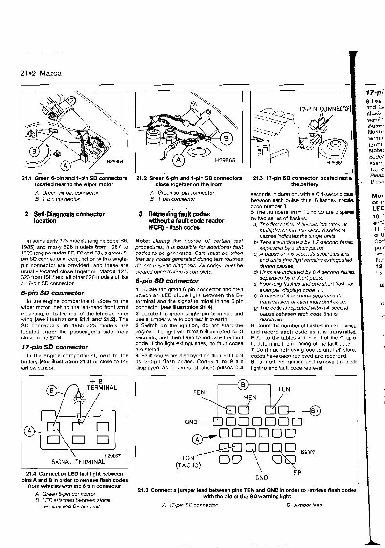
-- .- - . .
2 t 02 Mazda
21 .I Green 6-pin and 1-pin SD connectors located near to the wiper mator
A Green six-pin connector B I-ptn connector
2 Sell-Oiagnoals connector location
In some early 323 models (engine code B6, 1985) and many 626 models from 1987 to 1993 (engine codes FE, F2 and F3), a green 6- pln SD connector in conjunction with a single- pln connector are provided, and Ihese are usually !ocated close together. Mazda 121, 323 from 1987 and all other 626 models utilise a 17-pin SD cor,nector
6-pin SD connector In the engine compartn~erit, close to the
wiper motor, behind tile lett-nand front strut mounting, or to the rear of the ten-side inner wlng (see illustrations 21.1 and 21.2). The SD connectors on 1985 323 models are located under the passenger's side facia close lo the ECM.
7 7-pin SD connector In the englne compartment. next to the
battery (see illustration 21.3) or close to the a~rflow sensor.
21.4 Connect an LEO test light between pins A and B in order to retrieve flash codes
from vehicles with the 6-pin connector
A Green 6-pm connector 8 LED attached between signal
terminal and B+ terminal
21.2 Green 6-pin and 1 -pin SO connectors close together on the loom
A Green six-pin connector 5 I -pin connector
3 RletrieMg fault codes withuta fault cdsWxbr IpCR) - f b h codm
Note: During the course of certain test procedures, I ! a possrble for additional fault codes to be generated. Care must be taken that any codes generated dunng test rortttnes do not mislead diagnosis. AN codes must be cleared once testing is complete.
&pin SO connector 1 Locale the green 6-pin connector and then attach an LEO diode light between the B+ terminal and the signal terminal in the 6 pin connector (see illustration 21.4). 2 Locate the green s~nyle-pin terminal, and use a jumper wire lo connect it to earth. 3 Switch on the ~gn~tron, do not start the engine. The light will remain illuminated for 3 seconds, and then flash to indicate the fault code. I f the light extinguishes, no fault codes are stored. 4 Faull codes are displayed on the LED Light as 2-dig~t flash codes. Codes 1 to 9 are displayed as a series of short pulses 0.4
- 17-pi 9 Use and Gq illuvii . Warr b i i iJIuS~~: illuSir term11 term11 Note: code: exarr. 15, C
Plea: these
seconds In durat:on, with a 0.4-second pause between each pulse; thus. 8 flashes indicab code number 8. 5 The numbers from 10 to 69 are d~splayed by two series of flashes: a) The first series of flashes indicates the
multiples of ten, the second series of flashes indicates the s~ngle units.
b) Tens are indicated by 1.2-second flashes. separated by a short pause.
c) A pause of 1.6 seconds separates tens and units (the light remains extinguished during pauses).
d) Units are ndtcated by 0 4-second ftarashes, separated by a short pause.
el Four tong flashes and one short flash, tor example, displays code 4 7 .
f l A pause of 4 seconds separates rhe rransmission of each rndivrdual code.
g) The code is repeated wrth a 4-second pause between each code that is displayed.
6 Count the number of flashes in each serles. and record each code as it is transmitted. Refer to the tables at the end of the Chaptw to determine the meaning of the fairlt code. 7 Continue retrieving codes unt~l all stored codes have been retrieved and recorded. 8 Turn off the ignition and remove the d~ode light to end fault code retrieval.
oooooo- IGN ACHO)
GND
21.5 Connect a jumper lead between pins TEN and GND in order to retrieve flash codes with tho aid of the SD warning light
A 17-pm SD connector B Jurnner lead
Mom or r: LEE 10 : eng; 11 : or ii c0r pulf sec fla5 12
by
4
b
L
1
i
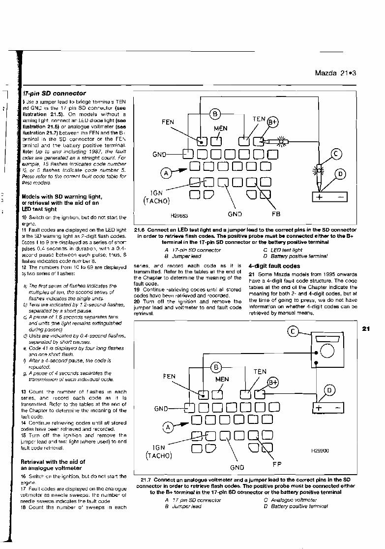
I l7-pin SD connector 9 Use a lumper lead to bridge tcrm~~~als TEN end GNO in the 17-pin SD connector (see llustration 21.5). On models w~thout a warnlng Ilgtif, connect an LED dlode l~ght (see illustration 21 -6) or a~ialogue voltmeter (see Hbstration 21.7) between the FEN and the B+ termlnal In the SO connector or the FEN termlnal and the battery positive terrnlnal. Note: 9p to and mcluding 1987, the fault c&es are generated as a strarght count Far example, 15 flashes rndrcates code number 15. or 5 flashes indicate code number 5. Please refer to the correct falilt code table for
1 these models
Models with SD warning light, or retrieval with the aid of an LED test light 10 Sw~tctl on the ignltlon, but do not start the engin*. 11 Fault codes are displayed on the LED l~ght or the SO warnlng l~ght as 2-digit !lash codes. Codes 1 to 9 are d~splayed as a series of short pulses 0.4 seconds in durat~on, wlth a 0.4- second pause between each pulse; thus, 8 Bashes indicates corle number 8. 12 The numbers from 10 to 69 are displayed by two serles of flashes:
a) The frrst serres of flashes inrlicates the multrples of ten, the second serres of flashes ~ndicates the single unrts
b) Tens am rndicated by 1.2-second fldshes, separated by a short pause.
c) A pause of 1.6 seccr~ids separates tens and units (the light remains extinguished during pauses!
dJ Units are ~nd~cated by 0.4-second flashes, separated by shot7 pauses.
el Code 4 1 is displayed b y four long flashes and one short flash.
0 After a 4-second pause. the code is repeated.
gJ A pause o f 4 seconds separates the transmission o f each mdrv~dual code.
13 Count the number of flashes In each serles, and record each code as ~t is transm~iied. Refer to the tables at the end of the Chapter to determine the meaning of the fault code. 14 Continue retrieving codes until all stored codes have been retrieved and recorded. 15 Turn off the ignltlon and remove the lumper lead and test light [where used) to end fault code retrieval.
I Retrieval with the aid of an analogue voltmeter 16 Switch on the ignition, but do not dart the engine 17 Fault codes are displayed on the analogue voltmeter as needle sweeps; the number of needle sweeps lnd~catos the fault code. 18 Count the nulnber of sweeps in each
GND
2j.6 Connect an LED test light and a jumper lead to the corlpel pins in the SD connector in order to retrieve flash codes. fhe positive probe must be connected either to the B+
terminal in the 17-pin SD connector or the battery positive terminal
C LED test light D Bartety positive terminal
series, and record each code as it is 4-digit fault codes - trsnsmltted. Refer to the tables a1 the end of Some Mazda models from 1995 the Chapter to determine the meaning of the
have a 4-digit fault code structure, The code s,.. ,I* ,.-An lault CIVUC.
19 Continue retrieving codes until all stored tables at the end of the Chapter indicate the
codes have been relrieved and recorded. meaning for both 2- and 4-digit codes, but at
20 Turn off the ignition and remove the the time of going to press, we do not have jumper lead and voltmeter to end fault code information on whether 4-digit codes can be retrieval. retrieved by manual means.
- OOODOO
GND FP
21 -7 Connect an analogue voltmeter and a jumper lead to ihe correct pins in the SO connector in order to retrieve flash codes. The positive probe must be connected either
to the B+ terminal in the 17-pln SD connector or the battary positive terminal A f 7-pm SO connector B Jumper lead
C Analogue voltmeter D Battety positive terminal
,SW~ ew ~sei AI~A!F@ 01 MOU k2 UO!jeUO~U! aJOW MI ~ead~l(3 01 Jakeu L
'pe~ols 6u!w II!IS wa mpo eJeym salnpam~d anoqa eqi ~eeda~ wu a3uo wpoo uneL do4 w33 BYI ~39~3 g
*peJIBp mu uelqold a41 41 au!urlelep 01 suo!~!puo3 Ino!len lopun au!Bua eyj unJ pue sepm rn leelo 'psl!edal uaaq seq Ilnej ell1 aouo g
'SW~ wow ayt u! punoj sj!nm3 w slueuodluo3 bo Xtuol~u~ ey~ Guusal p weew E pu!~ II!M noA aleqM 'p ~e~deq3 umpaomd 1-1 lusuodluo3 aq~ 01 ~epu P
.Alddns 10 umeJ WB BhIl3alap E se y3ns Jopej uowuloo rloj yo01 'palaqla6 em sepoa planas 41
~6u1ueau J!aw eu!luJelep o~ ~a1&43 MP pue 841 LE se~qel apoo II~Q eqi ol W~J
Weu~eB em sepoo jlnej aJaw JO euo 41 i:
Paw sepo3
.s JO E suqm u! peq!~osep se 'Allenuew sapoo ~eyl~6 (elq!ssod edeym) lo 'sepoo line4 lo4 w33 ew e~~bouewlol t133 ue ssn 1 -- wm inb by H Bu,~n swm
w JWJ 'Woq~ peq.u=w ward w =n 'W~W .- w sw Aweq eui muo mue-ar eq ese4r pve 'pesli~!vu! w eqw mw mas mwo w 6ucues m13 *sew o!w w JW s! YVMWP pumes eyl 'swnurw at ~I~J~)UI!XOJ~~R ~q @S W.@W SM 18 ~UMFIP 'm W eu!6ue eyj Bu!pgls sw!nbw senlen enljdepe flje!ldOddde ayj Gu!lueel-s~ .senlen engdp~ ~33 tie esi/e/~lu!-w II!~ ~PJ~~~UWSIP hww PW S! SJW W W8qMuP 1W Wl :OWN
-putuuej en~aku he~q eyl ~uuo3e~ g '11 es~ew ueyj pue spumes
s 1s8e1 JE 104 lewd ~BJQ eui sswdep Allnj s .spuoms oz weel 112
,oh leu!lwel en!)~Eeu heueq aql imuuoos!a p
.pe~eep aq mou plnoqs wpm unq perois IN 'sesnj aqt Upi ueq1 pua spuoms 02 ~oj llaM 8
'W~LUUE~L~O~ wldue ayl u! peje2or s! xoqesnl eql !~3 due -0E 841 pW asnl NIB dug-09 84L @MUJQH 2 'uo!t!sod ,,33~,, 841 01 Aeq uo!uu6! eui lunl L
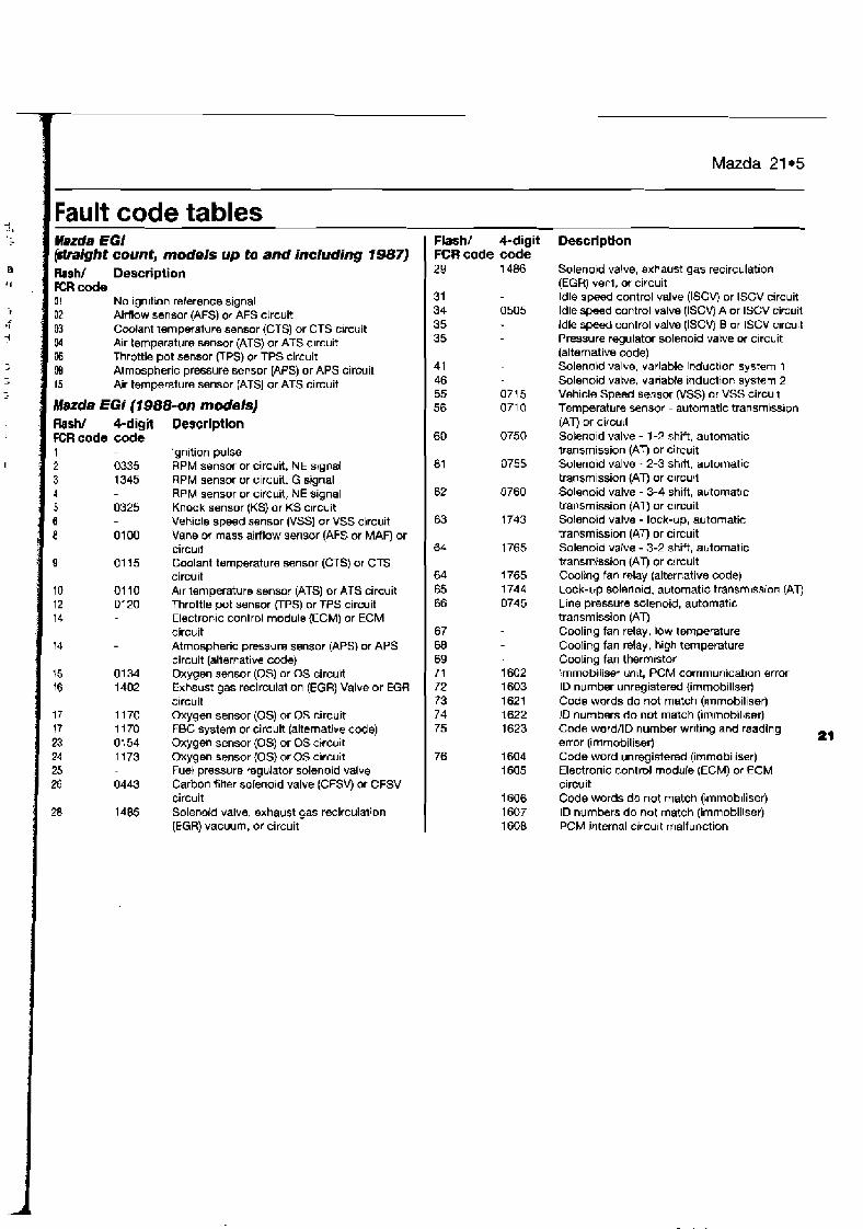
Mazda 21.5
Fault code tables -
Marda EGi (might count, models up to and including 1987) Flash/ Description FCR code 01 No ignition reference signal 02 Airflow sensor (AFS) or AFS circuit 03 Cmlant tempefature sensor (CTS) or CTS c!rcuit 04 Air temperature sensor (ATS) or ATS c~rcuit 06 Throttle pot sensor UPS) or TPS circuit M Atmospheric pressure sensor (APS) or APS circuit 15 Air temperature sensor (ATS) or ATS circuit
Mazda EGi (1988-on models) Ftashl Cdigit FCR code code 1 2 0335 3 1345 4 5 0325 6 8 0100
Description
lgn~tion pulse RPM sensor or circuit. NE signal RPM sensor or circuit, G signal RPM sensor or circuit, NE signal Knock sensor (KS) or KS circuit Vehicle speed sensor (VSS) or VSS circuit Vane or mass airflow sensor (AFS or MAF) or circu~t Coolant temperature sensor (CTS) or CTS circuit Air temperature sensor (ATS) or ATS circuit Throttle pot sensor FPS) or TPS circuit Electronic control module (ECM) or ECM circuit Atmospheric pressure sensor (APS) or APS circuit (alternative code) Oxygen sensor (0s) or OS circuit Exhsust gas recirculation (EGR) Valve or EGR circuit Oxygen sensor (0s) or OS circuit FBC system or circuit (alternative code) Oxygen sensor (0s) or OS circuit Oxygen sensor (0s) or OS c~rcuit Fuel pressure regurator solenoid valve Carbon fitter solenoid valve (CFSV) or CFSV circuit Solenoid valve, exhaust gas r~i rcula l ion (EGR) vacuum, or circuit
Flash/ FCR code 29
4-digit code 1 486
Description
Solenoid valve, exhaust gas recirculation (EGR) venl, or circuit ldle speed control valve (ISCV) or ISCV circuit ldle s p x d control valve (ISCV) A or ISCV circuit ldle s p d control valve (ISCV) B or ISCV circuit Pressure regulator solenoid valve or c~rcuit (altemative code) Solenoid valve, variable induction system 1 Solenoid valve, variable induction system 2 Vehicle Speed sensor (VSS) or VSS circu~t Temperature sensor - automatic transmiss~on (AT) or circuit Solenold valve - 1-2 shift, automatic transmission (AT) or circuit Solenoid valve - 2-3 sh~tl, automatic transmission (AT) or circul Solenoid valve - 3-4 shift, automatic transmission (AT) or circuit Solenoid valve - lock-up, automatic transmiss~on (AT) or circuit Solenoid valve - 3-2 shift, automatic transmission (AT) or circuit Cooling fan relay (alternative code) Lock-up solenoid, automatic transm~ssian (AT) Line pressure solenoid, automatic transmission (AT) Cooling fan relay, low temperature Cooling fan relay, high temperature Cooling fan therm~stor Irnmobilisef un~t, PCM communication error ID number unregistered (irr~rnobiliser) Code words do not match (~mmobiliser) ID numbers do not match (immobillser) Code word/lD number writing and reading error (immobiliser) 21 Code word unregistered (immobiliser) Electronic control module (ECM) or ECM circuit Code words do not match (immobiliser) ID numbers do not match (immobiliser) PCM internal circu~t malfunction

Chapter 22 Mercedes Contents Index of vehicles Bosch Motronic MP6.016.1 and HFMIPMS flash code retrieval . . . 7 Self-Dtagnos~s Clearing lault codes without a fault code reader (FCR) . . . . . . . . . 8 Bosch KE3 1 -Jetron~c duty cycle code retrieval . . . . . . . . . . . . . . . . 3 Guide to test procedures . . . . . . . . . . . . . . . . . . . . . 10 Bocttl +k t3 2-Jetrorw, duty cycle and flash code retr~eval . . . . . . . 4 Introduct~on . . . . . . . . . . . . . . . . . . . . . . . . . . . . . . . 1 Birsxtl hF5 7 Jetron~c and €2-L Ignition module duty cycle and Self-D~agr~os~s conoector location . . . . . . . . . . . . . . . . . . . . . 2
f l ~sh code retr~eval I 15-pln) . . . . . . . . . . . . . . . . . . . . . . . . . . . . . . 5 Self-Diagnos~s with a fault code reader (FCR) . . . . . . . . 9 E o ~ t ) LHJ.1 -.Jetror~~c and EZ-L ign~tion module duty cycle and Fault code tables
f l ~ h rtlilr. rr-tr~cval 178-p~n) . . . . . . . . . . . . . . . . . . . . . . . . . . . . 6
lndex of vehicles Model C180 190E cat :gut 2.3 CL31
190E 2.5 -16 B cat 130E 2.5-16 Evolut~on 190E 2.6 190E 2.6 cat C2UU E200 ?Out & 1 t cat C2ZU E270 C230 & Kun~pressur 23LlE. TE 8 CE cal 130GE 260L & cat 260E 4-Matlc & (.at 260SE R cat C28U E280 cat S28U SL?80 E3rl0 3UUSL. 5LL & cal 300F, TF. CF E cnl 300E R rat 300L-21. l L - 2 3 8, C:L-24 cal 3 0 U F 4 - M;rl~r, h cni 3011'sL R c:H
301.~5L-2-1 8 CA!
E370 c,3:,rj
51 5;'l)
J n l ~ h . S E R !<EL L42Q ?4, ' l1 i O l + LtlIJSL f,!~l15,F & 5 F I <hr15El; 5OI,5l. (>dl
Er>lIO
SSOIj
E,L',OO 60F"-;E L 5t8lill C A I
5;:;;l
SLt8Oil
Engine code 11 1.920 102.962 102.985 102.990 102.991 103.942 103.942 111.941 111.940 102.963 111 961 1 1 1.960
Year 1993 l o 1997 1988 to 1993 1989 to 1993 1988 to 1993 1989 tn 1992 1989 tu 1993 1987 to 1993 1994 to 1997 1992 to 1996 1988 to 1993 1993 to 1 997 1992 to t 997 1995 to 1997 1988 to 1993 1989 to 1991 1989 to 1993 1988 to 1992 1988 to 1992 1993 to 1997 1992 to 1996 1993 to 1997 1993 to 1997 1992 to 1995 1986 to 1992 1987 to 1993 1988 to 1993 1989 to 1993 1988 1cl 1993 198'3 10 1995 1989 to 1995 1892 to I>4>ii
11793 10 1997 1993 1cr I997 1991 on 199? tc 1945 1V>l3 lo 1>39; 1!,1-3: on 199,' on 193: on 1992 on 1389 ta 19'44 1992 to 1995 1993 to 1997 1 Y Y 3 to 1997 1991 to 19% 1991 to 1996 1996 to I OY I 19g3 to l W 7
System PMS (Sietiiens) Bosch KE3 5-Jetron~c Bosch KE3.5-Jetron~c Bosch KE3.1 -Jetronic Bosch KE3.1 -Jetron~c Bosch KE3.5-Jetronic Bosch KE3.5-Jetronrc PMS (S~ernens) PMS/Motronic 6.OiG.1 Bosch KE3.5-Jetronic HFM H FM HFM Busch KE3.5-Jetrurl~c Bosch KE3 5-Jetron~c Bosch KE3 5-Jetron~c Bosch KE3.5-Jelronic Bosch KE3 5-Jetron~c HFM HFM HFM llFM Bosch KE3.5 Jetron~c Bosch KE3.5-Jetron~c Bosch Kt3.5-Jelrunic Rosch KF3.5 Jetron~c Bosch KE5.2-Jetron~c/EZ-L ~ g n ~ t ~ o r l Bosch KE3.5-Jet ror~ Bosch KE5.2-JetronidEZ-L Ignltlon Bosch KL5.2-Jetrun~c/EZ-L ~ g n ~ t ~ o r ~ HFM HFM HFM 8psrh LHJ 1 Jet~n~i~i;'F.? I Ignltltm Fosch LHJ.1 -Jetrori~c/EZ-L ~ g r ~ ~ t ~ u r ~ 6osct1 LH4.1 -Jstrun~c/EZ-L lgn~ t~on Bosch 1.H3 1 -.Jetronic/EZ-L Ignltlon Bosch LH4 1 -Jetron~c/EZ-L lgnlt~orl Bosch LH4.1 -Jetron~c/EZ-L ~gni t~on Bmrh LH4.1-Jetrnnlc/EZ-L lgnltlon Busch KE5.2-JetrorircIEZ-L lgri~t~ori Bosch CH4.l-Jetronlc/EZ-L Ignltlori Bosch LH4.1-Jetronrc!EZ-L lgn~ t~on Bosch LH4.1 -Jetron~c/EZ-L igr l~t~on Bosch LH-Jetron~ciEZ-L Ignltlon Bosch LH4. I-JetroniciEL-L l g r ~ ~ t ~ u r i Bosch LH4.1 -Jetronlc/F7 I Ignltlon Bosch I. H4.1- Jetrnnic!EZ- 1 ~ g n ~ t ~ n n
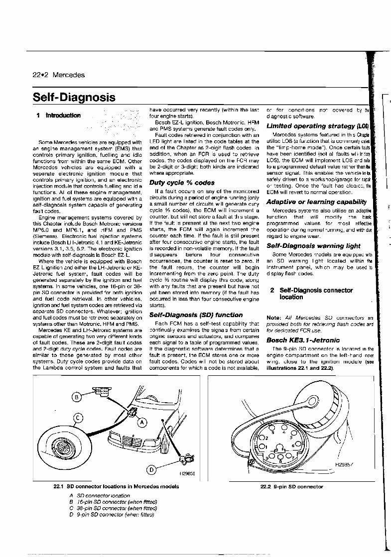
22.2 Mercedes
Self - Diagnosis
Some Mercedes vehicles are equipped with an engine management system (EMS) that controls primary ignition, fuelling and idle functions from within the same ECM. Other Mercedes vehicles are equipped with a separate electronic ignition module that controls primary ignition, and an electronic injection rncdule that controls fuelling and idle functions. All of these engine management, ~gnition and fuel systems are equipped with a self-diagnosis system capable of generating fault codes.
Engine management systems covered by this Chapter include Bosch Motronic versions MP6.0 and MP6.1, and HFM and PMS (Siemens). Electronic fuel injection systems include Boxh LH Jetronic 4.1 and KE-Jetmnic versions 3.1, 3.5, 5.2. The electronic ignition mdule with self-diagnosis is Bosch EZ-L.
Where the vehicle is equipped with Bosch EZ-L ignition and e~ther the LH-Jetronic or KE- Jetronic fuel system, fault codes will be generated separately by the ignition and fuel systems. In some vehicles, one 16-pin or 38- pin SO connector is provided for both ignition and fuel code retrieval. In other vehicles, ign~tion and fuel system codes are retrieved via separate SD connectors. Whatever; ignition and fuel codes must be retrieved separately on systems other than Motronic, HFM and PMS.
Mercedes KE and LH-Jetronic systems are capable of generating two very different kinds of fault codes. These are 2-digit fault codes and 2-digit duty cycle codes. Fault codes are similar to those generated by most other systems. Duty cycle codes provide data on the Lambda control system and faults that
have occurred very recently (within the last four engine starts).
Bosch EZ-L ignition, Bosch Motronic, HFM and PMS systems generate fault codes only.
Fault codes retrieved in conjunction with an LED light are listed in the code tables at the end of the Chapter as 2-digit flash codes. In addition, when an FCR is used to retrieve codes, the codes displayed on the FCR may be 2-digit or 3-digit; both kinds are indicated where appropriate.
Duty cycle % codes If a fault occurs on any of the monitored
circuits during a period of engine running (only a small number of circuits will generate duty cycle % codes), the ECM wit1 increment a counter, but will not store a fault at this stage. If the fault is present at the next two engine starts, the ECM will again increment the counter each time. If the fault is still present after four consecutive engine starts, the fault is recorded in non-volatile memory. If the fault disappears before four consecutive occurrences, the counter is reset to zero. If the fault recurs, the counter will begin incrementing from the zero point. The duty cycle % routine will display this code, along with any faults that are present but have not yet been stored into memory (if the fault has occurred in less than four consecutive engine starts).
Self-Diagnosis (SDJ function Each ECM has a self-test capability that
continually examines the signals from certain engine sensors and actuators, and compares each signal to a table of programmed values. If the diagnostic software determines that a fault is present, the ECM stores one or more fault codes. Codes will not be stored about components for which a code is not available,
22.1 SD connector locations in Mercedes models
A SD connector location B 16-pin SD connector (when fitted) C 38-pin SD connector (when fitted) D 9-pin SD connector (when fitted)
or for condrt~ons not covered by the diagnostic software.
Limited operating strategy (LO4 Mercedes systems featured in this Chapta
utilise LOS (a function that is commonly calY the "limp-home mode"). Once certain fauh have been identified (not all faults will initi* LOS), the ECM will implement LOS and rdw to a programmed default value rather than Ihe sensor signal. This enables the vehicle tobs safely driven to a workshop/garage for repair or testing. Once the fault has cleared, the ECM will revert to normal operation.
Adaptive or learning capability Mercedes systems also utilise an adaptive
function that will modify the basic programmed values for most effective operation during normal runnlng, and with due regard to engine wear.
Self-Diagnosis warning light Some Mercedes models are equ~pped with
an SD warning light located within the I instrument panel, wh~ch may be used tc display flash codes. I Note: All Mercedes SD connectors are provided both for retrievrng flash codes and for dedicated FCR use. t Bosch KE3-1- Jetronic
The 9-pin SD connector is located In the engine compartment on the left-hand Inner wing, close to the ignition module (see illustrations 22.1 and 22.2).
22.2 0-pin SD connector

Mercedes 22*3
-
the
BUTTON LEO
22.3 8-pin SO connector 22
The 8-pin SD connector IS located in the engine compartment on the right-hand blkhead {see illustration 22.3).
I k c h KE5.2-Jefrvnic wd EZ-L ignition
The 16-pin SD connector (2-digit fuel and bition code retrieval) is located in the engine compartment on the right-hand bulkhead (see illustration 22.4). The 9-pin SD connector pS percentage code retrieval) is located in the engine compartment on the left-hand hnw wing.
Bosch LH4.1 -Jetmnic end EZ-L ignition
The 38-pin SD connector (2-digit fuel and bition code retrieval) is located in the engine compartment's electrical box on the right- hand bulkhead (see illustration 22.5). The 9- pin SD connector (0s percentage code mtneval) is located in the engine compartment on the left-hand innet wing.
Note: Durmg the course of certain lest procedures, it is possible for additional codes to be generated. Care must be taken that any codes generated during test routines do not mislead diagnosis. All codes must be cleared once testing is complete.
1 Duty cycle codes alone can be retrieved from KE3.1-Jetronic. 2 Attach the positive probe of a digital multi- meter (DMM) to pin number 3 of the 9-pin SD connector. Attach the DMM negat~ve probe to earth, and switch the meter to read duty cycle (see illustration 22.6). 3 Switch on the ignition. 4 The meter should display the 2-digit duty cycle codes as a percentage. 5 Record the duty cycle percentage, and comDare the value with the dutv cvcle % code
I Bosch Motronic chart at the end of this chapte;. *
MP6.0/6. I , HFh4 and PMS 6 Turning off the ignition ends duty cycle code retrieval. Remove the DMM probes from
The 16-pin or 38-pin SD connector is the SD connector, 4 located in the enqne compartment on the
right-hand bulkhead. 4 h c h K € W & r d c duty
I mcbmtrttlash- ,,.
procedures, it is possible for additional codes to be generated. Care must be taken that any codes generated during test routines do not mislead diagnosis. Ail codes must be cleared once testing is complete. If using a fault code reader, proceed to Section 9. 1 Duty cycle codes and 2-digit fault codes can be retrieved from KE3.5-Jetronic systems. Duty cycle codes must be retrieved prior to 2-digit fault code retrieval. 2 Attach the positive probe of a digital multi- meter (DMM) to pin number 3 of the 8-pin SD
1.4 16-pin SO connector
3 Start and warm-up the engine so that the coolant temperature is at least 80°C (normal operating temperature). 4 Stop the engine and switch on the ignition. 5 The meter should display the 2-digit duty cycle codes as a percentage. 6 Record the duty cycle and compare the value with the duty cycle % code chart. 7 Turning off the ignition ends duty cycle code retrieval. Remove the DMM probes from the SO connector. 8 The method of retrieving 2-digit fault ccdes differs according to the type of 8-pin SD connector fitted. Some 8-pin SD connectors have an LED and button, others do not. 9 If the SD connector does not contain an LED and button, attach an accessory switch between pins 3 and 1 in the SD connector. Connect an LED diode test l~ght between the battery (+) supply and SD pin 3 as shown (refer to illustration 22.7). 10 Switch on the ignition. 11 Close the accessorj switch or depress the button for at least 5 seconds, and then open the switch or release the button. Afier approx- imately 2 seconds, the LED will begin to flash.
I I connector. Attach the DMM negative pmbe to 22.6 Connect a digital multi-meter (A) to 22.5 38-pin SD connector earth, and switch the meter to read duty cycle the 9-pin SD connector (B) in order to
(see illustration 22.7). retrieve percentage codes

22.4 Mercedes
12 The LED displays the 2-digit fault codes as a straight count. One flash is equal to one code number, so five flashes denotes fault code number 5, twenty-two flashes denotes fault code number 22, and so on. Each flash lasts for 0.5 seconds, and there is a I -second pause between each digit. 13 Count the number of flashes, and record the code. Refer to the tables at the end of the Chapter to determine the meaning of the flash code. 14 If code number 1 is transmitted, no faults codes are stored. 15 Retr~eve subsequent codes by once more closing the accessory switch or depressing the button for at least 5 seconds. Open the swktch or release the button, and after approximately 2 seconds the LED will begrn to flash. 16 Repeat code retrieval by turn~ng off the ignition and repeat~ng the whole procedure from the beginning. 17 Turn~ng off the lgnition ends fault code retr~eval. Remove the accessory switch and d~ode light from the SD connector where these components were used.
5 m&EsAWmiaRda- L ignition d d e duty end flaah code
Note: During the course of certain test procedures, ~t is possible for additional codes to be generated. Care must be taken that any codes generated dunng test routines do not mjslead diagncsis. All codes must be cleared once testtng is complete. If using a fault code reader, proceed to Section $. 1 Duty cycle codes and 2-digit fault codes can be retrieved from KE5.2-Jetronic systems. Duty cycle codes are available either with the engine stopped (ignition on) or with the engine running at idle speed, and must be retrieved prior to 2-digit fault code retrieval. In
addition, EZ-L ignition codes can be retrieved from the 16-pin SD connector. 2 Attach the positive probe of a digital multi- meter (DMM) to pin number 3 of the 9-pin SO connector. Attach the DMM negative probe to earth, and switch the meter to read duty cycle (refer to illustration 22.6). 3 Start and warm-up the engine so that the coolant temperature is at least 80°C (normal operating temperature). 4 Stop the engine. Ensure that the air conditioning is turned off, and the automatic transmission selector (where applicable) is in "P". Switch on the ignition. 5 The meter should display the 2-digit duty cycle codes as a percentage. 6 Record the duty cycle. The displayed value will be 50% if all sensor inputs are within the pre-determined operating parameters. If the display indicates another value, refer to the duty cycle % code chart at the end of this Chapter to determine the reason. 7 Start the engine and allow it to idle. The duty cycle should fluctuate if the system is operating correctly. If the duty cycle value remains fixed at one particular figure, refer to the duty cycle % code chart to determine the reason. 8 Turning off the ignition ends duty cycle code retrieval. Remove the DMM probes from the 9-pin SD connector. All of the following fault code retrieval routines must be performed after duty cycle code retrieval. 9 Attach an accessory switch between pins 3 and 1 in the 16-pin SD connector. Connect an LED diode test light between SD pin 16 (+) and SD pin 3 (-) as shown (see illustration 22.8). 10 Switch on the ignition. 11 Close the accessory switch for 2 to 4 seconds, and then open the switch. After approximately 2 seconds, the LED light will begin to flash. 12 The LED light displays the 2-digit fault codes as a straight count. One flash IS equal
I
5 6 7 8
BUTTON 1 ED
to one code number, so five flashes d fault code number 5, twenty-two f denotes fault code number 22, and Each flash lasts for 0.5 seconds, and t a 1 -second pause between each digit. 13 Count the number of flashes, and r the code. Refer to the tables at the end Chapter to determine the meaning of th
'
code. 14 If code number 1 is transmitted, no fa& codes are stored. 15 Retrieve subsequent codes by closingti accessoty switch once more for 2 to 4 secondn Open the switch, and after approximatebl seconds the LED light will begin to flash. A& all stored codes have been display&, th codes will be repeat& 16 Turning off the ignition ends KE5.2 fa
and diode light from the SD connecto;. 1 Engine systems control module flash code retrieval (16-pin) 17 Fault codes from the engine systems control module can be retrieved by follow~n~ the next set of routines. 18 Attach an accessory switch between 14 and 1 in the 16-pin SD connector. Connect an LED diode test light between SD pin 16[t) and SD pin 14 (-) as shown (see illustration 22.9). I 9 Switch on the ignition The method for code retrieval is den tical to that described above (paragraphs 11 to 16). 20 Retrieve ignition fault codes by following the routines described below (Bosch EZ-L). I Bosch EZ-L ignition module flash code retrieval (I 6-pin) 21 Only 2-digit fault codes can be retrieved from Bosch E - L ignition. 22 Attach the wires of an accessory switch between pins 8 and 1 in the 16-pin SO connector. Connect a diode test light between
- J 22.7 Connect a diode light (A) and accessory switch (6) to the 22.8 Connect a diode light and accessoty switch to the 16-pin SD
&-pin SD connector (C) in order to retrieve flash codes connector in order to retrieve flash codes

Mercedes 2 2 6
to 1 1 12
22.10 Connect a diode light and accessory switch to the 16-pin SD connector in order to retrieve ignition flash codes
SD pln 16 (+) and SO pin 8 (-1 as shown (see closing the accessory switch for between 2 5 The meter should display the 2-digit duty Mustration 22.10). and 4 seconds. Open the switch, and after cycle codes as a percentage. 23 Start the engine and warm it to normal approximately 2 seconds the LED light will 6 Record the duty cycle. The displayed value operating temperature. begin to flash. will be 50% if all sensor inputs are wlthin the a4 Allow the engine to idle. 36 Turning off the ignition ends ignition pre-determined operating parameters. If the 25 Raise the engine speed to between 3100 module fautt code retrieval, and also clears all display indicates another value, refer to the duty and 3600 rpm for approximately 8 seconds, fault codes from memory. Fault codes are not cycle % code chart to determine the reason. and then allow the engine to idle once more. retained in memory after the ignltlon has been 7 Start the engine and allow it to idle. The 26 Detach the vacuum hose from the turned off. duty cycle should fluctuate ~f the system IS
connection on the EZ-L ignition module. 37 Remove the accessory switch and diode operating correctly. If the duty cycle value 27 Move the automatic transmission selector light from the SD connector. remains fixed at one particular figure, refer to lever from the "P" position to "DM, and then the duty cycle % code chart to determine the
reason. 8 Turning off the ignition ends duty cycle
minimum of 2 seconds, and then allow the L i ~ ~ d u t y ~ code retrieval. Remove the DMM probes from engine to idle once more. andArsshdtWbd@&M) the SD connector. All of the following fault 28 Reconnect the vacuum hose to the code retrieval routines must be performed connection on the EZ-L ignition module. Note: During the course o f certain test immediately after duty cycle code retrieval. 30 Ra1setheenginespeedt02300rpm,and procedures,itispossibieforadditionaicodes 9 Attach the wiresof an accessory switch then briefly snap the throttle fully open so that to be generated. Care must be taken that any between pins 1 and 4 in the 38-pin SD the throttle switch full-load contacts become codes generated during test routines do not connector. Connect an LED diode test light closed. Allow the engine to idle once more. mislead diagnosis. All codes must be cleared between SD pin 3 (+) and SD pin 4 (-) as Note: I f the ignition is turned off at any point, once testrng rs compbte. I f using a fault code shown (see illustration 22.1 1). the whole procedure must be restarted from reader, proceed to Section 9. the beginning of the EZ-L ignitron codes 1 Duty cycle codes and 2-digit fault codes retrieval routine. can be retrieved from LH4.1-Jetronic 51 Close the accessory switch for between 2 systems. Duty cycle codes are available either and 4 seconds, and then open the switch. with the engine stopped (ignition on) or with After approximately 2 seconds, the LED light the engine running at idle speed, and must be
retrieved prior to 2-digit fault code retrieval. In 32 The LED light displays the 2-digit fault addition, EZ-t ignition codes can also be codes as a straight count. One flash is equal retrieved from the 38-pin SD connector. to one code number, so five flashes denotes 2 Attach the positive probe of a digital multi- lault code number 5, twenty-two flashes meter (DMM) to pin number 3 of the 9-pin SD denotes fautt code number 22, and so on. connector. Attach the DMM negative probe to Each flash lasts for 0.5 seconds, and there is earth, and switch the meter to read duty cycle a 1 -second pause between each digit. (refer to illustration 22.6). 33 Count the number of flashes, and record 3 Start and warm-up the engine so that the the code. Refer to the tables at the end of the coolant temperature is at least 80°C (normal Chapter to determine the meaning of the flash operating temperature).
4 Stop the engine. Ensure that the air 34 If code number 1 IS transmitted, no faults conditioning is turned OH, and the automatic 22.11 Connect a diode light and accessory codes are stored. transm~ss~on selector IS in "P" (where switch tothem-pin SD connectorin order 35 Retrieve subsequent codes by once more applicable). Switch on the ignition. to retrieve flash codes
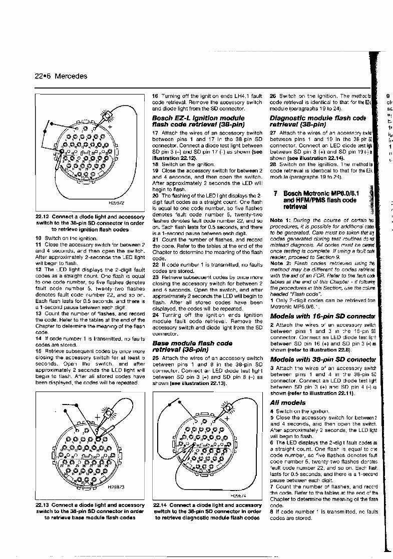
22.6 Mercedes
22.12 Connect a dlode light and accessory switch to the 38-pin SD connector in order
to retrieve ignition flash codes
$0 Switch on the Ignition. 11 Close the accessory switch for between 2 and 4 seconds, and then open the switch. After approximately 2-seconds the LED light will begin to flash. 12 The LED light displays the 2-digit fault codes as a straight count. One flash is equal to one code number, so live flashes denotes fault code number 5. twenly-two flashes denotes fault code number 22, and so on. Each flash lasts for 0.5 seconds, and there is a 1-second pause bwIween each dig~t. 13 Count the number of flashes, and record the code. Refer to the tables at the end of the Chapter to delermine the meanlng of Ihe lash code. 14 If code number 1 ts transmitted, no faults codes are slored. 15 Retrieve subsequenl codes by once Inore closing the accessory Swltch for a1 least 5 seconds. Open the switch, and after approximately 2 seconds the LED light wrll begin l o flash AHer all slored codes have been displayed, the c o d e will be repealed.
L I
22.t3 Connect a diode light and accessory switch to the %-pin SD connector in order
to retrieve base module flash codes
16 Turning off the ignition ends LH4.1 fault code retrieval. Remove the accessory switch and diode light from the SD connector.
Bosch EZ-L ignition module flash code retrieval (38-pin] 17 Attach the wires of an accessory switch between pins 1 and 17 in the 38-pin SD connector. Connect a diode test light between SD pin 3 (+) and SD pin 17 (-) as shown (see Illustration 22.f2). t8 Switch on the ignition. 19 Close the accessory switch for between 2 and 4 seconds, and then open the switch. After approximately 2 seconds the LED will begin to flash. 20 The flashing of the LED light displays the 2- digit fault codes as a straight count. One flash is equal to one code number, so five Rashes denotes fault code number 5, twenty-two flashes denotes fault code number 22, and so on. Each flash lasts for 0.5 seconds, and there is a 1-second pause between each digit. 21 Count the number of flashes, and record the code. Refer to the tables at the end of the Chapter to determine the meaning of the flash code. 22 If code number 1 is transmitted, no faults codes are stord. 23 Retrieve subsequent codes by once more closing the accessory switch for between 2 and 4 seconds. Open the switch, and after approximately 2 seconds the LED will begin to flash. After all stored codes have been displayed, the codes will be repeated. 24 Turning off the ignitlon ends ignition module fault code retrieval. Remove the accessory switch and diode light from the SD connector.
Base module flash code re trleval(38-pi) 25 Attach the wires of an accessory switch between plns 1 and 8 in the 38-pin SD connector. Connect an LED d~ode test light between SD pin 3 {+) and SD pin 8 (-) as shown (see illustration 22.13).
-
26 Switch on the ignition. The methodfa code retrieval is identical to that for the Ui module (paragraphs 19 to 24).
Diagnostic module flash code retrieval (38-pinJ 27 Attach the wires of an accessory switeh between pins 1 and 19 in the 38-pin SO connector. Connect an LED between SD pin 3 (+) and SD pin 19 (-)a shown (see- illustration 22.14). 28 Switch on the ignition. The methodla code retrieval ts identical to t module (paragraphs 19 to 24).
? hsch Motponic MP6.0/8.1 m&#FM/PMSflzishcode : retrieval I
Note 1 : During the course of certain tssl procedures, i t IS possible for additional codas to be generated. Care must be taken that any codes generated during test routines do no! mislead diagnosis. AN codes must be cleared once testing is complete. If using a faun code reader, proceed to Section 9. Note 2: Flash codes retrieved using thEs method may be different to codes relrieved with the aid of an FCR. Refer to the faun code tables at the end of this Chapter - if following the procedures in this Section, use the column headed "Flash code". 1 Only 2-digit codes can be retrieved from Motronic MP6.0/6.1.
Models with 16-pin SD con- [ 2 Attach the wires of an accessory switct between pins 1 and 3 in the 16-pin SD connector. Connect an LED diode test light between SD pin 16 (+) and SD pin 3 (-) a8 shown (refer to illustration 22.8). I Models with 38-pin SD connectw I 3 Attach the wires of an accessory switch between pins 1 and 4 in the 38-pin SO connector. Connect an LED diode test lhght between SD pin 3 (+) and SD pin 4 (-1 as shown (refer to illustration 22.1 1). I
HZ9874
All models 4 Sw~lch on the lgnll~on 5 Close the accessory switch for between 2 and 4 seconds, and then open the switch. Atter approximately 2 seconds, the LED light will bec~n to flash. 6 The LED dlsplays the 2-digit fault codesas a stra~ght count. One flash is equal to one code number, so five flashes denotes fault code number 5, twenty-two flashes denotes fault code number 22, and so on. Each flash lasts fat 0.5 seconds, and there is a 1 -second pause between each digit. 7 Count the number of flashes, and record the code. Refer to the tables at the end of the Chapter to determine the meaning of the flash
22.14 Connect a diode light and accessory code. swRch to tho Wpln SD connector in order 8 If code number 1 is transmitted, no faults to retrieve diagnostic module flash c&s codes are stored.

for '-L
. . . .<!I
SD . I ' I L
as
Jr
-L
. ,
-, . - .. i 3;
A -
;
I
I
Mercedes 22.7
Q Retrieve subsequent codes by once more closing the accessory switch for at least 5 wconds. Open the switch, and after approx~mately 2 seconds the LED light will b i n to flash. 10 Repeat code retrieval by turning off the lgnition and repeating the whole procedure fmm the beginning. 11 Turning off the ignition ends fault code retrieval. Remove the accessory switch and W e light from the SD connector.
Clearing fault codes without a fault code reader (FCR)
Me: It is not possible to clear fault codes by disconnection of the battery terminals. Fault code memory in Mercedes vehicles is non- volatile, and battery power is not required to stain codes.
1 Turning off the ignition ends fault code retrieval, and also clears all fault codes from memory. Fault codes are not reta~ned in memory after the ignition has been turned off.
I All systems except 16-pin Bosch EZ-L 2 Each fault code must be individually cleared as described in the following routines. 3 Carry out the procedure to retrieve the first fault code. 4 Clear the first code by depressing the accessory switch for a period of between 6 and 8 seconds. 5 Continue the process by retrieving and clearing each code in turn until all codes have been cleared.
Fault code tables
6 In some systems, several different modules are connected to the SD connector. Each code in each module must be retrieved and then cleared one after the other until all are clear. 7 Turn off the ignition and remove the accessory switch and diode light from the SD connector.
Note: During the course of certain test procedures, it IS possible for additional fault codes to be generated. Care must be taken that any codes generated during test routines do not mislead diagnosis.
All Mercedes models I Connect an FCR to the SD connector. Use the FCR for the following purposes, in strict compl~ance with th8 FCR manufacturer's instructions: a) Retrieving fault codes. b) Clearing fault codes. c) Testing actuators. d) Making service adjustments. e) Displaying Datastream.
Note: Not all of the above functions are available in a// vehicles. Fault codes thaf are retrieved by FCR may be 2-digit or 3-digit. Refer to the tables at the end of this Chapter. Codes retrieved with the aid of an FCR may be different to flash codes retrieved manually. 2 Codes must always be cleared after component testing, or after repairs involving the removal of an EMS component.
Bosch LH- Jetmnic, LH4.f - Jetronic, KE3.5-Jetronic, KE5.2-Jetronic Flash/ Description FCR code 1 No faults found in the ECM. Proceed with normal
diagnostic methods 2 Coolant temperature sensor (CTS) 1 or CTS circuit 2 Throttle pot sensor (TPS) or TPS circuit, full-load (KE5.2) 3 Coolant temperature sensor (CTS) 2 or CTS circu~t 4 Mass airflow (MAF) sensor or MAF sensor circuit 5 Oxygen sensor (0s) or OS circuit (KE5.2) 6 CO pot or CO pot circuit 7 TN (engine speed) signal incorrect 7 Vehicle speed sensor (VSS) or VSS circuit (LH4.1, KE5.2) 8 Camshaft position sensor (CMP) or CMP circuit 8 Cylinder identification (CID) sensor or CID sensor circuit
(LH4.1 8 Ignition system or circuit (KE5.2) 8 Barometric pressure sensor (BPS) or BPS circuit (KE3.5) 9 Starter signal 9 Pressure actuator (KE5.2, KE3.5) 10 Idle speed control valve (ISCV) or ISCV circuit
jO".~ab w9-, , , , , A
" 4 , ,
, , ,
1 Use an FCR to interrogate the ECM for fault codes, or gather flash codes manually.
Codes stored 2 If one or more fault codes are gathered, refer to the fault code tables at the end of this Chapter to determine their meaning. 3 If several codes are gathered, look for a common factor such as a defective earth return or supply. 4 Refer to the component test procedures in Chapter 4, where you will find a means of testing the majority of components and circuits found in the rncdern EMS. 5 Once the fault has been repaired, clear the codes and run the engine under various conditions to determine if the problem has cleared. 6 Check the ECM for fault codes once more. Repeat the above procedures where codes are still being stored. 7 Refer to Chapter 3 for more information on how to effectively test the EMS.
No codes stored 8 Where a running problem is experienced, but no codes are stored, the fauh is outside of the parameters designed into the SO system. Refer to Chapter 3 for more information on how to effectively t& the engine management system. B If the problem points to a specific component, refer to the test procedures in Chapter 4, where you will find a means of testing the majority of components and circuits found in the modem EMS. a9
Flash/ Description FCR code 10 Throttle pot sen= ('IPS) or TPS circuit (LH4.1, KE5.2, KE3.5) 11 Secondary air pump system 12 Mass airflow (MAF) sensor burn-off or MAF sensor circuit 12 Pressure signal from ignition system or circuit (KE5.2) 13 Air temperature sensor (ATS) or ATS circuit 14 Vehicle speed sensor (VSS) or VSS circuit (KE5.2) 15 Catalytic converter control unit (Japan only) 15 Exhaust gas recirculation (EGR) valve (LH4.1) 16 Exhaust gas recirculation (EGR) or EGR circuit 17 Throttle switch (TS), full-load switch 17 Idle speed controt valve (ISCV) or ISCV circuit 17 CAN signal (LH4.1) - communication between system
computers 17 Oxygen sensor (0s) or OS circuit (KE5.2) 18 Data transfer from ignition system 18 CAN signal (LH4.1) - communication between system
computers 18 Idle speed control valve (ISCV) or ISCV circuit (KE5.2) 20 Electronic control module (ECM) 20 CAN signal (LH4.1) - communication between system
computets
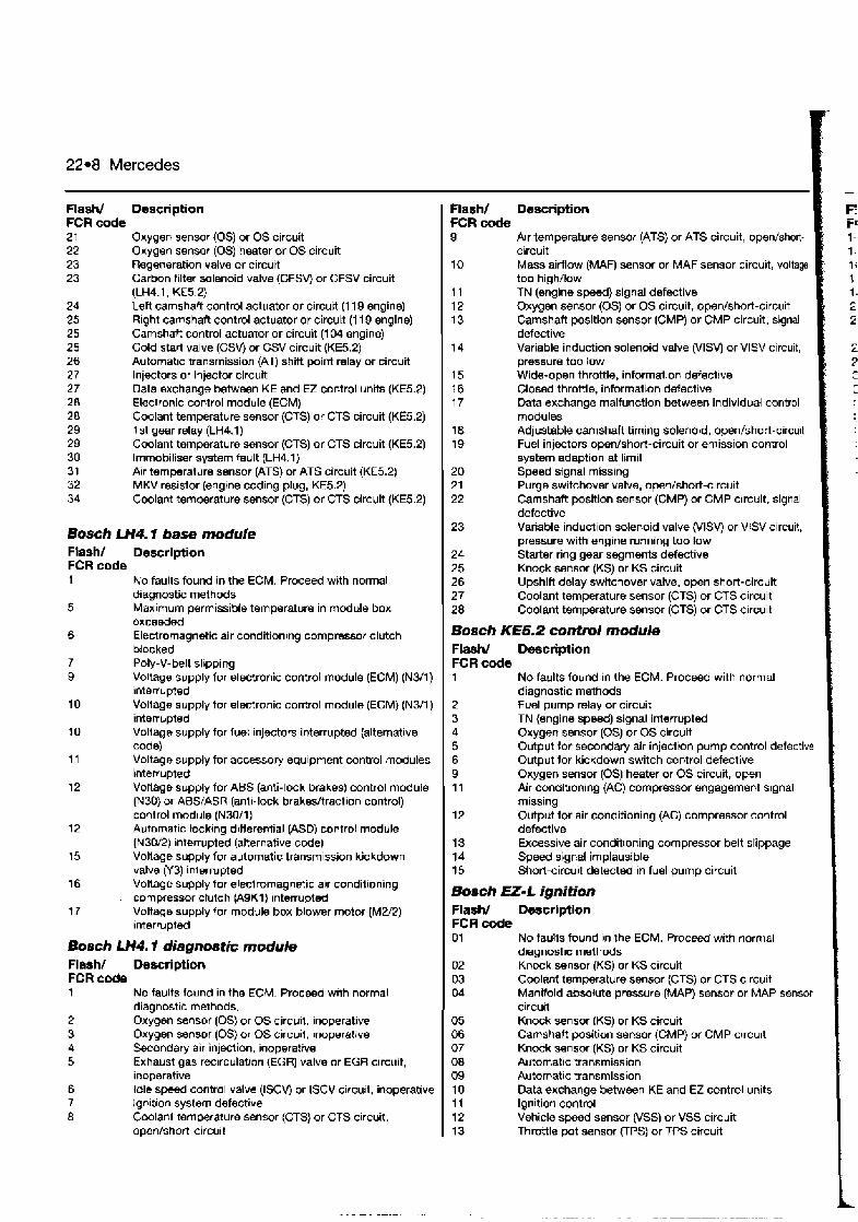
22.8 Mercedes
Flash/ Description FCR code 2 1 Oxygen sensor (0s) or OS circuit 22 Oxygen sensor (0s) heater or OS circuit 23 Regeneration valve or circuit 23 Carbon filter solenoid valve (CFSVj or CFSV circuit
(LH4.1, KE5.2) 24 Left camshaft control actuator or circuit (1 19 engine) 25 Rlght camshaft control actuator or circukt (1 19 engine) 25 Camshaft control actuator or circuit (1 04 engine) 25 Cold starl valve (CSV) or CSV circuit (KE5.2) 26 Automatic transmission (AT) shift point relay or circuit 27 Injectors or injector circult 27 Data exchange between KE and €2 control units (KE5.2) 28 Electronic control module (ECM) 28 Coolant temperature sensor (CTS) or CTS circuit (KE5.2) 29 1 st gear relay (LH4.1) 29 Coolant temperature sensor (CTS) or CTS clrcuit (KE5.2) 30 lmmobiliser system fault (LH4.1) 31 Air temperature sensor (ATS) or ATS circuit (KE5.2) 32 MKV resistor (engine coding plug, KE5.2) 34 Coolant temperature sensor (CTS) or CTS circuit (KE5.2)
Bosch LH4.1 base module Flash/ Deserlption FCR code 1 No faults found in the ECM. Proceed with normal
diagnostic met hods 5 Marrlmum permissible temperature in module box
e x c e d d 6 Electromagnetic air conditioning compressor clutch
blocked 7 Poly-V-belt slbpping 9 Voltage supply for electronic control module (ECM) (N3/1)
Interrupted 10 Voltage supply for electronic control module (ECM) (N3/1)
interrupted 10 Voltage supply for luet injectors interrupted (alternative
code) 11 Voltago supply for accessory equipment control modules
interrupted 12 Vollage supply for ABS (anti-lock brakes) control module
(N30) or ABS/ASR (anti-lock brakesjtraction control) control module {N30/1)
12 Automatic locking differential (ASD) control module (N30/2) ~nterrupted (alternat~ve code)
15 Vollage supply for automatic transmission kickdown valve (Y3) inlerrupted
16 Voltage supply for electromagnetic alr conditioning . compressor clutch (A9Kl) interrupted
17 Voltage supply for module box blower motor (M2/2) Interrupted
Bosch LH4.1 diagnostic module Flash/ Oescriptlon FCR & 7 No faults found in the ECM. Proceed wlth normal
diagnostic methods. 2 Oxygen sensor (0s) or 05 circuit, inoperative 3 Oxygen sensor (0s) or OS circuil, inoperative 4 Sacondary air injection, inoperative 5 Exhaust gas rmrculation (EGR) valve or EGR circuit,
inoperative 6 Idle speed control valve (ISCV) or ISCV circurt, inoperative 7 lgn~tlan system defective 8 Coolant temperature sensar (CTS) or CTS c~rcuit.
open/shon-circuit
Flash/ Description FCR c d e 9 Air temperature sensor (ATS) or ATS circuit, opn/short-
circuit 10 Mass airflow (MAW sensor or MAF sensor circuit, voltage
too high/low 11 TN (engine speed) signal defective 12 Oxygen sensor (0s) or OS circuit, open/short-circuit 13 Camshaft position sensor (CMP) or CMP circuit, signal
defective 14 Variable induction solenoid valve (VISV) or VlSV circuit,
pressure too low 15 Wlde-open throttle, information defective 16 Closed throttle, information defective 17 Data exchange malfunction between individual control
modules 18 Adjustable camshaft timing solenold, open/short-circult 19 Fuel injectors open/short-circuit or emission control
system adaption at limit 20 Speed signal missing 21 Purge switchover valve, open/short-circuit 22 Camshaft position sensor (CMP) or CMP circuit, signal
defective 23 Variable induction solenoid valve (VISV) or VlSV circuit,
pressure with engine running too low 24 Starter ring gear segments defective 25 Knock sensor (KS) or KS circuit 26 Upshift delay switchover valve, open short-circuit 27 Coolant temperature sensor (CTS) or CTS circuit 28 Coolant temperature sensor (CTS) or CTS circuit
Bosch KE5.2 control module Flash/ Description FCR code 1 No faults found in the ECM. Proceed with normal
diagnostic methods 2 fuel pump relay or circuit 3 TN (engine speed) signal interrupted 4 Oxygen sensor (0s) or OS circuit 5 Output for secondary air injection pump control defective 6 Output for kickdown switch control defective 9 Oxygen sensor (0s) heater or OS circuit, open 11 Air condltionlng (AC) compressor engagement signal
missing 12 Output for air conditioning (AC) compressor control
defective 13 Excessive air conditioning compressor belt slippage 14 Speed signal implausible 15 Short-circuit detected in fuel pump circuit
Boseh EL-L ignition Flash/ Deserlption FCR code 01 No taults found ~n the ECM. Proceed with normal
d~agnost~c methcds 02 Knmk wnsor (KS) or KS circuit 03 Coolant temperature sensor (CTS) or CTS circuit Od Manifold absolute pressure (MAP) sensor or MAP sensor
circuit 05 Knock sensor (KS) or KS circuit 06 Camshaft position sensor (CMP) or CMP circuit 07 Knock sensor (KS) or KS circuit 08 Autornat~c transmission G9 Autornat~c transmission 10 Data exchange between KE and EZ control units 11 Ignition control 12 Vehicle speed sensor (VSS) or VSS circuit 13 Throttle pot sensor (TPS) or TPS circuit
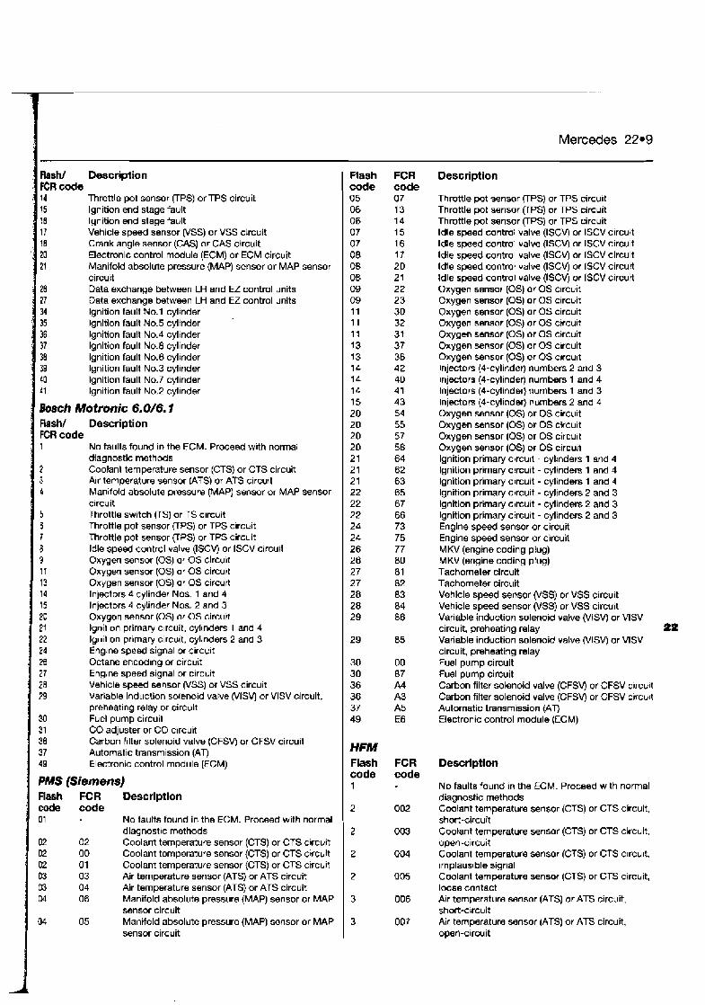
Mercedes 22.9
Flash/ Description
Throttle pot sensor (TPS) or TPS circuit lgnition end stage fault lgnition end stage fault Vehicle speed sensor (VSS) or VSS circuit Crank angle sensor (CAS) or CAS circuit Electronic control module (ECM) or ECM circuit Manifold absolute pressure (MAP) sensor or MAP sensor
Data exchange between LH and EZ control units Data exchange between LH and EZ control units lgnition fault No.1 cylinder Ignition fault No.5 cylinder lgnition fault No.4 cylinder lgnition fault No.8 cylinder lgnition fault No.6 cylinder lgnition fault No.3 cylinder lgnition fault No.7 cylinder lgnition fault No.2 cylinder
Bosch Motronic 6.0/6.7 Rash/ Description
No faults found in the ECM. Proceed with normal diagnostic methods Coolant temperature sensor (CTS) or CTS circuit k r temperature sensor IATS) or ATS circu~t Manifold absolute pressure (MAP) sensor or MAP sensor
Throttle switch VS) or TS c~rcuit Throttle pot sensor UPS) or TPS clrcuit Throttle pot sensor (TPS) or TPS circuit ldle speed control valve (ISCV) or ISCV circurt Oxygen sensor (0s) or OS circult Oxygel sensor (0s) or OS circuit Oxygen sensor (0s) or OS circurt Injectors d cylinder NOS. 1 and 4 Injectors 4 cylinder Nos. 2 and 3 Oxygen sensor (0s) or OS circuit Ignil~on primary c~rcuit, cyl~nders 1 and 4 Ign~l~on prlrnary c~rcult, cylinders 2 and 3 Englne speed signal or circu~t Octane encodlng or circuit Engrne speed signal or clrc~it Vehicle s p e d sensor (VSS) or VSS circuit Variable induction solenoid valve (VISV) or VlSV circuit, preheating relay or circuit Fuel pump circuit CO adjuster or CO circuit Carbon filter solenoid valve (CFSVj or CFSV circuit Automatic transmission (AT) Electronic control module (ECM)
PMS (Siemens) Rash FCR Description code code
No fautts found in the ECM. Proceed with normal diagnostic methods Coolant temperature sensor (CTS) or CTS clrcuit Coolant temperature sensor (CTS) or CTS c~rcult Coolant temperature sensor {CTS) or CTS ctrcuit Air temperature sensor (ATS) or ATS circuit Air temperature sensor (ATS) or ATS circuit Manifold absolute pressure (MAP) sensor or MAP sensor circuit Manifold absolute pressure (MAP) sensor or MAP sensor circuit
Flash FCR code code 05 07 06 13 06 14 07 15 07 16 08 17 OB 20 OB 21 09 22 09 23 1 I 30 11 32 11 31 13 37 13 36 14 42 14 40 14 41 15 43 20 54 20 55 20 57 20 56 21 64 21 62 21 63 22 65 22 67 22 66 24 73 24 75 26 77 26 80 27 81 27 82 28 83 28 84 29 86
Description
Throttle pot sensor (TPS) or TPS circu~t Throttle pot sensor VPS) or TPS circuit Throttle pot sensor VPS) or TPS circuit ldle speed control valve (ISCV) or ISCV circuit ldle speed control valve (ISCV) or ISCV circuit Idle speed control valve (ISCV) or ISCV circuit Idle speed control valve (ISCV) or ISCV circuit Idle speed control valve (ISCV) or ISCV circuit Oxygen sensor (0s) or OS c~rcuit Oxygen sensor (0s) or OS c~rcuit Oxygen sensor (0s) or OS c~rcuit Oxygen sensor (0s) or OS crrcult Oxygen sensor (0s) or OS c~rcuit Oxygen sensor (0s) or OS c~rcuit Oxygen sensor (0s) or OS curcult Injectors (4-cylinder) numbers 2 and 3 lnjectors (4-cylinder) numbers 1 and 4 Injectors (4-cylinder) numbers 1 and 3 lnjectors (4-cylinder) numbers 2 and 4 Oxygen sensor (0s) or OS circu~t Oxygen sensor (0s) or OS cucu~t Oxygen sensor (OS) or OS circu~t Oxygen sensor (0s) or OS circu~l lgnition primary clrcuit - cylinders 1 and 4 lgnition primary circuit - cylinders 1 and 4 lgnition primary circuit - cylinders 1 and 4 lgnition primay circuit - cylinders 2 and 3 lgnition primary circuit - cylindsts 2 and 3 lgnition primary circuit - cylinders 2 and 3 Engine sensor or circuit Engine speed sensor or circuit MKV (engine coding plug) MKV (engine coding plug) Tachometer circuit Tachometer circuit Vehicle speed sensor (VSS) or VSS circuit Vehicle speed sensor (VSS) or VSS circuit Variable induction solenoid valve (VISVJ or VlSV circuit, preheating relay Pa Variable induction solenoid valve (VISVj or VlSV circuit, preheating relay Fuel pump circuit Fuel pump circuit Carbon filter solenoid valve (CFSV) or CFSV clrcuit Carbon filter solenoid valve (CFSV) or CFSV circu~t Automatic transmission (AT) Electronic control module (ECM)
HFM Flash FCR code code 1
Description
No faults found in the ECM. Proceed with normal diagnostic methods Coolant temperature sensor (CTS) or CTS circuit, short-circuit Coolant temperature sensor (CTS) or CTS circuit, open-circuit Coolant temperature sensor (CTS) or CTS clrcult, implaus~ble signal Coolant temperature sensot (CTS) or CTS circuit, loose contact Alr temperature sensor (ATS) or ATS circuit. short-circuit Air temperature sensor (ATS) or ATS circuit, open-arcuit
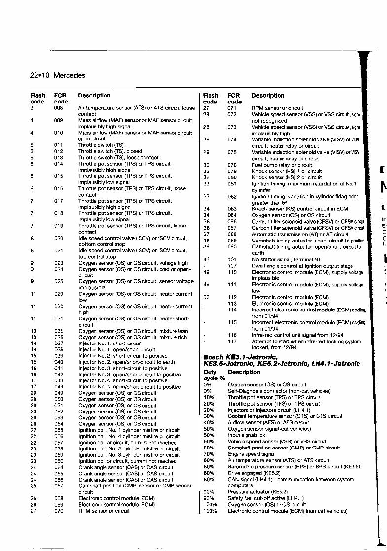
22.1 0 Mercedes
Flash code 3
FCR code 008
Description
Air temperature sensor (ATS) or ATS circuit, loose contact Mass airflow (MAR sensor or MAF sensor circuit, implausibly high signal Mass airflow (MAF) sensor or MAF sensor circuit, open-circuit Throttle switch (TS) Throttle switch (TS), closed Throttle swltch (TS), loose contact Throttle pot sensor (TPS) or TPS circuit, implausibly high signal Throttle pot sensor (TPS) or TPS circuit, implausibly low signal Throttle pot sensor RPS) or TPS circuit, loose contact Throttle pot sensor VPS) or TPS circuit, implausibly high signal Throttle pot sensor UPS) or TPS circuit, implausibly low signal Throttle pot sensor (TPS) or TPS circuit, loose contact ldle speed control valve (ISCVJ or 1SCV circuit, bottom control stop ldle speed control valve (ISCV) or ISCV circuit, top control stop Oxygen sensor (0s) or OS circuit, vollage high Oxygen sensor (0s) or OS circuit, cold or open- circuit Oxygen sensor (0s) or OS circuit, sensor voltage lrnplaus~ble Oxygen sensor (0s) or OS circuit, heater current low Oxygen sensor (0s) or OS circuit, heater current high Oxygen sensor (0s) or OS circuit, heater short- circu~t Oxygen sensor (0s) or OS circuit, mixture lean Oxygen sensor (0s) or OS circuit, mixture rich Injector No. 1, short-circuit Injector No. 1, open/short-circuit Injector No. 2, short-circuit to positive Injector No. 2, open/short-circuit to earth lnjector No. 3, short-circuit to positive Injwtor No. 3, open/short-circuit to positive Injector No. 4. short-circuit to positive lnjector No. 4, opedshort-circuit to positive Oxygen sensor (0s) or OS circuit Oxygen sensor (0s) or OS circuit Oxygen sensor (0s) or OS circuit Oxygen sensor (0s) or OS circuit Oxygen sensor (0s) or OS c~rcuit Oxygen sensor (0s) or OS c~rcuit lgnition coil, No. 1 cylinder misflre or c~rcuit Ignition coil, No. 4 cylinder m~sflre or c~rcuit lgnition coil or circuit, current not reached lgnition coil, No. 2 cylinder misfire or circuit lgnition coil, No. 3 cylinder misfire or circuit lgnition coil or circult, current not reached Crank angle sensor (CAS) or CAS circuit Crank angle sensor (CAS) or CAS circuit Crank angle sensor (CAS) or CAS circuit Camshaft position (CMP) sensor or CMP sensor circuit Electron~c control module (ECM) Electronic control module (ECM) RPM sensor or circuit
Flash FCR Description code code 27 071 RPM sensor or circuit 28 072 Vehicle speed smsor (VSS) or VSS crrcuil, sbrd
not recognised 28 073 Vehicle speed sensor (VSS) or VSS c~rcu~t, slgrd
implausibly high 29 074 Variable induction solenoid valve (ZIISV) or VI
circuit, heater relay or circuit 29 075 Variable induction solenoid valve (VISV) or VlSV
circuit, heater d a y or circuit 30 076 Fuel pump rslay or circuit 32 079 Knock sensor (KS) 1 or circuit 32 080 Knock sensor (KS) 2 or circuit 33 O B l Ignition timing, mawlmum retardation at No. 1
cylinder 33 082 lgn~t~on t~ming. var~ation in cylinder firing point
greater than 6 O 34 083 Knock sensor (KS) control circuit in ECM 34 084 Oxygen sensor (0s) or OS circuit 36 086 Carbon filter solenoid valve (CFSV) or CFSV d 36 087 Carbon filter solenoid valve (CFSV) or CFSV clrclA 37 088 Automatic transmission (AT) or AT circuit 38 089 Camshaft timing actuator, short-circuit to po 38 090 Camshaft timing actuator, openlshort-circuit to
earth 43 101 No starter s~gnal, terminal 50
107 Dwell angle control at ignition output stage 49 110 Electronic control module (ECM), supply voltage
implausible 49 11 1 Electronic control module (ECM), supply voltage
low 50 11 2 Electronic control module (ECM)
11 3 Electronic control module (ECM) 11 4 Incorrect electronic control module (ECM) coding,
from 01/94 1 15 Incorrect electronic conlrol module (ECM) coding,
from 01/94 1 16 Infra-red control unit signal from 12/94 1 17 Attempt to start when ~nfra-red locking system
locked, from 12/94
Bosch KES. 1 -Jetmnic, KE3.5-Jatronlc, KE5.2-Jetronic, LH4. f - Jetronic Duty Description cycle D/s 0% Oxygen sensor (0s) or OS circu~t 0% Self-Diagnosis connector (non-cat vehicles) 10% Throttle pot sensor (TPS) or TPS clrcur! 20% Throttle pot sensor (TPS) or TPS circuit 20% Injectors or injectors circu~l (LH4.1) 30% Coolant temperature sensor (CTS) or CTS clrcutt 40% Airflow sensor (AFS) or AFS circuit 50% Oxygen sensor signal (cat vehicles) 50% tnput signals ok 60% Vehicle speed sensor (VSS) or VSS circuit 60% Camshaft posltjon sensor (CMP) or CMP circuit 70% Engrne spa& signal 80% Air temperature sensor (ATS) or ATS circuit 80% 8arometric pressure sensor (BPS) or BPS circuit (KE3.5) 80% Drive engaged (KE5.2) 80% CAN signal (LH4.1) - communication between system
computers 90% Pressure actuator (KE5.2) 90% Safety fuel cut-off active (LH4.1) 100% Oxygen sensor (0s) or OS circuit 100% Electronic control module (ECM) (non-cat vehicles)

. . . . . . . . . . . . . index of vehicles Retrieving codes wtthout a fault code reader (FCR) 3 BeH-Diagnosis Set-Diagnosis connector location . . . . . . . . . . . . . . . . . . . . . . . . . . . 2 Clearing fault cod- without a fault code reader (FCR) . . . . . . . . . . . 4 Self-Diagnosis with a fault code reader (FCR) . . . . . . . . . . . . . . . . . . 5 hide to test procedurm . . . . . . . . . . . . . . . . . . . . . . . . . . . . . . . . . . 6 Fault code table btroduction . . . . . . . . . . . . . . . . . . . . . . . . . . . . . . . . . . . . . . . . . . . . 1
Index of vehicles
Carisma 1.6 SOHC 16V hisma 1.8 SOHC 16V Carisma 1.8 W H C 16V Colt 1.3i SOHC 1 2V cat Colt 1.3 SOHC 12V Colt 1600 GTi DOHC Colt 1.6 SOHC 16V Colt 1.6i 4x4 SOHC 16V cat Colt 1.6 SOHC l6V Colt 1800 GTi-16V DOHC 16V Colt 1.8 GTi DOHC 16V cat Cordia 1800 Turbo Galant 1800 SOHC l 6 V cat
Galant 2000 GLSi SOHC Galant 2000 GTi l 6 V DOHC Galant 2000 4WD DOHC Galant 2000 4WS cat DOHC Galant 2.13 SOHC 16V cat Galant 2.0i V6 DOeC 24V Galant Sapporo 2400 Galant 2.5i V6 DOHC 24V L300 SOHC 16V Lancer 1600 GTi 1 6V DOHC Lancer 1.6i SOHC 16V Lancer 1.6i 4x4 SOHC 16V cat Lancer 1800 GTi DOHC 1 6V Lancer 1.8 GTi DOHC 1 6V cat Lancer 1800 4.WD cat Shogun 3.5i V6 DOHC 24V Sigma Estate 12V Sigma Wagon 12V cat Sigma 3.0i 24V cat Space Wagon 1.8i SOHC 16V Space Wagon 2.0i DOHC 16V
Starion 2.6 Turbo cat
Engine code 6G72 4G92 4G93 4G93 4G13 4G13 4G61 4G92 4G92 4G92 4G67 4G93 4G62T 4G93 4G63T 4663 4663 4G63 4G63
6A12 4G64 6G73 4G63 4G61 4G92 4692 4G67 4G93 4G37-8 6674 6672 6G72 6G72 4G93 4G63 4G63T G54B1
Year 1 992 to 1997 1 996 to 1997 1996 to 1997 1996 to 1997 1992 to 1996 1996 to 1997 1988 to 1990 1 992 to 1996 1 992 to 1896 1 996 to 1997 1990 to 1993 t 992 to 1995 1985 to 1989 l993 to 1997 1985 to 1 988 1988 to 1 993 1988 to 1 993 1989 to 1 994 1989 to 1 994 1993 to 1997 1993 to 1997 1987 to 1 989 1993 to 1 995 1994 to 1997 1988 to 1990 1992 to 1996 1992 to 1 996 1990 to 1 993 1992 to 1995 1989 to 1 993 1994 to 1997 1993 to 1 996 1993 to 1 996 1981 to 1996 1991 to 1997 1992 to 1997 1986 to 1 989 1989 to 1991
System Mitsubishi ECI-Multi- MPi Mitsubishi ECI-Multi- MPi Mitsubishi ECI-Multi- MPi Mitsubishi ECI-Multi- MPI Mitsublshl ECI-Multl- MPI Mitsubishi ECI-Multi- MPi Mitsubishi ECI-Multi- MPi Mitsubishi ECI-Multi- MPi Mitsubishi ECI-Multi- MPI Mitsubisbi ECI-Multi- SEFi Mitsubishi ECI-Multi- MPi Mitsubishi ECI-Multi- MPi Mitsubishi ECI-Multi- MPi Mitsubishi ECI-Multi- MPI Mltsublshi ECI-Multi- Turbo Mitsubishi EQ-Multi- MPi Mitsubishi ECt-Multi- MPi Mitsubishi ECt-Multi- MPi Mitsubishi ECL-Multi- MPi Mitsubishl ECI-Multi- MPI Mitsubishi ECI-Multl- MPi Mitsubishi ECI-Multi- MPi Mitsubishi ECI-Multi- MPi Mitaubishi ECI-Multi- MPi Mltsublshi ECI-Multl- MPi Mitsubishi ECI-Multi- MPi Mitsubishi ECI-Multi- MPi Mitsubishi ECI-Multi- MPi Mitsubishi ECI-Multl- MPi Mitsubishi ECI-Multi- MPi Mltsubishl ECI-Multi- MPi Mitsubishi ECI-Multi- MPi Mitsubishi ECL-Multi- MPi Mitsubishi ECI-Multl- MPi Mitsubishi ECI-Multi- MPi Mitsubishi ECt-Multi- MPi Mitsubishi ECI-Multi- + Turbo Mitsubishi ECI-Multi- + Turbo
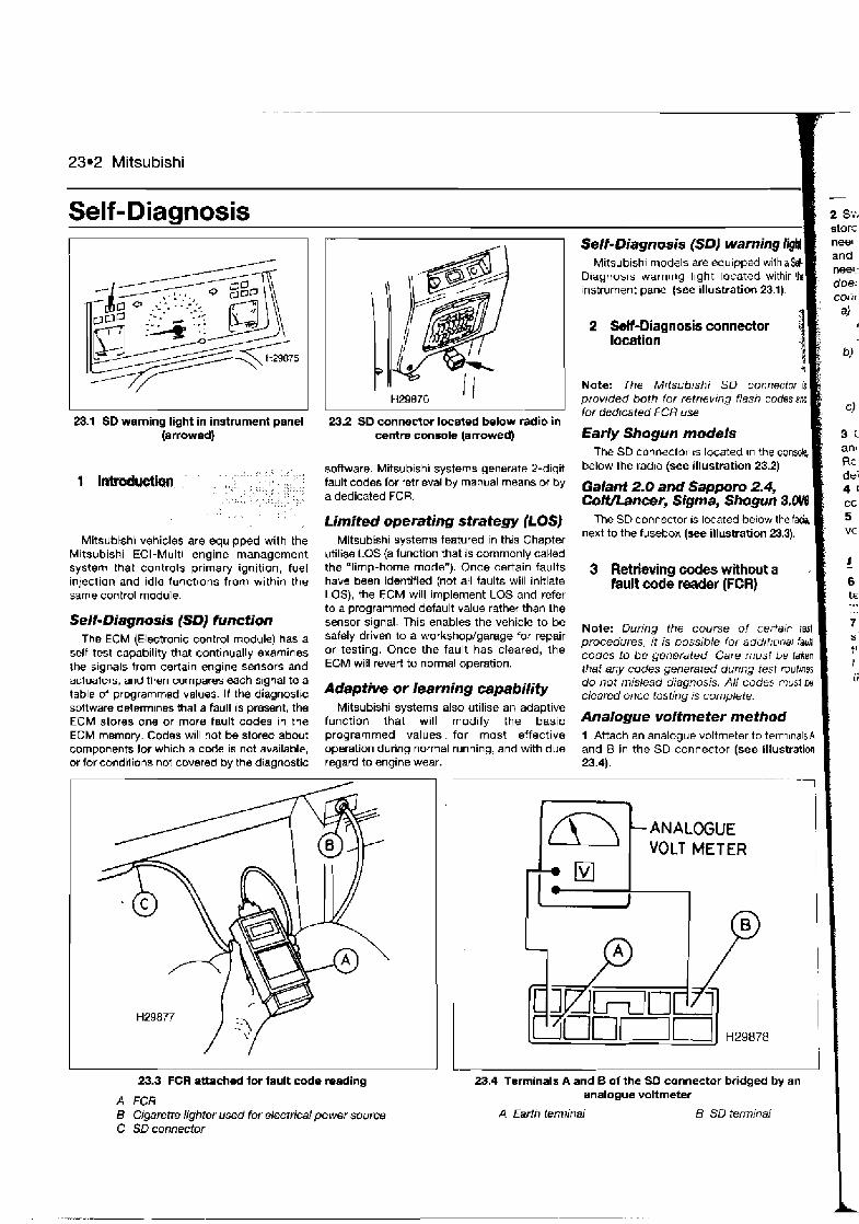
23.2 Mitsubishi
Self-Diannosis
23.1 SD waming light in instrument panel (a mowed)
Mitsubishi vehicles are equipped with the Mitsubishi ECI-Multi engine management system that controls primary ignition, fuel injection and idle functions from within tho same control module.
Self-Diagnosis (SD) function The ECM (Electronic control module) has a
self-test capab~lity that continually examines the signals trom certain engine sensors and aciuaiors, and then compares each slgnal to a table ot programmed values. H the diagnostic sottware determines that a fault is present, the ECM stores one or more fault codes In the ECM memory. Codes will not b Stored about components for which a code is not available, or for condllions not covered by the d~agnostic
23.2 SD connector located below radio in centre console (arrowed)
software. Mitsubishi systems generate 2-d~git fault codes for retrieval by manual means or b y a dedicated FCR.
Limited operating strategy (LOSJ Mitsubishi systems featured in this Chapter
utilim LOS (a function that is commonly called the "limp-home mode"). Once certain faults have been identified (not all faults will initiate LOS), the ECM will implement LOS and refer to a programmed default value rather than the sensor signal. This enables the vehicle t o be safely driven to a workshop/garage for repair or testing. Once the fault has cleared, the ECM will revert to normal operation.
Self-Diagnosis (SD) Mitsubishi models are equ~pped withaM
D~agnosls warnlrlg lhght Instrument panel (see illustration 23.1).
2 W-Diagnosis connector location 3 4
Note: The Mttsublsl~i SD connector 18 pfowded both for retrtevmg flash codes and tor dedrcated F CFi use
Early Shogun models The SD connector rs located In the console,
below the radlo (see illustration 23.2)
Galant 2.0 and Sapporn 2.4, CoWbncer, Sigma, Shogun 3.0H The SD connector IS located below the fa&i
next to the fusebox (see illustration 23.3).
3 Rdhulng codes without a fault code reader (FCR)
' I Note: During the course of certa~n tasl procedures, it is possible for addttrcnal faun codes to be generated Care must be Iaken that any codes generated during test roubnes do not mislead diagnosis. All codes must be Adaptive Or learning capability ,,e,, ,,, ,,,, j~ ,-- ma,e te. .,
Mitsubishi systems also utilise an adaptive function that will modify the basic method programmed values. for most effective 1 Attach an analogue voltmeter to terrn~nalsA operation during normal running, and with due and 8 in the SD connector (see illustration regard to engine wear. 23.4).
ANALOGUE VOLT METER
2 S;; st0 rc nee( and neel doe: cOlir
a)
3 r an1 RE de' 4 4
CC
5 - VC
23.3 FCR attached for fault code reading 23.4 Terminals A and B of the SD connector bridged by an
A FCR analogue voltmeter
5 Cigarette lighter used for electrical power source C SD connector
A Earfh lem~ir~al B SD terminal
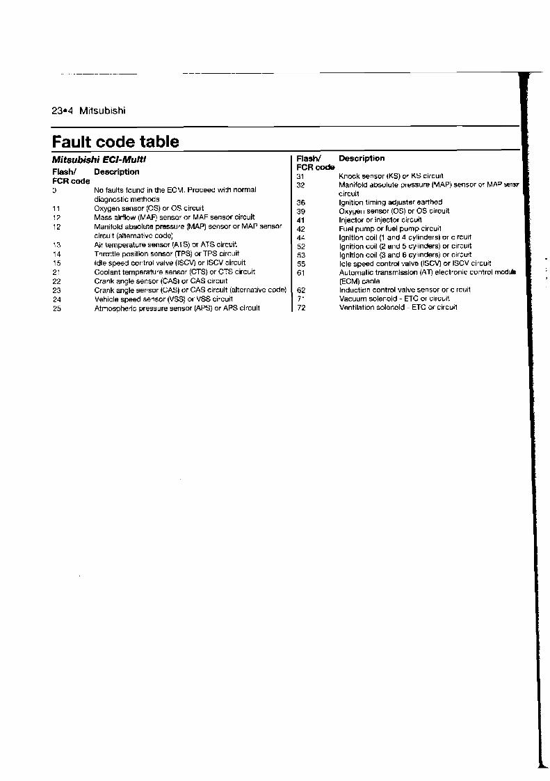
. - - - -. -.
23.4 Mitsubishi
Fault code table Mitsubishi EC/-Multi Flash/ Description Flash/ Description FCR code
FCR code 31 Knock sensor (KS) or KS circun 32 Manifold absolute pressure (MAP) sensor or MAP senm
0 No faults found in the ECM. Proceed with normal circuit diagnostic methods 36 Ignition timing adjuster earthed
11 Oxygen sensor (0s) or OS circuit 39 Oxygen sensor (0s) or OS circuit 12 Mass airflow (MAF) sensor or MAF sensor circuit 41 Injedor or injeclor circuit 12 Manifold absolute pressure (MAP) sensor or MAP sensor 42 Fuel pump or fuel pump circull
circuit (alternative code) 44 Ignition coil (1 and 4 cylinders) or c~rcult 13 Air temperature sensor (ATS) or ATS circuit 52 Ignition coil (2 and 5 cylinders) or c~rcu~t 14 Throttle position sensor (TPS) or TPS circuit 53 Ignition coil (3 and 6 cylinders) or circuit 15 idle speed control valve (ISCV) or ISCV circuit 55 Idle speed control valve (ISCV) or ISCV circu~t 21 Coolant temperature sensor (CTS) or CTS circuit 61 Automatic transmission (AT) electronic control module 22 Crank angle sensor (CAS) or CAS circuit (ECM) cable 23 Crank angle sensor (GAS) or GAS circuit (alternative code) 62 Induction control valve sensor or c~rcuit 24 Vehicle speed sensor (VSS) or VSS circuit 71 Vacuum solenoid - ETC or crrcuit 25 Atmospheric pressure sensor (APS) or APS circuit 72 Ventilation solenoid - ETC or c~rcu~ l
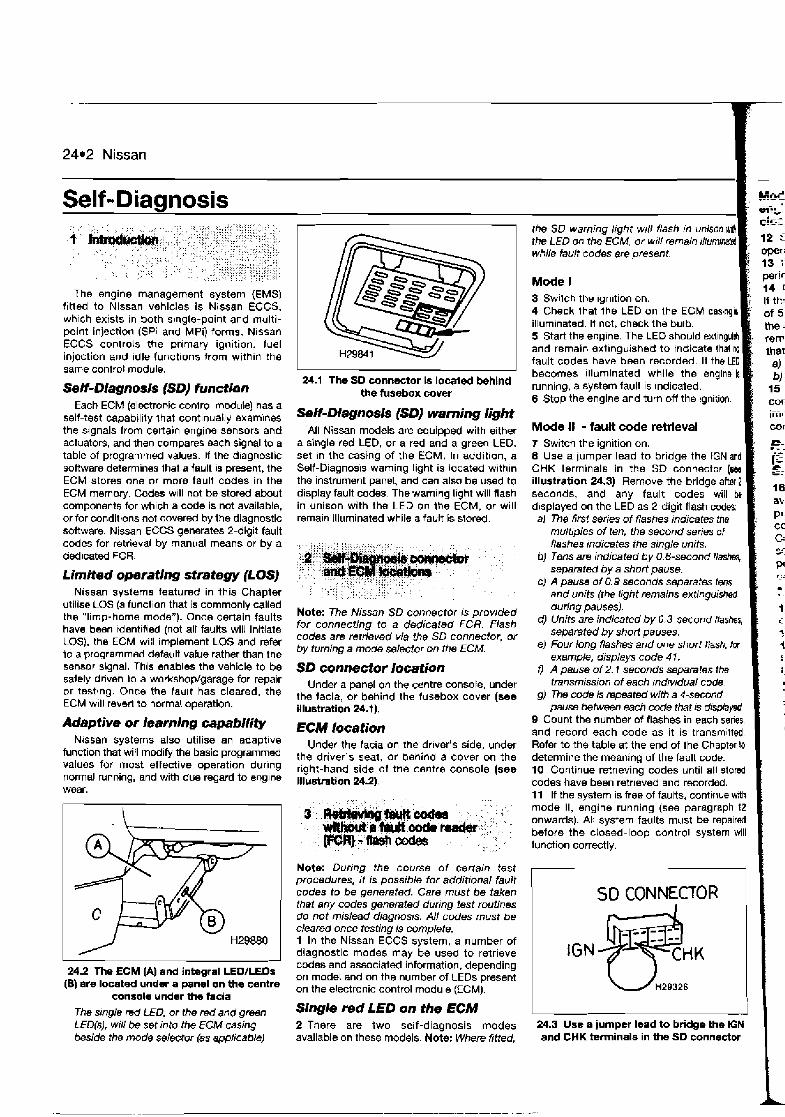
. ...
24.2 Nissan
Self -Diaanosis
The engine management system (EMS) f~tted to Nissan vehicles is Nissan ECCS, wh~ch exists in both single-point and rnulti- point injection (SPi and MPi) forms. Nissan ECCS controls the primary ignition, fuel injection and idle functions from within the same control module.
SeET-Dlagnosls (SD) function Each ECM (electronic conlrol module) has a
self-test capability that cont~nually examlnes the signals from certain engine sensors and actuators, and then compares wch signal to a table of programmed values. If the dragnostic software determines ihat a fault is present. the ECM stores one or more fault codes in the ECM memory. Codes w~ll not be stored about components for wh~ch a code is not available, or for conditions not cover& by the diagnostic software. Nissan ECCS generates 2-digit fault codes for retrieval by manual means or by a dedicated FCR.
Limited operating strategy (LOS) Nissan systems featured in this Chapter
utilise LOS (a function that is commonly called the "limp-home mode"). Once certain faults hava been rdentified (not all faults will initiate COS). the ECM will implement LOS and refer to a programmed default value rather than the sensor signal. This enables the vehicle to be safely dnven lo a workshop/garage for repair or testjng. Once the fault has cleared, the ECM wdl reverl lo normal operation.
Adaptive or learning capability Nlssan systems also utilise an adapt~ve
tunction that will modify the basic programmed values for most effective operation during normal running, and with due regard to englne wear.
24.2 The ECM (A) and integral LEOILEDs (B\ are located under a panel on the centre
console under the facia
24.1 The SO connector is located behind the hrsebox cover
SeH-Diagnosis (SD) warning light All Nissan models are equipped with either
a single red LED, or a red and a green LEO, set in the casing of the ECM. In addition, a Self-Diagnosis warning light is located w~thln the instrument panel, and can also be used to display fault codes. The warning light will flash in unison with the LED on Ihe ECM, or will remain illuminated while a fault is stored.
Note: The Nissan SD connector is provided for connecting to a dedicated FCR. Flash codes are retrieved via the SD connector, or by turning a mode selector on the ECM.
SD connector location Under a panel on the centre console, under
the facia, or behind ths fusebox cover (see illustration 24.t).
ECM location Under the facia an the drlver's side, under
the driver's seat, or behind a cover on the right-hand side of the centre console (see Illustation 24.2).
Note: Dunng the course of certain test procedures. it is possible for additional fault codes to be generated. Care must be taken ihai any codes generated during test routines do not mislead diagnosis. All codes must be cleared once testing is complete. 1 In the Nissan ECCS system, a number of diagnostic modes may be used to retrieve codes and associated information, depending on rnodet and on the number of LEDs present on the electronic control module (ECM).
the SO warning 11ght WIN flash In un the LED on the ECM, or will remain rllu while fault codes ere present.
Mode l 3 Swllch the ign~tion on. 4 Check that the LED on Ihe ECM caslnga illuminated. It not, check the bulb. 5 Start the engine. The LED should ext~nguld and remain oxt~nguished to tndicate that no fault codes have been recorded. If the LED becomes ~llurninated while the engine la running, a system fault is Indicated. 6 Stop the engine and turn off the ignition.
Mode II - fault code retrieval fi 7 Switch the ignition on. 8 Use a jumper lead to bridge the fGN and CHK terminals in the SD connector (m illustration 24.3). Remove the bridge after 2 seconds, and any fault codes will bo d~splayed on the LED as 2-digit flash coda: a) The fimt series of flashes indicates the
mult~ples of ten, the second series of flashes indicates the single units.
6) Tens am indicated by 0.6-second f / a separated by a short pause.
c) A pause of 0.9 seconds separates tens and units (the light remains extinguishd duHt?~ pauses).
d) Units are indicafed by 0.3-second flasher, separated by short pauses.
e) Four long flashes and one short flash. tor example, displays code 4 1.
f ) A pause of 2.1 seconds separates the transmission of each indivtduai code
g) The code is repeated with a 4-secmd pause behveen each code that rs displayed
9 Count the number of flashes in each senes and record each code as it is transm~tled Refer to the table at the end of the Chapter I determine the meaning of the fault code. 10 Continue retrieving codes until all storm codes have been retrieved and recorded. t 1 If the system is free of faults, conttnue wit mode II, engine running (see paragraph 1: onwards). All system faults must h repairw before the closed-loop control system wi function correctly.
SO CONNECTOR
The single red LED, or the red and green Single red LED on the ECM LED($, will be set into the ECM casing 2 There are two self-diagnosis modes 24.3 Use a jumper lead to bridge the IGN beside the mode selector (as appIicable) available on these models. Note: Where fitted, and CHK terminals in the SD connector
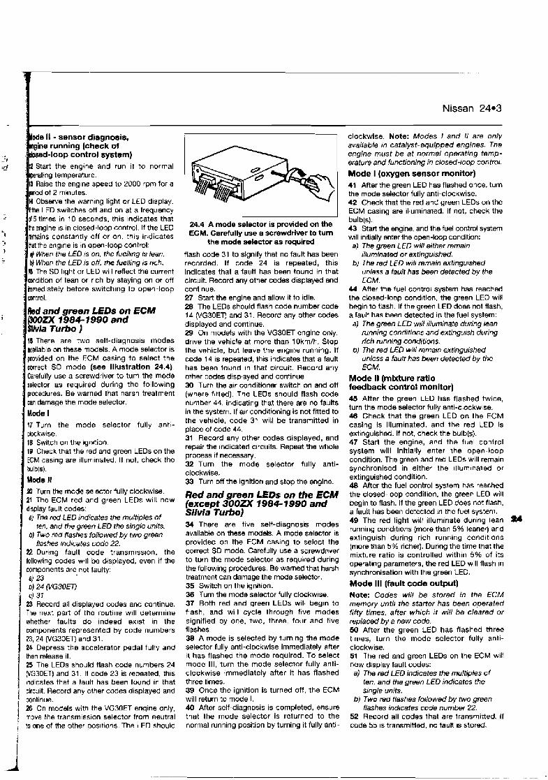
I Nissan 24*3
ode It - sensor diagnosis, gine running (cheek of k -loop control system) Start the engine and run it to normal ratlng temperature.
aise the englne speed to 2000 rpm for a d of 2 mrnutes b s e ~ 8 the warnlng light or LED d~xplay. LED switches off and on at a frequency
N 5 tlmes in 10 secovds, th~s ~ndicates that ke engine IS in closed-loop control. If the LED remains constantly off or on, thls Indicates tat the englne is in open-loop control: @ When the LED 1s on, the fuell~ng 1s lean. bJ When the LED is off, the fuelling is nch. 15 The SD l~ght or LED will reflect the current md~tion of lean or r~ch by staying on or off hmed~ately before switching to open-loop
Red and gmen LED5 on ECM ZX 1984- 1 BS0 and
/via Turbo J I6 There are two self-diagnosis modes mailable on these models. A mode selector is provided on the ECM casing to select the Forrect SO mode (see illustration 24.4). Carefully use a screwdriver to turn the mods selector as required during the following procedures. Be warned that harsh treatment m damage the mode selector.
Mcde I f7Turn the mode selector fully anti- ckckw~se. 1B Switch on the ~gn~tion. 18 Check that the red and green LEOS on the ECM casing are illum~nated. If not, check the bulb(s). Mode 1 aP Turn the mode selector fully clockwise. 21 The ECM red and green LED$ will now d~splay fault cod-:
eJ The red LED indicates the multiples of ten, arrd the green LED the single units.
b) Two fed flashes fdowed by two green flashes mdicates code 22.
22 Dur~ng fault code transm~ss~on, the following codes will be displayed, even if the components are not faulty: 4 23 b) 24 (VG30E7) C) 31
23 Record all displayed codes and continue. The next part of the routine w~ l l determine whether faults do Indeed exist in the components represented by code numbers 23,24 (VG30m and 31. 24 Depress the accelerator pedal fully and then release it. 25 The LEOs should flash code numbers 24 WGSOET) and 31. It code 23 is repeated, this indicates that a fault has been found in that
1 circuit. Record any other codes displayed and ! continue. 1 26 On m ~ d e l ~ with the VG30ET engine only. 1 move the transm~ss~on selector from neutral i lo one of the other posit~ons. The LEO should
I I
24.4 A mode selector is provided on the ECM. Carefully use a screwdriver to turn
the mode dector as required
flash code 31 to signify that no fault has been recorded. If code 24 is repeated, this indicates that a fault has been found in that circuit. Record any other codes displayed and continue. 27 Start the engine and allow It to idle. 28 The LEDs should flash code number code 1 d (VGSOET) and 31. Record any other codes display4 and continue. 29 On models with the VG30ET engine on!y, dr~ve the vehicle at more than lOkrn/h. Stop the vehicle, but leave the englne running. If code 1 4 1s repeated, Ihis indicates that a fault has been found In that circuit. Record any other codes d~splayed and continue 30 Turn the alr conditioner switch on and ofi (where f~tted). The LEOs should flash code number 44, indicating that there are no faults in the systern. If alr condbttoning is not fitted to the veh~cle, code 31 w~t l be transmitted in place of code 44. 31 Record any other codes displayed, and repair the indicated circuits. Repeat the whole process if necessary. 32 Turn the mode selector fully anti- clockwise. 33 Turn off the ignition and stop the engine.
Red and green LEDs on the ECM (excepf 300ZX 1984- 1990 and Silvia Tunbo] 34 There are five self-diagnos~s modes available on these models. A mode selector is provided on the ECM caslng to select the correct SD mode. Carefully use a screwdriver to turn the mode selector as required during the following procedures. Be warned that harsh treatment can damage the m d e selector. 35 Switch on the ignition. 30 Turn the mode selector fully clockwrse. 37 Both red and green LEOS will begin to flash, and will cycle through five modes signified by one, two, three, four and f ~ v e flashes. 38 A mode is selected by turning the mode selector fully anti-clockwise immediately after II has flashed the mode required. To select mode Ill, turn the mode selector fully anti- clockwise immediately after it has flashed three times. 39 Once the ignition is turned off, the ECM will return to mode I. 40 After self-diagnosis is completed, ensure that the mode selector is returned to the normal running position by turning it fully anti-
clockwise. Note: Modes I and I1 are only available in catalyst-equipped engines. The engine must be at normal operating temp- erature and functioning in closed-loop control. Mode I (oxygen sensor monitor) 41 After the green LED has flashed once, turn the mode selector fully anti-clockwise. 42 Check that the red and green LEDs on the ECM casing are illuminated. If not, check the bulb(s). 43 Start the engine, and the fuel control system will nirially enter the open-loop condition:
a) The green LED will either remain illuminated or extingurshed.
b) The md LED will remain extinguished unless a fault has been detected by the ECM.
44 After the fuel control system has reached the closed-loop cond~tion, the green LED will ixgln to flash. If the green LED does not flash, a fault has been detected in the fuel system: a) The green LED m N tlluminate during lean
running condttrons and extinguish during rich running conditions.
b) 7he red LED will remain extinguished unless a fault has been detected by the ECM.
Mode II (mixture ratio feedback control monitor) 45 After the green LED has flashed twice, turn the mode selector fully anti-clockwise. 4 8 Check that the green LED on the ECM casing is illuminated, and the red LED is extinguished. If not, check the bulb(s). 47 Start the engine, and the fuel conlrol system will initially enter the open-loop condition. The green and red LEDs w~l l remaln synchronised in either the ~llum~naled or extinguished condition. 48 After the fuel control syslem has reached the closed-loop condition, the grew LEO will begin to flash. If the green LED does not flash. a fauh has been detected ~n the fuel system. 49 The red light will illurnmate dur~ng lean running conditions (more than 5% leaner) and extinguish during rich running cond~t~ons (more than 5% richer). During the time that the mixture ratio is controlled within 5% of its operat~ng parameters, the red LED will flash In synchronisation with the green LED.
Mode 111 (fault code output) Note: Codes will be stored in the ECM memory until the starter has been operated fifty times, after which it will be cleared or replaced by a new code. 50 After the green LED has flashed three t~mes, turn the mode selector fully anti- clockwise. 51 The red and green LEOS on the ECM will now display fault codes: a) The red LED indicates the multiples of
ten, and the green LED indicates the single units.
b) Two red &shes followed by two green tiashes indicates code number 22.
52 Record all codes that are transmitted. I f code 55 is transmitted, no fault IS stored.

24.4 Nissan
53 It 15 now possible to enter the clear codes routlne Refer to Section 4. 54 Turn off the ignition.
Mode IV (switch-on/switch-off monitor) 55 After the green LED has flashed four trrnes, turn the mode selector fully anti- ctockwise. 56 The red LED should rernaln extinguished. 57 Start the engine. The red LED must illuminate during the time that the starter motor is in operailon. If the LED remalns off, check the starter s~gnal circuit to the ECM. 58 Depress the accelerator pedal. The red LED must ~llurninate dur~ng the time that the accelerator pedal 1s depressed. If the LED remains off, check the idle switch. The LED can be toggled on and off with every depression 01 the accelerator pedal. 59 Lift the drlve wheels so that the wheels can turn. O b s e ~ e all safety prlnclple~. 80 Engage a gear and drlve the wheels so that 12 rnph is exceeded. The green LED will illurrrnate at speeds over 12 mph, and exlingum8sh at speeds below 12 rnph. If the green LED does not behave as descr~bed, check the VSS arcuit. 61 Turn the ~gn~t~cm off.
Mode V (dynamic test of components) 62 Switch on the ignition and start the englne. 63 Turn the mode selector fully clockwise. 84 After the green LED has flashed flue tlrnes, turn the mode selector fully anti-clockwise. 65 Run the engine under various operaling conditions, and observe the LEDs. 88 If the LEDs begin to flash, counl Ihe flashes to determine the fault. The fault code is flashed once, and is not stored In memory: a) One red flash - fault defected in the crank
angle sensor circuit. 6) Two green flashes - f ~ u l t detected in the
aidlow sensor circuit. cJ Three red flashes - fault detected in the
fuel pump arcuit. d) Four green flashes - fault detected in the
lgnriron system circurt. 67 Slop the englne.
Red and green LEDs on the ECM (900ZX f 984- 1990 and Silvia Turbo) 5 Use the following method to clear the codes from these models: a) Switch on the ignition. bJ Turn the mode selector fully clockwise lor
a period exceeding two seconds. c) Turn the mode selector fully an!! clockwrse
for a period exceeding two seconds. d) Turn off the ignition.
Red and green LEDs on the ECM (except 3DOZ 1984- 1990 and Silvia Turbo) 6 Place the system in to mode Ill and retrieve the fault codes as desct~bed in Section 3. Note: Record aN codes before completing the following routines io clear the codes. When selectrng mode IV after mode Ill, the codes wiN be cleared from the ECM memory. a) Turn the mMe se(ector fully clockwise. 6) Afler the LED has flashed four times, turn
the mode selector fully anti-clockwise, wh~ch selects mode IV.
c) Turn the ignition of.
All models (alternative method) 7 Disconnect the battery for a per~od of twenty-four hours. Note: The first drawback to this method is that battery disconnection wit/ re-initialise all ECM adaptive values Re- learning the appropriate adaptive values requires starting the engine from cold, and dn'ving at various engine speeds for approximately 20 to 30 minutes. The engine should also be allowed to idle for approximately 7 0 minutes. The second drawback is that the radio security codes, clock setbng and other stored velues w111 be initialised, and these must be re-entered once the battery has been reconnected. Where possible, an FCR should be used for code clearing. 8 A fault is automat~cally cleared once the engine starter has been used lor a total of fifty times after the tault has cleared. If the fault recurs before 50 starts have been made, the counter will be reset to zero, and another 50 starts must occur before the fault is
a) Retrieving fault codes. b) Clearing fault codes. c) Displaying Datastream. d) Checking the closed-loop mixture contm. eJ Testing actuators. (J Returning adaptive functlon to original
default values. gJ Making adjustments:
Setting TPS position. Setting ignition timing advance. Adjusting CO/mixture value (nor]- catalysI models). Setting base rdle speed
h) Changing ihe b l l~w ing parameters (engine runnmgl:
ISCV duty cycle. Fuel injectron pulse rate. Ignition tirnrng retard. Coolant ten~pemture sensor (chang~ng temperaturn).
2 Codes must always be cleared alter component testing, or after repairs involvin~ the removal or replacement of an engine management system component.
6 Guide to teat procedures
1 Use an FCR to interrogate the ECM for fault codes, or gather codes manually, as described ~n Sections 3 or 5 . I Codes stored I 2 If one or more fault codes are gathered. refer to the fault code table at the end of this Chapter to determine thew meaning. 3 If several codes are gathered, look for a common factor such as a defective eath return or supply. 4 Refer to the component tesl procedures In Chapter 4, where you will t~nd a means ok testing the majority of components and circuits found in the modern EMS. 5 Once the fault has been repaired, clear the codes and run the engine under various conditions to determine if the problem has
4 Cleadng fault codas m o u t automatically cleared. This procedure occurs cleared. on an individual fault code basis; each code 6 Check the ECM for fault codes once more.
a huh code ~ e d e r (Wt) will only be cleared after 50 starts with no Repeal the above procedures where codes I 1 A number of methods may be used to clear codes from the ECM, depending on model. Ail methods are described below.
Single red LED on the ECM 2 Turn the ignition. 3 Place the system into mode II and retrieve the fault codes as described in Section 3. 4 After diagnostic mode two has been completed:
a) Bridge the SD terminals IGN and CHK. 6) Wait for at least 2 seconds. c) Disconnect the bridging wrre d) Turn of/ the ignrtion.
recurrence of that particular fault.
Notm: During the course of certain test procedures, it IS possible for additional fault codes to be generated. Care must be taken that any codes generated during test routmes do not mislead diagnosis.
1 Connect an FCR to the SD connector. Use the FCR for the following purposes, In str~ct
are d3l be~ng stored. 7 Refer to Chapter 3 for more information on I how to effect~vely :est the EMS.
No codes sfored 8 Where a runnlng problem is experienced, but no codes are stored, the fault 1s outs~de of the parameters designed into the SD system Refer to Chapter 3 for more informalloo on how to effectively test the engine management system. 9 If the problem points to a spec~f~c component, refer to the test procedures 111
Chapter 4, where you will find a means of testing the majority of components and circuits found in the modern EMS.

-.
Nissan 24.5
j~ault code table
Flash/ Description FCR coda 11 Crank angle sensor (GAS) in distributor or GAS c~rcult 11 RPM or RPM clrcuit (alternative code) 12 Mass a~rflow WAF) sensor or MAF circuit 13 Coolant temperature sensor {CTS) or CTS clrcuit 14 Vehicle speed sensor (VSS) or VSS clrcu~t 21' lgnition signal circud ;Z Fuel pump or fuel pump circutt B Throttle pot sensor VPS) - ~dls or TPS circuit 24 Throttle pot sensor VPS) or TPS circuit 24 Neutral/park swi!ch (alternat~ve code) 25 Auxil~arj alr valve (AAV) or AAV circu~t 26 Turbo, boost pressure sensor (BPS) or BPS c~rcuit M Air condlt~onrng (A/C models) 31 No faults found (non-NC models) - alternative code 31 Electron~c control module (ECM) - alternative code for
Flash/ Description FCR code 32 Starter signal 33 Oxygen sensor (0s) or OS circuit 34 Knock sensor (KS) or KS circuit 34 Throttle pot sensor (TPS) or TPS circuit (alternative code) 41 k r temperature sensor IATS) w ATS circu~t 62 Fuel temperature sensor (FTS) or FTS circuit 43 Throttle pot senwr VPS) or TPS circu~t 44 No faults found In the ECM. Proceed with normal diagnostic
methods 51 injectors or injector circuit 54 Automatic transrn~ssion (AT) signal lost 55 No faults found in the ECM. ProceW with normal d~agnostic
methods
'Note: If code 1 I and code 21 are both displayed in the same mcrdent, check the CAS circuit before check~ng other circuits.
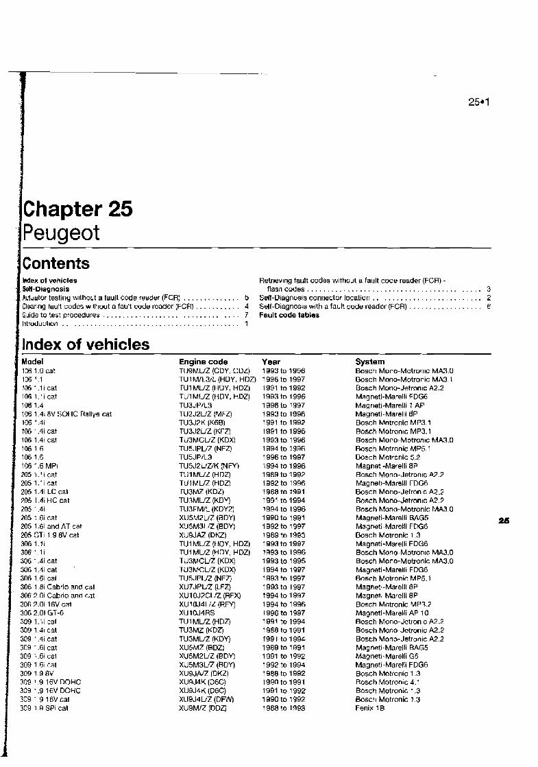
I kwlex of vehicles Retr~evingfault codes without a fault code reader (FCR) - SeH-Diagnosis flashcodes 3 Acluator testing without a fault code reader (FCR) . . . . . . . . . . . . . . 5 Self-Diagnosis connector location . . . . . . . . . . . . . . . . . . . . . . . . . . . 2 Clearing fault codes wlthout afault code reader (FCR) . . . . . . . . . . . 4 Self-Diagnos~s with a fault code reader (FCR) . . . . . . . . . . . . . . . . 6 Guide to test procedures . . . . . . . . . . . . . . . . . . . . . . . . . . . . . . . . . . 7 Fault code tables lntroductlon . . . . . . . . . . . . . . . . . . . . . - . . . . . . . . . . . . . . . . . . .. . . 1
Ilndex of vehicles -
106 '.l !06 1.l i cat 106 l . l i cat 106 1.4 106 1 41 8V SOHC Rallye cat 106 i .4i 106 1.4i cat 106 1.4i cat 106 1.6 106 1.6 106 1.6 MPI 205 1.11 cat 205 1.li cat 205 1.41 LC cat ?05 1 4; HC cat 205 1.4i 205 1.6i cat 205 1.61 and AT cat 205 GTI 1 9 8V cat 306 1 . l i 306 1.1 i 306 1.4i cat 306 1.4i cat '
306 1.6i cat 306 1 Ei Cabrio and cat 306 2.0i Cabrio and cat 306 2.0i 16V cat 306 2.01 GT-6 309 1.li cat 309 1 .JI cat 309 1.4i cat 309 1.61 cat 309 1.6i cal 309 1-61 cat 309 1.9 8V 309 1.9 16V DOHC 309 1.9 16V DOHC 309 1 916Vcat 309 1.9 SPI cat
Engine code TU9MVZ (CDY. CDZ) TUl M/L3/L (HOY, HDZ) TU1 MUZ (HDY, HDZ) TU1 MUZ (HDY, HDZ) TU3JPiL3 TU2 J2UZ (MFZ) TU3J2K (K6B) TU3JZUZ (KFZ) TMMCUZ (KDXI TU6JPVZ (NFZ) TUSJP/L3 TUSJPUUK ( N W TU 1 MU2 (H DZ) TUl MUZ (HDZ) TU3M.7 (KDZ) TUBMUZ (KDY) TU3FMIL (KDY2) XUSMZUZ (BDY) XUSMSLG! (BDY) XUSJAZ (DKZ) TU1 MU2 {HOY, HDZ) TUl MVZ (HDY, HDZ) TUBMCW (KDX) TU3MCLIZ (KDX) TUSJPUZ (NFZ) XU7JPUZ (LFZ) XU1 OJ2CVZ (RFX) XU1OJ4LfZ (RFY) XU 10J4RS TUIMLIZ (HDZJ TU3MZ (KDZ) TUBMUZ (KDY) XU5MZ (6DZ) XUSMZUZ (BDY! XUSMSVZ (BGYJ XU9JNZ (DKZ) XU9J4K (D6C) XU9J4K (D6C) XU9J4UZ (Dnnr) XU9M/Z (DDZ)
Year 1 993 to 1996 1 996 to 1997 1991 to 1992 1993 to 1 996 1996 to 1997 1 993 to 1996 1991 to 1992 1991 to 1996 1993 to 1 996 1994 to 1996 1 996 to 1997 1994 to 1 996 1989 to 1992 1992 to 1996 1988 to I991 1991 to 1994 1994 to 1996 1990 to 1 991 1992 to 1997 1989 to 1993 1993 to 1997 1993 to 1 996 1993 to 1 995 1994 to 1997 1993 to 1997 1993 to 1 997 f 994 to 1997 1994 to 1996 1996 to 1997 1991 to 1994 I988 to 1991 1991 to 1994 1989 to 1 991 1991 to 1992 1 992 to 1994 1968 to 1992 1990 to 1991 1991 to 1992 1990 to 1992 1 988 to 1993
-
System Bosch Mono-Motron~c MA3.0 Bosch Mono-Motronic MA3.1 Busch Mono-Jetronic A2.2 Magneti-Mare111 FDGG Magneti-Marelli I AP Magneti-Marelti dP Bosch Motronic MP3.1 Bosch Motronlc MP3.1 Bosch Mono- Motron~c MA3.D Bosch Motronic MP5.1 Bosch Motronic 5.2 Magnetl-Marelli BP Bosch Mono-Jetron~c A2.2 Magnetl-Marelli FOG6 Bosch Mono-Jelronlc A2.2 8osch Mono-Jetronic A2.2 Bosch Mono-Motronic MA3.0 Magneti-Marelli BAG5 Magneti-Marelli FDG6
2B
Bosch Motronic 1.3 Magneti-Marelli FDG6 Bosch Mono-Motronls MA3.O Bosch Mono-Motronic MA3.0 Magneti-Mare111 FDG6 Bosch Motronic MP5.1 Magnetl-Marell1 BP MagnM;-Marelli 8P Bosch Motronic MP3.2 Magneti-Marelli AP 10 Bosch Mono-detronic A2.2 Bosch Mono-Jetronic A2.2 Bosch Mono-Jetronic A2.2 Magneti-Marelli BAG5 Magneti-Marelli G5 Magneti-Marelii FDG6 Bosch Motron~c 1.3 Bosch Motron~c 4.1 Bosch Motronic 1.3 Bosch Motronic 1.3 Fenix 1 B

25.2 Peugeot
Model 405 1.41 cat 405 l.6i cat 105 1.61 cat 405 1.61 cat 405 1.61 cat 405 1.61 cat 405 1.6i cat 405 1.8i cat 405 1.9 8V cat 405 1.9Mi16and4n4 16V 405 1.9 Mi16 and 4x4 16V 405 1.9 Mi1 6 cat 405 1 .Qi Wldistributor 405 1.9 DIS 405 1.9 SPi cat 405 2.0i and 4x4 8V cat 405 2.0i 16V cat 405 2.04 16V turbo cat 406 1.61 cat 406 1.8i cat 406 1.8 16V 406 2.0 16V a06 2 o T U ~ ~ O
605 2.0i cat 605 2.0i cat 605 2.01 16V 605 2.0i turbo cat 605 2 Oi turbo 605 3 01 cat 605 3 01 24V DOHC cat 605 3.0i 24V V6 806 2.0 806 2.0 Turbo Boxer 2.0
Self - Diannosis 1 Introduction
The engine managemenl syslems (EMSs) fitted to Peugeot vehicles are mainly of Bosch origtn, and include Bosch Motronic versions 1.3, 3.1, 3.2, 4.1, 5 1. Other systems include Bosch Mono-Jetror~ic A2.2 and Bosch Mono- Motron~c MA3.0, Fenix l B , 38 and 4, and Magnetl-Marell! G5, G6, and 8P.
The rnqorlty of Peugeot engine management systems control primarj ignition, fuelling and idle lunctlons from within the same control module. Early verslons of Motmnic 4.1 and 1.3 utilised an auxlllary arr valve (AAV) that was not ECM-controlled. Bosch Mono-Jetronic fuel management systems control fuelling and idle lunct~ons alone
Self-Diagnosis {SD] function Each ECM has a self-test capability that
continually examines the signals from certain englne sensors and actuators, and compares each stgnal to a table of programmed values If the diagnostic software determines that a fault is present, the ECM stores one or more fault codes. Codes will not be stored about components for which a code 1s not available,
Engine code TUSMCUZ (KDX) XUSMZ (BDZ) XUSMPUZ (BDY) XUSM3Z IBDY) XUSM3UZ (SDY) XUSJPVZ (BFZ) XU5JPVZ (BFZ) XU7JPM (LFq XUSJNZ (DKZ) XU9J4K (NC) XU9J4K (06C) X U ~ J ~ I Z (Dnnr) XU9J2K (060) XU9J2K (060) XU9M/Z (DDZ) XUlOJ2CVZ (RFX) XU 1 OJ4/Z (RFY) XU1 OJ4TEUZ (RGZ) XU5JPL3(BFZ) XUTJPK(L6A) XU7JP4L XU1 DJ4RL XU1 W2TWL3 XUlOMU (RDZ) XUloJZUZ (RFZ) XUlOJ4RWL3 ( R W ) XUlOJZTEUZ (RGY) XUlOJ2CTEUZ (RGX) ZPJUZ (SFZ) ZPJIUZ (SKZ) ZPJ4UZ (UKZ) XU1 OJPCLIZ (RFU) XU1 OJ2CTEVZ (RGX) XU1 OJ2U (RFW)
Year 1992 to 1 994 1989 to 1991 1989 to 1991 1991 to 1992 1992 to 1993 1989 to 1992 1993 to 1995 1992 to 1997 f 989 to 1992 1988 to 1991 1990 to 1992 1 990 to 1992 1990 to 1991 1991 to 1992 1 989 to 1992 1992 to 1997 1992 to 1995 1993 to i 995 1996 to 1997 1996 to 1997 1995 to 1997 1995 to 1997 1996 to 1997 1989 to 1994 1 990 to 1995 1995 to 1997 1993 to 1994 1 995 to 1997 1990 to 1995 1990 to f 994 1995 to 1997 1995 to 1997 1995 to 1997 1994 to 1 997
or for conditions not covered by the dlagnostlc software. In Peugeot systems, the control module generates 2-digrt fault codes for retrieval either by manual means or by fault code reader (FCR).
Limifed operating strategy (LOS) Peugeot systems featured in this Chapter
utilise LOS (a runctlon that IS commonly called the "limp-home mode"). Once certain faults have been ident~lied (not all faults will Initiate LOS), the ECM w~l l implement LOS and refer to a prcgrammed default value rather than the sensor signal. This enables the vehicle to be safely driven to a workshop/garage for repair or testing. Once the fault has cieared, the ECM will revert to normal operation.
Adaptive or learning capability Peugeot systems also utilise an adaptive
function that will modify the basic progranirned values for most effective operation during normal running, and with due regard to engine wear.
Self-Diagnosis warning light The majority of Peugeot mdels are equrpped
wrth a facia-mounted SD warning light located wlthln the instrument panel. When the ignition is switched on, the light will illuminate. Once the
System Mono Motron~c MAX0 Magneti-Marell1 BAG5 Magneti-Marelli FDGS Magneti-Marelli FOG6 Magneti-Marelli FDGG Bosch Motronic 1.3 Magneti-Marelli DCMBPt3 Bosch Motronic MP5.1 Bosch Motronic 1.3 Bosch Motronic ML4.1 Bosch Motronic 1.3 Bosch Motronic 1.3 Bosch Motronic MP3.1 Bosch Motronic MP3.1 Fsnix 1 B Magnetl-Mare111 BP Bosch Motronic MP3.2 Magneti-Ma~lli AP MPI Magneti-Marelli BP Magneti-Marelli 8P Bosch Motronic MP5.1.1 Bosch Motronic MP5.1.1 Bosch Motronlc MP5 1 1 Magneti-Marelli G5 Bosch Motronic MP3.1 Bosch Motronic MP5.1 .I Bosch Motronic MP3 2 Bosch Motronic MP3.2 Fenix 38 Fenix 4 Fenix 4 Magneti-Mare111 8P-22 Bosch Motronlc MP3.2 Magneti-Marell1 8P11
englne has started, the light will extlnquish if the dlagnoslic software determines that a major bul l 4s nol present. If the light illuminates at any trme during a period of engine running, the ECM has dlagnosd presence d a major fault. PI- note that failure of certain components des~gnated as "minor" faults will not cause the light to illuminate. The warning light can also bs triggered to transmit flash codes (see Section 3).
2 Setf-Diagnosis connectw location I
The 2-pin SD connector is coloured green, and is located in the engine cornparlment. It IS
commonly mounted along the left- or right- hand inner wing, either close to the ECM, the battery, or the coollng system expansion bottle. In some vehicles, the SD connector is located Inside the relay box on either the left- or right-hand wing. The SD connector is provlded for both manual retrieval of flash codes and for dedicated FCR use.
The 30-prn SD connector fitted to many laier models IS located rn the passenger cornparlmenl, either under the facia or behind a cover on the lacia (see illustration 25.1) and IS for ded~caled FCR use alone.

Peugeot 25.3
i 25.1 30-pin SD connector and typical location
I' : 3 Rheving fault cod88 without a feutt code mdsr (FCR) - flash codes
Mote: Dunng the course of certain test procedures, ~t is possible for additional fault codes to be generated. Care must be taken that any codes generated during test routines do not mislead d~agnosis. All codes must be cleared orlce testing is cornplate.
1 Attach an on/off accessory sw~tch to the green 2-pir! Sl3 connector {see illustration
2 Switch on the Ipnitron. The warning light should bllurninate. 3 Close the accessory switch The light will
4 Opsn the sw~tch after 3 seconds. The warning light will begh to flash the 2-diq~t fault codes as follows: a) The two digits are indicated by two senes
ol flashes. ' b] The hrst series of fkshes indicates the
multiplas o f ten, tne second series of flashes indtcates the srngle units.
c) Each senes consists o f a /lumber of 1- second flashes. sepamted by a 1.5- second pause.
d) The code number "13" is indic~led by a 7-second flash, a 1.5-secofld pause and three 1 -second flashes. After a 2.5- second pause, the code will be repeafed.
5 Count the number of flashes in each series, and record each code as it is transmitted.
' Refer to Ihe tables at the end of the Chapter to determine the meaning of the fault code,
; 6 The first code to he d~splayed will be code
1 " 12", which indlcales initiat~on of diagnosis.
i
i
25.2 Retrieve flash codes by connecting an acceasoty switch and LED light (when a warning Ilght is not fied) to terminal 2 in the
2-pin SD connector A SD connector 8 Accessory switch C LED l~gght
7 The warning light wbll extinguish; Walt for 3 seconds before continuing. 8 Close the accessory switch for 3 seconds. 9 Open the switch. The warning light will begin flashing to ind~cate a code. 10 The warning lrght will extinguish; wait for 3 seconds before continuing. 11 Repeat the test to retrieve further codes. 12 Continue retrieving codes until code 1 7 is transmitted. Code 7 1 signifies that no more codes are stored. 13 If the evgine is a non-stafler, crank the engine on the starter motor for 5 seconds, and return the ignition key to the "on" position. Do no1 switch off the ignitm. 14 If code 1 ! is the first code transmitted after code 12, no faults are stored by the ECM. 15 After cads 11 1s transm~tted, the complete test may be repeatw from the start. 16 Switching off the ignition ends fault code retrieval.
All other systems with green 2-pin SD connector 17 Attach an on/off accessory switch to the green 2-ptn SD conneclor (refer to illustration 25.2). If the vehicle is not equipped with an SD warning light, attach an LED diode light to the SD connector as shown in the illustratim. 18 Switch on the ignition. The warning light or LED should illuminate. 19 Glose the accessory switch; the light will remain illuminated. 20 Open the switch after 3 seconds. The warning light or LED will begin to flash the 2- dig~t fault codes as follows:
a] The two digits are indicated by two series of flashes.
b) The I~rst series of flashes ~ndrcates the rnu/t:ples of ten, the second series of tiashes indicates the single units.
c) Each Serf8S consists o f a number of 1 - second flashes, separated by a 7.5.. second pause.
d) The code number "13" IS tndrcated by a 1 -second flash, a 1.5-second pause and three i-second i/a.-ihes. Aftef a 2.5- second pause, the code will be mpeated.
21 Count the number of flashes in each series, and record the code. Refer to the tables at the end of the Chapter to determ~ne the meaning of the fault code. 22 The first code indicated will be code "12". which ind~cates initiation of diagnosis. 23 Before continuing, weil 3 secorrds for the warning light or LED to ~lluminate. 24 Close the accessory switch for 3 wands ; the light or LED w~ll remain illum:nated. 25 Open the switch. The warning light or LED will bqln flashing to indicate a code. ZS Before continuing, wait 3 seconds for the warning lighl or LED to illuminate. 27 ~epeat the test to retrieve further codes. 28 Coniinue retrieving codes until code 11 ~s transmitted. Code 11 slgnifles that no more codes are stored. 29 If the engine IS a non-starter, crank the engine OF the starter motor for 5 seconds, and return the rgnitlon key to the "on" position. Do not swltch off the Ignition. 30 If code 11 ls the flrst code transm~tted after code 12, no faults are stored by the ECM 31 Afrer code 11 is transmitted, the comple?e test may be repeated from the start. 32 Turning off the ~gn i t~on ends tault code retrieval.
30-pin SD connector 33 A fault code reader (FCR) 1s required for those systems equ~pped with the 30-pin SD connector - flash codes are not available.
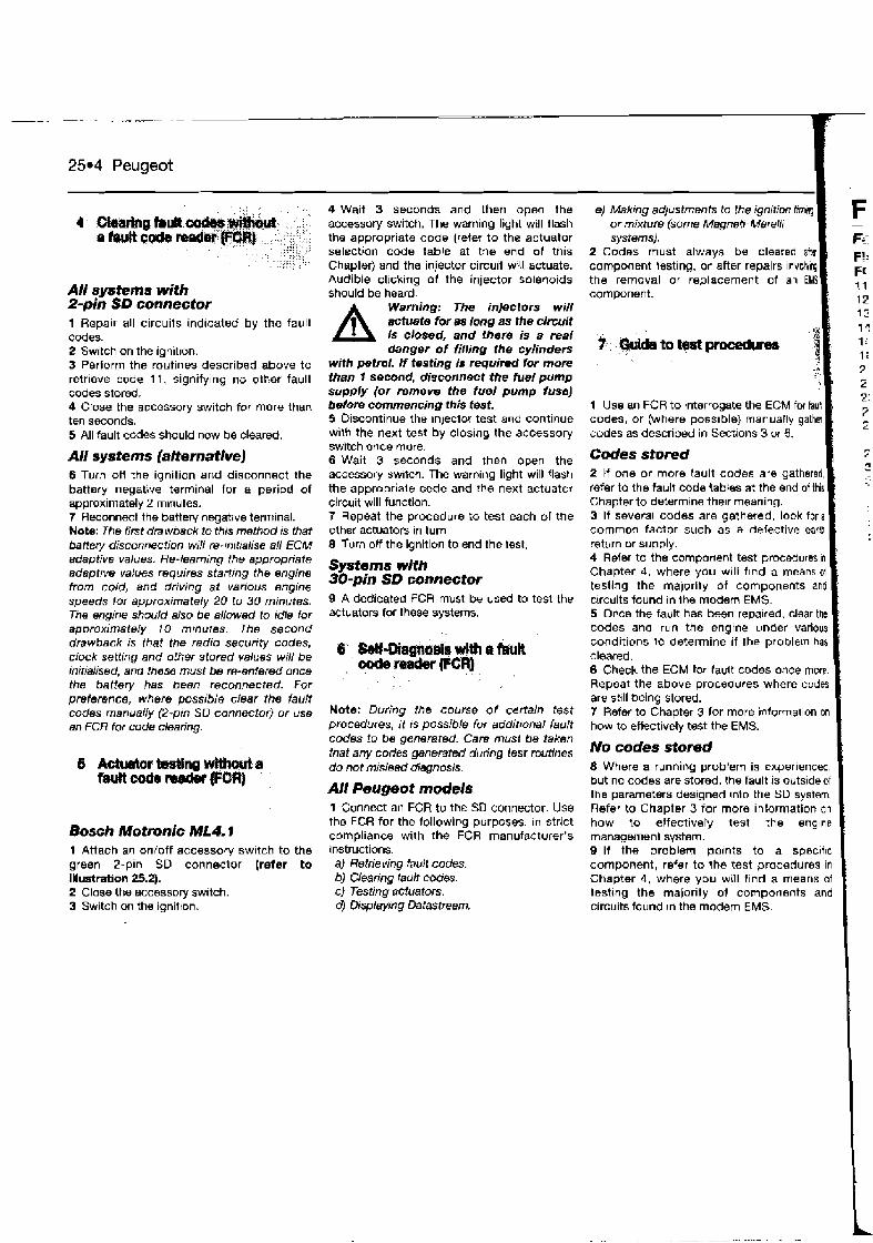
25.4 Peugeot
All systems with Spin SD connector 1 Repair all circuits ind~cated by the fault codes. 2 Switch on the ignit~on. 3 Perform the routines described above to retrieve code 11, signifying no other fault codes stored. 4 Close the accessory switch for more than ten seconds. 5 All fault codes should now be cleared.
All systems (altematlve) 6 Turn off the ignition and disconnect the battsry negative terminal for a period of approximately 2 minutes. 7 Reconnect the battery negative terminal. Note: The first drawback to this method is that banet-y disconnection will re-mitialise all ECM adaptive values. Re-learning the appropriate adapbw values requires starting the engine from cold, and driving at various engine speeds for approximately 20 to 30 minutes. The engine should also be aliowed to idle for appraximately 10 mmutes. The second drawback is that the radio security codes, clock setting and other stored values will be initialised, and those must be re-entered once the battery has been reconnected. For preference, where possible clear the fault codes manually (2-pin SD connector) or use an FCR for code clearing.
Bosch Motmnlc ML4.1 1 Attach an onfoff accessory sw~tch to the green ?-pin SD connector (refer to Illustration 25.2). 2 Close the accessory sw~tch. 3 Switch on the ignitton.
4 Wait 3 seconds and then open the accessory switch. The warning light will flash the appropriate code (reter to the actuator selection code table at the end of this Chapter) and the injector circuil wi!l actuate. Audible cl~cking of the injector solenoids should be heard.
A Warning: The injectors will actuate for as long as the circuit is closed, and there is a real danger of filling the cylinders
with petrol. If testing is required Tor more than f second, disconnect the fuel pump supply (or remove the fuel pump fuse) betom commencing this test. 5 Discontinue the lnjector test and continue with the next test by closing the accessory switch once mare. 6 Wait 3 seconds and then open the accessory sw~tch. The warning light will flash the appropriale code and the next actuator circuit will function. 7 Repeat the procedure to test each of the other actuators in turn 8 Turn off the ignition to end the test.
Sysfems with 30-pin SD connector 9 A dedicated FCR must be used to test the actuators for these systems.
Note: During the course of certain test procedures, it is possible for addittonal fault codes to be generated. Care must be taken that any codes generated during test routines do not m~slead diagnosis.
All Peugeot models 1 Connect an FGR to the SD connector. Use the FCR for the following purposes, in strict compliance with the FCR manufacturer's instructions. a) Retrieving fault codes. bJ Clearing fault cobes. c) Testing actuators. d) Displ~ying Datastream.
e) Making adjustments to the ignition timing or mixture (some Magneti- Marelli systems).
2 Codes must always be cleared ah component Issting, or after repairs ~nvdwq the removal or replacement of an EMS I
1 Use an FCR to interrogate the ECM for faub codes, or (where possible) manually gather codes as described in Sections 3 or 6. I Codes stored 1 2 If one or more fault codes are gathered, refer to the fault code tables at the end of this Chapter to determine thelr meaning. 3 If several codes are gathered, look for a common factor such as a defective earU ' return or supply. 4 Refer to the component test procedures In
Chapter 4, where you will f ~ n d a means ol testing the majority of components and circuits found in Ihe modem EMS. 5 Or,ce the fault has besn repalred, clear the codes and run the engine under various conditions lo determine if the problem has cleared. 6 Check the ECM far fault codes once more. Repeat the above procedures where codes
'
are still being stored. 7 Refer to Chapter 3 lor more informat~on on how to eAectively test the EMS.
No codes stored 1 8 Where a running problem is experienced. but no codes are stored, the rault is outside of I the parameters designed lnlo the SD system. Refer to Chapter 3 for more information on how to effectively test the englne management system. 9 If the problem po~nts to a spec~f~c component, refer to the test procedures In
Chapter 4, where you will find a means of testtng the majority of components and clrcuits found In the modem EMS.
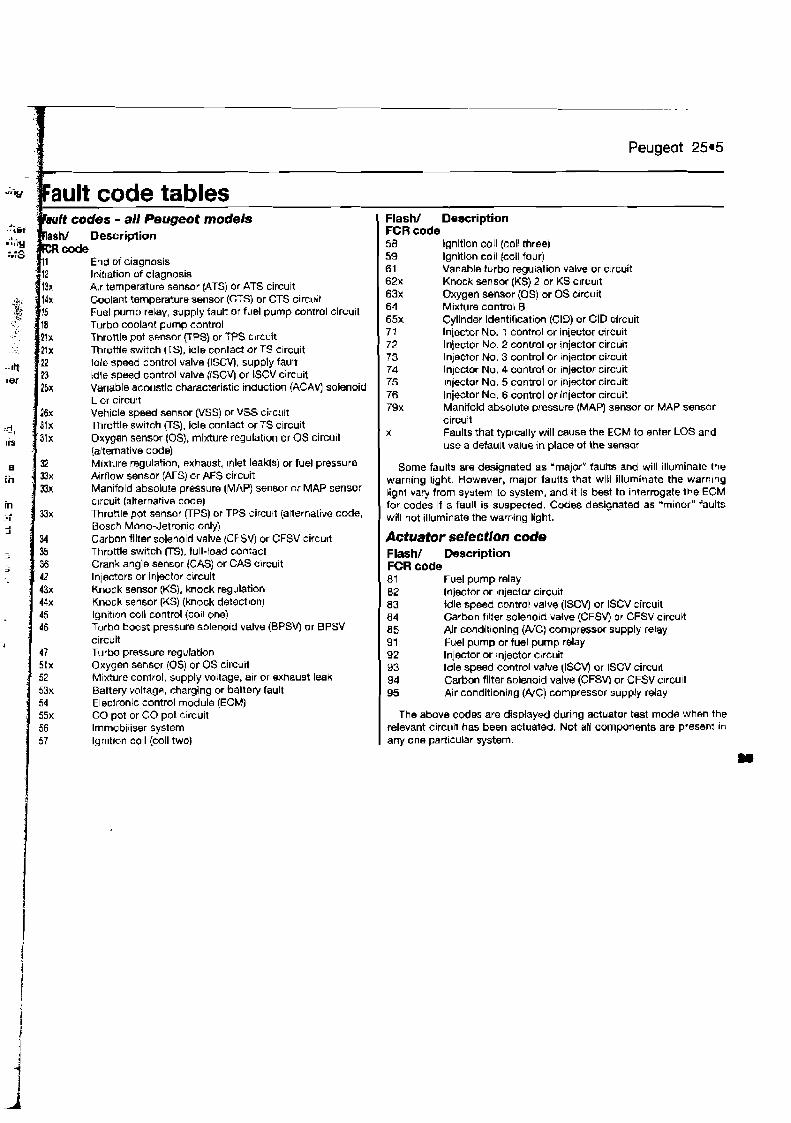
-1 - .
Peugeot 25.5
Bault code tables It codes - all Peugeot models ht Description code
End of diagnosis Initiation of diagnosis Air temperature sensor (ATS) or ATS circuit Coolant temperature sensor (CTS) or CTS circuit Fuel pump relay, supply fault or fuel pump control circuit Turbo coolant pump control Throttle pot sensor (TPS) or TPS c~rcuit Throele switch US), idle contact or TS c~rcuit ldle speed control valve (ISCV), supply fault Idle s p e d control valve (lSC\r) or tSCV circuit Variable acoustic characteristic induction (ACAV) solenoid L or circult Vehicte speed sensor (VSS) or VSS circujl Throttle sw~tch (TS), idle contact or TS circuit Oxygen sensor (OS), mixture regulation or OS circuit (alternative code) Mixture regulation, exhaust, ~nlet leak@) or fuel pressure Airflow sensor (AFS) or AFS circuit Manifold absolute pressure (MAP) sensor rx MAP sensor circuit (alternative code) Throttle pot sensor RPS) or TPS circuit (alternative code, Bosch Mono-Jetronic only) Carbon filter solenoid valve (CFSV) or CFSV circuit Throttle switch [TS), full-load contact Crank angle sensor (CAS) or GAS circuit Injectors or injector circuit Knock sensor (KS), knock regulation Knock sensor (KS) (knock detection) lgn~t~on coil control (co~l one) 45 Turbo boost pressure solenoid value (BPSW or BPSV circuit Turbo pressure regulation Oxygen sensor !OS) or OS circuit Mixture conlrol, supply voltage, alr or exhaust leak Battery voltage, charging or battery fault Electronic control module (ECM) CO pot or CO pot circuit lrnmabiliser system lgn~tron coil (coil two)
Flash/ Description FCR code 58 ignition coil (coil three) 59 Ignition coil (coil four) 61 Variable turbo regulation valve or c!rcuit 62x Knock sensor (KS) 2 or KS circu~t 63x Oxygen sensor (0s) or OS c~rclrit 64 Mixture control B 65x Cylinder identifleation (CID) or CID circuit 77 Injector No. 1 control or injector circuit 72 Injector No. 2 control or injector circuit 73 Inlector No. 3 control or injector circuit 74 Injector No. 4 contro! or injector circuit 75 lnjmtor No. 5 control or injstor circuit 76 Injector No. 6 control or injector circuit 79x Manifold absolute pressure (MAP) sensor or MAP sensor
circuit x Faults that typically will cause the ECM to enter LOS and
use a detault value in place of the sensor
Some faults are designated as 'major" fauns and will illuminate the warning I~ght. However, major fallits that will illuminate the warnlng light vary from system to system, and ~t is best to interrogate the ECM for codes if a fault is suspected. Codes designated as "minor" faults will not illuminate the warning light.
Actuator selection code Flash/ Description FCR code ~ Fuel pump relay
Injector or injector circuit 83 idle speed control valve (ISCV) or ISCV circuit 84 Carbon f~lter solenoid valve (CFSV) Or CFSV circuit 85 Air conditioning (AIC) compressor supply relay 91 Fuel pump or fuel pump relay 92 Injector or ~njector circuit
ldle speed control valve (ISCV) or ISCV circu~t Carlmn filter solenold valve (CFSVj or CFSV clrcult
95 Air conditioning (#C) compressor supply relay
The above codes are displayed during actuator test mode when the relevant circuit has been actuated. Not all components are presm! In
any one parl~cular system.

W e x of whicles Retrievtng fault codes without a fault code reader (FCR) . . . . . . . . . 3 Self-Diagnosis Self-Diagnosis connector location . . . . . . . . . . . . . . . . . . . . . . . . . . 2 Clearing fault codes without a fault code reader (FCR) . . . . . . . . . . . 4 Self-Diagnosis with afautt code reader (FCR) . . . . . . . . . . . . . . 5 Guide to test p r o d u r e s . . . . . . . . . . . . . . .... . . . . . . . . . . . . . . . 6 F w R code table knroduction . . . I
Index of vehicles Model 1.3 MPi 12V SOHC cat 1.5 M Pi 1 2V SOHC cat Persona 1.3 Cowpact SOHC 12V Persona 1.5 SOHC 12V Persona ! .5 Compact SOHC 12V Persona 1.6 SOHC 16V Persona 1.6 Compact SOHC 16V Pwsona 1.8 12V SOHC Persona 1.8 16V DOHC
Engine code 4013-2 4G 1 5-2 4G13-2 4G15 4G15 4G92 4G92 4G93 4G93
Year 1992 to 1997 I992 to 1897 1 995 to 1997 1993 to 1997 1993 to 1997 1993 to 1997 1 993 to 1997 1996 to 1997 1996 to 1997
System ECI-Multi- MPi ECI-Multi- MPi ECI-Multi- SEFI ECI-Multi- SEFb ECI-Multi- SEFi ECI-Multi- SEFi ECI-Multi- SEFi ECI-Multi- SEFi ECI-Multi- SEFi
Self-Diagnosis -- -
.>,
, , ECM memory. Codes will not be stored a b u t
:$ ~~~~n components for which a code is not available, 9 R d d # l a f a ~ H codes or for conditions not covered by the wffhoutafaultcde d~ I: d~agnostic software. In Proton systems, the control module generates 2-digit fauh codes.
PCW Proton vehicles are equipped wilh Ihe ECI- for retrieval either by manual methods Or by Note: During the course of certain tesl
Mult, engine management syslern, which a tauit code reader (FCR). procedures, it a possible for additronal fault conirols primary ignition, luel Injection and idle functions from w~thin the same control module.
Self-Diagnosis (SD) function The ECM has a self-test capability that
cantinualiy examines the signals from certain enoine sensors and actuators, and then MmpareS each s~gnal to a table of programmed values. If the diagnostic software determines that a fault is present, the ECM stores one or more fault codes In the
I
I
26.1 FCR attached to read fauh codas I -
Limited operating strategy (LOS) Proton systems featured in this Chapter
utilise LOS (a function that e commonly called thq "limp-home mode"). Once certain faults have been identified (not all fauhs will initlate LOS), the ECM w~l l implement LOS and refer to a programmed default value rather than the sensor signal. This enables the vehicle to be safely dr~ven to a workshop/garage for repair or testing. Once the lault has cleared, the ECM will revert to normal operation.
SeM-Diagnosis (SD) warning Ijght Proton modets are equipped with a self-
diagnosis warning light located wlthin the Instrument panel.
The SD connector is located where the facia and the centre console meet, on the right-hand (drlver's) side (see illustration 26.1). Note: The Proton SD connector is provided both for retrieving codes vra an analogue voltmeter and for dedicated FCR
codes to be generated. Care must be taken that any codes generated during test rout~nes do not mislead diagnosis. AN codes must be cleared once testing is complete. 1 Attach an analogue voltmeter to the A and B terminals in Ihe SO connector (see illustmtion 28.2).
ANALOGUE VOLT METER
28.2 Terminals A and B of the SD connector bridged by an analogue vollmeter
A Earth terminal B SO terminal use.
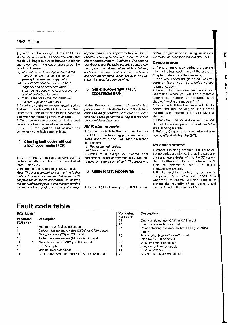
26.2 Proton
2 Switch on the ignit~on. If the EGM has stored bne or more fault codes, the voltmeter needle will begn to sweep between a h~gher and lower level. If no codes are stored, the needle will rernaln level. a) The frrst senes of sweeps indicates the
multiples o f ten, the second serres of sweeps indicates the single units.
6) The voltmeter needle wrll move lor a longer penod of deflection when transmitting codes in tens, and a shorter spell of deflect~or~ for units.
C) I f faults are not found, the meter wili indicate regular on/off puises.
3 Count the number of sweeps tn each serles, and record each code as it is transrn~tted. Refer to the table at the end of the Chapter to determine the meanlng of the fault code. 4 Continue retrlevrng codes until all stored codes have been retrieved and recorded. 5 Turn oft the ignition and remove the voltmeter to end fault code reltieval.
4 Clearing fault codes without a fault code reader (FCR)
1 Turn off the ~gn i l~on and disconnect the battery negative terminal for a period of at least 30 seconds. 2 Reconmct the battery negative terminal. Note: The first drawback to this method is that battery dr~~0nneMi0n will re-trritialise any ECM adaptive values (where applicable). Re-learning the appropriate adaptive vafilles quires staffing the engine from cold. and driving at various
engine speeds for approximately 20 to 30 minutes. The engrne should also be 8llowed to idle for approximately 10 minutes. -The second dmwback b that the radio secunty codes, clock setting and other stored values will be inrtialiW, and these must be re-entered once the battery has been reconnected. Where possible, an FCR should be used for wde chfing.
Note: Dur~ng the course o f certain test procedures, it is possible for additional fault codes to be generated. Care must be taken that any codes generated durrng test routines do not mislead diagnosis.
AII Proton models 1 Connect an FCR to the SD connector. Use the FCR for the follow~ng purposes, in strict compliance with the FCR manufacturer's ~nstructions: a) Retriev~ng {auk codes. bj Clearrng fault codes.
2 Codes must always be cleared after componenl test~ng, or after repalrs tnvolving the removal or replacement of an EMS component.
0 Qulde to test procedures ,
1 Use an FCR to interrogate the ECM lor fault
codes, or gather codes uslng an analogue voltmeter, as descriked in Secllons 3 or 5. I Codes stored I 2 If one or more fault codes are gatherei, refer to the fault code table at the end of th~s Chapter to determine the~r meaning. 3 If several codes are gathered, look for a common factor such as a defecilvr eaM return or supply. 4 Refer to the component test procedures in Chapter 3 , where you will find a means of testing the majority of components and circuits found in the modern EMS. 5 Once the fault has been repalred, clear the codes and run the engrne under various conditions to determine if the problenl ha3 cleared. 6 Check the ECM for fault codes once more Repeat the above procedures where codes are still being stored 7 Refer to Chapter 3 for more information or how to effectively test the EMS.
No codes stored 8 Where a running problem is experienced but no codes are stored. the fault is outs~ded I the parameters desjgned into the SD system Refer to Chapter 3 for more ~nformat~on on how to effectively test the engine manapment system. 9 If the problem points to a specific component, refer to the test procedures In Chapter 4, where you will find a means of testing Ihe majority of components and circuits found in the modern EMS.
Fault code table ECI- Muiti Voltmeter/ Description FCR code 7 Fuel pump or fuel pump c~rcuit 8 Carbon f~lter solenoid valve (CFSVj or CFSV circuit 11 Oxygen sensor (0s) or OS c~rcuit 13 Air temperature sensor (ATS) or ATS circurt 14 Throille pol sensor (TPS) or TPS circuit 16 Power supply 18 Ignition switch or circurt 21 Coolant temperature sensor (CTS) or CTS circuit
voltmeter/ Description FCR code 22 Crank angle sensor (GAS) or CAS clrcult 26 Idle position switch or circuit 27 Power steering pressure switch (PSPS) or PSPS
c~rcuit 28 Air cond~troning (NC) or NC circu~t 29 Inhibitor switch or circuit 32 Vacuum sensor or circuit 41 Injectors or inlector clrcuit 44 Ignition advance 49 Air condtlion~ng or A/G circu~t
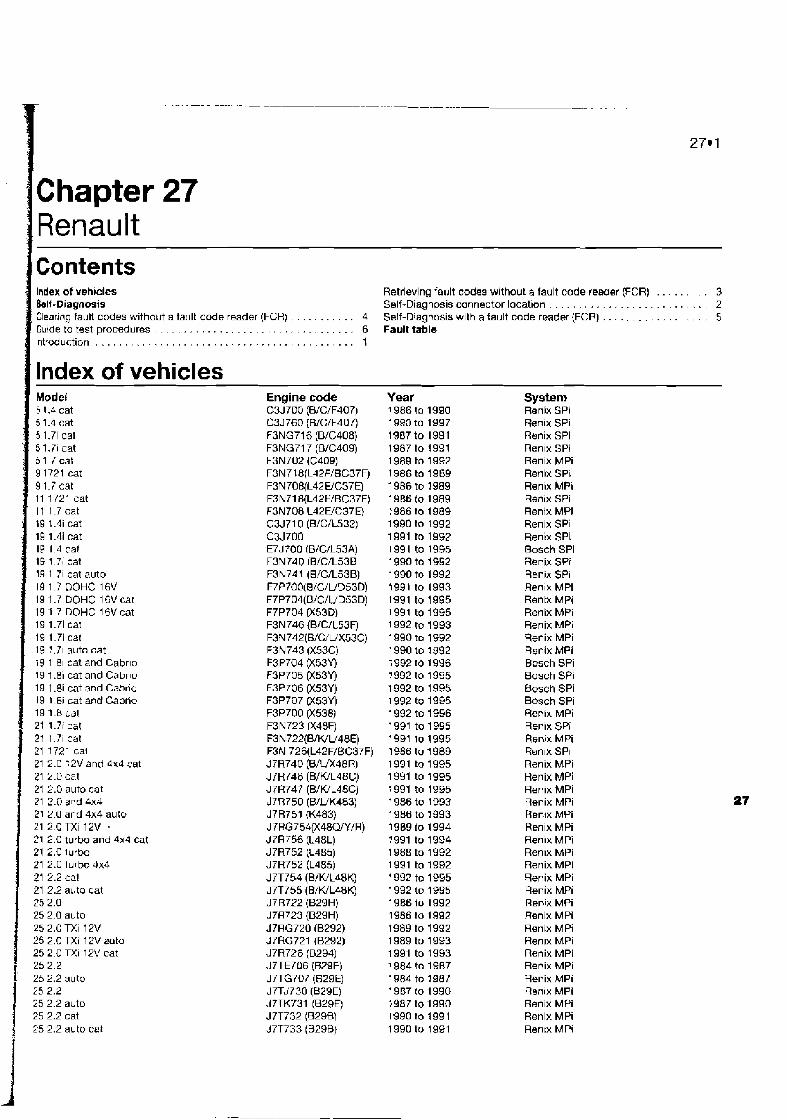
Chapter 27 Renault
lndex of vehicles &If-Diagnosis Clearing fault codes without a fa~~lt code reader (FCR) . . . . . . . . . . . 4 Gulde to test procedures . . . . . . . . . . . . . . . . . . . . . . . . . . . . . . . 6 Introdu~tion . . . . . . ... . . . . . . . . . . . . . . . . . . . . . . . .... . . . . . . 1
lndex of vehicles Model 5 1.4 cat 51.4 cat 5 1.7i cat 5 1.7i cat 51 7cat 9 1721 cat 9 1.7 cat 11 1721 cat 11 1.7cat 19 1.4i cat 19 1.41 cat l e 1 d cat 19 1 TI cat 19 1 71 cat auto 19 1 7 DOHC 16V 19 1.7 DOHC 16V mt 19 1.7 DOHC 16V cat 19 1.71 cat 19 1.7i cat 19 1.71 auto cat 19 1 81 cat and Cabrlo 19 1.8i cat and Cabrlo 19 l.8i cat and Cabrlu 19 1 8i cat and Cabrho 19 1.8 cal 21 1.71 cat 21 1.71 cat 21 1721 cat 21 2.0 t2V and 4x4 cat 21 2.0 cat 21 2.0 auto cat 21 2.0 and 4x4 21 2 0 and 4x4 auto 21 2OTXi 12V - 21 2.0 turbo and 4x4 cat 21 2.0 lurbo 21 2.0 lurbo 3x4 21 2.2 cat 21 2.2 auto cat 25 2.0 25 2.0 auto 25 2.0 mi 12V 252.0TXi 12Vaoto 25 2 0 TXi 12V cat 2 5 2 2 25 2.2 auto 25 2.2 25 2.2 auto 25 2.2 cat 25 2.2 auto cat
Engine code C3J700 (B/C/F407) C3J760 (BlClF407) F3NG716 (B/C40&) F3NG717 (B/C409) F3N702 (Cd09) F3N718(LJ2F/BC37F) F3N70B(L42 WC37E) F3h171 8(L4PF/BC37F) F3N708 L42WC37E) C3J710 (B/C/L532) C3J700 E7J700 (B/C/L53AI F3N740 IBfC/L53B F3N741 (B/C/L53B) F7P7dO(B/C/UD53D) F7P704(B/C/UD53D) F7P704 (X53D) F3N746 (BIC/L53F) F3N742(B/C/UX53C) F3N743 (X53C) F3P704 (X53Y) F3P705 (X53Y) F3P706 (X53Y) F3P707 (X53Y) F3P700 (X538) F3N723 (X48F) F3N722(B/WU48E) F3N 726(L42F/BC37F) J7R740 (B/L/X48R) J 7R746 (BIWL48C) J7R747 (BJWL48C) J7R750 (BfUK.183) J7R751 (K483) J7RG 754fl48QIYIR) J7RT56 (L48L) J7R752 (L485) J7R752 (L485) J7T754 (BIWL48K) J7T755 (BML48K) J7R722 (B29H) J7R723 (B29H) d7HG720 (B292) J7RG721 (B292) J7R726 (0294) J7TETD6 ( M E ) J7TG7@7 (B29E) J7Tdm730 (B29E) J7TK731 (B29E) J 7T732 (829B) J7T733 (B29B)
Retrieving fa i~ l t codes without a fault code reader (FCR) . . . . . . . 3 Self-Diagnosis connector location . . . . . . . . . . . . . . . . . . . . . . . . . 2 Self-Diagnosis wlth a fault code reader (FCR) . . . . . . . . . . . . . . . . . 5 Fault table
-
Year 1986 to 1990 1990 to 1997 1987to 1991 1987 to 1991 1989 to 1992 1986 to 1989 1986 to 1989 19B6 to 1989 1986 to 1989 1990 to 1992 1991 to 1992 1991 to 1996 1 990 to 1992 1990 to 1992 1991 to 1993 1991 to 1995 1991 to 1995 1992 to 1993 1990 to 1992 1990 to 1992 1992 to 1996 1992 to 1995 1992 to 1995 1992 to 1995 1992 to 1996 1991 to 1995 1941 10 1995 1986 to 1989 1991 to 1995 1991 to 1995 1991 to 1995 1 986 to 1993 1986 to 1393 1989 to 1994 1991 to 1994 1988 to 1992 1991 to 1992 1 992 to 1995 1992 to 1995 1986 10 1992 1986 to 1992 1989 to 1992 1989 to 1993 1991 to 1993 1 984 to 1987 1984 to 1987 1967 to 1990 1987 to 1990 1990 to 1991 1990 to 1991
-
System Renix SPi Ren~x SPi Rsnix SPi Renlx SPI Renix MPi Renix SPI Ren~x MPI Renix SPi Renix MPi Renix SPi Renix SPI Bosch SPi Renix SA Renix SPi Renl*. MPi Rentx MPi Renix MPi Renix MPI Renix MPi Renix MPi Bosch SPi Bosch SPi Bosch SPi Bosch SPi Renix MPi Ren~x SPi Renlx MPi Renlx SPI Renix MPi Renix MPi Renix MPi Renix MPi Renix MPi Rmlx MPi Ren~w MPI Renix MPi Renix MPi Renix MPi Renix MPi Renix MPi Renix MPi Renix MPi Ren~x MPi Renix MPi Renix MPI Renix MPi R e n ~ x MPi Renix MPi Renix MPI Rentx MPI

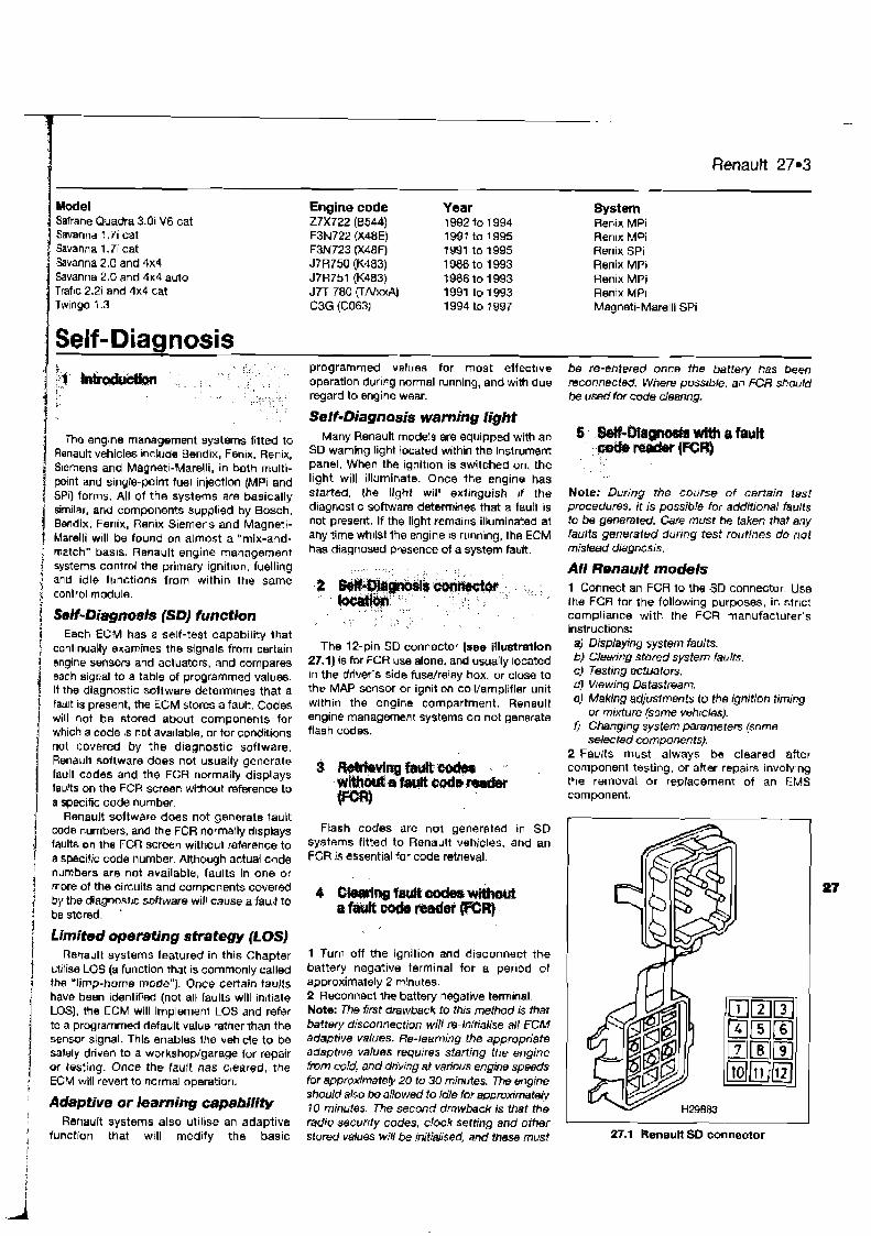
Savanna ! .7i cat Savanna 1.7i cat Savanna 2.0 and 4x4 Savanna 2.0 and 4x4 auto Trafic 2.2; and 4x4 cat Twingo 1.3
Self-Diagnosis
The engine management systems fitted to Rsnault vehicles Include Bendix, Fenix. Renix, Siemens and Magnetl-Marelli, in both multi- point and single-point fuel injection IMP1 and 1 SPi) forms. All of the systems are basically similar, and components supplied by Bosch, Bendix, Fenix, Renix Siemens and Magneti- Marelli will be found on almost a "mix-and- match" basis. Renault engine management systems control the primary ignition, fuelling
j and idle functions from within the same control module.
Self-Diagnosis (SD] function ! Each ECM has a self-test capability that i continually examines the signals from certain 1 engine sensm and actuators, and compares / each signal to a table of programmed values.
It the diagnostic software determines that a
i tau t IS present, the ECM stores a fault. Codes will not be stored about components for which a code is not ava~lable, or for condrtions
I not covered by the diagnostic software. Renault software does not usually generate fault codes and the FCR normally displays ladts on the FCR screen without reference to I a specific code number.
i Renault softwaro does not generate fault coda numbers, and the FCR normally d~spbays faults on the FCR screen without raterence to
f a specific code number. Although actual code
; numbers are not available, faults in one or : more of the circuits and components covered j by the diagnosttc software will cause a fault to ! be stored. '
j Limited operating strategy (LOS) j Re~ault systems fsatured in this Chapter 1 Milise LOS (a function that 1s commonly called
the "limp-home moda"). Once certain faults have been ~denlif.ied (not all faults will in~t~ate / LOS), the ECM will irnplemem LOS and refer
I to a programmed default value rather than the sensor signal. This enables the vehicle to be sately driven to a wofkshop/garage for repair
1 OI testing. Once the fault has cleared, the ECM will revert to normal operation.
: Adaptive or learning capability 1 - Renault systems also ut~lise an adaptive I funchon that will modify the basic
Engine code 27x722 (0544) F3N72.2 (X48E) F3N723 (X48F) J7R750 (K483) J7R751 (K483) J n 780 ( T N W C3G (C063)
Renault 27.3
Year 1992 to 1994 1991 to 1 995 1991 to 1995 19B6 to 1993 1986 to 1993 1991 to 1993 1994 to ? 997
System Renix MPi Ren~x MPi Ren~x SPi Renix MPi Renix MPi Renix MPi Magneti-Marelli SPi
programmed varues for most effective operation during normal running, and with due regard to engine wear.
be re-entered once the battery has been reconnected. Where possrble, an FCR should be used for code clearing.
SeIf-Diagnosis warning light Many Renault models are equippd with an
SD warning light located within the Instrument panel. When the ignltlon is switched on, the light will illuminate. Once the engine has started, the light will extinguish r f the diagnast~c software determines that a fauh is not present. If the light remains illuminated at any time whilst the engine is running, the ECM has diagnosed presence of a system fault.
The 12-pin SO connector (see illustration 27.1) is for FCR use alone, and usually located in the driver's side fusdrelay box, or close to the MAP sensor or ignitlm co~l/amplifisr unit wlthin the engine compartment. Renault engine management systems do not generate flash codes.
Ftash codes are not genereted ~n SD systems fitted to Renault vehicles, and an FCR is essential for code retrieval.
1 Turn off the ignition and disconnect the battety negative terminal for a per~od of approximately 2 minutes. 2 Reconnect the battery negative terminal. Note: The first drawback to this method is that battery disconnection wlll re-inrtialise all ECM adaptive values. Re-learning the appropriate adaptive values requrres starting the engine h m cold, and driving at various engine speeds for approximate(y 20 to 30 minutes. The engine should also be allowed to idle for approxrmteiy 10 minutes. The second drawback is that the radio securrty codes, clock setting and other stored values will be initiaf~sed, and these must
Note: During the course of certain lest procedures, it is possibb lor additional faults to be generated. Care must be taken that aiy faults generated during test routines do not mislead diagnos~s.
All Renault models 1 Connect an FCR to the SD connector Use the FCR for the follow~ng purposes, in strlc? compliance with the FCR manufacturer's instructions: a) Displaying system faults. b) Cleanha stored svstern laulrs C) ~estingactuatok d) Wewing Datastream. e) Making adjustments to the ignition timtng
or mixture (some vehrcles). 0 Changing system parameters (some
selected components). 2 Faults must always be cleared after component testing, or after repairs involving the removal or rewlacement of an EMS component.
1 I 27.1 Renaurt SP connector
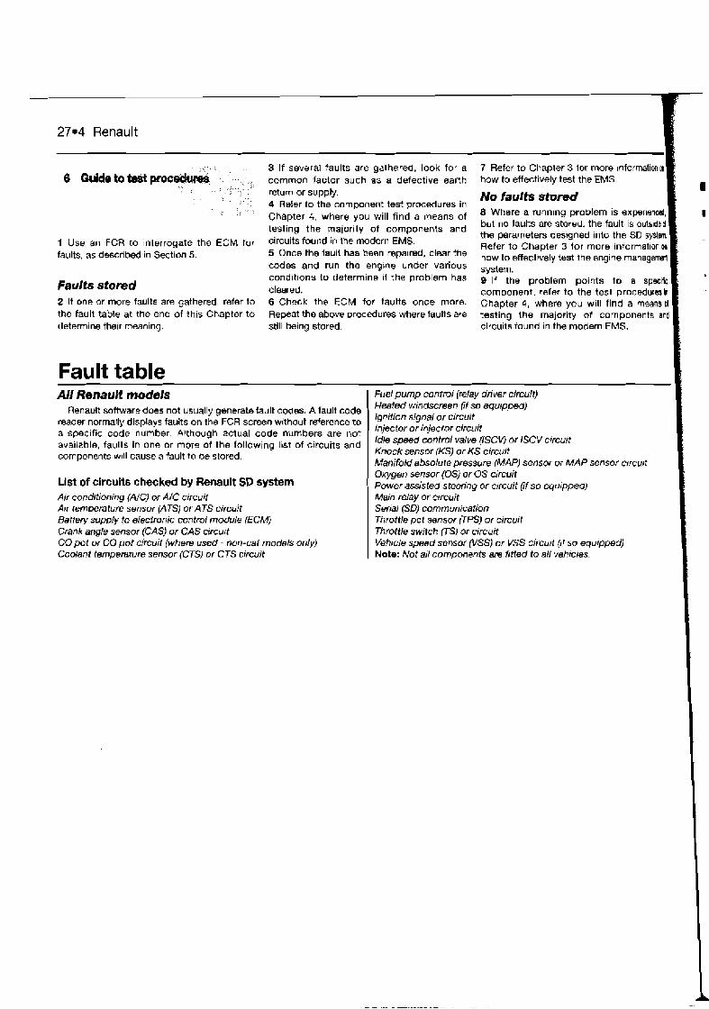
27.4 Renault
1 ,,", , < , 3 If several faults are gathered, look for a 7 Refer to Chapler 3 tor more ~nforrnal'ionm
6 & ~ i d e t ~ b d p m e d ~ ~ , ,, ,, common factor such as a defective earth how to effectively test the EMS. , , ,,
, : ,,, 1 1 , , 1 1 ,
: ,: . return or supply. , , A
' , : 4 Refer to the component test procedures in No faults stored
, ,, , , ,, . , Chapter 4, where you will find a means of Where a running problem is ex~eriend,
testing the ty of components and but no taults are stored. the fault is ovts~ded the parameters deslgned into the SD sflm.
1 Use an FCR to interrogate the ECM [or circuits found in the modern EMS. Refer to Chapter 3 for more information ~n faults, as described in Sect~on 5. 5 Once the hurt has been repalred, clear the ,,, effectively test the engine managem
codes and run the engme under various syslem, condrt~onv to determine ~f the problem has 9 If the problem points +o a ~ p ~ i f i E
Faults stored cleared. component, refer to the test proceduresin
2 It one or more faults are gathered, refer to 6 Check the ECM for faults once more. Chapter 4, where you will find a means d the fault table at the end of this Chapter to Repeat the above urocdures where faults are testing the majority of components and determine the~r meaning. still being stored. circuits found in the modern EMS.
Fault table AII Renault models Fuet pump controi (relay driver circuit)
Renault software does not usually generate fault codes. A fault code Heated windscreen
reader normally displays faults on the FCR screen without reference to 'Q"ition ' jgnai
a specific code number. Although actual code numbers are not Injector Or
available, faults in one or more of the following list of circuits and Idle speed control valve (iSCU lSCV circuit
components w~ll cause a fault to be stored. Knock sensor IKS) or KS circu~t Manifold absolute pressure (MAP) sensor or MAP sensor clrcurt Oxygen sensor (0s) or OS circuit
List of circuits checked by Aenault SD system Power assisted steering or circuit (if so equtpped) Air conditioning (A/C} w AIC circuit Main relay or c~rcuit Air temperature sensor (ATSJ or ATS circuit Serial (SDJ communication Battery supply to electronic control module (ECMJ Throttle pot sensor (TPS) or circuit Crank angle sensor (CAS) or CAS circurt Throttle switch rTS) or circuit CO pot or CO pot circuit (where used - non-cat models only) Vehicle speed sensor (VSS) or VSS circuit (if so equipped) Coolant temperature sensor {CTS) or CTS circuit Note: Not all components are fitted to all vehrcles.
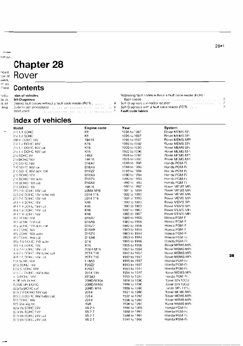
Chapter 28 '.:'5 Rover
.clflc Index of vehicles Retrievbng fault cndes without a fsul: code reader (FCR) - . . . . . . . . . . . . . . . . . . . . . . . 3s rn Self-Diagnosis flash codes . 3
IS of Cearlrlg fault codes w~thout n fault code reader (FCR) . . . . 4 Self-D~agnos!s cr)nnrclor location . . . . . . . . . . . . . . . . . . . 7 . . . . . . . . . . . . . . . . . and G~.-de tr, text prnccdures . . b Sell-Dlaqnosls v l lh a laull code reader (FCR) . . . . . . 5
. . . . . . Introducttr~n . . . . . . . . . . . . . . . . . . . . . . . 1 Fault code tables
lndex of vehicles Model
- 1111.1SOHC 114 1.4 SOHC 200 VI DOH(: 16V 213 1 ..l DOH(: t 6 V ;1.1 1.4 DOt1C 16Vr:al 21-1 1 4 DOHC 1FV ,:at 214 SOHC BV 212 CjClHC 16V Ylil SOHC 16V 7 , - <, _ , n ~ 0 t 1 C 16V cat 2'6 SOHC 1FV nutr~ cat i'G DOHC 1 f V .?'ti DOH(: 1 GV autn 7':ii DOH(: 16V cat 7:6 UOtiC; 16V 22U 2.0 UOtiC 16V cat 220 2 U DOHC 1 RV turbo cat 2?0 ? O Dl)H(: 1 GV cat J 1 1 1 .1 UOHC 16V .I1 I 1 . I uc\t IL. 1tiV #..,It
414 1 J [IOHT l l iV #:at 412 I J D\'H['. 1t jV
J 16 >S[ '+it; I bV I I5 S( ViL 1 LiV L-~I!
J I O sc,t IC ir;V ,111tc1 I-a7 4 ~ t . l V H C 1 I*V 4 1 L UUHC 1 L V al!ttr 3 1 ~ ; rJobir I I ~ V 4-,1t 4 1 i,: 1 G IC I 5v to 116 t L L I C N 1C 1bV 4L'U 2 0 :lc7Hc: 1fiV ':at 4;,0 2 ( 1 ~OHI' It;V tlrrha cat 43r l 2 0 DOH(: I h V ~ , s l F I $ S t l H ( : 1hV o:'UI SClt l i l tiV ~ . ' C I 5 5L3HC 1 t;V t , . ' ~ :' 1 1 TlrlHi: 1 tiV tc~rbcl t1.'31 CItIHC' 1 t iV 6.'11F SI3l [ lOti( ' S.>05E :,PI uu t IL 0201!'31 UO t IC cat ~:)[II :) n rjo~c: I sv cat 870 7.0 DOH(: 16V turbo cat 870 DOH(; 16V t!?5 Sterl111q Vt; BL'!)i Vti SOHC: 23V e:) vb s o ~ c ?.,lv 6?i1 V6 SOH(: 24V cat 8;'il Vti :;OIi(: 24V cat
Engine code KR K8 1BK16 K16 K16 K l f j 14K8 14K16 D16A7 D16A6 Dl 623 Dl 6A9 Dl 624 D l tjA8 l t j K 1 6 20M4 MI6 POT4 T I 6 20T4 T I 6 K16 K 16 K16 K16 D l 6A7 U 16A6 01622 016A9 D16Z4 D16A8 D 16 K16 ?OM4 M I 6 20T4 T I 6 20T4 T I 6 I 18A3 F20Z2 F?OZ1 20T4 T I 6 H23A3 20HD/M 16e 20HDIM16e 20HD MIA 20T4 "OT4 2014 KV6 VL; 2 5 VG 2 7 V6 2 7 V6 2 7
Year 1095 1u 1997 1005 lu 1997 1995 70 1997 1989 to 1992 T W O til 1 993 19Y2 tcl 1996 1995 to 1997 1995 tc> 19'3; 19tl!l tn 194G 1989 to 19Y6 1g8'3 tcr 1'396 1LJ9D tc) 1994 1990 t ~ ) 1994 1990 to 1994 1995 to 1997 1991 to 1994 1992 to 19% 1997 to 1996 1990 to 1993 1990 to 1993 199'2 lu 1997 1995 to 1997 1989 to 1996 1989 to 1996 1989 tu 1996 1990 to 1994 1990 to 199.1 1990 to 1994 1995 to 1996 1995 to 1996 1991 to 1994 1992 to 1997 1991 to 1997 1995 to 1997 1993 tu 1997 1993 lo 199/ 1994 to 1997 1993 to 1997 19Rf to 1990 1986 tu 1990 1988 tu 1990 1991 to 1996 1997 to 1997 1996 to 1997 l5l96 to 199i 198C to 19P6 7988 1991 1988 1@ 1991 1991 1 ~ 1 19llt;
System Rover MEMS SPI Raver M t M S SPr Rover MEMS MPi Rover MEMS SPI Hover MEMS SPI Rover MEMS MPI Rover MEMS MPI R w e r MEMS MPI Hmr~da PGM-Fi HcrnrJa PGM-FI Honda PGM-FI Honda PGM-Fi 1 l ~ r l d ~ PGM-FI Honda PGM FI R L ~ V P ~ MEMS MPI Rnver MEMS MPI Rover MEMS MPI Hover MEMS MPI Rover MEMS SPI Rover MEMS SPI Rover MEMS FAPI Hover MEMS MPI Honda PGM FI Hondn PCM-FI Honda PGM-FI Honda PGM-FI Horlda PGM-Fi Honda PGM FI Honda PGM-Fi Rover MEMS MPI Rover MEMS Mt' Hover MEMS MPI Hover MEMS MPI Honda PGM-FI Hnndn PGM-FI Honda PGM-F i Hover MEMS MPL liorida PGM-FI Rover SPI 1 OClJ Rover SPi f O(:U Lucas MPI 1 I C'U Hover MEMS MPI Rover MEMS MFI Rover MEMS MPI Rover MEMS MPI H o n d ~ PGM-F r Hondd PGM-FI Honcla PGM FI Honda PGM-FI
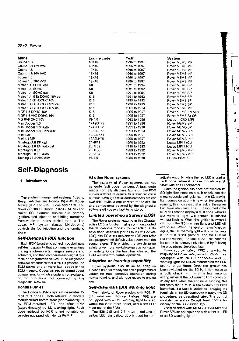
28.2 Rover
Model Coupe 1.6 Coupe 1.8 16V W C Cabrio 1.6 Cabrio 1.8 16V W C Tourer 1.6 Tourer 1.8 t6V W C Metro 1 .l i SOHC cat Metro 1.4i SOHC Metro 1.4i SOHC cat Metro 1.4i GTa DOHC 16V cat Metro 1.4 GTi DOHC 16V Metro 1.4 GTi DOHC l 6 V cat Metro 1.4 GTi DOHC 16V cat MGF 1.8 DOHC 16V MGF 1.8 WC DOHC 16V MG RV8 OHC 16V Mini Cooper 1.3 Mini Cooper 1.3 auto Mini Cooper 1.3i Cabriolet Mini 1.3 Mini t .3 MPi Montego 2.0 EFi cat Montego 2.0 EFi auto cat Montego 2.0 EFi Montego 2.0 EFi auto Sterlrng V6 SOHC 24V
Engine code 16K16 18K16 16Kl6 18K16 16K16 18K16 K8 K8 K 8 Kt6 K16 K16 K16 K16 K16 V8 4.0 12A2DF75 12A2DF76 12A2EF77 12A2EK71 12A2LK70 20HF51 20HF52 20HE36 20HE37 V6 2.5
Year System 1996 to 1997 Rover MEMS MPi 1996 to 1997 Rover MEMS MPi 1 996 to 1997 Rover MEMS MPi 1 996 to 1997 Rover MEMS MPi 1 996 to 1997 Rover MEMS MPi 1 996 to 1997 Rover MEMS MPi 1991 to 1994 Rover MEMS SPi 1991 to 1992 Rover MEMS SPi 1991 to 1993 Rover MEMS SPi 1991 to 1992 Rover MEMS SPi
Rover MEMS SPi Rover MEMS SPI Rover MEMS MPi Rover MEMS 1.9 MPi Rover MEMS 2J SF1 Lucas 14CUX MPi Rover MEMS SPi Rover MEMS SPI Rover MEMS SPi Rover MEMS SPi Rover MEMS MPi Lucas MPi I 1CU Lucas MPI l l C U Rover MEMS MPi Rover MEMS MPI Honda PGM-FI
Self -Diagnosis I
The engine management systems fitted to Rover vehlcles are Honda PGM-Fi, Rover MEMS (MPi and SPi), Lucas MPi 11CU and Rover SPi 10CU. Honda PGM-FI, MEMS and Rover SPi systems control the primary ignition, fuel injection and idling functions from within the same control module. The Lucas MPi system (Lucas LH-Jetronic) controls the fuel injection and idle functions alone.
Self-Diagnosis (SD) function Each ECM (electronic control module) has a
self-test capability that continually examines the signals.from certain engine sensors and actuators, and then compares each signal to a table of programmed values. If the diagnostic software determines that a fault is present, the ECM stores one or more fault codes in the ECM memory. Codes will not be stored about componenls for which a code is not available, or for conditions not covered by the diagnostic software.
Honda PGM-Fi The Honda PGM-Fi system generates 2 -
digit fault codes. Code retr~eval in models manufactured before 1992 (approx~mately) is by ECM-mounted LED, and after 1992 (approximately) by SD warning light. Fault code retrieval by FCR is not possible nn vehicles equipped with Honda PGM-FI.
-
All other Rover systems
The majortty of Rover systems do not generate fault code numbers. A fault code reader normally displays faults on the FCR screen without reference to a speciflc code number. Although actual code numbers are not available, faulls n one or more of the circults and components covered by the dlagnostlc software will cause a fault to be stored.
Limited operating strategy (LOSJ The Rover syste~ns teatured In thls Chapter
utrlise LOS (a function that IS commonly called the "limp-home mode"). Once cerlaln faults have been identrf~ed (not all faults w~l l ~ n ~ t ~ a t e LOS), the ECM w~ll Implement LOS and refer to a programmed default value rather than the sensor signal. This enables the veh~cle lo be safely driven to a workshop/garage tor repair or testing. Once the fault has cleared, the ECM will revert to normal operation.
Adaptive or learning capability Rover systems also u t~ l~se an adaptwe
function that will modify the bas~c programmed values for most effective operation dur~ng normal running, and with due regard to engine wear.
Self-Diagnosis (SDJ warning light The majority of Rover models with PGM-FI
that were manufactured before 1992 are equlpped with an SD warnlng l~ght located withln the Instrument panel, and a red LED mounted on the ECM.
The 825 2.3 and 2.7i have a red and a yellow LEO; the yellow LED is used for rpm
-
adjustment only, while the red LED is used for fault code retrieval. These models are not fitted wlth an SD connector.
Once the ignition has been switched on, the SD llght illuminates as a bulb check, and after . a few seconds extinguishes. If the SD warning llght comes on at any t~me when the engine is running, this indicates that a fault in the system has been identified. The LED mounted in the ECM will flash to display a fault code. while the SD warning light will remain illuminated w~thout flashing. When the ignition is switched off, both the SD warnlng light and LED will extinguish. When the ignrt~on is switched on again, the SD warning light will only lllum~nate 11 the fault is still present, and the LED w~ll resume flashing the fault code. This code will be s tord In memory until cleared by following the procedures described later.
From approximately 1992 onwards, the majority of Rover vehicles wjth PGM-FI are equipped with an SD conr.ector and SO warning light; the LED(s) mounted on the ECM are no longer fitted. Once the lgnltlon has been switched on, the SD lrght ~lluminates as a bulb check, and after a few ssconds extinguishes. If the SD warnlng llght comes on at any time when the englne rs runnlng, thrs indicates that a fault in the system has been identified. If a fault is indicated. bridg~ng the terminals in the SD connector trlggers the SD procedure, as described baler The control module generates 2-digit fault codes for display on the SD warning lighl.
Vehicles fitted with MEMS. Lucas MPt and Rover SPI are not equipped with erther an LED or an SO warning light.

/ 2 8 . 1 C M location - PGM-FI I
t Under metal cover plate in the front passenger footwell The LED IS wstbb through a cut-wi
jMM-Fi systems The ECM is either located under the driver's
jpeat, or under a metal cover fltted to the psssenger's side footwell, under the carpet. The SD connector (where f~tted) IS located under the kick panel or the lacia on the Iefl- hand side {see illustration 28.1). Note; The SD connector is provided tor retrieving flash mdes alone. Prior to 7992, flash codes can be obsenred on the LED on the ECM.
' / MEMS and ~ucsr SPI systems On the majority of vehicles equipped with
MEMS and Rover SPI, the SD connector IS
located adjacent to tne ECM. The ECM is located either close to the battery, or mounted centrally on the bulkhead (see Illustration
1 28.2) Note: The SD connector is provided tor
retrieved from these vehicles.
I 1 ded~cated FCR use. Flash codes cannot be
/ Lucas MPi systems i On vehicles equipped with Lucas MPi, the 1 SO connector is located close to the injection i ECM, either under the driver's or the front i passenger's seat. )
j 1 ~etMn$fault&:, ' . ' : : :
: wtttroutabukwlerbader: ,;
4' (FCR) - flash d m
Note: During the course of certain test procedures, it is possible for additional fault codes to be generated. Care must be taken that any codes generated dur~ng test routines do not mislead diagnosis. All codes must be cleamd once testing is complete.
Rover 2 16 and 4 16 wlth PGM-Fi (up to lBB2) 1 Swilch on the ignit~on. 2 Observe the red LED mounted rn the centre of the ECM (s- illustration 26.3).
Rover 28.3
I DlAGNOSTlC CONNECTOR PLUG 1
28.2 Rover MEMS - SD connector located close to the ECM, dlmnnected from wiring loom
a) The flashes are fmrsmitted as a stmght B If the fault@) are corrected, the LED will count. so fifteen Hashes indicates code continue to flash until the ECM memory is number 75. cleared. The me thd 13 detailed in Section 4.
b) The LED wi/( pause for 2 seconds and then transmit the next code. Rover 21 6,4 16,820 and 623
cl When aN codes have been tmnsmitted. wifh ffiM-Fi (1992 onwards) ' the LED wiN pause for 2 seconds and then
repeat the sequence.
3 Record the codes, and refer to the fault code table at the end of the Chapter to determine thew meaning. 4 If the number of flashes indicates a number for which there is no code, the ECM is suspect. Recheck the code output several times, and then check the earth and supply voltages to the ECM before fitting a replacement. 5 When the ignition is switched off, the LED will extinguish. However, the LED will resume flashing once the ignition has been switched on again.
7 Use a jumper lead to bridge the two terminals in the SD connector. 8 Swhch on the ignition. 9 Observe the SD warning light on the facia. If the warning light remains on and does not flash, the ECM is in back-up mode. In this instance, the ECM should be removed and checked by one of the speclalist ECM testing companies. 10 The flashes are transmitted as a series of long and short flashes: a) Short flashes indicate Sin~Ie units - fwr
short flashes indicates cod9 number 4. b) Long flashes indicate multiplss of ten -
four long flashes and one short flash indicates code 4 7.
28.3 PGM-Fi ECM with LEDs set into the casing
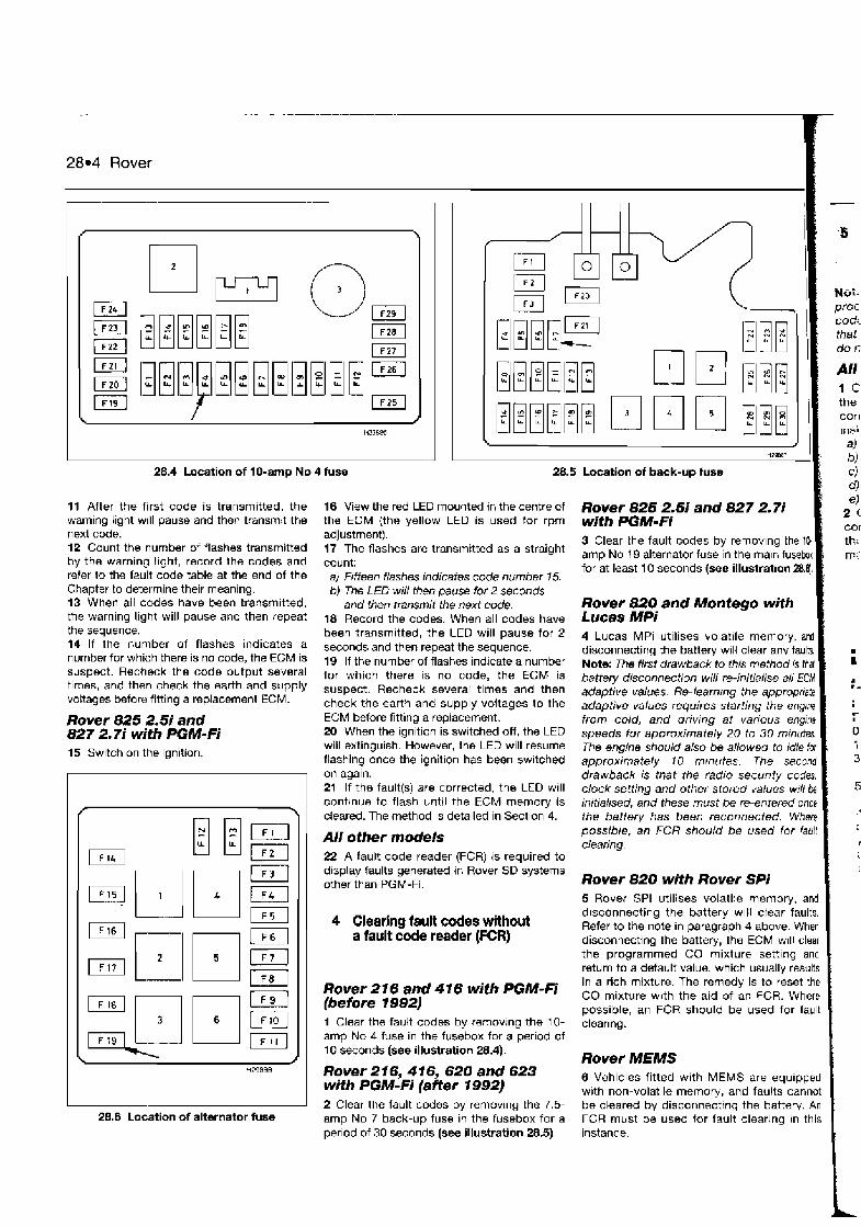
. - . . - . . . - -
28.4 Rover
28.4 Location of 10-amp No 4 fuse
11 After the first code is transmitted, the warning light will pause and then transmit the next code. 12 Count the number of flashes transmitted by the warning light, record the codes and refer to the fault code table at the end of the Chapter to determine their meaning. 13 When all codes have been transmitted, the warning light will pause and then repeat the sequence. 14 If the number of flashes indicates a number for which there is no code, the ECM is suspect. Recheck the code output several times, and then check the earth and supply vottages before fitting a replacement ECM.
Rover 825 2.5i and 827 2.7i with PGM-Fi 15 Switch on the ignition.
i
28.5 Location of back-up fuse
Nor: proc cod: that do r:
A/! 1 C
: the ' COT1
iris;
16 View the red LED mounted in the centre of the ECM (the yellow LED is used for rpm adjustment). 17 The flashes are transmitted as a straight count: a) Fifteen flashes indicates code number 15. b) The LED will then pause for 2 Seconds
and then transmit the next code. 18 Record the codes. When all codes have been transmitted, the LED will pause for 2 seconds and then repeat the sequence. 19 If the number of flashes indicate a number for which there is no code, the ECM is suspect. Recheck several times and then check the earth and supply voltages to the ECM before fitting a replacement. 20 When the ignition is switched off, the LED will extinguish. However, the LED will resume flashing once the ignition has been switched on again. 21 If the fault($) are corrected, the LED will contrnue to flash until the ECM memory is cleared. The method is detailed in Section 4.
AII other models 22 A fault code reader (FCR) is required to display faults generated in Rover SD systems other than PGM-Fi.
Rover 825 2.5i and 827 2.7i with PGM- Fi 3 Clear the fault codes by removlng the 1b amp No 19 alternator fuse in the maln fusehx for at least 10 seconds (see illustration 2&4.
Rover 820 and Montego with Lucas MPi 4 Lucas MPi utilises volatile memory, and disconnecting the battery will clear any fault. Note: The first drawback to this method is hal battery disconnection wiil i-e-initialise all ECM adaptive values. Re-learning the appropriale . adaptive values requires starting the engrne from cold, and driving at various engine speeds for approximately 20 to 30 minutes. The engine should also be allowed to idle iw approximately r 0 mtnutes. The second drawback is that the radio secunty codes, clock setting and other stored values will be initialised, and these must be re-entered once the battery has been reconnected. Where possible, an FCR should be used for faull clearing,
Rover 820 with Rover SPi 5 Rover SPi utilises volatile memow, and d~sconnscting the battery will clear faults.
4 Clearing fault codes without Refer to the note in paragraph 4 above. When a fault code reader (FCR) disconnectinq the batten/, the ECM w~l l clear I
the program-med CO mixture setting and return to a default value, which usually results 1 in a rich mixture. The remedy is to rkset the Rover *I6 and 416 with CO mixture with the aid of an FCR. Where (before 1992) possible, an FCR should be used for fault I
1 Clear the fault codes by removing the 10- clearing. amp No 4 fuse in the fusebox for a period of 10 seconds (see illustration 28.4). Rover MEMS Rover 2 16,4 16, 620 and 623 with PGM-Fi (after 1992)
6 Vehicles fitted with MEMS are equipped with non-volatile memow, and faults cannot I
2 Clear the fault codes by removing the 7.5- be cleared by disconnecting the battery. An 28.6 Location of alternator fuse amp No 7 back-up fuse in the fusebox for a FCR must be used for fault clearing in this
period of 30 seconds (see illustration 28.5). instance. I
a) bj c) dl el
2 COI
tk: ::
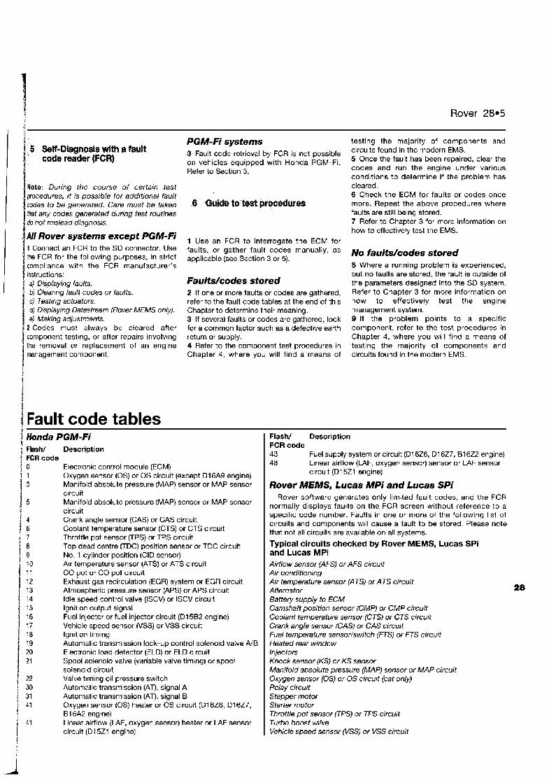
Rover 28.5
5 Sew-Diagnosis with a fault code reader (FCR)
i Mote: During the course of certain test 4 procedures, i f is possible for additional fault 1 codes to be generated. Care must b e taken
I That any codes generated during test routines do not mislead diagnosis.
4 A// Rover systems except PGM-Fi 1 Connect an FCR to the SD connector. Use the FCR for the following purposes, in strict compliance with the FCR manufacturer's instructions:
I a) Displaying faults. b) cleanng fault codes or faults.
I c) Testing ac tua to~ . d) Displaying Datastream (Rover #EMS only). eJ Making adjustments.
i 2 Codes must always be cleared after component testing, or after repairs involving
I the removal or replacement of an engine management component.
PGM-Fi systems 3 Fault code retrieval by FCR is not possible on vehicles equipped with Honda PGM-Fi. Refer to Section 3.
1 Use an FCR to interrogate the ECM for faults, or gather fault codes manually, as applicable (see Section 3 or 5).
Fauits/codes stored 2 If one or more faults or codes are gathered, refer to the fault code tables at the end of this Chapter to determine their meaning. 3 If several faults or codes are gathered, look for a common factor such as a defective earth return or supply. 4 Refer to the component test procedures in Chapter 4, where you will find a means of
testing the majority of components and circuits found in the modern EMS. 5 Once the fault has been repaired, clear the codes and run the engine under various conditions to determine if the problem has cleared. 6 Check the ECM for faults or codes once more. Repeat the above procedures where faults are still being stored. 7 Refer to Chapter 3 for more information on how to effectively test the EMS.
No fauCts/codes stored 8 Where a running problem is experienced, but no faults are stored, the fault is outside of the parameters designed into the SD system. Refer to Chapter 3 for more information on how to effectively test the engine management system. 9 If the problem points to a specific component, refer to the test procedures in Chapter 4, where you will find a means of testing the majority of components and circuits found in the modern EMS.
1 Fault code tables 1 Honda PGM-Fi I Flash/ Description
1 3 Manifold absolute pressure (MAP) sensor or MAP sensor I Rover MEMS, Lucas MPi and Lucas Spj
I ) Flash/ Description * FCR code 1 0 Electronic control module (ECM) ! 1 Oxygen sensor (0s) or OS circuit (except D l 6A9 engine)
1 c~rcuit i 1 Manifold absolute pressure (MAP) sensor or MAP sensor
circuit Crank angle sensor (CAS) or GAS circuit Coolant temperature sensor (CTS) or CTS c~rcuit Throttle pot sensor (TPS) or TPS c~rcuit Top dead centre (TDC) position sensor or TOC circuit No, 1 cylinder position (CID sensor) Air temperature sensor (ATS) or ATS circuit CO pot or CO pot c~rcuit Exhaust gas recirculation (EGR) system or EGR circuit Atmospheric pressure sensor (APS) or APS circuit Idle speed control valve (ISCVJ or ISCV circuit
j i; Ignition output signal Fuel injector or fuel injector circuit (Dl 582 engine) Vehicle speed sensor (VSS) or VSS circuit lgn~tion timing Automatic transmission lock-up control solenoid valve A/B Electronic load detector (ELD) or ELD circuit Spool solenoid valve (variable valve timing) or spool soleno~d circu~t Valve timing oil pressure switch Automatic transmission (AT), signal A
1 31 Automatic transmission (AT), signal B
1 41 Oxygen sensor (0s) heater or OS circuit (Dl 6Z6, D l 627,
I 81 6A2 engine)
f 41 Linear airflow (LAF, oxygen sensor) heater or LAF sensor
i circuit (Dl 5Z1 engine) I
FCR code 43 Fuel supply system or circuit (Dl 6Z6, Dl 627, B162.2 engine) 48 Linear airflow (MF, oxygen sensor) sensor or L4F sensor
circuit (Dl521 engine)
Rover software generates only limited fault codes, and the FCR normally displays faults on the FCR screen without reference to a specif~c code number. Faults in one or more of the following list of ctrcuits and components wtll cause a fault to be stored. Please note that not all circuits are avatlable on all systems.
Typical circuits checked by Rover MEMS, Lucas SPi and Lucas MPi Airflow sensor (AFS) or AFS circuit Air conditioning Air temperature sensor (ATS) or ATS circuit Alternator Battery supply to ECM Camshaft position sensor (CMP) or CMP circuit Coolant temperature sensor (CTS) or CTS circuit Crank angle sensor (CAS) or CAS circuit Fuel temperature sensor/switch (RS) or FTS circuit Heated rear window injectors Knock sensor (KS) or KS sensor Manifold absolute pressur& (MAP) sensor or MAP circuit Oxygen sensor (0s) or OS circurt (cat only) Relay circuit Stepper motor Starter motor Throttle pot sensor FPS) or TPS circuit Turbo boost valve Vehicle speed sensor (VSSJ or VSS circuit
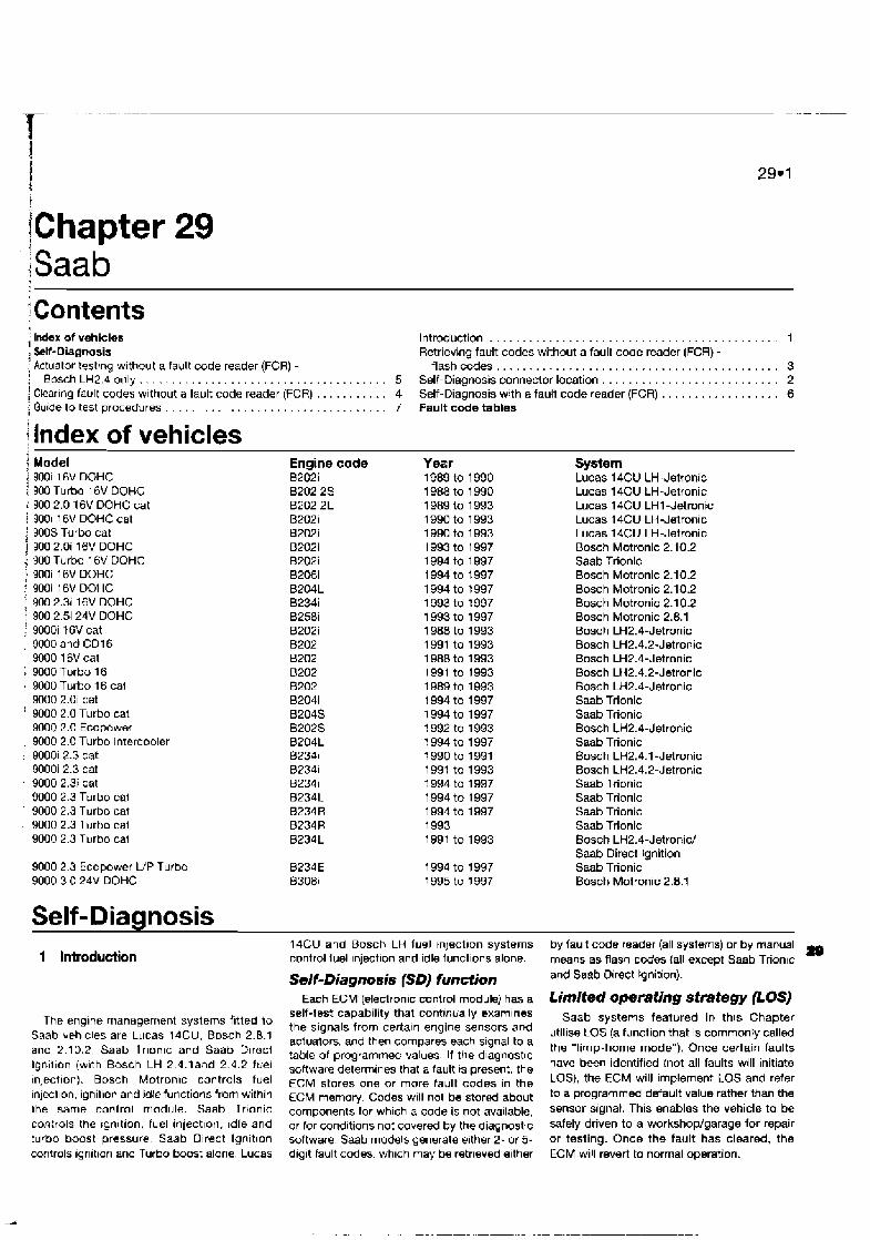
I
1 t
[Chapter I' 29 iSaab 1
Contents , Index of vehicles Introduction . . . . . . . . . . . . . . . . . . . . . . . . . . . . . . . . . . . . . . . . . . . . 1 , Sell-Diagnosis Retr~evlng fault codes without a fault code reader (FCR) - ' Actuator testrng wlthout a fault code reader (FCR) - flashcodes . . . . . . . . . . . . . . . . . . . . . . . . . . . . . . . . . . . . . . . . . . . 3 i . Bosch LH2.d only . . . . . . . . . . . . . . . . . . . . . . . . . . . . . . . . . . . . . 5 Self-Diagnosis connector location . . . . . . . . . . . . . . . . . . . . . . . . . . . 2 Clearlnq fault codes wlthout a fault code reader (FCR) . . . . . . . . . . . 4 Self-Diagnosis with a fault code reader (FCR) . . . . . . . . . . . . . . . . . . 6
i Gulde to test procedures . . . . . . . . . . . . . . . . . . . . . . . . . . . . . . 7 Fault code tables
/ Index of vehicles j Model j 9001 16V DOHC t 900 Turbo l6V DOUG : 900 2.0 16V DOHC cat ; 9001 16V DOHC cat : 900s Turbo cat i 900 2.0i 16V DOHC : 900 Turbo 16V DOHC j 9DOi 16V DOHC : 900i 16V DOHC ] 900 2.3 16V DOHC i 900 2.3 24V DOHC : 9000i 16V cat , 9000 and CD16
WOO 16V cat 1 9000 Turbo 16 , 9000 Turbo 16 cal
9000 2.0i cat 9000 2.0 ~ u r b o cat 9000 2.0 Ecopower
, 9000 2.0 Turbo Intercooler : DOOOi 2.3 cat
9000i 2.3 cat 9000 2.3i cat 9000 2.3 Turbo cai
' 9000 2.3 Turbo cat 9000 2.3 Turbo cal 9000 2.3 Turbo cal
9000 2 3 Ecopower U P Turbo 9000 3 0 24V DOHC
Self-Diannosis 1 Introduction
Engine code B202i B202 2s 8202 2L B202i B202i B202i B202i B206i B204L 82341 B258i B202i 8202 B202 6202 8202 B204i B204S 82025 B204L B23Sl 82341 82341 B23dL B234R 8234 R 8234L
The englne management systems fltted to Saab veh~cles are Lucas 14CU, Bosch 2.8.1 and 2.10.2, Saab Trlon~c and Saab D~reci Ign~l~on (w~th Bosch LH 2.4.land 2 4.2 f~e l ~nlect~on). Bosch Motronlc controls fuel lnleztlon, ignit~on and idle funct~ons from within the same control nlodule. Saab Trtonlc corl:rols the rgn~tion, fuel lnjectlon, Idle and
14CU and Bosch LH luel tnlectlon systems control luel lnjmtlon and idle funcllons alone.
Self-Diagnosis (SD) function Each ECM (electronic control module) has a
self-test capability that contrntrally examlnes the signals from certaln engine sensors and actuators. and then compares each signal to a ?able of programmed values. If the dlagnostlc software determines that a fault ts present, the ECM stores one or more fault codes in the ECM memory. Codes wlll not be stored about components for wh~ch a code is not ava~lable. or for cond~tions not covered by the diaqnostic
System Lucas 14CU LH-Jetronic Lucas 14CU LH-Jetronic Lucas 14CU LHl -Jetronic Lucas 14CU LH-Jetmnic Lucas 14CU LH-Jetmnic Bosch Motronic 2.10.2 Saab Trionlc Bosch Motronic 2.10.2 Bosch Motronic 2.10.2 Bosch Motronic 2.1 0.2 Bosch Motronic 2.8.1 Bosch LH2.4-Jetronic Bosch LH2.4.2-Jetronic Bosch LH2.4-Jetronic Bosch LH2.4.2-Jetronic Bosch LH2.4-Jetronic Saab Trionic Saab Trionic Bosch LH2.4-Jgtronic Saab Trionic Bosch LH2.4.1 -Jetronic Bosch LH2.4.2-Jetmnic Saab Trionic Saab Trionic Saab Trionic Saab Trionic Bosch LH2.4-Jetronic/ Saab Direct Ignition Saab Trionic Bosch Motronic 2.8.1
by fault code reader (all systems) or by manual fg means as flash c d e s (all excepi Saab Triontc and Saab Direct Ignition).
Limlted operating strategy POSJ Saab systems featured in this Chapter
utllise LOS (a function that Is commonly called the 'limp-home mode"). Once certain faults have been identified [not all faults will initiate LOS), the ECM will implement LOS and refer to a programmed default value rather than the sensor signal. This enables the vehicle to be safely driven to a workshop/garage for repair
turbo boost pressure Saab Dlrect lgnltlon software Saab models generate e~ther 2- or 5- or testing. Once the fault has cleared, the controls lgnltton and Turbo boost alone Lucas dlglt fault codes. whlch may be retrieved elther ECM will revert to normal operation.
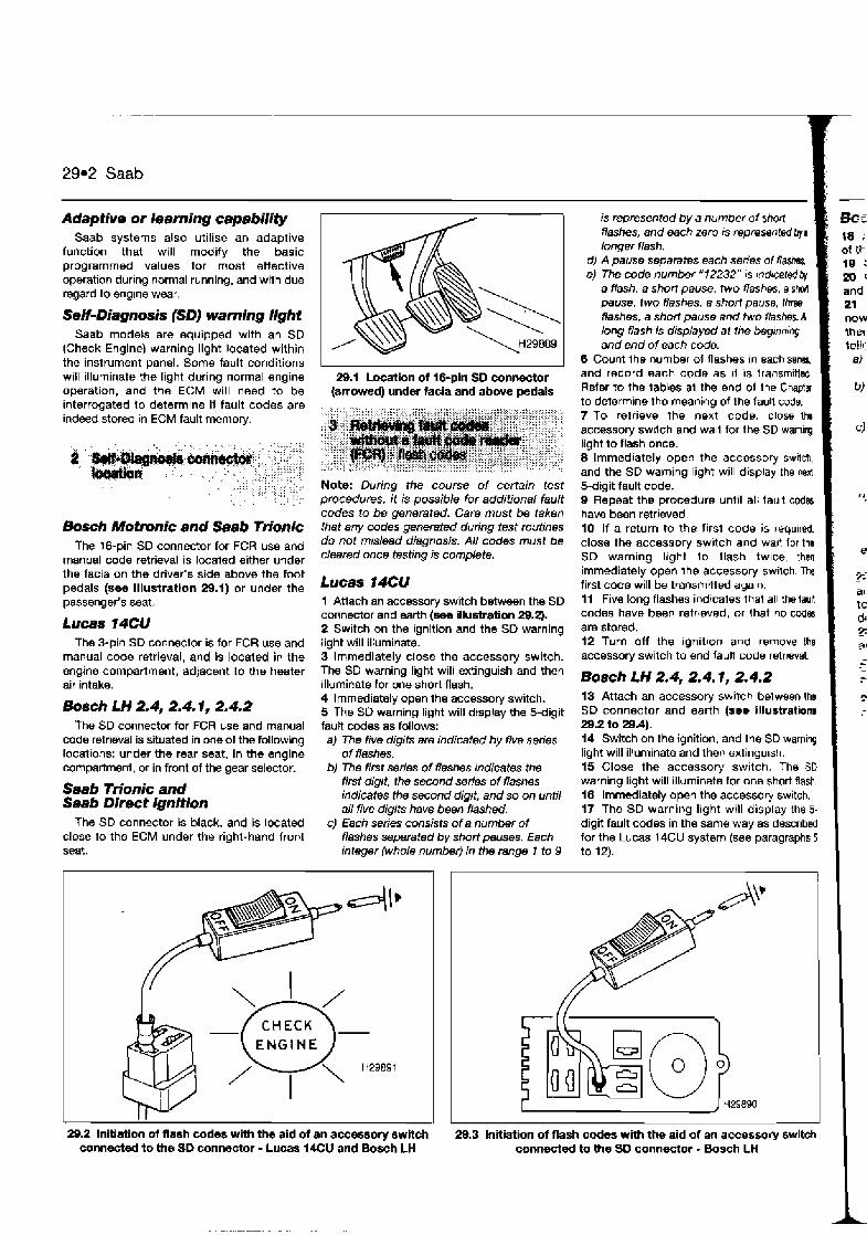
29.2 Saab
Adaptive or learning capability Saab systems also utilise an adaptive
function that will modify the basic programmed values for most effective operation during normal running, and with due regard to engine wear.
SeEf-Diagnosis (SDJ warning light Saab models are equipped with an SD
(Check Engine) warning light located wlthin the instrument panel. Some fault conditions will illuminate the light during normal engine operation, and the ECM will need to be interrogated to determine if fault codes are indeed stored in ECM fault memory.
Bosch Motmnic and Saab Trionic The 16-pin SD connector for FCR use and
manual code retrieval is located either under the facia on the driver's side above the foot pedals (see illustration 29.1) or under the passenger's seat.
Lucas 74CU The 3-pin SD connector is for FCR use and
manual code retrieval, and Is located in the engine compartment, adjacent to the heater air intake.
Bosch LH 2.4, 2.4.1, 2.4.2 The SD connector for FCR use and manual
code retrieval is situated in one of the following locations: under the rear seat, in the engine compartment, or in front of the gear selector.
Saab Trionic and Saab Direct Ignition
The SD connector is black, and is located close to the ECM under the right-hand front seat.
29.1 Location of 16-pln SD connector (arrowed) under facia and above pedals
Note: During the course of certain test procedures, it is possible for additional fault codes to be generated. Care must be taken that any codes generated during test routines do not mislead diagnosis. AN codes must be cleared once testing is complete.
Lucas 14CU 1 Attach an accessory switch between the SD connector and earth (see illustration 29.2). 2 Switch on the ignition and the SD warning light will illuminate. 3 Immediately close the accessory switch. The SD warning light will extinguish and then illuminate for one short flash. 4 lmmediately open the accessory switch. 5 The SO waming light will display the 5-digit fautt ccdes as follows: a) The five digits are indicated by five series
of flahes. b) The first series of flashes Indicates the
first digit, the second series of flashes indicates the second digit, and so on until all five digits have been flashed.
c) Each series consists of a number of flashes separated by short pauses. Each integer (whole number) in the range 1 to 9
is represented by a number of short Rashes, and each zero IS representd bya longer flash.
d) A pause separates each series 01 f l a s k e) The mde number "72232" 1s r
a flash, a short pause, two flashes, e shtwl pause. two flashes, a short pause, Ihm flashes, a short pause and two flasbs. A
I long flash is displayed at !he begmning and end of each code.
6 Count Ihe number of flashes In each s e w and record each code as 11 is transrnided Refer to the tables a1 the end of the Chapta to detem~ne the meanlng of the fault code. 7 To retrieve the next code, close tha accessorj swttch and wan for the SD wamlng l~ght to flash once. 8 lmmediately open the accessory sw~ich, and the SD waming light will display the next 5-dtgit fault code. 9 Repeat the procedure until all fault cod6 have been retrieved. 10 If a return to the first code is requ~red. close the accessory sw~tch and wa~t lor the SD warning l~ght l o flash twice, then immediately open Ihe accessory swilch The first code will be transmrited again 11 Five long flashes ind!caies that all thelwlt codes have been retrieved, or that no cDdtrs are stored. 12 Turn off the lgnltlon and remove the accessory swltch to end fault code retrreval
n- - mi- --- 18 ; of ik 19 : 20 ' and 21 now
Bosch LH 2.4, 2.4.1, 2.4.2 13 Attach an accessory switch belween tho SD connector and earth (see illustration8 29.2 to 29.4). 14 Switch on the ignition, and the SD warning light will illuminate and then extinguish. 15 Close the accessory switch. The SO warning light will illuminate for one short flash, 16 Immediately open the accessory switch. 17 The SD warning light will display the 5- digit fault codes in the same way as described for the Lucas 14CU system (see paragraphs 5
29.2 lnitiation of flash codes with the aid of an accessory switch 29.3 lnitiation of flash codes with the aid of an accessoq switch connected to the SD connector - Lucas 14CU and Bosch LH connacted to the SD connactor - Bosch LH I
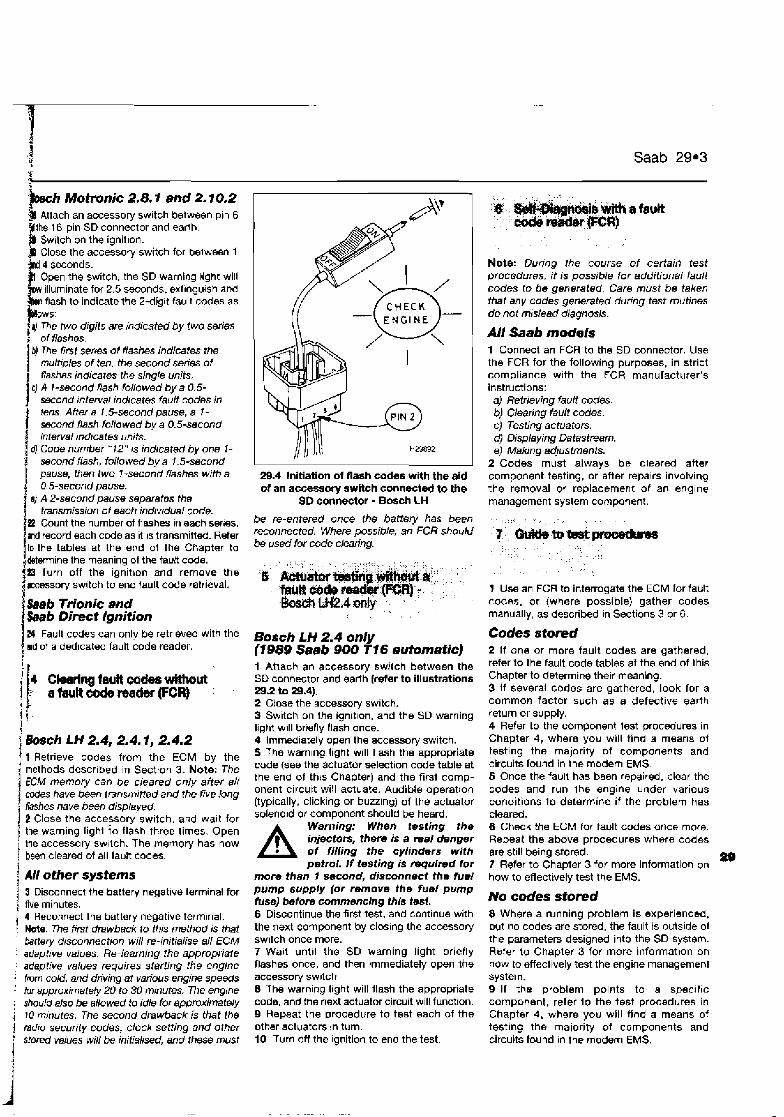
3 ' t Saab 29.3 $ ?
Motmnic 2.8.1 and 2.1 0.2 accessory switch between pin 6
SD connector and earth. Switch on the ignition.
accessory switch for belween 1
Open the switch, the SD warning light will illuminate for 2.5 seconds, extlngu~sh and flash to indicate the 2-digit fault codes as
The two digits are indicated by two series
b) The lirst serms of flashes indicates the multrples of ten, the second series of flashas indicates the single units.
c) A 1-second flash followed by a 0.5- second lnterval indicates fault codes in tens. A frer a I . 5-second pause, a I - sscond flash faflowed by a 0.5-second interval mdtcates units.
@ Code number " 12 " 1s indicated by one I - i second flash, followed by a 1.5-second 1 pause, then two 7 -second flashes with a
0.5-second pause. sJ A 2-second paus8 separatns the
transmission of each indrvrdual code. E Count the number of Rashes in each sw~es. mi record each code as it IS transmitted. Refer lo the tables at the end of Ihe Chapter to
+mine the meaning of the fault code.
i B Turn off the ignithon and remove the accessory switch to end fault code retrieval.
Saab Trionic and bab Direcf Ignition Zd Fault codes can only be retrieved with the old of a ded~cated fault code reader.
1
Ckrlng la18 wcw wifimut a ~ t t c o & m d w ( F C R )
i bsch LH 2.4, 2.4.1, 2.4.2 j I Retrieve codes from the ECM by the
methods descr~bed in Section 3. Note: The ECM memory can be cleared only after all codes have been fmnsmifted and the five .brig
i Ilashes have been displayed. 2 Close the accessory switch, and wa~t for
! the warning lighl to flash three times. Open i the accessory sw~lch. The rnemory has now j been cleared of all fault codes. 1 ; All other systems
3 Disconnect the battery negative terminal for , flue minutes.
4 Recoqnect the battery negative term~nal. Hot8. The first drawback to this method is that beltery disconnection will re-initialise a// ECM adaptrve val~8S. Re-learning the appropriate adaptive values requires starllng the engine frwn cold, and driving at various engine speeds for approximatwty 20 to 30 minutes. The engrne
. should also be allowed to idle for approximately j 10 minutes. The second drawback is that the 1 radio security codes, clock setfing and other ' stored values will be initialised, and these must
29.4 Initiation of flash codes with the aid of an accessory switch connected to the
SD connector - Bosch LH
be re-entered once the battery has been reconnected. Where possible, an FCR should be used for code clearing.
Bosch LH 2.4 only (1889 Saab 900 T16 automatic) 1 Atlach an accessory swilch between the SD connector and earth (reler to illustrations 29.2 to 29.4). 2 Close the accessory switch. 3 Switch on the ign~t~on, and the SD warning light w~l l briefly flash once. 4 Immediately open the accessoty switch. 5 The warnlng light will [lash the appropriate code (see the actuator selection code table at the end of thts Chapter) and the first comp- onent circuit will actuate. Audible operation (typically, clicking or buzz~ng) of the actuator solenoid or component should be heard.
A Warning: When testing the injectors, there is a real danger of filling the cylinders with petrol. I f testing is ~ u l r e d for
mom than 7 second, disconnect the fuel pump supply (or remove the fuel pump fuse) before commencing this test. 6 Discontinue the first test, and continue with the next component by clos~ng the accessory switch once more. 7 Wait until the SD warning light briefly flashes once, and then immediately open the accessorj S W I ~ C ~
8 The warning light will flash the appropriate code, and the next actuator circuit will function. 9 Repeat the procedure to test each of the other actuators In turn. 10 Turn off the Ignition to end the test.
Note: Dunng !he course of certain test pmcedures, it is possible for additional fault codes to be generated. Care must be taken that any codes generated during test routines do not m~slead diagnosis.
All Saeb models 1 Connect an FCA to the SD connector. Use the FCR for the following purposes, in strict compliance with the FCR manufacturer's instructions: a) Retrieving fault codes. b) Clearing fault codes. c) Testing actuators. d) Displaying Datastream. eJ Making adjustments.
2 Codes must always be cleared after component testing, or after repairs involving the removal or replacement of an englne management system component.
1 Use an FCR to interrogate the ECM lor fault codes, or (where possible) gather codes manually, as described in Sections 3 or 6.
Codes stored 2 If one or more fault codes are gathered. refer to the fault code tables at the end of this Chapter to determine their meaning. 3 If several codes are gathered, look for a common factor such as a defective earth return or supply. 4 Refer to the component test procedures in Chapter 4, where you will find a means of testing the majority 07 components and circuits found in the modem EMS. 5 Once the fault has been repaired, clear the codes and run Ihe engine under various conditions to determine if the problem has cleared. 8 Check the ECM for fault codes once mom. Repeat the above procedures where codes are st111 being stored. 7 Refer to Chapter 3 for more information on
m how to effectively test the EMS.
No codes stored 8 Where a running problem is experienced, but no codes are stored, the fault is outside of the parameters designd into the SD system. Refer to Chapter 3 for more information on how to effectively test the engine management system. 9 If the problem points to a speclfic component, refer l o the test procedures in Chapter 4, where you will find a means of testing the majority 07 components and circuits found In the modem EMS.
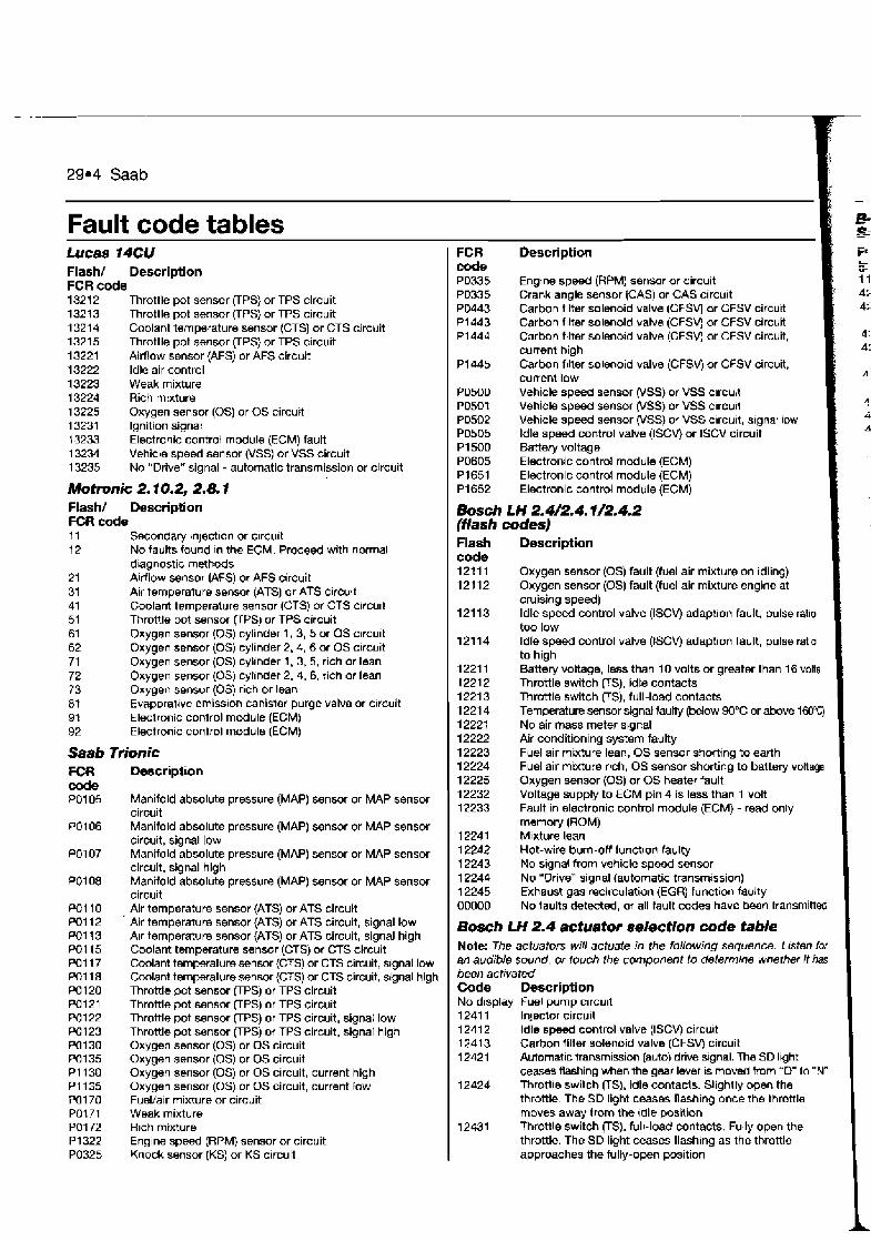
29.4 Saab
Fault code tables em -e- Lucas 14CU Flash/ Description FCR code 1321 2 Throttle pot sensor (TPS) or TPS circuit 1321 3 Throttle pot sensor (TPS) or TPS circuit 1321 4 Coolant temperature sensor (CTS) or CTS circuit 1321 5 Throttle pot sensor UPS) or TPS circuit 13221 Airflow sensor (AFS) or AFS circuit 13222 ldle air control 13223 Weak mixture 13224 Rich mixture 13225 Oxygen sensor (0s) or OS circuit 13231 Ignition signal 13233 Electronic control module (ECM) fault 13234 Vehicle speed sensor (VSS) or VSS circuit 13235 No "Drive" signal - automatic transmission or circuit
Motronic 2.10.2, 2.8.1 Flash/ Description FCR code 11 Secondary ~n~ection or clrcult 12 No faults found ~n the ECM. Proceed with normal
diagnostic methods 21 Al~flow sensor (AFS) or AFS circuit 31 Air temperature sensor (ATS) or ATS circujt 41 Coolant temperature sensor (CTS) or CTS circu~t 51 Throttle pot sensor UPS) or TPS circuit 61 Oxygen sensor (0s) cylinder 1, 3, 5 or OS clrcuit 62 Oxygen sensor (0s) cylinder 2, 4, 6 or OS circuit 71 Oxygen sensor (0s) cyllnder 1, 3,6, rich or lean 72 Oxygen sensor (0s) cyllnder 2, 4,6, rich or lean 73 Oxygen sensor (0s) rich or lean 81 Evaporat~ve emiss~on canister purge valve or crrcuit 91 Electronic control mcdule (ECM) 92 Electronic conlrol module (ECM)
Saab Trionic FCR Description code PO1 05 Manifold absolute pressure (MAP) sensor or MAP sensor
circuit PO1 06 Manifold absolute pressure (MAP) sensor or MAP sensor
circuit, signal low PO1 07 Manifold absolute pressure (MAP) sensor or MAP sensor
circuit, signal high PO1 08 Manifold absolute pressure (MAP) sensor or MAP sensor
circuit PO1 10 + Air temperature sensor (ATS) or ATS circuit PO1 12 Air temperature sensor (ATS) or ATS circuit, signal low PO1 13 Atr temperature sensor (ATS) or ATS circuit, signal high PO1 15 Coolant temperature sensor (CTS) or CTS circuit PO1 17 Coolant temperature sensor (CTS) or CTS circuit, signal low PO1 18 Coolant temperature sensor (CTS) or CTS circuit, signal high PO1 20 Throttle pot sensor OPS) or TPS circuit PO1 21 Throttle pot sensor (TPS) or TPS circuit PO122 Throttle pot sensor (TPS) or TPS circuit, signal low PO123 Throttle pot sensor PPS) or TPS circuit, signal high PO130 Oxygen sensor (0s) or OS circuit PO135 Oxygen sensor (0s) or OS circuit P I 130 Oxygen sensor (0s) or OS circuit, current high P I 135 Oxygen sensor (0s) or OS circuit, current tow PO1 70 Fuel/air mixture or circuit PO1 71 Weak mixture PO1 72 Rich mixture PI322 Engine speed (RPM) sensor or circuit PO325 Knock sensor (KS) or KS circuit
FCR d PO335 PO335 PO443 P1443 P1443
bescription
Engine speed (RPM) sensor or circult Crank angle sensor [CAS) or CAS circuit Carbon fllter solenoid valve (CFSV) or CFSV circurt Carbon fllter Solenold valve (CFSV) or CFSV circuit Carbon f~lter solenold valve (CFSVj or CFSV circuit, current hlgh Carbon f~lter solenold valve (CFSW or CFSV circuit, current low Vehicle speed sensor (VSS) or VSS clrcubt Vehicle speed sensor (VSS) or VSS clrcull Vehicle s p e d sensor (VSS) or VSS clrcult, s~gnat low ldle speed control valve (ISCV) or ISCV circuit Battery voltage Electrontc control module (ECM) Electronic control module IECM)
PI652 Electronic control rncdule (ECM)
Bosch LH 2.W2.4.112.4.2 (flash codes) Flash Description code 121 11 Oxygen sensor (0s) fault (fuel air mixture on idling) 121 12 O~ygen sensor (0s) fault (fuel air mixture engine at
cruising speed) 121 13 ldle speed control valve (ISCVj adaption fault, pulse ratio
too low 121 14 ldle speed control valve (ISCV) adaption fault, pulse ratio
to high 1221 1 Battery voltage, less than 10 volts or greater than 16 volts 1221 2 Throttle switch (TS), idle contacts 1221 3 Throttle switch FS), full-load contacts 1 221 4 Temperature sensor signal faulty (Wow 90°C or above 1W"C) 12221 No air mass meter signal 12222 Air conditioning system faulty 12223 Fuel air mixture lean, OS sensor shorting to earth 12224 Fuel air mixture rich, OS sensor shorting to battery voltage 12225 Oxygen sensor (0s) or OS heater fault 12232 Voltage supply to ECM pin 4 is less than 1 volt 12233 Fault in electronic control module (ECM) - read only
memory (ROM) 12241 Mlxture lean 12242 Hot-wire burn-off function faulty 12243 No signal from vehicle speed sensor 12244 No 'Drive" signal (automatic transmission) 12245 Exheust gas recirculation (EGR) function faulty 00000 No taults detected, or all fault codes have bean transmitted
Bosch LH 2.4 actuator sekctiorr code table Note: The actuaton will actuate in the following sequence. Listen lor an audible sound. or touch the component to determme whether it has been activated Code Description No display Fuel pump clrcu~t 1241 1 Injector circuit 12412 ldle s p e d control valve (ISCV) circu~t 12413 Carbon filter solenoid valve (CFSVj circuit 12421 Automatic transmission (auto) drive sgnal. The SD Ight
ceases Rashing when the gear lever IS moved from 'D to "N" 12424 Throtlle switch (TS), idle contacts. Slightly open the
throttle. The SD light ceases flashing once the throttle moves away from the rdle position
12431 Throttle switch (TS), full-load contacts. Fully open the throttle. The SD light ceases flashing as the throttle approaches the fully-open position

I $
Saab 29.5 1 4
I Bosch LH 2.4/2.4.2 and Saab Direct Ignition (FCR codes)
j FCA code FCR c d e lpmenent) flntsrmhnt) bscrlptlon 11 11 1 Reply code for OK 42241 22241 High voltage (1991-on) 62251 22251 Eleronic control module (ECM) pin 4,
signal low 42252 22252 Signal low, less than 10 volts 42291 22291 Battety voltage, less than 10 volwgreater
than 16 volts 42440 22440 Oxygen sensor (0s) or OS circuit, rich
mixture 42441 22441 Rich mixture, idling (1 991 -on) 42442 22442 Rich mixture, driving (199t-on) 42450 22450 Oxygen sensor (0s) or OS circuit, weak
mixture 42451 22451 Weak mixture, idling (1 991 -on) 42452 22452 Weak mixture, driving (t 991 -on) 42460 22460 Oxygen sensor (0s) or OS circuit 4249 1 22491 Idling mixture incorrect 42492 22492 Driving mixture incorrect
* 44221 24221 Engine RPM signal absent (1991 -on) 1 44251 24261 Vehicle speed sensor (VSS) or VSS circuit (1 991 -on)
44360 24360 Crank angle sensor (GAS) or CAS circuit 44460 24460 Engine load signal faulty
24660 Pre-ignition fault (knocking or pinking) 44661 24461 Knock sensor (KS) or KS circuit
24462 Combustion, synchronlsing fautl 24671 Pre-ignition signal over 20 seconds
45641 25641 Mass airflow (MAW sensor or MAF sensor circuit, signal high
FCR code FCR d e brmanent) [mtermient) Description 45651 25651 Mass airflow (MAF) sensor or MAF sensor
circuit, signal low 45691 25691 Mass Alrflow (MAF) sensor or MAF sensor
circuit 45723 25723 'Drive" signal (automatic transmission) 45771 25771 Throttle pot sensor (TPS) signal or TPS
circuit 45772 25772 Throttle pot sensor (TPS) signal or TPS
circuit 46221 26221 Coolant temperature sensor (CTS) or CTS
circuit, signal low 46271 26271 Coolant temperature sensor (CTS) or CTS
circuit, signal high 46391 26391 Exhaust gas recirculation (EGR) system or
EGR circuit 58121 38121 Mass airflow (MAR sensor or MAF sensor
circuit, burn-off absent 58321 38321 Air conditioning valve function or circuit 58322 38322 Evaporative loss control device (ELCD)
valve function or clrcult 58371 38371 Injector or injector circuit 58372 38372 Evaporative loss control device (ELCD)
valve or circuit 58382 38382 Evaporative loss control device (ELCD)
valve short-circuit (f 991 -on) 60000 Internal monitoring 60001 Read onty memory (ROM) fault 60002 Random access memory (RAM) fault 671 92 Electronic control module (ECM), read only
memory (ROM)

Index of vehicles Retrieving fault codes wlthout a fault code reader (FCR) - Self-Diagnosis flash codes.. . . . . . . . . . . . . . . . . . . . . . . . . . . . . . . . . . . . . . . . . . 3 Clearlng fault codes wlthout a fault code reader (FCR) . . . . . . . . . . . 4 Self-Diagnosis connector location . . . . . . . . . . . . . . . . . . . . . . . . . . . 2 Gurde to test procedures . . . . . . . . . . . . . . . . . . . . . . . . . . . . . . . . . 6 Self-Diagnosis with a fault code reader (FCR) . . . . . . . . . . . . . . . . 5 Intr@duct~on . . . . . . . . . . . . . . . . . . . . . . . . . . . . . . . . . . . . 1 Fault code table
1 Index of vehicles ! Model
Altlarllbra 2.0 Cordoba 1.41 SOHC 8V Cordoba 1 61 SOHC 8V Cordoba 1 HI SOHC 8V Cordoba 1.81 16V
I Cordoba 2 01 SOHC 8V 4: Ibiza 1.05i SOHC 8V lbiza 1.3i US83 '' lblza 1.4i SOHC 8V 1 lbiza 1.6i SOHC 8V Iblza 1.81 SOHC 8V 1 lbiza 1.8i 16V lbiza 2.0i SOHC 8V
'! Inca 1.41 Inca 1.6i Toledo 1.6i cat SOHC Toledo 1.6i SOHC
1 Toledo 1.8i SOHC Toledo 1.8i cat SOHC / Toledo 1-81 cat SOHC Toledo 1.81 SOHC BV Toledo 2.0i
Engine code ADY ABD ABU ABS ADL 2E M U AAV ABD ABU ABS ADL 2E
1 F 1 F RP RP RP ABS 2E
Year 1996to 1997 1994 to 1997 1993 to 1997 1993 to 1995 1994 to 1997 1993 to 1997 1993 to 1997 1993 to 1994 1994 to 1997 1993 to 1997 1993 to 1995 1994 to 1997 1993 to 1997 1995 to 1996 1995 to 1996 1991 to 1997 1994 to 1997 1991 to 1995 1991 to 1995 1991 to 1996 1994 to 1997 1991 to 1997
System Simos Bosch Mono-Motron~c Bosch Mono-Motronic Bosch Mono-Motronic VAG Digifant VAG Digifant Bosch Mono-Motronic Bosch Mono-Motronic Bosch Mono-Motronic Bosch Mono-Motronic Bosch Mono-Motronic VAG Digifant VAG Digifant Bosch Motronic MP 9.0 Bosch Mono-Motronic Bosch Mono-Jetronic Bosch Mono-Motronic Bosch Mono-Jetronic Bosch Mono-Jetronic Bosch Mono-Motronic Bosch Mono-Motronic VAG Diglfant
i j Self-Diagnosis / 1 Introduction
! The engine mnnngempnr systems (EMSs) 7 filled to SEAT models rnclude Bosch Motron~c '
MP5 0, Mono-Jetron~c. Mono-Motron~c, and : also VAG Dlglfant and Slmos. Bosch Motron~c
; MP4 0. Mono-Motron~c. VAG D~gitant and j Slrnos systems ~ontro l the prrmaw lgtiltion.
, fuel rnjectlon and rdtlng tunctlons trom wlthin : !he same cbntrol module. Mono-Jetronlc
cbr~irols the fuel lnjectlon and idle tunctlons : alone
) Self-Diagnosis (SD) function ' Each electronic conlrol module [ECM) has a '
self-test capahlllty that continually examines the srgnals Irom cenaln enytne sensors and actualors, and compares each slgnal to a
I rable 01 prograrnrned ~*alurs. If the dlagnostlc sofrwarr deternllnrs that a fault IS present. the
, ECLl stores one or more fault codes Codes
will not be stored about components for whrch a code IS no1 available, or for conditions not covered by the diagnostrc software.
SEAT systems are capable of generating two krnds of faull codes. Ttiese are 4 - d ~ g ~ t flash codes and 5-dig11 fault codes, a) Mono-Jetronrc systems car? only perrerate
4-drgrl flash codes These can be retrreved vra the wamrng bghl (where IrtteQ), or by usng a sepamle LED AHernalrvely. fault codes can be d~splayed on a dedrcaied fault code reader (FCR).
b) Later systems can generare both J-digtt and 5- dig, t fault codes, and retfleval requires a dedicated FCR. These systems irlciude early versions of Bosch Mono- rMotronrc and some VAG Drgttant (45-ptn)
c) The very latest systems can only generate 5-drgtt fautt codes, and these must he retrreved wrth the atd of a dedrcated FCR. These systems tnclude Bosch Mono- Motrwnlc MA 1.2.2 (later 45-p~n). Srmos and VAG Dtgrlanl (68pmn)
Limited operating strategy (LOS) All SEAT models featured in this Chapter
except those with Bosch Mono-Jetronic utllise LOS (a function that is commonly called the "limp-home mode"). Once certain faults have been identified (not all faults will initlate LOS). the ECM will implement LOS and reler to a programmed default value rather than ihe sensor signal. This enables the vehcle to be safely drlven to a workshnplgarage for repalr or testlng. Once the fault has cleared, the 30 ELM wrll revert to normal operatlon. Bosch Mono-Jetronlc does not have LOS.
Adaptive or learning capability SEAT systems also utilise an adaptive
functlon that will modify the basic programmed values for most effective operatlon during normal running and with due regard to engine wear.
Self-Diagnosis (SDJ warning light Bosch Mono-Jetronic equipped vehicles
are also fitted with an SD warnlng light located
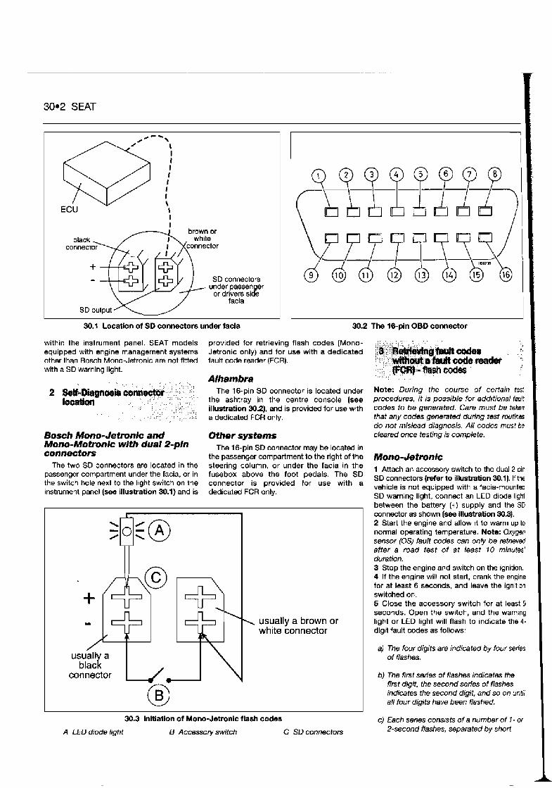
.
30.2 SEAT
sO--\
62 \ I I I I
I I I \
ECU I I I
SD connectors under passenger
or drivers side facia
30.1 Locatlon ol SD connectors under lacla 302 The 16-pin OBD connector
within the instrument panel. SEAT models equipped with engine management systems other than Bosch Mono-Jetronic are not fltted with a SD warning light.
Bosch Mono- Jetmnic and Mono-Motmnic with dual Spin connectors
The two SD connectors are located in the passenger compartment under the facia, or in the switch hole next to the light switch on the instrument panel (see illustration 30.1) and is
provided for retrieving flash codes (Mono- Jetronic only) and for use with a dedicated fautt code reader (FCR).
The 16-pin SD connector is located under the ashtray in the centre console (see illustration 30.2), and is provided for use with a dedicated FCR only.
Other systems The 16-pin SD connector may be located in
the passenger compartment to the right of the steering column, or under the facia in the fusebox above the foot pedals. The SD connector is provided for use with a dedicated FCR only.
1
'o$@ 0 -
- 7
\ usually a brown or white connector
connector
Note: During the course of certain test procedures, it is possible for additional fault codes to be generated. Care must be taken that any codes generated during test roufim do not mislead diagnosis. Ail codes must be cleared once testing is complete.
Mono-Jetronic 1 Attach an accessoty switch to the dual 2-pin SD connectors (refer to illustration 30.1). tf the vehicle is not equipped with a facia-mounted SD warning light, connect an LED diode light between the battery (+) supply and the SD connector as shown (see illustration 30.3). 2 Start the engine and allow it to warm up to normal operating temperature. Note: Oxygen sensor (0s) fault codes can only be mtneved after a road test of at least 10 minutes' duration. 3 Stop the engine and switch on the ignition. 4 If the engine will not start, crank the engine for at least 6 seconds, and leave the ignition switched on. 5 Close the accessory switch for at least 5 seconds. Open the switch, and the warning light or LED light will flash to indicate the 4- digit fault codes as follows:
a) The four digits are indicated by four series of flashes. I
bJ The first series of flashes indicates the first digit, the second series of flashes indicatss the second digit, and so on until all four digits have been flashed. I
30.3 Initiation of Mono-Jetronic flash codes c) Each sen- consjsts of a number of 7 - or
A LED diode light 8 Accessory switch C SD connectors 2-second flashes, separated by short
SEAT 30.3
pauses. Each rnteger (whole number) in the range 7 to 9 is represented by a
, number of l -second flashes, and each ] zero is represented by 2-second flashes. .' d) The code number "1231" is indicated by a - 7-second flash, a short pause, two I-see ] ond #ashes, a short pause, three I-second : flashes, a short pause and a 1-second ; flash. j e) A 2.5-second pause separates each : series of flashes. After this pause, the
code writ be mpeated.
I 6 Counl Ihe number of flashes in each series, , and record the code. Refer to the table at the f end of the Chapter to determine the meaning
of :he fault code. , 7 The code w~ l l be repeated until the i accessory sw~tch 1s once more closed for at least 5 seconds. Open the switch and the next
,i code will then be displayed. ' 8 Continue retrieving codes until code 0000 is h transmitted. Code 0000 sign~fies that no more
codes are stored, and is displayed when the 1 light flashes off and on at 2.5-second ' intervals. : @ If code 4444 is transmitted, no laull codes ' are stored. I 10 Turning off the ignit~on ends fault code
retrieval. ?
: All other systems : 11 Flash codes are not available, and a
ded~cated FCR must be used to retrieve fault
A// systems (alternative methodJ 5 Turn off the ignition and disconnect the bal?ery negative terminal for a period of approximately 5 minutes. 6 Reconnect the battery negative terminal. Note: The first drawback to this method is that battery disconnection will initialise a// ECM adaptive values (not Mono-Jetronic). Re- learning the appropriate adaptive values requires starting the engine from cold, and driving at various engine speeds for approximately 20 to 30 minutes. The engine should also be aNowed to idle for approximately 70 minutes. The second drawback rs that the radio security codes, clock setting and other stored values will be inilialised, and f h m mud be re-entered once the battery has been reconnected. Where possible, an FCR should be used for code clearing.
Note: During the course of certain tesf procedures, it is possible for additional fault codes to be generated. Care must be taken that any codes generated during tesf routines do not mislead diagnosis.
codes. All SEAT models
. 4 Cleadng fault calm without a fault code r e d m IF?CW1
Bosch Mono- Jetmnic 1 Carry out the procedure in Section 3 to retrieve all fault codes (wait unt~l code DO00 or code 4444 is displayed). 2 Turn off the ~gn~tion, and close the accessory switch. 3 Switch the ignition on. 4 After 5 seconds, open the accessory switch. All fault codes should now be cleared. Turn off the ign~t~on on completion.
1 Connect an FCR to the SO connector. Use the FCR for the following purposes, in strict compliance w~ th the FCR manufacturer's instructions:
a) Retrieving fault codes. b) Clearing fault codes. c) Testtng actuators. d) Displaying Datastmm. eJ Making adjustments to the ignition timing
or mixture (some systems).
2 Codes must always be cleared after component testing, or after repairs involving the removal or replacement ol an EMS component.
Engine management fault mdes 1 Use an FCR to interrogate the ECM for fault codes, or manually gather codes (where pospible) as desc r iw in Section 3 or 5.
Codes stor& by ECM 2 If one or more fault codes are gathered, refer to the faun code table at the end of this Chapter to determine their meaning. 3 If several codes are gathered, look for a common factor such as a defective earth return or supply. 4 Refer to the component test procedures In Chapter 4, where you will find a means of testing the majority of components and circuits found in the modern EMS. 5 Once the fault has been repaired, clear the codes and run the englne undec various conditions to determine i f the problem has cleared. 6 Check the ECM for fault codes once more Repeat the above procedures where codes are still being stored. 7 Refer to Chapter 3 for more information on how to effecttvely test the EMS.
Na codes stored 8 Where a running problem is experienced, but no codes are stored, the fault is outside of the parameters deslgned into the SD system. Refer to Chapter 3 for more information on how to effectively test the engine management system. 9 If the problem points to a specific component, reler to the test procedures in Chapter 4, where you will find a means of testing the majority of components and circuits found in the modern EMS.
Non-engine management fault codes 10 A number ot codes that could b stored by the ECM and retrieved dur~ng the code gathering operation may refer to the air conditioning system, fan control and automatic transmission. This manual spec~f~cally covers engine management components, and diagnosis of codes pointing to faults in ancillary components is not covered.
90 Fault code tables appear overleaf
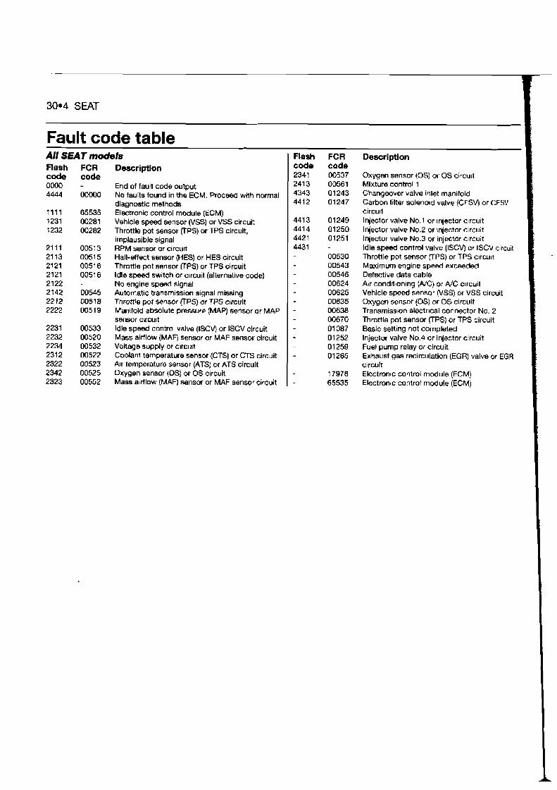
30.4 SEAT
Fault code table All SEAT models Flash FCR Description
Flash FCR Description code code code code 2341 00537 Oxygen sensor (0s) or 0s circu~t
0000 - End of fault code o~rtput 241 3 00561 Mixture control 1 4444 00000 No faults found in the ECM. Proceed wdh normal 4343 01243 Changeover valve inlet manifold
diagnostic methods 441 2 01247 Carbon filter solenold valve (CFSV) or CFSV
7 11 1 65535 Electronic mntrol module (ECM) circu~t t231 00281 Vehde speed sensor (VSS) or VSS circuit 441 3 01 249 Injector valve No.1 or ~nlecbr c~rcuit 1232 00282 Throttle pot sensor (TPS) or TPS c~rcuit, 441 4 01 250 Injector valve No.2 or mledor c~rcuit
implausible stgnal 4421 01251 Injector valve N0.3 or injector c~rcuit 21 11 0051 3 RPM sensor or circuit 4431 - Idle sped control valve (ISCV) nr ISCV clrcu~t 21 13 0051 5 Hal l -ef f~t sensor (HES) or HES circuit 00530 Throttlepotsensor~PS)orTPSc~rcu~t 2121 0051 6 Throttle pot sensor (TPS) or TPS circuit 00543 Maximum englne speed exceeded 2121 0051 6 Idle speed switch or circutt (alternative code) 00546 Defective data cable 2122 - No engine speed signal 00624 Alr condltbonlng (Nc) or #C Clrcuit 21 42 00545 Automat~c transm~ssion slgnal missing 00625 Vehicle s p e d sensor (VSS) or VSS circuit 2212 00518 ThrotllepdsensorflPS)orTPScircuit 00635 Oxygen sensor (0s) or OS circuit 2222 0051 9 Manifold absolute pressure (MAP) sensor or MAP - 00638 Transmissbon electrical connector No. 2
sensor cucuit 00670 Throttle pot sensor (TPS) or TPS circu~t 2231 00533 Idle speed control valve (ISCVj or ISCV crrcuit 01 087 Baslc setting not completed 2232 00520 Mass a~rflow (MAW sensor or MAF sensor circud - 01252 Injector valve No.4 or inlector c~rcuit 2234 00532 Voltage supply or clrcMt 01259 Fuel pump relay or circuit 2312 00522 Coolant temperature sensor (CTS) or CTS circuit - 01265 Exhaust gas recirculation (EGR) valve or EGR 2322 00523 Alr temperature sensor (ATS) or ATS circuit c~rcuit 2342 00525 Oxygen sensor (0s) or OS clrcult 17970 Electron~c control module (ECM) 2323 00552 Mass artlow (MAF) sensor or MAF sensor circurt - 65535 Electronrc control module (ECM)